Operation and Maintenance Manual - Australian Hammer ...
362
PUBLICATIONS.CAT.COM Language: Original Instructions Operation and Maintenance Manual 374F Excavator EBF 1-UP (374F) DNM 1-UP (374F) XWL 1-UP (374F) SEBU8588-16 (en-us) June 2020
-
Upload
khangminh22 -
Category
Documents
-
view
3 -
download
0
Transcript of Operation and Maintenance Manual - Australian Hammer ...

PUBLICATIONS.CAT.COM
Language: Original Instructions
Operation andMaintenanceManual374F ExcavatorEBF 1-UP (374F)DNM 1-UP (374F)XWL 1-UP (374F)
SEBU8588-16 (en-us)June 2020
i07966018
Important Safety InformationMost accidents that involve product operation, maintenance and repair are caused by failure to observebasic safety rules or precautions. An accident can often be avoided by recognizing potentially hazardoussituations before an accident occurs. A person must be alert to potential hazards, including human factorsthat can affect safety. This person should also have the necessary training, skills and tools to perform thesefunctions properly.
Improper operation, lubrication, maintenance or repair of this product can be dangerous and couldresult in injury or death.
Do not operate or perform any lubrication, maintenance or repair on this product, until you verifythat you are authorized to perform this work, and have read and understood the operation,lubrication, maintenance and repair information.
Safety precautions and warnings are provided in this manual and on the product. If these hazard warningsare not heeded, bodily injury or death could occur to you or to other persons.
The hazards are identified by the “Safety Alert Symbol” and followed by a “Signal Word” such as“DANGER”, “WARNING” or “CAUTION”. The Safety Alert “WARNING” label is shown below.
The meaning of this safety alert symbol is as follows:
Attention! Become Alert! Your Safety is Involved.
The message that appears under the warning explains the hazard and can be either written or pictoriallypresented.
A non-exhaustive list of operations that may cause product damage are identified by “NOTICE” labels onthe product and in this publication.
Caterpillar cannot anticipate every possible circumstance that might involve a potential hazard.The warnings in this publication and on the product are, therefore, not all inclusive. You must notuse this product in any manner different from that considered by this manual without firstsatisfying yourself that you have considered all safety rules and precautions applicable to theoperation of the product in the location of use, including site-specific rules and precautionsapplicable to the worksite. If a tool, procedure, work method or operating technique that is notspecifically recommended by Caterpillar is used, you must satisfy yourself that it is safe for youand for others. You should also ensure that you are authorized to perform this work, and that theproduct will not be damaged or become unsafe by the operation, lubrication, maintenance or repairprocedures that you intend to use.
The information, specifications, and illustrations in this publication are on the basis of information that wasavailable at the time that the publication was written. The specifications, torques, pressures,measurements, adjustments, illustrations, and other items can change at any time. These changes canaffect the service that is given to the product. Obtain the complete and most current information before youstart any job. Cat dealers have the most current information available.
NOTICEWhen replacement parts are required for this product Caterpillar recommends using original Cater-pillar® replacement parts.
Other parts may not meet certain original equipment specifications.
When replacement parts are installed, the machine owner/user should ensure that the machine re-mains in compliance with all applicable requirements.
In the United States, the maintenance, replacement, or repair of the emission control devices andsystems may be performed by any repair establishment or individual of the owner's choosing.

Table of Contents
Foreword ........................................................... 5
Safety Section
Safety Messages............................................... 7
Additional Messages ....................................... 19
General Hazard Information............................ 27
Crushing Prevention and Cutting Prevention.. 29
Burn Prevention............................................... 30
Fire Prevention and Explosion Prevention...... 31
Fire Safety ....................................................... 34
Fire Extinguisher Location............................... 35
Track Information ............................................ 35
High Pressure Fuel Lines................................ 35
Electrical Storm Injury Prevention................... 36
Before Starting Engine .................................... 36
Visibility Information ........................................ 36
Restricted Visibility .......................................... 37
Engine Starting................................................ 39
Before Operation ............................................. 39
Work Tools....................................................... 39
Operation......................................................... 40
Engine Stopping .............................................. 43
Lifting Objects.................................................. 43
Parking ............................................................ 43
Slope Operation .............................................. 44
Equipment Lowering with Engine Stopped ..... 45
Sound Information and Vibration Information . 45
Operator Station .............................................. 48
Guards (Operator Protection) ......................... 48
Product Information Section
General Information ........................................ 50
Identification Information................................. 89
Operation Section
Before Operation ............................................. 93
Machine Operation.......................................... 95
Engine Starting.............................................. 194
Operation....................................................... 198
Operating Techniques ................................... 202
Parking .......................................................... 222
Transportation Information ............................ 226
Towing Information ........................................ 247
Engine Starting (Alternate Methods)............. 251
Maintenance Section
Maintenance Access ..................................... 254
Lubricant Viscosities and Refill Capacities ... 256
Maintenance Support .................................... 266
Maintenance Interval Schedule..................... 273
Warranty Section
Warranty Information..................................... 351
Reference Information Section
Reference Materials ...................................... 352
Index Section
SEBU8588-16 3Table of Contents

Index.............................................................. 353
4 SEBU8588-16Table of Contents

Foreword
California Proposition 65 WarningDiesel engine exhaust and some of itsconstituents are known to the State ofCalifornia to cause cancer, birth defects,and other reproductive harm.
WARNING – This product canexpose you to chemicalsincluding ethylene glycol, which
is known to the State of California tocause birth defects or other reproductiveharm. For more information go to:
www.P65Warnings.ca.gov
Do not ingest this chemical. Wash handsafter handling to avoid incidentalingestion.
WARNING – This product canexpose you to chemicalsincluding lead and lead
compounds, which are known to theState of California to cause cancer, birthdefects, or other reproductive harm. Formore information go to:
www.P65Warnings.ca.gov
Wash hands after handling componentsthat may contain lead.
Literature InformationThis manual should be stored in the operator'scompartment in the literature holder or seat backliterature storage area.
This manual contains safety information, operationinstructions, transportation information, lubricationinformation, and maintenance information.
Some photographs or illustrations in this publicationshow details or attachments that can be differentfrom your machine. Guards and covers might havebeen removed for illustrative purposes.
Continuing improvement and advancement ofproduct design might have caused changes to yourmachine which are not included in this publication.Read, study, and keep this manual with the machine.
Whenever a question arises regarding your machine,or this publication, please consult your Cat dealer forthe latest available information.
SafetyThe safety section lists basic safety precautions. Inaddition, this section identifies the text and locationsof warning signs and labels used on the machine.
Read and understand the basic precautions listed inthe safety section before operating or performinglubrication, maintenance, and repair on this machine.
OperationThe operation section is a reference for the newoperator and a refresher for the experiencedoperator. This section includes a discussion ofgauges, switches, machine controls, attachmentcontrols, transportation, and towing information.
Photographs and illustrations guide the operatorthrough correct procedures of checking, starting,operating, and stopping the machine.
Operating techniques outlined in this publication arebasic. Skill and techniques develop as the operatorgains knowledge of the machine and its capabilities.
MaintenanceThe maintenance section is a guide to equipmentcare. The Maintenance Interval Schedule (MIS) liststhe items to be maintained at a specific serviceinterval. Items without specific intervals are listedunder the "When Required" service interval. TheMaintenance Interval Schedule lists the page numberfor the step-by-step instructions required toaccomplish the scheduled maintenance. Use theMaintenance Interval Schedule as an index or "onesafe source" for all maintenance procedures.
Maintenance IntervalsUse the service hour meter to determine servicingintervals. Calendar intervals shown (daily, weekly,monthly, etc.) can be used instead of service hourmeter intervals if the calendar intervals provide moreconvenient servicing schedules and approximate theindicated service hour meter reading. Perform therecommended service at the interval that occurs first.
Under severe, dusty, or wet operating conditions,more frequent lubrication than is specified in themaintenance intervals chart might be necessary.
SEBU8588-16 5Foreword

Perform service on items at multiples of the originalrequirement. For example, at every 500 servicehours or 3 months, also service those items listedunder every 250 service hours or monthly and every10 service hours or daily.
Certified Engine MaintenanceProper maintenance and repair are essential to keepthe engine and machine systems operating correctly.As the heavy-duty off-road diesel engine owner, youare responsible for the performance of the requiredmaintenance listed in the Owner Manual, Operationand Maintenance Manual, and Service Manual.
It is prohibited for any person engaged in thebusiness of repairing, servicing, selling, leasing, ortrading engines or machines to remove, alter, or torender inoperative, any emission-related device orelement of design installed on or in an engine ormachine that is in compliance with all applicableregulations of the intended country to which it hasbeen shipped. Certain elements of the machine andengine such as the exhaust system, fuel system,electrical system, intake air system, and coolingsystem may be emission-related and should not bealtered unless approved by Caterpillar.
Machine CapacityAdditional attachments or modifications may exceedmachine design capacity which can adversely affectperformance characteristics. Included would bestability and system certifications such as brakes,steering, and rollover protective structures (ROPS).Contact your Cat dealer for further information.
Product Identification NumberEffective First Quarter 2001 the Product IdentificationNumber (PIN) has changed from 8 to 17 characters.To provide uniform equipment identification,construction equipment manufacturers are moving tocomply with the latest version of the productidentification numbering standard. Non-road machinePINs are defined by ISO 10261. The new PIN formatwill apply to all machines and generator sets. ThePIN plates and frame marking will display the 17character PIN. The new format will look like thefollowing:
Illustration 1 g03891925
Where:
1. World Manufacturing Code (characters 1-3)
2. Machine Descriptor (characters 4-8)
3. Check Character (character 9)
4. Machine Indicator Section (MIS) or ProductSequence Number (characters 10-17). These werepreviously referred to as the Serial Number.
Machines and generator sets produced before FirstQuarter 2001 will maintain their 8 character PINformat.
Components such as engines, transmissions, axles,and work tools will continue to use an 8 characterSerial Number (S/N).
6 SEBU8588-16Foreword

Safety Sectioni08022368
Safety MessagesSMCS Code: 7000; 7405
There are several specific safety messages on thismachine. The exact location of the hazards and thedescription of the hazards are reviewed in thissection. Become familiarized with all safetymessages.
Make sure that all the safety messages are legible.Clean the safety messages or replace the safetymessages if you cannot read the words. Replace theillustrations if the illustrations are not visible. Whenyou clean the safety messages, use a cloth, water,and soap. Do not use solvent, gasoline, or otherharsh chemicals to clean the safety messages.Solvents, gasoline, or harsh chemicals could loosenthe adhesive that secures the safety message. Looseadhesive will allow the safety message to fall.
Replace any safety message that is damaged, ormissing. If a safety message is attached to a part thatis replaced, install a safety message on thereplacement part. Any Caterpillar dealer can providenew safety messages.
SEBU8588-16 7Safety Section
Safety Messages

Illustration 2 g01618205
8 SEBU8588-16Safety SectionSafety Messages

Illustration 3 g03567280
SEBU8588-16 9Safety Section
Safety Messages

Illustration 4 g06510953
Do Not Operate (1)This safety message is located in the cab on the rightside window, and on the back top side of thecounterweight.
10 SEBU8588-16Safety SectionSafety Messages

Illustration 5 g01370904
Do not operate or work on this equipment unlessyou have read and understand the instructionsand warnings in the Operation and MaintenanceManual. Failure to follow the instructions or heedthe warnings could result in injury or death. Con-tact any Cat dealer for replacement manuals.Proper care is your responsibility.
Crushing Hazard (2)This safety message is located in the cab on the rightside window.
Illustration 6 g01373971
Crushing Hazard! Certain machine front linkagecombinations (boom, stick, quick coupler, worktool) may require keeping the work tool awayfrom the cab during operation. Personal injury ordeath may result if the work tool contacts the cabduring operation.
Refer to Operation and Maintenance Manual,“Operating Technique Information” for furtherinformation.
Crushing Hazard (3)This safety message is located in the cab on the rightside window.
Illustration 7 g01373978
Personal injury can result if the window is notlatched in the overhead position; ensure the autolock is engaged.
Refer to Operation and Maintenance Manual,“Window (Front)” for further information.
Product Link (4)If equipped, this safety message is positioned in thecab.
SEBU8588-16 11Safety Section
Safety Messages

Illustration 8 g01370917
This machine is equipped with a Caterpillar Prod-uct Link communication device. When electricdetonators are used, this communication deviceshould be deactivated within 12 m (40 ft) of ablast site for satellite-based systems and within3 m (10 ft) of a blast site for cellular based sys-tems, or within the distance mandated under ap-plicable legal requirements. Failure to do socould cause interference with blasting operationsand result in serious injury or death.
In cases where the type of Product Link modulecannot be identified, Caterpillar recommends thatthe device be disabled no less than 12 m (40 ft)from the blast perimeter.
Refer to Operation and Maintenance Manual,“Product Link” for further information.
Crushing Injury (5)If equipped, this safety message is located in the cabon the right side window.
Illustration 9 g01374035
Crush injury. Could cause serious injury or death.Always confirm that the quick coupler is engagedonto the pins. Read the Operator's Manual.
Refer to Operation and Maintenance Manual, “QuickCoupler Operation” for further information.
Seat Belt (6)This safety message is located in the cab on the rightside window.
Illustration 10 g01370908
A seat belt should be worn at all times during ma-chine operation to prevent serious injury or deathin the event of an accident or machine overturn.Failure to wear a seat belt during machine opera-tion may result in serious injury or death.
Electrical Power Lines (7)This safety message is located in the cab on the rightside window.
12 SEBU8588-16Safety SectionSafety Messages

Illustration 11 g01374045
Electrocution Hazard! Keep the machine andattachments a safe distance from electricalpower. Stay clear 3 m (10 ft) plus twice the lineinsulator length. Read and understand theinstructions and warnings in the Operation andMaintenance Manual. Failure to follow theinstructions and warnings will cause seriousinjury or death
Refer to Operation and Maintenance Manual,“Specifications” for further information.
Crushing Hazard (8)This safety message is located in the cab on the rightside window.
Illustration 12 g01374048
The impact from objects that strike the front ofthe cab or the top of the cab could result in acrushing hazard with the potential for personalinjury or death.
The front guard and the top guard should be in-stalled on the cab for applications where the haz-ard of falling objects exist. Read the Operationand Maintenance Manual.
Refer to Operation and Maintenance Manual,“Guards” for further information.
Overload Warning Device (9) (IfEquipped)This safety message is located in the cab on the rightside window.
SEBU8588-16 13Safety Section
Safety Messages

Illustration 13 g01602013
Overloading the machine could impact the ma-chine's stability which could result in a tipoverhazard. A tipover hazard could result in seriousinjury or death. Always activate the overloadwarning device before you handle or lift objects.
Refer to Operation and Maintenance Manual,“Operator Controls” for further information.
Joystick Controls AlternatePatterns (10)This safety message is located in the cab on the rightside window.
Illustration 14 g01374050
Crush Hazard. Improper joystick setting couldcause possible unexpected movement of theboom, stick, or worktool which could result inserious injury or death. Confirm that the joysticksettings are properly configured before you oper-ate the machine. Read the Operation and Mainte-nance Manual.
Refer to Operation and Maintenance Manual,“Joystick Controls Alternate Patterns” for furtherinformation.
Crushing Hazard (11)This safety message is also on each side of thecounterweight.
Illustration 15 g03610418
Machine swings. Stay back. Crushing hazardcould cause serious injury or death.
Flying Debris (12)This safety message is on the left side near the rearof the machine.
14 SEBU8588-16Safety SectionSafety Messages

Illustration 16 g01404266
During operation of the reversing fan, flying de-bris could be discharged from the machine whichcould result in personal injury or death. Stay clearof the reversing fan discharge area during revers-ing fan operation.
Aerosol Starting Aid (13)This safety message is on the bracket that supportsthe air cleaner housing.
Illustration 17 g01372254
Explosion hazard! Do not use ether! This ma-chine is equipped with an air inlet heater. Usingether can create explosions or fires that cancause personal injury or death. Read and followthe starting procedure in the Operation and Main-tenance Manual.
Refer to Operation and Maintenance Manual,“Engine Starting” for further information.
Jump-Start Cables (14)This safety message is positioned on the circuitbreaker panel.
Illustration 18 g01370909
Explosion Hazard! Improper jumper cable con-nections can cause an explosion resulting in seri-ous injury or death. Batteries may be located inseparate compartments. Refer to the Operationand Maintenance Manual for the correct jumpstarting procedure.
Refer to Operation and Maintenance Manual,“Engine Starting with Jump-Start Cables” for furtherinformation.
Relieve Hydraulic Tank Pressure(15)This safety message is on the top of the hydraulictank.
SEBU8588-16 15Safety Section
Safety Messages

Illustration 19 g01371640
HYDRAULIC TANK
RELIEVE TANK PRESSURE WITH ENGINE OFFBY REMOVING CAP SLOWLY TO PREVENTBURNS FROM HOT OIL.
Hot Surface (16)This safety message is located under the enginehood.
Illustration 20 g03610688
Hot parts or hot components can cause burns orpersonal injury. Do not allow hot parts or compo-nents to contact your skin. Use protective cloth-ing or protective equipment to protect your skin.
Lifting Restriction/CounterweightOnly (17)This safety message is on top of the counterweight.
Illustration 21 g03481698
The rear link on the counterweight should beused for the counterweight only. Do not lift thewhole Machine by these counterweight links.This could cause serious injury or death. ReadOperation and Maintenance Manuals.
See the Operation and Maintenance Manual, “Liftingand Tying Down the Machine" and "CounterweightRemoval and Installation”for information on yourproduct.
Hot Surface (18)This safety message is on the engine hood.
16 SEBU8588-16Safety SectionSafety Messages

Illustration 22 g01372256
Hot parts or hot components can cause burns orpersonal injury. Do not allow hot parts or compo-nents to contact your skin. Use protective cloth-ing or protective equipment to protect your skin.
Crushing Hazard (19)This safety message is on both sides of the stick.
Illustration 23 g01385579
A crushing hazard exists when the stick andboom are in motion and when the machine isbeing used in object handling applications. Fail-ure to stay clear of the stick and boom when themachine is in operation can result in personal in-jury or death. Stay clear of the stick and boomwhen the machine is in operation.
High-Pressure Cylinder (20)This safety message is positioned on the trackadjusters.
SEBU8588-16 17Safety Section
Safety Messages

Illustration 24 g01076729
High Pressure Cylinder. Do not remove any partsfrom the cylinder until all of the pressure hasbeen relieved. This will prevent possible personalinjury or death.
See the Operation and Maintenance Manual, “TrackAdjustment - Adjust” information for your product.
High-Pressure Gas (21)This safety message is on the accumulator.
Illustration 25 g01374065
This system contains high pressure gas. Failureto follow the instructions and warnings couldcause an explosion, resulting in possible injuryor death.
Do not expose to fire. Do not weld. Do not drill.Relieve pressure before discharging.
See Operation and Maintenance Manual forcharging and discharging. See your CaterpillarDealer for tools and detailed information.
Refer to Operation and Maintenance Manual,“Equipment Lowering with Engine Stopped” forfurther information.
Crushing Hazard (22)If equipped, this safety message is located near thecounterweight mounting bolts.
18 SEBU8588-16Safety SectionSafety Messages

Illustration 26 g06509709
Crushing Hazard! Personal injury or death canoccur from counterweight falling during removalor installation. Do not remove any counterweightmounting bolts unless you have read and under-stand the instructions and warnings in the Opera-tion and Maintenance for counterweight removaland installation.
Reference: Refer to Operation and MaintenanceManual, Counterweight Removal and Installation forfurther information.
Crushing Hazard (Counterweight)(23)This safety message is on the right side of themachine inside the access door.
Illustration 27 g01435553
Crushing Hazard! When the counterweight is inthe fully extended position for servicing the ma-chine, secure the extended counterweight withthe counterweight lock lever.
Use the counterweight lock lever to avoid possi-ble personnel injury or death from crushing.
Refer to Operation and Maintenance Manual,“Counterweight Removal and Installation” for furtherinformation.
i06893630
Additional MessagesSMCS Code: 7000; 7405
There are several specific messages on thismachine. The exact location of the messages and thedescription of the messages are reviewed in thissection. Become familiarized with all messages.
Make sure that all the messages are legible. Cleanthe messages or replace the messages if you cannotread the words. Replace the illustrations if theillustrations are not legible. When you clean themessages, use a cloth, water, and soap. Do not usesolvent, gasoline, or other harsh chemicals to cleanthe messages. Solvents, gasoline, or harshchemicals could loosen the adhesive that secures themessages. Loose adhesive will allow the messagesto fall.
Replace any message that is damaged, or missing. Ifa message is attached to a part that is replaced,install a message on the replacement part. AnyCaterpillar dealer can provide new messages.
SEBU8588-16 19Safety Section
Additional Messages

Illustration 28 g03268719
Additional messages inside cab (if equipped)
20 SEBU8588-16Safety SectionAdditional Messages

Illustration 29 g06158337
Clean the Windows (1)This message is located in the cab on thepolycarbonate windows.
SEBU8588-16 21Safety Section
Additional Messages

Illustration 30 g01069071
NOTICEClean windows with a wet cloth or sponge. Dry clothor sponge may scratch window material.
See Operation and Maintenance Manual, “Windows -Clean” for instructions on cleaning polycarbonatewindows.
Refer to Operation and Maintenance Manual,“Windows - Check” for information on themaintenance of polycarbonate windows.
Joystick Controls AlternatePatterns (2)If equipped, this message is on the right side windowof the cab.
Illustration 31 g03094696
Refer to Operation and Maintenance Manual,“Joystick Controls Alternate Patterns” for furtherinformation.
Machine Security System (3)This message is on the window on the right side ofthe cab.
Illustration 32 g01396277
This machine may be equipped with a securitysystem. Read the Operation and MaintenanceManual before you operate the machine.
Refer to Operation and Maintenance Manual,“Machine Security System”.
Data Privacy (4)This message is on the window on the right side ofthe cab.
Illustration 33 g01418953
The Product Link System is a satellite communicationdevice that transmits information regarding themachine back to Caterpillar and Caterpillar dealersand customers. All logged events and diagnosticcodes that are available to the Caterpillar ElectronicTechnician (ET) on the CAT data link can be sent tothe satellite. Information can also be sent to theProduct Link System. The information is used toimprove Caterpillar products and Caterpillar services.
Refer to Operation and Maintenance Manual,“Product Link” for more information.
Alternate Exit Lock/Unlock (5)If equipped, this message is on the rear window inthe cab.
22 SEBU8588-16Safety SectionAdditional Messages

Illustration 34 g01353053
NOTICEUnlock alternate exit window during machineoperations.
Move the lever to the left to the UNLOCK position.Move the lever to the right to the LOCK position. Exitthrough the rear window.
For more information, refer to Operation andMaintenance Manual, “Alternate Exit”.
Alternate Exit (6)If equipped, this message is located in the bottomright corner of the rear window.
Illustration 35 g01069768
If the primary exits are blocked, use the hammer tobreak the glass. Exit the machine through the windowopening.
For more information, refer to Operation andMaintenance Manual, “Alternate Exit”.
Counterweight (7)This message is located underneath the cover on thecounterweight.
Illustration 36 g01435946
Do not tighten the counterweight mounting boltswithout checking the retainer pin for the properposition.
Refer to Operation and Maintenance Manual,“Counterweight Removal and Installation” for moreinformation.
Engine Oil (8)This message is on the engine oil fill, at the middle ofthe machine.
Illustration 37 g02448560
Cat DEO-ULS oils and oils that satisfy the “API CJ-4”and/or “ACEA E9” requirements are required forengines that are equipped with a diesel particulatefilter and certified for U.S. EPATier 4.
Refer to Operation and Maintenance Manual,“Lubricant Viscosities” for more information.
Air Conditioner (9), (10), (11)These messages are positioned on the pillar betweenleft rear access panel and left middle access panel.
SEBU8588-16 23Safety Section
Additional Messages

Illustration 38 g06158340
(1) Air Conditioning Symbol(2) R134a (Refrigerant type common name)(3) The system contains 1.1 kg of refrigerant.(4) The lubricating oil type for this system is PAG (polyalkylene
glycol)
Illustration 39 g06158344
If equipped(5) This is the Global warming potential of R134a(6) CO2 equivalent(7) System contains 1.573 metric tonne of CO2
Illustration 40 g06155418
If equipped(8) Translations (Contains fluorinated greenhouse gases)
These messages for the air conditioner system havethe appropriate information for the following services:the air conditioner lubricant, the refrigerant charge,and the refrigerant capacity.
Do not service the air conditioner system beforereading the service manual.
No Step (12)This message is on the engine hood and near thehydraulic tank. This message is also on the left sideof the machine behind the cab.
Illustration 41 g00911158
Wait to Disconnect Lamp (13)This notice is located next to the battery disconnectswitch.
Illustration 42 g03380714
NOTICEDo not turn the battery power disconnect switch offuntil indicator lamp has turned off. If the switch isturned off when the light is illuminated then the DEFsystem will not purge and DEF could freeze andcause damage to the pump and lines.
24 SEBU8588-16Safety SectionAdditional Messages

Refer to Operation and Maintenance Manual,“Battery Disconnect Switch” for more information.
Radial Air Cleaner (14)This message is on the cover of the air cleaner.
Illustration 43 g01134494
In order to avoid engine damage, replace old filterswith radial seal air filters.
The location and design of the gasket for the radialseal air filter is critical to the proper operation of theair cleaner element. Use only Caterpillarreplacements.
Refer to Operation and Maintenance Manual,“Engine Air Filter Primary Element - Clean/Replace”.
Diesel Engine Fuel (15)This Message is on the right side of the machine nextto the refueling pump (if equipped).
Illustration 44 g02052934
Diesel Exhaust Fluid Fill (16)This message is on the right side of the machine nearthe storage box.
Illustration 45 g03621698
Refer to Operation and Maintenance Manual,“Lubricant Viscosities” and Operation andMaintenance Manual, “Diesel Exhaust Fluid - Fill” formore information.
Diesel Fuel Requirements (17)This message is located by the fuel tank.
SEBU8588-16 25Safety Section
Additional Messages

Illustration 46 g03218956
(A) NACD film(B) EAME film(C) Japan film
Refer to Operation and Maintenance Manual,“Lubricant Viscosities” for more information.
Oil Biodegradable (18)This message is on the left side ofthe of themachineby the fuel tank.
Illustration 47 g03621717
Refer to Operation and Maintenance Manual,“Lubricant Viscosities” for more information about theoil.
Hydraulic Oil (19)This message is on the left side of the machine bythe fuel tank.
Illustration 48 g03621736
Refer to Operation and Maintenance Manual,“Lubricant Viscosities” for more information about theoil.
Adjustable Gauge UndercarriageFrame (20)This message is on the front of the track frames ofthe machine.
26 SEBU8588-16Safety SectionAdditional Messages

Illustration 49 g03392413
Reference: Refer to the Operation and MaintenanceManual, “Adjustable Gauge Undercarriage Frame”for the procedure to adjust the gauge of the tracks.
i07746355
General Hazard InformationSMCS Code: 7000
Illustration 50 g00104545
Typical example
Attach a “Do Not Operate” warning tag or a similarwarning tag to the start switch or to the controls.Attach the warning tag before you service theequipment or before you repair the equipment.Warning tag SEHS7332 is available from your Catdealer.
Operating the machine while distracted can resultin the loss of machine control. Use extreme cau-tion when using any device while operating themachine. Operating the machine while distractedcan result in personal injury or death.
Know the width of your equipment to maintain properclearance when you operate the equipment nearfences or near boundary obstacles.
Be aware of high-voltage power lines and powercables that are buried. If the machine comes incontact with these hazards, serious injury or deathmay occur from electrocution.
Illustration 51 g00702020
Wear a hard hat, protective glasses, and otherprotective equipment, as required.
Do not wear loose clothing or jewelry that can snagon controls or on other parts of the equipment.
Make sure that all protective guards and all coversare secured in place on the equipment.
Keep the equipment free from foreign material.Remove debris, oil, tools, and other items from thedeck, from walkways, and from steps.
Secure all loose items such as lunch boxes, tools,and other items that are not a part of the equipment.
Know the appropriate work site hand signals and thepersonnel that are authorized to give the handsignals. Accept hand signals from one person only.
Do not smoke when you service an air conditioner.Also, do not smoke if refrigerant gas may be present.Inhaling the fumes that are released from a flame thatcontacts air conditioner refrigerant can cause bodilyharm or death. Inhaling gas from air conditionerrefrigerant through a lighted cigarette can causebodily harm or death.
Never put maintenance fluids into glass containers.Drain all liquids into a suitable container.
Obey all local regulations for the disposal of liquids.
Use all cleaning solutions with care. Report allnecessary repairs.
Do not allow unauthorized personnel on theequipment.
SEBU8588-16 27Safety Section
General Hazard Information

Unless you are instructed otherwise, performmaintenance with the equipment in the servicingposition. Refer to Operation and MaintenanceManual for the procedure for placing the equipmentin the servicing position.
When you perform maintenance above ground level,use appropriate devices such as ladders or man liftmachines. If equipped, use the machine anchoragepoints and use approved fall arrest harnesses andlanyards.
Pressurized Air and WaterPressurized air and/or water can cause debris and/orhot water to be blown out. The debris and/or hotwater could result in personal injury.
When pressurized air and/or pressurized water isused for cleaning, wear protective clothing, protectiveshoes, and eye protection. Eye protection includesgoggles or a protective face shield.
The maximum air pressure for cleaning purposesmust be reduced to 205 kPa (30 psi) when thenozzle is deadheaded and the nozzle is used with aneffective chip deflector and personal protectiveequipment. The maximum water pressure forcleaning purposes must be below 275 kPa (40 psi).
Avoid direct spraying of water on electricalconnectors, connections, and components. Whenusing air for cleaning, allow the machine to cool toreduce the possibility of fine debris igniting when re-deposited on hot surfaces.
Trapped PressurePressure can be trapped in a hydraulic system.Releasing trapped pressure can cause suddenmachine movement or attachment movement. Usecaution if you disconnect hydraulic lines or fittings.High-pressure oil that is released can cause a hoseto whip. High-pressure oil that is released can causeoil to spray. Fluid penetration can cause seriousinjury and possible death.
Fluid PenetrationPressure can be trapped in the hydraulic circuit longafter the machine has been stopped. The pressurecan cause hydraulic fluid or items such as pipe plugsto escape rapidly if the pressure is not relievedcorrectly.
Do not remove any hydraulic components or partsuntil pressure has been relieved or personal injurymay occur. Do not disassemble any hydrauliccomponents or parts until pressure has been relievedor personal injury may occur. Refer to the ServiceManual for any procedures that are required torelieve the hydraulic pressure.
Illustration 52 g00687600
Always use a board or cardboard when you check fora leak. Leaking fluid that is under pressure canpenetrate body tissue. Fluid penetration can causeserious injury and possible death. A pin hole leak cancause severe injury. If fluid is injected into your skin,you must get treatment immediately. Seek treatmentfrom a doctor that is familiar with this type of injury.
Containing Fluid SpillageCare must be taken in order to ensure that fluids arecontained during performance of inspection,maintenance, testing, adjusting, and repair of theequipment. Prepare to collect the fluid with suitablecontainers before opening any compartment ordisassembling any component that contains fluids.
Refer to Special Publication, NENG2500, “Cat dealerService Tool Catalog” for the following items:
• Tools that are suitable for collecting fluids andequipment that is suitable for collecting fluids
• Tools that are suitable for containing fluids andequipment that is suitable for containing fluids
28 SEBU8588-16Safety SectionGeneral Hazard Information
Obey all local regulations for the disposal of liquids.
Inhalation
Illustration 53 g02159053
ExhaustUse caution. Exhaust fumes can be hazardous toyour health. If you operate the machine in anenclosed area, adequate ventilation is necessary.
Asbestos InformationCat equipment and replacement parts that areshipped from Caterpillar are asbestos free.Caterpillar recommends the use of only genuine Catreplacement parts. Use the following guidelines whenyou handle any replacement parts that containasbestos or when you handle asbestos debris.
Use caution. Avoid inhaling dust that might begenerated when you handle components that containasbestos fibers. Inhaling this dust can be hazardousto your health. The components that may containasbestos fibers are brake pads, brake bands, liningmaterial, clutch plates, and some gaskets. Theasbestos that is used in these components is boundin a resin or sealed in some way. Normal handling isnot hazardous unless airborne dust that containsasbestos is generated.
If dust that may contain asbestos is present, thereare several guidelines that should be followed:
• Never use compressed air for cleaning.
• Avoid brushing materials that contain asbestos.
• Avoid grinding materials that contain asbestos.
• Use a wet method in order to clean up asbestosmaterials.
• A vacuum cleaner that is equipped with a highefficiency particulate air filter (HEPA) can also beused.
• Use exhaust ventilation on permanent machiningjobs.
• Wear an approved respirator if there is no otherway to control the dust.
• Comply with applicable rules and regulations forthe work place. In the United States, useOccupational Safety and Health Administration(OSHA) requirements. These OSHA requirementscan be found in “29 CFR 1910.1001”. In Japan,use the requirements found in the “Ordinance onPrevention of Health Impairment due to Asbestos”in addition to the requirements of the IndustrialSafety and Health Act.
• Obey environmental regulations for the disposal ofasbestos.
• Stay away from areas that might have asbestosparticles in the air.
Dispose of Waste Properly
Illustration 54 g00706404
Improperly disposing of waste can threaten theenvironment. Potentially harmful fluids should bedisposed of according to local regulations.
Always use leakproof containers when you drainfluids. Do not pour waste onto the ground, down adrain, or into any source of water.
i01359664
Crushing Prevention andCutting PreventionSMCS Code: 7000
Support the equipment properly before you performany work or maintenance beneath that equipment.Do not depend on the hydraulic cylinders to hold upthe equipment. Equipment can fall if a control ismoved, or if a hydraulic line breaks.
SEBU8588-16 29Safety Section
Crushing Prevention and Cutting Prevention

Do not work beneath the cab of the machine unlessthe cab is properly supported.
Unless you are instructed otherwise, never attemptadjustments while the machine is moving or while theengine is running.
Never jump across the starter solenoid terminals inorder to start the engine. Unexpected machinemovement could result.
Whenever there are equipment control linkages theclearance in the linkage area will change with themovement of the equipment or the machine. Stayclear of areas that may have a sudden change inclearance with machine movement or equipmentmovement.
Stay clear of all rotating and moving parts.
If it is necessary to remove guards in order to performmaintenance, always install the guards after themaintenance is performed.
Keep objects away from moving fan blades. The fanblade will throw objects or cut objects.
Do not use a kinked wire cable or a frayed wire cable.Wear gloves when you handle wire cable.
When you strike a retainer pin with force, the retainerpin can fly out. The loose retainer pin can injurepersonnel. Make sure that the area is clear of peoplewhen you strike a retainer pin. To avoid injury to youreyes, wear protective glasses when you strike aretainer pin.
Chips or other debris can fly off an object when youstrike the object. Make sure that no one can beinjured by flying debris before striking any object.
i07746334
Burn PreventionSMCS Code: 7000
Do not touch any part of an operating engine. Allowthe engine to cool before any maintenance isperformed on the engine. Relieve all pressure in theair system, in the oil system, in the lubricationsystem, in the fuel system, or in the cooling systembefore any lines, fittings, or related items aredisconnected.
CoolantWhen the engine is at operating temperature, theengine coolant is hot. The coolant is also underpressure. The radiator and all lines to the heaters orto the engine contain hot coolant.
Any contact with hot coolant or with steam can causesevere burns. Allow cooling system components tocool before the cooling system is drained.
Check the coolant level only after the engine hasbeen stopped.
Ensure that the filler cap is cool before removing thefiller cap. The filler cap must be cool enough to touchwith a bare hand. Remove the filler cap slowly torelieve pressure.
Cooling system conditioner contains alkali. Alkali cancause personal injury. Do not allow alkali to contactthe skin, the eyes, or the mouth.
OilsHot oil and hot components can cause personalinjury. Do not allow hot oil to contact the skin. Also,do not allow hot components to contact the skin.
Remove the hydraulic tank filler cap only after theengine has been stopped. The filler cap must be coolenough to touch with a bare hand. Follow thestandard procedure in this manual to remove thehydraulic tank filler cap.
BatteriesThe liquid in a battery is an electrolyte. Electrolyte isan acid that can cause personal injury. Do not allowelectrolyte to contact the skin or the eyes.
Do not smoke while checking the battery electrolytelevels. Batteries give off flammable fumes which canexplode.
30 SEBU8588-16Safety SectionBurn Prevention

Always wear protective glasses when you work withbatteries. Wash hands after touching batteries. Theuse of gloves is recommended.
i06179517
Fire Prevention and ExplosionPreventionSMCS Code: 7000
Illustration 55 g00704000
RegenerationThe exhaust gas temperatures during regenerationwill be elevated. Follow proper fire preventioninstructions and use the disable regenerationfunction (if equipped) when appropriate.
GeneralAll fuels, most lubricants, and some coolant mixturesare flammable.
To minimize the risk of fire or explosion, Caterpillarrecommends the following actions.
Always perform a Walk-Around Inspection, whichmay help you identify a fire hazard. Do not operate amachine when a fire hazard exists. Contact your Catdealer for service.
Understand the use of the primary exit andalternative exit on the machine. Refer to Operationand Maintenance Manual, “Alternative Exit”.
Do not operate a machine with a fluid leak. Repairleaks and clean up fluids before resuming machineoperation. Fluids that are leaking or spilled onto hotsurfaces or onto electrical components can cause afire. A fire may cause personal injury or death.
Remove flammable material such as leaves, twigs,papers, trash, and so on. These items mayaccumulate in the engine compartment or aroundother hot areas and hot parts on the machine.
Keep the access doors to major machinecompartments closed and access doors in workingcondition in order to permit the use of firesuppression equipment, in case a fire should occur.
Clean all accumulations of flammable materials suchas fuel, oil, and debris from the machine.
Do not operate the machine near any flame.
Keep shields in place. Exhaust shields (if equipped)protect hot exhaust components from oil spray or fuelspray in a break in a line, in a hose, or in a seal.Exhaust shields must be installed correctly.
Do not weld or flame cut on tanks or lines that containflammable fluids or flammable material. Empty andpurge the lines and tanks. Then clean the lines andtanks with a nonflammable solvent prior to welding orflame cutting. Ensure that the components areproperly grounded in order to avoid unwanted arcs.
Dust that is generated from repairing nonmetallichoods or fenders may be flammable and/orexplosive. Repair such components in a ventilatedarea away from open flames or sparks. Use suitablePersonal Protection Equipment (PPE).
Inspect all lines and hoses for wear or deterioration.Replace damaged lines and hoses. The lines and thehoses should have adequate support and secureclamps. Tighten all connections to the recommendedtorque. Damage to the protective cover or insulationmay provide fuel for fires.
Store fuels and lubricants in properly markedcontainers away from unauthorized personnel. Storeoily rags and flammable materials in protectivecontainers. Do not smoke in areas that are used forstoring flammable materials.
SEBU8588-16 31Safety Section
Fire Prevention and Explosion Prevention

Illustration 56 g03839130
Use caution when you are fueling a machine. Do notsmoke while you are fueling a machine. Do not fuel amachine near open flames or sparks. Do not use cellphones or other electronic devices while you arerefueling. Always stop the engine before fueling. Fillthe fuel tank outdoors. Properly clean areas ofspillage.
Avoid static electricity risk when fueling. Ultra lowsulfur diesel (ULSD) poses a greater static ignitionhazard than earlier diesel formulations with a highersulfur content. Avoid death or serious injury from fireor explosion. Consult with your fuel or fuel systemsupplier to ensure that the delivery system is incompliance with fueling standards for propergrounding and bonding practices.
Never store flammable fluids in the operatorcompartment of the machine.
Battery and Battery Cables
Illustration 57 g03839133
Caterpillar recommends the following in order tominimize the risk of fire or an explosion related to thebattery.
Do not operate a machine if battery cables or relatedparts show signs of wear or damage. Contact yourCat dealer for service.
Follow safe procedures for engine starting with jump-start cables. Improper jumper cable connections cancause an explosion that may result in injury. Refer toOperation and Maintenance Manual, “Engine Startingwith Jump Start Cables” for specific instructions.
Do not charge a frozen battery. This may cause anexplosion.
Gases from a battery can explode. Keep any openflames or sparks away from the top of a battery. Donot smoke in battery charging areas. Do not use cellphones or other electronic devices in batterycharging areas.
Never check the battery charge by placing a metalobject across the terminal posts. Use a voltmeter inorder to check the battery charge.
Daily inspect battery cables that are in areas that arevisible. Inspect cables, clips, straps, and otherrestraints for damage. Replace any damaged parts.Check for signs of the following, which can occurover time due to use and environmental factors:
• Fraying
32 SEBU8588-16Safety SectionFire Prevention and Explosion Prevention

• Abrasion
• Cracking
• Discoloration
• Cuts on the insulation of the cable
• Fouling
• Corroded terminals, damaged terminals, andloose terminals
Replace damaged battery cable(s) and replace anyrelated parts. Eliminate any fouling, which may havecaused insulation failure or related componentdamage or wear. Ensure that all components arereinstalled correctly.
An exposed wire on the battery cable may cause ashort to ground if the exposed area comes intocontact with a grounded surface. A battery cableshort produces heat from the battery current, whichmay be a fire hazard.
An exposed wire on the ground cable between thebattery and the disconnect switch may cause thedisconnect switch to be bypassed if the exposed areacomes into contact with a grounded surface. Thismay result in an unsafe condition for servicing themachine. Repair components or replace componentsbefore servicing the machine.
Fire on a machine can result in personal injury ordeath. Exposed battery cables that come intocontact with a grounded connection can result infires. Replace cables and related parts that showsigns of wear or damage. Contact your Catdealer.
WiringCheck electrical wires daily. If any of the followingconditions exist, replace parts before you operate themachine.
• Fraying
• Signs of abrasion or wear
• Cracking
• Discoloration
• Cuts on insulation
• Other damage
Make sure that all clamps, guards, clips, and strapsare reinstalled correctly. This will help to preventvibration, rubbing against other parts, and excessiveheat during machine operation.
Attaching electrical wiring to hoses and tubes thatcontain flammable fluids or combustible fluids shouldbe avoided.
Consult your Cat dealer for repair or for replacementparts.
Keep wiring and electrical connections free of debris.
Lines, Tubes, and HosesDo not bend high-pressure lines. Do not strike high-pressure lines. Do not install any lines that are bentor damaged. Use the appropriate backup wrenchesin order to tighten all connections to therecommended torque.
Illustration 58 g00687600
Check lines, tubes, and hoses carefully. WearPersonal Protection Equipment (PPE) in order tocheck for leaks. Always use a board or cardboardwhen you check for a leak. Leaking fluid that is underpressure can penetrate body tissue. Fluid penetrationcan cause serious injury and possible death. A pinhole leak can cause severe injury. If fluid is injectedinto your skin, you must get treatment immediately.Seek treatment from a doctor that is familiar with thistype of injury.
Replace the affected parts if any of the followingconditions are present:
• End fittings are damaged or leaking.
• Outer coverings are chafed or cut.
• Wires are exposed.
• Outer coverings are swelling or ballooning.
• Flexible parts of the hoses are kinked.
• Outer covers have exposed embedded armoring.
• End fittings are displaced.
SEBU8588-16 33Safety Section
Fire Prevention and Explosion Prevention

Make sure that all clamps, guards, and heat shieldsare installed correctly. During machine operation, thiswill help to prevent vibration, rubbing against otherparts, excessive heat, and failure of lines, tubes, andhoses.
Do not operate a machine when a fire hazard exists.Repair any lines that are corroded, loose, ordamaged. Leaks may provide fuel for fires. Consultyour Cat dealer for repair or for replacement parts.Use genuine Cat parts or the equivalent, forcapabilities of both the pressure limit andtemperature limit.
EtherEther (if equipped) is commonly used in cold-weatherapplications. Ether is flammable and poisonous.
Only use approved Ether canisters for the Etherdispensing system fitted to your machine, do notspray Ether manually into an engine, follow thecorrect cold engine starting procedures. Refer to thesection in the Operation and Maintenance Manualwith the label “Engine Starting” .
Manually spraying Ether into an engine with aDiesel Particulate Filter (DPF) may result in theaccumulation of Ether in the DPF and an explo-sion. This in conjunction with other factors mayresult in an injury or death.
Use ether in ventilated areas. Do not smoke whileyou are replacing an ether cylinder.
Do not store ether cylinders in living areas or in theoperator compartment of a machine. Do not storeether cylinders in direct sunlight or in temperaturesabove 49° C (120.2° F). Keep ether cylinders awayfrom open flames or sparks.
Dispose of used ether cylinders properly. Do notpuncture an ether cylinder. Keep ether cylindersaway from unauthorized personnel.
Fire ExtinguisherAs an additional safety measure, keep a fireextinguisher on the machine.
Be familiar with the operation of the fire extinguisher.Inspect the fire extinguisher and service the fireextinguisher regularly. Follow the recommendationson the instruction plate.
Consider installation of an aftermarket FireSuppression System, if the application and workingconditions warrant the installation.
i07041871
Fire SafetySMCS Code: 7000
Note: Locate secondary exits and how to use thesecondary exits before you operate the machine.
Note: Locate fire extinguishers and how to use a fireextinguisher before you operate the machine.
If you find that you are involved in a machine fire,your safety and that of others on site are the toppriority. The following actions should only beperformed if the actions do not present a danger orrisk to you and any nearby people. Assess the risk ofpersonal injury and move away to a safe distance assoon as you feel unsafe.
Move the machine away from nearby combustiblematerial such as fuel/oil stations, structures, trash,mulch, and timber.
Lower any implements and turn off the engine assoon as possible. If you leave the engine running, theengine will continue to feed a fire. The fire will be fedfrom any damaged hoses that are attached to theengine or pumps.
If possible, turn the battery disconnect switch to theOFF position. Disconnecting the battery will removethe ignition source in the event of an electrical short.Disconnecting the battery will eliminate a secondignition source if electrical wiring is damaged by thefire, resulting in a short circuit.
Notify emergency personnel of the fire and yourlocation.
If your machine is equipped with a fire suppressionsystem, follow the manufacturers procedure foractivating the system.
Note: Fire suppression systems need to be regularlyinspected by qualified personnel. You must betrained to operate the fire suppression system.
If you are unable to do anything else, shut off themachine before exiting. By shutting off the machine,fuels will not continue to be pumped into the fire.
If the fire grows out of control, be aware of thefollowing risks:
• Tires on wheeled machines pose a risk ofexplosion as tires burn. Hot shrapnel and debriscan be thrown great distances in an explosion.
• Tanks, accumulators, hoses, and fittings canrupture in a fire, spraying fuels and shrapnel overa large area.
34 SEBU8588-16Safety SectionFire Safety

• Remember that nearly all the fluids on themachine are flammable, including coolant and oils.Additionally, plastics, rubbers, fabrics, and resinsin fiberglass panels are also flammable.
i05474728
Fire Extinguisher LocationSMCS Code: 7000; 7419
Illustration 59 g03459623
Typical example
Make sure that a fire extinguisher is available. Befamiliar with the operation of the fire extinguisher.Inspect the fire extinguisher and service the fireextinguisher regularly. Obey the recommendationson the instruction plate. The fire extinguisher may bemounted behind the cab. The fire extinguisher shouldbe mounted so that the fire extinguisher does notblock the path of the alternate exit.
i01329108
Track InformationSMCS Code: 4170; 7000
Track adjusting systems use either grease or oilunder high pressure to keep the track under tension.
Grease or oil under high pressure coming out of therelief valve can penetrate the body causing injury ordeath. Do not watch the relief valve to see if greaseor oil is escaping. Watch the track or track adjustmentcylinder to see if the track is being loosened.
The pins and bushings in a dry track pin joint canbecome very hot. It is possible to burn the fingers ifthere is more than brief contact with thesecomponents.
i02546320
High Pressure Fuel LinesSMCS Code: 1000; 1274; 7000
Contact with high pressure fuel may cause fluidpenetration and burn hazards. High pressure fuelspray may cause a fire hazard. Failure to followthese inspection, maintenance and service in-structions may cause personal injury or death.
The high pressure fuel lines are the fuel lines that arebetween the high pressure fuel pump and the highpressure fuel manifold and the fuel lines that arebetween the fuel manifold and cylinder head. Thesefuel lines are different from fuel lines on other fuelsystems.
This is because of the following differences:
• The high pressure fuel lines are constantlycharged with high pressure.
• The internal pressures of the high pressure fuellines are higher than other types of fuel system.
• The high pressure fuel lines are formed to shapeand then strengthened by a special process.
Do not step on the high pressure fuel lines. Do notdeflect the high pressure fuel lines. Do not bend orstrike the high pressure fuel lines. Deformation ordamage of the high pressure fuel lines may cause apoint of weakness and potential failure.
Do not check the high pressure fuel lines with theengine or the starting motor in operation. After theengine has stopped allow 10 minutes to pass in orderto allow the pressure to be purged before any serviceor repair is performed on the engine fuel lines.
Do not loosen the high pressure fuel lines in order toremove air from the fuel system. This procedure isnot required.
Visually inspect the high pressure fuel lines beforethe engine is started. This inspection should be eachday.
If you inspect the engine in operation, always use theproper inspection procedure in order to avoid a fluidpenetration hazard. Refer to Operation andMaintenance Manual, “General hazard Information”.
• Inspect the high pressure fuel lines for damage,deformation, a nick, a cut, a crease, or a dent.
• Do not operate the engine with a fuel leak. If thereis a leak do not tighten the connection in order tostop the leak. The connection must only betightened to the recommended torque. Refer toDisassembly and Assembly for your engine.
SEBU8588-16 35Safety Section
Fire Extinguisher Location

• If the high pressure fuel lines are torqued correctlyand the high pressure fuel lines are leaking thehigh pressure fuel lines must be replaced.
• Ensure that all clips on the high pressure fuel linesare in place. Do not operate the engine with clipsthat are damaged, missing or loose.
• Do not attach any other item to the high pressurefuel lines.
• Loosened high pressure fuel lines must bereplaced. Also removed high pressure fuel linesmust be replaced. Refer to Disassembly andAssembly for your engine.
i01122596
Electrical Storm InjuryPreventionSMCS Code: 7000
When lightning is striking in the vicinity of themachine, the operator should never attempt thefollowing procedures:
• Mount the machine.
• Dismount the machine.
If you are in the operator's station during an electricalstorm, stay in the operator's station. If you are on theground during an electrical storm, stay away from thevicinity of the machine.
i00771840
Before Starting EngineSMCS Code: 1000; 7000
Start the engine only from the operator compartment.Never short across the starter terminals or across thebatteries. Shorting could damage the electricalsystem by bypassing the engine neutral start system.
Inspect the condition of the seat belt and of themounting hardware. Replace any parts that are wornor damaged. Regardless of appearance, replace theseat belt after three years of use. Do not use a seatbelt extension on a retractable seat belt.
Adjust the seat so that full pedal travel can beachieved with the operator's back against the back ofthe seat.
Make sure that the machine is equipped with alighting system that is adequate for the jobconditions. Make sure that all machine lights areworking properly.
Before you start the engine and before you move themachine, make sure that no one is underneath themachine, around the machine, or on the machine.Make sure that the area is free of personnel.
i07746368
Visibility InformationSMCS Code: 7000
Before you start the machine, perform a walk-aroundinspection in order to ensure that there are nohazards around the machine.
While the machine is in operation, constantly surveythe area around the machine in order to identifypotential hazards as hazards become visible aroundthe machine.
Your machine may be equipped with visual aids.Some examples of visual aids are Closed CircuitTelevision (CCTV) and mirrors. Before operating themachine, ensure that the visual aids are in properworking condition and that the visual aids are clean.Adjust the visual aids using the procedures that arelocated in this Operation and Maintenance Manual. Ifequipped, the Work Area Vision System shall beadjusted according to Operation and MaintenanceManual, SEBU8157, “Work Area Vision System”. Ifequipped, the Cat Detect Object Detection shall beadjusted according to the Operation andMaintenance Manual, “Cat Detect Object Detection”for your machine.
It may not be possible to provide direct visibility onlarge machines to all areas around the machine.Appropriate job site organization is required in orderto minimize hazards that are caused by restrictedvisibility. Job site organization is a collection of rulesand procedures that coordinates machines andpeople that work together in the same area.Examples of job site organization include thefollowing:
• Safety instructions
• Controlled patterns of machine movement andvehicle movement
• Workers that direct safe movement of traffic
• Restricted areas
• Operator training
• Warning symbols or warning signs on machines oron vehicles
• A system of communication
• Communication between workers and operatorsprior to approaching the machine
36 SEBU8588-16Safety SectionElectrical Storm Injury Prevention

Modifications of the machine configuration by theuser that result in a restriction of visibility shall beevaluated.
i06590585
Restricted VisibilitySMCS Code: 7000
The size and the configuration of this machine mayresult in areas that cannot be seen when the operatoris seated. For restricted visibility areas, anappropriate job site organization must be utilized tominimize hazards of this restricted visibility. For moreinformation regarding job site organization refer toOperation and Maintenance Manual, “VisibilityInformation”.
Illustrations 60 - 62 provide an approximate visualindication of the areas at ground level inside a radiusof 24 m (79 ft) from the operator of significantrestricted visibility for various machine configurations.Refer to the correct illustration for your machineconfiguration. All restricted visibility areas less than300 mm wide may not be shown. These illustrationsdo not indicate areas of restricted visibility fordistances outside of the shown radius. The areas ofrestricted visibility shown in the illustrations are withthe track and work tool of the machine in the Travelposition. Illustration 63 shows the position of the worktool in the travel position. The Caterpillar authorizedwork tool that resulted in the largest visibilityrestriction was used.
Illustration 60 indicates restricted visibility areas atground level inside the shown radius from theoperator without the use of visual aids that may beoptional for this product in some markets.
Illustration 60 g06038258
Top view of the machine, ground level visibilitywithout use of optional visual aids(A) 24 m (79 ft)
Note: The shaded areas indicate the approximatelocation of areas with significant restricted visibility.
Illustration 61 indicates restricted visibility areas atground level inside the shown radius from theoperator with the use of available rear camera, rightside mirror, and left side mirror installed.
SEBU8588-16 37Safety Section
Restricted Visibility

Illustration 61 g06038262
Top view of the machine, ground level visibility withavailable camera, left side mirror and right side mirror(A) 24 m (79 ft)
Note: The shaded areas indicate the approximatelocation of areas with significant restricted visibility.
Illustration 62 indicates restricted visibility areas atground level inside the shown radius from theoperator with the use of available rear camera, rightside camera (if equipped), left side mirrors installed.
Illustration 62 g06038266
Top view of the machine, ground level visibility withavailable camera, left side mirror.(A) 24 m (79 ft)
Note: The shaded areas indicate the approximatelocation of areas with significant restricted visibility.
Restricted visibility is measured when the frontlinkage of the machine is in the travel position.Illustration 63 shows the machine in the travelposition.
Illustration 63 g02155813
(A) 1 m (3.0 ft) from the front of the machine to the bucket(B) 0.5 m (1.6 ft) from ground level
38 SEBU8588-16Safety SectionRestricted Visibility

i03562260
Engine StartingSMCS Code: 1000; 7000
If a warning tag is attached to the engine start switchor to the controls, do not start the engine. Also, do notmove any controls.
Make sure that you are seated before you start theengine.
Move all hydraulic controls to the HOLD positionbefore you start the engine. Move the hydrauliclockout control to the LOCKED position. For furtherdetails on this procedure, refer to Operation andMaintenance Manual, “Operator Controls”.
Diesel engine exhaust contains products ofcombustion which can be harmful to your health.Always run the engine in a well ventilated area. If youare in an enclosed area, vent the exhaust to theoutside.
Briefly sound the horn before you start the engine.
i01340061
Before OperationSMCS Code: 7000
Clear all personnel from the machine and from thearea.
Clear all obstacles from the machine's path. Bewareof hazards (wires, ditches, etc).
Be sure that all windows are clean. Secure the doorsand the windows in the open position or in the shutposition.
Adjust the rearview mirrors (if equipped) for the bestvisibility close to the machine. Make sure that thehorn, the travel alarm (if equipped), and all otherwarning devices are working properly.
Fasten the seat belt securely.
Warm up the engine and the hydraulic oil beforeoperating the machine.
Before moving the machine, check the position of theundercarriage. The normal travel position is with theidler wheels to the front under the cab and the drivesprockets to the rear. When the undercarriage is inthe reversed position, the directional controls must beoperated in opposite directions.
i04159629
Work ToolsSMCS Code: 6700
Only use work tools that are recommended byCaterpillar for use on Cat machines.
Use of work tools, including buckets, which areoutside of Caterpillar's recommendations orspecifications for weight, dimensions, flows,pressures, and so on. may result in less-than-optimalvehicle performance, including but not limited toreductions in production, stability, reliability, andcomponent durability. Caterpillar recommendsappropriate work tools for our machines to maximizethe value our customers receive from our products.Caterpillar understands that special circumstancesmay lead a customer to use tools outside of ourspecifications. In these cases, customers must beaware that such choices can reduce vehicleperformance and will affect their ability to claimwarranty in the event of what a customer mayperceive as a premature failure.
Work tools and work tool control systems, that arecompatible with your Cat machine, are required forsafe machine operation and/or reliable machineoperation. If you are in doubt about the compatibilityof a particular work tool with your machine, consultyour Cat dealer.
Make sure that all necessary guarding is in place onthe host machine and on the work tool.
Keep all windows and doors closed on the hostmachine. A polycarbonate shield must be used whenthe host machine is not equipped with windows andwhen a work tool could throw debris.
Do not exceed the maximum operating weight that islisted on the ROPS certification.
If your machine is equipped with an extendable stick,install the transport pin when you are using thefollowing work tools: hydraulic hammers, augers andcompactors
Always wear protective glasses. Always wear theprotective equipment that is recommended in theoperation manual for the work tool. Wear any otherprotective equipment that is required for theoperating environment.
To prevent personnel from being struck by flyingobjects, ensure that all personnel are out of the workarea.
While you are performing any maintenance, anytesting, or any adjustments to the work tool stay clearof the following areas: cutting edges, pinchingsurfaces and crushing surfaces.
Never use the work tool for a work platform.
SEBU8588-16 39Safety SectionEngine Starting

i07889511
OperationSMCS Code: 7000
Machine Operating TemperatureRangeThe machine must function satisfactorily in theanticipated ambient temperature limits that areencountered during operation. The standard machineconfiguration is intended for use within an ambienttemperature range of −18 °C (0 °F) to 43 °C(109 °F). Special configurations for different ambienttemperatures may be available. Consult your Catdealer for additional information on specialconfigurations of your machine.
Limiting Conditions and CriteriaLimiting conditions are immediate issues with thismachine that must be addressed prior to continuingoperation.
The Operation and Maintenance Manual, SafetySection describes limiting condition criteria forreplacing items such as safety messages, seat beltand mounting hardware, lines, tubes, hoses, batterycables and related parts, electrical wires, andrepairing any fluid leak.
The Operation and Maintenance Manual,Maintenance Interval Schedule describes limitingcondition criteria that require repair or replacementfor items (if equipped) such as alarms, horns, brakingsystem, steering system, and rollover protectivestructures.
The Operation and Maintenance Manual, MonitoringSystem (if equipped) provides information on limitingcondition criteria, including a Warning Category 3that requires immediate shutdown of the engine.
Critical FailuresThe following table provides summary information onseveral limiting conditions found in this Operation andMaintenance Manual. The table provides criteria andrequired action for the limiting conditions listed. EachSystem or Component in this table, together with therespective limiting condition, describes a potentialcritical failure that must be addressed. Notaddressing limiting conditions with required actionsmay, in conjunction with other factors orcircumstances, result in a risk of personal injury ordeath. If an accident occurs, notify emergencypersonnel and provide location and description ofaccident.
40 SEBU8588-16Safety SectionOperation

Table 1System orComponent
NameLimitingCondition
Criteria forAction
RequiredAction
Line, tubes, andhoses
End fittings are damaged or leak-ing. Outer coverings are chafed orcut. Wires are exposed. Outercoverings are swelling or balloon-ing. Flexible parts of the hosesare kinked. Outer covers have ex-posed embedded armoring. Endfittings are displaced.
Visible corrosion, loose, ordamaged lines, tubes, or ho-ses. Visible fluid leaks.
Immediately repair any lines, tubes, or hoses thatare corroded, loose, or damaged. Immediately re-pair any leaks as these may provide fuel for fires.
Electrical WiringSigns of fraying, abrasion, crack-ing, discoloration, cuts on theinsulation
Visible damage to electricalwiring
Immediately replace damaged wiring
Battery cable(s)
Signs of fraying, abrasion, crack-ing, discoloration, cuts on the in-sulation of the cable, fouling,corroded terminals, damaged ter-minals, and loose terminals
Visible damage to battery ca-ble(s)
Immediately replace damaged battery cables
Operator ProtectiveStructure
Structures that are bent, cracked,or loose. Loose, missing, or dam-aged bolts.
Visible damage to structure.Loose, missing, or damagedbolts.
Do not operate machine with damaged structure orloose, missing, or damaged bolts. Contact your Catdealer for inspection and repair or replacementoptions.
Seat BeltWorn or damaged seat belt ormounting hardware
Visible wear or damage Immediately replace parts that are worn ordamaged.
Seat Belt Age of seat belt Three years after date ofinstallation
Replace seat belt three years after date ofinstallation
Safety Messages Appearance of safety message Damage to safety messagesmaking them illegible
Replace the illustrations if illegible.
Audible Warning De-vice(s) (if equipped)
Sound level of audible warning Reduced or no audible warn-ing present
Immediately repair or replace audible warning devi-ces not working properly.
Camera(s) (ifequipped)
Dirt or debris on camera lens Dirt or debris obstructing cam-era view
Clean camera before operating machine.
Cab Windows (ifequipped)
Dirt, debris, or damaged windows Dirt or debris obstructing oper-ator visibility. Any damagedwindows.
Clean windows before operating machine. Repairor replace damaged windows before operatingmachine.
Mirrors (if equipped)Dirt, debris, or damaged mirror Dirt or debris obstructing oper-
ator visibility. Any damagedmirrors.
Clean mirrors before operating machine. Repair orreplace damaged mirrors before operatingmachine.
Braking System
Inadequate braking performance System does not pass BrakingSystem - Test(s) included inMaintenance Section or in theTesting and Adjusting Manual
Contact your Cat dealer to inspect and, if neces-sary, repair the brake system.
Cooling System
The coolant temperature is toohigh.
Monitoring System displaysWarning Category 3
Stop the engine immediately. Check the coolant lev-el and check the radiator for debris. Refer to Opera-tion and Maintenance Manual, Cooling SystemCoolant Level - Check. Check the fan drive belts forthe water pump. Refer to Operation and Mainte-nance Manual, Belts - Inspect/Adjust/ Replace.Make any necessary repairs.
Engine Oil SystemA problem has been detected withthe engine oil pressure.
Monitoring System displaysWarning Category 3
If the warning stays on during low idle, stop the en-gine and check the engine oil level. Perform anynecessary repairs as soon as possible.
Engine system An engine fault has been detectedby the engine ECM.
Monitoring System displaysWarning Category 3
Stop the engine immediately. Contact your Catdealer for service.
Fuel System A problem has been detected withthe fuel system.
Monitoring System displaysWarning Category 3
Stop the engine. Determine the cause of the faultand perform any necessary repairs.
Hydraulic Oil SystemThe hydraulic oil temperature istoo high.
Monitoring System displaysWarning Category 3
Stop the engine immediately. Check the hydraulicoil level and check the hydraulic oil cooler for debris.Perform any necessary repairs as soon as possible.
(continued)
SEBU8588-16 41Safety Section
Operation

(Table 1, contd)System orComponent
NameLimitingCondition
Criteria forAction
RequiredAction
Steering SystemA problem has been detected withthe steering system. (If equippedwith steering system monitoring.)
Monitoring System displaysWarning Category 3
Move machine to a safe location and stop the en-gine immediately. Contact your Cat dealer to in-spect and, if necessary, repair the steering system.
Overall MachineMachine service is required. Monitoring System displays
Warning Category 3Stop the engine immediately. Contact your Catdealer for service.
Machine OperationOnly operate the machine while you are in a seat.The seat belt must be fastened while you operate themachine. Only operate the controls while the engineis running.
Check for proper operation of all controls and of allprotective devices while you operate the machineslowly in an open area.
When the machine is moving watch the clearance ofthe boom. Uneven ground can cause the boom tomove in all directions.
Make sure that no personnel will be endangeredbefore you move the machine. Do not allow riders onthe machine unless the machine has an additionalseat with a seat belt.
Report any machine damage that was noted duringmachine operation. Make any necessary repairs.
Never use the work tool for a work platform.
Hold attachments approximately 40 cm (15 inches)above ground level while you drive the machine. Donot drive the machine close to an overhang, to theedge of a cliff, or to the edge of an excavation.
If the machine begins to sideslip on a grade,immediately dump the load and turn the machinedownhill.
Be careful to avoid any ground condition which couldcause the machine to tip. Tipping can occur whenyou work on hills, on banks, or on slopes. Tipping canalso occur when you cross ditches, ridges, or otherunexpected obstructions.
When possible, operate the machine up slopes anddown slopes with the final drive sprockets facingdown the slope. Avoid operating the machine acrossthe slope. Place the heaviest end of the machineuphill when you are working on an incline.
Keep the machine under control. Do not overload themachine beyond capacity.
Avoid changing the direction of travel on a slope.Changing the direction of travel on a slope couldresult in tipping or side slipping of the machine.
Bring the load close to the machine before travelingany distances.
Bring the load close to the machine before swingingthe load.
Lifting capacity decreases as the load is movedfurther from the machine.
Make sure that the towing eyes and the towingdevices are adequate for your needs.
Only connect trailing equipment to a drawbar or to ahitch.
Never straddle a wire cable. Never allow otherpersonnel to straddle a wire cable.
When you maneuver in order to connect theequipment, make sure that no personnel are betweenthe machine and trailing equipment. Block up thehitch of the trailing equipment in order to align theequipment with the drawbar.
Check the local regulations, state codes, and/ordirectives of the job site for a specific minimumdistance from obstacles.
Before you operate the machine, check with localutilities for the locations of underground pipes and forthe locations of buried cables.
Know the maximum dimensions of your machine.
Watch the load at all times.
Do not operate the machine without thecounterweight. The machine can tip when the boomis over the side.
The clamshell, the grapple, or the magnet can swingin all directions. Move the joysticks in a continuousmotion. Failure to move the joysticks in a continuousmotion can cause the clamshell, the grapple, or themagnet to swing into the cab or into a person in thework area. This will result in personal injury.
Certain machine front linkage combinations (boom,stick, quick coupler, work tool) can allow the work toolto contact the machine undercarriage, swing frame,boom, boom hydraulic cylinder and or the cab. Beaware of the position of the work tool while youoperate the machine.
42 SEBU8588-16Safety SectionOperation

Shut down the machine until damaged or non-functioning visibility aid(s) is repaired (if applicable) oruntil appropriate job site organization is used tominimize hazards that are caused by any resultingrestricted visibility.
Machine Operation when theMachine is not CompletelyAssembled
Illustration 64 g02202544
Attach the tag to the controls of the machine. Whenthe tag is attached to the controls, operate themachine as described below.
If the machine needs to be operated without theboom, stick, and/or counterweight being installed, themachine should be operated slowly on flat, stableground or pavement by qualified operators. Avoidany machine operations which could affect machinestability, including the swing function. The ROPSstructural certification depends on the support of theboom, stick, and counterweight in the event of amachine tip over or a machine rollover incident.
i06299648
Engine StoppingSMCS Code: 1000; 7000
Do not stop the engine immediately after the machinehas been operated under load. Stopping the engineimmediately can cause overheating and acceleratedwear of engine components.
After the machine is parked and the parking brake isengaged, allow the engine to run at low idle for 5minutes before shutdown. Running the engine allowshot areas of the engine to cool gradually.
i07262981
Lifting ObjectsSMCS Code: 7000
There may be local regulations and/or governmentregulations that govern the use of machines which liftheavy objects. Obey all local and governmentregulations.
If this machine is used to lift objects within an areathat is controlled by the European Directive “2006/42/EC”, the machine must be equipped with a boomlowering control valve, a stick lowering control valve,and an overload warning device.
i07393520
ParkingSMCS Code: 7000
The hydraulic system controls remain pressurized ifthe accumulator is charged. This condition is trueeven when the engine is not running. The hydrauliccontrol system pressure should decrease in a shorttime (approximately 1 minute). While the hydrauliccontrols maintain a charge, the hydraulic work toolsand machine controls remain functional.
There can be residual pressure within the hydraulicsystem even when the accumulator is empty. Referto this Operation and Maintenance Manual, “SystemPressure Release” before any service is performed tothe hydraulic system.
Machine movement that is sudden and unexpectedwill occur if any of the controls are moved. Machinemovement that is sudden and unexpected, can causepersonal injury or death.
Always move the hydraulic lockout control to theLOCKED position before you shut off the engine orimmediately after the engine stops running.
Park the machine on a hard, level surface. If youmust park the machine on a grade, chock the tracksof the machine.
SEBU8588-16 43Safety Section
Engine Stopping

Illustration 65 g02280104
Place the machine in the servicing position.
Note:Make sure that all work tools are in therecommended servicing position before servicing themachine.
Move the hydraulic lockout control to the LOCKEDposition.
Stop the engine.
Turn the engine start switch to the OFF position andremove the engine start switch key.
Turn the battery disconnect switch to the OFFposition.
Note: Do not turn the battery disconnect switch OFFuntil the “Wait to Disconnect Lamp” has turned off. Ifthe battery disconnect switch is turned off before thelamp has shut off, the DEF system will not purge.DEF could freeze and damage the pump and lines.
Remove the disconnect switch key if you do notoperate the machine for an extended period. This willprevent drainage of the battery. A battery shortcircuit, any current draw from certain components,and vandalism can cause drainage of the battery.
Install barriers or lighting as required to preventinterference in road traffic.
Select places free of danger by flooding and otherwater damage.
i07746366
Slope OperationSMCS Code: 7000
Machines that are operating safely in variousapplications depend on these criteria: the machinemodel, configuration, machine maintenance,operating speed of the machine, conditions of theterrain, fluid levels, and tire inflation pressures. Themost important criteria are the skill and judgment ofthe operator.
A well trained operator that follows the instructions inthe Operation and Maintenance Manual has thegreatest impact on stability. Operator trainingprovides a person with the following abilities:observation of working and environmental conditions,feel for the machine, identification of potentialhazards and operating the machine safely by makingappropriate decisions.
When you work on side hills and when you work onslopes, consider the following important points:
Speed of travel – At higher speeds, forces of inertiatend to make the machine less stable.
Roughness of terrain or surface – The machinemay be less stable with uneven terrain.
Direction of travel – Avoid operating the machineacross the slope. When possible, operate themachine up the slopes and operate the machinedown the slopes. Place the heaviest end of themachine uphill when you are working on an incline.
Mounted equipment – Balance of the machine maybe impeded by the following components: equipmentthat is mounted on the machine, machineconfiguration, weights, and counterweights.
Nature of surface – Ground that has been newlyfilled with earth may collapse from the weight of themachine.
Surface material – Rocks and moisture of thesurface material may drastically affect the machine'straction and machine's stability. Rocky surfaces maypromote side slipping of the machine.
Slippage due to excessive loads – This may causedownhill tracks or downhill tires to dig into the ground,which will increase the angle of the machine.
Width of tracks or tires – Narrower tracks ornarrower tires further increase the digging into theground which causes the machine to be less stable.
Implements attached to the drawbar – This maydecrease the weight on the uphill tracks. This mayalso decrease the weight on the uphill tires. Thedecreased weight will cause the machine to be lessstable.
Height of the working load of the machine – Whenthe working loads are in higher positions, the stabilityof the machine is reduced.
Operated equipment – Be aware of performancefeatures of the equipment in operation and the effectson machine stability.
Operating techniques – Keep all attachments orpulled loads low to the ground for optimum stability.
Machine systems have limitations on slopes –Slopes can affect the proper function and operationof the various machine systems. These machinesystems are needed for machine control.
44 SEBU8588-16Safety SectionSlope Operation

Note: Operators with lots of experience and properequipment for specific applications are also required.Safe operation on steep slopes may also requirespecial machine maintenance. Refer to LubricantViscosities and Refill Capacities in this manual for theproper fluid level requirements and intended machineuse. Fluids must be at the correct levels to ensurethat systems will operate properly on a slope.
i01329161
Equipment Lowering withEngine StoppedSMCS Code: 7000-II
Before lowering any equipment with the enginestopped, clear the area around the equipment of allpersonnel. The procedure to use will vary with thetype of equipment to be lowered. Keep in mind mostsystems use a high pressure fluid or air to raise orlower equipment. The procedure will cause highpressure air, hydraulic, or some other media to bereleased in order to lower the equipment. Wearappropriate personal protective equipment and followthe established procedure in the Operation andMaintenance Manual, “Equipment Lowering withEngine Stopped” in the Operation Section of themanual.
i07475727
Sound Information andVibration InformationSMCS Code: 7000
Sound Level InformationThe declared dynamic operator sound pressure levelis 72dB(A) when“ISO6396:2008” is used to measurethe value for an enclosed cab. The measurementwas conducted at 70% of the maximum enginecooling fan speed and with the regeneration systemfor the engine exhaust emissions disabled. Thesound level may vary at different engine cooling fanspeeds. The measurement was conducted with thecab doors and the cab windows closed. The cab wasproperly installed and maintained.
The declared sound levels listed above include bothmeasurement uncertainty and uncertainty due toproduction variation.
Hearing protection may be needed when themachine is operated with an open operator station forextended periods or in a noisy environment. Hearingprotection may be needed when the machine isoperated with a cab that is not properly maintained.When the doors and windows are open for extendedperiods or in a noisy environment.
Sound Level Information forMachines in European UnionCountries and in Countries thatAdopt the “EU Directives”The declared exterior sound power level (Lwa) is108dB(A) when“ISO6395” is used to measure thevalue for the standard machine. The measurementwas conducted at 70% of the maximum enginecooling fan speed and with the regeneration systemfor the engine exhaust emissions disabled. Thesound level may vary at different engine cooling fanspeeds.
The declared dynamic operator sound pressure levelis 72dB(A) when“ISO6396:2008” is used to measurethe value for an enclosed cab. The measurementwas conducted at 70% of the maximum enginecooling fan speed and with the regeneration systemfor the engine exhaust emissions disabled. Thesound level may vary at different engine cooling fanspeeds. The measurement was conducted with thecab doors and the cab windows closed. The cab wasproperly installed and maintained.
The declared sound levels listed above include bothmeasurement uncertainty and uncertainty due toproduction variation.
Sound Level Information forMachines in Eurasian EconomicUnion CountriesThe declared dynamic operator sound pressure levelis 72 dB(A) when “ISO 6396:2008” is used tomeasure the value for an enclosed cab. Themeasurement was conducted at 70 % of themaximum engine cooling fan speed. The sound levelmay vary at different engine cooling fan speeds. Themeasurement was conducted with the cab doors andthe cab windows closed.
The declared exterior sound power level (LWA) is108 dB(A) when the value is measured according tothe dynamic test procedures and the conditions thatare specified in “ISO 6395:2008”. The measurementwas conducted at 70 % of the maximum enginecooling fan speed. The sound level may vary atdifferent engine cooling fan speeds.
SEBU8588-16 45Safety Section
Equipment Lowering with Engine Stopped

The declared sound levels listed above include bothmeasurement uncertainty and uncertainty due toproduction variation.
“The European Union PhysicalAgents (Vibration) Directive 2002/44/EC”Vibration Data for Track Type Excavator
Information Concerning Hand/Arm VibrationLevel
When the machine is operated according to theintended use, the hand/arm vibration of this machineis below 2.5 m/s2.
Information Concerning Whole Body VibrationLevel
This section provides vibration data and a method forestimating the vibration level for track typeexcavators.
Note: Vibration levels are influenced by manydifferent parameters. Many items are listed below.
• Operator training, behavior, mode, and stress
• Job site organization, preparation, environment,weather, and material
• Machine type, quality of the seat, quality of thesuspension system, attachments, and condition ofthe equipment
It is not possible to get precise vibration levels for thismachine. The expected vibration levels can beestimated with the information in Table 2 to calculatethe daily vibration exposure. A simple evaluation ofthe machine application can be used.
Estimate the vibration levels for the three vibrationdirections. For typical operating conditions, use theaverage vibration levels as the estimated level. Withan experienced operator and smooth terrain, subtractthe Scenario Factors from the average vibration levelto obtain the estimated vibration level. For aggressiveoperations and severe terrain, add the ScenarioFactors to the average vibration level to obtain theestimated vibration level.
Note: All vibration levels are in meter per secondsquared.
46 SEBU8588-16Safety SectionSound Information and Vibration Information
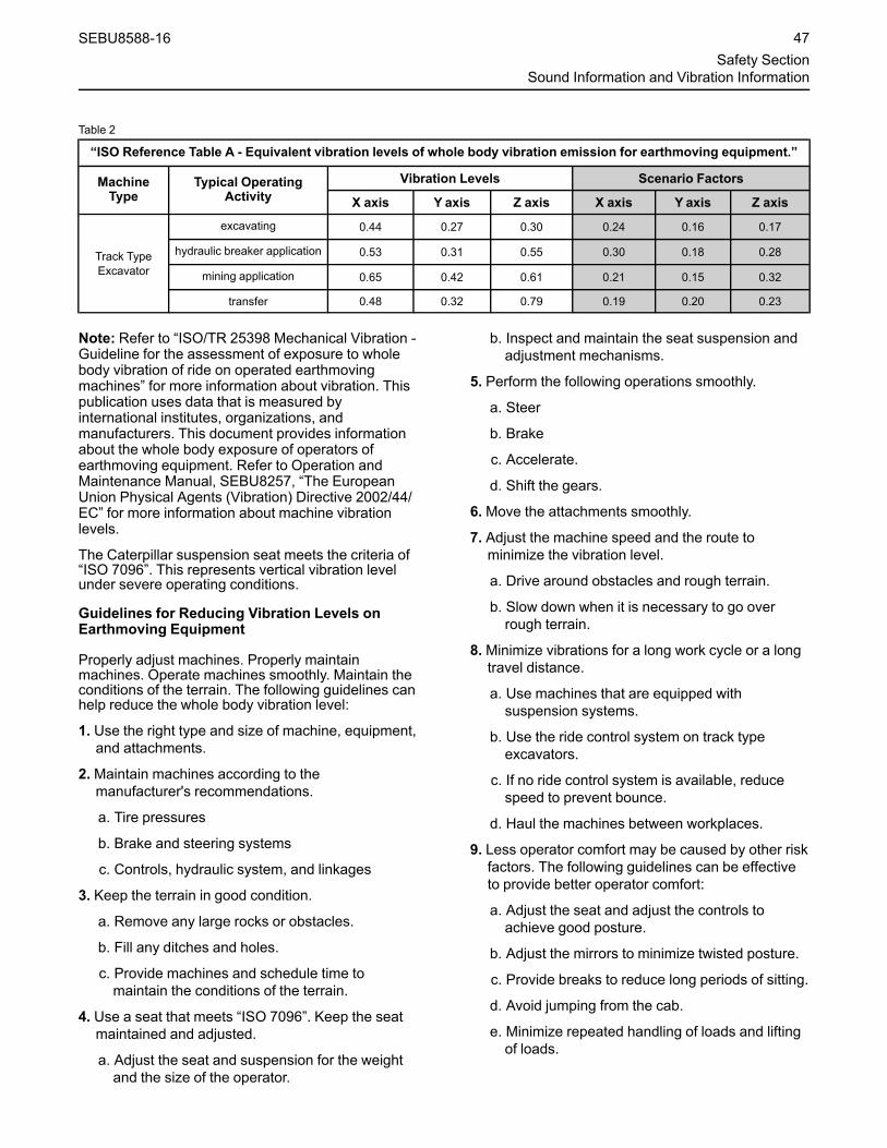
Table 2
“ISO Reference Table A - Equivalent vibration levels of whole body vibration emission for earthmoving equipment.”
MachineType
Typical OperatingActivity
Vibration Levels Scenario Factors
X axis Y axis Z axis X axis Y axis Z axis
Track TypeExcavator
excavating 0.44 0.27 0.30 0.24 0.16 0.17
hydraulic breaker application 0.53 0.31 0.55 0.30 0.18 0.28
mining application 0.65 0.42 0.61 0.21 0.15 0.32
transfer 0.48 0.32 0.79 0.19 0.20 0.23
Note: Refer to “ISO/TR 25398 Mechanical Vibration -Guideline for the assessment of exposure to wholebody vibration of ride on operated earthmovingmachines” for more information about vibration. Thispublication uses data that is measured byinternational institutes, organizations, andmanufacturers. This document provides informationabout the whole body exposure of operators ofearthmoving equipment. Refer to Operation andMaintenance Manual, SEBU8257, “The EuropeanUnion Physical Agents (Vibration) Directive 2002/44/EC” for more information about machine vibrationlevels.
The Caterpillar suspension seat meets the criteria of“ISO 7096”. This represents vertical vibration levelunder severe operating conditions.
Guidelines for Reducing Vibration Levels onEarthmoving Equipment
Properly adjust machines. Properly maintainmachines. Operate machines smoothly. Maintain theconditions of the terrain. The following guidelines canhelp reduce the whole body vibration level:
1. Use the right type and size of machine, equipment,and attachments.
2.Maintain machines according to themanufacturer's recommendations.
a. Tire pressures
b. Brake and steering systems
c. Controls, hydraulic system, and linkages
3. Keep the terrain in good condition.
a. Remove any large rocks or obstacles.
b. Fill any ditches and holes.
c. Provide machines and schedule time tomaintain the conditions of the terrain.
4. Use a seat that meets “ISO 7096”. Keep the seatmaintained and adjusted.
a. Adjust the seat and suspension for the weightand the size of the operator.
b. Inspect and maintain the seat suspension andadjustment mechanisms.
5. Perform the following operations smoothly.
a. Steer
b. Brake
c. Accelerate.
d. Shift the gears.
6.Move the attachments smoothly.
7. Adjust the machine speed and the route tominimize the vibration level.
a. Drive around obstacles and rough terrain.
b. Slow down when it is necessary to go overrough terrain.
8.Minimize vibrations for a long work cycle or a longtravel distance.
a. Use machines that are equipped withsuspension systems.
b. Use the ride control system on track typeexcavators.
c. If no ride control system is available, reducespeed to prevent bounce.
d. Haul the machines between workplaces.
9. Less operator comfort may be caused by other riskfactors. The following guidelines can be effectiveto provide better operator comfort:
a. Adjust the seat and adjust the controls toachieve good posture.
b. Adjust the mirrors to minimize twisted posture.
c. Provide breaks to reduce long periods of sitting.
d. Avoid jumping from the cab.
e. Minimize repeated handling of loads and liftingof loads.
SEBU8588-16 47Safety Section
Sound Information and Vibration Information

f. Minimize any shocks and impacts during sportsand leisure activities.
SourcesThe vibration information and calculation procedureis based on “ISO/TR 25398 Mechanical Vibration -Guideline for the assessment of exposure to wholebody vibration of ride on operated earthmovingmachines”. Harmonized data is measured byinternational institutes, organizations, andmanufacturers.
This literature provides information about assessingthe whole body vibration exposure of operators ofearthmoving equipment. The method is based onmeasured vibration emission under real workingconditions for all machines.
You should check the original directive. Thisdocument summarizes part of the content of theapplicable law. This document is not meant tosubstitute the original sources. Other parts of thesedocuments are based on information from the UnitedKingdom Health and Safety Executive.
Refer to Operation and Maintenance ManualSupplement, SEBU8257 for more information aboutvibration.
Consult your local Caterpillar dealer for moreinformation about machine features that minimizevibration levels. Consult your local Caterpillar dealerabout safe machine operation.
Use the following web site to find your local dealer:
Caterpillar, Inc.www.cat.com
i07746362
Operator StationSMCS Code: 7300; 7301; 7325
Any modifications to the inside of the operator stationshould not project into the operator space or into thespace for the companion seat (if equipped). Theaddition of a radio, fire extinguisher, and otherequipment must be installed so that the definedoperator space and the space for the companion seat(if equipped) is maintained. Any item that is broughtinto the cab should not project into the definedoperator space or the space for the companion seat(if equipped). A lunch box or other loose items mustbe secured. Objects must not pose an impact hazardin rough terrain or in the event of a rollover.
i07746359
Guards(Operator Protection)SMCS Code: 7000; 7150
There are different types of guards that are used toprotect the operator. The machine and the machineapplication determine the type of guard that shouldbe used.
A daily inspection of the guards is required in order tocheck for structures that are bent, cracked, or loose.Never operate a machine with a damaged structure.
The operator becomes exposed to a hazardoussituation if the machine is used improperly or if pooroperating techniques are used. This situation canoccur even though a machine is equipped with anappropriate protective guard. Follow the establishedoperating procedures that are recommended for yourmachine.
Rollover Protective Structure(ROPS), Falling Object ProtectiveStructure (FOPS) or Tip OverProtection Structure (TOPS)The ROPS/FOPS Structure (if equipped) on yourmachine is specifically designed, tested and certifiedfor that machine. Any alteration or any modification tothe ROPS/FOPS Structure could weaken thestructure. This places the operator into anunprotected environment. Modifications orattachments that cause the machine to exceed theweight that is stamped on the certification plate alsoplace the operator into an unprotected environment.Excessive weight may inhibit the brake performance,the steering performance and the ROPS. Theprotection that is offered by the ROPS/FOPSStructure will be impaired if the ROPS/FOPSStructure has structural damage. Damage to thestructure can be caused by an overturn, a fallingobject, a collision, etc.
Do not mount items (fire extinguishers, first aid kits,work lights, etc) by welding brackets to the ROPS/FOPS Structure or by drilling holes in the ROPS/FOPS Structure. Welding brackets or drilling holes inthe ROPS/FOPS Structures can weaken thestructures. Consult your Cat dealer for mountingguidelines.
48 SEBU8588-16Safety SectionOperator Station

The Tip Over Protection Structure (TOPS) is anothertype of guard that is used on mini hydraulicexcavators. This structure protects the operator in theevent of a tipover. The same guidelines for theinspection, the maintenance and the modification ofthe ROPS/FOPS Structure are required for the TipOver Protection Structure.
Other Guards (If Equipped)Protection from flying objects and/or falling objects isrequired for special applications. Loggingapplications and demolition applications are twoexamples that require special protection.
A front guard needs to be installed when a work toolthat creates flying objects is used. Mesh front guardsthat are approved by Caterpillar or polycarbonatefront guards that are approved by Caterpillar areavailable for machines with a cab or an open canopy.On machines that are equipped with cabs, thewindows should also be closed. Safety glasses arerecommended when flying hazards exist formachines with cabs and machines with opencanopies.
If the work material extends above the cab, topguards and front guards should be used. Typicalexamples of this type of application are listed below:
• Demolition applications
• Rock quarries
• Forestry products
Additional guards may be required for specificapplications or work tools. The Operation andMaintenance Manual for your machine or your worktool will provide specific requirements for the guards.Refer to Operation Maintenance manual,"Demolition" for additional information. Consult yourCat dealer for additional information.
SEBU8588-16 49Safety Section
Operator Protection
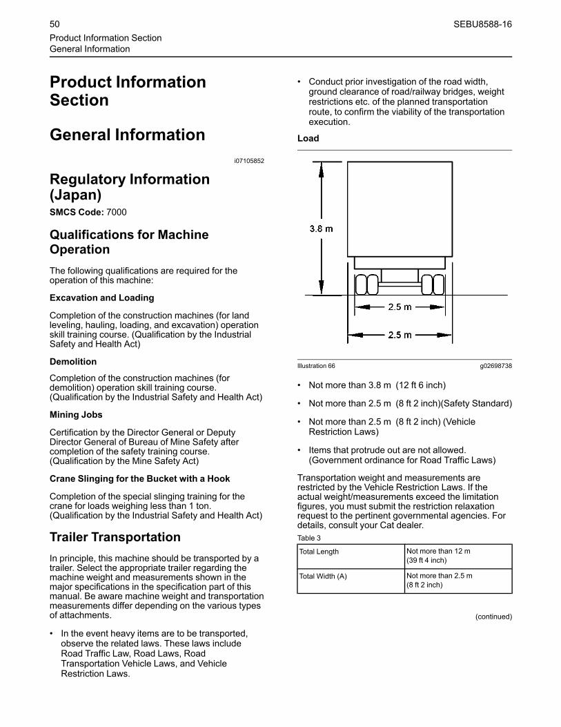
Product InformationSection
General Informationi07105852
Regulatory Information(Japan)SMCS Code: 7000
Qualifications for MachineOperationThe following qualifications are required for theoperation of this machine:
Excavation and Loading
Completion of the construction machines (for landleveling, hauling, loading, and excavation) operationskill training course. (Qualification by the IndustrialSafety and Health Act)
Demolition
Completion of the construction machines (fordemolition) operation skill training course.(Qualification by the Industrial Safety and Health Act)
Mining Jobs
Certification by the Director General or DeputyDirector General of Bureau of Mine Safety aftercompletion of the safety training course.(Qualification by the Mine Safety Act)
Crane Slinging for the Bucket with a Hook
Completion of the special slinging training for thecrane for loads weighing less than 1 ton.(Qualification by the Industrial Safety and Health Act)
Trailer TransportationIn principle, this machine should be transported by atrailer. Select the appropriate trailer regarding themachine weight and measurements shown in themajor specifications in the specification part of thismanual. Be aware machine weight and transportationmeasurements differ depending on the various typesof attachments.
• In the event heavy items are to be transported,observe the related laws. These laws includeRoad Traffic Law, Road Laws, RoadTransportation Vehicle Laws, and VehicleRestriction Laws.
• Conduct prior investigation of the road width,ground clearance of road/railway bridges, weightrestrictions etc. of the planned transportationroute, to confirm the viability of the transportationexecution.
Load
Illustration 66 g02698738
• Not more than 3.8 m (12 ft 6 inch)
• Not more than 2.5 m (8 ft 2 inch)(Safety Standard)
• Not more than 2.5 m (8 ft 2 inch) (VehicleRestriction Laws)
• Items that protrude out are not allowed.(Government ordinance for Road Traffic Laws)
Transportation weight and measurements arerestricted by the Vehicle Restriction Laws. If theactual weight/measurements exceed the limitationfigures, you must submit the restriction relaxationrequest to the pertinent governmental agencies. Fordetails, consult your Cat dealer.Table 3
Total Length Not more than 12 m(39 ft 4 inch)
Total Width (A) Not more than 2.5 m(8 ft 2 inch)
(continued)
50 SEBU8588-16Product Information SectionGeneral Information

(Table 3, contd)
Total Height (B) Not more than 3.8 m(12 ft 6 inch) when loaded onthe trailer.
Total Weight 20 to 25 ton (depending onroad, axle, and vehicle length)
Operation of ConstructionEquipment and the GoverningLaws and Regulations
NOTICEVarious laws and regulations, including IndustrialSafety and Health Act, are enforced to ensure pre-vention of injuries on and around constructionequipment and safe and comfortable operation ofequipment. Be sure to obey them.
NOTICEThe notices regarding machine operation, inspec-tion, maintenance, and safety contained in thismanual are applicable only to cases in which themachine is used for the specified jobs. It is im-possible for this kind of manual to cover everykind of operation. Therefore, the content of thismanual does not necessarily explain all possiblecases. Be sure to pay careful attention also to theitems not covered by this manual and confirm thesafety before starting jobs to prevent human in-jury and machine damage accidents.
Qualification of Operators
Operation of construction equipment is limited topersons who have any of the following licenses bylaw.
Note: Employers will face imprisonment up to amaximum of 6 months or a fine of up to a maximumof five hundred thousand yen if they let unqualifiedpersonnel operate equipment. Unqualified operatorswill also be fined up to a maximum of five hundredthousand yen.
• One who completed an operating skill course forvehicle-type construction equipment at aregistered training institution.
• One who passed the construction equipment andtechnologies license examination (Type 1-3)defined by the Construction Industry Law.
• One who completed an operating training coursefor construction equipment defined by theVocational Training Law.
• One who took a special training (rules and skills)at a registered training institution to operateequipment weighing less than 3 tons.
• With an auto-drivers license, an operator does notneed to complete an operating skill course forconstruction equipment to operate equipment onthe roads that apply to the rules of the Road TrafficAct. However, the operator needs to complete thecourse to engage in snow clearing or excavatingon the roads.
• The operator must be qualified under the MineSafety Act to operate construction equipment in amine.
Acquisition of the Qualifications
The company offers training courses for constructionmachine operation, in addition to other skills. Fordetails, contact the company's dealer in your area.
Regarding machine operation qualifications, alsorefer to the laws related to the construction machinesshown at the end of this manual.
Subsidy System
Small-to-medium-sized construction businesscompanies are eligible to receive a subsidy for a partof training fees and wages when they have theiremployees attend a training course to improve skills.
Operation of ConstructionEquipment and the GoverningLaws and Regulations
NOTICEInformation about operating skill course for ve-hicle-type construction equipment (for groundleveling, transporting, loading, excavating).
Industrial Safety and Health Act requires opera-tors of construction equipment weight 3 tons andover to acquire a certificate of completion of anoperating skill course. Registered with and au-thorized by the respective directors general ofthe regional labor bureaus, we offer operatingskill courses for vehicle-type construction equip-ment and special trainings.
SEBU8588-16 51Product Information Section
Regulatory Information (Japan)

Request for Periodical Self-Inspection
Rules of Periodical Self-Inspection
The employer shall, as provided for by the Ordinanceof the Ministry of Health, Labor and Welfare, conductself-inspection periodically. The employer shall keepthe records of the results in respect to constructionequipment such as tractor shovels and powershovels, etc., specified by Cabinet Order. (fromArticle 45, Industrial Safe and Health Act)
Ordinance on Industrial Safety and Hygiene
Periodical self-inspections Article 167
(1) The employer shall, as regards a vehicle typeconstruction machine, carry out self-inspections forthe following matters periodically once every periodwithin a year. However, this shall not apply to thenon-use period of a vehicle type constructionmachine, which is not used for a period exceeding 1year.
(2) The employer shall, as regards a vehicle typeconstruction machine set forth in the proviso of theproceeding paragraph, carry out self-inspection forabnormalities in each part of a construction machinebefore resuming the operation.
Periodical self-inspections Article 168
(1) The employer shall, as regards a vehicle typeconstruction machine, carry out self-inspections forthe following matters periodically once every periodwithin a month. However, this shall not apply to thenon-use period of a vehicle type constructionmachine, which is not used for a period exceedingone month:
• (i) Abnormalities in a brake, a clutch, a controllingdevice, and working devices.
• (ii) Damage in a wire, rope, and a chain
• (iii) Damage in a bucket, a dipper, etc.
(2) The employer shall, as regards to the vehicle typeconstruction machine set forth in the proviso of thepreceding paragraph, carry out self-inspection for thematters listed in each item of the same paragraphbefore resuming the operation.
Record of Periodical Self-Inspections Article 169
The employer shall, when having carried out the self-inspections set forth in the preceding two Articles,record the results and retain the records for 3 years.
Specified Self-Inspection Article 169-2
The specified self-inspection pertaining to the vehicletype construction machine shall be the self-inspection (prescribed by Article 167) and carried outby qualified personnel. The employer shall, whenhaving carried out the specified self-inspectionpertaining to a vehicle type construction machine,affix an inspection sticker stating the month and yearwhen the said specified self-inspection was carriedout at a readily visible location of the said machine.
• Caterpillar Japan has a supporting program forself-inspection as a registered inspection agency.Qualified personnel and inspection equipment areavailable to help customers who do not conductinternal inspections or do not have time to conductthe specified self-inspections. Contact a Catdealer near you for details.
• Maintenance and inspection record book for arecord-saving purpose can be purchased atCaterpillar Japan.
• Penalty: Employer who fails to carry out self-inspections and to record the results will face afine of up to five hundred thousand yen.
Checkup before Commencing the Work Article 170
The employer shall, when carrying out the work usinga vehicle type construction machine, check functionsof a brake and a clutch before commencing the workfor the day.
Other Rules
Besides qualification for operating equipment andself inspections, the following obligations are set forthin the Industrial Safety and Health Act:
• To conduct health and safety training for newrecruits and shop foremen.
• To appoint the operation leader or supervisor, andestablish health and safety management system.
• To inform employees of a chain of command at theworksite, communication and signal rules,traveling route of equipment, speed limits, signs ofrestricted areas, etc. for securing safety in theworkplace.
The Industrial Safety and Health Act further also setobligations related to mechanical structures andrental activities of equipment.
Safety comes before anything else. Establish aworkplace where no injuries occur by observingthe governing laws and by referring to thismanual, specifically the descriptions on safety.
52 SEBU8588-16Product Information SectionRegulatory Information (Japan)

Construction Equipment andEnvironmental Laws
Prohibition of Emissions and Obligations toRecover Fluorocarbons
Law Concerning the Recovery and Destruction ofFluorocarbons (Enforcement date: April 1, 2015)
Being emitted into the atmosphere, Fluorocarbons,used as refrigerants of air conditioning, destroy theozone layer and accelerate the global warming as acause of environmental destruction. Follow theinstructions below required by law when handling airconditioners to protect the global environment.
1. 1. Do not arbitrarily emit the encapsulatedrefrigerant installed on the product into theatmosphere.
2. 2. Recover the encapsulated refrigerant whendisposing of the product.
Note: Violators of the law will face a maximumone-year imprisonment or a fine up to amaximum of five hundred thousand yen.
When you need to fill, recover a refrigerant ordispose of a product with an encapsulated refrigerantinstalled, please ask a filling-recovery operatorregistered with the government of the local prefectureas "class-1 filling-recovery operator." And carry outthe simple inspection of air conditioner and keep therecord.
Class-1 Specified products sold after October 1,2015 shall have the label inside of the cab showingthe type and quantity of refrigerant, GWP (GlobalWarming Potential), and precautions for use. (Referto the fluorocarbon label in the OMM safety section)
Standard Certificate of TransferDear Customers
Japan Construction Equipment ManufacturersAssociation
Standard Certificate of Transfer
Issued by the Japan Construction EquipmentManufacturers Association
Standard Certificate of Transfer issued by theJapan Construction Equipment ManufacturersAssociation proves the ownership of yourequipment. Request us to issue the certificate asa proof of transfer of ownership.
Commercial transactions of construction equipmentare generally made on a long-term installment planbasis with a special provision of reservation ofownership that the seller retains the ownership of thesold equipment until the buyer completely pays offthe installments.
Ownership of some construction equipment can beproved with a vehicle inspection certificate, but thecertificate is not issued for most of the equipment.Therefore, the buyer will need to present a third partywith a proof of ownership of the sold equipment.
Japan Construction Equipment ManufacturersAssociation launched a system of standard certificateof transfer in 1971 to normalize trading inconstruction equipment and establishes a businesspractice relating to transfer of ownership. Customersare kindly requested to understand the intent of thesystem and request your seller to issue a certificateof transfer.
1. About the standard certificate of transfer
a. Japan Construction Equipment ManufacturersAssociation (hereinafter referred to as CEMA)sets the rules and form of standard certificate oftransfer (hereinafter referred to as certificate oftransfer), and members of the CEMA issue thecertificate of transfer. A certificate of transferproves the ownership of equipment.
2. Purpose of issuance
a. A certificate of transfer will be issued for thepurpose of clarifying the ownership ofequipment and preventing misconduct such astrades of stolen equipment or fraud.
3. Issuer
a. A certificate of transfer will be issued by adistributor (Primary transferer) who sells newconstruction equipment and is authorized by theCEMA.
4. Eligibility
a. A certificate of transfer will be issued for theequipment, which is sold by CEMA-memberdistributors and defined as constructionequipment by the CEMA
5. Issuance
a. A certificate of transfer will be issued anddirectly given to a buyer upon the buyer'srequest when he/she buys eligible equipmentfrom an issuer.
b. A certificate of transfer may not be issued forthe equipment, which was sold as newmerchandise more than 10 years ago.
c. A certificate of transfer is not permitted tosubstitute a vehicle inspection certificate.
6. Prohibition of reissuance
a. Certificate of transfer should be safely stored asit will not be reissued under any circumstances.
SEBU8588-16 53Product Information Section
Regulatory Information (Japan)

7. In case a certificate description runs out of space
a. Discretionary page/s to the certificate will bevalid with a tally seal of the issuer at the joint oftwo pages.
Contact CEMA-member companies ordistributors for more details of the system.
Industrial Safety and Health ActArticle 164 (Extracted) of IndustrialSafety and Health Act (Restriction on useOther Than Main Application)
Article 164
Business Operator must not use constructionmachineries of vehicle type for applications otherthan main application of the applicable constructionmachineries of vehicle type such as: lifting cargos byhydraulic excavator or lifting/lowering workers usingthe clamshell.
[2] The previous clause will not be applied for any ofthe following cases:
1. In performing cargo lifting, any one of the followingmay be applicable.
a. Cannot be avoided due to the nature of thework or necessary in view of performing work insafe.
b. When working with attachments installed formetals of hook or shackle etc or other devicesfor lifting application applicable to any one ofthe following as implements for boom or bucketetc
• Enough strength is retained bearable forloads to be applied.
• Load lifted up is not feared to be droppedfrom the applicable instrument used, due toprovided locking device is in use or etc.
• Load not feared of disengaging from theimplement.
2. In performing work other than cargo lifting, nothingis feared to do harm to the workers.
[3] The business operator must take the followingmeasures, in performing cargo lifting work applicableto Items 1a and 1b of Step 1 above. To prevent anydanger of workers from contact with lifted cargo, dropof lifted cargo or turnover or falling down ofconstruction machineries of vehicle type.
1. Designate one person who issues a sign as well assetting up fixed signs related to cargo lifting work,and follow his signs.
2. Perform work on a flat ground.
3. Keep any worker away from any place where isfeared to cause any danger to worker due tocontact with a cargo or drop of lifted cargo.
[4] Do not perform any work applying load exceedingthe allowed rated max load specified according tostructure or materials of the applicable constructionmachineries of the vehicle type.
[5] In using wire rope in slinging device, use wire ropeapplicable to every item of the followings.
• Safety coefficient is 6 or more. (The safetycoefficient here must be the same as specified inArticle 213 item 2 in Safety Rules on Crane Works(Article 34 in Ordinance of Ministry of Labor, 1972)etc. Hereinafter called as "Crane Rules")
• Among wire rope 1 strands, numbers of cutstrands (other than filler) are less than 10%.
• Reduction of diameter is 7% or less than nominaldiameter.
• Free from kinking.
• Free from badly collapse and corrosion.
[6] In using lifting chain as slinging device, the chainis applicable to every item of the followings.
• Safety coefficient is 5 or more.
• Elongation is 5% or less than the length when theapplicable lifting chain was fabricated.
• Reduction of diameter of the cross section of linkis 10% or less than diameter of cross section ofthe applicable link when the applicable lifting chainwas manufactured.
• Free from cracks.
54 SEBU8588-16Product Information SectionRegulatory Information (Japan)

[7] In using those other than wire rope and liftingchain as slinging device, they must be free from baddamage and corrosion.
i08134288
SpecificationsSMCS Code: 7000
Intended UseThe intended use of this machine is for excavatingwith a bucket or working with approved work tools.The machine should be operated with theundercarriage in a stationary position since the upperstructure is normally capable of 360 degree swingwith mounted equipment. This machine can be usedin object handling applications that are within the liftcapacity of the machine. When this machine is usedin object handling applications, ensure that themachine is properly configured and operatedproperly. Obey any local governmental regulationsand regional governmental regulations. Only liftobjects from approved lifting points and withapproved lifting devices.
Expected LifeThe expected life, defined as total machine hours, ofthis machine is dependent upon many factorsincluding the machine owner’s desire to rebuild themachine back to factory specifications. The expectedlife interval of this machine is 8,000 service hours.The expected life interval corresponds to the servicehours to engine overhaul or replacement. Servicehours to engine overhaul or replacement may varybased on overall machine duty cycle. At the expectedlife interval, remove the machine from operation andconsult your Cat dealer for inspect, repair, rebuild,install remanufactured, install new components, ordisposal options and to establish a new expected lifeinterval. If a decision is made to remove this machinefrom service, refer to Operation and MaintenanceManual, “Decommissioning and Disposal”.
The following items are required to obtain aneconomical expected life of this machine:
• Perform regular preventive maintenanceprocedures as described in the Operation andMaintenance Manual.
• Perform machine inspections as described in theOperation and Maintenance Manual and correctany problems discovered.
• Perform system testing as described in theOperation and Maintenance Manual and correctany problems discovered.
• Ensure that machine application conditionscomply with Caterpillar’s recommendations.
• Ensure that the operating weight does not exceedlimits set by manufacturer.
SEBU8588-16 55Product Information Section
Specifications

• Ensure that all frame cracks are identified,inspected, and repaired to prevent furtherdevelopment.
Application/ConfigurationRestrictionsThe maximum travel operating slope for machinelubrication is 35 degrees.
Specification Data
Illustration 67 g02150559
Table 4
374F L Excavator
7.80 m (25 ft 7 inch) Reach Boom
4.67 m (15 ft 4 inch)Stick
4.15 m (13 ft 7 inch)Stick
3.6 m (11 ft 10 inch)Stick
2.84 m (9 ft 4 inch) Stick
Bucket 3.8 m3 (5.0 yd3)
Approximate Weights73240 kg (161470 lb)(1)72190 kg (159150 lb)(2)71510 kg (157650 lb)(3)
73025 kg (160990 lb)(1)71980 kg (158690 lb)(2)71300 kg (157190 lb)(3)
72880 kg (160670 lb)(1)71825 kg (158350 lb)(2)71150 kg (156860 lb)(3)
72700 kg (160275 lb)(1)71650 kg (157960 lb)(2)70975 kg (156470 lb)(3)
Shipping Height (A) 4980 mm (16 ft 4 inch) 4650 mm (15 ft 3 inch) 4480 mm (14 ft 8 inch) 4380 mm (14 ft 4 inch)
Shipping Length (B) 13220 mm (43 ft 4 inch) 13310 mm (43 ft 8 inch) 13320 mm (43 ft 8 inch) 13470 mm (44 ft 2 inch)
Shipping Width (C)3020 mm (9 ft 11 inch)(1)
2750 mm (9 ft)(2)2650 mm (8 ft 8 inch)(3)
3020 mm (9 ft 11 inch)(1)2750 mm (9 ft)(2)
2650 mm (8 ft 8 inch)(3)
3020 mm (9 ft 11 inch)(1)2750 mm (9 ft)(2)
2650 mm (8 ft 8 inch)(3)
3020 mm (9 ft 11 inch)(1)2750 mm (9 ft)(2)
2650 mm (8 ft 8 inch)(3)
Track Shoe Width (D)900 mm (36 inch)750 mm (30 inch)650 mm (26 inch)
(continued)
56 SEBU8588-16Product Information SectionSpecifications

(Table 4, contd)
Cab Height (E) 3535 mm (11 ft 7 inch) 3535 mm (11 ft 7 inch) 3535 mm (11 ft 7 inch) 3535 mm (11 ft 7 inch)
Ground Clearance (F) 840 mm (33 inch) 840 mm (33 inch) 840 mm (33 inch) 840 mm (33 inch)
Tail Swing Radius (G) 4020 mm (13 ft 2 inch) 4020 mm (13 ft 2 inch) 4020 mm (13 ft 2 inch) 4020 mm (13 ft 2 inch)
Length to Center of Rollers(H) 4705 mm (15 ft 5 inch) 4705 mm (15 ft 5 inch) 4705 mm (15 ft 5 inch) 4705 mm (15 ft 5 inch)
Track Length (I) 5860 mm (19 ft 3 inch) 5860 mm (19 ft 3 inch) 5860 mm (19 ft 3 inch) 5860 mm (19 ft 3 inch)
Track Gauge (J) 2750 mm (9 ft)(4)3410 mm (11 ft 2 inch)(5)
2750 mm (9 ft)(4)3410 mm (11 ft 2 inch)(5)
2750 mm (9 ft)(4)3410 mm (11 ft 2 inch)(5)
2750 mm (9 ft)(4)3410 mm (11 ft 2 inch)(5)
(1) 900 mm (36 inch) track shoes(2) 750 mm (30 inch) track shoes(3) 650 mm (26 inch) track shoes(4) Retracted (shipping) position(5) Extended (working) position
Table 5
374F L Excavator
7.0 m (23 ft) Mass Boom
3.0 m (9 ft 10 inch) Stick 2.57 m (8 ft 5 inch) Stick
Bucket 4.6 m3 (6.0 yd3)
Approximate Weights75610 kg (166690 lb)(1)74560 kg (164375 lb)(2)73880 kg (162880 lb)(3)
75435 kg (166305 lb)(1)74390 kg (164000 lb)(2)73710 kg (162500 lb)(3)
Shipping Height (A) 4740 mm (15 ft 7 inch) 4560 mm (15 ft)
Shipping Length (B) 12630 mm (41 ft 5 inch) 12670 mm (41 ft 7 inch)
Shipping Width (C)3020 mm (9 ft 11 inch)(1)
2750 mm (9 ft)(2)2650 mm (8 ft 8 inch)(3)
3020 mm (9 ft 11 inch)(1)2750 mm (9 ft)(2)
2650 mm (8 ft 8 inch)(3)
Track Shoe Width (D)900 mm (36 inch)750 mm (30 inch)650 mm (26 inch)
Cab Height (E) 3535 mm (11 ft 7 inch) 3535 mm (11 ft 7 inch)
Ground Clearance (F) 840 mm (33 inch) 840 mm (33 inch)
Tail Swing Radius (G) 4020 mm (13 ft 2 inch) 4020 mm (13 ft 2 inch)
Length to Center of Rollers (H) 4705 mm (15 ft 5 inch) 4705 mm (15 ft 5 inch)
Track Length (I) 5860 mm (19 ft 3 inch) 5860 mm (19 ft 3 inch)
Track Gauge (J) 2750 mm (9 ft)(4)3410 mm (11 ft 2 inch)(5)
2750 mm (9 ft)(4)3410 mm (11 ft 2 inch)(5)
(1) 900 mm (36 inch) track shoes(2) 750 mm (30 inch) track shoes(3) 650 mm (26 inch) track shoes(4) Retracted (shipping) position(5) Extended (working) position
SEBU8588-16 57Product Information Section
Specifications

Working Ranges
Illustration 68 g03570437
Table 6
374F L Excavator
7.80 m (25 ft 7 inch) Reach Boom
4.67 m (15 ft 4 inch)Stick 4.15 m (13 ft 7 inch)Stick
3.6 m (11 ft 10 inch)Stick
2.84 m (9 ft 4 inch) Stick
Bucket 3.8 m3 (5.0 yd3)
Maximum Digging Depth(A) 9650 mm (31 ft 8 inch) 9130 mm (29 ft 11 inch) 8580 mm (28 ft 2 inch) 7820 mm (25 ft 8 inch)
Maximum Reach at GroundLevel (B) 14450 mm (47 ft 5 inch) 13690 mm (44 ft 11 inch) 13170 mm (43 ft 3 inch) 12780 mm (41 ft 11 inch)
Maximum Loading Height(C) 9000 mm (29 ft 6 inch) 8650 mm (28 ft 5 inch) 8420 mm (27 ft 7 inch) 8250 mm (27 ft 1 inch)
Minimum Loading Height(D) 2240 mm (7 ft 4 inch) 2760 mm (9 ft 1 inch) 3310 mm (10 ft 10 inch) 4070 mm (13 ft 4 inch)
(continued)
58 SEBU8588-16Product Information SectionSpecifications
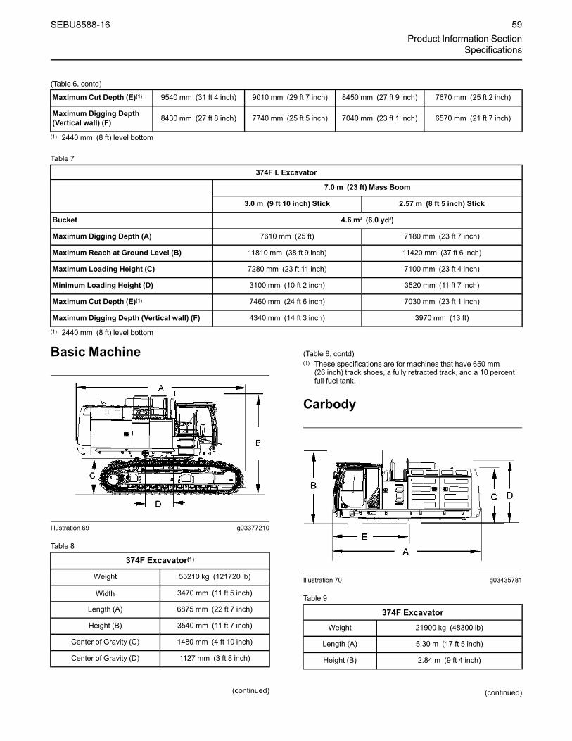
(Table 6, contd)
Maximum Cut Depth (E)(1) 9540 mm (31 ft 4 inch) 9010 mm (29 ft 7 inch) 8450 mm (27 ft 9 inch) 7670 mm (25 ft 2 inch)
Maximum Digging Depth(Vertical wall) (F) 8430 mm (27 ft 8 inch) 7740 mm (25 ft 5 inch) 7040 mm (23 ft 1 inch) 6570 mm (21 ft 7 inch)
(1) 2440 mm (8 ft) level bottom
Table 7
374F L Excavator
7.0 m (23 ft) Mass Boom
3.0 m (9 ft 10 inch) Stick 2.57 m (8 ft 5 inch) Stick
Bucket 4.6 m3 (6.0 yd3)
Maximum Digging Depth (A) 7610 mm (25 ft) 7180 mm (23 ft 7 inch)
Maximum Reach at Ground Level (B) 11810 mm (38 ft 9 inch) 11420 mm (37 ft 6 inch)
Maximum Loading Height (C) 7280 mm (23 ft 11 inch) 7100 mm (23 ft 4 inch)
Minimum Loading Height (D) 3100 mm (10 ft 2 inch) 3520 mm (11 ft 7 inch)
Maximum Cut Depth (E)(1) 7460 mm (24 ft 6 inch) 7030 mm (23 ft 1 inch)
Maximum Digging Depth (Vertical wall) (F) 4340 mm (14 ft 3 inch) 3970 mm (13 ft)
(1) 2440 mm (8 ft) level bottom
Basic Machine
Illustration 69 g03377210
Table 8
374F Excavator(1)
Weight 55210 kg (121720 lb)
Width 3470 mm (11 ft 5 inch)
Length (A) 6875 mm (22 ft 7 inch)
Height (B) 3540 mm (11 ft 7 inch)
Center of Gravity (C) 1480 mm (4 ft 10 inch)
Center of Gravity (D) 1127 mm (3 ft 8 inch)
(continued)
(Table 8, contd)(1) These specifications are for machines that have 650 mm
(26 inch) track shoes, a fully retracted track, and a 10 percentfull fuel tank.
Carbody
Illustration 70 g03435781
Table 9
374F ExcavatorWeight 21900 kg (48300 lb)
Length (A) 5.30 m (17 ft 5 inch)
Height (B) 2.84 m (9 ft 4 inch)
(continued)
SEBU8588-16 59Product Information Section
Specifications

(Table 9, contd)
374F ExcavatorHeight (C) 2.71 m (8 ft 11 inch)
Height (D) 3.22 m (10 ft 7 inch)
Length (E) 2.45 m (8 ft)
Track Frame
Illustration 71 g02571599
Table 10
374F Excavator(1)These specifications are for each track.
Weight (Each Track Frame) 10220 kg (22550 lb)
Length (A) 5.86 m (19 ft 3 inch)
Height (B) 1.34 m (4 ft 5 inch)
Width (C) 980 mm (3 ft 3 inch)
Center of Gravity (D) 64 mm (3 inch)
Center of Gravity (E) 710 mm (2 ft 4 inch)
(continued)
(Table 10, contd)(1) These specifications are for machines that have 650 mm
(26 inch) triple grouser track shoes .
Counterweight
Illustration 72 g03629216
Table 11
Standard Counterweight
Weight 10050 kg (22200 lb)
Length (A) 630 mm (2 ft 1 inch)
Height (B) 1.86 m (6 ft 1 inch)
Width (C) 3.46 m (11 ft 4 inch)
(continued)
60 SEBU8588-16Product Information SectionSpecifications

(Table 11, contd)
Standard Counterweight
Center of Gravity (D) 6 mm (0.23 inch)
Center of Gravity (E) 2330 mm (7 ft 8 inch)
Boom with Stick Cylinder
Illustration 73 g02765979
Table 12
7.80 m(25 ft 7 inch)Reach Boom
6.59 m(21 ft 7 inch)Mass Boom
Weight 6400 kg (14100 lb) 6420 kg (14200 lb)
Width 1.11 m (3 ft 8 inch) 1.11 m (3 ft 8 inch)
Length (A) 8.11 m (26 ft 7 inch) 6.90 m (22 ft 8 inch)
Height (B) 2.00 m (6 ft 7 inch) 2.42 m (7 ft 11 inch)
(continued)
SEBU8588-16 61Product Information Section
Specifications

(Table 12, contd)
7.80 m(25 ft 7 inch)Reach Boom
6.59 m(21 ft 7 inch)Mass Boom
Center of Gravity (C) 658 mm (2 ft 2 inch) 759 mm (2 ft 6 inch)
Center of Gravity (D) 3788 mm(12 ft 5 inch) 3502 mm (11 ft 6 ft)
Stick with Bucket Cylinder
Illustration 74 g02765978
Table 13
Long Stick (VB) forReach Boom 4.67 m
(15 ft 4 inch)
Medium Stick (VB)for Reach Boom
3.60 m(11 ft 10 inch)
Short Stick (VB)for Reach Boom
2.84 m(9 ft 4 inch)
Long Stick(WB) for MassBoom 3.00 m(9 ft 10 inch)
Short Stick (WB)for Mass Boom
2.57 m(8 ft 5 inch)
Weight 3980 kg (8800 lb) 3580 kg (7900 lb) 3370 kg (7400 lb) 4230 kg (9300 lb) 4050 kg (8900 lb)
Width 500 mm (1 ft 2 inch) 500 mm (1 ft 2 inch) 500 mm(1 ft 2 inch)
500 mm(1 ft 2 inch) 500 mm (1 ft 2 inch)
Length (A) 6.08 m (19 ft 11 inch) 5.03 m (16 ft 6 inch) 4.23 m(13 ft 11 inch)
4.42 m(14 ft 6 inch) 4.01 m (13 ft 2 inch)
Height (B) 1.32 m (4.3307 ft 4 inch) 1.36 m(4.4619 ft 6 inch) 1.52 m (5 ft) 1.56 m
(5 ft 1 inch) 1.57 m (5 ft 2 inch)
Center of Gravity (C) 319 mm (13 inch) 287 mm (11 inch) 345 mm (14 inch) 316 mm (12 inch) 285 mm (11 inch)
Center of Gravity (D) 1505 mm (4 ft 11 inch) 1047 mm (3 ft 5 inch) 628 mm(2 ft 1 inch)
740 mm(2 ft 5 inch) 572 mm (1 ft 10 inch)
62 SEBU8588-16Product Information SectionSpecifications

Bucket
Illustration 75 g00612093
Table 14
Application Capacity ofBucket
BucketFamily Length (A) Height (B) Width Weight
Heavy-Duty Rock 4.60 m3 (6.00 yd3) WB2280 mm(90 inch)
2135 mm(84 inch)
2100 mm(83 inch) 4880 kg (10755 lb)
Heavy-Duty 3.80 m3 (5.00 yd3) VB2210 mm(87 inch)
1875 mm(74 inch)
1980 mm(78 inch) 3390 kg (7470 lb)
SEBU8588-16 63Product Information Section
Specifications

Boom Cylinders
Illustration 76 g00589456
Table 15
Weight (Each BoomCylinder) 670 kg (1475 lb)
Length (A) 2.80 m (9 ft 2 inch)
Height (B) 1.10 m (3 ft 7 inch)
Walkway
Illustration 77 g01136960
Table 16
Walkway (1) Walkway (2) Walkway (3) Walkway (4)
Weight 25 kg (55 lb) 15 kg (33 lb) 30 kg (66 lb) 25 kg (55 lb)
Length (A) 1.95 m (6 ft 5 inch) 1.22 m (4 ft) 2.63 m (8 ft 8 inch) 1.95 m (6 ft 5 inch)
Width (B) 370 mm (1 ft 3 inch) 370 mm (1 ft 3 inch) 370 mm (1 ft 3 inch) 370 mm (1 ft 3 inch)
Height (C) 210 mm (8 inch) 210 mm (8 inch) 210 mm (8 inch) 210 mm (8 inch)
64 SEBU8588-16Product Information SectionSpecifications

Step for Track Frame
Illustration 78 g03377243
Left side of the machine
Illustration 79 g01198841
Right side of the machine
Table 17
Step (A) Step (B) Step (C) Step (D)
Quantity 3 3 1 1
Weight 9 kg (20 lb) 8 kg(18 lb)
15 kg(33 lb)
14 kg(31 lb)
Length (A) 590 mm(2 ft)
590 mm(2 ft)
480 mm(1 ft 7 inch)
480 mm(1 ft 7 inch)
(continued)
(Table 17, contd)
Length (B) 190 mm(8 inch)
80 mm(3 inch)
190 mm(8 inch)
160 mm(6 inch)
Width 140 mm(6 inch)
140 mm(6 inch)
140 mm(6 inch)
140 mm(6 inch)
Miscellaneous
Illustration 80 g01198153
Right side of the machine(1) Hand rail(2) Hand rail(3) Hand rail
Illustration 81 g03377320
Left side of the machine(4) Hand rail(5) Hand rail(6) Hand rail(7) Hand rail(8) Hand rail
SEBU8588-16 65Product Information Section
Specifications

Table 18
Exhaust Pipe Rear ViewMirror on
Storage Box
Hand rail (1) Hand rail (2) Hand rail (3) Hand rail (4) Hand rail (5) Hand rail (6)
Weight 7 kg (15.4 lb) 8 kg (18.0 lb) 3 kg (6.6 lb) 8 kg (17.6 lb) 23 kg(50.8 lb)
10 kg(22.0 lb)
4 kg (8.8 lb) 3 kg (6.6 lb)
Length 295 mm(11.6 inch)
380 mm(15.0 inch)
1260 mm(49.6 inch)
300 mm(11.8 inch)
720 mm(28.3 inch)
1010 mm(39.8 inch)
390 mm(15.4 inch)
1260 mm(49.6 inch)
Width 255 mm(10.0 inch)
160 mm(6.3 inch)
40 mm(1.6 inch)
270 mm(10.6 inch)
310 mm(12.2 inch)
390 mm(15.4 inch)
50 mm(2.0 inch)
40 mm(1.6 inch)
Height 640 mm(25.2 inch)
670 mm(26.4 inch)
90 mm(3.5 inch)
1390 mm(54.7 inch)
1700 mm(66.9 inch)
850 mm(33.5 inch)
610 mm(24.0 inch)
90 mm(3.5 inch)
i07178161
Boom/Stick/BucketCombinationsSMCS Code: 6000; 6700
This machine can be equipped with a large variety ofboom-stick-bucket combinations in order to meet theneeds of various applications.
Buckets are grouped into different families bycapacity. As a rule, use a bucket with a smallercapacity when you are using a longer stick and/or alonger boom. Conversely, use a bucket with a largercapacity when you are using a shorter stick and/or ashorter boom. This rule ensures better machinestability and protection against structural machinedamage.
A stick is designed to match only one specific familyof buckets.
Note: The selection of a compatible boom-stick-bucket combination is a guide. Work tools, unevenground conditions, soft ground conditions, or poorground conditions have effects on machineperformance. The operator is responsible for beingaware of these effects.
Consult your Cat dealer for information on selectingthe correct boom-stick-bucket combination.
The following tables show various compatible boom-stick-bucket combinations. Select an optimumcombination according to the working conditions andaccording to the type of work that is being done.Table 19
374F L ExcavatorWithout Quick Coupler
BucketType Linkage Width of
Bucket
SAE Ca-pacity ofBucket
Weight ofBucket
Fill (%) 7.8 m (25 ft 7 inch)Boom
7.0 m (23 ft)Boom
(continued)
66 SEBU8588-16Product Information SectionBoom/Stick/Bucket Combinations

(Table 19, contd)
2.84 m(9 ft 4inch)Stick
3.6 m(11 ft 10inch)Stick
4.15 m(13 ft 7inch)Stick
4.67 m(15 ft 4inch)Stick
2.57 m(8 ft 5inch)Stick
3.0 m(9 ft 10inch)Stick
GeneralDuty (GD)
VB21525 mm(60 inch)
2.9 m3
(3.9 yd3)3205 kg(7064 lb) 100 (1) (1) (1) (2)
VB21900 mm(75 inch)
3.8 m3
(5.0 yd3)3622 kg(7982 lb) 100 (1) (1) (1) (3)
VB21900 mm(75 inch)
3.8 m3
(5.0 yd3)3720 kg(8198 lb) 100 (1) (1) (1) (2)
WB22000 mm(79 inch)
4.6 m3
(6.0 yd3)4016 kg(8851 lb) 100 (1) (1)
WB22100 mm(83 inch)
5.0 m3
(6.5 yd3)4167 kg(9184 lb) 100 (1) (2)
GeneralDuty XL(GDXL)
VB22000 mm(79 inch)
4.6 m3
(6.0 yd3)4077 kg(8986 lb) 100 (2) (3) (4) (4)
Heavy Duty(HD)
VB21220 mm(48 inch)
2.2 m3
(2.9 yd3)2892 kg(6373 lb) 100 (1) (1) (1) (1)
VB21700 mm(66 inch)
3.3 m3
(4.3 yd3)3529 kg(7778 lb) 100 (1) (1) (2) (3)
VB21900 mm(75 inch)
3.8 m3
(5.0 yd3)3881 kg(8553 lb) 100 (1) (2) (3) (4)
VB21900 mm(75 inch)
3.8 m3
(5.0 yd3)3782 kg(8336 lb) 100 (1) (2) (3) (4)
WB22100 mm(83 inch)
5.0 m3
(6.5 yd3)4345 kg(9576 lb) 100 (1) (2)
WB22250 mm(89 inch)
5.3 m3
(7.0 yd3)4591 kg(10119 lb) 100 (2) (2)
(1) 1800 kg/m3 (3000 lb/yd3) is the maximum density of material.(2) 1500 kg/m3 (2500 lb/yd3) is the maximum density of material.(3) 1200 kg/m3 (2000 lb/yd3) is the maximum density of material.(4) Not Recommended
Note: The above figures are based on maximumrecommended dynamic working weights with frontlinkage fully extended at ground line with bucketcurled. They do not exceed a stability ratio of 1.25.Capacity is based on “ISO 7451”. The bucket weightsinclude General Duty tips
Table 20
374F L ExcavatorWithout Quick Coupler
BucketType Linkage Width of
Bucket
SAE Ca-pacity ofBucket
Weight ofBucket
Fill (%)
7.8 m (25 ft 7 inch)Boom
7.0 m (23 ft)Boom
2.84 m(9 ft 4inch)Stick
3.6 m(11 ft 10inch)Stick
4.15 m(13 ft 7inch)Stick
4.67 m(15 ft 4inch)Stick
2.57 m(8 ft 5inch)Stick
3.0 m(9 ft 10inch)Stick
(continued)
SEBU8588-16 67Product Information Section
Boom/Stick/Bucket Combinations

(Table 20, contd)
Severe Du-ty (SD)
VB21100 mm(43 inch)
1.9 m3
(2.5 yd3)2840 kg(6259 lb) 90 (1) (1) (1) (1)
VB21525 mm(60 inch)
2.9 m3
(3.9 yd3)3453 kg(7610 lb) 90 (1) (1) (1) (1)
VB21700 mm(66 inch)
3.3 m3
(4.3 yd3)3653 kg(8051 lb) 90 (1) (1) (1) (2)
VB21900 mm(75 inch)
3.8 m3
(5.0 yd3)4016 kg(8851 lb) 90 (1) (2) (3) (3)
WB21800 mm(71 inch)
3.7 m3
(4.8 yd3)4667 kg(10286 lb) 90 (1) (1)
WB21900 mm(75 inch)
4.0 m3
(5.25 yd3)4825 kg(10634 lb) 90 (1) (1)
WB22000 mm(79 inch)
4.4 m3
(5.75 yd3)4982 kg(10980 lb) 90 (1) (1)
WB22100 mm(83 inch)
4.6 m3
(6.0 yd3)5141 kg(11331 lb) 90 (1) (1)
WB22200 mm(87 inch)
5.0 m3
(6.5 yd3)5341 kg(11772 lb) 90 (1) (2)
ExtremeDuty (XD)
WB22000 mm(79 inch)
4.4 m3
(5.75 yd3)5785 kg(12750 lb) 90 (1) (1)
WB22100 mm(83 inch)
4.6 m3
(6.0 yd3)5982 kg(13184 lb) 90 (1) (2)
WB22200 mm(87 inch)
5.0 m3
(6.5 yd3)6212 kg(13691 lb) 90 (2) (3)
(1) 1800 kg/m3 (3000 lb/yd3) is the maximum density of material.(2) 1500 kg/m3 (2500 lb/yd3) is the maximum density of material.(3) 1200 kg/m3 (2000 lb/yd3) is the maximum density of material.
Note: The above figures are based on maximumrecommended dynamic working weights with frontlinkage fully extended at ground line with bucketcurled. They do not exceed a stability ratio of 1.25.Capacity is based on “ISO 7451”. The bucket weightsinclude General Duty tips
Table 21
374F L ExcavatorWith Quick Coupler
BucketType Linkage Width of
Bucket
SAE Ca-pacityof
Bucket
Weight ofBucket
Fill (%)
7.8 m (25 ft 7 inch)Boom
7.0 m (23 ft)Boom
2.84 m(9 ft 4inch)Stick
3.6 m(11 ft 10inch)Stick
4.15 m(13 ft 7inch)Stick
4.67 m(15 ft 4inch)Stick
2.57 m(8 ft 5inch)Stick
3.0 m(9 ft 10inch)Stick
GeneralDuty (GD) VB2
1900 mm(75 inch)
3.8 m3
(5.0 yd3)3668 kg(8084 lb) 100 (1) (1) (1) (2)
(continued)
68 SEBU8588-16Product Information SectionBoom/Stick/Bucket Combinations

(Table 21, contd)
Severe Du-ty(SD)
WB21900 mm(75 inch)
4.0 m3
(5.25yd3)
4802 kg(10584 lb) 90 (1) (1)
WB22000 mm(79 inch)
4.4 m3
(5.75yd3)
4959 kg(10930 lb) 90 (1) (1)
Heavy Du-ty (HD) WB2
2000 mm(79 inch)
4.4 m3
(5.75yd3)
5797 kg(12777 lb) 90 (1) (1)
(1) 1800 kg/m3 (3000 lb/yd3) is the maximum density of material.(2) 1500 kg/m3 (2500 lb/yd3) is the maximum density of material.
Note: The above figures are based on maximumrecommended dynamic working weights with frontlinkage fully extended at ground line with bucketcurled. They do not exceed a stability ratio of 1.25.Capacity is based on “ISO 7451”. The bucket weightsinclude General Duty tips
i05737002
Lifting CapacitiesSMCS Code: 7000
Failure to comply to the rated load can causepossible personal injury or property damage. Re-view the rated load of a particular work tool be-fore performing any operation. Make adjustmentsto the rated load as necessary for non-standardconfigurations.
There may be local regulations and/or governmentregulations that govern the use of excavators whichlift heavy objects. Obey all local and governmentregulations.
Lifting capacities should be used as a guide. Worktools, uneven ground conditions, soft groundconditions, or poor ground conditions have effects onlifting capacities. The operator is responsible forbeing aware of these effects.
The lifting capacities are defined by “ISO 105672007”. The lifting capacities are defined as the lowervalue of 75% of the static tipping capacity or 87% ofthe hydraulic lift capacity.
Note: Lifting capacities are based upon a standardmachine with the following conditions:
• Lift point: Stick nose without bucket
• Lubricants full
• Fuel tank full
• Steel track
• Complete cab with a 75 kg (165 lb) operator
Lifting capacities will vary with different work toolsand attachments. The weight of a work toolattachment must be subtracted from the lift capacity.Consult your Cat dealer regarding the liftingcapacities for specific work tools and attachments.
This machine may be equipped with various sticks.Lifting capacities may vary between the differentsticks. Measure the distance on the stick between theboom hinge pin and the work tool hinge pin. Thisdistance will inform you of the size of the stick that isequipped on the machine.
Use the lifting eye that is provided on the stick nosein order to lift objects. When the lifting eye is used,the connection must be made with a sling or shackle.
Note: Japan regulations require a shovel craneconfiguration in order to lift certain objects. A shovelcrane has a rated load capacity, therefore, the liftcapacities discussed below do not apply to a shovelcrane configuration. Contact your Cat dealer foradditional information.
Note: In European countries, regulations require aload sensing indicator and a boom and stick loweringcontrol device if more than 1000 kg (2200 lb) is liftedduring object handling applications. Regulations alsorequire a load sensing indicator and a boom loweringcontrol device if a force that is greater than40000 N·m (29500 lb ft) is created during objecthandling applications. Even if the hydraulic liftcapacity is capable, do not exceed a load of 1000 kg(2200 lb). Do not exceed a force of 40000 N·m(29500 lb ft) in European object handlingapplications.
Symbols Found in the LiftingCapacity ChartsBelow are symbols that are commonly found on liftingcapacity charts for track excavators.
Note: Depending on the machine configuration,some symbols may not be used.
SEBU8588-16 69Product Information Section
Lifting Capacities

Measurements are provided inmillimeters and inches
Lift Capacities are provided in kilogramsand pounds
Load is limited by hydraulic liftingcapacity rather than by a tipping load
Lift point radius
Lift point height
Lifting capacity over the front of themachine
Lifting capacity over the side of themachine
Heavy Lift ON
Reach Boom
70 SEBU8588-16Product Information SectionLifting Capacities

4670 mm (184 inch) Stick
Illustration 82 g03383176
Lift Chart Above: 374F LC, 7800 mm (307 inch ) reach boom, 4670 mm (184 inch) stick and 900 mm (35 inch)DGtrack shoes
SEBU8588-16 71Product Information Section
Lifting Capacities
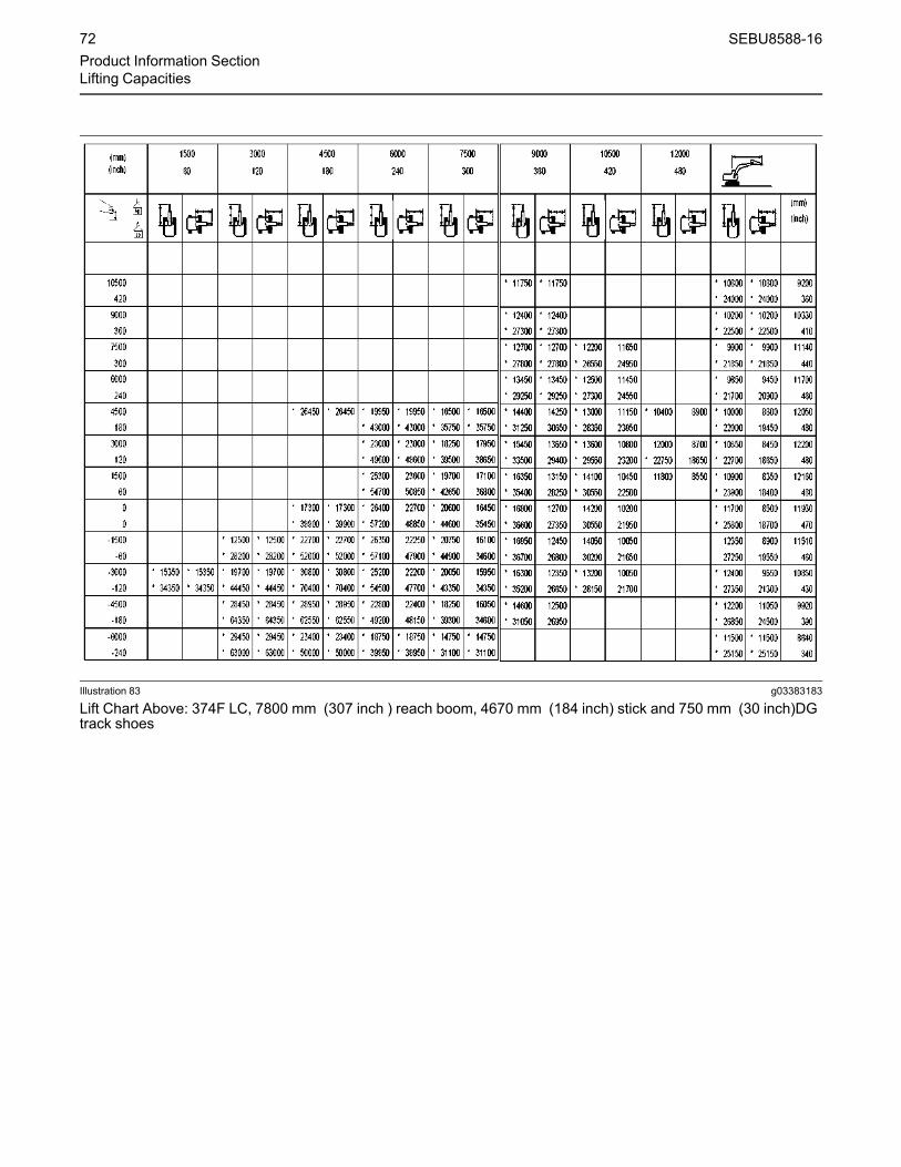
Illustration 83 g03383183
Lift Chart Above: 374F LC, 7800 mm (307 inch ) reach boom, 4670 mm (184 inch) stick and 750 mm (30 inch)DGtrack shoes
72 SEBU8588-16Product Information SectionLifting Capacities

Illustration 84 g03383181
Lift Chart Above: 374F LC, 7800 mm (307 inch ) reach boom, 4670 mm (184 inch) stick and 650 mm (26 inch)DGtrack shoes
Reach Boom
SEBU8588-16 73Product Information Section
Lifting Capacities

4150 mm (163 inch) Stick
Illustration 85 g03383688
Lift Chart Above: 374F LC, 7800 mm (307 inch ) reach boom, 4150 mm (163 inch) stick and 900 mm (35 inch)DGtrack shoes
74 SEBU8588-16Product Information SectionLifting Capacities

Illustration 86 g03383692
Lift Chart Above: 374F LC, 7800 mm (307 inch ) reach boom, 4150 mm (163 inch) stick and 750 mm (30 inch)DGtrack shoes
SEBU8588-16 75Product Information Section
Lifting Capacities

Illustration 87 g03383694
Lift Chart Above: 374F LC, 7800 mm (307 inch ) reach boom, 4150 mm (163 inch) stick and 650 mm (26 inch)DGtrack shoes
Reach Boom
76 SEBU8588-16Product Information SectionLifting Capacities

3600 mm (142 inch) Stick
Illustration 88 g03383763
Lift Chart Above: 374F LC, 7800 mm (307 inch ) reach boom, 3600 mm (142 inch) stick and 900 mm (35 inch)DGtrack shoes
SEBU8588-16 77Product Information Section
Lifting Capacities

Illustration 89 g03383770
Lift Chart Above: 374F LC, 7800 mm (307 inch ) reach boom, 3600 mm (142 inch) stick and 750 mm (30 inch)DGtrack shoes
78 SEBU8588-16Product Information SectionLifting Capacities

Illustration 90 g03383774
Lift Chart Above: 374F LC, 7800 mm (307 inch ) reach boom, 3600 mm (142 inch) stick and 650 mm (26 inch)DGtrack shoes
Reach Boom
SEBU8588-16 79Product Information Section
Lifting Capacities

2840 mm (112 inch) Stick
Illustration 91 g03383793
Lift Chart Above: 374F LC, 7800 mm (307 inch ) reach boom, 2840 mm (112 inch) stick and 900 mm (35 inch)DGtrack shoes
80 SEBU8588-16Product Information SectionLifting Capacities

Illustration 92 g03383795
Lift Chart Above: 374F LC, 7800 mm (307 inch ) reach boom, 2840 mm (112 inch) stick and 750 mm (30 inch)DGtrack shoes
SEBU8588-16 81Product Information Section
Lifting Capacities

Illustration 93 g03383798
Lift Chart Above: 374F LC, 7800 mm (307 inch ) reach boom, 2840 mm (112 inch) stick and 650 mm (26 inch)DGtrack shoes
Mass Boom
82 SEBU8588-16Product Information SectionLifting Capacities

2995 mm (118 inch) Stick
Illustration 94 g03383916
Lift Chart Above: 374F LC, 7000 mm (276 inch ) mass boom, 2995 mm (118 inch)stick and 900 mm (35 inch)track shoes
SEBU8588-16 83Product Information Section
Lifting Capacities

Illustration 95 g03383918
Lift Chart Above: 374F LC, 7000 mm (276 inch ) mass boom, 2995 mm (118 inch)stick and 750 mm (30inch) trackshoes
84 SEBU8588-16Product Information SectionLifting Capacities

Illustration 96 g03383919
Lift Chart Above: 374F LC, 7000 mm (276 inch ) mass boom, 2995 mm (118 inch)stick and 650 mm (26 inch)track shoes
Mass Boom
SEBU8588-16 85Product Information Section
Lifting Capacities

2574 mm (101 inch) Stick
Illustration 97 g03383921
Lift Chart Above: 374F LC, 7000 mm (276 inch ) mass boom, 2574 mm (101 inch)stick and 900 mm (35 inch)track shoes
86 SEBU8588-16Product Information SectionLifting Capacities

Illustration 98 g03383923
Lift Chart Above: 374F LC, 7000 mm (276 inch ) mass boom, 2574 mm (101 inch)stick and 750 mm (30 inch)track shoes
SEBU8588-16 87Product Information Section
Lifting Capacities

Illustration 99 g03383930
Lift Chart Above: 374F LC, 7000 mm (276 inch ) mass boom, 2574 mm (101 inch)stick and 650 mm (26 inch)track shoes
88 SEBU8588-16Product Information SectionLifting Capacities

Identification Informationi08134290
Plate Locations and FilmLocationsSMCS Code: 1000; 7000
The Product Identification Number (PIN) will be usedto identify a powered machine that is designed for anoperator to ride.
Caterpillar products such as engines, transmissions,and major attachments that are not designed for anoperator to ride are identified by Serial Numbers.
For quick reference, record the identificationnumbers in the spaces that are provided below theillustration.
Product Identification Number(PIN) and Regional CertificationPlate
Illustration 100 g00675011
The PIN plate is positioned on the front of themachine, close to the operator compartment.
Illustration 101 g02436556
Model number (A)
Machine PIN (B)
Service Information Plate (C)
Year of Manufacture (If Required) (D)
Regional Certification Plate (If Required) (E)
Country of Origin Info Plate (If Required) (F)
Local regulation may require documentation of theYear of Manufacture in the OMM. Comply with theseregulations.
Regional Certification Plate
Note: The Regional Certification plate is onmachines that are going into the European Union.
Note: The Regional Certification plate is onmachines that are certified to the European Unionrequirements that were effective at that time.
If the machine is equipped with the plate for theEuropean Union, this plate will be attached to the PINplate. Several pieces of information are stamped ontothe “CE” plate.
SEBU8588-16 89Product Information Section
Identification Information
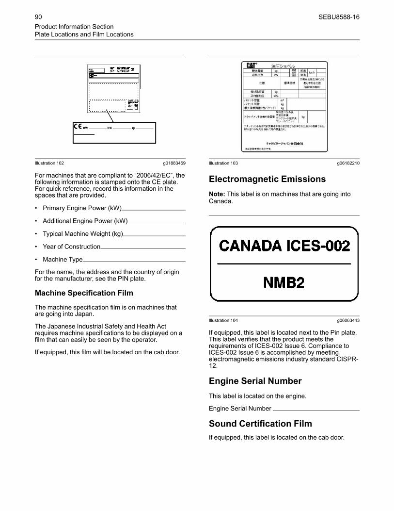
Illustration 102 g01883459
For machines that are compliant to “2006/42/EC”, thefollowing information is stamped onto the CE plate.For quick reference, record this information in thespaces that are provided.
• Primary Engine Power (kW)
• Additional Engine Power (kW)
• Typical Machine Weight (kg)
• Year of Construction
• Machine Type
For the name, the address and the country of originfor the manufacturer, see the PIN plate.
Machine Specification Film
The machine specification film is on machines thatare going into Japan.
The Japanese Industrial Safety and Health Actrequires machine specifications to be displayed on afilm that can easily be seen by the operator.
If equipped, this film will be located on the cab door.
Illustration 103 g06182210
Electromagnetic EmissionsNote: This label is on machines that are going intoCanada.
Illustration 104 g06063443
If equipped, this label is located next to the Pin plate.This label verifies that the product meets therequirements of ICES-002 Issue 6. Compliance toICES-002 Issue 6 is accomplished by meetingelectromagnetic emissions industry standard CISPR-12.
Engine Serial NumberThis label is located on the engine.
Engine Serial Number
Sound Certification FilmIf equipped, this label is located on the cab door.
90 SEBU8588-16Product Information SectionPlate Locations and Film Locations

Illustration 105 g03380730
If equipped, the certification label is used to verify theenvironmental sound certification of the machine tothe requirements of the European Union. The valuethat is listed on the label indicates the guaranteedexterior sound power level LWA at the time ofmanufacture for the conditions that are specified in“2000/14/EC”.
Illustration 106 g03105800
(A) Low Noise Film(B) Super Low Noise Film
If equipped, these certification labels are used toverify the Japan Ministry of Land, Infrastructure,Transportation, and Tourism (MLIT) noisedesignation according to the Japan “DesignationRule of Low Noise Type Contrsuction Machine” .
Low Noise (A) – Verifies that the Japan “MLIT”designates the machine as a “Low Noise” typeconstruction machine.
Super Low Noise (B) – Verifies that the Japan“MLIT” designates the machine as a “Super LowNoise” type construction machine.
i05757951
Emissions Certification FilmSMCS Code: 1000; 7000; 7405
Note: This information is pertinent in Japan.
Illustration 107 g03654940
2014 certification label example
A certification label is located on the cab door.
The certification label verifies that the machineconforms to the 2014 Japan Nonroad Special MotorVehicle Exhaust Regulation.
i08085827
Emissions Certification FilmSMCS Code: 1000; 7000; 7405
Consult your Cat dealer for an Emission ControlWarranty Statement.
The emission certification film is on the engine.
SEBU8588-16 91Product Information SectionEmissions Certification Film

Declaration of ConformitySMCS Code: 1000; 7000
Table 22
An EC or EU Declaration of Conformity document was provided with the machine if it was manufactured to comply with specific requirementsfor the European Union. In order to determine the details of the applicable Directives, review the complete EC or EU Declaration of Conformityprovided with the machine. The extract shown below from an EC or EU Declaration of Conformity for machines that are declared compliant to“2006/42/EC” applies only to those machines originally “CE”marked by the manufacturer listed and which have not since been modified.
Original EC or EU DECLARATION OF CONFORMITY
Manufacturer: Caterpillar Inc., 100 N.E. Adams Street, Peoria, Illinois 61629, USA
Person authorized to compile the Technical File and to communicate relevant part (s) of the Technical File to the Authorities of Euro-pean Union Member States on request:
Standards & Regulations Manager,Caterpillar France SAS40 Avenue Leon-Blum 38000 Grenoble, France
I, the undersigned, _________, hereby certify that the construction equipment specified hereunder
Description: Generic Denomination: Earth-moving Equipment
Function: Hydraulic Excavator
Model/Type: 374F
Serial Number:
Commercial Name: Caterpillar
Fulfills all the relevant provisions of the following Directives
Directives Notified Body Document No.
2000/14/EC amended by 2005/88/EC, Note (1)
2006/42/EC N/A
2004/108/EC N/A
2014/30/EU N/A
Note (1) Annex -_____ Guaranteed Sound Power Level -_____dB (A)Representative Equipment Type Sound Power Level - _____dB (A)Engine Power per ____-____ kW Rated engine speed - _____ rpmTechnical Documentation accessible through person listed above authorized to compile the Technical File
Done at: Signature
Date: Name/Position
Note: The above information was correct as of March 2016, but may be subject to change, please refer to the individual declaration of conform-ity issued with the machine for exact details.
92 SEBU8588-16Product Information SectionDeclaration of Conformity

Operation Section
Before Operationi04021647
Mounting and DismountingSMCS Code: 6700; 7000
Illustration 108 g00037860
Typical example
Mount the machine and dismount the machine onlyat locations that have steps and/or handholds. Beforeyou mount the machine, clean the steps and thehandholds. Inspect the steps and handholds. Makeall necessary repairs.
Face the machine whenever you get on the machineand whenever you get off the machine.
Maintain a three-point contact with the steps and withthe handholds.
Note: Three-point contact can be two feet and onehand. Three-point contact can also be one foot andtwo hands.
Do not mount a moving machine. Do not dismount amoving machine. Never jump off the machine. Do notcarry tools or supplies when you try to mount themachine or when you try to dismount the machine.Use a hand line to pull equipment onto the platform.Do not use any controls as handholds when youenter the operator compartment or when you exit theoperator compartment.
Machine Access SystemSpecificationsThe machine access system has been designed tomeet the intent of the technical requirements in “ISO2867 Earth-moving Machinery – Access Systems”.The access system provides for operator access tothe operator station and to conduct the maintenanceprocedures described in Maintenance section.
Alternate ExitMachines that are equipped with cabs have alternateexits. For additional information, see Operation andMaintenance Manual, “Alternate Exit”.
i03900822
Daily InspectionSMCS Code: 1000; 6319; 6700; 7000
NOTICEAccumulated grease and oil on a machine is a firehazard.
Remove debris with steam cleaning or high pressurewater, at the specified interval in the Maintenance In-terval Schedule or each time any significant quantityof oil is spilled on the machine.
For maximum service life of the machine, perform athorough walk-around inspection before you mountthe machine and before you start the engine.
Daily, perform the procedures that are applicable toyour machine.
Reference: For more information, refer to Operationand Maintenance Manual, “Maintenance IntervalSchedule”.
Remove any trash buildup and debris. Make allnecessary repairs before you operate the machine.
Note:Watch closely for leaks. If you observe a leak,find the source of the leak and correct the leak. If yoususpect a leak or you observe a leak, check the fluidlevels more frequently.
SEBU8588-16 93Operation SectionBefore Operation

Illustration 109 g02143767
Inspect the hydraulic cylinders for damage or forexcessive wear. Inspect the linkage and the bucketfor damage or for excessive wear. Make anynecessary repairs.
Inspect the lights for broken bulbs and for brokenlenses. Replace any broken bulbs and any brokenlenses.
Inspect the engine compartment for any trashbuildup. Remove any trash buildup from the enginecompartment.
Inspect the cooling system for any leaks, for faultyhoses and for any trash buildup. Correct any leaks.Remove any trash from the radiator.
Inspect all of the belts for the engine attachments.Replace any belts that are worn, frayed, or broken.
Illustration 110 g02143769
Inspect the hydraulic system for leaks. Inspect thetank, the cylinder rod seals, the hoses, the tubes, theplugs, the connections, and the fittings. Correct anyleaks in the hydraulic system.
Inspect the final drives for leaks. Make anynecessary repairs. Check the oil level if leakage isnoticed.
Inspect the swing drive for leaks. Make anynecessary repairs.
Make sure that all covers and guards are securelyattached. Inspect the covers and the guards fordamage.
Illustration 111 g00588149
Inspect the steps, the walkways, and the handholds.Clean the steps, the walkways, and the handholds.Make any necessary repairs.
Inspect the Falling Object Protective Structure fordamage. If repair is necessary, consult yourCaterpillar dealer. Tighten any loose bolts.
Inspect the operator compartment for a buildup oftrash. Check for a buildup of trash under thefloorplate. Keep these areas clean.
Adjust the mirrors for the correct rear view of themachine.
94 SEBU8588-16Operation SectionDaily Inspection

Machine Operationi05711950
Alternate ExitSMCS Code: 7310
Front Window (If Equipped)
Illustration 112 g02050493
(1) Lever(2) Handle
The front window serves as an alternate exit.
In order to remove the front window, move lever (1) tothe right. Grab handles (2) and lift the window into theoverhead storage position. Exit through the frontwindow.
Roof Hatch (If Equipped)
Illustration 113 g02851621
(4) Latch(5) Grip(6) Gas springs(7) Lock mechanism
Note: Before operating the machine, make sure lockmechanism (7) (if equipped) is unlocked.
Alternate Exit – The roof hatch serves asan alternate exit.
Slide the visor cover back. If equipped, make surelock mechanism (7) is unlocked.
Release latch (4). Hold grip (5) and push the roofhatch outward.
SEBU8588-16 95Operation SectionMachine Operation

Illustration 114 g02901996
If equipped with gas springs (6), press gas springrelease (9) and remove gas spring shaft (8) in orderto open hatch wider.
Exit through the roof hatch.
Removing the Roof Hatch from the Outside
Illustration 115 g02851583
(10) Hinge pin release
If equipped with hinge pin release (10), the roof hatchcan also be removed from the outside of the cab.
Press hinge pin release (10) and slide backward. Thehinge pin should detach and allow the hatch to belifted. Exit through the roof hatch.
Note: Lock mechanism (7) (if equipped) must beunlocked in order to allow the hatch to be lifted.
Roof Hatch (If Equipped)
Illustration 116 g02851579
Alternate Exit – The roof hatch serves asan alternate exit.
Slide the visor cover back.
Remove knobs (11) and push the roof hatch outward.Exit through the roof hatch.
FOGS (If Equipped)Note: Some FOGS are fixed/bolted-on and otherscan be opened. This information pertains to FOGSthat can be opened.
96 SEBU8588-16Operation SectionAlternate Exit

Top FOGS
Illustration 117 g02902217
In order to exit through the roof hatch, the FOGSguard is equipped with a release latch. Open the roofhatch as stated above. As the roof hatch is beingpushed outward, the roof hatch will hit lever (12).Lever (12) will allow the FOGS to lift upward. Exitthrough the roof hatch.
In order to open the top FOGS from the outside of themachine, reach under the FOGS and pull up onrelease lever (12). Follow the directions for removingthe hatch from the outside.
Front FOGS
Illustration 118 g02902219
In order to exit through the front window, the FOGSguard is equipped with a release latch. Open the frontwindow as stated above and remove the lowerwindow. Press down on levers (13) in order to openthe front FOGS. Exit through the front window.
SEBU8588-16 97Operation Section
Alternate Exit

i07194752
SeatSMCS Code: 5258-025; 7312-025; 7324; 7327
Illustration 119 g01636841
(1) Adjustment lever for the lumbar support(2) Adjustment lever for reclining the seat(3) Lever for the seat cushion adjustment(4) Seat fore and aft adjustment.(5) Seat height adjustment(6) Fore and aft seat and console adjustment(7) Console adjustment(8) Indicator(9) Seat angle lever(10) Armrest(11) Headrest
The lumbar support is located in the back of the seat.Turn knob (1) (if equipped) counterclockwise toincrease the force of the lumbar support. In order todecrease the lumbar support, continue to turn theknob counterclockwise.
Pull up lever (2) to change the angle of the seat. Holdthe seat back in the desired position. Release thelever.
Push in lever (3) to adjust the length of the cushion.
To adjust the seat forward or backward, pull up lever(4) and hold the lever. Move the seat to the desiredposition. To lock the seat in the selected position,release the lever.
Note: Before adjusting the seat forward or backward,make sure that the lever for the seat heightadjustment (5) is in the downward position.
Turn lever (5) to adjust the seat and the console tothe desired height. In order to raise the seat height,pull the grip downward and rotate the grip with theplus sign outward. In order to lower the seat height,pull the grip downward and rotate the grip with theminus sign outward. Release grip to return to theoriginal position.
Pull lever (6) to adjust the seat and the consoleforward and backward.
Use handle (7) to adjust the height of the console.When the lever is pulled forward, a gear is released.The operator can rotate the lever freely. Release thelever to return to the original position.
Push the lever (9) to adjust the tilt angle of the seat.
The operator can adjust the height of headrest (11).To adjust the headrest, hold the headrest with bothhands. Move the headrest up and down. Release theheadrest when the desired position is attained. Theheadrest will remain in the desired position.
Illustration 120 g01637296
If your machine is equipped with an air ridesuspension, the seat will be equipped with a lever(12). Pull up the lever to raise the height of the seat.Push down on the lever to lower the seat. If theadjustment is correct, indicator (8) will turn green. Ifthe indicator shows red, further adjustment isrequired.
98 SEBU8588-16Operation SectionSeat

Illustration 121 g01636977
(13) Armrest adjustment knob(14) Armrest height adjustment
The height of the armrest can be adjusted. Squeezelever (13) to adjust the height of the armrest. Movethe armrest upward or move the armrest downward.Release the lever when the armrest is in the desiredposition.
To adjust the angle of the armrest (10), operate dial(14). A dial is on the bottom of each armrest. Placethe armrests in the upright position when you enterthe machine or when you exit the machine.
Heated Seat and Ventilated Seat (IfEquipped)
Heat-induced burns can occur when some peopleuse a seat heater. Do not use the seat heater ifyou have a reduced ability to sense temperaturechanges, a reduced ability to feel pain, or havesensitive skin.
Illustration 122 g06249034
Heated Seat Switch – If equipped with a heatedseat, press the top of rocker switch (15) to turn theseat heater to the ON position. Press the bottom ofrocker switch (15) to turn the seat heater to the OFFposition.
Heated and Ventilated Seat Switch – If equippedwith a heated and ventilated seat, press the top ofrocker switch (15) for heat. Press the bottom ofrocker switch (15) for ventilation. The center switchposition is OFF.
i04200349
Seat BeltSMCS Code: 7327
Note: This machine was equipped with a seat beltwhen the machine was shipped from Caterpillar. Atthe time of installation, the seat belt and theinstructions for installation of the seat belt meet theSAE J386 and ISO 6683 standards. Consult your Catdealer for all replacement parts.
Always check the condition of the seat belt and thecondition of the mounting hardware before youoperate the machine.
Seat Belt Adjustment for Non-Retractable Seat BeltsAdjust both ends of the seat belt. The seat beltshould be snug but comfortable.
SEBU8588-16 99Operation Section
Seat Belt

Lengthening the Seat Belt
Illustration 123 g00100709
1. Unfasten the seat belt.
Illustration 124 g00932817
2. To remove the slack in outer loop (1), rotate buckle(2). This will free the lock bar. This permits theseat belt to move through the buckle.
3. Remove the slack from the outer belt loop bypulling on the buckle.
4. Loosen the other half of the seat belt in the samemanner. If the seat belt does not fit snugly with thebuckle in the center, readjust the seat belt.
Shortening the Seat Belt
Illustration 125 g00100713
1. Fasten the seat belt. Pull out on the outer belt loopin order to tighten the seat belt.
2. Adjust the other half of the seat belt in the samemanner.
3. If the seat belt does not fit snugly with the buckle inthe center, readjust the seat belt.
Fastening The Seat Belt
Illustration 126 g00932818
Fasten the seat belt catch (3) into the buckle (2).Make sure that the seat belt is placed low across thelap of the operator.
100 SEBU8588-16Operation SectionSeat Belt

Releasing The Seat Belt
Illustration 127 g00100717
Pull up on the release lever. This will release the seatbelt.
Seat Belt Adjustment forRetractable Seat BeltsFastening The Seat Belt
Illustration 128 g00867598
Pull seat belt (4) out of the retractor in a continuousmotion.
Fasten seat belt catch (3) into buckle (2). Make surethat the seat belt is placed low across the lap of theoperator.
The retractor will adjust the belt length and theretractor will lock in place. The comfort ride sleevewill allow the operator to have limited movement.
Releasing The Seat Belt
Illustration 129 g00039113
Push the release button on the buckle in order torelease the seat belt. The seat belt will automaticallyretract into the retractor.
Extension of the Seat Belt
When using retractable seat belts, do not useseat belt extensions, or personal injury or deathcan result.
The retractor system may or may not lock up de-pending on the length of the extension and thesize of the person. If the retractor does not lockup, the seat belt will not retain the person.
Longer, non-retractable seat belts and extensions forthe non-retractable seat belts are available.
Caterpillar requires only non-retractable seat belts tobe used with a seat belt extension.
SEBU8588-16 101Operation Section
Seat Belt
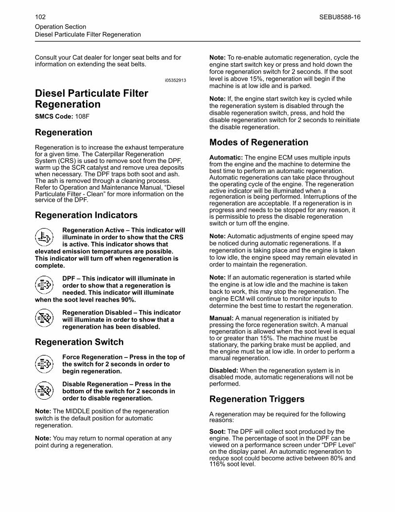
Consult your Cat dealer for longer seat belts and forinformation on extending the seat belts.
i05352913
Diesel Particulate FilterRegenerationSMCS Code: 108F
RegenerationRegeneration is to increase the exhaust temperaturefor a given time. The Caterpillar RegenerationSystem (CRS) is used to remove soot from the DPF,warm up the SCR catalyst and remove urea depositswhen necessary. The DPF traps both soot and ash.The ash is removed through a cleaning process.Refer to Operation and Maintenance Manual, “DieselParticulate Filter - Clean” for more information on theservice of the DPF.
Regeneration IndicatorsRegeneration Active – This indicator willilluminate in order to show that the CRSis active. This indicator shows that
elevated emission temperatures are possible.This indicator will turn off when regeneration iscomplete.
DPF – This indicator will illuminate inorder to show that a regeneration isneeded. This indicator will illuminate
when the soot level reaches 90%.
Regeneration Disabled – This indicatorwill illuminate in order to show that aregeneration has been disabled.
Regeneration SwitchForce Regeneration – Press in the top ofthe switch for 2 seconds in order tobegin regeneration.
Disable Regeneration – Press in thebottom of the switch for 2 seconds inorder to disable regeneration.
Note: The MIDDLE position of the regenerationswitch is the default position for automaticregeneration.
Note: You may return to normal operation at anypoint during a regeneration.
Note: To re-enable automatic regeneration, cycle theengine start switch key or press and hold down theforce regeneration switch for 2 seconds. If the sootlevel is above 15%, regeneration will begin if themachine is at low idle and is parked.
Note: If, the engine start switch key is cycled whilethe regeneration system is disabled through thedisable regeneration switch, press, and hold thedisable regeneration switch for 2 seconds to reinitiatethe disable regeneration.
Modes of RegenerationAutomatic: The engine ECM uses multiple inputsfrom the engine and the machine to determine thebest time to perform an automatic regeneration.Automatic regenerations can take place throughoutthe operating cycle of the engine. The regenerationactive indicator will be illuminated when aregeneration is being performed. Interruptions of theregeneration are acceptable. If a regeneration is inprogress and needs to be stopped for any reason, itis permissible to press the disable regenerationswitch or turn off the engine.
Note: Automatic adjustments of engine speed maybe noticed during automatic regenerations. If aregeneration is taking place and the engine is takento low idle, the engine speed may remain elevated inorder to maintain the regeneration.
Note: If an automatic regeneration is started whilethe engine is at low idle and the machine is takenback to work, this may stop the regeneration. Theengine ECM will continue to monitor inputs todetermine the best time to restart the regeneration.
Manual: A manual regeneration is initiated bypressing the force regeneration switch. A manualregeneration is allowed when the soot level is equalto or greater than 15%. The machine must bestationary, the parking brake must be applied, andthe engine must be at low idle. In order to perform amanual regeneration.
Disabled:When the regeneration system is indisabled mode, automatic regenerations will not beperformed.
Regeneration TriggersA regeneration may be required for the followingreasons:
Soot: The DPF will collect soot produced by theengine. The percentage of soot in the DPF can beviewed on a performance screen under “DPF Level”on the display panel. An automatic regeneration toreduce soot could become active between 80% and116% soot level.
102 SEBU8588-16Operation SectionDiesel Particulate Filter Regeneration

Start: A start regeneration could be initiated by theECM at the start of a cold engine. This is to reach adesired SCR catalyst temperature to allow DEFdosing to start.
SCR Maintenance: The ECM uses multiple inputsand determines when urea deposits may be presentin the exhaust system. The CRS will heat the exhaustto remove the deposits anywhere in the exhaustsystem.
ARD Maintenance: Some applications may have asignificant time between when a regeneration hasoccurred. A regeneration will occur if this time isgreater than 25 hours to flush fuel through the CRSsystem.
Regeneration System WarningIndicators
Illustration 130 g02117258
Indicator will illuminate when a regeneration isrequired. Soot level is greater than 90%
Regeneration should be performed as soon aspossible. A manual regeneration should beperformed as soon as possible.
Indicator will turn off once DPF regeneration hasstarted.
Note: In some situations, the DPF indicator may stayilluminated when the soot load is below 90%. Theilluminated DPF indicator indicates that a completeregeneration has not been performed. A completeregeneration is when the soot level is reduced to 0%.If the DPF indicator stays illuminated, perform aregeneration without interruption until the soot level isreduced to 0%. A complete regeneration will resetthe DPF indicator.
Illustration 131 g02117259
If the soot level has reached 100% or the “Time toRegen” is 0 hours, then a regeneration is required,the DPF indicator and an action indicator will beilluminated. Stop the machine and apply the parkingbrake. With the engine at low idle, initiate a manualregeneration. Engine power will be slightly derated ifthe machine continues to operate. The engine willalso be derated to 50% power. Engine power willgradually be lost until 100% soot or 25 hours withouta regeneration.
Illustration 132 g02117261
Once the soot level has reached 116% soot, the DPFindicator and an action indicator will be illuminatedand an audible alarm will sound.
10 minutes after the soot level has reached 116%,the engine will shut down. Cycle the engine startswitch key to return the engine to the previous deratebefore engine shutdown.
If the soot level reaches 120% or 5 hours of run timesince the action indictor was illuminated without asuccessful regeneration, the engine will have a 100%derate.
Once the engine has reached 140% soot, theregeneration will be locked out. At this time, aregeneration can only be done through Cat ElectronicTechnician (ET), by an authorized Cat dealer. Theengine may be restarted but will only run for 30seconds before shutting down again.
Delayed Engine ShutdownThe Delayed Engine Shutdown allows the engine torun for a time after the engine start switch is turned tothe OFF position to cool the engine and the machinesystem components. The engine start switch keymay be removed.
Note: There may be regulations that define therequirements for the operator and/or supportpersonnel to be present when the engine is running.
SEBU8588-16 103Operation Section
Diesel Particulate Filter Regeneration

Leaving the machine unattended when the engineis running may result in personal injury or death.Before leaving the machine operator station, neu-tralize the travel controls, lower the work tools tothe ground and deactivate all work tools, andplace the lever for the hydraulic lockout controlin the LOCKED position.
Refer to Operation and Maintenance Manual,“Parking” for more information.
Note: Leaving the machine unattended when theengine is running may result in property damage inthe event of a malfunction.
Turn the engine start switch to the OFF position.
Delayed Engine Shutdown – Thedelayed engine shutdown indicator willilluminate or the following text will be
displayed, ENGINE COOLDOWN ACTIVE.
Delayed engine shutdown will run for a minimum of30 seconds and will continue to run until the engineand machine system components are cooled. Themaximum run time is 10 minutes,
Note: To override delayed engine shutdown and stopthe engine, turn the engine start switch to the STOPposition. Overriding delayed engine shutdown mayreduce engine and machine system component life.A warning message and/or audible alarm will beinitiated and a fault code will be logged for improperengine shutdown.
Illustration 133 g02362719
Note: At any time during a delayed engine shutdown,the engine start switch may be turned to the ONposition. The machine may be placed back intoservice.
Note:With the operator key in the OFF position, thepurge system will activate after a delayed engineshutdown.
DEF Purge – DEF Purge allows toextract the residual DEF from the DEFinjectors, lines, and pump. The DEF
purge will activate during a Delayed EngineShutdown is running or after the key to theEngine is turned OFF in the shutdown position.The start key may be removed.
Note: There may be regulations that define therequirements for the operator and/or supportpersonnel to be present when the engine is running.
Leaving the machine unattended when the engineis running may result in personal injury or death.Before leaving the machine operator station, neu-tralize the travel controls, lower the work tools tothe ground and deactivate all work tools, andplace the lever for the hydraulic lockout controlin the LOCKED position.
Refer to Operation and Maintenance Manual,"Parking" for more information.
Note: Leaving the machine unattended when theengine is running may result in property damage inthe event of a malfunction.
i06301373
Selective Catalytic ReductionWarning SystemSMCS Code: 1091-WXX; 7400
The selective catalytic reduction (SCR) system is asystem used to reduce NOx emissions from theengine. Diesel exhaust fluid (DEF) is pumped fromthe DEF tank and is sprayed into the exhaust stream.The DEF reacts with the SCR catalyst to reduce NOxand leaves a nitrogen and water vapor. The ExhaustGas Recirculation (EGR) system cools, measures,and introduces recalculated exhaust gas into theintake manifold to aid in NOx reduction.
NOTICEStopping the engine immediately after the engine hasbeen working under load can result in overheating ofSCR components.
Refer to the Operation and Maintenance Manual,“Engine Stopping” procedure to allow the engine tocool and to prevent excessive temperatures in theturbocharger housing and the DEF injector.
Note:With the operator key in the OFF position, thepurge system will activate.
104 SEBU8588-16Operation SectionSelective Catalytic Reduction Warning System

DefinitionsObserve the following definitions.
Self-correct – Fault condition no longer exists. Anactive fault code will no longer be active.
Notification – Action taken by the system to alert theoperator of pending Inducement.
Inducement – Engine derates, vehicle speed limits,or other actions intended to prompt the operator torepair or maintain the emission control system.
Inducement Trigger – Fault conditions that result inactivation of the inducement strategy. DEF levelinducement faults have a diagnostic fault code. DEFquality fault, SCR tampering fault, SCR system fault,and EGR system faults will all have a relateddiagnostic fault code along with an inducementdiagnostic fault code.
First occurrence – A DEF quality fault, SCRtampering fault, SCR system fault, or an EGR systemfault becomes active for the first time.
Repeat occurrence – If any DEF quality fault, SCRtampering fault, SCR system fault, or an EGR systemfault becomes active again within 40 hours of the firstoccurrence.
Safe Harbor Mode – Safe harbor mode is a 20minute engine run time period. The engine can beoperated with full power after reaching a level 3inducement. Once in level 3 inducement, theoperator can perform a key cycle and the engine willenter safe harbor mode. Safe harbor mode can onlybe implemented once. Safe harbor mode is notallowed for DEF level inducements.
Illustration 134 g03684888
DEF Level Normal
Inducement Strategy for DEF LevelIf multiple warnings are present in the system, themost important problem is shown first. Press the rightkey or press the left key in order to view all of thewarnings that are present in the machine. If no keysare pressed within 5 seconds, the display will returnto the most important problem.
Illustration 135 g03681105
DEF Level Low
If the DEF level falls below 20%, “DEF Level Low”message will be displayed on the monitor. To avoidfurther inducements, turn the key to the OFF positionand add DEF to the DEF tank.
SEBU8588-16 105Operation Section
Selective Catalytic Reduction Warning System
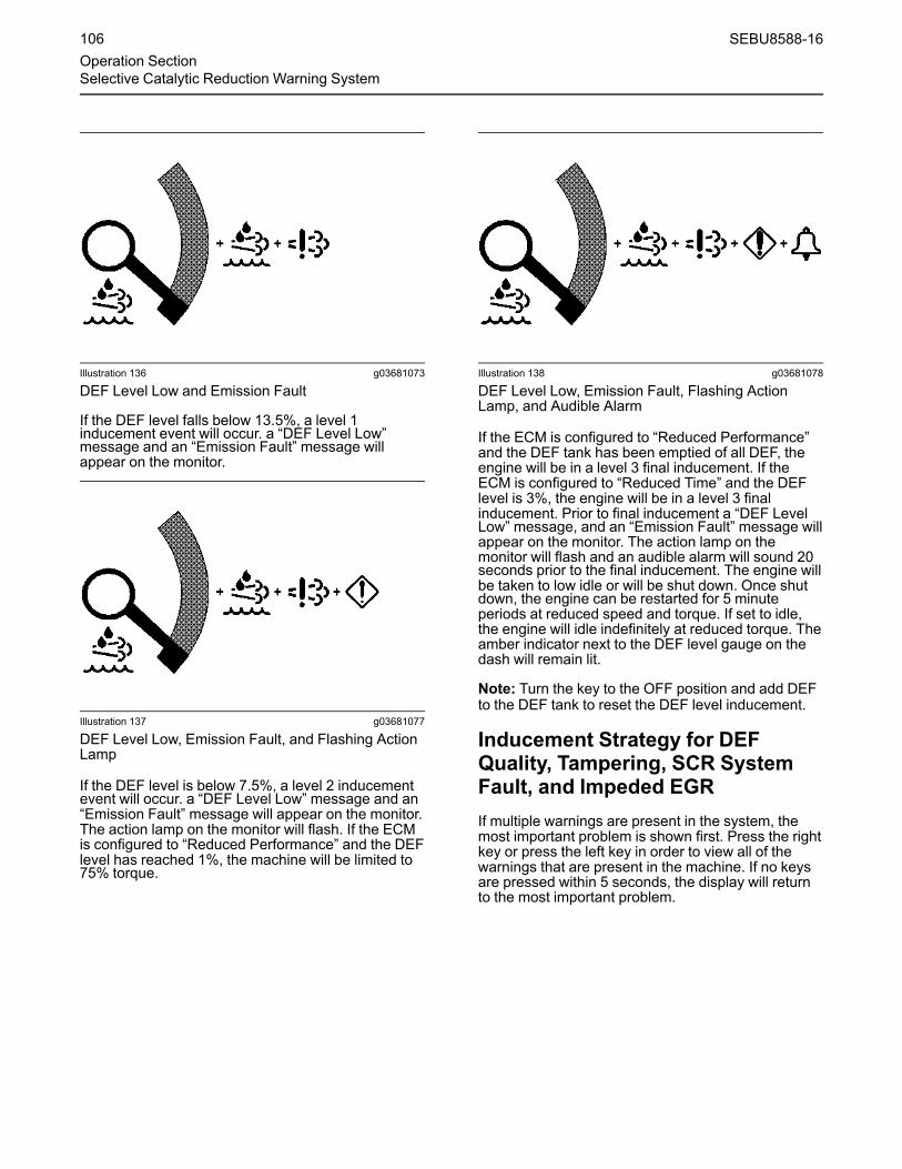
Illustration 136 g03681073
DEF Level Low and Emission Fault
If the DEF level falls below 13.5%, a level 1inducement event will occur. a “DEF Level Low”message and an “Emission Fault” message willappear on the monitor.
Illustration 137 g03681077
DEF Level Low, Emission Fault, and Flashing ActionLamp
If the DEF level is below 7.5%, a level 2 inducementevent will occur. a “DEF Level Low” message and an“Emission Fault” message will appear on the monitor.The action lamp on the monitor will flash. If the ECMis configured to “Reduced Performance” and the DEFlevel has reached 1%, the machine will be limited to75% torque.
Illustration 138 g03681078
DEF Level Low, Emission Fault, Flashing ActionLamp, and Audible Alarm
If the ECM is configured to “Reduced Performance”and the DEF tank has been emptied of all DEF, theengine will be in a level 3 final inducement. If theECM is configured to “Reduced Time” and the DEFlevel is 3%, the engine will be in a level 3 finalinducement. Prior to final inducement a “DEF LevelLow” message, and an “Emission Fault” message willappear on the monitor. The action lamp on themonitor will flash and an audible alarm will sound 20seconds prior to the final inducement. The engine willbe taken to low idle or will be shut down. Once shutdown, the engine can be restarted for 5 minuteperiods at reduced speed and torque. If set to idle,the engine will idle indefinitely at reduced torque. Theamber indicator next to the DEF level gauge on thedash will remain lit.
Note: Turn the key to the OFF position and add DEFto the DEF tank to reset the DEF level inducement.
Inducement Strategy for DEFQuality, Tampering, SCR SystemFault, and Impeded EGRIf multiple warnings are present in the system, themost important problem is shown first. Press the rightkey or press the left key in order to view all of thewarnings that are present in the machine. If no keysare pressed within 5 seconds, the display will returnto the most important problem.
106 SEBU8588-16Operation SectionSelective Catalytic Reduction Warning System

Illustration 139 g03623190
A “Engine Fault Check Engine” message and an“Emission Fault” message will appear on the monitorfor a fault resulting from poor DEF quality, SCRsystem tampering, SCR system fault, or an EGRsystem fault. If the fault is the result of poor DEFquality, SCR system tampering, or SCR system fault,a first occurrence will result in a level 1 inducementfor a duration of 2.5 hours. The level 1 inducementwill also illuminate the check engine lamp. Repeatoccurrences will result in a level 1 inducementduration of 5 minutes. If the fault is the result of anEGR system fault, a first occurrence will result in alevel 1 inducement for a duration of 35 hours. Repeatoccurrences will result in a level 1 inducementduration of 48 minutes.
Illustration 140 g03623191
If a fault condition exists for the entire duration ofinducement level 1, the strategy advances toinducement level 2. A “Engine Fault Check Engine”message, and an “Emission Fault” message willappear on the monitor and the action lamp on themonitor will flash for a fault resulting from poor DEFquality, SCR system tampering, SCR system fault, oran EGR system fault. For poor DEF quality, SCRsystem tampering, and SCR system faults, theduration for a level 2 inducement is 70 minutes forthe first occurrence. For EGR system faults, theduration for a level 2 inducement is 60 minutes forthe first occurrence. Repeat occurrences for poorDEF quality, SCR system tampering, and SCRsystem faults will result in a level 2 inducement of 5minutes. Repeat occurrences for EGR system faultswill result in a level 2 inducement of 60 minutes.
Illustration 141 g03623193
If a fault condition exists for the entire duration ofinducement level 2, the strategy advances toinducement level 3. A “Engine Fault Check Engine”message, and an “Emission Fault” message willappear on the monitor, the action lamp will flash, andan audible alarm will sound 20 seconds prior to thelevel 3 inducement. The engine will be taken to lowidle or will be shut down. After the level 3 inducementyou may cycle the key, which will allow 20 minutes ofengine run time with full torque. After 20 minutes, theengine will be in level 3 final inducement and willallow idle only or be shut down until the issue hasbeen resolved. Once shut down, the engine can berestarted for 5 minute periods at reduced speed andtorque. If set to idle, the engine will idle indefinitely atreduced torque.
Note: Contact your Cat dealer for repairs if a faultoccurs.
Inducement Emergency Overridefor Cat Engines Equipped withSelective Catalytic ReductionSystems (If Equipped)Note: The inducement emergency override willonly be allowed on a select number of machinesthat may be used in emergency situations.Contact your Cat dealer to find out if yourmachine is allowed to have this feature.
Inducement emergency override can only be enabledusing Caterpillar supplied passwords. The feature isdisabled by default. The feature will be enabled at thefactory if allowed. If the customer wants the featureenabled after delivery of engine, they will need tocontact their Cat dealer. Inducement emergencyoverride is regulated by the Environmental ProtectionAgency (EPA) and only allowed in the United States.The European Union and Japan do not allow thefeature to be used. For detailed information onactivating, deactivating, or resetting override, contactyour Cat dealer. Before you attempt the proceduresdocumented in this manual, make sure that you haveread and understand the information in thisdocument.
SEBU8588-16 107Operation Section
Selective Catalytic Reduction Warning System

The United States EPA requires the limiting of enginespeed and/or power (derate) in certain conditions, tohelp ensure proper functioning of the enginesemission control system. The EPA allows thetemporary disabling of these limits (restoration of fullengine speed and power capability) during a qualifiedemergency situation. The EPA defines a qualifiedemergency situation as a significant direct or indirectrisk to human life. Below are examples of directversus indirect risks.
Direct – An emission control condition that inhibitsperformance of an engine being used to rescue aperson from life-threatening situation.
Indirect – An emission control condition that inhibitsperformance of an engine being used to provideelectrical power to a data center that routes 911emergency response communications.
The emissions-related derate can be disabled for upto 120 hours of engine operation. The temporarydisabling of emissions-related derate is referred to as“Inducement Emergency Override” and must bereported to the United States EPA. The override canonly be enabled or disabled by an authorized Catdealer using Caterpillar supplied passwords. Onceenabled, the override can be activated thru theelectronic display menu in the cab (if equipped).Upon activation, the check engine and action lampswill be illuminated until and the override is reset. Acode indicating that the inducement emergencyoverride is active will also be active until the overrideis reset. The override can only be reset by the enginemanufacturer, Caterpillar. A Cat dealer can reset theoverride using Caterpillar supplied passwords.Improper use of the override, failure to deactivate theoverride when the emergency has ended, and failureto report use of the override is prohibited underfederal regulations and subject to penalties imposedby the United States EPA. The civil penalty per dayoperated in violation can be severe.
NOTICEWhen the inducement emergency override is active,damage to aftertreatment and engine componentscan occur. Never use the override longer than neces-sary and always fix the root cause of the inducementas soon as possible. There will always be a diagnos-tic code indicating root cause of the inducement. Re-fer to the troubleshooting guide for how to fixinducement related failures.
Override Activation MethodThere are two options for setting the override, usingCat Electronic Technician (ET) or thru the electronicdisplay menu in the cab (if equipped). If the overridehas already been enabled by an authorized Catdealer, then the operator can turn on the overridewithout further input from Caterpillar. Upon activation,the check engine and action lamps will illuminate toalert the operator that the override is active. Theoverride must be paused by the operator if theemergency ends before the 120 hours of overrideoperation has expired. While paused, the equipmentwill be subject to derates. Once paused, the overridecan be activated again if the 120 hour time periodhas not expired and if an emergency situation stillexists. Per federal regulations, the operator must fillout the Override Usage Report below and provide thereport to Caterpillar within 60 days of activating theoverride.
Setting the Override through Cat ElectronicTechnician (ET)
• Go to “Configuration Parameters”
• Select “Aftertreatment Configuration”
• Select “Operator Inducement Emergency OverrideActivation” to activate the override
• The “Value” field should be switched to “Activated”(to pause the override change the “Value” field to“Not Activated” )
Setting the Override through Electronic DisplayMenu
Machine applications will be able to activate ordeactivate the override thru the electronic displaymenu in the cab. The override will only be availablewhen engine is already in inducement (derated).Operators must be trained properly to understandwhere override is located and that there could besevere penalties as mentioned above for misusingthe override. There will be a warning on displaystating: “EMERGENCY USE ONLY. SEE OWNERSMANUAL. PENALTIES APPLY FOR MISUSE” .
108 SEBU8588-16Operation SectionSelective Catalytic Reduction Warning System

Resetting the Override
The override needs to be reset through CatElectronic Technician (ET) whenever the overridehas expired. The override cannot be used again untilthe override is reset. The override should also bereset whenever the emergency has ended,regardless if the override has expired or not (i.e.accumulated 120 hours). The check engine andaction lamps will continue to be illuminated until theoverride is reset. The code indicating that theinducement emergency override is active will alsocontinue to be active until the override is reset. Theoverride may be reset at any point after the initialactivation. The override can only be reset by theengine manufacturer, Caterpillar, or an authorizedCat dealer using Caterpillar supplied passwords.
Override Usage Report
To comply with federal regulations, the operator mustreport usage of the override to Caterpillar Inc. within60 days of activating the override. Failure to meet thisreporting requirement may subject the operator topenalties under 40 CFR 1068.101. Caterpillar Inc. willin turn report override usage annually to the UnitedStates EPA. Although submitted to Caterpillar Inc.,the override usage reports are deemed to besubmissions to the United States EPA. Federalregulations prohibit submitting false information. Thefollowing information must be included in the report:
• Contact name, mail and e-mail addresses, andtelephone number for the responsible company orentity
• A description of the emergency situation, thelocation of the engine during the emergency, andthe contact information for an official who canverify the emergency situation (such as a countysheriff, fire marshal, or hospital administrator)
• The reason for the activation of the override duringthe emergency situation, such as the lack of DEF,or the failure of an emission-related sensor whenthe engine was needed to respond to anemergency situation
• The engine serial number (or equivalent)
• A description of the extent and duration of theengine operation while the override was active,including a statement describing whether theoverride was manually deactivated (paused) afterthe emergency situation ended
The Override Usage Report may be sent via e-mail or regular mail to one of the followingaddresses:
Email :
Regular Mail :
Caterpillar Inc.P.O. Box 600Mossville, IL 61552-0600Attention: Emissions Compliance Manager
i07568615
Operator ControlsSMCS Code: 7300; 7301; 7451
Note: Your machine may not be equipped with all ofthe controls that are described in this topic.
Cat Grade Control (If Equipped)Cat Grade Control is designed to calculate bucket tipposition and provide visual and audible feedback tothe operator. This feedback allows the operator toachieve the desired grade safer, quicker and moreaccurately than traditional grading techniques.
SEBU8588-16 109Operation SectionOperator Controls

For information on how to use Cat Grade Control,refer to Operation and Maintenance Manual,SEBU8358, “Cat Grade Control Depth and Slope forE Series Excavators”.
Operator Controls
Illustration 142 g03071956
(1) Hydraulic lockout control(2) Travel controls(3) Service hour meter(4) Monitor
(5) Joystick controls(6) Engine start switch(7) Right side control panel(8) Operator seat
(9) Air conditioning and heating control(10) Radio
110 SEBU8588-16Operation SectionOperator Controls

Illustration 143 g03629778
(11) Engine speed control(12) Power mode(13) Travel speed control(14) Automatic engine speed control (AEC)(15) Travel alarm switch(16) Work tool control(17) Lift control(18) Window washer
(19) Window wiper(20) Light switch(21) Rear/Side view camera(22) Quick coupler control(23) Cat Regeneration System (CRS) switch(24A) Crane switch(24B) Radio mute(25A) Lower window wiper
(25B) Platform light(26) Lower window washer(27A) Boom pressure control switch(27B) SmartBoom control(27C) Fine swing control(28) Overload warning device
Note:Make sure that Switch is specified to eachattachment. If the attachment is not ordered, Switchis not activated even though a dedicated symbol forrelated control is displayed.
Hydraulic Lockout Control (1)The lever for the hydraulic lockout control is locatedat the left side of the left console.
Locked – Move the travel levers/pedalsand move the joysticks to the HOLD(center) position. Move the lever for the
hydraulic lockout control backward to theLOCKED position. All of the factory installedhydraulic controls will become inoperable.
Note: Make sure that the lever for the hydrauliclockout control is in the LOCKED position beforeattempting to start the engine. If the lever is in theUNLOCKED position, the engine start switch will notfunction.
SEBU8588-16 111Operation SectionOperator Controls

Unlocked – Move the lever for thehydraulic lockout control forward to theUNLOCKED position. All of the factory
installed hydraulic controls will becomeoperable.
Travel Control (2)
Illustration 144 g00753277
Position for normal travel(A) Rear of machine(B) Final drive(C) Idler
When you travel, make sure that final drive sprockets(B) are under the rear of the machine.
Stop – Release the travel levers/pedals in order tostop the machine. When you release the travellevers/pedals from any position, the travel levers/pedals will return to the CENTER position. The travelbrakes will be applied.
Move both of the travel levers or both of the travelpedals equally in the same direction in order to travelstraight.
Illustration 145 g00731542
FORWARD travel
Illustration 146 g00731543
REVERSE travel
Illustration 147 g00731472
Pivot left turn (FORWARD)
Illustration 148 g00731478
Pivot Left Turn (REVERSE)
112 SEBU8588-16Operation SectionOperator Controls

Illustration 149 g00731476
Counterrotate turn (LEFT)
Illustration 150 g00731471
Pivot right turn (FORWARD)
Illustration 151 g00731479
Pivot right turn (REVERSE)
Illustration 152 g00731477
Counterrotate turn (RIGHT)
Service Hour Meter (3)Service Hour Meter – This displayindicates the total operating hours of theengine. Use the display to determine the
service hour maintenance intervals.
Monitor (4)The monitor is used in order to display variousoperating information of the machine. For moreinformation on the operation of the monitor, refer toOperation and Maintenance Manual, “MonitoringSystem”.
Joystick Controls (5)The joystick control is used to control certainfunctions of the machine and work tools. For moreinformation on the individual functions of thejoysticks, refer to Operation and MaintenanceManual, “Joystick Controls”.
Note: During a boom down function the machineECM may reduce engine speed. This improves theoverall fuel consumption.
Engine Start Switch (6)
NOTICEThe engine start switch must be in the ON positionand the engine must be running in order to maintainelectrical functions and hydraulic functions. This pro-cedure must be followed in order to prevent seriousmachine damage.
SEBU8588-16 113Operation SectionOperator Controls

Illustration 153 g02362719
Engine Stop (Shutdown) – Turn the keyto this position in order to disable thedelayed engine shutdown (DES). The
engine will be shut down immediately.
Note: Shutting down the engine using this method isconsidered a hard shutdown which disables the DES.
Note: A warning message and/or Audible alarm willbe initiated. A fault code will be logged for improperengine shutdown if exhaust temperature is abovelimit.
Note: Overriding delayed engine shutdown mayreduce engine and machine system component life.
For more information, refer to Operation andMaintenance Manual, “Diesel Particulate FilterRegeneration”.
OFF – Insert the engine start switch keyonly while the start switch is in the OFFposition. Remove the engine start
switch key only while the engine start switch is inthe OFF position. Turn the engine start switch tothe OFF position before you attempt to restart theengine. Turn the engine start switch to the OFFposition in order to stop the engine.
ON – To activate the electrical circuits inthe cab, turn the key clockwise to theON position.
START – To start the tractor engine, turnthe key clockwise to the STARTposition. After the engine starts, release
the key. The key will return to the ON position.
Note: If the engine fails to start, return the enginestart switch key to the OFF position. Return the keyto the start position before you attempt to start theengine again.
Engine Idle Shutdown (7)This function shuts down the engine after theoperator is not operating the machine for aperiodoftime. This function does not shut down othersystems, such as the AC, which can run down thebattery after idle shutdown. This function comesdisabled from the factory but can be enabled andadjusted in the monitoring system. Refer to Operationand Maintenance Manual, "Monitoring System".
Note: Engine Idle Shutdown may be required forlocal regulations.
The Engine Idle Shutdown (EIS) shuts down theengine if the following conditions are met:
• The control lever is in neutral.
• The engine coolant temperature is greater than70° C (158° F).
• The battery voltage is greater than 24.5V
• The engine speed is less than 2000 rpm.
• The ambient temperature range is between 0° C(32° F) and 30° C (86° F).
• The Cat Regeneration System (CRS) is notworking.
Note: If any service tests or calibrations are runningthe machine will not enter into engine idle shutdown.
Engine Idle Shut down – The actionlamp will illuminate and the monitor willdisplay a message 20 seconds before
the engine shuts down. An operator can cancelthe shutdown by pressing a button on themonitor or move one of the controls.
Operators Seat (8)The operator seat and the console have variousadjustments in order to meet a wide range ofoperators. For more information, refer to Operationand Maintenance Manual, “Seat”.
Air Conditioning and HeatingControl (9)If equipped, the switch for the air conditioning andheating control is located on the right console.
114 SEBU8588-16Operation SectionOperator Controls

The heater/air conditioner provides comfort for theoperator that is working under various temperatureconditions. For more information on the airconditioning and heater controls, refer to Operationand Maintenance Manual, “Air Conditioning andHeating Control”.
Radio (10)This machine may be equipped with a radio. Formore information, refer to Operation andMaintenance Manual, “Radio”.
Engine Speed Control (11)Engine Speed – Turn the engine speeddial in order to control the engine speed(engine rpm). Select the desired position
from the ten available positions. The selectedposition of the engine speed dial is indicated onthe electronic monitor panel.
Decrease – Turn the engine speed dialcounterclockwise in order to decreasethe engine speed (engine rpm).
Increase – Turn the engine speed dialclockwise in order to increase theengine speed (engine rpm).
Power Mode (12)Power Mode – Press this switch in orderto active the power mode settings. Themodes that can be selected are
““ECONOMY”” and ““HIGH HYDRAULIC POWER”” .For more information, refer to Operation andMaintenance Manual, “Monitoring System”.
Travel Speed Control (13)
Do not change the setting of the travel speed con-trol switch while you travel. Machine stability maybe adversely affected.
Personal injury can result from sudden changesin machine stability.
Travel Speed Control Switch – Press thetravel speed control switch in order toselect automatic travel speed or low
travel speed. When the engine start switch is on,the travel speed control switch is always set atthe LOW SPEED position. Whenever the travelspeed control switch is pressed, the travel speedchanges.
LOW SPEED – Select the LOW SPEEDposition if you travel on rough surfacesor on soft surfaces or if you require a
great drawbar pull. Also, select the LOW SPEEDposition if you are loading a machine onto atrailer or you are unloading a machine from atrailer.
AUTOMATIC – If you travel on a hard,level surface at a fast speed, select theAUTO position.
Continuous driving at high speed should be limited to2 hours. If you need to continue driving at high speedfor more than 2 hours, stop the machine for 10minutes. This process will cool down the travel drivesbefore you resume driving.
Automatic Engine Speed Control(14)The Automatic Engine Speed Control (AEC)automatically reduces engine speed when themachine is inactive. The AEC system is designed toreduce fuel consumption and noise. Lower enginespeeds can also increase engine life.
The engine rpm will recover automatically to thesetting of the engine speed dial when any hydraulicfunction is activated. The AEC system operates inthree modes. Refer to Table 23 for a description ofeach mode.
Automatic Engine Speed Control (AEC)– The Automatic Engine Speed Controlswitch is activated when the engine
start switch is turned to the ON position. Theindicator lamp will turn on. When you press theAEC switch, the function of the AEC switchchanges from ON to OFF. The operator canchoose from three possible modes for automaticengine speed control. Refer to Table 23 for moredetails.
Illustration 154 g02050056
The switch for manual low idle is on the right joystick.
SEBU8588-16 115Operation SectionOperator Controls
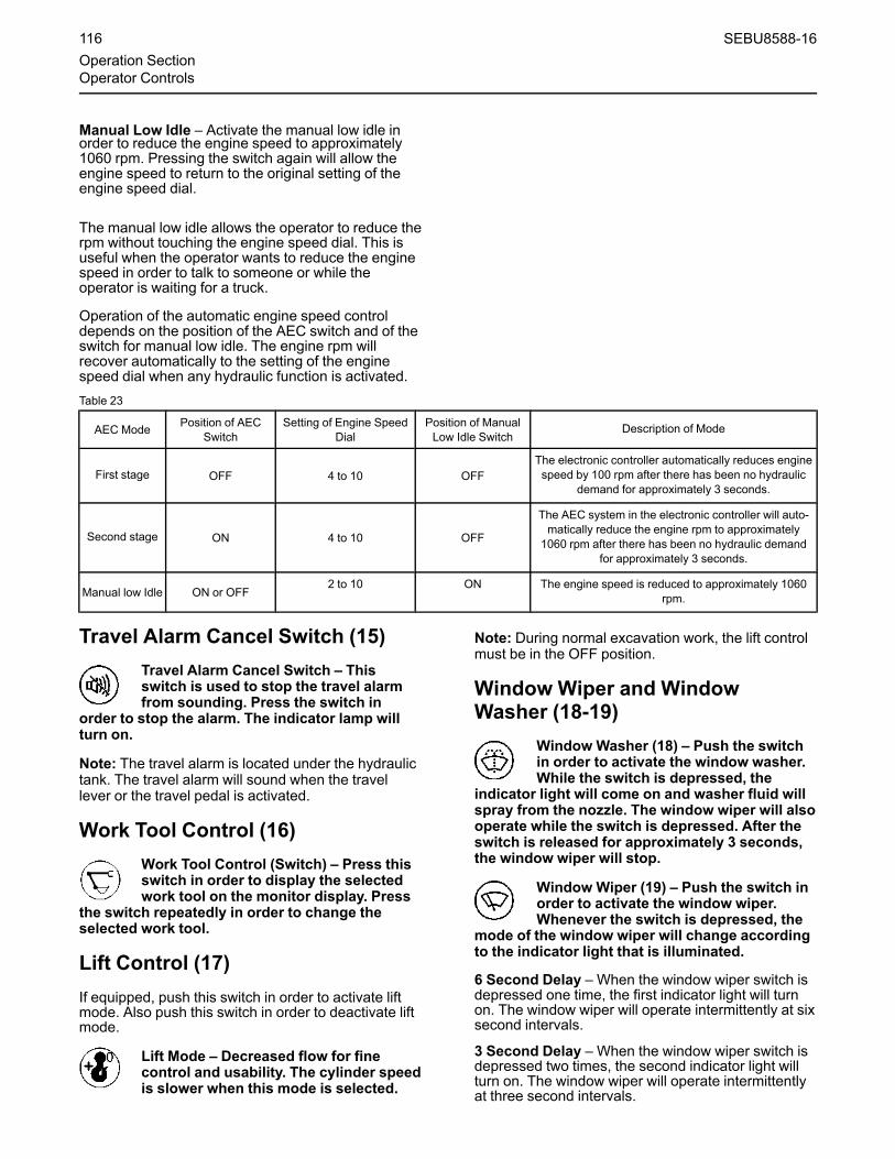
Manual Low Idle – Activate the manual low idle inorder to reduce the engine speed to approximately1060 rpm. Pressing the switch again will allow theengine speed to return to the original setting of theengine speed dial.
The manual low idle allows the operator to reduce therpm without touching the engine speed dial. This isuseful when the operator wants to reduce the enginespeed in order to talk to someone or while theoperator is waiting for a truck.
Operation of the automatic engine speed controldepends on the position of the AEC switch and of theswitch for manual low idle. The engine rpm willrecover automatically to the setting of the enginespeed dial when any hydraulic function is activated.Table 23
AEC Mode Position of AECSwitch
Setting of Engine SpeedDial
Position of ManualLow Idle Switch
Description of Mode
First stage OFF 4 to 10 OFFThe electronic controller automatically reduces enginespeed by 100 rpm after there has been no hydraulic
demand for approximately 3 seconds.
Second stage ON 4 to 10 OFF
The AEC system in the electronic controller will auto-matically reduce the engine rpm to approximately1060 rpm after there has been no hydraulic demand
for approximately 3 seconds.
Manual low Idle ON or OFF2 to 10 ON The engine speed is reduced to approximately 1060
rpm.
Travel Alarm Cancel Switch (15)Travel Alarm Cancel Switch – Thisswitch is used to stop the travel alarmfrom sounding. Press the switch in
order to stop the alarm. The indicator lamp willturn on.
Note: The travel alarm is located under the hydraulictank. The travel alarm will sound when the travellever or the travel pedal is activated.
Work Tool Control (16)Work Tool Control (Switch) – Press thisswitch in order to display the selectedwork tool on the monitor display. Press
the switch repeatedly in order to change theselected work tool.
Lift Control (17)If equipped, push this switch in order to activate liftmode. Also push this switch in order to deactivate liftmode.
Lift Mode – Decreased flow for finecontrol and usability. The cylinder speedis slower when this mode is selected.
Note: During normal excavation work, the lift controlmust be in the OFF position.
Window Wiper and WindowWasher (18-19)
Window Washer (18) – Push the switchin order to activate the window washer.While the switch is depressed, the
indicator light will come on and washer fluid willspray from the nozzle. The window wiper will alsooperate while the switch is depressed. After theswitch is released for approximately 3 seconds,the window wiper will stop.
Window Wiper (19) – Push the switch inorder to activate the window wiper.Whenever the switch is depressed, the
mode of the window wiper will change accordingto the indicator light that is illuminated.
6 Second Delay – When the window wiper switch isdepressed one time, the first indicator light will turnon. The window wiper will operate intermittently at sixsecond intervals.
3 Second Delay – When the window wiper switch isdepressed two times, the second indicator light willturn on. The window wiper will operate intermittentlyat three second intervals.
116 SEBU8588-16Operation SectionOperator Controls

Continuous Operation – When the window wiperswitch is depressed three times, the first indicatorlight and the second indicator light will turn on. Thewindow wiper will operate continuously.
OFF – When the window wiper switch is depressedfour times, the indicator lights will turn off. Thewindow wiper stops.
NOTICEIf the wiper does not operate with the switch in theON position, turn the switch off immediately. Checkthe cause. If the switch remains on, motor failure canresult.
NOTICEIf the washer is used continuously for more than 20seconds or used when no washer solution comesout, motor failure can result.
Light Switch (20)
Illustration 155 g02049516
Illustration 156 g02049520
Light Switch – Push the switch in orderto turn on the work lights.
Whenever you push the switch, you change thepattern of the work lights that are turned on. Theindicator lights in the cab indicate the pattern of thework lights.
Pattern 1 – When you press the light switch once,the first indicator light turns on. When the firstindicator light is on, the following work lights areturned on: work light (D), which is mounted on thechassis, and work lights (F), which are mounted onthe cab.
Pattern 2 – When you press the light switch twice,the first indicator light and the second indicator lightturn on. When the first indicator light and the secondindicator lights are on, the following work lights areturned on: work light (D), which is mounted on thechassis, work lights (F), which are mounted on thecab and work lights (E), which are mounted on theboom.
OFF – When both of the indicator lights are off, all ofthe work lights are off.
Note: Your machine may be equipped with a lightingsystem that has a time delay. When this system isinstalled, cab lights (F) and boom lights (E) will notturn off for a predetermined amount of time after theengine start key has been turned to the OFF position.The time delay can vary from 0 minutes to 5 minutes.For further details, consult your Cat dealer.
Rear/Side View Camera (21)Rear/Side View Camera – If equipped,push this switch in order to toggle theimages that are shown on the monitor in
the cab. For more information, refer to Operationand Maintenance Manual, “Monitoring System”.
Quick Coupler Control (22)Hydraulic Pin Grabber Quick Coupler
If equipped, the switch for the quick coupler control islocated on the right console.
LOCKED – Move the switch to thisposition in order to engage the quickcoupler onto the work tool.
UNLOCKED – Move the switch for thequick coupler to the UNLOCKEDposition in order to extend the wedge.
Use this position only during the coupling oruncoupling of the work tool. The hydraulicsystem is pressurized when the switch is in thisposition.
SEBU8588-16 117Operation SectionOperator Controls

Note: An alarm will sound whenever the switch is inthe UNLOCKED or LOCKED position.
For further details, see Operation and MaintenanceManual, “Quick Coupler Operation”.
Quick Coupler
LOCKED – Move the switch to thisposition in order to retract the wedgeand engage the quick coupler onto the
work tool
UNLOCKED – Move the switch for thequick coupler to the UNLOCKEDposition in order to extend the wedge.
Use this position only during the coupling oruncoupling of the work tool. The hydraulicsystem is pressurized when the switch is in thisposition.
Note: An alarm will sound whenever the switch is inthe UNLOCKED or LOCKED position.
For further details, see Operation and MaintenanceManual, “Quick Coupler Operation”.
Cat Regeneration System (CRS)Aftertreatment Switch (23)
Force Regeneration – Push in the top ofthe switch for 2 seconds in order tobegin a manual regeneration. An ““Active
Regen””message will be displayed on the monitorindicating that DPF regeneration cycle is inoperation.
Disable Regeneration – Push in thebottom of the switch for 2 seconds inorder to deactivate automatic
regeneration and/or stop an active DPFregeneration cycle. A ““Regen Disabled””messagewill be displayed on the monitor.
Note: In order to re-enable auto regeneration, cyclethe engine start switch to OFF and back to ON.
For more information, refer to Operation andMaintenance Manual, “Diesel Particulate FilterRegeneration”.
Crane Auto Stop Cancel Switch(24A)
Crane Auto Stop Cancel – If equipped,press and hold this switch in order toturn off the crane auto stop function.
Radio Mute Switch (24B)Radio Mute Switch – If equipped, pressthe switch in order to mute the radio.The indicator lamp will turn on.
Lower Window Wiper (25A) (IfEquipped)
Lower Window Wiper (25B) – Push downon the top of the switch in order to turnon the lower window wiper. Push down
the bottom portion of the switch in order to turnoff the lower window wiper.
NOTICEIf the wiper does not operate with the switch in theON position, turn the switch off immediately. Checkthe cause. If the switch remains on, motor failure canresult.
Platform Light (25B) (If Equipped)Platform Light – Press the switch inorder to turn on the platform light whichis installed at the rear of the cab.
Lower Window Washer (26) (IfEquipped
Lower Window Washer (26) – Pushdown on the top of the switch and keepthe switch depressed in order to
activate the lower window washer. While theswitch is depressed, the washer fluid will sprayfrom the nozzle.
118 SEBU8588-16Operation SectionOperator Controls

NOTICEIf the washer is used continuously for more than 20seconds or used when no washer solution comesout, motor failure can result.
Boom Pressure Control (27A)Boom Pressure Control – If equipped,press the switch in order to turn on theboom control pressure function. The
boom pressure control function improvescontrollability for low load operation such asraking up rocks by reducing vibration and shock.
SmartBoom Control (27B)SmartBoom Control – This machinemay be equipped with SmartBoomControl. For more information, refer to
Operation and Maintenance Manual, “SmartBoomControl”.
Fine Swing Control (27C)
The Fine Swing Control delays the engagementof the swing parking brake.
If the machine is operating on a slope with theFine Swing Control in the ON position, the swingmotion may become uncontrollable which couldresult in property damage, personal injury ordeath.
Turn the Fine Swing Control to the OFF positionwhen the machine is operating on a slope.
Fine Swing Control – If equipped, pushdown on the top of the switch in order toactivate the fine swing control.
When the fine swing control is ON, the swing parkingbrake is released. Swing control improves duringdeceleration of a swing because the swing is allowedto drift instead of stopping abruptly.
Push down on the bottom of the switch in order toturn off the fine swing control. Operate the machinewith the fine swing control in the OFF position whenthe machine is on a slope. Operate the machine withthe fine swing control in the OFF position when greatswing forces are required. For example, digging on asidewall requires great swing force. Operate themachine with the fine swing control in the OFFposition in order to control the motion with the swingbrake.
Overload Warning Device (28)If equipped, the switch for the overload warningdevice is located on the right console.
Overload Warning Device – In liftingapplications, the overload warningdevice activates a buzzer when there is
an unstable load condition. When the buzzersounds, the bucket load should be reduced or thestick should be moved inward.
ON – Push the right side of the switch inorder to activate the overload warningdevice.
OFF – Push the left side of the switch inorder to deactivate the overload warningdevice.
Service Port
Illustration 157 g03320855
Electronic Technician service port
An Electronic Technician (ET) service port is locatedinside the cab behind the seat. This service portallows service personnel to connect a laptopcomputer that is equipped with Electronic Technician.Service personnel can use electronic technician inorder to diagnose machine and engine systems.
SEBU8588-16 119Operation SectionOperator Controls

Contact your Cat dealer for additional information.
i05621751
Battery Disconnect SwitchSMCS Code: 1411-B11
Illustration 158 g03569314
The battery disconnect switch is on the left side of themachine behind the rear access door.
Illustration 159 g00406959
ON – To activate the electrical system,insert the disconnect switch key andturn the battery disconnect switch
clockwise. The battery disconnect switch mustbe turned to the ON position before you start theengine.
OFF – To deactivate the electricalsystem, turn the battery disconnectswitch counterclockwise to the OFF
position.
The battery disconnect switch and the engine startswitch perform different functions. The entireelectrical system is disabled when you turn thebattery disconnect switch to the OFF position. Thebattery remains connected to the electrical systemwhen you turn the engine start switch to the OFFposition.
Turn the battery disconnect switch to the OFFposition and remove the key when you service theelectrical system or any other machine components.
Illustration 160 g03382729
NOTICEDo not turn off the battery disconnect switch until theindicator lamp has turned off. If the switch is turnedoff when the indicator lamp is illuminated the DieselExhaust Fluid (DEF) system will not purge the DEF. Ifthe DEF does not purge, DEF could freeze and dam-age the pump and lines.
NOTICENever move the battery disconnect switch to the OFFposition while the engine is operating. Serious dam-age to the electrical system could result.
120 SEBU8588-16Operation SectionBattery Disconnect Switch

i05151989
Product Link(Product Link Japan)SMCS Code: 7490; 7606
NOTICEVehicles equipped with Product Link Japan areequipped with wireless devices that use public wire-less radio waves. Be sure to read and understand thefollowing precautions for use of this system.
Product Link Japan uses public wireless networksand cannot be used in areas where radio wave can-not be received.
A machine may become inoperable if the antennaand corresponding equipment are removed or dam-aged. If the antenna or corresponding equipmentneed to be removed, consult with your Cat dealer.
Persons with an implantable cardiac pacemaker orimplantable defibrillator must not approach within22 cm (8 inch) of the antenna that is installed at therear of an operator seat as such devices can be neg-atively affected by the radio waves.
Electronic devices can be negatively affected by ra-dio waves. If electronic devices are used near thissystem, consult the manufacturer of the electronicdevice regarding the affects of radio waves onoperation.
This system consumes power even when the enginestart switch is turned "OFF". If storing a machine foran extended period, make sure that the battery is fullycharged and turn the power disconnect switch toOFF.
Your machine may be equipped with the Cat ®Product Link Japan system.
The Product Link Japan system is a remotemanagement system in which machine information isautomatically transmitted from a machine to acustomers office.
Illustration 161 g03317923
(A) Machine (equipped with Product Link Japan)(B) Wireless network(C) Product Link Japan Center Sever(D) Internet(E) Customers computer or similar device(F) Cat dealer computer or similar device
For machines equipped with a wireless device theProduct Link Japan system will send information fromthe machine to the Product Link Japan Center. Thetransmitted information can then be monitoredthrough the Caterpillar website using a computer orsimilar device that is connected to the Internet.
Below is a list of items that can be monitored with theProduct Link Japan system.Table 24
Product Link Japan Functions
OperatingInformation
Location information (latitude/longitude)
Accumulated operating time
Operating status by time period
(continued)
SEBU8588-16 121Operation Section
Product Link

(Table 24, contd)
Fuel level
MaintenanceInformation
Engine coolant
Engine oil
Hydraulic oil
Travel drive oil
Swing drive oil
Water separator (primary fuel filter)
Secondary fuel filter
Fuel pump screen filter
Fuel tank cap
Engine oil filter
Pilot filter
Drain filter
Return filter
Attachment filter
Blowby gas filter
Ignition plug
WarningsStarting restrictions/Area warnings
Other warnings
StartingRestrictions
Date conditions
Day of the week conditions
Time conditions
Area conditions
Product Link Japan can also be used to specify andapply machine starting restrictions by using apersonal computer or similar device that is connectedto the Internet. Starting restrictions will prevent theengine from being started in accordance with thespecified conditions. See your Cat dealer foradditional information.
A “Security System Operating”message will appearon the monitor when a starting restriction hasprevented the engine from being started.
Note: Starting restrictions can be temporarilycanceled. Notify your site manager for moreinformation or contact your Cat dealer.
Note: A machine may become inoperable if theantenna and corresponding equipment are removedor damaged. Contact your Cat dealer if startingrestrictions have been applied when startingrestrictions have not been specified.
i08001446
Product LinkSMCS Code: 7490; 7606
Note: Your machine may be equipped with the Cat ®Product Link™ system.
The Cat Product Link communication device utilizescellular and/or satellite technology to communicateequipment information. This information iscommunicated to Caterpillar, Cat dealers, andCaterpillar customers. The Cat Product Linkcommunication device uses Global PositioningSystem (GPS) satellite receivers.
The capability of two-way communication betweenthe equipment and a remote user is available with theCat Product Link communication device. The remoteuser can be a dealer or a customer.
Data BroadcastsData concerning this machine, the condition of themachine, and the operation of the machine is beingtransmitted by Cat Product Link to Caterpillar and/orCat dealers. The data is used to serve the customerbetter and to improve upon Cat products andservices. The information transmitted may include:machine serial number, machine location, andoperational data, including but not limited to: faultcodes, emissions data, fuel usage, service meterhours, software, and hardware version numbers andinstalled attachments.
Caterpillar and/or Cat dealers may use thisinformation for various purposes. Refer to thefollowing list for possible uses:
• Providing services to the customer and/or themachine
• Checking or maintaining Cat Product Linkequipment
• Monitoring the health of the machine orperformance
• Helping maintain the machine and/or improve theefficiency of the machine
• Evaluating or improving Cat products andservices
• Complying with legal requirements and valid courtorders
• Performing market research
• Offering the customer new products and services
122 SEBU8588-16Operation SectionProduct Link

Caterpillar may share some or all the collectedinformation with Caterpillar affiliated companies,dealers, and authorized representatives. Caterpillarwill not sell or rent collected information to any otherthird party and will exercise reasonable efforts tokeep the information secure. Caterpillar recognizesand respects customer privacy. For more information,please contact your local Cat dealer.
Operation in a Blast Site forProduct Link Radios
This equipment is equipped with a Cat® ProductLink communication device. When electric deto-nators are being used for blasting operations, ra-dio frequency devices can cause interferencewith electric detonators for blasting operationswhich can result in serious injury or death. TheProduct Link communication device should bedeactivated within the distance mandated underall applicable national or local regulatory require-ments. In the absence of any regulatory require-ments Caterpillar recommends the end userperform their own risk assessment to determinesafe operating distance.
Refer to your products Operation and MaintenanceManual Supplement, “Regulatory ComplianceInformation” for more information.
For information regarding the methods to disable theCat Product Link communication device, please referto your specific Cat Product Link manual listed below:
• Operation and Maintenance Manual, SEBU8142, “Product Link - PL121, PL321, PL522, and PL523”
• Operation and Maintenance Manual, SEBU8832, “Product Link PLE702, PLE602, PLE601, PL641,PL631, PL542, PL240, PL241, PL243, PL141,PL131, PL161, PL083 and PL042 Systems”
Note: If no radio disable switch is installed and theequipment will be operating near a blast zone, aProduct Link radio disable switch may be installed onthe equipment. The switch will allow the Cat ProductLink communication device to be shut off by theoperator from the equipment control panel. For moredetails and installation procedures, refer to thefollowing:
• Special Instruction, REHS7339, “InstallationProcedure for Product Link PLE640 Systems”
• Special Instruction, REHS8850, “InstallationProcedure for the Elite Product Link PLE601,PLE641, and PLE631 Systems”
• Special Instruction, SEHS0377, “InstallationProcedure for the Product Link PL131, PL141,and PL161 Systems”
• Special Instruction, REHS9111, “InstallationProcedure for the Pro Product Link PL641 andPL631 Systems”
• Special Instruction, M0098124, “InstallationProcedure for Pro Product Link PL243 Systems”
• Special Instruction, M0109130, “InstallationProcedure for Product Link PL683 and PL783Systems”
i02793352
Power Receptacle(If Equipped)SMCS Code: 1436; 7451
Illustration 162 g01073919
Power Receptacle – A twelve volt power receptacleis located on the right side console. This powerreceptacle can be used for powering automotiveelectrical equipment or accessories. Remove the capbefore use. This machine can be equipped with onepower receptacle or with two power receptacles.
i07037877
Machine Security System(If Equipped)SMCS Code: 7631
Operation Section
NOTICEThis machine is equipped with a Caterpillar MachineSecurity System (MSS) and may not start under cer-tain conditions. Read the following information andknow your machine's settings. Your Caterpillar dealercan identify your machine settings.
SEBU8588-16 123Operation SectionPower Receptacle

Machine Security System (MSS) –Machines that are equipped with aCaterpillar Machine Security System
(MSS) can be identified by a decal in the operatorstation. The MSS is a theft deterrent and willprevent the unauthorized operation of themachine.
Basic OperationMSS may be programmed to use a standardCaterpillar key or an electronic key. The electronickey contains an electronic chip within the plastichousing for the key. Each key emits a unique signalto the MSS. The keys can be identified by a grayhousing or a yellow housing. MSS may haveprogrammed settings that require an electronic keyfor starting during certain periods of time. The MSSmay also have programmed settings that allow astandard Caterpillar key to start the machine duringcertain periods of time.
Note: Ensure that you have only one electronickey near the engine start switch when you areattempting to start the machine. If there is morethan one electronic key near the engine startswitch the MSS may not be able to read the key inthe engine start switch and the machine will notstart.
When the engine start switch is turned to the ONposition, the ECM will read the unique ID that isstored in the electronic key. The ECM will thencompare this ID to the list of authorized keys. Thestatus of the key will be displayed on the monitor. Ifthe key is not authorized for the machine,“UNAUTHORIZED KEY” will be displayed on themonitor.
Note:MSS will not shut down the machine after themachine has started.
Security ManagementMSS allows you to program the system toautomatically activate at different time periods withdifferent keys. The MSS can also be programmed toreject a specific electronic key after a selected dateand time. When you turn the key to the OFF positionand the MSS is active, you have a 30 second intervalto restart the machine. Also if the machine stalls,there is a 30 second interval for restarting themachine. This 30 second interval is counted from thetime of turning the key to the OFF position.
Note: Know your machine's settings because the useof an electronic key is no guarantee that the machinecan be restarted.
An expiration date can be set for each electronic keythat is contained in the list of keys for the machine.The key will no longer start the machine when theinternal clock in the security system passes theexpiration date. Each entry in the list of keys canhave a different expiration date.
Spare keys are available from your dealer. Before akey can operate the machine, the MSS must be setto accept that particular key. Contact your Caterpillardealer for information on additional features of theMSS.
Regulatory Compliance Section
Illustration 163 g00832427
Consult your Caterpillar Dealer with any questionsthat concern the operation of the MSS in a specificcountry.
124 SEBU8588-16Operation SectionIf Equipped

Illustration 164 g00822256
i06649948
CameraSMCS Code: 7347; 7348
Your machine may be equipped with two types ofcameras.
Rear View Camera (If Equipped)The rear view camera system consists of a camerathat is located in the middle of the top of thecounterweight and a “VIDEO MODE SETTING”menu on the monitor.
Note: The rear view camera system has been set upby the factory or by a Caterpillar dealer in order toprovide views which comply with specifiedguidelines. Consult your Caterpillar dealer before anyadjustments are made to the system.
For more information refer to Operation andMaintenance Manual, “Monitoring System”.
Side View Camera (If Equipped)The side view camera system consists of a camerathat is located on the top of the fuel tank and a“VIDEO MODE SETTING”menu on the monitor.
Note: The side view camera system has been set upby the factory or by a Cat dealer in order to provideviews which comply with specified machine right sideview. Consult your Cat dealer before any adjustmentsare made to the system.
For more information refer to Operation andMaintenance Manual, “Monitoring System”.
Work Area Vision System (WAVS)(If Equipped)Operation
WAVS is a closed circuit video monitoring system.WAVS consists of a 178 mm (7 inch) LCD displayand a camera. The display is mounted in the machinecab.
Power is supplied to the system when the operatorturns the engine start switch to the ON position. Thepower ON/OFF button that is on the display isdisabled.
The camera lens and the display screen will requireperiodic cleaning. Cleaning instructions for thecamera lens and the display are described in theMaintenance section.
Automatic Mode
The single camera system is only available with theautomatic mode. The single camera system can beplaced in “Standby” .
Note: If the single camera system can be placed inmanual mode, notify service personnel.
WAVS will automatically display the camera viewwhich is based on current machine operation and theconfiguration of WAVS. For example, WAVS may beconfigured to display a side view from a side-mounted camera.
SEBU8588-16 125Operation Section
Camera

Camera
Illustration 165 g01223051
WAVS camera
The orientation of the camera is set duringinstallation. After installation, there should be noneed to make any physical adjustments to any of thecameras under normal operating conditions. WAVSuses a fixed-focused camera that has been installedat the factory, a Caterpillar dealer, or a qualifiedtechnician.
Display
Keypad
Illustration 166 g01291176
(A) Camera Selection Button (multiple cameras only)(B) Automatic Brightness(C) Standby Function(D) Contrast Button(E) Brightness Button(F) Decrease Adjustment Button(G) Increase Adjustment Button(H) Power Button (disabled)(I) Camera Select LED Lights (multiple cameras only)(J) Button Status LED Lights(K) Light Sensor
Adjustment
The following selections for the WAVS display can bechanged by the operator.
126 SEBU8588-16Operation SectionCamera

Table 25
Display Button Operation for single camera system
Operation Procedure Notes
Brightness Adjustment Press button (E) in order to enable the “Bright-ness Adjustment” . Then press either button(F) or (G) in order to adjust the brightness.
Press any other display button in order to exitbrightness adjustment mode.
Contrast Adjustment Press button (D) in order to enable the Con-trast Adjustment. Then press either button (6)or (7) in order to adjust the contrast level.
Press any other display button in order to exitthe adjustment for the contrast.
Automatic Brightness ON/OFF Press button (B) in order to turn the automaticbrightness ON/OFF.
When WAVS is placed in the “AutomaticBrightness”mode, the display will illuminate orthe display will dim automatically as the ambi-ent light increases or decreases.The set point for the brightness can bechanged by the operator. Turn the auto bright-ness on, and adjust the brightness to the de-sired level in order to change the starting setpoint.
Standby ON/OFF Press button (C) in order to turn the standbyON/OFF.
Standby may be useful at night, when the dis-play is not desired.If the standby mode is on, the display will re-main dark until a WAVS input is detected, how-ever, the power and standby LED shouldremain on.
LED Indicators
If LED for button (H) and the LED (I) for the camera flash together, the image will turn off because the ambient temperature is below −25 °C(−13°F) or above 70 °C (158 °F).
Marker Line
Illustration 167 g01291431
Display screen with marker line
The marker line option provides a green horizontalline on the display. The marker line can be configuredby a Caterpillar technician. The marker linerepresents a fixed distance from the machine. Themarker line is not adjustable by the operator.
Mounting Position
In order to adjust the position of the display , performthe following steps:
1. Hold the display securely and loosen the mountingclamp handle.
2. Adjust the display to the desired position.
3. Tighten the mounting clamp handle.
Note: Do not adjust the display in a position thatwould cause any of the following:
• Cover any warning films or other importantinformation.
• Restrict access and exit procedures for themachine.
• Obstruct the operator's outside view.
• Obstruct the operator's view of instrumentation.
• Restrict the operation of any controls.
SEBU8588-16 127Operation Section
Camera

For more information about the WAVS system, referto Operation and Maintenance Manual, SEBU8157,“Work Area Vision System”.
i06648776
Monitoring SystemSMCS Code: 7451; 7490
NOTICEWhen the monitor provides a warning, immediatelycheck the monitor and perform the required action ormaintenance as indicated by the monitor.
The monitor indicator does not guarantee that themachine is in a good condition. Do not use the moni-tor panel as the only method of inspection. Mainte-nance and inspection of the machine must beperformed on a regular basis. See the MaintenanceSection of this Operation and Maintenance Manual.
Illustration 168 g03510903
(1) Alert Lamp(2) Clock bar(3) Gauges Area(4) Camera View(5) Warning Display area(6) Multi-information area(7) Keypad
Action Lamp (1)This action lamp illuminates in order to show that aproblem has occurred with the machine. The actionlamp will flash red when a level 2 warning or level 3warning is active.
Clock Bar (2)
Illustration 169 g03510998
Clock(2A) – The clock function displays the currenttime.
Service Hour Meter (2B) – This indicatorshows the total operating hours of theengine. Use the display to determine the
service hour maintenance intervals.
Fuel Consumption Rate (2B) – Thisindicator shows the rate of fuelconsumption.
Fuel Remain Time (2B) – This indicator shows thefuel remaining time.
““ECONOMY MODE SELECTED”” (2C) –The economy power mode has beenselected.
High Hydraulic Power Mode – Thisindicator shows that the machine is setto operate in the high hydraulic power
mode.
Throttle Dial (2D)
The throttle indicator shows the current position ofthe throttle dial on the right side panel.
Active Tool (2E)
128 SEBU8588-16Operation SectionMonitoring System
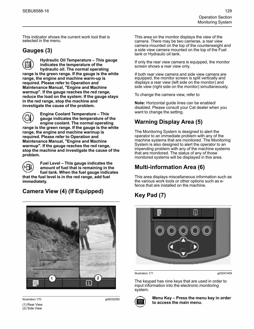
This indicator shows the current work tool that isselected in the menu.
Gauges (3)Hydraulic Oil Temperature – This gaugeindicates the temperature of thehydraulic oil. The normal operating
range is the green range. If the gauge is the whiterange, the engine and machine warm-up isrequired. Please refer to Operation andMaintenance Manual, "Engine and Machinewarmup". If the gauge reaches the red range,reduce the load on the system. If the gauge staysin the red range, stop the machine andinvestigate the cause of the problem.
Engine Coolant Temperature – Thisgauge indicates the temperature of theengine coolant. The normal operating
range is the green range. If the gauge is the whiterange, the engine and machine warmup isrequired. Please refer to Operation andMaintenance Manual, "Engine and Machinewarmup". If the gauge reaches the red range,stop the machine and investigate the cause of theproblem.
Fuel Level – This gauge indicates theamount of fuel that is remaining in thefuel tank. When the fuel gauge indicates
that the fuel level is in the red range, add fuelimmediately.
Camera View (4) (If Equipped)
Illustration 170 g06032090
(1) Rear View(2) Side View
This area on the monitor displays the view of thecamera. There may be two cameras, a rear viewcamera mounted on the top of the counterweight anda side view camera mounted on the top of the Fueltank or Hydraulic oil tank.
If only the rear view camera is equipped, the monitorscreen shows a rear view only.
If both rear view camera and side view camera areequipped, the monitor screen is split vertically anddisplays a rear view (left side on the monitor) andside view (right side on the monitor) simultaneously.
To change the camera view, refer to
Note: Horizontal guide lines can be enabled/disabled. Please consult your Cat dealer when youwant to change the setting.
Warning Display Area (5)The Monitoring System is designed to alert theoperator to an immediate problem with any of themachine systems that are monitored. The MonitoringSystem is also designed to alert the operator to animpending problem with any of the machine systemsthat are monitored. The status of any of thosemonitored systems will be displayed in this area.
Multi-information Area (6)This area displays miscellaneous information such asthe various work tools or other options such as e-fence that are installed on the machine.
Key Pad (7)
Illustration 171 g03547409
The keypad has nine keys that are used in order toinput information into the electronic monitoringsystem.
Menu Key – Press the menu key in orderto access the main menu.
SEBU8588-16 129Operation SectionMonitoring System

Home Key – Press the home key in orderto return to the default display at anytime.
Enter Key – Press the enter key in orderto confirm an entry.
Screen Cycle Key – Press the screencycle key in order to cycle the differentscreen views.
OK Key – Press the OK key in order toselect a menu option. Also press the OKkey in order to set values.
Reset Key – Press the reset key in orderto set all counters back to zero.
Back Key – Press the back key in orderto reject a menu option or a settingvalue. Also, press the back key in order
to return to the previous display.
Up Key – Press the up key in order tomove the cursor upward. Also press theup key in order to increase values.
Down Key – Press the down key in orderto move the cursor downward. Alsopress the down key in order to decrease
values.
Left Key – Press the left key in order tomove the cursor to the left. Also pressthe left key in order to decrease values.
Right Key – Press the right key in orderto move the cursor to the right. Alsopress the right key in order to increase
values.
Illustration 172 g03294460
Soft switch panel
Note: The soft switch panel on the right side of thecab can also be used to input numerical values intothe monitor.
Gain/Response ControlThe Gain/Response function can change thecontrollability of the joysticks in order to match themachine to a particular task. In order to enable ordisable the Gain/Response function, Flip the Gain/Response switch.
Illustration 173 g03514819
The Operator may select 1 of the following Gain/Response modes:
• Normal
• Soft
• Quick
Press the Gain key (7B) in order to change the Gaintype to Normal / Soft / Quick.
Note: The Gain/Response setting (7A) can becontinuously displayed on the monitor.
130 SEBU8588-16Operation SectionMonitoring System

Illustration 174 g03512217
Normal
Illustration 175 g03514801
Soft
Illustration 176 g03514778
Quick
Soft – Push the Gain/Response keyonce on the monitor in order to selectthe soft mode. This mode slows down
the movements of the boom, stick, work tool, andswing.
Quick – Push the Gain/Response keytwice on the monitor in order to selectthe quick mode. This mode reduces the
range of fine control of the joysticks.
Consult your Cat dealer in order to change thepresets of the Gain/Response modes.
Prestart Monitoring FunctionTurn the engine start switch to the ON position.
After approximately one second, Caterpillar appearsin the display and the action lamp turns on.
The pattern for the joystick controls is indicated in thebottom of the display for 3 seconds.
The coolant temperature, the fuel level, and theposition of the engine speed dial are now indicated.
The monitoring system checks the level of the enginecoolant, and the engine oil before the engine starts.
If the fluid level check detects a low fluid level, theappropriate message will be displayed. A pictographwill be shown to indicate the fluid level that is low.
Note: The service hours for the filters are checked.The service hours for the fluids are also checked. If afilter or a fluid is over the recommended changeinterval, “CHECK Service Parts INFO” appears onthe display. Refer to filter and fluid Informationlocated this Operation and Maintenance Manual formore information. This message will disappear after5 seconds.
Note: If more than one fluid level is low, the symbolsfor the right key and the left key are indicated in thebottom right area of warning message. Press theright key or the left key in order to check the otherwarning message. The low fluid level indicators willdisappear within 5 seconds after the engine isstarted.
Note: The machine cannot perform an accurate fluidlevel check when the machine is on a slope. Performthe fluid level check on level ground.
If the engine is started during the fluid level check,the monitor will cancel these checks.
Machine WarningsNote: All of the warnings that are listed may not beapplicable to all machine models.
The monitoring system provides three warningcategories.
• The first warning category requires only operatorawareness. This type of warning will be indicatedby a message on the display screen.
SEBU8588-16 131Operation SectionMonitoring System

• The second warning category requires a changeto the machine operation or a change to themaintenance of the machine. This type of warningwill be indicated by a message on the displayscreen and by a blinking of the Action Lamp.
• The third warning category requires immediateshutdown of the engine. This type of warning willbe indicated by a message on the display screen,by a blinking of the Action Lamp, and by a buzzer.
If multiple warnings are present in the system, themost important problem is shown first. Press the rightkey or press the left key in order to view all of thewarnings that are present in the machine. If no keysare pressed within 5 seconds, the display will returnto the most important problem.
Note: The menu is still functional by pressing themenu key.
Warning Category 1
In this category, only a warning will be shown in thedisplay screen. This category alerts the operator thatthe machine system needs attention. Failure of thesesystems will not endanger the operator. Failure ofthese systems will not damage the machinecomponents.
Note: The warnings that are listed may not beapplicable to all machine models.
““ENGINE FAULT CHECK ENGINE”” – Anabnormality has been detected in theengine. Stop the engine and contact
your Cat dealer.
““ENGINE OVER SPEED WARNING”” –The engine speed is too fast. Changethe operating technique. If the situation
continues, contact your Caterpillar Dealer.
““ENGINE SHUTDOWN ACTIVE”” – Anerror has occurred with the engine andthe engine is shutting down. Contact
your Cat Dealer.
““ENGINE SHUTDOWN IDLE TIMEEXCEEDED”” – The engine is stopped byengine idle shutdown function. Machine
shutdown such as air conditioner is pending.Turn the engine start key to the OFF position.
““1st FUEL FILTER PLUGGED”” – Stop theengine and change the 1st filter(primary).
““2nd FUEL FILTER PLUGGED”” – Stopthe engine and change the 2nd filter(main filter).
““FUEL PRESSURE HIGH”” – The fuelpressure is too high. Contact your CatDealer.
““Fuel Pressure Low”” – The fuel pressureis very low. Stop the engine and contactyour Caterpillar dealer
““INTAKE AIR FILTER PLUGGED”” – Theair filter is restricted. Engine output willbe decreased. Immediately inspect the
air filter. Clean the air filter. Inspect the conditionof the air filter. Replace the air filter, if necessary.Perform any necessary repairs. Refer toOperation and Maintenance Manual, “Engine AirFilter Primary Element - Clean/Replace”.
Machine Security – Contact yourCaterpillar Dealer.
Security Pending – Contact yourCaterpillar Dealer or change machinelocation to communicate via GPS/GSM.
““WATER SEPARATOR FULL”” – The waterseparator is full. Drain the water fromthe water separator as soon as possible.
Refer to Operation and Maintenance Manual,“Fuel System Water Separator - Drain”.
Warning Category 2
Note: The warnings that are listed may not beapplicable to all machine models.
1st Fuel Filter Power Derate – Stop theengine and change the 1st filter (primaryfilter) immediately.
2nd Fuel Filter Power Derate – Stop theengine and change the 2nd filter (mainfilter) immediately.
““ATTACHMENT FILTER PLUGGED”” –The hydraulic filter is restricted.Restriction of the filter will cause
hydraulic components to malfunction. Turn theengine start switch to the OFF position and thenturn the engine start switch to the ON position. Ifthe warning disappears, the filter is good.Operate the machine on flat ground for at least 10minutes. If the warning reappears, replace thefilter.
““BATTERY VOLTAGE IRREGULAR”” –The electrical charging system ismalfunctioning. Check the electrical
components of the charging circuit immediately.Perform any necessary repairs.
132 SEBU8588-16Operation SectionMonitoring System

““COOLANT TEMP POWER DERATE”” –The coolant temperature is too high. Theengine will derate until the coolant
temperature decreases to the correct level. If thewarning stays on during low idle, stop the engineand inspect the cooling system. Perform anynecessary repairs as soon as possible.
““CYCLE THE LOCK LEVER”” – An errorhas occurred with the lock lever. Cyclethe lock lever.
““ENGINE FAULT CHECK ENGINE”” – Anabnormality has been detected in theengine. Stop the engine and contact
your Cat dealer.
““ENGINE OIL PRESS LOW”” – The engineoil pressure is low. Stop the machineand check the engine oil level. If the
engine has started in the cold ambient, warm upthe machine properly. If the error disappears afterwarm-up, there is no engine oil pressure trouble.
““ENGINE SHUTDOWN PENDING”” – Theengine idle function will shut down theengine in 20 seconds. Operator can
cancel the shutdown by pressing a button on themonitor or move one of the controls.
““FUEL LEVEL LOW”” – The fuel in thetank is low on fuel. Refill the fuel tank.
““HYD OIL TEMP HIGH (TOOL)”” – Thehydraulic oil temperature is too high.Stop operating the machine and run the
engine at low idle until the hydraulic oiltemperature decreases to the correct level. If thewarning stays on during low idle, stop theengine. Check the hydraulic oil level and checkthe hydraulic oil cooler for debris. Perform anynecessary repairs as soon as possible.
““HYD OIL TEMP POWER DERATE”” – Thehydraulic oil temperature is too high.The engine will derate until the hydraulic
oil temperature decreases to the correct level. Ifthe warning stays on during low idle, stop theengine. Check the hydraulic oil level and checkthe hydraulic oil cooler for debris. Perform anynecessary repairs as soon as possible.
““HYD RETURN FLTR PLUGGED”” – Thehydraulic return filter is restricted.Restriction of the filter will cause
hydraulic components to malfunction. Turn theengine start switch to the OFF position and thenturn the engine start switch to the ON position. Ifthe warning disappears, the filter is good.Operate the machine on flat ground for at least 10minutes. If the warning reappears, replace thereturn filter cartridge. Refer to Operation andMaintenance Manual, “Hydraulic System Oil Filter(Return) - Replace”.
““Lever is Not Neutral”” – The lever is notin the NEUTRAL position.
““LIFT OVERLOAD WARNING”” – The loadon the machine is too heavy. Themachine is in danger of tipping. Reduce
the load immediately. Refer to Operation andMaintenance Manual, “Lifting Capacities” formore information.
Reverse Fan Error – An error hasoccurred while the reverse fan isoperating. Another warning should
appear. This other warning will indicate a specificcause. Check this warning and take appropriateaction. If the problem cannot be resolved. Stopthe engine and contact your Caterpillar Dealer.
““SECURITY SYSTEM ACTIVE”” – Thismachine is equipped with a MachineSecurity System. The key that is
currently in the ignition switch is not anauthorized key. Remove the key and insert anauthorized key.
““SERVICE REQUIRED”” – The machinehas detected a malfunction. Contactyour Caterpillar Dealer.
““TOOL CONTROL MALFUNCTION”” – Thework tool has malfunctioned. Stop themachine and inspect the work tool.
““WATER SEPARATOR FULL”” – The waterseparator is full. Drain the water fromthe water separator as soon as possible.
Refer to Operation and Maintenance Manual,“Fuel System Water Separator - Drain”.
Warning Category 3
Note: The warnings that are listed may not beapplicable to all machine models.
SEBU8588-16 133Operation SectionMonitoring System

““COOLANT TEMP HIGH”” – The coolanttemperature is too high. Stop the engineimmediately. Check the coolant level
and check the radiator for debris. Refer toOperation and Maintenance Manual, “CoolingSystem Coolant Level - Check”. Check the fandrive belts for the water pump. Refer to Operationand Maintenance Manual, “Belts - Inspect/Adjust/Replace”. Make any necessary repairs.
““COUNTERWEIGHT REMOVAL”” – Thecounterweight has been removed. Donot operate the machine until the
counterweight has been reinstalled.
““ENGINE FAULT SHUTDOWN SAFELY”” –An abnormality has been detected in theengine. Stop the engine immediately.
Contact your Cat dealer.
““ENGINE OIL PRESSURE POWERDERATE”” – The engine will derate untilthe engine oil pressure is at the correct
level. If the warning stays on during low idle, stopthe engine and check the engine oil level.Perform any necessary repairs as soon aspossible.
““HYD OIL TEMP HIGH”” – The hydraulicoil temperature is too high. Stop theengine. Check the hydraulic oil level and
check the hydraulic oil cooler for debris. Performany necessary repairs as soon as possible.
““INLETAIR TEMP POWER DERATE”” –Inlet air temperature exceeds threshold.Engine speed is restricted. Stop the
engine. Determine the cause of the fault andperform any necessary repairs.
““LIFT OVERLOAD WARNING”” – The loadon the machine is too heavy. Themachine is in danger of tipping. Reduce
the load immediately. Refer to Operation andMaintenance Manual, “Lifting Capacities” formore information.
““QUICK COUPLER UNLOCK”” – Thequick coupler is not locked. Lock thequick couple before operating the
machine.
““SERVICE REQUIRED”” – The machinehas detected a malfunction. Contactyour Caterpillar Dealer.
““WATER SEPARATOR FULL”” – The waterseparator is full. Drain the water fromthe water separator as soon as possible.
Refer to Operation and Maintenance Manual,“Fuel System Water Separator - Drain”.
Other MessagesPrestart
Note: The warnings that are listed may not beapplicable to all machine models.
CHECK SERVICE PARTS INFORMATION– One of the machines filters hasexceeded the recommended change
interval. Replace the filter and reset the hours forthe filter..
““COOLANT LEVEL LOW”” – The coolantlevel is too low. Stop the machineimmediately. Stop the engine and
investigate the cause of the fault.
““ENG OIL LEVEL LOW”” – The engine oillevel is too low. Stop the machineimmediately. Stop the engine and
investigate the cause of the fault.
““FASTEN SEAT BELT”” – Fasten yourseat belt.
Miscellaneous
Note: The warnings that are listed may not beapplicable to all machine models.
““ECONOMY MODE SELECTED”” – Theeconomy power mode has beenselected.
““HIGH POWER MODE SELECTED”” – Thehigh-power mode has been selected.
““POWER MODE LOCKING”” – Powermode has been locked through thepower mode setting menu. Refer to this
Operation and Maintenance Manual, “MonitoringSystem”
““QUICK COUPLER LOCKING”” – Thequick coupler is locking. See thisOperation and Maintenance Manual,
“Quick Coupler Control”
““REVERSE FAN STARTING”” – Thereverse fan is currently operating. Donot operate the machine until the
reverse fan has stopped.
134 SEBU8588-16Operation SectionMonitoring System

““VERIFY TOOL LOCKING”” – The quickcouple has been locked. Verify that thequick coupler is securely fixed to the
work tool.
““WARM-UP MODE POWER DERATE”” – Ifthe joysticks are held for more than 30seconds, the machine ECM will go into
the warm-up mode power derate setting. Themachine ECM limits the hydraulic pump torque to50 percent. Release the joysticks in order tocancel this setting. Refer to Operation andMaintenance Manual, “Engine and MachineWarm-Up”.
Main MenuThe “Main Menu” allows the operator to viewinformation concerning the machine. This menu alsoallows the operator to change information concerningthe machine.
1. Push the menu key when the default display isactive.
Table 26
““Main Menu””
“Maintenance Intervals”
2. The “Main Menu” will be displayed with menuoptions that are installed on the machine. Thenumber of choices can vary. For more informationon these menus, refer to the respectivedescriptions below.
3. Press the right key or the left key in order tohighlight the desired menu. Press the OK key inorder to open the desired menu.
Note: Press the back key or the home key in order toexit this menu and return to the default display.
Display SettingThe “Display Setting”menu allows the operator tochange the various display settings of the monitor.
1. Press the menu key.
Table 27
““Main Menu””
“Display Setting”
2. Press any of the arrow keys in order to highlightthe “Display Setting”menu. Press the OK key.
Table 28
““Display Setting””
“Clock Adjust”
3. The “Display Setting”menu will be displayed withfour new menu options. For more information onthese menus, refer to the respective descriptionsbelow.
4. Press any of the arrow keys in order to highlightthe desired menu. Press the OK key in order toopen the desired menu.
Note: Press the home key in order to return to thedefault display.
Adjusting the Clock
The “Clock Adjust”menu allows the operator tochange the time on the clock.
1. Press any of the arrow keys in order to highlightthe “Clock Adjust” menu. Press the OK key.
SEBU8588-16 135Operation SectionMonitoring System

Table 29
““Display Setting””
“Clock Adjust”
2. The “Clock Adjust”menu will be displayed with thecurrent time. Press the left arrow key or the rightarrow key in order to select the hour or the minute.Press the OK key.
Table 30
““Clock Adjust””
12 : 00
3. The hours or the minutes will be highlighted. Pressthe up arrow key in order to increase the value.Press the down arrow key in order to decrease thevalue.
4.When the clock is set to the desired time, press theOK key in order to save the new time in memory.
Note: Press the back key in order to return to theprevious display without saving.
Note: Press the home key in order to return to thedefault display.
Adjusting the Brightness
The “Brightness Adjust” menu allows the operator tochange the brightness of the monitor.
1. Press any of the arrow keys in order to highlightthe “Brightness Adjust” menu. Press the OK key.
Note: There are two brightness settings. The firstsetting is used for machine operation during the day.The second setting is used for machine operation atnight.
Table 31
““Display Setting””
“Brightness Adjust”
2. Press the up arrow key or the down arrow key inorder to select the “Day” setting or the “Night”setting. Press the OK key.
Table 32
““Brightness Adjust””
“Day”8
“Night”3
3. Press the right key in order to increase thebrightness. Press the left key in order to decreasethe brightness. The brightness can be set between1 and 10.
Note: Press the home key in order to return to thedefault display.
Display Unit Select
The “Display Unit Select” menu allows the operator tochange the display units.
1. Press any of the arrow keys in order to highlightthe “Display Unit Select” menu. Press the OK key.
136 SEBU8588-16Operation SectionMonitoring System

Table 33
““Display Setting””
“Display Unit Select”
2. Press the up arrow key or the down arrow key inorder to select the “Metric” setting or the “Imperial”setting. Press the OK key.
Table 34
““Display Unit Select””
“Metric”
“English”
3. Press the “Back” key in order to return to theprevious screen or press the “Home” key in orderto return to the main menu.
Default Screen PresetThe “Default Screen Preset” menu allows theoperator to change the default screen image whenthe monitor is turned on.
Note: This menu function is only available when themachine is equipped with a rear view camera.
Illustration 177 g03512276
(Pattern A) Camera view is not displayed, and gauges displayed inlarge view.
(Pattern B) Gauges and camera view displayed simultaneously.Pattern B is the default display if the rear view camera isequipped on the machine.
(Pattern C) Gauges are not displayed. Large view of rear viewcamera.
(Pattern D) Camera view displayed on full monitor screen. Anywarnings or events will default to Pattern B.
1. Press any of the arrow keys in order to highlightthe “Default Screen Setting” menu. Press the OKkey.
Table 35
““Display Setting””
“Default Screen Setting”
2. Press the up arrow key or the down arrow key inorder to select the default screen type. Press theOK key in order to enter the edit mode.
Note: Default screen #1 is preset at the factory andcannot be changed.
Table 36
““Default Screen Setting””
(continued)
SEBU8588-16 137Operation SectionMonitoring System

(Table 36, contd)
“Default Screen Type#1”
“Default Screen Type#2”
“Default Screen Type#3”
3. Press the up arrow key or the down arrow key inorder to select the default screen type. Press theOK key in order to highlight default screen type.Press the up arrow key or the down arrow key inorder to set the display pattern.
Note: Press the monitor view key in order to previewthe selected default screen.
4. Press the OK key in order to store the pattern thatwas selected.
5. Press the “Back” key in order to return to theprevious screen or press the “Home” key in orderto return to the main menu.
Language SelectionThe “Language Select”menu allows the operator tochange the language settings.
1. Press the menu key.Table 37
““Main Menu””
“Language Select”
2. Press any of the arrow keys in order to highlightthe “Language Select” menu. Press the OK key.
Table 38
““Language Select””
“ENGLISH”
“DANISH”
“FINNISH”
“ICELANDIC”
“NORWEGIAN”
“SWEDISH”
3. The “Language Select”menu will be displayed witha list of available languages. Press the up key orthe down key in order to scroll through theavailable languages. Press the OK key in order toselect the desired language.
Note: Press the home key in order to return to thedefault display.
PerformanceThe “Performance” menu allows the operator to viewmeasurements of various system components. Thefollowing components are a few examples of thecomponents that can be viewed through the“Performance” menu: battery voltage, engine speedand pump pressure.
1. Press the menu key.Table 39
““Main Menu””
“Performance”
2. Press the right key or the left key in order tohighlight the “Performance” menu. Press the OKkey.
Table 40
““Performance””
(continued)
138 SEBU8588-16Operation SectionMonitoring System

(Table 40, contd)
“Battery Voltage”
“26.0 [V]”
“Engine Speed”
“1300 [RPM]”
“Engine Coolant Temp”
“20 [°C]”
3. The “Performance” menu will be displayed with alist of system components and measurements.Press the up key or the down key in order to scrollthrough the list.
Note: Press the home key in order to return to thedefault display.
Power Mode SettingThe “Power Mode Setting” menu allows the operatorto change the various operating power modes.
Note: The mode(s) that are set to "Enabled" throughthis procedure can only be activated by the "PowerMode" switch on the right side control panel. Formore information, refer to Operation andMaintenance Manual "Operator Controls".
1. Press the menu key.Table 41
““Main Menu””
“Power Mode Setting”
2. Press any of the arrow keys in order to highlightthe “Power Mode Setting”menu. Press the OKkey.
3. You will be prompted to enter a password. After thepassword has been entered successfully, the“Power Mode Setting” menu will be displayed.
Note:When the machine leaves the factory, thepassword is initially set at 1.
Table 42
““Password Entry””
“Enter your password”
1 2 3 4 5
6 7 8 9 0
4. Press the up key or the down key in order tohighlight the desired setting. Press the OK key inorder to confirm the desired selection.
Note: Due to country-specific fuel consumptioncriteria, your machine may not be equipped with allPower Mode options.
Table 43
““Power Mode Setting””
“Standard PowerMode”
“Economy Mode”
Note: Press the home key in order to return to thedefault display.
Controllability SettingTable 44
““Main Menu””
“Controllability Setting”
(continued)
SEBU8588-16 139Operation SectionMonitoring System

(Table 44, contd)
Boom Swing PriorityTable 45
““Controllability Setting””
“Boom SwingPriority”
Boom Swing Priority – This feature allows you toadjust the flow balance with each actuator. If youwant the swing faster and the boom slower, select ahigh "Swing Priority #". If you want the boom upfaster and the swing slower, select a high "BoomPriority #".
Maintenance IntervalsThe “Maintenance Intervals” menu allows theoperator to view the current hours of use and therecommended change intervals for various systemcomponents.
1. Press the menu key.Table 46
““Main Menu””
“Maintenance Intervals”
2. Press any of the arrow keys in order to highlightthe “Maintenance Intervals” menu. Press the OKkey.
Table 47
““Maintenance Intervals””
“Engine Coolantr”“100 / 12000 [HR]”
“Engine Oil”“100 / 500 [HR]”
“Hydraulic Oil”“100 / 2000 [HR]”
3. A list of system components will be displayed.Press the up key or the down key in order to scrollthrough the list. For each of the systemcomponents, the current hours of use will bedisplayed. If the component has a recommendedchange interval, the recommended interval will bedisplayed.
4. Press the reset key in order to reset themaintenance hours.
Note: Press the home key in order to return to thedefault display.
Selecting the Work ToolThe “Work Tool Select” menu allows the operator tochange the settings for the work tool.
Note: Make sure that the hydraulic lockout control isin the LOCKED position before you change thesettings for the work tool.
Note: If a bucket is installed on the machine, or nowork tool is installed, select “Bucket/No Tool” in themenu.
1. Press the menu key.Table 48
““Main Menu””
“Work tool Select”
(continued)
140 SEBU8588-16Operation SectionMonitoring System

(Table 48, contd)
2. Press any of the arrow keys in order to highlightthe “Work Tool Select” menu. Press the OK key.
Table 49
““Work tool Select””
“Bucket / No Tool”
“Hammer”MKB 1500V
“Shear”MP-20
3. Press the up key or the down key in order tohighlight the “Work Tool Select” menu. Press theOK key.
Note: If the work tools have been configured throughthe Electronic Technician (ET), the names of the worktools will be displayed instead of the numbers.
4. The “Work Tools Select” menu will be displayedwith the current options for work tools. Press theup key or the down key in order to highlight thedesired work tool. Press the OK key in order toselect the new work tool.
Note: Press the home key in order to return to thedefault display.
Current TotalsThe “Current Totals”menu allows the operator toview the current totals for the machines systems.
1. Press the menu key.Table 50
““MAIN MENU””
“Current Totals”
(continued)
(Table 50, contd)
2. Press any of the arrow keys in order to highlightthe “Current Totals”menu. Press the OK key.
Table 51
““Current Totals””
“Total OperatingHours”
“12345.6 [hr]”
“Engine”“12345.6 [hr]”
“Hydraulic Pump”“12345.6 [hr]”
3. A list of system components will be displayed.Press the up key or the down key in order to scrollthrough the list.
Note: Press the home key in order to return to thedefault display.
Changing the PasswordThe “PASSWORD CHANGE”menu allows theoperator to change the password.
Note:When the machine leaves the factory, thepassword is initially set at 1.
1. Press the menu key.Table 52
““MAIN MENU””
“Password Change”
(continued)
SEBU8588-16 141Operation SectionMonitoring System
(Table 52, contd)
2. Press any of the arrow keys in order to highlightthe “Password Change” menu. Press the OK key.
Note: You will be prompted to enter a password.
Table 53
““Password Change””
“Enter your password”
1 2 3 4 5
6 7 8 9 0
3. After the password has been entered successfully,the “Enter new password” screen will appear.
Table 54
““Password Change””
“Enter new password”
1 2 3 4 5
6 7 8 9 0
4. Press any of the arrow keys in order to select thedesired character.
Note: The password is numeric. You may choosefrom “0” to “9” .
5. Press the OK key in order to enter the character.
Note: Press the back key in order to delete the lastcharacter that was entered.
6. After you enter the password, you will be asked toconfirm your selection. Press the “ENTER” key inorder to save the password in memory and returnto the “Main Menu” screen. Press the back key inorder to return to the “Password Change” menuwithout saving the password.
Note: Press the home key in order to return to thedefault display.
Joystick Control PatternThe “Controls Setup”menu allows the operator tochange the settings for the joystick pattern.
Note: Before the joystick pattern is changed, park themachine on a firm level surface, lower the work toolto the ground, and place the hydraulic lockout controlin the LOCKED position.
1. Press the menu key.Table 55
““Main Menu””
“Controls Setup”
2. Press the arrow keys in order to scroll through themenu in order to find the “Controls Setup” menu.Highlight the “Controls Setup”menu and press theOK key.
Note: You will be prompted to enter a password.When the machine leaves the factory, the passwordis initially set at 1.
Table 56
““Controls Setup””
“SAE/JIS”
“MHI”
“KOB”
“Former SCM”
(continued)
142 SEBU8588-16Operation SectionMonitoring System

(Table 56, contd)
3. The “Controls Setup”menu will be displayed withthe current options for joystick patterns. Press theup key or the down key in order to highlight thedesired joystick pattern. Press the OK key in orderto select the new joystick pattern.
Note: Press the home key in order to return to thedefault display.
Password EntryWhen you try to access certain menus, you will beprompted to enter a password. Follow this procedurein order to enter the password.Table 57
PASSWORD
“ENTER PASSWORD”
_ _ _ _
“< B C D E F 0 1 2 3 4 5 >”
1. Press the right key or the left key in order to selectthe desired character.
Note: The password is alphanumeric. You maychoose from “0” to “9” . You may also choose from“A” to “F” .
Note:When the machine leaves the factory, thepassword is initially set as 0001.
2. Press the OK key in order to enter the character.
Note: Press the back key in order to delete the lastcharacter that was entered.
3. After you enter 4 characters, the monitoringsystem checks the password. If the password iscorrect, you will have access to the menu.
Table 58
PASSWORD
“ENTER PASSWORD”
(continued)
(Table 58, contd)
* * * *
INVALID PASSWORD
4. If the password is incorrect, “INVALIDPASSWORD” will be displayed. Press the OK keyin order to retry the password or press the backkey in order to return to the previous menu.
Note: Consult your Caterpillar dealer if you forgetyour password.
Reverse Fan SettingNote: Make sure that the hydraulic lockout control isin the LOCKED position before you activate thereverse fan function.
The “REVERSE FAN SETTING”menu allows theoperator to set the reverse fan duration time.
Note: The reverse fan function is an optionalattachment which may not be equipped on yourmachine.
1. Press the menu key.Table 59
MAIN MENU
Reverse Fan Setting
2. Press the right key or the left key in order tohighlight the “Reverse Fan Setting” menu. Pressthe OK key.
Note: You will be prompted to enter a password.Refer to “Password Entry” for information on enteringa password.
SEBU8588-16 143Operation SectionMonitoring System

Table 60
Password Entry
Enter Your Password
“#-#-#-#”
3. After the password has been entered successfully,highlight the “Reverse Fan”menu. Press the OKkey.
Table 61
REVERSE FAN
Step 1 : Set Duration Time
Read Screen
Note:Make sure that the hydraulic lockout control isin the LOCKED position before you activate thereverse fan function.Table 62
REVERSE FAN
Step 2: Complete
4. The monitor should now indicate that the reversefan function is “Complete” in active mode.
Note: The reverse fan function will automatically stopwhen the fan has completed a cycle. However, thereverse fan function can be stopped manually bypressing the left key.
5. Press the home key in order to return to the defaultdisplay.
Error Messages for the Reverse FanTable 63
REVERSE FAN
ERROR
“-HYD OIL TEMP HIGH”
Typical example of an error message for the reversefan function
Reverse Fan Function Will Not Start
The monitor will provide one of the following errormessages if the reverse fan function does not start:
““NOT INSTALLED”” – The reverse fan is not installedon this machine. If this message is received in error,consult your Caterpillar dealer.
““HYD OIL TEMP HIGH”” – The hydraulic oiltemperature is too high. Shut off the engine and donot operate the machine until the hydraulic oiltemperature is below 85 °C (185 °F).
““COOLANT TEMP HIGH”” – The coolant temperatureis too high. Shut off the engine and do not operatethe machine until the coolant temperature is below95 °C (203 °F).
““HYD LOCK SW OFF”” – The hydraulic lockoutcontrol is in the UNLOCKED position. Move thehydraulic lockout control to the LOCKED position.
““SOL MALFUNCTION”” – The reverse fan ismalfunctioning. Consult your Caterpillar dealer.
Table 64
REVERSE FAN
Error
“Error ID : $0002”
Error ID : $0003
Error ID : $0004
(continued)
144 SEBU8588-16Operation SectionMonitoring System

(Table 64, contd)
Error ID : $0005
Reverse Fan Function Is Interrupted
If one of the following conditions occur, the reversefan function will stop, and regular operation of theradiator cooling fan will resume:
• The hydraulic lockout control is moved to theUNLOCKED position.
• The temperature of the hydraulic oil rises above90 °C (194 °F).
• The coolant temperature rises above 100 °C(212 °F).
This event will be accompanied by a “REVERSE FANERROR”message.
Controllability SettingTable 65
““Main Menu””
“Controllability Setting”
Boom Swing PriorityTable 66
““Controllability Setting””
“Boom SwingPriority”
Boom Swing Priority – This feature allows you toadjust the flow balance with each actuator. If youwant the swing faster and the boom slower, select ahigh "Swing Priority #". If you want the boom upfaster and the swing slower, select a high "BoomPriority #".
i06260804
Production MeasurementApplicationSMCS Code: 7490; 7494
S/N: EBF10001–Up
S/N: XWL1–Up
S/N: DNM10001–UpWhen enabled, the Cat Production MeasurementApplication provides production information to theoperator and owner.
The Cat Production Measurement Application iscomposed of a monitoring system that tracks anddisplays payload data. The Application also includesa reporting system that uses collected payload data,along with fuel usage and machine operation profiles,in order to generate production values.
Payload data can be viewed on the monitor display.
The following information is a brief overview of thebasic functions of the Cat Production MeasurementApplication:
• Monitor Display
• Cat Production Measurement Menu Screen
• Joystick Controls
• Basic Operation
• Work Monitor
• Preparing the System
Consult your Cat dealer in order to enable, or disable,the Cat Production Measurement Application.
Note: Complete the following Cat Grade Controlsettings before using the Cat ProductionMeasurement Application:
• Machine dimension - Configure, except for bucket
• Bucket Measure-up
Reference: System Operation/Testing and Adjusting,UENR1725, “Cat Grade Control Depth and Slope forE-Series and F-Series Excavators”.
SEBU8588-16 145Operation Section
Production Measurement Application

Monitor DisplayNote: For additional information regarding themonitor display, refer to Operation and MaintenanceManual, “Monitoring System”
The monitor display is the primary interface betweenthe operator and the Cat Production MeasurementApplication. The display is used for the followingpurposes:
• Display bucket payload, bucket count, truckpayload, truck count, weigh status, truck status,and remaining payload.
• Enter target payload
• Edit and select a pre-loaded truck ID.
• Display system messages to the operator
Press the pattern change key until the ProductionMeasurement screen appears on the monitor.
Illustration 178 g06032618
Typical example of the Production Measurementscreen(1) Key Pad(2) Function Key Buttons(3) Function Keys(4) Cat Production Measurement Information Bar
Key Pad (1)
The keypad has four keys that are used in order tomove and input information into the electronicmonitoring system.
Up Key – Press the up key in order tomove the cursor upward. Also press theup key in order to increase values.
Down Key – Press the down key in orderto move the cursor downward. Alsopress the down key in order to decrease
values.
Left Key – Press the left key in order tomove the cursor to the left. Also pressthe left key in order to decrease values.
Right Key – Press the right key in orderto move the cursor to the right. Alsopress the right key in order to increase
values.
Function Key Buttons (2)
There are five function key buttons located above thekey pad. These buttons allow you to select a functionthat is displayed in the function key area. Inorder toselect a function that is displayed in the function keyarea, press the corresponding function key buttonlocated directly below the function key item.
Function Keys (3)
This area displays the functions that are availablewithin a menu. Press the corresponding function keybutton in order to select the function.
Function keys specific to the Cat ProductionMeasurement application are listed below:
Pattern Change Key – Press the patternchange key in order to cycle throughdifferent function key patterns.
Standby/Weigh Key – Press the standby/weigh key in order to cycle betweenstandby and weigh modes.
Site Configuration Key – Press the siteconfiguration key in order to go to thesite configuration menu.
Truck Store Key – Press the truck storekey in order to store and saveinformation. Truck payload and bucket
count values will be cleared for the next truck.
Truck Cancel Key – Press the truckcancel key in order to clear informationfor a loaded truck. Truck Payload,
Remaining Payload, Bucket Pass, and BucketPayload values will be cleared. Truck Count valuewill remain the same.
Bucket Cancel Key – Press the bucketcancel key in order to subtract theprevious bucket payload value from the
current truck payload value. A bucket pass willalso be subtracted from the bucket count value.
146 SEBU8588-16Operation SectionProduction Measurement Application

Bucket Recall Key – Press the bucketrecall key in order to add the previousbucket payload value to the current
truck payload value. A bucket pass will also beadded to the bucket count value.
Bucket Zero Key – Press the BucketZero Key in order to go to the ““BucketZero Adjustment””menu. The ““Bucket
Zero Adjustment””menu is used to Bucket zerothe current bucket weight.
Reset Key – Press the reset key in orderto reset the work monitor information.The reset key is found on the ““Work
Monitor””menu.
Erase Key – Press the erase key in orderto erase the data stored in the systemmemory.
Tool Dimension – Press the tooldimension key in order to advance tothe tool dimension menu.
Note: Tool dimension is shown when the bucket isselected only
Bucket Measure-up – Press the bucketmeasure-up key in order to advance tothe bucket measure-up menu. The
bucket measure-up key is found on the ““WorkTool Select””menu.
Calibration – Press the calibration key inorder to advance to the calibrationmenu. The calibration key is found on
the ““Work Tool Select””menu.
Press the pattern change key until the desiredfunction symbol appears on the monitor. Refer toIllustration 179
Key pattern 3 and 4 appear when CGC function isenabled.
Illustration 179 g06026442
(1) CPM1 (CAT Production Measurement 1)(2) CPM2 (CAT Production Measurement 2)(3) Standard Display(4) CGC1 (CAT Grade Control 1)(5) CGC2 (CAT Grade Control 2)
Status Bar (4)
Illustration 180 g06026479
Typical example of the Cat Production MeasurementStatus Bar
(6) Cat Grade Control Linkage Elevation MonitorStatus – See Operation and Maintenance Manual,SEBU8358, “Cat Grade Control Depth & Slope for E-Series and F-Series Excavators”
(7) Truck Payload – Displays the weight of materialthat has been added to the truck total.
(8) Bucket Payload – Displays the weight of materialcurrently in the bucket.
(9) Weigh Status – Displays the bucket payloadweigh status and the accuracy of the weigh.
SEBU8588-16 147Operation Section
Production Measurement Application

(10) Truck Count – Displays the number of trucksthat have been loaded.
(11) Truck Status – Displays the load status of thetruck payload.
(12) Remaining Payload – Displays the remainingweight needed to reach the target payload for thetruck.
(13) Bucket Count – Displays the number of bucketsloaded to truck.
Warning MessagesNote: The warning message can be enabled ordisabled within the “Reweigh Warning” menu. The“Reweigh Warning” menu is accessed through the“Operating Mode” menu.
Note: Refer to Operation and Maintenance Manual,“Monitoring System” for more information aboutwarning categories.
Warning Category 1
““Weigh Calibration Required”” –Calibration has not performedaccurately. Perform accurate calibration.
““Inaccurate Weigh”” – Displayed payloadmay not be accurate. Reweigh byreoperating Lift-Swing.
This message instructs the operator to reweigh theprevious bucket. This message is displayedimmediately after the bucket has been weighed. Thismessage is displayed when the application detectsan error in the process of the lift.
““Inaccurate Weigh Boom Too High”” –Displayed payload may not be accurate.Reweigh by reoperating Lift-Swing with
suitable position.
Boom angle is greater than the maximum limits.Make sure that the boom angle is smaller than thelimit. Swing the loaded bucket again.
““Inaccurate Weigh Stick Too Close”” –Displayed payload may not be accurate.Reweigh by reoperating Lift-Swing with
suitable position.
Stick angle is smaller than the minimum limits. Makesure that the angle of the stick is greater than thelimits. Swing the loaded bucket again.
““Inaccurate Weigh Bucket Too Curl”” –Displayed payload may not be accurate.Reweigh by reoperating Lift-Swing with
suitable position.
Illustration 181 g06089643
The bucket angle in relation to the ground is greaterthan 40 degrees. Adjust the bucket angle to less than40 degrees against the ground. Swing the loadedbucket again. (Refer to Illustration 181 ).
““Inaccurate Weigh Bucket Too Open”” –Displayed payload may not be accurate.Reweigh by reoperating Lift-Swing with
suitable position.
The bucket angle in relation to the ground is less then-40 degrees. Adjust the bucket angle to greater than-40 degrees against the ground. Swing the loadedbucket again. (Refer to Illustration 181 ).
““Inaccurate Weigh Ground Unstable”” –Displayed payload may not be accurate.Reweigh by reoperating Lift-Swing with
suitable position.
The machine is operating on unstable ground.Reposition the machine or adjust the area under themachine (if possible). Swing the loaded bucket again.
Inaccurate Weigh Ground Too Tilt –Displayed payload may not be accurate.Reweigh by reoperating Lift-Swing with
suitable position.
The machine is operating on a slope that is greaterthan 10 degrees. Reposition the machine or adjustthe area under the machine (if possible). Swing theloaded bucket again.
““Inaccurate Weigh Swing Not Smooth”” –Displayed payload may not be accurate.Reweigh by reoperating Lift-Swing.
148 SEBU8588-16Operation SectionProduction Measurement Application

The duration of the swing was not long enough interms of time without slowing below 5 degrees persecond. Swing the loaded bucket at a slower speedor larger swing angle without triggering bucket dumpconditions. The swing time must exceed 2.4 secondswith the bucket in a carry position.
““Inaccurate Weigh Swing Too Short”” –Displayed payload may not be accurate.Reweigh by reoperating Lift-Swing.
Swing operation duration is less than 2.4 seconds.The swing operation duration must exceed 2.4seconds. Swing the loaded bucket again.
““Inaccurate Weigh Swing Too Slow”” –Displayed payload may not be accurate.Reweigh by reoperating Lift-Swing.
Swing speed is slower than 5 degrees per second.The swing speed must exceed 5 degrees persecond. Swing the loaded bucket again.
““Do Not Tilt Bucket During Weigh”” –Displayed payload may not be accuratewhen the bucket is tilted during
weighing. Reweigh by reoperating Lift-Swingwithout tilting the bucket.
This message is shown when "Tilt Bucket" is selectedon "Work Tool Select" menu.
Warning Category 2
““Check Sensor”” – This indicatesProduction Measurement Monitoringmalfunction is detected.
““Truck Overload”” – Exceeded the trucktarget payload. Finish the loading to thetruck. Press ““Truck Store”” to reset
current truck. Load the payload into the lastbucket to new truck.
““Water Separator Power Derate”” – Thewater separator is full. Drain the waterfrom the water separator as soon as
possible. Refer to Operation and MaintenanceManual, “Fuel System Water Separator - Drain”.
Miscellaneous
““Cycle Data Transferring”” – Transferringthe Cycle Data to USB Memory. Cycletimer will stop recording.
““Weigh Calibration Recommend”” –Calibration Recommended Interval isexceeded. Perform accurate calibration.
““Bucket Zero Recommend”” – ZeroCalibration Recommended Interval isexceeded. Perform accurate Zero
calibration.
““Cycle Data Transfer Required”” –Memory for Production MeasurementMonitoring is full, old data is deleted
automatically. Transfer the data to USB memory,and then delete all data.
““Cycle Data Transfer Recommend”” –Remaining memory for ProductionMeasurement Monitoring is low.
Transfer the data to USB memory, and then deleteall data.
““Reach Truck Target”” – The Truck targetpayload has been reached. Finish theloading to the truck. Press ““Truck Store””
to reset current truck.
““Last 1 Pass for Target”” – Will reach theTruck target payload by next bucketpass.
Cat Production MeasurementMenu ScreenNote: For additional information regarding themonitoring system menu screens, refer to Operationand Maintenance Manual, “Monitoring System”
SEBU8588-16 149Operation Section
Production Measurement Application

Illustration 182 g03819780
Main Menu
The “Production Measurement” screen is found onthe “Main Menu” of the monitoring system.
Illustration 183 g03819720
“Production Measurement”Menu
The following menus are available in the “ProductionMeasurement” menu:
(14) Work Monitor – See “Work Monitor”
(15) Operating Mode – See “Operating Mode”
(16) Sound Setup – See “Sound Setup”
(17) Site Configuration – See “Site Configuration”
(18) Truck List – See “Select an ID Configuration”
Joystick Controls (If Enabled)If enabled, the Cat Production MeasurementApplication is also capable of receiving inputs fromthe joystick controls.
150 SEBU8588-16Operation SectionProduction Measurement Application

Illustration 184 g06090035
(A) Left Joystick(B) Right Joystick(19) Weigh/Standby(20) Trigger (not visible)(21) Target Payload(22) Truck Store
The function of the joystick control buttons can beenabled/disabled by navigating through the followingmenus (and settings) of the operator monitor
Refer to the Illustration 185 and 186 when navigatingthe menus:
Illustration 185 g06090093
(23) Service(24) Production Measurement
Illustration 186 g06090104
(25) CPM Setting(26) Remote Switch (Payload)
If enabled, the following functions can be performedusing the joystick controls with pressing and holdingthe trigger button (20) on Left Joystick (A).
Standby/Weigh – When the Standby/Weigh key isavailable, press button (19) on the left joystick inorder to cycle between standby and weigh modes.
Target Payload – When the Standby/Weigh key isavailable, move thumb wheel (21) on the rightjoystick in order to adjust the target payload.
Truck Store – When the truck store key is available,press button (22) on the right joystick in order to storeand save information for a loaded truck. Truckpayload and bucket count values will be cleared forthe next truck.
Note: The “Standby/Weigh” and “Truck Store”functions can also be performed using the functionkeys when function “CPM 1” is selected. Refer to“Function Keys (3)”.
The “Target Payload” can also be adjusted with themonitor keypad. Refer to “Truck Payload andRemaining Truck Payload”
Basic OperationThe following is a brief review of the basic operationof the Cat Production Measurement Applicationincluding the following:
• Standby and Weigh Modes
• Weigh Bucket Payload
SEBU8588-16 151Operation Section
Production Measurement Application

• Evaluate Bucket Payload Accuracy
• Bucket Count
• Truck Payload and Remaining Payload
• Evaluate Truck Status
• Truck Store
• Truck Cancel
• Bucket Cancel
• Bucket Recall
• Bucket Zero
Standby and Weigh Modes
The Cat Production Measurement Application hastwo operating modes:
Standby Mode – When in standby mode, the bucketpayloads are still visible but will not transfer to thetruck. The truck weights that were displayed whenthe system was placed into standby are retained untilthe system is placed back into weigh mode. StandbyMode should be used for non-productive work.
Note: The system will automatically switch tostandby mode when an error is detected.
Weigh Mode – In this mode, a weight will beobtained after completing a steady lift through theweigh range. Weigh Mode should be used forproductive work.
To change between weigh and standby modes,select the “Standby/Weigh” function key on themonitor, or select the “Standby/Weigh” button locatedon left joystick (if enabled).
Note: The Cat Production Measurement Applicationmust be calibrated for the weigh mode to function. Ifnot already calibrated, consult your local Cat dealer.
Weigh Bucket Payload
In order to obtain an accurate weigh of the bucketpayload, observe the following:
• Ensure that the machine is not operating on aslope greater than 10 degrees.
• Ensure that the bucket is clean and free ofmaterial before loading.
• Ensure that the swing is smooth (not too slow ornot too fast).
• Maintain continuous swing
• Ensure that the bucket payload is not too low
• Ensure that the boom and stick are operatedwithin the certain range. Refer to illustration 187 .
• Ensure that the swing range is large enough toperform a weigh.
1. Ensure that the Cat Production MeasurementApplication is in the “Weigh Mode” .
2. Proceed to load the bucket with material.
3. Lift the bucket through the weigh range.
Note: Maintain consistent, smooth lift and swingspeed through the weigh range.
4. The system will start to weigh the payload as soonas swing starts. A weigh status indicator willilluminate on the status bar while the bucketpayload is being determined.
Evaluate Bucket Payload Accuracy
“Weigh Status” indicator (9), located on the statusbar, displays the accuracy of the bucket payload.
Estimated Payload – A BLACK squarewith the weigh symbol will illuminate onthe status bar while the bucket payload
is being determined or when a scaled payloadhas not been determined.
Scaled Payload Obtained – A GREENsquare with the weigh symbol willilluminate on the status bar when a
scaled payload has been obtained.
Scaled Payload Complete – A GREENsquare will be displayed when the truckhas been loaded with a scaled payload.
If enabled, an alarm may also sound. The statuswill remain until the next weigh operation.
Estimated Weigh Complete – A BLACKsquare will be displayed when the truckhas been loaded with an Estimated
payload. The status will remain until the nextweigh operation.
Once a payload weight has been obtained, the valueon the status bar display will remain until any of thefollowing conditions occur:
• A new “Bucket Payload” is obtained
• Truck Store is selected
• Standby is selected
• Truck Cancel is selected
152 SEBU8588-16Operation SectionProduction Measurement Application

The monitoring system will notify the operator whenthe system detects a significant payload error or isunable to obtain a weight during the weighingprocess.
Perform Reweigh – A ““Inaccurate Weigh””warning message will be displayed onthe monitor. Move the payload through
the weigh range again.
Note: Boom/stick/swing position shown at Red rangebelow may cause inaccurate weigh during the bucketpayload and “Perform Reweigh” warning messagewill be shown on the monitor. Make sure boom/stick/swing are moved inside the Green range.
Illustration 187 g03826489
(A) Boom angle is too high. Stick angle is too narrow.(B) Swing angle is too narrow. Slightly slower swing rate can
produce good measurement.(C) Red(D) Green(E) Red(F) Green(G) Green(H) Red
Bucket CountWhen the material is dumped into the truck, thebucket payload is transferred to the truck payload.The remaining truck payload is updated and thebucket count is increased by 1.
The value on the status bar display will remain untilany of the following conditions occur:
• Truck Store is selected
• Truck Cancel is selected
• Bucket Cancel is selected
• Reset All Truck is selected
Truck Payload and Remaining TruckPayload
The Cat Production Measurement Applicationcalculates and displays the truck payload andremaining payload with each increment of the bucketcount.
The target weight value will change to reflect theremaining truck payload needed to reach the desiredweight.
The value on the status bar display will remain untilthe bucket count updates and any of the followingconditions occur:
• Truck Store is selected
• Truck Cancel is selected
• Bucket Cancel is selected
• Reset All Truck is selected
The target payload can be adjusted by pressing the“UP” arrow key on the monitor. Use the arrows on thekeypad in order to adjust the target payload.
If enabled, the joysticks can also adjust the targettruck payload. Refer to “Joystick Controls (IfEnabled)”.
Evaluate Truck Status“Truck Status” indicator (11), located on the statusbar, displays the status of the truck payload.
Target Not Reached – The truck statusindicator will not be illuminated whenthe target payload has not been
reached.
Last Cycle – The center of the truckstatus indicator will illuminate GREENwhen one cycle is needed to reach the
target payload.
Reached Target – The entire truck statusindicator will illuminate GREEN whenthe target truck payload is reached.
Over Load – The entire truck statusindicator will illuminate RED when thebucket payload is heavier than the
remaining truck payload.
Note: A continuous alarm will sound when thesystem detects a bucket weight that is heavier thanthe remaining truck payload.
SEBU8588-16 153Operation Section
Production Measurement Application

Truck StoreUpon completion of loading the desired truck, pressthe truck store function key located on the monitor oron the right joystick (if enabled).
By selecting “Truck Store”, the following informationwill be cleared on the status bar:
• Truck Payload
• Truck Count
• Remaining Payload
• Bucket Count
• Bucket Payload
The Truck Count will remain and a new weigh cyclecan be started.
Truck CancelSelect the “Truck Cancel” function key in order toreset the truck payload without storing weight to theECM memory.
The following status bar measurements will be resetto 0:
• Truck Payload
• Remaining Payload
• Bucket Count
• Bucket Payload
Bucket CancelSelect the “Bucket Cancel” function key in order toremove the last bucket weight that has been added tothe truck total.
The truck payload will decrease by the last addedbucket payload and the bucket count will decrease by1.
Bucket RecallSelect the “Bucket Recall” function key in order toadd the last bucket weight that has been added to thetruck total.
The truck payload will increase by the last addedbucket payload and the bucket count will increase by1.
Bucket ZeroThe “Bucket Zero Adjustment” menu will calibrate theweight of an empty bucket.
Select the “Bucket Zero” function key in order to openthe “Bucket Zero Adjustment” menu. See “BucketZero Adjustment” for additional information.
154 SEBU8588-16Operation SectionProduction Measurement Application

Payload Cycle
Illustration 188 g06025474
(1) Dig – The weight from the previous bucket isdisplayed. If the previous load only obtained a“Estimated Payload” , “Weigh status” shows solidblack. If an “Scaled Payload Obtained” , “WeighStatus” shows the solid green.
(2) Lift – The bucket payload shows an EstimatedPayload as soon bucket is closed and lifted. The
Weigh Status will show the “Estimated PayloadWeigh Status” .
(3) Swing (Start) – Bucket payload weight begins toconverge with swing data. Estimated bucket payloadis displayed. “Weigh status” shows “EstimatedPayload” status.
SEBU8588-16 155Operation Section
Production Measurement Application

(4) Swing (End) – Weighing is completed. “BucketPayload” for current cycle is updated and “Weighstatus” shows “Scaled Payload Obtained” .
(5) Dump – When the material is dumped, “TruckPayload” / “Remaining Payload” / “Bucket Count” areupdated.
(6) Return – Bucket is lowered to begin excavation.“Weigh Status” shows “Scale Payload Complete” .
Note: Between the “Lift” and “Swing (Start)” stagesand “Dump” and “Return” stages, see “Bucket Tip-OffFunction” section for more detailed systeminformation and operator options about partialbuckets during Dump action.
Bucket Tip-Off FunctionThe Bucket Tip-Off function is integrated as part ofthe payload weigh cycle. The Bucket Tip-Off functionis a helpful feature when adjusting the bucketpayload to reach a specific target weight.
The Bucket Tip-Off feature offers two ways to adjustthe bucket payload depending on the operation andapplication:
Note: Of the two ways available for adjusting thebucket payload, the system will automatically selectthe way that matches the operators sequence ofoperation.
Estimated Bucket Payload
“Estimated Bucket Payload” is displayed on themonitor before obtaining a scaled payload or whenstarting a partial dump after obtaining a scaledpayload.
Illustration 189 g06017762
(1) Indication that “Weigh Status” is an estimated payload.(2) Display location for the “Estimated Payload” .
“Estimated Bucket Payload” is displayed on themonitor if:
• The Bucket Angle is in the “Carry Position”(Greater than -40 degrees against the ground)
• Estimated Payload is greater than 500 kg(1100 lb).
Illustration 190 g06017790
Note: “Estimated Bucket Payload” is a less accuratemeasurement used for estimation only.
Stockpile Tip-Off Function
Adjusting the Instantaneous Estimated BucketPayload prior to swing by partial dump into the pile ordigging location.
Prior to swinging the machine as soon as the bucketis in a carry position and a boom lift occurs, thesystem will display an Instantaneous EstimatedBucket Payload. The system shows theInstantaneous Estimated Bucket Payload and adjuststhe Instantaneous Estimated Bucket Payload ifmaterial is dumped from the bucket.
This Tip-Off type of operation may be helpful whenon the Last Pass and trying to load a truck close tothe Target Payload with a final partial bucket. Thesame operation can be accomplished with the Trip-Off to Truck way of operation, but without the carry-back of material.
Note: The minimum threshold of material that can beweighed in the bucket is still 500 kg (1100 lb).
The following process details the Stockpile Tip-OffOperation:
156 SEBU8588-16Operation SectionProduction Measurement Application

Illustration 191 g06017820
Bucket Payload: 4.52 t (Estimated)Weigh Status: Estimated Payload
1. Dig a material and lift until “Weigh Status” indicatordisplays “Estimated Payload” . “Bucket Payload”shows a “Estimated Bucket Payload” .
Illustration 192 g06017822
Bucket Payload 4.52 t (Estimated) > remainingPayload 2.00 tTruck Status: Overload
2. If “Bucket Payload” is greater than “RemainingPayload” , “Truck Status” indicates “Overload” .
Illustration 193 g06017840
Bucket Payload 1.98 t (Estimated)Bucket Payload 1.98 t < Remaining Payload 2.00 tTruck Status: Target Reached
3. Slowly dump a partial material bucket to stockpileuntil desired payload is reached. “Truck Status”indicates “Target Reached” .
Illustration 194 g06017842
Bucket Payload: 1.96 t (Scaled)Weigh Status: Scaled Payload Obtained
4. Obtain an accurate “Bucket Payload” by swingingto approach truck. “Bucket Payload” indicates ascaled value and “Weigh Status” indicates “ScaledPayload Obtained” .
Note: If a “Scaled Bucket Payload” is greater than“Remaining Payload” , return to Step 3 of “StockpileTip-Off” or Proceed to “Truck Tip-Off” . (Refer to“Truck Tip-Off” procedure in this manual.)
Illustration 195 g06017881
Weigh Status: Estimated PayloadBucket Payload: 1.96 t -> 0.96 t (Estimated)Truck Payload: 18.0 t + 1.0 t = 19.0 t (Estimated)Remaining Payload: 2.0 t - 1.0 t = 1.0 t (Estimated)
5. Once the operator begins dumping material to thetruck, “Weigh Status” indicates “EstimatedPayload” , “Bucket Payload” is moving to “TruckPayload” and “Remaining Payload” decreasesbased on the amount dumped.
Note: If “Estimated Bucket Payload” drops below500 kg (1100 lb), assume 100% of the bucket istransferred to the truck.
Illustration 196 g06017886
Truck Payload: 19.0 t + 0.96 t = 20.0 tBucket Payload: 1.0 t -> 0.0 t -> 1.96 t (Scaled)Weigh Status: Scaled Payload ObtainedRemaining Payload: 2.0 t - 2.0 t = 0.0 t
SEBU8588-16 157Operation Section
Production Measurement Application

6. After all material is dumped to the truck, “BucketPayload” displays “0” for a moment. The “BucketPayload” “Truck Payload/Weigh Status/RemainingPayload/Bucket Count” are then updated.
Note: “Last Bucket Payload” is shown on the Monitorwhen the bucket is fully opened or estimated “BucketPayload” is less than 500 kg (1100 lb).
Illustration 197 g06017967
Bucket Payload: 1.96 t (last scaled payload)Weigh Status: Scaled Payload Complete
7. Return to Digging position. “Weigh Status”indicated “Scaled Payload Complete” and “BucketPayload” displays back to last bucket payload.
Illustration 198 g06017971
Truck Payload: Reset to 0Truck Count: 123 + 1 = 124Truck Status: Target Not ReachedRemaining Payload: Reset to Target PayloadBucket Count: Reset to 0
8. Press “Truck Store” button to record the data and“Truck Payload” / “Truck Count” / “Truck Status” /“Remaining Payload” / “Bucket Count” areupdated.
Truck Tip-Off Function
Adjusting the Instantaneous Estimated BucketPayload to reach the Target Truck Payload bydumping a partial bucket into the Truck afterobtaining a Scaled Bucket Payload from swing.
After swinging the machine and obtaining a ScaledBucket Payload, an estimated amount of materialmay be dumped from the bucket. The system showsand adjusts the Instantaneous Estimated BucketPayload as material is dumped from the bucket. Thesystem shows the Estimated Weigh Status for partialbucket dumps due to the limitations on obtainingenough data to scale the payload.
The system will start to register material leaving thebucket when the bucket passes and will register acomplete material dump when the bucket reaches-40 degree angle. After registering a partial bucketpayload dump, a swing return to the pile or diglocation will scale the remaining bucket payload.Once the system scales the remaining bucketpayload on the swing return , it will adjust the partialbucket dumped into the truck with a scaled valuefrom the swing return.
Note: A best accuracy practice for storing TruckPayload would be to press the Truck Store only aftercompleting a swing return to scale the partial bucket.
This Tip-Off type of operation may be helpful whenon the Last Pass and trying to load a truck close tothe Target Payload and bucket.
The Truck Tip-Off operation is detailed in thefollowing steps:
Illustration 199 g06017990
Bucket Payload: 4.52 t (Estimated)Weigh Status: Estimated Payload
1. Dig a material and lift until “Weigh Status” indicatorshows “Estimated Payload” . “Bucket Payload”shows a “Estimated Bucket Payload” .
Illustration 200 g06017995
Bucket Payload 4.52 t (Estimated) > RemainingPayload 2.00 tTruck Status: Overload
2. If “Bucket Payload” is greater than “RemainingPayload” , “Truck Status” indicates “Overload” .
158 SEBU8588-16Operation SectionProduction Measurement Application

Illustration 201 g06018021
Bucket Payload: 4.46 t (Scaled)Weigh Status: Scaled Payload Obtained
3. Obtain an accurate “Bucket Payload” by swingingto approach truck. “Bucket Payload” indicates ascaled value and “Weigh Status” indicates “ScaledPayload Obtained” .
Illustration 202 g06018022
Bucket Count: 4 + 1 = 5Weigh Status: Estimated PayloadBucket Payload: 4.46 t -> 3.46 t (Estimated)Truck Payload: 18.0 t + 1.0 t = 19.0 tRemaining Payload: 2.0 t - 1.0 t = 1.0 t (Estimated)
4. After the operator starts dumping material to thetruck, “Bucket Count” is updated, “Weigh Status”indicates “Estimated Payload” , “Bucket Payload”transfers to “Truck Payload” and “RemainingPayload” is decreasing based on how much isavailable to be dumped.
Illustration 203 g06018026
Truck Payload: 19.0 t + 1.0 t = 20.0 t (Temporary)Bucket Payload: 3.46 t -> 2.46 t (Estimated)Remaining Payload: 1.0 t - 1.0 t = 0.0 t (Estimated)
5. Stop a partial dump when “Target Payload” isreached. “Remaining Payload” is updated but“Truck Status” is still “Overloaded” . The leftover“Bucket Payload” is a live value and “WeighStatus” is equal to “Estimated Payload” . “TruckPayload” is a temporary value until obtaining anaccurate “Bucket Payload” .
Illustration 204 g06020688
Bucket Payload: 2.57 t (Scaled)Weigh Status: Scaled Payload ObtainedTruck Payload: 20.0 t (Temp) - 2.57 t - 2.46 t) = 19.9 tRemaining Payload: 20.0 t (Target) - 19.9 t = 0.1 t
6. Swing back and reweigh the leftover material toobtain a scaled payload. Bucket Payload becomesa scaled value and Weigh Status indicates ScaledPayload Obtained. Truck Payload and RemainingPayload are also determined.
Illustration 205 g06018048
Truck Payload: Reset to 0Truck Count: 123 + 1 = 124Truck Status: Target Not ReachedRemaining Payload: Reset to Target PayloadBucket Count: Reset to 0
7. Press “Truck Store” button to record the data and“Truck Payload” / “Truck Count” / “Truck Status” /“Remaining Payload” / “Bucket Count” areupdated.
SEBU8588-16 159Operation Section
Production Measurement Application

Illustration 206 g06018056
Truck Payload: 0 t + 2.7 t = 2.57 tBucket Payload: 2.57 t -> 0.00 t -> 2.57 tRemaining Payload: 20.0 t - 2.57 t = 17.43 tBucket Count: 0 + 1 = 1
8. Dump the leftover material to the next truck whenthe next truck is ready. “Bucket Payload” transfersto “Truck Payload” . “Bucket Payload” shows “0”for a moment then displays the last “BucketPayload” . “Remaining Payload” and “Truck Count”are updated.
Illustration 207 g06018059
Weigh Status: Scaled Payload Complete
9. Return to digging position. “Weigh Status”indicates “Scaled Payload Complete” and readyfor next cycle.
Note: Reweigh step (Step 6) is necessary to obtainan accurate “Truck Payload” . The Reweigh could beskipped to avoid “irregular” operation. In this case,Bucket Payload and Truck Payload are the estimatedvalue and the payload accuracy is not guaranteed.Avoiding the Reweigh step may also affect theaccuracy of both the last “Truck Payload” and thenext “Truck Payload” readings. However TotalPayload of last “Truck Payload” and next “TruckPayload”must be accurate.
160 SEBU8588-16Operation SectionProduction Measurement Application

Illustration 208 g06018078
Each Truck has an estimated payload (3.0 t / 2.0 t) but total payload (5.0 t) is scaled and accurate.
Work MonitorThe “Work Monitor” screen provides additionalproductivity information calculated by the CatProduction Measurement Application.
The “Work Monitor”menu can be accessed from the“Production Measurement” menu. Refer to “CatProduction Measurement Menu Screen, and Cat”.
SEBU8588-16 161Operation Section
Production Measurement Application

Illustration 209 g03879266
The Work Monitor menu displays the following:
(1) “Average Fuel Rate” = Total Fuel (L) / MachineOperating Hours (h).
(2) “Average Productivity (t/h)” = Total Payload (t) /Machine Operating Hours (h).
(3) “Average Efficiency (t/L)” = (2) AverageProductivity / (1) Average Fuel Rate.
(4) “Total Payload (t)” = Total Payload Loading.
(5) “Truck Count” = Total Number of Trucks loaded.
(6) “Total Bucket Count” = Total Number of BucketLoads.
(7) “Idle Time Rate (%)” = Machine Idle Time (h) /Machine Operating Hours (h).
(8) “Reset Key” - Press the “Reset Key” to reset allinformation to “0”.
Illustration 210 g03838925
(9) “Truck” - Calculates Productivity Informationduring “Weigh”mode only.
(10) “All” - Calculates Productivity information atwhole cycle ( “Weigh” mode and “Standby” mode).
Note: “Truck” (9) is the information stored since thelast reset. “All” (10) is the information stored in totallifetime, which is the whole machine life.
162 SEBU8588-16Operation SectionProduction Measurement Application

Note: “Lifetime Payload” and “Lifetime Bucket Count”are sent to “VisionLink” . The data contained in“VisionLink” is not reset.
Preparing the SystemSite Configuration
The site configuration menu displays the currentconfiguration of the following:
• Truck ID
The “Site Configuration”menu can be accessed fromthe “Production Measurement” menu. Refer to “CatProduction Measurement Menu Screen, and Cat”.
Note: The “Site Configuration” function key may alsobe used to access this menu.
Note: If “Automatic ID” feature is enabled, the “SiteConfiguration”menu will be displayed when the“Truck Store” key is selected.
Select an ID Configuration
In order to select, or change, an ID configuration:
1. Navigate to the “Site Configuration” menu. Refer to“Cat Production Measurement Menu Screen, andCat”.
2. Use the keypad to highlight the ID configuration tobe changed and press the “OK” function key.
3. Select the desired ID configuration and press the“OK” function key.
Edit an ID Configuration
In order to edit an ID configuration.
1. Navigate to the “Production Measurement” menu.Refer to “Cat Production Measurement MenuScreen, and Cat”.
The following ID lists are available on the“Production Measurement” menu.
• Truck ID List
2. Use the keypad in order to select the desired ID listto edit. Press the “OK” function key.
3. Use the keypad in order to edit an item and/orparameter and press the “OK” function key whencomplete.
Bucket Measure-Up
The dimensions of the excavator bucket must berecorded for the Cat ® “Production MeasurementApplication” to function correctly.
Prior to beginning this process, review Operation andMaintenance Manual, SEBU8358, “Cat ® GradeControl Depth & Slope (E-Series and F-Series HEX)”.
Attaching A New Or Different Bucket
Each time that a new or different bucket is attachedto the machine, measurements must be entered intothe “Bucket Measure-Up” submenu. The submenu ispart of the overall menu for the Cat ® “ProductionMeasurement Application” .
The dimension of each bucket must be defined to aidthe measurement system in determining the loadstatus of the truck.
Gathering and Entering Data
After attaching the bucket to the machine, measurethe distance between the points displayed inIllustration 211 .
Illustration 211 g03823697
Measure and record the distances between “G” and“H” , “G” and “Q” , “Q” and “J” , and “J” and “J1” . (Allmeasurements must be metric.)
Enter the “Work Tool Select” menu. Locate and selectthe “Bucket Measure-Up”menu.
Follow the prompts to enter the requiredmeasurements. The measurements are entered intothe submenu to define the volume of the bucket.
Note: The “Bucket Measure-Up” information must beentered or the Cat ® “Production MeasurementApplication” will not function properly.
SEBU8588-16 163Operation Section
Production Measurement Application

Calibration
A crushing hazard exists when the stick andboom are in motion and when the machine isbeing used in object handling applications. Fail-ure to stay clear of the stick and boom when themachine is in operation can result in personal in-jury or death. Stay clear of the stick and boomwhen the machine is in operation.
Crushing Hazard! Certain machine front linkagecombinations (boom, stick, quick coupler, worktool) may require keeping the work tool awayfrom the cab during operation. Personal injury ordeath may result if the work tool contacts the cabduring operation.
Specific system calibrations are required for the CatProduction Measurement Application to provideproper accuracy of the payload control system.
Observe the following conditions when performingcalibrations.
• Ensure that the machine is at operatingtemperature.
• Ensure that the engine speed is at operatingspeed.
• Ensure that the work tool is free of material anddebris.
• Ensure that the work tool does not touch theground.
The order of calibration should be;
1. Boom Single Operation
2. Front Multi Operation
3. Bucket Zero Adjustment
Boom Single Operation
Perform the “Boom Single Operation” calibrationevery 6 months for each work tool, or when one ofthe following conditions apply:
• The front linkage is changed
• A work tool is used for the first time
• A calibration alert is displayed on the monitor
In order to perform the “Boom Single Operation”calibration:
1. Navigate to the “Work Tool Select” menu. Refer to“Cat Production Measurement Menu Screen, andCat”.
2. Press the “Calibrate” function key.
3. Use the keypad in order to select “Boom SingleOperation” . Press the “OK” function key in orderto start the calibration.
Illustration 212 g03842137
4. Follow the instruction and refer to illustration 212 :
Raise and lower the boom slowly at minimumreach.
START POSITION - Stick in and bucket closed.Refer to the black arrow on illustration 212 .
END POSITION - Stick in and bucket closed.
• Boom movement ONLY
• Constant speed
• Boom up: 30 seconds (towards end of cylinderstroke/success)
• Boom down: 30 seconds (return to startposition, bucket near ground/success)
Note: Repeat until “Success” is shown on display.When the calibration is completed successfully, abuzzer will sound.
Note: Hydraulic speed may change, moving boomlever slightly might be needed to maintain constantboom angle speed.
164 SEBU8588-16Operation SectionProduction Measurement Application
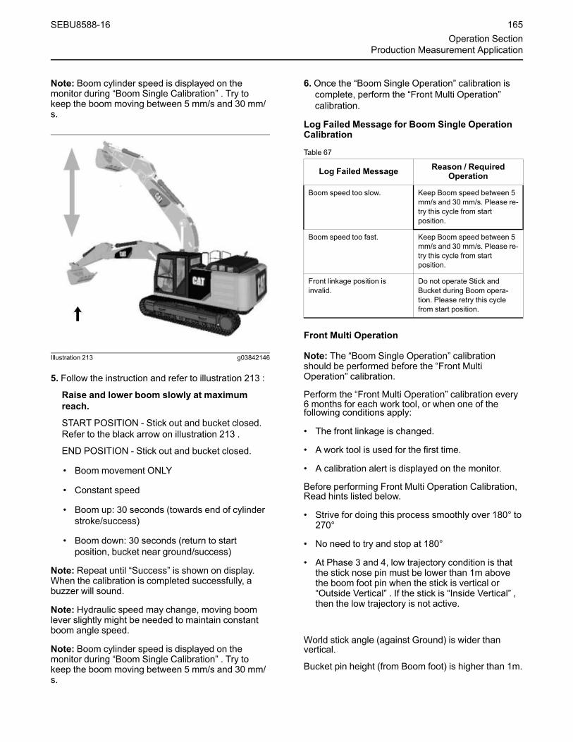
Note: Boom cylinder speed is displayed on themonitor during “Boom Single Calibration” . Try tokeep the boom moving between 5 mm/s and 30 mm/s.
Illustration 213 g03842146
5. Follow the instruction and refer to illustration 213 :
Raise and lower boom slowly at maximumreach.
START POSITION - Stick out and bucket closed.Refer to the black arrow on illustration 213 .
END POSITION - Stick out and bucket closed.
• Boom movement ONLY
• Constant speed
• Boom up: 30 seconds (towards end of cylinderstroke/success)
• Boom down: 30 seconds (return to startposition, bucket near ground/success)
Note: Repeat until “Success” is shown on display.When the calibration is completed successfully, abuzzer will sound.
Note: Hydraulic speed may change, moving boomlever slightly might be needed to maintain constantboom angle speed.
Note: Boom cylinder speed is displayed on themonitor during “Boom Single Calibration” . Try tokeep the boom moving between 5 mm/s and 30 mm/s.
6. Once the “Boom Single Operation” calibration iscomplete, perform the “Front Multi Operation”calibration.
Log Failed Message for Boom Single OperationCalibration
Table 67
Log Failed Message Reason / RequiredOperation
Boom speed too slow. Keep Boom speed between 5mm/s and 30 mm/s. Please re-try this cycle from startposition.
Boom speed too fast. Keep Boom speed between 5mm/s and 30 mm/s. Please re-try this cycle from startposition.
Front linkage position isinvalid.
Do not operate Stick andBucket during Boom opera-tion. Please retry this cyclefrom start position.
Front Multi Operation
Note: The “Boom Single Operation” calibrationshould be performed before the “Front MultiOperation” calibration.
Perform the “Front Multi Operation” calibration every6 months for each work tool, or when one of thefollowing conditions apply:
• The front linkage is changed.
• A work tool is used for the first time.
• A calibration alert is displayed on the monitor.
Before performing Front Multi Operation Calibration,Read hints listed below.
• Strive for doing this process smoothly over 180° to270°
• No need to try and stop at 180°
• At Phase 3 and 4, low trajectory condition is thatthe stick nose pin must be lower than 1m abovethe boom foot pin when the stick is vertical or“Outside Vertical” . If the stick is “Inside Vertical” ,then the low trajectory is not active.
World stick angle (against Ground) is wider thanvertical.
Bucket pin height (from Boom foot) is higher than 1m.
SEBU8588-16 165Operation Section
Production Measurement Application

Illustration 214 g06003422
The Red line indicates the ideal trajectory foroperation described in this section.(1) Outside Vertical Range(2) Inside Vertical Range
In order to perform the “Front Multi Operation”calibration:
1. Navigate to the “Work Tool Select” menu. Refer to“Cat Production Measurement Menu Screen, andCat”.
2. Press the “Calibrate” function key.
3. Use the keypad in order to select “Front MultiOperation” . Press the “OK” function key in orderto start the calibration.
Illustration 215 g03842148
Illustration 216 g03842149
Illustration 217 g03842150
166 SEBU8588-16Operation SectionProduction Measurement Application

Illustration 218 g03842151
4. Follow the instruction (Each operation should berepeated for five times):
Phase 1 – Raise the Boom Up and Swing 180° to270° (simultaneously). Refer to illustration 215 .
• START POSITION - Stick Out; Bucket Closed;Near Ground. Refer to the black arrow onillustration 215
• END POSITION - Stick Out; Bucket Closed; BoomUp
• RETURN - Swing Back & Boom Down; To startposition
Illustration 219 g06026464
Boom Angle is shown on the screen during thecalibration. The calibration must start with the boomangle less than 15 deg and end boom angle at morethan 45 deg.
Note: The bucket function is not moved during Phase1.
Note: Repeat until “Success” is shown on display,minimum 5 times. When the calibration is succeeded,a buzzer will sound each time.
Phase 2 – Raise the Boom and Swing 180° to 270°and Open Bucket (simultaneously). Refer toillustration 216 .
• START POSITION - Stick out; Bucket closed ; onground. Refer to the black arrow on illustration 216
• END POSITION - Stick out; Bucket Open; BoomUp
• RETURN - Swing Back & Boom Down & CloseBucket; To start position
Note: Repeat until “Success” is shown on display,minimum 5 times. When the calibration is succeeded,a buzzer will sound each time.
Phase 3 – Raise the Boom Up and Swing 180° to270° and Stick In (simultaneously). Refer toillustration 217 .
• START POSITION - Stick out; Bucket Closed;Near Ground. Refer to the black arrow onillustration 217
• END POSITION - Stick in; Bucket Closed; BoomUp
• RETURN - Swing Back & Boom Down & StickOut; To start position
Note: Repeat until “Success” is shown on display,minimum 5 times. When the calibration is succeeded,a buzzer will sound each time.
Phase 4 – Raise the Boom Up and Swing 180° to270° and Stick In (simultaneously). Refer toillustration 218 .
• START POSITION - Stick Out; Bucket Open, NearGround. Refer to the black arrow on illustration218
• END POSITION - Stick In; Bucket Open; Boom Up
• RETURN - Swing Back & Boom Down & StickOut; To start position
Note: Repeat until “Success” is shown on display,minimum 5 times. When the calibration is succeeded,a buzzer will sound each time.
Recommended AFTER each Bucket change.
Simulates truck loading (boom Lift / swing) withempty bucket
SEBU8588-16 167Operation Section
Production Measurement Application

• Raise and swing boom at least 90°
• Swing back & Boom Down in opposite direction tostart position
5. Once the “Front Multi Operation” calibration iscomplete, perform the “Bucket Zero Adjustment”calibration.
168 SEBU8588-16Operation SectionProduction Measurement Application
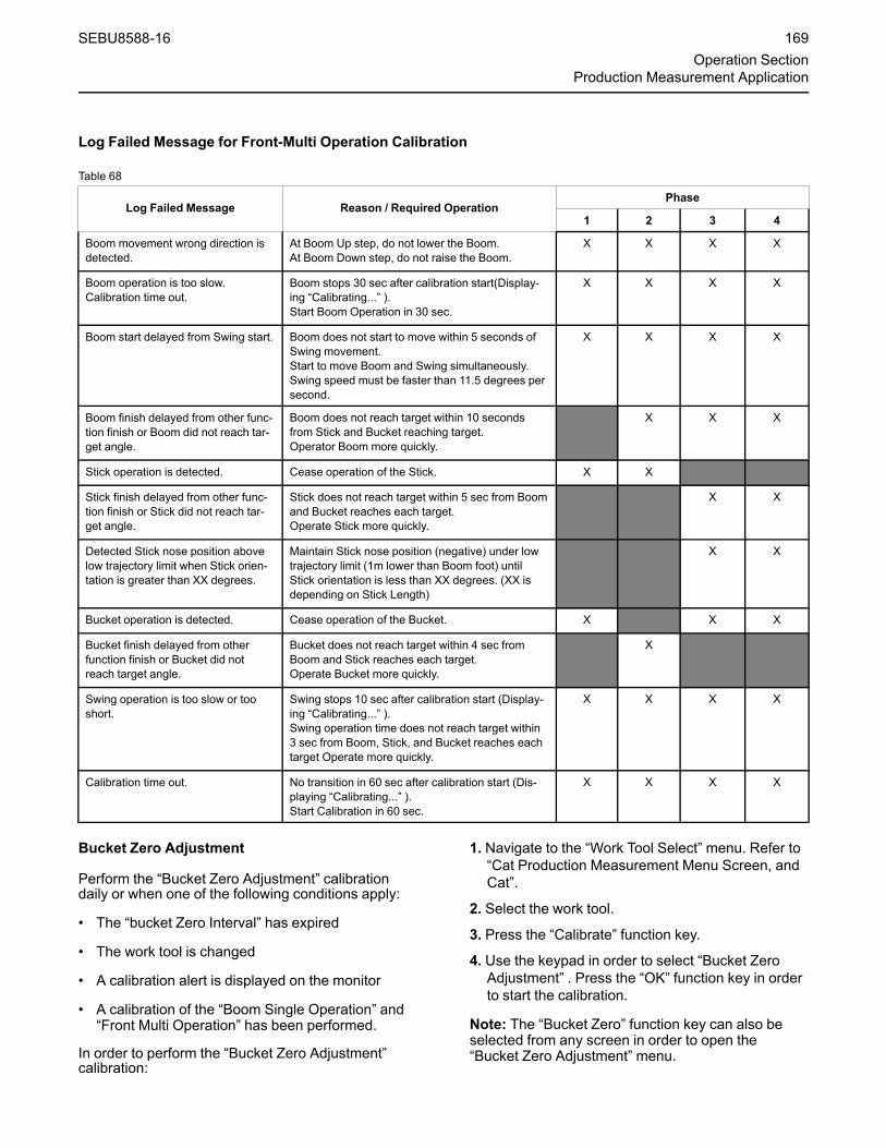
Log Failed Message for Front-Multi Operation Calibration
Table 68
Log Failed Message Reason / Required OperationPhase
1 2 3 4
Boom movement wrong direction isdetected.
At Boom Up step, do not lower the Boom.At Boom Down step, do not raise the Boom.
X X X X
Boom operation is too slow.Calibration time out.
Boom stops 30 sec after calibration start(Display-ing “Calibrating...” ).Start Boom Operation in 30 sec.
X X X X
Boom start delayed from Swing start. Boom does not start to move within 5 seconds ofSwing movement.Start to move Boom and Swing simultaneously.Swing speed must be faster than 11.5 degrees persecond.
X X X X
Boom finish delayed from other func-tion finish or Boom did not reach tar-get angle.
Boom does not reach target within 10 secondsfrom Stick and Bucket reaching target.Operator Boom more quickly.
X X X
Stick operation is detected. Cease operation of the Stick. X X
Stick finish delayed from other func-tion finish or Stick did not reach tar-get angle.
Stick does not reach target within 5 sec from Boomand Bucket reaches each target.Operate Stick more quickly.
X X
Detected Stick nose position abovelow trajectory limit when Stick orien-tation is greater than XX degrees.
Maintain Stick nose position (negative) under lowtrajectory limit (1m lower than Boom foot) untilStick orientation is less than XX degrees. (XX isdepending on Stick Length)
X X
Bucket operation is detected. Cease operation of the Bucket. X X X
Bucket finish delayed from otherfunction finish or Bucket did notreach target angle.
Bucket does not reach target within 4 sec fromBoom and Stick reaches each target.Operate Bucket more quickly.
X
Swing operation is too slow or tooshort.
Swing stops 10 sec after calibration start (Display-ing “Calibrating...” ).Swing operation time does not reach target within3 sec from Boom, Stick, and Bucket reaches eachtarget Operate more quickly.
X X X X
Calibration time out. No transition in 60 sec after calibration start (Dis-playing “Calibrating...” ).Start Calibration in 60 sec.
X X X X
Bucket Zero Adjustment
Perform the “Bucket Zero Adjustment” calibrationdaily or when one of the following conditions apply:
• The “bucket Zero Interval” has expired
• The work tool is changed
• A calibration alert is displayed on the monitor
• A calibration of the “Boom Single Operation” and“Front Multi Operation” has been performed.
In order to perform the “Bucket Zero Adjustment”calibration:
1. Navigate to the “Work Tool Select” menu. Refer to“Cat Production Measurement Menu Screen, andCat”.
2. Select the work tool.
3. Press the “Calibrate” function key.
4. Use the keypad in order to select “Bucket ZeroAdjustment” . Press the “OK” function key in orderto start the calibration.
Note: The “Bucket Zero” function key can also beselected from any screen in order to open the“Bucket Zero Adjustment”menu.
SEBU8588-16 169Operation Section
Production Measurement Application
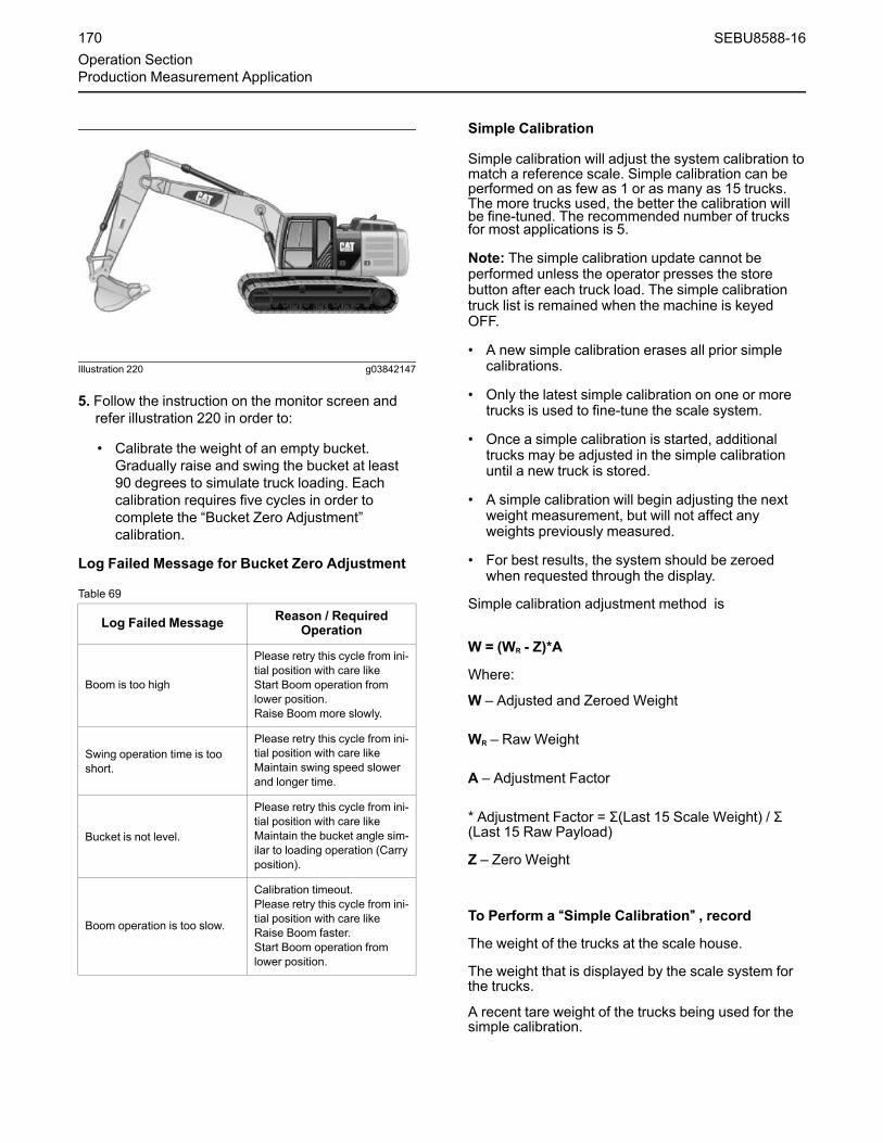
Illustration 220 g03842147
5. Follow the instruction on the monitor screen andrefer illustration 220 in order to:
• Calibrate the weight of an empty bucket.Gradually raise and swing the bucket at least90 degrees to simulate truck loading. Eachcalibration requires five cycles in order tocomplete the “Bucket Zero Adjustment”calibration.
Log Failed Message for Bucket Zero Adjustment
Table 69
Log Failed Message Reason / RequiredOperation
Boom is too high
Please retry this cycle from ini-tial position with care likeStart Boom operation fromlower position.Raise Boom more slowly.
Swing operation time is tooshort.
Please retry this cycle from ini-tial position with care likeMaintain swing speed slowerand longer time.
Bucket is not level.
Please retry this cycle from ini-tial position with care likeMaintain the bucket angle sim-ilar to loading operation (Carryposition).
Boom operation is too slow.
Calibration timeout.Please retry this cycle from ini-tial position with care likeRaise Boom faster.Start Boom operation fromlower position.
Simple Calibration
Simple calibration will adjust the system calibration tomatch a reference scale. Simple calibration can beperformed on as few as 1 or as many as 15 trucks.The more trucks used, the better the calibration willbe fine-tuned. The recommended number of trucksfor most applications is 5.
Note: The simple calibration update cannot beperformed unless the operator presses the storebutton after each truck load. The simple calibrationtruck list is remained when the machine is keyedOFF.
• A new simple calibration erases all prior simplecalibrations.
• Only the latest simple calibration on one or moretrucks is used to fine-tune the scale system.
• Once a simple calibration is started, additionaltrucks may be adjusted in the simple calibrationuntil a new truck is stored.
• A simple calibration will begin adjusting the nextweight measurement, but will not affect anyweights previously measured.
• For best results, the system should be zeroedwhen requested through the display.
Simple calibration adjustment method is
W = (WR - Z)*A
Where:
W – Adjusted and Zeroed Weight
WR – Raw Weight
A – Adjustment Factor
* Adjustment Factor = Σ(Last 15 Scale Weight) / Σ(Last 15 Raw Payload)
Z – Zero Weight
To Perform a ““Simple Calibration”” , record
The weight of the trucks at the scale house.
The weight that is displayed by the scale system forthe trucks.
A recent tare weight of the trucks being used for thesimple calibration.
170 SEBU8588-16Operation SectionProduction Measurement Application

Illustration 221 g06023396
1. Go to Main Menu > Work Tool Select >WeighingCalibration and select ““Simple Calibration”” andpush “OK” key.
2. Select and input the scale weight for theappropriate truck number. Continue to input thescale weight if you have multiple data.
3. Push “OK” key when finish to input all scaleweight.
4. Bucket Payload will be adjusted from the nextBucket.
Calibration alerts
Below are common calibration alerts that may bedisplayed on the monitor:
““ZERO ADJUSTMENT RECOMMENDED””– A set interval has expired or if asignificant condition has changed.
Select ““OK”” on the monitor in order to performthe calibration. Refer to “Operating Mode”.
““WEIGH CALIBRATIONRECOMMENDED”” – A set interval hasexpired or if a significant condition has
changed. Select ““OK”” on the monitor in order toperform the calibrations.
““WEIGH CALIBRATION REQUIRED”” – Aset interval has expired or if a significantcondition has changed. Select ““OK”” on
the monitor in order to perform the calibrations.
Sound Setup
The Cat Production Measurement Applicationincludes audible sound alerts for the following:
• Last 1 Pass
• reach Target
• Weighing Status
In order to enable or disable the audible sound alerts:
1. Navigate to the “Sound Setup” menu. Refer to “CatProduction Measurement Menu Screen, and Cat”.
2. Use the keypad to highlight the sound to bechanged and press the “OK” function key.
3. Use the keypad in order to select “ENABLED” or“DISABLED” .
4. Press the “OK” function key in order to confirmyour selection.
Operating Mode
Navigate to the “Operating Mode” menu. Refer to“Cat Production Measurement Menu Screen, andCat”.
The following parameters can be adjusted:
• CPM Enable Status
• Automatic ID Feature
• Bucket Zero Interval
Note: The “Operating Mode” menu can be accessedfrom the “Production Measurement” menu. The“Production Measurement”menu is found on the“Main Menu” of the monitoring system.
CPM Enable Status
1. Use the keypad in order to select “ProductionMeasurement Enable” and press the “OK” functionkey.
2. Use the keypad in order to select “ENABLED” or“DISABLED” .
3. Press the “OK” function key in order to confirmyour selection.
Automatic ID Feature
1. Navigate to the “Operating Mode” menu
2. Use the keypad in order to select “Automatic IDFeature” and press the “OK” function key.
3. Use the keypad in order to select “ENABLED” or“DISABLED” .
SEBU8588-16 171Operation Section
Production Measurement Application

4. Press the “OK” function key in order to confirmyour selection.
Bucket Zero Interval
1. Use the keypad in order to select “Bucket ZeroInterval” and press the “OK” function key.
2. Use the keypad in order to select the desiredinterval and press the “OK” function key.
3. Press the “OK” function key in order to confirmyour selection.
i05454870
Storage BoxSMCS Code: 7268
Interior Storage Box
Illustration 222 g01096952
The storage box is used to store miscellaneous itemssuch as a first aid kit or a lunch box.
Exterior Storage Box
Illustration 223 g03444862
The storage box is used to store the refueling pumpand the automatic lubrication system. The storagebox is also used to store miscellaneous tools.
172 SEBU8588-16Operation SectionStorage Box

i05192538
Storage and LiteratureCompartment(If Equipped)SMCS Code: 7268
Illustration 224 g01160959
A storage compartment is located inside the cab onthe left side. Use the compartment to store theliterature for the machine.
Note: Do not store tools in the storage compartment.Tools stored in the compartment could damage thecompartment.
i05622032
Fuel Transfer Pump(Refueling)(If Equipped)SMCS Code: 1256
S/N: EBF1–10000
S/N: XWL1–Up
S/N: DNM1–10000The fuel transfer pump pumps fuel into the fuel tank.
NOTICEDo not continuously operate the refueling pump formore than 30 minutes. Do not operate the refuelingpump more than a few seconds without fuel. Pumpdamage can result.
Illustration 225 g03377367
(1) Cap(2) Sight gauge(3) Storage box
Use the following procedure to pump fuel and storethe hose.
1. Open the outside cover of the storage box (3) thatis located at the front of the machine.
2. Remove cap (1) from the fuel tank, in order toallow proper ventilation.
Illustration 226 g03377379
Fuel transfer pump is located next to the storage box.(4) Hose end(5) On switch
3. Insert the free end of the suction hose (4) into acontainer of fuel.
4. Push the on switch (5) in order to supply the fuel tothe tank. When the tank is full, the pump stopsrefueling.
Note: Check sight gauge (2) in order to determinethe fuel level.
5. After refueling, install the cap on the fuel tank.
SEBU8588-16 173Operation Section
Storage and Literature Compartment
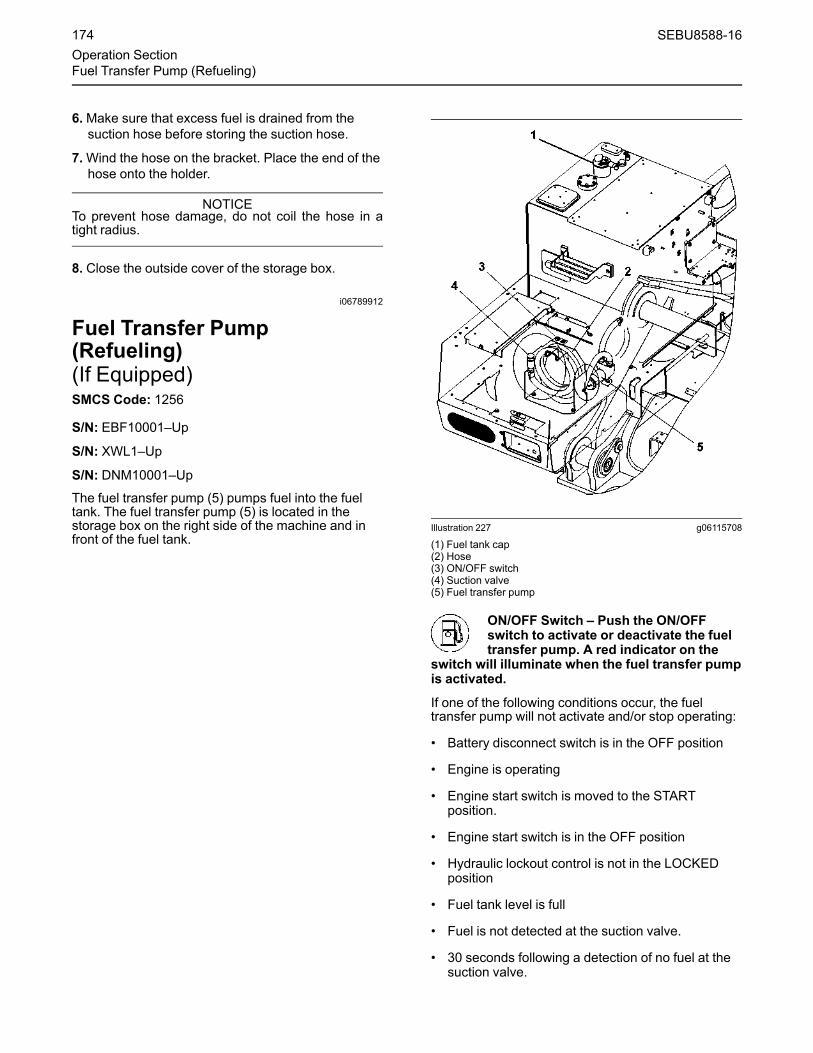
6.Make sure that excess fuel is drained from thesuction hose before storing the suction hose.
7.Wind the hose on the bracket. Place the end of thehose onto the holder.
NOTICETo prevent hose damage, do not coil the hose in atight radius.
8. Close the outside cover of the storage box.
i06789912
Fuel Transfer Pump(Refueling)(If Equipped)SMCS Code: 1256
S/N: EBF10001–Up
S/N: XWL1–Up
S/N: DNM10001–UpThe fuel transfer pump (5) pumps fuel into the fueltank. The fuel transfer pump (5) is located in thestorage box on the right side of the machine and infront of the fuel tank.
Illustration 227 g06115708
(1) Fuel tank cap(2) Hose(3) ON/OFF switch(4) Suction valve(5) Fuel transfer pump
ON/OFF Switch – Push the ON/OFFswitch to activate or deactivate the fueltransfer pump. A red indicator on the
switch will illuminate when the fuel transfer pumpis activated.
If one of the following conditions occur, the fueltransfer pump will not activate and/or stop operating:
• Battery disconnect switch is in the OFF position
• Engine is operating
• Engine start switch is moved to the STARTposition.
• Engine start switch is in the OFF position
• Hydraulic lockout control is not in the LOCKEDposition
• Fuel tank level is full
• Fuel is not detected at the suction valve.
• 30 seconds following a detection of no fuel at thesuction valve.
174 SEBU8588-16Operation SectionFuel Transfer Pump (Refueling)

Use the following procedure to pump fuel and storethe hose.
1. Park the machine on a level surface. Move thehydraulic lockout control to the LOCKED position.Stop the engine
2. Turn the engine start switch to the ON positionwithout starting the engine.
3. Remove fuel tank cap (1) from the fuel tank.
4. Open the storage box that is on the right side ofthe machine.
Illustration 228 g03660074
Suction valve (4) is at the end of hose (2).Turn the end of the suction valve clockwise to openthe valve
5. Uncoil hose (2) and turn the end of suction valve(4) clockwise to open the suction valve.
6. Properly insert the end of suction valve (4) into acontainer of fuel.
7. Push switch (3) to activate the fuel transfer pumpand supply the fuel to the tank. A red indicator onthe switch will illuminate when the fuel transferpump is activated.
When the fuel tank is full, the fuel transfer pumpwill automatically stop.
When the fuel container is empty, push switch (3)again to stop refueling. If additional fuel is needed,wait 30 seconds and return to step 6.
Note: The red indicator on the switch will no longerilluminate when the fuel transfer pump has stoppedrefueling.
Note: The fuel transfer pump will not activate for 30seconds following a detection of no fuel at the suctionvalve.
8. Push switch (3) at any time to deactivate the fueltransfer pump.
Note: The red indicator on the switch will no longerilluminate when the fuel transfer pump has stoppedrefueling.
9. Drain excess fuel from hose (2) and turn the end ofsuction valve (4) counter-clockwise to close thesuction valve.
10.When you store hose (2), wind the hose on thebar. Secure the suction valve in place.
NOTICETo prevent hose damage, do not coil the hose in atight radius.
11. Close the cover of the storage box.
12. install fuel tank cap (1) to the fuel tank.
13. Turn the engine start switch to the OFF position.
SEBU8588-16 175Operation Section
If Equipped

i03912100
Radio(If Equipped)SMCS Code: 7338
Illustration 229 g02117159
(1) Power switch(2) Volume control(3) Volume control(4) “AM/FM/AUX” selector
(5) Auxiliary plug(6) Display panel(7) “Tune” button(8) “Tune” button
(9) Button for scan and auto memoryfunction
(10) “Tone” control(11) Preset buttons
Note:When the machine is in operation, turn downthe volume of the radio.
Note: The radio can be used only when the batterydisconnect switch and the engine start switch are inthe ON position.
Note:When a button is pushed, a beep will occur.
(1) Power Switch – Push the power switch in orderto turn on the radio. Push the power switch again inorder to turn off the radio.
(2) and (3) Volume Control – Push the volumecontrol in order to control the volume. Push the uppervolume control in order to increase the sound leveland push the lower volume control in order todecrease the sound level.
(4) ““AM/FM/AUX”” Selector – After you push the“AM/FM/AUX” selector, the selected radio bandappears on display panel (6). This button is also usedto activate the auxiliary function.
(5) Auxiliary Plug – The front auxiliary plug allowsfor the connection of a portable audio device.
(6) Display – The display shows various functionssuch as the station frequency, band, and the volumelevel.
(7) and (8) ““Tune”” Buttons – Push the “tune” buttonsin order to select a radio station. Pressing “tune”button (7) will decrease the frequency. Pressing“tune” button (6) will increase the frequency. Pressingthe “tune” button for less than 0.5 seconds changesthe radio station one at a time. Pressing the “tune”buttons for more than 0.5 seconds will change thefrequency automatically until a radio station is found.
(9) Scan and Auto Memory – Press button (5) forless than 0.5 seconds in order to listen to 5 secondsof each preset radio station. Press button (5) at least1.5 seconds in order to store the radio stations withthe six strongest signals.
(10) Tone Control – Music is optimized by pressingthe tone control so that display (C) will show “MUSIC”.
(11) Preset Buttons – The circuitry in the memorysystem allows you to preset six radio stations. Topreset any of the “preset” buttons, follow the“Presetting Radio Stations” procedure.
176 SEBU8588-16Operation SectionRadio

Presetting Radio Stations
Illustration 230 g02117163
(6) Display(7) “Tune” button
(8) “Tune” button(11) Preset buttons
1. Turn on the radio. Select the AM band or the FMband.
2. Select the first radio station by using tuning switch(7) or tuning switch (8).
3. Depress one of preset buttons (11) for more than1.5 seconds. The radio station will be stored in thememory for the selected preset.
4. Push preset button (11) in order to tune in theradio station.
5. Repeat the same procedure for the remainingpreset switches.
SEBU8588-16 177Operation Section
If Equipped
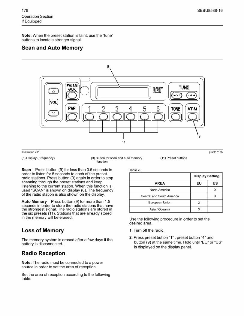
Note:When the preset station is faint, use the “tune”buttons to locate a stronger signal.
Scan and Auto Memory
Illustration 231 g02117175
(6) Display (Frequency) (9) Button for scan and auto memoryfunction
(11) Preset buttons
Scan – Press button (9) for less than 0.5 seconds inorder to listen for 5 seconds to each of the presetradio stations. Press button (9) again in order to stopscanning through the preset stations and keeplistening to the current station. When this function isused “SCAN” is shown on display (6). The frequencyof the radio station is also shown on the display.
Auto Memory – Press button (9) for more than 1.5seconds in order to store the radio stations that havethe strongest signal. The radio stations are stored inthe six presets (11). Stations that are already storedin the memory will be erased.
Loss of MemoryThe memory system is erased after a few days if thebattery is disconnected.
Radio ReceptionNote: The radio must be connected to a powersource in order to set the area of reception.
Set the area of reception according to the followingtable:
Table 70
Display Setting
AREA EU USNorth America X
Central and South America X
European Union X
Asia / Oceania X
Use the following procedure in order to set thedesired area.
1. Turn off the radio.
2. Press preset button “1” , preset button “4” andbutton (9) at the same time. Hold until “EU” or “US”is displayed on the display panel.
178 SEBU8588-16Operation SectionIf Equipped

Illustration 232 g02117176
(12) Protective film(13) Control panel(14) Method of selection
Note: Remove the film from the radio. Remove thevinyl from the operator seat. The film and vinyl maycause noise interference in the radio.
i05377826
Air Conditioning and HeatingControlSMCS Code: 7304; 7320; 7337
All machines are equipped with a heater. Only certainmachines are equipped with an air conditioner.Those machines that are not equipped with an airconditioner also are not equipped with a compressorswitch.
Illustration 233 g03402787
The climate control panel is located under the rightwindow inside the cab:
Redirect the louvers for air outlets by hand to thedesired direction. Some of the louvers for air outletcannot be redirected.
Illustration 234 g01106999
(1) On/Off switch(2) Automatic control switch(3) Temperature switch(4) LCD panel(5) Fan switch(6) Compressor switch(7) Defrost mode(8) Air inlet select switch(9) Air outlet select switch
Main Power ON/OFF Switch (1) – Pushthe ON/OFF switch in order to power onthe system. Push the switch again in
order to power off the system.
Automatic Control Switch (2) – In orderto enter the full ““AUT””mode forautomatic climate control, push this
switch. However, if you push the switch again,you cannot turn off the air conditioning. Whenthe system is in full ““AUT””mode, you canmanually change specific functions by pushinganother switch. If you manually change a specificfunction, ““AUT”” does not appear in the display,but the unchanged functions will remain in ““AUT””mode. Even on a day that is sunny, a climatecontrol system with only a heater can cool thecab in full ““AUT””mode if the ambient temperatureis no more than 20 °C (68 °F).
The climate control unit provides excellent operatorcomfort in the full “AUT” setting. Press the “AUT”switch for full “AUT”mode. Push temperature switch(3) in order to set the desired temperature. Thetemperature is only shown in metric values. All otherfunctions of climate control will be handledautomatically.
SEBU8588-16 179Operation Section
Air Conditioning and Heating Control

In order to take advantage of the full “AUT” setting ofthe climate control system, always keep the sunlightsensor clean. Do not obstruct the sunlight sensor. Ifthe climate control system is in the full “AUT” settingat engine start-up and the temperature inside the cabis too warm or too cool, the damper for fresh airventilation may automatically close for a few minutes.This will help to bring the air temperature to thepreset temperature more quickly.
Temperature Switch (3) – Theseswitches control the temperature of theair that is coming from the air outlets in
order to achieve the preset temperature. Thispreset temperature appears on LCD panel (4). Ifthe heating and air conditioning system is in theautomatic mode, pushing these switcheschanges the preset temperature.
Increase – Push this switch in order toincrease the temperature of the air thatis coming out of the air outlets or push
this switch in order to increase the presettemperature.
Decrease – Push this switch in order todecrease the temperature of the air thatis coming out of the air outlets or push
this switch in order to decrease the presettemperature.
Fan Switch (5) – The fan switch directlycontrols the fan speed. If the climatecontrol system is operating in the
automatic mode, pushing this switch overridesthe automatically selected fan speed.
Increase – Push this switch in order toincrease the fan speed.
Decrease – Push this switch in order todecrease the fan speed.
Compressor Switch (6) – Push theswitch in order to turn on thecompressor or push the switch in order
to turn off the compressor. In humid conditions,the compressor may be used to remove moisturefrom the air in the cab. In cool weather, operatethe compressor weekly in order to preventleakage of the refrigerant gas. This will also helpto maintain the compressor in optimum workingorder.
Defrost (7) – Depressing this switch willdefog the windows. The air will also bedehumidified while the compressor is
running. This selection directs air flow out of airoutlet (C) and air outlet (D).
Air Inlet Select Switch (8) – This switch selects theposition of the air inlet.
Recirculate – When this position isselected, the air inlet is closed. The airwill recirculate inside the cab.
Fresh Air – When this position isselected, the air inlet is open. Fresh airwill circulate into the cab.
Air Outlet Select Switch (9) – This switch selectsthe position of each air outlet. Each switch controls adifferent air outlet.
Upper Body – Selecting this switch willopen air outlet (A) and air outlet (D).
Upper Body and Floor – Selecting thisswitch will open air outlet (A), air outlet(B) and air outlet (D).
Floor – Selecting this switch will openair outlet (B).
Floor and Defroster – Selecting thisswitch will open air outlet (B) and airoutlets (C) and (D).
Consult with your Caterpillar dealer for periodicmaintenance of the heating and air conditioningsystem.
English Versus Metric ToggleIn order to convert the temperature reading fromDegrees Celsius to Degrees Fahrenheit, depressboth keys of the fan switch at the same time for fiveseconds. The same action is used for converting thetemperature reading from Degrees Fahrenheit toDegrees Celsius.
i03267463
Mirror(If Equipped)SMCS Code: 7319
Adjust all mirrors as specified in the Operationand Maintenance Manual. Failure to heed thiswarning can lead to personal injury or death.
180 SEBU8588-16Operation SectionMirror

Slips and falls can result in personal injury. Usethe machines access systems when adjusting themirrors. If the mirrors cannot be reached usingthe machine access systems follow the instruc-tions found within the Operation and Mainte-nance Manual, “Mirror” in order to access themirrors.
Note: Your machine may not be equipped with all ofthe mirrors that are described in this topic.
Illustration 235 g01598160
(1) Right side rear view mirror(2) Left side rear view mirror
Mirrors provide additional visibility around yourmachine. Make sure that the mirrors are in properworking condition and that the mirrors are clean.Adjust all mirrors at the beginning of each workperiod and adjust the mirrors when you changeoperators.
An appropriate job site organization is alsorecommended in order to minimize visibility hazards.For more information regarding job site organizationrefer to this Operation and Maintenance Manual,“Visibility Information”
Modified Machines or machines that have additionalequipment or attachments may influence yourvisibility.
Mirror Adjustment• Park the machine on a level surface.
• Lower the work tool to the ground.
• Move the hydraulic lockout control to the LOCKEDposition. For further details on this procedure,refer to Operation and Maintenance Manual,“Operator Controls”
• Stop the engine.
Note: You may need to use hand tools in order toadjust certain types of mirrors.
Right Side Rear View Mirror (1)
Illustration 236 g01665875
(1) Right side rear view mirror
Adjust the side mirror (1) on the storage box so thatthe right side access door and the right side track canbe seen from the operator seat. Additionally, provideas much visibility to the rear of the machine aspossible.
Left Side Rear View Mirror (2)
Illustration 237 g01666174
(2) Left side rear view mirror
SEBU8588-16 181Operation Section
If Equipped

Adjust the left mirror (2) on the cab so that the leftaccess door and the left side track can be seen fromthe operator seat. Additionally, provide as muchvisibility to the rear of the machine as possible.
i02630263
Window (Front)SMCS Code: 7310-FR
Note: The sun visor (if equipped) must be downbefore the front window is raised. The front windowwill not lock in the overhead storage position with thesun visor in the raised position.
To provide full ventilation inside the cab, the upperwindow and the lower window can be fully opened.
When opening or closing the windows, be extracareful to prevent any personal injury. The hy-draulic lockout control must be in the LOCKEDposition in order to prevent any possibility ofsudden movement of the machine due to inadver-tent contact with the hydraulic control(s).
Do not change the position of the window until thefollowing items have been done:
• Park the machine on a level surface.
• Lower the work tool to the ground.
• Move the lever for the hydraulic lockout control tothe LOCKED position.
• Stop the engine.
50/50 Window
Illustration 238 g00888387
(1) Latches for the lower window(2) Latches for the upper window
Open the Lower Window
Use the following procedure in order to open thelower window:
1. Squeeze latches (1) on each side of the lowerwindow.
2. Lift up on the lower window.
Note:When the lower window is fully opened,latches (1) will lock in place. This will secure thelower window into position.
Close the Lower WindowUse the following procedure in order to close thewindow:
1. Squeeze latches (1) on each side of the lowerwindow.
2. Lower the lower window into position.
Note: Hold the lower window. This will prevent thewindow from falling.
Note:When the lower window is fully closed, latches(1) will lock in place. This will secure the lowerwindow into position.
Open the Upper Window
Use the following procedure in order to open theupper window:
182 SEBU8588-16Operation SectionWindow (Front)

Note: Before you open the upper window, fully closethe sun screen.
1. Squeeze latches (2) on each side of the upperwindow.
2. Pull the upper window into the overhead position.
3.When the upper window is fully opened, latches (2)will lock in place. This will secure the upperwindow into position.
Close the Upper Window
Use the following procedure in order to close theupper window:
1. Squeeze latches (2) on each side of the upperwindow and pull down on the upper window.
2. Push the upper window toward the front of themachine.
Note:When the upper window is fully closed, latches(2) will lock in place. This will secure the upperwindow into position.
Open Both Windows Together
1. Follow the procedure for opening the lowerwindow. The lower window will latch to the upperwindow.
2. Follow the procedure for opening the upperwindow.
Close Both Windows
1. Squeeze latches (2) on each side of the upperwindow and pull down on the upper window.
2. Push the upper window toward the front of themachine until the window latches in place.
3. Squeeze latches (1) on each side of the lowerwindow.
4. Lower the lower window into position.
Note: Hold the lower window. This will prevent thewindow from falling.
Note:When the lower window is fully closed, latches(1) will lock in place. This will secure the lowerwindow into position.
70/30 window
Illustration 239 g01214362
Open the Upper Window
Use the following procedure in order to open theupper window:
Note: Before you open the upper window, fully closethe sun screen.
1. Squeeze latches (3) on each side of the upperwindow.
2. Pull the upper window into the overhead position.
3.When the upper window is fully opened, latches (3)will lock in place. This will secure the upperwindow into position.
Close the Upper Window
Use the following procedure in order to close theupper window:
1. Squeeze latches (3) on each side of the upperwindow and pull down on the upper window.
2. Push the upper window toward the front of themachine.
Note:When the upper window is fully closed, latches(3) will lock in place. This will secure the upperwindow into position.
SEBU8588-16 183Operation SectionWindow (Front)

Open the Lower Window and Close theLower Window
Illustration 240 g00103837
1. Open the upper window.
2. Raise the lower window out of the window frame.
Illustration 241 g01319054
(4) Brackets(5) Catch
3. Store the lower window in the holder that is locatedin the rear of the left side cab frame. In order tostore the lower window, locate one end of thelower window into brackets (4). Secure theopposite end of the lower window with catch (5).
4. In order to close the lower window, reverse theprocedure that is used for opening the lowerwindow.
Note: The lower window is curved. The lower windowcan only be positioned one way in the holders.
i01557158
Cab Visor(If Equipped)SMCS Code: 7301-ZZ
Illustration 242 g00751923
Pull out the cab visor. Hook the cab visor to thebracket. The cab visor can be used for the frontwindshield. The cab visor can also be used for theoverhead window.
184 SEBU8588-16Operation SectionCab Visor

i02500596
Sun Screen(If Equipped)SMCS Code: 7165-ZZ
Illustration 243 g01250563
Pull out the sun screen (1). Hook the sun screen tothe bracket (2). The sun screen may be positioned in3 different places.
i01463742
Roof HatchSMCS Code: 7303
Illustration 244 g00681034
(1) Grip(2) Lock
In order to open the roof hatch, release lock (2). Holdgrip (1) and push the roof hatch backward.
To close the roof hatch, hold grip (1) and pull the roofhatch forward. Engage lock (2) securely.
i05353017
Cab DoorSMCS Code: 7308
Illustration 245 g02041761
In order to open the cab door from the outside of thecab, pull outward on the door handle.
Illustration 246 g01141925
The cab door can also be opened from the outside ofthe cab by pulling upward on the handle that islocated behind the cab.
SEBU8588-16 185Operation Section
Sun Screen

Illustration 247 g01095780
In order to open the cab door from the inside of thecab, push forward on the lever for the cab door latch.
For additional ventilation, open the cab door all theway in order to engage the catch on the exterior wallof the cab.
Illustration 248 g01121189
In order to release the cab door from the catch, pulldownward on one of the two cab door release levers.
Illustration 249 g01096005
In order to open a window, release the window latch,and then slide the window to the desired position.
i01447292
Travel Control(Straight Travel Pedal (IfEquipped))SMCS Code: 5462
With certain attachment combinations, the thirdpedal can have different functions. Always checkfor third pedal function before using the thirdpedal. Improper operation of the third pedal couldresult in serious injury or death.
Illustration 250 g00753277
Position for normal travel(A) Rear of machine(B) Final drive(C) Idler
When you travel, make sure that final drive sprockets(B) are under the rear of the machine.
Illustration 251 g00757775
(1) Forward Travel(2) Reverse Travel
The third pedal is to the right of the right travel pedal.The third pedal controls the forward and backwardmovement of the machine.
186 SEBU8588-16Operation SectionTravel Control

Note: If the third pedal is depressed and a travelpedal or a travel lever is operated, the machine willturn accordingly.
Illustration 252 g00555934
(3) Lock pin(4) Pin(5) Notch(A) LOCKED position(B) UNLOCKED position (STORAGE position)
When the machine is not operated with the thirdpedal, install lock pin (3) at the LOCKED position inorder to prevent accidental operation.
Note: To prevent lock pin (3) from being pulled out,insert pin (4) through notch (5) and turn lock pin (3)counterclockwise by 1/4 turn.
i05378013
Work Tool Control PedalSMCS Code: 5059-P9
Illustration 253 g03402923
The pedal for work tool control can be located oneither side of the travel pedals or located on bothsides of the travel pedals. The pedal can be used toactuate work tools that require hydraulic flow in onedirection or both directions. The pedal allowsmodulation of the speed of the work tool. To causethe work tool to move faster, push down on the pedalmore.
Push down on the front of the pedal in order toactivate the work tool. Push down on the rear of thepedal in order to activate the work tool in the oppositedirection.
Note: There is a lock pin in the right pedal (ifequipped) and there is a lock pin in the left pedal (ifequipped). When you are changing the position ofone of the lock pins, you must also change theposition of the other lock pin.
SEBU8588-16 187Operation Section
Work Tool Control Pedal

Illustration 254 g01622566
(1) Lock pin(A) One-way flow(B) Locked(C) Two-way flow
In order to use the work tool, remove lock pin (1) fromLOCKED position (B) and place lock pin (1) inUNLOCKED position (A) or (C).
When you are not using the work tool, put lock pin (1)in LOCKED position (B) on both the left pedal (ifequipped) and the right pedal (if equipped). This willlock the pedals in order to help prevent anyunexpected operation of the work tool.
Illustration 255 g01622575
(1) Lock pin(2) Pin(3) Notch
Note: To prevent lock pin (1) from being accidentallypulled out, insert pin (2) through notch (3). Turn lockpin (2) counterclockwise by 1/4 turn. Repeat for theother pedal.
One-way FlowThe following information pertains to work tools thatrequire hydraulic oil flow in one direction. Hydraulichammers are an example of work tools that requirehydraulic oil flow in one direction.
Illustration 256 g01622588
Variable Speed – Push down on the frontof the pedal in order to activate the worktool. Push the pedal further in order to
increase the speed of the work tool. Release thepedal in order to turn off the work tool.
Two-way FlowThe following information pertains to work tools thatrequire hydraulic oil flow in two directions. Thesework tools can also be equipped with a rotate circuit.Hydraulic shears, pulverizers, crushers, and grapplesare examples of work tools that require hydraulic oilflow in two directions.
Illustration 257 g01622577
(4) CLOSE – Push down on the front ofthe pedal in order to close the work tool.
188 SEBU8588-16Operation SectionWork Tool Control Pedal

(5) OPEN – Push down on the rear of thepedal in order to open the work tool.
i03764090
Joystick Controls(Medium Pressure (If Equipped))SMCS Code: 5705
Illustration 258 g00559405
(1) STICK OUT(2) SWING RIGHT(3) STICK IN(4) SWING LEFT(5) BOOM LOWER(6) TOOL OPEN(7) BOOM RAISE(8) TOOL CLOSE(9) HOLD
The Fine Swing Control delays the engagementof the swing parking brake.
If the machine is operating on a slope with theFine Swing Control in the ON position, the swingmotion may become uncontrollable which couldresult in property damage, personal injury ordeath.
Turn the Fine Swing Control to the OFF positionwhen the machine is operating on a slope.
When you release the joysticks from any position, thejoysticks will return to HOLD position (9). Movementof the upper structure will stop unless the fine swingcontrol (if equipped) is ON. When the fine swingcontrol is ON, the swing parking brake will notactivate until 6.5 seconds after the joystick control forthe swing function returns to the HOLD position.
The machine control pattern is initially set at thefactory to the SAE system, as shown. The pattern onthe left pertains to the left joystick and the pattern onthe right pertains to the right joystick.
The machine control pattern can be varied. Refer toOperation and Maintenance Manual, “JoystickControls Alternate Patterns” for more information.
Two functions may be performed at the same time bymoving a joystick diagonally.
Rotating Tool Control
Illustration 259 g00875108
(A) Left joystick(B) Right joystick(1) Medium pressure switch(2) Horn switch(3) Medium pressure switch(4) AEC switch
Rotate Clockwise – Press the mediumpressure switch (1) on the left joystick inorder to rotate the tool clockwise.
Horn – Press the horn switch (2) on theleft joystick in order to activate the horn.
Rotate Counterclockwise – Press themedium pressure switch (3) on the rightjoystick in order to rotate the tool
counterclockwise.
SEBU8588-16 189Operation SectionJoystick Controls

AEC Switch – Press the AEC switch (4)on the right joystick in order to activatelow engine speed. Press the switch
again in order to activate high engine speed.
i04036189
Joystick ControlsSMCS Code: 5705
Illustration 260 g02233473
(1) STICK OUT(2) SWING RIGHT(3) STICK IN(4) SWING LEFT(5) BOOM LOWER(6) BUCKET DUMP(7) BOOM RAISE(8) BUCKET CLOSE(9) HOLD(9a) HORN (IF EQUIPPED)(9b) AUTOMATIC ENGINE SPEED CONTROL SWITCH (IF
EQUIPPED)(10) Seat
The Fine Swing Control delays the engagementof the swing parking brake.
If the machine is operating on a slope with theFine Swing Control in the ON position, the swingmotion may become uncontrollable which couldresult in property damage, personal injury ordeath.
Turn the Fine Swing Control to the OFF positionwhen the machine is operating on a slope.
When you release the joysticks from any position, thejoysticks will return to HOLD position (9). Movementof the upper structure will stop unless the fine swingcontrol (if equipped) is ON. When the fine swingcontrol is ON, the swing parking brake will notactivate until 6.5 seconds after the joystick control forthe swing function returns to the HOLD position.
Two functions may be performed at the same time bymoving a joystick diagonally.
The machine control pattern is initially set at thefactory to the SAE system, as shown. The pattern onthe left pertains to the left joystick and the pattern onthe right pertains to the right joystick.
The machine control pattern can be varied. Refer toOperation and Maintenance Manual, “JoystickControls Alternate Patterns” for more information.
i06836341
SmartBoom Control(If Equipped)SMCS Code: 5461-ZS; 7332
Personal injury or death can result from not fol-lowing the proper procedures.
To avoid the possibility of injury or death, followthe established procedure.
Activating the SmartBoom function and using thework tool joystick control while the front of themachine is elevated could result in unexpectedmachine motion. Unexpected machine motioncould result in serious injury or death. Do not ac-tivate the SmartBoom function if the front of themachine is elevated by the front linkage.
Do not elevate or lower the track when in theSmartBoom mode. Follow the operation proce-dures for the SmartBoom in the Operation andMaintenance Manual. Failure to follow these in-structions can result in serious injury or death.
Always make sure that the boom control joystickis in the NEUTRAL position before activating theSmartBoom control. Activating the SmartBoomcontrol with the joystick out of the neutral posi-tion could resulted in unexpected machine mo-tion which could result in serious injury or death.
190 SEBU8588-16Operation SectionJoystick Controls

Do not select any SmartBoom mode, using theSmartBoom selector switch located on the con-sole, while the tracks are elevated. Selecting theSmartBoom mode with the tracks elevated couldresult in a sudden drop of the machine whichcould result in serious injury or death.
If any SmartBoom mode is active and the boomcontrol joystick is in the BOOM DOWN position(forward) with a bucket or a work tool on theground, pressing the disable button that is lo-cated on the front of the right hand joystick couldcause a sudden boom down motion. This controlfunction could lift the machine upward, with un-expected machine movement that could result inserious injury or death. Do not press the disablebutton while the SmartBoom mode is active andthe boom control joystick is in the BOOM DOWNposition (forward) with a bucket or a work tool onthe ground.
Do not attempt to lift the tracks of the machine byusing the disable button and applying downwardforce with the boom lowering control while themachine is in any SmartBoom mode. Releasingthe disable button will immediately return the ma-chine to the active SmartBoom mode. This actioncould cause the machine to drop down abruptlywhich could result in serious injury or death.
The switches for the SmartBoom are on the right sideinstrument panel and on the right joystick.
Illustration 261 g00753781
Right side instrument panel
(1) SmartBoom UPAND DOWN – Pushdown on the top of the rocker switch toactivate the SmartBoom UPAND DOWN
mode. When the boom control joystick is movedto the BOOM DOWN position, the boom will lowerby the weight of the boom.` The boom can moveupward freely.
(2) SmartBoom DOWN – Push down onthe bottom of the rocker switch toactivate the SmartBoom DOWNmode.
The boom will lower by the weight of the boomwhen the control lever is moved to the BOOMLOWER position. This mode prevents the boomfrom moving upward. To move the boom upward,the operator must use the boom control joystickto activate the BOOM UP mode.
Note:When the rocker switch for the SmartBoom isin the CENTER position, the SmartBoom is no longerfunctional.
Illustration 262 g00753783
Right Joystick
(3) SmartBoom TEMPORARY DISABLE– Press the trigger switch on the front ofthe right joystick totemporarily override
the SmartBoom function. Release the triggerswitch to return to the selected SmartBoomfunction.
During operation of the SmartBoom, the operatormay wish to apply downward force to the boom.When the rocker switch is in the SmartBoom DOWNposition or the rocker switch is in the SmartBoom UPAND DOWN position, the operator can disable theSmartBoom function temporarily with the SmartBoomDISABLE switch. While the trigger switch is pressed,BOOM RAISE and BOOM LOWER will operate in thenormal modes.
Note: Smart Boom Control function is deactivatedwhen "Reach Front" is selected at "BoomConfiguration" on Monitor menu.
SEBU8588-16 191Operation Section
If Equipped

i02868544
Joystick Controls AlternatePatternsSMCS Code: 5059; 5137
Whenever a change is made to the machine con-trol pattern, also exchange the pattern card in thecab to match the new pattern.
Check the machine control pattern for conform-ance to the pattern on the card in the cab. If thepattern does not match, change the card to matchthe machine control pattern before you operatethe machine. Failure to do so could result in per-sonal injury.
Illustration 263 g01163836
In order to switch the joystick controls between thepatterns, refer to Operation and MaintenanceManual, “Monitoring System”.
STICK OUT (1) – Move the control leverto this position in order to move thestick outward.
SWING RIGHT (2) – Move the controllever to this position in order to swingthe upper structure to the right.
STICK IN (3) – Move the control lever tothis position in order to move the stickinward.
SWING LEFT (4) – Move the control leverto this position in order to swing theupper structure to the left.
BOOM LOWER (5) – Move the controllever to this position in order to lowerthe boom.
BUCKET DUMP (6) – Move the controllever to this position in order to dumpthe bucket.
BOOM RAISE (7) – Move the controllever to this position in order to raise theboom.
BUCKET CLOSE (8) – Move the controllever to this position in order to closethe bucket.
HOLD (9) – When the control lever is released fromany position, the control lever will return to the HOLDposition. Movement of the upper structure will stop.
Two functions may be performed at the same time bymoving a control lever diagonally.
If the machine is equipped with a hydraulic hammer,the function of position (6) and of position (8) isdifferent.
HYDRAULIC HAMMER RAISE (6) – Move thecontrol lever to this position in order to raise thehydraulic hammer.
HYDRAULIC HAMMER LOWER (8) – Move thecontrol lever to this position in order to lower thehydraulic hammer.
i02276685
Fuel Tank Shutoff and DrainControlSMCS Code: 1273
Illustration 264 g01139594
Fuel shutoff valve
The fuel shutoff valve is located under the fuel tank.
Fuel Shutoff Valve – To shut off the fuel supply, turnthe fuel shutoff valve clockwise. To turn on the fuelsupply, turn the fuel shutoff valve counterclockwise.
192 SEBU8588-16Operation SectionJoystick Controls Alternate Patterns

Illustration 265 g01043694
Fuel tank drain valve
The fuel tank drain valve is located on the side of themachine under the fuel tank.
Fuel Tank Drain Valve – To drain the water andsediment from the fuel tank, turn the fuel drain valvecounterclockwise. To close the fuel tank drain valve,turn the drain valve clockwise.
Note: For more detailed information that pertains todraining the water and sediment from the fuel tank,refer to Operation and Maintenance Manual, “FuelTank Water and Sediment - Drain”.
SEBU8588-16 193Operation Section
Fuel Tank Shutoff and Drain Control

Engine Startingi04947264
Engine StartingSMCS Code: 1000; 1090; 1456; 7000
NOTICEThe engine start switch must be in the ON positionand the engine must be running in order to maintainelectrical functions and hydraulic functions. This pro-cedure must be followed in order to prevent seriousmachine damage.
Illustration 266 g00406959
1. Turn the battery disconnect switch to the ONposition.
2.Make sure that the reset button for the circuitbreaker remains depressed. Refer to Operationand Maintenance Manual, “Circuit Breakers -Reset”.
3.Move the hydraulic lockout control to the LOCKEDposition.
This machine is equipped with an engine neutralstart system. The system only allows the engine tostart when the lever for the hydraulic lockoutcontrol is in the LOCKED position.
4.Move the joysticks to the HOLD position.
5. Before you start the engine, check for thepresence of bystanders or maintenancepersonnel. Ensure that all personnel are clear ofthe machine. Briefly sound the horn before youstart the engine.
Illustration 267 g02041555
6. Turn engine start switch (1) to the ON position.
7. The monitoring system starts.
Note: For more information on the monitoringsystem, refer to Operation and Maintenance Manual,“Monitoring System”.
8. If the engine start switch is placed in the ONposition for 2 seconds or more, the prestart checkof the monitoring system will be activated. If anyfluid levels are low, the low fluid level will be shownon the message display. Refer to Operation andMaintenance Manual, “Monitoring System” formore information on the prestart monitoringfunction.
If the fluid level is too low, add the correspondingfluid to the specified level. Add the fluid before youstart the engine.
Illustration 268 g02204433
9. Turn engine speed dial (2) to speed position “1” .
194 SEBU8588-16Operation SectionEngine Starting

NOTICEDo not crank the engine for more than 30 seconds. Ifthe engine does not start, allow the starter to cool fortwo minutes before cranking again. The engine startswitch must be turned to the OFF position before try-ing to restart.
10. Turn engine start switch (1) to the STARTposition.
11. Release the engine start switch key after theengine starts.
This machines engine with standard specificationscan start in areas that have temperatures as low as−18°C (0°F). For areas that are cooler, a starting kitfor cold weather is available.
i06954976
Engine and Machine Warm-UpSMCS Code: 1000; 7000
NOTICEKeep engine speed low and do not operate until themessage 'Warm-Up Mode Power Derate" on themonitor goes out. If it does not go out within thirtyseconds, stop the engine and investigate the causebefore starting again. Failure to do so, can cause en-gine damage.
NOTICEAlways run the engine at low idle for at least ten mi-nutes before performing any other operations in coldconditions or each time the engine oil and oil filter arechanged in order to protect your engine and hydrauliccomponents.
NOTICEDepending on the ambient temperature, in order toprevent the machine operation with high speed with-out sufficient lubrication at the turbo bearing, the en-gine speed may be set to low speed and thehydraulic power minimized for a pre-determined timeafter the engine starts. Refer to turbo protectionfeature.
The engine may automatically change speeds whenthe machine is stationary and idling in cold ambienttemperature for an extended time. This is to:
• Maintain desired coolant temperature.
• Maintain desired operation of engine systems.
• Maintain desired operation of the regenerationsystem.
During extended idling in cold ambient conditions,engine speed may operate between 900 rpm and1000 rpm. Operation at 1000 rpm is minimal and willonly last for up to 20 minutes. The regenerationactive indicator may also illuminate during extendedidling conditions to signal that a regeneration is inprogress.
Hydraulic System
When you cycle the machine controls, the ma-chine can move suddenly. Contact between themachine and external objects or ground person-nel can result in serious injury or death. Beforeyou cycle the machine controls, the machineshould be located in an unobstructed, hazard-free work area that is away from external objectsand ground personnel.
1.Make sure that the area is clear of personnel andequipment.
Note: The hydraulic lockout control must be in theUNLOCKED position before the hydraulic controlswill function.
2. Allow the engine to warm up at low idle for at least5 minutes. Engage the work tool controls anddisengage the work tool controls. This will speedup the warm-up of the hydraulic components.
When you idle the machine for warm-up, observethe following recommendations:
• If the temperature is greater than 0°C (32°F),warm up the engine for approximately 15minutes.
• If the temperature is less than 0°C (32°F),warm up the engine for approximately 30minutes.
• If the temperature is less than − 18°C (0°F) orif hydraulic functions are sluggish, additionaltime may be required.
NOTICEThe hydraulic oil temperature should be higher than25 °C (77 °F) before performing work with the ma-chine. Make sure that the warm-up procedure isperformed.
If the hydraulic oil temperature is less than 25 ° C(77 °F) and the machine is operated abruptly, seriousdamage to the hydraulic components may occur.
Note: The recommended operating temperature ofthe hydraulic fluid for this machine is 55 °C (131 °F).
SEBU8588-16 195Operation Section
Engine and Machine Warm-Up

3. To warm up the hydraulic oil, turn the engine speeddial to the medium engine speed. Run the enginefor approximately 5 minutes and move the joystickintermittently from the BUCKET DUMP position tothe HOLD position. Do not hold the joystick in theBUCKET DUMP position with the bucket cylinderfully extended for more than 10 seconds.
This allows the oil to attain relief pressure, whichcauses the oil to warm up more rapidly.
Note: If the joysticks are held for more than 30seconds, the machine ECM will go into a “Warm-UpMode Power Derate” setting. “Warm-Up Mode PowerDerate” will be shown on the monitor screen. When“Warm-Up Mode Power Derate” is active, themachine ECM limits the hydraulic pump torque to 50percent. Release the joysticks in order to cancel the“Warm-Up Mode Power Derate” setting.
4. Turn the engine speed dial to the maximum enginespeed and repeat step 3.
5. Cycle all controls in order to circulate warm oilthrough all hydraulic cylinders and all hydrauliclines, and through the swing motor and travelmotors.
6. Observe the gauges and the indicators frequentlyduring the operation.
Turbo Protection Power Derate – Afteran engine start, the engine speed will beset to dial one position and the
hydraulic power limited for a time period . Duringthis period, the monitor displays the message"Warm -Up Mode Power Derate". (Maximum isaround 30 seconds). After the turbo bearinglubrication is sufficient, the engine speed goes tothe setting dial speed and the monitor stops todisplay the message.
Hydraulic System AutomaticWarm-up
Hydraulic System Automatic Warm-up –When the hydraulic oil is belowoperating temperature, the automatic
warm-up function will automatically circulatehydraulic oil through the hydraulic circuits.Circulating the hydraulic oil through thehydraulic circuits will accelerate the warm-up ofthe hydraulic oil.
Note: The automatic warm-up feature can beenabled or disabled through the monitoring system.consult your Cat dealer for additional information.
The following conditions must be met in order for theautomatic warm-up to operate after the machine hasbeen started:
• Automatic Hydraulic System Warm-up functionmust be enabled
• Hydraulic Lockout Control is in the LOCKEDposition
• Hydraulic oil temperature is below operatingtemperature.
When conditions are met, a “STARTAUTOWARMING UP?” message will appear on the monitorand a hydraulic warm-up icon will appear as aselection on the monitor.
1. Lower the work tools to the ground and place thehydraulic lockout control in the LOCKED position.
2. Press the automatic warm-up key on the monitor.
3. Press the automatic warm-up key again in order tostart the automatic warm-up function.
Note: A “AUTOWARMING UP STARTING”messagewill appear on the monitor when the automatic warm-up function is active.
The automatic warm-up will stop once thetemperature of the hydraulic oil has reachedoperating temperature or when the hydraulic lockoutcontrol is moved to the UNLOCKED position.
Note: If any warning message or system eventmessage are active on the monitor, “AUTOWARMING UP” cannot be active. If any eventoccurred during “AUTOWARMING UP” , the systemis stopped.
Always make sure that the work tool is lowered tothe ground and deactivate all work tools beforeactivating the Hydraulic System AutomaticWarm-up. Activating the system with the worktool not on the ground could result in unexpectedmachine movement which could result in person-al injury or death.
Dynamic Cool Engine Elevated Idle(DCEEI)The Dynamic Cool Engine Elevated Idle (DCEEI)feature will temporarily increase the low idle enginespeed when the engine coolant is below normaloperating temperature. Increasing the low idle speedwill accelerate the warm-up of the engine and fluids.When the engine coolant reaches normal operatingtemperature, the engine speed returns to the low idlespeed.
196 SEBU8588-16Operation SectionEngine and Machine Warm-Up

Extended periods of low engine idle can also result inlower coolant temperatures. During extended periodsof low engine idle, the engine idle speed willautomatically increase if the engine coolant dropsbelow the operating temperature. This increase in theengine idle speed will prevent overcooling of theengine.
Improve Cold WeatherPerformanceCovers installed over the vents in the radiatorcompartment door will help to control overcooling inambient temperatures below −15° C (5° F).
The materials used for the covers and the methodused to install the covers is at the installersdiscretion.
Install the covers if overcooling is observed while themachine is idling in ambient temperatures below−15° C (5° F).
Stop the machine, and remove the covers under thefollowing conditions:
• The ambient temperature is above −15° C (5° F).
• The engine temperature gauge indicatesoverheating.
• The hydraulic oil temperature gauge indicatesoverheating.
Installation
Illustration 269 g03707408
Typical example of cover location on the radiatorcompartment door(1) Covers
1. Clean the surface of the radiator compartmentdoor.
2. Install the covers in the location shown inIllustration 269 . The covers should fully cover thedoor vents.
SEBU8588-16 197Operation Section
Engine and Machine Warm-Up

Operationi06231546
Operation InformationSMCS Code: 7000
Note: Operating Temperature Range for theMachine The machine must function satisfactorily inthe anticipated ambient temperature limits that areencountered during operation. The standard machineconfiguration is intended for use within an ambienttemperature range of −18 °C (0 °F) to 43 °C(109 °F). Special configurations for different ambienttemperatures may be available. Consult yourCaterpillar dealer for additional information on specialconfigurations of your machine.
Make sure that no personnel are on the machine ornear the machine in order to prevent any personalinjury. Keep the machine under control at all times inorder to prevent injury.
Sound the horn and allow adequate time forbystanders to clear the area before moving themachine into a restricted visibility area. Follow localpractices for your machine application. For moreinformation refer to Operation and MaintenanceManual, “Restricted Visibility”.
Reduce the engine speed when you maneuver themachine in tight quarters and when you drive over anincline.
Select the necessary travel speed range before youdrive downgrade. Do not change the travel speedrange while you drive downhill.
Use the same travel speed on a downgrade and onan upgrade.
When you travel for any distance, keep the stickinward and carry the boom in a low position.
When you drive up a steep grade, keep the boom asclose to the ground as possible.
When you travel uphill or you travel downhill, keepthe boom on the uphill side of the machine.
1. Adjust the operator seat.
2. Fasten the seat belt.
Illustration 270 g00732198
3. Turn the engine speed dial to the operating range.
4.Move the hydraulic lockout control to theUNLOCKED position.
Illustration 271 g02145475
5. Raise the boom enough in order to providesufficient ground clearance.
Illustration 272 g03262356
6. Select the desired travel speed by operating thetravel speed control switch.
198 SEBU8588-16Operation SectionOperation

7.Make sure that the position of the upper structureand of the undercarriage is known before youmove the machine. The drive sprockets should beat the rear of the machine.
Note: The directional steering controls will operatenormally if the drive sprockets are at the rear of themachine and the idlers are at the front of the machineand under the cab. When the sprockets are under thecab, the travel controls will operate backward.
8. Turn the engine speed dial in order to increase theengine speed (rpm) to the desired speed.
9. Push both travel levers forward at the same time inorder to travel forward. If both travel levers arepushed farther, the travel speed at the selectedengine speed (rpm) will be faster.
Note: If the machine does not operate or if themachine does not travel in a straight line, consultyour Caterpillar dealer.
10. See Operation and Maintenance Manual,“Operator Controls” for information about spotturning and about pivot turns.
11.When you make turns in soft material, travel in aforward direction occasionally in order to clear thetracks.
12. Slowly move both of the travel levers or both ofthe travel pedals to the CENTER position in orderto stop the machine.
Lifting ObjectsIf the machine is equipped with the CE plate perrequirements for the European Union, used to liftobjects, then the machine must be equipped with theoptional boom lowering control valve and an overloadwarning device.
A fit for purpose test was completed in order toconfirm that a properly equipped machine meets therequirements of the European Union MachineryDirective “2006/42/EC” for lifting objects.
The overload warning device (if equipped) must beadjusted for the bucket linkage and bucket size that isinstalled on the machine. Adjust the overload warningdevice for proper operation.
The setting for the overload warning device (ifequipped) should be checked by an authorizeddealer.
i00059294
Frozen Ground ConditionsSMCS Code: 7000
Illustration 273 g00101468
To free the tracks from frozen ground, swing theboom to the front of the machine. Use boom downpressure to free the idler end of the machine.
Swing the boom to the rear of the machine. Useboom down pressure to free the sprocket end of themachine.
i03599804
Equipment Lowering withEngine StoppedSMCS Code: 7000
In order to lower the boom, place the hydrauliclockout control in the UNLOCKED position. Move thejoystick to the BOOM LOWER position. If theaccumulator is still charged, the boom will lower.
If the boom does not lower, the accumulator is empty.Use one of the following methods to lower the boom.
Note: The boom can be lowered within 60 secondsafter turning off the engine if the accumulator ischarged. After 60 seconds, the hydraulic electroniccontrol module will shut off and the joysticks will bedisabled. The hydraulic lockout control must be in theUNLOCKED position.
SEBU8588-16 199Operation Section
Frozen Ground Conditions

Machine Without a Boom LoweringControl Valve
Be sure no one is under or near the work tools be-fore manually lowering the boom. Keep all per-sonnel away from the boom drop area whenlowering the boom with the engine stopped in or-der to avoid possible personal injury.
When you must manually lower the boom due toengine shutdown, use the following procedure:
Note: Keep all personnel away from the boom whenyou are lowering the boom.
Illustration 274 g00580815
Rear of the Main Control Valve(1) Locknut(2) Screw
1. Slowly loosen locknut (1).
2. Loosen screw (2) to a maximum of 1/2 turn. Theboom will now start to lower.
3. After the work tools have been lowered to theground, tighten the screw and the locknut.
4. Consult your Caterpillar dealer and make anynecessary repairs.
After completion of the manual boom lowering, makenecessary repairs before you operate the machineagain.
Machine With a Boom LoweringControl Valve (If Equipped)
Boom load may cause cylinder oil pressure toreach relief pressure of the boom lowering con-trol device when the boom is supported by onecylinder. Boom can lower suddenly, causing pos-sible injury or death.
To avoid possible injury or death, be sure no oneis under or near the work tool before manuallylowering the boom.
Keep all personnel away from the boom drop areawhen lowering the boom with the enginestopped.
If the engine is shut down or the hydraulic system isdisabled, the operator can still lower the boom. Theboom lowering control valve allows the operator tomanually lower the boom. Use the followingprocedure if the machine is equipped with a boomlowering control valve.
Illustration 275 g01924625
The boom lowering control valve is located near thebase of the boom.
1. Loosen locknut (1).
2. Slowly turn check valve (2) counterclockwise untilthe check valve stops. The boom will lower to theground.
200 SEBU8588-16Operation SectionEquipment Lowering with Engine Stopped

3.Make sure that the work tool has been loweredonto the ground. Tighten check valve (2) to atorque of 2.25 ± 0.25 N·m (1.66 ± 0.18 lb ft).
4. Tighten locknut (1) to a torque of 4 ± 0.5 N·m(3 ± 0.37 lb ft).
5. Before you begin operating the machine, makeany necessary repairs.
For additional information, consult your Caterpillardealer.
SEBU8588-16 201Operation Section
Equipment Lowering with Engine Stopped

Operating Techniquesi05125989
Operating TechniqueInformationSMCS Code: 7000
Know the maximum height and the maximumreach of your machine. Serious injury or death byelectrocution can occur if the machine or thework tools are not kept a safe distance from elec-trical power lines. Keep a distance of at least3000 mm (118 inch) plus an additional 10 mm(0.4 inch) for each 1000 volts over 50000 volts.
For safety, one of the following may require a greaterdistance:
• Local codes
• State codes
• Requirements of the job site
NOTICEWhen swinging into a ditch, do not use the ditch tostop the swinging motion. Inspect the machine fordamage if the boom is swung into a bank or anobject.
Repeated stopping by an object can cause structuraldamage if the boom is swung into a bank or anobject.
With certain boom-stick-bucket combinations, thebucket or worktool can hit the cab and/or the frontstructure of the machine. Always check for interfer-ence when first operating a new bucket or a new worktool. Keep the bucket or work tool away from the caband away from the front structure during operation.
Whenever the tracks of the machine raise off theground while digging, lower the machine back to theground smoothly. DO NOT DROP OR CATCH ITWITH THE HYDRAULICS. Damage to the machinecan result.
With certain combinations of work tools, the thirdpedal can have different functions. Always check thefunction of the third pedal before you use the thirdpedal.
Know the location of any buried cables. Mark thelocations clearly before you dig.
Consult your Caterpillar dealer for special work tooltips that are available for use in severe applications.
Move the machine whenever the position foroperating the machine is not efficient. The machinecan be moved forward or backward during theoperating cycle.
When you operate the machine in close places,utilize the bucket or the other work tool in order toperform the following functions:
• Pushing the machine
• Pulling the machine
• Lifting the tracks
Use a comfortable travel speed while you operate themachine.
Operating efficiency can be increased by using morethan one machine control to perform a task.
Never swing a load over a truck cab or workers.
Position the truck so that material can be loaded fromthe rear of the truck or from the side of the truck.Load the truck evenly so that the rear axles are notoverloaded.
An oversize bucket or a bucket that is equipped withside cutters should not be used in rocky material.These types of buckets slow down the cycle.Damage to the bucket and to other machinecomponents could result.
Restricted Operation
Illustration 276 g00529436
Do not use the swing force to perform the followingoperations:
• Soil compaction
• Ground breaking
• Demolition
Do not swing the machine while the bucket tips are inthe soil.
202 SEBU8588-16Operation SectionOperating Techniques

These operations will damage the boom, the stick,and the work tool and the operations will reduce thelife of the equipment.
Illustration 277 g00529457
Do not use the dropping force of the bucket or worktool as a hammer. This will bring excessive force onthe rear of the machine. Possible damage to themachine could result.
Illustration 278 g00529458
If the cylinder is operated at the end of the strokeduring operations, excessive force will occur on thestopper on the inside of the cylinder. This will reducethe life of the cylinder and structures. To avoid thisproblem, always leave a small margin of play whenthe cylinder is operated.
Illustration 279 g03286378
If the stick IN function is operated at full speed with afully loaded bucket or heavy work tool attachment tothe end of the cylinder stroke, excessive force willoccur inside the stick cylinder. This action will reducethe life of the stick cylinder. To avoid this problem,always operate a stick IN function with moderatespeed towards the end of cylinder stroke.
Illustration 280 g00529459
While the bucket is in the ground, do not use thetravel force for any excavation. This operation willcause excessive force on the rear of the machine.
SEBU8588-16 203Operation Section
Operating Technique Information

Illustration 281 g00529460
Do not use the dropping force of the rear of themachine for excavation. This operation will damagethe machine.
Operating Precaution
Illustration 282 g01250228
NOTICEDo not allow the machine to swing from the force oftraveling when you use the bucket , the stick, or theboom to assist in travel. If the force from travelingcauses the machine to swing, damage may occur tothe swing motor and to the swing drive.
Do not use the force of the bucket, the stick, or theboom to assist in turning the machine while themachine is traveling. This technique is referred to as“jump steering”. This technique will damage theswing motor and the swing brake.
Illustration 283 g00529462
When deep holes are dug, do not lower the boom sothat the bottom side of the boom touches the ground.
When deep holes are dug, do not allow the boom tointerfere with the tracks.
i05032265
Travel in Water and MudSMCS Code: 7000-V6
NOTICEWhen working in or around any body of water, arounda stream or river, or in conditions of heavy mud, becareful that the swing bearing, the swing drive gear,and the swivel joint do not dip into water, mud, sand,or gravel. If the swing bearing dips into water, mud,sand, or gravel, immediately grease the swing bear-ing until the used grease leaks from the outer circle ofthe swing bearing. Failure to carry out this proceduremay cause premature wear in the swing bearing.
Illustration 284 g00807842
Depth of water to the center of the track carrier roller
The following guidelines pertain to travel acrosswater and travel through mud, sand, or gravel.
204 SEBU8588-16Operation SectionTravel in Water and Mud
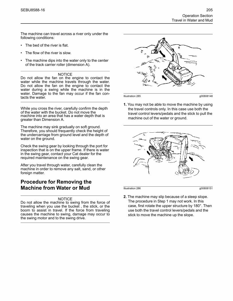
The machine can travel across a river only under thefollowing conditions:
• The bed of the river is flat.
• The flow of the river is slow.
• The machine dips into the water only to the centerof the track carrier roller (dimension A).
NOTICEDo not allow the fan on the engine to contact thewater while the machine travels through the water.Do not allow the fan on the engine to contact thewater during a swing while the machine is in thewater. Damage to the fan may occur if the fan con-tacts the water.
While you cross the river, carefully confirm the depthof the water with the bucket. Do not move themachine into an area that has a water depth that isgreater than Dimension A.
The machine may sink gradually on soft ground.Therefore, you should frequently check the height ofthe undercarriage from ground level and the depth ofwater on the ground.
Check the swing gear by looking through the port forinspection that is on the upper frame. If there is waterin the swing gear, contact your Cat dealer for therequired maintenance on the swing gear.
After you travel through water, carefully clean themachine in order to remove any salt, sand, or otherforeign matter.
Procedure for Removing theMachine from Water or Mud
NOTICEDo not allow the machine to swing from the force oftraveling when you use the bucket , the stick, or theboom to assist in travel. If the force from travelingcauses the machine to swing, damage may occur tothe swing motor and to the swing drive.
Illustration 285 g00808148
1. You may not be able to move the machine by usingthe travel controls only. In this case use both thetravel control levers/pedals and the stick to pull themachine out of the water or ground.
Illustration 286 g00808151
2. The machine may slip because of a steep slope.The procedure in Step 1 may not work. In thiscase, first rotate the upper structure by 180°. Thenuse both the travel control levers/pedals and thestick to move the machine up the slope.
SEBU8588-16 205Operation Section
Travel in Water and Mud
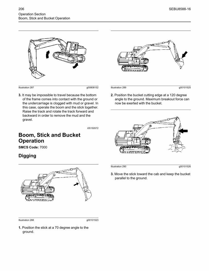
Illustration 287 g00808152
3. It may be impossible to travel because the bottomof the frame comes into contact with the ground orthe undercarriage is clogged with mud or gravel. Inthis case, operate the boom and the stick together.Raise the track and rotate the track forward andbackward in order to remove the mud and thegravel.
i05150572
Boom, Stick and BucketOperationSMCS Code: 7000
Digging
Illustration 288 g00101523
1. Position the stick at a 70 degree angle to theground.
Illustration 289 g00101525
2. Position the bucket cutting edge at a 120 degreeangle to the ground. Maximum breakout force cannow be exerted with the bucket.
Illustration 290 g00101526
3.Move the stick toward the cab and keep the bucketparallel to the ground.
206 SEBU8588-16Operation SectionBoom, Stick and Bucket Operation

Illustration 291 g00101527
4. If the stick stops due to the load, raise the boomand/or perform a curl in order to adjust the depthof the cut.
5. To apply the greatest force at the cutting edge,decrease the down pressure as you move thestick toward the cab.
6.Maintain a bucket attitude that ensures acontinuous flow of material into the bucket.
7. Continue the pass in a horizontal direction so thatmaterial peels into the bucket.
Illustration 292 g00101528
8. Close the bucket and raise the boom when thepass has been completed.
Illustration 293 g00101529
9. Engage the swing control when the bucket is clearof the excavation.
Illustration 294 g00101530
10. To dump a load, move the stick outward and openthe bucket in a smooth motion.
Lifting Objects
To prevent injury, do not exceed the rated load ca-pacity of the machine. If the machine is not onlevel ground, load capacities will vary.
NOTICEDamage to bucket cylinder, bucket or linkage couldresult if slings are placed incorrectly.
There may be local regulations and/or governmentregulations that govern the use of machines which liftheavy objects. Obey all local and governmentregulations.
SEBU8588-16 207Operation Section
Boom, Stick and Bucket Operation

If this machine is used to lift objects within an areathat is controlled by the European Directive “2006/42/EC”, the machine must be equipped with a boomlowering control valve, a stick lowering control valve,and an overload warning device.
Japan regulations require some machines to use ashovel crane configuration in order to lift ceratinobjects.
Contact your Cat dealer for additional information.
Short slings will prevent excessive load swing.
Illustration 295 g00101531
Use the lifting eye that is provided on the linkage tolift objects.
If the lifting eye is used, the connection must bemade with a sling or with a shackle.
Illustration 296 g00101532
An unstable condition can exist if a load exceeds themachine load rating or if a heavy load is swung overan end or over a side.
Illustration 297 g00101533
The most stable lifting position is over a corner of themachine.
Illustration 298 g00101534
For the best stability, carry a load close to themachine and to the ground.
208 SEBU8588-16Operation SectionBoom, Stick and Bucket Operation

Illustration 299 g00101535
Lift capacity decreases as the distance from theswing centerline is increased.
Machines that are Equipped with aLong Reach ConfigurationMachines with a long reach configuration requirelarger swing drift than standard machines whenstopping, because inertial force in time of swing islarge. Taking this into account, adjustments are madein timing for applying the swing brakes and speed ofswinging.
Machines with a long reach configuration could bedamaged and stability of the machine would beadversely affected if a control was suddenlyoperated, because inertial force of work tool is large.
i03875131
SmartBoom Operation(If Equipped)SMCS Code: 5461-ZS; 7332
Personal injury or death can result from not fol-lowing the proper procedures.
To avoid the possibility of injury or death, followthe established procedure.
Activating the SmartBoom function and using thework tool joystick control while the front of themachine is elevated could result in unexpectedmachine motion. Unexpected machine motioncould result in serious injury or death. Do not ac-tivate the SmartBoom function if the front of themachine is elevated by the front linkage.
Do not elevate or lower the track when in theSmartBoom mode. Follow the operation proce-dures for the SmartBoom in the Operation andMaintenance Manual. Failure to follow these in-structions can result in serious injury or death.
Always make sure that the boom control joystickis in the NEUTRAL position before activating theSmartBoom control. Activating the SmartBoomcontrol with the joystick out of the neutral posi-tion could resulted in unexpected machine mo-tion which could result in serious injury or death.
Do not select any SmartBoom mode, using theSmartBoom selector switch located on the con-sole, while the tracks are elevated. Selecting theSmartBoom mode with the tracks elevated couldresult in a sudden drop of the machine whichcould result in serious injury or death.
If any SmartBoom mode is active and the boomcontrol joystick is in the BOOM DOWN position(forward) with a bucket or a work tool on theground, pressing the disable button that is lo-cated on the front of the right hand joystick couldcause a sudden boom down motion. This controlfunction could lift the machine upward, with un-expected machine movement that could result inserious injury or death. Do not press the disablebutton while the SmartBoom mode is active andthe boom control joystick is in the BOOM DOWNposition (forward) with a bucket or a work tool onthe ground.
Do not attempt to lift the tracks of the machine byusing the disable button and applying downwardforce with the boom lowering control while themachine is in any SmartBoom mode. Releasingthe disable button will immediately return the ma-chine to the active SmartBoom mode. This actioncould cause the machine to drop down abruptlywhich could result in serious injury or death.
The Caterpillar SmartBoom provides significantadvantages in the following operations:
SEBU8588-16 209Operation Section
SmartBoom Operation

Excavation and LoadingThe operator should select the SmartBoom UPANDDOWN mode for excavating operations and forloading operations. This mode is effective during thereturn cycle. The BOOM DOWN movement isassisted by gravity, and the pump flow that isnormally required for the boom circuit is available forfaster STICK OUTand SWING functions. More workis performed for the amount of hydraulic oil flow thatis provided by the pumps. This results in faster cycletimes and improved fuel efficiency.
When the SmartBoom UPAND DOWN mode isactive, no downward hydraulic force is applied to theboom. The operator can intermittently applydownward hydraulic force when the force is requiredfor bucket penetration. A button on the right joystickenables the operator to override the SmartBoommode.
HammeringThe operator should select the SmartBoom DOWNmode for hammering operations. In the SmartBoomDOWN mode, the weight of the hammer plus theboom and the stick provides sufficient downwardforce for effective hammering. This mode preventsthe hammer from rebounding. The boom follows thehammer downward freely as the tool penetrates therock. This mode also reduces strain on the machinestructures.
AdvantagesIn hammering, the SmartBoom provides the followingadvantages:
• The mode reduces shock in the cab.
• The mode reduces strain on machine structures.
• The mode prevents blank shots.
• The mode maintains optimum frequency.
In rock cleaning, the SmartBoom provides thefollowing advantages:
• The mode reduces strain on machine structures.
• The mode reduces wear on the bucket and theteeth.
• The mode maintains optimum frequency.
In a leveling operation, the SmartBoom eases theoperation. Only STICK IN actuation and bucketactuation are required to level the surface.
In material handling, the SmartBoom reduces thechance of damage below the material.
i03122643
Quick Coupler Operation(Circuit for Universal Coupler (IfEquipped))SMCS Code: 6129; 6522; 7000
OperationThis procedure describes the use of the hydrauliccircuit with a Caterpillar dedicated quick coupler. If adifferent quick coupler is used, please contact yourCaterpillar dealer for pressure adjustment andconsult the documentation for the quick coupler forproper operation.
• The engine start switch is on.
• The engine is running.
• The hydraulic lockout control must be in theUNLOCKED position in order to operate the quickcoupler controls.
• During the operation, the alarm will sound.
When the above conditions are achieved, the systemwill perform the desired operation. A warning alarmwill sound if the switch for the quick coupler is turnedto the LOCKING position or the UNLOCKINGposition as long as the hydraulic lockout control is inthe UNLOCKED position.
Resetting the Quick CouplerControlsOperation of the quick coupler may be interrupted bydeactivating the hydraulic lockout control. The quickcoupler controls will be disabled. Use the followingprocedure to reset the quick coupler control.
1. Return the quick coupler switch to the LOCKEDposition.
2. Turn the engine start switch to the OFF positionand then turn the engine start switch to the ONposition.
210 SEBU8588-16Operation SectionQuick Coupler Operation

3.Move the hydraulic lockout control to the LOCKEDposition.
Securing the Work Tool
Inspect the coupler wedge engagement beforeyou operate the excavator.
Serious injury or death may result from an im-properly engaged coupler.
Inspect coupler wedge engagement from the cabby rotating the bucket or the work tool inward.Extend the bucket cylinder to bring the coupleractuator into view and bring the stick in until thewedges are visible.
Illustration 300 g00104707
1. Position the work tool on a level surface.
2. Retract the bucket cylinder. Position the quickcoupler in alignment between the hinges of thework tool.
Illustration 301 g00104708
(1) Lower bosses(2) Hinges
3.Move the stick forward and raise the stick until thelower bosses (1) engage the hinges (2) of the worktool.
Illustration 302 g01599774
(3) Locked(4) Locking(5) Unlocking
4.Move the switch for the quick coupler to theUNLOCKING position in order to extend thewedge. Use this position only during the couplingor uncoupling of the work tool. The hydraulicsystem is pressurized when the switch is in thisposition.
Note:Whenever the wedge is extended, a warningalarm will sound.
SEBU8588-16 211Operation Section
Circuit for Universal Coupler (If Equipped)

Illustration 303 g01620262
(6) Center bosses(7) Locking area
5. Extend the bucket cylinder in order to rotate thequick coupler toward the work tool.
Center bosses (6) must engage with the cutout ofthe hinge.
6.Move the switch for the quick coupler to theLOCKING position in order to retract the wedge.
The springs in the quick coupler will move thewedge into the locking area (7).
Note: Hold the switch in this position for about 5seconds. This will make sure that the wedge issecured in position by keeping the systempressurized. Do not Keep the switch in this positionfor a longer period of time. The warning alarm willsound as a reminder.
7. Return the switch to the LOCKED position. Thealarm will turn off.
Illustration 304 g00104710
8. Raise the boom or raise the stick. Retract thebucket cylinder in order to confirm that the wedgeis fully engaged. If the wedge is fully engaged, thework tool is locked in place. The work tool is readyto use.
Releasing the Work Tool
Place the work tool or bucket in a safe positionbefore disengaging the coupler. Disengaging thecoupler will release the work tool or bucket fromcontrol of the operator.
Serious injury or death may result from disengag-ing the work tool or bucket when it is in an unsta-ble position or carrying a load.
212 SEBU8588-16Operation SectionCircuit for Universal Coupler (If Equipped)

Illustration 305 g00104711
1. Level the bucket or level the work tool on theground.
Illustration 306 g01599774
(3) Locked(4) Locking(5) Unlocking
2.Move the switch for the quick coupler to theUNLOCKING position in order to extend thewedge. Use this position only during the couplingor uncoupling of the work tool. The hydraulicsystem is pressurized when the switch is in thisposition.
Note: The warning alarm will sound.
Illustration 307 g00104713
3. Retract the bucket cylinder in order to move thequick coupler toward the machine.
4.Move the switch for the quick coupler to theLOCKED position in order to retract the wedge.The alarm will turn off.
SEBU8588-16 213Operation Section
Circuit for Universal Coupler (If Equipped)

Illustration 308 g00104714
5. Lower the stick and move the stick toward themachine in order to disengage the quick coupler.
i06139647
Bucket - Remove and InstallSMCS Code: 6001; 6001-011; 6001-012; 6101;6102; 6523
Captured Flag
Failure to follow the instruction below for the in-stallation of a work tool may result in personal in-jury or death. Special care must be taken if morethan one person is installing the work tool.
• Confirm the verbal communication and thehand signals that will be used during theinstallation.
• Be alert for sudden movement of the front link-age and the work tool.
• Do not insert fingers into the bores of the sup-port pins when the support pins and the boresare being aligned.
NOTICETo facilitate removal of the bucket pins without caus-ing damage to the pins, the bearings, and/or the O-ring seals put the bucket on the floor and the stick ina vertical position, as shown.
Removal Procedure
Illustration 309 g02154493
1. Start the engine. Park the machine on a hard, levelsurface. Position the bucket, the stick, and thebucket control linkage, as shown. Shut off theengine.
Illustration 310 g03822729
2. Slide O-ring seals (1) off the pin joints and onto theflanges of the bucket.
When the pin assembly is removed, the linkageassembly may swing out of the bucket. To pre-vent possible personal injury, do not stand infront of the linkage assembly when the pin as-sembly is being removed.
Note: Removing the support pin may be difficult dueto excessive pressure on the support pin. Removethe pressure on the support pin by adjusting the frontlinkage.
214 SEBU8588-16Operation SectionBucket - Remove and Install

Illustration 311 g03822731
3. Remove bolts (2) and retaining plates (3). Thenremove support pin (4) and support pin (5).
4. Start the engine and raise the stick out of thebucket.
5. Remove the O-ring seals (1) from the flanges onthe bucket.
Note: After the support pins have been removed,make sure that the support pins do not becomecontaminated with sand or dirt. Make sure that theseals on the end of the stick and the seals on the endof the link do not become damaged.
Installation Procedure
1. Clean each pin and each pin bore. Lubricate eachpin bore with molybdenum grease.
Illustration 312 g03822729
2. Position the O-ring seals (1) onto the flanges of thebucket.
3. Start the engine and lower the stick into the bucketuntil the pin bores are in alignment with eachother. Stop the engine.
Illustration 313 g03822731
4. Insert support pin (5) into the pin bore. Make surethat the flange of the support pin rest inside thesupport on the side of the bucket.
5. Refer to Operation and Maintenance Manual,“Bucket Linkage - Inspect/Adjust” in order to adjustthe bucket clearance.
6. Install retaining plate (3). Install bolts (2). Tightenbolts (2) evenly.
7. Slide O-ring seals (1) in position over the pin jointsbetween the bucket and the stick.
8. Start the engine and position the bucket linkageinto the bucket until the pin bores are in alignmentwith each other. Stop the engine.
9. Insert support pin (4) into the pin bore. Make surethat the flange of the support pin rest inside thesupport on the side of the bucket.
10. Install retaining plate (3). Install bolts (2). Tightenbolts (2) evenly.
11. Slide the O-ring seals (1) over the pin jointsbetween the bucket and the link assembly.
SEBU8588-16 215Operation Section
Bucket - Remove and Install

12. Lubricate the bucket pins. Refer to Operation andMaintenance Manual, “Bucket Linkage - Lubricate”or Operation and Maintenance Manual, “Boom,Stick, and Bucket Linkage - Lubricate”.
Bolted Flag
Failure to follow the instruction below for the in-stallation of a work tool may result in personal in-jury or death. Special care must be taken if morethan one person is installing the work tool.
• Confirm the verbal communication and thehand signals that will be used during theinstallation.
• Be alert for sudden movement of the front link-age and the work tool.
• Do not insert fingers into the bores of the sup-port pins when the support pins and the boresare being aligned.
NOTICETo facilitate removal of the bucket pins without caus-ing damage to the pins, the bearings, and/or the O-ring seals put the bucket on the floor and the stick ina vertical position, as shown.
Removal Procedure
Illustration 314 g02154493
1. Start the engine. Park the machine on a hard, levelsurface. Position the bucket, the stick, and thebucket control linkage, as shown. Shut off theengine.
Illustration 315 g03822734
2. Slide O-ring seals (6) off the pin joints and onto theflanges of the bucket.
When the pin assembly is removed, the linkageassembly may swing out of the bucket. To pre-vent possible personal injury, do not stand infront of the linkage assembly when the pin as-sembly is being removed.
Note: Removing the support pin may be difficult dueto excessive pressure on the support pin. Removethe pressure on the support pin by adjusting the frontlinkage.
Illustration 316 g03822736
3. Remove bolt (7). Remove support pin (8).
4. Remove bolt (10). Remove support pin (9).
5. Start the engine and raise the stick out of thebucket.
6. Remove the O-ring seals (6) from the flanges onthe bucket.
216 SEBU8588-16Operation SectionBucket - Remove and Install

Note: After the support pins have been removed,make sure that the support pins do not becomecontaminated with sand or dirt. Make sure that theseals on the end of the stick and the seals on the endof the link do not become damaged.
Installation Procedure
1. Clean each pin and each pin bore. Lubricate eachpin bore with molybdenum grease.
Illustration 317 g03822734
2. Position the O-ring seals (6) onto the flanges of thebucket.
Illustration 318 g03822736
3. Start the engine and lower the stick into the bucketuntil the pin bores are in alignment with eachother. Stop the engine.
4. Install support pin (9) into the pin bore.
5. Install bolt (10).
6. Refer to Operation and Maintenance Manual,“Bucket Linkage - Inspect/Adjust” in order to adjustthe bucket clearance.
7. Slide O-ring seals (6) in position over the pin jointsbetween the bucket and the stick.
8. Start the engine and position the bucket linkageinto the bucket until the pin bores are in alignmentwith each other. Stop the engine.
9. Install support pin (8) into the pin bore.
10. Install Bolt (7).
11. Slide the O-ring seals (6) over the pin jointsbetween the bucket and the link assembly.
12. Lubricate the bucket pins. Refer to Operation andMaintenance Manual, “Bucket Linkage - Lubricate”or Operation and Maintenance Manual, “Boom,Stick, and Bucket Linkage - Lubricate”.
Crossbolt
Failure to follow the instruction below for the in-stallation of a work tool may result in personal in-jury or death. Special care must be taken if morethan one person is installing the work tool.
• Confirm the verbal communication and thehand signals that will be used during theinstallation.
• Be alert for sudden movement of the front link-age and the work tool.
• Do not insert fingers into the bores of the sup-port pins when the support pins and the boresare being aligned.
NOTICETo facilitate removal of the bucket pins without caus-ing damage to the pins, the bearings, and/or the O-ring seals put the bucket on the floor and the stick ina vertical position, as shown.
SEBU8588-16 217Operation Section
Bucket - Remove and Install

Removal Procedure
Illustration 319 g02154493
1. Start the engine. Park the machine on a hard, levelsurface. Position the bucket, the stick, and thebucket control linkage, as shown. Shut off theengine.
Illustration 320 g03822738
2. Slide O-ring seals (11) off the pin joints and ontothe flanges of the bucket.
When the pin assembly is removed, the linkageassembly may swing out of the bucket. To pre-vent possible personal injury, do not stand infront of the linkage assembly when the pin as-sembly is being removed.
Note: Removing the support pin may be difficult dueto excessive pressure on the support pin. Removethe pressure on the support pin by adjusting the frontlinkage.
Illustration 321 g03822739
3. Remove nuts and retaining bolt (12) from supportpin (13). Remove support pin (13).
4. Remove bolts (15) and adapter plate (14). Removethe shims.
5. Remove nuts and retaining bolt (17) from supportpin (16). Remove support pin (16).
6. Start the engine and raise the stick out of thebucket.
7. Remove the O-ring seals (11) from the flanges onthe bucket.
Note: After the support pins have been removed,make sure that the support pins do not becomecontaminated with sand or dirt. Make sure that theseals on the end of the stick and the seals on the endof the link do not become damaged.
Installation Procedure
1. Clean each pin and each pin bore. Lubricate eachpin bore with molybdenum grease.
Illustration 322 g03822738
2. Position the O-ring seals (11) onto the flanges ofthe bucket.
218 SEBU8588-16Operation SectionBucket - Remove and Install

3. Start the engine and lower the stick into the bucketuntil the pin bores are in alignment with eachother. Stop the engine.
Illustration 323 g03822739
4. Install support pin (16). Put the retaining bolt holethat is in support pin (16) in alignment with theretaining bolt hole that is in the bucket.
5. Install the retaining bolt and nuts (17). Installadapter plate (14) without the shims, and withoutbolts (15) that hold adapter plate (14).
6. Refer to Operation and Maintenance Manual,“Bucket Linkage - Inspect/Adjust” in order to adjustthe bucket clearance.
7. Slide O-ring seals (11) in position over the pinjoints between the bucket and the stick.
8. Start the engine and position the bucket linkageinto the bucket until the pin bores are in alignmentwith each other. Stop the engine.
9. Install support pin (13). Put the retaining bolt holethat is in the bucket pin in alignment with theretaining bolt hole that is in the bucket.
10. Install the retaining bolt and nuts (12).
11. Slide the O-ring seals (11) over the pin jointsbetween the bucket and the link assembly.
Illustration 324 g00510030
12. Tighten retaining nuts (12) and (17). Position theoutside nut even with the end of the retaining boltor 0.5 mm (0.02 inch) beyond the end of theretaining bolt. Tighten the inside nut against theoutside nut.
13. Lubricate the bucket pins. Refer to Operation andMaintenance Manual, “Bucket Linkage - Lubricate”or Operation and Maintenance Manual, “Boom,Stick, and Bucket Linkage - Lubricate”.
i03548680
Hammer Operation(If Equipped)SMCS Code: 5705-WTL
Illustration 325 g01876560
NOTICEUse only a hydraulic hammer that is recommendedbyCaterpillar. The use of a hydraulic hammer that isnot recommended by Caterpillar could damage yourmachine. Consult your Caterpillar dealer for informa-tion on recommended hydraulic hammers.
SEBU8588-16 219Operation SectionHammer Operation

Only use the hydraulic hammer to break rocks,concrete, and other hard objects. Before you starthydraulic hammer operation, place the machine on alevel, stable surface.
Before you start hydraulic hammer operation, closethe front window. Caterpillar recommends theinstallation of a window guard on the front window forprotection from flying debris.
NOTICEIn order to avoid structural damage to the host ma-chine or the hydraulic hammer, comply with thefollowing:
Do not attempt to break rocks or concrete by buryingthe hammer tool completely into the rocks orconcrete.
Do not apply a prying force to the hammer tool in or-der to remove the hammer tool from the material.
Do not allow the hydraulic hammer to continuouslyoperate at one location and for more than 15seconds. Change the location of the hydraulichammer and repeat the procedure. Failure to changethe location of the hydraulic hammer could cause thehydraulic oil to overheat. Overheated hydraulic oilcould cause damage to the accumulator.
Stop the hydraulic hammer immediately if the jumperlines are pulsating violently. This indicates that theaccumulator nitrogen charge is lost. Consult yourCaterpillar dealer for the necessary repair.
NOTICEDo not use the dropping force of the hydraulic ham-mer to break rocks or other hard objects. This couldcause structural damage to the machine.
Do not use the sides or back of the hydraulic hammerto move rocks or other hard objects. Doing this couldcause damage not only to the hammer but to stick orboom cylinder.
Do not operate the hydraulic hammer with any of thecylinders fully retracted or extended. Doing this couldcause structural damage to the machine, resulting inreduced machine life.
Do not use the hydraulic hammer to lift an object.
Do not operate the hydraulic hammer while the stickis vertical to the ground. This could allow the stickcylinder to vibrate excessively.
Operate the attachment control levers carefully inorder to keep the hydraulic hammer's tool from hittingthe boom.
Do not operate the hydraulic hammer under waterunless the hydraulic hammer is properly equipped.Operating the hydraulic hammer under water couldcause serious damage to the machine hydraulicsystem. Consult your Caterpillar dealer forinformation on underwater operation.
Do not operate the hydraulic hammer with the upperstructure sideways to the undercarriage. Before youstart hydraulic hammer operation, place the upperstructure in the recommended positions that areshown in illustration 326 . Any other operatingpositions could make the machine unstable. Anyother operating positions could place excessive loadson the undercarriage.
Refer to the following for any additional questionsabout the operation and care of your Caterpillarhydraulic hammer: Operation and MaintenanceManual, SEBU7346, “Hydraulic Hammers”,Operation and Maintenance Manual, HEPU9000,“Hydraulic Hammers” and Decal, SMEU7397,“Hammer Operation/Maintenance”.
Illustration 326 g00101503
(1) Incorrect working position(2) Correct working position(3) Incorrect working position(4) Correct working position
220 SEBU8588-16Operation SectionIf Equipped

i03578566
Shear Operation(If Equipped)SMCS Code: 5705-WTL
Illustration 327 g00763823
Do not operate or work on this work tool unlessyou have read and understand the instructionsand warnings in the Operation And MaintenanceManual for both the work tool and the hostmachine.
Failure to follow the instructions or heed thewarnings could result in injury or death.
Contact your Caterpillar dealer for replacementmanuals. Proper care is your responsibility.
NOTICESelection of a hydraulic shear must be done with ex-tra care.
Use of a hydraulic shear not recommended by Cater-pillar could result in structural damage to themachine.
Consult your Caterpillar dealer for hydraulic shearinformation.
Be sure that no one is near the work tool in order toprevent injury. Keep the work tool under control at alltimes in order to prevent injury. When a demolitiontool is used, all personnel should maintain aminimum distance of 10 m (33 ft).
Close all windows. Make sure that all required guardsare in place. Wear all required protective equipment.Follow the instructions in the Operation andMaintenance Manual for the work tool.
Serious injury or death could occur from the dem-olition of pipes, vessels, tanks or other contain-ers that may contain gas, flammable materials orhazardous chemicals.
Do not perform any demolition work on theseitems until all of their contents have beenremoved.
Follow all regulations for the removal and dis-posal of these materials.
NOTICEUsing the demolition tool to level the work site orpush over standing structures may damage the ma-chine or the demolition tool. Use appropriate equip-ment to do site preparation or maintenanceoperations.
NOTICETo avoid structural damage to the machine, do notbreak road surfaces by placing the cutting edge ofthe hydraulic shear on the ground and moving themachine.
SEBU8588-16 221Operation SectionShear Operation

Parkingi04176310
Stopping the MachineSMCS Code: 7000
Leaving the machine unattended when the engineis running may result in personal injury or death.Before leaving the machine operator station, neu-tralize the travel controls, lower the work tools tothe ground and deactivate all work tools, andplace the lever for the hydraulic lockout controlin the LOCKED position.
Note: There may be regulations that define therequirements for the operator and/or supportpersonnel to be present when the engine is running.
Park on a level surface. If the machine must beparked on a grade, chock the tracks securely.
Note: The swing parking brake is automaticallyapplied when the machine is stopped. The swingparking brake is released when the engine is runningand the joystick is activated.
1. Turn the engine speed dial counterclockwise inorder to reduce engine speed.
Illustration 328 g00560313
2. Release the travel levers/pedals in order to stopthe machine.
3. Lower the work tool to the ground. Apply a slightdownward pressure.
4.Move the hydraulic lockout control to the LOCKEDposition.
i01871055
Freezing ConditionsSMCS Code: 7000
If freezing temperatures are expected, remove themud and the dirt from each track roller frame. Parkthe machine on wood planks. Use the followingprocedure to clean each track roller frame.
Illustration 329 g00101644
1. Position the boom over one side of the machine.
2. Use boom down pressure in order to lift the trackon one side off the ground. Operate the track inthe forward direction. Then operate the track inreverse. Continue this procedure until themaximum amount of material is thrown off thetrack.
3. Lower the track onto the wood planks.
4. Repeat the procedure for the other track.
5. Clean the area around the carrier rollers andaround the track rollers.
6. Lower the work tool onto a wood plank in order toprevent the work tool from touching the ground.
i05340390
Stopping the EngineSMCS Code: 1000; 7000
NOTICEStopping the engine immediately after it has beenworking under load can result in overheating and ac-celerated wear of engine components.
Refer to the following procedure to allow the engineto cool and to prevent excessive temperatures in theturbocharger housing, which could cause oil cokingproblems.
222 SEBU8588-16Operation SectionParking
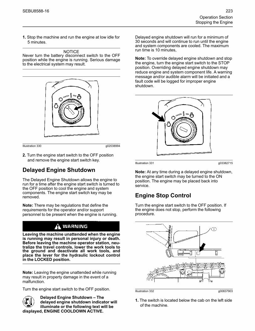
1. Stop the machine and run the engine at low idle for5 minutes.
NOTICENever turn the battery disconnect switch to the OFFposition while the engine is running. Serious damageto the electrical system may result.
Illustration 330 g02038994
2. Turn the engine start switch to the OFF positionand remove the engine start switch key.
Delayed Engine ShutdownThe Delayed Engine Shutdown allows the engine torun for a time after the engine start switch is turned tothe OFF position to cool the engine and systemcomponents. The engine start switch key may beremoved.
Note: There may be regulations that define therequirements for the operator and/or supportpersonnel to be present when the engine is running.
Leaving the machine unattended when the engineis running may result in personal injury or death.Before leaving the machine operator station, neu-tralize the travel controls, lower the work tools tothe ground and deactivate all work tools, andplace the lever for the hydraulic lockout controlin the LOCKED position.
Note: Leaving the engine unattended while runningmay result in property damage in the event of amalfunction.
Turn the engine start switch to the OFF position.
Delayed Engine Shutdown – Thedelayed engine shutdown indicator willilluminate or the following text will be
displayed, ENGINE COOLDOWN ACTIVE.
Delayed engine shutdown will run for a minimum of30 seconds and will continue to run until the engineand system components are cooled. The maximumrun time is 10 minutes,
Note: To override delayed engine shutdown and stopthe engine, turn the engine start switch to the STOPposition. Overriding delayed engine shutdown mayreduce engine and system component life. A warningmessage and/or audible alarm will be initiated and afault code will be logged for improper engineshutdown.
Illustration 331 g03382715
Note: At any time during a delayed engine shutdown,the engine start switch may be turned to the ONposition. The engine may be placed back intoservice.
Engine Stop ControlTurn the engine start switch to the OFF position. Ifthe engine does not stop, perform the followingprocedure.
Illustration 332 g00837903
1. The switch is located below the cab on the left sideof the machine.
SEBU8588-16 223Operation Section
Stopping the Engine

Illustration 333 g03374841
2. Lift cover (1).
3. Push switch (2) upward. This should stop theengine.
Note: Use the engine start switch to stop the enginefirst. Use the engine stop control as an alternatemethod to stop the engine.
4. Return the switch to the original position. Theengine will be enabled to start.
Note: Do not operate the machine again until themalfunction has been corrected.
5. Use the method that follows if the previous stepsdo not stop the engine.
Stop the Engine if an ElectricalMalfunction OccursTurn the engine start switch to the OFF position. Ifthe engine does not stop, perform the procedure thatfollows.
Illustration 334 g01139594
The fuel shutoff valve is located under the fuel tank.
Shut off the fuel supply by turning the fuel shutoffvalve clockwise. The engine will stop after consumingthe fuel in the fuel line. The engine may continue torun for a few minutes.
Repair the engine before you restart the engine. Thefuel system may need to be primed. See Operationand Maintenance Manual, “Fuel System - Prime” forinstructions.
i05716125
Leaving the MachineSMCS Code: 7000
Illustration 335 g00037860
1. Use the steps and the handholds when youdismount. When you dismount, face the machineand use both hands.
2. Inspect the engine compartment for debris. Cleanout any debris in order to avoid a fire hazard.
3. Remove all flammable debris from the front bottomguard through the access doors in order to reducea fire hazard. Discard the debris properly.
4. Always turn the battery disconnect switch to theOFF position before leaving the machine.
5. If the machine will not be operated for a month ormore, remove the battery disconnect switch key.
6. Lock all vandalism covers and all compartments.
7. Open the middle access door on the left side of themachine.
224 SEBU8588-16Operation SectionLeaving the Machine

Illustration 336 g03632898
8. Loosen the clamp that holds the vandalism guardsin place. Remove the vandalism guards from thestorage area.
Illustration 337 g02038846
9. Install the vandalism guards on the front windowand on the cab door. An identification number isstamped on each of the vandalism guards. Installthe vandalism guards in the correct sequence.Use bolts (A) only for vandalism guard (3) and forvandalism guard (5).
Note:When you are storing the vandalism guards,make sure that you place the guards in the storagearea in sequential order. The vandalism guards willonly fit in the storage area in this manner.
SEBU8588-16 225Operation Section
Leaving the Machine

Transportation Informationi02067410
Disconnecting HydraulicHoses and LinesSMCS Code: 5057
Release the pressure in the implement hydrauliccircuits (boom, stick and bucket) before any hydrauliclines or components are disconnected or removed.
Personal injury can result from hydraulic oil pres-sure and hot oil.
Hydraulic oil pressure can remain in the hydraulicsystem after the engine has been stopped. Seri-ous injury can be caused if this pressure is notreleased before any service is done on the hy-draulic system.
Make sure all of the work tools have been loweredto the ground, and the oil is cool before removingany components or lines. Remove the oil fillercap only when the engine is stopped, and the fill-er cap is cool enough to touch with your barehand.
NOTICECare must be taken to ensure that fluids are con-tained during performance of inspection, mainte-nance, testing, adjusting, and repair of the product.Be prepared to collect the fluid with suitable contain-ers before opening any compartment or disassem-bling any component containing fluids.
Refer to Special Publication, NENG2500, “DealerService Tool Catalog” for tools and supplies suitableto collect and contain fluids on Cat ® products.
Dispose of all fluids according to local regulationsand mandates.
1. Fully retract the stick cylinder rod.
2. Adjust the position of the bucket so that the bucketis parallel to the ground.
3. Lower the boom until the bucket is flat on theground.
4. Stop the engine.
5. Turn the engine start switch to the ON positionwithout starting the engine.
6. Place the hydraulic lockout (lever) in theUNLOCKED position.
7.Move the joysticks and pedals to FULL STROKEposition in all directions. This will release anypressure that might be present in the pilot system.
8. Turn the engine start switch to the OFF position.
9. Slowly loosen the fill/vent plug on the hydraulictank and release the pressure.
10. Tighten the fill/vent plug on the hydraulic tank.
Note: If a hydraulic line for the boom, the stick or thebucket must be disconnected, utilize the purgescrews.
Personal injury can result from hydraulic oil pres-sure and hot oil.
Hydraulic oil pressure can remain in the hydraulicsystem after the pilot pressure is released. Seri-ous injury can result if this remaining pressure isnot released before any service is done on the hy-draulic system.
Make sure that the remaining pressure has beenreleased by utilizing the purge screws that are lo-cated on the boom, stick and bucket lines. Beforeany purge screw is turned, the bucket and or allof the attachments must be lowered to the groundor properly supported.
11. Locate a section of hose that will tightly fit overone of the purge screws.
Illustration 338 g00583861
(1) Hose clamp(2) Hose
12. If a section of hose cannot be located, loosenclamp (1) and disconnect hose (2) from theradiator.
226 SEBU8588-16Operation SectionTransportation Information

Illustration 339 g00836573
(2) Hose(3) Purge screws (one on each line)(A) Line for the bucket(B) Line for the stick(C) Line for the stick(D) Line for the stick(E) Line for the bucket
13. Connect one end of drain hose (2) to purge screw(3). Insert the other end of drain hose (2) into anempty container.
14. Loosen purge screw (3) by 1/2 turn. Hydraulic oilwill be drained from the drain hose to thecontainer.
Note: Dispose of drained fluid according to localregulations.
15. Tighten purge screw (3) to a torque of 13 ± 2 N·m(9.6 ± 1.5 lb ft) after all of the hydraulic oil hasbeen drained from the line.
Illustration 340 g00836574
(4) Purge screws for the boom
Note: Purge screws (4) for the boom are located onthe boom cylinder lines. The above procedure shouldbe used to drain the hydraulic oil from the boom linesas well.
16. After the hydraulic oil is drained, tighten the purgescrew. Then disconnect hose (2) from the purgescrew on the hydraulic line that is being drained.
17. If the hose from the radiator was used, replacethe hose with a new hose. Connect the new hose(2) and tighten clamp (1).
18. Pressure in the hydraulic system should now bereleased and lines and components can beremoved.
i08036521
Shipping the MachineSMCS Code: 7000; 7500
Automatic Engine Speed Control (AEC) will in-crease engine speed automatically when you op-erate the control levers and/or travel pedals withAEC switch on.
When loading and unloading the machine fromthe truck or working in close quarters always turnAEC switch off to prevent any possibility of sud-den movement of machine, which could result inserious injury or death.
Set the travel speed control switch to LOW beforeloading the machine. Never operate this switchwhen loading the machine on a trailer.
Investigate the travel route for overpass clearances.Make sure that there will be adequate clearance forthe machine.
Remove ice, snow, or other slippery material from theloading dock and from the truck bed before you loadthe machine onto the transport machine. Removingice, snow, or other slippery material will help toprevent the machine from slipping in transit.
Note: Obey all laws that govern the characteristics ofa load (height, weight, width, and length). Observe allregulations that govern wide loads. Certain regionsmay require the removal of door hooks and cabbumpers, if equipped. Consult all local and regionalregulations
Choose the flattest ground when you load themachine or when you unload the machine.
1. Before you load the machine, chock the trailerwheels or the rail car wheels.
2.When you use loading ramps, make sure that theloading ramps have adequate length, adequatewidth, adequate strength, and an adequate slope.
3.Maintain the slope of the loading ramps within 15degrees of the ground.
SEBU8588-16 227Operation Section
Shipping the Machine

4. Position the machine so that the machine can drivestraight up the loading ramps. The final drivesshould be toward the rear of the machine. Do notoperate the control levers while the machine is onthe loading ramps.
5.When you drive over the loading ramp joint areas,maintain the balance point of the machine.
6. Lower the work tool to the bed or to the floor of thetransport machine.
7. To prevent rolling of the machine or suddenmovement of the machine, perform the followingitems:
• Chock both tracks.
• Install sufficient tie-downs at several locations.
• Fasten wire cables.
8. If equipped, remove door hooks, cab bumpers,and fuel tank step as necessary. Refer to localregulations.
Illustration 341 g06516462
(1) Cover(2) Nuts(3) Door Hook(A) Inside(B) Outside
a. Remove cover (1) and nuts (2) to remove doorhook (3).
Illustration 342 g06516469
b. Remove any bumpers on your cab.
NOTICEDo not allow the chrome surface of the bucket cylin-der rod to touch any part of the trailer. Damage to therod can occur from impact with the trailer duringtransport.
Note: Refer to Operation and Maintenance Manual,“Specifications”.
Shipping a Machine that is notCompletely AssembledIf the machine must be shipped when the boom,stick, or counterweight is not assembled on themachine, follow the instructions in Operation andMaintenance Manual, “Operation”.
228 SEBU8588-16Operation SectionShipping the Machine

The ROPS structural certification depends on thesupport of the boom, stick, and counterweight inthe event of a machine tip over or a machine roll-over incident.
When the machine needs to be moved withoutthe boom, stick, or counterweight being installed,avoid any machine operations which could affectmachine stability as a machine tip over or a ma-chine rollover incident could result in serious in-jury or death.
The machine should be operated slowly on flat,stable ground or pavement by qualifiedoperators.
i06650188
Securing the MachineSMCS Code: 7000
NOTICENever transport the machine with the engine running.
Comply with any laws that govern the characteristicsof a load (length, width, height, and weight).
Illustration 343 g00543871
1.Move the hydraulic lockout control to the LOCKEDposition.
2. Turn the engine start switch to the OFF position inorder to stop the engine. Remove the engine startswitch key.
3. Turn the battery disconnect switch to OFF andremove the disconnect switch key.
4. Remove the ether starting aid cylinder.
Reference: Refer to Operation and MaintenanceManual, “Ether Starting Aid Cylinder - Replace” forthe removal procedure.
5. Lock the door and the access covers. Attach anyvandalism protection.
6. The Product Link antenna (if equipped) may berepositioned in order to meet the regulationsregarding height of some locations. The ProductLink antenna is located on top of the cab. Performthe following procedure in order to move theProduct Link antenna to the transport position.
Illustration 344 g02263573
Bracket in normal operating position.
a. Remove bolts (2) from bracket (1).
SEBU8588-16 229Operation Section
Securing the Machine

Illustration 345 g02270173
b. Reinstall bracket (1) with bolts (2) located in thetop two holes of the bracket. Refer to illustration345 .
Note: The bracket for the Product Link antennamust be place back into the normal operatingposition before the machine can be placed backinto service.
7. The side view camera is located on top of the fueltank and it must be repositioned for transport.Perform the following procedure in order to movethe camera to the transport position.
Illustration 346 g06051521
Side view camera in position for transport
a. Loosen bolts (4) and (5) and slide the cameraupward to the transport position.
8. Tighten bolts (4) and (5).
Note: The side view camera must be placed backinto the normal operating position before the machinecan be placed back into service.
9. The platform light (if equipped) may berepositioned in order to meet the regulationsregarding height of some locations. The platformlight is located on top of the cab. Perform thefollowing procedure in order to move the platformlight to the transport position.
Illustration 347 g03670580
a. Remove bolts (2) from bracket (1).
Illustration 348 g03670582
b. Reinstall bracket (1) with bolts (2) located in thetop two holes of the bracket. Refer to illustration348 .
Note: The bracket for the platform light must beplace back into the normal operating positionbefore the machine can be placed back intoservice.
10. Cover the exhaust opening.
230 SEBU8588-16Operation SectionSecuring the Machine

NOTICEDo not allow the turbocharger to rotate while the en-gine is not operating. Damage to the turbochargercan result.
Note: Before you remove the excavator from thetransport machine, remove the protective coveringfrom the exhaust opening.
Illustration 349 g02142926
11. Chock the tracks and secure the machine with tie-downs. Make sure that you use the proper ratedwire cable.
Use the front towing eyes on the lower frame, therear towing eyes on the lower frame. Also use therear towing eye that is on the upper frame.
Securely fasten all loose parts and all removedparts to the trailer or to the rail car.
When the engine is stopped, the swing parking brakeis automatically applied. The parking brake willprevent the upper structure from swinging.
NOTICEIn freezing weather, protect the cooling system withantifreeze, to the lowest outside expected tempera-ture on the travel route. Or, drain the cooling systemcompletely.
i02238094
Mirror InstallationSMCS Code: 7319
Note: Before you transport the machine, remove therearview mirror.
After you transport the machine, reinstall the rearviewmirror. Use the following procedure.
Illustration 350 g01128822
Mounting bolts and washers
1. Use three mounting bolts and three washers toinstall the bracket on the right side of the storagebox.
Illustration 351 g01129011
(1) Mirror(2) Bracket(3) Bolt(4) Washer
2. Position mirror (1) on support bracket (2), andinstall bolts (3) and washers (4) on each end.
SEBU8588-16 231Operation SectionMirror Installation
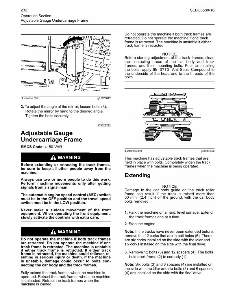
Illustration 352 g01129042
3. To adjust the angle of the mirror, loosen bolts (3).Rotate the mirror by hand to the desired angle.Tighten the bolts securely.
i05328212
Adjustable GaugeUndercarriage FrameSMCS Code: 4150-VAR
Before extending or retracting the track frames,be sure to keep all other people away from themachine.
Always use two or more people to do this work.Perform machine movements only after gettingsignals from a signal man.
The automatic engine speed control (AEC) switchmust be in the OFF position and the travel speedswitch must be in the LOW position.
Never make a sudden movement of the frontequipment. When operating the front equipment,slowly activate the controls with extra care.
Do not operate the machine if both track framesare retracted. Do not operate the machine if onetrack frame is retracted. The machine is unstableif either track frame is retracted. If either trackframe is retracted, the machine could rollover, re-sulting in serious injury or death. If the machineis unstable, damage could occur to bolts con-necting the car body and the track frames.
Fully extend the track frames when the machine isoperated. Retract the track frames when the machineis unloaded. Retract the track frames when themachine is loaded.
Do not operate the machine if both track frames areretracted. Do not operate the machine if one trackframe is retracted. The machine is unstable if eithertrack frame is retracted.
NOTICEBefore starting adjustment of the track frames, cleanthe contacting areas of the car body and trackframes, and their mounting bolts. Prior to installingthe bolts, apply 9M-3710 Anti-Seize Compound tothe underside of the head and to the threads of thebolts.
Illustration 353 g00285692
This machine has adjustable track frames that areheld in place with bolts. Completely widen the trackframes when the machine is being operated.
Extending
NOTICEDamage to the car body guide on the track rollerframe can result if the track is raised more than60 mm (2.4 inch) off the ground, with the car bodybolts removed.
1. Park the machine on a hard, level surface. Extendthe track frames one at a time.
2. Stop the engine.
Note: If the tracks have never been extended before,remove the 12 corks that are in bolt holes (6). Thereare six corks installed on the side with the idler andsix corks installed on the side with the final drive.
3. Remove 12 bolts (3) and 12 spacers (4). The boltshold track frame (2) to carbody (1).
Note: Six bolts (3) and 6 spacers (4) are installed onthe side with the idler and six bolts (3) and 6 spacers(4) are installed on the side with the final drive.
232 SEBU8588-16Operation SectionAdjustable Gauge Undercarriage Frame

Note:When track frame (2) is moved in order toextend the overall width, do not loosen two bolts (5)that are for the track guide.
Illustration 354 g02720211
(1) Carbody(2) Track frame(3) Bolts(4) Spacers(5) Bolts(6) Corks
4. Start the engine. Position the boom over theopposite track frame with the stick at anapproximate 80 degree angle to the ground. Placethe bucket teeth into the ground, as shown. Thismachine position provides the best stability forextending the track frames.
5. Apply a downward pressure with the boom in orderto raise the track slightly.
Illustration 355 g00286117
6. Use the STICK IN position to extend the trackframe by moving the carbody away from the track.
7. After the track frame has been correctly extended,lower the raised track frame to the ground.
8. Align the bolt holes of carbody (1) and track frame(2). Install 20 bolts (3) and 20 spacers (4). Ifnecessary, slowly operate the machine back andforth until the bolt holes are aligned. Tighten thebolts to 2800 ± 350 N·m (2000 ± 220 lb ft).
Illustration 356 g02720218
(1) Carbody(2) Track frame(3) Bolts(4) Spacers(5) Bolt
9. Install four bolts (3) and four spacers (4) to protectnon-used threads (A).
SEBU8588-16 233Operation Section
Adjustable Gauge Undercarriage Frame

Note: Two bolts (3) and two spacers (4) are installedon the side with the idler. Two bolts (3) and twospacers (4) are installed on the side with the finaldrive.
10. Repeat Steps 1 through 8 for the other trackframe.
Retracting1. Park the machine on a hard, level surface. Retractthe track frames one at a time.
Illustration 357 g00581851
2. Position the machine with the front at a right angleto the track frame that is being retracted, asshown.
3. Stop the engine.
Illustration 358 g02720218
(1) Carbody(2) Track frame(3) Bolts(4) Spacers(5) Bolt
4. Remove four bolts (3) and four spacers (4), whichprotect non-used threads (A).
Note: Two bolts (3) and two spacers (4) are installedon the side with the idler. Two bolts (3) and twospacers (4) are installed on the side with the finaldrive. Put these parts into storage.
5. Remove 20 bolts (3) and 20 spacers (4). The boltshold track frame (2) to carbody (1).
Note:When you move track frame (2) in order toretract the overall width, do not loosen two bolts (5)that are for the guide.
Note: Ten bolts (3) and ten spacers (4) are installedon the side with the idler and ten bolts (3) and tenspacers (4) are installed on the side with the finaldrive.
234 SEBU8588-16Operation SectionAdjustable Gauge Undercarriage Frame

Illustration 359 g00697383
6. Start the engine. Apply downward pressure withthe boom in order to raise the track approximately40 cm (16 inch) above ground level.
7. Slowly run the raised track at a low idle. This willcause the raised track to slide toward the center ofthe machine. The full sliding distance should be250 mm (10 inch).
8. After the raised track frame has been correctlyretracted, lower the track frame to the ground.
Illustration 360 g02720211
(1) Carbody(2) Track frame(3) Bolts(4) Spacers(5) Bolts(6) Corks
9. Align the bolt holes of carbody (1) and track frame(2). Install 12 bolts (3) and 12 spacers (4). Ifnecessary, slowly operate the machine back andforth until the bolt holes are aligned. Tighten thebolts to 2800 ± 350 N·m (2000 ± 220 lb ft).
Note: To protect the bolt holes that are in the trackframe from debris and mud, insert corks into five boltholes (A).
10. Repeat Steps 1 through 9 for the other trackframe.
i05718713
Camera Harness - Disconnectand ConnectSMCS Code: 1408; 7348
Working on the wiring harness for the rear cam-era during the removal and installation of thecounterweight could result in a crushing hazard.The counterweight could fall, and the falling ofthe counterweight could cause personal injury ordeath. Disconnect the wiring harness to the rearcamera before the you remove the counterweight.Reconnect the wiring harness to the rear cameraafter you install the counterweight.
Unexpected machine movement can cause injuryor death.
In order to avoid possible machine movement,move the hydraulic lockout control to theLOCKED position and attach a Special Instruc-tion, SEHS7332, “Do Not Operate” or similarwarning tag to the hydraulic lockout control.
1. Park the machine on level ground.
2. Lower the work tool to the ground.
3.Move the hydraulic lockout control to the LOCKEDposition.
4. Turn the engine start switch to the OFF position inorder to stop the engine. Remove the engine startswitch key.
5. Turn the battery disconnect switch to OFF andremove the disconnect switch key.
SEBU8588-16 235Operation Section
Camera Harness - Disconnect and Connect

Disconnection of the Harness forthe Rear View CameraDisconnect the harness for the rear view camerabefore removing the counterweight.
Illustration 361 g03635422
1. Open the engine hood.
Illustration 362 g03635400
2. Remove bolt (1) and clip (2).
3. Turn plug(3) and pull apart.
4. Pull the wiring for the rear view camera until plug(3) comes in to the pump compartment.
5. Close the engine hood.
Connection of the Harness for theRear View CameraReconnect the harness for the camera in the reverseorder.
i08134287
Counterweight Removal andInstallationSMCS Code: 7056
Counterweight Removal andInstallation for Standard Machines
Unexpected machine movement can cause injuryor death.
In order to avoid possible machine movement,move the hydraulic lockout control to theLOCKED position and attach a Special Instruc-tion, SEHS7332, “Do Not Operate” or similarwarning tag to the hydraulic lockout control.
Personal injury or death can occur from a coun-terweight falling during removal or installation.
Do not allow personnel under or around the coun-terweight during removal or installation.
Make sure that the lifting device is in good condi-tion and is capable of handling the weight of thecounterweight.
Personal injury or death can occur from a coun-terweight falling during removal or installation.
Before you remove the counterweight mountingbolts, read and understand the instructions andwarnings in the Operation and MaintenanceManual.
Make certain personnel are clear of cable whenthere is a load on it. Cable can break and causepersonal injury.
236 SEBU8588-16Operation SectionCounterweight Removal and Installation

Personal injury or death can occur from a coun-terweight falling during removal or installation.Before you begin the Removal Procedure, makesure that the support blocks are installed andtightened properly.
Crush Hazard. Read and Understand the Opera-tion and Maintenance Manual before performingmaintenance on equipment. Could cause seriousinjury or death.
Unexpected machine damage and personal injuryor death can occur from any machine operationwithout counterweight bolt tightened properly.
Make sure to tighten the counterweight mountingbolts when the counterweight is installed.
Machines Equipped with Endless Links
Reference: Refer to Operation and MaintenanceManual, “Specifications” for specific weightinformation.
Note: Before you remove the counterweight,disconnect the wiring for the rear view camera.Refer to Operation and Maintenance Manual,“Camera Harness - Disconnect and Connect” formore information.
1. Position the machine on a surface that is hard andlevel. Lower the work tool to the ground.
2.Move the hydraulic lockout control to the LOCKEDposition.
Illustration 363 g03485178
3. Fasten a proper rated wire cable with shackles tothe link on the counterweight. Use an appropriatelifting device to tension the cable.
4. Lift the counterweight enough so that there is noload on the retaining Links.
Illustration 364 g03437997
5. Remove six counterweight mounting bolts andwashers. Inspect the bolts for damage. If the boltsare damaged, replace the bolts.
SEBU8588-16 237Operation Section
Counterweight Removal and Installation

Illustration 365 g03438036
6. Separate the counterweight from the machine.Lower the counterweight onto suitable supports.
Counterweight Installation
Perform the installation procedure in reverse order.
Note: Temporarily tighten the six counterweightmounting bolts. Decrease the tension on the liftingcable. Make sure that the counterweight is correctlypositioned on the retaining pins. Tighten the bolts to atorque of 2800 ± 350 N·m (1990 ± 220 lb ft).
Machines Equipped withCounterweight Removal System
IMPROPER OPERATION OF THE COUNTER-WEIGHT REMOVAL SYSTEM CAN RESULT INSERIOUS INJURY OR DEATH. DO NOT OPERATETHIS SYSTEM UNLESS YOU HAVE READ ANDUNDERSTAND THE INSTRUCTIONS AND WARN-INGS IN THE OPERATION AND MAINTENANCEMANUAL.
Before you remove the counterweight, check forsigns of hydraulic oil leaking from the Counter-weight Removal System. An oil leak may be asign of a potential system failure and needs to becorrected before removing the counterweightmounting bolts. A hydraulic leak, along with otherfactors, can result in personal injury or death.
Inadequate linkage cylinder pressure can causethe counterweight to lower quickly. This may re-sult in personal injury or death.
Before removing bolts, make certain the lampand system are working properly by following theestablished procedure.
Contact your Cat dealer for service.
Counterweight Removal
Reference: Refer to Operation and MaintenanceManual, “Specifications” for specific weightinformation.
Note: Before you remove the counterweight,disconnect the wiring for the rear view camera.Refer to Operation and Maintenance Manual,“Camera Harness - Disconnect and Connect” formore information.
1. Position the machine on a surface that is hard andlevel.
2. Position the upper structure parallel to the tracks.Lower the work tool to the ground.
3. Start the engine. Adjust the engine speed to one-third of full throttle engine speed.
Illustration 366 g00104545
4.Move the hydraulic lockout control to the LOCKEDposition. Attach a “Do Not Operate” warning tag ora similar warning tag to the start switch or to thecontrols.
238 SEBU8588-16Operation SectionCounterweight Removal and Installation

Illustration 367 g03640796
5. Remove two bolts from the top of thecounterweight cover plate.
6. Open the rear access door on the right side of themachine.
Illustration 368 g03485316
(1) Switch(2) Control lever(3) Stop valves(A) CLOSED position(B) OPEN position
7. Place stop valves (3) in OPEN position (B).
8.Move switch (1) upward to the ON position.
9.Move control lever (2) upward to support thecounterweight and relieve the weight on thecounterweight mounting bolts. This will keep thecounterweight from possibly sliding off when thecounterweight mounting bolts are removed.
Illustration 369 g06510567
10. There should be a slight tension on the chains.Inspect both chains to verify condition and thatthey are not seized or binding. Monitor chaintension for 5 minutes to verify no leaks and noexcessive drift is present indicating service isrequired before system use. Contact yourCaterpillar dealer if service is required.
Illustration 370 g06548425
11. Remove bolts (C) from the counterweight.
12. Reinstall bolts (C) and tighten by hand until thebolts are fully engaged.
Note: Do not use tools to reinstall bolts (C).
13. Loosen bolts (C) two full revolutions.
Note: Do not remove bolts (C) from thecounterweight.
14. Remove remaining bolts (D).
15. Remove bolts (C) by hand .
Note: Do not use tools to remove bolts (C).
SEBU8588-16 239Operation Section
Counterweight Removal and Installation

Note: If unable to remove bolts (C) by hand, thecounterweight removal system may not beappropriately supporting the weight of thecounterweight. Adjustment of the linkage, oradditional support, may be required to safely removethe final two bolts.
Illustration 371 g03485336
(4) Counterweight(5) Retaining pin
16.Move control lever (2) upward to raise thecounterweight (4) until access to the retaining pins(5) can be gained.
Illustration 372 g03485358
(5) Retaining pin(6) Extension
17. Use a ratchet wrench and an extension (6) torotate each retaining pin (5). Retaining pins (5)require 90 degrees of rotation. The retaining pins(5) are now in the UNLOCKED position.
Illustration 373 g03485378
(4) Counterweight
When the removal cylinder is used to lower thecounterweight, the counterweight can wedgeagainst the machine frame which stops the down-ward movement of the counterweight. Since theremoval cylinder continues to retract and thecounterweight stopped, slack in the chain for theremoval cylinder occurs.
The counterweight can suddenly fall due to theslack in the chain which could result in personalinjury or death.
Monitor the lowering of the counterweight whenthe counterweight is being lowered with the re-moval cylinder. If the removal cylinder is re-tracted and the downward movement of thecounterweight stops, stop the lowering proce-dure and correct the wedging of the counter-weight against the machine frame.
18.Move control lever (2) downward to lowercounterweight (4) onto supports on the ground.
240 SEBU8588-16Operation SectionCounterweight Removal and Installation

Illustration 374 g03485456
(4) Counterweight(7) Chains(8) Pins(9) Nuts(10) Cotter pins
19. Remove cotter pins (10). Loosen nuts (9).
20. Remove pins (8) to disconnect chains (7) fromcounterweight (4).
Illustration 375 g03485485
(7) Chain(11) Bracket(12) Washer(13) Bolt(14) Pin(15) Bolt(16) Washer
21. Pin (14) should be located in the storage box.Remove pin (14) from the storage box.
22. Install pin (14) into chains (7).
23. Install bolts (15) and washers (16) to attach pin(14) to bracket (11).
24. At the end of pin (14), install washer (12) and bolt(13).
Illustration 376 g03485518
25. Fasten a proper rated wire cable with shackles tothe link on the counterweight. Use an appropriatelifting device to tension the cable.
Illustration 377 g03438601
26. Lift the counterweight enough so that there is noload on the retaining Links.
Illustration 378 g03438036
27. Use an appropriate lifting device to put thecounterweight on suitable supports.
SEBU8588-16 241Operation Section
Counterweight Removal and Installation

Counterweight Installation
Perform the installation procedure in reverse order.
Note:Make sure that you remove pin (14), bolt (13),washer (12), bolt (15), and washer (16). Return theseparts to the storage box.
Note: Before you install the counterweight mountingbolts, make sure that the retaining pins are in theLOCKED position and that the counterweight issecurely held on the retaining pins. There should bea slight amount of slack on the chains.
Tighten the counterweight mounting bolts to a torqueof 2800 ± 350 N·m (1990 ± 220 lb ft).
i08118445
Lifting and Tying Down theMachineSMCS Code: 7000; 7500
Toproperly lift the machine, the counterweight, andthe front parts must be disassembled.
Illustration 379 g03368287
Illustration 380 g03374854
NOTICEImproper lifting and improper tie-downs can allow theload to shift and cause injury or damage.
The weight and the instructions that are given hereindescribe the machine as the machine ismanufactured by Caterpillar.
Reference: Refer to the Operation and Maintenance,“Specifications” for specific weight information.
1. Use proper rated cables and slings for lifting. Thecrane should be positioned so that the machine islifted parallel to the ground.
2. To prevent contact with the machine, lifting cablesshould have sufficient length.
242 SEBU8588-16Operation SectionLifting and Tying Down the Machine

3. Use the rear eyes and the front eyes that areprovided on the lower frame to fasten tie-downs.Use corner protectors for sharp corners.
4.Move the hydraulic lockout control to the LOCKEDposition.
Tying Down the MachineThere are two methods that can be used to tie downa machine. Local and/or regional regulations willdetermine which method to use.
Note: Obey all local and regional governmentalregulations.
Frictional and Direct Lashing
When allowed, a combination of frictional lashing anddirect lashing is the preferred method to tie down amachine.
Illustration 381 g02793465
(A) Front of the machine (B) Rear of the machine
Diagonal Lashing
In areas where frictional lashing is not allowed, directlashing can be used as shown below.
Illustration 382 g06553236
(A) Front of the machine (B) Rear of the machine
SEBU8588-16 243Operation Section
Lifting and Tying Down the Machine

Tying Down the Machine
Tie Down Point – To tie down themachine, attach the tie-downs to the tie-down points.
The weight and the instructions that are given hereindescribe the machine as the machine ismanufactured by Caterpillar.
Refer to the Operation and Maintenance,“Specifications” for specific weight information.
1. Use proper rated cables and shackles for tyingdown the machine.
2. Use the rear eyes and the front eyes that areprovided on the lower frame to fasten tie-downs.Use corner protectors for sharp corners.
3.Move the hydraulic lockout control to the LOCKEDposition.
4. If there is a requirement of diagonal lashing fortying down, use the proper tie-down point on thelower frame. Set the lashing angle which is on thelongitudinal axis of the machine and the cable, at30 to 50 degrees.
Lifting the Machine SegmentsMachine Without Components
Illustration 383 g03638002
1. Remove engine hood (1).
Illustration 384 g03368309
Fasten a proper rated wire cable to each lifting eyewith a shackle. This machine has four lifting points onthe front of the machine. The machine also has onelifting point on the rear of the machine.
By using an appropriate lifting device, put tension onthe lifting cables and slowly lift the machine.
Counterweight
Illustration 385 g03438601
Refer to Operation and Maintenance Manual,“Counterweight Removal and Installation” for specificinformation.
244 SEBU8588-16Operation SectionLifting and Tying Down the Machine

Stick with Bucket Cylinder
Illustration 386 g00581738
Use the two lifting eyes that are provided in thebrackets on the top of the stick. Install shacklesthrough the lifting eyes and fasten properly rated wirecable to the front section of the stick. Use a cloth toprotect the lifting cable from being damaged by theedges of the stick.
Slowly lift the stick with the bucket cylinder.
Bucket
Illustration 387 g00115251
(1) Pin(2) Sleeve(3) Bolts(4) Nuts
Install pin (1) and sleeve (2) in the brackets of thebucket. Illustration 387 indicates the method tosecure pin (1) with bolts (3) and nuts (4). Fasten twoproper rated wire cables to pin (1).
Boom with Stick Cylinder
Illustration 388 g06229426
Use the two lifting eyes that are provided in thebrackets on the top of the Boom. Install shacklesthrough the lifting eyes and fasten properly rated wirecable to the front section of the Boom. Use a cloth toprotect the lifting cable from being damaged by theedges of the Boom.
Slowly lift the stick with the bucket cylinder.
Boom Cylinder
Illustration 389 g00581741
Fasten two properly rated wire cables to the boomcylinder and secure the piston rod to the cylindertube.
Slowly lift the boom cylinder.
SEBU8588-16 245Operation Section
Lifting and Tying Down the Machine

Walkway
Illustration 390 g00581742
Use two properly rated wire cables. Fasten the liftingcables to the positions that are indicated inIllustration 379 .
Lift the walkways one at a time.
246 SEBU8588-16Operation SectionLifting and Tying Down the Machine
Towing Informationi07816489
Towing the MachineSMCS Code: 7000
Personal injury or death could result when towinga disabled machine incorrectly.
Block the machine to prevent movement beforefinal drives are disengaged. The machine can rollfree if it is not blocked. With final drives disen-gaged, the machine cannot be stopped orsteered.
Follow the recommendations below, to properlyperform the towing procedure.
Relieve the hydraulic tank and line pressure be-fore any disassembly.
Even after the machine has been turned off, thehydraulic oil can still be hot enough to burn. Al-low the hydraulic oil to cool before draining.
NOTICETo tow the machine, both final drives must bedisengaged.
Do not operate the travel motors with the final drivesdisengaged. Damage could result.
These towing instructions are for moving a disabledmachine for a short distance at low speed. Move themachine at a speed of 2 km/h (1.2 mph) or less to aconvenient location for repair. Always haul themachine if long distance moving is required.
Shields must be provided on both machines. Theshields will protect the operator if the tow line or thetow bar breaks.
Do not allow an operator to be on the machine that isbeing towed.
Before you tow the machine, make sure that the towline or the tow bar is in good condition. Do not use awire rope that is kinked, twisted, or damaged. Makesure that the tow line or the tow bar has enoughstrength for the towing procedure that is involved.The strength of the tow line or of the tow bar shouldbe at least 150 percent of the gross weight of thetowed machine. This requirement is for a disabledmachine that is stuck in the mud and for being towedon a grade.
Do not use a chain for pulling a disabled machine. Achain link can break. Personal injury may be causedif a link breaks. Use a wire rope with ends that haveloops or rings. Put an observer in a safe position inorder to watch the pulling procedure. The observercan stop the procedure if the wire rope starts tobreak. Stop pulling whenever the towing machinemoves without moving the towed machine.
During towing, do not allow anyone to step betweenthe towing and the towed machines.
Do not allow the wire rope to be straddled while themachine is being towed.
Keep the tow line angle to a minimum. Do not exceeda 30 degree angle from the straight ahead position.
Avoid towing the machine on a slope.
Quick machine movement could overload the tow lineor the tow bar. This could cause the tow line or thetow bar to break. Gradual, steady machinemovement will be more effective.
Normally, the towing machine should be as large asthe disabled machine. Make sure that the towingmachine has enough brake capacity, enough weight,and enough power. The towing machine must beable to control both machines for the grade that isinvolved and for the distance that is involved.
Provide sufficient control and sufficient braking whenyou are moving a disabled machine downhill. A largertowing machine may be required or additionalmachines that are connected to the rear of thedisabled machine. This will prevent the machine fromrolling away out of control.
All situation requirements cannot be listed. Minimaltowing machine capacity is required on smooth, levelsurfaces. Maximum towing machine capacity isrequired on an incline or on a surface that is in poorcondition.
Do not tow a loaded machine.
Consult your Caterpillar dealer for the equipment thatis necessary for towing a disabled machine.
Prior to releasing the brake of the final drive, firmlylock both tracks in order to prevent the machine frommoving suddenly. When the machine is ready to betowed, release the brake of the final drive.
SEBU8588-16 247Operation SectionTowing Information

Parking Brake Release
Illustration 391 g00692529
1. Remove the travel drive covers from the baseframe.
2. Clean the travel motors, travel brake valves, andnearby areas.
3. Disconnect the hydraulic lines from the brakevalve. Plug the disconnected line.
Illustration 392 g00692530
4. Loosen bolts (1). Remove brake valve (2) fromtravel motor (3).
Illustration 393 g02409157
5. Remove plugs (4).Table 71
Washer Dimensions
CalloutInner diameter
(I.D.)Outer Diameter
(O.D.) Thickness
(5) 11 mm(0.43 inch)
25 mm(0.98 inch)
3 mm(0.12 inch)
(6) 11 mm(0.43 inch)
19 mm(0.75 inch)
6 mm(0.24 inch)
Bolt
(7) M8 x 1.25 x 90 mm
6. Install one washer (5) in each hole.
7. Install one washer (6) on top of each washer (5).
8. Insert one M8 x1.25 x 90 mm bolt (7) into eachhole and tighten until snug against the washersand travel motor head.
9. Alternately turn each bolt one half turn until eachbolt has been rotated two turns.
Note: If longer bolts are used, install the appropriatethicker washers in order to maintain requiredspacing.
Brake valve cover (9) is forced by spring (11). Itcan fly apart suddenly when the mounting boltsare removed. Take extra care when removing cov-er (9).
248 SEBU8588-16Operation SectionTowing the Machine

Illustration 394 g00692532
10. Remove bolts (8) in order to remove cover (9) ofbrake valve (2). To remove bolts (8), remove thetwo bolts that are separated by 180 degrees.Install two replacement M12 bolts in the removedbolt holes. Tighten the bolts.
11. Remove the remaining two bolts (8). Slowlyremove the replacement M12 bolts.
12. Remove bushing (10), spring (11), washer(12)and spool (13) from the brake valve.
13. Install cover (9) to the valve body. Tighten bolts(8).
Illustration 395 g00692530
14. Install brake valve (2) to motor (3) with bolts (1).Reconnect the two lines to brake valve (2).
15. Repeat Steps 1 through 14 for the other travelmotor.
Note: The parking brake has now been released.The machine is ready for towing.
16. After the machine has been towed, return thebrake and the brake valve to the original condition.Verify that the brake and the brake valve activatecorrectly.
Table 72
Item Number Part
Recommended Torque
N·m lb ft(1)
Bolt 100 ± 20 74 ± 10(8)
Retrieval of Machine
Illustration 396 g02533437
Note: Shackles must be used for towing themachine. The wire rope should be horizontal andstraight to the track frame.
Install a properly rated wire rope to the lower frame ofthe towing machine and the lower frame of the towedmachine. The permissible force for the lower frame is100 percent of the gross weight of the towedmachine.
Note: In order to prevent damage to the wire rope orthe lower frame of the machines, use protectivesleeves on the corners of the lower frame.
SEBU8588-16 249Operation Section
Towing the Machine

Retrieve the disabled machine carefully. The appliedload for each wire rope should be equal. The angle(A) between each wire rope should be 60 degreemaximum. Operate the machine at a low speed.
Lightweight Towing
Illustration 397 g03204763
The maximum load for lightweight towing is246000 N (55303 lb).
Shackles must be used for towing the machine. Thewire rope should be horizontal and straight to thetrack frame.
Install a properly rated wire rope to the lower frame ofthe towing machine and the lower frame of the towedmachine. Operate the machine at a low speed.
250 SEBU8588-16Operation SectionTowing the Machine

Engine Starting (AlternateMethods)
i05974849
Engine Starting with JumpStart Cables(If Equipped)SMCS Code: 1000; 7000
Failure to properly service the batteries maycause peronal injury.
Prevent sparks near the batteries. They couldcause vapors to explode. Do not allow the jumpstart cable ends to contact each other or themachine.
Do not smoke when checking battery electrolytelevels.
Electrolyte is an acid and can cause personal in-jury if it contacts skin or eyes.
Always wear eye protection when starting a ma-chine with jump start cables.
Improper jump start procedures can cause an ex-plosion resulting in personal injury.
Always connect the battery positive (+) to batterypositive (+) and the battery negative (−) to batterynegative (−).
Jump start only with an energy source with thesame voltage as the stalled machine.
Turn off all lights and accessories on the stalledmachine. Otherwise, they will operate when theenergy source is connected.
NOTICETo prevent damage to engine bearings and to electri-cal circuits when you jump-start a machine, do not al-low the stalled machine to touch the machine that isused as the electrical source.
Turn on (close) the battery disconnect switch prior tothe boost connection to prevent damage to electricalcomponents on the stalled machine.
Use only equal voltage for starting. Check the batteryand starter voltage rating of your machine. Use onlythe same voltage for jump starting. Use of a welder orhigher voltage will damage the electrical system.
Severely discharged maintenance free batteries donot fully recharge from the alternator after jump start-ing. The batteries must be charged to proper voltagewith a battery charger. Many batteries thought to beunusable are still rechargeable.
Refer to Special Instruction, SEHS7633, “Battery TestProcedure” for complete testing and charging infor-mation. This publication is available from your Catdealer.
When the auxiliary start receptacles are notavailable, use the following procedure.
1. Lower the equipment to the ground. Move allcontrols to the HOLD position. Move the hydrauliclockout control to the LOCKED position.
2. Turn the start switch on the stalled machine to theOFF position. Turn off all accessories.
3. Turn the battery disconnect switch on the stalledmachine to the ON position.
4.Move the machine that is being used as anelectrical source near the stalled machine so thatthe jump-start cables reach the stalled machine.Do not allow the machines to contact eachother.
5. Stop the engine of the machine that is being usedas an electrical source. If you are using anauxiliary power source, turn off the chargingsystem.
6. Ensure that battery caps on both machines aretight and correctly placed. Ensure that batteries inthe stalled machine are not frozen. Make sure thatthe batteries have enough electrolyte.
Note: The positive terminal of the 24 V system of thesource and the negative terminal of the 24 V systemof the source must be identified correctly before thejumper cables are connected. The positive terminalof the 24 V system of the discharged battery must beidentified correctly before the jumper cables areconnected.
SEBU8588-16 251Operation Section
Engine Starting (Alternate Methods)

7. The positive ends of the jump-start cable are red.Connect one positive end of the jump-start cableto the positive cable terminal of the dischargedbattery. Some machines have battery sets.
Note: Batteries that are in series may be in separatecompartments. Use the terminal that is connected tothe starter solenoid. This battery or battery set isnormally on the same side of the machine as thestarter.
Do not allow the positive cable clamps to contactany metal except for the battery terminals.
Illustration 398 g01226420
Typical example of the location of the batteries in anexcavator(1) Red positive post to starter(2) The black negative post connects to the battery disconnect
switch.(3) Do not use these two connections for jump starting. The red
positive post is connected in series to the black negative post.(4) Cover
8. Connect the other positive end of the jump-startcable to the positive cable terminal of the electricalsource.
9. Connect one negative end of the jump-start cableto the negative cable terminal of the electricalsource.
10. Finally, connect the other negative end of thejump-start cable to the frame of the stalledmachine. Do not connect the jump-start cable tothe battery post. Do not allow the jump-startcables to contact the battery cables, the fuel lines,the hydraulic lines, or any moving parts.
11. Start the engine of the machine that is being usedas an electrical source or energize the chargingsystem on the auxiliary power source.
12.Wait at least two minutes before you attempt tostart the stalled machine. This will allow thebatteries in the stalled machine to partially charge.
13. Attempt to start the stalled engine. See Operationand Maintenance Manual, “Engine Starting” for thecorrect starting procedure.
14. Immediately after you start the stalled engine,disconnect the jump-start cables in reverse order.
i06697121
Engine Starting with AuxiliaryStart Receptacle(If Equipped)SMCS Code: 1000; 7000
Illustration 399 g01122769
Typical location
Some Caterpillar products may be equipped with anauxiliary start receptacle as a standard part. If yourmachine is not equipped with an auxiliary startreceptacle, the machine can be equipped with anauxiliary start receptacle from parts service. This willensure that a permanent receptacle is alwaysavailable to jump-start the machine.
There are two cable assemblies that can be used tojump-start the stalled machine. You can jump-startthe stalled machine from another machine that isequipped with an auxiliary start receptacle or with anauxiliary power pack. Your Caterpillar dealer canprovide the correct cable lengths for your application.
1. Determine the reason that the engine will not start.
Reference: Refer to Special Instruction, SEHS7633,“Battery Test Procedure” for more information.
252 SEBU8588-16Operation SectionEngine Starting with Auxiliary Start Receptacle

2. Ensure that the travel control levers on the stalledmachine are in theCENTER position. Engage thehydraulic lockout control. Lower all work tools tothe ground. Move all controls to HOLD.
3. Turn the engine start switch key on the stalledmachine to the OFF position. Turn off allaccessories.
4. Turn the battery disconnect switch on the stalledmachine to ON.
5.Move the machine that is being used as a powersource close to the stalled machine. The jump-start cables should reach the batteries on bothmachines. DO NOTALLOW THE MACHINES TOCONTACT EACH OTHER.
6. Stop the engine on the machine that is being usedas a power source. If you use an auxiliary powersource, turn off the charging system.
7. Connect the appropriate jump-start cable to theauxiliary start receptacle on the stalled machine.
8. Connect the other end of the jump-start cable tothe auxiliary start receptacle of the machine that isbeing used as a power source.
9. Start the engine on the machine that is being usedas a power source or energize the chargingsystem on the auxiliary power source.
10.Wait for a minimum of 2 minutes while thebatteries in the stalled machine partially charge.
11. Attempt to start the stalled engine.
12. Immediately after the stalled engine starts,disconnect the jump-start cable from the powersource.
13. Disconnect the other end of the jump-start cablefrom the stalled machine.
14. Conclude the failure analysis on the startingcharging system of the stalled machine, asrequired. Check the machine while the engine isrunning and the charging system is in operation.
SEBU8588-16 253Operation Section
If Equipped

Maintenance Section
Maintenance Accessi05331621
Access Door and CoverLocationsSMCS Code: 726A-CH
Engine Hood
Illustration 400 g01103254
Left Front Access Door
Illustration 401 g01103128
Left Middle Access Door
Illustration 402 g01103134
Left Rear Access Door
Illustration 403 g01103253
Right Front Access Door
Illustration 404 g01103135
254 SEBU8588-16Maintenance SectionMaintenance Access

Right Rear Access Door
Illustration 405 g01103194
SEBU8588-16 255Maintenance Section
Access Door and Cover Locations

Lubricant Viscosities andRefill Capacities
i07419350
Lubricant Viscosities(Fluids Recommendations)SMCS Code: 7581
General Information for LubricantsWhen you are operating the machine in temperaturesbelow −20°C (−4°F), refer to Special Publication,SEBU5898, “Cold Weather Recommendations”. Thispublication is available from your Cat dealer.
Refer to the “Lubricant Information” section in thelatest revision of the Special Publication, SEBU6250,“Caterpillar Machine Fluids Recommendations” for alist of Cat engine oils and for detailed information.This manual may be found on the web at Safety.Cat.com.
The footnotes are a key part of the tables. Read allfootnotes that pertain to the machine compartment inquestion.
Selecting the ViscosityTo select the proper oil for each machinecompartment, refer to the “Lubricant Viscosity forAmbient Temperature” table. Use the oil type AND oilviscosity for the specific compartment at the properambient temperature.
The proper oil viscosity grade is determined by theminimum ambient temperature (the air in theimmediate vicinity of the machine). Measure thetemperature when the machine is started and whilethe machine is operated. To determine the proper oilviscosity grade, refer to the “Min” column in the table.This information reflects the coldest ambienttemperature condition for starting a cold machine andfor operating a cold machine. Refer to the “Max”column in the table for operating the machine at thehighest temperature that is anticipated. Unlessspecified otherwise in the “Lubricant Viscosities forAmbient Temperatures” tables, use the highest oilviscosity that is allowed for the ambient temperature.
Machines that are operated continuously should useoils that have the higher oil viscosity in the final drivesand in the differentials. The oils that have the higheroil viscosity will maintain the highest possible oil filmthickness. Refer to “General Information forLubricants” article, “Lubricant Viscosities” tables, andany associated footnotes. Consult your Cat dealer ifadditional information is needed.
NOTICENot following the recommendations found in thismanual can lead to reduced performance and com-partment failure.
Engine OilCat oils have been developed and tested to providethe full performance and life that has been designedand built into Cat engines.
Cat DEO-ULS or oils that meet the Cat ECF-3specification, API CJ-4, and the newer API CK-4, arerequired for use in the applications listed below. CatDEO-ULS and oils meeting Cat ECF-3 specification,API CJ-4, the newer API CK-4, and ACEA E9 oilcategories have been developed with limited sulfatedash, phosphorus, and sulfur. These chemical limitsare designed to maintain the expected aftertreatmentdevices life, performance, and service interval. If oilsmeeting the Cat ECF-3 specification, API CJ-4, thenewer API CK-4 specifications are not available, oilsmeeting ACEA E9 may be used. ACEA E9 oils meetthe chemical limits designed to maintainaftertreatment device life. ACEA E9 oils are validatedusing some but not all ECF-3 and API CJ-4 standardengine performance tests. Consult your oil supplierwhen considering use of an oil that is not Cat ECF-3,API CJ-4, or the newer API CK-4 qualified.
Failure to meet the listed requirements will damageaftertreatment-equipped engines and can negativelyimpact the performance of the aftertreatmentdevices. The Diesel Particulate Filter (DPF) ifequipped, will plug sooner and require more frequentDPF ash service intervals.
Typical aftertreatment systems may include thefollowing:
• Diesel Particulate Filters (DPF)
• Diesel Oxidation Catalysts (DOC)
• Selective Catalytic Reduction (SCR)
• Lean NOx Traps (LNT)
Other systems may apply.
Oils that are per API CI-4 or prior categories are notallowed. These oils have high ash and are notappropriate for use in engines with aftertreatmentdevices.
256 SEBU8588-16Maintenance SectionLubricant Viscosities and Refill Capacities
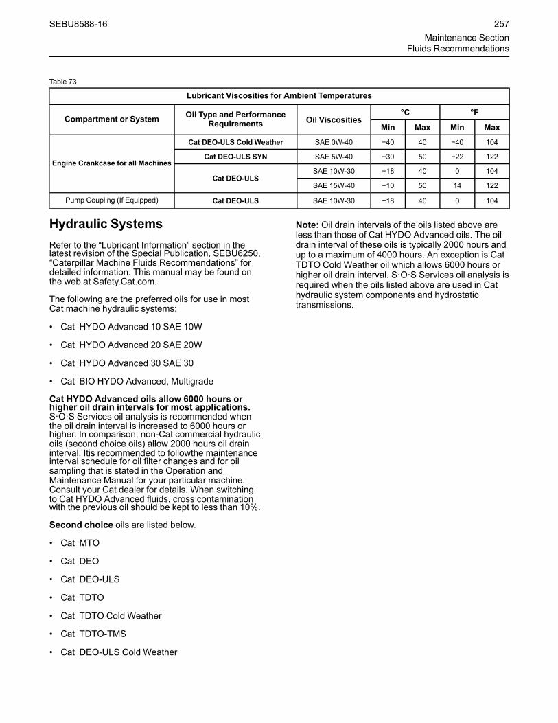
Table 73
Lubricant Viscosities for Ambient Temperatures
Compartment or System Oil Type and PerformanceRequirements Oil Viscosities
°C °F
Min Max Min Max
Engine Crankcase for all Machines
Cat DEO-ULS Cold Weather SAE 0W-40 −40 40 −40 104
Cat DEO-ULS SYN SAE 5W-40 −30 50 −22 122
Cat DEO-ULSSAE 10W-30 −18 40 0 104
SAE 15W-40 −10 50 14 122
Pump Coupling (If Equipped) Cat DEO-ULS SAE 10W-30 −18 40 0 104
Hydraulic SystemsRefer to the “Lubricant Information” section in thelatest revision of the Special Publication, SEBU6250,“Caterpillar Machine Fluids Recommendations” fordetailed information. This manual may be found onthe web at Safety.Cat.com.
The following are the preferred oils for use in mostCat machine hydraulic systems:
• Cat HYDO Advanced 10 SAE 10W
• Cat HYDO Advanced 20 SAE 20W
• Cat HYDO Advanced 30 SAE 30
• Cat BIO HYDO Advanced, Multigrade
Cat HYDO Advanced oils allow 6000 hours orhigher oil drain intervals for most applications.S·O·S Services oil analysis is recommended whenthe oil drain interval is increased to 6000 hours orhigher. In comparison, non-Cat commercial hydraulicoils (second choice oils) allow 2000 hours oil draininterval. Itis recommended to followthe maintenanceinterval schedule for oil filter changes and for oilsampling that is stated in the Operation andMaintenance Manual for your particular machine.Consult your Cat dealer for details. When switchingto Cat HYDO Advanced fluids, cross contaminationwith the previous oil should be kept to less than 10%.
Second choice oils are listed below.
• Cat MTO
• Cat DEO
• Cat DEO-ULS
• Cat TDTO
• Cat TDTO Cold Weather
• Cat TDTO-TMS
• Cat DEO-ULS Cold Weather
Note: Oil drain intervals of the oils listed above areless than those of Cat HYDO Advanced oils. The oildrain interval of these oils is typically 2000 hours andup to a maximum of 4000 hours. An exception is CatTDTO Cold Weather oil which allows 6000 hours orhigher oil drain interval. S·O·S Services oil analysis isrequired when the oils listed above are used in Cathydraulic system components and hydrostatictransmissions.
SEBU8588-16 257Maintenance Section
Fluids Recommendations

Table 74
Lubricant Viscosities for Ambient Temperatures
Compartment or System Oil Type and PerformanceRequirements Oil Viscosities
°C °F
Min Max Min Max
Hydraulic System
Cat HYDO Advanced 10Cat TDTO SAE 10W −20 40 −4 104
Cat HYDO Advanced 20Cat TDTO SAE 20W –5 45 23 113
Cat HYDO Advanced 30Cat TDTO SAE 30 10 50 50 122
Cat BIO HYDO Advanced “ISO 46” Multi-Grade −30 50 −22 122
Cat MTOCat DEO-ULSCat DEO
SAE10W-30 −20 40 −4 104
Cat DEO-ULSCat DEO SAE15W-40 −15 50 5 122
Cat TDTO-TMS Multi-Grade −15 50 5 122
Cat DEO-ULS SYN SAE 5W-40 −25 40 −13 104
Cat DEO-ULS Cold Weather SAE0W-40 −40 40 −40 104
Cat TDTO Cold Weather SAE 0W-20 −40 40 −40 104
For applications requiring the use of fire-resistanthydraulic fluids, Caterpillar recommends the use ofEcoSafe FR-46. This product is a fully synthetic, non-aqueous hydraulic fluid. Water based and glycol-based hydraulic products are not recommended foruse in Cat machine hydraulic systems. EcoSafe FR-46 is an ISO 46 multi-grade product. For moreinformation refer to the product information providedby the manufacturer of EcoSafe hydraulic oil. Referto your Cat dealer for availability.
Other Fluid ApplicationsTable 75
Excavators, Front Shovels, Mass Excavators, Demolition Excavators, and Track Material HandlersLubricant Viscosities for Ambient Temperatures
Compartment or System Oil Type and PerformanceRequirements Oil Viscosity Grade
°C °F
Min Max Min Max
Final Drives and Swing Drives
Cat TDTO Cold Weather SAE 0W-20 -40 0 -40 32
Cat TDTO
SAE 10W −30 0 -22 32
SAE 30(1) −30 35 −22 95
SAE 50 -15 50 5 122
Cat TDTO-TMS Multi-Grade −25 25 −13 77
Track Roller Frame Recoil Springand Pivot Shaft Bearings
Cat TDTO Cold Weather SAE 0W-20 −40 0 −40 32
Cat TDTOSAE 10W −30 0 −22 32
SAE 30(1) −20 25 −4 77
(continued)
258 SEBU8588-16Maintenance SectionFluids Recommendations

(Table 75, contd)
Excavators, Front Shovels, Mass Excavators, Demolition Excavators, and Track Material HandlersLubricant Viscosities for Ambient Temperatures
Compartment or System Oil Type and PerformanceRequirements Oil Viscosity Grade
°C °F
Min Max Min MaxSAE 50 0 50 32 122
Cat TDTO-TMS Multi-Grade −25 25 −13 77
Track Idlers and Track Rollers
Cat DEO-ULSCat DEO SAE 15W-40(1) -10 50 14 122
Cat DEO Cold Weather SAE 0W-40 −40 40 −40 104
Cat DEO-ULS SYN SAE 5W-40 −35 40 −31 104
Cat FDAO SYN Multi-Grade -30 50 -22 122(1) Factory fill oil for standard configuration machines.
Special LubricantsGreaseTo use a non-Cat grease, the supplier must certifythat the lubricant is compatible with Cat grease.
Each pin joint should be flushed with the new grease.Ensure that all old grease is removed. Failure to meetthis requirement may lead to failure of a pin joint.Table 76
Recommended Grease
Compartment or System Grease Type NLGI Grade°C °F
Min Max Min Max
External Lubrication Points
Cat Prime ApplicationGrease NLGI Grade 2 −20 140 −4 284
Cat Extreme ApplicationGrease
NLGI Grade 1 −20 140 −4 284
NLGI Grade 2 −15 140 +5 284
Cat Extreme ApplicationGrease-Artic NLGI Grade 0.5 -50 130 -58 266
Cat Extreme ApplicationGrease-Desert NLGI Grade 2 −10 140 +14 284
Cat Utility Grease NLGI Grade 2 −20 140 −4 284
Cat Ball Bearing Grease NLGI Grade 2 −20 160 −4 320
Diesel Fuel RecommendationsDiesel fuel must meet Caterpillar Specification forDistillate Fuel and the latest revisions of “ASTMD975” and “EN 590” to ensure optimum engineperformance. Refer to Special Publication,SEBU6250, “Caterpillar Machine FluidsRecommendations” for the latest fuel information andfor Cat fuel specification. This manual may be foundon the Web at Safety.Cat.com.
SEBU8588-16 259Maintenance Section
Fluids Recommendations

Illustration 406 g03218956
(A) North America film(B) Europe, Africa, Middle East film(C) Japan film
NOTICEUltra Low Sulfur Diesel (ULSD) fuel 0.0015 per-cent (≤15 ppm (mg/kg)) sulfur is required by regu-lation for use in engines certified to nonroad Tier4 standards (U. S. EPA Tier 4 certified) and thatare equipped with exhaust aftertreatmentsystems.
European ULSD 0.0010 percent (≤10ppm (mg/kg))sulfur fuel is required by regulation for use in en-gines certified to European Stage V type-ap-proved nonroad engines. Additionally, the Cetanenumber should not be less than 45, and the bio-diesel content should not be greater than 20%volume/volume.
Misfueling with fuels of higher sulfur level canhave the following negative effects:
• Shorten the time interval betweenaftertreatment device service intervals (causethe need for more frequent service intervals)
• Adversely impact the performance and life ofaftertreatment devices (cause loss ofperformance)
• Reduce regeneration intervals ofaftertreatment devices
• Reduce engine efficiency and durability.
• Increase the wear.
• Increase the corrosion.
• Increase the deposits.
• Lower fuel economy
• Shorten the time period between oil drain intervals(more frequent oil drain intervals).
• Increase overall operating costs.
Failures that result for the use of improper fuels arenot Caterpillar factory defects. Therefore, the cost ofrepairs would not be covered by a Caterpillarwarranty.
Caterpillar does not require the use of ULSD in non-road and machine applications that are not Tier 4/Stage V certified engines and are not equipped withaftertreatment devices. For Tier 4/Stage V certifiedengines, always follow operating instructions toensure that the correct fuels are used.
Refer to Special Publication, SEBU6250, “CaterpillarMachine Fluids Recommendations” for more detailsabout fuels, lubricants, and Tier 4/Stage Vrequirements. This manual may be found on the webat Safety.Cat.com.
Diesel Exhaust FluidGeneral InformationDiesel Exhaust Fluid (DEF) is a liquid that is injectedinto the exhaust system of engines equipped withSelective Catalytic Reduction (SCR) systems. SCRreduces emissions of nitrogen oxides (NOx) in dieselengine exhaust.
Diesel Exhaust Fluid (DEF) is also known underother names including Aqueous Urea Solution (AUS)32, AdBlue, or generically referred to as urea.
In engines equipped with SCR emissions reductionsystem, DEF is injected in controlled amounts intothe engine exhaust stream. At the elevated exhausttemperature, urea in DEF is converted to ammonia.The ammonia chemically reacts with NOx in dieselexhaust in the presence of the SCR catalyst. Thereaction converts NOx into harmless nitrogen (N2)and water (H2O).
DEF RecommendationsFor use in Cat engines, DEF must meet all therequirements defined by “ISO 22241-1”Requirements.
Caterpillar recommends the use of DEF availablethrough the Cat parts ordering system for use in Catengines equipped with SCR systems.
260 SEBU8588-16Maintenance SectionFluids Recommendations

In North America, commercial DEF that is APIapproved and meets all the requirements defined in“ISO 22241-1” may be used in Cat engines that areequipped with SCR systems.
Outside of North America, commercial DEF thatmeets all requirements defined in “ISO 22241-1” maybe used in Cat engines that are equipped with SCRsystems.
The supplier should provide documentation to provethat the DEF is compliant with the requirements of“ISO 22241-1”.
NOTICECat does not warrant the quality or performance ofnon-Cat fluids.
NOTICEDo not use agriculture grade urea solutions. Donot use any fluids that do not meet “ISO 22241-1” Re-quirements in SCR emissions reduction systems.Use of these fluids can result in numerous problemsincluding damage to SCR equipment and a reductionin NOx conversion efficiency.
DEF is a solution of solid urea that is dissolved indemineralized water to produce a final concentrationof 32.5% urea. DEF concentration of 32.5% isoptimal for use in SCR systems. DEF solution of32.5% urea has the lowest attainable freeze point of−11.5° C (11.3° F). DEF concentrations that arehigher or lower than 32.5% have higher freezepoints. DEF dosing systems and “ISO 22241-1”specifications are designed for a solution that isapproximately 32.5%.
Caterpillar offers a refractometer, Cat part number360-0774, that can be used to measure DEFconcentration. Follow the instructions provided withthe instrument. Appropriate commercial portablerefractometers can be used to determine ureaconcentration. Follow the instructions from themanufacturer.
DEF GuidelinesDEF solution is typically colorless and clear. Changesto color or clarity are indicators of quality issues.Quality of DEF can degrade when stored andhandled inappropriately or if DEF is not protectedfrom contamination. Details are provided below.
If quality issues are suspected, testing of DEF shouldfocus on urea percentage, alkalinity as NH3 andbiuret content. DEF that does not pass all these testsor that is no longer clear should not be used.
Materials compatibility
DEF is corrosive. Due to the corrosion caused, DEFmust be stored in tanks constructed of approvedmaterials. Recommended storage materials:
Stainless Steels:
• 304 (S30400)
• 304L (S30403)
• 316 (S31600)
• 316L (S31603)
Alloys and metals:
• Chromium Nickel (CrNi)
• Chromium Nickel Molybdenum (CrNiMo)
• Titanium
Non-metallic materials:
• Polyethylene
• Polypropylene
• Polyisobutylene
• Teflon (PFA)
• Polyfluoroethylene (PFE)
• Polyvinylidene fluoride (PVDF)
• Polytetrafluoroethylene (PTFE)
Materials NOTcompatible with DEF solutions includeAluminum, Magnesium, Zinc, Nickel coatings, Silverand Carbon steel, and Solders containing any of theabove. Unexpected reactions may occur if DEFsolutions come in contact with any non-compatiblematerial or unknown materials.
Bulk storage
Follow all local regulations covering bulk storagetanks. Follow proper tank construction guidelines.Tank volume typically should be 110% of plannedcapacity. Appropriately vent indoor tanks. Plan forcontrol of overflow of the tank. Heat tanks thatdispense DEF in cold climates.
Bulk tank breathers should be fitted with filtration tokeep airborne debris from entering the tank.Desiccant breathers should not be used becausewater will be absorbed, which potentially can alterDEF concentration.
Handling
Follow all local regulations covering transport andhandling. DEF transport temperature isrecommended to be −5° C (23° F) to 25° C (77° F).All transfer equipment and intermediate containersshould be used exclusively for DEF. Containersshould not be reused for any other fluids. Ensure thattransfer equipment is made from DEF-compatiblematerials. Recommended material for hoses andother non-metallic transfer equipment includes:
SEBU8588-16 261Maintenance Section
Fluids Recommendations

• Nitrile Rubber (NBR)
• Fluoroelastomer (FKM)
• Ethylene Propylene Diene Monomer (EPDM)
The condition of hoses and other nonmetallics thatare used with DEF should be monitored for signs ofdegradation. DEF leaks are easily recognizable bywhite urea crystals that accumulate at the site of theleak. Solid urea can be corrosive to galvanized orunalloyed steel, aluminum, copper, and brass. Leaksshould be repaired immediately to avoid damage tosurrounding hardware.
Cleanliness
Contaminants can degrade the quality and life ofDEF. Filtering DEF is recommended when dispensedinto the DEF tank. Filters should be compatible withDEF and should be used exclusively with DEF.Check with the filter supplier to confirm compatibilitywith DEF before using. Mesh-type filters usingcompatible metals, such as stainless steel, arerecommended. Paper (cellulose) media and somesynthetic filter media are not recommended becauseof degradation during use.
Care should be taken when dispensing DEF. Spillsshould be cleaned immediately. Machine or enginesurfaces should be wiped clean and rinsed withwater. Caution should be used when dispensing DEFnear an engine that has recently been running.Spilling DEF onto hot components will cause harmfulvapors.
Stability
NOTICEStoring Diesel Exhaust Fluid in high heat areas is notrecommended. Do not store DEF in high heat gener-ating areas on the machine, such as the pump com-partment or the engine compartment. The quality ofthe DEF can degrade when exposed to hightemperatures.
DEF fluid is stable when stored and handled properly.The quality of DEF rapidly degrades when stored athigh temperatures. The ideal storage temperature forDEF is between −9° C (15.8° F) and 25° C (77° F).DEF that is stored above 35° C (95° F) for longerthan 1 month must be tested before use. Testingshould evaluate Urea Percentage, Alkalinity as NH3and Biuret content.
The length of storage of DEF is listed in the followingtable:
Table 77
Storage Temperature Expected DEF Life
Below 25° C (77° F) 18 months
25° C (77° F) to 30° C (86° F) 12 months
30° C (86° F) to 35° C (95° F) 6 months
Above 35° C (95° F) test quality before use
Refer to “ISO 22241” document series for moreinformation about DEF quality control.
Note: Dispose of all fluids according to applicableregulations and mandates.
Fuel AdditivesCat Diesel Fuel Conditioner and Cat Fuel SystemCleaner are available for use when needed. Theseproducts are applicable to diesel and biodiesel fuels.Consult your Cat dealer for availability.
BiodieselBiodiesel is a fuel that can be made from variousrenewable resources that include vegetable oils,animal fat, and waste cooking oil. Soybean oil andrapeseed oil are the primary vegetable oil sources.To use any of these oils or fats as fuel, the oils, or fatsare chemically processed (esterified). The water andcontaminants are removed.
U.S. distillate diesel fuel specification “ASTM D7467”includes up to B20 (20 percent) biodiesel. Any dieselfuel in the U.S. may contain up to B20 biodiesel fuel.
European distillate diesel fuel specification“EN16709:2015” includes up to B20 (20 percent)biodiesel. Any diesel fuel in Europe may contain up toB20.
Note: The diesel portion used in the biodiesel blendmust be Ultra Low Sulfur Diesel (15 ppm sulfur orless, per “ASTM D975”). In Europe the diesel fuelportion used in the biodiesel blend must be sulfur freediesel (10 ppm sulfur or less, per “EN 590”). The finalblend must have 15 ppm sulfur or less.
When biodiesel fuel is used, certain guidelines mustbe followed. Biodiesel fuel can influence the engineoil, aftertreatment devices, non-metallic, fuel systemcomponents, and others. Biodiesel fuel has limitedstorage life and has limited oxidation stability. Followthe guidelines and requirements for engines that areseasonally operated.
To reduce the risks associated with the use ofbiodiesel, the final biodiesel blend and the biodieselfuel used must meet specific blending requirements.
262 SEBU8588-16Maintenance SectionFluids Recommendations

All the guidelines and requirements are provided inthe latest revision of Special Publication, SEBU6250,“Caterpillar Machine Fluids Recommendations”. Thismanual may be found on the web at Safety.Cat.com.
Coolant InformationThe information provided in this “CoolantRecommendation” section should be used with the“Lubricants Information” provided in the latestrevision of Special Publication, SEBU6250,“Caterpillar Machine Fluids Recommendations”. Thismanual may be found on the web at Safety.Cat.com.
The following two types of coolants may be used inCat diesel engines:
Preferred – Cat ELC (Extended Life Coolant)
Acceptable – Cat DEAC (Diesel Engine Antifreeze/Coolant)
NOTICENever use water alone as a coolant. Water alone iscorrosive at engine operating temperatures. In addi-tion, water alone does not provide adequate protec-tion against boiling or freezing.
Table 78
Recommendations for Finished Coolants for use in Cat engines
Coolant Type Recommendations Product Service hours (1)(2) Required Maintenance(3)
Cat ELC, Cat ELI, or com-mercial coolant thatmeets Cat EC-1
Preferred
Cat ELC 12000 hours or 6 yearsAdd Cat ELC Extender at6000 service hours or one
half of service life
Cat ELI (water based) (4) 12000 hours or 6 yearsAdd Cat ELC Extender at6000 service hours or one
half of service life
Min requirements
Cat EC-1 specification and“ASTM D6210” and
Organic Additive Technol-ogy (OAT) based on a com-
bination of amonocarboxylic acid and a
dicarboxylic acid.Free of phosphate, borate,
and silicate.Tolyltriazole: minimum typi-cal concentration of 900
ppmNitrite: minimum typicalconcentration of 500 ppm
in new coolants
6000 hours or 6 yearsAdd Extender at 3000 serv-ice hours or one half of
service life
Cat DEAC, Cat SCA, con-ventional coolants, andcommercial extended lifecoolants that do not meet
EC-1
Acceptable
Cat DEAC 3000 hours or 3 years SCA at maintenanceintervals
Cat SCA (water based) (4) 3000 hours or 2 years SCA at maintenanceintervals
(continued)
SEBU8588-16 263Maintenance Section
Fluids Recommendations

(Table 78, contd)
Recommendations for Finished Coolants for use in Cat engines
Min requirements for fullyformulated Heavy-DutyCommercial coolants
“ASTM D6210” andNitrite (as NO2) concentra-tion: Minimum of 1200 ppm(70 grains/US gal) andmaximum of 2400 ppm(140 grains/US gal)
Silicon concentration: mini-mum of 100 ppm and maxi-
mum of 275 ppm
3000 hours or 2 years SCA at maintenanceintervals
Min requirements for SCAand water (4) (5)
Commercial supplementalcoolant additive and water
havingNitrite (as NO2) concentra-tion: Minimum of 1200 ppm(70 grains/US gal) andmaximum of 2400 ppm(140 grains/US gal)
Silicon concentration: mini-mum of 100 ppm and maxi-
mum of 275 ppm
3000 hours or 1 year Per manufacturerrecommendations
(1) New Coolants at 50 volume percent diluted. Coolants that are prediluted at the coolant manufacturer must be diluted with water that meetsReagent 4 “ASTM D1193” requirements.
(2) Maintain the in-service coolant at the given limits.(3) For appropriate maintenance procedures, refer to the details given in this Chapter. For applications that allow the use of Cat ELI in water, a
minimum of 7.5 percent of Cat ELI is recommended. For applications that allow the use of SCA and water, a minimum of 6 percent to a maxi-mum of 8 percent concentration of Cat SCA are recommended.
(4) Water-based coolants are not allowed for use in machines that has NOx reduction aftertreatment devices, in engines that has AATAC and inMarine engines that have SWAC
(5) There are currently no industry standards to define the quality of water-based conventional coolants. To control the quality of SCA and watercoolants, the commercial SCA additive package should pass ASTM D6210 when this package is used in a glycol-based coolant. Do not usea commercial SCA additive package that only meets the ASTM D3306 or equivalent specification when used in a glycol-based coolant.
i05807851
Capacities (Refill)SMCS Code: 1000; 7000
Table 79
Approximate Refill Capacities
Component or System Liters US gal Recommended Type
Fuel Tank 920 243
Refer to Operation and Maintenance Manual, “LubricantViscosities”.
Cooling System 72 19
Coolant Reservoir 4.5 1.2
Engine Crankcase with Filter 60 15.5
Hydraulic System(1) 427 113
Diesel Exhaust Fluid Tank 48 12.5
Each Swing Drive 12 3
Each Final Drive 22 5.5
Swing Gear 38 10
(continued)
264 SEBU8588-16Maintenance SectionCapacities (Refill)

(Table 79, contd)
Approximate Refill Capacities
Component or System Liters US gal Recommended Type
kg lbs
Refrigerant(2) 1.1 2.4 R-134a(1) The amount of hydraulic fluid that is needed to refill the hydraulic system after performing Operation and Maintenance Manual, “Hydraulic
System Oil - Change”(2) Refer to Service Manual, “Air Conditioning and Heating R-134a for All Caterpillar Machines” for additional information
i07445339
S·O·S InformationSMCS Code: 1000; 1348; 3080; 4050; 5050; 7000;7542-008
S·O·S Services is a highly recommended process forCat customers to use in order to minimize owningand operating cost. Customers provide oil samples,coolant samples, and other machine information. Thedealer uses the data in order to provide the customerwith recommendations for management of theequipment. In addition, S·O·S Services can helpdetermine the cause of an existing product problem.
Refer to Special Publication, SEBU6250, “CaterpillarMachine Fluid Recommendations” for detailedinformation concerning S·O·S Services.
The effectiveness of S·O·S Services is dependent ontimely submission of the sample to the laboratory atrecommended intervals.
Refer to the Operation and Maintenance Manual,“Maintenance Interval Schedule” for a specificsampling location and a service hour maintenanceinterval.
Consult your Cat dealer for complete information andassistance in establishing an S·O·S program for yourequipment.
SEBU8588-16 265Maintenance SectionS·O·S Information

Maintenance Supporti05785641
Service Interval ChartSMCS Code: 7000
The service interval chart is located inside the caband on the window.
Refer to this Operation and Maintenance Manual,“Maintenance Interval Schedule” for the correctmaintenance intervals and procedures that arespecific to your machine.
Illustration 407 g03668448
Service hour interval – Hourly interval inwhich a maintenance procedure shouldbe performed.
Coolant level – Check the coolant level.
Cooling system coolant – Change theELC (Extended Life Coolant) .
Engine air filter primary element – Cleanor replace the primary air filter element.
Engine air filter secondary element –Replace the secondary air filter element.
Engine oil level – Check the engine oillevel.
266 SEBU8588-16Maintenance SectionMaintenance Support

Engine oil – Change the engine oil.
Engine oil filter – Change the engine oilfilter.
Final drive oil level – Check the finaldrive oil level.
Final drive oil – Change the final driveoil.
Fuel level – Check the fuel level.
Fuel system filter – Replace the fuelsystem filters.
Fuel system water separator – Drain thewater separator.
Fuel system water separator element –Replace the fuel system water separatorelement.
Grease zerk – Lubricate the designatedlocations.
Hydraulic oil level – Check the hydraulicoil level.
Hydraulic oil – Change the hydraulic oil.
Hydraulic oil filter – Change thehydraulic oil filter.
Swing drive oil level – Check the swingdrive oil level.
Swing drive oil – Change the swing driveoil.
i07327912
System Pressure ReleaseSMCS Code: 1250-553-PX; 1300-553-PX; 1350-553-PX; 5050-553-PX; 6700-553-PX; 7540-553-PX
Personal injury or death can result from suddenmachine movement.
Sudden movement of the machine can cause in-jury to persons on or near the machine.
To prevent injury or death, make sure that thearea around the machine is clear of personneland obstructions before operating the machine.
Coolant System
Pressurized system: Hot coolant can cause seri-ous burn. To open cap, stop engine, wait until ra-diator is cool. Then loosen cap slowly to relievethe pressure.
To relieve the pressure from the coolant system, turnoff the machine. Allow the cooling system pressurecap to cool. Remove the cooling system pressurecap slowly in order to relieve pressure.
Hydraulic SystemThe release of hydraulic pressure in a hydrauliccircuit is required before service is performed to thathydraulic circuit. Release the pressure in thefollowing hydraulic circuits before any hydraulic linesare disconnected or removed from that hydrauliccircuit.
• Boom hydraulic circuit
• Stick hydraulic circuit
• Bucket hydraulic circuit
• Swing hydraulic circuit
• Travel hydraulic circuit
• Attachment hydraulic circuits (if equipped)
• Pilot hydraulic circuit
• Return hydraulic circuit
Note: Refer to the Disassembly and AssemblyManual for additional information concerning serviceof the components of specific hydraulic circuits.
SEBU8588-16 267Maintenance Section
System Pressure Release

Release of Hydraulic Pressure from theMain Hydraulic System
Personal injury can result from hydraulic oil pres-sure and hot oil.
Hydraulic oil pressure can remain in the hydraulicsystem after the engine has been stopped. Seri-ous injury can be caused if this pressure is notreleased before any service is done on the hy-draulic system.
Make sure all of the work tools have been loweredto the ground, and the oil is cool before removingany components or lines. Remove the oil fillercap only when the engine is stopped, and the fill-er cap is cool enough to touch with your barehand.
NOTICECare must be taken to ensure that fluids are con-tained during performance of inspection, mainte-nance, testing, adjusting, and repair of the product.Be prepared to collect the fluid with suitable contain-ers before opening any compartment or disassem-bling any component containing fluids.
Refer to Special Publication, NENG2500, “DealerService Tool Catalog” for tools and supplies suitableto collect and contain fluids on Cat ® products.
Dispose of all fluids according to local regulationsand mandates.
Perform the following steps to release the hydraulicsystem pressure from the main hydraulic system. Forinformation on any fluids and capacities, refer to thisOperation and Maintenance Manual, "LubricantViscosities" and "Capacities (Refill)" for moreinformation.
Note: For additional safety, wrap hydraulic joint withmaterial that could absorb/reduce any residualpressure of oil when released. Loosen the jointslowly, pause, and carefully check hydraulic joint fortensions indicating presence of pressure or springforce in lines or components.
1. Position the machine on level ground.
Illustration 408 g02137969
2. Fully retract the stick cylinder rod. Adjust theposition of the bucket so that the bucket is parallelto the ground. Lower the boom until the bucket isflat on the ground. Refer to Illustration 408 .
3. Release the system pressure from the implementand swing hydraulic circuits.
a. Shut off the engine.
Note: Perform Step 3b through Step 3dimmediately after the engine is shut off to insureadequate pilot system pressure is available torelease the pressure in the hydraulic circuits.
b. Turn the engine start switch to the ON positionwithout starting the engine.
c. Place the hydraulic activation control lever inthe UNLOCKED position.
Illustration 409 g03315377
d. Move both joysticks in a circular motion to theFULL STROKE positions multiple times until thepilot accumulator has been exhausted.
Note: Pilot pressure is required to relieve hydraulicsystem pressure.
268 SEBU8588-16Maintenance SectionSystem Pressure Release
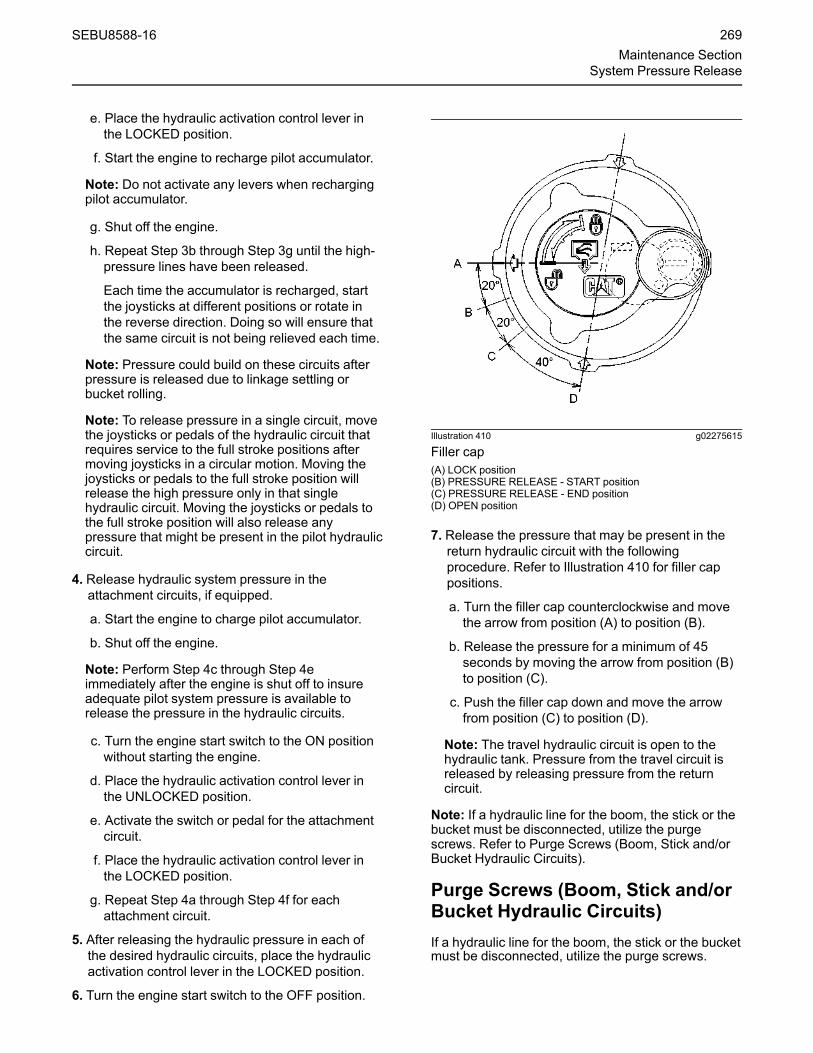
e. Place the hydraulic activation control lever inthe LOCKED position.
f. Start the engine to recharge pilot accumulator.
Note: Do not activate any levers when rechargingpilot accumulator.
g. Shut off the engine.
h. Repeat Step 3b through Step 3g until the high-pressure lines have been released.
Each time the accumulator is recharged, startthe joysticks at different positions or rotate inthe reverse direction. Doing so will ensure thatthe same circuit is not being relieved each time.
Note: Pressure could build on these circuits afterpressure is released due to linkage settling orbucket rolling.
Note: To release pressure in a single circuit, movethe joysticks or pedals of the hydraulic circuit thatrequires service to the full stroke positions aftermoving joysticks in a circular motion. Moving thejoysticks or pedals to the full stroke position willrelease the high pressure only in that singlehydraulic circuit. Moving the joysticks or pedals tothe full stroke position will also release anypressure that might be present in the pilot hydrauliccircuit.
4. Release hydraulic system pressure in theattachment circuits, if equipped.
a. Start the engine to charge pilot accumulator.
b. Shut off the engine.
Note: Perform Step 4c through Step 4eimmediately after the engine is shut off to insureadequate pilot system pressure is available torelease the pressure in the hydraulic circuits.
c. Turn the engine start switch to the ON positionwithout starting the engine.
d. Place the hydraulic activation control lever inthe UNLOCKED position.
e. Activate the switch or pedal for the attachmentcircuit.
f. Place the hydraulic activation control lever inthe LOCKED position.
g. Repeat Step 4a through Step 4f for eachattachment circuit.
5. After releasing the hydraulic pressure in each ofthe desired hydraulic circuits, place the hydraulicactivation control lever in the LOCKED position.
6. Turn the engine start switch to the OFF position.
Illustration 410 g02275615
Filler cap(A) LOCK position(B) PRESSURE RELEASE - START position(C) PRESSURE RELEASE - END position(D) OPEN position
7. Release the pressure that may be present in thereturn hydraulic circuit with the followingprocedure. Refer to Illustration 410 for filler cappositions.
a. Turn the filler cap counterclockwise and movethe arrow from position (A) to position (B).
b. Release the pressure for a minimum of 45seconds by moving the arrow from position (B)to position (C).
c. Push the filler cap down and move the arrowfrom position (C) to position (D).
Note: The travel hydraulic circuit is open to thehydraulic tank. Pressure from the travel circuit isreleased by releasing pressure from the returncircuit.
Note: If a hydraulic line for the boom, the stick or thebucket must be disconnected, utilize the purgescrews. Refer to Purge Screws (Boom, Stick and/orBucket Hydraulic Circuits).
Purge Screws (Boom, Stick and/orBucket Hydraulic Circuits)If a hydraulic line for the boom, the stick or the bucketmust be disconnected, utilize the purge screws.
SEBU8588-16 269Maintenance Section
System Pressure Release

Personal injury can result from hydraulic oil pres-sure and hot oil.
Hydraulic oil pressure can remain in the hydraulicsystem after the pilot pressure is released. Seri-ous injury can result if this remaining pressure isnot released before any service is done on the hy-draulic system.
Make sure that the remaining pressure has beenreleased by utilizing the purge screws that are lo-cated on the boom, stick and bucket lines. Beforeany purge screw is turned, the bucket and or allof the attachments must be lowered to the groundor properly supported.
1. Locate a section of hose that will tightly fit over oneof the purge screws.
Illustration 411 g06235838
374 Stick and Bucket circuits(2) Hose(3) Purge screws (one on each line)(A) Line for Stick In(B) Line for Bucket Open(C) Line for Bucket Close(D) Line for Stick Out
Illustration 412 g06235851
390 Stick and Bucket circuits(2) Hose(3) Purge screws (one on each line)(A) Lines for Stick In(B) Line for Bucket Open(C) Line for Bucket Close(D) Line for Stick Out
2. Connect one end of drain hose (2) to purge screw(3). Insert the other end of drain hose (2) into anempty container.
3. Loosen purge screw (3) by 1/2 turn. Hydraulic oilwill be drained from the drain hose to thecontainer.
Note: Dispose of drained fluid according to localregulations.
4. Tighten purge screw (3) to a torque of 13 ± 2 N·m(9.6 ± 1.5 lb ft) after all of the hydraulic oil hasbeen drained from the line.
5. Repeat Step 2 through Step 4 for all the stick andbucket circuits.
Illustration 413 g00582502
(4) Purge screws for the boom
270 SEBU8588-16Maintenance SectionSystem Pressure Release

6. Locate the purge screws for the boom circuit onthe boom cylinder lines.
7. Repeat Step 2 through Step 4 for all the boomcircuits.
8. Remove the drain hose and install the hydraulictank fill cap.
9. The pressure in the multiple hydraulic circuits thatrequire service is now released and lines andcomponents can be disconnected or removedfrom those hydraulic circuits.
i01821998
Welding on Machines andEngines with ElectronicControlsSMCS Code: 1000; 7000
Proper welding procedures are necessary in order toavoid damage to the electronic controls and to thebearings. The following steps should be followed inorder to weld on a machine or an engine withelectronic controls.
1. Turn off the engine.
2. Turn the battery disconnect switch to the OFFposition. If there is no battery disconnect switch,remove the negative battery cable at the battery.
3. Clamp the ground cable from the welder to thecomponent that will be welded. Place the clamp asclose as possible to the weld. Make sure that theelectrical path from the ground cable to thecomponent does not go through any bearing. Usethis procedure in order to reduce the possibility ofdamage to the following components:
• Bearings of the drive train
• Hydraulic components
• Electrical components
• Other components of the machine
NOTICEDo NOT use electrical components (ECM or sensors)or electronic component grounding points for ground-ing the welder.
4. Protect any wiring harnesses from the debriswhich is created from welding. Protect any wiringharnesses from the splatter which is created fromwelding.
5. Use standard welding procedures in order to weldthe materials together.
i04807435
Severe Service ApplicationSMCS Code: 1000
An engine which operates outside of normalconditions is operating in a severe serviceapplication.
An engine that operates in a severe serviceapplication may need more frequent maintenanceintervals in order to maximize the followingconditions:
• Reliability
• Service life
The number of individual applications cause theimpossibility of identifying all of the factors which maycontribute to severe service operation. Consult yourCaterpillar dealer for the unique maintenance thatmay be necessary for your engine.
An application is a severe service application if any ofthe following conditions apply:
Severe Environmental Factors• Frequent operation in dirty air
• Frequent operation at an altitude which is above1525 m (5000 ft)
• Frequent operation in ambient temperatures whichare above 32° C (90° F)
• Frequent operation in ambient temperatures whichare below 0° C (32° F)
Severe Operating Conditions• Frequent operation with inlet air which has acorrosive content
• Operation with inlet air which has a combustiblecontent
• Operation which is outside of the intendedapplication
• Operation with a plugged fuel filter
• Extended operation at low idle (more than 20% ofhours)
• Frequent cold starts at temperatures below 0° C(32° F)
SEBU8588-16 271Maintenance Section
Welding on Machines and Engines with Electronic Controls

• Frequent dry starts (starting after more than 72hours of shutdown)
• Frequent hot shutdowns (shutting down theengine without the minimum of 2 minutes to 5minutes of cool down time)
• Operation above the engine rated speed
• Operation below the peak torque speed
• Operating with fuel which does not meet thestandards for distillate diesel fuel as stated inSpecial Publication, SEBU6250, “CaterpillarMachine Fluids Recommendations” “DistillateDiesel Fuel”
• Operating with a blend of distillate fuel whichcontains more than 20 percent biodiesel
Improper Maintenance Procedures(Maintenance Procedures WhichMay Contribute to a Severe ServiceApplication)• Inadequate maintenance of fuel storage tanksfrom causes such as excessive water, sediment,and microorganism growth.
• Extending maintenance intervals beyond therecommended intervals
• Using fluids which are not recommended inSpecial Publication, SEBU6250, “CaterpillarMachine Fluids Recommendations”
• Extending maintenance intervals for changing theengine oil and engine coolant without S·O·Svalidation
• Extending maintenance intervals for changing airfilters, oil filters, and fuel filters
• Failure to use a water separator
• Using filters which are not recommended bySpecial Publication, PEWJ0074, “2008 Cat Filterand Fluid Application Guide”
• Storing the engine for more than 3 months but lessthan 1 yr (For information about engine storage,refer to Special Publication, SEHS9031, “StorageProcedure for Caterpillar Products”)
272 SEBU8588-16Maintenance SectionSevere Service Application

i08134286
Maintenance Interval ScheduleSMCS Code: 7000
Ensure that all safety information, warnings, andinstructions are read and understood before anyoperation or any maintenance procedures areperformed.
The user is responsible for the performance ofmaintenance. All adjustments, the use of properlubricants, fluids, filters, and the replacement ofcomponents due to normal wear and aging areincluded. Failure to adhere to proper maintenanceintervals and procedures may result in diminishedperformance of the product and/or accelerated wearof components.
Use mileage, fuel consumption, service hours, orcalendar time, WHICH EVER OCCURS FIRST, inorder to determine the maintenance intervals.Products that operate in severe operating conditionsmay require more frequent maintenance. Refer to themaintenance procedure for any other exceptions thatmay change the maintenance intervals.
Note: The aftertreatment system can be expected tofunction properly for the useful life of the engine(emissions durability period), as defined byregulation. All prescribed maintenance requirementsmust be followed.
Note: Before each consecutive interval is performed,all maintenance from the previous interval must beperformed.
Note: If Cat HYDO Advanced hydraulic oils are used,the hydraulic oil change interval is extended to 3000hours. S·O·S services may extend the oil changeeven longer. Consult your Cat dealer for details.
When Required“ Air Conditioner/Cab Heater Filter (Recirculation) -Inspect/Replace“ . . . . . . . . . . . . . . . . . . . . . . . . . . 276
“ Battery - Recycle“ . . . . . . . . . . . . . . . . . . . . . . . . 277
“ Battery or Battery Cable - Inspect/Replace“. . . . 278
“ Bucket Linkage - Inspect/Adjust“ . . . . . . . . . . . . 281
“ Bucket Tips - Inspect/Replace“ . . . . . . . . . . . . . . 282
“ Bucket Tips - Inspect/Replace“ . . . . . . . . . . . . . . 285
“ Cab Air Filter (Fresh Air) - Clean/Replace“ . . . . 289
“ Cab Door Latch - Inspect/Adjust/Replace“. . . . . 289
“ Camera - Clean“ . . . . . . . . . . . . . . . . . . . . . . . . . 291
“ Circuit Breakers - Reset“ . . . . . . . . . . . . . . . . . . . 292
“ Counterweight Removal Chain - Clean“. . . . . . . 297
“ DEF Filler Screen - Clean“ . . . . . . . . . . . . . . . . . 299
“ Diesel Exhaust Fluid - Fill“. . . . . . . . . . . . . . . . . . 303
“ Engine Air Filter Primary Element - Clean/Replace“ . . . . . . . . . . . . . . . . . . . . . . . . . . . . . . . . . 304
“ Engine Air Filter Secondary Element -Replace“ . . . . . . . . . . . . . . . . . . . . . . . . . . . . . . . . . 307
“ Engine Air Precleaner - Clean“ . . . . . . . . . . . . . . 307
“ Engine Oil Level - Check“ . . . . . . . . . . . . . . . . . . 308
“ Ether Starting Aid Cylinder - Replace“ . . . . . . . . 313
“ Film (Product Identification) - Clean“ . . . . . . . . . 314
“ Fuel System - Prime“ . . . . . . . . . . . . . . . . . . . . . . 316
“ Fuel System Water Separator - Drain“ . . . . . . . . 319
“ Fuses - Replace“ . . . . . . . . . . . . . . . . . . . . . . . . . 321
“ High Intensity Discharge Lamp (HID) -Replace“ . . . . . . . . . . . . . . . . . . . . . . . . . . . . . . . . . 323
“ Oil Filter - Inspect“ . . . . . . . . . . . . . . . . . . . . . . . . 339
“ Radiator Core - Clean“ . . . . . . . . . . . . . . . . . . . . 339
“ Track Adjustment - Adjust“ . . . . . . . . . . . . . . . . . 346
“ Window - Check“ . . . . . . . . . . . . . . . . . . . . . . . . . 349
“ Window Washer Reservoir - Fill“ . . . . . . . . . . . . 348
“ Window Wiper - Inspect/Replace“ . . . . . . . . . . . 349
“ Windows - Clean“. . . . . . . . . . . . . . . . . . . . . . . . . 349
Every 10 Service Hours or Daily forFirst 100 Hours“ Boom, Stick and Bucket Linkage - Lubricate“ . . 279
Every 10 Service Hours or Daily“ Air Cleaner Dust Valve - Clean/Inspect“ . . . . . . . 276
“ Cooling System Coolant Level - Check“. . . . . . . 295
“ Fuel Tank Water and Sediment - Drain“ . . . . . . . 320
“ Hydraulic System Oil Level - Check“ . . . . . . . . . 335
“ Indicators and Gauges - Test“ . . . . . . . . . . . . . . . 337
“ Seat Belt - Inspect“ . . . . . . . . . . . . . . . . . . . . . . . 340
“ Track Adjustment - Inspect“ . . . . . . . . . . . . . . . . 347
“ Travel Alarm - Test“ . . . . . . . . . . . . . . . . . . . . . . . 347
SEBU8588-16 273Maintenance Section
Maintenance Interval Schedule

“ Undercarriage - Check“ . . . . . . . . . . . . . . . . . . . . 348
Every 10 Service Hours or Daily forMachines Used in SevereApplications“ Boom, Stick and Bucket Linkage - Lubricate“ . . 279
Every 50 Service Hours or Weekly“ Boom, Stick and Bucket Linkage - Lubricate“ . . 279
Every 100 Service Hours ofContinuous Hammer Use“ Hydraulic System Filter Element (Fine Filtration) -Replace“ . . . . . . . . . . . . . . . . . . . . . . . . . . . . . . . . . 323
“ Hydraulic System Oil Filter - Replace“ . . . . . . . . 332
“ Oil Filter (Hydraulic Hammer) - Replace“ . . . . . . 337
Initial 250 Service Hours“ Final Drive Oil - Change“ . . . . . . . . . . . . . . . . . . . 315
“ Hydraulic System Filter Element (Fine Filtration) -Replace“ . . . . . . . . . . . . . . . . . . . . . . . . . . . . . . . . . 323
“ Hydraulic System Oil Filter (Return) -Replace“ . . . . . . . . . . . . . . . . . . . . . . . . . . . . . . . . . 328
“ Hydraulic System Oil Filter - Replace“ . . . . . . . . 332
“ Swing Drive Oil - Change“. . . . . . . . . . . . . . . . . . 342
Every 250 Service Hours“ Counterweight Removal Chain - Inspect“ . . . . . 298
“ Engine Oil Sample - Obtain“ . . . . . . . . . . . . . . . . 309
“ Final Drive Oil Sample - Obtain“ . . . . . . . . . . . . . 316
Every 250 Service Hours orMonthly“ Condenser (Refrigerant) - Clean“ . . . . . . . . . . . . 292
“ Final Drive Oil Level - Check“ . . . . . . . . . . . . . . . 315
“ Swing Bearing - Lubricate“ . . . . . . . . . . . . . . . . . 341
“ Swing Drive Oil Level - Check“ . . . . . . . . . . . . . . 343
Every 250 Service Hours of PartialHammer Use (50% of ServiceHours)“ Hydraulic System Filter Element (Fine Filtration) -Replace“ . . . . . . . . . . . . . . . . . . . . . . . . . . . . . . . . . 323
“ Hydraulic System Oil Filter - Replace“ . . . . . . . . 332
“ Oil Filter (Hydraulic Hammer) - Replace“ . . . . . . 337
Initial 500 Hours (for New Systems,Refilled Systems, and ConvertedSystems)“ Cooling System Coolant Sample (Level 2) -Obtain“ . . . . . . . . . . . . . . . . . . . . . . . . . . . . . . . . . . 297
Every 500 Service Hours“ Hydraulic System Oil Sample - Obtain“ . . . . . . . 336
“ Swing Drive Oil Sample - Obtain“ . . . . . . . . . . . . 344
Every 500 Service Hours or 3Months“ Belt - Inspect/Adjust/Replace“. . . . . . . . . . . . . . . 278
“ Cooling System Coolant Sample (Level 1) -Obtain“ . . . . . . . . . . . . . . . . . . . . . . . . . . . . . . . . . . 296
“ Engine Oil and Filter - Change“. . . . . . . . . . . . . . 309
“ Fuel System Primary Filter (Water Separator)Element - Replace“ . . . . . . . . . . . . . . . . . . . . . . . . 317
“ Fuel System Secondary Filter - Replace“. . . . . . 318
“ Fuel Tank Cap and Strainer - Clean“ . . . . . . . . . 319
“ Fuel Tank Strainer - Clean“ . . . . . . . . . . . . . . . . . 320
“ Hydraulic System Filter Element (Fine Filtration) -Replace“ . . . . . . . . . . . . . . . . . . . . . . . . . . . . . . . . . 323
“ Hydraulic System Oil Filter - Replace“ . . . . . . . . 332
Every 600 Service Hours ofContinuous Hammer Use“ Hydraulic System Oil - Change“ . . . . . . . . . . . . . 324
274 SEBU8588-16Maintenance SectionMaintenance Interval Schedule

“ Hydraulic System Oil Filter (Return) -Replace“ . . . . . . . . . . . . . . . . . . . . . . . . . . . . . . . . . 328
Every 1000 Service Hours or 6Months“ Battery - Clean“ . . . . . . . . . . . . . . . . . . . . . . . . . . 277
“ Battery Electrolyte Level - Check“ . . . . . . . . . . . 277
“ Battery Hold-Down - Tighten“ . . . . . . . . . . . . . . . 278
“ Counterweight Removal Chain - Lubricate“ . . . . 298
“ Fuel Tank Cap Filter - Replace“ . . . . . . . . . . . . . 320
“ Rollover Protective Structure (ROPS) -Inspect“ . . . . . . . . . . . . . . . . . . . . . . . . . . . . . . . . . . 340
“ Swing Drive Oil - Change“. . . . . . . . . . . . . . . . . . 342
Every 1000 Service Hours of PartialHammer Use (50% of ServiceHours)“ Hydraulic System Oil - Change“ . . . . . . . . . . . . . 324
“ Hydraulic System Oil Filter (Return) -Replace“ . . . . . . . . . . . . . . . . . . . . . . . . . . . . . . . . . 328
Every 2000 Service Hours or 1 Year“ Engine Valve Lash and Fuel Injector Timing -Check“ . . . . . . . . . . . . . . . . . . . . . . . . . . . . . . . . . . 312
“ Engine Valve Rotators - Inspect“ . . . . . . . . . . . . 312
“ Final Drive Oil - Change“ . . . . . . . . . . . . . . . . . . . 315
“ Hydraulic System Oil Filter (Return) -Replace“ . . . . . . . . . . . . . . . . . . . . . . . . . . . . . . . . . 328
“ Receiver Dryer (Refrigerant) - Replace“. . . . . . . 340
“ Swing Gear - Lubricate“. . . . . . . . . . . . . . . . . . . . 344
Every Year“ Cooling System Coolant Sample (Level 2) -Obtain“ . . . . . . . . . . . . . . . . . . . . . . . . . . . . . . . . . . 297
Every 3 Years After Date ofInstallation or Every 5 Years AfterDate of Manufacture“ Seat Belt - Replace“. . . . . . . . . . . . . . . . . . . . . . . 341
Every 5000 Service Hours“ ARD Spark Plug - Clean“. . . . . . . . . . . . . . . . . . . 276
“ Diesel Exhaust Fluid Filter - Replace“ . . . . . . . . 302
“ Diesel Exhaust Fluid Injector - Replace“ . . . . . . 303
“ Diesel Particulate Filter - Clean“ . . . . . . . . . . . . . 304
Every 6000 Service Hours or 3Years“ Cooling System Coolant Extender (ELC) -Add“ . . . . . . . . . . . . . . . . . . . . . . . . . . . . . . . . . . . . 294
“ Hydraulic System Oil - Change“ . . . . . . . . . . . . . 324
Every 10 000 Service Hours“ DEF Manifold Filters - Replace“ . . . . . . . . . . . . . 299
Every 12 000 Service Hours or 6Years“ Cooling System Coolant (ELC) - Change“ . . . . . 292
SEBU8588-16 275Maintenance Section
Maintenance Interval Schedule
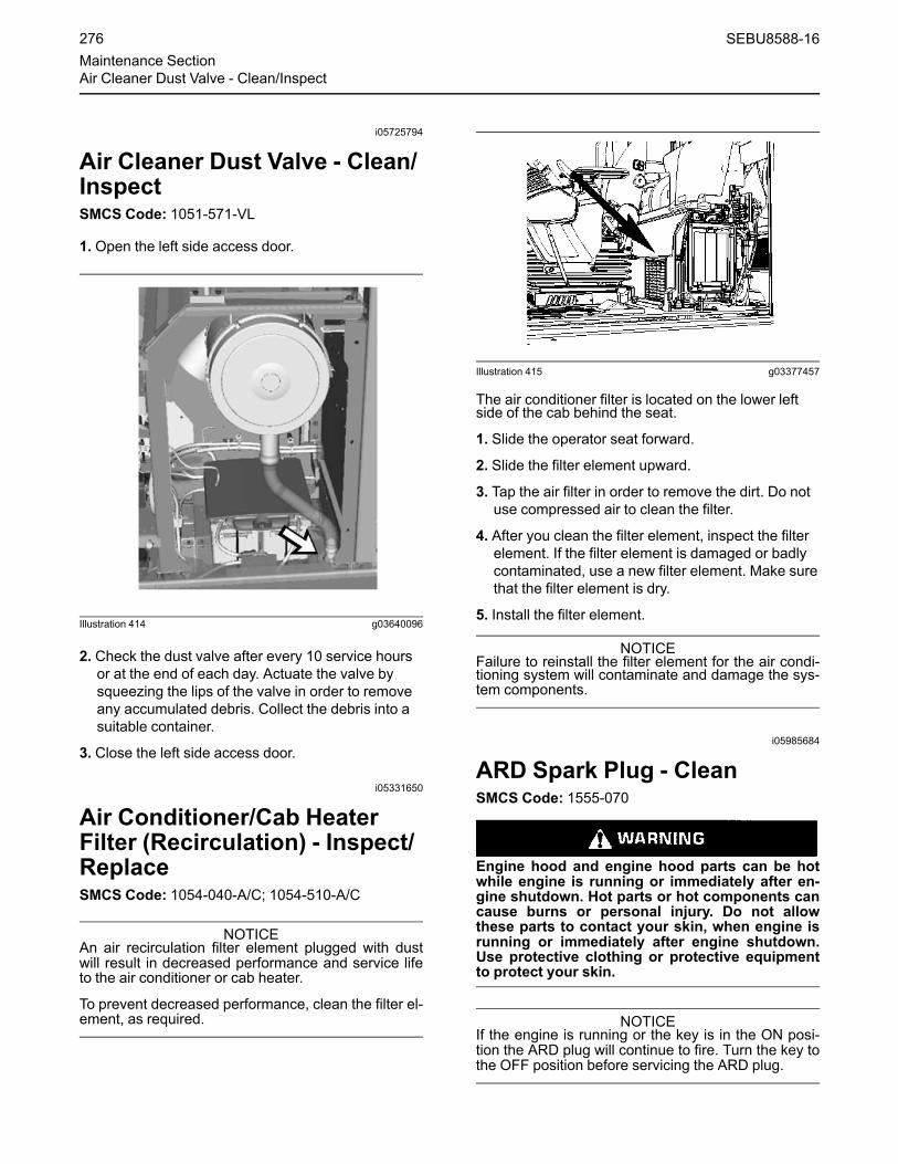
i05725794
Air Cleaner Dust Valve - Clean/InspectSMCS Code: 1051-571-VL
1. Open the left side access door.
Illustration 414 g03640096
2. Check the dust valve after every 10 service hoursor at the end of each day. Actuate the valve bysqueezing the lips of the valve in order to removeany accumulated debris. Collect the debris into asuitable container.
3. Close the left side access door.
i05331650
Air Conditioner/Cab HeaterFilter (Recirculation) - Inspect/ReplaceSMCS Code: 1054-040-A/C; 1054-510-A/C
NOTICEAn air recirculation filter element plugged with dustwill result in decreased performance and service lifeto the air conditioner or cab heater.
To prevent decreased performance, clean the filter el-ement, as required.
Illustration 415 g03377457
The air conditioner filter is located on the lower leftside of the cab behind the seat.
1. Slide the operator seat forward.
2. Slide the filter element upward.
3. Tap the air filter in order to remove the dirt. Do notuse compressed air to clean the filter.
4. After you clean the filter element, inspect the filterelement. If the filter element is damaged or badlycontaminated, use a new filter element. Make surethat the filter element is dry.
5. Install the filter element.
NOTICEFailure to reinstall the filter element for the air condi-tioning system will contaminate and damage the sys-tem components.
i05985684
ARD Spark Plug - CleanSMCS Code: 1555-070
Engine hood and engine hood parts can be hotwhile engine is running or immediately after en-gine shutdown. Hot parts or hot components cancause burns or personal injury. Do not allowthese parts to contact your skin, when engine isrunning or immediately after engine shutdown.Use protective clothing or protective equipmentto protect your skin.
NOTICEIf the engine is running or the key is in the ON posi-tion the ARD plug will continue to fire. Turn the key tothe OFF position before servicing the ARD plug.
276 SEBU8588-16Maintenance SectionAir Cleaner Dust Valve - Clean/Inspect

Illustration 416 g02113380
(1) Wiring harness(2) Spark plug
1. Position the machine on a level surface and lowerthe bucket to the ground.
2.Move the hydraulic lockout control to the LOCKEDposition. Stop the engine.
3. Allow the exhaust system to cool beforeperforming this procedure.
4. Unlatch the engine hood and raise the enginehood.
5. Remove any dirt or debris from the area aroundthe spark plug.
6. Remove wire harness (1) from spark plug (2).
7. Use a deep well socket and a breaker bar toloosen the spark plug. If necessary, see yourCaterpillar dealer for the part number of thesocket. After the spark plug has been loosened,use the socket to remove the spark plug by handin order to detect problems with the threads.
8. After removing spark plug, clean the ground probeinside the ARD combustion head by running aPlug Bore Brush through the hole in the ARDcombustion head. Run the brush through the holeseveral times.
9. Carefully clean the spark plug using a nonmetalliccleaning pad. If the probe appears to be bent,replace the spark plug. Otherwise, install theoriginal spark plug.
Note: The spark plug may be damaged if the sparkplug is dropped. Do not install a spark plug that hasbeen dropped.
NOTICEDo not overtighten the spark plug. The shell can becracked and the gasket can be deformed. The metalcan deform and the gasket can be damaged. Theshell can be stretched. This will loosen the seal thatis between the shell and the insulator, allowing com-bustion pressure to blow past the seal. Serious dam-age to the engine can occur.
Use the proper torque.
10. Install the spark plug by hand until the spark plugcontacts the ARD. Tighten the spark plug to atorque of 43.4 N·m (32 lb ft) to 51.5 N·m (38 lb ft).
11. Connect the wiring harness.
12. Close the engine hood and latch the enginehood.
i00934864
Battery - CleanSMCS Code: 1401-070
Clean the battery surface with a clean cloth. Keep theterminals clean and keep the terminals coated withpetroleum jelly. Install the post cover after you coatthe terminal post with petroleum jelly.
i07746330
Battery - RecycleSMCS Code: 1401-561
Always recycle a battery. Never discard a battery.
Always return used batteries to one of the followinglocations:
• A battery supplier
• An authorized battery collection facility
• Recycling facility
i06019968
Battery Electrolyte Level -CheckSMCS Code: 1401-535; 1401-535-FLV; 1401
All lead-acid batteries contain sulfuric acid whichcan burn the skin and clothing. Always wear aface shield and protective clothing when workingon or near batteries.
SEBU8588-16 277Maintenance Section
Battery - Clean

Note: If the machine is operated in extremetemperatures, check the electrolyte level Every 500Service Hours or 3 months.
When the engine is not run for long periods of time orwhen the engine is run for short periods, the batteriesmay not fully recharge. Ensure a full charge in orderto help prevent the battery from freezing.
1. Clean the battery surface with a clean cloth. Cleanthe terminals and the cable clamps. Coat theclamps and the terminals with silicone lubricant orpetroleum jelly. Install the post cover.
2. Inspect the electrolyte level in each battery cell.Maintain the electrolyte level to the bottom of thefiller openings. Use distilled water. If distilled wateris not available, use clean drinking water.
i00934872
Battery Hold-Down - TightenSMCS Code: 7257
Tighten the hold-downs for the battery in order toprevent the batteries from moving during machineoperation.
i04064489
Battery or Battery Cable -Inspect/ReplaceSMCS Code: 1401; 1401-040; 1401-561; 1401-510;1402-040; 1402-510
Personal injury can result from battery fumes orexplosion.
Batteries give off flammable fumes that can ex-plode. Electrolyte is an acid and can cause per-sonal injury if it contacts the skin or eyes.
Prevent sparks near the batteries. Sparks couldcause vapors to explode. Do not allow jumper ca-ble ends to contact each other or the engine. Im-proper jumper cable connections can cause anexplosion.
Always wear protective glasses when workingwith batteries.
1. Turn all of the switches to the OFF position. Turnthe engine start switch key to the OFF position.
2. Turn the battery disconnect switch to the OFFposition. Remove the key.
3. Disconnect the negative battery cable at thebattery.
4. Disconnect the positive battery cable at thebattery.
5. Disconnect the battery cables at the batterydisconnect switch. The battery disconnect switchis connected to the machine frame.
6.Make necessary repairs or replace the battery.
7. Connect the battery cable at the battery disconnectswitch.
8. Connect the positive battery cable of the battery.
9. Connect the negative battery cable of the battery.
10. Install the key and turn the battery disconnectswitch to the ON position.
i04779186
Belt - Inspect/Adjust/ReplaceSMCS Code: 1357-040; 1357-510; 1357-025; 1397-025; 1397-040; 1397-510
Note: This engine is equipped with a belt tightenerthat automatically adjusts the belt to the correcttension.
1. Unlatch the engine hood and raise the enginehood.
2. Inspect the belt for wear and for cracking.
3. If the belt requires replacement, perform Step 3athrough Step 3c.
278 SEBU8588-16Maintenance SectionBattery Hold-Down - Tighten

Illustration 417 g01127241
a. Turn the belt tensioner in order to release thetension from the belt.
b. Remove the belt.
c. Install a new belt.
Note: Refer to Disassembly and Assembly, “Belt -Remove and Install” for the procedure to replacethe belt.
4. Close the engine hood.
i03865613
Boom, Stick and BucketLinkage - LubricateSMCS Code: 6501-086; 6502-086; 6513-086
Note: Caterpillar recommends the use of 5%molybdenum grease for lubricating the boom, stick,and bucket linkage. Refer to Special Publication,SEBU6250, “Caterpillar Machine FluidsRecommendations” for more information onmolybdenum grease.
Illustration 418 g02109428
Wipe all fittings before you apply lubricant.
Illustration 419 g01122104
1. Apply lubricant through the fitting at the base ofeach boom cylinder.
SEBU8588-16 279Maintenance Section
Boom, Stick and Bucket Linkage - Lubricate

Illustration 420 g00685798
2. The fittings are at the base of the boom. Thefittings can be serviced from the platform on thestorage box. To lubricate the lower boom bearings,apply lubricant through fittings (1) and (2). Tolubricate the boom cylinder rod, apply lubricantthrough fittings (3) and (4). To lubricate the stickcylinder head, apply lubricant through fitting (5).
Note: To ensure proper lubrication of the lower boombearings and of the boom cylinder rod end bearings,lubricant should be applied through fittings (1), (2),(3), and (4). Apply lubricant first when the boom israised and any work tool is suspended. Then applylubricant when the boom is lowered and the work toolis rested on the ground with a slight downwardpressure.
Illustration 421 g01396856
3. Apply lubricant through fittings (6) and (7). Thesefittings are on the bucket.
4. Apply lubricant through fittings (8) and (9). Thesefittings are on the stick.
5. Apply lubricant through fittings (10), (11), and (12).These fittings are on the link.
Illustration 422 g01122102
6. Apply lubricant through fitting (13). Fitting (13) is atthe connection point of the boom and of the stick.
Illustration 423 g01122103
7. Apply lubricant through fitting (14) on the stickcylinder rod. Apply lubricant through fitting (15).Fitting (15) is at the connection point of the boomand of the stick. Apply lubricant through fitting (16)on the bucket cylinder head end.
280 SEBU8588-16Maintenance SectionBoom, Stick and Bucket Linkage - Lubricate

Grease Block on the Stick
Illustration 424 g01396894
(13) Left side connection point of boom and stick(14) Stick cylinder rod(15) Right side connection point of boom and stick(16) Bucket cylinder head end
Some machines may be equipped with a greaseblock that is located on the stick. Apply lubricantthrough the fittings.
i03933249
Bucket Linkage - Inspect/AdjustSMCS Code: 6513-025; 6513-040
Unexpected machine movement can cause injuryor death.
To avoid possible machine movement, move thehydraulic lockout control to the LOCKED positionand attach a Special Instruction, SEHS7332, “DoNot Operate” or similar warning tag to the hy-draulic lockout control.
NOTICEImproperly adjusted bucket clearance could causegalling on the contact surfaces of the bucket andstick, resulting in excessive noise and/or damaged O-ring seals.
Illustration 425 g01141595
(1) No gap(2) Stick boss(3) Bucket clearance(4) Shims(5) Plate(6) Pin(7) Plate(8) Bolts(9) Washers(10) Bolts(11) Washers(12) Location(13) Flange(14) Bucket boss
The clearance of the bucket control linkage on thismachine can be adjusted by shimming. If the gapbetween the bucket and the stick becomesexcessive, adjust bucket clearance (3) to 0.5 to 1 mm(0.02 to 0.04 inch).
Two shims of different thickness are used at location(12). The thicknesses of the shims are 0.5 mm(0.02 inch) and 1.0 mm (0.04 inch).
Illustration 426 g02109636
Area for linkage adjustment
1. Position the machine on a level surface and lowerthe bucket to the ground.
SEBU8588-16 281Maintenance Section
Bucket Linkage - Inspect/Adjust

2. Slowly operate the swing control lever until stickboss (2) and the bucket boss (14) are in full facecontact at no gap (1). This will help to determinethe total clearance of the connection point of thestick and of the bucket.
3.Move the hydraulic lockout control to the LOCKEDposition. Stop the engine.
4.Measure bucket clearance (3), which is theexisting total clearance.
5. Determine the number of shims that need to beremoved from shims (4) by using the followingcalculation:
Subtract 0.5 mm (0.02 inch) or 1.0 mm(0.04 inch) from bucket clearance (3).
6. Remove the appropriate number of shims atlocation (12) in order to meet the above thickness.Make sure that you use a minimum of three0.5 mm (0.02 inch) shims. To remove the shims,remove bolts (8), washers (9), plate (7), bolts (10),washers (11), and plate (5).
7. After the correct number of shims has beenremoved and pin (6) is aligned with the pin hole,install plate (5), washers (11), bolts (10), plate (7),washers (9), and bolts (8). Tighten the bolts to atorque of 240 ± 40 N·m (175 ± 30 lb ft).
8. After installation, make sure that bucket clearance(3) is still correct.
i03574842
Bucket Tips - Inspect/ReplaceSMCS Code: 6805-040; 6805-510
Block the bucket before changing the bucketteeth.
To prevent possible injury to the eyes, wear a pro-tective face shield when striking the pin.
The pin, when struck, can fly out and cause injuryto nearby personnel.
Bucket Tips
Illustration 427 g01577934
(1) Usable tip(2) Replaceable bucket tip(3) Overworn tip
Check the bucket tips for wear. If the bucket tip has ahole, replace the bucket tip.
1. Remove the pin from the bucket tip. The pin can beremoved by one of the following methods.
• Use a hammer and a punch from the retainerside of the bucket to drive out the pin.
• Use a Pin-Master. Follow Step 1a through Step1c for the procedure.
Illustration 428 g01577993
(4) Back of Pin-Master(5) Extractor
a. Place the Pin-Master on the bucket tip.
b. Align extractor (5) with the pin.
282 SEBU8588-16Maintenance SectionBucket Tips - Inspect/Replace

c. Strike the Pin-Master at the back of the tool (4)and remove the pin.
Note: Discard the old pin and the retainerassembly. When you change tips, use a new pinand a new retainer assembly. Refer to theappropriate parts manual for your machine.
Illustration 429 g01577913
(6) Retainer assembly(7) Adapter
2. Clean the adapter and the pin.
3. Fit retainer assembly (6) into the counterbore thatis in the side of adapter (7). Make sure that theface of the retainer assembly with the marking“OUTSIDE” is visible.
Illustration 430 g00101359
4. Install the new bucket tip onto the adapter.
Note: The bucket tips can be rotated by 180 degreesin order to allow the tip to wear evenly. You may alsomove the tips from the outside teeth to the insideteeth. Check the tips often. If wear is present on thetips, rotate the tips. The outside teeth generate themost wear.
5. Drive the pin through the bucket tip. The pin can beinstalled by using one of the following methods:
• From the same side of the retainer, drive thepin through the bucket tip, the retainerassembly, and the adapter.
• Use a Pin-Master. Follow Step 5a through Step5e for the procedure.
Illustration 431 g01578233
(8) Pin
a. Insert pin (8) through the bucket tip.
Illustration 432 g01578342
b. Place the Pin-Master over the bucket tips sothat the pin will fit into the counterbore of the pinholder (9).
c. Strike the Pin-Master with a hammer at theback of the tool (4) in order to insert the pin.
d. Slide pin holder (9) away from the pin androtate the tool slightly in order to align pin setter(10) with the pin.
SEBU8588-16 283Maintenance Section
Bucket Tips - Inspect/Replace

Illustration 433 g01209159
Final assembly of pin into bucket tip
e. Strike the end of the tool until the pin is fullyinserted.
Side Cutters
Illustration 434 g01579693
Bucket With Side Cutters
1. Remove the mounting bolts and the side cutters(11).
2. Clean the mounting surface of the side plate on thebucket and of the side cutter. Remove any burrs orprotrusions on the mating surfaces.
Illustration 435 g01579713
(12) Shear ledge on a side cutter(13) Side plate on a bucket(B) 0.0 mm (0.0 inch)
Note: Some side cutters may be rotated foradditional wear.
3. Install the side cutter.
Note: Certain bolts may require thread compound.
4. Hand tighten the bolts.
5.Make sure that there is not a gap between the sideplate on the bucket and the shear ledge on theside cutter.
6. Torque the mounting bolts to the correctspecification.
Side Protectors (If Equipped)Inspect the wear of the side protector. When toomuch wear is present, replace the protector.
284 SEBU8588-16Maintenance SectionBucket Tips - Inspect/Replace

Illustration 436 g01592996
Illustration 437 g01903678
(14) Side plate(15) Retainer(16) Side protector(17) Pin(18) Shim
1. Hit pin (17) from the side of the bucket without theretainer in order to remove side protector (16) fromside plate (14).
2. Clean side protector (16), pin (17), retainer (15)and side plate (14) before installation.
Note: Lateral clearance between the side plate andthe side protector should not exceed 1 mm(0.04 inch). Shims (18) may be required in order todecrease the lateral clearance which will decreasemovement. Install the shims (18) between the sideplate and the side protector on the opposite side ofthe retainer.
3. Put retainer (15) in side plate (14).
4. Align two pin holes of the new protector and theside plate. Hit the pin from the retainer side of thebucket.
Note: If the pin and/or the retainer are worn, replacethe pin and/or the retainer.
i07114992
Bucket Tips - Inspect/ReplaceSMCS Code: 6805-040; 6805-510
Personal injury or death can result from the buck-et falling.
Block the bucket before changing bucket tips.
Note: In order to maximize the life of the bucket tipand the penetration of the bucket tip, the bucket tipcan be rotated.
Illustration 438 g00101352
(1) Usable(2) Replace(3) Overworn
Check the bucket tips for wear. If the bucket tip has ahole, replace the bucket tip.
SEBU8588-16 285Maintenance Section
Bucket Tips - Inspect/Replace

Removal
Illustration 439 g01389463
Note: Retainers are often damaged during theremoval process. Caterpillar recommends theinstallation of a new retainer when bucket tips arerotated or replaced.
Illustration 440 g01175361
1. Use a pry bar in order to disengage retainer (5).
2. Use the pry bar in order to remove retainer (5) frombucket tip (4).
3. Remove bucket tip (4) from adapter (6) with aslight counterclockwise rotation.
4. Clean adapter (6).
Installation1. Clean the adapter and the area around the latch, ifnecessary.
2. Install the new bucket tip onto the adapter with aslight clockwise rotation.
Illustration 441 g01124736
3. Install the retainer. Make sure that the retainer'slatch catches under the tip pocket.
4.Make sure that the latch is properly seated bytrying to remove the bucket tip.
Bucket Tips (Cat® Advansys ) - IfEquipped
Illustration 442 g00101352
(1) Usable(2) Removal Procedure(3) Removal Procedure
Check the bucket tips for wear. If the bucket tip has ahole, replace the bucket tip.
286 SEBU8588-16Maintenance SectionBucket Tips - Inspect/Replace

Removal
Illustration 443 g03830653
(1) Bucket Tip(2) Retainer(3) Adapter(4) Compression Sleeve
1. Use a 3/4" ratchet and rotate the retainer (2) 180degrees to the unlocked position.
2. Remove the bucket tip (1) from adapter (3).
3. Clean adapter (3).
Installation
1. Clean the adapter and the area around the latch, ifnecessary.
2. Install the new bucket tip (1) onto the adapter (3).
Illustration 444 g03832654
3. Use a 3/4" ratchet to rotate the retainer (2) 180degrees to the locked position.
Side Cutters (If Equipped)
Illustration 445 g01389740
Bucket with side cuttersSide cutters
1. Remove the mounting bolts and the side cutters.
2. Clean the mounting surface of the side plate on thebucket and of the side cutter. Remove any burrs orprotrusions on the mating surfaces.
SEBU8588-16 287Maintenance Section
Bucket Tips - Inspect/Replace

Illustration 446 g01389456
(7) Side cutter
Note: Some side cutters may be rotated foradditional wear.
3. Install the side cutter.
Note: Certain bolts may require thread compound.
4. Hand tighten the bolts.
Illustration 447 g01389457
Section A-A From Illustration 446(8) Side cutter(9) Shear ledge on a side cutter(10) Side plate on a bucket(11) 0.0 mm (0.0 inch)
5.Make sure that there is not a gap between the sideplate on the bucket and the shear ledge on theside cutter.
6. Torque the mounting bolts to the correctspecification.
Side Protectors (If Equipped)Inspect the wear of the side protector. When toomuch wear is present, replace the protector.
Illustration 448 g01389458
Illustration 449 g01903698
Illustration 450 g01389459
(12) Side protector(13) Pin(14) Retainer(15) Side plate(16) Shim
1. Hit pin (13) from the side of the bucket without theretainer in order to remove side protector (12) fromside plate (15).
288 SEBU8588-16Maintenance SectionBucket Tips - Inspect/Replace

2. Clean side protector (12), pin (13), retainer (14)and side plate (15) before installation.
Note: Lateral clearance between the side plate andthe side protector should not exceed 1 mm(0.04 inch). Shims (16) may be required in order todecrease the lateral clearance which will decreasemovement. Install the shims(16) between the sideplate and the side protector on the opposite side ofthe retainer.
3. Put retainer (14) in side plate (15).
4. Align two pin holes of the new protector and theside plate. Hit the pin from the retainer side of thebucket.
Note: If the pin and/or the retainer are worn, replacethe pin and/or the retainer.
i03901495
Cab Air Filter (Fresh Air) -Clean/ReplaceSMCS Code: 7342-510; 7342-070
Illustration 451 g01973174
The cab air filter is located on the left side of the cab.
1. Use the ignition key in order to open the accesspanel.
Illustration 452 g02144326
(1) Air filter
2. Remove air filter (1).
3. Clean the air filter with a maximum of 200 kPa(30 psi) pressure air.
4. After you clean the air filter, inspect the air filter. Ifthe air filter is damaged or badly contaminated,use a new air filter.
5. Install the air filter and the filter cover.
i04281350
Cab Door Latch - Inspect/Adjust/ReplaceSMCS Code: 7308-LX
Cab Door Latch Inspect
Illustration 453 g02449296
(1) Cab Door Striker(2) Cab Door Latch(3) Cab Door Stop
1. Open the cab door and latch the door in the openposition.
SEBU8588-16 289Maintenance Section
Cab Air Filter (Fresh Air) - Clean/Replace

2. Inspect door stops (3) for proper adjustment. Thecab door should contact the door stops andslightly compress the rubber stoppers.
Note: Refer to “Cab Door Stop Adjust” if the doorstops require adjustment.
3. Inspect the operation of the door latch. The latchshould not release the door unless you pull downon one of the door release levers located in thecab. When the door is closed, the door shouldrelease from the latch smoothly.
Note: If needed, spray an appropriate lubricantthroughout the latch in order to clean and lubricatethe latch mechanism
4. Inspect the cab door striker (1) and the cab doorlatch (2). Ensure that the striker is properly alignedwith the latch.
5. Close the cab door.
Note: If the door does not latch properly or if the doordoes not release from the latch properly, refer to “CabDoor Latch Adjust” for the adjustment procedure.
Cab Door Stop Adjust
Illustration 454 g02449162
1. Completely loosen nut (4) and rotate the door stopclockwise.
2. Carefully open the cab door and latch the door inthe open position.
3. Rotate the door stop counter clockwise until thedoor stop contacts the door.
4. Close the cab door.
5. Rotate the door stop counter clockwise anadditional 1 to 1 1/4 revolutions and tighten nut (4).
Cab Door Latch Adjust
Illustration 455 g02449164
1. Use the ignition key in order to open the accesspanel for the cab air filter.
2. Loosen bolts (5) and align the striker on the cabdoor with the latch mechanism.
3. Tighten bolts (5) and close the access panel.
Cab Door Latch ReplaceCab Door Latch Removal
Illustration 456 g02449166
1. Use the ignition key in order to open the accesspanel for the cab air filter.
2. Loosen nut (6) and disconnect cable (7) from thelatch assembly.
3. Remove bolts (5) in order to remove the entirelatch assembly.
290 SEBU8588-16Maintenance SectionCab Door Latch - Inspect/Adjust/Replace

Illustration 457 g02449276
4. Remove bolts (8) and remove the latchmechanism from the assembly.
Cab Door Latch Installation
1. Perform the installation procedure in reverse order.
Note:Make sure that the striker and the latch areproperly aligned. Refer to “Cab Door Latch Adjust”.
i06587366
Camera - Clean(If Equipped)SMCS Code: 7348-070
Failure to use an appropriate external ladder oran appropriate platform for direct access to thecameras could result in slipping and falling whichcould result in personal injury or death. Be sureto use an appropriate external ladder or an appro-priate platform for direct access to the cameras.
The counterweight of the machine and the enginehood of the machine are not approved as mainte-nance platforms.
Unexpected machine movement can cause injuryor death.
In order to avoid possible machine movement,move the hydraulic lockout control to theLOCKED position and attach a Special Instruc-tion, SEHS7332, “Do Not Operate” or similarwarning tag to the hydraulic lockout control.
Note:When you access the cameras for cleaning, besure to observe safe procedures for access. Maintaina three-point contact and/or use a body harness.
Illustration 458 g02158495
The rear view camera is located on top of thecounterweight.
Illustration 459 g06035100
The side view camera is located on top of Fuel Tank.
If necessary, use a damp cloth in order to clean theglass of the camera. The camera is sealed. Thecamera is not affected by a wash with high-pressurespray.
Note: Alternatively, cameras may be cleaned fromground level by using a wash with a high-pressurespray or a damp rag on a wand.
SEBU8588-16 291Maintenance Section
Camera - Clean

i05333373
Circuit Breakers - ResetSMCS Code: 1420-529
Main Circuit – This circuit breaker isdesigned to protect the wires betweenthe batteries and the fuses. If the wires
are shorted to the machine's body, this circuitbreaker would minimize the damage to the wires.
The main circuit breaker has a capacity of 80 Amp.
Circuit Breaker Reset – Push in the button in orderto reset the circuit breaker. If the electrical system isworking properly, the button will remain depressed. Ifthe button does not remain depressed, check theappropriate electrical circuit. Repair the electricalcircuit, if necessary.
Illustration 460 g03378496
The circuit breaker is located behind the front leftaccess door.
i02189743
Condenser (Refrigerant) -CleanSMCS Code: 1805-070
NOTICEIf excessively dirty, clean condenser with a brush. Toprevent damage or bending of the fins, do not use astiff brush.
Repair the fins if found defective.
1. Open the middle access door on the left side of themachine. The condenser is located behind theengine air precleaner.
Illustration 461 g00537515
2. Inspect the condenser for debris. Clean thecondenser, if necessary.
3. Use clean water to wash off all dust and dirt fromthe condenser.
4. Close the access door.
i05331702
Cooling System Coolant (ELC)- ChangeSMCS Code: 1350-044
NOTICEMixing Extended Life Coolant (ELC) with other prod-ucts reduces the effectiveness of the coolant andshortens coolant life. Use only Caterpillar products orcommercial products that have passed the CaterpillarEC-1 specifications for premixed or concentrate cool-ants. Use only Caterpillar Extender with CaterpillarELC. Failure to follow these recommendations couldresult in the damage to cooling systems components.
If ELC cooling system contamination occurs, refer toSpecial Publication, SEBU6250, “Cat Extended LifeCoolant (ELC)”.
This machine was factory filled with Extended LifeCoolant.
292 SEBU8588-16Maintenance SectionCircuit Breakers - Reset
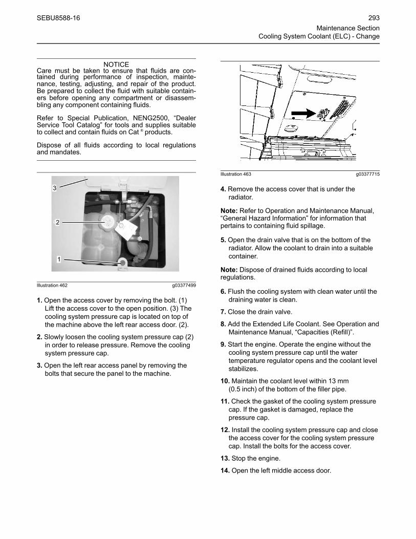
NOTICECare must be taken to ensure that fluids are con-tained during performance of inspection, mainte-nance, testing, adjusting, and repair of the product.Be prepared to collect the fluid with suitable contain-ers before opening any compartment or disassem-bling any component containing fluids.
Refer to Special Publication, NENG2500, “DealerService Tool Catalog” for tools and supplies suitableto collect and contain fluids on Cat ® products.
Dispose of all fluids according to local regulationsand mandates.
Illustration 462 g03377499
1. Open the access cover by removing the bolt. (1)Lift the access cover to the open position. (3) Thecooling system pressure cap is located on top ofthe machine above the left rear access door. (2).
2. Slowly loosen the cooling system pressure cap (2)in order to release pressure. Remove the coolingsystem pressure cap.
3. Open the left rear access panel by removing thebolts that secure the panel to the machine.
Illustration 463 g03377715
4. Remove the access cover that is under theradiator.
Note: Refer to Operation and Maintenance Manual,“General Hazard Information” for information thatpertains to containing fluid spillage.
5. Open the drain valve that is on the bottom of theradiator. Allow the coolant to drain into a suitablecontainer.
Note: Dispose of drained fluids according to localregulations.
6. Flush the cooling system with clean water until thedraining water is clean.
7. Close the drain valve.
8. Add the Extended Life Coolant. See Operation andMaintenance Manual, “Capacities (Refill)”.
9. Start the engine. Operate the engine without thecooling system pressure cap until the watertemperature regulator opens and the coolant levelstabilizes.
10.Maintain the coolant level within 13 mm(0.5 inch) of the bottom of the filler pipe.
11. Check the gasket of the cooling system pressurecap. If the gasket is damaged, replace thepressure cap.
12. Install the cooling system pressure cap and closethe access cover for the cooling system pressurecap. Install the bolts for the access cover.
13. Stop the engine.
14. Open the left middle access door.
SEBU8588-16 293Maintenance Section
Cooling System Coolant (ELC) - Change

Illustration 464 g03377742
Coolant reservoir(4) “FULL”(5) “LOW”
15. Check the coolant reservoir. Maintain the coolantlevel between the “FULL” mark (A) and the “LOW”mark (B).
16. If additional coolant is necessary, remove thereservoir cap on top of the coolant reservoir andadd the appropriate coolant solution.
17. Install the reservoir cap.
18. Close the left middle access door.
19. Close the left rear access panel and install thebolts for the left rear access panel.
20. Install the access cover that is under the radiator.
i05331973
Cooling System CoolantExtender (ELC) - AddSMCS Code: 1352; 1353; 1395
NOTICEMixing Extended Life Coolant (ELC) with other prod-ucts reduces the effectiveness of the coolant andshortens coolant life. Use only Caterpillar products orcommercial products that have passed the CaterpillarEC-1 specifications for premixed or concentrate cool-ants. Use only Caterpillar Extender with CaterpillarELC. Failure to follow these recommendations couldresult in the damage to cooling systems components.
If ELC cooling system contamination occurs, refer toSpecial Publication, SEBU6250, “Cat Extended LifeCoolant (ELC)”.
This machine was factory filled with Extended LifeCoolant.
NOTICECare must be taken to ensure that fluids are con-tained during performance of inspection, mainte-nance, testing, adjusting, and repair of the product.Be prepared to collect the fluid with suitable contain-ers before opening any compartment or disassem-bling any component containing fluids.
Refer to Special Publication, NENG2500, “DealerService Tool Catalog” for tools and supplies suitableto collect and contain fluids on Cat ® products.
Dispose of all fluids according to local regulationsand mandates.
When a Caterpillar Extended Life Coolant (ELC) isused, an Extender must be added to the coolingsystem. See Special Publication, SEBU6250,“Cooling Recommendations” for all cooling systemrequirements.
Use a coolant conditioner test kit in order to checkthe concentration of the coolant.
NOTICEMixing Extended Life Coolant (ELC) with other prod-ucts reduces the effectiveness of the coolant andshortens coolant life. Use only Caterpillar products orcommercial products that have passed the CaterpillarEC-1 specifications for premixed or concentrate cool-ants. Use only Caterpillar Extender with CaterpillarELC. Failure to follow these recommendations couldresult in the damage to cooling systems components.
If ELC cooling system contamination occurs, refer toSpecial Publication, SEBU6250, “Cat Extended LifeCoolant (ELC)”.
This machine was factory filled with Extended LifeCoolant.
294 SEBU8588-16Maintenance SectionCooling System Coolant Extender (ELC) - Add

Illustration 465 g03377757
1. Open the access cover (3) for the cooling systempressure cap (2). The access cover for the coolingsystem pressure cap is located on top of themachine above the left rear access door. Removebolt (1) . to open the access cover .
2. Slowly loosen the cooling system pressure cap inorder to release system pressure. Remove thepressure cap.
Note: Refer to Operation and Maintenance Manual,“General Hazard Information” for information oncontaining fluid spillage.
3. You may have to drain some coolant from theradiator so that Caterpillar Extender can be addedto the cooling system.
Note: Always discard drained fluids according tolocal regulations.
4. Add Extender to the cooling system. Refer to thefollowing topics for the proper amount ofCaterpillar Extender:
• Special Publication, SEBU6250, “Cat ExtendedLife Coolant (ELC)”
• Operation and Maintenance Manual,“Capacities (Refill)”
5. Inspect the gasket of the cooling system pressurecap. If the gasket is damaged, replace thepressure cap.
6. Install the cooling system pressure cap.
7. Close the access door for the cooling systempressure cap.
i05333384
Cooling System Coolant Level- CheckSMCS Code: 1350-535-FLV; 1350-040; 1395-535-FLV
1. Open the middle access door on the left side of themachine.
Illustration 466 g03378511
Coolant reservoir(A) “FULL”(B) “LOW”
2. Check the coolant level of the coolant reservoir.Maintain the coolant level between the “FULL”mark and the “LOW”mark. If the coolant reservoiris empty, follow Steps 2a through 2i.
Illustration 467 g03378512
a. Open the access cover (3) for the coolingsystem pressure cap (2). The access cover forthe cooling system pressure cap is located ontop of the machine above the left rear accessdoor. Remove bolt (1) and slide the accesscover open.
SEBU8588-16 295Maintenance Section
Cooling System Coolant Level - Check

b. Slowly loosen the cooling system pressure capin order to relieve system pressure. Removethe pressure cap.
Note: Refer to Operation and MaintenanceManual, “General Hazard Information” forinformation on containing fluid spillage.
c. Add the appropriate coolant solution to thecooling system. Refer to the following topics:
• Operation and Maintenance Manual,SEBU6250, “Cooling SystemSpecifications”
• Operation and Maintenance Manual,“Capacities (Refill)”
d. Start the engine. Operate the engine withoutthe cooling system pressure cap until the watertemperature regulator opens and the coolantlevel stabilizes.
e. Maintain the coolant level within 13 mm(0.5 inch) of the bottom of the filler pipe.
Illustration 468 g00102170
f. Inspect the condition of the gasket on thepressure cap. If the gasket is damaged, replacethe pressure cap.
g. Install the cooling system pressure cap.
h. Stop the engine.
i. Close the access cover for the cooling systempressure cap. Install and tighten bolts (1) and(2).
Note: Refer to Operation and Maintenance Manual,“General Hazard Information” for information oncontaining fluid spillage.
3. If additional coolant is necessary, remove thereservoir cap and add the appropriate coolantsolution.
4. Install the reservoir cap.
5. Close the left access door.
i02786578
Cooling System CoolantSample (Level 1) - ObtainSMCS Code: 1395-008; 1395-554; 7542
Note: It is not necessary to obtain a CoolantSample (Level 1) if the cooling system is filledwith Cat ELC (Extended Life Coolant). Coolingsystems that are filled with Cat ELC should have aCoolant Sample (Level 2) that is obtained at therecommended interval that is stated in theMaintenance Interval Schedule.
Note: Obtain a Coolant Sample (Level 1) if thecooling system is filled with any other coolantinstead of Cat ELC. This includes the followingtypes of coolants.
• Commercial long life coolants that meet theCaterpillar Engine Coolant Specification -1(Caterpillar EC-1)
• Cat Diesel Engine Antifreeze/Coolant (DEAC)
• Commercial heavy-duty coolant/antifreeze
NOTICEAlways use a designated pump for oil sampling, anduse a separate designated pump for coolant sam-pling. Using the same pump for both types of sam-ples may contaminate the samples that are beingdrawn. This contaminate may cause a false analysisand an incorrect interpretation that could lead to con-cerns by both dealers and customers.
Note: Level 1 results may indicate a need forLevel 2 Analysis.
Illustration 469 g01100386
Coolant sample port
296 SEBU8588-16Maintenance SectionCooling System Coolant Sample (Level 1) - Obtain

Refer to the Operation and Maintenance Manual,“Access Doors and Covers” for the location of theservice points.
Obtain the sample of the coolant as close as possibleto the recommended sampling interval. In order toreceive the full effect of S·O·S analysis, you mustestablish a consistent trend of data. In order toestablish a pertinent history of data, performconsistent samplings that are evenly spaced.Supplies for collecting samples can be obtained fromyour Caterpillar dealer.
Use the following guidelines for proper sampling ofthe coolant:
• Complete the information on the label for thesampling bottle before you begin to take thesamples.
• Keep the unused sampling bottles stored in plasticbags.
• Obtain coolant samples directly from the coolantsample port. You should not obtain the samplesfrom any other location.
• Keep the lids on empty sampling bottles until youare ready to collect the sample.
• Place the sample in the mailing tube immediatelyafter obtaining the sample in order to avoidcontamination.
• Never collect samples from expansion bottles.
• Never collect samples from the drain for a system.
Submit the sample for Level 1 analysis.
For additional information about coolant analysis, seeSpecial Publication, SEBU6250, “Caterpillar MachineFluids Recommendations” or consult your Caterpillardealer.
i07349178
Cooling System CoolantSample (Level 2) - ObtainSMCS Code: 1395-554; 1395-008; 7542
Reference: Refer to Operation and MaintenanceManual, “Cooling System Coolant Sample (Level 1) -Obtain” for the guidelines for proper sampling of thecoolant.
Obtain the sample of the coolant as close as possibleto the recommended sampling interval. Supplies forcollecting samples can be obtained from your Catdealer.
Submit the sample for Level 2 analysis.
Reference: For additional information about coolantanalysis, refer to Special Publication, SEBU6250,“Caterpillar Machine Fluids Recommendations” orconsult your Cat dealer.
i03591653
Counterweight Removal Chain- Clean(If Equipped)SMCS Code: 7056-070-CX
Proper operation of the Counterweight RemovalSystem depends on a properly lubricated coun-terweight chain. If the chain is not lubricatedproperly, the chain may rust and seize during theremoval operation. A seized chain can fractureand result in complete failure of the chain. Thecounterweight can then suddenly fall which canresult in personal injury or death.
Use an approved ladder or platform when lubri-cating the upper portion of the chain.
If seizure of the chain occurs during counter-weight removal, stop the operation of the coun-terweight removal system and contact yournearest dealer for chain replacement.
The counterweight removal chain must be clean andfree from rust. A chain with dirt or rust cannot bewound correctly.
1. If necessary, remove the entire chain assembly inorder to properly clean the chain assembly of rustand foreign contaminants.
2. Clean the chain assembly with a clean,nonflammable solvent and a wire brush.
3. Allow the chain assembly to dry. Lubricate thecounterweight removal chain. Refer to Operationand Maintenance Manual, “CounterweightRemoval Chain - Lubricate” for the properprocedure.
4. If the chain assembly was removed, install thechain assembly.
Note: Always clean the chain of rust and foreigncontaminants.
SEBU8588-16 297Maintenance Section
Cooling System Coolant Sample (Level 2) - Obtain
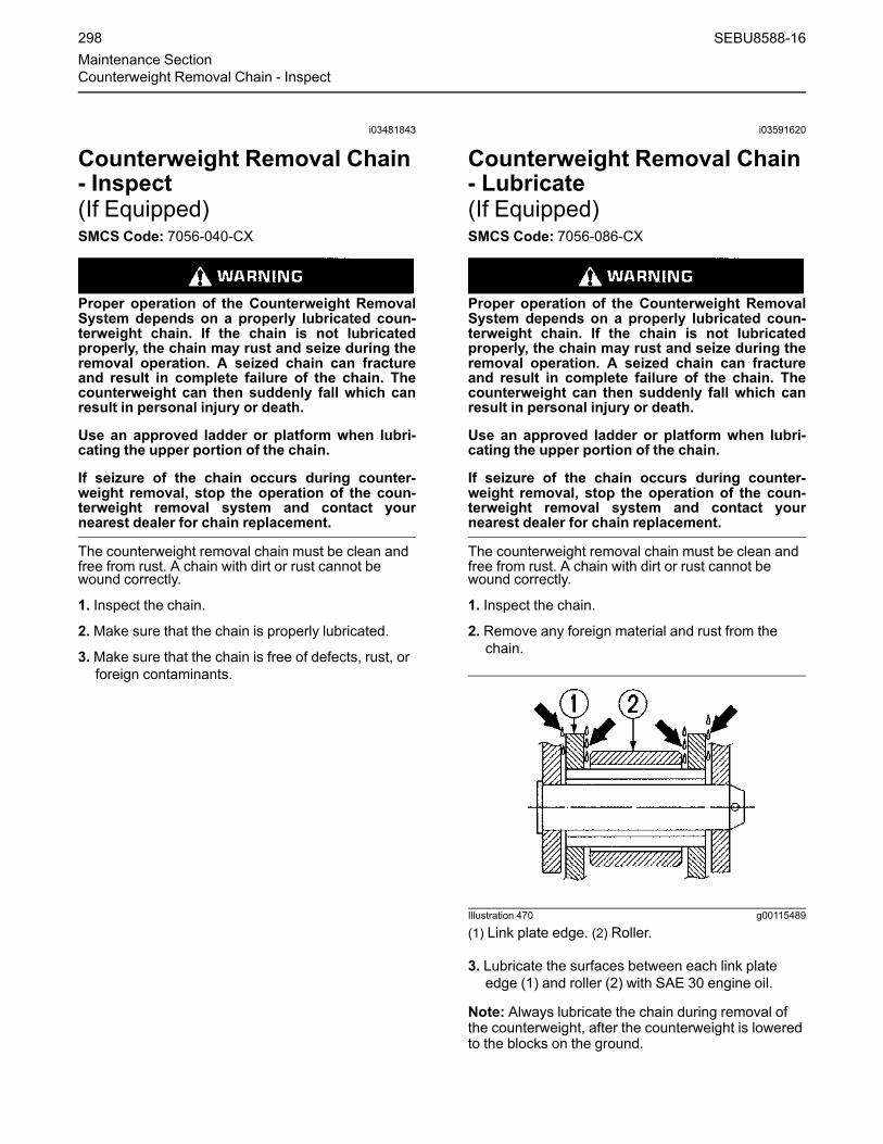
i03481843
Counterweight Removal Chain- Inspect(If Equipped)SMCS Code: 7056-040-CX
Proper operation of the Counterweight RemovalSystem depends on a properly lubricated coun-terweight chain. If the chain is not lubricatedproperly, the chain may rust and seize during theremoval operation. A seized chain can fractureand result in complete failure of the chain. Thecounterweight can then suddenly fall which canresult in personal injury or death.
Use an approved ladder or platform when lubri-cating the upper portion of the chain.
If seizure of the chain occurs during counter-weight removal, stop the operation of the coun-terweight removal system and contact yournearest dealer for chain replacement.
The counterweight removal chain must be clean andfree from rust. A chain with dirt or rust cannot bewound correctly.
1. Inspect the chain.
2.Make sure that the chain is properly lubricated.
3.Make sure that the chain is free of defects, rust, orforeign contaminants.
i03591620
Counterweight Removal Chain- Lubricate(If Equipped)SMCS Code: 7056-086-CX
Proper operation of the Counterweight RemovalSystem depends on a properly lubricated coun-terweight chain. If the chain is not lubricatedproperly, the chain may rust and seize during theremoval operation. A seized chain can fractureand result in complete failure of the chain. Thecounterweight can then suddenly fall which canresult in personal injury or death.
Use an approved ladder or platform when lubri-cating the upper portion of the chain.
If seizure of the chain occurs during counter-weight removal, stop the operation of the coun-terweight removal system and contact yournearest dealer for chain replacement.
The counterweight removal chain must be clean andfree from rust. A chain with dirt or rust cannot bewound correctly.
1. Inspect the chain.
2. Remove any foreign material and rust from thechain.
Illustration 470 g00115489
(1) Link plate edge. (2) Roller.
3. Lubricate the surfaces between each link plateedge (1) and roller (2) with SAE 30 engine oil.
Note: Always lubricate the chain during removal ofthe counterweight, after the counterweight is loweredto the blocks on the ground.
298 SEBU8588-16Maintenance SectionCounterweight Removal Chain - Inspect

i08057952
DEF Filler Screen - Clean((Emission Related Component))SMCS Code: 108K-070-Z3
NOTICEEnsure that the engine is stopped before any servic-ing or repair is performed.
NOTICECare must be taken to ensure that fluids are con-tained during performance of inspection, mainte-nance, testing, adjusting, and repair of the product.Be prepared to collect the fluid with suitable contain-ers before opening any compartment or disassem-bling any component containing fluids.
Refer to Special Publication, NENG2500, “Cat DealerService Tool Catalog” or refer to Special Publication,PECJ0003, “Cat Shop Supplies and Tools Catalog”for tools and supplies suitable to collect and containfluids on Cat products.
Dispose of all fluids according to local regulationsand mandates.
The filler neck adapter filter screen in the dieselexhaust fluid tank will need to be cleaned or replacedif contaminated.
Illustration 471 g03618438
1. Use a screwdriver or pick to press the tabs (1).
2. Pull the screen assembly (2) upward from bothsides and remove from the fill neck adapter
3. Use water or compressed air to clean out the filterscreen (3). If there is any debris inside, let dry andremove the debris by turning the screen upsidedown and dumping debris out. If the debris cannotbe removed or the filter screen is damaged,replace the filler neck adapter filter screen.
i07443771
DEF Manifold Filters - Replace(Emission Related Component)SMCS Code: 108K-510-FI
NOTICEEnsure that the engine is stopped before any servic-ing or repair is performed.
NOTICECare must be taken to ensure that fluids are con-tained during performance of inspection, mainte-nance, testing, adjusting, and repair of the product.Be prepared to collect the fluid with suitable contain-ers before opening any compartment or disassem-bling any component containing fluids.
Refer to Special Publication, NENG2500, “Cat DealerService Tool Catalog” or refer to Special Publication,PECJ0003, “Cat Shop Supplies and Tools Catalog”for tools and supplies suitable to collect and containfluids on Cat products.
Dispose of all fluids according to local regulationsand mandates.
Note: Refer to Special Instruction, REHS8231,“Removal Procedures for Diesel Exhaust Fluid (DEF)Connectors” for the correct removal procedure ofhose assemblies (1) and (5).
SEBU8588-16 299Maintenance Section
DEF Filler Screen - Clean

Illustration 472 g03662693
Typical Example
1. Clamp off hoses (1).
2. Remove clips (2) and (3). Disconnect harnessassemblies (4). Remove hose assemblies (1) and(5).
Illustration 473 g03665701
Typical Example
3. Remove bolts (6), plate (7), tank manifold (8), andgasket (not shown).
Illustration 474 g03665737
4. Unscrew the band clamp (9) and remove the bandclamp from the filter base (10).
300 SEBU8588-16Maintenance SectionEmission Related Component

Illustration 475 g03664911
5. Remove the filter (11) from the filter base.
Illustration 476 g03666075
6. Remove the suction filter (12) at the bottom of theheader coils by pulling tabs (13). Replace with anew suction filter.
7. Install new filter by pulling filter over the manifoldcoils up to the bottom of the assembled filter base.
Illustration 477 g03665754
8. Tighten the band clamp 4.5 ± 0.7 N·m(40 ± 6 lb in), ensuring that the band clamp isaligned, as shown in illustration 477 , to the flatspot on the base. Ensure that the filter does notbunch when tightening the band clamp.
9. Install the tank manifold following steps 3 through5 in reverse order with a new gasket.
10. Tighten bolts (6) in an alternating sequence to5 ± 1 N·m (44 ± 9 lb in). Tighten bolts (6) a secondtime in an alternating sequence to 5 ± 1 N·m(44 ± 9 lb in). Apply rubber lubricant to the o-ringseal inside of hose assemblies (1).
SEBU8588-16 301Maintenance Section
Emission Related Component

i05626950
Diesel Exhaust Fluid Filter -ReplaceSMCS Code: 108K-510-FI
Illustration 478 g03573976
The Diesel Exhaust Fluid (DEF) filter is located onthe DEF tank. The DEF tank is located next to thestorage box on the right side of the machine.
Illustration 479 g03332612
Typical Example
NOTICEEnsure that the engine is stopped before any servic-ing or repair is performed.
NOTICECare must be taken to ensure that fluids are con-tained during performance of inspection, mainte-nance, testing, adjusting, and repair of the product.Be prepared to collect the fluid with suitable contain-ers before opening any compartment or disassem-bling any component containing fluids.
Refer to Special Publication, NENG2500, “Cat DealerService Tool Catalog” or refer to Special Publication,PECJ0003, “Cat Shop Supplies and Tools Catalog”for tools and supplies suitable to collect and containfluids on Cat products.
Dispose of all fluids according to local regulationsand mandates.
1. Remove the diesel exhaust fluid (DEF) filter cap(3) with a 27 mm (1.06 inch) wrench.
2. Remove the rubber cone insert (2) from the DEFfilter (1).
Illustration 480 g03332637
Typical Example
3. Insert the DEF filter removal tool (4) into the DEFfilter (1) and remove the DEF filter (1).
Note:Wear gloves when you handle the DEF filterremoval tool (4).
4. Clean the area around the filter housing.
5. Apply a thin coat of 207-1601 Lubricant to theseals of the new DEF filter (1).
6. Install new DEF filter (1) and rubber cone insert.Torque the filter to 20 ± 5 N·m (14.8 ± 3.7 lb ft)with a 27 mm (1.06 inch) wrench.
302 SEBU8588-16Maintenance SectionDiesel Exhaust Fluid Filter - Replace

i07400077
Diesel Exhaust Fluid Injector -Replace(Emission Related Component)SMCS Code: 108I-510
Illustration 481 g03363165
Typical example shown
1. Remove the diesel exhaust fluid (DEF) line (1)from the injector (4).
2. Remove the coolant lines (2) from the injector.
3. Remove the electrical connector (3) from theinjector.
4. Remove the bolts from the injector and remove theinjector.
5. Replace gasket. The steel side of the gasketshould face towards diesel particulate filter (DPF)outlet.
6. Replace the injector.
7. Apply anti-seize to bolt threads.
8. Torque the bolts of the injector to 5 N·m (3.7 lb ft).Retighten all bolts to 5 N·m (3.7 lb ft), then turn90°.
9. Connect the electrical connector.
10. Connect the coolant lines.
11. Connect the DEF line.
i05622145
Diesel Exhaust Fluid - FillSMCS Code: 108K-544
Personal injury or death may result from failureto adhere to the following procedures.
Fuel leaked or spilled onto hot surfaces or electri-cal components can cause a fire.
Clean up all leaked or spilled fuel. Do not smokewhile working on the fuel system.
Turn the disconnect switch OFF or disconnectthe battery when changing fuel filters.
NOTICECare must be taken to ensure that fluids are con-tained during performance of inspection, mainte-nance, testing, adjusting, and repair of the machine.Be prepared to collect the fluid with suitable contain-ers before opening any compartment or disassem-bling any component containing fluids.
Dispose of all fluids according to local regulationsand mandates.
Reference: See Operation and MaintenanceManual, “Capacities (Refill)” for the capacity of thefuel tank for your machine.
Illustration 482 g03569489
The DEF tank is located in storage box on the rightside of the machine.
1. Open the right side storage box.
2. Clean filler cap and the surrounding area.
3. Remove the filler cap.
4. Fill tank with diesel exhaust fluid.
SEBU8588-16 303Maintenance Section
Diesel Exhaust Fluid Injector - Replace
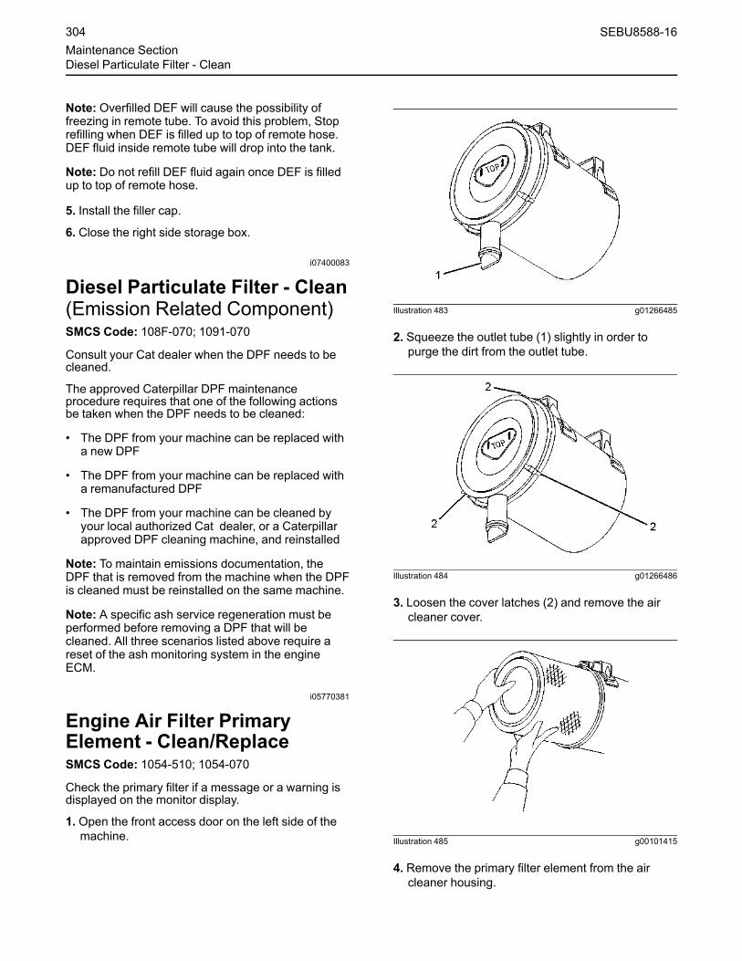
Note: Overfilled DEF will cause the possibility offreezing in remote tube. To avoid this problem, Stoprefilling when DEF is filled up to top of remote hose.DEF fluid inside remote tube will drop into the tank.
Note: Do not refill DEF fluid again once DEF is filledup to top of remote hose.
5. Install the filler cap.
6. Close the right side storage box.
i07400083
Diesel Particulate Filter - Clean(Emission Related Component)SMCS Code: 108F-070; 1091-070
Consult your Cat dealer when the DPF needs to becleaned.
The approved Caterpillar DPF maintenanceprocedure requires that one of the following actionsbe taken when the DPF needs to be cleaned:
• The DPF from your machine can be replaced witha new DPF
• The DPF from your machine can be replaced witha remanufactured DPF
• The DPF from your machine can be cleaned byyour local authorized Cat dealer, or a Caterpillarapproved DPF cleaning machine, and reinstalled
Note: To maintain emissions documentation, theDPF that is removed from the machine when the DPFis cleaned must be reinstalled on the same machine.
Note: A specific ash service regeneration must beperformed before removing a DPF that will becleaned. All three scenarios listed above require areset of the ash monitoring system in the engineECM.
i05770381
Engine Air Filter PrimaryElement - Clean/ReplaceSMCS Code: 1054-510; 1054-070
Check the primary filter if a message or a warning isdisplayed on the monitor display.
1. Open the front access door on the left side of themachine.
Illustration 483 g01266485
2. Squeeze the outlet tube (1) slightly in order topurge the dirt from the outlet tube.
Illustration 484 g01266486
3. Loosen the cover latches (2) and remove the aircleaner cover.
Illustration 485 g00101415
4. Remove the primary filter element from the aircleaner housing.
304 SEBU8588-16Maintenance SectionDiesel Particulate Filter - Clean

5. Clean the air cleaner cover and the inside of the aircleaner housing.
6. Inspect the O-ring seal on the air cleaner cover.Replace the O-ring seal if the O-ring seal is wornor damaged.
7. Install the clean primary filter.
Note: Refer to “Cleaning Primary Air FilterElements”.
8. Install the air cleaner cover and close the latchessecurely.
Illustration 486 g00101416
Note: Install the air cleaner cover properly. Thearrows must point upward.
9. Replace the filter if the “Restricted Air Filter ”indicator on the monitor display still comes on.
10. Close the access door.
Cleaning Primary Air FilterElements
NOTICECaterpillar recommends certified air filter cleaningservices available at participating Caterpillar dealers.The Caterpillar cleaning process uses proven proce-dures to assure consistent quality and sufficient filterlife.
Observe the following guidelines if you attempt toclean the filter element:
Do not tap or strike the filter element in order to re-move dust.
Do not wash the filter element.
Use low pressure compressed air in order to removethe dust from the filter element. Air pressure must notexceed 207 kPa (30 psi). Direct the air flow up thepleats and down the pleats from the inside of the filterelement. Take extreme care in order to avoid damageto the pleats.
Do not use air filters with damaged pleats, gaskets,or seals. Dirt entering the engine will cause damageto engine components.
When the primary air filter element is cleaned, checkfor rips or tears in the filter material. Replace theprimary air filter element after the primary air filterelement has been cleaned six times. The primary airfilter element should be replaced at least one timeper year. This replacement should be performedregardless how many times the filter was cleaned.
NOTICEDo not clean the air filter elements by bumping or tap-ping. This could damage the seals. Do not use ele-ments with damaged pleats, gaskets, or seals.Damaged elements will allow dirt to pass through.Engine damage could result.
Visually inspect the primary air filter elements beforecleaning. Inspect the air filter elements for damage tothe seal, the gaskets, and the outer cover. Discardany damaged air filter elements.
There are two common methods that are used toclean primary air filter elements:
• Pressurized air
• Vacuum cleaning
Pressurized AirPressurized air can be used to clean primary air filterelements that have not been cleaned more than twotimes. Pressurized air will not remove deposits ofcarbon and oil. Use filtered, dry air with a maximumpressure of 207 kPa (30 psi).
SEBU8588-16 305Maintenance Section
Engine Air Filter Primary Element - Clean/Replace

Illustration 487 g00281692
Note:When the primary air filter elements arecleaned, always begin with the clean side (inside) inorder to force dirt particles toward the dirty side(outside).
Aim the hose so that the air flows inside the elementalong the length of the filter in order to help preventdamage to the paper pleats. Do not aim the stream ofair directly at the primary air filter element. Dirt couldbe forced further into the pleats.
Vacuum Cleaning
Vacuum cleaning is another method for cleaningprimary air filter elements which require dailycleaning because of a dry, dusty environment.Cleaning with pressurized air is recommended priorto vacuum cleaning. Vacuum cleaning will notremove deposits of carbon and oil.
Inspecting the Primary Air FilterElements
Illustration 488 g00281693
Inspect the clean, dry primary air filter element. Use a60 W blue light in a dark room or in a similar facility.Place the blue light in the primary air filter element.Rotate the primary air filter element. Inspect theprimary air filter element for tears and/or holes.Inspect the primary air filter element for light that mayshow through the filter material. If necessary,compare the primary air filter element to a newprimary air filter element that has the same partnumber.
Do not use a primary air filter element that has anytears and/or holes in the filter material. Do not use aprimary air filter element with damaged pleats,gaskets, or seals. Discard damaged primary air filterelements.
Storing Primary Air Filter Elements
If a primary air filter element that passes inspectionwill not be used, the primary air filter element can bestored for future use.
306 SEBU8588-16Maintenance SectionEngine Air Filter Primary Element - Clean/Replace

Illustration 489 g00281694
Do not use paint, a waterproof cover, or plastic as aprotective covering for storage. An air flow restrictionmay result. To protect against dirt and damage, wrapthe primary air filter elements in Volatile CorrosionInhibited (VCI) paper.
Place the primary air filter element into a box forstorage. For identification, mark the outside of thebox and mark the primary air filter element. Includethe following information:
• The date that the filter was cleaned
• Number of times the filter has been cleaned
Store the box in a dry location.
i03900450
Engine Air Filter SecondaryElement - ReplaceSMCS Code: 1054-510
NOTICEAlways replace the secondary filter element. Neverattempt to reuse the secondary filter element bycleaning the element.
When the primary filter element is replaced, the sec-ondary filter element should be replaced.
The secondary filter element should also be replacedif the restricted Air Filter indicator comes on after theinstallation of a clean primary filter element or if theexhaust smoke is still black.
1. Open the middle access door on the left side of themachine.
2. See Operation and Maintenance Manual, “EngineAir Filter Primary Element - Clean/Replace”.Remove the air cleaner cover from the air cleanerhousing. Remove the primary filter element fromthe air cleaner housing.
Illustration 490 g00101451
3. Remove the secondary filter element.
4. Cover the air inlet opening. Clean the inside of theair cleaner housing.
5. Remove the cover from the air inlet opening.
6. Install the new secondary filter element.
7. Install the primary filter element.
8. Install the air cleaner cover and close the latchessecurely.
9. Close the access door.
i05336738
Engine Air Precleaner - CleanSMCS Code: 1055-070-DJ
Check the engine air precleaner for accumulation oftrash and dirt.
Illustration 491 g03380935
1. Loosen the latch and remove the cover from theprecleaner.
2. Clean the cover.
SEBU8588-16 307Maintenance Section
Engine Air Filter Secondary Element - Replace
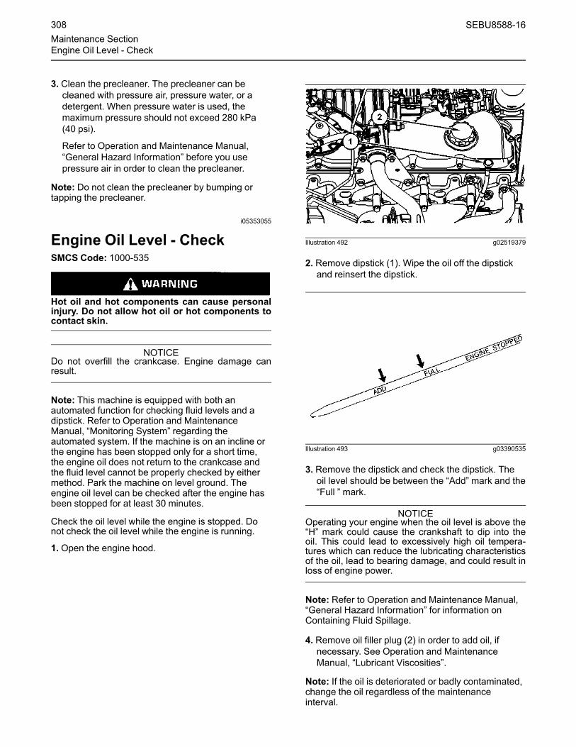
3. Clean the precleaner. The precleaner can becleaned with pressure air, pressure water, or adetergent. When pressure water is used, themaximum pressure should not exceed 280 kPa(40 psi).
Refer to Operation and Maintenance Manual,“General Hazard Information” before you usepressure air in order to clean the precleaner.
Note: Do not clean the precleaner by bumping ortapping the precleaner.
i05353055
Engine Oil Level - CheckSMCS Code: 1000-535
Hot oil and hot components can cause personalinjury. Do not allow hot oil or hot components tocontact skin.
NOTICEDo not overfill the crankcase. Engine damage canresult.
Note: This machine is equipped with both anautomated function for checking fluid levels and adipstick. Refer to Operation and MaintenanceManual, “Monitoring System” regarding theautomated system. If the machine is on an incline orthe engine has been stopped only for a short time,the engine oil does not return to the crankcase andthe fluid level cannot be properly checked by eithermethod. Park the machine on level ground. Theengine oil level can be checked after the engine hasbeen stopped for at least 30 minutes.
Check the oil level while the engine is stopped. Donot check the oil level while the engine is running.
1. Open the engine hood.
Illustration 492 g02519379
2. Remove dipstick (1). Wipe the oil off the dipstickand reinsert the dipstick.
Illustration 493 g03390535
3. Remove the dipstick and check the dipstick. Theoil level should be between the “Add”mark and the“Full ” mark.
NOTICEOperating your engine when the oil level is above the“H” mark could cause the crankshaft to dip into theoil. This could lead to excessively high oil tempera-tures which can reduce the lubricating characteristicsof the oil, lead to bearing damage, and could result inloss of engine power.
Note: Refer to Operation and Maintenance Manual,“General Hazard Information” for information onContaining Fluid Spillage.
4. Remove oil filler plug (2) in order to add oil, ifnecessary. See Operation and MaintenanceManual, “Lubricant Viscosities”.
Note: If the oil is deteriorated or badly contaminated,change the oil regardless of the maintenanceinterval.
308 SEBU8588-16Maintenance SectionEngine Oil Level - Check

5. Clean the oil filler plug. Install the oil filler plug.
6. Close the engine hood.
i05785517
Engine Oil Sample - ObtainSMCS Code: 1000-008; 1000; 1348-008; 1348-554-SM; 7542-554-OC; 7542-008; 7542-554-SM
Illustration 494 g03445017
Obtain a sample of the engine oil from the engine oilsampling valve that is located on the engine oil filterhousing. In the right rear access compartment. Referto Special Publication, SEBU6250, “S·O·S OilAnalysis” for information that pertains to obtaining asample of the engine oil. Refer to Special Publication,PEGJ0047, “How To Take A Good Oil Sample” formore information about obtaining a sample of theengine oil.
i06657353
Engine Oil and Filter - ChangeSMCS Code: 1318-510
Selection of the Oil Change Interval
NOTICEThis machine is equipped with an engine that meetsEPA Tier 3, Euro Stage III, or MOC Step 3 emissionregulations. A 500 hour engine oil change interval isavailable, if the following conditions are met. Accept-able operating conditions, recommended multigradeoil types, and an S·O·S oil sampling and analysis pro-gram are used. Otherwise, use a 250 hour engine oilchange interval.
If you select an interval for oil and filter change that istoo long, you may damage the engine.
CAToil filters are recommended.
Recommended multigrade oil types are listed inTable 80 . Do not use single grade oils.
Abnormally harsh operating cycles or harshenvironments can shorten the service life of theengine oil. Arctic temperatures, corrosiveenvironments, or extremely dusty conditions mayrequire a reduction in engine oil change intervalsfrom the recommendations in Table 80 . Also refer toManual, SEBU5898, “Cold-WeatherRecommendations”. Poor maintenance of air filtersor of fuel filters requires reduced oil change intervals.See your Caterpillar dealer for more information ifthis product will experience abnormally harshoperating cycles or harsh environments.Table 80
Engine Oil Change Interval(1)
MultigradeOil Type
Operating Conditions
Standard (1) Extended (1)
Severe
FuelSulfurabove0.3% (2)
Altitudeabove1830 m(6000 ft)
Cat DEOPreferred 250 hr 500 hr 250 hr 250 hr(3)
ECF-2Preferred 250 hr 500 hr 250 hr 250 hr
ECF-1-a 250 hr 250 hr 150 hr(3) 250 hr(3)
(1) The standard oil change interval for engines is 250 hours. Theextended oil change interval in this machine is 500 hours if thefollowing conditions are met. Acceptable operating conditions,recommended oil types, and an S·O·S oil sampling and analy-sis program are used. This extended interval is not permittedfor other machines. Refer to the applicable Operation andMaintenance Manuals for the other machines.
(2) For sulfur content above 0.1%, refer to this topic in the Manual,SEBU6250, “Caterpillar Machine Fluid Recommendations”.
(3) Use Program B below to determine an appropriate interval.
Adjustment of the Oil Change Interval
Note: Your Cat dealer has additional information onthis program.
Program B
Optimizing Oil Change Intervals
Begin with a standard oil change interval. The oilchange intervals are adjusted by increments. Eachinterval is adjusted an additional 50 hours. Periodicoil sampling and analysis are done during eachinterval. The analysis includes oil viscosity andinfrared (IR) analysis of the oil. Repeat Program B ifyou change the application of the machine.
If an oil sample does not pass the analysis, shortenthe oil change interval.
References
Reference: Form, PEDP7035, “Optimizing OilChange Intervals”
SEBU8588-16 309Maintenance Section
Engine Oil Sample - Obtain

Reference: Form, PEDP7036, “S·O·S FluidAnalysis”
Reference: Form, PEHP7076, “Understanding theS·O·S Oil Analysis Tests”
Procedure for Changing the EngineOil and Filter
Hot oil and hot components can cause personalinjury. Do not allow hot oil or hot components tocontact the skin.
Park the machine on a level surface. Stop the engine.
Note: Drain the crankcase while the oil is warm. Thisallows waste particles that are suspended in the oil todrain. As the oil cools, the waste particles will settleto the bottom of the crankcase. The particles will notbe removed by draining the oil and the particles willrecirculate in the engine lubrication system with thenew oil.
Note: Run the engine at low idle for at least tenminutes before performing any other operationseverytime the engine oil and oil filter are changed inorder to protect your engine. Refer to “OperationMaintenance Manual” Engine and Machine Warm-up.
Illustration 495 g01105786
The crankcase drain valve is located under the rearof the upper structure.
Illustration 496 g01100921
1. Remove the bolts and the washers. Remove thecrankcase drain valve access cover.
Illustration 497 g01100960
Note: Refer to Operation and Maintenance Manual,“General Hazard Information” for information thatpertains to containing fluid spillage.
2. Open the crankcase drain valve. Allow the oil todrain into a suitable container.
Note: Dispose of drained fluids according to localregulations.
3. Close the drain valve.
310 SEBU8588-16Maintenance SectionEngine Oil and Filter - Change

Illustration 498 g03445156
4. Open the access door on the right side of themachine.
5. Remove the oil filter with a strap type wrench.
Note: Dispose of the used oil filter according to localregulations.
6. Inspect the oil filter. See Operation andMaintenance Manual, “Oil Filter - Inspect”.
7. Clean the filter housing base. Make sure that all ofthe old filter gasket is removed.
Illustration 499 g00101634
8. Apply a thin coat of engine oil to the gasket of thenew filter.
9. Install the new filter by hand.
Instructions for the installation of the filter areprinted on the side of each Caterpillar spin-onfilter. For non-Caterpillar filters, refer to theinstallation instructions that are provided by thesupplier of the filter.
10. Close the access door on the left side of themachine.
11. Install the crankcase drain valve access coverwith the bolts and the washers.
12. Unlatch the engine hood and raise the enginehood.
Illustration 500 g03381776
(1) Dipstick for the engine oil(2) Filler plug for the engine oil
13. Unscrew oil filler plug (2) and remove the oil fillerplug.
14. Fill the crankcase with new oil. See Operationand Maintenance Manual, “Capacities (Refill)”.
15. Clean the oil filler plug and install the oil filler plug.
NOTICEDo not under fill or overfill engine crankcase with oil.Either condition can cause engine damage.
NOTICEOperating your engine when the oil level is above the“FULL” mark could cause your crankshaft to dip intothe oil. The air bubbles created from the crankshaftdipping into the oil reduces the oil's lubricating char-acteristics and could result in the loss of power or en-gine failure.
16. Start the engine and allow the oil to warm. Checkthe engine for leaks. Stop the engine.
17.Wait for 30 minutes so that the oil can drain backinto the crankcase, before you check the oil.
18. Remove dipstick (1). Wipe the oil off the dipstickand reinsert the dipstick.
SEBU8588-16 311Maintenance Section
Engine Oil and Filter - Change

Illustration 501 g01100724
19. Remove the dipstick again. Make sure that the oillevel is between the “ADD” and “FULL” marks onthe “ENGINE STOPPED” side of the dipstick.
20. Close the engine hood and latch the enginehood.
Fast FillIf your machine is equipped with a deluxe servicecenter, you may drain the hydraulic oil through thefast fill port. You may also add the hydraulic oilthrough a fast fill port.
Illustration 502 g03381169
1. Open the access door on the right side of themachine.
2. Remove the dust cover (1).
3. Attach the hose to the male coupling.
Note:Make sure that the coupling and receiver arefree from debris before attaching. Reinstall the dustcovers when done.
4. Drain the oil or add the oil, as needed.
5. Install the dust cover.
i00707053
Engine Valve Lash and FuelInjector Timing - CheckSMCS Code: 1105-025; 1209-535; 1290-531-FT
Refer to the Service Manual for the completeprocedure for checking the engine valve lash. Thisprocedure lists the steps for the engine valve lashadjustment and the steps in order to check theengine valve lash.
Note: Make sure that a qualified mechanic works onthe injector fuel timing. Special tools and training arerequired.
Refer to the Service Manual for the completeprocedure for checking the injector fuel timing or foradjusting the injector fuel timing.
Note: The correct fuel timing specification is given onthe Engine Information Plate. Fuel timingspecifications may differ for distinct engineapplications and/or power ratings.
i00059702
Engine Valve Rotators -InspectSMCS Code: 1109-040
When inspecting the valve rotators, protectiveglasses or face shield and protective clothingmust be worn to prevent being burned by hot oilspray.
1. Start the engine and run the engine at low idle.
312 SEBU8588-16Maintenance SectionEngine Valve Lash and Fuel Injector Timing - Check

Illustration 503 g00102025
2.Watch the top surface on each valve rotator. Eachvalve rotator should turn slightly whenever thecylinder valve closes.
If a cylinder valve fails to rotate, consult yourCaterpillar dealer.
i04688455
Ether Starting Aid Cylinder -Replace(If Equipped)SMCS Code: 1456-510-CD
Breathing ether vapors or repeated contact ofether with skin can cause personal injury. Per-sonal injury may occur from failure to adhere tothe following procedures.
Use ether only in well ventilated areas.
Do not smoke while changing ether cylinders.
Use ether with care to avoid fires.
Do not store replacement ether cylinders in livingareas or in the operator's compartment.
Do not store ether cylinders in direct sunlight orat temperatures above 49 °C (120 °F).
Discard cylinders in a safe place. Do not punctureor burn cylinders.
Keep ether cylinders out of the reach of unauthor-ized personnel.
To avoid possible injury, be sure the brakes areapplied and all controls are in HOLD or NEUTRALwhen starting the engine.
The ether cylinder is located inside the rear accessdoor on the left side of the machine.
Refer to Operation and Maintenance, “FirePrevention and Explosion Prevention” before youreplace the ether cylinders.
1. Open the rear access door on the left side of themachine.
Illustration 504 g00751767
2. Loosen the cylinder retaining clamp.
3. Unscrew the empty ether starting aid cylinder andremove the empty ether starting aid cylinder.
Illustration 505 g00751769
4. Remove the used gasket.
5. Install a new gasket.
Note: A new gasket is provided with each new etherstarting aid cylinder.
6. Install the new ether starting aid cylinder.
7. Tighten the ether starting aid cylinder hand tight.
8. Tighten the cylinder retaining clamp securely.
9. Close the access door.
SEBU8588-16 313Maintenance Section
Ether Starting Aid Cylinder - Replace

i07681009
Film (Product Identification) -CleanSMCS Code: 7405-070; 7557-070
Illustration 506 g02174985
Illustration 507 g02175297
Illustration 508 g06394021
Typical example of the Product Identification Films.
Cleaning of the FilmsMake sure that all of the product identification filmsare legible. Make sure that the recommendedprocedures are used in order to clean the productidentification films. Ensure that all the productidentification films are not damaged or missing.Clean the product identification films or replace thefilms.
Hand Washing
Use a wet solution with no abrasive material thatcontains no solvents and no alcohol. Use a wetsolution with a “pH” value between 3 and 11. Use asoft brush, a rag, or a sponge in order to clean theproduct identification films. Avoid wearing down thesurface of the product identification films withunnecessary scrubbing. Ensure that the surface ofthe product identification films is flushed with cleanwater and allow the product identification films to airdry.
Power Washing
Power washing or washing with pressure may beused in order to clean product identification films.However, aggressive washing can damage theproduct identification films.
Excessive pressure during power washing candamage the product identification films by forcingwater underneath the product identification films.Water lessens the adhesion of the productidentification film to the product, allowing the productidentification film to lift or curl. These problems aremagnified by wind. These problems are critical for theperforated film on windows.
To avoid lifting of the edge or other damage to theproduct identification films, follow these importantsteps:
• Use a spray nozzle with a wide spray pattern.
• A maximum pressure of 83 bar (1200 psi)
• A maximum water temperature of 50° C (120° F)
• Hold the nozzle perpendicular to the productidentification film at a minimum distance of305 mm (12 inch).
314 SEBU8588-16Maintenance SectionFilm (Product Identification) - Clean

• Do not direct a stream of water at a sharp angle tothe edge of the product identification film.
i06882903
Final Drive Oil - ChangeSMCS Code: 4050-044-FLV
Hot oil and hot components can cause personalinjury. Do not allow hot oil or hot components tocontact skin.
Illustration 509 g00822278
(1) Oil level plug(2) Oil drain plug
1. Position one final drive so that oil drain plug (2) isat the bottom.
Note: Refer to Operation and Maintenance Manual,“General Hazard Information” for information onContaining Fluid Spillage.
2. Remove drain plug (2) and level plug (1). Allow theoil to drain into a suitable container.
3. Clean the plugs and inspect the O-ring seals. Ifwear or damage is evident, replace the drain plug,the level plug, and/or the O-ring seals.
4. Install drain plug (2).
5. Fill the final drive to the bottom of the opening onlevel plug (1). See Operation and MaintenanceManual, “Lubricant Viscosities” and Operation andMaintenance Manual, “Capacities (Refill)”.
Note: If the oil fills slowly, the fill hole may be blockedby the planetary gear. Rotate the final drive to movethe planetary gear away from the fill hole.
Note: Overfilling the final drive will cause the sealson the travel motor to allow hydraulic oil or water toenter the final drive. The final drive may becomecontaminated.
6. Install level plug (1).
7. Perform Step 1 to Step 6 on the other final drive.Use a different container for the oil so that the oilsamples from the final drives will be separate.
8. Completely remove the oil that has spilled ontosurfaces.
9. Start the machine and allow the final drives to runthrough several cycles.
10. Stop the machine. Check the oil level.
11. Check the drained oil for metal chips or forparticles. If there are any chips or particles,consult your Cat dealer.
12. Properly dispose of the drained material. Obeylocal regulations for the disposal of the material.
i03914051
Final Drive Oil Level - CheckSMCS Code: 4050-535-FLV
Hot oil and hot components can cause personalinjury. Do not allow hot oil or hot components tocontact skin.
Illustration 510 g00822278
(1) Oil level plug(2) Oil drain plug
1. Position one final drive so that oil drain plug (2) isat the bottom.
SEBU8588-16 315Maintenance Section
Final Drive Oil - Change

Note: Refer to Operation and Maintenance Manual,“General Hazard Information” for information onContaining Fluid Spillage.
2. Remove oil level plug (1).
3. Check the oil level. The oil should be near thebottom of the level plug opening.
4. Add oil through the level plug opening, ifnecessary. See Operation and Maintenance,“Lubricant Viscosities”.
Note: If the oil fills slowly, the fill hole may be blockedby the planetary gear. Rotate the final drive in orderto move the planetary gear away from the fill hole.
Note: Overfilling the final drive will cause the sealson the travel motor to allow hydraulic oil or water toenter the final drive. The final drive may becomecontaminated.
5. Clean oil level plug (1). Inspect the O-ring seal.Replace the O-ring seal if the O-ring seal is wornor damaged.
6. Install oil level plug (1).
7. Repeat the procedure for the other final drive.
i03756611
Final Drive Oil Sample - ObtainSMCS Code: 4011-008; 4050-008; 4050-SM; 7542-008
Hot oil and hot components can cause personalinjury. Do not allow hot oil or hot components tocontact skin.
Illustration 511 g00822278
(1) Oil level plug(2) Oil drain plug
1. Position the final drive so that oil drain plug (2) is atthe bottom.
Note: Refer to Operation and Maintenance Manual,“General Hazard Information” for information onContaining Fluid Spillage.
2. Remove oil level plug (1).
3. Obtain a sample of the final drive oil through thehole for the oil level plug.
4. Install oil level plug (1).
Refer to Special Publication, SEBU6250, “CaterpillarMachine Fluids Recommendations” “S·O·S OilAnalysis” for more information on obtaining a sampleof the final drive oil. For additional information abouttaking an oil sample, refer to Special Publication,PEGJ0047, “How To Take A Good Oil Sample”.
i07318401
Fuel System - PrimeSMCS Code: 1250-548
Fuel leaked or spilled onto hot surfaces or electri-cal components can cause a fire. To help preventpossible injury, turn the start switch off whenchanging fuel filters or water separator elements.Clean up fuel spills immediately.
NOTICECare must be taken to ensure that fluids are con-tained during performance of inspection, mainte-nance, testing, adjusting, and repair of the product.Be prepared to collect the fluid with suitable contain-ers before opening any compartment or disassem-bling any component containing fluids.
Refer to Special Publication, NENG2500, “DealerService Tool Catalog” for tools and supplies suitableto collect and contain fluids on Cat ® products.
Dispose of all fluids according to local regulationsand mandates.
NOTICEDo not loosen the fuel lines at the fuel manifold. Thefittings may be damaged and/or a loss of primingpressure may occur when the fuel lines are loosened.
NOTICEDo not allow dirt to enter the fuel system. Thoroughlyclean the area around a fuel system component thatwill be disconnected. Fit a suitable cover over anydisconnected fuel system components.
316 SEBU8588-16Maintenance SectionFinal Drive Oil Sample - Obtain

Prime the fuel system to fill the fuel filter, and primethe fuel system to purge trapped air. The fuel systemshould be primed under the following conditions:
• The fuel tank is running low.
• The machine has been stored.
• The fuel filter is being replaced.
• The fuel system has been repaired.
1. Turn the engine start switch to the ON position.Leave the engine start switch in the ON positionfor 4 minutes.
2. Verify that the water separator is full of fuel.
3. If the water separator is not full of fuel, turn theengine start switch OFF and then turn the enginestart switch ON. Turning the engine start switch offand on will cycle the fuel priming pump again.
4.When the water separator is full of fuel, attempt tostart the engine. If the engine starts and theengine runs rough or the engine misfires, operateat low idle until the engine is running smoothly. Ifthe engine cannot be started, or if the enginecontinues to misfire or smoke, repeat Step 1.
i05785593
Fuel System Primary Filter(Water Separator) Element -ReplaceSMCS Code: 1263-510-FQ
Personal injury or death may result from failureto adhere to the following procedures.
Fuel leaked or spilled onto hot surfaces or electri-cal components can cause a fire.
Clean up all leaked or spilled fuel. Do not smokewhile working on the fuel system.
Turn the disconnect switch OFF or disconnectthe battery when changing fuel filters.
NOTICEDo not fill the fuel filters with fuel before installing thefuel filters. The fuel will not be filtered and could becontaminated. Contaminated fuel will cause acceler-ated wear to fuel system parts.
1. Remove the cover above the left side access door.
Illustration 512 g03231938
(1) Shutoff valve(2) Filter(3) Bowl(4) Drain valve
2. Turn off the fuel supply to the fuel filter by turningthe shutoff valve (1) clockwise.
Note: Refer to Operation and Maintenance Manual,“General Hazard Information” that pertains tocontaining fluid spillage.
3. Turn drain valve (4) counterclockwise in order toopen. The drain valve is located on the bottom ofthe water separator.
4. Drain the water and sediment into a suitablecontainer.
Note: Dispose of drained fluids and used filtersaccording to local regulations.
5. Close drain valve (4).
6. Remove the filter (2) from the filter base. A filterwrench may be used to loosen the filter.
7. Remove the bowl (3) from the filter (2). Discard theused filter.
Note: The water separator bowl is reusable. Do notdiscard the water separator bowl.
8. Clean the inside surface of the filter head and ofbowl (3).
9. Inspect the O-ring on bowl (3). Also inspect theseal on the filter head. Replace these seals if theseals are worn or damaged.
10. Lubricate the O-ring seal for the bowl (3) withclean diesel fuel or lubricate the O-ring seal withmotor oil. Place the O-ring seal in the groove in thebowl.
SEBU8588-16 317Maintenance Section
Fuel System Primary Filter (Water Separator) Element - Replace

11. Install the bowl (3) onto the new filter element byhand until the bowl is snug. Tighten the bowl to7.3 N·m (5.0 lb ft) to approximately 1/6 of a turn.Do not use tools to tighten the bowl to the newfilter element.
12. Lubricate the O-ring seal on the new filterelement with clean diesel fuel or lubricate the O-ring seal with motor oil.
13. Install the new filter by hand.
Instructions for the installation of the filter areprinted on the side of each Caterpillar spin-onfilter. For non-Caterpillar filters, refer to theinstallation instructions that are provided by thesupplier of the filter.
14. Turn on the fuel supply to the filter by turning theshutoff valve (1) counterclockwise.
Note: Do not start the engine until all service to thefuel system is complete. For instructions aboutpriming the fuel system, refer to Operation andMaintenance Manual, “Fuel System - Prime”.
15. Remount the cover over the filters.
i05065833
Fuel System Secondary Filter -ReplaceSMCS Code: 1261-510
Personal injury or death can result from a fire.
Fuel leaked or spilled onto hot surfaces or electri-cal components can cause a fire.
Clean up all leaked or spilled fuel. Do not smokewhile working on the fuel system.
Turn the disconnect switch OFF or disconnectthe battery when changing fuel filters.
NOTICETurn the disconnect switch OFF or disconnect thebattery when changing fuel filters.
Do not fill fuel filters with fuel before installing them.Contaminated fuel will cause accelerated wear to fuelsystem parts.
1. Remove the cover.
Illustration 513 g03232057
Note: Refer to Operation and Maintenance Manual,“General Hazard Information” for information oncontaining fluid spillage.
2. Remove the fuel filter.
Note: The fuel filter has not been drained. The filtercontains fuel. When you remove the filter, usecaution in order to avoid spilling the fuel.
3. Inspect the fuel filter for debris by cutting the fuelfilters open.
Note: Dispose of used filters and used fluidsaccording to local regulations.
4. Clean the mounting base of the fuel filter. Makesure that all of the old seal is removed from themounting base.
Illustration 514 g00101634
5. Apply a thin coat of clean diesel fuel to the sealingsurface of the new fuel filter.
6. Install the new filter by hand.
318 SEBU8588-16Maintenance SectionFuel System Secondary Filter - Replace
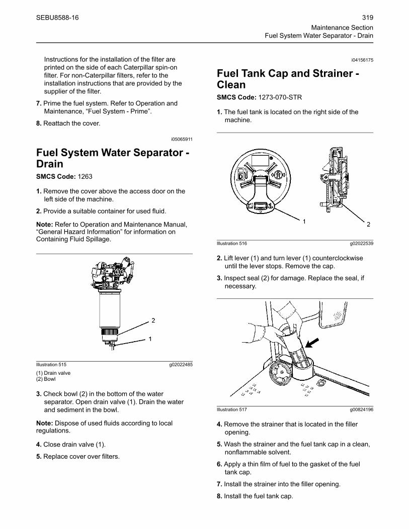
Instructions for the installation of the filter areprinted on the side of each Caterpillar spin-onfilter. For non-Caterpillar filters, refer to theinstallation instructions that are provided by thesupplier of the filter.
7. Prime the fuel system. Refer to Operation andMaintenance, “Fuel System - Prime”.
8. Reattach the cover.
i05065911
Fuel System Water Separator -DrainSMCS Code: 1263
1. Remove the cover above the access door on theleft side of the machine.
2. Provide a suitable container for used fluid.
Note: Refer to Operation and Maintenance Manual,“General Hazard Information” for information onContaining Fluid Spillage.
Illustration 515 g02022485
(1) Drain valve(2) Bowl
3. Check bowl (2) in the bottom of the waterseparator. Open drain valve (1). Drain the waterand sediment in the bowl.
Note: Dispose of used fluids according to localregulations.
4. Close drain valve (1).
5. Replace cover over filters.
i04156175
Fuel Tank Cap and Strainer -CleanSMCS Code: 1273-070-STR
1. The fuel tank is located on the right side of themachine.
Illustration 516 g02022539
2. Lift lever (1) and turn lever (1) counterclockwiseuntil the lever stops. Remove the cap.
3. Inspect seal (2) for damage. Replace the seal, ifnecessary.
Illustration 517 g00824196
4. Remove the strainer that is located in the filleropening.
5.Wash the strainer and the fuel tank cap in a clean,nonflammable solvent.
6. Apply a thin film of fuel to the gasket of the fueltank cap.
7. Install the strainer into the filler opening.
8. Install the fuel tank cap.
SEBU8588-16 319Maintenance Section
Fuel System Water Separator - Drain

i04421489
Fuel Tank Cap Filter - ReplaceSMCS Code: 1273-510-FI; 1273-510-Z2
Illustration 518 g02612539
1. Remove the fuel cap.
2. Remove filter element screws (2) from theunderside of the fuel cap and remove old filterelement (1).
3.Wash the fuel tank cap in a clean, nonflammablesolvent.
4. Install a new fuel cap filter element.
5. Install filter element screws (2) in order to securefilter element (1) to the fuel cap.
6. Install the fuel tank cap
i04462462
Fuel Tank Strainer - CleanSMCS Code: 1273-070-STR
Illustration 519 g02609604
1. Remove fuel tank cap (1).
2. Remove strainer (2) from the filler opening.
3.Wash the strainer in a clean, nonflammablesolvent.
4. Install the strainer into the filler opening.
5. Install the fuel tank cap.
i06061288
Fuel Tank Water and Sediment- DrainSMCS Code: 1273-543
The fuel tank drain valve is located on the right sideof the machine under the fuel tank.
Illustration 520 g03795583
Note: Refer to Operation and Maintenance Manual,“General Hazard Information” for information oncontaining fluid spillage.
1. Open the drain valve by turning the valvecounterclockwise. Allow the water and thesediment to drain into a suitable container.
Note: Dispose of drained fluids according to localregulations.
2. Close the drain valve by turning the valveclockwise.
Fill the Fuel TankYou can now add fuel to the fuel tank, if necessary.Remove the fuel tank cap and pump fuel through theopening.
320 SEBU8588-16Maintenance SectionFuel Tank Cap Filter - Replace

Make sure that you lock the fuel tank cap after therefueling is complete.
Note: For machines equipped with fast fill fuelattachment, when the fuel is refilled from the top fuelport, stop refilling as the indicator starts to appear inorder to avoid fuel spilling from the breather.
i05337713
Fuses - ReplaceSMCS Code: 1417-510
Open the access door on the left side of the machine.
The fuse panel is located on the circuit breaker panel.Open the access cover for fuse access.
Fuses – Fuses protect the electricalsystem from damage that is caused byoverloaded circuits. Change a fuse if the
element separates. If the element of a new fuseseparates, check the circuit and/or repair thecircuit.
NOTICEAlways replace fuses with the same type and ca-pacity fuse that was removed. Otherwise, electricaldamage could result.
NOTICEIf it is necessary to replace fuses frequently, an elec-trical problem may exist.
Contact your Cat dealer.
To replace a fuse, use the puller that is stored in thefuse panel. The following spare fuses are stored inthe fuse panel: one fuse of 5 A, two fuses of 10 A,two fuses of 15 A and one fuse of 30 A.
The following list identifies the circuits that areprotected by each fuse. The amperage for each fuseis included with each circuit.
Illustration 521 g03381186
(1) Spare – 20 Amp
(2) Hydraulic Lock – 10 Amp
(3) Engine Start Switch – 10 Amp
(4) Monitor – 15 Amp
(5) Air Conditioner Condenser Blower – 20 Amp
(6) Engine Control Module (ECM) – 30 Amp
(7) Spare – 15 Amp
(8) Fan – 20 Amp
(9) Auxiliary – 10 Amp
(10) Electronic Control Module – 15 Amp
(11) Cat Grade Control – 15 Amp
(12) Excavator Control Module – 25 Amp
(13) Cab Light – 10 Amp
(14) Engine Electronic Control Module (ECM) – 30Amp
SEBU8588-16 321Maintenance Section
Fuses - Replace

(15) Electric Refueling Pump – 30 Amp
(16) Boom Light – 10 Amp
(18) Product Link – 5 Amp
(19) Lifting Pump – 5 Amp
(20) Heater and Air Conditioner Blower Fan – 20Amp
(21) Horn – 10 Amp
(22) Spare – 15 Amp
(23) Spare – 15 Amp
(24) Air Suspension Seat – 10 Amp
(25) Camera – 5 Amp
(26) Auxiliary – 10 Amp
(27) Auxiliary – 10 Amp
(28) Beacon – 10 Amp
(29) Seat Heater – 5 Amp
(30) Spare – 25 Amp
(31) Priming Pump – 15 Amp
(32) Auxiliary – 5 Amp
(33) Air Conditioner – 5 Amp
(34)Spare – 10A
(35) Attachment Solenoid – 10 Amp
(36) 12V Converter – 10 Amp
(37) Radio – 5 Amp
(38) Window Wiper – 10 Amp
(39) Cat Grade Control – 15 Amp
(40) Chassis Light – 10 Amp
(41) Clean Emissions Module (ECM) – 20 Amp
(42) Warning Light – 5 Amp
Illustration 522 g03381411
(43) Travel Alarm – Relay
(44) Priming Pump – Relay
(45) Boom Light 1 – Relay
(46) Boom Light 2 – Relay
(47) Hydraulic Lock – Relay
(48) Chassis Lamp – Relay
(49) Neutral Start – Relay
(50) Chassis Light – Relay
(51) Horn – Relay
322 SEBU8588-16Maintenance SectionFuses - Replace

i08067436
High Intensity Discharge Lamp(HID) - Replace(If Equipped)SMCS Code: 1434-510
HID lamps operate at very high voltages. To avoidelectrical shock and personal injury, disconnectpower before servicing HID lamps.
HID bulbs become very hot during operation. Be-fore servicing, remove power from lamp for atleast five minutes to ensure lamp is cool.
NOTICEAlthough HID bulb materials may change over time,HID bulbs produced at the time of the printing of thismanual contain mercury. When disposing of this com-ponent, or any waste that contains mercury, pleaseuse caution and comply with any applicable laws.
1. Prepare the machine for maintenance. Refer toOperation and Maintenance Manual, “Prepare theMachine for Maintenance”.
2. Remove the electrical power from the highintensity discharge lamp (HID). The electricalpower must be removed from the HID lamp for atleast 5 minutes, to ensure that the bulb is cool.
3. Disassemble the housing for the HID lamp to haveaccess to the bulb.
Note: On some HID lamps, the bulb is a part of thelens assembly. The bulb is not removed separatelyfrom the lens assembly. Replace the entire lensassembly on these HID lamps.
4. Remove the bulb from the HID lamp.
5. Install the replacement bulb in the HID lamp.
If the bulb is a part of the lens assembly, install thereplacement lens assembly in the HID lamp.
Note: To avoid failure to the bulb that is premature,avoid touching the bulb's surface with your barehands. Clean any fingerprints from the bulb withalcohol prior to operation.
6. Reassemble the housing for the HID lamp. Ensurethat any printing on the lens is oriented correctlyfor the HID lamp's mounting position on themachine.
7. Reattach the electrical power to the HID lamp.
8. Check the HID lamp for proper operation.
Note: Consult your Cat dealer for additionalinformation on HID lamps.
i03997397
Hydraulic System FilterElement (Fine Filtration) -Replace(If Equipped)SMCS Code: 5068-510
Hot oil and hot components can cause personalinjury. Do not allow hot oil or hot components tocontact skin.
1. Park the machine on level ground.
2. Place the machine in the servicing position.
3.Move the hydraulic lockout control to the LOCKEDposition. Stop the engine.
4. Slowly loosen the filler plug in order to relieve anypressure.
5. Tighten the filler plug after the pressure is relieved.
6. Open the access door on the right side of themachine. The filter is located near the hydraulictank.
SEBU8588-16 323Maintenance Section
High Intensity Discharge Lamp (HID) - Replace

Illustration 523 g02175170
7. Remove four bolts (1) and cover (2) from the finefiltration filter.
8. Remove element (3) from the filter assembly.
9. Install a new filter element.
10. Install cover (2) and four bolts (1).
11. Close the access door.
i05626750
Hydraulic System Oil - ChangeSMCS Code: 5056-044
Cat HYDO Advanced 10 OilChange IntervalThe standard Cat HYDO Advanced 10 oil changeinterval is every 3000 service hours or 18 months.
A maintenance interval of 6000 service hours or 3years for changing the hydraulic oil is available. Theextended interval requires S·O·S monitoring of thehydraulic oil. The interval for S·O·S monitoring isevery 500 hours. The maintenance interval for thehydraulic oil filter is not changed.
Machines with hammers are not included in themaintenance interval of 6000 service hours or 3years . Machines with hammers must use theintervals that are listed in the Maintenance IntervalSchedule. Machines that are used in severeconditions are not included in the maintenanceinterval of 6000 service hours or 3 years. Machinesthat are used in severe conditions must use theinterval in the Maintenance Interval Schedule.
Drain the Oil
Hot oil and hot components can cause personalinjury. Do not allow hot oil or hot components tocontact skin.
1. Park the machine in the servicing position on levelground.
2. Clean the top of the hydraulic tank thoroughly inorder to keep dirt out of the hydraulic tank.
Illustration 524 g03241185
Pressurized system!
The hydraulic tank contains hot oil under pres-sure. To prevent burns from the sudden releaseof hot oil, relieve the tank pressure with the en-gine off by slowly turning the cap approximately1/8 of a turn until the cap reaches the secondarystop.
324 SEBU8588-16Maintenance SectionHydraulic System Oil - Change

Illustration 525 g02275615
Filler cap(A) LOCK position(B) PRESSURE RELEASE - START position(C) PRESSURE RELEASE - END position(D) OPEN position
3. Release the pressure that may be present in thereturn hydraulic circuit with the followingprocedure. Refer to Illustration 525 for filler cappositions.
a. Turn the filler cap counterclockwise, with nodownward force applied, and move the arrowfrom position (A) to position (B).
b. Release the pressure for a minimum of 45seconds by moving the arrow from position (B)to position (C).
c. Push the center of the filler cap down. Withouttilting the filler cap, move the arrow fromposition (C) to position (D).
d. The hydraulic tank pressure is relieved. Thefiller cap can now be removed if needed.
e. Tighten the filler cap on the hydraulic tank toposition (A).
4. After the pressure is relieved, tighten the filler cap.
Illustration 526 g01137581
5. Remove the two access covers that are locatedunder the hydraulic tank. This will allow access tothe drain valve and the pipe.
Illustration 527 g01137579
Note: Refer to Operation and Maintenance Manual,“General Hazard Information” for information thatpertains to containing fluid spillage.
6. Remove plug (1).
SEBU8588-16 325Maintenance Section
Hydraulic System Oil - Change

Illustration 528 g01137580
(2) Drain plug(3) Pipe Nipple(4) Tube
7. Install a pipe nipple (3) with a clear plastic tube (4)into the hole on the bottom of the hydraulic tank.
8. Loosen drain plug (2) in order to drain the oil.
9. Drain the oil into a suitable container.
10. After the oil has been drained, tighten drain plug(7) to a torque of 110 ± 15 N·m (81 ± 11 lb ft).
11. Remove the pipe nipple.
12. Clean plug (1) and install the plug. Tighten theplug to a torque of 75 ± 5 N·m (55 ± 48 lb ft).
Illustration 529 g01137392
13. Remove the plug from the tube. Allow the oil todrain into a container.
14. Inspect the O-ring. Replace the O-ring if wear ordamage is evident.
15. Clean the plug. Install the plug and the O-ring intothe drain port.
Illustration 530 g03241237
16. Remove the cover to the hydraulic tank screen.
Illustration 531 g01137588
(5) Spring(6) Screen
Note: Do not allow spring (5) to fall back into thetank.
17. Remove spring (5) and screen (6).
Note: Refer to Operation and Maintenance, “GeneralHazard Information” for information on containingfluid spillage.
326 SEBU8588-16Maintenance SectionHydraulic System Oil - Change

18.Wash the screen in a clean nonflammablesolvent. Allow the screen to dry. Inspect thescreen. Replace the screen, if the screen isdamaged.
19. There is an O-ring seal on the bottom of thescreen. There is also an O-ring seal on thehydraulic tank around the opening for the screen.Inspect the O-ring seals. Replace the O-ring sealsif wear or damage is evident.
20. Install the screen and the spring. Then install thecover.
Note:Make sure that the O-ring seals and the springare properly positioned during installation.
Service the Hydraulic SystemFiltersNote: The hydraulic oil system must be empty whenthe filters are being serviced. Service the filtersbefore refilling the machine with hydraulic oil.
Note: Dispose of used filters and used fluidsaccording to local regulations.
Refer to the following topics in order to service thehydraulic system filters:
• Operation and Maintenance Manual, “HydraulicSystem Filter Element (Fine Filtration) - Replace(If Equipped)”
• Operation and Maintenance Manual, “HydraulicSystem Oil Filter (Return) - Replace”
• Operation and Maintenance Manual, “HydraulicSystem Oil Filter (Case Drain) - Replace”
• Operation and Maintenance Manual, “HydraulicSystem Oil Filter (Pilot) - Replace”
Fill the Hydraulic Tank1. Fill the hydraulic system oil tank. Refer toOperation and Maintenance Manual, “Capacities(Refill)”.
2. Inspect the O-ring seal on the filler plug fordamage. Replace the O-ring, if necessary. Cleanthe filler plug. Install the filler plug.
Note:Make no attempt to start the engine until thepump has been filled with hydraulic oil. Seriousdamage to the hydraulic components can result.
When the hydraulic oil has been replaced, the airmust be removed from the hydraulic oil system. Toremove the air from the hydraulic oil system, followStep 2a through Step 2d.
a. Start the engine.
Illustration 532 g03573781
b. Slowly loosen the vent plug on top of the casedrain filter until hydraulic oil flows out of the ventplug.
c. After oil flows out of the vent plug without anyair bubbles, tighten the vent plug. This indicatesthat the air has been purged from the drain linesfor the main pump and the drain line for theswing pump. Tighten the vent plug to a torqueof 11 ± 1 N·m (97 ± 9 lb in).
d. Stop the engine.
3. Start the engine. Operate the engine at idlingspeed for five minutes.
4. Operate the joysticks in order to circulate thehydraulic oil. Return the machine to the servicingposition. Stop the engine.
Illustration 533 g01137399
(A) High temperature range(B) Low temperature range
SEBU8588-16 327Maintenance Section
Hydraulic System Oil - Change

5.Maintain the oil level between the marks on thesight gauge in the appropriate temperature range.
i05055829
Hydraulic System Oil Filter(Return) - ReplaceSMCS Code: 5068-510-RJ
The return filter is a cartridge type filter. By using acartridge type filter, the amount of foreign materialthat enters the hydraulic system is reduced when thefilter element is replaced.
Note: If the display shows that the hydraulic returnfilter is plugged, push the reset switch. Run themachine on level ground for approximately 10seconds. If the error is still present, inspect the filterand replace the filter, if necessary.
Illustration 534 g03225276
1. Remove the cover in order to access the returnfilters.
Illustration 535 g03225283
2. Hydraulic Cap is located on top of hydraulic tank.
Pressurized system!
The hydraulic tank contains hot oil under pres-sure. To prevent burns from the sudden releaseof hot oil, relieve the tank pressure with the en-gine off by slowly turning the cap approximately1/8 of a turn until the cap reaches the secondarystop.
Illustration 536 g02275615
Filler cap(A) LOCK position(B) PRESSURE RELEASE - START position(C) PRESSURE RELEASE - END position(D) OPEN position
3. Release the pressure that may be present in thereturn hydraulic circuit with the followingprocedure. Refer to Illustration 536 for filler cappositions.
a. Turn the filler cap counterclockwise, with nodownward force applied, and move the arrowfrom position (A) to position (B).
b. Release the pressure for a minimum of 45seconds by moving the arrow from position (B)to position (C).
c. Push the center of the filler cap down. Withouttilting the filler cap, move the arrow fromposition (C) to position (D).
d. The hydraulic tank pressure is relieved. Thefiller cap can now be removed if needed.
e. Tighten the filler cap on the hydraulic tank toposition (A).
328 SEBU8588-16Maintenance SectionHydraulic System Oil Filter (Return) - Replace

4. After the pressure is relieved, tighten the filler cap.
Illustration 537 g03225316
5. Remove the filter cartridge. Perform Step 5athrough Step 5f in order to remove the filtercartridge.
Illustration 538 g00102211
(1) Bolts(2) Washers(3) Cover(4) Plug(5) Filter cartridge
a. Remove bolts (1), washers (2), and cover (3).
Note: Refer to Operation and MaintenanceManual, “General Hazard Information” forinformation on containing fluid spillage.
b. Remove plug (4) in order to release thepressure in filter cartridge (5).
Illustration 539 g00102212
(5) Filter cartridge(6) Filter case(A) Guide
c. Pull up the handle at the top of filter cartridge(5) until the filter cartridge contacts guide (A) onfilter case (6).
Illustration 540 g00102214
d. Turn the filter cartridge counterclockwise by180 degrees in order to align the projection ofthe filter cartridge with the notch of the filtercase. Pull out the filter cartridge.
SEBU8588-16 329Maintenance Section
Hydraulic System Oil Filter (Return) - Replace

Illustration 541 g00102219
(7) O-ring
e. Inspect the cover and O-ring (7). If either part isdamaged, replace the part.
f. Inspect the filter cartridge for debris and fordamage. If necessary, replace the filtercartridge.
g. Repeat Step 5a through Step 5f for the otherfilter groups.
6. Remove the filter element. Perform Step 6athrough Step 6f in order to remove the filterelement.
Illustration 542 g00104507
(4) Plug(8) Plate(18) O-ring
a. Make sure that plug (4) is removed. Make surethat all of O-ring (18) is removed from plate (8).
Illustration 543 g00918893
(8) Plate(9) Spiral retaining ring
b. Remove spiral retaining ring (9).
Illustration 544 g00104510
(8) Plate(10) Shell(11) O-ring(12) Filter element
c. Hold the filter cartridge with one hand. Graspthe grip of plate (8) with your other hand. Liftplate (8) in order to separate plate (8) from thefilter cartridge.
d. Remove O-ring (11) from plate (8).
e. Lift filter element (12) from shell (10).
f. Pour the remaining oil into a suitable container.
Note: Dispose of used oil according to localregulations.
g. Repeat Step 6a through Step 6f for the otherfilter groups.
7. Clean the shell of the filter cartridge. Perform Step7a through Step 7d in order to clean the shell ofthe filter cartridge.
330 SEBU8588-16Maintenance SectionHydraulic System Oil Filter (Return) - Replace

Illustration 545 g00104511
(13) Slide plate(14) Pads(15) Screws(19) Port
a. Turn shell (10) upside-down.
b. Remove screws (15).
c. Remove Pads (14) from slide plate (13).
d. Wash the following parts in a cleannonflammable solvent: plug (4), plate (8), spiralretaining ring (9), shell (10) and Pads (14). Drythe parts.
e. Repeat Step 7a through Step 7d for the otherfilter groups.
8. Install the filter elements. Perform Step 8a throughStep 8k in order to install the filter elements.
Note: Consult a Caterpillar dealer for the Service Kitthat is needed to install the filter element and the filtercartridge.
a. Apply spray type oil to the inside of shell (10) inorder to prevent rust.
b. Apply grease to a new O-ring (11).
c. Plate (8) will contact the inside of shell (10).Apply grease to this point.
d. Apply grease to O-rings inside ports (19) at thebottom of shell (10).
e. Install new Pads (14). Tighten the screws to atorque of 0.4 N·m (3.5 lb in).
f. Apply spray type oil into the clearance betweenshell (10) and slide plate (13).
Illustration 546 g00104512
(8) Plate(10) Shell(16) Boss(17) Notch
g. Turn over shell (10). Apply grease to the two O-rings on new element (12). Install element (12)into shell (10).
h. Move boss (16) in alignment with notch (17).Install plate (8) into shell (10).
i. Install spiral retaining ring (9) into the groove inshell (10).
j. Apply grease to new O-ring (18). Install O-ring(18) on plug (4).
k. Install plug (4) into plate (8).
l. Repeat Step 8a through Step 8k for the otherfilter groups.
9. Install the filter cartridge. Perform Step 9a throughStep 9e in order to install the filter cartridge.
Illustration 547 g00102220
(B) Port(C) Slide plate
a. Check that ports (B) at the bottom of the filtercase are closed.
SEBU8588-16 331Maintenance Section
Hydraulic System Oil Filter (Return) - Replace

Note: If the ports are open, rotate slide plate (C)counterclockwise to the stopper in order to fullyclose the ports. When the ports are fully closed,any remaining oil in the filter case should becompletely removed.
Illustration 548 g00102221
(E) Slide plate(D) Port
b. Check that ports (D) of the filter cartridge arefully closed.
Note: The filter cartridge cannot be installed unlessthe ports are fully closed. If the ports are open,rotate slide plate (E) counterclockwise to thestopper in order to fully close the ports.
Illustration 549 g00102222
(F) O-rings
c. Check that O-rings (F) have been installed andthat oil has been applied to O-rings (F).
Illustration 550 g00102225
(1) Bolts
d. Install the filter cartridge into the filter case.Turn the filter cartridge clockwise by 180degrees and push down the filter cartridgewhen the filter cartridge contacts guide (A).
e. Install plug (4), cover (3), washers (2), and bolts(1). Tighten bolts (1) to a torque of 29 ± 5 N·m(22 ± 4 lb ft).
f. Repeat Step 9a through Step 9e for the otherfilter groups.
i05622834
Hydraulic System Oil Filter -ReplaceSMCS Code: 5068-510
Pilot Filter
Illustration 551 g01103135
1. Open the front access door on the right side of themachine.
332 SEBU8588-16Maintenance SectionHydraulic System Oil Filter - Replace

Illustration 552 g03570316
2. Clean the area in order to keep dirt out of the filterbase.
3. Remove the used pilot filter element from the filterbase.
Note: Dispose of used filters according to localregulations.
4. Clean the filter base.
Illustration 553 g00101502
5. Coat the seal of a new pilot filter with cleanhydraulic oil. Tighten the pilot filter hand tight.
6. Install the new pilot filter by hand.
Instructions for the installation of the filter areprinted on the side of each Caterpillar spin-onfilter. For non-Caterpillar filters, refer to theinstallation instructions that are provided by thesupplier of the filter.
7. Close the access door.
Case Drain Filters
Illustration 554 g03225501
The case drain filters are on the inside of the accessdoor.
Illustration 555 g03225517
1. Clean the area in order to keep dirt out of the filterbase.
2. Remove the used case drain filter from the filterbase.
Note: Dispose of used filters according to localregulations.
3. Clean the filter base.
SEBU8588-16 333Maintenance Section
Hydraulic System Oil Filter - Replace

Illustration 556 g00101502
4. Coat the seal of a new case drain filter with cleanhydraulic oil.
5. Install the new case drain filter by hand.
Instructions for the installation of the filter areprinted on the side of each Caterpillar spin-onfilter. For non-Caterpillar filters, refer to theinstallation instructions that are provided by thesupplier of the filter.
6. Start the engine.
7. Drive the machine slowly for 10 to 15 minutes.Move each cylinder evenly through several cycles.
Illustration 557 g02154822
8. Return the machine to the servicing position.Check the machine for oil leaks.
9. Stop the engine.
Illustration 558 g03447276
(A) High temperature range(B) Low temperature range
10.Maintain the oil level in the low temperature rangefor a cold machine. Maintain the oil level in thehigh temperature range for a machine that is at anormal operating temperature.
Illustration 559 g02024028
Pressurized system!
The hydraulic tank contains hot oil under pres-sure. To prevent burns from the sudden releaseof hot oil, relieve the tank pressure with the en-gine off by slowly turning the cap approximately1/8 of a turn until the cap reaches the secondarystop.
334 SEBU8588-16Maintenance SectionHydraulic System Oil Filter - Replace

Illustration 560 g02275615
Filler cap(A) LOCK position(B) PRESSURE RELEASE - START position(C) PRESSURE RELEASE - END position(D) OPEN position
11. Release the pressure that may be present in thereturn hydraulic circuit with the followingprocedure. Refer to Illustration 560 for filler cappositions.
a. Turn the filler cap counterclockwise, with nodownward force applied, and move the arrowfrom position (A) to position (B).
b. Release the pressure for a minimum of 45seconds by moving the arrow from position (B)to position (C).
c. Push the center of the filler cap down. Withouttilting the filler cap, move the arrow fromposition (C) to position (D).
d. The hydraulic tank pressure is relieved. Thefiller cap can now be removed if needed.
e. Tighten the filler cap on the hydraulic tank toposition (A).
12. After the pressure is relieved, tighten the fillercap.
i05457469
Hydraulic System Oil Level -CheckSMCS Code: 5050-535
NOTICENever remove the fill/vent plug from the hydraulictank if the oil is hot.
Air can enter the system and cause pump damage.
1. Park the machine in the servicing position on levelground.
Illustration 561 g03447317
(A) High temperature range(B) Low temperature range
2. For a machine that is at normal operatingtemperature, maintain the hydraulic oil level in thehigh temperature range. For a cold machine,maintain the hydraulic oil level in the lowtemperature range.
Note: Refer to Operation and Maintenance Manual,“General Hazard Information” for information oncontaining fluid spillage.
3. The Hydraulic fill cap is located on top of theHydraulic tank.
SEBU8588-16 335Maintenance Section
Hydraulic System Oil Level - Check

Illustration 562 g02024028
Pressurized system!
The hydraulic tank contains hot oil under pres-sure. To prevent burns from the sudden releaseof hot oil, relieve the tank pressure with the en-gine off by slowly turning the cap approximately1/8 of a turn until the cap reaches the secondarystop.
Illustration 563 g02275615
Filler cap(A) LOCK position(B) PRESSURE RELEASE - START position(C) PRESSURE RELEASE - END position(D) OPEN position
4. Release the pressure that may be present in thereturn hydraulic circuit with the followingprocedure. Refer to Illustration 563 for filler cappositions.
a. Turn the filler cap counterclockwise, with nodownward force applied, and move the arrowfrom position (A) to position (B).
b. Release the pressure for a minimum of 45seconds by moving the arrow from position (B)to position (C).
c. Push the center of the filler cap down. Withouttilting the filler cap, move the arrow fromposition (C) to position (D).
d. The hydraulic tank pressure is relieved. Thefiller cap can now be removed if needed.
e. Tighten the filler cap on the hydraulic tank toposition (A).
5. After the pressure is relieved, tighten the filler cap.
i05785514
Hydraulic System Oil Sample -ObtainSMCS Code: 5050-008-OC; 5095-SM; 5095-008;7542-008; 7542
Illustration 564 g03570397
The hydraulic oil sampling valve is near the swingpump in the right rear access compartment. Obtain asample of the hydraulic oil from the hydraulic oilsampling valve. Refer to Special Publication,SEBU6250, “S·O·S Oil Analysis” for information thatpertains to obtaining a sample of the hydraulic oil.Refer to Special Publication, PEGJ0047, “How ToTake A Good Oil Sample” for more information aboutobtaining a sample of the hydraulic oil.
336 SEBU8588-16Maintenance SectionHydraulic System Oil Sample - Obtain

i05623032
Indicators and Gauges - TestSMCS Code: 7450-081; 7490-081
Illustration 565 g03570421
1. Look for broken lenses on the gauges, brokenindicator lights, broken switches, and other brokencomponents in the cab.
2. Start the engine.
3. Look for inoperative gauges.
4. Turn on all machine lights. Check for properoperation.
5.Move the machine forward. Release the travellevers and the travel pedals. The machine shouldstop.
6. Stop the engine.
7.Make any repairs that are required beforeoperating the machine.
i04882709
Oil Filter (Hydraulic Hammer) -ReplaceSMCS Code: 5068-510
Hot oil and hot components can cause personalinjury. Do not allow hot oil or hot components tocontact skin.
1. Park the machine on level ground in the serviceposition.
2.Move the hydraulic lockout control to theUNLOCKED position.
3. Turn the engine start switch to the ON position.
4.Move the joysticks and the travel levers/pedals tothe full stroke positions in order to relieve thepressure in the hydraulic lines.
5. Turn the engine start switch to the OFF positionand return the lever for the hydraulic lockoutcontrol to the LOCKED position.
Pressurized system!
The hydraulic tank contains hot oil under pres-sure. To prevent burns from the sudden releaseof hot oil, relieve the tank pressure with the en-gine off by slowly turning the cap approximately1/8 of a turn until the cap reaches the secondarystop.
Illustration 566 g02275615
Filler cap(A) LOCK position(B) PRESSURE RELEASE - START position(C) PRESSURE RELEASE - END position(D) OPEN position
6. Release the pressure that may be present in thereturn hydraulic circuit with the followingprocedure. Refer to Illustration 566 for filler cappositions.
a. Turn the filler cap counterclockwise, with nodownward force applied, and move the arrowfrom position (A) to position (B).
b. Release the pressure for a minimum of 45seconds by moving the arrow from position (B)to position (C).
SEBU8588-16 337Maintenance Section
Indicators and Gauges - Test

c. Push the center of the filler cap down. Withouttilting the filler cap, move the arrow fromposition (C) to position (D).
d. The hydraulic tank pressure is relieved. Tightenthe filler cap on the hydraulic tank to position(A).
7. The oil filter for the hammer is located near thebase of the boom.
Illustration 567 g02902799
(1) Filter case(2) Filter element(3) Filter base
8. Position a suitable container in order to contain theoil.
Note: Refer to Operation and Maintenance Manual,“General Hazard Information” for information oncontaining fluid spillage.
9. Loosen filter case (1).
10. Lift filter case (1) in order to remove filter element(2).
11. Remove the used filter element from filter base(3).
Note: The element cannot be reused.
Note: Used filter elements should always bedisposed of according to local regulations.
12. Clean filter case (1) and inspect the O-ring fordamage. Replace the O-ring if necessary.
13. Install the new filter element.
Illustration 568 g02909599
14. Assemble filter case (1). Tighten the nut on thefilter case to a torque of 100 ± 10 N·m(74 ± 7 lb ft).
Illustration 569 g02909737
15. Remove plug (4) and inspect O-ring (5) fordamage. Replace the O-ring if necessary. Tightenplug (4) to a torque of 13 ± 2 N·m (10 ± 1.5 lb ft)
16. Start the engine and operate the machine slowlyfor 10 to 15 minutes. Move each cylinder evenlythrough several cycles and operate the hammer.
17. Return the machine to the service position.Check the machine for oil leaks.
18. Stop the engine.
19. Check the hydraulic oil level.
Reference: For the correct procedure, refer toOperation and Maintenance Manual, “HydraulicSystem Oil Level - Check”.
338 SEBU8588-16Maintenance SectionOil Filter (Hydraulic Hammer) - Replace

i01909798
Oil Filter - InspectSMCS Code: 1308-507; 5068-507
Inspect a Used Filter for Debris
Illustration 570 g00100013
The element is shown with debris.
Use a filter cutter in order to cut the filter elementopen. Spread apart the pleats and inspect theelement for metal and for other debris. An excessiveamount of debris in the filter element can indicate apossible failure.
If metals are found in the filter element, a magnet canbe used to differentiate between ferrous metals andnonferrous metals.
Ferrous metals can indicate wear on steel parts andon cast iron parts.
Nonferrous metals can indicate wear on thealuminum parts of the engine such as main bearings,rod bearings, or turbocharger bearings.
Small amounts of debris may be found in the filterelement. This could be caused by friction and bynormal wear. Consult your authorized dealer in orderto arrange for further analysis if an excessive amountof debris is found.
Using an oil filter element that is not recommendedcan result in severe engine damage to enginebearings, to the crankshaft, and to other parts. Thiscan result in larger particles in unfiltered oil. Theparticles could enter the lubricating system and theparticles could cause damage.
i05353276
Radiator Core - CleanSMCS Code: 1353-070
1. Open the rear access door's on the left side of themachine.
Illustration 571 g03390696
2. Check all of the core fins for debris.
3. Remove dust and debris from all of the core finsand from the screens.
Compressed air is preferred, but high-pressurewater or steam can be used to remove dust andgeneral debris from a core.
See Special Publication, SEBD0518, “Know YourCooling System” for more detailed informationabout cleaning core fins.
4. Close the rear access door's on the left side of themachine.
SEBU8588-16 339Maintenance Section
Oil Filter - Inspect
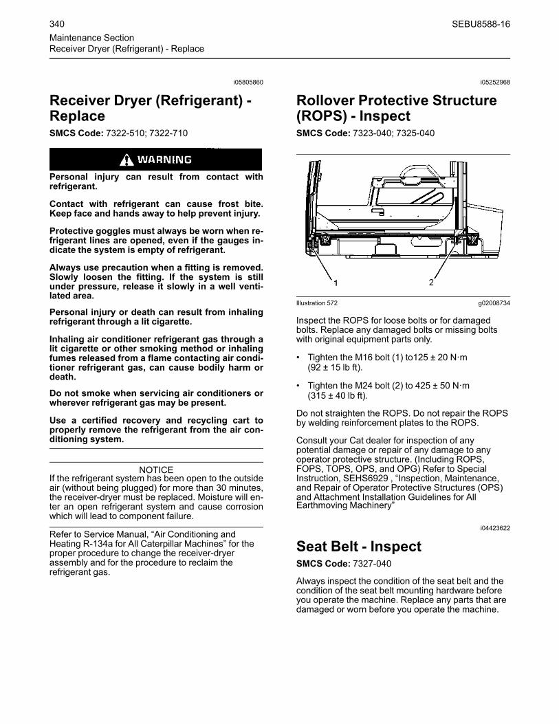
i05805860
Receiver Dryer (Refrigerant) -ReplaceSMCS Code: 7322-510; 7322-710
Personal injury can result from contact withrefrigerant.
Contact with refrigerant can cause frost bite.Keep face and hands away to help prevent injury.
Protective goggles must always be worn when re-frigerant lines are opened, even if the gauges in-dicate the system is empty of refrigerant.
Always use precaution when a fitting is removed.Slowly loosen the fitting. If the system is stillunder pressure, release it slowly in a well venti-lated area.
Personal injury or death can result from inhalingrefrigerant through a lit cigarette.
Inhaling air conditioner refrigerant gas through alit cigarette or other smoking method or inhalingfumes released from a flame contacting air condi-tioner refrigerant gas, can cause bodily harm ordeath.
Do not smoke when servicing air conditioners orwherever refrigerant gas may be present.
Use a certified recovery and recycling cart toproperly remove the refrigerant from the air con-ditioning system.
NOTICEIf the refrigerant system has been open to the outsideair (without being plugged) for more than 30 minutes,the receiver-dryer must be replaced. Moisture will en-ter an open refrigerant system and cause corrosionwhich will lead to component failure.
Refer to Service Manual, “Air Conditioning andHeating R-134a for All Caterpillar Machines” for theproper procedure to change the receiver-dryerassembly and for the procedure to reclaim therefrigerant gas.
i05252968
Rollover Protective Structure(ROPS) - InspectSMCS Code: 7323-040; 7325-040
Illustration 572 g02008734
Inspect the ROPS for loose bolts or for damagedbolts. Replace any damaged bolts or missing boltswith original equipment parts only.
• Tighten the M16 bolt (1) to125 ± 20 N·m(92 ± 15 lb ft).
• Tighten the M24 bolt (2) to 425 ± 50 N·m(315 ± 40 lb ft).
Do not straighten the ROPS. Do not repair the ROPSby welding reinforcement plates to the ROPS.
Consult your Cat dealer for inspection of anypotential damage or repair of any damage to anyoperator protective structure. (Including ROPS,FOPS, TOPS, OPS, and OPG) Refer to SpecialInstruction, SEHS6929 , “Inspection, Maintenance,and Repair of Operator Protective Structures (OPS)and Attachment Installation Guidelines for AllEarthmoving Machinery”
i04423622
Seat Belt - InspectSMCS Code: 7327-040
Always inspect the condition of the seat belt and thecondition of the seat belt mounting hardware beforeyou operate the machine. Replace any parts that aredamaged or worn before you operate the machine.
340 SEBU8588-16Maintenance SectionReceiver Dryer (Refrigerant) - Replace

Illustration 573 g02620101
Typical example
Inspect buckle (1) for wear or for damage. If thebuckle is worn or damaged, replace the seat belt.
Inspect seat belt (2) for webbing that is worn orfrayed. Replace the seat belt if the webbing is wornor frayed.
Inspect all seat belt mounting hardware for wear orfor damage. Replace any mounting hardware that isworn or damaged. Make sure that the mounting boltsare tight.
If your machine is equipped with a seat beltextension, also perform this inspection procedure forthe seat belt extension.
Contact your Cat dealer for the replacement of theseat belt and the mounting hardware.
Note: The seat belt should be replaced within 3 yearsof the date of installation. A date of installation labelis attached to the seat belt retractor and buckle. If thedate of installation label is missing, replace belt within3 years from the year of manufacture as indicated onbelt webbing label, buckle housing, or installationtags (non-retractable belts).
i06891605
Seat Belt - ReplaceSMCS Code: 7327-510
The seat belt should be replaced within 3 years of thedate of installation. A date of installation label isattached to the seat belt retractor and buckle. If thedate of installation label is missing, replace belt within3 years from the year of manufacture as indicated onbelt webbing label, buckle housing, or installationtags (non-retractable belts).
Illustration 574 g01152685
Typical Example(1) Date of installation (retractor)(2) Date of installation (buckle)(3) Year of manufacture (tag) (fully extended web)(4) Year of manufacture (underside) (buckle)
Consult your Cat dealer for the replacement of theseat belt and the mounting hardware.
Determine age of new seat belt before installing onseat. A manufacture label is on belt webbing andimprinted on belt buckle. Do not exceed install bydate on label.
Complete seat belt system should be installed withnew mounting hardware.
Date of installation labels should be marked andaffixed to the seat belt retractor and buckle.
Note: Date of installation labels should bepermanently marked by punch (retractable belt) orstamp (non-retractable belt).
If your machine is equipped with a seat beltextension, also perform this replacement procedurefor the seat belt extension.
i03867596
Swing Bearing - LubricateSMCS Code: 7063-086
Note: Caterpillar recommends the use ofmultipurpose lithium grease NLGI Grade 2 forlubricating the swing bearing. Refer to SpecialPublication, SEBU6250, “Caterpillar Machine FluidsRecommendations” for more information onmultipurpose lithium grease.
Note: Do not overgrease the swing bearings. Do notgrease more than the recommended maintenanceinterval. Refer to Operation and MaintenanceManual, “Maintenance Interval Schedule” for moreinformation.
Wipe the fittings before you lubricate the swingbearings.
SEBU8588-16 341Maintenance SectionSeat Belt - Replace

Illustration 575 g02110713
The swing bearings are under the base of the boom.
Illustration 576 g01106319
Apply lubricant through the fittings until the lubricantoverflows the bearing seals.
i02496710
Swing Drive Oil - ChangeSMCS Code: 5459-044
Drain the Swing Drives
Illustration 577 g01131530
1. Remove the access cover that is located under themachine, near the swing gear.
Illustration 578 g01131532
2. Pull out the ends of the drain hoses from the upperframe. Face the ends of the hoses toward thecontainer.
Note: Refer to Operation and Maintenance Manual,“General Hazard Information” for information thatpertains to containing fluid spillage.
342 SEBU8588-16Maintenance SectionSwing Drive Oil - Change

Illustration 579 g01131534
3. Reach through the access holes and open thedrain valves. Drain the oil into a suitable container.
Note: Dispose of drained fluids according to localregulations.
4. Tighten the drain valves.
5. Return the ends of the drain hoses to the upperframe. Make sure that the ends of the hoses arefacing upward.
6. Install the access cover.
Refill the Swing DrivesNote: Perform this procedure for each swing drive.
Illustration 580 g01100385
1. Remove the dipstick.
2. Add the specified quantity of oil through thedipstick tube. See Operation and Maintenance,“Capacities (Refill)”.
Illustration 581 g01106973
3.Make sure that the oil level is maintained betweenthe marks on the dipstick.
4. Check the oil that has been drained for metal chipsor metal particles. Consult your Caterpillar dealer ifany metal chips or metal particles are found.
Note: Dispose of drained materials according to localregulations.
i02789834
Swing Drive Oil Level - CheckSMCS Code: 5459-535-FLV
The dipstick for the swing drive oil is on the swingdrive near the right rear corner of the cab.
Note: There are two swing drives that are locatedbetween the swivel joint and the main control valve.Perform the same procedure for both swing drives.
Illustration 582 g01100385
1. Remove the dipstick.
SEBU8588-16 343Maintenance Section
Swing Drive Oil Level - Check

Illustration 583 g01106973
Note: Refer to Operation and Maintenance Manual,“General Hazard Information” for information thatpertains to containing fluid spillage.
2. Check the dipstick. Maintain the oil level betweenthe marks on the dipstick. Add oil through thedipstick tube, if necessary.
3. Insert the dipstick.
4. Check the dipstick again.
5. Reinsert the dipstick.
i05785504
Swing Drive Oil Sample -ObtainSMCS Code: 5459-554-OC; 5459-008; 5459-OC;5459-008-OC; 7542-008
Illustration 584 g01100385
Obtain an oil sample of the swing drive oil throughthe opening for the dipstick. Refer to SpecialPublication, SEBU6250, “S·O·S Oil Analysis” forinformation that pertains to obtaining an oil samplefrom the swing drive housing. Refer to SpecialPublication, PEGJ0047, “How To Take A Good OilSample” for more information about obtaining an oilsample from the swing drive housing.
i03804517
Swing Gear - LubricateSMCS Code: 7063-086
NOTICEImproper lubrication can cause damage to machinecomponents.
To avoid damage, make sure that the proper amountof grease is applied to the swing drive.
When the amount of grease in the compartment be-comes too large, the agitation loss becomes large,thereby accelerating grease deterioration.
Grease deterioration can cause damage to the piniongear of the swing drive and swing internal gear.
Not enough grease will result in poor gear lubrication.
344 SEBU8588-16Maintenance SectionSwing Drive Oil Sample - Obtain

Illustration 585 g00834990
Remove the inspection cover that is located near theboom base. Inspect the grease.
Illustration 586 g00688056
1. Remove bolts (1) and washers (2). Remove cover(3) and gasket (4).
Illustration 587 g00115464
2. Inspect gasket (4). Replace the gasket if damageis evident.
3. Check the level of the grease. The grease shouldbe evenly distributed on the floor of the pan.
Refer to Operation and Maintenance Manual,“Capacities (Refill)” for the capacity of the swinggear.
Add grease, as needed. Remove grease, asneeded. Too much grease will result in thedeterioration of the grease that is caused byexcessive movement of the grease. Too littlegrease will result in poor lubrication of the swinggear.
Illustration 588 g00101653
4. Check for contamination and for discoloredgrease.
5. If the grease is contaminated or discolored withwater, change the grease. Remove plug (5) inorder to allow the water to drain. When youreinstall plug (5), inspect O-ring seal (6). Replacethe O-ring seal if damage is evident.
Illustration 589 g00101644
6. Raise the boom and turn the upper structure by 90degrees. Lower the bucket to the ground.
7. Repeat Step 6 at every 90 degrees in 4 places.Add grease, as needed.
SEBU8588-16 345Maintenance Section
Swing Gear - Lubricate

i05647259
Track Adjustment - AdjustSMCS Code: 4170-025
Personal injury or death can result from greaseunder pressure.
Grease coming out of the relief valve under pres-sure can penetrate the body causing injury ordeath.
Do not watch the relief valve to see if grease is es-caping. Watch the track or track adjustment cylin-der to see if the track is being loosened.
Loosen the relief valve one turn only.
If track does not loosen, close the relief valve andcontact your Caterpillar dealer.
NOTICEKeeping the track properly adjusted will increase theservice life of the track and drive components.
Note: The track tension must be adjusted accordingto the current operating conditions. Keep the track asslack as possible if the soil is heavy.
Measuring Track Tension1. Operate the machine in the direction of the idlers.
Illustration 590 g01103855
2. Stop with one track pin directly over the frontcarrier roller. Park the machine and turn off theengine.
Illustration 591 g03472827
3. Place a straight edge on top of the track grousersbetween the front carrier roller and the idler. Thestraight edge should be long enough to reach fromthe front carrier roller to the idler.
Note: If your machine is equipped with three carrierrollers, place a straight edge on the tracks betweenthe carrier rollers. The straight edge should be longenough to reach from one carrier roller to anothercarrier roller.
4.Measure the maximum amount of sag in the track.The sag is measured from the highest point of thetrack grouser to the bottom of the straight edge. Atrack that is properly adjusted will have a sag of40.0 to 55.0 mm (1.57 to 2.17 inch).
5. If the track is too tight, or if the track is too loose,adjust the track tension according to theappropriate procedure below.
Adjusting Track Tension
Illustration 592 g00270405
Typical example
The track adjuster is located on the track frame.
346 SEBU8588-16Maintenance SectionTrack Adjustment - Adjust
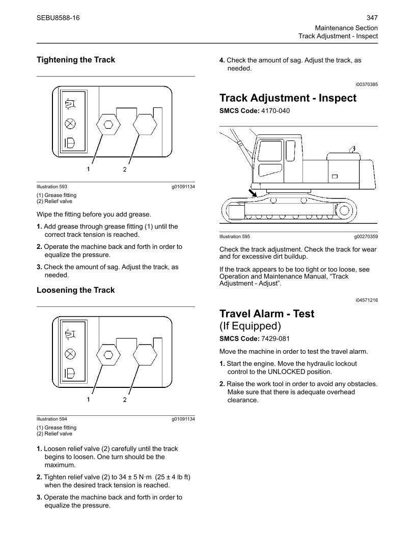
Tightening the Track
Illustration 593 g01091134
(1) Grease fitting(2) Relief valve
Wipe the fitting before you add grease.
1. Add grease through grease fitting (1) until thecorrect track tension is reached.
2. Operate the machine back and forth in order toequalize the pressure.
3. Check the amount of sag. Adjust the track, asneeded.
Loosening the Track
Illustration 594 g01091134
(1) Grease fitting(2) Relief valve
1. Loosen relief valve (2) carefully until the trackbegins to loosen. One turn should be themaximum.
2. Tighten relief valve (2) to 34 ± 5 N·m (25 ± 4 lb ft)when the desired track tension is reached.
3. Operate the machine back and forth in order toequalize the pressure.
4. Check the amount of sag. Adjust the track, asneeded.
i00370385
Track Adjustment - InspectSMCS Code: 4170-040
Illustration 595 g00270359
Check the track adjustment. Check the track for wearand for excessive dirt buildup.
If the track appears to be too tight or too loose, seeOperation and Maintenance Manual, “TrackAdjustment - Adjust”.
i04571216
Travel Alarm - Test(If Equipped)SMCS Code: 7429-081
Move the machine in order to test the travel alarm.
1. Start the engine. Move the hydraulic lockoutcontrol to the UNLOCKED position.
2. Raise the work tool in order to avoid any obstacles.Make sure that there is adequate overheadclearance.
SEBU8588-16 347Maintenance Section
Track Adjustment - Inspect

Illustration 596 g00560313
3. Use the travel levers or the travel pedals to movethe machine forward. The travel alarm shouldsound.
4. Release the travel levers and the travel pedals inorder to stop the machine.
5. Use the travel levers and the travel pedals to movethe machine backward. The travel alarm shouldsound.
Illustration 597 g02730938
6. Push the alarm cancel switch. The travel alarmshould shut off.
7. Stop the machine. Lower the work tool to theground. Move the hydraulic lockout control to theLOCKED position. Stop the engine.
i03934011
Undercarriage - CheckSMCS Code: 4150-535
Illustration 598 g02154815
1. Check the carrier rollers, the track rollers, and theidler wheels for possible leakage.
2. Check the surface of the track, the carrier rollers,the track rollers, the idler wheels, the track shoes,and the drive sprockets. Look for signs of wearand loose mounting bolts.
3. Listen for any abnormal noises while you aremoving slowly in an open area.
4. If abnormal wear exists or abnormal noises orleaks are found, consult your Caterpillar dealer.
i03754181
Window Washer Reservoir -FillSMCS Code: 7306-544-KE
NOTICEWhen operating in freezing temperatures, use Cater-pillar or any commercially available nonfreezing win-dow washer solvent.
1. Open the rear access door on the left side of themachine.
348 SEBU8588-16Maintenance SectionUndercarriage - Check

Illustration 599 g00688996
2. Remove the filler cap.
3. Fill the window washer reservoir with washer fluidthrough the filler opening.
4. Install the filler cap.
5. Close the access door.
i01258249
Window Wiper - Inspect/ReplaceSMCS Code: 7305-510; 7305-040
Inspect the condition of the wiper blades. Replacethe wiper blades if the wiper blades are worn ordamaged or if streaking occurs.
i03898951
Window - CheckSMCS Code: 7310-535
Check the polycarbonate windows of the cab for thefollowing conditions.
• yellow or haze
• scratches on either side of the window that can befelt with a fingernail
• small cracks that come from the edges ormounting holes
• contact with fluids that result in haze or clouds onthe window such as brake fluid
When any of the above conditions exist, contact yourCaterpillar dealer for replacement.
i05867976
Windows - CleanSMCS Code: 7310-070; 7340-070
Clean the outside of the windows from the ground,unless handholds are available.
Illustration 600 g00566124
Typical example
Cleaning MethodsAircraft Window CleanerApply the cleaner with a soft cloth. Rub the windowwith moderate pressure until all the dirt is removed.Allow the cleaner to dry. Wipe off the cleaner with aclean soft cloth.
Soap and Water
Use a clean sponge or a soft cloth. Wash thewindows with a mild soap or with a mild detergent.Also use plenty of lukewarm water. Rinse thewindows thoroughly. Dry the windows with a moistchamois or with a moist cellulose sponge.
Stubborn Dirt and GreaseWash the windows with a good grade of naphtha, ofisopropyl alcohol, or of Butyl Cellosolve. Then, washthe windows with soap and with water.
Polycarbonate Windows (Ifequipped)Special care is needed in order to cleanpolycarbonate windows.
Wash polycarbonate windows with mild soap andwarm water that does not exceed 50° C (122° F).Use a soft sponge, or damp cloth. Never use a drycloth or paper towels on polycarbonate windows.Rinse the windows with a sufficient amount of cleancold water.
SEBU8588-16 349Maintenance Section
Window Wiper - Inspect/Replace

Note: Naphtha or kerosene can be used in order toremove labels, films, paint, or marking pen frompolycarbonate windows.
Note: Do not use abrasive, or highly alkalinecleaners. Do not use sharp instruments, such assqueegees or razor blades on polycarbonatewindows. Do not clean polycarbonate windows in thehot sun or at elevated temperatures.
350 SEBU8588-16Maintenance SectionWindows - Clean

Warranty Section
Warranty Informationi06044323
Emissions WarrantyInformationSMCS Code: 1000
The certifying engine manufacturer warrants to theultimate purchaser and each subsequent purchaserthat:
1. New non-road diesel engines and stationary dieselengines less than 10 liters per cylinder (includingTier 1 and Tier 2 marine engines < 37 kW, butexcluding locomotive and other marine engines)operated and serviced in the United States andCanada, including all parts of their emissioncontrol systems (“emission related components”),are:
a. Designed, built, and equipped so as to conform,at the time of sale, with applicable emissionstandards prescribed by the United StatesEnvironmental Protection Agency (EPA) by wayof regulation.
b. Free from defects in materials andworkmanship in emission-related componentsthat can cause the engine to fail to conform toapplicable emission standards for the warrantyperiod.
2. New non-road diesel engines (including Tier 1 andTier 2 marine propulsion engines < 37 kW and Tier1 through Tier 4 marine auxiliary engines < 37 kW,but excluding locomotive and other marineengines) operated and serviced in the state ofCalifornia, including all parts of their emissioncontrol systems (“emission related components”),are:
a. Designed, built, and equipped so as to conform,at the time of sale, to all applicable regulationsadopted by the California Air Resources Board(ARB).
b. Free from defects in materials andworkmanship which cause the failure of anemission-related component to be identical inall material respects to the component asdescribed in the engine manufacturer'sapplication for certification for the warrantyperiod.
3. New non-road diesel engines installed inconstruction machines conforming to the SouthKorean regulations for construction machinesmanufactured after January 1, 2015, and operatedand serviced in South Korea, including all parts oftheir emission control systems (“emission relatedcomponents”), are:
a. Designed, built, and equipped so as to conform,at the time of sale, with applicable emissionstandards prescribed in the Enforcement Ruleof the Clean Air Conservation Act promulgatedby South Korea MOE.
b. Free from defects in materials andworkmanship in emission-related componentsthat can cause the engine to fail to conform toapplicable emission standards for the warrantyperiod.
The aftertreatment system can be expected tofunction properly for the lifetime of the engine(emissions durability period) subject to prescribedmaintenance requirements being followed.
A detailed explanation of the Emission ControlWarranty that is applicable to new non-road andstationary diesel engines, including the componentscovered and the warranty period, is found in asupplemental Special Publication. Consult yourauthorized Cat dealer to determine if your engine issubject to an Emission Control Warranty and toobtain a copy of the applicable Special Publication.
SEBU8588-16 351Warranty Section
Warranty Information

Reference InformationSection
Reference Materialsi07422648
Reference MaterialSMCS Code: 1000; 7000
Additional literature regarding your product may bepurchased from your local Cat dealer or by visitingpublications.cat.com. Use the product name, salesmodel, and serial number to obtain the correctinformation for your product.
publications.cat.com
i07743978
Decommissioning andDisposalSMCS Code: 1000; 7000
When the product is removed from service, localregulations for the product decommissioning willvary. Disposal of the product will vary with localregulations.
Improperly disposing of waste can threaten theenvironment. Obey all local regulations for thedecommissioning and disposal of materials.
Utilize appropriate personal protective equipmentwhen decommissioning and disposing product.
Consult the nearest Cat dealer for additionalinformation. Including information for componentremanufacturing and recycling options.
352 SEBU8588-16Reference Information SectionReference Materials

Index
A
Access Door and Cover Locations................ 254Engine Hood .............................................. 254Left Front Access Door .............................. 254Left Middle Access Door............................ 254Left Rear Access Door............................... 254Right Front Access Door ........................... 254Right Rear Access Door ............................ 255
Additional Messages ....................................... 19Adjustable Gauge Undercarriage Frame(20)............................................................. 26Air Conditioner (9), (10), (11) ....................... 23Alternate Exit (6) .......................................... 23Alternate Exit Lock/Unlock (5) ..................... 22Clean the Windows (1) ................................ 21Counterweight (7) ........................................ 23Data Privacy (4) ........................................... 22Diesel Engine Fuel (15) ............................... 25Diesel Exhaust Fluid Fill (16)....................... 25Diesel Fuel Requirements (17).................... 25Engine Oil (8) ............................................... 23Hydraulic Oil (19) ......................................... 26Joystick Controls Alternate Patterns (2) ...... 22Machine Security System (3)....................... 22No Step (12)................................................. 24Oil Biodegradable (18)................................. 26Radial Air Cleaner (14) ................................ 25Wait to Disconnect Lamp (13) ..................... 24
Adjustable Gauge Undercarriage Frame ...... 232Extending................................................... 232Retracting .................................................. 234
Air Cleaner Dust Valve - Clean/Inspect......... 276Air Conditioner/Cab Heater Filter(Recirculation) - Inspect/Replace ................ 276Air Conditioning and Heating Control............ 179English Versus Metric Toggle .................... 180
Alternate Exit ................................................... 95FOGS (If Equipped) ..................................... 96Front Window (If Equipped)......................... 95Roof Hatch (If Equipped) ....................... 95–96
ARD Spark Plug - Clean................................ 276
B
Battery - Clean............................................... 277Battery - Recycle ........................................... 277Battery Disconnect Switch ............................ 120Battery Electrolyte Level - Check .................. 277
Battery Hold-Down - Tighten......................... 278Battery or Battery Cable - Inspect/Replace... 278Before Operation ....................................... 39, 93Before Starting Engine .................................... 36Belt - Inspect/Adjust/Replace........................ 278Boom, Stick and Bucket Linkage -Lubricate...................................................... 279Grease Block on the Stick ......................... 281
Boom, Stick and Bucket Operation ............... 206Digging....................................................... 206Lifting Objects ............................................ 207Machines that are Equipped with a LongReach Configuration ................................ 209
Boom/Stick/Bucket Combinations................... 66Bucket - Remove and Install ......................... 214Bolted Flag................................................. 216Captured Flag ............................................ 214Crossbolt.................................................... 217
Bucket Linkage - Inspect/Adjust.................... 281Bucket Tips - Inspect/Replace .............. 282, 285Bucket Tips ................................................ 282Bucket Tips (Cat® Advansys ) - IfEquipped.................................................. 286Installation.................................................. 286Removal..................................................... 286Side Cutters ............................................... 284Side Cutters (If Equipped) ......................... 287Side Protectors (If Equipped) ............ 284, 288
Burn Prevention............................................... 30Batteries....................................................... 30Coolant ........................................................ 30Oils............................................................... 30
C
Cab Air Filter (Fresh Air) - Clean/Replace .... 289Cab Door ....................................................... 185Cab Door Latch - Inspect/Adjust/Replace..... 289Cab Door Latch Adjust............................... 290Cab Door Latch Inspect ............................. 289Cab Door Latch Replace ........................... 290Cab Door Stop Adjust ................................ 290
Cab Visor (If Equipped) ................................. 184Camera.......................................................... 125Rear View Camera (If Equipped)............... 125Side View Camera (If Equipped) ............... 125Work Area Vision System (WAVS) (IfEquipped)................................................. 125
Camera - Clean (If Equipped) ....................... 291
SEBU8588-16 353Index Section

Camera Harness - Disconnect andConnect ....................................................... 235Connection of the Harness for the Rear ViewCamera .................................................... 236Disconnection of the Harness for the RearView Camera ........................................... 236
Capacities (Refill) .......................................... 264Circuit Breakers - Reset ................................ 292Condenser (Refrigerant) - Clean................... 292Cooling System Coolant (ELC) - Change ..... 292Cooling System Coolant Extender (ELC) -Add .............................................................. 294Cooling System Coolant Level - Check......... 295Cooling System Coolant Sample (Level 1) -Obtain .......................................................... 296Cooling System Coolant Sample (Level 2) -Obtain .......................................................... 297Counterweight Removal and Installation ...... 236Counterweight Removal and Installation forStandard Machines.................................. 236Machines Equipped with CounterweightRemoval System...................................... 238
Counterweight Removal Chain - Clean (IfEquipped) .................................................... 297Counterweight Removal Chain - Inspect (IfEquipped) .................................................... 298Counterweight Removal Chain - Lubricate(If Equipped) ................................................ 298Crushing Prevention and Cutting Prevention.. 29
D
Daily Inspection ............................................... 93Declaration of Conformity................................ 92Decommissioning and Disposal.................... 352DEF Filler Screen - Clean ((EmissionRelated Component)) .................................. 299DEF Manifold Filters - Replace (EmissionRelated Component) ................................... 299Diesel Exhaust Fluid - Fill .............................. 303Diesel Exhaust Fluid Filter - Replace ............ 302Diesel Exhaust Fluid Injector - Replace(Emission Related Component) .................. 303Diesel Particulate Filter - Clean (EmissionRelated Component) ................................... 304Diesel Particulate Filter Regeneration .......... 102Delayed Engine Shutdown ........................ 103Modes of Regeneration ............................. 102Regeneration ............................................. 102Regeneration Indicators ............................ 102Regeneration Switch ................................. 102
Regeneration System WarningIndicators ................................................. 103Regeneration Triggers............................... 102
Disconnecting Hydraulic Hoses and Lines.... 226
E
Electrical Storm Injury Prevention................... 36Emissions Certification Film............................ 91Emissions Warranty Information ................... 351Engine Air Filter Primary Element - Clean/Replace ....................................................... 304Cleaning Primary Air Filter Elements ........ 305Inspecting the Primary Air FilterElements .................................................. 306
Engine Air Filter Secondary Element -Replace ....................................................... 307Engine Air Precleaner - Clean....................... 307Engine and Machine Warm-Up ..................... 195Dynamic Cool Engine Elevated Idle(DCEEI).................................................... 196Hydraulic System....................................... 195Hydraulic System Automatic Warm-up...... 196Improve Cold Weather Performance......... 197
Engine Oil and Filter - Change ...................... 309Fast Fill ...................................................... 312Procedure for Changing the Engine Oil andFilter ......................................................... 310Selection of the Oil Change Interval .......... 309
Engine Oil Level - Check............................... 308Engine Oil Sample - Obtain........................... 309Engine Starting........................................ 39, 194Engine Starting (Alternate Methods)............. 251Engine Starting with Auxiliary StartReceptacle (If Equipped)............................. 252Engine Starting with Jump Start Cables (IfEquipped) .................................................... 251Engine Stopping .............................................. 43Engine Valve Lash and Fuel Injector Timing- Check ........................................................ 312Engine Valve Rotators - Inspect .................... 312Equipment Lowering with Engine Stopped .... 45,199Machine With a Boom Lowering Control Valve(If Equipped) ............................................ 200Machine Without a Boom Lowering ControlValve ........................................................ 200
Ether Starting Aid Cylinder - Replace (IfEquipped) .................................................... 313
354 SEBU8588-16Index Section

F
Film (Product Identification) - Clean.............. 314Cleaning of the Films ................................. 314
Final Drive Oil - Change ................................ 315Final Drive Oil Level - Check......................... 315Final Drive Oil Sample - Obtain..................... 316Fire Extinguisher Location............................... 35Fire Prevention and Explosion Prevention...... 31Battery and Battery Cables.......................... 32Ether ............................................................ 34Fire Extinguisher.......................................... 34General ........................................................ 31Lines, Tubes, and Hoses ............................. 33Regeneration ............................................... 31Wiring........................................................... 33
Fire Safety ....................................................... 34Foreword ........................................................... 5California Proposition 65 Warning................. 5Certified Engine Maintenance ....................... 6Literature Information .................................... 5Machine Capacity .......................................... 6Maintenance .................................................. 5Operation ....................................................... 5Product Identification Number ....................... 6Safety............................................................. 5
Freezing Conditions ...................................... 222Frozen Ground Conditions ............................ 199Fuel System - Prime...................................... 316Fuel System Primary Filter (WaterSeparator) Element - Replace..................... 317Fuel System Secondary Filter - Replace ...... 318Fuel System Water Separator - Drain ........... 319Fuel Tank Cap and Strainer - Clean.............. 319Fuel Tank Cap Filter - Replace...................... 320Fuel Tank Shutoff and Drain Control ............. 192Fuel Tank Strainer - Clean............................. 320Fuel Tank Water and Sediment - Drain ......... 320Fill the Fuel Tank........................................ 320
Fuel Transfer Pump (Refueling) (IfEquipped) .................................................... 173Fuel Transfer Pump (Refueling) (IfEquipped) .................................................... 174Fuses - Replace ............................................ 321
G
General Hazard Information............................ 27Containing Fluid Spillage............................. 28Dispose of Waste Properly .......................... 29Fluid Penetration ......................................... 28Inhalation ..................................................... 29
Pressurized Air and Water........................... 28Trapped Pressure ........................................ 28
General Information ........................................ 50Guards............................................................. 48Guards (Operator Protection)Other Guards (If Equipped) ......................... 49Rollover Protective Structure (ROPS), FallingObject Protective Structure (FOPS) or TipOver Protection Structure (TOPS)............. 48
H
Hammer Operation (If Equipped) .................. 219High Intensity Discharge Lamp (HID) -Replace (If Equipped).................................. 323High Pressure Fuel Lines................................ 35Hydraulic System Filter Element (FineFiltration) - Replace (If Equipped) ............... 323Hydraulic System Oil - Change ..................... 324Cat HYDO Advanced 10 Oil ChangeInterval ..................................................... 324Drain the Oil ............................................... 324Fill the Hydraulic Tank................................ 327Service the Hydraulic System Filters......... 327
Hydraulic System Oil Filter - Replace ........... 332Case Drain Filters ...................................... 333Pilot Filter ................................................... 332
Hydraulic System Oil Filter (Return) -Replace ....................................................... 328Hydraulic System Oil Level - Check.............. 335Hydraulic System Oil Sample - Obtain.......... 336
I
Identification Information................................. 89Important Safety Information............................. 2Indicators and Gauges - Test ........................ 337
J
Joystick Controls ........................................... 190Joystick Controls (Medium Pressure (IfEquipped)) ................................................... 189Rotating Tool Control ................................. 189
Joystick Controls Alternate Patterns ............. 192
L
Leaving the Machine ..................................... 224Lifting and Tying Down the Machine ............. 242Lifting the Machine Segments ................... 244Tying Down the Machine ........................... 243
SEBU8588-16 355Index Section

Lifting Capacities ............................................. 69Mass Boom............................................ 82, 85Reach Boom.............................. 70, 73, 76, 79Symbols Found in the Lifting CapacityCharts ........................................................ 69
Lifting Objects.................................................. 43Lubricant Viscosities (FluidsRecommendations) ..................................... 256Biodiesel .................................................... 262Coolant Information ................................... 263Diesel Exhaust Fluid.................................. 260Diesel Fuel Recommendations ................. 259Engine Oil .................................................. 256Fuel Additives ............................................ 262General Information for Lubricants............ 256Hydraulic Systems..................................... 257Other Fluid Applications ............................ 258Selecting the Viscosity............................... 256Special Lubricants ..................................... 259
Lubricant Viscosities and Refill Capacities ... 256
M
Machine Operation.......................................... 95Machine Security System (If Equipped)........ 123Basic Operation ......................................... 124Operation Section...................................... 123Regulatory Compliance Section ................ 124Security Management................................ 124
Maintenance Access ..................................... 254Maintenance Interval Schedule..................... 273Every 10 000 Service Hours...................... 275Every 10 Service Hours or Daily................ 273Every 10 Service Hours or Daily for First 100Hours ....................................................... 273Every 10 Service Hours or Daily for MachinesUsed in Severe Applications.................... 274Every 100 Service Hours of ContinuousHammer Use............................................ 274Every 1000 Service Hours of Partial HammerUse (50% of Service Hours) .................... 275Every 1000 Service Hours or 6 Months..... 275Every 12 000 Service Hours or 6 Years..... 275Every 2000 Service Hours or 1 Year ......... 275Every 250 Service Hours........................... 274Every 250 Service Hours of Partial HammerUse (50% of Service Hours) .................... 274Every 250 Service Hours or Monthly ......... 274Every 3 Years After Date of Installation orEvery 5 Years After Date ofManufacture............................................. 275
Every 50 Service Hours or Weekly............ 274Every 500 Service Hours........................... 274Every 500 Service Hours or 3 Months....... 274Every 5000 Service Hours......................... 275Every 600 Service Hours of ContinuousHammer Use............................................ 274Every 6000 Service Hours or 3 Years ....... 275Every Year ................................................. 275Initial 250 Service Hours............................ 274Initial 500 Hours (for New Systems, RefilledSystems, and Converted Systems) ......... 274When Required.......................................... 273
Maintenance Section..................................... 254Maintenance Support .................................... 266Mirror (If Equipped) ....................................... 180Mirror Adjustment ...................................... 181
Mirror Installation........................................... 231Monitoring System......................................... 128Action Lamp (1) ......................................... 128Camera View (4) (If Equipped) .................. 129Changing the Password ............................ 141Clock Bar (2) .............................................. 128Controllability Setting......................... 139, 145Current Totals ............................................ 141Display Setting........................................... 135Gain/Response Control ............................. 130Gauges (3)................................................. 129Joystick Control Pattern............................. 142Key Pad (7) ................................................ 129Language Selection................................... 138Machine Warnings ..................................... 131Main Menu ................................................. 135Maintenance Intervals ............................... 140Multi-information Area (6) .......................... 129Other Messages ........................................ 134Password Entry.......................................... 143Performance .............................................. 138Power Mode Setting .................................. 139Prestart Monitoring Function ..................... 131Reverse Fan Setting.................................. 143Selecting the Work Tool ............................. 140Warning Display Area (5)........................... 129
Mounting and Dismounting ............................. 93Alternate Exit ............................................... 93Machine Access System Specifications...... 93
O
Oil Filter - Inspect .......................................... 339Inspect a Used Filter for Debris ................. 339
Oil Filter (Hydraulic Hammer) - Replace ....... 337
356 SEBU8588-16Index Section
Operating Technique Information.................. 202Operating Precaution................................. 204Restricted Operation.................................. 202
Operating Techniques ................................... 202Operation................................................. 40, 198Critical Failures ............................................ 40Limiting Conditions and Criteria .................. 40Machine Operating Temperature Range ..... 40Machine Operation ...................................... 42Machine Operation when the Machine is notCompletely Assembled.............................. 43
Operation Information ................................... 198Lifting Objects ............................................ 199
Operation Section............................................ 93Operator Controls.......................................... 109Air Conditioning and Heating Control (9)....114Automatic Engine Speed Control (14)........115Boom Pressure Control (27A) ....................119Cat Grade Control (If Equipped)................ 109Cat Regeneration System (CRS)Aftertreatment Switch (23)........................118Crane Auto Stop Cancel Switch (24A) .......118Engine Idle Shutdown (7) ...........................114Engine Speed Control (11) .........................115Engine Start Switch (6) ...............................113Fine Swing Control (27C) ...........................119Hydraulic Lockout Control (1) .....................111Joystick Controls (5) ...................................113Lift Control (17) ...........................................116Light Switch (20) .........................................117Lower Window Washer (26) (If Equipped...118Lower Window Wiper (25A) (IfEquipped)..................................................118Monitor (4) ..................................................113Operator Controls .......................................110Operators Seat (8) ......................................114Overload Warning Device (28) ...................119Platform Light (25B) (If Equipped) ..............118Power Mode (12) ........................................115Quick Coupler Control (22).........................117Radio (10) ...................................................115Radio Mute Switch (24B)............................118Rear/Side View Camera (21)......................117Service Hour Meter (3) ...............................113Service Port ................................................119SmartBoom Control (27B) .........................119Travel Alarm Cancel Switch (15) ................116Travel Control (2) ........................................112Travel Speed Control (13) ..........................115Window Wiper and Window Washer (18-19) .............................................................116
Work Tool Control (16)................................116Operator Station .............................................. 48
P
Parking .................................................... 43, 222Plate Locations and Film Locations ................ 89Electromagnetic Emissions ......................... 90Engine Serial Number ................................. 90Product Identification Number (PIN) andRegional Certification Plate ....................... 89Sound Certification Film .............................. 90
Power Receptacle (If Equipped) ................... 123Product Information Section............................ 50Product Link .................................................. 122Data Broadcasts ........................................ 122Operation in a Blast Site for Product LinkRadios...................................................... 123
Product Link (Product Link Japan) ................ 121Production Measurement Application ........... 145Basic Operation ......................................... 151Bucket Tip-Off Function ............................. 156Cat Production Measurement MenuScreen...................................................... 149Joystick Controls (If Enabled).................... 150Monitor Display .......................................... 146Preparing the System ................................ 163Warning Messages .................................... 148Work Monitor ............................................. 161
Q
Quick Coupler Operation (Circuit forUniversal Coupler (If Equipped)) ................. 210Operation ................................................... 210Releasing the Work Tool............................ 212Resetting the Quick Coupler Controls ....... 210Securing the Work Tool...............................211
R
Radiator Core - Clean ................................... 339Radio (If Equipped) ....................................... 176Loss of Memory ......................................... 178Presetting Radio Stations .......................... 177Radio Reception ........................................ 178Scan and Auto Memory ............................. 178
Receiver Dryer (Refrigerant) - Replace ........ 340Reference Information Section ..................... 352Reference Material ........................................ 352Reference Materials ...................................... 352Regulatory Information (Japan) ...................... 50
SEBU8588-16 357Index Section

Industrial Safety and Health Act .................. 54Operation of Construction Equipment and theGoverning Laws and Regulations.............. 51Qualifications for Machine Operation .......... 50Standard Certificate of Transfer .................. 53Trailer Transportation .................................. 50
Restricted Visibility .......................................... 37Rollover Protective Structure (ROPS) -Inspect ......................................................... 340Roof Hatch..................................................... 185
S
S·O·S Information ......................................... 265Safety Messages............................................... 7Aerosol Starting Aid (13) ............................. 15Crushing Hazard (11)................................... 14Crushing Hazard (19) .................................. 17Crushing Hazard (2) .....................................11Crushing Hazard (22) .................................. 18Crushing Hazard (3) .....................................11Crushing Hazard (8) .................................... 13Crushing Hazard (Counterweight) (23) ....... 19Crushing Injury (5) ....................................... 12Do Not Operate (1) ...................................... 10Electrical Power Lines (7)............................ 12Flying Debris (12) ........................................ 14High-Pressure Cylinder (20)........................ 17High-Pressure Gas (21)............................... 18Hot Surface (16) .......................................... 16Hot Surface (18) .......................................... 16Joystick Controls Alternate Patterns (10) .... 14Jump-Start Cables (14) ............................... 15Lifting Restriction/Counterweight Only(17)............................................................. 16Overload Warning Device (9) (IfEquipped)................................................... 13Product Link (4) ............................................11Relieve Hydraulic Tank Pressure (15) ......... 15Seat Belt (6) ................................................. 12
Safety Section ................................................... 7Seat ................................................................. 98Heated Seat and Ventilated Seat (IfEquipped)................................................... 99
Seat Belt .......................................................... 99Extension of the Seat Belt ......................... 101Seat Belt Adjustment for Non-RetractableSeat Belts................................................... 99Seat Belt Adjustment for Retractable SeatBelts ......................................................... 101
Seat Belt - Inspect ......................................... 340Seat Belt - Replace ....................................... 341
Securing the Machine.................................... 229Selective Catalytic Reduction WarningSystem......................................................... 104Definitions .................................................. 105Inducement Emergency Override for CatEngines Equipped with Selective CatalyticReduction Systems (If Equipped) ............ 107Inducement Strategy for DEF Level .......... 105Inducement Strategy for DEF Quality,Tampering, SCR System Fault, and ImpededEGR ......................................................... 106
Service Interval Chart.................................... 266Severe Service Application ........................... 271Improper Maintenance Procedures(Maintenance Procedures Which MayContribute to a Severe ServiceApplication) .............................................. 272Severe Environmental Factors .................. 271Severe Operating Conditions .................... 271
Shear Operation (If Equipped) ...................... 221Shipping the Machine.................................... 227Shipping a Machine that is not CompletelyAssembled ............................................... 228
Slope Operation .............................................. 44SmartBoom Control (If Equipped)................. 190SmartBoom Operation (If Equipped)............. 209Advantages................................................ 210Excavation and Loading ............................ 210Hammering ................................................ 210
Sound Information and VibrationInformation..................................................... 45Sound Level Information.............................. 45Sound Level Information for Machines inEurasian Economic Union Countries......... 45Sound Level Information for Machines inEuropean Union Countries and in Countriesthat Adopt the “EU Directives” ................... 45Sources........................................................ 48“The European Union Physical Agents(Vibration) Directive 2002/44/EC”.............. 46
Specifications .................................................. 55Application/Configuration Restrictions ........ 56Basic Machine ............................................. 59Boom Cylinders ........................................... 64Boom with Stick Cylinder............................. 61Bucket .......................................................... 63Carbody ....................................................... 59Counterweight ............................................. 60Expected Life ............................................... 55Intended Use ............................................... 55Miscellaneous.............................................. 65
358 SEBU8588-16Index Section

Specification Data........................................ 56Step for Track Frame................................... 65Stick with Bucket Cylinder ........................... 62Track Frame................................................. 60Walkway....................................................... 64Working Ranges .......................................... 58
Stopping the Engine ...................................... 222Delayed Engine Shutdown ........................ 223Engine Stop Control .................................. 223Stop the Engine if an Electrical MalfunctionOccurs...................................................... 224
Stopping the Machine.................................... 222Storage and Literature Compartment (IfEquipped) .................................................... 173Storage Box................................................... 172Exterior Storage Box ................................. 172Interior Storage Box................................... 172
Sun Screen (If Equipped) .............................. 185Swing Bearing - Lubricate ............................. 341Swing Drive Oil - Change .............................. 342Drain the Swing Drives .............................. 342Refill the Swing Drives............................... 343
Swing Drive Oil Level - Check....................... 343Swing Drive Oil Sample - Obtain................... 344Swing Gear - Lubricate.................................. 344System Pressure Release............................. 267Coolant System ......................................... 267Hydraulic System....................................... 267Purge Screws (Boom, Stick and/or BucketHydraulic Circuits).................................... 269
T
Table of Contents .............................................. 3Towing Information ........................................ 247Towing the Machine....................................... 247Lightweight Towing .................................... 250Parking Brake Release.............................. 248Retrieval of Machine.................................. 249
Track Adjustment - Adjust ............................. 346Adjusting Track Tension ............................ 346Measuring Track Tension .......................... 346
Track Adjustment - Inspect............................ 347Track Information ............................................ 35Transportation Information ............................ 226Travel Alarm - Test (If Equipped)................... 347Travel Control (Straight Travel Pedal (IfEquipped)) ................................................... 186Travel in Water and Mud ............................... 204Procedure for Removing the Machine fromWater or Mud ........................................... 205
U
Undercarriage - Check .................................. 348
V
Visibility Information ........................................ 36
W
Warranty Information..................................... 351Warranty Section........................................... 351Welding on Machines and Engines withElectronic Controls ...................................... 271Window - Check ............................................ 349Window (Front).............................................. 18250/50 Window............................................ 18270/30 window............................................. 183
Window Washer Reservoir - Fill .................... 348Window Wiper - Inspect/Replace.................. 349Windows - Clean ........................................... 349Cleaning Methods...................................... 349Polycarbonate Windows (If equipped) ...... 349
Work Tool Control Pedal................................ 187One-way Flow............................................ 188Two-way Flow............................................ 188
Work Tools....................................................... 39
SEBU8588-16 359Index Section


Product and Dealer InformationNote: For product identification plate locations, see the section “Product Identification Information” in the Operationand Maintenance Manual.
Delivery Date:
Product InformationModel:
Product Identification Number:
Engine Serial Number:
Transmission Serial Number:
Generator Serial Number:
Attachment Serial Numbers:
Attachment Information:
Customer Equipment Number:
Dealer Equipment Number:
Dealer InformationName: Branch:
Address:
Dealer Contact Phone Number Hours
Sales:
Parts:
Service:

SEBU8588©2020 CaterpillarAll Rights Reserved
CAT, CATERPILLAR, LET’S DO THE WORK, their respective logos, “Caterpillar Yellow”, the“Power Edge” and Cat “Modern Hex” trade dress as well as corporate and product identity usedherein, are trademarks of Caterpillar and may not be used without permission.
362 June 2020