
Small System Operation and Maintenance Practices - Potable ...
Upload
khangminh22Category
view
1download
0
100421A
Operation and Maintenance Manual
Kelt Exploration
Sullair PDR-20
Oak | 6-35-86-18W6M

Project #Kelt ExplorationOak | 6-35-86-18W6M Sullair PDR-20
1. Compressor
2. Driver
3. Cooler
4. Instrumentation / Auxiliary Equipment
5. Drawings/Panel Documentation
6. Bill of Materials
100421A
TABLE OF CONTENTS

1. Compressor

Sullair Long term storage 3.2 long-Term Storage The compressor package should be stored at all times in a dry location to prevent corrosion damage. The inlet and discharge lines are covered for shipment and short-term storage. If the unit is to be stored for a prolonged period of time, the unit should be checked occasionally to insure that the holding charge of dry nitrogen remains above atmospheric pressure. This will prevent corrosion from any moisture that might enter the compressor package, Refer to dry and wet storage below. Long-Term and Seasonal Storage Procedures Dry Storage (No Lube Oil in Machine) if Applicable
1. For long-term storage drain lubricant from machines and place desiccant (silica gel) inside:
- Lube/Gas Separator - Duplex Strainer - Bearing - lube Filters - Control Panel
2. Close off all external connections with gaskets and steel flanges according to connection
size. 3. Follow recommended vendor driver storage procedure.
4. A nitrogen purge can be supplied from a nitrogen bottle with a pressure regulator to
maintain a few inches of positive water pressure in the system Note: to be effective, the system must be positively sealed except for the relief valve.
Wet Storage (lube Oil in Machine) if applicable
1. Close off all external connections with gaskets and steel flanges according to connection size.
2. A nitrogen purge can be supplied from a nitrogen bottle with a pressure regulator to maintain a few inches of positive water pressure in the system to be effective, the system must be positively sealed except for the relief valve.
During wet storage, - the auxiliary lube pump, at two week intervals, should be run to circulate lube oil through
the system to insure proper lube protection. Run the pump(s) for approximately 60 seconds or a maximum of 10 PSIG is reached.
- Follow recommended vendor driver storage procedure. - The compressor shaft should be rotated by hand 10 to 15 revolutions each week in
storage.

'
SERIES PD1 0, PD12, PD16 & PD20
GAS COMPRESSOR
. OPERATOR'S MANUAL
Part Number 02250051-524 @Sullair Corporation, 1994 Effective 6/94


KEEP YOUR MACHINE IN TOP
OPERATING CONDITION
USE
GENUINE
SERVICE PARTS
CONTACT YOUR NEAREST SULLAIR
DISTRIBUTOR OR CALL 1-800-348-2722


1.1 Coapressor Specifications
Machine
Physical Measurements POlO Bare Unit
Wght. lb.
Lgth. in.
Wdth. in.
Hght. in.
Rotor Dia. nm.
190 * 16.0 * 13.8 * 13.3 *
102
Gear Ratio 1.15 1.24 1.35 1.73. 1.94 2.03 2.15 2.56 2.84 3.04 3.16 3.52 3.70 1.00
WR2 lb-in2
L/D Ratio
64 74 86 136 1~7 181 201 277 334 378 406 497 541 33
1.47
Shaft Rotation (facing driveshaft): Gear driven units = CCW Direct drive units • CW
Built-in Volume Ratio: 2.6 (low compression) 4.6 (high compression)
Max Inlet Pressure:
Max Outlet Pressure:
Operational Speed:
Bearings (outlet):
Bearings ,(inlet):
Bearing~(shaftt:
15 PSIG
150 PSIG
2808 MIN - 9362 MAX (Male rotor RPM)**
Steel, tapered roller
Poly. steel, brz, straight roller
Steel, tapered roller
NOTES: . * Overall dimensions of foot-mounted, gear driven unit. ** Consult Sullair for geared units

1.1 Coapressor Specifications (continued)
Machine.
Physical Measurements PD12 Bare Unit
Wght. lb. 346 * Lgth. in. 22.6 * Wdth. in. 15.7 * Hght. in. 11.8 *
Rotor D1a. nm. 127
Gear Ratio 1.51 1.76 1.91 2.06 2.29 2.52
. WR2 lb-in2 322 425 498 • 566 687 817
L/D Ratio 1.70
Shaft Rotation (facing driveshaft): Gear driven units = CCW Direct drive units • CW
Built-in Volume Ratio: 2.6 (low compression) 4.3 (high compression).
Max Inlet Pressure:
Max Outlet Pressure:
Operational Speed:
Bearings (outlet):
Bearings {inlet):
15 PSIG
175 PSIG
2256 HIH -·7519 MAX (Male Rotor RPM)**
Steel. tapered roller . Poly. steel, brz, straight roller
Bearin~{sliaft}: Steel, tapered roller • ~·· . .
NOTES: ._~:Qvera:11 dimensions of foot-mounted or driven unit • . -;·consult Su11a1 r for geared units.
2.74
952

1.1 Coapressor Specifications (continued)
Machine
Physical Measurements PD16 Bare Unit
Wght. 1 b. 599 * Lgth. in. 36.6'*
Wdth. in. 18.3 * Hght. in. 15.3 *
Rotor Dia. 11111. 163
Gear Ratio .85 1~0 1.17 1.24 1.34 1.45 1.54 1.69 1.85 1.91 2.03 2.26
WR2 lb-in2 316 335 582 647 747 863 964 1144 1352 1434 1604 1954
L/0 Ratio 1.67
Shaft Rotation (facing driveshaft): Gear driven units • CCV Direct drive units K CW
Built-in Volume Ratio: 2.6 (low compression)
Max Inlet Pressure:
Max Outlet Pressure:
Operational Speed:
Bearings (outlet):
. Bearings. (inlet):
Bear1ng~fshaft): ...
3.0. 3.6 (med. compression) 4.7. 5.5 (high compression)
25 PSIG
175 PSIG
1758 MIN - 5858 MAX (Male Rotor RPM)***
Steel. tapered roller .
Poly. steel. brz. stra1ght·ro11er
Steel. tapered roller
NOTES: -'·OVerall dimensions of foot-mo.unted. gear driven unit. ** QYerall dimensions of flange-mounted. gear driven unit.
***·COnsult Sullair for geared units.
r· I

1.1 Compressor Specifications (continued)
Machine
Physical Measurements PD20 Bare Unit
Wght. lb.
Lgth. in.
Wdth. in.
Hght. in.
Rotor D1a.
Gear Ratio -
l!l11 •
1008 *
45.0 * 22.5 * 18.8 *
204
• 96 1.11 1.17 1.36 1.45 1.57 1.65 1.80 1.94 2.13 2.06 1.00
WR2 L/0•2.2 1590 1078 2290 3023 3402 3940 4318 5071 5823 6920 6506 1426 WR2 L/Da1.7 1380 1800 1981 2606 2928 3384 3704 4340 4974 5896 5548 1200
L/D Ratio 1.7, 2.2
Shaft Rotation (facing driveshaft): Gear driven units • CCW Direct drive units = CW
Built-in Volume Ratio: 2.6 (low compression) 3.5 (med compression) 4.3 (high compression)
Max Inlet Pressure: 10 PSIG
Max Outlet Pressure: 175 PSIG
Operational Speed: 1404 MIN - 4681 MAX (Kale Rotor RPM)***
Bearings· (outlet): Poly, steel brz, straight roller & angular contac ball
Bearings· (inlet): Poly, steel, brz, straight roller
Bearings. (shaft): Poly steel, brz, straight roller, Conrad ball
NOTES: * Overall dimensions of foot-mounted, direct driven unit. ** Overall dimensions of flange-mounted, gear driven unit.
*** Consult Sullair for geared units.

SECTION 2
DESCRIPTIOII


2.1 Introduction
Your new Sullair Rotary Screw Compressor will provide you with improved reliability._ and reduced maintenance if ·ins.talled, started, operated and serviced according to this manual. As with all compressors, only trained personnel should install and operate the Sul'lair compressor. Take special note of the items marked IMPORTANT, DANGER or WARNING, as overlooking these can lead to dangerous situations. Should you have any questions which are not ·answered in this manual, contact Sullair Corporation or their agents for assistance.
To ensure correct application, the compressor package must be installed in a system designed to currently accepted practices.
Immediately on arrival of your new Sullair compressor, unpack all the crates and boxes and check the items against shipping lists for any possible shortages. Examine the compressor, package components and loose items for possible damage in transit. Notify the shipper of any shortages or damages and enter the <!ppropriate claim.
·. ·'

2.2 The Coapressor Unit
The U.S. made Sullair Rotary Screw Compressor is an advanced design incorporat1n.g.-many years of experience in the screw compressor field. The positive displacement, pulse-free compressor includes the following design features: ·
175 PSIS design casting (200 PSIG for POlO) Stator, inlet and discharge housings are SAE G3000 cast iron Stator is double wall design for strength and noise reduction Rotors are asyn~~~etri ca 1, Sullair designed and manufactured from
AISI-1141 free machining carbon steel Bearings: Various anti-friction styles used
Also included:
Shaft seal, rotary face mechanical, single unit for POlO & P012, double for P016 & P020. · Shaft driven, bearing lubricant oil pump on P016 & P020 units.
Lubricant is injected into the compressor unit and mixes directly with the gas as the rotors turn compressing the gas. The 1 ubri cant has three functions:
As a lubricant; it acts as a lubricating film between the rotors allowing the male rotor to directly drive the female rotor and to lubricate the thrust and sleeve bearings.
As a sealant; it seals the leakage paths between each rotor and the stator and .also between the two rotors '
As a coolant; it controls the rise of the gas temperature associated with the heat of compression
Lubricant selection requires careful study of service conditions.
SERVICE CONDITIONS
Process nature (i.e., refer, pumping, etc.) Gas composition (including liquids) Flowing pressure & temperatures Ambient teaperature Compressor- speed
OIL- PROPERTIES
Composition Viscosity Lubricity Anti oxidation Anticorrosion Flash Point
The gas-1 ubri cant mf xture discharged by the compressor 1s fed through a high efficiency separation process, and the recovered oil is subsequently cooled, filtered, and distributed for re-injection.

SECTION 3
I NSTALL.A TI ON
This section contains instructions·for the proper installation of Sullair. Screw Compressors. All items in this section must be carried out by those with installation responsibility before the Su11air Representative arrives for start-up.


3.1 General
This section contains instructions for the proper installation of Sullair Screw· Compressors. All items in this section must be completed by those with installation responsibility before the Sullair Representative arrives for start-up.
1. All piping is to be complete. Relief valves are to be properly vented.
2. The water piping is to be completed with the water valve installed for water-cooled machines.
3. The system and the compressor package are to be pressure-tested for leaks. See Section 3.5.
4. The system is to be evacuated to remove air and moisture. High and low point vents have been provided in all process lines (if specified).
5. The compressor lubrication system is packager filled with the correct amount and type· of lubricant. Check that the oil separator lubricant has -maintained a level indicating half of gage ·glass level while compressor is running. If the lubricant level has fallen below this level, fill the separator with. the proper lubricant. See proper Section for lubricant type and restore this level.
6. The electrical wiring is to be completed as required. Do not energize the compressor until the lubricant is added or the lubricant heater is connected
(if applicable). IMPORTANT
USED LUBRICANT SHOULD NEVER BE ADDED TO A SCREW COMPRESSOR UNDER ANY CIRCUMSTANCES •. USE ONLY NEW LUBRICANT.
7. The lubricant is to be warmed up if necessary.
8. ·The control panel is to be energized to check the protective controls. See Section 3.9

'·'
3.2 long-Tera Storage
The compressor package should be stored at all times in a dry location to prevent corrosion damage. The inlet and discharge lines are covered for shipment and short-term storage. If the unit is to be stored for a prolonged period of time, the unit should be checked occasionally to insure that the holding charge of dry nitrogen remains above atmospheric pressure. This will prevent corrosion from any mofsture that might enter the compressor package, Refer to dry and wet storage this page.
Long-Term and. Seasonal Storage Procedures
Dry Storage {No Lube Oil in Machine) if Applicable
For long-term storage drain lubricant from machines and place desiccant {silica gel) inside:
•
Lube/Gas Separator Duplex Strainer Bearing· lube Filters Control Panel
Close off all external connections. with gaskets and steel flanges according to connection size.. Follow recotrmended vendor driver storage procedure.
A nitrogen purge can be supplied from a nitrogen bottle with a pressure regulator to maintain a few inches of positive water pressure in the system - to be effective, the system must be positively sealed except for the relief valve.
Wet Storage {lube Oil in Machine) if applicable
Close off all external connections with gaskets and steel flanges according to connection size.
A nitrogen purge can be supplied from a nitrogen bottle with a pressure regulator to maintain a few inches of positive water pressure in the system - to be effective, the system must be positively sealed except for the relief valve.
Refer to Section 5.6 for further information. During wet storage, the auxiliary lube pump, at two week intervals, should be run to circulate lube oil througiJ(the· system to insure proper lube protection. Run the pump(s) for approxintely 60 seconds or a maximum of 10 PSIG is reached. Follow recotrmended::vendor driver storage procedure. The compressor shaft should be rotated by. hand 10 to 15 revolutions each week in storage.

3.3 Foundation and R1gg1ng
The compressor package can be mounted and secured to any hard rigid and level surrace which is adequate to ·support the weight of the package. Since tbe screw compressor is a relatively vibration-free rotary machine, it does not have to be mounted on an inertia block or pad.
If the mounting surface is not level, jacking screws may be required to distribute the weight evenly over the entire frame. Any gross distortion of the frame will complicate the alignment of the coupling.
Do not grout the package frame to the foundation at this stage (for 200 HP and above). Grouting with an expanding grout around the entire base is necessary after the piping is connected and the compressor and motor are roughly aligned (approximately 1/32 in (1 mm) total indicated reading).

3.4 Piping
All piping 11ust confonn to ANSI B31.3 Chemical Plant & Petroleum Refinery Piping. The customer must supply piping, fittings and equipment. up to the tenninating connections on the Sullair package. The size and location of the inlet, discharge and water connections can be found on the installation drawing of .t~ package provided with manual •
. The inlet, discharge and relief header connections should be installed and supported such that there is no load exerted on the compressor frame from either static forces or vibration. External forces from the piping can distort the flange alignments and cause major leak problems.
Gasketed Joints·
When using flanges, suitable gasket material should be used. · Prior to tightening flange bolts, the pipe to be connected should be in parallel alignment and the -bolt holes should be in line. Do not 'USe flanges as a means of straightening pipe, as they may stress adjacent compressors, valves and controls.
Flange bolts should be drawn up evenly when connecting flanges to prevent flange breakage.
Threaded Joints
The use of litharge and glycerine for sealing threaded joints has been replaced by many commercially available compounds and sealing tapes designed for use with different gases. Check for compatibility and follow instructions accompanying these compounds for method of application. Do not use excessive amounts or apply on female threads because any excess could contaminate the system.
IJU>ORTAJIT
GREAT CARE SHOULD BE EXERCISED IN WELDING ALL JOINTS ON THE INLET AND DISCHARGE LINES TO MINIMIZE THE AMOUNT OF- WELD SLAG INSIDE THE SYSTEM PIPES.
ALL STEEL LINES (ESPECIALLY INLET AND LUBE INJECTION LINES) SHOULD BE THOROUGHLY CLEANED BY BLOWING OUT THE LINES WITH COWR.ESSED AIR.
D~.NOT GROUND THROUGH THE COMPRESSOR WHEN ARC WELDING.

3.5 Pressure Test
The package c0111ponents sha 11 a 11 have been pressure-tested prior to 1 eavi ng the factory.· The compressor unit should, however, be leak-checked at the jobsite to detect leaks which may be present due to rough handling during shipment. This test should be done simultaneously with the system pressure test and system leak check.
Before the system pressure test, check that the lubricant separator element is seated correctly and that the gaskets are in the correct position. When the package is under pressure, tighten the manhole access cover.
1. Isolate the compressor package from the system.
2. Through .a supplied vent or drain on .the process piping, apply 25 PSIS of a dry inert gas to the package, e.g. nitrogen.
3. leave pressurized for approximately two hours and cheek pressure gauge for a loss of pressure.
4. If pressure is lost, perform a soap bubble test on all flanged and threaded connections and correct as necessary.
5. Evacuate the system by opening the supplied inlet or discharge bypass/blowdown valve to relieve the pressure in the system.

3.6 Coupling A11gnaent - Foot-Mounted Units
The compressor· shall be supplied leveled and secured to the pa.cl::age base frame. Do not loosen the bolts or disturb the compressor. Tighten the 1
compressor mounting bolts to the to~que given in Table 12 in Section 6.3 as they may have loosened in shipment. ·
Preparation for Alignment:
1. The compressor package should be leveled and securely anchored without base distortion as in Section 3.3.
2. Have available a supply of clean stainless steel shim stock in various thicknesses from 0.001" to 0.020" (0.02 to 0.50 mm) and slotted to fit the mounting bolts.
3. Check to make sure the driver feet and the package mounting pads are free of dirt and burrs.
4. Remove the coupling spacer and flexible elements, if fitted, by removing the nuts, bolts and thin and thick washers with the bevel facing the element pads. · ·
5. Tie a wire through one bolt ·hole of each element pad to retain the original orientation of each element in the pad and to ensure that each element pad contains the same number of elements.
6. If the hubs are not mounted on the compressor shaft and the driver shaft, assemble the hubs.
7. Have a crowbar or other strong lever available to raise the driver for access to the shims.
Preliminary Alignment
1. Loosen inlet and discharge piping at compressor flanges and check for piping misalignment and strain. Retighten piping.
2. Adjust driver components of compressor package as necessary.
IIU'ORTAJIT
PRECISE COUPLING ALIGNMENT IS THE GOAL IN THIS PROCEDURE. DO·IIO'F ALIGN THE PIPING IN SUCH A MANNER AS TO PUT EXCESS MlSAliGNMEMT ON THE COMPRESSOR OR DRIVER.
3. After correct compressor location is achieved, dowel pin the compressor to the package frame.
4. Roughly align the driver to the compressor to get approximate shaft separation and heights.

3.6 Coupling A11gnaent - Foot-Mounted Units (continued)
5. Set a pair of calipers to the proper shaft separation value.
6. Check the distance between the hubs at points N and s. Figure 3-1 using the calipers. ·
7. Add or remove shims at each corner of the driver base and use the jack screws( if supplied) to achieve the proper shaft separation around the complete perimeter of the hubs.
IMPORT AliT
DO NOT ADD OR SUBTRACT SHIMS . FROM UNDER THE COMPRESSOR. DOING THIS MAY RESULT IN DAMAGE TO PROCESS PIPING AND THE COMPRESSOR.
8. Place a straight edge across the rim of one hub flan·ge to the rim of the other at points E or W in Figure 3-2.
9. Measure the gap between the straight edge and the rim of the second hub flange with a feeler gauge. See Figure 3-4.
10. Use jack bolts at points A, B. C and D in Figure 3-2 to move the driver the proper distance.
11. Recheck the shaft separation and correct if necessary.
12. Again, place a straight edge across the hubs as in Figure 3-4 except now at points N and S in Figure 3-3.
13. Repeat Step 6.
14. Add or remove the same amount of shims at each corner of the driver base to achieve the same shaft elevations.
15. Recheck the shaft separation and angularity in elevation and correct as needed. ·
16. Rechec~ the concentricity in plan and correct as needed • .
17. Recheck': the- concentricity in elevation if any previous adjustments were· INideo.
Final AltPnt
1. Attach tllo dial indicators together securely to either coupling hub using a chain block or a vise claiiiP as in Figure 3.5. Set in one plunger on the top of the face of the opposite hub close to the rim or outside diameter (to measure the angularity) and set the other plunger on the top center of the rim (to measure the concentricity). Hake sure that the plunger point is on a clean unpainted surface. Position both indicators such that their plungers are approximately half depressed to alTow the movement of the pointer in either direction.
2. Set both dial faces to zero as in position N in Figure 3-5.

3.6 Coupling AlignMent- Foot-Mounted Unit (continued)
3. Malee· sure that the indicators are securely attached by rotating the compressor shaft and the driver shaft together 360o or one comp 1 ete , revolution. The d1al readings should return to zero. If the indicators do not return to zero, check the mounting of the indicators and tighten the chain block or the vise clamps. Indicator sag of 5-10 mils over a 12" span is possible; thus, elevation measurement concentricities may be severily affected if correction for sag is not made.
IMPORTANT:
4. The maximum allowable coupling angularity or concentricity misalignment is 0.002" (0.05 mm) total indicator reading (T.I.R.). The tota 1 indicator reading is obtai ned by subtracting the 1 owest reading from the highest reading. Use care to observe the sign change when subtractin9 a negative reading, e.g. 0.003 - (-0.002) = 0.005 and 0.003 - {+0.002) a 0.001.
5. The adjustment for misalignment should be made in a specific sequence. The three positions of al1gn!M!nt in F1gures 3-1. 3-2 and 3-3 are arranged in the recommended order.
6. The following example shows the recommended procedure for correcting coupling misalignment.
7. When making shim changes, use a small number. of thick shims rather than a large number of thin shims to prevent excessive compression of the shim packs when the mounting bolts are tightened. ·
8. When making shim changes, change and secure one foot at a time. Tighten the bolt only enough to prevent the driver from moving about while making shim changes. The next best procedure is to shim both inboard and outboard feet at the same time. This method helps to retain any corrections already obtained.
9. Whenever shims are changed and the motor is moved. the mounting bolts should be tightened evenly in the sequence in Figure 3-6 to the same torqu6.g1ven in Table 12 in Section 6.3. This minimizes misalignment cause«t •. b:!- the- driver shifting when tightening the bolts and by the motor.:::pa~s; not being level.
10. Whenever' shi111s are changed and the driver 1s moved and the mounting bolts:.iire .. tightened, a continuing sequential record should be kept of each· set' of 8 indicator readings on a simple elliptical sketch· as in Figure 3-5.
11. Set both dial indicators to zero (o.ooo•, 0.00 ~) in position N in Figure 3-5. Rotate both the compressor shaft and the driver shaft together in 90o steps. Turning both hubs together ensures that readings are recorded at the same point on each hub eliminating the effect of any irregularities on the rims or faces of the hubs. A mirror may assist in taking the readings. A sample set of readings is given in Figure 3-5.

3.6 Coupling Alignaent - Foot-Mounted Unit (continued)
12. Never accept a single reading. · Look fqr repeatability by rotating bot.h shafts togethe.r several time and check that the reading remains the s~~~~e.
13. The •angularity in elevation• misalignment from o.ooo• (0.00 11111 ) at point N to -0.006" (-0.15 11111) at point S indicates that the rear of the driver is higher than the front in relation to the compressor. The T.I.R. is 0.006" (0.15 11111). .
14. Calculate the distance to move the driver feet as follows: (Refer to Figure 3-7). ·
(a) Measure the angularity indicator plunger circle diameter (a little smaller than the coupling hub diameter) D (for example 6"
· (150m)). .·
(b) Measure the distance between the front and rear driver mounting .bolts L, for example 30" (750 mm).
(c) Let the angularity in elevation misalignment T.I.R. as measured in Step 13 be H. ·
(d) Let the shim thickness to be added or removed be s. (e) Then the shim thickness to be added or removed is calculated by
dividing the bolt distance. L by the coupling diameter D and multiplying the result by the misalignment H.
15. S = LH o
~ 30 X 0.006 • 750 X 0.15 6 150
~ 0.030" • 0.75 mm
Add 0.030" (0. 75 m) of shill from the two rear driver feet. Use a crowba~ or other strong lever to raise the driver for access to the s hillS..;;: ,.
• ... :..:.··~ ~-
16. Tight&5 the mounting bolts to the torque given in Table 12. " ~-
17. RecheCk the angularity in elevation misalignment as in Steps 11 to 14. Record'a·l'f 8 dial indicator readings. Note that the driver shaft can be above or below the compressor shaft (i.e., not concentric) and this will not affect the angularity in elevation calculation. When this is checked, the driver shaft is parallel in elevation to the compre,ssor shaft, completing Figure 3-1. ;
18. The "concentricity in plan• misalignment in Figure 3-2 from 0.020" (0.25 m) at point II indicates that the driver is displaced in the direction of point w. The T.I.R. is 0.020" (~.5 mm).
19. The distance to move the driver feet is half of the concentricity in plan misalignment T.I.R. This is 0.010" (0.25 mm).

3.6 Coupling Alignaent - Foot-Mounted Unit (continued)
20. Fit jack screws (if applicable) to the frame at points C and D in Figure 3-2. Bring both jack screws into contact with the driver frame and then turn them in the direction of the arrows to move both feet 0.010" (0.25 mm).
21. Tighten the mounting bolts to the torque given in Table 12 in Section 6.
22. Recheck the concentricity in plan misalignment and record all 8 dial indicator readings as in Step 11 above. If necessary, readjust the driver as outlined in the preceding steps if either of the angularity or concentricity indicators exceeds the maximum allowable misalignment of 0.002" (0.05 mm). When this is checked, the driver shaft should be satisfactorily aligned with 0.002" (0.05 mm) angularity and concentricity from top to bottom (elevation) and from side to side (plan) to the compressor shaft. •
23. The concentricity in elevation" misalignment in Figure 3-5 from o.ooo• (0.00 mm) at point N to o.ooa• (0.20 mm) at point S indicates that the driver is lower than the compressor. The T.I.R. is o.ooa• (0.00 mm).
24. The distance to move the driver feet is half of the concentricity in elevation misalignment T.I.R. This is 0.004" (0.10 mm) from Step 18.
25. Add 0.04" (0.10 mm) of shim to each of the four driver feet.
26. Tighten the mounting bolts to the torque given·in Table 12.
27. Recheck the concentricity in elevation misalignment and record all 8 dial indicator readings. When this is checked, the driver shaft is
. both level and parallel in elevation to the compressor shaft, completing Step 2 in Figure 3-3. No more shims should need to be added or removed from the driver feet to complete the alignment.
28. Reverse the checking procedure by adjusting both dial indicators to zero at point S. Again, readjust the driver as in- the ·preceding steps. ·
29. Check the spacing between the driver shaft and the compressor shaft to make· sure there is sufficient room to accept the coupling spacer.
30. Finally, tighten the driver mounting bolts in sequence as ·in Figure 3-6; then, tighten bolts to the torque in Table 12 in Section 6.
31. Finally, recheck the alignment as in Step 22. If difficulty is experienced obtaining the alignment within the tolerance, proceed to Step 34 as the driver feet may not be sufficiently level.
32. Set the flange to flange spacing to the specified distance in Section 1.1. When setting coupling spacing on motors with sleeve bearings, it is mandatory that the motor armature be located on its magnetic center. Contact the motor manufacturer for details.
'

3.6 Coupling Alignment - Foot-Mounted Units (continued)
33. Do not assemble the coupling and dowel pin the motor to the frame untfl the alignment has been verified by a Sullair Service Representative. The Sullair Representative will be available to supervise these operations, but the customer must supply the dowel pins, drill reamer, drill bits and the labor.
34. Leveling the Driver Feet - All driver or support feet must be in the same plane. If they are not level, it makes alignment difficult. If one foot is not level, it makes exact alignment difficult. If one foot is higher, it stresses and springs the framework and the motor, or, if badly out of level, it can break the foot. Each time this foot is tightened, it must be tightened to the same torque va 1 ue or a different indicator reading will result. The following procedure levels the motor feet in relation to the package base frame.
(a) Tighten all mounting bolts evenly in the sequence in Figure 3-6 to the torque in Table 12 in Section 6.
(b)· Attach a dial indicator plunger on the top center of the rim (to measure the concentricity) in position N on Figure 3-3. Position the plunger so it .is half depressed to allow movement of the pointer in either direction.
(c)
(d)
(e)
(f)
(g)
(h)
(f)
{j)
Set the dial face to zero.
Loosen one of the inboard feet and record the total movement on the indicator. Tighten the foot.
·.
Loosen the adjacent inboard foot and record the total movement before tightening ft.
If this reading is greater than the reading for the first foot, add shims to this second foot equal to the difference.
When the reading on the second foot is less than or equal to 0.003" (0.08 nn), recheck the first foot. This will confirm that the inboard feet checked are level.
Repeat·th~procedure for the outboard pair of adjacent feet. ~ . .,. .... · .. ~acceptable reading on any foot is less than or equal to 0.003" (o·~oa 1111) when· three bolts are tight and one· is loose • .. •.
Finally, tighten the driver mounting bolts evenly in the sequence in Figure 3-6 to the torque in Table 12 in Section 6.

3. 6 ·Coup Hog Al(gomeot (~~ttoue.dl. . . . -·
_A 1 ignment .Segygnce··· - -· m
MOTOR SIDE'
MOTOR SIDE
MOTOR TOP
8 A
MOTOR TOP
0.000 ln. (0.000 mm) -----..
N
s -0.006 ln.
(-0.152 mm)
0.000 ln.
COMPRESSOR SIDE
(0.000 mm) ,.----'""\ N
s +0.006 ln.
(+0.203 mm)
-0.004 ln.
COMPRESSOR SIDE
(- 0.102 mm) r:;.J..-~...,. E
w +0.010 ln ..
( +0.254 mm)
COMPRESSOR TOP
COMPRESSOR TOP
Step 1: Angularity in elevation-This alignment adjusted with shims and is not readily lost in mak the other adjustments.
Step 2: Concentricity in elevation-This alignmen · also made with shims, but it cannot be made wl
there is angular misalignment in elevation.
Step 3: Angularity In plan-This position can ea be lost if placed ahead of the two adjustments elevation.
Step 4: Concentricity in plan-This adjustment c not be made while there is still angular misalignrr in plan. and can easily be lost if eleval.ion adi• ments are made.

3.6 Coupling Alignment (conti~ued) .. Figure 3-4. -------------"""'"======---=--.-....._
Figure 3-5
STRAIGHT EDGE
PLAN OR ELEVATION VIEW
F ina 1 AJi gnment .. .P.c.ocedure
+0.010 ln. (+0.254mm)
.....
(
CONCENTRICITY INDICATOR
ANGULARITY INDICATOR
COMPRESSOR
-0.010 ln. (-0.254mm)
-0.004 ln. (-0.102mm)
-0.006 ln. (-0.152mm)
+0.0081n. (+0.203mm)
·-

3 •. 6 Coup I (ng Allgnment (continued} . '
Bolts
..
Figure 3-6
•.
'··:
..
I I 1 • t .! ~· .. :
. . . 5
:
. ..
. -. . ' .. ' . ... . ~
. . . .
Angularity Alignment
Figure 3-7
.••

3.7 Driver Rotat1on Check
IMPORT AliT
CONSULT SECTION 1 FOR PROPER COMPRESSOR ROTATION. DO NOT RON THE COMPRESSOR IN THE REVERSE DIRECTION FOR MORE THAN ONE SECOND. FAILURE TO OBSERVE THIS CAUTION COULD RESULT IN SERIOUS DAMAGE TO THE COMPRESSOR. IF COUPLING ALIGNMENT HAS NOT BEEN PERFORMED, IT IS PREFERABLE TO CHECK DRIVER ROTATION WITH DRIVER UNCOUPLED.
:· ..
.' ;

3.8 Pre-Start-Up Lubrication Charge
Before starting the compressor for the first time, a charge of lubricant shall be administered to ensure that the compressor, cooler, and lube lines have sufficient oil to build up pressure at .start-up.
Units With Pre-Lube Pumps - (PD16, PD20)
Run the pre-lube pump, but no longer than 1 minute, until 10-15 PSIG is achieved. If this pressure level cannot. be reached, refer to Section 5.5, "Low Lube Pressure".
Once the charge is complete, check for lube oil leaks throughout the supply lines and correct as needed.
Finally, rotate the compressor shaft approximately 10 revolutions to equalize the lubricant level in the compressor. Failure to do this may result in damage to the shaft seals during initial start-up.
Units Without Pre-Lube Pumps - (POlO, PD12)
Introduce 1 to 2 gallons of lubricant through a suitable opening in the supply lines between the oil filter and the compressor. Shop air may be used to aid distribution of the charge, but care must be taken to direct said charge towards the compressor.
As previously stated, rotate the compressor shaft approximately 10 revolutions to equalize the lubricant level in the compressor.

SECTIOII 4
OPERATIOII
After all the installation functions in Section 3 have been completed. it will be possible for the Sullair Service Representative to perform start-up service. Sullair should be notified a minimum of two weeks before a scheduled start-up to assure timely arrival of the Sullair Service Representative. It is necessary that key plan operating personnel be available to go through the start-up. since a great deal of knowledge canbe obtained in this manner. The operations covered in this section wfll be performed as start-up under the supervision of a Sullair Service Representative. · ··
··--··

4.1 Start-Up Service Outline
Before the Sullafr Service Representative arrives, the following must be completed in the order given;
1. The compressor is to be leveled and securely anchored to the foundation to assure stability of the c!luplfng alignment.
2. All piping is to be complete. Relief valves are to be properly vented.
3. The water piping is to be completed with the water valve installed for water-cooled machines (if applicable)
4. The system is to be evacuated to reroove air and moisture.
5. The system and the compressor package are to be pressure-tested for leaks as outlined in Section 3.5. ·
6. The system is again to be evacuated to remove air and moisture.
7. Driver lubrication is completed.
8. The Sullair Service Representative will verify that the coupling alignment has been achieved within the limits prescribed in Section 3.6. When alignment has been verified, it will be necessary for those with installation responsibility to dowel pin the motor (if required), assemble the coupling spacer and mount the coupling guard. The Sullair Representative will be available to supervise these operations but the customer must supply the dowel pins, drill, reamer, drill bfts and labor.
9. The compressor is to be filled with the correct type and amount of lubricant (see Section 1.1).
10. The Electrical wiring is to be completed as required. Do not energize the compressor contro 1 pane 1 unti 1 1 ubri cant is added and the 1 ube heater is connected (if applicable).
11. The lubricant is to be wannecf up (if applicable) .•
12. The control panel is to be energized to check the protective switches and t~·capacity control. (See Section 3.9)
13. The effraction of rotation of the motor is to be checked.
14. Have available two dowel pins, drill and reamer for the driver. The driver will be dowel pinned by the customer after the alignment is checked by the Sullair Service Representative.
15. All valves at the cooling water supply lines are fully open (water in and out), if applicable.

4.1 Start-Up Service Outline (continued)
The Sullair Service Representative will supervise the following with customer-supplied labor~ ·
1. Check the overall installation of compress'or package.
2. Check the coupling alignment. Customer will then dowel pin the motor.
3. Check all protective controls.
4. Check capacity control actuator adjustment (if applicable).
5. Start the compressor for the first time and adjust all the valves and controls on the package.
6. Explain compressor operation to the operating personnel.
·. -·
-; i

4.2 Pre-Start Check List
The following section covers only the initial start of the compressor. Be sure that: an necessary system valves are open and that the system is ready for start-up. Use the following check list to guarantee that no items of importance regarding the compressor package have been overlooked.
1. Driver Fuel/Power disengaged.
2. Instrument air/gas connected and regulated to the value given.
3. All protective switches verified for correct operation.
4. The lubricant in the separator sump 1s above 50oF (lOoC). The compressor package should not be started if lubricant temperature is below this value.
5. Correct lubricant level.
6. Pre start-up lubrication 'charge has been performed.
7. Cooling water to lube cooler turned on if water~cooled.
8. Isolating valves to the pressure gauges and switches are opened.
9. Manual blowdown valve closed, inlet and discharge valves open.
10. Coupling turns freely by hand.
11. Direction of motor rotation checked and coupling guard mounted.
12. Driver lubrication is completed.
13. Capacity control actuator indicator at minimum (if equipped).
14. Capacity control selection switch in manual (if equipped).
When the above items are verified, the compressor is ready for the initial start.

4.3 Initial Start Procedure
Your Sullair gas compressor has been supplied with an electrical control system. Refer to an app li cab 1 e wiring diagram and corresponding vendor instructions for proper field wiring before any start-up procedures are initiated.
If the compressor shuts down on low lube differential pressure after start-up, clean up the lube strainers and pump one (1) gallon (four litres) of lubricant into the lube filter to prelubricate the compressor bearings. Restart the compressor and, if it stops again because of low lube pressure differential, see "Troubleshooting•, Section 5.6, under Low Lube Pressure.
IMPORT AliT
THE COMPRESSOR PACKAGE MUST BE ISOLATED FROM THE SYSTEM BY CLOSING THE ISOLATING VALVES AND PRESSURE RELIEVED BEFORE REMOVING STRAINERS. FAILURE TO OBSERVE THIS CAUTION COULD RESULT IN SERIOUS INJURY.
After a successful start, run the compressor until the operating limits stated in Section 2.2 are met. The primary convern is to achieve and satisfy the correct discharge pressure; This pressure will help to achieve the remaining operating parameters of the c0111pressor. If the operating 1 imits are not met within approximately 30 minutes, refer to "Troubleshooting•, Section 5.6 of this manual.

4.4 Lube Pressure AdJustment
Before adjtlsting the lube pressure relief valve and the lube pressure regulating..,.:valve. make certain that the lube strainers are clean and the lube teaperature is at its normal operating temperature {see Section 1.2).
1. Loosen· the locknut on the relief valve· and screw in the adjustment screw w1tK an allen wrench as far as it will go.
2. Loosen the locknut on the lube pressure regulator and screw in the adjustment screw with an allen wrench unt11 the lube pressure is 75 PSI (9500 kPa) above the discharge pressure.
3. Back out the adjustment screw on the lube pressure relief valve while watching the lube pressure gauge until the lube pressure begins to drop. This indicates the valve is starting to relieve and bypass lube at 75 PSI {9500 kPa). Tighten the locknut.
4. Back out the adjustment screw of the 1 ube pressure regula tor wh11 e watching the lube pressure and discharge pressure gauges until the lube- pressure drops to 45 to 50 PSI (300 to 350 kPa) above discharge pressure. Tighten the locknut.
'

4.5 Start-Up Data Re'cord
After the compressor has run fully automatically for an hour and the pressures and tetnperatures have remained stab.le for 15 minutes, a Sullair Representative will fill out the start-up data record on the following page. A copy will be sent to Sullair Process & Gas Compressors, Inc. for the permanent file Sullair maintains on your machines.
f'·, .•

4.6 After Start-Up Maintenance
After the compressor has run for twenty-four hours, change the lube filters if its pressure differential exceeds 30 PSI (200 kPa). ·
Check the compressor shaft seal for excessive leakage of more than 10 drops per minute ... If excessive, replace the seal as in Section 6.5.
IMPORTANT
WHENEVER THE COMPRESSOR STOPS, IT RUNS IN THE REVERSE DIRECTION FOR SEVERAL SECONDS. AFTER THE DISCHARGE CHECK VALVE CLOSES, THE HIGH PRESSURE GAS IN THE SEPARATOR EXPANDS BACK THROUGH THE COMPRESSOR TO THE CLOSED INLET CHECK VALVE WHICH CAUSES THE COMPRESSOR TO RUN IN REVERSE. IT IS A COMPLETELY NORMAL ACTION AND IS NO CAUSE FOR ALARM. CONTINUED BACK SPIN FOR A FULL SECOND INDICATES EXCESS LEAKAGE THROUGH THE INLET CHECK VALVE. INSPECT OR REPLACE THE CHECK VALVE IF THIS SHOULD OCCUR. NOTE THAT COMPRESSOR BACK-SPIN EXCEEDING ONE (1) SECOND MAY RESULT IN SERIOUS
-DAMAGE.
. ..
'

Page 1 of 2
START UP DATA RECORD
Customer---------- Contractor ----------
Persons Contacted ------- Persons Contacted -------Phone -----------Tel ex :-:---:----------QwipiTelefax --------
Phone ------'------Telex Qwip/T~el;-:e-;;f~ax----------
Identification (Section 1.1) Package Model No.~-----Compressor Serial No. ----Pneumatic Diagram No. --:-:-::-"-:-~ Lubricant Cooling: Water I DX I Air
Coupling Alignment (Section 3.7) T. I. R. Concentri c1 ty ___ 1 n/11111 T.I.R. Angularity in/mm Coupling Spacing in/mm
Package Serial No.------Wiring Diagram No. ------Piping & Instr. No. -----Installation No. --------
Protective Switch Settings (Section 1.2 and 3·.9) Anti-recycle Timer min Low Oil Pressure 25 psf 1 175 kPa (Factory Set) High Lube Temperature OfiOC High Discharge Temperature ____ OffOC Low Discharge Temperature OffOC High DiScharge Temperature OffOC High Inlet Pressure PSIG/in Hg/kPa Low Inlet Pressure PSIG/in Hg/kPa Low Discharge Pressure PSIG/in Hg/kPa High Discharge Pressure PSlG/in Hg/kPa
Control Switch Settings Inlet Pressure: Cut In PSIG/in Hg/kPa
Cut Out ----- PSIG/in Hg/kPa Capacity Control Pressure: Pl Unload PSIG/in Hg/kPa
P2 Load PSIG/1n Hg/kPa

Page 2
START UP DATA RECORD
Driver Equipment
Driver Manufacturer------ Sul1air Supplied: Yes 1 No Driver Serial Number Driver Rated Power HP/kW
If Electric Drive: Electric Supply---- Volts ____ Hertz ----Phase
Operational Data
Gas Inlet Pressure ___ PSIG/in. Hg/kPa Inlet Temperature ----OF/ Disch Pressure PSIG I kPa Lube Pressure PSIG I kPa Lube Filter
Press Drop --- PSID I kPa Lube Type Water Temp:
Inlet Outlet -
Water Supply:
Disch Temperature OF/ Lube Temperature OF/
' Condenser/Cooling Tower/Treated/Untreated/Mains/Well /Other ---=--Current amps at above conditions with capacity control at
Corrments: ·
Sullair Representative Signature----------- Date __ _

SECTIOII 5
MAIIITEIIAIICE


5.1 General·
Although the maintenance for your Sullair Screw Compressor is minimal,. it must be carried out for a long compressor, life. The instrumentation and indicators provided will alert you of the first sign of a maintenance requirement •. Observe these instruments and 'indicators at regular intervals to be certain. that the machine is performing properly. Become familiar with the nonnal operating sound of the compressor and if something does not sound just right, shut down the machine. Excess'! ve vibration is a good
. indication that something is wrong and that vibration checks should be periodically made. this precaution may save the cost of a major repair.
Keep the compressor package clean to minimize dirt entering the compressor whenever components are opened during routine maintenance •.
Before cleaning a component with a solvent to remove gum or resin-like deposits, remove all the 0-rings as they can be chemically attacked. Alternatively, check the compatibility of the solvent with the 0-rings. Unfortunately, those solvents which most readily remove carbon deposits (e.g. trichlorethylene) rapidly attack viton. (To ensure no traces of solvent will be left to react with the lubricant and gas, thoroughly dry the component with an air blast.)

5.2 Daily Operation
It will be necessary to check the lube level inside the sump. Should the level be low, simply add the necessary amount of the proper lubricant.
After a routine start has been made, observe the instrument panel and be sure the gauges indicate the correct reading for that particular phase of operation.
After the machine has warmed up, check the overall compressor and instrument panel to make sure it is running properly. Immediate attention should be given to the following:
Lubricant Pressure Gauge Lubricant Temperature Gauge Discharge Temperature Gauge Discharge Pressure Gauge Inlet Pressure Gauge Other Gauges
A log of-the operating temperatures. pressures and service requirements can be valuable in troubleshooting. It is strongly recoamended that a log be kept of all readings at least every-eight hours as in Table 10.
Check the lubricant level in the oil separator sight glass. 'If the level is low, refer to Section 3.1 proper fill level and instructions.
WARJIIII6
DO NOT REMOVE : CAPS, PLUGS OR OTHER COMPONENTS WHEN COMPRESSOR IS RUNNING OR PRESSURIZED.
STOP COMPRESSOR AND RELIEVE ALL INTERNAL PRESSURE BEFORE DOING SO. DO NOT EXHAUST HAZARDOUS GASES INTO THE ATMOSPHERE.
IMPORT AliT
USED OR FILTERED LUBRICANT SHOULD NEVER BE ADDED TO A SULLAIR SCREW COMPRESSOR UNDER ANY CIRCUMSTANCE. USE ONLY NElL LUBRICANl.
Lubricant"' should be added if needed after the compressor has stopped or been shut:dOIIIt~ Add sufficient 1 ubri_cant into the separator to the proper level witlr-a. hand or electric pump.
If the addition of lubricant becotnes too frequent, a problem may have developed causing this excessive loss. See "Troubleshooting•, Section 5.5 under High Lube Consumption for a probable cause and remedy.

5.3 Maintenance After Inft1a1 200 Hours of Operation
After the initial 200 hours of operation. a few maintenance tasks are necessary to rid the system of foreign materials which may have accumulated during assembly and installation. Other procedures, stated below, are required to ensure that the initial operation of the machine is correct.
1. Replace the lubricant filter elements 2. Clean the lube strainers 3. Check the settings of the capacity control (if applicable) 4. Check the pressure gauge calibration (0 PSIG or 0 kPa when open to
atmosphere). 5. Tighten package fasteners. especially driver and compressor mounting
bolts. 6. Check compressor shaft seals for excessive leakage. A small lubricant
loss of 1 to 2 drops per minute is normal, maximum being 10 drops per minute.
7. Check coupling alignment. Alignment changes may be an indication of sub-suport settlement and/or over-hung (pipe strain) loads.
8. Check pertinent protection switches. 9. Check lubricant oil separator element and gaskets (of oil loss is
excessive. 10. Perform driver maintenance as required. 11. Restart and check all operating temperatures and pressures.

5.4 Maintenance Sc.hedule
OPERATION
1. Che~k all operating indicators.
Net lube Pressure (Equals lube pressure gauge minus discharge pressure gauge
lube Temperature Discharge Pressure Discharge Temperature Inlet Pressure lube Filter Pressure Drop lube Level Motor Current
SCHEDULING TIME PERIOD
Daily
Daily Daily Daily Daily Daily Daily Daily
2. Test all protective controls on monthly basis.
3. Main~ain lube quality with a lub~ analysis progra•.
Sample lube to check appearance and run a lube analysis
Change lubricant
Change lube filter cartridge
Clean lube strainers
4. General Maintenance
Check Noise level
Check Driver Bearings Temperature
Lubrica~ Driver Bearings
Engine Lubricant Sump (if applicable)
Every 1,000 hours for first 6,000 hours and every 2,000 hours thereafter.
Every three months or 2,000 hours unless using lube analysis. Maximum time six months.
Whenever lubricant is changed or when pressure drop across the filter exceeds 30 PSI (200 kPa) or is less than 4 PSI (30 kPa).
Whenever lubricant is changed.
Daily
Monthly or as recommended by motor manufacturer
Yearly or as recommended by driver manufacturer
Yearly or as recommended by driver manufacturer

5.4 Maintenance Schedule ·(continued)
OPERATION
Check Coupling Alignment and tighterr coupling bolts
Tighten Driver and Compressor Mounting Bolts
Inspect Rotor End Play
Inspect Lubricant Separator Filter Element
Inspect For Cleanliness
scHEDULING TIME PERIOD
Yearly
Yearly
Every six months
Refer to separator differential gauge. Inspect at 10 PSID.
Every three m<inths until required cleaning frequency is established.

5.5 Troubleshooting
The infonDation contained in the Troubleshooting Chart has been .compiled from data gathered from field service reports and factory experience. It contains symptoms and usual causes for the service problems described, however, DO NOT assume that these are the only problems that may occur. All available data concerning the trouble should be systematically analyzed before undertaking any repairs or replacing components.
With any problem, make a detailed visual and audible inspection. Some important things to look for are:
1. Damaged control tubing.
2. Loose wiring
3. Loose connections.
4. Unfamiliar noises or vibrations (driver, compressor, tanks, etc.)
Analyze ·the problem logically, step by step, with the aid of the Troubleshooting Chart.
Should your problem persist after making these checks, contact the Sulla1r Service Department.
. : .;

Troubleshooting Chart
SYMPTOM
1. Compressor will not start
PROBABLE CAUSE AND REMEDY
A. No power supply to control circui Check power supply.
B. One of the protective switches tripped. Remove cause. Check setting and reset.
C. Recycle timer activated. Wait for timer to time out.
D. Defective pre-lube pump.
2 •. Compressor shuts down A. Low lube pressure. See #3. immediately after starting.
3. Low lube pressure
4. . Rfgfr.lube pressure
5. ~lube ~emperature
B. Cold lubricant
A. Plugged lube strainer. Clean Strainer.
B. Plugged lube filter. Replace cartridge. Do not clean.
C. low lubricant charge. Check lube level with compressor shut down.
D. Worn lube pump (when supplied).
E. Low lube viscosity. (to be determined by oil analysis). Change lubricant: ·
A. Lube temperature too low. See #!
A. Thermal valve element defective. Replace element.
B. Lube heater or thermostat defecti (where applicable).
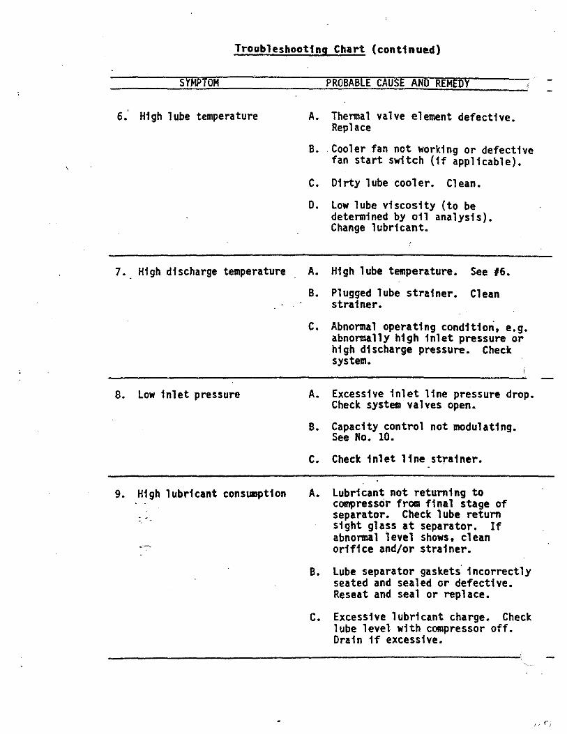
Troubleshooting Chart (continued)
SYMPTOM
6.' High lube temperature
7. High discharge temperature
8. low inlet pressure
9. Higb lubricant consuuption
... -.
PROBABLE CAUSE AND REMEDY
A. Thermal valve element defective. Replace
B •. Cooler fan not working or defective fan start switch (if applicable).
C. Dirty lube cooler. Clean.
D. low lube viscosity (to be determined by oil analysis). Change lubricant.
A. High lube temperature. See #6.
B. Plugged lube strainer. Clean strainer.
c. Abnormal operating condition. e.g. abnormally high inlet pressure or high discharge pressure. Check system.
A. Excessive inlet line pressure drop. Check system valves open.
B. Capacity control not modulating. See No. 10.
c. Check inlet line strainer.
A. lubricant not returning to compressor from final stage of separator. Check lube return sight glass at separator. If abnormal level shows. clean orifice and/or strainer •
B. lube separator gaskets· incorrectly seated and sealed or defective. Reseat and seal or replace.
c. Excessive lubricant charge. Check lube level with compressor off. Drain if excessive.
r

Troubleshooting Chart (continued)
SYMPTOM
10. Excessive compressor vibration
11. Driver Malfunction (Refer to Driver Manual)
PROBABLE cAUSE AND REMEDY
A• Rotor end play excessive. Con Sullafr with .results.
B. loose compressor anchoring. Tighten bolts. '
C. Check coupling alignment.
0. Any other persistent vibration noise. contact Sullair.

;
5.6 Seasonal or long-Tera Shutdown
To shut down a compressor for four months or longer, tightly shut both the inlet and- discharge stop valves. Disconnect all power and air sources. Place a moisture-absorbing compound (e.g. a desiccant such as silica gel) inside the control panel and the pneumatic valve actuator. If water-cooled. close the cooling water supply valves and drain the water from the lube cooler. Drain all liquid from the inlet separator system.
Place warning tags on the compressor control system and all closed stop valves.
Every week, while the compressor is shut down, turn the compressor and motor shafts 10 to 15 revolutions by hand.
Prior to starting up after a·shutdown, change the lubricant and repeat the items in Section 4.2.
I!<,)
I I L~d

SECTIOII 6
SERYICIII&

6.1 General
The following paragraphs outline the general servicing procedures for the Sullair Screw Compressors.
For ass·istance with any detail of service or servicing of an item not covered by. this manual, please consult Sullair or their agents. Service supervisors are available from Sullair who will assist on any servicing procedure.
To prevent needless downtime, have available on site all parts that may be needed to carry out the repair before col!lllencing any work.. Refer to recomended spare parts list for assistance.
To prevent dirt from entering opened components, keep the surroundings clean and cover the exposed working areas with plastic whenever possible.
Before cleaning a component with a solvent to remove g1.111 or resin-like deposits, remove all the 0-rings as they can be chemically attacked. Alternatively, checlc the compatibility of the solvent with the 0-rings. Unfortunately, those solvents which ·most readily remove carbon deposits, (e.g. trichlorethylene) rapidly attack viton. (To ensure no traces of solvent will be left to react with the gas and lubricant, thoroughly dry the component with an air blast.)

6.2 Shutdown Procedure
WARMING
BEFORE COMMENCING WORK ON ANY ITEM ON THE PACKAGE, ENSURE THAT THE FOLLOWING ARE CARRIED OUT FOR YOUR OWN PERSONAL PROTECTION.
COMPRESSOR SHUTDOWN
1. Whenever the compressor is to be shut down for service, place warning tags on the system and the line valves. Others who do not know the machine may be faulty or is being repaired must not attempt to start the compressor until the servicing is complete and it is ready for normal operation.
2. Stop the compressor with the stop button.
* 3. Secure the driver.
* 4. Disengage driver power/fuel.. ·
5. Close compressor inlet stop valve and discharge stop valve.
6. Relieve the gas pressure in the package by opening the blow down valve on the lube separator.
7. Leave the blow down valve open all the time while working on the package.
* Note:
HARJIIIIG
HAZARDOUS GASES MUST NOT BE EXHAUSTED INTO THE ATMOSPHERE.
Disengage electric power supply. always carry a warning tag even the power supply.
Exposed electrical wiring must though it is disconnected from

6.3 Bolt Tfghtenfng Torques
The tightening torques for servicing the various bolts and screws used in the package·are- gfven in Table 12. All fasteners (e.g. the ferry head screws) used in the compressor unit ate high-tensile Grade 8 only and they must always be. torqued to Condition B when the compressor is serviced. (The fasteners on the package (e.g. flange bolts) are high tensile Grade 87 with Grade 2H nuts and the tightening torques below may be used as a guide).
Bolts of different grades are distinguished by the number of slashes on the hexagonal head. Grade 8 bolts have six slashes, see Table 12. All ferry head screws are Grade 8.

(J) 1\) TABLE 12
TIGIHEHIHG TORQUES FOR THREADED BOLTS
Fastener --~--·-- ---.Q~mci!!L _PI~!:! Grade 2 ••
Thread ·· • Condition Inch Inch A 8 c D 1/4 20 5.5 4.0 3.7 2.8
7.5 5.4 5.0 3.8 5/16 18 11 8.0 7.5 5.5
14.9 10.8 10.2 7.5 3/8 16 20 15 13.5 10
27 20 18.3 13.6 1/2 13 50 35 34 25
68 47 46 34
5/8 11 100 75 67 50 136 102 91 68
3/4 . 10 175 130 117 68 237 176 159 92
7/8 ' 9 165 125 110 82 2~L 169 149 111
I 8 250' 190 168 125 339 258 228 169
INDENTIFICA TIOt I TENSILE STRENGTH
GRADE •• MARK PSI MPa
-2
I \ 74,000 510 ' \ I . -·' /-1\ 60,000 415
5 \_\) 105,000 725
a /\-/\
~-\7 150,000 1035
lbrll In lop lin~ .
Tightening torques: N.m In bottom line .
Grade 5 •• 'Condition
E A 8 c D 5.0 8.0 6.0 5.5 4.0 6.8 10.8 8.1 7.5 5.4 10 17 13 11.5 8.5
13.6 23 17.6 15.6 11.5 18 30 23 20 15 24 41 31 27 20 45 75 55 50 36 61 102 75 68 52 90 150 110 100 75
122 203 149 136 102' 158 260 200 174 130 214 353 271 236 176 148 430 320 288 215 201 583 434 390 291 225 640 480 429 320 305 868 650 582 434
YIELD STRENGTH DIAMETER
PSI MPa Inch
57,000 390 Up to 3/4
36,000 250 7/8 to 1
81.000 560 All Sizes
130,000 900 All Sizes
G~ade 8 •• 'Condlton ·
E A B c ·D E 7.2 12 9.0 8.0 6.0 11 9.8 16.3 12.2 10.8 8.1 14.9
15.3 25 18 17 12.5 22.5 21 34 24 23 16.9 31 27 45 35 31 22.5 40 37 61 47 42 31 54 68 110 80 74 55 99 92 149 108 100 75 134
135 '220 170 147 110 198 183 298 230 199 149 268 234 380 280 255 190 342 317 515 380 346 258 464 387 600 460 402 300 540 525 813 624 545 407 732.
576 900 680 603 450 810 781 1220 922 818 610 1098
'COIIDITIONS
A) ton-lubricated solvent-cleaned and dry.
B) ubrlcaled wilh ru'-'1 prevenlalive or cadmium or z nc plated.
C) tubrlcaled wilh oil or grease. !
0) ubrlcaled with d•y lube film or graphile/oil mlxl re.
I E) l:ubricaled with Jo,,lile or sealants.
(/)(/) mro ;on < :::!". _o n::J zen G)

6.4 Lube Separator Eleaent Servicing
INSPECT! Oft
1. Carry out the shutdown procedure in Section 6.2.
2. Remove the access cover on the top of the separator.
3. Inspect the access cover gasket and replace if necessary.
4. Inspect the element gaskets for tightness. If the gaskets are blown on either end, gaskets and elements must be replaced.
REMOVAL
1. Remove locking nut, flat washer and cover plate.
2. Remove element.
3. Scrape old gaskets from both ends of the element 1f the elements are to be reused.
4. Thoroughly clean the gasket surfaces, cover plate and the bulkhead in the separator.
INSTALLATION
1. Cement new gaskets to the element using. Loct1te No. 404 (ava1lable from Sullair). · ·
2. Replace element.
3. Tighten.nut until the cover plate bows (1/16• (1 mm).
4. Replace the access cover on the lube separator using a new gasket if necessary.
5. Close the blowdown valve.
6. Opert·t~inlet..stop valve and discharge stop valve • . ~· ~i
7. Stut:t~e. compressor • . -- ... ~

6.5 Shaft Seal Replacement
Preparation
1. Carry out the shutdown procedure in section 6.2
WARJIIMG
MAKE SURE THE STARTER IS DISCONNECTED BEFORE ANY WORK IS PERFORMED ON ELECTRIC DRIVEN COMPRESSORS.
Service of POlO, PD12 Units - Refer to Ffg. 6.1
When shaft seal replacement is necessary, use replacement kit per recommended spare parts list and follow the procedure explained below.
Disassembly
1. Remove screws (55 or (59) and remove shaft seal cover (54). The cover can be removed by forcing the· cover off by prying under the notch of the flange with a screw driver or similar tool. Care should be used in removing shims. They must be reinstalled to insure proper endplay.
WARJIIM&
THE AXIAL ENDPLAY OF THE SHAFT IS ADJUSTED BY THE USE OF SHIMS (56). ·WHEN THE COVER IS REMOVED, CARE MUST BE TAKEN THAT THE SAME SHIM SET IS REINSTALLED TO INSURE PROPER ENDPLAY. IF HOUSING (S4) I<IJST BE REPLACED, THE SHAFT END CL.EARANCE MUST BE ADJUSTED BY THE USE OF SHIMS. ORDER SHIM SET P/N 026397 (56). SHAFT END CLEARANCE TO BE ADJUSTED TO .002 - .003 AS MEASURED WITH INDICATOR ON THE END OF THE SHAFT.
2. Remove seal (Sl) from cover (S4) by laying machine edge of cover on a flat surface. Remove seal from housing by tapping on exposed part of seal with Sulla1r seal repair press tool, P/N 232958. Note: This tool fs-·also usect·when installing new seal.
· . .. 3. R~~seal seat from shaft. Do not remove spacer (529) •
. -: :.~~ ......
4. Remove:-D-r1ng (57) from seal cover (54) and dfschard.
Reassembly
1. Clean a 11 parts thorough 1 y and scrape off any o 1 d sea 1 ants on the housing and mating parts. check the bore and edges of seal cover (54) for burrs and brealc any sharp edges found fn seal cover. Check the shaft for burrs or sharp edges. Remove all that are found. Clean shaft with fine emery cloth to remove any dirt, metal particles, etc.
2. Install the seal seat by lightly coating input shaft O.D. with lube kit oil (001901A). Unwrap the seat.

6.5 Shaft Seal Replaceaent (PDIO. PD12) (continued)
IMPORTANT
THE FINISH OF THE LAPPED FACE IS EASILY DAMAGED AND MUST BE HANDLED CAREFULLY. THE LAPPED FACE CAN BE IDENTIFIED BY ITS HIGHLY POLISHED SURFACE. COAT THI~ SURFACE WITH OIL FROM LUBE KIT 001901A. KEEP FINGERS OFF LAPPED SURFACE.
3. Install seat over input shaft. Use only hand force to install. Seal seat should come to rest up against seal spacer (529).
4. Install seal assembly as follows: Coat the seal cover (54) bore lightly with lube kit 001901A. Unwrap seal (Sl). Install seal (Sl) into bore of seal cover (54) using Sullair seal repair press tool (P/N 232958). Note: This tool is also used in removing o11 seal from cover by using the opposite side.
IMPORTANT
- SEAL ASSEMBLY ( Sl) MUST BE STARTED SQUARELY INTO BORE OF SEAL COVER (54) BY HAND FORCE AGAINST THE LAPPED CARBON FACE. IF SEAL BECOMES LOCKED IN BORE. REMOVE AND START OVER; EXCESSIVE FORCE SHOULD NOT BE NECESSARY. EXTREME. CAUTION MUST BE EXERCISED NOT TO DAMAGE THE LAPPED CARBON SURFACE AND TO KEEP IT CLEAN. KEEP FINGERS OFF THE LAPPED CARBON SURFACE.
5. Reinstall the shim pack (56) which was removed in paragraph 2-1. If different housing is used. follow the instructions for setting sh endplay as described in the warning note irrmediately followlug paragraph 2-1. ·
6. Coat lapped surface of seal (Sl) in seal cover (54). Install seal cover (54) over the shaft. Line up the bolt holes until shim pack (56) and seal cover flange are flush against gear housing. NOTE: Seal cover (54) and shim pack (56) to be flush against adapter housing on belt-driven models. Hold housing into position-with one hand while screws (55) or (529) are installed. Torque screws to 18 ft./lbs.

6.5 Sh3it Seal Reolace~ent (Fi~ure 6.!)
.. I
.•

. - 6.10 Shaft S~al R~DlaeeatDt (cootioued)
FIGURE 6-1 Shaft Seal A~sembly
SEAL SEAT

6.5 Shaft Seal Rephce11ent - PD16, PD20
PREPARATION
l. Carry out the shutdown procedure in Section 6.2.
WARMING
MAKE SURE THAT THE STARTER IS DISCONNECTED BEFORE ANY WORK IS PERFORMED ON ELECTRIC-DRIVEN COMPRESSORS.
2. Remove the coupling guard, coupling spacer and coupling hub from the compressor shaft.
Service of PD16, PD20 Units - Refer to Figure 6-l.a and 6-1.b.
DISASSEMBLY
1. Disconnect oil conne.ction from seal housing (53) on PD20 unit, seal cover (4) on PD16 unit.
2. Remove screws (519) and remove shaft seal cover (54). under the flange can be broke.n loose by screwing screw 16 UNC puller hole in seal cover.
The adhesive (519) fn 3/8 -.
3. Remove seal (Sll) and (512) from the shaft. The rubber bellows are bonded to the shaft and have to be broken loose by pushing the whole seal further down the shaft. If tools are used care should be taken that the shaft is not scratched or damaged. When the bond is broken the seal can easily be removed. ·
4. Remove screws (56) and remove seal housing (53). The adhesive under the flange can be broken loose by screwing screw (519) fn the 3/8 - 16 UNC puller hole in seal housing.
5. Remove seats from both the seal cover (54) and seal housing (S3) by first removing snap ring (513). Then lay machined edge of cover and housing on flat surface and push stationary ring out of cover and housing by tapping on exposed part of ring with punch or similar tool.
6. If pins. (514) are sheared or bent, remove from seal cover (S4) and seal,.housing (53) by using a punch or similar tool.
INSPECTIO!f, &'PREPARATION FOR SEAL ASSEMBLY
1. Clea~ all parts thoroughly and scrape off any old adhesive material on the housing and mating parts.
2. Check the bore edges of the seal cover (54) and seal housing (53) for burrs, break any sharp edges found in the seal housing, and clean part. Make sure oil supply orifices in cover are open and threads are clean.

6.5 Shaft Seal Replaceaent (continued)
3. Check the shaft for any burrs on sharp edges and remove all burrs and break all sharp edges.
WARJIING
B~ CAREFUL NOT TO LET ADHESIVE GET INTO THE EXPOSED BEARING.
NEW SEALS MUST SLIDE OVER THE SHAFT. ANY SHARP EDGES WILL CUT THE SEAL; THEREFORE, THE EDGES MUST BE ROUNDED OFF OR B~W. -
4. Clean the shaft thoroughly with fine emery cloth to remove any dfrt, metal particles, etc.
INSTALLATION
1. Install the seal housing seat as follows:
1-1- If a new pin (Sl4) is required, install in seal housing (S3) by tapping with a hanner.
1-2 Lightly coat the bore of the seal housing with lubricant provided in lube kit 001901a.
1-3 Unwrap the seat.
WARJIIII&
THE fiNISH OF THE LAPPED FACE IS EASILY DAMAGED AND MUST BE HANDLED CAREFULLY. THE LAPPED FACE CAN BE IDENTIFIED BY ITS HIGHLY POLISHED SURFACE. COAT WITH LUBRICANT PROVIDED IN LUBE KIT 001901A •. KEEP FINGERS OFF THE LAPPED SURFACE.
1-4 Install seat into bore of seal housing (S3) with lapped surface fating the outside of the canpressor. Check to make sure seat fits over the pin. -
1-5 Install snap ring (S13) using a pair of snap ring pliers.
2. Inst~lt;n~·idhestve against the flange of the seal housing (S3). '!!..':~ ~ ~
3. Ins~~seal housing (S3) over shaft and line up bolt holes. Push down.!sqarely and slowly against the seal housing until flange conud·~ inlet housin!J. Hold the housing in position with one hand while ttie screws (S6) are installed. Torque the screws (S6) to 95 ft.-lbs. on the PD20 unit; 40 ft.-lbs. on the PD16 unit.

6.5 Shaft Seal Replaceaent (continued)
4. Install the seal assembly as follows:
4-1 Coat the shaft with lubricant provided in lube kit 001901A.
4-2 Unwrap seal assembly. Coat ID of bellows and lapped face with lubricant provided in lube kit 001901A.
4-3 Install seal assembly as. follows: slide first seal on shaft (with lapped carbon surfaces facing inside) until ft contacts seat. Slide spring on shaft until 1t contacts sea 1.· Slide second seal on shaft (with lapped carbon surface facing out) until it contacts spring. ---
IIAIUURG
SEAL ASSEMBLY MUST BE STARTED SQUARELY OVER SHAFT BY HAND FORCE AGAINST THE LAPPED CARBON FACE. IF THE SEAL ASSEMBLY BECOMES LOCKED ON THE SHAFT, REMOVE AND START OVER.
· EXCESSIVE FORCE SHOULD NOT BE NECESSARY. EXTREME CAUTION MUST BE EXERCISED NOT l'ifOAMAGE THE LAPPED CARBON SURFACE AND TO KEEP IT CLEA~ KEEP-FINGERS OFF THE LAPPED SURFACE.
5. Install seal cover seat as follows:
5-l If a new pin (514) is required, install 1n seal cover (54) by tapping with a ha~r.
5-2 lightly coat'the bore of the seal cover with lubricant provided in lube kft 00190la.
5-3 Unwrap the seat.
IIARRIR&
THE FINISH OF THE LAPPED FACE IS EASILY DAMAGED AND MUST BE HANDLED CAREFULLY. THE LAPPED FACE CAN BE IDENTI FI!D BY. ITS HIGHLY POLISHED SURFACE. COAT WITH LUBRICANT PROVIDED IN LUBE KIT 001901A. KEEP FINGERS OFF THE LAPPED SURFACE.
5-4·· Install seat into bore of seal cover (54) with lapped surface filcing the inside of the comrpessor. Check to make sure seat fits over the pin.
5-5 Install snap ring (Sl3) using a pair of snap rfng pliers.
6. Install adhesive against the flange of the seal cover (S4).

6.5 Shaft Seal Replaceaent (continued)
7. Install seal cover (S4) over the shaft and line up the bolt holes. Pusll-._dCMI squarely and slowly against the seal assembly until cover flange>' contacts seal housing. The seal will then be at proper operatfng.. height. Hold the cover in posHion with one hand while the scre~(S19) are installed. Torque the screws (Sl9) to 40 ft.-lbs.
WARIIIIIG
THE SEAL COVER (S4) MUST BE HELD IN POSITION UNTIL THE SCREWS (Sl9) ARE INSTALLED SINCE RELEASING THE HOUSING MAY ALLOW THE SPRING FORCE TO PUSH THE RUBBER BELLOWS (6) OUT OF POSITON. IF THE BELLOWS (6) GRIP THE SHAFT WHILE OUT OF POSITION, IT WILL NOT ALLOW THE SPRING TO EXERT THE CORRECT PRESSURE BETWEEN THE LAPPED FACES. THIS WILL RESULT IN SEAL FAILURE WITHIN A SHORT PERIOD OF TIME.
8. Reconnect the ofl lfne to seal housing (S3).

Fi1!1in 6-lA
.·
6.S Shaft Seal laplacaaeat (coatiaaad) - PDZO Compressor -
Shaft Seal Aaaembly

Figure 6-18
6.5 Shaft Seal Replac~ent ~onttnuedl
- P016.Compressor -

6.6 Compressor Unit Replaceaent
Should replacement of the Sullair compressor unit be neces'sary, the following procedures wi 11 ensure correct replacement and minimize down time. Contact Sullai r Service Department il1111ediately, to dete mine ff compressor replacement is required, with unit part and serial numbers.
They will also assist in the ordering of the new unit and scheduling of Sullair Servicemen if required.
REMOVAL
1. Carry out the shutdown procedure in Section 6.2.
2. Remove tubing in large sub-assemblies. This will save time and confusion when installing the new unit. Avoid bending the tubing assemblies. In most cases, the assemblies will fit the new unit.
3. When ·removing the old unit, install temporary pipe hangers to facilitate installation of the new unit.
4. Return the old unit to Sullair in the same crate in which the replacement was shipped.
INSTALLATION
1. Change the lube filter cartridge and thoroughly clean every lube strainer.
2. Thoroughly clean all tubing and piping with solvent and brush before refitting to compressor.
3. Reconnect the tubing and piping as originally installed. If tubing is to be replaced, do so with correct size only.
4. Follow the pressure test procedure, Section 3.5.
5. Evacuate the pressure in the system by opening the bloiidown. valve on the lube separator.
6. Follow,the alfgn.ent procedure, Section 3.6. :~~ ;;.. .
7. Drai~:dct df scard all the 1 ubri cant from the pacl:age by opening the drafll"'.;;v~l¥4 on the bottom of the 1 ube separator· and then removing draf~:PTugs from the botto~ of the lube cooler and the bottom of the coapressor.-stator.
B. Replace the drain plugs, close the lube separator drain valve and charge the system with new lubricant.
9. Follow the pre-start check list, Section 4.2.
10. Follow the initial start-up procedure, Section 4.3.
11. Follow the initial maintenance procedures as for a new machine, Section 5.3.

Refer to Figure 6.3
PREPARATION
6. 7 Lube P8!G Se1"Vi1 eiliJ (PD16 I PD2~n1ts OnlY -
1. Carry out the shutdown procedure in Section 6.2.
2. Remove the connecting pipework on either side of the pump (2).
DISASSEMBLY
1. Remove 3/8 x 1 capscrews (8) and lay aside for future use.
2. Pull oil pump (2} straight out from compressor unit. NOTE: Pump must be returned to factory for credit.
INSPECTION
1. Inspect drive assembly to determine 1f all pieces of shear pin are still in the drive assembly •. NOTE: Hissing pieces w111 require removing the outlet cover to recover the broken parts.
Inspect end of rotor to check that dowel pin (6) is intact. NOTE: Replace the bearing retainer (10) and the dowel pin (6) only in the event the pin has also been broken.
REASSEMBLY
1. Install drive assembly on the shaft of pump assembly (2).
2. Insert set screws (2) in the drive assembly but do not tighten~
3. Adjust drive assembly to provide a minimUIII of 1/32• clearance with the end of the shaft of the pump assembly (2).
4. Torque set screws (1) to 9 ft-pounds.
5. Install D-ring (9) over pump assembly (2).
6. Linec up slot fn drive assembly with dowel pin (6). Insert drive assl!llbly over dowel pin (6) and install capscrews (8) to retain the PIIIIP assembly.
7. Torque capscrews to 35ft-pounds.
8. Connect fluid lines.
ADJUSTMENT
1. Check to make sure pump assembly fits flush with the housing.
2. Turn unit over by hand. Unit should turn easily.
; -.

6.7 Lube Puap Servicing (Con't)
PREPARATIOit FOR START-UP
1. Reconnect oil lines to pump.
2. Close the blowdown valve.
3. Open the suction stop valve and discharge stop valve.
4. Reconnect the control panel to the air lfne.
5. Engage driver power/f&el.
6. Start the compressor.
:· ..

6.10 Lube P"""P Ser.ricina: (coatinuetl)
Fi ure 6-4
. .

SECTION 7
RECOMMENDED SPARE PARTS LIST. VENDOR DATA AND CATALOGS

REVISED 8-25-82 0-1 .
.
ORDER BLANK · .
. •
e SULLAIR CORPORATION MICHIGAN CITY, INDIANA, 46360 U.s.A.
UNIT MANUFACTURED UNDER FOLLOWING MAJOR SRM PATENT US.3423017,3073513-14,3129877
PART NUMBER RECORD ANY DATA
MODEL NUMBER RECORD ANY DATA . SERIAL NUMBER REQUIRED ON ALL ORDERS-NO
ORDER CAN BE MADE WITHOUT . - S.N. . .
£Eli) SULLAIR CORPORATION . CJPNO RECORD ANY DATA SIM NO REQUI:R..e:D ON ALL ORDERS IF .
NOT RECORDED, CHECK PLATE .. . . ON INSTRUMEN'r PANEL_; NO .. . . . . ORDER CAN U MA:l>£ -
WITHOUT S.N.
.
KEY NO. DESClUPTION PART'NO. QTY.
.
- .~ ,..l t \ .,

I
I
I
I
I
I
I
I
I
I
I
I
I
I
I
I

Part Number
WORLDWIDE SALES AND SERVICE
SULLAIR ASIA, LTD. Sullair Road, No. 1
Chlwan, Shekou Shenzhen, Guangdong PRV.
P.R.C. Post Code 518068 Telephone: 755-6851686
FAX: 755-6853473
~ ~®
SULLAIR EUROPE, S.A. Zone Des Granges BP 82
42602 Montbrison Cedex, France Telephone: 33-477968470
Fax: 33-477968499
SULLAIR CORPORATION Subsidiary of Sundstrand Corporation
3700 East Michigan Boulevard Michigan City, Indiana 46360 U.S.A.
Telephone: 1-800-SULLAIR (U.S.A. Only) or 1-219-879-5451
FAX: (219) 874-1273 FAX: (219) 874-1635 (Parts)
FAX: (219) 874-1805 (Service)
CE Printed in U.S.A.
02250051-524 Specifications Subject To
Change Without Prior Notice E97

Sullair Corporation3700 East Michigan BlvdMichigan City, IN 46360
SullGas 6.0.4 2021-05-10
Rotary Screw Gas Compressors
Job Description: Job/Run Ref No: 20711 re:100421Customer Name: Kelt Customer Ref No:
RESULTS (Rating at Given Conditions)Capacity Loading 100.0 100.0 %Volume Flow Predicted 0.494 0.494 mmscfdMass Flow Predicted 18.9 18.9 lb/minPower Required 149.5 149.5 bhpTorque Required 436.3 436.3 ft-lbEfficiency, Volumetric NA 70.7 %Efficiency, Adiabatic NA 51.5 %Oil Flow, Total 31.9 31.9 USgpmOil Flow, Brgs & Gears 6.8 6.8 USgpmOil Flow, Injection 25.2 25.2 USgpmHeat Load, Oil Cooler 5,056 5,056 Btu/minHeat Load, Aftercooler 644 644 Btu/min
COMPRESSOR PDR20X Rotor Diameter 204.0 mmMale Rotor L/D 2.20 Volume Ratio Type Fixed Internal Volume Ratio (Vi) 3.6 Ideal Volume Ratio 8.49 Internal Gear Ratio 1.04 Compressor Input Speed 1800 rpm CWDisplacement 0.3205 ft³/revMale Rotor Tip Speed 20.0 m/sMaximum Discharge Pressure 175 psigMinimum Manifold Pressure 73 psig
DRIVERAvailable Motor Power 200 bhpActual Motor Loading 74.8 %Actual Motor Speed 1800 rpmGearbox Ratio 1.000
COMPRESSOR OIL POLYGLYCOL 115Solubility of Gas in Oil Low (0%-10% by wt)Diluted Oil Viscosity 25 cStDensity 62.131 lb/ft³Specific Heat, Cp 0.474 Btu/lb/°F
SITE CONDITIONSElevation Above Sea Level 2500 feetBarometric Pressure 13.400 psia
PRESSURESSuction Flange, Skid 0.00 psigSuction Loss, Skid 1.50 psiSuction Flange, Compr -1.50 psigDischarge Flange, Compr 157.00 psigDischarge Loss, Skid 7.00 psiDischarge Flange, Skid 150.00 psigPressure Ratio, Compressor 14.32 Pressure Loss, Oil System 10.00 psi
TEMPERATURESAmbient Air 90.0 °FCompressor Suction 60.0 °FCompressor Discharge 200.0 °FAftercooler Outlet 130.0 °FCompressor Injection Oil 160.0 °F
GAS PROPERTIES (given Specific Gravity)Specific Gravity 0.720 Mole Weight 20.808 Specific Heat Ratio, Cp/Cv 1.244 Specific Heat, Cp 0.486 Btu/lb/°FInlet Compressibility 0.997
STATUS: Application requires PAA.
NOTICES: No warranty or guarantee, either implied or expressed, is given on results from this program. Data and procedures in this program are subject to change by Sullair Corp. without notice.
Accuracy of full-load compressor capacity and power predicted by this program is within +/-5%at the specified operating conditions. Part-load performance is estimated and has no tolerance.
PRODUCT APPLICATION ANALYSIS (PAA) BY SULLAIR: Sullair has the right to verify all applications and performance estimates prior to order acceptance.
An application will require PAA prior to order acceptance if any Formal Limit is violatedbut the corresponding PAA Limit is not violated.
Any PAA limit violation precludes both Product Application Analysis and application acceptance by Sullair.
All applications with H2S or CO2 require approval by Sullair Corp. prior to order acceptance.
All engine-driven applications require torsional analysis by the compressor skid packager.

Sullair Corporation3700 East Michigan BlvdMichigan City, IN 46360
SullGas 6.0.4 2021-05-11
Rotary Screw Gas Compressors
Job Description: Job/Run Ref No: 20711 100421 1.24-4.Customer Name: Customer Ref No:
RESULTS (Rating at Given Conditions)Capacity Loading 100.0 100.0 %Volume Flow Predicted 0.643 0.643 mmscfdMass Flow Predicted 24.6 24.6 lb/minPower Required 159.8 159.8 bhpTorque Required 466.4 466.4 ft-lbEfficiency, Volumetric NA 77.1 %Efficiency, Adiabatic NA 62.6 %Oil Flow, Total 32.6 32.6 USgpmOil Flow, Brgs & Gears 6.8 6.8 USgpmOil Flow, Injection 25.8 25.8 USgpmHeat Load, Oil Cooler 5,106 5,106 Btu/minHeat Load, Aftercooler 956 956 Btu/min
COMPRESSOR PDR20X Rotor Diameter 204.0 mmMale Rotor L/D 2.20 Volume Ratio Type Fixed Internal Volume Ratio (Vi) 4.7 Ideal Volume Ratio 8.49 Internal Gear Ratio 1.24 Compressor Input Speed 1800 rpm CWDisplacement 0.3205 ft³/revMale Rotor Tip Speed 23.8 m/sMaximum Discharge Pressure 175 psigMinimum Manifold Pressure 78 psig
DRIVERAvailable Motor Power 200 bhpActual Motor Loading 79.9 %Actual Motor Speed 1800 rpmGearbox Ratio 1.000
COMPRESSOR OIL POLYGLYCOL 115Solubility of Gas in Oil Low (0%-10% by wt)Diluted Oil Viscosity 25 cStDensity 62.131 lb/ft³Specific Heat, Cp 0.474 Btu/lb/°F
SITE CONDITIONSElevation Above Sea Level 2500 feetBarometric Pressure 13.400 psia
PRESSURESSuction Flange, Skid 0.00 psigSuction Loss, Skid 1.50 psiSuction Flange, Compr -1.50 psigDischarge Flange, Compr 157.00 psigDischarge Loss, Skid 7.00 psiDischarge Flange, Skid 150.00 psigPressure Ratio, Compressor 14.32 Pressure Loss, Oil System 10.00 psi
TEMPERATURESAmbient Air 90.0 °FCompressor Suction 60.0 °FCompressor Discharge 200.0 °FAftercooler Outlet 120.0 °FCompressor Injection Oil 160.0 °F
GAS PROPERTIES (given Specific Gravity)Specific Gravity 0.720 Mole Weight 20.808 Specific Heat Ratio, Cp/Cv 1.244 Specific Heat, Cp 0.486 Btu/lb/°FInlet Compressibility 0.997
STATUS: Application requires PAA.
NOTICES: No warranty or guarantee, either implied or expressed, is given on results from this program. Data and procedures in this program are subject to change by Sullair Corp. without notice.
Accuracy of full-load compressor capacity and power predicted by this program is within +/-5%at the specified operating conditions. Part-load performance is estimated and has no tolerance.
PRODUCT APPLICATION ANALYSIS (PAA) BY SULLAIR: Sullair has the right to verify all applications and performance estimates prior to order acceptance.
An application will require PAA prior to order acceptance if any Formal Limit is violatedbut the corresponding PAA Limit is not violated.
Any PAA limit violation precludes both Product Application Analysis and application acceptance by Sullair.
All applications with H2S or CO2 require approval by Sullair Corp. prior to order acceptance.
All engine-driven applications require torsional analysis by the compressor skid packager.

Sullair Corporation3700 East Michigan BlvdMichigan City, IN 46360
SullGas 6.0.4 2021-05-26
Rotary Screw Gas Compressors
Job Description: Job/Run Ref No: 20711 (100423) 0-175Customer Name: Customer Ref No:
RESULTS (Rating at Given Conditions)Capacity Loading 100.0 100.0 %Volume Flow Predicted 0.626 0.626 mmscfdMass Flow Predicted 23.9 23.9 lb/minPower Required 176.0 176.0 bhpTorque Required 513.4 513.4 ft-lbEfficiency, Volumetric NA 75.1 %Efficiency, Adiabatic NA 59.1 %Oil Flow, Total 36.9 36.9 USgpmOil Flow, Brgs & Gears 7.4 7.4 USgpmOil Flow, Injection 29.5 29.5 USgpmHeat Load, Oil Cooler 5,834 5,834 Btu/minHeat Load, Aftercooler 931 931 Btu/min
COMPRESSOR PDR20X Rotor Diameter 204.0 mmMale Rotor L/D 2.20 Volume Ratio Type Fixed Internal Volume Ratio (Vi) 4.7 Ideal Volume Ratio 9.48 Internal Gear Ratio 1.24 Compressor Input Speed 1800 rpm CWDisplacement 0.3205 ft³/revMale Rotor Tip Speed 23.8 m/sMaximum Discharge Pressure 175 psigMinimum Manifold Pressure 84 psig
DRIVERAvailable Motor Power 200 bhpActual Motor Loading 88.0 %Actual Motor Speed 1800 rpmGearbox Ratio 1.000
COMPRESSOR OIL POLYGLYCOL 115Solubility of Gas in Oil Low (0%-10% by wt)Diluted Oil Viscosity 25 cStDensity 62.131 lb/ft³Specific Heat, Cp 0.474 Btu/lb/°F
SITE CONDITIONSElevation Above Sea Level 2500 feetBarometric Pressure 13.400 psia
PRESSURESSuction Flange, Skid 0.00 psigSuction Loss, Skid 1.50 psiSuction Flange, Compr -1.50 psigDischarge Flange, Compr 182.00 psigDischarge Loss, Skid 7.00 psiDischarge Flange, Skid 175.00 psigPressure Ratio, Compressor 16.42 Pressure Loss, Oil System 10.00 psi
TEMPERATURESAmbient Air 90.0 °FCompressor Suction 60.0 °FCompressor Discharge 200.0 °FAftercooler Outlet 120.0 °FCompressor Injection Oil 160.0 °F
GAS PROPERTIES (given Specific Gravity)Specific Gravity 0.720 Mole Weight 20.808 Specific Heat Ratio, Cp/Cv 1.244 Specific Heat, Cp 0.486 Btu/lb/°FInlet Compressibility 0.997
STATUS: Application requires PAA.
NOTICES:
No warranty or guarantee, either implied or expressed, is given on results from this program.
Data and procedures in this program are subject to change by Sullair Corp. without notice.
Accuracy of full-load compressor capacity and power predicted by this program is within +/-5%at the specified operating conditions. Part-load performance is estimated and has no tolerance.
PRODUCT APPLICATION ANALYSIS (PAA) BY SULLAIR:
Sullair has the right to verify all applications and performance estimates prior to order acceptance.
An application will require PAA prior to order acceptance if any Formal Limit is violatedbut the corresponding PAA Limit is not violated.
Any PAA limit violation precludes both Product Application Analysis and application acceptance by Sullair.
All applications with H2S or CO2 require approval by Sullair Corp. prior to order acceptance.
All engine-driven applications require torsional analysis by the compressor skid packager.

2. Driver

Instructions For
Three Phase Induction Motors
Large Cast Iron Frame Type
IEC Frame 280 (NEMA Frame 444) and above

1
INDEX
1. INTRODUCTION .......................................................................................................................... 3
1.1 General .................................................................................................................................. 3
1.2 Serial number of the machine ............................................................................................. 4
1.3 Mounting ............................................................................................................................... 4
1.4 Direction of rotation ............................................................................................................. 4
2. ACCEPTING, INSPECTION, STORAGE, TRANSPORTATION ........................................... 5
2.1 Inspection upon receipt ....................................................................................................... 5
2.2 Storage ................................................................................................................................... 5
2.3 Transportation .................................................................................................................... 10
3. INSTALLATION .......................................................................................................................... 11
3.1 Site and environment for motor installation.................................................................... 11
3.2 Foundation .......................................................................................................................... 11
3.3 Installation of shaft coupling ............................................................................................. 14
3.4 Installation for belt drive ................................................................................................... 19
3.5 Conveyance with chain or gear ......................................................................................... 20
3.6 Electrical connections ........................................................................................................ 21
4. OPERATION ................................................................................................................................ 23
4.1 Examination before start ................................................................................................... 23
4.2 Starting operation .............................................................................................................. 29
5. MAINTENANCE ......................................................................................................................... 34
5.1 Major points in regular inspection and maintenance ..................................................... 34
5.2 Motor windings .................................................................................................................. 35
5.3 Clean the interior of the motor ......................................................................................... 35
5.4 Clean the exterior of the motor ......................................................................................... 36
5.5 Maintenance of anti-friction bearing ............................................................................... 38
5.5.1 Frequency of relubrication ........................................................................................ 38
5.5.2 Kinds of grease.......................................................................................................... 38
5.5.3 Grease quantity ......................................................................................................... 40
5.5.4 Re-greasing ............................................................................................................... 40
5.5.5 Oil relubrication (For oil lubrication types only) ...................................................... 41
5.5.6 Cleaning and installation of bearings ........................................................................ 42
5.6 Maintenance of sleeve bearing .......................................................................................... 43
5.6.1 Daily inspections ....................................................................................................... 43
5.6.2 Regular examination ................................................................................................. 43
5.6.3 Disassembly .............................................................................................................. 44
5.6.4 Reassembly ............................................................................................................... 45
Page

2
5.6.5 Oil viscosity for vertical motors ................................................................................ 46
5.7 Maintenance of slip ring (For Wound Rotor only).......................................................... 47
5.8 Maintenance of non-reverse ratchet mechanism ............................................................ 49
5.9 Dismantling and Assembly Procedure ............................................................................. 50
5.10 Records of operation and maintenance .......................................................................... 51
6. FAULT FINDING AND RECOGNITION ................................................................................. 52
7. RECYCLE .................................................................................................................................... 54
Appendix 1. Daily inspection........................................................................................................... 57
Appendix 2. Monthly inspection ..................................................................................................... 58
Appendix 3. Regular Inspection ..................................................................................................... 59
Appendix 4.Typical motor cross sectional drawings:SCIM, TEFC .......................................... 62
Appendix 5.Typical motor cross sectional drawings:ODP ........................................................ 63
Appendix 6.Typical motor cross sectional drawings:SCIM, TEWC ........................................ 64
Appendix 7. Typical ball bearing construction drawing .............................................................. 65
Appendix 8. Typical roller bearing construction drawing ........................................................... 66
Appendix 9. Typical ball bearing with insulation bushing construction drawing ..................... 67
Appendix 10. Typical thrust bearing assembly drawing (vertical machine) .............................. 68
Appendix 11. Sleeve bearing construction ..................................................................................... 69
Appendix 12. Mounting of Insulated Sleeve Bearings .................................................................. 71
Appendix 13. Shaft earth brush assembly drawing (TAC) .......................................................... 72
Appendix 14. Shaft earth brush assembly drawing (TECO) ....................................................... 73
Appendix 15. Bolt Torque (kg-cm) ................................................................................................. 74
Appendix 16. TECO Worldwide Operations ................................................................................. 75

3
1. INTRODUCTION
1.1 General This and the following instructions address the more common situations encountered in motor
installation, operation and maintenance. For the TECO motor warranty to be and to remain in effect,
the motor must be installed and operated in strict accordance with the outline drawing, motor
nameplates and these instructions, and must not be altered or modified in any unauthorized manner.
During the installation and operation of motors in heavy industrial applications there is a danger of
contact with live electrical and rotating parts. Therefore to prevent injury and/or damage the basic
planning work for installation, transport, assembly, operation, etc.… needs to be done and checked
by authorized and competent personnel only.
Since these instructions cannot cover every eventuality of installation, operation and maintenance,
the following points should however be considered and checked.
● Technical data and information on permissible use such as assembly, connection, ambient and
operating conditions given in the related catalogue, operating instructions, nameplates and other
production documentation.
● General erection and safety regulations.
● Local (job site) and plant-specific specifications and requirements.
● Proper use of transport, lifting devices and tools.
● Use of personal protective equipment.
The following safety indications should be observed when reading these instructions:
Electric Hazard.
Danger.
This instruction manual is for TECHNICAL USE ONLY, NOT FOR
COMMERCIAL PURPOSE. The warranty is limited to coverage expressed in your
sales contract. Documentation of storage, transportation, installation and examination,
if required, shall be obtained from TECO-Westinghouse service centers before start
and maintenance.
ATTENTION!
Warning of possible damage to the motor or installation.

4
1.2 Serial number of the machine
Each electric motor is identified with a serial number. It has been stamped on a main name plate
which is attached on the frame by rivets. This serial number is very important as an index for
tracking this motor’s history.
1.3 Mounting
In this instruction manual, the arrangements for most of the electric motor are as follows:
IM 1001 IM3011
Horizontal foot mounting (HFM) Vertical flange mounting (VFM)
Fig. 1 Mounting arrangement
1.4 Direction of rotation
The arrow on the direction nameplate indicates the direction of the rotation of the Rotor, looking in
front of the DE-Shaft-end.
The motor must be operated just on the plate shown direction.
Fig. 2 Direction nameplate
ATTENTION!
Operating the motor in the incorrect direction may cause serious damage to both the
motor and driven equipment.

5
2. ACCEPTING, INSPECTION, STORAGE, TRANSPORTATION
2.1 Inspection upon receipt
Check the following points upon receipt:
● Is there any visible damage to the motor or case? Any damage should be photographed,
documented and reported to the carrier and TECO-Westinghouse immediately.
● Are the nameplate ratings identical with your confirmed order?
● Are dimensions and color in compliance with your specifications?
● Are the nameplate ratings for heater, thermal protector, temperature detector, etc. identical with
your confirmed order?
● Are all accessories and accompanying instruction manuals in good order?
● Does the arrow head indicate the correct direction of rotation?
● If there are any specific requirements, please ensure they are in conformity with your
specification.
2.2 Storage
2.2.1 General
When motors are not in operation, the following precautionary measures must be taken to insure the
motors do not suffer deterioration or damage from moisture, dust and dirt, or careless handling. The
climate, length of time the equipment is to be stored, and the adequacy of the storage facilities will
determine the storage precautions required.
Any deterioration or damage of the motors due to customer's incorrect storage of the motors is not
covered by the warranty. This includes all periods of time when the motor is installed on site but has
not been placed into operation.
The following procedures must be followed and a maintenance log must be kept to keep from
voiding factory warranty. The records are also useful to decide if a motor is suitable or not to be put
into service.
2.2.2 Location
The ideal storage area is a clean, heated, and well-ventilated building.
(a) High and dry, well-ventilated indoor, without exposure to direct sun lights, free from dust,
corrosive gas (such as chlorine, sulfur, dioxide, and nitrous oxides) and fumes, and infestation
by vermin or insects.
(b) The ideal storage temperature range is from 10℃ to 50℃ (50℉ to 125℉)
(c) Not close to a boiler or freezer.
(d) Entirely free from vibration. Vibration levels above 2.5 mm/s (0.1 in/sec) velocity could
damage the bearings and cause “brinelling” of the bearing races.
(e) Motors should be put on pallets to prevent moisture from accumulating underneath.
(f) Motors should be stored in a heated building, outdoor storage is not suitable for motors. If
motors have to be stored outdoors for some reasons, they should be well covered with a
tarpaulin and protected from contamination and the elements. Motors should be well shielded
from dust, but under well-ventilated circumstances. This should be for a very short period of
time (say less than one month) only and the risk of deterioration is the responsibility of the
users.

6
2.2.3 Moisture prevention
Since moisture can be very detrimental to electrical components, the motor temperature should be
maintained about 3℃ above the dew point temperature by providing either external or internal heat.
If the motor is equipped with space heaters, they should be energized at the voltage shown by the
space heater nameplate attached to the motor. Check weekly that the space heaters are operating.
Incandescent light bulbs can be placed within the motor to provide heat, if the anti-condensation
space heaters are not fitted. However, if used, incandescent bulbs must not be allowed to come in
contact with any parts of the motor because of the concentrated hot spot that could result.
2.2.4 Prevent Corrosion and frost damage
When motors are shipped from the factory, the shaft extension and bearing journals on sleeve
bearing motors, are covered with a protective coating. This coating should be examined to see that it
has not been accidently removed. The coating should be renewed if there are any signs of corrosion
or if the coating has been removed. Care should be taken to keep parts such as fitted surface, key,
shaft extension, mounting feet or face, and axial central hole from any collision with foreign matters,
and to have rust preventative in place. It is a good practice to seal any shaft openings with silicone,
rubber caulking, or tape. If any rust is observed, measures should be taken to remove the rust and
protect against it. Grease or anti-corrosion agent should also be generously applied to prevent
rusting.
Water-cooled motors or motors using bearings with water-cooling coils, please make sure the water
is dried off to prevent tube corrosion or frost damage.
TECO-Westinghouse reserves the right to void warranties based upon evidence of rust or other
indications of moisture inside the motor that indicate that the motor was improperly stored.
2.2.5 Insulation resistance test
Even during storage, the insulation resistance should be kept above the specified values.
(a) For measurement of insulation resistance and acceptable standard values, please refer to
measures stated in 4.1.2 "Measurement of insulation resistance".
(b) Insulation resistance test should be performed once every three months.
(c) Resistance measurement of each temperature detector (ex. PT 100Ω/℃) is necessary once every
three months.
2.2.6 Long period of idle (storage)
If the motor is not in operation for a long period of time (one week and above) after installation or
has been in operation but stopped for a period of time, the following precautions must be taken.
(a) Protect the motor as measures stated in 2.2.3 and 2.2.4.
(b) Insulation resistance test should be performed as stated in 2.2.5.
(c) Bearing Protection per 2.2.7.
(d) Operation test should be performed once every three (3) months.

7
(e) If external vibration is present, the shaft coupling should be opened.
(f) If motors are mounted shaft up, a solid protective plate or shield shall be mounted above the
installation if needed.
(g) If motors are mounted shaft down, drip covers are to be mounted to give satisfactory protection
if needed.
(h) If motors are equipped with drain plugs, they should be removed.
(i) When motors equipped with brushes, the brushes should be lifted in the brush holder, if there is
no protective strip (such as MYLAR) between the brushes and collector rings.
(j) Water-cooled motors or motors using bearings with water-cooled coils, ensure the water is dried
off to prevent tube corrosion or frost damage.
(k) Storage maintenance must be documented for warranty and reference pourposes.
2.2.7 Bearing protection
(a) If the motor has been provided with a shaft shipping brace to prevent shaft movement during
transit, it must be removed before operating the motor.
It is very important that this brace be reinstalled exactly as it was originally, before the motor is
moved from storage or any time when the motor is being transported. This prevents axial rotor
movement that might damage the bearings.
Fig. 3 Shaft shipping brace
Shaft Shipping
Brace
Shaft Shipping
Brace

8
(b) Motors equipped with sleeve bearings are shipped from the factory with the bearing oil
reservoirs drained. In storage, the oil reservoirs should be properly filled to the center of the oil
level gauge with a good grade of rust inhibiting oil. To keep the bearing journals well oiled and
prevent rusting, the motor shaft should be rotated several revolutions every month ensuring the
shaft does not come to rest in its original position. While the shaft is rotating, it should be
pushed to both extremes of the endplay. If the motor is not in operation for over six months,
dismount the upper cover of the sleeve bearing housing and check the anti-corrosion protection.
Fig. 4 Sleeve bearing
(c) Motors with anti-friction bearings are properly lubricated with the correct grade of grease at the
factory and no further greasing is required in storage. If the motor is not in operation for over
three months, add grease to each bearing per lubrication nameplate. The shaft should be rotated
several revolutions every month to maintain proper distribution of the grease within the
bearings.
(d) Tilt-pad bearings are a type of sleeve bearing used in special design applications. Due to the
nature of this bearing, a loose oil ring for delivering lubricant cannot be provided. Therefore,
during the storage interval, oil must be manually introduced periodically into the pads and
housing to prevent the occurrence of oxidation of the precision machined components.
(1) Remove the pipe plug from the bearing cap located above the tilt-bearing shell.
(2) Pour in approximately one cup of oil every month and rotate the shaft a few revolutions
every two (2) weeks.
For long periods of storage, the oil that accumulates in the housing should be removed.
(e) The bearing assembly parts of motors with oil mist lubrication are put on with anti-rust oil, so
they can be preserved for several months in good condition. The motor should be stored indoor
and well-ventilated environment and prevent contact with contaminated or corrosive air. The
following points should be noted :
Oil gauge
Oil filler
Oil drain

9
(1) During preservation, the Inpro seal can not prevent moisture from going through into the
bearings. Please use the oil mist to lubricate the bearings every two (2) weeks.
(2) If the color of flow out oil is changed, the bearing should be rusted or have contamination in
it. Please contact TECO-Westinghouse.
(3) Avoid using grease as it will plug the vent/drain.
(4) All assembly surfaces are painted with seal bonds, do not disassemble them at anytime.
(5) Do not remove the plugs in vent/drain to prevent the moisture.
(6) Do not apply any force on the Inpro seal to prevent damage.
(7) The Inpro seal is a labyrinth type seal. Therefore it can not contain a pressure differential.
(f) If the storage is over two (2) years, it is recommended that the bearing assembly is dismantled
and the bearing parts are inspected before commissioning. Any corrosion has to be removed with
fine emery cloth.
(g) Motors with anti-friction bearings with provisions for oil mist are shipped from factory with the
correct grade of grease in the bearings and therefore it is not necessary to hook up the motors to
the oil mist system. The shaft should be rotated several revolutions every month to maintain
proper distribution of the grease within the bearings. If customers choose to hook up to the oil
mist system, all grease must be removed from the bearings.
2.2.8 Removal from storage
After long period of idle or storage, and, prior to energizing the motor, a thorough inspection and
megger test of windings is required. The bearings should be inspected for corrosion, brinelling and
deformation.
If any of the following conditions pertain, then re-conditioning may be required before putting a
motor into service.
(a) Winding resistance is less than recommended.
(b) Evidence of rust or other indications of moisture inside the motor.
(c) Corrosion or brinelling or deformation occurred in bearings.
(d) Idle or storage longer than the warranty period.
(e) Idle or storage in dirty or damp surroundings.
(f) Storage in unheated area where the temperature and humidity fluctuate.
(g) Idle or storage where it has been subject to vibration, such as from nearby machinery or passing
traffic.
(h) Outdoor storage.
(i) No maintenance records showing that the storage procedures have been followed.
Any reconditioning required, as noted by the inspections after removal from storage, should be
performed prior to putting the motor into service. Such inspection and testing or re-conditioning are
available from local TECO-Westinghouse service/facilities. Reconditioning after idle or storage is
not covered by factory warranty. Any parts that must be replaced due to damage or deterioration
will be at customer’s cost.

10
2.3 Transportation
Do not use the hoisting hook/eyebolts to lift more than the motor itself. They are
designed to support the motor only.
Make sure the hoisting hook is correctly attached to the eyebolt(s) or lug(s) of the
motor and that the eyebolt(s)/lug(s) are fully threaded in before hoisting. Also note
such parts as fan cover, ventilation box, bracket, slip-ring covers, etc. may have their
own hoisting lugs which can only carry their own weight. Nothing extra should be
attached while hoisting.
Do not twist or cross the steel cables. Make sure the eyebolts have been securely
threaded with the shoulder flush and the sling angle is correct.
Fig. 5
Suspension Rod
ATTENTION!
To keep the rotating parts of motors from moving, thus preventing damage and scratching
during transportation, they should be held securely with a locking device. Remove all
transit clamps before operating the motor. It is very important that this device be
reinstalled, exactly as it was originally, before the motor is moved from storage or any
time when the motor is being transported.
Vertical mount type motors should be transported in the vertical position only.

11
2F2 2F1
1
W
TR
L
3. INSTALLATION
3.1 Site and environment for motor installation
3.1.1 General
Standard environment and site conditions for the installation of motors are usually set as follows:
(a) Ambient temperature:-20 ~ +40 ℃
(b) Humidity:Relative humidity shall be below 95%RH for totally-enclosed types, and below
80%RH for semi-enclosed types.
(c) Elevation:Below 1000 meters.
(d) Harmful gases, liquids, dusts and high moisture levels should be absent.
(e) Foundations should be strong and free of vibration.
For water-cooled motors or motors using bearings with water-cooling coils, the ambient
temperature must not drop below 5℃ (41℉) to prevent frost damage. If there are any special
environmental conditions, please inform us at time of order.
3.1.2 Ventilation and space
(a) Installation area should be well-ventilated.
(b) The installation space should be large enough to facilitate heat dissipation and maintenance.
3.2 Foundation
Motor manufacturer is not responsible for the foundation design. Motor weight, thrust load, twisting
moments, seismic forces and other external applied loads must be considered in foundation design.
3.2.1 Reactions of horizontal motor
For a horizontal motor with four hold down bolts, the reactions necessary for
foundation design are as follows – kgs per bolt at centerline of hold down
bolt holes:
(a) Static weight = motor weight / bolt number
(b) Rated motor torque(TR), reactions = motor weight/bolt number ± TR/2L
(c) Maximum motor torque(Tmax),
Reactions = motor weight/bolt number ± Tmax/2L
3.2.2 Soleplate & common bed
Use rigid and solid soleplate or common bed as foundation.
Fig. 6
ATTENTION!
For best motor performance, it is advisable to use a sole plate or common bed,
particularly when using direct coupling.
If the sole plate or common bed does not have enough stiffness, the critical speed of
motors or equipment will then be affected. This change may cause a large vibration
(resonance) and decrease the life of the machines.

12
Fig. 7
3.2.3 Installation
(a) Select an appropriate foundation surface for the soleplate or common bed which will be
considered the ultimate level.
(b) Align the position of the common bed with reference to that level at a minimum of four points.
The accuracy should be within 0.04mm (1.5mil).
(c) Sole plate or common bed should be embedded in concrete foundation as illustrated in Fig.8.
Stiff pads should also be installed beneath the wedges which are welded together at various
spots about 400-500mm (15-20inches) apart to enable the foundation to evenly carry the weight
of the whole motor.
(d) The base should be sturdy and rigid to keep it flat and level.
(e) Make sure the mortar and concrete are completely dry and the precision of the level is
acceptable, then set the motor on the mounting foundation.
(f) After accurately install shaft couplings, weld the wedges to prevent soleplate or common bed
moving.
Fig. 8
Welding
Spots
Motor Coupling Load
Machine
Common
Bed
Non-contractive
Mortar Wedge Pad
Concrete
Foundation
Mortar

13
3.2.4 The foundation of vertical induction motor (Also the foundation of pump)
(a) Foundation of motor/pump must be rigid and secure to provide adequate support. There must be
no vibration, twisting, misalignment etc. due to inadequate foundations.
(b) A massive concrete foundation is preferred in order to minimize vibration. Rigidity and stability
are enhanced by prop plate and foundation bolt. As shown in Fig.9 and Fig.10.
3.2.5 Installation of vertical motor
(a) All mounting surfaces must be planished and clean.
(b) Foundation must be leveled at least at 4 points and guaranteed to be below 0.04mm flat and
level.
(c) Make sure the mortar and concrete are completely dry, and the precision of the level is
acceptable, then set the motor on the mounting foundation.
(d) Accurately install shaft couplings.
Hex nut Foundation bolt
Prop plate
(SS41)
Base plate
Concrete
Fig. 5 Fig. 10
Motor
Motor support
Base foundation
Pump
Fig. 9

14
3.3 Installation of shaft coupling
3.3.1 General
3.3.2 Mounting procedure
Field application of a coupling to the motor shaft should follow the procedures recommended by the
coupling manufacturer. The motor shaft extension must not be subjected to either extreme heat or
cold during coupling installation.
3.3.3 End-play
Although the sleeve bearings are equipped with thrust faces, these are intended only to provide
momentary axial restraint of rotor movement either during start-up or when operating the motor
disconnected from the driven equipment. They must not be operated under a constant thrust load
unless they were originally designed for this condition.
Motors with either sleeve or anti-friction bearings are suitable for connection to the driven load
through a flexible coupling. Coupling solidly to the load is not acceptable. With sleeve bearings, the
flexible coupling should be of the limited end float type to prevent the possibility of any end thrust
from the load being transmitted to the motor bearings, which could cause bearing damage.
The recommended limits of end float for couplings are as follows:
(a) When the motor is in operation after installation, be sure that the end-play indicator is within the
6mm of the groove on the shaft or aligned to the shaft shoulder immediately outboard of the
drive-end bearing to assure there is low friction between shaft and bearing.
(b) Unless otherwise specified, the designed end-play value X of the groove for
TECO-Westinghouse motors in general is within 7mm (0.276”) as illustrated in Fig. 11. In
essence, the end-play indicator is adjusted to point at the center of the groove or the drive-end
shaft shoulder; thus X equals to 7±1mm (0.276”±0.039”) or so, and the end-play value (Y) of the
couplings should equal or be smaller than 2.4mm (0.094”).
(c) If the desired value Y is greater than 3mm (0.118”) caused for instance by a thrust load and/or
load machine with large end-play, please inform us at time of order.
ATTENTION!
Motors must always be accurately aligned, and this applies especially where they are
directly coupled.
Incorrect alignment can lead to bearing failure, vibration and even shaft fracture. As soon
as bearing failure or vibration is detected, the alignment should be checked.

15
3.3.4 Thermal growth
In aligning the motor (and rotor) axially with the driven equipment, consideration should be given
not only to the end-play indicator position but also to axial shaft expansion and increase in shaft
centerline height due to thermal effects. In general, the axial shaft growth for motors can be
disregarded since neither bearing fixed nor any shaft growth due to temperature increase will
produce an elongation away from the coupling.
Shaft height growth (change in shaft centerline elevation) for TEFC machines can be calculated as
follows:
Δ=(0.0005)×(motor foot to shaft centerline dimension)
For non-TEFC machines, divide this number by 2.
3.3.5 Alignment
It is desirable, in normal operation, that the motor operate on its magnetic center, so that no axial
force is exerted on the coupling.
The motor shaft and the driven shaft should be aligned within the following tolerances in both
angular and parallel alignment:
Unit:mm
TIR Range of rotating speed Solid coupling Flexible coupling
C 2500rpm and above 0.03 0.03
Below 2500rpm 0.04 0.05
A 2500rpm and above 0.03 0.03
Below 2500rpm 0.03 0.04
Angular misalignment is the amount by which the centerlines of driver and driven shaft are
skewed. It can be measured using a dial indicator set up as shown in Fig.12. The couplings are
rotated together through 360 degrees so that the indicator does not measure run out of the coupling
hub face. The shafts should be forced against either the in or out extreme of their end float while
being rotated.
Parallel misalignment is the amount by which the centerlines of the driver and driven shafts are
out of parallel. It can be measured using a dial indicator set up as shown in Fig.13. Again, the
couplings are rotated together through 360 degrees so that the indicator does not measure runout of
the coupling hub outside diameter.
Fig. 11
X1≧7mm (0.276”) X=7mm (0.276”)
End-play indicator
Y≦2.4mm
The value of the
groove is 6mm
(0.094”)
(0.236”)

16
TIR = Total indicator reading (by dial indicator)
Fig. 12 Fig. 13
3.3.6 Shims for horizontal motor
During alignment, the motor is adjusted vertically by shimming between the mounting surface and
the motor feet. The shims (furnished only if part of the motor order) should be as large as the
projected area of the motor foot pad and should either partially or completely encircle the
hold-down bolts. Shimming must be done carefully to prevent any uneven support of the frame feet
that could result in frame distortion due to hold-down bolt tension. When properly shimmed, it
should be possible to insert 0.05mm thick feeler gauge between the top shim and the bottom of any
frame foot.
3.3.7 Dowel for horizontal motor
After the motor has been properly aligned with the driven equipment and the hold-down bolts have
been installed and tightened, for motors with fabricated frame, at least two dowel pins should be
installed in two diagonally opposite motor feet.
For motors with fabricated frame, pilot holes are provided to facilitate final field drilling and
reaming of the required dowel holes. Since the dowel pilot hole in the frame foot is set at a 45° angle from the vertical, it may first be necessary to spot face the motor mounting surface. This can
be accomplished with a flat bottom drill utilizing the pilot hole as a guide.
“A” TIR
indicator Indicator
base
Coupling Hubs
“C” TIR
indicator Indicator
base
Coupling Hubs
ATTENTION!
Measurements should be made only after shimming and with hold-down bolts properly
tightened.

17
3.3.8 Installation of shaft coupling (Vertical hollow shaft motor only)
Bolted coupling as Fig.14
(a) Bearings are provided to absorb some upward shaft thrust when the coupling is fitted.
(b) The coupling is fastened with bolts.
(c) This coupling type is not auto-release type.
Note:Standard high thrust motors can absorb momentary upthrust load up to 30% of the standard
downthrust load. If the upthrust is long duration (over 10 seconds) and/or exceeds 30% of
the standard high thrust rating, special design arrangements are required and a standard
motor is not suitable.
3.3.9 Non-reverse ratchet/coupling, as Fig. 14 (If fitted)
The non-reverse coupling is also a bolted type and,
(a) It prevents the pump and motor from rotating in the reverse direction.
(b) It also prevents damage from over speeding and damage to pump shaft and bearings.
(c) The ratchet pins are lifted by the ratchet teeth and are held clear by centrifugal force and friction
as the motor comes up to speed.
(d) When power is removed, speed decreases, and the pins fall. At the instant of reversal, a pin will
catch in a ratchet tooth and prevent backward rotation.
(e) When installing the non-reverse coupling, do not use lubricant. Lubrication will interfere with
proper operation. The top half of the coupling should seat solidly on the lower half and the pins
should touch the bottom of the pockets between the teeth in the plate.
(f) As with the bolted coupling, the upthrust capabilities are 30% of the standard high thrust rating
for downthrust.
Fig. 14
Upthrust
bolt
Pump
shaft
Drive
coupling
Drive
pin
Ratchet pin
ATTENTION!
Do not apply non-reverse ratchets on applications in which the pump reversal time from
shutdown (the instant the stop button is pressed) to zero speed is less than one second.

18
3.3.10 Manual rotation of large vertical rotor with sleeve bearing during alignment (Vertical
motor only)
(a) If there is a thread in the non-drive end shaft center, the breakaway torque can be overcome by
the use of torque wrench provided there is no ratchet. Remove the top cover, insert a bolt in the
threaded shaft center and use a torque wrench to apply the rotating force. The breakaway torque
is decided if a torque wrench is feasible.
Torque [kg-mm] = Rotor Wt [kg] * Thrust Pad Center Radius [mm] * 0.4
0.4 = coefficient of friction for dry lubrication
(b) An alternate is to use a long bar bolted to the coupling to apply the torque.
(c) If the rotor can be lifted either from above using a crane attached to the top of the rotor or from
below using a jack, then the rotor weight is reduced and the torque needed to breakaway is much
less. This does not always work, as sometimes the pads adhere to the thrust collar face due to
cohesion.
There is no danger of Babbitt damage due to breakaway because it only takes a small revolution of
the rotor to lubricate all shoe surfaces.
3.3.11 Removal of redundant shaft key
When the length of coupling hub is different from the length of shaft key, the motor may have a
high vibration level due to this unbalance condition. The removal of redundant shaft key is
necessary, shown as Fig.15.
Method (1):
After installing the coupling, use a
grinding wheel to remove the redundant
key (hatch area).
Method (2):
Before installing the coupling, calculate
the different length between coupling hub
and shaft key, then cut the half of this
different value (hatch area) to achieve
approximate-balance condition.
Method (2) Method (1)
Fig. 15
Redundant
key
Coupling
Redundant
key
Coupling
Drive-end
shaft
Drive-end
shaft

19
3.4 Installation for belt drive
3.4.1 General
In general, power transmission through direct flexible coupling is appropriate for large motors.
Such motors are not suitable for belt, chain or gear connection unless specially designed for such
service. However, for small and medium motors of which outputs within the ranges shown on table
below, it is acceptable to use belt transmission as indicated. Beyond these ranges, do not apply belt
sheaves unless specially designed.
3.4.2 Diameter of sheaves
The diameter ratio between conveyance sheaves should not be greater than 5 to 1 for flat belts, and
8 to 1 for V-belt. It is also advisable to limit the belt velocity to under 35 m/sec to limit belt abrasion
and vibration. The smaller the outer diameter of the V-belt sheave, the greater the shaft bending
stress will be. If the bending stress is in excess of the shaft fatigue stress, the shaft may break.
Therefore, please inform us when you have decided the size of the sheaves and the length of the
belts upon ordering.
3.4.3 Table of belt-sheave application for general electric motors
Output (kW) V-Belt Sheave
Conventional V-Belt Narrow V-Belt
4P 6P 8P V-Belt
Type
Number
of
Belts
Min.
PCD
(mm)
Max.
Width
(mm)
V-Belt
Type
Number
of
Belts
Min.
PCD
(mm)
Max.
Width
(mm)
45 -- -- C 6 265 162 5V 4 224 78
-- 45 -- C 7 280 187 5V 5 224 95
-- -- 45 C 7 315 187 5V 6 250 113
55 -- -- C 7 265 187 5V 5 224 95
-- 55 -- C 8 300 213 5V 6 250 113
-- -- 55 D 5 355 196 5V 6 280 113
75 -- -- C 8 315 213 5V 6 250 113
-- 75 -- D 6 355 233 5V 6 315 113
-- -- 75 D 6 400 233 5V 6 355 113
-- 90 -- D 6 400 233 5V 6 355 113
-- -- 90 D 6 425 233 8V 4 355 124
-- 110 -- D 7 400 270 8V 4 355 124
-- 132 110 D 7 450 270 8V 4 400 124
-- 160 132 D 9 450 344 8V 4 450 124
ATTENTION!
Place the sheave and belt as close as possible to the motor
body ( it is advisable to make x as shown in Fig.16 equal to 0 )
to reduce the bending moment and improve shaft life.
Fig. 16
V-belt
sheave
Drive-end
shaft
Fig. 16
V-belt
sheave
Drive-end
shaft

20
3.5 Conveyance with chain or gear
3.5.1 Loading capacity
Make sure the loading capacity of shaft and bearings is appropriate for the size and installation
position (overhung) of chain and gear. If necessary, please contact us to ensure the shaft and
bearings will meet your requirements.
3.5.2
Pay close attention to ensure the parallelism of shafts.
3.5.3
The teeth of couplings should be correctly and precisely matched; the force conveyance centers
should lie on the same line.
3.5.4
There should be no skip, jumping, vibration or unusual noises.
The exposed rotating parts should be covered to prevent accidents.
ATTENTION!
Do not hammer the conveyance devices such as couplings, belt sheaves, chain wheels,
gears etc. onto the shaft. Those shaft fitments should be fitted and removed only by means
of suitable devices. Heat shrinking may be a better alternative to avoid damaging bearings
and other components.

21
3.6 Electrical connections
All interconnecting wiring for controls and grounding should be in strict accordance with local
requirements such as the USA National Electrical Code and UK IEE wiring regulations.
Wiring of motor and control, overload protection and grounding should follow the instructions of
connection diagrams where provided.
3.6.1 Power
The rated conditions of operation for the motor are as shown on the nameplate. Within the limits,
given below, of voltage and frequency variation from the nameplate values, the motor will continue
to operate but with performance characteristics that may differ from those at the rated conditions:
+/- 10% of rated voltage
+/- 5% of rated frequency
+/- 10% combined voltage and frequency variation so long as frequency variation is no
more than +/- 5% of rated
3.6.2 Main lead box
The main lead box furnished with the motor has been sized to provide adequate space for the
make-up of the connections between the motor lead cables and the incoming power cables.
The bolted joints between the motor lead and the power cables must be made and
insulated in accordance with the best industry practices.
3.6.3 Grounding
Both fabricated steel motors and fan cooled cast frame motors are provided with grounding pads or
bolts.
The motor must be grounded by a proper connection to the electrical grounding
system.
3.6.4 Rotation direction
The rotation direction of the motor will be as shown by either a nameplate on the motor or the
outline drawing. The required phase rotation of the incoming power for this motor rotation may also
be stated. If either is unknown, the correct sequence can be determined in the following manner:While the motor is uncoupled from the load, start the motor and observe the direction of rotation.
Allow the motor to achieve full speed before disconnecting it from the power source. Refer to the
operation section of these instructions for information concerning initial start-up. If resulting
rotation is incorrect, it can be reversed by interchanging any two (2) incoming cables.
ATTENTION!
Operating the motor at voltages and frequencies outside of the above limits can result in
both unsatisfactory motor performance and damage to or failure of the motor.

22
3.6.5 Auxiliary devices
Auxiliary devices such as resistance temperature detectors, thermocouples, thermoguards, etc., will
generally terminate on terminal blocks located in the auxiliary terminal box on the motor. Other
devices may terminate in their own enclosures elsewhere on the motor. Such information can be
obtained by referring to the outline drawing. Information regarding terminal designation and the
connection of auxiliary devices can be obtained from auxiliary drawings or attached nameplates.
If the motor is provided with internal space heaters, the incoming voltage supplied to them must be
exactly as shown by either a nameplate on the motor or the outline drawing for proper heater
operation.
ATTENTION!
Caution must be exercised anytime contact is made with the incoming space heater circuit
as space heater voltage is often automatically applied when the motor is shutdown.

23
4. OPERATION
4.1 Examination before start
4.1.1 Wiring check
When motors are installed in good manner, ensure the wiring is according to the diagram. Also, the
following points should be noted:
(a) Make sure all wiring is correct.
(b) Ensure the sizes of cable wires are appropriate and all connections are well made for the
currents they will carry.
(c) Ensure all connections are properly insulated for the voltage and temperature they will
experience.
(d) Ensure the capacity of fuse, switches, magnetic switches and thermo relays etc. are appropriate
and the contactors are in good condition.
(e) Make sure that frame and terminal box are grounded.
(f) Make sure that the starting method is correct.
(g) Make sure switches and starters are set at their right positions.
(h) Motor heaters must be switched off when the motor is running.
4.1.2 Measurement of insulation resistance
During and immediately after measuring, the terminals must not be touched as they
may carry dangerous residual voltages. Furthermore, if power cables are connected,
make sure that the power supplies are clearly disconnected and there are no moving
parts.
(a) For rated voltage below 1000V, measured with a 500VDC megger.
For rated voltage above 1000V, measured with a 1000VDC megger.
(b) In accordance with IEEE 43-2000, there are three recommendation minimum insulation
resistance values. These values corrected to 40℃ are:
(1) kV+1 in Megohms for most windings made before 1970, all field windings and windings not
otherwise described.
(2) 100 Megohms for most DC armatures and AC windings built after about 1970 with form
wound coils.
(3) 5 Megohms for machines with random wound stator coils and for form wound coils rated
below 1kV.
(c) On a new winding, where the contaminant causing low insulation resistance is generally
moisture, drying the winding through the proper application of heat will normally increase the
insulation resistance to an acceptable level. The following are several accepted methods for
applying heat to a winding:
ATTENTION!
After measurement the winding must be grounded or shunted to discharge residual
voltages.

24
(1) If the motor is equipped with space heaters, they can be energized to heat the winding.
(2) Direct current (as from a welding equipment) can be passed through the winding. The total
current should not exceed approximately 20% of rated full load current. If the motor has
only three leads, two must be connected together to form one circuit through the winding. In
this case, one phase will carry the full applied current and each of the others, one-half each.
If the motor has six leads (3 mains and 3 neutrals), the three phases should be connected into
one series circuit.
Ensure there is adequate guarding so live parts cannot be touched.
(3) Heated air can be either blown directly into the motor or into a temporary enclosure
surrounding the motor. The source of heated air should preferably be electrical as opposed to
fueled (such as kerosene) where a malfunction of the fuel burner could result in carbon
entering the motor.
Insulation resistance measurements can be made while the winding is being heated. However,
they must be corrected to 40℃ for evaluation since the actual insulation resistance will
decrease with increasing temperature. As an approximation for a new winding, the insulation
resistance will be approximately halved for each 10℃ increase in insulation temperature
above the dew point temperature.
(d) Should the resistance fail to attain the specified value even after drying, careful examination
should be undertaken to eliminate all other possible causes, if any.
4.1.3 Power source
(a) Ensure the capacity of the power source is sufficient.
(b) Ensure the supply voltage and frequency ratings are identical to those on the nameplate.
(c) Voltage variation should be confined to ±10% of the rated value and the phase to phase voltages
should be balanced.
ATTENTION!
Caution must be exercised, when heating the motor with any source of heat other than self
contained space heaters, to raise the winding temperature at a gradual rate to allow any
entrapped moisture to vaporize and escape without rupturing the insulation. The entire
heating cycle should extend over 15-20 hours.

25
4.1.4 Bearing lubrication
(a) For sleeve bearing motors, the oil reservoir must be filled with oil to the correct level. On
self-lubricated bearings, the standstill oil level will be at the center of the oil gauge. The proper
oil is a rust and oxidation inhibiting, turbine grade oil. Refer to the lubrication nameplate for the
recommended viscosity.
(b) Motors which are supplied with provision for flood lubrication have an inlet orifice to meter the
oil flow to the bearing. Refer to the outline drawing for these values. If the supply pressure does
not match that stated on the outline, the orifice size must be adjusted to produce the specified
flow rate. In line with operation conditions (degree of contamination of the oil) filters must be
cleaned according to the instructions of the manufacturer. The recommendation mesh size of the
filters is 15~20μm.
The drain adapter (also provided) has a weir plate fixed to the inside of the pipe to permit the
establishment of the proper oil level. This weir plate must be located at the bottom of the pipe
and must be parallel to the plane of the motor feet. To ensure optimum flow, the drain line
should be vented to the atmosphere.
Oil inlet temperature:
Normal 20℃ (70℉) ~ 49℃ (120℉)
Alarm 60℃ (140℉)
Trip 65℃ (150℉)
(c) If the motor is in storage for over three (3) months, refilling of some new oil should be
undertaken before operation to prevent bearing damage due to dry friction. The oil level should
be kept at the center of the oil gauge. If necessary, drain some oil after refilling.
(d) Grease lubricant type
(1) The bearings have been well greased at factory before delivery. However, regreasing is
required if a significant period has elapsed between manufacture and use or in storage. Fill
new grease until it overflows and the old grease is entirely replaced.
(2) Unless otherwise specified and shown on nameplate, ExxonMobil Polyrex EM is the
standard applied to TECO-Westinghouse motors.
(3) If roller bearing is used, add a small amount of grease if abnormal sound occurrs in the
bearings. If this sound, disappears temporarily after regreasing, it is a normal condition
and can operate as it is, as long as the temperature rise of the bearing is normal.
Weir plate
Fig. 17

26
4.1.5 Oil-mist lubrication motors
Unless otherwise specified, Inpro seals are used as TECO-Westinghouse standard.
(a) Before operation:
Please check the rotor & stator parts of the Inpro seal, and make sure that they don't contact each
other. A 0.03mm feeler gauge is suggested to inspect the gap between rotor and stator as shown
in Fig.15. If they are touching on one side, it means that this seal is in the wrong position. You
can use a wooden or rubber hammer to adjust this seal gently. If this can't be done, this seal may
be damaged and have to be checked. Please contact with our service department.
(b) Lubricant:
Please use ISO VG68 or equal viscosity oil..
(c) About the oil mist lubrication generation system:
The users have to prepare an oil mist lubrication system and apply suitable inlet oil quantity and
pressure. Please follow the instruction for the oil mist lubrication system that you used. Avoid
high oil pressure to prevent oil from going into the inside of the motor damaging the insulation
or causing oil leakage.
(d) Operation:
Before first operation or after a long time without running, please turn on the oil mist lubrication
system for at least 5 hours to lubricate the bearings. If you use the central control system, the
mist system shall operate continuously for a minimum of 48 hours. After making sure the
pressure is stable and flow out oil is in good condition, you can operate this motor.
(e) Appendix:
Fitting or reclassifier of oil-mist lubrication system:
Reclassifiers or fittings are devices which convert small particle-size dry mist to larger particle
sizes which can lubricate bearings. Please use correct fittings or reclassifiers.
Please push here
while assembling.
The gap is 1~3 mils.
Please use 0.03mm
gap gauge to check it.
stator
rotor
Fig. 18

27
4.1.6 Cooling water for the motors with water jacket (TEWC)
Make sure the quality, volume and inlet temperature of cooling water for the motors are normal
before the machine is in operation.
Water:General tower water or industrial water, the suspended solid shall be below 20μm/l
Volume:Please see outline drawing
Inlet temperature:Normal below 30℃ (86℉);above 5℃ (41℉)
Alarm 35℃ (95℉)
Trip 40℃ (104℉)
Special temperature settings will be noted in outline drawings.
4.1.7 For motors equipped with independent force-ventilating blower unit
(a) Ensure the voltage and frequency of the power source are identical to the ratings shown on
blower motor name plate.
(b) Ensure the wiring to blower motor is according to the connection diagram.
(c) Test run the blower motor to ensure the phase currents are within the tolerance limits.
(d) Ensure the cooling air flow direction is correct. Refer to motor outline for cooling air flow
direction.
(e) Blower motor should be started prior to operating the main motor.
(f) Do not switch off the blower motor immediately after the main motor is shut off. It must be left
running for 15 minutes after the main motor is shut down.
(g) For small blower motor, double shield and pre-lubricated ball bearings are used and
re-lubrication is not necessary.
4.1.8 Remove all locks
4.1.9 Transmission system check
Make sure the transmission system, including belts, screws, bolts, nuts and set pins are in good
condition.
The keys fitted to the shaft extensions are held by plastic tape only to prevent them
from falling out during transportation or handling. The shaft key shall be removed to
prevent it from flying out, when the motor is operated prior to the couplings etc.
being fitted to the shaft extension.
4.1.10 Test run
Make sure the items above are examined. Test the motor running with or without load. Record and
check according to the statement of 5.11 "Records of operation and maintenance" at 15 minute
intervals during the first three hours of operation. Then regular examinations should take place at
longer intervals. If everything goes well, the motor can be classified as "in good order".
ATTENTION!
Make sure all locks which fasten the movable parts of the motor during transportation
are dismantled and the shaft can rotate freely.

28
ATTENTION!
To avoid the abnormal bearing temperature and vibration level increase, we suggest do
not run a vertical high thrust motor continuously without load.

29
4.2 Starting operation
4.2.1 Starting load
Initially run the motor unloaded prior to coupling to other machines. Unless otherwise specified, a
motor usually starts with light load which is then gradually increased proportional to the square of
speed and at last reach 100% load at full load speed.
4.2.2 Starting
Too frequent starts can harm the motors. The following restrictions should be observed:
(a) Motor can be restarted should the initial start fail. Two starts are generally permissible when the
motor is cold.
(b) Motor can be started only once when it is at normal running temperature.
(c) Should additional starts be necessary beyond the conditions stated above, the following
restrictions should be noted:
(1) Let the motor cool down for 60 minutes before restarting, fully loaded.
(2) Let the motor cool down for 30 minutes before restarting, unloaded.
(3) Two inching starts can be regarded as one normal start.
Possible reasons for not starting are:
(1) Voltage drop at the motor terminals is more than allowed ( check against motor data sheet).
(2) The counter torque is too large to accelerate the rotor.
(3) The driven machine is stuck, jammed or blocked.
(4) The electrical connections have not been made correct to drawings and standards.
(5) One phase is missing or single phase power has been applied.
(6) Any combination of the above.
4.2.3 Rotating direction
(a) Most TECO-Westinghouse motors can be operated in bi-directional rotation. However, when
some special types, such as high speed 2P, certain large capacity motors, those with a
non-reverse ratchet etc. should rotate in one direction, please ensure the rotation is in conformity
with the directional arrow-mark shown on the attached nameplate.
(b) To reverse a bi-directional motor, cut the power and wait until the motor stops. Then interchange
any two of the three phases.
ATTENTION!
If the motor rotor fails to start turning within one or two seconds, shut off the power
supply immediately.
Investigate thoroughly and take corrective action before attempting a restart.

30
4.2.4 Power source, voltage, current
(a) Ensure the voltage and frequency of the power source are identical to the ratings shown on the
nameplate.
(b) Voltage variation should be confined to ±10% of the rating and the three phase voltages should
be in full balance.
(c) Ensure the motor phase currents in no-load condition are within ±5% of the average values.
4.2.5 Power source, frequency
The variation of the frequency should be confined to ±5% of the rating. The aggregate variation of
voltage and frequency should be confined to ±10% of the absolute value of the ratings.
4.2.6 Starting time and unusual noises
4.2.7 Sleeve bearing oil rings (sleeve bearing types only)
As the oil ring is used to carry lubricant to sleeve bearings, frequently check to ensure the oil ring is
in motion.
ATTENTION!
Starting time is longer for the motors with large inertia. However, if starting time is longer
than usual or if there is difficulty in starting, or there is abnormal noise, do not run the
motor and refer to TECO-Westinghouse.

31
4.2.8 Bearing temperature rise
Following the initial start-up, the bearing temperatures should be closely monitored. The rise rate of
bearing temperature is more indicative of impending trouble than is the actual temperature.
If the bearing temperature rise and motor operation appear to be normal, operation should continue
until the bearing temperature is stabilized.
Recommended limits on bearing temperature are as follows:
Alarm Temperature setting Trip temperature setting
Sleeve Bearings
By permanently installed detector 90℃(194℉) 95℃(203℉)
Anti-friction Bearings
By permanently installed detector 95℃(203℉) 100℃(212℉)
ATTENTION!
If the rise rate of the temperature is excessive, the motor exhibits excessive vibration or
unusual noise, shut down the motor immediately. Before start up the motor again, a
thorough investigation has been made to figure out the cause.
ATTENTION!(For sleeve bearing)
(1) Flood lubrication sleeve bearings without external lubrication supply, the bearing
temperature must not be allowed to exceed 85℃ in total.
(2) Self-lube bearing, the rate of temperature rise should be from 11K to 14K for the first
ten (10) minutes after starting up and approximately 22K at thirty (30) minutes. The
rate of bearing temperature rise is a function of the natural ventilation and operating
conditions.
(3) When the rate of bearing temperature rise is less than ±1K per (30) minutes, the
bearing temperature is considered to steady conditions.
(4) If the total bearing temperature exceeds 95℃, the motor should be shut down
immediately and a thorough investigation has been made to figure out the cause.
ATTENTION!
If the rise rate of the temperature is excessive, the motor exhibits excessive vibration or
unusual noise, shut down the motor immediately. Before start up the motor again, a
thorough investigation has been made to figure out the cause.

32
4.2.9 Noise and Vibration
(a) NEMA MG1, vibration limits at no load
Unfiltered Vibration Limits
Speed, rpm Rotational
Frequency, Hz
Velocity, in./s peak
(mm/s)
3600 60 0.15 (3.8)
1800 30 0.15 (3.8)
1200 20 0.15 (3.8)
900 15 0.12 (3.0)
720 12 0.09 (2.3)
600 10 0.08 (2.0)
(b) ISO 10816, overall vibration severity chart for customer’s reference
ATTENTION!
Any abnormal noise or vibration should be immediately investigated and corrected.
Increased vibration can be indicative of a change in balance due to mechanical failure of a
rotor part, a stator winding problem or a change in motor alignment.
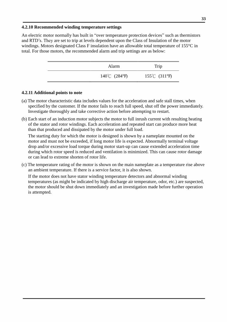
33
4.2.10 Recommended winding temperature settings
An electric motor normally has built in “over temperature protection devices” such as thermistors
and RTD’s. They are set to trip at levels dependent upon the Class of Insulation of the motor
windings. Motors designated Class F insulation have an allowable total temperature of 155°C in
total. For those motors, the recommended alarm and trip settings are as below:
Alarm Trip
140℃ (284℉) 155℃ (311℉)
4.2.11 Additional points to note
(a) The motor characteristic data includes values for the acceleration and safe stall times, when
specified by the customer. If the motor fails to reach full speed, shut off the power immediately.
Investigate thoroughly and take corrective action before attempting to restart.
(b) Each start of an induction motor subjects the motor to full inrush current with resulting heating
of the stator and rotor windings. Each acceleration and repeated start can produce more heat
than that produced and dissipated by the motor under full load.
The starting duty for which the motor is designed is shown by a nameplate mounted on the
motor and must not be exceeded, if long motor life is expected. Abnormally terminal voltage
drop and/or excessive load torque during motor start-up can cause extended acceleration time
during which rotor speed is reduced and ventilation is minimized. This can cause rotor damage
or can lead to extreme shorten of rotor life.
(c) The temperature rating of the motor is shown on the main nameplate as a temperature rise above
an ambient temperature. If there is a service factor, it is also shown.
If the motor does not have stator winding temperature detectors and abnormal winding
temperatures (as might be indicated by high discharge air temperature, odor, etc.) are suspected,
the motor should be shut down immediately and an investigation made before further operation
is attempted.

34
5. MAINTENANCE
5.1 Major points in regular inspection and maintenance
Maintenance and repairs must only be carried out by properly trained personnel.
Some testing, such as insulation resistance, usually requires the motor to be stopped
and isolated from power supply(ies).
Routine inspection and maintenance are usually performed visually, audibly, by odor, and by means
of simple meters.
High temperature may arise under operating conditions on the motor surfaces, so
touching should be prevented or avoided.
Keep away from moving and live parts.
Unless deemed necessary, do not remove guards while assessing the motor.
Timely replacement of worn parts can assure longevity and prevent breakdown.
Routine and regular inspection and maintenance are important in preventing breakdown and
lengthening service life.
Owing to the varied time and circumstances motors are used, it is difficult to set the items and
periods for regular inspection and maintenance. However, as a guide it is recommended to be
performed periodically according to factory maintenance program. Generally, the inspection scope
is determined by the following factors:
(a) Ambient temperature and ambient conditions (dust, humidity, other contamination).
(b) Starting and stop frequency.
(c) Troublesome parts usually affect motor dysfunctions.
(d) Easily abraded parts (slipring, brushes, earthing brushes).
(e) The important position of motor in the operational system should be duly recognized.
Therefore, its life time should be intact and fully protected, especially when it is operating in
severe conditions.

35
5.2 Motor windings
(a) Measurement of insulation resistance and standards to determine quality of insulation resistance,
please refer to measures stated in 4.1.2 "Measurement of insulation resistance".
(b) Inspection of coil-ends:
(1) Grease and dust accumulated on coils may cause insulation deterioration and poor cooling
effect.
(2) Moisture must not accumulate. Keep coils warm when motor is not in use (use space heater,
if it’s installed).
(3) Discoloring. This is mainly caused by overheating.
(c) Ensure no untoward change of wedges from original position occurs.
(d) Ensure the binding at the coil end is in its normal position.
5.3 Clean the interior of the motor (a) After a motor has been in operation for some time, accumulation of dust, carbon powder and
grease etc., on the inside is unavoidable, and may cause damage. Regular cleaning and
examination is necessary to assure top performance.
(b) Points to note during cleaning:
(1) If using compressed air or a blower:
a) Compressed air should be free of moisture. Be sure, that the dust and other materials can
come out of motor housing, iron core and windings.
b) Maintain air pressure below 4 kg/cm2, since high pressure can cause damage to coils.
(2) Vacuum
Vacuum cleaning can be used before and after other methods of cleaning, to remove loose
dirt and debris. It is a very effective way to remove loose surface contamination from the
winding without scattering. Vacuum cleaning tools should be non-metallic to avoid any
damage to the winding insulation.
(3) Wiping
Surface contamination on the winding can be removed by wiping using a soft, lint-free
wiping material. If the contamination is oily, the wiping material can be moistened (not
dripping wet) with a safety type petroleum solvent.
In hazardous locations, a solvent such as inhibited methyl chloroform may be used, but must
be used sparingly and immediately removed. While this solvent is non-flammable under
ordinary conditions, it is toxic and proper health and safety precautions should be followed
while using it.
ATTENTION!
Solvents of any type should never be used on windings provided with abrasion
protection. Abrasion protection is a gray, rubber-like coating applied to the winding
end-turns.

36
Adequate ventilation must always be provided in any area where solvents are being
used to avoid the danger of fire, explosion or health hazards. In confined areas (such
as pits) each operator should be provided with an air line respirator, a hose mask or a
self-contained breathing apparatus. Operators should wear goggles, aprons and
suitable gloves. Solvents and their vapors should never be exposed to open flames or
sparks and should always be stored in approved safety containers.
(4) Keep core ducts completely clean. The difference in temperature rise could be around 10℃
before and after cleaning.
(A) Riveted
(B) Welded with riveting films
(C) Welded with core bars
Fig. 19
5.4 Clean the exterior of the motor (a) On open ventilated motors, screens and louvers over the inlet air openings should not be allowed
to accumulate any build-up of dirt, lint, etc. that could restrict free air movement.
(b) If the motor is equipped with air filters, they should be replaced (disposable type) or cleaned and
reconditioned (permanent type) at a frequency that is dictated by conditions. It is better to
replace or recondition filters too often than not often enough. The Permanent type air filters can
be cleaned with fresh water, make sure to let them dry before reinstalling.
Disposable type filter fitted into two filter supports. Permanent type filter.
Fig. 20 Fig. 21
ATTENTION!
Screens and louvers should never be cleaned or disturbed while the motor is in operation
because any dislodged dirt or debris can be drawn directly into the motor.
Core ducts

37
(c) Totally enclosed air-to-air cooled and totally enclosed fan cooled motors require special cleaning
considerations. The external fan must be cleaned thoroughly since any dirt build-up not removed
can lead to unbalance and vibration. All of the tubes of the air-to-air heat exchanger should be
cleaned using a suitable tube brush having synthetic fiber bristles (not wire of any type).
(d) It is important to keep the external surfaces of any motor clean and free from buildup of dirt and
debris as this can function as an insulating blanket causing the motor to overheat drastically and
could reducing the life of the motor. Methods of cleaning external surfaces are: Scraping,
brushing, dry ice blasting etc.

38
5.5 Maintenance of anti-friction bearing
5.5.1 Frequency of relubrication
The life of grease varies greatly as a result of types of model, revolution speed, temperature,
operational conditions etc. It is, therefore, impossible to be precise about replenishment intervals.
However, for normal direct coupling transmission, the periods shown in Table 1 may be used as a
guide.
Remarks:
(a) The periods shown in Table 1 should be halved where bearings are used for belt drive
and/or in dirty, high ambient temperature or high humidity environments.
(b) Please refer to the lubrication nameplate, if attached to the motor.
(c) For bearing numbers outside the range of Table 1, please contact TECO-Westinghouse.
(d) If the periods referred to Table 1 for drive-end bearing and opposite drive-end bearing are
different, for the convenience of maintenance operation, one could take the shorter one
for re-greasing schedule.
5.5.2 Kinds of grease
ExxonMobil Polyrex EM grease is standard for TECO-Westinghouse motors except some special
models for which special grease will be shown on the lubrication nameplate. Please use identical
grease or its equivalents when maintaining.
ATTENTION!
Do not mix different kinds of grease.
Mixing grease with different types of thickeners may destroy its composition and
physical properties. Even if the thickeners are of the same type, possible differences in
the additive may cause detrimental effects.

39
Table 1
Bearing
number
600
RPM
720
RPM
750
RPM
900
RPM
1000
RPM
1200
RPM
1500
RPM
1800
RPM
3000
RPM
3600
RPM
62XX
63XX
72XX
73XX
6210
12 2000Hrs
13
14 1000Hrs
15
16 720 Hrs
17 2000Hrs
18 3000Hrs 500 Hrs
20
22
24 1500Hrs
26
28 2000Hrs 1000Hrs
30
32 500 Hrs
34 1500Hrs
36
38 2000Hrs 1000Hrs
Bearing
number
600
RPM
720
RPM
750
RPM
900
RPM
1000
RPM
1200
RPM
1500
RPM
1800
RPM
NU2XX
NU3XX
NU214
15 2000Hrs
16
17
18 3000Hrs 1500Hrs
20
22 1000Hrs
24
26 2000Hrs
28 500 Hrs
30
32
34 2000Hrs 1000Hrs
36
38 2000Hrs
40
44 1000Hrs 500 Hrs
48 1000Hrs
Bearing
number
600
RPM
720
RPM
750
RPM
900
RPM
1000
RPM
1200
RPM
1500
RPM
1800
RPM
222XX
223XX
22220 300Hrs
22
24 1000Hrs 500 Hrs
26
28
30 300 Hrs
32 500 Hrs
34
36
38 500 Hrs
40 300 Hrs
44
48 300 Hrs

40
5.5.3 Grease quantity
The amount of grease per replenishment depends on the type, size and construction of the bearings.
The minimum amount for replenishment of each bearing is shown in Table 2.
Table 2 Bearing No. Amount of
replenishment
Bearing No. Amount of
replenishment
62XX
72XX
NU2XX
222XX
6210 30g 63XX
73XX
NU3XX
223XX
6310 40g
6212 40 6312 60
6213 50 6313 80
6214 50 6314 80
6215 60 6315 100
6216 60 6316 100
6217 80 6317 120
6218 80 6318 120
6220 100 6320 160
6222 120 6322 220
6224 120 6324 270
6226 140 6326 300
6228 160 6328 400
6230 180 6330 450
6232 200 6332 500
6234 250 6334 600
6236 300 6336 700
6238 350 6338 800
6240 400 6340 900
6244 450 6344 900
6248 500 6348 900
Fill desirable however to regrease until it replaces and the old grease is entirely replaced. The
temperature of the bearing will initially increase because of the excess grease. After a few hours, the
excess grease will be expelled through the exit tube and the bearing temperature will return to
normal.
5.5.4 Re-greasing
If relubrication is to be performed when the motor is running, stay clear of rotating
parts.
It is advisable to re-grease while the motor is running to allow the new grease to be evenly
distributed inside the bearing.
Before re-greasing, the inlet fitting should be thoroughly cleaned to prevent any accumulated dirt
from being carried into the bearing with the new grease. The outlet or grease drain should be
opened to allow the proper venting of old grease.
Use a grease gun to pump grease through grease nipple into bearings slowly. After re-greasing,
operate the motor for 10-30 minutes to allow any excess grease to vent out.

41
5.5.5 Oil relubrication (For oil lubrication types only)
Maintain proper lubrication by checking the oil level periodically and adding oil when necessary.
Because of the initial clearing action of the bearing and the expansion of the oil as it comes up to
operating temperature, the oil level will be higher after the motor has been in operation for a while
than it is with the motor at standstill.
Overfilling should be avoided not only because of the possibility that expansion may force the oil
over the oil sleeve and on to the rotor, but also because too high an operating oil level prevents the
bearing from clearing itself of excess oil. The resultant churning can cause extra loss, high
temperatures, and oxidized oil. If, the oil level goes above the maximum shown on the sight gauge
during operation, drain enough oil to bring the level back within the recommended operating range.
Do not permit the operating level to fall below the minimum shown on the sight gauge.
Change the oil at regular intervals. The time between oil changes depends upon the severity of
operating conditions and, hence, must be determined by the motor user. Two or three changes a year
is typical, but special conditions, such as high ambient temperature, may require more frequent
changes. Avoid operating the motor with oxidized oil.
Use only good quality, oxidation-corrosion-inhibiting turbine oils produced by reputable oil
companies. The viscosity of the oil to be used depends upon the type and size of the bearing, its
load and speed, the ambient temperature, and the amount and temperature of the cooling water (if
used). The lubrication nameplate or instructions with each motor specifies the viscosity range of oil
suitable for average conditions. The usual oil viscosity recommendations are summarized in Table 3.
Operation in ambient temperatures that are near or below freezing may require preheating the oil or
the use of special oil. Whenever the motor is disassembled for general cleaning and reconditioning,
the bearing housing may be washed out with a suitable cleaning solvent. Be sure that the oil
metering hole is clear, and then dry the housing thoroughly before reassembly, and ensure all traces
of cleaning solvent have been removed.
Table 3 oil viscosity for vertical motors**
Bearing Type Oil viscosity Range of pole
Angular contact ball
(72XX,73XX)
ISO VG32
(150 SSU/100℉) 2 pole
ISO VG68
(300 SSU/100℉) 4 pole and above
Spherical roller
(293XX,294XX)
ISO VG68
(300 SSU/100℉) 4 pole
ISO VG150
(700 SSU/100℉) 6 pole and above
**Note: Where a lubrication nameplate is attached to the motor, use the lubrication oil it stipulates.
ATTENTION!
Should it ever become necessary to add excessive amount of make-up oil, investigate
immediately for oil leaks.

42
5.5.6 Cleaning and installation of bearings
(a) Apply the proper amount of grease to disassembled parts of the bearing after they have been
thoroughly cleaned with high quality cleaning oil. Then protect them from contamination
before and during assembly.
(b) Bearing installation
Since the bearing is a high precision component, it is important to avoid ingression of dust and
foreign matter and hammering during cleaning and installation. Be extremely careful and
ensure clean conditions exist during installation and assembly.
The bearing should be heated in a bath of clean oil to a temperature of approx. 80℃ or using
an induction bearing heater with a temperature probe. After warming, slide the bearings in
place quickly and nimbly so that it does not shrink onto the shaft before being fully in position.
Take care to keep the bearing straight during installation and ensure it is properly seated
against the shoulder. Maintain pressure against the shoulder for several seconds to ensure it
does not slide back from the shoulder, or become “cocked” on the journal.
Grease the bearing after the temperature returns to normal, and then reassemble the motor.
ATTENTION!
Before installing the bearings, make sure that the shaft mounted parts behind the
bearings are in place before installation.
ATTENTION!
The best way for bearing installation is heat shrinking. Knocking and hammering during
installation should be absolutely avoided.

43
5.6 Maintenance of sleeve bearing
5.6.1 Daily inspections
(a) Ensure the volume and quality of lubricating oil are in compliance with specifications.
Fig. 22
(b) Ensure there is motion of the oil ring and it is not clamped, but free to rotate.
(c) The indicator of the shaft endplay should be restricted within the specified range of the red
groove of the shaft or the ±3mm range of the drive-end shaft shoulder. Otherwise the bearing
will be destroyed.
Fig. 23
5.6.2 Regular examination
(a) Periodical change of oil
The oil reservoirs of self (not flood) lubricated bearings should be drained and refilled about
every six (6) months. More frequent changes may be needed on high-speed (3600-rpm)
motors or if severe oil discoloration or contamination occurs. In conditions where
contamination does occur, it may be advisable to flush the reservoir with kerosene to remove
any sediment before new oil is added. Proper care must be taken to thoroughly drain the
reservoir of the flushing material before refilling with the new oil.
Refill the reservoir to the center of oil sight glass with a rust and oxidation inhibiting turbine
grade oil. Refer to the outline and lubrication nameplate for the correct viscosity.
(b) Quantity of lubrication oil
Please refer to the lubrication nameplate for oil quantity.
Upper limit
Lower limit
Standard
Oil level
Groove
Indicator
Drive-end
shaft shoulder
Indicator

44
(c) Oil viscosity for horizontal motors with sleeve bearings
Table 4 oil viscosity for horizontal motors
Oil viscosity Equivalents Range of
pole ESSO MOBIL
ISO VG32
(150 SSU/100℉) TERESSO 32 DTE OIL LIGHT 2 pole
ISO VG46
(200 SSU/100℉) TERESSO 46 DTE OIL MEDIUM 4 pole
ISO VG68
(300 SSU/100℉) TERESSO 68 OIL HEAVY MEDIUM
6 pole &
above
Note: Where a lubrication nameplate is attached to the motor, use the lubrication oil it stipulates.
5.6.3 Disassembly
Prior to disassembling, ensure the power supplies are disconnected and there are no
moving parts.
The bearing sleeve is of the spherically seated, self-aligning type. The opposite drive end bearing is
normally insulated on larger motors (or when specified). On some motors, the insulation is bonded
to the spherical seat of the bearing housing.
The following is the recommended procedure for removing the bearing sleeve:
(a) Remove the oil drain plug in the housing bottom and drain the oil sump.
(b) Remove all instrumentation sensors that are in contact with the bearing sleeve. These would
include resistance temperature detectors, thermocouples, thermometers, etc.
(c) Remove the socket head bolts holding the bearing cap and the inner air seal. The end cover
plate must also be removed if the non-drive end bearing is being disassembled. Remove the
bearing cap and top half of the inner air seal. Place them on a clean, dry surface to avoid
damage to the parting surfaces.
(d) Remove the top half of the bearing sleeve using suitable eyebolts in the tapped holes
provided. Lift the bearing top straight up and avoid any contact with the shoulders of the
shaft journals that might damage the thrust faces of the bearing. Place on a clean, dry surface
taking care to prevent damage to either the parting surfaces or the locating pins that are
captive in the top bearing half.
(e) Remove the screws at the partings in the oil ring and dismantle the ring by gently tapping the
dowel pin ends with a soft face mallet. Remove the ring halves and immediately reassemble
them to avoid any mix up in parts or damage to the surface at the partings.
ATTENTION!
Extreme care must be exercised in removing the bearing sleeve from the insulated
support to avoid damaging this insulation.

45
(f) Pull up on the garter spring surrounding the floating labyrinth seal and carefully slip out the
top half. Rotate the garter spring until the lock is visible. Twist counter-clockwise to
disengage the lock, remove the garter spring, and then rotate the lower half of the seal out of
the groove in the bearing housing. Note the condition of these floating labyrinth seals. If they
are cracked or chipped, they must be replaced. Do not attempt to reuse a damaged seal.
(g) To remove the bottom bearing half, the shaft must be raised a slight amount to relieve
pressure on the bearing. On the drive end, this can be done by jacking or lifting on the shaft
extension. Protect the shaft. On the non-drive end, jacking or lifting can be done using eye
bolts threaded into the tapped holes provided in the shaft end.
(h) Roll the bottom bearing half to the top of the shaft journal and then lift it using suitable eye
bolts threaded into the holes provided. Again avoid any contact with the shaft shoulders that
could damage the bearing thrust faces. Place the lower bearing half on a clean, dry surface to
protect the parting surfaces.
Use extreme care when rolling out the lower bearing half. Keep the hands and fingers
well clear of any position where they might be caught by the bearing half if it were
accidentally released and suddenly falls back to its bottom position. Serious personal
injury could result.
(i) Protect the shaft journal by wrapping it with clean, heavy paper or cardboard.
Fig. 24
5.6.4 Reassembly
Bearing reassembly is basically a reverse of the disassembly procedures outlined above, with the
following suggestion:
(a) The interior of the bearing housing should be cleaned and then flushed with clean oil or
kerosene.
(b) The bearing halves and the shaft journal should be wiped clean using lint-free cloth soaked
with clean oil.

46
(c) All parts should be carefully inspected for nicks, scratches, etc., in any contact surfaces.
Such imperfections should be removed by an appropriate method such as stoning, scraping,
filing, etc., followed by thorough cleaning.
(d) Before installing the halves of the floating labyrinth seal, observe their condition. Do not
attempt to use a cracked or chipped seal. The bottom half seal has a set of drilled holes in its
internal face. These must be placed at the bottom toward the inside of the bearing. Only in
this position the accumulated oil can drain back into the housing.
(e) Put a bead of Curil-T around the seal half O.D.’s on both sides adjacent to the angular spring
groove. This will prevent oil from by-passing the seal around its outside.
(f) Place the bottom seal half on top of the shaft and roll it into position. Install the top half and
insert the garter spring pulling up on both ends to permit engaging the lock. Run a bead of
Curil-T around the O.D.’s on both sides adjacent to the garter spring groove on this half also.
(g) Carefully reassemble the two oil ring halves. Inspect the dowel pins for burrs and
straightness and make any corrections required. Do not force the ring halves together.
Excessive force may alter the roundness or flatness of the oil ring which can change its oil
delivery performance. Once assembled, the oil ring should be measured to ensure it is round,
if it is not it should be repaired or replaced.
(h) Some of the pipe plugs in the housing are metric thread type. These are identified as those
which have a copper, lead, or similar material washer. If these plugs are removed, be careful
not to lose the washers. Before reassembly, inspect the washers and replace them as required.
(i) Before installing the bearing cap, observe the position of the floating labyrinth seal. The
“tab” must be on top to engage the pocket. Failure to position the seal properly will result in
damage when the cap is assembled.
5.6.5 Oil viscosity for vertical motors
Bearing Type Oil viscosity Range of pole
RENK Vertical Bearing
Inserts Type EV or
Kingsbury Type
ISO VG68
(300 SSU/100℉) 4 pole and above
ATTENTION!
(1) Curil-T is the only approved compound for use in the assembly of the bearings on
this motor. Other products may harden and impede the operation.
(2) During the reassembly of the bearing parts, a thin layer of Curil-T should be applied
to all gaskets and machined interface surface. This suggestion does not apply to the
machined surfaces of the bearing liner halves.
(3) When seating the bearing shell, apply a thin layer of lube oil at the spherical surface
of the liner. Slowly roll the lower bearing liner into the bearing housing making sure
the split surfaces of the liner and the housing are flush. Gradually lower the shaft
onto the bearing. The weight of the shaft will help rotate the bearing liner so that the
babbitt surface of the liner will match the slope of the journal. Sometimes it is
required to use a rubber mallet to tap lightly on the bearing housing while slowly
rolling the shaft to help this seating operation.

47
5.7 Maintenance of slip ring (For Wound Rotor only)
Ensure motor is disconnected from power supplies and there are no accessible
moving parts before maintenance operation.
5.7.1 Adjustment of carbon brush
(a) Brush pressure for normal operation:
Electro-graphite brush
160 g/cm2 ±10% (for slip ring with spiral groove)
200 g/cm2 ±10% (for slip ring without groove)
When frequent vibrations are evident or the brush is small (area below 0.5 cm2), the
pressure should be greater than as shown.
(b) Adjustment of brush pressure:
The brush pressure should be adjusted to keep normal operation as it wears.
The brush pressure may be reduced after use, so it is necessary to re-adjust. For adjustment,
please turn adjusting screw, pressure adjusting pin or pressure adjusting plate as shown in
Fig.25 to obtain the correct tension (=0.23×brush cross sectional area in cm2) ±10% kg.
Fig. 25
(c) Brush pressure need not be adjusted if constant force spring is used as shown in Fig.26 and
Fig. 27.
Fig. 26 Fig. 27
Pressure
adjusting pin
Brush gear Constant
force spring

48
5.7.2 Brush replacement
The carbon brush is a part of the equipment which is easily worn away, replace it after it is worn to
1/2~3/5 of original size.
(a) Brush material
The brush material is important to the performance of the motor. Only the most appropriate
materials are chosen by TECO-Westinghouse, and are listed on the nameplate of motor. It is
important to know this when you replace the brush, only the recommended type and grade
should be used.
(b) Dimensions
Brush, holder and gap between them, please refer to CNS 2322 C4051 or JIS C2802.
(c) Adjustment of new brushes (Shown in Fig.28)
(1) Polish the new brush with sandpaper until it assumes the appropriate contour of the slip
ring which it touches.
(2) Place sandpaper (JIS R6252 NO.40…..50) on the slip ring with the abrasive face of the
paper against the brush to induce a closer contact by rubbing against each other.
(3) Repeat item 2 with fine sand-paper (JIS R6252 NO. 100 to 200) until the contact surface
between brush and slip ring exceeds 80%.
(4) Finally, clean the contaminated slip ring and brush with clean cloth or vacuum.
Fig. 28
Sandpaper
Slip ring Carbon brush
Brush holder
ATTENTION!
The gap between a brush and its holder is important for good performance and safety of
the motor.

49
5.8 Maintenance of non-reverse ratchet mechanism
(For Vertical high Thrust Motor only)
5.8.1 Non-reverse ratchet mechanism
In the pump piping system, a check valve and a stop valve should be installed in the discharge line.
The check valve, placed between the pump and the stop valve, is to protect the pump from reverse
flow and excessive back pressure. The stop valve is used in priming, starting and when shutting
down the pump. It is advisable to close the stop valve before stopping the pump. This is especially
important when the pump is operated against a high static head.
TECO-Westinghouse vertical high thrust motors are equipped with non-reverse ratchet (N.R.R.)
mechanism only when requested by the pump manufacturer. Typical construction of N.R.R.
mechanism is shown as Fig.29 below.
(A) Pin type N.R.R. (B) Ball type N.R.R.
Fig. 29
ITEM NAME
104 RATCHET
214 BEARING SEAT
402 EXTERNAL FAN
704 RATCHET PIN CARRIER
816 RATCHET PIN(BALL)

50
The N.R.R. mechanism keeps the pump and motor from rotating in the reverse direction. Thus
prevents damage from over speeding and damage to water-lubricated pump shaft bearings when, on
shutdown, the falling water column tends to drive the pump in the reverse direction.
In normal operation, the ratchet pins are lifted by the ratchet teeth and are held clear by centrifugal
force and friction as the motor comes up to speed. When power is removed, the speed decreases and
the pins fall. At the instant of reversal, a pin will catch in a ratchet tooth and prevent backward
rotation.
5.8.2 Service life
The service life of ratchet pins depends not only on the reverse shock load between the pin and
ratchet tooth when pump stopped but also the frequency of pump starting and stop in application.
Over time the pins can become deformed due to this reverse shock load, causing the up and down
motion of ratchet pins to become sluggish or jammed and unusual noises will arise.
The recommended replacement period for these ratchet pins is every three (3) years. If the reverse
shock load is greater than 30% of motor rated torque or the starting frequency is more than twice
per day, then the replacement period is to be halved.
5.9 Dismantling and Assembly Procedure
Please see the drawing in Appendix 4.
Brackets
w/anti-friction
bearing
Dismantling brackets Assembly
TEFC 1. Remove the fan cover & outer fan.
2. Remove securing bolts between the bearing
cover-outer (22) and the bracket (18).
3. It may be necessary to remove any seals /
grease flingers / temperature sensors etc
attached to the shaft or housings.
4. Pull out the bearing cover-outer (22) very
carefully.
5. Remove securing bolts hold between the
bracket (18) and frame (12).
6. Pull out the bracket (18) gently.
1. Check the bearing assembly.
Keep each part very clean.
2. Tighten securing bolts by
reverse step of dismantling.
ATTENTION!
The check valve and stop valve in the discharge line should be regularly inspected and
maintained to assure the normal function of these valves. This is important to protect the
pump and motor from damage and increase the service life of the N.R.R. mechanism.

51
5.10 Records of operation and maintenance
5.10.1 Objective
(a) Fully understand the purpose of the motors in operation and discover any abnormalities in
advance.
(b) Prevent negligence and omissions in maintenance.
(c) Map pertinent maintenance plans after fully understanding the operation of the motor.
(d) Access the life of the depreciating parts to determine the amount of spare parts to be kept.
(e) Plan the amount of spare motors and replacement parts to repair the motors in operation
according to actual situation and schedule.
5.10.2 Records of operation
(a) It is advisable to use a primed form with yes/no or right/wrong selections for the operator to
easily fill out.
(b) Principle contents:
(1) Serial number of machine.
(2) Load machine type.
(3) Models and specifications of motors.
(4) Three-phase voltage.
(5) Three-phase current.
(6) Temperature of a motor and bearings when in operation.
(7) Ambient temperature, humidity, weather, date and time.
(8) Time of start and stop.
(9) Special remarks.
(10) Operator’s name.
5.10.3 Maintenance records
(a) It is advisable to use a primed form with yes/no or right/wrong selections for the operator to
easily fill out.
(b) Principle contents:
(1) Serial number of machine.
(2) Load machine type.
(3) Models and specifications of motors.
(4) Ordinary operating conditions and data.
(5) Cause, date and disposition measures at breakdown.
(6) Quantity and name of replaced spare parts.
(7) Date of maintenance and initial operation.
(8) Items and date of maintenance.
(9) Special remarks.
(10) Name of maintenance personnel.

52
6. FAULT FINDING AND RECOGNITION
Type of
Breakdown Symptoms Possible causes Remedies
Fail to start
without load
Motionless and
soundless
Power-off Consult power company
Switch-off Switch-on
No fuse Install fuse
Broken wiring Check wiring and repair
Broken lead Check wiring and repair
Broken windings Check windings and repair
Fuse blowing.
(Automatic
switch trips off,
slow start with
electromagnetic
noise)
Short circuit of circuit switches Check circuit switches and replace
Incorrect wiring Check wiring according to nameplate
Poor contact at terminals Lock tightly
Windings grounded Factory repair
Broken windings Factory repair
Poor contact of circuit switches Check and repair
Broken wiring Check and repair
Poor contact of starting switches Check and repair
Short circuit of starting switches Check and repair
Incorrect connections of starting
switches
Connect according to nameplate
Loading
after start
Fuse blowing.
Fail to restart
due to trip-off of
automatic switch
Insufficient capacity of fuse Replace fuse if wiring permits
Overload Lighten load
High load at low voltage Check circuit capacity and reduce
load
Overheating
motor
Overload or intermittent overload Lighten load
Under-voltage Check circuit capacity and power
source
Over-voltage Check power source
Ventilation duct clogged Remove the foreign matter in the
duct
Ambient temperature exceeds 40C Correct insulation class F, or lower
ambient temperature.
Friction between rotor and stator Factory repair
Fuse blown (Single-phase rotating) Install the specified fuse
Poor contact of circuit switches Check and repair
Poor contact of circuit starting
switches
Check and repair
Unbalanced three-phase voltage Check circuit or consult power
company

53
Kinds of
Breakdown Symptoms Possible causes Remedies
Loading
after start
Speed falls
sharply
Voltage drop Check circuit and power source
Sudden overload Check machine
Single-phase rotating Check circuit and repair
Switch overheat Insufficient capacity of switch Replace switch
High load Lighten load
Bearing
overheating
Lack of oil Add oil
Lack of grease Add grease
Misalignment between motor and
machine shafts
Re-align
Over speed of bearing outer-ring Adjust bracket
High bearing noise Replace the damaged bearing
Noise
Electromagnetic
noise induced by
electricity
Occurrence from its first operation May be normal
Sudden sharp noise and smoking Short circuit of windings
Should be repaired at factory
Bearing noise
Churning sound May be normal noise from grease
circulating through the bearing
Rattling noise as result of poor
lubrication
Add Grease
Larger noise
Inspect cause -replace the damaged
bearing
Mechanical
noise caused
by machinery
Loose belt sheave Adjust key and lock the screw
Loose coupling or skip Adjust the position of couplings, lock
key and screw
Loose screw on fan cover Lock fan cover screw tightly
Fan rubbing Adjust fan position
Rubbing as a result of ingression of
foreign matters
Clean motor interior and ventilation
ducts
Wind noise Noise induced by air flowing through
ventilation ducts
Induced by conveyance machine Repair machine
Vibration
Electromagnetic
vibration
Short circuit of windings Factory repair
Open circuit of rotor Factory repair
Mechanical
vibration
Unbalanced rotor Factory repair
Unbalanced fan Factory repair
Broken fan blade Replace fan
Unsymmetrical centers between
belt sheaves
Align central points
Central points of couplings not in
alignment
Adjust the alignment between motor
and driven equipment
Improper mounting installation Check mounting and alignment
Motor mounting bed is not strong
enough
Reinforce mounting bed
Mounting bed vibration caused by
near machines
Eliminate the vibration source near
motor
Remarks:
(1) Circuit switches: These include knife switches, electromagnetic switches, fuse and other
connection switch etc.
(2) Starting switches: These include Delta-Star starters, compensate starters, reactance starters,
resistor starters, starting controllers etc.

54
7. RECYCLE
7.1 Introduction
TECO obey its environmental and protection policies. TECO has always been committed through
the use of recyclable and life cycle analysis of the results to improve environmental protection
products. Products, production processes or flow designs are all reflected the concept of
environmental protection. TECO's environmental management system through the ISO 14001
certification is used to implement an environmental policy tool.
The following guidelines only deal with the suggestions of environmental treatment on the
equipments. Customer shall be responsible for compliance with local regulations. This manual may
not include some of the customer's specific content. Project document provides additional
documentation.
7.2 Materials Average Content
When producing electrical equipments, the average material content used are as follows:
Material Die-casting frame
Induction machinery
Steel plate frame Induction
Machinery
Steel 45 – 56 % 79 - 83 %
Copper 8 – 10 % 12 – 14 %
Cast iron 32 – 43 % 1 – 3 %
Aluminum 0 – 5 % 0 - 1 %
Insulation materials 1 - 2 % 2 – 4 %
Stainless steel Below 1 % Below 1 %
Other Below 1 % Below 1 %
7.3 Packing Materials Recycling
When the equipments arrived to the place, the packing materials should be removed.
• All wood-made packing materials can be burned.
• The packing materials used with impregnated wood at sea shipping for some country must be
recycled according to local regulations.
• The plastic materials around equipments can be recycled.
• The anticorrosive agent covered on the surface of equipments can be cleaned by
gasoline-based cleaner or wipers. Treating the wipers must be complied with local regulations.
7.4 Equipment of disassembling
Disassembling equipment is a basic operation because equipment is assembled by bolts. However,
due to the heavy weight of equipment, the operator must be required to have received training in
handling the transportation of heavy loads to avoid any danger.

55
7.5 Classification of different materials
7.5.1 Frame, Bracket (bearing housing), Cover and Fan
These parts are made of structural steel and can be recycled according to local regulations. All of
auxiliary equipment, cables and bearings must be removed before melting.
7.5.2 Parts with electrical insulation
The stator and rotor are the main part of machinery included electrical materials. Some auxiliary
parts also included similar materials and should be used the same methods to dispose. These
materials include each insulator in outlet box, exciter, transformer with adjustable voltage and
current function, cables, wires, corona discharger and capacitor. Some parts are used for
synchronous machineries and some used for few equipments.
All of these parts are in an inert state when equipments were completed.
Some parts (especially the components into stator and rotor) including a large number of copper can
be separated by appropriate heat treatment and the organic adhesive materials in insulation
materials can be gasified. In order to ensure proper gas combustion, burner should provide an
appropriate supplementary burner. In the combustion process of heat treatment, following
conditions are recommended to minimize the material distributed processing:
Temperature of Heat treatment:380- 420°C (716- 788°F)
Duration:Processing object should be kept at that temperature for at least 5 hours when reaching to
90% of target temperature.
Supplementary gas combustion temperature for adhesives smoke: 850-920 ° C (1562-1688 ° F)
Flow rate: adhesives smoke in the combustion chamber should be kept at least three seconds
Note: The distribution of substances include O2, CO, CO2, NOx, CxHy gas and micro-particles.
User shall be responsible to ensure that the process comply with local regulations.
Note: You should pay particular attention to thermal processes and heat treatment equipment
maintenance, so as not to bring fire or explosion hazard. Since this work will use a variety of
devices, so TECO cannot provide a detailed maintenance guideline for treatment process or
equipment, customers will be responsible for dealing with these issues.
7.5.3 Permanent Magnet
If permanent magnet synchronous machineries will be totally melted, it’s no need to deal with the
permanent magnets.
In order to achieve a more complete recovery and removal of equipment or if the rotor will be sent
out after recovery, we suggest doing permanent magnet demagnetization. Rotor can be heated in the

56
furnace until the temperature of a permanent magnet reaches 300 °C (572 °F) to achieve degaussing
purpose.
Open or disassemble permanent magnet synchronous machinery or remove the rotor
of such equipment will produce stray magnetic fields. It may interfere with or
damage to other electrical or electromagnetic devices and components, such as
cardiac pacemakers, credit cards and more.
7.5.4 Hazardous Waste
The grease in oil lubrication system is hazardous waste and must be treated by local regulations.
7.5.5 Buried Waste
All insulation materials can be treated as landfill waste.

57
Appendix 1. Daily inspection
Checking
point
Checking
item
Description or
inspection parts
Method Criteria or notes
1. Bearing Oil supply Oil quantity Check oil level from oil
sight gauge.
In the middle of oil sight
gauge.
Oil pressure
(forced oil
lubrication only)
Check oil supply pressure
gauge near inlet pipe or
supply unit.
Within ±20% of
specified pressure.
Oil ring rotation
(horizontal sleeve
bearing only)
Check oil ring from
window at 12 o’clock.
Rotating smoothly
Oil leakage Shaft、labyrinth
seal、piping
connection、parting
line of housing
Inspect by eye and touch
by hand.
Dampness around
housing is normal. But
oil accumulation on floor
should be checked.
Temperature Bearing temperature
detector
Check the value is the
same as normal. Recommendation:
See 4.2.8
End play Axial fluctuation of
shaft
Inspect by eye. The shaft shoulder
should not touch the
liner.
Magnetic center Inspect the magnetic
center pointer on drive
end.
±3mm
Vibration Ref to 4.2.9 If the vibration level is
higher than normal,
please measure the
spectrum by instrument.
Analyze the spectrum.
Noise Ref to 4.2.9 Listen for unusual noise Assess noise , stop and
inspect if necessary
2. Stator Temperature Winding
temperature detector
Check the value is the
same as normal. Recommendation:
See 4.2.10
Load Voltage、current Check the value from
control panel Voltage variation<10%
Current<rated current
3. Cooler Water supply Water quantity Check the water flow
relay or indicator &
temperature.
The water flow rate and
temperature limitations
are shown on outline
drawing.
4. Filter Dust or
pollution
Clean filter Clean by fresh water Clean filter
5. Others Odor Windings &
Bearings
Check winding and
bearing temperature
monitors
Check load / cooling air
flow, oil condition.

58
Appendix 2. Monthly inspection
Checking
point
Checking
item
Description or
inspection parts
Method Criteria or notes
1. Bearing Oil supply Oil quantity Check oil level from oil
gauge.
In the middle of oil
gauge. If the oil quantity
is low , please add oil
and check for leaks
Oil leakage Shaft、labyrinth
seal、piping
connection、parting
line of housing
Inspect by eye and touch
by hand.
If oil is leaking, it is
important to find the root
cause.
2. Stator Temperature Winding
temperature
detector
Check the value if the
same as normal. Recommendation:See
4.2.10
Appearance Bolts/nuts for
bracket or frame
etc.
Inspect by eye and touch
by hand.
Re-tighten all loose.
Resistance Winding 500VDC/1000VDC
megger.
Once every three months
at least.
Ref to “Operation” 4.1.2
measurement of
insulation resistance.
3. Cooler Water
supply
Water quantity Check the water flow relay
or indicator &
temperature.
The water flow rate and
temperature limitations
are shown on outline
drawing.
4.Coupling Appearance Bolts/nuts Inspect by eye and touch
by hand.
Re-tighten all loose
bolts.
5. Space
heater
Resistance Heater wire 500VDC megger. Ref to “Operation” 4.1.2
measurement of
insulation resistance.

59
Appendix 3. Regular Inspection
item Checking
point
Description Regular inspection
In situ
Exterior
surface
inspection
In situ
Open
inspection
Removed for
Disassembly
inspection
1. In
spectio
n b
efore d
isassembly
(1) Vibration Measure and record the vibration
levels for reference ○ ○ ○
(2) Temperature Record bearing, winding &
ambient temperature for reference. ○ ○ ○
(3) Coupling Measure the mounting and shaft
end dimensions. Check if any bolts
are loose. Check if there are any
mounting hole, key & keyway
deformation.
○
(4) Alignment Check and record the alignment for
reference
○
(5) Anchor bolt,
mounting
bolt & nut
Check if there are any parts loose.
Check condition of all nuts , bolts,
Replace if defective.
○ ○
(6) Adjusting
shims
Check if rusty, damaged and
replace if damaged.
○
(7) Shaft
vibration
Measure the shaft vibration value
and record.
○
(8) Foundation
level
Check for any deformation that
may have occurred.
○
(9) Air gap Measure this value and record in 3
places at least for each end.
○
2. Sleeve
bearing
inspection
Sleeve
bearing
According to RENK “Instructions
for Maintenance and Inspection”.
○ ○
3. S
tator in
spectio
n
(1) Winding
resistance
Use 500VDC/1000VDC megger to
measure and record results. ○ ○ ○
(2) Winding
appearance
Check if any dust or oil
contamination on winding coil
○
(3) Coil end Check coils for loose blocking,
lashings, end rings.
○
(4) Coil
insulation
Check coil insulation material for
wear, discolouration or damage
○
(5) Cable lead Check if lead insulation broken,
cracked or damaged.
○
(6) Terminal
lug
Check for loose or damaged lugs
or terminals.
○
(7) Coil wedge Check for loose or damaged slot
wedges.
○
(8) Air guide Check each bolt & nut to see if any
is loose.
○

60
Appendix 3. Regular Inspection (continue)
item Checking
point
Description Regular inspection
In situ
Exterior
surface
inspection
In situ
Open
inspection
Removed for
Disassembly
inspection
4. R
oto
r
insp
ection
(1) Rotor
appearance
Check if any dust or oil
contamination is on rotor.
○
(2) Rotor bar Check for loose or damaged bars
Check rotor bar end ring welds.
○
(3) Rotor core Check for loose or damaged
laminations.
○ ○
5. Fan Fan Check welded portions for cracks,
bolts & nuts, any built up dirt or
rust.
○
6. In
spectio
n b
efore o
peratio
n
(1) Winding
resistance
Use 500VDC/1000VDC megger to
measure, record results. ○ ○ ○
(2) Supply lead
connection
Check all incoming supply leads
correctly connected.
○ ○
(3) Protection
relay
Check protection relay in normal
operation. ○ ○ ○
(4) Lubrication
oil
Oil level at the middle of oil gauge.
Oil inlet pressure correct and oil
drains smoothly.
○ ○ ○
(5) Alignment Check and record the alignment. ○
(6) Anchor bolt
& mounting
bolt
Check all mounting bolts are
securely tightened.
○ ○
(7) Driven
equipment
Check if all driven equipment is
ready for operation. ○ ○ ○
(8) Cooling
water
Check cooling water flow rate &
quantity. ○ ○ ○
7. In
spectio
n b
efore startin
g
(1) Rotational
direction
Check rotational direction. ○ ○ ○
(2) Oil ring Check if oil ring runs smoothly. ○ ○ ○
(3) Noise Check there is no abnormal noise. ○ ○ ○
(4) Vibration Check if vibration is normal. ○ ○ ○
(5) Bearing
temperature
For test run, please keep
monitoring for 2hrs at least. ○ ○ ○
(6) Oil level Check oil level. ○ ○ ○
(7) Current Make sure current is below rated
value shown on nameplate. ○ ○ ○

61
Note:
(a) Disassembly inspection:removing the rotor to inspect the stator & rotor.
Recommendation:every four (4) years, but depends on operation environment conditions &
machine type.
(b) Open inspection:inspect the maximum possible portions without removing rotor.
Recommendation:every two (2) years, but depends on operation environment conditions &
machine type.
(c) Exterior surface inspection
Recommendation:every year.

62
Appendix 4.Typical motor cross sectional drawings:SCIM, TEFC
Item Name Item Name
01 FAN COVER(N.D.E) 14 ROTOR
02 EXTERRAL FAN 15 EYE BOLT
03 DUST FLINGER 16 BEARING COVER-INNER
04 BEARING COVER-OUTER 17 GREASE FLINGER
05 GREASE FLINGER 18 END BRACKET
06 GREASE NIPPLE 19 BEARING
07 END BRACKET 20 GREASE NIPPLE
08 BEARING 21 GREASE FLINGER
09 GREASE FLINGER 22 BEARING COVER-OUTER
10 BEARING COVER-INNER 23 DUST FLINGER
11 INNER FAN 24 SHAFT
12 FRAME 25 SHIFT END KEY
13 STATOR

63
Appendix 5.Typical motor cross sectional drawings:ODP
Item Name Item Name
01 BEARING COVER-OUTER 12 R CORE
02 GREASE FLINGER 13 RETAINER RING-S
03 GREASE NIPPLE 14 RETAINER RING-R
04 BRACKET 15 BRACKET
05 BEARING 16 BEARING COVER-INNER
06 STOP RING-BEARING 17 STOP RING-BEARING
07 BEARING COVER-INNER 18 BEARING
08 AIR GUIDE 19 BEARING COVER-OUTER
09 INNER FAN 20 INPRO SEAL
10 FRAME 21 SHAFT
11 S CORE 22 KEY

64
Appendix 6.Typical motor cross sectional drawings:SCIM, TEWC
Item Name Item Name
01 COVER 10 S CORE
02 FLANGE-BRACKET 11 FRAME-INNER
03 PRE-LOAD SPRING 12 FRAME-OUTER
04 BEARING 13 BEARING COVER-INNER
05 GREASE FLINGER 14 GREASE FLINGER
06 EYE BOLT 15 BEARING
07 BEARING COVER-INNER 16 FLANGE BRACKET
08 BEARING COVER-INNER 17 SHAFT
09 ROTOR 18 KEY

65
Appendix 7. Typical ball bearing construction drawing
Item Name Item Name
1 Ball Bearing 6 Grease Nipple & Pipe
2 Grease Flinger-Inner 7 Shaft
3 Bearing Cover-Inner 8 Bracket
4 Grease Flinger-Outer 9 Dust Flinger
5 Bearing Cover-Outer
Please be noted:
1. Use sealing compound on screws (A) and the surface between parts (B).
2. In order to avoid abnormal bearing noise, please fill new grease as full as possible between races
during the change process of bearing.

66
Appendix 8. Typical roller bearing construction drawing
Item Name Item Name
1 Roller Bearing 5 Bearing Cover-Outer
2 Grease Flinger-Inner 6 Grease Nipple & Pipe
3 Bearing Cover-Inner 7 Shaft
4 Grease Flinger-Outer 8 Bracket
Please be noted:
1. Use sealing compound on screws (A) and the surface between parts (B).
2. In order to avoid abnormal bearing noise, please fill new grease as full as possible between races
during the change process of bearing.

67
Appendix 9. Typical ball bearing with insulation bushing construction drawing
Item Name Item Name
1 Ball Bearing 7 Shaft
2 Grease Flinger-Inner 8 Bracket
3 Bearing Cover-Inner 9 Insulation Plate
4 Grease Flinger-Outer 10 Insulation Bushing
5 Bearing Cover-Outer 11 Dust Flinger
6 Grease Nipple & Pipe
Please be noted:
1. Use sealing compound on screws (A) and the surface between parts (B).
2. In order to avoid abnormal bearing noise, please fill new grease as full as possible between races
during the change process of bearing.

68
Appendix 10. Typical thrust bearing assembly drawing (vertical machine)
Item Name Item Name
1 Thrust Bearing 8 Ratchet Pin Carrier
2 Ball Bearing 9 Ratchet Pin
3 Spring 10 Lock Nut
4 Insulation Bushing 11 External Fan
5 Oil Standpipe 12 Oil Lever Gauge
6 Upper Bearing Runner 13 Upper Bracket
7 Non-Reverse Ratchet
Please be noted:
Use sealing compound on spigot of oil tank (A), between non-reverse ratchet (item 7) and upper
bracket (item 13).

69
Appendix 11. Sleeve bearing construction

70
Item Name Item Name
1 Top half of the housing 2 Positioning pin nut
3 Plate ( Assembly opening ) 4 Screw
5 Eye bolt 6 Positioning pin
7 Top sight glass 8 Top half of the shell
9 Screw 10 Machine seal
11 Hemp packing seal groove 12 Hemp packing
13 Screw(split line of the housing)
14 Screw (split line of the machine seal)
15 Bottom half of the shell 16 Tapped hole
17 Bottom half of the housing 18 Recess
19 Pressure equalizing hose 20 Screw (split line of the shell)
21 Screw 22 Spherical seating
23 Tapped hole for temperature measurement of the journal part
24 Oil inlet connection hole
25 Tapped hole for the oil sump temperature measurement
26 Outlet/Inlet cooling water (optional)
27 Cooler (optional)
28 Hexagon head plug (Oil drain plug)
29 Metal tabs ( optional for EMZL. )
30 Oil outlet connection hole
31 Oil outlet pipe

71
Appendix 12. Mounting of Insulated Sleeve Bearings
Please be noted:
Generally, a pedestal bearing is insulated by means of insulating washers or insulating bushes.
(Right hand side of drawing)
Upon request insulated E bearings can be supplied. In this case the spherical seating which
accommodates the bearing shell is covered with a non-conductive plastic foil. (Left hand side of
drawing)
Insulation

72
Appendix 13. Shaft earth brush assembly drawing (TAC)
Item Name Item Name
010 Brush 030 Plain Washer
020 CR C SCREW 040 T Lock Washer

73
Appendix 14. Shaft earth brush assembly drawing (TECO)
Item Name Item Name
010 Support 060 Plain Washer
020 Hex Bolt 070 S Washer
030 S Washer 080 Hex Nut
040 Brush Holder 090 Brush Spring Assembly
050 Hex Bolt 100 Brush
Please be noted:
Directly connect grounding by a separate wire between one of M6 tap holes (A) on brush holder
(item 040) and earth is highly recommended.

74
Appendix 15. Bolt Torque (kg-cm)
BOLD
SIZE
THREAD
PITCH
MILD STEEL (property class 4.6 or 4.8) BRASS
WITHOUT SPRING
WASHER
WITH SPRING
WASHER
WITHOUT SPRING
WASHER
M4 0.7 25~34 10~13 8.4~11.3
M5 0.8 38~52 20~25 16.2~22.0
M6 1.0 68~97 40~50 28~38
M8 1.25 161~230 90~110 68~91
M10 1.5 288~416 180~230 125~183
M12 1.75 462~660 320~400 230~310
M16 2.0 1010~1440 800~1000 560~760
M20 2.5 2100~3000 1600~2000 1090~1470
M24 3.0 3800~5400 2800~3500 1870~2500
M30 3.5 8000~11500 5800~7250 3800~5100
M36 4.0 14000~20000 10000~12500 6500~8800

75
Appendix 16. TECO Worldwide Operations
HEAD OFFICE Teco Electric & Machinery Co. Ltd
10F. No. 3-1 Yuan Cyu St.
Nan-Kang, Taipei 115
Taiwan R.O.C.
Tel: +886 2 6615 9111
Fax: +886 2 6615 2253
www.tecomotor.com.tw
UNITED STATES Teco-Westinghouse Motor Company
PO Box 227 (78680-0277),
5100 N.IH35 Round Rock Texas 78681 USA
Tel: +1 512 255 4141
+1 800 873 8326
www.tecowestinghouse.com
CANADA Teco-Westinghouse Motors Inc. (Canada)
18060-109th Ave
Edmonton, Alberta T5S 2K2 Canada
Tel: +1 780 444 8933
Fax: (780) 486-4575
24 HR Emergency Pager: (780) 419-7734
Toll Free: 800-661-4023
Fax Toll Free: 888-USE-TWMI
www.twmi.com
MEXICO
TECO-Westinghouse Motor Company, S.A. de
C.V.
CIRCUITO MEXIAMORA PONIENTE 321
PARQUE SANTA FE GUANAJUATO
PUERTO INTERIOR
SILAO, GUANJUATO CP 36275, Mexico
E-mail: [email protected]
Tel: +52 (472) 748 9016 al 20
CHINA Suzhou Teco Electric & Machinery Co., Ltd
No. 1 Changjiang W.Rd.South-Dam
Industrial Park Liuhe Zhen, Taicang City,
Suzhou
Jiangsu Province, PRC
Tel: +86 512 5361 9901
Fax: +86 512 5396 1058
Wuxi Teco Electric & Machinery Co., Ltd.
No. 9 South Of Changjiang Road, New Zone,
Wuxi
Jiangsu Province. PRC
Tel: + 86 510 8534 2005
Fax: +86 510 8534 2001
www.wuxiteco.com
Jiangxi Teco Electric & Machinery Co., Ltd.
1328 Jinggangshan Rd., Nanchang
Jiangxi, PRC
Tel:+86 791 641 3690
Fax:+86 791 641 4228
Shanghai Office: Rm 321 Building No.6
Lane 1279 Zhongshan W. Rd.
Shanghai P.R.C
Tel: +86 21 5116 8255
Fax: +86 21 6278 8761
HONG KONG Tecoson Industrial Development (HK) Co., Ltd.
Rm 3712 Hong Kong Plaza
186-191 Connaught Rd West, Hong Kong
Tel: +852 2858 3220

76
SINGAPORE Teco Electric & Machinery (PTE) Ltd.
18 Chin Bee Drive
Singapore 619865
Tel: +65 6 265 4622
Fax: +65 6265 7354
www.teco.com.sg
INDONESIA P.T. Teco Multiguna Elektro
JL Bandengan Utara No. 83/1-2-3
Jakarta Utara-14400 Indonesia
Tel: +62 21 662 2201
Fax: +62 21 6697029
MALAYSIA STE Marketing SdN Bhd.
Plo 52, Jalan Firma 2/1 Kawasan Perind.
Tebrau 1, 81100 Johor Bahru Johor Malaysia
Tel: +60 7 351 8862
Fax: +607 354 6107
THAILAND Teco Electric & Machinery (Thai) Co. Ltd.
128/1 Soi Watsrivareenoi
Moo 7 Bangna-Trad Road Km 18
Bangchalong Bangplee
Samuthprakarn 10540 Thailand
Tel: +662 3371630-1
VIETNAM TECO(Vietnam)Electric & Machinery Co., Ltd.
KCN LONG Thanh, Huyen Long Thanh, Tinh
Dong Nai.
Tel: 84-061-3514108
Fax: 84-061-3514410
JAPAN
Sankyo Co., Ltd.
26th fl. World Trading Center Bldg.
2-4-1 Hamamatsucho Minato-ku
Tokyo Japan 105-6126
Tel: +81 3 3435 9729
Fax: +81 3 3578 8381

77
AUSTRALIA Sydney Office
Teco Australia Pty Ltd.
335-337 Woodpark Road
Smithfield NSW 2164 Australia
Tel: +61 2 9765 8118
www.teco.com.au
Melbourne Office
Teco Australia Pty Ltd.
16 Longstaff Road
Bayswater VIC 3153 Australia
Tel: +61 3 9720 4411
Brisbane Office
Teco Australia Pty. Ltd.
50 Murdoch Circuit,
Acacia Ridge QLD 4110 Australia
Tel: +61 7 3373 9600
Perth Office
Teco Australia Pty Ltd.
28 Belgravia Street,
Belmont WA 6104 Australia
Tel : +61 8 9479 4879
NEW ZEALAND Teco New Zealand Pty Ltd.
Unit 3 / 477 Great South Road
Penrose Auckland New Zealand
Tel: +64 9 526 8480
MIDDLE EAST Teco Middle East Electric & Machinery Co.,
Ltd.
Kingdom of Saudi Arabia Dammam City
P.O. Box 708 - Dammam 31421
Tel: +966 3 835 2619
Fax: +966 3 834 1678
www.teco-me.com
NETHERLANDS Teco Electvic & Machinery B.V.
Teco’s European Head Office
Rivium 3e Straat 27
2909 LH Capelle a/d Ijssel
Netherlands
Tel: +31 10 266 6633
Fax: +31 10 202 6415
UNITED KINGDOM Teco Electric Europe Limited
7 Dakota Avenue, Salford. M50 2PU England
Tel: +44 161 877 8025
Fax: +44 161 877 8030
www.teco.co.uk
GERMANY Teco Electvic & Machinery B.V.
Niederlassung Deutschland
Marktstrasse 69
37441 Bad Sachsa Germany
Tel: +49 5523 95340
Fax: +49 5523 953424
www.teco-westinghouse.de
SPAIN Teco Electric & Machinery B.V.
Spain Office
C/Apostol Santiago, 38, 1º-1
28017 Madrid, Spain
Tel: +34 91 326 3091
Fax: +34 91 326 3091

78
TECO Worldwide Operations - Agents
KOREA Seorim Corporation
#915,Woolim Lion's Valley I,
311-3,Sangdaewon- dong,
Jungwon-gu,Seongnam-city,
Gyeonggi-do, Korea
Tel: 82-31-737-2311
Fax: 82-31-737-2312
www.seorimcorp.co.kr
PHILIPPINES Trade One
No. 56 Aragon Street San Francisco
Del Monte 1170 Quezon City Metro Manila,
Philippines
Tel:(632) 371-3032
Fax:(632) 371-1175
www.tradeoneinc.com
TAIAN.(SUBIC)
Phase I, Subic Bay Industrial Park Argonaut
Highway Corner Brave Heart St., Subic Bay
Freeport Zone Philippines 2222.
Tel: 63-47-252-1668
Fax: 63-47-252-3234
www.taian.com.ph
SOUTH AFRICA ArmCoil Afrika (Pty) Ltd.
Unit 3 Prestige Park 127 Main Reef Road
Technikon Roodepoort
PO Box 500 Maraisburg 1700
Gauteng South Africa
Tel:+2711 763 2351
Fax:+086 502 0086
www.armcoil.co.za
TUNISIA AFRICA COMPANY
RUE ENNASRIA, IMM. NAFOURA BLOC
A-2-1 SFAX EL JADIDA 3027 SFAX -
TUNSIE (TUNISIA)
Tel: +216 74 40 28 85
Fax: +216 74 4028 84
SAUDI ARABIA Al-Quraishi Electrical Services of Saudi Arabia
P.O.Box 7386-Dammam 31462
Kingdom of Saudi Arabia
Phone : +966-3-857-2537
Fax : +966-3-857-2541
www.aqesa.com
EGYPT Automation Management Solutions
38 Mossadak Street, Dokki, Giza, Egypt
Tel:+202 333 79 774
Fax:+202 376 20 307
JORDAN Sham Project’s Solutions
P.O. Box 2001
Amman 11821-Jordan
Tel: 962-6-5526-227
Fax: 962-6-5526-228
IRAN, AZERBAIJAN & ARMENIA ATLAS DIBA Engineering & Trade Co.
No.3, Fakouri St., South Kadj Ave.
Golha Sq., Fatemi, Tehran, Iran
Tel:+98 21 88 33 03 81-3
Fax:+98 21 88 33 03 84

79
For more information, please contact your local agent
or branch office of TECO-Westinghouse.
3A057D874E REV.04
2010. Dec.

June 2, 2021 Page 1/1 Preliminary
Date: June 2, 2021
Dimensional DrawingCatalogue Type HP RPM Voltage Hz Frame SizePDH2004 AEHH8N 200 1800 460 60 447T
MountingA B C CL1 CL2 D G
E 2F1 2F2 H BA9 20 0.81 7.5 22.05 23.25 49.9 11 1.4
J K L M O P TTerminal Housing
AA AB AC XB4.35 23.9 17.15 23.52 24.76 4.33 2-3 24.02 17.91 1.83
Shaft Extension Key KeyseatN-W U V Width Thick Length R8.5 3.375 8 0.875 0.875 6.93 2.88
BearingsWeight Lbs Drive Method Dimensions
DE NDE6320 6316 2004 Direct Coupling / Belt Drive Inches

3. Cooler


DatePage
1 Purchaser Ultimate User2 Inquiry / PO# Destination3 # Units Model Reference4 Assembly Draft Est. Overall Size, Ft Est. Wt. 3,950 LBS
THERMAL & MECHANICAL DESIGN5 Service EJW TAW/CW6 Flow 7.5GPM 7.5GPM7 Fluid 50%GLY 50%GLY8 Temp. In / Out, °F 179.0 / 120.7 167.5 / 108.79 Pressure, PSI
10 Pressure Drop, PSI .2 .411 Heat Load, BTU/HR 202950 20295012 True LMTD 48.4 36.613 Overall Rate, U 59.1 59.414 Fouling Factor .0005 .000515 Surface, Tube / Total, Sq Ft 72 / 1141 95 / 151016 Sections, # (1) - COMBINED (1) - COMBINED17 Design Temp, °F Max / Min 300 / -20 300 / -2018 MWP / Test Press, PSIG * 14 / 75 * 14 / 7519 Pass Arrangement CROSSFLOW CROSSFLOW20 # Tube Rows 3 321 # Tube Passes 4 622 Tubes, OD x BWG 5/8X16 5/8X1623 Material SA214 STEEL SA214 STEEL24 # Per Section / Length, Ft 65 / 7 86 / 725 Turbulators26 Accelerators27 Fins, Type HI-EFF HI-EFF28 Material AL AL29 Nozzles, Rating / Type CPLG CPLG30 Material SA105 SA10531 #-Inlets / Size In (1) 2 (1) 232 #-Oulets / Size In (1) 2 (1) 233 Headers, Type REC TUBE REC TUBE34 Material A500 A50035 Corrosion Allow, In36 Grooved Tubesheet SGL SGL37 Plugs, Type TAPER TAPER38 Plugs Material STEEL STEEL39 PWHT40 ASME Code & Nat'l Board41 CRN42 Add'l Specs & Options43 API44 Louvers / Hail Screen45 Inspection / NDT
46 Ambient Air Temp, In °F 90 Fan(s) (1) MOORE-S27-5KVT Type Guards47 Elevation, Ft 2500 Blade Material ALUMINUM48 Air Flow, SCFM 30,966 HP / Fan 9.349 Outlet Air Temp, °F 101.6 Dia, In / # Blades 60 / 450 Min Air Temp, °F -20 RPM 64051 Tipspeed, FPM 1005352 Est. Noise Data: Pitch, Deg 9
53 Additional Info.5455565758
NDT Legend FX= 100% X-Ray of all header & nozzle butt welds with UT of attachment welds.SX= Spot X-Ray of 1 long seam & 1 end closure, per header. BX = 100% X-Ray of all nozzle butt welds.UT = 100% UT of all header seam and nozzle attachment welds. H = Hardness testing.
CK57912F
6/9/2021Claremore, OK 74017
Phone (918) 283-9200
CORE
84 dBA @1m, 64 dBA @ 15m
*-BUILT TO STANDARD 50# DESIGN BUT DESIGNATED 14# TO AVOID THE NEED FOR PROVINCIAL REGISTRATION
V-BELT BY OTHERS
401 E. Lowry Road Proposal / Job No.
NEXT COMPRESSION
www.axh.com
FAN DATA
AXH air-coolers Fax (918) 283-9229
60VI
DRIVER DATA
200HP STOCK
STRUCTURALAIR-SIDE PERFORMANCE
INDUCED1
1 OF 1
PACKAGED SEE DRAWING

h

Frames 143T - 445T
INSTALLATION AND
MAINTENANCE INSTRUCTIONS
FOR THREE PHASE
INDUCTION MOTORS
18060 -109 Ave Edmonton, AB T5S 2K2Phone: 800-661-4023 780-444-8933 Fax: 888-873-8964

RECEIVING1. Check nameplate data.2. Check whether any damage has occurred during transportation.3. After removal of shaft clamp, turn shaft by hand to check that it turns freely.4. If motor is to be reshipped (alone or installed to another piece of equipment) the shaft must
again be clamped to prevent axial movement.Note: Remove the bearing clamp before turning the shaft on 284T-449T frame motors.
WARNINGTHE FOLLOWING SAFETY PRECAUTIONS MUST BE OBSERVED:1. Electric rotating machinery and high voltage can cause serious or fatal injury if improperly
installed, operated or maintained. Responsible personnel should be familiarized withNEMA MG2; Safety Standards for Construction and Guide Selection. Installation and Useof Electric Motors and Generators; National Electric Code and all local safety requirements.
2. When servicing, all power sources to the motor and to the accessory devices should be de-energized and disconnected and all rotating parts should be at standstill.
3. Lifting means, when supplied, are intended for lifting the motor only. When two liftingdevices are supplied with the motor a dual chain must be used.
4. Suitable protection must be used when working near machinery with high noise levels.5. Safeguard or protective devices must not be by-passed or rendered inoperative.6. The frame of this machine must be grounded in accordance with the National Electric Code
and applicable local codes.7. A suitable enclosure should be provided to prevent access to the motor by other than
authorized personnel. Extra caution should be observed around motors that areautomatically or have automatic re-setting relays as they may restart unexpectedly.
8. Shaft key must be fully captive or removed before motor is started.9. Provide proper safeguards for personnel against possible failure of motor-mounted brake,
particularly on applications involving overhauling loads.10. Explosion proof motors are constructed to comply with the label service procedure manual,
repair of these motors must be made by TECO-Westinghouse or CSA/UL Listed service center in order to maintain CSA/UL Listing.
LOCATION1. Drip-proof motors are intended for use where atmosphere is relatively clean, dry, well
ventilated and non-corrosive.2. Totally enclosed motors may be installed where dirt, moisture, or dust are present and in
outdoor locations.3. Explosion-proof motors are built for use in hazardous locations as indicated by
Underwriters label on the motor.4. Chemical duty enclosed motors are designed for installation in high corrosion or excessive
moisture locations.Note: in all cases, no surrounding structure should obstruct normal flow orventilating air through or over the motor.

MOUNTING1. Mount motor securely on a firm, flat base. All ball bearing normal thrust motors up to and
including 256T frame size may be side-wall or ceiling mounted; all others check nearestTECO-Westinghouse office for mounting recommendations.
2. Align motor accurately, using a flexible coupling if possible. For drive recommendations,consult with drive or equipment manufacturer, or TECO-Westinghouse.
3. Mounting bolts must be carefully tightened to prevent changes in alignment and possibledamage to the equipment. The recommended tightening torque s for medium carbon steelbolts, identified by three radial lines at 120 degrees on the head, are:
Recommended Torque (Ft-lb.)Bolt SizeMinimum Maximum
2/8 25 371/2 60 905/8 120 1803/4 210 320
4. V-belts Sheave Pitch Diameters should not be less than those shown in Table 1 (NEMArecommended values)
5. Tighten belts only enough to prevent slippage. Belt speed should not exceed 5000 ft. permin.
TABLE 1. V-Belt Sheave Pitch Diameters (MG1-14.42)V-Belt Sheave
Conventional NarrowA, B, C, D AND E 3V, 5V, AND 8V
Horsepower atSynchronous Speed, RPMFrame
Number 3600 1800 1200 900
MinimumPitch
DiameterInches
*MaximumWidthInches
MinimumOutside
DiameterInches
**MaximumWidthInches
143T 1.5 1 .75 .5 2.2 4.25 2.2 2.25145T 2-3 1.5-2 1 .75 2.4 4.25 2.4 2.25182T 3 3 1.5 1 2.4 5.25 2.4 2.75182T 5 2.6 5.25 2.4 2.75184T 2 1.5 2.4 5.25 2.4 2.75184T 5 2.6 5.25 2.4 2.75184T 7.5 5 3.0 5.25 3.0 2.75213T 7.5-10 7.5 3 2 3.0 6.5 3.0 3.375215T 10 5 3 3.0 6.5 3.0 3.375215T 15 10 3.8 6.5 3.8 3.375254T 15 7.5 5 3.8 7.75 3.8 4254T 20 15 4.4 7.75 4.4 4256T 20-25 10 7.5 4.4 7.75 4.4 4256T 20 4.6 7.75 4.4 4284T 15 10 4.6 9 4.4 4.625284T 25 5.0 9 4.4 4.625286T 30 20 15 5.4 9 5.2 4.625

TABLE 1. V-Belt Sheave Pitch Diameters (MG1-14.42)V-Belt Sheave
Conventional NarrowA, B, C, D AND E 3V, 5V, AND 8V
Horsepower atSynchronous Speed, RPMFrame
Number 3600 1800 1200 900
MinimumPitch
DiameterInches
*MaximumWidthInches
MinimumOutside
DiameterInches
**MaximumWidthInches
324T 40 25 20 6.0 10.25 6.0 5.25326T 50 30 25 6.8 10.25 6.8 5.25364T 40 30 6.8 11.5 6.8 5364T 60 7.4 11.5 7.4 5.785365T 50 40 8.2 11.5 8.2 5.785365T 75 9.0 11.5 8.6 5.785404T 60 9.0 14.25 8.0 7.25404T 50 9.0 14.25 8.4 7.25404T 100 10.0 14.25 8.6 7.25405T 75 60 10.0 14.25 10.0 7.25405T 100 10.0 14.25 8.6 7.25405T 125 11.5 14.25 10.5 7.25444T 100 11.0 16.75 10.0 8.5444T 75 10.5 16.75 9.5 8.5444T 125 11.0 16.75 9.5 8.5444T 150 16.75 10.5 8.5445T 125 12.5 16.75 12.0 8.5445T 100 12.5 16.75 12.0 8.5445T 150 16.75 10.5 8.5
*Max. Sheave width = 2(N-W) - .25**Max Sheave width = N-W***Sheave ratios grater than 5:1 and center-to-center distance less than the diameter of the large sheave should be referred to TECO-Westinghouse.
POWER SUPPLY & CONNECTIONS1. Wiring of motor and control, overload protection and grounding should be in accordance
with National Electrical Code and all local safety requirements.2. Nameplate voltage and frequency should agree with power supply. Motor will operate
satisfactorily on line voltage within –10% of nameplate voltage; or frequency with –5% andwith a combined variation not to exceed –10%. 230-volt motors can be used on 208-voltnetwork systems, but with slightly modified performance characteristics as shown on thenameplate.
3. Dual voltage and single voltage motors can be connected for the desired voltage byfollowing connection diagram shown on the nameplate or inside of the conduit box.
4. All Explosion Proof motors have Temperature Limiting Devices in the motor enclosure toprevent excessive external surface temperature of the motor in accordance with CSA/ULstandards. Terminals of thermal protectors (P1 & P2) should be connected to the motorcontrol equipment, according to the connection diagram inside of the conduit box.
5. Standard connection diagram for three phase, not thermally protected, dual rotation motorsare shown in diagrams A through E.(Note: To change rotation, interchange any two line leads)

A. 3 Lead, Single Voltage
B. 6 Lead, Dual Voltage & Voltage Ration 1 to 3
B-1 Across the Line Start & Run B-2 Wye Start & Delta Run(Low Voltage only)
C. 9 Leads; Dual Voltage & Voltage Ratio 1 to 2, Wye Connected
C-1 Across the Line Start & Run C-2 Part Winding Start(Low Voltage only)

D. 9 Leads; Dual Voltage & Voltage Ration 1 to 2, Delta Connected
D-1 Across the Line Start & Run D-2 Part Winding Start(Low Voltage only)
E. 12 Leads, Dual Voltage
E-1 Across the Line Start & Run
E-2-1 Wye Start & Delta Run (Low Voltage only)
E-2-2 Wye Start & Delta Run (High Voltage only)

E-3 Part Winding Start (Low Voltage only)
*Important: For Part Winding Start, M2 contactor should be closed within two (2) secondsafter M1 contactor is closed.Only 4 pole and above (e.g., 6P, 8P ) motors are satisfactory for Part WindingStart at low voltage.
START UP1. Disconnect load and start motor. Check direction of rotation. If rotation must be changed,
ALLOW THE MOTOR TO STOP COMPLETLEY. Interchange any two leads of a three-phase motor.
2. Connect load. The motor should start quickly and run smoothly. If no, shut power off atonce. Recheck the assembly including all connections before restarting.
3. If excessive vibration is noted, check for loose mounting bolts too flexible motor supportstructure or transmitted vibration from adjacent machinery. Periodic vibration checksshould be made; foundations often settle.
4. Operate under load for short period of time and check operating current against nameplate.
TESTINGIf the motor has been in storage for an extensive period or has been subjected to adversemoisture conditions, it is best to check the insulation resistance of the stator winding with amegometer. Depending on the length and conditions of storage it may be necessary toregrease or change rusted bearings.If the resistance is lower than one megohm the windings should be dried in one of the followingtwo ways:1. Bake in oven at temperatures not exceeding 90ºC (194ºF) until insulation resistance becomes constant.2. With rotor locked, apply low voltage and gradually increase the current through windings
until temperature measured with a thermometer reaches 90ºC (194ºF). Do not exceed thistemperature.

MAINTENANCE
INSPECTIONInspect motor at regular intervals. Keep motor clean and ventilation openings clear.
LUBRICATION1. Frame 143T-256T: Double shielded and pre-lubricated ball-bearing motors without grease
fittings and don't need relubrication, except on Advantage Plus products whichhave regreasable features.
2. Frames 280TS, 320-449T(TS): Motors having grease fittings and grease dischargedevices at brackets. Motors are shipped with grease for initial running. It is necessary torelubricate anti-friction bearing motors periodically, depending on size and type of service.See Table 2 to provide maximum bearing life. Excessive or too frequent lubrication maydamage the motor.
TABLE 2
Horsepower StandardConditions
SevereConditions
ExtremeConditions
1 Thru 30 Hp, 1800 rpm and below 7 years 3 years 180 days40 Thru 75 Hp, 1800 rpm and below 210 days 70 days 30 days100 Thru 150 Hp, 1800 rpm and below 90 days 30 days 15 days1 Thru 20 Hp, 3600 rpm 5 years 2 years 90 days25 Thru 75 Hp, 3600 rpm 180 days 60 days 30 days100 Thru 150 Hp, 3600 rpm 90 days 30 days 15 days
Note:A. Standard conditions: 8 hours operation per day, normal or light loading, clear and 40ºC
ambient conditions.B. Severe conditions: 24-hour operation per day or light shock loading, vibration or in dirty
or dusty conditions.C. Extreme conditions: With heavy shock loading or vibration or dusty conditions.D. For double shielded bearings, above data (lubrication frequency) means that the
bearing must be replaced.
3. Be sure fittings are clean and free from dirt. Using a low-pressure grease gun, pump in therecommended grease until new grease appears at grease discharge hole.
4. Use ExxonMobil Polyrex EM grease or equivalent polyurea based grease unless special grease is specified on the nameplate.5. If relubrication is to be performed with the motor running, stay clear of rotating parts. After
regreasing, allow the motor to run for ten to thirty minutes.

RENEWAL PARTS1. Use only genuine TECO-Westinghouse renewal parts or as recommended by TECO-
Westinghouse.2. When you order renewal parts please specify complete information to TECO-Westinghouse
office/agent such as type, frame no., poles, horsepower, voltage, series no., quantity, etc.
FOR FURTHER INFORMATION PLEASE CONTACTTECO-WESTINGHOUSE MOTORS (CANADA) INC.

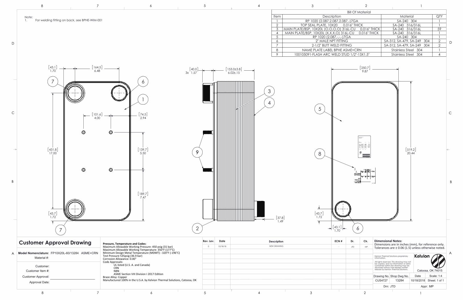
Side B
F( C) F( C)psi(bar)psi(bar)ft3(lit)
F( C) F( C)psi(bar)psi(bar)ft3(lit)
F( C) F( C)psi(bar)psi(bar)ft3(lit)
Fluid group : All refrigerants except Ammonia
Net Weight lbs(kg) lbs(kg)
UL
Model:Material:
Kelvion Thermal Solutions990 Keystone AveCatoosa, OK 74015(918) 266-3060
Min TMDMTMAWPPTVOL
Side A
LISTED
S/N:
Model number
Made in USA
101.64.00
74.52.94
139.75.50
189.77.47
164.56.48
43.11.70
431.817.00
43.71.72
1
67
7
3x 40.01.57
153.0±3.86.02±.15
37.81.49
2
99
3
4
43.71.72
43.11.70
250.79.87
519.220.44 8
5
6
Note:For welding fitting on back, see BPHE-WIM-0011.
Bill Of MaterialItem Description Material QTY
1 RP 1020 (2.087,2.087,2.087,-)7GA SA-240 304 12 TOP SEAL PLATE, 10X20 0.016" THICK SA-240 316/316L 13 MAIN PLATE/BSP, 10X20L (O,O,O,O) 316L-CU 0.016" THICK SA-240 316/316L 594 MAIN PLATE/BSP, 10X20L (X,X,X,O) 316L-CU 0.016" THICK SA-240 316/316L 15 RP 1020 (2.087,-,-,-)7GA SA-240 304 16 2" MALE NPT FITTING SA-312, SA-479, SA-249 304 27 2-1/2" BUTT WELD FITTING SA-312, SA-479, SA-249 304 28 NAME PLATE LABEL BPHE ASME+CRN Stainless Steel 304 19 100105091-FLASH ARC WELD STUD 1/2"-13X1.5" Stainless Steel 304 4
JTD
CUS4727
Drn:
Drawing No.10/18/2018
MPAppr:
DateShop Dwg No.
Customer Item #: Customer:
Customer Approval:
Approval Date:
Pressure, Temperature and Codes:Maximum Allowable Working Pressure: 450 psig (31 bar)Maximum Allowable Working Temperature: 350°F (177°C)Minimum Design Metal Temperature (MDMT): -320°F (-196°C)Test Pressure 535psig (36.9 bar)Corrosion Allowance: 0.00"Code Approvals:
UL listed (U.S. A. and Canada)CRNNBNASME Section VIII Division I 2017 Edition
Braze Alloy: CopperManufactured 100% in the U.S.A. by Kelvion Thermal Solutions, Catoosa, OK
Dimensional Notes:Dimensions are in inches (mm), for reference only.Tolerances are ± 0.06 (1.5) unless otherwise noted.
Dr.
Material #: Model Nomenclature:
Customer Approval Drawing
13284
D
C
B
AA
B
C
D
12345678
8 7 6 5 4 3 2 1
Sheet: 1 of 1Scale: 1:4
Catoosa, OK 74015
FP10X20L-60/13284 ASME+CRNKelvion Thermal Solutions proprietary information.
All rights reserved. This drawing may not be copied, and no information or data contained within the drawing may be disclosed without the express written release by Kelvion Thermal Solutions.
Rev. Lev.
NEW DRAWING
Date ECN #Description Ck.
0 10/18/18 JTD MP-

4. Instrumentation /
Auxiliary Equipment

3-Way Pilot ValvesModels 4057D & 4457A
Datasheet 4057_4457 3 Way Pilot Valve 0119rev6 Page 1
www.amot.com
Typical applications• Developed for use in manual and automatic
control systems:
- Hydraulic fluid control
- Actuator control
- Pneumatic panel systems
- Safety control systems
Key features and benefits• Suitable for use on many types of fluids:
- Clean air
- Natural gas
- LP gases
- Petroleum base lubricants
- Hydraulic oils
- Many other fluids
• Balanced force design
- Pressure can be applied to any port
- Simplified system design
• Can be panel or bracket mounted
- Simple, flexible and low cost installation
• Uses the AMOT patented “Tad Pole” seal
- Provides lower friction and longer cycle life than conventional o-ring seals
Model 4057D (Aluminum)
Model 4457A (Stainless steel)
Accreditations available• PED Suitable for Group 1 & 2 liquids & gases
(Ensure materials are compatible)
• ATEX II 3G TX X
• 4057D Complies with all relevant EU directives

3-Way Pilot Valves - Models 4057D/4457A
Datasheet 4057_4457 3 Way Pilot Valve 0119rev6 Page 2
ContentsOverview ................................................................ 3
Operation ............................................................... 3
Installation ............................................................. 3
Valve Characteristics ................................................ 3
Operator, finish and thread ................................. 3
Options ............................................................ 4
How to Order .......................................................... 4
Specification ........................................................... 4
Dimensions ............................................................. 5
Maintenance and Service Parts .................................. 6
How to order service kits .................................... 6
Service kit model number structure ..................... 7
Service parts .................................................... 7
Contact .................................................................. 9

3-Way Pilot Valves - Models 4057D/4457A
Datasheet 4057_4457 3 Way Pilot Valve 0119rev6 Page 3
OverviewAMOT Models 4057 and 4457 3-way valves have been developed for use in manual and automatic hydraulic or pneumatic control systems.
They offer versatility in operating requirements and allowable pressure limits. For a ¼” size control valve, they offer exceptional flow capacity.
OperationThe 3-way pilot valves feature modular construction and incorporate a sliding spool. The standard spool has a small center dead spot position and no valve port overlap. With the spool fully to the left (rest position), Port 2 is open to Port 3 and Port 1 is closed. With the spool moved to the right (actuated position), Port 2 is open to Port 1 and Port 3 is closed.
The valves are available with a variety of manual and pressure operators and with manual, pressure or spring returns. See the valve types table below for the standard variations which are available.
Installation• All connections are made with ¼” pipe thread
fittings.
• Apply a quality thread sealant such as LoctiteTM Pipe Sealant to pipe thread connections, but do not permit it to enter the valve passages.
• Teflon thread sealing tape may be used but must be applied so that shreds of the tape do not enter the valve.
• Avoid over-tightening fittings on the valve port bosses as they may be cracked, especially when Teflon thread sealing tape is used.
• All 4057D/4457A valves may be bracket mounted; most are also suitable for panel mounting.
Operator, finish and thread (B)1
Valve type (see page 6) Description4057D
Gulf-proofed NPT
4457A Stainless steel
NPT019F 001F CA Manual operated - 2.2 kg (5 lbs) force required020F 002F CB Manual pull spring return - 6.8 kg (15 lbs) force required
022H 004H CD Manual or pressure operated manual return - 0.69 bar (10 psi) pressure or 2.72 kg (6 lbs) force required
023H 005H CE Manual or pressure operated spring return - 1.79 bar (26 psi) pressure or 7.27 kg (16 lbs) force required
032J 014J CF Double pilot operated - 0.69 bar (10 psi) pressure required
031H 013H CG Pressure operated spring return - 1.79 bar (26 psi) pressure required
025H 007H CP Manual latch or pressure operated spring return when released - 1.8 bar (26 psi) pressure required
029K - CT Adjustable pressure operated spring return - Adjustable from 0.3 - 1.03 bar (5 - 15 psi) pressure required
035J - C2 Double pilot operated spring return in one direction - 0.69 bar (10 psi) and 1.79 bar (26 psi) pressure required
027K - SB Manual latch or pressure operated spring return when released - 0.9 bar (13 psi) pressure required
Valve CharacteristicsOperator, finish and thread
NOTES:1 If your operator, finish and thread code does not correspond with the given values, please contact the facility to confirm your operator, finish and thread code.

3-Way Pilot Valves - Models 4057D/4457A
Datasheet 4057_4457 3 Way Pilot Valve 0119rev6 Page 4
How to Order
Examples4057D 019F 1 -AA
Code description Comments4457A 001F 1 -AA
Basic model (A)
Basic model (A)4057D Anodized aluminum4457A Stainless steel
Operator, Finish & Thread (B)
Operator, finish and thread (B) * For operator, finish and threads available, refer to the operator, finish and thread table on page 3.Spool (C)
Spool (C)
1 Standard center dead spot ALL valve types EXCEPT SB2 Valve port overlap
5 Standard center dead spot4057D - SB ONLY
6 Valve port overlapCustomer special requirements (D)
Customer special requirements (D)-AA Standard May be omitted-*** Customer special code
Options• All valves may be bracket mounted; most are
also suitable for panel mounting.
• A satin chrome nut, part number: 3496L001 is available as an option, and it substitutes for the standard nut to improve the appearance for the front of a panel mounting.
• Red knob: part number 681L001 is available for types CA, CB, CD or CE as a substitute for the standard black knob.
Use the table below to select the unique specification of your 4057/4457 3-Way Pilot Valves.
Valve Characteristics Continued
Specification4057D 4457AMetric units English units Metric units English units
Body material Anodized aluminum Stainless steel
Standard spool and internal materials Anodized aluminum Anodized aluminum
Standard seal materials Viton Viton
Maximum temperature 120°C 248°F 120°C 248°F
Flow coefficient Kv = 1.04 Cv = 1.2 Kv = 1.04 Cv = 1.2
Maximum pressure at ports 1, 2 or 3 8.62 bar 125 psi 8.62 bar 125 psi
Maximum pressure at ports A or B 10.3 bar 150 psi 10.3 bar 150 psi
Maximum pressure at port C (types CT & SB ONLY) 8.62 bar 125 psi Not available
Net weight 0.3-0.9 kg 0.6-2 lbs 0.8-2.6 kg 1.7-5.7 lbs
Accreditations available
PED Suitable for Group 1 & 2 liquids & gases (Ensure materials are compatible)
ATEX II 3G TX X
4057D Complies with all relevant EU directives

3-Way Pilot Valves - Models 4057D/4457A
Datasheet 4057_4457 3 Way Pilot Valve 0119rev6 Page 5
DimensionsType CA: Manual operated - 2.27 kg (5 lbs) force required
Type CB: Manual pull spring return - 6.8 kg (15 lbs) force required
Type CD: Manual or pressure operated manual return - 0.69 bar (10 psi) pressure or 2.72 kg (6 lbs) force required
Type CE: Manual or pressure operated spring return - 1.79 bar (26 psi) pressure or 7.26 kg (16 lbs) force required
Type CG: Pressure operated spring return - 1.79 bar (26 psi) pressure required
2 1/8” (54.0)
1 1/16” (27.0)
3/4” (19.1)
1 1/2” (38.1)
1 3/4” (44.5)
1 1/32” (26.2)
1 1/32” (26.2)
1 1/8” (28.6)
9/32” (7.1) DIA
2 HOLES
4 1/8” (116.1)
13/16” (20.6)
13/16” (20.6)
1 3/8” (34.9)
1/2” (12.7)
3/8” (9.5)
1” (25.4)
PANEL OPENING 7/8” (22.2) DIA
1/2” (12.7)
5/8” (15.9)1”
(25.4)
ROTATED 90°
2 7/8” (73.0)
6” (152.4)
1 1/8” (28.6)
Dimensions - inches (mm)
Type CP: Manual latch or pressure operated spring return when released - 1.8 bar (26 psi) pressure required
Type CT: Adjustable pressure operated spring return - Adjustable from 0.3 to 1.03 bar (5 to 15 psi) pressure required
Type CF: Double pilot operated - 0.69 bar (10 psi) pressure required
Type C2: Double pilot operated spring return in one direction - 0.69 bar (10 psi) and 1.79 bar (26 psi) pressure required
2 7/8” (73.0)
7 1/2” (190.5)
2 7/8” (73.0) 6”
(152.4)8 1/4” (210.0)
9/16” (14.3)
2 9/16” (65.1) 6 13/16”
(173.0)
7/8” (22.0)

3-Way Pilot Valves - Models 4057D/4457A
Datasheet 4057_4457 3 Way Pilot Valve 0119rev6 Page 6
Dimensions ContinuedType SB: Manual latch or pressure operated spring return when released - 0.9 bar (13 psi) pressure requiredDimensions - inches (mm)
2 1/8” (54.0)
3/4” (19.1)
1 1/2” (38.1)
1 3/4” (44.5)
9/32” (7.1) DIA
2 HOLES
1 3/4” (44.5)
1 ” (25.4)
1 ” (25.4)
2 9/16” (65.1)
5 1/2” (140.0)
7 5/8” (193.7)
9/16” (14.3)
1 1/8” (28.6)
1 1/8” (28.6)
3 ” (76.2)
1 1/16” (27.0)
Maintenance and Service Parts
Service kits are available with seals and diaphragm required to service the valve. Order service kits by the service kit model number which is identified by the basic valve model and operator, finish and thread code found in the AMOT valve part number.
Refer to the AMOT valve part number printed on the valve nameplate and the AMOT valve part number structure in the how to order section on page 4.
Over time, exposure to foreign chemicals and particulate matter as well as prolonged operation at extreme conditions may reduce the effectiveness of the valve. At such time, AMOT Pilot Valves can be restored to original performance simply by installing an AMOT pilot valve service kit. Service kits include all new seals and diaphragm required for normal maintenance.
When these valves are used in safety control systems, it is recommended that the system be checked MONTHLY for proper functioning. The unit must be kept clean and free of dust. The end cap is to be regularly inspected for signs of damage or rust and replaced if necessary.
Ensure that regular inspections of the valve and end cap are carried out to ensure that it is kept clean and free from wear, damage or rust. If the valve shows signs of process fluid leakage, examine the seals. If the valve is subjected to prolonged periods of high vibration at low temperatures, it is possible that wear may occur to the disc assembly and it is recommended that the valve is isolated and safely removed from the system, and returned to AMOT for examination.
AMOT designs and tests all its products to ensure that high quality standards are met. For good product life, carefully follow AMOT’s installation and maintenance instructions; failure to do so could result in damage to the equipment being protected or controlled.
How to order service kits

3-Way Pilot Valves - Models 4057D/4457A
Datasheet 4057_4457 3 Way Pilot Valve 0119rev6 Page 7
Service kit model number structure
Service kit identificationBasic
model (A)Operator, finish and thread (B)1 Service kit model number
4457A
001F
9113X001
002F
004H
005H
007H
013H
014J
4057D
019F
020F
022H
023H
025H
031H
032J
035J
027K9128X001
029K
ExamplesValve part number Service kit model number
4057D 029K 2 9128X001
4457A 001F 1 -AA 9113X001
1) Identify the basic valve model, located in the Basic model (A) section of the AMOT valve part number.
2) Identify the operator, finish and thread code, located in the Operator, finish and thread (B) section of the AMOT valve part number.
3) Use those codes in the service kit identification table below to identify the proper service kit needed to service the valve. Two examples are shown in the table below.
Maintenance and Service Parts Continued
Service parts (refer to diagrams on page 8)
Service kit parts
Ref no.Qty.2
Description9113X001 9128X001
3 4 4 Spool seals
4 2 - Piston seals
47 - 1 Diaphragm
48 - 1 Thread seal
NOTES:1 If your operator, finish and thread code does not correspond with the given values, please contact the facility to confirm your operator, finish and thread code.2 Service kit 9113X001 contains extra parts when used with valve types CA, CB, CD, CE, CG and CP. Please discard of any extra parts.

3-Way Pilot Valves - Models 4057D/4457A
Datasheet 4057_4457 3 Way Pilot Valve 0119rev6 Page 8
Type CA Type CB
Type CD Type CE
Type CF Type CG
Type CP Type CT
Type SB Type C2
Maintenance and Service Parts ContinuedService parts continued

3-Way Pilot Valves - Models 4057D/4457A
Datasheet 4057_4457 3 Way Pilot Valve 0119rev6 Page 9
Contact
Americas Europe, Middle East and Africa
AMOT USA8824 Fallbrook Dr.Houston, TX 77064USA
Tel: +1 (281) 940 1800Fax: +1 (713) 559 9419Email: [email protected]
AMOT UKWestern WayBury St. EdmundsSuffolk, IP33 3SZEngland
Tel: +44 1284 715739Fax: +44 1284 760256Email: [email protected]
AMOT GermanyRondenbarg 2522525 HamburgGermany
Tel: +49 40 8537 1298Fax: +49 40 8537 1331Email: [email protected] Pacific
AMOT Shanghai Bd. 7A, No. 568, Longpan Rd., Malu JiadingShanghai 201801China
Tel: +86 21 5910 4052Fax: +86 21 5237 8560Email: [email protected]
www.amot.com

Dual Chamber OrificeFitting Datasheet
Branch Connection DetailsN1 N2 N3 N4 N5 N6 N7 N8
Style TOL TOL --- --- --- --- --- ---Size (Inches) 1 3/4 --- --- --- --- --- ---Schedules --- --- --- --- --- --- --- ---Rating 3000 3000 --- --- --- --- --- ---Orientation 0 0 --- --- --- --- --- ---Material A105N A105N --- --- --- --- --- ---
6759 - 65th Avenue, Red Deer, Alberta T4P 1X5Ph:(403)342-4494 Fax:(403)346-7110
Email: [email protected]
1 Tag No.2 Line No.3 Line Size/Schedule 2" SCH80 (XS)4 Inside Diameter 1.939 "5 Measurement Standard AGA 2016 Ed.6 Quantity 17 Paint Canalta Standard Ship Coat1 Orifice Plates Qty Provided (per): 1 Installed2 Material 316 SS3 Thickness(Inches) 0.1254 Beta(b) = d/D (installed) 0.525 Bore Diameter (d) (Inches) 1.0006 Max Allowable Beta (b) = d/D 0.757 Max Allow. Orifice Bore Diam. (d) (Inches) 1.3758 Vent | Drain9 Seal Assembly K-Style 316SS, HNBR, 85D10 Plate Holder Standard, CF8M Stainless1 Body Material A216WCB (NACE)2 Body Size / Rating 2" 6003 Body Connections Up:Weld Down:RF Dwl Pin:4 Seal Gap .562005 Trim Material NACE MR-01-75 (CS)6 Seat Style Grease7 Tap Hole Diameter 0.375
8 Body Stud Bolt/Nut Special Coating S: A193 B7M N: A194 2HMSpecial Coating: None
9 Engineering Design Standard ASME B16.34-201710 Tap Location 1.000" from plate face11 Tap Connection Style 1/2" NPT12 Sets of Taps 413 Shaft Orientation Left14 Valve Lockout Mechanism None1 Tube Material A106B2 Pipe Grade Cold Drawn3 Pipe (Outer) Connection Types Up:RF Down:RF4 Pipe Connection Size / Rating 2" 6005 Flange Material A105N
6 Stud Bolt / Nut Material S: A193 B7M N: A194 2HMSpecial Coating: None
7 Gasket 316 Spiral Wound Flex CG8 Pipe Measurement Standard AGA 2016 Catch All9 Engineering Design Standard ASME B31.3-20181 Flow Conditioner Type Contour2 Material AISI 316SS3 Spacer Included: 4 Connection Style RF Dwl Pin:
General
OrificePlate
OrificeFitting
MeterTube
FlowConditioner
Customer: Next CompressionCustomer PO#:Ref#:Sales Quote: SQ039277 Line: 610000Sales Order: Line: Sales Contact: Gord Gentner
Drawing Name: Dimensions (Inches)
Overall Length Tolerance +/- 1/4"Weld Bevels: 37.5° +/- 15°
OAL: N1:UL1: N2:UL2 N3:
N4:DL: N5:FC1: N6:
N7:N8:
57 1215 816
26
Seat Test: PSIGHydro Test: Hour(s) @ PSIGCorr. Allow.: 1/16CWP: PSIG @ °F to 100°F
Weld ProceduresGMAW, FCAW, or SAW(CCL5 may also be used on outlets of large runs)CCL-1N Rev 1(RT/LT-FCAW)CCL8 (STAINLESS-GMAW(RMD)/FCAW)CCL5 (RT/LT-SMAW)CCL-10N/11N (RT/LT-MCAW)CCL-14N (GTAW-PED)Subcontractor (refer to attachment)
Non-Destructive TestingFitting Radiography Testing (Critical Locations)Fitting Radiography Testing (Weldneck Only)Weld Radiography Testing: 10% by shop rate
MPILiquid PenetrantHardness10%PWHTUltrasonicFerrite
ASME B31.3 - Normal
16501 2225
1480 -20
Other Applicable Customer Specifications
RevDescription By Date0 Issued for quotation GG 06/14/20211 CL 600 option added GG 06/14/2021
Customer Approval
Signature
Printed Name:

N1
N2
Canalta Controls Ltd.DC Orifice Fitting 2" - 16"
150 - 1500 ANSI Flanged Flow Conditioner
DLUL1 UL2
RIGHT
LEFT
SECTION A-A
T.O.L. ORIENTATION
SPEC. PLATE BRACKET
OAL
A
A
180
(RIGHT)(LEFT)270 90
0
Tb Tb Tb
Th
or 0.5 TbLesser of 1/8"
Tc
1/8
"1/8
"
or 0.5 TbLesser of 1/8"
1/8
"1/8
"
1/4" or 0.7 Tb
CRN: 0F2015.213 / 0H6217.213
*Refer to datasheet for specifications*
OCT21-2011
DATE
SAN
BY
APP'D
DWN
BRANCH CONNECTION WELD DETAIL
SAN OCT21-2011
DCA-FC-F (2N-0)Dwg #:
Tc=Lesser of
REV 0-OCT 21, 2011


Donaldson Delivers
HAK05 Return-Line FilterMax Flow: 120 gpm (454 lpm)
Working Pressures to
500 psi3448 kPa34.5 bar
Rated Static Burst to
1000 psi6895 kPa69 bar
Flow Ranges to
Return-line: 120 gpm/ 454 l/minSuction: 30 gpm/114 l/min
Applications• Return Lines
• Side Loop Systems
• In-Plant and Mobile Machinery
• Lube Oil Systems
• Suction Lines
FeaturesThe hardy HAK05 is perfect for return-line filtering in heavy duty applications where you want a cartridge style filter. Its inside to outside flow pattern means that dirt is collected on the inside of the cartridge, eliminating the need for heavy cleaning of the housing when servicing the filter. HAK05 filters feature a die cast aluminum head, steel body, and a single center-retention bolt that simpliefies servicing.
HAK05 is available in two element lengths, 16' and 8", to accomodate various flow ratings. Several elements available at various performance lefvels. If you're looking for the convenience of a spin-on style filter, use the HMK05 or HMK25.
Beta Rating
• Performance to ß5(c)=1000
Porting Size Options
• 1½" NPT • SAE-24 O-ring
Replacement Filter Lengths
• 8" / 203 mm • 16" / 406 mm
Standard Bypass Ratings
• 25 psi / 172.5 kPa / 1.7 bar
Assembly Weight
• 18 lbs / 8.2 kg (long)
• 13 lbs / 5.9 kg (short)
Operating Temperatures
• Synthetic Media: -20°F to 250°F / -29°C to 121°C
Element Burst Ratings
• 100 psid / 690 kPa / 6.9 bar

HAK05Max Flow: 120 gpm (454 lpm)
HAK05 Specification IllustrationsAll dimensions are shown in inches [millimeters].
Torque center bolt to 75 ft-lbs.
Torque center bolt to 75 ft-lbs.
Assembly - Side View
Head - Top View
Long Assembly Short Assembly

HAK05Max Flow: 120 gpm (454 lpm)
HAK05 Service Parts
Repair Kit• P160710 BunaN seal‡
Bypass Valve AssemblyBypass Valves have BunaN seals
and snap into element endcap.
• P160373 Bypass‡
• P160351 Bypass‡
Housing• P160412 8"*
• P160083 16"*
Bypass Indicator 0-Ring• P160125 BunaN seal‡
• P161851 Viton seal (Size 227)‡
Head 0-Ring• P160016 BunaN seal (Size 351)*
• P161849 Viton seal*
Head AssemblyVisual Indicator Right Side,
Recessed Left Side
• P160438 NPT 11/2*
• P163257 SAE 24*
Visual Indicator Left Side,
Recessed Right Side
• P160451 NPT 11/2*
• P163186 SAE 24*
Visual Indicator• P160473 BunaN seal*
• P161847 Viton seal*
Bypass Spring• P160130 25 psi / 172 kPa‡
Commercial # 210Gasket Washer• P160020 BunaN seal‡
• P161852 Viton seal‡
Center Bolt• P160152 8"*
• P160154 16"*
*Lead Times Apply‡Stocked Item

Donaldson Company, Inc.Minneapolis, MN
donaldson.comshop.donaldson.com
North America 800-374-1374Mexico, Latin America, & Caribbean 52-449-300-2400Brazil 55-11-4894-6339Europe 32-16-38-3811South Africa 27-11-997-6000
Southeast Asia 65-6311-7373Greater China 86-400-650-0610Japan 81-42-540-4112Korea 82-2-517-3333Australasia 61-02-4350-2033India 91-124-4807-400
Brochure No. F111447 ENG (4/18)© 2018 Donaldson Company, Inc. All rights reserved. Donaldson Company, Inc. reserves the right to change or discontinue any model or specification at any time and without notice. Printed in the U.S.A.
Replacement Cartridge OptionsMedia
NumberMedia
Technologyßx(c) = 2/20/75
Rating
Length DonaldsonPart No.in mm
No. 1 Synteq® <2 / <2 / 3 16 406 P161016
No. 2 Synteq 2 / 3 / 5 8 203 P165626
Synteq 16 406 P165628
No. 2 1/2 Synteq 2 / 7 / 10 8 203 P176220
Synteq 16 406 P176221
No. 6 Synteq 5 / 10 / 13 8 203 P160558
No. 9 Synteq 10 / 17 / 22 8 203 P166461
Synteq 16 406 P164699
No. 16 Synteq 15 / 30 / 37 8 203 P163172
Synteq 16 406 P161571
No. 20 Synteq 20 / 33 / 40 8 203 P560527
Synteq 16 406 P166597
No. 149 Wiremesh 150 8 203 P162368
16 406 P160700
Filter NotesFilters with seals made of BunaN are appropriate for most applications involving petroleum oil. Filters with seals made of Viton® (a fluoroelastomer) are required when using diester, phosphate ester fluids, water glycol, water/oil emulsions, and HWCF (high water content fluids) over 150°F. Donaldson offers both types, as shown in the table at the above. (Viton® is a registered trademark of DuPont Dow Elastomers.)
Donaldson Synteq filter media is compatible with petroleum based fluids, most phosphate esters, water oil emulsions, and HWCF (high water content fluids).

Buy: www.ValinOnline.com | Phone: 844-385-3099 | Email: [email protected]

Buy: www.ValinOnline.com | Phone: 844-385-3099 | Email: [email protected]

Buy: www.ValinOnline.com | Phone: 844-385-3099 | Email: [email protected]

Buy: www.ValinOnline.com | Phone: 844-385-3099 | Email: [email protected]

1
NOTE: A pump running backwards but at a greatly reduced speed.
OPERATIONFLOODED SUCTION SYSTEMS
1. Fully open the suction and discharge valves.2. Start the pump and verify liquid is flowing. If there is no liquid
flow, refer to the “Troubleshooting” section of these instructions.3. Adjust the flow rate and pressure by regulating the discharge valve.
CAUTION: Never attempt to adjust the liquid flow with the suction valve. Limiting suction will damage pump components.
FLUSHING SYSTEMS EQUIPPED WITH FLUSH VALVES:
1. Fully close the suction and discharge valves.2. Connect the water supply to the water inlet valve and connect a
drain hose to water outlet valve.3. Turn on the water supply and open the inlet and outlet valves. Flush
the system until the pump has been cleared of any material buildup
ASSEMBLYPUMPS WITH MOTORS
1. No assembly required. Unpack the pump and motor and examine for any signs of shipping damage. If damage is detected, save the packaging and notify the carrier immediately.
2. Proceed to the “Installation” section of these instructions.
PUMPS WITHOUT MOTORS
Note: Do not remove shipping plug located in suction port of the pump until the pump is completely assembled onto the motor.
1. Unpack the pump and examine for any signs of shipping damage. If damage is detected, save packaging and notify the carrier immediately.
2. Place the motor on the fan cover. Align any set screw (item 9) with key slot in motor shaft. Place the aluminum motor adapter (item 8) onto the motor rabbet. Position the slot (shaft sleeve set screw access hole) in motor adapter with the top of the motor. Line up the bolt holes in the motor adapter with the bolt holes in the motor face. Install (4) bolts and lock washers (items 10,11). Securely tighten.
3. Through the top and bottom access holes, tighten securely two of the four set screws on the shaft adapter (item 6). You will need an 1/8” Allen wrench for this.
4. Remove the screw from the shipping plug and then remove the plug from the suction port. Rotate the motor fan until you can tighten the two remaining set screws on the shaft adapter.
5. Rotate the motor fan by hand and check for impeller rubbing. If the impeller rubs loosen the shaft adapter set screws and adjust the impeller accordingly. Retighten the shaft adapter set screws.
6. Proceed to the “Installation” section of these instructions.
INSTALLATIONMOUNTING
Motor or base plate must be securely fastened.
PIPING TO AND FROM THE PUMP
• Always support the piping near the pump to minimize stress and strain on the pump’s casing.• Minimize frictional losses by increasing the suction piping size by one diameter.• Use a minimal number of bends on suction piping. Keep bends beyond a distance of ten pipe diameters from the pump.• Install shut off valve on the suction line and flow control valve in the discharge line. Place the valves beyond a distance of ten pipe diameters from the pump.• Ensure that the piping is leak free.• Position the pump as close to the liquid source as possible.• Maintain a flooded suction at all times or prime the pump and maintain prime at all times.
CAUTION: Suction prime must be maintained at all times. Running the pump dry will cause damage to pump components. To protect the pump if prime is lost, use a pressure switch on the discharge, a vacuum switch on the suction, or a motor minder to monitor motor current draw.
PUMPING LIQUIDS THAT MAY SOLIDIFY OR CRYSTALLIZE:
AC 4 & 5 HORIZONTAL SERIESSealed Metallic Centrifugal Pumps
Installation and Maintenance Instructions
MOTOR/ELECTRICALOnly qualified personnel trained in the safe installation and opera-tion of this equipment should install the motor. Install the motor according to National Electric Code, NEMA MG-2, IEC standards requirements and/or applicable local electrical codes. The voltage and frequency variations of the power supply should never exceed the limits established in the applicable standard. Prior to connect-ing to the power line, check nameplate voltage, rotation connection and ensure proper grounding. Sufficient ventilation area should be provided to insure proper operation and cooling of the motor. The motor must be installed with a suitable overload pro¬tection circuit. For three phase motors it is recommended to install a phase failure protection device. Download the motor manual from the specific motor manufacturers’ website for additional information concerning motor installation, safety and maintenance instructions.
Wire the motor for clockwise rotation when facing the fan end of the motor.
CAUTION: Do not operate the pump to check rotation until the pump is full of liquid or damage may occur even if the motor is “bumped” to check motor rotation direction.
Check all electrical connections with the wiring diagram on the mo-tor. Make sure the voltage, frequency, phase and amp draw comply with the supply circuit.
If utilized, verify that power monitors or variable frequency drives have been properly installed according to the manufacturer’s instructions.
Figure 1
Add a flush system to the pump’s piping to prevent accumulation of material inside the pump. Install water inlet and outlet valves as shown in Figure 1. Refer to the “Operation” section of these instructions for the flush procedure.

2
compatible lubricant and carefully slide it over the shaft adapter with a rotating face pointing at the motor (as shown in figure 3).
NOTE: Rotating seal must be completely seated against the station-ary seal face.
6. Place the seal spring and spring retainer over the shaft adapter.
NOTE: To prevent spinning the impeller off in case the motor is wired for incorrect rotation, it is recommended to coat the shaft adapter threads with Loctite Threadlocker #262.
7. Holding the motor shaft firmly, thread the impeller onto the shaft adapter until it stops at the adapter shoulder.
8. Lubricate the housing o-ring (item 3) with chemically compatible lubricant, and install onto the backhead. Install the impeller hous-ing (item 1), the V-clamp (item 2), and the nut onto the V-clamp stud. Verify the V-clamp stud and housing discharge orientation and tighten the V-clamp. Firmly tap the V-clamp to seat it in several places and retighten the V-clamp nut.
NOTE: Stainless Steel hardware can gall, be damaged and become very difficult to remove. To prevent galling use a lubricant like Loctite Anti-Seize or some other compatible lubricant or coating material, use a slow RPM speed to tighten and immediately stop tightening if galling is noticed. If galled remove & replace the hardware.
9. Rotate the motor shaft by hand to verify there is no rubbing. Replace the motor fan and fan cover. Reinstall the pump into the system.
TROUBLESHOOTINGNO OR INSUFFICIENT FLOW 1. Pump not primed.2. Closed valve.3. Viscosity too high.4. Air leaks in suction piping.5. Discharge head higher than anticipated.6. Suction lift too high or insufficient NPSH. 7. Check for clogged suction line.8. Motor wired for wrong rotation.
INSUFFICIENT PRESSURE1. Air or gas in liquid.2. Impeller diameter too small.3. Discharge head higher than anticipated.4. Motor speed insufficient (too low) or motor rotation incorrect.
LOSS OF PRIME1. Leaking suction line.2. Foot valve or suction opening not submerged enough.3. Foot valve too small or leaking.4. Air or gas in liquid.5. Foreign matter in impeller.
EXCESSIVE POWER CONSUMPTION1. Head lower than rating. Excessive flow.2. Specific gravity or viscosity of liquid is too high.
EXCESSIVE VIBRATION1. Loose piping or bolts.2. Pump cavitating from improper suction or feed.
Figure 3
(usually approximately 5 minutes).4. Close the water inlet and outlet valves and turn off water supply.
MAINTENANCE DISASSEMBLY
1. Disconnect power. Remove electrical wiring.2. Close the suction and discharge valves and disconnect all piping. 3. Loosen and remove the nut on the V-clamp stud. Remove the V-
clamp (item 2) and the impeller housing (item 1). Note V-clamp stud and discharge spout location for reassemble alignment.
4. Remove the motor fan cover and fan. Secure the motor shaft to prevent it from turning, and unthread the impeller.
NOTE: Shaft adapter threads are coated with Loctite Threadlocker #262 to prevent the impeller from spinning off if the motor is inad-vertently wired for incorrect rotation. If necessary follow Loctite’s recommendations for loosening the threadlocker #262.
5. Remove the seal spring retainer, spring, and the rotating seal component from the shaft adapter. Remove the backhead (item 7) from the pump. Remove the stationary part of the seal from the backhead.
6. If the motor is being replaced, proceed to step 7. If the seal is being replaced, do not loosen or remove the shaft adapter (item 6) from the motor shaft. Proceed to step 3 of the reassembly instructions
7. Remove the four bolts holding the motor adapter/mounting plate assembly (items 8 & 15) to the motor and remove the motor adapter. Loosen all four setscrews and remove the shaft adapter.
8. Inspect all parts for wear and replace as required. Note the fin-ish on the shaft adapter where the rotating seal boot is located. If damaged or not smooth, replace the shaft adapter.
REASSEMBLY
1. Install the shaft adapter (item 6) onto the motor shaft. Be sure one of the setscrews is protruding into the motor shaft keyway slot, but do not tighten any setscrews yet.
2. Install the motor adapter/mounting plate assembly (8 & 15) with setscrews access slots at 12 and 6 location, and tighten all four bolts.
3. Lubricate the outer boot on the stationary part of the seal with a chemically compatible lubricant, and press into the backhead (item 7) until it is fully seated. The polished seal surface should be facing away from the motor.
NOTE: To keep the polished surface of the seal face clean, use a piece of cardboard to protect the seal face during installation.
4. Insert the backhead (item 7) into the motor adapter (item 8) bore and press into place.
If the shaft adapter was not loosened or removed, go to step 5. If replacing the shaft adapter, firmly hold the backhead toward the motor, and adjust the shaft adapter until the shoulder is .843 (27/32) inches from the stationary seal face (see figure 2). Tighten all four setscrews with a T wrench through the access slots in the motor adapter.
5. Lubricate the inside of the rotating seal component with a chemically
Figure 2

3
AC4 EXPLODED VIEW
AC5 EXPLODED VIEW
6
1
8
11 10
159
6
75
3 4
2
131412
168
12
11
1014 13
7
59
153
4
2117
Item Qty Description Part Number
1 1
Impeller HousingAC4STS1 - 316 SS - 3/4” x 1/2” FNPT/BSP A102106-1AC4STS2 - 316 SS - 3/4” x 1/2” FNPT/BSP w/ drain & plug A102106-2AC4STS3 - 316 SS - 3/4” x 1/2” ANSI 150# dimensional flanges 106923AC4STS4 - 316 SS - 1” x 1” ANSI 150# dimensional flanges 108454AC4STS5 - 316 SS - 1-1/2” x 3/4" electropolished tri-clamp fittings 108453AC4STS6 - 316 SS - 1-1/2” x 1" electropolished tri-clamp fittings 108453-1AC5STS1 - 1-1/2” x 1-1/4” standard FNPT A102112-1AC5STS2 - 1-1/4" x 3/4" standard FNPT A102113-1AC5STS4 - 1-1/2” x 1-1/4” standard BSP A102112-3AC5STS5 - 1-1/4” x 3/4” standard BSP A102113-2AC5STS7 - 1-1/2” x 1-1/2” electropolished tri-clamp fittings 108530AC5STS5 - 1-1/4” x 3/4” ANSI 150# dimensional flanges 107248AC5STS9 - 1-1/2” x 1” ANSI 150# dimensional flanges 108471AC5STS10 - 1-1/2” x 1-1/2” ANSI 150# dimensional flanges 108472-1AC5STS11 - 1-1/2” x 1” electropolished tri-clamp fittings 108469AC5STS3 - 2" x 1-1/2" standard FNPT (high flow) A102133-1AC5STS6 - 2” x 1-1/2” standard BSP (high flow) A102133-2AC5STS12 - 2” x 1-1/2” ANSI 150# dimensional flanges (high flow) 108473-1AC5STS13 - 2” x 1-1/2” electropolished tri-clamp fittings (high flow) 108378-1AC5HTS1 - 1/2" x 1/4" high head FNPT A102120-1AC5HTS2 - 1/2” x 1/4” high head BSP A102120-2AC5HTS3 - 1/2” x 1/4” high head FNPT electropolished A102120-3AC5HTS4 - 1/2” x 1/4” high head ANSI 150# dimensional flanges 108502AC5HTS5 - 1/2” x 1/4” high head electropolished tri-clamp fittings 108503AC5RTS1 - 1-1/2" x 1-1/4" recessed FNPT A102112-2AC5RTS2 - 2” x 1-1/2” recessed FNPT A102133-3AC5RTS3 - 1-1/2” x 1-1/4” recessed BSP A102112-4AC5RTS4 - 2” x 1-1/2” recessed BSP A102133-4AC5RTS5 - 1-1/2” x 1-1/2” recessed ANSI #150 dimensional flanges 108472-2AC5RTS6 - 2" x 1-1/2 recessed ANSI #150 dimensional flanges 108473-2AC5RTS7 - 1-1/2” x 1” recessed electropolished tri-clamp fittings 108469-1AC5RTS8 - 2” x 1-1/2” recessed electropolished tri-clamp fittings 108378-2

4
Item Qty Description Part Number
2 1 V-ClampJ102947
3 1
O-Ring FKM (AC4) J102946EPDM (AC4) J103004Buna (AC4 FDA compliant) 108213PTFE (AC4) J103042FKM (AC5) J102960EPDM (AC5) J103003Buna (AC5 FDA compliant) 108214PTFE (AC5) J103043
4 1
Impeller400 - 4.00" x 1/4" standard (AC5STS) A102114-1420 - 4.25" x 1/4" standard (AC5STS) A102114-2450 - 4.50" x 1/4" standard (AC5STS) A102114-3470 - 4.75" x 1/4" standard (AC5STS) A102114-4400 - 4.00" x 1/4" standard electropolished (AC5STS) 108445-1420 - 4.25" x 1/4" standard electropolished (AC5STS) 108445-2450 - 4.50" x 1/4" standard electropolished (AC5STS) 108445-3470 - 4.75" x 1/4" standard electropolished (AC5STS) 108445-4408 - 4.00" x 3/8" standard (AC5STS high flow) A102114-9428 - 4.25" x 3/8" standard (AC5STS high flow) A102114-10458 - 4.50" x 3/8" standard (AC5STS high flow) A102114-11478 - 4.75" x 3/8" standard (AC5STS high flow) A102114-12408 - 4.00" x 3/8" standard electropolished (AC5STS high flow) 108445-5428 - 4.25" x 3/8" standard electropolished (AC5STS high flow) 108445-6458 - 4.50" x 3/8" standard electropolished (AC5STS high flow) 108445-7478 - 4.75" x 3/8" standard electropolished (AC5STS high flow) 108445-8300 - 3.00" x 1/2" recessed (AC4STS/AC5RTS) A102105-1320 - 3.25" x 1/2" recessed (AC4STS/AC5RTS) A102105-2350 - 3.50" x 1/2" recessed (AC4STS/AC5RTS) A102105-3370 - 3.75" x 1/2" recessed (AC5RTS) A102105-4450 - 4.50" x 1/2" recessed (AC5RTS) A102105-5300 - 3.00" x 1/2" recessed electropolished (AC4STS/AC5RTS) 108444-1320 - 3.25" x 1/2" recessed electropolished (AC4STSAC5RTS) 108444-2350 - 3.50" x 1/2" recessed electropolished (AC4STS/AC5RTS) 108444-3370 - 3.75" x 1/2" recessed electropolished (AC5RTS) 108444-4450 - 4.50" x 1/2" recessed electropolished (AC5RTS) 108444-5450 - 4.50" x 1/8" high head (AC5HTS) A102183-1475 - 4.75" x 1/8" high head (AC5HTS) A102183-1450 - 4.50" x 1/8" high head electropolished (AC5HTS) A102183-2475 - 4.75" x 1/8" high head electropolished (AC5HTS) 108446
5 1
Seal3/4” Carbon/Ceramic/FKM seal J102957-13/4” Carbon/Ceramic/EPDM seal J102957-23/4” Carbon/Ceramic/Buna seal (FDA compliant) 1080733/4” Carbon/Ceramic/Kalrez seal J1030813/4” Silicon Carbide/Silicon Carbide/FKM seal J1030663/4” Silicon Carbide/Silicon Carbide/EPDM seal J103067
6 1
Shaft Adapter w/ Set Screws56C frame A10289571-B14 frame A10289680 frame (AC5 only) A10289790 frame (AC5 only) A102898
7 1Backhead
AC4 A102110-1AC5 A102121-1
8 1
Motor Adapter56C frame M102049-171-B14 frame M102049-280 frame (AC5 only) M102049-390 frame (AC5 only) M102049-4
9 4 1/4-20 x 1/4” Cup Point Set ScrewJ100220
10 4
Hex Head Cap Screw 3/8-16 x 1” (56C frame) J100114M6 x 25 mm (71-B14 & 80 frame) J103456M8 x 40 mm (90 frame) J102760

5
SAFETY PRECAUTIONS FOR ATEX PUMPSWARNING: Proper materials of construction must be chosen for the fluid being pumped. Improper material selection could lead to pump failure and leakage. This is the responsibility of the end user.
WARNING: ATEX pumps must have a power monitor, flow switch, pressure switch or similar device installed to protect against running dry, closed discharge valve, major leaks, and possible sources of ignition due to motor bearing failure. Any of these conditions could lead to a rise in surface temperature of the pump. The device must be set to stop the pump within three seconds of a fault.
WARNING: The pump must be checked for leaks on a regular basis. If leaks are detected, the pump must be repaired or replaced immediately.
WARNING: The pump must be cleaned on a regular basis to avoid dust buildup greater than 5mm.
Temperature ClassificationPump temperature is completely dependent on operating conditions. Pump will transfer heat from the piping system, motor, and fluid. These items must be considered as a system when assessing an ATEX application.
Item Qty Description Part Number
11 4
Lock Washer3/8” (56C) J1001155/16” (90 frame only) J1012821/4” (71-B14 & 80 frame) J100672
12 1
Slinger Ring 56C Frame M102064-171-B14 Frame M102064-280 Frame (AC5 only) M102064-390 Frame (AC5 only) M102064-4
13 4 Cap Screw Fillister Head (all)J100932
14 4 #10 Lock Washer (all)J100824
15 1 Mounting PlateJ103389-1
16 1 Metric Motor Adapter90 Frame only M102129
17 4 Flat Washer - 5/16”90 Frame only J101293
Finish Thompson, Inc (manufacturer) warrants this pump product to be free of defects in materials and workmanship for a period of one year from date of purchase by original purchaser. If a warranted defect, which is determined by manufacturer’s inspection, occurs within this period, it will be repaired or replaced at the manufacturer’s option, provided (1) the product is submitted with proof of purchase date and (2) transportation charges are prepaid to the manufacturer. Liability under this warranty is expressly limited to repairing or replacing the product of parts thereof and is in lieu of any other warranties, either expressed or implied. This warranty does not apply to normal wear of the product or components. This warranty does not apply to products or parts broken due to, in whole or in part, accident, overload, abuse, chemical attack, tampering, or alteration. The warranty does not apply to any other equipment used or purchased in combination with this product.
The manufacturer accepts no responsibility for product damage or personal injuries sustained when the product is modified in any way. If this war-ranty does not apply, the purchaser shall bear all cost for labor, material and transportation.
Manufacturer shall not be liable for incidental or consequential damages including, but not limited to process down time, transportation costs, costs associated with replacement or substitution products, labor costs, product installation or removal costs, or loss of profit. In any and all events, manufacturer’s liability shall not exceed the purchase price of the product and/or accessories.
Warranty RegistrationThank you for your purchase of this quality Finish Thompson product. Be sure to take a minute to register your pump at Finishthompson.com/warranty. Simply provide the model number, serial number and a few other pieces of information.
WARRANTY
CHEMICAL REACTION DISCLAIMERThe user must exercise primary responsibility in selecting the product’s materials of construction, which are compatible with the fluid(s) that come(s) in contact with the product. The user may consult Finish Thompson, Inc. (manufacturer) and a manufacturer’s representative/distributor agent to seek a recommendation of the product’s material of construction that offers the optimum available chemical compatibility.
However neither manufacturer nor agent shall be liable for product damage or failure, injuries, or any other damage or loss arising out of a reaction, interaction or any chemical effect that occurs between the materials of the product’s construction and fluids that come into contact with the product’s internals.
Call our toll free Technical Service Hot Line, 1-800-888-3743, if you have any questions regarding product operation or repair.

6
EU Declaration of Conformity
Manufactured by:
Finish Thompson, Inc.921 Greengarden RoadErie, Pennsylvania 16501 U.S.A.Phone: 1-(814)-455-4478Fax 1-(814)-455-8518Email: [email protected]: www.finishthompson.com
This declaration applies to Finish Thompson AC Series pumps.
Finish Thompson declares under our sole responsibility that the product listed above conforms to the relevant provisions of EU directive 2014/34/EU of 26 February 2014 for equipment and protective systems intended for usein potentially explosive atmospheres, and is certified for safe use in Atmosphere Group IIC/IIIC category 2 areas.
This product has used the following harmonized standards to verify conformance:
Non-electrical equipment for potentially explosive atmospheres: EN ISO 80079-36:2016Basic Methods and Requirements.
Non-electrical equipment intended for use in potentially explosive atmospheres: EN ISO 80079-37:2016Protection by construction safety “ch.” and control of ignition source “bh”
This product must not be used in areas other than specified above. If in doubt consult an authorized distributor, or refer to the manufacturer Finish Thompson.
Approved by:
Date: 5/5/2017
1026II 2GD Ex h IIC TX GbEx h IIIC TX DbFTZU 05 A127-05

7
EU Declaration of Conformity
Finish Thompson Inc. hereby declares that the following machine(s) fully comply with the applicable health and safety requirements as specified by the EU Directives listed. The product may not be taken into service until it has been established that the drive motor for the centrifugal pump complies with the provisions of all relevant EU Directives. The complete product complies with the provisions of the EC Directive on machinery safety provided motors carry CE marking.
This declaration is valid provided that the devices are fully assembled and no modifications are made to these devices.
Type of Device: Centrifugal Pumps
Models: AC/AK/AV - 400/500/600/800 GP-11/22/32 VKC-5.5/6/6H/7/8/10
DB-3/4/5/5.5/6/6H/7/8/9/10/11/15/22 MSKC SP-10/11/15/22
KC-3/4/5/5.5/6/6H/8/10/11/22/32 MSVKC
UC-1516/1516L/1518/1518L/2110/3158/326/326H/328/436/438/4310H/326H/4310H/6410
EU Directives: Machinery Safety (2006/42/EC)
Applied Harmonized Standards:
EN ISO 12100 EN 809
Manufacturer: Finish
Thompson Inc. 921 Greengarden Road
Erie, Pennsylvania 16501-1591 U.S.A
Signed,
President
1 August 2016 Person(s) Authorized to Compile Technical File: Finish Thompson GmbH
Otto-Hahn-Strasse 16 Maintal, D-63477 DEU Telephone: 49 (0)6181-90878-0

Tech Service: 800-888-3743P/N J103334, Rev. 20, 4/5/2019

www.fisherregulators.com
D10
1328
X01
2
May 2013
627 SeriesInstruction ManualForm 5252
627 Series Pressure Reducing Regulators
! WARNING
Failure to follow these instructions or to properly install and maintain this equipment could result in an explosion and/or fire causing property damage and personal injury or death.
Fisher® regulators must be installed, operated, and maintained in accordance with federal, state, and local codes, rules and regulations, and Emerson Process Management Regulator Technologies, Inc. (Regulator Technologies) instructions.
If the regulator vents gas or a leak develops in the system, service to the unit may be required. Failure to correct trouble could result in a hazardous condition.
Call a gas service person to service the unit. Only a qualified person must install or service the regulator.
Introduction
Scope of the Manual
This manual provides instructions for the installation, adjustment, maintenance, and parts ordering information for the 627 Series regulators. These regulators are usually shipped separate for line installation, although sometimes they are shipped installed on other equipment. Refer to the Instruction Manual of the other equipment for installation and operating instructions.
Description
The 627 Series direct-operated pressure reducing regulators (Figure 1) are for high and low pressure systems. These regulators can be used with natural gas, air, or a variety of other gases. Performance characteristics vary according to construction.
W4793
Figure 1. Typical 627 Direct-Operated Pressure Reducing Regulator
! WARNING
Personal injury, property damage, equipment damage, or leakage due to escaping gas or bursting of pressure-containing parts may result if this regulator is overpressured or is installed where service conditions could exceed the limits given in the Specifications section, Tables 1, 2, 3, and 4, or where conditions exceed any ratings of the adjacent piping or piping connections.
To avoid such injury or damage, provide pressure-relieving or pressure-limiting devices (as required by the appropriate code, regulation, or standard) to prevent service conditions from exceeding

627 Series
2
1. The pressure/temperature limits in this Instruction Manual or any applicable standard limitation should not be exceeded.2. Types 627, 627H, 627R, and 627LR are limited by maximum diaphragm casing pressure.3. Stainless steel body is rated to -40°F / -40°C. Steel and Ductile Iron bodies are rated to -20°F / -29°C.
Available ConstructionsType 627: Direct-operated pressure reducing regulator equipped with a pitot tube for greater regulated capacities (Figure 7).Type 627R: Type 627 with internal relief and with an open throat (Figure 8).Type 627LR: Type 627R with light rate relief spring(Figure 9).Type 627M: Type 627 with a stem seal between the body outlet pressure and diaphragm case. Pressure is measured under the diaphragm through the 1/4 NPT downstream control line connection (Figure 10).Type 627MR: Type 627M with internal relief (Figure 11).Type 627H: Type 627 with a diaphragm limiter to deliver a higher outlet pressure (Figure 12).Type 627HM: Type 627H with a stem seal between the body outlet pressure and diaphragm case. Pressure is measured under the diaphragm through the 1/4 NPT downstream control line connection (Figure 13).
Body Sizes and End Connection StylesBoDy SIzE
END CoNNECTIoN STyLE CoNSTRuCTIoN AvAILABLENPS DN
3/4 - - - - NPT
All1 25 NPT, CL150 RF, CL300 RF, CL600 RF, and Long Body
2 50 NPT, CL150 RF, CL300 RF, CL600 RF, and Long Body
Maximum Inlet Pressure(1) (Body Rating)NPT Stainless Steel: 2000 psig / 138 barFlanged Stainless Steel: 1440 psig / 99.3 barNPT Steel: 2000 psig / 138 barFlanged Steel: 1500 psig / 103 barDuctile Iron: 1000 psig / 69.0 bar
Maximum valve Disk Inlet Pressure Rating(1)
Nylon (PA) Disk: 2000 psig / 138 bar Nitrile (NBR) Disk: 1000 psig / 69.0 bar Fluorocarbon (FKM) Disk: 300 psig / 20.7 bar
Maximum operating Inlet Pressure, Pressure Differential, and outlet Pressure Ranges(1)
See Table 1 for pressures by orifice size and spring range
Maximum Spring and Diaphragm Casing Pressure(1)
See Table 2
Maximum Body outlet Pressure(1)(2)
(Types 627M, 627MR, and 627HM only)NPT Steel: 2000 psig / 138 barFlanged Steel: 1500 psig / 103 bar Ductile Iron: 1000 psig / 69.0 bar
Orifice SizesSee Table 1
Internal Relief PerformanceType 627R: See Table 3Type 627LR: See Table 4Type 627MR: Limited by field-installed control line piping
Elastomer Temperature Capabilities(1)(3)
MATERIAL DISK/DIAPHRAGM
TEMPERATuRE°F °C
Nitrile (NBR)Disk
-40 to 180 -40 to 82Diaphragm
Fluorocarbon (FKM)Disk
0 to 180 -18 to 82Diaphragm
Nylon (PA) Disk -40 to 180 -40 to 82Neoprene (CR) for
Types 627H and 627HM only Diaphragm -40 to 180 -40 to 82
Flow CoefficientsSee Table 5
IEC Sizing CoefficientsSee Table 6
Pressure RegistrationType 627, 627H, 627R, or 627LR: InternalType 627M, 627HM, or 627MR: External through1/4 NPT control line connection in thediaphragm casing
De-Icer SystemSee Figure 3 and Type 627M Regulator De-Icer System Application section
Relief IndicatorFor Types 627R, 627LR, and 627MR (see Figures 8, 9, and 11)
Spring Case vent Connection3/4 NPT with removable screened vent assembly
Approximate WeightsDuctile Iron, Steel, or Stainless Steel Casings: 10 pounds / 4 kgAluminum Casings: 6.3 pounds / 3 kg
Specifications
The Specifications section gives some general specifications for the 627 Series regulators. The nameplates give detailed information for a particular regulator as it comes from the factory.

627 Series
3
those limits. The Type 627R, 627LR, or 627MR regulator with internal relief will provide downstream overpressure protection within the limits given in the Specifications section, Tables 1, 2, 3, and 4. If these limits are exceeded, additional downstream overpressure protection must be provided by the user.
Additionally, physical damage to the regulator could cause personal injury or property damage due to escaping gas. To avoid such injury or damage, install the regulator in a safe location.
Principle of operationRefer to Figure 2. When downstream demand decreases, the pressure under the diaphragm increases. This pressure overcomes the regulator setting (which is set by a spring). Through the action of the pusher post assembly, lever, and valve stem the valve disk moves closer to the orifice and reduces gas flow. If demand downstream increases, pressure under the diaphragm decreases. Spring force pushes the pusher post assembly downward and the valve disk moves away from the orifice.
Product Description
Types 627 and 627H Direct-operated Pressure Reducing Regulators—The Types 627 and 627H regulators provide economical pressure reducing control for a variety of residential, commercial, and industrial applications. The regulator pitot tube located in a high velocity stream provides dynamic boost that compensates for outlet pressure drop.
Type 627 Long Body—The Type 627 Long Body regulator can be used as a drop-in replacement for existing Type 630 installations without the need to modify piping.
Internal Relief for Type 627R, 627LR, or 627MR Regulator—The Type 627R internal relief performance values were obtained by removing the disk assembly from the regulator. For the Type 627R, 627LR, or 627MR regulator, the internal relief across the diaphragm provides overpressure protection in many applications. As outlet pressures build up above the start-to-discharge point, the diaphragm moves off the relief valve seat allowing the excess pressure to bleed out through the screened vent.
For extra protection, should failure conditions exist which would prevent normal operation of the regulator
Figure 2. Type 627 Operational Schematic INLET PRESSUREOUTLET PRESSUREATMOSPHERIC PRESSURE
INLET PRESSUREOUTLET PRESSUREATMOSPHERIC PRESSURE
INLET PRESSuREouTLET PRESSuREATMoSPHERIC PRESSuRE
A6557
CoNTRoL SPRING
STEM
vALvE DISK
oRIFICELEvER
PuSHER PoST
DIAPHRAGM
ADjuSTING SCREW

627 Series
4
TyPE
ouTLET PRESSuRE RANGE, SPRING PART
NuMBER, AND CoLoR CoDE
oRIFICE SIzEMAxIMuM INLET PRESSuRE(1)
Nylon (PA) Disk Nitrile (NBR) Disk Fluorocarbon (FKM) DiskInches mm psig bar psig bar psig bar
627 and
627M(3)
5(2) to 20 psig / 0.34 to 1.4 bar
10B3076X012Yellow
3/32 1/8 3/16 1/4 3/8 1/2
2.4 3.2 4.8 6.49.513
20001000750 500 300 250
138 69.051.7 34.5 20.7 17.2
1000 1000 750 500 300 250
69.0 69.0 51.734.5 20.717.2
300300300300300250
20.7 20.7 20.7 20.7 20.7 17.2
15 to 40 psig / 1.0 to 2.8 bar
10B3077X012Green
3/32 1/8 3/16 1/4 3/8 1/2
2.4 3.2 4.8 6.49.513
20001500 1000 750 500 300
138 103 69.0 51.7 34.5 20.7
1000 1000 1000 750 500 300
69.0 69.0 69.0 51.7 34.5 20.7
300300300300300300
20.7 20.7 20.7 20.7 20.7 20.7
35 to 80 psig / 2.4 to 5.5 bar
10B3078X012Blue
3/32 1/8 3/16 1/4 3/8 1/2
2.4 3.2 4.8 6.49.513
2000200017501500 1000 750
138 138 121 103 69.0 51.7
1000 1000 1000 1000 1000750
69.069.069.069.069.0 51.7
300300300300300300
20.7 20.7 20.7 20.7 20.7 20.7
70 to 150 psig / 4.8 to 10.3 bar
10B3079X012Red
3/32 1/8 3/16 1/4 3/8 1/2
2.4 3.2 4.8 6.49.513
20002000200017501250750
138 138138 12186.251.7
1000 1000 1000 1000 1000750
69.069.069.069.069.051.7
300300300300300300
20.7 20.7 20.7 20.7 20.7 20.7
627R and
627MR
5(2) to 20 psig / 0.34 to 1.4 bar
10B3076X012Yellow
3/32 1/8 3/16 1/4 3/8 1/2
2.4 3.2 4.8 6.49.513
20001000750 500 300200
138 69.0 51.7 34.5 20.713.8
1000 1000750500300200
69.069.051.7 34.520.7 13.8
300300300300300200
20.7 20.7 20.7 20.7 20.7 13.8
15 to 40 psig / 1.0 to 2.8 bar
10B3077X012Green
3/32 1/8 3/16 1/4 3/8 1/2
2.4 3.2 4.8 6.49.513
2000 1500 1000 750 300 200
138 103 69.0 51.7 20.7 13.8
100010001000750300 200
69.069.069.051.7 20.7 13.8
300300300300300200
20.7 20.7 20.7 20.7 20.7 13.8
35 to 80 psig / 2.4 to 5.5 bar
10B3078X012Blue
3/32 1/8 3/16 1/4 3/8 1/2
2.4 3.2 4.8 6.49.513
2000 1750 1000 750 300 200
13812169.0 51.7 20.713.8
100010001000750 300200
69.069.069.0 51.720.7 13.8
300300300300300200
20.7 20.7 20.7 20.7 20.7 13.8
70 to 150 psig / 4.8 to 10.3 bar
10B3079X012Red
3/32 1/8 3/16 1/4 3/8 1/2
2.4 3.2 4.8 6.49.513
2000 1000 500 300 200 200
138 69.0 34.5 20.7 13.8 13.8
1000 1000500 300 200 200
69.069.0 34.5 20.7 13.8 13.8
300300300300200200
20.7 20.7 20.7 20.7 13.8 13.8
627LR
15 to 40 psig / 1.0 to 2.8 bar
10B3077X012 Green
3/32 1/8 3/16 1/4
2.4 3.2 4.8 6.4
1000 1000750500
69.069.0 51.7 34.5
300300300300
20.7 20.7 20.7 20.7
627H and
627HM(3)
140 to 250 psig / 9.7 to 17.2 bar
10B3078X012Blue
3/32 1/8 3/16 1/4 3/8 1/2
2.4 3.2 4.8 6.49.513
2000 2000 1750 1500 1000750
138 138 121 103 69.0 51.7
1000 1000 1000 1000750500
69.069.069.069.0 51.7 34.5
240 to 500 psig / 16.5 to 34.5 bar
10B3079X012Red
3/32 1/8 3/16 1/4 3/8 1/2
2.4 3.2 4.8 6.49.513
2000 2000 1750 1500 1000750
138 138 121 103 69.0 51.7
1000 1000 1000 1000 1000750
69.069.069.069.069.0 51.7
1. For inlet pressure in excess of 1000 psig / 69.0 bar, refer to the maximum body and disk pressure ratings in the Specifications section.2. For pressure settings under 10 psig / 0.69 bar, inlet pressure should be limited to approximately 100 psig / 6.9 bar so the setpoint adjustment can be obtained.3. The unbalance forces change from the wide-open monitor mode to an active regulator mode such that the Type 627M or 627HM should have a 3/8 inch / 9.5 mm or larger orifice.
- Shaded areas indicate that Fluorocarbon (FKM) and Nylon (PA) disk material are not available.
Table 1. Maximum Inlet Pressures and Outlet Pressure Ranges

627 Series
5
Table 2. Maximum Spring and Diaphragm Casing Pressure(1)
MAxIMuM PRESSuRE DESCRIPTIoN DIAPHRAGM CASING MATERIAL
TyPE 627 TyPES 627R AND 627LR TyPE 627M TyPE 627MR TyPES 627H
AND 627HMpsig bar psig bar psig bar psig bar psig bar
Maximum pressure to spring and diaphragm casings to prevent leak to atmosphere other than relief action (internal parts damage may occur)
Die cast aluminum
250 17.2 250 17.2
Not AvailableNot Available Not Available
Ductile iron250 17.2
Steel or Stainless steel 250 17.2 800 55.2
Maximum pressure to spring and diaphragm casings to prevent burst of casings during
abnormal operation (leak to atmosphere and internal parts damage may occur)
Die cast aluminum 375 25.9 375 25.9 Not Available Not AvailableNot Available
Ductile iron 465 32.1 465 32.1 465 32.1 465 32.1
Steel or Stainless steel 1500 103 1500 103 1500 103 1500 103 1500 103
Maximum diaphragm casing overpressure (above setpoint) to prevent damage to internal parts All materials 60 4.1 120 8.3 60 4.1 120 8.3 120 8.3
1. If the spring case is pressurized, a metal adjusting screw cap is required. Contact your local Sales Office for details.
(for example, disk broken off or disk erosion), the pusher post contacts the lever retainer causing the relief valve assembly to open. Since the diaphragm continues to rise as downstream pressure builds, it opens the relief valve; thereby, opening the valve. This internal relief may be adequate for the application.
Downstream Control Line for Type 627M, 627HM, or 627MR Regulator—A Type 627M, 627HM, or 627MR regulator has a blocking throat stem seal with O-rings and a 1/4 NPT control line connection in the diaphragm case. A regulator with a downstream control line is used for monitoring applications or other applications where other equipment is installed between the regulator and the pressure control point. The stem seal separates the body outlet pressure from the diaphragm case.
InstallationRegulator operation within ratings does not preclude the possibility of damage from debris in the lines or from external sources. A regulator should be inspected for damage periodically and after any overpressure condition. Key numbers referenced in this section are shown in Figures 7 through 13. Ensure that the operating temperature capabilities listed in Specifications section are not exceeded.
Note
If the regulator is shipped mounted on another unit, install that unit according to the appropriate Instruction Manual.
Perform steps 1 through 6 for all types of regulators:
1. Only personnel qualified through training and experience should install, operate, or maintain this regulator.
2. For a regulator that is shipped separately, make sure that there is no damage to or foreign material in the regulator.
3. Ensure that all tubing and piping have been blown free of foreign debris.
4. The regulator may be installed in any position as long as the flow through the body is in the direction indicated by the arrow cast on the body.
5. If continuous operation is required during inspection or maintenance, install a three-valve bypass around the regulator.
! WARNING
A regulator may vent some gas to the atmosphere. In hazardous or flammable gas service, vented gas may accumulate and cause personal injury, death, or property damage due to fire or explosion. vent a regulator in hazardous gas service to a remote, safe location away from air intakes or any hazardous area. The vent line or stack opening must be protected against condensation or clogging.
6. Position the body (key 1) and/or diaphragm spring case (key 29) so it will not collect moisture or debris into the screened vent. If the regulator requires repositioning, refer to the Body Area Maintenance Procedures and/or the Diaphragm and Spring Case Area Maintenance Procedures in the Maintenance section to reposition the screened vent for the application.

627 Series
6
Equ
ALI
zIN
G L
INE
NEEDLE vALvE
HAND vALvE
WoRKING REGuLAToR
CoNTRoL LINE
TyPE 627M SET LoWER THAN WoRKING REGuLAToR
GRAvITy FEED ALCoHoL DRIP PoT
vENT vALvE
INLET
A3725
Perform steps 7 through 9 for Types 627M, 627HM, and 627MR regulators only:
7. A Type 627M, 627HM, or 627MR regulator requires a downstream control line. Install the control line before putting the regulator into operation.
8. Ensure that the downstream control line piping is at least 3/8 inch / 9.5 mm or larger outside diameter tubing and connected to a straight section of outlet piping 10 diameters downstream of the regulator.
9. A hand valve should be installed in the control line. This hand valve can be used to throttle down and dampen outlet pulsations in control pressure which may cause instability or cycling of the regulator.
Remote vent Line Installation
All 627 Series regulators have a vent assembly installed in the 3/4 NPT spring case vent opening. The vent assembly can be removed to install a remote vent line if necessary. Remote vent lines must have the largest practical diameter. It should be as short as possible with minimum number of bends or elbows.
Protect the remote vent opening against entrance of rain, snow, or any other foreign material that may plug
the vent or vent line and prevent proper operation of the regulator. Periodically check the vent opening to be sure it is not plugged with foreign debris.
Type 627M or 627HM Regulator De-Icer System Application
For the Type 627M or 627HM regulator de-icer system, refer to the application shown in Figure 3. With a large pressure drop across the working regulator, ice can form within this regulator. The formation of ice decreases the size of the orifice, so the regulator is unable to supply enough flow to satisfy the downstream demand. When the downstream pressure falls below the outlet pressure setting of the Type 627M or 627HM regulator, the disk assembly of the Type 627M or 627HM regulator moves off its orifice, permitting alcohol to flow into the main gas line. The alcohol carried to the main regulator by the flowstream prevents additional ice from forming on the orifice. When normal flow resumes, and as pressure in the downstream system is restored, the Type 627M or 627HM regulator shuts off.
overpressure Protection627 Series regulators have outlet pressure ratings that are lower than their inlet pressure ratings. A pressure-
Figure 3. De-Icer System Operational Schematic

627 Series
7
Startup and Adjustment
Startup
! WARNING
To avoid personal injury or property damage due to explosion or damage to regulator or downstream components during startup, release downstream
relieving or pressure-limiting device must be provided by the user for the Types 627, 627H, 627M, and 627HM regulators if the inlet pressure can exceed the outlet pressure rating, since these regulators do not have internal relief.
Types 627R and 627LR regulators provide internal relief which limits the total outlet pressure buildup over setpoint. Use Tables 3 and 4 to determine the total outlet pressure. This internal relief may be adequate for the application, if not, provide additional pressure relief or a pressure-limiting device downstream.
Table 3. Type 627R Internal Relief Performance(1)
- continued -
ouTLET PRESSuRE RANGE,
SPRING PART NuMBER, AND CoLoR CoDE
ouTLET PRESSuRE
SETTING
MAxIMuM ALLoWABLE
DoWNSTREAM SySTEM
PRESSuRE
MAxIMuM INLET PRESSuRE To KEEP MAxIMuM ALLoWABLE DoWNSTREAM SySTEM PRESSuRE FRoM BEING ExCEEDED(2)
Orifice Size, Inches / mm
3/32 / 2.4 1/8 / 3.2 3/16 / 4.8 1/4 / 6.4 3/8 / 9.5 1/2 / 13
psig bar psig bar psig bar psig bar psig bar psig bar psig bar psig bar
5(3) to 20 psig / 0.34 to 1.4 bar
10B3076X012Yellow
10 0.69
60100125 175 200 250
4.1 6.9 8.6 12.1 13.8 17.2
1250 2000 2000 2000 2000 2000
86.2 138 138 138 138 138
740 1500 1900 2000 2000 2000
51.0 103 131 138 138 138
320 620 830 1100 1300 1600
22.1 42.7 57.2 75.8 89.6 110
190 390 480 670 770 960
13.1 26.9 33.1 46.2 53.1 66.2
95 180 220 320 360 450
6.6 12.4 15.2 22.1 24.8 31.0
75 130 160 220 260 320
5.2 9.0 11.0 15.2 17.9 22.1
15 1.0
60100125175200250
4.1 6.9 8.6 12.1 13.8 17.2
1000 2000 2000 2000 2000 2000
69.0 138 138 138 138 138
620 1400 1900 2000 2000 2000
42.7 96.5 131 138 138 138
260 610 810 1100 1300 1600
17.9 42.1 55.8 75.8 89.6 110
170 370 480 670 770 960
11.7 25.5 33.1 46.2 53.1 66.2
90 170 220 320 360 450
6.2 11.7 15.2 22.1 24.8 31.0
70 130 160 220 260 320
4.8 9.0 11.0 15.2 17.9 22.1
20 1.4
60100125175200250
4.1 6.9 8.6 12.1 13.8 17.2
850 2000 2000 2000 2000 2000
58.6 138 138 138 138 138
490 1300 1800 2000 2000 2000
33.8 89.6 124 138 138 138
210 600 800 1100 1300 1600
14.5 41.4 55.2 75.8 89.6 110
130 360 480 670 770 960
9.0 24.8 33.1 46.2 53.1 66.2
80 170 220 320 360 450
5.5 11.7 15.2 22.1 24.8 31.0
65 120 160 220 260 320
4.5 8.3 11.0 15.2 17.9 22.1
15 to 40 psig / 1.0 to 2.8 bar
10B3077X012Green
15 1.0
60100125175200250
4.1 6.9 8.6 12.1 13.8 17.2
1000 2000 2000 2000 2000 2000
69.0 138 138 138 138 138
380 1300 1800 2000 2000 2000
26.2 89.6 124 138 138 138
210 590 800 1100 1300 1600
14.5 40.7 55.2 75.8 89.6 66.2
130 350 470 640 780 960
9.0 24.1 32.4 44.1 53.8 66.2
80 170 220 320 370 450
5.5 11.7 15.2 22.1 25.5 31.0
65 120 160 220 260 320
4.5 8.3 11.0 15.2 17.9 22.1
20 1.4
60100125 175 200 250
4.1 6.9 8.6 12.1 13.8 17.2
630 2000 2000 200020002000
43.4 138 138 138 138 138
200 1200 1700 20002000 2000
13.8 82.7 117 138 138 138
150 550 760 1100 1300 1600
10.3 37.9 52.4 75.8 89.6 66.2
100 330 450 630 770 960
6.9 22.8 31.1 43.4 53.1 66.2
70 160 210 320 360 460
4.8 11.0 14.5 22.1 24.8 31.7
65 120 160 220 260 320
4.5 8.3 11.0 15.2 17.9 22.1
30 2.1
100125 175 200 250
6.9 8.6 12.1 13.8 17.2
2000 2000 2000 2000 2000
138 138 138 138 138
950 1500 2000 2000 2000
65.5 103 138 138 138
450 670
1000 1200 1600
31.1 46.2 69.0 82.7 110
260 400 610 760 970
17.9 27.6 42.1 52.4 66.9
140 190 300 360 460
9.7 13.1 20.7 24.8 31.7
110 150 220 260 320
7.6 10.3 15.2 17.9 22.1
40 2.8
100125 175 200 250
6.9 8.6 12.1 13.8 17.2
1500 2000 2000 2000 2000
103 138 138 138 138
700 1300 1800 2000 2000
48.3 89.6 124 138 138
330 560
1000 1200 1600
22.8 38.6 69.0 82.7 110
200 340 550 730 970
13.8 23.4 37.9 50.3 66.9
120 180 290 350 460
8.3 12.4 20.0 24.1 31.7
108 140 220 250 320
7.4 9.7 15.2 17.2 22.1
1. The internal relief performance values are obtained by removing the disk assembly.2. For inlet pressures in excess of 1000 psig / 69.0 bar, refer to the maximum body and disk pressure ratings in the Specifications section.3. For pressure settings under 10 psig / 0.69 bar, inlet pressure should be limited to approximately 100 psig / 6.9 bar so the setpoint adjustment can be obtained.
- Shaded areas indicate maximum inlet pressures allowed during system malfunction only. Table 1 gives the maximum inlet pressure for normal regulator operation.

627 Series
8
ouTLET PRESSuRE RANGE, SPRING PART NuMBER,
AND CoLoR CoDE
ouTLET PRESSuRE SETTING
MAxIMuM ALLoWABLE DoWNSTREAM
SySTEM PRESSuRE
MAxIMuM INLET PRESSuRE To KEEP MAxIMuM ALLoWABLE DoWNSTREAM SySTEM PRESSuRE FRoM BEING ExCEEDED(2)
Orifice Size, Inches / mm3/32 / 2.4 1/8 / 3.2 3/16 / 4.8 1/4 / 6.4
psig bar psig bar psig bar psig bar psig bar psig bar
15 to 40 psig / 1.03 to 2.8 bar
10B3077X012Green
30 2.155 3.8 500 34.5 270 18.6 110 7.6 80 5.560 4.1 850 58.6 480 33.1 200 13.8 120 8.366 4.5 1000 69.0 660 45.5 290 20.0 175 12.1
40 2.866 4.5 380 26.2 190 13.1 85 5.9 80 5.570 4.8 700 48.3 370 25.5 150 10.3 115 7.975 5.2 1000 69.0 560 38.6 240 16.5 160 11.0
1. The internal relief performance values are obtained by removing the disk assembly.2. For inlet pressures in excess of 1000 psig / 69.0 bar, refer to the maximum body and disk pressure ratings in the Specifications section.
Table 3. Type 627R Internal Relief Performance(1) (continued)
Table 4. Type 627LR Internal Relief Performance(1)
ouTLET PRESSuRE RANGE, SPRING PART NuMBER,
AND CoLoR CoDE
ouTLET PRESSuRE
SETTING
MAxIMuM ALLoWABLE
DoWNSTREAM SySTEM
PRESSuRE
MAxIMuM INLET PRESSuRE To KEEP MAxIMuM ALLoWABLE DoWNSTREAM SySTEM PRESSuRE FRoM BEING ExCEEDED(2)(3)
Orifice Size, Inches / mm
3/32 / 2.4 1/8 / 3.2 3/16 / 4.8 1/4 / 6.4 3/8 / 9.5 1/2 / 13
psig bar psig bar psig bar psig bar psig bar psig bar psig bar psig bar
35 to 80 psig / 2.4 to 5.5 bar
10B3078X012Blue
40 2.8
125150175200 250
8.6 10.3 12.1 13.8 17.2
2000 2000 2000 2000 2000
138 138 138 138 138
1100 1600 2000 2000 2000
75.8 110 138 138 138
500 750 980
1200 1600
34.5 51.7 67.6 82.7 110
300 440 580 720 940
20.7 30.3 40.0 49.6 64.8
170 230 290 340 450
11.7 15.9 20.0 23.4 31.0
140 180 220 250 320
9.7 12.4 15.2 17.2 22.1
50 3.4
125150175200 250
8.6 10.3 12.1 13.8 17.2
1400 2000 2000 2000 2000
96.5 138 138 138 138
820 1400 1900 2000 2000
56.5 96.5 131 138 138
400 650 700 1100 1500
27.6 44.8 48.3 75.8 103
230 370 530 670 920
15.9 25.5 36.5 46.2 63.4
150 210 270 330 430
10.3 14.5 18.6 22.8 29.6
140 170 210 240 320
9.7 11.7 14.5 16.5 22.1
60 4.1
125150175200 250
8.6 10.3 12.1 13.8 17.2
900 1700 2000 2000 2000
62.1 117 138 138 138
450 1100 1700 2000 2000
31.0 75.8 117 138 138
270 540 780
1000 1400
18.6 37.2 53.8 69.0 96.5
190 300 470 610 880
13.1 20.7 32.4 42.1 60.7
140 190 250 310 420
9.7 13.1 17.2 21.4 29.0
130 160 200 230 310
9.0 11.0 13.8 15.9 21.4
70 4.8
150175200 250
10.3 12.1 13.8 17.2
1200 2000 2000 2000
82.7 138 138 138
850 1400 2000 2000
58.6 96.5 138 138
430 670 920
1300
29.6 46.2 63.4 89.6
250 400 550 830
17.2 27.6 37.9 57.2
170 230 280 400
11.7 15.9 19.3 27.6
160 190 230 310
11.0 13.115.921.4
80 5.5
150175200 250
10.3 12.1 13.8 17.2
800 1500 2000 2000
55.2 103 138 138
500 1200 1700 2000
34.5 82.7 117 138
300 550 800
1200
20.7 37.9 55.2 82.7
200 330 480 770
13.8 22.8 33.1 53.1
160 210 270 390
11.0 14.5 18.6 26.9
150 190 220 300
10.3 13.1 15.2 20.7
70 to 150 psig / 4.8 to 10.3 bar
10B3079X012Red
70 4.8175200 250
12.1 13.8 17.2
1900 2000 2000
131 138 138
600 1200 2000
41.4 82.7 138
400 630 1100
27.6 43.4 75.8
260 380 680
17.9 26.2 46.9
200 250 360
13.8 17.2 24.8
175 210 290
12.1 14.5 20.0
80 5.5175200 250
12.1 13.8 17.2
1400 2000 2000
96.5 138 138
250 960
2000
17.2 66.2 138
240 520
1000
16.5 35.9 69.0
200 330 620
13.8 22.8 42.7
190 240 350
13.1 16.5 24.1
175 210 280
12.1 14.5 19.3
100 6.9 200 250
13.8 17.2
1500 2000
103 138
250 1600
17.2 110
240 770
16.5 53.1
230 520
15.9 35.9
210 320
14.5 22.1
210 270
14.5 18.6
125 8.6 250 17.2 2000 138 1000 69.0 500 34.5 390 26.9 290 20.0 260 17.9150 10.3 250 17.2 1200 82.7 260 17.9 260 17.9 260 17.9 260 17.9 260 17.9
1. The internal relief performance values are obtained by removing the disk assembly.2. For inlet pressures in excess of 1000 psig / 69.0 bar, refer to the maximum body and disk pressure ratings in the Specifications section.3. For pressure settings under 10 psig / 0.69 bar, inlet pressure should be limited to approximately 100 psig / 6.9 bar so the setpoint adjustment can be obtained.
- Shaded areas indicate maximum inlet pressures allowed during system malfunction only. Table 1 gives the maximum inlet pressure for normal regulator operation.

627 Series
9
pressure to prevent an overpressure condition on the diaphragm of the regulator.In order to avoid an overpressure condition and possible equipment damage, pressure gauges should always be used to monitor pressures during startup.
1. Slowly open the upstream shut-off valve.
2. Slowly open the downstream shut-off valve.
3. Check all connections for leaks.
4. Make final control spring adjustments according to the adjustment procedures.
Adjustment
The range of allowable pressure settings is marked on the nameplate. If a pressure setting beyond this range is necessary, substitute the appropriate regulator control spring. Change the nameplate to indicate the new pressure range.
Before increasing the setting, refer to Table 1, 2, 3, or 4. Review the pressure limits for the control spring range being used and be certain that the new pressure setting will not result in an overpressure condition.
Note
Always use a pressure gauge to monitor pressure when making adjustments.
KEy NuMBER(1) DESCRIPTIoNMAxIMuM ToRquE
FooT-PouNDS N•m2 Orifice 25 34
3Cap screw (with aluminum diaphragm casing) 16 22
Cap screw (with ductile iron or steel/stainless steel diaphragm casing) 25 3418 Lever cap screw 7 9.522 Diaphragm connector nut 17 2326 Guide retainer (for Types 627R, 627LR, and 627MR only) 3 4.1
37Spring case cap screw (with aluminum or ductile iron diaphragm casing) 7 9.5Spring case cap screw (with steel/stainless steel diaphragm casing) 35 47
46Diaphragm cap screw (with Type 627 or 627M) 7 9.5
Diaphragm cap screw (with Type 627H or 627HM) 14 191. Refer to Figures 7 through 13 for key number locations.
Table 7. Maximum Torque Values
Table 5. Flow Coefficients
oRIFICE 3/4 NPT NPS 1 / DN 25 BoDy NPS 2 / DN 50 BoDy
Inch mm
Wide-open Cg for
External Relief Sizing
Wide-open Cv for
External Relief Sizing
C1
Wide-open Cg for
External Relief Sizing
Wide-open Cv for
External Relief Sizing
C1
Wide-open Cg for
External Relief Sizing
Wide-open Cv for
External Relief Sizing
C1
3/32 2.4 6.9 0.24 29.2 6.9 0.24 28.5 6.9 0.23 29.71/8 3.2 12.5 0.43 29.1 12.5 0.43 29.4 12.5 0.42 29.5
3/16 4.8 29 1.01 28.6 29 0.93 31.2 29 1.02 28.51/4 6.4 50 1.63 30.6 50 1.71 29.3 52 1.66 31.33/8 9.5 108 2.99 36.1 108 3.42 31.6 115 3.39 33.91/2 13 190 4.87 39.0 190 5.29 35.9 200 5.01 39.9
oRIFICE SIzE x T FD FLInch mm 3/4 NPT Body NPS 1 / DN 25 Body NPS 2 / DN 50 Body3/32 2.4 0.539 0.514 0.558
0.50
0.851/8 3.2 0.536 0.547 0.539 0.793/16 4.8 0.517 0.616 0.514 0.851/4 6.4 0.592 0.543 0.620 0.873/8 9.5 0.824 0.632 0.727 0.891/2 13 0.962 0.815 1.01 0.86
Table 6. IEC Sizing Coefficients

627 Series
10
Refer to Figures 7 through 13 for key number locations.
1. Remove the adjusting screw cap (key 36).
2. Loosen the locknut (key 34).
3. Increase the outlet pressure setting by turning the adjusting screw (key 35) clockwise. Decrease the outlet pressure setting by turning the adjusting screw counterclockwise.
4. When the desired pressure is obtained, hold the adjusting screw (key 35) in place and tighten the locknut (key 34).
Shutdown
! WARNING
To avoid personal injury or property damage due to explosion or damage to regulator or downstream components during shutdown, release downstream pressure to prevent an overpressure condition on the diaphragm of the regulator.
1. Close the nearest upstream shut-off valve.
2. Close the nearest downstream shut-off valve.
3. Open the vent valve between the regulator and the downstream shut-off valve nearest to it.
4. For a Type 627, 627H, 627R, or 627LR regulator, the regulator will open to release pressure between the upstream shut-off valve and the regulator.
5. A Type 627M, 627HM, or 627MR regulator requires venting the control line and downstream pressure from the regulator before maintenance. The pressure between these shut-off valves is released through the open regulator because the disk assembly remains open in response to the decrease in control line pressure.
MaintenanceUnless otherwise specified, the following maintenance procedures apply to all types of regulators. For a summary of maximum torque values required for all types of regulators, refer to Table 7.
Due to normal wear, damage from external sources, or debris in the air or gas line, regulator parts such as the disk assembly, orifice, and diaphragm must
Figure 4. Relief Indicator
W4665
RELIEFINDICAToRCAP (KEy 49)
be inspected periodically and replaced as necessary to ensure correct performance. The frequency of inspection and replacement depends upon the severity of conditions and the requirements of state and federal laws. Normal wear of the orifice and disk assembly is accelerated with high pressure drops and with large amounts of impurities in the flowstream. Instructions are given below for replacing the disk assembly, orifice, diaphragm, and O-rings. These procedures may also be used for disassembly required for inspection and replacement of other parts.
Problem Indication for Types 627R, 627LR, and 627MR Regulators
! WARNING
Isolate the regulator from all pressure to avoid personal injury and equipment damage due to explosion or sudden release of process pressure. Cautiously release pressure from the regulator before attempting disassembly.
The vent assembly is equipped with a relief indicator (key 49, Figure 4). The cap for the relief indicator snaps over the vent assembly opening. If the relief valve opens wide, exhaust gas pops the cap off the screen vent assembly opening indicating a problem with the regulator. If the cap pops off, refer to the shutdown and to the Body Area Maintenance Procedures to inspect the disk assembly and orifice.
If the disk assembly and orifice are not damaged, refer to the Diaphragm and Spring Case Area Maintenance Procedures in this section.

627 Series
11
BLoCKED THRoAT BACK-uP RINGS (KEy 45)
BLoCKED THRoAT (KEy 43)
BLoCKED THRoAT o-RINGS (KEy 44)W4791
TyPES 627M, 627HM, AND 627MR
Figure 5. Stem Assemblies
The disk assembly and orifice can be inspected, removed, and replaced without removing the regulator body from the line connections. Refer to the Body Area Maintenance Procedures.
Body Area Maintenance Procedures
These procedures are for gaining access to the disk assembly, orifice, diaphragm casing O-ring, and stem assembly. All pressure must be released from the diaphragm casing before performing these steps.
While using the following procedures, refer to Figures 7 through 13 for key number locations.
Replacing the Disk Assembly or Orifice1. To inspect and replace the disk assembly (key 9)
or orifice (key 2), remove the cap screws (key 3, Figure 5), and separate the diaphragm casing (key 5) from the body (key 1).
2. Inspect and, if necessary, remove the orifice (key 2). If removed, coat the threads of the replacement orifice with lubricant and torque to 25 foot-pounds / 34 N•m.
3. Inspect the disk assembly (key 9) and, if necessary, remove the hair pin clip (key 13) that holds the disk assembly (key 9) in place. If replacing the disk assembly is the only maintenance required, skip to step 16.
Replacing the Stem Assembly
If it is necessary to perform maintenance on the stem assembly, continue with steps 4 through 8 and 15 through 19 for Types 627, 627H, 627R, and 627LR regulators, or steps 9 through 19 for Types 627M, 627HM, and 627MR regulators.
Perform steps 4 through 8 for Types 627, 627H, 627R, and 627LR Regulators only:
4. Use steps 5 through 8 to remove and replace the stem assembly.
5. Remove the boost body (key 6), stabilizer (key 7), and stem guide (key 8) from the diaphragm casing (key 5). Unhook and remove the stem (key 10) from the diaphragm casing (key 5).
6. Remove and inspect the diaphragm casing O-ring (key 4, Figure 7, 8, 9, or 12) and replace it if necessary.
W4792
TyPES 627, 627H, 627R, AND 627LR
PIToT TuBE AND TAB FoR TyPE 627 oNLy oRIFICE
(KEy 2)
BoDy (KEy 1)
CAP SCREW (KEy 3)
LEvER (KEy 15)
DIAPHRAGM CASING (KEy 5)
STEM BACK-uP RINGS (KEy 12)
STEM o-RING (KEy 11)
STEM (KEy 10)
STEM GuIDE (KEy 8)
STABILIzER (KEy 7)
DIAPHRAGM CASING o-RING (KEy 4)
BooST BoDy (KEy 6)
DISK ASSEMBLy (KEy 9)
HAIR PIN CLIP (KEy 13)

627 Series
12
7. Apply lubricant to a replacement diaphragm casing O-ring (key 4, Figure 7, 8, 9, or 12) and install it onto the boost body (key 6). Skip to step 14.
8. For the Type 627 or 627H regulators, be sure to insert the pitot tube (tab) into the outlet side of the body (see Figure 7 or 12). Skip to step 14.
Perform steps 9 through 19 for Types 627M, 627HM, and 627MR Regulators only:
9. Use steps 10 through 14 to remove and replace the stem assembly.
10. To remove the blocked throat (key 43), insert a screw driver blade into the groove provided in the throat and pry it out of the diaphragm casing (key 5). Inspect and replace parts as necessary.
11. Inspect and, if necessary, replace the blocked throat O-rings (key 44, Figure 5) and back-up rings (key 45, Figure 5).
12. Apply lubricant to replacement blocked throat O-rings (key 44) and back-up rings (key 45).
13. Apply lubricant to the replacement stem O-ring (key 11) and stem back-up rings (key 12) and install them on the stem (key 10).
14. For assembly, lubricate the stem (key 10) and insert the diaphragm casing (key 5) and hook it on the lever (key 15).
15. Lubricate the contact points of the lever (key 15).
16. Insert parts into the diaphragm casing (key 5) that were removed in steps 5 and 6 or step 10 (see Figure 5).
17. Install the disk assembly (key 9), line up the hole in the disk assembly and stem (key 10) and insert the hair pin clip (key 13).
18. Position the diaphragm casing (key 5) plus attached parts in relation to the body (key 1) so that they are correct for the application.
W5433-1
Figure 6. Diaphragm Assemblies
RELIEF vALvE o-RING (KEy 28)
PuSHER PoST (KEy 19)
DIAPHRAGM HEAD (KEy 24)
DIAPHRAGM (KEy 23)
DIAPHRAGM CoNNECToR NuT (KEy 22)
RELIEF vALvE SPRING (KEy 27)
RELIEF SEAL RETAINER (KEy 47) DIAPHRAGM CoNNECToR
ASSEMBLy (KEy 21)LoWER SPRING SEAT (KEy 31)
RELIEF SPRING SEAT (KEy 25)
W4668
TyPE 627, 627R, 627LR, 627M, oR 627MR
PuSHER PoST (KEy 19)
DIAPHRAGM (KEy 23)
PuSHER PoST o-RING (KEy 52)
DIAPHRAGM HEAD (KEy 24)
DIAPHRAGM LIMITER o-RING (KEy 51)
DIAPHRAGM LIMITER (KEy 50)
DIAPHRAGM HEAD CAP SCREW (KEy 46)
TyPES 627H AND 627HM
GuIDE RETAINER o-RING (KEy 48)
GuIDE RETAINER (KEy 26)

627 Series
13
19. Secure the diaphragm casing (key 5) to the body with the cap screws (key 3, Figure 5). For an aluminum diaphragm casing, torque the cap screws (key 3) to 16 foot-pounds / 22 N•m. For ductile iron or steel diaphragm casings, torque the cap screws (key 3) to 25 foot-pounds / 34 N•m.
20. It may be necessary to reposition the diaphragm spring case to prevent rain, ice, and foreign debris from entering the spring case. Refer to the Diaphragm and Spring Case Area Maintenance Procedures, steps 1, 2, and 21 through 25.
Diaphragm and Spring Case Area Maintenance Procedures
These procedures are for gaining access to the control spring, diaphragm assembly, and lever assembly. All spring pressure must be released from the diaphragm casing before these steps can be performed.
While using the following procedures, refer to Figures 7 through 13 for key number locations.
1. Remove the adjusting screw cap (key 36), loosen the lock nut (key 34), and turn the adjusting screw (key 35) counterclockwise until all compression is removed from the control spring (key 32).
2. Remove the spring case cap screws (key 37), the nameplates, and lift off the spring case (key 29). If changing the control spring (key 32) or repositioning the spring case (key 29) is the only maintenance required, install the replacement control spring or rotate the spring case so it is correct for the application. Skip to step 21. For diaphragm area maintenance, continue with step 3.
3. Remove the diaphragm limiter O-ring and diaphragm limiter (keys 51 and 50, on the Type 627H or 627HM only). Remove the diaphragm assembly by tilting it so that the pusher post (key 19) slips off the lever (key 15).
4. If it is necessary to replace the lever assembly, remove the lever cap screws (key 18).
5. Install the replacement lever (key 15) into the lever retainer (key 16) by inserting the lever pin (key 17). Secure the lever assembly into the diaphragm casing with the cap screws (key 18) and torque the cap screws to 7 foot-pounds / 9.5 N•m.
If it is necessary to perform maintenance on the diaphragm assembly, continue with steps 6 through 11 and step 20 for Types 627, 627H, 627M, and 627HM regulators, or steps 12 through 19 for Types 627R, 627LR, and 627MR regulators.
Perform steps 6 through 11 for Types 627, 627H, 627M, and 627HM Regulators only:
6. For Types 627, 627H, 627M, and 627HM regulators (Figures 5 and 6), use steps 7 through 11 to disassemble and reassemble the diaphragm assembly.
7. Remove the diaphragm head cap screw (key 46), lower spring seat (key 31, Type 627 or 627M only), and diaphragm head (key 24). On the Type 627H or 627HM, remove the pusher post O-rings (key 52). Separate the diaphragm (key 23) from the pusher post (key 19).
8. Install the diaphragm (key 23), in reverse order in step 7, on the pusher post (key 19), insert and finger tighten the diaphragm head cap screw (key 46).
9. Hook the pusher post on the lever (key 15), then turn the diaphragm (key 23) to match the holes in the diaphragm with the holes in the spring casing.
10. Unhook the pusher post from the lever (key 15) and torque the diaphragm head cap screw (key 46) to 7 foot-pounds / 9.5 N•m for the Type 627 or 627M. On the Type 627H or 627HM, torque the diaphragm head cap screw to 14 foot-pounds / 19 N•m.
11. Hook the pusher post on the lever (key 15) and check the hole alignment. If necessary, loosen the cap screw (key 46) and reposition the diaphragm (key 23) on the pusher post (key 19). Retorque the screw (see step 10). Skip to step 20.
Perform steps 12 through 19 for Types 627R, 627LR, and 627MR Regulators only:
12. For Types 627R, 627LR, and 627MR regulators (Figure 6), use steps 13 through 19 to disassemble and reassemble the diaphragm assembly.
13. Remove the guide retainer (key 26) and separate the diaphragm parts. Refer to Figure 6 for the sequence of parts.
14. To remove the diaphragm (key 23), remove the diaphragm connector nut (key 22) and lift off the diaphragm head (key 24) and diaphragm (key 23) from the connector assembly (key 21). Do not attempt to disassemble the connector assembly (key 21).

627 Series
14
15. Position the replacement diaphragm (key 23)on the connector assembly (key 21), install the diaphragm head (key 24) and connector nut (key 22), then torque to 17 foot-pounds / 23 N•m.
16. If necessary, replace the guide retainer O-ring (key 48) and, set the guide retainer (key 26) aside, ready for assembly.
17. On the pusher post (key 19) install the relief seal O-ring (key 28) and apply lubricant. Also, install the relief seal retainer (key 47), diaphragm connector assembly (key 21, with attached parts) relief spring (key 27), upper relief spring seat (key 33), and guide retainer (key 26). Torque the guide retainer (key 26) to 3 foot-pounds / 4.1 N•m.
18. Hook the pusher post (key 19) (with attached parts) on the lever (key 15) to check the alignment of the holes in the diaphragm with the holes in the spring casing. If the holes do not line up, unhook the pusher post from the lever, hold the pusher post, and rotate the diaphragm to the correct position.
19. Install the lower spring seat (key 31) over the relief spring so it rests flat on the connector nut (key 22).
20. Insert the diaphragm assembly into the diaphragm casing (key 5) and hook the pusher post on the lever (key 15).
21. Install the control spring (key 32) and upper spring seat (key 33), and apply lubricant to the upper spring seat (key 33).
22. Install the spring case (key 29) so that the screened vent assembly (key 30) is in the correct position for the application. Place the nameplates over the screw holes, insert the spring case cap screws (key 37), and finger tighten.
23. Screw in the adjusting screw (key 35) to put slack into the diaphragm (key 23).
24. Using a crisscross pattern, finish tightening the spring case cap screws (key 37) to 7 foot-pounds / 9.5 N•m of torque.
25. If necessary, refer to the installation and/or the Startup and Adjustment procedures.
26. Install the adjusting locknut (key 34) after regulator adjustment.
Parts ListNote
In this parts list, parts marked NACE are intended for corrosion-resistant service as detailed in the NACE International Standard MR0175.
Key Description Part Number
Type 627 Parts Kit with Aluminum/Nitrile (NBR) trim (include keys 4, 9, 11, 12, and 23) R627X000A12 Type 627 Parts Kit with Stainless steel/ Nitrile (NBR) trim (include keys 4, 9, 11, 12, and 23) R627X000S12 Type 627H Parts Kit with SST/Nylon (PA) trim R627HX00S12 Type 627R Parts Kit with Aluminum/ Nitrile (NBR) trim (include keys 4, 9, 11, 12, 23, 28, and 48) R627RX00A12 Type 627R Parts Kit with Stainless steel/ Nitrile (NBR) trim (include keys 4, 9, 11, 12, 23, 28, and 48) R627RX00S12 1 Body(1) Ductile iron 1000 psig / 69.0 bar maximum inlet pressure 3/4 NPT 30B3046X012 1 NPT 30B3048X012 2 NPT 30B3096X012 Ductile iron (Long Body) 1000 psig / 69.0 bar maximum inlet pressure 1 NPT 39B2451X012 2 NPT 39B0414X012 Steel 2000 psig / 138 bar maximum inlet pressure 3/4 NPT 30B3050X012 1 NPT 30B3051X012 2 NPT 30B7452X012 Steel (Long Body) 2000 psig / 138 bar maximum inlet pressure 1 NPT 39B0412X012 2 NPT 39B0415X012 Steel, CL600 RF flanged 1500 psig / 103 bar maximum inlet pressure NPS 1 / DN 25 40B6754X012 NPS 2 / DN 50 40B6756X012 Steel, CL300 RF flanged 750 psig / 51.7 bar maximum inlet pressure NPS 1 / DN 25 41B8978X012 NPS 2 / DN 50 41B8080X012
1. Bodies can be used for both standard and NACE constructions.
Parts orderingWhen corresponding with your local Sales Office about this equipment, always reference the equipment serial number or FS number that can be found on the nameplate.
When ordering replacement parts, reference the key number of each needed part as found in the following parts list. Separate kits containing all recommended spare parts are available.

627 Series
15
Key Description Part Number
4* Diaphragm Case O-ring Nitrile (NBR) For Type 627, 627H, or 627R only 17A2325X022 Fluorocarbon (FKM) For Types 627, 627R, and 627LR only 10A0037X012 5 Diaphragm Case For Type 627, 627R, or 627LR Aluminum without 1/8-inch / 3.2 mm gauge tap 40B3084X012 Aluminum with 1/8-inch / 3.2 mm gauge tap for 627 Series (except Types 627H and 627HM) 11B5380X012 Ductile iron without 1/8-inch / 3.2 mm gauge tap 30B3053X012 Ductile iron with 1/8-inch / 3.2 mm gauge tap for 627 Series (except Types 627H and 627HM) 31B0641X012 For Type 627, 627R, or 627LR Steel 30B3104X012 Ductile iron with 1/4 NPT gauge tap for 627 Series (except Types 627H and 627HM) 39A5987X012 Steel with 1/4 NPT gauge tap for 627 Series (except Type 627H) 30B8734X012 For Type 627M or 627MR Ductile iron 39A5987X012 Steel 30B8734X012 For Type 627H, Steel 30B3104X012 For Type 627, Stainless steel 30B3104X082 For Type 627HM, Steel 30B8734X012 6 Boost Body (not for Type 627M, 627HM, or 627MR), Delrin®
For Type 627 or 627H 30B3056X012 For Type 627R or 627LR 30B3057X012 7 Stabilizer Nitrile (NBR) For Types 627, 627H, 627R, and 627LR only 10B3060X012 Fluorocarbon (FKM) For Types 627, 627R, and 627LR only 10B3060X022 8 Stem Guide (for Types 627, 627H, 627R, and 627LR only), Powdered metal 20B3061X012 9* Disk Assembly (for all Orifice Size) Aluminum holder and Nitrile (NBR) disk 1C4248X0212 303 Stainless steel holder and Nitrile (NBR) disk 1C4248X0202 Aluminum holder and Nylon (PA) disk 1C4248X00A2 303 Stainless steel holder and Nylon (PA) disk 1C4248X0062 316 Stainless steel holder and Nylon (PA) disk 1C4248X0262 316 Stainless steel holder and Nitrile (NBR) disk 1C4248X0252 303 Stainless steel holder and Fluorocarbon (FKM) disk 1C4248X0052 Aluminum holder and Fluorocarbon (FKM) disk 1C4248X0182 316 Stainless steel holder and Fluorocarbon (FKM) disk 1C4248X0192 10 Stem 303 Stainless steel 10B3059X012 316 Stainless steel (NACE) 10B3059X022 11* Stem O-ring Nitrile (NBR) 1D687506992 Fluorocarbon (FKM) For Types 627, 627R, 627LR, 627M, and 627MR only 1N430406382 12* Stem Back-up Ring, Polytetrafluoroethylene (PTFE) (2 required) 1K786806992 13 Hair Pin Clip, Stainless steel 10B3058X012 14 Drive Pin, Plated steel 1H3671X0012 15 Lever, Plated steel 20B3063X012 16 Lever Retainer, Plated steel 30B3097X012 17 Lever Pin Stainless steel 10B3083X012 316 Stainless steel (NACE) 10B3083X022
Key Description Part Number
1 Body(1) (continued) Steel, CL150 RF flanged 290 psig / 20.0 bar maximum inlet pressure NPS 1 / DN 25 43B8656X022 NPS 2 / DN 50 44B0666X012 Steel, BWE 1000 psig / 69.0 bar maximum inlet pressure NPS 1 / DN 25 33B6723X012 NPS 2 / DN 50 38B1688X012 Steel, PN 16/25/40 RF 580 psig / 40.0 bar maximum inlet pressure NPS 1 / DN 25 44B0386X012 NPS 2 / DN 50 44B3342X012 Stainless Steel(2), NPT 2000 psig / 138 bar maximum inlet pressure 3/4 NPT 30B3050X062 1 NPT 30B3051X092 2 NPT 30B7452X052 Stainless Steel(2), CL150 RF flanged 275 psig / 18.9 bar maximum inlet pressure NPS 1 / DN 25 43B8656X052 NPS 2 / DN 50 44B0666X022 Stainless Steel(2), CL300 RF flanged 720 psig / 49.6 bar maximum inlet pressure NPS 1 / DN 25 41B8978X072 NPS 2 / DN 50 41B8080X072 Stainless Steel(2), CL600 RF flanged 1440 psig / 99.2 bar maximum inlet pressure NPS 1 / DN 25 40B6754X102 NPS 2 / DN 50 40B6756X062 Stainless Steel(2), PN 16/25/40 RF 580 psig / 40.0 bar maximum inlet pressure NPS 1 / DN 25 44B0386X032 NPS 2 / DN 50 44B3342X032 2* Orifice Aluminum 3/32 inch / 2.4 mm 0R044109022 1/8 inch / 3.2 mm 1A936709012 3/16 inch / 4.8 mm 00991209012 1/4 inch / 6.4 mm 0B042009012 3/8 inch / 9.5 mm 0B042209012 1/2 inch / 13 mm 1A928809012 303 Stainless steel 3/32 inch / 2.4 mm 0R044135032 1/8 inch / 3.2 mm 1A936735032 3/16 inch / 4.8 mm 00991235032 1/4 inch / 6.4 mm 0B042035032 3/8 inch / 9.5 mm 0B042235032 1/2 inch / 13 mm 1A928835032 316 Stainless steel, NACE construction only 3/32 inch / 2.4 mm 0R0441X0012 1/8 inch / 3.2 mm 1A9367X0022 3/16 inch / 4.8 mm 009912X0012 1/4 inch / 6.4 mm 0B0420X0012 3/8 inch / 9.5 mm 0B0422X0012 1/2 inch / 13 mm 1A9288X0012 3 Cap Screw (not shown), (2 required) 627 Series For Ductile iron/Steel diaphragm case 1A560724052 For Aluminum diaphragm case (not applicable for Types 627H and 627HM) 1A352524052 Type 627 Only For Ductile iron/Steel diaphragm case 1A5607X0052 For Aluminum case with Steel diaphragm case 10A3869X012 For SST Case and body 1A5607X0052 For Aluminum Case and SST body 10A3869X022
*Recommended spare part.1. Bodies can be used for both standard and NACE constructions.2. Stainless steel body material can be used for applications in temperature ranges down to -40°F / -40°C and are only available for Types 627, 627R, and 627H.Delrin® is a mark owned by E.I. du Pont de Nemours and Co.

627 Series
16
*Recommended spare part.
Key Description Part Number
30 Screened Vent Assembly, Plastic 10B3093X012 31 Lower Spring Seat, Plated steel For Type 627 or 627M 1D666625072 For Type 627R, 627LR, or 627MR 20B3073X012 32 Control Spring, Plated steel 5 to 20 psig / 0.34 to 1.4 bar, Yellow 10B3076X012 15 to 40 psig / 1.0 to 2.8 bar, Green 10B3077X012 35 to 80 psig / 2.4 to 5.5 bar, Blue 10B3078X012 70 to 150 psig / 4.8 to 10.3 bar, Red 10B3079X012 140 to 250 psig range / 9.7 to 17.2 bar, Blue, used for Type 627H or 627HM 10B3078X012 240 to 500 psig range / 16.5 to 34.5 bar, Red, used for Type 627H or 627HM 10B3079X012 33 Upper Spring Seat, Plated steel 1D667125072 34 Locknut, Plated steel 1D667728982 35 Adjusting Screw, Plated steel For Type 627, 627M, 627H, or 627HM 10B3081X012 For Type 627R, 627LR, or 627MR 10B3080X012 36 Adjusting Screw Cap, Plastic 20B3082X012 37 Spring Case Cap Screw, Plated steel (8 required) For Aluminum or ductile iron diaphragm case 1A391724052 For Steel diaphragm case 1A368324052 For Stainless steel case and body 1A3683X0062 For Aluminum case and SST body 1A3917X0062 For Type 627H/HM, steel diaphragm case 1A346424052 For Type 627H, Stainless steel case and body 1A3464X0022 43 Blocked Throat (For Type 627M, 627HM, or 627MR only), Stainless steel 10B3085X012 44* Blocked Throat O-ring Nitrile (NBR) For Type 627M, 627HM, or 627MR only (2 required) 1E264306992 Fluorocarbon (FKM) For Types 627M and 627MR only 1E2643X0022 45* Blocked Throat Back-up Ring (For Type 627M, 627HM, or 627MR only), PTFE (2 required) 10B3106X012 46 Diaphragm Head Cap Screw, Steel For Type 627 or 627M 1B290524052 For Type 627H or 627HM 1C379124052 47 Relief Seal Retainer (For Type 627R, 627LR, or 627MR only), Stainless steel 10B7445X012 48* Guide Retainer O-ring Nitrile (NBR) For Type 627R, 627LR, or 627MR only 1D682506992 Fluorocarbon (FKM) For Types 627R, 627LR, and 627MR only 1N423906382 49 Relief Indicator (For Type 627R, 627LR, or 627MR only), Rubber (not shown) 30B3100X012 50 Diaphragm Limiter (For Types 627H and 627HM only) 22B0176X012 51* Diaphragm Limiter O-ring For Types 627H and 627HM only 1K877606992 52* Pusher Post O-ring (2 required) For Types 627H and 627HM only 1C853806992 58 Pipe Plug, Zinc 1D8293T0022 67 Drive Screw, 18-8 Stainless steel 1A368228982 72 Pipe Plug, Zinc-plated steel 1A767524662
Key Description Part Number
18 Lever Cap Screw (2 required) Plated steel 10B7454X012 316 Stainless steel (NACE) 1B2905X0012 19 Pusher Post, Aluminum For Type 627 or 627M 10B3098X012 For Type 627R, 627LR, or 627MR 10B3098X022 For Type 627H or 627HM, 416 Stainless steel 10B3098X032 Stainless steel (NACE) 10B3098X102 21 Diaphragm Connector (for Type 627R, 627LR, or 627MR only), Stainless steel 28B8832X012 22 Diaphragm Connector Nut (for Type 627R, 627LR, or 627MR only), Stainless steel 10B7449X012 23* Diaphragm Nitrile (NBR) For Type 627 or 627M with Aluminum or Ductile iron diaphragm case 10B3069X012 For Type 627 or 627M with Steel diaphragm case 10B8735X012 For Type 627R, 627LR, or 627MR with Aluminum or Ductile iron diaphragm case 10B3068X012 For Type 627R, 627LR, or 627MR with Steel diaphragm case 10B8736X012 For Type 627H or 627HM with Steel diaphragm case (diaphragm is Neoprene (CR) with Nylon (PA) fabric) 12B0178X012 Fluorocarbon (FKM) For Types 627R, 627LR, and 627MR with Steel case 10B8736X022 For Types 627 and 627M with Steel case 10B8735X042 For Types 627R, 627LR, and 627MR with Ductile Iron and Aluminum Casing 10B3068X022 For Types 627 and 627M with Ductile Iron and Aluminum Casing 10B3069X032 24 Diaphragm Head, Plated steel For Type 627 or 627M, Plated steel 1D666428982 For Type 627R, 627LR, or 627MR, Plated steel 10B3071X012 For Type 627H or 627HM, 416 Stainless steel 12B0175X012 25 Relief Spring Seat (For Type 627R or 627MR only), Steel 10B7446X012 26 Guide Retainer (For Type 627R, 627LR, or 627MR only), Stainless steel 10B7450X012 27 Relief Spring (For Type 627R or 627MR only), Plated steel 10B6757X012 For Type 627LR 1B541327022 28* Relief Seal O-ring Nitrile (NBR) For Type 627R, 627LR, or 627MR only 1J108506992 Fluorocarbon (FKM) For Types 627R, 627LR, and 627MR only 1J1085X0042 29 Spring Case For Type 627, 627R, or 627LR Aluminum 40B3086X012 Ductile iron 30B3055X012 Steel 30B3102X012 Stainless steel (Types 627 and 627R only) 30B3102X092 29 Spring Case (continued) For Type 627M or 627MR Ductile iron 30B3055X012 Steel 30B3102X012 For Type 627H or 627HM Steel 30B3102X012 Stainless steel (Type 627H only) 30B3102X092

627 Series
17
Figure 7. Type 627 Regulator Assembly
35 34 32 29
18
37
5
8
4
7
6
1
2
9
13101211161714
15
19
46
23
24
31
30
33
36
L1
L1
L1
L2
L2 L2 L2
L2
30B3092_G
APPLy LuBRICANT(1)
L1 = MuLTI-PuRPoSE LITHIuM PoLyMER TyPE GREASEL2 = ExTREME LoW-TEMPERATuRE BEARING GREASEPARTS NoT SHoWN: 3
1. Lubricants must be selected such that they meet the temperature requirements.

627 Series
18
Figure 8. Type 627R Regulator Assembly
29 34 36 35 33 26 32 18
37
5
8
4
7
6
1
2
9
131012111614 1715
19
4728
2123
2422
3127
4830
L1
L1 L1
L2
L2 L2 L2 L2
L2
25
49
APPLy LuBRICANT(1)
L1 = MuLTI-PuRPoSE LITHIuM PoLyMER TyPE GREASEL2 = ExTREME LoW-TEMPERATuRE BEARING GREASEPARTS NoT SHoWN: 3
1. Lubricants must be selected such that they meet the temperature requirements.
30B3089_G

627 Series
19
Figure 9. Type 627LR Regulator Assembly
29 34 36 35 33 26 32 18
37
5
8
4
7
6
1
2
9
1310161714
1915
4728
2123
2422
31
30
L1
L1
L2
L2L2L2
L2
L1
49
4827
38B4843_C
APPLy LuBRICANT(1)
L1 = MuLTI-PuRPoSE LITHIuM PoLyMER TyPE GREASEL2 = ExTREME LoW-TEMPERATuRE BEARING GREASEPARTS NoT SHoWN: 3
1. Lubricants must be selected such that they meet the temperature requirements.

627 Series
20
Figure 10. Type 627M Regulator Assembly
36
L1
L1
L1
L2 L2 L2 L2
L2
33
30
31
24
23
46
19
1514 17 16 11 12 10 13
9
2
1
43
45
44
37
18
29323435
5
30B6433_E
APPLy LuBRICANT(1)
L1 = MuLTI-PuRPoSE LITHIuM PoLyMER TyPE GREASEL2 = ExTREME LoW-TEMPERATuRE BEARING GREASEPARTS NoT SHoWN: 3
1. Lubricants must be selected such that they meet the temperature requirements.

627 Series
21
Figure 11. Type 627MR Regulator Assembly
29 34 36 35 33 26 32 18
37
5
44
45
43
1
2
9
1310121116171415
19
4728
2123
2422
3127
4830
L1
L1 L1
L2
L2
L2 L2 L2 L2
25
49
30B6434_E
APPLy LuBRICANT(1)
L1 = MuLTI-PuRPoSE LITHIuM PoLyMER TyPE GREASEL2 = ExTREME LoW-TEMPERATuRE BEARING GREASEPARTS NoT SHoWN: 3
1. Lubricants must be selected such that they meet the temperature requirements.

627 Series
22
36
L1
L1
L1
L2L2 L2 L2
L2
33
30
24
37
23
46
19
15
14 17 16 11 12 10 13
9
2
1
6
7
4
8
550
18
51
5229323435
Figure 12. Type 627H Regulator Assembly
31B5374_D
APPLy LuBRICANT(1)
L1 = MuLTI-PuRPoSE LITHIuM PoLyMER TyPE GREASEL2 = ExTREME LoW-TEMPERATuRE BEARING GREASEPARTS NoT SHoWN: 3
1. Lubricants must be selected such that they meet the temperature requirements.

627 Series
23
Figure 13. Type 627HM Regulator Assembly
36
L1
L1
L1
L2 L2 L2 L2
L2
33
30
24
37
23
46
19
15 14 17 16 1211 1310 9
2
43
1
45
44
18
51
5229323435
550
31B9872_D
APPLy LuBRICANT(1)
L1 = MuLTI-PuRPoSE LITHIuM PoLyMER TyPE GREASEL2 = ExTREME LoW-TEMPERATuRE BEARING GREASEPARTS NoT SHoWN: 3
1. Lubricants must be selected such that they meet the temperature requirements.

627 Series
©Emerson Process Management Regulator Technologies, Inc., 1986, 2013; All Rights Reserved
The Emerson logo is a trademark and service mark of Emerson Electric Co. All other marks are the property of their prospective owners. Fisher is a mark owned by Fisher Controls International LLC, a business of Emerson Process Management.
The contents of this publication are presented for informational purposes only, and while every effort has been made to ensure their accuracy, they are not to be construed as warranties or guarantees, express or implied, regarding the products or services described herein or their use or applicability. We reserve the right to modify or improve the designs or specifications of such products at any time without notice.
Emerson Process Management Regulator Technologies, Inc., does not assume responsibility for the selection, use or maintenance of any product. Responsibility for proper selection, use and maintenance of any Emerson Process Management Regulator Technologies, Inc. product remains solely with the purchaser.
Industrial Regulators
Emerson Process Management Regulator Technologies, Inc.
USA - HeadquartersMcKinney, Texas 75069-1872, USATel: +1 800 558 5853Outside U.S. +1 972 548 3574
Asia-PacificShanghai 201206, ChinaTel: +86 21 2892 9000
EuropeBologna 40013, ItalyTel: +39 051 419 0611
Middle East and AfricaDubai, United Arab EmiratesTel: +971 4811 8100
Natural Gas Technologies
Emerson Process ManagementRegulator Technologies, Inc.
USA - HeadquartersMcKinney, Texas 75069-1872, USATel: +1 800 558 5853Outside U.S. +1 972 548 3574
Asia-PacificSingapore 128461, SingaporeTel: +65 6770 8337
EuropeBologna 40013, ItalyTel: +39 051 419 0611Chartres 28008, FranceTel: +33 2 37 33 47 00
TESCoM
Emerson Process ManagementTescom Corporation
USA - HeadquartersElk River, Minnesota 55330-2445, USATels: +1 763 241 3238 +1 800 447 1250
EuropeSelmsdorf 23923, GermanyTel: +49 38823 31 287
Asia-PacificShanghai 201206, ChinaTel: +86 21 2892 9499
For further information visit www.fisherregulators.com

www.Fisher.com
FisherrD4 Control Valve AssemblyContentsIntroduction 1. . . . . . . . . . . . . . . . . . . . . . . . . . . . . . . . .Scope of Manual 1. . . . . . . . . . . . . . . . . . . . . . . . . . . . .Description 1. . . . . . . . . . . . . . . . . . . . . . . . . . . . . . . . .Specifications 2. . . . . . . . . . . . . . . . . . . . . . . . . . . . . . .Educational Services 2. . . . . . . . . . . . . . . . . . . . . . . . .Installation 4. . . . . . . . . . . . . . . . . . . . . . . . . . . . . . . . . .Spring Adjustment 5. . . . . . . . . . . . . . . . . . . . . . . . . . . .Maintenance 6. . . . . . . . . . . . . . . . . . . . . . . . . . . . . . . . .Valve Plug and Seat Ring 6. . . . . . . . . . . . . . . . . . . . . .Valve Packing 8. . . . . . . . . . . . . . . . . . . . . . . . . . . . . . .Actuator 10. . . . . . . . . . . . . . . . . . . . . . . . . . . . . . . . . .Parts Ordering 14. . . . . . . . . . . . . . . . . . . . . . . . . . . . . . .Repair Kits 17. . . . . . . . . . . . . . . . . . . . . . . . . . . . . . . . . .Parts List 17. . . . . . . . . . . . . . . . . . . . . . . . . . . . . . . . . . .Appendix A 19. . . . . . . . . . . . . . . . . . . . . . . . . . . . . . . . .
Figure 1. Fisher D4 Control Valve
W8531
Introduction
Scope of ManualThis instructionmanual provides installation, maintenance, and parts information for the Fisher D4 control valve.
Do not install, operate, or maintain a D4 control valve without being fully trained and qualified in valve, actuator, andaccessory installation, operation, andmaintenance. To avoid personal injury or property damage, it is important tocarefully read, understand, and follow all the contents of this manual, including all safety cautions and warnings. If youhave any questions about these instructions, contact your Emerson Process Management sales office beforeproceeding.
DescriptionThe D4 control valve is a compact, rugged valve designed primarily for high-pressure throttling applications. This valveis ideal for use on pressure and flow control applications within the oil and gas production industry. The D4 valve alsomakes an excellent dump valve for high-pressure separators and scrubbers.
The D4 control valvemeets themetallurgical requirements of NACEMR0175/ISO 15156 without environmental limitsfor temperatures below 135_C (275_F). If the temperature is above 135_C (275_F), the N07718 Belleville washers willimpose some limits, as shown in table 3.
InstructionManualD103042X012
D4 ValveNovember 2013

InstructionManualD103042X012
D4 ValveNovember 2013
2
Table 1. Specifications
Available Configurations
Spring-to-CloseSpring-to-Open
Valve Body Sizes and End Connection Styles(1)
See table 2
Maximum Inlet Pressures and Temperatures(1)
If the valve nameplate shows an ASMEpressure-temperature class, maximum inlet pressureand temperature is consistent with the applicableclass per ASME B16.34. If the nameplate does notshow an ASME class, it will show amaximum coldworking pressure at 38_C (100_F) (for example, 293bar [4250 psi])
MaximumPressure Drops(1)
See tables 4, 5, 6, and 7
Input Signal to Actuator
See tables 4, 5, 6, and 7
ActuatorMaximum Casing Pressure(1)
3.4 bar (50 psig)
Shutoff Classification per ANSI/FCI 70-2and IEC 60534-4
Class IV
Material Temperature Capabilities(1)
Actuator Assembly: -40 to 93C (-40 to 200F)
Valve Body Assembly:Standard Bonnet O-Ring: -40 to 135C (-40 to 275F)Optional Fluorocarbon Bonnet O-Ring: -23 to 204C(-10 to 400F)
Flow Characteristic
Equal percentage
FlowDirection
Flow up only
Port Diameters
See table 2
Valve Plug Travel
19mm (0.75 inch)
Valve Plug Style
Micro-Form valve plug
Actuator Diaphragm Effective Area
452 cm2 (69 inches2)
Actuator Pressure Connection Size
1/4 NPT internal
1. The pressure or temperature limits in the referenced tables and any applicable ASME code limitations should not be exceeded.
SpecificationsTable 1 lists specifications for the D4 control valve. Some of the specifications for a given control valve as it originallycomes from the factory are stamped on a nameplate located on the actuator spring barrel.
Educational ServicesFor information on available courses for Fisher D4 valves, as well as a variety of other products, contact:
Emerson Process ManagementEducational Services, RegistrationP.O. Box 190; 301 S. 1st Ave.Marshalltown, IA 50158-2823Phone: 800-338-8158 orPhone: 641-754-3771FAX: 641-754-3431e-mail: [email protected]

InstructionManualD103042X012
D4 ValveNovember 2013
3
Table 2. Valve Sizes and Connection Styles
VALVESIZE,NPS
PORTDIAMETER,(INCHES)
SCREWED RAISED FACE (RF) FLANGED RING TYPE JOINT(RTJ) FLANGED
4250 psi CL150 CL300 CL600 CL900 andCL1500
CL600 CL900 andCL1500
1 0.25, 0.375,0.5, 0.75
X X X X X X X
2 0.25, 0.375, 0.50.75, 1, 1.25
X X X X X X X
X = Available construction.
Table 3. D4 Environmental Limits for NACEMR0175/ISO 15156 with Sour TrimMAXIMUMTEMPERATURE MAXIMUMH2S PARTIAL PRESSURE COMPATIBLEWITH
ELEMENTAL SULFUR?_C _F MPa psia
232 450 0.2 30 No
204 400 1.4 200 No
199 390 2.3 330 No
191 375 2.5 360 No
149 300 2.8 400 No
135 275 No Limit Yes
Table 4. Maximum Shutoff Pressure Drops(1) for Fisher D4 Control Valves (Spring-to-Close)When Used with Typical Control Instrumentation(2)
INPUT SIGNAL TOACTUATOR
0 to 1.2 Bar(0 to 18 Psig)
0 to 1.4 Bar(0 to 20 Psig)
0 to 2.0 Bar(0 to 30 Psig)
0 to 2.3 Bar(0 to 33 Psig)
0 to 2.4 Bar(0 to 35 Psig)
0 to 3.4 Bar(0 to 50 Psig)
SPRING Light Rate Heavy Rate
INITIAL SPRINGSETTING
0.77 Bar(11.2 Psig)
0.77 Bar(11.2 Psig)
0.85 Bar(12.4 Psig)
1.05 Bar(15.3 Psig)
1.18 Bar(17.1 Psig)
1.18 Bar(17.1 Psig)
PORTDIAMETER MaximumPressure Drop
mm Inches Bar Psi Bar Psi Bar Psi Bar Psi Bar Psi Bar Psi
6.49.512.719.125.431.8
0.250.3750.50.7511.25
293(3)
293(3)
191804225
4250(3)
4250(3)
27651160610365
293(3)
293(3)
191804225
4250(3)
4250(3)
27651160610365
293293219924930
4250425031801340715430
2932932881236741
4250425041801785965590
2932932931437848
42504250425020801130700
2932932931437848
42504250425020801130700
1. The pressure or temperature limits in the referenced tables and any applicable ASME code limitations should not be exceeded.2. For example, use the columnmarked 0-1.4 bar (0-20 psig) for a 0.21-1.0 bar (3-15 psig) pneumatic controller with 1.4 bar (20 psig) supply pressure.3. For applications with downstream pressure in excess of 196 bar (2845 psig), use 196 bar (2845 psig) for Maximum Shutoff Pressure.
Table 5. Maximum Shutoff Pressure Drops(1) for Fisher D4 Control Valves (Spring-to-Close)When Used with Instrumentation with Restricted Output Range(2)
INPUT SIGNAL TOACTUATOR
0.4 to 2.0 Bar(6 to 30 Psig)
0.14 to 2.3 Bar(2 to 33 Psig)
SPRING Heavy Rate Heavy Rate
INITIAL SPRINGSETTING
0.97 Bar(14.0 Psig)
1.17 Bar(17.0 Psig)
PORTDIAMETER MaximumPressure Drop
mm Inches Bar Psi Bar Psi
6.49.512.719.125.431.8
0.250.3750.50.7511.25
293(3)
210(3)
113452313
4250(3)
3045(3)
1635655330185
2932932821206539
4250425040951750945580
1. The pressure or temperature limits in the referenced tables and any applicable ASME code limitations should not be exceeded.2. For example, an Electro-Pneumatic Transducer calibrated for 0.4-2.0 bar (6-30 psig) output pressure.3. For applications with downstream pressure in excess of 118 bar (1715 psig), use 118 bar (1715 psig) for Maximum Shutoff Pressure.

InstructionManualD103042X012
D4 ValveNovember 2013
4
Table 6. Maximum Shutoff Pressure Drops(1) for Fisher D4 Control Valves (Spring-to-Open)When Used with Typical Control Instrumentation(2)
INPUT SIGNAL TOACTUATOR
0 to 1.2 Bar(0 to 18 Psig)
0 to 1.4 Bar(0 to 20 Psig)
0 to 2.0 Bar(0 to 30 Psig)
0 to 2.3 Bar(0 to 33 Psig)
0 to 2.4 Bar(0 to 35 Psig)
0 to 3.4 Bar(0 to 50 Psig)
SPRING Light Rate Heavy Rate
INITIAL SPRINGSETTING
0.23 Bar(3.4 Psig)
0.23 Bar(3.4 Psig)
0.28 Bar(4.0 Psig)
0.28 Bar(4.0 Psig)
0.28 Bar(4.0 Psig)
0.28 Bar(4.0 Psig)
PORTDIAMETER MaximumPressure Drop
mm Inches Bar Psi Bar Psi Bar Psi Bar Psi Bar Psi Bar Psi
6.49.512.719.125.431.8
0.250.3750.50.7511.25
293(3)
293(3)
187784124
4250(3)
4250(3)
27151135600355
293(3)
293(3)
233995332
4250(3)
4250(3)
33801430765465
2932932931478049
42504250425021301160715
2932932931789760
42504250425025751410875
29329329319810968
42504250425028751575985
293293293293195123
425042504250425028301785
1. The pressure or temperature limits in the referenced tables and any applicable ASME code limitations should not be exceeded.2. For example, use the columnmarked 0-1.4 bar (0-20 psig) for a 0.21-1.0 bar (3-15 psig) pneumatic controller with 1.4 bar (20 psig) supply pressure.3. For applications with downstream pressure in excess of 190 bar (2760 psig), use 190 bar (2760 psig) for Maximum Shutoff Pressure.
Table 7. Maximum Shutoff Pressure Drops(1) for Fisher D4 Control Valves (Spring-to-Open)When Used with Instrumentation with Restricted Output Range(2)
INPUT SIGNAL TOACTUATOR
0.4 to 2.0 Bar(6 to 30 Psig)
0.14 to 2.3 Bar(2 to 33 Psig)
SPRING Heavy Rate Heavy Rate
INITIAL SPRINGSETTING
0.69 Bar(10.0 Psig)
0.42 Bar(6.1 Psig)
PORTDIAMETER MaximumPressure Drop
mm Inches Bar Psi Bar Psi
6.49.512.719.125.431.8
0.250.3750.50.7511.25
293(3)
293(3)
196824326
4250(3)
4250(3)
28451195630380
2932932931568552
42504250425022651235765
1. The pressure or temperature limits in the referenced tables and any applicable ASME code limitations should not be exceeded.2. For example, an Electro-Pneumatic Transducer calibrated for 0.4-2.0 bar (6-30 psig) output pressure.3. For applications with downstream pressure in excess of 202 bar (2925 psig), use 202 bar (2925 psig) for Maximum Shutoff Pressure.
Installation
WARNING
Alwayswear protective gloves, clothing, and eyewear when performing any installation operations to avoid personalinjury.
To avoid personal injury or property damage caused by bursting of pressure-retaining parts or by uncontrolled processfluid, be certain the service conditions do not exceed the limits shown on the valve nameplate and in tables 1, 4, 5, 6, and 7.Use pressure-relieving devices required by government or accepted industry codes and good engineering practices.
Checkwith your process or safety engineer for any additional measures thatmust be taken to protect against processmedia.
If installing into an existing application, also refer to theWARNING at the beginning of theMaintenance section in thisinstructionmanual.

InstructionManualD103042X012
D4 ValveNovember 2013
5
WARNING
When ordered, the valve configuration and constructionmaterials were selected tomeet particular pressure, temperature,pressure drop, and controlled fluid conditions. Responsibility for the safety of processmedia and compatibility of valvematerials with processmedia rests solely with the purchaser and end-user. Since some body/trimmaterial combinationsare limited in their pressure drop and temperature ranges, do not apply any other conditions to the valvewithout firstcontacting your Emerson ProcessManagement sales office.
WARNING
Avoid personal injury or property damage caused by possible actuator failure. The use of a rigidly-mounted support on theactuator casingmay cause additional stress on the actuator leading to prematurewear and/or failure of the actuatorcomponents.
CAUTION
To avoid product damage, inspect the valve before installation for any damage or any foreignmaterial thatmay havecollected in the valve body. Also remove any pipe scale, welding slag, or other foreignmaterial from the pipeline.
1. Before installing the control valve assembly, inspect it for any damage and for any foreignmaterial that may havecollected in the valve body.
2. Remove any pipe scale, welding slag, and other foreignmaterial from the pipeline.
3. The control valve can be installed in any position, but normally the actuator is vertical above the valve. Install thevalve so the flow direction arrow on the side of the valve indicates the direction of the process flow.
4. Install the valve following local and national piping codes when they apply to the application. For screwedconnections, treat the external pipe threads with a good grade pipe compound. For flanged valves, use suitablegaskets between valve and pipeline flanges.
5. If continuous operation is required duringmaintenance and inspection, install a conventional three-valve bypassaround the valve.
6. Connect loading pressure for the Spring-to-Open configuration to the 1/4-18 NPT connection in the upper casingassembly (key 23) as shown in figure 5. The Spring-to-Close configuration loading pressure connection is in thelower casing assembly (key 39) as shown in figure 4.
Spring AdjustmentThe spring has a fixed pressure span over which loading pressure will stroke the valve. Adjustment of the springcompression shifts the span so that more or less loading pressure is required to start travel. Since the span does notchange, there will be a corresponding increase or decrease in the pressure requirements at the end of the valve stroke.
In order tomaximize shutoff pressure drop values, the actuator springmust be accurately adjusted for each InputSignal Pressure Range. If the actuator has been disassembled or pressure conditions have changed, the springmayrequire adjustment. Refer to tables 2 and 4 to determine the Initial Spring Set values based on the Input Signal rangethat is available to the actuator. These values include packing friction.

InstructionManualD103042X012
D4 ValveNovember 2013
6
Spring-to-CloseRefer to figure 4.
1. Loosen the adjusting screw nut (key 44).
2. Turn the adjusting screw (key 31) clockwise to compress the spring or counterclockwise to decrease springcompression.
3. After adjustment, tighten the adjusting screw nut (key 44).
Spring-to-OpenRefer to figure 5.
1. Unscrew the spring case assembly (key 27).
2. Turn the adjusting stem nut (key 44) clockwise to compress the spring or counterclockwise to decrease springcompression.
3. After adjustment, replace the spring case assembly (key 27).
MaintenanceRefer to figure 4.
Valve parts are subject to normal wear andmust be inspected and replaced as necessary. The frequency of inspectionandmaintenance depends on the severity of the service conditions.
WARNING
Avoid personal injury from sudden release of process pressure or bursting of parts. Before performing anymaintenanceoperations:
D Do not remove the actuator from the valvewhile the valve is still pressurized.
D Always wear protective gloves, clothing, and eyewearwhen performing anymaintenance operations to avoid personalinjury.
D Disconnect any operating lines providing air pressure, electric power, or a control signal to the actuator. Be sure theactuator cannot suddenly open or close the valve.
D Use bypass valves or completely shut off the process to isolate the valve from process pressure. Relieve process pressureon both sides of the valve. Drain the process media from both sides of the valve.
D Vent the power actuator loading pressure and relieve any actuator spring precompression.
D Use lock-out procedures to be sure that the abovemeasures stay in effect while youwork on the equipment.
D The valve packing boxmay contain process fluids that are pressurized, even when the valve has been removed from thepipeline. Process fluidsmay spray out under pressurewhen removing the packing hardware or packing rings.
D Checkwith your process or safety engineer for any additional measures thatmust be taken to protect against processmedia.
Valve Plug and Seat RingThe D4 control valve is designed to allow easy access to the valve plug and seat ring without disturbing the packing.Refer to other sections of this instructionmanual if additional maintenance is required.

InstructionManualD103042X012
D4 ValveNovember 2013
7
Disassembly1. Remove the loading pressure tubing and any accessories that may hamper disassembly.
2. Break the hammer nut (key 6) loose with a hammer. Continue turning the hammer nut by using a hammer or alarge adjustable wrench, tightened around one ear of the hammer nut. If the bonnet is stuck on the valve, continueto unscrew the hammer nut. The hammer nut will contact the spring pins (key 7) and will force the bonnet out ofthe valve. Carefully lift the actuator, bonnet, and valve plug assembly from the valve body.
WARNING
The spring pinsmust always be in place during valve operation. They provide a safeguard against injurywhen the unit isbeing disassembled.
3. Use a socket wrench to loosen the seat ring (key 3).
4. Remove the seat ring (key 3) and seat ring gasket (key 9) from the valve body.
5. Inspect parts for wear or damage that would prevent proper operation of the valve body. Carefully clean the seatring gasket surfaces and seat ring threads.
WARNING
Be careful to avoid damaging the seating surface on the valve plug or seat ring as damage in these areas will allowexcessive leakage at shutoff. Avoid damaging the highly polished valve stem surface. A damaged valve stem could cut thepacking and allow process fluid to leak to the atmosphere.
Table 8. Torque for Seat Ring (Key 3)VALVE SIZE RECOMMENDED TORQUE
NPS NSm LbfSft
1 407 300
2 698 515
6. For spring-to-close only: To remove the valve plug (key 2), drive out the groove pin (key 4) and unscrew the valveplug from the stem (key 47). If the groove pin (key 4) is not exposed, verify that downwardmovement of the stem isnot restricted by instrument linkages attached to the stem (key 47).
If the valve plug cannot be easily unscrewed from the stem, use a punch to keep the stem from turning as the plug isremoved.
7. For spring-to-open only: To remove the valve plug (key 2), first remove the spring case assembly (key 27). Removethe adjustment screw nut (key 44), the upper spring seat (key 29), and the spring (key 30). Push the adjustmentstem (key 31) fully downward until the diaphragm plate (key 40) contacts the cap screws (key 38), exposing thegroove pin (key 4) in the plug. If the groove pin (key 4) is not exposed, verify that downwardmovement of the stemis not restricted by instrument linkages attached to the stem (key 47). Drive out the groove pin (key 4) and unscrewthe valve plug from the stem (key 47).
If the valve plug cannot be easily unscrewed from the stem, use a punch to keep the stem from turning as the plug isremoved.
Assembly1. Make sure the bonnet O-ring (key 8) is on the bonnet and lubricated with lithium grease (key 49).

InstructionManualD103042X012
D4 ValveNovember 2013
8
2. Install the plug (key 2) on the stem (key 47) and insert a new groove pin (key 4).
3. Thoroughly clean the seat ring and bonnet threads in the valve body (key 1). Also clean the valve body seat ringgasket surfaces.
4. Apply anti-seize lubricant (key 54) to the threads of the seat ring (key 3), and its mating threads in the valve body.
5. Apply anti-seize lubricant (key 54) to the seat ring gasket (key 9) and install into the valve body.
6. Screw the seat ring into the valve body. Use a socket wrench to tighten the seat ring to the torque values shown intable 8. Remove all excess lubricant after tightening.
7. Lubricate (key 54) the threads on the valve body and hammer nut and the contact surfaces of the bonnet andhammer nut flange. Install the bonnet and actuator assembly with pinned valve plug onto the valve body. Tightenthe hammer nut using an adjustable wrench until the nut stops turning. A few hammer blows will be required toensure that the assembly is tight.
8. See the actuator assembly and spring adjustment sections of this manual.
Valve Packing
Note
These instructions apply to valves manufactured with serial numbers equal to and greater than 18679262. See Appendix A forinformation on packing constructions with serial numbers less than 18679262.
If your D4 valve assembly has a packing retainer lock ring (see figure 6), proceed to Appendix A.
WARNING
Observe thewarning at the start of theMaintenance section.
The valve stem packing can only be accessed fromwithin the valve body. If packingmaintenance is required, firstdisassemble per steps 1, 2, and 6 or 7 in the Valve Plug and Seat Ring Disassembly section of this document.
Disassembly1. Unscrew the packing retainer (key 10) from the bonnet (key 5).
2. Remove the five Belleville springs (key 11), packing spacer (key 14), packing (key 13), and two anti-extrusion rings(key 12) from the bonnet, using a formedwire hook.
3. Clean and inspect the packing box wall to ensure that the packing surfaces are not damaged. If the surfacecondition is damaged, and cannot be improved by light sanding, replace the bonnet by contacting your EmersonProcess Management sales office.
4. Inspect the valve stem for scratches or wear, and valve plug for wear or damage. Replace if necessary.

InstructionManualD103042X012
D4 ValveNovember 2013
9
Figure 2. Fisher D4 Packing Installation
VALVE PLUG, BELLEVILLE SPRINGS, AND PACKING RETAINERCORRECTLY INSTALLED AND TIGHTENED
BELLEVILLE SPRINGS FULLY ENCLOSED BYTHE PACKING RETAINER
PACKING RETAINER(KEY 8)
UNTIGHTENED,NOTE THE GAP
FULLY TIGHTENED,NO GAP
UPPER PACKINGSPACER (KEY 48)
Figure 3. Lubrication Locations on Packing
FEMALE PACKING ADAPTER
MALE PACKING ADAPTER
PACKING RING LUBRICATEWITH 3mm (1/8 INCHBEAD) OF SUPPLIED HIGH PERFORMANCEFLUORINATED GREASE
LUBRICATEWITH 3mm (1/8 INCHBEAD) OF SUPPLIED HIGH PERFORMANCEFLUORINATED GREASE

InstructionManualD103042X012
D4 ValveNovember 2013
10
AssemblyRefer to figures 2, 3, 4, and 5.
NoteIf your D4 valve assembly has a packing retainer lock ring (see figure 6), proceed to Appendix A.
1. Ensure the upper packing spacer (key 48) is installed, as shown in figure 2.2. Using a non-marring installation tool, such as a 12-inch length of 1/2 inch PVC pipe, push the first anti-extrusionwasher (key 12) fully into the packing box by hand. Then, use the packing spacer (key 14) to fully seat theanti-extrusion washer by firmly tapping the packing spacer against the anti-extrusion washer with a hammer andthe PVC pipe.
3. Remove the packing spacer from the packing bore.
CAUTION
All D4 packing kits include a single use packet of high performance fluorinated grease. This is the only acceptable D4packing lubricant.
NoteIn the following procedure, carefully install each packing ring individually over the valve stem and push completely into thepacking box with a non-marring tube. A 12-inch length of 1/2 inch PVC pipe works well for this. It is recommended that thelubricated packing rings be installed individually rather than pushed in as a set.
4. Apply a 3mm (1/8 inch) bead of the supplied high performance fluorinated grease (key 44) around the groove ofthe female packing adaptor as shown in figure 3 and install over the valve stem (key 16).
5. Apply a 3mm (1/8 inch) bead of the supplied high performance fluorinated grease (key 44) around the groove ofthe packing ring as shown in figure 3 and install over the valve stem.
6. Install themale packing adaptor, lower anti-extrusion washer (key 10), and lower packing spacer over the valvestem as shown in figure 2.
7. Firmly press all packing parts into the packing bore with a tube.8. Install the five Belleville springs (key 11) over the valve stem. The Belleville springs should be single-stacked with theinside diameter of the inner spring contacting the packing spacer (key 14), and the outside diameter of the outerspring contacting the packing retainer (key 10).
9. Lubricate the threads of the packing retainer with anti-seize and install into the bonnet using a 1-5/8 inch wrench.Make sure the Belleville springs are completely enclosed by the packing retainer as shown in figure 2.
10. Torque the packing retainer to 136 NSm (100 lbfSft). The packing retainer has been installed correctly when ametal-to-metal contact has beenmade between the packing retainer end and the bonnet (key 5). The packingretainer threads should be completely enclosed by the bonnet.
Actuator (Spring-to-Close)
WARNING
Observe thewarning at the start of theMaintenance section.

InstructionManualD103042X012
D4 ValveNovember 2013
11
Refer to figure 4.
Before disassembling the actuator, disassemble the valve plug, seat ring, and packing according to instructions in thismanual.
Disassembly1. Loosen the adjusting screw nut (key 44) and turn the adjusting screw (key 31) counterclockwise to remove allspring compression.
2. Unscrew the casing cap screws and hex nuts (keys 45 and 46), and remove the upper casing assembly (key 23) fromthe lower casing (key 39).
3. Remove the spring seat (key 29) and actuator spring (key 30).4. Lift out the diaphragm, diaphragm plate, and stem assembly. Remove the travel indicator (key 32) when thebottom of the stem enters the yoke window.
5. To replace the diaphragm (key 15), separate the diaphragm assembly by using a wrench on the hex nuts (key 42) tounscrew the assembly.
6. Separate the parts--diaphragmwasher, actuator O-ring (keys 41 and 25), diaphragm, and diaphragm plate, (keys 15and 40).
7. Inspect the diaphragm and the actuator O-ring for damage or deterioration, and replace if necessary. If thediaphragm is replaced, a newO-ring should also be installed.
8. Inspect the stemO-ring (key 19) and bonnet bushing (key 20); replace if necessary. To inspect the casing O-ring(key 18), remove the cap screws (key 38) and lift off the lower casing (key 39). Replace the O-ring if necessary.
9. If the hammer nut needs to be removed from the bonnet, the spring pins (key 7) can be removed with lockingpliers.
Assembly1. Before starting assembly, make sure all parts are clean and in good condition. There should be no burrs or sharpedges on any threads or surfaces that might cut or damage an O-ring, bushing, the packing, or the diaphragm.When replacing O-rings and bushings, be sure the O-ring or bushing groove is clean and undamaged. Using ageneral purpose lubricant (key 49), lubricate all bushings and O-rings and the threads of parts that have to passthrough the bushings and O-rings.
CAUTION
The threads on factory-produced valve stems have been specially machined to avoid O-ring, bushing, or packing damageduring trimmaintenance. Use of other than a factory-produced valve stemmay result in early stemO-ring, bushing, andpacking failure.
NoteDo not lubricate cap screws (key 38) before inserting them in the following procedure.
2. Place the hammer nut and spring pins on the bonnet, if removed. Install the casing O-ring (key 18), the stemO-ring(key 19), and the bonnet bushing (key 20). Position the lower casing (key 39) on the bonnet. Insert thenonlubricated cap screws (key 38), and torque to 49 NSm (36 lbfSft).
WARNING
The spring pinsmust always be in place during valve operation. They provide a safeguard against injurywhen the unit isbeing disassembled.

InstructionManualD103042X012
D4 ValveNovember 2013
12
3. Assemble the diaphragm plate assembly. Place the patterned side of the diaphragm (key 15) against the diaphragmplate (key 40). Be sure to turn the diaphragmwasher (key 41) so that the side that is beveled on the inside diameteris against the O-ring (key 25). Also, make sure that it is assembled for installation with the diaphragm on the loadingpressure side and the lockwasher (key 43) and lower spring seat (key 28) are on the spring side.
4. Fasten the diaphragm and diaphragm plate assembly on the stemwith hex nuts (key 42). Place the diaphragm anddiaphragm plate, and stem assembly into the lower casing and bonnet. Install the travel indicator (key 32) on thestem as the bottom of the stem enters the yoke window.
CAUTION
Over-tightening the diaphragm casing cap screws and nuts (keys 45 and 46) can damage the diaphragm. Do not exceed 27NSm (20 lbfSft) torque.
5. Replace the spring (key 30) on the diaphragm plate (key 40). Replace the upper spring seat (key 29). Position theupper casing (key 23) on the lower casing (key 39). Insert the cap screws (key 45) and tighten the hex nuts (key 46).Torque the casing cap screws evenly to 27 NSm (20 lbfSft) using a crisscross pattern.
6. Adjust the initial spring set per the Spring Adjustment section in this manual.
Actuator (Spring-to-Open)
WARNING
Observe thewarning at the start of theMaintenance section.
Refer to figure 5.
Before disassembling the actuator, disassemble the valve plug, seat ring, and packing according to instructions in thismanual.
Disassembly1. Unscrew the spring case assembly (key 27). Turn the adjusting screw nut (key 44) counterclockwise to remove allspring compression. Remove the adjusting screw nut, upper spring seat, and spring (keys 44, 29, and 30)
2. Unscrew the casing cap screws and hex nuts (keys 45 and 46), and remove the upper casing assembly (key 23) fromthe lower casing (key 39). Remove the cotter pin (key 36) and unscrew the adjusting stem (key 31).
3. Lift out the diaphragm (key 15), diaphragm plate (key 40), and stem assembly. Remove the travel indicator (key 32)when the bottom of the stem enters the yoke window.
4. To replace the diaphragm (key 15), separate the diaphragm assembly by using a wrench on the hex nuts (key 42) tounscrew the assembly.
5. Separate the parts--diaphragmwasher, actuator O-ring (keys 41 and 25), diaphragm, and diaphragm plate, (keys 15and 40).
6. Inspect the diaphragm and the actuator O-ring for damage or deterioration, and replace if necessary. If thediaphragm is replaced, a newO-ring should also be installed.
7. Inspect the stemO-ring (key 19) and bonnet bushing (key 20); replace if necessary. To inspect the casing O-ring(key 18), remove the cap screws (key 38) and lift off the lower casing (key 39). Replace the O-ring if necessary.Inspect the adjusting stem bushing (key 26) and actuator stemO-ring (key 53). Replace if necessary.

InstructionManualD103042X012
D4 ValveNovember 2013
13
8. If the hammer nut needs to be removed from the bonnet, the spring pins (key 7) can be removed with lockingpliers.
Assembly1. Before starting assembly, make sure all parts are clean and in good condition. There should be no burrs or sharpedges on any threads or surfaces that might cut or damage an O-ring, bushing, the packing, or the diaphragm.When replacing O-rings and bushings, be sure the O-ring or bushing groove is clean and undamaged. Using ageneral purpose lubricant (key 49), lubricate all bushings and O-rings and the threads of parts that have to passthrough the bushings and O-rings.
CAUTION
The threads on factory-produced valve stems have been specially machined to avoid O-ring, bushing, or packing damageduring trimmaintenance. Use of other than a factory-produced valve stemmay result in early stemO-ring, bushing, andpacking failure.
Note
Do not lubricate cap screws (key 38) before inserting them in the following procedure.
2. Place the hammer nut and spring pins on the bonnet, if removed. Install the casing O-ring (key 18), the stemO-ring(key 19), and the bonnet bushing (key 20). Position the lower casing (key 39) on the bonnet. Insert thenonlubricated cap screws (key 38), and torque to 49 NSm (36 lbfSft).
3. Assemble the diaphragm plate assembly. Place the patterned side of the diaphragm (key 15) against the diaphragmplate (key 40). Be sure to turn the diaphragmwasher (key 41) so that the side that is beveled on the inside diameteris against the O-ring (key 25). Also, make sure that it is assembled for installation with the diaphragm on the loadingpressure side and the lockwasher (key 43) and diaphragmwasher (key 41) are on the upper side.
WARNING
The spring pinsmust always be in place during valve operation. They provide a safeguard against injurywhen the unit isbeing disassembled.
4. Fasten the diaphragm and diaphragm plate assembly on the stemwith hex nuts (key 42). Place the diaphragm anddiaphragm plate, and stem assembly into the lower casing and bonnet. Install the travel indicator (key 32) on thestem as the bottom of the stem enters the yoke window.
5. Screw the adjusting stem (key 31) onto the stem (key 47) and secure the cotter pin (key 36). Make sure the bushingand O-ring are in place in the upper casing.
CAUTION
Over-tightening the diaphragm casing cap screws and nuts (keys 45 and 46) can damage the diaphragm. Do not exceed 27NSm (20 lbfSft) torque.
6. Position the upper casing (key 23) on the lower casing (key 39). Insert the cap screws (key 45) and tighten the hexnuts (key 46). Torque the casing cap screws evenly to 27 NSm (20 lbfSft) using a crisscross pattern.

InstructionManualD103042X012
D4 ValveNovember 2013
14
7. Replace the spring (key 30), spring seat (key 29), and adjusting stem nut (key 44) over the adjusting stem. Replacethe spring case assembly (key 27).
8. Adjust the initial spring set per the Spring Adjustment section in this manual.
Parts OrderingEach D4 control valve is assigned a serial number, which can be found on the nameplate. Refer to the number whencontacting your Emerson Process Management sales office for assistance or when ordering replacement parts.
WARNING
Use only genuine Fisher replacement parts. Components that are not supplied by Emerson Process Management shouldnot, under any circumstances, be used in any Fisher valve, because theymay void your warranty, might adversely affect theperformance of the valve, and could cause personal injury and property damage.

InstructionManualD103042X012
D4 ValveNovember 2013
15
Figure 4. Fisher D4 Valve Assembly (Spring-to-Close)
GE02332-C
BELLEVILLE SPRINGAND PACKING ARRANGEMENT
APPLY LUB

InstructionManualD103042X012
D4 ValveNovember 2013
16
Figure 5. Fisher D4 Valve Assembly (Spring-to-Open)
BELLEVILLE SPRINGAND PACKING ARRANGEMENT
APPLY LUB
GE02334-E

InstructionManualD103042X012
D4 ValveNovember 2013
17
Repair Kits
NoteAll repair kits are supplied with hydrogenated nitrile bonnet O-ring. FKM(fluorocarbon) bonnet O-ringmust be ordered separately whenrequired.
Description Part Number
* Packing Repair KitIncludes key numbers 4, 8, 12 (2 req'd),13, and high performance fluorinated grease RD4X0000012
* Actuator Repair KitIncludes key numbers 4, 8, 12 (2 req'd), 13,15, 18, 19, 20, 25, 26, 36, 53, andhigh performance fluorinated grease RD4X0000022
Parts List
NoteFor part numbers not shown, contact your Emerson ProcessManagement sales office.
Key Description Part Number
1 Valve Body2* Valve Plug
S41000 / S41600 HTNPS 1 valve0.25 inch port diameter 20C3692X0120.375 inch port diameter 20C3693X0120.5 inch port diameter 20C3694X0120.75 inch port diameter GE01557X012NPS 2 valve0.25 inch port diameter GE00992X0120.375 inch port diameter GE00993X0120.5 inch port diameter GE00994X0120.75 inch port diameter GE01558X0121-inch port diameter GE01561X0121.25 inch port diameter GE01555X012
S17400 H1150 DblNPS 1 valve0.25 inch port diameter 20C3692X0320.375 inch port diameter 20C3693X0320.5 inch port diameter 20C3694X0320.75 inch port diameter GE01557X032NPS 2 valve0.25 inch port diameter GE00992X0320.375 inch port diameter GE00993X0320.5 inch port diameter GE00994X0320.75 inch port diameter GE01558X0321-inch port diameter GE01561X032
Key Description Part Number
1.25 inch port diameter GE01555X032Tungsten CarbideNPS 1 valve0.25 inch port diameter 20C3696X0120.375 inch port diameter 20C3697X0120.5 inch port diameter 20C3698X0120.75 inch port diameter 20C3699X012NPS 2 valve0.25 inch port diameter 20C3682X0120.375 inch port diameter 20C3683X0120.5 inch port diameter 20C3685X0120.75 inch port diameter 20C3686X0121-inch port diameter 20C3687X0121.25 inch port diameter 20C3688X012
3* Seat RingS17400 H1150 DblNPS 1 valve0.25 inch port diameter GE00982X0320.375 inch port diameter GE00983X0320.5 inch port diameter GE00984X0320.75 inch port diameter GE00985X032NPS 2 valve0.25 inch port diameter GE00986X0320.375 inch port diameter GE00987X0320.5 inch port diameter GE00988X0320.75 inch port diameter GE00989X0321-inch port diameter GE00990X0321.25 inch port diameter GE00991X032
Tungsten CarbideNPS 1 valve0.25 inch port diameter GE07347X0120.375 inch port diameter GE07363X0120.5 inch port diameter GE07364X0120.75 inch port diameter GE07365X012NPS 2 valve0.25 inch port diameter GE07389X0120.375 inch port diameter GE07394X0120.5 inch port diameter GE07397X0120.75 inch port diameter GE07398X0121-inch port diameter GE07399X0121.25 inch port diameter GE07406X012
4* Groove Pin GE01163X0125 Bonnet6 Hammer Nut7 Spring Pin8* Bonnet O-ring
Hydrogenated Nitrile-46 to 149_C (-50 to 300_F) 10C3680X012FKM, -23 to 204_C (-10 to 400_F) 10C3680X022
9* Seat Ring GasketFor NPS 1 valve 1B198636042For NPS 2 valve 1B198836042
10 Packing Retainer11 Belleville Springs, 5 req'd12* Anti-ExtrusionWasher, 2 req'd 12B6335X02213* Packing Set 12B6667X01214 Packing Spacer15* Diaphragm 22B3521X01216 Nameplate17 Drive Screw18* Casing O-ring 1F9141X014219* StemO-ring 1K7561X007220* Bonnet Bushing 17A7112X01223 Upper Casing Assembly
*Recommended spare parts

InstructionManualD103042X012
D4 ValveNovember 2013
18
Key Description Part Number
25* Actuator O-ring 1K7561X007226* Adjusting Stem Bushing (spring-to-open only) 17A4059X01227 Spring Case Assembly28 Lower Spring Seat29 Upper Spring Seat30 Spring
Spring-to-Close, Light Rate 1F176827092Spring-to-Close, Heavy Rate 1E792427082Spring-to-Open, Light Rate 1F176727032Spring-to-Open, Heavy Rate 1F714327092
31 Adjustment Screw or Stem32 Travel Indicator34 Vent Assembly36* Cotter Pin (spring-to-open only) 1C60803502237 Pipe Plug38 Cap Screw39 Lower Casing
Key Description Part Number
40 Diaphragm Plate41 DiaphragmWasher42 Hex Nut43 Lockwasher44 Adjustment Screw Nut45 Cap Screw46 Hex Nut47* Valve Stem
S20910, Reverse Acting 20C3681X022S20910, Direct Acting 20C3716X022
48 Upper packing spacer49 Lubricant (lithium grease)51 Drive Screw53* Actuator StemO-ring (spring-to-open only) 1C7821X018254 Lubricant (anti-seize)55 Spring Setting Label (not shown)56 High Performance Fluorinated Grease
Packing Lubricant
*Recommended spare parts

InstructionManualD103042X012
D4 ValveNovember 2013
19
Appendix A
Note
These instructions apply to valves manufactured with serial numbers less than 18679262.
Valve Packing
WARNING
Observe thewarning at the start of theMaintenance section.
The valve stem packing can only be accessed fromwithin the valve body. If packingmaintenance is required, firstdisassemble per steps 1, 2, and 6 or 7 in the Valve Plug and Seat Ring Disassembly section of this document.
Disassembly1. Loosen the packing retainer locknut (key 22) with a spanner wrench or with a punch and hammer.
2. Unscrew the packing retainer (key 10) from the bonnet (key 5).
3. Remove the three Belleville springs (key 11), packing spacer (key 14), packing (key 13), and two anti-extrusion rings(key 12) from the bonnet, using a formedwire hook.
4. Clean and inspect the packing box wall to ensure that the packing surfaces are not damaged. If the surfacecondition is damaged, and cannot be improved by light sanding, replace the bonnet by contacting your EmersonProcess Management sales office.
5. Inspect the valve stem for scratches or wear, and valve plug for wear or damage. Replace if necessary.

InstructionManualD103042X012
D4 ValveNovember 2013
20
Figure 6. Fisher D4 Belleville Spring Procedure
BELLEVILLE SPRINGS REASONABLY TIGHTTO SEAT THE PACKING
BELLEVILLE SPRINGS FINGER TIGHT, THEN TIGHTEN1/2 TURN (3 FLATSON THE RETAINER)
BONNET DESIGN FOR VALVES (2006 ANDNEWER)WITH SERIAL NUMBERS LESS THAN 18679262
BONNET DESIGN FOR VALVES (BEFORE 2006)WITH SERIAL NUMBERS LESS THAN 18679262
BELLEVILLE SPRINGS REASONABLY TIGHTTO SEAT THE PACKING
BELLEVILLE SPRINGS FINGER TIGHT, THEN TIGHTEN1/2 TURN (3 FLATS ON THE RETAINER)
NOTE: RECOMMENDED SPARE PARTS, INCLUDING PACKING KITS, ARE THE SAME FOR BOTH BONNET DESIGNS.NOTE: FOR SERIAL NUMBERS GREATER THAN 18679262, SEE THE STANDARD SECTION OF THIS INSTRUCTIONMANUAL.
PACKING RETAINERLOCK RING(KEY 22)
PACKING RETAINERLOCK RING(KEY 22)

InstructionManualD103042X012
D4 ValveNovember 2013
21
Figure 7. Lubrication Locations on Packing
FEMALE PACKING ADAPTER
MALE PACKING ADAPTER
PACKING RING LUBRICATEWITH 3mm (1/8 INCHBEAD) OF SUPPLIED HIGH PERFORMANCEFLUORINATED GREASE
LUBRICATEWITH 3mm (1/8 INCHBEAD) OF SUPPLIED HIGH PERFORMANCEFLUORINATED GREASE
AssemblyRefer to figures 6 and 7.
1. Install new packing and Belleville springs according to the packing arrangement shown in figure 6.
2. Using a non-marring installation tool, such as a 12-inch length of 1/2 inch PVC pipe, push the first anti-extrusionwasher (key 12) fully into the packing box by hand. Then, use the packing spacer (key 14) to fully seat theanti-extrusion washer by firmly tapping the packing spacer against the anti-extrusion washer with a hammer andthe PVC pipe.
3. Remove the packing spacer from the packing bore.
CAUTION
All D4 packing kits include a single use packet of high performance fluorinated grease. This is the only acceptable D4packing lubricant.
Note
In the following procedure, carefully install each packing ring individually over the valve stem and push completely into thepacking box with a non-marring tube. A 12-inch length of 1/2 inch PVC pipe works well for this. It is recommended that thelubricated packing rings be installed individually rather than pushed in as a set.
4. Apply a 3mm (1/8 inch) bead of the supplied high performance fluorinated grease (key 44) around the groove ofthe female packing adaptor as shown in figure 7 and install over the valve stem (key 16).
5. Apply a 3mm (1/8 inch) bead of the supplied high performance fluorinated grease (key 44) around the groove ofthe packing ring as shown in figure 7 and install over the valve stem.
6. Install themale packing adaptor, lower anti-extrusion washer (key 10), and lower packing spacer over the valvestem as shown in figure 6.
7. Firmly press all packing parts into the packing bore with a tube.

InstructionManualD103042X012
D4 ValveNovember 2013
22
8. Install the Belleville springs (key 11). The Belleville springs (key 11) should be single stacked with the I.D. of theinner spring contacting the packing spacer (key 14) and the O.D. of the outer spring contacting the packing retainer(key 10). The final Belleville spring should be within the 1.26 inch diameter bore of the bonnet.
9. Adjust the packing retainer by hand until it makes contact with the Belleville springs. Do not tighten by hand, simplyinstall the packing retainer until it makes contact with the Belleville springs. Tighten the packing retainer clockwiseprecisely 1.16 turns (7 flats on the retainer) to seat the packing. This should fully compress the Belleville springs asdetected by an increase in torque between 6 and 7 flats.
10. Loosen the packing retainer completely. Adjust the packing retainer by hand until it makes contact with theBelleville springs. Do not tighten by hand, simply install the packing retainer until it makes contact with theBelleville springs. Tighten the packing retainer clockwise precisely 1/2 turn (3 flats on the retainer).
11. Lock the packing retainer (key 10) solidly in place by tightening the packing retainer locknut (key 22) using aspanner wrench or a hammer and punch or chisel.

InstructionManualD103042X012
D4 ValveNovember 2013
23

InstructionManualD103042X012
D4 ValveNovember 2013
24
Emerson Process ManagementMarshalltown, Iowa 50158 USASorocaba, 18087 BrazilChatham, Kent ME4 4QZUKDubai, United Arab EmiratesSingapore 128461 Singapore
www.Fisher.com
The contents of this publication are presented for informational purposes only, and while every effort has beenmade to ensure their accuracy, they are notto be construed as warranties or guarantees, express or implied, regarding the products or services described herein or their use or applicability. All sales aregoverned by our terms and conditions, which are available upon request. We reserve the right tomodify or improve the designs or specifications of suchproducts at any time without notice.
E 2002, 2013 Fisher Controls International LLC. All rights reserved.
Fisher is a mark owned by one of the companies in the Emerson Process Management business unit of Emerson Electric Co. Emerson Process Management,Emerson, and the Emerson logo are trademarks and servicemarks of Emerson Electric Co. All other marks are the property of their respective owners.
Neither Emerson, Emerson Process Management, nor any of their affiliated entities assumes responsibility for the selection, use ormaintenanceof any product. Responsibility for proper selection, use, andmaintenance of any product remains solely with the purchaser and end user.

Three-Way Thermostatic Valves
EUROPE, MIDDLE EAST, AFRICA, ASIA + PACIFIC +44 1733 206 [email protected]
AMERICAS +1 262 548 [email protected]
CHINA +86 0519 8158 [email protected]
www.FPEvalves.com
Compact and Reliable Temperature Control
Fluid Power Energy (FPE) thermostatic valves utilize the principle of expanding wax, which in the semi-liquid state undergoes large expansion rates within a relatively narrow temperature range. The self-contained element activates a stainless steel sleeve, which directs flow. All FPE thermostatic valves are factory set at predetermined temperatures: no further adjustments are necessary.
When used in a diverting application, on start-up the total fluid flow is routed back to the main system. As fluid temperature rises to the control range, some fluid is diverted to the cooling system. As fluid temperature continues to increase, more flow is diverted. When the thermostat is in a fully stroked condition, all fluid flow is directed to the cooling system.
FPE thermostatic valves may also be used in a mixing application. Hot fluid enters the “B” port and colder fluid enters the “C” port. The flows mix and the thermostat adjusts flow through ports “B” and “C” to reach the desired temperature, exiting the “A” port.
Standard FPE thermostatic valve housings are made from aluminum and grey iron castings, however, ductile iron, bronze, steel and stainless steel housings are available.
Additional BSP, SAE and JIS threads available.
Including:1530 1½” NPT1530M 1½” NPT, lever manual override1530MZ 1½” NPT, nut manual override1530J16 1” SAE O-Ring1530J20 1¼” SAE O-Ring1530J24 1½” SAE O-RingSF1530X 1½” 300lbs RF FlangeFlange options available
Features and Benefits• Wide range of temperatures• Heavy duty• Self-contained• Replaceable element• Non-adjustable• Rugged construction• Tamper-proof• Operate in any orientation• Compact
Model 1530 1” to 1½”DN25 to DN40

Model 1530 Three-Way Thermostatic Valve SpecificationsAll units in inches (mm) or lbs (Kg); English (metric)
NOTE: Service Kits are supplied with Housing O-Rings & Housing Gaskets. Make sure to replace your original housing seal using the same style seal, and discard the extra component. If your valve was originally supplied with a gasket, DO NOT attempt to use an O-Ring, as the seal will leak without a groove to accept the O-Ring
Note: FPE reserves the right to substitute ordered material for better quality.
EUROPE, MIDDLE EAST, AFRICA, ASIA + PACIFIC +44 1733 206 678 [email protected]
AMERICAS +1 262 548 6220 [email protected]
CHINA +86 0519 8158 0102 [email protected]
www.FPEvalves.com
Service Kits (xxx represents temperature °F)Model O-Ring Gasket LipSeal Thermostat
1500-xxx 1 of Buna-N 1 1 1
1500V-xxx 1 of Viton 1 1 1
1500E-xxx 1 of Neoprene 1 1 1
Lip Seal Insertion Tools
Part Number Component
1571-IT Lip Seal Insertion Plug
Lip Seal Extraction Tools
Part Number Component
1571-RT Lip Seal Extraction Plug
Weights
A AL B D S & SS
8 (4) 4 (2) 8 (4) 7 (3) 9 (4)
Pressure ratings @ 250°F
Material A, AL B D S SS
psi 150 180 225 670 590
Bar 10.3 12.4 15.5 46.1 40.6
Replace * with body material type: A = Cast iron, AL = Aluminum B = Bronze, D = Ductile iron, S = Steel, SS = Stainless Steel.
Model Number Body Material*
Nominal Pipe Size
Principal Dimensions Units Flange DrillingNo. of
elementsX Y W Z V No. of holes
Dia. of holes
Bolt circle
*1530 *1530M
A, AL B, D, S, SS 1 ½” NPT 3¾
(95)3 1/16 (77)
6 1/8 (155)
5¼ (133)
3¾ (95) N/A N/A N/A 1
*1530J16 *1530MJ16
A, AL B, D, S, SS
SAE 16 1 5/16”-12
3¾ (95)
3 1/16 (77)
6 1/8 (155)
5¼ (133)
3¾ (95) N/A N/A N/A 1
*1530J20 *1530MJ30
A, AL B, D, S, SS
SAE 20 1 5/8”-12
3¾ (95)
3 1/16 (77)
6 1/8 (155)
5¼ (133)
3 ¾ (95) N/A N/A N/A 1
*1530J24 *1530MJ24
A, AL B, D, S, SS
SAE 24 1 7/8”-12
3¾ (95)
3 1/16 (77)
6 1/8 (155)
5¼ (133)
3¾ (95) N/A N/A N/A 1
*1530JU33 *1530MJU33
A, AL B, D, S, SS
JIS-SAE 33 M 33x2.0
3¾ (95)
3 1/16 (77)
6 1/8 (155)
5¼ (133)
3¾ (95) N/A N/A N/A 1
*1530JU42 *1530MJU42
A, AL B, D, S, SS
JIS-SAE 42 M 42x2.0
3¾ (95)
3 1/16 (77)
6 1/8 (155)
5¼ (133)
3¾ (95) N/A N/A N/A 1
*1530JU48 *1530MJU48
A, AL B, D, S, SS
JIS-SAE 48 M 48x2.0
3¾ (95)
3 1/16 (77)
6 1/8 (155)
5¼ (133)
3¾ (95) N/A N/A N/A 1
*F1530 *F1530M*F1530MZ
A 1½” 125lbs FF FLANGE
3 7/8 (99)
3 7/16 (87)
6 7/8 (174)
6 3/8 (162)
5 (127) 4 5/8
(15)3 7/8 (98) 1
B 1½” 150lb FF FLANGE
3 13/16 (96)
3 5/16 (84)
6 5/8 (168)
6 1/4 (159)
5 (127) 4 5/8
(15)3 7/8 (98) 1
D 1½” 150lbs RF FLANGE
4 (102)
3 9/16 (90)
7 1/8 (181)
6 1/2 (165)
5 (127) 4 5/8
(15)3 7/8 (98) 1
S 1½” 150lbs RF FLANGE
3 7/8 (99)
3 3/8 (87)
6 7/8 (174)
6 7/16 (163)
5 (127) 4 5/8
(15)3 7/8 (98) 1
SS 1½”150lbs RF FLANGE
3 7/8 (99)
3 3/8 (87)
6 7/8 (174)
6 7/16 (163)
5 (127) 4 5/8
(15)3 7/8 (98) 1
*F1530X *F1530XM*F1530XMZ
S, SS 1½” 300lbs RF FLANGE
4 1/8 (103)
3 5/8 (92)
7¼ (184)
7 7/8 (198)
6 1/8 (155) 4 7/8
(22)4½
(114) 1
*F1530-X15 *F1530-X15M*F1530-X15MZ
S, SS 1½” 600# RF FLANGE
4 3/8 (112)
4 (100)
8 (200)
8 1/8 (206)
6 1/8 (155) 4 7/8
(22)4½
(114) 1
Copyright 2017 FPE.

Customer Name abigler
Company
Location
Quote # 2.41
Reference
Valve PSV/Tag Number
Quote is only valid for 30 days from the sized on date.
2021060832000438
SPRING DISK
A = B =
WARNING
TOTAL REQUIRED AREA
9004506
Rocky View County
NEXT Compression
Joe Herauf
Quote Contact
Quote Revision
Rev.: 1 ENG‐1047000
27‐May‐2021
SEAT O‐RINGS
INLET BASE / BODY MATERIAL
DECIBEL LEVEL
TAG CAPACITY
MAXIMUM CAPACITY OF LIQUID 2 AT OVER PRESS.
MAXIMUM CAPACITY OF LIQUID 1 AT OVER PRESS.
MAXIMUM CAPACITY OF GAS AT OVER PRESS.
SELECTED ORIFICE AREA SELECTED ORIFICE
278 SCFM AIR
(EN) ‐ 316 SS DISK & NOZZLEYES
VALVE DESIGN TEMP VALVE DESIGN PRESS
CENTER TO FACE DIMENSIONS
INLET AND OUTLET
FLANGED OR THREADED
VALVE SERIES
VALVE P/N: REPAIR KIT P/N:
CAP TYPE INLET PIPE TAP
NOZZLE TYPENOZZLE MATERIAL
ADJ SCREW ADJ BUSHING
TRIM MATERIALSSOUR SERVICE
Mercer Valve Co., Inc. assumes no liability in any way whatsoever for any direct or indirect loss or damage through the application of this software. This sizing sheet is not for resale.
All rights reserved. All trademarks, trade names and/or registered trademarks referred to in this sizing sheet are the property of their respective owners. See disclaimers sheet for
further information. As per ASME code, Section VIII, Division 1, para. UG‐125(a), the purchaser/user accepts all responsibility that the correct pressure relief valve is installed for their
application. The purchase order for the pressure relief valve confirms the sizing calculations and material compatibility choices made by Mercer Valve are correct for the application.
NOT AVAILABLE(1) ‐ CLOSED CAP
Threaded
Sizing Results
RELIEVING TEMPERATURE ONLY USED IN SIZING CALCULATIONS AND NOT IN MATERIAL SELECTION
Price Per Valve (US$) Total Valve Price (US$)
Lead Time (ARO)Quantity 1
3.202 ± 0.062 in. (81.3 ± 1.6 mm.)
(16) - 1" FNPT x 1" FNPT
STNLS STL
11.44 lbf
353 °F
0 psig
7 psig
FLOW COEFFICIENT
123 psig
5 psig
0.818
LIQUID 2
REQUIRED AREA
SPECIFIC GRAVITYVISCOSITY CORRECTION FACTOR
RELIEVING TEMPERATURE 60 °F
VISCOSITY CORRECTION FACTOR
FLOW COEFFICIENT
DENSITY
REQUIRED CAPACITY
FLOW COEFFICIENT
Please reference Quote Number on all corresponding Purchase Orders.
SYSTEM TYPE
SET PRESSURE
OPERATING PRESSURE
LIQUID 1
REQUIRED AREA
SPECIFIC GRAVITYMOLECULAR WEIGHT
GAS/VAPOR REQUIRED CAPACITY
ATMOSPHERIC PRESSURE
GAS COEFFICIENT
TOTAL BACK PRESSURE
VALVE CERTIFICATION / DESIGN CODEDISCHARGE COEFFICIENT AND AREAS
INLET PRESSURE LOSSES
COMPRESSIBILITY FACTOR
VISCOSITY
OPERATING TEMP
BUILT‐UP BP
SUPERIMPOSED CONST BP
REQUIRED AREA
SPECIFIC GRAVITY
2 psig
0.997
MP35N
STNLS STL
1.244
2 psig
SIZED ON
6/9/2021 9:39
Page 1 of 3
Water Vapor
Rupture Disk Correction
ASME BPVC, SECTION VIII, DIVISION 1
0.122 in² D ORIFICE
SINGLE OUTLET REACTION FORCE 95.49 dB @ 100 ft
Capacity Generation Due to Fire
1061.4 lb/hr
ASME Certified
0 psig / 0 %
Set on Air
0.122 in² 1.0
164.65 psia
Fluid Data
2.312 ± 0.062 in. (58.7 ± 1.6 mm.)
316 STNLS STL
13.4 psia
Materials
125 psig
Pricing Information
Semi Nozzle
9100 SERIES SPRING OPERATED VALVE
-20°F to 400°F (-29°C to 204°C) 120psig to 230psig (827.4kPag to 1585.8kPag)
(5) ‐ Carbon Steel / WCB Carbon Steel
(V) ‐ Fluorocarbon 90 DUROMETER
91-16D51V07EN2 1D1V2EN1
TEST GAG NO
316 STNLS STL
Comments
OVER PRESSURE
FLOWING PRESSURE
26.25 psig / 21 %
PSV‐100
VISCOSITY
341.6
0.122 in²
Valve Information
Process Conditions
SUPERIMPOSED VARIABLE BP
(2) ‐ Fluorocarbon, V0884‐75
28.97 1k‐RATIO OF SPECIFIC HEATS
CDTP
DENSITY
REQUIRED CAPACITY

Customer Name abigler
Company
Location
Quote # 2.41
Reference
Valve PSV/Tag Number
Fluid Properties Variable Name Symbol Input Value Equation Value
Gas Molecular Weight M
Ratio of Specific Heats k
Compressibility Z
Process Conditions Gas Required Area AGAS in² in2
Set Pressure Pset psig psig
Over Pressure Pover % psig
Inlet Line Loss Ploss % psig
Variable Superimposed Back Pressure Pvs psig psig
Constant Superimposed Back PressurePcs psig psig
Built‐up Back Pressure Pbu psig psig
Atmospheric Pressure Patm psia psia
Relieving Temperature T1 °F °R
Rupture Disk Correction Kc
Noise Level Distance d 100 ft ft
Valve Data Gas Discharge Coefficient KdGAS
Outlet Diameter Do in
Actual Valve Orifice Area ATAG in²
ASME Certified Flow CoefficientKdTag
Calculations Symbol Equation Equation Result
Flowing Pressure P1 P1 = Pset + Pover ‐ Ploss + Patm psia
Total Back Pressure P2 P2 = Pvs + Pcs + Pbu + Patm psia
Pressure Ratio PR PR = P1 / P2 8.07
Critical Flow Nozzle Pressure Pcf Pcf = P1 * [ 2 / ( k + 1 ) ] ^ [ k / ( k ‐ 1 ) ] psia
Sonic Flow Verification Pcf < Pback ==> SONIC FLOW
Gas Constant C C = 520 * { k * [ 2 / ( k + 1 ) ] ^ [ ( k + 1 ) / ( k ‐ 1 ) ] } ^ 0.5
Joe Herauf
NEXT Compression
Rocky View County
9004506
125
20.4
ENG‐1047000
27‐May‐2021
164.7
0
2
5
0.818
100
13.4
0
91.555
341.6
21
0
0.122
1
0.957
0.818
812.67
125
26.25
0.9970.997
28.97
0.1220.122
6/9/2021 9:39
Page 2 of 3
28.97
SIZED ON
1.244
PSV‐100
1.244
0
353
5
1
13.4
2
Mercer Valve Co., Inc. assumes no liability in any way whatsoever for any direct or indirect loss or damage through the application of this software. This sizing sheet is not for resale.
All rights reserved. All trademarks, trade names and/or registered trademarks referred to in this sizing sheet are the property of their respective owners. See disclaimers sheet for
further information.

Customer Name abigler
Company
Location
Quote # 2.41
Reference
Valve PSV/Tag Number
Calculations Symbol Equation Equation Result
Total Required Area A A = AGAS in²
Selected Orifice ORIFICE in²
Tag Flowing Pressure P1TAG P1TAG = Pset + Povertag + Patm psia
Tag Capacity VTAG SCFM AIR
Maximum Gas Flow Rate Vmax Vmax = 6.32 * C * KdGAS * P1 * Kc * A / ( T1 * Z * M ) ^ 0.5 scfm
Mass Flow W W = Vmax * M / 6.32 lb/hr
Noise Level Calculations
SoundPressureLevel L Calculated from Figure 18 in API 521 56.5 dB
Noise Level at 100 ft (30 m) L100 L100 = L + 10 * log ( 0.214967 * W * k *T1 / M ) dB
Noise Level at distance d Ld Ld = L100 ‐ 20 * log ( d / 100 ) dB
Reaction Forces
Outlet Static Pressure Po Po = Max Allowable Over Pressure psia
Outlet Area Ao Ao = ( π * Do ^ 2 ) / 4 in²
FrGas lbf
1
2
3
4
5
6
7
Picture may not be representative of actual valve
A = 3.202 ± 0.062 in. (81.3 ± 1.6 mm.)B = 2.312 ± 0.062 in. (58.7 ± 1.6 mm.)
Joe Herauf
NEXT Compression
Rocky View County
9004506
ENG‐1047000
27‐May‐2021
95.49
0.122
0.122
152.2
13.4
11.44Gas Reaction Force for Open Discharge FrGas = W / 366 * { ( k * T1 ) / [ ( k + 1 ) * M ] } ^ 0.5 + [ ( Po ‐ Patm ) * Ao ]
95.49
0.719
278VTAG = 18.331 * A * P1TAG * KdTAG
231.54
1061.35
SIZED ON
6/9/2021 9:39
Page 3 of 3
PSV‐100
Mercer Valve Co., Inc. assumes no liability in any way whatsoever for any direct or indirect loss or damage through the application of this software. This sizing sheet is not for resale.
All rights reserved. All trademarks, trade names and/or registered trademarks referred to in this sizing sheet are the property of their respective owners. See disclaimers sheet for
further information.
D

Customer Name jalvarez
Company
Location
Quote # 2.41
Reference
Valve PSV/Tag Number
Quote is only valid for 30 days from the sized on date.
DISK
A = B =
Comments
Price Per Valve (US$) Total Valve Price (US$)
1.906 ± 0.062 in. (48.4124 ± 1.6 mm.)
11V1N11
(1) - CLOSED CAP
(1) - FKM & BUNA N
MP35N 304 STNLS STL
1.27 MMSCFD
881 SCFM AIR
0.212 in²
-20°F to 400°F (-29°C to 204°C) 240psig to 350psig (1654.7kPag to 2413.2kPag)
Semi Nozzle
NO
3.202 ± 0.062 in. (81.3 ± 1.6 mm.)
Process Conditions
SUPERIMPOSED VARIABLE BP 0 psig 0 psig
200 °F
VALVE CERTIFICATION / DESIGN CODE ASME Certified ASME BPVC, SECTION VIII, DIVISION 1
245 psig
TOTAL BACK PRESSURE 0 psig 0 psig
90 °F
282.9 psia
24.5 psig / 10 % 0 psig / 0 %
DISCHARGE COEFFICIENT AND AREAS
8100 SERIES SPRING OPERATED VALVE
INLET PIPE TAP
1.0
(N1) - SOUR GAS SERVICE
STNLS STL
102.11 dB @ 100 ft
Fluid Data
GAS COEFFICIENT
20.86k-RATIO OF SPECIFIC HEATS 341.6 1.244
VISCOSITY VISCOSITY CORRECTION FACTOR
COMPRESSIBILITY FACTOR
VISCOSITY
Please reference Quote Number on all corresponding Purchase Orders.
Page 1 of 3
6/8/2021 9:59
0.72
0.75 MMSCFD
SIZED ON
Natural Gas
13.4 psia
0.798
VISCOSITY CORRECTION FACTOR
YES
316 STNLS STL
50.67 lbf
0.1252 in²
REQUIRED AREA
OPERATING PRESSURE
OPERATING TEMP
FLOW COEFFICIENT
Blocked Flow
CDTP
ATMOSPHERIC PRESSURE
Set on Air
INLET PRESSURE LOSSES
RELIEVING TEMPERATURE
DENSITY
REQUIRED CAPACITYLIQUID 1
REQUIRED CAPACITYLIQUID 2
SPECIFIC GRAVITY
REQUIRED AREA
FLOW COEFFICIENT
SPECIFIC GRAVITY
STNLS STL
Mercer Valve Co., Inc. assumes no liability in any way whatsoever for any direct or indirect loss or damage through the application of this software. This sizing sheet is not for resale. All
rights reserved. All trademarks, trade names and/or registered trademarks referred to in this sizing sheet are the property of their respective owners. See disclaimers sheet for further
information. As per ASME code, Section VIII, Division 1, para. UG-125(a), the purchaser/user accepts all responsibility that the correct pressure relief valve is installed for their
application. The purchase order for the pressure relief valve confirms the sizing calculations and material compatibility choices made by Mercer Valve are correct for the application.
Quantity Lead Time (ARO)Valve Design PressureValve Design Temp
Center to Face Dimensions
Inlet and Outlet
Repair Kit P/N:
Valve P/N:
Valve Type
CAP TYPE
Sizing Results
DECIBEL LEVEL
TAG CAPACITY
MAXIMUM CAPACITY OF LIQUID 2 AT OVER PRESS.
MAXIMUM CAPACITY OF LIQUID 1 AT OVER PRESS.
MAXIMUM CAPACITY OF GAS AT OVER PRESS.
SINGLE OUTLET REACTION FORCE
SELECTED ORIFICE AREA SELECTED ORIFICE 1/2" Diam ORIFICE
(5) - Carbon Steel / WCB Carbon Steel
Rupture Disk Correction
NOZZLE TYPE
Materials
Pricing Information
Valve Information
81-17151V10N11
(17) - 1" MNPT x 1" FNPT
NOZZLE MATERIAL
SPRING
ADJ SCREW ADJ BUSHING
TRIM MATERIALSSOUR SERVICE
1
REQUIRED CAPACITYGAS/VAPOR
OVER PRESSURE
0.997
0.1252 in²
SEAT O-RINGS
INLET BASE / BODY MATERIAL
(V) - FKM 90 DUROMETER
TOTAL REQUIRED AREA
SYSTEM TYPE
BUILT-UP BP
SUPERIMPOSED CONST BP
REQUIRED AREA FLOW COEFFICIENT
DENSITY
SPECIFIC GRAVITYMOLECULAR WEIGHT
SET PRESSURE
157 psig
FLOWING PRESSURE
Joe Herauf
Next
9004560
100421A 27-May-2021
ENG-1047000
Quote Contact
Quote Revision
Rev.:

Customer Name jalvarez
Company
Location
Quote # 2.41
Reference
Valve PSV/Tag Number
Fluid Properties Variable Name Symbol Input Value Equation Value
Gas Molecular Weight M
Ratio of Specific Heats k
Compressibility Z
Process Conditions Gas Required Flow V MMSCFD scfm
Set Pressure Pset psig psig
Over Pressure Pover % psig
Inlet Line Loss Ploss % psig
Variable Superimposed Back Pressure Pvs psig psig
Constant Superimposed Back Pressure Pcs psig psig
Built-up Back Pressure Pbu psig psig
Atmospheric Pressure Patm psia psia
Relieving Temperature T1 °F °R
Rupture Disk Correction Kc
Noise Level Distance d 100 ft ft
Valve Data Gas Discharge Coefficient KdGAS
Outlet Diameter Do in
Actual Valve Orifice Area ATAG in²
ASME Certified Slope Slope
Calculations Symbol Equation Equation Result
Flowing Pressure P1 P1 = Pset + Pover - Ploss + Patm psia
Total Back Pressure P2 P2 = Pvs + Pcs + Pbu + Patm psia
Pressure Ratio PR PR = P1 / P2 21.1
Critical Flow Nozzle Pressure Pcf Pcf = P1 * [ 2 / ( k + 1 ) ] ^ [ k / ( k - 1 ) ] psia
Sonic Flow Verification Pcf < Pback ==> SONIC FLOW
Gas Constant C C = 520 * { k * [ 2 / ( k + 1 ) ] ^ [ ( k + 1 ) / ( k - 1 ) ] } ^ 0.5
Gas Required Area AGAS AGAS = V * ( T1 * Z * M ) ^ 0.5 / ( 6.32 * C * KdGAS * P1 * Kc ) in²
0
0
0
200
1
20.86
0.997
1.244
SIZED ON
Page 2 of 3
6/8/2021 9:59
10
520.833
0.212
282.9
13.4
0
0
0
13.4
0.75
0
245
13.4
Mercer Valve Co., Inc. assumes no liability in any way whatsoever for any direct or indirect loss or damage through the application of this software. This sizing sheet is not for resale. All
rights reserved. All trademarks, trade names and/or registered trademarks referred to in this sizing sheet are the property of their respective owners. See disclaimers sheet for further
information.
157.308
341.6
0.798
659.67
1
100
0.1252
0.957
24.5
0
0.997
20.86
245
1.244
3.100
Joe Herauf
Next
9004560
100421A
ENG-1047000
27-May-2021

Customer Name jalvarez
Company
Location
Quote # 2.41
Reference
Valve PSV/Tag Number
Calculations Symbol Equation Equation Result
Total Required Area A A = AGAS in²
Selected Orifice ORIFICE in²
Tag Flowing Pressure P1TAG P1TAG = Pset + Povertag + Patm psia
Tag Capacity VTAG SCFM AIR
Maximum Gas Flow Rate Vmax Vmax = 6.32 * C * KdGAS * P1 * Kc * A / ( T1 * Z * M ) ^ 0.5 scfm
Mass Flow W W = Vmax * M / 6.32 lb/hr
Noise Level Calculations
SoundPressureLevel L Calculated from Figure 18 in API 521 58.2 dB
Noise Level at 100 ft (30 m) L100 L100 = L + 10 * log ( 0.214967 * W * k *T1 / M ) dB
Noise Level at distance d Ld Ld = L100 - 20 * log ( d / 100 ) dB
Reaction Forces
Outlet Static Pressure Po Po = 0.00245 * W / Do * [ T / ( k * M ) ] ^ 0.5 psia
Outlet Area Ao Ao = ( π * Do ^ 2 ) / 4 in²
FrGas lbf
1
2
3
4
5
6
7
Picture may not be representative of actual valveA = 3.202 ± 0.062 in. (81.3 ± 1.6 mm.)
B = 1.906 ± 0.062 in. (48.4124 ± 1.6 mm.)
0.212
284.2
2910.53
881
881.81
VTAG = slope * P1TAG
0.719
102.11
102.11
37.568
50.67
Mercer Valve Co., Inc. assumes no liability in any way whatsoever for any direct or indirect loss or damage through the application of this software. This sizing sheet is not for resale. All
rights reserved. All trademarks, trade names and/or registered trademarks referred to in this sizing sheet are the property of their respective owners. See disclaimers sheet for further
information.
Gas Reaction Force for Open Discharge FrGas = W / 366 * { ( k * T1 ) / [ ( k + 1 ) * M ] } ^ 0.5 + [ ( Po - Patm ) * Ao ]
ENG-1047000
27-May-2021
1/2" Diam
0.1252
SIZED ON
6/8/2021 9:59
Page 3 of 3
Joe Herauf
Next
9004560
100421A

NEWCO - Forged Steel Valves Gates • Globes • Swing Checks • Lift Checks
Manufacturer of
Corporate HeadquartersStafford, Texas13127 Trinity Dr.Stafford, TX 77477Tel: 281.302.4900Fax: 281.302.4801Toll Free: 800.231.3505www.NewmansValve.com
Product Line Technical Data

www.NewmansValve.comToll Free: 800.231.3505Rev: 072109
Table of ContentsIntroduction ....................................................................................................................................................................1NEWMANS HistoryMission StatementCompany ProfileProduct TechnologyNewmans’ Complete Product Range ............................................................................................................................2Products & Services ............................................................................................................................................................. 2VALVESValvesManual OperationsValve ModificationAUTOMATIONValve and Damper ActuationAutomation Site ServicesAutomation Shop ServicesControls and Digital CommunicationsFlange Dimensions - ANSI B16.5 ......................................................................................................................................... 3Pressure Temperature Ratings ANSI B16.34 - 2004 ...................................................................................................4 & 5NEWCO Forged Steel Valves Product Applications .............................................................................................. 8 & 9Threaded, Socket Weld, & Butt Weld End Gate ValvesFlanged End Gate ValvesExtended Body Gate ValvesThreaded, Socket Weld, & Butt Weld End Globe ValvesFlanged End Globe ValvesThreaded, Socket Weld, & Butt Weld End Swing & Lift Check ValvesFlanged End Swing & Lift Check ValvesThreaded, Socket Weld, & Butt Weld End Y-Pattern Globe ValvesValve & Identification Tag Overview ...........................................................................................................................10Body/Bonnet Materials ...................................................................................................................................................... 11Trim Materials ..................................................................................................................................................................... 11NEWCO Features and Benefits .......................................................................................................................................... 11How To Order NEWCO Products ...................................................................................................................................12Forged Steel Bolted & Welded Bonnet Valves Dimensional Data and Expanded Views ...........................13 thru 28Gates........................................................................ 1/2” thru 2” ..............................Class 150 thru 1500 ........................................ 13 thru 18Globes ...................................................................... 1/2” thru 2” ..............................Class 150 thru 1500 .........................................19 thru 24Swing Checks .......................................................... 1/2” thru 2” ...............................Class 150 thru 1500 ........................................ 25 thru 28Forged Steel Cv Values ................................................................................................................................................29Limited Warranty ..........................................................................................................................................................30Applicable Standards ..................................................................................................................................................31American Petroleum Institute (API)American Society of Mechanical Engineers (ASME)American Society Non-destructive Test (ASNT)American Society for Testing and Materials (ASTM)British Standards Institute (for reference only) (BS)Canadian Standards Association (CSA)International Organization for Standardization (ISO)Manufacturers Standardization Society (MSS)National Association of Corrosion Engineers (NACE)Terms and Conditions................................................................................................................................................ 32 & 33DefinitionsGeneral Terms and ConditionsService Terms

1
Newco Forged Steel ValvesProduct Line Technical Data
www.NewmansValve.comToll Free: 800.231.3505
Newmans HistoryNewco Valves, L.P., a Texas limited partnership, dba Newmans, and its wholly owned subsidiary, Newmans Valves, LTD, manufactures, markets and sells Gate, Globe, Check, Ball, and Triple Offset valves ranging in sizes from 1/4” thru 120” ANSI Class 125 thru 4500 lbs. The valves are manufactured to ASME, API, and MSS specifications from Carbon (cast and forged), Stainless (cast and forged including Duplex and Super Duplex products), and other alloys (low alloy steels, Inconel, Hastelloy, and noble alloys). “Newco”, “OIC”, and “Cooper Valves” brand name valves are used in various applications from low pressure processes to specialty applications within the refining, petrochemical, power, pulp and paper, and marine industries. The companies provide both standard product and special designs for their focused industries.Newmans, L.P., also offers value added services including modifications or actuations and installation of by-passes, bore changes and gear operators for its valves. Some of these modifications include various trim changes covering stems, packing and gaskets, new bolting or changes in the flange surface. In addition, Company operations include marketing, product design, quality control, vendor qualification and value-added services for its product lines.Timeline1936: The Company’s primary focus was wholesale plumbing and field salvage.1946: The Company was incorporated under the Newmans name. At that time the focus was changed to the PVF industry until acquired by the Jordan Group in 1989.1976: Newmans opened its Canadian branch under the name of Newmans Valve Limited.1984: Precision Actuation Services (PAS) was opened to perform valve modification and actuation services.1996: Precision Castparts Corporation (PCC) acquired Newmans. The business operated as part of the PCC Flow Technologies Division.1997: In March, Newmans acquired “OIC” and added this trade mark to its business.2003: On December 26th the business was purchased by the current group of partners that included the original owners of Newmans.2005: In June, Newco Valves, L.P., purchased the operations of Cooper Valves from Dresser, Inc., and added specialty alloys and materials to its valve products line.2006: Newmans opened its Shanghai, China office for service to the Far East market, direct shipments globally and service to the Far East for global project management.2007: Completed two foundry operations, two process centers, and one ball valve facility in the China. Newmans also opened Bergamo, Italy office.2008: Opened Atlanta, GA branch and a sales office in Chicago, Ill. Newmans formed a manufacturing joint venture for the Trinity Series Triple Offset valves 3” to 120” - 150 to 600 class.2009: Opened Stafford, TX Corporate Office and Projects branch and stocking warehouse. Acquired Australian companies Keamy Engineering and The Valve Connection.Over the years Newmans has established an excellent reputation for providing a broad product offering from world wide sources at competitive prices and a high level of quality and customer service. The company maintains seven (7) stocking warehouse locations in North America, one (1) in Shanghai, China, and one (1) in Melbourne, Australia. Newmans also has sales offices in Chicago, Ill., Bergamo, Italy, and Queensland, Australia.Newmans services its markets through a network of distributors and direct sales personnel. The Companies utilize the Info Commerce@Work (C@W) information system. Commerce@Work is a fully integrated system allowing all Newmans’ facilities to operate in an integrated and efficient manner.
Mission StatementIt is our goal to be known and respected in the Industry as “The Reliable Valve Source” for our extensive knowledge and superior service. Measured by keeping our word, we will deliver quality products on time at a fair value.We achieve the above dealing with integrity in an open and flexible environment allowing people access to valuable information to make good and timely decisions. We believe that all this can be accomplished yielding great rewards for all involved while maintaining a balance in life.
Company ProfileNewmans is recognized as a global valve manufacturing company providing product to the market on a world-wide basis. The NEWCO, OIC and COOPER trademarks are recognized and respected the world over for their high quality and ability to meet the industry’s most exacting standards. Newmans manufactures and markets one of the industry’s broadest product lines suitable for most applications and market segments. Newmans is fully committed to engineering excellence and product innovation supported by a highly qualified technical engineering staff. Superior customer service is backed by the inventories of finished valves shipped daily from the six divisions located strategically throughout North America.
Product TechnologyNewmans manufactures Gate, Globe, Check, Stop Check, Tilting Disc, Floating Ball, Trunnion Ball, QuadroSphere™ Ball, and Trinity Series Triple Offset valves in a full range of materials, valve styles, and pressure classes. Cast carbon steel and low-alloys, forged valves, cast iron and ductile iron valves are manufactured under the NEWCO trademark. 300 series stainless steel and Alloy 20 are produced and marketed under the OIC trademark. Other exotic alloys are manufactured under the Cooper trademark.Newmans manufactures and stocks valves in sizes from 1/4” to 120” in diameter and in pressure classes from 125 to 4500 lbs. Larger sizes are available on request.Newmans facilities operate under ISO 9001-2000 & 14001-2004 series registration. All valves are compliant to the industry standards of API, ASTM, and ASME. Inspection and testing is maintained throughout the manufacturing process to verify compliance to these standards as well as any specific customer requirements.Customer service is further enhanced by complete modification and actuation capabilities. This capability allows Newmans to provide rapid deliveries of special valve requirements to meet the customer’s delivery needs.

www.NewmansValve.comToll Free: 800.231.3505
2
Newco Forged Steel ValvesProduct Line Technical Data
Rev: 072109
Newmans’ Complete Product Range
*Larger sizes available upon request. **Other materials available upon request.
Products & ServicesVALVES NEWCO• Full Line of Gate, Globe, & Check Valves in Forged & Cast Steel • Trunnion Mounted Ball Valves• Floating Ball Valves • QuadroSphere® Trunnion Mounted Ball ValvesOIC• Gate, Globe, and Check Valves in Stainless Steel
COOPER• Gate, Globe, and Check Valves Flanged, Threaded, and Socket Weld in Cast and Forged Exotic Alloy, and Stainless Steel• Flanged and 3-Piece Ball Valves in Exotic Alloy
Manual Operations• Worm Gears, Spur Gears, Bevel Gears, and Reach Rods • Table Stands, Extension Systems, and Brackets• Field and Shop Installation Services
Valve Modification• By Passes, Bore Changes, Mounting Plates, Stem Extensions, Limit Switches, Trim Changes, etc.
AUTOMATION Valve & Damper Actuation• Capabilities and Support for all Actuators including: Limitorque, Rotork, Auma, EIM, Bettis, Automax, Fisher, Miller, and Hanna• Electric, Hydraulic, and Pneumatic Automation • Multi-turn, Quarter-turn, and Linear• New Applications and Field Retrofits
Automation Site Services• Experienced Field Technicians • Actuator Installation, Setting, Calibration, Start-up• Commissioning and Repair Services • Automation and Control Surveys
Automation Shop Services• Experienced Shop Technicians • Complete Automated Valve Assemblies• Special Wiring Diagrams and Control Schematic • Shop Acuator Repairs on Limitorque, Rotork, Auma, & EIM
Controls & Digital Communications• Pneumatic and Hydraulic Services • Solenoid and Speed Control Valves; Limit Switches• Two-wire Integration, Field Bus, ModBus, ProfiBus, DeviceNet, EtherNet, Serial Communications, Network Control Systems
Specialists in Electric and Pneumatic Actuation - Authorized Limitorque Distributor and Service Center
Brand Type Size Class Ends Available Material**Newco Cast Carbon * 2” to 48” 150 - 2500 RF, RTJ, BW WCB, LCCNewco Cast Alloy 2” to 24” 150 - 2500 RF, RTJ, BW C5, WC6, WC9, C12, C12ANewco Forged Carbon 1/4” to 3” 150 - 4500 FLGD, THRD, SW A105N, LF2Newco Forged Alloy 1/4” to 2” 150 - 4500 FLGD, THRD, SW F5, F9, F11, F22, F91, F51Newco Forged Stainless 1/4” to 2” 150 - 4500 FLGD. THRD, SW 304/L, 316/L, 317/L, 321, 347, A20Newco Pressure Seal 2” to 24” 600 - 4500 RF, RTJ, BW Cast - all grades
Newco Trunnion Ball & QuadroSphere 2” to 36” 150 - 2500 RF, BW A105, LF2, F316, F51
Newco Floating Ball 1/2” to 18” 150 - 600 RF WCB, LCC, CF8MNewco Trinity Triple Offset 3” to 120” 150 - 600 WFR, LUG, FLGD, BW WCB, 316, Monel, Hastelloy, NiAlBr
OIC Cast Stainless 1/2” to 24” 150 - 2500 RF, RTJ, BW 304/L, 316/L, 317/L, 321, 347/H, A20OIC Forged Stainless 1/4” to 2” 150 - 4500 FLGD, THRD, SW 304/L, 316/L, 317/L, 321, 347, A20
Cooper Cast Alloy 1/4” to 24” 150 - 1500 FLGD, THRD, SW, BW Monel, Inconel, Hastelloy, Titanium, Zirconium, Duplex
Cooper Forged Alloy 1/4” to 3” 800 - 1500 FLGD, THRD, SW, BW Monel, Inconel, Hastelloy, Titanium, Zirconium, Duplex
Cooper Ball Valves 1/4” to 3” 1500 PSI THRD, SW, BW Monel, Inconel, Hastelloy, Titanium, Zirconium, Duplex
Cooper Ball Valves 1/2” to 12” 150 - 900 PSI FLGD Monel, Inconel, Hastelloy, Titanium, Zirconium, Duplex

Newco Forged Steel ValvesProduct Line Technical Data
www.NewmansValve.comToll Free: 800.231.3505
3Rev: 072109
Flange Dimensions - ASME B16.5Flange Dimensions in Inches
ClassSizein.
mmA B C D
Ring Joint Facing RingNo.
Bolt Holes
C F E Size No.
150
1/2 3.5 0.44 1.38 2.38 - - --
0.624
15 89 11.58 34.9 60.3 - - - 163/4 3.88 0.5 1.69 2.75 - - -
-0.62
420 98 13 42.9 69 - - - 161 4.25 0.55 2 3.12 - - -
-0.62
425 108 14.5 50.8 79.4 - - - 16
1-1/4 4.62 0.62 2.5 3.5 - - --
0.624
32 117 16 68.5 88.9 - - - 161-1/2 5 0.69 2.88 3.88 - - -
-0.62
440 127 17.5 73 98.4 - - - 162 6 0.75 3.62 4.75 - - -
-0.75
450 152 19.5 92.1 120.6 - - - 19
300
1/2 3.75 0.56 1.38 2.62 - - --
0.624
15 95 14.5 34.9 66.7 - - - 163/4 4.62 0.62 1.69 3.25 - - -
-0.75
420 117 16 42.9 82.5 - - - 191 4.88 0.69 2 3.5 - - -
-0.75
425 124 17.5 50.8 88.9 - - - 19
1-1/4 5.25 0.75 2.5 3.88 - - --
0.754
32 133 19.5 68.5 98.4 - - - 191-1/2 6.12 0.81 2.88 4.5 - - -
-0.88
440 156 21 73 114.3 - - - 22.52 6.5 0.88 3.62 5 - - -
-0.75
850 165 22.5 92.1 127 - - - 19
600
1/2 3.75 0.56 1.38 2.62 2 1.34 0.22R 11
0.624
15 95 14.5 34.9 66.7 51 34.14 5.6 163/4 4.62 0.62 1.69 3.25 2.5 1.68 0.25
R 130.75
420 117 16 42.9 82.5 63.5 42.88 6.3 191 4.88 0.69 2 3.5 2.75 2 0.25
R 160.75
425 124 17.5 50.8 88.9 70 50.8 6.3 19
1-1/4 5.25 0.81 2.5 3.88 3.12 2.38 0.25R 18
0.754
32 133 21 63.5 98.4 79.5 60.32 6.3 191-1/2 6.12 0.88 2.88 4.5 3.56 2.69 0.25
R 200.88
440 156 22.5 73 114.3 90.5 68.28 6.3 22.52 6.5 1 3.62 5 4.25 3.25 0.31
R 230.75
850 165 25.5 92.1 127 108 82.55 79 19
1500
1/2 4.75 0.88 1.38 3.25 2.38 1.56 0.25R 12
0.884
15 121 22.5 34.9 82.5 60.5 39.67 6.3 22.53/4 5.12 1 1.69 3.5 2.62 1.75 0.25
R 140.88
420 130 22.5 42.9 88.9 66.5 44.45 6.3 22.51 5.88 1.12 2 4 2.81 2 0.25
R 161
425 149 29 50.8 101.6 71.5 50.8 6.3 25.5
1-1/4 6.25 1.12 2.5 4.38 3.19 2.37 0.25R 18
14
32 159 29 63.5 111.1 81 60.32 6.3 25.51-1/2 7 1.25 2.88 4.88 3.62 2.68 0.25
R 201.12
440 178 32 73 123.8 92 68.28 6.3 28.52 8.5 1.5 3.62 6.5 4.88 3.75 0.31
R 241
850 216 38.5 92.1 165.1 124 95.25 7.9 25.5
2500
1/2 5.25 1.19 1.38 3.5 2.56 1.68 0.25R 13
0.884
15 133.5 30.5 34.9 88.9 65 42.88 6.3 22.53/4 5.5 1.25 1.69 3.75 2.88 2 0.25
R 160.88
420 139.5 32 42.9 95.3 73.2 50.8 6.3 22.51 6.25 1.38 2 4.25 3.25 2.37 0.25
R 181
425 159 35 50.8 108 82.5 60.32 6.3 25.5
1-1/4 7.25 1.5 2.5 5.12 4 2.84 0.31R 21
1.124
32 184 38.5 63.5 130.2 101.6 72.24 7.9 28.51-1/2 8 1.75 2.88 5.75 4.5 3.25 0.31
R 231.25
440 203 44.5 73 146.1 114.3 82.55 7.9 322 9.25 2 3.62 6.75 5.25 4 0.31
R 261.12
850 235 51 92.1 171.5 133.4 101.6 7.9 28.5
B
116
14
CDA
B
CDA
B
E CF
DA
Raised FaceClass 150 & 300
Raised FaceClass 600 thru 2500
RTJClass 600 thru 2500

www.NewmansValve.comToll Free: 800.231.3505
4
Newco Forged Steel ValvesProduct Line Technical Data
Rev: 072109
Pressure Temperature Ratings - ASME B16.34 - 2004 (standard)Cl
ass
150
oF / PSI -20 to 100 200 300 400 500 600 650 700 750 800 850 900 950 1000 1050 1100 1150 1200A105* 285 260 230 200 170 140 125 110 95 80 65 50 35 20 - - - -LF2* 290 260 230 200 170 140 125 110 95 80 65 50 35 20 - - - -F11+ 290 260 230 200 170 140 125 110 95 80 65 50 35 20 20** 20** - -F22+ 290 260 230 200 170 140 125 110 95 80 65 50 35 20 20** 20** - -F5 290 260 230 200 170 140 125 110 95 80 65 50 35 20 20** 20** 20** 20**F9 290 260 230 200 170 140 125 110 95 80 65 50 35 20 20** 20** 20** 20**
F91 290 260 230 200 170 140 125 110 95 80 65 50 35 20 20 20 20 20
Clas
s 30
0
A105* 740 680 655 635 605 570 550 530 505 410 320 230 135 85 - - - -LF2* 740 680 655 635 605 570 550 530 505 410 320 230 135 85 - - - -F11+ 750 750 720 695 665 605 590 570 530 510 485 450 320 215 145 95 65 40F22+ 750 750 730 705 665 605 590 570 530 500 485 450 385 265 175 110 70 40F5 750 750 730 705 665 605 590 570 530 510 485 375 275 200 145 100 60 35F9 750 750 730 705 665 605 590 570 530 510 4185 450 375 255 170 115 75 50
F91 750 750 730 705 665 605 590 570 530 510 485 450 385 365 360 300 225 145
Clas
s 60
0
A105* 1480 1360 1310 1265 1205 1135 1100 1060 1015 825 640 460 275 170 - - - -LF2* 1480 1360 1310 1265 1205 1135 1100 1060 1015 825 640 460 275 170 - - - -F11+ 1500 1500 1445 1385 1330 1210 1175 1135 1065 1015 975 900 640 430 290 190 130 80F22+ 1500 1500 1455 1410 1330 1210 1175 1135 1065 1015 975 900 755 535 350 220 135 80F5 1500 1470 1400 1335 1290 1210 1175 1135 1065 1015 975 745 550 400 290 190 125 70F9 1500 1500 1455 1410 1330 1210 1175 1135 1065 1015 975 900 755 505 345 225 150 105
F91 1500 1500 1455 1410 1330 1210 1175 1135 1065 1015 975 900 775 725 720 605 445 290
Clas
s 80
0
A105* 1974 1810 1747 1689 1609 1515 1467 1414 1352 1098 850 613 365 227 - - - -LF2* 1974 1810 1747 1689 1609 1515 1467 1414 1352 1098 850 613 365 227 - - - -F11+ 2000 2000 1925 1849 1774 1614 1569 1515 1419 1355 1298 1200 850 577 383 257 173 110F22+ 2000 2000 1942 1880 1774 1614 1569 1515 1419 1355 1298 1200 1025 712 467 293 182 110F5 2000 1964 1876 1782 1724 1614 1569 1515 1419 1355 1298 995 733 530 383 257 165 93F9 2000 2000 1942 1880 1774 1614 1569 1515 1419 1355 1298 1200 1005 675 458 302 200 138
F91 2000 2000 1942 1880 1774 1614 1569 1515 1419 1355 1298 1200 1032 968 960 805 595 383
Clas
s 90
0
A105* 2220 2035 1965 1900 1810 1705 1650 1590 1520 1235 955 690 410 255 - - - -LF2* 2220 2035 1965 1900 1810 1705 1650 1590 1520 1235 955 690 410 255 - - - -F11+ 2250 2250 2165 2080 1995 1815 1765 1705 1595 1525 1460 1350 955 650 430 290 195 125F22+ 2250 2250 2185 2115 1995 1815 1765 1705 1595 1525 1460 1350 1160 800 525 330 205 125F5 2250 2210 2100 2005 1940 1815 1765 1705 1595 1525 1460 1120 825 595 430 290 185 105F9 2250 2250 2185 2115 1995 1815 1765 1705 1595 1525 1460 1350 1130 760 515 340 225 155
F91 2250 2250 2185 2115 1995 1815 1765 1705 1595 1525 1460 1350 1160 1090 1080 905 670 430
Clas
s 15
00
A105* 3705 3395 3270 3170 3015 2840 2745 2665 2535 2055 1595 1150 685 430 - - - -LF2* 3705 3395 3270 3170 3015 2840 2745 2665 2535 2055 1595 1150 685 430 - - - -F11+ 3750 3750 3610 3465 3325 3025 2940 2840 2660 2540 2435 2245 1595 1080 720 480 325 205F22+ 3750 3750 3640 3530 3325 3025 2940 2840 2660 2540 2435 2245 1930 1335 875 550 345 205F5 3750 3680 3495 3345 3230 3025 2940 2840 2660 2540 2435 1870 1370 995 720 480 310 170F9 3750 3750 3640 3530 3325 3025 2940 2840 2660 2540 2435 2245 1885 1270 855 565 375 255
F91 3750 3750 3640 3530 3325 3025 2940 2840 2660 2540 2435 2245 1930 1820 1800 1510 1115 720
Clas
s 16
90
A105* 4173 3824 3684 3571 3397 3199 3093 2999 2857 2316 1796 1295 772 484 - - - -LF2* 4173 3824 3684 3571 3397 3199 3093 2999 2857 2316 1796 1295 772 484 - - - -F11+ 4225 4225 4067 3904 3746 3408 3313 3199 2996 2861 2744 2530 1796 1217 811 541 367 232F22+ 4225 4225 4102 3977 3746 3408 3313 3199 2996 2861 2744 2530 2175 1505 985 619 388 232F5 4225 4146 3939 3768 3639 3408 3313 3199 2996 2861 2744 2107 1544 1120 811 541 349 192F9 4225 4225 4102 3977 3746 3408 3313 3199 2996 2861 2744 2530 2124 1431 964 637 423 288
F91 4225 4225 4102 3977 3746 3408 3313 3199 2996 2861 2744 2530 2175 2050 2028 1701 1256 811
Clas
s 25
00
A105* 6170 5655 5450 5280 5025 4730 4575 4425 4230 3430 2655 1915 1145 715 - - - -LF2* 6170 5655 5450 5280 5025 4730 4575 4425 4230 3430 2655 1915 1145 715 - - - -F11+ 6250 6250 6015 5775 5540 5040 5905 4730 4430 4230 4060 3745 2655 1800 1200 800 545 345F22+ 6250 6250 6070 5880 5540 5040 4905 4730 4430 4230 4060 3745 3220 2230 1455 915 570 345F5 6250 6135 5830 5570 5385 5040 4905 4730 4430 4230 4060 3115 2285 1655 1200 800 515 285F9 6250 6250 6070 5880 5540 5040 4905 4730 4430 4230 4060 3745 3145 2115 1430 945 630 430
F91 6250 6250 6070 5880 5540 5040 4905 4730 4430 4230 4060 3745 3220 3030 3000 2515 1855 1200
Clas
s 26
80
A105* 6615 6063 5843 5660 5386 5071 4905 4743 4534 3677 2847 2054 1227 766 - - - -LF2* 6615 6063 5843 5660 5386 5071 4905 4743 4534 3677 2847 2054 1227 766 - - - -F11+ 6700 6700 6448 6191 5938 5403 5258 5071 4749 4534 4352 4015 2847 1930 1286 858 584 369F22+ 6700 6700 6507 6303 5938 5403 5258 5071 4749 4534 4352 4015 3452 2390 1560 981 611 369F5 6700 6576 6249 5971 5772 5403 5258 5071 4749 4534 4352 3339 2450 1775 1286 858 552 306F9 6700 6700 6507 6303 5938 5403 5258 5071 4749 4534 4352 4015 3371 2267 1533 1013 675 461
F91 6700 6700 6507 6303 5938 5403 5258 5071 4749 4534 4352 4015 3452 3248 3216 2696 1989 1286
Clas
s 45
00
A105* 11110 10185 9815 9505 9040 8515 8240 7960 7610 6170 4785 3455 2055 1285 - - - -LF2* 11110 10185 9815 9505 9040 8515 8240 7960 7610 6170 4785 3455 2055 1285 - - - -F11+ 11250 11250 10830 10400 9965 9070 8825 8515 7970 7610 7305 6740 4785 3240 2160 1440 975 615F22+ 11250 11250 10925 10585 9965 9070 8825 8515 7970 7610 7305 6740 5795 4010 2625 1645 1030 615F5 11250 11040 10490 10030 9690 9070 8825 8515 7970 7610 7305 5605 4115 2985 2160 1440 925 515F9 11250 11250 10925 10585 9965 9070 8825 8515 7970 7610 7305 6740 5655 3805 2570 1695 1130 770
F91 11250 11250 10925 10586 9965 9070 8825 8515 7970 7610 7305 6740 5795 5450 5400 4525 3345 2160
* Not recommended for prolonged use above 800° F. + Not recommended for prolonged use above 1100° F. ** For weld end valves only. Flanged end ratings terminate at 1000° F.Note: Packing, gasket, or bolting may limit temperature. Please advise service temperature if above 1000° F. Ratings from ASME B16.34 standard class valves. Special class weld end valves to ASME B16.34 are available on special order.

Newco Forged Steel ValvesProduct Line Technical Data
www.NewmansValve.comToll Free: 800.231.3505
5Rev: 072109
Pressure Temperature Ratings - ASME B16.34 - 2004 (metric)Cl
ass
150
oC / BAR -29 to 38 100 150 200 250 300 350 375 400 425 450 475 500 538 575 600 625 650A105* 19.6 17.7 15.8 13.8 12.1 10.2 8.4 7.4 6.5 5.5 4.6 3.7 2.8 1.4 - - - -LF2* 19.6 17.7 15.8 13.8 12.1 10.2 8.4 7.4 6.5 5.5 4.6 3.7 2.8 1.4 - - - -F11+ 19.8 17.7 15.8 13.8 12.1 10.2 8.4 7.4 6.5 5.5 4.6 3.7 2.8 1.4 1.4** 1.4** 1.4** 1.1**F22+ 19.8 17.7 15.8 13.8 12.1 10.2 8.4 7.4 6.5 5.5 4.6 3.7 2.8 1.4 1.4** 1.4** 1.4** 1.1**F5 20.0 17.7 15.8 13.8 12.1 10.2 8.4 7.4 6.5 5.5 4.6 3.7 2.8 1.4 1.4** 1.4** 1.4** 0.9**F9 20.0 17.7 15.8 13.8 12.1 10.2 8.4 7.4 6.5 5.5 4.6 3.7 2.8 1.4 1.4** 1.4** 1.4** 1.4**
F91 20.0 17.7 15.8 13.8 12.1 10.2 8.4 7.4 6.5 5.5 4.6 3.7 2.8 1.4 1.4** 1.4** 1.4** 1.4**
Clas
s 30
0
A105* 51.1 46.6 45.1 43.8 41.9 39.8 37.6 36.4 34.7 28.8 23.0 17.4 11.8 5.9 - - - -LF2* 51.1 46.6 45.1 43.8 41.9 39.8 37.6 36.4 34.7 28.8 23.0 17.4 11.8 5.9 - - - -F11+ 51.7 51.5 49.7 48.0 46.3 42.9 40.3 38.9 36.5 35.2 33.7 31.7 25.7 14.9 8.8 6.1 4.3 2.8F22+ 51.7 51.5 50.3 48.6 46.3 42.9 40.3 38.9 36.5 35.2 33.7 31.7 28.2 18.4 10.5 6.9 4.5 2.8F5 51.7 51.5 50.3 48.6 46.3 42.9 40.3 38.9 36.5 35.2 33.7 27.9 21.4 13.7 8.9 6.2 4.0 2.4F9 51.7 51.5 50.3 48.6 46.3 42.9 40.3 38.9 36.5 35.2 33.7 31.7 28.2 17.5 10.5 7.2 5.0 3.5
F91 51.7 51.5 50.3 48.6 46.3 42.9 40.3 38.9 36.5 35.2 33.7 31.7 28.2 25.2 24.0 19.5 14.6 9.9
Clas
s 60
0
A105* 102.1 93.2 90.2 87.6 83.9 79.6 75.1 72.7 69.4 57.5 46.0 34.9 23.5 11.8 - - - -LF2* 102.1 93.2 90.2 87.6 83.9 79.6 75.1 72.7 69.4 57.5 46.0 34.9 23.5 11.8 - - - -F11+ 103.4 103.0 99.5 95.9 92.7 85.7 80.4 77.6 73.3 70.0 67.7 63.4 51.5 29.8 17.6 12.2 8.5 5.7F22+ 103.4 103.0 100.3 97.2 92.7 85.7 80.4 77.6 73.3 70.0 67.7 63.4 56.5 36.9 21.1 13.8 8.9 5.7F5 103.4 103.0 100.3 97.2 92.7 85.7 80.4 77.6 73.3 70.0 67.7 55.7 42.8 27.4 17.8 12.5 8.0 4.7F9 103.4 103.0 100.3 97.2 92.7 85.7 80.4 77.6 73.3 70.0 67.7 63.4 56.5 35.0 20.9 14.4 9.9 7.1
F91 103.4 103.0 100.3 97.2 92.7 85.7 80.4 77.6 73.3 70.0 67.7 63.4 56.5 50.0 47.9 39.0 29.2 19.9
Clas
s 80
0
A105* 136.0 124.7 120.4 116.3 110.8 104.4 101.1 97.4 93.1 75.7 58.6 42.3 25.2 15.6 - - - -LF2* 136.0 124.7 120.4 116.3 110.8 104.4 101.1 97.4 93.1 75.7 58.6 42.3 25.2 15.6 - - - -F11+ 137.8 137.8 132.6 127.4 122.2 111.2 108.1 104.4 97.7 93.4 89.5 82.7 58.6 39.7 26.4 17.7 11.9 7.6F22+ 137.8 137.8 133.8 129.5 122.2 111.2 108.1 104.4 97.7 93.4 89.5 82.7 70.6 49.0 32.2 20.2 12.5 7.6F5 137.8 135.3 128.6 122.8 118.8 111.2 108.1 104.4 97.7 93.4 89.5 68.6 50.5 36.5 26.4 17.7 11.4 6.4F9 137.8 137.8 133.8 129.5 122.2 111.2 108.1 104.4 97.7 93.4 89.5 82.7 69.3 46.5 31.6 20.8 13.8 9.5
F91 137.8 137.8 133.8 129.5 122.2 111.2 108.1 104.4 97.7 93.4 89.5 82.7 71.1 66.7 66.2 55.5 41.0 26.4
Clas
s 90
0
A105* 153.2 139.8 135.2 131.4 125.8 119.5 112.7 109.1 104.2 86.3 69.0 52.3 35.3 17.7 - - - -LF2* 153.2 139.8 135.2 131.4 125.8 119.5 112.7 109.1 104.2 86.3 69.0 52.3 35.3 17.7 - - - -F11+ 155.1 154.4 149.2 143.9 139.0 128.6 120.7 116.5 109.8 105.1 101.4 95.1 77.2 44.7 26.4 18.3 12.8 8.5F22+ 155.1 154.6 150.6 145.8 139.0 128.6 120.7 116.5 109.8 105.1 101.4 95.1 84.7 55.3 31.6 20.7 13.4 8.5F5 155.1 154.6 150.6 145.8 139.0 128.6 120.7 116.5 109.8 105.1 101.4 83.6 64.1 41.1 26.7 18.7 12.0 7.1F9 155.1 154.6 150.6 145.8 139.0 128.6 120.7 116.5 109.8 105.1 101.4 95.1 84.7 52.5 31.4 21.5 14.9 10.6
F91 155.1 154.6 150.6 145.8 139.0 128.6 120.7 116.5 109.8 105.1 101.4 95.1 84.7 75.2 71.8 58.5 43.8 29.8
Clas
s 15
00
A105* 255.3 233.0 225.4 219.0 209.7 199.1 187.8 181.8 173.6 143.8 115.0 87.2 58.8 29.5 - - - -LF2* 255.3 233.0 225.4 219.0 209.7 199.1 187.8 181.8 173.6 143.8 115.0 87.2 58.8 29.5 - - - -F11+ 258.6 257.4 248.7 239.8 231.8 214.4 201.1 194.1 183.1 175.1 169.0 158.2 128.6 74.5 44.0 30.5 21.3 14.2F22+ 258.6 257.6 250.8 243.4 231.8 214.4 201.1 194.1 183.1 175.1 169.0 158.2 140.9 92.2 52.6 34.4 22.3 14.2F5 258.6 257.6 250.8 243.4 231.8 214.4 201.1 194.1 183.1 175.1 169.0 139.3 106.9 68.6 44.4 31.2 20.0 11.8F9 258.6 257.6 250.8 243.4 231.8 214.4 201.1 194.1 183.1 175.1 169.0 158.2 140.9 87.5 52.3 35.9 24.8 17.7
F91 258.6 257.6 250.8 243.4 231.8 214.4 201.1 194.1 183.1 175.1 169.0 158.2 140.9 125.5 119.7 97.5 73.0 49.6
Clas
s 16
90
A105* 287.5 263.5 253.8 246.0 234.0 220.4 213.1 206.7 196.9 159.6 123.8 89.2 53.2 33.4 - - - -LF2* 287.5 263.5 253.8 246.0 234.0 220.4 213.1 206.7 196.9 159.6 123.8 89.2 53.2 33.4 - - - -F11+ 291.1 291.1 280.2 269.0 258.1 234.8 28.3 220.4 206.4 197.1 189.0 174.3 123.8 83.8 55.9 37.3 25.3 16.0F22+ 291.1 291.1 282.6 274.0 258.1 234.8 228.3 220.4 206.4 197.1 189.0 174.3 149.9 103.7 67.9 42.7 26.7 16.0F5 291.1 285.7 271.4 259.6 250.8 234.8 228.3 220.4 206.4 197.1 189.0 145.1 106.4 77.2 55.9 37.3 24.0 13.2F9 291.1 291.1 282.6 274.0 258.1 234.8 228.3 220.4 206.4 197.1 189.0 174.3 146.4 98.6 66.4 43.9 29.2 19.9
F91 291.1 291.1 282.6 274.0 258.1 234.8 228.3 220.4 206.4 197.1 189.0 174.3 149.9 141.2 139.7 117.2 86.5 55.9
Clas
s 25
00
A105* 425.5 388.3 375.6 365.0 349.5 331.8 313.0 303.1 289.3 239.7 191.7 145.3 97.9 49.2 - - - -LF2* 425.5 388.3 375.6 365.0 349.5 331.8 313.0 303.1 289.3 239.7 191.7 145.3 97.9 49.2 - - - -F11+ 430.9 429.0 414.5 399.6 386.2 357.1 335.3 323.2 304.9 291.6 281.8 263.9 214.4 124.1 73.4 50.9 35.5 23.6F22+ 430.9 429.4 418.2 405.4 386.2 357.1 335.3 323.2 304.9 291.6 281.8 263.9 235.0 153.7 87.7 57.4 37.2 23.6F5 430.9 429.4 418.2 405.4 386.2 357.1 335.3 323.2 304.9 291.6 281.8 232.1 178.2 114.3 74.0 51.9 33.3 19.7F9 430.9 429.4 418.2 405.4 386.2 357.1 335.3 323.2 304.9 291.6 281.8 263.9 235.0 145.8 87.1 59.8 41.4 29.5
F91 430.9 429.4 418.2 405.4 386.2 357.1 335.3 323.2 304.9 291.6 281.8 263.9 235.0 208.9 199.5 162.5 121.7 82.7
Clas
s 26
80
A105* 455.7 417.7 402.6 390.0 371.1 349.4 337.9 326.8 312.4 253.3 196.1 141.5 84.5 52.8 - - - -LF2* 455.7 417.7 402.6 390.0 371.1 349.4 337.9 326.8 312.4 253.3 196.1 141.5 84.5 52.8 - - - -F11+ 461.6 461.6 444.3 426.6 409.1 372.2 362.3 349.4 327.2 312.4 299.9 276.6 196.1 132.9 88.6 59.1 40.2 25.4F22+ 461.6 461.6 448.3 434.3 409.1 372.2 362.3 349.4 327.2 312.4 299.9 276.6 237.8 164.7 107.5 67.6 42.1 25.4F5 461.6 453.1 430.6 411.4 397.7 372.2 362.3 349.4 327.2 312.4 299.9 230.1 168.8 122.3 88.6 59.1 38.0 21.1F9 461.6 461.6 448.3 434.3 409.1 372.2 362.3 349.4 327.2 312.4 299.9 276.6 232.3 156.2 105.6 69.8 46.5 31.7
F91 461.6 461.6 448.3 434.3 409.1 372.2 362.3 349.4 327.2 312.4 299.9 276.6 237.8 223.8 221.6 185.7 137.0 88.6
Clas
s 45
00
A105* 765.9 699.0 676.1 657.0 629.1 597.3 563.5 545.5 520.8 431.5 345.1 261.5 176.3 88.6 - - - -LF2* 765.9 699.0 676.1 657.0 629.1 597.3 563.5 545.5 520.8 431.5 345.1 261.5 176.3 88.6 - - - -F11+ 775.7 772.2 746.2 719.4 694.8 642.6 603.3 581.8 548.5 524.7 507.0 474.8 385.9 223.4 132.0 91.6 63.9 42.6F22+ 775.7 773.0 752.8 729.8 694.8 642.6 603.3 581.8 548.5 524.7 507.0 474.8 423.0 276.6 157.9 103.3 66.9 42.6F5 775.7 773.0 752.8 729.8 694.8 642.6 603.3 581.8 548.5 524.7 507.0 417.8 320.7 205.7 133.3 93.5 59.9 35.5F9 775.7 773.0 752.8 729.8 694.8 642.6 603.3 581.8 548.5 524.7 507.0 474.8 423.0 262.4 156.8 107.7 74.5 53.2
F91 775.7 773.0 752.8 729.8 694.8 642.6 603.3 581.8 548.5 524.7 507.0 474.8 423.0 375.8 359.1 292.5 219.1 148.9
* Not recommended for prolonged use above 425° C. + Not recommended for prolonged use above 600° C. ** For weld end valves only. Flanged end ratings terminate at 538° C.Note: Packing, gasket, or bolting may limit temperature. Please advise service temperature if above 538° C. Ratings from ASME B16.34 standard class valves. Special class weld end valves to ASME B16.34 are available on special order.

“Reliable” is not just a word.
In the pre-dawn hours of Saturday, September 13th our corporate headquarters in Houston, Texas took a direct hit from Hurricane Ike. The entire upper Texas Gulf coast was shut down in the wake of this storm... leaving homes and businesses in the dark. Newmans was prepared! Our modern Disaster Recovery Plan was in place - globally!
Our reputation as the Reliable Source was put to the test. Even though our Houston operation was momentarily crippled, seven of our eight locations, with 75% of our $100 million inventory, were able to network seamlessly to maintain the
consistent high quality service to which our customers have been accustomed.
In the wake of the storm, Newmans proved once again that we are indeed The Reliable Source!
Newmans offers a complete line of valves in a full range of materials, sizes, styles, and pressure classes with complete actuation capabilities in sizes 1/4” thru 120” in classes ANSI 125 thru 4500 lbs.
For product details, visit our web site @ www.newmansvalve.com.
Gates • Globes • Checks • Stop Checks • Angles • Tilting Discs • Trunnion Balls • Floating Balls • QuadroSphere™ Balls •Triple Offset Butterflies
QuadroSphere™ with Hempel coating.
Houston, TX
Houston, TXAtlanta, GA
New Brunswick, NJ
Barrie, OntarioEdmonton, Alberta Bergamo, Italy
Shanghai, ChinaCarson, CA
Hurricane Ike
7Rev: 052109
FORGED STEELGates • Globes • Checks

www.NewmansValve.comToll Free: 800.231.3505
8
Newco Forged Steel ValvesProduct Line Technical Data
Rev: 072109
Newco Forged Steel Valves Product ApplicationsThe sole purpose of a valve is to regulate flow throughout a fluid processing/transport system whether it is starting, stopping, throttling, or simply controlling flow rate. Gate, Globe, Angle Globe, Swing and Lift Check valve configurations are designed to perform different functions within a fluid system. This section is designed to help you determine which Newmans valve will best address your application(s).
Flanged End Gate ValvesSizes: 1/2” thru 2” Class: 150 thru 2500Newmans’ Flanged Gate Valves are suited to bi-directional flow. They are ideal for on - off duties where tight shut-off is required. Many of our designs feature inegral body forging. Newmans
offers flanged gate valves for wide service conditions.
Threaded, Socket Weld, & Butt Weld End Globe ValvesSizes: 1/4” thru 2” Class: 800 thru 4500
Globe Valves are ideal for unidirectional, controlled flow. The flow characteristic of a Globe valve is repeatable, consistent, and easy to control at any open position, which makes the design suitable for throttling applications.
Threaded, Socket Weld, & Butt Weld End Gate ValvesSizes: 1/4” thru 3” Class: 800 thru 4500Gate Valves are ideal for bidirectional, full flow and tight seal shut-off. Due to the flow characteristics of the wedge-to-seat design, gate valves should be operated in the full-open or full-close position. Gate valves are utilized in applications where minimum pressure drop is necessary.
Extended Body Gate ValvesSizes: 1/2” thru 2” Class: 800 thru 1500These valves are available in a variety of connections. Extended Body Valves have a welded or threaded connection and are used for pressure vessels and header lines for vents, drains or takeoff lines and instrumentation .

Newco Forged Steel ValvesProduct Line Technical Data
www.NewmansValve.comToll Free: 800.231.3505
9Rev: 072109
Flanged End Globe ValvesSizes: 1/2” thru 2” Class: 150 thru 2500Flanged End Globe Valves offer flow characteristics that are repeatable,
consistent, and easy to control at any open position. This makes them ideal for unidirectional, controlled flow and suitable for throttling applications.
Flanged End Swing & Lift Check ValvesSizes: 1/2” thru 2” Class: 150 thru 1500Newco Flanged End Swing and Lift Check Valves are designed for use in mulitple applications. These valves are ideal for applications where flow characteristics of fluids require pressure control.
Threaded, Socket Weld, & Butt Weld Y-Pattern Globe ValvesSizes: 1/2” thru 2” Class: 800 thru 4500Y-Pattern Globe Valves are designed much the same as Angle Globe Valves. They are designed for a variety of service conditions and are used commonly for high pressure applications.
Threaded, Socket Weld, & Butt Weld End Swing & Lift Check ValvesSizes: 1/4” thru 2” Class: 800 thru 4500Swing and Lift Check valves are available for a variety of services, and where high pressure application is needed. Quality manufacturing ensures that the valve will prevent flow reversal. Newmans offers swing, piston, and ball configurations for these valves.

www.NewmansValve.comToll Free: 800.231.3505
10
Newco Forged Steel ValvesProduct Line Technical Data
Rev: 072109
Valve & I.D. Tag OverviewThe identification tag displays all construction and tracking data regarding the respective valve on which it is attached. Below is a general overview of the identification tag components.
I.D. Tags are located under the handwheel nut.
Globe and Check Valves will have a flow direction arrow on body for proper installation.
CE MarkValve TypeNominal Valve SizePressure ClassManufactured DateFactory Reference NumberMaximum TemperatureMax. Press. @ Max. Temp.Design SpecificationsPattern
Newco Figure Number
Pattern NumberBody MaterialStem MaterialDisc MaterialSeat Material
Minimum TemperatureMax. Press. @ Min. Temp.
Material
I.D. Tag
Pattern Size
Pressure Class
Pattern
Valve TypePressure ClassNominal Valve SizeManufactured DateFactory Reference NumberMaximum TemperatureMax. Press. @ Max. Temp.Design Specifications
Newco Figure Number
CE MarkBody MaterialStem MaterialDisc MaterialSeat Material
Minimum TemperatureMax. Press. @ Min. Temp.
NEWCO 41 I.D. Tag
NEWCO 45 I.D. Tag
FlowDirection

Newco Forged Steel ValvesProduct Line Technical Data
www.NewmansValve.comToll Free: 800.231.3505
11Rev: 072109
Body/Bonnet MaterialsNewco forged steel valves are available in stock in a wide range of body/bonnet materials and optional trim materials. Listed below are some of the more popular materials. Additional materials are available. Please contact Newmans or your local distributor for details.
Newco Material
DesignationCommon
DescriptionASTM Specs.
Body/Bonnet Material Service Limitations*
FS Carbon Steel A105 Non-corrosive service water, oil, & gases at temperatures between -20º F & +800º F
LF2 Low Temp Carbon A350 Low temperature service between -50º F & +800º F
F11 1.25% Chrome & .5% Moly A182 Non-corrosive service water, oil, & gases at temperatures between -20º F & +1100º F
F22 2.25% Chrome & 1% Moly A182 Non-corrosive service water, oil, & gases at temperatures between -20º F & +1100º F
F5 5% Chrome & .5% Moly A182 Corrosive, non-corrosive, or erosive service at temperatures between -20º F & +1200º F
F9 9% Chrome & 1% Moly A182 Corrosive, non-corrosive, or erosive service at temperatures between -20º F & +1200º F
F91 9% Chrome, 1% Moly, & V A182 Corrosive, non-corrosive, or erosive service at temperatures between -20º F & +1200º FF316 316 A182 Corrosive, cryogenic or high temperature service between -450º F & +1200º F
* Limitations are per 2004 Edition of ASME B16.34.
Trim MaterialsThe following are Newco’s standard trim designations.
Newco Trim
NumberCommon
NameAPI 600 Trim No.
Seat Ring Facing (1)
Wedge or Disc
Facing (1)Stem
Other Trim
Parts (2)Service Limitations
1 13 Chrome 1 CR 13 CR 13 CR 13 CR 13Non-corrosive applications.
Steam, gas, & general service to 700º F.Oil & oil vapor to 900º F
2 Half Stellite 8 HF CR 13 CR 13 CR 13 Steam, gas, & general service to 1000º F.Standard trim for gate valves
3 Full Stellite 5 HF HF CR 13 CR 13 Premium trim service to 1200º F. Excellent for high pressure water and steam service
4 316 10 316 316 316 316 Corrosive services to 850º F. Low temperature service standard for 316 SS valves
4/2 316/Half Stellite 12 HF 316 316 3164/3 316/Full Stellite 16 HF HF 316 316
5 Monel 9 NiCu NiCu NiCu NiCu Corrosive services to 750º F5/2 Monel/Half Stellite 11 HF NiCu NiCu NiCu5/3 Monel/Full Stellite - HF HF NiCu NiCu
6 Alloy 20 13 A20 A20 A20 A20 Corrosive services to 300º F
X Special Special Special Special Special Special Customer to specify
(1) Facing is defined as the seating surface of a seat ring and wedge/disc(2) Other trim parts are defined as small internal parts that are normally in contact with the service fluid. This includes the stem, etc. in gate and globe valves and the swing check disc nut
Newco Features and Benefits• Material Test Reports• International Organization for Standardization (ISO)• Traceability• Fugitive Emissions Tested• API-598 Tested• Major End-user Approved
• Ship from Multiple North American Locations• Extensive Engineering Capabilities• Excellent Customer Service• Warranty• Field Services for Start-up• In-house Automation Capabilities

www.NewmansValve.comToll Free: 800.231.3505
12
Newco Forged Steel ValvesProduct Line Technical Data
Rev: 072109
Figure NumberThe figure number shown below identifies specific valve configuration details of Newco valves such as valve type, pressure class, end connections, body/bonnet & trim materials, and special features.Please specify end connections, body materials, and trims not listed below.When placing an order, please refer to the respective product section of the catalog for size availability. A detailed description must be included with any special orders.
Pressure Class 1 = 150 2 = 125 3 = 300 6 = 600 8 = 800 9 = 900 15 = 1500 16 = 1690 25 = 2500 26 = 2680 45 = 4500End Connections F = Flanged J = RTJ S = Socket Weld T = Threaded W = Butt Weld X = Threaded x Socket Weld
Trim Material API Trim = 1 = CR13 ...................................... 1, 4, 8A 2 = CR13/HF** .................................8 3 = CR13/FHF** ..............................5 4 = 316 ..............................................10 4/2 = 316/HF**...................................12 4/3 = 316/FHF** ................................16 5 = NI Cu (Monel***) .......................9 5/2 = Monel/HF** ...............................11 6 = Alloy 20........................................13 7 = Bronze ........................................N/A A7 = Aluminum Bronze .....................N/A 8 = Iron ..............................................N/A 9 = Special (Customer to Specify)
Suffix Letters BP = By Pass BS = Bellows Seal CL = Chlorine Service CR = Cryogenic Service CW = Chain Wheel EB = Extended Body FP = Full Port FS = Fire Safe GI = Grease Injection GO = Gear Operated HB = Horizontal Ball Check HP = Horizontal Piston Check HO = Hydraulic Operator INT = Integral Flanged LD = Locking Device LL = Locking Loop LV = Live Load Packing MO = Motor Operated NC = NACE MR0103 Compliant OL = Outside Weight & Lever OX = Oxygen Service PO = Pneumatic Operator PS = Pressure Seal Bonnet PT = PTFE Seats QS = QuadroSphere RP = Regular Port SC = Stop Check SL = Spring Loading SPL = Special (Customer to specify) TD = Tilting Disc Check TF= Teflon*Insert TM = Trunnion Mounted VP = Vertical Ball Check VL = Vertical Lift Check VP = V-Port Disc VT = Viton* Insert WB = Welded Bonnet Y = Y Pattern *= VitonandTeflonareregistered
trademarks of DuPont Company **HF = Hardfaced - AWS 5.13 Class COCRA *** = Monel is a registered trademark of
International Nickel Company
Body/Bonnet Material A20 = ASTM A351, CN7M ..............................................= Cast Alloy 20 CB = ASTM A216, WCB .................................................= Cast Carbon Steel CC = ASTM A216, WCC .................................................= Cast Carbon Steel C5 = ASTM A217, C5 ....................................................= Cast Alloy Steel (5% Chrome, .5% Moly) C6 = ASTM A217, WC6 .................................................= Cast Alloy Steel (1.25% Chrome, .5% Moly) C9 = ASTM A217, WC9 .................................................= Cast Alloy Steel (2.25% Chrome, 1% Moly) C12 = ASTM A217, C12 ..................................................= Cast Alloy Steel (9% Chrome, 1% Moly) 12A = ASTM A217, C12A ................................................= Cast Alloy Steel (9% Chrome, 1% Moly, V) CF3 = ASTM A351, CF3 ..................................................= Cast Stainless Steel C3M = ASTM A351, CF3M ...............................................= Cast 316L Stainless Steel CF8 = ASTM A351, CF8 ..................................................= Cast 304 Stainless Steel C7L = ASTM A351, CG3M ..............................................= Cast 317L Stainless Steel C8M = ASTM A351, CF8M ...............................................= Cast 316 Stainless Steel C8C = ASTM A351, CF8C ................................................= Cast 347 Stainless Steel CT = ASTM A351, CG8M ..............................................= Cast 317 Stainless Steel DI = ASTM A395 ...........................................................= Cast Ductile Iron FS = ASTM A105 ...........................................................= Forged Carbon Steel F3M = ASTM A182, F316L ..............................................= Forged 316 Stainless Steel F5 = ASTM A182, F5 ....................................................= Forged Alloy Steel (5% Chrome, .5% Moly) F7 = ASTM A182, 317 ..................................................= Forged 317 Stainless Steel F7L = ASTM A182, F317L ..............................................= Forged 317L Stainless Steel F11 = ASTM A182, F11 ..................................................= Forged Alloy Steel (1.25% Chrome, .5% Moly) F22 = ASTM A182, F22 ..................................................= Forged Alloy Steel (2.25% Chrome, 1% Moly) F9 = ASTM A182, F9 ....................................................= Forged Alloy Steel (9% Chrome, 1% Moly) F91 = ASTM A182, F91 ..................................................= Forged Alloy Steel (9% Chrome, 1% Moly, V) F8 = ASTM A182, F304 ...............................................= Forged 304 Stainless Steel F8M = ASTM A182, F316 ................................................= Forged 316 Stainless Steel F8C = ASTM A182, F321 ...............................................= Forged 321 Stainless Steel IB = ASTM A126, CLB ..................................................= Cast Iron LCC = ASTM A352, LCC ..................................................= Cast Low Temperature Carbon Steel LF2 = ASTM A350, LF2 ..................................................= Forged Low Temperature Carbon Steel MO = ASTM A414, M35 .................................................= Cast NI Cu (Monel***) SPL = Special (Customer to specify)
Fig. 1 8 T - F S 2 _ _
How to Order All Newco ProductsNote: OIC and Cooper “How to Order” information can be found in their respective catalogs.
Type 1 = Gate, OS&Y 2 = Globe/Globe Stop Check, OS&Y 3 = Swing/Tilting Disc Check 4 = Piston Check 5 = Ball 6 = Gate, NRS 7 = Angle/Angle Stop Check, OS&Y

13Rev: 052109
Forged Steel Bolted & Welded Bonnet Gate ValvesSizes: 1/4” thru 3” • Pressure Class: 150 thru 4500
Manufactured by Newmans™

www.NewmansValve.comToll Free: 800.231.3505
14
Newco Forged Steel ValvesProduct Line Technical Data
Rev: 072109
1
2
3
5
4
7
9
16
15
14
13
12
11
11
10
6
8
Typical Newco Forged Steel Bolted & Welded Bonnet Gate Valve Expanded View
1. Handwheel Nut: The handwheel nut secures the handwheel to the bonnet assembly.
2. Handwheel: The handwheel cycles the valve.3. Stem Nut: The stem nut provides a precision guide for proper stem alignment..4. & 11. Gland Bolts & Nuts: The gland bolt and nut allows for easy adjustments for packing compression.5. Stuffing Box: The stuffing box contains the packing.6. Bonnet Bolts: The bonnet bolts secure the bonnet to the body.7. Yoke & Bonnet: Newco bonnet assemblies are built to the same standards as the bodies. Larger size gate valves utilize a multi-piece bonnet design.8. Bonnet Gasket: The bonnet gasket creates a leakproof seal between the bonnet and body.9. Body: Newco forged steel bodies provide low resistance flow and optimum strength and performance.10. Seat Rings: To ensure a stable shutoff, seat rings are aligned and swaged into the valve, then precision ground for optimal seating.12. Gland Flange: Applies pressure to the gland for accurate packing adjustments.13. Gland: Compresses the packing to create a stem seal above the back seat, between the bonnet and stem.14. Packing: The packing creates a seal above the back seat, between the bonnet and stem.15. Stem: The stem is precision machined and inserts into the horizontal channel in the disc.16. Wedge: Newmans solid wedge is machined to the tightest tolerances to ensure trouble free shutoff and cycling.

Newco Forged Steel ValvesProduct Line Technical Data
www.NewmansValve.comToll Free: 800.231.3505
15Rev: 072109
Forged Steel Bolted & Welded Bonnet GatesThreaded, Socket Weld & Buttweld EndsConventional PortClass 800 thru 2500Sizes: 1/4” thru 3”
Note: Dimensions: Inches/Millimeters - Weights: Pounds/Kilograms. Dimensions are subject to change without notice.
Design and Manufacturing StandardsValve Design: API 602
Pipe Threads, General Purpose, Inch: ASME B1.20.1
Socket Welding & Threaded: ASME B16.11
Tested in Accordance with: API 598
Recommended Spare Parts*
Class 800 thru 2500Bolted & Welded Bonnet Gates
Sizein.
mm
Class 800 WB Class 800 BBA B C D Wt. A B C D Wt.
41 45 41 45 41 45 41 45 41 45 41 45 41 45 41 45 41 45 41 451/4 3.1 0.31 5.7 3.1 3.5 3.1 0.31 5.7 3.1 3.9
6 80 8 145 80 1.6 80 8 145 80 1.83/8 3.1 0.39 5.7 3.1 3.5 3.1 0.39 5.7 3.1 3.9
9 80 10 145 80 1.6 80 10 145 80 1.81/2 3.2 3.1 0.39 0.39 5.7 4.9 3.2 3.3 3.2 3.1 3.2 3.1 0.39 0.39 5.7 4.9 3.2 3.3 3.9 3.115 80 78.7 10 10 145 124.5 80 83.8 1.6 1.4 80 78.7 10 10 145 124.5 80 83.8 1.8 1.43/4 3.5 3.6 0.55 0.55 6.1 5.2 3.2 3.3 4.4 3.7 3.5 3.6 0.55 0.55 6.1 5.2 3.2 3.3 4.6 3.720 90 91.4 14 14 155 132.1 80 83.8 2 1.7 90 91.4 14 14 155 132.1 80 83.8 2.1 1.71 4.3 4.4 0.71 0.71 7.3 6.7 3.9 4.7 7.1 6.6 4.3 4.4 0.71 0.71 7.3 6.7 3.9 4.7 7.9 6.6
25 110 111.8 18 18 185 170.2 100 119.4 3.2 3 110 111.8 18 18 185 170.2 100 119.4 3.6 31-1/4 5.0 4.7 0.95 0.95 8.6 7.6 4.7 5.9 10.7 11 5.0 4.7 0.95 0.95 8.6 7.6 4.7 5.9 11.2 11
32 127 119.4 24 24 218 193 120 149.9 4.8 5 127 119.4 24 24 218 193 120 149.9 5.3 51-1/2 5.0 4.7 1.22 1.22 10.0 8.3 5.5 5.9 14.3 12.3 5.0 4.7 1.22 1.22 10.0 8.3 5.5 5.9 15.4 12.3
40 127 119.4 30 30 255 210.8 140 149.9 6.5 5.6 127 119.4 30 30 255 210.8 140 149.9 7.5 5.62 5.1 5.5 1.44 1.44 10.9 9.3 5.5 6.7 18.7 20.3 5.1 5.5 1.44 1.44 10.9 9.3 5.5 6.7 20.0 20.3
50 130 139.7 36.5 36.5 277 236.2 140 170.2 8.5 9.2 130 139.7 36.5 36.5 277 236.2 140 170.2 9.8 9.23 - - - - - 7.3 2.13 15.5 11.3 56
75 - - - - - 184.2 53.98 393.7 285.8 25.5
Sizein.
mm
Class 1500 WB Class 1500 BBA B C D Wt. A B C D Wt.
41 45 41 45 41 45 41 45 41 45 41 45 41 45 41 45 41 45 41 451/2 3.5 4.4 0.39 0.55 6.07 7.8 3.2 4.9 5.0 9 3.5 4.4 0.39 0.55 6.07 7.8 3.2 4.9 5.5 915 90 111.8 10 13.97 152 198.1 80 124.5 2.2 4.1 90 111.8 10 139.7 152 198.1 80 124.5 2.5 4.13/4 4.3 4.4 0.55 0.55 7.1 7.8 3.9 4.9 8.4 9.5 4.3 4.4 0.55 0.55 7.1 7.8 3.9 4.9 8.4 9.520 110 111.8 14 13.97 180 198.1 100 124.5 3.6 4.3 110 111.8 14 139.7 180 198.1 100 124.5 3.8 4.31 4.7 4.5 0.75 0.71 8.6 8.6 4.7 6.2 12.6 13.5 4.7 4.5 0.75 0.71 8.6 8.6 4.7 6.2 11.9 13.5
25 120 114.3 18 18.03 218 218.4 120 157.5 5.2 6.1 120 114.3 18 18.03 218 218.4 120 157.5 5.4 6.11-1/4 5.1 4.7 0.95 0.95 9.8 9.3 5.5 6.2 14.6 19.2 5.1 4.7 0.95 0.95 9.9 9.3 5.5 6.2 17.6 19.2
32 130 119.4 24 24.13 250 236.2 140 157.5 7.5 8.7 130 119.4 24 24.13 252 236.2 140 157.5 8 8.71-1/2 5.1 5.5 1.16 1.14 10.8 10.8 5.5 7 22.0 26.9 5.1 5.5 1.16 1.14 10.8 10.8 5.5 7 22.4 26.9
40 130 139.7 29 28.95 275 274.3 140 177.8 10 12.2 130 139.7 29 28.95 275 274.3 170 177.8 10 12.22 5.9 6.4 1.44 1.44 12.6 12.6 6.7 7.9 33.0 39 5.9 6.4 1.44 1.44 12.6 12.6 6.7 7.9 33.0 39
50 150 162.6 36.5 36.57 320 320.0 170 200.7 14.5 17.7 150 162.6 37 36.57 320 320.0 170 200.7 15 17.7
Sizein.
mm
Class 2500 WB Class 2500 BBA B C D Wt. A B C D Wt.
41 45 41 45 41 45 41 45 41 45 41 45 41 45 41 45 41 45 41 451/2 4.3 5.9 0.39 0.39 6.9 9.5 3.9 6.3 7.7 27.1 4.3 5.9 0.39 0.39 8.3 9.5 3.9 6.3 12.1 27.115 110 149.9 10 9.9 175 241.3 100 160 3.5 12.3 110 149.9 9.9 9.9 210 241.3 100 160 5.5 12.33/4 4.7 5.9 0.55 0.55 8.3 9.5 4.7 6.3 12.1 26.6 4.7 5.9 0.55 0.55 10.0 9.5 4.7 6.3 18.7 26.620 120 149.9 14 13.97 210 241.3 120 160 5.5 12.1 120 149.9 13.97 13.97 255 241.3 120 160 8.5 12.11 5.1 6.7 0.75 0.71 9.4 10.8 5.5 7.1 16.5 26 5.1 6.7 0.75 0.71 10.4 10.8 5.5 7.1 22.4 26
25 130 170.2 18 18.03 240 274.3 140 180.3 7.5 11.8 130 170.2 19.05 18.03 265 274.3 140 180.3 10.2 11.81-1/4 5.1 8.7 0.95 0.95 11.0 13.1 6.7 7.8 22 46 8.3 8.7 0.95 0.95 14.4 13.1 6.7 7.8 57.2 46
32 130 220.9 24 24.13 280 332.7 170 198.1 10 20.9 210 220.9 24.13 24.13 365 332.7 170 198.1 26 20.91-1/2 8.3 8.7 1.16 1.14 12.2 13.1 6.7 7.8 35.2 60.5 8.3 8.7 1.16 1.14 14.8 13.1 6.7 7.8 57.2 60.5
40 210 220.9 29 28.95 310 332.7 170 198.1 16 27.5 210 220.9 29.46 28.95 375 332.7 170 198.1 26 27.52 9.4 9.8 1.44 1.44 14 16.8 10.2 11.8 55 117.3 9.4 9.8 1.44 1.44 15.4 16.8 10.2 11.8 81.4 117.3
50 240 248.9 36.5 36.57 355 426.7 260 299.7 25 53.3 240 248.9 36.57 36.57 390 426.7 260 299.7 37 53.3 Typical Bill of Materials (See page 12 for available materials.)
Component Material ASTM Spec Component Material ASTM SpecBody Carbon Steel A105N Handwheel Nut Carbon Steel Commercial
Bonnet Carbon Steel A105N Nameplate Aluminum Commercial* Packing Graphite W/Braided Carbon Fiber End Rings Handwheel Carbon Steel A105N* Gasket Stainless Steel 316 Graphite Yoke Sleeve Stainless Steel AISI 416
Stem Stainless Steel A479-410 Gland Nuts Carbon Steel A194 2HWedge Stainless Steel 13 Chrome Gland Flange Carbon Steel A105N
Seat Rings Stainless Steel A479-410 Gland Studs Stainless Steel AISI 410Bonnet Bolt Alloy Steel A193 B7 Packing Gland Stainless Steel A479-316
C
A
B
D
BOLT
ED B
ONN
ET
WEL
DED
BON
NET

www.NewmansValve.comToll Free: 800.231.3505
16
Newco Forged Steel ValvesProduct Line Technical Data
Rev: 072109
Note: Dimensions: Inches/Millimeters - Weights: Pounds/Kilograms. Dimensions are subject to change without notice.
Forged Steel Extended Body GatesBolted & Welded BonnetConventional PortClass 800 thru 1500Sizes: 1/2” thru 2”
Design and Manufacturing StandardsValve Design: API 602
Pipe Threads, General Purpose, Inch: ASME B1.20.1
Socket Welding : ASME B16.11
Tested in Accordance with: API 598
Recommended Spare Parts*
A
B
A
B
A
B
Available Ends
Class 800 & 1500 Extended Body - Bolted & Welded Bonnet GateSize
in.mm
Class 800 IR Contoured End Class 800 IR - Lip End Class 800 Threaded Class 800 Socket WeldA B C D Wt. A B C D Wt. A B C D Wt. A B C D Wt.
41 45 41 45 41 45 41 45 41 45 41 45 41 45 41 45 41 45 41 45 41 45 41 45 41 45 41 45 41 45 41 45 41 45 41 45 41 45 41 451/2 8.6 0.39 5.9 3.2 6 8.6 0.39 5.9 3.2 6 5.6 0.39 6.4 3.1 5.7 5.6 0.39 6.4 3.1 5.715 207 9.9 150 81 3 207 9.9 150 81 3 141.5 10 162 80 2.6 141.5 10 162 80 2.63/4 8.6 0.55 6.1 3.2 7 8.6 0.55 6.1 3.2 7 5.8 0.55 7.3 3.9 6.4 5.8 0.55 7.3 3.9 6.420 218 13.9 155 81 3 218 13.9 155 81 3 146.5 14 185 100 2.9 146.5 14 185 100 2.91 9.6 0.71 7.3 3.9 10 9.6 0.71 7.3 3.9 10 6.5 0.7 7.6 3.9 9.5 6.5 0.7 7.6 3.9 9.5
25 245 18 185 99 5 245 18 185 99 5 166 18 192 100 4.3 166 18 192 100 4.31-1/2 10.4 1.14 10.2 5.5 19 10.4 1.14 10.2 5.5 19 7.5 1.14 10 5.5 19.4 7.5 1.14 10 5.5 19.4
40 263 28.9 259 140 9 263 28.9 259 140 9 191 29 255 140 8.8 191 29 255 140 8.82 11.4 1.44 10.8 5.5 29 11.4 1.44 10.8 5.5 29 8.5 1.44 10.7 6.7 28.6 8.5 1.44 10.7 6.7 28.6
50 289 36.6 274 140 13 289 36.6 274 140 13 216 36.5 273 170 13 216 36.5 273 170 13
Sizein.
mm
Class 1500 Re-Out-Forced Class 1500 Re-In Forced Class 1500 Threaded Class 1500 Socket WeldA B C D Wt. A B C D Wt. A B C D Wt. A B C D Wt.
41 45 41 45 41 45 41 45 41 45 41 45 41 45 41 45 41 45 41 45 41 45 41 45 41 45 41 45 41 45 41 45 41 45 41 45 41 45 41 451/2 8.6 0.39 5.4 3.2 6 8.6 0.39 5.4 3.2 6 5.7 0.39 6.5 3.2 6.4 5.7 0.39 6.5 3.2 6.415 218 9.9 138 80 3 218 9.9 138 80 3 146 10 165 80 2.9 146 10 165 80 2.93/4 9.6 0.55 6.3 3.9 10 9.6 0.55 6.3 3.9 10 6.5 0.55 7.1 3.9 9.5 6.5 0.55 7.1 3.9 9.520 245 13.9 161 100 5 245 13.9 161 100 5 166 14 180 100 4.3 166 14 180 100 4.31 10.4 0.75 8.6 4.7 15 10.4 0.75 8.6 4.7 15 7.5 0.7 9.4 5.5 19.4 7.5 0.7 9.4 5.5 19.4
25 264 19 218 120 7 264 19 218 120 7 191 18 240 140 8.8 191 18 240 140 8.81-1/2 10.5 1.16 9.4 5.5 25 10.5 1.16 9.4 5.5 25 8.5 1.14 10.6 6.7 29.7 8.5 1.14 10.6 6.7 29.7
40 267 29.5 238 140 11 267 29.5 238 140 11 216 29 270 170 13.5 216 29 270 170 13.52 12.8 1.44 10.9 6.7 35 12.8 1.44 10.9 6.7 35 9.8 1.44 12.6 10.2 41.1 9.8 1.44 12.6 10.2 41.1
50 325 36.6 276 170 16 325 36.6 276 170 16 250 36.5 320 260 18.7 250 36.5 320 260 18.7
C
A
B
D
BOLT
ED B
ONN
ET
WEL
DED
BON
NET
Integrally ReinforcedContoured End
Threaded
Integrally ReinforcedLip End
Socket Weld
Typical Bill of Materials (See page 12 for available materials.)Component Material ASTM Spec Component Material ASTM Spec
Body Carbon Steel A105N Handwheel Nut Carbon Steel CommercialBonnet Carbon Steel A105N Nameplate Aluminum Commercial
* Packing Graphite W/Braided Carbon Fiber End Rings Handwheel Carbon Steel A105N* Gasket Stainless Steel 316 Graphite Yoke Sleeve Stainless Steel AISI 416
Stem Stainless Steel A479-410 Gland Nuts Carbon Steel A194 2HWedge Stainless Steel 13 Chrome Gland Flange Carbon Steel A105N
Seat Rings Stainless Steel A479-410 Gland Studs Stainless Steel AISI 410Bonnet Bolt Alloy Steel A193 B7 Packing Gland Stainless Steel A479-316

Newco Forged Steel ValvesProduct Line Technical Data
www.NewmansValve.comToll Free: 800.231.3505
17Rev: 072109
Note: Dimensions: Inches/Millimeters - Weights: Pounds/Kilograms. Larger sizes available on request. Dimensions are subject to change without notice.
Forged Steel Flanged End GatesBolted & Welded BonnetConventional PortClass 150 thru 1500Sizes: 1/2” thru 2” (1/4” & 3/8” available upon request)
Design and Manufacturing StandardsValve Design: API 602
Flange Dimensions: ASME B16.5
Face-to-Face Dimensions: ASME B16.10
Tested in Accordance with: API 598
Recommended Spare Parts*
C
B
A
D
BOLT
ED B
ONN
ET
WEL
DED
BON
NET
Class 150 thru 1500Bolted & Welded Bonnet Flanged Gates
Sizein.
mm
Class 150 BB & WBA B C D Wt.
41 45 41 45 41 45 41 45 41 451/2 4.3 0.39 0.39 6.8 4.9 3.2 6.8 6.615 108 10 10 173 125 80 3.1 33/4 4.6 0.55 0.55 7.1 5.2 3.2 8.6 7.720 118 14 14 180 132 80 4 3.51 5.0 0.71 0.71 8.1 6.7 4.0 12.1 12.1
25 127 18 18 205 170 100 5.7 5.51-1/4 5.5 0.94 0.95 9.3 7.6 4.8 18.1 15
32 140 24 24 235 193 120 8.2 6.81-1/2 6.5 1.22 1.14 10.2 8.3 5.5 23.4 22.9
40 165 30 29 260 211 140 10.5 10.42 7.0 1.44 1.44 11.7 9.3 5.5 32.0 31.7
50 178 37 37 296 236 170 15.4 14.4
Sizein.
mm
Class 300 BB & WBA B C D Wt.
41 45 41 45 41 45 41 45 41 451/2 5.5 0.39 0.39 6.9 4.9 3.2 7.3 7.915 140 10 10 174 125 80 4 3.63/4 6.0 0.55 0.55 7.1 5.2 3.2 10.8 10.820 153 14 14 180 132 80 5.4 4.91 6.5 0.71 0.71 8.1 6.7 3.9 14.7 15.4
25 165 18 18 205 170 100 6.5 71-1/4 7.0 0.94 0.95 10.2 7.6 4.7 21.1 20.7
32 178 24 24 260 193 140 12.5 9.41-1/2 7.5 1.22 1.14 10.4 8.3 5.5 29.5 29.3
40 191 30 29 265 211 140 13 13.32 8.5 1.44 1.44 11.7 9.3 6.7 35.9 39.6
50 216 37 37 296 236 170 17.5 18
Sizein.
mm
Class 600 BB & WBA B C D Wt.
41 45 41 45 41 45 41 45 41 451/2 6.5 0.39 0.39 5.7 4.9 3.2 7.7 9.215 165 10 10 145 125 80 4.2 4.23/4 7.5 0.55 0.55 6.1 5.2 3.2 11.7 12.820 191 14 14 155 132 80 5.6 5.81 8.5 0.71 0.71 7.3 6.7 4.0 15.7 19.4
25 216 18 18 185 170 100 7.2 8.81-1/4 9.0 1.14 0.95 9.8 7.6 5.5 30.9 26.6
32 229 29 24 248 193 140 14.5 12.11-1/2 9.5 1.22 1.14 9.8 8.3 5.5 30.9 34.3
40 241 30 29 248 211 140 14.5 15.62 11.5 1.44 1.44 10.7 9.3 5.6 40.8 34.3
50 292 37 37 273 236 170 18 19.5
Sizein.
mm
Class 1500 BB & WBA B C D Wt.
41 45 41 45 41 45 41 45 41 451/2 8.5 0.55 0.55 8.3 7.8 3.9 22 915 216 14 14 210 198 100 10 43/4 9 0.71 0.55 10.0 7.8 4.7 33 9.520 229 18 14 255 198 120 15 4.31 10 0.94 0.71 10.8 8.6 5.5 37.4 13.5
25 254 24 18 275 218 140 17 61-1/4 - - 0.95 - 9.3 - - 19.2
32 - - 24 - 236 - - 8.71-1/2 12 1.44 1.14 15 10.8 6.8 77 26.9
40 305 36.5 29 380 274 172 35 122 14.5 1.57 1.44 15.3 12.6 10.2 121 39
50 368 40 37 388 320 260 55 17.7
Typical Bill of Materials (See page 12 for available materials.)Component Material ASTM Spec
Body Carbon Steel A105NBonnet Carbon Steel A105N
* Packing Graphite W/Braided Carbon Fiber End Rings* Gasket Stainless Steel 316 Graphite
Stem Stainless Steel A479-410Wedge Stainless Steel 13 Chrome
Seat Rings Stainless Steel A479-410Bonnet Bolt Alloy Steel A193 B7
Handwheel Nut Carbon Steel CommercialNameplate Aluminum CommercialHandwheel Carbon Steel A105NYoke Sleeve Stainless Steel AISI 416Gland Nuts Carbon Steel A194 2H
Gland Flange Carbon Steel A105NGland Studs Stainless Steel AISI 410
Packing Gland Stainless Steel A479-316

www.NewmansValve.comToll Free: 800.231.3505
18
Newco Forged Steel ValvesProduct Line Technical Data
Rev: 072109
Forged Steel High PressureWelded Bonnet GateConventional PortClass 4500Sizes: 1/2” thru 2”
Design and Manufacturing StandardsValve Design: ASME B16.34
Pipe Threads, General Purpose, Inch: ASME B1.20.1
Socket Welding: ASME B16.11
Tested in Accordance with: API 598
Recommended Spare Parts*
Class 4500Welded Bonnet Gate
Size A B C D Wt.1/2 4.7 0.47 10.4 5.5 17.615 120 12 265 140 83/4 5.1 0.47 10.4 5.5 19.820 130 12 265 140 91 5.1 0.47 10.4 6.7 19.8
25 130 12 265 170 91-1/4 8.3 0.63 12.4 6.7 31.9
32 210 16 315 170 14.51-1/2 8.3 0.63 12.4 10.2 33
40 210 16 315 260 152 9.4 0.83 15.4 10.2 41.8
50 240 21 390 260 19C
A
B
D
Typical Bill of Materials (See page 12 for available materials.)Component Material ASTM Spec
Body Carbon Steel A105NBonnet Carbon Steel A105N
* Packing Graphite W/Braided Carbon Fiber End Rings* Gasket Stainless Steel 316 Graphite
Stem Stainless Steel A479-410Wedge Stainless Steel 13 Chrome
Seat Rings Stainless Steel A479-410Bonnet Bolt Alloy Steel A193 B7
Handwheel Nut Carbon Steel CommercialNameplate Aluminum CommercialHandwheel Carbon Steel A105NYoke Sleeve Stainless Steel AISI 416Gland Nuts Carbon Steel A194 2H
Gland Flange Carbon Steel A105NGland Studs Stainless Steel AISI 410
Packing Gland Stainless Steel A479-316
Note: Dimensions: Inches/Millimeters - Weights: Pounds/Kilograms. Larger sizes available on request. Dimensions are subject to change without notice.

19Rev: 052109
Forged Steel Bolted & Welded Bonnet Globe ValvesSizes: 1/2” thru 2” • Pressure Class: 150 thru 4500
Manufactured by Newmans™

www.NewmansValve.comToll Free: 800.231.3505
20
Newco Forged Steel ValvesProduct Line Technical Data
Rev: 072109
Typical Newco Forged Steel Bolted & Welded Bonnet Globe Valve Expanded View1. Handwheel Nut: The handwheel nut secures the hand-wheel to the bonnet assembly.
2. Handwheel Washer: The washer helps to prevent loosening.3. Handwheel: The handwheel cycles the valve.4. & 14. Gland Bolts & Nuts: The gland bolt and nut allows for easy adjustments for packing compression.5. Gland Flange: Applies pressure to the gland for accurate packing compression.6. Gland: Compresses the packing to create a stem seal above the back seat, between the bonnet and stem.7. Packing: The packing creates a seal above the back seat, between the bonnet and stem.8. Bonnet Bolts: The bonnet bolts secure the bonnet to the body.9. Bonnet: Newco bonnet assemblies are built to the same standards as the bodies.10. Bonnet Gasket: The bonnet gasket creates a leakproof seal between the bonnet and body.11. Body: Newco forged steel bodies provide low resistance flow and optimum strength and performance12. Seat Ring: To ensure a stable shutoff, the seat ring is aligned into the valve, then precision ground for optimal seating.13. Stem Nut: The stem nut provides a precision guide for proper stem alignment.15. Stuffing Box: The stuffing box contains the packing.16. Stem: The stem inserts vertically into the disc.17. Lock Groove: The lock groove receives the split lock ring which allows the disc nut to lift the disc during cycling.18. Disc Nut: The disc nut, in conjunction with the split lock ring, secures the disc to the stem.19. Split Ring: The split ring allows the disc nut to lift the disc during cycling.20. Disc: Newmans plug type disc is machined to the tightest tolerances to ensure trouble free shutoff and cycling.
1
2
3
4
5
6
9
10
11
12
16
20
19
18
17
7
13
14
15
4
8 8

Newco Forged Steel ValvesProduct Line Technical Data
www.NewmansValve.comToll Free: 800.231.3505
21Rev: 072109
Note: Dimensions: Inches/Millimeters - Weights: Pounds/Kilograms. Larger sizes available on request. Dimensions are subject to change without notice.
Typical Bill of Materials (See page 12 for available materials.)Component Material ASTM Spec Component Material ASTM Spec
Body Carbon Steel A105N Handwheel Nut Carbon Steel CommercialBonnet Carbon Steel A105N Nameplate Aluminum Commercial
* Packing Graphite W/Braided Carbon Fiber End Rings Handwheel Carbon Steel Commercial* Gasket Stainless Steel 316 Graphite Yoke Sleeve Stainless Steel AISI 416
Stem Stainless Steel A479-410 Gland Nuts Carbon Steel A194 2HDisc Stainless Steel 13 Chrome Gland Flange Carbon Steel A105N
Seat Rings Stainless Steel A479-410 Gland Studs Stainless Steel AISI 410Bonnet Bolt Alloy Steel A193 B7 Packing Gland Stainless Steel AISI 416
Washer Carbon Steel Commercial
Forged Steel Bolted & Welded Bonnet GlobesThreaded, Socket Weld & Buttweld EndsConventional PortClass 800 thru 2500Sizes: 1/2” thru 2” (1/4” & 3/8” available upon request)
Design and Manufacturing StandardsValve Design: API 602
Pipe Threads, General Purpose, Inch: ASME B1.20.1
Socket Welding: ASME B16.11
Tested in Accordance with: API 598
Recommended Spare Parts*
Class 800 thru 1500Bolted & Welded Bonnet Globes
Sizein.
mm
Class 800 WB Class 800 BBA B C D Wt. A B C D Wt.
41 45 41 45 41 45 41 45 41 45 41 45 41 45 41 45 41 45 41 451/2 3.2 3.1 0.35 6.3 5.2 3.2 3.3 4 2.9 3.2 3.1 0.35 6.3 5.2 3.2 3.3 4 2.915 80 78.7 9 160 132.1 80 83.8 1.8 1.3 80 78.7 9 160 132.1 80 83.8 1.8 1.33/4 3.5 3.6 0.49 6.7 5.4 3.2 3.3 4.4 3.7 3.5 3.6 0.49 6.7 5.4 3.2 3.3 4.4 3.720 90 91.4 12.5 170 137.2 80 83.8 2 1.7 90 91.4 12.5 170 137.2 80 83.8 2 1.71 4.3 4.4 0.68 7.9 7 3.9 4.7 7.3 6.4 4.3 4.4 0.68 7.9 7 3.9 4.7 7.3 6.4
25 110 111.8 17.5 200 177.8 100 119.4 3.3 2.9 110 111.8 17.5 200 177.8 100 119.4 3.3 2.91-1/4 5 4.7 0.88 9.3 8.3 4.7 5.9 11.9 15.9 5 4.7 0.88 9.3 8.3 4.7 5.9 11.9 15.9
32 127 119.4 22.5 235 210.8 120 149.9 5.4 7.2 127 119.4 22.5 235 210.8 120 149.9 5.4 7.21-1/2 6.1 6 1.14 9.3 8.4 5.5 5.9 17.4 14.9 6.1 6 1.14 9.3 8.4 5.5 5.9 17.4 14.9
40 155 152.4 29 270 213.4 140 149.9 7.9 6.8 155 152.4 29 270 213.4 140 149.9 7.9 6.82 6.7 6.8 1.37 11.4 10.3 6.7 6.7 23.8 23.4 6.7 6.8 1.37 11.4 10.3 6.7 6.7 23.8 23.4
50 170 172.7 35 290 261.6 170 170.2 10.8 10.6 170 172.7 35 290 261.6 170 170.2 10.8 10.6
Sizein.
mm
Class 1500 WB Class 1500 BBA B C D Wt. A B C D Wt.
41 45 41 45 41 45 41 45 41 45 41 45 41 45 41 45 41 45 41 451/2 3.5 4.4 0.35 0.39 6.5 8.1 3.2 4.9 4.2 4.4 3.5 4.4 0.35 0.39 6.5 8.1 3.2 4.9 4.4 4.415 90 111.8 9 9.9 165 205.7 80 124.5 1.9 2 90 111.8 9 9.9 165 205.7 80 124.5 2 23/4 4.3 4.4 0.43 0.51 7.7 8.1 4.7 4.9 7 8.4 4.3 4.4 0.43 0.51 7.7 8.1 4.7 4.9 7.3 8.420 110 111.8 11 12.95 195 205.7 120 124.5 3.2 3.8 110 111.8 11 12.95 195 205.7 120 124.5 3.3 3.81 4.7 5.1 0.57 0.66 9.3 9.4 5.5 6.2 12.1 9.3 4.7 5.1 0.57 0.66 9.1 9.4 5.5 6.2 12.1 9.3
25 120 129.5 14.5 16.76 235 238.8 140 157.5 5.5 4.2 120 129.5 14.5 16.76 230 238.8 140 157.5 5.5 4.21-1/4 5.1 5.9 0.75 0.9 10.4 10.2 5.5 6.2 17.6 17.6 5.1 5.9 0.75 0.9 10.2 10.2 5.5 6.2 19.8 17.6
32 130 149.9 19 22.86 265 259.1 140 157.5 8 8 130 149.9 19 22.86 260 259.1 140 157.5 9 81-1/2 6.7 6.8 1.06 1.18 11 11.4 6.7 6.2 24.2 29.1 6.7 6.8 1.06 1.18 11.2 11.4 6.7 6.2 26.4 29.1
40 170 172.7 27 29.97 280 289.6 170 157.5 11 13.2 170 172.7 27 29.97 285 289.6 170 157.5 12 13.22 8.3 8.7 1.22 1.49 13.2 13.3 6.7 7.1 39.6 37 8.3 8.7 1.22 1.49 13 13.3 6.7 7.1 39.6 37
50 210 220.9 31 37.85 335 337.8 170 180.3 18 16.8 210 220.9 31 37.85 330 337.8 170 180.3 18 16.8
Sizein.
mm
Class 2500 WB Class 2500 BBA B C D Wt. A B C D Wt.
41 45 41 45 41 45 41 45 41 45 41 45 41 45 41 45 41 45 41 451/2 4.3 0.43 7.7 4.7 8.6 4.3 0.43 10.6 4.7 1115 110 11 195 120 3.9 110 11 270 120 53/4 4.7 0.55 8.9 5.5 14.1 4.7 0.55 10.8 5.5 17.620 120 14 225 140 6.4 120 14 275 140 81 5.1 0.75 10 5.5 19.9 5.1 0.75 11.4 5.5 23.5
25 130 19 255 140 9 130 19 290 140 10.71-1/4 8.3 0.94 12.8 6.7 44 8.3 0.94 15.4 6.7 52.8
32 210 24 325 170 20 210 24 390 170 241-1/2 8.3 1.1 13 6.7 48.4 8.3 1.1 16.3 10.2 70.4
40 210 28 330 170 22 210 28 415 260 322 9.5 1.42 14.6 10.2 61.6 9.5 1.42 16.7 10.2 81.4
50 240 36 370 260 28 240 36 425 260 37
C
A
B
D
BOLT
ED B
ONN
ET
WEL
DED
BON
NET

www.NewmansValve.comToll Free: 800.231.3505
22
Newco Forged Steel ValvesProduct Line Technical Data
Rev: 072109
Note: Dimensions: Inches/Millimeters - Weights: Pounds/Kilograms. Larger sizes available on request. Dimensions are subject to change without notice.
Forged Steel Flanged End GlobesBolted & Welded BonnetConventional PortClass 150 thru 1500Sizes: 1/2” thru 2” (1/4” & 3/8” available upon request)
Design and Manufacturing StandardsValve Design: API 602
Flange Dimensions: ASME B16.5
Face-to-Face Dimensions: ASME B16.10
Tested in Accordance with: API 598
Recommended Spare Parts*
Typical Bill of Materials (See page 12 for available materials.)Component Material ASTM Spec
Body Carbon Steel A105NBonnet Carbon Steel A105N
* Packing Graphite W/Braided Carbon Fiber End Rings* Gasket Stainless Steel 316 Graphite
Stem Stainless Steel A479-410Disc Stainless Steel 13 Chrome
Seat Rings Stainless Steel A479-410Bonnet Bolts Alloy Steel A193 B7
Washer Carbon Steel CommercialHandwheel Nut Carbon Steel Commercial
Nameplate Aluminum CommercialHandwheel Carbon Steel CommercialYoke Sleeve Stainless Steel AISI 416Gland Nuts Carbon Steel A194 2H
Gland Flange Carbon Steel A105NGland Studs Stainless Steel AISI 410
Packing Gland Stainless Steel AISI 416
C
A
D
B
BOLT
ED B
ONN
ET
WEL
DED
BON
NET
Class 150 thru 1500Bolted & Welded Bonnet Flanged Globes
Sizein.
mm
Class 150 BB & WBA B C D Wt.
41 45 41 45 41 45 41 45 41 451/2 4.25 0.35 0.39 7.3 6.8 3.1 7 9.915 108 9 9.9 185 173 80 3.1 4.53/4 4.63 0.47 0.39 7.6 7.0 3.1 8 15.220 118 12.5 9.9 192 178 80 4 6.91 5.00 0.67 0.69 8.7 8.3 4.0 17 21.6
25 127 17.5 17.5 220 211 100 5.7 9.81-1/2 6.50 1.10 1.18 10.4 9.2 5.5 25 42.9
40 165 29 30 265 234 140 10.6 19.52 8.00 1.34 1.46 12.2 10.4 6.7 35 61.6
50 203 35 37.1 310 264 170 15.4 28
Sizein.
mm
Class 300 BB & WBA B C D Wt.
41 45 41 45 41 45 41 45 41 451/2 6.00 0.35 0.39 6.3 6.26 3.1 8 10.615 152.5 9 9.9 160 159 80 3.5 4.83/4 7.00 0.47 0.39 6.6 6.26 3.1 11 16.920 178 12.5 9.9 168 159 80 4.8 7.71 8.00 0.67 0.69 7.9 7.6 4.0 15 24.2
25 203 17.5 17.5 200 193 100 7.2 111-1/2 9.00 1.10 1.18 10.6 9.2 5.5 30 46.6
40 229 29 30 268 234 140 14.5 21.22 10.5 1.34 1.46 11.4 10.4 6.7 40 71.7
50 267 35 37.1 290 264 170 18 32.6
Sizein.
mm
Class 600 BB & WBA B C D Wt.
41 45 41 45 41 45 41 45 41 451/2 6.50 0.35 0.39 6.3 6.26 3.1 8.2 12.315 165 9 9.9 160 159 80 3.7 5.63/4 7.50 0.47 0.39 6.6 6.26 3.1 11.7 17.220 190.5 12.5 9.9 168 159 80 5.3 7.81 8.50 0.67 0.69 7.9 7.6 4.0 18.1 27.5
25 216 17.5 17.5 200 193 100 8.2 12.51-1/2 9.51 1.10 1.18 10.6 8.7 5.5 33.1 51.7
40 241.5 29 30 268 221 140 15 23.52 11.5 1.34 1.46 11.4 10.4 6.7 47.4 85.4
50 292 35 37.1 290 264 170 21.5 38.8
Sizein.
mm
Class 1500 BB & WBA B C D Wt.
41 45 41 45 41 45 41 45 41 451/2 8.5 .43 0.5 8.86 8.1 4.72 3.93 22.0 17.615 216 11 13 225 207 120 100 10.0 8.03/4 9.0 .57 0.7 10.63 9.4 5.51 4.92 33.0 29.020 229 14.5 18 270 240 140 125 15.0 13.21 10.0 .75 0.9 11.22 10.2 5.51 6.29 37.4 38.3
25 254 19 24 285 258 140 160 17.0 17.41-1/4 11.0 - 1.1 - 11.4 - 6.29 - 42.0
32 279 - 29 - 290 - 160 - 19.01-1/2 12.0 1.22 1.4 15.75 13.3 6.69 7.08 79.2 54.0
40 305 31 36.5 400 337 170 180 36.0 24.52 14.5 1.48 1.8 16.54 14.0 10.24 9.45 121.0 68.2
50 368 37.5 46.5 420 354 260 240 55.0 31.0

Newco Forged Steel ValvesProduct Line Technical Data
www.NewmansValve.comToll Free: 800.231.3505
23Rev: 072109
Forged Steel Y-PatternBolted & Welded Bonnet GlobeConventional PortClass 800 thru 2680Sizes: 1/2” thru 2” (1/4” & 3/8” available upon request)
Design and Manufacturing StandardsValve Design: ASME B16.34
Pipe Threads, General Purpose, Inch: ASME B1.20.1
Socket Welding: ASME B16.11
Tested in Accordance with: API 598
Recommended Spare Parts*
Class 2500 & 2680Welded Bonnet Globe
Size A B C D Wt.1/2 3.9 0.47 9.1 4.7 8.815 100 12 230 120 43/4 4.9 0.59 9.4 5.5 1120 125 15 240 140 51 6.3 0.79 12 6.7 20.9
25 160 20 305 170 9.51-1/4 6.3 0.98 12 6.7 23.1
32 160 25 305 170 10.51-1/2 7.5 1.22 13.6 7.9 37.4
40 190 31 345 200 172 8.3 1.49 15.7 10.2 50.6
50 210 38 400 260 23
Class 1500 & 1690Welded Bonnet Globe
Size A B C D Wt.1/2 3.9 0.51 7.3 3.9 6.615 100 13 185 100 33/4 4.3 0.69 9.1 5.5 8.820 110 17.5 230 140 41 4.9 0.89 9.4 5.5 11
25 125 22.5 240 140 51-1/4 5.9 1.1 12 6.7 20.9
32 150 28 305 170 9.51-1/2 6.3 1.38 13.4 7.9 24.2
40 160 35 340 200 112 7.5 1.73 15.7 10.2 37.4
50 190 44 400 260 17
C
A
D
B
BOLT
ED B
ONN
ET
WEL
DED
BON
NET
Class 800Bolted & Welded Bonnet Globe
Size A B C D Wt.1/2 3.6 0.39 7.5 3.7 4.415 92 10 190 95 23/4 3.6 0.51 7.5 3.7 4.420 92 13 190 95 21 4.4 0.69 9.3 4.3 9
25 111 17.5 235 110 4.11-1/4 6 0.94 11.2 5.5 19.8
32 152 24 286 140 91-1/2 6 1.22 11.2 5.5 19.8
40 152 31 286 140 92 6.8 1.46 12.8 6.7 30.4
50 172 37 325 200 13.8
Typical Bill of Materials (See page 12 for available materials.)Component Material ASTM Spec Component Material ASTM Spec
Body Carbon Steel A105N Handwheel Nut Carbon Steel CommercialBonnet Carbon Steel A105N Nameplate Aluminum Commercial
* Packing Graphite W/Braided Carbon Fiber End Rings Handwheel Carbon Steel Commercial* Gasket Stainless Steel 316 Graphite Yoke Sleeve Stainless Steel AISI 416
Stem Stainless Steel A479-410 Gland Nuts Carbon Steel A194 2HDisc Stainless Steel 13 Chrome Gland Flange Carbon Steel A105N
Seat Rings Stainless Steel A479-410 Gland Studs Stainless Steel AISI 410Bonnet Bolts Alloy Steel A193 B7 Packing Gland Stainless Steel AISI 416
Washer Carbon Steel Commercial
Note: Dimensions: Inches/Millimeters - Weights: Pounds/Kilograms. Larger sizes available on request. Dimensions are subject to change without notice.

www.NewmansValve.comToll Free: 800.231.3505
24
Newco Forged Steel ValvesProduct Line Technical Data
Rev: 072109
Forged Steel High PressureWelded Bonnet GlobeConventional PortClass 4500Sizes: 1/2” thru 2”
Design and Manufacturing StandardsValve Design: ASME B16.34
Pipe Threads, General Purpose, Inch: ASME B1.20.1
Socket Welding: ASME B16.11
Tested in Accordance with: API 598
Recommended Spare Parts*
Class 4500Welded Bonnet Globe
Size A B C D Wt.1/2 4.7 0.31 8.9 4.7 17.615 120 8 228 120 83/4 6.1 0.47 10.8 5.5 420 155 12 275 140 111 6.1 0.59 11 5.5 41.8
25 155 15 280 140 191-1/4 8.3 0.79 16.1 10.2 50.6
32 210 20 410 260 231-1/2 8.3 0.98 16.1 10.2 50.6
40 210 25 410 260 232 9.4 1.1 16.5 10.2 50.6
50 240 28 420 260 23
Class 4500Welded Bonnet Y-Pattern Globe
Size A B C D Wt.1/2 4.9 0.31 9.4 5.5 12.115 125 8 240 140 5.53/4 6.3 0.43 11.2 6.7 2220 160 11 285 170 101 7.5 0.59 12.6 7.9 37.4
25 190 15 320 200 171-1/4 7.5 0.71 12.6 7.9 37.4
32 190 18 320 200 171-1/2 8.3 0.79 12.6 10.2 41.8
40 210 20 360 260 192 11 0.98 17.7 14.6 52.8
50 280 25 450 370 24
D
C
A
B
C
A
B
D
Typical Bill of Materials (See page 12 for available materials.)Component Material ASTM Spec Component Material ASTM Spec
Body Carbon Steel A105N Handwheel Nut Carbon Steel CommercialBonnet Carbon Steel A105N Nameplate Aluminum Commercial
* Packing Graphite W/Braided Carbon Fiber End Rings Handwheel Carbon Steel Commercial* Gasket Stainless Steel 316 Graphite Yoke Sleeve Stainless Steel AISI 416
Stem Stainless Steel A479-410 Gland Nuts Carbon Steel A194 2HDisc Stainless Steel 13 Chrome Gland Flange Carbon Steel A105N
Seat Rings Stainless Steel A479-410 Gland Studs Stainless Steel AISI 410Bonnet Bolts Alloy Steel A193 B7 Packing Gland Stainless Steel AISI 416
Washer Carbon Steel Commercial
Note: Dimensions: Inches/Millimeters - Weights: Pounds/Kilograms. Larger sizes available on request. Dimensions are subject to change without notice.

25Rev: 052109
Forged Steel Bolted & Welded Bonnet Check ValvesSizes: 1/2” thru 2” • Pressure Class: 150 thru 1500
Manufactured by Newmans™

www.NewmansValve.comToll Free: 800.231.3505
26
Newco Forged Steel ValvesProduct Line Technical Data
Rev: 072109
Typical Newco Forged Steel Bolted Check Valve Expanded View1. Body: Newco forged steel bodies provide low resistance flow and optimum strength and performance.
2. Cover Studs: The cover studs secure the bonnet to the body.3. Cover: The cover allows access to internal components.4. Spring: The spring is precision made and loaded for precise pressures.5. Piston: Newmans piston is machined to the tightest tolerances to ensure trouble free shutoff and cycling.6. Cover Gasket: The cover gasket creates a leak-proof seal between the bonnet and the body.7. Seat: The seat ensures a stable shutoff. The seat is precision ground for optimal seating.
1
6
7
5
4
3
2

Newco Forged Steel ValvesProduct Line Technical Data
www.NewmansValve.comToll Free: 800.231.3505
27Rev: 072109
Note: Dimensions: Inches/Millimeters - Weights: Pounds/Kilograms. Larger sizes available on request. Dimensions are subject to change without notice.
Forged Steel Lift & Swing ChecksBolted & Welded CoverConventional PortClass 800 thru 1500Sizes: 1/2” thru 2” (1/4” & 3/8” available upon request)
Design and Manufacturing StandardsValve Design: API 602
Pipe Threads, General Purpose, Inch: ASME B1.20.1
Socket Welding: ASME B16.11
Tested in Accordance with: API 598
Recommended Spare Parts*
A
C BOLT
EDBO
NN
ET
WEL
DED
BON
NET
DB
C
A
DB
BOLT
EDBO
NN
ET
WEL
DED
BON
NET
Class 800 thru 1500Bolted & Welded Bonnet Lift & Swing Check
Sizein.
mm
Class 800 BB Lift Class 800 BB SwingA B C D Wt. A B C D Wt.
41 45 41 45 41 45 41 45 41 45 41 45 41 45 41 45 41 45 41 451/2 3.2 3.1 0.35 0.39 1.9 1.9 0.85 2.4 2.1 3.2 3.1 0.35 0.39 1.9 1.6 0.85 2.4 2.115 80 78.7 9 9.9 49 49 21.6 1.1 1 80 78.7 9 9.9 49 40.6 21.6 1.1 13/4 3.5 3.6 0.49 0.54 2.2 2.1 1.07 4 2.6 3.5 3.6 0.49 0.55 2.2 1.8 1.07 4 2.520 90 91.4 12.5 13.9 55 53.3 27.2 1.8 1.2 90 91.4 12.5 13.9 55 45.7 27.2 1.8 1.11 4.3 4.4 0.68 0.69 2.8 2.7 1.33 5.7 4.3 4.3 4.4 0.68 0.71 2.8 2.3 1.33 5.7 3.9
25 110 111.8 17.5 17.5 70 68.6 33.8 2.6 2 110 111.8 17.5 18 70 58.4 33.8 2.6 1.81-1/4 5 4.7 0.88 0.9 3 3.3 1.67 7.9 11.5 5 4.7 0.88 0.95 3 3.3 1.67 7.9 10.6
32 127 119.4 22.5 22.9 77 83.8 42.4 3.6 5.2 127 119.4 22.5 24.1 77 83.8 42.4 3.6 4.81-1/2 6.1 6 1.14 1.18 4.1 3.7 1.92 12.1 9.9 5 4.7 1.14 1.14 4.1 3.1 1.92 12.1 8.8
40 155 152.4 29 29.9 105 94 48.8 5.5 4.5 127 119.4 29 29 105 78.7 48.8 5.5 42 6.7 6.8 1.38 1.45 4.7 4.4 2.41 18.5 17 5.1 5.5 1.44 1.44 4.7 3.7 2.41 19.6 13.2
50 170 172.7 35 36.8 120 111.8 61.2 8.4 7.7 130 139.7 36.6 36.6 119 94 61.2 8.9 6
Sizein.
mm
Class 800 WB Lift Class 800 WB SwingA B C D Wt. A B C D Wt.
41 45 41 45 41 45 41 45 41 45 41 45 41 45 41 45 41 45 41 451/2 3.2 3.1 0.35 0.39 1.9 1.9 0.85 2 2.1 3.2 3.1 0.35 0.39 1.9 1.6 0.85 2 2.115 80 78.7 9 9.9 49 49 21.6 0.9 1 80 78.7 9 9.9 49 40.6 21.6 0.9 13/4 3.5 3.6 0.49 0.54 2.2 2.1 1.07 2.6 2.6 3.5 3.6 0.49 0.55 2.2 1.8 1.07 2.6 2.520 90 91.4 12.5 13.9 56 53.3 27.2 1.2 1.2 90 91.4 12.5 13.9 56 45.7 27.2 1.2 1.11 4.3 4.4 0.68 0.69 2.7 2.7 1.33 4.6 4.3 4.3 4.4 0.68 0.71 2.7 2.3 1.33 4.6 3.9
25 110 111.8 17.5 17.5 69 68.6 33.8 2.1 2 110 111.8 17.5 18 69 58.4 33.8 2.1 1.81-1/4 5 4.7 0.88 0.9 3.2 3.3 1.67 7.5 11.5 5 4.7 0.88 0.95 3.2 3.3 1.67 7.5 10.6
32 127 119.4 22.5 22.9 80 83.8 42.4 3.4 5.2 127 119.4 22.5 24.1 80 83.8 42.4 3.4 4.81-1/2 6.1 6 1.14 1.18 3.7 3.7 1.92 11.7 9.9 5 4.7 1.14 1.14 3.7 3.1 1.92 11.7 8.8
40 155 152.4 29 29.9 95 94 48.8 5.3 4.5 127 119.4 29 29 95 78.7 48.8 5.3 42 6.7 6.8 1.38 1.45 4.1 4.4 2.41 17.2 17 5.1 5.5 1.38 1.44 4.1 3.7 2.41 17.2 13.2
50 170 172.7 35 36.8 105 111.8 61.2 7.8 7.7 130 139.7 35 36.6 105 94 61.2 7.8 6
Sizein.
mm
Class 1500 BB Lift Class 1500 BB SwingA B C D Wt. A B C D Wt.
41 45 41 45 41 45 41 45 41 45 41 45 41 45 41 45 41 45 41 451/2 3.5 4.4 0.35 0.39 2.2 3.1 0.85 4.8 7.5 3.5 4.4 0.35 0.55 2.2 3.1 0.85 4.8 7.915 90 111.8 9 9.9 55 78.7 21.6 2.2 3.4 90 111.8 9 13.97 55 78.7 21.6 2.2 3.63/4 4.3 4.4 0.43 0.51 2.8 3.1 1.07 6.8 10.6 4.3 4.4 0.43 0.55 2.8 3.1 1.07 6.8 9.520 110 111.8 11 12.95 70 78.7 27.2 3.1 4.8 110 111.8 11 13.97 70 78.7 27.2 3.1 4.31 4.7 5.1 0.57 0.66 3 3.8 1.33 9.2 15.2 4.7 4.5 0.57 0.71 3 3.8 1.33 9.2 23.5
25 120 129.5 14.5 16.76 77 96.5 33.8 4.2 6.9 120 114.3 14.5 18.03 77 96.5 33.8 4.2 10.71-1/4 5.1 - 0.74 - 4.1 - 1.67 12.8 - 5.1 - 0.74 - 4.1 - 1.67 12.8 -
32 130 - 19 - 105 - 42.4 5.8 - 130 - 19 - 105 - 42.4 5.8 -1-1/2 6.7 6.8 1.06 1.18 4.5 4.7 1.92 20.7 19.4 5.1 5.5 1.06 1.14 4.5 4.7 1.92 20.7 27.7
40 170 172.7 27 29.97 115 119.4 48.8 9.4 8.8 130 139.7 27 28.95 115 119.4 48.8 9.4 12.62 8.3 8.7 1.22 1.49 5.7 5.5 2.41 26.6 27.1 8.3 6.4 1.22 1.44 5.7 5.5 2.41 26.6 34.1
50 210 220.9 31 37.85 145 139.7 61.2 12.1 12.3 210 162.6 31 36.57 145 139.7 61.2 12.1 15.5
Sizein.
mm
Class 1500 WB Lift Class 1500 WB SwingA B C D Wt. A B C D Wt.
41 45 41 45 41 45 41 45 41 45 41 45 41 45 41 45 41 45 41 451/2 3.5 4.4 0.35 0.39 2.2 3.1 0.85 2.9 7.5 3.5 4.4 0.35 0.55 2.2 3.1 0.85 2.9 7.915 90 111.8 9 9.9 55 78.7 21.6 1.3 3.4 90 111.8 9 13.97 55 78.7 21.6 1.3 3.63/4 4.3 4.4 0.43 0.51 2.8 3.1 1.07 5.5 10.6 4.3 4.4 0.43 0.55 2.8 3.1 1.07 5.5 9.520 110 111.8 11 12.95 70 78.7 27.2 2.5 4.8 110 111.8 11 13.97 70 78.7 27.2 2.5 4.31 4.7 5.1 0.57 0.66 3.2 3.8 1.33 8.4 15.2 4.7 4.5 0.57 0.71 3.2 3.8 1.33 8.4 23.5
25 120 129.5 14.5 16.76 80 96.5 33.8 3.8 6.9 120 114.3 14.5 18.03 80 96.5 33.8 3.8 10.71-1/4 5.1 - 0.74 - 3.5 - 1.67 12.1 - 5.1 - 0.74 - 3.5 - 1.67 12.1 -
32 130 - 19 - 90 - 42.4 5.5 - 130 - 19 - 90 - 42.4 5.5 -1-1/2 6.7 6.8 1.06 1.18 3.9 4.7 1.92 18.3 19.4 5.1 5.5 1.06 1.14 3.9 4.7 1.92 18.3 27.7
40 170 172.7 27 29.97 100 119.4 48.8 8.3 8.8 130 139.7 27 28.95 100 119.4 48.8 8.3 12.62 8.3 8.7 1.22 1.49 4.5 5.5 2.41 24.2 27.1 8.3 6.4 1.22 1.44 4.5 5.5 2.41 24.2 34.1
50 210 220.9 31 37.85 115 139.7 61.2 11 12.3 210 162.6 31 36.57 115 139.7 61.2 11 15.5
Typical Bill of Materials(See page 12 for available materials.)
Component Material ASTM SpecBody Carbon Steel A105N
Seat Ring Stainless Steel A479-410Piston Stainless Steel A479-410Rivet Brass Commercial
Spring Stainless Steel A479-316Nameplate Aluminum Commercial
* Gasket Stainless Steel 316 W/GraphiteSpiral Wound
Cap Carbon Steel A105NCap Bolt Alloy Steel A193-B7

www.NewmansValve.comToll Free: 800.231.3505
28
Newco Forged Steel ValvesProduct Line Technical Data
Rev: 072109
Forged Steel Lift & Swing ChecksBolted & Welded CoverConventional PortClass 150 thru 1500Sizes: 1/2” thru 2” (1/4” & 3/8” available upon request)
Note: Dimensions: Inches/Millimeters - Weights: Pounds/Kilograms. Larger sizes available on request. Dimensions are subject to change without notice.
Typical Bill of Materials(See page 12 for available materials.)
Component Material ASTM SpecBody Carbon Steel A105N
Seat Ring Stainless Steel A479-410Piston Stainless Steel A479-410Rivet Brass Commercial
Spring Stainless Steel A479-316Nameplate Aluminum Commercial* Gasket Stainless Steel 316 W/Graphite Spiral Wound
Cap Carbon Steel A105NCap Bolt Alloy Steel A193-B7
C
A
BD
BOLT
EDBO
NN
ET
WEL
DED
BON
NET
Design and Manufacturing StandardsValve Design: ASME B16.34
Flange Dimensions: ASME B16.5
Face-to-Face Dimensions: ASME B16.10
Tested in Accordance with: API 598
Recommended Spare Parts*
B
C
A
D
BOLT
EDBO
NN
ET
WEL
DED
BON
NET
Class 150 thru 1500Bolted & Welded Bonnet - Lift & Swing Check
Sizein.
mm
Class 150A B (lift) B (swing) C D Wt.
41 45 41 45 41 45 41 45 41 45 41 451/2 4.3 0.35 0.4 2.8 1.6 0.5 6.215 108 9 10 70 40.6 12.7 2.8 3.43/4 4.6 0.49 0.4 3.2 1.8 0.75 8.820 118 12.5 10 80 45.7 19.1 4 4.41 5 0.68 0.7 3.6 2.3 1 11.7
25 127 17.5 18 92 58.4 25.4 5.3 8.21-1/2 6.5 1.14 1.2 3.9 3.1 1.5 19.8
40 165 29 29.5 100 78.7 38.1 9 122 8 1.37 1.4 5.5 3.7 2 33
50 203 35 36.5 140 94 50.8 15 14.3
Sizein.
mm
Class 300A (lift) A (swing) B (lift) B (swing) C D Wt.
41 45 41 45 41 45 41 45 41 45 41 45 41 451/2 6 6 0.35 0.4 2 1.6 0.5 6.2 8.115 152.5 152.5 9 10 50 40.6 12.7 2.8 3.73/4 7 7 0.49 0.6 2.2 1.8 0.75 10.3 10.620 178 178 12.5 14 55 45.7 19.1 4.7 4.81 8 8.5 0.68 0.7 2.8 2.3 1 12.5 19.4
25 203 216 17.5 18 70 58.4 25.4 5.7 8.81-1/2 9 9.5 1.14 1.2 3.9 3.1 1.5 26 30.1
40 229 241 29 30 98 78.7 38.1 11.8 13.72 10.5 10.5 1.37 1.4 4.3 3.7 2 37.4 39.2
50 267 267 35 36.5 110 94 50.8 17 17.8
Sizein.
mm
Class 600A B (lift) B (swing) C D Wt.
41 45 41 45 41 45 41 45 41 45 41 451/2 6.5 0.35 0.4 2 1.6 0.5 6.4 8.815 165 9 10 50 40.6 12.7 2.9 43/4 7.5 0.49 0.6 2.2 1.8 0.75 10.6 12.820 191 12.5 14 55 45.7 19.1 4.8 5.81 8.5 0.68 0.7 2.8 2.3 1 21.3 20.9
25 216 17.5 18 70 58.4 25.4 9.7 9.51-1/2 9.5 1.14 1.2 3.9 3.1 1.5 26.4 34.3
40 241 29 30 98 78.7 38.1 12 15.62 11.5 1.37 1.4 4.3 3.7 2 38.1 53.9
50 292 35 36.5 110 94 50.8 17.3 24.5
Sizein.
mm
Class 1500A B (lift) B (swing) C D Wt.
41 45 41 45 41 45 41 45 41 45 41 451/2 8.5 0.43 0.6 3.5 0.5 16.715 216 11 14 90 12.7 7.63/4 9 0.57 0.7 4.1 0.69 23.820 229 14.5 18 105 17.5 10.81 10 0.74 0.9 4.7 0.87 31.9
25 254 19 24 120 22.1 14.51-1/2 12 1.22 1.4 6.3 1.37 68.2
40 305 31 36 160 34.8 312 14.5 1.48 1.6 6.7 1.87 94.6
50 368 37.5 40 170 47.5 43

Newco Forged Steel ValvesProduct Line Technical Data
www.NewmansValve.comToll Free: 800.231.3505
29Rev: 072109
NewcoForged SteelGate ValvesCv Values
NPS 150 - 800Full Bore
150 - 800Reduced Bore
1500Full Bore
1500Reduced Bore
2500Full Bore
1/2 12 6 13 6 53/4 23 10 24 11 12
1 43 26 44 27 231-1/4 57 44 59 45 431-1/2 98 65 100 66 56
2 200 103 * 99 97
Forged Steel Cv ValuesGates, Globes, Checks
NewcoForged SteelGlobe Valves
Cv Values
NPS 150 - 800Full Bore
150 - 800Reduced Bore
1500Full Bore
1500Reduced Bore
1/2 3 2 3 23/4 6 4 6 3
1 12 6 12 61-1/4 15 10 -- --1-1/2 21 18 20 16
2 38 22 24 20
NewcoForged Steel
Y-PatternGlobe Valves
Cv Values
NPS 800 1500 2500
1/2 5 5 33/4 11 11 6
1 14 15 121-1/4 -- -- --1-1/2 37 35 27
2 68 68 36
NewcoForged Steel
Swing Check ValvesCv Values
NPS 150 - 800Full Bore
150 - 800Reduced Bore
1500Full Bore
1500Reduced Bore
1/2 5 4 -- --3/4 12 6 -- --
1 17 13 -- --1-1/4 26 18 -- --1-1/2 54 28 -- --
2 101 55 -- --
NewcoForged Steel
Lift Check ValvesCv Values
NPS 150 - 800Full Bore
150 - 800Reduced Bore
1500Full Bore
1500Reduced Bore
1/2 3 1 3 23/4 5 3 6 3
1 11 6 11 51-1/4 -- -- -- --1-1/2 18 15 19 11
2 32 18 22 19
NewcoForged Steel
Y-PatternLift Check Valves
Cv Values
NPS 800 1500 2500
1/2 4 4 33/4 11 11 6
1 13 14 121-1/4 -- -- --1-1/2 36 34 27
2 67 67 36
* 40mm = >155
Table Applies to Both Piston and Ball Check Valves
Table Applies to Both Piston and Ball Check Valves

30 www.NewmansValve.comToll Free: 800.231.3505Rev: 072109
Limited WarrantyNewmans warrants to the original purchaser, for a period of one year from and after the date of delivery to the original customer, that its products will be free from defects in workmanship and materials, not caused or resulting from improper usage or application, improper installation, improper maintenance, repair modification or alterations.In the event the original purchaser shall determine that a product purchased from Newmans shall be defective in workmanship or materials, the customer shall notify the Newmans Warranty Representative by telephone (713) 675-8631 within 24 hours from such determination, followed by written notice to such effect within 7 days therefrom, addressed to:
Newmans 1300 Gazin Street Houston, Texas 77020In the event Newmans shall determine that the product is defective as a result of factory workmanship, based upon such examination of the product which Newmans may deem appropriate, Newmans shall thereupon, at its sole option, (a) cause the defective product to be repaired, (b) replaced with a substantially identical product, or (c) accept the return of a defective product and refund the purchasing price to the original purchaser. Newmans shall bear all normal surface transportation costs to the original purchaser but shall in no event bear any installation, re-installation, engineering or other costs incurred in connection with repair or replacement.Unless Newmans shall have provided engineering and/or suitability of application or installation services for a purchaser, for which a separate charge shall have been specifically identified and made, the selection, suitability, installation and fitness of all products sold by Newmans shall be deemed to have been determined exclusively by and within the sole discretion of the purchaser. Accordingly, Newmans disclaims any obligation, warranty or guarantee in any manner relating to or resulting from the selection, application, suitability, fitness or installation of its products.The foregoing constitutes the sole obligation of Newmans with respect to defective products purchased from it and in no manner shall Newmans assume or be liable for any other expenses, incidental or consequential damages, losses, lost profits, down time or otherwise, whether directly or indirectly suffered, or in any other manner relating to or as the result of any defect or failure or any product that it may sell.Except as otherwise provided herein, NEWMANS MAKES NO WARRANTIES OR REPRESENTATIONS, WHETHER EXPRESSED OR IMPLIED, OF ANY KIND WHATSOEVER WITH RESPECT TO GOODS AND PRODUCTS SOLD BY IT, INCLUDING WITHOUT LIMITATION, ANY WARRANTIES WITH RESPECT TO MERCHANTABILITY OR FITNESS FOR A PARTICULAR PURPOSE. NO PERSON IS AUTHORIZED TO GRANT OR EXTEND ANY WARRANTY OR REPRESENTATION ON BEHALF OF NEWMANS OTHER THAN AS SET FORTH HEREIN.

www.NewmansValve.comToll Free: 800.231.3505
31Rev: 072109
Industry Standards Typically Used in Valve Manufacturing(For Reference Only)ISO 9001: 2000RWTUV approved Newmans for design, manufacture, sales, & service of industrial valves under certificate registration number #08-1016ISO 14001: 2004The Newmans/Yancheng Manufacturing Team has passed the TUV-USA ISO 14001-2004 Certification Audit. All facilities inclusive of two (2) Foundries (Lost Wax and Sand Cast), Ball Valve Factory, Final Processing Center and Warehouses 15 & 16.
American Petroleum Institute (API)API RP 574 (1998) - Inspection practices for piping system componentsAPI 589 (1998) - Fire test for evaluation of valve stem packingAPI RP 591 (2003) - Process valve qualification procedureAPI 594 (2004) - Check valves-flanged, lug, wafer & buttweldingAPI 597 (1981) - Steel venturi gate valves, flanged, buttwelding endsAPI 598 (2004) - Valve inspection & testingAPI 599 (2002) - Metal plug valves - flanged, welding endsAPI 601 (1988) - Metallic gaskets for raised-face pipe flanges & flanged connections (double-jacketed corrugated & spiral wound)API 600 (2001) - Bolted bonnet steel gate valves for petroleum & natural as industries “ISO adoption from ISO 10434”API 602 (2005) - Steel gate, globe, & check valves for sizes DN100 and smaller for the petroleum & natural gas industriesAPI 603 (2001) - Corrosion-resistant, bolted bonnet gate valves-flanged & buttweld ends API 604 (1981) - Ductile iron gate valves, flanged endsAPI 605 (1988) - Large-diameter carbon steel flanges (nominal pipe sizes 26” through 60”, classes 75, 150, 300, 400, 600, & 900 (replaced by ANSI/ASME B16.47)API 606 (1989) - Compact steel gate valves, extended body (included in API 602) fire test for soft-seated quarter-turn valves “ISO adoption from ISO 10497-5 2004”API 607 (2005) - Fire test for soft-seated quarter-turn valves “ISO adoption from ISO 10497-5 2004” API 608 (2002) - Metal ball valves, flanged, threaded, & welding endsAPI 609 (2004) - Butterfly valves-double flanged, lug- & wafer-typeAPI RP 941 (2004) - Steel for hydrogen service at elevated temperatures & pressures in petroleum refineries & petrochemical plantsAPI RP 520 (2000), Part 1 - Sizing, selection & installation of pressure relieving devices in refineriesAPI RP 520 (2003), Part 2 - Sizing, selection & installation of pressure relieving devices in refineries devices in refineriesAPI Spec 6A (2005) - Specification for wellhead & christmas tree equipmentAPI Spec 6D (2005) - Specifications for pipeline valvesAPI Spec 14D (1994) - Specifications for wellhead surface safety valves & underwater safety valves for offshore serviceAPI 5B (2004) - Threading, gauging thread inspection of coring, tubing, & line pipe threadsAPI 6AM (2003) - Material toughnessAPI 6FA (1999) - Fire test for valvesAPI 6FC (1999) - Fire test for valves with backseatsAPI 6FD (1995) - Specification for fire test for check valvesAPI Q1 (2003) - Specification for quality programs for the petroleum, petrochemical, & natural gas
American Society of Mechanical Engineers (ASME)ASME Code (1997 addenda) - Boiler & pressure vessel codeASME A13.1 (1996) - Scheme for the identification of piping systemsASME B1.1 (2003) - Unified inch screw threads, UN, & UNR thread formASME B1.5 (1997) - ACME screw threadsASME B1.7M (1984) - Nomenclature, definitions, & letter symbols for screw threadsASME B1.8 (1988) - Stub ACME screw threadsASME B1.12 (1987) - Class 5 interference - fit threadASME B1.20.1 (1983) - Pipe threads, general purpose, inchASME B1.20.3 (1976) - Dry-seal pipe threads, inchANSI/ASME B16.1 (1998) - Cast iron pipe flanges & flanged fittingsANSI/ASME B16.5 (2003) - Pipe flanges & flanged fittings: NPS 1/2” through 24”ASME B16.9 (2003) - Factory made wrought steel buttwelding fittingsANSI/ASME B16.10 (2002) - Face-to-face & end-to-end dimensions of valvesASME B16.11 (2001) - Forged fittings, socket welding & threadedASME B16.20 (1998) - Metallic gaskets for pipe flanges: ring joint spiral wound & jacketedASME B16.21 (2005) - Non-metallic flat gaskets for pipe flangesASME B16.25 (2003) - Buttwelding endsANSI/ASME B16.33 (2002) - Manually operated metallic gas valves for use in gas piping systems up to 125 PSI (sizes NPS 1/2” through 2” )ANSI/ASME B31.1 (2004) - Power pipingANSI/ASME B31.3 (2004) - Process pipingANSI/ASME B16.34 (2004) - Valves flanged, threaded & welding endANSI/ASME B16.36 (1996) - Orifice flangesANSI/ASME B16.38 (1985) - Large metallic valves for gas distribution (manually operated, NPS 2-1/2” through 12”, 125 PSIG maximum)ANSI/ASME B16.42 (1998) - Ductile iron pipe flanges & flanged fittings: classes 150 & 300ANSI/ASME B16.47 (1996) - Large diameter steel flangesANSI B17.1 (1967, R’ 89) - Keys & keyseatsANSI B18.2.2 (1987) - Square & hex nutsASME B31.4 (2002) - Pipeline transportation systems for liquid hydrocarbons & other ammonia & alcoholsANSI/ASME B31.8 (2003) - Gas transmission & distribution piping systemsANSI/ASME B36.10 (2004) - Welded & seamless wrought steel pipeANSI/ASME B36.19 (2004) - Stainless steel pipeANSI FCI-2 (1991) - Control valve seat leakage
American Society Non-destructive Test (ASNT)ASNT-TC-1A (1996) - Recommended practice no. SNT-TC-1A 1996
American Society for Testing and Materials (ASTM)British Standards Institute (BS)BS 1414 (1975, R’ 91) - Gate, wedge & double disk valves: steelBS 1868 (1975, R’ 91) - Check valves: steelBS 1873 (1975, R’ 91) - Globe & check valves: steelBS 2080 (1989) obsolete - Flanged & buttweld end steel valvesBS 5146 - (withdrawn) Replaced by BS 6755 p.1 steel valves testing (1986) & BS 6755 p.2 (1984) BS 5152 (1974, R’ 91) - Globe & check: cast ironBS 5153 (1974, R’ 91) - Check: cast ironBS 5159 (1974, R’ 91) - Ball: cast iron & carbon steelBS 5160 (1974, R’ 91) - Globe & check: steelBS 5163 (1986, R’ 91) - Gate, wedge & double disk: cast ironBS 5351 (1986, R’ 91) - Ball: steelBS 5352 (1986, R’ 91) - Globe & check: steelBS 5418 - (withdrawn) Replaced by BS EN 19 (1992) marking: general purpose industrialBS 5840 (1980, R’ 91) - Valve mating details for actuator operationBS 6364 (1984, R’ 91) - CryogenicBS 6683 (1985, R’ 91) - Guide: installation & use of valvesBS 6755: Part 1 (1986, R’ 91) - Specification for production pressure testing requirementsBS 6755: Part 2 (1987) - Specification for fire type-testing requirementsBS EN 19 (1992) - Marking of general purpose industrial valves
Canadian Standards AssociationB51-97 - Boiler, pressure vessel, & pressure piping code Z245.15-96 - Steel valves CAN3-z299.4-85 (reaffirmed 1997) - Quality assurance program - Category 4 CAN3-z299.3-85 (reaffirmed 1997) - Quality assurance program - Category 3
International Organization for StandardizationISO 5211/1 (2001) - Industrial valves- part-turn actuator attachmentsISO 5211/2 (2001) - Part-turn valve actuator attachment-flange & coupling performance characteristicsISO 5211/3 (2001) - Part-turn valve actuator attachment-dimensions of driving componentsISO 5752 (1982) - Metal valves for use in flanged pipe systems face-to-face & center-to-face dimensionsISO 9000 (2005) - Quality management systems and fundamentals & vocabularyISO 10012-1 (1992) - Quality assurance requirements for measuring equipment
Manufacturers Standardization SocietySP-6 (2001) - Standard finishes for contact faces of pipe flanges & connecting-end flanges of valves & fittingsSP-9 (r2005) - Spot facing for bronze, iron & steel flangesSP-25 (1998) - Standard marking system for valves, fittings, flanges & unionsSP-42 (2004) - Class 150 corrosion resistant gate, globe, angle, & check valves with flanged & buttweld endsSP-44 (2001) - Steel pipeline flangesSP-45 (2003) - Bypass & drain connectionsSP-51 (2003) - Class 150/w corrosion resistant cast flanges & flanged fittingsSP-53 (2002) - Quality standard for steel castings & forgings for valves, flanges, & fittings & other piping components: magnetic particle exam methodSP-54 (2002) - Quality standard for steel castings for valves, flanges, & fittings and other piping components: radiographic examination methodSP-55 (2001) - Quality standard for steel castings for valves, flanges other piping components-visual method for evaluation of surface irregularitiesSP-60 (2004) - Connecting flange joint between tapping sleeves & tapping valvesSP-61 (2003) - Pressure testing of steel valvesSP-65 (2004) - High pressure chemical industry flanges & threaded stubs for use with lens gasketsSP-67 (2000A) - Butterfly valvesSP-69 (2003) - ANSI/MSS edition pipe hangers & supports, selection & applicationSP-70 (1998) - Cast iron gate valves, flanged & threaded endsSP-71 (1997) - Gray iron swing check valves, flanged & threaded endsSP-72 (1999) - Ball valves with flanged or butt-welding ends for general serviceSP-79 (2004) - Socket-welding reducer insertsSP-81 (2001) - Stainless steel, bonnetless, flanged knife gate valvesSP-82 (1992) - Valve pressure testing methodsSP-84 (1990) - Valves - socket welding & threaded endsSP-85 (2002) - Cast iron globe & angle valves, flanged & threaded endsSP-86 (2002) - Guidelines for metric data in standards for valves, flanges, fittings & actuatorsSP-88 (r2001) - Diaphragm valvesSP-91 (1992) - Guidelines for manual operation of valvesSP-92 (1999) - MSS valve user guideSP-93 (r2004) - Quality standard for steel castings & forgings for valves, flanges & fittings & other piping components- liquid penetrant exam methodSP-94 (r2004) - Quality standard for ferritic & martensitic steel castings for valves, flanges, & fittings and others piping components - ultrasonic exam methodSP-96 (r2005) - Guidelines on terminology for valves & fittingsSP-98 (2001) - Protective coatings for the interior of valves, hydrants, & fittingsSP-99 (r2005) - Instrument valvesSP-101 (r2001) - Part-turn valve actuator attachment-flange and driving component dimensions & performance characteristicsSP-102 (r2001) - Multi-turn valve actuator attachment: flange and driving component dimensions & performance characteristicsSP-110 (1996) - Ball valves threaded, socket-welding, solder joint, grooved, & flared endsSP-117 (2002) - Bellows seals for globe & gate valvesSP-118 (2002) - Compact steel globe and check valves-flanged, flangeless, threaded & welding ends (chemical & petroleum refinery service)SP-120 (2002) - Flexible graphite packing system for rising stem steel valves (design requirements)SP-121 (R2002) - Qualification testing methods for stem packing for rising stem steel valves
National Association of Corrosion Engineers (NACE) MR0175 (2005) - Sulfide stress cracking resistant metallic materials for oil field equipment MR0103 (2005) - Materials resistant to sulfide street cracking in corrosive petroleum refining environments
32 www.NewmansValve.comToll Free: 800.231.3505Rev: 072109
Terms & Conditions Definitions1) Supplier
“Supplier” refers to NEWCO Valves LP dba NEWMANS, a Texas (USA) limited partnership, and all of its affiliated or related entities, including, but not limited to, its parent, subsidiary, affiliated companies, their officers, directors, employees and agents, individually and collectively.
2) Customer“Customer,” refers to all of the following:a) any party acting as agent for the Customer, the party ordering goods or services on behalf
of himself, herself or itself and others;b) the person signing Supplier’s credit application, service order, bill of lading, delivery receipt
or ticket;c) the store, factory, warehouse, shipping company, accepting agent, contractor or
subcontractor of the job site, store, warehouse, transportation company, accepting agent; d) the person accepting and/or ordering Supplier’s goods and services acknowledges that
he or she has the actual and apparent agency authority to bind the Customer and owner of the property the product will improve, to the terms and conditions of this agreement, all of whom are included in the term “Customer”; and
e) the person paying the invoices of Supplier, signing Supplier’s service orders, delivery tickets, bills of lading or other Supplier contracts, acknowledges that he or she is the agent of the Customer and/or any entity who is benefited by the Supplier’s product, and that they are said person’s agent.
3) Equipment“Equipment” refers to any goods and service, item of supply or equipment or property ordered or purchased by Customer or the Customer’s agent from Supplier or provided by Supplier, including, but not limited to: valves, pipe, fittings, product or general equipment, supplies, parts, materials, supplies and/or merchandise sold by Supplier or provided in connection with Supplier’s provider capabilities or needed by Supplier to assist Supplier in the performance and delivery of its product to Customer, but “Equipment” excludes “Services” as defined below.
4) Services“Service(s)” refers to all employees or agents furnished by Supplier as consultants and/or to perform any function, including the operation of equipment which performs any function, trucks or other merchandise necessary to perform any function when operated by Customer’s employees or agents or the Supplier’s employees or agents on Customer’s job or to satisfy the Customer’s order or orders.
5) Claims“Claim(s)” refers to all of the following:a) any liability of Supplier to Customer; b) loss of equipment, time, money, or profit of Supplier;
and c) claim, demand, cause of action, proceeding, damage to person, damage to personal or real property, damage and penalty, including attorney’s fees, costs and expenses.
6) Price Book, Price List, Manual, & Credit ApplicationCustomer agrees to be bound by all relevant provisions of the following:a) “Supplier’s Price Book” and “Price Book” refer to the current book published by Supplier
which may list the Supplier’s contractual terms and conditions, lists prices for Equipment and Services offered by Supplier, including all amendments;
b) “Supplier’s Manual,” “Manual” and “Employee Manual” refer to any manual of Supplier governing, which may contain its contractual terms and conditions, the procedures for pricing Equipment and Services of Supplier, or the manner in which Supplier is to provide goods or services plus all amendments and updates. Customer agrees to be bound by such terms and conditions, procedures; and
c) “Supplier’s Credit Application” and “Credit Application” refer to any application or request submitted by Customer to Supplier for the purpose of seeking the extension of credit by Supplier and which may contain the Supplier’s terms and conditions all of which shall be binding on the Customer.
General Terms & ConditionsCustomer acknowledges that it has reviewed and agrees to be bound by the above and following (Definitions, Terms and Conditions and all of the language contained herein and in related documents described elsewhere herein) whenever it or its employees, transportation and/or warehouse company, its customer or end user, and/or agent either: i) accepts the Equipment or Services of Supplier; or ii) signs a Credit Application, service order, delivery ticket, bill of lading or contract for goods or services; or iii) receives an invoice from Supplier and/or orders more Equipment or Services from Supplier.
1) Entire ContractThe Terms and Conditions herein, in the invoice, acknowledgement or acceptance of Customer’s order, Price Book, Manual and Credit Application as defined above and elsewhere herein, the other documents aforementioned, all of which are incorporated herein by reference for all purposes, constitute the entire contract (“Contract”) between the parties and may not be amended except in writing signed by Supplier’s authorized representative.
2) Controlling Terms and ConditionsEquipment or Services furnished to Customer by Supplier or its agents will be controlled only by the Terms and Conditions contained herein and contained in the other documents of Supplier mentioned herein and these are the only terms and conditions to which these parties shall be bound. In the event that Customer writes any letters or uses any other document generated by Customer to order or accept Supplier’s Equipment or Services, the Terms and Conditions contained herein shall control and this document does hereby serve as an objection thereto.
3) Failure of Any Party to Enforce
The failure of either party to enforce any provision hereof will not constitute a waiver or preclude subsequent enforcement thereof.
4) Invalidity of Any Term or Condition Contained HereinNo partial invalidity of this Contract will affect the remainder. In the event that any term or condition contained herein is found to be invalid, the parties agree that the remainder of Supplier’s contract shall remain valid.
5) Jurisdiction and Venue; Construction of Terms and ConditionsThe Parties hereto agree that the terms and conditions of Supplier’s documents mentioned herein and the Terms and Conditions of this document shall be construed in accordance with the laws of the State of Texas or, if offshore, in accordance with General Maritime Law of the United States, without giving effect to respective conflicts of law principals, or Supplier at its exclusive option may choose the Jurisdiction to interpret the terms and conditions contained herein and in the other documents mentioned herein. In the event of litigation between Customer and Supplier, Customer hereby waives any claim it may have to any jurisdiction and venue other than that chosen by Supplier. Customer agrees that it is to perform its obligations herein in Houston, Harris County, Texas, non-exclusively to include payment. Canada: Whenever the facts of a particular contract would in the sole opinion of the Supplier be best litigated in Canada, the parties agree that Supplier can choose that jurisdiction and that Supplier can choose any venue it deems appropriate in Canada. All the other terms and conditions contained in this document shall then apply in Canada as if this agreement was in the United States of America.
6) CreditTerms are cash in advance unless credit is approved in writing prior to the sale. If credit is approved, Customer must maintain credit satisfactory to Supplier. When Customer or its agent signs any of Supplier’s documents in the process of ordering or receiving Equipment or Services from Supplier, it states for Supplier’s reliance that it has the current ability to pay for the Equipment or Services ordered or accepted and it further agrees that Supplier reserves the right to require Customer to furnish security for performance of Customer’s obligations. Payments shall be made in U.S. Dollars net 30 days at Supplier’s address in Houston, Harris County, Texas. If credit terms are not met or Customer otherwise fails to follow the Terms and Conditions contained herein, in addition to its other legal rights, Supplier may and Customer hereby authorizes Supplier to: a) defer or cancel further shipments of Equipment or Services and/or otherwise decline to provide its product to Customer; b) enter upon any property or job site on which the Equipment of Supplier is located by taking any necessary action, including, but not limited to, opening gates, cutting locks, cutting chains; c) authorize any other company to remove its equipment from any location, to the extent needed for Supplier to be able to remove its equipment, and said company moving its equipment shall send its bill for the same to Customer or Supplier may pay said bill and include the same in its bill to Customer; d) take any action needed to remove its equipment from the job site; e) act as stated herein at the expense of Customer and Customer hereby indemnifies and holds harmless Supplier from any harm arising from said actions, including, but not limited to, environmental harm, harm to the real property and personal property and harm to the real and personal property of any third party; and f) charge Customer interest on any unpaid balance at the lesser of: i) eighteen percent (18%) per annum, or ii) the maximum rate permitted by applicable law.
7) TaxesCustomer shall be responsible for all customs fees, duties, and foreign, federal, state or local taxes (including, sales, use, excise or similar taxes and foreign withholding taxes).
8) TransportationFor Equipment sold, Customer may arrange shipment and will pay all crating, handling and shipping costs. Risk of loss passes to Customer at the time Customer and/or any carrier takes possession of the Equipment from Supplier. For Equipment sold where Customer does not timely furnish shipping instructions or requests that Supplier arrange shipment, such transportation shall be in a commercially reasonable manner at Customer’s risk and invoiced to Customer at current freight rates, plus all handling incurred, or at the prevailing mileage rate for any vehicles used by Supplier’s personnel. Risk of loss will then pass to Customer at the time the Equipment leaves Supplier’s premises, warehouse or store. All claims for shortages, damages, corrections or deductions must be made in writing within 10 days from receipt of goods and if shipper fails to comply, it waives its right to make a claim.
9) Consequential and Incidental DamagesSupplier will not be responsible for consequential or incidental damages of any kind, which shall include, but not be limited to, loss of profits, use or business opportunity, damages for failure to meet deadlines, pollution damage and/or wreck or debris removal expense and Customer holds harmless and indemnifies Supplier from all harm arising from any claims made against Supplier from out of any of these things.
10) Force MajeureSupplier will not be liable for any damages, including special and consequential damages, as stated above, caused by events of force majeure or any other occurrences beyond Supplier’s reasonable control subject to all of the limitations contained herein. In such event, the time for performance will be extended automatically for such reasonable time as is necessary to permit performance hereof.
11) Disclaimer Of All Warranties Except Those Specifically Granted Herein Supplier hereby disclaims all warranties except those specifically granted and states as follows:a) Supplier makes no warranties of any kind regarding its equipment and/or services;b) technical information and any assistance in equipment installation or technical or
engineering information concerning equipment or services provided by Supplier will be advisory only, at Customer’s sole cost and on an “as is” basis;
c) no warranty is given with respect to such services or information and Supplier will not be liable for any claims arising from its furnishing or Customer’s use of such assistance or information;
d) Supplier specifically disclaims all implied warranties, the warranty of merchantability, warranty of fitness for a particular purpose and any warranty that the equipment or service provided by Supplier will actually accomplish the goal(s) desired by Customer. Supplier grants to Customer only a limited warranty as follows: Supplier grants only to Customer only a 1-year warranty on material and workmanship on its new products commencing at date of shipment.

www.NewmansValve.comToll Free: 800.231.3505
33Rev: 072109
12) InsuranceThe parties agree that the indemnities provided by Customer to Supplier herein shall be supported either by available insurance or that Customer shall voluntarily become self-insured, in whole or part and upon request of Supplier prove that Customer is good for the loss and that Customer is sufficiently self insured. In addition, Customer shall, at its expense, maintain adequate insurance to fully protect any Equipment or Services or personnel supplied by Supplier and shall supply to Supplier, upon request, satisfactory evidence of sufficient insurance coverage to protect Supplier, Supplier’s property, Supplier’s personnel and Supplier’s liability.
13) PricesAll Supplier’s, terms, conditions, prices, rates and charges are subject to change without notice.
14) AssignmentCustomer may not assign any rights or obligations hereunder, without Supplier’s prior written consent.
15) Amendment of Indemnities to Conform to LawThe indemnities provided by Customer herein shall be limited to the extent necessary for compliance with applicable state and federal laws.
16) Termination/CancellationUnless provided otherwise in writing herein, Customer cannot terminate or cancel any order once Supplier has accepted the order. No termination shall relieve Customer of any liability incurred and Customer’s obligations shall survive such termination, including all hold harmless and all indemnities and all warranties & non-warranties contained herein which are made expressly for the benefit of Supplier.a) Termination Policy: No goods or products supplied pursuant hereto maybe returned
without Supplier’s written permission. Supplier assumes no responsibility without Supplier’s written permission. All returns shall be made freight prepaid. Supplier will charge to Customer a 25% Restocking Charge upon the return of goods by Customer.
b) Special Orders: A special order is an order for any product of Supplier or which comes from Supplier’s sources which is non standard requiring separate/additional manufacturing, engineering, modification, tooling and machining. If Supplier agrees in writing that a Special Order can be terminated, Special Orders cannot be cancelled unless Customer agrees in writing to pay for all work including engineering completed up to the time of cancellation.
17) DefaultIf Customer ever defaults on or breaches any Term or Condition contained herein or in any other document of Supplier mentioned above, all charges for all Equipment and Services provided by Supplier for Customer’s benefit shall automatically accelerate and shall immediately become due and payable, notwithstanding any other provision which would afford Customer, under normal circumstances, any stated amount of time in which to pay for said charges. In addition, all discounts which may have been offered to Customer shall automatically and immediately be revoked and become fully due and owing with no action or notice from Supplier, notwithstanding any other provision to the contrary. If Customer ever disputes any charges of Supplier, Customer shall tender to Supplier all amounts for all charges which are not disputed by Customer. Customer hereby indemnifies and holds Supplier harmless for and agrees to reimburse Supplier for all costs of collections, including, but not limited to, actual attorney’s fees and costs incurred in connection with the collection of past due amounts and defending against any counterclaims. Notwithstanding any other provision in this document or any other document or check, Customer agrees that all payments received by Supplier on Customer’s account may be applied first to all outstanding interest and then to the oldest amounts owed by Customer to Supplier, and this provision is not waived by Supplier by accepting any check from Customer containing contrary language.
18) Customer Holds Harmless and Indemnifies SupplierCustomer shall hold harmless, defend, indemnify, release and hold Supplier harmless from and against any and all claims by Customer, Customer’s customer, owner, or any other person or entity against Supplier of every kind or character, whatsoever, whether such claims are based on theories of contract law, tort law, or otherwise, direct or indirect, including incidental, special and consequential damages caused by Supplier arising out of delivery, pick-up, repair, use or operation of equipment or services relating to execution, completion or termination of this contract or on account of bodily injury or death or property damage, destruction or economic loss (including , but not limited to release of radioactive materials, contamination or damage to real property or personal property, land, buildings, vehicles, or property rights) because of purchase, delivery, installation, possession, operation, use, condition or return of goods, people, services and/or equipment used, purchased, or used during the term of this contract, or on account of infringement of any patent, design, copyright, or trade name or mark, whether by Supplier, Customer or otherwise, irrespective of whether Supplier was concurrently negligent or at fault for any such claims where the damage, injury or death was caused by the sole or partial negligence of Supplier.
19) InspectionCustomer’s acceptance of delivery and signature of its representative on any delivery tickets or other Supplier documents is conclusive evidence that Customer found the Equipment to be suitable for its needs and in good condition and that the signor was the agent for Customer or Customer’s Customer, building or land owner, contractor, sub contractor and operator. Customer also has a duty to inspect Equipment prior to use and to notify Supplier immediately of any defects and before use of the Supplier’s product. SALE TERMS: The following are in addition to and a part of all other Terms and Conditions provided for herein.
20) Limited Liability/Disclaimera) Supplier does warrant Equipment sold by Supplier to Customer to be free from defects in
material or workmanship.b) In the event that a court finds that Supplier is liable for any breach of contract or any
breach of warranty, Supplier’s liability for said breach is expressly limited to the repair or replacement, at its sole option, of any Equipment which proves to be defective during any period declared by the court to be a period of warranty. All such Equipment shall be repaired or replaced F.O.B. Supplier’s plant, warehouse, store or premises.
c) In the event that a court finds that Supplier has an obligation to repair or replace equipment, said repair or replacement constitutes agreed and liquidated damages for any breach of Supplier’s actual or court-declared warranty.
d) The remedies stated above for any such breach thereof, shall be in lieu of all other
warranties, express or implied, including all other warranties for merchantability or fitness for any particular purpose which Supplier has specifically disclaimed herein, and in lieu of liability for Supplier’s negligence or fault and Customer’s rights and remedies under the texas deceptive trade practices consumer protection act (chapter 17, texas business and commerce code).
21) Pricesa) Prices for standard equipment will be the sales price shown on Supplier’s current product
sales price list (“Price List”) or Price Book, F.O.B. Supplier’s plant, warehouse, district stock points, or premises.
b) Requests for quotations for nonstandard Equipment should be sent to the appropriate Supplier office. Quoted prices are valid for 30 days after the date of the quotation, unless otherwise noted on the quotation or unless canceled by Supplier prior to Customer’s acceptance.
c) Cost of additional labor, materials or outside services for modification of such procedures or specifications requested by Customer will be charged to Customer at Supplier’s prevailing rate.
d) Services required to install Equipment will be based on the prevailing rates at the time of installation.
22) Delivery/Disclaimera) Supplier will use its best efforts to have Equipment ready for shipment, subject to receipt of
all necessary Customer information, including approved drawings. HOWEVER, SUPPLIER ASSUMES NO LIABILITY FOR DAMAGES INCURRED AS A RESULT OF ITS LATE DELIVERY OF EQUIPMENT, SUPPLIES, PRODUCT, PERSONAL PROPERTY, REGARDLESS OF CAUSE.
b) Title and risk of loss will pass to Customer upon delivery of Equipment, F.O.B. Supplier’s plant, warehouse or premises.
c) If unable to deliver, Supplier may charge Customer its customary storage rates and Customer will maintain all-risk property insurance on Equipment, at its replacement value. Supplier will not be liable for deterioration of Equipment, personal property, product resulting from atmospheric conditions, acts of God, or other events regardless of whether they are within Supplier’s reasonable control while in Supplier’s possession or in transit to Customer’s destination or location.
Service TermsThe following are in addition to and a part of all other Terms and Conditions provided for herein.
1) Limited Liability/Disclaimera) Supplier will use its best efforts to ensure that all personnel furnished are competent and
that Equipment, supplies, personal property or product furnished is in good condition; however, Customer agrees that the Equipment and personnel come without warranty or guarantee of any kind whatsoever except as provided herein.
b) Supplier’s personnel will attempt to perform the work requested by Customer; however, because of the nature of the work to be accomplished and because of the unpredictable conditions which always exist, such results as required by Customer or Customer’s Customer cannot be and are not guaranteed or warranted and Customer agrees that Supplier makes no warranties of any kind and that Supplier does not guarantee any particular result as from furnishing people, goods, product, personal property, equipment or services.
c) Supplier reserves the right not to do work if, in its sole discretion, job conditions render such action inadvisable for any reason or unsafe for any reason.
d) Customer agrees that any employee(s) furnished by Supplier shall not be responsible for any final decision made on any job. Rather, Customer shall retain complete control and supervision of the job, building site, project and performance of operations in and about the job site.
e) Customer shall pay Supplier for Equipment and Services regardless of whether the desired results are achieved without any deduction or offset of any kind, irrespective of any Claims which Customer may assert or allege against Supplier or any Supplier and/or manufacturer of Equipment and/or Services, at the rates indicated in the Customer’s document, manual, delivery documents or Price Book in effect at the time of delivery.
f) Customer will be invoiced at the sales rate or service rates in effect at the beginning of the invoice period.
g) Supplier makes no warranty or representation of any kind, express or implied, as to the quality, performance or function of its people, as to the design, operation, condition or quality of the material or workmanship of equipment or performance of equipment delivered to Customer, it being agreed that all such risks as between Supplier and Customer are to be borne by Customer, regardless of whether such equipment is operated under Supplier’s supervision, and all equipment, services and people are accepted by Customer “as is” except as provided elsewhere herein. Customers desiring different standards than those contained herein should, at Customer’s expense, obtain an inspection of goods, services, equipment and people prior to use and the benefits of any and all implied warranties of Supplier are hereby waived by Customer except as elsewhere provided herein.
2) ChargesAll charges are on a daily basis for a 24-hour day or any part stated therein.a) Services
i) all Services are on a daily or hourly basis, subject to any minimum charge, all of which are specified by Supplier in Supplier’s documents mentioned herein;
ii) charges begin when each Service person departs Supplier’s store location where said person or Equipment is based and the charges shall continue until returned to that store;
iii) Customer shall furnish quarters and meals for Supplier’s personnel or reimburse Supplier for reasonable living expenses incurred at the prevailing rate from the time each Service person leaves the Supplier’s location until return to Supplier’s location;
iv) if personnel and/or Equipment are dispatched at Customer’s request, but are later canceled, Customer will be invoiced for a “dead call” as provided in the Price Book or other Supplier documents mentioned herein.
b) Standby Charges: Standby rates may be applied under conditions specified in the Price Book.
3) Trade DiscountTrade discounts, if any, apply only to Equipment, goods, or services which are paid for within 30 days of the invoice date. In the event payment is not timely made, with time being deemed to be of the absolute essence, all discounts granted are automatically revoked and reversed on Customer’s account and are fully due and owing.

“Quality in Design” “Durability in Construction”
Toll Free: 1.800.231.3505 www.NewmansValve.com
w w w . N e w m a n s V a l v e . c o m
The Reliable Source
Corporate HeadquartersStafford - Texas13127 Trinity Dr.Stafford, TX 77477Tel: 281.302.4900 / Fax: 281.302.4801Toll Free: 800.231.3505
Houston - Texas1300 Gazin St.Houston, TX 77020Tel: 713.675.8631 / Fax: 713.675.1589
California1539 Del Amo Blvd.Carson, CA 90746Tel: 310.667.8570 / Fax: 310.878.0355
New Jersey19A Cotters LaneEast Brunswick, NJ 08816Tel: 732.257.0300 / Fax: 732.238.0132
Atlanta, Georgia3065 Chastain Meadows Pkwy.Building 200 Suite 200Marietta, GA 30066Tel: 678.278.4000 / Fax: 678.278.4040
Edmonton9555 - 12 Ave. SWEdmonton, AB T6X 0C6CanadaTel: 780.464.3500 / Fax: 780.467.0376Toll Free: *800.661.7326
Barrie92 Davidson St.Barrie, Ontario L4M 4Y6CanadaTel: 705.737.4216 / Fax: 705.737.5156Toll Free: *800.461.4430
ChinaSuite 702, Jinying Tower A No. 1518 Minsheng Road Pudong, Shanghai CHINA 200135Tel: ++ 86.216.1049569 / Fax: ++ 86.216.1049579
ItalyPiazza Salvo D’Acquisto, 9024069 Trescore Balneario (BG) - ItalyTel: ++ 39.035.944914 / Fax: ++ 39.035.4271247
Australia8-10 Apoinga StreetDandenong, Victoria 3175Tel: ++61.039.7683444 / Fax: ++61.039.7683456
Manufacturer of
* = Canadian 800 numbers work only in Canada.

�1
com
pressed air
and gas filters
Parker Hannifin CorporationFinite Filter OperationOxford, MI
Problem Probable Cause Solution Too High Initial Air flow Excessive for housing size. Install larger filter. Pressure Drop Filter media grade too fine. Install coarser element.
Too much oil/water from compressor. Precoalesce with grade 10 - oversize housing.
Premature Clogging Lubricant improperly selected for compressor, Change oil, consult with lubricant (Air Flow Drops Off) causing varnish or carbonizing of lubricant. supplier.
Excessive inlet particulate contamination. Prefilter with Interceptor. Excessive lubricants present on element caused Prefilter with Grade 10 and oversize by either high lubricant viscosity or very high coalescer to compensate. inlet aerosol level.
Oil/water emulsion forming on element. Remove water by drip leg, aftercooler. Install mechanical separator upstream.
Ice forming or oil viscosity too high due to Raise temperature. Excessively low unit temperature.
Oil Present Down- Bowl not properly drained of waste liquids. Drain regularly, use auto drain. stream of Filter Element not sealing. Replace element.
Filter piped backwards. See "INSTALLATION"; Re-pipe.
Filter being by-passed by valving. Close valve.
Contaminated air entering system from second Change pipe or relocate filter. source downstream. Oil vapors condensing downstream. Install an adsorber. Excessive inlet oil level. Precoalesce with Grade 10 and possibly oversize.
Element damaged, chemically attacked or not Change and consult distributor installed in housing. or factory for other than neutral pH.
Oil present in precontaminated Clean piping. downstream piping.
Excessive flow surges. Relocate filter, precoalesce with grade 10 and oversize coalescers.
Head - NPT 41508 41509 41510 41508 41509 41510 41511 41512 Head (DPI) - NPT* 41513 41514 41515 41513 41514 41515 41516 41517 Head (P Ports) NPT 41518 41519 Head - BSPF 41429 41430 41431 41429 41430 41431 41432 41433 Head (DPI) - BSPF* 41439 41440 41441 41439 41440 41441 41442 41443 Head (P Ports) BSPF 41450 41451 Head - BSPT 41540 41541 Head (DPI) - BSPT* 41544 41545 Head (P Ports) BSPT 41548 41549 Elements: C C10-025 C10-050 C15-060 C15-095 CU CU10-025 CU10-050 CU15-060 CU15-095 IU IU10-025 IU10-050 IU15-060 IU15-095 DS DS10-025 DS10-050 DS15-060 DS15-095 QU QU10-025 QU10-050 QU15-060 QU15-095 3PU 3PU10-025 3PU10-050 3PU15-060 3PU15-095 100WSU 100WSU10-025 100WSU10-025 100WSU15-060 AU AU10-025 AU10-050 AU15-060 AU15-095 Rod 40076 40077 45068 45069 End Cap 45076 45077 End Cap (high temp) 41359 41038 O-Ring 76143 76235 O-Ring (high temp) 76143V 76235V Brass Drain Bushing 23054 O-Ring (drain) 76114V Bowl Only 41520 41521 41522 41523 Bowl Assy. 41529 41530 41531 41532 w/Manual Drain Brass Nut 23041 Drain Valve 70010 Manual Drain Kit (includes Drain Valve, Brass Nut, Brass Drain Bushing and O-Ring) EBD-12 =insert grade 2, 4, 6, 8 or 10 * DPI-13 or DPG-15 Differential pressure indicator required.
Maintenance Bulletin - International H-Series (1 1/4" to 3" NPT, BSPF, BSPT Sizes only)
When Coalescer or Interceptor differential pressure reaches clogged condition (6-10 PSID) replace element immediately. DO NOT ATTEMPT TO CLEAN FILTER TUBE. System contamination can result. DO NOT BY-PASS THE CO-ALESCER unless the by-pass line is also filtered.
INSTALLATION OPERATION Air coalescing is a continuous, balanced, steady-state process occurring at or below rated flow, which depends on two factors for high performance: (1) The bowl must be kept free of waste liquidbuildup and (2) The element must be replaced when the differentialpressure reaches 6-10 psid, 12 psid Maximum. Differential pressure can be sensed at the inlet and outlet ports by two gauges, or by Finite'sDPI-13 differential pressure indicator, DPG-15 differential pressure gage, or by observing system characteristics.
Bowl draining is accomplished by opening the manual drain valve(standard on all housings), at least once every 8 hours dependingon the liquid load. The Finite Auto-Drain AD-12 is a useful tool thatreplaces manual draining. Finite has an assortment of electrically timed drain valves that can be used to drain the bowl automatically.
A Finite coalescer, under normal system conditions, will operate for 6 to 12 months before reaching its Maximum differential pressure. A "PU" series Interceptor, or a "QU" series coalescing element with a pleated prefilter can be employed ahead of the coalescer to increase its life. The interceptor should be replaced when its differential pres-sure reaches 8 - 10 PSID.
Finite coalescers are designed for nominal operation with 10-20 wt. oil. Any viscosity increase over that of 20 wt. oil must be offset by a proportionate oversizing of the filter element. Consult your Finite representative.
Finite H-Series filters should be installed in a level pipeline, mounted vertically, the bowl downward with one bowl length clearance for element removal. The filter should be installed at the highest pressure point available, and as near as possible to the equipment to be protected and have a drip leg immediately upstream. The coalescers and particulate filters should be visible and easily accessible for periodic draining and maintenance. Filters should be piped according to these instructions also following the flow direction label on the filters. Filters up to and including 2" connection sizes flow as follows: Coalescers/WS: from port 1 to port 2 Interceptors: from port 2 to port 1 Adsorbers: from port 2 to port 1.Filters with connection sizes 2 1/2" and 3" flow as follows: Coalescers/WS: from port 1 to port 2 Interceptors: from port 1 to port 2 Adsorbers: from port 1 to port 2. The following are recommended filter locations relative to other com-pressed air equipment (unless specific instructions are given to the contrary): (1) COALESCERS and WATER SEPARATORS (WS) (liquid removal) are placed before the dryer. (2) The INTERCEPTOR (particulate removal) should be installed ahead of the COALESCER when prefiltration is required. (3) The INTERCEPTOR (particulate removal) can also be installed downstream of desiccant dryers to prevent desiccant migration. (4) The ADSORBER (vapor removal) is always preceded by a COALESCER.
DANGERFilter housings must be depressurized before
performing any maintenance activities.
!
MB-143
TROUBLESHOOTING CHART

��
com
pres
sed
air
an
d g
as f
ilter
s
Parker Hannifin CorporationFinite Filter OperationOxford, MI
Head - NPT 41328 41329 41330 41330 41330 41331 41332 Head (DPI) - NPT* 41333 41334 41335 41335 41335 41336 41337Head, P Ports NPT 41338 41339 41340 41340 41340 41341 41342Head - BSPF 41434 41435 41436 41436 41436 41437 41438Head (DPI), BSPF 41444 41445 41446 41446 41446 41447 41448Head, P Ports BSPF 41452 41453 41454 41454 41454 41455 41456Head - BSPT 41478 41479 41480 41480 41480 41481 41482Head (DPI) - BSPT* 41488 41489 41490 41490 41490 41491 41492Head, P Ports BSPT 41498 41499 41500 41500 41500 41501 41502Head (DPI) - SAE32 N/A N/A 42106 42106 42106 N/A N/A
Elements: CU CU25-130 CU25-187 CU25-235 CU35-280 DV DV25-130 DV25-187 DV25-235 DV35-280 QU QU25-130 QU25-187 QU25-235 QU35-280 7CVP 7CVP25-130 7CVP25-187 7CVP25-235 7CVP35-280 3PU 3PU25-130 3PU25-187 3PU25-235 3PU35-280 100WS 100WS25-130 100WS25-187 100WS25-235 100WS35-280 AU AU25-130 AU25-187 AU25-235 AU35-280Rod 41347 41348 41349 41585End Cap 45079 45080End Cap (high temp) 41040 45080O-Ring 76246 75046O-Ring (high temp) 76246V 75046VBrass Drain Bushing 23054O-Ring (drain) 76114VBowl Only 41464 41465 41466 41467Bowl Assy. 41533 41534 41535 41536w/Manual DrainBrass Nut 23041Drain Valve 70010Manual Drain Kit (includes Drain Valve, Brass Nut, Brass Drain Bushing and O-Ring) EBD-12 =insert grade 2, 4, 6, 8 or 10* DPI-13 or DPG-15 Differential pressure indicator required.
H_5S H_6S H_8E H_8S H_8L H_OL H_12L 1 1/4" 1 1/2" 2" 2" 2" 2 1/2" 3"
Part NamePort Size
(When installed - Max. Operatingpressure = 250 PSIG @ 175oF)DPI-13 includes all parts listed out below plus a base plate (41117) for remote mounting.
Differential Pressure Indicator Options
Differential Pressure GaugeDPG-15
(When installed - Max. Operating Pressure = 500 PSIG @ 175oF)
Assembly Drawing/Parts List 1 1/4" to 3" NPT/BSPF/BSPT
Automatic Drain Valve AD-12
(When installed - Max. Operating Pressure = 250 PSIG @ 175oF)
Cap Screws - (2) 70005
Bracket - 40894
Shell - 40605
Spring - 40006 Piston - 40604 Diaphram - 41569
Optional Accessories
Also available:Kit 2095 (DPI hole block off kit)Kit 2003 (contains all DPI-13 parts listed below)
Also available DPI-13 Spare Parts:
Note: DPG-15 comes with two o-rings and two screws (shown above) for mounting.
Rod
End Cap
O-Ring
Head
Element
Bowl
Brass Nut
Drain Valve
Drain Bushing
O-Ring (drain)


Rev 2.0
Cast Iron Butterfly Valve
Model # EW52NBL
ANSI Class 125, 200 WOG
Material Specifications No. Description Material
1 Body Cast Iron
2 Disc Ductile Iron
3 Seat Buna-N
4 Stem 420 SS
5 Position Plate Steel-Chrome Plate
6 Bushing PTFE
7 Seal Buna-N O-Ring
8 Handle Malleable Iron
Dimensions
Size, NPS
A, mm
B, mm
C, mm
D, mm
E, mm
F, mm
G, mm
H, mm
I, mm
2” 77 33 43 0.13
124 0.79
80 96 19.1 7 10
3” 77 33 46 0.13
152 0.79
95.25 127 19.1 7 10
4” 92 38 52 0.13
171 0.79
114.3 157.5 19.1 10 10
5” 92 38 56 0.13
185 0.79
127 187 22.4 10 13
6” 92 44 56 0.13
197 139.7 213.5 22.4 10 13
8” 125 48 60 231 0.79
174 266 22.4 12 19
10” 125 51 68 0.31
262 0.79
203 326 25.4 12 19
12” 140 58 78 0.31
303 0.79
234 400 25.4 12 19
www.predatorvalve.com


ADVANTAGES
§ Uses process gas
§ Green technology – no venting – no emissions
§ No spring and diaphragm
§ Small footprint
§ Four main components interchangeable between applications
§ Ease of repair reduces downtime and maintenance costs
SPECIFICATIONS
Standard Valve Sizes 1" to 10" (for larger sizes, contact Sur-Flo)
Pressure Rating Up to 2500 ANSI
Valve Temperature Range -45°C – 205°C, -50°F – 400°F
Process Connections Raised Faced Flanged, Wafer Style
Housing Material Carbon Steel, Stainless Steel
Sleeve Material HSN, Viton, EPDM
Cone Material Stainless Steel, Tool Steel
SLEEVE MATERIAL
Cone Assembly SF55 HSN SF75
Viton or HSN SF75H
Viton H or HSN Continuous Pressure Drop
S43 X 430 kpa 62 psi
S43 X 860 kpa 124 psi
S43 X 1375 kpa 199 psi
S63 X 1215 kpa 176 psi
S63 X 2430 kpa 352 psi
S63 X 3890 kpa 564 psi
S83 X 2415 kpa 350 psi
S83 X 4830 kpa 700 psi
S83 X 7730 kpa 1121 psi
S93 X 8400 kpa 1218 psi
S10 X 13790 kpa 2000 psi
SF10V CONTROL VALVE
Sur-Flo Meters & Controls Ltd. 4520 - 50 Avenue SE Calgary, Alberta T2B 3R4
Toll Free 1-877-527-8977 Office 403 207-9715 Fax 403 207-9440
Canadian Inquiries: [email protected] US Inquiries: [email protected]
www.sur-flo.net
©2018 Sur-Flo Meters & Controls Ltd. SF10V-SPECS-201807-2

| ValvSource WGI Products Catalogue56© ValvSource Equipment Inc., all rights reserved. All valves information and its contents hereof are proprietary to ValvSource. Any unauthorized reproduction or disclosure, in whole or in part is strictly prohibited. All materials, images and data sheets in this document are for general information and shall not be used for specific performance data and material selection without first consulting with ValvSource. ValvSource reserves the right to change the enclosed information without notice. ValvSource does not accept any liability or damages arising from the use of any information within this document. Visit us at valvsource.com
WGI Packager Needle Valves – Instrumentation Valve – Carbon Steel
Valves
Dimensions
Part Number Size Pattern Ends Material Cv A B C L DWN1612PN ¼" G F x F CS NACE 0.25 22.0 22.0 74 54.0 3.2WN1613PN 3/8" G F x F CS NACE 0.25 28.5 28.5 85 68.0 3.2WN1614PN ½" G F x F CS NACE 0.25 28.5 28.5 85 76.2 3.2WN1616PN 3/4" G F x F CS NACE 0.70 35.0 35.0 89 68.0 6.0WN1618PN 1" G F x F CS NACE 0.70 45.0 45.0 91 76.2 6.0WN1631PN ½" x 3/8" G M x F CS NACE 0.25 22.0 22.0 62 54.0 3.2WN1632PN ¼" G M x F CS NACE 0.25 22.0 22.0 62 54.0 3.2WN1633PN 3/8" G M x F CS NACE 0.25 28.5 28.5 85 76.2 3.2WN1634PN ½" G M x F CS NACE 0.25 28.5 28.5 85 76.2 3.2WN1635PN ½" x ¼" G M x F CS NACE 0.25 28.5 28.5 85 76.2 3.2WN1636PN 3/4" G M x F CS NACE 0.70 35.0 35.0 89 76.2 6.0WN1637PN ¾" x ½" G M x F CS NACE 0.40 30.0 30.0 78 76.2 4.2WN1638PN 1" G M x F CS NACE 0.70 45.0 45.0 112 90.0 6.0WN1639PN 1" x ½" G M x F CS NACE - 45.0 45.0 112 90.0 9.0
WGI packager series needle valve offers a compact valve at a very competitive price. The carbon steel valve comes with standard NACE MR0175 approval and carry a traceable heat number stamped on each valve.
Specifications
Sizes 1/4" — 1"
Maximum Operating Pressure 6,000 PSI tested at 10,000 PSI
Body & Bonnet Material ASME-A175SN
Stem Material ASME-SA-479
Stem Packing ASTM SA479
Stem Non-rotating tip – 1/2" NPT and larger
Temperature Limits -40°F — 500°F (-40°C — 260°C)
*D = Orifice diameter | Dimensions: mm

MechanicalPressure Measurement
R
Bourdon Tube Pressure GaugesStainless Steel SeriesType 232.53 - Dry CaseType 233.53 - Liquid-filled Case
Page 1 of 8WIKA Datasheet 23X.53 · 03/2021
(*) EN837-1 does not apply to FlexWindow™.
WIKA Datasheet 23X.53
Bourdon Tube Pressure Gauge Model 232.53 – 2-1/2 » with FlexWindowTM option
Applications
Withliquidfilledcaseforapplicationswithhighdynamicpressurepulsationsorvibration
Suitableforcorrosiveenvironmentsandgaseousorliquidmediathatwillnotobstructthepressuresystem
Processindustry:chemical/petrochemical,power stations,mining,onandoffshore,environmentaltech-nology,mechanicalengineeringandplantconstruction
Product features
Excellentload-cyclestabilityandshockresistance Allstainlesssteelconstruction Positivepressurerangesto15,000psi(1,000bar) FlexWindowTMoptionwithintegratedpressure
compensationand100%casefill*
Specifications
DesignASME B40.100 & EN 837-1
Sizes2”,2½”&4”(50,63and100mm)
Accuracy class2”&2½”:±2/1/2%ofspan(ASMEB40.100GradeA)4”: ±1.0%ofspan(ASMEB40.100Grade1A)
RangesVacuum/compoundto200psi(16bar)Pressurefrom15psi(1bar)to15,000psi(1,000bar)orotherequivalentunitsofpressureorvacuum
Working pressure2”&2½”: Steady: 3/4scalevalue Fluctuating: 2/3fullscalevalue Shorttime: fullscalevalue
4”: Steady: fullscalevalue Fluctuating: 0.9xfullscalevalue Shorttime: 1.3xfullscalevalue
Operating temperatureAmbient: -40°Fto+140°F(-40°Cto+60°C)-dry -4°Fto+140°F(-20°Cto+60°C)-glycerinefilled -40°Fto+140°F(-40°Cto+60°C)-siliconefilledMedium: +212°F(+100°C)maximum
Temperature errorAdditionalerrorwhentemperaturechangesfromreferencetemperatureof68°F(20°C)±0.4%ofspanforevery18°F(10°K)risingorfalling.
Ingress protectionIP65perEN60529/IEC60259IP66(NEMA4)withFlexWindowTM option (2-1/2” only)
Pressure connectionMaterial:316stainlesssteelLowermount(LM)orcenterbackmount(CBM)Lowerbackmount(LBM)for4”size1/8”NPT,1/4”NPTor1/2”NPTlimitedtowrenchflatarea
Bourdon tubeMaterial:316stainlesssteel<1,500psi(100bar):C-shape,>1,500psi(100bar):Helicaltype
MovementStainless steel
DialWhitealuminumwithblacklettering,2”and2½”withstoppin
PointerBlackaluminum

WIKA Datasheet 23X.53 · 03/2021Page 2 of 8
Case304stainlesssteelwithventplugforranges≤300psi(FlexWindowTMoptionwithoutventplug)andstainlesssteelcrimpring. WindowPolycarbonate(standard)LaminatedSafetyGlassFlexWindowTM(Clearliquidsiliconerubber)
Case fillModel233.53–Glycerin,Glycerin/Water100%CasefillwithintegratedpressurecompensationwithFlexWindowTMoption(onlyavailablein2-1/2”)
ApprovalsNGV3.1Approval(notavailablewithFlexWindowTM)
Optional extras SSrestrictor SSfrontflange SSrearflange(2½”and4”only) Zinc-platedsteelorSSu-clampbracket (fieldinstallable-seenote) Cleanedforoxygenservice (notavailablewithFlexWindowTM) Reddragpointerormarkpointer(2½”and4”only) (notavailablewithFlexWindowTM) Externalzeroadjustment(4”sizeonly) Otherpressureconnections SiliconeorHalocarbonOilcasefilling (notavailablewithFlexWindowTM) Otherpressurescalesavailable:

Size A B C D E G H J K M N S T W Weight2” mm 55 48 30 50 12 53 - 3.6 71 71 60 5.5 14 0.27lb.dry in 2.17 1.89 1.18 1.97 0.47 2.09 - 0.14 2.80 2.80 2.36 0.22 1/4” 0.55 0.33lb.filled2.5” mm 69 54 32 62 13 54 - 3.6 85 88.1 75 6.5 14 0.36lb.dry in 2.69 2.13 1.26 2.45 0.51 2.13 - 0.14 3.35 3.47 2.95 0.26 1/4” 0.55 0.44lb.filled4” mm 107 87 48 100 15.5 79.5 30 4.8 132 132 116 8 22 1.10lb.dry in 4.21 3.43 1.89 3.91 0.61 3.13 1.18 0.19 5.20 5.20 4.57 0.31 1/2” 0.87 1.76lb.filled
Dimensions
WIKA Datasheet 23X.53 · 03/2021Page 3 of 8
Recommended panel cutout is dimension D + 3 mm

WIKA Datasheet 23X.53 · 03/2021Page 4 of 8
Standard Order Code - 23X.53 2”
Additional Text:
1 2 3 4 5 6 7 8 9 10 11 12 13 14 15
Modelcode: 2 3 . 53 .050 - - - - Z
Additional scale ranges and options are available. Please contact the factory or access the product configurator for model 23X.53 on the WIKA US website.

Page 5 of 8WIKA Datasheet 23X.53 · 03/2021
Quick Order Guide/Standard Items - 23X.53 21/2”Bourdon Tube Pressure Gauges,stainless steel
Specifications according to data sheet 23X.53 and 23X.54Nominal size 2.5"
Standard featuresMeasuring System Stainless SteelProcess Connection 1/4 NPTAccuracy Class +/- 2/1/2% (ASME B40.100 Grade A)Case material Stainless steel 1.4301 (standard)
Ordering informationCase Non-removable crimp ring
Case filling without with
Connector location
Unit of outer Scale psi / -inHg psi / -inHg psi / -inHg psi / -inHg
Scale range 2nd Scale / SpecialScale without without 2nd scale bar 2nd scale kPa without without
0/15 psi 9768734 9768351 50603515 7310315 9833604 9833272
0/30 psi 9768726 9768343 4335911 7310366 9833590 9833264
0/60 psi 9768718 9768335 8992848 8993089 9833582 9833255
0/100 psi 9768700 9768327 8992856 8993097 9833574 9833247
0/160 psi 9768696 9768319 8992865 8993101 9833565 9833239
0/200 psi 9768688 9768300 8992873 8993119 9833557 9833221
0/300 psi 9768670 9768297 8992881 8993127 9833549 9833213
0/400 psi 9768661 9768289 50982274 7310439 9833531 9833205
0/600 psi 9768653 9768270 9779685 9779693 9833523 9833191
0/1000 psi 9768645 9768262 8992899 8993135 9833515 9833183
0/1500 psi 9768637 9768254 8992903 7310499 9833506 9833175
0/2000 psi 9768629 9768246 8992911 8993152 9833493 9833166
0/3000 psi 9768610 9768238 8992929 52906341 9833485 9833158
0/5000 psi 9768602 9768220 8992937 8993178 9833476 9833140
0/10000 psi 9768599 9768211 8992954 8993195 9833468 9833132
0/15000 psi 50401581 9779715 9776715 9779723 50987764 9779715-0003
-30 inHg/0 psi 9768777 9768394 52875470 7309661 9833646 9833310
-30 inHg/15 psi 4386189 4259029 52875471 52812065 4210194 4257905
-30 inHg/30 psi 9768769 9768386 52875472 52428486 9833638 9833302
-30 inHg/60 psi 9768750 9768378 52875473 7310269 9833620 9833298
-30 inHg/100 psi 4382621 50771990 52620174 7310277 4382621-0001 50164619
-30 inHg/160 psi 9768742 9768360 52875474 52875476 9833612 9833280
-30 inHg/200 psi 50590324 52875469 52875475 52875477 50091905 52912385
available on stock
available after production
- not available
23X.5X.063 A20 08/07/2020 1

WIKA Datasheet 23X.53 · 03/2021Page6of8
Standard Order Code - 23X.53 21/2”
Additional Text:
1 2 3 4 5 6 7 8 9 10 11 12 13 14 15
Modelcode: 2 3 . 53 .063 - - - - Z
Additional scale ranges and options are available. Please contact the factory or access the product configurator for model 23X.53 on the WIKA US website.

Page 7 of 8WIKA Datasheet 23X.53 · 03/2021
Quick Order Guide/Standard Items - 23X.53 4” Bourdon Tube Pressure Gauges,stainless steel
Specifications according to data sheet 23X.53 and 23X.54Nominal size 100 mm
Standard featuresMeasuring System Stainless Steel2nd Scale / Special Scale withoutAccuracy Class +/- 1% (ASME B40.100 Grade 1A)Material pressure element Measuring System 316L
Ordering informationCase Non-removable crimp ring
Case filling without with
Connector location
Unit of outer Scale psi / -inHg psi / -inHg psi / -inHg psi / -inHg
Scale range Process Connection 1/2 NPT 1/4 NPT 1/2 NPT 1/2 NPT 1/4 NPT 1/2 NPT
0/15 psi 9768513 9767428 9737120 9833387 9833026 9831571
0/30 psi 9768521 9767436 9737138 9833395 9833035 9831589
0/60 psi 9768530 9767444 9737146 9833409 9833043 9831597
0/100 psi 9768548 9767452 9737154 9833417 9833051 9831601
0/160 psi 9768556 9767460 9737162 9833425 9833069 9831619
0/200 psi 9768564 9767479 9737170 9833434 9833077 9831627
0/300 psi 9768572 9767487 9737189 9833442 9833085 9831635
0/400 psi 9768580 9767495 9737197 9833450 9833094 9831644
0/600 psi 9768963 9767509 9737200 9833727 9833107 9831652
0/1000 psi 9768858 9767517 9737227 9833697 9833115 9831678
0/1500 psi 9768866 4382613 9737235 9833701 50417754 9831686
0/2000 psi 9768807 50025708 9737243 9833655 50570838 9831695
0/3000 psi 9768874 50576151 9737251 9833719 50563181 9831708
0/5000 psi 9768823 4232724 9737260 9833663 4267927 9831716
0/10000 psi 9768831 52806638 9737278 9833671 4267935 9831725
0/15000 psi 9768840 52873915 9737286 9833689 52142809 9831733
-30 inHg/0 psi 9768459 9767576 9737057 9833328 9833124 9831504
-30 inHg/15 psi 9768467 9737910 9737065 9833336 9831775 9831512
-30 inHg/30 psi 9768475 9767398 9737073 9833345 9832993 9831520
-30 inHg/60 psi 9768483 9767401 52912433 9833353 9833000 9831538
-30 inHg/100 psi 9737880 9737898 9737090 9831741 9831759 9831546
-30 inHg/160 psi 9768491 9767410 9737103 9833361 9833018 9831555
-30 inHg/200 psi 9768505 9737901 9737111 9833379 9831767 9831563
available on stock
available after production
- not available
23X.5X.100 A20 09/06/2020 1

WIKA Datasheet 23X.53 · 03/2021Page 8 of 8
Standard Order Code - 23X.53 4”
Additional Text:
1 2 3 4 5 6 7 8 9 10 11 12 13 14 15
Modelcode: 2 3 . 53 .100 - - - - Z
Additional scale ranges and options are available. Please contact the factory or access the product configurator for model 23X.53 on the WIKA US website.

MAINTENANCE MANUAL
YAMADA AIR-OPERATED DOUBLE DIAPHRAGM PUMP
DP-15 series
Doc. No. NDP 173M-08

WARNING ▪ For your own safety, be sure to read procedures carefully before performing maintenance on this
product. After reading this document, be sure to keep it handy for future reference.
This maintenance manual covers what you should know about maintenance of the Yamada DP-15 series Diaphragm Pumps. This edition is based on the standards for the December 2018 production run. Remember, the specifications are always subject to change; therefore, some of the information in this edition may not apply to new specifications.
·Warnings and Cautions
For safe use of this product, be sure to note the following: In this document, warnings and cautions are indicated by symbols. These symbols are for those who will operate this product and for those who will be nearby, for safe operation and for prevention of personal injury and property damage. The following warning and caution symbols have the meanings described below. Be sure to remember their meanings.
If you ignore the warning described and operate the product in an improper manner, there is danger of serious bodily injury or death. If you ignore the caution described and operate the product in an improper manner, there is danger of personal injury or property damage.
Furthermore, to indicate the type of danger and damage, the following symbols are also used along with those mentioned above:
This symbol indicates a DON'T, and will be accompanied by an explanation on something you must not do.
This symbol indicates a DO, and will be accompanied by instructions on something you must do in a certain situation.
WARNING ▪ Before starting maintenance work, cut off the feed air and clean the pump. If air pressure or
residue remain in the pump, there is danger of explosion, or possible poisoning resulting in serious injury or death if chemicals adhere to the skin or are accidentally swallowed. (For details on cleaning the pump, refer to Chapter 6 of the Operation Manual.)
▪ When replacing parts, be sure to use the recommended genuine parts or Equivalents. Use of other parts may cause a malfunction of the product. (Refer to Exploded View and Reminder to order correct item on the separate sheets.)
CAUTION ▪ When it is instructed that special tools must be used, be sure to use the specified tools.
Otherwise, the pump may be damaged.
▪ Refer to 10.1 "Specifications" in the Operation Manual. Also, remember that the pump is heavy, and extreme care must be taken when lifting it.
WARNING :
CAUTION :

Table of Contents ·Warnings and Cautions
·Table of Contents
1. Principles of operation ·························································· 1
2. Tools, etc. 2.1 General tools ······································································· 1
2.2 Misc. ·················································································· 1
3. Ordering Replacement parts ·················································· 1
4. Balls and Valve seats 4.1 Removal ············································································· 2
4.2 Inspection ··········································································· 3
4.3 Installation ·········································································· 3
5. Diaphragm 5.1 Removal ············································································· 4
5.2 Inspection ··········································································· 4
5.3 Installation
■_PH, _PS types ··································································· 5
■_PN, _PT types ··································································· 5
6. Center rod, Body and Guide bush 6.1 Removal ············································································· 6
6.2 Inspection ··········································································· 6
6.3 Installation ·········································································· 6
7. Spool valve case and Spool Assembly 7.1 Removal ············································································· 7
7.2 Inspection ··········································································· 7
7.3 Installation ·········································································· 7
8. Retightening of tie rods ······················································ 8

1
1. Principles of operation There are two diaphragms fixed to the center rod, one at each end. When compressed air is supplied to air chamber b (right side, see Fig.1.1), the center rod moves to the right, the material in material chamber B is pushed out, and at the same time material is sucked into material chamber A. When the center rod is moved full-stroke to the right, the air switch valve is switched, compressed air is sent to air chamber a (left side, see Fig.1.2), and the center rod moves to the left. The material in material chamber A is pushed out, and at the same time material is sucked into material chamber B.
Through repetition of this operation, material is repeatedly taken in and discharged out. 2. Tools, etc. 2.1 General tools ·Socket wrenches 13mm ·Hexagonal box wrenches 5mm ·Open-end wrenches 21mm
·Snap ring pliers
2.2 Misc. ·Assembly oil Turbine oil none addition class 1(equivalent to ISO VG32 grade)
·Grease Urea grease grade (NLGI) No.2
3. Ordering Replacement parts For accurate and speedy shipment of parts, be sure to order the right parts for your model to distributor. Indicate the part numbers, descriptions, and quantities.

2
4. Balls and Valve seats
4.1 Removal
▪ Remove the 4 retainer nuts from the out manifold, and remove the out manifold. [Fig.4.1]
▪ Remove the O ring, valve stopper, ball (flat valve) and valve seat. [Fig.4.2]
▪ Turn over the main body assembly. [Fig.4.3] Remove the 4 retainer nuts from the in manifold, and remove the base and in manifold. [Fig.4.3]
▪ Remove the O ring, valve seat, ball (flat valve) and valve stopper. [Fig.4.4]

3
4.2 Inspection
■ Ball valve type
▪ Ball [Fig.4.5] Measure the outside diameter, and if it is outside the usable range, replace the ball.
Usable range of ball Sø0.787 ~ Sø0.898 in {Sø20.0 ~ Sø22.8 mm}
▪ Valve seat [Fig.4.6] Measure the dimension shown at left, and if it is outside the usable range, replace the seat.
Usable range of valve seat 0.102 ~ 0.225 in {2.6 ~ 5.7 mm}
■ Flat valve type
▪ Flat valve [Fig.4.7] Measure the dimension shown at left, and if it is outside the usable range, replace the seat. If the seal ring is worn out or cracked, replace it.
Usable range of Flat valve 0.169 ~ 0.197 in {4.3 ~ 5.0 mm}
▪ Valve seat [Fig.4.8] Measure the dimension shown at left, and if it is outside the usable range, replace the seat.
Usable range of Valve seat
0.323 ~ 0.394 in {8.2 ~ 10.0 mm}
▪ O ring (other than PTFE) If O ring is worn out or cracked, replace it.
4.3 Installation
For installation, see [Exploded View] on the separate sheet and install in the reverse order of disassembly.
Tightening torque for manifold retainer bolts
105 in-lbf {12 N-m}
<NOTE> ▪ Make sure there is no dust on the seal surface and the seal is not damaged. ▪ Replace the PTFE O ring regardless of its condition.

4
5. Diaphragm
5.1 Removal
▪ Remove the ball (flat valve), valve stopper and valve seat etc.(see [4.1 Removal)▪ Remove the 12 retainer bolts from the out chamber, andremove the out chamber. [Fig.5.1]
▪ Remove the center disk from one side. [Fig.5.2]▪ After the center disk (on one side) have been removed,remove the diaphragm and the center disk (inside).
▪ Remove the center disk and diaphragm from the oppositeside using the double nut. [Fig.5.3]Be careful not to scratch or score the center rod.
5.2 Inspection
▪ DiaphragmIf the diaphragm is worn out or damaged, replace it. Never replace just one diaphragm.
Guideline of diaphragm life NBR, PTFE 10,000,000 cycle TPEE, TPO 15,000,000 cycle
(When used with clean water at room temperature)

5
5.3 Installation
■ _PH, _PS types For installation, see [Exploded View] on the separate sheet and install in the reverse order of disassembly.
▪ Apply assembly oil to the center rod, and insert it into the main body. ▪ Keep the convex side to the outside (cf.Fig.5.4). ▪ Tighten the center disk using the open-end wrenches. (No coned disk springs and nuts are needed.) ▪ Tighten the out chamber temporarily at first. ▪ After installation of the out chambers on both sides, place the pump on a flat surface and stand the pump upright for further assembly.
Tightening torque for center rod and out chamber Center rod Out chamber
122 in-lbf {14 N-m} 105 in-lbf {12 N-m}
<NOTE> ▪ Make sure there is no dust on the seal surface in order to prevent seal damaged ▪ Tighten the bolts that balance should be equal from both side on diagonal line with even torque.
■ _PN, _PT types
For installation, see [Exploded View] on the separate sheet and install in the reverse order of disassembly.
▪ Apply assembly grease to the center rod, and insert it into the main body. ▪Keep the marking “LIQUID” to liquid end for NBR diaphragms. Keep the convex side to the outside for PTFE diaphragm. ▪ Install the O ring (cf. Fig.5.5). ▪ Tighten the center disk using the open-end wrenches. (No coned disk springs and nuts are needed.) ▪ After installation of the out chambers on both sides, place the pump on a flat surface and stand the pump upright for further assembly.
Tightening torque for center rod and out chamber. Center rod Out chamber
122 in-lbf {14 N-m} 105 in-lbf {12 N-m}
<NOTE> ▪ Make sure there is no dust on the seal surface in order to prevent seal damaged. ▪ Replace the PTFE O ring by new one. ▪ Tighten the bolts that balance should be equal from both side on diagonal line with even torque.

6
6. Center rod, Body and Guide bushing
6.1 Removal
▪ Remove the diaphragm etc. (see [5.1 Removal]) ▪ Remove the snap ring using the snap ring pliers, and remove the guide bushing, spacer and center rod assembly. [Fig.6.1]
6.2 Inspection
▪ Center rod assembly [Fig.6.2] Measure the outside diameter (A), and if it is outside the usable range, replace the slipper seal.
Usable range of Slipper seal (A)
ø0.783 ~ø0.787 in {ø19.9 ~ø20.0 mm}
Measure the outside diameter (B), and if it is outside the usable range, replace the center rod Slipper seal.
Usable range of Center rod (B)
ø0.547 ~ø0.551 in {ø13.9 ~ø14.0 mm}
▪ Sleeve [Fig.6.3] Measure the inside diameter, and if it is outside the usable range, replace the Sleeve. Remove the Sleeve from the Spacer side.
Usable range of Body
ø0.7874 ~ø0.7906 in {ø20.00 ~ø20.08 mm}
▪ Guide bushing [Fig.6.4] Measure the inside diameter, and if it is outside the usable range, replace the guide bushing.
Usable range of Guide bushing
ø0.5520 ~ø0.5551 in {ø14.02 ~ø14.10 mm}
▪ O ring If the O ring is worn out or cracked, replace it.
6.3 Installation
For installation, see [Exploded View] on the separate sheet and install in the reverse order of disassembly.
<NOTE> ▪ Make sure there is no dust on the seal surface and it is not damaged. ▪ Apply grease to packing.

7
7. Spool valve case and Spool Assembly
7.1 Removal
▪ Remove the 2 retainer from the spool valve case, and remove the spool valve case. [Fig.7.1]
▪ Remove the 2 retainer bolts from the cap, and remove the reinforcement plate A, cap and reset button. [Fig.7.2]
▪ Remove the 2 retainer bolts from the cap, and remove the reinforcement plate B, and cap. [Fig.7.2]
▪ Remove the spool valve assembly from the spool valve case.
7.2 Inspection
▪ Spool valve assembly [Fig.7.3] Measure the outside diameter, and if it is outside the usable range, replace the slipper seal.
Usable range of spool valve assembly ø0.783 ~ø0.787 in {ø19.9 ~ø20.0 mm}
▪ Spool valve case [Fig.7.4] Measure the inside diameter, and if it is outside the usable range, replace the Spool valve case.
Usable range of spool valve case
ø0.7874 ~ø0.7906 in {ø20.00 ~ø20.08 mm}
7.3 Installation
For installation, see [Exploded View] on the separate sheet and install in the reverse order of disassembly.
Tightening torque for installation Cap 55 in-lbf {6 N-m}
Tightening torque for installation Spool valve case
55 in-lbf {6 N-m}
▪ Sleeve [Fig.7.5] When inserting the sleeve into the body, please make sure the position of the 3 holes in the sleeve match the corresponding holes in the body.
<NOTE> ▪ Make sure there is no dust on the seal surface and it is not damaged.

8
8. Retightening of Tie rods
▪ The torque should be applied on the occasion of (1) Right before the pump to use (2) There are any leaks of material on daily inspecting a pump.
Retightening of tie rods and torque Horizontal tie rods Vertical tie rods
105 in-lbf {12 N-m} 105 in-lbf {12 N-m}
<NOTE> ▪ Fasten the nut (tie rods) on a diagonal line alternately with even force. ▪ Retighten the horizontal tie rods and then the vertical tie rods. [Fig.8.1]

YAMADA AMERICA, INC
955 E. ALGONQUIN RD., ARLINGTON HEIGHTS, IL 60005, USA PHONE: 1-847-631-9200 or 1-800-990-7867 (Toll Free) FAX : 1-847-631-9273
www.yamadapump.com
Manufactured by:
YAMADA CORPORATION International Department 1-1-3 CHOME, MINAMI MAGOME, OHTA-KU, TOKYO, 143-8504, JAPAN PHONE : +81-(0)3-3777-0241 FAX : +81-(0)3-3777-0584
201812 NDP173M

5. Drawings


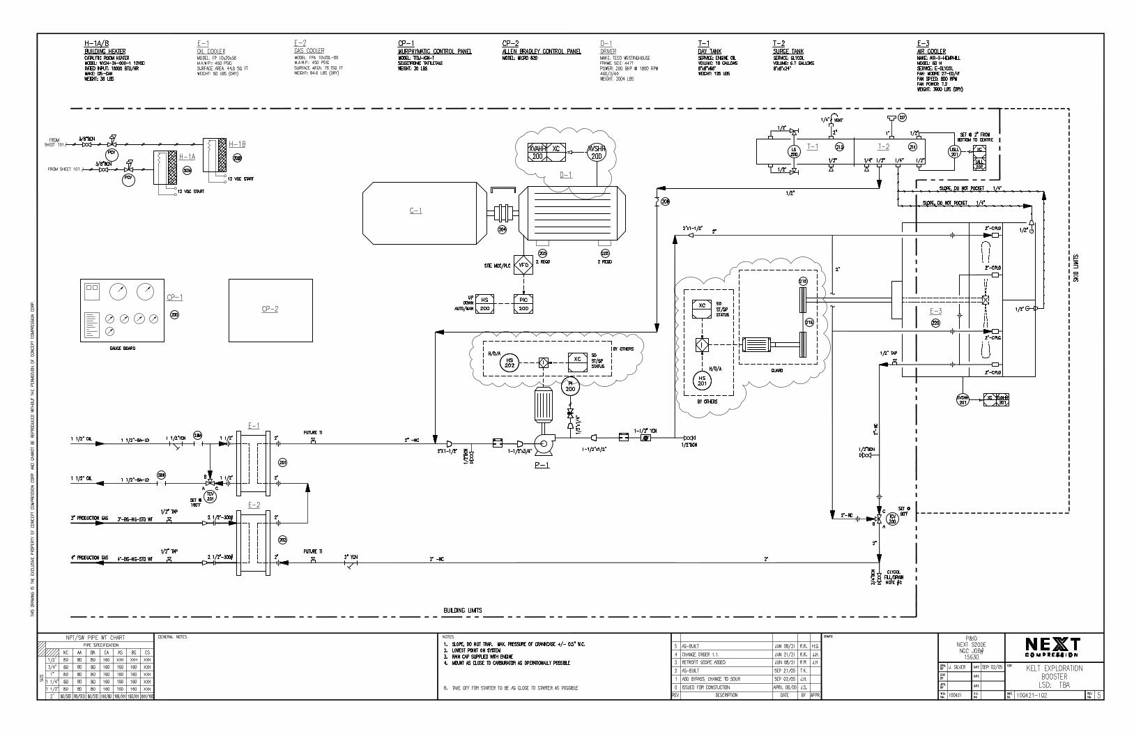

DRAWING INDEX
DRAWING INDEX
SPARTAN DWG No. DESCRIPTION REV.
CAD-1420-AA-010-00 DRAWING INDEX 0
CAD-1420-AA-100-00 CABINET LAYOUT 0
CAD-1420-AA-200-00 PNEUMATIC LOGIC AND BILL OF MATERIALS 0
CAD-1420-AA-600-00 MURPHY ANNUNCIATOR WIRING DIAGRAM 0
FIELD AS BUILT (CHANGE FROM ENGINE TO MOTOR)0 30 JUN 2021RDW MLA MLA MLA
NEXT COMPRESSION
COMPRESSOR CONTROL SYSTEM
-
-
LSD:
CAD1049
P.O.#REF. #
CAD-1420-AA-010-00NTS 0
CAD-1420-AA-700-00 RELAY BOX WIRING 0
June 30 2021 6:39PM
PERM
IT / EN
G. SEAL
REV. DESCRIPTION DESIGNDRAWNDATE CHK APP
THIS DRAWING, INCLUDING THE INFORMATION IT BEARS, IS THE PROPERTY OF SPARTAN CONTROLS AND
PROJECT
No.
SCALE: DRAWING
No.
REV.
MUST BE HELD IN STRICT CONFIDENCE AND PROPERLY SAFEGUARDED BY THE RECIPIENT AT ALL TIMES.
B
C
E
F
G
H
D
1 2 3 4 5 6 7 8
B
C
E
F
G
H
D
A
1 2 3 4 5 6 7 8

CABINET LAYOUT
TAG BB - (TAPED)
(LAMACOID SIZE: 1.5x3.5, COLOR: YELLOW)
PANEL NOT SUITABLE
FOR USE IN H S
(SOUR) ENVIRONMENTS
2
BLANK
BLANK
COMPRESSOR
OIL PRESSURE
20" X 20" GAUGE BOARD
DISCHARGE TEMP
COMPRESSOR
DIFF PRESSURE
COMPRESSOR
Input Voltage: 150VDC
Suitable for Class I, Div. 2 Locations, Grp C, D
10
F.W. MURPHY ANNUNCIATOR PANEL
Annunciation: 5VDC Non-Incendive
Manufacturer: F.W. MURPHY MANUFACTURER
Model: M03-019
OIL TEMPERATURE
COMPRESSOR
11
4 5
SUCTION PRESSURE
COMPRESSOR
2
1
12
PIC
DISCHARGE PRESSURE
COMPRESSOR
3
BB
9
AA
8
(LAMACOID SIZE: 1x4, COLOR: BLACK)
LAMACOID TAG 'AA'
SERIAL #M02-152-040
CAD-1420-AA-100-00
2019
FIELD AS BUILT (CHANGE FROM ENGINE TO MOTOR)0 30 JUN 2021RDW MLA MLA MLA
NEXT COMPRESSION
COMPRESSOR CONTROL SYSTEM
-
-
LSD:
CAD1049
P.O.#REF. #
NTS 0
July 08 2021 3:53PM
PERM
IT / EN
G. SEAL
REV. DESCRIPTION DESIGNDRAWNDATE CHK APP
THIS DRAWING, INCLUDING THE INFORMATION IT BEARS, IS THE PROPERTY OF SPARTAN CONTROLS AND
PROJECT
No.
SCALE: DRAWING
No.
REV.
MUST BE HELD IN STRICT CONFIDENCE AND PROPERLY SAFEGUARDED BY THE RECIPIENT AT ALL TIMES.
B
C
E
F
G
H
D
1 2 3 4 5 6 7 8
B
C
E
F
G
H
D
A
1 2 3 4 5 6 7 8
BLANK
19
COMPRESSOR
LOADING
21
EQUIPMENT RECORD # 10933927

BILL OF MATERIALS
14.
SUCTION PRESSURE "SWICHGAGE" - FIELD ADJUSTABLE
DIGITAL FAULT ANNUNCIATOR HEAD
OPLFC-S-200
TTD-H
PANEL LEGEND
10.
12.
13.
11.
7.
6.
4.
5.
3.
1.
2.
ITEM MODEL No. DESCRIPTION
COMPRESSOR OIL DIFFERENTIAL PRESSURE "SWICHGAGE" - SET FALLING 50PSID
DISCHARGE PRESSURE "SWICHGAGE" - FIELD ADJUSTABLE
COMPRESSOR OIL TEMPERATURE "SWICHGAGE" - FIELD ADJUSTABLE
"SOLD & SERVICED" TAG60PANEL TAGPIC
25CDPEF-100
20T-250-16-1/2MURPHY
-
MURPHY
MURPHY
MFR.
OPLFC-S-300
- - -
- -
MURPHY
MURPHY
HOFFMAN ASE886 8"x8"x6" ENCLOSURE TO COVER TTD
20T-250-16-1/2MURPHY COMPRESSOR DISCHARGE TEMPERATURE "SWICHGAGE" - FIELD ADJUSTABLE
ELECTRICAL FITTING 3/4"2535-
HI/LO COMPRESSOR OIL PRESSURE "SWICHGAGE" - FIELD ADJUSTABLE20P-HL-150MURPHY
UNLESS OTHERWISE NOTED ALL DEVICES ARE SHOWN IN THE SHELF POSITION.
ALL WIRING TO BE 18 GA. UNLESS OTHERWISE NOTED.
EARTH/NON-INCENDIVE CHASSIS/NON-INCENDIVE DC COM/CLOSE LOOP
GROUND SYMBOLS WILL BE SHOWN PER THE FOLLOWING:
THIS PANEL IS SUITABLE FOR USE IN CLASS I, DIV. 2, GROUP C&D HAZARDOUS LOCATIONS.
CAUTION: DISCONNECT ALL SENSOR LEADS BEFORE WELDING.
FOR SHUTDOWN OR ALARM. SPARE SHUTDOWNS WILL BE DEFAULTED TO CLASS "A".
INPUT #31 IS REMOTE LOCKOUT OR CLASS "A"
(INHIBITS CLASS "B1" & "B2" LOCKOUT TIMERS)
CLOSED SWITCHES.
DISPLAY #52 IS MANUAL STOP (INTERNAL)
EACH OF THE FIRST 16 INPUTS CAN BE CONFIGURED FOR CLASS A, B1, B2, OR C AND
INPUT #30 IS SELECTABLE REMOTE RESET OR CLASS "A"
INPUT #29 IS SELECTABLE CLASS "A" OR FOR EMERGENCY STOP (OVERRIDES TEST TIMER)
SENSOR INPUTS ARE PASSIVE SWITCHES. REMOVE FACTORY INSTALLED JUMPER FOR NORMALLY
FOR ADDITIONAL INFORMATION REFER TO INSTALLATION BULLETIN.
NORMALLY OPEN SENSORS ARE RETURNED TO GROUND TO ACTIVATE ANNUNCIATOR.
INPUT #32 TYPICALLY USED FOR EMERGENCY STOP (OVERRIDES TEST TIMER)
DISPLAY #51 IS UNDERSPEED/LOSS OF IGNITION (ON "T" MODEL ONLY)
DISPLAY #50 IS OVERSPEED (INTERNAL, ON "T" MODEL ONLY)
14.
15.
13.
12.
10.
11.
9.
8.
7.
6.
/ / / / / / / / / / / / / / / /
FACTORY WIRING:
END USER WIRING:
CUSTOMER WIRING:
MAXIMUM LENGTH OF SENSOR LEADS IS 200 FEET.
FITTINGS: N/A
TUBING: N/A
ROUTE SENSOR LEADS SEPARATE FROM ALL OTHER WIRING.
"18-BL-25" REPRESENTS "AWG-WIRE COLOR-WIRE NUMBER"
NOTES:
3.
4.
5.
2.
TUBING:
1.
9.
8. 50225495 VERTICAL LEGEND c/w 50225541
PIC
MURPHY
M03-019 BOARD 20"x20" ALUMINUM GAUGEBOARD
16.
15. - CI-1706 3/4" LOCK NUT
---
18-BL-118-BL-5
RED
2
BLK
SUCTIONPRESSURE
RED
3
18-BL-17
BLK
PRESSUREDISCHARGE
DIFF PRESSURE
COMPRESSOR OIL
4
18-BL-S3
18-BL-C3
N.C.
C
N.0.
5
18-BL-18
BLK
TEMPERATURE
COMPRESSOR OIL
10
18-BL-25
BLK
TEMPERATURE
COMPRESSOR DISCHARGE
18-BL-2
RED
11
PRESSURE
COMPRESSOR OIL
18-BL-7
BLK
1
1
-
1
1
1
1
1
1
QTY.
1
-
-
1
1
1
1
CAD-1420-AA-200-00
18.
17. -
MURPHY PSU-2-T DIV 2 POWER SUPPLY/C/W TACH TTD G-LEAD CHOKE (FERRITE ASSMBLY)
- -
1
-
19. MURPHY 05706163 2" HOLE COVER1
FIELD AS BUILT (CHANGE FROM ENGINE TO MOTOR)0 30 JUN 2021RDW MLA MLA MLA
NEXT COMPRESSION
COMPRESSOR CONTROL SYSTEM
-
-
LSD:
CAD1049
P.O.#REF. #
NTS 0
June 30 2021 6:38PM
PERM
IT / EN
G. SEAL
REV. DESCRIPTION DESIGNDRAWNDATE CHK APP
THIS DRAWING, INCLUDING THE INFORMATION IT BEARS, IS THE PROPERTY OF SPARTAN CONTROLS AND
PROJECT
No.
SCALE: DRAWING
No.
REV.
MUST BE HELD IN STRICT CONFIDENCE AND PROPERLY SAFEGUARDED BY THE RECIPIENT AT ALL TIMES.
B
C
E
F
G
H
D
1 2 3 4 5 6 7 8
B
C
E
F
G
H
D
A
1 2 3 4 5 6 7 8
20. MURPHY 05706178 2.5" HOLE COVER1
21. MURPHY 208PG-50 COMPRESSOR LOADING GAUGE1
21
LOADING
COMPRESSOR
18-BL-8

MURPHY ANNUNCIATOR WIRING DIAGRAM
2
4
2
11
11
3
18-BL-S2
18-BL-C2
18-BL-1
18-BL-5
18-BL-6
18-BL-7
18-BL-17
18-BL-18
18-BL-25
5
10
CAD-1420-AA-600-00
.
TERMINAL BLOCK LOCATED
MANUAL STOP
LOW DC VOLTAGE (ALARM)
LOSS OF SP1 LINK
WATCHDOG TIMER
B
A
62
61
A
A
A
B
52
60
50
51 UNDERSPEED
OVERSPEED
EMERGENCY STOP (OPTIOANL)
LOSS OF IGNITION (LESS THAN 90 VDC)
47ESD
B
48
49
ESD
.
46
45 .
REMOTE SHUTDOWN (OPTIONAL)
. 42
.
.
43
44
.
.
41
40
.
.
.
.
.
.
. 37
.
.
38
39
.
.
36
35
.
.
.
.
.
.32
.
.
33
34
.
.
31
30
.
.
.
TTD(J) SENSOR INPUT
OF SHUTDOWN ONLY. ACTUAL SHUTDOWN
1TB1
IS PHYSICALLY ON THE LEFT
ON BACK OF TTD
3132
SHOULD BE ACCOMPLISHED BY CUSTOMER'S
SHUTDOWN DEVICE MOUNTED LOCALLY.
48
47
46
45
42
43
44
41
40
37
38
39
36
35
32
33
34
31
30
N.O. SENSOR USED
NOTE: TYPICAL CONNECTION IF
ESD IS DESIGNED FOR ANNUNCIATION
09
09
WIRING
NON-INCENDIVE
.
HIGH SUCTION SCRUBBER LEVEL
HIGH COMPRESSOR OIL PRESSURE
.
.
HIGH COOLER VIBRATION
LOW AUXILIARY COOLANT LEVEL
HIGH COMPRESSOR DISCHARGE TEMPERATURE
.
HIGH COMPRESSOR VIBRATION
.
LOW OIL SEPARATOR LEVEL
.27
.
.29
28
.
A
26
25
.22
.
A
24
23
.
A
21
20
HIGH COMPRESSOR OIL TEMPERATURE
HIGH DISCHARGE PRESSURE
.
A17
A
A
19
18
.
.
16
15.
.12
.
.
14
13
.
.
11
10
.
.
.
.
.
.
LOW DISCHARGE PRESSURE
.
LOW SUCTION PRESSURE
.
LOW COMPRESSOR DIFFERENTIAL PRESSURE
LOW COMPRESSOR OIL PRESSURE
B107
.
B1
09
08
.
B1
06
05
DISPLAY
B1
.
B1
04
03
B1
CLASS
01
02
HIGH SUCTION PRESSURE
DESCRIPTION
INDICATOR READOUTS
27
28
29
26
25
22
24
23
21
20
17
19
18
16
15
12
14
13
11
10
07
09
08
06
05
02
04
03
01
COMMUNICATIONS ARE ONLY AVAILABLE
WHEN DC POWER IS APPLIED
INCENDIVE
WIRING
ALR
SETUP A = 1
A GOOD SKID GRD
CONNECT TO
RLY (DC SD)
IGN (IGN SD)
DC+
GND
FV+
FV-
TERMINAL BLOCK
RS485
RS232
18-G
MPU
AUX
A
B
BACK OF TTD
LOCATED ON
GND
RX
TX
1
..
TO CUSTOMER SUPPLIED
PLC ENCLOSURE
FIELD AS BUILT (CHANGE FROM ENGINE TO MOTOR)0 30 JUN 2021RDW MLA MLA MLA
NEXT COMPRESSION
COMPRESSOR CONTROL SYSTEM
-
-
LSD:
CAD1049
P.O.#REF. #
NTS 0
July 08 2021 3:22PM
PERM
IT / EN
G. SEAL
REV. DESCRIPTION DESIGNDRAWNDATE CHK APP
THIS DRAWING, INCLUDING THE INFORMATION IT BEARS, IS THE PROPERTY OF SPARTAN CONTROLS AND
PROJECT
No.
SCALE: DRAWING
No.
REV.
MUST BE HELD IN STRICT CONFIDENCE AND PROPERLY SAFEGUARDED BY THE RECIPIENT AT ALL TIMES.
B
C
E
F
G
H
D
1 2 3 4 5 6 7 8
B
C
E
F
G
H
D
A
1 2 3 4 5 6 7 8
3
18-BL-8
TO CUSTOMER SUPPLIED
POWER DISTRIBUTION

RELAY BOX WIRING
ALR
SETUP A = 1
RLY (DC SD)
IGN
GND
DC+
FV-
FV+
TERMINAL BLOCK
AUX
MPU
A
B
LOCATED ON
BACK OF TTD
GND
TX
RX
1
14
11
A1
CR1
A2
START
MOTOR
CUSTOMER SUPPLIED
INCENDIVE
WIRING
CAD-1420-AA-700-00
FIELD AS BUILT (CHANGE FROM ENGINE TO MOTOR)0 30 JUN 2021RDW MLA MLA MLA
NEXT COMPRESSION
COMPRESSOR CONTROL SYSTEM
-
-
LSD:
CAD1049
P.O.#REF. #
NTS 0
July 08 2021 3:22PM
PERM
IT / EN
G. SEAL
REV. DESCRIPTION DESIGNDRAWNDATE CHK APP
THIS DRAWING, INCLUDING THE INFORMATION IT BEARS, IS THE PROPERTY OF SPARTAN CONTROLS AND
PROJECT
No.
SCALE: DRAWING
No.
REV.
MUST BE HELD IN STRICT CONFIDENCE AND PROPERLY SAFEGUARDED BY THE RECIPIENT AT ALL TIMES.
B
C
E
F
G
H
D
1 2 3 4 5 6 7 8
B
C
E
F
G
H
D
A
1 2 3 4 5 6 7 8
PLC ENCLOSURE
TO CUSTOMER SUPPLIED
POWER DISTRIBUTION


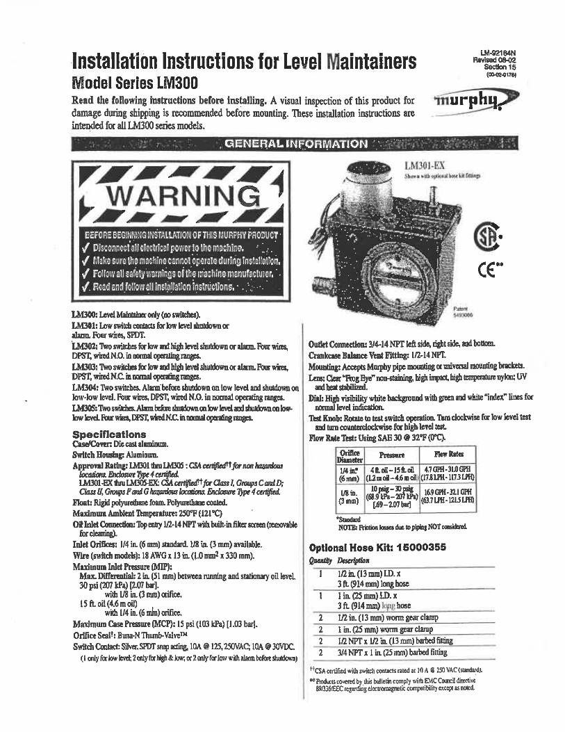


PSPHOENIX ENERGY SERVICES24VDC, 10ACLASS I, Div 2, Group B, C&D T3
WARNING: EXPLOSION HAZARD
CAUTION: DO NOT CONNECT ORDISCONNECT UNLESS AREA ISKNOWN TO BE NON-HAZARDOUSDo not service or replace fuse unless area is known to benon-hazardous. Replacement fuses bust be sand-filledand of the same type and rating as original.Substitution of components may impair the suitability for DIV2.Installation in Class I Div2/Zone2 area is subject to acceptance bythe local AUTHORITY HAVING JURISDICTION.

01
02
03
04
05
06
07
08
09
10
11
12
13
14
15
16
17
18
19
20
21
22
23
24
00
27
28
29
30
31
32
33
34
35
36
37
38
39
40
41
42
43
44
45
46
47
48
49
26
25

WW
W

DW
06/17/21
Rev 0
Tag Device Name Setpoint
PIT-100 Suction Pressure Tx. 1kPa PID PID
XA-100 Run Status Input Off Functional Open 0% Open*
Note 1
Note 2
Note 3
Note 4
Note 5
Note 6
Note 7
Note 8
Phoenix VRU PID Control Panel Job# 2106038
PID Has Manual Control ability on Local HMI.
Auto Load will wait warmup time before Loading.
Tag
De
vice
Nam
e
Rec
ycle
Val
ve
**N
ote
2,4
**
VFD
Sp
eed
**N
ote
2**
Blo
wd
ow
n V
alve
**N
ote
3,4
**
PY-
10
1
SY-1
00
BY-
10
0 Cause and Effect Diagram
Notes
Shutdowns Provided by External Device (Annunciator Panel).
PID Control of Suction Pressure, split range for Speed/Recycle.
Time Delay (Adjustable) for Blowdown after Input turns off.
Recycle and Blowdown Valves are Fail Open devices.
Manual Load will wait for operator to initiate Loading.

The new Allen-Bradley Micro820 20pt controller is specifically designed for small standalone machines and remote automation projects with embedded Ethernet and Serial ports. It can function as a RTU (remote terminal unit) for remote machines with support for Modbus RTU and TCP. It has embedded support for 4 thermistor temperature inputs for use as a DDC (direct digital controller) for Building Management Systems.
The Micro820 supports an embedded microSD slot that can be used for storing large amounts of data that normally cannot fit into memory for applications that require datalog and recipe. All files are stored in CSV text format for easy viewing and editing. The microSD card is also used for backing up and restoring the program, which can be used for duplicating the program in several machines.
The Allen-Bradley Micro800 Remote LCD Display connects to the controller’s embedded RS232 port and works as an essential accessory for the Micro820 controller. With 4 or 8 lines of ASCII text and a tactile keypad, it can be used as a simple HMI. Its system menu is available in multiple languages for direct viewing and editing of controller variables. Controller’s Ethernet address can also be easily set from the menu. Supports front panel mounting as well as DIN rail mounting next to the controller.
Micro820™ Programmable Logic ControllerBulletin 2080 Product Profile
Micro800 Remote LCD Display • USB port for program download
to controller• IP65 for front panel mount• Configurable start-up screen
Features and Benefits• Features optimized for small
standalone machines and remote automation projects
• EtherNet/IPTM for Connected Components WorkbenchTM
programming, RTU applications and HMI connectivity
• Built-in Real Time Clock (RTC) with no battery required
• microSDTM slot for program transfer, datalog and recipe
• Selected models available with removable terminal blocks for easier wiring and installation
• 5 KHz PWM Output for controlling solenoids and valves
Temperature : 24 CHumidity : 50%Pressure : 10 PSIAir Flow : 0.05 kg/s
* Readings on LCD Display are for illustration purposes only, not actual readings.

Catalog NumberInputs Outputs
120V AC 24V DC/ V AC Analog 0-10V (shared with 24V DC) Relay 24V DC SRC Analog 0-10V
2080-LC20-20QWB(R) - 12 4 7 - 12080-LC20-20QBB(R) - 12 4 - 7 12080-LC20-20AWB(R) 8 4 4 7 - 1
Micro820 20-pt QWB(R) 20-pt QBB(R) 20-pt AWB(R)Base Unit
Power SupplyBase Unit has embedded 24V DC
Power Supply. Optional External 120/240V AC via
Cat. No. 2080-PS120-240VACBase Programming Port Embedded Ethernet Port
Base EtherNet/IPTM port EtherNet/IP Class 3, Modbus TCP
Base Serial Port RS232/485 non-isolated, CIP Serial, Modbus RTU, ASCII
Plug-in Slots 210V Output for Thermistors
1 Output Reference (supports up to four 10k thermistors)
PWM Output 5 KHzmicroSD Card Slot 1Supported microSD Card Formats FAT32/16
microSD Card Size, Max 32GBmicroSD Card Class Speed Class 6 and 10 SDSC and SDHC
I/ODigital I/O (In/Out) 12/7 (4 Inputs shared with Analog Inputs)Analog I/O Channels 4/1ProgammingSoftware Connected Components WorkbenchProgram Steps (or instructions) 10Ksteps
Data (bytes) 20Kbytes (up to 400bytes non-volatile)
IEC 61131-3 Languages Ladder Diagram, Function Block, Structured Text
User Defined Function Blocks Yes
Motion Instructions No PTO motion supportedFloating Point Math 32-bit and 64-bitPID Loop Control YesEnvironmentsCertifications c-UL-us CL1DIV2, CE, C-Tick, KCTemperature Range (Controller) -20°…65°C
Dimensions (HxWxD, mm) 90x100x80
Bulletin 2080
Publication 2080-PP004A-EN-P – December 2013 Copyright ©2013 Rockwell Automation, Inc. All Rights Reserved. Printed in USA.
Allen-Bradley, Connected Components Workbench and Micro820 are trademarks of Rockwell Automation, Inc.Trademarks not belonging to Rockwell Automation are property of their respective companies.
LCD DisplayCommunications
Embedded Serial Port RS232 (connects to Controller’s Embedded RS232 port)
Embedded USB Port Controller programming port (USB to Serial pass-through)
EnvironmentalsTemperature Range (LCD Display) 0°…50°C
Dimensions (HxWxD, mm) 97x130x36
Catalog Number Plug-in Modules
2080-IQ4 4-pt Digital Input, 12/24VDC, Sink/Source, Type3
2080-OB4 4-pt Digital Output, 12/24VDC, Source2080-OV4 4-pt Digital Output, 12/24VDC, Sink2080-OW4I 4-pt Relay Output, Individually Isolated, 2A
2080-IQ4OB48-pt Combo: 4-pt Digital Input, 12/24VDC,
Sink/Source, Type3, and 4-pt Digital Output, 12/24VDC, Source
2080-IQ4OV48-pt Combo: 4-pt Digital Input, 12/24VDC,
Sink/Source, Type3, and 4-pt Digital Output, 12/24VDC, Sink
2080-IF2, 2080-IF4 2/4-ch Analog Input, 0-20 mA, 0-10V, non-isolated 12-bit
2080-OF2 2-ch Analog Output 0-20 mA, 0-10V, non-isolated 12-bit
2080-SERIALISOL RS232/485 isolated serial port2080-TRIMPOT6 6-ch Trimpot Analog Input2080-RTD2 2-ch RTD, non-isolated, ±1.0 °C2080-TC2 2-ch TC, non-isolated, ±1.0 °C
2080-MOT-HSC High Speed Counter, 250kHz, Differential Line Receiver, 1 Digital Output
2080-DNET20 DeviceNet Scanner, 20 NodesCatalog Number Accessories2080-PS120-240VAC External 120/240V AC power supply
2080-REMLCD Remote 3.5 in. LCD Display, 24V DC Power, 4 or 8 lines ASCII text
Removable terminal blocks are available on modules with catalog numbers that end in R. Catalog numbers that do not end in R have fixed terminal blocks.

6. Bill of Materials

100421A Kelt Exploration
Client BOM rev# 19-Jul-21
Drawing Reference: 100421A Clien BOMStatus Flag SAP_Part Tag Activity Code Item_Description Main_Group Qty
Material Cost
eachCurrency
Material Cost Total
CDNShort_Description Manufacturer Mfg._Part_Number Material_Description Supplier
1 $0 00
(1),(1), C 16‐Jun 2030627 F3201 Cooler Motor Motor Driver 1 $904.36 $904.36 Motor Teco 15 HP TEFC 1800 RPM Frame 254T Teco‐Westinghouse PDH0154 Motor Teco 15 HP TEFC 1800 RPM Frame 254T c/w SB254T Double Adjustable Slide baseTECO‐Westinghouse Motors
Canada Inc
(1),(4), C 16‐Jun Nonstock215
216F3201 Sheaves & Belts 1 $113.26 $113.26
Sheaves & Belts for Cooler Motor InstallMasterDrive ‐
Sheave & Belts for Cooler Motor Install
1 2B68SDS MST MASTERDRIVE QD SHEAVE
1 SDS1 5/8 MST MASTERDRIVE QD BUSHING
2 BX100 CAR CARLISLE V‐BELT
Transmission Supplies Ltd.
(1),(1), O 10‐Jun (‐6) 2027707 204 F3501 Coupling 1 $1,176.61 $1,176.61 Coupling PDR20X with 200E Sure‐Flex
11HS‐Altered
11CMPBX3.375‐11SC48‐
11SCHMPB
TB Woods Sure Flex Coupling for PDR20X Screw compressor with 200 hp Electric Motor, 11HS Hytrel sleeve (split), Altered 11CMPB X 3.375
: Type C flange, 11SC48: Type SC flange, 11SCHMPB: SC hub.Transmission Supplies Ltd
(4),(4), C 16‐Jun 2030632 205 F3501 Engine Driver 4 $179.55 $718.20 Mounting Chock, Adjustable, 5/8" bolt, 35‐45mm
height, 80 mm OD, Vibracon SM16‐CSTRVibracon SM16‐CSTR Mounting Chock, Adjustable, 5/8" bolt, 35‐45mm height, 80 mm OD, Vibracon SM16‐CSTR JCI Filtration & Separation Inc
(1),(1), C 16‐Jun 2000890 PCV‐103 F6101 Instrumentation 1 $1,677.00 $1,677.00 valve control D4 1 NPT 3/4 orifice fail open
natural gasFisher D4
Fisher D4 Control Valve, 1" NPT Connections, Standard Materials 2250 psig pressure rating 3/4" orifice, 0 to 35 psig, Fail Open Service:
Natural Gas CondensateSpartan Controls Ltd.
(3),(1), C 16‐Jun 2000878 F6101 Piping 1 $19.08 $19.08 K Valve Needle NPT Carbon Steel 1/4F x 1/4F
6000# SourWGI WN1612PN K Needle Valve, 1/4" FNPT x 1/4" FNPT c/w Carbon Steel Body, Stainless Steel Stem, PTFE Packing, 6000# WOG rating
ValvSource Equipment
Limited
(1),(1), C 16‐Jun 2027710 F6101 Drain Pump Pumps 1 $797.00 $797.00 Yamada Pneumatic Pump (Condensate) 6gpm @
6scfm, 100psig air supplyYamada NDP‐15‐BAN
Yamada Liquid Pump Flow 6 gpm utilizing 6 scfm, gas supply MAWP 100 psig, Pump casting MAWP 300 psig, Diaphram material: Buna,
Maximum operating temperature 180°F C/w 1/2" FNPT inlet and outlet connections, Air inlet connetion 1/4" FNPT & ball valve.
Smith Cameron Process
Solutions
Rel'd , DTO = 2028290 PCV‐116 F6101 Regulator for Drain Pump Instrumentation 1 $137.75 $137.75 Regulator, Fisher 67CFR, 1/4" NPT, 0 ‐ 125 PSI,
AJD Screw, W/Pressure gaugeFisher 67 CFR/E1409SS
Regulator, Fisher 67CFR, 1/4" NPT, 0 ‐ 125 PSI, AJD Screw, W/Pressure gaugeFisher 67 Regulator1/4" NPT Tapped‐Bonnet Type: 67CFR, 0‐
125 psi, Adjustable Spring Range, 5 Micron Filter, Internal Relief: Yes, Adj Screw with Closing CapWinters E1409SS Pressure Gauge0‐160
psi/kpa range, 2" dial / 1/4" NPT center back mount, 316 SST tube & socket
Spartan Controls Ltd.
(1),(1), O 9‐Jun (0) 2000946 ‐ $ UY‐108 F6101 Amot Shuttle Valve Valves 1 $324.22 $324.22 Valve Solenoid Pneumatic Natural Gas
4057D031H2Amot 4057D031H2
Amot 4057 Valve Model 4057D031H2 Type CG 3‐way Valve Precision Cast Aluminum Body Material 0.031 or 5/16 inch NPT Viton Seal
Material Service: Natural gasSpartan Controls Ltd.
Rel'd , DTO = 2000820 F6101 Isolation Valves Piping 2 $17.68 $35.36 Valve Ball 1/2 NPT 316SS Reg Port 2000# Locking
Handle NACENewco 5A‐C1R05S20A21 Ball Valve, 1/2" NPT, Stainless Steel Locking Handle regular port, 2000# WOG, 316 SS NACE trim. MRC Global (Canada) Ltd
Rel'd , DTO = 2027993 F6101 Y‐Strainer Piping 1 $48.12 $48.12 Y strainer threaded ends cast steel 1/2 SS mesh
600#Predator SY160TN03 Y Strainer, 0.5" NPT, Cast Steel Body, CL 600 rating, stainless steel mesh Model: SY160TN03 Service: Natural Gas / Oil
Cascade Flow Control
Solutions
(1),(1), C 17‐Jun 2030630 PCV‐101 F6101 BPCV Instrumentation 1 $3,361.50 $3,361.50 Valve Control Sur‐Flo Wafer Bladder 4 300# c/w
Centering KitSur‐Flo SF10V‐C‐V‐S63‐4.3
4" 300 ANSI Control Valve CS Housing w/ Viton
Sleeve & S63 SST Cones
MAX DP OF 352 PSI
c/w Centering Kit
Sur‐Flo Meters & Controls Ltd.
Rel'd , DTO = 2000585 PCV‐109 F6101 Regulator for Drain Pump Instrumentation 1 $337.50 $337.50 Regulator 1/4 NPT 5‐400psig low bleed MAWP
500psigFairchild 10292BE
Fairchild Series 10 Outlet Pressure Regulator c/w 1/4" NPT connections, 5 to 400 psi spring range Mounting Bracket Model: EB‐09921
Service: Instrument GasTelematic Controls Inc.
(1),(1), C 16‐Jun 2000415 106 F6101 Instrument Air Filter Instrumentation 1 $169.32 $169.32 Filter Assy. Coalescing 1/2"FNPT MAWP 500psig Finite HN2L‐10CNParker Filter Model: HN2L‐10CN Connection: 1/2" NPT c/w Drain valve, CRN, MAWP 500 psig Replacement Element: Model No: 25‐178‐70C
Service: Natural gas
Twister Instrumentation &
Process Solutions Inc
Rel'd , DTO = 2000820 F6101 Isolation Valves Piping 1 $17.68 $17.68 Valve Ball 1/2 NPT 316SS Reg Port 2000# Locking
Handle NACENewco 5A‐C1R05S20A21 Ball Valve, 1/2" NPT, Stainless Steel Locking Handle regular port, 2000# WOG, 316 SS NACE trim. MRC Global (Canada) Ltd
(3),(1), C 16‐Jun 2000878 F6101 Needle Valve Piping 1 $19.08 $19.08 K Valve Needle NPT Carbon Steel 1/4F x 1/4F
6000# SourWGI WN1612PN K Needle Valve, 1/4" FNPT x 1/4" FNPT c/w Carbon Steel Body, Stainless Steel Stem, PTFE Packing, 6000# WOG rating
ValvSource Equipment
Limited
Rel'd , DTO = 2028289 PCV‐110 F6101 Instrument Air Regulator Instrumentation 1 $137.75 $137.75 Regulator, Fisher 67CFR, 1/4" NPT, 0 ‐ 60 PSI,
AJD Screw, W/Pressure gaugeFisher 67 CFR/E1405SS
Regulator, Fisher 67CFR, 1/4" NPT, 0 ‐ 60 PSI, AJD Screw, W/Pressure gauge Fisher 67 Regulator 1/4" NPT Tapped‐Bonnet Type: 67CFR, 0‐
60 psi, Adjustable Spring Range, 5 Micron Filter Internal Relief: Yes, Adj Screw with Closing Cap Winters E1405SS Pressure Gauge 0‐60
psi/kpa range, 2" dial / 1/4" NPT center back mount, 316 SST tube & socket
Spartan Controls Ltd.
(1),(1), C 17‐Jun 2030633 PSV‐100 F6101 Suction PSV Instrumentation 1 $337.77 $337.77 Valve pressure safety 1FNPT X 1FNPT orifice D
Set 125psig, fire case, Sour trimMercer 91‐16D51V07EN2
Mercer Pressure Safety Valve, Mercer 91‐16D51V07EN2 , 1" FNPT x 1" FNPT connec ons, Set pressure 125psi, D Orifice, CS Body,316 Trim,
316 spring, FKM seat and sealsService: Sour Natural GasMercer Valve Co., INC.
(1),(1), C 17‐Jun 2028388 PSV‐101 F6101 Discharge PSV Instrumentation 1 $265.83 $265.83 Valve pressure safety 1MNPT X 1FNPT orifice E
Set 245psig SourMercer 81‐17151V10N11
Mercer Pressure Safety Valve, Mercer 81‐17151V11N11, 1" MNPT x 1" FNT connec ons, Set pressure 245psi, E Orifice, CS Body,316 Trim,
Inconel X750 spring, viton seat, Service: Sour Natural GasMercer Valve Co., INC.
(1),(1), O 10‐Jun (‐6) 2000694 107 F6101 Start‐up Strainer Piping 1 $155.67 $155.67 Strainer Cone Wafer CS 8 150# 1/8" Perforation,
150% Open, 20 mesh, Sch. STD
Failure Prevention
ServicesStrainer Cone Wafer CS 8 150# 1/8" Perforation, 150% Open, 20 mesh, Sch. STD Failure Prevention Services
Rel'd , DTO = 2030699 FE‐101 F6100 Meter Run Instrumentation 1 $3,783.06 $3,783.06 Meter Run, 2"‐600 RF, Sch80, Dual chamber, 3
PC, CS, NACE internals‐ No Manufacturer ‐
260RFDC80SAW00WFTT_
ABA9‐FF‐CB‐N‐0
Meter Run, 2"‐600 RF, Sch80, Dual chamber, 3 PC, CS, NACE internals, Grease Seat, 600 WxF Teletaps, AGA 2016 Ed., A216WCB (NACE),
LEFT HAND, O‐PLT 2"x1/8" 1.000" 316SS, K‐Style 316 SS, HNBR, 85D, Pipe: Cold Drawn, A106B / A105N, OAL:57", AGA 2016, Upstream:
600RF, Downstream: 600RF, Contour Flow Cond.: RF, 0.75 Beta, Outlets: 1"TOL, 0.75"TOL, Includes Hydro Test, MTR's, Canalta Inspection,
Canalta Standard Paint
Canalta Controls Ltd
stock transfer 2023886 F6100Coalescing Filter element
for Oil SeparatorFilters 1 $397.68 $397.68
Element Coalescing NEXT 1036H 26" x 11.5",
22.66 ft sq, 99.97% @ 0.1 micronFPS NEXT‐1036H
NEXT‐1036H filter oil compressor element coalescing Open Both ends, Viton O ring seal 26" x 11.5", 22.66 sq 99.97 @ 0.1 micronFPS P/N:
FPD0110‐208#1750‐016PFailure Prevention Services
(1),(1), O 9‐Jun (‐1) 2000418 F7501 Oil Filter Fluid 1 $912.44 $912.44 Filter Assy. Oil Compressor 1‐1/2NPT HAK05 (no
bypass)Donaldson K05‐0765NB
Donaldson Oil Filter Housing Model No: HAK05 no bypass K05‐0765NB C/W Element Model No:P164697 Replacement Element Model
No:P164699 c/w viton seal, 1.5" FNPT connections, 4 micron element, DP indicator mounted on left side. 100 psig collapse rating. Service:
Compressor OilDO NOT PURCHASE THIS ‐ USE PART# 2021854 INSTEAD
LD Filtration
Rel'd , DTO = 2030717 F7501 Extra oil filter Filters 1 $110.65 $110.65 Element Oil Filter Donaldson P176221 P176221 filter oil hydraulic spin‐on Corona Supplies LD Filtration
(2),(2), O 14‐Jun (‐4) 2026819 F7501 Filter Isolation Valves Valves 2 $46.33 $92.66
Valve, Ball, 1‐1/2" NPT, Stainless Steel, Locking
Handle, regular port, 2000# WOG, 316 SS NACE
tri
Navco C1‐R15S20A Valve, Ball, 1‐1/2" NPT, Stainless Steel, Locking Handle, regular port, 2000# WOG, 316 SS NACE trim. MRC Global (Canada) Ltd
Rel'd , DTO = 2022934 F7501 Sample/Vent Valve Valves 1 $25.88 $25.88 Valve Needle 1/2" MNPT x FNPT. 10,000PSI
NACEWGI WN1534N Needle valve, WGI WN1534N1/2" MNPT x 1/2" FNPT, straight, hard seat, standard flow10 000psi, carbon steel, SS Trim,NACE
ValvSource Equipment
Limited
(1),(1), C 16‐Jun 2027341 TCV‐201 F7501 Oil Thermostatic Valve Cooling 1 $914.07 $914.07 Thermostatic 3‐Way Valve c/w 1‐1/2" FNPT 160‐
180FFluid Power S1530170
Thermosta c 3‐Way Valve c/w 1‐1/2" FNPT 160‐180F (FPE)Model No: S1530‐170 1.5" NPTElement full open at 180 degree F, standard trim,
Steel body, MAWP ‐ 500 psigService: OilZimco Instrumentation
(1),(1), C 16‐Jun 2029116 P‐1 F7601 Coolant Pump Pumps 1 $1,395.00 $1,395.00 Pump, Coolant, AC4 serice, 3/4"x1/2"x3" IMP,
5HP 3600 RPM, 230/460/3/60TEFCFinish Thompson AC4STS1V300B015C09
Finish‐Thompson Coolant PumpModel: AC4STS1V300B015C09AC4 SERIES 3/4"x1/2"x3" IMPW/.5 HP 3600 RPM 230/460/3/60 TEFC316SS
Construc on 3.00" Impeller w/ Viton O‐RingFlow: 15 US GPM @ 37' TDHMotor: 1/2HP, 3600rpm, TEFCVoltage: 230/460/3/60HzService
50/50 Glycol/Water.
Smith Cameron Process
Solutions
Rel'd , DTO = 2028718 F7601Butterfly Valve
(Throttling)Valves 1 $28.65 $28.65
Butterfly Valve Wafer CI/ENP‐DI/Buna w/Lever
ANSI 125, 2"Predator EW52NBL08 Bu erfly Valve Wafer 2", Cast Iron Body, Nickel Plated (ENP) Duc le Iron Disc, 416 SS Stem, BUNA‐N Seat Liner,Predator EW52NBL08
Cascade Flow Control
Solutions
Rel'd , DTO = 2018259 F7601 Hub Flanges Piping 2 $14.83 $29.66 Flange THD 2" 150# RF x 2" NPT SA105N ‐ No Manufacturer ‐ Flange THD 2" 150# RF x 2" NPT SA105N Trans Am Piping Products Ltd.
Rel'd , DTO = 2004288 F7601 Pressure Gauge Instrumentation 1 $23.30 $23.30 Gauge Press 0‐60PSI 2‐1/2 1/4 CBM Wika 9207338 9207338 233.53 Gauge Press 0‐60PSI 2‐1/2 1/4 CBM SS Connection WIKA Instruments Ltd.
(3),(1), C 16‐Jun 2000878 F7601 Needle Valve Piping 1 $19.08 $19.08 K Valve Needle NPT Carbon Steel 1/4F x 1/4F
6000# SourWGI WN1612PN K Needle Valve, 1/4" FNPT x 1/4" FNPT c/w Carbon Steel Body, Stainless Steel Stem, PTFE Packing, 6000# WOG rating
ValvSource Equipment
Limited
Rel'd , DTO = 2000421 F7601 Flexible Coupling Piping 2 $71.70 $143.40 Coupling Assy. 200P Flexmaster NH1600C200B0400 Flexmaster coupling, 2.0" 200P Gregg Distributors
Rel'd , DTO = 2030733 CP‐1 F8101Murphy Panel Components
‐ 24VDC relayPanel 1 $86.19 $86.19 RELAY TERM BLK 20MA 24VDC Murphy 80.010.4005.0 RELAY TERM BLK 20MA 24VDC, 80.010.4005.0 Spartan Controls Ltd.
Rel'd , DTO = 2030734 CP‐1 F8101Murphy Panel Components
‐ Display HeadPanel 1 $885.58 $885.58
DISPLAY HEAD ONLY, 48 PT DIGITAL FAULT
ANNUNCMurphy TTD‐H DISPLAY HEAD ONLY, 48 PT DIGITAL FAULT ANNUNC (W), TTD‐H Spartan Controls Ltd.
Rel'd , DTO = 2030735 CP‐1 F8101Murphy Panel Components
‐ Power SupplyPanel 1 $505.19 $505.19
POWER SUPPLY (NO TACH) FOR TTD‐H, CL 1 BCD
DIV 2Murphy PSU‐2 POWER SUPPLY (NO TACH) FOR TTD‐H, CL 1 BCD DIV 2, PSU‐2 Spartan Controls Ltd.
Page 1 of 1
Copyright © 2022 FDOKUMEN