Operation and Maintenance Manual - Power TK
136
Operation and Maintenance Manual 1206F-E70TA and 1206F-E70TTA Industrial Engines BM (Engine) BN (Engine) SEBU8732 September 2013
-
Upload
khangminh22 -
Category
Documents
-
view
0 -
download
0
Transcript of Operation and Maintenance Manual - Power TK

Operation andMaintenanceManual1206F-E70TA and 1206F-E70TTAIndustrial EnginesBM (Engine)BN (Engine)
SEBU8732September 2013

Important Safety InformationMost accidents that involve product operation, maintenance and repair are caused by failure toobserve basic safety rules or precautions. An accident can often be avoided by recognizing potentiallyhazardous situations before an accident occurs. A person must be alert to potential hazards. Thisperson should also have the necessary training, skills and tools to perform these functions properly.
Improper operation, lubrication, maintenance or repair of this product can be dangerous andcould result in injury or death.
Do not operate or perform any lubrication, maintenance or repair on this product, until you haveread and understood the operation, lubrication, maintenance and repair information.
Safety precautions and warnings are provided in this manual and on the product. If these hazardwarnings are not heeded, bodily injury or death could occur to you or to other persons.
The hazards are identified by the “Safety Alert Symbol” and followed by a “Signal Word” such as“DANGER”, “WARNING” or “CAUTION”. The Safety Alert “WARNING” label is shown below.
The meaning of this safety alert symbol is as follows:
Attention! Become Alert! Your Safety is Involved.
The message that appears under the warning explains the hazard and can be either written orpictorially presented.
Operations that may cause product damage are identified by “NOTICE” labels on the product and inthis publication.
Perkins cannot anticipate every possible circumstance that might involve a potential hazard. Thewarnings in this publication and on the product are, therefore, not all inclusive. If a tool, procedure,work method or operating technique that is not specifically recommended by Perkins is used,you must satisfy yourself that it is safe for you and for others. You should also ensure that theproduct will not be damaged or be made unsafe by the operation, lubrication, maintenance orrepair procedures that you choose.
The information, specifications, and illustrations in this publication are on the basis of information thatwas available at the time that the publication was written. The specifications, torques, pressures,measurements, adjustments, illustrations, and other items can change at any time. These changes canaffect the service that is given to the product. Obtain the complete and most current information beforeyou start any job. Perkins dealers or Perkins distributors have the most current information available.
When replacement parts are required for thisproduct Perkins recommends using Perkins replacement parts.Failure to heed this warning can lead to prema-ture failures, product damage, personal injury ordeath.

Table of Contents
Foreword.............................. ............................. 4
Safety Section
Safety Messages....................... ....................... 5
General Hazard Information ............... .............. 8
Burn Prevention....................... ........................11
Fire Prevention and Explosion Prevention ... .. 12
Crushing Prevention and Cutting Prevention . 14
Mounting and Dismounting............... .............. 14
High Pressure Fuel Lines ................ ............... 15
Before Starting Engine ................. .................. 16
Engine Starting........................ ....................... 16
Engine Stopping ....................... ...................... 17
Electrical System...................... ...................... 17
Engine Electronics..................... ..................... 18
Product InformationSection
General Information.................... .................... 20
Product Identification Information.......... ......... 29
Operation Section
Lifting and Storage..................... ..................... 32
Features and Controls .................. .................. 36
Engine Diagnostics..................... .................... 58
Engine Starting........................ ....................... 63
Engine Operation...................... ...................... 66
Cold Weather Operation................. ................ 68
Engine Stopping ....................... ...................... 72
MaintenanceSection
Refill Capacities....................... ....................... 74
Maintenance Recommendations.......... .......... 88
Maintenance Interval Schedule ........... ........... 91
Warranty Section
Warranty Information .................. .................. 127
Reference InformationSection
ReferenceMaterials .................. ................... 128
Index Section
Index............................... .............................. 131
SEBU8732 3Table of Contents

Foreword
Literature InformationThis manual contains safety, operation instructions,lubrication and maintenance information. This manualshould be stored in or near the engine area in aliterature holder or literature storage area. Read,study and keep it with the literature and engineinformation.
English is the primary language for all Perkinspublications. The English used facilitates translationand consistency.
Some photographs or illustrations in this manualshow details or attachments that may be differentfrom your engine. Guards and covers may have beenremoved for illustrative purposes. Continuingimprovement and advancement of product designmay have caused changes to your engine which arenot included in this manual. Whenever a questionarises regarding your engine, or this manual, pleaseconsult with your Perkins dealer or your Perkinsdistributor for the latest available information.
SafetyThis safety section lists basic safety precautions. Inaddition, this section identifies hazardous, warningsituations. Read and understand the basicprecautions listed in the safety section beforeoperating or performing lubrication, maintenance andrepair on this product.
OperationOperating techniques outlined in this manual arebasic. They assist with developing the skills andtechniques required to operate the engine moreefficiently and economically. Skill and techniquesdevelop as the operator gains knowledge of theengine and its capabilities.
The operation section is a reference for operators.Photographs and illustrations guide the operatorthrough procedures of inspecting, starting, operatingand stopping the engine. This section also includes adiscussion of electronic diagnostic information.
MaintenanceThe maintenance section is a guide to engine care.The illustrated, step-by-step instructions are groupedby service hours and/or calendar time maintenanceintervals. Items in the maintenance schedule arereferenced to detailed instructions that follow.
Recommended service should be performed at theappropriate intervals as indicated in the MaintenanceInterval Schedule. The actual operating environmentof the engine also governs the Maintenance IntervalSchedule. Therefore, under extremely severe, dusty,wet or freezing cold operating conditions, morefrequent lubrication and maintenance than isspecified in the Maintenance Interval Schedule maybe necessary.
The maintenance schedule items are organized for apreventive maintenance management program. If thepreventive maintenance program is followed, aperiodic tune-up is not required. The implementationof a preventive maintenance management programshould minimize operating costs through costavoidances resulting from reductions in unscheduleddowntime and failures.
Maintenance IntervalsPerformmaintenance on items at multiples of theoriginal requirement.We recommend that themaintenance schedules be reproduced and displayednear the engine as a convenient reminder. We alsorecommend that a maintenance record be maintainedas part of the engine's permanent record.
Your authorized Perkins dealer or your Perkinsdistributor can assist you in adjusting yourmaintenance schedule to meet the needs of youroperating environment.
OverhaulMajor engine overhaul details are not covered in theOperation and Maintenance Manual except for theinterval and the maintenance items in that interval.Major repairs should only be carried out by Perkinsauthorized personnel. Your Perkins dealer or yourPerkins distributor offers a variety of optionsregarding overhaul programs. If you experience amajor engine failure, there are also numerous afterfailure overhaul options available. Consult with yourPerkins dealer or your Perkins distributor forinformation regarding these options.
California Proposition 65 WarningDiesel engine exhaust and some of its constituentsare known to the State of California to cause cancer,birth defects, and other reproductive harm. Batteryposts, terminals and related accessories contain leadand lead compounds.Wash hands after handling.
4 SEBU8732Foreword

Safety Sectioni05192372
Safety Messages
There may be several specific warning signs on yourengine. The exact location and a description of thewarning signs are reviewed in this section. Pleasebecome familiar with all warning signs.
Ensure that all of the warning signs are legible. Cleanthe warning signs or replace the warning signs if thewords cannot be read or if the illustrations are notvisible. Use a cloth, water, and soap to clean thewarning signs. Do not use solvents, gasoline, or otherharsh chemicals. Solvents, gasoline, or harshchemicals could loosen the adhesive that secures thewarning signs. The warning signs that are loosenedcould drop off the engine.
Replace any warning sign that is damaged ormissing. If a warning sign is attached to a part of theengine that is replaced, install a new warning sign onthe replacement part. Your Perkins dealer or yourPerkins distributor can provide new warning signs.
UniversalWarning 1
Do not operate or work on this equipment unlessyou have read and understand the instructionsand warnings in the Operation and MaintenanceManuals. Failure to follow the instructions or heedthe warnings could result in serious injury ordeath.
SEBU8732 5Safety Section
Safety Messages

Illustration 1 g03022899
Typical example
The universal warning label is install in two positionson the engine. On the valve mechanism cover and onthe intake manifold, refer to illustration 1 .
Ether Warning 2
Do not use aerosol types of starting aids such asether. Such use could result in an explosion andpersonal injury.
Illustration 2 g03023096
Typical example
6 SEBU8732Safety SectionSafety Messages

The ether warning label is installed on the intakemanifold, refer to illustration 2 .
Hand (High Pressure) 3
Contact with high pressure fuel may cause fluidpenetration and burn hazards. High pressure fuelspray may cause a fire hazard. Failure to followthese inspection, maintenance and service in-structionsmay cause personal injury or death.
Illustration 3 g03023097
Typical example
The hand high-pressure warning label is a rap aroundlabel installed on the main injection line, refer toillustration 3 .
SEBU8732 7Safety Section
Safety Messages

i05192438
General Hazard Information
Illustration 4 g00104545
Attach a “Do Not Operate” warning tag or a similarwarning tag to the start switch or to the controlsbefore the engine is serviced or before the engine isrepaired. Attach the warning tags to the engine and toeach operator control station. When appropriate,disconnect the starting controls.
Do not allow unauthorized personnel on the engine,or around the engine when the engine is beingserviced.
• Tampering with the engine installation or tamperingwith the OEM supplied wiring can be dangerous.Personal injury, death and/or engine damagecould result.
• Vent the engine exhaust to the outside when theengine is operated in an enclosed area.
• If the engine is not running, do not release thesecondary brake or the parking brake systemsunless the vehicle is blocked or unless the vehicleis restrained.
• Wear a hard hat, protective glasses, and otherprotective equipment, as required.
• When work is performed around an engine that isoperating, wear protective devices for ears in orderto help prevent damage to hearing.
• Do not wear loose clothing or jewelry that can snagon controls or on other parts of the engine.
• Ensure that all protective guards and all covers aresecured in place on the engine.
• Never put maintenance fluids into glasscontainers. Glass containers can break.
• Use all cleaning solutions with care.
• Report all necessary repairs.
Unless other instructions are provided, perform themaintenance under the following conditions:
8 SEBU8732Safety SectionGeneral Hazard Information

• The engine is stopped. Ensure that the enginecannot be started.
• The protective locks or the controls are in theapplied position.
• Engage the secondary brakes or parking brakes.
• Block the vehicle or restrain the vehicle beforemaintenance or repairs are performed.
• Disconnect the batteries when maintenance isperformed or when the electrical system isserviced. Disconnect the battery ground leads.Tape the leads in order to help prevent sparks. Ifequipped, allow the diesel exhaust fluid to bepurged before disconnecting the battery.
• If equipped, disconnect the connectors for the unitinjectors that are located on the valve cover base.This action will help prevent personal injury fromthe high voltage to the unit injectors. Do not comein contact with the unit injector terminals while theengine is operating.
• Do not attempt any repairs or any adjustments tothe engine while the engine is operating.
• Do not attempt any repairs that are notunderstood. Use the proper tools. Replace anyequipment that is damaged or repair theequipment.
• For initial start-up of a new engine or for starting anengine that has been serviced, make provisions tostop the engine if an overspeed occurs. Thestopping of the engine may be accomplished byshutting off the fuel supply and/or the air supply tothe engine. Ensure that only the fuel supply line isshut off. Ensure that the fuel return line is open.
• Start the engine from the operators station (cab).Never short across the starting motor terminals orthe batteries. This action could bypass the engineneutral start system and/or the electrical systemcould be damaged.
Engine exhaust contains products of combustionwhich may be harmful to your health. Always start theengine and operate the engine in a well ventilatedarea. If the engine is in an enclosed area, vent theengine exhaust to the outside.
Cautiously remove the following parts. To helpprevent spraying or splashing of pressurized fluids,hold a rag over the part that is being removed.
• Filler caps
• Grease fittings
• Pressure taps
• Breathers
• Drain plugs
Use caution when cover plates are removed.Gradually loosen, but do not remove the last two boltsor nuts that are located at opposite ends of the coverplate or the device. Before removing the last two boltsor nuts, pry the cover loose in order to relieve anyspring pressure or other pressure.
Illustration 5 g00702020
• Wear a hard hat, protective glasses, and otherprotective equipment, as required.
• When work is performed around an engine that isoperating, wear protective devices for ears in orderto help prevent damage to hearing.
• Do not wear loose clothing or jewelry that can snagon controls or on other parts of the engine.
• Ensure that all protective guards and all covers aresecured in place on the engine.
• Never put maintenance fluids into glasscontainers. Glass containers can break.
• Use all cleaning solutions with care.
• Report all necessary repairs.
Unless other instructions are provided, performthe maintenance under the following conditions:
SEBU8732 9Safety Section
General Hazard Information

• The engine is stopped. Ensure that the enginecannot be started.
• Disconnect the batteries when maintenance isperformed or when the electrical system isserviced. Disconnect the battery ground leads.Tape the leads in order to help prevent sparks.
• Do not attempt any repairs that are notunderstood. Use the proper tools. Replace anyequipment that is damaged or repair theequipment.
Pressurized Air and WaterPressurized air and/or water can cause debris and/orhot water to be blown out. This action could result inpersonal injury.
When pressurized air and/or pressurized water isused for cleaning, wear protective clothing, protectiveshoes, and eye protection. Eye protection includesgoggles or a protective face shield.
The maximum air pressure for cleaning purposesmust be below 205 kPa (30 psi). The maximum waterpressure for cleaning purposes must be below275 kPa (40 psi).
Fluid PenetrationPressure can be trapped in the hydraulic circuit longafter the engine has been stopped. The pressure cancause hydraulic fluid or items such as pipe plugs toescape rapidly if the pressure is not relieved correctly.
Do not remove any hydraulic components or partsuntil pressure has been relieved or personal injurymay occur. Do not disassemble any hydrauliccomponents or parts until pressure has been relievedor personal injury may occur. Refer to the OEMinformation for any procedures that are required torelieve the hydraulic pressure.
Illustration 6 g00687600
Always use a board or cardboard when you check fora leak. Leaking fluid that is under pressure canpenetrate body tissue. Fluid penetration can causeserious injury and possible death. A pin hole leak cancause severe injury. If fluid is injected into your skin,you must get treatment immediately. Seek treatmentfrom a doctor that is familiar with this type of injury.
Containing Fluid SpillageCare must be taken to ensure that fluids arecontained during performance of inspection,maintenance, testing, adjusting, and repair of theproduct. Be prepared to collect the fluid with suitablecontainers before opening any compartment ordisassembling any component containing fluids.
Dispose of all fluids according to local regulations andmandates.
Inhalation
Illustration 7 g00702022
ExhaustUse caution. Exhaust fumes can be hazardous tohealth. If you operate the equipment in an enclosedarea, adequate ventilation is necessary.
10 SEBU8732Safety SectionGeneral Hazard Information

Asbestos InformationPerkins equipment and replacement parts that areshipped from Perkins engine company limited areasbestos free. Perkins recommends the use of onlygenuine Perkins replacement parts. Use the followingguidelines when you handle any replacement partsthat contain asbestos or when you handle asbestosdebris.
Use caution. Avoid inhaling dust that might begenerated when you handle components that containasbestos fibers. Inhaling this dust can be hazardousto your health. The components that may containasbestos fibers are brake pads, brake bands, liningmaterial, clutch plates, and some gaskets. Theasbestos that is used in these components is usuallybound in a resin or sealed in some way. Normalhandling is not hazardous unless airborne dust thatcontains asbestos is generated.
If dust that may contain asbestos is present, there areseveral guidelines that should be followed:
• Never use compressed air for cleaning.
• Avoid brushing materials that contain asbestos.
• Avoid grinding materials that contain asbestos.
• Use a wet method in order to clean up asbestosmaterials.
• A vacuum cleaner that is equipped with a highefficiency particulate air filter (HEPA) can also beused.
• Use exhaust ventilation on permanent machiningjobs.
• Wear an approved respirator if there is no otherway to control the dust.
• Comply with applicable rules and regulations forthe work place. In the United States , useOccupational Safety and Health Administration(OSHA) requirements. These OSHArequirements can be found in 29 CFR 1910.1001.
• Obey environmental regulations for the disposal ofasbestos.
• Stay away from areas that might have asbestosparticles in the air.
Dispose of Waste Properly
Illustration 8 g00706404
Improperly disposing of waste can threaten theenvironment. Potentially harmful fluids should bedisposed of according to local regulations.
Always use leakproof containers when you drainfluids. Do not pour waste onto the ground, down adrain, or into any source of water.
i04891356
Burn Prevention
Do not touch any part of an operating engine system.The engine, the exhaust, and the engineaftertreatment system can reach temperatures ashigh as 650° C (1202° F) under normal operatingconditions.
Allow the engine system to cool before anymaintenance is performed. Relieve all pressure in theair system, hydraulic system, lubrication system, fuelsystem, and the cooling system before the relateditems are disconnected.
Contact with high pressure fuel may cause fluidpenetration and burn hazards. High pressure fuelspray may cause a fire hazard. Failure to followthese inspection, maintenance and service in-structionsmay cause personal injury or death.
After the engine has stopped, you must wait for 10minutes in order to allow the fuel pressure to bepurged from the high-pressure fuel lines before anyservice or repair is performed on the engine fuel lines.
Allow the pressure to be purged in the air system, inthe hydraulic system, in the lubrication system, or inthe cooling system before any lines, fittings, or relateditems are disconnected.
SEBU8732 11Safety Section
Burn Prevention

InductionSystem
Sulfuric Acid Burn Hazard may cause serious per-sonal injury or death.
The exhaust gas cooler may contain a smallamount of sulfuric acid. The use of fuel with sulfurlevels greater than 15 ppm may increase theamount of sulfuric acid formed. The sulfuric acidmay spill from the cooler during service of the en-gine. The sulfuric acid will burn the eyes, skin andclothing on contact. Always wear the appropriatepersonal protective equipment (PPE) that is notedon a material safety data sheet (MSDS) for sulfuricacid. Always follow the directions for first aid thatare noted on a material safety data sheet (MSDS)for sulfuric acid.
CoolantWhen the engine is at operating temperature, theengine coolant is hot. The coolant is also underpressure. The radiator and all lines to the heaters,aftertreatment system or to the engine contain hotcoolant.
Any contact with hot coolant or with steam can causesevere burns. Allow cooling system components tocool before the cooling system is drained.
Check that the coolant level after the engine hasstopped and the engine has been allowed to cool.
Ensure that the filler cap is cool before removing thefiller cap. The filler cap must be cool enough to touchwith a bare hand. Remove the filler cap slowly inorder to relieve pressure.
Cooling system conditioner contains alkali. Alkali cancause personal injury. Do not allow alkali to contactthe skin, the eyes, or the mouth.
OilsHot oil and hot lubricating components can causepersonal injury. Do not allow hot oil to contact theskin. Also, do not allow hot components to contact theskin.
BatteriesElectrolyte is an acid. Electrolyte can cause personalinjury. Do not allow electrolyte to contact the skin orthe eyes. Always wear protective glasses forservicing batteries. Wash hands after touching thebatteries and connectors. Use of gloves isrecommended.
AftertreatmentSystemAllow the aftertreatment to cool down before anymaintenance or repair is performed.
i05408772
Fire Prevention and ExplosionPrevention
Illustration 9 g00704000
All fuels, most lubricants, and some coolant mixturesare flammable.
Flammable fluids that are leaking or spilled onto hotsurfaces or onto electrical components can cause afire. Fire may cause personal injury and propertydamage.
After the emergency stop button is operated, ensurethat you allow 15 minutes, before the engine coversare removed.
Determine whether the engine will be operated in anenvironment that allows combustible gases to bedrawn into the air inlet system. These gases couldcause the engine to overspeed. Personal injury,property damage, or engine damage could result.
If the application involves the presence ofcombustible gases, consult your Perkins dealer and/or your Perkins distributor for additional informationabout suitable protection devices.
Remove all flammable combustible materials orconductive materials such as fuel, oil, and debris fromthe engine. Do not allow any flammable combustiblematerials or conductive materials to accumulate onthe engine.
Store fuels and lubricants in correctly markedcontainers away from unauthorized persons. Storeoily rags and any flammable materials in protectivecontainers. Do not smoke in areas that are used forstoring flammable materials.
Do not expose the engine to any flame.
Exhaust shields (if equipped) protect hot exhaustcomponents from oil or fuel spray in case of a line, atube, or a seal failure. Exhaust shields must beinstalled correctly.
12 SEBU8732Safety SectionFire Prevention and Explosion Prevention
Do not weld on lines or tanks that contain flammablefluids. Do not flame cut lines or tanks that containflammable fluid. Clean any such lines or tanksthoroughly with a nonflammable solvent prior towelding or flame cutting.
Wiring must be kept in good condition. Ensure that allelectrical wires are correctly installed and securelyattached. Check all electrical wires daily. Repair anywires that are loose or frayed before you operate theengine. Clean all electrical connections and tighten allelectrical connections.
Eliminate all wiring that is unattached or unnecessary.Do not use any wires or cables that are smaller thanthe recommended gauge. Do not bypass any fusesand/or circuit breakers.
Arcing or sparking could cause a fire. Secureconnections, recommended wiring, and correctlymaintained battery cables will help to prevent arcingor sparking.
Contact with high pressure fuel may cause fluidpenetration and burn hazards. High pressure fuelspray may cause a fire hazard. Failure to followthese inspection, maintenance and service in-structionsmay cause personal injury or death.
After the engine has stopped, you must wait for 10minutes in order to allow the fuel pressure to bepurged from the high-pressure fuel lines before anyservice or repair is performed on the engine fuel lines.
Ensure that the engine is stopped. Inspect all linesand hoses for wear or for deterioration. Ensure thatthe hoses are correctly routed. The lines and hosesmust have adequate support and secure clamps.
Oil filters and fuel filters must be correctly installed.The filter housings must be tightened to the correcttorque. Refer to the Disassembly and Assemblymanual for more information.
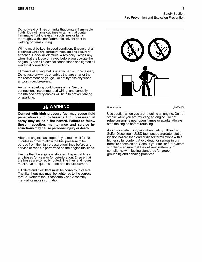
Illustration 10 g00704059
Use caution when you are refueling an engine. Do notsmoke while you are refueling an engine. Do notrefuel an engine near open flames or sparks. Alwaysstop the engine before refueling.
Avoid static electricity risk when fueling. Ultra-lowSulfur Diesel fuel (ULSD fuel) poses a greater staticignition hazard than earlier diesel formulations with ahigher sulfur content. Avoid death or serious injuryfrom fire or explosion. Consult your fuel or fuel systemsupplier to ensure that the delivery system is incompliance with fueling standards for propergrounding and bonding practices.
SEBU8732 13Safety Section
Fire Prevention and Explosion Prevention

Illustration 11 g00704135
Gases from a battery can explode. Keep any openflames or sparks away from the top of a battery. Donot smoke in battery charging areas.
Never check the battery charge by placing a metalobject across the terminal posts. Use a voltmeter or ahydrometer.
Incorrect jumper cable connections can cause anexplosion that can result in injury. Refer to theOperation Section of this manual for specificinstructions.
Do not charge a frozen battery. A frozen battery maycause an explosion.
The batteries must be kept clean. The covers (ifequipped) must be kept on the cells. Use therecommended cables, connections, and battery boxcovers when the engine is operated.
Fire ExtinguisherMake sure that a fire extinguisher is available. Befamiliar with the operation of the fire extinguisher.Inspect the fire extinguisher and service the fireextinguisher regularly. Obey the recommendations onthe instruction plate.
Lines, Tubes, and HosesDo not bend high-pressure lines. Do not strike high-pressure lines. Do not install any lines that aredamaged.
Leaks can cause fires. Consult your Perkins dealeror your Perkins distributor for replacement parts.
Replace the parts if any of the following conditionsare present:
• High-pressure fuel line or lines are removed.
• End fittings are damaged or leaking.
• Outer coverings are chafed or cut.
• Wires are exposed.
• Outer coverings are ballooning.
• Flexible parts of the hoses are kinked.
• Outer covers have embedded armoring.
• End fittings are displaced.
Make sure that all clamps, guards, and heat shieldsare installed correctly. During engine operation,correct installation will help to prevent vibration,rubbing against other parts, and excessive heat.
i02143194
Crushing Prevention andCutting Prevention
Support the component correctly when work beneaththe component is performed.
Unless other maintenance instructions are provided,never attempt adjustments while the engine isrunning.
Stay clear of all rotating parts and of all moving parts.Leave the guards in place until maintenance isperformed. After the maintenance is performed,reinstall the guards.
Keep objects away frommoving fan blades. The fanblades will throw objects or cut objects.
When objects are struck, wear protective glasses inorder to avoid injury to the eyes.
Chips or other debris may fly off objects when objectsare struck. Before objects are struck, ensure that noone will be injured by flying debris.
i04016709
Mounting and Dismounting
Do not climb on the engine or the engineaftertreatment. The engine and aftertreatment havenot been designed with mounting or dismountinglocations.
Refer to the OEM for the location of foot and handholds for your specific application.
14 SEBU8732Safety SectionCrushing Prevention and Cutting Prevention

i03550790
High Pressure Fuel Lines
Contact with high pressure fuel may cause fluidpenetration and burn hazards. High pressure fuelspray may cause a fire hazard. Failure to followthese inspection, maintenance and service in-structionsmay cause personal injury or death.
Illustration 12 g01877473
(1) High pressure line(2) High pressure line(3) High pressure line
(4) High pressure line(5) High pressure line(6) High pressure line
(7) High pressure fuel manifold (rail)(8) High pressure line(9) Fuel transfer line that is high pressure
The high pressure fuel lines are the fuel lines that arebetween the high pressure fuel pump and the highpressure fuel manifold and the fuel lines that arebetween the fuel manifold and cylinder head. Thesefuel lines are different from fuel lines on other fuelsystems.
This is because of the following items:
• The high pressure fuel lines are constantlycharged with high pressure.
• The internal pressures of the high pressure fuellines are higher than other types of fuel system.
• The high pressure fuel lines are formed to shapeand then strengthened by a special process.
Do not step on the high pressure fuel lines. Do notdeflect the high pressure fuel lines. Do not bend orstrike the high pressure fuel lines. Deformation ordamage of the high pressure fuel lines may cause apoint of weakness and potential failure.
Do not check the high pressure fuel lines with theengine or the starting motor in operation. After theengine has stopped, you must wait for 10 minutes inorder to allow the fuel pressure to be purged from thehigh pressure fuel lines before any service or repair isperformed on the engine fuel lines.
Do not loosen the high pressure fuel lines in order toremove air from the fuel system. This procedure is notrequired.
Visually inspect the high pressure fuel lines beforethe engine is started. This inspection should be eachday.
SEBU8732 15Safety Section
High Pressure Fuel Lines

If you inspect the engine in operation, always use theproper inspection procedure in order to avoid a fluidpenetration hazard. Refer to Operation andMaintenance Manual, “General hazard Information”.
• Inspect the high pressure fuel lines for damage,deformation, a nick, a cut, a crease, or a dent.
• Do not operate the engine with a fuel leak. If thereis a leak do not tighten the connection in order tostop the leak. The connection must only betightened to the recommended torque. Refer toDisassembly and Assembly, “Fuel injection lines -Remove and Fuel injection lines - Install”.
• If the high pressure fuel lines are torqued correctlyand the high pressure fuel lines are leaking thehigh pressure fuel lines must be replaced.
• Ensure that all clips on the high pressure fuel linesare in place. Do not operate the engine with clipsthat are damaged, missing or loose.
• Do not attach any other item to the high pressurefuel lines.
• Loosened high pressure fuel lines must bereplaced. Also removed high pressure fuel linesmust be replaced. Refer to Disassembly andassembly manual, “Fuel Injection Lines - Install”.
i02813489
Before Starting Engine
Before the initial start-up of an engine that is new,serviced or repaired, make provision to shut theengine off, in order to stop an overspeed. This maybe accomplished by shutting off the air and/or fuelsupply to the engine.
Overspeed shutdown should occur automatically forengines that are controlled electronically. If automaticshutdown does not occur, press the emergency stopbutton in order to cut the fuel and/or air to the engine.
Inspect the engine for potential hazards.
Before starting the engine, ensure that no one is on,underneath, or close to the engine. Ensure that thearea is free of personnel.
If equipped, ensure that the lighting system for theengine is suitable for the conditions. Ensure that alllights work correctly, if equipped.
All protective guards and all protective covers mustbe installed if the engine must be started in order toperform service procedures. To help prevent anaccident that is caused by parts in rotation, workaround the parts carefully.
Do not bypass the automatic shutoff circuits. Do notdisable the automatic shutoff circuits. The circuits areprovided in order to help prevent personal injury. Thecircuits are also provided in order to help preventengine damage.
See the Service Manual for repairs and foradjustments.
i03996487
Engine Starting
Do not use aerosol types of starting aids such asether. Such use could result in an explosion andpersonal injury.
If a warning tag is attached to the engine start switch,or to the controls DO NOTstart the engine or movethe controls. Consult with the person that attachedthe warning tag before the engine is started.
All protective guards and all protective covers mustbe installed if the engine must be started in order toperform service procedures. To help prevent anaccident that is caused by parts in rotation, workaround the parts carefully.
Start the engine from the operators compartment orfrom the engine start switch.
Always start the engine according to the procedurethat is described in the Operation and MaintenanceManual, “Engine Starting” topic in the OperationSection. Knowing that the correct procedure will helpto prevent major damage to the engine components.Knowing that the procedure will also help to preventpersonal injury.
To ensure that the jacket water heater (if equipped)and/or the lube oil heater (if equipped) is workingcorrectly, check the water temperature gauge. Also,check the oil temperature gauge during the heateroperation.
Engine exhaust contains products of combustionwhich can be harmful to your health. Always start theengine and operate the engine in a well ventilatedarea. If the engine is started in an enclosed area, ventthe engine exhaust to the outside.
Note: The engine is equipped with a device for coldstarting. If the engine will be operated in very coldconditions, then an extra cold starting aid may berequired. Normally, the engine will be equipped withthe correct type of starting aid for your region ofoperation.
16 SEBU8732Safety SectionBefore Starting Engine

These engines are equipped with a glow plug startingaid in each individual cylinder that heats the intake airin order to improve starting. Some Perkins enginesmay have a cold starting system that is controlled bythe ECM that allows a controlled flow of ether into theengine. The ECM will disconnect the glow plugsbefore the ether is introduced. This system would beinstalled at the factory.
i02234873
Engine Stopping
Stop the engine according to the procedure in theOperation and Maintenance Manual, “EngineStopping (Operation Section)” in order to avoidoverheating of the engine and accelerated wear ofthe engine components.
Use the Emergency Stop Button (if equipped) ONLYin an emergency situation. Do not use the EmergencyStop Button for normal engine stopping. After anemergency stop, DO NOTstart the engine until theproblem that caused the emergency stop has beencorrected.
Stop the engine if an overspeed condition occursduring the initial start-up of a new engine or an enginethat has been overhauled.
To stop an electronically controlled engine, cut thepower to the engine and/or shutting off the air supplyto the engine.
i04891806
Electrical System
Never disconnect any charging unit circuit or batterycircuit cable from the battery when the charging unit isoperating. A spark can cause the combustible gasesthat are produced by some batteries to ignite.
To help prevent sparks from igniting combustiblegases that are produced by some batteries, thenegative “−” cable should be connected last from theexternal power source to the primary position forgrounding.
Check the electrical wires daily for wires that areloose or frayed. Tighten all loose electricalconnections before the engine is started. Repair allfrayed electrical wires before the engine is started.See the Operation and Maintenance Manual forspecific starting instructions.
Grounding Practices
Illustration 13 g01888534
Typical example(1) Ground to battery(2) Ground to starting motor(3) Starting motor to engine block
SEBU8732 17Safety Section
Engine Stopping

Illustration 14 g03027396
Typical example(5) Ground to the battery(6) Ground to the engine block(7) Primary position for grounding
Correct grounding for the engine electrical system isnecessary for optimum engine performance andreliability. Incorrect grounding will result inuncontrolled electrical circuit paths and in unreliableelectrical circuit paths.
Uncontrolled electrical circuit paths can result indamage to the crankshaft bearing journal surfacesand to aluminum components.
Engines that are installed without engine-to-frameground straps can be damaged by electricaldischarge.
To ensure that the engine and the engine electricalsystems function correctly, an engine-to-frameground strap with a direct path to the battery must beused. This path may be provided by way of a directengine ground to the frame.
The connections for the grounds should be tight andfree of corrosion. The engine alternator must begrounded to the negative “-” battery terminal. Thewire used must be adequate to handle the fullcharging current of the alternator.
The power supply connections and the groundconnections for the engine electronics should alwaysbe from the isolator to the battery.
i05192488
Engine Electronics
Tampering with the electronic system installationor the OEM wiring installation can be dangerousand could result in personal injury or death and/orengine damage.
Electrical Shock Hazard. The electronic unit injec-tors use DC voltage. The ECM sends this voltageto the electronic unit injectors. Do not come incontact with the harness connector for the elec-tronic unit injectors while the engine is operating.Failure to follow this instruction could result inpersonal injury or death.
This engine has a comprehensive, programmableEngine Monitoring System. The Electronic ControlModule (ECM) monitors the engine operatingconditions. If any of the engine parameters extendoutside an allowable range, the ECM will initiate animmediate action.
The following actions are available for enginemonitoring control:
• Warning
• Derate
• Shutdown
The following monitored engine operating conditionsand components can limit engine speed and/or theengine power:
• Engine Coolant Temperature
• Engine Oil Pressure
• Engine Speed
• Intake Manifold Air Temperature
• Wastegate Regulator
• Supply Voltage to Sensors
• Fuel Temperature
• Fuel Pressure in Manifold (Rail)
• NOxReduction System
• Engine Aftertreatment System
18 SEBU8732Safety SectionEngine Electronics

The Engine Monitoring package can vary for differentengine models and different engine applications.However, the monitoring system and the enginemonitoring control will be similar for all engines.
Note:Many of the engine control systems anddisplay modules that are available for Perkinsengines will work in unison with the EngineMonitoring System. Together, the two controls willprovide the engine monitoring function for the specificengine application. Refer to the Troubleshooting formore information on the Engine Monitoring System.
SEBU8732 19Safety Section
Engine Electronics

Product InformationSection
General Informationi05192513
Model View Illustrations
The following model views show typical features ofthe engine. Due to individual applications, yourengine may appear different from the illustrations.1206F-E70TA Single Turbocharged Engine with Installed Aftertreatment
Illustration 15 g03393436
Typical example
20 SEBU8732Product Information SectionModel View Illustrations
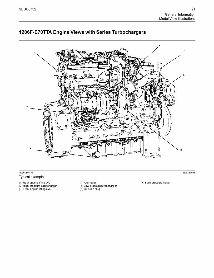
1206F-E70TTA Engine Views with Series Turbochargers
Illustration 16 g03387645
Typical example(1) Rear engine lifting eye(2) High-pressure turbocharger(3) Front engine lifting eye
(4) Alternator(5) Low-pressure turbocharger(6) Oil drain plug
(7) Back pressure valve
SEBU8732 21General Information
Model View Illustrations

Illustration 17 g03387666
Typical example(8) Secondary fuel filter(9) Primary fuel filter(10) Crankcase breather(11) Engine Electronic Control Module
(ECM)
(12) Flywheel housing(13) Flywheel(14) Solenoid for starting motor(15) Startingmotor(16) Oil filter
(17) Oil level gauge (Dipstick)(18) Oil drain tap(19) location for the oil sampling valve(20) High-pressure fuel pump
22 SEBU8732General InformationModel View Illustrations

Illustration 18 g03387667
Typical example(21) NOx Reduction system (NRS)(22) Air intake(23) Coolant outlet
(24) Oil filler cap(25) Water pump(26) Coolant intake
(27) Crankshaft damper(28) Belt tensioner(29) Belt
SEBU8732 23General Information
Model View Illustrations
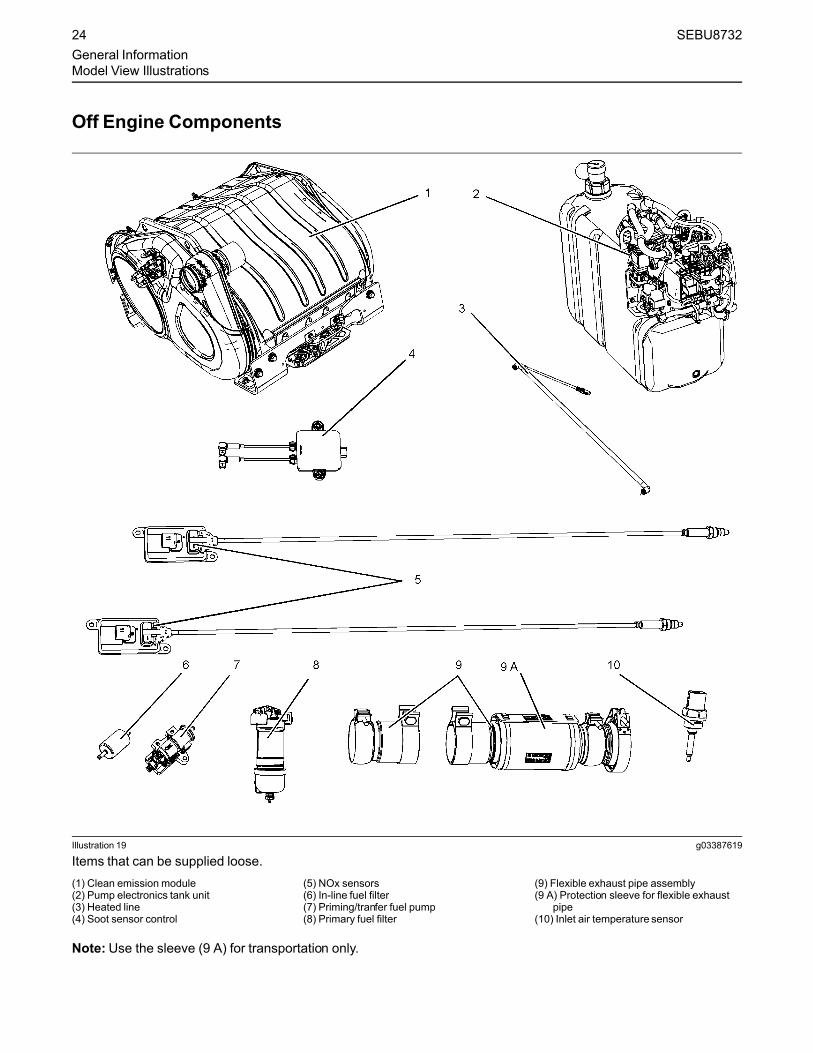
Off Engine Components
Illustration 19 g03387619
Items that can be supplied loose.(1) Clean emission module(2) Pump electronics tank unit(3) Heated line(4) Soot sensor control
(5) NOx sensors(6) In-line fuel filter(7) Priming/tranfer fuel pump(8) Primary fuel filter
(9) Flexible exhaust pipe assembly(9 A) Protection sleeve for flexible exhaust
pipe(10) Inlet air temperature sensor
Note:Use the sleeve (9 A) for transportation only.
24 SEBU8732General InformationModel View Illustrations

Engine AftertreatmentSystem
Illustration 20 g03027726
Typical example(1) Clean Emission Module (CEM)(2) Lifting eyes for CEM
(3) Exhaust intake connection(4) Exhaust outlet connection
(5) Diesel Exhaust Fluid (DEF) injector
SEBU8732 25General Information
Model View Illustrations
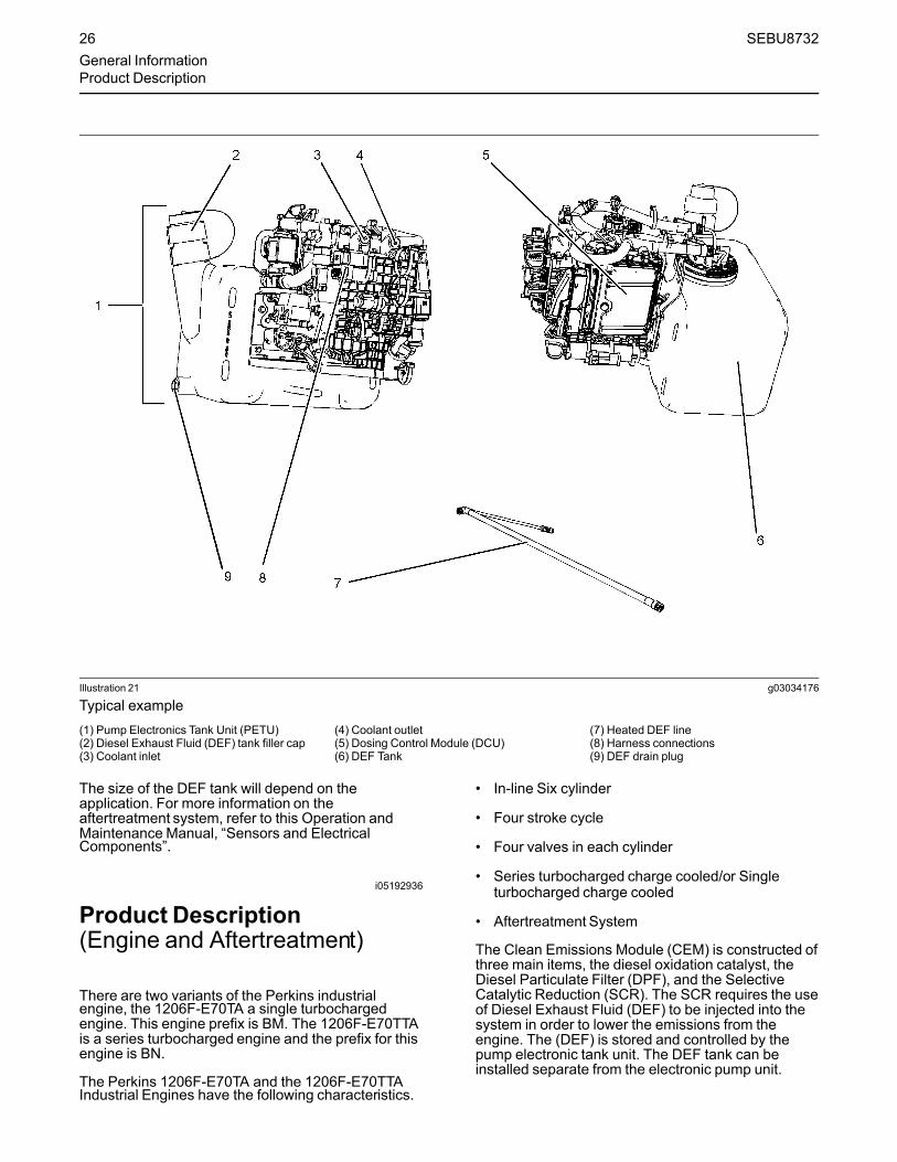
Illustration 21 g03034176
Typical example(1) Pump Electronics Tank Unit (PETU)(2) Diesel Exhaust Fluid (DEF) tank filler cap(3) Coolant inlet
(4) Coolant outlet(5) Dosing Control Module (DCU)(6) DEF Tank
(7) Heated DEF line(8) Harness connections(9) DEF drain plug
The size of the DEF tank will depend on theapplication. For more information on theaftertreatment system, refer to this Operation andMaintenance Manual, “Sensors and ElectricalComponents”.
i05192936
Product Description(Engine and Aftertreatment)
There are two variants of the Perkins industrialengine, the 1206F-E70TA a single turbochargedengine. This engine prefix is BM. The 1206F-E70TTAis a series turbocharged engine and the prefix for thisengine is BN.
The Perkins 1206F-E70TA and the 1206F-E70TTAIndustrial Engines have the following characteristics.
• In-line Six cylinder
• Four stroke cycle
• Four valves in each cylinder
• Series turbocharged charge cooled/or Singleturbocharged charge cooled
• Aftertreatment System
The Clean Emissions Module (CEM) is constructed ofthree main items, the diesel oxidation catalyst, theDiesel Particulate Filter (DPF), and the SelectiveCatalytic Reduction (SCR). The SCR requires the useof Diesel Exhaust Fluid (DEF) to be injected into thesystem in order to lower the emissions from theengine. The (DEF) is stored and controlled by thepump electronic tank unit. The DEF tank can beinstalled separate from the electronic pump unit.
26 SEBU8732General InformationProduct Description

For more information on DEF, refer this Operation andMaintenance Manual, “Fluid Recommendations”.
Engine SpecificationsNote: The front end of the engine is opposite theflywheel end of the engine. The left and the rightsides of the engine are determined from the flywheelend. The number 1 cylinder is the front cylinder.
Illustration 22 g01127295
Cylinder and valve location(A) Exhaust valves(B) Inlet valves
Table 1
1206F-TA Single Turbocharged Engine Specifications
Operating Range (rpm) 900 to 2800(1)
Number of Cylinders 6 In-Line
Bore 105 mm (4.13 inch)
Stroke 127 mm (5 inch)
Power 116 to 151 kW(155.5 to 202.5 hp)
Aspiration Turbocharged charge cooled
Compression Ratio 16.4:1
Displacement 7.01 L (428 in3)
Firing Order 1-5-3-6-2-4
Rotation (flywheel end) Counterclockwise(1) The operating rpm is dependent on the engine rating, the appli-
cation, and the configuration of the throttle.
Table 2
1206F-70TTA Series TurbochargedEngine Specifications
Operating Range (rpm) 900 to 2800(1)
Number of Cylinders 6 In-Line
Bore 105 mm (4.13 inch)
(continued)
(Table 2, contd)
Stroke 135 mm (5.31495 inch)
Power 151 to 205 kW(202.5 to 274.9 hp)
Aspiration Turbocharged charge cooled
Compression Ratio 16.4:1
Displacement 7.01 L (428 in3)
Firing Order 1-5-3-6-2-4
Rotation (flywheel end) Counterclockwise(1) The operating rpm is dependent on the engine rating, the appli-
cation, and the configuration of the throttle.
Electronic Engine FeaturesThe engine and aftertreatment operating conditionsare monitored. The Electronic Control Module (ECM)controls the response of the engine to theseconditions and to the demands of the operator. Theseconditions and operator demands determine theprecise control of fuel injection by the ECM. Theelectronic engine control system provides thefollowing features:
• Engine monitoring
• Engine speed governing
• Control of the injection pressure
• Cold start strategy
• Automatic air/fuel ratio control
• Torque rise shaping
• Injection timing control
• System diagnostics
• NOx reduction system control
• Aftertreatment system control
The ECM provides an electronic governor thatcontrols the injector output in order to maintain thedesired engine speed.
For more information on electronic engine features,refer to the Operation and Maintenance Manual,“Features and Controls” topic (Operation Section).
Engine DiagnosticsThe engine has built-in diagnostics in order to ensurethat the engine systems are functioning correctly. Theoperator will be alerted to the condition by a “Stop orWarning” lamp. Under certain conditions, the enginehorsepower and the vehicle speed may be limited.The electronic service tool may be used to display thediagnostic codes.
SEBU8732 27General InformationProduct Description

There are three types of diagnostic codes: active,logged and event.
Most of the diagnostic codes are logged and stored inthe ECM. For additional information, refer to theOperation and Maintenance Manual, “EngineDiagnostics” topic (Operation Section).
Engine Cooling and LubricationThe cooling system and lubrication system consistsof the following components:
• Gear-driven centrifugal water pump
• Water temperature regulator which regulates theengine coolant temperature
• Gear-driven gerotor type oil pump
• Oil cooler
The engine lubricating oil is supplied by a gerotortype oil pump. The engine lubricating oil is cooled andthe engine lubricating oil is filtered. The bypass valvecan provide unrestricted flow of lubrication oil to theengine if the oil filter element should becomeplugged.
Engine efficiency, efficiency of emission controls, andengine performance depend on adherence to properoperation and maintenance recommendations.Engine performance and efficiency also depend onthe use of recommended fuels, lubrication oils, andcoolants. Refer to this Operation and MaintenanceManual, “Maintenance Interval Schedule” for moreinformation on maintenance items.
Engine Service LifeEngine efficiency and maximum utilization of engineperformance depend on the adherence to properoperation and maintenance recommendations. Inaddition, use recommended fuels, coolants, andlubricants. Use the Operation and MaintenanceManual as a guide for required engine maintenance.
Expected engine life is generally predicted by theaverage power that is demanded. The average powerthat is demanded is based on fuel consumption of theengine over time. Reduced hours of operation at fullthrottle and/or operating at reduced throttle settingsresult in a lower average power demand. Reducedhours of operation will increase the length ofoperating time before an engine overhaul is required.For more information, refer to the Operation andMaintenance Manual, “Overhaul Considerations”topic (Maintenance Section).
Aftermarket Products and PerkinsEnginesPerkins does not warrant the quality or performanceof non-Perkins fluids and filters.
When auxiliary devices, accessories, or consumables(filters, additives, catalysts,) which are made by othermanufacturers are used on Perkins products, thePerkins warranty is not affected simply because ofsuch use.
However, failures that result from the installationor use of other manufacturers devices,accessories, or consumables are NOT Perkinsdefects. Therefore, the defects are NOTcoveredunder the Perkins warranty.
AftertreatmentSystemThe aftertreatment system is approved for use byPerkins . In order to be emission-compliant only theapproved Perkins aftertreatment system must beused on a Perkins engine.
28 SEBU8732General InformationProduct Description

Product IdentificationInformation
i05193032
Plate Locations and FilmLocations
Illustration 23 g03046077
Perkins engines are identified by an engine serialnumber.
An example of an engine number isBN*****U000001J.
***** The list number for the engine
BN Type of engine
U Built in the United Kingdom
000001 Engine Serial Number
W Year of Manufacture
Perkins dealers or Perkins distributors need all ofthese numbers in order to determine the componentsthat were included with the engine. This informationpermits accurate identification of replacement partnumbers.
The numbers for fuel setting information for electronicengines are stored within the flash file. Thesenumbers can be read by using the electronic servicetool.
Serial Number Plate (1)The engine serial number plate is located on the leftside of the cylinder block to the rear of the frontengine mounting.
Illustration 24 g01094203
Serial number plate
i05193060
Plate Locations and FilmLocations(AftertreatmentSystem)
Clean EmissionModule (CEM)
Illustration 25 g03047499
Typical example
The identification plate (1) is located on the intakeend of the CEM.
SEBU8732 29Product Identification Information
Plate Locations and Film Locations
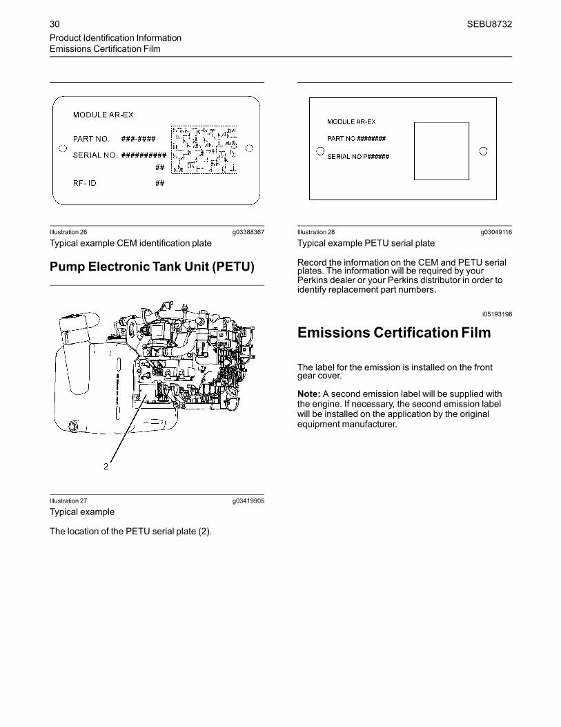
Illustration 26 g03388367
Typical example CEM identification plate
Pump Electronic Tank Unit (PETU)
Illustration 27 g03419905
Typical example
The location of the PETU serial plate (2).
Illustration 28 g03049116
Typical example PETU serial plate
Record the information on the CEM and PETU serialplates. The information will be required by yourPerkins dealer or your Perkins distributor in order toidentify replacement part numbers.
i05193198
Emissions CertificationFilm
The label for the emission is installed on the frontgear cover.
Note: A second emission label will be supplied withthe engine. If necessary, the second emission labelwill be installed on the application by the originalequipment manufacturer.
30 SEBU8732Product Identification InformationEmissions Certification Film

Illustration 29 g02443596
Typical example
i05362542
Reference Information
Information for the following items may be needed toorder parts. Locate the information for your engine.Record the information in the appropriate space.Make a copy of this list for a record. Keep theinformation for future reference.
Record for ReferenceEngine Model
Engine Serial number
Engine Low Idle rpm
Engine Full Load rpm
In Line Fuel Filter
Primary Fuel Filter
Secondary Fuel Filter Element
Lubrication Oil Filter Element
Auxiliary Oil Filter Element
Total Lubrication System Capacity
Total Cooling System Capacity
Air Cleaner Element
Drive Belt
Clean Emission ModulePart Number
Serial Number
Pump Electronics Tank Unit
Part Number
Serial Number
SEBU8732 31Product Identification Information
Reference Information
Operation Section
Lifting and Storagei05350494
Product Lifting
NOTICENever bend the eyebolts and the brackets. Only loadthe eyebolts and the brackets under tension. Remem-ber that the capacity of an eyebolt is less as the anglebetween the supporting members and the object be-comes less than 90 degrees.
When it is necessary to remove a component at anangle, only use a link bracket that is properly rated forthe weight.
Read all the information within produce lifting beforeany lifting is attempted. Ensure that the correct set oflifting eyes for the assembly to be lifted have beenselected.
Use a hoist to remove heavy components. Use anadjustable lifting beam to lift the assembly. Allsupporting members (chains and cables) should beparallel to each other. The chains and cables shouldbe perpendicular to the top of the object that is beinglifted.
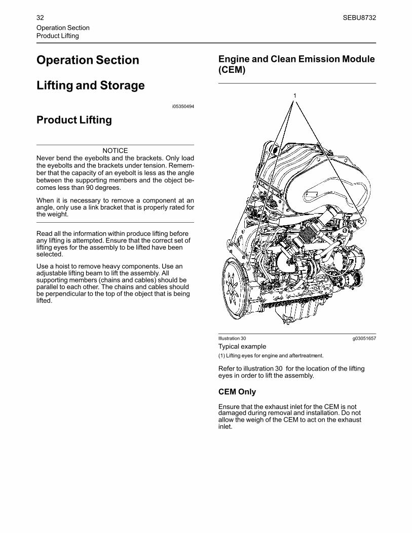
Engine and Clean EmissionModule(CEM)
Illustration 30 g03051657
Typical example(1) Lifting eyes for engine and aftertreatment.
Refer to illustration 30 for the location of the liftingeyes in order to lift the assembly.
CEM Only
Ensure that the exhaust inlet for the CEM is notdamaged during removal and installation. Do notallow the weigh of the CEM to act on the exhaustinlet.
32 SEBU8732Operation SectionProduct Lifting

Illustration 31 g03051677
Typical example(2) Lifting eyes for the CEM
Refer to illustration 31 for the location of the liftingeyes in order to lift the CEM. The lifting eyes (2) aredesigned only to lift the CEM. The lifting eyes (2)must not be used to lift any other parts of theapplication.
Note: If the CEM is removed from the application, theinlet and outlet connections must be protected inorder to prevent damage.
Pump Electronics Tank Unit (PETU) Only
The tank on the PETU should be empty before theassembly is lifted.
Illustration 32 g03419909
Typical example(3) Lifting eyes for PETU
Refer to illustration 32 for the location of the liftingeyes in order to lift the PETU.
SEBU8732 33Lifting and Storage
Product Lifting

Engine Only
Illustration 33 g03051679
Typical example(4) Lifting eyes for the engine
Refer to illustration 32 for the location of the liftingeyes in order to lift the engine.
i05193225
Product Storage(Engine and Aftertreatment)
Perkins are not responsible for damage which mayoccur when an engine is in storage after a period inservice.
Your Perkins dealer or your Perkins distributor canassist in preparing the engine for extended storageperiods.
Some applications, the engine can be equipped withdelayed engine shutdown. Allow at least 2 minutesafter the engine has stopped before you turn thebattery disconnect switch to OFF. Disconnecting thebattery power too soon will prevent purging of theDEF fluid lines after the engine is shut down. Also,during the 2 minutes the engine electronic controlmodule is active storing information from the engineand aftertreatment sensors.
Condition for StorageThe engine must be stored in a water proof building.The building must be kept at a constant temperature.Engines that are filled with Perkins ELC will havecoolant protection to an ambient temperature of−36° C (−32.8° F). The engine must not be subjectedto extreme variations in temperature and humidity.
Storage Period
An engine can be stored for up to 6 months providedall the recommendation are adhered to.
Storage Procedure
Keep a record of the procedure that has beencompleted on the engine.
Note: Do not store an engine that has biodiesel in thefuel system.
1. Ensure that the engine is clean and dry.
a. If the engine has been operated usingbiodiesel, the system must be drained andnew filters installed. The fuel tank will requireflushing.
b. Fill the fuel system with an ultra low sulfur fuel.For more information on acceptable fuels referto this Operation and Maintenance Manual,“Fluid recommendations”. Operate the enginefor 15 minutes in order to remove all biodieselfrom the system.
2. Drain any water from the primary filter waterseparator. Ensure that the fuel tank is full.
3. The engine oil will not need to be drained in orderto store the engine. Provided the correctspecification of engine oil is used the engine canbe stored for up to 6 months. For the correctspecification of engine oil refer to this Operationand Maintenance Manual, “Fluidrecommendations”.
4. Remove the drive belt from the engine.
Sealed Coolant System
Ensure that the cooling system is filled with PerkinsELC, or an antifreeze that meets ASTM D6210specification.
34 SEBU8732Lifting and StorageProduct Storage

Open Cooling System
Ensure that all cooling drain plugs have beenopened. Allow the coolant to drain. Install the drainplugs. Place a vapor phase inhibitor into the system.The coolant system must be sealed once the vaporphase inhibitor has been introduced. The effect of thevapor phase inhibitor will be lost if the cooling systemis open to the atmosphere.
For maintenance procedures ref to this Operation andMaintenance Manual.
Monthly Checks
The crankshaft must be rotated in order to change thespring loading on the valve train. Rotate thecrankshaft more than 180 degrees. Visibly check fordamage or corrosion to the engine andaftertreatment.
Ensure that the engine and aftertreatment arecovered completely before storage. Log theprocedure in the record for the engine.
AftertreatmentThe engine must be allowed to perform a DieselExhaust Fluid (DEF) purge before the batterydisconnect switch is turned off. Some applications,the engine can be equipped with delayed engineshutdown. Allow 2 minutes after the engine hasstopped before disconnecting the battery disconnectswitch.
The exhaust outlet of the aftertreatment must becapped. In order to prevent damage to the exhaustoutlet connection during storage, the weight of theCEM must not act on the exhaust outlet.
DEF Tank Storage
1. Ensure normal engine shutdown, allow the DEF tobe purged. Do not disconnect the batterydisconnect switch, allow 2 minutes after key offbefore disconnection.
2. Fill the tank with DEF that meet all the requirementdefined in ISO 22241-1.
3. Ensure that all DEF lines and electrical connectionare connected prior to prevent crystal fromforming.
4. Ensure that the DEF filler cap is correctly installed.
Removal from Storage
DEF has a limited life, refer to table 3 for the time andtemperature range. DEF that is outside this rangeMUST be replaced.
On removal from storage the DEF quality in the tankmust be tested with a refractometer. The DEF in thetank must meet the requirements defined in ISO22241-1 and comply with table 3 .
1. If necessary, drain the tank and fill with DEF thatmeet ISO 22241-1.
2. Replace the DEF filter, refer to this Operation andMaintenance Manual, “Diesel Exhaust Fluid Filter-Clean/Replace”.
3. Ensure that the drive belt is correctly installed.Ensure that all engine coolant and engine oil hasthe correct specification and grade. Ensure that thecoolant and the engine oil are at the correct level.Start the engine. If a fault becomes active turn offthe engine, allow 2 minutes for the DEF system topurge, then restart the engine.
4. If the fault continues to stay active, refer toTroubleshooting for more information.
Table 3
Temperature Duration
10° C (50° F) 36 months
25° C (77° F) 18 months
30° C (86° F) 12 months
35° C (95° F)(1) 6 months
(1) At 35° C, significant degradation can occur. Check every batchbefore use.
SEBU8732 35Lifting and StorageProduct Storage

Features and Controlsi05416516
Alarms and Shutoffs
ShutoffsThe shutoffs are electrically operated or mechanicallyoperated. The electrically operated shutoffs arecontrolled by the ECM.
Shutoffs are set at critical levels for the followingitems:
• Operating temperature
• Operating pressure
• Operating level
• Operating rpm
The particular shutoff may need to be reset before theengine will start.
NOTICEAlways determine the cause of the engine shutdown.Make necessary repairs before attempting to restartthe engine.
Be familiar with the following items:
• Types and locations of shutoff
• Conditions which cause each shutoff to function
• The resetting procedure that is required to restartthe engine
AlarmsThe alarms are electrically operated. The operationsof the alarms are controlled by the ECM.
The alarm is operated by a sensor or by a switch.When the sensor or the switch is activated, a signal issent to the ECM. An event code is created by theECM. The ECM will send a signal in order toilluminate the lamp.
Your engine may be equipped with the followingsensors or switches:
Coolant temperature – The coolant temperaturesensor indicates high jacket water coolanttemperature.
Intake manifold air temperature – The intakemanifold air temperature sensor indicates high intakeair temperature.
Intake manifold pressure – The intake manifoldpressure sensor checks the rated pressure in theengine manifold.
Fuel rail pressure – The fuel rail pressure sensormeasures the high pressure or low pressure in thefuel rail. The ECM will Check the pressure.
Engine oil pressure – The engine oil pressuresensor indicates when oil pressure drops below ratedsystem pressure, at a set engine speed.
Engine overspeed – If, the engine rpm exceeds theoverspeed setting the alarm will be activated.
Air filter restriction – The switch checks the air filterwhen the engine is operating.
User-defined switch – This switch can shut downthe engine remotely.
Water in fuel switch – This switch checks for waterin the primary fuel filter when the engine is operating.
Fuel temperature – The fuel temperature sensormonitors the pressurized fuel in the high-pressure fuelpump.
Note: The sensing element of the coolanttemperature switch must be submerged in coolant inorder to operate.
Engines may be equipped with alarms in order toalert the operator when undesirable operatingconditions occur.
NOTICEWhen an alarm is activated, corrective measuresmust be taken before the situation becomes an emer-gency in order to avoid possible engine damage.
If corrective measures are not taken within areasonable time, engine damage could result. Thealarm will continue until the condition is corrected.The alarm may need to be reset.
Note: If installed, the coolant level switch and the oillevel switch are indicators. Both switches operatewhen the application is on level ground and theengine RPM at zero.
Clean Emission Module (CEM)
• Diesel Oxidation Catalyst (DOC)
• Selective Catalyst Reduction (SCR)
Soot Sensors – The soot sensors monitor the sootlevel within the CEM
NOx Sensors – Two NOx sensors monitor the NOxconcentration within the exhaust gas before and afterthe selective catalyst reduction module.
Temperature Sensors – A temperature sensor afterthe engine exhaust gas exit, after the DOC and
36 SEBU8732Features and ControlsAlarms and Shutoffs

before the SCR module monitor the temperatureswithin the system.
Pump Electronics Tank Unit (PETU)Alarms and ShutoffDiesel Exhaust Fluid (DEF) Level Sensor – TheDEF level sensor monitors the volume of fluid in thetank and signals the ECM if the level drops below agiven point.
Dosing Control Unit (DCU) – The DCU controls theinjection of the DEF and will signal the ECM if theinjection has been interrupted.
TestingTurning the keyswitch to the ON position will checkthe indicator lights on the control panel. All theindicator lights will be illuminated for 2 seconds afterthe keyswitch is operated. Replace suspect bulbsimmediately.
Refer to Troubleshooting for more information.
i05194082
Selective Catalytic ReductionWarning System
The Selective Catalytic Reduction (SCR) system is asystem used to reduce NOx emissions from theengine. Diesel Exhaust Fluid (DEF) is pumped fromthe DEF tank and is sprayed into the exhaust stream.The DEF reacts with the SCR catalyst to reduce NOxand leaves a nitrogen and water vapor.
NOTICEStopping the engine immediately after the engine hasbeen working under load can result in overheating ofSCR components.
Refer to the Operation and Maintenance Manual, “En-gine Stopping” procedure to allow the engine to cooland to prevent excessive temperatures in the turbo-charger housing and the DEF injector.
NOTICEAllow at least 2 minutes after shutting down the en-gine before you turn the battery disconnect switch toOFF. Disconnecting the battery power too soon willprevent purging of the DEF lines after the engine isshut down.
Note: For information on DEF, refer to this Operationand Maintenance Manual, “Fluid Recommendations”.
Warning StrategyThe Electronic Control Module (ECM) will have eithera world-wide warning strategy or a European unionwarning strategy enabled within the ECM software.
The European union warning strategy is comprised oftwo different options. The two options will givedifferent response times for the operated to act anddifferent de-rates to the engine. Only one option willbe enabled.
DEF Level Warning Strategy
The DEF level world-wide warning strategy and theDEF level European union warning strategy both offertwo options. Only one option will be enabled.
Warning IndicatorsThe warning indicators consist of a level gauge forthe DEF, a low-level lamp for the DEF, an emissionmalfunction lamp, and the application stop lamp.
Illustration 34 g03069862
(1) DEF gauge(A) Low-level warning lamp
Illustration 35 g02852336
Emission malfunction lamp
Warning LevelsThe SCR has three levels of warning. Depending onthe fault that has been detected and software enabledwill govern the time that the system will stay at eachwarning level.
SEBU8732 37Features and Controls
Selective Catalytic Reduction Warning System

Any warning should be investigated immediately,contact your Perkins dealer or your PerkinsDistributor . The system is equipped with an overrideoption. Once the override option has been used andthe fault still exist, the engine will be locked in de-rateor shutdown mode.
World-Wide SCRWarnings
• At Level 1 the emission malfunction lamp will be onsolid.
• At Level 2 the emission malfunction lamp will flash.
• At Level 3 the emission malfunction lamp will flashand the stop lamp will activate.
• At Level 3 the engine may shut down or operate at1000 Revolutions Per Minute (RPM).
• At Level 3 cycling the keyswitch will give 20minutes override at full power, before theshutdown or idle is triggered. The emissionmalfunction lamp will continue to flash .
Table 4
World-Wide
DEF Quality Tampering and Dosing Interruption
- Normal operation Level 1 Level 2 Level 3 Override
Inducement TimeFirst occurrence
None 2.5 Hours 70 minutes Shut down or idleUntil fault heals
Cycling the keyswitchwill give 20 minutes offull power
The systemmust be fault free for 40 hours before the system will reset to zero. If the fault is intermittent, and returns within the 40 hours, then therepeat inducement time will be triggered.The override can only be used once
Repeat Inducementtime
None 5 minutes 5 minutes Shut down or idleUntil fault heals
Cycling the keyswitchwill give 20 minutes offull power
Inducement None None None
Notification None Emission malfunctionlamp will be on solid
Emission malfunctionlamp will flash
Emission malfunctionlamp will flashThe stop lamp will beon solid
Emission malfunctionlamp will flash
Contact your Perkins dealer or your Perkins Distributor at level 1 warning, do not let the fault develop.
Table 5
World-Wide
NOx ReductionSystem Fault
- Normal operation Level 1 Level 2 Level 3 Override
Inducement TimeFirst occurrence
None 35 Hours 60 minutes Shut down or idleUntil fault heals
Cycling the keyswitchwill give 20 minutes offull power
(continued)
38 SEBU8732Features and ControlsSelective Catalytic Reduction Warning System
(Table 5, contd)
The systemmust be fault free for 40 hours before the system will reset to zero. If the fault is intermittent, and returns within the 40 hours, then therepeat inducement time will be triggered.The override can only be used once.
Repeat Inducementtime
None 48 minutes 20 minutes Shut down or idleUntil fault heals
Cycling the keyswitchwill give 20 minutes offull power
Inducement None None None
Notification None Emission malfunctionlamp will be on solid
Emission malfunctionlamp will flash
Emission malfunctionlamp will flashThe stop lamp willactivate
Emission malfunctionlamp will flash
Contact your Perkins dealer or your Perkins Distributor at level 1 warning, do not let the fault develop.
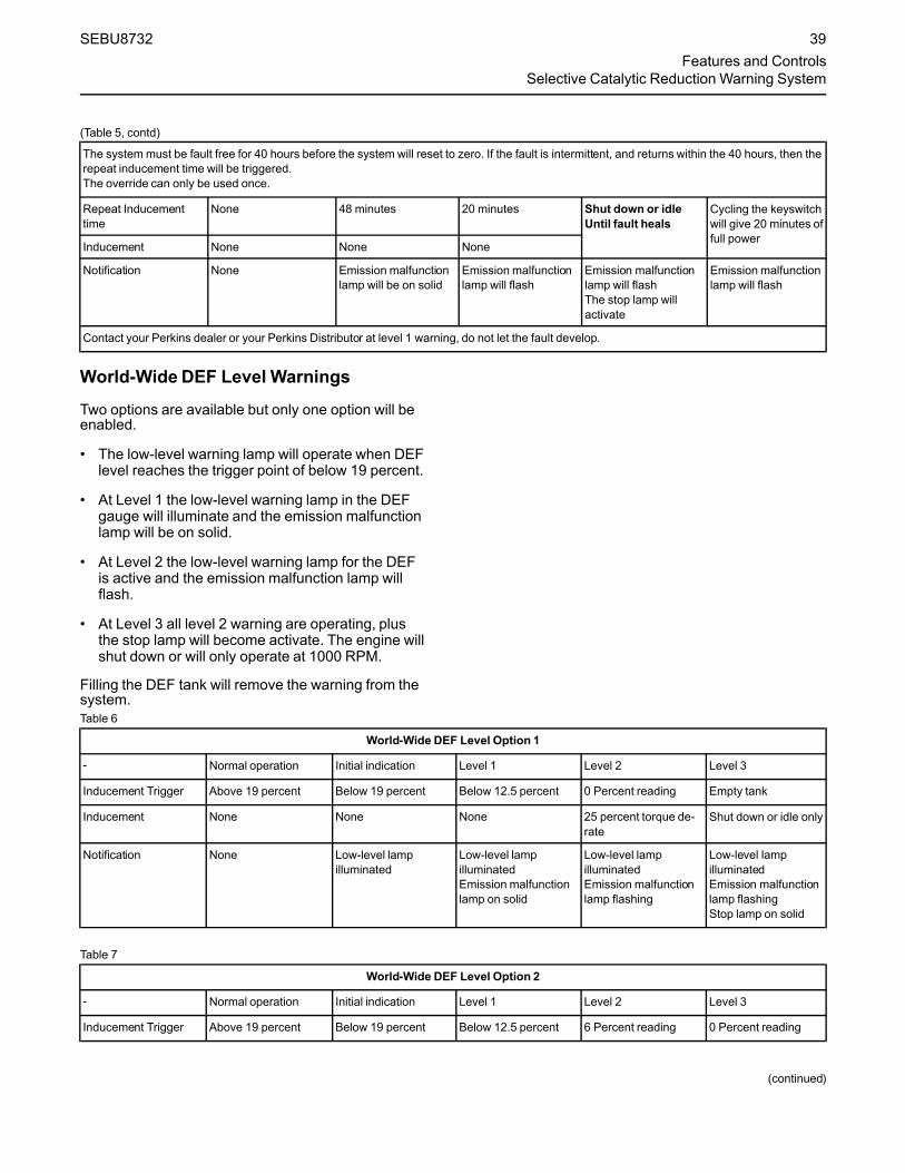
World-Wide DEF Level Warnings
Two options are available but only one option will beenabled.
• The low-level warning lamp will operate when DEFlevel reaches the trigger point of below 19 percent.
• At Level 1 the low-level warning lamp in the DEFgauge will illuminate and the emission malfunctionlamp will be on solid.
• At Level 2 the low-level warning lamp for the DEFis active and the emission malfunction lamp willflash.
• At Level 3 all level 2 warning are operating, plusthe stop lamp will become activate. The engine willshut down or will only operate at 1000 RPM.
Filling the DEF tank will remove the warning from thesystem.Table 6
World-Wide DEF Level Option 1
- Normal operation Initial indication Level 1 Level 2 Level 3
Inducement Trigger Above 19 percent Below 19 percent Below 12.5 percent 0 Percent reading Empty tank
Inducement None None None 25 percent torque de-rate
Shut down or idle only
Notification None Low-level lampilluminated
Low-level lampilluminatedEmission malfunctionlamp on solid
Low-level lampilluminatedEmission malfunctionlamp flashing
Low-level lampilluminatedEmission malfunctionlamp flashingStop lamp on solid
Table 7
World-Wide DEF Level Option 2
- Normal operation Initial indication Level 1 Level 2 Level 3
Inducement Trigger Above 19 percent Below 19 percent Below 12.5 percent 6 Percent reading 0 Percent reading
(continued)
SEBU8732 39Features and Controls
Selective Catalytic Reduction Warning System

(Table 7, contd)
Inducement None None None None Shut down or idle only
Notification None Low-level lampilluminated
Low-level lampilluminatedEmission malfunctionlamp on solid
Low-level lampilluminatedEmission malfunctionlamp flashing
Low-level lampilluminatedEmission malfunctionlamp flashingStop lamp on solid
i05408886
Battery Disconnect Switch(If Equipped)
Allow at least 2 minutes after the engine has stoppedbefore you turn the battery disconnect switch to OFF.Disconnecting the battery power too soon will preventpurging of the Diesel Exhaust Fluid (DEF) lines afterthe engine is shut down. Also, during the 2 minutesthe engine Electronic Control Module (ECM) is activestoring information from the engine andaftertreatment sensors.
Not allowing the DEF purge to be performed candamage the DEF system. Not allowing the engineECM time to store the information from the sensorscan damage to emission control system.
Some applications, the engine can be equipped witha wait to disconnect lamp. The wait to disconnectlamp will be illuminated during engine operation andwill be extinguished approximately 2 minutes after theengine has stopped.
Illustration 36 g03265058
Battery disconnect switch label
NOTICEDo not turn off the battery disconnect switch until theindicator lamp has turned off. If the switch is turned offwhen the indicator lamp is illuminated the Diesel Ex-haust Fluid (DEF) system will not purge the DEF. Ifthe DEF does not purge, DEF could freeze and dam-age the pump and lines.
NOTICENever move the battery disconnect switch to the OFFposition while the engine is operating. Serious dam-age to the electrical system could result.
i05194972
Gauges and Indicators
Your engine may not have the same gauges or all ofthe gauges that are described. For more informationabout the gauge package, see the OEM information.
Gauges provide indications of engine performance.Ensure that the gauges are in good working order.Determine the normal operating range by observingthe gauges over a period.
Noticeable changes in gauge readings indicatepotential gauge or engine problems. Problems mayalso be indicated by gauge readings that changeeven if the readings are within specifications.Determine and correct the cause of any significantchange in the readings. Consult your Perkins dealeror your Perkins distributor for assistance.
Some engine applications are equipped with IndicatorLamps. Indicator lamps can be used as a diagnosticaid. There are two lamps. One lamp has an orangelens and the other lamp has a red lens.
These indicator lamps can be used in two ways:
• The indicator lamps can be used to identify thecurrent operational status of the engine. Theindicator lamps can also indicate that the enginehas a fault. This system is automatically operatedvia the ignition switch.
• The indicator lamps can be used to identify activediagnostic codes. This system is activated bypressing the Flash Code button.
Refer to the Troubleshooting Guide, “IndicatorLamps” for further information.
NOTICEIf no oil pressure is indicated, STOP the engine. Ifmaximum coolant temperature is exceeded, STOPthe engine. Engine damage can result.
40 SEBU8732Features and ControlsBattery Disconnect Switch

Engine Oil Pressure – The oil pressureshould be greatest after a cold engine isstarted. The typical engine oil pressure
with SAE10W40 is 350 to 450 kPa ( 50 to 65 psi) atrated rpm.
A lower oil pressure is normal at low idle. If the enginespeed and load are stable and the gauge readingchanges, perform the following procedure:
1. Remove the load.
2. Stop the engine.
3. Check and maintain the oil level.
Jacket Water Coolant Temperature –Typical temperature range is 82° to 94°C(179.6° to 169.2°F). This temperature
range will vary according to engine load and theambient temperature.
A 100 kPa (14.5 psi) radiator cap must be installedon the cooling system. The maximum temperature forthe cooling system is 108° C (226.4° F). Thistemperature is measured at the outlet for the watertemperature regulator. The engine coolanttemperature is regulated by the engine sensors andthe engine ECM. This programming cannot bealtered. Derates can occur if the maximum enginecoolant temperature is exceeded.
If the engine is operating above the normal range,reduce the engine load. If high coolant temperaturesare a frequent event, perform the followingprocedures:
1. Reduce the load on the engine.
2. Determine if the engine must be shut downimmediately or if the engine can be cooled byreducing the load.
3. Inspect the cooling system for leaks. If necessary,consult your Perkins dealer or your Perkinsdistributor for assistance.
Tachometer – This gauge indicatesengine speed (rpm). When the throttlecontrol lever is moved to the full throttle
positionwithout load, the engine is running athigh idle. The engine is running at the full loadrpm when the throttle control lever is at the fullthrottle position with maximum rated load.
NOTICETo help prevent engine damage, never exceed thehigh idle rpm. Overspeeding can result in seriousdamage to the engine. Operation at speeds exceed-ing high idle rpm should be kept to a minimum.
Ammeter – This gauge indicates theamount of charge or discharge in thebattery charging circuit. Operation of the
indicator should be to the ““+”” side of ““0”” (zero).
Fuel Level – This gauge indicates thefuel level in the fuel tank. The fuel levelgauge operates when the ““START/
STOP”” switch is in the ““on”” position.
Service Hour Meter – The gaugeindicates total operating hours of theengine.
Indicator Lamps• Shutdown lamp
• Warning lamp
• Low oil pressure lamp
• Wait to start lamp (Glow plug warning lamp)
For information, refer to this manual, “MonitoringSystem (Table for the Indicator Lamps)” for thesequence of operation of the shutdown lamp and thewarning lamp.
The function of the wait to start lamp is automaticallycontrolled at engine start-up.
The function of the low oil pressure lamp is controlledby the engine ECM. If low oil pressure is detected, thelamp will be illuminated. The reason for theillumination of the low-pressure lamp should beinvestigated immediately.
The glow plug warning lamp will flash in order to showthat the engine is been held at low speed. Thisfunction will be performed at engine starting and theduration will depend on ambient temperature andengine temperature.
The lamps will illuminate for 2 seconds in order tocheck that the lamps are functioning when thekeyswitch is turned to the ON position. If any of thelamps stay illuminated, or a lamp fails to beilluminated the reason should be investigatedimmediately.
AftertreatmentLamps and gaugesAll applications will require the following lamps andgauges:
• Emission malfunction lamp
• Action indicator lamp
• Gauge for Diesel Exhaust Fluid (DEF)
• Low warning lamp for DEF
• Wait to disconnect lamp (optional)
SEBU8732 41Features and ControlsGauges and Indicators

The wait to disconnect lamp will be illuminated duringengine operation and will be extinguishedapproximately 2 minutes after the engine hasstopped. Do not disconnect the battery disconnectswitch during the period the lamp is illuminated. Thediesel exhaust fluid system will be purged during thistime. Also, during the 2 minutes the engine electroniccontrol module is active storing information from theengine and aftertreatment sensors.
Note: The wait to disconnect lamp will not bechecked at key on.
i05194981
Monitoring System(Engine Indicators andAftertreatment Indicators)
Engine Indicator LampsNote:When in operation the amber warning lamp hasthree states, solid, flashing, and fast flashing. Thesequence is to give a visual indication of theimportance of the warning. Some application canhave an audible warning installed.
Ensure that the engine maintenance is carried out atthe correct intervals. A lack of maintenance can resultin illumination of the warning lamp. For the correctintervals of maintenance, refer to the Operation andMaintenance Manual, “Maintenance IntervalSchedule”.Table 8
Indicator Lamp Table
WarningLamp
ShutdownAction Indi-cator Lamp
Lamp State Description of the Indication Engine Status
On On Lamp Check When the keyswitch is moved to the ON po-sition, the lamps come on for 2 seconds andthe lamps will then go off.
The keyswitch is in the ON position but the en-gine has not yet been cranked.
If any of the indicators will not illuminate during indicator check, the fault must be investigated immediatelyIf any Indicators stay illuminated or flash, the fault must be investigated immediately.
Off Off No Faults With the engine in operation, there are noactive warnings, diagnostic codes, or eventcodes.
The engine is operating with no detected faults.
On Solid Off Warning Level 1 warning The engine is operating normally but there isone or more faults with the electronic manage-ment system for the engine.
As soon as possible the fault should be investigated.
(continued)
42 SEBU8732Features and ControlsMonitoring System

(Table 8, contd)
Indicator Lamp Table
WarningLamp
ShutdownAction Indi-cator Lamp
Lamp State Description of the Indication Engine Status
Flashing Off Warning Level 2 warning The engine continues to be operated, but thelevel of importance of the warning hasincreased.Depending on the particular fault and the se-verity the engine may be de-rated.The engine could be damaged if continued tobe operated.
Stop the engine. Investigate the code.
Flashing On Engine Shutdown Level 3 warningIf both the warning lamp and the shutdownlamp are in operation, this issue indicatesone of the following conditions.
1. One or more of the shutdown values forthe engine protection strategy has beenexceeded.
2. A serious active diagnostic code has beendetected.
If install, the audible warning will sound.After a short time period, the engine mayshut down.
The engine is either shutdown or an engineshutdown is imminent. One or more monitoredengine parameters have exceeded the limit foran engine shutdown. This pattern of lamps canbe caused by the detection of a serious activediagnostic code.
Contact your Perkins dealer or your Perkinsdistributor.
Flash CodesSome applications may support flash codes. A flashcode can be viewed by an indicator lamp that whenasked will flash in a particular sequence. Theindicator lamp used to view the codes is the warninglamp, the lamp can then be refer to as a diagnosticlamp. For more information refer to this Operation andMaintenance Manual, “Diagnostic Lamp”.
AftertreatmentSystem
The aftertreatment indicators should illuminate at keyon for 2 seconds in order to test the system. If any ofthe indicators do not illuminate, the fault must beinvestigated immediately.
For more information on the illumination of theaftertreatment indicators refer to this Operation andMaintenance Manual, “Selective Catalytic ReductionWarning System”.
i03554501
Overspeed
• ECM Electronic Control Module
• RPM Revolutions Per Minute
An overspeed is detected by the speed/timingsensors.
The default setting for an overspeed is 3000 rpm. TheECM will cut the power to the electronic unit injectors,until the rpm drops below 200 rpm of the overspeedsetting. A diagnostic fault code will be logged into theECM memory and a warning lamp will indicate adiagnostic fault code.
An overspeed can be set from 2600 rpm to 3000 rpm.This setting depends on the application.
i05350563
Sensors and ElectricalComponents
The illustrations within the following sections aretypical location of the sensors or electricalcomponents for an industrial engine. Specific enginesmay appear different due to differences inapplications.
SEBU8732 43Features and Controls
Overspeed

Engine Components
Illustration 37 g03389319
Typical example(1) Coolant Temperature Sensor(2) Injector Connector for Number One and
Two Injectors(3) Injector Connector for Number three and
Four Injectors(4) Injector Connector for Number Five and
Six Injectors(5) Fuel Pressure Sensor
(6) Inlet Manifold Air Temperature Sensor(7) Inlet Manifold Air Pressure Sensor(8) Glow Plug Connection(9) Diagnostic Connector(10) Electronic Control Module(11) Atmospheric Pressure Sensor
(Barometric Pressure sensor)(12) Oil Pressure Sensor
(13) Primary Speed/Timing Sensor(14) Starter Solenoid(15) Starter relay(16) Starting Motor(17) Oil Level Switch(18) Fuel Temperature Sensor(19) Solenoid for High Pressure Fuel Pump
44 SEBU8732Features and ControlsSensors and Electrical Components

Illustration 38 g03389322
Typical example(20) Wastegate Regulator(21) Control Valve for the NOx Reduction
System (NRS)
(22) Temperature Sensor for the NRS(23) Intake Pressure for the NRS(24) Differential Pressure for the NRS
(25) Back Pressure Valve
SEBU8732 45Features and Controls
Sensors and Electrical Components

Illustration 39 g03389323
Typical example(26) Alternator (27) Secondary Speed/Timing sensor (28) Exhaust Temperature Sensor
46 SEBU8732Features and ControlsSensors and Electrical Components

Illustration 40 g03393046
Typical example(29) Water in Fuel Switch(30) Inlet Air Temperature
Some applications do not require a diagnosticconnector (9) installed in the engine wiring harness.The Inlet air temperature sensor (30) will be installedin the induction system between the air cleaner andthe inlet manifold.
Illustration 41 g03058119
Typical example(1) Coolant Temperature Sensor(2) Injector connector(3) Injector Connector
(4) Injector Connector(5) Fuel Pressure Sensor(6) Inlet Manifold Temperature Sensor
(7) Inlet Manifold Pressure Sensor(8) Glow Plug Connection
SEBU8732 47Features and Controls
Sensors and Electrical Components

Illustration 42 g03393011
Typical example(9) Diagnostic connector(10) Electronic Control Module(11) Atmospheric Pressure Sensor (Barometric Pressure sensor)(12) Oil pressure sensor
Illustration 43 g03392999
Typical example(13) Primary Speed/Timing Sensor
48 SEBU8732Features and ControlsSensors and Electrical Components
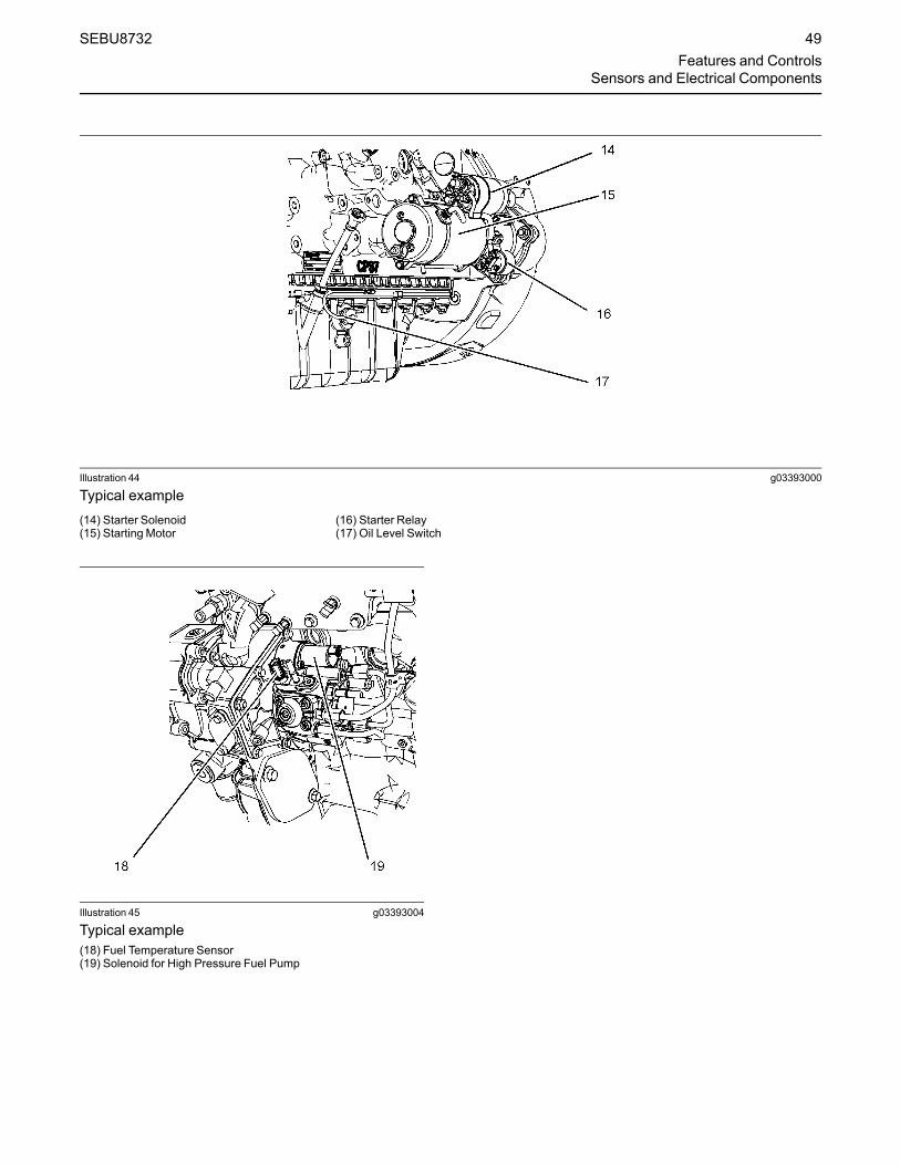
Illustration 44 g03393000
Typical example(14) Starter Solenoid(15) Starting Motor
(16) Starter Relay(17) Oil Level Switch
Illustration 45 g03393004
Typical example(18) Fuel Temperature Sensor(19) Solenoid for High Pressure Fuel Pump
SEBU8732 49Features and Controls
Sensors and Electrical Components
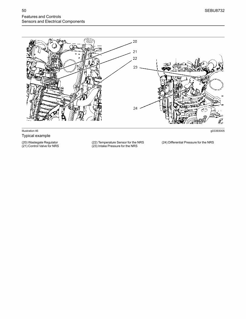
Illustration 46 g03393005
Typical example(20) Wastegate Regulator(21) Control Valve for NRS
(22) Temperature Sensor for the NRS(23) Intake Pressure for the NRS
(24) Differential Pressure for the NRS
50 SEBU8732Features and ControlsSensors and Electrical Components

Illustration 47 g03393010
Typical example(25) Back Pressure valve(26) Alternator
SEBU8732 51Features and Controls
Sensors and Electrical Components

Illustration 48 g03393006
Typical example(27) Secondary Speed/Timing sensor(28) Exhaust Temperature Sensor
52 SEBU8732Features and ControlsSensors and Electrical Components

AftertreatmentComponents
Illustration 49 g03393078
Clean EmissionsModule (CEM)
Illustration 50 g03393624
(1) Clean Emission Module(2) Gas Intake Temperature Sensor(3) Soot Sensor Antenna(4) Location for NOx Sensing Element(5) Soot Sensor Antenna(6) Diesel Exhaust Fluid Injector(7) Temperature Sensor Connector(8) Identification Module(9) Gas Temperature Sensor before Selective Catalytic Reduction
SEBU8732 53Features and Controls
Sensors and Electrical Components

CEM Sensors
Illustration 51 g03393632
(2) Gas Intake Temperature Sensor(3) Soot Sensor Antenna
(4) Location for NOx Sensing Element(5) Soot Sensor Antenna
(6) Diesel Exhaust Fluid Injector
Illustration 52 g03393634
(7) Temperature Sensor Connector(8) Identification Module
(9) Gas TemperatureSensor beforeSelective Catalytic Reduction
54 SEBU8732Features and ControlsSensors and Electrical Components

Soot and NOx Sensors
Illustration 53 g03393956
(10) Soot Sensor (11) NOx Sensors
The location of the soot sensor (10) and NOx sensor(11) will depend on the application.
SEBU8732 55Features and Controls
Sensors and Electrical Components

Pump Electronic Tank Unit (PETU)
Illustration 54 g03393959
(1) DEF Level Sensor and DEF TemperatureSensor
(2) Coolant Diverter Valve
(3) Customer Connections(4) Dosing Control Module(5) Relays
(6) Voltage Limiting ProtectionModule
56 SEBU8732Features and ControlsSensors and Electrical Components

Heated Line
Illustration 55 g03393960
Typical example(7) Heated line
SEBU8732 57Features and Controls
Sensors and Electrical Components

Engine Diagnosticsi05194988
Self-Diagnostics
Perkins Electronic Engines have the capability toperform a self-diagnostics test. When the systemdetects an active problem, a diagnostic lamp isactivated. Diagnostic codes will be stored inpermanent memory in the Electronic Control Module(ECM). The diagnostic codes can be retrieved byusing Perkins electronic service tools.
Some installations have electronic displays thatprovide direct readouts of the engine diagnosticcodes. Refer to the manual that is provided by theOEM for more information on retrieving enginediagnostic codes.
Active codes represent problems that currently exist.These problems should be investigated first.
Logged codes represent the following items:
• Intermittent problems
• Recorded events
• Performance history
The problems may have been repaired since thelogging of the code. These codes do not indicate thata repair is needed. The codes are guides or signalswhen a situation exists. Codes may be helpful totroubleshoot problems.
When the problems have been corrected, thecorresponding logged fault codes should be cleared.
i03554520
Diagnostic Lamp
A diagnostic lamp is used to indicate the existence ofan active fault. A fault diagnostic code will remainactive until the problem is repaired. The diagnosticcode may be retrieved by using the electronic servicetool.
i04907245
Diagnostic Flash CodeRetrieval
Use the following procedure to retrieve the flashcodes if the engine is equipped with a“DIAGNOSTIC” lamp:
1.Move the keyswitch from the on/off two times within3 seconds.
2. The shutdown warning lamp will flash once.
3. A flashing YELLOW lamp indicates a 3-digitdiagnostic code for the engine. The sequence offlashes represents the system diagnosticmessage. Count the first sequence of flashes inorder to determine the first digit of the flash code.After a two second pause, the second sequence offlashes will identify the second digit of the flashcode. After the second pause, the third sequenceof flashes will identify the flash code.
4. After the diagnostic codes have been displayed,the shutdown lamp will flash twice and theindicator lamp will start to flash the loggeddiagnostic codes.
5. After the logged diagnostic codes have beendisplayed, the shutdown lamp will flash three timesin order to indication that the code sequences havefinished.
Note: If there are no diagnostic codes or loggeddiagnostic codes, the system will flash the code 551.
i05406659
Fault Logging
The system provides the capability of Fault Logging.When the Electronic Control Module (ECM)generates an active diagnostic code, the code will belogged in the memory of the ECM. The codes thathave been logged by the ECM can be identified bythe electronic service tool. The active codes that havebeen logged will be cleared when the fault has beenrectified or the fault is no longer active. The followinglogged faults cannot be cleared from the memory ofthe ECM without using a factory password:Overspeed, low engine oil pressure, high enginecoolant temperature, and aftertreatment codes.
i03554534
Engine Operationwith ActiveDiagnostic Codes
If a diagnostic lamp illuminates during normal engineoperation, the system has identified a situation that isnot within the specification. Use electronic servicetools to check the active diagnostic codes.
58 SEBU8732Engine DiagnosticsSelf-Diagnostics

Note: If the customer has selected “DERATE” and ifthere is a low oil pressure condition, the ElectronicControl Module (ECM) will limit the engine power untilthe problem is corrected. If the oil pressure is withinthe normal range, the engine may be operated at therated speed and load. However, maintenance shouldbe performed as soon as possible.
The active diagnostic code should be investigated.The cause of the problem should be corrected assoon as possible. If the cause of the active diagnosticcode is repaired and there is only one activediagnostic code, the diagnostic lamp will turn off.
Operation of the engine and performance of theengine can be limited as a result of the activediagnostic code that is generated. Acceleration ratesmay be significantly slower. Refer to theTroubleshooting Guide for more information on therelationship between these active diagnostic codesand engine performance.
i01797063
Engine OperationwithIntermittent Diagnostic Codes
If a diagnostic lamp illuminates during normal engineoperation and the diagnostic lamp shuts off, anintermittent fault may have occurred. If a fault hasoccurred, the fault will be logged into the memory ofthe Electronic Control Module (ECM).
In most cases, it is not necessary to stop the enginebecause of an intermittent code. However, theoperator should retrieve the logged fault codes andthe operator should reference the appropriateinformation in order to identify the nature of the event.The operator should log any observation that couldhave caused the lamp to light.
• Low power
• Limits of the engine speed
• Excessive smoke, etc
This information can be useful to help troubleshootthe situation. The information can also be used forfuture reference. For more information on diagnosticcodes, refer to the Troubleshooting Guide for thisengine.
i05402551
Configuration Parameters
The engine electronic control module (ECM) has twotypes of configuration parameters. The systemconfiguration parameters and the customer specifiedparameters.
The electronic service tool is required in order to alterthe configuration parameters.
System ConfigurationParametersSystem configuration parameters affect the emissionsof the engine or the power of the engine. Systemconfiguration parameters are programmed at thefactory. Normally, system configuration parameterswould never require changing through the life of theengine. System configuration parameters must bereprogrammed if an ECM is replaced. Systemconfiguration parameters do not requirereprogrammed if the ECM software is changed.Factory passwords are required to change theseparameters.
SEBU8732 59Engine Diagnostics
Engine Operation with Intermittent Diagnostic Codes

Table 9
SystemConfiguration Parameters
Configuration Parameters Record
Engine Serial Number
Factory Installed Aftertreatment #1 Identification Number
DPF #1 Soot Loading Sensing System Configuration Code
Limp Home Engine Speed Ramp Rate
SystemOperating Voltage Configuration
Rating Number
CAN Communication Protocol Write Security
Engine Emissions Operator Inducement Progress Configuration
Engine Emissions Operator Inducement Regulation Configuration
Customer Specified ParametersCustomer specified parameters allow the engine tobe configured to the exact needs of the application.
The electronic service tool is required in order to alterthe customer configuration parameters.
Customer parameters may be changed repeatedly asoperational requirements change.Table 10
Customer Specified Parameters
Specified Parameters Record
Throttle Type Channel 1
Throttle Type Channel 2
IVS Channel 1
IVS Channel 2
Continuous Position Throttle Configuration 1
Continuous Position Throttle Configuration 2
Multi Position Throttle Switch Configuration
Throttle Arbitration
Equipment ID
Low Idle Speed
Delay Engine Shutdown
Ether Solenoid Configuration
Engine Idle ShutdownMinimumAmbient Air Temperature
Engine Idle ShutdownMaximumAmbient Air Temperature
Engine Idle Shutdown Enable Status
Engine Idle Shutdown Delay Time
(continued)
60 SEBU8732Engine DiagnosticsConfiguration Parameters

(Table 10, contd)
Engine Idle Shutdown Ambient TemperatureOverride Enable Status
High Soot Load Aftertreatment Protection Enable Status
Air Shutoff
Throttle Lock Feature Installation Status
PTO Mode
Throttle Lock Engine Set Speed #1
Throttle Lock Engine Set Speed #2
Throttle Lock Increment Speed Ramp Rate
Throttle Lock Decrement Speed Ramp Rate
Throttle Lock Engine Set Speed Increment
Throttle Lock Engine Set Speed Decrement
Monitoring Mode Shutdowns
Monitoring Mode Derates
Limp Home Desired Engine Speed
Engine Acceleration Rate
Engine Speed Decelerating Ramp Rate
Intermediate Engine Speed
Fan
Engine Fan Control
Engine Fan Type Configuration
Engine Cooling Fan TemperatureError Increasing Hysteresis
Engine Cooling Fan TemperatureError Decreasing Hysteresis
Engine Cooling Fan Current Ramp Rate
Engine Cooling Fan Speed
Top Engine Fan Speed
Minimum Desired Engine Cooling Fan Speed
Engine Cooling Fan Solenoid MinimumCurrent
Engine Cooling Fan Solenoid MaximumCurrent
Engine cooling Fan solenoid Dither Frequency
Engine Cooling Fan Solenoid Dither Amplitude
Fan Temperatures
Engine Fan Control Charge Air Cooler Outlet Temperature Input Enable
Engine Cooling Fan MaximumAir Flow Charge Air Cooler Outlet Temperature
Engine Cooling Fan MinimumAir Flow Charge Air Cooler Outlet Temperature
Engine Cooling Fan Control Coolant Temperature Input Enable Status
Engine Cooling Fan MaximumAir Flow Coolant Temperature
(continued)
SEBU8732 61Engine Diagnostics
Configuration Parameters
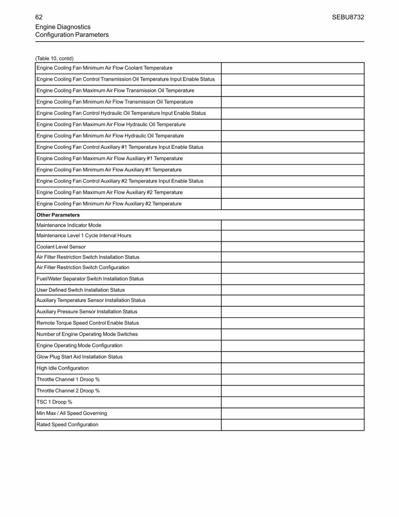
(Table 10, contd)
Engine Cooling Fan MinimumAir Flow Coolant Temperature
Engine Cooling Fan Control Transmission Oil Temperature Input Enable Status
Engine Cooling Fan MaximumAir Flow Transmission Oil Temperature
Engine Cooling Fan MinimumAir Flow Transmission Oil Temperature
Engine Cooling Fan Control Hydraulic Oil Temperature Input Enable Status
Engine Cooling Fan MaximumAir Flow Hydraulic Oil Temperature
Engine Cooling Fan MinimumAir Flow Hydraulic Oil Temperature
Engine Cooling Fan Control Auxiliary #1 Temperature Input Enable Status
Engine Cooling Fan MaximumAir Flow Auxiliary #1 Temperature
Engine Cooling Fan MinimumAir Flow Auxiliary #1 Temperature
Engine Cooling Fan Control Auxiliary #2 Temperature Input Enable Status
Engine Cooling Fan MaximumAir Flow Auxiliary #2 Temperature
Engine Cooling Fan MinimumAir Flow Auxiliary #2 Temperature
Other Parameters
Maintenance Indicator Mode
Maintenance Level 1 Cycle Interval Hours
Coolant Level Sensor
Air Filter Restriction Switch Installation Status
Air Filter Restriction Switch Configuration
Fuel/Water Separator Switch Installation Status
User Defined Switch Installation Status
Auxiliary Temperature Sensor Installation Status
Auxiliary Pressure Sensor Installation Status
Remote Torque Speed Control Enable Status
Number of Engine Operating Mode Switches
Engine OperatingMode Configuration
Glow Plug Start Aid Installation Status
High Idle Configuration
Throttle Channel 1 Droop%
Throttle Channel 2 Droop%
TSC 1 Droop %
Min Max / All Speed Governing
Rated Speed Configuration
62 SEBU8732Engine DiagnosticsConfiguration Parameters

Engine Startingi04935860
Before Starting Engine
Perform the required daily maintenance and otherperiodic maintenance before the engine is started.Inspect the engine compartment. This inspection canhelp prevent major repairs at a later date. Refer to theOperation and Maintenance Manual, “MaintenanceInterval Schedule” for more information.
• Ensure that the engine has an adequate fuelsupply.
• Ensure that the engine has an adequate dieselexhaust fluid supply
• Open the fuel supply valve (if equipped).
NOTICEAll valves in the fuel return line must be open and fuelsupply lines must be open. Damage to the fuel sys-tem can occur if fuel lines are closed with the enginein operation.
If the engine has not been started for several weeks,fuel may have drained from the fuel system. Air mayhave entered the filter housing. Also, when fuel filtershave been changed, some air pockets will be trappedin the engine. In these instances, prime the fuelsystem. Refer to the Operation and MaintenanceManual, “Fuel System - Prime” for more informationon priming the fuel system. Also, check that the fuelspecification is correct and that the fuel condition iscorrect. Refer to the Operation and MaintenanceManual, “Fuel Recommendations”.
Engine exhaust contains products of combustionwhich may be harmful to your health. Always startand operate the engine in a well ventilated areaand, if in an enclosed area, vent the exhaust to theoutside.
• Do not start the engine or move any of the controlsif there is a “DO NOT OPERATE” warning tag orsimilar warning tag attached to the start switch orto the controls.
• Reset all of the shutoffs or alarm components.
• Ensure that any driven equipment has beendisengaged. Minimize electrical loads or removeany electrical loads.
i05360375
Cold Weather Starting
Do not use aerosol types of starting aids such asether. Such use could result in an explosion andpersonal injury.
The ability to start the engine will be improved attemperatures below −18 °C (0 °F) from the use of ajacket water heater or extra battery capacity.
The following items provide a means of minimizingstarting problems and fuel problems in cold weather:Engine oil pan heaters, jacket water heaters, fuelheaters and fuel line insulation.
Use the procedure that follows for cold weatherstarting.
Note: Do not adjust the engine speed control duringstart-up. The electronic control module (ECM) willcontrol the engine speed during start-up.
1. Disengage any driven equipment.
Note: During key ON, the indicator lamps will beilluminated for 2 seconds in order to check the lampoperation. If any of the indicator lamps do notilluminate check the bulb. If any indicator lamps stayilluminated or flash, refer to Troubleshooting,“Indicator Lamp Circuit - Test”.2. Turn the keyswitch to the RUN position. Leave the
keyswitch in the RUN position until the warninglight for the glow plugs is extinguished.
3.When the warning light for the glow plugs isextinguished cycle the keyswitch. Turn thekeyswitch to the OFF position and then to theSTART position in order to engage the electricstarting motor and crank the engine.
Note: The operating period of the warning light for theglow plugs will change due to the ambient airtemperature.
NOTICEDo not engage the starting motor when flywheel isturning. Do not start the engine under load.
If the engine fails to start within 30 seconds, releasethe starter switch or button and wait two minutes to al-low the starting motor to cool before attempting tostart the engine again.
SEBU8732 63Engine Starting
Before Starting Engine

4. Allow the keyswitch to return to the RUN positionafter the engine starts.
5. Repeat step 2 through step 4 if the engine fails tostart.
Note: After starting, the engine may be held at lowspeed for a duration between 1 and 25 seconds toallow engine systems to stabilize. The duration willdepend on ambient temperature, time since last runand other factors. The glow plug warning lamp willflash in order to indicate that the engine is been heldat low speed.6. The engine should not be raced in order to speed
up the warm-up process. Allow the engine to idlefor 3 to 5 minutes, or allow the engine to idle untilthe water temperature indicator begins to rise.When idling after the engine has started in coldweather, increase the engine rpm from 1000 to1200 rpm. This operation will warm up the enginemore quickly.
7. Operate the engine at low load until all systemsreach operating temperature. Check the gaugesduring the warm-up period.
Following a cold start white smoke can be seen fromthe tailpipe. This smoke is normal and caused bycondensation leaving the exhaust system afterwarming up. The white smoke should clear followingworking of the engine.
i05354322
Starting the Engine
Note:Do not adjust the engine speed control duringstart-up. The electronic control module (ECM) willcontrol the engine speed during start-up.
Starting the Engine1. Disengage any equipment that is driven by the
engine.
2. Turn the keyswitch to the RUN position. Leave thekeyswitch in the RUN position until the warninglight for the glow plugs is extinguished.
Note:During the key on, the indicator lamps will beilluminated for 2 seconds in order to check lampoperation. If any of the lamps do not illuminate, checkthe bulb. If any indicator lamps stay illuminated orflash, refer to Troubleshooting, “Indicator LampCircuit - Test”.
3.When the warning light for the glow plugs isextinguished cycle the keyswitch. Turn thekeyswitch to the OFF position and then to theSTART position in order to engage the electricstarting motor and crank the engine.
Note: The operating period of the warning light for theglow plugs will change due to the temperature of theengine.
NOTICEDo not engage the starting motor when flywheel isturning. Do not start the engine under load.
If the engine fails to start within 30 seconds, releasethe starter switch or button and wait two minutes to al-low the starting motor to cool before attempting tostart the engine again.
4. Allow the keyswitch to return to the RUN positionafter the engine starts.
5. Repeat step 2 through step 4 if the engine fails tostart.
6. After starting, the engine may be held at low speedfor a duration between 1 and 25 seconds to allowengine systems to stabilize. The duration willdepend on ambient temperature, time since lastrun and other factors. The glow plug warning lightwill flash in order to indicate that the engine is beenheld at low speed.
i03663103
Startingwith Jump StartCables
Improper jump start cable connections can causean explosion resulting in personal injury.
Prevent sparks near the batteries. Sparks couldcause vapors to explode. Do not allow jump startcable ends to contact each other or the engine.
64 SEBU8732Engine StartingStarting the Engine

Note: If it is possible, first diagnose the reason for thestarting failure. Refer to Troubleshooting, “Engine WillNot Crank and Engine Cranks But Will Not Start” forfurther information. Make any necessary repairs. Ifthe engine will not start only due to the condition ofthe battery, either charge the battery, or start theengine by using another battery with jump startcables.The condition of the battery can be rechecked afterthe engine has been switched OFF.
NOTICEUsing a battery source with the same voltage as theelectric starting motor. Use ONLY equal voltage forjump starting. The use of higher voltage will damagethe electrical system.
Do not reverse the battery cables. The alternator canbe damaged. Attach ground cable last and removefirst.
Turn all electrical accessories OFF before attachingthe jump start cables.
Ensure that the main power switch is in the OFF posi-tion before attaching the jump start cables to the en-gine being started.
1. Turn the start switch on the stalled engine to theOFF position. Turn off all the engine's accessories.
2. Connect one positive end of the jump start cable tothe positive cable terminal of the dischargedbattery. Connect the other positive end of the jumpstart cable to the positive cable terminal of theelectrical source.
3. Connect one negative end of the jump start cableto the negative cable terminal of the electricalsource. Connect the other negative end of thejump start cable to the engine block or to thechassis ground. This procedure helps to preventpotential sparks from igniting the combustiblegases that are produced by some batteries.
Note: The engine ECM must be powered before thestarting motor is operated or damage can occur.4. Start the engine in the normal operating procedure.
Refer to this Operation and Maintenance Manual,“Starting the Engine”.
5. Immediately after the engine is started, disconnectthe jump start cables in reverse order.
After jump starting, the alternator may not be able tofully recharge batteries that are severely discharged.The batteries must be replaced or charged to theproper voltage with a battery charger after the engineis stopped. Many batteries which are consideredunusable are still rechargeable. Refer to Operationand Maintenance Manual, “Battery - Replace” andTesting and Adjusting Manual, “Battery - Test”.
i05354355
After Starting Engine
After starting, the engine may be held at low speedfor a duration between 1 and 25 seconds to allowengine systems to stabilize. The duration will dependon ambient temperature, time since last run and otherfactors.
Note: In ambient temperatures from 0 to 60°C(32 to 140°F), the warm-up time is approximately 3minutes. In temperatures below 0°C (32°F),additional warm-up time may be required.
When the engine idles during warm-up, observe thefollowing conditions:
Do not check the high-pressure fuel lines with theengine or the starting motor in operation. If youinspect the engine in operation, always use theproper inspection procedure in order to avoid a fluidpenetration hazard. Refer to Operation andMaintenance Manual, “General hazard Information”.
• Check for any fluid or for any air leaks at idle rpmand at one-half full rpm (no load on the engine)before operating the engine under load. This checkmay not possible in some applications.
• Allow the engine to idle for 3 to 5 minutes, or allowthe engine to idle until the water temperatureindicator begins to rise. Check all gauges duringthe warm-up period.
Note:Gauge readings should be observed and thedata should be recorded frequently while the engineis operating. Comparing the data over time will help todetermine normal readings for each gauge.Comparing data over time will also help detectabnormal operating developments. Significantchanges in the readings should be investigated.
SEBU8732 65Engine Starting
After Starting Engine

Engine Operationi04907268
Engine Operation
Proper operation and maintenance are key factors inobtaining the maximum life and economy of theengine. If the directions in the Operation andMaintenance Manual are followed, costs can beminimized and engine service life can be maximized.
The time that is needed for the engine to reachnormal operating temperature can be less than thetime taken for a walk-around inspection of the engine.
The engine can be operated at the rated rpm after theengine is started and after the engine reachesoperating temperature. The engine will reach normaloperating temperature sooner during a low enginespeed (rpm) and during a low-power demand. Thisprocedure is more effective than idling the engine atno load. The engine should reach operatingtemperature in a few minutes.
Avoid excess idling. Excessive idling causes carbonbuildup, engine slobber and soot loading of theDiesel Particulate Filter (DPF). These issues areharmful to the engine.
Gauge readings should be observed and the datashould be recorded frequently while the engine isoperating. Comparing the data over time will help todetermine normal readings for each gauge.Comparing data over time will also help detectabnormal operating developments. Significantchanges in the readings should be investigated.
Engine Operation and theAftertreatmentSystemThe exhaust gases and hydrocarbon particles fromthe engine first pass through Diesel OxidationCatalyst (DOC). Some of the gasses and matter areoxidized as they pass through the DOC. The gassesthen pass through the Diesel Particulate Filter (DPF).The DPF collects the soot and any ash that isproduced by the combustion in the engine. Duringregeneration, the soot is converted into a gas and theash remains in the DPF. The gasses finally passthrough the Selective Catalytic Reduction (SCR).Before the gasses pass through the SCR, DieselExhaust Fluid (DEF) is injected into the gas stream.The DEF is stored and controlled by the PumpElectronic Tank Unit (PETU). The mixtures of DEFand the exhaust gas pass through the SCR reducingthe NOx in the exhaust emissions.
The DPF may require the exhaust gas temperature torise in order to remove the soot. If necessary, theback pressure valve operates in order to create therise in temperature. In some applications, theoperation of the back pressure valve will make theengine tone different.
The engine software will control the amount of DEFthat will be required in order to keep the exhaustemission compliant.
This design of DPF will not require a servicemaintenance interval. The DPF can be expected tofunction properly for the useful life of the engine(emissions durability period), as defined byregulation, subject to prescribed maintenancerequirements being followed.
i01646335
Engaging the DrivenEquipment
1. Operate the engine at one-half of the rated rpm,when possible.
2. Engage the driven equipment without a load on theequipment, when possible.
Interrupted starts put excessive stress on the drivetrain. Interrupted starts also waste fuel. To get thedriven equipment in motion, engage the clutchsmoothly with no load on the equipment. Thismethod should produce a start that is smooth andeasy. The engine rpm should not increase and theclutch should not slip.
3. Ensure that the ranges of the gauges are normalwhen the engine is operating at one-half of therated rpm. Ensure that all gauges operate properly.
4. Increase the engine rpm to the rated rpm. Alwaysincrease the engine rpm to the rated rpm beforethe load is applied.
5. Apply the load. Begin operating the engine at lowload. Check the gauges and equipment for properoperation. After normal oil pressure is reached andthe temperature gauge begins to move, the enginemay be operated at full load. Check the gaugesand equipment frequently when the engine isoperated under load.
Extended operation at low idle or at reduced loadmay cause increased oil consumption and carbonbuildup in the cylinders. This carbon buildupresults in a loss of power and/or poor performance.
66 SEBU8732Engine OperationEngine Operation

i04018232
Fuel ConservationPractices
The efficiency of the engine can affect the fueleconomy. Perkins design and technology inmanufacturing provides maximum fuel efficiency in allapplications. Follow the recommended procedures inorder to attain optimum performance for the life of theengine.
• Avoid spilling fuel.
Fuel expands when the fuel is warmed up. The fuelmay overflow from the fuel tank. Inspect fuel lines forleaks. Repair the fuel lines, as needed.
• Be aware of the properties of the different fuels.Use only the recommended fuels. Refer to theOperations and Maintenance Manual, “FuelRecommendations”for further information.
• Avoid unnecessary idling.
Shut off the engine rather than idle for long periods oftime.
• Observe the service indicator frequently. Keep theair cleaner elements clean.
• Ensure that the turbocharger is operating correctly.For more information refer to this Operation andMaintenance Manual, “Turbocharger - Inspect”
• Maintain a good electrical system.
One faulty battery cell will overwork the alternator.This fault will consume excess power and excessfuel.
• The belt should be in good condition. Refer to theSystems Operation, Testing and Adjusting, “V-BeltTest” for further information.
• Ensure that all of the connections of the hoses aretight. The connections should not leak.
• Ensure that the driven equipment is in goodworking order.
• Cold engines consume excess fuel. Utilize heatfrom the jacket water system and the exhaustsystem, when possible. Keep cooling systemcomponents clean and keep cooling systemcomponents in good repair. Never operate theengine without water temperature regulators. All ofthese items will help maintain operatingtemperatures.
SEBU8732 67Engine Operation
Fuel Conservation Practices

Cold Weather Operationi05362556
ColdWeather Operation
Perkins Diesel Engines can operate effectively incold weather. During cold weather, the starting andthe operation of the diesel engine is dependent on thefollowing items:
• The type of fuel that is used
• The viscosity of the engine oil
• The operation of the glow plugs
• Optional Cold starting aid
• Battery condition
This section will cover the following information:
• Potential problems that are caused by cold-weather operation
• Suggest steps which can be taken in order tominimize starting problems and operatingproblems when the ambient air temperature isbetween 0° to−40 °C (32° to 40 °F).
The operation and maintenance of an engine infreezing temperatures is complex . This complexity isbecause of the following conditions:
• Weather conditions
• Engine applications
Recommendations from your Perkins dealer or yourPerkins distributor are based on past provenpractices. The information that is contained in thissection provides guidelines for cold-weatheroperation.
Hints for Cold Weather Operation• If the engine will start, operate the engine until a
minimum operating temperature of 80° C (176° F)is achieved. Achieving operating temperature willhelp prevent the intake valves and exhaust valvesfrom sticking.
• The cooling system and the lubrication system forthe engine do not lose heat immediately uponshutdown. This means that an engine can be shutdown for a period and the engine can still have theability to start readily.
• Install the correct specification of engine lubricantbefore the beginning of cold weather. Refer to thisOperation and Maintenance Manual, “FluidRecommendations” for the recommendedviscosity of oil.
• Check all rubber parts (hoses, fan drive belts,)weekly.
• Check all electrical wiring and connections for anyfraying or damaged insulation.
• Keep all batteries fully charged and warm byensuring that the engine is allowed to operated atnormal operating temperature.
• Fill the fuel tank at the end of each shift.
• Check the air cleaners and the air intake daily.Check the air intake more often when you operatein snow.
• Ensure that the glow plugs are in working order.Refer to Troubleshooting, “Glow Plug Starting Aid-Test”.
Personal injury or property damage can resultfrom alcohol or starting fluids.
Alcohol or starting fluids are highly flammableand toxic and if improperly stored could result ininjury or property damage.
Do not use aerosol types of starting aids such asether. Such use could result in an explosion andpersonal injury.
• For jump starting with cables in cold weather, referto the Operation and Maintenance Manual,“Starting with Jump Start Cables.” for instructions.
68 SEBU8732Cold Weather OperationCold Weather Operation

Viscosity of the Engine LubricationOilCorrect engine oil viscosity is essential. Oil viscosityaffects lubrication properties and wear protection thatthe oil provides for the engine. Refer to this Operationand Maintenance Manual, “Fluid Recommendations”for the recommended viscosity of oil.
Recommendations for the CoolantProvide cooling system protection for the lowestexpected outside temperature. Refer to thisOperation and Maintenance Manual, “FluidRecommendations” for the recommended coolantmixture.
In cold weather, check the coolant often for thecorrect glycol concentration in order to ensureadequate freeze protection.
Engine Block Heaters
Engine block heaters (if equipped) heat the enginejacket water that surrounds the combustionchambers. This heat provides the following functions:
• Startability is improved.
• Warm up time is reduced.
An electric block heater can be activated once theengine is stopped. A block heater can be 110 V dc or240 V dc. The output can be 750/1000W. Consultyour Perkins dealer or your Perkins distributor formore information.
Idling the EngineAfter starting the engine, the engine speed will begoverned for a maximum period of 25 seconds. Whenidling after the engine is started in cold weather,increase the engine rpm from 1000 to 1200 rpm. Thisidling will warm up the engine more quickly.Maintaining an elevated low idle speed for extendedperiods will be easier with the installation of a handthrottle. The engine should not be “raced” in order tospeed up the warm-up process.
While the engine is idling, the application of a lightload (parasitic load) will assist in achieving theminimum operating temperature. The minimumoperating temperature is 80° C (176° F).
Recommendations for CoolantWarm UpWarm up an engine that has cooled below normaloperating temperatures due to inactivity. This warm-up should be performed before the engine isreturned to full operation. During operation in verycold temperature conditions, damage to engine valvemechanisms can result from engine operation forshort intervals. This damage can happen if the engineis started and the engine is stopped many timeswithout being operated in order to warm upcompletely.
When the engine is operated below normal operatingtemperatures, fuel and oil are not completely burnedin the combustion chamber. This fuel and oil causessoft carbon deposits to form on the valve stems.Generally, the deposits do not cause problems andthe deposits are burned off during operation at normalengine operating temperatures.
When starting and stopping an engine many timeswithout being operated in order to warm upcompletely, the carbon deposits become thicker. Thisstarting and stopping can cause the followingproblems:
• Free operation of the valves is prevented.
• Valves become stuck.
• Pushrods may become bent.
• Other damage to valve train components canresult.
For this reason, when the engine is started, theengine must be operated until the coolanttemperature is 80° C (176° F) minimum. Carbondeposits on the valve stems will be kept at a minimumand the free operation of the valves and the valvecomponents will be maintained.
The engine must be thoroughly warmed in order tokeep other engine parts in better condition. Theservice life of the engine will be generally extended.Lubrication will be improved. There will be less acidand less sludge in the oil. This condition will providelonger service life for the engine bearings, the pistonrings, and other parts. However, limit unnecessaryidle time to 10 minutes in order to reduce wear andunnecessary fuel consumption.
SEBU8732 69Cold Weather OperationCold Weather Operation

The Water Temperature Regulator andInsulated Heater LinesThe engine is equipped with a water temperatureregulator. When the engine coolant is below thecorrect operating temperature, jacket water circulatesthrough the engine cylinder block and into the enginecylinder head. The coolant then returns to the cylinderblock via an internal passage that bypasses the valveof the coolant temperature regulator. This returnensures that coolant flows around the engine undercold operating conditions. The water temperatureregulator begins to open when the engine jacketwater has reached the correct minimum operatingtemperature. As the jacket water coolant temperaturerises above the minimum operating temperature, thewater temperature regulator opens further allowingmore coolant through the radiator to dissipate excessheat.
The progressive opening of the water temperatureregulator operates the progressive closing of thebypass passage between the cylinder block andhead. This action ensures maximum coolant flow tothe radiator in order to achieve maximum heatdissipation.
Note:Do not restrict the air flow. Restriction of the airflow can damage the fuel system. Perkinsdiscourages the use of all air flow restriction devicessuch as radiator shutters. Restriction of the air flowcan result in the following: high exhausttemperatures, power loss, excessive fan usage andreduction in fuel economy.
A cab heater is beneficial in very cold weather. Thefeed from the engine and the return lines from the cabshould be insulated in order to reduce heat loss to theoutside air.
Recommendation for Crankcase BreatherProtectionCrankcase ventilation gases contain a large quantityof water vapor. This water vapor can freeze in coldambient conditions and can plug or damage thecrankcase ventilation system. If the engine isoperated in temperatures below −25° C (−13° F),measures must be taken to prevent freezing andplugging of the breather system. An open breathersystem will operate more effectively in temperaturesbelow −25° C (−13° F). In extreme weatherconditions insulating the breather hose will help toprotect the system.
Consult with your Perkins dealer or your Perkinsdistributer for the recommended breathercomponents for operation from −25° to -40°C(−13° to -72.°F).
i05203509
Radiator Restrictions
Perkins discourages the use of airflow restrictiondevices that are mounted in front of radiators. Airflowrestriction can cause the following conditions:
• High exhaust temperatures
• Power loss
• Excessive fan usage
• Reduction in fuel economy
Reducing air flow over components will also affectunder hood temperatures. Reducing air flow canincrease surface temperatures during anaftertreatment regeneration and could affectcomponent reliability.
Reducing air flow can increase surface temperaturesduring an aftertreatment regeneration and couldaffect component reliability.
If an airflow restriction device must be used, thedevice should have a permanent opening directly inline with the fan hub. The device must have aminimum opening dimension of at least 770 cm2
(120 in2).
A centered opening that is directly in line with the fanhub is specified in order to prevent an interruptedairflow on the fan blades. Interrupted airflow on thefan blades could cause a fan failure.
Perkins recommends a warning device for the inletmanifold temperature and/or the installation of an inletair temperature gauge. The warning device for theinlet manifold temperature should be set at 75 °C(167 °F). The inlet manifold air temperature shouldnot exceed 75 °C (167 °F). Temperatures thatexceed this limit can cause power loss and potentialengine damage.
i02685960
Fuel and the Effect from ColdWeather
Note:Only use grades of fuel that are recommendedby Perkins . Refer to this Operation and MaintenanceManual, “Fluid Recommendations”.
The following components provide a means ofminimizing problems in cold weather:
70 SEBU8732Cold Weather OperationRadiator Restrictions

• Glow plugs (if equipped)
• Engine coolant heaters, which may be an OEMoption
• Fuel heaters, which may be an OEM option
• Fuel line insulation, which may be an OEM option
The cloud point is a temperature that allows waxcrystals to form in the fuel. These crystals can causethe fuel filters to plug.
The pour point is the temperature when diesel fuel willthicken. The diesel fuel becomes more resistant toflow through fuel lines, fuel filters,and fuel pumps.
Be aware of these facts when diesel fuel ispurchased. Consider the average ambient airtemperature for the engine's application. Engines thatare fueled in one climate may not operate well if theengines are moved to another climate. Problems canresult due to changes in temperature.
Before troubleshooting for low power or for poorperformance in the winter, check the fuel for waxing.
Low temperature fuels may be available for engineoperation at temperatures below 0 °C (32 °F). Thesefuels limit the formation of wax in the fuel at lowtemperatures.
For more information on cold weather operation, referto the Operation and Maintenance Manual, “ColdWeather Operation and Fuel Related Components inCold Weather”.
i05359588
Fuel Related Components inCold Weather
Fuel TanksCondensation can form in partially filled fuel tanks.Top off the fuel tanks after you operate the engine.
Fuel tanks should contain some provision for drainingwater and sediment from the bottom of the tanks.
Some fuel tanks use supply pipes that allow waterand sediment to settle below the end of the fuelsupply pipe.
Some fuel tanks use supply lines that take fueldirectly from the bottom of the tank. If the engine isequipped with this system, regular maintenance ofthe fuel system filter is important.
Drain the water and sediment from any fuel storagetank at the following intervals: weekly, serviceintervals and refueling of the fuel tank. Draining willhelp prevent water and/or sediment from beingpumped from the fuel storage tank and into theengine fuel tank.
Fuel FiltersAfter you change the fuel filter, always prime the fuelsystem in order to remove air bubbles from the fuelsystem. Refer to the Operation and MaintenanceManual in the Maintenance Section for moreinformation on priming the fuel system.
The micron rating and the location of a primary fuelfilter is important in cold-weather operation. The In-line filter, primary fuel filter, and the fuel supply lineare the most common components that are affectedby cold fuel.
Fuel HeatersNote: The OEMmay equip the application with fuelheaters. If so, the temperature of the fuel must notexceed 73 °C (163 °F) at the fuel transfer pump. Thefuel heater should be installed before the electric liftpump.
For more information about fuel heaters (if equipped),refer to the OEM information.
i04928593
Diesel Exhaust Fluid in ColdWeather
Due to the freezing point of Diesel Exhaust Fluid(DEF) the aftertreatment system is equipped withelectrically heated DEF lines. The system also has acoolant heated element in the DEF tank. Forinformation on DEF refer to this Operation andMaintenance Manual, “Fluid Recommendations”.
SEBU8732 71Cold Weather Operation
Fuel Related Components in Cold Weather

Engine Stoppingi05406628
Stopping the Engine
NOTICEStopping the engine immediately after the engine hasbeen working under load, can result in overheatingand accelerated wear of the engine components.
Avoid accelerating the engine prior to shutting downthe engine.
Avoiding hot engine shutdowns will maximize turbo-charger shaft and bearing life. Also, selective catalyticreduction component life.
Note: Individual applications will have differentcontrol systems. Ensure that the shutoff proceduresare understood. Use the following general guidelinesin order to stop the engine.
1. Remove the load from the engine. Reduce theengine speed to low idle. Allow the engine to idlefor 5 minutes in order to cool the engine.
2. Stop the engine after the cool down periodaccording to the shutoff system on the engine andturn the ignition keyswitch to the OFF position. Ifnecessary, refer to the instructions that areprovided by the OEM.
Note: Some applications the engine will continue tooperate after the keyswitch is turned to the OFFposition. The engine will operate for a short time inorder to allow engine components to cool.3. Allow at least 2 minutes after the engine has
stopped before you turn the battery disconnectswitch to OFF. Disconnecting the battery power toosoon will prevent purging of the DEF fluid linesafter the engine is shut down. Also, during the 2minutes the engine electronic control module isactive, storing information from the engine andaftertreatment sensors.
Delayed Engine Shutdown (ifEquipped)The delayed engine shutdown allows the engine torun for a time after the engine start switch is turned tothe OFF position in order to cool the systemcomponents. The engine start switch key may beremoved.
Note: There may be regulations that define therequirements for the operator and/or supportpersonnel to be present when the engine is running.
Leaving the machine unattended when the engineis running may result in personal injury or death.Before leaving the machine operator station, neu-tralize the travel controls, lower the work tools tothe ground and deactivate all work tools, andplace the lever for the hydraulic lockout control inthe LOCKED position.
Leaving the engine unattended while running mayresult in property damage in the event of amalfunction.
Note: An authorized dealer can change the maximumrun time value up to 30 minutes but the default settingis 10 minutes.
An override can be enabled so that the delayedengine shutdown will not operate. Overriding delayedengine shutdown may reduce engine and systemcomponent life. The override is operated by thekeyswitch.
At any time during a delayed engine shutdown, theengine start switch may be turned to the ON position.The engine may be placed back into service.
i05195199
Emergency Stopping
NOTICEEmergency shutoff controls are for EMERGENCYuse ONLY. DO NOT use emergency shutoff devicesor controls for normal stopping procedure.
The OEMmay have equipped the application with anemergency stop button. For more information aboutthe emergency stop button, refer to the OEMinformation.
Ensure that any components for the external systemthat support the engine operation are secured afterthe engine is stopped.
72 SEBU8732Engine StoppingStopping the Engine

i05402556
After Stopping Engine
Note: Before you check the engine oil, do not operatethe engine. Wait for at least 10 minutes after theengine has stopped in order to allow the engine oil toreturn to the oil pan.
Contact with high pressure fuel may cause fluidpenetration and burn hazards. High pressure fuelspray may cause a fire hazard. Failure to followthese inspection, maintenance and service in-structionsmay cause personal injury or death.
• Diesel Exhaust Fluid (DEF) purge, do notdisconnect the battery disconnect switch until theDEF purge has been completed. The procedure isautomatically controlled and will takeapproximately 2 minutes.
• After the engine has stopped, you must wait for 10minutes in order to allow the fuel pressure to bepurged from the high-pressure fuel lines beforeany service or repair is performed on the enginefuel lines. If necessary, performminor adjustments.Repair any leaks from the low-pressure fuelsystem and from the cooling, lubrication, or airsystems. Replace any high-pressure fuel line thathas leaked. Refer to Disassembly and AssemblyManual, “Fuel Injection Lines - Install”.
• Check the crankcase oil level. Maintain the oil levelbetween the “MIN” mark and the “MAX” mark onthe engine oil level gauge.
• If the engine is equipped with a service hour meter,note the reading. Perform the maintenance that isin the Operation and Maintenance Manual,“Maintenance Interval Schedule”.
• Fill the fuel tank, in order to help preventaccumulation of moisture in the fuel. Do not overfillthe fuel tank.
• Fill the DEF tank, a low level of DEF in the tankcan result in engine de-rate.
NOTICEOnly use antifreeze/coolant mixtures recommendedin this Operation and Maintenance Manual, “Refill Ca-pacities and Recommendations” topic or in this Oper-ation and Maintenance Manual, “FluidRecommendations” topic. Failure to do so can causeengine damage.
Pressurized System: Hot coolant can cause seri-ous burns. To open the cooling system filler cap,stop the engine and wait until the cooling systemcomponents are cool. Loosen the cooling systempressure cap slowly in order to relieve thepressure.
• Allow the engine to cool. Check the coolant level.
• Check the coolant for correct antifreeze protectionand the correct corrosion protection. Add thecorrect coolant/water mixture, if necessary.
• Perform all required periodic maintenance on alldriven equipment. This maintenance is outlined inthe instructions from the OEM.
SEBU8732 73Engine Stopping
After Stopping Engine
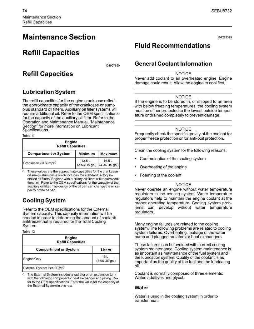
MaintenanceSection
Refill Capacitiesi04907690
Refill Capacities
LubricationSystemThe refill capacities for the engine crankcase reflectthe approximate capacity of the crankcase or sumpplus standard oil filters. Auxiliary oil filter systems willrequire additional oil. Refer to the OEM specificationsfor the capacity of the auxiliary oil filter. Refer to theOperation and Maintenance Manual, “MaintenanceSection” for more information on LubricantSpecifications.Table 11
EngineRefill Capacities
Compartment or System Minimum Maximum
Crankcase Oil Sump(1) 13.5 L(3.56 US gal)
16.5 L(4.36 US gal)
(1) These values are the approximate capacities for the crankcaseoil sump (aluminum) which includes the standard factory in-stalled oil filters. Engines with auxiliary oil filters will require addi-tional oil. Refer to the OEM specifications for the capacity of theauxiliary oil filter. The design of the oil pan can change the oil ca-pacity of the oil pan.
Cooling SystemRefer to the OEM specifications for the ExternalSystem capacity. This capacity information will beneeded in order to determine the amount of coolant/antifreeze that is required for the Total CoolingSystem.Table 12
EngineRefill Capacities
Compartment or System Liters
Engine Only 15 L(3.96 US gal)
External System Per OEM(1)
(1) The External System includes a radiator or an expansion tankwith the following components: heat exchanger and piping. Re-fer to the OEM specifications. Enter the value for the capacity ofthe External System in this row.
i04229329
Fluid Recommendations
General Coolant InformationNOTICE
Never add coolant to an overheated engine. Enginedamage could result. Allow the engine to cool first.
NOTICEIf the engine is to be stored in, or shipped to an areawith below freezing temperatures, the cooling systemmust be either protected to the lowest outside temper-ature or drained completely to prevent damage.
NOTICEFrequently check the specific gravity of the coolant forproper freeze protection or for anti-boil protection.
Clean the cooling system for the following reasons:
• Contamination of the cooling system
• Overheating of the engine
• Foaming of the coolant
NOTICENever operate an engine without water temperatureregulators in the cooling system. Water temperatureregulators help to maintain the engine coolant at theproper operating temperature. Cooling system prob-lems can develop without water temperatureregulators.
Many engine failures are related to the coolingsystem. The following problems are related to coolingsystem failures: Overheating, leakage of the waterpump and plugged radiators or heat exchangers.
These failures can be avoided with correct coolingsystem maintenance. Cooling system maintenance isas important as maintenance of the fuel system andthe lubrication system. Quality of the coolant is asimportant as the quality of the fuel and the lubricatingoil.
Coolant is normally composed of three elements:Water, additives and glycol.
WaterWater is used in the cooling system in order totransfer heat.
74 SEBU8732Maintenance SectionRefill Capacities
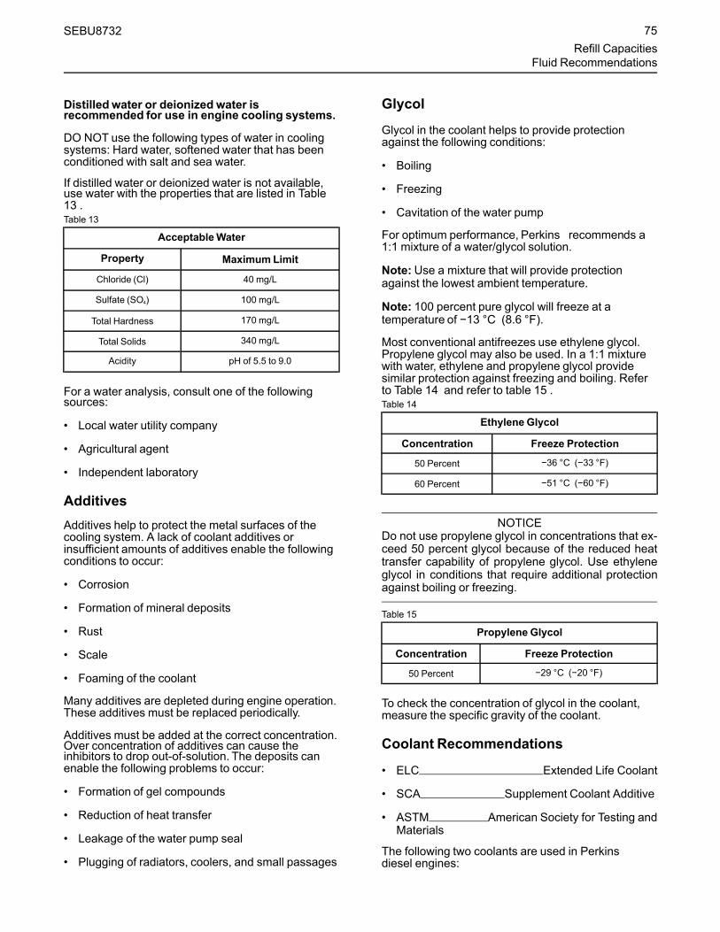
Distilled water or deionized water isrecommended for use in engine cooling systems.
DO NOT use the following types of water in coolingsystems: Hard water, softened water that has beenconditioned with salt and sea water.
If distilled water or deionized water is not available,use water with the properties that are listed in Table13 .Table 13
AcceptableWater
Property Maximum Limit
Chloride (Cl) 40 mg/L
Sulfate (SO4) 100 mg/L
Total Hardness 170 mg/L
Total Solids 340 mg/L
Acidity pH of 5.5 to 9.0
For a water analysis, consult one of the followingsources:
• Local water utility company
• Agricultural agent
• Independent laboratory
AdditivesAdditives help to protect the metal surfaces of thecooling system. A lack of coolant additives orinsufficient amounts of additives enable the followingconditions to occur:
• Corrosion
• Formation of mineral deposits
• Rust
• Scale
• Foaming of the coolant
Many additives are depleted during engine operation.These additives must be replaced periodically.
Additives must be added at the correct concentration.Over concentration of additives can cause theinhibitors to drop out-of-solution. The deposits canenable the following problems to occur:
• Formation of gel compounds
• Reduction of heat transfer
• Leakage of the water pump seal
• Plugging of radiators, coolers, and small passages
Glycol
Glycol in the coolant helps to provide protectionagainst the following conditions:
• Boiling
• Freezing
• Cavitation of the water pump
For optimum performance, Perkins recommends a1:1 mixture of a water/glycol solution.
Note: Use a mixture that will provide protectionagainst the lowest ambient temperature.
Note: 100 percent pure glycol will freeze at atemperature of −13 °C (8.6 °F).
Most conventional antifreezes use ethylene glycol.Propylene glycol may also be used. In a 1:1 mixturewith water, ethylene and propylene glycol providesimilar protection against freezing and boiling. Referto Table 14 and refer to table 15 .Table 14
Ethylene Glycol
Concentration Freeze Protection
50 Percent −36 °C (−33 °F)
60 Percent −51 °C (−60 °F)
NOTICEDo not use propylene glycol in concentrations that ex-ceed 50 percent glycol because of the reduced heattransfer capability of propylene glycol. Use ethyleneglycol in conditions that require additional protectionagainst boiling or freezing.
Table 15
Propylene Glycol
Concentration Freeze Protection
50 Percent −29 °C (−20 °F)
To check the concentration of glycol in the coolant,measure the specific gravity of the coolant.
Coolant Recommendations
• ELC Extended Life Coolant
• SCA Supplement Coolant Additive
• ASTM American Society for Testing andMaterials
The following two coolants are used in Perkinsdiesel engines:
SEBU8732 75Refill Capacities
Fluid Recommendations

Preferred – Perkins ELC
Acceptable – A commercial heavy-duty antifreezethat meets ASTM D6210 specifications
NOTICEThe 1200 series industrial engines must be oper-ated with a 1:1 mixture of water and glycol. Thisconcentration allows the NOx reduction system tooperate correctly at high ambient temperatures.
NOTICEDo not use a commercial coolant/antifreeze that onlymeets the ASTM D3306 specification. This type ofcoolant/antifreeze is made for light automotiveapplications.
Perkins recommends a 1:1 mixture of water andglycol. This mixture of water and glycol will provideoptimum heavy-duty performance as an antifreeze.This ratio may be increased to 1:2 water to glycol ifextra freezing protection is required.
A mixture of SCA inhibitor and water is acceptablebut will not give the same level of corrosion, boilingand, freezing protection as ELC. Perkinsrecommends a 6 percent to 8 percent concentrationof SCA in those cooling systems. Distilled water ordeionized water is preferred.Water which has therecommended properties may be used.Table 16
Coolant Service Life
Coolant Type Service Life (1)
Perkins ELC 6,000 Service Hours or ThreeYears
Commercial Heavy-Duty Anti-freeze that meets ASTM
D62103000 Service Hours or Two Year
Commercial SCA inhibitor andWater 3000 Service Hours or One Year
(1) Use the interval that occurs first. The cooling systemmust alsobe flushed out at this time.
ELCPerkins provides ELC for use in the followingapplications:
• Heavy-duty spark ignited gas engines
• Heavy-duty diesel engines
• Automotive applications
The anti-corrosion package for ELC is different fromthe anti-corrosion package for other coolants. ELC isan ethylene glycol base coolant. However, ELCcontains organic corrosion inhibitors and antifoamagents with low amounts of nitrite. Perkins ELC hasbeen formulated with the correct amount of theseadditives in order to provide superior corrosionprotection for all metals in engine cooling systems.
ELC is available in a premixed cooling solution withdistilled water. ELC is a 1:1 mixture. The PremixedELC provides freeze protection to −36 °C (−33 °F).The Premixed ELC is recommended for the initial fillof the cooling system. The Premixed ELC is alsorecommended for topping off the cooling system.
Containers of several sizes are available. Consultyour Perkins distributor for the part numbers.
ELC Cooling SystemMaintenance
Correct additions to the Extended LifeCoolant
NOTICEUse only Perkins products for pre-mixed or concen-trated coolants.
Mixing Extended Life Coolant with other products re-duces the Extended Life Coolant service life. Failureto follow the recommendations can reduce coolingsystem components life unless appropriate correctiveaction is performed.
In order to maintain the correct balance between theantifreeze and the additives, you must maintain therecommended concentration of ELC. Lowering theproportion of antifreeze lowers the proportion ofadditive. This will lower the ability of the coolant toprotect the system from pitting, from cavitation, fromerosion, and from deposits.
NOTICEDo not use a conventional coolant to top-off a coolingsystem that is filled with Extended Life Coolant (ELC).
Do not use standard supplemental coolant additive(SCA).
When using Perkins ELC, do not use standard SCA'sor SCA filters.
ELC Cooling System Cleaning
Note: If the cooling system is already using ELC,cleaning agents are not required to be used at thespecified coolant change interval. Cleaning agentsare only required if the system has beencontaminated by the addition of some other type ofcoolant or by cooling system damage.
76 SEBU8732Refill CapacitiesFluid Recommendations

Clean water is the only cleaning agent that is requiredwhen ELC is drained from the cooling system.
Before the cooling system is filled, the heater control(if equipped) must be set to the HOT position. Referto the OEM in order to set the heater control. After thecooling system is drained and the cooling system isrefilled, operate the engine until the coolant levelreaches the normal operating temperature and untilthe coolant level stabilizes. As needed, add thecoolant mixture in order to fill the system to thespecified level.
Changing to Perkins ELC
To change from heavy-duty antifreeze to the PerkinsELC, perform the following steps:
NOTICECare must be taken to ensure that all fluids are con-tained during performance of inspection, mainte-nance, testing, adjusting and the repair of theproduct. Be prepared to collect the fluid with suitablecontainers before opening any compartment or disas-sembling any component containing fluids.
Dispose of all fluids according to local regulations andmandates.
1. Drain the coolant into a suitable container.
2. Dispose of the coolant according to localregulations.
3. Flush the system with clean water in order toremove any debris.
4. Use an appropriate cleaner to clean the system.Follow the instruction on the label.
5. Drain the cleaner into a suitable container. Flushthe cooling system with clean water.
6. Fill the cooling system with clean water andoperate the engine until the engine is warmed to49° to 66°C (120° to 150°F).
NOTICEIncorrect or incomplete flushing of the cooling systemcan result in damage to copper and other metalcomponents.
To avoid damage to the cooling system, make sure tocompletely flush the cooling system with clear water.Continue to flush the system until all the signs of thecleaning agent are gone.
7. Drain the cooling system into a suitable containerand flush the cooling system with clean water.
Note: The cooling system cleaner must be thoroughlyflushed from the cooling system. Cooling systemcleaner that is left in the system will contaminate thecoolant. The cleaner may also corrode the coolingsystem.8. Repeat Steps 6 and repeat steps 7 until the system
is completely clean.
9. Fill the cooling system with the Perkins PremixedELC.
ELC Cooling System Contamination
NOTICEMixing ELC with other products reduces the effective-ness of the ELC and shortens the ELC service life.Use only Perkins Products for premixed or concen-trate coolants. Failure to follow these recommenda-tions can result in shortened cooling systemcomponent life.
ELC cooling systems can withstand contamination toa maximum of 10 percent of conventional heavy-dutyantifreeze or SCA. If the contamination exceeds 10percent of the total system capacity, performONE ofthe following procedures:
• Drain the cooling system into a suitable container.Dispose of the coolant according to localregulations. Flush the system with clean water. Fillthe system with the Perkins ELC.
• Drain a portion of the cooling system into asuitable container according to local regulations.Then, fill the cooling system with premixed ELC.This procedure should lower the contamination toless than 10 percent.
• Maintain the system as a conventional Heavy-DutyCoolant. Treat the system with an SCA. Changethe coolant at the interval that is recommended forthe conventional Heavy-Duty Coolant.
Commercial Heavy-Duty Antifreeze andSCA
NOTICECommercial Heavy-Duty Coolant which containsAmine as part of the corrosion protection systemmust not be used.
SEBU8732 77Refill Capacities
Fluid Recommendations

NOTICENever operate an engine without water temperatureregulators in the cooling system. Water temperatureregulators help to maintain the engine coolant at thecorrect operating temperature. Cooling system prob-lems can develop without water temperatureregulators.
Check the antifreeze (glycol concentration) in order toensure adequate protection against boiling orfreezing. Perkins recommends the use of arefractometer for checking the glycol concentration. Ahydrometer should not be used.
Perkins engine cooling systems should be tested at500 hour intervals for the concentration of SCA.
Additions of SCA are based on the results of the test.An SCA that is liquid may be needed at 500 hourintervals.
Adding the SCA to Heavy-Duty Coolant atthe Initial FillUse the equation that is in Table 17 to determine theamount of SCA that is required when the coolingsystem is initially filled.Table 17
Equation For Adding The SCATo The Heavy-Duty Coolant AtThe Initial Fill
V × 0.045 = X
V is the total volume of the cooling system.
X is the amount of SCA that is required.
Table 18 is an example for using the equation that isin Table 17 .Table 18
Example Of The Equation For Adding The SCATo The Heavy-Duty Coolant At The Initial Fill
Total Volume of theCooling System (V)
MultiplicationFactor
Amount of SCAthat is Required (X)
15 L (4 US gal) × 0.045 0.7 L (24 oz)
Adding The SCA to The Heavy-DutyCoolant For MaintenanceHeavy-duty antifreeze of all types REQUIRE periodicadditions of an SCA.
Test the antifreeze periodically for the concentrationof SCA. For the interval, refer to the Operation andMaintenance Manual, “Maintenance IntervalSchedule” (Maintenance Section). Cooling SystemSupplemental Coolant Additive (SCA) Test/Add.
Additions of SCA are based on the results of the test.The size of the cooling system determines theamount of SCA that is needed.
Use the equation that is in Table 19 to determine theamount of SCA that is required, if necessary:Table 19
Equation For Adding The SCATo The Heavy-Duty Coolant ForMaintenance
V × 0.014 = X
V is the total volume of the cooling system.
X is the amount of SCA that is required.
Table 20 is an example for using the equation that isin Table 19 .Table 20
Example Of The Equation For Adding The SCATo The Heavy-Duty Coolant For Maintenance
Total Volume of theCooling System (V)
MultiplicationFactor
Amount of SCAthat is Required (X)
15 L (4 US gal) × 0.014 0.2 L (7 oz)
Cleaning the System of Heavy-DutyAntifreeze
• Clean the cooling system after used coolant isdrained or before the cooling system is filled withnew coolant.
• Clean the cooling system whenever the coolant iscontaminated or whenever the coolant is foaming.
i05196225
Fluid Recommendations
General Lubricant InformationBecause of government regulations regarding thecertification of exhaust emissions from the engine, thelubricant recommendations must be followed.
• API American Petroleum Institute
• SAE Society Of Automotive Engineers Inc.
• ACEA Association des ConstructersEuropean Automobiles .
• ECF-3 Engine Crankcase Fluid
78 SEBU8732Refill CapacitiesFluid Recommendations
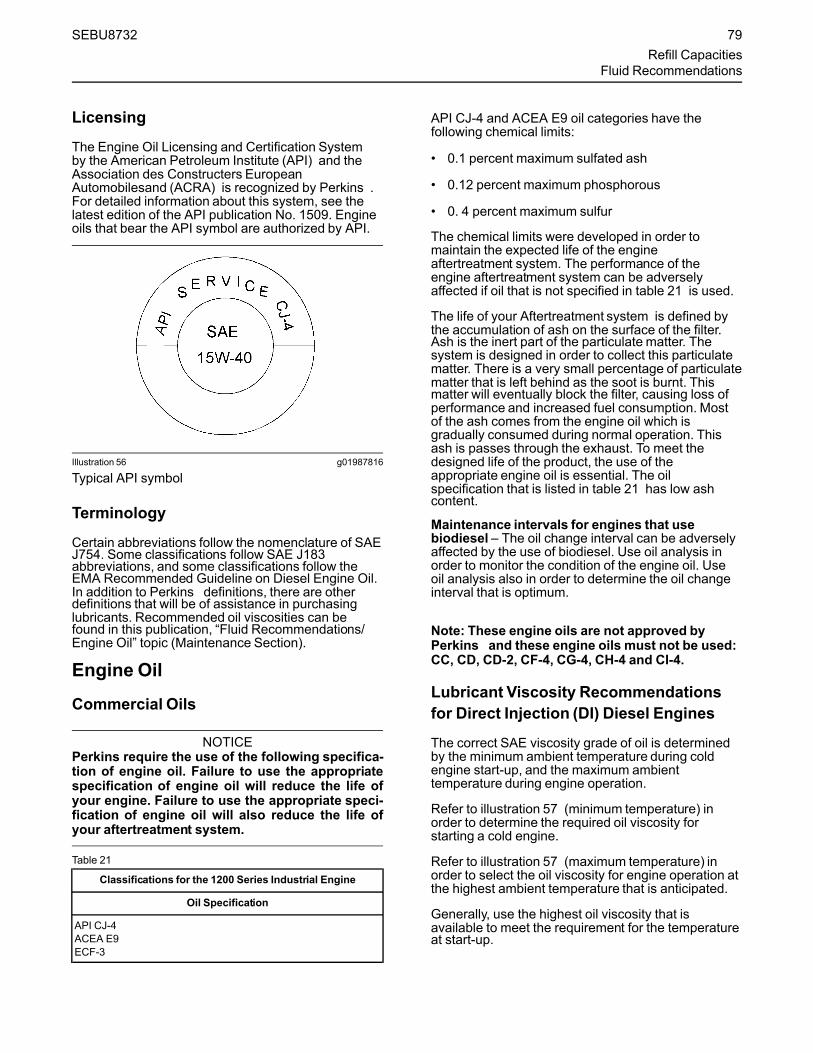
Licensing
The Engine Oil Licensing and Certification Systemby the American Petroleum Institute (API) and theAssociation des Constructers EuropeanAutomobilesand (ACRA) is recognized by Perkins .For detailed information about this system, see thelatest edition of the API publication No. 1509. Engineoils that bear the API symbol are authorized by API.
Illustration 56 g01987816
Typical API symbol
Terminology
Certain abbreviations follow the nomenclature of SAEJ754. Some classifications follow SAE J183abbreviations, and some classifications follow theEMA Recommended Guideline on Diesel Engine Oil.In addition to Perkins definitions, there are otherdefinitions that will be of assistance in purchasinglubricants. Recommended oil viscosities can befound in this publication, “Fluid Recommendations/Engine Oil” topic (Maintenance Section).
Engine Oil
Commercial Oils
NOTICEPerkins require the use of the following specifica-tion of engine oil. Failure to use the appropriatespecification of engine oil will reduce the life ofyour engine. Failure to use the appropriate speci-fication of engine oil will also reduce the life ofyour aftertreatment system.
Table 21
Classifications for the 1200 Series Industrial Engine
Oil Specification
API CJ-4ACEA E9ECF-3
API CJ-4 and ACEA E9 oil categories have thefollowing chemical limits:
• 0.1 percent maximum sulfated ash
• 0.12 percent maximum phosphorous
• 0. 4 percent maximum sulfur
The chemical limits were developed in order tomaintain the expected life of the engineaftertreatment system. The performance of theengine aftertreatment system can be adverselyaffected if oil that is not specified in table 21 is used.
The life of your Aftertreatment system is defined bythe accumulation of ash on the surface of the filter.Ash is the inert part of the particulate matter. Thesystem is designed in order to collect this particulatematter. There is a very small percentage of particulatematter that is left behind as the soot is burnt. Thismatter will eventually block the filter, causing loss ofperformance and increased fuel consumption. Mostof the ash comes from the engine oil which isgradually consumed during normal operation. Thisash is passes through the exhaust. To meet thedesigned life of the product, the use of theappropriate engine oil is essential. The oilspecification that is listed in table 21 has low ashcontent.
Maintenance intervals for engines that usebiodiesel – The oil change interval can be adverselyaffected by the use of biodiesel. Use oil analysis inorder to monitor the condition of the engine oil. Useoil analysis also in order to determine the oil changeinterval that is optimum.
Note: These engine oils are not approved byPerkins and these engine oils must not be used:CC, CD, CD-2, CF-4, CG-4, CH-4 and CI-4.
Lubricant Viscosity Recommendationsfor Direct Injection (DI) Diesel Engines
The correct SAE viscosity grade of oil is determinedby the minimum ambient temperature during coldengine start-up, and the maximum ambienttemperature during engine operation.
Refer to illustration 57 (minimum temperature) inorder to determine the required oil viscosity forstarting a cold engine.
Refer to illustration 57 (maximum temperature) inorder to select the oil viscosity for engine operation atthe highest ambient temperature that is anticipated.
Generally, use the highest oil viscosity that isavailable to meet the requirement for the temperatureat start-up.
SEBU8732 79Refill Capacities
Fluid Recommendations

Illustration 57 g03329707
Lubricant ViscositiesSupplemental heat is recommended for cold soakedstarts below the minimum ambient temperature.Supplemental heat may be required for cold soakedstarts that are above the minimum temperature that isstated, depending on the parasitic load and otherfactors. Cold soaked starts occur when the enginehas not been operated for a period of time. Thisinterval will allow the oil to become more viscous dueto cooler ambient temperatures.
Aftermarket Oil AdditivesPerkins does not recommend the use of aftermarketadditives in oil. It is not necessary to use aftermarketadditives in order to achieve the engines maximumservice life or rated performance. Fully formulated,finished oils consist of base oils and of commercialadditive packages. These additive packages areblended into the base oils at precise percentages inorder to help provide finished oils with performancecharacteristics that meet industry standards.
There are no industry standard tests that evaluate theperformance or the compatibility of aftermarketadditives in finished oil. Aftermarket additives may notbe compatible with the finished oils additive package,which could lower the performance of the finished oil.The aftermarket additive could fail to mix with thefinished oil. This failure could produce sludge in thecrankcase. Perkins discourages the use ofaftermarket additives in finished oils.
To achieve the best performance from a Perkinsengine, conform to the following guidelines:
• See the appropriate “Lubricant Viscosities”. Referto the illustration 57 in order to find the correct oilviscosity grade for your engine.
• At the specified interval, service the engine. Usenew oil and install a new oil filter.
• Performmaintenance at the intervals that arespecified in the Operation and MaintenanceManual, “Maintenance Interval Schedule”.
Oil analysis
Some engines may be equipped with an oil samplingvalve. If oil analysis is required, the oil sampling valveis used to obtain samples of the engine oil. The oilanalysis will complement the preventive maintenanceprogram.
The oil analysis is a diagnostic tool that is used todetermine oil performance and component wearrates. Contamination can be identified and measuredby using oil analysis. The oil analysis includes thefollowing tests:
• The Wear Rate Analysis monitors the wear of theengines metals. The amount of wear metal andtype of wear metal that is in the oil is analyzed. Theincrease in the rate of engine wear metal in the oilis as important as the quantity of engine wearmetal in the oil.
• Tests are conducted in order to detectcontamination of the oil by water, glycol, or fuel.
• The Oil Condition Analysis determines the loss ofthe oils lubricating properties. An infrared analysisis used to compare the properties of new oil to theproperties of the used oil sample. This analysisallows technicians to determine the amount ofdeterioration of the oil during use. This analysisalso allows technicians to verify the performanceof the oil according to the specification during theentire oil change interval.
i05195224
Fluid Recommendations(Diesel Exhaust Fluid (DEF))
General InformationDiesel Exhaust Fluid (DEF) is a liquid that is injectedinto the aftertreatment system before SelectiveCatalytic Reduction (SCR). This system of injectingthe DEF into the exhaust will reactor in the SCRsystem. The Nitrogen Oxide (NOx) molecules in theexhaust are converted to elemental nitrogen andwater, reduces the emission of the engine.
80 SEBU8732Refill CapacitiesFluid Recommendations
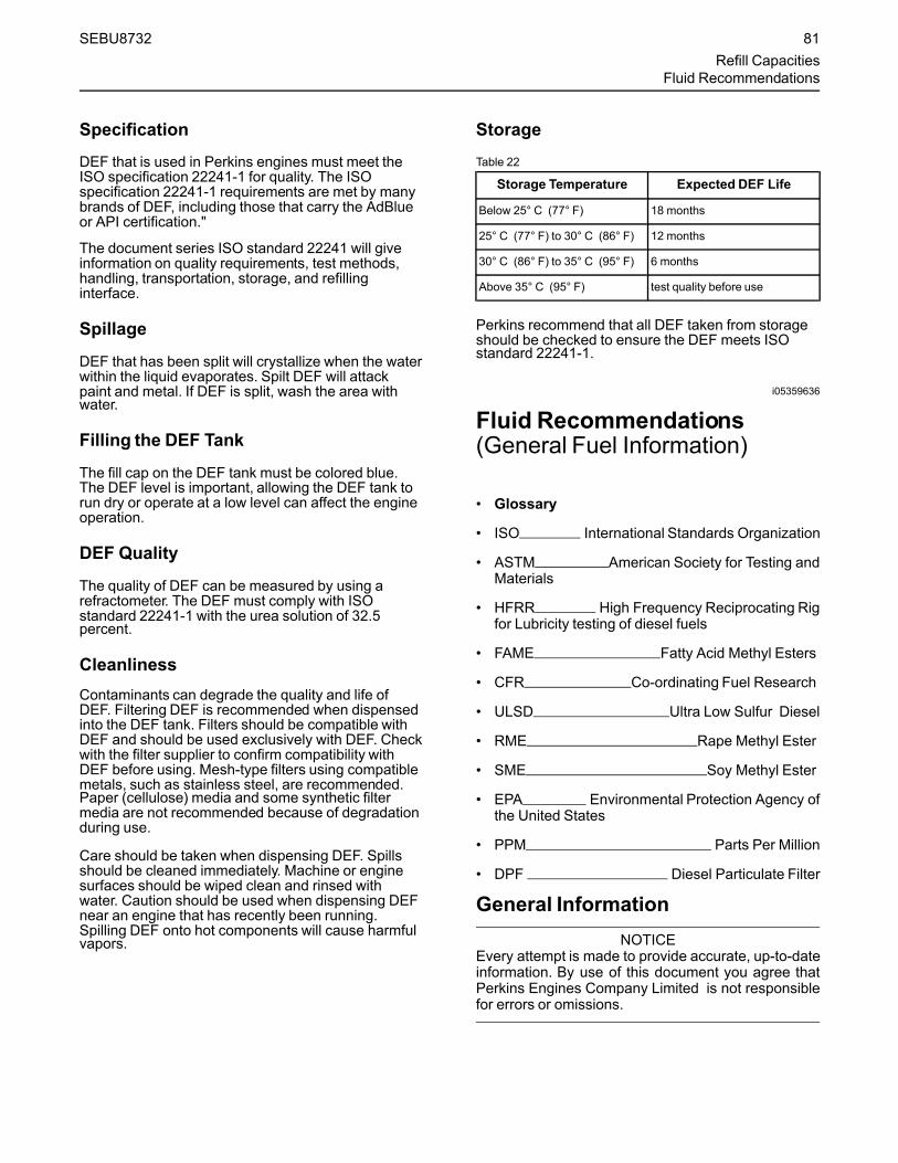
Specification
DEF that is used in Perkins engines must meet theISO specification 22241-1 for quality. The ISOspecification 22241-1 requirements are met by manybrands of DEF, including those that carry the AdBlueor API certification."
The document series ISO standard 22241 will giveinformation on quality requirements, test methods,handling, transportation, storage, and refillinginterface.
Spillage
DEF that has been split will crystallize when the waterwithin the liquid evaporates. Spilt DEF will attackpaint and metal. If DEF is split, wash the area withwater.
Filling the DEF Tank
The fill cap on the DEF tank must be colored blue.The DEF level is important, allowing the DEF tank torun dry or operate at a low level can affect the engineoperation.
DEF Quality
The quality of DEF can be measured by using arefractometer. The DEF must comply with ISOstandard 22241-1 with the urea solution of 32.5percent.
CleanlinessContaminants can degrade the quality and life ofDEF. Filtering DEF is recommended when dispensedinto the DEF tank. Filters should be compatible withDEF and should be used exclusively with DEF. Checkwith the filter supplier to confirm compatibility withDEF before using. Mesh-type filters using compatiblemetals, such as stainless steel, are recommended.Paper (cellulose) media and some synthetic filtermedia are not recommended because of degradationduring use.
Care should be taken when dispensing DEF. Spillsshould be cleaned immediately. Machine or enginesurfaces should be wiped clean and rinsed withwater. Caution should be used when dispensing DEFnear an engine that has recently been running.Spilling DEF onto hot components will cause harmfulvapors.
StorageTable 22
Storage Temperature Expected DEF Life
Below 25° C (77° F) 18 months
25° C (77° F) to 30° C (86° F) 12 months
30° C (86° F) to 35° C (95° F) 6 months
Above 35° C (95° F) test quality before use
Perkins recommend that all DEF taken from storageshould be checked to ensure the DEF meets ISOstandard 22241-1.
i05359636
Fluid Recommendations(General Fuel Information)
• Glossary
• ISO International Standards Organization
• ASTM American Society for Testing andMaterials
• HFRR High Frequency Reciprocating Rigfor Lubricity testing of diesel fuels
• FAME Fatty Acid Methyl Esters
• CFR Co-ordinating Fuel Research
• ULSD Ultra Low Sulfur Diesel
• RME Rape Methyl Ester
• SME Soy Methyl Ester
• EPA Environmental Protection Agency ofthe United States
• PPM Parts Per Million
• DPF Diesel Particulate Filter
General InformationNOTICE
Every attempt is made to provide accurate, up-to-dateinformation. By use of this document you agree thatPerkins Engines Company Limited is not responsiblefor errors or omissions.
SEBU8732 81Refill Capacities
Fluid Recommendations

NOTICEThese recommendations are subject to change with-out notice. Contact your local Perkins distributor forthe most up-to-date recommendations.
Diesel Fuel RequirementsPerkins is not in a position to continuously evaluateand monitor all worldwide distillate diesel fuelspecifications that are published by governments andtechnological societies.
The Perkins Specification for Distillate Diesel Fuelprovides a known reliable baseline in order to judgethe expected performance of distillate diesel fuelsthat are derived from conventional sources.
Satisfactory engine performance is dependent on theuse of a good quality fuel. The use of a good qualityfuel will give the following results: long engine life andacceptable exhaust emissions levels . The fuel mustmeet the minimum requirements that are stated in thetable 23 .
NOTICEThe footnotes are of the key part Perkins Specifica-tion for Distillate Diesel Fuel Table. Read ALL of thefootnotes.
Table 23
Perkins Specification for DistillateDiesel Fuel(1)
Property UNITS Requirements ASTMTest ISOTest
Aromatics %Volume 35%maximum D1319 ISO3837
Ash %Weight 0.01%maximum D482 ISO6245
Carbon Residue on 10%Bottoms
%Weight 0.35%maximum D524 ISO4262
Cetane Number (2) - 40 minimum D613/D6890 ISO5165
Cloud Point °C The cloud point must not ex-ceed the lowest expectedambient temperature.
D2500 ISO3015
Copper Strip Corrosion - No. 3 maximum D130 ISO2160
Density at 15 °C (59 °F)(3) kg/m3 801 minimum and 876maximum
No equivalent test ISO 3675ISO 12185
Distillation °C 10% at 282 °C (539.6 °F)maximum90% at 360 °C (680 °F)maximum
D86 ISO3405
Flash Point °C legal limit D93 ISO2719
Thermal Stability - Minimum of 80% reflectanceafter aging for 180 minutesat 150 °C (302 °F)
D6468 No equivalent test
(continued)
82 SEBU8732Refill CapacitiesFluid Recommendations

(Table 23, contd)
Pour Point °C 6 °C (42.8 °F) minimum be-low ambient temperature
D97 ISO3016
Sulfur (1) %mass 0.0015 D5453/D26222 ISO 20846ISO 20884
Kinematic Viscosity (4) mm2/s (cSt) The viscosity of the fuel thatis delivered to the fuel injec-tion pump. “1.4 minimum/4.5 maximum”
D445 ISO3405
Water and sediment % weight 0.1%maximum D1796 ISO3734
Water % weight 0.1%maximum D1744 No equivalent test
Sediment % weight 0.05%maximum D473 ISO3735
Gums and Resins (5) mg/100mL 10 mg per 100 mLmaximum
D381 ISO6246
Lubricity corrected wearscar diameter at 60 °C(140 °F). (6)
mm 0.52 maximum D6079 ISO12156-1
(1) This specification includes the requirements for Ultra Low Sulfur Diesel (ULSD). ULSD fuel will have ≤ 15 ppm (0.0015%) sulfur. Refer toASTM D5453, ASTM D2622, or ISO 20846, ISO 20884 test methods.
(2) A fuel with a higher cetane number is recommended in order to operate at a higher altitude or in cold weather.(3) “Via standards tables, the equivalent API gravity for the minimum density of 801 kg / m3 (kilograms per cubic meter) is 45 and for the maximum
density of 876 kg / m3 is 30”.(4) The values of the fuel viscosity are the values as the fuel is delivered to the fuel injection pumps. Fuel should also meet the minimum viscosity
requirement and the fuel should meet the maximum viscosity requirements at 40 °C (104 °F) of either the ASTM D445 test method or the ISO3104 test method. If a fuel with a low viscosity is used, cooling of the fuel may be required to maintain “1.4 cSt”or greater viscosity at the fuel in-jection pump. Fuels with a high viscosity might require fuel heaters in order to lower the viscosity to “1.4 cSt” at the fuel injection pump.
(5) Follow the test conditions and procedures for gasoline (motor).(6) The lubricity of a fuel is a concern with ultra low sulfur fuel. To determine the lubricity of the fuel, use the ISO 12156-1 or ASTM D6079 High
Frequency Reciprocating Rig (HFRR) test. If the lubricity of a fuel does not meet the minimum requirements, consult your fuel supplier. Do nottreat the fuel without consulting the fuel supplier. Some additives are not compatible. These additives can cause problems in the fuel system.
Engines that are manufactured by Perkins arecertified with the fuel that is prescribed by the UnitedStates Environmental Protection Agency . Enginesthat are manufactured by Perkins are certified withthe fuel that is prescribed by the EuropeanCertification. Perkins does not certify diesel engineson any other fuel.
Note: The owner and the operator of the engine hasthe responsibility of using the fuel that is prescribedby the EPA and other appropriate regulatoryagencies.
NOTICEOperating with fuels that do not meet the Perkins rec-ommendations can cause the following effects: Start-ing difficulty, reduced fuel filter service life, poorcombustion, deposits in the fuel injectors, significantlyreduce service life of the fuel system, deposits in thecombustion chamber and reduced service life of theengine.
NOTICEThe Perkins 1200 series of diesel engine must be op-erated using Ultra Low Sulfur Diesel. The sulphurcontent of this fuel must be lower than 15 PPM. Thisfuel complies with the emissions regulations that areprescribed by the Environmental Protection Agencyof the United States.
Illustration 58 g02157153
Illustration 58 is a representation of the label that willbe installed next to the fuel filler cap on the fuel tankof the application.
SEBU8732 83Refill Capacities
Fluid Recommendations

The fuel specifications that are listed in the table 24are released as acceptable to use on all 1200 seriesof engine.Table 24
Acceptable Fuel Specification for the 1200 Series of Engines(1)
Fuel Specification Comments
EN590 European Automotive Diesel Fuel (DERV)
ASTM D975 GRADE 1D S15 “North American Light Distillate Diesel fuel with less than 15 PPM sulfurlevel”
ASTM D975 GRADE 2D S15 “North American Middle Distillate general purpose Diesel fuel with lessthan 15 PPM sulfur level”
JIS K2204 “Japanese Diesel Fuel” Must meet the requirements that are stated inthe section “Lubricity”.
BS 2869: 2010 CLASS A2 or EU equivalent “EU Off Road Diesel fuel. Acceptable from 2011 MUST have less than10 PPM sulfur level”
(1) All the fuels must comply with the specification in the table for the Perkins Specification DistillateDiesel Fuel .
Diesel Fuel CharacteristicsCetane Number
Fuel that has a high cetane number will give a shorterignition delay. A high cetane number will produce abetter ignition quality. Cetane numbers are derived forfuels against proportions of cetane andheptamethylnonane in the standard CFR engine.Refer to ISO 5165 for the test method.
Cetane numbers in excess of 45 are normallyexpected from current diesel fuel. However, a cetanenumber of 40 may be experienced in some territories.The United States of America is one of the territoriesthat can have a low cetane value. A minimum cetanevalue of 40 is required during average startingconditions. A fuel with higher cetane number isrecommended for operations at high altitudes or incold-weather operations.
Fuel with a low cetane number can be the root causeof problems during a cold start.
Viscosity
Viscosity is the property of a liquid of offeringresistance to shear or flow. Viscosity decreases withincreasing temperature. This decrease in viscosityfollows a logarithmic relationship for normal fossilfuel. The common reference is to kinematic viscosity.Kinematic viscosity is the quotient of the dynamicviscosity that is divided by the density. Thedetermination of kinematic viscosity is normally byreadings from gravity flow viscometers at standardtemperatures. Refer to ISO 3104 for the test method.
The viscosity of the fuel is significant because fuelserves as a lubricant for the fuel system components.Fuel must have sufficient viscosity in order tolubricate the fuel system in both extremely coldtemperatures and extremely hot temperatures . If thekinematic viscosity of the fuel is lower than “1.4 cSt”at the fuel injection pump, damage to the fuel injectionpump can occur. This damage can be excessivescuffing and seizure. Low viscosity may lead todifficult hot restarting, stalling, and loss ofperformance. High viscosity may result in seizure ofthe pump.
Perkins recommends kinematic viscosities of 1.4 and4.5 mm2/sec that is delivered to the fuel injectionpump. If a fuel with a low viscosity is used, cooling ofthe fuel may be required to maintain 1.4 cSt orgreater viscosity at the fuel injection pump. Fuels witha high viscosity might require fuel heaters in order tolower the viscosity to 4.5 cSt at the fuel injectionpump.
Density
Density is the mass of the fuel per unit volume at aspecific temperature. This parameter has a directinfluence on engine performance and a directinfluence on emissions. This influence determinesfrom a heat output given injected volume of fuel. Thisparameter is quoted in the following kg/m3 at 15 °C(59 °F).
Perkins recommends a density of 841 kg/m 3 in orderto obtain the correct power output. Lighter fuels areacceptable but these fuels will not produce the ratedpower.
84 SEBU8732Refill CapacitiesFluid Recommendations

SulfurThe level of sulfur is governed by emissionslegislations . Regional regulation, nationalregulations, or international regulations can require afuel with a specific sulfur limit. The sulfur content ofthe fuel and the fuel quality must comply with allexisting local regulations for emissions.
Perkins 1200 series diesel engines have beendesigned to operate only with ULSD. By using thetest methods ASTM D5453, ASTM D2622, or ISO20846 ISO 20884, the content of sulfur in ULSD fuelmust be below 15 PPM (mg/kg) or 0.0015%mass.
NOTICEUse of diesel fuel with higher than 15 PPM sulphurlimit in these engines will harm or permanently dam-age emissions control systems and/or shorten theirservice interval.
Lubricity
Lubricity is the capability of the fuel to prevent pumpwear. The fluids lubricity describes the ability of thefluid to reduce the friction between surfaces that areunder load. This ability reduces the damage that iscaused by friction. Fuel injection systems rely on thelubricating properties of the fuel. Until fuel sulfur limitswere mandated, the fuels lubricity was generallybelieved to be a function of fuel viscosity.
The lubricity has particular significance to the currentultra low sulfur fuel, and low aromatic fossil fuels.These fuels are made in order to meet stringentexhaust emissions.
The lubricity of these fuels must not exceed wear scardiameter of 0.52 mm (0.0205 inch). The fuel lubricitytest must be performed on an HFRR, operated at60 °C (140 °F). Refer to ISO 12156-1.
NOTICEThe fuels system has been qualified with fuel havinglubricity up to 0.52 mm (0.0205 inch) wear scar diam-eter as tested by ISO 12156-1. Fuel with higher wearscar diameter than 0.52 mm (0.0205 inch) will lead toreduced service life and premature failure of the fuelsystem.
Fuel additives can enhance the lubricity of a fuel.Contact your fuel supplier for those circumstanceswhen fuel additives are required. Your fuel suppliercan make recommendations for additives to use, andfor the proper level of treatment.
DistillationDistillation is an indication of the mixture of differenthydrocarbons in the fuel. A high ratio of light weighthydrocarbons can affect the characteristics ofcombustion.
Recommendation for Biodiesel and UsingB20Biodiesel is a fuel that can be defined as mono-alkylesters of fatty acids . Biodiesel is a fuel that can bemade from various feedstock. The most commonlyavailable biodiesel in Europe is Rape Methyl Ester(RME) . This biodiesel is derived from rapeseed oil .Soy Methyl Ester (SME) is the most commonbiodiesel in the United States. This biodiesel isderived from soybean oil . Soybean oil or rapeseedoil are the primary feedstocks. These fuels aretogether known as Fatty Acid Methyl Esters (FAME) .
Raw pressed vegetable oils are NOTacceptable foruse as a fuel in any concentration in compressionengines . Without esterification, these oils solidify inthe crankcase and the fuel tank. These fuels may notbe compatible with many of the elastomers that areused in engines that are manufactured today. Inoriginal forms, these oils are not suitable for use as afuel in compression engines . Alternate base stocksfor biodiesel may include animal tallow , wastecooking oils , or various other feedstocks. In order touse any of the products that are listed as fuel, the oilmust be esterified .
Fuel made of 100 percent FAME is generally referredto as B100 biodiesel or neat biodiesel.
Biodiesel can be blended with distillate diesel fuel.The blends can be used as fuel. The most commonlyavailable biodiesel blends are B5, which is 5 percentbiodiesel and 95 percent distillate diesel fuel. B20,which is 20 percent biodiesel and 80 percent distillatediesel fuel.
Note: The percentages given are volume-based.
The U.S. distillate diesel fuel specification ASTMD975-09a includes up to B5 (5 percent) biodiesel.
European distillate diesel fuel specification EN590:2010 includes up B7 (7 percent) biodiesel.
Note: Engines that are manufactured by Perkins arecertified by use of the prescribed EnvironmentalProtection Agency (EPA) and European Certificationfuels. Perkins does not certify engines on any otherfuel. The user of the engine has the responsibility ofusing the correct fuel that is recommended by themanufacturer and allowed by the EPA and otherappropriate regulatory agencies.
SpecificationRequirements
The neat biodiesel must conform to the latestEN14214 or ASTM D6751 (in the USA). Thebiodiesel can only be blended in mixture of up to 20%by volume in acceptable mineral diesel fuel meetinglatest edition of EN590 or ASTM D975 S15designation.
SEBU8732 85Refill Capacities
Fluid Recommendations

In United States Biodiesel blends of B6 to B20 mustmeet the requirements listed in the latest edition ofASTM D7467 (B6 to B20) and must be of an APIgravity of 30-45.
In North America biodiesel and biodiesel blends mustbe purchased from the BQ-9000 accreditedproducers and BQ-9000 certified distributors.
In other areas of the world, the use of biodiesel that isBQ-9000 accredited and certified, or that isaccredited and certified by a comparable biodieselquality body to meet similar biodiesel qualitystandards is required.
Engine Service Requirements
Aggressive properties of biodiesel fuel may causedebris in the fuel tank and fuel lines. The aggressiveproperties of biodiesel will clean the fuel tank and fuellines. This cleaning of the fuel system canprematurely block of the fuel filters. Perkinsrecommend that after the initial usage of B20biodiesel blended fuel the fuel filters must be replacedat 50 hours.
Glycerides present in biodiesel fuel will also causefuel filters to become blocked more quickly. Thereforethe regular service interval should be reduced to 250hours.
When biodiesel fuel is used, crank case oil andaftertreatment systems may be influenced. Thisinfluence is due to the chemical composition andcharacteristics of biodiesel fuel, such as density andvolatility, and to chemical contaminants that can bepresent in this fuel, such as alkali and alkaline metals(sodium, potassium, calcium, and magnesium).
• Crankcase oil fuel dilution can be higher whenbiodiesel or biodiesel blends are used. Thisincreased level of fuel dilution when usingbiodiesel or biodiesel blends is related to thetypically lower volatility of biodiesel. In-cylinderemissions control strategies utilized in many of theindustrial latest engine designs may lead to ahigher level of biodiesel concentration in the sump.The long-term effect of biodiesel concentration incrankcase oil is currently unknown.
• Perkins recommend the use of oil analysis inorder to check the quality of the engine oil ifbiodiesel fuel is used. Ensure that the level ofbiodiesel in the fuel is noted when the oil sample istaken.
Performance Related IssuesDue to the lower energy content than the standarddistillate fuel B20 will cause a power loss in order of 2to 4 percent. In addition, over time the power maydeteriorate further due to deposits in the fuel injectors.
Biodiesel and biodiesel blends are known to cause anincrease in fuel system deposits, most significant ofwhich are deposits within the fuel injector. Thesedeposits can cause a loss in power due to restrictedor modified fuel injection or cause other functionalissues associated with these deposits.
Note: Perkins T400012 Fuel Cleaner is mosteffective in cleaning and preventing the formation ofdeposits. Perkins Diesel Fuel Conditioner helps tolimit deposit issues by improving the stability ofbiodiesel and biodiesel blends. For more informationrefer to “Perkins Diesel Fuel System Cleaner”.
Biodiesel fuel contains metal contaminants (sodium,potassium, calcium, and/or magnesium) that form ashproducts upon combustion in the diesel engine. Theash can have an impact on the life and performanceof aftertreatment emissions control devices and canaccumulate in DPF. The ash accumulation may causethe need for more frequent ash service intervals andcause loss of performance
General Requirements
Biodiesel has poor oxidation stability, which can resultin long-term problems in the storage of biodiesel.Biodiesel fuel should be used within 6 months ofmanufacture. Equipment should not be stored withthe B20 biodiesel blends in the fuel system for longerthan 3 months.
Due to poor oxidation stability and other potentialissues, it is strongly recommended that engines withlimited operational time either not use B20 biodieselblends or, while accepting some risk, limit biodieselblend to a maximum of B5. Examples of applicationsthat should limit the use of biodiesel are the following:Standby Generator sets and certain emergencyvehicles.
Perkins strongly recommended that seasonallyoperated engines have the fuel systems, includingfuel tanks, flashed with conventional diesel fuelbefore prolonged shutdown periods. An example ofan application that should seasonally flush the fuelsystem is a combine harvester.
Microbial contamination and growth can causecorrosion in the fuel system and premature pluggingof the fuel filter. Consult your supplier of fuel forassistance in selecting appropriate anti-microbialadditive.
Water accelerates microbial contamination andgrowth. When biodiesel is compared to distillate fuels,water is naturally more likely to exist in the biodiesel.It is therefore essential to check frequently and ifnecessary, drain the water separator.
Materials such as brass, bronze, copper, lead, tin,and zinc accelerate the oxidation process of thebiodiesel fuel. The oxidation process can causedeposits formation therefore these materials must notbe used for fuel tanks and fuel lines.
86 SEBU8732Refill CapacitiesFluid Recommendations

Fuel for Cold Weather Operation
The European standard EN590 contains climatedependant requirements and a range of options. Theoptions can be applied differently in each country.There are five classes that are given to arctic climatesand severe winter climates . 0, 1, 2, 3 and 4.
Fuel that complies with EN590 CLASS 4 can be usedat temperatures as low as −44 °C (−47.2 °F). Referto EN590 for a detailed discretion of the physicalproperties of the fuel.
The diesel fuel ASTM D975 1-D used in the UnitedStates of America may be used in very coldtemperatures that are below −18 °C (−0.4 °F).
Aftermarket Fuel AdditivesSupplemental diesel fuel additives are not generallyrecommended . This recommendation is due topotential damage to the fuel system or the engine.Your fuel supplier or the fuel manufacturer will add theappropriate supplemental diesel fuel additives.
Perkins recognizes the fact that additives may berequired in some special circumstances.
Note: Some anti-corrosion additives can lead toinjector fouling, this fouling can cause the injector tooperate incorrectly.
Contact your fuel supplier for those circumstanceswhen fuel additives are required. Your fuel suppliercan recommend the appropriate fuel additive and thecorrect level of treatment.
Note: For the best results, your fuel supplier shouldtreat the fuel when additives are required. The treatedfuel must meet the requirements that are stated intable 23 .
Perkins Diesel Fuel System Cleaner
Perkins T400012 Fuel Cleaner is the only fuelcleaner that is recommended by Perkins .
If biodiesel or biodiesel blends of fuel are to be used,Perkins require the use of Perkins fuel cleaner. Theuse of the fuel is in order to remove deposits withinthe fuel system that is created with the use ofbiodiesel. For more information on the use ofbiodiesel and biodiesel blends refer to“Recommendation for Biodiesel and Using B20”.
Perkins fuel cleaner will remove deposits that canform in the fuel system with the use of biodiesel andbiodiesel blends. These deposits can create a loss ofpower and engine performance.
Once the fuel cleaner has been added to the fuel, thedeposits within the fuel system are removed after 30hours of engine operation. For maximum results,continue to use the fuel cleaner for up to 80 hours.Perkins fuel cleaner can be used on an on-goingbasis with no adverse impact on engine or fuelsystem durability.
Details instruction on the rate of which the fuelcleaner must be use are on the container.
Note: Perkins fuel cleaner is compatible withexisting and U.S. EPATier 4 nonroad certified dieselengine emission control catalysts and particulatefilters. Perkins fuel system cleaner contains lessthan 15 ppm of sulfur and is acceptable for use withULSD fuel.
SEBU8732 87Refill Capacities
Fluid Recommendations

MaintenanceRecommendations
i03648938
System Pressure Release
Coolant System
Pressurized system: Hot coolant can cause seri-ous burn. To open cap, stop engine, wait until ra-diator is cool. Then loosen cap slowly to relievethe pressure.
The engine can have the ability to auto start. Ensurethat the power supply is isolated before any service orrepair is performed.
To relieve the pressure from the coolant system, turnoff the engine. Allow the cooling system pressure capto cool. Remove the cooling system pressure capslowly in order to relieve pressure.
Fuel SystemTo relieve the pressure from the fuel system, turn offthe engine.
High Pressure Fuel Lines
Contact with high pressure fuel may cause fluidpenetration and burn hazards. High pressure fuelspray may cause a fire hazard. Failure to followthese inspection, maintenance and service in-structionsmay cause personal injury or death.
The high pressure fuel lines are the fuel lines that arebetween the high pressure fuel pump and the highpressure fuel manifold and the fuel lines that arebetween the fuel manifold and cylinder head. Thesefuel lines are different from fuel lines on other fuelsystems.
This is because of the following differences:
• The high pressure fuel lines are constantlycharged with high pressure.
• The internal pressures of the high pressure fuellines are higher than other types of fuel system.
Before any service or repair is performed on theengine fuel lines, perform the following tasks:
1. Stop the engine.
2.Wait for 10 minutes.
Do not loosen the high pressure fuel lines in order toremove air from the fuel system.
Engine OilTo relieve pressure from the lubricating system, turnoff the engine.
i05359716
Welding on Engines withElectronic Controls
NOTICEBecause the strength of the frame may decrease,some manufacturers do not recommend welding ontoa chassis frame or rail. Consult the OEM of the equip-ment or your Perkins dealer regarding welding on achassis frame or rail.
Proper welding procedures are necessary in order toavoid damage to the engines ECM, sensors, andassociated components. When possible, remove thecomponent from the unit and then weld thecomponent. If removal of the component is notpossible, the following procedure must be followedwhen you weld on a unit equipped with an ElectronicEngine. The following procedure is considered to bethe safest procedure to weld on a component. Thisprocedure should provide a minimum risk of damageto electronic components.
NOTICEDo not ground the welder to electrical componentssuch as the ECM or sensors. Improper grounding cancause damage to the drive train bearings, hydrauliccomponents, electrical components, and othercomponents.
Clamp the ground cable from the welder to the com-ponent that will be welded. Place the clamp as closeas possible to the weld. This will help reduce the pos-sibility of damage.
Note: Perform the welding in areas that are free fromexplosive hazards.
1. Stop the engine. Turn the switched power to theOFF position.
2. Ensure that the fuel supply to the engine is turnedoff.
88 SEBU8732Maintenance RecommendationsSystem Pressure Release
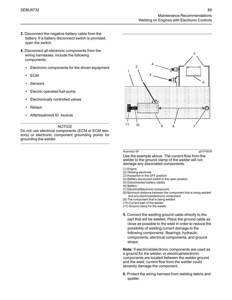
3. Disconnect the negative battery cable from thebattery. If a battery disconnect switch is provided,open the switch.
4. Disconnect all electronic components from thewiring harnesses. Include the followingcomponents:
• Electronic components for the driven equipment
• ECM
• Sensors
• Electric operated fuel pump
• Electronically controlled valves
• Relays
• Aftertreatment ID module
NOTICEDo not use electrical components (ECM or ECM sen-sors) or electronic component grounding points forgrounding the welder.
Illustration 59 g01075639
Use the example above. The current flow from thewelder to the ground clamp of the welder will notdamage any associated components.(1) Engine(2) Welding electrode(3) Keyswitch in the OFF position(4) Battery disconnect switch in the open position(5) Disconnected battery cables(6) Battery(7) Electrical/Electronic component(8) Minimum distance between the component that is being welded
and any electrical/electronic component(9) The component that is being welded(10) Current path of the welder(11) Ground clamp for the welder
5. Connect the welding ground cable directly to thepart that will be welded. Place the ground cable asclose as possible to the weld in order to reduce thepossibility of welding current damage to thefollowing components. Bearings, hydrauliccomponents, electrical components, and groundstraps.
Note: If electrical/electronic components are used asa ground for the welder, or electrical/electroniccomponents are located between the welder groundand the weld, current flow from the welder couldseverely damage the component.
6. Protect the wiring harness from welding debris andspatter.
SEBU8732 89Maintenance Recommendations
Welding on Engines with Electronic Controls

7. Use standard welding practices to weld thematerials.
i05196263
Severe Service Application
Severe service is the application of an engine thatexceeds the current published standards for thatengine. Perkins maintains standards for thefollowing engine parameters:
• Performance such as power range, speed range,and fuel consumption
• Fuel quality
• Operational Altitude
• Maintenance intervals
• Oil selection and maintenance
• Coolant type and maintenance
• Environmental qualities
• Installation
• The temperature of the fluid in the engine
Refer to the standards for the engine or consult yourPerkins dealer or your Perkins distributor in order todetermine if the engine is operating within the definedparameters.
Severe service operation can accelerate componentwear. Engines that operate under severe conditionsmay need more frequent maintenance intervals inorder to ensure maximum reliability and retention offull service life.
Due to individual applications, it is not possible toidentify all of the factors which can contribute tosevere service operation. Consult your Perkinsdealer or your Perkins distributor for the uniquemaintenance that is necessary for the engine.
The operating environment, incorrect operatingprocedures, and incorrect maintenance procedurescan be factors which contribute to a severe serviceapplication.
Environmental FactorsAmbient temperatures – The engine may beexposed to extended operation in extremely coldenvironments or hot environments. Valvecomponents can be damaged by carbon buildup if theengine is frequently started and stopped in very coldtemperatures. Extremely hot intake air reducesengine performance.
Quality of the air – The engine may be exposed toextended operation in an environment that is dirty ordusty, unless the equipment is cleaned regularly.Mud, dirt, and dust can encase components.Maintenance can be very difficult. The buildup cancontain corrosive chemicals.
Buildup – Compounds, elements, corrosivechemicals, and salt can damage some components.
Altitude – Problems can arise when the engine isoperated at altitudes that are higher than the intendedsettings for that application. Necessary adjustmentsshould be made.
Incorrect Operating Procedures• Extended operation at low idle
• Frequent hot shutdowns
• Operating at excessive loads
• Operating at excessive speeds
• Operating outside the intended application
Incorrect MaintenanceProcedures• Extending the maintenance intervals
• Failure to use recommended fuel, lubricants, andcoolant/antifreeze
90 SEBU8732Maintenance RecommendationsSevere Service Application

i05196439
Maintenance Interval Schedule
When Required“Battery - Replace”...................................................92
“Battery or Battery Cable - Disconnect”...................94
“Diesel Exhaust Fluid - Fill”................................... 100
“Engine - Clean”.................................................... 102
“Engine Air Cleaner Element (Dual Element) -Inspect/Clean/Replace” ........................................102
“Engine Air Cleaner Element (Single Element) -Inspect/Replace”................................................... 104
“Engine Oil Sample - Obtain”.................................110
“Fuel System - Prime”............................................114
Daily“Coolant Level - Check”...........................................99
“Driven Equipment - Check” ................................. 101
“Engine Air Cleaner Service Indicator - Inspect” .. 105
“Engine Air Precleaner - Check/Clean” ................ 106
“Engine Oil Level - Check”.....................................110
“Fuel System Primary Filter/Water Separator -Drain” .....................................................................117
“Walk-Around Inspection”..................................... 124
Every Week“Hoses and Clamps - Inspect/Replace”................ 120
Every 50 Service Hours or Weekly“Fuel Tank Water and Sediment - Drain” ...............119
Every 500 Service Hours“Fan Clearance - Check” .......................................113
Every 500 Service Hours or 1 Year“Battery Electrolyte Level - Check” ..........................93
“Crankshaft Vibration Damper - Inspect”.............. 100
“Engine Air Cleaner Element (Dual Element) -Inspect/Clean/Replace” ........................................102
“Engine Air Cleaner Element (Single Element) -Inspect/Replace”................................................... 104
“Engine Oil and Filter - Change”............................111
“Fuel Filter (In-Line) - Replace”..............................114
“Fuel System Primary Filter (Water Separator)Element - Replace”................................................115
“Fuel System Secondary Filter - Replace” ............118
“Radiator - Clean” ................................................. 122
Every 1000 Service Hours“Belt Tensioner - Check” ..........................................94
“Belt - Inspect”..........................................................95
“Water Pump - Inspect”.........................................126
Every 1500 Service Hours“Engine Crankcase Breather Element - Replace” 106
Every 2000 Service Hours“Aftercooler Core - Inspect” .....................................92
“Engine Mounts - Inspect” ....................................109
“Starting Motor - Inspect” ...................................... 123
“Turbocharger - Inspect” .......................................123
Every 3000 Service Hours“Alternator - Inspect” ................................................92
“Alternator and Fan Belts - Replace” .......................92
Every 3000 Service Hours or 2Years“Coolant (DEAC) - Change”.....................................95
Every 4000 Service Hours“Aftercooler Core - Clean/Test”................................92
Every 5000 Service Hours“Diesel Exhaust Fluid Filter - Clean/Replace” ...... 101
“Injector (Diesel Exhaust Fluid) - Replace”........... 121
Every 6000 Service Hours or 3Years“Coolant Extender (ELC) - Add” ..............................99
Every 12 000 Service Hours or 6Years“Coolant (ELC) - Change”........................................97
SEBU8732 91Maintenance RecommendationsMaintenance Interval Schedule

i01807350
Aftercooler Core - Clean/Test(Air-To-Air Aftercooler)
The air-to-air aftercooler is OEM installed in manyapplications. Please refer to the OEM specificationsfor information that is related to the aftercooler.
i02322295
Aftercooler Core - Inspect
Note: Adjust the frequency of cleaning according tothe effects of the operating environment.
Inspect the aftercooler for these items: damaged fins,corrosion, dirt, grease, insects, leaves, oil and otherdebris. Clean the aftercooler, if necessary.
For air-to-air aftercoolers, use the same methods thatare used for cleaning radiators.
Personal injury can result from air pressure.
Personal injury can result without following prop-er procedure. When using pressure air, wear aprotective face shield and protective clothing.
Maximum air pressure at the nozzle must be lessthan 205 kPa (30 psi) for cleaning purposes.
After cleaning, start the engine and accelerate theengine to high idle rpm. This will help in the removalof debris and drying of the core. Stop the engine. Usea light bulb behind the core in order to inspect thecore for cleanliness. Repeat the cleaning, ifnecessary.
Inspect the fins for damage. Bent fins may be openedwith a “comb”.
Note: If parts of the aftercooler system are repairedor replaced, a leak test is highly recommended.
Inspect these items for good condition: Welds,mounting brackets, air lines, connections, clamps andseals. Make repairs, if necessary.
i02322311
Alternator - Inspect
Perkins recommends a scheduled inspection of thealternator. Inspect the alternator for looseconnections and correct battery charging. Check theammeter (if equipped) during engine operation inorder to ensure correct battery performance and/orcorrect performance of the electrical system. Makerepairs, as required.
Check the alternator and the battery charger forcorrect operation. If the batteries are correctlycharged, the ammeter reading should be very nearzero. All batteries should be kept charged. Thebatteries should be kept warm because temperatureaffects the cranking power. If the battery is too cold,the battery will not crank the engine. When the engineis not run for long periods of time or if the engine isrun for short periods, the batteries may not fullycharge. A battery with a low charge will freeze moreeasily than a battery with a full charge.
i02680137
Alternator and Fan Belts -Replace
Refer to Disassembly and Assembly Manual,“Alternator Belt - Remove and Install”.
i05425759
Battery - Replace
Batteries give off combustible gases which canexplode. A spark can cause the combustiblegases to ignite. This can result in severe personalinjury or death.
Ensure proper ventilation for batteries that are inan enclosure. Follow the proper procedures in or-der to help prevent electrical arcs and/or sparksnear batteries. Do not smoke when batteries areserviced.
92 SEBU8732Maintenance RecommendationsAftercooler Core - Clean/Test

The battery cables or the batteries should not beremoved with the battery cover in place. The bat-tery cover should be removed before any servic-ing is attempted.
Removing the battery cables or the batteries withthe cover in place may cause a battery explosionresulting in personal injury.
1. Switch the engine to the OFF position. Remove allelectrical loads.
Note: After the engine has stopped, allow 2 minutesin order for the diesel exhaust fluid lines to be purgedbefore disconnecting the power.
2. Turn off any battery chargers. Disconnect anybattery chargers.
3. Ensure that the battery disconnect switch is in theOFF position.
4. Disconnect the NEGATIVE “-” cable from theNEGATIVE “-” battery terminal.
5. Disconnect the POSITIVE “+” cable from thePOSITIVE “+” battery terminal.
Note: Always recycle a battery. Never discard abattery. Dispose of used batteries to an appropriaterecycling facility.6. Remove the used battery.
7. Install the new battery.
Note: Before the cables are connected, ensure thatthe battery disconnect switch is in the OFF position.8. Connect the POSITIVE “+” cable to the POSITIVE
“+” battery terminal.
9. Connect the NEGATIVE “-” cable to theNEGATIVE “-” battery terminal.
10. Turn the battery disconnect switch to the ONposition.
i02747977
Battery Electrolyte Level -Check
When the engine is not run for long periods of time orwhen the engine is run for short periods, the batteriesmay not fully recharge. Ensure a full charge in orderto help prevent the battery from freezing. If batteriesare correctly charged, the ammeter reading should bevery near zero, when the engine is in operation.
All lead-acid batteries contain sulfuric acid whichcan burn the skin and clothing. Always wear aface shield and protective clothing when workingon or near batteries.
1. Remove the filler caps. Maintain the electrolytelevel to the “FULL” mark on the battery.
If the addition of water is necessary, use distilledwater. If distilled water is not available use cleanwater that is low in minerals. Do not use artificiallysoftened water.
2. Check the condition of the electrolyte with asuitable battery tester.
3. Install the caps.
4. Keep the batteries clean.
Clean the battery case with one of the followingcleaning solutions:
• Use a solution of 0.1 kg (0.2 lb) baking sodaand 1 L (1 qt) of clean water.
• Use a solution of ammonium hydroxide .
Thoroughly rinse the battery case with clean water.
SEBU8732 93Maintenance RecommendationsBattery Electrolyte Level - Check

i05424317
Battery or Battery Cable -Disconnect
The battery cables or the batteries should not beremoved with the battery cover in place. The bat-tery cover should be removed before any servic-ing is attempted.
Removing the battery cables or the batteries withthe cover in place may cause a battery explosionresulting in personal injury.
1. Turn the start switch to the OFF position. Turn theignition switch (if equipped) to the OFF positionand remove the key and all electrical loads.
Note: After the engine has stopped, allow 2 minutesin order for the diesel exhaust fluid lines to be purgedbefore disconnecting the power.
2. Disconnect the negative battery terminal. Ensurethat the cable cannot contact the terminal. Whenfour 12 V batteries are involved, 2 negativeconnections must be disconnected.
3. Remove the positive connection.
4. Clean all disconnected connection and batteryterminals.
5. Use a fine grade of sandpaper to clean theterminals and the cable clamps. Clean the itemsuntil the surfaces are bright or shiny. DO NOTremove material excessively. Excessive removal ofmaterial can cause the clamps to fit incorrectly.Coat the clamps and the terminals with a suitablesilicone lubricant or petroleum jelly.
6. Tape the cable connections in order to help preventaccidental starting.
7. Proceed with necessary system repairs.
8. In order to connect the battery, connect the positiveconnection before the negative connector.
i04907925
Belt Tensioner - Check
Illustration 60 g03074016
Typical example
Remove the belt. Refer to Disassembly andAssembly, “Alternator Belt - Remove and Install”.
Ensure that the belt tensioner is securely installed.Visually inspect the belt tensioner (1) for damage.Check that the pulley on the tensioner rotates freelyand that the bearing is not loose. Some engines havean idler pulley (2). Ensure that the idler pulley issecurely installed. Visually inspect the idler pulley fordamage. Ensure that the idler pulley can rotate freelyand that the bearing is not loose. If necessary,replace damaged components.
Install the belt. Refer to Disassembly and Assembly,“Alternator Belt - Remove and Install”.
94 SEBU8732Maintenance RecommendationsBattery or Battery Cable - Disconnect
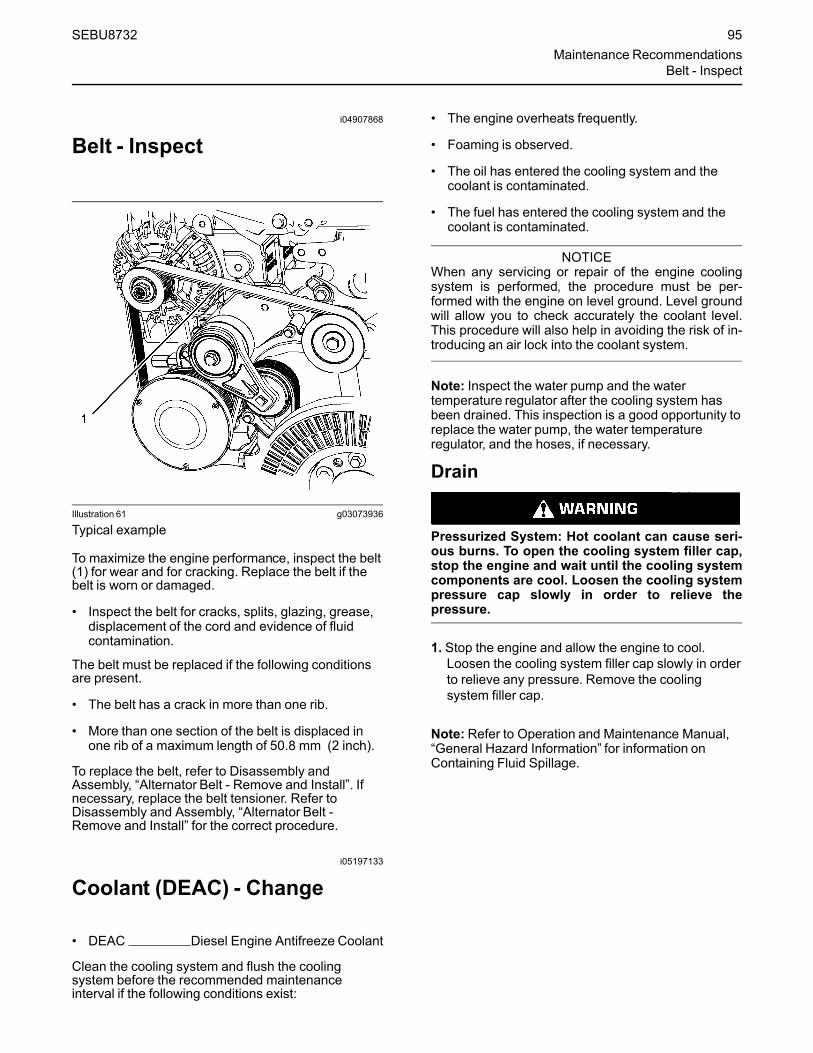
i04907868
Belt - Inspect
Illustration 61 g03073936
Typical example
To maximize the engine performance, inspect the belt(1) for wear and for cracking. Replace the belt if thebelt is worn or damaged.
• Inspect the belt for cracks, splits, glazing, grease,displacement of the cord and evidence of fluidcontamination.
The belt must be replaced if the following conditionsare present.
• The belt has a crack in more than one rib.
• More than one section of the belt is displaced inone rib of a maximum length of 50.8 mm (2 inch).
To replace the belt, refer to Disassembly andAssembly, “Alternator Belt - Remove and Install”. Ifnecessary, replace the belt tensioner. Refer toDisassembly and Assembly, “Alternator Belt -Remove and Install” for the correct procedure.
i05197133
Coolant (DEAC) - Change
• DEAC Diesel Engine Antifreeze Coolant
Clean the cooling system and flush the coolingsystem before the recommended maintenanceinterval if the following conditions exist:
• The engine overheats frequently.
• Foaming is observed.
• The oil has entered the cooling system and thecoolant is contaminated.
• The fuel has entered the cooling system and thecoolant is contaminated.
NOTICEWhen any servicing or repair of the engine coolingsystem is performed, the procedure must be per-formed with the engine on level ground. Level groundwill allow you to check accurately the coolant level.This procedure will also help in avoiding the risk of in-troducing an air lock into the coolant system.
Note: Inspect the water pump and the watertemperature regulator after the cooling system hasbeen drained. This inspection is a good opportunity toreplace the water pump, the water temperatureregulator, and the hoses, if necessary.
Drain
Pressurized System: Hot coolant can cause seri-ous burns. To open the cooling system filler cap,stop the engine and wait until the cooling systemcomponents are cool. Loosen the cooling systempressure cap slowly in order to relieve thepressure.
1. Stop the engine and allow the engine to cool.Loosen the cooling system filler cap slowly in orderto relieve any pressure. Remove the coolingsystem filler cap.
Note: Refer to Operation and Maintenance Manual,“General Hazard Information” for information onContaining Fluid Spillage.
SEBU8732 95Maintenance Recommendations
Belt - Inspect

Illustration 62 g03461657
Illustration 63 g02350785
2. Remove connection hose (1) on the engine. Alsoremove the drain plug (2). Open the drain cock orremove the drain plug on the radiator.
Allow the coolant to drain into a suitable container.
3. Properly dispose of the drained material. Obeylocal regulations for the disposal of the material.
Alternative Drain Plug
The cylinder coolant can be drained from the plugbelow the oil cooler. Refer to illustration 64 . If thealternative drain plug (3) is removed, the O ring sealmust be replaced. Tighten the drain plug to a torqueof 35 N·m (25 lb ft).
Illustration 64 g03081697
Flush1. Flush the cooling system with clean water and a
suitable cleaning agent in order to remove anydebris. Refer to your Perkins dealer or distributorfor suitable cleaning agents.
2. Install connection hose. Clean the drain plugs.Install the drain plugs. Tighten drain plug securely.
NOTICEDo not fill the cooling system faster than 5 L(1.3 US gal) per minute to avoid air locks.
Cooling system air locks may result in enginedamage.
3. Fill the cooling system with clean water and installthe cooling system filler cap.
4. Start and run the engine at low idle for a minimumof 30 minutes. The coolant temperature should beat least 82 °C (180 °F).
96 SEBU8732Maintenance RecommendationsCoolant (DEAC) - Change

NOTICEImproper or incomplete rinsing of the cooling systemcan result in damage to copper and other metalcomponents.
To avoid damage to the cooling system, make sure tocompletely flush the cooling system with clear water.Continue to flush the system until all signs of thecleaning agent are gone.
5. Stop the engine and allow the engine to cool.Loosen the cooling system filler cap slowly in orderto relieve any pressure. Remove the coolingsystem filler cap. Remove the connection hose orremove the cooling system drain plugs. Allow thewater to drain. Flush the cooling system with cleanwater. Install the connection hose.
6. The drain plug O rings on the engine block must bereplaced. Clean the drain plugs and install new Oring seal. Install the drain plugs and tighten to atorque of 35 N·m (25 lb ft).
Fill
NOTICEDo not fill the cooling system faster than 5 L(1.3 US gal) per minute to avoid air locks.
Cooling system air locks may result in enginedamage.
1. Fill the cooling system with the coolant/antifreeze.Refer to this Operation and Maintenance Manual,“Refill Capacities and Recommendations” topic(Maintenance Section) for more information oncooling system specifications. Do not install thecooling system filler cap.
2. Start and run the engine at low idle. Increase theengine rpm to high idle. Operate the engine inorder to open the engine thermostat. Thisoperation will allow any air in the system to bepurged. Decrease the engine speed to low idle.Stop the engine.
3.Maintain the coolant level at the maximummarkthat is correct for your application.
4. Clean the cooling system filler cap. Inspect thegasket that is on the cooling system filler cap. If thegasket that is on the cooling system filler cap isdamaged, discard the old cooling system filler capand install a new cooling system filler cap. If thegasket that is on the cooling system filler cap is notdamaged, perform a pressure test. If the coolingsystem filler cap does not retain the correctpressure, install a new cooling system filler cap.
5. Start the engine. Inspect the cooling system forleaks and for the correct operating temperature.
i05197293
Coolant (ELC) - Change
NOTICEPerkins ELC must be using with an extender in orderto achieve 12000 hours operation. For more informa-tion on a suitable extender contact your Perkins deal-er or Perkins distributor.
Clean the cooling system and flush the coolingsystem before the recommended maintenanceinterval if the following conditions exist:
• The engine overheats frequently.
• Foaming is observed.
• The oil has entered the cooling system and thecoolant is contaminated.
• The fuel has entered the cooling system and thecoolant is contaminated.
Note:When the cooling system is cleaned, onlyclean water is needed when the ELC is drained andreplaced.
Note: Inspect the water pump and the watertemperature regulator after the cooling system hasbeen drained. Replace the water pump, the watertemperature regulator, and the hoses, if necessary.
NOTICEService or repair of the engine cooling system mustbe performed on level ground. The engine must belevel in order to check the coolant level. The enginemust be level in order to avoid the risk of introducingan air lock into the coolant system.
SEBU8732 97Maintenance Recommendations
Coolant (ELC) - Change

Drain
Pressurized System: Hot coolant can cause seri-ous burns. To open the cooling system filler cap,stop the engine and wait until the cooling systemcomponents are cool. Loosen the cooling systempressure cap slowly in order to relieve thepressure.
1. Stop the engine and allow the engine to cool.Loosen the cooling system filler cap slowly in orderto relieve any pressure. Remove the coolingsystem filler cap.
Illustration 65 g03461657
Illustration 66 g02350785
2. Remove connection hose (1) on the engine. Alsoremove the drain plug (2). Open the drain cock orremove the drain plug on the radiator.
Allow the coolant to drain.
For information regarding the disposal and therecycling of used coolant, consult your Perkins dealeror Perkins distributor.
Flush1. Flush the cooling system with clean water in order
to remove any debris.
98 SEBU8732Maintenance RecommendationsCoolant (ELC) - Change

2. Install the connection hose. Clean the drain plugsand install the drain plugs. Tighten the drain plugssecurely.
NOTICEDo not fill the cooling system faster than 5 L(1.3 US gal) per minute to avoid air locks.
Cooling system air locks may result in enginedamage.
3. Fill the cooling system with clean water. Install thecooling system filler cap.
4. Start and run the engine at low idle until thetemperature reaches 49 to 66 °C (120 to 150 °F).
5. Stop the engine and allow the engine to cool.Loosen the cooling system filler cap slowly in orderto relieve any pressure. Remove the coolingsystem filler cap. Remove the connection hoseand remove the cooling system drain plugs. Allowthe water to drain. Flush the cooling system withclean water. Install the connection hose.
6. The drain plug O rings on the engine block must bereplaced. Clean the drain plugs and install new Oring seal. Install the drain plugs and tighten to atorque of 35 N·m (25 lb ft).
Fill
NOTICEDo not fill the cooling system faster than 5 L(1.3 US gal) per minute to avoid air locks.
Cooling system air locks may result in enginedamage.
1. Fill the cooling system with Extended Life Coolant(ELC). Refer to this Operation and MaintenanceManual, “Refill Capacities” topic (MaintenanceSection) for more information on cooling systemspecifications. Do not install the cooling systemfiller cap.
2. Start and run the engine at low idle. Increase theengine rpm to high idle. Operate the engine inorder to open the engine thermostat. An openthermostat will allow any air in the system to bepurged. Decrease the engine speed to low idle.Stop the engine.
3.Maintain the coolant level at the maximummarkthat is correct for your application.
4. Clean the cooling system filler cap. Inspect thegasket that is on the cooling system filler cap. If thegasket that is on the cooling system filler cap isdamaged, discard the old cooling system filler capand install a new cooling system filler cap. If thegasket that is on the cooling system filler cap is notdamaged, pressure test the cooling system fillercap. The correct pressure for the cooling systemfiller cap is stamped on the face of the coolingsystem filler cap. If the cooling system filler capdoes not retain the correct pressure, install a newcooling system filler cap.
5. Start the engine. Inspect the cooling system forleaks and for proper operating temperature.
i05197396
Coolant Extender (ELC) - Add
In order for Perkins ELC to achieve 12000 hours anextender must be added at 6000 hours. For a suitableextender, contact your Perkins dealer or Perkinsdistributor.
i05436397
Coolant Level - Check
Pressurized System: Hot coolant can cause seri-ous burns. To open the cooling system filler cap,stop the engine and wait until the cooling systemcomponents are cool. Loosen the cooling systempressure cap slowly in order to relieve thepressure.
Check the coolant level when the engine is stoppedand cool.
NOTICEWhen any servicing or repair of the engine coolingsystem is performed, the procedure must be per-formed with the engine on level ground. This proce-dure will allow you to check accurately the coolantlevel. This procedure will also help in avoiding the riskof introducing an air lock into the coolant system.
1. Remove the cooling system filler cap slowly inorder to relieve pressure.
SEBU8732 99Maintenance RecommendationsCoolant Extender (ELC) - Add
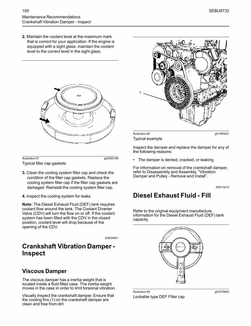
2.Maintain the coolant level at the maximummarkthat is correct for your application. If the engine isequipped with a sight glass, maintain the coolantlevel to the correct level in the sight glass.
Illustration 67 g02590196
Typical filler cap gaskets
3. Clean the cooling system filler cap and check thecondition of the filler cap gaskets. Replace thecooling system filler cap if the filler cap gaskets aredamaged. Reinstall the cooling system filler cap.
4. Inspect the cooling system for leaks.
Note: The Diesel Exhaust Fluid (DEF) tank requirescoolant flow around the tank. The Coolant DiverterValve (CDV) will turn the flow on or off. If the coolantsystem has been filled with the CDV in the closedposition, coolant level will drop because of theopening of the CDV.
i03634651
Crankshaft Vibration Damper -Inspect
Viscous DamperThe viscous damper has a inertia weight that islocated inside a fluid filled case. The inertia weightmoves in the case in order to limit torsional vibration.
Visually inspect the crankshaft damper. Ensure thatthe cooling fins (1) on the crankshaft damper areclean and free from dirt.
Illustration 68 g01950241
Typical example
Inspect the damper and replace the damper for any ofthe following reasons:
• The damper is dented, cracked, or leaking.
For information on removal of the crankshaft damper,refer to Disassembly and Assembly, “VibrationDamper and Pulley - Remove and Install”.
i05413412
Diesel Exhaust Fluid - Fill
Refer to the original equipment manufactureinformation for the Diesel Exhaust Fluid (DEF) tankcapacity.
Illustration 69 g03379943
Lockable type DEF Filler cap
100 SEBU8732Maintenance RecommendationsCrankshaft Vibration Damper - Inspect

Illustration 70 g03417998
Typical example
1. Ensure that the DEF cap (1) and the surroundingarea is clean and free from dirt.
2. Remove the DEF cap from the tank.
3. Fill the tank with the required amount of DEF.Ensure that dirt is not introduced into the tankduring filling. Do not over fill the tank. The DEFmay require room for expansion.
4. The opening on the DEF tank (2) is a specialdiameter. Ensure that the correct nozzle is usedwhen filling the DEF tank.
5. Install the DEF cap.
i04928595
Diesel Exhaust Fluid Filter -Clean/Replace
Illustration 71 g03097598
1. Ensure that the area around the Diesel ExhaustFluid (DEF) filter is clean and free from dirt. Use a27mm Bi-Hex socket in order to remove filter cap(3).
2. Remove the expansion device (2). Use toolsupplied with new filter element in order to removeexpansion device. Remove filter element (1) frommain body (4).
3. Install new filter element (1) into main body (4).Install expansion device (2) into filter element (1).Install filter cap (3) and tighten cap to 20 N·m(15 lb ft).
i02151646
Driven Equipment - Check
Refer to the OEM specifications for more informationon the following maintenance recommendations forthe driven equipment:
• Inspection
• Adjustment
• Lubrication
• Other maintenance recommendations
Perform any maintenance for the driven equipmentwhich is recommended by the OEM.
SEBU8732 101Maintenance Recommendations
Diesel Exhaust Fluid Filter - Clean/Replace

i03991933
Engine - Clean
Personal injury or death can result from highvoltage.
Moisture can create paths of electricalconductivity.
Make sure that the electrical system is OFF. Lockout the starting controls and tag the controls ““DONOT OPERATE”” .
NOTICEAccumulated grease and oil on an engine is a firehazard. Keep the engine clean. Remove debris andfluid spills whenever a significant quantity accumu-lates on the engine.
Periodic cleaning of the engine is recommended.Steam cleaning the engine will remove accumulatedoil and grease. A clean engine provides the followingbenefits:
• Easy detection of fluid leaks
• Maximum heat transfer characteristics
• Ease of maintenance
Note:Caution must be used in order to preventelectrical components from being damaged byexcessive water when the engine is cleaned.Pressure washers and steam cleaners should not bedirected at any electrical connectors or the junction ofcables into the rear of the connectors. Avoid electricalcomponents such as the alternator, the starter, andthe ECM. Protect the fuel injection pump from fluids inorder to wash the engine.
AftertreatmentDuring the engine cleaning process, ensure thatwater or cleaning fluids cannot enter theaftertreatment system. If cleaning fluids enters theaftertreatment system, damage could occur.
i05207494
Engine Air Cleaner Element(Dual Element) - Inspect/Clean/Replace
NOTICENever run the engine without an air cleaner elementinstalled. Never run the engine with a damaged aircleaner element. Do not use air cleaner elements withdamaged pleats, gaskets or seals. Dirt entering theengine causes premature wear and damage to en-gine components. Air cleaner elements help to pre-vent airborne debris from entering the air inlet.
NOTICENever service the air cleaner element with the enginerunning since this will allow dirt to enter the engine.
Servicing the Air Cleaner ElementsNote: The air filter system may not have beenprovided by Perkins . The procedure that follows isfor a typical air filter system. Refer to the OEMinformation for the correct procedure.
If the air cleaner element becomes plugged, the aircan split the material of the air cleaner element.Unfiltered air will drastically accelerate internal enginewear. Refer to the OEM information for the correct aircleaner elements for your application.
• Check the precleaner (if equipped) and the dustbowl daily for accumulation of dirt and debris.Remove any dirt and debris, as needed.
• Operating in dirty conditions may require morefrequent service of the air cleaner element.
• The air cleaner element should be replaced atleast one time per year. This replacement shouldbe performed regardless of the number ofcleanings.
Replace the dirty air cleaner elements with clean aircleaner elements. Before installation, the air cleanerelements should be thoroughly checked for tears and/or holes in the filter material. Inspect the gasket or theseal of the air cleaner element for damage. Maintain asupply of suitable air cleaner elements forreplacement purposes.
Dual Element Air CleanersThe dual element air cleaner contains a primary aircleaner element and a secondary air cleanerelement.
102 SEBU8732Maintenance RecommendationsEngine - Clean
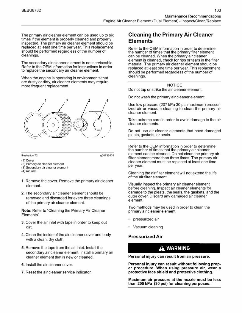
The primary air cleaner element can be used up to sixtimes if the element is properly cleaned and properlyinspected. The primary air cleaner element should bereplaced at least one time per year. This replacementshould be performed regardless of the number ofcleanings.
The secondary air cleaner element is not serviceable.Refer to the OEM information for instructions in orderto replace the secondary air cleaner element.
When the engine is operating in environments thatare dusty or dirty, air cleaner elements may requiremore frequent replacement.
Illustration 72 g00736431
(1) Cover(2) Primary air cleaner element(3) Secondary air cleaner element(4) Air inlet
1. Remove the cover. Remove the primary air cleanerelement.
2. The secondary air cleaner element should beremoved and discarded for every three cleaningsof the primary air cleaner element.
Note:Refer to “Cleaning the Primary Air CleanerElements”.
3. Cover the air inlet with tape in order to keep outdirt.
4. Clean the inside of the air cleaner cover and bodywith a clean, dry cloth.
5. Remove the tape from the air inlet. Install thesecondary air cleaner element. Install a primary aircleaner element that is new or cleaned.
6. Install the air cleaner cover.
7. Reset the air cleaner service indicator.
Cleaning the Primary Air CleanerElementsRefer to the OEM information in order to determinethe number of times that the primary filter elementcan be cleaned. When the primary air cleanerelement is cleaned, check for rips or tears in the filtermaterial. The primary air cleaner element should bereplaced at least one time per year. This replacementshould be performed regardless of the number ofcleanings.
NOTICEDo not tap or strike the air cleaner element.
Do not wash the primary air cleaner element.
Use low pressure (207 kPa 30 psi maximum) pressur-ized air or vacuum cleaning to clean the primary aircleaner element.
Take extreme care in order to avoid damage to the aircleaner elements.
Do not use air cleaner elements that have damagedpleats, gaskets, or seals.
Refer to the OEM information in order to determinethe number of times that the primary air cleanerelement can be cleaned. Do not clean the primary airfilter element more than three times. The primary aircleaner element must be replaced at least one timeper year.
Cleaning the air filter element will not extend the lifeof the air filter element.
Visually inspect the primary air cleaner elementbefore cleaning. Inspect air cleaner elements fordamage to the pleats, the seals, the gaskets, and theouter cover. Discard any damaged air cleanerelement.
Two methods may be used in order to clean theprimary air cleaner element:
• pressurized air
• Vacuum cleaning
Pressurized Air
Personal injury can result from air pressure.
Personal injury can result without following prop-er procedure. When using pressure air, wear aprotective face shield and protective clothing.
Maximum air pressure at the nozzle must be lessthan 205 kPa (30 psi) for cleaning purposes.
SEBU8732 103Maintenance Recommendations
Engine Air Cleaner Element (Dual Element) - Inspect/Clean/Replace

Pressurized air can be used to clean primary aircleaner elements that have not been cleaned morethan three times. Use filtered, dry air with a maximumpressure of 207 kPa (30 psi). Pressurized air will notremove deposits of carbon and oil.
Illustration 73 g00281692
Note:When the primary air cleaner elements arecleaned, always begin with the clean side (inside) inorder to force dirt particles toward the dirty side(outside).
Aim the air hose so that air flows along the length ofthe filter. Follow the direction of the paper pleats inorder to prevent damage to the pleats. Do not aim theair directly at the face of the paper pleats.
Note:Refer to “Inspecting the Primary Air CleanerElements”.
Vacuum Cleaning
Vacuum cleaning is a good method for removingaccumulated dirt from the dirty side (outside) of aprimary air cleaner element. Vacuum cleaning isespecially useful for cleaning primary air cleanerelements which require daily cleaning because of adry, dusty environment.
Cleaning from the clean side (inside) with pressurizedair is recommended prior to vacuum cleaning the dirtyside (outside) of a primary air cleaner element.
Note:Refer to “Inspecting the Primary Air CleanerElements”.
Inspecting the Primary Air CleanerElements
Illustration 74 g00281693
Inspect the clean, dry primary air cleaner element.Use a 60 W blue light in a dark room or in a similarfacility. Place the blue light in the primary air cleanerelement. Rotate the primary air cleaner element.Inspect the primary air cleaner element for tears and/or holes. Inspect the primary air cleaner element forlight that may show through the filter material. If it isnecessary in order to confirm the result, compare theprimary air cleaner element to a new primary aircleaner element that has the same part number.
Do not use a primary air cleaner element that has anytears and/or holes in the filter material. Do not use aprimary air cleaner element with damaged pleats,gaskets, or seals. Discard damaged primary aircleaner elements.
i01432811
Engine Air Cleaner Element(Single Element) - Inspect/Replace
Perform the Operation and Maintenance Manual,“Engine Air Cleaner Service Indicator-Inspect”procedure and perform the Operation andMaintenance Manual, “Engine Air Precleaner Check/Clean” procedure (if equipped) before performing thefollowing procedure.
NOTICENever run the engine without an air cleaner elementinstalled. Never run the engine with a damaged aircleaner element. Do not use air cleaner elements withdamaged pleats, gaskets or seals. Dirt entering theengine causes premature wear and damage to en-gine components. Air cleaner elements help to pre-vent airborne debris from entering the air inlet.
104 SEBU8732Maintenance RecommendationsEngine Air Cleaner Element (Single Element) - Inspect/Replace

NOTICENever service the air cleaner element with the enginerunning since this will allow dirt to enter the engine.
Illustration 75 g00310664
(1) Air cleaner cover(2) Air filter element(3) Air inlet
1. Remove air cleaner cover (1) and remove air filterelement (2).
2. Cover air inlet (3) with tape or a clean cloth so thatdebris cannot enter the air inlet.
3. Clean the inside of air cleaner cover (1). Clean thebody that holds the air cleaner element.
4. Inspect the replacement element for the followingitems:damage, dirt and debris.
5. Remove the seal from the opening of the air inlet.
6. Install a clean, undamaged air filter element (2).
7. Install air cleaner cover (1).
8. Reset the air cleaner service indicator.
i02335405
Engine Air Cleaner ServiceIndicator - Inspect
Some engines may be equipped with a differentservice indicator.
Some engines are equipped with a differential gaugefor inlet air pressure. The differential gauge for inletair pressure displays the difference in the pressurethat is measured before the air cleaner element andthe pressure that is measured after the air cleanerelement. As the air cleaner element becomes dirty,the pressure differential rises. If your engine isequipped with a different type of service indicator,follow the OEM recommendations in order to servicethe air cleaner service indicator.
The service indicator may be mounted on the aircleaner element or in a remote location.
Illustration 76 g00103777
Typical service indicator
Observe the service indicator. The air cleanerelement should be cleaned or the air cleaner elementshould be replaced when one of the followingconditions occur:
• The yellow diaphragm enters the red zone.
• The red piston locks in the visible position.
Test the Service IndicatorService indicators are important instruments.
• Check for ease of resetting. The service indicatorshould reset in less than three pushes.
• Check the movement of the yellow core when theengine is accelerated to the engine rated speed.The yellow core should latch at the greatestvacuum that is attained.
If the service indicator does not reset easily, or if theyellow core does not latch at the greatest vacuum,the service indicator should be replaced. If the newservice indicator will not reset, the hole for the serviceindicator may be restricted.
The service indicator may need to be replacedfrequently in environments that are severely dusty.
SEBU8732 105Maintenance Recommendations
Engine Air Cleaner Service Indicator - Inspect
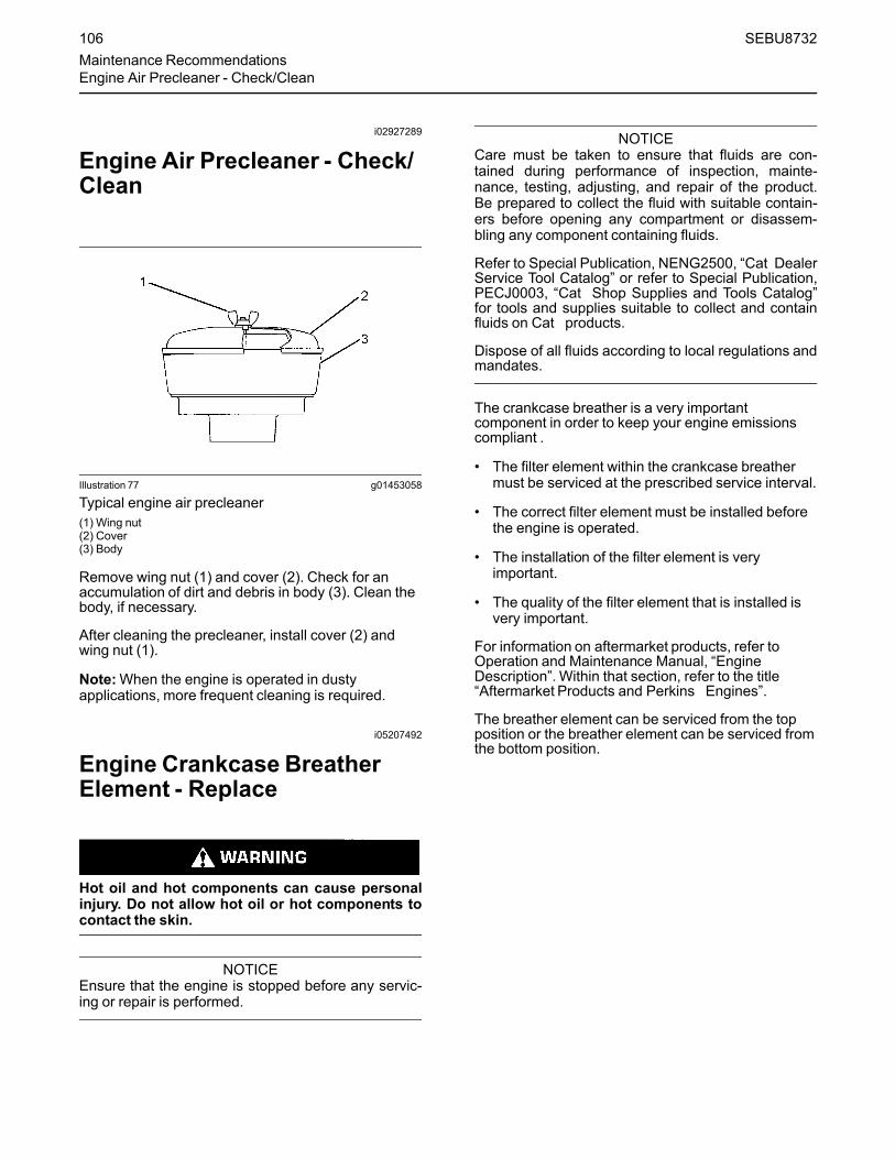
i02927289
Engine Air Precleaner - Check/Clean
Illustration 77 g01453058
Typical engine air precleaner(1) Wing nut(2) Cover(3) Body
Remove wing nut (1) and cover (2). Check for anaccumulation of dirt and debris in body (3). Clean thebody, if necessary.
After cleaning the precleaner, install cover (2) andwing nut (1).
Note:When the engine is operated in dustyapplications, more frequent cleaning is required.
i05207492
Engine Crankcase BreatherElement - Replace
Hot oil and hot components can cause personalinjury. Do not allow hot oil or hot components tocontact the skin.
NOTICEEnsure that the engine is stopped before any servic-ing or repair is performed.
NOTICECare must be taken to ensure that fluids are con-tained during performance of inspection, mainte-nance, testing, adjusting, and repair of the product.Be prepared to collect the fluid with suitable contain-ers before opening any compartment or disassem-bling any component containing fluids.
Refer to Special Publication, NENG2500, “Cat DealerService Tool Catalog” or refer to Special Publication,PECJ0003, “Cat Shop Supplies and Tools Catalog”for tools and supplies suitable to collect and containfluids on Cat products.
Dispose of all fluids according to local regulations andmandates.
The crankcase breather is a very importantcomponent in order to keep your engine emissionscompliant .
• The filter element within the crankcase breathermust be serviced at the prescribed service interval.
• The correct filter element must be installed beforethe engine is operated.
• The installation of the filter element is veryimportant.
• The quality of the filter element that is installed isvery important.
For information on aftermarket products, refer toOperation and Maintenance Manual, “EngineDescription”. Within that section, refer to the title“Aftermarket Products and Perkins Engines”.
The breather element can be serviced from the topposition or the breather element can be serviced fromthe bottom position.
106 SEBU8732Maintenance RecommendationsEngine Air Precleaner - Check/Clean

Top Service
Illustration 78 g03090965
1. Ensure that dirt cannot enter the breatherassembly. Ensure that the outside body of thebreather assembly is clean and free from damage.Place a container under the breather assembly.
2. Rotate the top cap (1) counterclockwise into theunlocked position. Remove the top cap from thebody of the breather (3) and remove the filterelement (2).
Illustration 79 g03090963
3. Remove the old seal (4) and install a new seal.
Note: The cut away from section (5) in the top capallows access to the seal.
Illustration 80 g03090938
(A) Alignment position(B) Alignment position
SEBU8732 107Maintenance Recommendations
Engine Crankcase Breather Element - Replace

4. Install a new filter element into the breather body(3). Ensure the correct position of the element,refer to illustration 80 . Align position (A) on the topcap to position (B) on the filter element.
Illustration 81 g02346577
Typical example
5. Install the top cap (1). Rotate the top cap by handclockwise until the top cap locks into the lockedposition (C) on the breather body.
6. Remove the container.
BottomServiceEnsure that dirt cannot enter the breather assembly.
Illustration 82 g02346498
Typical example(X) Alignment mark(Y) Alignment mark
1. Ensure that the outside body of the breatherassembly is clean and free from damage. Place acontainer under the breather.
2. Remove the tube connection (1). Ensure that dirtcannot enter the tube connection. Note the positionof the alignment marks (X and Y). Rotate thebottom cap (2) counterclockwise in order torelease the cap and the filter element (4) from thebreather body (3).
108 SEBU8732Maintenance RecommendationsEngine Crankcase Breather Element - Replace

Illustration 83 g03090968
Typical example(A) Alignment postion(B) Alignment postion
3. Remove the filter element (4). Remove the seal (5).
Note: The bottom cap has a section that allowsaccess in order to remove the seal.
4. Install a new seal (5). Install a new filter elementinto the bottom cap (2).
5. Align position (A) on the top cap to position (B) onthe filter element. Refer to illustration 83 .
6. Install the assembly of the filter element and thebottom cap (2). Rotate the bottom cap by handclockwise until the bottom cap locks into the lockedposition on the breather body. Ensure that thealignment marks (X and Y) are correctly aligned.Refer to illustration 82 .
7. Install tube connection (1). Ensure that theretaining clips on the tube connection are correctlyengaged. Remove the container.
Check the System
Illustration 84 g02346500
Typical example
Inspect the breather tube (1) for damage. Ensure thatthe outlet (2) is clean and free from any obstructions.Ice can cause obstructions in adverse weatherconditions.
i02323089
Engine Mounts - Inspect
Note: The engine mounts may not have beensupplied by Perkins . Refer to the OEM informationfor further information on the engine mounts and thecorrect bolt torque.
Inspect the engine mounts for deterioration and forcorrect bolt torque. Engine vibration can be causedby the following conditions:
• Incorrect mounting of the engine
• Deterioration of the engine mounts
• Loose engine mounts
Any engine mount that shows deterioration should bereplaced. Refer to the OEM information for therecommended torques.
SEBU8732 109Maintenance Recommendations
Engine Mounts - Inspect

i05300117
Engine Oil Level - Check
Hot oil and hot components can cause personalinjury. Do not allow hot oil or hot components tocontact the skin.
Illustration 85 g02173847
“L” Low“H” High
NOTICEPerform this maintenance with the engine stopped.
Note: Ensure that the engine is either level or that theengine is in the normal operating position in order toobtain a true level indication.
Note: After the engine has been switched OFF, waitfor 10 minutes in order to allow the engine oil to drainto the oil pan before checking the oil level.
1.Maintain the oil level between the mark (L) and themark (H) on the engine oil dipstick. Do not fill thecrankcase above the “H” .
NOTICEOperating your engine when the oil level is above the“H” mark could cause your crankshaft to dip into theoil. The air bubbles created from the crankshaft dip-ping into the oil reduces the oils lubricating character-istics and could result in the loss of power.
2. Remove the oil filler cap and add oil, if necessary.Clean the oil filler cap. Install the oil filler cap.
If an increase in the oil level is noticed, refer toTroubleshooting, “Oil Contains Fuel”.
i01907674
Engine Oil Sample - Obtain
The condition of the engine lubricating oil may bechecked at regular intervals as part of a preventivemaintenance program. Perkins include an oilsampling valve as an option. The oil sampling valve(if equipped) is included in order to regularly samplethe engine lubricating oil. The oil sampling valve ispositioned on the oil filter head or the oil samplingvalve is positioned on the cylinder block.
Perkins recommends using a sampling valve in orderto obtain oil samples. The quality and the consistencyof the samples are better when a sampling valve isused. The location of the sampling valve allows oilthat is flowing under pressure to be obtained duringnormal engine operation.
Obtain the Sample and the Analysis
Hot oil and hot components can cause personalinjury. Do not allow hot oil or hot components tocontact the skin.
In order to help obtain the most accurate analysis,record the following information before an oil sampleis taken:
• The date of the sample
• Engine model
• Engine number
• Service hours on the engine
• The number of hours that have accumulated sincethe last oil change
• The amount of oil that has been added since thelast oil change
Ensure that the container for the sample is clean anddry. Also ensure that the container for the sample isclearly labelled.
To ensure that the sample is representative of the oilin the crankcase, obtain a warm, well mixed oilsample.
To avoid contamination of the oil samples, the toolsand the supplies that are used for obtaining oilsamples must be clean.
110 SEBU8732Maintenance RecommendationsEngine Oil Level - Check

The sample can be checked for the following: thequality of the oil, the existence of any coolant in theoil, the existence of any ferrous metal particles in theoil and the existence of any nonferrous metalparticles in the oil.
i03996054
Engine Oil and Filter - Change
Hot oil and hot components can cause personalinjury. Do not allow hot oil or hot components tocontact the skin.
NOTICECare must be taken to ensure that fluids are con-tained during performance of inspection, mainte-nance, testing, adjusting and repair of the product. Beprepared to collect the fluid with suitable containersbefore opening any compartment or disassemblingany component containing fluids.
Dispose of all fluids according to local regulations andmandates.
NOTICEKeep all parts clean from contaminants.
Contaminants may cause rapid wear and shortenedcomponent life.
Do not drain the engine lubricating oil when theengine is cold. As the engine lubricating oil cools,suspended waste particles settle on the bottom of theoil pan. The waste particles are not removed withdraining cold oil. Drain the oil pan with the enginestopped. Drain the oil pan with the oil warm. Thisdraining method allows the waste particles that aresuspended in the oil to be drained properly.
Failure to follow this recommended procedure willcause the waste particles to be recirculated throughthe engine lubrication system with the new oil.
Drain the Engine LubricatingOilNote: Ensure that the vessel that will be used is largeenough to collect the waste oil.
After the engine has been run at the normal operatingtemperature, stop the engine. Use one of thefollowing methods to drain the engine oil pan:
Illustration 86 g01880893
Typical example
• If the engine is equipped with a drain valve, turnthe drain valve knob counterclockwise in order todrain the oil. After the oil has drained, turn thedrain valve knob clockwise in order to close thedrain valve.
• If the engine is not equipped with a drain valve,remove the oil drain plug (1) in order to allow theoil to drain. If the engine is equipped with a shallowoil pan, remove the bottom oil drain plugs fromboth ends of the oil pan.
After the oil has drained, the oil drain plugs should becleaned and installed. If necessary, replace the O ringseal. Tighten the drain plug to 34 N·m (25 lb ft).
Replace the Oil FilterNOTICE
Perkins oil filters are manufactured to Perkins speci-fications. Use of an oil filter that is not recommendedby Perkins could result in severe damage to the en-gine bearings, crankshaft, etc., as a result of the larg-er waste particles from unfiltered oil entering theengine lubricating system. Only use oil filters recom-mended by Perkins .
1. Remove the oil filter with a suitable tool.
Note: The following actions can be carried out as partof the preventive maintenance program.
SEBU8732 111Maintenance RecommendationsEngine Oil and Filter - Change
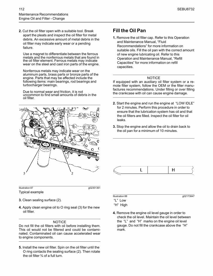
2. Cut the oil filter open with a suitable tool. Breakapart the pleats and inspect the oil filter for metaldebris. An excessive amount of metal debris in theoil filter may indicate early wear or a pendingfailure.
Use a magnet to differentiate between the ferrousmetals and the nonferrous metals that are found inthe oil filter element. Ferrous metals may indicatewear on the steel and cast iron parts of the engine.
Nonferrous metals may indicate wear on thealuminum parts, brass parts or bronze parts of theengine. Parts that may be affected include thefollowing items: main bearings, rod bearings andturbocharger bearings.
Due to normal wear and friction, it is notuncommon to find small amounts of debris in theoil filter.
Illustration 87 g02351361
Typical example
3. Clean sealing surface (2).
4. Apply clean engine oil to O ring seal (3) for the newoil filter.
NOTICEDo not fill the oil filters with oil before installing them.This oil would not be filtered and could be contami-nated. Contaminated oil can cause accelerated wearto engine components.
5. Install the new oil filter. Spin on the oil filter until theO ring contacts the sealing surface (2). Then rotatethe oil filter ¾ of a full turn.
Fill the Oil Pan1. Remove the oil filler cap. Refer to this Operation
and Maintenance Manual, “FluidRecommendations” for more information onsuitable oils. Fill the oil pan with the correct amountof new engine lubricating oil. Refer to thisOperation and Maintenance Manual, “RefillCapacities” for more information on refillcapacities.
NOTICEIf equipped with an auxiliary oil filter system or a re-mote filter system, follow the OEM or the filter manu-factures recommendations. Under filling or over fillingthe crankcase with oil can cause engine damage.
2. Start the engine and run the engine at “LOW IDLE”for 2 minutes. Perform this procedure in order toensure that the lubrication system has oil and thatthe oil filters are filled. Inspect the oil filter for oilleaks.
3. Stop the engine and allow the oil to drain back tothe oil pan for a minimum of 10 minutes.
Illustration 88 g02173847
“L” Low“H” High
4. Remove the engine oil level gauge in order tocheck the oil level. Maintain the oil level betweenthe “L” and “H” marks on the engine oil levelgauge. Do not fill the crankcase above the “H”mark.
112 SEBU8732Maintenance RecommendationsEngine Oil and Filter - Change

i05404932
Fan Clearance - Check
There are different types of cooling systems that canbe installed. Refer to the Original EquipmentManufactory (OEM) for your application for moreinformation.
Ensure that the engine is stopped and allow 2minutes before the battery disconnect switch isturned off. This procedure will allow the DieselExhaust Fluid (DEF) system to purged.
Ensure that the cooling system is full before checkingthe fan tip clearance. The fan tip clearance is thedistance between the tip of the fan blade (2) and theedge of the cover (1).
Illustration 89 g03414037
Typical example
The gap (A) must be checked in the vertical positionand in the horizontal position.
In the vertical position the gap can be checked at thevertically top position or at the vertically bottomposition.
SEBU8732 113Maintenance Recommendations
Fan Clearance - Check

• Gap (A) vertical top position 12 ± 1 mm(0.47244 ± 0.03937 inch).
• Gap (A) vertical bottom position 8 ± 1 mm(0.31496 ± 0.03937 inch).
After the gap (A) has been checked in the vertical topposition or the vertical bottom position, the horizontalposition must be checked.
• Gap (A) in the horizontal position must be aminimum of 9 mm (0.35433 inch).
If the fan tip clearance requires adjustment, refer tothe Disassembly and Assembly manual for moreinformation.
i04921339
Fuel Filter (In-Line) - Replace
Fuel leaked or spilled onto hot surfaces or electri-cal components can cause a fire. To help preventpossible injury, turn the start switch off whenchanging fuel filters or water separator elements.Clean up fuel spills immediately.
Note: Refer to Systems Operation, Testing, andAdjusting, “Cleanliness of Fuel SystemComponents” for detailed information on thestandards of cleanliness that must be observedduring ALL work on the fuel system.
NOTICEEnsure that the engine is stopped before any servic-ing or repair is performed.
The location of the in-line fuel filter will depend on theapplication that the engine has been installed.
Illustration 90 g03086919
Typical example
1. Turn the fuel supply valve (if equipped) to the OFFposition. Remove any brackets that hold the in-linefuel filter (1) in place, refer to OEM information.
2. Release the hose clips (3) and remove the hoselines from the in-line fuel filter. Remove the in-linefilter.
3. Install a new in-line filter and secure, refer to OEMinformation. Ensure that the arrow mark (2) isaligned to the direction of fuel flow from the tank tothe fuel pump.
4. Install the fuel hose lines and install the hose clips(3). Turn the fuel supply valve (if equipped) to theON position.
5. The in-line fuel filter must be changed with theprimary filter and the secondary fuel filter.
i03906114
Fuel System - Prime
Note: Refer to Systems Operation, Testing, andAdjusting, “Cleanliness of Fuel SystemComponents” for detailed information on thestandards of cleanliness that must be observedduring ALL work on the fuel system.
Ensure that all adjustments and repairs areperformed by authorized personnel that have had thecorrect training.
114 SEBU8732Maintenance RecommendationsFuel Filter (In-Line) - Replace

NOTICEDo not crank the engine continuously for more than30 seconds. Allow the starting motor to cool for twominutes before cranking the engine again.
If air enters the fuel system, the air must be purgedfrom the fuel system before the engine can bestarted. Air can enter the fuel system when thefollowing events occur:
• The fuel tank is empty or the fuel tank has beenpartially drained.
• The low-pressure fuel lines are disconnected.
• A leak exists in the low-pressure fuel system.
• The fuel filter has been replaced.
Use the following procedures in order to remove airfrom the fuel system:
1. Ensure that the fuel system is in working order.Check that the fuel supply valve (if equipped) is inthe “ON” position.
2. Turn the keyswitch to the “RUN” position.
3. The keyswitch will allow the electric priming pumpto operate. Operate the electric priming pump. TheECM will stop the pump after 2 minutes.
4. Turn the keyswitch to the “OFF” position. The fuelsystem should now be primed and the engineshould be able to start.
5. Operate the engine starter and crank the engine.After the engine has started, operate the engine atlow idle for a minimum of 5 minutes. Ensure thatthe fuel system is free from leaks.
Note:Operating the engine for this period will helpensure that the fuel system is free of air. DO NOTloosen the high-pressure fuel lines in order topurge air from the fuel system. This procedure isnot required.
After the engine has stopped, you must wait for 10minutes in order to allow the fuel pressure to bepurged from the high-pressure fuel lines before anyservice or repair is performed on the engine fuel lines.If necessary, performminor adjustments. Repair anyleaks from the low-pressure fuel system and from thecooling, lubrication, or air systems. Replace any high-pressure fuel line that has leaked. Refer toDisassembly and Assembly Manual, “Fuel InjectionLines - Install”.
If you inspect the engine in operation, always use theproper inspection procedure in order to avoid a fluidpenetration hazard . Refer to Operation andMaintenance Manual, “General hazard Information”.
If the engine will not start, refer to Troubleshooting,“Engine Cranks but will not Start”.
i05207487
Fuel System Primary Filter(Water Separator) Element -Replace
Fuel leaked or spilled onto hot surfaces or electri-cal components can cause a fire. To help preventpossible injury, turn the start switch off whenchanging fuel filters or water separator elements.Clean up fuel spills immediately.
Note: Refer to Systems Operation, Testing, andAdjusting, “Cleanliness of Fuel SystemComponents” for detailed information on thestandards of cleanliness that must be observedduring ALL work on the fuel system.
NOTICEEnsure that the engine is stopped before any servic-ing or repair is performed.
Remove the Element1. Turn the fuel supply valve (if equipped) to the OFF
position before performing this maintenance.
2. Place a suitable container under the waterseparator in order to catch any fuel that might spill.Clean up any spilled fuel. Clean the outside bodyof the filter assembly.
SEBU8732 115Maintenance Recommendations
Fuel System Primary Filter (Water Separator) Element - Replace

Illustration 91 g03086757
Typical example
3. Install a suitable tube onto drain (3). Open the drainvalve (2). Rotate the drain valve counterclockwise.Two full turns are required.
4. Loosen the vent screw (1).
5. Allow the fuel to drain into the container. Removethe tube from the drain valve.
6. Tighten the vent screw (1) securely . Remove thewiring harness from connection (4).
7. Rotate filter bowl (6) counterclockwise and removethe filter bowl from assembly.
Illustration 92 g02148402
Typical example
8. Rotate the filter element (5) counterclockwise andremove the filter element . Clean the filter bowl.
Install the New Filter Element
116 SEBU8732Maintenance RecommendationsFuel System Primary Filter (Water Separator) Element - Replace

Illustration 93 g03086798
Typical example
1. Locate the thread in the new filter element (8) ontothe threads (9). Spin on the filter element andtighten the drain valve (2) securely.
2. Lubricate the O ring seal (7) with clean engine oil.Do NOT fill the bowl with fuel before the assemblyis installed.
3. Do not use a tool in order to install the filterassembly. Tighten the filter bowl (6) by hand.Install the filter bowl (6). Turn the filter bowlclockwise until the filter bowl locks into positionagainst the stops.
4. Remove the container and dispose of the fuel in asafe place.
5. The secondary filter element must be replaced atthe same time as the primary filter element. Also,the in-line filter must be changed. Refer to theOperation and Maintenance Manual, “Fuel SystemFilter - Replace”.
i04925799
Fuel System Primary Filter/Water Separator - Drain
Fuel leaked or spilled onto hot surfaces or electri-cal components can cause a fire. To help preventpossible injury, turn the start switch off whenchanging fuel filters or water separator elements.Clean up fuel spills immediately.
NOTICEEnsure that the engine is stopped before any servic-ing or repair is performed.
NOTICEThe water separator can be under suction during nor-mal engine operation. Ensure that the drain valve istightened securely to help prevent air from enteringthe fuel system.
1. Place a suitable container under the waterseparator in order to catch any fluid that might spill.Clean up any spilled fluid.
2. Ensure that the outer body of the filter assembly isclean and free from dirt.
Illustration 94 g02148370
Typical example
SEBU8732 117Maintenance Recommendations
Fuel System Primary Filter/Water Separator - Drain
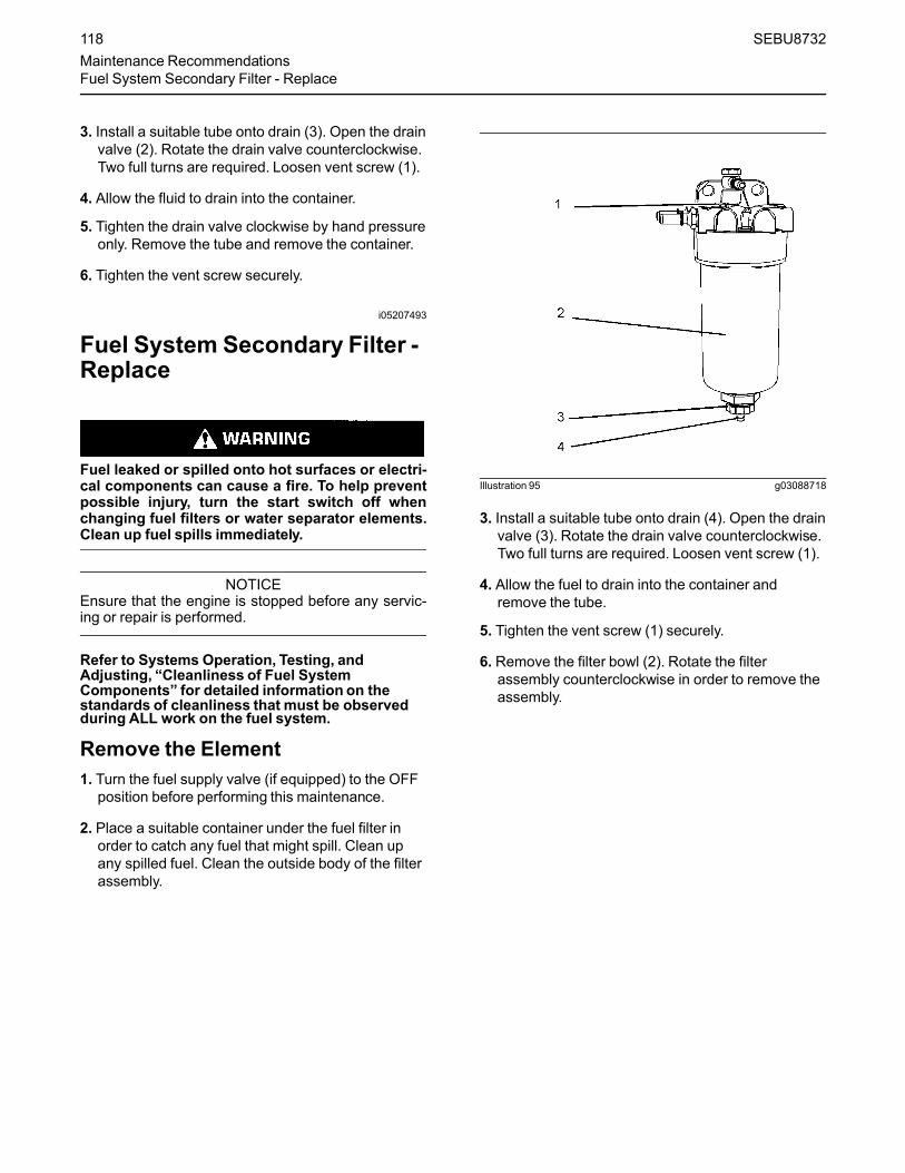
3. Install a suitable tube onto drain (3). Open the drainvalve (2). Rotate the drain valve counterclockwise.Two full turns are required. Loosen vent screw (1).
4. Allow the fluid to drain into the container.
5. Tighten the drain valve clockwise by hand pressureonly. Remove the tube and remove the container.
6. Tighten the vent screw securely.
i05207493
Fuel System Secondary Filter -Replace
Fuel leaked or spilled onto hot surfaces or electri-cal components can cause a fire. To help preventpossible injury, turn the start switch off whenchanging fuel filters or water separator elements.Clean up fuel spills immediately.
NOTICEEnsure that the engine is stopped before any servic-ing or repair is performed.
Refer to Systems Operation, Testing, andAdjusting, “Cleanliness of Fuel SystemComponents” for detailed information on thestandards of cleanliness that must be observedduring ALL work on the fuel system.
Remove the Element1. Turn the fuel supply valve (if equipped) to the OFF
position before performing this maintenance.
2. Place a suitable container under the fuel filter inorder to catch any fuel that might spill. Clean upany spilled fuel. Clean the outside body of the filterassembly.
Illustration 95 g03088718
3. Install a suitable tube onto drain (4). Open the drainvalve (3). Rotate the drain valve counterclockwise.Two full turns are required. Loosen vent screw (1).
4. Allow the fuel to drain into the container andremove the tube.
5. Tighten the vent screw (1) securely.
6. Remove the filter bowl (2). Rotate the filterassembly counterclockwise in order to remove theassembly.
118 SEBU8732Maintenance RecommendationsFuel System Secondary Filter - Replace
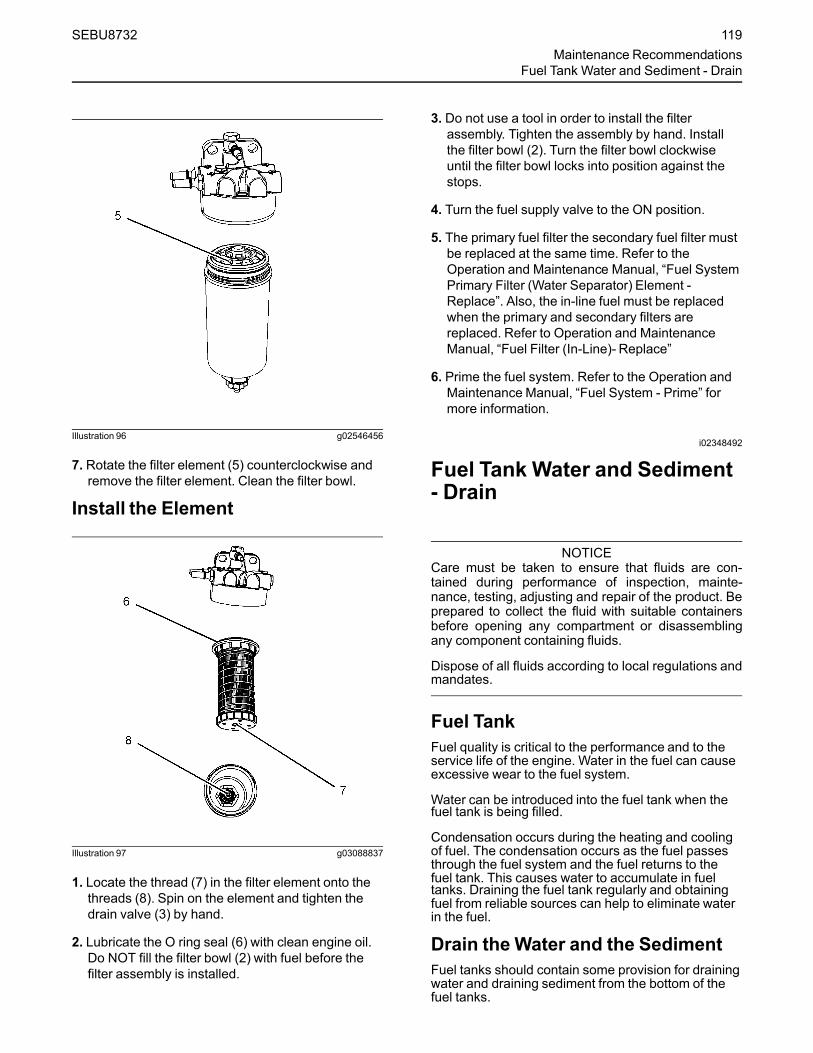
Illustration 96 g02546456
7. Rotate the filter element (5) counterclockwise andremove the filter element. Clean the filter bowl.
Install the Element
Illustration 97 g03088837
1. Locate the thread (7) in the filter element onto thethreads (8). Spin on the element and tighten thedrain valve (3) by hand.
2. Lubricate the O ring seal (6) with clean engine oil.Do NOT fill the filter bowl (2) with fuel before thefilter assembly is installed.
3. Do not use a tool in order to install the filterassembly. Tighten the assembly by hand. Installthe filter bowl (2). Turn the filter bowl clockwiseuntil the filter bowl locks into position against thestops.
4. Turn the fuel supply valve to the ON position.
5. The primary fuel filter the secondary fuel filter mustbe replaced at the same time. Refer to theOperation and Maintenance Manual, “Fuel SystemPrimary Filter (Water Separator) Element -Replace”. Also, the in-line fuel must be replacedwhen the primary and secondary filters arereplaced. Refer to Operation and MaintenanceManual, “Fuel Filter (In-Line)- Replace”
6. Prime the fuel system. Refer to the Operation andMaintenance Manual, “Fuel System - Prime” formore information.
i02348492
Fuel Tank Water and Sediment- Drain
NOTICECare must be taken to ensure that fluids are con-tained during performance of inspection, mainte-nance, testing, adjusting and repair of the product. Beprepared to collect the fluid with suitable containersbefore opening any compartment or disassemblingany component containing fluids.
Dispose of all fluids according to local regulations andmandates.
Fuel TankFuel quality is critical to the performance and to theservice life of the engine. Water in the fuel can causeexcessive wear to the fuel system.
Water can be introduced into the fuel tank when thefuel tank is being filled.
Condensation occurs during the heating and coolingof fuel. The condensation occurs as the fuel passesthrough the fuel system and the fuel returns to thefuel tank. This causes water to accumulate in fueltanks. Draining the fuel tank regularly and obtainingfuel from reliable sources can help to eliminate waterin the fuel.
Drain the Water and the SedimentFuel tanks should contain some provision for drainingwater and draining sediment from the bottom of thefuel tanks.
SEBU8732 119Maintenance Recommendations
Fuel Tank Water and Sediment - Drain

Open the drain valve on the bottom of the fuel tank inorder to drain the water and the sediment. Close thedrain valve.
Check the fuel daily. Allow five minutes after the fueltank has been filled before draining water andsediment from the fuel tank.
Fill the fuel tank after operating the engine in order todrive out moist air. This will help preventcondensation. Do not fill the tank to the top. The fuelexpands as the fuel gets warm. The tank mayoverflow.
Some fuel tanks use supply pipes that allow waterand sediment to settle below the end of the fuelsupply pipe. Some fuel tanks use supply lines thattake fuel directly from the bottom of the tank. If theengine is equipped with this system, regularmaintenance of the fuel system filter is important.
Fuel Storage TanksDrain the water and the sediment from the fuelstorage tank at the following intervals:
• Weekly
• Service intervals
• Refill of the tank
This will help prevent water or sediment from beingpumped from the storage tank into the engine fueltank.
If a bulk storage tank has been refilled or movedrecently, allow adequate time for the sediment tosettle before filling the engine fuel tank. Internalbaffles in the bulk storage tank will also help trapsediment. Filtering fuel that is pumped from thestorage tank helps to ensure the quality of the fuel.When possible, water separators should be used.
i02518232
Hoses and Clamps - Inspect/Replace
Contact with high pressure fuel may cause fluidpenetration and burn hazards. High pressure fuelspray may cause a fire hazard. Failure to followthese inspection, maintenance and service in-structionsmay cause personal injury or death.
If you inspect the engine in operation, always use theproper inspection procedure in order to avoid a fluidpenetration hazard. Refer to Operation andMaintenance Manual, “General hazard Information”.
Inspect all hoses for leaks that are caused by thefollowing conditions:
• Cracking
• Softness
• Loose clamps
Replace hoses that are cracked or soft. Tighten anyloose clamps.
Check for the following conditions:
• End fittings that are damaged or leaking
• Outer covering that is chafed or cut
• Exposed wire that is used for reinforcement
• Outer covering that is ballooning locally
• Flexible part of the hose that is kinked or crushed
• Armoring that is embedded in the outer covering
A constant torque hose clamp can be used in place ofany standard hose clamp. Ensure that the constanttorque hose clamp is the same size as the standardclamp.
Due to extreme temperature changes, the hose willharden. Hardening of the hoses will cause hoseclamps to loosen. This can result in leaks. A constanttorque hose clamp will help to prevent loose hoseclamps.
Each installation application can be different. Thedifferences depend on the following factors:
• Type of hose
• Type of fitting material
• Anticipated expansion and contraction of the hose
• Anticipated expansion and contraction of thefittings
Replace the Hoses and the ClampsRefer to the OEM information for further informationon removing and replacing fuel hoses (if equipped).
The following text describes a typical method ofreplacing coolant hoses. Refer to the OEMinformation for further information on the coolantsystem and the hoses for the coolant system.
120 SEBU8732Maintenance RecommendationsHoses and Clamps - Inspect/Replace
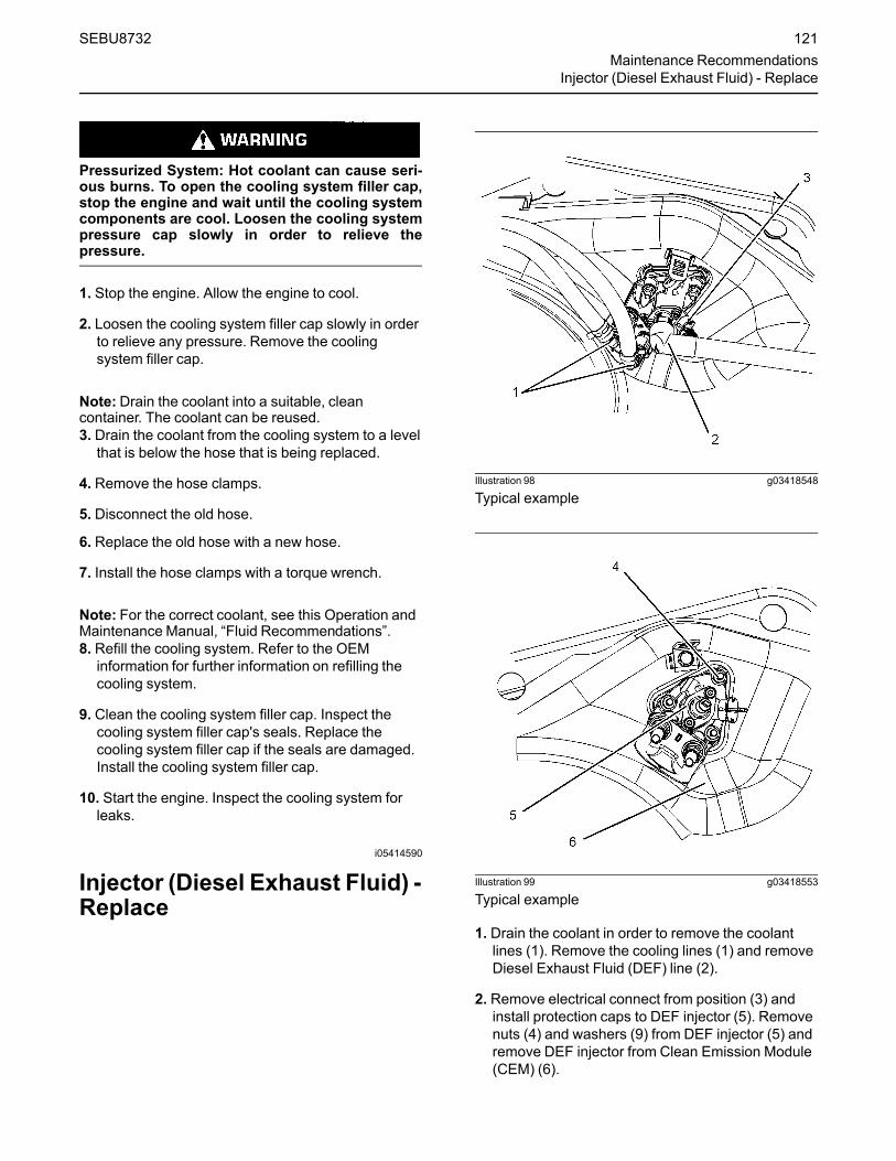
Pressurized System: Hot coolant can cause seri-ous burns. To open the cooling system filler cap,stop the engine and wait until the cooling systemcomponents are cool. Loosen the cooling systempressure cap slowly in order to relieve thepressure.
1. Stop the engine. Allow the engine to cool.
2. Loosen the cooling system filler cap slowly in orderto relieve any pressure. Remove the coolingsystem filler cap.
Note:Drain the coolant into a suitable, cleancontainer. The coolant can be reused.3. Drain the coolant from the cooling system to a level
that is below the hose that is being replaced.
4. Remove the hose clamps.
5. Disconnect the old hose.
6. Replace the old hose with a new hose.
7. Install the hose clamps with a torque wrench.
Note: For the correct coolant, see this Operation andMaintenance Manual, “Fluid Recommendations”.8. Refill the cooling system. Refer to the OEM
information for further information on refilling thecooling system.
9. Clean the cooling system filler cap. Inspect thecooling system filler cap's seals. Replace thecooling system filler cap if the seals are damaged.Install the cooling system filler cap.
10. Start the engine. Inspect the cooling system forleaks.
i05414590
Injector (Diesel Exhaust Fluid) -Replace
Illustration 98 g03418548
Typical example
Illustration 99 g03418553
Typical example
1. Drain the coolant in order to remove the coolantlines (1). Remove the cooling lines (1) and removeDiesel Exhaust Fluid (DEF) line (2).
2. Remove electrical connect from position (3) andinstall protection caps to DEF injector (5). Removenuts (4) and washers (9) from DEF injector (5) andremove DEF injector from Clean Emission Module(CEM) (6).
SEBU8732 121Maintenance Recommendations
Injector (Diesel Exhaust Fluid) - Replace

Illustration 100 g03418578
Typical example
3. Remove gasket (7) and remove the studs (8).Discard the gasket and the studs.
4. Ensure that the sealing face of the CEM is cleanand free from dirt.
5. Apply bostik pure nickel ant-seize compound toends of the new studs (8). Install the coated endsof the new studs into the CEM, and tighten to atorque of 5 N·m (44 lb in).
6. Install new gasket (7), ensure that the metal side ofthe gasket is to the CEM. Install new DEF injector(5) to CEM (6).
7. Install washers (9) and apply bostik pure nickelant-seize compound to the threads of the studs (8).
8. Install the nuts (4) and tighten the nuts to a torqueof 5 N·m (44 lb in). Retighten the nuts to 5 N·m(44 lb in). Then, turn the nuts additional 90degrees.
9. Install electrical connection into position (3) andinstall DEF line (2). Install coolant lines (1).
10. Fill cooling system to the correct level. Ensurethat the correct specification of coolant is used.
If available, using the electronic service tool (ET)perform DEF Dosing System Verification test.
i02335774
Radiator - Clean
The radiator is not usually supplied by Perkins . Thefollowing text describes a typical cleaning procedurefor the radiator. Refer to the OEM information forfurther information on cleaning the radiator.
Note: Adjust the frequency of cleaning according tothe effects of the operating environment.
Inspect the radiator for these items: Damaged fins,corrosion, dirt, grease, insects, leaves, oil and otherdebris. Clean the radiator, if necessary.
Personal injury can result from air pressure.
Personal injury can result without following prop-er procedure. When using pressure air, wear aprotective face shield and protective clothing.
Maximum air pressure at the nozzle must be lessthan 205 kPa (30 psi) for cleaning purposes.
Pressurized air is the preferred method for removingloose debris. Direct the air in the opposite direction tothe fan's air flow. Hold the nozzle approximately 6 mm(0.25 inch) away from the radiator fins. Slowly movethe air nozzle in a direction that is parallel with theradiator tube assembly. This will remove debris that isbetween the tubes.
Pressurized water may also be used for cleaning. Themaximum water pressure for cleaning purposes mustbe less than 275 kPa (40 psi). Use pressurized waterin order to soften mud. Clean the core from bothsides.
Use a degreaser and steam for removal of oil andgrease. Clean both sides of the core. Wash the corewith detergent and hot water. Thoroughly rinse thecore with clean water.
If the radiator is blocked internally, refer to the OEMManual for information regarding flushing the coolingsystem.
After cleaning the radiator, start the engine. Allow theengine to operate at low idle speed for three to fiveminutes. Accelerate the engine to high idle. This willhelp in the removal of debris and the drying of thecore. Slowly reduce the engine speed to low idle andthen stop the engine. Use a light bulb behind the corein order to inspect the core for cleanliness. Repeatthe cleaning, if necessary.
Inspect the fins for damage. Bent fins may be openedwith a “comb”. Inspect these items for good condition:Welds, mounting brackets, air lines, connections,clamps and seals. Make repairs, if necessary.
122 SEBU8732Maintenance RecommendationsRadiator - Clean

i02177969
StartingMotor - Inspect
Perkins recommends a scheduled inspection of thestarting motor. If the starting motor fails, the enginemay not start in an emergency situation.
Check the starting motor for correct operation. Checkthe electrical connections and clean the electricalconnections. Refer to the Systems Operation, Testingand Adjusting Manual, “Electric Starting System -Test” for more information on the checking procedureand for specifications or consult your Perkins dealeror your Perkins distributor for assistance.
i04922217
Turbocharger - Inspect
Hot engine components can cause injury fromburns. Before performing maintenance on the en-gine, allow the engine and the components tocool.
NOTICETurbocharger bearing failures can cause large quanti-ties of oil to enter the air intake and exhaust systems.Loss of engine lubricant can result in serious enginedamage.
Minor leakage of oil into a turbocharger under ex-tended low idle operation should not cause problemsas long as a turbocharger bearing failure has notoccured.
When a turbocharger bearing failure is accompaniedby a significant engine performance loss (exhaustsmoke or engine rpm up at no load), do not continueengine operation until the turbocharger is renewed.
A visual inspection of the turbocharger orturbochargers can minimize unscheduled downtime.A visual inspection of the turbocharger orturbochargers can also reduce the chance forpotential damage to other engine parts. Do notinspect the engine with the engine in operation.
Engine Installedwith SingleTurbocharger
Illustration 101 g03089297
1. Ensure that the turbocharger is clean and free fromdirt before removing components for inspection.
2. Remove the pipe from the turbocharger exhaustoutlet and remove the air intake pipe (1). Visuallyinspect the piping for the presence of oil. Clean theinterior of the pipes in order to prevent dirt fromentering during reassembly.
3. Check for obvious heat discoloration of theturbocharger. Check for any loose bolts or anymissing bolts. Check for damage to the oil supplyline and the oil drain line. Check for cracks in thehousing of the turbocharger. Ensure that thecompressor wheel can rotate freely.
4. Check for the presence of oil. If oil is leaking fromthe back side of the compressor wheel, there is apossibility of a failed turbocharger oil seal.
The presence of oil may be the result of extendedengine operation at low idle. The presence of oilmay also be the result of a restriction of the line forthe intake air (clogged air filters), which causes theturbocharger to slobber.
5. Install the air intake pipe and the exhaust outletpipe to the turbocharger housing. Ensure that allclamps are installed correctly and that all clampsare tightened securely. For more information, referto Systems Operation, Testing, and Adjusting,“Turbocharger - Inspect”.
SEBU8732 123Maintenance Recommendations
Starting Motor - Inspect

Engine Installedwith High PressureTurbocharger and Low PressureTurbocharger
Illustration 102 g03089316
The engine is equipped with a high-pressureturbocharger (1) and a low-pressure turbocharger (4).A regular visual inspection of both turbochargers isrecommended. If the turbocharger fails during engineoperation, damage to the turbocharger compressorwheel and/or to the engine may occur. Damage to theturbocharger compressor wheel can damage thepistons, the valves, and the cylinder head.
1. Ensure that the turbochargers are clean and freefrom dirt before removing components forinspection.
2. Remove the pipe from the high-pressureturbocharger exhaust outlet and remove the airintake pipe (3 ) to the turbocharger. Visuallyinspect the piping for the presence of oil. Clean theinterior of the pipes in order to prevent dirt fromentering during reassembly.
3. Remove elbow (2) and check for the presence ofengine oil.
4. Check for obvious heat discoloration of theturbocharger. Check for any loose bolts or anymissing bolts. Check for damage to the oil supplyline and the oil drain line. Check for cracks in thehousing of the turbocharger. Ensure that thecompressor wheel can rotate freely.
5. Check for the presence of oil. If oil is leaking fromthe back side of the compressor wheel, there is apossibility of a failed turbocharger oil seal.
The presence of oil may be the result of extendedengine operation at low idle. The presence of oilmay also be the result of a restriction of the line forthe intake air (clogged air filters), which causes theturbocharger to slobber.
6. Inspect the bore of the housing of the turbine outletfor corrosion.
7. Install the air intake pipe and the exhaust outletpipe to the turbocharger housing. Ensure that allclamps are installed correctly and that all clampsare tightened securely. For more information, referto Systems Operation, Testing, and Adjusting,“Turbocharger - Inspect”.
i05204644
Walk-Around Inspection
Inspect the Tube of the CrankcaseBreather
Illustration 103 g02351425
Typical example
Inspect the breather tube (1) for damage. Ensure thatthe outlet (2) is clean and free from any obstructions.Ice can cause obstructions in adverse weatherconditions.
124 SEBU8732Maintenance RecommendationsWalk-Around Inspection

Inspect the Engine for Leaks andfor Loose ConnectionsA walk-around inspection should only take a fewminutes. When the time is taken to perform thesechecks, costly repairs and accidents can be avoided.
For maximum engine service life, make a thoroughinspection of the engine compartment before startingthe engine. Look for items such as oil leaks or coolantleaks, loose bolts, worn belts, loose connections, andtrash buildup. Make repairs, as needed:
• The guards must be in the correct place. Repairdamaged guards or replace missing guards.
• Wipe all caps and plugs before the engine isserviced in order to reduce the chance of systemcontamination.
NOTICEFor any type of leak (coolant, lube, or fuel) clean upthe fluid. If leaking is observed, find the source andcorrect the leak. If leaking is suspected, check the flu-id levels more often than recommended until the leakis found or fixed, or until the suspicion of a leak isproved to be unwarranted.
NOTICEAccumulated grease and/or oil on an engine is a firehazard. Remove the accumulated grease and oil. Re-fer to this Operation and Maintenance Manual, “En-gine - Clean” for more information.
• Ensure that the cooling system hoses are correctlyclamped and that the cooling system hoses aretight. Check for leaks. Check the condition of allpipes.
• Inspect the water pump for coolant leaks.
Note: The water pump seal is lubricated by thecoolant in the cooling system. It is normal for a smallamount of leakage to occur as the engine cools downand the parts contract.
Excessive coolant leakage may indicate the need toreplace the water pump. Remove the water pump.Refer to Disassembly and Assembly, “Water Pump -Remove and Install”. For more information, consultyour Perkins dealer or your Perkins distributor.
• Inspect the lubrication system for leaks at the frontcrankshaft seal, the rear crankshaft seal, the oilpan, the oil filters, and the rocker cover.
• Inspect the piping for the air intake system and theelbows for cracks and for loose clamps. Ensurethat hoses and tubes are not contacting otherhoses, tubes, wiring harnesses.
• Ensure that the areas around the rotating parts areclear.
• Inspect the alternator belts and any accessorydrive belts for cracks, breaks, or other damage.
• Inspect the wiring harness for damage.
Belts for multiple groove pulleys must be replaced asmatched sets. If only one belt is replaced, the belt willcarry more load than the belts that are not replaced.The older belts are stretched. The additional load onthe new belt could cause the belt to break.
High Pressure Fuel Lines
Contact with high pressure fuel may cause fluidpenetration and burn hazards. High pressure fuelspray may cause a fire hazard. Failure to followthese inspection, maintenance and service in-structionsmay cause personal injury or death.
After the engine has stopped, you must wait for 10minutes in order to allow the fuel pressure to bepurged from the high-pressure fuel lines before anyservice or repair is performed on the engine fuel lines.If necessary, performminor adjustments. Repair anyleaks from the low-pressure fuel system and from thecooling, lubrication, or air systems. Replace any high-pressure fuel line that has leaked. Refer toDisassembly and Assembly Manual, “Fuel InjectionLines - Install”.
If you inspect the engine in operation, always use theproper inspection procedure in order to avoid a fluidpenetration hazard. Refer to Operation andMaintenance Manual, “General hazard Information”.
Visually inspect the high-pressure fuel lines fordamage or signs of fuel leakage. Replace anydamaged high-pressure fuel lines or high-pressurefuel lines that have leaked.
Ensure that all clips on the high-pressure fuel linesare in place and that the clips are not loose.
SEBU8732 125Maintenance Recommendations
Walk-Around Inspection

• Inspect the rest of the fuel system for leaks. Lookfor loose fuel line clamps.
• Drain the water and the sediment from the fueltank on a daily basis in order to ensure that onlyclean fuel enters the fuel system.
• Inspect the wiring and the wiring harnesses forloose connections and for worn wires or frayedwires. Check for any loose tie-wraps or missing tie-wraps.
• Inspect the ground strap for a good connectionand for good condition.
• Disconnect any battery chargers that are notprotected against the current drain of the startingmotor. Check the condition and the electrolytelevel of the batteries, unless the engine isequipped with a maintenance free battery.
• Check the condition of the gauges. Replace anygauges that are cracked. Replace any gauge thatcannot be calibrated.
Engine AftertreatmentCheck the condition of the coolant lines , DieselExhaust Fluid (DEF) lines, and electrical connections.Check that all clamps, clips, and tie-wraps are secureand in good condition. Check that the DEF filler cap issecure and that cap is clean and free from dirt.
Check the level of DEF in the tank is adequate foroperational purpose, if necessary fill the tank.
i03570653
Water Pump - Inspect
A failed water pump may cause severe engineoverheating problems that could result in the followingconditions:
• Cracks in the cylinder head
• A piston seizure
• Other potential damage to the engine
Illustration 104 g01904773
(A) Weep hole(B) Vent hole
Note: The water pump seals are lubricated by thecoolant in the cooling system. It is normal for a smallamount of leakage to occur. Refer to illustration 104for the position of the weep hole and the vent hole.
Visually inspect the water pump for leaks.
Note: If engine coolant enters the engine lubricatingsystem the lubricating oil and the engine oil filter mustbe replaced. This will remove any contamination thatis caused by the coolant and this will prevent anyirregular oil samples.
The water pump is not a serviceable item. In order toinstall a new water pump, refer to the Disassemblyand Assembly Manual, “Water Pump - Remove andInstall”.
126 SEBU8732Maintenance RecommendationsWater Pump - Inspect

Warranty Section
Warranty Informationi05204663
Emissions WarrantyInformation
• EPA United States EnvironmentalProtection Agency
• CARB California Air Resources Board
The warranty of the engine applies to engines thatare operated within the areas of the world where thefollowing regulations apply: US EPATier 4 final, EUStage IV, or Japanese MLIT Step 5. If an engine isoperated in regions of the world where theseregulations do not apply, the warranty will be void.Contact your Perkins dealer or your Perkinsdistributor for more information. For customers thathave a valid user name and password, for Perkins.com . secure login then go to TIPSS, and thewarranty information can be accessed.
SEBU8732 127Warranty Section
Emissions Warranty Information
Reference InformationSection
ReferenceMaterialsi05204672
MaintenanceRecords
Perkins recommends the retention of accuratemaintenance records. Accurate maintenance recordscan be used for the following purposes:
• Determine operating costs.
• Establish maintenance schedules for otherengines that are operated in the sameenvironment.
• Show compliance with the required maintenancepractices and maintenance intervals.
Maintenance records can be used for various otherbusiness decisions that are related to enginemaintenance.
Maintenance records are a key element of amaintenance program that is correctly managed.Accurate maintenance records can help your Perkinsdealer to fine-tune the recommended maintenanceintervals in order to meet the specific operatingsituation. This should result in a lower engineoperating cost.
Records should be kept for the following items:
Fuel Consumption – A record of fuel consumption isessential in order to determine when the loadsensitive components should be inspected orrepaired. Fuel consumption also determines overhaulintervals.
Service Hours – A record of service hours isessential to determine when the speed sensitivecomponents should be inspected or repaired.
Documents – These items should be easy to obtain,and these items should be kept in the engine historyfile. All of the documents should show thisinformation: date, service hours, fuel consumption,unit number and engine serial number. The followingtypes of documents should be kept as proof ofmaintenance or repair for warranty:
Keep the following types of documents as proof ofmaintenance for warranty. Also, keep these types ofdocuments as proof of repair for warranty:
• Dealer work orders and itemized bills
• Owners repair costs
• Owners receipts
• Maintenance log
128 SEBU8732Reference Information SectionMaintenance Records

i05204675
MaintenanceLog
Table 25
Engine Model Customer Identifier
Serial Number ArrangementNumber
ServiceHours
QuantityOfFuel Service Item Date Authorization
SEBU8732 129Reference Materials
Maintenance Log
i05204677
Reference Material(Extended Service Contract)
Extended Service Contracts-purchased in minutes,protected for years.
Extended Service Contracts (ESC) protect you fromthe stress that unexpected repair work brings to yourlife bt covering the cost of getting your engine up andrunning again. Unlike other extended warranties,Perkins Platinum ESC protects you against allcomponent part failures.
Purchase peace of mine from only £0.03 / $0.05 /euro 0.04 a day and let an ESC make your dreams areality.
Why buy an Extended Service Contract?
1. No surprises - total protection from unexpectedrepair cost (parts, labor, and travel).
2. Enjoy longer lasting product support from Perkinsglobal network.
3. Genuine Perkins parts ensure continued engineperformance.
4. Highly trained technicians carry out all repairs.
5. Transferable coverage should you sell yourmachine.
Flexible coverage provides the right level ofprotection for your Perkins Engine. Coverage can beextended to 2 years/ 1,000 hours right up to 10 year/40,000
You can buy an ESC at any time during standardwarranty - even the last day!
Each Perkins Distributor has highly trained andexperienced Perkins Product Support ServiceTechnicians. The Support Service are equipped, andavailable around the clock to get your engine runningagain with the minimum of downtime. Buying an ESCmeans that you get all this for free.
To purchase an Extended Service Contract, is quickand simple! Contact your local Perkins Distributornow and the distributor can provide you with a quotein minutes. You can locate your nearest PerkinsDistributor by visiting:
www.perkins.com
NOTICEDependant upon engine type and application.
130 SEBU8732Reference MaterialsReference Material

Index
AAfter Starting Engine........................................ 65After Stopping Engine...................................... 73Aftercooler Core - Clean/Test (Air-To-AirAftercooler) .................................................... 92Aftercooler Core - Inspect................................ 92Alarms and Shutoffs ........................................ 36Alarms.......................................................... 36Shutoffs........................................................ 36Testing.......................................................... 37
Alternator - Inspect .......................................... 92Alternator and Fan Belts - Replace.................. 92
BBattery - Replace............................................. 92Battery Disconnect Switch (If Equipped) ......... 40Battery Electrolyte Level - Check .................... 93Battery or Battery Cable - Disconnect ............. 94Before Starting Engine ...............................16, 63Belt - Inspect.................................................... 95Belt Tensioner - Check..................................... 94Burn Prevention................................................11AftertreatmentSystem ................................. 12Batteries....................................................... 12Coolant......................................................... 12Induction System ......................................... 12Oils............................................................... 12
CCold Weather Operation.................................. 68Hints for Cold Weather Operation................ 68Idling the Engine .......................................... 69Recommendations for Coolant Warm Up .... 69Recommendations for the Coolant .............. 69Viscosity of the Engine Lubrication Oil......... 69
Cold Weather Starting ..................................... 63Configuration Parameters................................ 59Customer Specified Parameters.................. 60System Configuration Parameters............... 59
Coolant (DEAC) - Change ............................... 95Drain ............................................................ 95Fill................................................................. 97Flush ............................................................ 96
Coolant (ELC) - Change .................................. 97Drain ............................................................ 98Fill................................................................. 99
Flush ............................................................ 98Coolant Extender (ELC) - Add......................... 99Coolant Level - Check ..................................... 99Crankshaft Vibration Damper - Inspect.......... 100Viscous Damper......................................... 100
Crushing Prevention and Cutting Prevention .. 14
DDiagnostic Flash Code Retrieval ..................... 58Diagnostic Lamp.............................................. 58Diesel Exhaust Fluid - Fill .............................. 100Diesel Exhaust Fluid Filter - Clean/Replace.. 101Diesel Exhaust Fluid in Cold Weather ............. 71Driven Equipment - Check............................. 101
EElectrical System............................................. 17Grounding Practices .................................... 17
Emergency Stopping ....................................... 72Emissions Certification Film ............................ 30Emissions Warranty Information.................... 127Engaging the Driven Equipment...................... 66Engine - Clean............................................... 102Aftertreatment ............................................ 102
Engine Air Cleaner Element (Dual Element)- Inspect/Clean/Replace .............................. 102Cleaning the Primary Air Cleaner Elements................................................................. 103
Servicing the Air Cleaner Elements ........... 102Engine Air Cleaner Element (SingleElement) - Inspect/Replace ......................... 104Engine Air Cleaner Service Indicator -Inspect ......................................................... 105Test the Service Indicator........................... 105
Engine Air Precleaner - Check/Clean............ 106Engine Crankcase Breather Element -Replace........................................................ 106Bottom Service........................................... 108Check the System...................................... 109Top Service ................................................ 107
Engine Diagnostics.......................................... 58Engine Electronics........................................... 18Engine Mounts - Inspect................................ 109Engine Oil and Filter - Change .......................111Drain the Engine Lubricating Oil .................111Fill the Oil Pan.............................................112
SEBU8732 131Index Section

Replace the Oil Filter...................................111Engine Oil Level - Check ................................110Engine Oil Sample - Obtain ............................110Obtain the Sample and the Analysis...........110
Engine Operation............................................. 66Engine Operation and the AftertreatmentSystem ....................................................... 66
Engine Operation with Active DiagnosticCodes ............................................................ 58Engine Operation with IntermittentDiagnostic Codes........................................... 59Engine Starting...........................................16, 63Engine Stopping .........................................17, 72
FFan Clearance - Check...................................113Fault Logging................................................... 58Features and Controls ..................................... 36Fire Prevention and Explosion Prevention ...... 12Fire Extinguisher.......................................... 14Lines, Tubes, and Hoses ............................. 14
Fluid Recommendations.............................74, 78ELC Cooling System Maintenance.............. 76Engine Oil .................................................... 79General Coolant Information........................ 74General Lubricant Information ..................... 78
Fluid Recommendations (Diesel ExhaustFluid (DEF)) ................................................... 80General Information ..................................... 80
Fluid Recommendations (General FuelInformation).................................................... 81Diesel Fuel Characteristics ......................... 84Diesel Fuel Requirements ........................... 82General Information ..................................... 81
Foreword............................................................ 4California Proposition 65 Warning ................. 4Literature Information..................................... 4Maintenance .................................................. 4Maintenance Intervals.................................... 4Operation ....................................................... 4Overhaul ........................................................ 4Safety............................................................. 4
Fuel and the Effect from Cold Weather............ 70Fuel Conservation Practices............................ 67Fuel Filter (In-Line) - Replace .........................114Fuel Related Components in Cold Weather .... 71Fuel Filters ................................................... 71Fuel Heaters ................................................ 71Fuel Tanks.................................................... 71
Fuel System - Prime .......................................114
Fuel System Primary Filter (Water Separator)Element - Replace ........................................115Install the New Filter Element .....................116Remove the Element ..................................115
Fuel System Primary Filter/Water Separator- Drain ...........................................................117Fuel System Secondary Filter - Replace ........118Install the Element ......................................119Remove the Element ..................................118
Fuel Tank Water and Sediment - Drain...........119Drain the Water and the Sediment..............119Fuel Storage Tanks .................................... 120Fuel Tank ....................................................119
GGauges and Indicators .................................... 40Aftertreatment Lamps and gauges............... 41Indicator Lamps ........................................... 41
General Hazard Information .............................. 8Containing Fluid Spillage ............................. 10Dispose of Waste Properly............................11Fluid Penetration.......................................... 10Inhalation ..................................................... 10Pressurized Air and Water ........................... 10
General Information......................................... 20
HHigh Pressure Fuel Lines ................................ 15Hoses and Clamps - Inspect/Replace........... 120Replace the Hoses and the Clamps .......... 120
IImportant Safety Information ............................. 2Injector (Diesel Exhaust Fluid) - Replace ...... 121
LLifting and Storage........................................... 32
MMaintenance Interval Schedule ....................... 91Daily ............................................................. 91Every 1000 Service Hours ........................... 91Every 12 000 Service Hours or 6 Years ....... 91Every 1500 Service Hours ........................... 91Every 2000 Service Hours ........................... 91
132 SEBU8732Index Section

Every 3000 Service Hours ........................... 91Every 3000 Service Hours or 2 Years .......... 91Every 4000 Service Hours ........................... 91Every 50 Service Hours or Weekly .............. 91Every 500 Service Hours ............................. 91Every 500 Service Hours or 1 Year.............. 91Every 5000 Service Hours ........................... 91Every 6000 Service Hours or 3 Years .......... 91Every Week.................................................. 91When Required............................................ 91
Maintenance Log ........................................... 129Maintenance Recommendations..................... 88Maintenance Records.................................... 128Maintenance Section....................................... 74Model View Illustrations................................... 201206F-E70TA Single Turbocharged Enginewith Installed Aftertreatment....................... 201206F-E70TTA Engine Views with SeriesTurbochargers............................................ 21Engine AftertreatmentSystem..................... 25Off Engine Components............................... 24
Monitoring System (Engine Indicators andAftertreatment Indicators) .............................. 42Engine Indicator Lamps ............................... 42
Mounting and Dismounting.............................. 14
OOperation Section............................................ 32Overspeed....................................................... 43
PPlate Locations and Film Locations................. 29Serial Number Plate (1)................................ 29
Plate Locations and Film Locations(AftertreatmentSystem)................................. 29Clean Emission Module (CEM).................... 29Pump Electronic Tank Unit (PETU).............. 30
Product Description (Engine andAftertreatment)............................................... 26Aftermarket Products and Perkins Engines................................................................... 28
AftertreatmentSystem ................................. 28Electronic Engine Features.......................... 27Engine Cooling and Lubrication................... 28Engine Diagnostics ...................................... 27Engine Service Life ...................................... 28Engine Specifications .................................. 27
Product Identification Information.................... 29Product Information Section ............................ 20
Product Lifting.................................................. 32Engine and Clean Emission Module (CEM)................................................................... 32
Product Storage (Engine andAftertreatment)............................................... 34Aftertreatment .............................................. 35Condition for Storage................................... 34
RRadiator - Clean............................................. 122Radiator Restrictions ....................................... 70Reference Information..................................... 31Record for Reference................................... 31
Reference Information Section...................... 128ReferenceMaterial (Extended ServiceContract) ...................................................... 130ReferenceMaterials ...................................... 128Refill Capacities............................................... 74Cooling System............................................ 74Lubrication System ...................................... 74
SSafety Messages............................................... 5Ether Warning 2 ............................................. 6Hand (High Pressure) 3 ................................. 7Universal Warning 1....................................... 5
Safety Section ................................................... 5Selective Catalytic ReductionWarningSystem........................................................... 37Warning Indicators ....................................... 37Warning Levels ............................................ 37Warning Strategy ......................................... 37
Self-Diagnostics............................................... 58Sensors and Electrical Components ............... 43AftertreatmentComponents......................... 53CEM Sensors............................................... 54Clean Emissions Module (CEM).................. 53Engine Components .................................... 44Pump Electronic Tank Unit (PETU).............. 56
Severe Service Application.............................. 90Environmental Factors................................. 90Incorrect Maintenance Procedures.............. 90Incorrect Operating Procedures................... 90
Starting Motor - Inspect ................................. 123Starting the Engine .......................................... 64Starting the Engine ...................................... 64
Starting with Jump Start Cables ...................... 64Stopping the Engine ........................................ 72
SEBU8732 133Index Section

Delayed Engine Shutdown (if Equipped) ..... 72System Pressure Release............................... 88Coolant System............................................ 88Engine Oil .................................................... 88Fuel System................................................. 88
TTable of Contents............................................... 3Turbocharger - Inspect .................................. 123Engine Installed with High PressureTurbocharger and Low PressureTurbocharger............................................ 124Engine Installed with Single Turbocharger................................................................. 123
WWalk-Around Inspection ................................ 124Engine Aftertreatment................................ 126High Pressure Fuel Lines........................... 125Inspect the Engine for Leaks and for LooseConnections ............................................. 125Inspect the Tube of the Crankcase Breather................................................................. 124
Warranty Information ..................................... 127Warranty Section ........................................... 127Water Pump - Inspect .................................... 126Welding on Engines with Electronic Controls.. 88
134 SEBU8732Index Section

Product and Dealer InformationNote: Forproduct identification plate locations, see the section “Product IdentificationInformation” in the Operation and Maintenance Manual.
Delivery Date:
Product InformationModel:
Product Identification Number:
Engine Serial Number:
TransmissionSerial Number:
Generator Serial Number:
Attachment Serial Numbers:
Attachment Information:
Customer Equipment Number:
Dealer EquipmentNumber:
Dealer InformationName: Branch:
Address:
DealerContact
PhoneNumber
Hours
Sales:
Parts:
Service:

©2013 Perkins Engines Compony LimitedAll Rights Reserved