OPERATION & MAINTENANCE Feeder Dynapac MF2500CS
512
OPERATION & MAINTENANCE Feeder Dynapac MF2500CS Type 704 Keep for later use in document compartment 4812010805 (A5) 01-0114 Valid for: _________________ to _________________ _________________ to _________________
-
Upload
khangminh22 -
Category
Documents
-
view
3 -
download
0
Transcript of OPERATION & MAINTENANCE Feeder Dynapac MF2500CS

OPERATION & MAINTENANCE
FeederDynapacMF2500CSType 704
Keep for later use in document compartment4812010805 (A5)01-0114
Valid for: _________________ to _________________ _________________ to _________________

www.atlascopco.com

Table of contents
V Preface ..................................................................................... 1
1 General safety instructions ........................................................................ 21.1 Laws, guidelines, accident prevention regulations ..................................... 21.2 Safety signs, signal words ......................................................................... 3
"Danger"! ............................................................................................... 3"Warning"! .............................................................................................. 3"Caution"! ............................................................................................... 3"Note"! .................................................................................................... 3
1.3 Other supplementary information ............................................................... 31.4 Warning symbols ....................................................................................... 41.5 Prohibitive symbols .................................................................................... 61.6 Protective equipment ................................................................................. 71.7 Environmental protection ........................................................................... 81.8 Fire prevention ........................................................................................... 81.9 Additional information ................................................................................ 92 CE identification and declaration of conformity ........................................ 103 Guarantee conditions ............................................................................... 104 Residual risks ........................................................................................... 115 Sensibly predictable incorrect usage ....................................................... 12
A Correct use and application ................................................... 1
B Vehicle description ................................................................. 1
1 Application ................................................................................................. 12 Description of assemblies and functions .................................................... 22.1 Vehicle ....................................................................................................... 3
Construction ........................................................................................... 33 Danger zones ............................................................................................. 63.1 Danger zone, standard version .................................................................. 63.2 Danger zone, with slewing belt option ....................................................... 64 Safety devices ............................................................................................ 85 Technical data .......................................................................................... 105.1 Dimensions, standard version (all dimensions in mm) ............................. 105.2 Dimensions, with slewing belt option (all dimensions in mm) .................. 115.3 Dimensions, with "hydraulically adjustable end piece" option
(all dimensions in mm) ............................................................................. 125.4 Dimensions, slewing belt, solo (all dimensions in mm) ............................ 135.5 Allowed angle of rise and slope ............................................................... 145.6 Permissible approach angle ..................................................................... 145.7 Weights (all weights in t) .......................................................................... 155.8 Capacity data .......................................................................................... 155.9 Travel drive/traction unit ........................................................................... 155.10 Engine EU IIIa / Tier 3 (o) ........................................................................ 165.11 Engine EU IIIa / Tier 3 (o) >/= s/n GG001804 .......................................... 165.12 Engine EU IIIb / Tier 4i (o) ....................................................................... 16
1

5.13 Engine EU IV / Tier 4final (o) ....................................................................165.14 Hydraulic system ......................................................................................175.15 Material compartment (hopper) ................................................................175.16 Material transfer .......................................................................................175.17 Electrical system ......................................................................................175.18 Permissible temperature ranges ..............................................................176 Location of instruction labels and type plates ...........................................186.1 Warning signs ...........................................................................................226.2 Information signs ......................................................................................246.3 CE marking ...............................................................................................276.4 Instructive symbols, prohibitive symbols, warning symbols .....................276.5 Danger symbols .......................................................................................286.6 Further warnings and operating instructions ............................................296.7 Identification label for the feeder (41) ....................................................316.8 Type plate slewing belt (42) (o) ................................................................326.9 Engine type plate ......................................................................................337 EN standards ............................................................................................347.1 Continuous sound pressure MF2500CS, Cummins QSB 6.7-C260 .........347.2 Operating conditions during measurement ..............................................347.3 Measuring point configuration ..................................................................347.4 Vibration acting on the entire body ...........................................................357.5 Vibrations acting on hands and arms .......................................................357.6 Electromagnetic compatibility (EMC) .......................................................35
C11 Transportation .........................................................................1
1 Safety regulations for transportation on a low loader .................................12 Transportation on low-bed trailers ..............................................................2
Preparations ...........................................................................................33 Securing the load .......................................................................................43.1 Prepare the low loader ...............................................................................43.2 Driving onto the low-bed trailer ...................................................................53.3 Lashing equipment - MF2500CS / CM .......................................................73.4 Loading .......................................................................................................83.5 Preparing the vehicle ..................................................................................94 Securing the load .....................................................................................104.1 Securing at the front ................................................................................104.2 Securing at the rear .................................................................................114.3 Securing the conveyor belt .....................................................................124.4 After transportation ...................................................................................135 Low-bed trailer transportation, slewing belt(solo) .....................................14
Low-bed trailer requirements ...............................................................145.1 Prepare low loader and conveyor belt ......................................................145.2 Lashing equipment ...................................................................................165.3 Loading .....................................................................................................176 Securing the load .....................................................................................186.1 Securing at the front ................................................................................186.2 Securing at the rear .................................................................................196.3 After transportation ...................................................................................20
Protective roof (o) .................................................................................21
2

7 Transportation .......................................................................................... 23Preparations ........................................................................................ 24
7.1 Driving mode ............................................................................................ 258 Loading by crane ..................................................................................... 26
Loading the vehicle .............................................................................. 27Loading the slewing conveyor belt (o) ................................................. 28
9 Towing ..................................................................................................... 2910 Safely parking the vehicle ........................................................................ 31
D11 Operation ................................................................................. 1
1 Safety regulations ...................................................................................... 12 Controls ...................................................................................................... 32.1 Operating panel ......................................................................................... 3
Side operating unit - front .................................................................... 52Side operating unit - rear ..................................................................... 56Side operating unit - slewing conveyor belt (o) .................................... 60Joystick - travel drive / slewing belt (o) ................................................ 64
D21 Operation ................................................................................. 1
1 Operation of the input and display terminal ............................................... 1Button layout on the display ................................................................... 1Command symbols ................................................................................ 2
1.1 Menu operation .......................................................................................... 3Main menu ............................................................................................ 5Displays: ................................................................................................ 5Active / inactive display function .......................................................... 7"Engine speed" menu ............................................................................ 8Set-up menu Engine speed ................................................................... 8Measured value display Drive engine .................................................... 9"Conveyor belt parameter"menu .......................................................... 10Set-up menu Conveyor belt parameters .............................................. 10Automatic steering unit menu .............................................................. 11"Conveyor belt angle / distance control" menu (o) ............................... 12Menu "System information & basic settings" ....................................... 13Menu "Service" .................................................................................... 14Set-up menu "Terminal settings" ........................................................ 14System menu - "Display basic settings" .............................................. 15Menu "Camera display" ....................................................................... 16"Camera 2" display .............................................................................. 16Menu - "Error memory" ........................................................................ 18Vehicle error messages display ........................................................... 18Engine error messages display ........................................................... 19
2 Terminal error messages ......................................................................... 202.1 Drive engine error codes .......................................................................... 212.2 Fault codes .............................................................................................. 23
3

D30 Mode of operation ................................................................... 1
1 Vehicle control elements ............................................................................11.1 Control elements on the operator's control station .....................................1
Ladder ....................................................................................................2Raisable platform ...................................................................................3Emergency descent ...............................................................................3Protective roof (o) ...................................................................................4Protective roof (o) ...................................................................................7Windscreen wiper ...................................................................................8Mirror ......................................................................................................8Seat bracket and seat console, swivelling ............................................9Operating panel console, swivelling and telescopic .............................11Driver's seat, type I .............................................................................12Storage space ......................................................................................13Conveyor belt maintenance flap ...........................................................13Batteries ...............................................................................................14Main battery switch ..............................................................................14Hopper transport safeguard .................................................................15Conveyor belt lighting (o) .....................................................................16Engine compartment lighting (o) ..........................................................16LED working light (o) ............................................................................17Camera system (o) ...............................................................................18Surface course / binder course signal lamps (o) ..................................19Emulsion spraying system ...................................................................20Spring arm scraper ...............................................................................22Disengage scraper: ..............................................................................2224 volt / 12 volt sockets (o) ..................................................................23Chain lubricating system ......................................................................24Lane clearer (o) ....................................................................................25Fire extinguisher (o) .............................................................................25Rotary beacon (o) ................................................................................26Hopper scraper ....................................................................................27Ultrasonic sensor for height sensing: ...................................................28Distance sensor ...................................................................................29Automatic steering unit .........................................................................30
1.1 Mounting the automatic steering unit on the feeder .................................31Mounting and aligning the sensor ........................................................32Connecting the sensor .........................................................................32Tray ......................................................................................................33Fuse box ..............................................................................................33Illuminated balloon (o) ..........................................................................34Installation and operation .....................................................................35Maintenance .........................................................................................36Replacing the lamp ..............................................................................36
4

D41 Mode of operation ................................................................... 1
1 Preparing for operation .............................................................................. 1Required devices and aids .................................................................... 1Before starting work (in the morning or when starting paving) .............. 3Check list for the vehicle operator ......................................................... 4
1.1 Starting the vehicle .................................................................................... 6Before starting the vehicle ..................................................................... 6"Normal" starting .................................................................................... 6External starting (starting aid) ................................................................ 8After starting ........................................................................................ 11Observe indicator lamps ...................................................................... 13Engine coolant temperature check (79) ............................................... 13Battery charge indicator (83) ............................................................... 13Oil pressure indicator lamp for the diesel engine (86) ......................... 13Oil pressure indicator lamp for the travel drive (87) ............................. 15
1.2 Preparation for transportation .................................................................. 17Driving and stopping the vehicle .......................................................... 19
1.3 Preparations for feeder operation ............................................................ 21Separator fluid ..................................................................................... 21Loading/conveying material ................................................................. 23
1.4 Starting for feeder operation .................................................................... 25Operation during compact asphalt paving ........................................... 27Material change with empty hopper ..................................................... 27
1.5 Interrupting/terminating operation ............................................................ 28During breaks in paving (e.g. delay due to material trucks) ................. 28During longer interruptions (e.g. lunch break) ..................................... 28When work is finished .......................................................................... 30
2 Malfunctions ............................................................................................. 312.1 Malfunctions - cause - remedy ................................................................. 312.2 Lower slewing belt (o) / hydraulic end piece (o) in the event of
a malfunction ............................................................................................ 332.3 Lower height-adjustable platform (o) in the event of a malfunction ......... 35
E Set-up and modification ......................................................... 1
1 Special safety instructions ......................................................................... 12 Automatic steering unit .............................................................................. 22.1 Mounting the automatic steering unit ......................................................... 3
Mounting and aligning the sensor .......................................................... 4Connecting the sensor ........................................................................... 4Automatic steering unit operating instructions ....................................... 5
3 Mount slewing belt (o) ................................................................................ 6Preparing the vehicle ............................................................................. 6Preparing the slewing belt ..................................................................... 7Raise the slewing belt and fasten to the feeder ..................................... 8
4 Material chute (o) .................................................................................... 13Mount the material chute ..................................................................... 14
5

F11 Maintenance............................................................................. 1
1 Maintenance safety instructions .................................................................12 Maintenance and repair work with height-adjustable control platform (o) ..42.1 Insert the platform locking mechanisms .....................................................5
F25 Maintenance overview ............................................................1
1 Maintenance overview ................................................................................1
F30 Maintenance - conveyor belt .................................................. 1
1 Maintenance - conveyor belt ......................................................................11.1 Maintenance intervals ................................................................................31.2 Points of maintenance ................................................................................7
Conveyor belt tension (1) .......................................................................7Conveyor belt - Replace chain ...............................................................9Check conveyor belt for damage and soiling .......................................10Conveyor belt - screw connections ......................................................11Emulsion spraying system (2) ..............................................................12Central lubrication system (3) ..............................................................13Central lubrication system Check filling level ......................................13Spring arm scraper (4) ........................................................................15Scraper - Variant1 ................................................................................15Check tension: .....................................................................................15Adjust tension: ......................................................................................15Check scraper blade wear: ..................................................................16Replace scraper blades: ......................................................................16Main scraper - Variant 2 .......................................................................17Relieve scraper ....................................................................................18Move scraper into working position before starting work, carry out functi-on test/adjust distance .........................................................................19Clean scraper/routine check ................................................................20Wear check, readjust/replace scraper blades ......................................22Scraper basic setting ............................................................................23Screw connections (5) ..........................................................................24Lubrication points (6) ...........................................................................25Belt drive guide ....................................................................................25Bearing points ......................................................................................25Guide rails (7) .......................................................................................26
6

F32 Maintenance - slewing belt .................................................... 1
1 Maintenance - conveyor belt ...................................................................... 11.1 Maintenance intervals ................................................................................ 31.2 Points of maintenance ............................................................................... 6
Conveyor belt tension (1) ....................................................................... 6Belt tension ............................................................................................ 7Conveyor belt - Replace chain ............................................................... 8Check conveyor belt for damage and soiling .............................................................................................. 9Conveyor belt - screw connections ...................................................... 10Check conveyor belt frame for deposits, clean (2) .............................. 11Spring arm scraper (4) ........................................................................ 13Scraper - Variant1 ................................................................................ 13Check tension: ..................................................................................... 13Adjust tension: ..................................................................................... 13Check scraper blade wear: .................................................................. 14Exchange scraper blades: ................................................................... 14Main scraper - Variant 2 ...................................................................... 15Relieve scraper .................................................................................... 16Move scraper into working position before starting work, carry out functi-on test/adjust distance ......................................................................... 17Clean scraper/routine check ................................................................ 18Wear check, readjust/replace scraper blades ...................................... 20Scraper basic setting ........................................................................... 21Screw connections (5) ......................................................................... 22Lubrication points (6) .......................................................................... 23Swivel joint - bearing ............................................................................ 23Belt drive guide .................................................................................... 23Bearing points ...................................................................................... 24Guide rails (7) ...................................................................................... 25
F50 Maintenance - engine assembly Tier 3 (o) ............................ 1
1 Maintenance - engine assembly ................................................................ 11.1 Maintenance intervals ................................................................................ 31.2 Maintenance points .................................................................................... 6
Engine fuel tank (1) ............................................................................... 6Engine lube oil system (2) .................................................................... 7Engine fuel system (3) ........................................................................ 10Engine air filter (4) ............................................................................... 12Engine cooling system (5) ................................................................... 14Engine drive belt (6) ............................................................................. 16
7

F51 Maintenance - engine assembly Tier 4i (o) ........................... 1
1 Maintenance - engine assembly .................................................................11.1 Maintenance intervals ................................................................................31.2 Maintenance points ....................................................................................6
Engine fuel tank (1) ...............................................................................6Engine lube oil system (2) .....................................................................7Engine fuel system (3) ........................................................................10Engine air filter (4) ................................................................................12Engine cooling system (5) ....................................................................14Engine drive belt (6) .............................................................................16Crankshaft ventilation filter (7) .............................................................17Exhaust system - particulate filter (8) ...................................................18
F52 Maintenance - engine assembly Tier 4F (o) .......................... 1
1 Maintenance - engine assembly .................................................................11.1 Maintenance intervals ................................................................................31.2 Maintenance points ....................................................................................7
Engine fuel tank (1) ...............................................................................7Engine lube oil system (2) .....................................................................9Engine fuel system (3) ........................................................................12Engine air filter (4) ................................................................................14Engine cooling system (5) ....................................................................16AdBlue® / DEF tank (6) ......................................................................18AdBlue® / DEF tank - suction filter ......................................................21Filter change < / = s/n 003055 .............................................................23Filter change > / = s/n 003056 .............................................................26AdBlue® / DEF tank - tank cover .........................................................29AdBlue® / DEF dosing unit .................................................................31Engine drive belt (7) .............................................................................32Crankshaft ventilation filter (8) .............................................................33Exhaust system - diesel oxidisation catalytic converter (9) ..................34
F60 Maintenance - hydraulic system ............................................ 1
1 Maintenance - hydraulic system .................................................................11.1 Maintenance intervals ................................................................................41.2 Maintenance points ....................................................................................6
Hydraulic oil tank (1) ..............................................................................6Suction/return flow hydraulic filter (2) .....................................................8Bleeding the filter ...................................................................................9High-pressure filter (3) .........................................................................10Pump distribution gear (4) ....................................................................11Bleeder ................................................................................................12Hydraulic hoses (5) ..............................................................................13Marking hydraulic hoses / storage period, period of use ............................................................................15Auxiliary flow filter (6) ...........................................................................16
8

F71 Maintenance - drive units ....................................................... 1
1 Maintenance - drive units ........................................................................... 11.1 Maintenance intervals ................................................................................ 31.2 Maintenance points .................................................................................... 6
Chain tension (1) ................................................................................... 6Bottom plates (2) ................................................................................... 9Rollers (3) ............................................................................................ 10Planetary gear (4) ................................................................................ 11Screw connections ............................................................................... 12Lubrication points (5) ........................................................................... 13Drive unit guide .................................................................................... 13
F81 Maintenance - electrical system ............................................ 1
1 Maintenance - electrical system ................................................................. 11.1 Maintenance intervals ................................................................................ 31.2 Maintenance points .................................................................................... 4
Batteries (1) ........................................................................................... 4Recharging the batteries ........................................................................ 5
2 Electrical fuses / relays .............................................................................. 62.1 Main fuses (A) ............................................................................................ 62.2 Fuses in terminal box (B) .......................................................................... 7
Relays in the engine compartment ........................................................ 9Relays in terminal box (C) .................................................................. 10
F90 Maintenance - lubricating points........................................... 1
1 Maintenance - lubricating points ................................................................ 11.1 Maintenance intervals ................................................................................ 21.2 Maintenance points .................................................................................... 3
Chain lubricating system (1) .................................................................. 3Bearing points (2) .................................................................................. 6
F100 Checking, shutdown ............................................................... 1
1 Tests, checks, cleaning, shutdown ............................................................ 11.1 Maintenance intervals ................................................................................ 22 General visual inspection ........................................................................... 33 Check that the bolts and nuts fit firmly ....................................................... 34 Inspection by an expert .............................................................................. 35 Ladders, steps ........................................................................................... 36 Cleaning ..................................................................................................... 46.1 Cleaning the hopper ................................................................................... 56.2 Cleaning the conveyor belt ........................................................................ 67 Preserving the feeder ................................................................................. 77.1 Shutdowns for up to 6 months ................................................................... 77.2 Shutdowns lasting from 6 months to 1 year ............................................... 77.3 Recommissioning the machine .................................................................. 78 Environmental protection, disposal ............................................................ 8
9

8.1 Environmental protection ............................................................................88.2 Disposal ......................................................................................................89 Bolts - torques ............................................................................................99.1 Standard metric threads - strength class 8.8 / 10.9 / 12.9 ..........................99.2 Fine metric threads - strength class 8.8 / 10.9 / 12.9 ...............................10
F110 Lubricants and operating substances .................................. 1
1 Lubricants and operating substances .........................................................11.1 Capacities ...................................................................................................32 Operating substance specifications ............................................................42.1 Drive engine TIER IV (o) - fuel specification ..............................................42.2 Drive engine TIER 3, 4i, 4F / Stage IIIa, IIIb, IV (o) - lubricating oil ............42.3 Cooling system ...........................................................................................52.4 Hydraulic system ........................................................................................52.5 Pump distribution gear ...............................................................................52.6 Drive unit planetary gear ............................................................................52.7 Emulsion ....................................................................................................62.8 Chain oil ....................................................................................................62.9 Grease .......................................................................................................62.10 Drive engine - AdBlue® / DEF ....................................................................72.11 Hydraulic oil ................................................................................................8
10

V Preface
Original operating instructions
If the vehicle is to be operated safely, the information provided in these operating in-structions will be required. The information is provided in a concise, clearly structured form. The individual chapters are arranged in alphabetical order, and every chapter starts with page 1. The individual pages are identified by the chapter letter and the page number. Example: Page B 2 is the second page of chapter B.
These operating instructions cover various vehicle options. Make sure that during op-eration and maintenance work the description appropriate to the vehicle option is used.
In the interest of continued development, the manufacturer reserves the right to make changes to the vehicle (which will not, however, change the essential features of the type of vehicle described) without updating the present operating instructions at the same time.
Dynapac GmbH Wardenburg
Ammerländer Strasse 93 D-26203 Wardenburg / Germany Telephone: +49 / (0)4407 / 972-0 Fax: +49 / (0)4407 / 972-228 www.dynapac.com
V 1

1 General safety instructions
1.1 Laws, guidelines, accident prevention regulations
A The locally applicable laws, guidelines and accident prevention regulations must al-ways be observed, even if these are not expressly named here. The user himself/herself is responsible for compliance with the resulting regulations and measures!
A The following warnings, prohibitive symbols and instructive symbols indicate dangers for persons, the vehicle and the environment due to residual risks when operating the vehicle.
A Failure to observe this information, prohibitions and instructions can result in life-threatening injuries!
A The "Guidelines for the correct and proper use of feeders" compiled by Dynapac must also be observed!
V 2

1.2 Safety signs, signal words
In the safety instructions, the signal words "Danger", "Warning", "Caution", "Note" are positioned in the coloured title block. They follow a certain hierarchy; in combination with the warning symbol, they indicate the severity of the danger or the type of note.
"Danger"!
Danger of personal injury. Indication of an immediately threatening danger that result in fatal or severe injuries unless the corresponding actions are taken.
"Warning"!
Indication of a possible danger that can result in fatal or se-vere injuries unless the corresponding actions are taken.
"Caution"!
Indication of a possible danger that result in moderate or mi-nor injuries unless the corresponding actions are taken.
"Note"!
Indication of a possible drawback unless the corresponding actions are taken, e.g. unwanted conditions or consequences can occur.
1.3 Other supplementary information
Other information and important explanations are identified by the follow-ing pictograms:
f Precedes safety instructions that must be observed in order to prevent danger to personnel.
m Precedes notes that must be observed to prevent damage to equipment.
A Precedes general notes and explanations.
DANGER
WARNING
CAUTION
NOTE
V 3

1.4 Warning symbols
Warning on a dangerous area or hazard! Failure to observe the warnings can result in life-threa-tening injuries!
Warning on danger of being pulled in!
m In this working area/on this element there is a danger of being pulled in by rotating or conveying elements! Only carry out activities with elements switched off!
Warning on dangerous electrical voltage!
m All maintenance and repair work on the screed's electrical system must always be carried out by an electrician!
Warning on suspended loads!
m Never stand under suspended loads!
Warning on danger of crushing!
m There is a danger of crushing when certain components are operat-ed, or certain functions or vehicle movements are carried out. Always make sure that there are no persons within the endan-gered areas!
Warning on hand injuries!
Warning on hot surfaces or hot liquids!
V 4

Warning on danger of falling!
Warning on dangers posed by batteries!
Warning on hazardous or irritating substances!
Warning on substances which constitute a fire hazard!
Warning on gas bottles!
V 5

1.5 Prohibitive symbols
Opening/walking on/reaching in/carrying out/setting up are prohibit-ed during operation or while the drive engine is running!
Do not start engine/drive! Maintenance and repair work may only be carried out with the diesel engine shut down!
Spraying with water is prohibited!
Extinguishing with water is prohibited!
Unauthorised maintenance is prohibited! Only qualified experts may conduct maintenance!
A Consult the Dynapac Service Department
Fire!, naked flames and smoking are prohibited!
Do not switch!
V 6

1.6 Protective equipment
A Locally applicable regulations may require the wearing of various safety equipment! Always observe these regulations!
Wear safety goggles to protect your eyes!
Wear suitable head protection!
Wear suitable hearing protection to protect your hearing!
Wear suitable safety gloves to protect your hands!
Wear safety shoes to protect your feet!
Always wear close-fitting work clothing! Wear a warning vest to be seen in time to avoid accidents!
Wear respiratory equipment if breathing air is contaminated!
V 7

1.7 Environmental protection
A The locally applicable laws, guidelines and accident prevention regulations for the proper recycling and disposal of waste must always be observed, even if these are not expressly named here. Water-endangering substances like:
- Lubricants (oil, grease)
- Hydraulic oil
- Diesel fuel
- Coolant
- Cleaning liquids
must not get into the soil or sewer system during cleaning, maintenance and repair work!
Substances must be caught, stored, transported and brought to pro-fessional disposal sites in suitable containers!
Environmentally hazardous substance!
1.8 Fire prevention
A Locally applicable regulations may require suitable extinguishing agents to be carried on the vehicle! Always observe these regulations!
Fire extinguisher! (optional equipment)
V 8

1.9 Additional information
m Also observe the manufacturer's documentation and additional documentation!
A For example, the maintenance instructions of the engine manufacturer
t Used to indicate standard equipment.
o Used to indicate optional equipment.
V 9

2 CE identification and declaration of conformity
(only applies to vehicles sold in the EU/EEC)
This vehicle has CE identification. This identification says that the vehicle fulfils the basic health and safety requirements pursuant to the Machinery Directive 2006/42/EC together with all other valid regulations. The scope of supply of the vehicle includes a Declaration of Conformity as specified in the valid regulations and amendments together with harmo-nised standards and other valid provisions.
3 Guarantee conditions
A The guarantee conditions are included in the scope of supply of the vehicle. This contains a complete specification of the valid conditions.
The guarantee becomes null and void if
- damage occurs through malfunctions caused by improper use and incorrect operation.
- repairs or manipulations are carried out by persons who are neither trained nor au-thorised accordingly.
- accessories or spare parts are used that cause damage and which are not ap-proved by Dynapac.
V 10

4 Residual risks
These are risks that remain even if all possible measures and safety precautions have been taken to help minimise dangers (risks) or to reduce their probability and scope to zero.
Residual risks in the form of
- Danger to life and limb of persons on the vehicle- Danger to the environment posed by the vehicle- Damage to property and restricted output and functionality of the vehicle- Damage to property in the operating range of the vehicle
caused by:
- wrong or improper use of the vehicle
- defective or missing safety devices
- use of the vehicle by untrained, uninstructed staff
- defective or damaged parts
- incorrect transport of the vehicle
- incorrect maintenance or repairs
- leaking operating substances
- emission of noise and vibrations
- impermissible operating substances
Existing residual risks can be avoided by complying and implementing the following:
- warnings on the vehicle
- warnings and instructions in the safety manual for feeders and in the operating in-structions for the feeder
- operating instructions of the vehicle operator
V 11

5 Sensibly predictable incorrect usage
Every kind of sensibly predictable incorrect usage of the vehicle constitutes misuse. Incorrect usage renders the manufacturer's warranty null and void; the operator bears sole responsibility.
Sensibly predictable incorrect usage of the vehicle includes:
- presence in the danger zone of the vehicle
- transporting persons
- leaving the operator's platform while the vehicle is operating
- removing protection or safety devices
- starting and using the vehicle outside of the operator's platform
- failing to comply with the maintenance instructions
- omission or incorrect execution of maintenance or repair work
- spraying the vehicle with high pressure cleaners
V 12

A Correct use and applicationA The Dynapac "Guideline for the correct and proper use of feeders" is included in the
scope of delivery of this device. The guidelines are part of the present operating in-structions and must always be heeded. National regulations are fully applicable.
The vehicle described in these operating instructions is a feeder which is used as a transportation and conveyor system for paving materials for paver finishers and which forwards material accepted from transport vehicles to paver finishers. Roll-down or lean-mixed concrete, track-laying ballast and unbound mineral aggregates for paving foundations are suitable paving materials. The feeder must be used, operated and maintained according to the specifications in these operating instructions. Any other use is regarded as improper and can cause injury to persons or damage to the feeder or other assets.
Any use going beyond the range of applications described above is regarded as im-proper use and is expressly forbidden! Especially in those cases where the feeder is to be operated on inclines or where it is to be used for special purposes (construction of dumps, dams), it is absolutely necessary to contact the manufacturer.
Duties of the operator: An operator within the meaning of these operating instruc-tions is defined as any natural or legal person who either uses the feeder himself or on whose behalf it is used. In special cases (e.g. leasing or renting), the operator is considered to be the person who, in accordance with existing contractual agreements between the owner and the user of the feeder, is charged with the observance of the operating duties. The operator must ensure that the feeder is only used in the proper manner and that all danger to the life and limb of the user or third parties is avoided. In addition to this, it must be ensured that the relevant accident prevention regulations and other safety-related provisions as well as the operating, servicing and maintenance guidelines are observed. The operator must also ensure that all persons operating the feeder have read and understood the present operating instructions.
Mounting of attachments: The feeder can only be operated with paver finishers and paving materials that have been approved by the manufacturer. Mounting or installa-tion of additional facilities that interfere with or supplement the functions of the feeder are only permissible after written approval has been obtained from the manufacturer. If necessary, approval must be obtained from local authorities. Any approval obtained from local authorities does not, however, make approval by the manufacturer unnecessary.
A 1

A 2

B Vehicle description
1 Application
Dynapac feeder MF2500CS is a transportation and conveyor system with caterpillar drives that is used as a link between paver finishers and transport vehicles for the pro-vision of material. A material compartment, whose lateral covers can be folded in to achieve better emp-tying and even material conveying, is used to accept material. Material conveying is carried out using a rubber conveyor belt. Material transfer is carried out into a material compartment adapted to the paver fin-isher; it is positioned in the paver finisher's hopper.
B 1

2 Description of assemblies and functions
Pos. Designation
1 t Material compartment (hopper)
2 t Hydraulic front hopper flap
3 t Push roller crossbar for truck docking
4 t Tube for sensor rod (direction indicator) and holder for levelling shoe
5 t Caterpillar drive
6 t Travel drive of the caterpillar drive
7 t Lane cleaner
8 t Operator’s platform
8 o Operator's platform, height-adjustable
9 t Seat bracket, seat (swivelling)
10 t Operating panel (laterally moveable, swivelling)
11 t Protective roof
12 t Conveyor belt
13 t Conveyor belt drive
14 t Conveyor belt, heat-resistant
15 t Spring arm scraper
16 t Working lights
17 o Slewing conveyor belt
18 o Swivel cylinder left / right
19 o Conveyor belt, heat-resistant
20 o Conveyor belt drive
21 o Spring arm scraper
t = Standard equipment o = Optional equipment
1
36 4
11
16
2
5 7
15
18
14
12
8
10
9
20 21 19
13
17
B 2

2.1 Vehicle
Construction
The feeder has a welded steel frame on which the individual assemblies are mounted.
The caterpillar drives are able to compensate uneven areas on the ground. The continuously adjustable hydrostatic travel drive allows the speed of the feeder to be matched to the relevant work conditions.
Operation of the feeder is made considerably easier by the clearly arranged operating elements and controls.
The following extra equipment (option) is available:
o Swivelling conveyor belt
o Automatic steering unit
o Feeder-paver finisher distance control
o Material requirement signal system
o Additional headlights, warning lamps, work lighting
o Camera system
o Reverse buzzer
o 12 volt system
o Luxury seats
o Fire extinguisher
o Further equipment and upgrade options on request
B 3

Engine: The feeder is driven by a water cooled diesel engine. For further details see the technical data and the engine's instruction manual.
Various engine variants in different emission classes are available as options.
Stage IIIa / Tier 3 (o): There is no separate exhaust aftertreatment for this engine type when used in countries without specific regulations.
Stage IIIb / Tier 4i (o): A particulate filter cleans the exhaust gas from the incurred soot particles, reduces the generation of gaseous carbon monoxide and carbon diox-ide pollutants and therefore acts as a catalytic converter to minimize environmental and health pollution. Particulate filter regeneration can be carried out automatically or manually.
Stage IV / Tier 4final (o): The engine complies with the latest emissions standards and helps to reduce diesel consumption and improve the working environment. The exhaust gas aftertreatment system consists e.g. of a diesel oxidisation catalytic converter (DOC), an SCR catalytic converter (Selective Catalytic Reducer) and an AdBlue® / DEF injection system. The emission of exhaust gases which are harmful to the environment and health is significantly reduced.
Drive unit: Both caterpillar drives are directly driven by separate drives. They operate directly, without any drive chains which require maintenance or servicing. The tension of the caterpillar chains can be readjusted using tensioners. For adaptation to the filling height of the material transporter or its tyre size and for driving onto the low-loader, a hydraulic cylinder connected to drive unit and vehicle chassis can be used to raise or lower the front section of the entire vehicle chassis. A swivelling lane cleaner (o), which ensures an even passage during paving, is lo-cated in front of each of the drive units. Small obstacles lying in the lane are cleared away to the side.
Hydraulic system: The diesel engine drives the hydraulic pumps for all of the feed-er's main drives via the flange-mounted distribution gear and its auxiliary drive shafts.
Travel drive: The continuously adjustable travel drive pumps are connected to the travel drive engines by means of high pressure hydraulic hoses. These hydraulic motors drive the caterpillar chains via planetary gears that are mounted directly inside the drive units of the caterpillar chains.
B 4

Steering system/operator's platform: The independent hydrostatic travel drives al-low the feeder to be turned on the spot. Electronic synchronous control ensures precise straight-ahead travel. The hydraulically height-adjustable control platform (o) provides the driver with an optimal view of all necessary working areas. The driver's seats and the operating panel can be swivelled for operation beyond the outer edge of the vehicle.
Push roller crossbar: The push rollers for material trucks are fastened to a cross bar that is pivoted at its centre. The feeder deviates less from its course and material transfer in curves is made easier. For adaptation to various truck design types, the push roller crossbar can be shifted to two positions.
Material compartment (hopper): The hopper inlet is equipped with a conveyor sys-tem for emptying and transporting the material onwards. The hopper can hold approx. 12.0 t. To facilitate emptying and achieve even material transfer, each of the lateral covers of the hopper can be hydraulically folded in. The hydraulic front hopper flaps ensure that no material remains in the front area of the hoppers.
Conveyor belt: The feeder is equipped with a rubber conveyor belt for material trans-fer. The hydrostatic drive is continuously adjustable. The transfer amount or speed is regulated fully automatically by scanning the filling height. A spring arm scraper is located in the ejection area for cleaning and to reduce wear. An automatic chain lubricating system keeps the drive chains constantly lubricated. Height-adjustable conveyor belt (o): A height-adjustable conveyor belt is available tor adjusting to different types of material compartment.
Slewing conveyor belt (o): A quickly mounted slewing conveyor belt can be fitted to the vehicle frame behind the short conveyor belt to offer additional possibilities for the feeder, such as filling two paver finishers or providing material for the construction of a cycle track at the side. A spring arm scraper is located in the ejection area for cleaning and to reduce wear. An automatic chain lubricating system keeps the drive chains constantly lubricated.
Distance sensor (o): A laser sensor on the rear of the vehicle is used to sense the distance between the feeder and the paver finisher. As soon as the engaged sensor registers the approach of the paver finisher, the feeder's speed is adjusted to that of the paver finisher and the distance is automati-cally maintained.
Central lubricating system (o): A central lubrication pump ensures that the convey-or belt chain links are lubricated with chain oil at adjustable intervals.
B 5

3 Danger zones
3.1 Danger zone, standard version
3.2 Danger zone, with slewing belt option
B 6

Danger for persons in the danger zone
Persons in the danger zone can suffer severe or fatal inju-ries from movements and functions of the vehicle!
- Remaining in the vehicle's danger zone during operation is prohibited!
- Only the vehicle operator may remain on the vehicle dur-ing operation. The vehicle operator must keep to the respective driver's seats.
- Make sure that there is no-one in the danger zone before switching the vehicle on or starting it moving.
- The vehicle operator must ensure that no-one is in the danger zone!
- Sound the horn before driving away.- Comply with all further information in these instructions
and in the safety manual.
Heed the danger zones of other vehicles and machin-ery being used in the construction site area!Persons in the danger zone can suffer severe or fatal inju-ries from movements and functions of the vehicle!
- Never stand in any of the danger zones of the entire pav-ing system while in operation!
- Make yourself familiar with the danger zones of down-stream vehicles, such as paver finishers.
- Comply with all further information in these instructions and in the safety manual.
WARNING
WARNING
B 7

4 Safety devices
3 4 5
7
1
1
6
11
8
9
2
10
B 8

** Located on both sides of the vehicle
m Safe operation is only possible when all operating and control elements are function-ing correctly and when all safety devices are in position.
m Check the function of these devices at regular intervals.
A Functional descriptions for the individual safety facilities can be found in the following chapters.
Pos. Designation
1 Hopper transport safeguard **
2 Main switch
3 Emergency stop button
4 Horn
5 Ignition key
6 Lights **
7 Protective roof latch **
8 Warning lights
9 Fire extinguisher
10 Hopper hazard warning flasher **
11 Covers, lateral flaps, coverings **
B 9

5 Technical data
5.1 Dimensions, standard version (all dimensions in mm)
9130
6610
2010
2520
3099
23653830-4
830
3090
525
995
3665
25001255
3555
2550
2090320
3090
B 10

5.2 Dimensions, with slewing belt option (all dimensions in mm) 5475
55°
55°
5025
13300
3860
2900
1970
1060
B 11

5.3 Dimensions, with "hydraulically adjustable end piece" option (all dimensions in mm)
2560
2180
B 12

5.4 Dimensions, slewing belt, solo (all dimensions in mm)
B 13

5.5 Allowed angle of rise and slope
A Before operating your vehicle in an inclined position (gradient, slope, lateral inclina-tion) which is above the specified limit value, please consult the customer service de-partment for your vehicle!
5.6 Permissible approach angle
max. 15° max. 15°
max. 15° max. 15°
max. 10° max. 10°
B 14

5.7 Weights (all weights in t)
5.8 Capacity data
5.9 Travel drive/traction unit
Feeder MF2500CS approx. 20.0
Feeder MF2500CS, with slewing belt
approx. 24.5
With filled hopper Additionally max.
approx. 12.0
Slewing belt approx. 4.5
Transport speed 0 - 4 km/h
Operating speed 0 - 25 m/min
Conveyor 4000 t/h
Slewing belt conveying rate (o) 2000 t/h
Drive Hydrostatic drive, continuously controllable
Drive unit Two separately driven caterpillar drives with rub-ber grouser chains
Turning capacity Turning on the spot
Speed See above
B 15

5.10 Engine EU IIIa / Tier 3 (o)
5.11 Engine EU IIIa / Tier 3 (o) >/= s/n GG001804
5.12 Engine EU IIIb / Tier 4i (o)
5.13 Engine EU IV / Tier 4final (o)
Make/type Cummins QSB 6.7-C260
Version 6-cylinder diesel engine (water cooled)
Performance 164 KW / 223 PS (at 2200 rpm)
Pollutant emissions in accordance with:
Stage IIIa / Tier 3
Fuel consumption, full load Fuel consumption, 2/3 load
44.8 l/h 29.9 l/h
Fuel tank capacity (See chapter F)
Make/type Cummins QSB 6.7-C220
Version 6-cylinder diesel engine (water-cooled)
Performance 164 KW / 223 PS (at 2200 rpm)
Pollutant emissions in accordance with:
Stage IIIa / Tier 3
Fuel consumption, full load Fuel consumption, 2/3 load
44.8 l/h 29.9 l/h
Fuel tank capacity (See chapter F)
Make/type Cummins QSB 6.7-C260
Version 6-cylinder diesel engine (water-cooled)
Performance 170 kW / 231 hp (at 2200 rpm)
Pollutant emissions in accordance with:
Stage IIIb / Tier 4i
Fuel consumption, full load Fuel consumption, 2/3 load
44.0 l/h 29.3 l/h
Fuel tank capacity (See chapter F)
Make/type Cummins QSB 6.7-C260
Version 6-cylinder diesel engine (water-cooled)
Performance 168 KW / 225 PS (at 2200 rpm)
Pollutant emissions in accordance with:
Stage IV / Tier 4final
Fuel consumption, full load Fuel consumption, 2/3 load
42.1 l/h 28.1 l/h
Fuel tank capacity (See chapter F)
B 16

5.14 Hydraulic system
5.15 Material compartment (hopper)
5.16 Material transfer
5.17 Electrical system
5.18 Permissible temperature ranges
Pressure generationHydraulic pumps via distribution gear (directly flanged to the engine)
Pressure distribution
Hydraulic circuits for:- Travel drive- Conveyor belt- Operating functions- Fan
Hydraulic oil reservoir - volume (See chapter F)
Volume Approx. 5.2 m3 = approx. 12.0 t
Minimum inlet height, centre 525 mm
Hopper width, outside, open 3335
Type Rubber conveyor belt
Width, main conveyor belt 1200 mm
Width, slewing conveyor belt 1380 mm
Drive Hydrostatic, continuously controllable
Conveying volume controller Fully automatic via configurable switching points
On-board voltage 24 V
Batteries 2 x 12 V, 100 Ah
Operation -5°C / +45°C
Storage -5°C / +45°C
B 17

6 Location of instruction labels and type plates
Danger due to missing or misunderstood vehicle signs
Missing or misunderstood vehicle signs pose a danger of injuries!
- Never remove any warnings or information signs from the vehicle.
- Damaged or lost warning or information signs must be replaced immediately.
- Make yourself familiar with the meaning and position of the warning and information signs.
- Comply with all further information in these instructions and in the safety manual.
CAUTION
B 18

50
1
3
2
24
60
20 53
22
21
51
8
34
24
3
7
33 28
23
29 3031
52
22
21
22
21
25
4
5
26
27
1
B 19

42
xxxxxxxxxxxxxxxxx
4041
70
6
6
72
73
73
10
10
11
75
1175
B 20

9
74
54
72
76
3
21
21
22
22
75
11
72
76
11
9
2122
2122
75
42
B 21

6.1 Warning signs
No. Pictogram Meaning
1
- Warning - operating instructions! Danger due to improper operation. The vehicle personnel must have read and understood the safety, operating and maintenance instructions for the vehicle before the vehicle is put into operation! Failure to comply with the operating and warning instructions can cause severe or fatal injuries. Always replace lost op-erating instructions immediately! It is your personal responsibility to take due care and attention!
2
- Warning - switch off the engine and remove the ignition key before per-forming any maintenance and repair work! If the drive engine is left running or func-tions are switched on, this can cause se-vere or fatal injuries! Switch the engine off and remove the ig-nition key.
3
- Warning - danger of crushing! Crushing points can cause severe or fa-tal injuries! Maintain a safe distance from the dan-ger area!
4
- Warning - hot surface - risk of burning! Hot surfaces can cause severe injuries! Keep your hands a safe distance away from the danger area! Use protective clothing or protective equipment!
5
- Warning - danger from fan! Rotating fans can cause severe injuries from cutting or severing fingers and hands. Keep your hands a safe distance away from the danger area!
B 22

No. Pictogram Meaning
6
- Warning - spring-loaded component! Performing work incorrectly can cause severe to fatal injuries. Always observe the maintenance in-structions!
7
- Caution - danger due to incorrect towing! Vehicle movements can cause severe or fatal injuries. The traction system brake must be re-leased before towing. Always observe the operating instruc-tions!
8
- Warning - danger from running en-gine! If the drive engine is left running, this can cause severe or fatal injuries. Never open the engine hood while the engine is running!
9
- Warning - danger of crushing from above! Crushing points can cause severe or fa-tal injuries! Maintain a safe distance from the dan-ger area!
10
- Warning - danger of crushing fingers and hands due to moving, accessible vehicle parts! Crushing points can cause severe inju-ries with the loss of parts of the fingers or hand. Keep your hands a safe distance away from the danger area!
11
- Warning - Danger due to laser light! The laser beam can cause severe inju-ries! Do not look into the laser beam! Maintain a safe distance from the dan-ger area!
B 23

6.2 Information signs
No. Pictogram Meaning
20- Operating instructions
Position of the storage compartment.
21- Lifting point
Lifting the vehicle is only permitted at these lifting points!
22- Lashing point
Lashing the vehicle is only permitted at these points!
23- Main battery switch
Position of the main battery switch.
24- Diesel fuel
Position of the filling point.
24- Diesel fuel, sulphur level < 15 ppm
Position of the filling point, specification.
25- Fuel drainage point
Position of the drainage point.
B 24

No. Pictogram Meaning
26- Engine coolant
Position of the filling and control point.
27- Engine oil
Position of the filling and control point.
28- Engine oil drainage point
Position of the drainage point.
29- Hydraulic oil
Position of the filling point.
30- Hydraulic oil level
Position of the control point.
31- Engine oil drainage point
Position of the drainage point.
32- Gearbox oil
Position of the filling and control point.
B 25

No. Pictogram Meaning
33- Gear oil drainage point
Position of the drainage point.
34- Separator fluid spraying system - filling point
Position of the filling point.
m Only fill in "Belt Guard" - 4812019375!
B 26

6.3 CE marking
6.4 Instructive symbols, prohibitive symbols, warning symbols
No. Pictogram Meaning
40 - CE, sound output level
No. Pictogram Meaning
50 - Wear ear protectors
51 - Do not spray the area or component with water!
52 - Warning on dangers posed by batteries!
53 - First aid kit
54(O)
- Escape route
A In the event of a vehicle malfunction, the raised control platform can be left via this route. (Emer-gency steps + ladder)
B 27

6.5 Danger symbols
No. Pictogram Meaning No.
60
- XN: Danger to health! This substance can damage your health when absorbed in the body! Substance irritating to skin, eyes and res-piratory system; can cause inflammation. Avoid contact with the human body; also avoid inhaling the vapours and seek med-ical advice if feeling unwell.
- N: Environmentally hazardous sub-stance! May cause immediate or delayed danger to the eco-system when released into the environment. Do not release into the sewage system, ground or environment, depending on hazard potential. Comply with special dis-posal regulations!
- Diesel fuel complies with EN590
B 28

6.6 Further warnings and operating instructions
No. Pictogram Meaning
70
- Attention - danger of high voltage in vehicle electrical system! Disconnect batteries and electronics dur-ing welding work or when charging the batteries, or use a service watchdog D978000024 in accordance with the cor-responding instruction manual.
72
- Attention - note conveyor belt scraper setting! Swivel scraper down in conveyor belt reversing mode! Always observe the operating instructions!
73
- Attention - check conveyor belt sag! When the conveyor belt end piece is in the horizontal position, conveyor belt sag must be correctly set at the marked position! Always observe the maintenance instruc-tions!
B 29

No. Pictogram Meaning
74
- Attention - note rigid / slewing con-veyor belt scraper hydraulic switching! Set hydraulic valve according to vehicle equipment! Always observe the operating instruc-tions!
75
- Attention - danger zone! Entering the danger zone between the feeder and the paver finisher can trigger undesired vehicle movements; these may lead to severe to fatal injuries! Never enter the danger zone!
76
- Attention - check conveyor belt sag! When the conveyor belt end piece is in the horizontal position, conveyor belt sag must be correctly set at the marked position! Always observe the maintenance instruc-tions!
B 30

6.7 Identification label for the feeder (41)
A The punched vehicle identification number (VIN) on the feeder must match the prod-uct identification number (8).
Pos. Designation
1 Feeder type
2 Year of construction
3 Operating weight, incl. all extension parts, in kg
4 Maximum permitted total weight in kg
5 Max. permissible load on the front axle, in kg
6 Max. permissible load on the rear axle, in kg
7 Rated performance in kW
8 Product identification number (PIN)
13
4
6
87
5
2
B 31

6.8 Type plate slewing belt (42) (o)
A The punched product identification number (PIN) on the slewing belt must match the product identification number (3).
Pos. Designation
1 Slewing belt type
2 Year of construction
3 Product identification number (PIN)
4 Operating weight, incl. all extension parts, in kg
1
2
4
3
B 32

6.9 Engine type plate
A The engine type plate (1) is affixed on top of the engine. The type plate states the engine type, serial number and engine data. Please state the engine number of the engine when ordering spare parts. See also operating instructions for the engine.
B 33

7 EN standards
7.1 Continuous sound pressure MF2500CS, Cummins QSB 6.7-C260
m Ear protectors must be worn when operating this vehicle. The emission value at the ear of the driver varies depending on the materials used for paving and may even rise above 85 dB(A). If no ear protectors are used, hearing can be impaired. The vehicle sound emission level measurements were performed under free-field conditions according to EN 500-6:2006 and ISO 4872.
Sound pressure level at the operator’s position (at the height of the head): LAF = 86.7 dB(A)
Sound capacity level: LWA = 105.7 dB(A)
Sound pressure level at the vehicle
7.2 Operating conditions during measurement
The diesel engine was running at maximum speed. The conveyor belt was operated at a minimum of 20% of its maximum speed.
7.3 Measuring point configuration
Hemispherical measuring surface with a radius of 16 m. The vehicle was at the cen-tre. The measuring points had been assigned the following coordinates:
Measuring point 2 4 6 8 10 12
Sound pressure level LAFeq (dB(A)) 72.7 72.0 71.7 73.8 72.8 72.9
Measuring points 2, 4, 6, 8 Measuring points 10, 12Co-ordinates X Y Z X Y Z
±11.2 ±11.2 1.5- 4.32+4.32
+10.4-10.4
11.3611.36
B 34

7.4 Vibration acting on the entire body
When the vehicle is used properly, the weighted effective acceleration values at the driver’s seat of aw = 0.5 m/s2 according to DIN EN 1032 are not exceeded.
7.5 Vibrations acting on hands and arms
When the vehicle is used properly, the weighted effective acceleration values at the driver’s seat of ahw = 2.5 m/s2 according to DIN EN ISO 20643 are not exceeded.
7.6 Electromagnetic compatibility (EMC)
The following limit values are observed according to the protection requirements of the EMC Directive 2004/108/EC:
- Interference emission according to DIN EN 13309: < 35 dB μV/m for frequencies of 30 MHz - 1GHz measured at a distance of 10 m < 45 db μV/m for frequencies of 30 MHz - 1 GHz measured at a distance of 10 m
- Interference immunity against electrostatic discharge (ESD) according to DIN EN 13309: The ± 4-KV contact and the ± 4-KV airborne discharge did not result in any influ-ence on the vehicle which could be detected. Compliance is maintained with the modifications in accordance with assessment criterion "A", i.e. the vehicle continues to operate correctly during the test.
Electrical or electronic components and their arrangement may only be modified after written approval has been obtained from the manufacturer.
B 35

B 36

C 11 Transportation1 Safety regulations for transportation on a low loader
Danger due to vehicle loading
Loading or unloading the vehicle onto or from another vehi-cle poses a potential risk of accident. Vehicles can tip over on driving onto the low loader and cause severe to fatal injuries!
- The transportation vehicle must always meet the requirements for transportation and be designed for this.
- Ensure that the transportation vehicle is secured cor-rectly during loading and unloading.
- Do not enter the danger zone.- Always work with a signalman during loading and
unloading.- Only reliable persons may be used as signalmen who
must have been received instructions about their task before taking up their activity. This refers in particular to the hand signals to be used. Standardised hand signals must be used.
- Do not leave any load or loose parts on the vehicle.- Comply with all further information in these instructions
and in the safety manual.
WARNING
C 11 1

2 Transportation on low-bed trailers
m Reduce the feeder to its basic width. The maximum approach angle is indicated in the section entitled "Technical data"!
m Check the fill level of the operating substances so that these do not escape when driv-ing on an incline.
m Attachment and loading equipment must meet the conditions of the applicable acci-dent prevention regulations!
m Remove all protruding or loose parts from the feeder. Stow all parts securely.
m The vehicle must be cleaned, all material deposits removed and all maintenance flaps closed correctly.
m Swivel in the operating panel guide and seat consoles; insert the relevant locking bolts appropriately.
C 11 2

Preparations
Operation Buttons
- Deactivating the function lock
- Activate set-up mode.
- Lower control platform.(o)
- Close the hopper lids.
- Engage both hopper transport safeguards.
- Fully extend drive unit frame cylinders.
- Raise slewing belt.(o)- Bring slewing belt into the
centre position.(o) - Lower main conveyor belt (o).
- Insert the retaining pin at the swivel arm.(o)
- Deactivate set-up mode.
C 11 3

3 Securing the load
A The following instructions for securing the load on the low-bed trailer consist merely in examples of how to secure the load correctly.
A Always comply with the local regulations for securing the load and for correct use of load securing equipment.
A Normal driving mode also includes emergency braking, evasive manoeuvres and poor road surfaces.
A Use should be made of the different methods available for securing loads (positive fit, force connection, diagonal lashing, etc.) in accordance with the specific transport vehicle.
m The low loader must have the necessary number of lashing points with a lashing strength of LC 6,000 daN.
m The total height and total width must not exceed the maximum permissible dimensions.
m The ends of lashing chains and straps must be secured to prevent them working loose and falling down unintentionally!
3.1 Prepare the low loader
m The floor of the loading space must always be undamaged, free of oil and mud, dry (residual moisture is permitted without accumulations of water) and swept clean!
C 11 4

3.2 Driving onto the low-bed trailer
Danger due to vehicle loading
Loading or unloading the vehicle onto or from another vehi-cle poses a potential risk of accident. Vehicles can tip over on driving onto the low loader and cause severe to fatal injuries!
- The transportation vehicle must always meet the requirements for transportation and be designed for this.
- Ensure that the transportation vehicle is secured cor-rectly during loading and unloading.
- Do not enter the danger zone.- Always work with a signalman during loading and
unloading.- Only reliable persons may be used as signalmen who
must have been received instructions about their task before taking up their activity. This refers in particular to the hand signals to be used. Standardised hand signals must be used.
- Do not leave any load or loose parts on the vehicle.- Comply with all further information in these instructions
and in the safety manual.
WARNING
C 11 5

m To avoid damage, the transportation vehicle's loading ramps must not exceed a ver-tical angle of 10°.
- Use the work gear and low engine speeds to drive onto the low-bed trailer.
Caution! Possible collision of parts
- When driving up inclines, lock the lane clearer in the upper position.
NOTE
C 11 6

3.3 Lashing equipment - MF2500CS / CM
Use the load securing equipment, lashing straps and chains belonging to the vehicle. Additional shackles, eyebolts, edge guards and non-slip mats may be needed de-pending on the type of load securing equipment.
m Always comply with the stated values for permitted lashing force and load rating!
m Always tighten the lashing chains and straps hand-tight (100-150 daN).
m Lashing equipment must be checked by the user for any signs of damage before use. On detecting any signs of damage that affect safety, the lashing equipment must be withdrawn from further use.
* when fitted with slewing belt (o)
- Lashing chain permissible lashing force LC 6,000 daN
or- Heavy load strap
permissible lashing force LC 6,000 daN
- Edge guards for lashing straps
- Lashing straps permissible lashing force LC 2,500 daN
C 11 7

3.4 Loading
m Pay attention to load distribution during loading! On some vehicles, the kingpin load is too low so that the load has to be positioned further to the back of the vehicle. Always observe the specifications regarding load distribution for the vehicle and the centre of gravity of the vehicle.
m The overall height (X) of 4 m must not be exceeded!
m The overall width (X) of 2.55m must not be exceeded!
X
X
C 11 8

3.5 Preparing the vehicle
After the vehicle has been positioned on the low-loader, the following preparations must be carried out:
- Move the operating panel (1) to the transportation position and lock properly in position.
- Move the seat console (2) to the transportation position and lock properly in position.
- Close the hopper and set the hopper transport safeguards (3) on both sides.
- Lower slewing belt (o) to lowest position.
- Lower height-adjustable (o) conveyor belt to lowest position.
- Lower control platform to lowest position (o).
- Switch the machine off.
- Insert the retaining pin (4) at the swivel arm (o).
- Attach and secure the protective hood (5) to the operating panel.
- Lower the roof and set the latches (6) properly on both sides (see Section entitled "Protective roof").
- Fold up the folding step (7) on both sides.
6
3
1
5
2
74
C 11 9

4 Securing the load
4.1 Securing at the front
m Diagonal lashing must be performed to secure the vehicle in the direction of travel. The lashing points on the vehicle and on the low-loader must be used. The lashing equipment must be installed as shown.
m The vertical angle "a" must not be less or more than the 19° - 36° ranges! The horizontal angle "ß" must not be less or more than the 6° - 39° ranges!
C 11 10

4.2 Securing at the rear
m Diagonal lashing must be performed to secure the vehicle counter to the direction of travel. The lashing points on the vehicle and on the low-loader must be used. Fasten the lashing straps as shown.
m The lashing angles should be: "ß" between 6°-55° and "a" between 20°-65°!
C 11 11

4.3 Securing the conveyor belt
m In addition to the above described securing measures, the conveyor belt must be se-cured by lashing down with lashing equipment and edge guards. The lashing points on the low-load trailer must be observed.
A The edge guards and the lashing straps must run beneath the supply lines!
m The lasting straps must reveal an LC value of at least 2,500 daN!
C 11 12

4.4 After transportation
- Remove the attachment devices.
- Raise protective roof:
A See section entitled "Protective roof"
m Risk of collision! Raise the front area of the vehicle chassis by completely extending the drive unit cyl-inders.
- Start the engine and drive from the trailer at a low engine/traction speed.
- Park the vehicle in a secure spot and switch off the engine.
- Remove the key and/or cover the operating panel with the protective hood and secure it.
C 11 13

5 Low-bed trailer transportation, slewing belt(solo)
Low-bed trailer requirements
m The low-loader must have the necessary number of lashing points with a lashing strength of LC 2,000 daN.
5.1 Prepare low loader and conveyor belt
m Before loading begins, non-slip mats (1) fitted to the contact points where the convey-or belt frame stands on the low loader.
A The conveyor belt can be raised with suitable lifting gear or a forklift truck.
The conveyor belt must be prepared for loading as follows:
1
2
4 5
63
20
6
7
C 11 14

- The conveyor belt must be cleaned, all material deposits removed and all mainte-nance flaps closed correctly.
- The conveyor belt must stand on all standing legs (2). The standing legs must be secured in lowered position with the corresponding retaining pins (3).
- Open the openings (4) for the forklift truck fork (lock nut (5)).
- Insert the retaining pin (6) at the swivel arm.
- The hose package (7) must be fastened to the parking coupling (8)!
m Always work with a signalman when approaching with the forklift truck and inserting the forklift tines in the openings.
C 11 15

5.2 Lashing equipment
Use the load securing equipment, lashing straps and chains belonging to the vehicle. Additional shackles, eyebolts, edge guards and non-slip mats may be needed de-pending on the type of load securing equipment.
m Always comply with the stated values for permitted lashing force and load rating!
m Always tighten the lashing chains and straps hand-tight (100-150 daN).
m Lashing equipment must be checked by the user for any signs of damage before use. On detecting any signs of damage that affect safety, the lashing equipment must be withdrawn from further use.
- Lashing chain permissible lashing force min. LC 2,200 daN
- Lashing straps permissible lashing force min. LC 2,500 daN
- Non-slip mats 8mm compressive stress min. 2.7 N/mm2
C 11 16

5.3 Loading
m Pay attention to load distribution during loading! On some vehicles, the kingpin load is too low so that the load has to be positioned further to the back of the vehicle. Always observe the specifications regarding load distribution for the vehicle and the centre of gravity of the vehicle.
C 11 17

6 Securing the load
6.1 Securing at the front
m Diagonal lashing must be performed to secure the load counter to the direction of travel. The lashing points on the vehicle and on the low-loader must be used. The lashing equipment must be installed as shown.
m The vertical angle "a" must not be less or more than the 20° - 65° ranges! The horizontal angle "ß" must not be less or more than the 6° - 55° ranges!
C 11 18

6.2 Securing at the rear
m Diagonal lashing must be performed to secure the load counter to the direction of travel. The lashing points on the vehicle and on the low-loader must be used. Fasten the lashing straps as shown.
m The lashing angles should be: "ß" between 6°-55° and "a" between 20°-65°!
C 11 19

6.3 After transportation
- Remove the attachment devices.
- Raise protective roof:
A See section entitled "Protective roof"
m Risk of collision! Raise the front area of the vehicle chassis by completely extending the drive unit cyl-inders.
- Start the engine and drive from the trailer at a low engine/traction speed.
- Park the vehicle in a secure spot and switch off the engine.
- Remove the key and/or cover the operating panel with the protective hood and secure it.
C 11 20

Protective roof (o)
The protective roof can be raised and lowered with a manual hydraulic pump.
A The exhaust pipe is lowered or raised to-gether with the roof.
- Connect the pump lever (1) to the pump (2).
- Lower the roof: The locks (3) on both sides of the roof must be released.
- Raise the roof: the locks (4) on both sides of the roof must be released.
- Set the adjustment lever (5) to the "Raise" or "Lower" position.
- Raise the roof: The lever points for-wards.
- Lower the roof: The lever points backwards.
- Operate the pump lever (1) until the roof has reached the upper or lower limit position.
- Roof in uppermost position: Set the locks (3) on both sides of the roof.
- Roof lowered: set the lock (4) on both sides of the roof.
A Place the pump lever in the bracket (6).
m After lowering, check whether the pin (7) of the side windows is located in the rel-evant mounting.
3
2
4
1
5
6
7
C 11 21

Caution! Possible collision of parts
The following adjustments must be made before lowering the roof:
- Seat consoles swivelled in and locked- Operating panel locked in a central position in front of
one of the driver's seats.- Side windows closed.- Engine hood and lateral flaps closed.- Rotary beacon swivelled inwards and in lowest setting
NOTE
C 11 22

7 Transportation
m Reduce the feeder to its basic width. Remove all protruding or loose parts from the feeder. Stow all parts securely.
m The vehicle must be cleaned, all material deposits removed and all maintenance flaps closed correctly.
m Only accessories and extension parts may be transported in the hopper, no material!
m Lock the lane cleaner in the upper position.
m Swivel in the operating panel guide and seat consoles; insert the relevant locking bolts appropriately. The operating panel must be moved to the side of the oncoming traffic and secured in this position.
m The headlights and warning lamps must be switched on and properly adjusted.
Additional stipulations for transportation on public roads:
m In Germany, feeders must never be driven as self-propelling vehicles on public roads. Note that in other countries different regulations may apply.
The operator must be in the possession of a valid permit for vehicles of this type.
Danger due to restricted vision
Restricted vision poses a risk of injury!
- Before starting work, arrange the intended driver's seat to ensure adequate vision.
- Signalmen must be used when vision is restricted, also to the sides and when reversing.
- Only reliable persons may be used as signalmen who must have been received instructions about their task before taking up their activity. This refers in particular to the hand signals to be used. Standardised hand signals must be used.
- Adequate lighting must be provided when working at night.
- Comply with all further information in these instructions and in the safety manual.
CAUTION
C 11 23

Preparations
Operation Buttons
- Deactivating the function lock
- Activate set-up mode.
- Lower control platform (o).
- Close the hopper lids.
- Engage both hopper transport safeguards.
- Fully extend drive unit frame cylinders.
- Raise slewing belt.(o)- Bring slewing belt into the
centre position.(o)
- Insert the retaining pin at the - swivel arm.(o)
- Deactivate set-up mode.
C 11 24

7.1 Driving mode
f Press the emergency stop button when a dangerous situation arises!
Operation Buttons
- Set the fast/slow switch to "Hare" if neces-sary.
- Turn the preselector to "zero".
- Swivel the drive lever to maximum.
f The vehicle already advances slightly on deflecting the drive lever!
- Adjust required vehicle speed with the preselector.
- To stop the vehicle, swivel the drive lever to the middle setting and set the preselec-tor to "zero".
C 11 25

8 Loading by crane
m Use only lifting gear that can bear the load. (See chapter B for weights and dimensions).
m Attachment and loading equipment must meet the conditions of the applicable acci-dent prevention regulations!
m The vehicle's centre of gravity is dependent on the conveyor belt version.
m Disconnect the slewing conveyor belt (o) from the vehicle before loading by crane! The vehicle and conveyor belt must be loaded separately!
Danger from suspended loads
Crane and/or lifted vehicle can tip when lifted and cause injuries!
- The vehicle may only be raised at the marked lifting points.
- Heed the operating weight of the vehicle.- Do not enter the danger zone.- Use only lifting gear that can bear the load.- Do not leave any load or loose parts on the vehicle.- Comply with all further information in these instructions
and in the safety manual.
WARNING
C 11 26

Loading the vehicle
A Four lifting eyes (1, 2) are provided for loading the vehicle with a crane.
- Reduce the vehicle to its basic width.
- Lower the front area of the vehicle chassis by completely retracting the drive unit cylinders.
- Swivel in the operating panel guide and seat consoles; insert the relevant locking bolts appropriately.
- Close the hopper and set the hopper transport safeguards on both sides.
- Switch the vehicle off.
- Attach and secure the protective hood to protect the operating panel.
- Remove protruding or loose parts (see chapters E and D).
- Then lower and set the latches properly on both sides:
A See section entitled "Protective roof"
- Attach lifting gear to the four attachment points (1, 2).
m The max. permissible attachment point load at the attachment points is: 73.5 kN.
m The permissible load applies in the vertical direction!
m Make sure that the feeder remains in a horizontal position during transportation!
3
2
1 1850
108
0
C 11 27

Loading the slewing conveyor belt (o)
A Four lifting eyes (4,5) are provided for loading the conveyor belt with a crane.
- The conveyor belt must be cleaned, all material deposits removed and all mainte-nance flaps closed correctly.
- The conveyor belt must stand on all standing legs. The standing legs must be se-cured in lowered position with the corresponding retaining pins (6).
- The retaining pin (7) must be inserted at the swivel arm.
- Attach lifting gear to the four attachment points (4, 5).
m The max. permissible attachment point load at the attachment points is xx.x kN.
m The permissible load applies in the vertical direction!
m Make sure that the conveyor belt remains in a horizontal position during transportation!
4 5
67
C 11 28

9 Towing
f Heed all regulations and apply all safety measures applicable for towing heavy con-struction machines.
m The towing vehicle must be capable of securing the feeder even on slopes.
Use only approved tow bars!
If necessary, reduce the feeder to its basic width.
A A hand pump (1) is located in the engine compartment (left side); it must be actuated to be able to tow the machine. Pressure for releasing the traction system brakes is built up with the hand pump.
- Release lock nut (2), screw threaded dowel (3) into pump as far as possible and secure with lock nut.
- Actuate lever (4) of hand pump until sufficient pressure has been built up and traction system brakes have been released.
m On completion of the towing process, re-store the initial status.
m Only release the traction system brakes when the machine is sufficiently secured against accidental rolling or is already properly connected to the towing vehicle.
3
2
4
1
C 11 29

A Two high-pressure cartridges (6) are lo-cated on both of the travel drive pumps (5). The following activities must be carried out to activate the towing function:
- Loosen lock nut (7) half a turn.
- Screw in the bolt (8) until increased re-sistance occurs. Then screw the bolt a further half turn into the high-pressure cartridge.
- Tighten the lock nut (7) to a torque of 22 Nm.
m On completion of the towing process, re-store the initial status.
- Attach the tow bar to the coupling (9)located in the bumper.
A The machine can now be carefully and slowly towed out of the construction site area.
m Only ever tow the shortest distance to the means of transport or the next park-ing possibility.
m The max. permissible towing speed is 10 m/min! In hazardous situations, a towing speed of 15 m/min is only permitted temporarily.
m The max. permissible towing eye (9) load is: 200 kN
5
6
7
8
9
C 11 30

10 Safely parking the vehicle
m When the feeder is parked in a location accessible to the public, it must be se-cured in such a way that unauthorised persons or playing children cannot dam-age the vehicle.
- Remove ignition key and main switch(1) and take them with you – do not leave them "hidden" on the machine.
- Protect the operating panel with the dust cover (2) and lock it.
- Store loose parts and accessories in a safe place.
- Then lower and set the latches proper-ly on both sides.
1
2
C 11 31

C 11 32

D 11 Operation1 Safety regulations
f Injury or death can result through starting the engine, travel drive, conveyor belt or lifting units. Before starting, ensure that nobody is working on or underneath the vehicle or standing in the vehicle's danger area!
- Do not start the engine or do not actuate any controls when this is expressly forbidden! Unless otherwise specified, the controls may only be actuated when the engine is running!
f Never enter the hopper or conveyor belt whilst the engine is running. Danger to life!
- Always make sure during work that no-one is endangered by the vehicle!
- Ensure that all protective covers and hoods are fitted and secured accordingly!
- Immediately rectify damage which as been ascertained! Operation must not be continued when the vehicle is defective!
- Do not allow anyone to ride along on the vehicle!
- Remove obstacles from the road and the work area!
- Always try to choose a driver’s position that is opposite to the flowing traffic! Lock the operating panel and the driver’s seat.
- Maintain sufficient safety clearance from overhanging objects, other vehicles and points of danger!
- Be careful when travelling on rough terrain to keep the feeder from slipping, tipping or turning over.
f Always maintain control of the vehicle; never try to use it beyond its capacities!
D 11 1

Danger due to improper operation
Improper operation of the vehicles can cause severe to fatal injuries!
- The vehicle may only be used in the proper manner for its intended purpose.
- The vehicle may only be operated by trained staff.- The vehicle operators must have made themselves famil-
iar with the contents of the operating instructions.- Avoid jerky movements of the vehicle.- Do not exceed the permissible angle of rise and slope.- Keep hoods and covering parts closed during operation.- Comply with all further information in these instructions
and in the safety manual.
Danger of being pulled in by rotating or conveying vehicle partsRotating or conveying vehicle parts can cause severe or fatal injuries!
- Do not enter the danger zone.- Do not reach into rotating or conveying parts.- Only wear close-fitting clothing.- Comply with the warning and information signs on
the vehicle.- Stop the engine and remove the ignition key for any main-
tenance work.- Comply with all further information in these instructions and
in the safety manual.
Danger of crushing due to moving vehicle parts
Vehicle parts performing movements can cause severe or fatal injuries!
- Remaining in the vehicle's danger zone during operation is prohibited!
- Do not reach into the danger zone.- Comply with the warning and information signs on
the vehicle.- Comply with all further information in these instructions and
in the safety manual.
DANGER
WARNING
WARNING
D 11 2

2 Controls
2.1 Operating panel
A All detent switch functions which may pose a risk on starting the diesel engine are set to the STOP function in the event of an EMERGENCY STOP or on restarting the con-trol system. If settings are changed when the diesel engine is stopped ("AUTO" or "MANUAL"), these are reset to "STOP" on starting the diesel engine. The "Turning on the spot" function is reset to "Straight-ahead travel".
f Only adjust the operating panel position whilst the vehicle is stationary!
m Make sure it is latched properly!
D 11 3

10
13
16
1517 11
12
D 11 4

Pos. Designation Brief description
10Emergency stop button
Press in an emergency (danger to persons, impending colli-sion, etc.)! - Pressing the emergency stop button switches off the en-
gine, the drives and the steering system. Making way, moving the conveyor belt, etc. is then no longer possible! Danger of accidents!
- To restart the engine, the button must be pulled out again.
11 Ignition lock
To activate the ignition voltage by turning the key.- Switch off by turning the key back to its starting position.
A After activating the ignition voltage, the input and dis-play terminal requires a few seconds for the booting process.
A On shutting off the vehicle, first switch off the ignition, then deactivate the main switch.
A Before the main battery switch is deactivated, a period of at least 10 seconds must elapse after switching off the vehicle.
12Starter / drive engine OFF
For starting and shutting off the drive engine.- On actuation, the starter is in operation
- Switch the running engine OFF by pressing the but-ton again
m Run the starter continuously for a maximum of 20 sec-onds, then take a break for 1 minute!
A The emergency stop button must be pulled up during the starting process.
D 11 5

10
13
16
1517 11
12
D 11 6

Pos. Designation Brief description
13Drive lever (traction)
For engaging the feeder functions and continuously regulating the vehicle speed – forward or reverse. Centre position: Engine in neutral; no travel drive; - To swivel the drive lever out, release by pulling the
handle up. - Engagement of the conveying functions set
to "AUTO"!
A Use the preselector to set the maximum speed.
f The vehicle speed cannot be reduced to "0" with the preselector. The vehicle advances slightly with deflect-ed drive lever, even if the travel drive preselector is set to zero!
A If the engine is started with the drive lever swivelled, the travel drive is blocked. To be able to start the travel drive, the drive lever must first be returned to the centre position.
A When changing over between forwards and reverse travel, the drive lever must remain briefly in neutral.
D 11 7

10
13
16
1517 11
12
D 11 8

Pos. Designation Brief description
15Travel drive preselector
For setting the maximum speed that can be reached when the drive lever is at its stop.
A The scale roughly matches the speed in m/min (during paving).
f The vehicle speed cannot be reduced to "0" with the preselector. The vehicle advances slightly with deflect-ed drive lever, even if the travel drive preselector is set to zero!
16Steering potentiometer
The steering wheel movement is transferred electrohydrauli-cally.
A For precise adjustments (position "0" = straight-ahead), see the straight-ahead travel synchronisation. For turning on the spot, see switch (Turning on the spot).
17 Horn
Press in the case of emergencies and to indicate when the ve-hicle starts to move!
A The horn can also be used to communicate acoustical-ly with the truck driver for material loading!
D 11 9

18 19 20 21 22 23
D 11 10

Pos. Designation Brief description
18Front working lights ON / OFF (o)
Button with detent switch function and LED feedback:- For switching on the front working lights
- Switch OFF by pressing the button again
f Avoid dazzling other road users!
19Rear working lights ON / OFF (o)
Button with detent switch function and LED feedback:- For switching on the rear working lights
- Switch OFF by pressing the button again
f Avoid dazzling other road users!
20Conveyor belt working lights ON / OFF (o)
Button with detent switch function and LED feedback:- For engaging the working lights on the conveyor belt
- Switch OFF by pressing the button again
f Avoid dazzling other road users!
21Rotary beacon ON / OFF (o)
Button with detent switch function and LED feedback:- For switching on the rotary beacon
- Switch OFF by pressing the button again
A Switch on for safety on roads and in the construction site area
22Seat heating ON / OFF (o)
Button with detent switch function and LED feedback:- For switching on the seat heating
- Switch OFF by pressing the button again
23 not used
D 11 11

24 25 26 27 28 29
D 11 12

Pos. Designation Brief description
24Raise control platform (o)
Pushbutton function with LED feedback:- To raise the control platform.
m The platform lock must be released before moving the control platform!
f On actuation, heed danger zones of moving parts of the vehicle!
f When negotiating bridges, tunnels, overhead wires, un-derpasses, etc., you must ensure that a sufficient dis-tance is maintained.
25Lower control platform (o)
Pushbutton function with LED feedback:- To lower the control platform.
f On actuation, heed danger zones of moving parts of the vehicle!
26 Not used
27 Not used
28 Not used
29 Not used
D 11 13

30 31 32 33 34 35
D 11 14

Pos. Designation Brief description
30Particulate filter regeneration, manual (o)
Detent switch function with LED feedback:- For activating / manually triggering particulate filter
regeneration.
A Particulate filter regeneration does not start when the soot level in the particulate filter is too low.
A Particulate filter regeneration takes about 45 minutes.
31
Particulate filter r egeneration, automatic - deactivate (o)
Detent switch function with LED feedback:- For deactivating automatic triggering of particulate filter
regeneration.
A Depending on the saturation level of the particulate fil-ter, automatic particular filter regeneration can take place immediately after deactivation has been disabled.
32Camera system ON / OFF (o)
Button with detent switch function and LED feedback:- For engaging cameras / display
- Switch OFF by pressing the button again
33Illuminated balloon ON / OFF (o)
Button with detent switch function and LED feedback:- For engaging the illuminated balloon
- Switch OFF by pressing the button again
34Windscreen wipers ON / OFF (o)
Detent switch function with LED feedback:- For switching on the windscreen wipers
- Switch OFF by pressing the button again
35
Windscreen washer system + windscreen wiper ON / OFF (o)
Detent switch function with LED feedback:- For engaging the windscreen washer system + wind-
screen wipers
- Switched OFF with time control
D 11 15

36
38
39
37
D 11 16

Pos. Designation Brief description
36 Close hopper left
Pushbutton function:- To close the left hopper lid + front hopper.
f On actuation, heed danger zones of moving parts of the vehicle!
A If the "Joint hopper actuation" function is activated, both hopper lids are moved.
37 Close hopper right
Pushbutton function:- To close the right hopper lid + front hopper.
f On actuation, heed danger zones of moving parts of the vehicle!
A If the "Joint hopper actuation" function is activated, both hopper lids are moved.
38 Open hopper left
Pushbutton function:- To open the left hopper lid + front hopper.
f On actuation, heed danger zones of moving parts of the vehicle!
A If the "Joint hopper actuation" function is activated, both hopper lids are moved.
39 Open hopper right
Pushbutton function:- To open the right hopper lid + front hopper.
f On actuation, heed danger zones of moving parts of the vehicle!
A If the "Joint hopper actuation" function is activated, both hopper lids are moved.
D 11 17

42
40
41
43
D 11 18

Pos. Designation Brief description
40Slew slewing belt to the left (o)
Pushbutton function:- For slewing the conveyor belt to the left.
A This function is not used in vehicle configurations with-out a slewing belt.
f On actuation, heed danger zones of moving parts of the vehicle!
41Slew slewing belt to the right (o)
Pushbutton function:- For slewing the conveyor belt to the right.
A This function is not used in vehicle configurations with-out a slewing belt.
f On actuation, heed danger zones of moving parts of the vehicle!
42Raise slewing belt (o)
Pushbutton function:- To raise the slewing belt.
A This function is not used in vehicle configurations with-out a slewing belt.
f On actuation, heed danger zones of moving parts of the vehicle!
43Lower slewing belt (o)
Pushbutton function:- To lower the slewing belt.
A This function is not used in vehicle configurations with-out a slewing belt.
f On actuation, heed danger zones of moving parts of the vehicle!
D 11 19

44
45
D 11 20

Pos. Designation Brief description
44 Close front hopper
Pushbutton function:- To close the front hopper flap.
f On actuation, heed danger zones of moving parts of the vehicle!
45 Open front hopper
Pushbutton function:- To lower the front hopper flap.
f On actuation, heed danger zones of moving parts of the vehicle!
D 11 21

46
47
D 11 22

Pos. Designation Brief description
46Raise drive unit frame
Pushbutton function:- To raise the drive unit frame.
f On actuation, heed danger zones of moving parts of the vehicle!
47Lower drive unit frame
Pushbutton function:- To lower the drive unit frame.
f On actuation, heed danger zones of moving parts of the vehicle!
D 11 23

48
49
D 11 24

m MF2500CS: For joint use of slewing conveyor belt (o) and height-adjustable main conveyor belt (o), the main conveyor belt must be set up to its lowest position during operation!
Pos. Designation Brief description
48Raise main conveyor belt (o)
Pushbutton function:- To raise the main conveyor belt.
f On actuation, heed danger zones of moving parts of the vehicle!
49Lower main conveyor belt (o)
Pushbutton function:- To lower the main conveyor belt.
f On actuation, heed danger zones of moving parts of the vehicle!
D 11 25

50
51
D 11 26

Pos. Designation Brief description
50
Main conveyor belt + slewing conveyor belt (o) - Increase convey-ing rate (+)
Pushbutton function:- To adjust the conveying rate to max. output.
Adjustment is carried out in 5% steps.
51
Main conveyor belt + slewing conveyor belt (o) - Reduce conveying rate (-)
Pushbutton function:- To adjust the conveying rate to min. output.
Adjustment is carried out in 5% steps.
D 11 27

52
55
53
54
D 11 28

Pos. Designation Brief description
52
Main conveyor belt + slewing conveyor belt (o) - "AUTO"
Button with detent switch function and LED feedback:- The conveying function is switched on when the drive
lever is swivelled out and is continuously controlled via the material limit switches.
- Switch OFF by pressing the button again
A The function is shut off by pressing the EMERGENCY STOP button or restarting the vehicle.
A The main function switch locks the conveying function.
f On actuation, heed danger zones of moving parts of the vehicle!
53
Main conveyor belt + slewing conveyor belt (o) - "MANUAL" Slow speed
Button with detent switch function and LED feedback:- The conveying function is switched on continuously at
half of the delivery rate, without material control via the limit switches.
- Switch OFF by pressing the button again
A The function is shut off by pressing the EMERGENCY STOP button or restarting the vehicle.
A The main function switch locks the conveying function.
f On actuation, heed danger zones of moving parts of the vehicle!
D 11 29

52
55
53
54
D 11 30

Pos. Designation Brief description
54
Main conveyor belt + slewing conveyor belt (o) - "MANUAL" Fast speed
Button with detent switch function and LED feedback:- The conveying function is switched on continuously
at high delivery rate, without material control via the limit switches.
- Switch OFF by pressing the button again
A The function is shut off by pressing the EMERGENCY STOP button or restarting the vehicle.
A The main function switch locks the conveying function.
f On actuation, heed danger zones of moving parts of the vehicle!
55
Slewing conveyor belt (o) - "MANUAL" Slow speed
Button with detent switch function and LED feedback:- The conveying function is switched on constantly,
without material control via the limit switches.
- Switch OFF by pressing the button again
A The function is shut off by pressing the EMERGENCY STOP button or restarting the vehicle.
A The main function switch locks the conveying function.
f On actuation, heed danger zones of moving parts of the vehicle!
D 11 31

58
56
57
59
61
60
D 11 32

Pos. Designation Brief description
56
Distance control ON / OFF Stage I, save distance value (o)
Button with detent switch function and LED feedback:
A Distance control can only be activated whilst the vehicle is moving in working gear when the conveying function is engaged. The vehicle speed is automatically adapted to the speed of the paver finisher. When the paver finisher comes to a stop, the feeder is halted and all "Auto" functions are paused.
- Activate distance control when the feeder has reached the desired position and the distance is to be maintained.
- Switch OFF by pressing the button again.
A Distance values in the memory: If the current position is maintained, the LEDs on both distance control buttons light up. To end distance control, move the drive lever into its centre position.
- Press the button again to use the stored distance value.
A If the distance value from the memory is used, only the relevant button's LED lights up.
- Switch OFF by pressing the button again.
- To save the current distance value (memory location 1), press the button for approx. 2 sec.
A For further information on the stored distance values, refer to the section entitled "Input and display terminal"
A Distance control can be activated in a distance range between 0.2 and 9.9 m.
A If necessary, adjust the distance using buttons (58)/(59).
D 11 33

58
56
57
59
61
60
D 11 34

Pos. Designation Brief description
57
Distance control ON / OFF Stage II Save distance value (o)
Button with detent switch function and LED feedback:
A Distance control can only be activated whilst the vehicle is moving in working gear when the conveying function is engaged. The vehicle speed is automatically adapted to the speed of the paver finisher. When the paver finisher comes to a stop, the feeder is halted and all "Auto" functions are paused.
- Activate distance control when the feeder has reached the desired position and the distance is to be maintained.
- Switch OFF by pressing the button again.
A Distance values in the memory: If the current position is maintained, the LEDs on both distance control buttons light up. To end distance control, move the drive lever into its centre position.
- Press the button again to use the stored distance value.
A If the distance value from the memory is used, only the relevant button's LED lights up.
- Switch OFF by pressing the button again.
- To save the current distance value (memory location 2), press the button for approx. 2 sec.
A For further information on the stored distance values, refer to the section entitled "Input and display terminal"
A Distance control can be activated in a distance range between 0.2 and 9.9 m.
A If necessary, adjust the distance using buttons (58)/(59).
D 11 35

58
56
57
59
61
60
D 11 36

Pos. Designation Brief description
58Distance control - Increase distance (+)
Pushbutton function:- To adjust the distance to max.
Adjustment is carried out in 10cm steps.
A Adjustment range max. + 1 m.
59Distance control - Reduce distance (-)
Pushbutton function:- To adjust the distance to min.
Adjustment is carried out in 10cm steps.
A Adjustment range max. -1 m.
60Preselection Belt position "top", save position (o)
Button with detent switch function and LED feedback:- On actuation, the conveyor belt moves to a defined
upper position.
- To save the belt position (memory location 1), press the button for approx. 2 sec.
A If the conveyor moves to the stored belt position by pressing the button, the LED goes out on reaching the position.
A Refer to the section entitled "Input and display terminal" for use of the stored belt position.
f On actuation, heed danger zones of moving parts of the vehicle!
61
Preselection Belt position "bottom", save position (o)
Button with detent switch function and LED feedback:- On actuation, the conveyor belt moves to a defined
lower position.
- To save the belt position (memory location 2), press the button for approx. 2 sec.
A If the conveyor moves to the stored belt position by pressing the button, the LED goes out on reaching the position.
A Refer to the section entitled "Input and display terminal" for use of the stored belt position.
f On actuation, heed danger zones of moving parts of the vehicle!
D 11 37

62
63
D 11 38

Pos. Designation Brief description
62Separator fluid spray systemON / OFF
Button with detent switch function and LED feedback:- On engagement, work can be undertaken with the
manual emulsion spray.
- Switch OFF by pressing the button again.
f Do not spray into open flame or on hot surface! Danger of explosion!
A If the tank is empty, the pump shuts off automatically.
63Conveyor belt spraying system "AUTO"
Button with detent switch function and LED feedback:- The conveyor belt spraying system is switched on on
engaging the conveying function.
- Switch OFF by pressing the button again.
A Automatic shut-off takes place after one complete con-veyor belt revolution.
D 11 39

64
65
D 11 40

Pos. Designation Brief description
64Fill vehicle for con-veying process
Detent switch function with LED feedback:- Filling function for the conveying process.
The diesel engine's speed is increased to the preselect-ed nominal speed and all functions set to "Automatic" are engaged.
A The main function switch must be set to the OFF position.
- Switch OFF by pressing the button again or by swiv-elling the drive lever out to the paving position.
- On reaching the adjusted material height (material sensor), the filling function is automatically switched off.
f On actuation, heed danger zones of moving parts of the vehicle!
65 Set-up mode
Detent switch function with LED feedback:- When the vehicle is stationary, this function enables
all operating functions, which are only activated when the drive lever is swivelled out (vehicle driv-ing), to be started up.
A The main function switch must be set to the OFF position.
A The engine speed is increased to the preselected nominal value.
D 11 41

67 69 71 73 75
66 68 70 72 74
D 11 42

Pos. Designation Brief description
66Main function switch
Detent switch function with LED feedback:- To lock all "Auto" functions.
Despite "Auto" settings in the individual functions, these are not activated when the drive lever is swiv-elled out.
- Switch OFF by pressing the button again.
A The preset vehicle can be relocated and released at the new paving location. The conveying process is contin-ued on swivelling the drive lever out.
A On restarting, the function is set to "ON".
67 Not used
68Signal system - red ON / OFF (o)
Button with detent switch function and LED feedback:- Engage signal system "RED" to request the corre-
sponding material or indicate its conveying.
- Alternate switching with "Signal system - green", press the button again to switch off.
69Signal system - green ON / OFF (o)
Button with detent switch function and LED feedback:- Engage signal system "GREEN" to request the corre-
sponding material or indicate its conveying.
- Alternate switching with "Signal system - red", press the button again to switch off.
70 Not used
71 Not used
D 11 43

67 69 71 73 75
66 68 70 72 74
D 11 44

Pos. Designation Brief description
72
Traction drive speed fast(hare) - transport speed
Buttons with detent switch function and LED feedback:- To preselect the speed level -transport speed
A On restarting, the speed is set to operating speed (tortoise).
73
Traction drive speed slow(tortoise) working gear
Buttons with detent switch function and LED feedback:- To preselect the speed level -operating speed.
A On restarting, the buttons are set to operating speed (tortoise).
74Straight-ahead travel
Button with detent switch function and LED feedback:- Normal position for straight-ahead travel.
A On restarting, the "Straight-ahead travel" button is set.
A If the "Turning on the spot" function has been inadvert-ently activated (and the steering is set to straight-ahead travel), the vehicle does not move. This is often interpreted as a "malfunction".
75Turning on the spot
Button with detent switch function and LED feedback:- The vehicle turns on the spot (the caterpillar chain-
sare) - transport sperun in opposite directions) when the steering is set to "10".
- Steering turned to the left = vehicle turns to the left
- Steering turned to the right = vehicle turns to the right
A The function can only be activated in the working gear ("travel drive slow") speed.
A If the "Turning on the spot" function has been inadvert-ently activated (and the steering is set to straight-ahead travel), the vehicle does not move. This is often interpreted as a "malfunction".
f When the vehicle turns, persons and objects next to the vehicle are in extreme danger. Monitor the area where the vehicle turns!
D 11 45

STOP
83 84 85 86 87 88 89
76 77 78 79 80 81 82
D 11 46

Pos. Designation Brief description
76Indicator lamp particulate filter maintenance (o)
Lights up when particulate filter regeneration is necessary. - Indicator lamp on permanently: Urgent maintenance, level I.
Particulate filter regeneration must be carried out as soon as the operating status of the vehicle permits.
- Indicator lamp flashes: Urgent maintenance, level II. Particular filter regeneration must be carried out as soon as possible.
- Indicator lamp flashes + indicator lamp "Engine malfunc-tion" (85) is on permanently. Urgent maintenance, level III. Particulate filter regeneration is vitally necessary to avoid subsequent damage and repairs.
- Indicator lamp goes off + indicator lamp "Engine malfunc-tion" (78) is on permanently. Particulate filter regeneration is no longer possible.
m Operation must be stopped immediately.
A Consult the Dynapac service department.
77
Indicator lamp particulate filter Particulate filter re-generation, auto-matic - deactivated (o)
Lights up when particulate filter regeneration is deactivated.
A Automatic regeneration should only be deactivated if the operating status of the vehicle does not permit any automatic function.
78Error message "Serious error" (red)
Lights up when a serious error has occurred on the engine.
m Switch off the drive engine immediately!
A The error code can be retrieved using the "Call up error/malfunction" switch.
A Lights up for a few seconds once the ignition has been switched on for checking purposes.
D 11 47

STOP
83 84 85 86 87 88 89
76 77 78 79 80 81 82
D 11 48

Pos. Designation Brief description
79Indicator lamp Engine coolant temperature
Lights up when the engine temperature is too high.
m The engine performance will be throttled down auto-matically. (Driving mode remains possible). Stop the vehicle (drive lever in centre position), let the engine cool down while idling. Determine the cause and rectify if necessary (refer to "Malfunctions" section). After cooling down to normal temperature, the engine will run with full performance again.
A Indicates the fault together with the "Error message" lamp.
80Indicator lamp hydraulic filter
Lights up when the hydraulic filter needs replacing.
A Replace filter element acc. to Maintenance Instructions!
81 Not used
82 Not used
83Battery charge in-dicator (red)
Must go out after starting when the engine revs up. - If the light does not go out, switch off the engine
84"HEST" warning message (o)
The HEST lamp lights up when the exhaust gas temperature is increased due to particulate filter regeneration. This is a normal process and does not indicate a fault.
m When this lamp lights up, make sure that the exhaust pipe is not pointing at flammable materials or surfaces!
85Error message (yellow)
Indicates that there is a drive engine fault. Depending on the type of fault, the vehicle can temporarily continue to be operat-ed or, in the case of serious faults, should be shut down im-mediately to prevent further damage from occurring. Each fault should be rectified as soon as possible!
A The error code can be retrieved using the "Call up error/malfunction" switch.
A Lights up for a few seconds once the ignition has been switched on for checking purposes.
D 11 49

STOP
83 84 85 86 87 88 89
76 77 78 79 80 81 82
D 11 50

Pos. Designation Brief description
86Oil pressure indi-cator lamp for the diesel engine (red)
m Lights up when the oil pressure is too low. Switch off the engine immediately! For further possible faults, see Engine's operating in-structions.
A Indicates the fault together with the "Error message" lamp.
87
Oil pressure indi-cator for the hy-draulic travel drive (red)
Must go out right after the engine has been started. Observe warm running. The hydraulic oil is possibly too cold and stiff.
m Do not switch on the travel drive when the lamp does not go out (see the section "Malfunctions").
A The lamp goes out when the pressure drops below 2.8 bar = 40 psi.
88 Not used
89 Not used
D 11 51

Side operating unit - front
101 103 105 106 107
102 104
100
D 11 52

Pos. Designation Brief description
100Emergency stop button
Press in an emergency (danger to persons, impending colli-sion, etc.)! - Pressing the emergency stop button switches off the en-
gine, the drives and the steering system. Making way, moving the conveyor belt, etc. is then no longer possible! Danger of accidents!
- To restart the engine, the button must be pulled out again.
101 Open hopper left
Pushbutton function:- To open the left hopper lid + front hopper.
f On actuation, heed danger zones of moving parts of the vehicle!
102 Close hopper left
Pushbutton function:- To close the left hopper lid + front hopper.
f On actuation, heed danger zones of moving parts of the vehicle!
103 Open hopper right
Pushbutton function:- To open the right hopper lid + front hopper.
f On actuation, heed danger zones of moving parts of the vehicle!
104 Close hopper right
Pushbutton function:- To close the right hopper lid + front hopper.
f On actuation, heed danger zones of moving parts of the vehicle!
D 11 53

101 103 105 106 107
102 104
100
D 11 54

Pos. Designation Brief description
105Signal system - green ON / OFF (o)
Button with detent switch function:E.g. for communication with material transporter and material recipient during compact asphalt paving.
- Engage signal system "GREEN" to request the corre-sponding material or indicate its conveying.
- Alternate switching with "Signal system - green", press the button again to switch off.
106Signal system - red ON / OFF (o)
Button with detent switch function:E.g. for communication with material transporter and material recipient during compact asphalt paving.
- Engage signal system "RED" to request the corre-sponding material or indicate its conveying.
- Alternate switching with "Signal system - green", press the button again to switch off.
107Emulsion spraying systemON / OFF
Button with detent switch function:- On engagement, work can be undertaken with the
manual emulsion spray.
- Switch OFF by pressing the button again.
f Do not spray into open flame or on hot surface! Danger of explosion!
A If the tank is empty, the pump shuts off automatically.
D 11 55

Side operating unit - rear
108 109 110 112 113 114
111
D 11 56

Pos. Designation Brief description
108Emergency stop button
Press in an emergency (danger to persons, impending colli-sion, etc.)! - Pressing the emergency stop button switches off the en-
gine, the drives and the steering system. Making way, moving the conveyor belt, etc. is then no longer possible! Danger of accidents!
- To restart the engine, the button must be pulled out again.
109Key switch con-veyor belt mainte-nance
Key switch with detent switch function:- For releasing and blocking the conveyor belt mainte-
nance functions.
- Switch setting I: functions released
- Switch setting 0: functions blocked, remove key.
A Observe maintenance intervals for conveyor belt tension!
m If the function is not required, remove the key from the switch.
A When conveyor belt maintenance is engaged, all con-veyor belt functions on the operating panel are blocked.
110Increase conveyor belt tension
Button with pushbutton function:- To increase the conveyor belt tension.
A Observe maintenance intervals for and regulations re-garding conveyor belt tension!
111Decrease convey-or belt tension
Button with pushbutton function:- To reduce the conveyor belt tension.
A Observe maintenance intervals for and regulations re-garding conveyor belt tension!
D 11 57

108 109 110 112 113 114
111
D 11 58

Pos. Designation Brief description
112Conveyor belt drive "manual"
Button with pushbutton function:- For temporarily driving the conveyor belt during main-
tenance work.
A The conveyor belt is driven at low speed!
f On actuation, heed danger zones of moving parts of the vehicle!
113Reverse conveyor belt drive "manual"
Button with pushbutton function:- For temporarily driving the conveyor belt during main-
tenance work.
A The conveyor belt is driven at low speed for a defined time!
f On actuation, heed danger zones of moving parts of the vehicle!
m Risk of damage to equipment! Only allow the conveyor belt to run in reversing mode if the conveyor belt scraper has been disengaged!
114 Not used
D 11 59

Side operating unit - slewing conveyor belt (o)
115 116 117 118
D 11 60

Pos. Designation Brief description
115Emergency stop button
Press in an emergency (danger to persons, impending colli-sion, etc.)! - Pressing the emergency stop button switches off the en-
gine, the drives and the steering system. Making way, moving the conveyor belt, etc. is then no longer possible! Danger of accidents!
- To restart the engine, the button must be pulled out again.
116Key switch con-veyor belt mainte-nance
Key switch with detent switch function:- For releasing and blocking the conveyor belt mainte-
nance functions.
- Switch setting I: functions released
- Switch setting 0: functions blocked, remove key.
A Observe maintenance intervals for conveyor belt tension!
m If the function is not required, remove the key from the switch.
A When conveyor belt maintenance is engaged, all con-veyor belt functions on the operating panel are blocked.
D 11 61

115 116 117 118
D 11 62

Pos. Designation Brief description
117Conveyor belt drive "manual"
Button with pushbutton function:- For temporarily driving the conveyor belt during main-
tenance work.
A The conveyor belt is driven at low speed!
f On actuation, heed danger zones of moving parts of the vehicle!
118Reverse conveyor belt drive "manual"
Button with pushbutton function:- For temporarily driving the conveyor belt during main-
tenance work.
A The conveyor belt is driven at low speed for a defined time!
f On actuation, heed danger zones of moving parts of the vehicle!
m Risk of damage to equipment! Only allow the conveyor belt to run in reversing mode if the conveyor belt scraper has been disengaged!
D 11 63

Joystick - travel drive / slewing belt (o)
124
123
122
121
120
D 11 64

A The joystick holder can be fitted to both driver's seats. To fit the joystick holder to the driver's seat, the right armrest of the seat has to be dismantled.
A There are various possible settings for adjusting the joystick holder to the needs of the driver.
Pos. Designation Brief description
120 Mounting plate For mounting the joystick holder to the driver's seat.
121Knob - for adjusting the height
Press the knob to adjust the armrest up or down.
122Latch - for horizontal adjustment
For fixing armrest and control unit (horizontal adjustment).
123Latch - pivot joint 1
For fixing the pivot joint in the armrest
124Latch - pivot joint 2
For fixing the pivot joint in the control unit (joystick box)
D 11 65

113 114
128
129
130
127
133
134
131
132
126
125
D 11 66

Pos. Designation Brief description
125Drive and function lever (joystick)
For engaging the feeder functions and continuously regulating the vehicle speed – forward or reverse. Centre position: Engine in neutral; no travel drive; - Press release button (121) to swivel out.
- Engagement of the conveying functions set to "AUTO"!
A Use the preselector on the operating panel to set the maximum speed.
f The vehicle speed cannot be reduced to "0" with the preselector. The vehicle advances slightly with deflect-ed drive lever, even if the travel drive preselector is set to zero!
A If the engine is started with the drive lever swivelled, the travel drive is blocked. To be able to start the travel drive, the drive lever must first be returned to the centre position.
A When changing over between forwards and reverse travel, the drive lever must remain briefly in neutral.
126 Release button- Must be pressed to release the travel drive with deflected
drive lever.
127
Main conveyor belt + slewing conveyor belt (o) - conveying rate + / -
Rotary switch:- for adjusting the conveying rate from max.
to min. rate. - turning "upwards": increase conveying rate. - turning "downwards": reduce conveying rate.
128 Horn
Press in the case of emergencies and to indicate when the ve-hicle starts to move!
A The horn can also be used to communicate acoustical-ly with the truck driver for material loading!
D 11 67

113 114
128
129
130
127
133
134
131
132
126
125
D 11 68

Pos. Designation Brief description
129
Main conveyor belt + slewing conveyor belt - "MANUAL" / "AUTO"
For switching the "MANUAL" and "AUTO" modes of the con-veying function ON and OFF:- Engaging the "MANUAL" mode: Press button (124) briefly
(< 1 second).
A The conveying function is switched on continuously at half of the delivery rate, without material control via the limit switches.
- Switch OFF by pressing the button again (briefly).
- Engaging the "AUTO" mode: Press button (124) min. 1 second.
A The conveying function is switched on when the drive lever is swivelled out and is continuously controlled via the material limit switches.
- Switch OFF by pressing the button again (min 1 second).
A The function is shut off by pressing the EMERGENCY STOP button or restarting the vehicle.
A The main function switch (operating panel) locks the conveying function.
f On actuation, heed danger zones of moving parts of the vehicle!
D 11 69

113 114
128
129
130
127
133
134
131
132
126
125
D 11 70

Pos. Designation Brief description
130Distance control ON / OFF
Button with detent switch function:
A Distance control can only be activated whilst the vehicle is moving in working gear when the conveying function is engaged. The vehicle speed is automatically adapted to the speed of the paver finisher. When the paver finisher comes to a stop, the feeder is halted and all "Auto" functions are paused.
- Activate distance control when the feeder has reached the desired position and the distance is to be maintained.
- Switch OFF by pressing the button again.
A Distance control can be activated in a distance range between 0.2 and 9.9 m.
D 11 71

113 114
128
129
130
127
133
134
131
132
126
125
D 11 72

Pos. Designation Brief description
131 Raise slewing belt
Pushbutton:- To raise the slewing belt.
f On actuation, heed danger zones of moving parts of the vehicle!
132 Lower slewing belt
Pushbutton:- To lower the slewing belt.
f On actuation, heed danger zones of moving parts of the vehicle!
133Swivel slewing belt to the left
Pushbutton function:- For slewing the conveyor belt to the left.
f On actuation, heed danger zones of moving parts of the vehicle!
134Swivel slewing belt to the right
Pushbutton function:- For slewing the conveyor belt to the right.
f On actuation, heed danger zones of moving parts of the vehicle!
D 11 73

D 11 74

D 21 Operation
1 Operation of the input and display terminal
Button layout on the display
- (A) Encoder (rotary actuation):
- To scroll in the menu
- To select various parameters within a menu
- To change parameters
- (B) - (G) Function buttons:
- To trigger the commands assigned in the display area (H)
- To select the menus assigned in the display area (H)
B
C
A
D
E
F
G
H
D 21 1

Command symbols
Command Symbol in the display
- Edit selected parameters.
- Adopt edited parameters.- For error messages: confirms message and
goes straight to the error list.
- Exit menu. Return to the previous menu. Edited parameters are not adopted.
- Cancel. Edited parameters are not adopted.
- Return to start menu. Edited parameters are not adopted.
- Save parameters.
- Load parameter from memory.
- Parameter successfully saved / loaded
D 21 2

1.1 Menu operation
B
A
F
G
C
A
G
H
C
D 21 3

Example: Conveyor belt parameter menu
- Turn the encoder (A) until the desired menu appears in the display area (H).
- Press button (C) to call up the "Conveyor belt parameter" menu.
- Turn the encoder (A) again until the selection field (red frame) is positioned over the desired parameter to be adjusted.
- Press button (B) to activate the selected parameter to be adjusted.
- Set the desired parameter by turning the encoder (A).
- Press button (F) to exit parameter adjustment without saving.
- Press button (C) to confirm the adjusted parameter.
- Press button (G) to go to the start menu.
D 21 4

Main menu
Display and function menu
Displays:
- (1) Speed:
- paving operation (m/min)
- driving mode (km/h)
- (2) Fuel gauge
- (3) Conveyor belt speed
- (4) Emulsion tank filling level
- (5) Distance feeder / paver finisher (o) - memory location, current distance (m)
- (6) Time of day (hh/mm)
- (7) Error warning (retrievable in the error memory)
- (8) Paver finisher hopper filling level
- (9) Conveyor belt "STOP" - conveyor belt maintenance active
- (10) Conveyor belt angle (o) - memory location, current angle (°)
- (11) Level AdBlue® / DEF tank (o)
m If the level is too low, a warning appears at this point. Level 10% - display flashes Level 5% - display stays on permanently Level 0% - drive engine is throttled to emergency mode
- (12) Operating status - different symbols are shown depending on the operating status:
Hare: Transportation gear active
Tortoise: Working gear active
STOP: Vehicle stop
Snow flake: hydraulic oil temperature too low! Bring vehicle up to tempera-ture with stationary acceleration!
A The engine speed cannot be increased when the hydraulic oil temperature is too low!
Red cross: Emergency mode active.
B
C
D
E
F
G
A
12
2
4 3
1
5
7
6
8109
11
D 21 5

Functions:
Pressing encoder (A) calls up the available menus or func-tions in the start screen.
A The menus are called up by pressing the adjacent func-tion button.
A Pressing the adjacent func-tion button activates or deac-tivates the functions. If the relevant symbol is covered with a red cross, the function is deactivated.
- (20) "Engine speed" menu.
- (21) "Conveyor belt param-eters" menu.
- (22) "Automatic steering unit" menu.
- (23) Not used
- (24): "Conveyor belt angle / distance control" menu (o).
- (25): "Set-up" menu
- (26) "Eco mode" function
- The engine speed is con-stantly regulated to 1600 rpm.
- (27) "Automatic steering unit" function
- The vehicle is steered automatically via corresponding sensing along a reference (e.g. cable).
m When the automatic steering unit is activated, the steering potentiometer is deactivated.
A If the driver carries out a steering movement, this overrides the automatic steering unit due to safety reasons.
20
21
22
23
24
25
26
27
28
29
A
30
31
D 21 6

- (28): "Joint hopper actuation" function
- Both hopper lids are actuated together with one of the hopper function switches (open hopper / close hopper).
- (29): "Central lubrication system" function
- The central lubrication system is engaged for a defined period of time.
- (30): Camera display function / menu (o).
- The vehicle positions monitored by camera are shown in the display.
- (31) "Error memory" menu.
Active / inactive display function
Pressing the adjacent func-tion button activates or deac-tivates the functions. If the relevant symbol is cov-ered with a red cross, the function is deactivated.
D 21 7

"Engine speed" menu
Menu for showing and adjust-ing the engine speed.
A Press the adjacent function button (B) to call up the menus.
Set-up menu Engine speed
- (1) Nominal speed display and adjustment parameters
- (2) Actual speed display
A Press encoder (A) to start the editing menu.
A Adjustment is carried out in steps of 50; the engine speed is adapted directly.
A Press the adjacent function button (D) to call up the "Drive engine measured value" display.
B
1
2
D
A
D 21 8

Measured value display Drive engine
Menu for retrieving various drive engine measured values.
- (1) On-board voltage (V)
- (2) Engine coolant temperature (°C)
- (3) Engine oil pressure (bar)
- (4) Operating hours (h)
- (5) Fuel consumption (l/h)
1
2
3
4
5
D 21 9

"Conveyor belt parameter" menu
Menu for showing and setting the conveyor belt parameters.
A Press the adjacent function button (B) to call up the menu.
Set-up menu Conveyor belt parameters
- (1) Max. material filling lev-el display and setting pa-rameters (paver finisher hopper) (%).
A The conveying function is shut off when the max. filling level is reached.
- (2) Conveyor belt rpm dis-play and setting parame-ters (%) "AUTO" operating mode.
- (3) Conveyor belt rpm dis-play and setting parameters (%) "MANUAL - slow" operating mode.
B
1
2
3
D 21 10

Automatic steering unit menu
Menu for displaying steering monitoring and resetting the steering monitoring reference.
- (1) Steering monitoring is used for distance control scanning --> reference.
- Set reference value to ze-ro: button (E).
A Ideal distance scanning --> reference is the value "0" in display (1). Excursions indi-cate increased or reduced distances.
A If necessary, carry out correction via slight steering movement!
A If the driver carries out a steering movement, this overrides the automatic steering unit due to safety reasons.
1
E
D 21 11

"Conveyor belt angle / dis-tance control" menu (o)
Menu for displaying and sav-ing conveyor belt positions and distance values.
- (1) Conveyor belt angle dis-play and selection parame-ters.
- (2) Memory location - conveyor belt "up", dis-play of the stored angle.
- (3) Memory location - conveyor belt "down", dis-play of the stored angle.
A The current value is saved by pressing the relevant function buttons (B) / (C).
A In the main menu, the memo-ry location and the relevant conveyor belt angle are shown in display (4).
- (5) Distance control display and selection parameters.
- (6) Memory location - "short distance", display of the stored distance.
- (7) Memory location - "long distance", display of the stored distance.
A The current value is saved by pressing the relevant function buttons (D) / (E).
A In the main menu, the memory location and the relevant distance value are shown in display (8).
A All stored values are reset to "zero" on re-starting.
D
2
3
6
7
1
5 E
B
C
4
8
D 21 12

Menu "System information & basic settings"
Display of the following infor-mation:
- (1) Time (hh/mm/ss)
- (2) Date (dd/mm/yyyy)
- (3) Software version, travel drive computer
- (4) Software version, terminal
- (5) Operating hours (h)
A If consultation with Technical Support is required for your vehicle, always specify the software version!
The following set-up menus can be called up directly:
- (6) "Service" menu.
- (7) "Terminal" set-up menu
1
4
5
2
3
6
7
D 21 13

Menu "Service"
Password-protected menu for various service settings.
Set-up menu "Terminal settings"
- (1) Button day time bright-ness (%) display and adjustment parameters
- (2) Button night time brightness (%) display and adjustment parameters
A Setting range 0-100%
A When the working lights are switched on, the system au-tomatically switches to the night time operation settings.
- (3) "Beep" display and adjustment parameters - warning signal for error messages until the error has been acknowledged.
- "beep" ON: parameter 1
- "beep" OFF: parameter 0
A Press button (D) to call up the system menu.
1 2
3
D
D 21 14

System menu - "Display basic settings"
- (1) Language display and adjustment parameters
- (2) Time display and adjustment parameters (hh-mm)
- (3) Date display and adjust-ment parameters (DD-MM-YYYY)
- (4) Monitor brightness dis-play and adjustment pa-rameters
- (5) Button brightness dis-play and adjustment pa-rameters
A The display brightness is adjusted directly, the buttons light up briefly to check.
1
E
2
3
4
5
D 21 15

Menu "Camera display"
Machine parts partly con-cealed from view can be dis-played by the camera system.
When this function is called up, display camera 1 appears.
- Show camera 2 display: button (B).
- Show camera 1+2 dis-play: button (C).
A When the camera function is active, the rear camera is au-tomatically displayed on reverse travel.
"Camera 2" display
- "Show camera 1" display: button (B).
- Show camera 1+2 dis-play: button (C).
C
B
C
B
D 21 16

"Camera 1+2" display
- Show camera 1 display: button (B).
- Show camera 2 display: button (C).
C
B
D 21 17

Menu - "Error memory"
Menu for retrieving existing error messages.
- (1) Number of warning messages.
- Warning messages retrieval: button (C).
- (2) Number of error mes-sages with engine stop.
- Error messages retrieval: button (D).
- (3) Number of error mes-sages drive engine.
- Error messages retrieval: button (E).
- (4) System error display.
A Notify the customer service department for your vehicle of the system error number which is displayed; the customer service department will then discuss the further pro-cedure with you.
Vehicle error messages display
Display of existing error mes-sages in a table.
A This is shown separately from warning messages and error messages with engine stop.
- (1) Error code.
- (2) Error description.
- (3) Designation of the faulty part as per BMK/EIC list.
A Press (C) / (D) to scroll through the list.
C
D
E
4
C
D
1 2 3
D 21 18

Engine error messages display
Display of existing error mes-sages in a table.
A This is shown separately from warning messages and error messages with engine stop.
- (1) SPN code.
- (2) FMI code.
- (3) OC error frequency.
A All error messages can be identified in the section "Error codes drive engine".
A Press (C) / (D) to scroll through the list.
C
D
1 2 3
D 21 19

2 Terminal error messages
A The following error messages appear directly in the display when corresponding er-rors occur.
A Press (B) to confirm and call up the corresponding error list.
Error No. / meaning Display
Error message "Stop"- Display for all error mes-
sages with machine stop.
Error message "Engine malfunction"- Display for all engine stop
error messages.
Error message "800F"- Emergency stop button
actuated or communication master display interrupted.
B
B
B
D 21 20

2.1 Drive engine error codes
If a fault has been detected on the drive engine, this is indicated by the corresponding warning lamp (1) / (2) and appears at the same time as a warning message in the display.
The error message that can be called up in the display contains several numerical codes, which uniquely define the fault af-ter decoding.
- Display "Engine fault" (3) indicates that there is a fault on the drive engine.
m It may be possible to continue operating the vehicle, depending on the severity of the error. The error should however be remedied quickly to prevent further damage.
A Severe errors in the drive engine result in the engine stopping automatically to prevent further damage.
- After confirming the display, the nu-merical codes appear in the corre-sponding error list (4).
STOP
2
1
3
4
D 21 21

Example:
Explanation: Warning light and display signal a serious fault on the drive engine with automatic or necessary engine shut-down. Display: SPN: 157 FMI: 3 OC: 1
Cause: Cable break on sensor for rail pressure. Effect: Engine shut-down. Frequency: Fault occurs for the 1st time.
m Notify the customer service department for your vehicle of the error number which is displayed; the customer service department will then discuss the further procedure with you.
STOP?
D 21 22

2.2 Fault codes
Diesel Engine fault codes chartFault Code SPN FMI Lamp SPN
description Cumins Description
111 629 12 Red Controller #1Engine Control Module Critical Internal Failure - Bad intelligent device or component
115 612 2 RedSystem Diagnostic Code #2
Engine Magnetic Speed/Position Lost Both of Two Signals - Data erratic, intermittent or incorrect
122 102 3 AmberEngine Intake Manifold #1 Pressure
Intake Manifold 1 Pressure Sensor Circuit - Voltage above normal, or
shorted to high source
123 102 4 AmberEngine Intake Manifold #1 Pressure
Intake Manifold 1 Pressure Sensor Circuit - Voltage below normal, or
shorted to low source
124 102 16 AmberEngine Intake Manifold #1 Pressure
Intake Manifold 1 Pressure - Data Valid But Above Normal Operating Range - Moderately Severe Level
125 102 18 AmberEngine Intake Manifold #1 Pressure
Intake Manifold 1 Pressure - Data Valid But Below Normal Operating
Range - Moderately Severe Level
131 91 3 RedAccelerator Pedal Position 1
Accelerator Pedal or Lever Position Sensor 1 Circuit - Voltage above normal, or shorted to high source
132 91 4 RedAccelerator Pedal Position 1
Accelerator Pedal or Lever Position Sensor 1 Circuit - Voltage below normal, or shorted to low source
133 974 3 RedRemote Accelerator Pedal Position
Remote Accelerator Pedal or Lever Position Sensor 1 Circuit - Voltage above normal, or shorted to high source
134 974 4 RedRemote Accelerator Pedal Position
Remote Accelerator Pedal or Lever Position Sensor 1 Circuit - Voltage below normal, or shorted to low source
135 100 3 AmberEngine Oil Pressure
Engine Oil Rifle Pressure 1 Sensor Circuit - Voltage above normal, or shorted to high source
141 100 4 AmberEngine Oil Pressure
Engine Oil Rifle Pressure 1 Sensor Circuit - Voltage below normal, or shorted to low source
143 100 18 AmberEngine Oil Pressure
Engine Oil Rifle Pressure - Data Valid But Below Normal Operating Range - Moderately Severe Level
144 110 3 AmberEngine Coolant Temperature
Engine Coolant Temperature 1 Sensor Circuit - Voltage above normal, or shorted to high source
145 110 4 AmberEngine Coolant Temperature
Engine Coolant Temperature 1 Sensor Circuit - Voltage below normal, or shorted to low source
146 110 16 AmberEngine Coolant Temperature
Engine Coolant Temperature - Data Valid But Above Normal Operating Range - Moderately Severe Level
147 91 1 RedAccelerator Pedal Position 1
Accelerator Pedal or Lever Position 1 Sensor Circuit Frequency - Data valid but below normal operating Range
D 21 23

148 91 0 RedAccelerator Pedal Position 1
Accelerator Pedal or Lever Position Sensor 1 - Data valid but above normal operational range - Most
Severe Level
151 110 0 RedEngine Coolant Temperature
Engine Coolant Temperature - Data valid but above normal operational range - Most Severe Level
153 105 3 AmberEngine Intake Manifold 1 Temperature
Intake Manifold 1 Temperature Sensor Circuit - Voltage above normal, or shorted to high source
154 105 4 AmberEngine Intake Manifold 1 Temperature
Intake Manifold 1 Temperature Sensor Circuit - Voltage below normal,
or shorted to low source
155 105 0 RedEngine Intake Manifold 1 Temperature
Intake Manifold 1 Temperature - Data valid but above normal operational range - Most Severe Level
187 3510 4 AmberSensor supply volt-age 2
Sensor Supply 2 Circuit - Voltage below normal, or shorted to low source
193 520199 3 Amber Cruise ControlCruise Control (Resistive) Signal Circuit - Voltage above normal, or shorted to high source
194 520199 4 Amber Cruise ControlCruise Control (Resistive) Signal Circuit - Voltage below normal, or shorted to low source
195 111 3 AmberEngine Coolant Level
Coolant Level Sensor 1 Circuit - Voltage above normal, or shorted to high source
196 111 4 AmberEngine Coolant Level
Coolant Level Sensor 1 Circuit - Voltage below normal, or shorted to low source
197 111 18 AmberEngine Coolant Level
Coolant Level - Data Valid But Below Normal Operating Range - Moderately Severe Level
212 175 3 AmberEngine Oil Temperature 1
Engine Oil Temperature Sensor 1 Circuit - Voltage above normal, or shorted to high source
213 175 4 AmberEngine Oil Temperature 1
Engine Oil Temperature Sensor 1 Circuit - Voltage below normal, or shorted to low source
214 175 0 RedEngine Oil Temperature 1
Engine Oil Temperature - Data valid but above normal operational range - Most Severe Level
221 108 3 AmberBarometric Pressure
Barometric Pressure Sensor Circuit - Voltage above normal, or shorted to high source
222 108 4 AmberBarometric Pressure
Barometric Pressure Sensor Circuit - Voltage above normal, or shorted to high source
227 3510 3 AmberSensor supply volt-age 2
Sensor Supply 2 Circuit - Voltage above normal, or shorted to high source
231 109 3 AmberEngine Coolant Pressure
Coolant Pressure Sensor Circuit - Voltage above normal, or shorted to high source
Diesel Engine fault codes chartFault Code SPN FMI Lamp SPN
description Cumins Description
D 21 24

232 109 4 AmberEngine Coolant Pressure
Coolant Pressure Sensor Circuit - Voltage below normal, or shorted to low source
233 109 18 AmberEngine Coolant Pressure
Coolant Pressure - Data Valid But Below Normal Operating Range - Moderately Severe Level
234 190 0 Red Engine SpeedEngine Crankshaft Speed/Position - Data valid but above normal operational range - Most Severe Level
235 111 1 RedEngine Coolant Level
Coolant Level - Data valid but below normal operational range - Most Severe Level
237 644 2 AmberEngine External Speed Command Input
External Speed Command Input (Multiple Unit Synchronization) - Data erratic, intermittent or incorrect
238 3511 4 AmberSensor supply volt-age 3
Sensor Supply 3 Circuit - Voltage below normal, or shorted to low source
239 3511 3 AmberSensor supply volt-age 3
Sensor Supply 3 Circuit - Voltage above normal, or shorted to high source
241 84 2 AmberWheel-Based Vehicle Speed
Wheel-Based Vehicle Speed - Data erratic, intermittent or incorrect
242 84 10 AmberWheel-Based Vehicle Speed
Wheel-Based Vehicle Speed Sensor Circuit tampering has been detected - Abnormal rate of change
245 647 4 AmberEngine Fan Clutch 1 Output Device Driver
Fan Control Circuit - Voltage below normal, or shorted to low source
249 171 3 AmberAmbient Air Temperature
Ambient Air Temperature Sensor 1 Circuit - Voltage above normal, or shorted to high source
253 98 1 Red Engine Oil LevelEngine Oil Level - Data valid but below normal operational range - Most Severe Level
256 171 4 AmberAmbient Air Temperature
Ambient Air Temperature Sensor 1 Circuit - Voltage below normal, or shorted to low source
261 174 16 AmberEngine Fuel Temperature 1
Engine Fuel Temperature - Data Valid But Above Normal Operating Range - Moderately Severe Level
263 174 3 AmberEngine Fuel Temperature 1
Engine Fuel Temperature Sensor 1 Circuit - Voltage above normal, or shorted to high source
265 174 4 AmberEngine Fuel Temperature 1
Engine Fuel Temperature Sensor 1 Circuit - Voltage below normal, or shorted to low source
266 174 0 RedEngine Fuel Temperature 1
Engine Fuel Temperature - Data valid but above normal operational range - Most Severe Level
269 1195 2 RedAnti-theft Password Valid Indicator
Antitheft Password Valid Indicator - Data erratic, intermittent or incor-
rect
271 1347 4 AmberEngine Fuel Pump Pressurizing Assembly #1
Engine Fuel Pump Pressurizing Assembly 1 Circuit - Voltage below
normal, or shorted to low source
Diesel Engine fault codes chartFault Code SPN FMI Lamp SPN
description Cumins Description
D 21 25
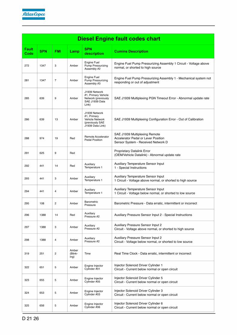
272 1347 3 AmberEngine Fuel Pump Pressurizing Assembly #2
Engine Fuel Pump Pressurizing Assembly 1 Circuit - Voltage above
normal, or shorted to high source
281 1347 7 AmberEngine Fuel Pump Pressurizing Assembly #3
Engine Fuel Pump Pressurizing Assembly 1 - Mechanical system not responding or out of adjustment
285 639 9 Amber
J1939 Network #1, Primary Vehicle Network (previously SAE J1939 Data Link)
SAE J1939 Multiplexing PGN Timeout Error - Abnormal update rate
286 639 13 Amber
J1939 Network #1, Primary Vehicle Network (previously SAE J1939 Data Link)
SAE J1939 Multiplexing Configuration Error - Out of Calibration
288 974 19 RedRemote Accelerator Pedal Position
SAE J1939 Multiplexing Remote Accelerator Pedal or Lever Position Sensor System - Received Network D
291 625 9 RedProprietary Datalink Error (OEM/Vehicle Datalink) - Abnormal update rate
292 441 14 RedAuxiliary Temperature 1
Auxiliary Temperature Sensor Input 1 - Special Instructions
293 441 3 AmberAuxiliary Temperature 1
Auxiliary Temperature Sensor Input 1 Circuit - Voltage above normal, or shorted to high source
294 441 4 AmberAuxiliary Temperature 1
Auxiliary Temperature Sensor Input 1 Circuit - Voltage below normal, or shorted to low source
295 108 2 AmberBarometric Pressure
Barometric Pressure - Data erratic, intermittent or incorrect
296 1388 14 RedAuxiliary Pressure #2
Auxiliary Pressure Sensor Input 2 - Special Instructions
297 1388 3 AmberAuxiliary Pressure #2
Auxiliary Pressure Sensor Input 2 Circuit - Voltage above normal, or shorted to high source
298 1388 4 AmberAuxiliary Pressure #2
Auxiliary Pressure Sensor Input 2 Circuit - Voltage below normal, or shorted to low source
319 251 2Amber (Blink-ing)
Time Real Time Clock - Data erratic, intermittent or incorrect
322 651 5 AmberEngine Injector Cylinder #01
Injector Solenoid Driver Cylinder 1 Circuit - Current below normal or open circuit
323 655 5 AmberEngine Injector Cylinder #05
Injector Solenoid Driver Cylinder 5 Circuit - Current below normal or open circuit
324 653 5 AmberEngine Injector Cylinder #03
Injector Solenoid Driver Cylinder 3 Circuit - Current below normal or open circuit
325 656 5 AmberEngine Injector Cylinder #06
Injector Solenoid Driver Cylinder 6 Circuit - Current below normal or open circuit
Diesel Engine fault codes chartFault Code SPN FMI Lamp SPN
description Cumins Description
D 21 26

331 652 5 AmberEngine Injector Cylinder #02
Injector Solenoid Driver Cylinder 2 Circuit - Current below normal or open circuit
332 654 5 AmberEngine Injector Cylinder #04
Injector Solenoid Driver Cylinder 4 Circuit - Current below normal or open circuit
334 110 2 AmberEngine Coolant Temperature
Engine Coolant Temperature - Data erratic, intermittent or incorrect
338 1267 3 Amber
Idle Shutdown Vehicle Accesso-ries Relay Driver Circuit
Idle Shutdown Vehicle Accessories Relay Driver Circuit - Voltage
above normal, or shorted to high source
339 1267 4 Amber
Idle Shutdown Vehicle Accessories Relay Driver Circuit
Idle Shutdown Vehicle Accessories Relay Driver Circuit - Voltage
below normal, or shorted to low source
343 629 12 Amber Controller #1Engine Control Module Warning Internal Hardware Failure - Bad intelligent device or component
346 630 12 AmberCalibration Memory
Engine Control Module Calibration Memory Software - Bad intelligent device or component
349 191 16 AmberTransmission Output Shaft Speed
Transmission Output Shaft Speed - Data Valid But Above Normal Operating Range - Moderately Severe Level
351 3597 12 AmberECU Power Output Supply Voltage #1
Injector Power Supply - Bad intelligent device or component
352 3509 4 AmberSensor supply volt-age 1
Sensor Supply 1 Circuit - Voltage below normal, or shorted to low source
386 3509 3 AmberSensor supply volt-age 1
Sensor Supply 1 Circuit - Voltage above normal, or shorted to high source
415 100 1 RedEngine Oil Pressure
Engine Oil Rifle Pressure - Data valid but below normal operational range - Most Severe Level
418 97 15Amber (Blink-ing)
Water In Fuel Indicator
Water in Fuel Indicator - Data Valid But Above Normal Operating Range - Least Severe Level
421 175 16 AmberEngine Oil Temperature 1
Engine Oil Temperature - Data Valid But Above Normal Operating Range - Moderately Severe Level
422 111 2 AmberEngine Coolant Level
Coolant Level - Data erratic, intermittent or incorrect
425 175 2 AmberEngine Oil Temperature 1
Engine Oil Temperature - Data erratic, intermittent or incorrect
426 639 2 None
J1939 Network #1, Primary Vehicle Network (previously SAE J1939 Data Link)
J1939 Network #1 - Data erratic, intermittent or incorrect
Diesel Engine fault codes chartFault Code SPN FMI Lamp SPN
description Cumins Description
D 21 27

427 639 9 None
J1939 Network #1, Primary Vehicle Network (previously SAE J1939 Data Link)
SAE J1939 Datalink - Abnormal update rate
428 97 3 AmberWater In Fuel Indicator
Water in Fuel Indicator Sensor Circuit - Voltage above normal, or shorted to high source
429 97 4 AmberWater In Fuel Indicator
Water in Fuel Indicator Sensor Circuit - Voltage below normal, or shorted to low source
431 558 2 AmberAccelerator Pedal 1 Low Idle Switch
Accelerator Pedal or Lever Idle Validation Switch - Data erratic, intermittent or incorrect
432 558 13 RedAccelerator Pedal 1 Low Idle Switch
Accelerator Pedal or Lever Idle Validation Switch Circuit - Out of Calibration
435 100 2 AmberEngine Oil Pressure
Engine Oil Rifle Pressure - Data erratic, intermittent or incorrect
436 105 2 AmberEngine Intake Manifold 1 Temperature
Intake Manifold 1 Temperature - Data erratic, intermittent or incorrect
441 168 18 AmberBattery Potential / Power Input 1
Battery 1 Voltage - Data Valid But Below Normal Operating Range - Moderately Severe Level
442 168 16 AmberBattery Potential / Power Input 1
Battery 1 Voltage - Data Valid But Above Normal Operating Range - Moderately Severe Level
449 157 0 RedEngine Injector Metering Rail 1 Pressure
Injector Metering Rail 1 Pressure - Data valid but above normal operational range - Most Severe Level
451 157 3 AmberEngine Injector Metering Rail 1 Pressure
Injector Metering Rail 1 Pressure Sensor Circuit - Voltage above nor-mal, or shorted to high source
452 157 4 AmberEngine Injector Metering Rail 1 Pressure
Injector Metering Rail 1 Pressure Sensor Circuit - Voltage below nor-
mal, or shorted to low source
471 98 17Amber (Blink-ing)
Engine Oil LevelEngine Oil Level - Data Valid But Below Normal Operating Range - Least Severe Level
483 1349 3 AmberEngine Injector Metering Rail 2 Pressure
Injector Metering Rail 2 Pressure Sensor Circuit - Voltage above normal, or shorted to high source
484 1349 4 AmberEngine Injector Metering Rail 2 Pressure
Injector Metering Rail 2 Pressure Sensor Circuit - Voltage below normal, or shorted to low source
487 626 18 AmberEngine Start Enable Device 1
Start Enable Device 1 Canister Empty (Ether Injection) - Data Valid But Below Normal Operating
Range
489 191 18 AmberTransmission Output Shaft Speed
Transmission Output Shaft Speed - Data Valid But Below Normal Operating Range - Moderately Severe
Level
Diesel Engine fault codes chartFault Code SPN FMI Lamp SPN
description Cumins Description
D 21 28

497 1377 2 AmberEngine Synchronization Switch
Multiple Unit Synchronization Switch - Data erratic, intermittent or incorrect
515 3514 3 AmberSensor supply volt-age 6
Sensor Supply 6 Circuit - Voltage above normal, or shorted to high source
516 3514 4 AmberSensor supply volt-age 6
Sensor Supply 6 Circuit - Voltage below normal, or shorted to low source
523 611 2 AmberSystem Diagnostic Code #1
Auxiliary Intermediate (PTO) Speed Switch Validation - Data erratic, intermittent or incorrect
527 702 3 Amber Auxiliary I/O #02Auxiliary Input/Output 2 Circuit - Voltage above normal, or shorted to high source
528 93 2 AmberEngine Net Brake Torque
Auxiliary Alternate Torque Validation Switch - Data erratic, intermittent or incorrect
529 703 3 Amber Auxiliary I/O #03Auxiliary Input/Output 3 Circuit - Voltage above normal, or shorted to high source
535 174 2 AmberEngine Fuel Temperature 1
Engine Fuel Temperature - Data erratic, intermittent or incorrect
546 94 3 AmberEngine Fuel Delivery Pressure
Fuel Delivery Pressure Sensor Circuit - Voltage above normal, or shorted to high source
547 94 4 AmberEngine Fuel Delivery Pressure
Fuel Delivery Pressure Sensor Circuit - Voltage below normal, or shorted to low source
553 157 16 AmberEngine Injector Metering Rail 1 Pressure
Injector Metering Rail 1 Pressure - Data Valid But Above Normal Oper-
ating Range - Moderately Severe Level
554 157 2 AmberEngine Injector Metering Rail 1 Pressure
Injector Metering Rail 1 Pressure - Data erratic, intermittent or incor-
rect
555 101 16 AmberEngine Crankcase Pressure
Crankcase Pressure - Data Valid But Above Normal Operating Range - Moderately Severe Level
556 101 0 RedEngine Crankcase Pressure
Crankcase Pressure - Data valid but above normal operational range - Most Severe Level
559 157 18 AmberEngine Injector Metering Rail 1 Pressure
Injector Metering Rail 1 Pressure - Data Valid But Below Normal Operating Range - Moderately Severe Level
584 677 3 AmberEngine Starter Motor Relay
Starter Relay Driver Circuit - Voltage above normal, or shorted to high source
585 677 4 AmberEngine Starter Motor Relay
Starter Relay Driver Circuit - Voltage below normal, or shorted to low source
595 103 16 AmberEngine Turbocharger 1 Speed
Turbocharger 1 Speed - Data Valid But Above Normal Operating Range - Moderately Severe Level
Diesel Engine fault codes chartFault Code SPN FMI Lamp SPN
description Cumins Description
D 21 29

599 640 14 RedEngine External Protection Input
Auxiliary Commanded Dual Output Shutdown - Special Instructions
611 1383 31 NoneEngine was Shut Down Hot
Engine Shut Down Hot - Condition Exists
629 1176 18 Amber
Engine Turbocharger 1 Compressor Intake Pressure
Turbocharger 1 Compressor Intake Pressure - Data Valid But Below Normal Operating Range - Moderately
649 1378 31Amber (Blink-ing)
Engine Oil Change Interval
Engine Oil Change Interval - Condition Exists
686 103 2 AmberEngine Turbocharger 1 Speed
Turbocharger 1 Speed - Data erratic, intermittent or incorrect
687 103 18 AmberEngine Turbocharger 1 Speed
Turbocharger 1 Speed - Data Valid But Below Normal Operating Range - Moderately Severe Level
688 98 0 Red Engine Oil LevelEngine Oil Level - Data valid but above normal operational range - Most Severe Level
689 190 2 Amber Engine SpeedEngine Crankshaft Speed/Position - Data erratic, intermittent or incor-rect
691 1172 3 Amber
Engine Turbocharger 1 Compressor Intake Temperature
Turbocharger 1 Compressor Intake Temperature Circuit - Voltage
above normal, or shorted to high source
692 1172 4 Amber
Engine Turbocharger 1 Compressor Intake Temperature
Turbocharger 1 Compressor Intake Temperature Circuit - Voltage
below normal, or shorted to low source
693 1172 2 Amber
Engine Turbocharger 1 Compressor Intake Temperature
Turbocharger 1 Compressor Intake Temperature - Data erratic, inter-
mittent or incorrect
697 1136 3 AmberEngine ECU Tem-perature
Engine ECU Temperature Sensor Circuit - Voltage above normal, or shorted to high source
698 1136 4 AmberEngine ECU Tem-perature
Engine ECU Temperature Sensor Circuit - Voltage below normal, or shorted to low source
699 1136 2 AmberEngine ECU Temperature
Engine ECU Temperature - Data erratic, intermittent or incorrect
731 723 7 Amber Engine Speed 2
Engine Speed / Position Camshaft and Crankshaft Misalignment - Mechanical system not responding or
out of adjustment
741 1176 3 Amber
Engine Turbocharger 1 Compressor Intake Pressure
Turbocharger 1 Compressor Intake Pressure Circuit - Voltage above
normal, or shorted to high source
Diesel Engine fault codes chartFault Code SPN FMI Lamp SPN
description Cumins Description
D 21 30

742 1176 4 Amber
Engine Turbocharger 1 Compressor Intake Pressure
Turbocharger 1 Compressor Intake Pressure Circuit - Voltage below normal, or shorted to low source
743 1176 2 Amber
Engine Turbocharger 1 Compressor Intake Pressure
Turbocharger 1 Compressor Intake Pressure - Data erratic, intermit-tent or incorrect
755 157 7 AmberEngine Injector Metering Rail 1 Pressure
Injector Metering Rail 1 Pressure - Mechanical system not responding
or out of adjustment
769 597 3 Amber Brake Switch Brake Switch Circuit - Voltage above normal, or shorted to high source
771 597 4 Amber Brake Switch Brake Switch Circuit - Voltage below normal, or shorted to low source
778 723 2 Amber Engine Speed 2Engine Camshaft Speed / Position Sensor - Data erratic, intermittent or incorrect
784 1590 2 NoneAdaptive Cruise Control Mode
Adaptive Cruise Control Mode - Data erratic, intermittent or incorrect
1117 3597 2 NoneECU Power Output Supply Voltage #1
Power Supply Lost With Ignition On - Data erratic, intermittent or incorrect
1139 651 7 AmberEngine Injector Cylinder #01
Injector Solenoid Driver Cylinder 1 - Mechanical system not responding or out of adjustment
1141 652 7 AmberEngine Injector Cylinder #02
Injector Solenoid Driver Cylinder 2 - Mechanical system not responding or out of adjustment
1142 653 7 AmberEngine Injector Cylinder #03
Injector Solenoid Driver Cylinder 3 - Mechanical system not responding or out of adjustment
1143 654 7 AmberEngine Injector Cylinder #04
Injector Solenoid Driver Cylinder 4 - Mechanical system not responding or out of adjustment
1144 655 7 AmberEngine Injector Cylinder #05
Injector Solenoid Driver Cylinder 5 - Mechanical system not responding or out of adjustment
1145 656 7 AmberEngine Injector Cylinder #06
Injector Solenoid Driver Cylinder 6 - Mechanical system not responding or out of adjustment
1228 27 2 Amber
Engine Exhaust Gas Recirculation 1 Valve Position
EGR Valve Position - Data erratic, intermittent or incorrect
1239 2623 3 AmberAccelerator Pedal #1 Channel 2
Accelerator Pedal or Lever Position Sensor 2 Circuit - Voltage above normal, or shorted to high source
1241 2623 4 AmberAccelerator Pedal #1 Channel 2
Accelerator Pedal or Lever Position Sensor 2 Circuit - Voltage below normal, or shorted to low source
1242 91 2 RedAccelerator Pedal Position 1
Accelerator Pedal or Lever Position Sensor 1 - Data erratic, intermittent or incorrect
1256 1563 2 AmberIncompatible Monitor/Controller
Control Module Identification Input State Error - Data erratic, intermittent or incorrect
Diesel Engine fault codes chartFault Code SPN FMI Lamp SPN
description Cumins Description
D 21 31

1257 1563 2 RedIncompatible Monitor/Controller
Control Module Identification Input State Error - Data erratic, intermittent or incorrect
1411 4182 3 Amber
Generator Output Frequency Adjust Potentiometer Circuit - Voltage above normal, or shorted to high source
1412 4183 3 AmberDroop Adjust Potentiometer Circuit - Voltage above normal, or shorted to high source
1418 4184 3 AmberGain Adjust Potentiometer Circuit - Voltage above normal, or shorted to high source
1427 4185 31 AmberOverspeed Shutdown Relay Driver
Overspeed Shutdown Relay Driver Diagnostic has detected an error - Condition Exists
1428 4186 31 AmberLow Oil Pressure Shutdown Relay Driver
Low Oil Pressure (LOP) Shutdown Relay Driver Diagnostic has detected an error - Condition Exists
1429 4187 31 AmberHigh Engine Temperature Shut-down Relay Driver
High Engine Temperature (HET) Shutdown Relay Driver Diagnostic has detected an error - Condition Exists
1431 4188 31 AmberPre-Low Oil Pressure Indicator Relay Driver
Pre-Low Oil Pressure Warning Relay Driver Diagnostic has detected an error - Condition Exists
1432 4223 31 AmberPre-High Engine Temperature Warn-ing Relay Driver
Pre-High Engine Temperature Warning Relay Driver Diagnostic has detected an error - Condition
Exists
1515 91 19 RedAccelerator Pedal Position 1
SAE J1939 Multiplexed Accelerator Pedal or Lever Sensor System - Received Network Data In Error
1539 1387 3 AmberAuxiliary Pressure #1
Auxiliary Pressure Sensor Input 1 Circuit - Voltage above normal, or shorted to high source
1548 657 5 AmberEngine Injector Cylinder #7
Injector Solenoid Driver Cylinder 7 Circuit - Current below normal or open circuit
1549 658 5 AmberEngine Injector Cylinder #8
Injector Solenoid Driver Cylinder 8 Circuit - Current below normal or open circuit
1551 660 5 AmberEngine Injector Cylinder #10
Injector Solenoid Driver Cylinder 10 Circuit - Current below normal or open circuit
1552 661 5 AmberEngine Injector Cylinder #11
Injector Solenoid Driver Cylinder 11 Circuit - Current below normal or open circuit
1553 662 5 AmberEngine Injector Cylinder #12
Injector Solenoid Driver Cylinder 12 Circuit - Current below normal or open circuit
1554 663 5 AmberEngine Injector Cylinder #13
Injector Solenoid Driver Cylinder 13 Circuit - Current below normal or open circuit
1555 664 5 AmberEngine Injector Cylinder #14
Injector Solenoid Driver Cylinder 14 Circuit - Current below normal or open circuit
Diesel Engine fault codes chartFault Code SPN FMI Lamp SPN
description Cumins Description
D 21 32

1556 665 5 AmberEngine Injector Cylinder #15
Injector Solenoid Driver Cylinder 15 Circuit - Current below normal or open circuit
1557 666 5 AmberEngine Injector Cylinder #16
Injector Solenoid Driver Cylinder 16 Circuit - Current below normal or open circuit
1621 1387 4 AmberAuxiliary Pressure #1
Auxiliary Pressure Sensor Input 1 Circuit - Voltage below normal, or shorted to low source
1622 659 5 AmberEngine Injector Cylinder #9
Injector Solenoid Driver Cylinder 9 Circuit - Current below normal or open circuit
1654 1323 31 AmberEngine Misfire Cylinder #1
Engine Misfire Cylinder 1 - Condition Exists
1655 1324 31 AmberEngine Misfire Cylinder #2
Engine Misfire Cylinder 2 - Condition Exists
1656 1325 31 AmberEngine Misfire Cylinder #3
Engine Misfire Cylinder 3 - Condition Exists
1657 1326 31 AmberEngine Misfire Cylinder #4
Engine Misfire Cylinder 4 - Condition Exists
1658 1327 31 AmberEngine Misfire Cylinder #5
Engine Misfire Cylinder 5 - Condition Exists
1659 1328 31 AmberEngine Misfire Cylinder #6
Engine Misfire Cylinder 6 - Condition Exists
1664 4796 31 AmberAftertreatment 1 Diesel Oxidation Catalyst Missing
Aftertreatment 1 Diesel Oxidation Catalyst Missing - Condition Exists
1668 1761 4 AmberAftertreatment 1 Diesel Exhaust Fluid Tank Level
Aftertreatment 1 Diesel Exhaust Fluid Tank Level Sensor Circuit - Voltage below normal, or shorted to low source
1669 1761 3 AmberAftertreatment 1 Diesel Exhaust Fluid Tank Level
Aftertreatment 1 Diesel Exhaust Fluid Tank Level Sensor Circuit - Voltage above normal, or shorted to high
source
1673 1761 1 AmberAftertreatment 1 Diesel Exhaust Fluid Tank Level
Aftertreatment 1 Diesel Exhaust Fluid Tank Level - Data valid but below normal operational range -Most
Severe Level
1677 3031 4 Amber
Aftertreatment 1 Diesel Exhaust Fluid Tank Temperature
Aftertreatment 1 Diesel Exhaust Fluid Tank Temperature Sensor - Voltage below normal, or shorted to low source
1678 3031 3 Amber
Aftertreatment 1 Diesel Exhaust Fluid Tank Temperature
Aftertreatment 1 Diesel Exhaust Fluid Tank Temperature Sensor - Voltage above normal, or shorted to high source
1679 3031 2 Amber
Aftertreatment 1 Diesel Exhaust Fluid Tank Temperature
Aftertreatment 1 Diesel Exhaust Fluid Tank Temperature - Data
erratic, intermittent or incorrect
1682 3362 31 Amber
Aftertreatment 1 Diesel Exhaust Fluid Dosing Unit Input Lines
Aftertreatment 1 Diesel Exhaust Fluid Dosing Unit Input Lines - Con-
dition Exists
Diesel Engine fault codes chartFault Code SPN FMI Lamp SPN
description Cumins Description
D 21 33

1683 3363 3 Amber
Aftertreatment 1 Diesel Exhaust Fluid Tank 1 Heater
Aftertreatment 1 Diesel Exhaust Fluid Tank Heater - Voltage above normal, or shorted to high source
1684 3363 4 Amber
Aftertreatment 1 Diesel Exhaust Fluid Tank 1 Heater
Aftertreatment 1 Diesel Exhaust Fluid Tank Heater - Voltage below normal, or shorted to low source
1685 3364 4 Amber
Aftertreatment 1 Diesel Exhaust Fluid Tank 1 Quality
Aftertreatment Diesel Exhaust Fluid Quality Sensor Circuit - Voltage below normal, or shorted to low
source
1686 3364 3 Amber
Aftertreatment 1 Diesel Exhaust Fluid Tank 1 Quality
Aftertreatment Diesel Exhaust Fluid Quality Sensor Circuit - Voltage above normal, or shorted to high
source
1691 5298 18 Amber
Aftertreatment 1 Diesel Oxidation Catalyst Conver-sion Efficiency
Aftertreatment 1 Diesel Oxidation Catalyst Conversion Efficiency - Data Valid But Below Normal Operating Range - Moderately Severe Level
1694 3226 2 AmberAftertreatment 1 Outlet NOx
Aftertreatment 1 Outlet NOx Sensor - Data erratic, intermittent or incorrect
1695 3513 3 AmberSensor supply voltage 5
Sensor Supply 5 - Voltage above normal, or shorted to high source
1696 3513 4 AmberSensor supply voltage 5
Sensor Supply 5 - Voltage below normal, or shorted to low source
1699 1761 2 AmberAftertreatment 1 Diesel Exhaust Fluid Tank Level
Aftertreatment 1 Diesel Exhaust Fluid Tank Level Sensor - Data erratic, intermittent or incorrect
1712 3363 18 Amber
Aftertreatment 1 Diesel Exhaust Fluid Tank 1 Heater
Aftertreatment 1 Diesel Exhaust Fluid Tank Heater - Data Valid But Below Normal Operating Range -
Moderately Severe Level
1713 3363 16 Amber
Aftertreatment 1 Diesel Exhaust Fluid Tank 1 Heater
Aftertreatment 1 Diesel Exhaust Fluid Tank Heater - Data Valid But Above Normal Operating Range -
Moderately Severe Level
1714 3364 13 Amber
Aftertreatment 1 Diesel Exhaust Fluid Tank 1 Quality
Aftertreatment Diesel Exhaust Fluid Quality - Out of Calibration
1715 3364 11 Amber
Aftertreatment 1 Diesel Exhaust Fluid Tank 1 Quality
Aftertreatment Diesel Exhaust Fluid Quality - Root Cause Not Known
1718 1322 31 AmberEngine Misfire for Multiple Cylinders
Engine Misfire for Multiple Cylinders - Condition Exists
1776 2634 3 Amber Power RelayPower Relay Driver Circuit - Voltage above normal, or shorted to high source
1777 2634 4 Amber Power RelayPower Relay Driver Circuit - Voltage below normal, or shorted to low source
Diesel Engine fault codes chartFault Code SPN FMI Lamp SPN
description Cumins Description
D 21 34

1843 101 3 AmberEngine Crankcase Pressure
Crankcase Pressure Circuit - Voltage above normal, or shorted to high source
1844 101 4 AmberEngine Crankcase Pressure
Crankcase Pressure Circuit - Voltage below normal, or shorted to low source
1847 110 14 RedEngine Coolant Temperature
Engine Coolant Temperature - Special Instructions
1852 97 16 AmberWater In Fuel Indicator
Water in Fuel Indicator - Data Valid But Above Normal Operating Range - Moderately Severe Level
1861 3217 2 AmberAftertreatment 1 Intake O2
Aftertreatment Intake Oxygen Sensor - Data erratic, intermittent or incorrect
1866 411 2 Amber
Engine Exhaust Gas Recirculation 1 Differential Pressure
Exhaust Gas Recirculation Differential Pressure - Data erratic, inter-mittent or incorrect
1867 412 2 Amber
Engine Exhaust Gas Recirculation 1 Temperature
Exhaust Gas Recirculation Temperature - Data erratic, intermittent or
incorrect
1879 3251 3 Amber
Aftertreatment 1 Diesel Particulate Filter Differential Pressure
Aftertreatment Diesel Particulate Filter Differential Pressure Sensor
Circuit - Voltage above normal
1881 3251 4 Amber
Aftertreatment 1 Diesel Particulate Filter Differential Pressure
Aftertreatment Diesel Particulate Filter Differential Pressure Sensor
Circuit - Voltage below normal
1883 3251 2 Amber
Aftertreatment 1 Diesel Particulate Filter Differential Pressure
Aftertreatment Diesel Particulate Filter Differential Pressure Sensor -
Data erratic, intermittent or incorrect
1885 3216 4 AmberAftertreatment 1 Intake Nox
Aftertreatment 1 Intake NOx Sensor Circuit - Voltage below normal, or shorted to low source
1887 3226 4 AmberAftertreatment 1 Outlet NOx
Aftertreatment 1 Outlet NOx Sensor Circuit - Voltage below normal, or shorted to low source
1893 2791 9 Amber
Engine Exhaust Gas Recirculation 1 (EGR1) Valve Control
EGR Valve Control Circuit - Abnormal update rate
1896 2791 13 Amber
Engine Exhaust Gas Recirculation 1 (EGR1) Valve Control
EGR Valve Controller - Out of Calibration
1898 641 13 AmberEngine Variable Geometry Turbo-charger Actuator #1
VGT Actuator Controller - Out of Calibration
1921 3251 16 Amber
Aftertreatment 1 Diesel Particulate Filter Differential Pressure
Aftertreatment Diesel Particulate Filter Differential Pressure - Data Valid But Above Normal Operating Range
Diesel Engine fault codes chartFault Code SPN FMI Lamp SPN
description Cumins Description
D 21 35

1922 3251 0 Red
Aftertreatment 1 Diesel Particulate Filter Differential Pressure
Aftertreatment Diesel Particulate Filter Differential Pressure - Data valid but above normal Operating Range
1923 3482 3 AmberAftertreatment 1 Fuel Enable Actuator
Aftertreatment Fuel Shutoff Valve Circuit - Voltage above normal, or shorted to high source
1924 3482 4 AmberAftertreatment 1 Fuel Enable Actuator
Aftertreatment Fuel Shutoff Valve Circuit - Voltage below normal, or shorted to low source
1925 3482 2 AmberAftertreatment 1 Fuel Enable Actuator
Aftertreatment Fuel Shutoff Valve - Data erratic, intermittent or incor-rect
1926 3480 2 AmberAftertreatment Fuel Pressure
Aftertreatment Fuel Pressure Sensor - Data erratic, intermittent or incorrect
1927 3480 3 AmberAftertreatment Fuel Pressure
Aftertreatment Fuel Pressure Sensor Circuit - Voltage above normal, or shorted to high source
1928 3480 4 AmberAftertreatment Fuel Pressure
Aftertreatment Fuel Pressure Sensor Circuit - Voltage below normal, or shorted to low source
1932 3556 2 AmberAftertreatment Hydrocarbon Doser
Aftertreatment Doser - Data erratic, intermittent or incorrect
1938 3597 18 AmberECU Power Output Supply Voltage #1
ECU Power Output Supply Voltage 1 - Data Valid But Below Normal Operating Range - Moderately
Severe Level
1939 3597 3 AmberECU Power Output Supply Voltage #1
ECU Power Output Supply Voltage 1 - Voltage above normal, or shorted to high source
1941 3597 4 AmberECU Power Output Supply Voltage #1
ECU Power Output Supply Voltage 1 - Voltage below normal, or shorted to low source
1942 101 2 AmberEngine Crankcase Pressure
Crankcase Pressure - Data erratic, intermittent or incorrect
1943 3555 17 NoneAmbient Air Density
Ambient Air Density - Data Valid But Below Normal Operating Range - Least Severe Level
1961 2791 15 Amber
Engine Exhaust Gas Recirculation 1 (EGR1) Valve Control
EGR Valve Control Circuit Over Temperature - Data Valid But Above Normal Operating Range - Least
Severe Level
1962 641 15 AmberEngine Variable Geometry Turbo-charger Actuator #1
VGT Actuator Driver Over Temperature (Calculated) - Data Valid But Above Normal Operating
Range - Least Severe Level
1963 3482 7 AmberAftertreatment 1 Fuel Enable Actuator
Aftertreatment Fuel Shutoff Valve - Mechanical system not responding or out of adjustment
1964 3556 7 AmberAftertreatment Hydrocarbon Doser
Aftertreatment Doser - Mechanical system not responding or out of adjustment
Diesel Engine fault codes chartFault Code SPN FMI Lamp SPN
description Cumins Description
D 21 36

1974 101 15Amber (Blink-ing)
Engine Crankcase Pressure
Crankcase Pressure - Data Valid But Above Normal Operating Range - Least Severe Level
1977 3556 5 AmberAftertreatment Hydrocarbon Doser
Aftertreatment Doser Circuit - Current below normal or open circuit.
1978 3938 3 AmberGenerator Speed / Load Governing Bias Circuit - Voltage above normal, or shorted to high source
1979 3938 4 AmberGenerator Speed / Load Governing Bias Circuit - Voltage below normal, or shorted to low source
1981 3936 15 AmberAftertreatment Diesel Particulate Filter System
Aftertreatment 1 Diesel Particulate Filter System - Data Valid But Above Normal Operating Range - Level
1992 190 16 Red Engine Speed
Engine Crankshaft Speed/Position - Data Valid But Above Normal Operating Range - Moderately Severe Level
1993 4795 31 AmberAftertreatment 1 Diesel Particulate Filter Missing
Aftertreatment 1 Diesel Particulate Filter Missing - Condition Exists
2182 1072 3 AmberEngine (Compression) Brake Output #1
Engine Brake Actuator Driver 1 Circuit - Voltage above normal, or shorted to high source
2183 1072 4 AmberEngine (Compression) Brake Output #1
Engine Brake Actuator Driver 1 Circuit - Voltage below normal, or shorted to low source
2185 3512 3 AmberSensor supply volt-age 4
Sensor Supply 4 Circuit - Voltage above normal, or shorted to high source
2186 3512 4 AmberSensor supply volt-age 4
Sensor Supply 4 Circuit - Voltage below normal, or shorted to low source
2198 641 11 Amber
Engine Variable Geometry Turbocharger Actuator #1
VGT Actuator Driver Circuit - Root Cause Not Known
2215 94 18 AmberEngine Fuel Delivery Pressure
Fuel Pump Delivery Pressure - Data Valid But Below Normal Operating Range - Moderately Severe Level
2249 157 1 AmberEngine Injector Metering Rail 1 Pressure
Injector Metering Rail 1 Pressure - Data valid but below normal operational range - Most Severe Level
2261 94 15Amber (Blink-ing)
Engine Fuel Delivery Pressure
Fuel Pump Delivery Pressure - Data Valid But Above Normal Operating Range - Least Severe Level
2262 94 17Amber (Blink-ing)
Engine Fuel Delivery Pressure
Fuel Pump Delivery Pressure - Data Valid But Below Normal Operating Range - Least Severe Level
2263 1800 16 AmberBattery 1 Temperature
Battery Temperature - Data Valid But Above Normal Operating Range - Moderately Severe Level
Diesel Engine fault codes chartFault Code SPN FMI Lamp SPN
description Cumins Description
D 21 37

2264 1800 18 AmberBattery 1 Temperature
Battery Temperature - Data Valid But Below Normal Operating Range - Moderately Severe Level
2265 1075 3 AmberEngine Electric Lift Pump for Engine Fuel Supply
Electric Lift Pump for Engine Fuel Supply Circuit - Voltage above nor-
mal, or shorted to high source
2266 1075 4 AmberEngine Electric Lift Pump for Engine Fuel Supply
Electric Lift Pump for Engine Fuel Supply Circuit - Voltage below nor-
mal, or shorted to low source
2272 27 4 Amber
Engine Exhaust Gas Recirculation 1 Valve Position
EGR Valve Position Circuit - Voltage below normal, or shorted to low source
2273 411 3 Amber
Engine Exhaust Gas Recirculation 1 Differential Pressure
Exhaust Gas Recirculation Differential Pressure Sensor Circuit - Volt-
age above normal, or shorted to high source
2274 411 4 Amber
Engine Exhaust Gas Recirculation 1 Differential Pressure
Exhaust Gas Recirculation Differential Pressure Sensor Circuit - Volt-age below normal, or shorted to low source
2288 103 15 NoneEngine Turbocharger 1 Speed
Turbocharger 1 Speed - Data Valid But Above Normal Operating Range - Least Severe Level
2292 611 16 AmberFuel Inlet Meter Device
Fuel Inlet Meter Device - Data Valid But Above Normal Operating Range - Moderately Severe Level
2293 611 18 AmberFuel Inlet Meter Device
Fuel Inlet Meter Device flow demand lower than expected - Data Valid But Below Normal Operating Range
2311 633 31 Amber
Engine Fuel Actuator 1 Control Command
Electronic Fuel Injection Control Valve Circuit - Condition Exists
2321 190 2 None Engine SpeedEngine Crankshaft Speed/Position - Data erratic, intermittent or incor-
rect
2322 723 2 None Engine Speed 2Engine Camshaft Speed / Position Sensor - Data erratic, intermittent or incorrect
2346 2789 15 None
Engine Turbocharger 1 Calculated Turbine Intake Temperature
Turbocharger Turbine Intake Temperature - Data Valid But Above
Normal Operating Range - Least Severe
2347 2629 15 None
Engine Turbocharger 1 Compressor Outlet Temperature
Turbocharger Compressor Outlet Temperature (Calculated) - Data
Valid But Above Normal Operating Range
2349 2791 5 Amber
Engine Exhaust Gas Recirculation 1 (EGR1) Valve Control
EGR Valve Control Circuit - Current below normal or open circuit
Diesel Engine fault codes chartFault Code SPN FMI Lamp SPN
description Cumins Description
D 21 38

2353 2791 6 Amber
Engine Exhaust Gas Recirculation 1 (EGR1) Valve Control
EGR Valve Control Circuit - Current above normal or grounded circuit
2357 2791 7 Amber
Engine Exhaust Gas Recirculation 1 (EGR1) Valve Control
EGR Valve Control Circuit - Mechanical system not responding or out
of adjustment
2363 1073 4 AmberEngine (Compression) Brake Output #2
Engine Brake Actuator Driver Output 2 Circuit - Voltage below normal, or shorted to low source
2365 1112 4 AmberEngine (Compression) Brake Output #3
Engine Brake Actuator Driver Output 3 Circuit - Voltage below normal, or shorted to low source
2367 1073 3 AmberEngine (Compression) Brake Output #2
Engine Brake Actuator Driver Output 2 Circuit - Voltage above normal, or shorted to high source
2368 1112 3 AmberEngine (Compression) Brake Output #3
Engine Brake Actuator Driver 3 Circuit - Voltage above normal, or shorted to high source
2372 95 16 AmberEngine Fuel Filter Differential Pressure
Fuel Filter Differential Pressure - Data Valid But Above Normal Operating Range - Moderately Severe
2373 1209 3 AmberEngine Exhaust Gas Pressure 1
Exhaust Gas Pressure Sensor 1 Circuit - Voltage above normal, or shorted to high source
2374 1209 4 AmberEngine Exhaust Gas Pressure 1
Exhaust Gas Pressure Sensor 1 Circuit - Voltage below normal, or shorted to low source
2375 412 3 Amber
Engine Exhaust Gas Recirculation 1 Temperature
Exhaust Gas Recirculation Temperature Sensor Circuit - Voltage above normal, or shorted to high source
2376 412 4 Amber
Engine Exhaust Gas Recirculation 1 Temperature
Exhaust Gas Recirculation Temperature Sensor Circuit - Voltage below normal, or shorted to low source
2377 647 3 AmberEngine Fan Clutch 1 Output Device Driver
Fan Control Circuit - Voltage above normal, or shorted to high source
2387 641 7 Amber
Engine Variable Geometry Turbocharger Actuator #1
VGT Actuator Driver Circuit (Motor) - Mechanical system not respond-
ing or out of adjustment
2398 171 2 AmberAmbient Air Temperature
Ambient Air Temperature - Data erratic, intermittent or incorrect
2448 111 17Amber (Blink-ing)
Engine Coolant Level
Coolant Level - Data Valid But Below Normal Operating Range - Least Severe Level
2449 641 13 Red
Engine Variable Geometry Turbocharger Actuator #1
VGT Actuator Controller - Out of Calibration
Diesel Engine fault codes chartFault Code SPN FMI Lamp SPN
description Cumins Description
D 21 39

2451 2789 16 None
Engine Turbocharger 1 Calculated Turbine Intake Temperature
Turbocharger Turbine Intake Temperature - Data Valid But Above
Normal Operating Range - Moderately S
2468 190 16 Amber Engine Speed
Engine Crankshaft Speed/Position - Data Valid But Above Normal Operating Range - Moderately Severe Level
2554 1209 2 AmberEngine Exhaust Gas Pressure 1
Exhaust Gas Pressure 1 - Data erratic, intermittent or incorrect
2555 729 3 AmberEngine Intake Air Heater Driver #1
Engine Intake Air Heater 1 Circuit - Voltage above normal, or shorted to high source
2556 729 4 AmberEngine Intake Air Heater Driver #1
Engine Intake Air Heater 1 Circuit - Voltage below normal, or shorted to low source
2557 697 3 AmberAuxiliary PWM Driver #1
Auxiliary PWM Driver 1 Circuit - Voltage above normal, or shorted to high source
2558 697 4 AmberAuxiliary PWM Driver #1
Auxiliary PWM Driver 1 Circuit - Voltage below normal, or shorted to low source
2571 2630 3 Amber
Engine Charge Air Cooler 1 Outlet Temperature
Engine Charge Air Cooler Outlet Temperature - Voltage above nor-
mal, or shorted to high source
2572 2630 4 Amber
Engine Charge Air Cooler 1 Outlet Temperature
Engine Charge Air Cooler Outlet Temperature - Voltage below normal,
or shorted to low source
2634 641 12 Red
Engine Variable Geometry Turbocharger Actuator #1
VGT Actuator Controller - Bad intelligent device or component
2635 641 31 Red
Engine Variable Geometry Turbocharger Actuator #1
VGT Actuator Driver Circuit - Condition Exists
2636 641 9 Red
Engine Variable Geometry Turbocharger Actuator #1
VGT Actuator Driver Circuit - Abnormal update rate
2637 5018 11 NoneAftertreatment Diesel Oxidation Catalyst
Aftertreatment 1 Diesel Oxidation Catalyst Face Plugged - Root Cause Not Known
2639 3251 15 None
Aftertreatment 1 Diesel Particulate Filter Differential Pressure
Aftertreatment Diesel Particulate Filter Differential Pressure - Data valid but above normal Operating
Range
2646 110 31 AmberEngine Coolant Temperature
Engine Coolant Temperature - Condition Exists
2659 110 31 NoneEngine Coolant Temperature
Engine Coolant Temperature - Condition Exists
2661 629 31 Red Controller #1 At Least One Unacknowledged Most Severe Fault - Condition Exists
Diesel Engine fault codes chartFault Code SPN FMI Lamp SPN
description Cumins Description
D 21 40

2662 629 31 Amber Controller #1At Least One Unacknowledged Moderately Severe Fault - Condition Exists
2683 3227 9 AmberAftertreatment 1 Outlet O2
Aftertreatment Outlet Oxygen Sensor Circuit - Abnormal update rate
2699 520320 7 AmberCrankcase Depression Valve
Crankcase Depression Valve - Mechanical system not responding or out of adjustment
2721 599 2 AmberCruise Control Set Switch
Cruise Control Set Switch - Data erratic, intermittent or incorrect
2732 4097 3 AmberAftertreatment 1 Fuel Drain Actuator
Aftertreatment Fuel Drain Valve Circuit - Voltage above normal, or shorted to high source
2733 4097 4 AmberAftertreatment 1 Fuel Drain Actuator
Aftertreatment Fuel Drain Valve Circuit - Voltage below normal, or shorted to low source
2738 626 3 AmberEngine Start Enable Device 1
Start Enable Device 1 Circuit (Ether Injection) - Voltage above normal, or shorted to high source
2739 626 4 AmberEngine Start Enable Device 1
Start Enable Device 1Circuit (Ether Injection) - Voltage below normal, or shorted to low source
2741 3482 13 AmberAftertreatment 1 Fuel Enable Actuator
Aftertreatment Fuel Shutoff Valve Swapped - Out of Calibration
2742 3249 17 NoneAftertreatment 1 Exhaust Gas Temperature 2
Aftertreatment Exhaust Gas Temperature 2 - Data Valid But Below Normal Operating Range - Least Sever
2743 3249 18 AmberAftertreatment 1 Exhaust Gas Temperature 2
Aftertreatment Exhaust Gas Temperature 2 - Data Valid But Below Normal Operating Range - Moderately
2753 412 0 Red
Engine Exhaust Gas Recirculation 1 Temperature
Exhaust Gas Recirculation Temperature - Data valid but above normal
operational range - Most Severe
2754 81 16 AmberEngine Diesel Par-ticulate Filter Intake Pressure
Engine Diesel Particulate Filter Intake Pressure - Data Valid But Above Normal Operating Range - Moderately Severe Level
2755 520332 3 Amber Intake PressureCruise Control (Resistive) #2 Signal Circuit - Voltage above normal, or shorted to high source
2756 520332 4 AmberCruise Control (Resistive) #2 Signal Circuit - Voltage below normal, or shorted to low source
2764 1209 16 AmberEngine Exhaust Gas Pressure 1
Exhaust Gas Pressure 1 - Data Valid But Above Normal Operating Range - Moderately Severe Level
2765 2797 13 NoneEngine Injector Group 1
Engine Injector Bank 1 Barcodes - Out of Calibration
2771 3226 9 AmberAftertreatment 1 Outlet NOx
Aftertreatment 1 Outlet NOx Sensor - Abnormal update rate
Diesel Engine fault codes chartFault Code SPN FMI Lamp SPN
description Cumins Description
D 21 41

2777 3703 31Amber (Blink-ing)
Diesel Particulate Filter Active Regeneration Inhib-ited Due to Inhibit Switch
Particulate Trap Active Regeneration Inhibited Due to Inhibit Switch - Condition Exists
2778 3481 16 AmberAftertreatment 1 Fuel Rate
Aftertreatment Fuel Rate - Data Valid But Above Normal Operating Range - Moderately Severe Level
2789 110 18 AmberEngine Coolant Temperature
Engine Coolant Temperature - Data Valid But Below Normal Operating Range - Moderately Severe Level
2878 4097 7 AmberAftertreatment 1 Fuel Drain Actuator
Aftertreatment Fuel Drain Valve - Mechanical system not responding or out of adjustment
2881 3480 17 AmberAftertreatment Fuel Pressure
Aftertreatment Fuel Pressure Sensor - Data Valid But Below Normal Operating Range - Least Severe Level
2961 412 15 None
Engine Exhaust Gas Recirculation 1 Temperature
Exhaust Gas Recirculation Temperature - Data Valid But Above Nor-mal Operating Range - Least Severe Level
2962 412 16 Amber
Engine Exhaust Gas Recirculation 1 Temperature
Exhaust Gas Recirculation Temperature - Data Valid But Above Nor-mal Operating Range - Moderately Severe Level
2963 110 15 NoneEngine Coolant Temperature
Engine Coolant Temperature - Data Valid But Above Normal Operating Range - Least Severe Level
2964 105 15 NoneEngine Intake Manifold #1 Temperature
Intake Manifold 1 Temperature - Data Valid But Above Normal Operating Range - Least Severe Level
2973 102 2 AmberEngine Intake Manifold #1 Pressure
Intake Manifold 1 Pressure - Data erratic, intermittent or incorrect
2976 3361 2 AmberAftertreatment 1 Diesel Exhaust Fluid Dosing Unit
Aftertreatment 1 Diesel Exhaust Fluid Dosing Unit Temperature - Data erratic, intermittent or incorrect
2998 1632 14 AmberEngine Torque Limit Feature
Engine Torque Limit Feature - Special Instructions
3133 3610 3 Amber
Aftertreatment Diesel Particulate Filter Outlet Pres-sure
Aftertreatment 1 Diesel Particulate Filter Outlet Pressure Sensor Circuit - Voltage above normal, or shorted to high source
3134 3610 4 Amber
Aftertreatment Diesel Particulate Filter Outlet Pres-sure
Aftertreatment 1 Diesel Particulate Filter Outlet Pressure Sensor Circuit - Voltage below normal, or shorted to low source
3135 3610 2 Amber
Aftertreatment Diesel Particulate Filter Outlet Pres-sure
Aftertreatment 1 Diesel Particulate Filter Outlet Pressure - Data erratic, intermittent or incorrect
3136 5019 3 AmberEngine Exhaust Gas Recirculation 1 Outlet Pressure
Engine Exhaust Gas Recirculation Outlet Pressure Sensor Circuit - Voltage above normal, or shorted to
high source
Diesel Engine fault codes chartFault Code SPN FMI Lamp SPN
description Cumins Description
D 21 42

3137 5019 4 AmberEngine Exhaust Gas Recirculation 1 Outlet Pressure
Engine Exhaust Gas Recirculation Outlet Pressure Sensor Circuit -
Voltage below normal, or shorted to low source
3138 5019 2 AmberEngine Exhaust Gas Recirculation 1 Outlet Pressure
Engine Exhaust Gas Recirculation Outlet Pressure - Data erratic, intermittent or incorrect
3139 3667 3 AmberEngine Air Shutoff Status
Engine Air Shutoff Circuit - Voltage above normal, or shorted to high source
3141 3667 4 AmberEngine Air Shutoff Status
Engine Air Shutoff Circuit - Voltage below normal, or shorted to low source
3142 4360 3 Amber
Aftertreatment 1 SCR Catalyst Intake Gas Temperature
Aftertreatment 1 SCR Intake Temperature Sensor Circuit - Voltage above normal, or shorted to high source
3143 4360 4 Amber
Aftertreatment 1 SCR Catalyst Intake Gas Temperature
Aftertreatment 1 SCR Intake Temperature Sensor Circuit - Voltage below normal, or shorted to low source
3144 4360 2 Amber
Aftertreatment 1 SCR Catalyst Intake Gas Temperature
Aftertreatment 1 SCR Intake Temperature Sensor - Data erratic, inter-
mittent or incorrect
3146 4363 3 Amber
Aftertreatment 1 SCR Catalyst Outlet Gas Temperature
Aftertreatment 1 SCR Outlet Temperature Sensor Circuit - Voltage above normal, or shorted to high source
3147 4363 4 Amber
Aftertreatment 1 SCR Catalyst Outlet Gas Temperature
Aftertreatment 1 SCR Outlet Temperature Sensor Circuit - Voltage below normal, or shorted to low source
3148 4363 2 AmberAftertreatment 1 SCR Catalyst Outlet Gas Temperature
Aftertreatment 1 SCR Outlet Temperature Sensor - Data erratic, inter-mittent or incorrect
3151 4794 31 Amber Aftertreatment 1 SCR Catalyst System Missing - Condition Exists
3152 4809 3 Amber
Aftertreatment Warm Up Diesel Oxidation Catalyst Intake Temperature
Aftertreatment Warm Up Diesel Oxidation Catalyst Intake Tempera-
ture Sensor Circuit - Voltage above normal
3153 4809 4 Amber
Aftertreatment Warm Up Diesel Oxidation Catalyst Intake Temperature
Aftertreatment Warm Up Diesel Oxidation Catalyst Intake Tempera-ture Sensor Circuit - Voltage below normal
3154 4809 2 Amber
Aftertreatment Warm Up Diesel Oxidation Catalyst Intake Temperature
Aftertreatment Warm Up Diesel Oxidation Catalyst Intake Tempera-ture - Data erratic, intermittent or incorrect
3155 4810 3 Amber
Aftertreatment Warm Up Diesel Oxidation Catalyst Outlet Temperature
Aftertreatment Warm Up Diesel Oxidation Catalyst Outlet Tempera-
ture Sensor Circuit - Voltage above normal
Diesel Engine fault codes chartFault Code SPN FMI Lamp SPN
description Cumins Description
D 21 43

3156 4810 4 Amber
Aftertreatment Warm Up Diesel Oxidation Catalyst Outlet Temperature
Aftertreatment Warm Up Diesel Oxidation Catalyst Outlet Tempera-
ture Sensor Circuit - Voltage below normal
3157 4810 2 Amber
Aftertreatment Warm Up Diesel Oxidation Catalyst Outlet Temperature
Aftertreatment Warm Up Diesel Oxidation Catalyst Outlet Tempera-
ture - Data erratic, intermittent or incorrect
3158 4793 31 AmberAftertreatment Warm Up Diesel Oxidation Catalyst Missing - Condition Exists
3162 4810 0 Red
Aftertreatment Warm Up Diesel Oxidation Catalyst Outlet Temperature
Aftertreatment Warm Up Diesel Oxidation Catalyst Outlet Temperature - Data valid but above normal
operating Range –Most Severe level
3164 4360 15 None
Aftertreatment 1 SCR Catalyst Intake Gas Temperature
Aftertreatment 1 SCR Intake Temperature - Data Valid But Above Normal Operating Range - Least Severe
3165 4363 0 Red
Aftertreatment 1 SCR Catalyst Outlet Gas Temperature
Aftertreatment 1 SCR Outlet Temperature - Data valid but above normal operational range - Most Severe
3166 4809 13 Amber
Aftertreatment Warm Up Diesel Oxidation Catalyst Intake Temperature
Aftertreatment Warm Up Diesel Oxidation Catalyst Intake Tempera-ture Sensor Swapped - Out of Calibration
3167 3556 18 AmberAftertreatment Hydrocarbon Doser
Aftertreatment Doser - Data Valid But Below Normal Operating Range - Moderately Severe Level
3169 4810 16 Red
Aftertreatment Warm Up Diesel Oxidation Catalyst Outlet Temperature
Aftertreatment Warm Up Diesel Oxidation Catalyst Outlet Tempera-
ture - Data Valid But Above Normal Operating Range
3173 4791 18 Amber
Aftertreatment 1 Warm Up Diesel Oxidation Catalyst Efficiency - Data Valid But Below Normal Operating Range
3186 1623 9 AmberTachograph output shaft speed
Tachograph Output Shaft Speed - Abnormal update rate
3213 1623 19 AmberTachograph output shaft speed
Tachograph Output Shaft Speed - Received Network Data In Error
3222 520435 12 Amber Glow Plug Module - Bad intelligent device or component
3223 3490 4 AmberAftertreatment 1 Purge Air Actuator
Aftertreatment Purge Air Actuator Circuit - Voltage below normal, or shorted to low source
3224 3490 3 AmberAftertreatment 1 Purge Air Actuator
Aftertreatment Purge Air Actuator Circuit - Voltage above normal, or shorted to high source
3225 3490 7 AmberAftertreatment 1 Purge Air Actuator
Aftertreatment Purge Air Actuator - Mechanical system not responding or out of adjustment
Diesel Engine fault codes chartFault Code SPN FMI Lamp SPN
description Cumins Description
D 21 44

3228 3216 2 AmberAftertreatment 1 Intake NOx
Aftertreatment 1 Intake NOx Sensor - Data erratic, intermittent or incorrect
3229 4360 0 Red
Aftertreatment 1 SCR Catalyst Intake Gas Temperature
Aftertreatment 1 SCR Intake Temperature - Data valid but above normal operational range - Most Severe Level
3231 4360 16 Red
Aftertreatment 1 SCR Catalyst Intake Gas Temperature
Aftertreatment 1 SCR Intake Temperature - Data Valid But Above Normal Operating Range - Moderately Severe Level
3232 3216 9 AmberAftertreatment 1 Intake NOx
Aftertreatment 1 Intake NOx Sensor - Abnormal update rate
3235 4363 16 RedAftertreatment 1 SCR Catalyst Outlet Gas Temperature
Aftertreatment 1 SCR Outlet Temperature - Data Valid But Above Normal Operating Range - Mod-erately Severe Level
3237 4340 3 Amber
Aftertreatment 1 Diesel Exhaust Fluid Line Heater 1 State
Aftertreatment 1 Diesel Exhaust Fluid Line Heater 1 Circuit - Voltage above normal, or shorted to high source
3238 4340 4 Amber
Aftertreatment 1 Diesel Exhaust Fluid Line Heater 1 State
Aftertreatment 1 Diesel Exhaust Fluid Line Heater 1 Circuit - Voltage below normal, or shorted to low source
3239 4342 3 Amber
Aftertreatment 1 Diesel Exhaust Fluid Line Heater 2 State
Aftertreatment 1 Diesel Exhaust Fluid Line Heater 2 Circuit - Voltage above normal, or shorted to high source
3241 4342 4 Amber
Aftertreatment 1 Diesel Exhaust Fluid Line Heater 2 State
Aftertreatment 1 Diesel Exhaust Fluid Line Heater 2 Circuit - Voltage below normal, or shorted to low source
3242 3363 7 Amber
Aftertreatment 1 Diesel Exhaust Fluid Tank 1 Heater
Aftertreatment 1 Diesel Exhaust Fluid Tank Heater - Mechanical system not responding or out of adjustment
3245 3936 7 AmberAftertreatment 1 Diesel Particulate Filter System - Mechanical system not responding or out of adjustment
3247 4809 16 Red
Aftertreatment Warm Up Diesel Oxidation Catalyst Intake Temperature
Aftertreatment Warm Up Diesel Oxidation Catalyst Intake Tempera-
ture - Data Valid But Above Normal Operating Range
3249 4810 15 Amber
Aftertreatment Warm Up Diesel Oxidation Catalyst Outlet Temperature
Aftertreatment Warm Up Diesel Oxidation Catalyst Outlet Tempera-ture - Data Valid But Above Normal Operating Range
3251 4765 16 Red
Aftertreatment Diesel Oxidation Catalyst Intake Temperature
Aftertreatment 1 Diesel Oxidation Catalyst Intake Temperature - Data Valid But Above Normal Operating
Range
Diesel Engine fault codes chartFault Code SPN FMI Lamp SPN
description Cumins Description
D 21 45

3253 3242 16 Red
Aftertreatment 1 Diesel Particulate Filter Intake Gas Temperature
Aftertreatment 1 Diesel Particulate Filter Intake Temperature - Data Valid But Above Normal Operating
Range
3254 3242 15 Amber
Aftertreatment 1 Diesel Particulate Filter Intake Gas Temperature
Aftertreatment 1 Diesel Particulate Filter Intake Temperature - Data Valid But Above Normal Operating
Range
3255 3246 16 Red
Aftertreatment 1 Diesel Particulate Filter Outlet Gas Temperature
Aftertreatment 1 Diesel Particulate Filter Outlet Temperature - Data Valid But Above Normal Operating Range
3256 3246 15 Amber
Aftertreatment 1 Diesel Particulate Filter Outlet Gas Temperature
Aftertreatment 1 Diesel Particulate Filter Outlet Temperature - Data Valid But Above Normal Operating Range
3258 4340 5 Amber
Aftertreatment 1 Diesel Exhaust Fluid Line Heater 1 State
Aftertreatment 1 Diesel Exhaust Fluid Line Heater 1 Circuit - Current
below normal or open circuit
3261 4342 5 Amber
Aftertreatment 1 Diesel Exhaust Fluid Line Heater 2 State
Aftertreatment 1 Diesel Exhaust Fluid Line Heater 2 Circuit - Current
below normal or open circuit
3298 1194 13 RedAnti-theft Encryption Seed Present Indicator
Anti-theft Encryption Seed - Out of Calibration
3311 3242 0 Red
Aftertreatment 1 Diesel Particulate Filter Intake Gas Temperature
Aftertreatment 1 Diesel Particulate Filter Intake Temperature - Data valid but above normal operation
3312 3246 0 Red
Aftertreatment 1 Diesel Particulate Filter Outlet Gas Temperature
Aftertreatment 1 Diesel Particulate Filter Outlet Temperature - Data valid but above normal operation
3313 4765 4 Amber
Aftertreatment Diesel Oxidation Catalyst Intake Temperature
Aftertreatment 1 Diesel Oxidation Catalyst Intake Temperature Sensor Circuit - Voltage below normal, or shorted to low source
3314 4765 3 Amber
Aftertreatment Diesel Oxidation Catalyst Intake Temperature
Aftertreatment 1 Diesel Oxidation Catalyst Intake Temperature Sensor Circuit - Voltage above normal, or shorted to high source
3315 4765 2 Amber
Aftertreatment Diesel Oxidation Catalyst Intake Temperature
Aftertreatment 1 Diesel Oxidation Catalyst Intake Temperature - Data erratic, intermittent or incorrect
3316 3242 4 Amber
Aftertreatment 1 Diesel Particulate Filter Intake Gas Temperature
Aftertreatment 1 Diesel Particulate Filter Intake Temperature Sensor Circuit - Voltage below normal, or shorted to low source
3317 3242 3 Amber
Aftertreatment 1 Diesel Particulate Filter Intake Gas Temperature
Aftertreatment 1 Diesel Particulate Filter Intake Temperature Sensor Circuit - Voltage above normal, or shorted to high source
Diesel Engine fault codes chartFault Code SPN FMI Lamp SPN
description Cumins Description
D 21 46

3318 3242 2 Amber
Aftertreatment 1 Diesel Particulate Filter Intake Gas Temperature
Aftertreatment 1 Diesel Particulate Filter Intake Temperature - Data erratic, intermittent or incorrect
3319 3246 3 Amber
Aftertreatment 1 Diesel Particulate Filter Outlet Gas Temperature
Aftertreatment 1 Diesel Particulate Filter Outlet Temperature Sensor Circuit - Voltage above normal, or shorted to high source
3321 3246 4 Amber
Aftertreatment 1 Diesel Particulate Filter Outlet Gas Temperature
Aftertreatment 1 Diesel Particulate Filter Outlet Temperature Sensor Circuit - Voltage below normal, or
shorted to low source
3322 3246 2 Amber
Aftertreatment 1 Diesel Particulate Filter Outlet Gas Temperature
Aftertreatment 1 Diesel Particulate Filter Outlet Temperature - Data
erratic, intermittent or incorrect
3325 4765 13 Amber
Aftertreatment Diesel Oxidation Catalyst Intake Temperature
Aftertreatment 1 Diesel Oxidation Catalyst Intake Temperature
Swapped - Out of Calibration
3326 91 9 RedAccelerator Pedal Position 1
SAE J1939 Multiplexed Accelerator Pedal or Lever Sensor System - Abnormal update rate
3328 191 9 AmberTransmission Output Shaft Speed
Transmission Output Shaft Speed - Abnormal update rate
3329 1231 2 None J1939 Network #2 - Data erratic, intermittent or incorrect
3331 1235 2 None J1939 Network #3 - Data erratic, intermittent or incorrect
3337 5395 16 AmberEngine Idle Fuel Quantity
Engine Idle Fuel Quantity - Data Valid But Above Normal Operating Range - Moderately Severe Level
3338 5395 18 AmberEngine Idle Fuel Quantity
Engine Idle Fuel Quantity - Data Valid But Below Normal Operating Range - Moderately Severe Level
3341 107 16 AmberEngine Air Filter 1 Differential Pressure
Engine Air Filter Differential Pressure - Data Valid But Above Normal Operating Range - Moderately Severe Level
3348 1176 1 Red
Engine Turbocharger 1 Compressor Intake Pressure
Turbocharger 1 Compressor Intake Pressure - Data valid but below normal operational range - Most Severe Level
3361 102 10 AmberEngine Intake Manifold #1 Pressure
Intake Manifold 1 Pressure - Abnormal rate of change
3366 111 18 NoneEngine Coolant Level
Coolant Level - Data Valid But Below Normal Operating Range - Moderately Severe Level
3367 4490 9 Amber Specific HumiditySpecific Humidity Sensor - Abnormal update rate
3368 4490 19 Amber Specific HumiditySpecific Humidity Sensor - Received Network Data In Error
Diesel Engine fault codes chartFault Code SPN FMI Lamp SPN
description Cumins Description
D 21 47

3369 1172 9 Amber
Engine Turbocharger 1 Compressor Intake Temperature
Turbocharger 1 Compressor Intake Temperature Sensor - Abnormal
update rate
3371 1172 19 Amber
Engine Turbocharger 1 Compressor Intake Temperature
Turbocharger 1 Compressor Intake Temperature Sensor - Received
Network Data In Error
3372 1176 9 Amber
Engine Turbocharger 1 Compressor Intake Pressure
Turbocharger 1 Compressor Intake Pressure - Abnormal update rate
3373 1176 19 Amber
Engine Turbocharger 1 Compressor Intake Pressure
Turbocharger 1 Compressor Intake Pressure - Received Network Data In Error
3374 1818 31 NoneROP Brake Control active
Roll Over Protection Brake Control Active - Condition Exists
3375 5397 31 Amber
Aftertreatment 1 Diesel Particulate Filter Regeneration too Frequent
Aftertreatment Diesel Particulate Filter Regeneration too Frequent -
Condition Exists
3376 5319 31 Amber
Aftertreatment 1 Diesel Particulate Filter Incomplete Regeneration
Aftertreatment Diesel Particulate Filter Incomplete Regeneration -
Condition Exists
3377 5396 31 Amber
Engine Crankcase Ventilation Hose Disconnected
Engine Crankcase Ventilation Hose Disconnected - Condition Exists
3385 105 18 AmberEngine Intake Manifold 1 Temperature
Intake Manifold 1 Temperature - Data Valid But Below Normal Operating Range - Moderately Severe Level
3396 3750 31 Amber
Diesel Particulate Filter 1 Conditions Not Met for Active Regeneration
Diesel Particulate Filter 1 Conditions Not Met for Active Regeneration
- Condition Exists
3418 191 19 AmberTransmission Output Shaft Speed
Transmission Output Shaft Speed - Received Network Data In Error
3419 5125 3 AmberSensor supply volt-age 7
Sensor Supply 7 Circuit - Voltage above normal, or shorted to high source
3421 5125 4 AmberSensor supply volt-age 7
Sensor Supply 7 Circuit - Voltage below normal, or shorted to low source
3422 4344 3 Amber
Aftertreatment 1 Diesel Exhaust Fluid Line Heater 3 State
Aftertreatment Diesel Exhaust Fluid Line Heater 3 Circuit - Voltage above normal, or shorted to high source
Diesel Engine fault codes chartFault Code SPN FMI Lamp SPN
description Cumins Description
D 21 48

3423 4344 4 Amber
Aftertreatment 1 Diesel Exhaust Fluid Line Heater 3 State
Aftertreatment Diesel Exhaust Fluid Line Heater 3 Circuit - Voltage below normal, or shorted to low source
3425 4344 5 Amber
Aftertreatment 1 Diesel Exhaust Fluid Line Heater 3 State
Aftertreatment Diesel Exhaust Fluid Line Heater 3 Circuit - Current below normal or open circuit
3478 2630 2 Amber
Engine Charge Air Cooler 1 Outlet Temperature
Engine Charge Air Cooler Outlet Temperature - Data erratic, intermit-
tent or incorrect
3488 563 9 AmberAnti-Lock Braking (ABS) Active
Anti-Lock Braking (ABS) Controller - Abnormal update rate
3494 1081 7 AmberEngine Wait to Start Lamp
Engine Wait to Start Lamp - Mechanical system not responding or out of adjustment
3497 1761 17Amber (Blink-ing)
Aftertreatment 1 Diesel Exhaust Fluid Tank Level
Aftertreatment 1 Diesel Exhaust Fluid Tank Level - Data Valid But Below Normal Operating Range -
Least Severe Level
3498 1761 18Amber (Blink-ing)
Aftertreatment 1 Diesel Exhaust Fluid Tank Level
Aftertreatment 1 Diesel Exhaust Fluid Tank Level - Data Valid But Below Normal Operating Range -
Moderately Severe Level
3525 84 19 AmberWheel-Based Vehicle Speed
Wheel-Based Vehicle Speed - Received Network Data In Error
3526 84 9 AmberWheel-Based Vehicle Speed
Wheel-Based Vehicle Speed - Abnormal update rate
3527 558 19 RedAccelerator Pedal 1 Low Idle Switch
Accelerator Pedal or Lever Idle Validation Switch - Received Network Data In Error
3528 558 9 RedAccelerator Pedal 1 Low Idle Switch
Accelerator Pedal or Lever Idle Validation Switch - Abnormal update rate
3531 171 9 AmberAmbient Air Temperature
Ambient Air Temperature - Abnormal update rate
3532 171 19 AmberAmbient Air Temperature
Ambient Air Temperature - Received Network Data In Error
3535 1213 9 AmberMalfunction Indicator Lamp
Malfunction Indicator Lamp - Abnormal update rate
3543 4094 31 Amber
NOx limits exceeded due to Insufficient Diesel Exhaust Fluid Qual-ity
NOx limits exceeded due to Insufficient Reagent Quality - Condition
Exists
3545 3226 10 AmberAftertreatment 1 Outlet NOx
Aftertreatment 1 Outlet NOx Sensor - Abnormal rate of change
Diesel Engine fault codes chartFault Code SPN FMI Lamp SPN
description Cumins Description
D 21 49

3547 4096 31 None
NOx limits exceeded due to Empty Diesel Exhaust Fluid Tank
Aftertreatment Diesel Exhaust Fluid Tank Empty - Condition Exists
3555 1081 9 AmberEngine Wait to Start Lamp
Engine Wait to Start Lamp - Abnormal update rate
3556 1081 19 AmberEngine Wait to Start Lamp
Engine Wait to Start Lamp - Received Network Data In Error
3558 3361 3 AmberAftertreatment 1 Diesel Exhaust Fluid Dosing Unit
Aftertreatment 1 Diesel Exhaust Fluid Dosing Unit - Voltage above normal, or shorted to high source
3559 3361 4 AmberAftertreatment 1 Diesel Exhaust Fluid Dosing Unit
Aftertreatment 1 Diesel Exhaust Fluid Dosing Unit - Voltage below normal, or shorted to low source
3562 5491 3 Amber
Aftertreatment 1 Diesel Exhaust Fluid Line Heater Relay
Aftertreatment Diesel Exhaust Fluid Line Heater Relay - Voltage
above normal, or shorted to high source
3563 5491 4 Amber
Aftertreatment 1 Diesel Exhaust Fluid Line Heater Relay
Aftertreatment Diesel Exhaust Fluid Line Heater Relay - Voltage below
normal, or shorted to low source
3567 5394 5 Amber
Aftertreatment Diesel Exhaust Fluid Dosing Valve
Aftertreatment Diesel Exhaust Fluid Dosing Valve - Current below nor-
mal or open circuit
3568 5394 7 Amber
Aftertreatment Diesel Exhaust Fluid Dosing Valve
Aftertreatment Diesel Exhaust Fluid Dosing Valve - Mechanical sys-
tem not responding or out of adjustment
3571 4334 3 Amber
Aftertreatment 1 Diesel Exhaust Fluid Doser Absolute Pressure
Aftertreatment 1 Diesel Exhaust Fluid Pressure Sensor - Voltage above normal, or shorted to high source
3572 4334 4 Amber
Aftertreatment 1 Diesel Exhaust Fluid Doser Absolute Pressure
Aftertreatment 1 Diesel Exhaust Fluid Pressure Sensor - Voltage below normal, or shorted to low source
3574 4334 18 Amber
Aftertreatment 1 Diesel Exhaust Fluid Doser Abso-lute Pressure
Aftertreatment 1 Diesel Exhaust Fluid Pressure Sensor - Data Valid
But Below Normal Operating Range
3575 4334 16 Amber
Aftertreatment 1 Diesel Exhaust Fluid Doser Absolute Pressure
Aftertreatment 1 Diesel Exhaust Fluid Pressure Sensor - Data Valid
But Above Normal Operating Range
3577 4376 3 Amber
Aftertreatment 1 Diesel Exhaust Fluid Return Valve
Aftertreatment Diesel Exhaust Fluid Return Valve - Voltage above nor-
mal, or shorted to high source
3578 4376 4 AmberAftertreatment 1 Diesel Exhaust Fluid Return Valve
Aftertreatment Diesel Exhaust Fluid Return Valve - Voltage below nor-
mal, or shorted to low source
Diesel Engine fault codes chartFault Code SPN FMI Lamp SPN
description Cumins Description
D 21 50

3582 4364 18 AmberAftertreatment 1 SCR Conversion Efficiency
Aftertreatment SCR Catalyst Conversion Efficiency - Data Valid But Below Normal Operating Range - Moderately Severe Level
3583 5031 10 AmberAftertreatment 1 Outlet Gas NOx Sensor Heater Ratio
Aftertreatment 1 Outlet NOx Sensor Heater - Abnormal rate of change
3596 4334 2 Amber
Aftertreatment 1 Diesel Exhaust Fluid Doser Absolute Pressure
Aftertreatment 1 Diesel Exhaust Fluid Pressure Sensor - Data erratic, intermittent or incorrect
3616 2633 7 None
Engine Variable Geometry Turbocharger (VGT) 1 Nozzle Position
Engine VGT Nozzle Position - Mechanical system not responding or out of adjustment
3633 5484 3 AmberEngine Fan Clutch 2 Output Device Driver
Engine Fan Clutch 2 Control Circuit - Voltage above normal, or shorted to high source
3634 5484 4 AmberEngine Fan Clutch 2 Output Device Driver
Engine Fan Clutch 2 Control Circuit - Voltage below normal, or shorted to low source
3641 748 9 AmberTransmission Output Retarder
Transmission Output Retarder - Abnormal update rate
3649 5024 10 AmberAftertreatment 1 Intake Gas NOx Sensor Heater Ratio
Aftertreatment 1 Intake NOx Sensor Heater - Abnormal rate of change
3681 3228 2 AmberAftertreatment 1 Outlet Gas Sensor Power Status
Aftertreatment 1 Outlet NOx Sensor Power Supply - Data erratic, inter-
mittent or incorrect
3682 3218 2 AmberAftertreatment 1 Intake Gas Sensor Power Status
Aftertreatment 1 Intake NOx Sensor Power Supply - Data erratic, inter-mittent or incorrect
3683 1127 7 AmberEngine Turbocharger 1 Boost Pressure
Engine Turbocharger 1 Boost Pressure - Mechanical system not responding or out of adjustment
3694 4184 4 AmberGain Adjust Potentiometer Circuit - Voltage below normal, or shorted to low source
3695 4182 4 AmberGenerator Output Frequency Adjust Potentiometer Circuit - Voltage below normal, or shorted to low source
3696 4183 4 AmberDroop Adjust Potentiometer Circuit - Voltage below normal, or shorted to low source
3697 630 12 RedEngine Control Module Calibration Memory - Bad intelligent device or component
3712 5246 0 Red
Aftertreatment SCR Operator Inducement Severity
Aftertreatment SCR Operator Inducement - Data valid but above normal operational range - Most Severe level
Diesel Engine fault codes chartFault Code SPN FMI Lamp SPN
description Cumins Description
D 21 51

3714 1569 31 AmberEngine Protection Torque Derate
Engine Protection Torque Derate - Condition Exists
3715 188 16 Amber
Engine Speed At Idle, Point 1 (Engine Configuration)
Engine Speed At Idle - Data Valid But Above Normal Operating Range - Moderately Severe Level
3716 188 18 Amber
Engine Speed At Idle, Point 1 (Engine Configuration)
Engine Speed At Idle - Data Valid But Below Normal Operating Range - Moderately Severe Level
3717 3226 13 AmberAftertreatment 1 Outlet NOx
Aftertreatment 1 Outlet NOx Sensor - Out of Calibration
3718 3216 13 AmberAftertreatment 1 Intake NOx
Aftertreatment 1 Intake NOx - Out of Calibration
3724 168 17 AmberBattery Potential / Power Input 1
Battery 1 Voltage - Data Valid But Below Normal Operating Range - Least Severe Level
3725 3216 10 AmberAftertreatment 1 Intake NOx
Aftertreatment 1 Intake NOx Sensor - Abnormal rate of change
3726 3216 16 AmberAftertreatment 1 Intake NOx
Aftertreatment 1 Intake NOx - Data Valid But Above Normal Operating Range - Moderately Severe Level
3727 5571 7 None
High Pressure Common Rail Fuel Pressure Relief Valve
High Pressure Common Rail Fuel Pressure Relief Valve - Mechanical system not responding or out of
adjustment
3733 862 3 AmberCrankcase Breather Filter Heater Circuit - Voltage above normal, or shorted to high source
3734 862 4 AmberCrankcase Breather Filter Heater Circuit - Voltage below normal, or shorted to low source
3737 1675 31 NoneEngine Starter Mode
Engine Starter Mode Overcrank Protection - Condition Exists
3741 5571 0 Amber
High Pressure Common Rail Fuel Pressure Relief Valve
High Pressure Common Rail Fuel Pressure Relief Valve - Data valid but above normal operational range
3748 3216 20 AmberAftertreatment 1 Intake NOx
Aftertreatment 1 Intake NOx Sensor - Data not Rational - Drifted High
3749 3226 20 AmberAftertreatment 1 Outlet NOx
Aftertreatment 1 Outlet NOx Sensor - Data not Rational - Drifted High
3751 4792 7 NoneAftertreatment SCR Catalyst System - Mechanical system not responding or out of adjustment
3753 3713 31 None
Diesel Particulate Filter Active Regen-eration Inhibited Due to System Timeout
Diesel Particulate Filter Active Regeneration Inhibited Due to System
Timeout - Condition Exists
Diesel Engine fault codes chartFault Code SPN FMI Lamp SPN
description Cumins Description
D 21 52

3755 5394 2 NoneAftertreatment Diesel Exhaust Fluid Dosing Valve - Data erratic, intermittent or incorrect
3765 442 3 AmberAuxiliary Temperature 2
Auxiliary Temperature Sensor Input 2 Circuit - Voltage above normal, or shorted to high source
3766 442 4 AmberAuxiliary Temperature 2
Auxiliary Temperature Sensor Input 2 Circuit - Voltage below normal, or shorted to low source
3838 2978 9 AmberEstimated Engine Parasitic Losses - Percent Torque
Estimated Engine Parasitic Losses - Percent Torque - Abnormal update rate
3839 596 7 AmberCruise Control Enable Switch
Cruise Control Enable Switch - Mechanical system not responding or out of adjustment
3841 596 2 AmberCruise Control Enable Switch
Cruise Control Enable Switch - Data erratic, intermittent or incorrect
3842 596 13 AmberCruise Control Enable Switch
Cruise Control Enable Switch - Out of Calibration
3843 5603 9 NoneCruise Control Disable Command
Cruise Control Disable Command - Abnormal update rate
3844 5605 31 NoneCruise Control Pause Command
Cruise Control Pause Command - Condition Exists
3845 5603 31 NoneCruise Control Disable Command
Cruise Control Disable Command - Condition Exists
3866 3364 1 Amber
Aftertreatment 1 Diesel Exhaust Fluid Tank 1 Quality
Aftertreatment Diesel Exhaust Fluid Quality - Data valid but below nor-mal operational range - Most Severe Level
3867 3364 18 Amber
Aftertreatment 1 Diesel Exhaust Fluid Tank 1 Quality
Aftertreatment Diesel Exhaust Fluid Quality - Data Valid But Below Normal Operating Range - Moderate
Severe Level
3868 3364 9 Amber
Aftertreatment 1 Diesel Exhaust Fluid Tank 1 Quality
Aftertreatment Diesel Exhaust Fluid Quality - Abnormal update rate
3876 3364 7 Amber
Aftertreatment 1 Diesel Exhaust Fluid Tank 1 Quality
Aftertreatment Diesel Exhaust Fluid Quality Sensor - Mechanical sys-tem not responding or out of adjustment
3877 3364 12 Amber
Aftertreatment 1 Diesel Exhaust Fluid Tank 1 Quality
Aftertreatment Diesel Exhaust Fluid Quality Sensor - Bad intelligent device or component
3878 3364 2 Amber
Aftertreatment 1 Diesel Exhaust Fluid Tank 1 Quality
Aftertreatment Diesel Exhaust Fluid Quality - Data erratic, intermittent or incorrect
3899 5848 4 AmberAftertreatment 1 SCR Intermediate NH3
Aftertreatment 1 SCR Intermediate NH3 Sensor - Voltage below normal, or shorted to low source
Diesel Engine fault codes chartFault Code SPN FMI Lamp SPN
description Cumins Description
D 21 53

3911 5848 9 AmberAftertreatment 1 SCR Intermediate NH3
Aftertreatment 1 SCR Intermediate NH3 Sensor - Abnormal update rate
3912 5853 10 Amber
Aftertreatment 1 SCR Intermediate NH3 Gas Sensor Heater Preliminary FMI
Aftertreatment 1 Outlet NH3 Gas Sensor Heater - Abnormal rate of
change
3917 104 18 Amber
Engine Turbocharger Lube Oil Pressure 1
Engine Turbocharger Lube Oil Pressure - Data Valid But Below Nor-
mal Operating Range - Moderately Severe Level
3931 1109 0 RedEngine Protection System Approach-ing Shutdown
Engine Protection System Approaching Shutdown - Data valid but above normal operational
range - Most
3932 5851 16 Amber
Aftertreatment 1 SCR Intermediate NH3 Gas Sensor Power In Range
Aftertreatment 1 SCR Intermediate NH3 Gas Sensor Power Supply - Data Valid But Above Normal Operating Range – Most Severe Level
3933 5851 18 Amber
Aftertreatment 1 SCR Intermediate NH3 Gas Sensor Power In Range
Aftertreatment 1 SCR Intermediate NH3 Gas Sensor Power Supply - Data Valid But Below Normal Operating Range – Most Severe Level
3934 5851 2 Amber
Aftertreatment 1 SCR Intermediate NH3 Gas Sensor Power In Range
Aftertreatment 1 SCR Intermediate NH3 Gas Sensor Power Supply -
Data erratic, intermittent or incorrect
3935 5848 13 AmberAftertreatment 1 SCR Intermediate NH3
Aftertreatment 1 SCR Intermediate NH3 Sensor - Out of Calibration
3936 5848 12 AmberAftertreatment 1 SCR Intermediate NH3
Aftertreatment 1 SCR Intermediate NH3 Sensor - Bad intelligent device or component
3937 5848 10 AmberAftertreatment 1 SCR Intermediate NH3
Aftertreatment 1 SCR Intermediate NH3 Sensor - Abnormal rate of change
3988 3265 9 AmberAftertreatment 2 Outlet NOx
Aftertreatment 2 Outlet NOx - Abnormal Update Rate
4143 5741 3 AmberAftertreatment 1 Outlet Soot Sensor - Voltage Above Normal, or Shorted to High Source
4144 5741 4 AmberAftertreatment 1 Outlet Soot Sensor - Voltage below normal, or shorted to low source
4145 3255 9 AmberAftertreatment 2 Intake NOx
Aftertreatment 2 Intake Nox Sensor - Abnormal update rate
4151 5742 9 AmberAftertreatment Diesel Particulate Filter Temperature Sensor Module - Abnormal update rate
Diesel Engine fault codes chartFault Code SPN FMI Lamp SPN
description Cumins Description
D 21 54

4152 5743 9 Amber
Aftertreatment Selective Catalytic Reduction Temperature Sensor Module - Abnormal update rate
4153 5747 3 Amber
Aftertreatment 1 Outlet Soot Sensor Heater - Voltage Above Normal, or Shorted to High Source
4154 5747 4 AmberAftertreatment 1 Outlet Soot Sensor Heater - Voltage below normal, or shorted to low source
4155 5746 3 Amber
Aftertreatment 1 Diesel Exhaust Fluid Dosing Unit Heater Relay - Voltage Above Normal, or Shorted to high source
4156 5746 4 Amber
Aftertreatment 1 Diesel Exhaust Fluid Dosing Unit Heater Relay - Voltage below normal, or shorted to low source
4157 4376 7 Amber
Aftertreatment 1 Diesel Exhaust Fluid Return Valve
Aftertreatment Diesel Exhaust Fluid Return Valve - Mechanical sys-
tem not responding or out of adjust
4158 5742 12 Amber
Aftertreatment Diesel Particulate Filter Temperature Sensor Module - Bad intelligent device or compo-nent
4159 5743 12 Amber
Aftertreatment Selective Catalytic Reduction Temperature Sensor Module - Bad intelligent device or component
4161 5742 3 Amber
Aftertreatment Diesel Particulate Filter Temperature Sensor Module - Voltage Above Normal, or Shorted to high source
4162 5742 4 Amber
Aftertreatment Diesel Particulate Filter Temperature Sensor Module - Voltage below normal, or shorted
to low source
4163 5742 16 Amber
Aftertreatment Diesel Particulate Filter Temperature Sensor Module- Data Valid But Above Normal Operating Range
4164 5743 3 Amber
Aftertreatment Selective Catalytic Reduction Temperature Sensor Module - Voltage Above Normal, or Shorted to high source
4165 5743 4 Amber
Aftertreatment Selective Catalytic Reduction Temperature Sensor Module - Voltage below normal, or Shorted to low source
4166 5743 16 Amber
Aftertreatment Selective Catalytic Reduction Temperature Sensor Module - Data Valid But Above Nor-mal
Diesel Engine fault codes chartFault Code SPN FMI Lamp SPN
description Cumins Description
D 21 55

4168 5745 3 Amber
Aftertreatment 1 Diesel Exhaust Fluid Dosing Unit Heater - Voltage Above Normal, or Shorted to High
4169 5745 4 Amber
Aftertreatment 1 Diesel Exhaust Fluid Dosing Unit Heater - Voltage below normal, or shorted to low source
4171 5745 18 Amber
Aftertreatment 1 Diesel Exhaust Fluid Dosing Unit Heater - Data Valid But Below Normal Operating Range
4213 3695 2 Amber
Diesel Particulate Filter Regeneration Inhibit Switch
Aftertreatment Diesel Particulate Filter Regeneration Inhibit Switch - Data erratic, intermittent or incorrect
4215 563 31 NoneAnti-Lock Braking (ABS) Active
Anti-Lock Braking (ABS) Active - Condition Exists
4233 3515 3 Amber
Aftertreatment 1 Diesel Exhaust Fluid Temperature 2
Aftertreatment 1 Diesel Exhaust Fluid Temperature 2 Sensor Circuit - Voltage above normal, or shorted
to high source
4234 3515 4 Amber
Aftertreatment 1 Diesel Exhaust Fluid Temperature 2
Aftertreatment 1 Diesel Exhaust Fluid Temperature 2 Sensor Circuit - Voltage below normal, or shorted to low source
4235 3521 31 RedAftertreatment 1 Diesel Exhaust Fluid Property
Aftertreatment 1 Diesel Exhaust Fluid Property - Condition Exists
4241 3364 19 Amber
Aftertreatment 1 Diesel Exhaust Fluid Tank 1 Quality
Aftertreatment Diesel Exhaust Fluid Quality - Received Network Data
In Error
4242 3515 2 Amber
Aftertreatment 1 Diesel Exhaust Fluid Temperature 2
Aftertreatment 1 Diesel Exhaust Fluid Temperature 2 - Data erratic,
intermittent or incorrect
4243 3515 10 Amber
Aftertreatment 1 Diesel Exhaust Fluid Temperature 2
Aftertreatment 1 Diesel Exhaust Fluid Temperature 2 - Abnormal Rate
of Change
4244 4337 2 Amber
Aftertreatment 1 Diesel Exhaust Fluid Dosing Tempera-ture
Aftertreatment 1 Diesel Exhaust Fluid Dosing Temperature - Data
erratic, intermittent or incorrect
4245 5798 2 Amber
Aftertreatment 1 Diesel Exhaust Fluid Dosing Unit Heater Temperature - Data erratic, intermittent or incorrect
4249 4337 10 Amber
Aftertreatment 1 Diesel Exhaust Fluid Dosing Tempera-ture
Aftertreatment 1 Diesel Exhaust Fluid Dosing Temperature - Abnormal
Rate of Change
Diesel Engine fault codes chartFault Code SPN FMI Lamp SPN
description Cumins Description
D 21 56

4251 5798 10 Amber
Aftertreatment 1 Diesel Exhaust Fluid Dosing Unit Heater Temperature - Abnormal Rate of Change
4252 1081 31 AmberEngine Wait to Start Lamp
Engine Wait to Start Lamp - Condition Exists
4253 5797 12 Amber
Aftertreatment Warm Up Diesel Oxidation Catalyst Temperature Sensor Module - Bad intelligent device
4254 5797 3 Amber
Aftertreatment Warm Up Diesel Oxidation Catalyst Temperature Sensor Module - Voltage Above Nor-
mal, or shorted to high source
4255 5797 4 Amber
Aftertreatment Warm Up Diesel Oxidation Catalyst Temperature Sensor Module - Voltage below nor-
mal, or shorted to low source
4256 5797 16 Amber
Aftertreatment Warm Up Diesel Oxidation Catalyst Temperature Sensor Module - Data Valid But Above Normal Operating Range – Moderately Severe Level
4258 5797 11 Amber
Aftertreatment Warm Up Diesel Oxidation Catalyst Temperature Sensor Module - Root Cause Not Known
4259 5742 11 AmberAftertreatment Diesel Particulate Filter Temperature Sensor Module - Root Cause Not Known
4261 5743 11 Amber
Aftertreatment Selective Catalytic Reduction Temperature Sensor Module - Root Cause Not Known
4262 5571 3 Amber
High Pressure Common Rail Fuel Pressure Relief Valve
High Pressure Common Rail Fuel Pressure Relief Valve - Voltage Above Normal, or Shorted to High Source
4263 5571 4 Amber
High Pressure Common Rail Fuel Pressure Relief Valve
High Pressure Common Rail Fuel Pressure Relief Valve - Voltage below normal, or shorted to low source
4265 5571 11 Amber
High Pressure Common Rail Fuel Pressure Relief Valve
High Pressure Common Rail Fuel Pressure Relief Valve - Root Cause
Not Known
4277 3364 10 Amber
Aftertreatment 1 Diesel Exhaust Fluid Tank 1 Quality
Aftertreatment Diesel Exhaust Fluid Quality - Abnormal Rate of Change
4278 5848 20 AmberAftertreatment 1 SCR Intermediate NH3
Aftertreatment 1 SCR Intermediate NH3 - Data not Rational - Drifted High
4279 5848 21 AmberAftertreatment 1 SCR Intermediate NH3
Aftertreatment 1 SCR Intermediate NH3 - Data not Rational - Drifted Low
Diesel Engine fault codes chartFault Code SPN FMI Lamp SPN
description Cumins Description
D 21 57

4281 5848 2 AmberAftertreatment 1 SCR Intermediate NH3
Aftertreatment 1 SCR Intermediate NH3 - Data erratic, intermittent or incorrect
4284 5793 9 AmberDesired Engine Fueling State - Abnormal Update Rate
4286 520595 3 Amber
Closed Crankcase Ventilation System Pressure Sensor - Voltage Above Normal, or Shorted to High Source
4287 520595 4 Amber
Closed Crankcase Ventilation System Pressure Sensor - Voltage below normal, or shorted to low
source
4288 520595 2 AmberClosed Crankcase Ventilation System Pressure - Data erratic, intermittent or incorrect
4293 5097 3 AmberEngine Brake Active Lamp Data
Engine Brake Active Lamp - Voltage Above Normal, or Shorted to High Source
4294 5097 4 AmberEngine Brake Active Lamp Data
Engine Brake Active Lamp - Voltage below normal, or shorted to low source
4437 1668 2 NoneJ1939 Network #4 - Data erratic, intermittent or incorrect
4449 5747 10 AmberAftertreatment 1 Outlet Soot Sensor Heater - Abnormal rate of change
4451 5741 2 AmberAftertreatment 1 Outlet Soot - Data erratic, intermittent or incorrect
4452 520668 31 Amber
Aftertreatment 1 Outlet NOx Sensor Closed Loop Operation - Condition Exists
4453 520669 31 Amber
Aftertreatment 1 Outlet NH3 Sensor Closed Loop Operation - Condition Exists
4454 5302 18 Amber
Aftertreatment 1 Post SCR NH3 Conversion Efficiency - Data Valid But Below Normal Operating Range -
4485 5838 31 AmberEGR Valve Malfunction - Condition Exists
4486 5839 31 AmberDiesel Exhaust Fluid Consumption Malfunction - Condition Exists
4487 5840 31 AmberDiesel Exhaust Fluid Dosing Malfunction - Condition Exists
4488 5841 31 AmberDiesel Exhaust Fluid Quality Malfunction - Condition Exists
Diesel Engine fault codes chartFault Code SPN FMI Lamp SPN
description Cumins Description
D 21 58
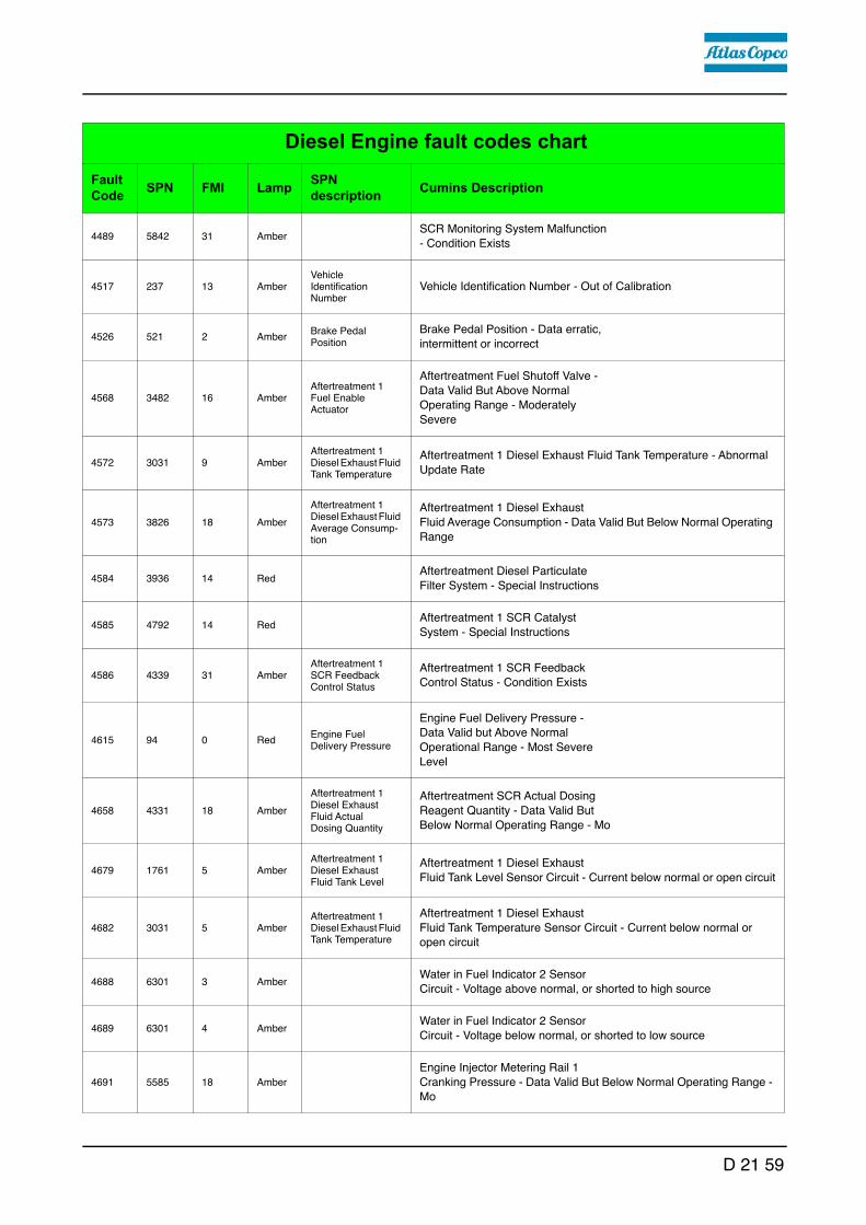
4489 5842 31 AmberSCR Monitoring System Malfunction - Condition Exists
4517 237 13 AmberVehicle Identification Number
Vehicle Identification Number - Out of Calibration
4526 521 2 AmberBrake Pedal Position
Brake Pedal Position - Data erratic, intermittent or incorrect
4568 3482 16 AmberAftertreatment 1 Fuel Enable Actuator
Aftertreatment Fuel Shutoff Valve - Data Valid But Above Normal Operating Range - Moderately Severe
4572 3031 9 AmberAftertreatment 1 Diesel Exhaust Fluid Tank Temperature
Aftertreatment 1 Diesel Exhaust Fluid Tank Temperature - Abnormal
Update Rate
4573 3826 18 Amber
Aftertreatment 1 Diesel Exhaust Fluid Average Consump-tion
Aftertreatment 1 Diesel Exhaust Fluid Average Consumption - Data Valid But Below Normal Operating
Range
4584 3936 14 RedAftertreatment Diesel Particulate Filter System - Special Instructions
4585 4792 14 RedAftertreatment 1 SCR Catalyst System - Special Instructions
4586 4339 31 AmberAftertreatment 1 SCR Feedback Control Status
Aftertreatment 1 SCR Feedback Control Status - Condition Exists
4615 94 0 RedEngine Fuel Delivery Pressure
Engine Fuel Delivery Pressure - Data Valid but Above Normal Operational Range - Most Severe Level
4658 4331 18 Amber
Aftertreatment 1 Diesel Exhaust Fluid Actual Dosing Quantity
Aftertreatment SCR Actual Dosing Reagent Quantity - Data Valid But Below Normal Operating Range - Mo
4679 1761 5 AmberAftertreatment 1 Diesel Exhaust Fluid Tank Level
Aftertreatment 1 Diesel Exhaust Fluid Tank Level Sensor Circuit - Current below normal or open circuit
4682 3031 5 AmberAftertreatment 1 Diesel Exhaust Fluid Tank Temperature
Aftertreatment 1 Diesel Exhaust Fluid Tank Temperature Sensor Circuit - Current below normal or open circuit
4688 6301 3 AmberWater in Fuel Indicator 2 Sensor Circuit - Voltage above normal, or shorted to high source
4689 6301 4 AmberWater in Fuel Indicator 2 Sensor Circuit - Voltage below normal, or shorted to low source
4691 5585 18 Amber
Engine Injector Metering Rail 1 Cranking Pressure - Data Valid But Below Normal Operating Range - Mo
Diesel Engine fault codes chartFault Code SPN FMI Lamp SPN
description Cumins Description
D 21 59

4713 5357 31 Amber
Engine Fuel Injection Quantity Error for Multiple Cylinders - Condition Exists
4721 237 31 AmberVehicle Identification Number
Vehicle Identification Number - Condition Exists
4722 237 2 AmberVehicle Identification Number
Vehicle Identification Number - Data erratic, intermittent or incorrect
4724 702 5 Amber Auxiliary I/O #02Auxiliary Input/Output 2 Circuit - Current below normal or open circuit
4725 702 6 Amber Auxiliary I/O #02Auxiliary Input/Output 2 Circuit - Current above normal or grounded circuit
4726 1239 16 AmberEngine Fuel Leakage 1
Engine Fuel Leakage - Data Valid But Above Normal Operating Range - Moderately Severe Level
4727 157 15 AmberEngine Injector Metering Rail 1 Pressure
Injector Metering Rail 1 Pressure - Data Valid But Above Normal Operating Range - Least Severe Level
4734 701 14 Red Auxiliary I/O #01Auxiliary Input/Output 1 - Special Instructions
4736 3031 6 AmberAftertreatment 1 Diesel Exhaust Fluid Tank Temperature
Aftertreatment 1 Diesel Exhaust Fluid Tank Temperature Sensor Circuit - Current above normal or
grounded circuit
4737 3031 11 AmberAftertreatment 1 Diesel Exhaust Fluid Tank Temperature
Aftertreatment 1 Diesel Exhaust Fluid Tank Temperature - Root
Cause Not Known
4738 1761 6 AmberAftertreatment 1 Diesel Exhaust Fluid Tank Level
Aftertreatment 1 Diesel Exhaust Fluid Tank Level Sensor Circuit - Current above normal or grounded
circuit
4739 1761 11 AmberAftertreatment 1 Diesel Exhaust Fluid Tank Level
Aftertreatment 1 Diesel Exhaust Fluid Tank Level Sensor - Root Cause Not Known
4741 3364 5 Amber
Aftertreatment 1 Diesel Exhaust Fluid Tank 1 Quality
Aftertreatment Diesel Exhaust Fluid Quality Sensor Circuit - Current below normal or open circuit
4742 3364 6 Amber
Aftertreatment 1 Diesel Exhaust Fluid Tank 1 Quality
Aftertreatment Diesel Exhaust Fluid Quality Sensor Circuit - Current above normal or grounded circuit
4743 3515 5 Amber
Aftertreatment 1 Diesel Exhaust Fluid Temperature 2
Aftertreatment 1 Diesel Exhaust Fluid Temperature 2 Sensor Circuit - Current below normal or open
circuit
Diesel Engine fault codes chartFault Code SPN FMI Lamp SPN
description Cumins Description
D 21 60

4744 3515 6 Amber
Aftertreatment 1 Diesel Exhaust Fluid Temperature 2
Aftertreatment 1 Diesel Exhaust Fluid Temperature 2 Sensor Circuit - Current above normal or
grounded
4745 3515 11 Amber
Aftertreatment 1 Diesel Exhaust Fluid Temperature 2
Aftertreatment 1 Diesel Exhaust Fluid Temperature 2 - Root Cause Not Known
4768 3521 11 AmberAftertreatment 1 Diesel Exhaust Fluid Property
Aftertreatment 1 Diesel Exhaust Fluid Property - Root Cause Not Known
4769 1761 10 AmberAftertreatment 1 Diesel Exhaust Fluid Tank Level
Aftertreatment 1 Diesel Exhaust Fluid Tank Level Sensor - Abnormal Rate of Change
4789 1639 0 Amber Fan Speed
Fan Speed - Data Valid but Above Normal Operational Range - Most Severe Level
4791 1639 1 Amber Fan Speed
Fan Speed - Data Valid but Below Normal Operational Range - Most Severe Level
4841 6653 16 Amber
Cold Start Injector Metering Rail 1 Pressure - Data Valid But Above Normal Operating Range - Moderate
Severe Level
4842 3364 15 NoneAftertreatment Die-sel Exhaust Fluid Quality
Aftertreatment Diesel Exhaust Fluid Quality - Data Valid But Above Normal Operating Range - Least
Severe Level
4863 5245 31 Amber
Aftertreatment Selective Catalytic Reduction Operator Inducement Active
Aftertreatment SCR Operator Inducement Active - Condition Exists
4867 5571 31 Amber
High Pressure Common Rail Fuel Pressure Relief Valve
High Pressure Common Rail Fuel Pressure Relief Valve - Condition
Exists
4951 6655 3 AmberECU Power Lamp
Maintain ECU Power Lamp - Voltage Above Normal, or Shorted to High Source
4952 6655 4 AmberECU Power Lamp
Maintain ECU Power Lamp - Voltage Below Normal, or Shorted to Low Source
4953 3353 3 AmberAlternator 1 Status
Alternator 1 Status - Voltage Above Normal, or Shorted to High Source
4954 3353 4 AmberAlternator 1 Status
Alternator 1 Status - Voltage Below Normal, or Shorted to Low Source
5133 2006 9 AmberSource Address 6 - Abnormal Update Rate
5167 111 17 AmberEngine Coolant Level
Coolant Level - Data Valid But Below Normal Operating Range - Least Severe Level
Diesel Engine fault codes chartFault Code SPN FMI Lamp SPN
description Cumins Description
D 21 61

5193 1632 31 AmberEngine Torque Limit Feature
Engine Torque Limit Feature - Condition Exists
5215 520791 2 AmberEngine Boost Curve Selection
Engine Boost Curve Selection - Data erratic, intermittent or incorrect
9952 524286 31 AmberReserved for temporary use - Condition Exists
9953 524286 31 AmberReserved for temporary use - Condition Exists
9999 524286 31 AmberReserved for temporary use - Condition Exists
Diesel Engine fault codes chartFault Code SPN FMI Lamp SPN
description Cumins Description
D 21 62

D 30 Mode of operation1 Vehicle control elements
1.1 Control elements on the operator's control station
Danger of falling from the vehicle
Entering and leaving the vehicle and the driver's seat dur-ing operation poses a risk of falling from the vehicle, which can cause severe to fatal injuries!
- The operator must be at the intended driver's seat during operation.
- Never jump onto or off a moving vehicle.- Keep accessible surfaces free of any soiling, e.g. operat-
ing substances, to avoid the risk of slipping.- Use the steps provided and hold onto the handrail with
both hands.- Comply with all further information in these instructions
and in the safety manual.
WARNING
D 30 1

Ladder
A ladder (1) and a folding step (2) on the drive units are located on both sides of the vehicle.
- The step (2) has to be folded down to ascend or descend.
f Never climb up/down on the vehicle dur-ing travel. Hold tight when climbing up and down.
f The ladder must not be used when the control platform is raised!
m Folded down, the step increases the ba-sic width of the vehicle.
f During transportation in road traffic and when transporting the vehicle on trans-porters, the step must be folded up!
f Always choose the ladder on the side away from road traffic!
2
2
D 30 2

Raisable platform
The entire control platform can be raised for better clarity.
f The permissible transportation height must be checked. When negotiating bridges, tunnels, overhead wires, un-derpasses, etc., always ensure that you maintain a safe distance from them at all times.
f During transportation in road traffic and when transporting the vehicle on trans-porters, the control platform must be lowered!
Emergency descent
An emergency descent is available if it should prove impossible to lower the platform. In addition to the descent, two steps (1) are also available in the covering for safely climbing down.
1
D 30 3

Protective roof (o)
The protective roof can be raised and lowered with a manual hydraulic pump.
A The exhaust pipe is lowered or raised together with the roof.
Caution! Possible collision of parts
The following adjustments must be made before lowering the roof:
- Seat consoles swivelled in and locked- Operating panel locked in a central position in front of
one of the driver's seats.- Side windows closed.- Engine hood and lateral flaps closed.- Rotary beacon swivelled inwards and in lowest setting
NOTE
D 30 4

A sn < 1460
- Connect the pump lever (1) to the pump (2).
- Lower the roof: The locks (3) on both sides of the roof must be released.
- Raise the roof: the locks (4) on both sides of the roof must be released.
- Set the adjustment lever (5) to the "Raise" or "Lower" position.
- Raise the roof: The lever points for-wards.
- Lower the roof: The lever points backwards.
- Operate the pump lever (1) until the roof has reached the upper or lower limit position.
- Roof in uppermost position: Set the locks (3) on both sides of the roof.
- Roof lowered: set the lock (4) on both sides of the roof.
A Place the pump lever in the bracket (6).
3
2
4
1
5
6
D 30 5

A sn >/=1460
- Connect the pump lever (1) to the pump (2).
- Tighten bolts (3) on both sides of the roof.
- Operate the pump lever (1) until the roof has reached the upper or lower limit position.
- Set bolts (3) in the respective posi-tion on both sides of the roof.
A Place the pump lever in the bracket (6).
6
5
1
2
3
D 30 6

Protective roof (o)
A
C
BC
B
A
1
2
D4
3
C
D
D 30 7

The protective roof is equipped with an additional front window and two side windows.
- The side windows can be swivelled out to the side at the sliding frame. To close the side windows, press the latch (1) and pull the sliding frame at the strap (2).
Windscreen wiper
- Engage the windscreen wiper / screen wash on the operating panel if necessary.
A Ensure that the washer fluid tank (3) is always adequately filled.
m Replace worn wiper blades immediately.
Mirror
- The mirror (4) enables a better view into the hopper.
A If necessary, turn the mirror on its bracket.
Risk of crushing hands
When closing the spring-loaded front and side windows, there is a risk of crushing which can cause injuries!
- Do not reach into the danger zone.- Set the latches correctly.- Comply with further instructions in the safety manual.
CAUTION
D 30 8

Seat bracket and seat console, swivelling
A The left/right seat consoles can be pushed out beyond the outer edge of the vehicle. This provides the driver with a better view of the paving area and material transfer.
Swivelling seat console:
m Caution! Possible collision of parts" Before swivelling the seat console out, the driver's seat must be moved to the fore-most position and the side window (o) must be swivelled open.
- Release the latch (1) and swivel the seat console out to stop.
- To swivel the seat console in, release the latch (1) again.
A The latch must audibly engage in both positions.
m When swivelled out, the seat consoles increase the basic width of the vehicle.
m Make sure it is latched properly!
f Always choose the driver position on the side away from road traffic!
2
1
D 30 9

f During transportation in road traffic and when transporting the vehicle on transport-ers, the seat console must be swivelled in!
f Only adjust the operating position whilst the vehicle is stationary!
D 30 10

Operating panel console, swivelling and telescopic
The operating panel console can be set-up for the various working positions.
Swivelling the operating panel:
- Release the latch (1), swivel the panel bracket to the desired position and allow to engage in one of the detent positions (2).
Extending / shortening the operating panel bracket:
- Release the latch (3), set the panel bracket to the desired length and lock the latch.
Swivelling the operating panel console:
- Release the latch (4), swivel the panel console to the desired position and lock the latch.
f Only adjust the operating position whilst the vehicle is stationary!
m Make sure it is latched properly!
1
3
2
4
D 30 11

Driver's seat, type I
f To avoid damage to health, the individu-al seat settings should be checked and adjusted before starting the vehicle.
f After locking the individual elements, it must no longer be possible to shift then to another position.
- Weight setting (1): The relevant driv-er's weight should be set by turning the weight adjustment lever when the driver's seat is unoccupied.
- Weight indicator (2): The set driver's weight can be read off at the viewing window.
- Longitudinal adjustment (3): Longi-tudinal adjustment is released by actu-ating the locking lever. The locking lever must engage in the desired position.
- Seat depth adjustment (4): The seat depth can be individually adjusted. Raise the button to adjust the seat depth. The desired position is set by simultaneously sliding the seat surface forwards or backwards.
- Seat inclination adjustment (5): The seat surface's longitudinal inclination can be individually adjusted. Raise the button to adjust the inclination. The seat surface in-clines to the desired position by simultaneously loading or relieving it.
- Armrest inclination (6): The armrest's longitudinal inclination can be adjusted by turning the hand wheel. Turning outwards raises the front of the armrest; turning inwards lowers it at the front. In addition, the armrests can be folded up fully.
- Lumbar support (7): Both the height and the extent of the convexity in the backrest padding can be individually adjusted by turning the hand wheel to the left or right.
- Backrest adjustment (8): The backrest is adjusted via the locking lever. The lock-ing lever must engage in the desired position.
- Back extension (9): By pulling out via perceptible detents, the height can be indi-vidually adjusted up to a limit stop. To remove the back extension, the limit stop is overcome with a jolt.
- Seat heating ON/OFF (10): The seat heating is switched on and off by actuating the switch.
- Seat belt (11): The seat belt must be applied before starting up the vehicle.
f The seat belts must be replaced following an accident.
3
7
10
4
5
6
6
8
11
1
9
2
D 30 12

Storage space
- The storage space (1) can be used to store the on-board tool kit, operating instructions and other attachments.
A Keep the storage space closed after work has been completed.
Conveyor belt maintenance flap
The conveyor belt can be accessed through the open maintenance flap (2) for main-tenance work.
f Keep the maintenance flap closed during operation; never open whilst the conveyor belt is running!
Danger from damaged or missing operating instructionsFailure to comply with the operating instructions can cause severe to fatal injuries!
- Familiarise yourself with the contents of the operating instructions.
- Always keep the operating instructions in the intended place on the vehicle.
- Replace any missing or damaged operating instructions immediately.
- Comply with all further information in the operating instructions and in the safety manual.
1
2
WARNING
D 30 13

Batteries
The batteries (1) of the 24 V system are located in the vehicle footwell.
A For the specifications, refer to chapter B, "Technical data". For maintenance, see chapter "F".
m External starting must only be carried out according to the instructions (see section "Starting the feeder, external starting (starting aid)"
Main battery switch
The main battery switch separates the current circuit from the battery to the main fuse.
A For the assignment of all fuses, see chapter F.
- To interrupt the battery's current cir-cuit, turn the key pin (3) to the left and pull it out.
A Do not lose the key pin as in this case the feeder can no longer be moved!
1
3
3
D 30 14

Hopper transport safeguard
Before transporting or in order to park the vehicle, the hopper lids must be swung upwards and the transport safe-guards for the hopper must be inserted on both sides of the vehicle.
- Pull the locking pin (1) and place the transport safeguard (2) with the han-dle above the hopper cylinder's piston rod.
f Without transport safeguards inserted, the hopper lids will slowly open; danger during transportation!
1
2
D 30 15

Conveyor belt lighting (o)
A Two swivelling headlights (1) are located on the left and right of the conveyor belt for illuminating the transfer point.
- They are engaged together with the working lights.
A These are activated together with the other working lights on the operating panel!
Engine compartment lighting (o)
A The engine compartment lighting can be activated when the ignition is switched on.
- On/off switch (1) for the engine com-partment lighting.
1
1
D 30 16

LED working light (o)
There are two LED spotlights (1) at the front and rear of the vehicle.
f Always align the working lights to avoid dazzling the operating personnel or oth-er road users!
1
D 30 17

Camera system (o)
Cameras for monitoring blind spots are lo-cated in several positions on the vehicle.
- The cameras can be swivelled in vari-ous directions.
- Front of vehicle (hopper) (1)
- Material transfer area (2)
- Rear of vehicle (3)
A The pictures are shown in the control panel display.
f Several cameras are located in the vehi-cle's danger zone! Carry out set-up work only when the ve-hicle is stationary!
2
3
1
D 30 18

Surface course / binder course signal lamps (o)
Two removable signal lamps for control-ling the material flow are located at the front and rear of the vehicle. During compact asphalt paving, the signal lamps can be used to indicate to the driv-ers of the material transporters and the paver finisher whether surface or binder course material is required or the material with which the paver finisher is fed.
- Red signal lamp (1) - surface course
- Green signal lamp (2) - binder course
- Insert the lamp unit in the intended bracket (3); connect the connection cable to the relevant socket (4).
A The signal lamps are switched using the operating panel.
1
2
3
4
D 30 19

Emulsion spraying system
Used to spray the parts coming into contact with asphalt with a separator emulsion. The emulsion spraying system tank (1) is located behind the right lateral flap.
The spraying system consists of:
- a manual spray with hose reeling device (2)
- a spraying bar (3) above the conveyor belt
- a manual spray with hose (4) (o)
A The hose reeling device can be mounted on both sides of the vehicle.
- Connection options (quick-action cou-plers) for the spray hose are located on the left/right in the front and rear area of the vehicle (5), (6).
A The spraying bar installed on the con-veyor belt is engaged with time control on activation of the conveying function.
A The separator fluid functions most effi-ciently when it is sprayed on the convey-or belt while it is still hot to removed any material residues! This means that the conveyor belt should be sprayed imme-diately in case of longer interruptions in work and immediately after the end of work.
A Repeat spraying 2-3 times to completely spray the conveyor belt.
5
7
4
1
3
26
6
7
8
D 30 20

A The scraper scrapes the separator fluid off the belt again, causing it to be wetted and protected against material adhesions.
A Repeat spraying regularly in the continuous working gear; see the following table for orientation:
A Spray all other parts which come into contact with asphalt using the manual spray. Engagement is carried out on the operating panel / side operating unit.
m Only switch on the spraying system when the diesel engine is running; otherwise, the battery will be discharged. Switch off after use.
f Refill the tank only whilst the vehicle is stationary!
f Do not spray into open flame or on hot surface! Danger of explosion!
m Use only approved separator fluid! See section entitled "Lubricants and operating substances".
- Hose reeling device: connect supply hose with quick-action coupling.
- Pull the spray hose out of the device until a click is audible. When released, the hose automatically engages here. The hose is automatically rolled up again by pull-ing and letting go again.
- Actuate the manual valve (7) to spray.
- If the system is not in use, place the spray lance in the holder (8) provided.
Bas
e co
urse
Bin
der c
ours
e /
Surf
ace
cour
se
- Truck loads between two spraying processes
4 2
- Separator fluid consumption of feeder
approx. 10 l approx. 20 l
- Separator fluid consumption of feeder with slewing belt
approx. 20 l approx. 40 l
D 30 21

Spring arm scraper
A A scraper is available to minimise dirt and wear on the conveyor belt.
A The scraper is equipped with several scraper plates which scrape off bonded material residues during conveyor belt operation.
m Risk of damage to equipment! Only allow the conveyor belt to run in re-versing mode if the conveyor belt scrap-er has been disengaged!
Disengage scraper:
- Remove tensioning fixture bolts (A) on both sides of the vehicle.
- Place an appropriate wrench on the hexagon head (B) and relieve scraper.
- Insert bolts (A) in the next possible po-sition to secure the scraper in the low-er position.
A
B
D 30 22

24 volt / 12 volt sockets (o)
Additional 2 V / 24 V sockets (1) are lo-cated in several positions. Additional working lights can be con-nected here, for example.
- Control platform (1)
- Rear of vehicle (2)
A Voltage is present when the main switch is switched on.
1
2
D 30 23

Chain lubricating system
A The central lubrication unit is located be-hind the left lateral flap.
The reservoir (1) is filled with chain oil and ensures that the conveyor belt chain links are lubricated at set intervals of time.
A Factory setting of the chain lubrication system operating intervals when the conveyor belt is running: 4 minutes' operation / 20 minutes' break.
A Observe the instructions in section "Maintenance"!
O
1
D 30 24

Lane clearer (o)
A swivelling lane clearer (1), which de-flects small obstacles away to one side, is located in front of both drive units.
A The lane clearers should only be swiv-elled down in operating mode.
Swivelling the lane clearers:
- Swivel the lane clearers (1) up and se-cure in the uppermost position with a hook (2).
m To avoid collisions in operating mode, the lane clearer may only be lowered so that a space of a few mm is available be-tween the ground and the blade (3).
Fire extinguisher (o)
A The machine personnel must be famil-iarised with operation of the fire extin-guisher (1).
A Observe the inspection interval for the fire extinguisher!
13
2
1
D 30 25

Rotary beacon (o)
m The function of the rotary beacon must be checked daily before starting work.
- Place the rotary beacon (1) onto the plug-in contact and secure with a wing bolt (2).
- Extend the rotary beacon with tube (3) to the desired height and secure with the clamping bolt (4).
- Activate the function on the operat-ing panel as necessary.
- On completion of work, release the bolt (5) and swivel the bracket 90°.
A The rotary beacon is easy to remove and should be stored securely at the end of work.
(o)
1
2
3
4
5
D 30 26

Hopper scraper
To reduce the gap between hopper and vehicle frame, the hopper scrapers (1) must be adjusted on both hopper lids.
- Loosen the mounting screws (2).
- Set a gap of 6 mm across the whole length of the scraper.
- Retighten the mounting screws (2) properly.
f Risk of injury due to sharp-edged parts! Wear suitable safety gloves to protect your hands!
1
2
D 30 27
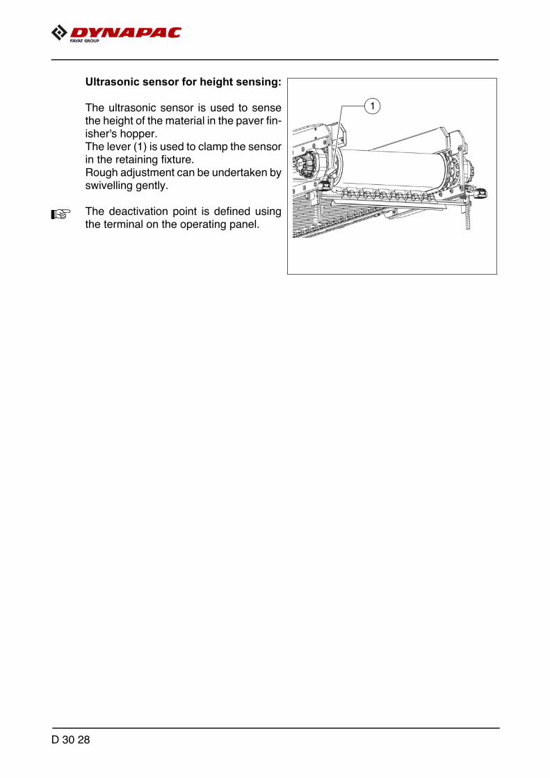
Ultrasonic sensor for height sensing:
The ultrasonic sensor is used to sense the height of the material in the paver fin-isher's hopper. The lever (1) is used to clamp the sensor in the retaining fixture. Rough adjustment can be undertaken by swivelling gently.
A The deactivation point is defined using the terminal on the operating panel.
Ultrasch_MF300
1
D 30 28

Distance sensor
The laser sensor (1) on the rear of the vehicle is used to sense the distance be-tween the feeder and the paver finisher. As soon as the engaged sensor regis-ters the paver finisher on approaching, the feeder's speed is adjusted to that of the paver finisher and the distance is maintained.
A The function is engaged and disen-gaged on the operating panel.
A There is a switch (2) in the terminal box for switching the laser off by hand. (type-dependent)
Danger due to laser beam
Improper handling of the laser system can cause severe injuries!
- Do not look into the laser beam.- Do not enter the danger zone.- Assembly, electrical connection, commissioning, opera-
tion and maintenance may only be undertaken by spe-cialist personnel!
- Immediately decommission damaged lasers or supply cables.
- Only commission correctly aligned lasers.
Ultrasch2_MF300
1
2
WARNING
D 30 29

Automatic steering unit
20
2
1
3
6
7
8
4
12
9
10511
17
18
15
16
14
21
13
19
D 30 30

1.1 Mounting the automatic steering unit on the feeder
m During operation, no work may be carried out on the automatic steering unit!
A Depending on the desired sensing side on the vehicle, the sensor rod tube may have to be removed and re-inserted on the other side of the vehicle!
- Pull the sensor rod tube (1) at the front of the vehicle out to the desired length and secure with the clamping bolts (2).
A Only for 14 m automatic steering unit: -Push the connecting tube (3) into the sensor rod tube (1), fix with bolts and lock nuts (4). -Push extension (5) onto the connection tube and fix in the same way. -Fix support wheel (6) in a suitable position using the corresponding assembly parts. -Heed vertical alignment!
- Insert tube (7) to the required length and also fix with bolts and lock nuts (8).
- Fit the clamping piece (9) with extension arm (10) to the end of the tube.
A Heed vertical alignment!
- If necessary, adjust the height of the support wheel at the adjustment knob (11) until all extension tubes are horizontally in line.
- Swivel the extension arm (9) to the desired angle and secure by tightening the bolt (12).
m Use of the automatic steering unit increases the basic width of the vehicle!
A If the automatic steering unit is used, ensure that there are no persons or obstacles in the danger area.
D 30 31

Mounting and aligning the sensor
- Insert the sensor mounting (13) into the bracket (14) and secure with a wing nut (15).
- Align the angle between the sensor and reference and secure with the relevant clamping bolt (16).
A The sensor and reference must be at right angles to each other!
- The sensing height can be set by loosening the fixing screw (17).
A The reference should run centrally along the sensor.
- The sensor's distance from the reference can be set by loosening the fixing screw (18).
A The distance between the sensor and reference (cable) should be 350 mm!
A All assembly parts must be mounted and tightened properly to ensure safe and pre-cise operation of the automatic steering unit!
Connecting the sensor
A A socket for connecting the sensing system to the vehicle's control system is located on the left and right sides of the vehicle on the inner side of the bumper.
- Connect the relevant connection cable (19) to the socket (20) and sensor (21).
A A connection socket for the automatic steering unit is located on both sides of the vehicle.
m Route the connection cable so that it cannot be damaged during operation.
m Seal unused sockets with the relevant protective caps.
D 30 32

Tray
- Open the flap (1) to use the extenda-ble tray (2).
- Secure the tray in the front or rear po-sition with the latch (3).
A Construction site documents can be com-pleted or a laptop set down on the tray.
Fuse box
Open the door (4) to access the terminal box. The terminal box contains all fuses and relays, etc.
A An assignment plan for fuses and relays can be found in chapter F8.
1
2
3
4
D 30 33

Illuminated balloon (o)
The illuminated balloon generates shadow-reducing and anti-dazzle light.
f The illuminated balloon makes the vehicle higher and wider.
f Note the passage height of bridges and tunnels and the enlarged vehicle width.
f Always disconnect the power supply before working on the illuminated balloon!
f Never look directly in the balloon when it is switched on!
f The illuminated balloon must not be used in the vicinity of highly flammable materials (e.g. petrol and gas); a safety distance of at least 1 metre must be maintained from combustible materials.
1
4
3
8
7
5
2
6
9
D 30 34
f Danger due to electric shock. Voltage flashover poses the risk of severe or fatal injuries! Adhere to the following safety distances from high-voltage lines: < 125 kV 5 m > 125 kV 15 m
f The illuminated balloon must not be operated if the electric supply cables or connec-tors are damaged.
m Before starting up, check that the zip fastener of the balloon skin is closed. If the skin is damaged, it must be repaired or replaced. The bulbs must be checked for firm seat-ing and damage.
A The balloon cannot be operated with a damaged skin.
m Never operate the balloon unattended!
m Maximum wind speed for using the balloon: 80 km/h.
Installation and operation
- Fasten the illuminated balloon (1) to the holding tube (2) and pull the clamping lever (3) tight.
- Set the telescopic tube to the desired height using the clamping lever (4).
- Close the zip fastener (5) in the balloon skin and smooth away any large wrinkles in the skin.
- Guide the holding tube (6) into the pre-mounted holder (7) and tighten the clamping screws correctly to fix the holding tube.
- Once the illuminated balloon is completely mounted and secured, connect the plug (8) of the illuminated balloon in the corresponding switch cabinet sockets (9).
m Route the supply lines so as to rule out any risk of stumbling or damage to the lines.
- After it has been engaged at the switch cabinet, the illuminated balloon inflates au-tomatically.
- The skin of the illuminated balloon collapses again on being switched off.
- Remove the plug and open the zip of the balloon skin. Let the lamps cool down completely.
- Store any dry illuminated balloons that are not needed in the corresponding trans-port cover.
m The holding tube most be removed during transport or to lower the roof!
D 30 35

Maintenance
m Occasionally clean or replace the air fil-ter (10) beneath the connection plate.
m Do not use solvents to clean the balloon skin!
Replacing the lamp
- Disconnect the power cable and open the zip fastener of the skin.
f Let lamp cool down completely!
m Always wear the supplied cotton glove to touch the lamp!
- Press the lamp down gently to remove it.
- Insert the new lamp in the socket.
- Close the zip fastener of the balloon skin.
10
D 30 36

D 41 Mode of operation1 Preparing for operation
Required devices and aids
To avoid delays on site, check before starting work whether or not the following de-vices and aids are present:
- Diesel fuel
- Engine oil and hydraulic oil, lubricants
- Separator fluids (emulsion) and manual injector
- Shovel and broom
- Any devices required to clean various parts of the vehicle
- Protective clothing, signal vest, gloves, ear protection
D 41 1

Danger due to restricted vision
Restricted vision poses a risk of injury!
- Before starting work, arrange the intended driver's seat to ensure adequate vision.
- Signalmen must be used when vision is restricted, also to the sides and when reversing.
- Only reliable persons may be used as signalmen who must have been received instructions about their task before taking up their activity. This refers in particular to the hand signals to be used. Standardised hand signals must be used.
- Adequate lighting must be provided when working at night.
- Comply with all further information in these instructions and in the safety manual.
Danger of falling from the vehicle
Entering and leaving the vehicle and the driver's seat dur-ing operation poses a risk of falling from the vehicle, which can cause severe to fatal injuries!
- During operation, the operator must be at the intended driver's seat and be seated properly.
- Never jump onto or off a moving vehicle.- Keep accessible surfaces free of any soiling, e.g. operat-
ing substances, to avoid the risk of slipping.- Use the steps provided and hold onto the handrail with
both hands.- Comply with all further information in these instructions
and in the safety manual.
CAUTION
WARNING
D 41 2

Before starting work (in the morning or when starting paving)
- Heed the safety instructions.
- Check the personal protective equipment .
- Take walk around the vehicle to inspect it and check for any leaks and damage.
- Install parts removed for transportation or for the night.
- Perform the check according to the "Checklist for the vehicle operator" given below.
D 41 3

Check list for the vehicle operator
Check! How?
Emergency stop button - on the operating panel - on the side operating units
Push in the button. The diesel engine and all running drives must stop immediately.
SteeringThe feeder must immediately and pre-cisely follow every steering movement. Check straight ahead travel.
Horn - On the operating panel
Briefly press the horn button. Horn signal must sound.
LightsSwitch on with the ignition key, walk around the vehicle, check and switch off again.
Warning lightsThe warning lights must be engageable when the ignition is switched on.
Hopper transport safeguardWhen the hopper is closed, it must be possible to swivel the safeguards over the hopper cylinders.
Protective roof The locking bolts must be set properly.
Other facilities: - Engine panels - Lateral flaps - Covers
Check that the coverings, flaps and cov-ers are securely seated.
Accessories: - First aid box
Equipment must be present on the vehicle!
A Always observe the local regula-tions!
D 41 4

13
11
12
10
15
108
100
D 41 5

1.1 Starting the vehicle
Before starting the vehicle
The following must be carried out before the diesel engine can be started and the ve-hicle can be operated:
- Daily maintenance of the vehicle (see chapter F).
m Check the operating hours counter to determine whether further maintenance work should be conducted.
- Check the safety devices and protective devices.
"Normal" starting
- Set the drive lever (13) to the centre position and the travel drive preselector (15) to minimum.
- Insert the ignition key (11) in position "0".
m The lights should be switched off during starting to reduce the current drain on the battery.
A It is impossible to start the vehicle if an emergency stop button (10) / (100, 108) is pressed. (Error shown on the display)
- Press the starter button (12) to start the engine. Run the starter continuously for a maximum of 20 seconds, then take a break for 2 minutes!
D 41 6

108
100
13
11
12
10
15
D 41 7

External starting (starting aid)
A The engine can be started with the help of an external power source if the batteries are empty and the starter no longer turns.
Suitable power sources are:
- Other vehicles with a 24V system
- Additional 24V battery
- Start device that is suitable for external starting (24 V/90 A).
m Standard chargers or quick chargers cannot be used for external starting.
To externally start the engine:
- Switch on the ignition (11), set the drive lever (13) to the centre position and the travel drive preselector (15) to minimum.
m The starting aid cable must be connect-ed to 24 V.
- First connect the positive terminal (1) of the starting aid battery to the posi-tive terminal (2) of the vehicle battery.
- Then connect the negative terminal (3) of the starting aid battery to the ground of the discharged vehicle, e.g. to the engine block or to a bolt (4) on the vehicle frame.
f Do not connect the starting aid cable to the negative terminal of the discharged battery! Danger of explosion!
m Lay the starting aid cable so that it can be disconnected once the engine is running.
A It is impossible to start the vehicle if an emergency stop button (10) / (100, 108) is pressed. (Error shown on the display)
2 1
3
4
D 41 8

- If necessary, start the engine of the vehicle supplying power and leave to run for a while.
Now try to start the other vehicle:
- Press the starter button (12) to start the engine. Run the starter continuously for a maximum of 20 seconds, then take a break for 2 minutes!
- If the engine still has not started after two attempts, ascertain the cause!
- If the engine starts up: disconnect the starting aid cable again in reverse order.
D 41 9

13
65
D 41 10

After starting
To increase the engine speed:
- Press button (65) to increase engine speed.
A The engine speed is increased to the preset value.
m Let the vehicle warm up for approx. 5 minutes if the engine is cold.
D 41 11

13
STOP
83 84 85 86 87 88 89
76 77 78 79 80 81 82
D 41 12

Observe indicator lamps
The following indicator lamps must be observed under all circumstances:
For further possible faults, see Engine's operating instructions.
Engine coolant temperature check (79)
Lights up when the engine temperature is outside of the permissible range.
m Stop the vehicle (drive lever in centre position), let the engine cool down while idling. Determine the cause and correct it if necessary.
A The engine performance will be throttled down automatically. (Driving mode remains possible). After cooling down to normal temperature, the engine will run with full performance again.
Battery charge indicator (83)
Must go out after starting when the engine revs up.
m If the lamp does not go out or lights up during operation: Briefly rev up the engine. Switch off the engine and determine the fault if the lamp does not go out.
For further possible malfunctions, refer to the section "Malfunctions".
Oil pressure indicator lamp for the diesel engine (86)
Must go out 15 seconds after starting at the latest.
m If the lamp does not go out or lights up during operation: switch off engine immediately and determine fault.
D 41 13

65
54
STOP
83 84 85 86 87 88 89
76 77 78 79 80 81 82
53
D 41 14

Oil pressure indicator lamp for the travel drive (87)
- Must go out after starting.
m If the lamp does not go out: Do not switch on the travel drive! Otherwise, the entire hydraulic system could be damaged.
- Activate set-up mode function (65).
- Set conveyor belt functions (53) or (54) to "manual". The conveyor belts start to operate
- Let the hydraulics warm up until the indicator lamp goes out.
A The Lamp goes out when the pressure drops below 2.8 bar = 40 psi.
For further possible faults, refer to the section "Malfunctions".
D 41 15

373615
13
27
47
43
D 41 16

1.2 Preparation for transportation
- Move the drive lever (13) to the centre position.
- Turn the travel drive preselector (15) to zero.
- Close the hopper with buttons (36)//(37).
- Lower the platform with button (25) (o).
- Lower the main conveyor belt with button (49).
- Lower the slewing conveyor belt (o) with button (43).
- Engage both hopper transport safeguards.
A If the engine is started with the drive lever swivelled, the travel drive is blocked. To be able to start the travel drive, the drive lever must first be returned to the centre position.
D 41 17

2
15
13
16
1072
D 41 18

Driving and stopping the vehicle
- Set the Fast/Slow switch (72) to "Hare".
- Set the preselector (15) to mark 10.
- For driving, carefully tilt the drive lever (13) forward or backward according to the drive direction desired.
- Adjust the speed with the preselector (15).
- Carry out steering movements by actuating the steering potentiometer (16).
f In case of an emergency, press the emergency stop button (10)!
- To stop, set the preselector (15) to "0" and move the drive lever (13) into its centre position.
D 41 19

63
107
62
D 41 20

1.3 Preparations for feeder operation
Separator fluid
- Engage the separator fluid spraying system with button (62) or (107).
A Spray all surfaces coming into contact with asphalt material (hopper, push roll-ers, scraper) with separator fluid.
m Do not use diesel fuel as it dissolves the bitumen (prohibited in Germany!).
- Switch the conveyor belt spraying sys-tem function to "AUTO" with button (63).
A The conveyor belt spraying system is switched on on engaging the conveying function.
A Automatic shut-off takes place after one complete conveyor belt revolution.
m Repeat the process after long interruptions!
D 41 21

3938
52
A
4140
4342
6466
5958
5756
4948
5150
D 41 22

Loading/conveying material
m To convey material, the feeder must be in the correct transfer position in front of the paver finisher.
- Function (66) must be switched off.
- Set the main conveyor belt to the required transfer height using buttons (48)/(49) (o).
- Set the slewing conveyor belt (o) to the required transfer height using buttons (40)/(41) and (42)/(43) and set-up the transfer position.
m MF2500CS: For joint use of slewing conveyor belt (o) and height-adjustable main conveyor belt (o), the main conveyor belt must be set up to its lowest position!
- If necessary, activate distance control (56)/(57) and adjust the distance (58)/(59).
- Use switch (38)/(39) to open the hopper. Instruct the truck driver to dump the material.
- Switch the conveyor belt functions (52) to "AUTO".
- Activate function (64) to fill the vehicle for the paving process. The paver finisher hopper is now filled to the set height.
- If necessary, regulate the output of the main conveyor belt and the cross conveyor (o) using buttons (50)/(51).
A If necessary, adjust material height scanning at the ultrasonic sensor (A).
D 41 23

15
73 64
5958
5756
50
13
51
52
D 41 24

1.4 Starting for feeder operation
Set the following switches, levers and controls to the specified positions when the paver finisher has been filled with sufficient material:
- Push the drive lever (13) all the way to the front and start driving. Regulated by material scanning, the main conveyor belt and cross conveyor (o) are started up.
- As soon as the desired distance between the paver finisher and feeder has been reached, activate distance control (56)/(57) (LED "ON") and adjust the dis-tance (58)/(59) if necessary.
f During feeder operation without distance control (o), always adjust the vehicle speed to the paver finisher's speed! Always equip and operate the paver finisher with the "Emergency stop during feeder operation" function!
- Observe the distribution of the material and adjust the limit switch if necessary.
Pos. Travelling direction Position
64 Filling function LED "OFF"
73 Travel drive fast/slow Tortoise-operating speed
15 Travel drive preselector Mark 6-7
52Main conveyor belt / slewing convey-or belt (o)
"AUTO"
50/51Output control Main conveyor belt + slewing convey-or belt (o)
adapted to the paving situation
D 41 25

15
73 64
13
3938
69
68
25
24
5958
5756
50 51
52
11
4948
D 41 26

Operation during compact asphalt paving
- Move the feeder to the correct position in front of the paver finisher.
- Use buttons (38)/(39) to open the hopper.
- Use buttons (68)/(69) to indicate to the truck drivers whether surface course of binder course material is to be delivered.
- Instruct the truck driver to dump the material.
- Set the main conveyor belt to the required transfer height using buttons (48)/(49).
- Switch the conveyor belt functions (52) to "AUTO".
- Activate function (64) to fill the vehicle for the paving process. The paver finisher hopper is now filled to the set height.
- Switch function (64) "OFF".
- Push the drive lever (13) all the way to the front and start driving. Regulated by material scanning, the main conveyor belt and cross conveyor (o) are started up.
- As soon as the desired distance between the paver finisher and feeder has been reached, activate distance control (56)/(57) (LED "ON") and adjust the dis-tance (58)/(59) if necessary.
- If necessary, regulate the output of the main conveyor belt using buttons (50)/(51).
- Raise/lower the operator's platform using buttons (24)/(25) if necessary.
Material change with empty hopper
- Switch the conveyor belt functions (52) to "OFF".
- Set the main conveyor belt to the required transfer height using buttons (48)/(49).
A If the distance between the feeder and paver finisher has to be changed to set-up cor-rect material transfer, distance control must be deactivated.
- As soon as the desired distance between the paver finisher and feeder has been reached, activate distance control (56)/(57) (LED "ON") and adjust the dis-tance (58)/(59) if necessary.
- Switch the conveyor belt functions (52) (o) and (54) to "AUTO".
- Use buttons (38)/(39) to open the hopper.
- Switch the signal lamps to the different material type using buttons (68)/(69).
- Instruct the truck driver to dump the material.
D 41 27

1.5 Interrupting/terminating operation
During breaks in paving (e.g. delay due to material trucks)
- Determine the approximate duration.
- Run the vehicle empty if it is anticipated that the material will cool below the mini-mum paving temperature.
- Set the drive lever (13) to the centre position.
During longer interruptions (e.g. lunch break)
- Set the drive lever (13) to the centre position and the speed adjuster (15) to minimum.
- Switch off the ignition (11).
D 41 28

13
11
15
4140
3938
25
24
D 41 29

When work is finished
- Run the vehicle empty and stop it.
- Set the drive lever (13) to the centre position and the speed adjuster (15) to minimum.
- Swivel the slewing conveyor belt (o) in to the centre position (40)/(41)
- Use buttons (36)/(37) to close the hopper.
- Lower the operator's platform using button (25) if necessary.
- Switch off the ignition (11).
- Remove any accessories that have been used and stow them in the storage boxes, close flaps.
- Remove or secure all projecting parts if the vehicle is to be transported over public roads on a low-loader.
- Read and check the operating hour counter to determine whether maintenance work must be performed (see chapter F).
- Cover and lock the operating panel.
- Remove material residues from the vehicle and spray all parts with separator fluid.
D 41 30

2 Malfunctions
2.1 Malfunctions - cause - remedy
Malfunction Cause Remedy
At the diesel engine VariousSee operating instructions for the engine
Diesel engine does not start
Batteries emptySee "External starting" (start assistance)
Various see "Towing"
Conveyor belt runs too slowly
Hydraulic oil level in the tank is too low
Top up oil
Power supply is interruptedCheck fuses and cables; replace if necessary
Switch is defective Replace the switch
Pressure limiting valves defective
Repair or exchange valve
Pump shaft broken Replace the pump
Pump is defectiveCheck the high pressure filter for dirt particles; replace if necessary
Oil filter is soiledClean the filter; if necessary, replace the filter
Conveyor belt can-not be raised
Oil pressure too low Increase the oil pressure
Leaking seal Replace
Power supply is interruptedCheck fuse and cables; replace if necessary
Switch is defective Replace the switch
Conveyor belt lowers inadvertently
Control valve is defective Replace
Leaking hydraulic cylinder sleeves
Replace
Hopper cannot be swung open
Engine speed is too low Increase the speed
Hydraulic oil level is too low Top up oil
Leak in the suction line Tighten the connections
Flow rate regulator defective Replace
Leaking seals of the hydraulic cylinder
Replace
Control valve is defective Replace
Power supply interruptedCheck fuse and cables; replace if necessary
Hoppers lowers inad-vertently
Control valve is defective Replace
Leaking hydraulic cylinder sleeves
Replace
D 41 31

Malfunction Cause Remedy
Traction does not work
Travel drive fuse defective Replace
Power supply is interruptedCheck potentiometer, cables, connectors; replace if necessary
Travel drive monitoring defective
Replace
Electro-hydraulic servo unit of the pump defective
Replace the servo unit
Insufficient supply pressure
Check and adjust if necessary
Check the suction filter; replace the supply pump and the filter if necessary
Drive shaft of hydraulic pumps or engines broken
Replace pump or engine
Irregular engine speed, engine stop function does not work
Fuel level too lowCheck the fuel level; refill fuel if necessary
Fuse "engine speed con-trol" defective
Replace
Electrical power defect (line break or short circuit)
Check potentiometer, cables, connectors; replace if necessary
D 41 32

2.2 Lower slewing belt (o) / hydraulic end piece (o) in the event of a malfunction
1
1 3
45
3 2
45
2
D 41 33

A hydraulic emergency function can be used if a technical defect means it is no longer possible to lower the slewing belt or hydraulic end piece.
m Observe the danger zone of the conveyor belt being lowered! Proceed with two peo-ple (one person on each side of the machine).
A There is a lowering brake valve (3). in each case on both hoisting cylinders (1) on the left and right of the slewing belt / on both hoisting cylinders (2) of the hydraulic end piece.
- Remove the protective cap from the lowering brake valve.
- Loosen the lock nut (4) of the hexagon socket screw (5).
- Tighten the hexagon socket screw (5) a quarter of a turn clockwise alternately at the left and right hoisting cylinder until the conveyor belt starts to lower and finally reaches its end position.
A There is no possibility of readjusting the lowering brake valve on site. This is why the lowering brake valve then has to be replaced at both cylinders!
D 41 34

2.3 Lower height-adjustable platform (o) in the event of a malfunction
A hydraulic emergency function can be used if a technical defect means it is no longer possible to lower the platform.
m Observe the danger zone of the platform being lowered!
A There is a ball valve (1) on the hydraulic block.
- Slowly swivel the valve lever (2) upwards until the platform begins to lower.
- Close the valve again once the platform has reached the lowest position.
2 1
D 41 35

D 41 36

E Set-up and modification
1 Special safety instructions
f Danger to personnel by inadvertent starting of the engine, travel drive, conveyor belt, raising or slewing equipment. Unless otherwise specified, work may only be performed when the engine is at a standstill!
- Protect machine to prevent it from being started accidentally: Move drive lever into centre position and turn preselector controller to zero, remove ignition key and battery main switch.
- Protect lifted vehicle parts (e.g. control platform, conveyor belt or hopper) against lowering by means of mechanical safeguards.
- Replace parts or have them replaced as stipulated.
f When connecting or disconnecting hydraulic hoses and when working on the hydrau-lic system, hot hydraulic fluid may spurt out at high pressure. Switch off the engine and depressurise the hydraulic system! Protect your eyes!
- Mount all protective devices before re-commissioning the feeder.
Danger due to changes at the vehicle
Structural chances to the vehicle make the operating licence null and void and can cause severe to fatal injuries!
- Only use original spare parts and approved accessories.- After maintenance and repair work, ensure that any dis-
mantled protective and safety devices are all completely fitted again.
- Comply with all further information in these instructions and in the safety manual.
DANGER
E 1

2 Automatic steering unit
202
1
3
6
7
8
4
12
9
10511
17
18
15
16
14
21
13
19
E 2

2.1 Mounting the automatic steering unit
m During operation, no work may be carried out on the automatic steering unit!
A Depending on the desired sensing side on the vehicle, the sensor rod tube may have to be removed and re-inserted on the other side of the vehicle!
- Pull the sensor rod tube (1) at the front of the vehicle out to the desired length and secure with the clamping bolts (2).
A Only for 14 m automatic steering unit: -Push the connecting tube (3) into the sensor rod tube (1), fix with bolts and lock nuts (4). -Push extension (5) onto the connection tube and fix in the same way. -Fix support wheel (6) in a suitable position using the corresponding assembly parts. -Heed vertical alignment!
- Insert tube (7) to the required length and also fix with bolts and lock nuts (8).
- Fit the clamping piece (9) with extension arm (10) to the end of the tube.
A Heed vertical alignment!
- If necessary, adjust the height of the support wheel at the adjustment knob (11) until all extension tubes are horizontally in line.
- Swivel the extension arm (9) to the desired angle and secure by tightening the bolt (12).
m Use of the automatic steering unit increases the basic width of the vehicle!
A If the automatic steering unit is used, ensure that there are no persons or obstacles in the danger area.
E 3

Mounting and aligning the sensor
- Insert the sensor mounting (13) into the bracket (14) and secure with a wing nut (15).
- Align the angle between the sensor and reference and secure with the relevant clamping bolt (16).
A The sensor and reference must be at right angles to each other!
- The sensing height can be set by loosening the fixing screw (17).
A The reference should run centrally along the sensor.
- The sensor's distance from the reference can be set by loosening the fixing screw (18).
A The distance between the sensor and reference (cable) should be 350 mm!
A All assembly parts must be mounted and tightened properly to ensure safe and pre-cise operation of the automatic steering unit!
Connecting the sensor
A A socket for connecting the sensing system to the vehicle's control system is located on the left and right sides of the vehicle on the inner side of the bumper.
- Connect the relevant connection cable (19) to the socket (20) and sensor (21).
A A connection socket for the automatic steering unit is located on both sides of the vehicle.
m Route the connection cable so that it cannot be damaged during operation.
m Seal unused sockets with the relevant protective caps.
E 4
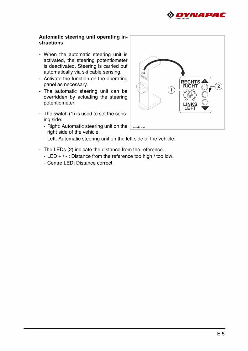
Automatic steering unit operating in-structions
- When the automatic steering unit is activated, the steering potentiometer is deactivated. Steering is carried out automatically via ski cable sensing.
- Activate the function on the operating panel as necessary.
- The automatic steering unit can be overridden by actuating the steering potentiometer.
- The switch (1) is used to set the sens-ing side:
- Right: Automatic steering unit on the right side of the vehicle.
- Left: Automatic steering unit on the left side of the vehicle.
- The LEDs (2) indicate the distance from the reference.
- LED + / - : Distance from the reference too high / too low.
- Centre LED: Distance correct.
12
Lenkski.wmf
E 5

3 Mount slewing belt (o)
Preparing the vehicle
- Place the vehicle on a flat surface with adequate load rating.
- Dismantle the ultrasonic sensor and holder (1).
- Fit the material chute (2) to the conveyor belt.
A The material chute is included in the scope of supply of the slewing belt.
- Raise the conveyor belt (3) to max. position (o).
- Switch the drive engine off and remove the main key.
3
2
1
E 6

Preparing the slewing belt
A Four lifting eyes (4,5) are provided for lifting the conveyor belt with a crane.
- The conveyor belt must be cleaned, all material deposits removed and all mainte-nance flaps closed correctly.
m The retaining pin (6) must be inserted at the swivel arm.
- Remove the bolts (7) on both sides.
- Attach lifting gear to the four attachment points (4, 5).
4 5
6
7
E 7
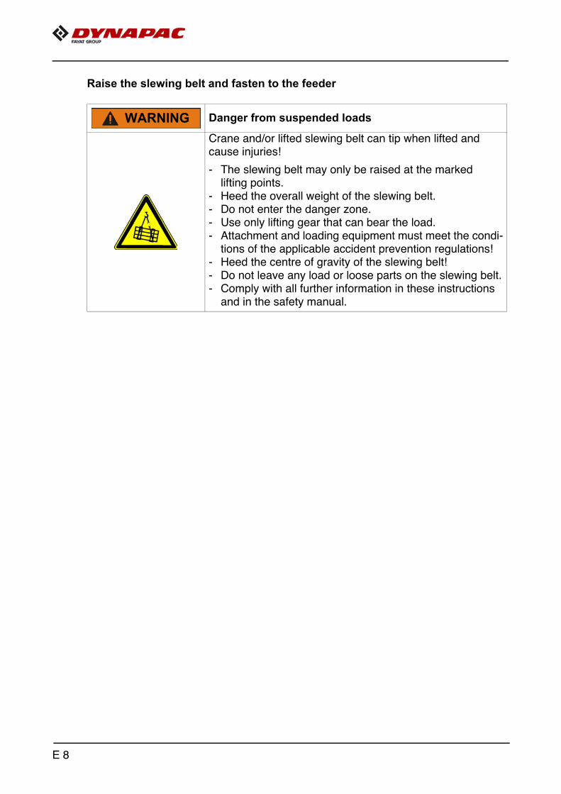
Raise the slewing belt and fasten to the feeder
Danger from suspended loads
Crane and/or lifted slewing belt can tip when lifted and cause injuries!
- The slewing belt may only be raised at the marked lifting points.
- Heed the overall weight of the slewing belt.- Do not enter the danger zone.- Use only lifting gear that can bear the load.- Attachment and loading equipment must meet the condi-
tions of the applicable accident prevention regulations!- Heed the centre of gravity of the slewing belt!- Do not leave any load or loose parts on the slewing belt.- Comply with all further information in these instructions
and in the safety manual.
WARNING
E 8

- Raise slewing belt.
- Guide the raised slewing belt slowly and on the correct height setting up to the frame of the feeder.
- Insert the collar (8) in the opening (8a) on both sides and lower the slewing belt slowly until the drilled hole (9) is in line with the bearing (9a).
- Insert the bolts (7) on both sides and secure with the screw (10).
- Lower the lifting gear and take the crane hook out of the lifting eyes.
8
8a
9a
9
7
10
E 9

- Connect the hydraulic hoses (11) and the supply line of the spraying system (12) and chain lubrication system (13) of the slewing belt with the corre-sponding quick-release couplings of the feeder.
- Remove the dummy connector (14) and insert the slewing belt connector; secure it with the corresponding shackles.
11
14
1213
E 10

Connect the hydraulic compact coupling:
- Move the locking clamp (16) on the compact coupling (15) and remove the plate (17).
- Pull the knob (19) on the parking cou-pling (18), remove the hose package (20) and insert in the compact cou-pling (15).
- Move the locking clamp (16) into lock-ing position.
- Insert the plate (17) in the parking cou-pling (18).
- Open the valve (21) (swivel the handle upwards).
f If the swivel conveyor belt is not mount-ed to the machine, the hose package (20) must always be fastened to the parking coupling (18)!
16
17
1918
20
21
17
15
E 11

- Remove the retaining pin (6) from the swivel arm.
- Secure the standing legs (22) in the top position with the bolt (23).
- Mount the ultrasonic sensor and holder (1) to the slewing belt.
- Check the tension of the conveyor belt, proceed with maintenance if necessary.
- Trial operation:
- Proceed with trial operation of the slewing belt, test slewing and height adjustment.
- Check functions of the chain lubrication system and spraying system.
6 22
226
23
1
1
E 12

4 Material chute (o)
1
2
E 13

Mount the material chute
A To warrant smooth transfer of material to the slewing conveyor belt, the material chute (1) must be fitted to the main conveyor belt:
- Mount the holders (2) of the premounted material chute (1) to the housing of the conveyor belt drive on both sides of the vehicle.
Caution! Disrupted material flow possible!
Use of the material chute depends on the specific application:
- For applications with slewing conveyor belt, the material chute must be fitted to the main conveyor belt.
- For standard applications without slewing conveyor belt, the material chute may not be fitted to the main conveyor belt.
NOTE
E 14

F 11 Maintenance1 Maintenance safety instructions
Danger due to incorrect vehicle maintenance
Incorrectly performed maintenance and repair work can cause severe or fatal injuries!
- Ensure that maintenance and repair work is always only carried out by trained, specialist staff.
- All maintenance, repair and cleaning work should only be carried out with the engine turned off. Remove igni-tion key and main switch.
- Affix a sign "Do not start" to the vehicle.- Perform a visual inspection and check all functions
every day.- Proceed with all maintenance tasks according to the
maintenance schedule.- Proceed with expert inspection every twelve months.- Eliminate all ascertained faults straight away.- Do not restart the vehicle until all ascertained faults have
been eliminated.- Failure to comply with the prescribed inspection and
maintenance work renders the operating licence null and void!
- Comply with all further information in these instructions and in the safety manual.
Danger due to changes at the vehicle
Structural chances to the vehicle make the operating licence null and void and can cause severe to fatal injuries!
- Only use original spare parts and approved accessories.- After maintenance and repair work, ensure that any dis-
mantled protective and safety devices are all completely fitted again.
- Comply with all further information in these instructions and in the safety manual.
DANGER
DANGER
F 11 1

Hot surfaces!
Surfaces including those behind covering parts, together with engine combustion gases can be very hot and cause injuries!
- Wear your personal safety gear.- Do not touch hot parts of the vehicle.- Only perform maintenance and repair work after the
vehicle has cooled down.- Comply with all further information in these instructions
and in the safety manual.
Danger due to electric shock
Injuries can be caused by touching live parts directly or indirectly!
- Do not remove any protective safeguards.- Never spray water on electric or electronic components.- Maintenance work to the electric system should only be
carried out by trained specialist staff.- Comply with all further information in these instructions
and in the safety manual.
Danger from heavy loads
Lowering vehicle parts may cause injuries!
- When the vehicle is parked and during maintenance and transport, close both hopper lids and fit the correspond-ing hopper transport safeguards.
- When the vehicle is parked and during maintenance and transport, secure the conveyor belt mechanically to pre-vent lowering.
- Ensure that opened hoods and covering parts are locked properly.
- Comply with all further information in these instructions and in the safety manual.
CAUTION
CAUTION
CAUTION
F 11 2

f Cleaning: Do not use any inflammable substances (such as petrol). Avoid directly cleaning electrical parts and insulation material with a steam jet; cover them up beforehand.
f Working in enclosed environments: Exhaust fumes must be conducted into the open air. Propane gas bottles must not be stored in closed rooms.
m As well as this maintenance manual, always also pay close attention to the mainte-nance manual provided by the engine manufacturer. All maintenance work and serv-ice intervals itemised here are binding in nature.
A Information on how to maintain the optional equipment can be found in the individual sub-sections of this chapter!
F 11 3

2 Maintenance and repair work with height-adjustable control platform (o)
Danger from lowering control platform
Severe to fatal injuries can be incurred when working below the raised control platform if this has not been locked!
- Raise the control platform completely and insert the cor-responding locking mechanisms correctly according to the instructions.
- After maintenance and repair work, keep the locking mechanisms in the holder provided.
- Comply with all further information in these instructions and in the safety manual.
DANGER
F 11 4

2.1 Insert the platform locking mechanisms
- Raise the control platform completely.
- Remove locking mechanisms (A) from the holder.
- Insert locking mechanisms (A) in the corresponding recesses (B) on the vehicle frame.
f Always wear a safety helmet when working beneath the control platform!
- After completing the work, remove the two locking mechanisms and keep them in the holder provided. If necessary, the platform may have to be raised again to re-move the locking mechanisms.
A
B
B
F 11 5

F 11 6

F 25 Maintenance overview1 Maintenance overview
F70
F81 F90 F100
F60
F30
F51F50
Tier 3
/ Sta
ge II
Ia
Tier 4
i / S
tage
IIIb
F32
F52
Tier 4
F / Sta
ge IV
F 25 1

A In this overview, you will find the maintenance intervals for optional machine equip-ment!
Assembly Chapter
Maintenance necessary after oper-ating hours
10 50 100
250
500
1000
/ an
nual
ly20
00 /
ever
y 2
year
s40
0050
0020
000
If ne
cess
ary
Conveyor belt F30 q q q q q qConveyor belt F32 q q q q q qDrive engine - Tier 3 / Stage IIIa
F50 q q q q q q
Drive engine - Tier 4i / Stage IIIb
F51 q q q q q q q
Drive engine - Tier4F / Stage IV
F52 q q q q q q q
Hydraulic system F60 q q q q q qDrive units F70 q q q q q q qElectrical system F81 q q q q qLubrication points F90 q q q qChecking/shutdown F100 q q q
Maintenance required q
F 25 2

F 30 Maintenance - conveyor belt1 Maintenance - conveyor belt
F 30 1

Danger of being pulled in by rotating or conveying vehicle partsRotating or conveying vehicle parts can cause severe or fatal injuries!
- Do not enter the danger zone.- Do not reach into rotating or conveying parts.- Only wear close-fitting clothing.- Comply with the warning and information signs on
the vehicle.- Stop the engine and remove the ignition key before any
maintenance work.- Comply with all further information in these instructions
and in the safety manual.
Danger from heavy loads
The raised machine can slide away and cause severe to fatal injuries!
- The vehicle may only be raised at the marked lifting points.
- Heed the operating weight of the vehicle.- Do not enter the danger zone.- Only use approved ramps and adequately dimensioned
ramps or pits.- Use only lifting gear that can bear the load.- Do not leave any load or loose parts on the vehicle.- Comply with all further information in these instructions
and in the safety manual.
Hot surfaces!
Surfaces including those behind covering parts, together with engine combustion gases can be very hot and cause injuries!
- Wear your personal safety gear.- Do not touch hot parts of the vehicle.- Only perform maintenance and repair work after the
vehicle has cooled down.- Comply with all further information in these instructions
and in the safety manual.
WARNING
WARNING
CAUTION
F 30 2

1.1 Maintenance intervalsPo
s.Interval
Points of maintenance Note
10 50 100
250
500
1000
/ an
nual
ly20
00 /
ever
y 2
year
sIf
nece
ssar
y
1
1 - Conveyor belt - Check tension
q - Conveyor belt - Adjust tension
q - Conveyor belt - Replace chain
q - Conveyor belt - Check for damage
q - Conveyor belt - Check screw connections
q - Conveyor belt - Repair / exchange conveyor belt
2
q - Emulsion spraying system - Check filling level
q - Emulsion spraying system - Top up tank
Maintenance qMaintenance during the running-in period g
F 30 3

Item
Interval
Points of maintenance Note
10 50 100
250
500
1000
/ an
nual
ly20
00 /
ever
y 2
year
sIf
nece
ssar
y
3
q - Central lubrication system - Check filling level
q - Central lubrication system - Top up oil
q- Central lubrication system -
Function check / check oil brush
q - Central lubrication system - Exchange oil brush
4
q q - Scraper - Check tightness
Variant 1
q - Scraper - Adjust tension
Variant 1
q - Scraper - Check scraper blade wear
Variant 1
q - Scraper - Exchange scraper blades
Variant 1
Maintenance qMaintenance during the running-in period g
F 30 4

Item
Interval
Points of maintenance Note
10 50 100
250
500
1000
/ an
nual
ly20
00 /
ever
y 2
year
sif
nece
ssar
y
4
q - Relieve scraper Variant 2
q q - Scraper - Check function
Variant 2
q - Scraper - Adjust distance
Variant 2
q q - Scraper - Cleaning / routine check
Variant 2
q - Scraper - Wear check for blades
Variant 2
q - Scraper - Replace blades
Variant 2
q - Scraper - Carry out basic setting
Variant 2
Maintenance qMaintenance during the running-in period g
F 30 5

Item
Interval
Points of maintenance Note
10 50 100
250
500
1000
/ an
nual
ly20
00 /
ever
y 2
year
sif
nece
ssar
y
5
q - Screw connections - Check screw connections
q - Screw connections - Tighten screw connections
6
q - Lubrication points - Grease belt drive guide
q - Lubrication points - Lubricate bearing points
7
q q - Guide rails - Check wear
q - Guide rails - Replacing the guide rails
Maintenance qMaintenance during the running-in period g
F 30 6

1.2 Points of maintenance
Conveyor belt tension (1)
Check tension:
m When the conveyor belt end piece is in the horizontal position, conveyor belt sag (A) must be correctly at the marked position to the lower edge of the chain must be 0 mm +/- 5 mm!
A
F 30 7

Adjust belt tension:
To adjust the tension, key switch (A) of the lateral control unit must first be switched to position I.
- To increase the tension, press switch (B) until the desired tension is achieved.
- To reduce the tension, press switch (C) until the desired tension is achieved.
- After adjusting the tension, allow the conveyor belt to run briefly again and check its sag again; readjust if necessary.
A If the conveyor belt has been slackened e.g. for cleaning purposes, it can be driven slackened condition by pressing switches (D) and (E).
m Risk of damage to equipment! Only allow the conveyor belt to run in reversing mode if the conveyor belt scraper has been disengaged!
f Ensure that nobody is located in the danger area when working on the conveyor belt! Danger of crushing
A At the latest, the drive chains and conveyor belt must be exchanged when their elon-gation has progressed so far that they can no longer be re-tensioned.
m Chain links must not be removed to shorten the chain! Incorrectly dividing the chains would lead to destruction of the drive wheels!
EBCA D
F 30 8

Conveyor belt - Replace chain
Caution! Heed wear limits!
The chain must be replaced if the conveyor belt chain has lengthened to such an extent that it is no longer possible to adjust the prescribed conveyor belt sag.
NOTE
F 30 9

Check conveyor belt for damage and soiling
f Perform inspection, cleaning and repairs whilst the drive motor is stationary!
A If discovered early on, conveyor belt damage can be repaired permanently!
A The conveyor belt can be accessed through the open maintenance flap (A) for maintenance work.
f Keep the maintenance flap closed dur-ing operation; never open whilst the con-veyor belt is running!
- To inspect it, lower the conveyor belt and secure the conveyor belt drive to prevent reactivation.
- Gradually move and check the convey-or belt using the lateral operating unit.
A Check the entire conveyor belt (B) for the following defects:
- Cracks, breakage and wear on the surface and at the sides.
- Missing or loose assembly parts.
- Wear, damage and soiling on the drive chains and chain sprockets.
A If necessary, remove covers (C) to check the conveyor belt.
- Remove encrusted material from the sealing plates (D).
A Your Dynapac customer service will be happy to provide support during maintenance, repair and the replacement of wearing parts!
2
AB
CD
F 30 10

Conveyor belt - screw connections
m Incorrectly installed conveyor belt bolts can lead to severe damage to the entire conveyor belt.
m Visually and mechanically check that the screw connections are fastened correctly.
- Conveyor belt - conveyor belt web (D) (flat-headed bolts):
- The bolt head must be positioned plane with the rubber surface and may be recessed by max. 1 mm.
- Drive chain - conveyor belt (E) (hexagonal bolts):
- The bolts must not be tightened too tightly.
m Self-locking nuts must be replaced and must not be retightened!
D
E
DE
F 30 11

Emulsion spraying system (2)
A The spraying bar (A) installed above the conveyor belt is engaged on activation of the conveying function.
- Check the filling level using the dis-play on the operating panel.
A Increased emulsion consumption due to use of the manual spray.
To top up the tank:
- Remove cap (B).
- Fill in emulsion through the filler open-ing until the required filling level is achieved.
- Screw cap (B) on again.
f Refill the tank only whilst the vehicle is stationary!
m Only operate the spraying system with approved emulsion!
B
A
F 30 12

Central lubrication system (3)
Danger of injuries!
f Do not reach into the tank when the pump is running!
f The central lubrication system must only be operated with the safety valve installed!
f Do not undertake any work on parts of the system during operation!
f Ensure that the diesel engine cannot be started when working on the system!
f Observe safety regulations for handling hydraulic systems!
m Ensure maximum cleanliness when working on the central lubrication system!
Central lubrication system Check filling level
m The lubricant tank should always be filled sufficiently to ensure that the sys-tem cannot "run dry" and that sufficient drive chain lubrication is ensured.
To top up with lubricant:
- Top up the tank to the "MAX" mark be-fore starting work or on receipt of an electronic empty message.
- Release and pull off connector (A).
- Unscrew tank cap (B).
- Top the tank up to the "MAX" mark with the specified oil.
- Screw on the tank cap (B) again and position the connector properly.
O
A
B
F 30 13

Function check / check oil brush
f Perform inspection, cleaning and repairs whilst the drive motor is stationary!
A A pair of oil brushes, which apply the lu-bricant onto the drive chain, is located on both sides of the conveyor belt.
- After trial operation, check whether an oil film was applied onto the chain when the central lubricating system was running.
- In the event of malfunctions, determine and immediately rectify the cause.
- If the brushes are worn on visual in-spection, they must be exchanged im-mediately.
m A disturbed lubricant flow leads to increased wear!
F 30 14

Spring arm scraper (4)
A A scraper is available to minimise dirt and wear on the conveyor belt.
Scraper - Variant1
A The scraper is equipped with several scraper plates which scrape off bonded material residues during conveyor belt operation.
Check tension:
m The tension must be readjusted as soon as the scraper no longer operates cor-rectly and material residues stick to the conveyor belt.
Adjust tension:
- Remove tensioning fixture bolts (A) on both sides of the vehicle.
- Place an appropriate wrench on the hexagon head (B) and tension scraper.
- After scraper blade contact with the belt, continue turning one hole division.
- Insert and secure bolt (A).
- Insert and secure bolt (A) in the identi-cal hole on the other side.
- Observe scraping effect, ret-ension if necessary.
F0152_A1.TIF
A
B
F 30 15

Check scraper blade wear:
m The scraper blades must be exchanged as soon as the scraper can no longer be re-tensioned correctly, final wear is an-ticipated soon or the scraper blades are damaged.
Replace scraper blades:
- Relieve the scraper.
- Remove the hexagon nut (C), remove worn scraper blade.
- Position new scraper blade (D) and tighten hexagon nut (C) properly again.
- Adjust scraper tension.
A Always replace scraper blades in sets!
C
D
F 30 16

Main scraper - Variant 2
A A scraper (A) is available to protect the conveyor belt against asphalt residues during and after work. The scraper is equipped with several scraper blades that scrape off material residues during operation. The scraper can be disengaged for cleaning and maintenance.
A
F 30 17

Relieve scraper
- Remove spring cotter pin (B).
- Push mounting lever (C) into recess (D) and slightly raise scraper.
- Fold away adjusting screw (E) to side.
- Carefully set down scraper in chain (F).
- Repeat process on other side.
B C
D
E
F
G
F 30 18

Move scraper into working position before starting work, carry out function test/adjust distance
- Move scraper into working position:
- Raise scraper with mounting lever (C).
- Swivel adjusting screw (E) into related groove of scraper tube.
- Relieve mounting lever and remove.
- Insert spring cotter pin (B) properly.
- Repeat process on other side.
- Exit danger area and carry out test run: Visually check whether all scraper blades are in permanent contact with belt while conveyor belt is running. Carry out a complete belt circulation when doing so.
- If necessary, switch off conveyor belt and retension adjusting screws (D) on both sides in steps of 0.5 rotations.
A Locking pin (G) must be raised for adjustment.
- Repeat process until correct setting is achieved.
- Spray scraper with separator fluid again if necessary.
F 30 19

Clean scraper/routine check
m Clean the scraper after each working day.
m Danger of subsequent damage! Never clean the scraper in the working position!
Sharp-edged components!
Surfaces subject to wear can be very sharp-edged and can cause injuries!
- Wear your personal safety gear.- Comply with all further information in these instructions
and in the safety manual.
Hot surfaces!
Surfaces including those behind covering parts, together with engine combustion gases, can be very hot and cause injuries!
- Wear your personal safety gear.- Do not touch hot parts of the vehicle.- Only perform maintenance and repair work after the ve-
hicle has cooled down.- Comply with all further information in these instructions
and in the safety manual.
Danger from burner
Incorrectly performed work on burners can cause severe or fatal injuries!
- Wear your personal safety gear.- See the burner operating instructions and familiarise
yourself with all notes contained in them.
CAUTION
CAUTION
WARNING
F 30 20

- Relieve scraper (see "Relieve scraper" section)
- Clean scraper completely under the influence of flames.
m Protect the conveyor belt from excessing heating.
- Heat the back for this purpose. This results in asphalt residues falling down at the front.
- Rework with a spatula if necessary.
f Allow scraper to cool down.
- Move scraper into working position (see section entitled "Move scraper into working position")
- Spray scraper with separator fluid.
Routine check following cleaning:
m Check that all fastening parts have been tightened correctly. Tighten any loose connections properly.
F 30 21

Wear check, readjust/replace scraper blades
If the scraper blade (H) is less than 2mm above the blade holder (I), the wear limit has been reached.
- If the second blade wear level is still available:
- Loosen assembly parts (J) of scrap-er blade
- Install scraper blades properly at in-stallation position II (K).
A All scraper tripper blades must always be installed at the same position.
A If the scraper blades are worn at the up-per position, they must be replaced as a set for the entire scraper.
m Following adjustment or reinstallation of the scraper blades, a basic setting must be carried out (see section entitled "Scraper basic setting")
Sharp-edged components!
Surfaces subject to wear can be very sharp-edged and can cause injuries!
- Wear your personal safety gear.- Comply with all further information in these instructions
and in the safety manual.
CAUTION
I
H
KY
F 30 22

Scraper basic setting
A basic setting must be carried out after changing or adjusting the blades.
- Screw the adjusting screws (E) on both sides of the scraper into the pins (L) until the thread ends flush with the surface of the pin.
A Locking pin (G) must be raised for ad-justment.
- Evenly tighten the adjusting screws (E) in steps on both sides of the scrap-er until all scraper blades have perma-nent contact with the conveyor belt.
- Exit danger area and carry out test run: Visually check whether all scraper blades are in permanent contact with belt while conveyor belt is running. Carry out a complete belt circulation when doing so.
- If necessary, switch off conveyor belt and retension adjusting screws (E) on both sides in steps of 0.5 rotations.
- Repeat process until correct setting is achieved.
m Should the conveyor belt chain tension be changed, then the adjustment of the scrap-er must also be checked and, if necessary, adjusted.
A
Caution! Possible collision of parts
The following adjustment must be made before starting up the slewing belt:
- Move the scraper of the main conveyor belt located over the slewing belt into the working position.
- Carry out a collision check by slowly slewing the slewing belt.
- If necessary, adjust the height adjustment of the main belt to prevent a collision.
L
G
E
E
NOTE
F 30 23

Screw connections (5)
m After approx. 250 hours of operation at full load, check that all mounting and connecting screws are firmly seated.
m Improperly tightened screws may lead to increased wear and to the destruction of components!
- Tighten loose or loosened screw con-nections properly.
A
F 30 24

Lubrication points (6)
Belt drive guide
A Grease the belt drive guide surfaces (A) on both sides of the conveyor belt.
Bearing points
A One lubricating nipple (B) is located at each hydraulic cylinder bearing point.
A
2x
B
F 30 25

Guide rails (7)
A There are 4 wear rails (A) at the hopper and 3 wear rails (B) at the conveyor belt end piece.
A Check wear at the prescribed intervals and every time that the belt is changed.
A The guide rails (A) / (B) must be re-placed at the latest when the wear limit of 7 mm is no longer achieved in the marked areas (C).
m If the guide rails have to be replaced, this always has to happen in complete sets.
A Your Dynapac customer service will be happy to provide support during mainte-nance, repair and the replacement of wearing parts!
B
A
C
F 30 26

F 32 Maintenance - slewing belt1 Maintenance - conveyor belt
F 32 1

Danger of being pulled in by rotating or conveying vehicle partsRotating or conveying vehicle parts can cause severe or fatal injuries!
- Do not enter the danger zone.- Do not reach into rotating or conveying parts.- Only wear close-fitting clothing.- Comply with the warning and information signs on
the vehicle.- Stop the engine and remove the ignition key before any
maintenance work.- Comply with all further information in these instructions
and in the safety manual.
Danger from heavy loads
The raised machine can slide away and cause severe to fatal injuries!
- The vehicle may only be raised at the marked lifting points.
- Heed the operating weight of the vehicle.- Do not enter the danger zone.- Only use approved ramps and adequately dimensioned
ramps or pits.- Use only lifting gear that can bear the load.- Do not leave any load or loose parts on the vehicle.- Comply with all further information in these instructions
and in the safety manual.
Hot surfaces!
Surfaces including those behind covering parts, together with engine combustion gases can be very hot and cause injuries!- Wear your personal safety gear.- Do not touch hot parts of the vehicle.- Only perform maintenance and repair work after the
vehicle has cooled down.- Comply with all further information in these instructions
and in the safety manual.
WARNING
WARNING
CAUTION
F 32 2

1.1 Maintenance intervalsIte
mInterval
Points of maintenance Note
10 50 100
250
500
1000
/ an
nual
ly20
00 /
ever
y 2
year
sIf
nece
ssar
y
1
q - Conveyor belt - Check tension
q - Conveyor belt - Adjust tension
q - Conveyor belt - Replace chain
q - Conveyor belt - Check for damage
q - Conveyor belt - Check screw connections
q - Conveyor belt - Repair / exchange conveyor belt
2
q - Conveyor belt frame- Check for deposits
q - Conveyor belt frame- Clean
3
q- Central lubrication system -
Function check / check oil brush
q - Central lubrication system - Exchange oil brush
Maintenance qMaintenance during the running-in period g
F 32 3

Item
Interval
Points of maintenance Note
10 50 100
250
500
1000
/ an
nual
ly20
00 /
ever
y 2
year
sIf
nece
ssar
y
4
q q - Scraper - Check tightness
Variant 1
q - Scraper - Adjust tension
Variant 1
q- Scraper -
Check scraper blade wear
Variant 1
q - Scraper - Exchange scraper blades
Variant 1
4
q - Relieve scraper Variant 2
q q - Scraper - Check function
Variant 2
q - Scraper - Adjust distance
Variant 2
q q - Scraper - Cleaning / routine check
Variant 2
q - Scraper - Wear check for blades
Variant 2
q - Scraper - Replace blades
Variant 2
q - Scraper - Carry out basic setting
Variant 2
Maintenance qMaintenance during the running-in period g
F 32 4

Item
Interval
Points of maintenance Note
10 50 100
250
500
1000
/ an
nual
ly20
00 /
ever
y 2
year
sif
nece
ssar
y
5
q - Screw connections - Check screw connections
q - Screw connections - Tighten screw connections
6
q - Lubrication points - Swivel joint - lubricate bearing
q - Lubrication points - Grease belt drive guide
q - Lubrication points - Lubricate bearing points
7
q q - Guide rails - Check wear
q - Guide rails - Replacing the guide rails
Maintenance qMaintenance during the running-in period g
F 32 5

1.2 Points of maintenance
Conveyor belt tension (1)
Check tension:
m When the conveyor belt end piece is in the horizontal position, conveyor belt sag (A) must be correctly at the marked position to the lower edge of the chain must be 0 mm +/- 5 mm!
m After completing the adjustments, check whether the belt tension has been restored evenly on both sides. The length of the spindle (B) must be identical on both sides!
A
B
F 32 6

Belt tension
m Check belt tension on a daily basis. If there is too much slack in the belt, ad-just the tension.
Increasing the tension:
- Unfasten lock nuts (A) on both sides of the tensioning fixtures.
- Use an open-end wrench to adjust tension on both sides evenly on the adjusting nuts (B).
- Tighten lock nuts (A) back down after the adjustment procedure.
A If the belt on the reversing drum is run-ning to one side, tighten the right-hand spindle or loosen the left-hand spindle if the drum is rotating clockwise, or vice versa for anti-clockwise rotation.
m Avoid an inclined position of the reversing drum because this can cause damage to the conveyor belt.
m After completing the adjustments, check whether the belt tension has been restored evenly on both sides. The length of the spindle (C) must be identical on both sides!
A At the latest, the drive chains and conveyor belt must be exchanged when their elon-gation has progressed so far that they can no longer be re-tensioned.
m Chain links must not be removed to shorten the chain! Incorrectly dividing the chains would lead to destruction of the drive wheels!
B A
C
F 32 7

Conveyor belt - Replace chain
Caution! Heed wear limits!
The chain must be replaced if the conveyor belt chain has lengthened to such an extent that it is no longer possible to adjust the prescribed conveyor belt sag.
NOTE
F 32 8

Check conveyor belt for damage and soiling
f Perform inspection, cleaning and repairs whilst the drive motor is stationary!
A If discovered early on, conveyor belt damage can be repaired permanently!
- To inspect it, lower the conveyor belt and secure the conveyor belt drive to prevent reactivation.
A Check the entire conveyor belt (A) for the following defects:
- Cracks, breakage and wear on the surface and at the sides.
- Missing or loose assembly parts.
- Wear, damage and soiling on the drive chains and chain sprockets.
- Remove encrusted material from the sealing plates (B).
A Your Dynapac customer service will be happy to provide support during maintenance, repair and the replacement of wearing parts!
A
B
F 32 9

Conveyor belt - screw connections
m Incorrectly installed conveyor belt bolts can lead to severe damage to the entire conveyor belt.
m Visually and mechanically check that the screw connections are fastened correctly.
- Conveyor belt - conveyor belt web (D) (flat-headed bolts):
- The bolt head must be positioned plane with the rubber surface and may be recessed by max. 1 mm.
- Drive chain - conveyor belt (E) (hexagonal bolts):
- The bolts must not be tightened too tightly.
m Self-locking nuts must be replaced and must not be retightened!
D
E
DE
F 32 10

Check conveyor belt frame for depos-its, clean (2)
f Perform inspection, cleaning and repairs whilst the drive motor is stationary!
A Material deposits in the frame of the con-veyor belt can cause subsequent damage!
A There are maintenance flaps under-neath the frame and at the rear reversal.
- Loosen wind bolts (A) and open all flaps (B).
- Remove material deposits, possibly spray the surfaces with separator fluid.
- Close all maintenance flaps again correctly.
f All maintenance flaps must be closed during operation!
A
B
A B
F 32 11

Function check / Check oil brush (3)
f Perform inspection, cleaning and repairs whilst the drive motor is stationary!
A A pair of oil brushes, which apply the lu-bricant onto the drive chain, is located on both sides of the conveyor belt.
- After trial operation, check whether an oil film was applied onto the chain when the central lubricating system was running.
- In the event of malfunctions, determine and immediately rectify the cause.
- If the brushes are worn on visual in-spection, they must be exchanged im-mediately.
m A disturbed lubricant flow leads to increased wear!
F 32 12

Spring arm scraper (4)
A A scraper is available to minimise dirt and wear on the conveyor belt.
Scraper - Variant1
A The scraper is equipped with several scraper plates which scrape off bonded material residues during conveyor belt operation.
Check tension:
m The tension must be readjusted as soon as the scraper no longer operates cor-rectly and material residues stick to the conveyor belt.
Adjust tension:
- Remove tensioning fixture bolts (A) on both sides of the vehicle.
- Place an appropriate wrench on the hexagon head (B) and tension scraper.
- After scraper blade contact with the belt, continue turning one hole division.
- Insert and secure bolt (A).
- Insert and secure bolt (A) in the identi-cal hole on the other side.
- Observe scraping effect, re-tension if necessary.
F0152_A1.TIF
A
B
F 32 13

Check scraper blade wear:
m The scraper blades must be exchanged as soon as the scraper can no longer be re-tensioned correctly, final wear is an-ticipated soon or the scraper blades are damaged.
Exchange scraper blades:
- Relieve the scraper.
- Remove the hexagon nut (C), remove worn scraper blade.
- Position new scraper blade (D) and tighten hexagon nut (C) properly again.
- Adjust scraper tension.
A Always replace scraper blades in sets!
C
D
F 32 14

Main scraper - Variant 2
A A scraper (A) is available to protect the conveyor belt against asphalt residues during and after work. The scraper is equipped with several scraper blades that scrape off material residues during operation. The scraper can be disengaged for cleaning and maintenance.
A
F 32 15

Relieve scraper
- Remove spring cotter pin (B).
- Push mounting lever (C) into recess (D) and slightly raise scraper.
- Fold away adjusting screw (E) to side.
- Carefully set down scraper in chain (F).
- Repeat process on other side.
B C
D
E
F
G
F 32 16

Move scraper into working position before starting work, carry out function test/adjust distance
- Move scraper into working position:
- Raise scraper with mounting lever (C).
- Swivel adjusting screw (E) into related groove of scraper tube.
- Relieve mounting lever and remove.
- Insert spring cotter pin (B) properly.
- Repeat process on other side.
- Exit danger area and carry out test run: Visually check whether all scraper blades are in permanent contact with belt while conveyor belt is running. Carry out a complete belt circulation when doing so.
- If necessary, switch off conveyor belt and retension adjusting screws (D) on both sides in steps of 0.5 rotations.
A Locking pin (G) must be raised for adjustment.
- Repeat process until correct setting is achieved.
- Spray scraper with separator fluid again if necessary.
F 32 17

Clean scraper/routine check
m Clean the scraper after each working day.
m Danger of subsequent damage! Never clean the scraper in the working position!
Sharp-edged components!
Surfaces subject to wear can be very sharp-edged and can cause injuries!
- Wear your personal safety gear.- Comply with all further information in these instructions
and in the safety manual.
Hot surfaces!
Surfaces including those behind covering parts, together with engine combustion gases, can be very hot and cause injuries!
- Wear your personal safety gear.- Do not touch hot parts of the vehicle.- Only perform maintenance and repair work after the ve-
hicle has cooled down.- Comply with all further information in these instructions
and in the safety manual.
Danger from burner
Incorrectly performed work on burners can cause severe or fatal injuries!
- Wear your personal safety gear.- See the burner operating instructions and familiarise
yourself with all notes contained in them.
CAUTION
CAUTION
WARNING
F 32 18

- Relieve scraper (see "Relieve scraper" section)
- Clean scraper completely under the influence of flames.
m Protect the conveyor belt from excessing heating.
- Heat the back for this purpose. This results in asphalt residues falling down at the front.
- Rework with a spatula if necessary.
f Allow scraper to cool down.
- Move scraper into working position (see section entitled "Move scraper into working position")
- Spray scraper with separator fluid.
Routine check following cleaning:
m Check that all fastening parts have been tightened correctly. Tighten any loose connections properly.
F 32 19

Wear check, readjust/replace scraper blades
If the scraper blade (H) is less than 2mm above the blade holder (I), the wear limit has been reached.
- If the second blade wear level is still available:
- Loosen assembly parts (J) of scrap-er blade
- Install scraper blades properly at in-stallation position II (K).
A All scraper tripper blades must always be installed at the same position.
A If the scraper blades are worn at the up-per position, they must be replaced as a set for the entire scraper.
m Following adjustment or reinstallation of the scraper blades, a basic setting must be carried out (see section entitled "Scraper basic setting")
Sharp-edged components!
Surfaces subject to wear can be very sharp-edged and can cause injuries!
- Wear your personal safety gear.- Comply with all further information in these instructions
and in the safety manual.
CAUTION
I
H
KY
F 32 20

Scraper basic setting
A basic setting must be carried out after changing or adjusting the blades.
- Screw the adjusting screws (E) on both sides of the scraper into the pins (L) until the thread ends flush with the surface of the pin.
A Locking pin (G) must be raised for ad-justment.
- Evenly tighten the adjusting screws (E) in steps on both sides of the scrap-er until all scraper blades have perma-nent contact with the conveyor belt.
- Exit danger area and carry out test run: Visually check whether all scraper blades are in permanent contact with belt while conveyor belt is running. Carry out a complete belt circulation when doing so.
- If necessary, switch off conveyor belt and retension adjusting screws (E) on both sides in steps of 0.5 rotations.
- Repeat process until correct setting is achieved.
m Should the conveyor belt chain tension be changed, then the adjustment of the scrap-er must also be checked and, if necessary, adjusted.
A
Caution! Possible collision of parts
The following adjustment must be made before starting up the slewing belt:
- Move the scraper of the main conveyor belt located over the slewing belt into the working position.
- Carry out a collision check by slowly slewing the slewing belt.
- If necessary, adjust the height adjustment of the main belt to prevent a collision.
L
G
E
E
NOTE
F 32 21

Screw connections (5)
m After approx. 250 hours of operation at full load, check that all mounting and connecting screws are firmly seated.
m Improperly tightened screws may lead to increased wear and to the destruction of components!
- Tighten loose or loosened screw con-nections properly.
F 32 22

Lubrication points (6)
Swivel joint - bearing
A One lubricating nipple (A) is located at each bearing point.
Belt drive guide
A Grease the belt drive guide surfaces (B) on both sides of the conveyor belt.
3x
A
B
F 32 23

Bearing points
A One lubricating nipple (C) is located at each hydraulic cylinder bearing point.
2x
C
F 32 24

Guide rails (7)
A There are 3 wear rails (A) at the convey-or belt end piece.
A Check wear at the prescribed intervals and every time that the belt is changed.
A The guide rails (A) must be replaced at the latest when the wear limit of 7 mm is no longer achieved in the marked areas (B).
m If the guide rails have to be replaced, this always has to happen in complete sets.
A Your Dynapac customer service will be happy to provide support during mainte-nance, repair and the replacement of wearing parts!
A
B
F 32 25

F 32 26

F 50 Maintenance - engine assembly Tier 3 (o)
1 Maintenance - engine assembly
m As well as this maintenance manual, always also pay close attention to the mainte-nance manual provided by the engine manufacturer. All maintenance work and serv-ice intervals itemised here are binding in nature.
F 50 1

Danger of being pulled in by rotating or conveying vehicle partsRotating or conveying vehicle parts can cause severe or fatal injuries!
- Do not enter the danger zone.- Do not reach into rotating or conveying parts.- Only wear close-fitting clothing.- Comply with the warning and information signs on
the vehicle.- Stop the engine and remove the ignition key before any
maintenance work.- Comply with all further information in these instructions
and in the safety manual.
Hot surfaces!
Surfaces including those behind covering parts, together with engine combustion gases can be very hot and cause injuries!- Wear your personal safety gear.- Do not touch hot parts of the vehicle.- Only perform maintenance and repair work after the
vehicle has cooled down.- Comply with all further information in these instructions
and in the safety manual.
WARNING
CAUTION
F 50 2

1.1 Maintenance intervalsPo
s.Interval
Maintenance point Note
10 50 100
250
500
/ ann
ually
1000
/ an
nual
ly20
00 /
ever
y 2
year
sIf
nece
ssar
y
1
q - Fuel tank Check filling level
q - Fuel tank Refill with fuel
q - Fuel tank Clean the tank and system
2
q - Engine lube oil system Check oil level
q - Engine lube oil system Top up oil
q - Engine lube oil system Change oil
q - Engine lube oil system Change oil filter
3
q- Engine fuel system
Fuel filter (drain the water separator)
q - Engine fuel system Replace fuel pre-filter
q - Engine fuel system Replace fuel filter
q - Engine fuel system Bleed fuel system
Maintenance qMaintenance during the running-in period g
F 50 3

Pos.
Interval
Maintenance point Note
10 50 100
250
500
/ ann
ually
1000
/ an
nual
ly20
00 /
ever
y 2
year
sIf
nece
ssar
y
4
q - Engine air filter Check air filter
q - Engine air filter Empty dust collector
q q - Engine air filter Exchange air filter insert
5
q - Engine cooling system Check radiator fins
q q - Engine cooling system Clean radiator fins
q - Engine cooling system Check level of the coolant
q - Engine cooling system Top up coolant
q - Engine cooling system Check coolant concentration
q - Engine cooling system Adjust coolant concentration
q - Engine cooling system Change coolant
Maintenance qMaintenance during the running-in period g
F 50 4

Pos.
Interval
Maintenance point Note
10 50 100
250
500
/ ann
ually
1000
/ an
nual
ly20
00 /
ever
y 2
year
sIf
nece
ssar
y
6
q - Engine drive belt Check drive belt
q - Engine drive belt Tighten drive belt
q - Engine drive belt Replace drive belt
Maintenance qMaintenance during the running-in period g
F 50 5

1.2 Maintenance points
Engine fuel tank (1)
- Check the filling level using the dis-play on the operating panel.
A Fill the fuel tank each time before start-ing work so that the fuel system cannot "run dry" and time-consuming venting (bleeding) can therefore be avoided.
For filling in the fuel:
- Remove cap (A).
- Fill in fuel through the filling port until the required fill lever is achieved.
- Replace the cap (A).
Clean the tank and system:
- Unscrew the drain plug (B) at the bot-tom of the tank and drain into a collec-tion pan about 1 l fuel.
- When fastening the screw again after draining, make sure to use a new seal.
A
B
F 50 6

Engine lube oil system (2)
Check oil level
A In case of correct oil level, the oil is between the two notches of the sensor rod (A).
A Only check the oil level when the vehicle is in a horizontal position!
m Too much oil in engine damages gas-kets; too little oil results in overheating and engine destruction.
For filling in the oil:
- Remove cap (B).
- Fill up oil to correct level.
- Return cap (B).
- Use sensor rod to check level again.
B
A
F 50 7

Oil change:
A Change the oil when the engine is at operating temperature.
A Oil change < / = s/n XXXX
- Place the end of the oil drain port hose (C) in the collection container.
- Remove the screw cap with a wrench and allow the oil to drain completely.
- Replace the screw cap and tighten properly.
- Fill in the specified quality of oil through the filler opening (B) on the engine until the oil level rises to the correct mark on the sensor rod (A).
A Oil change > / = s/n XXXX
- Unscrew seal cap (C).
- Screwing on the oil drainage hose (D) opens the valve to let the oil drain out.
- Place the end of the hose in the col-lecting vessel and let the oil drain com-pletely.
- Unscrew the drainage hose and return the screw cap.
C
C
D
F 50 8

Changing the oil filter:
A All filters are accessed via the service flap (F) on the vehicle's centre wall:
- Remove the screws (G) from the inner side of the frame and remove the serv-ice flap (F).
- After completing the maintenance work, reinstall the service flap (F) properly.
A The new filter is inserted during an oil change once the used oil has been drained out.
- Loosen the filter (H) with a filter wrench or filter strap and unscrew it. Clean the contact surface.
- Apply light coating of oil to the gasket on the new filter and fill filter with oil before installing it.
- Tighten filter by hand.
A After installing the oil filter, attention must be paid to the oil pressure display and good sealing during the test run. Check oil level again.
G
F
H
F 50 9

Engine fuel system (3)
A All filters are accessed via the service flap (A) on the vehicle's centre wall:
- Remove the screws (B) from the inner side of the frame and remove the serv-ice flap (A).
- After completing the maintenance work, reinstall the service flap (A) properly.
A The fuel filter system consists of two filters:
- Prefilter with water separator (C)
- Main filter (D)
Prefilter - draining of water
A Drain the collecting vessel at regular in-tervals, or in response to an error mes-sage from the engine control unit.
- Drain off separated water at the cock (E) and collect, then close the cock again.
B
A
D C
A
G
EF
F 50 10

Changing the prefilter:
- Drain off separated water at the cock (E) and collect, then close the cock again.
- Pull off the water sensor (F) connector.
- Loosen the filter cartridge (C) using a filter wrench or filter strap and unscrew.
- Clean sealing surface of filter bracket.
- Lightly oil filter cartridge seal and screw hand-tight under the bracket.
- Reconnect the water sensor (F) connector.
Bleeding the pre-filter:
- Release the manual fuel pump's (G) bayonet lock by pressing and simultaneously turning counter-clockwise.
- The pump plunger is now pressed out via the spring.
- Pump until a very high resistance is perceptible and pumping can only be carried out very slowly.
- Now continue pumping a few more times. (The return line must be filled).
- Start the engine and operate for approx. 5 minutes at idle speed or low load.
- Check the prefilter for leaks whilst doing this.
- Lock the manual fuel pump's (G) bayonet lock by pressing and simultaneously turn-ing clockwise.
Replacing the main filter:
- Loosen the filter cartridge (D) using a filter wrench or filter strap and unscrew.
- Clean sealing surface of filter bracket.
- Lightly oil filter cartridge seal and screw hand-tight under the bracket.
A After fitting the filter, ensure good sealing action during the test run.
F 50 11

Engine air filter (4)
Empty dust collector
- Empty the dust removal valve (A) on the air filter housing by compressing the discharge slot.
- Remove any baked on dust by press-ing together the upper valve section.
A Clean the dust removal valve from time to time.
A
F 50 12

Exchange air filter insert
A Maintenance of the filter becomes nec-essary if:
- Engine electronics service indicator
- Open the air filter housing (B) at the clips (C).
- Move filter element (D) to the side a lit-tle and then pull it out of the housing.
- Pull out the safety element (E) and check for damage.
A Replace the safety element (E) after the filter has been serviced 3 times, but after 2 years at the latest (never clean it!).
E
C
C
B
D
D
F 50 13

Engine cooling system (5)
Checking / topping up coolant
The cooling water level must be checked when the system is cold. Make sure that sufficient anti-freeze and anti-corrosion agent is available (-25°C).
f When hot, the system is under pressure. When opening, there is a danger of scalding!
- If necessary fill in a sufficient amount of coolant through the open port (A) of the compensating tank.
Change coolant
f When hot, the system is under pressure. When opening, there is a danger of scalding!
m Use only approved coolants!
A Observe the instructions in the chapter entitled "Operating substances"!
- Remove the drain screw (B) on the ra-diator and let the coolant drain com-pletely.
- Reinstall the drain screw (B) and tight-en properly.
- Fill in coolant through the filling open-ing (A) on the compensation tank up to approx. 7 cm (C) from the top edge of the compensation tank.
m The air is only able to escape completely from the cooling system once the engine has reached its operating temperature (at least 90°C). Check the fluid level again, top up if necessary.
A
B
C
F 50 14

Checking and cleaning the radiator fins
- If necessary, remove leaves, dust or sand from the radiator.
A Observe engine's operating instructions
Check coolant concentration
- Check the concentration using a suitable tester (hydrometer).
- Adjust the concentration if necessary.
A Observe engine's operating instructions!
F 50 15

Engine drive belt (6)
Check drive belt
- Check the drive belt for damage.
A Small transverse cracks in the belt are acceptable.
m In the event of longitudinal cracks which intersect with transverse cracks and damaged material surfaces, belt re-placement is necessary.
A Observe engine's operating instructions!
Replace drive belt
A Observe engine's operating instructions!
F 50 16

F 51 Maintenance - engine assembly Tier 4i (o)
1 Maintenance - engine assembly
m As well as this maintenance manual, always also pay close attention to the mainte-nance manual provided by the engine manufacturer. All maintenance work and serv-ice intervals itemised here are binding in nature.
F 51 1

Danger of being pulled in by rotating or conveying vehicle partsRotating or conveying vehicle parts can cause severe or fatal injuries!
- Do not enter the danger zone.- Do not reach into rotating or conveying parts.- Only wear close-fitting clothing.- Comply with the warning and information signs on
the vehicle.- Stop the engine and remove the ignition key before any
maintenance work.- Comply with all further information in these instructions
and in the safety manual.
Hot surfaces!
Surfaces including those behind covering parts, together with engine combustion gases can be very hot and cause injuries!
- Wear your personal safety gear.- Do not touch hot parts of the vehicle.- Only perform maintenance and repair work after the
vehicle has cooled down.- Comply with all further information in these instructions
and in the safety manual.
WARNING
CAUTION
F 51 2

1.1 Maintenance intervalsPo
s.Interval
Maintenance point Note
10 50 250
500
/ ann
ually
1000
/ an
nual
ly20
00 /
ever
y 2
year
s50
00If
nece
ssar
y
1
q - Fuel tank Check filling level
q - Fuel tank Refill with fuel
q - Fuel tank Clean the tank and system
2
q - Engine lube oil system Check oil level
q - Engine lube oil system Top up oil
q - Engine lube oil system Change oil
q - Engine lube oil system Change oil filter
3
q- Engine fuel system
Fuel filter (drain the water separator)
q - Engine fuel system Replace fuel pre-filter
q - Engine fuel system Replace fuel filter
q - Engine fuel system Bleed fuel system
Maintenance qMaintenance during the running-in period g
F 51 3

Pos.
Interval
Maintenance point Note
10 50 250
500
/ ann
ually
1000
/ an
nual
ly20
00 /
ever
y 2
year
s50
00If
nece
ssar
y
4
q - Engine air filter Check air filter
q - Engine air filter Empty dust collector
q q - Engine air filter Exchange air filter insert
5
q - Engine cooling system Check radiator fins
q q - Engine cooling system Clean radiator fins
q - Engine cooling system Check level of the coolant
q - Engine cooling system Top up coolant
q - Engine cooling system Check coolant concentration
q - Engine cooling system Adjust coolant concentration
q - Engine cooling system Change coolant
Maintenance qMaintenance during the running-in period g
F 51 4

Pos.
Interval
Maintenance point Note
10 50 250
500
/ ann
ually
1000
/ an
nual
ly20
00 /
ever
y 2
year
s50
00If
nece
ssar
y
6
q - Engine drive belt Check drive belt
q - Engine drive belt Tighten drive belt
q - Engine drive belt Replace drive belt
7 q - Crankshaft ventilation filter Replace filter element
8 q - Exhaust system Inspect the particulate filter
Maintenance qMaintenance during the running-in period g
F 51 5

1.2 Maintenance points
Engine fuel tank (1)
- Check the filling level using the dis-play on the operating panel.
A Fill the fuel tank each time before start-ing work so that the fuel system cannot "run dry" and time-consuming venting (bleeding) can therefore be avoided.
For filling in the fuel:
- Remove cap (A).
- Fill in fuel through the filling port until the required fill lever is achieved.
- Replace the cap (A).
Clean the tank and system:
- Unscrew the drain plug (B) at the bot-tom of the tank and drain into a collec-tion pan about 1 l fuel.
- When fastening the screw again after draining, make sure to use a new seal.
A
B
F 51 6

Engine lube oil system (2)
Check oil level
A In case of correct oil level, the oil is be-tween the two notches of the sensor rod (A).
A Only check the oil level when the vehicle is in a horizontal position!
m Too much oil in engine damages gas-kets; too little oil results in overheating and engine destruction.
For filling in the oil:
- Remove cap (B).
- Fill up oil to correct level.
- Return cap (B).
- Use sensor rod to check level again.
B
A
F 51 7

Oil change:
A Change the oil when the engine is at operating temperature
- Place the end of the oil drain port hose (C) in the collection container.
- Remove the screw cap with a wrench and allow the oil to drain completely.
- Replace the screw cap and tighten properly.
- Fill in the specified quality of oil through the filler opening (B) on the engine until the oil level rises to the correct mark on the sensor rod (A).
Changing the oil filter:
A All filters are accessed via the service flap (F) on the vehicle's centre wall:
- Remove the screws (G) from the inner side of the frame and remove the serv-ice flap (F).
- After completing the maintenance work, reinstall the service flap (F) properly.
C
G
F
F 51 8

A The new filter is inserted during an oil change once the used oil has been drained out.
- Loosen the filter (H) with a filter wrench or filter strap and unscrew it. Clean the contact surface.
- Apply light coating of oil to the gasket on the new filter and fill filter with oil before installing it.
- Tighten filter by hand.
A After installing the oil filter, attention must be paid to the oil pressure display and good sealing during the test run. Check oil level again.
H
F 51 9

Engine fuel system (3)
A All filters are accessed via the service flap (A) on the vehicle's centre wall:
- Remove the screws (B) from the inner side of the frame and remove the serv-ice flap (A).
- After completing the maintenance work, reinstall the service flap (A) properly.
A The fuel filter system consists of two filters:
- Prefilter with water separator (C)
- Main filter (D)
Prefilter - draining of water
A Drain the collecting vessel at regular in-tervals, or in response to an error mes-sage from the engine control unit.
- Drain off separated water at the cock (E) and collect, then close the cock again.
B
A
D C
A
G
EF
F 51 10

Changing the prefilter:
- Drain off separated water at the cock (E) and collect, then close the cock again.
- Pull off the water sensor (F) connector.
- Loosen the filter cartridge (C) using a filter wrench or filter strap and unscrew.
- Clean sealing surface of filter bracket.
- Lightly oil filter cartridge seal and screw hand-tight under the bracket.
- Reconnect the water sensor (F) connector.
Bleeding the pre-filter:
- Release the manual fuel pump's (G) bayonet lock by pressing and simultaneously turning counter-clockwise.
- The pump plunger is now pressed out via the spring.
- Pump until a very high resistance is perceptible and pumping can only be carried out very slowly.
- Now continue pumping a few more times. (The return line must be filled).
- Start the engine and operate for approx. 5 minutes at idle speed or low load.
- Check the prefilter for leaks whilst doing this.
- Lock the manual fuel pump's (G) bayonet lock by pressing and simultaneously turn-ing clockwise.
Replacing the main filter:
- Loosen the filter cartridge (D) using a filter wrench or filter strap and unscrew.
- Clean sealing surface of filter bracket.
- Lightly oil filter cartridge seal and screw hand-tight under the bracket.
A After fitting the filter, ensure good sealing action during the test run.
F 51 11

Engine air filter (4)
Empty dust collector
- Empty the dust removal valve (A) on the air filter housing by compressing the discharge slot.
- Remove any baked on dust by press-ing together the upper valve section.
- Open the collector housing (B) at the clips (C) and remove dust accumula-tions.
- Properly reposition the collector hous-ing and lock at the clips (C).
A Clean the dust removal valve from time to time.
C
C
A
B
F 51 12

Cleaning / replacing the air filter cartridge
A Maintenance of the filter becomes nec-essary if:
- Engine electronics service indicator
- Open the collector housing (B) at the clips (C)
- Open the collector housing (D) at the clips (E).
- Pull out the filter element (F) and safe-ty element (G).
A Clean the filter element (F) and replace after one year at the latest.
- Blow out with dry pressure air (max. 5 bar) from inside out or tap it (in case of emergency only).
A Do not damage cartridge when doing so.
- Check the soundness of the filter pa-pers of the filter cartridge (by exposing to light) and the soundness of the seals. Replace them if necessary.
A Replace the safety element (G) after the filter has been serviced 5 times, but after 2 years at the latest (never clean it!).
C
C B
DE
F
G
F 51 13

Engine cooling system (5)
Checking / topping up coolant
The cooling water level must be checked when the system is cold. Make sure that sufficient anti-freeze and anti-corrosion agent is available (-25°C).
f When hot, the system is under pressure. When opening, there is a danger of scalding!
- If necessary fill in a sufficient amount of coolant through the open port (A) of the compensating tank.
Change coolant
f When hot, the system is under pressure. When opening, there is a danger of scalding!
m Use only approved coolants!
A Observe the instructions in the chapter entitled "Operating substances"!
- Remove the drain screw (B) on the ra-diator and let the coolant drain com-pletely.
- Reinstall the drain screw (B) and tight-en properly.
- Fill in coolant through the filling open-ing (A) on the compensation tank until the coolant level rises to the centre of the sight glass (C).
m The air is only able to escape completely from the cooling system once the engine has reached its operating temperature (at least 90°C). Check the fluid level again, top up if necessary.
B
A
C
F 51 14

Checking and cleaning the radiator fins
- If necessary, remove leaves, dust or sand from the radiator.
A Observe engine's operating instructions!
Check coolant concentration
- Check the concentration using a suitable tester (hydrometer).
- Adjust the concentration if necessary.
A Observe engine's operating instructions!
F 51 15

Engine drive belt (6)
Check drive belt
- Check the drive belt for damage.
A Small transverse cracks in the belt are acceptable.
m In the event of longitudinal cracks which intersect with transverse cracks and damaged material surfaces, belt re-placement is necessary.
A Observe engine's operating instructions!
Replace drive belt
A Observe engine's operating instructions!
F 51 16

Crankshaft ventilation filter (7)
Replace filter element
- Take the cover off (A) and remove the filter cover (B)
- Remove the depleted filter.
A Check the cover and cover seal for any signs of damage and replace if necessary!
- Clean the contact surface (D) of the fil-ter and the sealing surfaces of the O-rings with a cloth and light solvent and then dry them with a clean cloth.
- Clean the filter cover with warm soapy water (E) and dry it with compressed air.
f Wear protective goggles when using working with compressed air! Never blow compressed air towards other people!
f Use personal safety equipment when cleaning with solvents! Avoid contact with skin!
- Apply a little fresh engine oil to the O-rings (F) of the new filter and set the filter correctly on its contact surface.
- Fit the cover (B):
- Start with the inside screw (G) and work forwards clockwise.
m The torque for the cover screws is 7 Nm.
m After installation, check correct sealing during a trial run.
AC
B
D
E
F
G
F 51 17

Exhaust system - particulate filter (8)
Inspect the particulate filter
A The particular filter must be dismantled for full inspection. A detailed description can be found in the operating manual for the engine.
m All safety instructions can be found in the operating manual for the engine, togeth-er with the details of the prescribed tor-ques or required aids (e.g. locking the screws).
F 51 18

F 52 Maintenance - engine assembly Tier 4F (o)
1 Maintenance - engine assembly
m As well as this maintenance manual, always also pay close attention to the mainte-nance manual provided by the engine manufacturer. All maintenance work and serv-ice intervals itemised here are binding in nature.
F 52 1

Danger of being pulled in by rotating or conveying vehicle partsRotating or conveying vehicle parts can cause severe or fatal injuries!
- Do not enter the danger zone.- Do not reach into rotating or conveying parts.- Only wear close-fitting clothing.- Comply with the warning and information signs on
the vehicle.- Stop the engine and remove the ignition key before any
maintenance work.- Comply with all further information in these instructions
and in the safety manual.
Hot surfaces!
Surfaces including those behind covering parts, together with engine combustion gases can be very hot and cause injuries!
- Wear your personal safety gear.- Do not touch hot parts of the vehicle.- Only perform maintenance and repair work after the
vehicle has cooled down.- Comply with all further information in these instructions
and in the safety manual.
WARNING
CAUTION
F 52 2

1.1 Maintenance intervalsPo
s.Interval
Maintenance point Note
10 50 250
500
/ ann
ually
1000
/ an
nual
ly20
00 /
ever
y 2
year
s40
00 /
ever
y 3
year
s50
00If
nece
ssar
y
1
q - Fuel tank Check filling level
q - Fuel tank Refill with fuel
q - Fuel tank Clean the tank and system
2
q - Engine lube oil system Check oil level
q - Engine lube oil system Top up oil
q - Engine lube oil system Change oil
q - Engine lube oil system Change oil filter
3
q- Engine fuel system
Fuel filter (drain the water separator)
q - Engine fuel system Replace fuel pre-filter
q - Engine fuel system Replace fuel filter
q - Engine fuel system Bleed fuel system
Maintenance qMaintenance during the running-in period g
F 52 3

Pos.
Interval
Maintenance point Note
10 50 250
500
/ ann
ually
1000
/ an
nual
ly20
00 /
ever
y 2
year
s40
00 /
ever
y 3
year
s50
00If
nece
ssar
y
4
q - Engine air filter Check air filter
q - Engine air filter Empty dust collector
q q - Engine air filter Exchange air filter insert
5
q - Engine cooling system Check radiator fins
q q - Engine cooling system Clean radiator fins
q - Engine cooling system Check level of the coolant
q - Engine cooling system Top up coolant
q - Engine cooling system Check coolant concentration
q - Engine cooling system Adjust coolant concentration
q - Engine cooling system Change coolant
Maintenance qMaintenance during the running-in period g
F 52 4

Pos.
Interval
Maintenance point Note
10 50 250
500
/ ann
ually
1000
/ an
nual
ly20
00 /
ever
y 2
year
s40
00 /
ever
y 3
year
s50
00If
nece
ssar
y
6
q - AdBlue® / DEF tank Check level
q - AdBlue® / DEF tank Top up with AdBlue® / DEF
q q - AdBlue® / DEF tank Replace suction filter
q - AdBlue® / DEF tank Check tank cover
q - AdBlue® / DEF tank Clean tank cover
q - AdBlue® / DEF dosing unit Inspection and cleaning
q q - AdBlue® / DEF dosing unit Change filter
q - Check hoses and lines for damage
Maintenance qMaintenance during the running-in period g
F 52 5

Pos.
Interval
Maintenance point Note
10 50 250
500
/ ann
ually
1000
/ an
nual
ly20
00 /
ever
y 2
year
s40
00 /
ever
y 3
year
s50
00If
nece
ssar
y
7
q - Engine drive belt Check drive belt
q - Engine drive belt Tighten drive belt
q - Engine drive belt Replace drive belt
8 q - Crankshaft ventilation filter Replace filter element
9 q- Exhaust system /
Inspect diesel oxidisation catalytic converter
Maintenance qMaintenance during the running-in period g
F 52 6

1.2 Maintenance points
Engine fuel tank (1)
- Check the filling level using the dis-play on the operating panel.
A Fill the fuel tank each time before start-ing work so that the fuel system cannot "run dry" and time-consuming venting (bleeding) can therefore be avoided.
m Observe the instructions for fuel recom-mendations and the specification in the chapter on "Lubricants and operating sub-stances"!
Danger from ultra low-sulphur diesel
Ultra low-sulphur diesel (ULSD) poses a greater risk of combustion from static electricity than earlier grades of die-sel that contained more sulphur. An explosion or combus-tion can cause severe to fatal injuries !
- When refuelling vehicles, always ensure that the fuel pump is earthed with equipotential bonding to the vehi-cle.
- When a fuel pump has correct equipotential bonding, there is a continuous electrically conductive connection between all components of the fuel pump and the vehi-cle being refuelled.
- Contact your fuel supplier or the supplier of your refuel-ling system to ensure that the fuel pump complies with the currently valid refuelling standards and that correct earthing and equipotential bonding is warranted.
DANGER
F 52 7

For filling in the fuel:
- Remove cap (A).
- Fill in fuel through the filling port until the required fill lever is achieved.
- Replace the cap (A).
Clean the tank and system:
- Unscrew the drain plug (B) at the bot-tom of the tank and drain into a collec-tion pan about 1 l fuel.
- When fastening the screw again after draining, make sure to use a new seal.
A
B
F 52 8

Engine lube oil system (2)
Check oil level
A In case of correct oil level, the oil is be-tween the two notches of the sensor rod (A).
A Only check the oil level when the vehicle is in a horizontal position!
m Too much oil in engine damages gas-kets; too little oil results in overheating and engine destruction.
For filling in the oil:
- Remove cap (B).
- Fill up oil to correct level.
- Return cap (B).
- Use sensor rod to check level again.
B
A
F 52 9

Oil change:
A Change the oil when the engine is at operating temperature.
A Oil change < / = s/n XXXX
- Place the end of the oil drain port hose (C) in the collection container.
- Remove the screw cap with a wrench and allow the oil to drain completely.
- Replace the screw cap and tighten properly.
- Fill in the specified quality of oil through the filler opening (B) on the engine until the oil level rises to the correct mark on the sensor rod (A).
A Oil change > / = s/n XXXX
- Unscrew seal cap (C).
- Screwing on the oil drainage hose (D) opens the valve to let the oil drain out.
- Place the end of the hose in the col-lecting vessel and let the oil drain com-pletely.
- Unscrew the drainage hose and return the screw cap.
C
C
D
F 52 10

Changing the oil filter:
A All filters are accessed via the service flap (F) on the vehicle's centre wall:
- Remove the screws (G) from the inner side of the frame and remove the serv-ice flap (F).
- After completing the maintenance work, reinstall the service flap (F) properly.
A The new filter is inserted during an oil change once the used oil has been drained out.
- Loosen the filter (H) with a filter wrench or filter strap and unscrew it. Clean the contact surface.
- Apply light coating of oil to the gasket on the new filter and fill filter with oil before installing it.
- Tighten filter by hand.
A After installing the oil filter, attention must be paid to the oil pressure display and good sealing during the test run. Check oil level again.
G
F
H
F 52 11

Engine fuel system (3)
A All filters are accessed via the service flap (A) on the vehicle's centre wall:
- Remove the screws (B) from the inner side of the frame and remove the serv-ice flap (A).
- After completing the maintenance work, reinstall the service flap (A) properly.
A The fuel filter system consists of two filters:
- Prefilter with water separator (C)
- Main filter (D)
Prefilter - draining of water
A Drain the collecting vessel at regular in-tervals, or in response to an error mes-sage from the engine control unit.
- Drain off separated water at the cock (E) and collect, then close the cock again.
B
A
D
C
AG
F
E
F 52 12

Changing the prefilter:
- Drain off separated water at the cock (E) and collect, then close the cock again.
- Pull off the water sensor (F) connector.
- Loosen the filter cartridge (C) using a filter wrench or filter strap and unscrew.
- Clean sealing surface of filter bracket.
- Lightly oil filter cartridge seal and screw hand-tight under the bracket.
- Reconnect the water sensor (F) connector.
Bleeding the pre-filter:
- Release the manual fuel pump's (G) bayonet lock by pressing and simultaneously turning counter-clockwise.
- The pump plunger is now pressed out via the spring.
- Pump until a very high resistance is perceptible and pumping can only be carried out very slowly.
- Now continue pumping a few more times. (The return line must be filled).
- Start the engine and operate for approx. 5 minutes at idle speed or low load.
- Check the prefilter for leaks whilst doing this.
- Lock the manual fuel pump's (G) bayonet lock by pressing and simultaneously turn-ing clockwise.
Replacing the main filter:
- Loosen the filter cartridge (D) using a filter wrench or filter strap and unscrew.
- Clean sealing surface of filter bracket.
- Lightly oil filter cartridge seal and screw hand-tight under the bracket.
A After fitting the filter, ensure good sealing action during the test run.
F 52 13

Engine air filter (4)
Empty dust collector
- Empty the dust removal valve (A) on the air filter housing by compressing the discharge slot.
- Remove any baked on dust by press-ing together the upper valve section.
- Open the collector housing (B) at the clips (C) and remove dust accumula-tions.
- Properly reposition the collector hous-ing and lock at the clips (C).
A Clean the dust removal valve from time to time.
C
C
A
B
F 52 14

Cleaning / replacing the air filter car-tridge
A Maintenance of the filter becomes nec-essary if:
- Engine electronics service indicator
- Open the collector housing (B) at the clips (C)
- Open the collector housing (D) at the clips (E).
- Pull out the filter element (F) and safe-ty element (G).
A Clean the filter element (F) and replace after one year at the latest.
- Blow out with dry pressure air (max. 5 bar) from inside out or tap it (in case of emergency only).
A Do not damage cartridge when doing so.
- Check the soundness of the filter pa-pers of the filter cartridge (by exposing to light) and the soundness of the seals. Replace them if necessary.
A Replace the safety element (G) after the filter has been serviced 5 times, but after 2 years at the latest (never clean it!).
C
C B
DE
F
G
F 52 15

Engine cooling system (5)
Checking / topping up coolant
The cooling water level must be checked when the system is cold. Make sure that sufficient anti-freeze and anti-corrosion agent is available (-25°C).
f When hot, the system is under pressure. When opening, there is a danger of scalding!
- If necessary fill in a sufficient amount of coolant through the open port (A) of the compensating tank.
Change coolant
f When hot, the system is under pressure. When opening, there is a danger of scalding!
m Use only approved coolants!
A Observe the instructions in the chapter entitled "Operating substances"!
- Remove the drain screw (B) on the ra-diator and let the coolant drain com-pletely.
- Reinstall the drain screw (B) and tight-en properly.
- Fill in coolant through the filling open-ing (A) on the compensation tank until the coolant level rises to the centre of the sight glass (C).
m The air is only able to escape completely from the cooling system once the engine has reached its operating temperature (at least 90°C). Check the fluid level again, top up if necessary.
B
A
C
F 52 16

Checking and cleaning the radiator fins
- If necessary, remove leaves, dust or sand from the radiator.
A Observe engine's operating instructions!
Check coolant concentration
- Check the concentration using a suitable tester (hydrometer).
- Adjust the concentration if necessary.
A Observe engine's operating instructions
F 52 17

AdBlue® / DEF tank (6)
- Check the filling level using the dis-play on the operating panel.
A Top up with AdBlue® / DEF if necessary.
Storage and handling AdBlue® / Diesel Exhaust Fluid (DEF)Incorrect handling of AdBlue® / DEF can cause major dam-age to the vehicle:
- Never fill oil, diesel or other fluids into the AdBlue® /DEF system:
- Do not start the engine after filling incorrectly
- Consult the Dynapac Service Department
- Only use AdBlue® / DEF as per ISO 22241-1 /DIN 70070.
- The storage temperature for AdBlue® / DEF is between -5°C and 25°C (23°F and 77°F)
- Store in sealed containers to avoid impurities.- No direct sunlight.- It is not advisable to store in a vehicle for longer
than 6 months. Seal the tank breathers when stored in the urea tank.
- If AdBlue® / DEF is spilt on painted surfaces or alumin-ium surfaces when topping up, rinse the affected areas immediately with water.
- Do not fill the AdBlue® / DEF tank until it overflows, oth-erwise it can be damaged at very low temperatures.
- Always heed the local rules and regulations when dis-
posing of AdBlue® / DEF!
- Comply with all further information in the engine operat-ing instructions.
NOTE
F 52 18

Danger from AdBlue® / Diesel Exhaust Fluid (DEF)
Inadequate preparations for using AdBlue® / DEF can result in severe injuries! AdBlue® / DEF should never be in contact with the skin,
eyes or clothing or be swallowed. Keep AdBlue® / DEF out of reach of children.
- Before handling AdBlue® / DEF, make yourself familiar with the safety data sheet.
- If you get AdBlue® / DEF in your eyes, rinse your eyes immediately and thoroughly in clear water for at least 15 minutes. Seek medical advice immediately!
- Wash AdBlue® / DEF off your skin immediately with soap and water.
- If you have swallowed AdBlue® / DEF, rinse your mouth out with water and drink plenty of water. Seek medical advice immediately!
- Change any clothing soiled with AdBlue® / DEF immediately.
- Comply with all further instructions in the AdBlue® / DEF safety data sheet.
- Comply with all further information in the engine operat-ing instructions.
WARNING
F 52 19

To top up with AdBlue® / DEF
- Remove cap (A).
- Top up with AdBlue® / DEF through the filling port until the required level is reached.
- Replace the cap (A).
Danger from ammonia vapours, overpressure in the tank If you open the AdBlue® / DEF tank cap at high tempera-tures, ammonia vapours can escape and cause injuries!
- Only fill the AdBlue® / DEF tank in well ventilated areas.
- Always be careful when opening the AdBlue® / DEF, as this can cause pressure to be released. AdBlue® / DEF may leak as a result.
- Do not inhale the ammonia vapours!- Ammonia vapours have a biting smell and cause irrita-
tion above all to the skin, mucous membranes and eyes.- Consult a doctor immediately if injured.
- Comply with all further instructions in the AdBlue® / DEF safety data sheet.
- Comply with all further information in the engine operat-ing instructions.
WARNING
A
F 52 20

AdBlue® / DEF tank - suction filter
Replace filter element
- To change the filter, the supply lines (B) at the AdBlue® / DEF multi-head (A) must be dismantled and the electrical connection (plug) (C) disconnected.
A Use a suitable container or cloth to take up any leaked residues.
- Loosen screws (D) and remove retain-ing ring (E).
B
A
C
D
E
F 52 21

- Carefully lever the multi-head (A) from the tank surface by applying a suitable slotted screwdriver around the edge. Pull the head at the same time.
m Do not pull the connection cable or con-nection port!
- Carefully pull the multi-head up until the lower part is beneath the tank opening.
- Carefully tilt the lower part up and turn the head until the lower part is at the tank opening.
- Carefully pull the lower part out of the tank opening.
A
F 52 22

Filter change < / = s/n 003055
- Loosen the fastening screw (F) of the filter.
- Pull the used filter (G) from the suction pipe.
- Fit the new filter onto the suction pipe and fasten with a new fastening screw (F).
F
G
F
F 52 23

- Lightly grease the O-ring (H) of the multi-head.
- Fold the filter element (G) in the middle towards the underside of the lower part.
- Tilt the lower part at an angle of about 45°.
- Place the filter side and the tip of the lower part in the tank opening as shown.
- Gradually insert the lower part in the tank opening, proceeding carefully.
m Do not push the parts with force directly into the tank opening. This will cause damage!
- Position the head in the required align-ment and press on the top until the head fits completely in the tank opening.
H
G
F 52 24

- Place the retaining ring (E) over the fil-ter head.
- Tighten the screws (D) properly.
- Then mount the supply lines (B) and con-nect up to the power supply (plug) (C).
m After installation, check correct sealing during a trial run.
E
B
C
D
F 52 25

Filter change > / = s/n 003056
- Loosen the fastening screw (F) of the filter.
- Pull the used filter (G) from the suction pipe.
- Fit the new filter onto the suction pipe and fasten with a new fastening screw (F).
A Ensure correct alignment of filter and holders!
- Lightly grease the O-ring (H) of the multi-head.
F
G
F
H
F 52 26

- Introduce the filter side into the tank opening as shown.
- Gradually introduce the whole unit I into the tank opening, using due caution.
m Do not push the parts with force directly into the tank opening. This will cause damage!
- Position the head in the required align-ment. Ensure that the two noses (I) at the flange of the filter head fit in the corre-sponding recesses at the tank! Press on the top until the head fits completely in the tank opening.
- Place the retaining ring (E) over the fil-ter head.
I
E
F 52 27

- Tighten the screws (D) properly.
- Then mount the supply lines (B) and connect up to the power supply (plug) (C).
m After installation, check correct sealing during a trial run.
B
C
D
F 52 28

AdBlue® / DEF tank - tank cover
Clean tank cover
m Impurities or crystals of AdBlue® / DEFon the outside and inside of the tank cov-er can considerably interfere with the system!
A If the tank cover is visibly soiled, it must be cleaned as follows.
- Loosen the retaining tab (A) and un-screw the tank cover (B) from the tank.
- Put the cover in a vessel filled with wa-ter so that the water comes up to half the height of the blue edge (large di-ameter). Leave the cap to soak for about five minutes.
m Make sure that the cover is not com-pletely covered with water as this inter-feres with the ventilation function.
- Shake the cap to let any residual water drain out.
B
A
F 52 29

- Wipe the gasket with a damp cloth to remove any remaining DEF crystals or dirt.
- Then connect the tank cover with the previously loosened retaining tab and screw onto the tank.
F 52 30

AdBlue® / DEF dosing unit
m Do not disconnect the vehicle batteries un-til the dosing system has finished the rins-ing cycle. Wait for at least 5 minutes after the ignition has been switched off before starting to work on the dosing unit.
Replace filter element
- Place a suitable container under the filter housing to catch any AdBlue® / DEF residues.
- Unscrew the cover (A) (27mm wrench) and compensating element (B).
- Remove the filter (C) using the corresponding service tool (supplied with the filter). The tool engages on the filter with a "click".
A Use the side of the service tool with the same colour markings as the filter.
m Depending on their condition, the com-pensation element and filter must be re-placed after they have been removed.
A Check the cover (A), cover thread and thread (D) of the dosing unit for any damage and replace if necessary!
- Clean the cover (A), the cap thread and the dosing unit with warm water and a clean cloth.
A Do not oil the O-rings and gaskets of the filter!
- Insert the compensating element (B) in the filter cartridge (C) and push this into the dosing unit.
- Fit the cover (A). Torque: 20 Nm.
m Let the engine run for at least 15 minutes so that the system reaches operating temperature. Look out for any leaks.
A
C
B
D
A
C
B
F 52 31

Engine drive belt (7)
Check drive belt
- Check the drive belt for damage.
A Small transverse cracks in the belt are acceptable.
m In the event of longitudinal cracks which intersect with transverse cracks and damaged material surfaces, belt re-placement is necessary.
A Observe engine's operating instructions
Replace drive belt
A Observe engine's operating instructions
F 52 32

Crankshaft ventilation filter (8)
Replace filter element
- Take the cover off (A) and remove the filter cover (B)
- Remove the depleted filter.
A Check the cover and cover seal for any signs of damage and replace if neces-sary!
- Clean the contact surface (D) of the fil-ter and the sealing surfaces of the O-rings with a cloth and light solvent and then dry them with a clean cloth.
- Clean the filter cover with warm soapy water (E) and dry it with compressed air.
f Wear protective goggles when using working with compressed air! Never blow compressed air towards other people!
f Use personal safety equipment when cleaning with solvents! Avoid contact with skin!
- Apply a little fresh engine oil to the O-rings (F) of the new filter and set the filter correctly on its contact surface.
- Fit the cover (B):
- Start with the inside screw (G) and work forwards clockwise.
m The torque for the cover screws is 7 Nm.
m After installation, check correct sealing during a trial run.
AC
B
D
E
F
G
F 52 33

Exhaust system - diesel oxidisation catalytic converter (9)
Inspect the exhaust system
A Basically the exhaust system does not need any maintenance.Inspection consists of a visual check:
- damaged parts?
- loose screwed connections, plugs or lines?
m The Dynapac Customer Service must be consulted whenever the ex-haust system is to be repaired!
Risk from hot surfaces!
During system cleaning, the exhaust temperature and the surface temperature of the exhaust system is very hot and can cause severe injuries! The exhaust and exhaust com-ponents remain hot after the engine has stopped.
- Let the exhaust system cool down before startinginspection work.
- Make sure that no flammable materials can come intocontact with the exhaust system.
- Wear your personal safety gear.- Do not touch hot parts of the vehicle.- Comply with all further information in the engine operat-
ing instructions and in the safety manual.
WARNING
F 52 34

F 60 Maintenance - hydraulic system1 Maintenance - hydraulic system
F 60 1

Danger due to hydraulic oil
Hydraulic oil under high pressure can cause severe to fatal injuries!
- Only competent staff should work on the hydraulic system!
- Any hydraulic hoses that are cracked or soaked through must be replaced immediately.
- Depressurise the hydraulic system.- Open hopper, lower conveyor belt if necessary- Stop the engine and remove the ignition key before any
maintenance work.- Secure the vehicle to prevent it being switched on again.- Consult a doctor immediately if injured.- Comply with all further information in these instructions
and in the safety manual.
Hot surfaces!
Surfaces including those behind covering parts, together with engine combustion gases can be very hot and cause injuries!
- Wear your personal safety gear.- Do not touch hot parts of the vehicle.- Only perform maintenance and repair work after the
vehicle has cooled down.- Comply with all further information in these instructions
and in the safety manual.
WARNING
CAUTION
F 60 2

Safety during hydraulic maintenance
Inadequate preparations for hydraulic maintenance can cause severe or fatal injuries!
- Park the vehicle on a smooth surface and prevent it from rolling away. Activate the parking brake if necessary!
- Retract the hopper cylinder completely; when working on the hopper cylinder, secure the hopper.
- Move all conveyor lifting cylinders to lower limit position.- Bring conveyor swivel cylinders to middle position and
insert retaining pin.- Retract conveyor tensioning cylinders.- Move platform lifting cylinders to lower limit position.- Move front hopper cylinder to lower limit position.- Turn diesel engine off and secure to prevent it starting
up again without authorisation.- Disconnect battery from vehicle electrical system.- Let the hydraulic oil cool down.- Allow a waiting period to relieve residual pressures.- After depressurising, open screwed connections slowly
and carefully. Continue to loosen the screwed connections with caution in order to notice possible dangers resulting from any still remaining pressure in the hydraulic fluid so that precautions can be taken.
- Do not continue loosening the screwed connection if there is still any remaining pressure in the system. Depressurise the system again and check once more that this has been effective.
WARNING
F 60 3

1.1 Maintenance intervalsPo
s.Interval
Maintenance point Note
10 50 100
250
500
1000
/ an
nual
ly20
00 /
ever
y 2
year
sIf
nece
ssar
y
1
q - Hydraulic oil tank - Check filling level
q - Hydraulic oil tank - Top up with oil
q - Hydraulic oil tank - Change oil and clean
2
q - Hydraulic oil tank - Check maintenance indicator
q q- Hydraulic oil tank -
Change and vent the suction/re-turn flow hydraulic filter
3
q - High-pressure filter - Check maintenance indicator
q q - High-pressure filter - Replace filter element
4
q - Pump distribution gear - Check oil level
q - Pump distribution gear - Top up oil
q - Pump distribution gear - Change oil
q - Pump distribution gear - Check bleeder
q - Pump distribution gear - Clean bleeder
Maintenance qMaintenance during the running-in period g
F 60 4

Pos.
Interval
Maintenance point Note
10 50 100
250
500
1000
/ an
nual
ly20
00 /
ever
y 2
year
sIf
nece
ssar
y
5
gq
- Hydraulic hoses - Visual inspection
gq
- Hydraulic system Leak test
q - Hydraulic system Retighten screw connections
q q - Hydraulic hoses - Replace hoses
6 q q - Auxiliary flow filter- Change filter element
(o)
Maintenance qMaintenance during the running-in period g
F 60 5

1.2 Maintenance points
Hydraulic oil tank (1)
- Check oil level on sight glass (A).
A The oil level must be up to the centre of the sight glass when the cylinders are retracted.
A If all the cylinders are extended, the level can fall below the sight glass.
A The sight glass is located on the side of the tank.
For filling in the oil:
- Remove cap (B).
- Fill in oil through the filler opening until the oil level rises to the centre of the sight glass (A) (+/- 5 mm).
- Screw cap (B) on again.
A Regularly remove dust and dirt from the oil tank vent (C). Clean the surfaces of the oil cooler.
m Use only the recommended hydraulic oils - see section "Recommended hy-draulic oils".
A When filling for the first time, all hydraulic cylinders should be extended/retracted at least 2x for ventilation!
A
B
C
F 60 6

To change oil:
- To drain the hydraulic oil unscrew the drain plug (D) at the bottom of the tank.
- Collect the oil in a container using a funnel.
- When fastening the screw again after draining, make sure to use a new seal.
A The oil should be changed when at oper-ating temperature.
m When changing the hydraulic oil also change the filter.
D
F 60 7

Suction/return flow hydraulic filter (2)
Carry out filter replacement according to the interval or the indicator lamp in the operating panel!
- Remove cover securing screws (A) and lift off cover.
- Disassemble the removed unit into:
- Cover (B)
- Separating plate (C)
- Filter (D)
- Dirt trap (E)
- Clean the filter housing, cover, sepa-rating plate and dirt trap.
- Check the O-rings (F), replace if nec-essary.
- Coat the sealing surfaces and O-rings with clean operating fluid.
m The filter must be bled following filter replacement! F
E D C B
A
F 60 8

Bleeding the filter
- Fill the opened filter housing with hy-draulic oil up to approx. 2 cm below the top edge.
- If the oil level drops, replenish oil again.
A Slow oil level reduction of approx. 1 cm / min. is normal!
- If the oil level remains stable, slowly insert the assembled unit with new fil-ter element into the housing and tight-en the cover mounting screws (A).
- Open the bleed screw (G).
- Place a transparent hose (H) onto the bleed screw, ending in a suitable con-tainer.
- Start the up drive engine at idle speed.
- Close the bleed screw (G) as soon as the oil forced through the hose is clear and therefore free of air bubbles.
A The process from assembling the filter cover to starting the drive engine should take place in less than 3 minutes, as the oil level in the filter housing otherwise falls too far.
m Ensure seal integrity is good after changing the filter.
A
H
G
F 60 9

High-pressure filter (3)
The filter elements must be replaced when the maintenance indicator (A) turns red.
A The vehicle's hydraulic system contains 2 high-pressure filters.
- Unscrew filter housing (B).
- Remove the filter cartridge.
- Clean the filter housing.
- Insert the new filter cartridge.
- Replace the seal ring of the filter housing.
- Turn on the filter housing by hand and tighten it using a wrench.
- Start trial operation and check the tightness of the filter.
A Replace the seal ring whenever the filter cartridge is replaced.
A After replacing the filter element, the red mark in the maintenance indicator (A) automatically reverts to green.
B
A
F 60 10

Pump distribution gear (4)
- Check oil level check on sensor rod (A).
A The oil level must lie between the upper and lower marks.
For filling in the oil:
- Pull out the sensor rod (A) completely.
- Replenish new oil through the sensor rod opening (B).
- Check the fluid level using the sen-sor rod.
A Before checking with the sensor rod, wait for a moment, as the oil which has been poured in first has to flow off.
m Make sure to clean the screw and the vi-cinity of the drain bore!
Oil change
A The oil should be changed when at operating temperature.
Oil change< / = s/n XXXX
- Place the end of the oil drain port hose (C) in the collection container.
- Remove the screw cap with a wrench and allow the oil to drain completely.
- Replace the screw cap and tighten properly.
- Pour in the prescribed quality of oil through the sensor rod opening (B).
- Check the fluid level using the sen-sor rod.
A The oil should be changed when at oper-ating temperature.
AB
C
F 60 11

A Oil change > / = s/n XXXX
- Unscrew seal cap (C).
- Screwing on the oil drainage hose (D) opens the valve to let the oil drain out.
- Place the end of the hose in the col-lecting vessel and let the oil drain com-pletely.
- Unscrew the drainage hose and return the screw cap.
Bleeder
A The bleeder (A) can be found on the rear of the pump distribution gear housing.
- The functioning of the bleeder must be ensured. If soiling has occurred, the bleeder should be cleaned.
C
D
A
F 60 12

Hydraulic hoses (5)
- Specifically check the condition of the hydraulic hoses.
- Immediately replace any damaged hoses.
A Replace hydraulic hoses if the following criteria are found on inspection:
- damage of the outer layer to the inlay (e.g. chafing, cuts, cracks).
- brittleness of the outer layer (cracking of the hose material).
- deformation that does not correspond to the natural shape of the hose or pipe when depressurised or under pressure or when bent (e.g. separated layers, blistering, pinched or buckled points).
- leaks.
- damage or deformation to the hose fittings (affecting the sealing function); replace-ments are not necessary for minor damage to the surface.
- hose coming away from the fitting.
- corrosion of the fitting with a detrimental effect on function and strength.
- failure to comply with the installation requirements.
- period of use has exceeded 6 years. Here it is the date of manufacture of the hy-draulic hose stated on the fitting that counts, plus 6 years. If the fitting states "2004" as the date of manufacture, the period of use ends in February 2010.
A See the section on "Marking hydraulic hoses".
f Ageing hoses become porous and may burst! Danger of accidents!
F 60 13

m Always comply with the following instructions when installing and removing hydraulic hoses:
- Always only use original Dynapac hydraulic hoses!
- Always observe high standards of cleanliness!
- Hydraulic hoses must always be fitted to ensure that in all operating statuses,
- there is no tensile load apart from dead weight.
- there is no compressive load for short lengths.
- any external mechanical impact on the hydraulic hoses is avoided.
- appropriate positioning and fastening of the hoses prevents them from chafing on components or on each other. components with sharp edges must be covered when installing hydraulic hoses.
- bending radii are not smaller than the permitted values.
- When hydraulic hoses are connected to moving parts, the length of the hose must be dimensioned to ensure that the bending radii are not smaller than the permitted smallest values right across the full range of movement and/or that the hydraulic hose is not also exposed to tension.
- Fasten the hydraulic hoses to the provided fastening points. the hoses must not be hindered in their natural movement and change in length.
- Painting the hydraulic hoses is forbidden!
F 60 14

Marking hydraulic hoses / storage period, period of use
A A number stamped onto the screwed connection provides information about the date of manufacture (A) (month / year) and the maximum pressure per-mitted for this hose (B).
m Never install hoses on top of one anoth-er and always ensure that they are at the correct pressure.
In individual cases, the period of use can be stipulated according to experience and may differ from the following general indications:
- When producing the hose pipe, the hose (purchased by the meter) should not be more than four years old.
- The period of use of a hose pipe should not exceed six years, including any possi-ble storage period. The storage period should not exceed two years.
DHH 03/11 225BAR
A B
F 60 15

Auxiliary flow filter (6)
A The hydraulic oil change is omitted on use of an auxiliary flow filter! The quality of the oil must be checked regularly. The oil level must be topped up if necessary!
Replace filter element:
- Release the threaded cover connection (A) then open the non-return valve briefly to lower the oil level in the filter, then close the non-return valve again.
- Replace filter element (B) and sealing ring (C):
- Turn filter element clockwise with the help of carrier straps and, at the same time, raise it slightly.
- Wait for a moment until the oil has escaped downwards, then remove the filter element.
- Check inlet and outlet in filter housing (D).
- As required, top up hydraulic oil level in filter housing then screw down the cover.
- Bleed the hydraulic system.
m Do not remove the cardboard sleeve from the filter element! This is part of the filter!
A
D
C
B
F 60 16

F 71 Maintenance - drive units1 Maintenance - drive units
F 71 1

Danger of being pulled in by rotating or conveying vehicle partsRotating or conveying vehicle parts can cause severe or fatal injuries!
- Do not enter the danger zone.- Do not reach into rotating or conveying parts.- Only wear close-fitting clothing.- Comply with the warning and information signs on the
vehicle.- Stop the engine and remove the ignition key before any
maintenance work.- Comply with all further information in these instructions
and in the safety manual.
Danger from heavy loads
The raised machine can slide away and cause severe to fatal injuries!
- The vehicle may only be raised at the marked lifting points.
- Heed the operating weight of the vehicle.- Do not enter the danger zone.- Only use approved ramps and adequately dimensioned
ramps or pits.- Use only lifting gear that can bear the load.- Do not leave any load or loose parts on the vehicle.- Comply with all further information in these instructions
and in the safety manual.
Hot surfaces!
Surfaces including those behind covering parts, together with engine combustion gases can be very hot and cause injuries!
- Wear your personal safety gear.- Do not touch hot parts of the vehicle.- Only perform maintenance and repair work after the
vehicle has cooled down.- Comply with all further information in these instructions
and in the safety manual.
WARNING
WARNING
CAUTION
F 71 2

1.1 Maintenance intervalsPo
s.Interval
Maintenance point Note
10 50 100
250
500
1000
/ an
nual
ly20
00 /
ever
y 2
year
sIf
nece
ssar
y
1
q - Chain tension - Check
q - Chain tension - Adjust
q - Chains - Relieve
2
q - Bottom plates - Check wear
q - Bottom plates - Replace
3
q - Rollers - Check for leaks
q - Rollers - Check wear
q - Rollers - Replace
Maintenance qMaintenance during the running-in period g
F 71 3

Pos.
Interval
Maintenance point Note
10 50 100
250
500
1000
/ an
nual
ly20
00 /
ever
y 2
year
sIf
nece
ssar
y
4
q - Planetary gear - Check oil level
q - Planetary gear - Top up oil
g q - Planetary gear - Change oil
q - Planetary gear - Check oil quality
q - Planetary gear - Check screw connections
q - Planetary gear - Tighten screw connections
5 q - Lubrication points - Grease the track guide
Maintenance qMaintenance during the running-in period g
F 71 4

f Any work on the pretensioned spring element must only be carried out by trained, specialist personnel!
f The spring elements must only be removed by a specialist workshop! The following applies to all spring elements in the event of a necessary repair: replace the complete unit only!
f Repairing the spring elements involves significant safety measures and should only be carried out by a specialist workshop!
A Your Dynapac customer service will be happy to provide support during maintenance, repair and the replacement of wearing parts!
Danger from pretensioned springs
Incorrectly performed maintenance and repair work can cause severe or fatal injuries!
- Always observe the maintenance instructions.- Do not perform any unauthorised maintenance or repair
work to pretensioned springs.- Comply with all further information in these instructions
and in the safety manual.
WARNING
F 71 5

1.2 Maintenance points
Chain tension (1)
m If the chains are not tensioned sufficient-ly, they can slip out of their guide formed by rollers, drive gear and idler wheel, thereby increasing wear levels.
m If the chains are tensioned too tightly, this increases wear on the idler wheel and drive unit mounting, and also increases wear on track bolts and bushes.
Checking / adjusting chain tension
- The chain tension is adjusted with grease tensioners. The filling ports (A) are located on the RH and LH sides of the drive unit frame.
- Run vehicle drive unit onto a suitable piece of square timber (B) or onto a similar object.
- To relieve strain on the chain, reverse a short distance, ensuring that the ve-hicle remains on the angled timber.
A The chain tension is correct if the chain slack (C) between centre roller and chain is 30-40 mm.
A If a different level of slack is detected during the measurement process, pro-ceed as follows:
x
A
C
B
F 71 6

- Drive the vehicle forwards slightly, to relieve strain on the upper track section.
- Screw head section for flat nipple (toolbox) onto the grease gun.
- Refill the chain tensioner with grease at the filler connection (A), then remove the grease gun.
- Next, drive the vehicle forwards and backwards a few times.
- Check the chain tension once again, as described above.
A Repeat this procedure on both drive units!
F 71 7

Relieving the chain:
f The grease in the tensioning element is under pressure. Carefully and slowly un-screw the filling valve, but not too far.
- Unscrew the lubricating nipple (A) on the grease tensioner using a tool until the grease is able to emerge from the nipple's lateral hole.
A The idler wheel moves back indepen-dently or must be reset manually.
x
A
F 71 8

Bottom plates (2)
m Always use new bolts and nuts when in-stalling new bottom plates!
- After removing the worn bottom plates, the adhesions must be cleaned from the contact surfaces of the chain links and the nut seats.
- Place the bottom plate with the front edge (A) over the chain links' bolt eye (B).
- Lubricate the threads and the contact surfaces beneath the bolt heads with a thin film of oil or grease.
- Insert the bolts (C) into the holes and screw them into the nuts (D) a few turns.
- Tighten the bolts without applying significant torque.
- Tighten the bolts diagonally (E) to the required torque 155 ± 8 Nm.
m Check that each bolt has attained the full tightening torque!
Bodenplatte.bmp
A
E
B
C
D
F 71 9

Rollers (3)
m Rollers with damaged surfaces or which are leaking should be replaced immedi-ately!
- Relieving the caterpillar chain:
- Raise the track chassis using suitable lifting equipment and remove adhering dirt.
f Observe the safety measures when rais-ing and securing loads!
- Remove the defective roller.
- Install the new roller using new as-sembly parts.
- Tighten the bolts without applying sig-nificant torque.
- Tighten the bolts diagonally to the re-quired torque.
- Tighten to the following torques:
- Small rollers (A): 220 Nm
- Large rollers (B): 87 Nm
m Check that each bolt has attained the full tightening torque!
- Lower the track chassis and tension the caterpillar chain properly.
A
B
F 71 10

Planetary gear (4)
- Turn the conveyor chain sprocket so that the drain plug (B) is located at the bottom.
- For oil level check unscrew and re-move the inspection bolt (A).
A When oil level is correct, the oil comes up to the lower edge of the inspection bore or a small amount of oil escapes through the aperture.
For filling in the oil:
- Unscrew the filler screw (A).
- Fill in the specified oil into the filler bore at (A) until the oil level has reached the lower edge of the filler bore.
- Screw the filler screw (A) back in.
Oil change:
A The oil should be changed when at oper-ating temperature.
m Ensure that no dirt or foreign bodies are able to enter the gear.
- Turn the conveyor chain sprocket so that the drain plug (B) is located at the bottom.
- Unscrew and remove the drain plug (B) and filler screw (A) and drain off oil.
- Check gaskets on both screws and replace if necessary.
- Screw the drain plug (B) in.
- Fill new oil through the filler opening until the lower edge of the opening is reached.
- Tighten the filler screw (A).
A
B
F 71 11

Screw connections
m After approx. 250 hours of operation at full load, check that all gearbox mount-ing screws are firmly seated.
m Improperly tightened screws may lead to increased wear and to the destruction of components!
- The correct torque for the gear/track chassis connecting screws (B) is: 500Nm +/- 50Nm
- The correct torque for the hydraulic motor/gear connecting screws (C) is: 410Nm
BC
F 71 12

Lubrication points (5)
Drive unit guide
A There is a grease nipple (A) on both sides of the drive unit guide.
15x
A
F 71 13

F 71 14

F 81 Maintenance - electrical system1 Maintenance - electrical system
F 81 1

Danger of being pulled in by rotating or conveying vehicle partsRotating or conveying vehicle parts can cause severe or fatal injuries!
- Do not enter the danger zone.- Do not reach into rotating or conveying parts.- Only wear close-fitting clothing.- Comply with the warning and information signs on
the vehicle.- Stop the engine and remove the ignition key before any
maintenance work.- Comply with all further information in these instructions
and in the safety manual.
Danger due to electric shock
Injuries can be caused by touching live parts directly or indirectly!
- Do not remove any protective safeguards.- Never spray water on electric or electronic components.- Maintenance work to the electric system should only be
carried out by trained specialist staff.- Comply with all further information in these instructions
and in the safety manual.
Danger from batteries
Incorrect handling of the batteries poses a danger of injuries!
- Wear your personal safety gear.- Do not smoke, avoid any open flames.- Ensure the working area is well ventilated after opening
the battery compartment.- Avoid short-circuiting the battery terminals.- Comply with all further information in these instructions
and in the safety manual.
WARNING
CAUTION
CAUTION
F 81 2

1.1 Maintenance intervalsPo
s.
Interval
Maintenance point Note
10 50 100
250
500
1000
/ an
nual
ly20
00 /
ever
y 2
year
sIf
nece
ssar
y
1
q Check fill level of battery acid
q Top up with distilled water
q Apply grease to battery terminals
2 q Electrical fuses
Maintenance q
Maintenance during the running-in period g
F 81 3

1.2 Maintenance points
Batteries (1)
Maintenance of batteries
A The batteries are factory-filled with the correct quantity of acid. Ensure than an electrolyte level of 10 to 15 mm above the plates or the mark-ing is guaranteed accordingly; top up with distilled water only. Never overfill, as this affects performance and causes excessive corrosion.
A The amount of water that has evaporated from the batteries usually depends on the operating conditions, such as e.g. temperatures, number of starts, operating time be-tween starting and stopping, etc. If a battery has to be topped up with increasing frequency, this indicates overloading. If a battery does not have to be topped up at all over a long period of operation, the battery may be underloaded e.g. due to poor cable connections.
m The battery terminal clamps must be free of oxide and protected with a special terminal grease.
m When removing the batteries, always first remove the negative terminal, en-suring that the battery terminals cannot be short circuited.
F 81 4

Recharging the batteries
Both batteries must be recharged individually and must be dismantled from the vehi-cle for this purpose.
f Always keep batteries upright during transport!
Before and after recharging a battery, always check the electrolyte level in every cell; if this needs to be topped up, only use distilled water.
m When recharging batteries, every cell must be opened, i.e. plugs and/or covers must be removed.
m Only use commercially available automatic battery chargers according to the manu-facturer's instructions.
A Preferably use the slow recharging procedure and adjust the charge current accord-ing to the following rule of thumb: Battery capacity in Ah divided by 20 results in the safe charge current in A.
F 81 5

2 Electrical fuses / relays
2.1 Main fuses (A)
F A
F1.1 Main fuse 50
F1.2 Main fuse 30
F1.3 Preheater T4f (O) 125
F1.4 Illuminated balloon 30
A
F 81 6

2.2 Fuses in terminal box (B)
B
F 81 7

F Usage AF2 Ignition, EMERGENCY STOP, horn button 3
F3 Main computer 25
F4 Main computer 25
F5 Main computer 20
F6 Engine control unit 30
F7 Keyboard and display constant positive 2
F8 Lights 10
F9 Lights 10
F10 Horn 10
F11 Engine interface 5
F12 Ignition for keyboard and display 5
F13 Windscreen wiper system 15
F14 Seat heating 15
F15 12V socket 10
F16 Lights 10
F17 Ignition for keyboard and display 10
F18 Keyboard 10
F19 Steering potentiometer, drive unit sensors 7.5
F20 Distance sensor 5
F21 Start-stop button 5
F22 Emulsion pumps 10
F23 24V sockets 10
F24 Traffic light system 10
F25 Engine compartment lighting 5
F26 Automatic steering unit 2
F27 Interface 10
F28 Interface 2
F29 Central lubrication system 10
F 81 8

Relays in the engine compartment
K
0 Engine start
30 Preheater (O)
31 Illuminated balloon (O)
K31
K30 K0
F 81 9

Relays in terminal box (C)
C
F 81 10

K Function1 Ignition
2 Main computer
3 Main computer
4 Engine stop
5 Main computer voltage supply
6 Display, keyboard
7 Headlights
8 Headlights
9 Horn
10 Emergency stop
11 Start inhibit
12 Rotary beacon
13 Seat heating
14 Windscreen wiper
15 Windscreen washer system
16 Reverse buzzer
17 Diesel pump
18 Emulsion spraying system, manual
19 Emulsion spraying system, conveyor
20 Headlights
21 Central lubrication system
22 Traffic light system (green)
23 Traffic light system (red)
24 Convenience light
F 81 11

F 81 12

F 90 Maintenance - lubricating points1 Maintenance - lubricating points
A The information on the lubricating points for the various assemblies is assigned to the specific maintenance descriptions and must be read there!
F 90 1

A Due to the use of a central lubrication system (o), the number of lubricating points may deviate from the description.
1.1 Maintenance intervals
Pos.
Interval
Maintenance point Note
10 50 100
250
500
1000
/ an
nual
ly20
00 /
ever
y 2
year
sIf
nece
ssar
y
1
q - Check lubricant tank fill level (o)
q - Top up lubricant tank (o)
q - Bleed central lubrication system (o)
q - Check pressure limiting valve (o)
q - Check flow of lubricant at the consumer
(o)
2 q - Bearing points
Maintenance q
Maintenance during the running-in period g
F 90 2

1.2 Maintenance points
Chain lubricating system (1)
Danger of injuries!
f Do not reach into the tank when the pump is running!
f The central lubrication system must only be operated with the safety valve installed!
f Do not undertake any work on the pres-sure relief valve during operation!
f Risk of injury due to escaping lubricant, as the system operates at high pressures!
f Ensure that the diesel engine cannot be started when working on the system!
f Observe safety regulations for handling hydraulic systems!
m Ensure maximum cleanliness when working on the central lubrication system!
The following assemblies' lubricating points can be automatically supplied with oil by the central lubrication system:
- Chain conveyor belt drive
Handverl.jpg/Gefahr.jpg
O
F 90 3

Central lubrication system Check filling level
A The lubricant tank should always be filled sufficiently so that the system cannot "run dry", ensuring sufficient drive chain lubri-cation and eliminating the need for time-consuming bleeding of the system.
- Always maintain a fill level above the "MIN" mark (a) on the tank.
Top up lubricant tank
- Unscrew cap (b) and fill tank from above.
A When the lubricant tank is completely empty, the pump may have to run for up to 10 minutes until the full delivery rate is achieved after filling.
Bleed central lubrication system
Bleeding the lubrication system is nec-essary if the central lubrication system has been operated with an empty lubri-cant tank.
- Release the main lubrication line (a) at the distributor (b).
- Start up the central lubrication sys-tem with the filled lubricant tank (c).
- Allow the pump to run until lubricant emerges from the previously re-leased main line (a).
- Reconnect the main line (a) to the distributor.
- Release all distribution lines (d) from the distributor.
- Reconnect all distribution lines as soon as lubricant has emerged.
- Check all connections and lines for leaks.
Oa
b
a
b
c
d
d
F 90 4

Check pressure limiting valve
m If lubricant emerges at the pressure lim-iting valve (a), this indicates a malfunc-tion in the system. The consumers are no longer adequate-ly supplied with lubricant.
- Release all distribution lines (b) leading from the distributor (c) to the consumers in succession.
- If lubricant emerges from one of the released distribution lines (b) under pressure, search in this lubrication circuit for the cause of the blockage which has triggered the pressure limiting valve.
- After rectifying the malfunction and reconnecting all lines, again check the pressure limiting valve (a) for lu-bricant emergence.
- Check all connections and lines for leaks.
Check the flow of lubricant at the consumers
Each lubrication channel at the consum-ers must be checked as regards clear-ance.
A A pair of oil brushes, which apply the lu-bricant onto the drive chain, is located on both sides of the conveyor belt.
- Check whether an oil film is applied onto the chain when the central lubri-cating system is running.
- Check all connections and lines for leaks.
a
c
b
b
F 90 5

Bearing points (2)
A One lubricating nipple (A) is located at each hydraulic cylinder bearing point (top and bottom).
A One lubricating nipple (B) is located at each push roller bearing point.
2x
A
2x
B
F 90 6

F 100 Checking, shutdown ...1 Tests, checks, cleaning, shutdown
F 100 1

1.1 Maintenance intervalsPo
s.Interval
Maintenance point Note
10 50 100
250
500
1000
/ an
nual
ly20
00 /
ever
y 2
year
sIf
nece
ssar
y
1 q - General visual inspection
2 regularly- Check that the bolts and nuts
fit firmly
3 q q - Inspection by an expert
4 q - Check ladders, steps
5 q - Cleaning
6 q - Preserving the feeder
Maintenance q
Maintenance during the running-in period g
F 100 2

2 General visual inspection
A walk around the vehicle and the following inspections form part of the daily routine:
- Are components or controls damaged?
- Are there leaks on the engine, the hydraulics, the gearbox, etc.?
- All fastening points OK?
m Immediately take actions to correct any detected malfunction to avoid damages, dan-gers or environmental hazards!
3 Check that the bolts and nuts fit firmly
Bolts and nuts must be checked regularly to ensure that they fit firmly; retighten them if necessary.
A The spare parts catalogue states the special torques at the corresponding parts.
A For the necessary standard torques, please refer to the section "Bolts - torques"
4 Inspection by an expert
A The vehicle must be inspected by a skilled specialist
- when required (according to the operating conditions and the nature of application),
- however, at least once a year, check that they are all in good operational condition.
5 Ladders, steps
A The surface structure of steps and ladders becomes worn over time.
- The surfaces of areas and components designed to be non-slip must be checked to ensure that they are safe to operate at least once a year.
f Components which are no longer sufficiently non-slip must be exchanged immediately!
F 100 3

6 Cleaning
- Clean all parts coming into contact with paving material.
- Spray contaminated parts with the separator fluid spraying system (o).
m Before cleaning work with the high pressure cleaner, grease all lube points acc. to specification.
- Clean the vehicle with water after laying mineral aggregates, lean-mixed concrete, etc.
m Do not spray bearing points, electrical or electronic components with water.
- Remove residual paving material.
m After cleaning work with the high pres-sure cleaner, grease all lube points acc. to specification.
f Danger of slipping! Ensure that all steps and ladders are free of grease and oil!
F 100 4

6.1 Cleaning the hopper
m Clean the hopper regularly
To clean the hopper, park the vehicle on a smooth surface with the hopper open. Switch off the engine.
Hot surfaces!
Surfaces including those behind covering parts, together with engine combustion gases can be very hot and cause injuries!
- Wear your personal safety gear.- Do not touch hot parts of the vehicle.- Only perform maintenance and repair work after the
vehicle has cooled down.- Comply with all further information in these instructions
and in the safety manual.
CAUTION
F 100 5

6.2 Cleaning the conveyor belt
m Clean the conveyor belt regularly.
If necessary, let the conveyor belt run at low speed during cleaning.
Danger of being pulled in by rotating or conveying vehicle partsRotating or conveying vehicle parts can cause severe or fatal injuries!
- Do not enter the danger zone.- Do not reach into rotating or conveying parts.- Only wear close-fitting clothing.- Comply with the warning and information signs
on the vehicle.- Stop the engine and remove the ignition key before any
maintenance work.- Comply with all further information in these instructions
and in the safety manual.
Caution! Possible destruction of parts
The spring arm scraper is fitted with parts that are sensitive to heat.
- Damage can be caused when using a blowtorch or simi-lar equipment for cleaning!
WARNING
NOTE
F 100 6

7 Preserving the feeder
7.1 Shutdowns for up to 6 months
- Park the vehicle in a place where it is protected from great exposure to direct sun-light, wind, humidity and frost.
- Grease all lube points in accordance with specifications. Allow optional central lu-bricating unit to run if necessary.
- Change oil in diesel engine.
- Seal exhaust silencer to make it airtight.
- Remove batteries, charge them and store them in a well ventilated place at room temperature.
m Recharge removed batteries every 2 months.
- Protect all bare metal components, e.g. piston rods on hydraulic cylinders, with a suitable corrosion inhibitor.
- If it is not possible to park the vehicle is an enclosed building or under cover, it must be covered with a suitable size of tarpaulin. In all cases, seal all air intake and ex-haust apertures with plastic film and adhesive tape.
m Move the conveyor belt(s) 2 to 3 meters every 2 months.
7.2 Shutdowns lasting from 6 months to 1 year
- Carry out all the actions listed for "Shutdowns of up to 6 months".
- Once the engine oil has been drained off, fill the diesel engine with a manufacturer-approved grade of preserving oil.
7.3 Recommissioning the machine
- Reverse all the steps described in the "Shutdown" sections.
F 100 7

8 Environmental protection, disposal
8.1 Environmental protection
A Packaging materials, used operating substances, cleaning agents and vehicle acces-sories must be correctly recycled.
A Always observe the local regulations!
8.2 Disposal
A Correctly sorted disposal must be carried out after replacing wear and spare parts and after the vehicle has been withdrawn from service (scrapped). The materials must be sorted correctly according to metal, plastic, electronic scrap, various operating substances etc. Any oily or greasy parts (hydraulic hoses, lube pipes etc.) must be treated separately.
A Electric devices, accessories and packaging should be recycled in an environment-friendly manner.
A Always observe the local regulations!
F 100 8

9 Bolts - torques
9.1 Standard metric threads - strength class 8.8 / 10.9 / 12.9
Tre
atm
ent
dry/lightly oiled Molykote ®
Torq
ue (
Nm
)
Perm
itted
devia
tion (
+/-
Nm
)
Torq
ue (
Nm
)
Perm
itted
devia
tion (
+/-
Nm
)
Torq
ue (
Nm
)
Perm
itted
devia
tion (
+/-
Nm
)
Torq
ue (
Nm
)
Perm
itted
devia
tion (
+/-
Nm
)
Torq
ue (
Nm
)
Perm
itted
devia
tion (
+/-
Nm
)
Torq
ue (
Nm
)
Perm
itted
devia
tion (
+/-
Nm
)
Str
ength
cla
ss
8.8 8.8 10.9 10.9 12.9 12.9 8.8 8.8 10.9 10.9 12.9 12.9
M3 1 0.3 1.5 0.4 1.7 0.4 1 0.3 1.4 0.4 1.7 0.4
M4 2.4 0.6 3.5 0.9 4 1 2.3 0.6 3.3 0.8 3.9 1
M5 5 1.2 7 1.7 8 2 4.6 1.1 6.4 1.6 7.7 1.9
M6 8 2.1 12 3 14 3 7.8 1.9 11 2.7 13 3.3
M8 20 5 28 7.1 34 8 19 4.7 26 6.6 31 7.9
M10 41 10 57 14 70 17 37 9 52 13 62 16
M12 73 18 97 24 120 30 63 16 89 22 107 27
M14 115 29 154 39 195 45 100 25 141 35 169 42
M16 185 46 243 61 315 75 156 39 219 55 263 66
M18 238 60 335 84 402 100 215 54 302 76 363 91
M20 335 84 474 119 600 150 304 76 427 107 513 128
M22 462 116 650 162 759 190 410 102 575 144 690 173
M24 600 150 817 204 1020 250 522 131 734 184 881 220
M27 858 214 1206 301 1410 352 760 190 1067 267 1281 320
M30 1200 300 1622 405 1948 487 1049 262 1475 369 1770 443
M33 1581 395 2224 556 2669 667 1400 350 1969 492 2362 590
M36 2000 500 2854 714 3383 846 1819 455 2528 632 3070 767
F 100 9

9.2 Fine metric threads - strength class 8.8 / 10.9 / 12.9T
rea
tme
nt
dry/lightly oiled Molykote ®Torq
ue (
Nm
)
Perm
itte
d
devi
atio
n (
+/-
Nm
)
Torq
ue (
Nm
)
Perm
itte
d
devi
atio
n (
+/-
Nm
)
Torq
ue (
Nm
)
Perm
itte
d
devi
atio
n (
+/-
Nm
)
Torq
ue (
Nm
)
Perm
itte
d
devi
atio
n (
+/-
Nm
)
Torq
ue (
Nm
)
Perm
itte
d
devi
atio
n (
+/-
Nm
)
Torq
ue (
Nm
)
Perm
itte
d
devi
atio
n (
+/-
Nm
)
Str
en
gth
cl
ass 8.8 8.8 10.9 10.9 12.9 12.9 8.8 8.8 10.9 10.9 12.9 12.9
M3x0.35 1.2 0.3 1.7 0.4 2.1 0.5 1.1 0.3 1.5 0.4 1.8 0.5
M4x0.5 2.8 0.7 3.9 1 4.7 1.2 2.5 0.6 3.5 0.9 4.2 1
M5x0.5 5.7 1.4 8 2 9.6 2.4 5.1 1.3 7.1 1.8 8.5 2.1
M6x0.75 9.2 2.3 12.9 3.2 15.5 3.9 8.3 2.1 11.6 2.9 13.9 3.5
M8x1 21.7 5.4 30.6 7.6 36.7 9.2 19.5 4.9 27.4 6.8 32.8 8.2
M10x1.25 42.1 10.5 59.2 15 71 17.8 37.7 9.4 53 13 63.6 15.9
M12x1.25 75.7 18.9 106.2 26 127 31.9 67.2 16.8 94.5 24 113 28.3
M14x1.5 119 29.7 167 42 200 50.1 106 26 149 37 178 44.6
M16x1.5 183 45.6 257 64 308 77 162 40 227 57 273 68.2
M18x1.5 267 66.8 376 94 451 112.7 236 59 331 83 398 99.4
M20x1.5 373 93.2 524 131 629 157.3 328 82 461 115 553 138.3
M22x1.5 503 126 707 177 848 212.1 442 110 621 155 745 186.3
M24x2 630 158 886 221 1063 265.8 556 139 782 195 938 234.5
M27x2 918 229 1290 323 1548 387.1 807 202 1136 284 1363 340.7
M30x2 1281 320 1802 450 2162 540.6 1124 281 1581 395 1897 474.3
M33x2 1728 432 2430 607 2916 728.9 1514 378 2128 532 2554 638.5
M36x3 2126 532 2990 747 3588 897.1 1876 469 2638 659 3165 791.3
F 100 10

F 110 Lubricants and operating substances
1 Lubricants and operating substances
m Use only the lubricants listed below or comparable qualities of well-known brands.
m Only use containers which are clean on inside and outside for filling oil or fuel.
A Note capacities (see section "Capacities").
m Incorrect oil or lubricant levels promote rapid wear and feeder failure.
m Never mix synthetic oils with mineral oils!
F 110 1

3
21
6
6
7
8
4
5
9
F 110 2

1.1 Capacities
m Note specifications on the following pages!
Substance Volume
1 Fuel tank Diesel fuel 300 litres
2Diesel engine (with oil filter change)
Engine oil 13 litres
3 Engine cooling system Cooling liquid 20 litres
4 Hydraulic oil reservoir Hydraulic oil 200 litres
5 Pump distribution gear Gearbox oil 7.0 litres
6Planetary gear drive unit
Gearbox oil 2.5 litres
7 Emulsion spraying system Emulsion 100 litres
8 Chain lubricating system Chain oil 2.0 litres
9 AdBlue® / DEF tank (o) AdBlue® / DEF fluid 19 litres
Batteries Distilled water
F 110 3

2 Operating substance specifications
2.1 Drive engine TIER IV (o) - fuel specification
m Low-sulphur diesel fuel is prescribed for correct operation of the exhaust-gas treat-ment system! The maximum sulphur level must not exceed 15 ppm!If low-sulphur diesel fuel is not used, the prescribed exhaust values cannot be met and damage will be caused to the engine and to the exhaust-gas treatment system!
f Danger of explosion! Never mix diesel fuel with ethanol, petrol or alcohol!
m Diesel fuel contaminated with water or dirt can cause serious damage to the fuel sys-tem! Keep fuel and fuel system free of water and impurities!
m Observe the instructions for fuel recommendations and the specification in the main-tenance instructions of the engine manufacturer!
2.2 Drive engine TIER 3, 4i, 4F / Stage IIIa, IIIb, IV (o) - lubricating oil
A (*) = recommended
m Observe the instructions for lubricant recommendations and the specification in the maintenance instructions of the engine manufacturer!
Dynapac Aral BPEsso / Exxon
Fuchs Mobil Shell
Engine Oil 200(*)
F 110 4

2.3 Cooling system
A (*) = recommended
2.4 Hydraulic system
A (*) = recommended
2.5 Pump distribution gear
A (*) = filled in at the factory
2.6 Drive unit planetary gear
A (*) = recommended
Dynapac AGIP Chevron Caltex Delo Petronas Finke
Coolant 200(*)
-AntifreezeSpezial
ExtendedLife Coolant
Antifreeze G12
AviaticonFinkofreeze
P12+
Dynapac AGIP Chevron Caltex Fuchs Mobil Shell Finke
Hydraulic100(*)
RandoHDZ 46
RandoHDZ 46
-Tellus OilS2 V46
-Tellus S2VX46
AviaticonHV 46
Dynapac Aral BP Esso / Exxon Fuchs Mobil Shell
Gear Oil 400 (*)
-Titan ATF6000 SL (*)
-Spirax S4ATF HDX-Spirax S6ATF VM
Dynapac Aral BPEsso / Exxon
Fuchs Mobil Shell
Gear Oil 100 (*)
-Omala
S2 GX 220
F 110 5

2.7 Emulsion
A (*) = recommended
2.8 Chain oil
A (*) = recommended
2.9 Grease
A (*) = recommended
DynapacBelt Guard4812215842
(*)
Dynapac Aral BPEsso / Exxon
Fuchs Mobil Shell Chevron
Chain fluidD956921561
(*)
Dynapac Aral BPEsso /
ExxonFuchs Mobil Shell Chevron
PaverGrease
(*)
-Gadus S5T460 1.5
-High
Temp
Premium2
F 110 6

2.10 Drive engine - AdBlue® / DEF
m For correct operation of the exhaust gas treatment system, the use of AdBlue® / DEF fluid is prescribed pursuant to ISO 22241-1 respectively DIN 70070! For vehicles operating in North America, the use of a DEF fluid with API approval is urgently recommended!
m Observe the instructions for the AdBlue® / DEF recommendations and specification in the maintenance instructions issued by the engine manufacturer!
Dynapac
F 110 7

2.11 Hydraulic oil
Preferred hydraulic oils:
a) Synthetic hydraulic liquids based on ester, HEES
A (*) = recommended
m When changing from mineral oil pressure fluids to biodegradable pressure fluids, please contact our factory advisory service!
Caution! Do not mix Panolin!
When using Panolin, it must not be mixed with other hydraulic fluids:
- Keep Panolin in stock for topping up.- Heed the marking at the filling point.
Manufacturer ISO viscosity class VG 46
Dynapac Hydraulic 120 (*)
Shell Natural HF-E46
Panolin HLP SYNTH 46
Esso Univis HEES 46
Total Total Biohydran SE 46
Aral Vitam EHF 46
Finke Aviaticon HY-HE 46
NOTE
F 110 8

Parts & Service
TrainingWe offer our customers training courses on DYNAPAC equipment in our dedicated factory training centre. We hold regular training courses in this training centre as well as courses outside the scheduled hours.
ServicePlease contact one of our responsible service outlets if you encounter any operational problems or have enquiries about spare parts. Our trained, specialist staff will ensure that you receive prompt attention and repairs in the event of any ac-cident or malfunction you may encounter.
Factory Advisory ServiceIf ever for any reason our dealership network encounters limits to what it is able to do for you, please always feel free to contact us directly. Our team of technical advisers is on hand to assist you. [email protected]

www.atlascopco.com