RF Feeder System & Accessories
35
RF Feeder System & Accessories We are at the Heart of All Human Communication
-
Upload
khangminh22 -
Category
Documents
-
view
5 -
download
0
Transcript of RF Feeder System & Accessories

RF Feeder System & AccessoriesWe are at the Heart of All Human Communication

002 LS cable & system
THE WORLDBEST CABLESOLUTIONLEADER
LS Cable & System supplies various cables and materials usedfor power grids and communication networks around the world acrossall industries providing its top class technology and excellent quality.The company has also developed state of the art products, such as superconductors,HVDC and submarine cables that will lead the future energy industry.
LS spun off from LG in 2003 as a group specializingin electronics, electrical systems, energy and materials.
Transmission CableDistribution CableSubmarine CableTelecommunication CableIndustrial CableIndustrial Material
Electric &Automatic Equipments
Copper Refinement
LNG LPG
Mechanical &Electronic Parts
Power &CommunicationCables

005 The way we walked
LS RF Total Solution for Wireless Base Station, In building System
Transmission Line ProductsRF Feeder Cables In-Building Passive Product
In-Building Solutions
Contents
LS Cable & System, a global supplier in the wire & cable sector, is now expanding its product portfolio
on the wireless communication field to provide total-package solution. With years of experience serving
in one of the most advanced market in the world, LS Cable & System has capability to implement the
most efficient solutions based on state of the art technologies on hand, LS Cable & System is now a RF
Total Solution provider to support our customers to meet sophisticated demand of today’s fast-evolving
technology of wireless communications. We are determined to support our customers with our leading
solution technologies.
ULL SeriesLHF SeriesHFC SeriesHFSC SeriesRFCX SeriesAluminum RFACX SeriesRFCL SeriesHFAC SeriesHFASC SeriesJacket OptionPacking InformationConversion Table
68
10121416182022242526
AccessoriesConnectorJumpersAccessories
283335
Splitter/Tapper
Coupler
Combiner
Hybrid Combiner
POI
5255565861
004 Contents

ULL Series (Ultimate Low Loss Flexible Foam Dielectric Feeder)6
Feeder Cable
ULL SeriesUltimate Low Loss Flexible Foam Dielectric Feeder
7/8LHF 22D-U / LHF-FR 22D-U
1-5/8LHF 42D-U / LHF-FR 42D-U
LHF 42D-U (1-5/8 )LHF 22D-U (7/8 )
Construction
250 500
Standard Jacket (oC) -40 ~ +80 -40 ~ +80
Halogen-Free / -30 ~ +80 -30 ~ +80Flame-Retardant Jacket (oC)
Standard Jacket 0.47 1.05
Halogen-Free /0.51 1.15Flame-Retardant Jacket
1.4 1.6
147 181
LHF 22D-U (7/8 ) LHF 42D-U (1-5/8 )
Mechanical Characteristics
* ULL series is upgraded version of LHF with superior attenuation characteristics
Material / Construction Smooth Helically CorrugatedCopper Tube Copper Tube
Diameter ( ) 9.5 18.1
Material / Construction Foamed Foamed Polyethylene Polyethylene
Diameter ( ) 23.1 43.6
Material / Construction Annularly Corrugated Annularly CorrugatedCopper Tube Copper Tube
Diameter ( ) 25.3 46.6
Standard Jacket ( ) 28.2 50.0
Halogen-Free / 28.2 50.0Flame-Retardant Jacket ( )
Inner Conductor
Min. Bending Radius ( )
Dielectric
Outer Conductor
Jacket Diameter
RecommendedOperatingTemperature
Nominal Weight
Flat Plate Crush Resistance
Max. Pulling Force ( )
ULL Series (Ultimate Low Loss Flexible Foam Dielectric Feeder) 7
1.5 (0.5) 1.4 (0.4)
1.9 (0.6) 0.6 (0.2)
10,000 10,000
DC 6,000V DC 11,000V
91 92
91 302
5.0 2.5
50 1 50 1
28 28
30 0.60 (0.18) 0.35 (0.10)
100 1.11 (0.34) 0.65 (0.20)
150 1.37 (0.42) 0.80 (0.24)
450 2.44 (0.74) 1.44 (0.44)
824 3.38 (1.03) 2.02 (0.61)
894 3.53 (1.08) 2.11 (0.64)
960 3.67 (1.12) 2.20 (0.67)
1,000 3.76 (1.15) 2.25 (0.69)
1,700 5.04 (1.54) 3.05 (0.93)
1,800 5.21 (1.59) 3.16 (0.96)
2,000 5.52 (1.68) 3.36 (1.02)
2,400 6.13 (1.87) 3.74 (1.14)
2,700 6.55 (2.00) -
3,000 6.96 (2.12) -
3,500 7.62 (2.32) -
4,000 8.23 (2.51) -
5,000 9.40 (2.86) -
30 11.73 25.98
100 6.36 13.95
150 5.16 11.28
450 2.92 6.26
824 2.12 4.49
894 2.03 4.29
960 1.95 4.12
1,000 1.91 3.55
1,700 1.44 2.97
1,800 1.39 2.88
2,000 1.31 2.70
2,400 1.19 2.43
2,700 1.11 -
3,000 1.05 -
3,500 0.96 -
4,000 0.89 -
5,000 0.79 -
LHF 42D-U (1-5/8 )LHF 22D-U (7/8 )
Insulation Resistance(M )
Dielectric Strength(for 1 Min.)
Velocity of Propagation(%)
Peak Power Rating( )
Max. Operating Frequency( )
Characteristic Impedance( )
Return Loss (Typical Value) ( )
DC Resistance/1,000m
( /1,000ft)
AttenuationdB/100m(dB/100ft)
AveragePower Rating (kW)
Electrical Characteristics
Frequency(MHz) LHF 42D-U (1-5/8 )LHF 22D-U (7/8 )
Attenuation(at 20 C) & Average Power Rating(at Ambient 40 C, Inner Conductor 100 C)
* Attenuation is typical value* Standard Conditions : V.S.W.R 1.0 ; Ambient Temperature 20* Specifications Subject to change without notice
Inner Conductor
Outer Conductor

LHF Series (Low Loss Flexible Foam Dielectric Feeder)8
Feeder Cable
LHF SeriesLow Loss Flexible Foam Dielectric Feeder
1/2LHF 12D / LHF-FR 12D
7/8LHF 22D / LHF-FR 22D
1-1/4LHF 33D / LHF-FR 33D
1-5/8LHF 42D / LHF-FR 42D
LHF 12D (1/2 ) LHF 33D (1-1/4 ) LHF 42D (1-5/8 )LHF 22D (7/8 )
Construction
125 250 380 500
Standard Jacket (oC) -40 ~ +80 -40 ~ +80 -40 ~ +80 -40 ~ +80
Halogen-Free / -30 ~ +80 -30 ~ +80 -30 ~ +80 -30 ~ +80Flame-Retardant Jacket (oC)
Standard Jacket 0.23 0.46 0.84 1.09
Halogen-Free /0.25 0.51 0.91 1.19Flame-Retardant Jacket
2.0 1.4 2.4 1.6
113 147 260 181
LHF 12D (1/2 ) LHF 33D (1-1/4 ) LHF 42D (1-5/8 )LHF 22D (7/8 )
Mechanical Characteristics
Material / Construction Copper-Clad Smooth Smooth Helically CorrugatedAluminum Wire Copper Tube Copper Tube Copper Tube
Diameter ( ) 5.0 9.4 13.7 18.1
Material / Construction Foamed Foamed Foamed Foamed Polyethylene Polyethylene Polyethylene Polyethylene
Diameter ( ) 12.5 23.0 33.6 43.5
Material / Construction Annularly Corrugated Annularly Corrugated Annularly Corrugated Annularly CorrugatedCopper Tube Copper Tube Copper Tube Copper Tube
Diameter ( ) 14.2 25.2 36.4 46.5
Standard Jacket ( ) 16.4 28.2 39.4 50.0
Halogen-Free / 16.4 28.2 39.4 50.0Flame-Retardant Jacket ( )
Inner Conductor
Min. Bending Radius ( )
Dielectric
Outer Conductor
Jacket Diameter
RecommendedOperatingTemperature
Nominal Weight
Flat Plate Crush Resistance
Max. Pulling Force ( )
LHF Series (Low Loss Flexible Foam Dielectric Feeder) 9
1.6 (0.5) 1.5 (0.5) 1.1 (0.3) 1.4 (0.4)
1.9 (0.6) 1.9 (0.6) 1.0 (0.3) 0.6 (0.2)
10,000 10,000 10,000 10,000
DC 4,000V DC 6,000V DC 10,000V DC 11,000V
89 89 89 89
40 91 200 302
8.8 4.9 3.3 2.5
50 50 50 50
28 28 28 28
30 1.14 (0.35) 0.59 (0.18) 0.42 (0.13) 0.33 (0.10)
100 2.12 (0.65) 1.13 (0.34) 0.79 (0.24) 0.64 (0.20)
150 2.60 (0.79) 1.40 (0.43) 0.98 (0.30) 0.80 (0.24)
450 4.58 (1.40) 2.52 (0.77) 1.78 (0.54) 1.48 (0.45)
824 6.31 (1.92) 3.51 (1.07) 2.51 (0.77) 2.11 (0.64)
894 6.55 (2.00) 3.67 (1.12) 2.64 (0.81) 2.20 (0.67)
960 6.84 (2.08) 3.82 (1.16) 2.75 (0.84) 2.31 (0.70)
1,000 7.00 (2.13) 3.92 (1.19) 2.79 (0.85) 2.38 (0.73)
1,700 9.32 (2.84) 5.29 (1.61) 3.84 (1.17) 3.28 (1.00)
1,800 9.61 (2.93) 5.47 (1.67) 3.97 (1.21) 3.40 (1.04)
2,000 10.19 (3.11) 5.81 (1.77) 4.25 (1.30) 3.63 (1.11)
2,400 11.10 (3.38) 6.46 (1.97) 4.73 (1.44) 4.05 (1.23)
2,700 12.53 (3.73) 6.88 (2.10) 5.11 (1.56) 4.18 (1.27)
3,000 12.96 (3.95) 7.37 (2.25) 5.43 (1.66) -
3,500 13.92 (4.24) 8.08 (2.46) - -
4,000 15.27 (4.65) 8.75 (2.67) - -
5,000 17.15 (5.23) 9.99 (3.04) - -
30 6.10 13.58 21.30 30.60
100 3.32 7.36 11.50 16.42
150 2.71 5.98 9.32 13.28
450 1.55 3.38 5.23 7.37
824 1.13 2.46 3.78 5.28
894 1.09 2.36 3.61 5.05
960 1.05 2.27 3.48 4.85
1,000 1.03 2.22 3.40 4.74
1,700 0.78 1.67 2.53 3.50
1,800 0.76 1.62 2.45 3.39
2,000 0.71 1.53 2.31 3.18
2,400 0.65 1.38 2.09 2.86
2,700 0.61 1.31 1.95 2.77
3,000 0.58 1.22 1.84 -
3,500 0.53 1.12 - -
4,000 0.50 1.04 - -
5,000 0.44 0.92 - -
LHF12D (1/2 ) LHF33D (1-1/4 ) LHF42D (1-5/8 )LHF22D (7/8 )
Insulation Resistance(M )
Dielectric Strength(for 1 Min.)
Velocity of Propagation(%)
Peak Power Rating( )
Max. Operating Frequency( )
Characteristic Impedance( )
Return Loss (Typical Value) ( )
DC Resistance/1,000m
( /1,000ft)
AttenuationdB/100m(dB/100ft)
AveragePower Rating (kW)
Electrical Characteristics
LHF 12D (1/2 )Frequency(MHz) LHF 33D (1-1/4 ) LHF 42D (1-5/8 )LHF 22D (7/8 )
Attenuation(at 20 C) & Average Power Rating(at Ambient 40 C, Inner Conductor 100 C)
* Attenuation is typical value* Standard Conditions : V.S.W.R 1.0 ; Ambient Temperature 20* Specifications Subject to change without notice
Inner Conductor
Outer Conductor

HFC Series (Flexible Foam Dielectric Feeder)10
Splitter / Tapper
Wide Band Power SplitterSPT-Xway-100-NF
Feeder Cable
HFC SeriesFlexible Foam Dielectric Feeder
1/2HFC 12D / HFC-FR 12D
7/8HFC 22D / HFC-FR 22D
1-1/4HFC 33D / HFC-FR 33D
1-5/8HFC 42D / HFC-FR 42D
HFC 12D (1/2 ) HFC 33D (1-1/4 ) HFC 42D (1-5/8 )HFC 22D (7/8 )
Construction
125 250 380 500
Standard Jacket (oC) -40 ~ +80 -40 ~ +80 -40 ~ +80 -40 ~ +80
Halogen-Free / -30 ~ +80 -30 ~ +80 -30 ~ +80 -30 ~ +80Flame-Retardant Jacket (oC)
Standard Jacket 0.23 0.48 0.87 1.13
Halogen-Free /0.25 0.53 0.94 1.23Flame-Retardant Jacket
2.0 1.4 2.4 2.7
113 147 260 250
HFC 12D (1/2 ) HFC 33D (1-1/4 ) HFC 42D (1-5/8 )HFC 22D (7/8 )
Mechanical Characteristics
Material / Construction Copper-Clad Smooth Smooth Helically CorrugatedAluminum Wire Copper Tube Copper Tube Copper Tube
Diameter ( ) 4.8 9.0 13.1 17.2
Material / Construction Foamed Foamed Foamed Foamed Polyethylene Polyethylene Polyethylene Polyethylene
Diameter ( ) 12.0 22.1 32.5 42.5
Material / Construction Annularly Corrugated Annularly Corrugated Annularly Corrugated Annularly CorrugatedCopper Tube Copper Tube Copper Tube Copper Tube
Diameter ( ) 13.8 24.9 36.0 46.5
Standard Jacket ( ) 16.0 27.9 39.0 50.0
Halogen-Free / 16.0 27.9 39.0 50.0Flame-Retardant Jacket ( )
Inner Conductor
Min. Bending Radius ( )
Dielectric
Outer Conductor
Jacket Diameter
RecommendedOperatingTemperature
Nominal Weight
Flat Plate Crush Resistance
Max. Pulling Force ( )
Splitter / Tapper
Wide Band Power SplitterSPT-Xway-700-DF
HFC Series (Flexible Foam Dielectric Feeder) 11
1.6 (0.5) 1.3 (0.4) 0.8 (0.2) 0.9 (0.3)
2.3 (0.7) 1.4 (0.4) 0.7 (0.2) 0.6 (0.2)
10,000 10,000 10,000 10,000
DC 4,000V DC 6,000V DC 9,000V DC 11,000V
88 88 88 88
40 91 205 315
8.8 5.0 3.3 2.5
50 50 50 50
28 28 28 28
HFC 12D (1/2 ) HFC 33D (1-1/4 ) HFC 42D (1-5/8 )HFC 22D (7/8 )
Insulation Resistance(M )
Dielectric Strength(for 1 Min.)
Velocity of Propagation(%)
Peak Power Rating( )
Max. Operating Frequency( )
Characteristic Impedance( )
Return Loss (Typical Value) ( )
DC Resistance/1,000m
( /1,000ft)
Electrical Characteristics
Inner Conductor
Outer Conductor
30 1.17 (0.36) 0.64 (0.20) 0.44 (0.13) 0.36 (0.11)
100 2.17 (0.66) 1.19 (0.36) 0.83 (0.25) 0.67 (0.20)
150 2.67 (0.81) 1.47 (0.45) 1.03 (0.31) 0.84 (0.26)
450 4.75 (1.45) 2.65 (0.81) 1.86 (0.57) 1.53 (0.47)
824 6.49 (1.98) 3.68 (1.12) 2.62 (0.80) 2.17 (0.66)
890 6.76 (2.06) 3.85 (1.17) 2.75 (0.84) 2.27 (0.69)
960 7.04 (2.15) 4.01 (1.22) 2.86 (0.87) 2.38 (0.73)
1,000 7.20 (2.19) 4.10 (1.25) 2.94 (0.90) 2.43 (0.74)
1,700 9.61 (2.93) 5.54 (1.69) 4.01 (1.22) 3.35 (1.02)
1,800 9.91 (3.02) 5.73 (1.75) 4.15 (1.26) 3.47 (1.06)
2,000 10.70 (3.26) 6.09 (1.86) 4.43 (1.35) 3.71 (1.13)
2,300 11.54 (3.52) 6.63 (2.02) 4.60 (1.40) 4.07 (1.24)
2,700 12.61 (3.84) 7.30 (2.13) 5.11 (1.56) 4.53 (1.38)
3,000 13.44 (4.10) 7.81 (2.38) 5.43 (1.66) -
3,400 14.44 (4.40) 8.52 (2.60) - -
4,000 15.81 (4.82) 9.42 (2.87) - -
5,000 17.77 (5.42) 10.84 (3.30) - -
30 6.19 13.90 21.33 29.55
100 3.36 7.51 11.36 15.60
150 2.74 6.09 9.15 12.52
450 1.56 3.43 5.02 6.76
824 1.14 2.48 3.56 4.74
890 1.10 2.38 3.40 4.52
960 1.05 2.28 3.26 4.32
1,000 1.03 2.23 3.18 4.22
1,700 0.78 1.67 2.32 3.04
1,800 0.76 1.62 2.24 2.93
2,000 0.72 1.52 2.10 2.74
2,300 0.66 1.41 1.93 2.51
2,700 0.62 1.33 1.74 2.25
3,000 0.58 1.21 1.64 -
3,400 0.54 1.13 - -
4,000 0.49 1.03 - -
5,000 0.44 0.90 - -
AttenuationdB/100m(dB/100ft)
AveragePower Rating (kW)
HFC 12D (1/2 )Frequency(MHz) HFC 33D (1-1/4 ) HFC 42D (1-5/8 )HFC 22D (7/8 )
Attenuation(at 20 C) & Average Power Rating(at Ambient 40 C, Inner Conductor 100 C)
* Attenuation is typical value* Standard Conditions : V.S.W.R 1.0 ; Ambient Temperature 20* Specifications Subject to change without notice
HFSC Series (Super Flexible Foam Dielectric Feeder)12
Splitter / Tapper
Wide Band Power SplitterSPT-Xway-100-NF
Feeder Cable
HFSC SeriesSuper Flexible Foam Dielectric Feeder
1/4HFSC 6D / HFSC-FR 6D
3/8HFSC 10D / HFSC-FR 10D
1/2HFSC 12D / HFSC-FR 12D
7/8HFSC 22D / HFSC-FR 22D
HFSC 6D (1/4 ) HFSC 12D (1/2 ) HFSC 22D (7/8 )HFSC 10D (3/8 )
Construction
25 25 32 125
Standard Jacket (oC) -40 ~ +80 -40 ~ +80 -40 ~ +80 -40 ~ +80
Halogen-Free / -30 ~ +80 -30 ~ +80 -30 ~ +80 -30 ~ +80Flame-Retardant Jacket (oC)
Standard Jacket 0.06 0.11 0.18 0.44
Halogen-Free /0.07 0.12 0.19 0.50Flame-Retardant Jacket
1.86 1.7 1.7 1.4
68 60 65 102
HFSC 6D (1/4 ) HFSC 12D (1/2 ) HFSC 22D (7/8 )HFSC 10D (3/8 )
Mechanical Characteristics
Material / Construction Copper-Clad Copper-Clad Copper-Clad Helically CorrugatedAluminum Wire Aluminum Wire Aluminum Wire Copper Tube
Diameter ( ) 1.9 2.8 3.6 9.4
Material / Construction Foamed Foamed Foamed Foamed Polyethylene Polyethylene Polyethylene Polyethylene
Diameter ( ) 4.7 7.2 8.9 23.0
Material / Construction Annularly Corrugated Annularly Corrugated Annularly Corrugated Annularly CorrugatedCopper Tube Copper Tube Copper Tube Copper Tube
Diameter ( ) 6.4 9.5 12.2 25.2
Standard Jacket ( ) 7.5 10.5 13.6 27.9
Halogen-Free / 7.5 10.5 13.6 27.9Flame-Retardant Jacket ( )
Inner Conductor
Min. Bending Radius ( )
Dielectric
Outer Conductor
Jacket Diameter
RecommendedOperatingTemperature
Nominal Weight
Flat Plate Crush Resistance
Max. Pulling Force ( )
Splitter / Tapper
Wide Band Power SplitterSPT-Xway-700-DF
HFSC Series (Super Flexible Foam Dielectric Feeder) 13
30 3.15 (0.96) 2.28 (0.69) 1.80 (0.55) 0.70 (0.21)
100 5.82 (1.77) 4.22 (1.29) 3.33 (1.01) 1.29 (0.39)
150 7.17 (2.19) 5.20 (1.58) 4.10 (1.25) 1.61 (0.49)
450 12.70 (3.87) 9.22 (2.81) 7.29 (2.22) 2.85 (0.87)
824 17.60 (5.36) 12.70 (3.87) 10.10 (3.08) 3.97 (1.21)
894 18.40 (5.61) 13.30 (4.05) 10.50 (3.20) 4.12 (1.26)
960 19.10 (5.82) 13.80 (4.21) 11.00 (3.35) 4.32 (1.32)
1,000 19.50 (5.94) 14.10 (4.30) 11.20 (3.41) 4.42 (1.35)
1,700 26.10 (7.96) 18.80 (5.73) 15.00 (4.57) 5.95 (1.81)
1,800 26.90 (8.20) 19.40 (5.91) 15.50 (4.72) 6.13 (1.87)
2,000 28.50 (8.69) 20.60 (6.28) 16.40 (5.00) 6.52 (1.99)
2,400 31.60 (9.63) 22.80 (6.95) 18.20 (5.55) 7.13 (2.17)
3,000 35.80 (10.91) 25.80 (7.86) 20.70 (6.31) 8.27 (2.52)
4,000 42.20 (12.86) 30.40 (9.27) 24.40 (7.44) 9.80 (2.99)
6.000 53.40 (16.28) 38.40 (11.70) 31.00 (9.45) -
10,000 72.60 (22.13) 52.10 (15.90) 42.30 (12.89) -
14,000 89.40 (27.25) - - -
16,000 97.20 (29.63) - - -
30 2.08 3.44 4.87 14.32
100 1.13 1.86 2.62 7.72
150 0.92 1.51 2.12 6.26
450 0.52 0.85 1.19 3.51
824 0.38 0.61 0.85 2.53
894 0.36 0.59 0.82 2.42
960 0.35 0.57 0.79 2.33
1,000 0.34 0.55 0.77 2.28
1,700 0.26 0.41 0.57 1.70
1,800 0.25 0.40 0.55 1.65
2,000 0.24 0.38 0.52 1.55
2,400 0.22 0.34 0.47 1.40
3,000 0.19 0.30 0.41 1.23
4,000 0.16 0.26 0.35 1.04
6,000 0.13 0.20 0.27 -
10,000 0.10 0.15 0.20 -
14,000 0.08 - - -
16,000 0.08 - - -
AttenuationdB/100m
(dB/100ft)
AveragePower Rating
(kW)
HFSC 6D (1/4 )Frequency (MHz) HFSC 12D (1/2 ) HFSC 22D (7/8 )HFSC 10D (3/8 )
Attenuation (at 20 C) & Average Power Rating (at Ambient 40 C, Inner Conductor 100 C)
* Attenuation is typical value* Standard Conditions : V.S.W.R 1.0 ; Ambient Temperature 20* Specifications Subject to change without notice
9.80 (2.99) 4.20 (1.28) 2.85 (0.87) 3.00 (0.91)
6.50 (1.98) 5.00 (1.52) 3.75 (1.14) 1.40 (0.43)
10,000 10,000 10,000 10,000
DC 1,600V DC 2,300V DC 2,500V DC 6,000V
81 81 81 88
6.4 13.2 15.6 90
20.4 13.0 10.0 5.0
50 50 50 50
28 28 28 28
HFSC 6D (1/4 ) HFSC 12D (1/2 ) HFSC 22D (7/8 )HFSC 10D (3/8 )
Insulation Resistance(M )
Dielectric Strength(for 1 Min.)
Velocity of Propagation(%)
Peak Power Rating( )
Max. Operating Frequency( )
Characteristic Impedance( )
Return Loss (Typical Value) ( )
DC Resistance/1,000m
( /1,000ft)
Electrical Characteristics
Inner Conductor
Outer Conductor

RFCX Series-Coupled Mode (Radiating Cable)14
Radiating Cable
RFCX Series(Coupled Mode)
1/2RFCX 12D / RFCX-FR 12D
7/8RFCX 22D / RFCX-FR 22D
1-1/4RFCX 33D / RFCX-FR 33D
1-5/8RFCX 42D / RFCX-FR 42D
RFCX 12D (1/2 ) RFCX 33D (1-1/4 ) RFCX 42D (1-5/8 )RFCX 22D (7/8 )
Construction
125 250 380 500
Standard Jacket (oC) -40 ~ +80 -40 ~ +80 -40 ~ +80 -40 ~ +80
Halogen-Free / -30 ~ +80 -30 ~ +80 -30 ~ +80 -30 ~ +80Flame-Retardant Jacket (oC)
Standard Jacket 0.22 0.48 0.87 1.12
Halogen-Free /0.24 0.52 0.93 1.22Flame-Retardant Jacket
RFCX 12D (1/2 ) RFCX 33D (1-1/4 ) RFCX 42D (1-5/8 )RFCX 22D (7/8 )
Mechanical Characteristics
Material / Construction Copper-CladSmooth Copper Tube Smooth Copper Tube
Helically CorrugatedAluminum Wire Copper Tube
Diameter ( ) 4.8 9.0 13.1 17.2
Material / Construction Foamed Foamed Foamed Foamed Polyethylene Polyethylene Polyethylene Polyethylene
Diameter ( ) 12.0 22.1 32.5 42.5
Material / Construction Annularly Corrugated Copper Annularly Corrugated Copper Annularly Corrugated Copper Annularly Corrugated CopperTube with Milled Slots Tube with Milled Slots Tube with Milled Slots Tube with Milled Slots
Diameter ( ) 13.8 24.9 36.0 46.5
Standard Jacket ( ) 16.0 27.9 39.0 50.0
Halogen-Free / 16.0 27.9 39.0 50.0Flame-Retardant Jacket ( )
Inner Conductor
Min. Bending Radius ( )
Dielectric
Outer Conductor
Jacket Diameter
RecommendedOperatingTemperature
Nominal Weight
RFCX Series-Coupled Mode (Radiating Cable) 15
Inner Conductor 1.55 (0.47) 1.30 (0.43) 0.80 (0.24) 0.85 (0.26)
Outer Conductor 3.00 (0.91) 1.90 (0.58) 0.90 (0.27) 0.90 (0.28)
10,000 10,000 10,000 10,000
DC 4,000V DC 6,000V DC 9,000V DC 11,000V
88 88 88 87
50 50 50 50
RFCX 12D (1/2 ) RFCX 33D (1-1/4 ) RFCX 42D (1-5/8 )RFCX 22D (7/8 )
DC Resistance/1,000m
( /1,000ft)
Insulation Resistance (M )
Dielectric Strength (for 1 Min.)
Velocity of Propagation (%)
Characteristic Impedance ( )
Electrical Characteristics
75 63 / 74 59 / 69 61 / 71 63 / 74
150 67 / 77 66 / 77 70 / 77 72 / 81
450 71 / 83 70 / 80 77 / 90 76 / 86
800 75 / 86 70 / 82 77 / 89 76 / 87
900 74 / 85 69 / 79 77 / 86 76 / 88
1,800 71 / 82 67 / 81 74 / 85 73 / 81
2,200 73 / 84 69 / 80 74 / 85 80 / 91
2,400 71 / 83 69 / 82 76 / 87 79 / 90
75 2.2 1.2 1.0 0.75
150 3.1 1.6 1.3 0.95
450 5.5 2.9 2.4 1.9
800 7.5 4.8 3.4 2.6
900 7.9 4.9 3.6 2.8
1,800 11.8 7.5 5.9 4.3
2,200 13.1 8.8 7.1 5.5
2,400 14.0 9.0 8.1 5.8
Attenuation
(dB/100m)
Coupling Loss
(dB, 50% / 95%)
RFCX 12D (1/2 )Frequency (MHz) RFCX 33D (1-1/4 ) RFCX 42D (1-5/8 )RFCX 22D (7/8 )
Attenuation (at 20 C) & Average Power Rating (at Ambient 40 C, Inner Conductor 100 C)
* Attenuation is typical value* Specifications Subject to change without notice

Aluminum RFCX Series-Coupled Mode (Radiating Cable)16
Radiating Cable
Aluminum RFACX Series(Coupled Mode)
Material / Construction Copper-Clad Aluminum Wire Smooth Copper Tube
Diameter ( ) 4.8 9.4
Material / Construction Foamed Polyethylene Foamed Polyethylene
Diameter ( ) 12.0 23.0
Material / Construction Annularly Corrugated Aluminum Annularly Corrugated AluminumTube with Milled Slots Tube with Milled Slots
Diameter ( ) 13.8 25.2
Standard Jacket ( ) 16.0 28.2
Halogen-Free / Flame-Retardant Jacket ( ) 16.0 28.2
RFACX 12D (1/2 ) RFACX 22D (7/8 )
Inner Conductor
Dielectric
Outer Conductor
Jacket Diameter
Construction
125 250
Standard Jacket ( ) -40 ~ +80 -40 ~ +80
Halogen-Free /-30 ~ +80 -30 ~ +80Flame-Retardant Jacket ( )
Standard Jacket ( / ) 0.17 0.38
Halogen-Free /0.19 0.42Flame-Retardant Jacket ( / )
RFACX 12D (1/2 ) RFACX 22D (7/8 )
Min. Bending Radius ( )
RecommendedOperatingTemperature
Nominal Weight
Mechanical Characteristics
1/2RFACX 12D / RFACX-FR 12D
7/8RFACX 22D / RFACX-FR 22D
Aluminum RFCX Series-Coupled Mode (Radiating Cable) 17
Inner Conductor 1.55 (0.47) 1.50 (0.45)
Outer Conductor 3.00 (0.91) 1.70 (0.52)
10,000 10,000
DC 4,000V DC 6,000V
88 88
50 50
RFACX 12D (1/2 ) RFACX 22D (7/8 )
DC Resistance/1,000m
( /1,000ft)
Insulation Resistance (M )
Dielectric Strength (for 1 Min.)
Velocity of Propagation (%)
Characteristic Impedance ( )
Electrical Characteristics
75 63 / 74 59 / 69
150 67 / 77 66 / 77
450 71 / 83 70 / 80
800 75 / 86 70 / 82
900 74 / 85 69 / 79
1,800 71 / 82 67 / 81
2,200 73 / 84 69 / 80
2,400 71 / 83 69 /82
75 2.2 1.3
150 3.1 1.8
450 5.5 3.0
800 7.5 4.9
900 7.9 5.2
1,800 11.8 7.6
2,200 13.1 8.8
2,400 14.0 9.2
Attenuation
(dB/100m)
Coupling Loss
(dB, 50% / 95%)
RFACX 12D (1/2 )Frequency (MHz) RFACX 22D (7/8 )
Attenuation (at 20 C) & Average Power Rating (at Ambient 40 C, Inner Conductor 100 C)
* Attenuation is typical value* Specifications Subject to change without notice

RFCL Series-Radiating Mode (Radiating Cable)18
Radiating Cable
RFCL Series(Radiating Mode)
Material / ConstructionSmooth Copper Tube Smooth Copper Tube
Helically CorrugatedCopper Tube
Diameter ( ) 9.0 13.0 17.1
Material / Construction Foamed Polyethylene Foamed Polyethylene Foamed Polyethylene
Diameter ( ) 23.3 33.0 43.5
Material / Construction Overlapped Copper Foil Overlapped Copper Foil Overlapped Copper Foilwith Punched Leaky Slots with Punched Leaky Slots with Punched Leaky Slots
Diameter ( ) 23.7 33.5 45.5
Standard Jacket ( ) 29.7 38.0 50.6
Halogen-Free / Flame-Retardant Jacket ( ) 29.7 39.0 50.6
RFCL 22D (7/8 ) RFCL 33D (1-1/4 ) RFCL 42D (1-5/8 )
Inner Conductor
Dielectric
Outer Conductor
Jacket Diameter
Construction
350 500 700
Standard Jacket ( ) -40 ~ +80 -40 ~ +80 -40 ~ +80
Halogen-Free /-30 ~ +80 -30 ~ +80 -30 ~ +80Flame-Retardant Jacket ( )
Standard Jacket ( / ) 0.61 0.88 1.01
Halogen-Free /0.71 0.99 1.15Flame-Retardant Jacket ( / )
RFCL 22D (7/8 ) RFCL 33D (1-1/4 ) RFCL 42D (1-5/8 )
Min. Bending Radius ( )
RecommendedOperatingTemperature
Nominal Weight
Mechanical Characteristics
7/8RFCL 22D /
RFCL-FR 22D
1-1/4RFCL 33D /
RFCL-FR 33D
1-5/8RFCL 42D /
RFCL-FR 42D
RFCL Series-Radiating Mode (Radiating Cable) 19
Inner Conductor 1.50 (0.46) 1.50 (0.46) 1.50 (0.46)
Outer Conductor 2.00 (0.61) 2.30 (0.70) 2.00 (0.61)
10,000 10,000 10,000
DC 6,000V DC 9,000V DC 11,000V
88 87 87
50 50 50
RFCL 22D (7/8 ) RFCL 33D (1-1/4 ) RFCL 42D (1-5/8 )
DC Resistance/1,000m
( /1,000ft)
Insulation Resistance (M )
Dielectric Strength (for 1 Min.)
Velocity of Propagation (%)
Characteristic Impedance ( )
Electrical Characteristics
Attenuation (at 20 C) & Average Power Rating (at Ambient 40 C, Inner Conductor 100 C)
75 1.1 79 / 86 0.8 71 / 81 0.7 70 / 80
150 1.5 77 / 83 1.1 76 / 85 0.9 70 / 80
450 3.0 84 / 89 2.1 73 / 80 1.6 62 / 67
800 4.0 63 / 73 3.3 64 / 72 2.6 65 / 70
900 4.3 65 / 75 3.6 64 / 70 2.8 65 / 70
1,700 5.9 63 / 68 5.5 56 / 61 5.8 58 / 63
1,900 6.2 64 / 69 5.9 62 / 67 6.3 56 / 61
2,100 6.5 64 / 69 6.3 69 / 64 7.1 58 / 63
2,300 7.0 65 / 70 6.7 60 / 65 8.6 60 / 65
2,400 7.3 65 / 70 7.8 60 / 65 9.6 60 / 65
RFCL 22D (7/8 )
Frequency (MHz)RFCL 42D (1-5/8 )RFCL 33D (1-1/4 )
Attenuation
(dB/100m)
Coupling Loss
50% / 95%
Coupling Loss
50% / 95%
Coupling Loss
50% / 95%
Attenuation
(dB/100m)
Attenuation
(dB/100m)
RFCLM-Type
RFCLW-Type
* Attenuation is typical value* Specifications Subject to change without notice

HFAC Series (Flexible Foam Dielectric Aluminum Feeder)20
Material / Construction Copper-Clad Smooth Copper Smooth Copper Helically CorrugatedAluminum Wire Tube Tube Copper Tube
Diameter ( ) 5.0 9.4 13.7 18.1
Material / Construction Foamed Polyethylene Foamed Polyethylene Foamed Polyethylene Foamed Polyethylene
Diameter ( ) 12.5 23.0 33.6 43.5
Material / Construction Annularly Corrugated Annularly Corrugated Annularly Corrugated Annularly CorrugatedAluminum Tube Aluminum Tube Aluminum Tube Aluminum Tube
Diameter ( ) 14.2 25.2 33.6 46.7
Standard Jacket ( ) 16.4 28.2 37.0 50.2
Halogen-Free / Flame-Retardant Jacket ( ) 16.4 28.2 40.0 50.2
HFAC 12D (1/2 ) HFAC 22D (7/8 ) HFAC 33D (1-1/4 ) HFAC 42D (1-5/8 )
Inner Conductor
Dielectric
Outer Conductor
Jacket Diameter
Construction
125 250 380 500
Standard Jacket ( ) -40 ~ +80 -40 ~ +80 -40 ~ +80 -40 ~ +80
Halogen-Free /-30 ~ +80 -30 ~ +80 -30 ~ +80 -30 ~ +80Flame-Retardant Jacket ( )
Standard Jacket ( / ) 0.18 0.38 0.71 0.93
Halogen-Free /0.20 0.43 0.77 1.03Flame-Retardant Jacket ( / )
113 147 260 181
HFAC 12D (1/2 ) HFAC 22D (7/8 ) HFAC 33D (1-1/4 ) HFAC 42D (1-5/8 )
Min. Bending Radius ( )
RecommendedOperatingTemperature
Nominal Weight
Max. Pulling Force ( )
Mechanical Characteristics
Feeder Cable
HFAC SeriesFlexible Foam Dielectric Aluminum Feeder
1/2HFAC 12D / HFAC-FR 12D
7/8HFAC 22D / HFAC-FR 22D
1-1/4HFAC 33D / HFAC-FR 33D
1-5/8HFAC 42D / HFAC-FR 42D
HFAC Series (Flexible Foam Dielectric Aluminum Feeder) 21
Inner Conductor 1.60 (4.9) 1.50 (0.46) 1.10 (0.46) 1.40 (0.59)
Outer Conductor 2.50 (0.77) 2.40 (0.74) 1.50 (0.74) 1.00 (0.42)
10,000 10,000 10,000 10,000
DC 4,000V DC 6,000V DC 9,000V DC 11,000V
89 89 89 89
40 91 200 302
8.8 5.0 3.3 2.5
50 50 50 50
28 28 28 28
HFAC 22D (7/8 ) HFAC 33D (1-1/4 ) HFAC 42D (1-5/8 )HFAC 12D (1/2 )
DC Resistance/1,000m
( /1,000ft)
Insulation Resistance (M )
Dielectric Strength (for 1 Min.)
Velocity of Propagation (%)
Peak Power Rating ( )
Max. Operating Frequency ( )
Characteristic Impedance ( )
Return Loss (Typical Value) ( )
Electrical Characteristics
30 1.17 (0.36) 0.64 (0.20) 0.47 (0.14) 0.67 (0.21)
450 4.75 (1.46) 2.65 (0.82) 1.93 (0.59) 1.53 (0.47)
824 6.49 (2.00) 3.68 (1.13) 2.70 (0.83) 2.17 (0.67)
890 6.76 (2.08) 3.85 (1.18) 2.82 (0.87) 2.27 (0.70)
1,700 9.61 (2.96) 5.54 (1.70) 4.11 (1.26) 3.35 (1.03)
2,000 10.70 (3.30) 6.09 (1.87) 4.56 (1.40) 3.71 (1.14)
2,300 11.54 (3.55) 6.63 (2.04) 4.85 (1.49) 4.07 (1.25)
30 5.81 12.93 20.29 29.14
450 1.46 3.30 4.99 7.02
824 1.07 2.40 3.60 5.03
890 1.02 2.30 3.44 4.81
1,700 0.72 1.63 2.41 3.33
2,000 0.65 1.49 2.20 3.03
2,300 0.60 1.38 2.05 2.57
AttenuationdB/100m
(dB/100ft)
AveragePower Rating
(kW)
HFAC 12D (1/2 )Frequency (MHz) HFAC 22D (7/8 ) HFAC 33D (1-1/4 ) HFAC 42D (1-5/8 )
Attenuation (at 20 C) & Average Power Rating (at Ambient 40 C, Inner Conductor 100 C)
* Attenuation is typical value* Standard Conditions : V.S.W.R 1.0 ; Ambient Temperature 20* Specifications Subject to change without notice

HFASC Series (Super Flexible Foam Dielectric Aluminum Feeder)22
Feeder Cable
HFASC SeriesSuper Flexible Foam Dielectric Aluminum Feeder
Material / Construction Copper-Clad Aluminum Wire Copper-Clad Aluminum Wire
Diameter ( ) 3.6 5.0
Material / Construction Foamed Polyethylene Foamed Polyethylene
Diameter ( ) 9.7 13.4
Material / Construction Aluminum AluminumSmooth Tube Smooth Tube
Diameter ( ) 10.1 13.8
Standard Jacket ( ) 11.4 15.6
Halogen-Free / Flame-Retardant Jacket ( ) 11.4 15.6
HFASC 10D (3/8 ) HFASC 12D (1/2 )
Inner Conductor
Dielectric
Outer Conductor
Jacket Diameter
Construction
32 60
Standard Jacket ( ) -40 ~ +80 -40 ~ +80
Halogen-Free /-30 ~ +80 -30 ~ +80Flame-Retardant Jacket ( )
Standard Jacket ( / ) 109 0.18
Halogen-Free /117 0.19Flame-Retardant Jacket ( / )
1.7 1.7
113 182
HFASC 10D (3/8 ) HFASC 12D (1/2 )
Min. Bending Radius ( )
RecommendedOperatingTemperature
Nominal Weight
Flat Plate Crush Resistance ( / )
Max. Pulling Force ( )
Mechanical Characteristics
3/8HFASC 10D / HFASC-FR 10D
1/2HFASC 12D / HFASC-FR 12D
* Cable dimension is nominal value
HFASC Series (Super Flexible Foam Dielectric Aluminum Feeder) 23
Inner Conductor 3.0 (1.0) 1.8 (0.6)
Outer Conductor 3.4 (1.1) 2.8 (0.9)
10,000 10,000
DC 2,500V DC 2,500V
85 88
15.6 41.8
12 8.8
50 50
28 28
HFASC 12D (1/2 )HFASC 10D (3/8 )
DC Resistance/1,000m
( /1,000ft)
Insulation Resistance (M )
Dielectric Strength (for 1 Min.)
Velocity of Propagation (%)
Peak Power Rating ( )
Max. Operating Frequency ( )
Characteristic Impedance ( )
Return Loss (Typical Value) ( )
Electrical Characteristics
100 3.13 (0.95) 2.23 (0.68)
450 6.94 (2.12) 4.72 (1.44)
824 9.43 (2.87) 6.46 (1.97)
894 9.92 (3.02) 6.76 (2.06)
1,500 13.10 (3.99) 9.45 (2.88)
1,800 14.38 (4.38) 9.92 (3.02)
2,000 15.35 (4.68) 10.53 (3.21)
2,400 16.85 (5.14) 11.65 (3.55)
100 2.89 3.57
450 1.30 1.56
824 0.93 1.13
894 0.89 1.10
1,500 0.66 0.78
1,800 0.60 0.73
2,000 0.55 0.70
2,400 0.50 0.63
AttenuationdB/100m
(dB/100ft)
AveragePower Rating
(kW)
HFASC 10D (3/8 )Frequency (MHz) HFASC 12D (1/2 )
Attenuation (at 20 C) & Average Power Rating (at Ambient 40 C, Inner Conductor 100 C)
* Attenuation is typical value* Standard Conditions : V.S.W.R 1.0 ; Ambient Temperature 20* Specifications Subject to change without notice

Jacket Option24
Jacket Option
ASTM E 662IEEE 383IEC 332-3CIEC 332-1IEC 754-2IEC 754-1Model Jacket
Flame Retardant JacketLHF & HFC & HFSC & HFAC & RFCX & RFACX Series Cables Complying with;
IEC 754-1 : Halogen Acid Gas Content (Chlorine < 0.5%)IEC 754-2 : Degree of Acidity of Gas (pH-Value > 4.0, Conductivity < 100 / )IEC 332-1 : Flammability Test on Single CablesIEC 332-3C : Flammability Test on Cable BundlesIEEE 383 : Flammability Test on Cable BundlesASTME 662 : Optical Density of Smoke (Smoke - Density < 150)
RFCL Series Cables Complying with;
IEC 754-1 : Halogen Acid Gas Content (Chlorine < 0.5%)IEC 754-2 : Degree of Acidity of Gas (pH-Value > 4.0, Conductivity < 100 / )IEC 332-1 : FlammabilityTest on Single CablesASTME 662 : Optical Density of Smoke (Smoke - Density < 150)
Standard JacketLHF & HFC & HFSC & HFAC & RFCX & RFACX & RFCL Series Cables Complying with;
IEC 754-1 : Halogen Acid Gas Content (Chlorine < 0.5%)IEC 754-2 : Degree of Acidity of Gas (pH-Value > 4.0, Conductivity < 100 / )
Halogen-FreeFlame-RetardantBlack Compound
Halogen-Free Flame-RetardantBlack Compound
LHF 12D / 22D / 32D / 42D
HFC 12D / 22D / 32D / 42D
HFSC 6D / 10D
HFSC 12D / 22D
HFAC 12D / 22D / 32D / 42D
RFCX 12D / 22D / 32D / 42D
RFCAX 12D / 22D
RFCL 22D / 33D / 42D
RFCL-FR 22D / 33D / 42D
LHF-FR 12D / 22D / 33D / 42D
HFC-FR 12D / 22D / 33D / 42D
HFSC-FR 6D / 10D / 12D / 22D
HFAC-FR 12D / 22D / 33D / 42D
RFCX-FR 12D / 22D / 33D / 42D
RFACX-FR 12D / 22D
Standard Black PE
Standard Black PE
Packing Information 25
Packing Information
A 20 ft 40 ft 40 ft HQB C D ESize Model Standard
(m)Drum Weight
(kg)
Drum Type Quantity of Drums Per Container
1-5/8
1-1/4
7/8
1/2
1/2 S.F
1/2
3/8
LHF(-FR) 42D
HFC(-FR) 42D
HFC(-FR) 33D
RFCX(-FR) 33D
HFC(-FR) 22D
RFCX(-FR) 22D
HFSC(-FR) 22D
HFC(-FR) 12D
RFCX(-FR) 12D
HFSC(-FR) 12D
HFSC(-FR) 12D
HFSC(-FR) 12D
HFSC(-FR) 10D
500 110 2,100 2,160 1,020 1,200 485 5 10 10
500 110 1,700 1,760 750 900 250 6 13 13
500 110 1,200 1,260 650 750 160 12 25 45
500 75 850 900 428 500 70 44 100 100
500 75 850 870 428 500 65 44 100 100
500 75 860 910 430 470 45 44 100 100
500 85 860 910 430 470 45 44 100 100

Conversion Table26
Conversion Table
V.S.W.RReflection
Coefficient (%)Return Loss (dB) HFC 22D HFC 42D
The reflection coefficient sums up the effects of all the impedence variations within the cable and its end at a certain frequency.
Return Loss or V.S.W.R is usually used instead of reflection coefficient.
The following fomulas can be used for converting among the Returns Loss , Reflection Coefficient and V.S.W.R.
V.S.W.RReflection
Coefficient (%)Return Loss (dB) V.S.W.R
ReflectionCoefficient (%)
Return Loss (dB)
V.S.W.R =
R.L. (Return Loss) = - 20 log (l l)
1
1Reflection Coefficient ( ) = = =Ζ n
ΖΖ L
ΖΖ L
ΖΖ L
Ζ n
Ζ 1
1n
RF Total Solutionfor Wireless Base Station, In building System
LS Cable & System, a global supplier in the wire & cable sector, is nowexpanding its product portfolio on the wireless communication field toprovide total- package solution.
With years of experience serving in one of the most advanced marketin the world, LS Cable & System has capability to implement the mostefficient solutions based on state of the art technologies on hand,
LS Cable & System is now a RF Total Solution provider to support ourcustomers to meet sophisticated demand of today’s fast- evolvingtechnology of wireless communications.
We are determined to support our customers with our leading solution technologies.

Connector (7/16 DIN Series / N Series Connectors )28
Connector
7/16 DIN Series / N Series
Products Overview
1/4
3/8
1/2
7/8
1-1/4
1-5/8
Cable
CHFS 6NM
CHFS 6NMR
CHFS 10NM
CHFS 10NMR
CHFS 12NM
CHFS 12NMR
CHF 12NM
CLH 12NM
CHFS 22NM
CHF 22NM
CLH 22NM
CHF 33NM
CLH 33NM
CHF 42NM
CLH 42NM
N ConnectorCable Description
7/16 DIN Connector
Male Female Male Female
HFSC-FR 6D
HFSC-FR 10D
HFSC-FR 12D
HFC-FR 12D
LHF-FR 12D
HFSC-FR 22D
HFC-FR 22D
LHF-FR 22D
HFC-FR 33D
LHF-FR 33D
HFC-FR 42D
LHF-FR 42D
Super Flex. 1/4
Super Flex. 3/8
Super Flex. 1/2
Flex. 1/2
Super Flex. 7/8
Flex. 7/8
Low Loss 7/8
Flex. 1-1/4
Flex. 1-5/8
Low Loss 1-5/8
CHFS 6NF
CHFS 6NFR
CHFS 10NF
CHFS 10NFR
CHFS 12NF
CHFS 12NFR
CHF 12NF
CLH 12NF
CHFS 22NF
CHF 22NF
CLH 22NF
CHF 33NF
CLH 33NF
CHF 42NF
CLH 42NF
CHFS 6DM
CHFS 6DMR
CHFS 10DM
CHFS 10DMR
CHFS 12DM
CHFS 12DMR
CHF 12DM
CLH 12DM
CHFS 22DM
CHF 22DM
CLH 22DM
CHF 33DM
CLH 33DM
CHF 42DM
CLH 42DM
CHFS 6DF
CHFS 6DFR
CHFS 10DF
CHFS 10DFR
CHFS 12DF
CHFS 12DFR
CHF 12DF
CLH 12DF
CHF 22DF
CHF 22DF
CLH 22DF
CHF 33DF
CLH 33DF
CHF 42DF
CLH 42DF
* Other Designs are Available on Request
DescriptionRF connector with 7/16 DIN & N interface is typical type forcommunication systems. LS connectors are designed and produced to have features as below.
Excellent V.S.W.R PerformanceLow Intermodulation
Fast and Easy Installation
Waterproof
Environment Resistance Ensures Long Life and Consistent Performance
Connector (7/16 DIN Series / N Series Connectors) 29
Connector
7/16 DIN Series
Connector Din Type for 1-5/8" LHF & HFAC & HFC
Din-Female for 1-5/8 99.5 59.6 1,000 CLH 42DF CHFA 42DF CHF 42DF
Din-Male for 1-5/8 107 59.6 1,070 CLH 42DM CHFA 42DM CHF 42DM
Din-Female for 1-5/8 Din-Male for 1-5/8
Electrical Characteristics Mechanical Characteristics
Description Length(mm)
Max.Dia(mm)
Weight(g) HFCLHF HFAC
Code
Connector Din Type for 1-1/4" LHF & HFC
Din-Female for 1-1/4 88.9 47.6 560 CLH 33DF CHF 33DF
Din-Male for 1-1/4 95.4 47.6 560 CLH 33DM CHF 33DM
Description Length(mm)
Max.Dia(mm)
Weight(g) HFCLHF
Code
Impendence
Frequency Range
Insertion Loss
IMD
Dielectric Withstanding Voltage
Working Voltage
Insulation Resistance
1 GHz (Straight / Right Angle)
2 GHz (Straight / Right Angle)
V.S.W.R(Mating)
Contact Resistance Inner Contact
Outer Contact
50
(Max.) 7.5 GHz
1.08 / 1.12
1.10 / 1.15
(Max.) 0.2 dB @ 3 GHz
-155dBc
4.0 kV rms, 50 Hz
2.7 kV rms, 50 Hz
10 G
0.4 m
1.5 m
Coupling Nut Torque
Coupling Nut Retension Force
Contact Captivation
Durability (Mating)
(Recommanded) 25 Nm ~ 30 Nm
1,000 Nm
200 N
500 Times
Din-Female for 1-1/4 Din-Male for 1-1/4

Connector (7/16 DIN Series / N Series)30
Connector Din Type for 7/8" LHF & HFAC & HFC
Din-Female for 7/8 66.5 35.2 210 CLH 22DF CHF 22DF CHFS 22DF
Din-Male for 7/8 71.5 35.2 230 CLH 22DM CHF 22DM CHFS 22DM
Description Length(mm)
Max.Dia(mm)
Weight(g) HFACLHF
Code
HFC
Connector Din Type for 1/2" LHF & HFC & HFSC
Din-Female for 1/2 67.4 21.8 150 CLH 12DF CHF 12DF CHFS 12DF
Din-Male for 1/2 65.4 21.8 183 CLH 12DM CHF 12DM CHFS 12DM
Description Length(mm)
Max.Dia(mm)
Weight(g) LHF HFC
CodeHFSC
Din-Female for 7/8 Din-Male for 7/8
Din-Female for 1/2 Din-Male for 1/2
Environmental Characteristics Material Characteristics
Temperature Range
Corrosion (Salt Spray Test)
Vibration
Waterproof
-65 ~ +165 / -85 ~ +329
IEC-68-2-11-Ka
CECC 22000 Part. 4.6.3
IP68
Bodies, Cap (Coupling Nut)
Back Nut
Insulators
Gasket
Brass / Nickel Plated
Fluoroplastic such as PTFE
Silicon Rubber
Brass / Silver Plated or Su Co (Alloy of Cu/ Sn/ Zn) Plated
PinMale
Female
Brass / Silver Plated or Su Co (Alloy of Cu/ Sn/ Zn) Plated
Beryllium - Copper / Silver Platedor Su Co (Alloy of Cu/ Sn/ Zn) Plated
Connector (7/16 DIN Series / N Series) 31
Connector
N Series
Connector N Type for 1-5/8" LHF & HFAC & HFC
N-Female for 1-5/8 105 59.6 1,000 CLH 42NF CHF 42NF CHF 42NF
N-Male for 1-5/8 108 59.6 1,070 CLH 42NM CHF 42NM CHF 42NM
Description Length(mm)
Max.Dia(mm)
Weight(g) LHF HFCHFAC
Code
Connector N Type for 1-1/4" LHF & HFC
N-Female for 1-1/4 95.5 47.6 560 CLH 33NF CHF 33NF
N-Male for 1-1/4 98 47.6 560 CLH 33NM CHF 33NM
Description Length(mm)
Max.Dia(mm)
Weight(g) HFCLHF
Code
N-Female for 1-5/8 N-Male for 1-5/8
N-Female for 1-1/4 N-Male for 1-1/4
Electrical Characteristics Mechanical Characteristics
Impendence
Frequency Range
Insertion Loss
IMD
Dielectric Withstanding Voltage
Working Voltage
Insulation Resistance
1 GHz (Straight / Right Angle)
2 GHz (Straight / Right Angle)
V.S.W.R(Mating)
Contact Resistance Inner Contact
Outer Contact
50
(Max.) 11 GHz
1.08 / 1.12
1.10 / 1.15
(Max.) 0.2 dB @ 3 GHz
-155dBc
2.5 kV rms, 50 Hz
1.0 kV rms, 50 Hz
5,000 m
1.0 m
1.0 m
Coupling Nut Torque
Coupling Nut Retension Force
Contact Captivation
Durability (Mating)
(Recommanded) 0.68 Nm ~ 1.13 Nm
450 Nm
28 N
500 Times

Connector (7/16 DIN Series / N Series)32
Connector N Type for 7/8" LHF & HFAC & HFC
N-Female for 7/8 69.9 35.2 215 CLH 22NF CHF 22NF CHFS 22NF
N-Male for 7/8 72.7 35.2 215 CLH 22NF CHF 22NM CHFS 22NM
Description Length(mm)
Max.Dia(mm)
Weight(g) HFACLHF
Code
HFC
Connector N Type for 1/2" LHF & HFC & HFSC
N-Female for 1/2 69.8 21.8 115 CLH 12NF CHF 12NF CHFS 12NF
N-Male for 1/2 68.8 21.8 120 CLH 12NM CHF 12NM CHFS 12NM
Description Length(mm)
Max.Dia(mm)
Weight(g) HFCLHF
CodeHFSC
N-Female for 7/8 N-Male for 7/8
N-Female for 1/2 N-Male for 1/2
Environmental Characteristics Material Characteristics
Temperature Range
Corrosion (Salt Spray Test)
Vibration
Waterproof
-65 ~ +165 / -85 ~ +329
IEC-68-2-11-Ka
CECC 22000 Part. 4.6.3
IP68
Bodies, Cap (Coupling Nut)
Back Nut
Insulators
Gasket
Brass / Nickel Plated
Fluoroplastic such as PTFE
Silicon Rubber
Brass / Silver Plated or Su Co (Alloy of Cu/ Sn/ Zn) Plated
PinMale
Female
Brass / Silver Plated or Su Co (Alloy of Cu/ Sn/ Zn) Plated
Beryllium - Copper / Silver Platedor Su Co (Alloy of Cu/ Sn/ Zn) Plated
Jumper Cable 33
Jumpers
Jumper Cable
DescriptionLS Cable & System provides jumper cables which have outstanding electrical performance along with high durability for tight routingand superior environmental sealing for long life reliability.
LS jumper cables are offered in sizes of 3/8 and 1/2 . Jumper cables are used in areas that require extremely small bending radius suchas on the connection between main feeders and antennas or between main feeders and RF-equipments. LS jumper cables are designedand produced to have features as belows.
Features / Benefits High Pull-Off Strength
Excellent V.S.W.R Performance- Typical V.S.W.R Over Cellular, PCS and 3 G-Band are 1.08
Low and Stable Intermodulation- Typical IM3 Product Value with 40 dBm is -155 dBc Over the Cellular and PCS Band
Complete Weatherproof
Cable Type (Min. Bending Radius)HFSC 10D : 25 mm
HFSC 12D : 35 mm

Jumper Cable34
Product Code
7/16 Male to 7/16 Female
7/16 Female to 7/16 Female
N Male to 7/16 Male
N Female to 7/16 Female
N Male to 7/16 Female
N Female to 7/16 Male
N Male to N Male
N Male to N Female
N Female to N Female
Description of Attached Connector
7/16 Male to 7/16 Male JHFS10-1-DMDM
JHFS10-1-DMDF
JHFS10-1-DFDF
JHFS10-1-NMDM
JHFS10-1-NFDF
JHFS10-1-NMDF
JHFS10-1-NFDM
JHFS10-1-NMNM
JHFS10-1-NMNF
JHFS10-1-NFNF
1M
JHFS10-2-DMDM
JHFS10-2-DMDF
JHFS10-2-DFDF
JHFS10-2-NMDM
JHFS10-2-NFDF
JHFS10-2-NMDF
JHFS10-2-NFDM
JHFS10-2-NMNM
JHFS10-2-NMNF
JHFS10-2-NFNF
2M
JHFS10-3-DMDM
JHFS10-3-DMDF
JHFS10-3-DFDF
JHFS10-3-NMDM
JHFS10-3-NFDF
JHFS10-3-NMDF
JHFS10-3-NFDM
JHFS10-3-NMNM
JHFS10-3-NMNF
JHFS10-3-NFNF
3M
HFSC 10D
7/16 Male to 7/16 Female
7/16 Female to 7/16 Female
N Male to 7/16 Male
N Female to 7/16 Female
N Male to 7/16 Female
N Female to 7/16 Male
N Male to N Male
N Male to N Female
N Female to N Female
Description of Attached Connector
7/16 Male to 7/16 Male JHFS12-1-DMDM
JHFS12-1-DMDF
JHFS12-1-DFDF
JHFS12-1-NMDM
JHFS12-1-NFDF
JHFS12-1-NMDF
JHFS12-1-NFDM
JHFS12-1-NMNM
JHFS12-1-NMNF
JHFS12-1-NFNF
1M
JHFS12-2-DMDM
JHFS12-2-DMDF
JHFS12-2-DFDF
JHFS12-2-NMDM
JHFS12-2-NFDF
JHFS12-2-NMDF
JHFS12-2-NFDM
JHFS12-2-NMNM
JHFS12-2-NMNF
JHFS12-2-NFNF
2M
JHFS12-3-DMDM
JHFS12-3-DMDF
JHFS12-3-DFDF
JHFS12-3-NMDM
JHFS12-3-NFDF
JHFS12-3-NMDF
JHFS12-3-NFDM
JHFS12-3-NMNM
JHFS12-3-NMNF
JHFS12-3-NFNF
3M
HFSC 12D
Accessories (Adaptors) 35
Accessories
Adaptors
Electrical Characteristics Environmental Characteristics
Adaptor type & product code<Between series>
AHF NM(F)DM(F) N / 7/16DIN Male (Female) Male (Female)
AHF SM(F)NM(F) SMA / N Male (Female) Male (Female)
Product code Adaptor Type Gender A Gender B
Impendence
Frequency Range
V.S.W.R (Max)
Insertion (Max)
Intermodulation Distortion
Insulation Resistance
ContactResistance
DielectricWithstanding
Center Contact Outer Contact
50
DC to 3 GHz
1.07:1(DC to 3 GHz)
-0.1 dB
-150dBc (2 43dBm carrier)
5 10 3m
Voltage (at sea level) 2500V rms, 50 Hz
Working Voltage (at sea level) 1000V rms, 50 Hz
1.0 m
1.0 m
Temperature Range
Temperature Shock
Moisture Resistance
Corrosion
Shock
-65 ~ +165
MIL-STD202, Method107, Condition B
MIL-STD202, Method106
MIL-STD-202, Method213. Condition I
Saltspray test acc. To MIL-STD-202 Method101D Condition B
<In-series>
AHF NM(F)NF(M) N Male (Female) Male (Female)
AHF DM(F)DF(M) 7/16DIN Male (Female) Male (Female)
AHF SM(F)SF(M) SMA Male (Female) Male (Female)
Product code Adaptor Type Gender A Gender B
DescriptionRF Adaptor with Between Series & IN - Series is very typicaltype for communication systems. LS Adaptors are designedand produced to have features as below.
Excellent V.S.W.R Performance
Very Low Intermodulation
Fast and Easy Installation
Waterproof
Environment Resistance Ensures Long Life andConsistent Performance

Accessories (Surge Arrestor - /4 wave)36
Accessories
Surge Arrestor( /4 wave)
DescriptionLS Cable & System s surge arrestors provide excellentlightning protection and outstanding RF performance.All designs have low return loss, low insertion loss and lowintermodulation.LS Cable & System offers / 4 wave shorting stubs with afull line of mounting adaptors and accessories.
Features / BenefitsOutstanding RF PerformanceComplete WeatherproofAvailable with Type N or DIN InterfaceMaintenance Free Operation ( / 4 Wave Shorting Stubs)
Electrical Characteristics
Impedance (Nominal) 50
V.S.W.R 1.1
Insertion Loss 0.1 dB
IMD -155dBc
Max.Impulse Spark-Over Voltage 600V
/4 Wave Shorting StubModel
Product Code
AT-NMNF-W 800 ~ 2,700 N-Male / N-Female
AT-NMNF-01 800 ~ 900 N-Male / N-Female
AT-NMNF-02 890 ~ 960 N-Male / N-Female
AT-NMNF-03 1,700 ~ 1,900 N-Male / N-Female
Model
/4 Wave
Mechanical Characteristics
Outer Conductor Brass / Silver or SuCo Plated
Inner Conductor BeCu (Female) / Silver or SuCo Plated
Other Metal Parts Brass / Nickel Plated
Temperature Range -40 ~ +100
Moisture Resistance Waterproof
/4 Wave Shorting StubModel
Frequency Band(MHz) Interface TypeCode
AT-DMDF-W 800 ~ 2,700 DIN-Male / DIN-Female
AT-DMDF-01 800 ~ 900 DIN-Male / DIN-Female
AT-DMDF-02 890 ~ 960 DIN-Male / DIN-Female
AT-DMDF-03 1,700 ~ 1,900 DIN-Male / DIN-Female
Model
/4 Wave
Frequency Band(MHz) Interface TypeCode
Accessories (Surge Arrestor-Gas Tube) 37
Accessories
Surge Arrestor(Gas Tube)
Electrical Characteristics
Impedance (Nominal) 50
V.S.W.R 1.1
Insertion Loss 0.1 dB
Max.Impulse Spark-Over Voltage 600V
Gas TubeModel
Product Code
AG-NMNF-01 DC ~ 2,700 N-Male / N-Female
AG-DMDF-02 DC ~ 2,700 DIN-Male / DIN-Female
Model
Gas Tube
Mechanical Characteristics
Outer Conductor Brass / Silver or SuCo Plated
Inner Conductor BeCu (Female) / Silver or SuCo Plated
Other Metal Parts Brass / Nickel Plated
Temperature Range -40 ~ +100
Moisture Resistance Waterproof
Gas TubeModel
Frequency Band(MHz) Interface TypeCode
DescriptionLS Cable & System’s gas discharge tube type lightning arrestor is one oflightning strike protector that is used most widely with /4 shorting stubtype lightning arrestor. The biggest difference from others is that itadapts replaceable gas discharge tube between internal and outerconductor and it discharges electron pulse that occurred instantaneouslyat lightning strike to earth.
Features / BenefitsOutstanding Broadband RF Performance (DC~2,700MHz)DC Pass Capability High Tensional Internal Conductor StructureComplate WaterproofAvailable with Type N or 7/16 DIN Type

Accessories (Dummy Load)38
Accessories
Dummy Load
DescriptionDummy load is a means of termination microwave transmission linewithout much reflection.It is performed by microwave power absorption.Dummy load is used in RFCL or RFCX application to providelaunch for the signal from the end of the cable.All connector interfaces conform to MIL-C-39012.V.S.W.R : 0~3GHz. Max 1.15.
Features / BenefitsOutstanding RF Performance. Low V.S.W.RAvailable with Type N Interfaces
Code V. S. W. R Connector Interface Dummy Load Power Rating
L-DL-10-NM
L-DL-10-NF
L-DL-20-NM
L-DL-20-NF
L-DL-30-NM
L-DL-30-NF
L-DL-50-NM
L-DL-50-NF
L-DL-10-DM
L-DL-10-DF
L-DL-20-DM
L-DL-20-DF
L-DL-30-DM
L-DL-30-DF
L-DL-50-DM
L-DL-50-DF
Product Code
* Note : Other Designs are Available on Request
Accessories
Cable Cutting Tool
Accessories (Cable Cutting Tool) 39
DescriptionConnector termination is one of the most important factors affectingRF transmission line operation. LS Cable & System offers cable cuttingtools in sizes ranging from 1/2 to 1 - 5/8 which are desinged to cutthe jacket and outer conductor in seconds.These cutting tools make the accurate cuts of cables at top ofcurrugation at exact distance required for easy connector attachment.It allows to give one more way to ensure consistent electricalperformance for your application.
Features / BenefitsAccurate TerminationEasy Handling
L-CT-12D Cut Jacket & Outer Conductor 1/2 Flex.
L-CT-12DS Cut Jacket & Outer Conductor 1/2 Super Flex.
L-CT-22D Cut Jacket, Outer Conductor, Dielectric & Inner Conductor 7/8 Flex.
L-CT-33D Cut Jacket, Outer Conductor, Dielectric & Inner Conductor 1-1/4 Flex.
L-CT-42D Cut Jacket, Outer Conductor, Dielectric & Inner Conductor 1-5/8 Flex.
Code Description Cable Type
Product Code

Accessories (DC STOP 800~2500MHz)40
Accessories
DC STOP 800~2500MHzBLK-0822-DMDF
Specification
Frequency Range 800 ~ 2,500 MHz
Insertion Loss0.1 dB (800 ~ 2,500 MHz)
Port1 Port2
Isolation70 dB(DC)
Port1 Port2
V.S.W.R 1.2
Impedance 50
Inter Modulation -160dBc@Tone (2Tone=43dBm)
Input Power 750 W (800 ~ 2,500 MHz)
Temperature Range -20oC ~ +75oC
ConnectorsPort1 : 7~16 Male
Port2 : 7~16 Female
Weight 0.38
Size50 x 38 x 37.5 mm
104 x 38 x 37.5 mm (Inc. Connector)
BLK-0822-DMDFItems
Mechanical
Features
Low RF Signal Insertion loss High DC Signal Isolation from Port1 to Port2 and vice versa
Suitable for Indoor or Outdoor Applications
Accessories (Attenuator) 41
Accessories
AttenuatorATT-XdB-002-NMNF / ATT-XdB-002-DMDF
Specification
Frequency Range DC ~ 3,000 MHz
Impedance 50
V.S.W.R 1.2 : 1
Attenuation Value -3, -6, -10, -20 dB 0.5 dB-3, -6, -10, -20 dB 0.5 dB-30 dB 0.7 dB
Input Power 2W / 10W / 20W
Connectors N-Male to N-Female DIN-Male to DIN-Female
Operating Temperature -35oC ~ +75oC
Weight 70 g 280g
Size(without Connectors) 56.8 x Ø19.0 mm 69.5 x Ø33 mm
ATT-XdB-002-NMNF ATT-XdB-002-DMDFItems
Features
Wideband Performance DC ~ 3000MHz Compact Size Low VSWR
Indoor Applications N Connectors DIN Connectors
Att-XdB-002-NMNF Att-XdB-002-DMDF

Accessories (Grounding Kit)42
Accessories
Grounding KitClip-on Type
L-GK-C12
L-GK-C22
L-GK-C33
L-GK-C42
Code
Standard Ground Kit for 1/2 Corrugated Cable
Standard Ground Kit for 7/8 Corrugated Cable
Standard Ground Kit for 1-1/4 Corrugated Cable
Standard Ground Kit for 1-5/8 Corrugated Cable
* Note : 3/8 (100mm) two-hole lugs are universal to accommodate 3/4 to 1 (19mm to 25mm) spacing requirements. Versions of these
kits are available with 1/4 (6mm) two-hole lugs or with your choice of lug pre-attached.
Description
1.4 (0.6)
1.4 (0.6)
1.4 (0.6)
1.5 (0.7)
Wt. lbs (Wt. kg)
Each
Each
Each
Each
Kit Qty.
Characteristics
Cable Protection
1/2 to 1-5/8 Cable
Economical Protection
Bolt - on Style with 5 (1.5 m) Lead / Crimp Lug
Cable Outer Conductor
Copper or Aluminum Strap
Grounding Kit, Lug, Weatherproofing Kit
App.
Size
Feature
Design
Mounts to
Material
Incl.
Product Code
DescriptionThe standard ground kits facilitate easy installation with a pre-formedcopper strap that eliminates the need for a coiling tool and preventsovertightening. These kits are designed to comply with MIL-STD-188-124Aand have been verified by independent labs to protect cable from thedamaging effects of lightning current in excess of 200 kA. Each kit includesa 5 (1.5m), 6-gauge 7-strand copper ground lead which can be trimmedto the exact length required for a neat and effective installation.
Included in each kit is a two-hole 3/8 (10mm) universal lug, and allhardware necessary for attachment to the buss bar. The innovative two-hole universal lug features a unique slotted design which allows it toaccommodate 3/4 to 1 (19mm to 25mm) buss bar hole spacings,ensuring a perfect fir in any ground system. The standard ground kits alsoinclude required mastic and electric tape for weatherproofing each kit.
Accessories (Grounding Kit) 43
Accessories
Grounding KitEasy Install Grounding Kit
L-GK-12-WEI
L-GK-22-WEI
L-GK-33-WEI
L-GK-42-WEI
Code
Easy install grounding kit for 1/2” corrugated cable
Easy install grounding kit for 7/8” corrugated cable
Easy install grounding kit for 1-1/4” corrugated cable
Easy install grounding kit for 1-5/8” corrugated cable
Description
Product Code
Fields of ApplicationProvides lightning protection on feeder cable and radio equipments with easly installation.
Characteristics
-45 to +85 deg C
< 1m ohm
16mm sq. (black or green)
800mm
Tinned, 8mm dimenter hole
70KA
IP68
Operating Temp. Range
Contacting Resistance
Cable
Cable Length
Cable Lugs
Surge Current
Waterproofing
Features
304 stainless steel body moulded in EPDM rubber.Contact point, tinted braided copper.Ground wire, 16mm sq. Copper.RoHs comply

L-MT-12SC1 Single Hanger Clamp Set for 1/2 Corrugated Cable 1 Run
L-MT-12SC2 Single Hanger Clamp Set for 1/2 Corrugated Cable 2 Runs
L-MT-12SC3 Single Hanger Clamp Set for 1/2 Corrugated Cable 3 Runs
L-MT-22SC1 Single Hanger Clamp Set for 7/8 Corrugated Cable 1 Run
L-MT-22SC2 Single Hanger Clamp Set for 7/8 Corrugated Cable 2 Runs
L-MT-22SC3 Single Hanger Clamp Set for 7/8 Corrugated Cable 3 Runs
L-MT-33SC1 Single Hanger Clamp Set for 1- 1/4 Corrugated Cable 1 Run
L-MT-33SC2 Single Hanger Clamp Set for 1- 1/4 Corrugated Cable 2 Runs
L-MT-33SC3 Single Hanger Clamp Set for 1-1/4 Corrugated Cable 3 Runs
L-MT-42SC1 Single Hanger Clamp Set for 1- 5/8 Corrugated Cable 1 Run
L-MT-42SC2 Single Hanger Clamp Set for 1- 5/8 Corrugated Cable 2 Runs
L-MT-42SC3 Single Hanger Clamp Set for 1- 5/8 Corrugated Cable 3 Runs
Accessories (Single Hanger Clamp Set)44
Accessories
Single Hanger Clamp Set
DescriptionThis single hanger clamp set is a second generation hanger solutiondesigned specially for BTS tower application.
Consist of SetHanger clamp : UV and chemical resistancesHardware kits : 10mm 304 stainless steel hardware kitAngle adaptor : adaptor bracket, stainless 304
Product Code
DescriptionCode
L-MT-12SC1L Single Hanger Clamp Set for 1/2 Corrugated Cable 1 Run
L-MT-12SC2L Single Hanger Clamp Set for 1/2 Corrugated Cable 2 Runs
L-MT-12SC3L Single Hanger Clamp Set for 1/2 Corrugated Cable 3 Runs
L-MT-22SC1L Single Hanger Clamp Set for 7/8 Corrugated Cable 1 Run
L-MT-22SC2L Single Hanger Clamp Set for 7/8 Corrugated Cable 2 Runs
L-MT-22SC3L Single Hanger Clamp Set for 7/8 Corrugated Cable 3 Runs
L-MT-33SC1L Single Hanger Clamp Set for 1- 1/4 Corrugated Cable 1 Run
L-MT-33SC2L Single Hanger Clamp Set for 1- 1/4 Corrugated Cable 2 Runs
L-MT-33SC3L Single Hanger Clamp Set for 1-1/4 Corrugated Cable 3 Runs
DescriptionThis single hanger clamp set for a second generation hanger solutiondesigned specially for BTS tower application.
Consist of SetHanger clamp : UV and chemical resistancesHardware kits : 10mm 304 stainless steel hardware kitAngle adaptor : adaptor bracket, stainless 304
Product Code
DescriptionCodefor Small Tower (Max.50m)
* Note : Not available for 1-5/8 corrugated cable
Accessories (Double Hanger Clamp Set) 45
Accessories
Double Hanger Clamp Set
L-MT-12DC1 Double Hanger Clamp Set for 1/2 Corrugated Cable 2 Runs
L-MT-12DC2 Double Hanger Clamp Set for 1/2 Corrugated Cable 4 Runs
L-MT-12DC3 Double Hanger Clamp Set for 1/2 Corrugated Cable 6 Runs
L-MT-22DC1 Double Hanger Clamp Set for 7/8 Corrugated Cable 2 Runs
L-MT-22DC2 Double Hanger Clamp Set for 7/8 Corrugated Cable 4 Runs
L-MT-22DC3 Double Hanger Clamp Set for 7/8 Corrugated Cable 6 Runs
L-MT-33DC1 Double Hanger Clamp Set for 1-1/4 Corrugated Cable 2 Runs
L-MT-33DC2 Double Hanger Clamp Set for 1-1/4 Corrugated Cable 4 Runs
L-MT-33DC3 Double Hanger Clamp Set for 1-1/4 Corrugated Cable 6 Runs
L-MT-42DC1 Double Hanger Clamp Set for 1-5/8 Corrugated Cable 2 Runs
L-MT-42DC2 Double Hanger Clamp Set for 1-5/8 Corrugated Cable 4 Runs
L-MT-42DC3 Double Hanger Clamp Set for 1-5/8 Corrugated Cable 6 Runs
DescriptionThis double hanger clamp set is a second generation hanger solutiondesigned specially for BTS tower application.
Consist of SetHanger clamp : UV and chemical resistancesHardware kits : 10mm 304 stainless steel hardware kitAngle adaptor : adaptor bracket, stainless 304
Product Code
DescriptionCode
L-MT-12DC1L Double Hanger Clamp Set for 1/2 Corrugated Cable 2 Runs Less 50m
L-MT-12DC2L Double Hanger Clamp Set for 1/2 Corrugated Cable 4 Runs Less 50m
L-MT-12DC3L Double Hanger Clamp Set for 1/2 Corrugated Cable 6 Runs Less 50m
L-MT-22DC1L Double Hanger Clamp Set for 7/8 Corrugated Cable 2 Runs Less 50m
L-MT-33DC1L Double Hanger Clamp Set for 1-1/4 Corrugated Cable 2 Runs Less 50m
DescriptionThis double hanger clamp set for small tower which is shorter than50m height is a second generation hanger solution designed speciallyfor BTS tower application.
Consist of SetHanger clamp : UV and chemical resistancesHardware kits : 10mm 304 stainless steel hardware kitAngle adaptor : adaptor bracket, stainless 304
Product Code
DescriptionCode
for Small Tower (Max.50m)
* Note : Not available for 7/8 corrguated cable for more then 2 stacks* Note : Not available for 1-1/4 corrguated cable for more then 2 stacks* Note : Not available for 1-5/8 corrugated cable

Accessories (Hoisting Grip)46
Accessories
Hoisting GripLace-Up Hoisting Grip / Pre-Laced Hoisting Grip
DescriptionPre-laced hoisting grips feature a closed-mesh design which
simplifies installation over traditional split, lace-up style grips. The
unique design allows the pre-laced hoisting grip to slip over an
unterminated end of cable. The grip securely tightens when pulled,
providing an effective means to hoist cable into position and to
provide additional support for the cable once in place. Pre-laced
hoisting grips for RF cables include a self-locking clip and
sealing tape to provide additional support both during and after
installation.
DescriptionLace-up hoisting grips provide an effective means for hoisting cable
and elliptical waveguide into position and can be utilized to provide
additional support once in place. The lace-up design allows the
hoisting grip to be attached even when the run has been
connectorized and facilitates easy positioning at 200 (61m)
increments on long cable runs. Lace-up hoisting grips for RF
cables include a self-locking clip and sealing tape to provide
additional support both during and after installation.
L-HG-12
L-HG-22
L-HG-33
L-HG-42
L-HG-12L
L-HG-22L
L-HG-33L
L-HG-42L
Code
Lace-Up
Hoisting Grip
Pre-Laced
Hoisting Grip
Open Weave Hoisting Grip for 1/2 Corrugated Cable
Open Weave Hoisting Grip for 7/8 Corrugated Cable
Open Weave Hoisting Grip for 1-1/4 Corrugated Cable
Open Weave Hoisting Grip for 1-5/8 Corrugated Cable
Open Weave Hoisting Grip for 1/2 Corrugated Cable
Open Weave Hoisting Grip for 7/8 Corrugated Cable
Open Weave Hoisting Grip for 1-1/4 Corrugated Cable
Open Weave Hoisting Grip for 1-5/8 Corrugated Cable
Description
0.3 (0.1)
0.6 (0.3)
0.6 (0.3)
1.3 (0.6)
0.4 (0.2)
0.5 (0.2)
0.5 (0.2)
1.3 (0.6)
Wt. lbs(Wt. kg)
Each
Each
Each
Each
Each
Each
Each
Each
Kit Qty.
Characteristics
Cable
1/2 to 1-5/8
Lace-Up Installation at Ant Point On Cable
Mesh Grip with Single Eye Support
Tinned Broze
Grip, Self-Locking Clip, Tape
pirG gnitsioH decaL-erPpirG gnitsioH pU-ecaL
Cable Support
1/2 to 1-5/8
Pre-Laced to Simplify Installation
Mesh Grip with Single Eye Support
Tinned Bronze
Grip, Self-Locking Clip, Tape
App.
Size
Feature
Design
Material
Incl.
pirG gnitsioH decaL-erP pirG gnitsioH pU-ecaL
Product Code
L-CB-GL06-U1 Generic Locking Cable Blocks for 1/4” Cable, Single Stack, 3 to12mm, 1/8” to 1/2” Round or Flat 29.21(1.13) 25.40(1.00) 73.03(2.88) 23.81(0.94)
L-CB-GL06-U2 Generic Locking Cable Blocks for 1/4” Cable, Double Stack, 3 to12mm, 1/8” to 1/2” Round or Flat 57.15(2.25) 25.40(1.00) 101.60(4.00) 23.81(0.94)
L-CB-GL06-U3 Generic Locking Cable Blocks for 1/4” Cable, Triple Stack, 3 to12mm, 1/8” to 1/2” Round or Flat 85.73(3.38) 25.40(1.00) 130.18(5.13) 23.81(0.94)
L-CB-GL12-U1 Generic Locking Cable Blocks for 1/2” Cable, Single Stack, 3 to12mm, 1/8” to 1/2” Round or Flat 29.21(1.13) 25.40(1.00) 73.03(2.88) 23.81(0.94)
L-CB-GL12-U2 Generic Locking Cable Blocks for 1/2” Cable, Double Stack, 3 to12mm, 1/8” to 1/2” Round or Flat 57.15(2.25) 25.40(1.00) 101.60(4.00) 23.81(0.94)
L-CB-GL12-U3 Generic Locking Cable Blocks for 1/2” Cable, Triple Stack, 3 to12mm, 1/8” to 1/2” Round or Flat 85.73(3.38) 25.40(1.00) 130.18(5.13) 23.81(0.94)
L-CB-GL22-U1 Generic Locking Cable Blocks for 7/8” Cable, Single Stack, 3 to12mm, 1/8” to 1/2” Round or Flat 38.10(1.50) 25.40(1.00) 82.55(3.25) 36.58(1.44)
L-CB-GL22-U2 Generic Locking Cable Blocks for 7/8” Cable, Double Stack, 3 to12mm, 1/8” to 1/2” Round or Flat 76.20(3.00) 25.40(1.00) 120.65(4.75) 36.58(1.44)
L-CB-GL22-U3 Generic Locking Cable Blocks for 7/8” Cable, Triple Stack, 3 to12mm, 1/8” to 1/2” Round or Flat 114.30(4.50) 25.40(1.00) 158.75(6.25) 36.58(1.44)
L-CB-GL33-U1 Generic Locking Cable Blocks for 1-1/4” Cable, Single Stack, 3 to12mm, 1/8” to 1/2” Round or Flat 52.39(2.06) 25.40(1.00) 95.25(3.75) 47.63(1.88)
L-CB-GL33-U2 Generic Locking Cable Blocks for 1-1/4” Cable, Double Stack, 3 to12mm, 1/8” to 1/2” Round or Flat 104.78(4.13) 25.40(1.00) 120.65(4.75) 47.63(1.88)
L-CB-GL33-U3 Generic Locking Cable Blocks for 1-1/4” Cable, Triple Stack, 3 to12mm, 1/8” to 1/2” Round or Flat 157.23(6.19) 25.40(1.00) 146.05(5.75) 47.63(1.88)
L-CB-GL42-U1 Generic Locking Cable Blocks for 1-5/8” Cable, Single Stack, 3 to12mm, 1/8” to 1/2” Round or Flat 63.50(2.50) 25.40(1.00) 107.95(4.25) 60.45(2.38)
L-CB-GL42-U2 Generic Locking Cable Blocks for 1-5/8” Cable, Double Stack, 3 to12mm, 1/8” to 1/2” Round or Flat 127.00(5.00) 25.40(1.00) 171.45(6.75) 60.45(2.38)
L-CB-GL42-U3 Generic Locking Cable Blocks for 1-5/8” Cable, Triple Stack, 3 to12mm, 1/8” to 1/2” Round or Flat 190.50(7.50) 25.40(1.00) 234.95(9.25) 60.45(2.38)
Accessories (Generic Locking Cable Blocks) 47
DescriptionUtilizing a stainless teel frame to fasten the support blocks inposition, the Generic Locking Cable Blocks provide an optimal, low-costsolution
for mounting transmission lines to the most commonly used telecom structures.
Its design secures for adaptors or hole drilling This, combined with the hex head set screw, simplifies intallation while minimizing construction costs.
The Generic Locking Cable Blocks are designed to attatch directly to round and flat members up to 15 millimeters(0.6inch)thick.
Manufactured from 304 stainless steel and polypropylene, the Generic Locking Cable Blocks provide a cost efficient solution in almost any
application.
Characteristics
DescriptionCode A(mm/inch) B(mm/inch) C(mm/inch) D(mm/inch)
Accessories
Generic Locking Cable BlocksSingle and Multi-Stack Version For Round or Flat Members
Accessories (Weatherproofing Kit)48
Accessories
Weatherproofing KitUniversal Weatherproofing Kit/Cold Shrink Weatherproofing Kit
L-WK-U
Code
3.4 (1.5)
Wt. lbs (Wt. kg)
Each
Kit Qty.
Characteristics
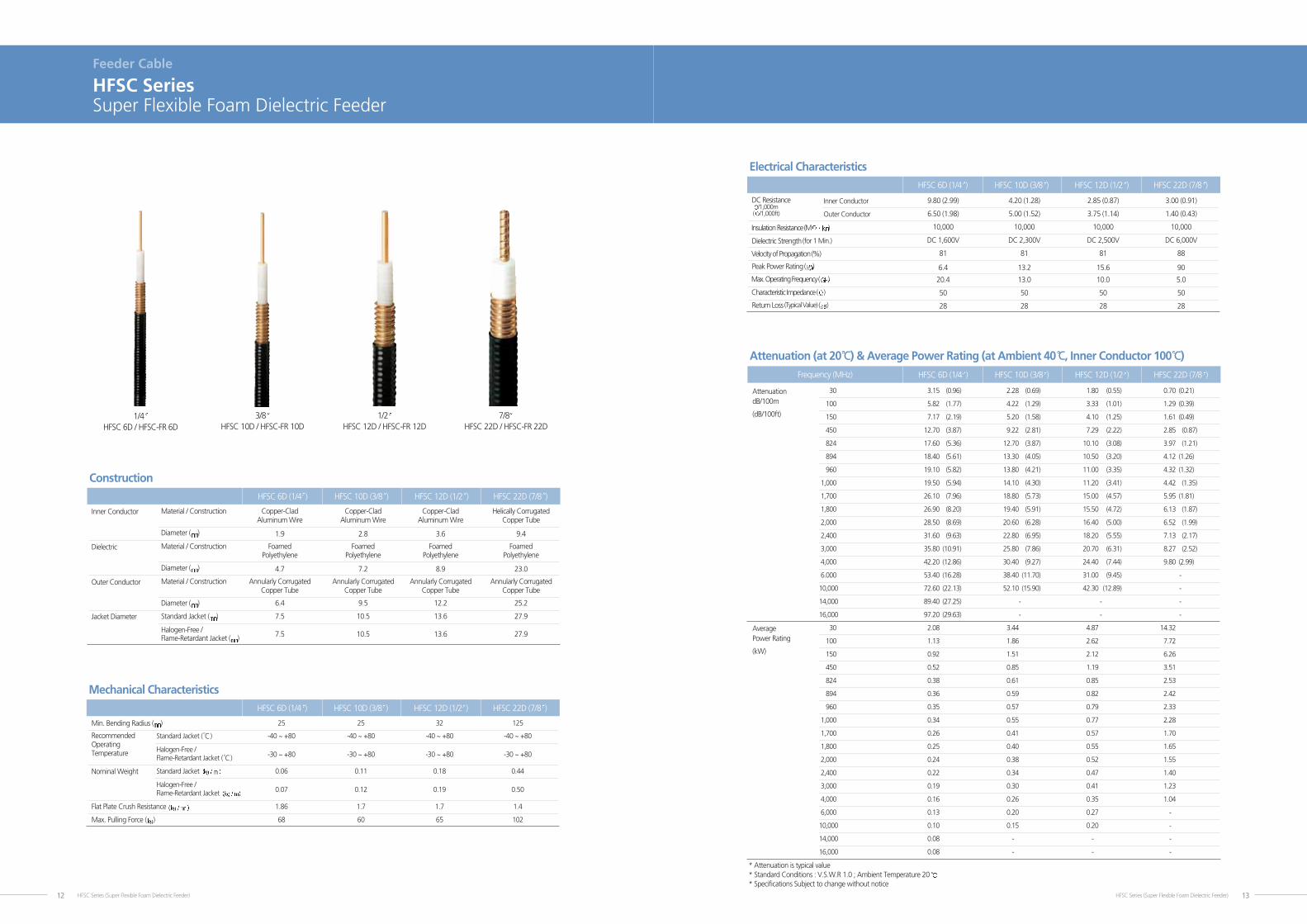
Universal Weatherproofing kit
Cable Protection
Two Versions
Multi-Connection Protection
Tape Kit for Multi-Layer Wrap
Butyl and Winyl
See Text
App.
Size
Feature
Design
Material
Incl.
DescriptionAvoid messy tapes and mastics with cold shrinkTM. This unique weatherproofing
solution installs in less than three minutes, and eliminates difficult and time
consuming taping processes. Because no speacial techniques are required, cold
shrinkTM can be installed perfectly by both new and experienced installers. To
apply, position the kit over a connection, and unwind the spiral support. As the
tube loses its support, it collapses over the connection to form a long term
environmental seal. An universally designed spacer accommodates similar cable sizes
with tolerance variances allowing these kits to be used on a variety of
manufacturers RF cables regardless of your cable preference. Cold shrinkTM kits
are available to seal main feeder, jumper and antenna connections.
30MTMCold ShrinkTM Weatherproofing Kit
edoCedoC
Splices Main Feeder to Jumper
Cable Size Cable Size
1/2 to 1/2
7/8 to 7/8
1-1/4 to 1-1/4
1-5/8 to 1-5/8
L-CS-U1212
L-CS-U2222
L-CS-U3333
L-CS-U4242
0.2 (0.1)
0.8 (0.4)
1.0 (0.5)
1.0 (0.5)
)gk .tW( sbl .tW)gk .tW( sbl .tW
7/8 to 1/2
1-1/4 to 1/2
1-1/4 to 1-5/8
1-5/8 to 1/2
L-CS-U1222
L-CS-U1233
L-CS-U3342
L-CS-U1242
0.8 (0.4)
1.0 (0.5)
1.0 (0.5)
1.0 (0.5)
Product Code
Product Code
Universal Weatherproofing Kit
Description
DescriptionThe universal weatherproofing kits include mastic and electrical tapes that are
applied to provide a multi-layer, long-term environmental seal over multiple
connections. The standard version (L-WK-U) includes five 3-3/4 x 2 (95mm x
0.6m) rolls of butyl mastic tape, two 3/4 x 44 (19mm x 13m) rolls of electrical
tape, and one 2 x 20 (51mm x 6m) roll of electrical tape. The large version (L-WK-
UL) includes five 3-3/4 x 2 (95mm x 0.6m) rolls of butyl mastic tape, three 3/4 x
44 (19mm x 13m) rolls of electrical tape, and three 2 x 20 (51mm x 6m) rolls of
electrical tape.
Accessories (Entry Port System) 49
Accessories
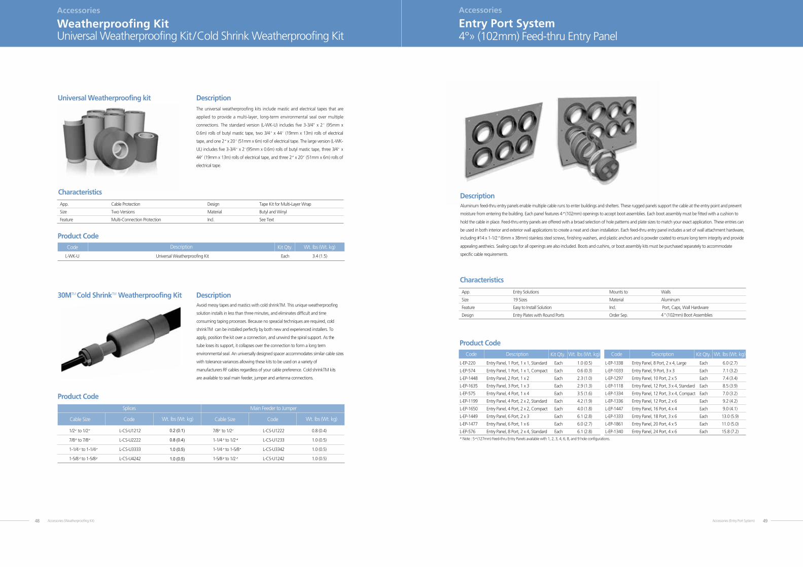
Entry Port System4°» (102mm) Feed-thru Entry Panel
DescriptionAluminum feed-thru entry panels enable multiple cable runs to enter buildings and shelters. These rugged panels support the cable at the entry point and prevent
moisture from entering the building. Each panel features 4 (102mm) openings to accept boot assemblies. Each boot assembly must be fitted with a cushion to
hold the cable in place. Feed-thru entry panels are offered with a broad selection of hole patterns and plate sizes to match your exact application. These entries can
be used in both interior and exterior wall applications to create a neat and clean installation. Each feed-thru entry panel includes a set of wall attachment hardware,
including #14 x 1-1/2 (6mm x 38mm) stainless steel screws, finishing washers, and plastic anchors and is powder coated to ensure long term integrity and provide
appealing aestheics. Sealing caps for all openings are also included. Boots and cushins, or boot assembly kits must be purchased separately to accommodate
specific cable requirements.
Characteristics
Entry Solutions
19 Sizes
Easy to Install Solution
Entry Plates with Round Ports
Walls
Aluminum
Port, Caps, Wall Hardware
4 (102mm) Boot Assemblies
App.
Size
Feature
Design
L-EP-220 Entry Panel, 1 Port, 1 x 1, Standard Each 1.0 (0.5)
L-EP-574 Entry Panel, 1 Port, 1 x 1, Compact Each 0.6 (0.3)
L-EP-1448 Entry Panel, 2 Port, 1 x 2 Each 2.3 (1.0)
L-EP-1635 Entry Panel, 3 Port, 1 x 3 Each 2.9 (1.3)
L-EP-575 Entry Panel, 4 Port, 1 x 4 Each 3.5 (1.6)
L-EP-1199 Entry Panel, 4 Port, 2 x 2, Standard Each 4.2 (1.9)
L-EP-1650 Entry Panel, 4 Port, 2 x 2, Compact Each 4.0 (1.8)
L-EP-1449 Entry Panel, 6 Port, 2 x 3 Each 6.1 (2.8)
L-EP-1477 Entry Panel, 6 Port, 1 x 6 Each 6.0 (2.7)
L-EP-576 Entry Panel, 8 Port, 2 x 4, Standard Each 6.1 (2.8)
* Note : 5 (127mm) Feed-thru Entry Panels available with 1, 2, 3, 4, 6, 8, and 9 hole configurations.
Mounts to
Material
Incl.
Order Sep.
Code Description Wt. lbs (Wt. kg)Kit Qty.
Product Code
L-EP-1338 Entry Panel, 8 Port, 2 x 4, Large Each 6.0 (2.7)
L-EP-1033 Entry Panel, 9 Port, 3 x 3 Each 7.1 (3.2)
L-EP-1297 Entry Panel, 10 Port, 2 x 5 Each 7.4 (3.4)
L-EP-1118 Entry Panel, 12 Port, 3 x 4, Standard Each 8.5 (3.9)
L-EP-1334 Entry Panel, 12 Port, 3 x 4, Compact Each 7.0 (3.2)
L-EP-1336 Entry Panel, 12 Port, 2 x 6 Each 9.2 (4.2)
L-EP-1447 Entry Panel, 16 Port, 4 x 4 Each 9.0 (4.1)
L-EP-1333 Entry Panel, 18 Port, 3 x 6 Each 13.0 (5.9)
L-EP-1861 Entry Panel, 20 Port, 4 x 5 Each 11.0 (5.0)
L-EP-1340 Entry Panel, 24 Port, 4 x 6 Each 15.8 (7.2)
Code Description Wt. lbs (Wt. kg)Kit Qty.

Accessories (Cushion and Boot)50
Accessories
Cushion and Boot4°» (102mm) Boot Assembly Kit
DescriptionThese innovative boot assembly kits feature a boot assembly and
standard cushion insert in one convenient package. The unique boot
assembly features a split, one-piece design which dramatically reduces
installation time and difficulty. Boot assembly kits are designed to be
fitted onto EP-series entry panels in wall/roof feed-thru applications.
L-BA-12-1A Boot Assembly Kit, 4 (102mm) w/1 Hole for 1/2 )7.0( 6.1hcaECable detagurroC
L-BA-12-2A Boot Assembly Kit, 4 (102mm) w/2 Hole for 1/2 )7.0( 6.1hcaECable detagurroC
L-BA-12-3A Boot Assembly Kit, 4 (102mm) w/3 Hole for 1/2 )7.0( 6.1hcaECable detagurroC
L-BA-12-4A Boot Assembly Kit, 4 (102mm) w/4 Hole for 1/2 )7.0( 6.1hcaECable detagurroC
L-BA-12-5A Boot Assembly Kit, 4 (102mm) w/5 Hole for 1/2 )7.0( 6.1hcaECable detagurroC
L-BA-12F-1A Boot Assembly Kit, 4 (102mm) w/1 Hole for 1/2 )7.0( 6.1hcaECable xelF
L-BA-12F-2A Boot Assembly Kit, 4 (102mm) w/2Hole for 1/2 )7.0( 6.1hcaECable xelF
L-BA-12F-3A Boot Assembly Kit, 4 (102mm) w/3 Hole for 1/2 )7.0( 6.1hcaECable xelF
L-BA-12F-4A Boot Assembly Kit, 4 (102mm) w/4 Hole for 1/2 )7.0( 6.1hcaECable xelF
L-BA-16-1A Boot Assembly Kit, 4 (102mm) w/1 Hole for 5/8 )7.0( 6.1hcaECable detagurroC
L-BA-16-2A Boot Assembly Kit, 4 (102mm) w/2 Hole for 5/8 )7.0( 6.1hcaECable detagurroC
L-BA-16-3A Boot Assembly Kit, 4 (102mm) w/3 Hole for 5/8 )7.0( 6.1hcaECable detagurro C
L-BA-16-4A Boot Assembly Kit, 4 (102mm) w/4 Hole for 5/8 )7.0( 6.1hcaECable detagurroC
L-BA-22-1A Boot Assembly Kit, 4 (102mm) w/1 Hole for 7/8 )7.0( 6.1hcaECable detagurroC
L-BA-22-2A Boot Assembly Kit, 4 (102mm) w/2 Hole for 7/8 )7.0( 6.1hcaECable detagurroC
L-BA-22-3A Boot Assembly Kit, 4 )7.0( 6.1hcaECable detagurroC "8/7 rof eloH 3/w )mm201(
L-BA-22-4A Boot Assembly Kit, 4 (102mm) w/4 Hole for 7/8 )7.0( 6.1hcaECable detagurroC
L-BA-33-1A Boot Assembly Kit, 4 (102mm) w/1 Hole for 1-1/4 )7.0( 6.1hcaECable detagurroC
L-BA-42-1A Boot Assembly Kit, 4 (102mm) w/1 Hole for 1-5/8 )7.0( 6.1hcaECable detagurroC
L-BA-57-1A Boot Assembly Kit, 4 (102mm) w/1 Hole for 2-1/4 )7.0( 6.1hcaECable detagurroC
Characteristics
Entry Solutions
Versions for Cable and Elliptical Waveguide
One-Piece Design Simplifies Installation
Compression Boot Kit for Aluminum Entry Panels
4 (102mm) Entry Panels
EPDM Rubber
Boot, Cushion, Two Hose Clames
4 (102mm) Entry Panel
App.
Size
Feature
Design
Mounts to
Material
Incl.
Order Sep.
Code Description Wt. lbs (Wt. kg)Kit Qty.
Product Code
Hybrid Combiner
Combiner
POI
Coupler
Splitter / Tapper
In-Building Passive Product
RF Total Soluition

In-building Solutions_Splitter52
Splitter / Tapper
Wide Band Power Splitter(200W)
Common Specification
Frequency Range 800 ~ 2,700 MHz
Impedance 50
V.S.W.R 1.2
Insertion Loss 0.1 dB
PIMD (2-tone x 20W) -150 dBc
Input Power (avg.) 200 Watt
Connectors N - Female
Number of Input Port 1
DC - path All ports
Operating Temperature -35oC ~ +75oC / 0 ~ 95%
Environmental Class IP 68
SPT-2way-100-NF / SPT-3way-100-NF / SPT-4way-100-NFItems
Specification
Number of Output Port 2 3 4
Split Loss 3 +/- 0.1 dB 4.8 +/- 0.15 dB 6.0 +/- 0.15 dB
Size 193 x 25 x 25 mm 191 x 25 x 25 mm 193 x 25 x 25 mm
Weight Approx. 0.4 kg Approx. 0.45 kg Approx. 0.5 kg
SPT-2way-100-NF SPT-3way-100-NF SPT-4way-100-NFModel No.
SPT-2way-100-NF / SPT-3way-100-NF / SPT-4way-100-NFWideband Performance 800 ~ 2700 MHz 200 Watt Average Power Rating Low Insertion LossLow VSWR Low Passive Inter Modulation Products Indoor / Outdoor Applications N Female Connectors
2 way 3 way 4 way
In-building Solutions_Splitter 53
Common Specification
Frequency Range 800 ~ 2,700 MHz
Impedance 50
V.S.W.R 1.2
Insertion Loss 0.1 dB
PIMD (2-tone x 20W) -150 dBc
Input Power (avg.) 700 Watt
Connectors 7/16 (DIN) - Female
Number of Input Port 1
DC - path All ports
Size 211 x 40 x 40 mm
Operating Temperature -35oC ~ +75oC / 0 ~ 95%
Environmental Class IP 68
SPT-2way-700-NF / SPT-3way-700-NF / SPT-4way-700-NFItems
Specification
Number of Output Port 2 3 4
Split Loss 3 +/- 0.1 dB 4.8 +/- 0.15 dB 6.0 +/- 0.15 dB
Weight Approx. 1.05 kg Approx. 1.11 kg Approx. 1.15 kg
SPT-2way-700-NF SPT-3way-700-NF SPT-4way-700-NFModel No.
SPT-2way-700-NF / SPT-3way-700-NF / SPT-4way-700-NFWideband Performance 800 ~ 2700 MHz 700 Watt Average Power Rating Low Insertion Loss Low VSWRLow Passive Inter Modulation Products Indoor / Outdoor Applications DIN(7/16) Female Connectors
Splitter / Tapper
Wide Band Power Splitter(700W)
2 way 3 way 4 way

In-building Solutions_Tapper54
Splitter / Tapper
Wide Band Power Tapper(200W)
TAP -7dB-100-NF /TAP -10dB-100-NF/TAP -15dB-100-NF
FeaturesWideband Performance 800 ~ 2700 MHz
200 Watt Average Power Rating
Low Insertion Loss
Low VSWR
Low Passive Inter Modulation Products
Indoor / Outdoor Applications
N Female Connectors
Common Specification
Frequency Range 800 ~ 2,700 MHz
Impedance 50
V.S.W.R 1.4
Insertion Loss 0.1 dB
PIMD (2-tone x 20W) -150 dBc
Input Power (avg.) 200 Watt
Connectors N - Female
Number of Input Port 1
Number of /output Port 2
DC - path All ports
Size 184 x 25 x 25 mm
Weight Approx. 0.4 kg
Operating Temperature -35oC ~ +75oC / 0 ~ 95%
Environmental Class IP 68
TAP -7dB-100-NF / TAP -10dB-100-NF / TAP -15dB-100-NFItems
Specification
Tap Loss (Input - P1) -7 +/- 1.0 dB -10 +/- 1.0 dB -15 +/- 1.0 dB
Tap Loss (Input - P2) 1.3 dB 0.7 dB 0.4 dB
TAP -7dB-100-NF TAP -10dB-100-NF TAP -15dB-100-NFModel No.
In-building Solutions_Coupler 55
Coupler
Wide Band Directional Coupler
CPL-100-6dB-NF /CPL-100-8dB-NF /CPL-100-10dB-NFCPL-100-13dB-NF /CPL-100-15dB-NF /CPL-100-20dB-NFCPL-100-30dB-NF
FeaturesWideband Performance 800 ~ 2700 MHz
100 Watt Average Power Rating
Low Insertion Loss
Low VSWR
Low Passive Inter Modulation Products
Compact Size
Indoor Applications
N Female Connectors
Common Specification
Frequency Range 800 ~ 2,700 MHz
Impedance 50
V.S.W.R 1.2
Directiyity 20 dB
PIMD (2-tone x 20W) -150 dBc
Input Power (avg.) 100 Watt (Forward Input, All Port Terminated)
Connectors N - Female
Operating Temperature -33oC ~ +75oC / 0 ~ 95%
Weight 0.3 kg
Size 108.4 x 29.2 x 23 mm
Wideband Directional CouplerItems
Tap Loss (Input - P1) -15 +/- 1.0 dB -20 +/- 1.0 dB -30 +/- 1.0 dB
Tap Loss (Input - P2) 0.4 dB 0.2 dB 0.2 dB
CPL-100-15dB-NF CPL-100-20dB-NF CPL-100-30dB-NFModel No.
Specification
Tap Loss (Input - P1) -6 +/- 0.8 dB -8 +/- 0.8 dB -10 +/- 0.8 dB -13 +/- 1.0 dB
Tap Loss (Input - P2) 1.5 dB 1.1 dB 0.7 dB 0.5 dB
CPL-100-6dB-NF CPL-100-8dB-NF CPL-100-10dB-NF CPL-100-13dB-NFModel No.

Combiner
Dual Band Combiner
Common Specification
Frequency Range Band1 : 806 ~ 960 MHz / Band2 : 1710 ~ 2170 MHz
Impedance 50
VSWR 1.2 : 1
Insertion LossPort1 Port3 0.15 dB Typ. (806 ~ 960 MHz)Port2 Port3 0.25 dB Typ. (1710 ~ 2170 MHz)
Isolation Loss -45 dB (806 ~ 824 MHz)Port1 Port2 -50 dB (1710 ~ 2170 MHz)
PIMD -150dBc
Input Power (avg.) 250 Watt
Mounting Wall
Connectors 7/16(DIN) – Female
Environmental Class IP 65
Operating Temperature -40oC ~ +60oC
Weight 1.6 kg
Size(with Bracket) 210 x 129 x 42mm
DBC-0822-3D / DBC-0822-3FItems
FeaturesIntegrates Wireless Bands(806 MHz~960 MHz & 1920 MHz~2170 MHz)
Designed for Co-Site Systems
Available as a Single Unit or Double Unit
Wall or Pole Mounting
Reciprocal Characteristic
Low Insertion Loss
Low Passive Inter Modulation Products
Indoor / Outdoor Applications
7/16(Din) Female Connectors
DBC-0822-3D / DBC-0822-3F
Specification
DC Pass Band 1 : DC Pass / Band 2 : DC Pass Band 1 : DC Block / Band 2 : DC Pass
DBC-0822-3D DBC-0822-3FModel No.
In-building Solutions_Combiner56
Combiner
Triple Band Combiner
Common Specification
Frequency Range806 ~ 960 MHz 1710 ~ 1880 MHz 1920 ~ 2170 MHz
(CDMA800, GSM900) (GSM1800) (UMTS)
Insertion Loss(Max.) 0.2 dB 0.4 dB 0.4 dB
VSWR 1.2:1
Isolation(Min.)50 dB (1710 ~ 1880) 50 dB (806 ~ 960) 50dB (806 ~ 960)50 dB (1920 ~ 2170) 50 dB (1920 ~ 2170) 50dB (1710 ~ 1880)
Intermodulation Products-160 dBc@2-tone * 20w[dBc]
Connectors 7/16(DIN)-Female
Operating Power 240W Avg.
Application (Indoor or Outdoor) IP 66
Mounting Wall Mounting, Mast Mounting
Size 242 x 216 x 65 mm
Operating Temperature -40oC ~ +60oC
TBC-0822-4A / TBC-0822-4DItems
FeaturesHigh Isolation Cross BandMinimal Insertion LossHigh “Q” Value DesignCompact Size & Low Weight240W High Power RatingIndoor or Outdoor ApplicationLow Passive IntermodulationHigh Reliability7/ 16(Din) Connector & N ConnectorCo-Site SystemIntegrates CDMA800 / GSM900 & GSM & UMTS
TBC-0822-4A /TBC-0822-4D
Specification
DC Pass DC Block DC By-Pass
TBC-0822-4A TBC-0822-4DModel No.
In-building Solutions_Combiner 57

In-building Solutions_Hybrid Combiner58
Hybrid Combiner
3dB Hybrid Combiner
CPL-100-3-DF-B / CPL-100-3-NF-B
FeaturesWideband Performance 800 ~ 2700 MHz
High Isolation
120 Watt Average Power Rating
Low Insertion Loss
Low VSWR
Low Passive Inter Modulation Products
Compact Size
Indoor / Outdoor Applications
7/16(Din) or N Female Connectors
CPL-100-3-DF-B
CPL-100-3-NF-B
Common Specification
Frequency Range 800 ~ 2,700 MHz
Impedance 50
V.S.W.R 1.2:1
Coupling Value 3.0 +/- 0.6 dB
Isolation -23 dB
PIMD (2-tone x 20W) -150 dBc
Input Power (avg.) 120 W
Operating Temperature -35oC ~ +75oC
Environmental Class IP 68
CPL-100-3-DF-B / CPL-100-3-NF-BItems
Specification
Connectors 7/16 (DIN) - Female N - Female
Size (without Connector) 129 x 42 x 40 mm 129 x 44 x 31.5 mm
Weight 940 g 650 g
CPL-100-3-DF-B CPL-100-3-NF-BModel No.
In-building Solutions_Hybrid Combiner 59
Hybrid Combiner
4 x 4 Hybrid Combiner(Square Type)
MUL-0827-44A
FeaturesWideband Performance 800 ~ 2700 MHz
Co-Site System
High Isolation
100 Watt Average Power Rating
Low Insertion Loss
Low VSWR
Low PIMD
Compact Size
Indoor / Outdoor Applications
7/16(Din) or N Female Connectors
Common Specification
Frequency Range 800 ~ 2,700 MHz
Impedance 50
V.S.W.R 1.2:1
Coupling Value 6.2 +/- 0.8dB
Isolation -25 dB
PIMD (2-tone x 20W) -150 dBc
Input Power (avg.) 100 Watt
Operating Temperature -20oC ~ +75oC / 0 ~95%
Environmental Class IP 68
MUL-0827-44A / MUL-0827-44BItems
Specification
Connectors N - Female 7/16 (DIN) - Female
Size (without Connector) 150.4 x 150.4 x 28.4 mm 153 x 153 x 35 mm
Weight 1.85 kg 2.6 kg
MUL -0827-44A MUL -0827-44BModel No.
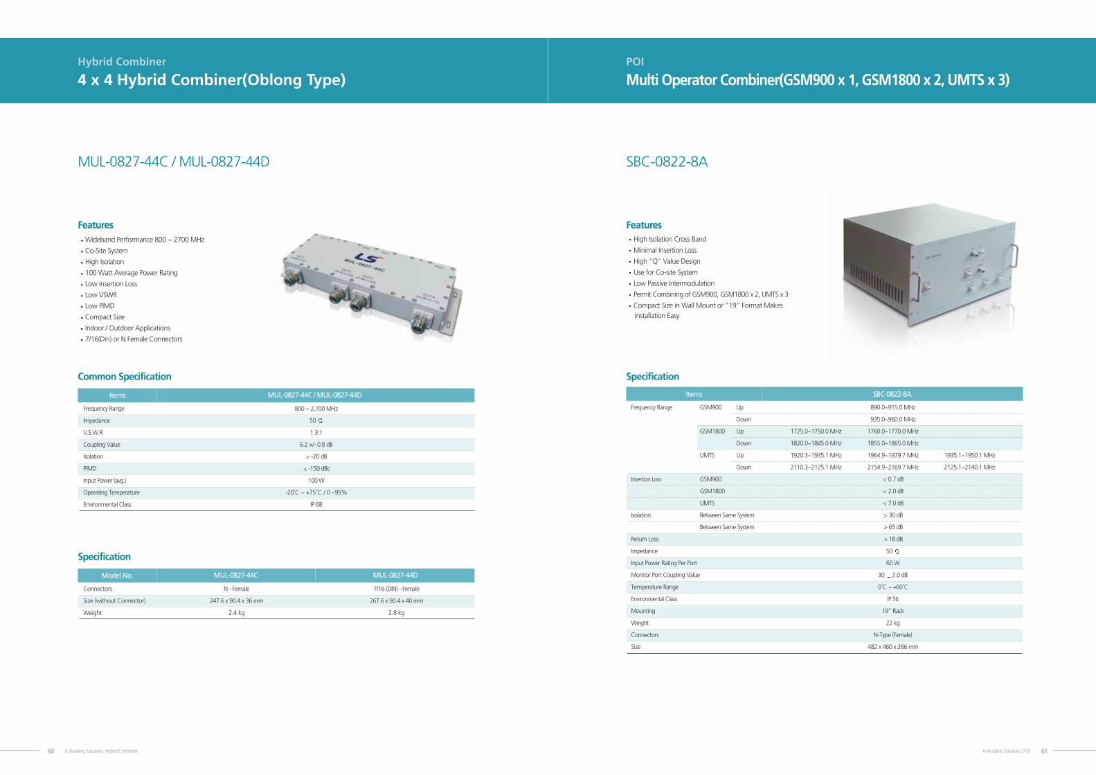
In-building Solutions_Hybrid Combiner60
Hybrid Combiner
4 x 4 Hybrid Combiner(Oblong Type)
FeaturesWideband Performance 800 ~ 2700 MHz
Co-Site System
High Isolation
100 Watt Average Power Rating
Low Insertion Loss
Low VSWR
Low PIMD
Compact Size
Indoor / Outdoor Applications
7/16(Din) or N Female Connectors
MUL-0827-44C / MUL-0827-44D
Common Specification
Frequency Range 800 ~ 2,700 MHz
Impedance 50
V.S.W.R 1.3:1
Coupling Value 6.2 +/- 0.8 dB
Isolation -20 dB
PIMD -150 dBc
Input Power (avg.) 100 W
Operating Temperature -20oC ~ +75oC / 0 ~95%
Environmental Class IP 68
MUL-0827-44C / MUL-0827-44DItems
Specification
Connectors N - Female 7/16 (DIN) - Female
Size (without Connector) 247.6 x 90.4 x 36 mm 267.6 x 90.4 x 40 mm
Weight 2.4 kg 2.8 kg
MUL-0827-44C MUL-0827-44DModel No.
In-building Solutions_POI 61
POI
Multi Operator Combiner(GSM900 x 1, GSM1800 x 2, UMTS x 3)
FeaturesHigh Isolation Cross Band
Minimal Insertion Loss
High “Q” Value Design
Use for Co-site System
Low Passive Intermodulation
Permit Combining of GSM900, GSM1800 x 2, UMTS x 3
Compact Size in Wall Mount or “19” Format Makes Installation Easy
Specification
Frequency Range GSM900 Up 890.0~915.0 MHz
Down 935.0~960.0 MHz
GSM1800 Up 1725.0~1750.0 MHz 1760.0~1770.0 MHz
Down 1820.0~1845.0 MHz 1855.0~1865.0 MHz
UMTS Up 1920.3~1935.1 MHz 1964.9~1979.7 MHz 1935.1~1950.1 MHz
Down 2110.3~2125.1 MHz 2154.9~2169.7 MHz 2125.1~2140.1 MHz
Insertion Loss GSM900 0.7 dB
GSM1800 2.0 dB
UMTS 7.0 dB
Isolation Between Same System 30 dB
Between Same System 65 dB
Return Loss 18 dB
Impedance 50
Input Power Rating Per Port 60 W
Monitor Port Coupling Value 30 2.0 dB
Temperature Range 0oC ~ +60
oC
Environmental Class IP 56
Mounting 19” Rack
Weight 22 kg
Connectors N-Type (Female)
Size 482 x 460 x 266 mm
SBC-0822-8AItems
SBC-0822-8A

In-building Solutions_POI62
POI
Multi Operator Combiner(GSM900 x 2, GSM1800 x 3, UMTS x 3)
FeaturesHigh Isolation Cross Band
Minimal Insertion Loss
High “Q” Value Design
Use for Co-site System
Low Passive Intermodulation
Permit Combining of GSM900 x 2, GSM1800 x 3, UMTS x 3
Compact Size in Wall Mount or (19” Format Optional)
Makes Installation Easy
Specification
Operator 1 Operator 2 Operator 3 Operator 4Items
MBC-0822-14A
Frequency Range IDEN Up 806~825 MHz
Down 851~870 MHz
EGSM Up 880~890 MHz
Down 925~935 MHz
GSM900 Up 900~915 MHz 890~900 MHz
Down 945~960 MHz 935~945 MHz
GSM1800 Up 1710~1730 MHz 1760~1780 MHz 1740~1760 MHz
Down 1805~1825 MHz 1855~1875 MHz 1835~1855 MHz
UMTS Up 1935.1~1950.1 MHz 1950.1~1964.9 MHz 1920.0~1935.1 MHz
Down 2125.1~2140.1 MHz 2140.1~2154.9 MHz 2110.3~2125.1 MHz
Insertion Loss 5.5 dB
Between Same System IDEN/GSM900/GSM1800 22 dBIsolation UMTS 33 dB
Between Different System IDEN-EGSM/GSM900 40 dBIsolation IDEN-GSM1800/UMTS 91 dB
EGSM/GSM900-GSM1800/UMTS 91 dB
GSM1800-UMTS 91 dB
Return Loss Input Port 20 dB
Output 6 dB
Impedance 50
Input Power Rating Per Port 100 W / IDEN : 150W
3rd PIMD @2 x 43dBm 155 dBc
Monitor Port Coupling Value 30 2.0 dBc
Temperature Range 0oC ~ +75
oC
Mounting Wall mount (Optional 19” Rack)
Environmental Class IP 65 (Only wall mount)
Weight 35 kg
Connectors Input / Output 7-16 DIN – Female (N-Female Optional) :12port
Coupling Port N-Female : 2port
Size 650 x 591 x 319 mm (Include mounting)
In-building Solutions_POI 63
POI
Multi Operator Combiner(GSM1800 x 6, WCDMA x 6)
FeaturesMinimal Insertion Loss
High “Q” Value Design
Use for Co-site System
Low PIMD
Permit Combining of GSM1800 x 6, WCDMA x 6,Sector Output x 2, x 2, x 2,
Compact Size in Wall Mount or “19” Format
MBC-1822-18A
Specification
Frequency Range GSM1800 Up 1710~1785 MHz 1710~1785 MHz 1710~1785 MHz
Down 1805~1880 MHz 1805~1880 MHz 1805~1880 MHz
WCDMA Up 1920~1980 MHz 1920~1980 MHz 1920~1980 MHz
Down 2110~2170 MHz 2110~2170 MHz 2110~2170 MHz
Insertion Loss 4.5 dB
Between Same System GSM1800-GSM1800 20 dBIsolation WCDMA-WCDMA 20 dB
Between System Isolation GSM1800-WCDMA 40 dB
Return Loss 18 dB
Impedance 50
Input Power Rating Per Port 100 W
3rd PIMD @2 x 43dBm 140 dBc
Temperature Range -10oC ~ +60
oC
Mounting 19” Rack, Wall mount
Weight 25 kg (Approximate)
Connectors N-Female
Size 437 x 330 x 270 mm (Approximate)
Operator 1 Operator 2 Operator 3Items

In-building Solutions_POI64
POI
Multi Operator Combiner(CDMA x 3, GSM900 x 2, GSM1800 x 3 and UMTS x 4)
FeaturesHigh Isolation Cross Band
Minimal Insertion Loss
High “Q” Value Design
Use for Co-site System
Low Passive Intermodulation
Permit Combining of CDMA x 3,GSM900 x 2, GSM1800 x 3 and UMTS x 4
Compact Size
Makes Installation Easy
Specification
Operator 1 Operator 2 Operator 3 Operator 4Items
MBC-0822-18B
Frequency Range CDMA Up 824~849 MHz 824~849 MHz 824~849 MHz
Down 870~879 MHz 870~894 MHz 870~894 MHz
GSM900 Up 897.5~915 MHz 897.5~915 MHz
Down 942.5~960 MHz 942.5~960 MHz
GSM1800 Up 1710~1785 MHz 1710~1785 MHz 1710~1785 MHz
Down 1805~1880 MHz 1805~1880 MHz 1805~1880 MHz
WCDMA Up 1920~1980 MHz 1920~1980 MHz 1920~1980 MHz 1920~1980 MHz
Down 2110~2170 MHz 2110~2170 MHz 2110~2170 MHz 2110~2170 MHz
Insertion Loss CDMA/GSM900 8.5 dB
GSM1800 /WCDMA 7.5 dB
Between Same System Isolation
Between System Isolation CDMA GSM900,GSM1800,WCDMA 50 dB
GSM900 CDMA,GSM1800,WCDMA 50 dB
GSM1800 CDMA,GSM900,WCDMA 50 dB
WCDMA CDMA,GSM90M,GSM1800 50 dB
Return Loss Input Port 18 dB
Output 14 dB
Impedance 50
Input Power Rating Per Port 100 W
3rd PIMD @2 x 43 dBm -150 dBc
Monitor Port Coupling Value 30 2.0 dBc
Temperature Range -10oC ~ +60
oC
Mounting 19” Rack, Wall mount
Weight 35 kg
Connectors BTS /ANT Ports 16port : 7-16 DIN - Female
Coupling Ports 2port : N-Female
Size 482 x 460 x 266 mm
CDMA/GSM900/GSM1800/WCDMA
20 dB

United StatesLSCA FORT LEELSCUS TARBORO
Global Network
Gumi PlantEHV / MV / LV cableUTP, RF cableSCR, Magnet wireOverhead cable, Bus duct
Optical fiberOptical cable
Submarine cableIndustrial specialty cable
EHV / MV / LV cableIndustrial specialty cable
Industrial devices cableAutomotive cableHarness & moduleAluminum, Bus duct
EHV / MV / LV cableSCR, ACSROverhead cable
MV / LV cableUTP, Optical cableOverhead cable
EHV / MV / LV cableRF cableOverhead cable
MV / LV cableControl, Instrument cable Automotive battery components
Optical cable
Indong Plant Donghae Plant LSHQ(Yichang) LSCW(Wuxi)
KOREA CHINA
MexicoMEXICO CITY
Factory
Sales office
Branch office
GLOBAL NETWORK
Australia
JapanKorea
China
Indonesia
VietnamTaiwanMyanmar
Singapore
Bangladesh
IndiaUAESaudiArabia
UK
France
Poland
LSCJ TOKYO
TAIPEILSGM THILAWALSGMT YANGON
DHAKA
RIYADH
EgyptLSMC
10TH OF RAMADAN CITY
LSAGI JAKARTALSAGS JAKARTA
SINGAPORE
LSCAU SYDNEY
DONGHAE PLANT
DUBAIABU DHABI
LSHQ YICHANGLSCW WUXILS EV POLAND DZIERZONIOW
LSCP DZIERZONIOW
LSCU LONDON
LSCF PARIS
LSCI BAWAL LS-VINA HAIPHONGLSCV HO CHI MINH
LS-VINA(Haiphong) LSCV(HO Chi Minh) LSCI(Bawal) LSCUS(Tarboro) LS EV Poland./LSCP(Dzierzoniow)
VIETNAM INDIA USA POLAND
More than 60 Factories,Sales and Production Sitesin 20 Countries.
066

ⓒ2020 LS Cable & System Ltd. All right reserved.This product or document is protected by copyright anddistributed under licenses restricting its use, copying, distribution,and recompilation. No part of this product or document may bereproduced in any form by any means without prior written authorizationof LS Cable&System and its licensors, if any.Products shown on this catalog are subject to change without any prior notice.
www.lscns.comLS RF Feeder System & Accessories
19F, LS Yongsan Tower, 92, Hangang-daero, Yongsan-gu, Seoul, 04386, Korea Tel. 02-2189-9231/9328 Fax. 02-2189-9259