M38A1 - Operation & Organizational Maintenance-TM9-8014
391
-
Upload
khangminh22 -
Category
Documents
-
view
3 -
download
0
Transcript of M38A1 - Operation & Organizational Maintenance-TM9-8014


Thfa manuat is correct to 95 Janwrg 1955
*TM 9-8014/TO 36A-l-401
TECHNIG~MANUAL DEPARTMENTS OF THE ARMY AND
No. g-3014 THE AIR FORCE
No. 368-l-401 1966
OPERATION AND ORGANIZATIONAL MAINTENANCE:
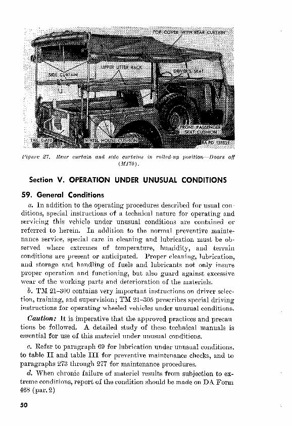
‘/k-TON 4 x 4 UTILITY TRUCK M38Al AND %-TON 4 x 4 FRONT tlNE AMBULANCE Ml70
CHAPTEIR 1.
and replacement--___--______
PW 3-4
1

Section XXIV.
xxv.
XXVI.
XXVII.
XXVIII.
CHAPTEa 4.
Section I.
II.
ORGANIZATIONAL MAINTENANCE p”‘~ra~l*
INSTRUCTIONS-Continued
Wheela and tires-_______________________ 248-262
Body and frame (M38Al)________________ 263-261
Body and frame (M170)_________________ 262-272
Maintenance under unusual oonditions- _ _ _ 273-277
Radio interference suppression______-_____ 278-282
SHIPMENT AND LIMITED STORAGE
AND DESTRUCTION OF MATERIEL
TO PREVENT ENEMY USE
Shipment and limited storage_____________ 283-287
Destruction of materiel to prevent enemy
use_________________________________ 288-292
299404 304-329 329-347
347350
351,352
353-364
365-367
INDEX____ ~_________________~_~~_____~~~~~~~~~~~~~~~~- ---___- 372
HOCKEbfN,DE 3~707

These instructions are published for information and guidance
of the persomlel to whom this material is issued. They contain in-
formation on the operation and organizational maintenance of the
materiel as well as descriptions of major units and their functions in
relation to other components of the materiel.
b. The appendix contains a list of current references, including
supply manuals, forms, technical manuals, and other available pub-
lications applicable to the materiel.
c. This manual differs from TM 9-804A, 21 July 1952, as shown
below.
(1)
(2)
Adds information on the 1/4-ton 4 x 4 front line ambulance
M170.
Revises information on-name, caution, and instruction
plates; tabulated data; controls and instruments; lubrication
order ; preventive maintenance services ; troubleshooting ; special tools, fuel lines, propeller shafts with universal joints,
clutch controls and linkage, and springs and toe-in adjust-
ment.
(3) Deletes reference teengine oil pan replacement, clutch re-
placement, Pitman arm replacement, and engine tuneup.
d. This edition is being published in advance of complete technical
review of all concerned. Any errors or omissions will be brought to
the attention of Chief of Ordnance, Washington 25, D. C., ATTN:
ORDFM-Pub.
In general, the prescribed organizational maintenance responsi-
bilities will apply as reflected in the allocation of tools and spare
parts in the appropriate columns of the current ORD 7 supply manual
pertaining to this vehicle and in accordance with the extent of dis-
assembly prescribed in this manual for the purpose of cleaning, lubri-
cating, or replacing authorized spare parts. In all cases where the
nature of repair, modification, or adjustment is beyond the scope or
3

facilities of the using organization, the supporting ordnance maint.e-
nance unit should be informed in order that trained personnel with
suitable tools and equipment may be provided or other proper in-
structions issued.
Note. The replacement of certain assemblies (engine, transmission, transfer,
front axle, and rear axle) is normally an ordnance maintenance operation, but
may be performed in an emergency by the using organization, provided approval
for performing tnese replacements is obtained from the supporting ordnance
offlcer. A replacement assembly, any tools needed for the operation which are
not carried by the using organization, any necessary special instructions re-
garding associated accessories, etc., may be obtained from the supporting ord-
nance maintenance unit.
3. Forms, Records, and Reports
a. Gemral. Responsibility for the proper ,execution of forms? rec-
ords, and reports rests upon the oticers of all units maintaining this
equipment. However, the value of accurate records must be fully
appreciated by all persons responsible for their compilation, mainte-
nance, and use. Records, reports, and authorized forms are normally
utilized to indicate the type, quantity, and condition of materiel to
be inspected, to be repaired, or to be used in repair. Propefly ex-
ecuted forms convey authorization and serve as records for repair
or replacement of materiel in the hands of troops and for delivery of
materiel requiring further repair to ordnance shops in arsenals,
depots, etc. The forms, records, and reports establish the work re-
quired, the progress of the work within the shops, and the status of
the materiel upon completion of its repair.
b. Authorized Forma. The forms generally applicable to units
operating and maintaining these vehicles are listed in the appendix.
No forms other than those approved for the Department of the ,4rmy
will be used. Pending availability of all forms listed, old forms may
be used. For a current and complete listing of all forms, refer to
SR 310-20-6.
c. Field Report of Accidents. The reports necessary to coml)ly
with the requirelnents of t,he Army safety program are prescribed in
detail in the SR 385-1040 series of special regulations. These rc-
ports are required whenever accidents involving injury to personnel
or damage to materiel occur. In addition to any applicable reports
required above, details of the accident will be reported as prescribed
in SR 385-310-l.
d. Report of Unsatisfactory Equipment or Jfateriak Suggestio1ls
for ilnprovement in design and maintenance of equipment. and spar”
parts, safety and efficiency of operation, or pertaining to the applica-
tion of prescribed petroleum fuels, lubrication, and/or preserving
materials, or technical inaccuracies will be reported through technical
channels, as prescribed in SR 70045-5, to the Chief of Ordnance,
4

Washington 25, D. C., ATTN: ORDFM, using DA Form 468, I_Jn-
satisfactory Equipment Report. Such suggestions are encouraged
in order that other organizations may benefit.
Note. Do not report all failures that occur. Report only REPBATED or RIO-
CURRENT failures or malfunctions which indicate unsatisfactory design or
material. However, reports will always be made in the event that exceptionally
costly equipment is involved. See also SR W&45-5 and printed instructions on
DA Worm 468.
Section II. DESCRIPTION AND DATA
4. Description a. Generd. This manual describes and illustrates the 1/4-ton 4 x 4
utility truck M38Al (figs. 1,2, and 3), and the l/!-ton 4 x 4 front line
ambulance Ml70 (figs. 4 and 5). With the exception of the differences
discussed in paragraph 5, both vehicles are similar. The descriptions
of individual components listed below apply to both models.
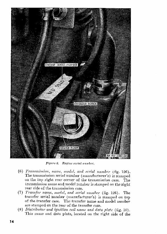
b. Engine (fig. 36). Power is supplied by an F-head, four-cylinder,
four-cycle, water-cooled, gasoline-type engine. This type of engine is
a combination valve-in-block and valve-in-head construction and is
three-point mounted on the frame.
c. Transmission.. The synchromesh transmission (fig. 126) is
mounted on the rear of the engine. The transmission has three for-
ward speeds and one reverse speed, all manually selected by means of
the transmission gearshift lever (X, fig. 11) mounted on top of the
transmission and extending into the driver’s compartment.
d. Transfer. The transfer (fig. 126) is a two-speed unit driven by
the transmission and distributes power to the front and rear axles
through propeller shafts. The transfer is manually controlled by the
transfer front wheel drive, and the high and low range gearshift lev-
ers (T, fig. 11)) located on top of the transfer and extending into the
driver’s compartment, These levers provide for engaging or disen-
gaging the front axle and selecting the high or low transfer ratio.
e. Front Axle and Suspension.
(1) The front axle (fig. 152) is a full-floating, single reduction
type equipped with a conventional differential with hypoid
drive gears. The axle shafts (fig. 136) are fitted to uni-
versal joints which revolve within steering knuckles con-
structed as part of the axle housing. The front propeller
shaft transmits power from the transfer to the front axle.
(2) The front suspension consists of two semielliptic-type leaf
springs (fig. 164). The rear of the springs are shackled to
the underside of the frame by U-bolt-type shackles. Pivot
bolts are used to secure the front ends of the springs to the
frame brackets on the frame underside. U-bolts secure the
5


Weight w/o crew (h138.41) :
Cross conntry_____________-~--____--~-------------~~~-------___ 3,463Ib
Empty___________________--___--___-----~~-~-----------------__ 2,665lb
Highway__________-~----__--------__________~-~~~_~--------_-- 3,865lb
Weight w/o crew (iU170) :
Cross country_____________-~-------_-___-___~~~___~~~-_~---~-_- 3,i63lb
Empty ___________~___~_______~~~~_--------_----__-_--____--___ 2,963Ib
High~~~ay____~~---~-----------------_-_____----__-__------------ 4,163lb
Wheelbase (M3YA1)____~_____________--_-----------__------_~~_--____ 81in.
Wheelbase (M1~O)____~_______~______-------------_--------~----- IOlin.
b. Performance.
Allowable speed
Transfer-high range___________---. ______._____~~~~. 21 40 60 16 mph
Transfer-low range__----______--__- ~__~~__________ 9 16 24 6 mph
Angle (M38Al) : Approach____________---__-______---_------__-~__~__--______-___---_ 46”
Departure_~___-______-~____.____--_-___-____~_-______-____--_----_ 34”
Cruising range (loaded)_-_--------~--__---_-------_-----~--~---~----_ 280 mi
Cruising speed_______~-_______-----______-----------~-_~------------ 55 mph
Engine horsepower: (brake horsepower) at 4,000 rprn____~~~~__--__--__ 72 hp
Fording depth__-_-___--_--_----____-__--------~~-~-~~_~__~_________ 371/ in.
Recommended towed load, maximum : Cross country___________~~__-_------_--_____--------~-------~~__ 1,500lb
Highway____________---____________-----_--______________--___ 2,000 lb
Turning circle, diameter (M38Al) : Left________-__------..--~---~~~~_..._---~ ___. ~~_~_~_____~________ 38 ft
Right_______________-_---___---__---_----~~_-___--__-__-__--- 38 ft 8 in.
Turning circle, dia*meter (M170) : Left_______~__~_----------------~~-~~~~~___-__--------------- 24ftZin.
Right____--------_--___-________--_-_------------~--____--- 24 ft 7 in.
c. Detailed Data References. additional detailed t,abular data
pertaining to individual components and systems are contained in the
following-paragraphs :
Batteries and lighting systen_____---___-_____-__-___-__--_____
Body and frame (M38Al)______________--__--____--__-_-_-_------
Body and frame (&~li’O)__________---___--__---__-__-___--------_
Brake systems_-_-___-__------_--___---_---__-------_--__-_---___
Clutch ____________________-__-___--___-~~_---__-__-_--___---__-_
Cooling system__________________---------------------------------
Engine ____________________--____________________________--_-___
Exhaust system________..__________-------------------------------
Frontaxle________----_-__--_-___----------___--__-__-----~___---_
Fuel and air intake
Generating system_______________-____---___-_-__-___-_---_--__
Ignition system_______-___________-----_------_------------------
Propeller shafts with universal joints________________--------------
Rear axle--____----_--__--__--_-__--__---------__------_---_--_
Springs and shock absorbers______________---_-_--_-----__-__----
Starting system______________---_---___________--__---------
Steering system_-__----~------_---____---_____-_______---_------__
Transfer _________~_~______~~________~______---_____-----_-------
Transmission ________________________-~~___-_----------__-__---_
Wheels and tires________--_----________---________---_---__------
161
253
262
231
190
126
104
143
206
133
157
147
201
215
239
154
222
197
192 _A,.. &!tB
19

9. Preliminary Services
a. General Inspection and Servicing Procedures.
(1)
(2)
(3)
Uncrate vehicle, if crated. Remove metal strapping, ply-
wood, tape, seals, wrapping paper, and dehydrant bags. If
exterior surf aces are coated with rust-preventive compound,
remove it with dry-cleaning solvent or volatile mineral
spirits.
Read Preparation Record for Storage or Shipment tag and
follow all precautions checked thereon. This tag should
be in the driver’s compartment attached to the steering wheel
or steering levers or to the switch.
Using a suitable socket wrench and extension, crank engine
by hand, at least two revolutions, before turning ignition
on, to test for hydrostatic lock. (This precaution is taken
because there might be an excess of preservative oil in the
Section I. SERVICE UPON RECEIPT OF MATERIEL
8. Purpose
a. When a new or reconditioned vehicle is received by the using
organization, it is necessary for the organizational mechanics to deter-
mine whether the vehicle has been properly prepared for service by
the supplying organization and is in condition to perform any mission
to which it may be assigned when placed in service. For this pur-
pose, inspect all assemblies, subassemblies, and accessories to be sure
they are properly assembled, secured, clean, and correctly adjusted
and/or lubricated. Check all tools and equipment (pars. 65-68) to be
sure every item is present, in good condition, clean, and properly
mounted or stowed.
b. In addition, perform a “break-in” of a least 500 miles on all new
or reconditioned vehicles and a sufficient number of miles on used
vehicles to completely check their operation (par. 10).
c. Whenever practicable, the vehicle driver will assist in the per-
formance of these services.
20

combustion chambers or, possibly, coolant may have. leaked
into them.)
Note. If the vehicle has been driven to the using organization,
most or all of the foregoing procedures should have already been
performed.
(4) Follow the general procedures given in paragraph 766.
These procedures apply to both first and seconcl echelon pre-
ventive maintenance services and to all inspections and are
just as important as the specific procedures.
b. Xpecific Procedures. Perform the semiannual mileage D (6-
month or 6,000-mile) preventive maintenance services (par. 79)) with
the following variations : (1) Line out the other services on the work sheet (DA Form 461)
and write in “New (or Rebuilt) Vehicle Reception.”
(2) Before starting engine, tighten cylinder-head ‘nuts with a
torque-indicatin g wrench to 65-75 foot-pounds torque and
in the sequence prescribed in figure 48.
(3) Perform item 27 before starting the road test,. If a process-
ing tag (a(2) above) on the engine or vehicle states that
the engine contains preservative oil that is suitable for 500
miles of operation, and of the correct seasonal viscosity,
check the level but do not change the oil; otherwise change
the oil. Lubricate all points, regardless of int.erval, except
as noted in (6) below. Check the levels of the lubricant in
all gear cases. If the gear lubricant is known to be of the
correct seasonal grade, do not change it; otherwise change it.
(4) When the engine has been thoroughly warmed up to operat-
ing temperature, recheck the tightness of the cylinder-head
nuts with a torque-indicating wrench to 65-75 foot-pounds
torque in the sequence shown in figure 48.
(5) Perform item 35. Inspect breaker points, clressing should
not be necessary,
(6) Perform item 39. Look at wheel bearings. If lubrication
appears to be adequate, do not clean and repack. Do not ad-
just brakes unless necessary.
10. Break-In
a. Operating Vehicle. Refer to paragraph 41 t.hrough 52 for op-
eration under usual conditions. After the preliminary service has
been performed (par. 9)) the break-in period (500 miles) may be
accomplished in normal service of the vehicle under the supervision
of a competent driver. The driver will be cautioned against excessive
speeds, skipping speeds in shifting gears, rapid acceleration, or in any
way loading the engine or power train to capacity during the break-in
period. If the vehicle was driven to the using organization, consider
the mileage so traveled as break-in mileage.
21

6. After 500 Miles. After 500 miles of vehicle operation,
perform the mileage “C” (1,000 mile) preventive maintenance service
(par. 79)) with the following variations : (1) Line out the other services on the work sheet (DA Form 461)
and write in ‘LNew (or Rebuilt) Vehicle 500-Mile Service.”
(2) Change the engine oil.
G. Service After I7000 Miles. When the vehicle has been driven
1:OOO miles, it will be placed on the regular preventive maintenance
schedule and will be given the first regular mileage “C” (1,000 mile)
preventive maintenance service (par. 79).
11. Correction of Deficiencies
a. Ordinary deficiencies disclosed during the preliminary inspection
and servicing or during the break-in period will be corrected by the
using organization or a higher maintenance echelon.
b. Serious deficiencies, which appear to involve unsatisfactory de-
sign or material, will be reported on DA Form 468. The commander
of the using organization will submit the completed form to the Chief
of Ordnance, Washington 25, D. C., ATTN: ORDFM.
Section II. CONTROLS AND INSTRUMENTS
12. General
a. This section describes, locates, and illustrates, the various con-
trols and instruments provided for the proper operation of the vehicle.
b. All pedal and hand lever controls, instruments, gages, and
switches are grouped in the driver’s compartment (figs. 11 and 13)
and are readily accessible to the driver for the operation of the vehicle.
The major graduations, letters, figures, and pointer tips on all instru-
ments and gages grouped in the instrument cluster (J, fig. 11) are
coated with luminous paint for visibility during night operation.
13. Steering Wheel
The steering wheel (D, fig. 11 and A, fig. 13)) located on the left
side of the driver’s compartment, turns the front wheels and thereby
steers the vehicle. Turn the steering wheel clockwise for a right turn
and counterclockwise for a left turn.
14. Service Brake Pedal
The service brake pedal (BB, fig. 11 and N, fig. 13) located on the
upper-front floor pan cover to the right of the steering gear jacket
and is accessible to the driver’s right foot. This pedal controls the
hydraulic service brakes on all four wheels. Depress the service brake
pedal to apply the brakes. The degree of brake application is de-
pendent upon the amount of physical effort applied to the brake pedal.
Release the pedal to release the brakes.
22


6. c)p c!r~trfi#le.
/‘#“itiotL Turn the
Ulrrckoz~ f ~tttarlcet* position. Turn
Bla.cfiow? drive position.
Stoplight yositioTL
dt+ce position.
t Gng position.
25. Headlight Dimmer Switch
29

press the dimmer switch. The headlight high beam indicator light
(AA, fig. 11) indicates when high beam-or bright lights are on.
26. Windshield locks Two windshield locks (C, figs. 11 and 13) are provided on the
windshield assembly to hold it in the vertical position. To disen-
gage windshield locks from the windshield locking clamp catches on
the instrument panel, pull locks out at the bottoms. To e.ngage wind-
shield locks, position locks over the windshield locking clamp catches
and push bottoms of locks toward instrument panel. Lowering and
raising of the windshield assembly is described in paragraph 2%.
27. Glove Compartment Door lock The glove compartment door lock (B, fig. 11 and D, fig. 13) is
located on the top of the glove compartment door on the extreme left
of the instrument panel. To open glove compartment door, press
button in center of the lock and pull door open. To close the glove
compartment door, swing the door up against instrument panel. The
lock will automatically latch when door is closed.
28: Tool Compartment Lid Handle :
The tool compartment is located under the front passenger seat on
the right side of the driver’s compartment and provides for vehicular
tool stowage. To gain access to tool compartment, swing front pas-
senger seat up and forward. To open tool compartment lid, turn the
tool compartment lid handle (R, fig. 11) 90” and pull upward. To
close tool compartment lid, lower lid making sure handle is turned
90” to clear flange of tool compartment, and lock the lid by turning
handle 90“ toward front. of vehicle.
29, Medical Supplies Stowage Compartments Handles (Ml 70) Two compartments, one in each rear wheel house, provide for med-
ical supply stowage. To gain access to the stowage compartmenm,
lift the front cushion of the left-rear passenger seat and the rear
cushion of the right-rear passenger seat. To open the compartment
lid, turn the medical supplies stowage compartment lid ha.ndle 90”
and pull upward. To close the lid, lower lid making sure handle is
turned to clear the compartment flange, and lock the lid by turning
the handle 90”.
30. Windshield Wiper Air Regulating Valve The windshield wiper air regulating valve (A, fig. 11 and B, fig. 13)
is located on the windshield assembly at the left of the steering wheel.
This valve controls the operation of the windshield wiper motors. To
turn the motors on, turn the valve lever counterclockwise. To turn the
motors off, turn the valve lever clockwise,
30

31. Windshield Wiper Manual Control Handles A windshield wiper manual control handle (E, fig. 11) is mounted on
each windshield wiper motor for manual operation of the windshield
wiper blade. To 0perat.o blade, move handle back and forth as
necessary.
32. Horn Button Cap
The horn button c.ap (F, fig. 11) is located in the center of the
steering wheel. Depress cap to somld the horn. Release cap pressure
to stop sounding of horn.
33. Ammeter (M38Al) and Battery Generator Indicator The ammeter (M38Al) (K, fig. 11) and the battery generator indi-
cator (MlSO) (J, fig.. 12) are located in the upper-left corner of the
instrument cluster. The ammeter indicates the amount of current
flowing to and from the batteries, depending upon whether the battery
is being charged or discharged. The ammeter dial (M38Al) is cali-
brated to register from DIS to CHG, with zero at the midfront of the
needle swing. The battery generator indicator (M170) is a combina-
t.ion volt.meter and ammeter. When the ignition switch is turned on,
before t,he engine is started, the position of the needle indicates the
voltage available in the battery : red, low voltage; yellow, normal volt-
age; and green, high voltage. After the engine is started, the indi-
cat.or funct,ions as an ammeter. The ammeter will generally show a
charge when the e,ngine is first started and continue to show a charge
as engine speed is increased, depending upon the amount of electrical
power being used. Abnormal readings (par. 86)) when engine is oper-
at,ing at normal speed, indicates an inoperative generating system.
If improper operation of generating system is indicated by ammeter,
stop engine and invest.igate cause (par. 90a).
34. Fuel Gage The fuel gage (N, fig. ll), located in the upper right corner of the
inst.rument, cluster, indicates the amount of fuel in the fuel tank. The
gage dial is marked with E, I/, y2, s/a and F. The fuel gage functions
only when the ignition switch is on. If gage is inoperative, refer to
paragraph 906.
35. Oil Pressure Gage The oil pressure gage (P, fig. 11)) located in t.he lower right corner
of the inst,rument cluster, indicates the engine oil pressure when the
engine is running.
Note. Engine oil pressure does not indicate amount of oil in the engine crank-
case.
The gage dial is marked from 0 to 120 psi in graduations of 30 psi.
Oil pressure under normal operating conditions is 30 to 35 psi and
31

approximately 10 psi when engine is idling. Absence of oil pressure
when engine is running indicates a faulty engine lubrication system or
an inoperative gage circuit. If improper operation of lubrication
system or gage circuit is indicated, stop engine immediately and in-
vestigate cause (pars. 81; and 90d).
Note. When engine is started cold, oil pressure may indicate slightly high but,
under normal condition, will return to normal reading (30 to 35 psi) after engine
has warmed up.
36. Water Temperature Gage
The water temperature gage (CC, fig. 11) is located in the lower left
corner of the instrunrent. cluster. The gage dial is marked from 60°
to 260” F. This gage, which is actuated by the engine water tempera-
ture sending unit mounted on the engine, indicates the engine coolant
temperature. Normal operating temperature is 160’ to 180” F. If
temperature rises suddenly during warmup or normal operation, stop
engine and investigate cause (par. 88). Temperature below 140° F.,
during normal operation indicates an inoperative cooling system. If
temperature is below 140” F., stop engine and investigate cause (par.
88). For inoperative gage, refer to paragraph 9Oc.
37. Instrument Panel lights
Two instrument panel lights (L, fig. 11) are located on the instru-
ment cluster below, and one to either side of the speedometer. These
lights provide illumination for the instruments and gages duxing
night operation. The auxiliary switch lever on the light switch (fig.
15) actuates these lights and permits them to be turned off, on dim, or
on bright. Metal shields over the panel light lamps prevent reflec-
tion during night operation.
38. Headlight High Beam Indicator Light
The headlight high beam indicator light (AA, fig. 11)) located
the instrument cluster below the speedometer, indicates when the high
beam of the headlights is on. This light will go out when headlights
are returned to low beam by operation of the headlight dimmer switch
(par. 25).
39. Speedometer
The speedometer (M, fig. 11)) located in the center of the instrument
cluster, indicates vehicle speeds in miles per hour and records the total
mileage (on odometer) the vehicle has been driven. The speedometer
face is graduated from 0 to 60 in units of 1 mph and the odometer is
calibrated from 0 to 99,999 miles.
32

40. Emergency Reel lamp .Swit& IMt 70) The emergency reel lamp switch (fig. 109) is located in the lamp
handle. Current is supplied .to the. switch only when one of the light
switch levers (fig. 15) is in any position except OFF. The lamp unit is
protected by an adjustable cover that can be partially closed for
blackout use.
Section III. OPERATION UNDER USUAL CONDITIONS
41. General
This section contains instructions for the mechanical steps necessa,ry
to operate the 1/,-ton 4 x 4 utility truck M38Al and the ‘l/4-ton 4 x 4
front line ambulance Ml70 under conditions of moderate temperature
and humidity. For operation under unusual conditions, refer to sec-
tion V, this chapter.
42. Starting the Engine a. The driver must become familiar with the purpose and location
of the various controls and instruments described in section II (pars.
12 through 38) before he makes any attempt to start the engine. In
conjunction with starting and warming up the engine, the driver must
perform the prescribed before-operation services listed in table II.
6. Position the transmission gearshift lever (X, fig. 11 and R, fig. 13)
in the NEUTRAL position indicated on the shifting instruction plate
(fig. 6). c. If the vehicle is being operated at night, turn on the instrument
panel lights (par. 24a (1) and (2) ) . d. Pull the choke control (EE, fig. 11) all the way out. If engine
has been recently operated and is still warm, choking will not be
necessary.
e. Turn the ignition switch clockwise to ON position.
f. Depress clutch pedal (DD, fig. 11 and P, fig. 13) to disengage
clutch. Hold clutch pedal down until engine is started.
g. Depress starter pedal (V, fig. 11 and U, fig. 12) until starter
operates to crank engine. Release pedal as soon as engine starts.
Caution: Do not hold starter engaged for periods in excess of 30
seconds to avoid overheating and resultant damage to starter. If
starter has been engaged without results, wait for 15 seconds; then
crank engine again. If, after several attempts, the engine fails to
start, determine the cause (par, 81b).
IL. After engine starts, use the throttle control or accelerator pedal
to speed up engine if it shows signs of stopping. Release the clutch
pedal. Push the choke control in to a point at which engine is
running smoothly. As soon as engine is properly warmed up, push
choke control all the way in.
33 3397440-55-3

i. Check the reading on the oil pressure gage (P, fig. 11). Oil
pressure should be 10 psi at idling with engine warb and higher if
engine is cold.
Note. Stop engine and investigate cause if gage shows no pressure (pars. 81i
and god).
Check the ammeter (K, fig. 11). Ammeter should show a charge,
with lights turned off, when engine is running at a fast idle. If am-
meter does not show charge, stop the engine and investigate the cause
(par. 90~5).
j. Check the reading on the water temperature gage (CC, fig. 11)
after the engine has warmed up for several minutes. Normal operat-
ing temperatures is between 160” and 180° F. If the engine coolant
temperature rises quickly (above 180” or remains below 160” F.,
stop engine and investigate cause for overheating or unde,rcooling
(par. 88). Check reading on fuel gage (N, fig. 11) to see if there is
sufficient fuel to perform mission to which vehicle has been assigned.
43. Placing the Vehicle in Motion
a. Place the transfer high and low range gearshift lever (T, fig. 11
and M, fig. 13) in the rear position to engage the t.ransfer HIGH range
(par. 46). If the front axle is to be used for four wheel driving,
place the transfer front wheel drive gearshift lever (S, fig. 11 and I,,
fig. 13) in the IN position (to the rear) to engage the front a.xle (par.
46). If the front axle is to be disengaged, move the transfer front
wheel drive gearshift lever to the forward or OUT position.
Note. The transfer shifting diagrams are located on the shifting instruction
Plate (fig. 6) on the instrument panel to aid in gearshift lever selection.
b. Depress clutch pedal (DD, fig. 11) and move the transmission
gearshift lever (X, fig. 11) from NEUTRAL position to its extrenle
limit of travel to the left and pull it to the rear (toward driver) to
engage low (1st) gear.
Note. The transmission gearshift lever positions are diagrammed on the
shifting instruction plate (fig. 6) on the instrument panel.
c. Release the hand brake handle (Q, fig. 13) by pressing release
lever and lowering handle to released position.
d. Depress accelerator pedal (Y, fig. 11) slightly to increase engine
speed, and, at the same time, slowly release the clutch pedal. As the
clutch engages and the vehicle begins to move, gradually increase
engine speed by increasing pressure on accelerator pedal.
Note. During the next two operations, perform the during-operation services
outlined in table II.
e. Increase speed to approximately 10 mph, depress clutch pedal
and, at the same time, release the accelerator pedal completely. While
clutch pedal is depressed, move transmission gearshift lever up out
34

of low gear, across NEUTRAL position to its extreme limit of travel
t’o the right, and forward (away from driver) into intermediate (sec-
ond) gear. No “double clutching” is required in this operation. Re-
lease clutch pedal and accelerate engine.
f. When vehicle has attained a speed of approximately 20 mph in
second gear, depress clutch pedal and release accelerator pedal,
move transmission gearshift lever rearward (toward driver) into third
(high) gear position. Release clutch pedal and accelerate engine.
44.
The greater part of the normal driving will be on paved or im-
proved roads where it is not necessary to use the front axle. The
transmission gearshift lever should be left in third gear unless speed
of vehicle reduces to a point where the engine begins to labor. In this
case, the vehicle should be placed in a lower gear range until speed
again reaches a. point where it may be safely shifted into third gear.
b. The foot pressure on the accelerator pedal determines the engine
and vehicle speed. To slow the vehicle speed where there is no neces-
sity for brakes, release the pressure on the accelerator pedal. It is
not necessary to shift the transmission when accelerating from speeds
above 28 mph.
c. To compensate for hills, shift into a lower gear range. When
descending normal hills, release pressure on accelerator pedal.
Caution: Never depress clutch pedal or disengage transmission
when descending hills.
d. When driving on met or slippery paved roads, gage speed of
vehicle accordingly to have maximum control at all times. Avoid
turning steering wheel too sharply. Do not negotiate hills or trenches
in excess of the limits specified in the tabulated data (par. 7). Do
not exceed speeds indicated on the speed caution plate (fig. 6).
45.
When approaching unusually steep grades or rough terrain, it
sometimes becomes necessary to shift the transmission to a lower gear
range in order to retain complete vehicle control and keep the vehicle
moving.
b. When approaching a hill or a stretch of soft terrain, shifting
gears to lower speeds may be accomplished without severe clashing or
grinding of gears by a “double clutching” method (c below). The
shift to a lower gear should be made before the engine starts to labor
and the vehicle loses momentum.
c. To “double clutch,” perform the following operations in sequence
and as rapidly as possible to avoid unnecessary loss of vehicle speed : (1) Depress clutch pedal and quickly move transmission gearshift
lever to NEUTRAL position.
35

(2) Release clutch pedal and accelerate engine to a speed approxi-
mately or slightly more than the speed needed to maintain the
same vehicle speed in the lower gear being selected. This
action speeds up the transmission drive gear to match the
t,ransmission driven gear speed, eliminating gear clash.
(3) Quickly depress clutch pedal, move transmission gearshift
lever from NEUTRAL position to the desired (next lower)
gear position, release clutch pedal, and depress accelerator
pedal to accelerate engine for desired vehicle speed.
The engine speed need not be accelerated for the two later
operations.
46. Shifting Gears in Transfer
a. General. The transfer front wheel drive gearshift lever (S, fig.
11) and the transfer high and low range gearshift lever (T, fig. 11)
provide for applying power to the front axle as well as the rear. In
addition, the low range gear provided by the transfer doubles the
number of speed ranges provided by the transmission. The selection
of the various gear ratios depends upon the load and road conditions.
Shift gears in the transfer in accordance with the instructions on the
shifting instruction plate (fig. 6) on the instrument panel, and observe
the warnings on the speed caution plate, also on the instrument panel.
Caution: Do not shift high and low range gearshift lever from
HIGH to LOW at speeds above 5 mph.
The selection of the transmission gears does not, in any way, affect the
selection or shifting procedure of the transfer. The vehicle may be
driven by the rear axle alone or by both the front and rear axles.
6. Engaging Front Axle.
(1) The front axle should be engaged only for off-the-road oper-
ation, slippery road, steep grades, or during hard pulling. Ill
ordinary use on average roads and under normal conditions,
the front axle should be disengaged. Engagement of the
front axle can be made wit,h the vehicle stopped or in motion.
The transfer must be in front axle drive for use of transfer
LOW range.
(2) To engage the front axle, depress the clutch pedal to facilitate
shifting. Pull the transfer front wheel drive gearshift, lever
(S, fig. 11) to the rear or IN position.
(3) To disengage the front axle, depress clutch pedal to facilitate
shifting and push the transfer front wheel drive gearshift,
lever forward to the OUT position.
c. Xebcting LOW or JZ1GH Range Speeds.
(1) For normal operations, the transfer high and low range gear-
shift lever (T, fig. 11) should be in the rear or HIGH posit,ion
36

(2)
(8)
(fig. 6). With the lever in this position, the vehicle may be
operated in either two or four wheel drive.
To shift, the transfer to -LOW range position (when not in
four wheel drive), move the transfer front wheel drive gear-
shift lever to the rear or IN position, move the transfer high
and low range gearshift lever forward to the LOW position.
Caution: Do not shift high and low range gearshift lever
from HIGH to LOW at speeds above 5 mph.
Whenever possible, halt the vehicle prior to shifting the
transfer high and low range gearshift lever from LOW to
HIGH range or from HIGH to LOW range. Depress the
clutch pedal to facilitate shifting. In some cases, when
shifting the transfer gearshift levers, it may be necessary to
“double clutch” (pap. 450).
47. Stopping the Vehicle
a. When stopping the vehicle, foot should be removed from the ac-
oelerator pedal before the anticipated stopping point is reached.
Application of the service brake pedal should be made at a distance, in
accordance with vehicle speed, to avoid sudden jerking stops which
apply sudden loads and strains on the brake system and vehicle.
b. When a stop is anticipated, remove foot from the accelerator pedal
and move it to the service brake pedal (BB, fig. 11 and N, fig. 13).
Apply brakes by depressing service brake pedal. Apply brakes gently
but firmly to avoid skidding tires and bring vehicle to a smooth stop.
c. When stopping vehicle on ice or slippery terrain, the brakes
should be applied in a series of quick applications and releases, to
increase traction qualities. Holding brakes applied on ice or slippery
terrain will cause wheels to skid.
d. When stopping a vehicle with a towed load, such as a trailer,
the weight of the towed load should be considered and used to determine
the distance needed for stopping. Stops should be made as easily
and smoothly as possible to prevent “jack-knifing” the trailer with
resultant damage to vehicle or trailer. If trailer is equipped with
brakes which has controls installed in the vehicle, trailer brakes should
be applied first to prevent “jack-knifing” before vehicle brakes are
applied.
e. When vehicle speed has been reduced, and engine has returned to
near idling speed, depress clutch pedal, stop vehicle, and move the
transmission gearshift lever to the NEUTRAL position (fig. 6).
f. When vehicle is stopped &mpletely, apply the hand brake handle
with sticient force to hold vehicle, and release the clutch and brake
pedals.
37

48. Parking the Vehicle
a. When parking the vehicle, make sure all switches are in t.he OFF
position unless the t,actical situation requires otherwise.
b. When parking on a hill or grade, make sure hand brake is applied
and, if grade is extremely steep, chock the front or rear wheels to pre-
vent acc.idental movement of vehicle.
c. Avoid parkin, v vehicle in mud or water, if possible, to prevent
damage to tires if freezing occurs.
d. If parking in formation or line, leave ample space between re-
hicles to avoid bumping, with resulta.nt vehicle damage.
49. Reversing the Vehicle
~1. Before attempting to reverse the vehicle, bring it to a complete
stop and make sure the area behind is clear. If vision to the rear
is obscured, station someone outside to direct the reversing operation.
b. -4110~ engine to return to idle speed. Depress clutch pedal, and
move the transmission gearshift lever through the NEUTRSL posi-
tion (if in second or third gear position) to its extreme limit, of travel
to the left and then push it forward (away from driver) to t,he RE-
VERSE position (fig. 6). If the gearshift lever is in first gear posi-
tion prior to stopping, move the lever straight forward to the reverse
position.
c. Release the clutch pedal slowly and, at the same time, depress
the accelerator pedal. Sccelerate engine to move the vehicle at de-
sired speed.
Caution: Do not attempt to drive vehicle at excessive speeds in re-
verse gear as cont,rol is easily lost.
50. Stopping the Engine
dfter the vehicle is at a complete stop (par. 47) turn the ignition
switch (H, fig. 13) counterclockwise to the OFF position. At the
end of the day’s operations, perform t,he after-operation services out-
lined in table II.
51. Use of lights
a. General. The type of lights used on the mission to which the
vehicle has been assigned depends upon the tactical situation. Use
of the light switch (E, fi,. u 13) is described in paragraph 24. Opera-
tion of the headlight dimmer switch (FF, fig. 11) for controlling the
high and low beams of the headlights is described in paragraph 25.
b. Trailer Coupling Electrical Connector Receptade (M38AI) (fig. 16). The trailer c.oupling electrical connector receptacle is located at
the left rear corner of the body and the wiring is interconnected with
the vehicle light switch. The light switch positions control the tail-
lights on t.he trailer in the same manner as controlled on the vehicle
38


Tools, equipment, and spare parts are issued to the using organiza-
tion for maintaining the materiel. Tools and equipment should not
be used for purposes other than prescribed and, when not in use,
should be properly stored in the chest and/or roll provided for them.
Spare parts are supplied to the using organization for replacement
of those parts most likely to become worn, broken, or otherwise un-
serviceable, providing replacement of these parts within the scope of
organizational maintenance functions. Spare parts, tools, and equip-
ment supplied for the $-ton 4 x 4 utility truck M38Al and 1/b-ton
4 x 4 front line ambulance Ml70 are listed in Department of the _4rmy
Supply Manual ORD 7 SNL G-758, which is the aut,hority for requisi-
tioning replacements.
Standard and commonly used tools and equipment having general
application to this materiel are authorized for issue to 1st echelon
by ORD 7 SNL G-758. Common tools and equipment for 2d echelon
are listed in ORD 6 SNL J-7, Sections 1, 2 and 3 and ORD 6 SXL
J-10, Section 4, and are authorized for issue by TA and TOE.
Certain tools and equipment specially designed for operation and
organizational maintenance, repair, and general use with the materiel
are listed in table I for information only. This list will not be used
for requisitioning replacements.
57

Table I. Special Tools and Equipment for Operation and Organizational Maintenance
ItWl
--~-
ADAPTER, puller
steering wheel.
PULLER, water
pump pulley.
REMOVER and
REPLACER,
bearing cup (spin-
dle pin), thd 3/4-
16NF-2, female,
(used w/SCREW
41-5-1047-300).
REMOVER and
REPLACER,
bearing cup
(wheel) (used
w/SCREW
41-s-1047-330).
SCREW, remover
and replacer
(bearing cup) thd
“/,-16NF-2, lgh
6 in.
SCREW, remover
and replacer
(bearing cup) thd
1&12NF-2.
WRENCH, wheel
hub nut, 23/s-in.
hex.
-
--
-
Identifying No.
--
(41-A-18-251)
B7950710
(41-P-290&240)
(41-R-2374-750)
(41-R-2374-845) 28,138 208
(41-s-1047-300) 28,142 213
(41-S-1047-330) 28,138 208
(41-W-3825-200) 28,135 207
-
References
-- Figure
28, 154
28,63
Par.
-
229
L31
28, 142 213
use
Removing steering
wheel.
Removing fan and
water pump
pulley.
Removing steering
knuckle flange
bearing cups.
Removing and
installing front
hub bearing cup.
Used w/RE-
MOVER and
REPLACER
41-R-2374-750.
Used w/RE-
MOVER and
REPLACER
41-R-2374-845.
Removing and
installing front
hub bearing jam
and adjusting
nuts.

and
Section II. LUBRICATION AND PAINTING
69. lubrication Chart
The lubrication chart (figs. 29 and 30) prescribes cleaning and
lubricating procedures as to locations, intervals, and proper materials
for these vehicles. When the revised official lubrication order is avail-
able, it will be issued with each vehicle and is to be carried with it at
all times. In the event the vehicle is received without a copy, the
using organization will immediately requisition one. See DS
Pamphlet 3104 for lubrication order of current date. Lubricat.ion
which is to be performed by ordnance maintenance personnel is listed
on the lubrication chart in the NOTES.
70. General lubrication Instructions
a. General. Special lubricating instructions required for specific
mechanism or parts are covered in the pertinent section.
b. Usual Conditions. Service intervals specified on the lubrication
chart are for normal operation and where moderate temperature,
humidity, and atmospheric conditions prevail.
G. Lubrication Equipment. Each vehicle is supplied with lubrica-
tion equipment adequate for its maintenance. Operate the lubricating
59

ShQJ.3
References TM
intervals ore bared on normal operation. Reduce to compensate for ob-
normal operation, severe conditions or contaminated lubricants. During
inactive peribds, intervals may be extended commensurate with adequate
preservation. Reiubrkate after washing or fording.
Clean fittings before lubricafing. Clean ports with THINNER, paint, voia-
file mineial spirits (TPM) or SOLVENT, dry cleaning (SD). Dry before
lubricating. Lubricofe dotted arrow points on bofh sides of the equipment.
interval * Lubricant Lubricant * Interval
[Inner)
- lie [Ouferl
-
Link
- 12,000 miles or
annuoily, remove, cieon, dry and repack]
-
1
1
GA?% 1
1
GAA 1
12
6
5 oe
s
(Check level)
[Drain and refill. Cop. 2% pfs.) (See note 51
(Turn handle one complete furn) ISee note 31
(Check level1
(Drain and refill. Cop. 5 qts.) {See note 21
note 1)
L, fig. 34
\A# fig. 34
5, fig. 32
R, fig. 32
BB, fig. 34
x, fig. 33
r, fig. 33

- Bmke Master [Fill to Y, inch from top)
Fill
(Check level)
- (Drain and refill Cap. 1 qt)
ISee note 51
-
GAA
GM
12
1
1
(Check level)
and retill. pts.) (See “Ok
(Every 12,000 miles or annually, rmncwe, clean, dry and repack)
Rear (Drain and refill. Cap. 2n pts.1 ISee note 5)
Spring shackle e
H, fig.
ILfig.31

-KEY-
LUBRICANTS EXPECTED TEMPERATURES
above +32” F
z LUBRICANTS I
OE-011, lubr, engine OE 30
GO--LUBRICANT, gear, universal GO 90
GA&GREASE, lubr, automotive rmd artillery
GAA
f4G”F to -10°F OOF to -65’=F : v)
OE 10 OES ; i OES-OIL, lubr, engine, sub-zero
GO 73 GOS %P v ; GOS--LUBRICANT, gear, universal,
GAA GAA &L sub-zero
HB HBA :+
s HBA-FLUID, hydraulic broke, arctic
PL (Special1 PL (Special) y
~-FLUID, hydra& brake
PL-OIL, lubr, preservative
HB
PL IMed)
1. AIR CWiiiER ond E?zbllw-[o;l Both Type1 Doily, replenish to bead level with OE, cronk- case grade. Every 1,000 miles, clean oil reser- voir and refill with OE os above. Disassemble, clean all ports, refill with OE os above when- 4. ever crankcase oil is chowed. For desert or ex- tremely dusty operation; disassemble, clean all Darts and refill with OE once every operating do; or more frequently if required.. -
2. CRANKCASE-Drain every 6,000 miles or semi- annually. Drain only when engine is hot. Refill to FULL mark. Run engine a few minutes, re- 6. check level. For satisfactory operation on heavy duty engine oil, engine thermostat must be op- erating properly to maintain engine coolon? lemperoture of -l-140’ F minimum. CAUTIONa Besurepresruregougeindicatesoiliscirculoting. 6.
3. OIL FILTER-Every 1,000 miles, remove plug in
bottom of case and drain sediment. Every 6,000 miles or semionnuolly, while cronkcose is being drained, remove, clean and inspect element, clean inside of cow, instoll element.
DISTRIBUTOR - Semionnuollv, wine cam lightly with GAA and I&r&e breaker arm Divot ond wick under rotor with 1 to 2 drop; of PL. Remove distributor, remove plug and wick under name plate, rook felt wick in prerervotive oil. Fill cavity with GAA. Insert wick, remove excess grease and install plug.
GEAR CASES-Drain every 12,000 miles or onnuolly. Drain only when hot after operation. Fill to plug levels before operation and after draining. Clean vents weekly and after oper- ation in water or mud.
UNIVERSAL JOINT AND STEERING KNUCKLE BEARINGS-Every 1,000 miles, rw
INTERVALS
D-Doily
W-Weekly
S-Semionnuolly
l-1,000 Miles
6-6.000 Miles
12-12,000 Miles
move oloa and till to level. When wheels ore _ removed for pocking, remove steering knuckles, clean and repack universal joint housing. Do nof dirossemble constant velocity universal joint.
7. OIL CAN POINTS-Every 1,000 miles, lubri- tote hand broke linkage, clutch ond broke pedal linkage, pintle hook if not equipped with fittings, with PL.
8. DO NOT LUBRICATE-Shock absorbers, springs, clutch r&ore bearing, water pump.
9. LUBRICATED AT TIME OF DISASSEMBLY BY ORDNANCE PERSONNEL-Ventilator dual valve control, throttle control, choke control, steerinq column bearing (upperl, generator, rtorter, clutch fulcrum bill, cl&h rel&se bear. ina carrier, clutch pilot bearing, hand brake co&, rpeedomete; flexible shift.
J
RAPD 181824
Figure SO. s-ton 4 x 4 zLtility truck M38Al and y4-ton 4 x .J front line ambulance Ml70 lubrication chart.

guns carefully and in such a manner as. to insure a proper distribution of the lubricant.
d.
(1)
(2)
(3)
Lubrication fittings, grease cups, oilers and oilholes are shown in figures 31 through 34 and are referenced to the
lubrication chart. Wipe these devices and the surrounding
surfaces clean before and after lubricant is applied.
A %-inch red circle should be painted around all lubricating
fittings and oilholes.
Clean and lubricate unsealed bearings as shown below.
(a)
@I
(4
Wash all the old lubricant out of the bearings and from the
inside of the hubs with volatile mineral spirits or dry-clean- ing solvent .and dry the parts thoroughly.
Caution: Bearings must not be dried or spun with com- pressed air. See TM 37-265 for care and maintenance of
bearings.
Pack the bearings by hand or with a mechanical packer,
introducing the lubricant carefully between the rollers.
Do not smear grease only on’the outside of the bearings
and expect it to work in. Great care must be exercised to
insure that dirt, grit, lint, or other contaminants are not
introduced into the bearings. If the hearings are not to
be installed immediately after repacking, they should be
wrapped in clean oilproof paper to protect from con-
taminants.
After the bearings are properly lubricated, pack the hub
with a sutllcient amount of lubricant to uniformly fill it to
the inside diameters of the inner and outer bearing races.
Coat the spindles and hub caps with a thin layer of lubri-
cant (not over one-sixteenth of an inch) to prevent, rust,ing.
Do not fill the hub caps to serve as grease cups under any
circumstances. They should be lightly coated, however, to
prevent rusting.
Note. For normal operation, lubricate wheel bearings at 12,000 miles or at annual intervals, whichever comes first.
(1) Report unsatisfactory performance of prescribed petroleum
fuels, lubricants, or preserving materials, using DA Form
468.
(2) Maintain a record of lubrication of the vehicle on DA Form
461, Preventive Maintenance Service and Inspection for
Wheeled and Half-Track Vehicles.
63

Figure 91. Localized lubrication points A throzcgh If.
64

32.
65
‘&Q744”--5.5-k?

Figure 33. Localized lubrication points T through P.
66

RAPD 18t827 ' ^.
84. Localixd luhrication~ points z t7!rough CC.
71. lubrication Under Unusual Conditions
a. Unusual Conditions. Reduce service intervals specified on the
lubrication chart, i. e., lubricate more frequently, to compensate for
abnormal or extreme conditions, such as high or low temperatures,
prolonged periods of high speed operations, continued operation rn
sand or dust, immersion in water, or exposure to moisture. Any of these operations or conditions may cause contamination and quickly
destroy the protective qualities of the lubricants. Intervals may be
extended during inactive periods, commensurate with adequate preser-
vation.
b. Changing Grade of Lubricants. Lubricants are prescribed in
the “I<ey” (fig. 30) in accordance with three temperature ranges : above i-32” F., +40° to -loo F., and from 0” to -65” F. Change
the grade of lubricants whenever weather forecast data indicates air
temperatures will be consistently in the next higher or lower tempera-
ture range or when sluggish starting caused by lubricant thickening
occurs. No change in grade will be made when a temporary rise in
temperature is encountered.
67

c. Ma&tai&ng Proper Lubricant Levels. Lubricant levels must
be observed closely and necessary steps taken to replenish in order to
maintain proper levels at all times.
72. lubrication for Continued Operation Below 0” F.
Refer to TM-2855 for instructions on necessary special preliminary
lubrication of the vehicle, and to TB 9-2855-3 for instructions on
installation of the winterization kit.
73. lubrication After Fording Operations
a. After any fording operation in water 12 inches or over, lubri-
cate all chassis points to cleanse bearings of water or grit as well as
any other points required in accordance with paragra.ph 276, for
maintenance operations after fording.
b. If the vehicle. has been in deep water for a considerable length
of time or was submerged beyond its fording capabilities, precautions
must be taken as soon as practicable to avoid damage to the engine
and other vehicle components as shown below.
(1) Perform a complete lubrication service (par. 69).
(2) Inspect engine crankcase oil. If water or sludge is found,
drain the oil and flush the engine with preservative engine
oil PE-30. Before putting in new oil, drain the oil filter and
install a new filter element (par. 114).
Rote. If preservative engine oil is not available, engine lubricating oil OE-30 may be used.
(3) Operation in bodies of sa.lt water enhances t.he rapid growth
of rust and corrosion, especially on mlpainted surfaces. It
is most important, to remove all traces of salt water and salt
deposits from every part of the vehicle. For assemblies
which have to be dissassembled, dried. and relubricated, per-
form these operations as soon as the situat,ion permits.
Wheel bearings must be disassembled and repacked after each
submersion. Regardless of the temporary measures taken,
the vehicle must be delivered as soon as practicable to the
ordnance maintenance unit.
74. lubrication After Operation Under Dusty or Sandy Condi-
tions
After operation under dusty or sa.ndy condit,ions, clean and inspect
all points of lubrication for fouled lubricants and relubricate as
necessary.
Note. A lubricant which is fouled by dust and sand makes an abrasive mixture that causes rapid wear of parts.
68

Instructions for the preparation of the materiel for painting,
methods of painting, and materials to be used are contained in TM
9-2851. Instructions for camouflage painting are contained in FM
5-20B. Materials for painting are listed in ORD 7 SNL-758.
Preventive maintenance services
are the responsibility of the using organization. These services con-
sist generally of daily operator’s services (daily A services) performed
by the operator or crew ; biweekly services (biweekly B services) per-
formed by the crew (under supervision of the squad, section, and pla- toon leaders) ; and scheduled services to be performed by organiza- tional maintenance personnel. (C and D services.) Intervals are based on normal operations. Reduce intervals for abnormal opera-
tions or severe conditions. Intervals during inactive periods may be
extended accordingly. b. Tern. Inspections to see if items are in good
condition, correctly assembled or stowed, secure, notexcessively worn,
not leaking, and adequately lubricated apply to most items in the preventive maintenance and inspection procedures. Any or all of
these checks that are pertinent to any item (including supporting, at- taching, or connecting members) will be performed automatically, as general procedures, in addition to any specific proeedures given.
(1) Inspection for “good condition” is usually a visual inspec- tion to determine if the unit is safe or serviceable. “Good
condition” is explained further as meaning: not bent or twist-
ed, not chafed or burned, not broken or oracked, not bare or
frayed, not dented or collapsed, not torn or cut, not deterio- rated.
(2) Inspection of a unit to see if it is “correctly assembled or
stowed” is usually a visual inspection to see if the unit is in
its normal position in the vehicle and if all its parts are present and in the correct relative positions.
(8) Inspection of a unit to see if it is “secure” is usually a visual, hand-feel; pry-bar, wrench, or screwdriver inspection for
looseness in the unit. This inspection will include any brackets, lockwashers, locknuts, locking wires, and cotter pins
as well as any connecting tubes, hoses, or wires. (4) “Excessively worn” is understood to mean worn beyond serv-
iceable limits, or likely to fail if not replaced before the next
scheduled inspection. Excessive wear of mating parts or
linkage connections is usually evidenced by too much play
69

(lash or lost motion). It includes illegibility as applied to
markings, data and caution plates, and printed matter.
(5) Where the instruction “tighten” appears in the procedures,
it means tighten with a wrench, even if the item appears to
be secure.
(6) Such expressions as “adjust if necessary” or “replace if
necessary” are not used in the specific procedures. It is
understood that whenever inspection reveals the need of ad-
justments, repairs, or replacements, the necessary action will
be taken.
77. Cleaning
Special cleaning instructions required for specific
mechanisms or parts are contained in the pertinent section. General
cleaning instructions are as shown below.
(1) Name plates, caution plates, and instructions plates made of
steel rust very rapidly. When found to be.in a rusty con-
dition, they should be thoroughly cleaned and heavily coated
with an application of lacquer.
(2) Use dry-cleaning solvent or vola.tile mineral spirits to clean
or wash grease or oil from all parts of the vehicle.
(3) A solution of one part grease-cleaning compound to four
parts dry-cleaning solvent or volatile mineral spirits may be
used for dissolving grease and oil from engine blocks, chassis,
and other parts. Use cold water to rinse off any solution
which remains after cleaning.
(4) After the parts are cleaned, rinse and dry them thoroughly.
Apply a light grade of oil to all polished metal surfaces to
prevent rusting.
(5) Before installing new parts, remove any preservative mate-
rials, such as rust-preventive compound, protective grease,
etc. ; prepare parts as required (oil seals, etc.) ; and for those
parts requiring lubrication, apply the lubricant prescribed in
the lubrication chart (par. 69).
Dry-cleaning solvent and volatile mineral spirits are in-
flammable and should not be used near an open flame. Fire
extinguishers should be provided when these materials are
used. Use only in well ventilated places.
(2) These cleaners evaporate quickly and have drying effect
on the skin. If used without gloves, they may cause cracks
in the skin and, in the case of some individuals, a mild
irritation or inflammation.
(3) Avoid getting petroleum products, such as dry-cleaning
solvent, volatile mineral spirits, engine fuels, or lubricants
on rubber parts as they will deteriorate the rubber.
7Q

(4) The use of diesel fuel oil, gasoline, or benzene (benzol) for
cleaning is prohibited.
78. Preventive Maintenance by Driver or Operator
a. Purpose. To insure efficient operation, it is necessary that the
vehicle be systematically inspected at intervals every day it is operated
and biweekly, so defects may be discovered and corrected before they
result in serious damage or failure. Certain scheduled maintenance
services will be performed at these designated intervals. All defects
or unsatisfactory operating characteristics beyond the scope of the
driver or operator(s) to correct must be reported at the earliest
opportunity to the designated individual in authority.
b. Services. Driver’s or operator’s preventive maintenance services
are listed in table II. Every organization must thoroughly school its
personire in performing the maitnenance procedures for this vehicle
as set forth in this manual.
Table II. Driver’s or Operator’s Preventive Maintenance Services
1nterral s __-__
____
___-
___-
_-_-
_-_-
- aI
-I
_ _
._ _
_-_--
X
X
X
X
____
Cu ution: Place all tags describing condi- tion of vehicle in the driver’s compartment
in a conspicuous location so that they ail1 not be overlooked.
Fuel, oil, and water. Check fuel, oil, and
water levels. Check spare containers for
contents. If water is added in cold
weather, test solution with a hydrometer to determine if there is sufficient anti-
freeze. Tires. Gage tires for correct pressure (par.
248b).
Remove penetrating objects such as nails or glass. Note any apparent loss of air, unusual wear, or missing valve caps.
Leaks, general. Look under vehicle and in engine compartment for any indication
of fuel, engine oil, water, or brake fluid leaks.
Vehicle equipment. Visually inspect fire
extinguishers and vehicle publications,
including Standard Form 91 and DD
Form 518.
71

Table II. Driver’s or Operatar’a Preventive Maintenance Services-continued 1
hkuval8
-
I B&m opem MOII
--I
__---
X
_____
X
__---
_____
_____
____-
_____
em-__
_--_-
____-
_____
__---
“A”
---- _- After
‘Eli? -. ___-
X
____
____
____
X
X
X
X
___-
___-
___-
___.
___. -
IWeeuJ “B”
--
X
X
X
_-_--
_-_--
X
X
X
X
X
X
X
X
X
-
: c
--
_ -.
_I_.
- _.
_,
..__-
___-.
____
_-_-
____
X
X
_-_-
____
____
-___
-s-e
____
___-
3ee that fire extinguishers are charged and
sealed (if required). Dperate lights, horn (if tactical situation
permits), and windshield wipers. Vis-
ually inspect mirrors, reflectors, body, towing connections, canvas items, tools,
eto. Check for tampering or damage that may
have occurred sintie last inspection. for normal readings
during warmup and during operation of vehicle.
Cautfoon: If it is necessary to add water
to a radiator while the engine is over- heated, run the engine at idling speed and alowly add the water. If oil pressure is zero
Dr excessively low, shut off engine immedi- ately and investigate cause (pal: 81i).
General operation. Be alert for any unusual noises or improper operation of steering, clutch, brakes, or gear shifting.
Operatingfaults. Investigate and correct or
report all faults noted during operation. Springs and suspensions. Look at springs
and shock absorbers to see if they have
been damaged. Lubricate. Lubricate items specified on
lubrication chart (par. 69). Clean. Clean glass, vision devices, and in-
side of vehicle. Wipe off exterior of
vehicle. Wash vehicle. Clean engine and engine
compartment. Battery. Clean. Cheek water level. Inspect
ter&mla for ti&ness and coaQing of
grease Inspect assemblies
such 86. carburetor, generator, starter, and water pump for looseness of mount-
ings or connections. Test fan and
generator drive belts to determine if
tension is correct (par. 130aJ. Electrical wiring. Visually inspect, electri-
cal wiring, conduits, and shielding.
A&e and Inspect for clogging.

79. Organizational Mechanic or Maintenance Crew “C” and “D” Preventive Maintenance Servicer
a. Intervak The indicated frequency of the prescribed preventive
maintenance services is considered a minimum requirement for normal
operation of vehicle. Under unusual operating conditions, such as
extreme temperatures, dust or sand, or extremely wet terrain, it may be necessary to perform certain maintenance s0rvices more frequently.
b. Driver ocr Operator Participation. The drivers or operators
should accompany vehicle and assist the mechanics while periodic organizational preventive maintenance services are performed. The
driver should present the vehicle for a scheduled preventive mainte-
nance service in a reasonably clean condition. o. SpeciaZ Services. These are indicated by the item numbers in
the columns which show the interval at which the services are to be performed, and show that the parts or assemblies are to receive certain
mandatory services. For example, an item number in one or both
columns opposite a tighten procedure means that the actual tightening
of the object must be performed. The special services are as shown
below.
(1)
(2)
(8)
(4)
(5)
Adjust. Make all necessary adjustments in accordance with instructions contained in the pertinent section of this manual and appropriate technical bulletins.
Oi!ean. Clean the unit as outlined in paragraph 77 to remove
old lubricant, dirt, and other foreign material. Spe&ul l.uM’cation. This applies either to lubrication
operations that do not appear on the vehicle lubrication chart or to items that do appear but which should be performed in connection with the maintenance operations if parts have to be disassembled for inspection or service.
Serve. This usually consists of performing special opera- tions, such as replenishing battery water, draining and re- filling units with oil, and changing or cleaning the oil filter,
air cleaner, or cartridges. Tighten. All tightening operations should be performed
with sufficient wrench torque (force on the wrench handle) to tighten the unit according to good mechanical practice. Use a torque-indicating wrench where specified. Do not overtighten, as this may strip threads or cause distortion. Tightening will always be understood to include the correct installation of lockwasher, locknuts, locking wire, or cotter pins to secure the tightened nut.
d. Special Condition8. When conditions make it difficult to per- form the complete preventive maintenance procedures at one time,
they can sometimes be handled in sections. Plan to complete all operations within the week if possible. All available time at halts
73

and in bivouac areas must be utilized, if necessary, to assure that
maintenance operations are completed. When limited by the tactical
situation, items with special services in the columns should be given
first consideration.
e. DA Form _@Z. The numbers of the preventive maintenance
procedures that follow are identical with those outlined on DA Form
461. Certain items on the form that do not apply to this vehicle
are not included in the procedures in this manual. In general, the
sequevce of items on the form is followed, but in some instances there
is deviation for conservation of the mechanic’s time and effort.
f. Procedures. Table III lists the services to be performed by the
organizational mechanic or maintenance crew at the designated inter-
vals. Each page of the table has two columns at its left edge for
designated intervals o$ every 1,000 miles (“(2” service) and 6 months
or 6,000 miles whichever occurs first (“D” service). Very often it will
be found that a particular procedure does not apply to both scheduled
intervals. In order to determine which procedure to follow, look
down the column corresponding to the maintenance procedure and
wherever an item number appears, perform the operations indicated
opposite the number.
Organizational Maintenance Crew “C” and
q-p (1 ooo l&es)
1
(6 nonths II 6axJ m&s)
-
_-
i
Maintenance Set&es
Procedure
- ---
INSPECTION AND ROAD TEST
Note. When the tactical situation doss not permit a full road test, perform only those terns that require little or no movement of the vehicle.
leaks, visual vehicle and
ment. Perform the before-operation service listed in table II.
controls. Note generator output on the ammeter immediately after
starting engine, before generator regulator has reduced the
charging rate. Observe all instruments for normal readings. Notice if the ignition switch operates freely and makes positive
contact, and check other controls for normal operation. mirrors, and Sound horn to see if signal
is normal (if tactical situation permits). Test windshield wipers for satisfactory operations. Examine mirrors and reflectors.
acceleration, power, noise, governed In warming up the engine, observe if it starts easily and if action of choke
and hand throttle are satisfactory. Note if idling speed is correct. Listen for unusual noises at idle and higher speeds.

Ma~ntena?me Crew “6”’ and E3eruicea-Continued
D” (6 lonths : 6,wl OikS) --
10
INSPECTION AND ROAD TEST-Continued
When operating the vehicle, note if it has normal power and acceleration. Listen for unusual noises when the engine is under load. Speed up the vehicle, level stretch, to see if it will reach the speed indicated on the speed caution plate.
play, and wheel. With the vehicle moving straight ahead, see if the steering wheel has excessive free play and if there is a tendency
to wander, shimmy, or pull to the side. Turn the steering wheel through its entire range and note any bind. Examine
steering column and wheel. travel, drag, noise, if clutch
pedal has specified free travel (par. 191a) and if action of pedal
return spring is satisfactory. Note whether clutch disengages completely or has a tendency to drag. Observe smoothness of engagement and tendency to chatter, grab, or slip and any
unusual noise. With transmission in neutral, depress and release clutch pedal, listening for defective release bearing.
Brakes if brake pedal has specified
free travel (par. 233a(2)) and if action of return spring is sat-
isfactory. Observe if pedal goes too close to floor. Make several stops noting side pull, noise, chatter, or other unusual condition. Observe if ratchet of hand brake holds and if the lever requires more than three-quarters travel for full applica-
tion. Stop the vehicle on an incline and apply the brake to see if it holds the vehicle or if application of the brake at a speed of 10 mph stops the vehicle within a reasonable distance.
Inspect ratchet and pawl. noise, Notice if the
starter engages smoothly without unusual noise and turns the
engine with adequate cranking speed. Examine generator
brushes and clean commutator. Transmission and
Shift transmission and transfer into all speeds, observ- ing any unusual stiffness of the shift levers, tendency to slip out of speed, unusual noise, or excessive vibration. Make
similar observations with the transfer front wheel drive lever.
and wheels, power train. At all times during the road test, be alert for unusual or excessive noises that may indicate looseness, defects, or deficient lubrica- tion in these components.
During stops in the road test, test the operation of these exterior and interior lights and light switches. Notice if headlights appear to be properly aimed. Note condition of lights and safety reflectors.

Preventive
Ber&es--Continued
up
(lfOOO UllkS)
---_
‘Jy> (
,r 6,cQ miles) ---.
25 25
_____
26
25
26
27 27
27
_____,
27
27
28 28
29 29
- 6
0” -
Procedure
-
AFTER ROAD TEST
Temperatures-brake drums, diflerentials. Immediately after the road test, feel these units
cautiously. An overheated wheel hub and brake drum indi-
cates an improperly adjusted, defective, or dry wheel bearing
or a dragging brake. An abnormally cool condition indicates
an inoperative brake. An overheated gear case indicates in-
ternal maladjustment, damage, or lack of lubrication.
Note. It is normal for hypoid rear axles and transfers to run quite hot after the vehicle has run a considerable distance. If these particular units are too hot for the hand to be placed upon them, it is not necessarily a sign of malfunctioning. If they are adequately lubricated and did not howl during the road test, assume they are all right.
Inspect propeller shafts. Tighten universal joint assembly and
flange units.
and all components carrying grease. Make general observations in the engine compartment and under-
neath the vehicle for oil, water, fuel, and exhaust leaks. Look at spark plug, manifold, and cylinder head gaskets.
Caution: Do not tighten the cylinder head or manifold unless
there is evidence of looseness or leakage. If cylinder head requires tightening, use a torque-indicating
wrench and tighten to a torque of 6Q-65 foot-pounds in the sequence illustrated in figure 48.
in Coordinate with inspection and disassembly opera-
tions to avoid duplication.
During lubrication, inspect tires for unusual wear, penetrating
objects, and proper matching. Rotate and match tires according to tread design and degree of
wear. See TM 31-200 for acceptable limits in matching tires. Tighten axle flange nuts.
MAINTENANCE OPERATION
Make hydrometer test of electrolyte in
each cell according to instruction in TM Q-2857 and record
specific gravity in space provided on DA Form 461. Perform high-rate discharge test according to
instruction in TM Q-2857 or accompanying test instrument. Record voltage of each cell in space provided on DA Form 461.
After battery test, clean top of battery, coat terminals lightly with grease, repaint carrier if corroded, See if battery requires
water.
76

Organizational i?Zervices-Continued
__---
__---
_____
_____
____-
-___-
_____
_____
miles)
MAINTENANCE OPERATION-Continued
Compression. Test compression (par. 106) in each cylinder, with throttle and choke wide open, and record in space provided on DA Form 461. It is preferable to make compression test with
engine at operating temperature.
caps and Inspect carburetor, breather, and crankcase-ventilator caps and air cleaners.
Clean and service these items in accordance with lubrication
chart (par. 69) or instructions in the pertinent sections of this
manual. Radiator-core, Inspect these items, noticing
particularly if the radiator core is clogged with foreign matter
or if fins are bent. Test the operation of pressure cap. Observe coolant level and examine coolant for contamination. In cold
weather, test coolant with a hydrometer to see if it contains sufficient antifreeze.
If need is indicated, drain radiator and block, clean, flush, refill, and add inhibitor, unless antifreeze, which contains inhibitor,
is used (TM 9-2858). Tighten radiator mounting and hose
clamps. drive and pulleys. Inspect pulleys and
fan for alinement and belts for tension (par. 130a). Notice if water pump is leaking.
mechanism-clearance, cover valve tappet
clearance and look for broken valve springs, low compression, or tappet noise. If clearance is insufficient, adjust, and recheck
compression. Inspect cover gaskets.
and wiring, Remove and in- spect spark plugs (par. 153~). Inspect distributor cap, rotor, and breaker points and test operation of centrifugal and vacuum
advance mechanisms by hand. Test distributor shaft for loose- ness by hand. Test ignition coil and distributor capacitor with high-tension ignition-circuit tester, if available, according to
instructions accompanying test instrument. Using timing light, observe if ignition timing is correct (par. 149) and if spark
advances automatically as engine is accelerated. Test generator regulator with low-voltage circuit tester following instructions
accompanying test instrument. Clean spark plugs and adjust gaps (par. 153d). Dress distributor
breaker points and adjust gaps (par. 151b(l)). If points are
badly pitted, replace both points (par. 151b(2) and (3)) and capacitor (par. 151c).
Inspect this item. Look particularly for signs of
leakage at the manifold gaskets.
77

and
“(y
%I
Services-Continued
MAINTENANCE OPERATION-Continued
Inspect these items,
noticing particularly if the shafts and linkage operate freely
and are not excessively worn. Observe if the choke valve
opens fully when the control is released and if the throttle valve
opens fully when the accelerator is fully depressed. Make an engine vacuum test (par. 107) and adjust carburetor
idle mixture. Test fuel pump pressure (par. 82a(5)).
Drain water and sediment from fuel tank if there is evidence of contamination, nsing a container to catch the draining8 (par.
140a(l)). Examine fuel lines and connections for evidence of
leaks. Inspect; listen for excessive or unusual
noises and look exhaust leaks. Tighten, mountings.
Inspect flexible brake lines and solid lines and
test linkage for freedom of action. Remove wheels and hubs
and examine brake drums, shoes, linings, links, guides, anchors,
supports, retractor springs, and cylinders or cams. Clean and
inspect hub bearings.
Wheel breaings will be disassembled, cleaned, and repacked in every second 6,006-mile inspection or If the hub
bearings are due for repacking, remove wheels and hubs and make observations of the brake internal components as in the preceding paragraph. Clean the anchor plates and tighten the anchor plate bolts. If the hub bearings are not due for repacking, inspect the internal brake components. Adjust
brakes. If wheels have not been disassembled from brake drums, tighten hub nuts.
curtains fasteners, safety Inspect these items,
paying particular attention to body mountings; include springs.
Test operation of windshield, hood hinges, and fasteners. Observe seat mountings and upholstery. Make a general
inspection of body, including glass, panels, tops, fenders, chains, bows, curtains, and grille. Examine condition of paint and legibility of markings and identification and caution plates.
Tighten body mounting bolts. Loosen the steering column clamp before tightening body mounting bolts and tighten
afterwards. Tighten spring U-bolts and rebound clips. Inspect these items;
include lifting shackles. Test operation of towing pintle.

Section IV. TROUBLESHOOTING
80. Scope
a. This section contains troubleshooting information and tests for locating and correcting some of the troubles which may develop in the vehicle. Troubleshooting is a systematic isolation of defective
components by means of an analysis of vehicle trouble symptoms; testing to determine the defective component and applying the rem-
edies. Each symptom of trouble given for an individual unit or system
is followed by a list of probable causes of the trouble and suggested procedures to be followed.
Caution: When using the substitution method of troubleshooting and the trouble is not,immediately corrected by replacement of an item, reinstall the original unit before operating the vehicle.
This manual cannot cover all possible troubles and deficiencies
that may occur under the many conditions of operation. If a specific
trouble, test, and remedy therefor is not covered herein, proceed to isolate the system in which the trouble occurs and then locate the
defective component. Do not neglect use of any test instruments such
as voltmeter, ammeter, test lamp, hydrometqand pressure and vac- uum gages that are available (pars. 65 through 68). Standard auto-
motive theories and principles of operation apply in troubleshooting the vehicle. Question vehicle driver or operator to obtain maximum
number of observed symptoms. The greater the number of symptoms
of troubles that can be evaluated, the easier will be the isolation of
the defect.
81. Engine
a. (1) Refer to paragraph (2) Me&an&at sebure Remove spark plugs (par. 153~).
Place a suitable socket wrench and extensions on the crank- shaft pulley nut (fig. 152). Try to turn the engine in a
clockwise direction. If engine cannot be turned, notify ordnance maintenance personnel.
(1) Fill the fuel tank with fuel.
(2) Slou, CranMng speed Refer to paragraph
(3) Engine Press accelerator pedal to floor and crank engine until it starts.
(4) Remove the air intake hose at the carburetor. Pull choke control in driver’s com-
partment all the way out. Look into the choke control body to make certain that choke control valve is fully closed. If
79

it is not fully closed, adjust the choke control assembly (par.
13!%(l)).
Note. Make sure choke control valve is fully open when choke control is pushed all the way in (par. 82c(2) ).
(6) Remove one spark plug cable and hold cable terminal one-quarter inch from cylinder head
while cranking engine with starter. If spark does not jump the gap between the terminal and the cylinder head, the
ignition system is inoperative. Refer to paragraph 846. (6) Fuel inoperative. Remove the fuel and vacuum pump-
to-carburetor line from the carburetor (par. 142 f (1) ) . With
the ignition switch turned off, turn the engine with the starter. If a continuous flow of fuel is not evident, the fuel
system is inoperative. Refer to paragraph 8%~ (7) Check the ignition timing and
adjust if necessary (par. 149). (8) Check the valve clearance and
adjust if necessary (par. 110).
(9) CyG&er compression poor 0T Uneven. Perform cylinder compression test and follow corrective procedure outlined
in paragraph 106.
c. (1) Service the air cleaner (par.
69). (2) Fuel Refer to b (6) above. (3) Remove spark
plugs (par. 153c). Clean the plugs and set gaps to 0.030- inch. Replace out plugs (par.
Re- move the distributor cover and cap assembly (par. 151a( 1) ) . Inspect the rotor to make certain it is properly installed and not damaged. Replace if necessary.
(5) Remove the distributor cover
and cap assembly (par. l&z(l) ) . Inspect the cap for dam-
age or unusual oxidation. Replace cap if necessary (par.
l&z(2)). (6) Bre&er improperzy Check
and adjust the breaker point set (par. 1516(l)). Check
point set for signs of unusual burning or pitting. Replace if necessary (par. 1516 (2) and (3) ) .
(1) Adjust carburetor to cor-
rect idle speed (par. 134a(2) ) . (2) fuel adju.&ment Correct carburetor idle
fuel adjustment (par. 134a(l)).
80

Refer to c (3) above.
(4) IYeah Remove one spark plug cable and hold cable terminal one-quart& inch from cylinder head while crank- ing the engine with starter. If spark is weak, refer to para- graph 84~.
(5) Cylinder compression poor or uneven. Refer to b (9) above.
(6) Service the air cleaner (par. 69).
(7) Refer to b (4) above.
e. Engine Misjires.
(1) Refer to d (4) above.
(2) Refer to c(3) above.
(3) R.efer to b (9) above.
(4) Perform manifold vacuum test and fol-
low corrective procedure outlined in paragraph 107.
(1) Service the air cleaner (par.
69).
(2) Check accelerator
pedal adjustment and correct if necessary (par. 135a( 1) ) . (3) Refer to c(3)
above.
(4) Ignition Refer to above.
(5) Refer to e(4) above.
(6) CyXnder empression poor or uneven. Refer to above.
(7) Use gasoline with an octane rating of not less than 79.
(8) With engine at normal operating temperature (160” to HO0 F.), rapidly accelerate vehicle in third ge,ar.
If the engine is preigniting, a ping or knock will be heard
during part of the accelerating period. If correct grade of fuel is being used ( (7) above), and the ignition system is
functioning satisfactorily (par. the spark plugs may be
faulty or of improper heat range. Replace the spark plugs
(par. 153~ and d) . If spark plug replacement does not cor-
rect the condition, notify ordnance maintenance personnel.
(9) Bra&~ After the vehicle has been driven a short dis-
tance, put the transmission in neutral, jack up the wheels one
at a time and try to turn each wheel. If a drag is noticed on
any wheel, refer to paragraph
81 839744’--554

(1) CooZ;ng Refer to paragraph 88.
Check the ignition timing and
adjust if necessary (par. 149).
(3) Check level of oil in crankcase
and fill if necessary (par. 69).
h. Excessive OiZ
(1) Leaks. Inspect engine compartment and under front of
vehicle for signs of engine oil leaks. Tighten leaking con-
nections or replace damaged oil lines. If leak continues, no-
tify ordnance maintenance personnel.
(2) Crankcase overfiZZed. Maintain oil at correct level (par. 69).
(3) Avoid unnecessary and
excessively high speeds.
(4) Excessive low-range Operate vehicle in proper gear
for desired speeds and terrain.
(5) Engine Refer to g above.
(6) CyZinder Refer to b (9) above.
i. Low Check engine oil level and grade of oil (par,
69). If the crankcase is properly filled with oil of the correct grade,
check the oil pressure gage (par. 90d). If oil pressure gage is operat-
ing correctly, low oil pressure is caused by worn engine parts. Notify
ordnance maintenance personnel.
(1) Fuel Make sure the fuel shutoff valve
(Q, fig. 55) is in the OPEN position (valve handle parallel to
line).
(2) PueZ Check fuel gage for level in fuel tank and
refuel if necessary.
(3) PueZ Remove the fuel filter assembly (par.
138a) and replace element (par. 139). Make sure connec-
tions are tight.
(4) Fuel Zine ZeaJc. Check all fuel lines and fittings carefully for
leaks (par. 142).
(5) Fuel Disconnect fuel line from
outlet side of fuel and vacuum pump. Install a pressure
gage (fig. 35) in the fuel and vacuum pump outlet. With
ignition switch turned off, crank engine with starter until the
pointer on the pressure gage reaches a maximum reading.
Fuel pump pressure should be between 41/2 and 5 psi. If
pressure is incorrec4 replace the fuel and vacuum pump as-
sembly (par. 137). If pressure of new pump is incorrect,
notify ordnance maintenance personnel.
82

(6) FueZ Zincs cZoogged. Disconnect fuel lines (par. 142) and
blow out wit.h compressed air.
b. Fuel Does Not Reach Cylinders. Disconnect. fuel line (E, fig. 64)
from inlet side of carburetor and crank engine with starter to make
certain fuel is reaching carburetor. Connect fuel line to carburetor
and disconnect the air intake hose at the top of the carburetor. Pour
a small amount of fuel into the neck of the carburetor and try to
start the engine. If the engine starts but stops quickly, fuel is not
reaching the cylinders. Replace t.he carburetor (par. 134).
c. Engine Floods.
(1) (2)
(3) (4)
(5)
cleaner restricted OT dirty. Service air cleaner (par 60).
Cmburetor choke co&r02 nof fully open. Remove the air
intake hose (E, fig. 66) at the carburetor. Push the choke
contro1 in the driver’s compartment all the way in. Look
into the choke control body to make certain the choke control
valve is fully open. If it is not fully open, adjust. the choke
control assembly (par. 136i( 1) ) . Fuel pump pressure incorrect. Refer to a (5) above.
Carburetor adjustment incowect. Adjust, carburet.or (par.
134u).
Worn carburetor. If engine continues to flood after (1)
through (4) above have been checked, replace the carburetor
(par. 134).
83

d. Excessive Fuel Consumption.
(1) Leaks. Carefully inspect all fuel lines and fittings for leaks.
Tighten or replace damaged lines or fittings (par. 142).
(2) Carburetor choke control not fuzzy open. Refer to c (2) above.
(3) Carburetor adjustment incorrect. Adjust carburetor (par.
134a).
(4) Air cleaner restric$ed or dirty. Service air cleaner (par. 69).
(5) Weak spark Remove one spark plug cable and hold cable
terminal one-quarter inch from cylinder head while cranking
the engine with starter. If spark is weak, refer to para-
graph 840.
(6) Spark pZugs dirty or incorrectly adjusted. Remove the spark
plugs (par. 1536). Clean the plugs and set gaps to 0.030-
inch. Replace worn out plugs (par. 153d).
ii; Fuel pump pressure incorrect. Refer to a( 5) above.
Ignition .timing incorrect. Check the ignition timing and
adjust if necessary (par. 149).
(9) Valve adjustment incorrect, Eerform manifold vacuum test
and follow corrective procedure outlined to paragraph 107.
(10) Brakes drag. Refer to paragraph Slf( 9).
(11) CyZinder compression poor or uneven. Perform cylinder
compression test and follow corrective procedure outlined in
paragraph 106.
a. UnusuaZ Noise.
(1) Exhaust mufler broken. Inspect the exhaust muffler for
breaks or cracks. If muffler is damaged, replace it (par. 144).
(2) Loose connections or broken gaskets. Inspect the exhaust
system (par. 143) for broken brackets or leaking gaskets. Re-
place damaged parts as required.
(3) Exhaust pipe or exhaust pipe extension broken. Check the
exhaust pipe and exhaust pipe extension for breaks and re-
place, if necessary (pars. 145 and 146).
b. Odor of Exhaust Fumes in Driver’s Compartment.
Warning: If exhaust fumes are noted in driver’s compartment,
carefully inspect all parts of the exhaust system and replace faulty
or damaged parts immediately. Carbon monoxide (a colorless gas),
found in exhaust fumes, is poisonous.
a. General. To isolate the ignition system as a source of trouble,
attempt to start the engine. If the starter is inoperative or the crank-
ing speed is excessively slow, refer to paragraph 85~ or b. If this
does not isolate the trouble, remove one spark plug cable and hold the
84

cable terminal one-quarter inch from the cylinder head while cranking
the engine with the starter. If there is no spark, refer to b below.
If the spark is weak, refer to c below.
b. No #park.
(1) Clean terminals (fig. 99) and make
certain connections are tight.
(2) Refer to figure 75 and make a
continuity check of the voltage supply through the Q&ion
switch. If suitable equipment for checking continuity is not
available, check by replacing the ignition switch (par. 181)
with one known to be operating.
(3) Primary or Remove the distributor
cover and cap assembly (par. 151a( 1) ) . Disconnect the ig-
nition coil primary cable from the coil. With the ignition
switch on, momentarily ground the cable terminal. If no
spark results, a break in the line from the switch to the
capacitor or a faulty capacitor is indicated. Remove the
primary capacitor (par. 151d (1) ) . Check the capacitor with
suitable test equipment, or replace with one known to be
working (par. 151d(2) ). If a break in the line is indicated,
notify ordnance maintenance personnel.
(4) Remove the ignition coil (par.
152a). Check the coil with suitable test equipment or re-
place with one known to be operating (par. 152b).
(5) Breaker point Remove the breaker
point capacitor (par. 151c( 1) ). Check the capacitor with
suitable test equipment, or replace with one known to be
operating (par. 1510 (2) ).
(6) Check
and adjust the breaker point set (par. 1516(l)). Check
point set for signs of unusual burning or pitting. Replace if
necessary.
(7) Remove the distributor cover and
cap assembly (par. 151a(l) ). Inspect cap for damage or
unusual oxidation. Replace cap if necessary (par. 151a( 2) ) . (8) Remove
the distributor cover and cap assembly (par. 151a(l) ). In-
spect rotor for proper installation and for damage. Replace
if necessary (par. 151,b (1) ) . Broken cables. If there is no spark after (1) through (8)
above have been checked, notify ordnance maintenance
personnel.
0.
(1) Loose Check all connections in the ignition sys-
tem (par. 147a) and tighten if necessary.
85

(2)
(3)
it;
Remove the distributor cover and cap as- sembly (par. 151a( 1) ) . Check the rotor and cam for side
play or wear. If parts are sufficiently worn to cause uneven breaker point opening, replace the distributor (par. 150).
Refer to b (4) above. Bre&er Refer to b(5) above.
or Refer
to b (6) above.
(1) (2)
(3)
(4)
(5)
(6)
Refer to TM 9-2857.
Clean terminals and make certain all connections are tight (par. 1626).
Check all connections in the starting system and tighten if necessary (pars. 155 and
Replace starter switch (par. 156) with one known to be operating.
If starter is inoperative after (1) through (4) above have been checked, replace the starter as- sembly (par. 155).
Refer to paragraph 81a (2).
6.
(1) (2) (3) (4)
(5)
Refer to TM 9-2857.
Refer to a (2) above. Loose connections. Refer to a (3) above. ~nCOWt?Ct oil oil. If, of improper grade, drain crankcase and refill with correct grade of oil (par. 69).
If starting speed is still slow after (1) through (4) b a ove have been checked, replace the starter assembly (par. 155).
(1) Check the mounting bolt,s in the
starter support and tighten if necessary.
(2) If noise originates from within the starter,
replace the starter assembly (par. 155).
Before attempting to isolate trouble in the generating
system, test the batteries (TM 9-2857). If batteries are not fully charged, and a low charging rate is indicated by the ammeter, refer to b below. If the batteries are fully charged, and a high charging rate
is indicated by the ammeter, refer to c below. b. Charged.
(1) Fan Adjust the tension
(par. 130a).

(2) Clean termina.ls and
tighten bolts. Refer to TM 9-2857.
Replace the generator reg-
ulator assembly with one known t,o be operating (par. 159
or 160).
If trouble has not been corrected
after (1)) (2), and (3) above have been checked, replace the
generator assembly (par. 158).
Check ammeter by replacing with one
known to be operating (par. 174).
(1) Refer to b (2) above.
(2) Refer to b (3) above.
(1) Adjust the ten-
sion (par. 130a).
(2) mounting loose. Tighten the generat,or mounting
bolts.
(3) If Iioise originates from within the
generator, replace the generator assembly (par. 158).
When checking the batteries and lighting system, refer
to figure 95 for circuit continuity. The most common causes of light
failure are faulty lamps, grounded or shorted cables, or discharged
batteries. For testing and maintenance of batteries, refer to TM
9-285’7.
b.
(1)
(2)
(3)
(4)
(5)
(engine When possible, avoid the use of elec-
trical equipment with the engine stopped.
Clean and tighten the
battery terminals (fig. 99). Refer to TM 9-2857.
Replace the generator
regulator with one known to be operating (par. 159 or 160).
Generator Replace t,he generator assembly with
one known to be operating (par. 158).
Refer to TM 9-2857.
(1) (2)
(3)
Refer to b above.
Check continuity of cables
(par. 171). If wiring is faulty, refer to ordnance main-
tenance personnel.
Replace light switch with one
known to be operating (par. 182).
87

d. One Light Faib.
( 1) Lamp unit inoperative. Replace lamp unit (par. 166a).
(2) Lamp assembly not properZy grounded. Tighten and clean
all connecting screws or bolts.
(3) Loose connections. Check and tighten all connections.
(4) Damaged wiring. Check continuity of wiring. If wiring is
damaged, refer to ordnance maintenance personnel.
e. Insujkient Light.
(1) ParttiZZy d&charged battery. Refer to b above.
(2) Loose connectiolw. Check and tighten all connections.
(3) Lemes dirty. Clean lenses.
f. Frequent Lamp Unit FaiZme.
(1) Generator reguzator inoperative. Refer to b (3) above.
(2) Loose connections. Check and tighten all connections.
g. Stoplight Inoperative.
(1) Lamp u&t inoperative. Replace lamp unit (par. 166a).
(2) Stopligiht switch inoperative. Replace stop light switch with
one known to be operating (par. 186).
(3) Light switch inoperative. Replace the light switch with one
known to be operating (par. 182).
(4) Damaged w+ing. Refer to d(4) above.
a. General. Normal operating temperature is between 160” and
180” F. If the water temperature gage falls below 140” F., or rises
above 200° F., stop the engine and investigate the cause.
b. Engine Overheats.
(1) Znswfficient coolant. Make certain that radiator is filled with
coolant to a level one inch below the bottom of the filler neck.
If continued loss of coolant is indicated, refer to d below.
(2) Fan and generator drive belt set loose. Adjust the tension
(par. 130a).
(3) Radiator clogged. Clean the cooling system in accordance
with directions in TM 9-2858.
(4) Radiator air passages restricted. Check radiator for ob-
structions. Use compressed air to blow dirt from air passages
of radiator.
(5) Ignition timing incorrect. Check the ignition timing and
adjust if necessary (par. 149).
(6) Zncorrect carburetor fuel and air ad&tment. Adjust car-
buretor fuel air mixture (par. 134 a (1) ) . Water pump inoperative. Check water pump for external
leaks or noisy operation. Replace water pump (par. 131)
if necessary.
(8) Water tempera&e thermostat inoperative. Replace thermo-
stat (par. 132) with one known to be operating.

Replace water tem-
perature gage (par. 176) with one known to be operating.
(10) Replace
water temperature sending unit with one known to be oper-
ating (par. 188).
(11) If engine continues
to overheat after (1) through (10) above have been checked,
notify ordnance maintenance personnel.
c. Engine Faib
(1) Refer to b(8)
above.
(2) Refer to b(9) above.
Refer to b (10)
above.
(1) Fill cooling system and run engine at idling
speed. Inspect radiator, radiator hose, water pump, and all
connections for leaks. Tighten connections or replace leak-
ing units.
(2) To detect internal leaks, proceed as follows :
Remove the temperature thermostat (par. 132~~). Re-
move the fan and generator drive belt set (par. 130b). Fill
the cylinder head with coolant. With the transmission in
neutral, start the engine and accelerate rapidly several times.
Bubbles in the coolant indicate leaks in the cylinder head
gasket, or cracks in the cylinder head or block. Replace the
cylinder head gasket (par. 111). If internal leaks are still
indicated, notify ordnance maintenance personnel.
89. Horn
a. Earn Does Sound.
(1) Refer to paragraph 87b.
(2) Horn Check the connections at the horn
switch (par. 185) and at the horn (par. 184) for proper cable
connections. Refer to figure 110 and check the continuity of
the circuit.
(3) Horn Replace the horn switch with a
switch known to be operating (par. 185).
(4) Replace the horn with one known to be
operating (par. 184).
b. Horn If the horn sounds continuously,
the horn switch is inoperative. Refer to a(3) above.
89

a. Ammeter Inoperative or Reads Incorrectly.
(1) Generating system inoperative. Refer to paragraph 86.
(2) Ammeter disconnected. Make certain ammeter connections
are tight (par. 174).
(3) Ammeter inoperative. Refer to paragraph 865 (5).
(4) Ammeter reads backward. Check the polarity of the bat-
teries (par. 162a(8)). A mmeter connections reversed ; check
table IV, circuit Nos. 8 and 9 (par. 171).
(5) Damaged wiring. Refer to paragraph 171.
b. Fuel Level Gage FaiZs to Register Correct Fuel Level.
(1) Fuel level gage inoperative. Replace fuel level gage with
one known to be operating (par. 175).
(2) Fuel Zevel sending wit inoperative. Replace fuel level
sending unit with one known to be operating (par. 189).
(3) Damaged wiring. Refer to paragraph 171.
c. Engine Water Temperature Gage Apparently Registers In-
correctly.
(1) Cooling system inoperative. Refer to paragraph 88.
(2) Engine water temperature gage inoperative. Refer to para.-
graph 88b (9).
(3) Engine water temperatie sendhg unit inoperative. Refer
to paragraph 88b (10).
(4) Damaged wiring. Refer to paragraph 171.
d. Engine Oil Pressure Gage Fails to Register.
(1) Check oil level and grade (par. 69).
(2) Damaged wiring. Refer to paragraph 171.
(3) Engine oil pressure gage inoperative. Replace oil pressure
gage with one known to be operating (par. 177).
(4) Engine oil pressure sending unit inoperative. Replace en-
gine oil pressure sending unit with one known to be operat-
ing (par. 187).
(5) Engine oil pressure system inoperative. If oil p,ressure gage
fails to register after (1) through (4) above have been
checked, notify ordnance maintenance personnel.
Caution: Do not continue to run the engine if insufficient
or no oil pressure is indicated.
e. Speedometer Inoperative.
(1) Speedometer flexible shaft core ‘broken. Replace the speed-
ometer flexible shaft core (par. 178~).
(2) Speedometer inoperative. Replace the speedometer (par.
178a and b).
f. Ignition Switch Pa& to Operate.
(1) Damaged wiring. Refer to paragraph 171.
90

(2) Ignition switch inoperative. Replace ignition switch with
one known to be operating (par. 181).
g. Light Switch Pails to Operate.
(1) Damaged wiring. Refer to paragraph 171.
(2) Light switch inoperative. Replace light switch with one
known to be operating (par. 182).
h. Beadlight Dimmer Switch Pails to Operate.
(1) Damaged wiring. Refer to paragraph 171.
(2) Headlight dimmer switch inoperative. Replace headlight
dimmer switch with one known to be operating (par. 183).
i. Stoplight Switch Pails to Operate.
(1) Damaged wiring. Refer to paragraph 171.
(2) Stoplight switch inoperative. Replace the stoplight switch
with one known to be operating (par. 186).
91.
a. General. To locate the source of radio interference in a vehicle;
the use of a radio receiver is required. With the vehicle at least 100
feet from any other vehicle and with the engine turned off, turn the
radio on; Any noise heard on the receiver will be from an outside
source. Start the engine and drive the vehicle, keeping at least 100
feet away from other vehicles. Any additional noise heard on the
receiver will be from the vehicle itself.
6. Isolating Source of Znterference Originating from Vehicle.
(1) Operate the engine with the vehicle not in motion and listen
for noises in the radio receiver. If a crackling or clicking
noise is heard, accelerate the engine and turn off the ignition
with the engine running at high speed. If the noise stops
immediately, the source of interference is the ignition system
(c below). If an irregular clicking or chattering continues
for a few seconds after the ignition is turned off, the source
of interference is in the generating system (d below). If a
whining or whirring noise is heard, accelerate the engine and
turn off the ignition with the engine running at high speed.
If the tone lowers in pitch but continues for a few seconds
after the ignition is turned off, the source of the interference
is the generator (d below).
(2) Operate the vehicle and note whether there is a clicking or
scratching noise in the receiver. Stop the vehicle but leave
the engine running. If the noise stops when the vehicle is
stopped, the source of interference is loose cable connections
or faulty vehicle wiring. Refer to e below.
c. Zgnition System Sources of Interference. Make certain the
ignition system is operating correctly (par. 84). Incorrect spark
plug gaps, distributor breaker point set adjustment, or worn parts
91
will affect the suppression system. Clean and tighten all electrical
connections. Tighten the engine mountings. Disconnect the cable
from one spark plug at a time and start the engine. If interference is
eliminated or reduced, replace the defective spark plug (par. 153~
and d) . d. Generating System Sources of Interference. Check the gen-
erator regulator mounting bracket bolts and tighten if necessary.
Check wiring harness connecting generator to generator regulator for
broken or damaged insulation. Replace generator (par. 158) or
generator regulator (par. 159 or 160)) if necessary.
e. Vehicle Wiring Damaged. Inspect all wiring for frayed or
otherwise damaged insulation. Replace if necessary. Clean and
tighten all connections.
92. Clutch a. General. Run the engine at idling speed. Depress the clutch
pedal to fully released position long enough to let the clutch disk
stop rotating. Shift the transmission into low or reverse gear. If
shift cannot be made without severe gear clashing, or if there is a
vehicle movement with the clutch fully released, the clutch is dragging.
Refer to b below. With the engine idling, depress the clutch pedal
to release the clutch and shift the transmission into high gear. Apply
the hand brake and service brakes fully. Slowly engage the clutch.
If the engine continues to run with the clutch fully engaged, the clutch
is slipping. Refer to c below.
b. Clutch Drags.
(1) Clutch pedal free travel excessive. Adjust the clutch linkage
(par. 191).
(2) Clutch u>orn m damaged. If clutch continues to drag after
the clutch pedal free travel has been adjusted, notify ordnance
maintenance personnel.
c. Clutch Slipping.
(1) Clutch pedal free travel insufficient. Adjust clutch linkage
(par. 191).
(2) CZu.tch worn or damaged. If clutch continues to slip after
the clutch pedal free travel has been adjusted, notify ordnance
maintenance personnel.
d. C’lutch Noisy in Operation.
(1) Clutch linkage incorrectly adjwted. Adjust clutch linkage
(par. 191).
(2) Loose connections. Check the tightness of the engine rear
supports, transmission mountings, and universal joints.
Tighten as necessary.
(3) Clutch worn or damaged. If clutch continues to be noisy in
operation after (1) and (2) above have been checked, notify
ordnance maintenance personnel.
92

e. Clutch Pedal Pressure Unusually Stiff.
(1) Zn.sqj%ient lubrication. Lubricate the clutch linkage (par.
69).
(2) Clutch worn or damaged. If c1utc.h pedal continues to be
unusually stiff after lubricat.ion, notify ordnance maintenance
personnel.
a. Transmission Will Not Shift Into Gear.
(1) Zncorrect lubricant. If condition occurs in extreme cold
weather, tra.nsmission lubricant may be of incorrect viscosity.
Drain transmission and refill with correct lubricant (par. 69).
(2) Clutch linkage incorrectly adjusted. Sdjust clutch linkage
(par. 191).
(3) Clutch worn or damaged. Re.fer to paragraph 92.
(4) Transmission zuorn or damaged. Replace t,ransmission
(pars. 195 and 196).
b. Transmission Slips Out of Gear. Refer to ordnance maintenance
personnel.
c. Transmission Noisy in Operation.
(1) Znsuficient lubrication. Check the transmission lubricant
level and fill if necessary (par. 69).
(2) Transmission worn or damaged. Replace transmission
(pars. 195 and 196).
(3) Transfer worn or damaged. Unusual noises apparently in
the transmission may sometimes be caused by a faulty trans-
fer. If noise is noticed only when transfer is engaged, refer
to paragraph 94d.
d. Transmission Leaks Lubricant.
(1) Drain pZug loose or damaged. Tighten or replace drain
plug. (2) Mounting connections loose. Tighten mounting connections.
(3) Oil seals or gaskets damaged. Refer to ordnance mainte-
nance personnel.
a. Transfer Will Not Shift Into Gear.
(1) Incorrect Zubricamt. If condition occurs during extreme
cold weather, transfer lubricant may be of incorrect viscosity.
Drain transfer and refill with correct lubricant (par. 69).
(2) Transfer worn or damaged. Replace t.he transfer assembly
(pars. 199 and 200).
b. Transfer Will Not Disengage. If transfer will not disengage
while in front wheel drive position, stop the vehicle. Depress the
clutch pedal and shift the transmission into reverse gear. Release
93

the clutch and back the vehicle a few feet. Depress the clutch pedal
and release the transfer from front wheel drive.
G. Transfer Slips Out of Gear. Notify ordnance maintenance
personnel.
d. Transfer Noisy Operation.
(1) Insufficient lubrication. Check the transfer lubricant level
and fill as necessary (par. 69).
(2) Incorrect lubricant. Make certain that lubricant is of cor-
rect grade (par. 69).
(3) Transfer worn or damaged. Replace transfer assembly
(pars. 199 and 200).
e. Transfer Leaks Lubricant.
(1) Drain plug loose or damaged. Tighten or replace drain
plug.
(2) Loose mounting bolts. Tighten all mounting bolts.
(3) Damaged oil seal or gasket. Refer to ordnance mainte-
nance personnel.
95. Propeller Shafts With Universal Joint Assemblies
a. Unusual Vibration.
(1) Foreign material on propeller shaft. Check propeller shafts
for tar or other foreign material that might throw shaft out
of balance.
(2) Propeller shaft bent. Check propeller shafts for bends or
dents. Replace propeller shafts with universal joint as-
semblies (pars. 202 and 203) if necessary.
(3) Loose U-bolts. Tighten or replace U-bolts.
b. Backlash.
(1) Universal joint assemnblies worn. Turn propeller shaft by
hand to detect unusual looseness in universal joint as-
semblies. If universal joints are worn, replace them
(par. 204).
(2) Loose U-bolts. Tighten or replace U-bolts.
96. Front Axle
a. Hard Steering.
(1) Insuficient lubrication. Lubricate the front axle and steer-
ing system (par. 69).
(2) Steering knuckle flange bearings incorrectly adjusted. Dis-
connect the steering knuckle flange arm from the tie rod end.
Check and adjust the steering knuckle flange bearings (par.
213c(5)).
(3) Steering system worn or damaged. Refer to paragraph 102.
b. Front End Shimmy.
(1) Steering system worn or damaged. Refer to paragraph 102.
(2) Wheel damaged. Refer to paragraph 100.
94

(3) Front hub bearings worn or incorrectly adjusted. Adjust
bearings or replace if necessary (par. 208).
c. Vehicle Wanders.
(1) Steering system worn or damaged. Refer to paragraph 102.
(2) Front hub bearings worn or incorrectly adjusted. Adjust
bearings or replace if necessary (par. 208).
(3) Axle shifted.- Check alinemen; of
spring center bolt is broken, notify
personnel.
axle and springs. If
ordnance maintenance
d. Unusual Noise.
(1) Insuficient lubrication. Check the
and fill if necessary (par. 69).
front axle lubrication
(2) Front hub bearings worn or incorrectly adjusted. Adjust
bearings or replace if necessary (par. 208).
(3) Front axle worn or damaged. If noise persists after (1)
and (2) above have been checked, notify ordnance mainte-
nance personnel.
e. Front AxZe Leaks Lubricant.
(1) Drain phgs loose or damaged. Tighten or replace drain
97.
a.
b.
PlYgs* (2) Steering knuckle flange oil seals dunnaged. Replace the
steering knuckle flange oil seals (par. 212).
(3) Axle housing dazruzged or cover gasket leaking. Notify ord-
nance maintenance personnel.
(1) 1nsuficien.t lubrication. Check the rear axle lubrication and
fill if necessary (par. 69).
(2) Tires under&fluted or damaged. Refer to paragraphs 2483
and 2493.
(3) Propeller shaft hose or damaged. Refer to paragraph 95.
(4) Rear axle worn or damaged. If noise persists after (1))
(2)) and (3) above have been checked, notify ordnance
maintenance personnel.
Axle Leaks Lubricant.
(1) Drain plugs loose or damaged. Tighten or replace drain
plugs.
(2) Oil seals damaged. Replace oil seals (par. 218).
(3) Axle housing damaged or cover gasket leaking. Notify
ordnance maintenance personnel.
Caution: Make certain the service brakes are adjusted and oper-
ating correctly after making any tests or repairs on the brake
system.
95

(1)
(2)
(3)
1nszLfficient hydra&c flu&& Check level of hydraulic fluid
in brake master cylinder and fill if necessary (par. 234~~).
Adjust the service brakes (par.
2333).
Replace the brake shoe with linings
assembly (par. 2336 and d) .
Check
and adjust the service brake pedal free travel (par. 233a).
Bleed the brakes (par. 237)
to remove air from the brake lines.
G.
(1)
(2)
(3)
Adjust the service brakes
(par. 2333).
Check
and adjust the service brake pedal free travel (par.
Bleed brakes (par.
237) and refill with correct hydraulic brake fluid (par. 69).
If this does not correct the trouble, notify ordnance maint.e-
nance personnel.
(1)
(2)
(3)
Adjust the dragging
brake (par. 2333).
Remove the brake
drum (par. and inspect the shoe retracting spring.
Replace spring if necessary (par. 233~ (3) and ) .
Bleed the line
to the dragging brake (par. 237). If fluid flows freely from
the bleeder valve, the wheel cylinder is faulty. Replace the
wheel cylinder (par. 235). If fluid does not flow freely from
the bleeder valve, the line is clogged. Notify ordnance main-
tenance personnel.
(1)
(2)
Adjust the service brakes (par.
2333).
on linings. Remove brake
drum (par. 209a) and inspect brake parts for signs of oil,
grease or hydraulic fluid. Check oil and grease seals for
leaks and replace if necessary (pars. 211 and 218). If wheel
cylinder is leaking, replace wheel cylinder (par. 235). If
linings are soaked with oil, grease, or hydraulic fluid, re-
pIace brake shoe with linings assembly (par. 233~ and d) .

99. Hand Brake
(1) Check and adjust the
hand brake (par. 238a).
(2) linings Zuo+m. Replace the brake shoe with linings
assembly (par. 2383 and c) . b. Overheats.
(1) in motion.
Make certain hand brake is fully released before placing ve-
hicle in motion.
(2) incorrect. Check and adjust the
hand brake (par. 238a).
100. Wheels and Tires
Make certain all tires are inflated to
the correct pressure (par. 2483).
(2) Check and adjust toe-in
if necessary (par. 224). If toe-in adjustment does not cor-
rect the alinement trouble, notify ordnance maintenance per-
sonnel.
(3) Inspect wheels for out-of-round, dents, or dam-
age to rims. Replace wheels if necessary (par. 250).
(4) Bu6 bearings worn or Adjust bearings
or replace if necessary (par. 208).
21. Refer to a(3) above.
(2) Tighten hub nuts.
(3) Hub Refer to a(4)
above.
o.
(1) Refer to TM 31-200.
(2) Refer to a(3) above.
(3) Hub bearings worn or improperly adjusted. Refer to a(4)
above.
(4) 0 If wheel continues to pound after (1) through
(3) above have been checked, notify ordnance maintenance
personnel.
101. Springs and Shock Absorbers
(1) Imuj%imt Lubricate shackles (par. 69).
(2) SpGng Remove, clean, and in-
stall the spring shackles (par. 242 or 243).
97 339744’-55-7

(3) Shock absorber inoperative. Disconnect and test the shock
absorber action. If shock absorber is inoperative, replace
(par. 247).
6. Excessive Flexibility.
(1) Shock absorber inoperative. Refer to a (3) above.
(2) Spring leases broken. Inspect the springs for broken leaves.
If leaves are broken, replace the spring (par. 245 or 246).
c. Vehicle Sags to t9n.e Side. (1) Improper load distribution. Equalize wheel loading if pos-
sible.
(2) Underir&ted tire. Inflate tires to correct pressure (par.
24823).
(3) Weak sprin.g. Replace weak spring (par. 245 or 246).
(4) Spring Zeeaves broken. Refer to 6 (2) above.
d. Unusual Spring Noises.
(1) Insuficient lubrication.. Lubricate springs and shackles (par.
69).
(2) Pivot boZts or shackles worn. Check pivot bolts and shackles
for wear and replace if necessary (pars. 242 and 244).
(3) SjLocJc absorber inoperative. Refer to a (3) above.
a. Hard Steering.
(1) Insu,@ient lubrication. Lubricate steering system (par. 69).
(2) UrtderilzfEated tires. Inflate t,ires to correct pressure (par.
2483).
(3) Steering gear incorrectly adjmted. Adjust the steering gear
assembly (par. 230a).
(4) Steering gear damaged. Disconnect the drag link from the
pitman arm (par. 227a(2) ) . If unusual noise or binding
cannot be eliminated by adjustment ( (3) above), not.ify ord-
nance maint.enance personnel.
(5)Steering 7m~cMe flange bearings incorrectly adjzcsted. Dis-
connect the steering knuckle flange arm from the tie rod end.
Check and adjust the steering knuckle flange bearings (par.
213c(5)).
b. VehicZe Wanders.
(1) Insuficiertt Zubrication. Lubricate steering system (par. 69).
(2) Steering gear incorrectly adjusted. Refer to a(3) above.
(3) Unequal tire pressure. Inflate t.ires to correct pressure (par.
2486).
(4) Tie rod ends worn. Check tie rod ends for looseness and
replace if necessary (par. 226).
(5) Zmowect toe-in adju&ment. ,4djust toe-in (par. 224).
(6) Spring weak or broken. Inspect the springs for weak or
broken leaves and replace if necessary (par. 245 or 246).
98

(7) mounting boZts loose. Check and tighten steer-
ing gear mounting bolts if necessary.
c. Front End Shimmy.
(1) Unequal tire pressure. Inflate tires to correct pressure (par.
2483).
(2) Steering gear mownAny boZts loose. Refer to b(7) above.
(3) Front hub bearings worn or incorrectly adjusted. Adjust
bearings or replace if necessary (par. 208).
(4) Wheel damaged. Refer to paragraph 100.
(5) Tie rod ends worn. Refer to b (4) above.
(6) Loose or worn steer&g J%auc&le bearings. Replace if
necessary (par. 213).
Both SVindshietd Wipers Inoperative.
(1) Restricted vacuum pump-to-tee Zinc or air regulating valve-
line hose. Inspect the vacuum line for
dents or damage. Inspect the hose for cracks or signs of
deterioration. Replace if necessary (par. 259e).
(2) Loose con.nections. Make certain all line and hose connec-
tions are tight.
(3) Facuum pump inoperative. Replace fuel and vacuum pump
with one known to be operating (par. 137).
(4) Windshield wiper motor inoperative. Replace wiper motor
with one known to be operating (par. 259c).
Right Windshield Wiper Inoperative.
(1) Center winds7LieZd wiper line loose or Tighten
connections or replace the line (par. 259d (2) ) . (2) Windshiled wiper motor inoperative. Replace wiper motor
with one known to be operatiq (par. 259c).
36)
a. Description.
(1) Engine. The engtne is a four-cylinder, liquid-cooled, gaso-
line engine of the F-head design with a combination valve-
in-head and valve-in-block construction. The engine can
operate when totally submerged provided it is
equipped with a deep-water fording ventilation system.
Parts for the fording system can be requisitioned as a kit.
The intake valves are located in the cylinder head while the
exhaust valves are located in the cylinder block. Intake
99

(2)
(3)
valves are operated through int.ake valve push rods and by
overhead valve rocker arms. The exhaust valves, which are
equipped with rotator caps, are operated by valve tappet,s in
the cylinder block. The intake manifold is of the sealed in
type, cast directly into, and considered a part of the cylinder
head. The exhaust manifold assembly, a, single c.ase unit,, is
attached to the left side of the cylinder block. The po\ver
plant,, including the engine, transmission, transfer, and radia-
tor, is designed to be removed from the vehicle as a complete
unit.. The removal and installation of the power plant, is
described in paragraphs 120 and 124 for the M38A1, and
paragraphs 121 and 125 for the M170.
En,yine bdwication. The engine is lubricated by a fo,rce feed,
continuous circulating system. A planetary gear-type oil
pump, driven by the camshaft., delivers oil under pressure to
drilled oil passages and external oil pipes and lines which,
in turn, direct oil t.o all moving parts of the engine. Oil is
drawn through a floating-type oil strainer in the, oil pan.
The replaceable element-type oil filter is mounted on the right
side of the engine. A portion of t.he engine oil is continu-
ously passed through the filter where foleeign materials are
removed before t,he oil is returned to the oil pan.
Enyizte nonzenclckure. The fan end of the engine will be
referred to as the “front.” The flywheel end of the engine
will be referred to as the “rear.” The terms “left” and “ri~~ht” h
Figure 36. Engine installed in t?ehicle (U3SAi).
100

are used with reference to the engine as viewed from the rear.
Cyhders are numbered from the front. The crankshaft
rotates in a clockwise direction when riewing the engine from
the front.
6. Data.
Tyl~e____________________-~-_-----___-------------____--_-_---___--- Fhead
~Iake____--__--_____~_---~_.-----__~~-_----__------__--------_--___- Willys
Number ofc~lintlers_________---~__--__--~_______---_---__----_________--- 4
Bore_________________-------~~---___-_-----__-__-___----_---___--_- 3lh in.
Stroke---__________-__~-___------~~~___---___----__--____----__-_--- 435 in.
Compression ratio_______~________-~__-__--~__--_--___-_____---_____ 7.4 to 1
Compression pressure_________~___----_--_~-_---____-_--__ 135 psi at 185 rpm
Disl~laccment___________-___---___----_-__ ____ _____~___~________ 134.2 cu-in.
Maximum brake l~orsepo~~er______~___---__-__-_______--___-- ‘72 at 4,000 rpm
Maximum torqne--__-______-_------~--_________ 114 foot-pounds at 2,000 rpm
Firing ord~r_--______-___~_-_--~~_~--_----___------_---~--_--_-__-- l-3-4-2
Valre clearance : Intake_____________----_-----__--_----___-~_--___-~~_--------- 0.018 in.
Exhanst_____---_-________-______-__--_---____-_~-__-_~__--_-_ 0.016 in.
Weights : Powerplant____________-----_-------__________-_-_--____--____ 680.81lb
Engine, dry weight complete with flywheel and accessories--_--___. 499.65 lb
Engine, dry weight complete with flywheel, less accessories___-___ 365.15 lb
Oil capacities : With oilfilter_________-____~_---~_--____-_____~______-____--____-~ 5 qt.
Without oil filter_______________-__---_-________--__~_--____-_-___- 4 qt
101

105. Operations Performed With Engine in Vehicle
Most of the organizational maintenance operat.ions on the engine
and engine accessories can be performed with the engine installed in
the vehicle. These maintenance operations, with a reference to the
specific paragraph for detailed instructions, are listed below :
Air cleaner assembly____________-~----------------__------___
Batteries and cables_________-___--__-___~_____-------____-____
Carburetor assembly______________________~_-______-----___--
Carburetor controls (accelerator, throttle, and choke) ___________
Cooling systen~_______~______--_---___------------------------
Cylinder compression test-~___--__~~____-___________________~
Cylinder head gasket__-___________---_-__-_____------_------
Exhaust manifold____________---------~~-----_-_-------_--__-
Exhaust manifold gaskets_______-,____--_--~~~____~_--------~-
External lines and Ettings____--__-_____-__-------___---____--
Fan and generator drive belts__________________-__-----_______
Fuel and vacuum pump assembly_______________------------__-
Generator assembly______________-----~-__----------_________
Generator regulator assembly-_-_____-___------_______________
Ignition system______________-__-------__----________________
Manifold vacuum test____-_-___-___________-__---------__--__
filler pipe assembly_______________----______--____________
Oil Elter assembly_______~_________---____--_~~-----_________
Oil filter element__-_____------___-------~~__-______________~_
Rocker arm cover assembly and gasl~et_________--_____________
Starter and starter switch assemblies__________---_-__-______--
Valve clearance adjustment_________--___-------__---_________
Valve compartment cover and gasket___-------__----___________
Paragraph
136
162
134
135
126-132
106
111
112
113
115
130
137
158
159,160
147-153
107
117
115
114
108
155,156
110
109
106. Cylinder Compression Test
a. Start engine (par. 42) and run unt.il normal operat.ing tempera-
ture (160” to 180” F.), is reached. Stop the engine and tighten t.he
cylinder head screws to a torque of 60-65 foot-pounds in the sequence
shown in figure 48.
b. Remove spark plugs (par. 153~).
G. Pull the throt.tle control out to wide open position. Make sure
the choke control is pushed in all the way against t,he instrument panel.
d. Shut off the fuel flow by turning the fuel shutoff valve (Q, fig.
55) off.
e. Insert a conventional-type compression gage (fig. 38) into the
spark plug holes, one at a time, beginning wit.11 the number one cylin-
der, and crank the engine with the starter. Record the highest com-
pression reading from each cylinder on DS Form 461.
f. Compare the compression pressures of the cylinders. Normal
compression pressure is 125 psi at a starter speed of 185 rpm. The
minimum compression allowable is 100 psi. Readings of cylinder
pressure should not vary more than 10 psi. ,4 low compression read-
ing on two adjacent cylinders indicates the possibility of a leak from
102

one cylinder t,o the other at the cylinder head gasket. The leakage
may be caused by improperly tightened cylinder head screws or a
faulty cylinder head gasket. Tighten the cylinder head screws to a
torque of GO-65 foot-pounds in the sequence shown in figure 48. Check
cylinder compression again. If compression is still low on adjacent
cylinders, there may be leakage because of a faulty cylinder head
gasket. Before replacing the gasket (par. HI), check the manifold
vacuum (par. 107) to see if there is leakage at the gasket.
g. If compression readings are uniformly low, the low compression
may be due either to leakage at the valves or piston rings, or incorrect
valve timing. Perform the manifold vacuum test (par. 10’7) to de-
termine the cause of low compression.
h. If compression pressures of cylinders vary more than 10 psi, or
are lower than 100 psi (after correct,ions indicated by the vacuum
test have been made), notify ordnance maintenance personnel.
i. After completing the compression test, turn the fuel shutoff valve
on and install the spark plugs (par. 153d).
107. Manifold Vacuum Test
a. Raise the hood (par. 255a). Remove the pipe plug installed in
the top of the cylinder head, below and to the front of the carburetor
assembly. Using suitable connectors and adapters, connect the hose
103

of a conventional vacuum gage to the opening in the cylinder head
(fig. 39). Be sure all connectibns are tight, as even a slight leak will
result in a false reading.
b. Start engine (par. 42) and run at idling speed until minimum
operating temperat.ure (160’ F.) is reached. Check carburetor ad-
justments (par. 134a).
c. With the engine running at normal idling speed, vacuum gage
should show a steady reading of from 17 to 21 inches of mercury.
As a further check, open and close the throttle quickly. If the engine
is in good condition, vacuum should drop to 2 inches at wide open
throttle and quickly return to approximately 25 inches at closed
throttle. If this action is not obtained, worn piston rings, or an
abnormal restriction in the carburetor, air cleaner, or exhaust system
are indicated.
d. Incorrect valve timing is indicated by a steady reading of ap-
proximately 10 inches of mercury.
e. Weak valve springs are indicated by a rapid fluctuation of the
gage hand when the engine is accelerated. If a valve sticks at times
only, the vacuum drops 4 or 5 inches momentarily when the valve
sticks, and fluctuation resumes when the valve is operating properly
again. A rapid fluctuation of the gage hand between 14 and 19 inches
indicates that the valve guides are worn.
f. A slow movement of the gage hand between 12 and 16 inches indi-
cates poor carburetion.
104

g. Leakage at the carburetor gasket is indicated by a steady read-
ing of 3 to 4 inches. Leakage of compression between the cylinders is
indicated by the gage hand drifting regularly between 5 and 19
inches. MTorn or poorly fitted piston rings or scored pistons and
cylinder walls are indicated by the gage hand remaining lower than
normal, at approximately 15 inches.
Note. The above readings are for sea level operation. At higher elevations,
the vacuum gage readings are lowered approximately 1 inch of mercury for each
1,000 feet increase in altitude.
h. After performing the. manifold vacuum tests, disconnect the
vacuum gage hose from the connectors and adapters in the cylinder
head. Remove the connectors and adapters from the cylinder head
and install the $&-inch pipe plug. Tighten the plug.
i. Close the hood (par. 25%).
108. Rocker Arm Cover Assembly and Gasket
a. RemovaL
(1)
(2)
(3)
Disconnect the spark plug cables from plugs and free the
cables from the clips (fig. 40) that retain them.
Loosen the screTv (N, fig. 64) in the throttle control wire st,op
with screw assembly (M, fig. 64) and pull the stop off the end
of the throttle comrol wire (S, fig. 64). Remove the two
lockwasher screws securing the throttle control conduit clamp
(V, fig. 65) to the top of the carburetor. Swing the control
n-ire and clamp out of the way of the rocker arm cover
assembly.
Remove the cotter pins and flat washers securing the t.hrot.tle
rod (B, fig. 65) to the accelerator upper bellcrank assembIy
Figure cower installed.
105

(4)
(5)
(D, fig. 65) and the carburetor throttle valve lever (U, fig.
65)) and remove the rod.
Remove the hose clamp securing the oil filler tube-to-rocker
arm cover hose to the rocker arm cover elbow. Pull the hose
free of t.he elbow.
Remove the two plain nuts securing the rocker arm cover
to bhe studs in&alled in the rocker arm shaft brackets mounted
on the cylinder head. Lift the three clips off the front stud
and one off the rear stud. Remove the gasket-type copper
(6)
(7)
washer from each stud. Lift the rocker arm cover (fig. 41)
off the cylinder head. Remove and discard the rocker arm
cover gasket.
Unscrew t.he rocker arm cover elbow from the top of the
cover.
Do not remove the two st.uds (fig. 43) from the two end
rocker arm shaft brackets unless they are damaged. To
remove the studs, unscrew them from the tops of the brackets
and remove the internal-teeth lock washer from each stud.
6. InstaZZation.
(1) If the studs (fig. 43) securing the rocker arm cover assembly
were removed, install them. Using one yla-inch internal-
106


clockwise to open the gap. When the gap is adjusted so an 0.01%inch feeler gage can be inserted wit,h only a slight drag,
hold the scre\v in that position and tighten the plain nut to lock the screw in place. When all valves are adjusted, check clearance again to make certain the nut t,ightening did not
dist.urb the adjustment.
(4) Install the rocker arm cover assembly and rocker arm cover
gasket (par. 1086 (3) t,hrougl: (9) ) v
b. E’27m.d Vulves.
(I) Remove the valve compart,ment corer and gasket (par. 109a).
(2) Using a suitable socket T.vrench and extensions, turn the
engine crankshaft? as necessnq to bring each exhaust valve
(fig. 45) full ,.loscd position ( exhaust valve t.appet
all the :v-ny don-ii i.
(3)
(4)
(5)
Figwe 45. Adjust iwg exhccust tm 11.~2 clerrra~1ce.
Check the exhaust valve clearance by inserting a feeler gage
between the, end of the valve tappet adjusting screw (fig. 45) and the bottom of t,he exhaust valve rotator cap and measure clearance. The clearance should be 0.016 inch.
Adjust the valve clearance by placing one wrench on the exhaust valve tappet and another wrench on the valve tappet adjusting screw, hold tappet from turning and turn the
adjusting screw in or out, as necessary, to obtain the correct
clearance.
lnstall the valve compartment cover and gasket (par. 109b).
111

The key letters noted in parentheses refer to figure 46, except where otherwise indicated.
a. Remoml.
(1) (2) (3)
(4)
Raise the hood (par. 255~~).
Drain the cooling system (par. 127~ ( 1) ) . Remove the rocker arm cover assembly and gasket (par.
108a( 1) through (5) ) . Loosen the hose clamp securing the lower end of the water
pump bypass hose (J) to the water pump and pull the hose
oft’ the connection on top of t,he pump.
Figwe 46. Cylinder headinstalled rocker arm co?;er lemoVed.

(5)
(6)
(7)
(8)
(9)
Loosen the hose clamp securing the radiator water inlet
hose (K) to the radiator. Pull the hose off the radiator
neck.
Unscrew the fitting on the crankcase-to-cylinder head oil
line (F) from the connector installed at the rear of the
cylinder head on the left side.
Disconnect cable No. 33 from the engine water temperature
sending unit assembly (A) installed on the right side of t.he
cylinder head.
Unscrew the crankcase vent line (P) from the tee installed
on the right side of the cylinder head.
Remove the hose clamp securing the air intake pipe-to-oil
filler tube hose (R) to the carburetor air intake pipe and
pull the hose free of the tube projection on the intake pipe.
(10) Remove the lockwasher bolt securing the oil filler pipe
support bracket (fig. 51) to the right side of the cylinder
head.
Note. The bracket secures the crankcase oil filler pipe assembly (N) .
(11) Remove the carburetor assembly (S) (par. 1346).
(12) Unscrew the studs (C) from the tops of the two end rocker
arm shaft brackets (E). Turn the studs over and screw
the long ends of the studs into the brackets so that the rocker
arm assembly components mill stay together as a unit when
removed from the cylinder head.
(13) Remove the four lock nuts (D) securing the rocker arm
shaft brackets (E) to the studs in t,he top of the cylinder
head. Lift the rocker arm shaft brackets, rocker arms,
roc.ker arm shaft, and springs as a unit from the top of the
cylinder head.
(14) Remove the four push rods (H) by lifting them out through
the cylinder head holes.
(15) Remove the two screws securing the lifting hook (Q,) to the
cylinder head and the cylinder head to the cylinder block.
Remove the lifting hook. Remove the flat washer beneath
the lifting hook and the top of the cylinder head at the rear
hole of the hook.
(16) Remove the screw securing the oil filter bracket (L) to the.
cylinder head and the right front of the cylinder head to the
cylinder block. Push the bracket and oil filter assembly (M)
away from cylinder head to prevent interference with the
head when removing it.
(17) Remove the screw securing the accelerator upper bellcrank
(G) to the cylinder head and the left side of the cylinder
head to the cylinder block.
113 339744”-55-s

(18) 11Jorking through the hole over which the carburetor is
mounted, when installed, remove the screw securing the
cylinder head to the cylinder block.
(19) Remove the remaining 10 screws (B) and flat washers se-
curing the cylinder head t,o the cylinder block.
(20) Lift the cylinder head (T) from the top of the cylinder
block.
(21) Remove and discard the cylinder head gasket (fig. 47) from
either the bottom of the cylinder head or the top of the
cylinder block.
Figwe 47. Cylinder bend
InstaUation.
(1) Clean gasket and carbon deposits from both the cylinder head
and the cylinder block.
(2) Carefully position a new cylinder head gasket on the cylinder
block (fig. 47).
(3) Carefully lower the cylinder head onto the cylinder head
gasket and cylinder block. Insert a &inch flat washer and
7/le x 41/4 screw at each end of the cylinder head to properly
aline cylinder head with cylinder head ga.sket and cylinder
block.
(4) Position the oil filter bracket (L) on the cylinder head in
alinement with the first two holes on the right side, and
install the 7:le x 41/! screw in the front hole.
114

(5)
(6)
(7)
Position the lifting hook (Q,) over the rear hole in the oil
filter bracket and start a 7/1a x 45/ screw into the thread.
Note.
not tighten screw. Position a 7/1a-inch flat washer be-
tween the bottom of the hook and the top of the cylinder bead
at the rear of the hook. Install a 7/1a x 45/ screw through
the hook, washer, and cylinder head. Tighten the two screws.
Position the accelerator upper bellcrank (G) on the left side
of the cylinder head over the f0urt.h hole (counting from the
front). Install the 7 ,ie x 4rbl screw through the bellcrank
and cylinder head.
Working through the hole over xhich the carburetor is
mounted, lvhen installed, install the 7/rls s 11l/1a screw.
(8) Install the remaining eight 7/1a-inch flat n-ashers and 7/le x
4% screws (B) . (9) Tighten all the screws to a torque of 60-65 foot-pounds in
the sequence shown in figure 48.
(10) Install the four push rods (H) by inserting them through
the holes in the left side of the cylinder head.
(II) Aline the holes in the rocker arm shaft brackets (E) with
the studs mounted in t,lre cylinder head and position the
brackets, rocker arms, rocker arm shaft, and springs as a
unit on top of the cylinder head. X&e ce.rtain push rods
are properly positioned in rocker arm sockets. Secure the
brackets to the studs by installing the four 3/s-inch lock nuts
(D) on the studs. Tighten nuts to a torque of 30-36 foot-
115

(12) Unscrew the studs f rom the tops of the rocker arm shaft
brackets (E) at the front and rear of the shaft assembly.
Turn the studs over and screw the short ends of the studs into
the brackets.
(13) Install the carburetor assembly (S) (par. 1346).
(14) Secure the oil filler pipe support bracket to the right side
of the cylinder head with a 5/le x 11/L lockwasher bolt.
Note. The bracket secures the crankcase oil filler pipe assembly (N) .
(15) Install the free end of the air intake pipe-to-oil filler tube
hose (R) on the tube projection provided on the carbuletor
air intake pipe. Secure the hose to the tube projection by
installing the hose clamp.
(16) Comlect the crankcase vent line (P) to the tee installed on
the right side of the cylinder head.
(17) Connect cable No. 33 to the engine water temperature send-
ing unit assembly (A) installed on the right side of the
cylinder head.
(18) Comiect the crankcase-to-cylinder head oil line (F) to the
connector installed at the rear of the cylinder head on the left
side by screwing the fitting on the line into the connector.
(19) Slide the radiator water inlet hose (Ii) on the radiator
neck a,nd secure hose to neck by insta.lling the radiator hose
clamp,
(20) Slide the lower end of the water pump bypass hose (J) on
the connection on top of the water pump. Secure the hose
to the comiection by tightening the hose clamp.
(21) Check the intake valve clearance (par. 110~).
(22) Install the rocker arm cover assembly and rocker arm cover
gasket (par. 1085 (3) through (9) ) . (23) Fill the cooling system ( par. 12’7~~ (2) ) . (24) Close the hood (par. 2553).
a. Removal.
(1) (2)
(3)
(4)
116
Raise the hood (par. 255~).
Disconnect the exhaust pipe from the exhaust manifold
assembly (par. 146a ( 1) ) . Remove the five self-locking nuts securing the exhaust mani-
fold assembly (fig. 42) to the studs mounted in the cylinder
block. Remove the plain washer from the top center stud.
Pull the clip securing the vacuum pump-to-tee line from the
right lower stud.
Pull the exhaust manifold away from the engine until it
clears the studs in the cylinder block and then up to dis-
engage the exhaust pipe from the stud in the manifold.

(5) If the studs in the cylinder block are damaged, remove t,hem.
b. r’rlstaZlatio~. (1) If any studs were removed from the side of the cylinder
block, install them. Use 3/s--16NC-2 x 3/s-24NF-3 x ll/s
studs in the lower center holes and the two end holes, and a
3/s-16NC (J&) x 3/s x 3/s-24NF (7/s) x 194 stud in the top center
hole on the side of the cylinder block.
(2) Aline the holes in the exhaust manifold assembly (fig. 42)
with the studs in the cylinder block and position the exhaust
manifold on the studs. Place a 13/3,-inch plain washer on the
top center stud. Place the clip securing the vacuum pump-
to-t.ee line on the right lower stud. Secure the manifold to
the studs with five s/s-inch self-locking nuts. Tighten nuts
to a torque of 29-35 foot-pounds.
(3) Connect the exhaust pipe to the exhaust manifold assembly
(par. 146b(l), (3), and (5)).
(4) Close the hood (par. 2553).
113.
a. Removd.
(1) Remove the exhaust manifold assembly (par. 112a).
(2) Remove and discard the exhaust manifold center gasket and
the two exhaust manifold end gaskets from the stuck in the
cylinder block.
b. Installation.
(1) Aline the holes in the new exhaust manifold center gasket
with the three center studs in the side of the cylinder block
and position the gasket on the studs. Aline the hole in each
of the two new exhaust manifold end gaskets with an end
stud and position the gaskets on the studs, making certain
that the metal portions of the gaskets are inserted into the
exhaust ports.
(2) Install the exhaust manifold assembly (par. 1126).
114.
Note. Servicing of the oil filter element consists of replacing the element at
scheduled lubrication periods (par. 69).
a. RemovaL
(1) Raise the hood (par. 255a). Place a suitable container under
the oil filter assembly, remove the drain plug (fig. 49)) and
allow oil to drain. Install drain plug after oil ha.s drained.
(2) Unscrew cover bolt and lift the oil filter cover off the oil filter
case. Remove and discard the cover seal from the inside
of the cover. The cover spring, located on the inside of the
cover, seats on the bolt. It is not necessary to pull the spring
off the bolt.
117

(3) Wipe the top surf ace of the oil filter element (fig. 50) clean,
grasp handle on element, and lift element out of the oil filter
case. Clean inside of case with dry-cleaning solvent or
volatile mineral spirits.
b.
(1) Aline the hole in the new oil filter element (fig. 50) with the
mounting stud in the oil filter case and slide the element down
on the stud, making certain the element seats properly in the
case.
(2) Install a new cover seal in the inside of the oil filter cover.
Posit.ion the cover on top of the case, and secure the cover
to the case by tightening the cover bolt (fig. 49).
(3) Start and run engine to check for leaks at cover. Tighten
cover bolt if necessary. Add oil to the engine lubricating
system to bring the oil to the proper level (par. 69).
(4) Close the hood (par. 2523).
115.
(1) Drain the oil filter assembly (par. 114a(l)).
(2) Unscrew the oil filter inlet flexible line (fig. 49) from the
connector installed in the oil filter case.
118

(3)
(4)
(5)
(6)
Unscrew the oil filter outlet flexible line assembly from the
connector installed in the timing gear cover (fig. 91).
Remove the two bolts and lockwasher nuts securing the
upper of the two oil filter mounting brackets (fig. 49) to
to the mounting bracket mounted on the cylinder head. Re-
move the bolt and lo&washer nut securing the right side of
the lower of the two mounting brackets to the bracket on the
cylinder head. Remove the 1ockJvasher nut securing the left
side of the lower bracket of the two mounting brackets to the
Figure 50. Removing oil filter element.
bolt mounted in the bracket on the cylinder head. Remove
the oil filter assembly.
Unscrew the out,Iet flexible line from the elbow in t.he bottom
of the oil filter case.
Unscrew the elbow from the bottom of the case. Unscrew
the connector from the side of the case.
(1)
(2)
Coat the threads of the connector and elbow with plastic
type gasket cement. Screw the connector and elbow in place
in the oil filter case. Connect the oil filter outlet flexible line
assembly to the elbow.
Position the oil filter assembly on the mounting bracket
on the right side of the cylinder head. Secure the upper of
119

(3)
(4)
(5)
(6)
the two oil filter mounting brackets to the bracket on the
cylinder head with two 5/&, x 3/4 bolts and yIs-inch lockwasher
nuts. Secure the lower of the two brackets to the bracket
on t.he cylinder head with one 5/ls x 3/4 bolt and 5&-inch nut,
and one 5/I,6-inch lockwasher nut.
Connect the oil filter inlet flexible line assembly to the con-
nector installed in the oil filter case.
Connect the free end of the oil filter outlet flexible line to the
connect,or installed in the timing gear cover (fig. 91).
Start and run engine to check for leaks of connections.
Tighten connections, if necessary. Add oil to engine lubri-
cating system to bring oil up to the proper oil level (par, 69).
Close the hood (par. 2553).
116. Oil Filter lines
a. Removal.
(1) (2)
(3)
(4)
(5)
(6)
Drain the oil filter assembly (par. 114a (1) ) .
Disconnect the oil filter inlet flexible line assembly at the
oil filter case (par. lEa(2)).
Remove the bolt. and lockwasher securing the clip on the oil
filter flexible inlet line (fig. 60) to t.he water pump, and the
water pump assembly to the block. Remove the bolt and
lockwasher nut, securing the clip on the inlet line, and the
timing gear cover, to the engine front mounting plate.
Remove the fuel and vacuum pump assembly (par. 137a).
Unscrew the inlet line from the elbow installed in the side of
the cylinder block. Remove the inlet line and slide the two
clips and looms off the line.
Disconnect the lower end of the oil filter outlet flexible line
assembly (par. 115a(3) ). U nscrem and remove the outlet
line from t,he connector in the oil filter case (fig. 49).
b. Installation.
(1)
(2)
(3)
(4)
120
Slide two looms and clips on the oil filter inlet flexible line
assembly. Screw the lower end of the inlet line to the elbow
in the side of the cylinder block.
Position one clip over one loom and secure the clip to the
timing gear cover and the engine front mounting plate with
a 3/3 x 3/4 bolt and s/s-inch lockwasher nut.
Position the other clip over the other loom and secure the
clip to the water pump assembly, and the water pump assem-
bly to the cylinder block with a 5/1c-inch lockwasher nut and
5/1e x 7/S bolt.
Connect the inlet flexible line (fig. 49) to the oil filter case
(par. 115b(3)).

(5)
(6) (7) (8)
Connect the oil filter outlet flexible line assembly to t,he con-
nector in the oil filter case. Connect the lower end of the
outlet line to t.he connector in the timing gear cover.
Install the fuel and vacuum pump assembly (par. Wi’b).
Check installation (par. 11% (5) ) .
Close the hood (par. 2656).
Service. The crankcase oil filler pipe assembly is a steel tube
projecting from the cylinder block upper portion on the engine right
side. The pipe is equipped with an oil level gage wit,h cap assembly.
The bayonet-type gage is fastened to the underside of the cap. The
cap and gage are removed to add engine oil. The gage is used to
check the engine oil level.
b. RemosaZ.
(1) Raise the hood (par. 255a). Remove the oil level gage with
cap assembly.
(2) Remove the hose clamp securing the air intake pipe-to-oil
filler tube hose to the filler pipe and pull the hose free of
121

13)
the tube projection on the pipe. Remove the hose clamp
securing the oil filler tube-to-rocker arm cover hose to the
oil filler pipe and pull the hose free of the tube projection
on the nine.
R.emove the 1ockFasher bolt securing the oil filler pipe sup-
port bracket to the cylinder head and remove the oil filler
pipe.
A’ote. The filler pipe is a drive fit in the cylinder block. Some
difficulty may be experienced in removal. The pipe may be loosened by +onni7,u front and rear side alternately and, at the same time; LUIIyIYb . pulling straight up on the pipe.
Do not install a used or damaged filler pipe, as a
tight fit
(1)
(2)
(3)
(4)
in the cylinder block is essential to prevent oil leakage.
Place a coating of plastic-type gasket cement around the
circulllference of the pipe at the area Khich will mate with
t,he block. Insert the pipe end in the block opening, with
the flat side, at center portion of pipe, facing the generat,or
assembly. Tap pipe into place, using a soft mallet or
wooden block.
Slip the ends of the air intake pipe-to-oil filler tube and the
oil filler tube-to-rocker arm cover hoses on the tube projec-
tions of the filler pipe. Secure the hoses to the projections
with the hose clamps.
Install the y116 x 11/a lockwasher bolt securing the oil filler
pipe support bracket to the cylinder head. Install the oil
level gage with cap assembly on the filler pipe.
Run engine until normal operating temperature (160°-
180’ F.) is reached and check filler pipe at lower end for
leaks. Close the hood (par. 2553).
. . e r- -1 ~.~_ .~I I -_ _
a. External lines consist of flexible- and solid-type.
b. Fittings, as termed, consist of elbows, nipples, tees, and shutoff
valve.
c. The lines and fittings for various systems are covered below.
(1) Brake system (par. 236).
(2) Oil filter assembly (par. 116).
(3) Fuel lines and fittings (par. 142).
(4) Windshield wiper lines and hoses (par. 259d).
(5) Vent lines are in the paragraphs pertinent to major unit.
___ 122

C_,r?,, \I1 JecTIuII v I.
Coordination With Ordnance Maintenance Unit
For coordinaOion with an ordnance maintenance unit, refer to para-
graph 2.
120. Power Plant Removal (M38Al)
a. The power plant (figs. 52 and 53))
_rrili& consists of the engine, clutch, transmission, transfer, and radi-
ator, must be removed from the vehicle as a unit before removing any
of the individual components. It is not necessary to drain the radi-
ator, crankcase, transmission, or transfer before removing the power
plant.
(3) Remove the radiator guard (par. 257a).
6. Riyht Side Disconnections.
lVote. The key letters noted in parentheses refer to figure 54, except where otherwise indicated.
(1)
(2)
(3)
(4)
(5)
(6)
(7)
J,oosen the two hose clamps (B) and remove the air cleaner-
to-air intake pipe flexible hose (C) .
Unscrew the connector (Y) from the generator receptacle (2).
Unscrew the connector (I<) from the receptacle of the gen-
erator regulator assembly (M) receptacle. Unscrew the nut
from the terminal stud (W) of the starter svitch assembly
(V) terminal stud (IV) and remove the lockwasher, battery-
to-start,er cable assembly 82 (Q) , and generator regulator-to-
starter cable 4 (I?), and remove the cable from the clip on the
shield (J) . Unscrew the four lockwasher screws (fig. 93) from the gen-
erator regulator mounting brackets, and remove the regulator
with brackets and cable from the vehicle. Unscrew the sheet
metal screw from t,he shield (J) and remove the shield.
Disconnect cable 12 (N) f ram the wiring harness receptacle
on the distributor housing, by unscrewing the nut (X) from
the receptacle.
Disc0nnec.t cable 33 (R) from the engine water temperature
sending unit assembly (S) and cable 36 (T) from the engine
oil pressure sending unit assembly (U) . Unscrew the lockwasher nuts (FE”) and remove the bolts and
flat washers from the front mounting support cushion as-
sembly (E) and the frame bracket (G) . Loosen the screw in the throttle control wire stop with screw
assembly (M, fig. 64) and remove the stop from the wire.
123

12
4

plant remove&-right rear view.
125

INTAKE PlPF f_Fhl “.L .,._.
H-GROUND
K-CONNECTOR X-‘NUT I.-GENERATOR-YO-C
54. Pozcev pltrnt ~e)~201;‘~1l--diaco~l~lect points side of 9e7jirle.
Loosen the screw from the nut in the throttle control as-
sembly (D, fig. 64) clamp. Pull the t~hrottle control assembly
out of the clamp and the throttle rod (L, fig. 64) pivot.
Loosen the bolt (R, fig. 64) from the nut in the choke control
conduit clamp (Q, fig. 64). Loosen the set screw (V, fig. 64)
f ram the choke valve lewr pivot (U, fig. 64) . Pull the choke
control assembly out of the pivot and clamp.
c. Left Xide Disconnections.
Note. The key letters noted in parentheses refer to figure 55; except where otherwise indicated.
126

(1)
(2)
(3)
(4)
Turn the fuel shutoff valve (Q) to t.he OFF position.
Unscrew t’he nut (N) from the flexible fuel line (RI).
Pull the air regulating valve-to-distributor tee line hose (E)
off the tee-to-windshield wiper line (II).
Unswelv the two nuts securing the exhaust pipe (H) to the
exhaust manifold assembly (G) and remove the bolt (F).
Separate the flanges and discard the exhaust pipe flange
gasket.
Remove a cotter pin and flat \~:asher and separate the throttle
rod adjusting block (B) f- ‘zom the accelerator lower bellcrank
Figwe 55. Power ~el,Lo~a1--discol2nect points left side of cehiclc.
with bushing assembly (A) II Push the link rod (C) up
through the upper front floor pan cover into the driver‘s
compartment.
(5) Unscrew the t\vo lockwasher nuts (J) and remove the bolts
a,nd flat washers from the front mounting support cushion
assembly (Ii) and the bracket (L) .
d. Driver’s Compartmerd Disconnections.
Note. The key letters noted in parentheses refer to figure 56, except where
otherwise indicated.
127

(1)
(2)
(3)
(4)
128
Remove t.he gearshift lever knob from the transmission gear-
shift lever (A) and the knobs (R) from the transfer high
and 10~ range gearshift lever (E) and the transfer front
wheel drive gearshift lever (F) . Remove the sheet metal screws from the boot retaining ring
(B) and slide the boot (C) up a.nd off the levers. Loosen
the screw in the clamp (G). Loosen the clamp (J) and
remove the transmission gearshift lever boot (H) and the
clamps from the lever.
Loosen the lockwasher screws in the transfer gearshift lever
pivot pin access plate (D) and swing the plate back. Reach
through the opening and unscrew the gearshift lever pivot
pin (J, fig. 57). Pull the pin with lockwasher (H, fig. 57)
out through the opening, and remove the gearshift levers and
springs (N, fig. 57).
Unscrew the transmission gearshift lever housing cap from
the housing and remove the lever. Stuff a clean rag in the
housing opening.
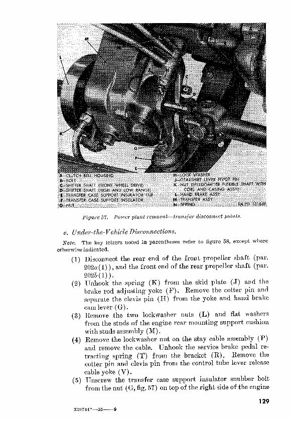
Figure 57. Power plant wmoval-trunsfer disconnect poids.
e. Under-the-Vehicle Disconnections.
Note. The key letters noted in parentheses refer to figure 58, except where
otherwise indicated.
(1)
(2)
(3)
(4)
(5)
Disconnect the rear end of the front propeller shaft (par.
202a( 1) ) , and the front end of the rear propeller shaft (par.
2026(l)).
Unhook the spring (K) from the skid plate (J) and t,he
brake rod adjusting yoke (F) . Remove the cotter pin and
separate the clevis pin (H) from the yoke and hand brake
cam lever (G) .
Remove the two lockwasher nuts (L) and flat washers
from the studs of the engine rear mounting support cushion
with studs assembly (M) . Remove the lockwasher nut on the stay cable assembly (I?)
and remove the cable. Unhook the service brake pedal re-
tracting spring (T) from the bracket Remove the
cotter pin and clevis pin from the control tube lever release
cable yoke (V) . Unscrew the transfer case support insulator snubber bolt
from the nut (G, fig. 5’7) on top of the right side of the engine
129
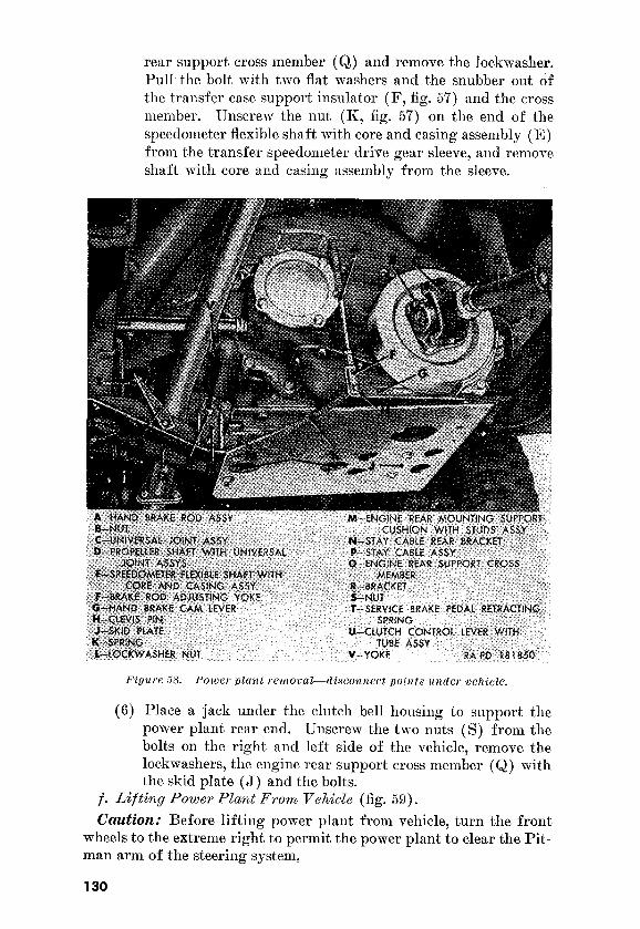
rear support cross member (Q) and remove the lockwasher.
Pull the bolt. with two flat washers and the snubber out of
the transfer case support insulator (F, fig. 57) and the cross
member. Unscrew the nut (Ii, fi g. 5’7) on the end of the
speedometer flexible shaft wit.11 core and casing assembly (E)
from the transfer speedometer drive gear sleeve, and remove
shaft with core and casing assembly from the sleeve.
Figure 5s. Pouxr plant ~enlocal-disco?lnect pnir1t.s u?lder vehicle.
(6) Place a jack under the clutch bell housing to support the
power plant rear end. Unscrew the two nuts (S) from the
bolts on the right and left side of the vehicle, remove the
lockwashers, the engine rear support cross member (Q) with
the skid plate (J) and the bolts.
f. Lif tiny Power Plant From Behide (fig. 59).
Caution: Before lifting power plant from vehicle, turn the front
wheels to the extreme right t,o permit the power plant to clear the Pit-
man arm of the steering system.
130

(1)
(2)
(3)
Connect a suitable lifting device to the rear eye of the lifting
hook. Carefully raise the engine sufficiently to lift the en-
gine front mounting support cushion assemblies from the
brackets on the frame.
Using a pry bar, slide the power plant rear toward the
vehicle right side until the clutch control lever with tube as-
sembly is off the control lever tube ball stud on
the transfer.
Raise the power plant sufficiently to clear the frame front
cross member, and roll the vehicle back while guiding the
Dower plant out of the vehicle. Place the power plant on
a suitable stand.
121. Power Plant Removal (M 170)
(fig. 54)
Procedures for power plant removal of the Ml70 are the same as
those for the M38Al (par. 120) except for substituting a and b belom
for paragraph 1206 (2) and (3).
a. Unscrew the connector (Y) from the generator receptacle (Z) . Unscrew the nut from the starter switch assembly (V) terminal stud
(IV) and remove the lockwasher, battery-to-starter cable assembly 82
(Q) , and the generator regulator-to-starter cable 4 (P) . b. Eemove the two sheet metal screws and flat washers from the
shield (J) and remove the shield.
131

122. Engine Removal From Power Plant
a. Remove the transmission and transfer by separating the trans-
mission from the engine (par. 1956 through g) , 6. Drain the cooling system (par. 127a(l) ) and remove the radi-
ator with shroud assembly (par. 128a).
123. Engine Installation on Power Plant
a. Install the radiator with shroud assembly on the power plant,
(par. 12Sb).
b. Install the transmission and transfer on the engine by connect-
ing the transmission to the engine (par. 196a through e) .
124. Power Plant Installation (M38Al)
a. Lowering Power Plant Ifnto Vehicle (fig. 59).
Caution: Before lowering the pomer plant into the vehicle, turn
the front wheels to the extreme right to permit the power plant to
clear the steering system Pitman arm.
(1)
(2)
(3)
Connect a. suitable lifting device to the lifting hook rear eye.
Raise the power plant sufficiently to clear the frame front
cross member.
Roll the vehicle forward and 1owe.r the power plant into
the engine compartment, tilt.ing the power plant rear end
down. Place a jack under the clutch bell housing and raise
the power plant rear end sufficiently to aline the transfer
ball stud with the clutch control lever with tube assembly
(U, fig. 58).
Using a pry bar, slide the power plant to the left and guide
the control lever onto the ball stud.
b. Under-the-Vehicle Connections.
Note. The key letters noted in parentheses refer to figure 58, except where
otherwise indicated.
(1)
(2)
Position the engine rear support cross member (Q) with
t.he skid plate (J) under the rear of the power plant. Posi-
tion the transfer case support insulator cup, insulator, and
r/s-inch washer on the right side of the cross member. Raise
the cross member and guide the studs in the engine rear mount-
ing support cushion with studs assembly (M) through t.he
holes in the cross member. Insert two 3/s-inch bolts through
the frame side rail and the cross member on both sides of the
vehicle. Install a 3/s-inch lockwasher and 3/8-inch nut on
each bolt.
Place a r/2-inch flat masher, the t.ransfer case support insu-
lator snubber, and a 17/,,-inch ID flat washer on the 1/2-inch
transfer case support insulator bolt. Push the bolt through
132

the cross member, the case support insulator retaining cup,
the case support insulator, the +&inch washer, and through
t.he hole in the transfer case support. Install a l/2-inch lock-
washer and ?&inch nut (G, fig. 57). Connect the speed-
ometer flexible shaft with core and casing assembly to the
speedometer gear sleeve on the transfer.
(3) Push the engine stay cable assembly (P) threaded end
through the clutch bell housing hole, and slide the opposite
end into the stay cable rear bracket (N) slot, Install a ys-
inch lockwasher nut on the cable. Position the yoke (V) on
the clutch control lever, and secure with a 5/116 x 2’7& clevis
pin and $& x l/2 cotter pin.
(4) Install a x,-inch ID flat washer and a $&-inch lockwasher
nut (L) on each of the two studs of the engine rear mounting
support cushion with studs assembly (M) .
(5) Place the brake rod adjusting yoke (F) on the hand brake
cam lever (G) and secure with a 5/,,-inch clevis pin and $& x
1/Z cotter pin. Hook the spring (K) to the yoke and skid
plate (J). Hook the service brake pedal retracting spring
(T) into the bracket (R) . (6) Install the rear end of the front propeller shaft (par. 203a
(2) ), and the front end of the rear propeller shaft (par 2032,
(I)). c. Driver’s Compartment Connections.
Note. The key letters noted in parentheses refer to figure 56, except where
otherwise indicated.
(1) Insert the transmission gearshift lever (A) in the housing
and screw the transmission gearshift lever housing cap onto
the housing. Slide the boot (C) and clamp (G) over the
lever and tighten the screw in the clamp. Slide the clamp
(J) over the lever and boot and tighten the clamp.
(2) Position the transfer high and low range gearshift lever (E)
in the shifter shaft (D, fig. 57) slot. Place a 5/s-inch internal-
teeth lockwasher on the gearshift lever pivot pin (J, fig. 57).
Working through the access plate opening, push the pin into
the transfer hole and part way through the lever hole. Posi-
tion the transfer front wheel drive gearshift lever (F) in the
shifter shaft (C, fig. 57) slot and slide the pivot pin through
the lever hole. Install the springs (N, fig. 57) over the pivot
pin and onto the levers. Screw the pivot pin into the
transfer.
(3) Swing the gearshift lever pivot pin access plate (D) into
position and tighten the two lockwasher screws. Slide the
boot (C) and the boot retaining ring (B) over the levers and
install the four sheet metal screws in the ring.
133

(4) Install the transmission gearshift lever knob on the lever.
Install the transfer high and low range gearshift lever (E)
and the transfer front wheel gearshift lever knobs (Ii) on the
levers.
d. Left Side Connections.
Note. The key letters noted in parentheses refer to figure 53, except where
otherwise indicated.
(1)
(2)
(3)
(4)
(5)
Insert two 5/ls x 7/s bolts, with flat washers, through the front
mounting support cushion bracket (L) and through the
front mount.ing support. cushion assembly (1~) and secure
wit.11 a 5/,,-inch lockwasher nut on each bolt.
Pull the link rod (C) down through the upper front floor
pan cover and insert the throttle rod adjusting block (R)
into the accelerator lower bellcrank with bushing assembly
(A). Secure the bellcrank to the block with a No. 8 flat
masher and a ylG x I/! cotter pin.
Install the exhaust pipe on the exhaust manifold (par.
146b(l) and (3).
Push the air regulating valve-to-distributor tee line hose (E)
onto the tee-to-windshield wiper line
Screw the nut (N) on the line (P) into the flexible fuel line
(M) and turn the fuel shutoff valve (Q) to the ON position.
e. Right &de Connections.
Note. The key letters noted in parentheses refer to figure 54, except lvhere
otherwise indicated.
(1)
(2)
(3)
134
Push the choke control assembly (P, fig. 64) t.hrough the
choke control conduit clamp (Q, fig. 64) and t.he choke valve
lever pivot (U, fig. 64). Make certain that. the choke con-
trol on the instrument panel is pushed in. Tighten the screw
in the pivot and clamp.
Push the throttle control assembly (D, fig. 64) through the
throttle control conduit clamp and the thrott,le rod (L, fig.64)
pivot. Make certain the throttle control on the instrument
panel is pushed in. Slide the throttle control wire stop with
screw (M, fig. 64) on the control wire (S, fig. 64) up to the
throttle rod (L, fig. 64) pivot. Slide the stop off the wire
slightly and tighten the screws in the stop and clamp.
Insert a 5/ls x 7/s bolt, with ylG-inch flat washer, through the
bracket (G) and the front mounting support cushion assem-
bly (E) at the front of the cushion, and secure with a 5/ls-
inch lockwasher nut Insert a 5/16 x 7/8 bolt, with x6-
inch flat washer, through the frame bracket (G) and the
front mounting support cushion assembly (E). Place a
“/ls-inch internal- and external-teeth lockwasher and ground

strap (H) over the bolt and secure with a VI,-inch lockwasher
nut (F).
(4) Connect cable 33 (R) to the engine water temperature sending
unit assembly (S) and cable 36 (T) to the engine oil pressure
sending unit assembly
(5) Insert the terminal plug of cable 12 (N) into the wiring
harness receptacle on the distributor housing and secure by
tightening nut
(6) Position the shield (J) on the frame side rail and the gen-
erator regulator mounting brackets on the frame, and insert
but do not tighten a sheet metal screw through the shield
and into the frame. Position the generator regulator assem-
bly (M) with the mounting brackets on the shield.
(7) Install the four lockwasher screws through the mounting
brackets, shield, and supports on the frame side rail.
Tighten the sheet metal screws securing the shield to the
frame. Place the generator regulator-to-starter cable 4 (P) , the battery-to-starter cable 82 (Q,) , and a 3/s-inch lockwasher
on the starter switch terminal stud (W) in the order named.
Secure with a s/s-inch nut. Insert cable 4 in the clip on the
shield (J) and install connector (I<) on the receptacle of
the generator regulator assembly (M). Connect the gen-
erator-to-generator regulator cable (IA) to the generator
receptacle (Z) .
(8) Install the air cleaner-to-air intake pipe flexible hose (C) and tighten the screws in the two hose clamps (B) .
Operations. (1) Install the radiator guard (par. 2573).
(2) Push the ground cable (fig. 99) through the grommet in the
battery box and position the cable end on the negative post
terminal of battery B. Secure with a 3/s-inch nut.
(3) If a new power plant was installed, fill the cooling system
(par. 127a(2) ) , fill the transmission, transfer, and crankcase
(par. 69).
(4) Install the hood (par. 255d).
(5) Start the engine and check for proper operation, and fuel,
oil, or water leaks.
(6) Make a record of replacement on DA Form 4’78.
125. Power Plant Installation (M170)
(fig- 54) Procedures for the power plant installation of the Ml70 are the
same as those for the M38Al (par. 124) except for substituting CG and
6 below for paragraph 124e (6) and (‘7).
a. Position the shield (J) on the frame side rail and install the two
sheet metal screws and flat washers securing the shield to the frame.
135

b. Place the generator regulator-to-starter cable. 4 (P) , the battery-
to-starter cable 82 (Q) , and a s/s-inch lockwasher on the starter switch
terminal stud (W) in t.he order named, and secure with a s/s-inch nut.
Connect the generator-to-generator regulator c.able (L) to the gen-
era.tor receptacle (Z) .
a. Description. The cooling system (fig. SO) includes the radiator,
fan, water pump, water temperature thermostat, fan and generator
drive belts, and connecting hose and fittings. The radiator is the cel-
lular-type with upper and lower tanks. A pressure-type filler neck
cap permits cooling system pressure to rise to 41/s psi. The four-
blade fan and the centrifugal-type water pump are driven from the
generator drive pulley by a matched pair of V-belts. The water tem-
perature thermostat is a bellows-type, located on top of the cylinder
head in the thermostat housing. With the coolant below normal
operating temperature (160” to 180” F.), the thermostat. blocks coolant
return to the top of the radiator, returning the coolant directly to the
pump through the water pump bypass.
b. Data.
Radiator : Manufacturer___________-_---_~_____-----__--------_-------_ Blackstone
Type-_______________________----_-----_-_____-----__-_-------_ cellular
Capacity____________--_____---________-~____-__----____------_- 11% qt
Filler cap_____-_____-__-------_____------____----__ 41/z psi pressure-type
Water pump and fan : Water pump ty~________________________-_______--____----- centrifugal Fan________________-__-____---_____-----___---- four blade, 15 in. diam
Drive_________________________--_______________---___--- double V-belts
Location__----__-___----__--__----~____--_______--frontofcylinderblock Drive belts :
Type______-_________--________--___-__-____--_----_--__ V,matched pair Width______________________---___--__----------___----_-________ 3/s in.
Thermostat : Location____________~-_____------_--_------- __ Thermostat housing Range (opening)____---_______-_-_______-_____----_---____ 148”-155” F.
Caution: The cooling system is pressurized. Be. sure the engine
coolant temperature is below 200” F., before loosening or removing
filler cap.
a. Draining and Filling.
(1) Draining. Open the hood and loosen filler neck cap to re-
lieve pressure in the cooling system. Remove the filler cap.
If coolant is to be saved, place suitable cont.ainers under the
136

(2)
Figure 60. Gooihg i3ystem
drain cocks (fig. 61). Open both drain cocks, allow sys-
tem to drain completely, and close drain cocks.
Filling. Be sure both drain cocks (fig. 61) are closed. Fill
the cooling system with water, or antifreeze solution of suf-
ficient strength to protect the system against the lowest an-
ticipated temperature, to a level one inch below the filler neck.
Be sure rust inhibitor is added to prevent the formation of
137

Figure 61. Cooling system drain cocks.
rust. Run the engine to circulate the coolant and expel air
from the system, and recheck the coolant level.
b. For directions on cleaning and flush-
ing, refer to TM 9-2858.
128.
Renaowak.
(1)
(2)
(3)
Drain the cooling system (par. 12’7a( 1) ) and remove the
radiator guard (pars. 257a for the M38Al and 266a for
the M1’70).
Loosen the hose clamp screws on the radiator water inlet and
water outlet hose (fig. 60) and pull hose from connections on
radiator.
Lift the radiator with shroud assembly off the radiator-to-
engine support rods, taking care that the radiator core does
not rub against the fan blade.
(1)
(2)
(3)
138
Lift the radiator with shroud assembly into posit,ion in front
of the fan, being careful not to damage the radiator core.
Insert the ends of the radiator-to-engine support rods into the
brackets on the bottom of the radiator.
Slip the radiator water inlet and outlet hoses over the con-
nections on the radiator, and tighten the hose clamp screws.
Install the radiator guard (pars. 25’73 and 266b) and fill the
cooling system (par. 127a (2) ) .

129. Coolant Hose
(fig. 60) a. Radiator Water Inlet Hose.
(1) Removal. Drain the cooling system (par. 127a( 1) ) suffi-
ciently to lower the level of the coolant below the thermo-
stat housing. Loosen the screw in the radiator water hose
clamp and pull the end of the radiator water inlet hose from
the connection on t.op of the radiator. Loosen the screw in
the hose clamp and remove the hose with clamps from the
thermostat housing. Remove the clamps from the hose.
(2) InstaZlation. Make sure the connections at radiator and
thermostat housing are clean and free of rust or scale.
Place a radiator wa.ter hose clamp on each end of the radia-
tor water inlet hose. Push one end of the hose over the ther-
mostat housing and the other over the connection on top of the
radiator. Tighten the screws in the clamps. Refill the cool-
ing system ( par. 127a (2) ) and check all connections for leaks.
6. Radiator Water Outlet Ilose.
(1) RemovaZ. Drain the cooling system (par, 127a( 1) ) . Loosen the screw in the radiator water hose clamp and pull
the end of the radiator water outlet hose from the connection
on the bottom of the radiator. Loosen the screw in the clamp
and remove the hose with clamps from the connection on the
water pump. Remove the clamps from the hose.
(2) Installation. Make sure connections at the radiator and
water pump are clean and free of rust or scale. Place a
radiator water hose clamp on each end of the radiator water
outlet hose. Push one end of the hose over the connection
on the bottom of the radiator and the other end over the con-
nection on the water pump. Tighten the screws in the
clamps. Fill the cooling system (par. 127a(2) ) and check
all connections for leaks.
c. Water Pump Bypass Hose.
(1) Removal. Drain the cooling system (par. 127a (1) ) . Loosen
the screws in the water pump bypass hose clamps,: Pull one
end of the hose from the connection on top of the water pump.
Remove the hose with clamps from the water bypass hose
nipple in the cylinder head. Remove the clamps from the
hose.
(2) Installation. Make sure water bypass hose nipple and con- nection on top of water pump are clean and free of rust or
scale. Place hose clamp on each end of the water pump
bypass hose. Push one end of the hose over the connection
on the top of the water pump and the other end over the
139

nipple. Tighten the screws in the hose clamps. Fill the
cooling system (par. 127~2 (2) ) and check all connections for
leaks.
130. Fan and Generator Drive Belt Set
(fig* 62) u. Acljustment. Loosen the lockwasher bolt securing the generator
belt tension brace to the generator drive end head. Place a straight-
edge over the fan and generator drive belts between t.he fan and water
pump pulley and the generator drive pulley. Move t,he generator
mltil the drive belts have a measured s/-inch deflection, as a result of
Figure 62. Adjusting fan and generator drice belt set.
a firm push, as shown in figure 62. When adjustment is correct,
tighten the lockwasher bolt securing the generator belt tension brace
to the generator drive end head.
b. Removal. Loosen the lockwasher bolt securing the generator
belt tension brace to the generator drive end head, and push the gen-
erator toward the engine as far as possible. Work the front fan and
generator drive belt over the front edge of the generator drive pulley.
When free, slip the belt over the fan blade and off the fan and water
pump pulley. Work the rear belt into the front grooves of both
pulleys, and follow the procedure used to remove the front bolt.
140

c. Ins taZZation. Place one fan and generator drive belt over the fan
blade and into the front groove of the fan and water pump pulley.
Work the belt into the rear grooves of the generator drive pulley and
fan a.nd water pump pulley. By the same method, place the second
belt in the front grooves of both pulleys. When the belts are in place,
adjust their tension (cd above).
131. Removing Fan and Water Pump Pulley From Water Pump
Assembly
a. RemovaZ (fig. 60).
(1) Remove the radiator with shroud assembly (par. 12%~).
Loosen the hose clamps screw on the water pump end of the
radiator water outlet hose, and remove hose with clamp from
connection on the water pump. Loosen the hose clamp screw
on the water pump end of the water pump bypass hose.
Remove the fan and generator drive belt set (par. 130b).
(2) Remove the four bolts and lockwashers securing the fan
blade to the fan and water pump pulley, and remove fan
blade.
(3) Remove the four screws and lockwashers securing the water
pump to the cylinder block; Pull the pump with pulley and
gasket from the cylinder block, at the same time, slipping
the connection on the water pump out of the end of the water
pump bypass hose. Discard gasket.
(4) Clamp the water pump in a vise with soft jaws. Using
pullerAl-P-2908-240 (fig. 63)) remove the pulley from the
pump*
b. InstalZation.
(1)
(2)
(3)
(4)
Place the fan and water pump pulley on the end of the water
pump shaft and press it onto the shaft until the front face of
the pulley hub is flush with the end of the shaft.
Make sure the gasket surfaces of the cylinder block and
water pump body are clean and free of rust or scale. Place
a new gasket on the water pump body with the gasket holes
alined with the bolt holes in the water pump body.
Position the water pump assembly (fig. 60) in the opening
in the front of the cylinder block, at the same time, sliding
the water pump bypass hose with clamp over the connection
on the water pump.
Insert a 5/ls x 21/2 screw, with lockwasher, through the hole
in the water pump body inlet opening. Start the threads but
do not tighten. Insert a 5/ls x 7/s screw, with lockwasher, into
the top mounting hole in the water pump body and through
the clip securing the flexible oil line to the cylinder block, and
start the threads. Insert two 5/ls x 7/s screws, with lock-
141

mashers, into the other two holes in the water pump body,
and tighten the four screws evenly and securely. Tighten
t.he screw in the hose clamp of the water pump bypass hose.
Place t.he fan on the front of the fan and water pump pulley
with the conca.ve side of the blades toward the engine. Secure
the fan blade t.o the pulley with four l/4 x 5/ bolts and
lockwashers.
03.
(6) Install the fan and generator drive belt set (par. 130~)) place
the end of the radiator water outlet hose, with clamp, over
t.he connection on the water pump and tighten the screw in
the clamp.
(7) Install the radiator with shroud assembly (par. 128b).
132. Water Temperature Thermostat
a. Remowl. Drain the cooling system (par. 127a( 1) ) sufficiently
to lower the level of the coolant below the thermostat housing. Re-
move the three screws and lockwashers securing the thermostat hous-
ing (fig. 60) to the cylinder block. Lift the end of the radiator water
inlet hose, with t.hermostat housing and gasket attached, from the
142

cylinder block. Lift the thermostat out of its seat in the cylinder
block. Discard gasket.
b. Be sure the gasket surfaces on the cylinder block
and thermostat housing are clean and free of rust or scale. Place the
thermostat in position in the cylinder block. Place a new gasket on
the cylinder block with holes alined. Position the thermostat housing,
with radiator water inlet hose attached, on the cylinder block. Secure
the thermostat housing to the cylinder block with three 3/s x II/ screws
and lockwashers. Refill the cooling system (par. 127a (2) ) . Check the
thermostat operation by running the engine with filler neck cap re-
moved, and watching the radiator coolant. Coolant flow should start
when an operating temperature of 160” I?., is reached.
Section VIII. FUEL AND AIR INTAKE SYSTEM
133. Description and Data
The fuel and air intake system includes the car-
buretor, fuel and vacuum pump, air cleaner, accelerator
throttle and choke controls, fuel filter, fuel tank, fuel level
gage, fuel level sending unit, and fuel lines and fittings.
(2) The air cleaner assembly (figs. 36 and
37), an oil bath-type with removable element and oil-cup, is
waterproofed. The assembly is mounted at the right rear of
the engine compartment and connected to the carburetor by
an air intake pipe and hose.
(3) Carburetor assembly. The carburetor assembly (figs. 36 and
37) is a waterproof, single venturi, downdraft balanced-type.
The float cha.mber and all control and adjustment points are
fully sealed. The carburetor assembly is mounted on the
right side of the engine and connects directly to a built-in
intake manifold.
(4) Fuel a& vacuncMn The fuel and vacuum pump (M,
fig. 67) is a diaphragm-type. It provides a constant flow of
fuel to the carburetor when the engine is running and a
constant vacuum to operate the windshield wiper motors.
The fuel pump is equipped with a hand priming lever. The
pump is mounted on the left side of the cylinder block at the
front of the engine.
(5) FuieZ The fuel tank (B, fig. 69 and fig. ‘70) is located
on the left side of the vehicle under the driver’s seat. The
filler cap with chain assembly is located in a left side recess
of the body panel. The fuel level sending unit is mounted
in the top of the fuel tank.
143

(6)
(7)
Fuel filter ussembZy.
fittings (fig.
b. Data.
Carburetor assembly : Rlanufacturer_______-__--________-_-______-_-_-_-__---_____---_- Carter
R~odel______~_______----_---____-.-____----______--__-_______-- YS 950 S
Type--~_--____--__--____--__----____--__---~__--__________-- downdraft
Venturi______________------______-___--_---_-___---__________--_- single
Adjustments____~_____--______---~--____---_--_~------ mixture and speed
Fuel and vacuum pump: ~lanufacturer________------____~~~~-_~~__---___ AC Spark Plug Div GMC
;\lodel____________----__--__--____--____-----__-__------- AC-GP1539810 Type--____--______--_-----__--__________--___--__________~- diaphragm
Drive______--_-______--__--__----__-_-___--~~______________-- camshaft
Pressure__-______________---________--____-_---- 4x-5 psi at 1,800 rpm Vacuum__________________--__--_--- 10 in. at 200 rpm, 12 in. at 1,500 rpm
Air cleaner assembly : RLanufacturer_______-__------__-----______~---------- United Specialties
Type__________________---_____--__-______-__--_---___________- oil bath
Capacity____________----_--------_____--__-----_____-----_----__ 11/ pt
Fuel tank : Capacity____________--____--__-_--______--__--~_--__________-- 17% gal
Type__-_-_--____----__------____--_---_---____-____-_____-- pressurized
Filler cap w/chain assemi~ly__~_________~~____..----~----~---- pressurized
134. Carburetor Assembly Note. The key letters noted in parentheses refer to figure 64, except where
otherwise indicated.
a. Adju&ments.
(1) Air-fuel mixture adjustment.
(160” to 180” I?.),
Caution:
Idle speed ad@&me&.

valve lever stop adjusting screw (J) in a clockwise direction
to increase and a counterclockwise direction to decrease the
engine speed.
b.
Loosen the screw in the hose clamp 66) at the
carburetor.
(2)
(3)
Unscrew the nut on the vent line (A) end from the vent
line elbow (B). Unscrew the nut on the fuel line (E) end
from the fuel line elbow (C). Remove both elbows.
Loosen the set screw (V) in the choke valve lever pivot
Loosen the bolt (R) from the nut in the choke control conduit
clamp (Q), and pull the choke control assembly out of the
145 339744”-55-10

(4)
(5)
(6)
pivot and clamp. Remove the two screws and lock washers
from the throttle control conduit clamp on the carburetor,
and remove the clamp.
Remove the cotter pin from the throttle rod (L) , and slide
the rod out of the throttle valve lever (K) . Unscrew the two nuts (G) from the studs and remove the
carburetor assembly from the studs and air intake pipe hose.
Remove the insulator (F) from the studs.
If the carburetor is to be replaced, remove the two elbows
(B and C).
c.
(1)
(2)
(3)
(4)
(5)
(6)
(7)
Install the vent line elbow (B) and the fuel line elbow (C)
in a new carburetor assembly.
Position the insulator (F) on the studs in the cylinder head.
Position the carburetor assembly (W) on the studs and into
the air intake pipe hose and secure with two y&inch nuts (G) . Slide the choke control assembly (P) through the choke con-
trol conduit clamp (Q) and into the choke valve lever pivot
(U) . Push the choke valve lever (T) forward as far as pos-
sible and tighten the set screw (V) . Tighten the bolt (R) in
the choke control conduit clamp (Q) . Slide the throttle rod (L) end through the throttle valve
lever (K) hole and secure with a yle x l/2 cotter pin.
Position the throttle control conduit clamp on the carbure.tor
and secure with two No. 10 x ‘$$e screws and lockwashers.
Install.the vent line (A) on the elbow (B) and the fuel line
(E) on the elbow (C) . Tighten the screw in the hose clamp
(C, fig. 66) at the carburetor.
Adjust the carburetor (a above) and check all controls for
proper operation.
d. ThrottZe VaZve Body-to-Manifold ZnsJator.
(1) RemovaL
(a>
(6)
(cl
Loosen the screw (B, fig. 66) in the hose clamp (C, fig. 66)
at the carburetor, and slide the hose (E, fig. 66) off the
carburetor assembly.
Unscrew the nut on the vent line (A) end from the vent
line elbow (B) . Unscrew the nut on the fuel line (E) end
from the fuel line elbow (C).
Unscrew the two nuts (G) from the studs. Raise the
carburetor assembly (W) to clear the studs and remove
the throttle valve body-to-manifold insulator Dis-
card insulator.
(2) Installation.
(a) Install a new throttle valve body-to-manifold insulator
(F) over the studs in the cylinder head.
146

@I
(4
Install the carburetor assembly (W) over the studs and
into the air intake pipe hose and tighten the screw (B,
fig. 66) in the hose clamp (C, fig. 66). Screw the two
3/s-inch nuts (G) on the studs and Cghten evenly.
Start the engine and warm it up to operating temperat.ure (160° to 180” I?.). Check the controls for proper opera-
tion and for air leaks around the thrott,le valve body insu-
lator. Adjust carburetor (a above).
135. Accelerator, Choke, and Throttle Controls
Note. The key letters noted in parentheses refer to figure 65, except where
otherwise indicated.
(a>
ud
(c>
The pedal adjustment is made through t.he threaded link
(E) of the accelerator pedal assembly (F) and the throttle
adjusting block (N) , Check for proper adjustment ( (b)
below).
To check for proper pedal adjustment, remove the cotter
pin and flat washer from the throttle adjusting block (N)
on the inner side of the accelerator lower bellcrank with
bushing assembly (S) and remove the block from the bell-
crank. Push the lower lever of the bellcrank to the front
of the vehicle as far as possible. Grasping t,he adjusting
block, pull the link (E) toward the front of the vehicle
as far as possible or until the pedal is resting on the floor
board. The adjusting block should line up with the hole
in the accelerator bellcrank. If adjustment is correct, in-
stall the block in the bellcrank and install the flat washer
and the cotter pin in the block. If adjustment is not cor-
rect, adjust ( (c) below).
Unhook the accelerator pedal return spring (T) from the
lower bellcrank with bushing assembly (S). Unscrew the
adjusting nut (P) and the lock nut (M) sufficiently to
permit adjustment. Swing the lower end of the bellcrank
(S) toward the front of the vehicle as far as possible.
Grasp the adjusting block and pull the link (E) toward
the front of the vehicle or until the accelerat,or pedal is
resting on the floor board. Holding the bellcrank and
link in this position, install the adjusting block in the bell-
crank and install a flat washer and cotter pin in the block.
Making sure the bellcrank and link are in the above men-
tioned positions, screw the adjusting nut and the lock nut up to the block and then tighten the nuts. Hook the
147

Fiywe 65. Carburetor controls (partial).
148

accelerator pedal return spring (T) into the bellcrank
When properly adjusted, this mill provide the maximum
engine acceleration.
(2) Removal.
(a)
(b)
cc>
(4
Remove the cot,ter pin and flat washer from the throttle
adjusting block (N) on the inner side of t,he accelerator
lower bellcrank with bushing assembly (S) and pull the
block out from t.he bellc.ra.nk.
Remove the cotter pin and flat washer from the pin
(J) and pull the pin out of the accelerator pedal assembly
(F) and the accelerator pedal hinge (I<).
Pull the accelerator pedal assembly (F) toward the vehicle.
rear and out of the accelerator link boot
Unscrew the adjusting nut (P) from the link Slide
t,he thrott.le adjusting block (N) off the link. Unscrew
the lock nut (M) f ram the link.
(3) ZnstalZation.
(6)
(cl
(4
(e>
Screw the lock nut (M) onto the accelerator pedal as-
sembly link (E). Slide the throttle adjusting block (N)
onto the link. Screw the adjusting nut (P) partway onto
the link.
Push the link (E) through the boot (H) and position the
pedal in the hinge (K). Position the hinge spring on
the hinge and the pedal.
Push t,he pin (J) through the hinge, over the hinge spring
and through the pedal, install an 11/32-incll ID flat washer
over the pin and a 1/G x 1/Z cotter pin in the pin, and
spread the ends.
Position t.he throt.tle adjusting block (S) on the bell-
crank (S) and install a No. 8 flat masher and a 1/16 x l/z
cotter pin on the block at the bellcrank inner side.
Adjust the accelerator pedal (a (1) above).
b. Accelerator Pedal Hinge Spring.
(I) Removal. Remove the accelerator pedal assembly (a(2) (a)
through (c) above) and remove the spring.
(2) Installation. Install the accelerator peclal assembly
(a(3) (6) and (c) above) and install the spring.
c. Accelerator Pedal Binge.
(1) Removal.
(a) Remove t,he accelerator pedal assembly (F) (a(2) (a)
through (c) above).
(6) Unscrew t,he two bolts from the nuts (L) and remove the
hinge (K) and the bolts.
149

(2) InstaZlation.
(a) Position the accelerator pedal hinge (K) on the floor
board. Push the two No. 10 x 1/2 bolts through the holes
in the hinge and the floor board and inst,all the No. 10
nuts (L) on the bolts.
(6) TL;St;rbll the accelerator pedal assembly (F) (4 3) (6) and
c a ove.
d. Accelerator Lower Bellcrank with BzLshing Assembly.
(1) Removal. Unhook the accelerator pedal return spring (T)
from the bellcrank (S). Remove the cotter pin and flat
washer from the accelerator bellcrank link rod (G) in the
bellcrank (S). R emove the cotter pin and flat washer from
the throttle adjusting block (N) on the bellcrank inner side.
Remove the cotter pin (R) and flat washer (Q) from the
valve compartment screw. Slide the bellcrank and flat
washer off the screw.
(2) Iristallation.
(4
(5)
(c)
Place an ?&-inch ID flat washer (Q,) over the 5/ls x Ss/,a
valve cover screw, and slide the bellcrank (S) over the
screw. Place an l&-inch ID flat washer (Q) over the
end of the screw, install a r/16 x 1/ cotter pin (R) in the
screw hole and spread the pin ends.
Install the throttle adjusting block (N) through the bell-
crank (S) rear hole. Place a No. 8 flat washer over the
block end on the bellcrank inner side, install a 1/1e x 1/
cotter pin through the block hole, and spread the pin ends.
Push the accelerator bellcrank link rod (G) end through
the bellcrank (S) f ront hole. Install a No. 8 flat washer
over the rod end, install a 1/1e x l/s cotter pin in the rod
hole, and spread the pin ends. Hook the accelerator pedal
return spring (T) into the bellcrank
e. Accelerator Be&rank Link Rod.
(1)
(2)
Removal. Remove the cotter pin and flat washer from the
rod (G) in the accelerator lower bellcrank with bushing
assembly (S). R emove the cotter pin and flat washer from
the rod (G) in the accelerator upper bellcrank assembly
(D) , and remove the rod from the upper and lower bellcranks.
In&a&&on. Install the accelerator bellcrank link rod (G)
through the upper and lower bellcrank (S and D) holes and
install a No. 8 flat washer over each end of the rod and a
l/l6 x 1,s cotter pin.
f. Accelerator Upper Be&rank Assembly.
(1) Removal. Remove the cotter pin and flat washer from the
accelerator bellcrank link rod (G) on the bellcrank (D) . Re-
move the cotter pin and flat washer from the throttle rod
150

(B) on the bellcrank (D). U nscrew the cylinder head screw
(C) securing the bellcrank to the cylinder head. Remove
the. screw and the bellcrank from the vehicle.
(2) Installation.
(a) Position the accelerator upper bellcrank assembly (D) on
the cylinder head, install a 7/le x 41/4 cylinder head screw
(C) through the hole in the bellcrank bracket, and screw
the cylinder head screw in tight.
(b) Push the accelerator bellcrank link rod (G) end through
the bellcrank (D) hole. Place a No. 8 flat washer over
t,he rod end, install a l/la x l/2 cotter pin through the rod
hole, and spread the pin ends.
(G) Push the throttle rod (B) end through the upper bell-
crank assembly (D) hole, place a No. 8 flat washer over
t,he rod end, install a $i6 x 1,s cotter pin through the rod
hole, and spread the pin ends.
g. Throttle Rod.
(1) Removal.
(a) Remove the cot,ter pin and flat washer from the throttle
rod (B) in the accelerator upper bellcrank assembly (D) . (b) Remove the throttle control wire stop wit.h screw assembly
(h(2) (a) below).
(c) Remove the cotter pin and flat washer from the rod (73)
in the throttle valve lever (U). Pull the rod out of the
lever a.nd the bellcrank and slide t,he rod with pivot off
the hand throttle control wire of the throttle control
assembly.
(2) Installation.
(a) (7))
(4
(4
Slide the throttle rod pivot onto the throttle control wire.
Push the rod (B) end through the t,hrottle valve lever
(U) hole, install a No. 8 flat washer over the rod end, a
I/le x r/s cotter pin through the rod hole, and spread the
pin ends.
Push the rod (B) opposite end through the accelerator
upper bellcrank assembly (D) hole, install a No. 8 flat
washer over the rod end, a l/la x 1/s cotter pin through the
rod hole and spread the pin ends.
Install the throttle control wire stop with screw (h (3) (d)
below).
h. Throttle Control Assembly.
(1) Adjustment. Loosen the set screw (N, fig. 64) in the throttle
control wire stop with screw assembly (M, fig. 64). Push
the throttle control (H, fig. 11) handle all the way into the
dash. Slide the stop (M, fig. 64) up to the throttle rod (L,
fig. 64) pivot ; then slide the stop away from t.he pivot slightly
and t,ighten the screw in the st.op.
151

(2) Remofvul.
b-4
(6)
(c>
(4
Loosen the set screw (N, fig. 64) and slide the throttle
control wire stop with screw assembly (M, fig. 64) off the
throttle control wire (S, fig. 64).
Loosen the screw in the throttle control conduit clamp (V)
from the nut.
Unscrew the lockwasher nut from the throttle control
assembly on the reverse side of the instrument panel.
Pull the throttle control assembly out of the pivot of the
throttle rod, the conduit clamp, and the grommet in the
dash, and out of the lockwasher nut and instrument panel.
(3) Installation.
(a>
(b)
(0)
(4
Push the throttle control assembly end through the instru-
ment panel hole part way and slide the s/s-inch lockwasher
nut over the control end.
Push the control end through the grommet, in the dash,
the throttle control conduit clamp (V) and the throttle
rod (B) pivot.
Install the 3/8-inch lockwasher nut onto the throttle control
assembly at the reverse side of the instrument panel. Push
the control handle all the way into the instrument panel.
Leave a little slack in the control between the grommet in
the dash and the throttle control conduit clamp and tighten
the screw in the clamp.
Make sure the control handle is pushed all the way into
the dash. Slide the throttle control wire stop with screw
assembly (M, fig. 64) over the wire ($5, fig. 64) end and
up to the throttle rod (L, fig. 64) pivot. Slide the stop
away from the pivot slightly and tighten the screw in the
stop.
i. Choke Control Assembly.
(1) Adjustment. Loosen the set screw (V, fig. 64) in the choke
valve lever pivot (U, fig. 64). Push the choke control (EE,
fig. 11) handle all the way into the instrument panel. Push
the choke valve lever (T, fig. 64) towards the front of the
vehicle as far as it will go. Tighten the set screw (V, fig. 64)
in the choke valve lever pivot (U, fig. 64).
(2) Removal.
(a) Loosen the set screw (V, fig. 64) in the choke valve lever
pivot (U, fig. 64). Loosen the bolt (R, fig. 64) from the
nut in the choke control conduit clamp (Q, fig. 64).
(6) Unscrew the lockwasher nut from the choke control assem-
bly on the reverse side of the instrument panel.
(c) Pull the choke assembly out of the pivot, the conduit clamp,
the grommet in the dash, the lockwasher nut, and instru-
ment panel.
152

(3) Installation.
Push the choke control assembly end through the hole in
the instrument panel part way, and slide the 3/s-inch lock-
washer nut over the control end.
Push the control end through the grommet in the dash,
the choke control conduit clamp (Q, fig. 64)) and the choke
valve lever pivot (U, fig. 64).
Screw the 3/s-inch lockwasher nut onto the choke control
assembly at the reverse side of the instrument panel and
tighten the nut.. Push the control handle all the way into
the intrument panel. Leave a litt,le slack in the control
between the grommet in the dash and the choke control
conduit clamp and tighten the screw in the clamp.
Sdjust the choke control ( (1) above).
a. Removal.
(I) Loosen the screw (B) in the hose clamp (C) at the air cleaner
assembly (A) and slide the flexible hose (D) off the cleaner.
(2) Unscrew the four lockwasher screws (Q) from the air cleaner
assembly (A) bracket and remove the air cleaner from the
vehicle.
153

(3) Loosen the screw in the clamp on the air precleaner with rain
deflector assembly (P) and pull the air precleaner and clamp
from the air cleaner.
bi Installation.
(1) Place the 31/s-inch clamp on the neck of the air precleaner
with rain deflector assembly (P) , install air precleaner on air
cleaner assembly (A), and tighten the clamp screw.
(2) Push the air cleaner into the flexible hose (D) and position
the air cleaner on the dash. Put the four 5/ls x 5/g lockwasher
screws (0,) through the air cleaner bracket holes and screw
them into the dash and tighten. Tighten the screw (B) in
the hose clamp (C) on the flexible hose (D) at the air cleaner,
137, Fuel and Vacuum Pump Assembly
Note. The key letters noted in parentheses refer to figure 67, except where
otherwise indicated.
a. Removal.
(1) (2)
(3)
(4)
Close the fuel shutoff valve (Q, fig. 55).
Unscrew the nut (B) on the fuel line (A) end from the elbow
(C) in the fuel and vacuum pump (M). Unscrew the nut
(Q) on the fuel line (P) end from the flexible fuel line (It).
Unscrew the nut (K) on the vacuum pump-to-tee line (J)
end from the elbow (L) in the pump. Unscrew the nut
(G) on the vent line (F) end from the elbow (H) in the
pump*
Unscrew the screw (N) and the bolt (E) in the pump and
remove the pump, spacer, and gaskets from the vehicle.
Unscrew the three elbows (C, H, and L) from the pump.
Unscrew the elbow (S) with the flexible fuel line (R) from
the pump if pump is being replaced.
6. Installation.
(1)
(2)
(3)
-(4)
154
If pump is being replaced, install the three elbows (C, H,
and L) and the flexible fuel line (R) with the elbow (S) in the
Pump*
Place a 3$6-inch lockwasher on the screw (N) and bolt
Push the screw and bolt with the lockwasher through the
pump holes.
Place a fuel pump-to-cylinder block gasket, fuel pump-to-
cylinder block spacer, and a gasket over the end of the screw
and bolt in the above named order.
Position the fuel and vacuum pump (M) with gaskets and
spacer on the cylinder block (D) and install the bolt (E)
and screw (N) into the block, tightening evenly.

(5) Screw the nut on t.he fuel line (A) into the elbow (C).
Screw the nut on the vacuum pump-to-tee line (J) end into
the elbow (L) . Screw the nut on the vent line (F) end into
the elbow (H) . Screw the nut on the fuel line (P) end into
the flexible fuel line (R) . (6) Turn the fuel shutoff valve (Q, fig. 55) on. Start the engine
and check for proper pump operation or leaks.
138. Fuel Filter Assembly
(fig* 69)
Remove the driver’s seat (pars. 261a( 1) for the M38Al and
2’72a( 1) for the Ml’70).
(2) Unscrew the nut (M) on the fuel line (C) from the fuel
filter assembly (H) .
155

(3) Unscrew the 12 screws (L) from the fuel filter assembly and
remove the screws and soft copper seal washers. Lift the
filter out of the fuel tank and remove and discard the neo-
prene gasket (J) from the top of the tank.
b. ImtaZlation.
(1)
(2)
(3)
Place neoprene gasket (J) around the opening in the
fuel tank for the fuel filter assembly (H). Install the filter
in the tank. Aline the holes in the gasket and the filter with
the holes in the tank. Place a soft copper sealing washer
over each of the 12 screws (L). Install the
screws through the filter and the gasket, screw into the tank,
and tighten evenly.
Install the fuel line (C) in the fuel filter assembly and screw
the nut (M) on the line end into the filter.
Install the driver’s seat (pars. 261a(2) for the M38Al and
for the M170).
139. Fuel Filter Element
(fig- 68)
(1) Remove the fuel filter assembly (par. 138a).
(2) Unscrem the nut on the line of the upper end plate with line
from the cover plate with vent assembly.
(3) Loosen the screw from the nut in the cover plate with vent
assembly bracket sufficiently to allow the fuel filter element
to slide through the bracket, and remove the element.
156
Figure GS. Fvel filter element-exploded view.

(4) Unscrew the nut from the screw in the element and remove
the lockwasher. Pull the screw out of the upper end plate
a.nd out of the element. Remove the lower end plate from
the bott.om of the element.
b.
Slide the lower end plate over the No. IO x 6 screw. Slide
the fuel filter element over the screw and position the element
on the end plate. Slide the upper end plate with fuel line
over the screw and position the plate on the element. Place
a NO. 10 lockwasher over the screw and a No. IO nut onto
the screw and tighten.
(2) Slide the fuel filter element into the c.over plate with vent
assembly bracket. Screw the nut on the line of the upper
end plate with line into the cover plate. Tighten the screw
into the cover plate with vent assembly bracket nut.
(3) Inst.all the fuel filter assembly (par. 1386).
140. Fuel Tank (M38Al)
(fig. 69)
a. fi?emoval.
(1) Remove the drain plug from the bottom of the fuel tank (R)
and drain the fuel into suitable container.
(2) Remove the driver’s seat (par. 261a( 1) ) . (3) Remove t,he fuel level sending unit assembly (T) (par. 189u)
and remove the sending unit cable 28 (N) from the clips (G) , (4) Remove the fuel filter assembly (par. 13%~).
(5) Remove the fuel line (C) (par. 142e ( 1).
(6) Remove the filler cap with chain assembly (E) by turning
t.he cap counterclockwise and unhook t.he chain from the
inside of the fuel tank filler neck (D) . (7) Remove the lockwasher screw (K) at the front and at the
rear of the tank from the mounting strap (Q) and remove
the strap and antisqueak (P) . (8) Slide the tank to the right of the vehicle until the filler neck
(D) has cleared the grommet (F) in the filler neck opening
in the side of the body, and remove the tank.
b.
(1) Position the fuel tank in the vehicle and carefully slide the
filler neck (D) through the grommet (F) in tile opening in
the side of the body.
(2) Position the antisqueak (P) over the top of the tank, install
the mounting strap (Q) over the antisqueak, install a 5/1e x 7/s
157

(3)
(4) (5)
lockwasher screw (K) through the hole in the strap at the
front and the rear of the tank, and screw into the floor pan
cover.
Place cable 28 (W) in the clips (G) and install the fuel level
sending unit (par 189b).
Install the fuel filter assembly (par. 1386).
Install the fuel line (C) (par. 142e ) .
(6)
(7)
(8)
Install the drain plug in the bottom of the fuel tank (B).
Install the filler cap with chain assembly (E) by hooking
the chain into the loop inside of the filler neck. Fill the tank
wit,h fuel, install filler cap on the filler neck, and turn in a
clockwise direction to lock the cap on the tank.
Start the engine and make sure there are no leaks at fuel line
connections. Check the fuel level gage for proper sending
unit operation.
Install the driver’s seat (par. 261a (2) ) .

141. Fuel Tank (Ml 70)
(fig* 70)
(1)
(2) (3)
(4) (5)
Remove the drain plug from the bottom of the tank and drain
fuel into a suitable container.
Tilt driver’s seat forward and remove (par. 1) ) .
Unscrew the seven lockwasher screws securing the fuel tank
unit access plate to the vehicle floor.
Unscrew the fuel line nut.
Disconnect the cable bayonet connector from the fuel level
sending unit.
Figure 70. Fuel tank, fuel, filter, and fuel 1evelJ sendirbg unit ussemblies
(~4lYO)-i?lstaIlcd--drivel’s seut and fuel tank uwt uccess plute removed.
(6)
(7)
(8) (9)
Pla.ce a stand or blocking under the t,ank, making certain
that such stand or blocking clears the fuel tank support strap
(fig. 71). Remove the four nuts and flat washers from the studs on the
fuel tank support strap attaching bracket,s at each end of the
fuel tank, and remove the two fuel tank shields and support
straps.
Remove stands or blocking and lower tank.
Remove the filler cap with chain assembly by turning the cap
counterclockwise~ and unhook the chain from the inside of
the fuel tank filler neck.
(10) Remove the 12 screws and soft copper seal washers securing
fuel filter assembly to the tank, and remove the filter assembly
and gasket.
159

Figure 71. F?lel tank (&fl70)--installed.
(11) Remove the five screws and soft copper seal washers securing
the fuel level sending unit to the tank, and remove the sending
unit and gasket.
6. Znstaklation.
(1)
(2)
(3)
(4)
(5)
(6)
(7)
160
Position fuel level sending unit and gasket on top of the
fuel tank and secure with No. 8 x 1/s screws and soft copper
seal washers.
Position fuel filter assembly and gasket on top of the fuel
tank and secure with twelve No. 8 x 7/ls screws and soft
copper seal washers.
Install new antisqueak strips to top of tank with adequate
adhesive.
Raise tank between the fuel tank support strap attaching
brackets and position stands or blocking under the tank, mak-
ing certain such stand or blocking will clear fuel tank sup-
port straps.
Make sure fuel line and fuel level sending cable
are accessible through fuel tank unit access plate opening
and are free from binding.
Aline the ends of the two fuel tank support straps and one
tank shield on the fuel tank support bracket studs at one
end of the tank. Start but do not tighten the two s/s-inch
nuts with washers on the two tank support bracket studs.
Repeat the procedure for the other end of the tank. Tighten
the four tank support bracket stud nuts.
Remove the stands or blocking.
Install the drain plug in the bottom of the tank.

(8) Connect the bayonet connector to the fuel level sending
unit.
(9) Install the fuel line nut to the fuel filter assembly.
(10) Bill the fuel tank. Install the filler cap with chain assem-
bly, by hooking the chain into the loop inside of the filler
neck, install filler cap on the filler neck, and turn in a
clockwise direction to lock the cap on the tank.
(11) Start the engine and make sure there are no leaks at the
fuel line connections. Check the fuel level gage for proper
sending unit operation.
(12) Position the fuel tank unit access plate over the opening
in the floor and secure with seven 1/4 x i/s lockwasher screws.
(13) Install driver’s seat by tilting the seat forward until seat
frame slips into seat brackets on the vehicle floor (par. 272~
(2) ) -
142. Fuel lines and Fittings
(fig* 72)
a. Flexible FueZ Line.
(1) RemouaZ. Unscrew the nut on the fuel line (Q) from the
flexible fuel line (M) . Unscrew the flexible fuel line (M)
from the connector on the fuel and vacuum pump assembly
(L). (2) Installation. Screw the flexible fuel line (M) into the con-
nector on the fuel and vacuum pump assembly (L). Screw
the nut on the fuel line (Q) into the flexible fuel line (M) . b. Fuel Shutoff Vahe-to-Flexible FueZ Line.
(1)
(2)
Remo&. Unscrew the nut at each end of the fuel line (Q)
and remove the line from the vehicle.
InstaZZatiolz. Position the fuel line (Q) between the shut-
off valve (P) and the flexible fuel line (M) and screw the
nut on each end of the line into the flexible fuel line and the
fuel shutoff valve.
c. Tee-to-Shutoff Valve Puce2 Line.
(1) IZemoual. Unscrew the nut on each end of the fuel line (N) . Remove the line from the clips (D) , and remove from the
vehicle.
(2) I9dallation. Position the fuel line (N) between the tee
(A) and the fuel shutoff valve (P) and screw the nut on
each end of the line into the tee and the shutoff valve. Se-
cure the line in the clips (D) . d. Rear Fuel Gne (Elbow-to-Tee).
(1) Removal. Unscrew the nut at each end of the fuel line
Remove the line from the clips (D) and remove from the
vehicle.
161 339744"-55---11

162

(2) Imtallation. Position the fuel line (E) between the tee (A)
and the elbow (F) and screw the nut on each end of the line
into the tee and the elbow. Secure the line in the clips
e. Tank-to-Elbow Fuel Line With Conduit Asembly.
(1) Removal.
(a) Remove the driver’s seat (pars. 261a( 1) for the M38Al
and 272a( 1) for the M170).
(6) Unscrew the nut on each end of the fuel line Re-
move the line from the clip (G) , and remove the line from
the vehicle.
(2) In.8tallation.
(a) Position the fuel line (H) between the fuel filter assem-
bly (I~) and the elbow (F) and in the clip (G). Screw
the nut on each end of the line into the elbow (F) and the
fuel filter assembly (K) . (6) Install the driver’s seat (pars. 261a(2) for the M38Al and
272a(2) for the M170).
f. FueZ and Vacuum Pump-to-Carihretor Line Assembly.
(1) Removal. Unscrew the nut on each end of the fuel line (R)
and remove the line from the vehicle.
(2) Instalation. Position the fuel line (R) between the fuel
and vacuum pump assembly (L) and the carburetor assem-
bly and screw the nut on each line end into t,he carbu-
retor and the fuel and Vacuum pump elbows.
g. Tee.
(I) Removal: Unscrew the nuts on fuel line (N and from
the tee (A), and remove the tee from the vehicle.
(2) Installation. Position the tee (A) between fuel line (N
and E) . Screw the nuts on the end of the lines (N and E)
into the tee.
h. Puel Xhutoff Valve.
(1) Removal. Unscrew the nut on fuel lines (N and Q) from
the fuel shutoff valve (P) and remove the valve from the
vehicle.
(2) Installation. Position the fuel shutoff valve (P) between
the fuel lines (N and Q) and screw the nut on the end of the
lines into the valve.
i. Blboz~ (Rear Fuel Line-to-Elbow, and Tar&-to-Elbow Line).
(1) RemovaZ. Unscrew the nut on the fuel line (H and E) from
the elbow (F) , and remove the elbow from the vehicle.
(2) Installation. Position the elbow (F) between the fuel line
(E and H) and screw the nut on the end of the lines into the
elbow.
163

Section IX. EXHAUST SYSTEM
143. Description
The exhaust system (fig. 73) includes the exhaust muffler, the ex-
haust pipe extension, and the exhaust pipe. The system is supported
at three poionts-the exhaust pipe is secured to the exhaust manifold
of the engine ; the exhaust pipe extension is secured to the frame by a
bracket and spacer; and the muffler is secured to t,he frame by a
muffler support clamp bracket around the tail pipe of the muffler
assembly.
Figure 1‘3. Exkactst system.
144. Exhaust System (fig. 74)
a. Removd.
(1)
(2)
(3)
Remove the t.hree safety nuts and bolts securing t,he muffler
flange to the exhaust pipe extension rear flange.
Remove the nut and bolt securing t.he muffler support clamp
bracket to the frame rear cross member.
Remove the exhaust muffler with bracket. assembly. Separate
and discard the gasket from the flange.
b. zrl8tulzutio!n.
(1) Insert three 5/ls x bolts through the front. flange of the ex-
haust muffler with bracket assembly, and place a new gasket
over the bolts. Raise the muffler into position and insert the
164

bolts through the exhaust pipe extension rear flange holes.
Start but do not tighten three 5/1e-inch safety nuts onto the
bolts.
Insert a 5/1e x 11/ bolt through the hole in the muffler sup-
port clamp bracket and the frame cross member. Place a
5/le-inch nut on the bolt end and tighten the bolt.
Tighten the three safety nuts on the bolts securing the
muffler to the exhaust pipe extension.
Start the engine and check all exhaust comlections for leaks.
muf/tev
a. Removal.
(1)
(2)
(3)
(4)
Remove the three nuts and bolts securing the exhaust pipe
extension to the exhaust pipe (fig. 73).
Remove the three nuts and bolts securing the exhaust pipe
extension to the exhaust muffler (fig. 74).
Loosen the bolt securing the mutiler support clamp bracket
to the frame rear cross member and slide the muffler back
about one inch.
While supporting the exhaust pipe extension, remove the
nut, washer, spacer, and bolt securing the exhaust pipe ex-
tension support bracket to the frame cross member.
165

(5) Separate the front flange of the exhaust pipe extension from
the rear flange of the exhaust pipe, and remove exhaust
pipe extension with bracket. Sepa,rate and discard gasket
from both flanges.
br
(1)
(2)
Clean the flange gasket surfaces. Loosen the nut and bolt
in the clamp at the exhaust pipe ext,ension support bracket
(fig. Place the exhaust pipe extension in approximate
position under the vehicle with the offset end toward the
exhaust muffler (fig.
Insert a. 5/ls x 11/ machine bolt through the bracket (fig. 74)
hole and slip the exhaust pipe extension spacer over the bolt.
Ra.ise the exhaust pipe extension wit.h bracket into posit.ion
with the bolt end inserted into the frame cross member hole.
Place a. 11/z ID x Il/ls OD washer over the bolt and screw
a 25/,,-inch nut on the threads enough t,o support the exhaust
pipe extension weight.
Place a new gasket on the front flange of the exhaust pipe
extension (fig. and insert three 5/1s x 1 bolts through the
exhaust pipe flange, gasket, and exhaust pipe extension
flange. St.art three se-inch nuts on the. three bolts, but do
not tighten.
Place a new gasket on the flange of the exhaust muffler (fig.
74). Pull the muffler forward and insert three 5/1s x 1 bolt,s
through the. muffler flange, gaskets, and rear fla.nge of the ex-
haust pipe extension. Start three ss-inch nuts on the bolts,
but do not tighten.
Tighten the bolts and nuts securing t,he exhaust, pipe exten-
sion to the exhaust pipe. Tight.en the bolts and nuts secur-
ing the exhaust pipe extension to the exhaust muffler (fig. 73).
Tighten the bolt securing the exhaust. pipe extension support
bracket to the frame cross member. Tighten the bolt and
nut in the support bracket clamp. Tighten the bolt secur-
ing the muffler support clamp bracket (fig. to the frame
rear cross member.
Start engine and check all exhaust connec.tions for leaks.
146. Exhaust Pipe
(fig.
Remove the nut from the stud in the. exhaust. manifold flange.
Remove the nut and bolt securing the exhaust pipe front
flange to the exhaust manifold.

(2)
(3)
Separate the flanges. Remove the three nuts and bolts
securing the exhaust pipe rear flange to the exhaust pipe ex-
tension front flange. Separate the flanges. Remove and
discard gaskets.
Drop the exhaust pipe down and remove.
b.
(1)
(2)
(3)
(4)
(5)
Clean the gasket surfaces of the exhaust pipe flanges. Place
a new gasket on the front flange and position the flange over
the 3/s-inch stud in the exhaust manifold. Start a s)&inch
nut on the stud, but do not tighten. Insert a s/s x 11/s bolt
through the manifold mounting hole and the flange hole.
Start but do not tighten a v&inch nut on the bolt.
Place a new gasket on the exhaust pipe rear flange and posi-
tion the flange against the exhaust pipe extension front
flange, alining the holes in the two flanges. Insert three
5/1a x 1 bolts through the holes in the flanges and gasket, and
start but do not tighten three y&-inch nuts on the bolts.
Tighten the nuts on the stud and bolt securing the exhaust
pipe to the exhaust manifold.
Tighten the three nuts and bolts securing the exhaust pipe to
the exhaust pipe extension.
Start the engine and check all exhaust connections for leaks.
The ignition system consists of the batteries, igni-
tion switch, distributor with coil assembly, spark plugs, and circuit
cables. The batteries are discussed in paragraph 162 and the ignition
switch in paragraph 181. The distributor with coil assembly con-
sists of the distributor, two capacitors, and ignition coil, in single
unit mounted on the right side of the engine block and driven from the
oil pump. The primary, or low voltage circuit includes the batteries,
ignition switch, breaker points, primary capacitor, breaker point
capacitor, and the primary windings of the ignition coil. The second-
ary, or high voltage circuit, consists of the secondary winding of the
coil, distributor rotor, distributor cover, cap assembly, spark plug
cable assemblies, and spark plugs. The entire ignition system is
waterproofed and includes devices for suppressing radio interference
as described in paragraph 280. Ignition system components and
cables are identified in figures ‘75 and 76.
167

II ’ _ I’
I
'12- . . dr5 \
Figure Igrbition system components and cables identification (iW3SAl).

I f 7
I r
169

b. Data.
Distributor with coil assembly : ~~anufacturer_________--__________________-____-_---- Electric Auto-Lite Rotation _________-______________-_______-__________-__ counterclockwise Type of advance ____________________--__-__________-_-_---- centrifugal Breaker point opening_____________-_____-__-----------__---_-_ 0.020 in. Breaker arm spring tension ______________~___________________ 17 to 20 oz Firing order ________~______________---_----------_--_-__-__---_ l-3-4-2 Voltage ________-_-_---_--____-_-----______-______--_--___-____------24 Cam angle __________~__________--_----_--_--_--_-___-----__-__--__ 22”
Ignition coil : Manufacturer ____________________-__-------__----_--- Electric Auto-Lite Model ____________________-_---_--__________-_----------__-- CT 4002 Voltage ____________~_________--_--_---________________--_-----___--- 24
Spark plugs : Ordnance number ~_______________________-__-__--__------_--__- 8357724 Thread size _____________________--____________-____-_--_--_--_--__ 14-mm Gap________~__________-__-~------___~~___-_----_------------- 0.030 in.
;
plug
170
SSchwend
38° per revision
SSchwend
22”

c. Unscrew the terminal nut securing the spark plug cable assembly
to the No. I spark plug (fig. 40)) and disconnect the cable. Push the
timing light adapter (fig. 77) over the spark plug and connect the
cable to the adapter. Connect one timing light terminal to the adapter
and the other terminal to a convenient ground.
d. Start the engine and run at idling speed. Direct the timing
light beam on the “5” timing mark on the timing gear cover (fig. ‘78).
The timing mark should be alined with the crankshaft pulley
notch. If not, loosen the mounting screw (fig. 79) securing the dis-
tributor with coil assembly to the spark advance control arm. Turn
the distributor until the timing mark and hole are alined. Tighten
the mounting screw.
light adapter-installed.
e. Stop the engine and remove the timing light. Pull the adapter
from the spark plug and unscrew the terminal nut from the adapter.
Connect the No. 1 spark plug cable assembly to the spark plug (fig. 40)
by screwing the terminal nut onto the spark plug.
a. Removal,
(1) Mark the spark plug cable assemblies for identification at
installation. Unscrew the four terminal nuts securing the
spark plug cable assemblies to the distributor cover and dis-
connect the cables.
171

(2)
(3)
(4)
(5)
Unscrew the t,wo nuts securing the two vent lines to t.he two
connectors and pull the lines from the connectors.
Unscrew the nut securing the primary cable to the wiring
harness recept.acle and pull the cable from t.he receptacle.
Remove the lockwasher screw and flat washer securing the
distributor to t.he spark advance control arm.
Note. This screw is installed through the control arm slot.
Lift the distributor with drive shaft from engine block.
Remove the spark advance control arm thrust washer from
the shaft. Remove the two vent line connectors.
Figure YS. Timing ma&s.
6. Znstullation.
(1)
(2)
(3)
172
Install vent line connectors in mounting holes. Make certain
that dist.ributor drive shaft friction spring is in place on
lower end of drive shaft. Slip the spark advance control arm
thrust washer over the shaft and against the bottom of the
distributor.
Insert the drive shaft into the engine cylinder block side bore
and lower the distributor with coil assembly into position.
If necessary, rotate the shaft until the distributor seats oa
the spark advance control arm.
Place a y$s ID x 5/s OD flat washer on a. l/4 x 5/ lockwasher
screw and start the screw through the spark advance control

(4)
(5)
(6)
(7)
arm slot and into the bottom of the distributor. Do not
tighten screw until after timing ignition (par. 149).
Insert the primary cable plug into the wiring harness recep-
tacle. Install the nut on the receptacle threads.
Insert the two vent lines into the two connectors and secure
by tightening the two nuts.
Connect the spark plug cable assemblies to the distributor
cover by screwing the terminal nuts onto the cover. Be cer-
tain that cables are installed in correct firing order.
Set the ignition timing (par. 149).
Figure 79. Distributor with coil assemb12/installed--wirirzg harness removed.
151. Distributor
a. Cover Mark the spark plug cable assemblies (fig. ‘79)
for identification. Unscrew the four terminal nuts securing
the spark plug cable assemblies to the cover and cap assembly
and disconnect the cable assemblies. Unscrew and remove
the six fillister-head screws securing the cover to the dis-
tributor. Remove the cover and cap assemblies. Remove
three bolts and lockwashers securing cap to cover (fig. 80).
Remove cap.
173

Figure 80. Distributor cap installed ix corer.
Figure 81. Distributor wit7L coil assembly-cocer alzd cap assem-nblies rernoz;ed.

,M InstaZJatiolz. Position cap in cover (fig. 80) and secure with
three No. 8 x 1 bolts and internal-teeth lo&washers. Position
the cover and cap assembly on the top of the distributor (fig.
79). Insert six No. 10 x ll/ls fillister-head internal-teeth
lockwasher screws into the six threaded holes in the top of
the distributor and tighten the screws. Connect the spark
plug cable assemblies to the cover by screwing the terminal
nuts onto the cover. Be certain cables are installed in correct
fir,ing order.
6. Breaker Point Xet.
(1)
Unscrew and remove the six fillister-head screws securing
the cover to the distributor and remove the cover with the
cap. Lift the rotor (fig. 81) off the cam.
(6)
(c)
(4
Pigzcre 82. Breaker point ga,p adjustm,ent.
Turn the crankshaft by pulling the top of the fan blade
toward the right side of the vehicle, and pressing firmly
on the drive belt. Continue turning until the breaker
points are open, with the breaker lever on one of the four
high points of the cam. Loosen the bolt securing the sta-
tionary contact bracket with point to the breaker plate.
Adjust the point gap by turning the adjusting eccentric
(fig. 82) until the gap is 0.020 inch. Tighten the bolt and
recheck the gap.
Place the breaker lever spring gage (fig. 83) end over the
moveable breaker point and pull on the gage at right angle
175

to the breaker lever. The p0int.s should start to open with
a pull of from 17 to 20 ounces. If necessary, adjust the
tension by bending the breaker lever spring.
(e) Place the rotor (fig. 81) on the cam, Position the cover
with the cap (fig. 79) on the distributor and secure the
cover to the distributor with six No. 10 x il/;a fillister-head
internal-teeth lockwasher screws.
(2) Removal (fig. 81). Remove the cover and cap assemblies
( (1) above). Loosen the terminal screw securing the
breaker lever spring clip to the breaker lever terminal. Slide
t.he breaker lever spring LIP and out of the clip and, at the
(3)
176
same time, lift the breaker lever up and off t.he pin. Remove
the bolt and lockwasher securing the stationary contact
bracket with point to the breaker plate, and remove the
bracket.
81). Place the. stationary contact bracket
with point over t.lie, breaker plate. pin, and over the adjusting
eccent.ric.. Slip a No. 8 internal-teeth lockwasher over a
No. 8 x 3/la bolt and st.art but do not tighte.n the bolt in the
breaker pla.te threads. Place the breaker lever onto the
brea.ker plate pin and position the breaker lever spring slot
over the screw inside the breaker lever spring clip. Push the
breaker lever onto the pin as far as it will go, making sure the
lever spring is in the clip, and tighten the. screw securing the

clip to the breaker lever terminal. Adjust the breaker point
set gap ( (1) (b) through (d) above).
(4) Instull rotor and cover. Refer to (1) (e) above.
c. Breaker Point Cupacitor~.
(1) IZemovaZ.
(a>
(b)
Unscrew and remove the six fillister-head screws securing
the cover to the distributor, and remove the cover and cap
assemblies (fig. ‘79). Lift the rotor (fig. 81) off the shaft
cam end.
Loosen the terminal screw securing the breaker lever
spring clip to the breaker lever terminal, and pull the
capacitor cable terminal from the screw. R’emove the
screw and lockwasher securing the capacitor to the breaker
plate, and remove the capacitor.
(2) Zn8tuUutio~n. Position the breaker point capacitor (fig. 81)
on the breaker plate and secure it with one No. 6 x s/16 screw
and 3/,,-inch internal-teeth lockwasher. Slip the capacitor
cable terminal onto the screw securing the breaker lever
spring clip to t.he breaker lever terminal and tighten the
screw. Position the rotor on the cam and the cover and cap
assembly (fig. 79) on the distributor and secure with six No.
10 x ll/ls fillister-head internal-teeth lockwasher screlvs.
a. P&MPV Capacitor.
(1)
(2)
3397440-55---12
Re&osai. Unscrew and remove the six fillister-head screws
securing the cover to the distributor housing, and remove the
cover and cap assembly (fig. 79). Remove nuts, washers,
and terminals of the ignition coil (fig. 81). Remove the two
bolts, lockwashers, and clips securing the ignition coil. Re-
move the ignition coil. Remove t.he four lockwasher screws
securing the wiring harness receptacle to the distributor
housing. Unscrew the nut (X, fig. 54) securing the primary
c.able to the wiring harness receptacle and pull the cable
from the receptacle. Pull the receptacle and primary ca-
pacitor from the distributor housing and separate the re-
ceptacle from the capacitor.
Installation. Insert the primary capacitor control into the
wiring harness receptacle (fig. 81) with the capacitor flange
against the receptacle flange. Insert t.he terminal end of the
ignition coil primary cable into the distributor housing; the
other end is soldered to the primary capacitor. Pull the
cable through sufficiently to place the csble terminal over
the positive terminal of the ignition coil and secure with a
No. IO lockwasher and No. 10 nut. Secure the wiring harness
receptacle to the distributor housing with four lockwasher
screws. Place the ignition coil in the dist,ributor housing.
177

Position and secure the ignition coil primary cable to t.he
coil mounting bracket with clip, No. 10 lockwasher, and a
No. 10 x ‘& bolt. Secure the ignition coil to the housing
with another No. 10 lockwasher and No. 10 x 7/re bolt. Insert
the primary cable plug into the wiring harness receptacle.
Start the nut onto the receptacle threads and tighten. Posi-
tion the cover and cap assembly (fig. 79) on the top of the
distributor housing and secure with six No. IO x 11/1e fillister-
head, internal-teeth lockwasher screws.
Figure 84. Ignition coil removal.
152. Ignition Coil
(1)
(2)
(3)
178
Unscrew and remove the six fillister-head screws securing
the cover to the distributor housing, and remove the cover
and cap assembly (fig. 79).
Remove the two nuts, washers, and cable terminals on the
two ignition coil terminals studs. Remove the two bolts,
lockwashers, and cable clips securing the ignition coil mount-
ing bracket and cables to the distributor housing.
Lift ignition coil (fig. 84) with mounting bracket from the
distributor with coil assembly.


(4)
rear, adjacent to the clutch bell housing, remove the nut and
copper washer from the bolt and then remove the bolt and
copper washer from the clutch and pinion housing of the
starter and the clutch bell housing. Working at the starter
top, adjacent to the clutch bell housing, remove the screw
and lockwasher securing the clutch and pinion housing of
the starter to the clutch bell housing.
Pull the starter straight forward toward the vehicle front
until the clutch and pinion housing is clear of the clutch bell
housing, and lift the starter out of the engine compartment.
Remove and discard the starter mounting gasket from either
the starter or clutch bell housing.
b.
(1)
(2)
182
Make sure all the old gasket is removed from mating
surfaces of the clutch and pinion housing of the starter as-
sembly and chtch bell housing. Coat a new starter mount-
ing gasket with plastic-type liquid cement and place the
gasket in position on the starter clutch and pinion housing.
Insert the starter clutch and pinion housing into the clutch
bell housing hole at the right side of the engine and position

3/ x 7/s
011
SUN
5Aq

(3) Connect the auxiliary power receptacle cable (if used), gen-
erator regulator-to-starter cable, and battery-to-starter cable
to the st,arter switch assembly terminal (par. 1556).
(4) Connect the battery “B” ground cable (par. 162b (9) (b) and
(0) )*
Description. The 24-volt, single-wire, waterproof generating
system (figs. 88 and 89) consists of the generator and generator reg-
ulator assemblies, connecting cables, and batteries. Refer to para-
graph 162 for information relative to the batteries. The system func-
tions to keep the batteries fully charged. A two-brush, 25 ampere,
24-volt generator (fig. 90)) mounted on the right side of the engine, is
driven in conjunction with the water pump by a matched pair of
V-belts from the engine crankshaft. A belt tension brace provides for
drive belt adjustment. The generator regulator (figs. 92 and 94)
assembly consists of three units; the voltage regulator, which controls
the generator output voltage to prevent overcharging the batteries;
the current regulator, which prevents overloading the generator ; and
the circuit breaker, which opens to prevent discharging the batteries
when the generator output falls below the level required to charge the
batteries.
b.
Generator:
Controlled output---_________-________________--______________ 25 amp Ground polarit~------__--___-________--_________-----___--_-_--___ neg Manufacturer_------__--______________ Delco-Remy or Electric Auto-Lit0 Model________________-_----_______----- DR-117495 or AL-GHA4m2UT
Voltage--_____----__-_-_________________-____--____--____--_-_______ 24
Generator regulator : ~peres----__-_-________-_-________--___--__-__--__________________ 25 Groundpolarity--_-____________________--__--__--------__--________ neg Manufacturer__-----__-______-_--__-__ Delco-Remy or Electric Auto-Lite Model_-____-__ __________ ____ ____ ________ DR-118606 or ALVBC4002UT Voltage_______--_--____-____---__________________________-_____-____ 24
Caution: Disconnect the batteries before attempting any work on
the generator assembly. See WARNING on top of the right front
fender.
a. Removal.
(1) Disconnect the ground cable of battery “B” (par. 1625 (8)
(a) and (6)).
184

+-I---@ -

186
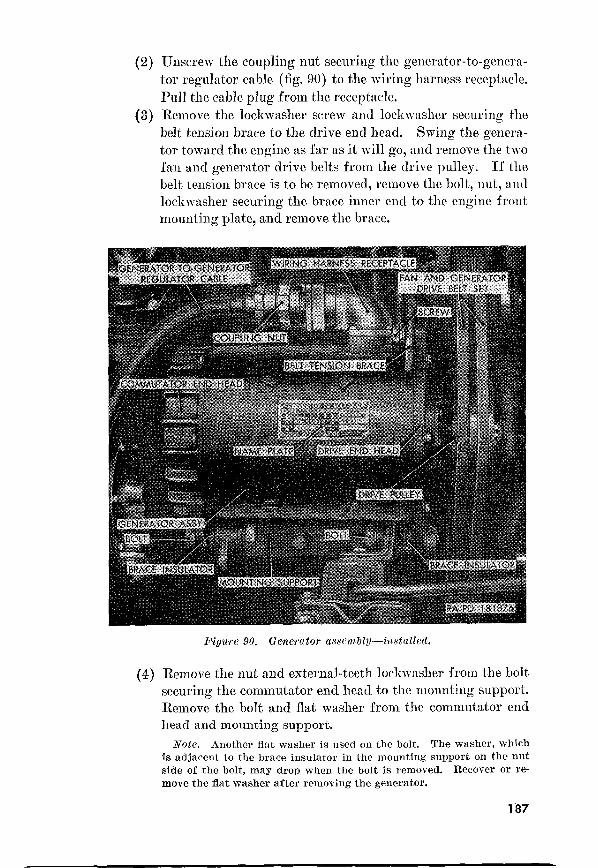
(2)
(3)
Unscrew the coupling nut securing the generator-to-genera-
tor regulator cable (fig. 90) to the wiring harness receptacle.
Pull t.he cable plug from t,he receptacle.
Remove the lockwasher screw and lockwasher securing the
belt tension brace to the drive end head. Swing the genera-
tor toward the engine as far as it will go, and remove the two
fan and generator drive be1t.s from the drive pulley. If the
belt tension brace is to be removed, remove the bolt, nut, and
lockmasher securing the brace inner end to t,he engine front
mounting plate, a.nd remove the brace.
(4)
Figure 90. Generator asscm~l?l-i,lstcclled.
Remove the nut and external-te.eth lockwasher from t,he bolt
securing the commutator end head t.o the mounting support.
Remove the bolt and flat washer from the commutator end
Note. is used on the bolt. The washer, which
is adjacexlt to the brace insulator in the mounting support on the nut
side of the bolt, may drop when the bolt is removed. Recover or re-
move the flat washer after removing the generator.
187

(5)
(6)
(8)
(9)
Disconnect the drive end head from the engine front mount-
ing support in the same manner as that outlined for the com-
mutator end head ( (4) above).
Lift the generator straight up until it clears the brace in-
sulators in the mounting support and engine front mounting
plate, and remove the generator.
Remove the cotter pin, castellated nut, and lockwasher
securing the drive pulley to the armature shaft. Using a
conventional puller, pull the drive pulley off the shaft. Re-
move the woodruff key from the shaft. Discard cotter pin.
91. Generator mounting sugportinstalled.
Inspect the two brace insulators (fig. 91) for damaged or
deteriorated condition. One insulator is mounted in the
mounting support, while the other is mounted in the engine
front mounting plate. If the insulators are damaged,
remove them
Remove the two bolts and lockwashers securing the mounting
support to the cylinder block and remove the support.
6. InsuZation.
(1) Place the mounting support (fig. 91) in position on the right
side of the cylinder block. Secure the support to the block
with two s/s-inch lockwashers and 3/8 x 7/s bolts.
188

(2)

slot with the receptacle pin. Push the pin in as far as pos-
sible and screw the coupling nut onto the receptacle, using
a spanner wrench.
(12) Connect the ground cable of battery “B” (par. 1626 (9) (b)
and (c)).
159.
Caution: Disconnect the batteries before attempting any work on
the generator regulator assembly. See WARNING on top of the
generator regulator cover and on top of the right front fender.
Figure 92. Generator regulator assembly installed (K%3Al).
Removal.
(1)
(2)
(3)
(4)
190
Disconnect the ground cable of battery “B” (par 1626 (8) (a)
and (5)).
Using a spanner wrench, unscrew the coupling nut of the
generator-to-generator regulator cable (fig. 92) and pull the
cable plug out of the receptacle.
Using a spanner wrench, unscrew the generator regulator
wiring cable coupling nut and pull the cable plug out of the
receptacle.
Remove the four plain nuts and lockwashers securing the
generator regulator assembly to the mount,ing bracket cush-

(5)
(6)
ion studs. Lift the generator regulator straight up unt,il
holes in base clear st,uds, and remove the regulator.
Remove the two lockwasher screws securing each of the two
mounting brackets (fig. 93) to the shield and support. Lift
the two mount.ing brackets off the shield. Unscrew the two
mount,ing bracket cushion st,uds from each mounting bracket..
Lift the ground strap from the stud in each mounting
bracket cushion.
Free the generator regulator wiring cable from the two
wiring clips mounted in the shield. Remove the screw and
Piyare 93. Generator regulator vzou,lting b~~cte7iets-inst(llle(l (Al3891 ) .
flat, washer securing the shield front to the frame right, side
rail. Lift the shield from the engine and the t.wo Firing
clips from the shield.
b. Insta7lation.
(1)
i-Q)
Install the two wiring clips in the shield (fig. 93). Position
the shield on the support. welded to t.he frame right side rail.
Secure the shield front to the frame right side rail with one
flat. washer and screw.
Install one end of a ground stra,p on one side. of the st,ud
protruding from one mount.ing bracket cushion (fig. 93).
Install the end of the st.rap on the other side of the
191

(3)
(4)
(5)
(6)
stud. Install a ground strap on the other three cushions in
the same manner. Install two mounting bracket cushions on
each of the two mounting brackets by screwing the stud
short ends in the cushions into the bracket outer holes, mak-
ing sure the bracket indented side is down. Screw studs
into brackets as far as possible, making sure the ground straps
face away from the bracket center. Position the two mount-
ing brackets on top of the support shield. Secure the
brackets to the shield and support with four l/4 x 3/4 lock-
washer screws.
Position the holes in the base of the generator regulator
assembly (fig. 92) (receptacles facing front of vehicle) over
the studs of the mounting bracket cushions. Secure the
regulator to the cushions with four 5/s-inch lockwashers and
yls-inch plain nuts.
Insert the generator regulator wiring cable plug into the
inner receptacle on the front of the generator regulator,
making sure to aline the plug slot with the receptacle pin.
Connect the plug to the receptacle by screwing the coupling
nut onto the receptacle, using a spanner wrench.
Connect the generator-to-generator regulator cable (fig.
92) to the outer receptacle on the generator regulator in
the same manner as described in (4) above for the generator
regulator wiring cable.
Connect the ground cable of battery “B” (par. 162 (b) (9) (b)
and (c)).
160. Generator Regulator Assembly (Ml 70) (fig. 94)’
Caution: Disconnect the batteries before attempting any work on
the generator regulator assembly. See WARNING on the top of
the generator regulator cover and on top of the left front fender.
a. Removal.
(1)
(2)
(3)
(4)
192
Disconnect the ground cable of battery “B” (par. 162b (8)
and (6)).
Using a spanner wrench, unscrew the generator-to-generator
regulator cable coupling nut, .and pull the cable plug out of
the receptacle.
Using a spanner wrench, unenrew the generator regulator
wiring cable coupling nut and pull the cable plug out of the
receptacle.
Remove the four plain nuts and lo!ckwashers securing the
generator regulator assembly to the mounting bracket cushion
studs. Slide the generator regulator forward until holes in
base clear studs, and remove the regulator.

(5) Remove the two lo&washer screws securing each of the two
mounting brackets to the dash, and remove the brackets. Un-
screw the two mounting bracket cushion studs from each
mounting bracket. Remove the ground strap from the stud
in each mounting bracket cushion.
6. Zmtallatiolz.
(1) Install one end of a ground strap on one side of the stud
protruding from one mounting bracket cushion. Install the
other end of the strap on the other side of the stud. Install
a ground strap on the other three cushions in the same manner.
Install two mounting bracket cushions on each of the two
mounting brackets, by screwing the stud short ends in the
cushions into the bracket outer holes, making sure the bracket
(2)
(3)
Figldre $4.
indented side is against the dash. Screw studs into brackets
as far as possible, making sure the ground straps face away
from the bracket center. Secure the brackets to the dash
with four l/L x 3/4 lockwasher screws.
Position the holes in the base of the generator regulator
assembly (receptacles facing the right side of the vehicle) on
the mounting bracket cushion studs. Secure the regulator
to the cushions with four 5/,a-inch lockwashers and 5/,e-inch
plain nuts.
Insert the generator regulator wiring cable pl~lg into the
inner receptacle in the generator regulator end, making sure
to aline the plug slot with the receptacle pin. Connect the
plug to the receptacle by screwing the coupling nut onto the
receptacle, using a spanner wrench.
193 339744”-55-13

(4) Connect the generator-to-generator regulator cable to the
outer receptacle on the generator in the same manner as
described in (3) above for the generator regulator wiring
cable.
(5) Connect the ground cable of battery “B” (par. 1626 (9) (5)
and (c) ) .
Section XIII. BATTERIES AND LIGHTING SYSTEM
161. Description and Data
(1)
(2)
(3)
(4)
(5)
(6)
(7)
194
G&eraZ. The 24-volt batteries and lighting system (figs. 95
and 96) is completely waterproofed. All cable connectors
are bayonet-type with interlocking sleeves. Rubber grom-
mets in the sleeves protect the connections from moisture. A
single circuit breaker in the generator regulator protects bot,h
the ignition and lighting systems from overload. All light
circuits are controlled by the light switch (E, fig. 13) on the
instrument panel. The continuity of all circuits is described
in paragraph 1’71, table IV, and cables are identified by num-
ber in figures 95 and 96. On the vehicle, cables are identified
by numbered tags near each cable end.
The 24-volt primary circuit is supplied
by two 12-volt lead- and acid-type storage batteries, connected
in series. The batteries and connections are designed for
under water operation. The batteries compartment is in
front of the dash on the right side of the vehicle.
Service 101). The sealed beam-type service
headlights are mounted in the radiator grille. High or low
beam is selected by a foot-operated switch.
A single blackout driving
light is mounted on the left front fender. This driving light
supplies a diffused, low-intensity light beam, for use when
the tactical situation prohibits use of the service headlights.
Xignal b kc&o& marker
Two light assemblies, one mounted directly below each serv-
ice headlight, serve the dual purpose of signal blackout
marker lights and service parking lights.
The blackout t,ail
and stop light is mounted on the right rear corner of the
vehicle body. The unit includes two lamps, a blackout stop
light in the upper half, and a blackout taillight in the lower
half.
Service 10’7). The service
tail and stop light assembly is mounted in the left rear corner
of the vehicle body. The upper half of the assembly houses

3 / Ill
I III
I I
\
===9
Figure 95. Batteries and lighting system components and cable identification (M38Al).

f-l-v
@
Y I ““l a
lighting sfptcm components

(8)
(9)
two lamp units, a service taillight, and a service stop light.
The lower half houses a single lamp unit, a blackout taillight.
Trailer coupling eZectrica1 connector receptacle (fig. 108) A
four-terminal receptacle is mounted on the left rear corner of
the body of the utility truck M38Al. This receptacle pro-
vides a means of connecting the electrical units of a towed
trailer to the vehicle electrical system. When connected,
trailer lights are controlled by the towing vehicle light
switch.
Emergency reel lamp (fig. 109). An emergency reel lamp
is mounted on the body of the front line ambulance Ml70 to
the left and to the rear of the driver’s seat. Voltage is
available at the lamp switch if any of the vehicle lighting cir-
cuits are turned on.
b. Battery Dutu.
Manufacturer ____________________--__----~-_--________-__ Electric Auto-Lite
31odel______-___-------__--___----__-_--~~.----___-_-__------_----_--- 2 HH
Voltage_~____--___--_-------___--------____~_--_-_--_--_--_-_-____-_____ 12
Plates per cell____-___________----__---------___--------_~__-___----__- I1
‘I’ype________-____--___-----___-__--_--~---_-______----~.---_---- waterproof
Number of batteries used____-__-------______-_---___---_--_~-_--~__--___ 2
How connected_.._--___--___---____--__---__._-____-__--_--__-_ series for 24~
162. Batteries and Battery Cables
a., Batteries. For purposes of identif-ication, the left battery (fig.
99) is referred to as battery “A,” and t.he right battery as battery “1%”
(1) Specific gravity test. Refer t.o TM 9-2857 for instructions
on performing specific gravity test.
(2) Adding water. Refer to TM 9-2857 for instructions on add-
ing water.
(3) Cleaning. Refer to TM 9-2857 for cleaning.
(4) Battery “A” removaL
(a> Loosen the eight thumb screws (fig. 97) securing batteries
cover in position on M38Al. Slide cover toward right side
of vehicle to disengage it from thumb screws, and remove
cover.
(b)
(c>
(4
Zl’ote. On the M170, the clamp is raised to remove the batteries
cover (fig. 9s).
Remove the negative post terminal with bolt and nut as-
sembly, and positive post terminal with bolt and nut as-
sembly (b(8) (c) beZow).
Remove the two wing nuts from the holddown frame bolts
and lift holddown frame assembly off bolts and battery.
Lift battery out of batteries compartment.
Caution: Do not use a lifting strap that fastens to bat-
tery posts, as damage to battery will result.
197

(5) Battery “B” Battery “B” removal is
the same as battery “A” removal ( (4) above).
(6)
Lower battery “A” (fig. 99) into batteries compartment
with the positive post facing left side of vehicle (see
Caution (4) (d) above).
(6) Install holddown frame assembly on holddown bolts and
battery, then secure frame in position with two sG-inch
wing nuts.
Note. In order to prevent any possibility of excessive battery
movement, make sure to install lockwashers under the wing nuts.
Figure 97. Batteries locatiow--batteries coz’er installe& (613881).
(cl
(4
(4
Install the negative post terminal with bolt and nut as-
sembly and positive post terminal with bolt and nut assem-
bly (b (9) (a) below).
Position the batteries cover on M38Al over bat-
teries compartment and slide towards left side of vehicle
to engage cover slots with thumb screws, then tighten
thumb screws securely.
Note. On the M170, the hinged corer is lowered and clamped
on (fig. 98).
Check polarity ( (8) below).
(7)
(8)
198
Battery “B” installation
is the same as battery “A” installation ( (6) above).
Test polarity by turning on headlights. If
lights illuminate, and ammeter registers DIS, polarity is

correct. If the lights illuminate, and ammeter registers no
apparent reading, one battery is reversed. If headlights
illuminate, and ammeter registers CHG, both batteries are
reversed. Correct installation as necessary.
b. Cables and Cabb Terminals.
(1) Cleaning. Refer to TM 9-2857 for instructions on cleaning.
(2) Ground ca6le assembly 7 removal.
(a) Remove batteries cover (a (4) (a) above).
(b) Remove the ground cable ‘7 from battery ‘(B” ( (8) (6)
below).
(c) Remove the lockwasher screws from the two clips securing
cable to dash and to fender splash apron (fig. 181). Spread
clips and remove from cable.
Figure 98. Batteries location-batteries cover installed (Ml70).
(4
(4
Remove the bolt and two lockwashers securing cable to
mounting bracket welded to the frame side rail at right
of generator regulator (fig. 92).
Withdraw cable from batteries compartment (fig. 99) and
remove from vehicle.
(3) Ground cable assembly No. 7 installation.
(a>
(b)
Install a y&inch lockwasher on a ys x 7/s bolt and insert
bolt through one terminal end of ground cable assembly.
Install another $&inch lockwasher on the bolt and thread
bolt into ground cable mounting bracket welded to frame
side rail at right of generator regulat.or (fig. 92).
Insert other terminal end of cable through grommet in
dash and into batteries compartment. Install cable 7
((9) (b) below).
199

Figure 99. Batteries installed--batteries cocer removed.
(6)
(4
Position a 5/s-inch clip on the ground cable and secure
clip to dash with a No. 10 x 1/2 lockwasher screw. Position
another 5/s-inch clip on the cable and secure to fender
splash apron with a No. 10 x $$ lockwasher screw.
Install batteries cover (a (6) (d) above).
(4)
(4 (6) (c)
(4
(4
200
Remove batteries cover (a(4)-(a) above).
Remove the battery-to-starter cable 82 ( (8) (b) below),
Remove the lockwasher screw from the clip securing the
cable to the dash, spread clip, and remove from cable.
Remove the nut and lockwasher securing the cable to
starter switch terminal and pull cable off terminal (fig. 87).
Withdraw cable from batteries compartment and remove
from vehicle.

(5) Battery-to-starter cable assembly No. 8!i? installation.
(a) Position one terminal end of battery-to-starter cable as-
sembly on starter switch terminal, and secure in position
with a s/&inch light lockwasher and s/s-inch nut (fig. 8’7).
(6) Insert other terminal end of cable through grommet in
dash and into batteries compartment. Install cable 82
((9) (b) below).
(c) Position a 5/s-inch clip on cable and secure clip to dash
with a No. 10 x l/z lockwasher screw.
(8) Install batteries cover (a (6) (d) above).
(6) Connecting cable assembly No. 68 removal (fig. 99).
(a) Remove batteries cover (a (4) (a) above).
(71) Remove the connecting cable assembly from battery “A”
and “B” ( (8) (b) below).
(7) Connecting cable assembly No. 68 installation (fig. 99).
(a) Install the connecting cable assembly to battery “A” and
“B” ( (9) (6) below).
(6) Install batteries cover (a (6) (d) above).
(8) Buttery cable terminal with ho& and nut assembly removal
(fig. 99).
Note. The remora1 procedure for positive post terminal or negative
post terminal on battery “A” or battery “B” is the same.
(a) Remove the batteries cover (a (4) (a) above).
(b) Remove the nut securing the cable to the integral stud of
the terminal with bolt and nut assembly and pull cable off
stud.
(c) Loosen the terminal nut and bolt and pull terminal off post.
(9) Battery cable terminal with bolt and nut assembly instalZa-
tion (fig. 99).
iVote. The installation procedure for positive post terminal or nega- tive post terminal on battery “A” or battery “B” is the same.
(a) Position the terminal on post and tighten nut and bolt.
(b) Position cable on integral stud of terminal with bolt and
nut assembly and secure with a s/s-inch nut.
(c) Install batteries cover (a (6) (d) above).
163. Headlights a. Adjustment.
(1)
(2)
Place the unloaded vehicle on a smooth, level, horizontal
surface so the headlights are 25 feet from a vertical wall or
other vertical surface. The center line of the vehicle should
be at right angles to the vertical surface.
Measure the height of the headlight center from the floor,
and mark a horizontal line at this height on the vertical
surf ace (X-X, fig. 100).
201

(3)
(4)
(5)
(6)
(7)
Mark line A-A, one-twelfth the distance between X-X and
the horizontal surface, below X-X (fig. 100).
Measure the distance from the center of the left headlight
to the center of the right headlight. Scribe this dimension
on line X-X and then mark vertical lines B-B and C-C
as shown in figure 100.
Turn on headlights at light switch and select high beam
with dimmer switch. It is not necessary to make adjust.ment
on low beam.
Cover one headlight while adjusting (aiming) the other.
Aim headlight so center of hot spot registers with intersecting
lines A-A and B-B, or A-,4 and GC respectively (fig. 100).
Remove headlight door (6 (1) (a) below).
(8)
(9)
Figure 100. Headlight adjustment chart.
Adjust headlight beam by the adjusting screws shown in
figure 101. Top adjusting screw provides vertical adjust-
ment and side screw provides horizontal adjustment. Turn
adjusting screws as necessary to obtain beam pat,t.ern as shown
in figure 100. Adjust opposite headlight in same manner.
Install headlight door assembly (6 (2) (d) below). Turn off
headlights.
b. Lump-Unit with Cables AssembZy.
(1) Remowd.
(a) Loosen the three door assembly screws and pull the door
off the headlight housing assembly.
(6) Loosen the three lamp-unit retaining ring screws (fig.
101). Turn the ring counterclockwise and remove from
the lamp-unit.
202

(cl
(4
Lift lamp-unit out of the mounting assembly and pull the
cable connectors out of the clips in the housing assembly
(fig. 102).
Disconnect the cable connectors and remove the lamp-unit
from the vehicle.
(2)
Position the lamp-unit at housing assembly and connect
the cable connectors (fig. 102) of cables 17, 18, and 91.
(6) Press the three cable connectors into the clips in the mount-
ing housing.
Cc)
(4
Figure 101.
Position the lamp-unit into the mounting housing. Install
the lamp-unit retaining ring over the three retaining ring
screws. Turn the ring clockwise to lock and tighten the
screws.
Install the door assembly on the headlight housing assem-
bly alining the three door assembly screws with the holes
in the housing assembly mounting brackets. Start the
screws into the bracket holes and tighten evenly.
c.
Follow procedure in b(1) above.
203

(2)
(3)
Remove the grommet, ‘headlight cable assembly, and the
ground c.able 91 from the headlight housing assembly (Kg.
104).
Remove the seven lock-washer screws from the front, and
one lockwasher screw from the rear, securing the headlight
housing assembly and the ground cable 91, to the radiator
guard assembly, and remove the headlight housing assembly
with the lamp-unit mounting assembly (fig. 102) and the
headlight. assembly mounting pad from the vehicle.
U~~.Yl~Zb~~J.
d. Headlight Ass-embly Installation.
(1)
(2)
204
Position the mounting pad on the rear of the housing as-
sembly and aline pad mounting holes with housing mounting
holes.
Position the housing assembly and mounting pad in radiator
guard assembly (f?g. 102) and aline housing and pad mount-
ing holes with radiator guard mounting holes. Secure hous-
ing and pad to guard with seven No. 10 x l/! lockwasher
screws from the front,. Position the cable 91 (fig. 104) on
the guard assembly at the rear and install a So. 10 x 1/2
lockwasher screw.

(3)
(4)
Insert headlight cable assembly and cable 91 through the
hole in the top of the headlight housing assembly and press
grommet into hole. Pull cables to front of housing far
enough to connect lamp-unit.
Follow procedure in 6 (2) above.
164. Blackout Driving light
Cables RepZacemerzt.
(1) RemouaZ.
(a) Loosen the three door assembly bolts and pull the door
and lamp-unit with cables free from the housing (fig. 103).
driving assembly
Pull the cable connectors free from the clips on the housing
and disconnect the cable Nos. 19 and 91 connectors, and
remove door and lamp-unit.
(c) Remove the three lamp-unit retaining springs (fig. 103)
from the door, and remove the lamp-unit.
(2) Installation.
(a) Position the lamp-unit with cables in the door, making
sure the metal locating tab on the unit is engaged in the
door slot. Install the three lamp-unit retaining springs.
(6) Position the door and lamp-unit at the housing and con-
nect the cable 19 and 91 connectors. Push the connectors into the clips in the housing.
(c) Position the door and lamp unit on the housing and aline
the door bolts (fig. 104) with the housing mounting holes.
Start the bolts into the mounting holes and tighten equally.
205

(1) Follow procedure in a( 1) above.
(2) Pull t.he cable assembly and the grommet out of the housing.
(3) Remove the nut, lockwasher, and washer securing the black-
out driving light assembly to the blackout driving light
guard, and remove the light from the vehicle.
c. Driving
(1) Position the blackout driving light assembly in the black-
out driving light guard and secure the light. Kith a xasher,
3/s-inch lockwasher, and s/&inch nut.
El'igtcre
(2)
(3)
Push the cable assembly through the housing hole and in-
stall the grommet on the cable and in the housing.
Follow procedureina(2) above.
(1)
(2)
(3)
206
Remove the two bolts securing the door with lens assem-
bly of the signal blackout marker and service parking light
(fig. and remove the door and the door gasket (fig. 105).
Reach into light assembly and turn lamp counterclockwise
and remove lamp.
Insert new lamp into lamp socket and turn clockwise to lock
lamp in position.

(4) Position door with lens assembly and door gasket on signal
blackout marker and service parking light assembly and se-
cure door to light with two No, 8 x 1/Z bolts.
b. LQht Assembly Removal.
ui
(2)
Disconnect signal blackout marker and service parking light
assembly cable 20 (fig. 182) from wiring harness cable 20
clipped to radiator guard assembly side.
Remove the lockwasher nut securing the light to its mount-
ing bracket welded to the radiator guard, and remove light
and mounting pad from vehicle.
Pigwe 105. Siy%al blackout marker and service parking light assembly--door removed.
c. Light Assembly Installation.
(1) Position mounting pad on mounting stud of signal blackout
marker and service parking light assembly. Insert light
assembly stud through mounting bracket hole welded to
radiator guard assembly. Secure in position with a 5/1a-inch
lockwasher nut.
(2) Connect connector end of light cable 20 (fig. 182) to connector
end of wiring harness cable 20 clipped to radiator guard
side.
106)
a. Lamp Replacement.
(1) Loosen the six door with lens assembly screws and remove
the door from the housing.
207

(2) Press in on faulty lamp and turn counterclock\\-ise to dis-
engage it from lamp socket.
Press new lamp into socket and turn clocklvise to lock it in
position.
Install the door wi;ith lens assembly on the housing and start
the six door screws into their housing mounting holes.
Tighten the screws uniformly.
6. Light AssembZy remounl.
(1) Working from underneath vehicle at rear of right wheel
house, disconnect cable connectors of cables 24 and 25. Pull
light cables out of clip secured to upper portion of mounting
bracket welded to vehicle body.
(2) Remove the two lock\vasher bolts securing light to mounting
bracket and, working from rear of vehicle, pull light out. of
body,
Cl>
(2)
(3)
Position blackout tail and stop light assembly in rear of right
wheel house and insert cables 24 and 25 through hole in
mounting bracket welded to vehicle body. Aline housing
mounting holes with bracket mounting holes.
Working from underneath vehicle in right wheel house,
insert the two 3/s x 5/s lock\vasher bolts through the rear of
mounting bracket and into housing mounting holes. Tighten
bolts uniformly.
Comlect the connectors of cables 24 and 25. Secure cables
in clip attached to upper portion of mounting bracket.

a. Lamp Replacement (fig. 107).
(1) Remove door with lens assembly (par. 166a (1) ) . (2) Press in on faulty lamp and turn counterclockwise to dis-
engage it from lamp socket.
(3) Press new la.mp into socket and turn clockwise to lock it in
position.
(4) Install door with lens assembly (par. 166a(4)).
b. Removal (fig. 108).
(1)
(2)
(3)
(4)
Remove the four lockwasher screws in the passenger com-
partment securing the service tail and stop light and the
trailer coupling electrical connector receptacle guard to the
body. Two of the screws are located on the top of the wheel
house and two are located on the body side panel of the wheel
house.
Remove the lockwasher screw securing the guard to the
bracket welded to the inner side of the wheel house outer
panel, and remove the guard.
Working from underneath the vehicle, remove the two lock-
washer bolts securing the service tail and stop light assembly
to mounting bracket welded to the body.
Working from rear of vehicle, pull light out of body and
disconnect cables 21,22, and 24 tail and stop light connectors.
Remove light from vehicle.
Pigure 107. Service tail aml, stop light assemDl?J-installed-door removed.
209 339744”~-55----14

assem- 6lie.s )-disconnect
c.
(1)
(2)
(3)
(4)
(5)
Position service tail and stop light assembly at vehicle body
and connect cables 21,22, and 24 connectors.
Position light in vehicle body and aline mounting holes in
bracket welded to body.
Working from underneath vehicle, install two 3/s x 5/s lock-
washer bolts through rear of bracket and into mounting holes
in the light housing. Tighten bolts uniformly.
Position the service tail and stop light and the trailer cou-
pling electrical connector receptacle guard in the wheel house.
Install the four 1/4 x 5/s lockwasher screws as located in b (1)
and (2) above.
The removal, installation, and lamp replacement for the instrument
panel lights and high beam indicator lights are contained in para-
graphs 179 and 180.
210

169. Trailer Coupling Electrical Connector Receptacle (M38Al) (fig. 108)
cc. Removal.
(1)
(2)
(3)
(4)
Remove the service tail and stop light and trailer coupling
electrical connector receptacle guard from the vehicle body
(par. 16’?%(l) and (2)).
Disconnect receptacle cables 21, 22, 23, and 24 from miring
harness cables 21,22,23, and 24.
Working from rear of vehicle remove the screw, nut, lock-
washer, and internal-external-teeth IQckwasher securing
cable 90 (ground cable) to vehicle body. ‘The screw is located
below the left of the receptacle.
Remove the four lockwasher screws securing the receptacle
to body and remove receptacle from vehicle.
Note. When removing receptacle from body, the cover assembly
and polarizing bracket are unavoidably detached from receptacle.
6. Instuzlution.
(3.1
(2)
(3)
(4)
(5)
(6)
Position polarizing bracket and cover assembly on trailer
coupling electrical connector receptacle assembly.
Insert receptacle into its mounting hole in body, alining
mounting holes in bracket, cover, and receptacle with mount-
ing holes in body. Secure receptacle in position with four
1/b x 5/s lockwasher screws.
Insert a No. IO x 5/s screw through its hole below and to the
left of the receptacle.
Working in the rear left wheel house, carefully position a
No. 10 internal-external-teeth lockwasher, cable 90 (ground
cable) of receptacle, No. 10 lockwasher, and No. IO nut on
screw installed in (3) above and tighten.
Connect receptacle cables 21,22, 23, and 24 to wiring harness
cables 21,22,23, and 24.
Install the service tail and stop light and trailer coupling
electrical connector receptacle guard (par. 167c( 4) ) .
170. Emergency Reel lamp Assembly (Ml701 (fig. 109)
a. Lamp Unit Replacement.
(1) Remove lamp unit by opening lamp unit cover nnd pressing
lamp unit in and t.urning in a counterclockwise direction.
(2) Install lamp unit by pressing lamp unit into lamp unit socket
and turning in a clockwise direction. Close lamp unit cover.
b. Light Assembly remoud.
(1) Disconnect the connector on cable 39 and slip cable from
retaining clip.
211

(2) Remove top lockwasher screw securing emergency reel lamp
mounting bracket to mounting pad.
(3) Remove bottom lockmasher screw, cable 39A bracket, and
internal-external-teeth lockwasher, and remove reel assembly.
c. Light Assem bZy Installation.
(1) Position holes in reel mounting bracket on mourning pad
holes on the left side of the driver’s seat and start the top
l/4 x l/s lockwasher screw, but do not tighten.
(2) Aline holes in cable 39A bracket, internal-external-teeth lock-
washer, and mounting bracket bottom hole and secure with a
l/4 x l/e lock~asher screw.
Emergency reel lamp
(3) Tighten the mounting bracket top lockwasher screw.
(4) Connect cable 39 bayonet connector and slip cable behind re-
taining clip.
171. Electrical Components and Cables
a. General. Each electrical cable, with the exception of spark plug
cables, is identified by a numbered metal tag at each end of cable. All
cables in a single circuit are identified by the same number; however,
when cables are connected through more than one connector, they may
connect to a different numbered terminal at each connector. Reference
should be made to figures 110 or 111 when making cable replacements.
212

/

’
-lB
.
1 M
i”in
-=YP
6 Figure 111. Vehicle electrical components and cable identification (iWl70).

Table TV lists each circuit number in the
electrical system and briefly traces each circuit from its source to its
end. A point-to-point check for circuit continuity can be made, using
a b’attery operated test light, conventional 24-volt test light, and volt-
meter equipped with long cables and suitable prods.
11
21
39A 40 68 75 82 90 91
Generator regulator output A terminal to starter. Battery “B” to ground. (ienerator regulator output B terminal to positive ammeter terminal. Generator regulator output D terminal to negative ammeter terminal. Generator regulator output C terminal to horn switch, ignition switch, and
light switch connector. Ignition switch to light switch F terminal. Distributor and ignition coil to ignition switch. Generator regulator 0 terminal to light switch F terminal. Light switch M terminal to dimmer switch. Headlight to dimmer switch and high beam indicator. Headlight to dimmer switch. Light switch D terminal to blackout driving light. Light switch E terminal to signal blackout marker and service parking
lights. Light switch H terminal to trailer coupling electrical connector receptacle
E terminal and service tail and stop light. Light switch C terminal to trailer coupling electrical connector receptacle B
terminal and service tail and stop light. Light switch N terminal to trailer coupling electrical connector receptacle F
terminal and blackout tail and stop light and service tail and stop light. Light switch E terminal to trailer coupling electrical connector receptacle
H and C terminals and service tail and stop light, and blackout tail and stop light and service tail and stop light.
Horn circuit from generator regulator C terminal to horn switch, horn, and horn ground.
Instrument panel to ignition switch. Fuel gage to fuel level sending unit. Engine water temperature gage to engine water temperature sending unit. Engine oil pressure gage to engine oM pressure sending unit. Light switch to emergency reel lamp assembly. Emergency reel lamp assembly to ground. Light switch B terminal to instrument panel lights. Battery “A” to Battery “IS”. Light switch A and K terminals to stoplight switch Battery “A” to starter. Battery “A” to starter. ‘l’railer coupling electrical connector receptacle to ground.
(Xrcuits 21, 22, 23, 24, and 90 do not include a trailer coupling electrical connector on the M170. Circuits 39 and 39A are not included on the M38Al.
215

a. Instrument Cluster (figs. 112 and 113). The speedometer, am-
met.er, engine oil pressure gage, water temperature gage, fuel level
gage, two instrument panel lights, and headlight high beam indicator
light are mounted in the instrument panel mounting plate located
in the instrument panel. This assembly is referred to as the instru-
ment cluster. The location and function of the va.rious units in the
instrument cluster are described in paragraphs 33 through 39.
0. &witches. The location and function of the various switches,
except for the stoplight switch, are described in paragraphs 23, 24,
and 25. The stoplight switch is attached to the front of the brake
master cylinder, and is hydraulically operated by the action of the
service brake pedal.
c. Xending Fnits.
(1)
(2)
(3)
P?~ghe zuate?, temperature sending unit (fig. 120). The en-
gine water temperature sendin g unit, mounted on the right
side of the cylinder head, electrically transmits the water
temperature to the water temperature gage through cable 33.
Engine oil pressure sending wnit (fig. 120). The engine oil
pressure sending unit, mounted on the right side of the cyl-
inder block, electrically transmits the engine oil pressure to
the oil pressure gage through cable 36.
FwZ level sending unit (figs. 69 and 70). The fuel tank level
sending unit, mounted in the top section of the fuel tank,
electrically transmits the fuel level in the tank to the fuel
gage t.hrough cable 28.
dJ Horn (fig. 104), The horn is of the vibrator-type, electrically
operated, and fully waterproofed. It is mounted underneath the
hood and attached to the left front fender by a mounting bracket.
The horn is connected to the horn switch by the two cables 25.
e. Cable Numbers. Standard circuit or cable numbers are used
throughout. These cable numbers are stamped on small melal tags
attached near the ends of each cable. These numbers are shown in
figure 110.
Note. The key letters noted in parentheses refer to figure 114, except where otherwise indicated.
a. Removal. Disconnect the ground cable 7 (par. 162b (8) (a) and
(b) ) . Turn each of the four instrument cluster mounting plate studs
(A, fig. 112) one-half turn counterclockwise and pull instrument
cluster free from instrument panel. Unscrew the nut securing the
216

Figure 112. InLstl-ument cluster (MSSAl)-front l;iezc.
Figure 113. Instrument cluster (M170)-frost dew.
217

speedometer flexible shaft assembly to the speedometer (DD) and
pull shaft from speedometer. Disconnect cable 2’7 at connector (T) from instrument cluster circuit breaker-to-gages wiring harness (AA).
Disconnect cable 17 at connector (U) . Disconnect cable 40 at double
connector (R) . Disconnect cables 8 and 9 at terminals (H and L) . Disconnect cable 33 at terminal (M) . Disconnect cable 36 at terminal
(W). Disconnect cable 28 at terminal (A). Remove instrument
cluster from instrument panel.
b. Installation. Position the instrument cluster at instrument
panel so cables may be connected. Connect cable 36 at terminal W,
and cable 33 at terminal 51. Connect cable 28 at terminal A. Con-
nect cable 8 at terminal H and cable 9 at terminal L. Connect cable
218

40 at double connector R. Connect cable 17 at connector U. Connect
cable 2’1 to connector T. Position speedometer flexible shaft assembly
in rear of speedometer and tighten nut securing shaft to speedometer
(DD). Install instrument cluster in instrument panel and secure in
position by turning the four instrument cluster mounting plate studs
(A, fig. 112) one-half turn clockwise. Connect ground cable 7 (par.
1623(9)(b) and (c)).
174. Ammeter IM38Al) and Battery Generator Indicator IMI 70)
a. Ammeter Removal (M38Al).
Note. The key letters noted in parentheses refer to figure 114, except where
otherwise indicated.
Disconnect ground cable ‘7 (par. 162.3 (8) (a) and (b) ), Turn the
four instrument cluster mounting plate studs (A, fig. 112) one-half
Figure 115. In’nstrzcment cluster (MlYO)--rear
219

(.
3
/

n P
‘L r
3
221

turn counterclockwise and pull instrument cluster free from instru-
ment panel. Disconnect cables 8 and 9 from terminals H and L.
Remove the nuts and lockwashers (Ii) securing the ammeter (B, fig.
112) and ammeter mounting bracket (J) in position and remove
bracket and ammeter from instrument panel mounting plate (E).
b. Ammeter ZnstaUation (M38Al) .
Note. The key letters noted in parentheses refer to figure 114, except where otherwise indicated.
Position the ammeter in the instrument panel mounting plate (E)
and rotate ammeter until it engages the locating slot in the plate.
Position ammeter mounting ,bracket (J) over the ammeter and secure
ammeter and bracket in position with two No. 8 lockwashers and nuts
(K). Install cable 8 on terminal H and cable 9 on terminal L. Posi-
tion the instrument cluster on the instrument panel and turn the four
instrument cluster mounting plate studs (A, fig. 112) one-half tllrn
clockwise. Conne.ct ground cable 7 (par. 1626 (9) (b) and (c) ) .
G. Battery Generator Indicator Removal (Ml70).
Note. The key letters noted in parentheses refer to Egure 115, except where otherwise indicated.
Disconnect the ground cable 7 (par. 1628 (8) (a) and (b) ) . Turn
the four instrument mounting plate studs (A, fig. 113) one-half turn
counterclockwise and pull instrument cluster free from instrument
panel. Disconnect cable 27 from terminal L. Remove the two nuts
and lockwashers (K) securing the battery generator indicator (B,
fig. 113) and the battery generator indicator mounting bracket (J),
and remove indicator and bracket from instrument panel mounting
plate (E).
d. Buttery Generator Indicator ZnstaLhtion (Ul70).
Note. The key letters noted in parentheses refer to figure 115, except where otherwise indicated.
Position the battery generator indicator (B, fig. 113) in the instru-
ment panel mounting plate (E) and rotate indicator until it engages
the locating slot in plate. Install the battery generator indicator
mounting bracket (J) over the indicator and secure the indicator and
bracket to the instrument panel mounting plate (E) with two No. 8
lockwashers and nuts (K). Connect cable 27 to terminal L. Position
the instrument cluster on the instrument panel and turn the four
instrument cluster mounting plate studs (A, fig. 113) one-half turn
clockwise. Connect ground cable ‘7 (par. 1626 (9) (6) and (c) ) .
175. Fuel Gage
a. Removal. The removal procedure for the fuel level gage (F,
fig. 112) is the same as the removal procedure for the ammeter (par.
174a) with the exception of the mounting bracket and the cables.
222

Fuel gage mount.ing bracket (B, fig. 114) is used. Disconnect cables
2’7 and 28 from terminals (D and A, fig. 114).
6. The installation procedure for the fuel level gage
(F, fig. 112) is the same as installation procedure for the ammeter
(par. 1746) with the exception of mounting bracket and cables. The
fuel gage mounting bracket (B, fig. 114) is used. Install cable 28
on terminal (A, fig. 114) and cable 27 on terminal (D, fig. 114).
176. Engine Water Temperature Gage
a. Removal. The removal procedure for the engine water tempera-
ture gage (J, fig. 112) is the same as the removal procedure for the
ammeter (par. 174a) with the exception of the mounting bracket and
the cables. Water temperature gage mounting bracket (N, fig. 114)
is used. Disconnect cable 27 from terminal (Q, fig. 114) and cable 33
from terminal (M, fig. 114).
b. The installation procedure for the engine water
temperature ga.ge is the same as the installation procedure for the
ammeter (par. 1746) with the exception of the mounting bracket and
the cables. Water temperature gage mounting bracket (N, fig. 114)
is used. Connect cable 33 to terminal (M, fig. 114) and cable 27 to
terminal (Q, fig. 114).
177. Engine Oil Pressure Gage
The removal procedure for the engine oil pressure
gage (G, fig. 112) is the same as removal procedure for the ammeter
(par. 174a) except for the mounting bracket and cables. Oil pressure
gage mounting bracket (V, fig. 114) is used. Disconnect cable 27 from
terminal (Y, fig. 114) and cable 36 from terminal (W, fig. 114).
6. Installation of the engine oil pressure gage (G,
fig. 112) is the same as installat.ion of the ammeter (par. 1746) with
the exception of t,he mounting bracket and cables. Oil pressure gage
mounting bracket (V, fig. 114) is used. Inst.all cable 36 on terminal
(W, fig. 114) and cable 27 on terminal (Y, fig. 114).
178. Speedometer Note. The key letters noted in parentheses refer to figure 114, except where
otherwise indicated.
(1) Turn the four instrument cluster mounting plate studs (A,
fig. 112) one-half turn counterclockwise and pull the instru-
ment cluster free from instrument panel.
(8) Unscrew the nut securing the speedometer flexible shaft
a.ssembly to the speedometer (DD), and pull shaft out of
speedometer.
(3) Remove the nut (CC), 1 k oc washer, and plain washer securing
the instrument cluster circuit. breaker-to-gages wiring harness
223

(4)
(5)
(AA) to the wiring harness mounting stud (BB) and detach
harness from stud.
Remove plain washer, wiring harness mounting stud, and
lockwasher from the speedometer mounting stud.
Remove the nut and lockwasher (G) from the remaining
speedometer mounting stud and remove speedometer mount-
ing bracket (F) and speedometer (DD) from instrument.
panel mounting plate
b. In8ta22ation.
(1)
(2)
(3)
(4)
(5)
Position the speedometer (DD) in the instrument panel
mounting plate (E) and locate speedometer mounting bracket
(F) over speedometer mounting studs.
Install a No. 8 lockwasher on speedometer lower mounting
stud, and screw the wiring harness mounting stud (BB) on
the speedometer mounting stud.
Install the 0.32’2-inch ID plain vvasher, instrument cluster
circuit breaker-to-gages wiring harness (AA), 0.203-inch ID
plain washer, and No. 8 nut (CC) on the wiring harness
mounting stud. Install a No. 8 lockwasher and nut (G) on
the remaining speedometer mounting stud.
Install the speedometer flexible shaft assembly in the speed-
ometer (DD) and tighten nut securely.
Position instrument cluster on instrument panel and turn the
four instrument cluster mounting plate studs (A, fig. 112)
one-half turn clockwise.
c. Speedometer Flexible Shaft Core Replacement. Disconnect the
speedometer at the instrument cluster (a( 1) and (2) above). Using
long nosed pliers, pull the core out of the speedometer casing. If the
core is broken, unscrew the nut (K, fig. 57) from the speedometer
driven gear sleeve on the transfer. Remove the lower end of the
casing from the sleeve and pull out the broken part of the core. Push
a new flexible shaft core into the upper end of the casing far enough
to seat. Position the lower end of the flexible shaft core in the speed-
ometer driven gear sleeve and secure the casing to the sleeve with nut
(K, fig. 57). Install the speedometer at the instrument cluster (6 (4)
and (5) above).
179. Instrument Panel Lights
Note. The key letters noted in parentheses refer to figure 114, except where otherwise indicated.
a. Removal (M38A1). Turn the four instrument cluster mounting
plate studs (A, fig. 112) one-half turn counterclockwise and pull in-
strument cluster free from instrument panel. The two instrument
panel lights with cables are permanently connected together in double
connector (R) and must be replaced as one unit. Disconnect cable 40
224

at double connector (R). - Remove the -f&r screws and lockwashers
securing the instrument panel lights (Z) to the instrument panel
mounting plate (E) and remove lights and instrument panel light
shields (I>, fig. 112).
b. /nntcrllcrtion (Mh’SAl). Position the instrument panel light
shields (D, fig. 112) in the instrument panel mounting plate (E).
Position the t,wo instrument panel lights on the plate and secure each
one with t,wo No. 8 x ?G6 screws and No. 8 lockwashers. Connect
cable 40 to double connector R. Position instrument cluster on in-
strument panel and turn the four instrument cluster mounting plate
studs (A, fig. 112) one-half turn clockwise.
c. Bemoz~a7 (MI70). Turn the four instrument cluster mounting
plat,e studs (A? fi,. * 113) one-half turn counterclockwise and pull in-
strument, cluster free from instrument panel. Unscrew the instrument
panel light, cover (D, fig. 113) from the instrument panel light (Z,
fig. 115). Disconnect cable 40 from connector (R, fig. 115). Unscrew
the nut (FF, fig. 115) and remove the lo&washer securing the instru-
ment panel light, (Z, fig. 115) to the bracket (EE, fig. 115) and push
light out of bracket, from the rear of the panel and through the opening
in the panel.
cl. Insfa77ation. (Ml7’0). Insert the instrument panel light into the
bracket (EE, fig. 115) through the opening in the instrument cluster
panel. Place a, locl~wasl~~ over the threaded end of t,he light and in-
stall the nut. (FF? fig. 115) securing the light to the bracket (EE,
fig, 115). Connect cable 40 to the connector (R, fig. 115). Screw the
cover (D, fig. 113) onto the instrument panel light (Z, fig. 115).
Position the instrument cluster on the instrument panel and turn the
four instrument cluster mounting plate studs (A, fig. 113) one-half
turn clockwise.
e. Laqlzp Replaccmenf (M3SAl), Turn the four instrument cluster
mounting plate studs (A, fig. 112) one-half turn counterclockwise and
pull instrument cluster free from instrument panel. Press in on the
cover of the instrument panel light (Z), turn counterclockwise and
pull cover off light body. Press in and turn lamp counterclockwise,
to disengage it. from lamp socket and remove lamp. Install new lamp
by pressing lamp into socket and turning clockwise. Install instru-
ment panel light cover by pressing in and turning clockwise in lamp
body. Position instrument. cluster on instrument panel and turn the
four instrument cluster mounting plate studs (A, fig. 112) one-half
turn clockwise.
f_ Lamp Replaeernmf (Ml70). Screw the instrument panel light
cover (D, fig. 113) counterclockwise and remove. Press in and turn
lamp counte.rclockwise to disengage. Install new lamp by pressing
lamp into socket and turning clockwise. Install instrument panel
light, cover.
225 3.39744°--55---15

ZZemovuZ Turn the four inst,rument cluster mounting
plate studs (A, fig. 112) one-half turn counterclockwis0 and pull in-
strument cluster free from instrument panel. Disconnect cable 1’7 at
connector (IT, fig. 114). Remove the two screws and lockwashers
securing the. headlight high beam indicator light in position and re-
move indicator light,.
7,. Position t,he headlight high beam in- dicator light (S, fig. 114) on the instrument panel mounting plate (II:, fig. 114) and secure in position wit,11 two No. 8 x $$ screws and No. 8 lockwashers. Connect cable 1’7 to connector (IT, fig. 114). Position
inst.nlniellt cluster on instrunient, panel and tarn the four instrument
clust,cr mounting plate st.ntls (A, fig. 112) one-half turn clockwise. c. /tes,?,ovu.z (MlYV) . Follow the same procedure as outlined in
paragraph 1707, (1) for instrument panel lights except that cable 17
is discollncc+ed from c~onncctor (T, fig. 115).
cl. /nshdlation (ilflD7). Follow the Saine procedure as outlined
in paragraph 1707, (2) for inst,rnment panel lights except t,hat cable 17 is connec1e~l to the conncct~or (T, fig. 115).
e. Lamp I2eplaccment (M38Al). Turn the four instrument cluster
mounl.ing plate st.uds (A, f ig. 112) one-half turn counterclockwise and pull instrument cluster free from instzunlent panel. Turn the cover
of the headlight high beam indicator light (S, fig. 114) counterclock- wise and I”111 cover out of light l)ody. l’ress in and turn lamp counter- clockwise to disengage it from lamp socket. Install new lamp by pressing it into lamp socket and rotating clockwise. Position indi-
cator light cover on light body, press in and turn cover clockwise to engage wit,11 light body. I’osition instrument cluster on instrument panel and turn the four instrument cluster mounting plate studs (A, fig. 112) one-half turn clockwise.
f. Lump Replacement (JllYO). $3 crew the instrument panel light cover (U, fig. 113) counterclockwise and remove. Prf5ss in and turn lamp counterclockwise to disengage, Install new lamp by pressing lamp into socket and turning clookwise. Install headlight high beam indicator light cover.
22emovaZ. Disconnect ground cable 7 from battery “13” (par. 1623(8)(a) and (b)). Remove, bolt, and lockwasher securing and ignition switch lever to the ignition switch (1~1, fig. 13) and pull lever off switch. Remove tile plain nnt and lockwasher securing the ignition
switch in position and push switch out, of instrument panel. Discon-
nect connector on cables 11, 12, and 27. Remove switch from face of inst,rument, panel.
226

6. InstaQation. Position switch in instrument panel and connect
connectors on cables 11, 12, and 27 (fig. 96). Secure ignition switch
in position with a $&inch lockwasher and plain nut. Position ignition
switch lever on t,he ignition switch and secure with a No. 8 lockwasher
and No. 8 x ys bolt. Connect ground cable 7 (par. 1626 (9) (6) and
(c)) to battery W.”
15)
a. /c’en?oval’. Remove the bolt and internal-teeth lockwasher se-
curing t.he main switch lever in position and remove switch lever and
118. switch-reverse side.
fiat wnsllcr. Remove the four lockwasher screws securing light
switch to the instrumental panel. Push in on light switch and, at the
same time, tilt down so the mechanical switch lever and auxiliary
switch lcrcr cuter ol)eniug in instrument panel and pull switch out
from reverse side of instrument panel. Disconnect the cable plug
from the. switch re.cept.ncle and remove switch.
b. Position light switch in instrument panel and se-
cure wit,h four No. 10 x I,! pan-head lockwasher screws. Connect
cable plug to receptacle in light switch. Make sure the felt washer is
instnllcd on the main switch lever shaft. Install a s/s-inch flat
washer on the shaft against the felt washer. Insta,ll main switch
227

lever on shaft and secnre in position with a No. 8 internal-teeth lock-
washer and No. 8 x rva bolt.
183. Headlight Dimmer Switch (fig. 119)
CG. /I’esn,omZ. Disconnect, cloilble c*onnec:t or on cable 17. Discon-
nect connectors on cables 16 and 18. Remove the two lo&washer
screws securing switch in position and renrove s\vit.ch.
6, 1nstu7Zation. l’osition hentlligl~t~ tlinlnler switch in t,he front
floor l)an ant1 SBCIIIY? with two $!t x I$$ lockwasher screws. Connect
cables 16 and 18 to c*oirncc:tors on switch. (lonnect cable 17 at double
connect 01‘.
184. Horn (fig. 105)
u. Be~~ovaZ. Disconnect the two cables 25 at the connectors on the
horn. Remove the two lockwasher bolts secnring the horn bracket to
fender and remove horn and horn bracket. To remove the horn in-
dependently from the bracket., disconnect the two cables 25 from the
connectors on the horn. Remove the two plain nuts, four lockwash-
ers, and two bolts securing the horn to bracket and remove horn and
name plate.
b. Installation. Position horn and horn bracket on fender and se-
cure in position with two l/4 x s/s lo&washer bolts. Connect cables 25
to connectors on horn. To install horn on horn bracket,, install a
$&-inch lockwasher on a 1, x .7/4 bolt. Position horn name plate on
horn bracket slining the mounting holes in the plate with mounting
holes in bracket, and insert bolt throngh name plate and bracket.
Position horn at horn bracket, alining the mounting holes in the horn
with the mounting holes in t,he bracket, and thread the bolt into the
horn. Install a IA-inch lo&washer on a lh x y4 bolt and insert bolt
228

through the remaining mounting hole in the name plate and bracket
and thread into horn. Tighten the two bolts’; then secure with two
I/-inch lockwashers and plain nuts. Connect the two cables 25 to
the connectors on t,he horn.
185. Horn Switch
a;. Removd. Disconnect the two cables 25 at the connectors (H,
fig. 161). Unscrew the switch from bottom of steering gear.
b. Instal7ation. Screw horn switch into bottom of steering gear
and tighten securely. Connect cable 25 to connectors (H, fig. 161).
186. Stoplight Switch
u. Remova?. Disconnect cables 75 at double connector (K, fig. 161)
on stoplight switch. Unscrew stoplight switch (L, fig. 161) from the
master cylinder omlet fitting bolt.
b. Installafion.. Screw stoplight switch (L, fig. 161) into the
master cylinder outlet fitting bolt and tighten securely. Connect
cables 75 at double. connector (K, fig. 161) on switch. Bleed brakes
(par. 237).
187. Engine Oil Pressure Sending Unit (fig. 120)
a. Removctl. Disconnect cable 36 connector from the engine oil pres-
sure sending unit. receptacle. Unscrew the sending unit oil line nut
from the elbow connector and pull the line free from the connector.
Note. Use cnre in pulling line free from connector to prevent binding of line.
Loosen the nut aud bolt, in the support and drop sending unit out of
support.
6. InstuZlafio/x. Insert the engine oil pressure sending unit into the
support and Gghten the support nut and bolt. Insert the sending
unit oil line nut into the elbow connector and tighten securely. Con-
nect cable 36 connector to the receptacle in the sending unit.
188. Engine Water Temperature Sending Unit
(fig. 120)
a. Removnl. Drain cooling system (par. 127a( 1) ) . Disconnect
cable 33 from receptacle in engine water temperature sending unit.
Unscrew and remove sending unit from cylinder head.
b. Installation. Screvv the engine water temperature sending unit
into the cylinder head and tighten securely. Connect cable 33 con-
nector to receptacle in sending unit. Refill cooling system (par. 127a
(2)).
189. Fuel level Sending Unit
a. Removal (M38A1). Remove driver’s seat (par. 261a( 1) ) . Dis-
connect cable 28 (N, fig. 69) connector from receptacle in fuel level
229

Figure 120. Engine oil pressure and engine water temperature
sending unit. Remove the five bolts and soft copper washers and lift
sending unit out of fuel tank. Remove and discard the fuel level
sending unit gasket from either the tank or unit,.
b. (M38A1). Clean fuel tank of any old gasket mn-
terials. Position a new fuel level sending unit gasket on the fuel tank,
alining the mounting holes in the gasket with mount.ing holes in tank.
Insert the fuel level sending unit into the tank and rotate unit to aline
the mounting holes. Secure unit in position with five No. 8 x 1/2
bolts and soft copper washers. Connect cable 28 connector to recep-
tacle in sending unit. Install driver’s seat (par. 26l’a( 2) ) . C. Removal (Ml70). Refer to paragraph 141a(2), (3), (5), and
(11). d. (M170). Refer to paragraph 1416 (l), (8), (12),
and (13).
Section XV. CLUTCH
190. Description and Data
a. The clutch, locat.ed between the engine and trans-
mission, is a single disk, dry-type, composed of two major units, the
clutch pressure plate (fig. 125) and the driven disk. The cont;lolled
pressure of the driven disk against the engine flywheel provides n
230

means of engaging or disengaging the engine power from the trans-
mission. The clutch is always engaged unless disengaged by de-
pressing the clutch pedal.
6. Data.
Type ___________~_______~~_____~--____------___---___-_____ Single dry plate
Torque capacity_____--_____--_----_-----___--__---__-----___-_- 144 ft-lb
Clutch driren plate w/facing assembly : Make--__________~_-__-_----_--___-----__-------~--______ Borg ana Beck
Facing material_____---_-____-----_------___-----_----_ two molded asbestos
Facing diameter. inside_______-____---___-----_----______------_ 51/3 in. Facing diameter, ontside__-__-____-------____--_____________-___ S1h in.
liacingthickness--_-_-_--------------_____-----__-_________-_ 0.138 in.
Clutch pressure plate assembly : Make--___-_----_----_-_----_-_---------------~_--_____-__---__ Auburn Number of springs-_______----__-------__----_-__---______-_---___--__- 6
191. Clutch linkage Adjustment
Q As the clutch facings wear, the free travel of the clutch pedal
diminishes. Check the clutch pedal free travel (fig. periodically
to make certain the clutch pedal has at least 11) inches of free travel
before the clutch starts to disengage.
Figure 121. Clutch pedal

b. Loosen the lock nut (fig. 122) that locks the yoke to the control
tube lever release cable. Unscrew the yoke from the cable until the
clutch pedal has 1x/4-inch free travel. Tighten the lock nut against
the yoke after the adjust.ment is made.
Description. The transmission (fig. 123) is a synchro-mesh,
selective-gear-type, with three forward speeds and one reverse. Speed
selection is accomplished manually by manipulating the transmission
gear shift lever. The lever extends out of the top of the control lever
housing into the driver’s compart.ment of the vehicle.
6. Data.
i\lake---______--_______--_________________---_-___------ Borg-Warner Corp,
Warner Gear Div. Type_________________--~-_-----__~-------___~~---___-~~~___-- synchromesh Speeds-___-_---______--________-_____----__--- three forward, one reverse
Ratios :
LOW (fi~S~)______---_____________--________-----__---_____-- 2.i98 to 1 Intermediate (second)__--__---_______---___----_-______--___ 1.551 to 1 High (third)_____________-________-_-_-_------__------------ 1.000 to 1 Reverse--____--___------___---___--_________-------------__- 3.iS8 to 1
Lubricant capacity________-_____-_____________-_--__-________-_____--_ 2 pt
Refer to paragraph 2 for information on coordination with an
ordnance maintenance unit.
232

Organiza t.ional maintenance of the transmission consists of lubrica-
tion (par. 69)) inspection for looseness or noise, and the testing of
the gearshift lever for proper operation.
a. Remove the power plant (par. 120).
6. Remove the transfer (par. 199).
c. Remove six lockwasher screws securing the linkage inspection
covers (fig. 123) to the top of the clutch bell housing. Remove the
cover and gasket. Working through the inspection hole, disconnect
the control tube lever release cable from the end of the release fork.
Disengage the fork from the release bearing carrier and lift the fork
out of the clutch compa.rtment. Discard gasket.
G?. While supporting the transmission, remove the four bolts and
copper washers (fig. 123) securing the transmission to the clutch
bell housing. P~dl the transmission straight back until the transmis-
sion input shaft is clear of the bell housing.
l%gure 123. Transmission rear view, transfer removed---power plant removed
from vehicle.
233

e. Disconnect the release bearing carrier spring (fig. 124) from
the transmission input shaft bearing cover. Slide the release bearing
carrier a.nd release bea.ring off the input shaft. Remove t,he release
fork ball stud from the bearing cover.
f. Remove the three socket-head cap screws and gaskets securing
the input shaft bearing cover (fig. 124) to the front face of the trans-
mission. Slide the cover off the input shaft and remove t.he case-to-bell
housing gasket. Discard gasket.
g. Remove the four bo1t.s and lockwashers securing the engine rea.r
mounting bracket to the bottom of the transmission and remove the
bracket.
196.
Position the engine rear mounting bracket (fig. 124) on the bot-
tom of the transmission. Secure the bracket to the transmission with
four 3/8-inch lockwashers and 3/s x 5/s bolts.
b. Coat a new case-to-bell housing gasket (fig. 124) \vith plastic-
type gasket cement. Position the gasket against the front face of
the transmission, alining the gasket holes with the transmission holes.
Slide the transmission input sha-ft bearing cover over the shaft
and into position against the gasket. Secure the cover and gasket
to the transmission Trith three q/le-inch screw gaskets and 5/ls x 11/4
socket-head cap screxs.
234

G. Slide the release bearing carrier (fig. 124) and release bearing
on to the input shaft, making certain to position the two flanges
vertically as shown in figure 124. Connect the release bearing carrier
spring to the bearin, v cover on the transmission. Install the release
fork ball stud in the bearing cover hole.
CL Aline the input shaft splines with the clutch driven disk (fig.
125) hub splines and insert the input shaft through the disk hub
until it seats in the engine flywheel clutch pilot bearing. Secure the
Pigure 125. Clutch bell housing--rem removed.
transmission to the clutch bell housing with four 7/r6-inch copper
washers and 7/1a x 11/ bolts (fig. 123). Tighten the bolts evenly.
e. Working through the inspection hole in the top of the bell hous-
ing, install the release fork so the fork recess engages the bearing
cover ball stud, and with the two ends of the fork behind the
release bearing ca.rrier flanges. Engage the control tube lever release
cable ball behind the two projections at the small end of the fork.
Coat a new linkage inspection cover gasket with plastic-type liquid
cement. Place the gasket and the inspection cover in position on top
of the clutch ball housing (fig. 123). Secure cover and gasket to bell
housing with six 1/4 x .1/2 lockwasher screws.
f. Install transfer (par, 200).
g. Install the power plant (par. 124).
h. Record the replacement of the transmission on DA Form 478.
235

Section XVII. TRANSFER
197. Description and Data
a. Des&p tion. The transfer is an auxiliary, two-speed gear unit.,
attached to the rear of the transmission. The transfer transmits
power from the transmission to the front and rear differentials through
propeller shafts. By manipulation of two transfer gearshift levers
(T, fig. 11)) additional high and low speed ranges can be selected. and
power to the front axle can be connected or disconnected. The hand
brake drum (fig. 126) and shoes are mountecl on the rear of the trans-
fer. A cover at the rear of the transfer provides access to the interior
of the assembly when installing a po\ver takeoff.
b~ake____-____-------_-----_-----___--__---___----__----~~-- Spicer Mfg Corp ~odel----___--_-________-____----_---_----_-~---__-------_-----_---- 38 Ratios :
Lowrange_______________---________-----------___----____--__ 2.43 to 1 High range______________~~__-------_--__----___--____-----__- 1.00 to 1
Lubricantcapacity____________----_---_-_---__-----_------_______-___--3 pt
198. Coordination With Ordnance Maintenance Unit
Refer to paragraph 2 for information on coordination with an
ordnance maintenance unit.
236

199. Transfer Removal
a. Remove the power plant (par. 120).
6. Remove the drain plugs from the transmission (fig. 123) and
transfer (fig. 126) and permit the lubricant to drain. After draining
completely, install the drain plugs.
c. Remove five bolts and external-teeth lockwashers securing the
transfer rear cover (fig. 126) to the transfer case. Remove t,he cover
and rear cover gasket. Discard gasket.
d. Shift transmission out of neutral and remove the cotter pin, nut
(fig. 127)) and washer securing the transfer drive gear to the trans-
mission main sha.ft,. Shift transmission back to neutral. Pull the
drive gear off the shaft..
While supporting the transfer, remove the four bolts and lock-
washers (fig. 12’7) two at the top, and two at the bottom, securing the
transfer to the transmission. Remove a fifth bolt and lockwasher
securing the transfer to the transmission from the lower right rear of
the transmission flange.
f_ Pull the transfer straight back until it clears the bearing mounted
on the transmission main shaft.
g. Remove and discard the transfer case-to-transmission gasket.
h. Remove the nut (fig. 128) and washer securing the companion
flange to the rear axle output shaft. Using a suitable puller, pull the
237

companion flange and hand brake drum off the shaft.. RemoT-e. the
four bolts securing the drum to the flange and separate the drum from
the flange.
i. Remove the nut ancl lockvasher securing the anchor pin (fig. 15%)
to the transfer. Pull the anchor pin, with inner and out.er shoes
attached, from the transfer.
Figure 128. Trunsfer removed.
200. Transfer Installation
Insert the anchor pin (fig. 128)) with inner mid outer shoe
attached, through the hole in the retainer of the transfer. Secure the
pin to the retainer with one %-inch xasher and nut.
6. Position the hand brake drum (fig. 128) on the companion
flange, with the drum rim toward the flange hub. Secure the drum
to the flange with four 3/s x 11/s bolts with bolts in position shown in
figure 128. Aline the flange splines with the rear axle out.put shaft
splines. Install the flange on the shaft, making certain the inner and
outer shoes are alined to mate with the brake drum rim. Using a
soft mallet, tap the flange into position on the shaft. Secure. the flange
to the shaft with one a/,-inch washer and a/-inch nut,.
23%

G. Make certain the transfer and transmission mating surfaces are
clean and free of old gasket material. Coat a new transfer case-to-
transmission gasket with plastic-type gasket cement and position the
gasket on t.he front side of the transfer case. Make certain the trans-
mission main shaft bearing is in place against the transmission rear
flange. Position the transfer assembly on the rear of the transmission
assembly. Secure the transfer to the transmission wit811 four 3/y x 1l/8
bolts (fig. 127).
Note. The four 3/s x ii/y bolts are installed from the rear side of the trnnsfel
flange into the transmission. The ys x 1 bolt is installed through the rear fln~lge
of the transmission into the transfer.
Draw the bolts up evenly.
d. Working through the opening at the rear of the transfer, slide
the transfer drive gear onto the transmission main shaft. Making
certain the drive gear teeth are mated with the transfer countershaft
gear teeth. Secure the gear to the shaft with one ys-inch washer,
“i/s-inch nut, and 1/s x 11/4 cotter pin.
Note. Shift transmission out of neutral, if necessary, to prevent, main shaft
turning when nut is tightened.
e. Coat a new rear cover gasket with plastic type gasket cement
and position gasket and transfer rear cover (fig. 126) on the rear of
the transfer case. Secure the cover to the case with five $&inch
external-teeth lockwashers and five 3/3 x 3/4 bolts.
f. Install the power plant (par. 124).
9. Record the replacement of the transfer on DA Form 4’78.
Description. The front propeller shaft (fig. 129) with universal
joints transmits power from the transfer to the front axle. The rear
propeller shaft, (fi,. 0’ 130) with universal joints transmits power from
the transfer to the rear axle. Each assembly includes a propeller
shaft, a universal joint sleeve yoke, and two universal joints. Cor-
responding parts of the front and rear assemblies are similar except
for the length of the shaft, and the front universal joints of the rear
propeller shaft. This universal joint includes the propeller shaft
flange yoke, and is modified accordingly.
b.
Manufacturer_______________-_______-__----_~----__-_--____ Spicer Mfg Corp
Type of shaft_-_________----__________--___--_____-_ tube, with welded seam
Type of joints_________-__----_________--__--___---___---___- roller bearing
239

202. Front Propeller Shaft With Universal Joints (fig. 129)
a. h!ernoval.
(1)
(2)
Remove the four safety nuts from the two U-bolts securing
t.he rear universal joint to the transfer-front axle output
shaft yoke. Remove the U-bolts and separate the universal
joint from the yoke.
Loosen and remove the four safety nuts from the two U-
bolts securing the front universal joint to the front axle end
yoke with shield assembly. Remove the U-bolts, and remove
the front propeller shaft, wit.h universal joints from under
the vehicle.
Figure
b. In&allation.
(1) Position the front propeller shaft with universal joints under the front of the vehicle and insert the front universal joint
into the front axle end yoke with shield assembly. Place the
two U-bolts over the two exposed journal bearings and insert
the U-bolt ends through t.he holes in the axle end yoke. Secure
the U-bo1t.s to the yoke with four yra-inch safety nuts.
(2) Insert the rear universal joint into the transfer-front axle
output shaft yoke. Place the two U-bolts over the two ex-
posed journal bea.rings and insert the U-bolt ends through
the holes in the yoke. Secure the U-bolts to t.he yoke with
four 5/1a-inch safety nuts.
240

203. Rear Propeller Shaft With Universal Joints (fig. 130)
a. Rem0 ual.
(1) Remove the four sa,fety nuts from the two U-bolts securing
the rear universal joint to the rear axle end yoke. Remove
the U-bolts, and separate the universal joint from the yoke.
(2) Loosen the four nuts on the bolts se.curing the rear propeller
shaft flange yoke to the transfer companion flange. Remove
t.he nuts and lockwashers, and remove the propeller shaft with
universal joints from under the vehicle.
b. Imtallation.
(1) Posit,ion the rear propeller shaft with universal joints under
the rear of the vehicle. Position the rear prope,ller shaft
Figure 180. Rear propeller shnft LcitA wniversal joints--installed.
(2)
flange yoke on the four ys-inch bolts projecting from the
transfer companion flange. Place four 3/s-inch lockwashers
and 3/s-inch nuts on Ohe ends of the bolts, and tighten the nuts.
Insert the rear universal joint into the rear axle end yoke.
Place two U-bolts over t.he two exposed journal bearings, and
insert the ends of t,he U-bolts through the holes in t.he yoke.
Secure the U-bolts to the yoke. with four y16-inch safety nuts.
204. Universal Joints
a. Frond PropeZZer Shaft Universal Joinh Disassembly (fig. 131).
Procedures for disassembly of both universal joints of the front pro-
peller shaft with universal joints are the same.
(1) Remove front propeller shaft with universal joints (par.
202a).
241 339744”-55--16

(2)
(3)
Remove the two loose journal bearings and oil seals from
journal, being careful not to lose the rollers. Do not remove
the plug.
Remove the two journal bearing snap rings from the yoke by
squeezing the open ends of the ring together with pliers.
Place a brass drift against the end of one of the bearings and
drive the bearing into the yoke until the bearing on the oppo-
site end of the journal is driven out of the yoke. Pull the
protruding bearing and journal bearing oil seal from the
Figure X31. Front propeller shaft universal. joint and yoke-Partially exploded view.
journal? being careful not to lose the rollers. Using the brass
drift. against the end of the journal from which the bearing
has been removed, drive the journal back until the other bear-
ing has been driven out of the yoke. Pull the second bearing
and the journal bearing oil seal from the journal, being care-
ful not to lose the rollers. Slide the yoke to one side of the
journal and Tvork the journal out of the yoke.
b. Pror~t Propeller Shaft UnisersaZ Joints Assembly (fig. 131).
Procedures for assembly of both universal joints of the front propeller
shaft with universal joints are the same.
242

(1)
(2)
(3)
(4)
Push a journal bearing oil seal onto each of t,he two journal
ends, convex side first. Insert the journal into the yoke holes.
Carefully start the two bearings ont.0 the journal ends and
into the yoke holes. Using a brass drift, carefully tap the
bearings in until their outer ends are just inside the snap ring
grooves in the holes. Install the two journal bearing snap
rings by squeezing the ends together with pliers.
Push a journal bearing oil seal onto each of two journal ends,
convex side first. Push a bearing onto each journal end.
Install the front propeller shaft with universal joints (par.
2026).
Figure 132. Rear propeller shaft front universal joint and rear propeller shnft-
to-transfer flange yoke--partially exploded View.
c. Rear Propeller Shaft .Tniverml Joints DisussembZy. Remove
the rear propeller shaft lvith universal joints (par. 203~). Procedure
for disassembly of the rear universal joint of the rear propeller shaft
is the same as the procedure for disassembly of the universal joints
of the front propeller shaft (a(2) and (3) above). For disassembly
of the front universal joint of t.he rear propeller shaft, refer to
figure 132.
(1) Follom the procedure of CC(~) above to relnove journal and
bearings from the sleeve yoke.
(2) Follow the procedure of a( 3) a b ove to remove journal and
bearings from the rear propeller shaft-t,o-transfer flange
yoke.
243

G?. Rear Propeller Shaft Procedure
for assembly of the rear universal joint of the rear propeller shaft is
the same as the procedure for assembly of the universal joints of the
front propeller shaft (6 above). For assembly of the front universal
joint of the rear propeller shaft, refer to figure 132.
(1)
(2)
(3)
Follow the procedure of b (1) and (2) above to install the
journal and bearings in the sleeve yoke.
Follow the procedure of b (1) and (2) above to install the
journal and bearings in the rear propeller shaft-to-transfer
flange yoke.
Install the rear propeller shaft with universal joints (par.
203b).
205. Universal Joint Sleeve Yoke Assemblies
a. General. The universal joint sleeve yoke assemblies (figs. 129
and 130) used on the front and rear propeller shafts are practically
identical. Removal and installation procedures for both are refer-
enced to figure 133.
Figure Recrr liropeller s11nlt with universal joints-partially explode& view.
6. Universal Joint X7eeve Poke Removed (fig. 133).
(1)
(2)
(3)
244
Remove the propeller shaft with universal joints (par. 202a
or 203~~).
Unscrew the dust cap from the sleeve yoke and slide the
yoke with universal joint off the splined shaft. Remove the
packing washer and the split washer from the dust cap.
Work the two washers and cap off the shaft over the splines.
Unscrew and remove the lubrication fitting.
Follow the procedure described in paragraph 204a( 3).

c. Unhewal Joint Xleeue Yoke Znstallatiorb (fig. 133).
(1) Follow the procedure described in paragraph 204b( 1)
and (2).
(2) Slide universal joint sleeve yoke dust cap over splines on
the propeller shaft, convex side first. Slide universal joint
sleeve yoke dust cap split washer over splines, and install
in dust cap. Slide universal joint sleeve yoke dust cap pack-
ing washer over splines and install in cap. Slide the uni-
versal joint. sleeve yoke with universal joint assembly onto
t,he propeller shaft splined end. Screw the unirersnl joint
sleeve yoke dust cap, with the two washers inclosed, onto the
yoke end. Insert the lubrication fitting into the yoke hole
and tighten the fitting.
(3) Install the propeller shaft with universal joints (par 2026
or 2036).
Section XIX. FRONT AXLE
206. Description and Data
a. Description. The front axle is a full float,ing-type, enclosing a
front wheel driving unit, having a single reduction, two pinion dif-
ferential, and hypoid drive gear. The diflerential carrier housing is
offset to the right so that the propeller shaft is located to the right of
the engine for maximum ground clearance. A cover provides easy
access to the differential unit.
b. Data.
Manufactnrer___-____----~_~-~ _______~_____________-~-_~_- Spicer Jlfg Corp
Model_________---__-----------_-_--_---_____---_-_____~_-_-___-___ 23
Drive gear ratio__-_____--~-~_-___-__--_---_-_-------_----_--_--__---- 5.38-l
Drive type________________-__-___--_-_---__-____------_~__~~---- Hotchkiss Axle type_____________~-~_~~_-_____-____----_-___________--~__~- full floating Differentialtype______--__-_--_-__-_--------_-___--__----_--__---___~ pinion Differential drive gear type--~_______--__-____--__-_-__---_----_~~-__~- hypoid
Turning angle__________-__~----__--_-_-_---__-_-------____-__~__~-~~~ 25 deg Lubricant capacity_________-~-___---_--____--__--_---_--------_-_-____ 1% gt
207. Front Axle Shafts With Universal Joints
Note. The removal and installation procedures described in this paragraph
apply to either left or right axle shaft assemblies. The key letters noted in
parentheses are in figure 134, except where otherwise indicated.
a. Removal.
(1) Jack up the vehicle and remove the wheel (par. 250~).
(2) Pry off the hub cap (A) and remove the six screws (C) and
lockwashers (D) . (3) Remove the hub cap seal (B) from the drive shaft flange
(‘E) recess. Install a suitable puller over the flange lip and
245

Figure IS//. Front axle-partially exploded wicw.

(4)
(5)
(6)
pull the flange from the shaft. Separate and discard the
drive shaft flange gasket (F) from the flange.
Straighten the hub bearing nut lockwasher (H) bent edge
sufficiently to clear the hub bearing jamnut (G).
Position wrench 41-M-3825-200 (fig. 135) on the jamnut
and unscrew the nut from the spindle. Slide the lockwasher
off the spindle.
Using wrench 41-‘Q-3825-200, unscrew the hub bearing ad-
justing nut (J) and remove the nut and hub bearing washer
(K) from the spindle.
Figure
Pull the hub and brake drum (P) from the spindle, and re-
move the hub bearing cone (outer) (L) from the hub. The
hub bearing cone (inner) will remain in the hub.
(8) Unscrew the nut securing the front wheel cylinder line (G, fig. 136) to the front wheel cylinder assembly.
(9) Remove the six machine bolts (A, fig. 136) and lo&washers
securing the brake backing plate with brake shoe assembly
(C, fig. 136) and the spindle with bearing assembly (D,
fig. 136) to th flange with arm assembly
(F, fig. 136). Remove the brake backing plate with brake
shoe assembly off the spindle. Remove the spindle from the
steering knuckle flange.
247

(10) Withdraw the shaft with universal joint assembly (E,
fig. 136) from the axle housing.
b. ImtaZZation.
(1) Insert the shaft with universal joint assembly (E, fig. 136)
through the steering knuckle flange with arm assembly (F,
fig. 136) and into the axle housing. Rotate the shaft until
it can be started into the differential side gear. With a soft
mallet, tap the shaft until it seats in the housing.
(2) Place the spindle with bearing assembly (D, fig. 136) on the
shaft with the spindle mounting holes alined with the steer-
ing knuckle flange mounting holes, and tap the spindle into
position against the flange. Place the brake backing plate
136. Shaft with ,miversal joint, spindle with bear&g, an& brake backing
(3)
(4)
(5)
248
plnte with lwnke shoe assemblies--partial121 exploded view.
with brake shoe assembly (C, fig. 136) on the spindle with
the backing plate mounting holes alined with the spindle and
steering knuckle flange mounting holes. Secure the backing
plate and spindle to the flange with six s/s-inch lockmashers
and 3/b x 33A bolts (A and B, fig. 136).
Screw the front wheel cylinder line (G, fig. 136) nut into the
front wheel cylinder assembly.
Place the hub and brake drum (P) on the spindle. With the
small end of the bearing taper toward the vehicle, insert the
hub bearing cone (outer) (L) into the hub, and press into
position.
Slide the hub bearing washer (K) on the spindle shaft with
the washer tang in the shaft slot. Screw the hub bearing
adjusting nut (J) on the spindle shaft, fingertight.

(6)
ii;
(9)
Position the wheel on the wheel hub and brake drum. Screw
five .1/-inch nuts on the hub studs (left wheel, counterclock-
wise; right wheel, clockwise). Tighten the nuts alternately
and evenly.
Adjust the front hub bearing (par. 208a( 2) ).
Slide the hub bearing nut lockwasher (H) on the spindle
shaft with the washer tang in the shaft slot. Screw the hub
bearing jamnut (G) on the spindle shaft, and tighten nut
with the wheel bearing nut -wrench-41-W-3825-200 (fig.
135).
Bend the lockwasher edge to engage one flat of the jamnut.
Caution: Never use a point next to the hub mounting holes
as a fulcrum.
(10) -4pply a little grease to the gasket surface of the drive shaft
flange (E) and place a new drive shaft flange gasket (F) on
the flange with the gasket holes alined with the flange holes.
(11) Place the flange and gasket on the shaft and aline t,he flange
splines with the shaft splines. With a soft mallet, tap the
flange and gasket part way onto the shaft. Turn the hub
and drum to aline the flange mounting holes with the hub
mounting holes. Tap the flange completely onto the shaft
and secure to the hub with six s/s-inch lock\vashers and
3/8 x 3/4 bolts.
(12) Slip the hub cap seal (B) over the drive shaft flange end
and into the flange recess.
(13) Place the hub cap (A) over the flange end and tap into
position.
(14) Bleed the brakes (par. 237).
Remove the safety st,ands or blocking and lower vehicle to
the ground.
208. Front Hub Bearings
a. Adjustment.
(I) Jack up the vehicle and follow the procedure described in
paragraph 207a (2) through (5).
(2) tighten the hub
bearing adjustin, v nut (J, fig. 134) until the bearings begin
to bind when the wheel is turned. Back off on the adjust-
ment one-sixth turn or until the wheel just turns freely.
(3)
through (13)) and (15).
b. Removd.
Follow the procedure described in paragraph 207u( 1)
through (7).
249

(2)
(3)
Using a brass drift, tap the hub (inner) bearing cone and
hub bearing oil seal (fig. 137) out of the hub. Discard oil
sea.1.
Install the remover and replacer 4i-R-2374-845 and screw
41-s-1047-330 (fig. 138) in the hub bearing cup (inner)
(fig. 137) and drive the cup out of the hub. Reverse the hub
and, with the remover and replacer 41-R-2374-845 and screw
41-S-1047-330, drive the hub bearing cup (outer) from the
hub.
and drum, inner and and oil seal assem-
blies-exploded view.
c. cmd Packing. Clean all lubricant from front hub
bearing cups and cones with dry-cleaning solvent or volatile mineral
spirits. Pack bearing cones with the grease prescribed in paragraph
69. If a bearing packer is not available, pack bearings by hand, work-
ing grease into cone rollers. Keep bearing cones clean.
d. Installation.
(1)
(2)
Insert the small inside diameter end of the hub bearing cup
(outer) (fig. 137) into the brake drum side of the hub.
Place the remover and replacer 41-R-2374-845 and screw
41-S-1047-330 (fig. 138) in the hub and drive cup into
position.
Insert the small inside diameter end of the hub bearing cup
(inner) (fig. 137) into the brake assembly side of the hub.
Place the remover and replacer 41-R-237&845 and screw

41-S-1047-330 (fig. 138) in the hub and drive cup into
position.
(3) _With the small end of the bearing cone taper toward t.he
brake drum, insert the hub bearing cone (inner) (fig. 137)
into the hub.
(4) Place a new hub bearing oil seal in the brake assembly side
of the hub, with the lip of the seal facing the cone. With a
soft mallet, tap on t.he seal until it is flush Jvith the hub.
replacer
(5) Follow the procedure described in paragraph 207b (4)
through (13)) and (15).
209. Front Brake Drums
a. Remowl.
(1) Remove the wheel (par. 250~~).
(2) Unscrew and remove the three bolts (fig. 139) securing the
brake drum to the hub, and pull the drum from the hub.
b. Installation.
(1) Place the brake drum on the hub, and aline the drum mount-
ing holes with the hub mounting holes. Secure the drum
to the hub with three 1/ x 3/s bolts.
(2) Install the wheel and lower vehicle to ground (par. 250b).

210. Front Hubs
a. Removal.
(1) Follow procedure of paragraph 207a(l) through (‘7).
(2) Remove the brake drum (par. 209a (2) ) .
6. InstalZation.
(1) Install the brake drum on the hub (par. 2096 (1) ) .
(2) Follow procedure of paragraph 207b (4) through (13)) and
(15).
211. Hub Bearing Oil Seal
Procedure for removal and installation of the hub bearing oil seal
is the same as procedure for removal and insta.llation of the hub bear-
ings (par. 208b, c, and d).
212. Steering Knuckle Flange Oil Seal Assembly (fig. 140)
a. Removal.
(1) Loosen the eight screws securing the two halves of the steering
knuckle flange oil seal with retainer assembly to the steering
knuckle flange. Remove the screws, lockwashers, and front
axle shaft nameplate.
Figure 189. Bralce drum-renamed from hub.
252

140. Removing steering knuckle flange oil seal assemb&
(2) Remove the two halves of the oil seal with retainer assemblies
and the steering knuckle flange oil seal gasket from the steer-
ing knuckle flange.
(3) Separate the gasket from the flange. Discard gasket,.
6. Installation.
(1)
(2)
Apply a little grease to the gasket surface of the steering
knuckle flange oil seal assembly. Place a new steering
knuckle flange oil seal gasket on the steering knuckle flange
with the gasket holes alined with the flange holes.
Place the two halves of the steering knuckle oil seal with
retainer assemblies in position against the flange and secure
with six $/16-inch lockwashers and 5/16 x 5/8 screws.
(3 Place the front axle shaft nameplate in position over the t.wo
upper forward mounting holes in the oil seal and secure to
flange with two ‘a-inch lockwashers and s/r6 x 5/s screws.
Removal.
(1) Remove the, axle shaft with universal joints assembly (par.
207a).
253

(2)
(3)
(4)
(5)
Withdraw the cotter pin and unscrew the nut securing the
steering tie rod end to the steering knuckle arm (fig. 141).
Remove the front brake flexible line assembly (par.
2363(l) (a)).
Unscrew the two machine bolts (T, fig. 134) and remove the
bolts, lockwashers, and flexible line guard (U, fig. 134).
Remove the two remaining bolts and lockwashers, and pry
the flange upper cap and shims from the flange.
and shims flow right stwvi?!g
(6)
(7)
(8)
(9)
Loosen the four bolts securing the flange lower cap (fig. 141)
to the flange and remove the bolts and lockwashers. Pry the
cap from the flange.
Remove the steering knuckle flange oil seal wit,11 retainer
assembly (par. 212~~).
Pull the steering knuckle flange off the a,xle housing and
steering tie rod end.
Lift one bearing cone out of the fla.nge and the other out of
the axle housing.
(10) Position the remover and replacer 41-R-2374-760 and screw
41-S-104’7-300 (fig. 142) in the axle housing and drive one
steering knuckle flange cap bearing cup out of the housing.
Remove the other cup in the same manner.
254

Fiywe 14% bearing cup


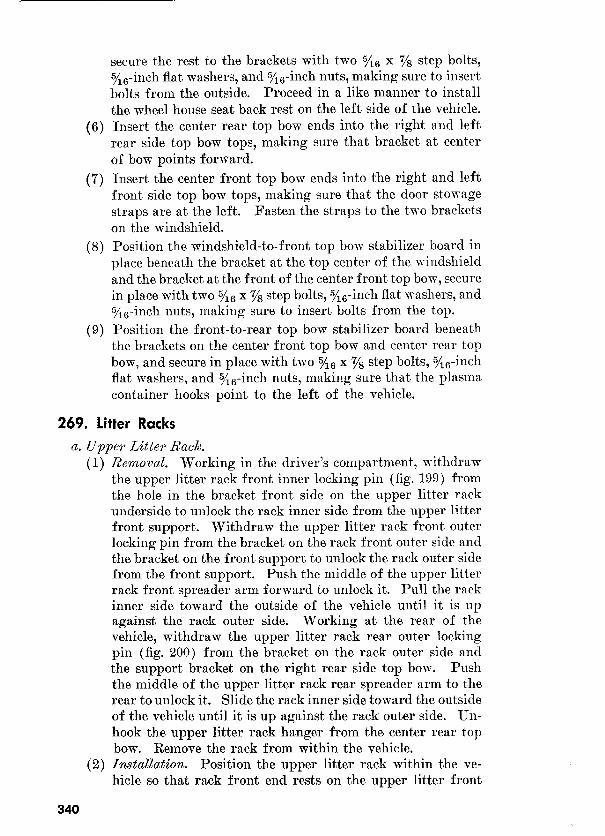


a. Preparation for shipment in aone of interior. When shipping
the IA-ton 4 x 4 utility truck M38Al and ambulance Ml70 interstate
or within the zone of interior, except directly to ports of embarkation,
the officer in charge of prepa.ring shipments will be responsible for
furnishing the vehicle to carriers for transport in a serviceabZe condi-
tion, properly cleaned, preserved, painted, and lubricated as prescribed
in SB 94.
Note: For loading and blocking instructions for these vehicles on flatcars, see paragraphs 285 and 286. On-vehicle material (OVM) will be processed, packaged, and stowed as prescribed in paragraph 285b.
6. Removal of Preservatives before Shipment. Personnel with-
drawing vehicles from limited storage for domestic shipment must
not remove preservatives, other than to insure that the vehicles are
complete and serviceable. If it has been determined that preserva-
tives have been removed, they must be restored prior to domestic
shipment. Removal of preservatives is the responsibility of depots,
ports, and field installations receiving shipment.
c. Preparation for Shipment to Ports (see AR 747-30).
(1) Inspection. All used vehicles destined for oversea use will
be inspected, prior t.o shipment, in accordance with TB ORD
385.
(2) Processing for shipment to ports. All vehicles dest.ined to ports
of embarkation for oversea shipment will be further
processed in accordance with SB 94.
Note: Ports of embarkation will perform any necessary supplementary or previously omitted processing upon receipt of vehicles, in accordance with AR 747-30.
(3) Marking of arctic-lubricated material. It will be the re-
sponsibility of the officer in charge of the organization per-
forming arctic lubrication to insure that the equipment is
marked as prescribed in SR ‘746-30-10. It will be the re-
353

sponsibility of the officer in charge of the organization
shipping arctic-lubricated equipment to insure that each item
is so marked. Unit commanders of using organizations will
insure that such markings are not obliterated while the equip-
ment is arctic-lubricated. When the equipment is deproc-
essed of the special lubrication, such marking will *be immediately and thoroughly obliterated.
d. Prepare all Army shipping
documents accompanying freight in accordance with TM 38-705.
e. P0rdin.g. If deep-water fording is anticipated
during shipment, prepare vehicles in accordance with TM 9-2853.
(1) Vehicles received for storage and already processed for
domestic shipment, as indicated on DA Form 9-3, Process-
ing Record for Shipment and Storage of Vehicles and Boxed
Engines, must not be processed unless inspection performed,
on receipt of vehicles, reveals corrosion, deterioration, etc.
(2) Completely process vehicles upon receipt directly from
manufacturing facilities or if processing data recorded on
tag indicate that preservatives have been rendered ineffective
by operation or freight shipping damage.
(3) Vehicles to be prepared for limited storage must be given
a limited technical inspection and processed as prescribed
in SB 94. Re.sults and classification will be entered on DA
Form 461-5, Limited Technical Inspection.
b.
(1) Report on DD Form Receipt of Damaged or Improper
Shipment, all vehicles received for storage in a damaged
condition or improperly prepared for shipment, in accord-
ance with SR 745-45-5. Report of vehicles received in an
unsatisfactory condition (chronic failure or malfunction)
will be made on DA Form 468, in accordance with SR
700-45-5.
vehicles are inactivated, they will be processed in ac-
cordance with type I as prescribed in SB 9-4. Standby
storage will ordinarily be handled by ordnance maintenance
personnel only.
Immediately upon receipt of vehicles for storage, they must
be inspect,ed and serviced as prescribed in paragraphs 8
through 11. Perform a systematic inspection and replace or
repair all missing or broken parts. If repairs are beyond
scope of unit and vehicles will be inactivated for an appre-
ciable length of time, place them in limited storage and a,ttach

tags specifying the repairs needed. Report of these condi-
tions will be submitted by the unit commander for action
by an ordnance maintenance unit.
c. Inspection During Storage. Perform a visual inspection periodi-
cally to determine general condition. If corrosion is found, remove
it and clean, paint, or treat with the prescribed preservatives.
Note. Touchup painting will be in accordance with TM 9-2851.
d. Removal from Limited Storage.
(1) If vehicles are not shipped or issued upon expirat.ion of the
limited storage period, they will be further treated for stand-
by storage by ordnance maintenance personnel.
(2) If vehicles to be shipped will reach their destination within
the limited storage period, they need not be reprocessed upon
removal from storage unless inspection reveals it, to be neces-
sary according to ant.icipated intransit weather conditions.
Note. All vehicles being reissued through the depot supply system to troops within the continental limits of the United States must meet
the requirements of TB ORD 385. This is NOT required for so-called
reissues, exchanges, or redistribution among troop units, where the
depot supply system is not involved.
(3) Deprocess vehicles when it has been ascertained that they are
to be placed into immediate service. Remove all corrosion-
preventive compounds and lubricate as prescribed in para-
graphs 69 through 74. Inspect and service vehicles as pre-
scribed in paragraphs 8 through 11.
(4) Repair and/or replace all items tagged in accorclance with
b (3) above.
e. Storage Site. Whenever possible, store vehicles under cover in
open sheds or warehouses. When it is found necessary to store vehicles
outdoors, the st.orage site must be selected in accordance with AR
700-105 and vehicles protected against the elements as prescribed in
TB ORD 379.
285. loading the %-Ton 4 x 4 Utility Truck M38Al and Am-
bulance Ml70 on Railroad Flatcar
a. Preparation.
(1) When vehicles are shipped by rail, every precaution must be
taken to see t.hat they are properly loaded and securely fas-
tened and blocked to floor of flatcar.
Note. The spare tire for the ambulance Ml70 illustrated is located inside the vehicle. The spare tire for the utility truck M38A1, however,
is attached to the rear of the vehicle. If these vehicles are to be
lifted, rather than driven onto the flatcar, the attached spare tires may
interfere with lifting devices, and they should be removed and secured
with metal strapping at some other suitable location on the vehicle.
355

(2) Prepare vehicles for rail shipment in accordance with SB 94. On-vehicle materiel will be thoroughly cleaned, preserved,
packed (boxed or crated), and securely stowed in or on the vehicle as prescribed in b below.
(3) Load vehicles on flatcars so they will not form an unbalanced
load.
(4) After each vehicle has been Anally spotted on flatcar, apply parking brakes.
(5) Increase tire pressure slightly higher than normal except
when vehicle is to be shipped to hot weather areas. b.
(1) Preserve and package all OVM individually, ex- cept items used in sets or in quantities greater than one.
(2)
If the materiel is to be shipped within the continental limits of the United States, directly to ports of embarkation, disconnect the battery cables from battery, clean ( (b) below), if necessary, coat cable terminals and battery posts with automotive and artillery grease (GAA) ,
and wrap with nonhygroscopic adhesive tape. Secure ter-
minals away from battery. (8) If materiel is to be shipped directly to ports of embarka-
tion, when it is to be combat-loaded, disconnect bat-
tery cables and remove batteries. Plug vents and clean outside of batteries with a solution containing one-half pound of commercial grade baking soda (sodium carbon-
ate) to one gallon of water. Rinse with cool water and remove vent plugs. Scrape or wire-brush and clean cable terminals and battery box (holder) with this cleaning solu- tion, rinse with coo2 water, coat terminals with automotive
and artillery grease (GAA) and wrap with nonhygroscopic adhesive tape. Paint battery boxes, if required, with black acid-resisting paint. Battery and eleotrolyte will be
packed in accordance with TM and shipped in vehicle separate from other OVM.
(3) Pub Place technical manual in type 1, grade A, class B bags and heat seal the opening (Method IC-3, TM 9-1005). Pack in the OVM container. Publications pro- vided by separate technical services will be packaged similarly and packed in the same exterior OVM containers as the items
to which they are applicable. (4) Unit Unit packages that are not water-resistant
and are impracticable for intermediate packaging will be overwrapped in flexible waterproof barrier-material (method
IC-2, TM g-1005) and sealed with waterproof, water-resis- tant adhesive.
356

(5) Intermediate pa&ages.
Exterior contuiners.
(a)
Note. Weatherproofing of container tops will not be neces-
sary, if containers are to be stowed within the vehicle (if the
vehicle is covered).

5. Cover exterior surfaces of all OVM exterior containers
(except tops) wit.h one coat of quick-drying lustreless
enamel.
Note. OVJI containers stowed within the vehicle will not require painting if the vehicle is covered.
(7) Stowage.
(a) Stow all OVJf containers inside the body of vehicle, when
practical. Containers stowed outside the vehicle must be
placed so as not to increase the cubic displacement of the
vehicle. Strap, block, or brace all OVM containers to pre-
vent free movement.
Note. OVhI containers must receive maximum protection against corrosion, deterioration, and mechanical damage during shipment and prolonged periods of storage.
(6) OVM containers constructed without skids, which are to
be stowed in exposed locations in contact with platforms,
floors, or other boxes, will be placed on nominal 1 x 4 wood
cleats to minimize surface contact. Secure cleats in a
manner that will prevent shifting or damage to contact
surfaces.
(c) If vehicle is equipped with steel tool boxes, remove all pad-
locks and keys from vehicle in order to prevent pilferage
while in transit. Secure lids of steel tool boxes by wiring
hasp to prevent, damage during shipment. Preserve pad-
locks and keys with preservative engine oil (grade 1) and
wrap in greaseproof barrier material for domestic ship-
ment or seal in a. waterproof-greaseproof wrapping or bag
(Method IC-1) for oversea shipment. Locate all wrapped
padlocks and keys in shipping container with parts.
c. Method of Loading the 1/4-tori 4 x 4 Ambulalzce
J138A1 on Flatccry8. For method of loading and general load-
ing rules pertaining to rail shipment of ordnance vehicles, see TU
0-OSSC-G.
Warning: The height, ancl width of vehicles, when prepared for
rail transportation, must not exceed the limitations indicated by the
loading table in AR 700-106 (section II). Whenever possible, local
transportation officers must. be consulted about the limitations of the
particular railroad lines to be. used for the movement in order to avoid
delays, dangerous conditions, or damage to equipment.
286. Blocking the %-Ton 4 x 4 Ambulance Ml70 for Rail Shipment
CC. General. All blocking instructions specified herein are minimum
and are in accordance with Pa.mphlet No. MD-‘7, Rules Governing
the Loading of Defense Materiel on Open Top Cars of the Association

of American Railroads. Additional blocking may be added, as re-
quired, at the discretion of the officer in charge. Double-headed nails
may be used, except in the lower piece of two piece cleats. All item
reference letters in b through e (5) below refer to details and locations
shown in figures 203 and 204. The number of vehicles to be loaded
will depend upon the length of flatcar.
Note. Any other loading methods or instructions, regardless of source, which
appear to be in conflict with this publication or existing loading rules of the
carriers, must be submitted for approval to the Chief of Ordnance, Department
of the Army, Washington 25, D. C.
b. Brake Wheel Clearance “A.” Load vehicles on flatcars, with a
minimum clearance of at least 4 inches below and 6 inches above,
behind, and to each side of the brake wheel. Any increase in clearance
must be consistent with proper location of load.
Note. Three methods of blocking are given herein ; the method to be used will depend on dimensions of flatcars and availability of required blocking materials.
These instructions are for vehicles double-loaded as shown in figure 203. Ve- hicles may also be single-loaded. Double-deck loading, or incline-loading (with
the front wheels of the second vehicle positioned in the rear body of the first vehicle, etc.) will be restricted to vehicles shipped unroofed.
c. Method I.
(1) Chock Mocks “B” (6 x 9 x -72, six required per truck, co%-
structed as shown in detail I, f;s. ,204). Locate the 53 degree
surface of blocks against the front and rear of each outside
wheel, against the front of each inside front wheel, and
against the rear of each inside rear wheel. Nail heel of each
block to car floor with three forty penny nails and toenail
both sides of blocks to car flood with one fortypenny nail each.
Note. Alternate type B-l or B-2 chock blocks may be constructed as
shown in details 2 and 3, figure 204 and located against tires AX shown
in details 1 and 2, figure 203. Vehicles, single-loaded, require chock
blocks at the front and rear of all four wheels.
(2) In&de wheel blocks “0” (6 x 9 x 1.2, four required per truck,
constructed as shown in detail I, figure .%?Q+J). Locate. t.he 6 x 9
surface of block flush against the inside of each wheel, as
shown in figure 203. Nail heel of each block to car floor with
fortypenny nails and toenail each side to floor with one forty-
pemly nail.
Note. Alternate type inside wheel blocks C-l may be constructed as
shown in detail 4, figure 204, and located against tires as shown in detail 2, figure 203. When inside wheel blocks C-l are used, cushion-
ing material “D” (waterproof paper or burlap) will be placed between
blocks C-l and inside of tire. The materiel should extend 2 inchrs
beyond block on car floor and 2 inches above block against side of tire.
(3) Vehicle strapping “E” (I-in. No. .I,$ BW gage, hot-rolled
steel, length to suit, two required per truck). Locate
359


strapping “E” over front bumper of vehicle and through
rear pulling hook of vehicle, as shown in figure 203. Pass
strapping “E” over front bumper of vehicle and through
and nail anchor plates to car floor with eight twentypenny
nails. Substitute, if desired, four strands of No. 8 gage, black
annealed wire, “E-l,” twist-tied to form cables. Pass the cable ’
over the bumper or through the pulling hook underneath and
around random 2 x 4 x 18 cleat “F” (detail 6, figure 204).
Nail cleat lengthwise to car floor and twist-tighteucables t,o __ remove all slack.
(4) Vehicle (6
length to suit). Pass cables around frame
(bumpers, hooks, brackets, etc.) at front and rear of every
two side-by-side vehicles as shown in figure 203. Twist-
tighten cables to remove all slack.
(1) WheeZ
Locate a cleat “N” across the front and rear of front and rear
wheels as shown in detail 3, figure 203, and toenail each to car
floor with four thirtypenny nails.
(2) inches longer
Locate the 2-inch side of support “Q” against each side of car
floor. Secure each end to cleats “N” with l-inch diameter
bolt, nut, and washer, as shown in detail 3, figure 203.
Note. After the nuts have been assembled to the bolts, nick the
threaded portion of each bolt behind the nut to prevent the nut from
turning loose.
(3)
four Locate cleat “J” across top cleats “N” with sides of cleats
“J” flush against inside of tires, as shown in detail 3, figure
203. Nail end of each cleat “J” to cleats “N” with three
twentypenny nails.
(4)
Locate four cleats “P” equidistant across car floor with ends
flush against cleats “N,” as shown in detail 3, figure 203. Nail
cleat to car floor with four thirtypenny nails. Locate one
cleat on top of each lower cleat and nail with four thirtypenny
nails.
e.
(1)
Locate a cleat “H” across
flatcar close to front and rear of front and rear wheels and
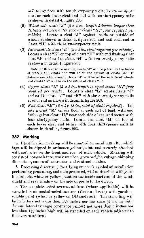
nail to car floor with ten thirtypenny nails; locate an upper
cleat on each lower cleat and nail with t,en thirtypenny nails
as shown in detail 4, figure 203.
(2)
Locate a cleat “J” against inside or outside of
wheels as shown in detail 4, figure 203, and nail each end to
cleats “H” with three twentypenny nails.
(3) 4 in., Locate a cleat “K” on top of cleats “H” with end flush against,
cleat “J” and nail t.o cleats “H” with two twentypenny nails
as shown in detail 4, figure 203.
Note.
(4)
Locate a cleat “L” across cleats “.J”
and nail to cleats “J” and “K” with three twentypenny nails
at each end as shown in detail 4, figure 203.
(5) 18 in., repzcired). Lo-
cate a cleat “M” on car floor at each end of load, with end
flush against cleat “H,” near each side of car, and secure with
four thirtypenny nails. Locate one cleat “M” on top of
each lower cleat and secure with four thirtypenny nails as
shown in detail 4, figure 203.
a. Identification marking will be stamped on metal tags after which
tags will be dipped in ordnance yellow paint, and securely attached
with soft wire on the front and rear of each vehicle. Marking will
consist of nomenclature, stock number, gross weight, cubage, shipping
dimensions, names of contractor, and contract number.
Processing directive (identifying number), symbol of installation
performing processing, and date processed, will be stenciled with gaso-
line-soluble, white or yellow paint on the inside surfaces of the wind-
shield and rear window on the side opposite to the driver.
c. The complete coded oversea address (where applicable) will be
stenciled in an unobstructed location (front and rear) with gasoline-
soluble paint (white or yellow on OD surfaces). The stenciling will
be in letters not more than inches nor less than
An equilateral triangle (ordnance yellow) not more than 3 inches nor
less than 11/2 inches high will be stenciled on each vehicle adjacent to
the oversea address.
364

Destruction of the l/a-ton 4 x 4 utility truck M38Al and the l/-ton 4 x 4 front line ambulance Ml70 when subject to capture or abandon- ment in the combat zone will be undertaken by the using organization
only when, in the judgment of the unit commander concerned, such
action is necessary in accordance with orders of, or policy established by, the army commander.
6. The information which follows is for guidance only. Certain of the procedures outlined require the use of explosives and incendiary
grenades which normally may not be authorized items for the vehicle. The issue of these and related materials, and the conditions under which destruction will be effected, are command decisions in each case,
according to the tactical situation. Of the several means of destruc- tion, those most generally applicable are-
Mechanical-Requires axe, pick mattock, sledge, crowbar, or similar implement.
Burning -Requires gasoline, oil, incendiary grenades, or other
flammables. Demolition-Requires suitable explosives or ammunition. Gunfire- Includes artillery, machine guns, rifles using rifle
grenades, and launchers using antitank rockets. Under some circumstances hand grenades may be
used.
In general, destruction of essential parts, followed by burning will usually be sutlicient to render the vehicle useless. However, selection of the particular method of destruction requires imagination and
resourcefulness in the utilization of the facilities at hand under the existing conditions. Time is usually critical.
c. If destruction to prevent enemy use is resorted to, the vehicle
must be so badly damaged that it cannot be restored to a usable condi- tion in the combat zone either by repair or cannibalization. Adequate
destruction requires that all parts essential to the operation of the materiel, including essential spare parts, be destroyed or damaged beyond repair. However, when lack of time and personnel prevents destruction of all parts, priority is given to the destruction of those parts most difficult to replace. Equally important, the same essential
parts must be destroyed on all like materiel so the enemy cannot con- struct one complete unit from several damaged ones.
CE. If destruction is directed, due consideration should be given to-
(1) Selection of a point of destruction that will cause greatest obstruction to enemy movement and also prevent hazard to
365

friendly troops from fragments or ricocheting projectiles which -may occur incidental to the destruction.
I (2) Observance of appropriate safety precautions.
289. Destruction of the %-Ton 4 x 4 Vehicle
The vehicles covered in this manual are similar with the exception
of differences in chassis length and the bodies mounted thereon. Therefore, the methods of destruction described in paragraphs 290,
291, and 292 are applicable to both vehicles,
290. Method No. l-Destruction by Burning
a. Using an axe, pick mattock, sledge, or other heavy implement, smash all vital elements such as distributor, carburetor, generator, ignition coil, fuel pump, spark plugs, air cleaner, lights, instruments,
and controls. If time permits, and a sufficiently heavy implement is
available, smash the engine cylinder block and head, crankcase, and
transmission. b. Puncture fuel tank as near the bottom as possible, collecting
gasoline for use as outlined in e below. c. Slash tires. If tires are inflated exercise care to prevent injury
should the tire blow out while being slashed. Whenever practicable,
it is usually preferable to deflate tires before slashing.
d. Explosive ammunition, if available nearby, should be removed from packing or other protective material. Place ammunition in and
about the vehicle so that it will be fully exposed to the fire and in such locations that the greatest damage will result from its detonation.
Remove any safety devices from ammunition. e. Pour gasoline and oil in and over the entire vehicle. Ignite by
means of an incendiary grenade fired from a safe distance, a burst from a flame thrower, a combustible train of suitable length, or other appro- priate means. Take cover immediately. If gasoline and oil are not
available, use other flammables such as oily rags or waste, wood, or
paper. Ignite by means of incendiary grenades or other suitable means.
Caution: Cover must be taken without delay since an early explo- sion of the explosive ammunition, if present, may be caused by the fire.. Due consideration should be given to the highly flammable nature of gasoline and its vapor. Carelessness in its use may result in painful
burns. Elapsed time: about 6 minutes.
291. Method No. 2-Destruction by Demolition
a. Prepare two a-pound charges of EXPLOSIVE, TNT (two l-lb blocks or equivalent per charge together with the necessary detonating cord to make up each charge). Set the charges as follows :
(1) The fir&, on top of the clutch housing.
366

(2) The second, as low on the left side of the engine as possible.
(3) Connect the two charges for simultaneous detonation with
detonating cord. Provide for dual priming to minimize the
possibility of a misfire.
(4) For priming either a nonelectric blasting cap crimped to at
least 5 feet of safety fuse (safety fuse burns at the rate of
1 ft in a prx 40 set ; test before using) or an electric blasting
cap and firing wire may be used. Safety fuse, which con-
tains black powder, and nonelectric blasting caps must be
protected from moisture at all times. The safety fuse may
be ignited by a fuse lighter or a match; the electric blasting
cap requires a blasting machine or equivalent source of
electricity.
Caution: Keep the blasting caps, detonating cord, and
safety fuse separated from the charges until required for use.
Note. For the successful execution of methods of destruction in-
volving the use of demolition materials, all personnel concerned will be thoroughly familiar with the pertinent provisions of FM 5-25.
Training and careful planning are essential.
6. Destroy the tires as in paragraph 2900.
c. Detonate the charges. If primed with nonelectric blasting cap
and safety fuse, ignite and take cover. If primed with electric blasting
cap, take cover before firing the charges. The danger zone is approxi-
mately 200 yards. Elapsed time : about 5 minutes.
292. Method No. 3-Destruction by Gunfire
a. Destroy the tires as in paragraph 29Oc.
b. Destroy the vehicle by gunfire using artillery, machine guns,
rifles using rifle grenades, or launchers using antitank rockets. Fire
on the vehicle aiming at the engine, axles, body, and wheels. Although
one well-placed direct hit may destroy the vehicle, several hits are
usually required for complete destruction unless an intense fire is
started, in which case the vehicle may be considered destroyed.
Caution: Firing artillery at ranges of 500 yards or less should be
from cover. Firing rifle grenades or antitank rockets should be from
cover. Elapsed time: about 5 minutes.
367

:
Land Mines and Components ; Demolition Explosives ORD 3 SNL R-7
and Related Items; and Ammunition for Simulated
Artillery, Booby Trap, Hand Grenade, and Land Mine
Fire.
b.
Cleaners, Preservatives, Lubricants, Recoil Fluids, ORD 3 SNL K-l
Special Oils, and Related Maintenance Materials,
Items of Soldering, Metallizing, Brazing and Welding ORD 3 SNL K-2
Materials: Gases and Related Items.
Lubricating Equipment, Accessories, and Related ORD (* ) SNL K-3
Dispensers.
Lubricating Fittings, Oil Filters, and Oil Filter ORD 5 SNL H-16
Elements.
c.
Truck, Ambulance, Front Line, i/4-Ton, 4 x 4, M170, and
Truck, Utility, S-Ton, 4 x 4, M3SAl.
Field and Depot Maintenance Allowances________ ORD 8, SNL G-758
Organizational Maintenance Allowances__-_____- ORD ‘7, SNL G-758
Truck, Utility, X-Ton, 4 x 4, M38Al; List of All Serv- ORD 9, SNL G-758
ice Parts.
Introduction _____________________-------_-_--_____ ORD 1
*See DA Pamphlet 310-29, Index of Supply Manuals-Ordnance Crops, for published types of manuals of the Ordnance section of the Department of the Army Supply Manual.

3. Forms
:
Standard Form 91, Operator’s Report of Motor Vehicle Accident.
Standard Form 93, Report of Investigating Officer.
Standard Form 94, Statement of Witness.
DA Form 9-3, Processing Record for Storage and Shipment of Vehicles and
Boxed Eugines.
DA Form 9-4, Vehicular Storage and Servicing Record.
DA Form 9-68, Spot Check Inspection Report for Wheeled and Half-Track
Vehicles.
DA Form 9-75, Daily Dispatching Record of Motor Vehicles.
DA Form 285, Accident.
DA Form 348, Driver Qualification Record.
DA Form 460, Preventive Maintenance Roster.
DA Form 461: Preventive Maintenance Service and Inspection for Wheeled
and Half-Track Vehicles.
DA Form 461-5, Limited Technical Inspection.
DA Form 468, Unsatisfactory Equipment Report.
DA Form 478, Organizational Equipment File.
DA Form 811, Work Request and Job Order.
DA Form 811-1, Work Request and Hand Receipt.
DA Form 1089, Claim for Personal Property.
DD Form 6, Report of Damaged or Improper Shipment.
DD Form 313, U. 5. Government Operator’s Permit.
DD Form 317, Preventive Maintenance Service.
4. Other Publications
Uamouflage, Basic Principles-_________----______--_________--- FM 5-20
Camouflage of Vehicles__________-_--_____-_--__-______-__-__- FM 5-20B
b.
Decontamination_____________---____-----________-___________ TM 3-220
Defense Against CBR Attack____---___-_-_-_________________- FM 2140
c.
Explosives and Demolitions____-_-_---______________________-_ FM 5-25
Cleaning and Black Finishing Equipment of Ferrous Metals____.-
Cooling Systems: Vehicles and Powered Ground Equipment-----
Driver’s Manual__-____ ___________________________-_______---
Driver Selection and Training________________________________-
Fording Kits for Combat and Transport Vehicles___---____---__
Fuel-Burning Heaters for Winterization Equipment____-_______
Inspection of Ordnance Materiel in the Hands of Troops________
Instruction Guide: Operation and Maintenance of Ordnance
Materiel in Extreme Cold (0’ to -65’
Military Vehicles____________-__________-----__________------
TM 9-1861
TM 92858
TM 21305
TM 21-300
MIL-F-3201
TM 9-8662
TM 91100
TM 9-2855
TM 92800

Motor Transportation Operations____---_--___________-______- FM 25-10
Mountain Operations_____-___-_--______-__---______________-_ FM 7o;LO
Operations in the Arctic_____________---------_________---__-- FM 31-71
Precautions in Handling Gasoline___-_________-___-_____--_--- AR 850-20
Preparation of Ordnance Materiel for Deep Water Fording_____- TM 9-2853
Principles of Automotive Vehicles___-_______________-_________ TM 9-2700 (to be re-
numbered
TM 9-8000-
1) Prevention of Motor Vehicle Accidents___-_-__________________ AR 385-55
Accident ~porting__________-__-__--_--____--______--______- SR 385-10-40
Spark Plugs_____________---___---_____---_____-____--______- TB ORD 313
Storage Batteries, Lead-Acid Type____-__---_--____-_--______- TM 9-2857
Supplies and Equipment: Motor Vehicles____________-_-___-___- AR 500-105
Supplies and Equipment : Unsatisfactory Equipment Report---__ SR 70&455
iliahtename
Abrasive, Gleaning, Preserving, Sealing, Adhesive, and Related TM 9-850
Materials Issued for Ordnance Materiel. Instruction Guide: Care and Maintenance of Ball and Roller TM 37-265
Bearings. Lubrication______________________----______________________-- TM 9-2835
Maintenance and Care of Hand Tools__--______--______--____-- TM 9-867
Maintenance and Care of Pneumatic Tires and Rubber Treads___ TM 31-200
Maintenance of Supplies and Equipment : Maintenance Responsi- AR 75&5
bilities and Shop Operation. Painting Instructions for Field Use______--_________________-_ TM 9-2851
Preparation of Ordnance Materiel for Deep Water Fording_----- TM 9-2853
Tactical Motor Vehicle Inspection and Preventive Maintenance TM 9-2810
Services.
f.
Army Shipping Document___________________________________-_ TM 38-705
Instruction Guide : Ordnance Preservation, Packaging, Packing, TM 9-1005
Storage and Shipment.
Manual of Approved Packaging Instructions for Major Items PS 10001
and Spare Parts for Ordnance General Supplies.
Marking of Arctic-Lubricated Materiel and Equipment__________ SR 746-30-10
Marking of Oversea Supply_____________-__--------___________ SR 7463&5
ShipmentDigitMarking___________________--_--_---------___- SR 74630-6
Military Standard, Marking of Shipments_____________________ MIL STD
129 a
Ordnance Storage and Shipment Chart-Group G_______________ TB 9-OSSCG
Packaging and Packing for Shipment and Storage of Spare Parts MIL-P-11443 for Military Vehicles. (GRD)
Packaging of On Vehicle Materiel (OVM) for Military Vehicles, MILP-12841 Transport and Combat. (GRD)
Preparation of Supplies and Equipment : Processing of Unboxed AR 74730 and Uncrated Equipment for Oversea Shipment.
Preservation, Methods of__________________-_-________________ MIL-P-116B
1 CoPles may be obtained from the Raritan Arsenal Publications Division, M&when, N. J.
’ Copies may be obtained from Aberdeen Proving Ground, Aberdeen, Md.

Preservation, Packaging, and Packing of Military Supplies and TM 38-230
Equipment.
Preservation, Packaging, and Packing Materials, Supplies and SB 3%100
Equipment Used in the Army.
Processing of Motor Vehicles and Related Unboxed Materiel for SB 9-4
Shipment and Storage.
Protection of Ordnance General Supplies in Open Storage_-____- TB ORD 379
Shipment of Supplies and Equipment: Report of Damaged or SR 745-45-5
Improper Shipment.
Standards for Oversea Shipment and Domestic Issue of Ord- TB ORD 385
nance Materiel other than Ammunition and Army Aircraft.
371

Absorbers, shock:
Data(M38Al)______________-_-_____________________
Data(M170)___-____-_---___-__-__-----______--_-__
Description (M38A1)____________________--_________-
Description (M170)________-----_________--__________
Installation_______________-~---________---________--
Organizational maintenance_____~__~__------__------_-
Removal_________________-----___--------__-~------
Troubleshooting___________----_____-------__--------
Accelerator pedal. (See Pedal, accelerator.)
Accidents, report of________________---________---________
Adjustment:
Accelerator pedal_____________---_____-----___-----__
Breaker point set____-__-------__-------___----______
Carburetor_____________-------__-----_____
Chokecontrol_____________-~---__-_----___-
Clutchlinkage__________--------~~------_~------___-
Fan and generator drive belt set_____~~------_-----____
Front hub bearings____________-~------____----______
Handbrake________________----___------__----______
Headlights__________________---___------__----______
Rear view mirror______________--_____~----__------__
Servicebrakes_______________---_____------__------__
Steering gear________________---___-_------_---
Throttle control_____________---_____------__-~------
Toe-in______________________---______-----__------_-
Valve clearance___________-----__~------_~----______
Air cleaner, assy:
Installation_______---____-----____----____----______
Removal_________________-----__-------__----______
Ammeter (M38Al):
Installation_________-_____-----____-----__------____
Removal___________________---_____------__------__
Axle, front (see also Shafts, front axle with universal joints):
Data_______________-_____-----____-----__-----_____
PCZra-
aw’ha 239 240
239
240
247
241
247
101
Description____________----_____----___----_-_----- 4,
Installation_____________--______---_____---____---__
Removal________________-______-_________-______--_
Troubleshooting_____________------__----___---______
Axle, rear (See also Shafts, rear axle):
Data_______________----___---_-___-________________
Description____________--__------___---____________ 4,
Installation______________-____----___---____--_-____
Removal_____________--___---_____-________________
Troubleshooting_______--_-__---____-_______-________
Page
290 291
290
291
299
291
299
97
3 4
135 147
151 173
134 144
135 147
191 231
130 140
208 249
238 287
163 201
259 316
233 276
230 271
135 147
224 296
110 109
136 153
136 153
174
174
219
219
206
206
214
214
96
245
5,245
258
258
94
215 259
215 5,259
221 263
221 263
97 95
372

Bar, stabilizer. (See Stabilizer bar (M170).)
Batteries: Insta~ation_________-________--________-___________-
Maintenance after fording-___________________________
Removal__________-________-____--_________________
Batteries and lighting system:
Data_______________-________-______-__-____-_______
Description___________________--____-_----___-______
Troubleshooting_______________________-_______--____
Battery cables. (See Cables, battery.)
Battery generator indicator (M 170). (See Indicator, battery
generator (M 170) .)
Bearings, front hub:
Adjustment______-__________________________________
Cleaningandpacking___________________-____________
Insta~ation_____--_________-________________________
Removal__________,__________-___________________--
Bearings, rear axle shaft________-_____-_-_________________
Bearings, steering knuckle flange:
Cleaningandpacking________________-__-_____-______
Installation____________________-_______-________--__
Removal____________________-_-_______-____________
Bellcrank, steering:
Installation_____--_______________--_________________
Removal_-___-_-________--_________________________
Bell set, fan and generator drive:
Adjustment_________-________--_____-_______________
Installation______--_____--__________________________
Removal___________-_________-________-____________
Blackout driving lights:
Installation_________________________--_-____________
Lamp unit with cables assy:
Installation__________________-__-_______-_______
Removal___________-_________-________--_______
RemovJ_____________________________________-_____
Bleeding brake system. (See Brake system.)
Body (M170):
Date_________________________________-_____-_______
Description_________________________-_-_____________
Maintenance after fording__--____--__________________
Body (M38Al) : Data________________________--_____________________
Description_______________________-_________-_______
Maintenance after fording____________________________
Bolts, spring pivot:
Installation________________________-________________
Removal_____________________-_____________________
Bond straps (See Regulator, generator)
Bows, side and center top (M170):
Installation_________________-_______________________
Removal___________________--______________________
Brake drums. (See Drums, brake.)
Brake, hand:
Adjustment___ ______________________~~~~~~~~ ______--
PUW
gR%plkY
162
276
162
161 194
161 194
87 87
208 249 208 249 208 249
208 249
217 262
213 253
213 253
213 253
228 270
228 270
130
130
130
164 205
164 205
164 205
164 205
262 329 262 329
276 349
253 304
253 304
276 349
244 296
244 296
268 335
268 335
238 282
Page
197
349
197
140
140
140
373

Brake, hand---Continued
Shoe with lining: Pllrll- graphs
Instollation_____________________________________ 238
Removal_______________________________________ 238
Troubleshooting____..--___________--_________________ 99
Brake line. (See Brake system).
Brake pedal. (See Pedal, service brake.)
Brake, service:
Adjustment________________-__-__--_________________ 233
Shoe with lining: Installation__________-__________________________ 233
Removal_____-_-________________-_______-______ 233
Troubleshooting_____________________________________ 98
Brake system:
Bleeding__________________-_________________________ 237
I>ata_-____-___________________-____________________ 231
Description_________.____________________-___________ 4, 231
Lines and connections________________--_______-__-___
Maintenance after fording____________________________
Organixational maintenance_________-_-_____--__--____
Break-in_____-___-______________________________________
Breaker point capacitor. (See Distributor,)
Breaker poinB. (see Distributor).
Bumper bar:
M38Al: Installation________-__-_______-_________________
Removal_________________-__---_---_-__________
M170_____________________-______________________-_
Bumperettes:
M38Al: fnstallation________--_--________-_____--___-__--
Removal________________-______________________
M170______________________-__-____-_______________
Cables, battery:
Removal______________-______________-_-_--_-______
Instalation_______________-_------_--______-________
Cap, horn button. (See Steering wheel.)
Cap, steering knuckle flange. (See Steering knuckle flange
cap.) Carburetor:
Adjrlstment________________-________-____-__________
Installation________________________-_____-__-_-_____
Renloval__________________-___-____________________
Throttle valve body-to-manifold insulator:
Installation________________-____________________
Removal_______________-_______________________
Caution:
Battery____-__-_____-___-_____________--___-_______
Bearings____________________________________--______
Carburetor_________________-________-______________
Clutchpedal_______________________-___-____________
Extreme-cold_-____________-________-___--___-______
Front axle shafts installation______-_____--__--_-______
Fuel tank (M170) installation__________-______________
Gearshift lever_______________-______________________
374
236
276
10
10
287
275
5,275
283
349
21
21
260 322
260 322
271 343
260 322
260 322
271 343
162 197
162 197
134
134
134
144
144
144
134
134
144
144
162 197
70 59
134 144
44 35
60 51
207 245
141 159
46 36
Page
287
287
97
276
276
276
95

Caution-Continued PWZ-
graphs
Generator___________-----__________________----_-_- 158
Generator regulator (M38Al)___________________------ 159
Generatorregulator(M170)___~_______________________ 160
Hand brake adjustment____----------------_-_-______ 238
Oilpressuregage______----__________--------_____-__ 90
Organizational maintenance, cooling system------_______ 127
Power plant__________________------___-__________ 120, 124
Removal of accumulations after operation-___-_-_-_-_-_
Reversegear__________~---____~_-_-----_______-_-_-_
Service brakes_____________~~--------~-_-------------
Starter______________-----~~~~-~-------_~_-_--------
Steering gear removal__----.._.____-~---_____________
Table II, tags___________-_------------__------------
Table II, water and oil pressure_~~______________-___-_
TableIII,leaks___________________-----_____________
Towing______________~~~~~__._~_~~-----_____________
Troubleshooting_____------~~----------__-___---_----
Unusual conditions___-----____---------___----------
Choke control. (See Control, choke.)
Circuitidentification_____-_--________------________------
Clutch:
Data_____----__----------__--------____--------____
Description__________-----____------_-__-___----____
Linkage adjustment___~----______~_-----___________-_
Troubleshooting_______~~--__..____~_---_____________
Coil, ignition:
Installation___~~_____---~~-~----------_-----------__
Removal__________-------____---------_________----
Common tools and equipment_______________----------____
Compartment, medical supplies stowage:
General________________________-------________-__--
Opening and closing_____________--_____-------____--
Control, carburetor_____-----___-------____-_--------____
Control, choke:
Adjustment_______--------_~----------__----------__
Installation_________------____---------___------_-__
Removal_____________----________-----_________----
Control, throttle:
Adjustment_______--------__-_---------___--------__
Installation________-------____---------_____-_------
Removal_____________----________-_---_________-_--
Controls and instruments:
Accelerator pedal_______________---_____------_______
Ammeter (M38Al) and battery generator indicator
(M170)________________.__.~------___---------_-__
Chokecontrol___________________-------_______----__
Clutchpedal____________________-------___~__-------
Emergency reel lamp switch________-----_______-_----
Fuellevelgage______________--_---_____-------_____-
General_______________-_____-_---_____-----________
Glove compartment door lock_____------__-_----_____-
Handbrake handle______________-_______-__--________
Headlight dimmer switch (Ml70)_________---_---______
Headlight high beam indicator light______-_______-----_
63
49
98
42
230
78
78
79
52
80
59
Page
184
190
192
287
90
136
123, 132
54
38
95
33
271
71
71
73
39
79
50
171 212
190 230
190 230
191 231
92 92
152 178
152 178
67 57
57 48
57 48
135 147
135
135
135
147
147
147
135
135
135
147
147
147
16 24
33 31
22 27
15 23
40 33
34 31
12 22
27 30
20 27
25 29
38 32
375

Controls and instruments-Continued PUT& graphs
Horn button cap_-__________..______-____-___________ 32
Ignitionswitch_________-_________-______-___________ 23
Instrumentpanellights______________________________ 37
Lightswitch_____-____--_______-______________-_____ 24
Medical supplies stowage compartment handles (Mli’O) _ _ 29
Oilpressuregage__-_____-______-____________________ 35
[3ervicebrakepedal________________-_________________ 14
Speedometer_____--___-____________________________- 39
Strrrterpedal_________-________-_--__________________ 17
Steering wheel_________-__________________-_________ 13
Throttle control_____________________________________ 21
Tool compartment lid handle___________-_______-_____ 28
Transfer levers___________________-______-_-_________ 19
Transmission gearshift lever__________________________ 18
Watertemperaturegage______________________________ 36
Windshieldlooks____~-________________________-_____ 26
Windshield wiper air regulating valve__________________ 30
Windshield wiper manual control handles________-______ 31
Cooling system: Data____________-___________-_-_______-________-___ 126
Description_________________________________________ 126
Organizational maintenance__________-________________ 127
Troubleshooting_______-________-____________________ 88
Coordination with ordnance maintenance unit. (See Grgani-
zational maintenance allocation.)
Correction of deficiencies____________-_______________-____ 11
Cover, rocker arm: Installation___________________-_____________________ 108
Removal- ____-___________________-________-________ 108
Cover, valve compartment:
Installation_____________________-___-_______________ 109
Removal________-_____-____________________________ 109
Crankcase oil filler pipe. (See Pipe, crankcase oil filler.)
Curtains:
M38Al________________________________-____________ 258
M170____________-___-__________--_____-__________ 58,268
Cushions. (See Seat and cushions.)
Cylinder:
Compression test _ _ ________-_____________~~~~~~~~~~~~ 106
Cylinder, master. (See Master cylinder.)
Cylinder, wheel. (See Wheel cylinder.)
Data:
Detailed data references__________--__________________ 7 General__________-__-__________-_-___--____________ 7
Performance__--________-______________---__________
Tabulated______-_____________-_-__-_____--_________ ::
Description, general_______________--__-_________-________ 4
Destruction to prevent enemy use:
Burning_______-______________-_________-_-____-____ 288
Demolition____________________-____-____________-__ 289
General_______-_________-_____-_________-_____-_-__ 287
Gun~e________--_-___-_--_____-___-____-______-____ 290
Differences between models__-____________________--____-_ 5
Page
31
27
32
28
30
31
22
32
25
22
27
30
26
25
32
30
30
31
136
136
136
88
22
105
105
107
107
313
49,313
102
18
18
18
18
5
365
366
364
366
11
376

Distributor : Breaker point capacitor:
Installstion_______________-__-__________________
Removal__________________---_-________________
Breaker point set: Adjustment__-__--_-______________--_-__________
Installation_____________________________________
Removal__________z________-__---_-____________
Cap : Installation_________________-__--__-____________
Removal________________-______________________
Cover:
Installation______________-_---_-________________
Removal_______--___-________-__-______________
Maintenance after fording____________________________
Primary capacitor:
Installation______________-_____-________________
Removal__-____-___________-_____--____________
Distributor with coil assy:
Installstion_______________----__--__________________
Removal_________________-__-_-____________________
Doors. (See Curtains.)
Drag link:
Assembly__________________-_-______________________
Disassembly______________________________________-_
Installation________________~-__-__--________________
Removal___________________________________________
Driving light. (See Light, driving.)
Driving, normal. (Isee Vehicle.)
Drums, brake:
Front:
Instaliation_____________-_______________________
Removal_______________-_-_-___________________
Rear : Installation_______________________-_--__________
Removal_______________----____________________
Electrical components and cables:
Circuit identification_________________--_-____________
General____________________-__--__-__--____________
TableIV___________________________________________
Electrical system:
Description_________-________---____________________
Maintenance after fording____________________________
Emergency reel lamp. (See Lamp, emergency reel.)
Engine : Cylinder compression test____-_______________________
Data_________________-_-_____-___--________________
151
151
173
173
151
151
151
173
173
173
151
151
173
173
151 173
151 173
276 349
151
151
150
150
173
173
171
171
227 268
227 268
227 268
227 268
209 251
209 251
219
219
212
212
171
171
171
212
212
212
4
276 34:
106
104
102
99
5,99
122
132
349
102
132
33
Description_________-_--____________--______________ 4,104
External lines and fittings_____-____________________-- 118
Installation on power plant_____-___--__-_____________ 123
Maintenance after fording__________________-_________ 276
Operation in vehicle__________________-______________ 105
Removal from power plant___________________________ 122
Starting______________________________-__-__________ 42
3397440-55-25 377

Engine-Continued
Stopping_______-_____-______-___--_____-_-__-_____-
Troubleshooting_____-_____--____________-______-_-_-
Engine oil pressure gage. (See Gages.)
Engine oil pressure sending unit. (See Sending units.)
Engine water temperature gage. (See Gages.)
Engine water temperature sending unit. (See Sending units.)
Exhaust manifold. (See Manifold, exhaust.)
Exhaust pipe. (See Pipe, exhaust.)
Exhaust pipe extension:
Installation__________________---___-____---____--___
Removal_______-__--_-_______--____---__--____-____
Exhaust system:
Description___________-_-____________--_____-__---__
Installation________--________---_---____--________-_
Removal____________________---_~--_-__--________-_
Troubleshooting_____-_-_______--___-_--_---_____-___
External lines and fittings___________-_____---__-_---_--__
Extreme-hot weather maintenance:
Batteries_______--__-_-______---_---_-__---_._______
Body__________--_--__--_____--_______-_-_
Chassis_________--__-__--.____--___-_--__--_____-___
Coolingsystem_______________--__---____-_________-_
Fan: Installation_________-________---__--____---_____--~_
Removal________-_____________-_________--_____-___
Fan and generator drive belt set. (See Belt set, fan and genera-
tor drive).
Fasteners________________________--___--____--________-_
Fenders:
M38Al:
Installation______________---__--____-___________
Removal_____________--_-------____--__________
M170:
Installation___________--_---__--_-__---_________
Removal_____________--_----_--_-__--- ____ _____
Filter, fuel: Element__-____________--____________---_--_--__--__
Installation_________-_________---~--_-___--~____-___
Removal_______--__-_~-______---_--_--_---_-___-___
Filter, oil : Element_________-_____--______--____--_---_--__-___
Installation______-_____--_______-____---_--_-___-___
Lines : Installation__-_____--__-___--____---_--_-___-_~_
Removal_____________--__---_--_____-__________
Removal_______--_____--_____---_--_-___--_________
Fording operations:
After fording: Lubrication_________--_--_---~_____-__
General__-_______________---_-~_---_____--_________
Forms___________-__-_________---____-__________________
Frame:
M38Al:
Data______________-___-___-_____-___-__________
Description_____________-_-___--________________
378
PWU-
graph8
50
81
145 165
145 165
143 164
144 164
144 164
83 84
118 122
275 348
275 348
275 348
275 348
131
131
282 352
256 307
256 307
265 330
265 330
139 156
138 155
138 155
114 117
115 118
116 120
116 120
115 118
73 68
64 55
3 4
253 304
253 304
Page
38
79
141
141

Frame-Continued
M170:
Data___________________________________________
Description______________________ ____________ ___
Front axle. (See Axle, front.)
Front axle shafts. (See Shafts, front axle, with universal
joints.)
Front hub bearings. (See Bearings, front hub.)
Front hubs. (See Hubs.)
Fuel and air intake system:
Data_______________________________________________
Description_________-------_-_______________________
Lines and fittings-----______ ___________________ _____
Maintenance after fording__-----___ _________________ _
Troubleshooting----_-__-__ ___________ ___________ ____
Fuel and vacuum pump:
Installation________-____--______________________-_-_
Removal_____________------________________________
Fuel filter. (See Filter, fuel.)
Fuel filter element. (See Filter, fuel.)
Fuel gage. (See Gages.)
Fuel level sending unit. (See Sending units.)
Fuel lines. (See Fuel and air intake system and
Fuel tank. (See Tank, fuel, Ml70 or M38Al.)
Para-
262
262
133 143
133 143
142 161
276 349
82 82
137
137
Gages : Ammeter. (See Ammeter (M38Al) .)
Battery generator indicator (M 170). Indicator,
batt,ery generator (M170) .)
Fuel_____________________---------___--------______ 175
General____________________-------.__--------______ 172
Oilpressure___________________--__-___________----__ 177
Speedometer. (See Speedometer.)
Troubleshooting_____________________---_____--_----_ 90
Water temperature___---------__--__---_____________ 176
Gaskets:
Cylinderhead_________________----.______----------_ 111
Exhaust manifold.______________----______--_------__ 113
Rockerarmcover__________________-------__________ 108
Valve compartment cover___-__---_-___------_-______ 109
Gate, tail. (See Tailgate.)
Gearshift levers. (See Transmission or Transfer gearshift
levers.)
Generating system : Data__.________--__________----____----__--________ 157
Description____________________-----____-------___ 157,281
Maintenance__________________-----____-_-----______ 281
Troubleshooting________________-----______----______ 86
Generator:
Installation________________________________________- 158
Removal_____________--------__--_----------_______ 158
Generator regulator (M38Al). (See Regulator, generator.)
Generator regulator (M170). (See Regulator, generator.)
Glovecompartmentdoorlock___________________-___-_____ 27
Page
329 329
154
154
222
216
223
90 223
112
117
105
107
184
184,351
351
86
184
184
30
379

Hand brake. (See Brake, hand.)
Headlight dimmer switch. (See Switches.)
Headlight high beam indicator light___----________________
Headlights:
Adjustment_____________--_-__--____--______________
Installation_______________--__-_-_-_-___--_.______-_-
Lamp unit with cable assy:
Installation_________________--__________---_____
Removal-_-___-_------_-__-_------_----_-______
Removal__________________________________-_____-__
Hood:
M38A1_______________________-_----_----------_-_-_
M170______________________________________________
Horn:
General_____________---____________________________
Installation__________--__---------------______-_____
Removal______________-----------------__-__-______
Troubleshooting_________________ _________ ___________
Horn button cap. (See Cap, horn button.)
Horn switch. (See Switches.)
Hose : Waterinlet_________.______________________-_---_--_
Wateroutlet__________________----______________-___
Water pump bypass_________________________________
Hub bearing oil seal-_______-___________-__-____-_--___-_
Hubs:
Front_-_________________________-_-__--_-----_--_-_
Rear____________________________-__________________
Ignition coil. (See Coil, ignition.)
Ignition switch. (See Switches.)
Ignition system:
Data_________________----_-_______-_-_--_--___-__-_
Description____________-----______-_--_-___-_-_____-
Organizational maintenance_____-__-_-__-_____-_______
Timing______________________________________-______
Troubleshooting______-----_-_-__________-__-________
Indicator, battery generator (M170) : Installation____________________________________-_--_
Removal____________________________________-______
Instrument cluster:
General__________________--_-______________________
Installation_________________________________________
Removal___________________________________________
Instrument panel lights__________________________________
Instruments:
General____________________________________________
Troubleshooting______-----__________________________
(See also Controls and instruments.)
Insulator, throttle valve body-to-manifold. (See carburetor.)
Joints, universal. (See Universal joints.)
Lamp, emergency reel:
Installation______________-_____-_-__--_-_-___-_-____
Lamp-unit replacement_______________________________
Removal_____________-_____________________________
Para-
graphs 180
163 201
163 201
163 201
163 201
163 201
255 306
264 330
172 216
184 228
184 228
89 89
129 139
129 139
129 139
211 252
210 252
220 263
147 167
147 167
148 170
149 170
84 84
174
174
172 216
173 216
173 216
179 224
172 216
90 90
170
170
170
Page
226
219
219
211
211
211

Lifting shackles (M170)______________-___________________
Light switch. (See Switches.)
Lights:
Blackout driving. (See Blackout driving lights.)
Blackout marker. (See Signal blackout marker lights.)
Headlights. (See Headlights.)
High beam indicator. (See Headlight high beam indi-
cator light.)
Instrument. (See Instrument panel lights.)
Parking. (See Parking lights, service.)
Tail and stop. (See Tail and stoplights.)
Litter racks. (See Racks, litter.)
Lubrication : After fording operations________-___..___---_______----
After operation under dusty or sandy conditions_-- _ _ _ _ _ _
Chart______________________---_____----____---__-__
Continued operation below 0” F_______________________
Equipment_______--_____------_-------___----______
General______________..____---_--___---____
Points of application_-__.____---_____------____-----_
Unusual conditions___-__----_____---______--________
Usual conditions_____________---_____------__-_---___
Maintenance after fording:
Aluminum or magnesium parts_-__________--________-_
Axles_______________________--_______----____-_-__-
Batteries__________--_____-----____-----__----_-____
Body________________________-_______----____--___-
Brakes_____________-_____-_---___------__----______
Chassis____________--_____-----___------__----_-____
Condensation_____________-_---_____------__-_--____
Deepwaterfording__________________-------_----____
Distributor_________-_____-----____~----_-------____
Electrical connections______-_---___-_----__-_----_-__
Engine___________-_-___-_------__-----___----______
Fuel system________--_____-----___----____----_-____
General____________-_____-_----__-_----__------____
Steeringgear________________-_--____-----___-______-
Transfercase___________-----___------____--________
Transmission________-___------__-_----____--_-______
Wheels_____________-_________-_____-_--_-__----____
Maintenance after operation on unusual terrain_____________
Maintenance under unusual conditions:
Extreme cold weather maintenance____----____--______
Extreme cold weather problems--_----________________
Extreme hot weather maintenance_-_--________________
Manifold, exhaust: Installation_________________----__-____-_______-____
Removal___________________--_-__---_______________
Manifold vacuum test____________--____--_______-________
Master cylinder: Filling_____________________-_--__-_--____________-_
Installation_________-___---_____________--__--------
Removal___________-___-_____________----__--------
Para-
graphs
271
73 68
74 68
69 59
72 68
70 59
70 59
70 59
71 67
70 59
276 349
276 349
276 349
276 349
276 349
276 349
276 349
276 349
276 349
276 349
276 349
276 349
276 349
276 349
276 349
276 349
276 349
277 350
274 348
273 347
275 348
112 116
112 116
107 103
234 280
234 280
234 280
Page
343
381

Mirrors:
M38Al:
Outside rear view___-______________________--____
M170______________--____--_____-_____-__--_______-
Motor, vacuum, windshield wiper. (See Windshield wiper).
Name, data, caution, and instruction plates_____-_____--____
Oil filter. (See Filter, oil.)
Oil filter element. (See Filter, oil.)
Oil filter lines. (See Filter, oil.)
Oil seal, steering knuckle flange. (See Steering knuckle flange
oil seal.)
Operation of ambulance equipment:
General_____________________-__________-_______-___
Operation under unusual conditions:
Extreme-cold weather conditions-__-____--____________
Extreme-cold weather operation_______________--___-__
Extreme-hot weather conditions___________-___--____--
Fording operations_____________--__-___-_____--____--
General______________________-___-___--____-_______
Operation on unusual terrain___-___-_________-__-_____
Operation under usual conditions:
General______________--__--_______-______-_________
Organizational maintenance allocation--__----_-____-___-__-
Organizational maintenance instruction:
General____________________--___--___--__--__-__---
Painting________________--_______-____________-__--__-__
Parking lights, service______--______--____--______-__--___
Parking the vehicle. (See Vehicle.)
Parts________-___--__________--______-______-__________
Pedal, accelerator:
Adjustment_______________---______-_____-__________
Hinge________-_______--_____-_____-________________
Hingespring________________-__-_________--_________
Instalation_________________-____-_______-__________
Removal___________________--_________--_________--
Pedal, service brake:
Installation___________--__--________________________
Removal___________________--___-_________-________
Pintle, towing. (See towing pintle.)_
Pipe, crankcase oil filler:
Instalation_________________-__-_-___--______-___-_-
Removal___--__-_____-___-________-________________
Service_______-_______-___--_____________-__________
Pipe, exhaust:
Installation___________________-________-___-________
Removal_____-_______________-_______--____--___-__
Power plant:
M3gAl:
Installation_______-___-___________________--~_-_
Removal______-__-______________-________--__--
M170:
Installation_____________-___-_____________------
Removal_______________--______--________-.-__--
Para- graphs Pllge
316
343
6 12
53 41
60 51
61 52
62 53
64 55
59 50
63 54
41
2
33
3
65
75
165
57
69
206
66
135
135
135
135
135
57
147
147
147
147
147
230
271
271
117
117
117
121
121
121
146 166
146 166
124 132
120 123
125 135
121 131
382

ParIP grapha
Preliminary services_______________-___--_-___-_--_-_---_ 9
Prevent,ative maintenance services:
Cleaning___________________________________________ 77
Daily “A” and biweekly “B” services:
TableII__________________--____________________ 78 General__-_______-_-_--------______________________ 76
Mileage “C” and “D” services:
Table III_________________________-_-___________ 79
Primary capacitor. (See distributor.)
Propeller shaft. (See Shafts, propeller with universal joints,front
or rear.)
Propeller shafts with universal joints. (See Shaft, propeller with
universal joints.)
Pump, fuel and vacuum. (See Fuel and vacuum pump.)
Pump, water. (See Water pump.)
Racks, litter (M17D):
General_____________---_-______-------______-_-_-__ 54
Lower: Installation___________________---------_________ 269
Removal___________________-_------____________ 269
Upper: Installation_____________--------_-______________ 269
Lowering--_-___________-_--___.____________-___ 54
Raising_____________--______----------------____ 54
Removal_______-_------______--------------_-__ 269
Stowing__----__________---___._____________-_-- 54
Radiator guard with deflector:
M38Al:
Installation_____________----____________________ 257
Removal_______________--------_-______________ 257
M170:
Installation_____________-------_________________ 266
Removal_______________------__________________ 266
Radiator with shroud:
Installation___________-_--________-_-_--------______ 128
Removal_____________-_-_________~_-_-_------------ 128
Radio interference suppression system:
Description_____~____--.----____-_-_--------______ 279,280
Maintenance______~_------.__.__~_-_--------------__ 280
Purpose_____________---~-~_----------~-_-__________ 278
Troubleshooting_____------~-~_~---------------_____- 91
Rear axle shaft bearings. (See Bearings, rear axle shaft.)
Rear axle shaft oil seals. (See Shafts, rear axle.)
Rear axle shafts. (See Shaft, rear axle.)
Rear hubs. (See Hubs.)
Receptacle, trailer coupling electrical connector:
Installation_________-_----__-_------~___.___________ 169
Removal_________________-_----------______________ 169
Records______________-______-___-____________________-_ 3
Reflectors:
M38Al:
Rearreflex______________-__-_-____________-_---- 259
M170____________________________________________-_ 270
71
69
73
41
340
340
340
41
41
340
41
311
311
331
331
138
138
351
351
351
91
211
211
4
316
343
383

Regulator, generator:
M38Al:
Installation________-__________-_____--_______-__
Removal___--____-_______--____--_____-______-_
M170:
Installation_-_________________________________-_
Removal___________-_._________________-______-
Reports______-___--__-_--____-_--__-__-_______-________
Reversing the vehicle. (See Vehicle.)
Red, throttle:
Installation___-___________----__-_--____-__--______-
Removal______-______-___-_____-_-___-_________-____
Scope__-_-__-____--____--__________--____________--____
Seats and cushions:
M38Al:
Driver’s__________________-_________-_--________
Passenger__________.__--_-__----__---____-______
Rear___________-__-__----_-----_-----_-__--____
M170:
Driver’s__________--____--_--_-----_--_-__-_--_-
General____-___-_____-_-----_--_--_--____--_-._
Passenger_______________-_--__-__-__-_--__--_-~-
Wheelhouse_______-__-_____--____-______-_-____
Sending units:
Fuel level:
Installation_____________-__-__-_--__-_--__--____
Removal_______-______-_-__---____-_____-____-_
Gener~____________________-___-_--__-_--___-_-____
Oil pressure:
Installation___________-__-__--___________-______
Removal________-_-_____-__--___________-__._-_
Troubleshooting_______-___-_--__----__--_-___-______
Water temperature:
Installation_-_________-_-----~--~-----~-_---_-__
Removal_____________-_--_-----__----___-______
Service brake pedal. (See Pedal, service brake.)
Service brakes. (See Brake, service.)
Shackles, lifting:
M38Al:
Installation_______-_____-_____--____-_-_________
Removal__________-_-.__-_---_--_--_--___-_-____
M170________-_________----------_____-____________
Shackles, spring. (See Springs.)
Shaft, front propeller with universal joints:
Data__-_______________________--___-___-_____-_____
Description_________-_-_____---_--___-______________
Insta~ation___________-_____--__--_-___-____________
Removal___________-_-___-_------___-______________
Troubleshooting_____-_____-__---_-___-______________
Shaft, rear propeller with universal joints:
Data_________--__-_______-_____-____-______________
Description_________-_______--____-___--____--_-____
Installation_________________-_________-_____-_______
Removal_____-_________-__-____-_____--____-_____--
Troubleshooting_____-_____-_-______-__-__-___-______
PlWU-
159
159
160 192
160 192
3 4
135
135
261 325
261 325
261 325
272 343
55 43
272 343
272 343
189 229
189 229
172 216
187 229
187 229
90 90
188 229
188 229
250 300
260 322
271 343
201 239
201 239
202 240
202 240
95 94
201 239
201 239
203 241
203 241
95 94
Page
190
190
147
147
3

Shafts, front axle with universal joints:
Installation_________________________________________
Removal___________________________________________
Shafts, rear axle:
Cleaning and packing________-___________-___-___-_-_
Inneroilseal________________-_-_____-_-_-_-_-_-_-_-_
Insta~ation_________________________________________
Outeroilseal___________________-____-_______________
Removal__________________-_-_-_____---___-___-_-__
Shipment and limited storage:
Blooking____________________________--------------__
Domestic shipping instructions______________-_---_-___
Limited storage instructions__-__-_--___-____--________
Loading__________________---------__-___-___-____-_
Shock absorbers. (See Absorbers, shock.)
Side curtains (M 170) : Installation____________________--_-----____-__-_--__
Removal____________________________-______________
Signal blackout marker lights__________-____-_____________
Spare wheel. (See Wheel.)
Spark plugs:
Cables-_____________________-__--___-_______-___-__
Installation________________-_----__________-__--__--
Removal_________________________-____-___-___-__--
Special tools and equipment:
TableI___________________-__________-___-__________
Speedometer:
Flexible shaft core replacement__-___-______-__________
Installation________________----------___-___________
Removal_____________---_________----__--_--_______
Spring pivot bolts. (See Bolts, spring pivot.)
Spring shackles:
M38Al: Installation_____________--____-___---___________
Removal__-_-_________________-__---___________
M170:
Installation______________________-__--__________
Removal_______________________________________
Springs:
M38Al:
Data______________________-____________________
Description______________------_________________
Installation______________------------___________
Organizational maintenance___-___ _____________ ___
Removal__________-----_____--------------_-___
Shackles________________-___-___________________
Troubleshooting_________-------__ _____________ __
M170: Data_______---_________---_____________________
Description--_______ ____ ___________ ______ _______
Installation---___________--________ __________ ___
Organizational maintenance_______________________
Removal__________________------________________
Shackles___________________-____________________
Troubleshooting__________-______________________
POW-
grwhs 207
207
216 259 218 262
216 259
218 262
216 259
286 358
283 353
284 354
285 355
268 335
268 335
165 206
153
153
153
68 57
178 223
178 223
178 223
242 293 242 293
243 294 243 294
239 290 239 290
245 297 241 291
245 297
242 293
101 97
240 291
240 291
246 298
241 291
246 298
243 294
101 97
Page
245
245
179
179
179
385

Stabilizer bar (M 170) : Installation________-____--__-___--___--_______-_____
Removal_____________----__-____--__--________-__--
Starter:
Installation___--___---_---__-____--_---_______--___-
Removal_______________--__-____--___-_____________
Starter switch. (See Switches.)
Starting system:
Data____-___-______--__--__-___---__--_______-_____
Description__________-__--_______--__--_____________
Troubleshooting________--__-___--__---_--____-_____-
Steering bellcrank. (See Bellcrank, steering.)
Steering gear:
Adjustment____-__-------_--__---__---_--___---___-_
Installation_________--_---_--___---_---_-_____--__--
Maintenance after fording-----__----_---_-____---_---
Removal______-___--___--______---_---______---___-
Steering knuckle flange bearings. (See Bearings, steering
knuckle flange.)
Steering knuckle flange cap:
Installation_--_______-__--________-___-_____________
Removal-_-__--__--___-----__-_--__--__-___-_--__-_
Steering knuckle flange oil seal:
Installation_________--__-_--__--___---_--___----__--
Removal______-__---_--__--_--____-___-__---___--__
Steering system:
Data_______________--__----__---__-___--_----__--__
Description__________-__--______---_---_-___--------
Organizational maintenance______________-__--____--__
Troubleshooting_____--__--_____---_---_--_----__----
Steering wheel:
Installation_____.___--__--_____--__-___--_-______-__
Removal___________-~__~-______--_---__-____--_--~-
Stoplight switch. (See Switches.)
Stopping the vehicle. (See Vehicle.)
Storage. (Xee Shipment and limited storage.)
Switches: General________~___--__--~-__----_--__-__--________
Headlight dimmer____________~._---_---_-___--__--__
Horn_______________--_-----__----_-___-__--________
Ignition________________________---_---_-___--__--__
Light_______-_____---------__--___-___-__--________
Starter_____________--__--____----_---_--_---___--__
Stoplight___________--__--____----_---_--_----__--__
Troubleshooting_________--______--__--__-___--__--__
Tables: Table I-Special tools and equipment__--__-___--__--__
Table II- Daily “A” and biweekly “B” preventive
maintenance services____-______-__--_____--________
Table III-Mileage “C” and semiannual-mileage “D”
preventive maintenance services___________-~__~_____
Table IV-Circuit numbers and descriptions______._.___
Tabulated data__________--____--__-__________-____-___--
386
PaRZ-
267
267
155 180
155 180
154 180
154 180
85 86
230 271
230 271
276 349
230 271
213 253
213 253
212 252
212 252
222 264
222 264
223 265
102 98
229 270
229 270
172 216
183 228
185 229
181 226
182 227
156 183
186 229
90 90
68
78 71
79 73
171 212
7 18
Pap
333
333
57

Tail and stop lights:
Blackout________________________________----_-_-_-_
Service________________________________________----_
Tailgate:
General_____________________________________-__-___
Lowering___________________________________________
Raising_____________________________________-_______
Tank, fuel:
M38Al:
Installation__________---________________________
Removal_________________________________-_-___
M170:
Installation_____________________________________
Removal_________________________________-_____
Thermostat, water temperature:
Installation_____________~_~___~_____________________
Removal_____.._._____~~-~_________________________
Throttle control. (See Control, throttle.)
Throttle rod. (See Rod, throttle.)
Tie rod ends:
Installation_________________________._______________
Removal_____________----_________-_--------_-_____
Tie rod with ends:
Installation___.___________________________-------_-_
Removal_______~_________---~~_~____________-_----_
Timing_____________________-_-_~__.___________-----__-_
Tires and tubes:
Data_____________________-_-_-______________-_----_
Description__________-_-_-_______-_-_-_----_-_-_-___
Organizational maintenance __._____________ ___________
Removal and installation_____~._____________-_-_----_
Spare wheel and tire-~___________.___ _~_~___________
Troubleshooting______-----___________------_-_-_____
Toe-in adjustn~ent__________-_______-_-_--------_-_-_____
Top rails (M170):
Installation_______________-_-_~_____.____-_------_-_
Removal______________-_-___________-_------_-_____
Towing pintle:
M38A1________________-_--_~___.____-_-_------_-___
M170________________----_______-_-~----_-_-_______
Towing the vehicle. (See Vehicle.)
Trailer coupling electrical connector receptacle. (See Recep-
tacle, trailer coupling electrical connector.)
Transfer:
Data_________________________.___._.-_-.-_------_-_
PWl-
166
167
Page
207
209
56 47
56 47
56 47
140
140
157
157
141
141
159
159
132 142
132 142
226 268
226 268
225 266
225 266
149 170
248 299
248 299
249 300
252 304
251 302
100 97
224 265
268
268
260
271
335
335
322
343
197 236
5,236
36
238
349
237
93
Description____________________-_-_-~-~ ___.__ _______ 4, 197
Gears, shifting__________________~___________________ 46
Installation_______________________.____________-_-__ 200
Maintenance after fording___________________-_----_-_ 276
Removal_________________________._________________ 199
Troubleshooting_______-________ ____ ___ _____ _________ 94
Transfer gearshift levers:
Installation (M38Al)_____________________________-_- 124
Installation (M170)__________________________________ 125
Operation_______________________ ____ _ ____ _ ____ _____ 43,46
132
135
34,36
387
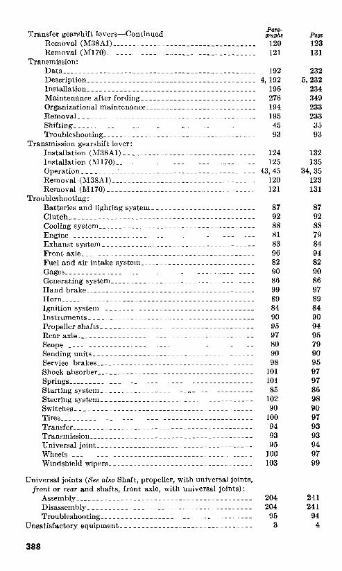
Transfer gearshift levers-Continued PlWlZ. graph8
Removal (M38Al)___________________________________ 120
Removal(M170)____________________________________ 121
Transmission:
Data________________________--_____-_____--____---- 192
Description- ________________ ____________________---- 4,192
Installation_______________---~----__--___---____---- 196
Maintenance after fording----____--____--___---____-- 276
Organizational maintenance-______--_____-____--____-- 194
Removal___________._____--_---____-____--____---__ 195
Shifting_______.____________._______________________ 45
Troubleshooting_________________--___---__----____-_ 93
Transmission gearshift lever:
Installation (~~38A1)__________________--____--__---- 124
Installation (h~170)_____________-___---___--____---__ 125
Operation_____.____________________________________ 43,45
Removal (M38Al)_____________----___-_-_----__---__ 120
Removal(M170)____________________________________ 121
Troubleshooting:
Batteries and lighting system_________________________ 87
Clutch_______________________--___-________________ 92
Coolingsysten~_____________.__----_---___-- ____ _ ____ 88
Engine__-____--__--_-_---____~---_-----_---___--___ 81
Exhaustsysten~_____--__----_-__--__----_-----_---__ 83
Frontaxle___~_______~_______~---~_---___-~____-____ 96
Fuel and air intake system____________---__---___---__ 82
Gages______~__________--~_._-----_---_________-____ 90
Generating system____________-----_---___---___-____ 86
Handbrake__________________---___-__________-_____ 99
Horn______~_________________---___--____-_____~____ 89
Ignition system_______________---__---___--____-____ 84
Instruments__________________----__----_-----_--___ 90
Propellershafts_______________----__----_---___---__ 95
Rearaxle_______-__---__--_~____---_----_----__---__ 97
Scope__________-___--_---______---~----_----~_---__ 80
Sending units___-___--_-----___~--__----_----~_---__ 90
Service brakes___________~ ___. ___~___~____~~..~~ ____ 98
Shockabsorber_____________--__---_---___---___-____ 101
Springs_________-___--__--_--___---_~-------___--___ 101
Startingsystem______________---~~_-__~__-~ _______ __ 85
Steering system_____________-__----_---~~---___-____ 102
Switches____________--__---____---__~--------__--__ 90
Tires__________________--__-___---_---___--____-____ 100
Transfer_____________________---___-_____.__________ 94
Transmission___________-_____---___--____- ____ ______ 93
Universal joint_________________--------__---________ 95
Wheels_____________--__--__-___---_----_---________ 100
Windshield wipers___________-___---__----_--____-___ 103
Universal joints (See also Shaft, propeller, with universal joints,
front or rear and shaft,s, front axle, with universal joints):
Assembly_________________--__---__---____-___~_____ 204
Disassembly_______________--__---__--____-_________ 204
Troubleshooting_______________--____________________ 95
Unsatisfactory equipment____-__-___-___--_______________ 3
page
123
131
232
5,232
234
349
233
233
35
93
132
135
34,35
123
131
87
92
88
79
84
94
82
90
86
97
89
84
90
94
95
79
90
95
97
97
86
98
90
97
93
93
94
97
99
241
241
94
4

Vacuum pump. (See Fuel and vacuum pump.)
Valve, windshield wiper air regulating. (See Windshield
wipers.)
Vehicle:
~ormaldriving_________---______________________---_
Parking_____________-----_~-_--------------________
Placing in motion_~~_________________----------_-__-_
Reversing____-______-----_____________-__--------__
Shifting gears in transfer___________--------_-_______-
Shifting transmission__-----____________-___-_--_____-
Stopping____________---________-_------_____-_____-
Towing_____________________-___________-___________
Warning:
Exhaustsystem________________--_____--__--________
Water pump : Insta~ation___~~~~___~__~_______~__~_________~______
Removal______________-___________-____-__-___-_-__
Water pump pulley:
Installation_____________________----_________-______
Removal_____________----___________-______-__-__-_
Wheel cylinder:
Installation________-----____-------_________________
Removal_____________----________----____-___-_--__
Wheel, steering. (See Steering wheel.)
Wheels:
Data______---____--------____-------_______________
Description_.__________---____________-_-_--_-_____-
Installation________-------__~_----------____________
Maintenance after fording---__________--_------______
Organizational maintenance_________------____________
Removal_----_.__--------___-----------_-__________
Sparewheel_______________--------__________________
Troubleshooting__________._-------_-_-______________
Windshield : M38Al:
Lowering_---_______________________-_-__-______
Raising______________________-______-_____-____
M170_______-________________________-_-___-__-____
Windshield wipers:
M38Al:
Adjustable arm____-__-______------_____-___-_-__
Air regulating valve__---________________---____-
Blade_______________-_-___-------______________
Lines and hoses_______--____________-_---__-____
Motor_________________-_------________________
Troubleshooting___----__________---___-__-______
M170:
General________----________________-_--________
Troubleshooting_____--_-_________________---_-__
Yoke, sleeve universal joint:
General_____________-___-____________-__-__________
Installation_____--___________-____________--________
Removal___________-_______________________________
[AG 451 (8 Mar 55) 1
Para-
v&a 44
48
43
49
46
45
47
52
83 84
131
131
131
131
235 282
235 282
248 299 248 299 250 300
276 349
249 300
250 300
251 302
109 97
254 305
254 305
263 330
259 316
259 316
a59 316
259 316
259 316
103 99
270 343
103 99
205 244
205 244
205 244
Page
35
38
34
38
36
35
37
39
141
141
141
141
389

BY ORDER OF THE S~ETARIES OF TIIE ARYY AND THE AIR FORCE :
M. B. RIDCJWAY,
Gen.era& United States Army, OFFICIAL: Chief of S.ta#i
JOHN A. KLEIN,
Major General, United St&es Amy, The Adjutant General.
@FICIAL : E. E. TORO,
N. F. TWINING,
Chief of Staff, United State8 Air Force.
Oolon%Z, United States Air Force, Air Adjutant General.
Active At-my: Tee Svc, DA (1) ORD PO (10)
Ord Bd (2) Ord Arsenals (6)
CONARC (3) Mil Diet (1)
Army AA Comd (2) Ord Proc Dist (10)
OS Maj Comd (5) MMG (1)
OS Base Comd (2) Mil Msn (1)
Log Comd (3) Units organized under follow-
MDW (1) ing TOE’s :
Armies (3) 9-1.28, Hq & Hq Co., &faint
Corps (2) &supGp,Ammo (1).
Div (2) 9-17, Ammo Co, Army (1)
Brig (2) 9-46A, Sp Wpn Spt or
Ord GP (2) Depot Bn (1)
Regt/Gp (1) 946A, Hq h Hq Det, SP
Ord Bn (2) Wpns Spt or Depot Bn
Bn (1) (1) Ord Co (2) 9-47A, Sp Wpns Spt or
Co (1) Depot Co (1)
Ft & Cp (2) 9-49, Sp Wpns Dir Spt Co
(fen & Br Svc Sch (2) (1) Ord Sch (59) 9-67A, Fld Sup Co (1)
PMST Ord ROTC units (1) 9-229, ORD GM Dir Spt Co
Gen Depots (2) (1) Ord Set, Glen Depots (5) 9-347, Ord Tire Rebuild Co
Ord Depots (10) (1) POE (2) 9-367, Sup Depot Co (1)
OS Sup Agencies (1) 9-387, Ammo Depot Co (1)
NG: Same as Active Army except allowance is one copy to each tmit.
UUR: None.
For explanation of abbreviations used, gee SR 329-6&l.