
OPERATION AND MAINTENANCE MANUAL - cloudfront.net
318
OPERATION AND MAINTENANCE MANUAL 8029 S 200th St. Kent, WA 98032 USA | www.rottlermfg.com | Ph: 253-872-7050 | Fax: 253-395-0230 9.05.2019
-
Upload
khangminh22 -
Category
Documents
-
view
2 -
download
0
Transcript of OPERATION AND MAINTENANCE MANUAL - cloudfront.net

OPERATION AND MAINTENANCE MANUAL
8029 S 200th St. Kent, WA 98032 USA | www.rottlermfg.com | Ph: 253-872-7050 | Fax: 253-395-02309.05.2019


ORDERING PROCEDUREContact your regional Rottler sales rep for assistance in ordering optional equipment, replacement parts, or tooling.If you are unable to contact your regional Rottler sales rep, call the factory at 253-872-7050 and ask to speak to the parts sales specialist.Have the following information handy to expedite the ordering process:
1. Your name, business name, and contact number2. Customer number3. If you don’t have a customer number, your billing address4. Shipping address if different from billing address5. Machine model and serial number6. Part number and description of what you want to order7. Preferred method of shipment8. You may also contact us via e-mail with the above information. Send e-mail requests to:
In some cases you may be requested to send a photo of the part you are ordering if it is a replacement part, or doesn’t appear in the database.
If you are unsure which part you need to order, contact our service department and ask to speak to one of our service consultants. They will assist you in determining which part you require.
THERE IS A MINIMUM ORDER OF $25.00
MANUAL SECTIONSINTRODUCTIONINSTALLATION
SAFETYCONTROL DEFINITIONS
OPERATING INSTRUCTIONSMAINTENANCE
TROUBLESHOOTINGMACHINE PARTS
OPTIONSMSDS


Section 1 Introduction F103/4/5A Manual
www.rottlermfg.com
I
INTRODUCTIONContents
Introduction ..................................................................................................................1-1
Description ...................................................................................................................1-2
Disclaimer ....................................................................................................................1-2
Limited Warranty .........................................................................................................1-3
Online Documentation Access ...................................................................................1-4

Section 1 Introduction F103/4/5A Manual
www.rottlermfg.com
1-1
Introduction
READ THE SAFETY CHAPTER BEFORE INSTALLING MACHINE. THOROUGHLY UNDERSTAND ALL SAFETY ISSUES BEFORE OPERATING MACHINE.
ATTENTION OWNER/BUSINESS MANAGERTo validate the warranty on your new Rottler machine, please be sure to sign and complete the “Installation Report” located in the Installation Chapter of this manual.
We suggest that the new user of the F103/4/5A read the CONTROL DEFINITIONS to get an idea how the machine operates.
The Operating Instructions chapter should be read in order to familiarize the user with the actual button pushing sequences required to carry out a job. These chapters in the manual should be considered an introduction. As the operators of the F103/4/5A series machines gain experience with using the different functions of the machine, complicated setups and programs will make more sense.
The rest of the manual contains information and part number reference on fixtures, cutting tools, and machine maintenance. The operator should read and become familiar with these areas as well.

Section 1 Introduction F103/4/5A Manual
www.rottlermfg.com
1-2
Description
The model F103/4/5A machine is a precision, single point boring, and high-speed surfacing unit. The machine can be equipped with tooling and accessories for surfacing and re-boring most American passenger car and truck engines, In-lines, as well as 90 and 60 degree V-types.
F103/4/5A machines can be easily tooled, to machine a wide range of engines, including European and Asian engines, also, the machine can be easily adapted to perform other boring and surfacing operations.
The machine is designed, to maintain alignment of cylinder bores, and cylinder head, deck surfaces to the pan rails and main bearing bore locations, as was done in the original factory machining. This overcomes the many inaccuracies and out-of-alignment problems associated with clamping portable boring bars to the cylinder head surface of blocks.
Convenient controls, fast block clamping, precise 3 axis CNC positioning and clamping, means considerable savings in floor to floor time, and operator involvement.
Change over or resetting time required to set up V-type or in-line engines is a minimum, making this machine highly suited to the jobber shop where engines cannot be run through in model lots.
All feeds and rapid travels are power operated and controlled form the control panel.
Disclaimer
The F103/4/5A Manual (henceforth to be referred to as the “Manual”) is proprietary to Rottler Manufacturing LLC. (“Rottler Manufacturing”) and no ownership rights are hereby transferred. No part of the Manual shall be used, reproduced, translated, converted, adapted, stored in a retrieval system, communicated or transmitted by any means, for any commercial purpose, including without limitation, sale, resale, license, rental or lease, without the prior express written consent of Rottler Manufacturing.Rottler Manufacturing does not make any representations, warranties or guarantees, express or implied, as to the accuracy or completeness of the Manual. Users must be aware that updates and amendments will be made from time to time to the Manual. It is the user’s responsibility to determine whether there have been any such updates or amendments. Neither Rottler Manufacturing nor any of its directors, officers, employees or agents shall not be liable in any manner whatsoever to any person for any loss, damage, injury, liability, cost or expense of any nature, including without limitation incidental, special, direct or consequential damages arising out of or in connection with the use of the Manual.
Rottler Manufacturing and its employees or representatives are not responsible for any information regarding final specifications of any workpiece that is created as a final product when using Rottler equipment. It is the responsibility of the end user of Rottler equipment to determine the final dimensions and finishes of the workpiece that they are working on. Any information regarding final dimensions and finishes that appears in any Rottler literature or that is expressed by anyone representing Rottler is to be regarded as general information to help with the demonstration of or for operator training of Rottler equipment.

Section 1 Introduction F103/4/5A Manual
www.rottlermfg.com
1-3
Limited Warranty
The model F103/4/5A machine is a precision, single point boring, and high-speed surfacing unit. The machine can be equipped with tooling and accessories for surfacing and re-boring most American passenger car and truck engines, In-lines, as well as 90 and 60 degree V-types.
F103/4/5A machines can be easily tooled, to machine a wide range of engines, including European and Asian engines, also, the machine can be easily adapted to perform other boring and surfacing operations.
The machine is designed, to maintain alignment of cylinder bores, and cylinder head, deck surfaces to the pan rails and main bearing bore locations, as was done in the original factory machining. This overcomes the many inaccuracies and out-of-alignment problems associated with clamping portable boring bars to the cylinder head surface of blocks.
Convenient controls, fast block clamping, precise 3 axis CNC positioning and clamping, means considerable savings in floor to floor time, and operator involvement.
Change over or resetting time required to set up V-type or in-line engines is a minimum, making this machine highly suited to the jobber shop where engines cannot be run through in model lots.
All feeds and rapid travels are power operated and controlled form the control panel.
DisclaimerThe F103/4/5A Manual (henceforth to be referred to as the “Manual”) is proprietary to Rottler Manufacturing LLC. (“Rottler Manufacturing”) and no ownership rights are hereby transferred. No part of the Manual shall be used, reproduced, translated, converted, adapted, stored in a retrieval system, communicated or transmitted by any means, for any commercial purpose, including without limitation, sale, resale, license, rental or lease, without the prior express written consent of Rottler Manufacturing.Rottler Manufacturing does not make any representations, warranties or guarantees, express or implied, as to the accuracy or completeness of the Manual. Users must be aware that updates and amendments will be made from time to time to the Manual. It is the user’s responsibility to determine whether there have been any such updates or amendments. Neither Rottler Manufacturing nor any of its directors, officers, employees or agents shall not be liable in any manner whatsoever to any person for any loss, damage, injury, liability, cost or expense of any nature, including without limitation incidental, special, direct or consequential damages arising out of or in connection with the use of the Manual.
Rottler Manufacturing and its employees or representatives are not responsible for any information regarding final specifications of any workpiece that is created as a final product when using Rottler equipment. It is the responsibility of the end user of Rottler equipment to determine the final dimensions and finishes of the workpiece that they are working on. Any information regarding final dimensions and finishes that appears in any Rottler literature or that is expressed by anyone representing Rottler is to be regarded as general information to help with the demonstration of or for operator training of Rottler equipment.

Section 1 Introduction F103/4/5A Manual
www.rottlermfg.com
1-4
Online Documentation Access
Online documentation for machines and optional equipment can be accessed at the Rottler website. To access documentation open your browser and navigate to https://www.rottlermfg.com.
Scroll to the bottom of the page and under the Owner Resources title click the type of documentation you want to access.
If a log in window pops up asking for user name and password fill in the blanks as shown.

Section 1 Introduction F103/4/5A Manual
www.rottlermfg.com
1-5
Section 2 Installation F103/4/5A Manual
www.rottlermfg.com
I
INSTALLATIONContents
F103/4/5 INSTALLATION PREPARATION REQUIREMENTS .....................................2-1
F100 SERIES INSTALLATION REPORT .....................................................................2-3
Removing Machine from Shipping Container .........................................................2-11
Installation Procedure ...............................................................................................2-13
Rottler F103/4/5 Series Foundation and Hold Down Requirements ............................. 2-13
Lifting Machine with Provided Lift Eyes ........................................................................... 2-14
F105A Hold Down and Jacking Bolt Locations ............................................................... 2-16
F105A Optional Enclosure Mounting Bolt Locations ...................................................... 2-17
F104A Hold Down / Jacking Bolt Locations ..................................................................... 2-18
F103A Hold Down / Jacking Bolt Locations ..................................................................... 2-19
F103A Hold Down / Jacking Bolt Locations Sunken Foundation .................................. 2-20
F104A Hold Down / Jacking Bolt Locations Sunken Foundation .................................. 2-21
F105A Hold Down / Jacking Bolt Locations Sunken Foundation .................................. 2-22
F105A Hold Down / Jacking Bolt Locations Sunken Foundation .................................. 2-23
Machine Dimensions .......................................................................................................... 2-24
Location ...........................................................................................................................................2-25Unpacking ........................................................................................................................................2-25Column Hold Down .........................................................................................................................2-25Leveling ...........................................................................................................................................2-25
Air Supply ............................................................................................................................ 2-26
Power Supply ...................................................................................................................... 2-27
Grounding ........................................................................................................................................2-27
Creating a Skype Account ........................................................................................2-28

Section 2 Installation F103/4/5A Manual
www.rottlermfg.com
2-1
F103/4/5 INSTALLATION PREPARATION REQUIREMENTS
1. Floor needs to be prepared with anchor bolts installed. Rottler highly recommends the Hilti system.
2. Machine needs to be set in place with a leveling pad under each leveling bolt. After setting the machine in place, check that each anchor bolt nut turns freely and that there is no damage to the anchor bolt threads.
3. Rough level the machine.
4. Electrical connection made to the machine. Provide 208-240 VAC 3 phase power. 60 amp service is required.
5. Ground rod installed and connected.
6. 6. Air supply to the machine. Minimum 100 PSI of clean, dry air.
7. Fixtures removed from the machine bed, and cleaned of rust preventative.
8. Machine cleaned of rust preventative.
9. Machine requires an Internet connection. Preferably wireless.
10. Have a scrap block available for operator training. Preferably a block commonly repaired at your facility.

Section 2 Installation F103/4/5A Manual
www.rottlermfg.com
2-2
ATTENTION OWNER/BUSINESS MANAGER
To validate the warranty on your new Rottler machine, please be sure to sign the installation report after the installation technician has installed the machine and verified the machine is operating correctly and given the operators operation and maintenance training.
Thank you for your cooperation and the opportunity to be of service to you.
ROTTLER MANUFACTURING

INSTALLATION REPORT
REV 062718F100 SERIES
OFFICE USE ONLY
Route to: Servicer Mgr Accounting Andy Accounting Warranty Exp Date ________
ROTTLER MANUFACTURING MUST HAVE THIS REPORT RETURNED TO PROPERLY QUALIFY WARRANTY ON EQUIPMENT
Customer:____________________________ Address:_______________________________________City:_________________________________ State:_____ Zip:_________ Phone:_______________Country:______________________________Machine Model:___________ Serial Number:__________ Representative:________________________
MACHINE INSTALLATION: Electrical information MUST be complete to validate this report.
______Customer has read and fully understands importance of machine location as explained in the installation section of the manual.
The following is the customer’s responsibility prior to the arrival of Rottler technician. Please initial each item when it is completed.
Customer must provide foundation and hold down bolt system, see following attached drawing and document “F70 and F100 Series Foundation and Hold Down Requirements”
VERY IMPORTANT: Modern design machines contain electronic low voltage circuitry that provides great advantages and a better machine life. BUT, you must have an excellent, stable, isolated power supply along with an isolated ground. If not, electrical noise problems are likely to interfere with machine operation unexpectedly.
Customer is responsible for providing electricity to machine in a manner that meets the local electrical code requirements.
______Remove machine from truck. Weight: F103 14,000 lbs (6,350 kg) F104 16,000 lbs (7257 kg) F105 18,000 lbs (8165 kg) F107 45,000 lbs (20,412 kg) F109 50,000 lbs (22680 kg).
______If the machine was shipped in a container follow the removal procedure in the installation section of the manual. (F103, F104, F105 only)
______Remove fixturing and misc. parts from machine and clean.______Install machine on foundation with supplied jack pads under jacking bolts.______Install hold down nuts and bolts, see attached document. – This must e done first.______Rough Level the machine using a precision level so there is equal tension on all bolts.______This machine requires between 208 and 240 Volts AC, Three Phase, 50/60 Hz, isolated power
supply. For voltages above 240 or below 208 VAC, a 17kva transformer will be required and is available at Rottler. Please specify voltage when ordering. Measure the incoming voltage between L1 and L2, L2 and L3, and L1 and L3. Current requirements for this machine is 60 amps. Measure the incoming AC voltage at least twice during installation.
1. L1to L2 __________VAC, L2 to L3 __________ VAC, L1 to L3 __________ 2. L1to L2 __________VAC, L2 to L3 __________ VAC, L1 to L3 __________

Section 2 Installation F103/4/5A Manual
www.rottlermfg.com
2-4
______Measure each leg of the incoming supply to ground. Sometimes you may find a “high” leg to ground. When this happens make sure the high leg is running to L3.
L1 to ground __________VAC L2 to ground __________VAC L3 to ground __________VAC
Neutral and machine ground are not the same thing. You should measure an open circuit between Neutral and ground.
IF VOLTAGE IS OUTSIDE THE CORRECT RANGE AT ANY TIME THE MACHINE WILL NOT OPERATE PROPERLY AND MAY BE DAMAGED.
______Air of the proper pressure and capacity connected to the machine. Air supply must be free from oil and water. Oil or water will damage electrical and air components.
______Customer should attempt to have junk work piece available.______Have the operator read through the operation manual before training begins. This will help him
be familiar with the button pushing sequences. Have the operator read through the manual again after training and some of the sequences will make more sense.
______Have Internet connection available for the machine. Either via Ethernet cable or Wireless. The machine comes equipped with a wireless USB adapter.
The following is the Rottler technician’s responsibility______Check column top and spindle base bottom for rust and nicks if spindle must be installed. Clean
and stone as required.______When lifting spindle unit, keep in mind the front to back center of gravity is located approximately
12 inches from the front end and has a tendency to lean forward.______Each main system is protected internally by circuit breakers. Green indicates the breaker is
“tripped” and red indicates the breaker is “Hot” (conducting electricity).______Clean any rust inhibitor from the machine surfaces. Move the column from side to side continually
cleaning the machine base until all inhibitor is removed.______Install spindle unit on column, if required, using one of the approved methods described in the
operation manual. (Spindle unit weighs 6,000 lbs, 2,800 Kgs.)
Using fork lift angle iron brackets
______Bolt brackets to each side of the spindle base.______Use large C-clamps to clamp the fork lift forks to the angle iron brackets. This will prevent any
accidental slips. Loosen 1/2 13 x 3 1/2 Inch bolts on pendent arm to allow it to be moved out of the way.
______Use a forklift to lift the spindle unit onto the column. Be careful to watch clearance of all items.______Install the Right (Fixed Side Rail) and removable dowel pins. Torque Side Rail bolts to 80 Ft/lbs.______Lift spindle unit into place. Push spindle base up against Right Side Rail.______Install left side rail (9202A) with 2 Belleville’s (9024E) opposing each other () on each set screw
(9202D), torque side rail bolts to 80 Ft/lbs.______Adjust the adjustable screws (9202D) on SIDE rails by tightening them until they bottom out, then
unscrewing them 1/8 turn.______Measure the protrusion of the Sides Rails above the spindle base and record. Right: Front _________ Rear _________ Left Front _________ Rear _______________Install the Right and Left Top Rails.______Install top rails (9202B) with 2 Belleville’s opposing each other () on each adjustable set screw
(9202D). Torque to 80 lbs.

Section 2 Installation F103/4/5A Manual
www.rottlermfg.com
2-5
______Adjust the adjustable screws (9202D) on TOP rails by tightening them until they bottom out, then unscrewing them 3/4 turn.
______Remove angle iron brackets form spindle base.______Connect air and oil lines per air logic diagram.______Remind customer of the proper air pressure and capacity connected to the machine. Air supply
must be free from oil and water. Oil or water will damage electrical and air components.______Connect electrical wires in main rear enclosure if required using machine wiring diagram.
MACHINE START-UP
When starting the machine for the first time, it may move out of control. Make sure all hands are clear of machine parts. Be ready to press the Emergency Stop button if needed.
______BEFORE turning power on to the machine. Check all wires for security by using the correct screw driver and turning CW until movement stops. Stranded wire can “spread” slightly from vibration during transport.
______Install electrical component covers inside the electrical enclosure with fasteners provided.______Turn main power on at the main disconnect switch located on the rear enclosure.______If machine moves out of control, turn power off and contact factory for help in trouble shooting.______If any of the circuit breakers “trip”, reset and call factory for possible trouble shooting.______Install and test the Internet connection to the machine. DO NOT download any updates unless
instructed to do so by Rottler.______Check the computer control options and make sure that you turn on z-axis bit 2 and spindle bit 3.
MACHINE MOVEMENTS
______Make sure there is nothing obstructing the full vertical, horizontal or In/Out travel of the machine taking special notice of the rear enclosure, way travel and top of the spindle unit.
______Put the machine in hand wheel mode and verify Vertical operation. Put an indicator on the cutter head and verify .001” movement per detent in course mode and .0001” in fine mode. If the indicator is jumpy the outer spindle adjustment may be too tight. Refer to manual and re-adjust.
______Put the machine in hand wheel mode and verify Horizontal operation. Put an indicator on the cutter head and verify .001” movement per detent in course mode and .0001” in fine mode
______Use the rapid buttons and verify proper vertical, horizontal and In/out travel.______Check limit switch operation with handwheel before using the power feed.______Move the machine to its vertical limits to verify proper operation.______Move the machine to its horizontal limits to verify proper operation.______Move the machine to its In/Out limits to verify proper operation.______Start the spindle and verify operation at all speeds.______Use the spindle creep buttons and verify proper operation.______Prime the oiling system. (See maintenance section of manual for complete details.)______Use a precision level and level the machine:
Record machine level readings below (must be within .0005). Back Way:
Back Way:P1 ______ P2 ______ P3 ______ P4 ______ P5 ______ P6 _____ P7 _____ P8 _____Back to Front Way:P1 ______ P2 ______ P3 ______ P4 ______ P5 ______ P6 _____ P7 _____ P8 _____

Section 2 Installation F103/4/5A Manual
www.rottlermfg.com
2-6
Record Dial Indicator readings:
Spindle to Back Table:P1 ______ P2 ______ P3 ______ P4 ______ P5 ______ P6 _____ P7 _____ P8 _____Spindle to Front Table:P1 ______ P2 ______ P3 ______ P4 ______ P5 ______ P6 _____ P7 _____ P8 _____
______Check mill tilt, and lift amounts with Y axis in the middle of travel, and record Amount of tilt ____________ Amount of tilt _____________ (See Section 6 of the manual for specification)
The following procedures should be shown to personal involved in machine maintenance.See maintenance section of manual for complete details. Video of procedure can be viewed at:www.rottlertube.com
______Check, and adjust X axis gibs Should be .0002-.0005 (see maintenance for further instructions.)______Adjust outer spindle bushings.______Adjust inner spindle bearings______Perform spindle sweep adjustment.______Verify ALL axis backlash comp is operating properly, adjust if needed. Record actual readings after
verification. Auto Handwheel X-Axis__________ __________ Y-Axis__________ __________ Z-Axis__________ __________
______Install way cover brackets and way covers. Way Cover support brackets should be flush with way surface.
INSTRUCTING THE OPERATOR
Note: Rotter employees and representatives per company policy are not permitted to provide end user of Rottler equipment with any OEM specifications for the workpiece that is created by end user using Rottler equipment.
______ Explain to the customer and operator that at NO time is there to be any software or hardware other than Windows Auto Update and Rottler installed on this machine. This includes screen savers, anti-virus software, and any hardware device that installs software on the machine. Installation of screen savers and anti-virus software can cause dangerous control problems. Any installation of software or hardware will void the warranty on the machine.
______Explain to the customer and operator that the machine should be hooked up to the Internet anytime it is on. The software on the machine will automatically connect to our server to send back useful information on machine status.
______Connect customer supplied Internet to the machine. Verify that the Internet is accessible from the machine.
______Once the machine has been fully setup and is ready for operation create a Skype account for the machine following the instructions in the Installation Section of the manual.
______Explain to the customer and the operator how the to log onto Skype and communicate with Rottler when needed.

Section 2 Installation F103/4/5A Manual
www.rottlermfg.com
2-7
______ Computer Viruses will cause the machine control system to become unstable. This may cause the machine to make uncontrolled moves which could create a dangerous environment for the machine operator.
______Refer to Chapter 4, Control Definitions of the Machine Manual, Section: Computer and Controller System Safety. Explain and discuss this section carefully with Owner/Manager/Operator and have them sign off. Failure to do so will result in the machine warranty being Null and Void.
_______________________________________________________________________ Signature / Title
______Explain to the customer the importance of backing up the block profiles to a separate device. Any computer failure or possible operator input error can result in the loss of all block profiles that were created for the machine. Refer to Chapter 5 of the machine manual for detailed instructions on backing up and restoring block profiles.
______Explain to the customer the proper way to turn the machine off when it is not in use. Do not leave the machine on overnight. It is important to close all programs followed by shutting down Windows before turning the main power switch off. Do not turn the main power switch off before shutting down Windows.
______Using the operating manual as a guide explain the function of all buttons.______Cycle all machine movements and supervise the handling of same by operator.______Demonstrate the differences of Manual and Auto operation.______Fully explain the entire Auto Cycle from Centering to Auto Retract.______Explain machine parameters and error messages. It is very important that the customer does not
change parameter settings without first checking with Rottler Manufacturing. If certain parameters are changed the machine may make uncontrolled moves or not operate at all.
______Point out safety features to customer and operator. Do not push any buttons without thinking of safety first.
Do not assume the cutterhead micrometer has been calibrated.
______Install a work piece in the machine and perform an undersize test bore to qualify the micrometer setting to the customers measuring tools.
Note adjustments: + __________, - __________.______Explain precision reset of tool in cutterhead.______The following is a checklist to go through every time the machine is started to begin a cut or
automatic cycle.• Work piece secure• RPM set• Feed Rate set• Correct program in use• Program oriented correctly (vertical zero at correct place) Centering range adequate• Guards in place• Cutterhead secure• Tool holder adjusted to the correct size• Tool holder locked in place
______Proceed to have operator bore block to size.

Section 2 Installation F103/4/5A Manual
www.rottlermfg.com
2-8
______Demonstrate and explain boring with the electronic hand wheel.______Explain the correct Feed rates and speeds from Cutting Insert Bulletin.______Cutter head change and expected stub bar performance.______Parts ordering, refer the to the operating manual for part numbers and description.______Offset tool bits, calibration of micrometer and anvil setting.______Train on ALL Rottler programs even if they need to be run in the air.______If Rottler CAM was provided to the customer train on any programs supplied by Rottler.______Review Emergency stop procedure with operator per operating manual.
MAINTENANCE SECTION
______Use the manual as a reference when explaining routine maintenance and lubrication.______Overload devices, There are no mechanical overload devices on this machine. The machine is
protected from overload by the motor controllers. If the system is overloaded the controllers shut the motors off. The controllers can be reset by turning the main power off for at least 1 minute, then turning it back on.
______Explain again the proper Inner and Outer spindle adjustment to the operator.______Dampener cleaning.______Micrometer and anvil thread adjustment.______Inspection of tool bit hole in tool holders (deformation due to accidental impact).

Section 2 Installation F103/4/5A Manual
www.rottlermfg.com
2-9
Rottler Manufacturing and its employees or representatives are not responsible for any information regarding final specifications of any workpiece that is created as a final product when using Rottler equipment. It is the responsibility of the end user of Rottler equipment to determine the final dimensions and finishes of the workpiece that they are working on. Any information regarding final dimensions and finishes that appears in any Rottler literature or that is expressed by anyone representing Rottler is to be regarded as general information to help with the demonstration of or for operator training of Rottler equipment.
Note: Rotter employees and representatives per company policy are not permitted to provide end user of Rottler equipment with any OEM specifications for the workpiece that is created by end user using Rottler equipment.
General remarks on machine performance, adjustments as received and any further organization or parts required to complete the installation.
____________________________________________________________________________________
____________________________________________________________________________________
____________________________________________________________________________________
____________________________________________________________________________________
____________________________________________________________________________________
____________________________________________________________________________________
____________________________________________________________________________________
____________________________________________________________________________________
____________________________________________________________________________________
____________________________________________________________________________________
____________________________________________________________________________________
Instructions given to:___________________________________________________________________
Sales/Service Engineer: _______________________________________________ Date_____________
Shop Foreman/Superintendent or Owner: _________________________________ Date_____________
Once completed send this form to:Rottler Manufacturingattn: Service Manager8029 S 200 StKent, WA 98032 USA
Alternately you may send this form via fax or e-mail:fax: [+1] 253-395-0230e-mail: [email protected]

Section 2 Installation F103/4/5A Manual
www.rottlermfg.com
2-10

Section 2 Installation F103/4/5A Manual
www.rottlermfg.com
2-11
Removing Machine from Shipping Container
All F100 machines that are shipped in a container must be unloaded using the following method.
Machines will be loaded into containers at the factory mounted on metal tubes. These tubes will facilitate the sliding of the machine out of the container.
If the machine is to be removed from the container for transfer to its final destination the seal must not be broken.
Use lifting straps or chains placed through the tubes to pull the machine from the container. Make certain that the machine is clear of the container before attempting to lift machine.
The photo below shows the machine packed and sealed for placement into a container.

Section 2 Installation F103/4/5A Manual
www.rottlermfg.com
2-12
The photos below show the tubes that the machine sits on. Place straps or chains through these tubes to pull the machine out of the container. Take care not to damage the threads of the bolts holding the tubes to the machine.
Using an alternative method to remove the machine from the container that results in damage to the foil packaging seal or to the machine itself could result in the warranty being voided.
Section 2 Installation F103/4/5A Manual
www.rottlermfg.com
2-13
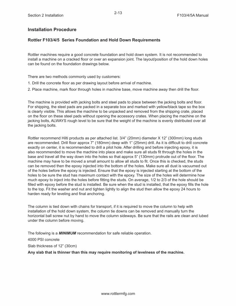
Installation Procedure
Rottler F103/4/5 Series Foundation and Hold Down Requirements
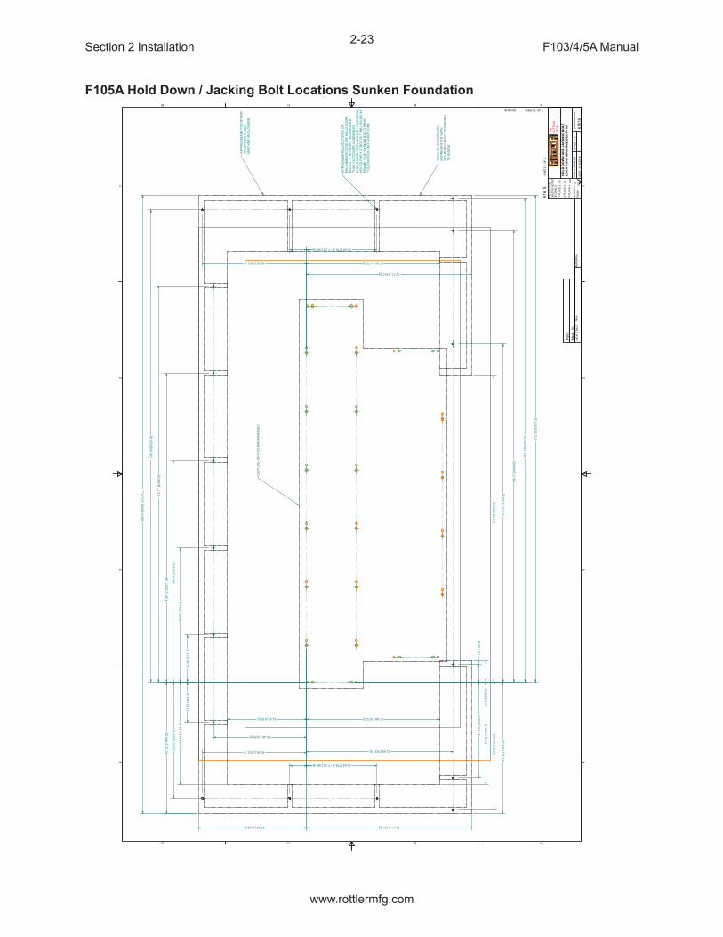
Rottler machines require a good concrete foundation and hold down system. It is not recommended to install a machine on a cracked floor or over an expansion joint. The layout/position of the hold down holes can be found on the foundation drawings below.
There are two methods commonly used by customers:1. Drill the concrete floor as per drawing layout before arrival of machine. 2. Place machine, mark floor through holes in machine base, move machine away then drill the floor.
The machine is provided with jacking bolts and steel pads to place between the jacking bolts and floor. For shipping, the steel pads are packed in a separate box and marked with yellow/black tape so the box is clearly visible. This allows the machine to be unpacked and removed from the shipping crate, placed on the floor on these steel pads without opening the accessory crates. When placing the machine on the jacking bolts, ALWAYS rough level to be sure that the weight of the machine is evenly distributed over all the jacking bolts.
Rottler recommend Hilti products as per attached list. 3/4” (20mm) diameter X 12” (300mm) long studs are recommended. Drill floor approx 7” (180mm) deep with 1” (25mm) drill. As it is difficult to drill concrete exactly on center, it is recommended to drill a pilot hole. After drilling and before injecting epoxy, it is also recommended to move the machine into place and make sure all studs fit through the holes in the base and travel all the way down into the holes so that approx 5” (130mm) protrude out of the floor. The machine may have to be moved a small amount to allow all studs to fit. Once this is checked, the studs can be removed then the epoxy injected into the bottom of the holes. Make sure all dust is vacuumed out of the holes before the epoxy is injected. Ensure that the epoxy is injected starting at the bottom of the holes to be sure the stud has maximum contact with the epoxy. The size of the holes will determine how much epoxy to inject into the holes before fitting the studs. On average, 1/2 to 2/3 of the hole should be filled with epoxy before the stud is installed. Be sure when the stud is installed, that the epoxy fills the hole to the top. Fit the washer and nut and tighten lightly to align the stud then allow the epoxy 24 hours to harden ready for leveling and final anchoring.
The column is tied down with chains for transport, if it is required to move the column to help with installation of the hold down system, the column tie downs can be removed and manually turn the horizontal ball screw nut by hand to move the column sideways. Be sure that the rails are clean and lubed under the column before moving.
The following is a MINIMUM recommendation for safe reliable operation.4000 PSI concreteSlab thickness of 12” (30cm)Any slab that is thinner than this may require monitoring of levelness of the machine.

Section 2 Installation F103/4/5A Manual
www.rottlermfg.com
2-14
Lifting Machine with Provided Lift Eyes
Lifting a machine using the following method is a dangerous and demanding procedure. Therefore Rottler recommends that the customer hire a licensed and bonded material handling specialists. Rottler will not be held liable for and consequences resulting from mishandling of the machine using this method.
Observe the following precautions:1. Check the machine invoice to see what the shipping weight was and be certain that the hoists to be
used ratings exceed that weight.2. Be certain that all rigging used is rated for the weight that will be lifted.3. Check lift eyes for damage and for secure attachment.4. Nylon straps are preferred over cable and chain in order to prevent damage to machine.

Section 2 Installation F103/4/5A Manual
www.rottlermfg.com
2-15

Section 2 Installation F103/4/5A Manual
www.rottlermfg.com
2-16
F105A Hold Down and Jacking Bolt Locations

Section 2 Installation F103/4/5A Manual
www.rottlermfg.com
2-17
F105A Optional Enclosure Mounting Bolt Locations

Section 2 Installation F103/4/5A Manual
www.rottlermfg.com
2-18
F104A Hold Down / Jacking Bolt Locations
Section 2 Installation F103/4/5A Manual
www.rottlermfg.com
2-19
F103A Hold Down / Jacking Bolt Locations

Section 2 Installation F103/4/5A Manual
www.rottlermfg.com
2-20
F103A Hold Down / Jacking Bolt Locations Sunken Foundation
Section 2 Installation F103/4/5A Manual
www.rottlermfg.com
2-21
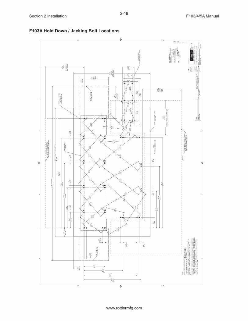
F104A Hold Down / Jacking Bolt Locations Sunken Foundation

Section 2 Installation F103/4/5A Manual
www.rottlermfg.com
2-22
F105A Hold Down / Jacking Bolt Locations Sunken Foundation
Section 2 Installation F103/4/5A Manual
www.rottlermfg.com
2-23
F105A Hold Down / Jacking Bolt Locations Sunken Foundation

Section 2 Installation F103/4/5A Manual
www.rottlermfg.com
2-24
Machine Dimensions
Left Side View

Section 2 Installation F103/4/5A Manual
www.rottlermfg.com
2-25
IMPORTANT! Placement of Machine
It is critical that the machine be placed in an area of the facility that has a stable thermal environment. The machine should be kept away from direct sunlight, large heating units, and doorways that would allow outside air direct contact on the machine.Exposure to the above and other extremes in temperature will cause thermal drift to occur in the machines which could have a detrimental effect on machining accuracy. A number of unrepeatable errors in machine performance have been linked to this condition.LocationThe productivity of this machine will depend a great deal on its proper initial installation. Pay particular attention to the means by which work pieces are lifted into the machine as well as the material handling to and from other operations in your shop.The proper loading arrangement and area location for your F103/4/5A machine is extremely important.A slow travel (6’ to 10’ per minute) power hoist, operated from either a bridge crane or a jib crane arrangement works very well. Verify the hoist has a rating that exceeds the load being lifted.For the shop where large production runs are anticipated, the work pieces should be directly loaded and unloaded from a conveyor. If this is not the case we recommend considerable attention be given to the crane so that it covers an adequate area, to allow the operator to back up and remove work pieces without creating a dangerous, cluttered work area.UnpackingUse care in removing the crate materials from the machine. Be careful not to use force on any part of the machine.Remove the toolbox, parallels and optional equipment from the machine. Completely clean these articles as well as the rest of the machine with solvent. Rust inhibitor was applied, at the time of shipment. Any of this left on the machine, will allow cast iron dust to collect in that area, which could cause premature wear.Column Hold DownThe machine was shipped with the column held in place with chains and turnbuckles to the Main bed. Do not attempt to move the machine under power until these restraints have been removed.LevelingLocated in the bottom of the main base are the leveling and tie down screws. If care is taken, the main base can be leveled extremely accurately. Start by placing the jacking pads under the jacking screws. Adjust the jacking screws so the lowest point of the main base is at least 1/4” off the jacking pad. Make sure all the jacking screws are touching their jacking pads. Use a precision machinist’s level, and check the base at several points to get an idea where the high and low spots are, adjust evenly where necessary. Start with the back way surface. With your precision level, level the back way in the lengthwise direction to .0005” per foot. Take the readings approximately mid way between the jacking points. Use a precision metal support to span the distance between the front and rear parallels. (Support must be parallel within .0005” in its length). Take readings over every jacking bolt and level within .0005” over the length of the base. Be sure to use the jacking points down the middle of the main base.Recheck the way surfaces for level. Now check the machine table. Using the front jacking screws level the table within .0005” in both directions.Be sure that all jacking bolts have approximately equal weight on them. As you go leveling the base snug the tie down bolts to help hold the main base in place. Recheck all areas of the main base for level.

Section 2 Installation F103/4/5A Manual
www.rottlermfg.com
2-26
Air Supply
It is very important the air source for the F103/4/5A machine be moisture free. Water and oil in the line will result in early cylinder and valve failure. The factory recommends installing a water trap at the machine.
Attach a 100 PSI air source to the appropriate intake in the small enclosure located on the left rear of the machine near the bottom.

Section 2 Installation F103/4/5A Manual
www.rottlermfg.com
2-27
Power Supply
This machine has the following power requirements:• 208 to 240 VAC• Three Phase• 50 or 60 Hertz• 60 amps
See illustration below for correct connection of “measured” incoming power. Connect three phase wiring to the electrical box located on the back of the machine in the lower right hand corner. See illustration below. If a “high leg” exists, this must be at Line 3. All ground wires go to ground block. Important: Note: For voltages over 240 VAC (380 – 440 VAC) a transformer needs to be installed with the machine.
GroundingThis machine must be connected to a good earth ground rod. A 6 foot, 1/2” diameter, 15 OHM, Copper grounding rod driven into the earth next to the machines is preferred. Not providing a grounding rod could void factory warranty.
Electrically connect in accordance with national and local electrical codes.

Section 2 Installation F103/4/5A Manual
www.rottlermfg.com
2-28
Creating a Skype Account
Click on create an account
Click on: Use your email instead
Click on: Get new email address

Section 2 Installation F103/4/5A Manual
www.rottlermfg.com
2-29
Name the email account using the Rottler machine Model and Serial number.
Ex: H85A111, EM69P001
Create a password that is easy to remember.
Uncheck the box to receive emails from Microsoft.
First Name: Model-Serial Number
Ex: F105A-113
Last Name: RottlerMfg
Select your Country/region
Birthday: Today’s date, year 1992

Section 2 Installation F103/4/5A Manual
www.rottlermfg.com
2-30
Type the code exactly as it appears.
Click “Next”
Click “Continue”
If your headset and/or web camera are hooked up you can verify that they are working here.
Otherwise, click “Continue”

Section 2 Installation F103/4/5A Manual
www.rottlermfg.com
2-31
Click “Add later” to skip this part.
Your Skype account is set up and ready for use.

Section 2 Installation F103/4/5A Manual
www.rottlermfg.com
2-32

Section 3 Safety F103/4/5A Manual
www.rottlermfg.com
I
SAFETYContents
Safety Information .......................................................................................................3-1
Safety Instructions for Machine Use .................................................................................. 3-1
Electrical Power .................................................................................................................... 3-3
Machine Operator ................................................................................................................. 3-5
Emergency Procedure ......................................................................................................... 3-6
Computer and Controller System Safety ........................................................................... 3-6
Electrical Safety Features Of Rottler DM Controlled Machines ..............................3-7

Section 3 Safety F103/4/5A Manual
www.rottlermfg.com
3-1
Safety Information
For Your Own Safety Read This Instruction Manual Before Operating This Machine.
This is the safety alert symbol. It is used to alert you to potential personal injury hazards. Obey all safety messages that follow this symbol to avoid possible injury or death.
DANGER indicates an imminently hazardous situation which, if not avoided, will result in death or serious injury.
WARNING indicates a potentially hazardous situation which, if not avoided, could result in serious injury.
CAUTION indicates a potentially hazardous situation which, if not avoided, may result in minor or moderate injury.
CAUTION used without the safety alert symbol indicates a potentially hazardous situation which, if not avoided, may result in property damage.
Safety Instructions for Machine Use
This machine is capable of causing severe bodily injury
ONLY A QUALIFIED, EXPERIENCED OPERATOR SHOULD OPERATE THIS MACHINE. NEVER ALLOW UNSUPERVISED OR UNTRAINED PERSONNEL TO OPERATE THE MACHINE. Make sure any instructions you give in regards to machine operation are approved, correct, safe, and clearly understood. Untrained personal present a hazard to themselves and the machine. Improper operation will void the warranty.
KEEP GUARDS IN PLACE and in proper working order. If equipped with doors, they must be in the closed position when the machine is in operation.
KEEP WORK AREA CLEAN. Cluttered areas and benches invite accidents.
Section 3 Safety F103/4/5A Manual
www.rottlermfg.com
3-2
KEEP CHILDREN AND VISITORS AWAY. All children and visitors should be kept a safe distance from work area.
WEAR THE PROPER APPAREL. DO NOT wear loose clothing, gloves, rings, bracelets, or other jewelry which may get caught in moving parts. Non-Slip foot wear is recommended. Wear protective hair covering to contain long hair.
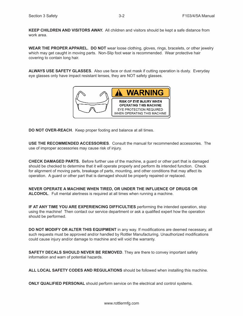
ALWAYS USE SAFETY GLASSES. Also use face or dust mask if cutting operation is dusty. Everyday eye glasses only have impact resistant lenses, they are NOT safety glasses.
DO NOT OVER-REACH. Keep proper footing and balance at all times.
USE THE RECOMMENDED ACCESSORIES. Consult the manual for recommended accessories. The use of improper accessories may cause risk of injury.
CHECK DAMAGED PARTS. Before further use of the machine, a guard or other part that is damaged should be checked to determine that it will operate properly and perform its intended function. Check for alignment of moving parts, breakage of parts, mounting, and other conditions that may affect its operation. A guard or other part that is damaged should be properly repaired or replaced.
NEVER OPERATE A MACHINE WHEN TIRED, OR UNDER THE INFLUENCE OF DRUGS OR ALCOHOL. Full mental alertness is required at all times when running a machine.
IF AT ANY TIME YOU ARE EXPERIENCING DIFFICULTIES performing the intended operation, stop using the machine! Then contact our service department or ask a qualified expert how the operation should be performed.
DO NOT MODIFY OR ALTER THIS EQUIPMENT in any way. If modifications are deemed necessary, all such requests must be approved and/or handled by Rottler Manufacturing. Unauthorized modifications could cause injury and/or damage to machine and will void the warranty.
SAFETY DECALS SHOULD NEVER BE REMOVED. They are there to convey important safety information and warn of potential hazards.
ALL LOCAL SAFETY CODES AND REGULATIONS should be followed when installing this machine.
ONLY QUALIFIED PERSONAL should perform service on the electrical and control systems.

Section 3 Safety F103/4/5A Manual
www.rottlermfg.com
3-3
When boring the machine is capable of throwing metal chips over 10- feet from the cutting area. Always use the guards. Eye protection must be worn at all times by the operator and all other personnel in the area of the machine.
No list of safety guidelines can be complete. Every piece of shop environment is different. Always consider safety first, as it applies to your individual working
conditions. Use this and other machinery with caution and respect. Failure to follow guidelines could result in serious personal injury, damage to equipment or poor work results.
Electrical Power
THIS MACHINE IS AUTOMATICALLY CONTROLLED AND MAY START AT ANYTIME
All electrical power should be removed from the machine before opening the rear electrical enclosure.

Section 3 Safety F103/4/5A Manual
www.rottlermfg.com
3-4
In the event of an electrical short, grounding reduces the risk of electric shock by providing a path of least resistance to disperse electric current.
Electrocution or a fire can result if the machine is not grounded correctly. Make sure the ground is connected in accordance with this manual. DO NOT operate the machine if it is not grounded.
No single list of electrical guidelines can be comprehensive for all shop environments. Operating this machinery may require additional electrical
upgrades specific to your shop environment. It is your responsibility to make sure your electrical system comply with all local codes and ordinances.
This machine operates under computerized control and, as is all computerized equipment, and is susceptible to extraneous electrical impulses internally for
externally produced. The machine may make moves out of the operator control at any time. The operator should work in and around the machine with caution at all times.The operator and nearby personnel should be familiar with the location and operation of the Emergency Stop Button.Make sure all electrical equipment has the proper overload protection. This machine should have a fully isolated power supply to prevent damage and uncontrolled movement of the machine. If this machine is on the same power lines that are running to other electrical equipment (grinders, welders, and other AC motors) electrical noise can be induced into this machines electrical system. Electrical noise can cause the controller to see false signals to move. Not supplying a fully isolated supply to the machine may void factory warranty. Refer to the Power supply section located in the Installation section for voltage and

Section 3 Safety F103/4/5A Manual
www.rottlermfg.com
3-5
Machine Operator
The operator of this machine should be a skilled machinist craftsman who is well versed in the caution, care, and knowledge required to safely operate metal cutting tools. If the operator is not a skilled machinist he/she must pay strict attention to the Operating Instructions outlined in this manual, and get instruction from a qualified machinist in both production and operation of this machine.This machine has the following areas of exposed moving parts that you must train yourself to respect and stay away from when they are in motion:
Cutting Tool Area – Any operation involving hands in the cutter head area, such as inspection or alignment of the cutter head or tools, changing Centering Fingers, tool insertion, and removal, cutter head changes, and size checking etc. requires the machine to be in Neutral.
Machining – Eye protection must be worn during all operations of the machine. Hands must be kept completely away from the cutter head. All chip guards must be in position during machine operations.
Work Loading and Unloading – Carefully develop handling methods of loading and unloading work pieces so that no injury can result if hoist
equipment or lift connection should fail. Periodically check lift components for damage that may cause failure.
Machine Maintenance – Any machine adjustment, maintenance or parts replacement absolutely requires a complete power disconnection from the
machine.

Section 3 Safety F103/4/5A Manual
www.rottlermfg.com
3-6
Emergency Procedure
Assuming one of the following has occurred: tool bit set completely off size, work piece or spindle base not clamped, spindle is not properly centered, and these mistakes will become obvious the minute the cut startsPRESS THE EMERGENCY STOP BUTTON (on the front control panel) IMMEDIATELY!Find out what the problem is; return the spindle to its up position without causing more damage. To restart the machine, turn the Emergency Stop Button CW until the button pops outBe alert to quickly stop the machine in the event of a serious disruption of the boring process either at the top or bottom of the bores.“REMEMBER” metal cutting tools have the speed and torque to severely injure any part of the human body exposed to them.
Computer and Controller System Safety
The computer and controller are located in the main rear electrical enclosure. This unit is a full computer, running Windows 7 64 Bit operating system. Contact the factory if more information on the computer system is required.
The computer in this machine has the ability to connect to the World Wide Web via Ethernet or Wireless using a USB wireless (Wi-Fi) adapter. Updating the Rottler
software should ONLY be done when directed to do so by a Rottler service technician. Updating Rottler Software when not directed by Rottler personnel will result in a non-operational machine.The machine should be hooked up to the Internet anytime it is on. The software on the machine will automatically connect to our server to send back useful information on machine status.
Any “IT” personnel should ALWAYS get approval from Rottler before doing ANYTHING on the computer.
This machine is capable of causing severe injury or death. Doing any of the following without Rottler’s direct consent may cause severe injury or death.
Do not attempt to install USB devices in the PCI ports. These
ports have high voltage and any attempt to connect a USB device in these ports will result in destruction of that device. There is also the possibility of damage to the computer system of the machine.
Downloading any program or changing any Rottler or Computer settings may cause the machine and/or software to become unstable. DO NOT install ANY screen
saver, Anti-Virus, Spyware or any type of Security software on the computer. This could create a hazardous environment for the operator and personnel around the machine. Performing any of the above will also result in the machine warranty being NULL and VOID.
DO NOT connect any type of external hardware to the computer via USB or any other means. Do not install any type of Device Driver. This could create a
hazardous environment for the operator and personnel around the machine. Performing any of the above will also result in the machine warranty being NULL and VOID.

Section 3 Safety F103/4/5A Manual
www.rottlermfg.com
3-7
Electrical Safety Features Of Rottler DM Controlled Machines
All Rottler machines that use the DM operational control system are designed to comply with all applicable safety standards. This includes but is not limited to the following systems:Thermal sensors in all motors and motor controls.
1. Current sensors in all motor control panels.2. Electrical breakers to prevent voltage surges and spikes from reaching electrical system.3. Electrical lockout on main electrical enclosure.4. E-Stop that shuts down all operational systems in an event of an emergency.
All thermal and current limits for motors and motor controls are preset at the factory. In the event that any of those parameters are exceeded during operation of the machine, the machine control system will shut down the machine and a warning of the specific fault will appear on the control screen.
Section 4 Control Definitions F103/4/5A Manual
www.rottlermfg.com
I
CONTROL DEFINITIONSContents
Control Definitions ......................................................................................................4-1
Computer and Controller System Safety for DM Controlled Machines ........................... 4-1
Master Power On/Off Switch ............................................................................................................4-2
Initialization Screen .............................................................................................................. 4-3
General Information ............................................................................................................. 4-3
Home ...................................................................................................................................... 4-3
Program Select ..................................................................................................................... 4-3
New .....................................................................................................................................................4-4Options ..............................................................................................................................................4-4Delete .................................................................................................................................................4-4
Mode Select ........................................................................................................................... 4-5
New .....................................................................................................................................................4-5Std (Standard) Setup ........................................................................................................................4-6Options ..............................................................................................................................................4-6Delete .................................................................................................................................................4-7
Basic Machine Controls ..............................................................................................4-7
Cylinder Bore, General Bore 3 Axis (without Tool Changer) ............................................ 4-8
Set Zero Tab.......................................................................................................................................4-8Actual Position ..................................................................................................................................4-8Velocity Override ...............................................................................................................................4-8Zero Buttons ......................................................................................................................................4-8Handwheel Buttons ..........................................................................................................................4-9Spindle Start ......................................................................................................................................4-9CW and CCW Creep ..........................................................................................................................4-9Jog Buttons .......................................................................................................................................4-9Move to ..............................................................................................................................................4-9Move To Zeros ...................................................................................................................................4-9CW and CCW Index ...........................................................................................................................4-9Using SSV (Spindle Speed Variance) ............................................................................................4-10Setting Spindle Index .....................................................................................................................4-10

Section 4 Control Definitions F103/4/5A Manual
www.rottlermfg.com
II
Probe Auto Center ..........................................................................................................................4-10
Vertical Stops Tab ................................................................................................................4-11
Horizontal Offset for Honing ..........................................................................................................4-12
Left and Right Locations Tab ............................................................................................ 4-13
Cylinder Bore – Bore Locations ....................................................................................................4-13Blueprint ..........................................................................................................................................4-13Move Buttons ..................................................................................................................................4-13Bore Buttons ...................................................................................................................................4-14Indicated ..........................................................................................................................................4-14Set Buttons ......................................................................................................................................4-14Copy Values .....................................................................................................................................4-14Difference ........................................................................................................................................4-14Bore Left and Right .........................................................................................................................4-14Probing ............................................................................................................................................4-15Probe Buttons .................................................................................................................................4-15Probe Left or Right .........................................................................................................................4-15Probed Diameter .............................................................................................................................4-15
LOWER SLEEVE REPAIR ................................................................................................... 4-15
Block Clearance ..............................................................................................................................4-15Centering Height .............................................................................................................................4-16X-Clearance .....................................................................................................................................4-16180 index (check box) ...................................................................................................................4-16X-Overshoot ....................................................................................................................................4-16Start Boring Height .........................................................................................................................4-16Bottom of the Bore .........................................................................................................................4-17Stop and Index Spindle after Cycle ...............................................................................................4-17
Probing For The Mill Cycle ................................................................................................ 4-18
Lifter Bore ........................................................................................................................... 4-20
Cylinder Bore 4 Axis........................................................................................................... 4-20
Set Zero Tab.....................................................................................................................................4-20Jog Controls ....................................................................................................................................4-204th Axis Degree and Move .............................................................................................................4-204th axis Brake ..................................................................................................................................4-21Light Clamp .....................................................................................................................................4-21Full Clamp ........................................................................................................................................4-21Retract ..............................................................................................................................................4-21
Table Of Tools ..................................................................................................................... 4-22

Section 4 Control Definitions F103/4/5A Manual
www.rottlermfg.com
III
Table Of Tools General Information ..............................................................................................4-22Accessing Table Of Tools ...............................................................................................................4-22Add Tool ...........................................................................................................................................4-23Remove Tool ....................................................................................................................................4-24Set Active Tool ................................................................................................................................4-24
Setting Tool Offsets ............................................................................................................ 4-25
Z Location from Zero ......................................................................................................................4-26Z Touch Off Height ..........................................................................................................................4-26Add Tool Radius?............................................................................................................................4-26Applying Table of Tools to Rottler Programs ...............................................................................4-27Fixture Select ..................................................................................................................................4-27

Section 4 Control Definitions F103/4/5A Manual
www.rottlermfg.com
4-1
Control Definitions
The purpose of this chapter is to define the function of the buttons throughout the various screens. Certain button functions may not make sense right away in this chapter. As the operator reads through the Operating Instructions chapter of this manual, the function of these buttons will become clear.
Computer and Controller System Safety for DM Controlled Machines
The computer and controller are located in the main rear electrical enclosure. This unit is a full computer, running Windows operating system. Contact the factory if more information on the computer system is required.
IMPORTANT: The computer in this machine has the ability to connect to the World Wide Web via Ethernet or Wireless using a USB wireless (Wi-Fi) adapter. Updating the Rottler software should ONLY be done when directed to do so by a Rottler service technician. Updating Rottler Software when not directed by Rottler personnel could result in a non-operational machine.
It is recommended that the machine be hooked up to the Internet anytime it is on. The software on the machine will automatically connect to our server to send back useful information on machine status. It will also record performance parameters that will be used to evaluate any occurrence of a malfunction.
The Auto Update for the Windows Firewall (Security) and Windows Defender (Anti-Virus) is turned on. The computer will automatically download the updates and then install them when the computer is shut down every Friday night.
Any “IT” personnel should ALWAYS get approval from Rottler before doing ANYTHING on the computer.
Downloading ANY program from the Internet or by other means when not directed by Rottler is prohibited and will result in the machine warranty being NULL and VOID.
Downloading any program or changing any Rottler or Computer settings may cause the machine and/or software to become unstable. DO NOT install ANY
screen saver, Anti-Virus, Spyware or any type of Security software on the computer. This could create a hazardous environment for the operator and personnel around the machine. Performing any of the above will also result in the machine warranty being NULL and VOID.

Section 4 Control Definitions F103/4/5A Manual
www.rottlermfg.com
4-2
Master Power On/Off SwitchThis switch is located on the main electrical control enclosure on the right hand side of the machine.
When first applying power to the machine the computer will need to boot up. Be patient, it will take several minutes to complete booting. The Rottler program will not automatically start. Double tap the Rottler_WPF icon on the screen to start Rottler.
When turning the main power to the machine off there is a specific procedure to follow so as not to damage the computer. The computer must shut down its internal systems before main power is removed from it.
Press the “Start” button in the left-hand side of the Start Bar. This will bring up the “Start Menu”. Press the “Shutdown” line at the bottom of the Start Menu. This will bring up a Pop Up menu, make sure that “shut down computer” is selected and press “OK”.
This will shut down the computer. It is now OK to turn Main Power off to the machine.

Section 4 Control Definitions F103/4/5A Manual
www.rottlermfg.com
4-3
Initialization Screen
When the F103/4/5A is powered up the Rottler program will not automatically start. It may take several minutes for the computer to power. Start the Rottler program by double tapping the Rottler_WPF icon on the desktop Once the program is started, the Rottler Program Select will appear.
NOTE: Do not push any buttons or icons on the screen before the Rottler program starts or an error may be caused on the computer.
General Information
The Rottler software operates on a Block Model format. You select or create the block you are working with. Then select or create an operation to be performed on that block.
Home
Pressing this button will cause the machine to run a self check on the electronics. The machine MUST be homed after it is turned on.
Program Select
This is the left section of the screen. This is where you create and select blocks you will be working with.

Section 4 Control Definitions F103/4/5A Manual
www.rottlermfg.com
4-4
NewPressing this in the Upper level will cause a dialog box to appear. Here is where you name and configure the block, the number of cylinders and Inline or V Block.
Pressing OK will result in the Block Model being inserted into the left hand side of the screen.
OptionsThis will bring up the same dialog box as described above if any of the information needs to be changed.DeleteThis will delete whatever block program is selected. A dialog box will appear to ask you if you want that program deleted.

Section 4 Control Definitions F103/4/5A Manual
www.rottlermfg.com
4-5
Mode Select
This is the right section of the screen. This is where you create or select operations to be performed on the selected Block. This area will be blank when you first create a block.You can create only certain modes you will use on a block or use a standard set up that inserts all modes available. You can also create a new mode and rename if for a specific use.NewPressing this button will bring up a dialog box with Rottler standard operations.
Select the operation you want to create and then press OK. This will place a general Bore operation under the Cylinder bore mode in the right hand section.
To enter General Bore mode highlight it and then press Select. This will take you to the operation screens that will be described later.

Section 4 Control Definitions F103/4/5A Manual
www.rottlermfg.com
4-6
Std (Standard) SetupPressing this button will insert all the Rottler operations into the right hand section automatically.
Use the slide bar on the right hand side to scroll through all the operations.OptionsPress this button to bring up a dialog box to allow positive numbers to be entered in the horizontal stops. Most all programs are from left to right, the farther right you go the larger the negative number. However if a different zero point is used a positive number may be needed. For example, if you zero on the first cylinder on the left bank of a block and then “roll it over” the first cylinder is farther to the right than the zero position. Which would be a positive number.

Section 4 Control Definitions F103/4/5A Manual
www.rottlermfg.com
4-7
DeleteThis will delete the selected Mode. It will ask you if you want this mode deleted before deleting it.NOTE: Once the control definition for a particular button has been discussed it will not be repeated in the different modes of operation. Only new buttons or buttons with a different function will be discussed in different modes.For these descriptions the Tool# and Probe # are not being used. They will be described later in this chapter.
Basic Machine Controls

Section 4 Control Definitions F103/4/5A Manual
www.rottlermfg.com
4-8
Cylinder Bore, General Bore 3 Axis (without Tool Changer)
Each buttons function will be described in this section. In the different MODES, the same buttons will not be described again.Set Zero Tab
Actual PositionThese are a numerical display showing the actual distance the axis are away from where they have been zeroed.Velocity OverrideThe Velocity override is displayed in the upper left of the Actual Position display. The default is 100% of the programmed Feed Rate. When operating… turning the handwheel Counter Clockwise will override the axis rapid travel and feed rate 100 and 0% when in an automatic cycle.Zero ButtonsThese buttons will erase the actual position display of their associated axis and reset the displayed value to zero.

Section 4 Control Definitions F103/4/5A Manual
www.rottlermfg.com
4-9
Handwheel ButtonsThese buttons will activate their associated axis for use with the handwheel. The left button of each axis will move the machine in .010” per detent, the middle button .010” per detent and the right .0001” per detent of the handwheel. Pressing any of the axis Jog buttons will disengage the handwheel.Spindle StartThis button will start the spindle at the RPM that is specified on the Auto Bore Cycle tab. Once the button has been pressed and the spindle is running the button will turn red and read Spindle Stop. Pressing the button again will stop the spindle and cause the button to go back to green.CW and CCW CreepThese buttons will cause the spindle to rotate slowly CW or CCW direction. The spindle will continue to rotate as long as the button is pressed. The speed at which the spindle will rotate is set in the Machine Parameters and should not be changed unless instructed to do so by the factory.Jog ButtonsThese buttons control the rapid travel of the Vertical, Horizontal and In/Out axis. Pressing these buttons will allow you to move the machine through all ranges of its travel unobstructed. If the spindle is turned on these buttons become feed buttons and the machine will feed in whatever direction you have pressed. The rate at which the machine will feed is determined by the value set in the Auto Bore Cycle tab. When in rapid travel, these buttons are momentary contact and you will have to keep them pressed to keep the machine moving. When the spindle is on, they are latching buttons and once they are pressed the travel will continue until they are pressed again.Move toPressing these buttons will bring up a dialog box for the associated axis. Enter a value that you want the axis to move to and press ENTER. That axis will then move to that position. You can do multiple “Move To” at the same time. One after another.Move To ZerosPressing this button will cause the vertical to move the zero position first. The in/out and horizontal will move after the vertical has moved to zeros.CW and CCW IndexPressing either of these buttons will cause the spindle to rotate to the index position. Index position is with the tool to the right as you are facing the machine.

Section 4 Control Definitions F103/4/5A Manual
www.rottlermfg.com
4-10
Using SSV (Spindle Speed Variance)Spindle Speed Variation (SSV) allows you to modify the spindle speed within a range causing it to continuously change. This changes the harmonic frequency of the machining, which can help in the appearance of chatter. Various issues can cause chatter: spindle speed, incorrect feeds, depth of cut, part rigidity, the type of part being machined, thin walls, or diameter-length ratio.
Checking enable SSV- will engage it for the machining process you are doingTime per Cycle- each cycle is measured as a second.RPM Variation- How much the rpm can vary up and down from what you set in the program(NOTE: setting this too extreme can cause Spindle errors and spindle crashes.)
Setting Spindle IndexAny time the machine has been turned off the spindle index position must be set. Turn the spindle to the index position (tool holder facing to the right at 90 degrees from the operator). Then press the Zero button net to the spindle position read out. This will put a zero value in the display box.This screen also shows the Spindle Load, programmed Feed Rate and Spindle RPM.Probe Auto CenterThe Probe is an option on the F103/4/5A machine. When this button is pressed a single Probing routine will be run in the position the machine is currently at.

Section 4 Control Definitions F103/4/5A Manual
www.rottlermfg.com
4-11
Vertical Stops Tab
This screen is used to set the Vertical stops the machine will use to bore a cylinder. There are four Vertical stops used on this screen plus two optional Lower Clearance stops.
If the machine is equipped with a probe there are two (2) additional stops, Probe Clearance and Probe Height.
The function of the Vertical stops will be defined in the Operating Instructions chapter in this manual.
To enter any of the Vertical Stops press the Data box next to the Vertical stop you want to enter. A pop-up menu will appear. Press the desired numerical value and then press ENTER. The numerical data will then appear in the data box. You can also move the Vertical physically to the location you want the stop to be at and press the “SET” button next to the Data Box. This will take the current position from the Digital read out and insert it into the associated Data Box.

Section 4 Control Definitions F103/4/5A Manual
www.rottlermfg.com
4-12
Horizontal Offset for HoningThere is often the need to machine out the “webbing” at the bottom of a cylinder to get the correct honing clearance. Checking the box next to “Horizontal Offset for Honing” will bring up an additional screen section on the lower right.
This is where you will set the amount, direction and speed the offset will cut.
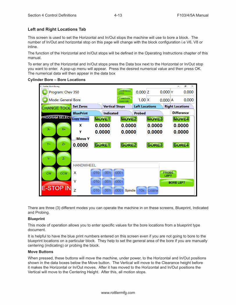
Section 4 Control Definitions F103/4/5A Manual
www.rottlermfg.com
4-13
Left and Right Locations Tab
This screen is used to set the Horizontal and In/Out stops the machine will use to bore a block. The number of In/Out and horizontal stop on this page will change with the block configuration i.e V6, V8 or inline.The function of the Horizontal and In/Out stops will be defined in the Operating Instructions chapter of this manual.To enter any of the Horizontal and In/Out stops press the Data box next to the Horizontal or In/Out stop you want to enter. A pop-up menu will appear. Press the desired numerical value and then press OK. The numerical data will then appear in the data boxCylinder Bore – Bore Locations
There are three (3) different modes you can operate the machine in on these screens, Blueprint, Indicated and Probing.BlueprintThis mode of operation allows you to enter specific values for the bore locations from a blueprint type document.It is helpful to have the blue print numbers entered on this screen even if you are not going to bore to the blueprint locations on a particular block. They help to set the general area of the bore if you are manually centering (indicating) or probing the block.Move ButtonsWhen pressed, these buttons will move the machine, under power, to the Horizontal and In/Out positions shown in the data boxes below the Move button. The Vertical will move to the Clearance height before it makes the Horizontal or In/Out moves. After it has moved to the Horizontal and In/Out positions the Vertical will move to the Centering Height. After this, all motion stops.

Section 4 Control Definitions F103/4/5A Manual
www.rottlermfg.com
4-14
Bore ButtonsPressing this button once will cause it to turn yellow. This indicates when the “Bore Left” button is pressed this cylinder will not be bored.Touching this button again (with a pause in between touches) will turn the button back to green. All green bores will be bored if the “Bore Left” button is pressed. The control will ask you if you sure you want to bore the selected bores.Double Clicking a Bore button will keep it green and turn all other bore buttons yellow.IndicatedThis screen is designed to manually indicate each cylinder in for it’s specific location.
Set ButtonsOnce a cylinder has been indicate, pressing the associated Set Button will take the current machine position and place the values in the Data Box associated with that cylinder.Copy ValuesPressing this button will bring up another window where you can select to copy the In/Out and Horizontal values from Blueprint, Indicated or Probed screen.DifferenceChecking this Box will cause a green check mark to be placed in the box. The Data Boxes will then display the difference in values from the blueprint screen to the indicated screen. This is helpful to know how far the cylinders actual location is from blueprint values.Bore Left and RightPressing this button will cause the entire Left or Right bank to be bored automatically. The Bore buttons that are yellow will not be bored though.

Section 4 Control Definitions F103/4/5A Manual
www.rottlermfg.com
4-15
ProbingThe probe is an option on the F103/4/5A machine.This screen is designed to automatically probe one or all of the cylinders.
Probe ButtonsPressing this button will cause a probing routine to be run on the associated cylinder.Probe Left or RightPressing this button will cause the entire Left or Right banks to be probed automatically.Probed DiameterThis Data Box will display the diameter of the cylinders as they are probed.
LOWER SLEEVE REPAIR
Lower Sleeve repair is meant to be used when the Upper Bore is smaller in Diameter than the LowerBore. Therefore the spindle has to offset in the Horizontal to clear the Upper Bore.The Lower Sleeve Repair mode operates the same as the Cylinder Bore Mode with the exception of additional parameters in the Vertical Stops Tab.
Block ClearanceThis is the distance above the zero position or block deck allowing the cutter head to move to the next bore unobstructed. If you are blueprinting a block the number will be just enough to allow the tool in the cutter head to clear the block deck.

Section 4 Control Definitions F103/4/5A Manual
www.rottlermfg.com
4-16
Centering HeightThis is a distance above the vertical zero where you will be manually centering the block. The drawingBelow is a typical set up for manual centering or indicting a cylinder.
X-ClearanceThis is the parameter will index the cutter pointing in the x+ direction, (right) three O’clock position. The amount you set will allow the tool to move so it clears the block deck of the upper bore does not contact the block or upper bore. See drawing below. Machine moves in the X axis, and can be set to positive or negative movement. Should be set to negative value ex... -.200 (-5mm) 180 index (check box) This will make the spindle index with the tool pointing in the (X-) direction, (left) nine O’clock position. Should set X-clearance to a positive value, ex... .200 (5mm)
X-OvershootThis refers to the amount that it will overshoot the machine to help eliminate any backlash. IMPORTANT- If your X-clearance is negative (-) the overshoot should be a positive value, if the X-clearance is positive the overshoot should be negative (-)
Start Boring HeightThis is the distance above zero or the block deck where you want the cutter head to start rotating and the downward feed to start. Generally this is just a short distance above the lower sleeve to minimize the amount of time the machine bores through air.

Section 4 Control Definitions F103/4/5A Manual
www.rottlermfg.com
4-17
Bottom of the BoreThis is the distance below zero or the Block deck where you want the machine to stop boring and retract out of the cylinder. When the spindle retracts it will then go to the Block Clearance position.This is an example of what the above program would look like on the vertical stops.
Stop and Index Spindle after CycleChecking this box will cause the spindle to be indexed to the three O’clock position after the cylinder has been bored but before it retracts. It will also offset to the left before the tool is retracted. This is the default setting. You would not want this check in an operation such as Lifter Boring.
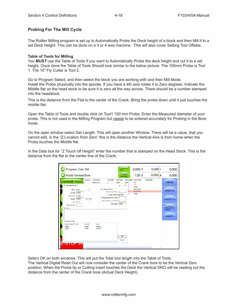
Section 4 Control Definitions F103/4/5A Manual
www.rottlermfg.com
4-18
Probing For The Mill Cycle
The Rottler Milling program is set up to Automatically Probe the Deck height of a block and then Mill it to a set Deck Height. This can be done on a 3 or 4 axis machine. This will also cover Setting Tool Offsets.
Table of Tools for MillingYou MUST use the Table of Tools if you want to Automatically Probe the deck height and cut it to a set height. Once done the Table of Tools Should look similar to the below picture. The 100mm Probe is Tool 1. The 10” Fly Cutter is Tool 2.
Go to Program Select, and then select the block you are working with and then Mill Mode.Install the Probe physically into the spindle. If you have a 4th axis rotate it to Zero degrees. Indicate the Middle flat on the head stock to be sure it is zero all the way across. There should be a number stamped into the headstock.This is the distance from the Flat to the center of the Crank. Bring the probe down until it just touches the middle flat.
Open the Table of Tools and double click on Tool1 100 mm Probe. Enter the Measured diameter of your probe. This is not used in the Milling Program but needs to be entered accurately for Probing in the Bore mode.
On the open window select Get Length. This will open another Window. There will be a value, that youcannot edit, in the “Z Location from Zero” this is the distance the Vertical Axis is from home when theProbe touches the Middle flat.
In the Data box for “Z Touch off Height” enter the number that is stamped on the Head Stock. This is the distance from the flat to the center line of the Crank.
Select OK on both windows. This will put the Total tool length into the Table of Tools.The Vertical Digital Read Out will now consider the center of the Crank bore to be the Vertical Zeroposition. When the Probe tip or Cutting insert touches the Deck the Vertical DRO will be reading out the distance from the center of the Crank bore (Actual Deck Height).

Section 4 Control Definitions F103/4/5A Manual
www.rottlermfg.com
4-19
Assigning ToolsFrom the Set Zero Tab, select Probe#. This will open the Tools Select Form. Select Tool 1, 50 mmProbe and click OK.Select the Tool#. This will open The Tool Select Form. Select Tool 2, 10 inch Fly Cutter and click OK.
The tools to be used have now been assigned to the program.Left Deck ProbeEnter the positions you want the Probe to probe here. You can physically move the probe to the locationson the bank you want to probe and hit the set button also.Right Deck ProbeRoll the block over to the Right Bank. Enter the positions you want the Probe to probe here. You canPhysically move the probe to the locations on the bank you want to probe and hit the set button also.Auto ProbingPress the Start Probing button. The machine will first probe each programmed location on the left bankand record the height. The spindle will move to Vertical Clearance height and the block will roll over tothe right bank and probe the programmed locations and record them. If you have a 4th axis The block will then roll back over to the Left bank and the spindle will move to the first Left location and stop.

Section 4 Control Definitions F103/4/5A Manual
www.rottlermfg.com
4-20
Lifter Bore
The Lifter Bore Mode and its buttons operate identical to the Bore Mode with a couple of exceptions.On the Program Vertical Stops screen, lower Clearance Offset is not an option.After a bore is complete the spindle will not offset .020” for tool clearance unless the “Horizontal Offset after Cycle” box is checked. This is used when a single point boring tool is used for lifter boring.
Cylinder Bore 4 Axis
Most of the Control Definition in the 4th axis is the same as the 3 axis version of software. Only the differences or new features will be discussed in this section.Set Zero Tab
Jog Controls4Th-Pressing this button will cause the 4th axis to rotate in a negative direction while held.4Th+Pressing this button will cause the 4th axis to rotate in a positive direction while held.4th Axis Degree and MoveTouching the 4th Axis Degree Data Box will bring up a Pop-Up Menu so a degree can be entered. Once a value is entered (even zero), pressing the Move button will move the 4th axis to that position.

Section 4 Control Definitions F103/4/5A Manual
www.rottlermfg.com
4-21
4th axis BrakeThis shows the status of the 4th axis brake a well as manually turning the brake on and off. When the 4th axis is rotated using the jog controls the fixture will automatically switch the brake On and Off.Light ClampPressing this button will cause light pressure to be exerted from the Tail Stock towards the Head stock. When the 4th axis is rotated using the jog controls the fixture will automatically switch from Full to Light clamp and back.Full ClampPressing this button will cause full pressure to be exerted from the Tail Stock towards the Head stock. RetractPressing this button will cause the tail stock to fully retract. A dialog box will appear when this button is pressed to assure you want to retract the tail stock. This is to prevent an accidental retraction when a block is in the fixture.

Section 4 Control Definitions F103/4/5A Manual
www.rottlermfg.com
4-22
Table Of Tools
The Table Of Tools is a very powerful feature in this software. Most of the Rottler programs are designed to be used without interacting with the Table Of Tools.Only the program specific uses will be described here.
Table Of Tools General InformationThe Table Of Tools is used to set different tool lengths so multiple tools can be used in one program and reference the same vertical zero position.For Example, if you were to use two boring bars in one program. One boring bar is 8” long and the other is 4” long. There is then a 4” difference in where the cutter of each bar will come into contact with the part to be machined. Using the Table of Tools you can set the 4” difference for one of the boring bars so that both of the cutting tools will come into contact with the material at the same vertical position.
Accessing Table Of ToolsSelect TABLE OF TOOLS from any screen in the upper left hand corner. This will open up the Table Of Tools.On this screen you will be able to Add, Remove or Set that tool Active (installed in spindle and being used).
The Table of Tools comes with Tool 0 installed with no offset amount. Tool 0 will remain tool 0 with no offset always. Tool 0 will be set active when you are using programs that do not require tool offsets.

Section 4 Control Definitions F103/4/5A Manual
www.rottlermfg.com
4-23
Add ToolTo add a tool to the Table of Tools press Add Tool. This will open another window. Here you will name the Tool you are adding. Such as 2.9 production Stub. It is important to give an accurate name to the tool. You want the tool easily identifiable by its name. The only other data box the Rottler software uses is the Length Data Box. This will be discussed later. Press OK.
The Added tool will now show in the Table of Tools.

Section 4 Control Definitions F103/4/5A Manual
www.rottlermfg.com
4-24
Remove ToolPressing this button will remove the highlighted tool from the Table of Tools.Set Active ToolPressing this button will set the highlighted tool to an Active Status (tool installed and will be used) Any Vertical offset associated with that tool will be used when a program is run. You can tell which tool is active because it is highlighted in Red. When no offset is required in a program Tool 0, Default Tool should be active.When setting a tool active another window will open. This is the Tool Change Form. It is basically there to verify the tool information before it is set to an active status. Verify the information and press OK.
This window will open when the machine does an automatic tool change. This will be discussed in Chapter 5 Operating Instructions. After you press OK another window will open. This is a Warning Dialog box to inform the operator of the possibility of the spindle start if the tool change is done in an automatic program. Press OK.

Section 4 Control Definitions F103/4/5A Manual
www.rottlermfg.com
4-25
Setting Tool Offsets
Add all the tools that will need offsets into the table of tools. Leave the Length value at 00.00 when you first enter them.For this example we will be setting offsets for a 2.9 Production Stub, 100mm Probe and a 10 inch Fly cutter. Add these tools to the table of Tools.
NOTE: Only the Probe will use the Tool Diameter. The Probe will use the Tool Diameter when probing a cylinder, it will not use the Tool Diameter when touch off a surface such as a block deck. Changing this setting will be discussed in later in this Chapter.
To set Tool Offsets you will need a fixed vertical reference point on the machine that does not change such as the head stock of the 4th axis or Performance Fixture.

Section 4 Control Definitions F103/4/5A Manual
www.rottlermfg.com
4-26
Install the first tool such as the 2.9 Production Stub with Cutting insert installed. Bring the cutting insert down until it just touches the flat on the head stock of the 4th axis fixture. Go to the TABLE OF TOOLS and double click the 2.9 Production Stub tool. Select Get Length from that window. This will bring up the Tool Length window.
Z Location from ZeroThis is the distance the Vertical Axis is from the home position. NOT where the operator has set the Vertical Zero in the program. This value is set by the computer automatically. In this example the tool just touched the flat at 8.0000.Z Touch Off HeightThis value is an additional value you want added to the Z location from zero. For example, if you wanted to use the center of the Crankshaft as the vertical reference point, but you are touching the tool off of the flat of that head stock, you would enter the distance from where you are touching off to the center of the Crank (this value is stamped into the headstock by Rottler). The values from Z Location from Zero and Z Touch off Height are added together by the computer to get the Final tool Length value. If you are not referencing another vertical position then this value will remain 00.000.Add Tool Radius?Checking this box will add the Tool Radius to the Final Tool Length. This is not used in the Rottler programs and should remain unchecked for all tools.

Section 4 Control Definitions F103/4/5A Manual
www.rottlermfg.com
4-27
Repeat this procedure for each tool. Touch ALL of them off from the same point.When running a Rottler program the cutting insert for each tool will reference the Vertical Zero the operator set in the program and come into contact with the surface to be machined at the same vertical value.Applying Table of Tools to Rottler ProgramsThe use of the Table of Tools to specific Rottler programs such as Bore and Mill will be defined in Chapter 5 Operating Instructions.Fixture SelectThis is also a very powerful tool. It is not generally used in the Rottler Programs. It’s basic function is to offset a program and table of tools a set distance on each axis (if desired) and run the same program without resetting axis zero points.For example, if you have to fixtures that are identical but are set at a different location on the table you can set the difference values in the table of fixtures and run the program. It is recommended this is not used unless you are a very experienced operator.

Section 5 Operating Instructions F103/4/5A Manual
www.rottlermfg.com
I
OPERATING INSTRUCTIONSContents
Operating Instructions ................................................................................................5-1
Loading Blocks ..................................................................................................................... 5-1
Small Gas and Diesel ........................................................................................................... 5-1
Manual V6/V8 Combination Fixture 502-1-72H ...............................................................................5-1Boring Application ............................................................................................................................5-1
Normal Operating Procedure .............................................................................................. 5-3
Surfacing Application .......................................................................................................................5-5
Normal Operating Procedure .............................................................................................. 5-7
Retrofitting 502-1-15C Parallels to V6/V8 Combination Fixture ....................................... 5-8
Diesel Blocks ...................................................................................................................... 5-10
6725 Diesel Fixture ............................................................................................................. 5-10
Small Diesel V Blocks .....................................................................................................................5-10Triangle Clamping ...........................................................................................................................5-11Block Clamp Arm ............................................................................................................................5-11
Small Diesel In Line Blocks ............................................................................................... 5-13
Triangle Clamping ...........................................................................................................................5-14
6405F Large V-Block .......................................................................................................... 5-16
Triangle Clamping ...........................................................................................................................5-17
6810 Waukesha 7042, 9390 and CAT 379, 398, 399 Block Line Bore Fixture ................ 5-20
6821 Adjustable, Universal Line Bore Parallel Assembly ............................................... 5-24
7119V Dual Axis Table Assembly ...................................................................................... 5-29
Instructions for Small In-Line Blocks ...........................................................................................5-30Mounting Block to Table.................................................................................................................5-30Blocks with Main Caps Removed or Raised Main Bearings .......................................................5-30Blocks with Main Caps Installed ...................................................................................................5-31Typical Head Set Up Procedure .....................................................................................................5-32
Setting Up Rottler Fly Cutting Tool With Two Inserts .................................................... 5-34
12” Multi Tooth Milling Head - 6865 .................................................................................. 5-35
18” Multi Tooth Milling Head 6864 .................................................................................... 5-35

Section 5 Operating Instructions F103/4/5A Manual
www.rottlermfg.com
II
General Machine Information ...................................................................................5-36
Homing ................................................................................................................................ 5-36
Create a Block Program ..................................................................................................... 5-36
New ...................................................................................................................................................5-36
Options ................................................................................................................................ 5-37
Creating Operating Modes for a Block Model .................................................................. 5-37
New ...................................................................................................................................... 5-38
Std (Standard) Setup .......................................................................................................... 5-39
Select ................................................................................................................................... 5-39
Options ................................................................................................................................ 5-39
Cylinder Bore Mode 3 Axis ................................................................................................ 5-40
Setting Zeros ...................................................................................................................................5-41Horizontal and In/Out Zero .............................................................................................................5-41Vertical Zero ....................................................................................................................................5-41
Blueprinting ........................................................................................................................ 5-43
Programming Vertical Stops ............................................................................................. 5-43
Block Clearance .................................................................................................................. 5-43
Centering Height ................................................................................................................. 5-44
Start Boring Height ............................................................................................................. 5-44
Bottom of the Bore ............................................................................................................. 5-44
Horizontal Offset for Honing ............................................................................................. 5-45
Start Offset Height .............................................................................................................. 5-45
Horizontal Offset ................................................................................................................. 5-45
Change Speeds at Horizontal Offset ................................................................................ 5-45
Washout Cycle .................................................................................................................... 5-45
Stop and Index Spindle after Cycle .................................................................................. 5-45
Bore Locations ................................................................................................................... 5-46
Left Locations ..................................................................................................................... 5-47
Right Locations .................................................................................................................. 5-47
Boring a Block .................................................................................................................... 5-48

Section 5 Operating Instructions F103/4/5A Manual
www.rottlermfg.com
III
Indicating ............................................................................................................................. 5-48
Vertical Zero ....................................................................................................................................5-48
Programming Vertical Stops ............................................................................................. 5-49
Block Clearance .................................................................................................................. 5-49
Centering Height ................................................................................................................. 5-50
Start Boring Height ............................................................................................................. 5-50
Bottom of the Bore ............................................................................................................. 5-51
Bore Locations ................................................................................................................... 5-52
Boring a Block .................................................................................................................... 5-54
Probing ................................................................................................................................ 5-54
Vertical Zero ....................................................................................................................................5-54
Programming Vertical Stops ............................................................................................. 5-55
Block Clearance .................................................................................................................. 5-55
Centering Height ................................................................................................................. 5-55
Start Boring Height ............................................................................................................. 5-55
Bottom of the Bore ............................................................................................................. 5-56
Probe Height ....................................................................................................................... 5-56
Bore Locations ................................................................................................................... 5-57
Probe Auto Center .............................................................................................................. 5-57
Automatic Probing Procedure ........................................................................................... 5-57
Boring a Block .................................................................................................................... 5-58
Cylinder Bore Mode 4th Axis ............................................................................................. 5-58
Setting Zeros ...................................................................................................................................5-58
4th Axis (Rotational) Zero .................................................................................................. 5-58
Finding the In/Out (Y) Axis Zero with 4th Axis ................................................................. 5-58
Building Programs with the 4th Axis ................................................................................ 5-58
Setting Vertical Clearance with 4th Axis .......................................................................... 5-59
Table of Tools for 3 and 4th Axis Bore Mode ................................................................... 5-59
Building a Program with Table of Tools ........................................................................... 5-59
Assigning Tools .................................................................................................................. 5-59

Section 5 Operating Instructions F103/4/5A Manual
www.rottlermfg.com
IV
Setting Tools Active ........................................................................................................... 5-60
Mill Mode 3 Axis .................................................................................................................. 5-62
Setting Zeros ....................................................................................................................... 5-62
Horizontal Zero ................................................................................................................................5-62In/Out Zero .......................................................................................................................................5-62Vertical Zero ....................................................................................................................................5-62Example ...........................................................................................................................................5-62
Mill Operation ...................................................................................................................... 5-64
End ....................................................................................................................................... 5-64
Horizontal End .................................................................................................................................5-64Amount Per Pass ............................................................................................................................5-64Vertical Start ....................................................................................................................................5-64Vertical End .....................................................................................................................................5-64Copy Lowest Copy Highest ...........................................................................................................5-65
Rough Settings ................................................................................................................... 5-65
Rough Feed Rate ............................................................................................................................5-65Rough Spindle RPM ........................................................................................................................5-65Finish Cut Settings .........................................................................................................................5-65Finish Amount .................................................................................................................................5-65Finish Feed Rate .............................................................................................................................5-65Finish RPM ......................................................................................................................................5-65
Start Auto Cycle .................................................................................................................. 5-66
Mill Mode 4th Axis .............................................................................................................. 5-66
Setting Zeros ....................................................................................................................... 5-66
Horizontal Zero ................................................................................................................................5-66In/Out Zero .......................................................................................................................................5-66Vertical Zero ....................................................................................................................................5-66
Mill Operation ...................................................................................................................... 5-68
End ....................................................................................................................................... 5-68
Horizontal End .................................................................................................................................5-68Amount Per Pass ............................................................................................................................5-68Vertical Start ....................................................................................................................................5-68Vertical End .....................................................................................................................................5-68Copy Lowest Copy Highest ...........................................................................................................5-69
4th Axis Angles ................................................................................................................... 5-69

Section 5 Operating Instructions F103/4/5A Manual
www.rottlermfg.com
V
Left Bank Angle ...............................................................................................................................5-69Right Bank Angle ............................................................................................................................5-69Rollover Vertical Clearance ............................................................................................................5-69In/Out Offset ....................................................................................................................................5-69
Rough Settings ................................................................................................................... 5-69
Rough Feed Rate ............................................................................................................................5-69Rough Spindle RPM ........................................................................................................................5-69
Finish Cut Settings ............................................................................................................. 5-69
Finish Amount .................................................................................................................................5-69Finish Feed Rate .............................................................................................................................5-69Finish RPM ......................................................................................................................................5-69
Cut Left and Cut Right ....................................................................................................... 5-70
Start Auto Cycle .................................................................................................................. 5-70
Overlap Mill Setting ............................................................................................................ 5-71
Milling Using Automatic Deck Probing............................................................................. 5-72
Table of Tools for Milling .................................................................................................... 5-72
Assigning Tools .................................................................................................................. 5-74
Setting Tools Active ........................................................................................................... 5-75
Building a Program Using Table of Tools......................................................................... 5-75
Left Deck Probe ...............................................................................................................................5-76Right Deck Probe ............................................................................................................................5-76
Auto Probing ....................................................................................................................... 5-76
Auto Milling ......................................................................................................................... 5-77
Vertical Start ....................................................................................................................................5-77Vertical End .....................................................................................................................................5-77Cut Left or Cut Right .......................................................................................................................5-77Start Auto Cycle ..............................................................................................................................5-77
Lifter Bore Mode 3 Axis...................................................................................................... 5-78
In / Out Zero .....................................................................................................................................5-78Start Boring Height .........................................................................................................................5-78Lifter Bore Angle .............................................................................................................................5-78
Lifter Bore 4th Axis............................................................................................................. 5-79
Start Boring Height .........................................................................................................................5-79Lifter Bore Angle .............................................................................................................................5-79

Section 5 Operating Instructions F103/4/5A Manual
www.rottlermfg.com
VI
Calculate In/Out ...............................................................................................................................5-79
Right Angle Drive Installation ..................................................................................5-80
Line Bore Mode ................................................................................................................... 5-84
Mounting and Aligning the 90 Degree Head .................................................................... 5-84
Setting Zeros ....................................................................................................................... 5-84
Horizontal Zero ................................................................................................................................5-85In/Out and Vertical Zero ..................................................................................................................5-85
Line Bore Options .............................................................................................................. 5-86
Programming Vertical Stops ............................................................................................. 5-87
Thrust Cutting ..................................................................................................................... 5-89
Setting Zeros ....................................................................................................................... 5-89
Horizontal Zero ................................................................................................................... 5-89
Dimensions & Auto Cycle .................................................................................................. 5-90
Thrust Dimensions ............................................................................................................. 5-90
Outside .............................................................................................................................................5-90Inside ................................................................................................................................................5-90Cutter ...............................................................................................................................................5-90
Clearances .......................................................................................................................... 5-90
Vertical .............................................................................................................................................5-90Horizontal ........................................................................................................................................5-90
Dimensions ......................................................................................................................... 5-90
Main Width .......................................................................................................................................5-90Insert Width .....................................................................................................................................5-91Left Depth of Cut .............................................................................................................................5-91Right Depth of Cut ..........................................................................................................................5-91Cut Right Side .................................................................................................................................5-91Cut Left Side ....................................................................................................................................5-91
Description and Running of the Auto Cycle .................................................................... 5-91
Start Auto Cycle ..............................................................................................................................5-91
Backing Up and Restoring Block Profiles...............................................................5-92

Section 5 Operating Instructions F103/4/5A Manual
www.rottlermfg.com
5-1
Operating Instructions
The purpose of this chapter is to explain and then guide the operator from loading a block through running an automatic cycle.All modes of operation will be discussed in this chapter.Note: We recommend, particularly for operators unfamiliar with the boring machine, to practice on a junk block in order to become familiar with the controls and procedures of the boring machine.
Loading Blocks
Small Gas and Diesel
Manual V6/V8 Combination Fixture 502-1-72H
Handle the block and fixture with EXTREME care and guidance. A block hoist is REQUIRED. Mishandling of a heavy engine block and fixture may result in
the dropping of parts and personal injury.The Model 502-1-72H manual V6/V8 combination fixture is a fast, simple and universal system to properly and accurately hold most 60 degree V-type engine blocks for either cylinder boring or deck surfacing.See illustration on the following page.
Boring ApplicationNOTE: The block must have the main bearing caps in place and torqued.Care must be taken to assure the contact edges of the locator bar are near the cap split line. A pair of 3/8” and 1/2” spacers are provided for blocks with large main bearing bores, to enable the bar to locate near the main bearing split line. (See figure 2)
V-blocks: (blocks with main bearing center lines no more than 1/2” higher than the pan rail plane) are mounted with the 502-3-8B V-block frame in place. Select the 90-degree option placement of the frame to suit block length, or main bearing caps will interfere with frame. Rotate frame 90 degrees by moving its shoulder screws to alternate set of holes.
Y-Blocks: (blocks with main bearing center lines 2-3/8” to 3-1/2” higher than the pan rail plane) are mounted directly on the fixture. Some Y-blocks (GM 60 degree) have too narrow pan rails and some have too low main bearing location which will require the use of the 502-1-15C precision 1-1/4” x 3” parallel set to raise and or support the block. Use the shoulder screw from the V-block frame and hook the parallels over the back of the V-fixture.
This fixture may be easily repositioned on the support parallels (without a block in place) to shift from the 60 degree support surface to the 90 degree support surface or vice versa.

Section 5 Operating Instructions F103/4/5A Manual
www.rottlermfg.com
5-2
Extreme care must be taken by operator whenever handling large blocks. Large blocks may cause fixture to tip when floated too far outward. We
recommend leaving hoist attached when moving these blocks. Large blocks should be lifted from the block bank surface.

Section 5 Operating Instructions F103/4/5A Manual
www.rottlermfg.com
5-3
Normal Operating Procedure
The normal operation procedure on smaller V-blocks is to first pick up the block. Place the 502-1-82X locator bar through the main bearings and hoist the block into the fixture. Pulling the block towards you, with the locator against the positioners, will prevent jamming in the slot of the guides during the loading and unloading operations. The locator bar is positioned with the word ‘UP’ that is on the end of the bar facing up and away from the operator. (see figure 1) After the locator bar is engaged in the positioners, pivot block outwards as you lower it. Slide block to the far left (this is the non adjustable position).
Make sure the block is firmly seated in place and not resting on pan-rail burrs or other interference points. Accurate seating can also be a problem with extremely warped, distorted blocks. Another cause of problems is failure to remove main bearing inserts. The locator bar has a relief for blocks with a small main bearing or seal. Rotate locator bar clamps into position & lightly tighten the hand screws, applying even pressure to both. Clamp the block securely with the main base clamp arms.
Warped or distorted blocks may require leveling of the deck surface in the long direction. This is possible with the hand-screw assembly in the left-hand bar positioner. Loosen both clamp hand-screws and slide the locator bar to the far right position. Retighten both clamp hand-screws. Raise or lower the adjusting hand-screw as required. For the non-adjustable position slide locator bar to the far left.

Section 5 Operating Instructions F103/4/5A Manual
www.rottlermfg.com
5-4
Push fixture back into bore position. There is a guide block (502-1-105) attached to the bottom of the fixture to aid in guiding the fixture along the support ways.
Operate the block clamp arms, bore, and pull fixture back to the load position.
Loosen locator bar hand screws and rotate clamps out of the way. Lift the block, either from the deck surface or with the optional 502-1-95 block handler. Turn the block 180 degrees & reload to duplicate the operation on the other bank.
After turning the engine block 180 degrees the locator bar must be twisted 180 degrees also. Again the word ’UP’ must enter into the positioners facing up and away from the operator. (See figure 1).
Figure 1502-1-82X main bearing locator bar indexes at point A. When bank is reversed and the bar is twisted 180 degrees, point A still indexes the main bearing.
Point C holds the block down. When bank is reversed and the bar is twisted 180 degrees, point B holds the block down.
Figure 2502-1-82X main bearing locator bar indexes near bearing split line. Point C does not contact the bearing cap but rests on matched spacers that are provided to fit in the bar positioners slot. If there is a means of holding the block down such as block clamp towers, this method may be used in large bores in order to properly index near the bearing split line. If extreme care is used this method may be used to index blocks without bearing caps attached. (Optional clamp down must be provided).

Section 5 Operating Instructions F103/4/5A Manual
www.rottlermfg.com
5-5
Surfacing Application
NOTE: The block must have the main bearing caps in place and torqued.
Care must be taken to assure the contact edges of the locator bar are near the cap split line. A pair of 3/8” and 1/2” spacers are provided for blocks with large main bearing bores, to enable the bar to locate near the main bearing split line. (See figure 2)
V-blocks:(blocks with main bearing center lines no more than 1/2” higher than the pan rail plane) are mounted with the 502-3-8B V-block frame in place. Select the 90-degree option placement of the frame to suit block length, or main bearing caps will interfere with frame. Rotate frame 90 degrees by moving its shoulder screws to alternate set of holes.
Y-Blocks:(blocks with main bearing center lines 2-3/8” to 3-1/2” higher than the pan rail plane) are mounted directly on the fixture. Some Y-blocks (GM 60 degree) have too narrow pan rails and some have too low main bearing location which will require the use of the 502-1-15C precision 1-1/4” x 3” parallel set to raise and or support the block. Use the shoulder screw from the V-block frame and hook the parallels over the back of the V-fixture.
This fixture may be easily repositioned on the support parallels (without a block in place) to shift from the 60 degree support surface to the 90 degree support surface or vice versa.

Section 5 Operating Instructions F103/4/5A Manual
www.rottlermfg.com
5-6
Extreme care must be taken by operator whenever handling large blocks. Large blocks may cause fixture to tip when floated too far outward. We recommend
leaving hoist attached when moving these blocks. Large blocks should be lifted from the block bank surface.

Section 5 Operating Instructions F103/4/5A Manual
www.rottlermfg.com
5-7
Normal Operating Procedure
The normal operation procedure on smaller V-blocks is to first pick up the block. Place the 502-1-82X locator bar through the main bearings and hoist the block into the fixture. Pulling the block towards you, with the locator against the positioners, will prevent jamming in the slot of the guides during the loading and unloading operations. The locator bar is positioned with the word ‘UP’ that is on the end of the bar facing up and away from the operator. (see figure 1) After the locator bar is engaged in the positioners, pivot block outwards as you lower it. Slide block to the far left (this is the non adjustable position).Make sure the block is firmly seated in place and not resting on pan-rail burrs or other interference points. Accurate seating can also be a problem with extremely warped, distorted blocks. Another cause of problems is failure to remove main bearing inserts. The locator bar has a relief for blocks with a small main bearing or seal. Rotate locator bar clamps into position & lightly tighten the hand screws, applying even pressure to both. Clamp the block securely with the main base clamp arms.Warped or distorted blocks may require leveling of the deck surface in the long direction. This is possible with the hand-screw assembly in the left-hand bar positioner. Loosen both clamp hand-screws and slide the locator bar to the far right position. Retighten both clamp hand-screws. Raise or lower the adjusting hand-screw as required. For the non-adjustable position slide locator bar to the far left.Push fixture back into surfacing position with the back of the fixture on the Shim Stock. The shim stock is put in place to raise the back side of the block, you can then use the Jacking Screw to raise and lower the front of the block. There is a guide block (502-1-105) attached to the bottom of the fixture to aid in guiding the fixture along the support ways.Operate the block clamp arms, surface, and pull fixture back to the load position.Loosen locator bar hand screws and rotate clamps out of the way. Lift the block, either from the deck surface. Turn the block 180 degrees & reload to duplicate the operation on the other bank.After turning the engine block 180 degrees the locator bar must be twisted 180 degrees also. Again the word ’UP’ must enter into the positioners facing up and away from the operator. (See figure 1).
Figure 1502-1-82X main bearing locator bar indexes at point A. When bank is reversed and the bar is twisted 180 degrees, point A still indexes the main bearing.Point C holds the block down. When bank is reversed and the bar is twisted 180 degrees, point B holds the block down.
Figure 2502-1-82X main bearing locator bar indexes near bearing split line. Point C does not contact the bearing cap but rests on matched spacers that are provided to fit in the bar positioners slot. If there is a means of holding the block down such as block clamp towers, this method may be used in large bores in order to properly index near the bearing split line. If extreme care is used this method may be used to index blocks without bearing caps attached. (Optional clamp down must be provided).
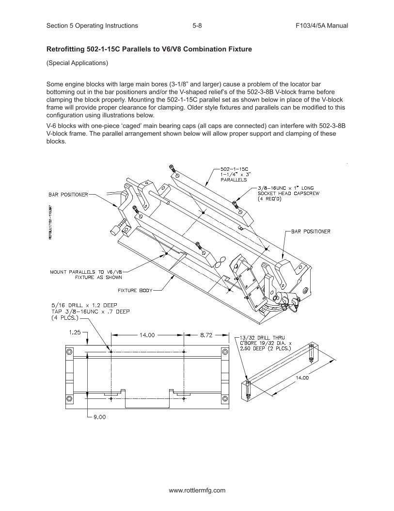
Section 5 Operating Instructions F103/4/5A Manual
www.rottlermfg.com
5-8
Retrofitting 502-1-15C Parallels to V6/V8 Combination Fixture
(Special Applications)
Some engine blocks with large main bores (3-1/8” and larger) cause a problem of the locator bar bottoming out in the bar positioners and/or the V-shaped relief’s of the 502-3-8B V-block frame before clamping the block properly. Mounting the 502-1-15C parallel set as shown below in place of the V-block frame will provide proper clearance for clamping. Older style fixtures and parallels can be modified to this configuration using illustrations below.V-6 blocks with one-piece ‘caged’ main bearing caps (all caps are connected) can interfere with 502-3-8B V-block frame. The parallel arrangement shown below will allow proper support and clamping of these blocks.
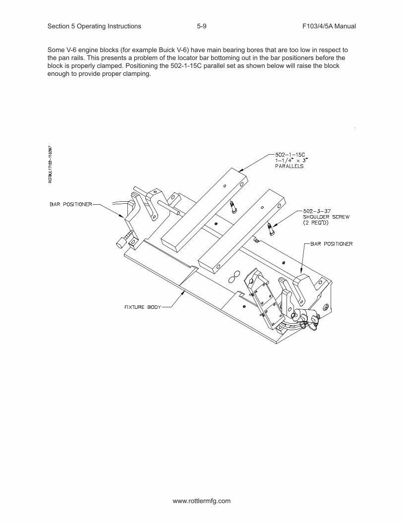
Section 5 Operating Instructions F103/4/5A Manual
www.rottlermfg.com
5-9
Some V-6 engine blocks (for example Buick V-6) have main bearing bores that are too low in respect to the pan rails. This presents a problem of the locator bar bottoming out in the bar positioners before the block is properly clamped. Positioning the 502-1-15C parallel set as shown below will raise the block enough to provide proper clamping.
Section 5 Operating Instructions F103/4/5A Manual
www.rottlermfg.com
5-10
Diesel Blocks
6725 Diesel Fixture
Small Diesel V BlocksOn these blocks it will be necessary to install the 6370Z, 10” parallels or 6794E, 8” parallels onto the bed of the machine. These parallels are keyed, place them onto the deck surface and then push them toward the rear of the machine. This will located them evenly on the middle keyway of the machine bed. Place the two 6553F main bearing supports onto the parallels, these are also keyed and fit into the machined slots on the parallels. This will put the two main bearing supports in line with each other. Tighten all bolts to lock the parallels and main bearing support into place. Select the correct size main bearing locators and install them into the mains of the block..
Note: Make sure there are no burrs or debris in the main bearing bores where they will contact the main bearing locators. This can cause the block not to clamp properly and may cause tipping or rocking of the block.
Handle these large blocks with Extreme care and guidance. A block hoist is required when handling these blocks. These blocks should be lifted from the
block bank surface.Install the main bearing locators into the mains of the engine block. Lower the block so that the locators go into the main bearing support.
The hoist must remain attached to the block until it is firmly clamped into position. The blocks will have a tendency to tip forward until they are properly
supported and clamp. When not properly supported and attached to a hoist these blocks will roll forward and out of the fixture. This will cause severe injury or death to operator.
Select the correct jacking screw to reach the block. Place the jacking screws into the jack bodies and place on the parallels in a location they will support the block from rolling forward.Position the block clamps so the front of the shoe will clamp the block in the middle on both ends. The following illustration shows the correct triangle clamping system that should be used.You can raise and lower the ends of the block by rotating the Hex nut located on the ends of the main bearing locators.

Section 5 Operating Instructions F103/4/5A Manual
www.rottlermfg.com
5-11
Triangle Clamping
Adjust the height so the shoes rest on the clamp points. Tighten the clamp leg handles. Actuate the clamp shoes by turning their knobs. Apply pressure to the two clamps as evenly as possible to avoid tipping the block up on one side.
Block Clamp Arm

Section 5 Operating Instructions F103/4/5A Manual
www.rottlermfg.com
5-12

Section 5 Operating Instructions F103/4/5A Manual
www.rottlermfg.com
5-13
Small Diesel In Line Blocks
On these blocks it will be necessary to install the 6370Z, 10” parallels onto the bed of the machine. These parallels are keyed, place them onto the deck surface and then push them toward the rear of the machine. This will located them evenly on the middle keyway of the machine bed. Place the two 6553F main bearing supports onto the parallels, these are also keyed and fit into the machined slots on the parallels. Use the forward machined slots. This will put the two main bearing supports in line with each other, and on centerline of the machine bed. Position the fixtures at a distance apart equal to the outboard main journals. Tighten all bolts to lock the parallels and main bearing support into place. Select the correct size main bearing locators, and install them into the mains of the block. Notice the locators have a flat area. Installing with the flat side up will allow end to end height adjustment of the block by rotating the locator. Installing with the round side up will position the block so all machining operations are parallel and perpendicular to the main bore centerline. This simply requires leveling the block in the front to rear direction.
Note: Make sure there are no burrs or debris in the main bearing bores where they will contact the main bearing locators. This can cause the block not to clamp properly and may cause tipping or rocking of the block.
Handle these large blocks with Extreme care and guidance. A block hoist is required when handling these blocks. These blocks should be lifted from the
block bank surface.
Lower the block so that the locators go into the main bearing support. A clevis pin is provided to keep the locator in position on the main bearing support. For in-line blocks, load the block with the heavier side towards the front.
The hoist must remain attached to the block until it is firmly clamped into position. The blocks will have a tendency to tip until they are properly
supported and clamp. When not properly supported and attached to a hoist these blocks will roll forward or backwards and out of the fixture. This will cause severe injury or death to operator.
Select the correct jacking screws to reach the block. Place the jacking screws into the jack bodies and place on the machine bed in a location they will support the block from rolling forwards. Rough level the block using a spirit level.The following illustration shows the correct triangle clamping system that should be used.

Section 5 Operating Instructions F103/4/5A Manual
www.rottlermfg.com
5-14
Triangle Clamping
Adjust the height so the shoes rest on the clamp points. Tighten the clamp leg handles. Actuate the clamp shoes by turning their knobs. Apply pressure to the two clamps as evenly as possible to avoid tipping the block up on one side. Be sure the clamp is below the deck surface if you to resurface the block.
Do not release the hoist or lifting device from the block until the clamping is secure.

Section 5 Operating Instructions F103/4/5A Manual
www.rottlermfg.com
5-15

Section 5 Operating Instructions F103/4/5A Manual
www.rottlermfg.com
5-16
6405F Large V-Block
Place the 6405 supports on the machine bed. Make sure there is no debris or burrs on the mating surfaced. The supports should be placed on the machine bed with the two dowels on the bottom of the supports into the middle keyway. Place the supports the same distance apart as the mains you will be using. On long blocks, it is recommended to use main bearing locations inward from the ends, to more equally balance the block and avoid sag. Push the supports back toward the rear of the machine against the dowel pins. This will line the supports up with each other. Tighten the four (4) mounting bolts on each support. Install the correct size locators into the main bores that will be used.
Handle these large blocks with Extreme care and guidance. A block hoist is required when handling these blocks. These blocks should be lifted from the block bank surface.
The hoist must remain attached to the block until it is firmly clamped into position. The blocks will have a tendency to tip until they are properly
supported and clamp. When not properly supported and attached to a hoist these blocks will roll forward or backwards and out of the fixture. This will cause severe injury or death to operator.
The main bearing bores being used, should be on centerline of each support. Set the jacking bodies, with the proper length jack screw installed onto the machine base. These should be located in the general area of the supports. Temporarily secure to the deck with at least one bolt. Lower the block down onto the supports. Place a level on the deck of the engine block and check the level front to back. Position the jack stands in a location to properly support the block and secure. To level, use the jacking screws to raise or lower the front of the engine block. Position the block clamps on the machine bed and secure in a location to allow proper clamping. The following illustration shows the correct triangle clamping system that should be used.

Section 5 Operating Instructions F103/4/5A Manual
www.rottlermfg.com
5-17
Triangle Clamping
Adjust the height so the shoes rest on the clamp points. Tighten the clamp leg handles. Actuate the clamp shoes by turning their knobs. Apply pressure to the two clamps as evenly as possible to avoid tipping the block up on one side.

Section 5 Operating Instructions F103/4/5A Manual
www.rottlermfg.com
5-18

Section 5 Operating Instructions F103/4/5A Manual
www.rottlermfg.com
5-19

Section 5 Operating Instructions F103/4/5A Manual
www.rottlermfg.com
5-20
6810 Waukesha 7042, 9390 and CAT 379, 398, 399 Block Line Bore Fixture
This fixture is designed to be mounted directly on the bed of an F100 Series machine. Due to the large size of the Waukesha 7042 block, care must be taken when loading and unloading to avoid bumping the block into the block into the column or spindle unit.
Handle these large blocks with Extreme care and guidance. A block hoist is required when handling these blocks.
Use the diagram on the following pages when referring to part numbers listed below. This Line Bore fixture consists of a stationary cradle and a adjustable support. The Cradle (6811A) is mounted to the machine bed over the locating pivot key and pin assembly. The locating pivot pin (6819) is pressed into the locating pivot key (6820). This assembly is positioned in the center keyway of the machine bed and the (2) set screws (MF-72) are tightened to lock the key in place. The Cradle is positioned over the pin and mounted to the machine bed. With the mounting bolts installed but not tight this provides a standard pivot point for the Cradle.

Section 5 Operating Instructions F103/4/5A Manual
www.rottlermfg.com
5-21
The support (6812A) is assembled with the adjusting screw (6754V) and the adjusting block (6814). This assembly is mounted to the machine bed with the lower tab of the adjusting block in the center keyway. Be sure to install the special ratchet adjusting wrench prior to setting this assembly on the machine bed
The adjustable tube (6813) is bolted to the Waukesha Block using the Cam Bearing Cap mounting holes. The adjustable tube has ten (10) holes drilled in it. Four (4) of the holes are used to bolt the adjustable tube to the engine block, the remaining six (6) holes are clearance for the cap alignment dowel pins in the engine block. Since the Cam Bearing Caps are not evenly spaced along the block, the adjustable tube must be mounted on the front end of the block as shown in the following illustration.

Section 5 Operating Instructions F103/4/5A Manual
www.rottlermfg.com
5-22
The upper and lower leveling pads, bracket and screw are already installed in the adjustable tube.
With the adjustable tube installed, the block is ready to be lowered into the Cradle and Support. Use caution to locate the adjustable tube correctly on the support. The two roll pins (MF-229B) installed in the lower leveling pad (6411) are designed to locate the leveling pads properly.

Section 5 Operating Instructions F103/4/5A Manual
www.rottlermfg.com
5-23
All mounting bolts should be loose to start with. Due to the design of this fixture the Cradle end of the block is stationary both in relationship to the machine bed key way and in height. This end is not adjustable. The adjustable end of the fixture is located on the same machine bed keyway as the cradle. Once the block is loaded into the fixture it is ready to be aligned for the line boring operation. Up and down adjustment is accomplished using the leveling screw (6408) inside the adjustable tube. The block is adjusted in and out by activating the air float on the support, and turning the adjustment screw using the previously installed ratchet wrench. Once the block is located in and out deactivate the air float and tighten the support end mounting bolt to lock into place. Tighten the three (3) mounting bolts on the Cradle end of the fixture now. The alignment of the block should be checked again at this time. Repeat alignment adjustments as needed.
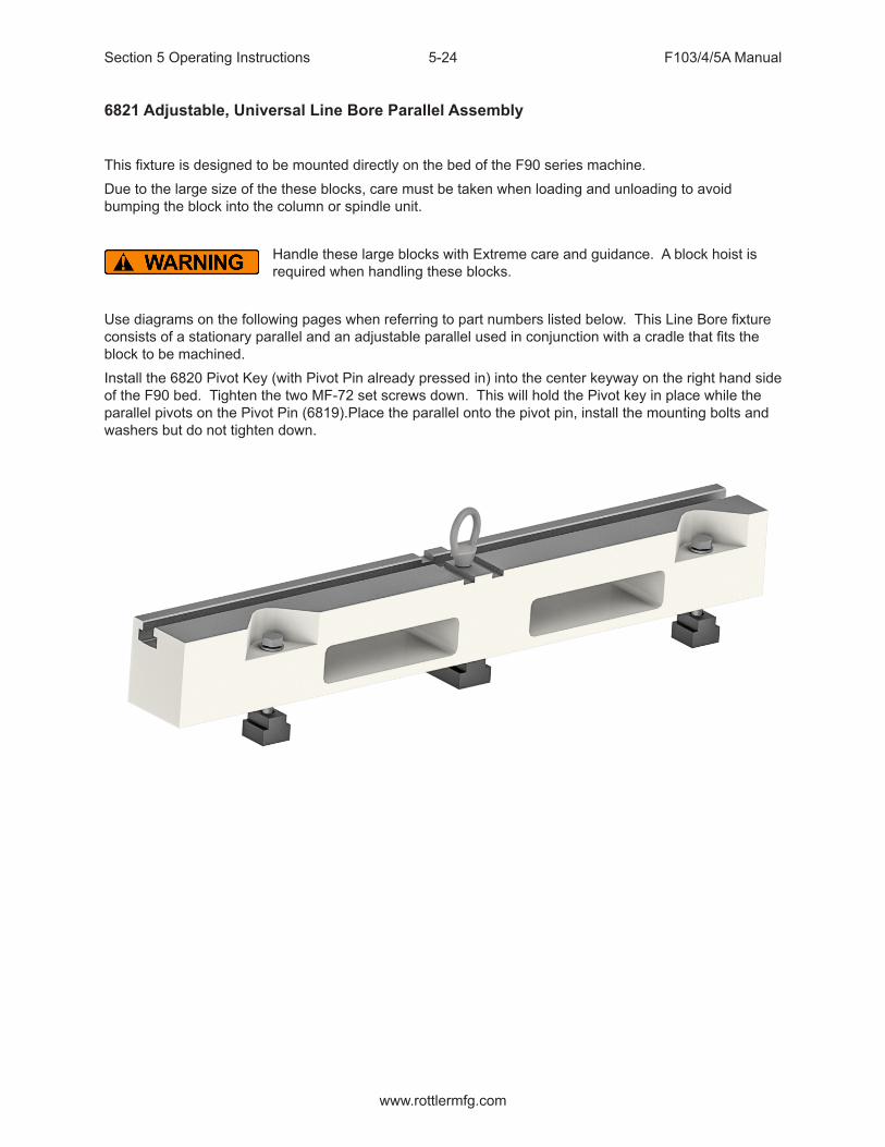
Section 5 Operating Instructions F103/4/5A Manual
www.rottlermfg.com
5-24
6821 Adjustable, Universal Line Bore Parallel Assembly
This fixture is designed to be mounted directly on the bed of the F90 series machine.Due to the large size of the these blocks, care must be taken when loading and unloading to avoid bumping the block into the column or spindle unit.
Handle these large blocks with Extreme care and guidance. A block hoist is required when handling these blocks.
Use diagrams on the following pages when referring to part numbers listed below. This Line Bore fixture consists of a stationary parallel and an adjustable parallel used in conjunction with a cradle that fits the block to be machined.Install the 6820 Pivot Key (with Pivot Pin already pressed in) into the center keyway on the right hand side of the F90 bed. Tighten the two MF-72 set screws down. This will hold the Pivot key in place while the parallel pivots on the Pivot Pin (6819).Place the parallel onto the pivot pin, install the mounting bolts and washers but do not tighten down.
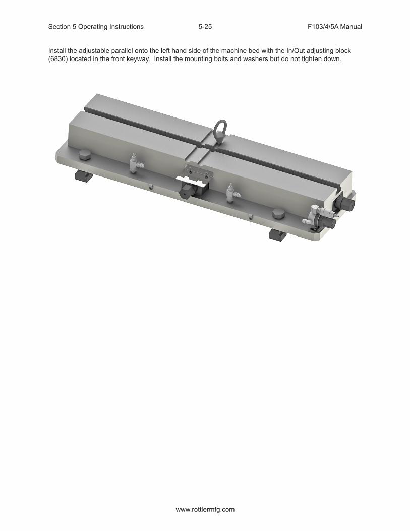
Section 5 Operating Instructions F103/4/5A Manual
www.rottlermfg.com
5-25
Install the adjustable parallel onto the left hand side of the machine bed with the In/Out adjusting block (6830) located in the front keyway. Install the mounting bolts and washers but do not tighten down.
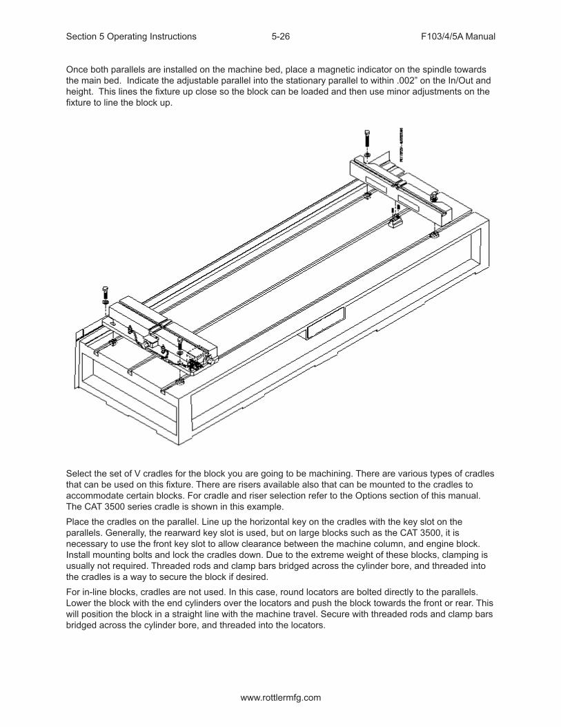
Section 5 Operating Instructions F103/4/5A Manual
www.rottlermfg.com
5-26
Once both parallels are installed on the machine bed, place a magnetic indicator on the spindle towards the main bed. Indicate the adjustable parallel into the stationary parallel to within .002” on the In/Out and height. This lines the fixture up close so the block can be loaded and then use minor adjustments on the fixture to line the block up.
Select the set of V cradles for the block you are going to be machining. There are various types of cradles that can be used on this fixture. There are risers available also that can be mounted to the cradles to accommodate certain blocks. For cradle and riser selection refer to the Options section of this manual. The CAT 3500 series cradle is shown in this example. Place the cradles on the parallel. Line up the horizontal key on the cradles with the key slot on the parallels. Generally, the rearward key slot is used, but on large blocks such as the CAT 3500, it is necessary to use the front key slot to allow clearance between the machine column, and engine block. Install mounting bolts and lock the cradles down. Due to the extreme weight of these blocks, clamping is usually not required. Threaded rods and clamp bars bridged across the cylinder bore, and threaded into the cradles is a way to secure the block if desired. For in-line blocks, cradles are not used. In this case, round locators are bolted directly to the parallels. Lower the block with the end cylinders over the locators and push the block towards the front or rear. This will position the block in a straight line with the machine travel. Secure with threaded rods and clamp bars bridged across the cylinder bore, and threaded into the locators.

Section 5 Operating Instructions F103/4/5A Manual
www.rottlermfg.com
5-27
Lower the block slowly down into the cradles. Using a heavy soft mallet, tap the sides of the cradles to allow the block to settle into position. The block is now ready for alignment.
Up and down adjustment is accomplished by turning the screw on the side of the adjustable parallel. The in/out direction is adjusted by turning screw at the front of the adjustable parallel. Apply air pressure to the fixture while adjusting the in/out direction. Once the block is aligned, tighten down the fixture bolts and recheck alignment. Readjust as necessary.

Section 5 Operating Instructions F103/4/5A Manual
www.rottlermfg.com
5-28
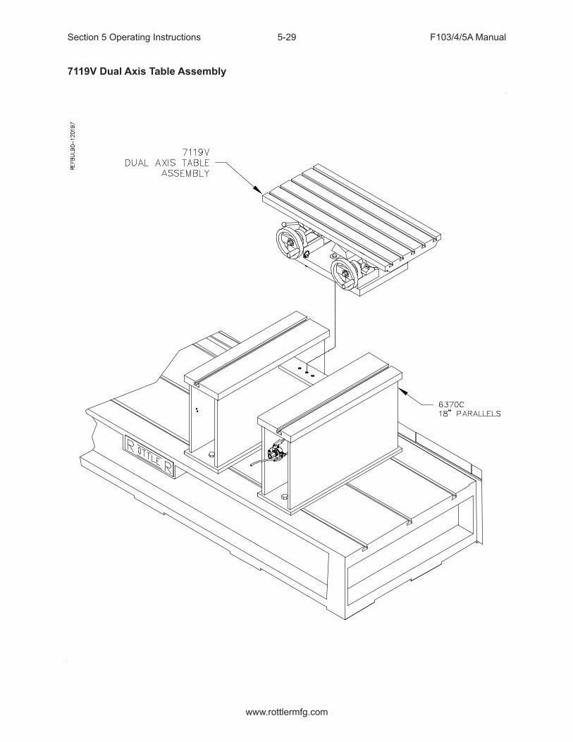
Section 5 Operating Instructions F103/4/5A Manual
www.rottlermfg.com
5-29
7119V Dual Axis Table Assembly

Section 5 Operating Instructions F103/4/5A Manual
www.rottlermfg.com
5-30
Instructions for Small In-Line BlocksThe Dual Axis Table has the capability of holding small (less than 13 ½” from pan rail to head surface) in-line cylinder blocks for resurfacing. This will require the use of parts from the 7119P Universal Head Fixturing package.
Mounting Block to TableThere are two (2) methods for mounting blocks to the Table. Blocks with the main caps removed or with the raised main bearings can be mounted directly to the table surface. Block with the main bearing caps installed which are lower than the pan rail surface must be mounted using support blocks from the Universal Fixturing package.
Blocks with Main Caps Removed or Raised Main BearingsRemove any burrs from pan rails of block.Locate cone washers on table to approximately center block in path of cutter-head and ‘hook’ the edge of the pan rail in the rear. Clamp the block using clamp handle assembly. We suggest you install the stop rod assembly on the left hand end of the block. This is an added safety precaution.
Check that all bolts and hold downs are tight. Loosen table clamp and level head surface of block in both directions. Lock table clamp and recheck block for level.

Section 5 Operating Instructions F103/4/5A Manual
www.rottlermfg.com
5-31
Blocks with Main Caps InstalledRemove any burrs from pan rails of block.Position rear supports and front supports to hold block approximately centered in path of cutter-head. Generally, place the front supports closer together than the rear supports.Place the block on the supports. Reposition the supports if necessary to clear main caps. Etc. Elevate the cones to hook the pan rail in the rear. Tighten set screws to lock cones in place. Tighten the hex bolts on the supports. Adjust the support block jack to eliminate any rocking. Lightly apply the clamp handle assembly.
Loosen table clamp and level head surface of block in both directions. Lock table clamp. With the level still on the block tighten clamp handle assembly with appropriate clamp nose on the lower portion of a port or indent near the middle of the block. Tighten the clamp 1/8 to1/4 turn after contacting the block. Do not over-tighten. Watch the level as you tighten to check for movement or warping. If the block moves or warps, repositioning the front supports inward will generally solve the problem. Check to see that the block cannot be moved in the fixture. We suggest that you install the stop rod assembly on the left hand end of the block. This is an added safety precaution.
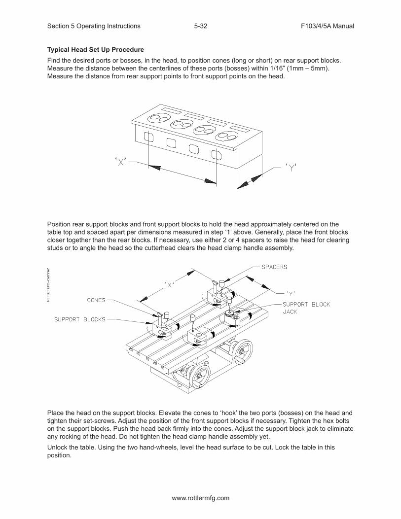
Section 5 Operating Instructions F103/4/5A Manual
www.rottlermfg.com
5-32
Typical Head Set Up ProcedureFind the desired ports or bosses, in the head, to position cones (long or short) on rear support blocks. Measure the distance between the centerlines of these ports (bosses) within 1/16” (1mm – 5mm). Measure the distance from rear support points to front support points on the head.
Position rear support blocks and front support blocks to hold the head approximately centered on the table top and spaced apart per dimensions measured in step ‘1’ above. Generally, place the front blocks closer together than the rear blocks. If necessary, use either 2 or 4 spacers to raise the head for clearing studs or to angle the head so the cutterhead clears the head clamp handle assembly.
Place the head on the support blocks. Elevate the cones to ‘hook’ the two ports (bosses) on the head and tighten their set-screws. Adjust the position of the front support blocks if necessary. Tighten the hex bolts on the support blocks. Push the head back firmly into the cones. Adjust the support block jack to eliminate any rocking of the head. Do not tighten the head clamp handle assembly yet.Unlock the table. Using the two hand-wheels, level the head surface to be cut. Lock the table in this position.

Section 5 Operating Instructions F103/4/5A Manual
www.rottlermfg.com
5-33
The head clamp handle assembly has a replaceable nose that pushes on the head. With the level still on the head surface, tighten the head clamp handle assembly on the lower edge of a port or indent near the middle of the head. Tighten the clamp 1/8 to 1/4 turn after contacting the head. Do not over tighten. Watch the level as you tighten to check for movement or warping. Some heads are very sensitive to support block placement, and the front support blocks may have to be moved slightly inward to prevent this warping. Check to see that the head cannot be moved in the fixture.
Slide the end stop block up against the left end of the head towards the rear. If possible, rotate the stop rod to contact a machined area on the end of the head. This will aid in loading a run of similar heads.

Section 5 Operating Instructions F103/4/5A Manual
www.rottlermfg.com
5-34
Visually check for clearance between the cutterhead and head fixture tooling pieces, especially the head clamp handle, assembly. The head should be approximately centered in the path of the cutterhead.
Setting Up Rottler Fly Cutting Tool With Two Inserts
• Travel the spindle to the center of the machine bed.• Go to the Rottler home screen on the machine before proceeding.• Remove the cutter head shroud from the fly cutter. Attach a dial runout indicator to a cylinder head or
engine block, etc.• Rotate cutter head and check to see that both inserts are the same distance from the center of the
spindle, within .004.• If adjustment is necessary loosen the tool holder clamp wedge, and the height adjustment screw.
Move tool in or out the required distance. Tighten the clamp wedge. Snug up the height adjustment screw. There is a set screw located at the bottom of the tool holder; it locks a dowel pin in place.
• When the in-out adjustment is set, loosen the set screw, the pin will pop out and hit the back of the slot. Tighten the set screw. This way, when a tool holder is removed and then replaced, it will be located very nearly where it was.
• Insert height will still need to be adjusted.• Rotate cutter head and check to see that both inserts are the same height within .0015-.0003 The
closer you get it the more accurate your surface will be.• If adjustment is necessary loosen the tool holder clamp wedge, then alternately loosen and tighten
the height adjusting screw and the retaining screw, until both inserts are set as desired.• Retighten the tool holder clamp wedge, and recheck both inserts.

Section 5 Operating Instructions F103/4/5A Manual
www.rottlermfg.com
5-35
12” Multi Tooth Milling Head - 6865
This milling head holds 14 insert cartridges. Each insert has 10 cutting edges, 5 on each side. The inserts need to be adjusted to be at equal height of each other to within .0004” (.01mm). To set the height of the inserts, install the milling head into the machine spindle. Install the inserts. Back off the small set screw above each tool cartridge. Loosen each tool cartridge, push up, and re-tighten. Using an indicator with a large diameter convex tip, find the insert that is at the lowest setting. Now, adjust the remaining inserts to equal height by turning the small set screw above each tool cartridge.
18” Multi Tooth Milling Head 6864
This milling head holds 9 insert cartridges. Each insert has 10 cutting edges, 5 on each side. The inserts need to be adjusted to be at equal height of each other to within .0004” (.01mm). To set the height of the inserts, install the milling head into the machine spindle. Install the inserts. Back off the small set screw above each tool cartridge. Loosen each tool cartridge, push up, and re-tighten. Using an indicator with a large diameter convex tip, find the insert that is at the lowest setting. Now, adjust the remaining inserts to equal height by turning the small set screw above each tool cartridge. Install the dampener band around the perimeter of the milling head.

Section 5 Operating Instructions F103/4/5A Manual
www.rottlermfg.com
5-36
General Machine Information
Before starting to build or use any of the Rottler operating programs it is important to understand how the machine operates internally.The Rottler F103/4/5A model uses Computerized Numeric Control (CNC). The CNC is always operating when the machine is turned on. However, you will not see the CNC controls unless you switch over to the CNC operating screen.
Homing
The F103/4/5A MUST be homed anytime it is turned off.
Building ProgramsNOTE: The instructions in this section are done WITHOUT using tool or Fixture offset values.
Create a Block Program
Block Programs are listed on the left hand side of the screen. Mode programs that are for a specific Block Model are listed on the right side of the screen.
NewFrom the Program Select screen select New from the Left hand menu. This will open a window where will enter the Block name and configuration i.e. V6, V8 or Inline and number of cylinders.NOTE: There is an existing program on start-up of new software called Part Program. This can be deleted after the first Block Program is entered.

Section 5 Operating Instructions F103/4/5A Manual
www.rottlermfg.com
5-37
Options
If you need to change the block configuration or name of a block that has already been created, use the Options button. This will bring up the same window as when the block was created.
Creating Operating Modes for a Block Model
Select the Block model on the left hand side of the screen.
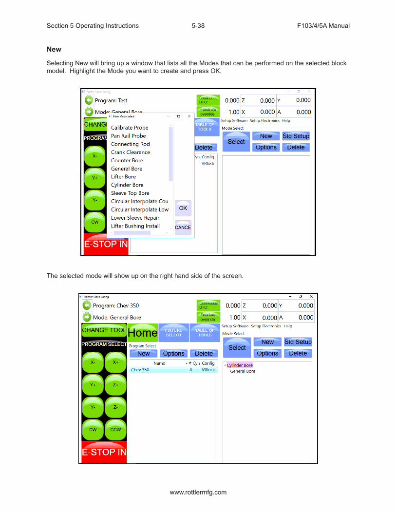
Section 5 Operating Instructions F103/4/5A Manual
www.rottlermfg.com
5-38
New
Selecting New will bring up a window that lists all the Modes that can be performed on the selected block model. Highlight the Mode you want to create and press OK.
The selected mode will show up on the right hand side of the screen.
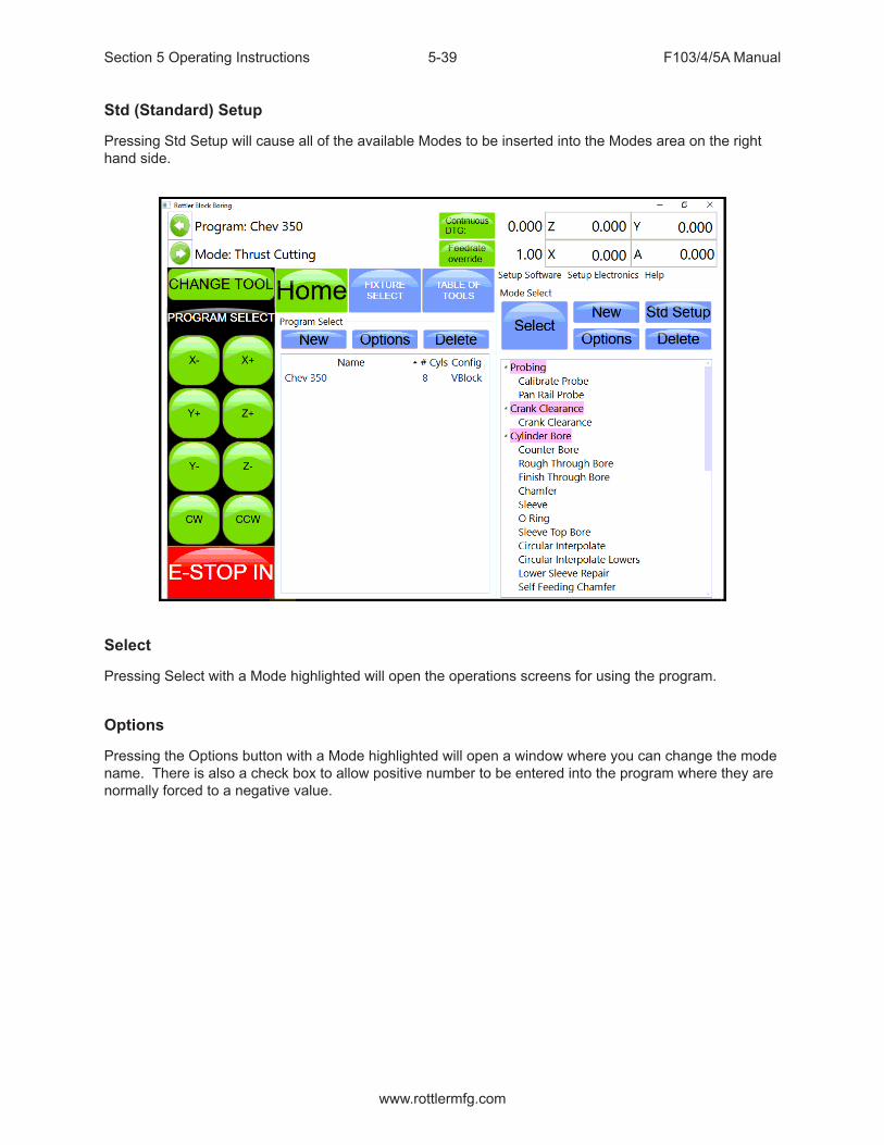
Section 5 Operating Instructions F103/4/5A Manual
www.rottlermfg.com
5-39
Std (Standard) Setup
Pressing Std Setup will cause all of the available Modes to be inserted into the Modes area on the right hand side.
Select
Pressing Select with a Mode highlighted will open the operations screens for using the program.
Options
Pressing the Options button with a Mode highlighted will open a window where you can change the mode name. There is also a check box to allow positive number to be entered into the program where they are normally forced to a negative value.

Section 5 Operating Instructions F103/4/5A Manual
www.rottlermfg.com
5-40
Cylinder Bore Mode 3 Axis
Select Cylinder Bore and then Rough Through Bore on the screen. This will bring up the boring program with the Set Zeros tab shown.NOTE: Once a certain feature is discussed in a particular mode it will not be discussed again in the following modes.
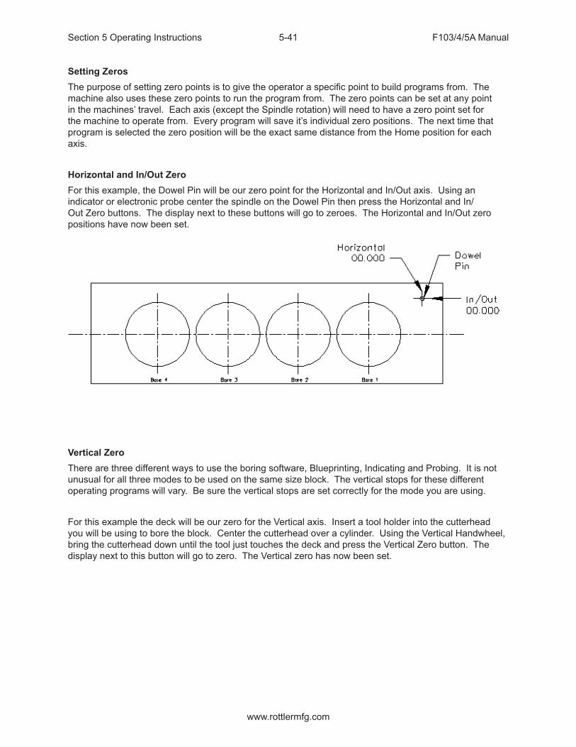
Section 5 Operating Instructions F103/4/5A Manual
www.rottlermfg.com
5-41
Setting ZerosThe purpose of setting zero points is to give the operator a specific point to build programs from. The machine also uses these zero points to run the program from. The zero points can be set at any point in the machines’ travel. Each axis (except the Spindle rotation) will need to have a zero point set for the machine to operate from. Every program will save it’s individual zero positions. The next time that program is selected the zero position will be the exact same distance from the Home position for each axis.
Horizontal and In/Out ZeroFor this example, the Dowel Pin will be our zero point for the Horizontal and In/Out axis. Using an indicator or electronic probe center the spindle on the Dowel Pin then press the Horizontal and In/Out Zero buttons. The display next to these buttons will go to zeroes. The Horizontal and In/Out zero positions have now been set.
Vertical ZeroThere are three different ways to use the boring software, Blueprinting, Indicating and Probing. It is not unusual for all three modes to be used on the same size block. The vertical stops for these different operating programs will vary. Be sure the vertical stops are set correctly for the mode you are using.
For this example the deck will be our zero for the Vertical axis. Insert a tool holder into the cutterhead you will be using to bore the block. Center the cutterhead over a cylinder. Using the Vertical Handwheel, bring the cutterhead down until the tool just touches the deck and press the Vertical Zero button. The display next to this button will go to zero. The Vertical zero has now been set.

Section 5 Operating Instructions F103/4/5A Manual
www.rottlermfg.com
5-42
The zeros points for all axis have now been set. All the numbers entered from this point on will reference these zero positions. You are finished with the Set Zeros screen, select the next Tab to the Right, Vertical Stops.
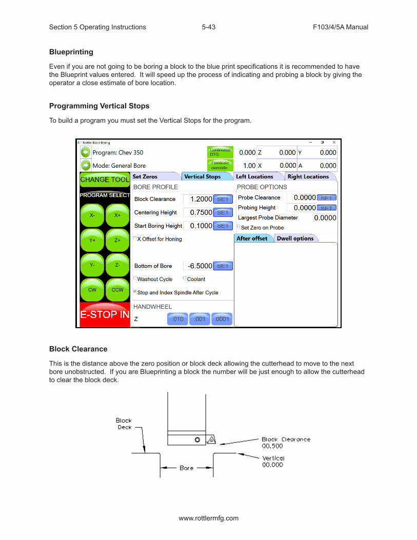
Section 5 Operating Instructions F103/4/5A Manual
www.rottlermfg.com
5-43
Blueprinting
Even if you are not going to be boring a block to the blue print specifications it is recommended to have the Blueprint values entered. It will speed up the process of indicating and probing a block by giving the operator a close estimate of bore location.
Programming Vertical Stops
To build a program you must set the Vertical Stops for the program.
Block Clearance
This is the distance above the zero position or block deck allowing the cutterhead to move to the next bore unobstructed. If you are Blueprinting a block the number will be just enough to allow the cutterhead to clear the block deck.

Section 5 Operating Instructions F103/4/5A Manual
www.rottlermfg.com
5-44
Centering Height
When Blueprinting this stop is not needed. It should be the same as the block Clearance Height.
Start Boring Height
This is the distance above zero or the block deck where you want the cutterhead to start rotating and the downward feed to start. Generally this is just a short distance above the block deck to minimize the amount of time the machine bores through air.
Bottom of the Bore
This is the distance below zero or the Block deck where you want the machine to stop boring and retract out of the cylinder. When the spindle retracts it will then go to the Block Clearance position.This is an example of what the above program would look like on the vertical stops.
When Blueprinting the Probe is not used. It will be discussed later in this Chapter.

Section 5 Operating Instructions F103/4/5A Manual
www.rottlermfg.com
5-45
Horizontal Offset for Honing
This feature is designed to offset the cutter at a certain height in the lower bore to cut out block web intrusions to make room for the honing process.Checking this box will bring up another value to be entered on the left hand side of the screen.
Start Offset Height
This is the vertical depth at which the cutter will shift to the side to start cutting.
Horizontal Offset
This is the distance the cutter will offset from the bore center.
Change Speeds at Horizontal Offset
Often the clearance cut is much larger that the cut for the rest of the bore. For this you can check this box and enter a different RPM and Feed Rate. If a different speed and feed are not need do not check this box and the same feed and speed will be used that was used to bore the cylinder.For each bank (of a V Block) you can select the direction the offset should go.
Washout Cycle
Checking this box will open another window on the right hand side of the screen. Here you can enter the RPM and number of revolutions that will be performed when the cutter reaches the Bottom of Bore position. In Through Boring this is not generally used. This is used when a certain type of finish is required on a counter bore or the bottom of a sleeve cut.
Stop and Index Spindle after Cycle
Checking this box will cause the spindle to be indexed to the three O’clock position after the cylinder has been bored but before it retracts. It will also offset to the left before the tool is retracted. This is the default setting. You would not want this check in an operation such as Lifter Boring.

Section 5 Operating Instructions F103/4/5A Manual
www.rottlermfg.com
5-46
Bore Locations
To build a program you must set the Horizontal and In/Out Stops for the program. All Horizontal and In/Out stop are based from where their zero positions were set. The following illustration shows how the stop positions were derived. These stops would be used when blueprinting a block.

Section 5 Operating Instructions F103/4/5A Manual
www.rottlermfg.com
5-47
The following is an example of what the screens would look like for the above block.
Left Locations
Right Locations
The Horizontal and In/Out stops have now been set.

Section 5 Operating Instructions F103/4/5A Manual
www.rottlermfg.com
5-48
Boring a Block
Once the Vertical, Horizontal and In/Out stops have all been entered the Spindle RPM and Feed Rate need to be entered. This is done on the Set Zeros screen. Once this is done you can go to the Left and/or Right Bore location screens and bore the cylinders.Pressing the Bore Left for Bore Right buttons Will Bore all the cylinders that have Green bore button below them.Pressing a Bore button once will turn that button Yellow. Any Yellow button will not be bored when the Bore Left or Right button is pressed.Double clicking any Bore button will turn all the Bore button yellow EXCEPT the one that was double click.
Indicating
Even if you are not going to be boring a block to the blue print specifications it is recommended to have these values entered. It will speed up the process of indicating and probing a block by giving the operator a close estimate of bore location.Vertical ZeroThere are three different ways to use the boring software, Blueprinting, Indicating and Probing. It is not unusual for all three modes to be used on the same size block. The vertical stops for these different operating programs will vary. Be sure the vertical stops are set correctly for the mode you are using.For this example the deck will be our zero for the Vertical axis. Insert a tool holder into the cutterhead you will be using to bore the block. Center the cutterhead over a cylinder. Using the Vertical Handwheel, bring the cutterhead down until the tool just touches the deck and press the Vertical Zero button. The display above this button will go to zero. The Vertical zero has now been set.
The zeros points for all axis have now been set. All the numbers entered from this point on will reference these zero positions. You are finished with the Set Zeros screen, select the next Tab to the Right.
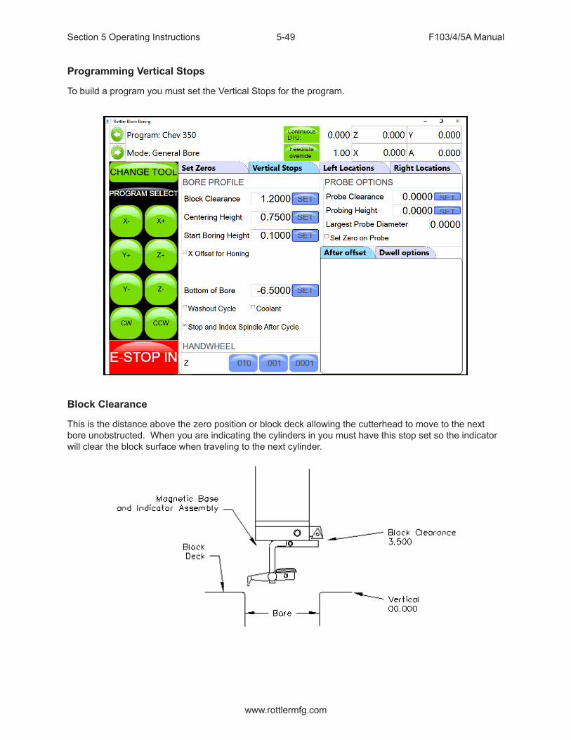
Section 5 Operating Instructions F103/4/5A Manual
www.rottlermfg.com
5-49
Programming Vertical Stops
To build a program you must set the Vertical Stops for the program.
Block Clearance
This is the distance above the zero position or block deck allowing the cutterhead to move to the next bore unobstructed. When you are indicating the cylinders in you must have this stop set so the indicator will clear the block surface when traveling to the next cylinder.

Section 5 Operating Instructions F103/4/5A Manual
www.rottlermfg.com
5-50
Centering Height
This is a distance above the vertical zero where you will be manually centering the block. The drawing below is a typical set up for manual centering or indicting a cylinder.
Start Boring Height
This is the distance above zero or the block deck where you want the cutterhead to start rotating and the downward feed to start. Generally this is just a short distance above the block deck to minimize the amount of time the machine bores through air. This will be a negative number.
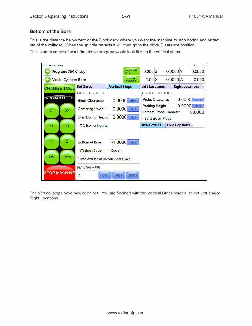
Section 5 Operating Instructions F103/4/5A Manual
www.rottlermfg.com
5-51
Bottom of the Bore
This is the distance below zero or the Block deck where you want the machine to stop boring and retract out of the cylinder. When the spindle retracts it will then go to the block Clearance position.This is an example of what the above program would look like on the vertical stops.
The Vertical stops have now been set. You are finished with the Vertical Stops screen, select Left and/or Right Locations.

Section 5 Operating Instructions F103/4/5A Manual
www.rottlermfg.com
5-52
Bore Locations
To build a program you must set the Horizontal and In/Out Stops for the program. There are eight (8) Horizontal and In/Out stops used in the boring program. All Horizontal and In/Out stop are based from where their zero positions were set.Select Left Locations and the Blueprint. Program the blueprint values (or close approximation) into the Horizontal and In/Out stops. Do the same for the Right Locations.

Section 5 Operating Instructions F103/4/5A Manual
www.rottlermfg.com
5-53
Select Left Locations and then Indicated. If you have programmed the blueprint locations into this program then press Copy Values and then Blueprint. This will cause the values from the Blueprint page to be copied into the Indicated page. This give you a starting point to indicate the individual cylinder from.
Press the Move 1 button. The machine will move to the first cylinder and stop at the centering position. Manually indicate the cylinder in using the Horizontal and In/Out handwheel. Once the cylinder is centered press the Set 1 button. This will transfer the current position of the machine into the first set of Data Boxes. Repeat this process for all the cylinders that need to be indicated. Press the Right Locations tab and repeat the above procedure for the cylinders to be indicated on the right bank.
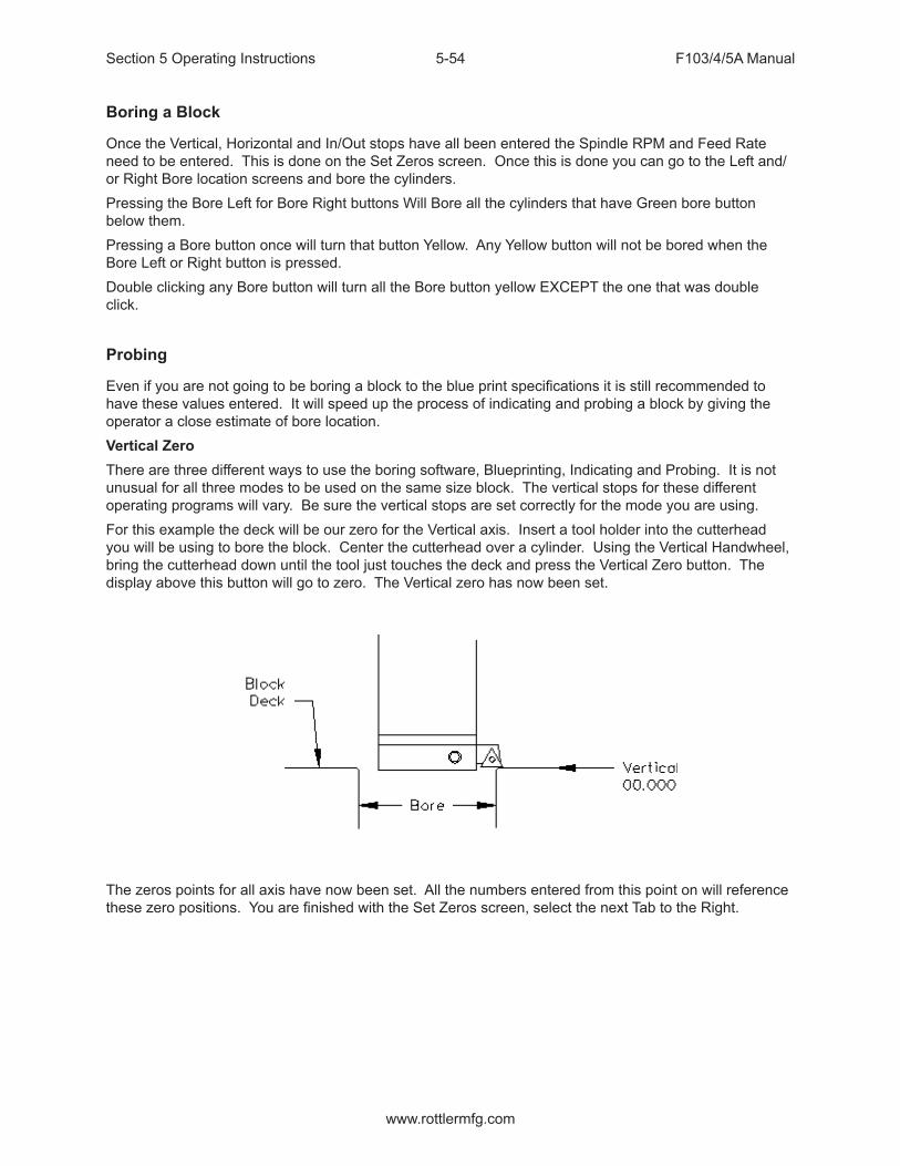
Section 5 Operating Instructions F103/4/5A Manual
www.rottlermfg.com
5-54
Boring a Block
Once the Vertical, Horizontal and In/Out stops have all been entered the Spindle RPM and Feed Rate need to be entered. This is done on the Set Zeros screen. Once this is done you can go to the Left and/or Right Bore location screens and bore the cylinders.Pressing the Bore Left for Bore Right buttons Will Bore all the cylinders that have Green bore button below them.Pressing a Bore button once will turn that button Yellow. Any Yellow button will not be bored when the Bore Left or Right button is pressed.Double clicking any Bore button will turn all the Bore button yellow EXCEPT the one that was double click.
Probing
Even if you are not going to be boring a block to the blue print specifications it is still recommended to have these values entered. It will speed up the process of indicating and probing a block by giving the operator a close estimate of bore location.Vertical ZeroThere are three different ways to use the boring software, Blueprinting, Indicating and Probing. It is not unusual for all three modes to be used on the same size block. The vertical stops for these different operating programs will vary. Be sure the vertical stops are set correctly for the mode you are using.For this example the deck will be our zero for the Vertical axis. Insert a tool holder into the cutterhead you will be using to bore the block. Center the cutterhead over a cylinder. Using the Vertical Handwheel, bring the cutterhead down until the tool just touches the deck and press the Vertical Zero button. The display above this button will go to zero. The Vertical zero has now been set.
The zeros points for all axis have now been set. All the numbers entered from this point on will reference these zero positions. You are finished with the Set Zeros screen, select the next Tab to the Right.

Section 5 Operating Instructions F103/4/5A Manual
www.rottlermfg.com
5-55
Programming Vertical Stops
To build a program you must set the Vertical Stops for the program.
Block Clearance
This is the distance above the zero position or block deck allowing the probe to move to the next bore unobstructed.
Centering Height
This stop is not used when you are using the probing feature. It is recommended that it be set to the same value as the Block Clearance.
Start Boring Height
This is the distance above zero or the block deck where you want the cutterhead to start rotating and the downward feed to start. Generally this is just a short distance above the block deck to minimize the amount of time the machine bores through air.

Section 5 Operating Instructions F103/4/5A Manual
www.rottlermfg.com
5-56
Bottom of the Bore
This is the distance below zero or the Block deck where you want the machine to stop boring and retract out of the cylinder. When the spindle retracts it will then go to the block Clearance position.This is an example of what the above program would look like on the vertical stops.
Probe Height
When using the optional Probe… install the probe into the spindle after your vertical positions have been set using the cutterhead. Using the handwheel and bring the Probe down to the location in the cylinder you will be probing. Press the SET button next to Probe height. This will set the probing height position.Using the handwheel move the probe up until it can safely move horizontal to the next cylinder. Press the SET button next to Probe Clearance. This will set the clearance height.The Vertical stops have now been set. You are finished with the Vertical Stops screen, select Left and/or Right Locations.

Section 5 Operating Instructions F103/4/5A Manual
www.rottlermfg.com
5-57
Bore Locations
To build a program you must set the Horizontal and In/Out Stops for the program All Horizontal and In/Out stop are based from where their zero positions were set.Select Left Locations and the Blueprint. Program the blueprint values (or close approximation) into the Horizontal and In/Out stops. Do the same for the Right Locations.Select Left Locations and then Probing. You can probe each cylinder individual by pressing the associated Probe button or you can probe the entire bank by pressing the Probe Left Button. This is the same procedure for the Right Bank.
Probe Auto Center
This feature is located on the Set Zero page. This allows easily find the center of a hole or cylinder. Roughly place the probe in the center of a cylinder. Press Probe Auto Center. The cylinder will be probed in 4 places, when finished the probe will move to the center of the probed cylinder. Pressing Horizontal and In/Out zero will then establish the center of that hole.
Automatic Probing Procedure
The probe will move to the center of the cylinder to be probed. It will then move to the right at a slow rate until the side of the cylinder is touched, it will then back off slightly and touch the same spot again to confirm position. The probe will then touch off the cylinder in three more spots and retract from cylinder.As each cylinder is probed the Probed Diameter, Horizontal and In/Out positions will be placed into the Data Boxes for the corresponding cylinder.Press the Right Locations tab and repeat the above procedure for the cylinders to be probed on the right bank.
The Horizontal and In/Out stops have now been set.
Section 5 Operating Instructions F103/4/5A Manual
www.rottlermfg.com
5-58
Boring a Block
Once the Vertical, Horizontal and In/Out stops have all been entered the Spindle RPM and Feed Rate need to be entered. This is done on the Set Zeros screen. Once this is done you can go to the Left and/or Right Bore location screens and bore the cylinders.Pressing the Bore Left for Bore Right buttons Will Bore all the cylinders that have Green bore button below them.Pressing a Bore button once will turn that button Yellow. Any Yellow button will not be bored when the Bore Left or Right button is pressed.Double clicking any Bore button will turn all the Bore button yellow EXCEPT the one that was double click.
Cylinder Bore Mode 4th Axis
NOTE: The program with the 4th axis installed works basically the same as the 3 axis mode. ONLY the differences in operation and screens will be discussed here. Carefully read through the 3 Axis mode and then the 4th axis mode for operation and building programs.Select Cylinder Bore and then Through Bore on the control panel. This will bring up the boring program with the Set Zeros tab shown.Setting ZerosThe purpose of setting zero points is to give the operator a specific point to build programs from. The machine also uses these zero points to run the program from. The zero points can be set at any point in the machines’ travel. Each axis (except the Spindle rotation) will need to have a zero point set for the machine to operate from.
4th Axis (Rotational) Zero
The Zero position for the 4th (Rotational) Axis should be preset from the factory. If the zero needs to be reset use the following procedure.There are three (3) flats cut onto the Head Stock Plate. Use the middle flat to set the rotational zero. Using an indicator off of the spindle indicate the middle flat to Zero all the way along it. Use the 4th Axis hand wheel to do this. When the middle flat is indicated in press the 4th Axis Zero button. You 4th (Rotational) Zero is set.
Finding the In/Out (Y) Axis Zero with 4th Axis
The Head Stock Plate has a hole in it next to the Middle Flat. This hole is centered on the center of the Main and Cam locator shafts.
Building Programs with the 4th Axis
Program are built the same as in the 3 Axis mode with the exception of setting the Angle for each Bank. The Left and the Right Locations page each have an Angle Data Box. Here you enter the angle of each bank from the 4th Axis (Rotational) zero position. The zero position is with the Cam and Crank Locators lined up vertically.Example: On a Chevy 350 the Left bank would be positive 45 Degrees and the Right Bank would be a negative -45 Degrees.

Section 5 Operating Instructions F103/4/5A Manual
www.rottlermfg.com
5-59
Setting Vertical Clearance with 4th Axis
It is very important when setting your Vertical and Probe Clearance height that you be sure to account for the Roll Over of the block from bank to bank. When in an automatic program the block will roll from the Left Bank to the Right bank at the Left Bank Bore1 position. It will also rotate from the Bore1 position when going from Right Bank to Left.
Table of Tools for 3 and 4th Axis Bore Mode
NOTE: The Table of Tools is not needed to run the Rottler automatic programs. It is recommended that it not be used except by the advanced operator.
Building a Program with Table of Tools
Build the program as described above for 3 and 4 Axis programs using the same vertical zero locations.Put the tools to be used into the Table of Tools as described in Chapter 2. In Bore mode you are not referencing another vertical location such as the Crank centerline so the Z Touch off Location will remain at zero.
Assigning Tools
Tools to be used in the boring operations are set on the Set Zeros page. To select a Tool, double click on Tool # on the right side of the screen. This will bring up the Table of Tools window. Highlight the tool you will be using, such as 2.9 Production Stub and select OK.Do the Same to select the Probe you will be using, such as 100mm Probe.NOTE: The Tool highlighted in red is the currently Active tool.

Section 5 Operating Instructions F103/4/5A Manual
www.rottlermfg.com
5-60
The following shows what the screen will look like with to tools assigned but none of them active. Default Tool 0 is set active and only shows on the Table of Tools screen.
Setting Tools Active
Physically install the first tool you will be using in the program. For this example physically install the 100mm Probe into the spindle. Press the Set Active button below the Probe #. The Tool Change Form will Open. This is to very your Vertical Tool Length and Probe Diameter. Select OK and then OK again on the spindle warning page.
IMPORTANT: The Tool Diameter on this page is used for the Probe. This must be set to the actual Diameter of the probe when probing cylinders. The Tool Diameter is NOT used for Boring Bars, End Mills etc… in the Rottler Bore program.

Section 5 Operating Instructions F103/4/5A Manual
www.rottlermfg.com
5-61
The Currently Active tool in a program will be highlighted in Pink on the Set Zero page.
If you attempt to run the Probing Cycle with the Tool # active the machine will automatically move to the Tool Change clearance position and open the Tool Change Window so you can change the tool and vise versa.

Section 5 Operating Instructions F103/4/5A Manual
www.rottlermfg.com
5-62
Mill Mode 3 Axis
Setting Zeros
The purpose of setting zero points is to give the operator a specific point to build programs from. The machine also uses these zero points to run the program from. The zero points can be set at any point in the machines’ travel. Each axis will need to have a zero point set for the machine to operate from.
Horizontal ZeroFor this example we are going to set the Horizontal Zero approximately 1/4” from the right hand side of the work piece.In/Out ZeroFor this example we are going to set the In/Out Zero at the center line of the work piece.Vertical ZeroFor this example the Vertical Zero will be at the deck height of the work piece.ExampleInstall the Milling cutterhead you will be using into the machine. Move the In/Out axis and center the work piece under the spindle. Press the In/Out Zero button here. Move the Horizontal Axis to that the cutter is overhanging the work piece about 1/4”. Bring the Vertical Axis down until the cutter is just above the work piece. At this time it should look similar to the drawing below.

Section 5 Operating Instructions F103/4/5A Manual
www.rottlermfg.com
5-63
Set the Spindle RPM and Feed rate on this screen.
Start the spindle. Press the Vert .001 button to put the handwheel in .001 per detent. Slowly move the spindle downward until you can hear or see the cutter just touch the block. Press your Vertical Zero button here. Press the Right travel button to feed the spindle off of the work piece. When the cutter has cleared the work piece press the Right travel button again to stop the feeding. Press the Horizontal Zero here.
Your zero position for all axis have now been set.

Section 5 Operating Instructions F103/4/5A Manual
www.rottlermfg.com
5-64
Mill Operation
IMPORTANT: Do not move the machine In/Out with the Wedge on. The Wedge comes on automatically when the Mill program is entered. If you need to move the machine In/Out to center on the work Piece use the turn Wedge On/Off button at the bottom of the page to do so. Make sure the Wedge is back on when you start the cycle.This screen is used to set certain parameters the F103/4/5A will use to run the automatic cycle.
End
Horizontal EndThis displays the current end stop value. To enter a new value press the display and a pop-up numerical key pad will appear. Press the desired end stop value and then ENTER. This is the distance from where the Horizontal Zero was set. You can move the fly cutter manually to the end of the cut and press the SET button. This will automatically put the Horizontal End value in for you.Amount Per PassThis is the amount of material removed from the work piece on each pass of the cutterhead.Vertical StartThis is the Vertical Position the machine will start cutting at. This value is usually Zero which is usually the starting Deck Height.Vertical EndThis is the Vertical Position the machine will stop cutting at. It is the Total amount of material you want to remove in the Milling process.

Section 5 Operating Instructions F103/4/5A Manual
www.rottlermfg.com
5-65
Copy Lowest Copy HighestThese buttons will be discussed in the Mill Probing section of this Chapter.
Rough Settings
These values are used when taking multiple passes on a work piece. These values can be wet high to remove material quickly. The finish on the work piece does not matter in these settings. There will be a Final pass that will apply the finish to the work piece.Rough Feed RateEnter the desired Roughing Feed Rate;Rough Spindle RPMEnter the Desired Roughing Spindle RPM.Finish Cut SettingsThese values will be used for the last pass the machine will make on the work piece. These will determine the finish left on the work piece.Finish AmountEnter the amount to be removed on the last pass.Finish Feed RateEnter the desired Finish Feed Rate.Finish RPMEnter the desired Finish Spindle RPM.NOTE: You do not need to have evenly divisible numbers in these sections. The computer will do the math to remove the correct amount each time and for the final pass to be at the amount you set.
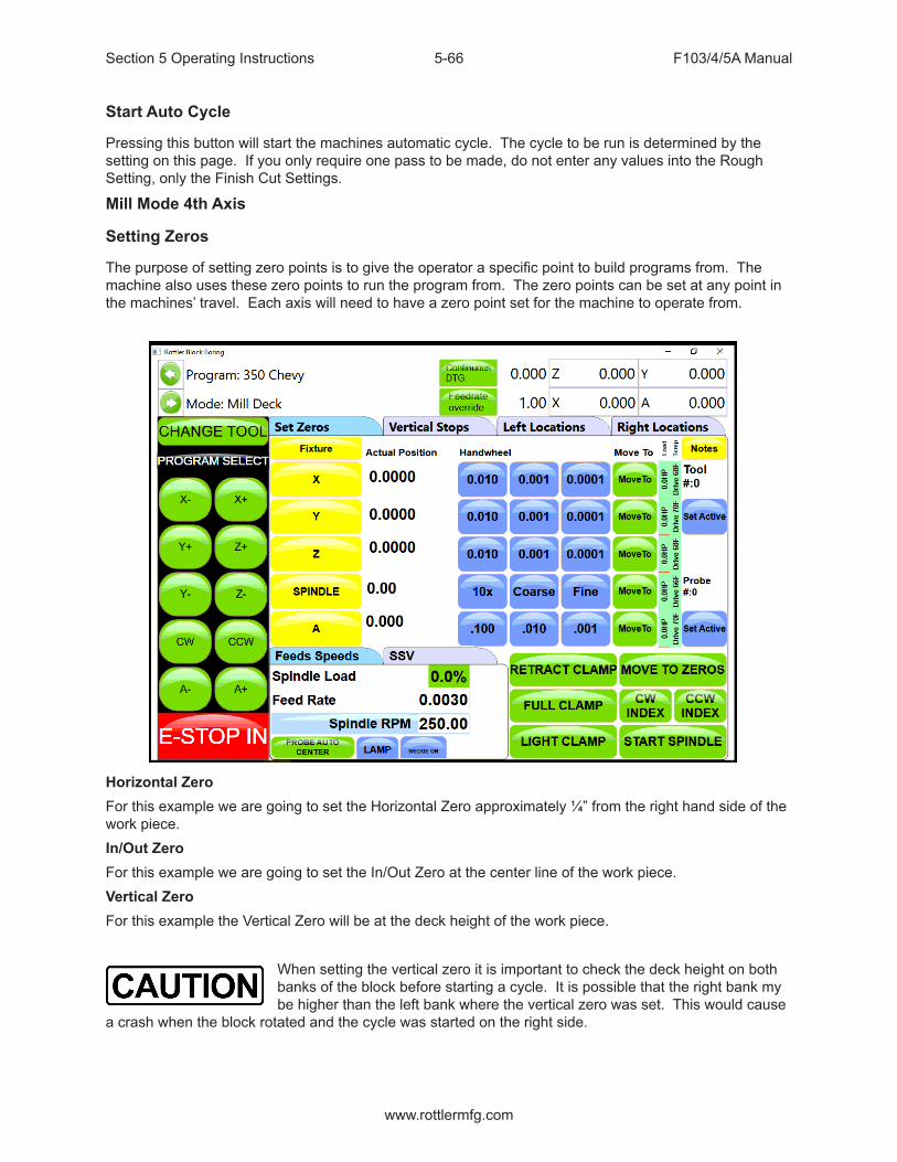
Section 5 Operating Instructions F103/4/5A Manual
www.rottlermfg.com
5-66
Start Auto Cycle
Pressing this button will start the machines automatic cycle. The cycle to be run is determined by the setting on this page. If you only require one pass to be made, do not enter any values into the Rough Setting, only the Finish Cut Settings.
Mill Mode 4th Axis
Setting Zeros
The purpose of setting zero points is to give the operator a specific point to build programs from. The machine also uses these zero points to run the program from. The zero points can be set at any point in the machines’ travel. Each axis will need to have a zero point set for the machine to operate from.
Horizontal ZeroFor this example we are going to set the Horizontal Zero approximately ¼” from the right hand side of the work piece.In/Out ZeroFor this example we are going to set the In/Out Zero at the center line of the work piece.Vertical ZeroFor this example the Vertical Zero will be at the deck height of the work piece.
When setting the vertical zero it is important to check the deck height on both banks of the block before starting a cycle. It is possible that the right bank my be higher than the left bank where the vertical zero was set. This would cause
a crash when the block rotated and the cycle was started on the right side.

Section 5 Operating Instructions F103/4/5A Manual
www.rottlermfg.com
5-67
Example:Install the Milling cutterhead you will be using into the machine. Move the In/Out axis and center the work piece under the spindle. Press the In/Out Zero button here. Move the Horizontal Axis to that the cutter is overhanging the work piece about ¼”. Bring the Vertical Axis down until the cutter is just above the work piece. At this time it should look similar to the drawing below.
Set the Spindle RPM and Feed rate on this screen.
Start the spindle. Press the Vert .001 button to put the handwheel in .001 per detent. Slowly move the spindle downward until you can hear or see the cutter just touch the block. Press your Vertical Zero button here. Press the Right travel button to feed the spindle off of the work piece. When the cutter has cleared the work piece press the Right travel button again to stop the feeding. Press the Horizontal Zero here.
Your zero position for all axis have now been set.

Section 5 Operating Instructions F103/4/5A Manual
www.rottlermfg.com
5-68
Mill Operation
IMPORTANT: Do not move the machine In/Out with the Wedge on. The Wedge comes on automatically when the Mill program is entered. If you need to move the machine In/Out to center on the work Piece use the turn Wedge On/Off button at the bottom of the page to do so. Make sure the Wedge is back on when you start the cycle.
This screen is used to set certain parameters the F103/4/5A will use to run the automatic cycle.
End
Horizontal EndThis displays the current end stop value. To enter a new value press the display and a pop-up numerical key pad will appear. Press the desired end stop value and then ENTER. This is the distance from where the Horizontal Zero was set. You can move the fly cutter manually to the end of the cut and press the SET button. This will automatically put the Horizontal End value in for you.Amount Per PassThis is the amount of material removed from the work piece on each pass of the cutterhead.Vertical StartThis is the Vertical Position the machine will start cutting at. This value is usually Zero which is usually the starting Deck Height.Vertical EndThis is the Vertical Position the machine will stop cutting at. It is the Total amount of material you want to remove in the Milling process.

Section 5 Operating Instructions F103/4/5A Manual
www.rottlermfg.com
5-69
Copy Lowest Copy HighestThese buttons will be discussed in the Mill Probing section of this Chapter.
4th Axis Angles
Left Bank AngleEnter the angle of the Left Deck. This is the angle of the block in reference to the Cam and Crank bore being lined up Vertically.Right Bank AngleEnter the angle of the Right Deck. This is the angle of the block in reference to the Cam and Crank bore being lined up Vertically.Rollover Vertical ClearanceEnter the value the Fly Cutter will have to move up vertically to clear the block when it rolls over from bank to bank.In/Out OffsetThis is a value that can be entered to center the fly cutter in the middle of the deck. You In/Out center on the Left bank will not be the center of the In/out on the Right bank. Enter the value the In/Out will need to be moved to center on the Right Bank when it rolls over.
Rough Settings
These values are used when taking multiple passes on a work piece. These values can be wet high to remove material quickly. The finish on the work piece does not matter in these settings. There will be a Final pass that will apply the finish to the work piece.Rough Feed RateEnter the desired Roughing Feed Rate;Rough Spindle RPMEnter the Desired Roughing Spindle RPM.
Finish Cut Settings
These values will be used for the last pass the machine will make on the work piece. These will determine the finish left on the work piece.Finish AmountEnter the amount to be removed on the last pass.Finish Feed RateEnter the desired Finish Feed Rate.Finish RPMEnter the desired Finish Spindle RPM.
NOTE: You do not need to have evenly divisible numbers in these sections. The computer will do the math to remove the correct amount each time and for the final pass to be at the amount you set.

Section 5 Operating Instructions F103/4/5A Manual
www.rottlermfg.com
5-70
Cut Left and Cut Right
Pressing these buttons will cause the machine to run an automatic cycle (per the parameter defined in the Operations page) on the associated bank.
Start Auto Cycle
Pressing this button will start the machines automatic cycle. The cycle to be run is determined by the setting on this page. If you only require one pass to be made, do not enter any values into the Rough Setting, only the Finish Cut Settings.

Section 5 Operating Instructions F103/4/5A Manual
www.rottlermfg.com
5-71
Overlap Mill Setting
These settings will cause the mill head to do a zig zag pattern on whatever you are milling. It is important to note that when using this function that the wedge will not be engaged, and will warn you that it is off.

Section 5 Operating Instructions F103/4/5A Manual
www.rottlermfg.com
5-72
Milling Using Automatic Deck Probing
The Rottler Milling program is set up to Automatically Probe the Deck height of a block and then Mill it to a set Deck Height. This can be done on a 3 or 4 axis machine.
Table of Tools for Milling
You MUST use the Table of Tools if you want to Automatically Probe the deck height and cut it to a set height.Once done the Table of Tools Should look similar to the below picture.
The 100mm Probe is Tool 1. The 10” Fly Cutter is Tool 2.Go to Program Select, then select the block you are working with and then Mill Mode.Install the Probe physically into the spindle. Rotate the 4th axis to Zero degrees. Indicate the Middle flat on the head stock to be sure it is zero all the way across. There should be a number stamped into the headstock. This is the distance from the Flat to the center of the Crank. Bring the probe down until it just touches the middle flat.Open the Table of Tools and double click on Tool1 100 mm Probe. Enter the Measured diameter of you r Probe. This is not used in the Milling Program but needs to be entered accurately for Probing in the Bore mode.On the open window select Get Length. This will open another Window. There will be a value, that you cannot edit, in the “Z Location from Zero” this is the distance the Vertical Axis is from home when the Probe touches the Middle flat.In the Data box for “Z Touch off Height” enter the number that is stamped on the Head Stock. This is the distance from the flat to the center line of the Crank.

Section 5 Operating Instructions F103/4/5A Manual
www.rottlermfg.com
5-73
Select OK on both windows. This will put the Total tool length into the Table of Tools.
The Vertical Digital Read Out will now consider the center of the Crank bore to be the Vertical Zero position.
When the Probe tip or Cutting insert touches the Deck the Vertical DRO will be reading out the distance from the center of the Crank bore (Actual Deck Height).

Section 5 Operating Instructions F103/4/5A Manual
www.rottlermfg.com
5-74
Assigning Tools
From the Set Zero Tab, select Probe#. This will open the Tools Select Form. Select Tool 1, 100 mm Probe and click OK.Select the Tool#. This sill open The Tool Select Form. Select Tool 2, 10 inch Fly Cutter and click OK.The tools to be used have now been assigned to the program.

Section 5 Operating Instructions F103/4/5A Manual
www.rottlermfg.com
5-75
Setting Tools Active
To set a Tool Active (tool to be used) Press the Set Active button below that tool. Set the Probe Active. This will bring up the Tool Change Form. Her you can verify the information for the tool. Select OK. Select OK on the Spindle warning form if it appears.
The Probe# will now be highlighted in Pink, this indicates that the tool is active (being used). If you were to open the Table of Tools at this point, Tool 1 will be highlighted in Red. This also indicates that Tool 1 is active.
Building a Program Using Table of Tools
Enter all the values that were described in 3 and 4 Axis Milling earlier in the chapter.
Physically install the probe into the spindle and set active. Bring the probe down until it just touches the Deck. Look at the value in the Vertical DRO. This is the current deck height at position. Enter that numeric value into the Vertical Start. This gives the Probe a value to start probing the deck at.

Section 5 Operating Instructions F103/4/5A Manual
www.rottlermfg.com
5-76
Left Deck ProbeEnter the positions you want the Probe to probe here. You can physically move the probe to the locations on the bank you want to probe and hit the set button also.Right Deck ProbeRoll the block over to the Right Bank. Enter the positions you want the Probe to probe here. You can physically move the probe to the locations on the bank you want to probe and hit the set button also.
Auto Probing
Press the Start Probing button. The machine will first probe each programmed location on the left bank and record the height. The spindle will move to Vertical Clearance height and the block will roll over to the right bank and probe the programmed locations and record them. The block will then roll back over to the Left bank and the spindle will move to the first Left location and stop.

Section 5 Operating Instructions F103/4/5A Manual
www.rottlermfg.com
5-77
Auto Milling
Go to the Operations Tab. Vertical StartPress Copy Highest next to Vertical Start. This will copy the Highest Probed point of either bank. This is the Height at which the Start Auto Cycle would start the first cutting pass.Vertical EndPress Copy Highest next to Vertical Start. This will copy the Highest Probed point of either bank. This is the height at which the Start Auto Cycle would end the Final Pass. You would use this value if you just wanted to clean the deck up to the lowest point. If you want to cut the Deck Height to a certain value you would manually enter that value into the Vertical End Data Box.Cut Left or Cut RightPressing either of these buttons will Start the Auto Cycle for only the associated bank. That bank will be cut to the set parameters and the machine will stop.Start Auto CyclePressing this button will start the Auto Cycle for Both Banks. First the Left bank will be cut to the set parameters. The spindle will go to the Clearance Height and Roll over to the Right bank and cut it to the set parameters. The Spindle will again go to the Clearance Height and roll over to the Left bank. The machine will go idle at this point.

Section 5 Operating Instructions F103/4/5A Manual
www.rottlermfg.com
5-78
Lifter Bore Mode 3 Axis
Lifter Bore programs are built the same as described in the Bore Mode 3 Axis. Only the differences will be discussed in this section.In / Out ZeroThe In/Out zero position for Lifters is the center line of the Cam Bore. An easy way to find the center of the cam line is to use the electronic probe. The following is an example of this procedure. Install the probe into the holder and the holder into the spindle. Bring the probe down until it is in the approximate center of the cam Bar Vertically. Press the Vertical Zero button now (this is only a temporary Vertical Zero position). Using the In/Out handwheel bring the probe up to the Cam Bar until it lights. Press the In/Out zero button here. Move the spindle up enough to clear the Cam Bar, move the probe to the other side of the Cam Bar. Bring the vertical down to the zero position. Hand wheel the probe into the Cam Bar until the light comes on. Note the In/Out position reading. Divide this reading by two. Bring the spindle up until it can clear the Cam Bar. Use the In/Out handwheel and move the In/Out position until it matches the divided number. This is the center line of the Cam Bar. Press the IN/Out Zero button now. The In/Out zero position has been set. The following illustration visual shows the above description.
Start Boring HeightPay particular attention when setting this height, there are often protrusions in the casting that will not allow the End Mill to travel unobstructed all the way to the start of the lifter bore. It is safest to set the Start Boring Height above the Deck.Lifter Bore AngleRottler has specific Lifter Bore spacers that are installed on the Cam bar to set the correct angle for lifter boring when using the Performance Fixture.
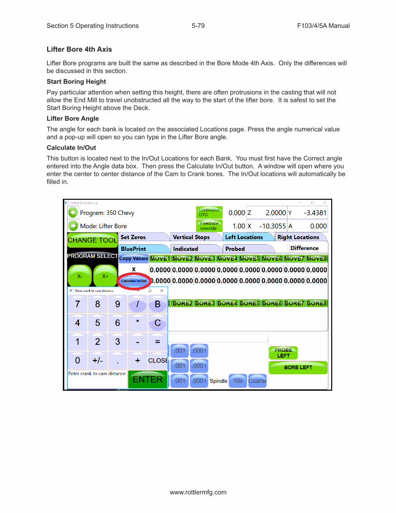
Section 5 Operating Instructions F103/4/5A Manual
www.rottlermfg.com
5-79
Lifter Bore 4th Axis
Lifter Bore programs are built the same as described in the Bore Mode 4th Axis. Only the differences will be discussed in this section.Start Boring HeightPay particular attention when setting this height, there are often protrusions in the casting that will not allow the End Mill to travel unobstructed all the way to the start of the lifter bore. It is safest to set the Start Boring Height above the Deck.Lifter Bore AngleThe angle for each bank is located on the associated Locations page. Press the angle numerical value and a pop-up will open so you can type in the Lifter Bore angle.Calculate In/OutThis button is located next to the In/Out Locations for each Bank. You must first have the Correct angle entered into the Angle data box. Then press the Calculate In/Out button. A window will open where you enter the center to center distance of the Cam to Crank bores. The In/Out locations will automatically be filled in.

Section 5 Operating Instructions F103/4/5A Manual
www.rottlermfg.com
5-80
Right Angle Drive Installation
Move the Rotate the inner spindle to position the keyway toward the left, in line with the outer spindle keyway notch. Press the tool release switch to compress the drawbar.
Rotate the RAD driveshaft so the drive key is pointing to the front or rear.

Section 5 Operating Instructions F103/4/5A Manual
www.rottlermfg.com
5-81
Carefully insert the RAD driveshaft into the inner spindle and lift the unit upward as far as it will go. Rotate the RAD output shaft until the driveshaft key is lined up with the inner spindle keyway. This will be visible through a small window on the left side of the RAD hub. At this point, the RAD will not fall out, so holding it in place is not required.
There are two adjustable keys on the RAD mounting hub that need to be lined up with the keyway notches of the outer spindle. It is not possible to see that these are aligned, so it is a little bit of trial and error when installing the unit. If the unit has never been installed on this particular machine, it would be best to temporarily remove these keys during the initial installation.Before rotating the tool engage the drawbar to finish installing the unit, using a small shim under the inner spindle drive key in case it is not perfectly aligned to prevent bending of the key. A small flat screwdriver works well.
NOTE: Verify that the RAD hub is against the bottom face of the outer spindle. If not, the inner, or outer keys, are not lined up, repeat the prior procedure until it is correct.
At this point, the RAD must be aligned so that the hub face is 90° to the travel of the X axis. With an indicator touching the output face of the RAD, move the Y axis back and forth to see the amount of error.
There are two (2) adjusting set screws and an adjustment block on the RAD hub. The two set screws push against the adjustment block to turn the head left or right. The adjusting block is keyed to the outer spindle. The two screws mounting the adjusting block to the hub need to be slightly loose.

Section 5 Operating Instructions F103/4/5A Manual
www.rottlermfg.com
5-82
Start turning the set screw that will rotate the RAD in the direction you need to go. The set screws will rotate the unit counter clockwise or clockwise. The set screw will move the key on the adjusting block until it hits the keyway in the outer spindle. As you are turning one set screw you will need to keep the opposite set screw backed off, it will stop.Final alignment results should be less than .0005” (.025mm), or as close as possible.
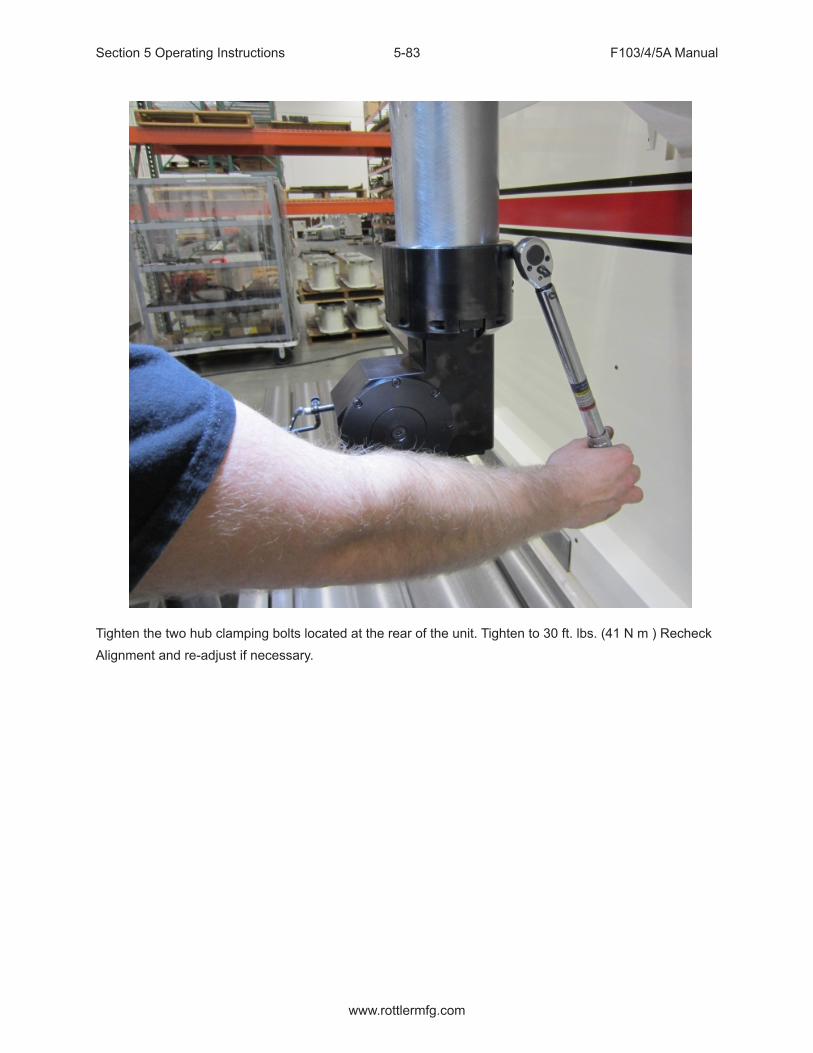
Section 5 Operating Instructions F103/4/5A Manual
www.rottlermfg.com
5-83
Tighten the two hub clamping bolts located at the rear of the unit. Tighten to 30 ft. lbs. (41 N m ) RecheckAlignment and re-adjust if necessary.

Section 5 Operating Instructions F103/4/5A Manual
www.rottlermfg.com
5-84
Line Bore Mode
Select the Line Bore button from the Main Menu. This will bring up the Line Bore Mode with the Set Zeros tab shown.NOTE: Run the right angle drive for at least 15 minutes bedore boring due to drive growth. Colder climates may need to run the head longer.
Mounting and Aligning the 90 Degree Head
Mount the 90 degree head onto the spindle and tighten the mount bolt. Use the following instructions to align the head.Mount a .001” or .0001” dial indicator to the machine table or block. The 90 degree head has two machined surfaces that can easily be used to align the head. The two surfaces and indicator positions are shown below.
Put some pressure on the indicator. Using the In/Out handwheel move the indicator form one side to the other noting the amount of difference. Keep the indicator on that side of the head and rotate it half of the noted distance. Repeat this procedure until there is less than .0005” variance.Tighten the four mounting bolts for the head and check the surface again to be sure it did not shift when tightening the head.
Setting Zeros
The purpose of setting zero points is to give the operator a specific point to build programs from. The machine also uses these zero points to run the program from. The zero points can be set at any point in the machines’ travel. Each axis (except the Spindle rotation) will need to have a zero point set for the machine to operate from.

Section 5 Operating Instructions F103/4/5A Manual
www.rottlermfg.com
5-85
Horizontal ZeroThe Horizontal should be set about .050” from the front of the first main to be bored, making sure that that position will allow the head to travel up without interference. Bring the head down and roughly center it in front of the first main. It does not need to be perfectly centered to set the horizontal zero. Press the Horizontal Zero button at this location.In/Out and Vertical ZeroLocate the supplied Last Word indicator and small magnetic base. Mount on cutterhead as shown below.
Using the Horizontal handwheel move the indicator inside the main bore, making sure the indicator is not touching the main bore at this point. You will be indicating both sides and the bottom of the saddle, generally the cap is not used to indicate from.Physically move the indicator and mag base on the cutterhead until there is about .010” pressure on it. Start rotating the spindle CW and CCW watching he indicator. As there is too much or too little pressure on the indicator, use the In/Out and Vertical handwheel to adjust the spindle in the bore until all three point are equal. Press the In/Out and Vertical zero buttons at this point.
The Vertical stops have now been set. You are finished with the Program Vertical Stops screen, select the next Tab to the Right.

Section 5 Operating Instructions F103/4/5A Manual
www.rottlermfg.com
5-86
Line Bore Options
When you create a line bore program you will be given option to allow Positive Horizontal values. Only check this if you need to bore in the +X, only used in special applications.
Block ClearanceThis stop is set at a positive value that will allow the 90 degree head to retract, in the Z-axis, and move over the top of the caps to the next main bore unobstructed. In the case that there is not enough clearance to go over the caps, “Clearance Retract Angle” can also be used.Clearance Retract AngleWhen “Block Clearance” is set to zero, the Z axis will move straight up. If set to 90, (degrees) the Y axis will move in, or out to go around the caps because they can’t go over the top. The amount specified by the “Block Clearance” value +, or -, will determine the length, and direction the Y axis to clear the caps.Any angle can be entered here, for example is 45 (degrees) is entered, Y-axis will move at a 45° & Z-axis will move up, simultaneously, to clear the caps.Dwell RPMSThis is used when boring to a “step”, maybe where an oil seal would be installed. RPM can be changed when it reaches the end of the “Bore Length” value to smooth out the finish of the step area.Dwell RevolutionsValue entered will determine how many times the spindle rotates at the “Dwell RPM’s” to give a satisfactory finish of the bore stepRAD options/RatioThis is the gear ratio of the Right Angle Drive you are using. Many Rottler drives are 2:1 so there should be a 2.000 here.

Section 5 Operating Instructions F103/4/5A Manual
www.rottlermfg.com
5-87
Programming Vertical Stops
To build a program you must set the axis stop. The stops that are used in the Line bore mode are X,Y,Z.
Programming X StopThe Horizontal Zero was set .050” before the first Main Bore, so the first Horizontal stop will be 00.000.Measure the distance between each main and enter it into the corresponding stop number.Programming Y Stop (optional)The in-out Zero is usually set and left to 0 when in Line Bore. In the rare case it is necessary to correct for misalignment on the y-axis, or a special offset type bore..Bore Z Stop CenterlineThe first vertical stop is on the main bore centerline. The vertical zero was set on the bore centerline.Therefore this stop will always be zero. This field should be used to account for minor variations in the block, .0005 -.005.Programming Bore LengthMeasure the length of each Main Bore and enter that value into the corresponding length boxDeviation from main line.Graph Probed ValuesUsed to give a visual picture of the actual main bore before and after

Section 5 Operating Instructions F103/4/5A Manual
www.rottlermfg.com
5-88
Running the Auto CycleYou will need to set a Feed Rate and Spindle RPM on the Set Zeros screen to run an auto cycle. The spindle will move up the Block Clearance distance as entered on the “Vertical Stops “ page, move to the horizontal bore location, then will then move down to the zero position, spindle will start and feed to the “Bottom of Bore” length, retract horizontally out of the bore, go back up to “Block Clearance, move horizontally over to the next bore etc.If you press the MOVE buttons or the Cycle Start button the machine will not move the In/Out axis to the
zero position. You need to move the In/Out axis to the zero position manually before you press Cycle Start.
The machine will go idle at this time. Pressing the “Start Auto Cycle” button will cause the entire cycle to run.After a program has been completed the machine will move the spindle over to the first Main Bore at the clearance distance.
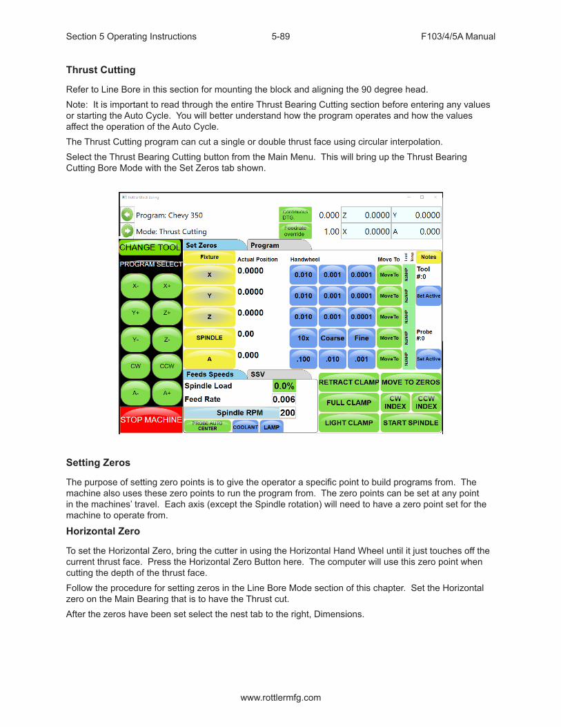
Section 5 Operating Instructions F103/4/5A Manual
www.rottlermfg.com
5-89
Thrust Cutting
Refer to Line Bore in this section for mounting the block and aligning the 90 degree head.Note: It is important to read through the entire Thrust Bearing Cutting section before entering any values or starting the Auto Cycle. You will better understand how the program operates and how the values affect the operation of the Auto Cycle.The Thrust Cutting program can cut a single or double thrust face using circular interpolation.Select the Thrust Bearing Cutting button from the Main Menu. This will bring up the Thrust Bearing Cutting Bore Mode with the Set Zeros tab shown.
Setting Zeros
The purpose of setting zero points is to give the operator a specific point to build programs from. The machine also uses these zero points to run the program from. The zero points can be set at any point in the machines’ travel. Each axis (except the Spindle rotation) will need to have a zero point set for the machine to operate from.
Horizontal Zero
To set the Horizontal Zero, bring the cutter in using the Horizontal Hand Wheel until it just touches off the current thrust face. Press the Horizontal Zero Button here. The computer will use this zero point when cutting the depth of the thrust face.Follow the procedure for setting zeros in the Line Bore Mode section of this chapter. Set the Horizontal zero on the Main Bearing that is to have the Thrust cut.After the zeros have been set select the nest tab to the right, Dimensions.

Section 5 Operating Instructions F103/4/5A Manual
www.rottlermfg.com
5-90
Dimensions & Auto Cycle
There are several values that need to be set on this screen for the program to operate properly. Below is illustration and a description of each of these values.
Thrust Dimensions
OutsideThis is the Outside dimension of the thrust face to be machined.InsideThis is the Inside dimension of the thrust face to be machined.CutterThis is the radius, from the center of the 90 degree head to the tip of the insert.
Clearances
VerticalThis is the distance, from zero, the 90 degree head will have to travel up to clear the main caps on the block.HorizontalThis is the distance, from zero, the 90 degree head will have to travel to clear the main for the next vertical move.
Dimensions
Main WidthWidth of the Main.

Section 5 Operating Instructions F103/4/5A Manual
www.rottlermfg.com
5-91
Insert WidthWidth of the Insert.Left Depth of CutDepth of left cut.Right Depth of CutDepth of right cut.Cut Right SideIf you select Cut Right Side the automatic cycle will cut the thrust face on the right hand side of the Main.Cut Left SideIf you select Cut left Side the automatic cycle will cut the thrust face on the left hand side of the Main.
Description and Running of the Auto Cycle
You will need to enter the Feed Rate and Spindle RPM the program will run at.There are no Move to buttons in this program. You MUST be at the zero positions when the Auto Cycle is started.Start Auto CycleWhen you are at the zero positions press the Auto Cycle, the spindle will start at the programmed RPM. The vertical feed will start at the programmed rate in an upward direction until the correct Outside diameter is reached. The circular interpolation will start at this point and go 360 degrees. It will then continue the circular interpolation back towards the center of the Main to clear the cutting tool from the thrust face. When the cutterhead is back at the center point (zero positions) of the Main, all motion will stop. The cutterhead will then rapid travel to the left taking the main width and the cutter diameter into account to reach the correct depth on the second thrust face. The same circular interpolation process will then be repeated for the second face. The cutterhead will then retract horizontally to the clearance distance then vertically to the block clearance distance.When the program is running the “Start Auto Cycle” button will change to “Press to Pause”. If this button is pressed the machine will pause the program right where it is. At this point the screens are locked out from changing anything. The button will the change to “Press to Resume”. If you want to resume press the button and the program will continue from that point on. If you do not wish to continue press the “Stop” button. This will put the machine back in idle mode and changes can be made to the program.

Section 5 Operating Instructions F103/4/5A Manual
www.rottlermfg.com
5-92
Backing Up and Restoring Block Profiles
This section will explain how to back up and restore the operator created block profiles for DM controlled machines for archival purposes or to transfer to a different machine.
First step is to open your file bowser and locate the RottlerWPF file on the C disk drive.
The next step is to plug in a flash drive to an open USB port

Section 5 Operating Instructions F103/4/5A Manual
www.rottlermfg.com
5-93
The following pop up box will appear on your screen.
Click on the Open folder to view files option and the following screen will appear. This is the contents of the flash drive you just plugged in.

Section 5 Operating Instructions F103/4/5A Manual
www.rottlermfg.com
5-94
Next resize and arrange both file browsers so that they are side by side.

Section 5 Operating Instructions F103/4/5A Manual
www.rottlermfg.com
5-95
Block profiles are backed up each time the machine is run with the current profiles being shown in the RottlerWPF folder. All that needs to be done to back up the current profile is to simply drag it from the RottlerWPF folder to the flash drive folder. A copy of the file will be placed on the flash drive.
Backup is now complete. Close both file browser windows and remove the flash drive.

Section 5 Operating Instructions F103/4/5A Manual
www.rottlermfg.com
5-96
To restore or add block profiles go through the first 5 steps explained previously.
Highlight the block profiles file in the flash drive and drag it into the RottlerWPF folder on the local hard drive.
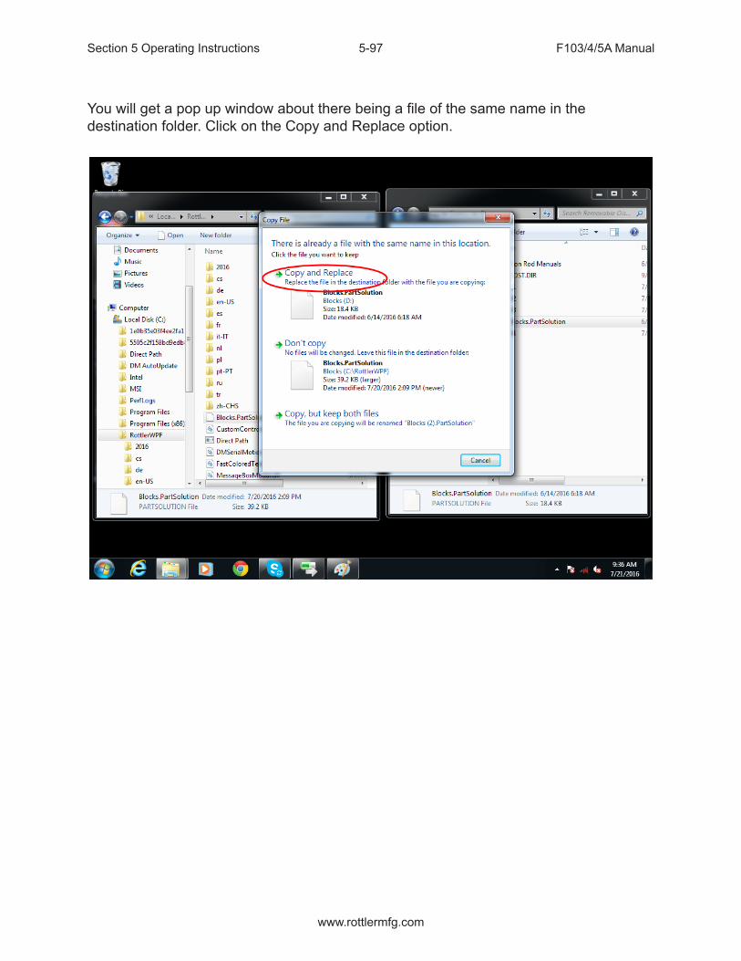
Section 5 Operating Instructions F103/4/5A Manual
www.rottlermfg.com
5-97
You will get a pop up window about there being a file of the same name in the destination folder. Click on the Copy and Replace option.

Section 5 Operating Instructions F103/4/5A Manual
www.rottlermfg.com
5-98
The archived block profiles will now be installed.
Close both browser windows and remove the flash drive. The restore process is now complete.

Section 6 Maintenance F103/4/5A Manual
www.rottlermfg.com
I
MAINTENANCEContents
Quick Reference Lubrication Chart: F103/4/5A ................................................................. 6-1
Quick Reference Preventative Maintenance Chart: F103/4/5A ......................................... 6-1
Grease Cross Reference Chart ........................................................................................... 6-2
Maintenance .................................................................................................................6-6
Lubrication ............................................................................................................................ 6-6
Outer Spindle ....................................................................................................................................6-6Upper Belt Housing ..........................................................................................................................6-6
Oil Reservoir System ........................................................................................................... 6-7
Inner Spindle Bearings ........................................................................................................ 6-7
Vertical Ballscrew Bearings ................................................................................................. 6-7
Priming Spindle Base Oil Lines .......................................................................................... 6-8
Lubrication Locations .......................................................................................................... 6-9
Right Angle Drive Lubrication Information .......................................................................6-11
Air Line Diagram ................................................................................................................. 6-12
F103/4/5A Wiring Diagram ................................................................................................. 6-13
ELO Alignment .................................................................................................................... 6-14
Magnescale Indicator Set Up ............................................................................................. 6-16
Spindle Drive Belt Replacement / Adjustment ................................................................. 6-17
Outer Spindle Bushing Adjustment .................................................................................. 6-22
Upper Bushing Adjustment ............................................................................................................6-23
Inner Spindle Adjustment .................................................................................................. 6-24
F103/4/5A Upper Housing Disassembly ........................................................................... 6-28
F103/4/5A Inner Spindle Removal ..................................................................................... 6-31
Inner Spindle Angular Contact Bearing Replacement .................................................... 6-31
Spindle Sweep .................................................................................................................... 6-33
Horizontal Gibs ................................................................................................................... 6-34
Section 6 Maintenance F103/4/5A Manual
www.rottlermfg.com
II
Adjusting Y-Axis Gibs ........................................................................................................ 6-36
Adjustment Procedure ...................................................................................................................6-37
Backlash Setting .NET Software ....................................................................................... 6-38
Spindle Belt Adjustment .................................................................................................... 6-47
Top and Side Rail Adjustment ........................................................................................... 6-48
Mill Tilt Adjustment Procedure .......................................................................................... 6-49
Checking Wear on Column Turcite Pads.......................................................................... 6-51
Digital Micrometer setting instructions ............................................................................ 6-53
To set or edit micrometer ...............................................................................................................6-54
Probe “On-Center” Adjustment......................................................................................... 6-58
Replacing the Motherboard Battery .................................................................................. 6-62
Ballscrew Assemblies Reference ............................................................................6-65
Alignment Definitions for Angular Bearings and Belleville Washers ............................ 6-65
Bearing Alignment ..........................................................................................................................6-65Belleville Washer Alignment ..........................................................................................................6-65
Z-Axis Lower Bearing and Belleville Washer Stacking Order ........................................ 6-66
Z-Axis Lower Bearing and Belleville Washer Section View ............................................ 6-67
Z-Axis Upper Belleville Washer Stacking Order .............................................................. 6-68
Z-Axis Upper Belleville Washer Section View ..............................................................................6-68
X-Axis Drive Side Bearing Stacking Order ....................................................................... 6-69
X-Axis Drive Side Bearing Section View .......................................................................................6-69
X-Axis Idle Side Bearing Stacking Order ......................................................................... 6-70
X-Axis Idle Side Bearing Section View..........................................................................................6-70
Y-Axis Bearing Stacking Order ......................................................................................... 6-71
Y-Axis Bearing Section View..........................................................................................................6-71
Inner Spindle Upper Section Belleville Washer Stacking Order .................................... 6-72
Inner Spindle Upper Section Belleville Washer Section View ....................................................6-72
Inner Spindle Lower Section Bearing Stacking Order .................................................... 6-73
Inner Spindle Lower Section Bearing Section View ........................................................ 6-74

Section 6 Maintenance F103/4/5A Manual
www.rottlermfg.com
6-1
Quick Reference Lubrication Chart: F103/4/5ARefer to the maintenance section in the manual for lubrication location points and instruction.
Assembly Frequency Lube Operation Recommended Lubricant
Date Serviced
Outer Spindle 8 Hours
1000 Hours
Wipe with oil
Soak felt wiper with oil
ISO VG 68 Way Oil
Oil Reservoir System
8 Hours
175 Hours
Check upper oil lines are fullFill reservoir with oil if needed
ISO VG 68 Way Oil
Upper Vertical Ballscrew Pillow Block Bearing
175 Hours Grease NLGI 2 White Lithium Grease
Lower Vertical Ballscrew Bearing Pack
175 Hours Grease NLGI 2 White Lithium Grease
Rear Y Axis Bearing Housing Grease Fitting
175 Hours Grease NLGI 2 White Lithium Grease
Column Feed Gear Housing
1000 Hours Fill with oil GL-5 or MT-1 80W-90 Gear Oil
Quick Reference Preventative Maintenance Chart: F103/4/5ARefer to the procedures in the maintenance section of the manual to make or check these adjustments. Not all of the items listed in the table below have adjustment. The information should be recorded and the amount of wear tracked so the part can be replaced before down time on the machine occurs.
Procedure Frequency Date Serviced/CommentsSpindle Sweep Adjustment 150 HoursOuter Spindle Bushing Adjustment 500 HoursSpindle Tilt Measurement 500 HoursInner Spindle Bearing Adjustment 1000 HoursHorizontal Gib(s) Adjustment 1000 HoursX,Y,Z Auto Mode Backlash Adjustment 1000 HoursX,Y,Z Handwheel Backlash Adjustment 1000 HoursElectrical Enclosure Air Filter Replacement 1000 HoursMachine Level Adjustment 1000 HoursSpindle Drive Belt Adjustment 1000 HoursVertical Drive Belt Adjustment 1000 HoursHorizontal Ballscrew Inspection 2000 HoursSpindle Wear Measurement 2000 HoursHorizontal Way Wear Measurement 2000 Hours

Section 6 Maintenance F103/4/5A Manual
www.rottlermfg.com
6-2
Grease Cross Reference Chart
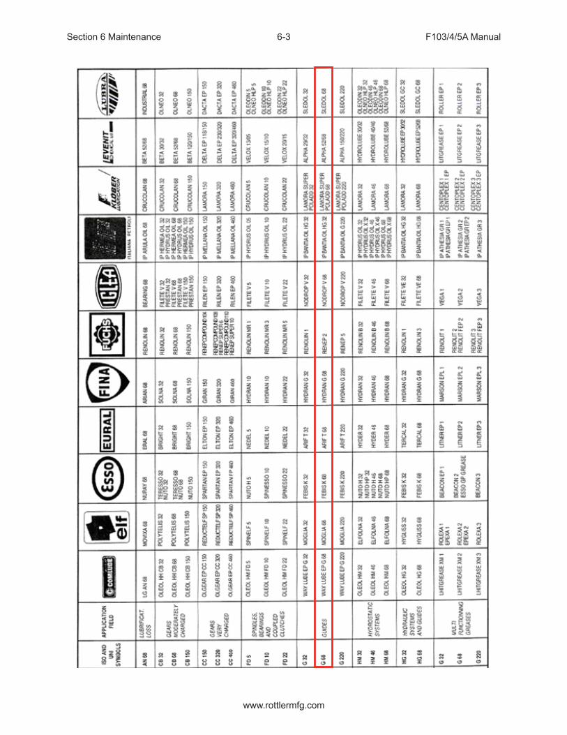
Section 6 Maintenance F103/4/5A Manual
www.rottlermfg.com
6-3

Section 6 Maintenance F103/4/5A Manual
www.rottlermfg.com
6-4

Section 6 Maintenance F103/4/5A Manual
www.rottlermfg.com
6-5

Section 6 Maintenance F103/4/5A Manual
www.rottlermfg.com
6-6
Maintenance
LubricationRefer to images following these written instructions:
Below are the directions that explain how and where to add oil to the different systems:
Do not overfill any of the lubrication points, serious electrical damage may result.
Outer SpindleThe Outer Spindle is hard chromed and is supported in tapered, cast iron spindle bushings. The Outer Spindle supports the Inner Spindle, bearings, seals etc… and maintains the boring rigidity.
Every 8 hours:The Outer Spindle needs to be moved down to the lower limit, wiped clean, and then lightly coated with a ISO VG 68 Way Oil. This is very important, if the spindle is allowed to operate dirty the cast iron dust will act as an abrasive on the spindle chrome. This will cause the spindle to wear prematurely. The outer spindle is a very expensive item to replace.
Every 1000 Hours:Open the sheet metal cover from the front of the spindle unit. There is a large nut where the outer spindle passes through the top of the spindle base. Using a spanner wrench or punch carefully remove the upper nut.
Note: Do not adjust the nut below the felt wiper (see the mechanical section for correct adjustment of this nut).
Slide the felt wiper back into place and tighten the Upper Nut back down.
Upper Belt HousingNo lubrication is necessary in the Upper Belt Housing.

Section 6 Maintenance F103/4/5A Manual
www.rottlermfg.com
6-7
Oil Reservoir SystemEvery 8 hours check the oil supply lines to the upper spindle to be sure they are full of oil.
The oil reservoir system is located inside the lower portion of the column. This system lubricates the following:
Ways Inner Spindle Bearings (Upper and Lower) Horizontal Ballscrew Outer Spindle
Every 175 Hours:The oil level of the reservoir should be checked, and filled with WAY OIL ISO VG 68.
When the oil reservoir is low or empty on the F103/4/5A machine, the control will “LOW OIL” and will not run until the reservoir has been filled.
The oil system may require priming if the reservoir has been run empty. You can do this automatically. Pull up the IO screen under Setup Electronics tab, select the Oiler section, and check the box to turn the oiler on.
Inner Spindle BearingsThe Inner Spindle Bearings are lubricated from the oil reservoir system. It is normal for a small amount of this oil to seep through the spindle bearings and onto the cutterhead.
Vertical Ballscrew BearingsThe Upper Pillow Block bearing is located on the top plate just below the driven sprocket. The lower bearing set is located at the bottom of the ballscrew in the spindle base.
Every 175 Hours:These bearings should be greased with NLGI 2 White Lithium Grease.
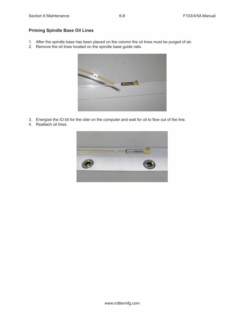
Section 6 Maintenance F103/4/5A Manual
www.rottlermfg.com
6-8
Priming Spindle Base Oil Lines
1. After the spindle base has been placed on the column the oil lines must be purged of air.2. Remove the oil lines located on the spindle base guide rails.
3. Energize the IO bit for the oiler on the computer and wait for oil to flow out of the line.4. Reattach oil lines.

Section 6 Maintenance F103/4/5A Manual
www.rottlermfg.com
6-9
Lubrication Locations

Section 6 Maintenance F103/4/5A Manual
www.rottlermfg.com
6-10
Lubrication Locations cont:

Section 6 Maintenance F103/4/5A Manual
www.rottlermfg.com
6-11
Right Angle Drive Lubrication Information
All right angle drives require lubrication at the point where the pinion drive intersects with the drive gear. This is generally in the area where the cutterhead is attached, except for the units that have belt drive. There will be a small pipe plug that is removed to check oil level and add oil if needed. See illustration below for general locations.
With the drive mounted on the machine spindle the oil level should be even with the bottom of the pipe plug threads.
All Rottler Right Angle Drives are filled with Union 76 Turbine Oil 68 prior to shipment. Use this or an equivalent ISO VG68 oil if the need to add or change oil arises.
When adding oil, fill until oil starts to run out of fill hole. Allow excess oil to drain, then coat pipe plug threads with anti-seize compound and replace it.
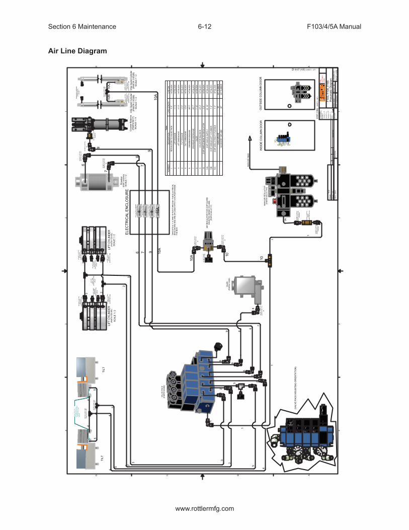
Section 6 Maintenance F103/4/5A Manual
www.rottlermfg.com
6-12
Air Line Diagram
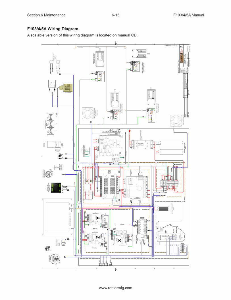
Section 6 Maintenance F103/4/5A Manual
www.rottlermfg.com
6-13
F103/4/5A Wiring DiagramA scalable version of this wiring diagram is located on manual CD.
1 1
2 2
3 3
4 4
AA
BB
CC
DD
TO
LE
RA
NC
ES
UN
LE
SS
NO
TE
DD
EC
IMA
LS
1 P
LA
CE
`
2 P
LA
CE
`
3 P
LA
CE
`
AN
GL
ES
`
~
FIN
ISH
DR
WN
:
DA
TE
:
SC
AL
E:
DR
AW
ING
NO
.M
AT
ER
IAL
:H
EA
T T
RE
AT
:to
nyt
9/2
9/2
015
80
12
re
v7
801
2 r
ev7
8012 rev7
.05
.01
.00
1
.5 12
5
1
:1
C
TH
EC
UT
TIN
GE
DG
E
Mass:
N/A
Pain
t:N
on
e
SH
EE
T 1
O
F 1
SHEET 1 OF 1
7
CA
TE
GO
RY
LIF
TW
ED
GE
DR
AW
BA
R
11
12
22
RD
WH
BK
WH
BN
WH
GN
DG
ND
GN
D
1 3
AIR
PR
ES
SU
RE
SW
ITC
H N
/O
GR
4
RD
T3BN
PU
BR
AK
E
BL
BK
3
YL
TH
ER
MA
L S
WIT
CH
N.C
.
GN
T2
GN
D
SHIELD
T1
21
GR
RD
BN
BK T1
GN
D
T2
TH
ER
MA
L S
WIT
CH
N.C
.
SHIELD
2
GN
YL
T3
1
T3
1
BN
2YL
GN
TH
ER
MA
L S
WIT
CH
N.C
.
T2RD
BK T1
GR
GN
D
SHIELD
T3
1
BN
2YL
GN
TH
ER
MA
L S
WIT
CH
N.C
.
T2RD
BK T1
GR
GN
D
SHIELD
BN
WH
DO
TT
ED
WH
CL
EA
R
DO
TT
ED
BK
CL
EA
RC
19
C2
C8
C5
C11
C7
C4
C1
C10
C10
C7
C4
C1
C1
7
C1
7
CPU
C20
C42
C36
C3
6
C1
3
C1
4
C3
6
C8
C1
9
C14
C13
C15
C16
C16
C36
C2
0
C36
C34
C1
8
C5
C11
C2
C8
C15
C1
8
C3
4
C42
C43
C4
3
C4
4
C44
71
0/1
0/2
01
7T
ON
YM
OV
ED
PR
OB
E T
O 1
2V
DC
61
/19
/20
17
TO
NY
CH
AN
GE
D O
ILE
R T
O T
OP
OF
OU
TP
UT
BO
AR
D
51
2/2
0/1
6T
ON
YC
HA
NG
ED
MO
TO
R P
OW
ER
CA
BL
E G
RO
UN
D F
RO
M
OR
AN
GE
TO
GR
EE
N
RE
VT
OD
AY
'S
RE
QU
ES
TD
ES
CR
IPT
ION
Y-A
XIS
MO
TO
R 9
020H
BM
S90
C-3
250A
B2
X-A
XIS
MO
TO
R 9
21
5F
BS
M1
00C
-525
0A
B2
Z-A
XIS
MO
TO
R 9
21
5J
BS
M9
0N
-22
50B
B2
SP
IND
LE
MO
TO
R 9
215
GB
SM
13
2C
-5200
AB
RA
DIO
RE
CE
IVE
RP
AR
T#
65
0-3
-59
U
MP
40
PR
OB
E65
0-3
-59
Z
SO
NY
LT
20
AP
AR
T# 5
02
-12
-7M
EM
ER
GE
NC
YS
TO
P63
89D
TO
UC
H S
CR
EE
N M
ON
ITO
R
HE
AT
SIN
K M
OU
NT
ED
SP
IND
LE
FA
NP
AR
T#
71
92
DO
OR
MO
UN
TE
D F
AN
BR
AK
ING
RE
SIS
TO
RS
903
8E
60A
MA
IN B
RE
AK
ER
S
WIT
CH
SP
IND
LE
AM
P9
03
5N
GR
OU
ND
BU
SC
ON
TA
CT
OR
OU
TP
UT
BO
AR
D9
03
4G
PO
WE
R B
OA
RD
903
4E
X
ZY
CH
AR
GIN
G R
ES
IST
OR
64
86P
24 V
OLT
90W
PO
WE
R S
UP
PLY
12 V
OL
T9
0W
PO
WE
R S
UP
PL
Y
HA
ND
WH
EE
L
BIT
6B
IT 4
BIT
2B
IT 0
BIT
7B
IT 5
BIT
3B
IT 1
VID
EO
C3
3
US
B 4
US
B 1
US
B 2
US
B 3
C3
C9
C3
2C
31
C3
0C
12
C6C
30
C3
C9
C6
C33
US
B 2
US
B 3
US
B 4
C32C
31
VID
EO
US
B 1
+-
UV
WG
ND
+-
UV
WG
ND
+-
UV
W
U V W
BR
AK
E-
+
+V
GN
D
SWAA-
BB-
II-UU-
VV-
WW-
KT
Y0V
TH
MS
W
+-
++
++
++
++
++
++
++
++
++
--
--
--
--
--
--
--
--
--
01
23
45
678
91
011
12
13
14
15 PROBE
START
OILER
LIFT
WEDGE
LIGHT
FAN
CUTTERRELEASE
Z-AXISBRAKE
E-STOP
CO
NT
.C
OIL
L1
L2
CH
AR
GE
RE
SIS
TO
RF
RO
M C
ON
TA
CT
OR
++
+
++
++
++
++
--
-
--
--
--
--
+ -
1 2
3 4
5 6
+V +V+V-V-V-V
N NLLINPUT INPUT
7A
7A
7A
7A
3A
3A
3A
3A
3A
3A
3A
3A
50
A
50A
50A
50A
50A
50A
+-
AA
-B
B-
++
++
++
++
++
++
++
++
ININ
ININ
ININ
ININ
ININ
ININ
ININ
ININ
--
--
--
--
--
--
--
--
++
--
L1
L2
L3
KT
Y
0V
TH
L
SW
KT
YK
TY
0V
0V
TH
LT
HL
SW
SW
+V
+V
+VGND
GND
GND
SW
SW
SW
A
A-
B
B-
I
I-
U
U-
V
V-
W
W-
A
A
A-
A-
B
B
B-
B-
I
I
I-
I-
U
U-
V
V-
W
W
W-
W-
U
U-
V
V-
12
3
+V
0V
L1
L2
L3
T3
T2
T1
910
11
12
13
BK
WH
BK
26
WH
27
34
2435
25
TO
CP
U P
OW
ER
CP
U
GN
D
GN
D
GN
D
L1
L2
L3L1
L1
L1
L2
L2L2
BK
WH
BK
WH
23
22
22
23
L1
L2
L3
L1
L2
L3
87
22
23
RD
BU
BN
/WH
BN
PK
/BU
PK
RD
BU
BN/WH
BNPK/BUPK
RD
RDBU
BU
BN/WH
BN/WH
BN
BNPK/BU
PK/BU
PK
PK
GN
YL
YL
GN
GN
YL
GN
YL
T1
T2
T3
TH
ER
MA
L
THERMAL
THERMAL
THERMAL
T1
T2
T3
T1
T1
T2
T2
T3
T36
53
4
12
TQ/BKTQ
GN/BKGN
WH
BK
BK
BK
BK
BK
WH
WH
RD
GN
GN
D
20
21
30
31
RD
BK
WH
BK
25
24
27
26
BK
WH
WH SH
LD
WH
BK
BK
GN
BK
WH
BK
RD
16
15
14
13
12
11
19
18
BK/BN
WH/WH
BK
WH
35
34
WH
BN
RD
WH
BK
WH
BN
WH
BK/BN
WH/WH
BU
PR
31
30
8 7
14
15
16
20
21
10
918
19
BK
WH
12
34
56
MO
TO
R B
RA
KE
F1
03
, F
10
4,
F1
05
WIR
ING
DIA
GR
AM
(OP
TIO
NA
L)
(OP
TIO
NA
L)
WHWH
WH
BK
BKBK
BR
BU
C1
9,
C2
0,
C3
4,
C4
4C
20
, C
42
, C
44
C1
9,
C2
0,
C4
2,
C4
4C
19
, C
20
, C
36
, C
42
, C
44
C1
4,
C1
5
C13, C14, C15, C19, C20, C36, C42, C44 C13, C14, C15, C19, C20, C36, C42, C44
C1
4,
C1
5,
C1
9,
C2
0,
C4
2,
C4
4C
14
, C
15
, C
19
, C
42
C42
C14
C36
C36
C3
6C
36C
15
C8
C1
1
C8, C11C5, C8, C11C2, C5, C8, C11
C7, C10C4, C7, C10
C1,
C4
, C
7, C
10
C1
, C
4,
C7
, C
10
C1
, C
4,
C7
C4
, C
7
C2
, C
5,
C8
C2
, C
5,
C8
, C
11
C1
C19, C43
C11
C18, C19, C34, C43
42
43
42
43
(Z) AXIS DRIVE AMP.9034
(Y) AXIS DRIVE AMP.9034
(X) AXIS DRIVE AMP.9035T
INP
UT
BO
AR
D9
03
4F
OIL
ER
634
9H
SO
LE
NO
ID P
AC
K90
05
M
WO
RK
LIG
HT
S6
457
N
C12
INC
OM
ING
PO
WE
R
01
23
45
678
910
11
12
13
14
15
44
43
22
21
E2
31
32
11
12
E1
WH
BK
BK
RD
BK
WH
DOOR SAFETY LOCK

Section 6 Maintenance F103/4/5A Manual
www.rottlermfg.com
6-14
ELO Alignment
Find the small arrow in the lower right hand side of your screen. Click on the ELO icon in the lower right, by the clock. Then click on Align.Touch the center on each of the targets.

Section 6 Maintenance F103/4/5A Manual
www.rottlermfg.com
6-15
When this screen appears touch around the screen to make sure the arrow follows your finger.If it is good click the green check mark. If not click the blue arrow to do the alignment again.

Section 6 Maintenance F103/4/5A Manual
www.rottlermfg.com
6-16
Magnescale Indicator Set Up
--Turn off power to Magnescale by unplugging the connector on the back of the unit. Or having someone else shut off the power while you stay in front of the unit.-- Plug it back in while you are holding down the reset button. You will see either “mm” or “in”-- While the still holding the reset button down, press the mode button and both the “mm” or “in” will start blinking, you are now in edit mode.-- You can now release the reset button, use the up arrow to switch between “mm” and “in”.hit the set button to lock in the selectionSetting Up Sensor Stroke Depth.Press and hold set and mode until options menu starts blinking. Push mode once to switch to rSLP and then press up arrow to set +.0005.
-- Push set once, and then mode ONE time, then rSL should be blinking-- Press and hold set and mode until options menu starts blinking. Push mode once to switch to rSL and then press up arrow to set +.0002.
-- Push set once, and then mode button.
-- should be set to rEF > OFF-- Push mode button once.
-- Should be set to E_St > St-- Push mode button once. You should be back to the main readout screen--Depress the plunger it should go from zero to max of .2000-2500
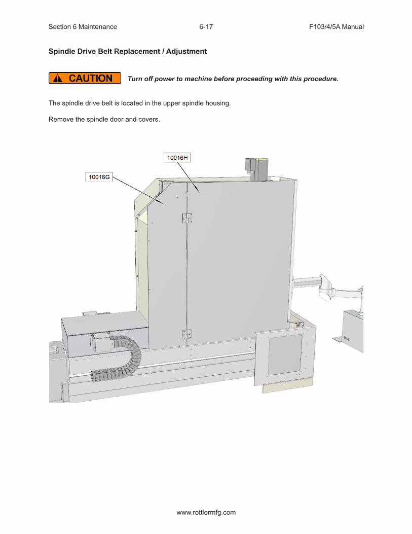
Section 6 Maintenance F103/4/5A Manual
www.rottlermfg.com
6-17
Spindle Drive Belt Replacement / Adjustment
Turn off power to machine before proceeding with this procedure.
The spindle drive belt is located in the upper spindle housing.
Remove the spindle door and covers.

Section 6 Maintenance F103/4/5A Manual
www.rottlermfg.com
6-18
Lower spindle down onto a piece of wood to prevent the motor from falling.

Section 6 Maintenance F103/4/5A Manual
www.rottlermfg.com
6-19
Remove the counter weight cable end from the upper housing.
Remove Z-Axis motor, mount plate, and bracket.

Section 6 Maintenance F103/4/5A Manual
www.rottlermfg.com
6-20
Remove drawbar bracket assembly and front housing cover plate.
Remove rear housing cover plate.

Section 6 Maintenance F103/4/5A Manual
www.rottlermfg.com
6-21
Loosen motor mount bolts and belt tension adjusting bolt.
Remove and replace bolt.
When the new belt is in place use the adjusting bolt to set the belt tension. Proper tension is when there is 5/16” of deflection when 2-4 lbs. of force is applied between the 2 pulleys.

Section 6 Maintenance F103/4/5A Manual
www.rottlermfg.com
6-22
Outer Spindle Bushing Adjustment
The Lower Spindle Bushing will be adjusted in this demonstration.
1. Start the Rottler Software.2. Move the spindle to its full downward position.
3. Loosen the four 10-24 bolts in the Retainer and pull out the O-Ring and Felt. 4. Loosen set screw at top of Bushing Carrier.5. Take a punch and tighten Lower Bushing Nut with palm of hand. Raise spindle 5” and repeat. This
helps set the bushing in the bushing carrier.
(WARNING: Do not tighten Spindle bushing retaining nut when spindle is at the top 3” of travel. Excessive wear and premature failure could result.)
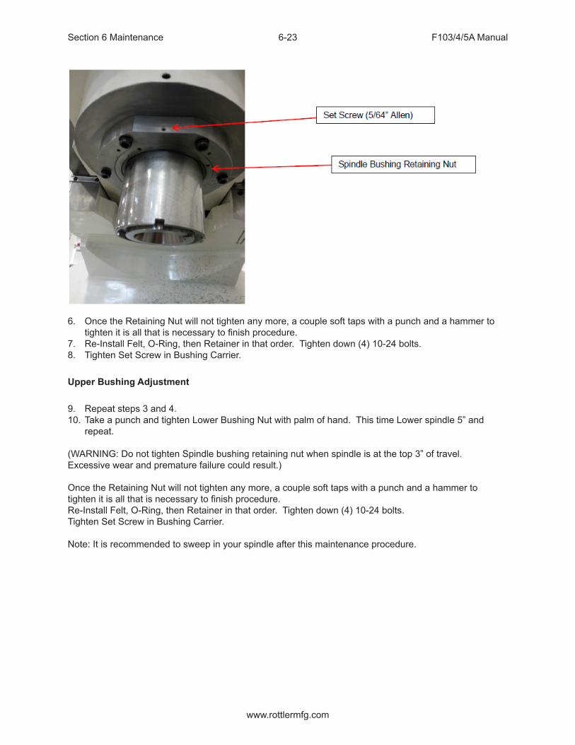
Section 6 Maintenance F103/4/5A Manual
www.rottlermfg.com
6-23
6. Once the Retaining Nut will not tighten any more, a couple soft taps with a punch and a hammer to tighten it is all that is necessary to finish procedure.
7. Re-Install Felt, O-Ring, then Retainer in that order. Tighten down (4) 10-24 bolts.8. Tighten Set Screw in Bushing Carrier.
Upper Bushing Adjustment
9. Repeat steps 3 and 4.10. Take a punch and tighten Lower Bushing Nut with palm of hand. This time Lower spindle 5” and
repeat.
(WARNING: Do not tighten Spindle bushing retaining nut when spindle is at the top 3” of travel. Excessive wear and premature failure could result.)
Once the Retaining Nut will not tighten any more, a couple soft taps with a punch and a hammer to tighten it is all that is necessary to finish procedure.Re-Install Felt, O-Ring, then Retainer in that order. Tighten down (4) 10-24 bolts.Tighten Set Screw in Bushing Carrier.
Note: It is recommended to sweep in your spindle after this maintenance procedure.

Section 6 Maintenance F103/4/5A Manual
www.rottlermfg.com
6-24
Inner Spindle Adjustment
FOLLOW ALL SAFETY PROCEDURES LISTED IN THE SAFETY SECTION OF THIS MANUAL BEFORE STARTING THIS PROCEDURE
Open the spindle base door.
Install surfacing cutterhead or boring cutterhead with long tool holder onto spindle.

Section 6 Maintenance F103/4/5A Manual
www.rottlermfg.com
6-25
Locate opening in the belt housing.

Section 6 Maintenance F103/4/5A Manual
www.rottlermfg.com
6-26
Insert a rod into one of the drilled holes of the adjustment nut. This is used to lock the adjustment nut in place so that the nut won’t turn while inner spindle is turned.
Grab hold of the cutterhead and turn it one turn clockwise to loosen the inner spindle adjustment.
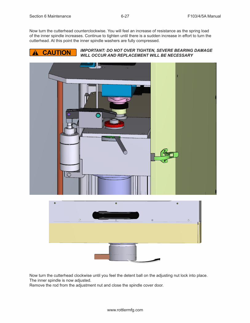
Section 6 Maintenance F103/4/5A Manual
www.rottlermfg.com
6-27
Now turn the cutterhead counterclockwise. You will feel an increase of resistance as the spring load of the inner spindle increases. Continue to tighten until there is a sudden increase in effort to turn the cutterhead. At this point the inner spindle washers are fully compressed.
IMPORTANT: DO NOT OVER TIGHTEN, SEVERE BEARING DAMAGE WILL OCCUR AND REPLACEMENT WILL BE NECESSARY
Now turn the cutterhead clockwise until you feel the detent ball on the adjusting nut lock into place.The inner spindle is now adjusted.Remove the rod from the adjustment nut and close the spindle cover door.

Section 6 Maintenance F103/4/5A Manual
www.rottlermfg.com
6-28
F103/4/5A Upper Housing Disassembly
Travel the machine to the right Home position.Remove the spindle base door and right side cover.Place a board across the spindle base directly below the spindle motor (6790K or 6790U). Lower the spindle until the motor just touches the board.
Disconnect all power and air to the machine before continuing, severe bodily injury may occur.
Remove the four (4) bolts securing the motor the belt housing. Remove the two (2) bolts that secure the cable carrier (6314K) to the upper housing. Remove the oil and air lines from the upper housing.
Note: It is not necessary to disconnect the spindle motor wiring.
Rotate the vertical ballscrew by hand until it is about eight (8) inches from the top plate.Place a board, of proper length, between the bottom of the upper housing and the top of the spindle base to prevent it from falling.
Remove the two bolts that secure the centering gear housing (6168H) to the belt housing. Work the centering housing up off the centering shaft. Tie it up to the top plate.
IMPORTANT!!: Do not attempt to move the vertical under power when the centering housing is not bolted to the belt housing or the upper plate. Severe damage will result to the centering shaft!!
Remove the Clevis Pin (7210B) from the draw bar actuator bracket (6174B). Lift the actuator arm (6173B), move the arm and cylinder off to the side. Remove the air cylinder (6204A), clevis pin (6189A) and mount bracket (6188C) from the side of the belt housing. Remove the two (2) bolts that attach the draw bar actuator bracket (6174B) to the to belt housing cover.
Remove the counter weight cable (6453 F or 6453G) from the upper housing by loosening the lock nut and unscrewing the cable nut.
Note: When reassembling, be sure not to thread the cable nut in too far as it may come in contact with the driven pulley.
Remove the eight (8) screws holding the inner spindle end cap (6180A). Unscrew these bolts slowly around the diameter of the end cap as they are under spring pressure from the draw bar. Remove the cap by pulling straight up.
Note: When reinstalling, the end cap must be aligned concentric to the draw bar.
Remove the three (3) screws that secure the vertical ballscrew nut to the belt housing. Holding the nut with one hand, turn the ballscrew with the other to move it up and out of the way so the belt housing lid can be removed.
Remove the bolts securing the belt housing covers. The covers are pinned to the belt housing. Use a soft face mallet to carefully remove the covers.From this position you can remove and/or replace pulleys and belts.

Section 6 Maintenance F103/4/5A Manual
www.rottlermfg.com
6-29

Section 6 Maintenance F103/4/5A Manual
www.rottlermfg.com
6-30
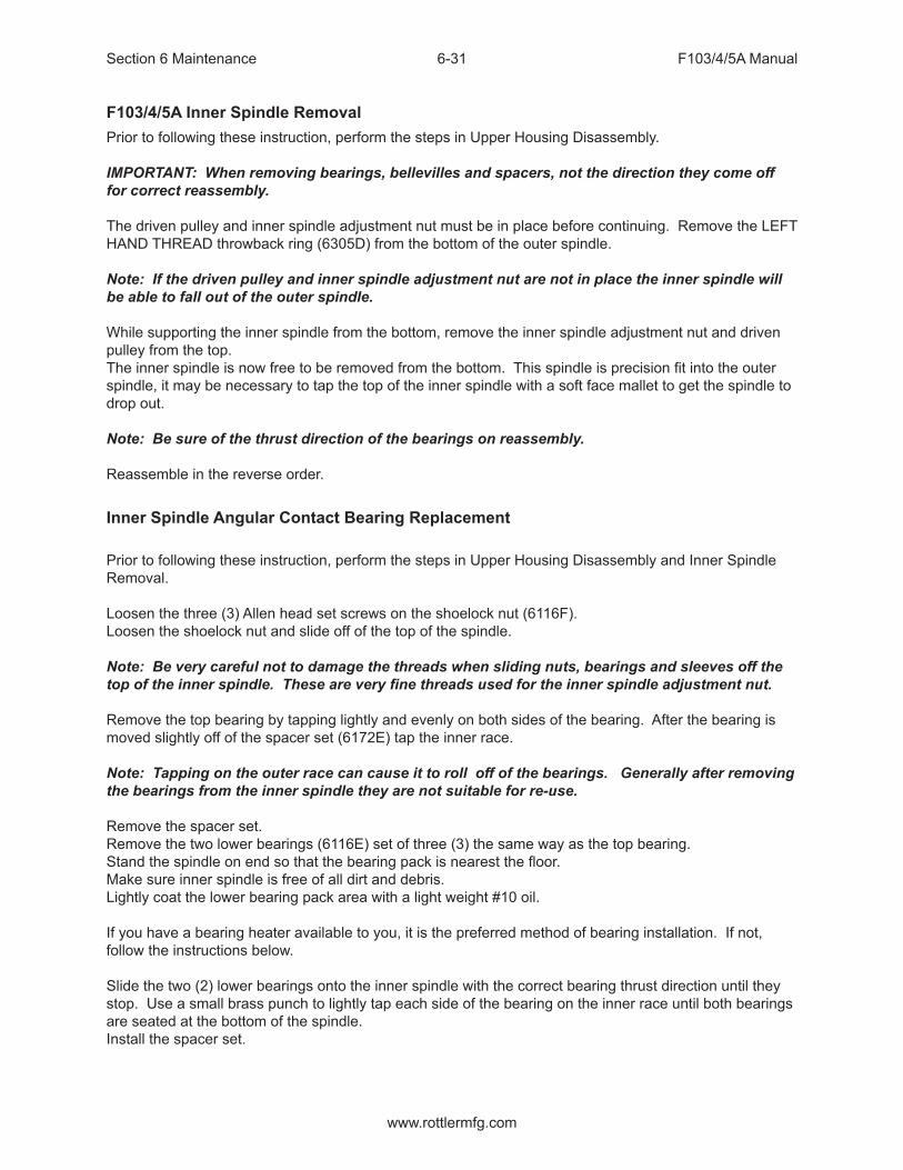
Section 6 Maintenance F103/4/5A Manual
www.rottlermfg.com
6-31
F103/4/5A Inner Spindle RemovalPrior to following these instruction, perform the steps in Upper Housing Disassembly.
IMPORTANT: When removing bearings, bellevilles and spacers, not the direction they come off for correct reassembly.
The driven pulley and inner spindle adjustment nut must be in place before continuing. Remove the LEFT HAND THREAD throwback ring (6305D) from the bottom of the outer spindle.
Note: If the driven pulley and inner spindle adjustment nut are not in place the inner spindle will be able to fall out of the outer spindle.
While supporting the inner spindle from the bottom, remove the inner spindle adjustment nut and driven pulley from the top.The inner spindle is now free to be removed from the bottom. This spindle is precision fit into the outer spindle, it may be necessary to tap the top of the inner spindle with a soft face mallet to get the spindle to drop out.
Note: Be sure of the thrust direction of the bearings on reassembly.
Reassemble in the reverse order.
Inner Spindle Angular Contact Bearing Replacement
Prior to following these instruction, perform the steps in Upper Housing Disassembly and Inner Spindle Removal.
Loosen the three (3) Allen head set screws on the shoelock nut (6116F).Loosen the shoelock nut and slide off of the top of the spindle.
Note: Be very careful not to damage the threads when sliding nuts, bearings and sleeves off the top of the inner spindle. These are very fine threads used for the inner spindle adjustment nut.
Remove the top bearing by tapping lightly and evenly on both sides of the bearing. After the bearing is moved slightly off of the spacer set (6172E) tap the inner race.
Note: Tapping on the outer race can cause it to roll off of the bearings. Generally after removing the bearings from the inner spindle they are not suitable for re-use.
Remove the spacer set.Remove the two lower bearings (6116E) set of three (3) the same way as the top bearing.Stand the spindle on end so that the bearing pack is nearest the floor.Make sure inner spindle is free of all dirt and debris.Lightly coat the lower bearing pack area with a light weight #10 oil.
If you have a bearing heater available to you, it is the preferred method of bearing installation. If not, follow the instructions below.
Slide the two (2) lower bearings onto the inner spindle with the correct bearing thrust direction until they stop. Use a small brass punch to lightly tap each side of the bearing on the inner race until both bearings are seated at the bottom of the spindle.Install the spacer set.

Section 6 Maintenance F103/4/5A Manual
www.rottlermfg.com
6-32
Install the top bearing using the same procedure as the lower bearings until it is seated against the spacer set.
Install the shoelock nut and tighten with a spanner wrench until the inner races of the bearings and spacer set are fully seated together.Tighten the three (3) set screws on the shoelock nut.Place the inner spindle in a vise near the bearing pack and lock the vise.Indicate the bearing set to within .0005” all the way around. Adjust the spacer set by tapping the high side lightly with a brass drift.

Section 6 Maintenance F103/4/5A Manual
www.rottlermfg.com
6-33
Spindle Sweep
The outer spindle must be swept into the main bed of the machine to achieve accurate bores.
Remove all fixturing from the machine bed, clean and stone if needed.Install a boring cutterhead into the machine.Install the sweep are into the cutterhead.Bring the machine down until you have about .005” pressure on the indicator.
Disconnect all power and air to the machine before continuing, severe bodily injury may occur.
Turn the sweep arm to the 9 O’clock position. Zero the indicator here.Loosen the 6 socket head cap screws on the lower spindle hub. You do not want them all the way loose, just snug.Use the four (4) set screws in the spindle base to move the spindle until the indicator reads within .0005” with a full 360 degree sweep of the indicator.
Note: You do not want the right hand side of the spindle to be more positive than the left, it will interfere with the automatic tilt of the machine when in Mill mode.
Once the spindle is swept in tighten the six (6) socket head cap screws and double check that the sweep did not move.

Section 6 Maintenance F103/4/5A Manual
www.rottlermfg.com
6-34
Horizontal Gibs
The Horizontal gibs are located under the main column, on the back side of the front way. These gibs keep the column from “cocking” when the direction of travel is changed. This adjustment becomes more critical when line boring. If the gibs are too loose the column will turn slightly side ways when traveling. This will cause the alignment of the right angle drive to be off. The cutterhead will then cut heavier on one side of the bore.
To adjust:Loosen the Gib bolts (two on each side)Loosen the Lock Nut on the set screw.Tighten the set screw as much as possible using only the correct size Allen Wrench. This will pull the Front Way bearing up against the front way while pressing the Gib up against the back of the Front Way.Loosen the Set Screw.Tighten the set screw up until you can feel it contact the Gib.Lock the Lock nut. Run the machine back and forth to let the gibs adjust to adjust in.Tighten the Gib bolts. Torque to 5 ft. lbs. or 60 in. lbs.
If the machine will not travel full speed or the handwheel movement is erratic the gibs may be too tight. Re-adjust leaving the Set Screw a little bit looser than the previous adjustment.

Section 6 Maintenance F103/4/5A Manual
www.rottlermfg.com
6-35
Another way to check for correct adjustment is to attach a magnetic base dial indicator (.0001 resolution) to the column with the indicator tip contacting the machine way surface.
Now using the handwheel in .010” per click mode, move the column back and forth, about two turns on the handwheel in each direction at a rapid rate.Note the amount of movement on the dial indicator.The acceptable amount of movement on the dial indicator is between .0002”-.0005”. Adjust as necessary. This procedure must be performed at both, the right, and left, sides of the column.

Section 6 Maintenance F103/4/5A Manual
www.rottlermfg.com
6-36
Adjusting Y-Axis Gibs
The Y-Axis adjusting gibs are located at the top of the machine column that the spindle base is mounted on. There are gibs located on the top and side rails on the left side of the column. Two are located on the top rail and two are located on the side rail.
On the right side of the column there are gibs located on the top rail.

Section 6 Maintenance F103/4/5A Manual
www.rottlermfg.com
6-37
Adjustment Procedure
1. On the left side rail loosen the jam nuts.2. Tighten the set screws until they bottom out and can’t be turned further.3. Loosen each set screw 1/8 turn.4. Tighten jam nuts.5. On both top rails loosen jam nuts.6. Tighten the set screws until they bottom out and can’t be turned further.7. Loosen each set screw 3/4 turn.8. Tighten jam nuts.

Section 6 Maintenance F103/4/5A Manual
www.rottlermfg.com
6-38
Backlash Setting .NET SoftwareThe Screens depicted below are for setting Backlash compensation values only. DO NOT use any other information on these screens to change information on the machine.
Turn off “Overshoot Backlash Setup”
Note: Only the F70-90 and 100 machines use the overshoot feature.
Go to Setup Software>Addins>Overshoot Backlash Setup
The Following screen will appear.
1. Record the existing X and Y “Overshoot Amount”. Generally .250
2. Use the “On Screen Keyboard”, or plug in the full size keyboard, and change the amounts to 0.00, and click on OK. Close the “Setup” screen.

Section 6 Maintenance F103/4/5A Manual
www.rottlermfg.com
6-39
3. Go to Setup Electronics>Control

Section 6 Maintenance F103/4/5A Manual
www.rottlermfg.com
6-40
4. On the “Control Options” screen, double click the X to bring up the “X Options” screen.
Now minimize the screen.
5. Repeat step 5 for the Y and Z axis.6. Close the “Control Options “screen.

Section 6 Maintenance F103/4/5A Manual
www.rottlermfg.com
6-41
7. Select a program (block), then select any cylinder bore mode.
Notes:***The photos shown are demonstrating the X axis (horizontal) backlash adjustment. The Y and Z axis are adjusted following the same steps.***The direction of machine travel to put the initial load on the dial indicator, are as follows: X (horizontal), from the right toward the left.Y (in/out), from back toward the front. Z (vertical) from top toward the bottom.

Section 6 Maintenance F103/4/5A Manual
www.rottlermfg.com
6-42
A Dial Indicator with 1.0” to 1.5” of travel should be used for several reasons.
If the axis is overshooting or coming to position slowly you will be able to see it with a dial indicator. With Digital indicator you will only see the end position. The Magnascale indicator should be used to dial or tram in. The automatic moves of the machine can “Shock” the sensitive plunger of the Magnascale.
8. Attach the magnetic base and dial indicator to a stationary stand, parallel, or engine block fixed to the machine bed.
9. Bring the spindle of the machine in position to put a slight load on the Plunger, about .020”.

Section 6 Maintenance F103/4/5A Manual
www.rottlermfg.com
6-43
10. Set “Vertical, Horizontal, In/Out” zero.
11. Set all vertical stops to “zero”.

Section 6 Maintenance F103/4/5A Manual
www.rottlermfg.com
6-44
12. Move the machine spindle away from the Plunger a few inches, and press ”Move to” and then 0 and Enter from the pop up keypad for the axis that is being measured..
13. Repeat the movement to verify the machine will repeatedly position itself at zero.
14. Now, use the “Move To” button and then -.200 to move the spindle -.200” in the opposite direction.
15. Press “Move to” and then 0 and Enter from the pop up keypad for the axis that is being measured.
If the machine did not position itself to bring the digital readout to zero, a backlash compensation adjustment is needed.
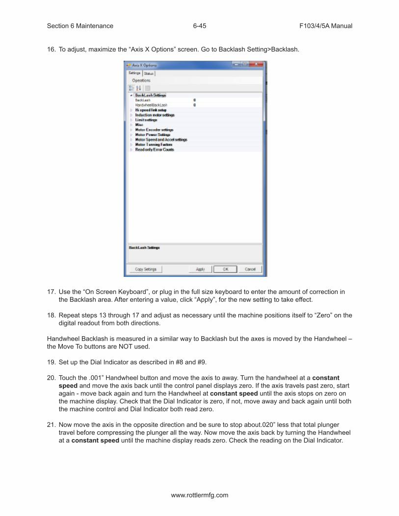
Section 6 Maintenance F103/4/5A Manual
www.rottlermfg.com
6-45
16. To adjust, maximize the “Axis X Options” screen. Go to Backlash Setting>Backlash.
17. Use the “On Screen Keyboard”, or plug in the full size keyboard to enter the amount of correction in the Backlash area. After entering a value, click “Apply”, for the new setting to take effect.
18. Repeat steps 13 through 17 and adjust as necessary until the machine positions itself to “Zero” on the digital readout from both directions.
Handwheel Backlash is measured in a similar way to Backlash but the axes is moved by the Handwheel – the Move To buttons are NOT used.
19. Set up the Dial Indicator as described in #8 and #9.
20. Touch the .001” Handwheel button and move the axis to away. Turn the handwheel at a constant speed and move the axis back until the control panel displays zero. If the axis travels past zero, start again - move back again and turn the Handwheel at constant speed until the axis stops on zero on the machine display. Check that the Dial Indicator is zero, if not, move away and back again until both the machine control and Dial Indicator both read zero.
21. Now move the axis in the opposite direction and be sure to stop about.020” less that total plunger travel before compressing the plunger all the way. Now move the axis back by turning the Handwheel at a constant speed until the machine display reads zero. Check the reading on the Dial Indicator.

Section 6 Maintenance F103/4/5A Manual
www.rottlermfg.com
6-46
22. Use the “On Screen Keyboard”, or plug in the full size keyboard to enter the amount of correction into Handwheel Backlash. Press Apply when you are done.
23. Follow steps 9 through 22 for the Y and Z axis.
24. When finished, re-enter the “Overshoot Backlash Amounts”, as recorded in step 2 and click OK and close the window.

Section 6 Maintenance F103/4/5A Manual
www.rottlermfg.com
6-47
Spindle Belt Adjustment
The spindle belt should not require adjustment very often, but if required use the following instructions.
Open the Spindle Base shroud.Loosen the four Motor mounting bolts on the spindle motor.Tighten or loosen the Tension adjustment bolt on the rear of the belt housing until 5 pounds of pressure causes the spindle belt to deflect 1/4”.
If the spindle motor is run at high speed and a high pitched wining is heard from the belt housing area the belt adjustment is probably too tight.
If you can visually see the belt jumping around while running the belt is too loose.

Section 6 Maintenance F103/4/5A Manual
www.rottlermfg.com
6-48
Top and Side Rail Adjustment1. Loosen jam nuts on side rail adjustment screws2. Tighten adjustment screws until they bottom out3. Back adjustment screws out 1/8 of a turn4. Tighten jam nuts
5. Loosen jam nuts on top rail adjustment screws6. Tighten adjustment screws until they bottom out7. Back adjustment screws out 3/4 of a turn8. Tighten jam nuts

Section 6 Maintenance F103/4/5A Manual
www.rottlermfg.com
6-49
Mill Tilt Adjustment Procedure1. Position the Y axis in the middle of its travel. Using a 5/32” hex key, loosen the locking set screw
through the access hole in the right side guide rail
2. Put the machine in “Mill Cycle” mode, with the wedge turned off. Attach an indicator as shown in the following photo, and set to zero position.

Section 6 Maintenance F103/4/5A Manual
www.rottlermfg.com
6-50
3. Using a 3/16” hex key, turn the adjustment screw in or out to increase, or decrease, the amount of mill tilt. Turn the screw CCW to increase, or turn CW to decrease the amount as shown in the photo at step #2. After each adjustment, turn the “Wedge On”, to check the amount. Set to .002”- .004” (.05mm - .1mm) of lift with the wedge turned on. Turn the wedge off to readjust, and then turn the wedge on to check the amount.
4. When finished, tighten the locking set screw as shown in the photo in step #1.5. Repeat the procedure for the rear wedge.
6. After adjusting the rear wedge, re-check the front, to make sure it did not change.
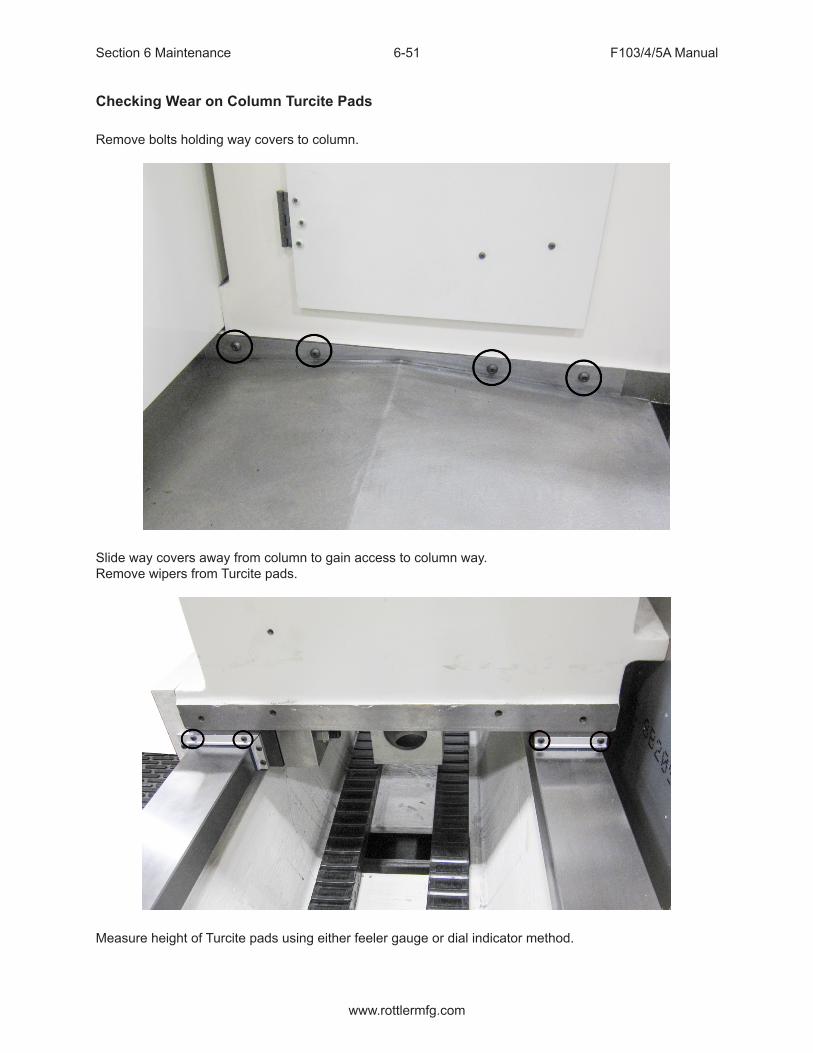
Section 6 Maintenance F103/4/5A Manual
www.rottlermfg.com
6-51
Checking Wear on Column Turcite Pads
Remove bolts holding way covers to column.
Slide way covers away from column to gain access to column way.Remove wipers from Turcite pads.
Measure height of Turcite pads using either feeler gauge or dial indicator method.

Section 6 Maintenance F103/4/5A Manual
www.rottlermfg.com
6-52
Pads will have to be replaced or shimmed if height difference between the 4 pads exceeds .005”.

Section 6 Maintenance F103/4/5A Manual
www.rottlermfg.com
6-53
Digital Micrometer setting instructions
Turn the thimble until the ‘0’ line on the thimble lines up with the vertical line nearest the spindle lock ring.
Determine which cutter head bore range the micrometer is going to be used on. ( example; 2.9 – 6.0 ) We want to initially set the micrometer to the minimum bore diameter of this cutterhead.
NOTE: MICROMETER CAN NOT BE PROGRAMMED IF THE LETTERS INC APPEAR IN THE DISPLAY. To get rid of INC, quickly press the in/mm/ABS button.

Section 6 Maintenance F103/4/5A Manual
www.rottlermfg.com
6-54
To set or edit micrometer
Press and hold the set/on button and the + or – button at the same time. “Set” will flash in the display. This places the micrometer in edit mode. (CAUTION: use a pencil tip or something similar to gently push the small round buttons - they are quite small and a bit delicate.)
Press and hold the + or – buttons to change the display number to the minimum bore diameter determined earlier (example; 2.9). Caution: Pushing the + or – buttons and holding in place will cause the numbers to scroll automatically. The numbers will count slowly at first and once 0.010” has been counted off the scrolling speed will pick dramatically.
After you have reached the desired number in the display, press the set/on button twice quickly to exit the edit mode. “Set” should no longer be flashing in the display. The micrometer is now ready for use.
CAUTION: AFTER MICROMETER SET-UP IS COMPLETE, DO NOT PUSH SET/ON BUTTON AGAIN. PUSHING THE SET/ON BUTTON DURING USE WILL RETURN THE DISPLAY TO THE ORIGINAL MINIMUM BORE DIAMETER. THE ONLY TIME YOU SHOULD USE THE SET/ON BUTTON AGAIN IS TO- A. To shut micrometer off at which time you push and hold the button or B. to turn micrometer display back on at which time you push button one time. The display will then show the last reading before micrometer was shut off.
CAUTION: DO NOT BACK THE THIMBLE ALL THE WAY OUT TO THE END OF IT’S TRAVEL. ONCE THE THIMBLE IS BACKED ALL THE WAY OUT, IT WILL NO LONGER ROTATE PROPERLY AND THE DIGITAL HEAD WILL NEED TO BE REPLACED.
Micrometer is calibrated in inch mode. If metric is desired, press and hold in/mm/ABS button until mode changes to metric (approximately 3-4 seconds). A quick press of the in/mm/ABS button will put micrometer in ABS mode: 0.000, with another quick press returning it to initial setting.
Set up the cutter head and bore a set up hole. Measure the bore accurately. Set the digital display to this bore dimension and then -
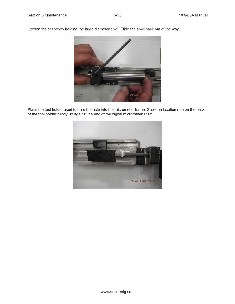
Section 6 Maintenance F103/4/5A Manual
www.rottlermfg.com
6-55
Loosen the set screw holding the large diameter anvil. Slide the anvil back out of the way.
Place the tool holder used to bore the hole into the micrometer frame. Slide the location nub on the back of the tool holder gently up against the end of the digital micrometer shaft.

Section 6 Maintenance F103/4/5A Manual
www.rottlermfg.com
6-56
Slide the large diameter anvil up until it touches the end of the cutting tip of the tool holder. Tighten the set screw.
Back the digital micrometer shaft off, then bring it up to touch the tool holder and recheck that the numbers in the display are the same as the numbers previously shown.

Section 6 Maintenance F103/4/5A Manual
www.rottlermfg.com
6-57
The micrometer is now set up for use with this cutter head.
Note: this procedure must be repeated to set the micrometer to a different cutter head. The micrometer can only be set to one cutter head at a time.
To shut off micrometer press and hold set/on button until screen goes blank or let micrometer set until display disappears.
With initial setting of micrometer it is recommended that you use the procedure detailed below in the event you think you have size problems.
Procedure:The short vertical lines that cross the horizontal scale on the micrometer sleeve are reference marks. Set the zero on the micrometer thimble even with the first vertical line and note the size shown in the digital display. Record this size for future reference. Now follow the same procedure for each line and record the sizes. At any time you feel your micrometer is reading incorrectly, you can quickly refer to the recorded size of the line closest to the range you are using and check that the micrometer is still accurate.

Section 6 Maintenance F103/4/5A Manual
www.rottlermfg.com
6-58
Probe “On-Center” AdjustmentThis covers setup and calibration of the probe, so it will accurately position your machine.
• Verify that the four adjusting screws and two locking screws are installed in the probe tool holder. • Assemble probe on either CAT 40 Shank or Rottler Taper• With the machine breaker that supplies power to the probe receiver turned off;• Install batteries in the probe WITH stylus deflected.
Probe LED check will run.• Release stylus after battery check this will put you in edit mode. • First will be Switch off method, you want this at purple, purple, yellow (Radio On). If it is not, deflect
and release stylus quickly to change the mode. • Hold the stylus deflected until the colors change to move to the next setting. • You should be at Switch Off method; it should be red, red, yellow (134 seconds). If it is not, deflect
and release stylus quickly to change the mode. • Hold the stylus deflected until the colors change to move to the next setting. • You should be at Enhanced trigger filter; it should be green, green, green (on). If it is not, deflect and
release stylus quickly to change the mode. • Hold the stylus deflected until the colors change again to move to the next setting. • You should be at Acquisition mode, light blue, light blue, light blue. • Turn on machine and quickly deflect and release the stylus. This must be done within 10 seconds of
turning on the power breaker to the probe. If you are watching the RMI-Q (located ON the machine) you will see the right light turn red, yellow, red, yellow, red, yellow is shows the partnership has been acquired.
• Go into the software and do a probe auto center and hit start probe to verify that it works correctly.

Section 6 Maintenance F103/4/5A Manual
www.rottlermfg.com
6-59

Section 6 Maintenance F103/4/5A Manual
www.rottlermfg.com
6-60
If the Probe does not turn off after 137 seconds you will need to make sure that the RMI-Q switches are shown in the following positions:
During normal use, the difference between the touch position and the reported position does not change, but it is important that the probe is calibrated in the following circumstances:• when a probe system is to be used for the first time;• when a new stylus is fitted to the probe;• when it is suspected that the stylus has become distorted or that the probe has crashed; • at regular intervals to compensate for mechanical changes of your machine tool;• if repeatability of relocation of the probe shank is poor. In this case, the probe may need to be
recalibrated each time it is selected.
It is good practice to set the tip of the stylus on center, because this reduces the effect of any variation in spindle and tool orientation. A small amount of run-out is acceptable, and can be compensated for as part of the normal calibration process.• calibrating either in a bored hole of know size, a ring gauge, or on a datum sphere.
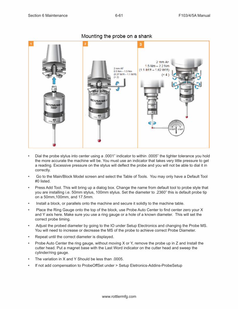
Section 6 Maintenance F103/4/5A Manual
www.rottlermfg.com
6-61
• Dial the probe stylus into center using a .0001” indicator to within .0005” the tighter tolerance you hold the more accurate the machine will be. You must use an indicator that takes very little pressure to get a reading. Excessive pressure on the stylus will deflect the probe and you will not be able to dial it in correctly.
• Go to the Main/Block Model screen and select the Table of Tools. You may only have a Default Tool #0 listed.
• Press Add Tool. This will bring up a dialog box. Change the name from default tool to probe style that you are installing i.e. 50mm stylus, 100mm stylus. Set the diameter to .2360” this is default probe tip on a 50mm,100mm, and 17.5mm.
• Install a block, or parallels onto the machine and secure it solidly to the machine table. • Place the Ring Gauge onto the top of the block, use Probe Auto Center to find center zero your X
and Y axis here. Make sure you use a ring gauge or a hole of a known diameter. This will set the correct probe timing.
• Adjust the probed diameter by going to the IO under Setup Electronics and changing the Probe MS. You will need to increase or decrease the MS of the probe to achieve correct Probe Diameter.
• Repeat until the correct diameter is displayed.• Probe Auto Center the ring gauge, without moving X or Y, remove the probe up in Z and Install the
cutter head. Put a magnet base with the Last Word indicator on the cutter head and sweep the cylinder/ring gauge.
• The variation in X and Y Should be less than .0005. • If not add compensation to ProbeOffSet under > Setup Eletronics-Addins-ProbeSetup

Section 6 Maintenance F103/4/5A Manual
www.rottlermfg.com
6-62
Replacing the Motherboard Battery
If computer fails to boot up and you get a CMOS error message on the screen, then the battery on the computer motherboard has failed and needs to be replaced.
The following is the procedure for replacing the motherboard battery.
Turn off the power on the electrical enclosure and remove the enclosure cover.
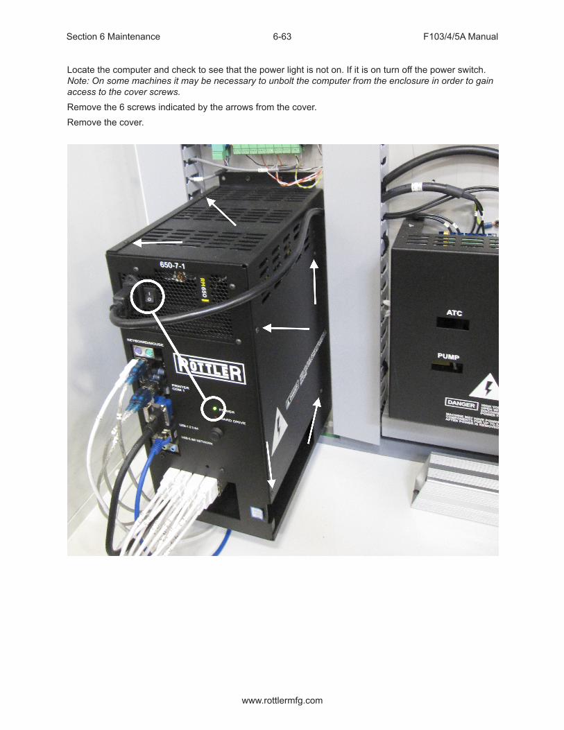
Section 6 Maintenance F103/4/5A Manual
www.rottlermfg.com
6-63
Locate the computer and check to see that the power light is not on. If it is on turn off the power switch. Note: On some machines it may be necessary to unbolt the computer from the enclosure in order to gain access to the cover screws.Remove the 6 screws indicated by the arrows from the cover.Remove the cover.

Section 6 Maintenance F103/4/5A Manual
www.rottlermfg.com
6-64
Locate the battery on the motherboard.
Push the battery retention clip away from the battery. When the clip is released the battery will pop up.
Remove the battery and place new battery in the battery holder.
Using your finger tip push down on the battery until the retention clip is in its lock position.
Replace computer cover and make sure that power switch on the computer is on.Replace the enclosure cover and switch power back on.
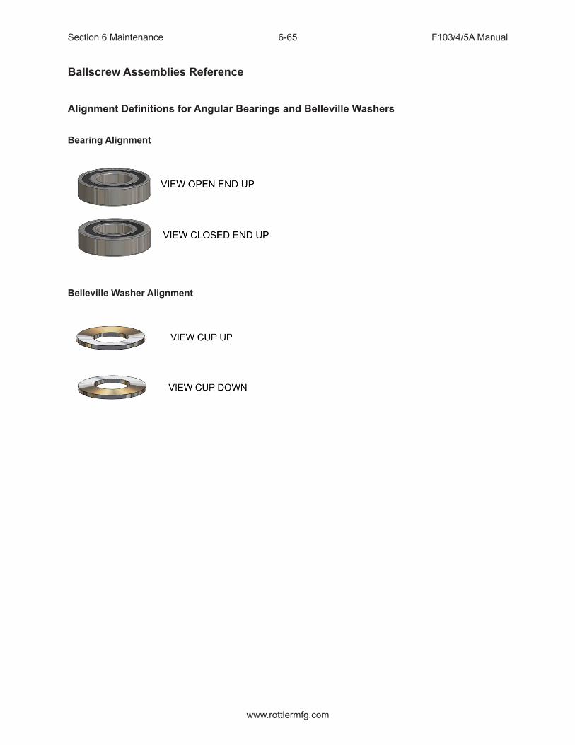
Section 6 Maintenance F103/4/5A Manual
www.rottlermfg.com
6-65
Ballscrew Assemblies Reference
Alignment Definitions for Angular Bearings and Belleville Washers
Bearing Alignment
Belleville Washer Alignment

Section 6 Maintenance F103/4/5A Manual
www.rottlermfg.com
6-66
Z-Axis Lower Bearing and Belleville Washer Stacking Order

Section 6 Maintenance F103/4/5A Manual
www.rottlermfg.com
6-67
Z-Axis Lower Bearing and Belleville Washer Section View
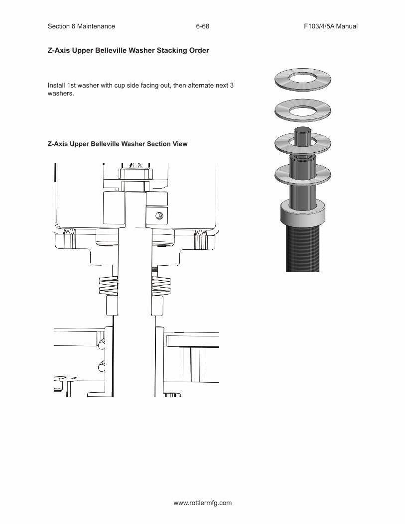
Section 6 Maintenance F103/4/5A Manual
www.rottlermfg.com
6-68
Z-Axis Upper Belleville Washer Stacking Order
Install 1st washer with cup side facing out, then alternate next 3 washers.
Z-Axis Upper Belleville Washer Section View

Section 6 Maintenance F103/4/5A Manual
www.rottlermfg.com
6-69
X-Axis Drive Side Bearing Stacking OrderInstall 1st and 2nd bearings with open side facing in. Install 3rd and 4th bearings with open end facing out.
X-Axis Drive Side Bearing Section View
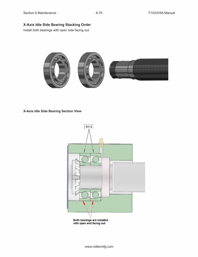
Section 6 Maintenance F103/4/5A Manual
www.rottlermfg.com
6-70
X-Axis Idle Side Bearing Stacking OrderInstall both bearings with open side facing out.
X-Axis Idle Side Bearing Section View

Section 6 Maintenance F103/4/5A Manual
www.rottlermfg.com
6-71
Y-Axis Bearing Stacking OrderInstall 1st bearing with open end toward ballscrew shoulder. Install 2nd and 3rd bearings with closed end toward 1st bearing.
Y-Axis Bearing Section View
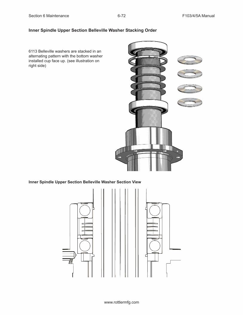
Section 6 Maintenance F103/4/5A Manual
www.rottlermfg.com
6-72
Inner Spindle Upper Section Belleville Washer Stacking Order
6113 Belleville washers are stacked in an alternating pattern with the bottom washer installed cup face up. (see illustration on right side)
Inner Spindle Upper Section Belleville Washer Section View
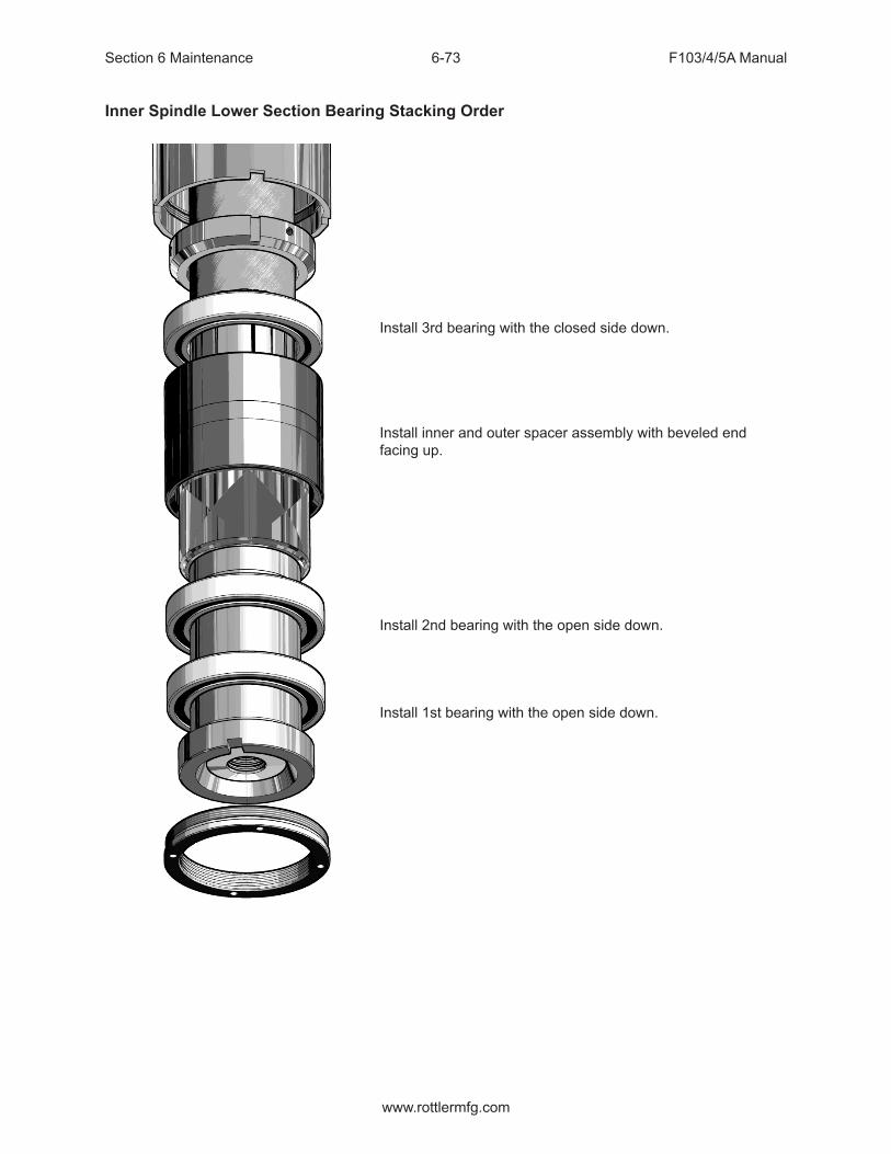
Section 6 Maintenance F103/4/5A Manual
www.rottlermfg.com
6-73
Inner Spindle Lower Section Bearing Stacking Order
Install 3rd bearing with the closed side down.
Install inner and outer spacer assembly with beveled end facing up.
Install 2nd bearing with the open side down.
Install 1st bearing with the open side down.
A

Section 6 Maintenance F103/4/5A Manual
www.rottlermfg.com
6-74
Inner Spindle Lower Section Bearing Section View

Section 7 Troubleshooting F103/4/5A Manual
www.rottlermfg.com
I
TROUBLESHOOTING
Problem:Icon on screen does not move to area touched.
Solution:Follow the procedure below to recalibrate the touchscreen.
1. Get to the Alignment screen.
1. If an Elo icon is available in the tool tray at the lower right side of the desktop, click it, then click Align.
2. Otherwise, go to the Windows Control Panel, double-click Elo Touchscreen and click the Align button on the General tab.
1. If Windows XP and no Elo icon, click the “Switch to Classic View” button on the left
2. If Windows 7 and no Elo icon, look for “View by: Category” text toward the upper right; click it and select “Small icons”
2. Touch and release the upper left target; the target should jump to the lower right.
3. Touch and release the lower right target; the target should jump to the upper right.
4. Touch and release the upper right target; a check screen should appear.
5. Touch and release the green check mark; the check screen should disappear.
6. The cursor should now jump to the point of touch.
7. If the Elo Control Panel is open, close it and the Windows Control Panel.

Section 7 Troubleshooting F103/4/5A Manual
www.rottlermfg.com
7-1
Chatter Problems
If you are having chatter problems when you are boring you should do the following steps;1. Replace the insert, Make sure you use Rottler RT321 inserts it is strongly advised. 2. Clean the inside of the bore head. Oil will build up if you leave the boring head in the machine overnight or have the oiler turned up. You will need to clean any oil off of the counterweight (11), also clean the cavity that the counterweight sits in. This is done by removing the bolts (15). This procedure is the same with other Rottler cutter heads. See the optional equipment parts catalogue for breakdowns of the cutter heads.3. Check Inner Spindle Adjustment, see maintenance section.4. Check outer spindle adjustment/bushings, see maintenance section.5. Newer models we recommend the use of the SSV system, if you are having chatter issues.6. Counter balance cable pressure; verify that it is in service and unbroken. See maintenance section.

Section 8 Machine Parts F103/4/5A Manual
www.rottlermfg.com
I
MACHINE PARTSContents
Machine Parts ..............................................................................................................8-1
Front Sheet Metal ................................................................................................................. 8-1
Rear Left Sheet Metal ........................................................................................................... 8-2
Right Rear Sheet Metal ........................................................................................................ 8-3
Air Control Door ................................................................................................................... 8-4
Air Control Solenoid Pack ................................................................................................... 8-5
Oiler Door .............................................................................................................................. 8-6
Electrical Wiring Diagram .................................................................................................... 8-7
Electrical Enclosure Assembly F103/4/5A Series .............................................................. 8-8
Enclosure Outside Parts ..................................................................................................................8-8
Enclosure Inside Parts ......................................................................................................... 8-9
Enclosure Panel .................................................................................................................. 8-10
DIN Rail Components ..........................................................................................................8-11
650-1-27X Computer Enclosure Assembly....................................................................... 8-12
Computer Components ...................................................................................................... 8-13
Spindle Base, Right Side ................................................................................................... 8-14
Spindle Base, Left Side ...................................................................................................... 8-15
Counterbalance Cylinder Pop Off Valve Assembly Parts ............................................... 8-16
Motor Housing Parts .......................................................................................................... 8-17
Z-Axis Motor Parts .............................................................................................................. 8-18
Counter Balance Pulley Parts ........................................................................................... 8-19
Spindle Motor Housing Parts Outside .............................................................................. 8-20
HSK Upper Spindle Housing Parts ................................................................................... 8-21
Spindle Motor Housing Parts Inside ................................................................................. 8-22
Upper Spindle & Ballscrew Parts ...................................................................................... 8-23
Lower Spindle & Ballscrew Parts ...................................................................................... 8-25

Section 8 Machine Parts F103/4/5A Manual
www.rottlermfg.com
II
Inner Spindle Lower Section Parts ................................................................................... 8-27
HSK Drawbar Upper Section Parts ................................................................................... 8-28
Y-Axis Drive Parts ............................................................................................................... 8-29
Column and Spindle Base Retainers ................................................................................ 8-30
Column Base Parts ............................................................................................................. 8-31
Pendant Swing Arm ............................................................................................................ 8-32
Pendent Swing Arm Assembly Parts List .....................................................................................8-33
Pendant Components ........................................................................................................ 8-34
Main Base Parts .................................................................................................................. 8-35
X-Axis Assembly: Drive End Parts.................................................................................... 8-36
X-Axis Assembly: Idle End ................................................................................................ 8-37
Chip Shield Assembly ........................................................................................................ 8-38
Front Cover and Lights ...................................................................................................... 8-39
Oil Line Diagram ................................................................................................................. 8-40
Air Line Diagram ................................................................................................................. 8-41

Section 8 Machine Parts F103/4/5A Manual
www.rottlermfg.com
8-1
Machine Parts
Front Sheet Metal

Section 8 Machine Parts F103/4/5A Manual
www.rottlermfg.com
8-2
Rear Left Sheet Metal

Section 8 Machine Parts F103/4/5A Manual
www.rottlermfg.com
8-3
Right Rear Sheet Metal

Section 8 Machine Parts F103/4/5A Manual
www.rottlermfg.com
8-4
Air Control Door

Section 8 Machine Parts F103/4/5A Manual
www.rottlermfg.com
8-5
Air Control Solenoid Pack

Section 8 Machine Parts F103/4/5A Manual
www.rottlermfg.com
8-6
Oiler Door

Section 8 Machine Parts F103/4/5A Manual
www.rottlermfg.com
8-7
Electrical Wiring Diagram1 1
2 2
3 3
4 4
AA
BB
CC
DD
TO
LE
RA
NC
ES
UN
LE
SS
NO
TE
DD
EC
IMA
LS
1 P
LA
CE
`
2 P
LA
CE
`
3 P
LA
CE
`
AN
GL
ES
`
~
FIN
ISH
DR
WN
:
DA
TE
:
SC
AL
E:
DR
AW
ING
NO
.M
AT
ER
IAL
:H
EA
T T
RE
AT
:to
nyt
9/2
9/2
015
80
12
re
v7
801
2 r
ev7
8012 rev7
.05
.01
.00
1
.5 12
5
1
:1
C
TH
EC
UT
TIN
GE
DG
E
Mass:
N/A
Pain
t:N
on
e
SH
EE
T 1
O
F 1
SHEET 1 OF 1
7
CA
TE
GO
RY
LIF
TW
ED
GE
DR
AW
BA
R
11
12
22
RD
WH
BK
WH
BN
WH
GN
DG
ND
GN
D
1 3
AIR
PR
ES
SU
RE
SW
ITC
H N
/O
GR
4
RD
T3BN
PU
BR
AK
E
BL
BK
3
YL
TH
ER
MA
L S
WIT
CH
N.C
.
GN
T2
GN
D
SHIELD
T1
21
GR
RD
BN
BK T1
GN
D
T2
TH
ER
MA
L S
WIT
CH
N.C
.
SHIELD
2
GN
YL
T3
1
T3
1
BN
2YL
GN
TH
ER
MA
L S
WIT
CH
N.C
.
T2RD
BK T1
GR
GN
D
SHIELD
T3
1
BN
2YL
GN
TH
ER
MA
L S
WIT
CH
N.C
.
T2RD
BK T1
GR
GN
D
SHIELD
BN
WH
DO
TT
ED
WH
CL
EA
R
DO
TT
ED
BK
CL
EA
RC
19
C2
C8
C5
C11
C7
C4
C1
C10
C10
C7
C4
C1
C1
7
C1
7
CPU
C20
C42
C36
C3
6
C1
3
C1
4
C3
6
C8
C1
9
C14
C13
C15
C16
C16
C36
C2
0
C36
C34
C1
8
C5
C11
C2
C8
C15
C1
8
C3
4
C42
C43
C4
3
C4
4
C44
71
0/1
0/2
01
7T
ON
YM
OV
ED
PR
OB
E T
O 1
2V
DC
61
/19
/20
17
TO
NY
CH
AN
GE
D O
ILE
R T
O T
OP
OF
OU
TP
UT
BO
AR
D
51
2/2
0/1
6T
ON
YC
HA
NG
ED
MO
TO
R P
OW
ER
CA
BL
E G
RO
UN
D F
RO
M
OR
AN
GE
TO
GR
EE
N
RE
VT
OD
AY
'S
RE
QU
ES
TD
ES
CR
IPT
ION
Y-A
XIS
MO
TO
R 9
020H
BM
S90C
-3250A
B2
X-A
XIS
MO
TO
R 9
215F
BS
M100C
-5250A
B2
Z-A
XIS
MO
TO
R 9
215J
BS
M90N
-2250B
B2
SP
IND
LE
MO
TO
R 9
215G
BS
M132C
-5200A
B
RA
DIO
RE
CE
IVE
RP
AR
T#650-3
-59U
MP
40 P
RO
BE
650-3
-59Z
SO
NY
LT
20A
PA
RT
# 5
02-1
2-7
M
EM
ER
GE
NC
YS
TO
P6389D
TO
UC
H S
CR
EE
N M
ON
ITO
R
HE
AT
SIN
K M
OU
NT
ED
SP
IND
LE
FA
NP
AR
T# 7
192
DO
OR
MO
UN
TE
D F
AN
BR
AK
ING
RE
SIS
TO
RS
9038E
60A
MA
IN B
RE
AK
ER
S
WIT
CH
SP
IND
LE
AM
P9035N
GR
OU
ND
BU
SC
ON
TA
CT
OR
OU
TP
UT
BO
AR
D9034G
PO
WE
R B
OA
RD
903
4E
X
ZY
CH
AR
GIN
G R
ES
IST
OR
6486P
24 V
OLT
90W
PO
WE
R S
UP
PLY
12 V
OL
T9
0W
PO
WE
R S
UP
PL
Y
HA
ND
WH
EE
L
BIT
6B
IT 4
BIT
2B
IT 0
BIT
7B
IT 5
BIT
3B
IT 1
VID
EO
C3
3
US
B 4
US
B 1
US
B 2
US
B 3
C3
C9
C3
2C
31
C3
0C
12
C6C
30
C3
C9
C6
C33
US
B 2
US
B 3
US
B 4
C32C
31
VID
EO
US
B 1
+-
UV
WG
ND
+-
UV
WG
ND
+-
UV
W
U V W
BR
AK
E-
+
+V
GN
D
SWAA-
BB-
II-UU-
VV-
WW-
KT
Y0V
TH
MS
W
+-
++
++
++
++
++
++
++
++
++
--
--
--
--
--
--
--
--
--
01
23
45
678
91
011
12
13
14
15 PROBE
START
OILER
LIFT
WEDGE
LIGHT
FAN
CUTTERRELEASE
Z-AXISBRAKE
E-STOP
CO
NT
.C
OIL
L1
L2
CH
AR
GE
RE
SIS
TO
RF
RO
M C
ON
TA
CT
OR
++
+
++
++
++
++
--
-
--
--
--
--
+ -
1 2
3 4
5 6
+V +V+V-V-V-V
N NLLINPUT INPUT
7A
7A
7A
7A
3A
3A
3A
3A
3A
3A
3A
3A
50
A
50A
50A
50A
50A
50A
+-
AA
-B
B-
++
++
++
++
++
++
++
++
ININ
ININ
ININ
ININ
ININ
ININ
ININ
ININ
--
--
--
--
--
--
--
--
++
--
L1
L2
L3
KT
Y
0V
TH
L
SW
KT
YK
TY
0V
0V
TH
LT
HL
SW
SW
+V
+V
+VGND
GND
GND
SW
SW
SW
A
A-
B
B-
I
I-
U
U-
V
V-
W
W-
A
A
A-
A-
B
B
B-
B-
I
I
I-
I-
U
U-
V
V-
W
W
W-
W-
U
U-
V
V-
12
3
+V
0V
L1
L2
L3
T3
T2
T1
910
11
12
13
BK
WH
BK
26
WH
27
34
2435
25
TO
CP
U P
OW
ER
CP
U
GN
D
GN
D
GN
D
L1
L2
L3L1
L1
L1
L2
L2L2
BK
WH
BK
WH
23
22
22
23
L1
L2
L3
L1
L2
L3
87
22
23
RD
BU
BN
/WH
BN
PK
/BU
PK
RD
BU
BN/WH
BNPK/BUPK
RD
RDBU
BU
BN/WH
BN/WH
BN
BNPK/BU
PK/BU
PK
PK
GN
YL
YL
GN
GN
YL
GN
YL
T1
T2
T3
TH
ER
MA
L
THERMAL
THERMAL
THERMAL
T1
T2
T3
T1
T1
T2
T2
T3
T36
53
4
12
TQ/BKTQ
GN/BKGN
WH
BK
BK
BK
BK
BK
WH
WH
RD
GN
GN
D
20
21
30
31
RD
BK
WH
BK
25
24
27
26
BK
WH
WH SH
LD
WH
BK
BK
GN
BK
WH
BK
RD
16
15
14
13
12
11
19
18
BK/BN
WH/WH
BK
WH
35
34
WH
BN
RD
WH
BK
WH
BN
WH
BK/BN
WH/WH
BU
PR
31
30
8 7
14
15
16
20
21
10
918
19
BK
WH
12
34
56
MO
TO
R B
RA
KE
F1
03
, F
10
4,
F1
05
WIR
ING
DIA
GR
AM
(OP
TIO
NA
L)
(OP
TIO
NA
L)
WHWH
WH
BK
BKBK
BR
BU
C1
9,
C2
0,
C3
4,
C4
4C
20
, C
42
, C
44
C1
9,
C2
0,
C4
2,
C4
4C
19
, C
20
, C
36
, C
42
, C
44
C1
4,
C1
5
C13, C14, C15, C19, C20, C36, C42, C44 C13, C14, C15, C19, C20, C36, C42, C44
C1
4,
C1
5,
C1
9,
C2
0,
C4
2,
C4
4C
14
, C
15
, C
19
, C
42
C42
C14
C36
C36
C3
6C
36C
15
C8
C1
1
C8, C11C5, C8, C11C2, C5, C8, C11
C7, C10C4, C7, C10
C1,
C4
, C
7, C
10
C1
, C
4,
C7
, C
10
C1
, C
4,
C7
C4
, C
7
C2
, C
5,
C8
C2
, C
5,
C8
, C
11
C1
C19, C43
C11
C18, C19, C34, C43
42
43
42
43
(Z) AXIS DRIVE AMP.9034
(Y) AXIS DRIVE AMP.9034
(X) AXIS DRIVE AMP.9035T
INP
UT
BO
AR
D9
03
4F
OIL
ER
6349H
SO
LE
NO
ID P
AC
K9005M
WO
RK
LIG
HT
S6457N
C12
INC
OM
ING
PO
WE
R
01
23
45
678
910
11
12
13
14
15
44
43
22
21
E2
31
32
11
12
E1
WH
BK
BK
RD
BK
WH
DOOR SAFETY LOCK

Section 8 Machine Parts F103/4/5A Manual
www.rottlermfg.com
8-8
Electrical Enclosure Assembly F103/4/5A Series
Enclosure Outside Parts

Section 8 Machine Parts F103/4/5A Manual
www.rottlermfg.com
8-9
Enclosure Inside Parts

Section 8 Machine Parts F103/4/5A Manual
www.rottlermfg.com
8-10
Enclosure Panel

Section 8 Machine Parts F103/4/5A Manual
www.rottlermfg.com
8-11
DIN Rail Components

Section 8 Machine Parts F103/4/5A Manual
www.rottlermfg.com
8-12
650-1-27X Computer Enclosure Assembly

Section 8 Machine Parts F103/4/5A Manual
www.rottlermfg.com
8-13
Computer Components

Section 8 Machine Parts F103/4/5A Manual
www.rottlermfg.com
8-14
Spindle Base, Right Side

Section 8 Machine Parts F103/4/5A Manual
www.rottlermfg.com
8-15
Spindle Base, Left Side

Section 8 Machine Parts F103/4/5A Manual
www.rottlermfg.com
8-16
Counterbalance Cylinder Pop Off Valve Assembly Parts

Section 8 Machine Parts F103/4/5A Manual
www.rottlermfg.com
8-17
Motor Housing Parts

Section 8 Machine Parts F103/4/5A Manual
www.rottlermfg.com
8-18
Z-Axis Motor Parts

Section 8 Machine Parts F103/4/5A Manual
www.rottlermfg.com
8-19
Counter Balance Pulley Parts

Section 8 Machine Parts F103/4/5A Manual
www.rottlermfg.com
8-20
Spindle Motor Housing Parts Outside

Section 8 Machine Parts F103/4/5A Manual
www.rottlermfg.com
8-21
HSK Upper Spindle Housing Parts
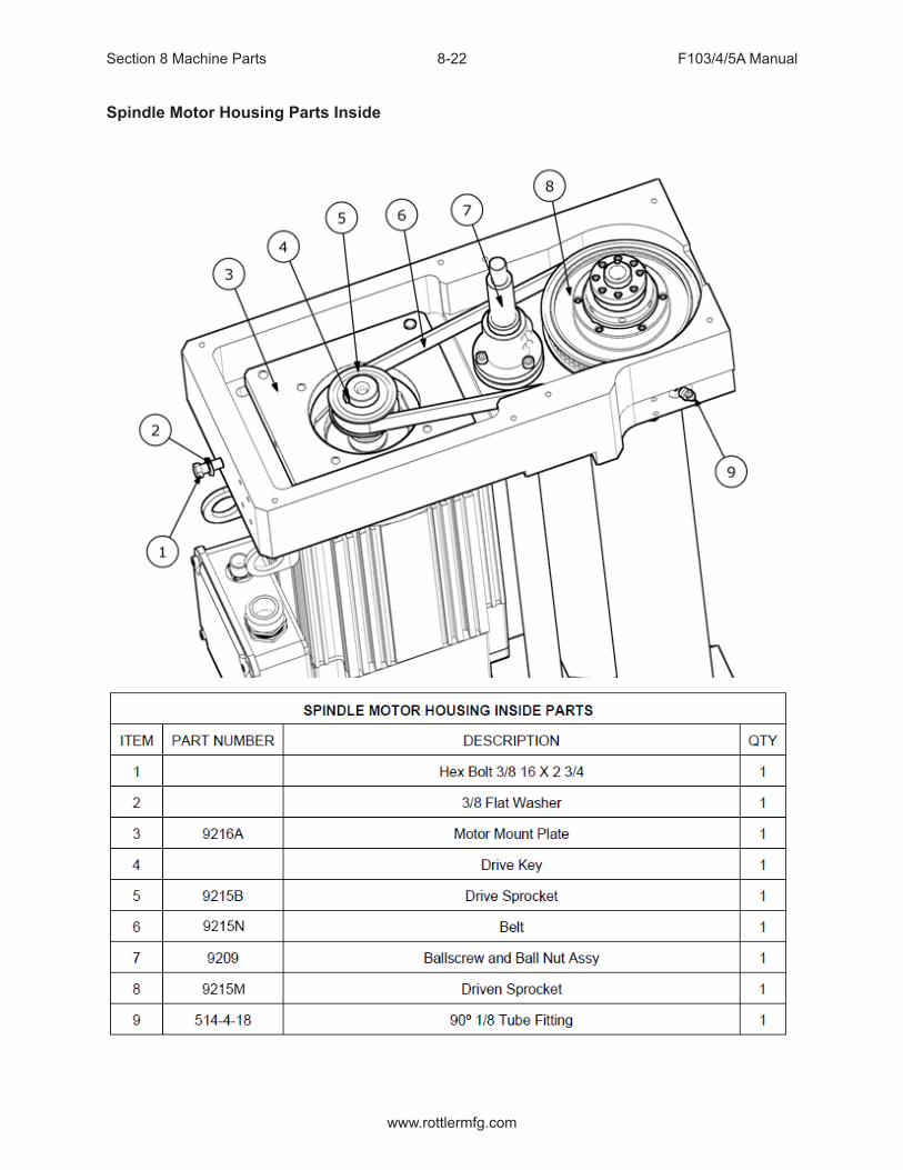
Section 8 Machine Parts F103/4/5A Manual
www.rottlermfg.com
8-22
Spindle Motor Housing Parts Inside

Section 8 Machine Parts F103/4/5A Manual
www.rottlermfg.com
8-23
Upper Spindle & Ballscrew Parts

Section 8 Machine Parts F103/4/5A Manual
www.rottlermfg.com
8-24
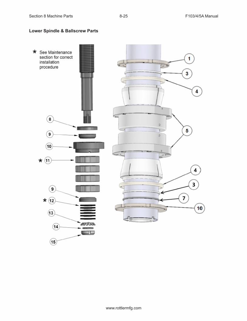
Section 8 Machine Parts F103/4/5A Manual
www.rottlermfg.com
8-25
Lower Spindle & Ballscrew Parts

Section 8 Machine Parts F103/4/5A Manual
www.rottlermfg.com
8-26

Section 8 Machine Parts F103/4/5A Manual
www.rottlermfg.com
8-27
Inner Spindle Lower Section Parts
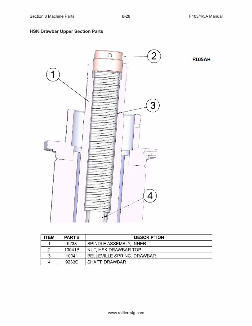
Section 8 Machine Parts F103/4/5A Manual
www.rottlermfg.com
8-28
HSK Drawbar Upper Section Parts

Section 8 Machine Parts F103/4/5A Manual
www.rottlermfg.com
8-29
Y-Axis Drive Parts
Y-AXIS ASSEMBLY PARTSITEM QTY PART NUMBER DESCRIPTION
1 1 6481 Motor2 4 MF-30 Socket Head Cap Screw3 1 9001M Coupler Assembly4 1 504-34-53 Oil Seal5 1 504-34-54 Lock Nut6 3 6778D Bearing7 1 11008A Direct Drive Motor Housing8 1 MF-191A Grease Fitting9 1 100-82-2 Brass Tip Set Screw
10 1 504-34-15A Thrust Nut11 1 9201A Ball Screw12 1 7245E Snap Ring13 1 6778D Bearing14 1 9001A Ball Screw Support

Section 8 Machine Parts F103/4/5A Manual
www.rottlermfg.com
8-30
Column and Spindle Base Retainers

Section 8 Machine Parts F103/4/5A Manual
www.rottlermfg.com
8-31
Column Base Parts
Assembly Image and Parts List are unavailable at this time.
Please visit the service tab of our web page www.rottlermfg.com and Send a Service Request. Or contact the Rottler Factory Service at [email protected] for assistance.
You may also call Rottler at 1-800-452-0534 or 1-253-872-7050
Please ensure you have the Machine Model and Serial Number available when contacting Rottler for Service

Section 8 Machine Parts F103/4/5A Manual
www.rottlermfg.com
8-32
Pendant Swing Arm

Section 8 Machine Parts F103/4/5A Manual
www.rottlermfg.com
8-33
Pendent Swing Arm Assembly Parts List

Section 8 Machine Parts F103/4/5A Manual
www.rottlermfg.com
8-34
Pendant Components

Section 8 Machine Parts F103/4/5A Manual
www.rottlermfg.com
8-35
Main Base Parts

Section 8 Machine Parts F103/4/5A Manual
www.rottlermfg.com
8-36
X-Axis Assembly: Drive End Parts

Section 8 Machine Parts F103/4/5A Manual
www.rottlermfg.com
8-37
X-Axis Assembly: Idle End
X-AXIS IDLE END PARTSITEM QTY PART NUMBER DESCRIPTION
1 1 9112D Ball Screw Nut Mount2 1 6073U Ball Screw Nut Assembly3 6 MF-22 Socket Head Cap Screw4 1 9201G Ball Screw5 1 9232 Ball Screw Over Travel Spring6 1 ME-189 Grease Fitting7 1 9112F Ball Screw Support8 1 Seal9 2 9113 Bearing
10 1 9113B Lock Washer11 1 9113A Lock Nut12 1 9113D Cover13 4 MF-248 Round Head Cap Screw

Section 8 Machine Parts F103/4/5A Manual
www.rottlermfg.com
8-38
Chip Shield Assembly

Section 8 Machine Parts F103/4/5A Manual
www.rottlermfg.com
8-39
Front Cover and Lights

Section 8 Machine Parts F103/4/5A Manual
www.rottlermfg.com
8-40
Oil Line Diagram

Section 8 Machine Parts F103/4/5A Manual
www.rottlermfg.com
8-41
Air Line Diagram
SCAL
E 1
/ 2
Chi
p G
uard
Cyl
inde
r(P
ART#
110
32B)
SCAL
E 1
/ 2
Chi
p G
uard
Cyl
inde
r(P
ART#
110
32B)
SCAL
E 1
/ 2
Dra
wba
r(P
AR
T #
6204
A)
SCAL
E 1
/ 2
Cou
nter
Bal
ance
(PA
RT#
921
7)SC
ALE
1 / 4
SCAL
E 1
/ 2
6
710
B10
C
9
99
9
10A
77
66
CIR
CU
ITS
6, 7
, 9, A
ND
10
RU
N T
HR
OU
GH
TH
E E
LEC
TRIC
AL
ENC
LOSU
RE
AN
D A
RE
SP
LIC
ED
WIT
H A
CO
UPL
ER
INS
IDE
THE
BO
X.
ELEC
TRIC
AL E
NC
LOSU
RE
10A
76
INSI
DE
CO
LUM
N D
OO
RO
UTS
IDE
CO
LUM
N D
OO
R
3
2
5 47
6
8
93
33
2
22
555
444
9
86
8
7
1A
MA
IN A
IR F
EED
OIL
ER
(PA
RT#
110
28)
VAL
VE
PAC
K(P
ART#
903
8D)
MA
IN A
IR R
EG
ULA
TOR
(PA
RT#
502
-37-
71H
)
Tabl
eN
UM
BE
RD
ES
CR
IPTI
ON
LIN
E L
EN
GTH
LIN
E D
IA.
1R
EG
ULA
TOR
TO
VA
LVE
PA
CK
1' 5
"1/
4" B
LAC
K
2LI
FT E
NG
AGE
11' 3
'1/
4" B
LAC
K
3LI
FT D
ISE
NG
AG
E11
' 3"
1/4"
BLA
CK
4TI
LT E
NG
AGE
12' 6
"1/
8" B
LAC
K
5TI
LT D
ISE
NG
AG
E12
' 6"
1/8"
BLA
CK
6D
RAW
BA
R E
NG
AGE
26' 7
"1/
4" B
LAC
K
7D
RA
WB
AR
DIS
EN
GA
GE
26' 7
"1/
4" B
LAC
K
8O
ILER
7' 1
0"1/
4" B
LAC
K
9C
OU
NTE
R B
ALA
NC
E23
' 4"
1/4"
BLA
CK
10C
HIP
SH
IELD
MA
IN T
O R
EGU
LATO
R3'
6"
1/4"
BLA
CK
10A
CH
IP S
HIE
LD S
UP
PLY
24' 1
0"1/
8" B
LAC
K
10B
CH
IP S
HIE
LD L
EFT
CYL
IND
ER
1' 4
"1/
8" B
LAC
K
10C
CH
IP S
HIE
LD R
IGH
T C
YLIN
DER
1' 4
"1/
8" B
LAC
K
M
AIN
AIR
LIN
E35
'3/
8" R
UB
BE
R
ACC
ES
OR
Y A
IR L
INE
36"
3/8"
RU
BB
ER
10A 10
10A
TILT
TILT
LIFT
CYL
IND
ER(P
ART#
100
18E
)
AIR
RE
GU
LATO
R F
OR
CH
IP G
UA
RD
MO
UN
TED
INS
IDE
CO
LUM
N(P
AR
T# 5
02-2
7-17
)
10-3
2 x
1/8"
PTC
(PA
RT#
514
-4-1
7J)
10-3
2 B
ANJO
FIT
TIN
G(P
AR
T# 5
14-4
-16A
)4
PLC
S
1/4"
NPT
X 1
/4" P
TC
S
TRA
IGH
T(P
AR
T# 5
14-4
-18N
)
1/4"
NP
T C
ON
E
MU
FFLE
R(P
ART#
514
-3-9
9)2
PLC
S
1/4"
PTC
3 W
AY
"TE
E"(P
AR
T# 5
14-4
-17N
)2
PLC
S
1/4"
NP
T X
1/4
" PTC
(PAR
T# 5
14-4
-17Y
)90
1/8"
NP
T X
1/4
" PTC
90
10-3
2 x
1/8"
PTC
(PAR
T# 5
14-4
-17J
)10
-32
BAN
JO(P
ART#
514
-4-1
6A)
1/4"
X 1
/4" P
TC C
OU
PLE
R(P
ART#
514
-4-1
7K)
1/8"
X 1
/8" P
TC C
OU
PLE
R51
4-4-
21
1/4"
NP
T G
AU
GE
(PAR
T# 5
02-1
1-8)
44
55
2
1/8"
PTC
3-W
AY
TEE
(PAR
T# 5
14-4
-17P
)
1/8"
PTC
3-W
AY
TEE
(PAR
T# 5
14-4
-17P
)
LIFT
CYL
IND
ER
(PA
RT#
100
18E
)
1/4"
NP
T X
1/4
" PTC
STR
AIG
HT
(PAR
T# 5
14-4
-18N
)
1/4"
NP
T X
1/4
" PTC
STR
AIG
HT
(PAR
T# 5
14-4
-18N
)
1/4"
NPT
X 1
/4" P
TC
S
TRA
IGH
T(P
ART#
514
-4-1
8N)
1/4"
NP
T X
1/4
" PTC
(PA
RT#
514
-4-1
7Y)
90
10-3
2 x
1/8"
PTC
(PA
RT#
514
-4-1
7J)
10-3
2 BA
NJO
(PAR
T# 5
14-4
-16A
)
1/8"
PTC
3-W
AY
TEE
(PAR
T# 5
14-4
-17P
)
1/4"
X 1
/4" P
TC C
OU
PLE
R(P
AR
T# 5
14-4
-17K
)
1/4"
X 1
/4" P
TC C
OU
PLE
R(P
AR
T# 5
14-4
-17K
)
1/4"
NP
T X
1/8
" PTC
(PAR
T# 5
14-4
-17Y
)90
1/4"
NPT
X 1
/4" P
TC(P
ART#
514
-4-1
7Y)
90
1/4"
NP
T X
1/4
" PTC
(PAR
T# 5
14-4
-17Y
)90
1/8
NPT
X 1
/8 P
TC(P
AR
T# 5
14-4
-17A
)
STR
AIG
HT
1/8
NP
T X
1/8
PTC
(PAR
T# 5
14-4
-17A
)
STR
AIG
HT
1/8
PTC
X 1
/8 P
TCU
NIO
N(P
ART#
XX
X-X
X-XX
)
(VAL
VE P
ACK
MO
UN
TIN
G O
RIE
NTA
TIO
N)
1/8"
NPT
X 1
/2" N
PTB
USH
ING
1/4"
NP
T C
ON
E
MU
FFLE
R(P
AR
T# 5
14-3
-99)
2 P
LCS
233
SIL
ENC
ER/S
LOW
DO
WN
(PA
RT#
903
2F)
2 P
LCS
1
11
1
1
10

Section 8 Machine Parts F103/4/5A Manual
www.rottlermfg.com
8-42

Section 9 Options F103/4/5A Manual
www.rottlermfg.com
9-1
Optional Equipment
Optional Equipment Catalog and Parts Manual are located on the Manual CD shipped with machine.
OPTIONS

Section 9 Options F103/4/5A Manual
www.rottlermfg.com
9-2

Section 10 Material Data Safety Sheets F103/4/5A Manual
www.rottlermfg.com
10-1
The Material Data Safety Sheets list shown in this section are the substances and materials that an operator is most likely to come in contact with while using this machine.
Other substances and materials are used in the manufacture, testing, and shipping of this machine. A complete list of the Material Data Safety Sheets of substances and materials used by Rottler Manufacturing during manufacturing, testing, and shipping is located on the Manual CD shipped with the machine. Material Data Safety Sheets are also located on the company web site: http://www.rottlermfg.com/documentation.php
MSDS
1) Mobil Vactra Oil #2

Section 10 Material Data Safety Sheets F103/4/5A Manual
www.rottlermfg.com
10-2

Section 10 Material Data Safety Sheets F103/4/5A Manual
www.rottlermfg.com
10-3
Section 10 Material Data Safety Sheets F103/4/5A Manual
www.rottlermfg.com
10-4

Section 10 Material Data Safety Sheets F103/4/5A Manual
www.rottlermfg.com
10-5

Section 10 Material Data Safety Sheets F103/4/5A Manual
www.rottlermfg.com
10-6

Section 10 Material Data Safety Sheets F103/4/5A Manual
www.rottlermfg.com
10-7

Section 10 Material Data Safety Sheets F103/4/5A Manual
www.rottlermfg.com
10-8

Section 10 Material Data Safety Sheets F103/4/5A Manual
www.rottlermfg.com
10-9