OPERATION AND MAINTENANCE MANUAL - Hyva
75
HYVA INDIA PVT. LTD. Plot No. EL-215, MIDC, MAHAPE, Navi Mumbai - 400 701 (The contents given in this manual are not binding and are subject to change without notice. The details given are guidelines and are for illustration purpose only.) Edition : XL/RV-2/18-19/1000 www.hyva.com OPERATION AND MAINTENANCE MANUAL
-
Upload
khangminh22 -
Category
Documents
-
view
4 -
download
0
Transcript of OPERATION AND MAINTENANCE MANUAL - Hyva

HYVA INDIA PVT. LTD.Plot No. EL-215, MIDC, MAHAPE,
Navi Mumbai - 400 701
(The contents given in this manual are not binding and are subject to change without notice. The details given are
guidelines and are for illustration purpose only.)
Edition : XL/RV-2/18-19/1000
www.hyva.com
OPERATION AND MAINTENANCE MANUAL
2
Dear Customer,
This manual outlines the maintenance and operating practices of Hyva Tipping System fitted on your vehicle. The purpose of this manual is to assist you in maintaining the system and get maximum life out of components. This is also to educate you in good operating practices and safety of equipment at all times. Overall it helps you to obtain better performance at optimum operating costs.
All service and maintenance tasks are to be carried out at the specified intervals.
This manual briefs about the system and components for your understanding and knowledge. Fault diagnosis given in this manual helps you in diagnosing the problem in a systematic manner.
Some of the items/accessories/features given in this book may not be fitted on your vehicle, but they are applicable to other versions.
Hyva India Pvt. LimitedMumbai
FOREWORD

3
INDEX
l Safety 5
l Periodic Check List 9
l Recommended Replacement Period for Consumables 10
l Recommended Hydraulic Oil Specification 10
l Tipper Operation Instructions 11
l Major Operating Parts
l HYVA P.T.O 14
l HYVA Gear Pump 24
l HYVA Tipping Valve 28
l Air Control for P.T.O / Valve 29
l Tank Return Line Filter 30
l Air Breather Filter 31
l Cylinder Nomenclature 32
l Cylinder Repair Instructions 33
l Hyfix Body Clamp 51
l Hydraulic Hoses 53
l Mk5 vs Alpha Cylinders 54
l Fault Diagnosis 57
l Greasing Layout 66
l Specific Densities 69
l Warranty Guidelines 70
l Record of Repairs/Services performed 73

4
5
IMPORTANT SAFETY NOTICEProper service and repair is extremely important for the safe operation of your machine. The service and repair technique recommended by HYVA and described in this manual are both effective and safe methods of operation. Some of these operations require the use of tools specially designed by HYVA for the purpose.
SAFETY
GENERAL PRECAUTIONS Mistakes in operation are extremely dangerous. Read the Operation and Maintenance Manual carefully BEFORE operating the machine.1 Be fo re ca r ry ing ou t any
greasing or repairs, read all the precautions given on the decals which are fixed to the machine.
2 When carrying out any operation, always wear safety shoes and helmet. Do not wear loose work clothes, or clothes with buttons missing.l Always wear safety glasses
when hitting parts with a hammer.
l Always wear safety glasses when grinding parts with a grinder, etc.
3 If welding repairs are needed, a l w a y s h a v e a t r a i n e d , experienced welder to carry
out the work. When carrying out welding work, always wear welding gloves, apron, glasses, cap and other clothes suited for welding work.
4 When carry ing out any operation with two or more workers, always agree on the operating procedure before starting. Always inform your fellow workers before starting any step of the operation. Before starting work, hang “UNDER REPAIR” signs on the controls in the operator’s compartment.
5 Keep all tools in good condition and learn the correct way to use them.
6 Decide a place in the repair workshop to keep tools and removed parts. Always keep the tools and parts in their correct places. Always keep the work area clean and make sure that there is no dirt or oil on the floor.
PREPARATIONS FOR WORK
7 Before adding oil or making any repairs, park the machine on hard, level ground, and block the wheels to prevent the machine from moving.
8 Before starting work, rest dump body on prop and hang
SAFETY

6
“UNDER REPAIR” board on them.
9 W h e n d i s a s s e m b l i n g o r assemb l ing , suppor t the machine with blocks, jacks or stands before starting work.
10 Remove all mud and oil from the steps or other places used to get on and off the machine. Always use the handrails, ladders or steps when getting on or off the machine. Never jump on or off the machine. If it is impossible to use the handrails, ladders or steps, use a stand to provide safe footing.
PRECAUTIONS DURING WORK
11 When removing the oil filler cap, drain plug or hydraulic pressure measuring plugs, loosen them slowly to prevent the oil from spurting out.
Be fo re d i sconnec t ing o r removing components of the oil and air circuit, first release the pressure completely from the circuit.
12 The oil in the circuit is hot when the engine is stopped, so be careful not to get burnt.
Wait for the oil to cool before carrying out any work on the oil circuit.
13 Before starting work, remove the leads from the battery. Always remove the lead from the negative (-) terminal first.
14 When raising heavy components, use a hoist or crane.
Check that the wire rope, chains and hooks are free from damage.
Always use lifting equipment which has ample capacity.
Install the lifting equipment at the correct places. Use a hoist or crane and operate slowly to prevent the component from hitting any other part. Do not work with any part still raised by the hoist or crane.
15 When removing covers which are under internal pressure or under pressure from a spring, always leave two bolts in position on opposite sides. Slowly release the pressure, then slowly loosen the bolts to remove.
16 When removing components, be careful not to break or damage the wiring. Damaged wiring may cause electrical fires.
17 When removing piping, stop the oil from spilling out. If any oil drips on the floor, wipe it up immediately. Fuel or oil on the floor can cause you to slip, or can even start fires.
SAFETY

7
18 As a general rule, do not use gasoline to wash parts. In particular, use only the minimum of gasoline when washing electrical parts.
19 Be sure to assemble all parts again in their original places.
Replace any damaged parts with new parts.
l When installing hoses and wires, be sure that they will not be damaged by contact with other parts when the machine is being operated.
20 When installing high pressure hoses, make sure that they are not twisted. Damaged tubes are dangerous, so be extremely careful when installing tubes for high pressure circuits. Also, check that connecting parts are correctly installed.
21 When assembling or installing parts, always use the specified t ightening torques. When installing protective parts such as guards, or parts which vibrate violently or rotate at high speed, be particularly careful to check that they are installed correctly.
22 When aligning two holes, never insert your fingers or hand. Be careful not to get your fingers caught in a hole.
SAFETY
23 When measuring hydraulic pressure, check that the measuring tool is correctly assembled before taking any measurements.
24 While carrying out welding on tipper, earthing should be done nearer to the welding spot. Earthing should not be done through cylinder and other hydraulic components, to avoid damage due to sparking.
25 While carrying out welding on head board / load body, the tipping cylinder and other hydraulic components should be covered with fire-resistant cover so that welding spatters will not damage stages and seals.

8
SAFE PRACTICES
Do’s Don’ts
OVERLOAD
LOAD UNEVEN
TIP ON UNEVEN GROUND
STAY IN THE WORKINGAREA OF THE TIPPER
DRIVE WITH RAISED BODY
TIP WITH TRAILER IN AN ANGLE TO THE TRUCK
EXTENDING TIPPERBODY HEIGHT
STAY UNDER AN UNSUPPORTED
BODY

9
PERIODIC CHECKLIST
DAILY CHECKS POINTS (BEFORE STARTING THE TRUCK) l Check the Oil level in the Oil Tank.
Oil level has to be in the middle of the sight glass or level Indicator, while the body is resting on the sub-frame.
l Make visual inspection of Hydraulic System i.e. P.T.O., Pump, Tank, Valve, Hoses and Couplings for leakages.
l Check all Pneumatic and Hydraulic connections for slackness.
PERIODIC CHECK POINTS - WEEKLYl Breather Element must be cleaned
once in a week with compressed air only.
l Lubricate all greasing points on the tipper. (Cylinder Eye End, Hyfix, Cylinder mounting bush, Stabilizer, Body Prop, Rear Hinge Shaft, Side locking tail door mechanism - Refer Greasing Layout on Page No. 65)
Note : Greasing is recommended on a daily basis for Mining tippers.
l Care should be taken while tightening Pivot Mounting Bolt (see Fig. ), so that Pivot Spring does not get compressed completely. A minimum gap of 0.5 mm should be maintained (equivalent to
thickness of a Hacksaw Blade) so that this Spring can offer required compression under load.
l Check Gearbox Oil level.
l Check Pivot bracket bol ts, Attachment bolts (80 Nm) and Cylinder Cradle Mounting Bracket Bolts, Rear hinge shaft/pin locking, Pump Mounting Bolts, Stabiliser pin locking bolt and tighten if necessary. Check Tail door locking mechanism linkage (nuts & lock pins), Body lifting bracket bolts (for FC cylinder), Check gap between trunnion pin & Cylinder mounting bracket bush (Replace bush if gap observed is more than 1.5mm).
Note :Tightening Torque for Cylinder Mounting Bracket Bolts is 200 Nm and Pump Mounting Bolts is 50 Nm.

10
RECOMMENDED REPLACEMENT
Sl. No.
Description of Items Replacement Periods
1Air Breather Filter Element (08102117)
Once in every 4 months in normal working condition. (Non Mining application)
Once in every 2 months in dusty working condition. (Mining application)
2
Return Line Filter Element 150Lpm (14896991A)
Once in every 4 months in normal working condition. (Non-Mining application)
Once in every 2 months in dusty working condition. (Mining application)
Return Line Filter Element 300Lpm (14896990)
Once in every 4 months in dusty working condition. (Mining application)
3 Hydraulic Oil First change at 6 months and thereafter once in a year.
We recommend Super-clean anti-wear, oxidation stable and rust preventive Hydraulic oil conforming the characteristics according to BIS-11656-86 and DIN 51524/2.
RECOMMENDED HYDRAULIC OIL
Make Brand & TypeAmbient
TemperatureFrom To
HYVA HYVA Superfluid - 5OC 60OC
Note :1) Over and above the schedule, Filter and Breather elements need to be
replaced whenever hydraulic oil is changed.2) In the event of metal particles being found, due to failure of components,
hydraulic oil needs to be changed alongwith new components.

11
OPERATION INSTRUCTIONS
Before putting your vehicle into operation, it is necessary to familiarize yourself thoroughly with the mode of the operation and function of the tipper.LOADINGl Body must be uniformly loaded. l Please load as per the specification chart provided in order to ensure longer
life and safer operation. l Ensure proper loading or hopping process in order to avoid undue impact
load on vehicle. TIPPINGl Before tipping, make sure the tipper is standing on level & stable ground. l Make sure that front wheels are in line with rear wheels.l Ensure that hand brake of the vehicle is in “ON” position.l In neutral gear, start the engine, build up the air pressure upto
7-8 kg/cm2, then press the clutch pedal and engage the PTO slowly using air control valve lever inside the cabin
l In case of vehicle with tail gate system, ensure that the safety lock pin is removed & stowed in open position from the tail door locking mechanism.
l Ensure that mechanical lock pin is removed from the tail door locking mechanism before tipping operation. Otherwise this will damage the locking mechanism.
l Start tipping by using the air control inside the cabin. LOWERINGl Using the air control inside the Cabin, lower the tipper body. Lowering
operation automatically disengages PTO. l Do not put the engine in high R.P.M, while lowering the body. GENERAL TIPSl Please ensure the raising of body prop while doing any work on chassis or
sub-frames underneath the body. l Please remember, incorrect operational practice may be fatal to the vehicle
and cause even casualty of human life. WARNING : l Applying side load and dynamic forces to any cylinder is dangerous.l Working under an unsupported body is a danger to life.
12
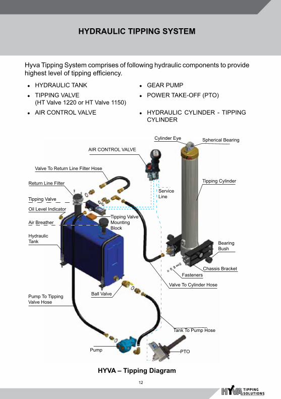
HYDRAULIC TIPPING SYSTEM
Hyva Tipping System comprises of following hydraulic components to provide highest level of tipping efficiency.
lHYDRAULIC TANK lGEAR PUMPlTIPPING VALVE
(HT Valve 1220 or HT Valve 1150)lPOWER TAKE-OFF (PTO)
lAIR CONTROL VALVE lHYDRAULIC CYLINDER - TIPPING CYLINDER
HYVA – Tipping Diagram
Pump
Cylinder Eye Spherical Bearing
Valve To Return Line Filter Hose
Tipping CylinderReturn Line Filter
Air Breather
Tipping Valve
Oil Level IndicatorTipping Valve Mounting Block
HydraulicTank
Pump To Tipping Valve Hose
Valve To Cylinder Hose
Ball Valve
Chassis BracketFasteners
Bearing Bush
Tank To Pump Hose
PTO
AIR CONTROL VALVE
ServiceLine

13
HYDRAULIC & PNEUMATIC CIRCUIT DIAGRAM
HYDRAULIC & PNEUMATIC CIRCUIT DIAGRAMWITH HT 1220 / 1150 VALVE

14
P.T.O
P.T.O: A P.T.O (Power Take Off) is an auxillary gear box mounted on the transmission. Its function is to transmit the power from rotation of the engine.
Hyva Supplies the following P.T.Os :I. Side mounted P.T.O. : 1. G600 /G750 V1 Type (Remote Drive) 2. G600 /G750 V2 Type (Direct mounting)II. Rear mounted P.T.O. : 1. Dual Block P.T.O. 2. Mono Block P.T.O.III. P.T.O. Operation
IMPORTANT : When engaging and disengaging the PTO, always press the clutch pedal!
Working Temperature and Load conditionsThe temperature depends on the way the PTO is used and it is recommended to keep it between the following values.Short duration (less than 15 minutes) max. 120OC, long duration (more than 15 minutes) max. 100OC.The PTO temperature is affected by various factors; it is possible to reduce overheating by:l Changing the oil more often in case of heavy duty system.l When the PTO is side mounted, ensuring that the gear backlash is
accurately checked.l When the PTO is rear mounted, considering to provide the PTO with a
supplementary lubrication kit.IV. PTO Installationa. Side mounted PTO installation :l Empty or reduce the gearbox oil
level, check cleanliness. If oil is dirty or contaminated it should be replaced. (Pict. 1)
Notice : In some applications (for example automatic Allison Gearbox) it is not necessary to empty gearbox. Always check gearbox service manual. Picture. 1

15
P.T.O
l Remove gearbox aperture cover and accurately clean the gearbox aperture surface (Pict. 2)
l Check gearbox gear teeth and the gear backlash (Pict. 3)
l Open the PTO package. Use PTO specific mounting kit and if necessary spacers.
l Studs for mounting onto the gearbox :
- Accurately check that the holes in the gearbox are threaded. Be careful that studs do not interfere with gears.
- Fit the studs. (Pict. 4) shows a typical mounting example.
Backlash between gear tooth and spacer insertion:
To get backlash of 0.15 mm, add 0.4 mm spacer between PTO and gearbox, as necessary.
Backlash checking can be carried out in two ways.
Picture. 2
Picture. 3
Picture. 4

16
- In case of PTOs equipped with inspection plug, check by hand, (rocking the gear to get the “feel” for gear backlash) or by means of a dial gauge (Pict. 5). The use of a dial gauge is recommended as it is much more accurate.
- In case of PTOs without inspection plug, adjustment is carried out in stages. The PTO has to be checked against the transmission flange by adding spacers until there is no backlash. After that, another 0.5 mm spacer should be added and the nuts tightened.
Recommendations on seal and spacer use.- Remember that once the nuts
have been tightened, the seal thickness reduces, resulting in a similar backlash reduction. The backlash therefore has to be checked even after tightening.
- Available seals (Pict. 6) have a thickness of 0.5 and 0.25 mm (special series).
- When a spacer is fitted, use a gasket to ensure tightness (at least one on both sides).
- In order to avoid the seals sticking to each other, use grease. NEVER use adhesive fluid when the PTO mounting kit requires special gasket. USE adhesive fluid only when the PTO mounting kit DOESN’T involve any gasket.
0.5 mm 0.25 mm
P.T.O
Picture. 5
Picture. 6

17
Once the suitable thickness has been determined, tighten the nuts with a torque wrench (see tightening torque table)Note : Once the nuts have been tightened, the backlash has to be rechecked and if necessary the shiming operation may be repeated.When the installation operation has been completed, fill the gearbox with oil (Pict.7)Note : In case of applications with separate lubrication (for example on Allison transmission) an external tube kit is needed to be fitted.After installing operations, proceed with the checks.b. Rear mounted PTO
installation :l Empty or reduce the gearbox oil
level, check cleanliness. If oil is dirty or contaminated it should be replaced. (Pict. 8).
Note : In some applications (for example automatic Allison gearbox) it is not necessary to empty gearbox.
l Remove gearbox aperture cover and accurately clean the gearbox aperture surface (Pict. 9)
l If a shaft kit is provided for the application, follow mounting instructions given below.
P.T.O
Picture. 7
Picture. 8

18
Picture. 9
Picture. 10
Mounting instructions :First insert quill shaft in gear box
Then fit the quill shaft bearing cone with the help of proper tool. Add shims if required (Note: - After fitment of bearing cone, the cone surface and gearbox surface should be uniform)
P.T.O

19
Fit PTO mounting studs with help of monkey plier
It is recommended to lock studs or bolts with locking fluid. (see tightening torque table)
Install PTO packing on gear box surface
Fit ZF Mono block PTO in installed studs
Fit Gear Pump packing on PTO
P.T.O

20
P.T.O
Picture. 11
Then install Pump on PTO and tighten with nut along with spring washer
Note : In case of a connection to an ISO flange pump: if the oil seal is fitted to the pump, then the pump must be fitted to the gearbox before filling with oil.
l When the fitting operation is complete, refill gearbox with oil (Pict.11) Note : In case of application with separate lubrication, a supplementary lubrication kit should be fitted.
l When installation is completed, proceed with the checks (see ‘After Installation checks’ on next page)

21
P.T.O
V. AFTER INSTALLATION CHECKS. :Once the installation phase is complete, the following checks are recommended.
Engagement /disengagement check
Performance soon after engine start. If a clash is heard, this may be due to one of the following:
- Clutch not working properly
- There’s no or insufficient air pressure.
Oil level check Carry out an oil check when the engine is still cold and top up if necessary.
Oil Leak Check to be carried out under all the working conditions, with PTO engaged and gear in neutral position.
In case of a side mounted PTO, an excessive noise may mean a wrong backlash according the following:
- High pitched noise; backlash is too tight
- Rattle noise; excessive backlash.
Tightening bolts check Normally bolts tend to loosen because of the seal setting. It is recommended that all bolts and nuts are checked after a few hours of work checking the tightening by means of a torque wrench. With side mounted PTO’s, recheck the backlash after tightening.
22
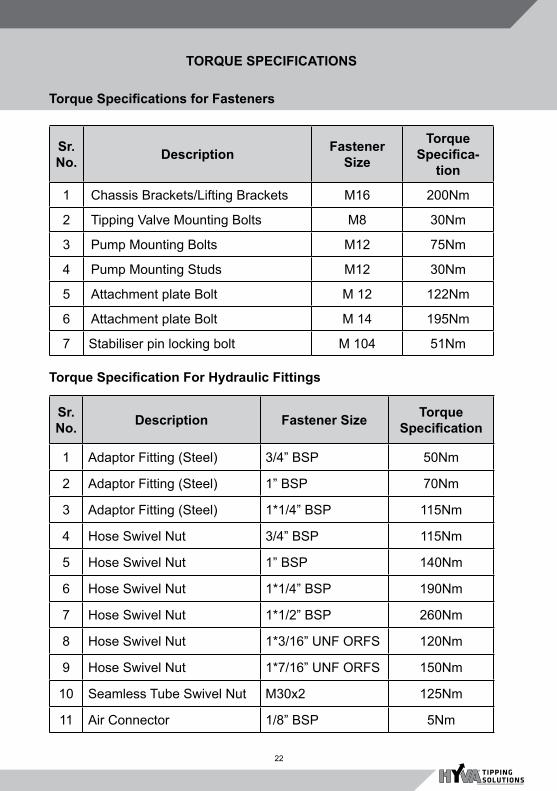
Torque Specifications for Fasteners
TORQUE SPECIFICATIONS
Sr. No. Description Fastener
Size
Torque Specifica-
tion
1 Chassis Brackets/Lifting Brackets M16 200Nm
2 Tipping Valve Mounting Bolts M8 30Nm
3 Pump Mounting Bolts M12 75Nm
4 Pump Mounting Studs M12 30Nm
5 Attachment plate Bolt M 12 122Nm
6 Attachment plate Bolt M 14 195Nm
7 Stabiliser pin locking bolt M 104 51Nm
Sr. No. Description Fastener Size Torque
Specification
1 Adaptor Fitting (Steel) 3/4” BSP 50Nm
2 Adaptor Fitting (Steel) 1” BSP 70Nm
3 Adaptor Fitting (Steel) 1*1/4” BSP 115Nm
4 Hose Swivel Nut 3/4” BSP 115Nm
5 Hose Swivel Nut 1” BSP 140Nm
6 Hose Swivel Nut 1*1/4” BSP 190Nm
7 Hose Swivel Nut 1*1/2” BSP 260Nm
8 Hose Swivel Nut 1*3/16” UNF ORFS 120Nm
9 Hose Swivel Nut 1*7/16” UNF ORFS 150Nm
10 Seamless Tube Swivel Nut M30x2 125Nm
11 Air Connector 1/8” BSP 5Nm
Torque Specification For Hydraulic Fittings

23
GEAR PUMP
Gear Pump specifications 52 cc 82 cc 92 cc
Displacement per revolution 51.88 cc 81.61 cc 91.56cc
Maximum peak pressure 230 Bar 230 Bar 230 Bar
Maximum intermittent pressure 220 Bar 220 Bar 220 Bar
Maximum Continuous pressure 190 Bar 190 Bar 190 Bar
Oil temperature range -25OC to 110OC
-25OC to110OC
-25OC to 110OC
Inlet pressure range in Bar (abs) 0.7 - 3.0 0.7 - 3.0 0.7 - 3.0
Hyva Gear Pump
Gear pump is a mechanical device which converts mechanical energy into hydraulic energy. It consists of two gears with external teeth meshing with each other.
l Gear pumps are self priming type. These are compact in size, less moving parts and therefore less wear and tear.
Note: 82 / 92 denotes the displacement of oil in cc per rev i.e. 82.cc pump runs at 1000 rpm capacity will be 82 lts/min
We recommend operating tipper application at correct engine RPM as per PTO ratio of that particular pump housing and gears. Revving up the engine beyond recommended speed can lead to pump failure or excessive wear and tear of the pump.
Note : Recommended engine speed for normal operation is 1000 to 1200 rpm.

24
One of the two gearwheels is driven from outside (Drive Gear) and drives the other gearwheel (Driven Gear). With the right hand rotation of the top gearwheel (consider fig.) oil is sucked from the LHS port (Pump suction). Oil trapped in between the gear teeth and the pump body travels along the periphery of the Pump body towards the RHS port (Pump delivery). As the teeth and the side of the gears are closely sealed against the Pump body and the Thrust Plates, pressure builds up against the resistance to the oil flow at the delivery port.
Basic principle of Gear Pump
GEAR PUMP

25
GEAR PUMP
Hyva Gear Pump (82 cc Black)
SL. Descriion Qty.
1 Body 12 Front Cover 13 Thrust plate Brite 24 Drive Shaft 15 Driven Gear 16 Roller Bearing 17 Roller Bearing 18 Screw 89 Dowel 1/8” 210 Washer 811 Lock washer 112 OR-seal 113 ‘O’ Ring 114 Seal 215 Shaft Seal 116 Shaft Seal 1
SL. Description Qty.
17 Shaft Seal 118 Circlip 119 Locking ring 120 Locking ring 121 Back-up ring 222 Spacer 223 Shaft seal mounting ring 124 Sleeve bearing 425 Threaded locking ring 126 Back-up washer plastic 127 Support Shaft 128 Ball 229 Steel bushes 430 Steel plug 231 Protection plug 1

26
GEAR PUMP
HYVA GEAR PUMP OVERHAULING PROCEDURE :Please follow the steps mentioned below: l Remove the pump from vehicle and place it on a clean tablel Loosen all allen bolts by using suitable allen key l Tap the flange area and remove the cover of the pumpl Slowly remove the O-ring from groove of cover plate. Check and replace,
if necessaryl Remove the oil seal from pump shaft. Check the condition and replace, if
necessaryl Remove the top thrust plate. Also, remove the thrust plate seal and anti
extrusion ringl Remove the set of drive and driven gearl Follow the above instruction for removing the bottom thrust platel Check clearance between housing and gear teeth. The clearance should
not be more than 0.005”.l Check and replace the seal and backup ring, if necessaryl Clean each part thoroughly and assemble back in reverse sequence of
dismantling pumpl Check the backlash of gearsl Bolt tightening torque - 20 Nm TO BLEED THE SYSTEM :The Hyva Gear pumps, as well as the Hyva cylinders do not have a bleeder screw. After installation of tipping system some components can have some amount of air trapped inside. Therefore it becomes necessary to bleed the system. To bleed the system, follow instructions given below.
l Loosen the pressure hose of the pump a little so that the air in the suction hose and the pump can escape and the system will be filled up with oil.
l Loosen the pressure hose and the cylinder hose a little. Run the pump at a low speed and put the tipping valve in “Tip” position. After a short while once the air escapes from the system, the connections must be tightened.
l As the piston of the cylinder is closed, only a little air remains between the stages. This will “mix-up” with the oil after a few tips and will escape via the oil tank.

27
l If air remains in the system after 8-10 tips the position of the suction hose must be checked and the connections must be tightened. If the temperature is high or the oil is thick, one must wait longer before bleeding a second time.
l Top up the oil tank as oil has now entered the cylinder, hoses and oil filter.
l Check the working pressure and check that the pump is operating properly. If it is too noisy or if there are shocks in the hoses, air may still be there in the system and the pump is facing cavitation. Bleed the system.
l Check the working pressure. Check and ensure that the complete hydraulic system works properly (Working pressure - 170 bar for FLASH series cylinders and 190 bar for ALPHA series cylinders).
GEAR PUMP

28
HYVA TIPPING VALVE
GENERAL MOUNTING INFORMATIONl The tipping valve is mounted on
oil tank through valve mounting block. To prevent the valve housing deformation the mounting plate surface or block must be completely flat.
l Before mounting the valve, remove the plug underneath the valve and use the O-ring between valve return line opening and valve block.
l Recommended torque for tipping valve mounting allen bolts is 45 Nm.
DISMANTLING TIPSl The Valve must be dismantled in
a clean area and using the correct tools.
l If a fault has been developed which can be traced to the valve it is possible to replace the internal seals and O-Rings.
l All parts should be thoroughly cleaned before reassembly.
pressuregauge
l Hyva recommends that total hydraulic circuits must be tested on completion of fitting as per following:
- Make sure that the body is fully lowered and the PTO is disengaged.
- Connect a pressure gauge to the point shown on the figure.
Note : Connector thread size 1/4 BSP for HT valve.
- Engage the P.T.O. and tip the body fully. Hold the lever at tipping condition until the oil get relieves to tank.
- Check for leaks in the system and read the pressure gauge.
PRESSURE CHECKING POINTSNote : System working pressure - 170 bar for FLASH series cylinders and 190 bar for ALPHA series cylinders.
pressuregauge HT Valve 1150
HT Valve 1220

29
AIR CONTROL FOR P.T.O. / VALVE
GENERAL INFORMATIONl The air control for P.T.O/Valve with automatic P.T.O. disengagement is a
three way operated, variable air control (for P.T.O. engagement, tipping and lowering operation).
l When used with a compatible tipping valve with proportional lowering, the proportional movement of the air control lever can regulate the speed of descent of the body.
l Hyva Air controls are easy to mount in the cabin. l The functions of Hyva air controls are clearly indicated with symbol.
MOUNTING OF THE AIR CONTROLl When air control is mounted next to the driver’s seat, a strong support
should be used.l Ensure using rubber grommets to protect air tubes and to prevent entry of
dust and water inside cabin.l For trouble free operational life of the entire pneumatic system, the
condensed water in the air tank should be regularly drained.l Also make sure that the air tubes are not too close to sharp objects, moving
parts exhaust and compressor lines, should not get too stretched.l Please take precaution to protect pneumatic lines while doing welding in
nearby area.

30
RETURN LINE FILTER
RETURN LINE FILTER ASSEMBLYReturn line filter assembly is located on top of the hydraulic oil tank & adjacent to tipping valve. Oil from cylinder on its return path, (Cylinder Tipper Valve) flows to the tank through Return line filter.The function of RLF assembly is to remove contamination from the hydraulic oil on its way back to the tank. (Rating 25 Microns)
1
It consists the following Parts1 Cover2. Aluminum Body3. Flange Pipe4. Return Line Filter Element
5
5
2
5. Flange Seal6. ‘O’ Ring7. ‘O’ Ring8. Spring
6
5
4
3
Note:
Periodic replacement of filter element is strongly advised to prevent premature wear and failure of tipping system components.
2
NOTE : Filter element must be replaced as per the recommendation given in periodic check list.

31
AIR BREATHER FILTER
Breather Assembly
As the name indicates, this helps the Hydraulic oil tank to ‘Breath in’ or ‘Breath out’ air, in order to maintain the atmospheric pressure inside tank, even when there is lower level of oil (in tipped condition) or higher level of oil (due to lowering down or heat generation in the system), in order to prevent any kind of deformation of tank. A Breather filter element of 10-micron filtration capacity ensures entry of dust and foreign particle – free air inside hydraulic tank.
It consists of the following parts1. Cover2. Housing3. Breather Filter Element4. Seal5. Screw6. Sleeve
Note : Breather Element must be replaced periodically as per the recommendations.

32
HYVA Cylinder Nomenclature
To identify the Type and Part number look for the Cylinder name Plate, which is located above the Trunnion & below the oil Port of the Cylinder. Make sure about all the parameters before placing an order for Assembly or Spare Parts.In Front End Tipping Systems used generally in India, Hyva is using two types of Cylinders, i.e. FE & FC. (Find herewith the Nomenclature for Front End Cylinder with Cover - FC)
NOTE : Stroke Length: Distance travelled between close to open length by cylinder eye or cover trunnion.
CYLINDER NOMENCLATURE
CYLINDER NOMENCLATURE
Eye withtrunnion FE
Cover withTrunnion FC
FE 129 - 3 - 03640 - 001A - K1529 - HC
FC 129 - 3 - 04270 - 000A - K0343 - HC
Type ofCylinder
No. ofstages
StrokeLength
Positionof oil inlet
HardChrome
Diameterof firststage
K Mountingdimension
in mm
33
CYLINDER REPAIR INSTRUCTIONS
FC & FE CYLINDERS REPAIR INSTRUCTIONSIntroduction Hyva cylinders contain a small number of components, which are subject to wear. Therefore it is sometimes necessary to dismantle the cylinder and replace the worn out parts like seal kit.Depending on the load requirements, either of the following types of cylinders are incorporated in system :
1) FE/FC110 2) FE/FC129 3) FE/FC 1494) FE/FC 169 5) FE/FC191
Repair of Hyva cylinder should be carried out always in accordance with instructions given below. 1. Before dismantling any Hyva cylinders always check the name plate for
type of Cylinder, which is primary requirement in ordering right parts. 2. Remove the Cylinder from the chassis prior to dismantling and always
place it horizontally on a clean and dust free place. Only in case of FC type of cylinder it is possible to leave the outer cover attached to the body.

34
POS. DESCRIPTION QTY.0 Packset Fl 149 011 Base 149 012 Seal Bottom Plate 149 013 Bottom Plate 149 014 Locking Plate 149 035 Spring Washer M8 Set 036 Bolt M8x1.25x20 Set 037 Liftring Fl 149 0120 Packset Fl 129 0121 Stage 129 0122 Outer Stopring Fl 129 0223 Slider Fl 129 0124 Liftring Fl 129 0130 Packset Fl 110 0131 Stage 110 0132 Outer Stopring Fl 110 0233 Slider Fl 110 0134 Liftring Fl 110 01
POS. DESCRIPTION QTY.101 Piston S 091 01
102 Pin Round Head Grooved 6X15 Mm 01
103 0-Ring Piston Top 091 01104 Outer Stopring Fl 091 02105 Slider Fl 091 (2x1/2) 01106 Inner Stopring Fl 091 01
107 Bottom Plate Piston 091 Raised 01
108 0-Ring Piston Bottom 091 01109 Circlip 78 Din 472 (82.5X2.5) 01110 Piston Eye Sph. 091 Greased 01111 Spherical Eye D.50 Do 01112 Circlip 75 Ge 50 Do Din 472 01
123 DUST COVER FE 129 YELLOW 01
SEAL KIT COMPLETE : Consists of all Packsets with packset grease and ‘O’ rings and pin (Pos. 102)
SPARE PART LIST
HYVA Cylinder FE 129
CYLINDER REPAIR INSTRUCTIONS

35
CYLINDER REPAIR INSTRUCTIONS
Dismantling and Assembly of FE Cylinder:
Dismantling Procedure :
Lay the cylinder flat on a clean bench with the oil inlet facing downwards. Collect the waste oil.
Remove the bottom locking plate bolts (6nos.) using appropriate spanner.
Remove all the three locking plates

36
CYLINDER REPAIR INSTRUCTIONS
Bottom plates can be removed by either of the following methods.
A) Attach two Lock Plates as shown and pullout the base plate evenly.
B) Use Puller to Pullout Bottom plate

37
CYLINDER REPAIR INSTRUCTIONS
Remove the Piston Rivet with the help of chisel
Properly cover all the stages with cotton cloth and then start grinding of piston eye welding
After completion of grinding start unscrew the piston eye with help of Nylon mallet

38
CYLINDER REPAIR INSTRUCTIONS
Push the Piston little inside to expose the Snap Ring in the next stage.
Remove the snap ring using a thin screwdriver. *CAUTION:Removing the snap ring carefully as it may jump out of grove.
Push the Piston towards the bottom such that both the sliders are exposed.
Remove the Piston sliders carefully
39
CYLINDER REPAIR INSTRUCTIONS
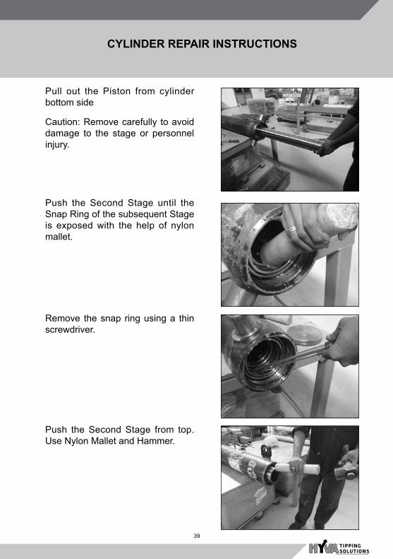
Pull out the Piston from cylinder bottom side
Caution: Remove carefully to avoid damage to the stage or personnel injury.
Push the Second Stage until the Snap Ring of the subsequent Stage is exposed with the help of nylon mallet.
Remove the snap ring using a thin screwdriver.
Push the Second Stage from top. Use Nylon Mallet and Hammer.

40
CYLINDER REPAIR INSTRUCTIONS
Push the 2nd stage towards the bottom such that both the sliders are exposed
Pull out 2nd stage from bottom side
Push the 1st Stage until the Snap Ring of the subsequent Stage is exposed with the help of nylon mallet. (applicable for MK3, MK4, MK5 and Alpha series Cylinders)
Remove the snap ring using a thin screwdriver.

41
CYLINDER REPAIR INSTRUCTIONS
Push the 1st stage towards the bottom such that both the sliders are exposed
Remove 1st stage sliders carefully
Pull out 1st stage from base tube
CautionThe dismantled stages must be placed on a clean surface to prevent scratches and damages.

42
Removing FC Cylinder from the Chassis:
- Before attempting to remove the Cylinder, place the Air control lever in a lowering position so that the residue oil in the cylinder is drained out in the hydraulic oil tank.
- Remove Pressure hose connected to the cylinder and allow the balance oil to drain.
- Disconnect one of the Cylinder mounting bracket and Body lifting bracket (same side) from their respective position by removing bracket bolts.
- Secure the Cylinder with rope or a sling so that the cylinder does not topple over.
- Now remove the disconnected brackets.
- Using adequate manpower, remove the cylinder from the chassis.
- Lay the cylinder on the workbench for the repairs. Secure cylinder in a bench vice whenever required during the course of repairs.
CYLINDER REPAIR INSTRUCTIONS
Assembly of Cylinder-FE
For procedure for assembling is in the reverse order of dismantling procedure. Follow the instructions given below : Slide the first stage in to the base tube up to the extent that only the slider groves are out. Place
the sliders in their respective groves with sufficient grease and push until the sliders are in. Follow the same procedure for inserting the 2nd Stage. Insert the Piston from bottom of the cylinder, push all the way towards top until the Slider groves are only exposed. Place the sliders in their respective groves with sufficient grease and push until the sliders are in. Push each stage slightly inside to place the Snap rings in the respective snap ring groves. There can be some resistance for the stage while passing through the pack set, which is normal. Place the Cylinder bottom plate followed by lock plates. Tighten the lock plate with spring
Washer and bolt (Never forget to apply Loctite ® 243 on the locking bolts.)

43
CYLINDER REPAIR INSTRUCTIONS
Pos Description Qty.
0 PACKSET 149 01
1 BASE 149 01
2 SEAL BOTTOM PLATE 149 01
3 BOTTOM PLATE 149 01
4 LOCKING PLATE 149 03
5 SPRING WASHER M8 SET 03
6 BOLT M8 X 1.25 X 20 SET 03
20 PACKSET 129 01
21 STAGE 129 01
22 OUTER STOP RING FL129 02
23 SLIDER 129 (2 X 1/2) 01
24 LIFT RING 129 01
30 PACKSET 110 01
31 STAGE 110 01
32 OUTER STOP RING FL110 02
33 SLIDER 110 (2 X 1/2) 01
34 LIFTRING 110 01
HYVA Cylinder FC 129
Pos Description Qty.
103 O-RING PISTON TOP 091 01
104 OUTER STOP RING FL 091
02
105 SLIDER 091 (2 X 1/2) 01
106 O-RING PISTON BOTTOM 091
01
107 BOTTOM PLATE PISTON 091
01
108 SNAP RING FOR PISTON 091
01
120 TOPNUT M48x3 01
121 COVER 219 01
122 WASHER M48 01
123 DUST COVER FOR COV-ER 219
01
125 O-RING COVER D219 01
Seal kit
com-plete:
Seal kit complete: consists of all packsets with packset grease, O-rings and Pin (pos.102)

44
Loosen the FC Cylinder cover securing Self locking Nut with appropriate spanner by holding the piston head as shown.
Unscrew the Nylock Nut completely
Remove the Flat washer.
Tap the Piston head with Nylon Mallet and Hammer carefully for not damaging the Piston threads.
Dismantling and assembly of FC Cylinder
CYLINDER REPAIR INSTRUCTIONS

45
Separate Cylinder from Cover carefully....
.....and remove.
Lay the Cylinder flat on a clean bench with the oil inlet facing downwards. Collect the waste oil. T h e subsequent steps for dismantling procedure are the same as those for dismantling procedure or FE cylinder.
CYLINDER REPAIR INSTRUCTIONS

46
Pack set dismantling and assembly in FE & FC Cylinders:Remove Wear rings from all the stages including Base tube, in the following manner. Remove Wiper (-Seal) using a blunt screwdriver. Starting with 4th Wear Ring… Dismantling Pack set:General InstructionsThe seal kit for each stage is called as Pack set for that stage. Pack Set consists of Seal, Wear Rings and Wiper (In FLASH Cylinders-Wiper Seal). Pack set for all the stages along with
Base ‘O’ Ring makes a Complete Pack Set.
Remove Wipers, Wear Rings and Seals from the internal groves at the top of each stage carefully.
Check all the stages for physical parameters. (i.e. Straightness, oval ness and damages to internal or external surface)
Clean each stage thoroughly, apply sufficient grease to the pack sets and the grooves.
While changing a new pack set to each stage, Start with Seal (Grove 1, starting from inside) followed by Wear rings (Grove 2) & (Grove 3) and the Wiper (Grove 4).
Ensure correct sequence and proper seating of each pack set component in its grove. Incorrect fitting can lead to failure.
Assembly of FC Cylinder
For assembling the FC Cylinder follow reverse order of dismantling procedure. Follow the instructions given as follows :
- Slide the first stage into the base tube up to the extent that only the slider grooves are out. Place the sliders in their respective grooves with sufficient grease and push until the sliders are in.
- Follow the same procedure for inserting the 2nd Stage and also for piston rod.
- Push each stage slightly inside to place the snap rings in the respective snap ring grooves starting from pushing Piston rod.
- There can be some resistance for the stage while passing through the pack set, which is normal.
- Place the Cylinder bottom plate followed by lock plates. Tighten the lock plate with spring washer and bolt (Never forget to apply thread sealant on the locking bolts).
- Assemble the cover and tighten the top nut fully.
CYLINDER REPAIR INSTRUCTIONS

47
Dismantling Pack set:
Remove Wear rings from all the stages including base tube, in the following manner.
Starting with 4th Wear Ring…
Remove Wiper (Seal) using a blunt screwdriver.
Then 3rd wear ring
Then 2nd wear ring
CYLINDER REPAIR INSTRUCTIONS
48
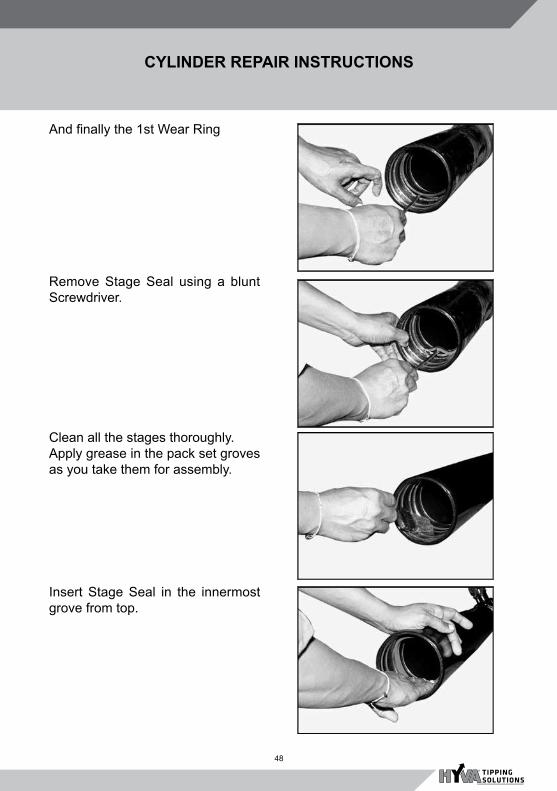
And finally the 1st Wear Ring
Remove Stage Seal using a blunt Screwdriver.
Clean all the stages thoroughly.Apply grease in the pack set groves as you take them for assembly.
Insert Stage Seal in the innermost grove from top.
CYLINDER REPAIR INSTRUCTIONS

49
Insert innermost 1st Wear ring in the 2nd grove from inside.
Insert 2nd Wear ring in the same groove (of the first Wear ring) as shown.
A view of Base tube after assembly of first pair of Wear rings.
Assemble 3rd wear ring in the third groove and finally the 4th Wear Ring.
CYLINDER REPAIR INSTRUCTIONS

50
Assemble Wiper in the 4th grove from inside
Inner view of Base tube after the Pack set assembly.
Replace old ‘O’ Ring with a new one after cleaning the Base plate peripheral grove.
Note:Repeat the same procedure to dismantled and assemble respective Pack sets in all the stages. Also note that this procedure is more or less same for all FE, FC, UCB and to certain extent UBEE Cylinders.
CYLINDER REPAIR INSTRUCTIONS

51
HYFIX BODY CLAMPS
This is a unique feature of hyva tipping system.
l Hyfix clamp mounted underneath the body, stops rattling of the empty tipper body on the chassis and thus prevents damage to the chassis, structural part and sub-frame and reduce the noise nuisance.
l This hyfix clamp is a revolutionary solution for continuous tipper problem of chassis receiving enormous hammering from the tipper body caused by potholes and bumps on the road.
l Hyfix ensures a fixed connection between tipper body chassis. The continuous bolt and nut, depending on where hyfix is fitted and the dimensions of the tipper body can adjust the compression load in the power block. The compression load can vary from 250 to 1600 kgs.
WELDING OF THE HYFIXl The hyfix to be fully supported and
welded over the entire surface before the compression load is set, so that no bending moment will arise on the power block and locking.
l Also the Hyfix bracket has to be fully welded.
DISMANTLING THE HYFIXl Open the Hyfix with hollow steel
bar and remove the setting pin.l While setting pin is removed
and the Hyfix closes, there is a possibility of clamping between the power block and the hook.
l Greasing points should be properly greased at regular intervals.
l Condition of power block and compression rod must be checked twice a year.

52
HOSES AND ADAPTERS
SUCTION & HIGH PRESSURE HOSES
Make sure the proper hose orientation in order to ensure (a) Same is not getting rubbed with any object (b) there is no twist (c) Hose is not bent too sharply.
l The mounting torque of the hose clamp must be 6 Nm
l Take care the hoses do not come in contact with hot or moving parts like the exhaust or drive shaft.
l Use Nylon Tape to seal the threads of elbows and hose pillars without O-ring, do not use Nylon Tape in combination with elbows or hose pillars with O-ring
Please use Hyva hoses only for replacement whenever required in order to ensure longer and safe life of hydraulic components.

53
HOSE ORIENTATION

54
MK5 Vs ALPHA SERIES FE CYLINDERSFE
-SER
IES
(Reg
ular
/ M
k 5)
FE S
ERIE
S (A
lpha
FL2
)Sr
.No.
PAR
T N
O.
DES
CR
IPTI
ON
PAR
T N
O.
DES
CR
IPTI
ON
0171
5331
65FE
-110
-3-0
3205
-009
A-K
1399
-HC
7053
3165
FE A
110-
3-03
150-
009-
K14
00-H
D-H
C02
7153
3165
SFE
-110
-3-0
2635
-009
A-K
1399
-HC
--
0371
5541
67FE
129
-3-0
3145
-009
A-K
1399
-HD
5-H
C
7053
4167
FE A
129-
3-03
145-
009-
K13
99-H
D-H
C04
7155
4181
FE 1
29-3
-034
00-0
01A
-K14
49-H
D5-
HC
705
3418
1FE
A12
9-3-
0339
5-00
1-K
1450
-HD
-HC
05
7155
4201
FE 1
29-3
-036
40-0
01A
-K15
29-H
D5-
HC
7053
4211
FE A
129-
3-03
635-
001-
K15
30-H
D-H
C
0671
5542
21FE
129
-3-0
3880
-001
A-K
1609
-HD
5-H
C 7
0534
221
FE A
129-
3-03
845-
001-
K16
00-H
D-H
C
0771
5542
57FE
129
-3-0
4270
-011
A-K
1739
-HD
5-H
C70
5342
57FE
A12
9-3-
0423
5-00
1-K
1730
-HD
-HC
0871
5552
01FE
149
-3-0
3620
-001
A-K
1529
-HD
5-H
C 7
0535
201
FE A
149-
3-03
620-
001-
K15
30-H
D-H
C09
7155
5227
FE 1
49-3
-038
60-0
09A
-K16
44-H
D5-
HC
7053
5211
FE A
149-
3-03
830-
009-
K16
45-H
D-H
C10
7155
5257
FE 1
49-3
-042
50-0
01A
-K17
39-H
D5-
HC
7053
5257
FE A
149-
3-04
220-
001-
K17
30H
D-H
C11
7155
5261
FE 1
49-4
-041
85-0
01A
-K13
64-H
D5-
HC
7053
5251
FE A
149-
4-04
185-
001-
K13
65-H
D-H
C12
7155
5301
FE 1
49-4
-045
25-0
09A
-K14
84-H
D5-
HC
7053
5295
FE A
149-
4-04
525-
009-
K14
85-H
D-H
C
1371
5562
99FE
169
-4-0
4500
-009
A-K
1479
-HD
5-H
C70
5362
91FE
A16
9-4-
0450
5-00
1-K
1449
HD
-HC
1471
5563
21FE
169
-4-0
4820
-001
A-K
1524
-HD
5-H
C70
5363
21FE
A16
9-4-
0482
5-00
1-K
1529
-HD
-HC
1571
5563
91FE
169
-4-0
5140
-001
A-K
1604
-HD
5-H
C70
5363
71FE
A16
9-4-
0510
5-00
1-K
1599
-HD
-HC
16
7155
6413
FE
169
-5-0
5220
-001
A-K
1359
-HD
5-H
C70
5363
91FE
A16
9-5-
0522
5-00
1-K
1364
-HD
-HC
17
7155
6455
FE16
9-5-
0578
0-00
9A-K
1524
-HD
5-H
C70
5364
73FE
A16
9-5-
0578
0-00
9-K
1529
-HD
-HC
1871
5573
21FE
191
-4-0
4790
-011
A-K
1527
-HD
5-H
C
7053
7369
FE A
191-
4-04
805-
011-
K15
32-H
D-H
C19
7155
7491
FE 1
91-5
-060
10-0
11A
-K15
27-H
D5-
HC
70
5375
31FE
A19
1-5-
0602
5-01
1-K
1532
-HD
-HC
2071
5574
11FE
191
-5-0
5185
-011
A-K
1362
-HD
5-H
C
7053
7411
FE A
191-
5-05
200-
011-
K13
67-H
D-H
C

55
MK5 Vs ALPHA SERIES FC CYLINDERSFC
-SER
IES
(Reg
ular
/ M
k 5)
FC S
ERIE
S (A
lpha
FL2
)Sr
.No.
PAR
T N
O.
DES
CR
IPTI
ON
PAR
T N
O.
DES
CR
IPTI
ON
0171
5031
61S
FC-1
10-3
-026
35-0
00A
-K03
43-H
C70
5131
55FC
A11
0-3-
0263
5-00
9-K
0343
-HD
-HC
0271
5031
61FC
-110
-3-0
3205
-000
A-K
0343
-HC
7051
3161
FC A
110-
3-03
150-
000-
K03
43-H
D-H
C03
7150
4180
FC 1
29-3
-034
60-0
00A
-K03
4370
5141
81FC
A12
9-3-
0339
5-00
0-K
0343
-HD
-HC
04-
DO
SE
NT
EX
IST
7051
4211
FC A
129-
3-38
45-0
00-K
0343
-HD
-HC
0571
5242
51FC
129
-3-0
4270
-000
A-K
0343
-HD
5-H
C70
5142
51FC
A12
9-3-
0423
5-00
0-K
0343
-HD
-HC
0671
5242
01FC
129
-3-0
3640
-000
A-K
0343
-HD
5-H
C70
5142
01FC
A12
9-3-
0363
5-00
0-K
0343
-HD
-HC
0771
5252
93FC
149
-4-0
4525
-070
A-K
0343
-HD
5-H
C70
5153
43FC
A14
9-4-
0452
5-07
0-K
0343
-HD
-HC
08
7152
5221
FC 1
49-3
-038
60-0
00A
-K03
43-H
D5-
HC
7051
5221
FC A
149-
3-03
830-
000-
K03
43-H
D-H
C09
7152
5261
FC 1
49-4
-041
85-0
00A
-K03
43-H
D5-
HC
7051
5261
FC A
149-
4-04
185-
000-
K03
43-H
D-H
C10
7152
6261
FC 1
69-4
-041
60-0
00A
-K03
43-H
D5-
HC
7051
6261
FC A
169-
4-04
165-
000-
K03
43-H
D-H
C
1171
5262
91FC
169
-4-0
4500
-000
A-K
0343
-HD
5-H
C70
5162
81FC
A16
9-4-
0450
5-00
0-K
0343
-HD
-HC
1271
5263
21FC
169
-4-0
4820
-000
A-K
0343
-HD
5-H
C70
5163
21FC
A16
9-4-
0482
5-00
0-K
0343
-HD
-HC
13
-D
OS
EN
T E
XIS
T70
5163
51FC
A16
9-4-
0510
5-00
0-K
0343
-HD
-HC
1471
5275
93FC
191
-5-0
7060
-014
A-K
1050
-HD
5-H
C70
5175
93FC
A19
1-5-
0702
5-01
4-K
1050
-HD
-HC
1571
5275
81FC
191
-5-0
7060
-000
A-K
0343
-HD
5-H
C70
5175
81FC
A19
1-5-
0702
5-00
0-K
0343
-HD
-HC
1671
5274
91FC
191
-5-0
6010
-000
A-K
0343
-HD
5-H
C70
5174
91FC
A19
1-5-
0602
5-00
0-K
0343
-HD
-HC
1771
5277
51FC
191-
5-08
130-
000A
-K03
43-H
D5-
HC
7051
7701
FC A
191-
5-08
130-
004-
K03
43-H
D-H
C18
7152
7991
FC 1
91-5
-090
30-0
04B
-K03
43-H
D5-
HC
7051
7991
FC A
191-
5-09
030-
004-
K03
43-H
D-H
C19
7152
8491
FC 2
14-5
-059
80-0
00B
-K03
43-H
D5-
HC
7051
8491
FC A
214-
5-05
995-
000-
K03
43-H
D-H
C20
7152
8581
FC 2
14-5
-070
30-0
00B
-K03
43-H
D5-
HC
7051
8581
FC A
214-
5-06
995-
000-
K03
43-H
D-H
C

56
FAULT DIAGNOSISTy
pe o
f Fai
lure
Cau
se o
f fai
lure
Rem
edy
1 T
IPP
ING
CY
LIN
DE
R
Cyl
inde
r Ben
t
Tipp
ing
on u
neve
n gr
ound
Tipp
ing
shou
ld a
lway
s be
car
ried
on e
ven
grou
nd.
Run
ning
the
vehi
cle
with
bod
y no
t re
stin
g on
sub
fram
e co
mpl
etel
yM
ove
the
tippe
r whe
n th
e bo
dy is
com
plet
ely
rest
on
subf
ram
e
Vehi
cle
topp
ling
in a
n ac
cide
ntC
heck
tipp
ing
is c
arrie
d on
eve
n su
rface
s. C
heck
bod
y co
nditi
on
and
body
alig
nmen
t w.r.
t to
Sub
fram
e an
d ch
assi
s.
Cyl
inde
r Bul
ge
Pre
ssur
e re
lief v
alve
set
ting
tam
pere
d fo
r Max
per
mis
sibl
e pr
essu
re (r
efer
pa
ge n
o. 2
7)R
epla
ce p
ress
ure
relie
f val
ve
Pre
ssur
e re
lief v
alve
not
wor
king
pr
oper
lyR
epla
ce p
ress
ure
relie
f val
ve
Che
ck o
il qu
ality
and
repl
ace
if ne
cess
ary.
Cyl
inde
r Sta
ge b
ulge
d ne
ar s
top
ring
groo
ve. V
ehic
le je
rked
whi
le u
nloa
ding
th
e m
ater
ial.
Rep
lace
dam
aged
par
ts. C
heck
ope
ratin
g pr
actic
es. A
void
je
rkin
g or
mov
ing
vehi
cle
to a
nd fr
o w
hile
unl
oadi
ng th
e m
ater
ial.
Cyl
inde
r Sco
ring
Cyl
inde
r int
erna
l com
pone
nt fa
ilure
O/H
cyl
inde
r and
repl
ace
dam
aged
com
pone
nts
Sco
ring
in th
e ax
is o
f tru
nnio
n du
e to
si
de lo
ad
Che
ck c
ylin
der m
ount
ing
dim
ensi
ons.
Cyl
inde
r to
be m
ount
ed
in c
entre
of b
ody
head
boar
d on
top
side
and
cen
tre o
f the
sub
fra
me
on b
otto
m s
ide.
Che
ck m
axim
um p
lay
betw
een
the
brac
kets
and
the
trunn
ion
is
2mm
on
each
sid
e.
Che
ck s
pace
rs a
re fi
tted
on b
oth
side
of p
isto
n ey
e an
d m
axim
um p
lay
of 1
.5 m
m is
mai
ntai
ned
betw
een
bkt a
nd
cylin
der e
ye s
pace
r.
Che
ck o
pera
ting
prac
tices
. Tip
ping
sho
uld
alw
ays
be c
arrie
d on
ev
en g
roun
d.

57
FAULT DIAGNOSISTy
pe o
f Fai
lure
Cau
se o
f fai
lure
Rem
edy
TIP
PIN
G C
YLI
ND
ER
(con
td.)
Cyl
inde
r Sco
ring
Sco
ring
in th
e ax
is o
f tru
nnio
n du
e to
si
de lo
ad
Avoi
d un
auth
oris
ed b
ody
exte
nsio
n.
Che
ck b
ody
for m
isal
ignm
ent/d
efor
mat
ion
and
real
ign/
repa
ir if
nece
ssar
y.
Che
ck R
r hin
ge b
rack
et, b
ushe
s an
d pi
n fo
r exc
ess
wea
r. R
epla
ce if
nec
essa
ry.
Sco
ring
due
to s
top
ring
disl
ocat
ion
Che
ck lo
ad m
ater
ial s
tuck
insi
de th
e bo
dy. C
lean
up s
tuck
m
ater
ial r
egul
arly.
Vehi
cle
jerk
ed w
hile
unl
oadi
ng th
e m
ater
ial.
Che
ck o
pera
ting
prac
tices
. Avo
id je
rkin
g or
mov
ing
vehi
cle
to a
nd fr
o w
hile
un
load
ing
the
mat
eria
l.
Sco
ring
due
to d
amag
ed e
xter
nal
surfa
ce (E
lect
rical
spa
rk/ e
xter
nal
hitti
ng) o
f Cyl
inde
r sta
ges
O/H
cyl
inde
r and
repl
ace
dam
aged
com
pone
nts.
Cov
er th
e cy
linde
r whi
le d
oing
wel
ding
nea
r cyl
inde
r.
Slid
ers
Bro
ken
insi
de th
e cy
linde
r due
to
sid
e lo
adO
/H c
ylin
der a
nd re
plac
e da
mag
ed c
ompo
nent
s. T
ippi
ng s
houl
d al
way
s be
car
ried
on e
ven
grou
nd.
Oil
Leak
age
from
C
ylin
der S
tage
s
Wro
ng F
itmen
t of s
eal
Rep
lace
com
plet
e se
al k
it.
Sea
ls d
amag
ed d
ue to
sco
ring
of
cylin
der s
tage
sO
/H c
ylin
der r
epla
ce d
amag
e pa
rts a
long
with
sea
l kit
Cyl
inde
r sub
ject
ed to
con
tinuo
us lo
adR
epla
ce s
eal k
it. V
ehic
le s
houl
d be
par
ked
with
bod
y re
stin
g on
su
b fra
me
or o
n th
e bo
dy p
rops
. Mai
ntai
n K
-val
ue a
s m
entio
ned
on C
ylin
der i
dent
ifica
tion
plat
e.
Oil
Leak
age
from
C
ylin
der S
tage
sH
igh
oil t
empe
ratu
re
Che
ck if
PTO
is c
ontin
uous
ly e
ngag
ed. R
ectif
y P
TO c
onne
ctio
n.
Use
cor
rect
gra
de o
f oil
in h
ydra
ulic
sys
tem
Che
ck P
ress
ure
relie
f val
ve w
orki
ng p
rope
rly, r
epla
ce if
pr
essu
re fo
und
less
than
130
bar
.
Con
tam
inat
ed o
ilC
heck
oil
qual
ity a
nd re
plac
e, if
nec
essa
ry.

58
FAULT DIAGNOSISTy
pe o
f Fai
lure
Cau
se o
f fai
lure
Rem
edy
TIP
PIN
G C
YLI
ND
ER
(con
td.)
Oil
Leak
age
from
C
ylin
der b
otto
m p
late
Poo
r Qua
lity
of S
eal
Rep
lace
bot
tom
pla
te s
eal.
Cyl
inde
r sub
ject
ed to
con
tinuo
us lo
adK
-val
ue s
houl
d be
mai
ntai
ned
as m
entio
ned
on c
ylin
der
iden
tifica
tion
plat
e
Pis
ton
com
ing
out
Jerk
y op
erat
ion
Che
ck o
pera
ting
prac
tices
. Avo
id je
rkin
g or
mov
ing
vehi
cle
to
and
fro w
hile
unl
oadi
ng th
e m
ater
ial.
Rep
lace
dam
aged
par
ts.
Poo
r loc
king
of p
isto
n ey
eC
heck
Pis
ton
eye
thre
ads
and
wel
ded
join
t con
ditio
n
Cyl
inde
r Bas
e tu
be
Cra
ckC
rack
on
trunn
ion
side
due
to s
ide
load
Rep
lace
bas
e tu
be. C
heck
cyl
inde
r mou
ntin
g di
men
sion
s.
Cyl
inde
r to
be m
ount
ed in
cen
tre o
f bod
y he
adbo
ard
on to
p si
de
and
cent
re o
f the
sub
fram
e on
bot
tom
sid
e.
2 T
IPP
ING
VA
LVE
Oil
Leak
age
from
Ti
ppin
g va
lve
Wor
n ou
t sea
l kit
Rep
lace
sea
l kit
Mai
nten
ance
sch
edul
e s
houl
d be
follo
wed
.
Sco
ring
insi
de ti
ppin
g va
lve
Rep
lace
tipp
ing
valv
e if
body
or s
pool
foun
d sc
ored
/ def
orm
ed.
Oil
leak
age
betw
een
valv
e an
d va
lve
mou
ntin
g bl
ock
Ens
ure
prop
er fi
tmen
t of s
ealin
g ‘O
’ rin
g be
twee
n tip
ping
val
ve
and
valv
e m
ount
ing
bloc
k.
Mal
func
tioni
ng o
f Ti
ppin
g Va
lve
Stic
ky S
pool
of t
ippi
ng v
alve
Che
ck o
il qu
ality
and
repl
ace
if ne
cess
ary.
O/H
tipp
ing
valv
e re
plac
e se
al k
it.
Rep
lace
tipp
ing
valv
e if
body
or s
pool
foun
d sc
ored
/ def
orm
ed.
Low
air
pres
sure
Che
ck a
ir pr
essu
re a
t tip
ping
val
ve a
ir in
let p
orts
to b
e m
inim
um
6 K
g/cm
2 .
Low
ope
ratin
g P
ress
ure
Pre
ssur
e re
lief v
alve
def
ectiv
eR
epla
ce p
ress
ure
relie
f val
ve.
Che
ck m
aint
enan
ce s
ched
ule
is fo
llow
ed.

59
FAULT DIAGNOSISTy
pe o
f Fai
lure
Cau
se o
f fai
lure
Rem
edy
TIP
PIN
G V
ALV
E (c
ontd
)
Load
bod
y co
min
g do
wn
in H
old/
Neu
tral
posi
tion
Non
retu
rn v
alve
fitte
d on
tipp
ing
valv
e pu
mp
port
defe
ctiv
eC
lean
non
retu
rn v
alve
and
repl
ace
if ne
cess
ary
Inte
rnal
leak
age
in c
ontro
l val
ve
Rep
lace
Sea
l kit
Rep
lace
tipp
ing
valv
e if
body
or s
pool
foun
d sc
ored
/ def
orm
ed.
Che
ck
Pre
ssur
e re
lief v
alve
if p
artia
lly o
pene
d. R
epla
ce if
pr
essu
re fo
und
less
than
130
bar
.
3
HY
DR
AU
LIC
PU
MP
Pum
p no
t wor
king
pr
oper
ly/ i
nsuf
ficie
nt
oil fl
owTh
rust
pla
te /
pum
p ho
usin
g w
orn
out
Rep
lace
dam
aged
par
ts. P
ump
shou
ld b
e op
erat
e at
max
.120
0 en
gine
R.P
.M.
Che
ck h
ydra
ulic
oil
qual
ity. C
heck
mai
nten
ance
sch
edul
e is
fo
llow
ed.
Ens
ure
corr
ect g
rade
of o
il is
use
d in
hyd
raul
ic s
yste
m
Che
ck a
nd to
p up
Hyd
raul
ic o
il le
vel
Che
ck if
veh
icle
is ru
n w
ith P
TO e
ngag
ed. R
ectif
y P
TO
conn
ectio
n.
Pum
p no
t wor
king
pr
oper
ly/ i
nsuf
ficie
nt
oil fl
owS
eal k
it da
mag
ed /
mel
ted
O/H
Pum
p, re
plac
e da
mag
ed p
arts
.
Use
cor
rect
gra
de o
f oil
in h
ydra
ulic
sys
tem
Che
ck if
veh
icle
is ru
n w
ith P
TO e
ngag
ed. R
ectif
y P
TO
conn
ectio
n.
Che
ck a
nd to
p up
Hyd
raul
ic o
il le
vel
Ens
ure
gate
val
ve is
in o
pen
posi
tion
whi
le o
pera
ting
pum
p.
Oil
Leak
age
from
P
ump
wee
p ho
leS
eal K
it de
fect
ive
Rep
lace
sea
l kit.
HY
DR
AU
LIC
PU
MP
(con
td)

60
FAULT DIAGNOSISTy
pe o
f Fai
lure
Cau
se o
f fai
lure
Rem
edy
Pum
p C
rack
Hig
h m
axim
um o
pera
ting
pres
sure
Rep
lace
pum
p.
Che
ck M
axim
um w
orki
ng p
ress
ure
of th
e sy
stem
. Max
170
Bar
R
epla
ce p
ress
ure
relie
f val
ve if
nec
essa
ry.
Che
ck M
ount
ing
Stu
ds a
nd B
olts
for t
ight
ness
.
Pum
p S
haft
Bro
ken
Sys
tem
pre
ssur
e hi
ghR
epla
ce p
ress
ure
relie
f val
ve.
Inte
rnal
com
pone
nts
seiz
ed
Che
ck o
il qu
ality
and
repl
ace
if ne
cess
ary.
Use
cor
rect
gra
de o
f oil
in h
ydra
ulic
sys
tem
Che
ck fo
r Hyd
raul
ic o
il le
vel
Ens
ure
gate
val
ve is
in o
pen
posi
tion
whi
le o
pera
ting
pum
p.
4
AIR
CO
NTR
OL
VALV
E
Air
leak
age
from
air
cont
rol v
alve
Impr
oper
sea
ling
join
t bet
wee
n ai
r co
ntro
l val
ve a
nd a
dapt
orR
ectif
y ai
r lea
kage
from
sea
ling
join
t.
Air
cont
rol v
alve
def
ectiv
eR
epla
ce A
ir C
ontro
l Val
ve
Air
Leak
age
from
air
cont
rol v
alve
whi
le
tippi
ng
Def
ectiv
e tip
ping
val
ve s
eal k
itC
heck
and
repl
ace
tippi
ng v
alve
sea
l kit
Che
ck m
aint
enan
ce s
ched
ule
is fo
llow
ed.
Air
cont
rol v
alve
def
ectiv
eR
epla
ce A
ir co
ntro
l val
ve
Air
cont
rol v
alve
le
ver/
knob
bro
ken
Forc
eful
ope
ratio
n of
air
cont
rol v
alve
Che
ck d
river
ope
ratin
g pr
actic
e. L
ift th
e A
CV
kno
b an
d th
en
oper
ate
the
leve
r.
Oil
in a
ir co
ntro
l va
lve
Tipp
ing
valv
e se
al k
it de
fect
ive
Che
ck a
nd re
plac
e ti
ppin
g va
lve
seal
kit.
Che
ck m
aint
enan
ce s
ched
ule
is fo
llow
ed.
Less
air
pres
sure
ou
tput
from
tip,
low
an
d P
TO p
orts
Air
pres
sure
sup
ply
belo
w 6
Kg/
cm2
Ens
ure
air p
ress
ure
supp
ly fr
om c
hass
is is
min
7-8
bar
.

61
FAULT DIAGNOSISTy
pe o
f Fai
lure
Cau
se o
f fai
lure
Rem
edy
5
PO
WE
R T
AK
E O
FF (P
TO)
Noi
se w
hile
en
gagi
ng
Insu
ffici
ent a
ir pr
essu
reE
nsur
e ai
r pre
ssur
e su
pply
from
cha
ssis
is m
in 7
-8 b
ar.
Clu
tch
not d
isen
gagi
ng c
ompl
etel
yC
heck
clu
tch
for c
ompl
ete
dise
ngag
ing.
Hig
h en
gine
idlin
g R
.P.M
Adj
ust e
ngin
e id
ling
R.P
.M
PTO
ope
ratin
g ai
r cyl
inde
r stic
kyC
heck
for p
rope
r wor
king
of a
ir cy
linde
r. R
epla
ce if
nec
essa
ry.
PTO
air
cylin
der t
rave
l ins
uffic
ient
Adj
ust a
ir cy
linde
r stro
ke fo
r com
plet
e en
gage
men
t of P
TO
Pne
umat
ic o
pera
ted
pist
on in
side
PTO
no
t wor
king
pro
perly
Che
ck P
TO in
tern
al p
arts
. Rep
lace
dam
aged
par
ts.
PO
WE
R T
AK
E O
FF (P
TO) (
cont
d)
Noi
se w
hile
en
gagi
ngG
ear t
eeth
wor
n ou
t
Rep
lace
wor
n ou
t PTO
gea
r. C
heck
gea
r box
cou
nter
shaf
t re
spec
tive
gear
.
Ens
ure
air p
ress
ure
supp
ly fr
om c
hass
is is
min
7-8
bar
.
Che
ck c
lutc
h fo
r com
plet
e di
seng
agin
g.
Che
ck d
river
pra
ctic
e fo
r PTO
eng
agin
g at
hig
her e
ngin
e R
.P.M
. S
ugge
sted
to e
ngag
e P
TO a
t eng
ine
idlin
g R
.P.M
.
PTO
not
wor
king
Low
air
pres
sure
Ens
ure
air p
ress
ure
supp
ly fr
om c
hass
is is
min
7-8
bar
.
Che
ck a
ir su
pply
from
air
cont
rol v
alve
to P
TO
PTO
co
ntin
uous
ly
enga
ged
Con
tinuo
us a
ir su
pply
to P
TOR
ectif
y ai
r con
nect
ion,
ens
ure
corre
ct o
pera
tion
of A
ir co
ntro
l val
ve
PTO
ope
ratin
g ai
r cyl
inde
r stu
ck u
pR
epla
ce A
ir cy
linde
r
Pne
umat
ic o
pera
ted
pist
on in
side
PTO
no
t wor
king
pro
perly
Che
ck P
TO in
tern
al p
arts
, rep
lace
nec
essa
ry p
arts
Noi
se in
PTO
in
enga
ged
posi
tion
Gea
r tee
th b
roke
nR
epla
ce d
amag
ed g
ear.
Ens
ure
corr
ect g
ear b
ackl
ash
of
0.2m
m m
ax.

62
FAULT DIAGNOSISTy
pe o
f Fai
lure
Cau
se o
f fai
lure
Rem
edy
Oil
leak
age
from
P
TO
Def
ectiv
e se
alin
g be
twee
n P
TO a
nd
Gea
r box
join
tR
ectif
y le
akag
e fro
m s
ealin
g jo
int.
PTO
Hou
sing
cra
ckR
epla
ce P
TO h
ousi
ng.
Che
ck P
TO m
ount
ing
stud
s an
d bo
lts fo
r tig
htne
ss.
6
OIL
TA
NK
Oil
Leak
age
from
oil
tank
Def
ectiv
e se
alin
g be
twee
n ac
cess
orie
s an
d oi
l tan
kR
ectif
y le
akag
e fro
m s
ealin
g jo
ints
Che
ck ti
ghtn
ess
of m
ount
ing
bolts
, oil
leve
l ind
icat
or, a
dapt
ors
Leak
age
from
wel
ded
join
tR
ewel
d de
fect
ive
join
t.
Oil
thro
win
g fro
m
Tank
(Bre
athe
r filte
r/re
turn
line
filte
r)
Oil
leve
l too
hig
hE
nsur
e co
rrec
t hyd
raul
ic o
il le
vel
Clo
gged
Filt
ers
Rep
lace
filte
rs
7 H
YD
RA
ULI
C H
OS
ES
Oil
leak
age
from
H
ose
Inco
rrec
t sea
ling
betw
een
hose
and
ad
apto
rsR
epla
ce S
ealin
g jo
ints
(Dow
ty s
eals
, ‘O
’ Rin
gs)
Oil
leak
age
from
hos
e cr
impi
ng
Rep
lace
hos
e.
Rem
ove
Sha
rp h
ose
bend
ver
y ne
ar to
crim
ping
are
a.
Che
ck fo
r tw
istin
g of
hos
e du
e to
wro
ng fi
tmen
t.
Oil
leak
age
due
to e
xter
nal d
amag
esR
epla
ce h
ose
if da
mag
ed. E
nsur
e ho
se is
not
rubb
ing
with
ot
her p
arts
of v
ehic
le.

63
FAULT DIAGNOSISTy
pe o
f Fai
lure
Cau
se o
f fai
lure
Rem
edy
8 TI
PP
ER
BO
DY
Sub
fram
e C
rack
ed
Cra
ck d
ue to
loos
e m
ount
ing
bolts
Rew
eld
& ti
ghte
n m
ount
ing
bolts
as
per s
peci
fied
torq
ue.
Cra
ck d
ue to
impr
oper
load
ing
patte
rnTi
pper
sho
uld
not o
verlo
aded
.
Che
ck if
the
tippe
r is
used
for s
peci
fied
appl
icat
ion.
Cra
ck d
ue to
poo
r wel
ded
join
tsR
ewel
d th
e jo
int.
Cra
ck d
ue to
acc
iden
tR
epai
r / re
plac
e su
b fra
me
Cra
ck d
ue to
ove
r tig
hten
ing
of P
ivot
bo
ltsP
ivot
bol
ts s
houl
d be
tigh
ten
as p
er in
stru
ctio
n.
Sub
fram
e B
end
Sub
Fra
me
bend
due
to A
ccid
ent
Rep
lace
sub
fram
e
Cyl
inde
r Cra
dle
Ben
dC
radl
e be
nd d
ue to
cyl
inde
r fou
ling
to
crad
le
Che
ck ti
pper
bod
y tip
ping
ang
le s
houl
d no
t mor
e th
an 5
6 °
Adj
ust g
ap b
etw
een
cylin
der a
nd c
radl
e.
Che
ck re
ar h
inge
pin
and
lock
ing
bolt
TIP
PE
R B
OD
Y (c
ontd
)
Cyl
inde
r Cra
dle
Wel
ding
cra
ck
Cra
ck d
ue to
poo
r wel
ded
join
tsR
ewel
d th
e c
radl
e jo
int
Cra
ck d
ue to
impr
oper
load
ing
patte
rnTi
pper
sho
uld
not o
verlo
aded
.
Che
ck if
the
tippe
r is
used
for s
peci
fied
appl
icat
ion.
Rea
r Hin
ge s
haft/
P
in w
orn
out
Sha
ft /P
in w
orn-
out d
ue to
lack
of
lubr
icat
ion
Rep
lace
rear
hin
ge p
in &
sha
ft in
nec
essa
ry. F
ollo
w lu
bric
atio
n sc
hedu
le.
Bod
y Fl
oor D
amag
ed
Bod
y flo
or d
amag
ed d
ue to
Roc
k (S
tand
ard
body
use
d fo
r roc
k ap
plic
atio
n)E
nsur
e tip
per u
sage
spe
cifie
d ap
plic
atio
n.
Bod
y flo
or d
amag
ed d
ue to
Acc
iden
tR
epai
r Bod
y flo
or

64
FAULT DIAGNOSISTy
pe o
f Fai
lure
Cau
se o
f fai
lure
Rem
edy
Bod
y he
ad b
oard
fo
ulin
g w
ith o
il ta
nk
Bod
y he
ad b
oard
def
orm
due
to w
rong
ap
plic
atio
n (S
TD b
ody
used
for r
ock
appl
icat
ion)
Ens
ure
tippe
r usa
ge s
peci
fied
appl
icat
ion.
Hea
d bo
ard
foul
ing
due
to le
ss g
ap in
be
twee
n ta
nk a
nd h
ead
boar
dC
heck
tipp
er b
ody
rear
hin
ge b
rack
et is
wel
ded
in c
orre
ct
posi
tion
Sid
e B
oard
Bul
ge
Sid
e bo
ard
bulg
e du
e to
Acc
iden
t (T
oppl
ing)
Rea
lign/
repa
ir th
e si
de b
oard
Sid
e bo
ard
bulg
e du
e to
impr
oper
lo
adin
g pa
ttern
Ens
ure
load
ing
and
oper
atin
g pr
actic
e as
reco
mm
ende
d.
Tail
Doo
r Ben
d
Tail
Doo
r ben
d du
e to
Acc
iden
tR
epai
r or r
epla
ce T
ail d
oor
Tail
Doo
r ben
d du
e to
impr
oper
lock
ing
mec
hani
smR
ealig
n ta
il do
or. E
nsur
e ta
il do
or lo
ckin
g m
echa
nism
wor
king
pr
oper
ly
Tail
Doo
r ben
d du
e to
ove
r loa
ding
Rea
lign
tail
door
. Tip
per s
houl
d no
t ove
rload
ed.

65
GREASING LAYOUT
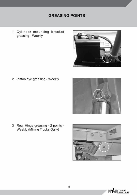
66
GREASING POINTS
1 Cyl inder mount ing bracket greasing - Weekly
2 Piston eye greasing - Weekly
3 Rear Hinge greasing - 2 points - Weekly (Mining Trucks-Daily)

67
GREASING POINTS
5 Tail door hinge - 2 points - Weekly
6 Body prop - 1Point - Weekly
4 Tail Door Locking Mechanism greasing - 3 points. Weekly

68
7 Hyfix assy. greasing - 1 point - Weekly
8 Stabiliser assy. greasing - 6. points - Weekly (All Rock Bodies on Mining Trucks)
9 Side locking tail door mechanism - 2 Points - Weekly
GREASING POINTS

69
Material Kg / Cu. M. Material Kg/Cu. M.
Ashes and cinders (wet) 1015-1330 Gravel and sand (dry) 1460-1728
Ashes and cinders (dry) 780-1030 Lime paste 1150-2000
Asphalt (pitch) 2128 Lime Powder 500
Asphalt (massive) 2394 Limestone burnt 775-1000
Asphalt (tar) 1878-2510 Marl 2300-2600
Barley in bulk 1729-1928 Molding sand 1446-1596
Bone meal 700-1100 Oats 415-515
Brick (loose) 1263-1662 Ore 2095-2560
Brick (stacked) 1480-1995 Potatoes 650-700
Brick (general) 630 Pebbles 1350-2000
Cement (loose) 1446 Rubble (broken stone) 1530-1730
Cement (natural) 897 Sand (wet) 1660
Clay (wet) 1760 Sand (dry) 1330
Clay (dy) 1015 Slag and cinders 1263-1660
Coal (anthracite) 897 Snow 80-800
Coke Grit 400-548 Stone (broken, coarse) 1662
Coke 360-615 Stone (broken, fine) 1197-1462
Concrete (wet) 2377 Stone (Grinded) 1600
Concrete (dry) 1240 Sugar in bulk 797-880
Corn and rye 765 Sulphur 1930-2070
Earth (wet) 1600-1800 Super phospate 1000-1200
Earth (dry) 1200 Town refuse 498
Fertilizer 1030 Wheat 765
Flour of corn 400-500 Wood chips 200
Flour 600-731 Wooden logs deal 320
Garbage 680 Wooden logs oak 420
Gravel 1680 Wooden logs beech 400
Gravel and sand (wet) 1928 Woodwool 50
APRROX. SPECIFIC DENSITIES
SPECIFIC DENSITIES
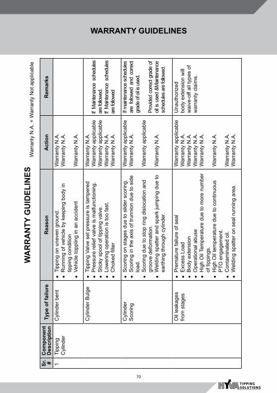
70
WA
RR
AN
TY G
UID
ELIN
ESW
arra
nty
N.A
. = W
arra
nty
Not
app
licab
le
Sr. #
Com
pone
nt
Des
crip
tion
Type
of f
ailu
reR
easo
nA
ctio
nR
emar
ks
1Ti
ppin
g C
ylin
der
Cyl
inde
r ben
tl T
ippi
ng o
n un
even
gro
und.
l R
unni
ng o
f veh
icle
by
keep
ing
body
in
tippi
ng c
ondi
tion
l V
ehic
le to
pplin
g in
an
acci
dent
War
rant
y N
.A.
War
rant
y N
.A.
War
rant
y N
.A.
Cyl
inde
r Bul
ge
l T
ippi
ng V
alve
set
pre
ssur
e is
tam
pere
dl P
ress
ure
relie
f val
ve is
mal
func
tioni
ng.
l S
ticky
spo
ol o
f tip
ping
val
ve.
l L
ower
ing
oper
atio
n is
too
fast
. l C
hoke
d fil
ter
War
rant
y N
.A.
War
rant
y ap
plic
able
W
arra
nty
appl
icab
le
War
rant
y N
.A.
War
rant
y N
.A.
If M
ainte
nanc
e sc
hedu
les
are
follo
wed.
If M
ainte
nanc
e sc
hedu
les
are
follo
wed
Cyl
inde
r S
corin
gl S
corin
g on
sta
ges
due
to s
lider
sco
ring.
l S
corin
g in
the
axis
of t
runn
ion
due
to s
ide
load
.l S
corin
g du
e to
sto
p rin
g di
sloc
atio
n an
d gr
oove
def
orm
atio
n.l W
eldi
ng s
patte
r and
spa
rk ju
mpi
ng d
ue to
ea
rthin
g th
roug
h cy
linde
r.
War
rant
y ap
plic
able
War
rant
y N
.A.
War
rant
y ap
plic
able
War
rant
y N
.A.
If m
ainte
nanc
e sc
hedu
les
are
follo
wed
and
corre
ct
grad
e of
oil is
use
d. Pr
ovide
d co
rrect
grad
e of
oil
is u
sed
&Main
tena
nce
sche
dules
are
follo
wed.
Oil
leak
ages
fro
m s
tage
sl P
rem
atur
e fa
ilure
of s
eal
l E
xces
s Lo
adl B
ody
exte
nsio
nl O
pera
tiona
l abu
sel H
igh
Oil
Tem
pera
ture
due
to m
ore
num
ber
of ti
ppin
gs.
l H
igh
Oil
tem
pera
ture
due
to c
ontin
uous
P
TO e
ngag
emen
t.l C
onta
min
ated
oil.
l W
eldi
ng s
patte
r on
seal
runn
ing
area
.
War
rant
y ap
plic
able
War
rant
y N
.A.
War
rant
y N
.A.
War
rant
y N
.A.
War
rant
y N
.A.
War
rant
y N
.A.
War
rant
y N
.A.
War
rant
y N
.A.
Una
utho
rized
bo
dy e
xten
sion
will
w
aive
-off
all t
ypes
of
war
rant
y cl
aim
s.
WARRANTY GUIDELINES

71
WA
RR
AN
TY G
UID
ELIN
ES (C
ontd
..) War
rant
y N
.A. =
War
rant
y N
ot a
pplic
able
Sr. #
Com
pone
nt
Des
crip
tion
Type
of f
ailu
reR
easo
nA
ctio
nR
emar
ks
Oil
leak
age
from
cyl
inde
r bo
ttom
pla
te
l P
rem
atur
e fa
ilure
of s
eal
War
rant
y ap
plic
able
Pis
ton
com
ing
out
l J
erky
ope
ratio
n by
pus
hing
bac
kwar
d af
ter
unlo
adin
g.W
arra
nty
N.A
.
Cyl
inde
r bas
e tu
be c
rack
l C
rack
is o
n tru
nion
sid
e du
e to
sid
e lo
ads.
l C
rack
is o
n al
l aro
und
truni
on.
War
rant
y N
.A.
War
rant
y ap
plic
able
C
ylin
der S
tuck
l S
lider
s ov
er ri
ding
War
rant
y ap
plic
able
2Ti
ppin
g Va
lve
Oil
leak
age
l P
rem
atur
e fa
ilure
of s
eal.
War
rant
y ap
plic
able
Mal
func
tioni
ng
of v
alve
l S
ticky
spo
olW
arra
nty
appl
icab
leP
rovi
ded
mai
nten
ance
sc
hedu
les
are
follo
wed
.H
igh
oper
atin
g pr
essu
re.
l P
ress
ure
relie
f val
ve ta
mpe
red.
War
rant
y N
.A.
Wor
king
pr
essu
re is
too
low
.
l L
ow s
yste
m p
ress
ure
as re
lief v
alve
m
alfu
nctio
ning
War
rant
y ap
plic
able
3H
ydra
ulic
pu
mp
Pum
p fa
ilsl R
elie
f val
ve s
et p
ress
ure
is ta
mpe
red
l N
o hy
drau
lic o
il in
the
tank
l P
ump
oper
ated
with
out o
peni
ng b
all v
alve
.l E
xter
nal d
amag
e du
e to
hit
by
exte
rnal
ob
ject
.l C
orre
ct g
rade
of o
il is
not
use
d.l T
hrus
t pla
te &
hou
sing
wea
r out
due
to
exce
ss ra
ving
of e
ngin
e rp
m.
War
rant
y N
.A.
War
rant
y N
.A.
War
rant
y N
.A.
War
rant
y N
.A.
War
rant
y N
.A.
War
rant
y N
.A.
WARRANTY GUIDELINES
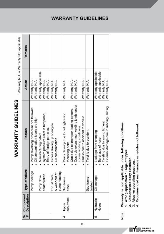
72
Sr. #
Com
pone
nt
Des
crip
tion
Type
of f
ailu
reR
easo
nA
ctio
nR
emar
ks
Pum
p le
akag
el P
ump
reve
rsin
g pr
oced
ure
not f
ollo
wed
l O
il co
ntam
inat
ion
leve
ls a
re h
igh
War
rant
y N
.A.
War
rant
y N
.A.
Pum
p dr
ive
shaf
t bro
ken
l M
anuf
actu
ring
defe
ctl S
yste
m p
ress
ure
relie
f is
tam
pere
d.l E
ntry
of f
orei
gn p
artic
les.
War
rant
y ap
plic
able
War
rant
y N
.A.
War
rant
y N
.A.
Thru
st p
late
&
wea
r out
of
pum
p ho
usin
g
l E
xces
s R
avin
g up
of e
ngin
el O
il co
ntam
inat
ion
War
rant
y N
.A.
War
rant
y N
.A.
4 Ti
pper
su
b-fra
me
Sub
fram
e cr
ack
l C
rack
dev
elop
due
to n
ot ti
ghte
ning
m
ount
ing
bolts
.l C
rack
due
to im
prop
er lo
adin
g pa
ttern
.l C
rack
dev
elop
s ne
ar w
eldi
ng jo
ints
und
er
norm
al w
orki
ng c
ondi
tions
.l C
rack
s du
e to
acc
iden
t to
vehi
cle
War
rant
y N
.A.
War
rant
y N
.A.
War
rant
y N
.A.
War
rant
y N
.A.
Sub
fram
e tw
iste
dl T
wis
t is
due
to a
ccid
ent
War
rant
y N
.A.
5H
ydra
ulic
H
oses
Oil
leak
age
l L
eaka
ge fr
om c
rimpi
ngl B
urst
age
of h
ose.
l T
wis
ting
due
to w
rong
fitm
ent
l E
xter
nal d
amag
e du
e to
rubb
ing
/ hitt
ing
War
rant
y ap
plic
able
War
rant
y ap
plic
able
War
rant
y N
.A.
War
rant
y N
.A.
War
rant
y N
.A. =
War
rant
y N
ot a
pplic
able
WA
RR
AN
TY G
UID
ELIN
ES
Not
e:
War
rant
y is
not
app
licab
le u
nder
fol
low
ing
cond
ition
s.
1. W
rong
app
licat
ion
/ usa
ge o
f tip
per.
2.
U
naut
horiz
ed b
ody
exte
nsio
n.
3. A
busi
ve o
pera
ting
prac
tices
.
4. R
ecom
men
ded
mai
nten
ance
sch
edul
es n
ot fo
llow
ed.
WARRANTY GUIDELINES
73
D
ate
P
artic
ular
s of
Rep
air
Hyv
a au
thor
ised
R
epre
sent
ativ
e S
ign.
Rec
ord
of S
ervi
ce /
Rep
airs
per
form
ed

74
Model .....................................................................................................
Chassis No. ..........................................................................................
Body Type ............................................................................................
Body Sr. No. ..........................................................................................
Date of sale ..........................................................................................
Owner’s name ......................................................................................
Address ................................................................................................
...............................................................................................................
...............................................................................................................
VEHICLE PARTICULARS

75