LP-400/V/W series Operation/Maintenance Manual
334
2018.7 panasonic.net/id/pidsx/global Laser Marker Operation / Maintenance Manual LP-400 series LP-V series LP-W series ME-LP400V-OP-6 No.9000-0062-14V Please read these instructions carefully before using this product, and save this manual for future use.
-
Upload
khangminh22 -
Category
Documents
-
view
3 -
download
0
Transcript of LP-400/V/W series Operation/Maintenance Manual

2018.7 panasonic.net/id/pidsx/global
Laser Marker
Operation /
Maintenance Manual
LP-400 series LP-V series LP-W series
ME-LP400V-OP-6 No.9000-0062-14V
Please read these instructions carefully before using this product, and save this manual for future use.
2
PrefaceThank you for purchasing our product.For full use of this product safely and properly, please read this document carefully.This product has been strictly checked and tested prior to its delivery. However, please make sure that this product operates properly before using it. In case that the product becomes damaged or does not operate as specified in this document, contact the dealer you purchased from or our sales office.
� General terms and conditions of this document1. Before using this product, or before every starting operation, please confirm the correct functioning and performance
of this product.2. Contents of this document could be changed without notice.3. This document must not be partially or totally copied or revised.4. All efforts have been made to ensure the accuracy of all information in this document. If there are any questions,
mistakes, or comments in this document, please notify us.5. Please remind that we assume no liability for any results arising out of operations regardless of the above clauses.
� DisclaimerThe applications described in this document are all intended for examples only. The purchase of our products described in this document shall not be regarded as granting of a license to use our products in the described applications. We do NOT warrant that we have obtained some intellectual properties, such as patent rights, with respect to such applications, or that the described application may not infringe any intellectual property rights, such as patent rights, of a third party.
� Trademark• Windows is a registered trademark or trademark of Microsoft Corporation in the United States and/or other countries.• QR Code is a registered trademarks of DENSO WAVE INCORPORATED.• Adobe, the Adobe logo, Acrobat, and Reader are either registered trademarks or trademarks of Adobe Systems
Incorporated in the United States and/or other countries.• All other product names and companies provided in this document are trademarks or registered trademarks of their
respective companies.
ME-LP400V-OP-6

3
Cautions in HandlingTo reduce the risk of injury, loss of life, electric shock, fire, malfunction, and damage to equipment or property, always observe the following safety precautions.
The following symbols are used to classify and describe the level of hazard, injury, and property damage caused when the denotation is disregarded and improper use is performed.
DANGER Denotes a potential hazard that will result in serious injury or death.
WARNING Denotes a potential hazard that could result in serious injury or death.
CAUTION Denotes a hazard that could result in minor injury.
The following symbols are used to classify and describe the type of instructions to be observed.
This symbol is used to alert users to a specific operating procedure that must not be performed.
This symbols is used to alert users to a specific operating procedure that must be followed in order to operate the unit safely.
This symbols is used to alert users to a specific operating procedure that must be performed carefully.
DANGER• Never look at laser beam directly, through lens or through any other optical components. Laser beam
radiation into the eye causes blindness or serious damage to the eye. Not only the direct beam of laser, but also diffused reflected beam is harmful.
• Never touch laser beam and avoid human skin, clothing and any other flammable object from laser beam exposure directly. Burning into deep skin might result and there is a risk of fire.
ALWAYS FOLLOW THESE IMPORTANT SAFETY PRECAUTIONS!
ME-LP400V-OP-6

4
WARNING• Do not use this product anywhere where fire is strictly prohibited, near inflammable gas, objects or organic
solvents such as thinner or gasoline, or in dusty place. There is a risk of fire.
• Do not use this product in wet place. In addition, never conduct wiring or maintenance work with wet hands or when the product surface is wet. Otherwise, electric shock and/or malfunction may result.
• Never disassemble the product. Doing so may cause exposure to the laser beam or electric shock.
• Do not insert hands or objects between the gaps of the exhaust port or inspiratory port. There is a risk of electrical shock or injury.
• For LP-V / LP-W series, be careful neither to give strong power to the fiber cable nor to nip it for installation. Do not install the product to the systems that give excessive load acts on the fiber cable, such as head movement unit. If the fiber cable is damaged, laser beam comes out from the cable and it may cause laser exposures.
• Take laser protection measures required to use Class 4 laser products subject to the local laws and regulations of the country or region in which this laser product is used.
• To protect the operators’ eyes, make it mandatory to wear goggles against laser beam within the laser controlled area. The protective goggles can momentarily protect the eyes against the scattered beam. Never look at the direct beam or reflected beam even when you are wearing the protective goggles.
• Construct an interlock systems such as a function to stop laser radiation for the maintenance door of the protective enclosure.
• Set protective enclosure with proper reflectance, durability and thermal resistance to enclose the laser radiation area without leakage.
• After power supply of laser marker is turned off, laser safety manager must remove the key and keep it.
• Be sure to connect the head to the exclusive controller. It will cause exposure of laser beam and a failure if it connects with any equipment other than the exclusive controller.
• Read all packaged guides and manuals thoroughly, and do not operate, install and connect the laser marker with any other methods except the instructions provided in the manuals. Inappropriate use might cause injury, electrical shock or exposure of laser beam.
ME-LP400V-OP-6

5
WARNING• Remove the dust and/or gas which may be generated during the laser radiation with dust collector or
exhauster. Use an appropriate dust collector or exhauster for dust or gas generated. Depending on the material of the objects, harmful dust and/or gas to the human body and the laser marker may be generated.
Dust collector
Protective enclosure
• When using the assist gas for laser processing, take safety precautions to protect operators from exposure, ignition, toxic effect, excess or lack of oxygen.
• Prior to wiring, cable connecting, and/or maintenance work, ensure that all the power switches are turned off. Otherwise, electrical shock may result.
• The wiring and maintenance must be conducted by the electrical engineers or under their supervision. Incorrect work may cause electrical shock.
• Connect ground wire before using. A failure or electrical leakage that occurs when the unit is not properly grounded may result in electric shock.
• To carry this product, wear the non-slip gloves and safety shoes, hold the bottom of the unit as shown below figure. Carry the controller unit with two persons.
• Install this product in the stable place without vibration and shock.• In case it falls down, it may cause injury.
Controller
ME-LP400V-OP-6

6
For the Proper Use of Product
• Be sure to observe the following matters to prevent a failure or a malfunction of this product and to maintain the product performance properly.
� Usage environment• Do not use the product in a place with frequent vibrations or shocks. Moreover, please do not drop this product. It
may affect the precision component and optical component inside, which could impair the performance or result in a failure.
• Do not use the system outdoors.• The product is air-cooled. Please install not to bar the flow of air cooling. Avoid placing heat sources near the product.• Be sure to use the product within the ambient temperature and humidity defined in the specifications.• Be careful not to have water, oil, fingerprints, dust, or dirt attached to the laser emission port of the head. This could
degrade the lasing performance and may result in a failure. If the laser emission port becomes dirty, use a dry soft cloth to clean the port.
• If the air filter becomes dirt, clean the filter. Failure to do so may hinder the air flow, resulting in failure of this product. Replace air filter periodically.
• Ensure that the dust or gas are removed by placing the intake duct of the dust collector or exhauster near the source of dust or gas. Any dust or gas contamination on the laser emission port may cause failure or decrease the laser marking or processing quality. In addition, when the laser beam is blocked by dust or gas, it may cause decrease in laser marking or processing quality.
� Installation and mounting• Do not hold the cables and connectors at carrying this product.• Do not touch the laser emission port on the bottom of the head. They may affect the laser marking quality badly.• For LP-V / LP-W series, do not grasp the fiber unit when carrying the head part.• Carry the head as shown in the figure below.
LP-400 series
OK NG
LP-V/LP-W series
OK NG
Laser emission port
Laser pointer emission port
Fiber cable
• Do not install the product to the systems that give excessive load acts on the head and cables, such as head movement unit. Failure to do so may damage the head precision parts or disconnect the cables, resulting in a failure.
• Be careful neither to give strong power to the cables nor to nip it for installation.• Verify the minimum bend radius of each cable and install them without excess forces being applied.• Do not hit the device with a tool such as a hammer at the installation. Do not use excessive force while tightening the
screws (nuts). It may cause a failure.• Do not insert any objects between the gaps of the exhaust port or inspiratory port.• Use anti-reflection material (ex. black paint for metal) for an external shutter or a protective enclosure in a path of
laser beam. It may cause a failure of the components inside the laser marker head.• If any other devices such as a sensor or a camera are installed near the laser marker, make sure that these devices
are installed in the place where laser beam and its reflected beam do not damage to them.
ME-LP400V-OP-6

7
For the Proper Use of Product
• Be sure to observe the following matters to prevent a failure or a malfunction of this product and to maintain the product performance properly.
� Wiring• Verify that the cables are wired correctly before powering on.• For the connection of this product, use the dedicated cables attached to the product or the specified optional cables.• Check the voltage fluctuations of the power supply. Do not input the power supply exceeding the rating.• If a surge occurs in the power supplied, connect a surge absorber to a source of the surge to absorb it.• Be sure to take measures against surge before connecting any induction load such as DC relay to the load.• The output has no protection function for short-circuit, therefore, do not connect the power supply or capacitive load
directly.• Make sure to ground the frame ground terminal of this product.• Install such that the controller housing and the head housing are at the same electric potential.• Each connecting cable should not be used in the same raceway or connected in parallel to any device that generates
high-tension wires, power lines, large switching surge or the like. There is a risk of malfunction caused by induction.• USB cable should not be connected in parallel with the controller power cable or the motor power cable.• Make the wiring as short as possible to prevent a malfunction by the noise.
� Operation• Do not turn off the power supply until completing the system start.• In case of turning ON the power supply after turning OFF, leave the interval at least 5 seconds between ON and OFF.• The following items, Date, Lot, and Expiry Date are marked based on the internal clock of the laser marker. The
internal clock might be deviated due to error of the internal parts or degree of the battery drain, ambient temperature and humidity. Therefore, be sure to check the time of the internal clock before the operation.
• Do not remove the USB media nor turn off the power during the data writing and reading operation.
� Others• Be sure to delete all registered data when transferring or discarding this product. Retained data might result in illegal
read out and leaking of information by a third-party with malicious intent.
ME-LP400V-OP-6

8
� General Terms and ConditionsAlthough we are striving to improve quality and reliability of our products, failure in electric components and devices may happen with a certain probability. It is highly recommended to employ fail-safe designs, including redundant design, flame propagation prevention design, and malfunction prevention design, as well as periodical maintenance to avoid any risk of bodily injury, fire accident, or social damage due to any failure of our products.Please read carefully and accept the following “Cautions for Safe Use” and “Warranty Policy” before using our products.
1. PRODUCT MODIFICATIONS & DISCONTINUANCE:Panasonic Industrial Devices SUNX expressly reserves the right to modify, including the right to discontinue, any of the Products, prior to their order, from time to time without notice.
2. WARRANTIES:(1) Subject to the exclusions stated in 3 (EXCLUSIONS) herein below, Panasonic Industrial Devices SUNX warrants the Products
to be free of defects in material and workmanship for a period of one (1) year from the date of shipment under normal usage in environments commonly found in manufacturing industry.
(2) Any Products found to be defective must be shipped to Panasonic Industrial Devices SUNX with all shipping costs paid by Purchaser for inspection and examination. Upon examination by Panasonic Industrial Devices SUNX, Panasonic Industrial Devices SUNX will, at its sole discretion, repair or replace at no charge, or refund the purchaser price of, any Products found to be defective.
3. EXCLUSIONS:(1) This warranty does not apply to defects resulting from any cause:
(i) which was due to abuse, misuse, mishandling, improper installation, improper interfacing, or improper repair by Purchaser;(ii) which was due to unauthorized modification by Purchaser, in part or in whole, whether in structure, performance or
specification;(iii) which was not discoverable by a person with the state-of-the-art scientific and technical knowledge at the time of manufacture;(iv) which was due to an operation or use by Purchaser outside of the limits of operation or environment specified by Panasonic
Industrial Devices SUNX;(v) which was due to Force Majeure; and(vi) which was due to any use or application expressly discouraged by Panasonic Industrial Devices SUNX in 5 (CAUTIONS FOR
SAFE USE) hereunder.(2) This warranty extends only to the first purchaser for application, and is not transferable to any person or entity which purchased
from such purchaser for application.
4. DISCLAIMERS:(1) Panasonic Industrial Devices SUNX’s sole obligation and liability under this warranty is limited to the repair or replacement, or
refund of the purchase price, of a defective Product, at Panasonic Industrial Devices SUNX’s option.(2) THE REPAIR, REPLACEMENT, OR REFUND IS THE EXCLUSIVE REMEDY OF THE PURCHASER, AND ALL OTHER
WARRANTIES, EXPRESS OR IMPLIED, INCLUDING, WITHOUT LIMITATION, THE WARRANTIES OF MERCHANTABILITY, FITNESS FOR A PARTICULAR PURPOSE, AND NON-INFRINGEMENT OF PROPRIETARY RIGHTS, ARE HEREBY EXPRESSLY DISCLAIMED. IN NO EVENT SHALL PANASONIC INDUSTRIAL DEVICES SUNX AND ITS AFFILIATED ENTITIES BE LIABLE FOR DAMAGES IN EXCESS OF THE PURCHASE PRICE OF THE PRODUCTS, OR FOR ANY INDIRECT, INCIDENTAL, SPECIAL OR CONSEQUENTIAL DAMAGES OF ANY KIND, OR ANY DAMAGES RESULTING FROM LOSS OF USE, BUSINESS INTERRUPTION, LOSS OF INFORMATION, LOSS OR INACCURACY OF DATA, LOSS OF PROFITS, LOSS OF SAVINGS, THE COST OF PROCUREMENT OF SUBSTITUTED GOODS, SERVICES OR TECHNOLOGIES, OR FOR ANY MATTER ARISING OUT OF OR IN CONNECTION WITH THE USE OR INABILITY TO USE THE PRODUCTS.
5. CAUTIONS FOR SAFE USE:(1) It is Purchaser’s sole responsibility to ascertain the fitness and suitability of the Products for any particular application, as well as
to abide by Purchaser’s applicable local laws and regulations, if any.(2) In incorporating the Products to any equipment, facilities or systems, it is highly recommended to employ fail-safe designs,
including but not limited to a redundant design, flame propagation prevention design, and malfunction prevention design so as not to cause any risk of bodily injury, fire accident, or social damage due to any failure of such equipment, facilities or systems,
(3) The Products are each intended for use only in environments commonly found in manufacturing industry, and, unless expressly allowed in the manual, specification or otherwise, shall not be used in, or incorporated into, any equipment, facilities or systems, such as those:(i) which are used for the protection of human life or body parts;(ii) which are used outdoors or in environments subject to any likelihood of chemical contamination or electromagnetic influence;(iii) which are likely to be used beyond the limits of operations or environments specified by Panasonic Industrial Devices SUNX in
this document or otherwise;(iv) which may cause risk to life or property, such as nuclear energy control equipment, transportation equipment whether on rail or
land, or in air or at sea, and medical equipment;(v) which otherwise require a high level of safety performance similar to that required in those equipment, facilities or systems as
listed in (i) through (iv) above.
6. EXPORT CONTROL LAWS:In some jurisdictions, the Products may be subject to local export laws and regulations. If any diversion or re-export is to be made, Purchaser is advised to abide by such local export laws and regulations, if any, at its own responsibility.
7. PURCHASER’S TRANSFER OBLIGATIONS:If Purchaser resell or deliver the Products to a third party, Purchaser must provide such third party with a copy of this document, all specifications, manuals, catalogs, leaflets and written information of any kind provided to Purchaser by Panasonic Industrial Devices SUNX or its authorized local representative from time to time regarding the Products.
ME-LP400V-OP-6

9
Applicable Standards and Related Regulations � Applicable standards
This product is designed to meet the following standards according to the model.Note that our products do not conform to the safety standards of the countries and regions not listed in the applicable standards section. When exporting the product by itself or integrated into machine or device, confirm the regulations and standards of the exporting country or region.
Model Applicable standards and regulations
LP-430(T)U / LP-431(T)U / LP-435(T)U / LP-420S9(T)U / LP-421S9(T)ULP-425S9(T)U / LP-410(T)U / LP-411(T)ULP-V10U / LP-V15U / LP-W052U
JIS (Japanese Industrial Standards)• JIS C 6802: 2014 “Safety of laser products”
LP-430(T)U-A / LP-431(T)U-ALP-435(T)U-A / LP-420S9(T)U-ALP-421S9(T)U-A / LP-425S9(T)U-ALP-410(T)U-A / LP-411(T)U-ALP-V10U-A / LP-V15U-A / LP-W052U-A
FDA (Food and Drug Administration) Regulations• 21 CFR1040.10 and 1040.11 except for deviations pursuant to Laser
Notice No. 50 “PART 1040 PERFORMANCE STANDARDS FOR LIGHT-EMITTING PRODUCTS”
LP-430(T)U-C / LP-431(T)U-CLP-435(T)U-C / LP-420S9(T)U-CLP-421S9(T)U-C / LP-425S9(T)U-CLP-410(T)U-C / LP-411(T)U-CLP-V10U-C / LP-V15U-C
EN Standard (CE Marking) *1• 2014/30/EU “EMC Directive”
• EN55011: 2009+A1: 2010 “Industrial, scientific and medical equipment. Radio-frequency disturbance characteristics. Limits and methods of measurement”
• EN61000-6-2: 2005 “Electromagnetic compatibility (EMC). Generic standards. Immunity for industrial environments”
• 2014/35/EU “Low Voltage Directive”• EN60204-1: 2006+A1: 2009 “Safety of machinery. Electrical
equipment of machines. General requirements”• (partially applied *2) EN61010-1: 2010 “Safety requirements for
electrical equipment for measurement, control, and laboratory use. General requirements”
• EN60825-1: 2014 “Safety of laser products. Equipment classification and requirements”
• 2011/65/EU “RoHS Directive”• EN 50581:2012 “Technical documentation for the assessment of
electrical and electronic products with respect to the restriction of hazardous substances”
LP-430(T)U-CHN / LP-431(T)U-CHNLP-435(T)U-CHN / LP-420S9(T)U-CHNLP-421S9(T)U-CHN / LP-425S9(T)U-CHNLP-410(T)U-CHN / LP-411(T)U-CHNLP-V10U-CHN / LP-V15U-CHN
GB (Chinese National Standard)• GB 7247.1-2012 (idt IEC60825-1: 2007) “激光产品的安全 第1部分:设
备分类、要求”
*1 : Contact for CE:Panasonic Marketing Europe GmbH, Panasonic Testing Center Winsbergring 15, 22525 Hamburg, Germany
*2 : Although EN 60204-1 is applied as a harmonized standard of LVD, EN 61010-1 is partially applied to enhance the conformity with electrical safety and requirement of LVD.
• Construct a safety system before using this product as it is a class 4 laser product.
ME-LP400V-OP-6

10
� Implementing safety measures for the laser productsThis product uses the Class 4 laser classified by the safety of laser products in JIS C6802, IEC60825-1, FDA standards 21 CFR 1040.10 and 1040.11.Class 4 laser refers to “Laser products for which intrabeam viewing and skin exposure is hazardous and for which the viewing of diffuse reflections may be hazardous. These lasers also often represent a fire hazard.”To avoid injuries of the workers who handle the laser equipment or who may be exposed to the laser beam, use the product safely and properly by observing the matters listed in the “For the Safety Use of Laser Product” (P.20) as well as the standards and regulations of the region where this product will be used.
� Removing and eliminating dust or gasDepending on the laser radiation objects, noxious dust or gas may generate by the laser radiation, which could harm human body or the environment.Eliminate dust or gas generated using a dust collector or an exhauster according to the constituent of such dust or gas.Dispose of the exhaust gas safely and appropriately according to the laws and regulations of the country, region, or area applicable.
� Attention for the laser marker disposalFor disposal of this product, segregate and dispose of it appropriately according to the laws and regulations of the country, region, or area applicable.Batteries, when disposed in the European Union, must be separately collected in accordance with the EU Battery Directive (2006/66/EC). EU Battery Directive (2006/66/EC) obliges separate collection and recycling of batteries that were used in the European Union.Refer to “Disposal of Laser Marker” (P.289).
� Conformity registration of KC mark (Korea Certification)The following laser marker models get the KC mark registration.
ModelLP-430U-C, LP-430TU-CLP-431U-C, LP-431TU-CLP-435U-C, LP-435TU-CLP-420S9U-C, LP-420S9TU-CLP-421S9U-C, LP-421S9TU-CLP-425S9U-C, LP-425S9TU-CLP-410U-C, LP-410TU-CLP-411U-C, LP-411TU-CLP-V10U-CLP-V15U-C
KC mark (Korea Certification):Class A Equipment (Industrial Broadcasting & Communication Equipment)This equipment is Industrial (Class A) electromagnetic wave suitability equipment and seller or user should take notice of it, and this equipment is to be used in the places except for home.A 급 기기 ( 업무용 방송통신기자재 )이 기기는 업무용 (A 급 ) 전자파적합기기로서 판매자 또는 사용자는 이 점을 주의하시기 바라며 , 가정외의 지역에서 사용하는 것을 목적으로 합니다 .
ME-LP400V-OP-6

11
MEMO
ME-LP400V-OP-6

12
How to Read this Document
⿎Target laser markerThis document is subject to the following Laser Marker models.In this document, “laser marker” means this product.If the setting contents or specifications vary by models, the target models are specified in the text. (The target models are not specified for items which are common to all models.) In the text, multiple models may be described collectively, as shown in the table below.Note that the illustration and the screen images may vary with model.
Target model Description in the textLP-430U, LP-430TU LP-4xx(T)U LP-430 LP-4x0 LP-400 SeriesLP-430U-A, LP-430TU-A LP-4xx(T)U-ALP-430U-C, LP-430TU-C LP-4xx(T)U-CLP-430U-CHN, LP-430TU-CHN LP-4xx(T)U-CHNLP-420S9U, LP-420S9TU LP-4xxS9(T)U LP-420LP-420S9U-A, LP-420S9TU-A LP-4xxS9(T)U-ALP-420S9U-C, LP-420S9TU-C LP-4xxS9(T)U-CLP-420S9U-CHN, LP-420S9TU-CHN LP-4xxS9(T)U-CHNLP-410U, LP-410TU LP-4xx(T)U LP-410LP-410U-A, LP-410TU-A LP-4xx(T)U-ALP-410U-C, LP-410TU-C LP-4xx(T)U-CLP-410U-CHN, LP-410TU-CHN LP-4xx(T)U-CHNLP-435U, LP-435TU LP-4xx(T)U LP-435 LP-4x5LP-435U-A, LP-435TU-A LP-4xx(T)U-ALP-435U-C, LP-435TU-C LP-4xx(T)U-CLP-435U-CHN, LP-435TU-CHN LP-4xx(T)U-CHNLP-425S9U, LP-425S9TU LP-4xxS9(T)U LP-425LP-425S9U-A, LP-425S9TU-A LP-4xxS9(T)U-ALP-425S9U-C, LP-425S9TU-C LP-4xxS9(T)U-CLP-425S9U-CHN, LP-425S9TU-CHN LP-4xxS9(T)U-CHNLP-431U, LP-431TU LP-4xx(T)U LP-431 LP-4x1LP-431U-A, LP-431TU-A LP-4xx(T)U-ALP-431U-C, LP-431TU-C LP-4xx(T)U-CLP-431U-CHN, LP-431TU-CHN LP-4xx(T)U-CHNLP-421S9U, LP-421S9TU LP-4xxS9(T)U LP-421LP-421S9U-A, LP-421S9TU-A LP-4xxS9(T)U-ALP-421S9U-C, LP-421S9TU-C LP-4xxS9(T)U-CLP-421S9U-CHN, LP-421S9TU-CHN LP-4xxS9(T)U-CHNLP-411U, LP-411TU LP-4xx(T)U LP-411LP-411U-A, LP-411TU-A LP-4xx(T)U-ALP-411U-C, LP-411TU-C LP-4xx(T)U-CLP-411U-CHN, LP-411TU-CHN LP-4xx(T)U-CHNLP-V10U LP-VxxU LP-V10 LP-V SeriesLP-V10U-A LP-VxxU-ALP-V10U-C LP-VxxU-CLP-V10U-CHN LP-VxxU-CHNLP-V15U LP-VxxU LP-V15LP-V15U-A LP-VxxU-ALP-V15U-C LP-VxxU-CLP-V15U-CHN LP-VxxU-CHNLP-W052U LP-W052U LP-W052 LP-W SeriesLP-W052U-A LP-W052U-A
ME-LP400V-OP-6

13
⿎Symbol indications
Notice• “Notice” denotes any instructions or precautions for using this product. To prevent the
damage or malfunction of the product, observe these precautions fully.
Reference • “Reference” denotes any hints for operation, detail explanations, or references.
⿎Type of manualsFor this product the following manuals are prepared. Read each manuals and operate this product correctly and safely. Save the manuals for future use.
Operation/Maintenance ManualThis manual describes the safety precautions and the items required for the installation, operation and maintenance of the laser marker.
• Precautions and safety measures: All users shall be required for reading this part.• Specifications and outer dimensions• Setup and connecting method• How to operate the laser marker and set the marking data using touch panel console or monitor and mouse.• Maintenance• Troubleshooting
External Control ManualThis manual describes how to control this product externally using I/O signals and serial communication (RS-232C/Ethernet) commands.Mainly the machine builder and system integrator shall be required for reading this manual.
• I/O control method (interfaces, signal layout, I/O rating, timing chart etc.)• Command control method (serial communication interfaces, communication settings, command data formats etc.)
Laser Maker NAVI Operation ManualThis manual describes how to operate the laser marker and set the marking data using PC setting software “Laser Marker NAVI”.
Reference
• The PDF data of each manual are included on an attached CD-ROM “Laser Marker Driver & Utility”.• To read the PDF manual, Adobe Reader (Version 7 or later) of Adobe Systems Incorporated is required.
ME-LP400V-OP-6

14
Mark Current Date/Time Mark Code SymbolP.91
January
P.105
Mark Expiry Date/Time Mark LogoP.94
2020.04.01.Expiry DateExpiry Date
P.110
Mark Lot Mark Step & RepeatP.98
JAN
FEB
DEC
January
February
December
P.113
Mark Counter Mark to Flying ObjectP.101
…0001 0002 0003 0004
P.117
“Let’s Try” ContentsThe user can refer to the corresponding pages in which the contents of what user “tries to do” are described using this “Let's Try” Contents.
ME-LP400V-OP-6

15
Install and Connect Laser Marker“2-1 Installation” (P.59)“2-2 Connecting Laser Marker” (P.72)
Control by I/O or RS-232C / EthernetExternal Control Manual
ABC ABC
Convert or Edit Graphic Data Create or Edit Making Font• Logo Data Conversion Software Operation Manual• Logo Data Editing Software Operation Manual
Font Maker Operation Manual
Install Laser Marker NAVI When in Trouble...Laser Marker NAVI Operation Manual “Troubleshooting” (P.291)
ME-LP400V-OP-6

16
ContentsPreface ……………………………………………………………………………… 2Cautions in Handling ………………………………………………………………… 3Applicable Standards and Related Regulations ………………………………… 9How to Read this Document ………………………………………………………12“Let’s Try” Contents …………………………………………………………………14For the Safety Use of Laser Product ………………………………………………20
Radiation Information [LP-400 Series] ………………………………………20Radiation Information [LP-V/LP-W Series] …………………………………23Safety Protection Measures for Users ………………………………………25Safety Functions on Laser Marker ……………………………………………27
1 Product Overview ……………………………………………………321-1 Product Model ……………………………………………………………………331-2 Product Configuration …………………………………………………………351-3 Specification ……………………………………………………………………361-4 Outer Dimensional Drawing ……………………………………………………40
1-4-1 LP-400 Series …………………………………………………………401-4-2 LP-V/LP-W Series ………………………………………………………431-4-3 Cable ……………………………………………………………………451-4-4 Console (Option) ………………………………………………………46
1-5 Package …………………………………………………………………………471-6 Name of Each Part ……………………………………………………………49
1-6-1 Head ……………………………………………………………………491-6-2 Controller ………………………………………………………………531-6-3 DIP Switch ………………………………………………………………57
2 Installation and Connection …………………………………………582-1 Installation ………………………………………………………………………59
2-1-1 Installation Environment ………………………………………………592-1-2 Installation of LP-400 Series Head ……………………………………612-1-3 Rotation of LP-400 Standard Head Scanner ………………………642-1-4 Installation of LP-V / LP-W Head ……………………………………652-1-5 Installation of the Controller ……………………………………………672-1-6 Marking Field and Marking Center Position …………………………682-1-7 Lasing position check …………………………………………………692-1-8 Focus adjustment function ……………………………………………70
2-2 Connecting Laser Marker ………………………………………………………722-2-1 Connecting Head, Controller, Terminal Block ………………………722-2-2 Connecting Ground and Power Supply ………………………………742-2-3 When Using PC …………………………………………………………75
ME-LP400V-OP-6

17
2-2-4 When Using Console (Option) ………………………………………762-2-5 When Using Monitor and Mouse ……………………………………76
3 Basic Operation Procedure …………………………………………773-1 Display Operation ………………………………………………………………783-2 Operation Overview ……………………………………………………………80
3-2-1 Setup and connect the laser marker …………………………………813-2-2 Startup of Laser Marker ………………………………………………823-2-3 Set the marking data …………………………………………………833-2-4 Radiate the laser ………………………………………………………873-2-5 Save the marking data …………………………………………………893-2-6 Turn OFF Power of Laser Marker ……………………………………90
3-3 Setting Procedure for Basic Function …………………………………………913-3-1 Mark Current Date/Time ………………………………………………913-3-2 Mark Expiry Date/Time ………………………………………………943-3-3 Mark Lot No. ……………………………………………………………983-3-4 Mark Counter ……………………………………………………… 1013-3-5 Mark Code Symbol ………………………………………………… 1053-3-6 Mark Logo …………………………………………………………… 1103-3-7 Mark Step & Repeat ………………………………………………… 1133-3-8 Mark to Flying Object ……………………………………………… 117
4 Description of Operation Screen ……………………………… 1214-1 Screen Composition ………………………………………………………… 1224-2 Functional Description ……………………………………………………… 1244-3 Operation Screen …………………………………………………………… 126
4-3-1 Character Display …………………………………………………… 1264-3-2 Image Display ……………………………………………………… 1274-3-3 Password to Open the Setting Screen …………………………… 128
4-4 Operator Adjustment Screen ……………………………………………… 1294-4-1 Operator Adjusting Screen ………………………………………… 1294-4-2 Operator Adjustable Items ………………………………………… 130
4-5 Maintenance ………………………………………………………………… 1334-5-1 I/O Check Monitor …………………………………………………… 1334-5-2 Error Log …………………………………………………………… 134
4-6 Selecting Marking Mode …………………………………………………… 1354-6-1 Dual pointer ………………………………………………………… 1364-6-2 Guide laser ………………………………………………………… 1374-6-3 Test Marking ………………………………………………………… 1384-6-4 RUN Mode…………………………………………………………… 139
4-7 FILE …………………………………………………………………………… 1404-7-1 Comment …………………………………………………………… 1404-7-2 Change File No. ……………………………………………………… 141
ME-LP400V-OP-6

18
4-7-3 Save ………………………………………………………………… 1424-7-4 Save to Different No. ……………………………………………… 1434-7-5 New Creation ………………………………………………………… 144
4-8 Character Setting …………………………………………………………… 1454-8-1 Character Type ……………………………………………………… 1454-8-2 Character Input ……………………………………………………… 1484-8-3 Editing Character …………………………………………………… 1514-8-4 Function Character ………………………………………………… 153
4-9 Function Setting ……………………………………………………………… 1624-9-1 Expiry Date ………………………………………………………… 1624-9-2 Counter ……………………………………………………………… 1644-9-3 Lot …………………………………………………………………… 1664-9-4 Rank ………………………………………………………………… 1684-9-5 External Offset ……………………………………………………… 170
4-10 Marking Condition ………………………………………………………… 1734-10-1 General Condition ………………………………………………… 1734-10-2 Character Conditions ……………………………………………… 1804-10-3 Logo Condition …………………………………………………… 1864-10-4 Bar Code Condition ……………………………………………… 1884-10-5 Processing Condition ……………………………………………… 2074-10-6 Point Radiation Condition ………………………………………… 212
4-11 Laser Setting ………………………………………………………………… 2144-11-1 Setting Parameters ………………………………………………… 2144-11-2 Detail Adjustment (Laser Setting) ………………………………… 217
4-12 Trigger Setting ……………………………………………………………… 2194-12-1 Marking to Static Work …………………………………………… 2194-12-2 Marking to Flying Object ………………………………………… 220
4-13 Common Setting …………………………………………………………… 2324-13-1 Common Character Setting ……………………………………… 2334-13-2 Common Expiry Date ……………………………………………… 2344-13-3 Common Counter ………………………………………………… 2354-13-4 Common Lot ……………………………………………………… 237
4-14 Image Display Screen ……………………………………………………… 2394-14-1 Image Display ……………………………………………………… 2394-14-2 Work Image Display ……………………………………………… 240
4-15 USB Media ………………………………………………………………… 2414-15-1 Registration File …………………………………………………… 2414-15-2 Common File ……………………………………………………… 2424-15-3 Logo File …………………………………………………………… 2434-15-4 Font File …………………………………………………………… 2444-15-5 File Management ………………………………………………… 2464-15-6 Backup ……………………………………………………………… 249
4-16 Environment Setting ……………………………………………………… 253
ME-LP400V-OP-6

19
4-16-1 Display Setting (Environment 1) ………………………………… 2534-16-2 System Setting (Environment 2) ………………………………… 2584-16-3 Communication, I/O Setting (Environment 3) …………………… 2614-16-4 Power check ……………………………………………………… 2654-16-5 Output Simulation ………………………………………………… 2674-16-6 Adjustment of Touch Panel ……………………………………… 2684-16-7 Language Selection ……………………………………………… 2694-16-8 System Information………………………………………………… 270
Maintenance ………………………………………………………… 272Maintenance Items ……………………………………………………………… 273Maintenance Details of Parts …………………………………………………… 274
Laser emission port (fθ lens) ……………………………………………… 274Cleaning / Replacement of Laser Emission Port ………………………… 276Intake/exhaust vent ………………………………………………………… 278Air filter ……………………………………………………………………… 279Air-cooling fan ……………………………………………………………… 280Laser oscillator ……………………………………………………………… 281Galvano scanner …………………………………………………………… 284Internal shutter ……………………………………………………………… 285Battery inside the controller ……………………………………………… 285Replacement of fuse ……………………………………………………… 286Replacement of cable ……………………………………………………… 286
Obtaining Backup Data …………………………………………………………… 287Serial No. Checking Method …………………………………………………… 288Disposal of Laser Marker ………………………………………………………… 289
Cautions for separate disposal of head of LP-400 series ……………… 289Disposal of old equipment and batteries ………………………………… 289
Troubleshooting ……………………………………………………… 291Troubleshooting …………………………………………………………………… 292Error Indication …………………………………………………………………… 301
Alarm ………………………………………………………………………… 301Warning ……………………………………………………………………… 304
Appendix …………………………………………………………… 308Description of Code Symbols …………………………………………………… 309Readable DXF File ……………………………………………………………… 326
Index ………………………………………………………………… 328Index ……………………………………………………………………………… 329
ME-LP400V-OP-6

20
For the Safety Use of Laser ProductThis product falls into Class 4 laser (marking laser) and Class 2 laser (guide laser) based on the classifications of “Safety of laser products” IEC60825-1 and FDA standards 21 CFR 1040.10 and 1040.11. Perform the safety protection measure before using the system. Refer to “Safety Protection Measures for Users” (P.25) for details.
Radiation Information [LP-400 Series]
⿎Marking Laser (Class 4)Class 4 laser refers to “Laser products for which intrabeam viewing and skin exposure is hazardous and for which the viewing of diffuse reflections may be hazardous. These lasers also often represent a fire hazard.”
Model NameLP-430U
LP-430TULP-431U
LP-431TULP-435U
LP-435TULP-410U
LP-410TULP-411U
LP-411TURemarks
Wavelength 10.6 μm Invisible beam
Laser Medium CO2 Laser ―
Max. Output *1 75 W 30 W ―
Mode of Operation CW (continuous wave) ―
Class 4 ―
NOHD *2 4.9 m 3 m 6.9 m 2.5 m 1.5 mNominal ocular hazard distance
MPE *3 1000 W/m2Maximum
Permissible Exposure
NHZ
NHZ represents the area where the amount of beam irradiance or radiant exposure exceeds the maximum permissible exposure to eyes. It is equal of NOHD at a maximum.NHZ varies depending on the reflectance or surface condition of works. Please calculate it based on the actual working environment.
Nominal hazard zone
Model NameLP-420S9U
LP-420S9TULP-421S9U
LP-421S9TULP-425S9U
LP-425S9TURemarks
Wavelength 9.3 μm Invisible beam
Laser Medium CO2 Laser ―
Max. Output *1 75 W ―
Mode of Operation CW (continuous wave) ―
Class 4 ―
NOHD *2 4.9 m 3 m 6.9 mNominal ocular hazard distance
MPE *3 1000 W/m2Maximum
Permissible Exposure
NHZ
NHZ represents the area where the amount of beam irradiance or radiant exposure exceeds the maximum permissible exposure to eyes. It is equal of NOHD at a maximum.NHZ varies depending on the reflectance or surface condition of works. Please calculate it based on the actual working environment.
Nominal hazard zone
*1 : The maximum output power means the maximum value of output that can be output from a laser oscillator itself. Refer to “1-3 Specification” (P.36) for details of average output.
*2 : “NOHD” means the distance that the area where the amount of beam irradiance or radiant exposure becomes equal to the maximum permissible exposure to eyes.
*3 : MPE in this table is a value calculated with exposure time set to 10 seconds.
ME-LP400V-OP-6

21
⿎Guide Laser and Pointer (Class 2)The laser classified into the Class 2 refers to “Laser products that emit visible radiation in the wavelength range from 400 nm to 700 nm that are safe for momentary exposures but can be hazardous for deliberate staring into the beam.”
Model Name LP-400 series Remarks
Wavelength 655nm Visible beam
Laser Medium Semiconductor Laser -
Max. Output *1 1mW -
Mode of Operation CW (continuous wave) -
Class 2 -
*1 : Sum of the guide laser and pointer values.
⿎Radiation range of LP-400 Series Standard Head Model
A
C
E
G
C
E
G
B
F
D
NOHD
Unit: mm
Specified PointModel
LP-430ULP-420S9U
LP-410ULP-431U
LP-421S9ULP-411U
LP-435ULP-425S9U
A : Center Position of Laser Emission Port 28
B : Center Position of Laser Emission Port 113
C : Diameter of Laser Emission Port φ66
D : Working distance 185 111 262
E : Laser Radiation Range at Working distance φ160 φ80 φ230
F : NOHD 4900 2500 3000 1500 6900
G : Laser Radiation Range at NOHD φ3500 φ1900 φ1600 φ800 φ5300
ME-LP400V-OP-6

22
⿎Radiation range of LP-400 Series Tower Head Model
E
C
B
D
NOHD
F
G
A
E
C
G
Unit: mm
Specified PointModel
LP-430TULP-420S9TU
LP-410TULP-431TU
LP-421S9TULP-411TU
LP-435TULP-425S9TU
A : Center Position of Laser Emission Port 22
B : Center Position of Laser Emission Port 170.5
C : Diameter of Laser Emission Port φ66
D : Working distance 185 111 262
E : Laser Radiation Range at Working distance φ160 φ80 φ230
F : NOHD 4900 2500 3000 1500 6900
G : Laser Radiation Range at NOHD φ3500 φ1900 φ1600 φ800 φ5300
ME-LP400V-OP-6

23
Radiation Information [LP-V/LP-W Series]
⿎Marking Laser (Class 4)Class 4 laser refers to “Laser products for which intrabeam viewing and skin exposure is hazardous and for which the viewing of diffuse reflections may be hazardous. These lasers also often represent a fire hazard.”
Model Name LP-V10U LP-V15U LP-W052U Remarks
Wavelength 1060nm Invisible beam
Laser Medium Yb:FIBER ―
Max. Output *1 40 W 7.5 W ―
Mode of Operation PulsedCW
(continuous wave)―
Pulse Cycle 10 μs to 50 μs ― ―
Pulse Width *2 1 ns to 1000 ns ― ―
Class 4 ―
NOHD *3 35.8 m 65.9 m 21 mNominal ocular hazard distance
MPE *4 50 W/m2Maximum
Permissible Exposure
NHZ
NHZ represents the area where the amount of beam irradiance or radiant exposure exceeds the maximum permissible exposure to eyes. It is equal of NOHD at a maximum.NHZ varies depending on the reflectance or surface condition of works. Please calculate it based on the actual working environment.
Nominal hazard zone
*1 : The maximum output power means the maximum value of output that can be output from a laser oscillator itself. Refer to “1-3 Specification” (P.36) for details of average output.
*2 : The pulse width means the available output range from the laser oscillator itself.*3 : “NOHD” means the distance that the area where the amount of beam irradiance or radiant exposure becomes equal
to the maximum permissible exposure to eyes.*4 : MPE in this table is a value calculated with exposure time set to 10 seconds.
⿎Guide Laser and Pointer (Class 2)The laser classified into the Class 2 refers to “Laser products that emit visible radiation in the wavelength range from 400 nm to 700 nm that are safe for momentary exposures but can be hazardous for deliberate staring into the beam.”
Model Name LP-V/LP-W series Remarks
Wavelength 655nm Visible beam
Laser Medium Semiconductor Laser -
Max. Output *1 1mW -
Mode of Operation CW (continuous wave) -
Class 2 -
*1 : Sum of the guide laser and pointer values.
ME-LP400V-OP-6

24
⿎Radiation range of LP-V / LP-W Series
C
AD
E
G
F
B
NOHD
Unit: mm
Specified PointModel
LP-V10U LP-V15U LP-W052U
A : Center Position of Laser Emission Port 60
B : Center Position of Laser Emission Port 91
C : Diameter of Laser Emission Port φ87 φ106 φ87
D : Working distance 190 350 127
E : Laser Radiation Range at Working distance φ130 φ230 φ80
F : NOHD 35800 65900 21000
G : Laser Radiation Range at NOHD φ19200 φ37700 φ10000
ME-LP400V-OP-6

25
Safety Protection Measures for UsersThis product falls into Class 4 laser (marking laser) and Class 2 laser (guide laser) based on the classifications of the Safety of laser products by IEC60825-1 / FDA standards 21 CFR 1040.10 and 1040.11 / JIS C 6802. Perform the safety protection measure shown below before using the system. For more detail instruction, refer to each of the standard.Moreover, there is a case where related regulations are set for using the laser product depending on a country and a region. When use this product, follow these regulations.
⿎Construction of interlock systemFor operating this product, construct the protective enclosure enclosing the range of the laser radiation for protecting the exposure caused by the reflection of the laser radiation from the marking object or the surrounding objects, and also construct the interlock system at the same time. Additionally, install the control part that is not to exposure to the laser beam. Refer to “Construction of Interlock System” (P.31) for details.
WARNING • Construct a system for re-pumping the laser manually as safety protection measures after stop of the laser radiation.
⿎Wearing protective gogglesFor protection eyes of an operator, make it mandatory to wear goggles against laser beam in the laser control area.Use the laser protective goggles or glasses applicable for wavelength of the specific to the marking laser and appropriate to working conditions.For this product, use the laser protective goggles or glasses which meet the following requirements.• For LP-400 series: The goggles or glasses that have Optical Density (OD) of more than 6 at wavelength 9300 nm to
10600 nm (9.3 to 10.6 micrometers).• For LP-V/LP-W series: The goggles or glasses that have Optical Density (OD) of more than 6 at wavelength 1060 nm to
1070 nm (1.06 to 1.07 micrometers).• Through the goggles or glasses, the laser radiation indicator should be recognized.• ANSI Z136 and CE certified laser safety goggles or glasses
The protective goggles can momentarily protect the eyes against the scattered beam. Never look at the direct beam or reflected beam even when the goggles are used.
⿎Protective enclosureIn order to prevent exposure to laser beam accidentally reflected from the marking object or from its circumferential areas, place a protective enclosure so that it can enclose the area in the range of laser radiation.Construct the enclosure with proper reflectance, durability and thermal resistance materials that does not transmit a wavelength of the marking laser.Recommended material for the enclosures:• For LP-400 series: Metals such as iron, aluminum, or stainless steel, or acrylic resins. For acrylic plate, its thickness
should be more than 3mm and it is recommended to use the plate that has a color to reduce the secondary radiation beam such as spark during the lasing.
• For LP-V / LP-W series: Metals such as iron, aluminum, or stainless steel.Design the enclosure not to leak the laser beam from the joint parts.
Laser Laser
Laser
Danger of laser exposures
Enclosure Enclosure
Example of recommended joint design
Example of the joint parts:
ME-LP400V-OP-6

26
⿎Key controlIn order to avoid the operation of the system by the person without authorization and allowance, the laser safety manager must remove key and keep it when not in use.
WARNING
• It is obligated by IEC/FDA/JIS that laser products shall incorporate a key-actuated master control. Actuation of this product is basically controlled by the key switch located on the front of the controller. However, in considering situations when the laser marker is operating as a part of a larger system, the laser marker turns on if the key switch is already in ON position, and power is supplied. In this case, be sure that the external system controls the operation of the laser marker with a key-actuated master control.
⿎Power failure recoveryFor power failure occurs on the laser marker, construct a laser re-pumping system by manual operation for safety.
⿎Radiation direction of laser beamTo assure safety, be sure to place the protective enclosure.Measures should be taken so that the direction of laser radiation can be seen and checked by others as well as an operator. (The warning labels are adhered to this product with shipment. Do not peel them off.)
⿎Termination of laser beamTerminate a laser beam path within the marking range by using a flame-resistant object. Do not use the specular object for the termination.
⿎Path of laser beamThe laser beam path should be set avoiding the eye level of workers at both sitting and standing time.
⿎ IlluminationMake the area surrounding the laser marker well-lighted as much as possible.Because the pupils are contracted in the well-lit place, it reduces the risk to the eyes.For LP-V/LP-W series, do not expose strong beam to the laser radiation exit. Failure to do so could cause the malfunction of the power check monitor.
⿎Protective clothingExposure of the skin to the laser beam may cause a skin burn. Exposure of the clothing to the laser beam may cause burning as well.Wear the clothing which can minimize the exposure of the skin to the laser and which is flame-resistant.
⿎Appointment of laser safety managerBy appointing a laser safety manager*, ensure that the laser product is handled safety.Items that the laser safety manager has to manage and execute are as follows:• Implementation of countermeasure against the prevention of disability from laser beam• Setting and management of laser management area• Management of laser device and system and key• Inspection and maintenance of laser device, and storage of records• Inspection, maintenance, and check the status of use of protective equipment• Execution of safety education and training for users for the laser* Responsible person having adequate knowledge of laser hazard evaluation and competence in protection against laser
hazards
ME-LP400V-OP-6

27
Safety Functions on Laser MarkerThis laser marker has the functions shown below for safety measures.Use these functions properly and operate the laser marker system safely.
Head
1
2
4
3
5
1
2
43
5
4
LP-400 Series Standard Head Model
LP-V/LP-W series
LP-400 Series Tower Head Model
1
2
3
45
1 Internal Shutter : This is a shutter inside the head. The emission of laser beam is stopped by closing the internal shutter.
2 Laser Radiation Indicator
: The operations of the laser radiation indicator are as follows:
Laser in non-pumped state Lights-out Laser pumping is in progress (uncompleted) and internal shutter closed Blue flashingLaser pumping is in progress (uncompleted) and internal shutter opened Purple flashing *1Being in laser pumped state and internal shutter closed Blue lighted-upBeing in laser pumped state and internal shutter opened Purple lighted-upBeing in laser emitting Red lighted-up
*1 : This status is shown only by LP-V and LP-W series.
WARNING• If the laser emission indicator on the laser marker is placed out of the
sight of operators, place the external indicator light or warning lamp on the immediately apparent place on the system.
ME-LP400V-OP-6

28
3 to 5 Labels : The labels shown below are affixed to the laser marker.(Contents of the labels vary depending on model.)If the head is placed out of the sight of operators, place the attached warning label on the immediately apparent place on the system.
3 Warning / Explanatory / Aperture Label
LP-430(T)U-A / LP-431(T)U-A / LP-435(T)U-A / LP-430(T)U-C / LP-431(T)U-C / LP-435(T)U-C
LP-420S9(T)U-A / LP-421S9(T)U-A / LP-425S9(T)U-A / LP-420S9(T)U-C / LP-421S9(T)U-C / LP-425S9(T)U-C
LP-410(T)U-A / LP-411(T)U-A / LP-410(T)U-C / LP-411(T)U-C
LP-V10U-A / LP-V15U-A / LP-V10U-C / LP-V15U-C LP-W052U-A
4 Protective Housing Label
5 Certification and Identification Label for FDA compliant model
LP-4xx(T)U-A / LP-4xxS9(T)U-A / LP-VxxU-A LP-W052U-A
ME-LP400V-OP-6
29
Controller
21
4
3
2
1
4
3
5, 65, 6
LP-400 SeriesFront
LP-V/LP-W SeriesFront
Rear Rear
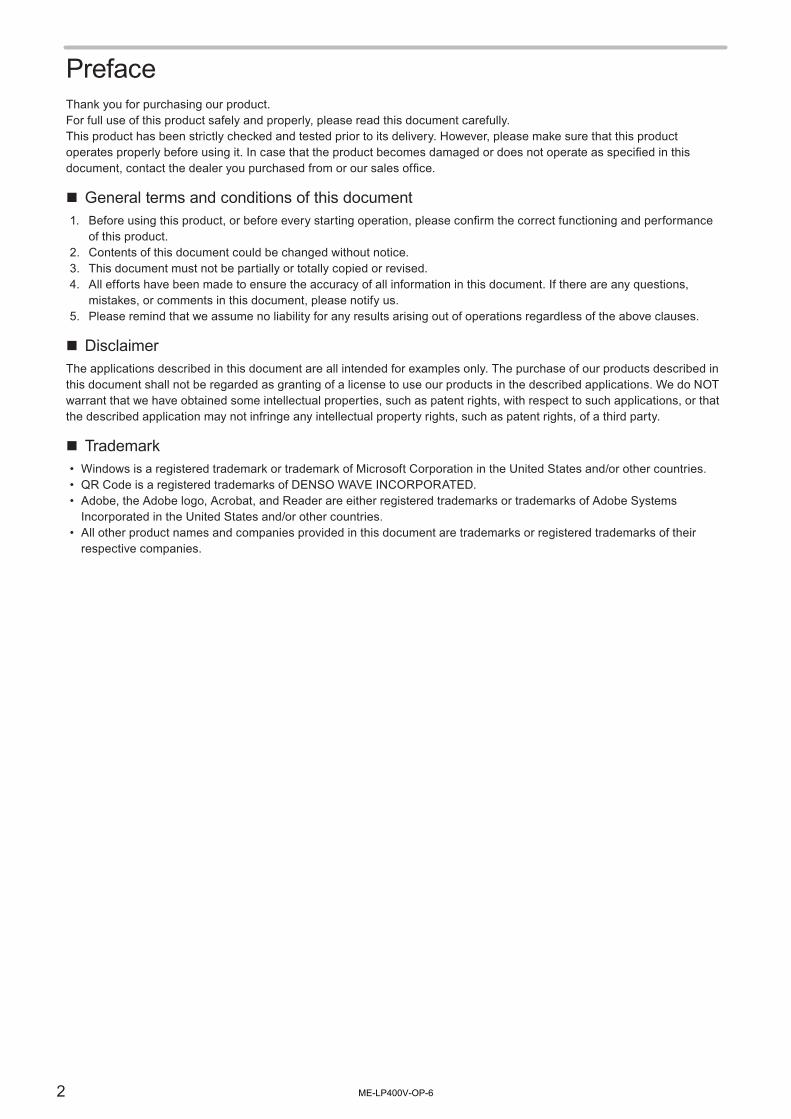
1 Key Switch : This is the key switch for starting up the laser marker.Only when the key switch is turned OFF (in O position), the key can be pulled out.When the laser marker is not in use, the key should be in safekeeping by a laser safety manager.
2 Laser Radiation Indicator
: The operations of the laser radiation indicator are as follows:
Non-emitting state Lights-out Being in laser emitting Orange lighted-up
3 Emergency Stop Switch
: This switch is used to forcibly stop the laser pumping.Push this switch at emergency or to stop the laser radiation. Turn the switch to the direction of the arrow to release it.
4 Alarm Reset Switch : This switch is used to reset the system when an alarm generates. LED lights up in blue when an alarm generates. Release the cause of alarm and press this switch. Alarm can be reset from the input/output terminal, console (optional) or monitor screen.
5 Laser Stop InputEmergency Stop Input (I/O terminal)
: The I/O terminal equips Laser Stop input and Emergency Stop input. Opening either of the signals or making its voltage level Low disables the laser emission. Construct the safety system by connecting it to the door or switch of the equipment.Operation when Laser stop is released :• When laser is not radiating: Close the internal shutter.• When laser is radiating: Close the internal shutter and turn Laser pumping OFF.
Operation when Emergency stop is released :• Close the internal shutter and turn Laser pumping OFF.
6 Input/Output Terminal : The terminal equips various signals, such as shutter input, marking output, mark end output, ready output etc.Use these signals for the purpose of controlling other external safety devices, such as an indicating lamp.Refer to the External control manual for details.
ME-LP400V-OP-6

30
⿎ Laser Marker Operation at Inputting the Safety Functions
Safety Function Laser Marker Operation Release Method
Laser Stop in I/O terminal *1CLOSE to OPEN
Laser stop input during laser emission• Laser Pumping: OFF• Internal Shutter: CLOSE• Status: Alarm E011
Close Laser Stop and input alarm reset.
Laser stop input at non-emitting with opened shutter• Laser Pumping: Hold ON• Internal Shutter: CLOSE• Status: Warning E811
Close Laser Stop.
Emergency Stop in I/O terminal CLOSE to OPEN
• Laser Pumping: OFF• Internal Shutter: CLOSE• Status: Alarm E004 *2
Close Emergency Stop and input alarm reset.
Push Emergency Stop Switch
• Laser Pumping: OFF• Internal Shutter: CLOSE• Status: Alarm E002 *2
Push emergency stop switch and input alarm reset.
*1 : The operation behavior of Laser Stop varies depending on the laser emission ON / OFF status. (Inputting Emergency Stop in I/O terminal and Emergency Stop Switch, regardless laser emission ON/OFF status, the laser is powered OFF and the shutter is closed.)
*2 : Under the non-remote mode in closing shutter status (non-emitting status), the error does not occur.
ME-LP400V-OP-6

31
⿎Construction of Interlock SystemFor operating this product, construct the protective enclosure enclosing the range of the laser radiation for protecting the exposure caused by the reflection of the laser radiation from the work piece or the surrounding objects, and also construct the interlock system. The following figure shows the construction sample of the interlock system.
ABCD
ABCD
ABCD
BCD
q
w
r
e
y
r
t
No. Description Note
q Emergency stop button Construct a control system for shutting off the laser power when it is opened.
w Door for the maintenance
e Safety switch
r Laser protection shutter for marking object gateway Construct a control system which will separate (cut off) the laser beam or shut off the laser power when it is open.
t Depending on the system control specification, use safety relay unit or safety PLC etc.
Connect the devices q to r and I/O terminal of the laser marker.Depending on the system design, use the safety relay unit or the safety PLC.
y To I/O terminal (laser stop input, emergency stop input, etc.)
Reference
• When primary AC power supply of the system is performed as a safety measure, process AC power cable to set the switch as follows.
AC Power Cable
Emergency Stop Switch Relay
ME-LP400V-OP-6

32
1 Product Overview
ME-LP400V-OP-6

33
1-1 Product Model ⿎ LP-400 Series
Laser marker LP-400 series have the following models.Some of the specifications and the packaged contents vary depending on the model. For details, see “1-3 Specification” (P.36) and “1-5 Package” (P.47).
ModelLaser output /Wavelength
Marking field [mm]
Head type
LP-430U, LP-430U-A, LP-430U-C, LP-430U-CHN 30W10.6μm
110 x 110 Standard
LP-430TU, LP-430TU-A, LP-430TU-C, LP-430TU-CHN Tower Head
LP-431U, LP-431U-A, LP-431U-C, LP-431U-CHN 55 x 55 Standard
LP-431TU, LP-431TU-A, LP-431TU-C, LP-431TU-CHN Tower Head
LP-435U, LP-435U-A, LP-435U-C, LP-435U-CHN 160 x 160 Standard
LP-435TU, LP-435TU-A, LP-435TU-C, LP-435TU-CHN Tower Head
LP-420S9U, LP-420S9U-A, LP-420S9U-C, LP-420S9U-CHN 20W9.3μm
110 x 110 Standard
LP-420S9TU, LP-420S9TU-A, LP-420S9TU-C, LP-420S9TU-CHN Tower Head
LP-421S9U, LP-421S9U-A, LP-421S9U-C, LP-421S9U-CHN 55 x 55 Standard
LP-421S9TU, LP-421S9TU-A, LP-421S9TU-C, LP-421S9TU-CHN Tower Head
LP-425S9U, LP-425S9U-A, LP-425S9U-C, LP-425S9U-CHN 160 x 160 Standard
LP-425S9TU, LP-425S9TU-A, LP-425S9TU-C, LP-425S9TU-CHN Tower Head
LP-410U, LP-410U-A, LP-410U-C, LP-410U-CHN 10W10.6μm
110 x 110 Standard
LP-410TU, LP-410TU-A, LP-410TU-C, LP-410TU-CHN Tower Head
LP-411U, LP-411U-A, LP-411U-C, LP-411U-CHN 55 x 55 Standard
LP-411TU, LP-411TU-A, LP-411TU-C, LP-411TU-CHN Tower Head
⿎Model Name Description
LP - 4 3 0 U - Aq w e t y
LP - 4 2 5 S 9 T U - Cq w e yr t
q Series name of the product. LP-400 series is the CO2 laser marker.
w Represents laser output power class as follows.3: Oscillator average output power 30W2: Oscillator average output power 20W1: Oscillator average output power 10W
e Represents marking field class as follows.0: Marking field 110 mm x 110 mm1: Marking field 55 mm x 55 mm5: Marking field 160 mm x 160 mm
r “S9” is added to the model with the laser wavelength 9.3μm.
t Represents the type of the head unit.
U: Standard Head
TU: Tower Head
y Added if the product has additional features or another specification from standard specification.-A: FDA regulations compliant model.-C: CE Marking compliant model.-CHN: GB standard compliant model. (for use in China)
ME-LP400V-OP-6

34
⿎ LP-V/LP-W SeriesLaser marker LP-V series and LP-W series have the following models.Some of the specifications and the packaged contents vary depending on the model. For details, see “1-3 Specification” (P.36) and “1-5 Package” (P.47).
Model Laser output Oscillation mode Marking field [mm]
LP-V10U, LP-V10U-A, LP-V10U-C, LP-V10U-CHN 12W Pulsed 90 x 90
LP-V15U, LP-V15U-A, LP-V15U-C, LP-V15U-CHN 160 x 160
LP-W052U, LP-W052U-A 5W CW 55 x 55
⿎Model Name Description
LP - V 1 0 U - CHNq we
LP - W 05 2 U - Aq w e rr
q Series name of the product. LP-V series and LP-W series are the fiber laser markers.
w Represents laser output power class as follows.1: Oscillator average output power 12W05: Oscillator average output power 5W
e Represents marking field class as follows.0: Marking field 90 mm x 90 mm5: Marking field 160 mm x 160 mm2: Marking field 55 mm x 55 mm
r Added if the product has additional features or another specification from standard specification.-A: FDA regulations compliant model.-C: CE Marking compliant model.-CHN: GB standard compliant model. (for use in China)
ME-LP400V-OP-6

35
1-2 Product ConfigurationThis product is a laser marker which is designed to mark and process the object by radiating a laser beam to the target.This product consists mainly of the following units.
LP-V/LP-W SeriesLP-400 Series
q
w y
t
e
q
w
r
y
t
e
No. Name Description
q Head It is the unit that radiates the laser beam. The optical components and the scanner are loaded inside.
w Controller It is the unit that stores the setting data and controls the operation. The main power supply and connection interface with external devices are loaded.
e Head Power Cable (Attached accessory)Head Control Cable (Attached accessory)
Cables to connect the head and controller.
r Fiber cable (only LP-V/LP-W series) Cable to deliver the laser beam from controller to head.
t Controller power cable (Attached accessory) Cable to supply AC power.
y Touch panel console (Optional item)orCommercially available monitor and mouse (Not included in this product.)
Connect the touch panel console or monitor and mouse to the laser marker to set the marking data and other parameters. This display can be used also as a monitor during the operation.It is also possible to configure the marking data with PC by installing the attached software “Laser Marker Driver & Utility”.
⿎Optional itemsThe following optional items (sold separately) are available for this product.To purchase them and for the detailed information, please contact our sales office.
Optional Items Model
Touch Panel Console LP-ADP40
Air Filter (for replacement) LP-400 Series : LP-AFT20LP-V Series /LP-W Series : LP-AFT21
Protection Glass of Laser Emission Port (for replacement) *1
LP-V10(U) Type *2 : LP-ACV10 or LP-ACV20 or LP-ACV60LP-V15(U) Type *2 : LP-ACV15 or LP-ACV25LP-W052(U) Type : LP-ACV12
Head Power Cable (for replacement) LP-ACP20-5
Head Control Cable (for replacement) LP-ACS20-5
*1 : The protection glass of the laser emission port is available only for LP-V/LP-W series.*2 : Depending on the manufactured period of the laser marker, the parts model of the protection glass is vary. Check the
serial No. of the laser marker and contact our sales office.
ME-LP400V-OP-6

36
1-3 SpecificationLP-400 Series
ItemModel
LP-430ULP-430TU
LP-420S9ULP-420S9TU
LP-410ULP-410TU
LP-431ULP-431TU
LP-421S9ULP-421S9TU
LP-411ULP-411TU
LP-435ULP-435TU
LP-425S9ULP-425S9TU
Marking laser
Laser type CO2 laser, Class 4 Laser
Wavelength 10.6μm 9.3μm 10.6μm 9.3μm 10.6μm 9.3μm
Oscillator average output *1
30W 20W 10W 30W 20W 10W 30W 20W
Output stability (typ.) *2
±3% ±10% ±3% ±10% ±3%
Mode of operation
CW
Guide laser, laser pointerRed Semiconductor, λ =655nm, Class 2 Laser
Max. Output: 1mW
Scanning system Galvano Scanning Method
Beam stop Shutter (Equipped inside of head)
Marking object status Stationary object, Moving object
Marking field (X, Y) [mm] 110 × 110 55 × 55 160 × 160
Work distance [mm] *3 185 111 262
Max. scan speed [mm/sec.] *4, *5
12,000 6,000 12,000
Max. line speed [m/min.] *4 240 170 120 85 240
Marking data
CharacterCapital and small letter of alphabet, numeric, Japanese (Katakana, Hiragana, Kanji of JIS
level-1 and JIS level-2), symbols, user registration character (up to 50 characters can be set)
Bar code
CODE39, CODE128, ITF, NW-7, EAN/UPC, GS1 DataBar (GS1 DataBar Limited, GS1 DataBar Stacked, GS1 DataBar Expanded, etc.),
GS1 composite code (GS1 DataBar Limited CC-A, GS1 DataBar Stacked CC-A, GS1-128 CC-A, etc.)
2D code QR Code, Micro QR Code, SQRC (Security QR Code) *6, DataMatrix, GS1 DataMatrix
Logo data *7
VEC, DXF, HPGL, BMP, JPEG, AI, EPS
Character height/width [mm] *4
0.1 to 110 0.1 to 55 0.1 to 160
Number of setting files Max. 2,048 files
Number of characters / file 30 characters/line, max. 60 lines
Input/Output I/O Terminal, I/O Connector
Serial communication interface
EIA-RS-232C, Ethernet
Removable storage media *8
USB Media
Display language English and Japanese
Attached softwareLaser Marker NAVI, Logo Data Conversion Software,
Logo Data Editing Software, Font Maker, and ExportVec
ME-LP400V-OP-6
37
ItemModel
LP-430ULP-430TU
LP-420S9ULP-420S9TU
LP-410ULP-410TU
LP-431ULP-431TU
LP-421S9ULP-421S9TU
LP-411ULP-411TU
LP-435ULP-435TU
LP-425S9ULP-425S9TU
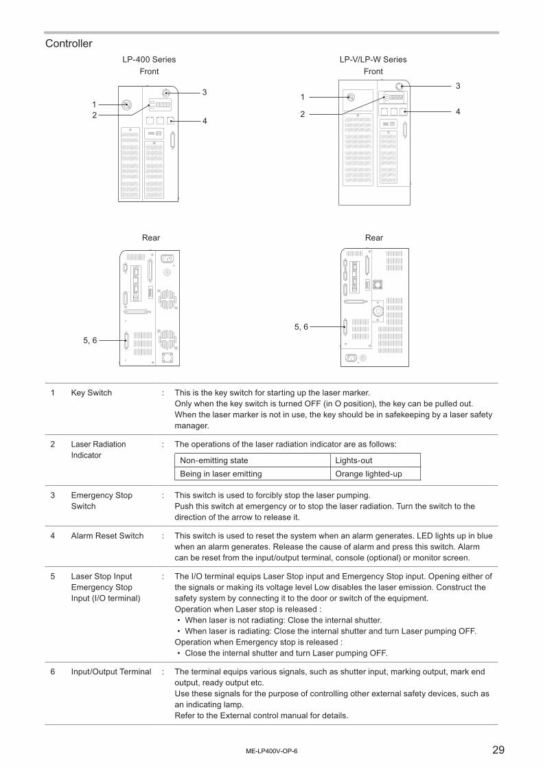
Applicable OS for PC software
Windows® 10 Pro 32bit, 64bit / Windows® 8 Pro 32bit, 64bit / Windows® 7 Professional 32bit, 64bit
Windows® Vista Business 32bit / Windows® XP Professional 32bit
Required time for system startup
Approx. 75 sec.
Required time for laser pumping
Approx. 15 sec.
Power voltage90V to 132V AC or 180V to 264V AC (including ±10% voltage fluctuations) *9
Frequency: 50/60 Hz
Power consumption
*10
100V AC 1000VA or less670VA or less
1000VA or less670VA or less
1000VA or less
200V AC 1200VA or less700VA or less
1200VA or less700VA or less
1200VA or less
Grounding method Controller: Direct Earth
Cooling method Head: Forced air-cooling, Controller: Forced air-cooling
Ambient temperature *11 0 °C to +40 °C
Ambient temperature for storage *11
-10 °C to +60 °C
Ambient humidity *11 35 to 85%RH
Overvoltage category Ⅱ
Pollution degree 2
Use location Indoor; at an altitude of 1000 m or below
WeightHead Approx. 20 kg
Approx. 16 kg
Approx. 20 kgApprox. 16 kg
Approx. 20 kg
Controller Approx. 12 kgApprox.
11 kgApprox. 12 kg
Approx. 11 kg
Approx. 12 kg
Battery (Embedded in product)
Type Graphite Fluoride Lithium Battery
Model BR-1 / 2AAC2P
Quantity 1 piece
Weight Approx. 9.5 g
*1 : Average output power from the laser oscillator at delivery time with the laser power setting 100.*2 : Value of output 20% or larger, and at 10 min passed after starting-up.*3 : Work distance has an individual error of approx.+/-2 mm per product.*4 : The descried values are available ranges for configuration. The marking quality may vary depending on materials of
marking objects and marking conditions.*5 : Depending on the marking data, the available scan speed might be limited in case the continuous marking more than
1 minute with high scan speed is set.*6 : For using SQRC, an optional software is needed. SQRC marking function is available only for use in Japan.*7 : VEC is a graphic file format dedicated for the laser marker. To use HPGL, BMP or JPEG files, convert them to VEC
format with the attached “Logo Data Conversion software”. To use AI or EPS files, convert them to VEC format with the attached software “ExportVEC”.
*8 : Check the performance and operation before use. USB media with security features cannot be used.*9 : The power supply voltage switches automatically.*10 : The typical value of the inrush current at system startup is 40A. (Duration time is 10 ms or less.)*11 : This specification is applied to both controller and head. No condensation and freezing shall be allowed. If there is
a gap between the stored temperature and operating temperature, make sure to have the product get used to the operating ambient temperature gradually prior to use to prevent the dew condensation.
ME-LP400V-OP-6

38
LP-V/LP-W Series
ItemModel
LP-V10U LP-V15U LP-W052U
Marking laser
Laser type Yb : FIBER laser, λ =1060nm, Class 4 Laser
Oscillator average output *1
12W 5W
Mode of operation
Pulsed CW
Pulse cycle 10 μs to 50 μs -
Guide laser, laser pointerRed Semiconductor, λ =655nm, Class 2 Laser
Max. Output: 1mW
Scanning system Galvano Scanning Method
Beam stop Shutter (Equipped inside of head)
Marking object status Stationary object, Moving object
Marking field (X, Y) [mm] 90 × 90 160 × 160 55 × 55
Work distance [mm] *2 190 350 127
Max. scan speed [mm/sec.] *3, *4
12,000 6,000
Max. line speed [m/min.] *3 240 120
Marking data
CharacterCapital and small letter of alphabet, numeric, Japanese (Katakana, Hiragana, Kanji of
JIS level-1 and JIS level-2), symbols, user registration character (up to 50 characters can be set)
Bar code
CODE39, CODE128, ITF, NW-7, EAN/UPC, GS1 DataBar (GS1 DataBar Limited, GS1 DataBar Stacked, GS1 DataBar Expanded,
etc.),GS1 composite code (GS1 DataBar Limited CC-A, GS1 DataBar Stacked CC-A,
GS1-128 CC-A, etc.)
2D code QR Code, Micro QR Code, SQRC (Security QR Code) *5, DataMatrix, GS1 DataMatrix
Logo data *6 VEC, DXF, HPGL, BMP, JPEG, AI, EPS
Character height/width [mm] *3
0.1 to 90 0.1 to 160 0.1 to 55
Number of setting files Max. 2,048 files
Number of characters / file 30 characters/line, max. 60 lines
Input/Output I/O Terminal, I/O Connector
Serial communication interface
EIA-RS-232C, Ethernet
Removable storage media *7
USB Media
Display language English and Japanese
Attached softwareLaser Marker NAVI, Logo Data Conversion Software,
Logo Data Editing Software, Font Maker, and ExportVec
Applicable OS for PC software
Windows® 10 Pro 32bit, 64bit / Windows® 8 Pro 32bit, 64bit / Windows® 7 Professional 32bit, 64bit
Windows® Vista Business 32bit / Windows® XP Professional 32bit
Required time for system startup
Approx. 75 sec.
ME-LP400V-OP-6

39
ItemModel
LP-V10U LP-V15U LP-W052U
Required time for laser pumping
Approx. 20 sec. Approx. 15 sec.
Power voltage90V to 132V AC or 180V to 264V AC (including ±10% voltage fluctuations) *8
Frequency: 50/60 Hz
Power consumption *9
100V AC 390VA or less 310VA or less
200V AC 420VA or less 360VA or less
Grounding method Head: Direct Earth, Controller: Direct Earth
Cooling method Head: Forced air-cooling, Controller: Forced air-cooling
Ambient temperature *10 0 °C to +40 °C
Ambient temperature for storage *10
-10 °C to +60 °C
Ambient humidity *10 35 to 85%RH
Overvoltage category Ⅱ
Pollution degree 2
Use location Indoor; at an altitude of 1000 m or below
Fiber cable length 4.5 m, Minimum bent radius 60 mm
Installation direction
Head Omnidirectionally
Controller Vertically or Horizontally
WeightHead Approx. 9 kg Approx. 10 kg Approx. 9 kg
Controller Approx. 22 kg
Battery (Embedded in product)
Type Graphite Fluoride Lithium Battery
Model BR-1 / 2AAC2P
Quantity 1 piece
Weight Approx. 9.5 g
*1 : Average output power from the laser oscillator at delivery time with the laser power setting 100.*2 : Work distance has an individual error of approx.+/-2 mm per product.*3 : The descried values are available ranges for configuration. The marking quality may vary depending on materials of
marking objects and marking conditions.*4 : Depending on the marking data, the available scan speed might be limited in case the continuous marking more than
1 minute with high scan speed is set.*5 : For using SQRC, an optional software is needed. SQRC marking function is available only for use in Japan.*6 : VEC is a graphic file format dedicated for the laser marker. To use HPGL, BMP or JPEG files, convert them to VEC
format with the attached “Logo Data Conversion software”. To use AI or EPS files, convert them to VEC format with the attached software “ExportVEC”.
*7 : Check the performance and operation before use. USB media with security features cannot be used.*8 : The power supply voltage switches automatically.*9 : The typical value of the inrush current at system startup is 40A. (Duration time is 10 ms or less.)*10 : This specification is applied to both controller and head. No condensation and freezing shall be allowed. If there is
a gap between the stored temperature and operating temperature, make sure to have the product get used to the operating ambient temperature gradually prior to use to prevent the dew condensation.
ME-LP400V-OP-6

40
1-4 Outer Dimensional Drawing
1-4-1 LP-400 Series
⿎Head (Standard Model)LP-430U / 420S9U / 410U/ 431U / 421S9U / 411U / 435U / 425S9U
130
(51) 113 87 180 180
(200) (1
9) 59
.5
(119) (333)
337
41
504 670
169
5
106
(91)
(117) (21)
( 7)
5
111
175 190 (20)
(3)
(175
)(3
3)
60
(16) (60)
(76)
(3
0)
94
202
(2)
(1) (1)
(20)
(1
42)
690
166
(13)
475 20
412
r
q
i
u
o
w
t
e
y
t
Unit: mm
No. Description
q Work distance:LP-430U / LP-420S9U / LP-410U : 185mmLP-431U / LP-421S9U / LP-411U : 111mmLP-435U / LP-425S9U : 262mm
w Center of marking field
e Marking Field (X, Y):LP-430U / LP-420S9U / LP-410U : 110mm x 110mmLP-431U / LP-421S9U / LP-411U: 55mm x 55mmLP-435U / LP-425S9U : 160mm x 160mm
r Center of the scanner unit rotation
t Screw hole for general purpose (2 holes in each surface of top and both sides): M4 Screw, Depth 10
y Laser pointer emission port: Aperture diameter: φ19mm
u Head positioning pin hole: φ8 + 0.01 0 , Depth 4
i Head positioning pin hole: φ8 + 0.01 0 x 12 Elongated hole, Depth 4
o Head fixing screw hole (6 holes): M6 Screw, Depth 15
ME-LP400V-OP-6
41
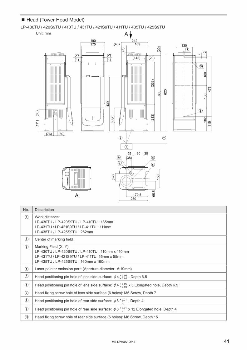
⿎Head (Tower Head Model)LP-430TU / 420S9TU / 410TU / 431TU / 421S9TU / 411TU / 435TU / 425S9TU
A 170.5230
3090
(62)
(38)r
e
t
o
1)
i
yu
w
65.5
150
(76) (30)
(111
)(6
0)
(185
)
175190
430
(213
)(3
33)
169212
600
(20)
620
182
180
180
130
(142) (20)
(43)
(2)(1)
(2)(1)
(3)
475
4 1211
5
55
q
AUnit: mm
No. Description
q Work distance:LP-430TU / LP-420S9TU / LP-410TU : 185mmLP-431TU / LP-421S9TU / LP-411TU : 111mmLP-435TU / LP-425S9TU : 262mm
w Center of marking field
e Marking Field (X, Y):LP-430TU / LP-420S9TU / LP-410TU : 110mm x 110mmLP-431TU / LP-421S9TU / LP-411TU: 55mm x 55mmLP-435TU / LP-425S9TU : 160mm x 160mm
r Laser pointer emission port: (Aperture diameter: φ19mm)
t Head positioning pin hole of lens side surface: φ4 + 0.06+ 0.02 , Depth 6.5
y Head positioning pin hole of lens side surface: φ4 + 0.06+ 0.02 x 5 Elongated hole, Depth 6.5
u Head fixing screw hole of lens side surface (6 holes): M6 Screw, Depth 7
i Head positioning pin hole of rear side surface: φ8 + 0.01 0 , Depth 4
o Head positioning pin hole of rear side surface: φ8 + 0.01 0 x 12 Elongated hole, Depth 4
1) Head fixing screw hole of rear side surface (6 holes): M6 Screw, Depth 15
ME-LP400V-OP-6

42
⿎ControllerLP-400 series
(130
)
(140) (37) (10)
310 40
40
272
340
175
340
(27) 390
(54)
20
120
40 310
q
w
q
(164) Unit: mm
No. Description
q Rubber feet installation screw hole (4 holes on base and left side surface each): M5, Depth 6The rubber feet for controller can be installed on base or side surfaces.
w Screw for frame ground: M4, Depth 10
ME-LP400V-OP-6

43
1-4-2 LP-V/LP-W Series
⿎HeadLP-V10U / LP-V15U / LP-W052U
(142
)(3
0)(118)
φ14.5R60
220
(77)(57)
(163)
(218
)
(15)(96) (90)
(217
)(9
5)
60 6091
64
30
4040
40404040
120
(44)
(248
)
350
y
q
t
o
e
r
u
w
i
1)
Unit: mm
No. Description
q Work distance:LP-V10U : 190 mmLP-V15U : 350 mmLP-W052U : 127 mm
w Center of marking field
e Marking Field (X, Y):LP-V10U : 90 mm x 90 mmLP-V15U : 160 mm x 160 mmLP-W052U : 55 mm x 55 mm
r Laser pointer emission port: φ27 mm (Aperture diameter: φ20 mm)
t Laser emission port:LP-V10U: φ87 mmLP-V15U: φ106 mmLP-W052U: φ87 mm
y Laser emission port height:LP-V10U: (19) mmLP-V15U: (40) mmLP-W052U: (19) mm
u Head positioning pin hole: φ4 + 0.012 0 , Depth 7
i Head positioning pin hole: φ4 + 0.1 0 x 5 Elongated hole, Depth 7
o Head fixing screw hole (LP-V10U/LP-W052U: 10 holes, LP-V15U: 6 holes *) : M6, Depth 6* For LP-V15U, the 4 screw holes surrounding the laser emission port are not available.
1) Screw for frame ground: M4, Depth 8
ME-LP400V-OP-6

44
⿎ControllerLP-V10U / LP-V15U / LP-W052U
(103)
(70)
(1
30)
(187
)
230
400
(27) 390 (193)
40 310
320
40
(54)
25
180
40 310 (195) (37)
w
q
q
Unit: mm
No. Description
q Rubber feet installation screw hole (4 holes on base and left side surface each): M5, Depth 6The rubber feet for controller can be installed on base or side surfaces.
w Screw for frame ground: M4, Depth 10
Notice
• Both the head and controller are connected with fiber cable and this cable cannot be detached from the device. Forcibly detaching them might damage the product.
ME-LP400V-OP-6
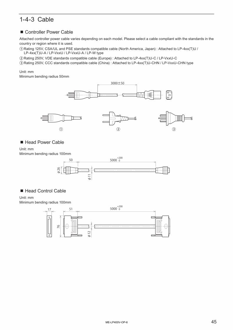
45
1-4-3 Cable
⿎Controller Power CableAttached controller power cable varies depending on each model. Please select a cable compliant with the standards in the country or region where it is used.q Rating 125V, CSA/UL and PSE standards compatible cable (North America, Japan) : Attached to LP-4xx(T)U /
LP-4xx(T)U-A / LP-VxxU / LP-VxxU-A / LP-W typew Rating 250V, VDE standards compatible cable (Europe) : Attached to LP-4xx(T)U-C / LP-VxxU-Ce Rating 250V, CCC standards compatible cable (China) : Attached to LP-4xx(T)U-CHN / LP-VxxU-CHN type
Unit: mmMinimum bending radius 50mm
q w e
3000±50
⿎Head Power CableUnit: mmMinimum bending radius 100mm
50
26
11
5000+200 0
⿎Head Control CableUnit: mmMinimum bending radius 100mm
5117 5000+200 0
76
12
ME-LP400V-OP-6

46
1-4-4 Console (Option)
Model name: LP-ADP40Unit: mm
(171)(41.5)
(15)(6)(55)
143±1.2
(19.5)
2900±70
80±0.8w
e
q
(60)
(253)
(197)
(128)
No. Description
q Pen holder attaching nut M4, depth 6 (both left and right sides)
w Fixing nut (4 positions) M4, depth 6
e Controller Connecting Cable
ME-LP400V-OP-6

47
1-5 PackageBefore using this product, be sure to check the packed objects as shown below.The product have been strictly checked and tested prior to packaging. However, please make sure that there is no damage during transportation and the product operates properly before using it. In case that the product becomes damaged or does not operate as specified in this manual, contact the dealer you purchased it or our sales office.
Notice
• Be sure to store the packing materials. Since this product is precision machinery, reuse the packing materials to prevent damages during transportation.
• For LP-V / LP-W series, both the head and controller are connected with fiber cable and this cable cannot be detached from the device. Forcibly detaching them might damage the product.
LP-400 Standard Head model LP-400 Tower Head model LP-V / LP-W Series
□□ Laser Marker 1 head unit and 1 controller unit
� Head Power Cable � Head Control Cable � Controller Power Cable *1
� System Key
qty.: 1 qty.: 1 qty.: 1 qty.: 2
� I/O Connector � I/O Connector Cover
� I/O Terminal Block � USB Cable (2m) � Return Harness
qty.: 1 qty.: 1 qty.: 1 qty.: 1 qty.: 1
□□Rubber Foot for Controller (M5x15 Screw)
□□Binding Band /Binding Base *2
□□Warning / Explanatory / Aperture label (LP-400 Series) *3, *5
□□Warning / Explanatory / Aperture label (LP-V/LP-W Series) *4, *5
□□Laser Marker Driver & Utility (CD-ROM) *6
qty.: 4 2 pack-set qty.: 1 qty.: 1 qty.: 1
ME-LP400V-OP-6

48
� Leaflet of Safety Directions
� Carrying Caution Leaflet *7
� General information for safety (For EU
users) *9
� Ground Wire *8 � Lens cap *4
qty.: 1 qty.: 1 qty.: 1 qty.: 1 qty.: 1
*1 : Attached controller power cable varies depending on each model. Please select a cable compliant with the standards in the country or region where it is used.
• LP-4xx(T)U / LP-4xx(T)U-A / LP-VxxU / LP-VxxU-A / LP-W : Rating 125V, CSA/UL and PSE standards compatible cable (North America, Japan)
• LP-4xx(T)U-C / LP-VxxU-C : Rating 250V, VDE standards compatible cable (Europe)• LP-4xx(T)U-CHN / LP-VxxU-CHN: Rating 250V, CCC standards compatible cable (China)
*2 : Enclosed only in LP-43xTU / LP-42xS9TU / LP-43xTU-C / LP-42xS9TU-C / LP-43xTU-CHN / LP-42xS9TU-CHN.*3 : Enclosed only in LP-400 series.*4 : Enclosed only in LP-V / LP-W series.*5 : Attached label language varies depending on each model.
• LP-4xx(T)U / LP-VxxU / LP-W052U : Japanese• LP-4xx(T)U-A / LP-4xx(T)U-C / LP-VxxU-A / LP-VxxU-C / LP-W052U-A : English• LP-4xx(T)U-CHN / LP-VxxU-CHN : Chinese
*6 : The following data are stored into this CD-ROM “Laser Marker Driver & Utility“.
Software for PC Setting of Laser MarkerLaser Marker NAVI Font MakerLogo Data Conversion Software Export VECLogo Data Editing Software
PDF ManualLP-400/V/W series Operation/Maintenance ManualLP-400/V/W series External Control ManualLaser Marker NAVI Operation ManualLogo Data Conversion Software Operation ManualLogo Data Editing Software Operation ManualExportVec Operation ManualFont Maker Operation Manual
Font DataOriginal 1 Font Original 1 reduced-size Font User Registration FontOriginal 2 Font Original 2 reduced-size Font 2D Code Pattern FontOriginal 3 Font Original 3 reduced-size Font OCR1 FontOriginal 4 Font JIS Level-1 FontOriginal 5 Font JIS Level-2 Font
*7 : Enclosed except in Tower Head Model of LP-400 series.*8 : Enclosed only in LP-4xx(T)U-A type.*9 : Enclosed only in LP-4xx(T)U-C / LP-VxxU-C type.
Reference
• LP-4xx(T)U-A / LP-4xx(T)U-C / LP-VxxU-A / LP-VxxU-C / LP-W052U-A types have no book form manuals. The manuals are stored in the CD-ROM in PDF format.
ME-LP400V-OP-6

49
1-6 Name of Each Part
1-6-1 Head
⿎ LP-400 Series with the Standard Head [LP-4xxU / LP-4xxU-A / LP-4xxU-C / LP-4xxS9U / LP-4xxS9U-A / LP-4xxS9U-C]
1 37 9 102 68
4 5
⿎ LP-400 Series with the Tower Head [LP-4xxTU / LP-4xxTU-A / LP-4xxTU-C / LP-4xxS9TU / LP-4xxS9TU-A / LP-4xxS9TU-C]
1
2
3
6
8
7
5
4
ME-LP400V-OP-6

50
1. Signal Connector: SIGNALThis is the terminal for communicating between head and controller. Connect the attached head control cable.
2. Power Connector: POWERThis is the connector for supplying the power to the head.Connect the attached head power cable.
3. Laser Radiation IndicatorThis indicator indicates the laser radiation state. Refer to “Safety Functions on Laser Marker” (P.27) for the detail.
4. Laser Pointer Emission PortThe emission port of the red laser pointer radiated when using the dual pointer function. To use the dual pointer function, do not seal the laser pointer emission port at the installation. For details, refer to “2-1-7 Lasing position check” (P.69).
5. Laser Emission PortThis is the emission port of the laser beam.
6. Focus DialThis is the dial to check the focus adjusting. Refer to “2-1-8 Focus adjustment function” (P.70) for the detail.
7. Focus Adjusting ControlThe control for adjusting the distance from the work. Refer to “2-1-8 Focus adjustment function” (P.70) for the detail.
8. Intake Vent for Air CoolingAir inlet for cooling the head. In this vent the filter is installed.
9. Setscrew for Scanning Angle [Only for LP-400 series with the standard head]This is the setscrew for rotation of head scanning. Loosen this setscrew for rotating scanner.Refer to “2-1-3 Rotation of LP-400 Standard Head Scanner” (P.64) for the detail.
10. Arrow for Indicating Rotation Angle [Only for LP-400 series with the standard head]This is the arrow that indicates rotation angle of the head scanner.Refer to “2-1-3 Rotation of LP-400 Standard Head Scanner” (P.64) for the detail.
ME-LP400V-OP-6

51
3
8
1
2
910
5
4
6
7
1. Signal Connector: SIGNALThis is the terminal for communicating between head and controller. Connect the attached head control cable.
2. Power Connector: POWERThis is the connector for supplying the power to the head.Connect the attached head power cable.
3. Laser Radiation IndicatorThis indicator indicates the laser radiation state. Refer to Refer to “Safety Functions on Laser Marker” (P.27) for the detail.
4. Laser Pointer Emission PortThe emission port of the red laser pointer radiated when using the dual pointer function. To use the dual pointer function, do not seal the laser pointer emission port at the installation. For details, refer to “2-1-7 Lasing position check” (P.69).
5. Laser Emission PortThis is the emission port of the laser beam.
6. Focus DialThis is the dial to check the focus adjusting. Refer to Refer to “2-1-8 Focus adjustment function” (P.70) for the detail.
7. Focus Adjusting ControlThe control for adjusting the distance from the work. Refer to Refer to “2-1-8 Focus adjustment function” (P.70) for the detail.
⿎ LP-V/LP-W Series [LP-VxxU / LP-VxxU-A / LP-VxxU-C / LP-W052U / LP-W052U-A]
ME-LP400V-OP-6

52
8. Intake Vent for Air CoolingAir inlet for cooling the head. In this vent the filter is installed.
9. Frame Ground Terminal: F.G.This is the terminal for ground. Be sure to connect it to earth permanently.
10. Fiber CableThis is the cable for transmitting the laser. This cable cannot be detached from the device.
ME-LP400V-OP-6

53
1-6-2 Controller
Front
543
6
9
2
2
1
7
8
10
6
1
543
9
7
8
10
LP-400 Series LP-V/LP-W Series
1. Key Switch: POWERThis key switch is used to start the laser marker system.Turn ON ( | ) the switch to start-up the system, and turn OFF ( o ) the switch to shutdown the system.When the laser marker is not used, remove the key, and the safety manager must keep it.Since the ON/OFF operation of the key switch makes a load to the laser marker, leave an interval for 5 seconds or more from turning OFF the power to turning ON the power again.Do not turn off the power supply while the system starts (during the system start indicator is flashing).
2. Controller display panelThe indicator that shows the status of laser radiation and the laser marker.
No. Display name Status Indication
q FILE No. / ERROR CODE Normal state Displays selected file No.
Alarm or warning status Displays error code No. Refer to “Error Indication” (P.301).
w MAIN System is powered on Green lighted-up
System under starting up (uncompleted)
Green flashing
e MARKING Being in laser emitting Orange lighted-up
OFF
ON
w
eq
ME-LP400V-OP-6

54
3. Laser Pumping Switch (with white LED): LASERThis is the switch for starting laser pumping.LED flashes (LP-400 / LP-W series: approx. 15 sec., LP-V series: approx. 20 sec.) in white when the switch is pressed, and it lights up when the laser irradiation becomes enabled.
4. Remote Switch (with white LED): REMOTEThis is the switch for activating communication control and I/O control. This indicator is lighted-up by pressing this switch, and is changed into remote mode.
5. Alarm Reset Switch (with blue LED): ALARM RESETThis switch is used to reset the system when an alarm generates. LED lights up in blue when an alarm generates. Release the cause of alarm and press this switch. Alarm can be reset from the I/O terminal, console (optional) or monitor screen.
6. Emergency Stop Switch: EMERGENCY STOPThis switch is used to forcibly stop the laser pumping.Push this switch at emergency or to stop the laser radiation. Turn the switch to the direction of the arrow to release it.
7. Console Connector: CONSOLEThis is the connector for console (optional).
8. USB Connector B: PCThis is the connector for connecting the attached USB cable. Connect with PC in using Laser Marker NAVI.
9. USB Connector A: USB MEDIAThis is the terminal for connecting the USB media or USB mouse.For registering or saving data in the laser marker, connect a commercially available USB. USB media with security features cannot be used.You can also connect a USB mouse when setting by using a commercially available monitor.A USB port is also mounted at the back.
Notice
• Do not connect the USB devices other than a USB media or a USB mouse.
10. Intake Vent for Controller Air CoolingAir inlet for cooling the controller. In this vent the filter is installed.
ME-LP400V-OP-6

55
Rear
1
3
45
8
7
2
9
6
10
14
1112
13
15
1
3
45
8
7
2
9
6
11
10
13
14
12
16
15
LP-400 Series LP-V/LP-W Series
1. Return Connector: RETURN OUTThis is the connector for connecting the attached return harness for using console (option).
2. RS-232C Connector: RS-232CThis is the connector for connecting to the external device so as to control the laser marker with RS-232C. For details, refer to External Control Manual.
3. Ethernet PortThis is the connector for connecting to the external device to control the laser marker with Ethernet.For details, refer to External Control Manual.If Ethernet is not used for the external control, connect nothing to the Ethernet port.
4. VGA Connector: VGA OUTThis is the connector for connecting VGA OUT monitor. When using a console (optional item), connect the attached return harness.
5. USB Connector A (2 connectors)This is the terminal for connecting the USB media or USB mouse.For registering or saving data in the laser marker, connect a commercially available USB.You can also connect a USB mouse when setting by using a commercially available monitor.A USB port is also mounted on the front.
Notice
• Do not connect the USB devices other than a USB media or a USB mouse.
6. Console Return Connector: (VGA+RETURN)INThis is the connector for connecting the attached return harness for using console (option).
ME-LP400V-OP-6

56
7. DIP SwitchSets the operational options of the laser marker.For details, refer to “1-6-3 DIP Switch” (P.57).
Notice
• A plastic cover is installed on the DIP switch. Install this cover always to avoid the dust penetration to the controller.
8. I/O Connector: I/OThis is the terminal for connecting signal for the purpose of controlling laser marker from the external device.Refer to External Control Manual for details.
9. Terminal Block Connector: TERMINALThis is the connector of the terminal for connecting I/O signals to control laser marker from the external device. It is available to connect the attached terminal.Refer to External Control Manual for details.
10. AC Power InletInlet for connecting AC power supply cable. Connect the attached controller power cable.90V to 132V AC or 180V to 264V AC (including ±10% voltage fluctuations), 50Hz/60Hz (The voltage and frequency switch automatically.)Be sure to connect the ground pin of the controller power cable to earth permanently.
11. Frame Ground Terminal: F.G.This is the terminal for ground. Be sure to connect it to earth permanently.
12. Fuse Holder: FUSERotate and remove holder for replacing the fuse on fusing. The rated ampere of the fuse varies with models.Refer to “Replacement of fuse” (P.286) for details.
13. Signal Connector: SIGNALThis is the terminal for communicating between head and controller. Connect the attached head control cable.
14. Power Connector: POWERThis is the connector for supplying the power to the head. Connect the attached head power cable.
15. Cooling Fan of the Controller (Exhaust port)This is a cooling fan to release the heat from controller part.
16. Fiber Cable [Only for LP-V/LP-W series]This is the cable for transmitting the laser light. This cable cannot be detached from the device.
ME-LP400V-OP-6

57
1-6-3 DIP Switch• The DIP switch is located in rear of the controller. Refer to “1-6-2 Controller” (P.53).• The all DIP switch is set to OFF side at factory shipment.• Switch the DIP switch with the power be shut down.• A plastic cover is installed on the DIP switch. Install this cover always to avoid the dust penetration to the controller.
No. 1 Switch for system reservation. Keep OFF of this switch.
No. 2 Selects external control method of “Laser Pumping” and “Shutter Control”.
ON Indicates “Laser Pumping”, “Shutter Control”, “Guide Laser Control”, “Laser Check Radiation”, and “Power Check” are externally controlled using serial communication. *1
OFF Indicates “Laser Pumping” and “Shutter Control” are controlled using I/O terminal.
*1 : “Guide Laser Control”, “Laser Check Radiation”, and “Power Check” can be controlled only using serial communication in the remote mode.
No. 3 Sets buzzer for error occurrence.
ON This setting does not sound buzzer when occurring error.OFF This setting sounds buzzer when occurring error.
No. 4 Selects valid/invalid for password lock when shifting screen from operation to each setting one.
ON Sets invalid for password lock.OFF Sets valid for password lock.
Refer to “Password” (P.255) for the detail.
No. 5 Selects shifting method for the remote mode.
ON Controls switching to the remote mode from the I/O terminal block.OFF In case of shifting mode into remote mode using the remote switch on the front of the
controller. (To set No. 6 to ON, set No. 5 to OFF.)
No. 6 Selects status when the key switch is turned ON.
ON Shifts to the remote mode by setting the key switch to ON.OFF Does not shift to the remote mode by turning the key switch ON.
(To set No. 5 to ON, set No. 6 to OFF.)
CAUTION• If the DIP switch No. 5 or No. 6 are used while turned on, construct a system
for re-pumping the laser manually as safety protection measures after the stop of the laser radiation due to an interlock or other safety functions.
No. 7 / No. 8 These switches cannot be used. Keep OFF of both No. 7 and No. 8.
ME-LP400V-OP-6

2 Installation and Connection
ME-LP400V-OP-6

59
2-1 Installation
2-1-1 Installation EnvironmentUse this product in the following environments.
Item Installation environment conditionsOperating Ambient Temperature *1 0°C to +40°COperating Ambient Humidity *1 35 to 85%RHAmbient Temperature for Storage *1 -10°C to +60°C *2Use location Indoor; at an altitude of 1000 m or below
*1 : No condensation or freezing shall be allowed.*2 : If there is a gap between the stored temperature and operating temperature, make sure to have the product get used
to the operating ambient temperature gradually prior to use to prevent the dew condensation.
Notice
• Do not install the laser marker at a place where vibrations and shocks can be directly transmitted to it.• Do not incorporate the laser marker in a unit where the laser head will be moved. It may cause failure.• Do not use the laser marker at a place with a lot of oil mist and/or dust. Take measures to prevent oil contents and dust
from entering into the laser marker, e.g. using a storage box.
⿎ Installation environment for the stable operationFor the stable operation, install the laser marker with an appropriate protection measures as follows according to the usage environment.
• Protection in a dusty placeIf the laser marker is installed at a dusty and/or oil-mist-laden place, it could cause malfunction of the product. Take a measures to protect the laser marker from penetration of the contamination, such as placing the head and the controller in the dust and/or oil protective enclosure.Besides, clean or replace the filters regularly in accordance with the usage conditions.
Example of a storage box:According to the ambient temperature, use a storage box equipped with panel cooler or heat exchanger to maintain the air-cooling performance of the laser marker.
Panel CoolerorHeat Exchanger
WARNING• If the laser emission indicator on the laser marker is placed out of the sight of
operators, place the external indicator light or warning lamp on the immediately apparent place on the system.
ME-LP400V-OP-6

60
• Removing the dust and smokeRemove any dust and smoke from the laser emission port and laser beam path using a dust collector. For effective dust collection, put the suction port of the dust collector near the lasing part. In an environment where dust and smoke that tend to attach to the lens surface, it is recommended to create a compression air flow to ensure thorough dust collection.In such situation, clean the laser emission port regularly.
BCD ABCD
BCD
Compressed Air
Dust Collector
• Protection against electrical noiseIf there are devices that generate electrical noise such as a motor or the objects that generate static electricity around the laser marker, the laser marker can be damaged by the noise.Securely ground the frame ground terminal of the laser marker.Depending on the grounding environment, use the noise cut-off transformer or uninterruptible power supply system.
Position of the frame ground terminals
LP-400 series Controller
LP-V/LP-W series Controller
LP-V/LP-W series Head
ME-LP400V-OP-6

61
2-1-2 Installation of LP-400 Series Head
WARNING• Install the product so that the laser beam path does not cross the eye height.• The laser beam path shall be enclosed with protective enclosure and make sure
it is not exposed with direct light or reflected light.
⿎ Installation Method• Install the head on a plate with a thickness of 10 mm to 15 mm which is made of aluminum or other material with
radiation performance equivalent to that of aluminum.• For the installation dimension, refer to the outer dimension in “1-4-1 LP-400 Series” (P.40).• Fix the head with the following conditions.
Head type Fixing position Fixing screw Inserting length of the screw Tightening torqueStandard head Bottom face M6 screws at 6
positions7 mm to 10 mm 3.0N・m or below
Tower head Rear face 7 mm to 10 mmBottom face (Laser emission port side)
5 mm to 7 mm
Laser marker
Washer thickness + stand thickInserting length of the screw (See above table for the length.)
M6 screw
120
180
180
182
15090
55
180
130180
200
11387
Standard Head Model
Tower Head Model
Notice
• Check the length of the screw and install it. Using improper screws and forcibly tightening them might damage the product.
ME-LP400V-OP-6

62
⿎ Installation Direction
Standard Head ModelThe standard head can be mounted in the following direction. After the installation, the scanner unit can be rotate. Refer to “2-1-3 Rotation of LP-400 Standard Head Scanner” (P.64).
Tower Head ModelWhen the mounting surface of the tower head is rear side, it can be mounted in the left, right, top and bottom direction. When the lens side is mounting surface, install the tower head always with the lens side down.
Notice
• Do not incorporate the laser marker in a unit where the laser head will be moved. It may cause failure.• When install the head with the lens side up, clean the laser emission port and remove the marking dust regularly.• When the lens side of the tower head is mounting surface, never install it with other directions than described above
figure.
ME-LP400V-OP-6

63
⿎ Installation SpaceSince this laser marker has the fan and slit for cooling, provide space around the device as shown in the following figure:
Standard Head Model
150mm
150mm
200mm
Tower Head Model
150mm
150mm
200mm
Notice
• Ensure the minimum bent radius of each cable.• Please install not to bar the flow of air cooling.• Installing near a heating element could be over ambient temperature and cause malfunction of the product.• When setting more than one laser marker, install them so that a space of 300mm or more is given between the heads of
each marker. Not doing so may cause malfunction. It might cause the malfunction with the laser marker.
ME-LP400V-OP-6

64
2-1-3 Rotation of LP-400 Standard Head ScannerFor the standard head models of LP-400 series (LP-430U / LP-420S9U / LP-410U / LP-431U / LP-420S9U / LP-411U / LP-435U / LP-425S9U), the angle of the head scanner unit can be set freely.* This function is specific to the standard head model of LP-400 series. It is not equipped in the tower head model.
⿎Rotation Method• The head scanner can be rotated up to 350 degrees by loosening the hexagon socket head cap screw (M4).
After rotating the scanner unit, fix it tightly.• The tightening torque shall be 1.5N·m or less.
Loosen
Approx. 200 degree Approx. 150 degree
M4 Hexagon Wrench
WARNING• Never use the laser marker with the setscrew for scanner angle loosened.
Failure to do so could rotate the head during the operation and cause laser emission to the dangerous direction.
⿎Center of Rotation[Unit: mm]
51.2130
158.4
91
15.814.2
41
115.515.8
28 29.2129.231.8
119
29 129 31.83.5
107.2
633.
5
141
161
61
End Standard for Base
Approx. 60°
Center of Rotation Axis
Approx. 20°Dead Angle: Approx. 10°
ME-LP400V-OP-6

65
2-1-4 Installation of LP-V / LP-W Head
WARNING• Install the product so that the laser beam path does not cross the eye height.• The laser beam path shall be enclosed with protective enclosure and make sure
it is not exposed with direct light or reflected light.
⿎ Installation Method and Direction• LP-V10U / LP-W052U: The head can be fixed from the bottom with M6 screw at 10 locations.• LP-V15U: The head can be fixed from the bottom with M6 screw at 6 locations.• For the installation dimension, refer to “1-4 Outer Dimensional Drawing” (P.40).• Install the head on a plate with a thickness of 10 mm to 15 mm which is made of aluminum or other material with
radiation performance equivalent to that of aluminum.• Tightening torque: 3.0 N·m or less.• The inserting length of the screw shall be 5 mm to 6 mm.
Laser marker
Washer thickness + stand thickness5 to 6 mm
M6 screw
Lens cap*
* For LP-V / LP-W series, the plastic lens cap is attached at shipping. Be sure to remove it before use.
Notice
• Do not incorporate the laser marker in a unit where the laser head will be moved. It may cause failure.• When install the head with the lens side up, clean the laser emission port and remove the marking dust regularly.• Check the length of the screw and install it. Using improper screws and forcibly tightening them might damage the
product.
ME-LP400V-OP-6

66
⿎ Installation SpaceFor the appropriate air cooling, provide space around the device as shown in the following figure.
150 mm
150 mm
200 mm
Notice
• Ensure the minimum bent radius of each cable.• Please install not to bar the flow of air cooling.• Installing near a heating element could be over ambient temperature and cause malfunction of the product.• When setting more than one laser marker, install them so that a space of 300 mm or more is given between the heads of
each marker. Not doing so may cause malfunction. It might cause the malfunction with the laser marker.
ME-LP400V-OP-6

67
2-1-5 Installation of the ControllerThe installation method of the controller is common to LP-400, LP-V and LP-W series.
⿎ Installation Method and Direction• The controller can be fixed from the bottom or side surfaces with M5 screw at four locations.• When the side surface is the mounting surface, set the key-switch side down.• For the installation dimension, refer to “Controller” (P.42) for LP-400series, “Controller” (P.44) for LP-V/LP-W series.• The inserting length of the screw shall be 4 mm to 6 mm.• Tightening torque: 2.0 N·m or less.• The rubber feet can be mounted either on bottom or side face. For the rubber feet installation, use the attached M5
depth 15 mm screws.
M5 ScrewM5 Screw
⿎ Installation SpaceFor the appropriate air cooling, provide space around the device as shown in the following figure.
150mm50mm
50mm
200mm
q
w
q Intake airw Exhaust
Notice
• Ensure the minimum bent radius of each cable.• Please install not to bar the flow of air cooling.• Installing near a heating element could be over ambient temperature and cause malfunction of the product.• Check the length of the screw and install it. Using improper screws and forcibly tightening them might damage the
product.
ME-LP400V-OP-6

68
2-1-6 Marking Field and Marking Center PositionUnit: mm
LP-400 Series Standard Head Model
66
B
113A
2859.5
66
B
LP-400 Series Tower Head Model
22 65.5
B
66
B
66
170.5
A
LP-V/LP-W Series
120
60A
B
91
LP-430(T)ULP-420S9(T)U
LP-410(T)U
LP-431(T)ULP-421S9(T)U
LP-411(T)U
LP-435(T)ULP-425S9(T)U
LP-V10U LP-V15U LP-W052U
A : Work Distance [mm] 185 111 262 190 350 127
B : Marking Field (X, Y) [mm]
110 x 110 55 x 55 160 x 160 90 x 90 160 x 160 55 x 55
Notice
• Do not place anything in the area between the laser emission port and lasing object.• Use anti-reflection material (ex. black paint for metal) for an external shutter or a protective enclosure in a path of laser
beam. It may cause a failure of the components inside the head.• If any other devices such as a sensor or a camera are installed near the laser marker, make sure that these devices are
installed in the place where laser beam and its reflected beam do not damage to them.
ME-LP400V-OP-6

69
2-1-7 Lasing position check
Notice
• Use the dual pointer and guide laser only as the guideline. For obtaining the appropriate marking position and quality, fine adjust the work position and distance after marking on an actual work.
⿎Dual Pointer FunctionDual pointer shows the rough indication of the work distance (distance from the head base to the marking surface). It displays the red point emitted in oblique and the red cross emitted perpendicularly from the head. The distance where the laser point is closest to the center of the cross represents the guide of the work distance.Depending on the required marking quality or installation condition including the focus adjustment usage, the dual pointer may shows not always the appropriate work distance. Confirm the marking quality with the work distance indicated by the dual pointer and adjust it accurately as appropriate.Refer to “4-6-1 Dual pointer” (P.136) for details.
Where the red point is closest to the center of the cross is the rough indication of the work distance.
LP-400 Series LP-V/LP-W Series
⿎Guide Laser FunctionThe marking contents and marking field can be traced with the red guide laser. By using the guide laser function, the position and contents of the marking can be checked visually.Refer to “4-6-2 Guide laser” (P.137) for the using method.
+Y
-Y+X
-X
ABCD
+Y
-Y+X
-X
ABCD
LP-400 Series LP-V/LP-W Series
Reference
• The guide indication is stopped automatically after passing 1 minute from start-up.• The dual pointer is adjusted according to the distance from the work defined at the factory. When the work distance is
changed by the focus adjustment function, dual pointer does not move with this function, so it cannot be used as the work distance guide.
ME-LP400V-OP-6

70
2-1-8 Focus adjustment functionWith this function, the distance from work (focal length) can be adjusted without moving up/down the head.Marking energy density can be reduced by moving the focus point of the laser spot with the specified distance between the works and changing the spot diameter.
Notice
• Use the focusing ruler as an adjustment guide. Repeat the adjustment and marking test to set the most appropriate work distance.
• Always close the cover after adjusting the focus. The work distance might be changed if the cover is not closed. • Use the focus adjusting function when the product is installed. Do not use this function for the daily use such as setup
change. Excessive use of this function may cause failure of the product.
q
w
q
w
Short
Long Focus adjusting control
Focus adjusting ruler
w Turn in the right direction (Long direction) : Makes the work distance (focal length) longer.
q Turn in the left direction (Short direction) : Makes the work distance (focal length) shorter.
1. Use a Phillips screwdriver to remove the focus adjustment cover.
Keep the cover for next use.
2. Turn the focus adjusting control with a flat-blade screwdriver.
Notice
• Do not turn the screw beyond the scale markings with an extra force. It may cause the product failure.
ME-LP400V-OP-6

71
3. Reinstall the focus adjustment cover.Tightening torque for the cover should be 0.3 N • m or less.
Reference
• Focus adjustment range varies depending on models.• LP-430(T)U / LP-420S9(T)U / LP-410(T)U: Approx. ± 3 mm• LP-431(T)U / LP-421S9(T)U / LP-411(T)U / LP-V10U: Approx. ± 2 mm• LP-435(T)U / LP-425S9(T)U: Approx. ± 4 mm• LP-V15U: Approx. ± 7 mm• LP-W052U: Approx. ± 0.7 mm
• The ruler is set to “0” at factory.• Adjusting focus changes the marking field and spot diameter. In addition, the amount of the spot diameter difference
between the marking field center and the marking field end becomes large, which may cause uneven marking quality.• The dual pointer is adjusted according to the distance from the work defined at the factory. When the work distance is
changed by the focus adjustment function, dual pointer does not move with this function, so it cannot be used as the work distance guide. Refer to “Dual Pointer Function” (P.69).
ME-LP400V-OP-6

72
2-2 Connecting Laser Marker
CAUTION • Prior to wiring and/or cable connecting work, ensure that all the power switches are turned off. Otherwise, electrical shock may result.
2-2-1 Connecting Head, Controller, Terminal Block
⿎ LP-400 Series
Head Control Cable (5 m) (Min. bending radius: 100 mm)
Head Power Cable (5 m) (Min. bending radius: 100 mm)
Terminal Block
ControllerHead
To SIGNAL
To TERMINAL
To SIGNAL
To POWER
To POWER
⿎ LP-V Series and LP-W Series
Fiber Cable (4.5 m) (Min. bending radius: 60 mm)*This cable can not be detached.
Head Power Cable (5 m) (Min. bending radius: 100 mm) Terminal Block
ControllerHead
To SIGNAL
To TERMINAL
To SIGNALTo POWER
To POWER
Head Control Cable (5 m) (Min. bending radius: 100 mm)
ME-LP400V-OP-6

73
Notice
• Connect the head and controller combined for the same serial number.• For the connection of this product, use the dedicated cables attached to the product or the specified optional cables.• Do not connect the Head Control Cable to the I/O Connector. It may cause a failure.• Insert the cables all the way in a straight line. Tilting and inserting the cable may cause a failure.
Reference
• Connect the terminal block wiring [IN COM.], [OUT COM], [LASER STOP +] and [EMER. +] with proper connection respectively. The laser pumping and marking cannot start without connecting them.
⿎Cable Wiring for LP-400 series Tower HeadFor LP-43xTU / LP-42xS9TU / LP-43xTU-C / LP-42xS9TU-C / LP-43xTU-CHN / LP-42xS9TU-CHN model, connect the cables using the banding band and banding base as shown below figure.
Notice
• Do not place the cables over the exhaust vent. It may cause the malfunction.
ME-LP400V-OP-6

74
2-2-2 Connecting Ground and Power SupplyNotice
• Before connecting power supply, ground the frame ground terminal of the laser marker permanently.• Use the attached controller power cable for the AC power cable. • Be sure to connect the ground pin of the controller power cable to earth permanently.• Attached controller power cable varies depending on each model. Please select a cable compliant with the standards in
the country or region where it is used.• Set each connecting cable away from the device that generates high voltage, power line, and large switching surge as
far as possible. If any noise is occurred on the power source, use the noise cut-off transducer.
90 V to 132 V AC or 180 V to 264 V AC, 50/60 Hz (Auto-switching)
Controller Head
Controller power cable Frame ground (F.G.) Earthing
conductorGround pin (125V cable)
AC power supply INLET
⿎ LP-400 series ⿎ LP-V/LP-W seriesController
Reference
• When primary AC power supply of the system is performed as a safety measure, process AC power cable to set the switch as follows.
AC Power Cable
Emergency Stop Switch Relay
ME-LP400V-OP-6

75
2-2-3 When Using PCTo use the PC installed the software in attached CD-R “Laser Marker Driver & Utility” with online status, connect the attached USB cable to the front side of the controller.
Notice
• USB cable should not be connected in parallel with the controller power cable or the motor power cable.
⿎Operating environment of Laser Marker NAVIThe PC setting software “Laser Marker NAVI” is stored in the attached CD-ROM “Laser Marker Driver & Utility”.To use this software, install the data in the CD-ROM to the commercially available PC in the following environment. For the installation procedures, refer to “Laser Marker NAVI Operation Manual” stored in the CD-ROM.
Item Installation requirements
OS *1 Windows® 10 Pro 32bit, 64bitWindows® 8 Pro 32bit, 64bitWindows® 7 Professional 32bit, 64bitWindows® Vista Business 32bitWindows® XP Professional 32bit
Free area on hard disk 100MB or more
CD-ROM drive *2 1 set or more
USB port USB1.1 and upper grade
Memory capacity 1GB or more
Display resolution 1024 x 768 pixels or above
Others Pointing device such as a mouse and character input device such as a keyboard
*1 : The CPU type, memory capacity, hard-disk space, and display function required to operate each OS should be provided in accordance with the recommendation of Microsoft.
*2 : To install the software on a PC without a CD-ROM drive, copy all CD-ROM data to the PC using external storage media such as a USB flash drive before installation.
Reference
• Laser Marker NAVI can be installed in English or in Japanese. It is preferred that the OS language corresponds to the installation language. If the OS language is other than English or Japanese, install Laser Marker NAVI in English.
⿎ Installation proceduresSet the CD-ROM “Laser Marker Driver & Utility” to the PC and the installation will start automatically.Install “Laser Marker Driver & Utility” by following the instructions shown on the screen.If the installation screen does not appears, double-click on following file to start installation.[CD-ROM]\Setup\LaserMarkerDriverAndUtility\setup.exe
Front side of Controller
To USB connector B
PCUSB Cable
ME-LP400V-OP-6

76
2-2-4 When Using Console (Option)• When using the console LP-ADP40 (optional item), connect the return harness to the rear of the controller.• Do not take out and put in the console in being powered on.
Return Harness
To CONSOLE
Front side of Controller
LP-ADP40 (Option)
Rear side of Controller
To (VGA+COM1) IN
RETURN OUT
To VGA OUT
2-2-5 When Using Monitor and Mouse• Be sure to check the operation status when using the monitor and mouse beforehand. This connection status does not
warrant all operations of VGA monitor and USB mouse.• Do not take out and put in a monitor, and a mouse in being powered on.• When using monitor and mouse, do not connect the return harness.• USB hub cannot be used for this product.• There is 1 port on the front of the controller and 2 ports on the back for USB connector A. USB mouse can be connected
in any of these ports.• The connectable monitor and mouse are as follows:
Monitor: VGA terminal (15-pin 3-row) (Recommended Pixel Count: 640×480 or more) Mouse: USB mouse with Human interface device (HID) class
Rear side of Controller
To VGA OUT
Mouse
Monitor
To USB Connector A
ME-LP400V-OP-6

3 Basic Operation Procedure
ME-LP400V-OP-6

78
3-1 Display OperationHere describes how to operate the screen of the touch panel or monitor.
For touch panel consoleTap the items to be set with a finger or a rotundate object.
For monitor and mouseClick on the items to be set with the left mouse button.
⿎General settingPress the button.According to the selected button, the screen will change.
Reference
• If the touch panel responds out of the pointed position, adjust the touch panel referring to “4-16-6 Adjustment of Touch Panel” (P.268).
⿎Selection of setting itemsSelect the setting items with the following methods.
q Press pq or tu button to switch the items.
w Press the item to be set from the list.The item displayed with “・” is selected.
e To activate the setting, press the item and check the box.
w
q
e
ME-LP400V-OP-6

79
⿎ Input numbersWhen press the entry field for numbers, input screen will appear.Input the numbers and press [SET].
q
w
e
r t
y
⿎ Input charactersWhen press the entry field for characters, character input screen will appear.Input the characters and press [SET].
q
w
e r ty u
Function of the button on the entry field
q [CANCEL] closes the entry field screen.
w [SET] fixes the input and close the entry field screen.
e Arrow key moves the input cursor position.
r [DEL] deletes a character or number behind of the cursor.
t [BS] removes a character or number in front of the cursor.
y The decimal point and minus symbols are displayed in the numeric input window.
u [SP] inserts the space for one character.
ME-LP400V-OP-6

80
3-2 Operation OverviewThis section describes the basic procedures to use laser marker from start-up to power off.
Flow:
2. Startup of Laser Marker
6. Turn OFF Power of Laser Marker
1. Setup and connect the laser marker
5. Save the marking data
1. Select the File No.
2. Input the marking contents. (characters, symbol code, logos, etc.)
3. Set the marking layout (coordinates, size, etc.)
4. Set the laser condition
1. Confirm the radiation position by the guide laser.
2. Radiate the laser for marking
3. Set the marking data
4. Radiate the laser
ME-LP400V-OP-6

81
3-2-1 Setup and connect the laser marker
Reference
• For the installation and connecting, refer to “2-1 Installation” (P.59) and “2-2 Connecting Laser Marker” (P.72).
1. Install the laser marker ensuring the following points.• Take laser protection measures required to use Class 4 laser products.• Please avoid vibration and install in a place without any shocks.• For the proper cooling performance, install not to bar the flow of air.
2. Connect the head and controller of the laser marker using these cables.• Head control cable• Head power cable• Fiber cable *1
3. Connect the following devices and cables to the controller.• Touch panel console and return harness, or monitor and mouse, or PC• I/O terminal *2
4. Connect the controller power cable.
*1 : Only for LP-V and LP-W series. The fiber cable cannot be detached from the device.*2 : Wire the each terminals depending on the control method.
* Place a protective enclosure in the range of laser radiation for actual use.
ME-LP400V-OP-6

82
3-2-2 Startup of Laser Marker
1. Turn ON ( | ) the key switch of the controller.(Insert the key and turn it toward ON ( | ) side.)The main indicator flashes in green, and changes into lighted-up status after approx. 75 seconds.
Turn the key switch toward ON ( | ) side
MAINFlash in green
iLight up in green
Notice
• Since the ON/OFF operation of the key switch puts load to laser marker, do not turn off the power supply until completing the system start.
• In case of turning ON the power supply after turning OFF, leave the interval at least 5 seconds between ON and OFF.
2. The operation screen is appeared after the system is started.
Reference
• To switch the display language, refer to “4-16-7 Language Selection” (P.269).
ME-LP400V-OP-6

83
3-2-3 Set the marking data1. Select the File No.The marking contents and layout data are stored in “file” format. Select the file No. at first to set the marking data.
1. Press [SETTING] to switch the screen mode from operation to setting mode.
2. Press [FILE].
3. Press [CHANGE FILE No.].
The [Select File No.] window will appear.
4. Select the file number and press [EXECUTE].
ME-LP400V-OP-6

84
2. Input the marking contents.Input the marking contents such as characters, code symbols, or logos. Here describes the procedure to input character data “ABCD”.
1. Press [CHARACTER].The screen is changed into the character setting one.
2. Place the cursor on the first line (01), and press [EDIT].Re-adjusting the cursor to the first line (01), and then pressing (double-clicking) the same cursor performs the same operation.
3. Press [ALPHA•NUM].
4. Input [ABCD].
5. Press [SET].
ME-LP400V-OP-6

85
3. Set the marking layoutSet the size and coordinate for the marking contents. Here describes the procedures to set the following layout.
ABCDCharacter Interval 5 mm
Character Width 4 mm
Character Height 4 mm
Starting CoordinateX : -10 mmY : 5 mm
1. Press [CONDITION].
Then, press [CHARACTER].
2. Set “4 mm” to [Character Height].
Set “4 mm” to [Character Width].Set “-10 mm” to [X Position].Set “5 mm” to [Y Position].Set “5 mm” to [Char. Interval] (Character Interval).
3. Press [IMAGE] to check the marking layout.
ME-LP400V-OP-6

86
4. Set the laser conditionSet the laser power and scanning speed.
1. Press [LASER].
2. Set “30” to [Laser Power].The larger value, the marking becomes darker or deeper.To find the proper value, set here from small value and adjust it to larger value according to the marking quality.
3. Set “300 mm/s” to [Scan Speed].The larger value, the marking becomes lighter and the marking time becomes shorter.
ME-LP400V-OP-6

87
3-2-4 Radiate the laser1. Confirm the radiation position by the guide laser.
1. Set the marking object, and adjust the work distance.Set the distance between the laser emission port of the head and the work surface to the appropriate work distance position for each model.For the appropriate work distance for each model, refer to “1-3 Specification” (P.36).
Reference
• The work distance can visually be confirmed using “4-6-1 Dual pointer” (P.136).
2. Press [IMAGE] to check the marking layout.
3. Press [INDICATE].
4. Select [Marking Character] and press [START].The marking content is displayed with the red guide laser.Adjust the position of the marking object.
5. The guide laser is stopped by pressing [STOP].
ME-LP400V-OP-6

88
2. Radiate the laser for marking
1. Press the laser pumping switch on the controller.The laser pumping switch will be flashing in white. When the switch is changed from flashing to lightning up, the laser marker is ready for radiation.(Flashing time: approx. 20sec.)
2. Select [TEST] of the marking mode.
3. The marking is started by pressing [START].
WARNING • The laser beam is emitted. Be sure to use the protective goggle and enclosure while dealing with the laser.
Flashing to lightning
ME-LP400V-OP-6

89
3-2-5 Save the marking dataSave the marking data in laser marker. The data is stored in “file” format.
1. Press [FILE].
2. Press the character string of the Comments to set the file name.
3. Input the comment, and press [SET].
Reference
• For the file name, up to 20 characters can be input in case of inputting all single-byte letter.
4. Press [SAVE].The file content is saved.
Notice
• The file is not saved only by inputting file name. For saving the file, be sure to overwrite the file.
ME-LP400V-OP-6

90
3-2-6 Turn OFF Power of Laser Marker
1. Turn off the laser pumping switch.
2. Turn OFF the key switch.Turn the key to OFF (O) side (to the left), and pull it out.The main indicator is off.The system key should be in safekeeping by a laser safety manager.
Notice
• If turning off the power of the laser marker without overwriting the file under dealing, the data is not saved. Be sure to check the file saving before turning off the power.
• Do not turn off the power during marking. Turning off the power during marking might cause the failure of the laser marker. If it needs to stop the laser radiation immediately, press the emergency stop button.
21
ME-LP400V-OP-6

91
3-3 Setting Procedure for Basic FunctionThe setting method for function to be applied to the actual marking is described in this section using sample.
3-3-1 Mark Current Date/Time
Sample
16 40Hour Min.
Displayed number of digits (Figure) : 2Display format : Hour (24)/MinuteDisplay leading zeros (Zero Indi.) : Enable
The procedure for marking current time is described below.
1. Input function character for the current date.
Refer to “3. Set the marking layout” (P.85) and “4. Set the laser condition” (P.86) in “3-2-3 Set the marking data” (P.83).
2. Set conditions for character and laser applied for the current date function.
Notice
• The following items, Date, Lot, and Expiry date are marked based on the internal clock of the laser marker. The internal clock might be deviated caused by the error of the internal parts or degree of the battery drain. Therefore, be sure to check the time of the internal clock before the operation without fail.
Reference
• For details on the current date function, refer to “Current Date and Expiry Date” (P.153).• By using “TIME HOLD IN” signal of the I/O connector pin No. 23, the functional characters such as date/time and lot
do not update and the laser marker marks the time and date at the point when the input was turned ON. For the TIME HOLD IN function, refer to the “External control manual”.
ME-LP400V-OP-6

92
1. Input the current date function character.
1. Press [CHARACTER].
2. Select the first line (01), and press [EDIT].Or double-click the first line (01).
3. Press [FUNC. CHAR.] (FUNCTION CHARACTER) and press [CURRENT] (CURRENT DATE).
4. Set “2” to [Figure].
5. Select [Hour(24)].
6. Select [Zero Indi.].
ME-LP400V-OP-6

93
7. Press [INPUT].
8. Set “2” to [Figure] continuously.The figure can be set from 1 to 6.
9. Select [Minute].
10. Select [Zero Indi.].
11. Press [INPUT], and then press [SET].The “%02:H0%02:m0” is input into the first line of the marking character string.
12. Press [IMAGE] to check the marking layout.The data to be marked (current time) is displayed.
2
1
ME-LP400V-OP-6

94
3-3-2 Mark Expiry Date/Time
Sample
06 13Expiry Date
Month Date
Time limit (EXPIRY) : 30 daysDisplayed number of digits (Figure) : 2Display format : Month/DateDisplay leading zeros (Zero Indi.) : Enable
The expiry date (30 days later) is marked.
2. Input the function character of the expiry date.
1. Set the expiry date.
Refer to “3. Set the marking layout” (P.85) and “4. Set the laser condition” (P.86) in “3-2-3 Set the marking data” (P.83).
3. Set the conditions of the function character for the expiry date and laser.
Notice
• The following items, Date, Lot, and Expiry date are marked based on the internal clock of the laser marker. The internal clock might be deviated caused by the error of the internal parts or degree of the battery drain. Therefore, be sure to check the time of the internal clock before the operation without fail.
Reference
• For details on the expiry date function, refer to “4-9-1 Expiry Date” (P.162).• By using “TIME HOLD IN” signal of the I/O connector pin No. 23, the functional characters such as date/time and lot
do not update and the laser marker marks the time and date at the point when the input was turned ON. For the TIME HOLD IN function, refer to the “External control manual”.
ME-LP400V-OP-6

95
1. Set the expiry date.
1. Press [FUNCTION] , and then press [EXPIRY] (Expiry Date).Here the condition is set to expiry No. 1.
Reference
• The expiration is settable up to 4 per file (1 to 4). Other than this setting, the setting for “common counter” (5 to 8) that are common to all files are available. Refer to “4-13 Common Setting” (P.232).
2. Set “30” to [Expi] (Expiry Date).
3. Set “Day” to Unit.
2
1
ME-LP400V-OP-6

96
2. Input the expiry date of the function character
1. Press [CHARACTER].
2. Select the first line (01), and press [EDIT].Or double-click the first line (01).
3. Press [FUNC. CHAR.] (FUNCTION CHARACTER), and then press [EXPIRY] (Expiry Date).
4. Enter “1” to the [EXPIRY] (Expiry No.). field.
Set “2” to [Figure].
The figure can be set from 1 to 6.
5. Select [Month].
6. Select [Zero Indi.].
ME-LP400V-OP-6

97
7. Press [INPUT].
8. Select [Day] continuously.
9. Select [Zero Indi.].
10. Press [INPUT], and then press [SET].The “%02:M1%02:D1” is input into the 1st line of the marking character string.
11. Press [IMAGE] to check the marking layout.The date to be marked is displayed.
ME-LP400V-OP-6

98
3-3-3 Mark Lot No.
Sample
January February March December
JAN FEB MAR … DEC
Period : Current DateUnit : Month
Set the lot No. to replace month data with the specified characters as above mentioned.
2. Input the function character of the lot.
1. Set the Lot.
Refer to “3. Set the marking layout” (P.85) and “4. Set the laser condition” (P.86), “3-2-3 Set the marking data” (P.83).
3. Set the conditions of the function character of the lot and laser.
Notice
• The following items, Date, Lot, and Expiry date are marked based on the internal clock of the laser marker. The internal clock might be deviated caused by the error of the internal parts or degree of the battery drain. Therefore, be sure to check the time of the internal clock before the operation without fail.
Reference
• For details on the lot function, refer to “4-9-3 Lot” (P.166).• By using “TIME HOLD IN” signal of the I/O connector pin No. 23, the functional characters such as date/time and lot
do not update and the laser marker marks the time and date at the point when the input was turned ON. For the TIME HOLD IN function, refer to the “External control manual”.
ME-LP400V-OP-6

99
1. Set the lot.
1. Press [FUNCTION] , and press [LOT].
2. Set “0” to [Lot No.].
3. Set “Current Date” to [Period].
Reference
• The lot is settable up to 4 per file (0 to 3). Other than this setting, the setting for “common lot” (4 to 7) that are common to all files are available. Refer to “4-13 Common Setting” (P.232).
• The period of the lot is selectable among “Expiry 1” to “Expiry 8”, “Counter 0” to “Common Counter 7” other than “Current Date”. Refer to “4-9 Function Setting” (P.162).
4. Set “Month” to [Unit].
5. Define [Period] and [Marking Character].Set the period and marking character as follows:
Period Marking Character1 to 1 JAN2 to 2 FEB3 to 3 MAR4 to 4 APR5 to 5 MAY6 to 6 JUN7 to 7 JUL8 to 8 AUG9 to 9 SEP10 to 10 OCT11 to 11 NOV12 to 12 DEC
Reference
• Set the both period of start and end.
2
1
ME-LP400V-OP-6

100
2. Input the function character of the lot.
1. Press [CHARACTER].
2. Select the first line (01), and press [EDIT].Or double-click the first line (01).
3. Press [FUNC. CHAR.] (FUNCTION CHARACTER), and press [LOT].
4. Set “0” to [Lot] (Lot No.).
5. Press [INPUT], and then press [SET].The “%SFT:0” is input to first line of the marking character string.
6. Press [IMAGE] to check the marking layout.
ME-LP400V-OP-6

101
3-3-4 Mark Counter
Sample
0001 0002 0003 … 0998 0999 1000 0001 0002
Initial value (Init) : 1End value (End) : 1000Step : 1Counter source (Source) : Trigger signalDisplayed number of digits (Figure) : 4Display leading zeros (Zero Indi.) : EnableType of base number : Base-10 (Decimal) number system
Set the counters shown above.
2. Input the function character of the counter.
1. Set the counter.
Refer to “3. Set the marking layout” (P.85) and “4. Set the laser condition” (P.86) in “3-2-3 Set the marking data” (P.83).
3. Set the conditions of the function character of the counter and laser.
Reference
• For details on the counter function, refer to“4-9-2 Counter” (P.164).
ME-LP400V-OP-6

102
1. Set the counter.
1. Press [FUNCTION], and press [COUNTER].Here the condition is set to Counter No. 0.
Reference
• The counter is settable up to 4 per file (0 to 3). Other than this setting, the setting for “common counter” (4 to 7) that are common to all files are available. For details, refer to “4-13-3 Common Counter” (P.235).
2. Set “1” to [Curr] (current value).
Set “1” to [Init] (initial value).Set “1000” to [End] (end value).Set “1” to [Step]. Select “TRIG” (TRIGGER) for [Source] (Count Source).
1
2
ME-LP400V-OP-6

103
2. Input the counter function character.
1. Press [CHARACTER].The screen changes to the character setting screen.
2. Select the first line (01), and press [EDIT].Or double-click the first line (01).
3. Press [FUNC. CHAR.] (FUNCTION CHARACTER) and press [COUNTER].
4. Set “0” to [Counter] (Counter Number).
Set “4” to [Figure].Set “0” to [Offset].Set the number to “Decimal Number”.Select [Zero Indi.] (Zero indication).
The figure can be set from 1 to 6.The offset can be set from 0 to 9.The number can be set from 2 binary to 36.
ME-LP400V-OP-6

104
5. Press [INPUT], and then press [SET].The “%04:C0” is input to 1st line of the marking character string.
6. Press [IMAGE] to check the marking layout.“0001” is displayed.
2
1
ME-LP400V-OP-6

105
3-3-5 Mark Code Symbol
Sample
Bar Code Type : QR Code Model 2Version : 0(Auto setting)Mode : AlphanumericalError correction level : HModule H. : 0.500 mmModule W. : 0.500 mmData : ABCDEFGHIJKLMN12345
The procedures to mark the above QR code at a center point with X coordinate=0 and Y coordinate=0 are described below.
3. Set the pattern.
2. Set the data to be converted into QR code.
Refer to “4. Set the laser condition” (P.86) in “3-2-3 Set the marking data” (P.83).
4. Set the laser setting of QR code.
1. Set QR code condition.
Reference
• For details on QR code marking, refer to “Setting for QR Code and DataMatrix Code” (P.198).
ME-LP400V-OP-6

106
1. Set QR code condition.
1. Press [CONDITION].
Then, press [BAR CODE].
2. Set “0” to [Bar Code No.].
The bar code numbers 0 to 7 can be selected per file.
3. Set “QR Code Model 2“ to Bar Code Type.
Set the bar code type from the bar code pop-up window after clicking “Type” column.
4. Press [CONDITION].
ME-LP400V-OP-6

107
5. Set “0” (Auto) to [Version].
Reference
• For details on versions of QR codes, refer to “QR Code Version and Data Capacity” (P.319).
6. Set “Alpha” (Alphanumeric) to [Mode].
Press [Mode] to switch display in the order of “Alpha”, “Binary”, “Kanji”, and “Numeric”.
7. Set “H” to [Err. Cor.] (Error Correction).
Press [Err. Cor.] to switch display in the order of “M”, “Q”, “H”, and “L”.
8. Set “0.500 mm” to [Module H.] (Module Height).
Set “0.500 mm” to [Module W.] (Module Width).
9. Set QR position.
Set “0.000 mm” to [X Pos.].Set “0.000 mm” to [Y Pos.].
ME-LP400V-OP-6

108
2. Set the data to be converted into QR code.
1. Select the first line (01) of the QR Code Data, and press [EDIT].Or double-click the first line (01).
2. Press [ALPHA•NUM] and input [ABCDEFGHIJKLMN12345].
3. Press [SET].
2
1
ME-LP400V-OP-6

109
3. Set the pattern.
1. Press [PATTERN].
2. Set the code pattern of [Dark Module].
Press [Pattern Code] box for [Dark module].
3. Input screen of painting pattern for the modules in QR code is displayed.
Select a pattern and press [SET].
Reference
• If a reading failure occurs with the standard pattern, use the font maker provided to created the proper pattern. Refer to “Font Maker Operation Manual” for details.
• 2D code pattern can be also set using the character code. Press [JIS Code] to open the ten-key pad, and then input the character code.
4. Press [IMAGE] to check the marking layout.
2
1
ME-LP400V-OP-6
110
3-3-6 Mark Logo
Sample
The marking procedure for the previously defined logo like shown above is described below.
2. Set the condition for logo.
1. Select logo data.
Refer to “4. Set the laser condition” (P.86) in “3-2-3 Set the marking data” (P.83).
3. Set the conditions for the laser.
Reference
• For details on logo marking, refer to “4-10-3 Logo Condition” (P.186).
ME-LP400V-OP-6

111
1. Select the logo data.
1. Press [CONDITION] and press [LOGO].
2. Select the logo No. 00, and then press [SET].The logo No. is available to set from 0 to 15.
3. Press [Logo File].
4. Select the logo file from the list and press [SET].
Reference
• The logo file created newly is required to register into the laser marker. Refer to “4-15 USB Media” (P.241) and “Logo Data Conversion Software Operation Manual”.
• As for the following file format data, BMP, DXF, JPEG, and HPGL, and art work made by Adobe® Illustrator® convert these data into the appropriate file format data using logo data conversion software or ExportVec, and then register the data into the laser marker. (DXF files are not required to be converted.) Refer to the “Logo Data Conversion Software Operation Manual”, “ExportVec Operation Manual” for details.
ME-LP400V-OP-6

112
2. Set condition for logo.
1. Set “1” to both [X Scale] and [Y Scale].
2. Set “0.000 mm” to [X Position].
Set “0.000 mm” to [Y Position].Set “0.00 degree” to [Rotation Angle].
3. Set “100%” to [Laser Power Cor.] (Laser Power Correction).
Set “100%” to [Scan Speed Cor.] (Scan Speed Correction).
Reference
• To adjust the laser power and/or scan speed set in the laser setting screen only for the logo data, input the correction ratio in this screen. Refer to “4-10-3 Logo Condition” (P.186).
4. Press [IMAGE] to check the marking layout.
ME-LP400V-OP-6

113
3-3-7 Mark Step & Repeat
Sample
ABC ABC ABC
ABC ABC ABC
ABC ABC ABC
Starting Position: X=-20 mm
Starting PositionY=20 mm
Column Step: 18 mm
Character Interval: 4 mm Character Width: 3 mm
Row Step: 10 mm
Character Height: 3 mm
Mark “ABC” in 3 columns and 3 rows.
3. Set the conditions for Step-Repeat.
2. Set the character condition.
1. Set the marking character.
Refer to “4. Set the laser condition” (P.86) in “3-2-3 Set the marking data” (P.83).
4. Set the laser condition.
Reference
• For details, refer to “Step & Repeat” (P.175).
ME-LP400V-OP-6

114
1. Set the marking character.
1. Press [CHARACTER].
2. Select the first line (01), and press [EDIT].Or double-click the first line (01).
3. Press [ALPHA•NUM].
4. Input [ABC], and press [SET].
ME-LP400V-OP-6

115
2. Set character condition.
1. Press [CONDITION].
Then, press [CHARACTER].
2. Set “3.000 mm” to [Character Height].
Set “3.000 mm” to [Character Width].Set “0.000 mm” to [X Position].Set “0.000 mm” to [Y Position].Set “4.000 mm” to [Char. Interval] (Character Interval).
ME-LP400V-OP-6

116
3. Set the conditions for Step & Repeat.
1. Press [GENERAL].
Then, press [STEP and REP.].
2. Check [Step and Repeat].
3. Set “3” to [Number of Row].
Set “3” to [Number of Col.] (Number of Column).
4. Set “10 mm” to [Row Step].
Set “18 mm” to [Column Step].
5. Set “-20.000 mm” to [X Offset].
Set “20.000 mm” to [Y Offset].
6. Press [IMAGE] to check the marking layout.
ME-LP400V-OP-6

117
3-3-8 Mark to Flying Object
Sample
Sensor
The following shows the procedure for marking to flying object.
Refer to “3-2-3 Set the marking data” (P.83).
The detail is described in “1. Set the conditions of the on-the-fly marking.” (P.118).
2. Set the conditions of the on-the-fly marking.
1. Input character and set the marking conditions.
The detail is described in “2. Set the status of the laser marker into ready for receiving for trigger.” (P.120).
3. Set the status of the laser marker into ready for receiving trigger.
Reference
• For details on marking on moving object, refer to “4-12-2 Marking to Flying Object” (P.220).
ME-LP400V-OP-6

118
1. Set the conditions of the on-the-fly marking.
1. Press [TRIGGER].
2. Set “RIGHT” to [Moving Direction].The work is marked to the direction shown in the following figure.
“RIGHT” “RIGHT” “RIGHT”
Notice
• Set the marker head in vertical against the work flow direction.
Reference
• Refer to “4-12 Trigger Setting” (P.219) for the work moving direction.
3. Set “Trigger Marking” to [Trigger].
ME-LP400V-OP-6

119
4. Set [Delay Distance].Input the distance from sensor for trigger to the starting position of the marking using laser marker.Here, set the distance to 60 mm.
5. Set [Line Speed].Here, set the speed to 0.060 m/min.
Sensor
Delay distance
Work direction
Sensor
Delay distance
Work direction
Notice
• Fine-adjust the delay distance by executing the test marking actually.
Reference
• When the line speed fluctuates, use [Encoder signal]. In such case, enter the number of encoder pulses. When the encoder is not used, marking on flying objects is executed by applying the calculation result based on the line speed already input.For the encoder signal, refer to “Trigger Selection” (P.221).
ME-LP400V-OP-6

120
2. Set the status of the laser marker into ready for receiving for trigger.
1. Press the laser pumping switch on the controller.
The laser pumping switch will be flashing in white. When the switch is changed from flashing to lightning up, the laser marker is ready for radiation.(Flashing time: approx. 20 sec.)
2. Set marking mode to [RUN].
3. Press [START].The marking is started by inputting trigger.
Reference
• Set the marking mode to “RUN” and press START. Then the internal shutter is opened and the laser marker is ready for receiving the trigger.
• For changing the status of the laser marker into ready for receiving trigger, set the marking mode to “REMOTE”, other than setting into “RUN” mode, and control the laser marker from the external. Refer to “External Control Manual” for details.
Flashing to lightning
ME-LP400V-OP-6

4 Description of Operation Screen
ME-LP400V-OP-6

122
Each button for selecting marking mode is displayed at the bottom of each screen in common. Note that the button for selecting marking mode is not displayed on the following screens, “Operation Screen”, “USB media”, and “Environment Setting”.
Maintenance P.133
Operator Adjusting Screen P.129
Operator Adjustable Items P.130
4-1 Screen Composition
Operation Screen P.126
I/O Check Monitor P.133
Error Log P.134
Selecting Marking Mode P.135
Setting
Operator Adjustment Screen P.129
Dual pointer P.136
Guide laser P.137
Test Marking P.138
RUN Mode P.139
ME-LP400V-OP-6

123
FILE P.140
Comment P.140
Change File No. P.141
Save P.142
Save to Different No. P.143
New Creation P.144
Common Setting P.232
Common Character Setting P.233
Common Expiry Date P.234
Common Counter P.235
Common Lot P.237
Function Setting P.162
Expiry Date P.162
Counter P.164
Lot P.166
Rank P.168
External Offset P.170
Laser Setting P.214
Setting Parameters P.214
Detail Adjustment (Laser Setting) P.217
Character Setting P.145
Character Type P.145
Character Input P.148
Function Character P.153
Image Display Screen P.239
Image Display P.239
Work Image Display P.240
USB Media P.241
Registration File P.241
Common File P.242
Logo File P.243
Font File P.244
Backup P.249
Environment Setting P.253
Display Setting (Environment 1) P.253
System Setting (Environment 2) P.258
Communication, I/O Setting (Environment 3) P.261
Power check P.265
Output Simulation P.267
Adjustment of Touch Panel P.268
Language Selection P.269
Trigger Setting P.219
Marking to Static Work P.219
Marking to Flying Object P.220
Marking Condition P.173
General Condition P.173
Character Conditions P.180
Logo Condition P.186
Bar Code Condition P.188
Processing Condition P.207
Point Radiation Condition P.212
ME-LP400V-OP-6

124
4-2 Functional Description
Functions Outline
Marking order optimizing This allows rearranging of marking order of characters to shorten the time required for marking.
Intersection offset This keeps the intersection points of characters from being engraved too deeply.
Counter marking The marking is performed sequentially according to the counter conditions you set.(Count-up/Count-down)
Current date marking This allows marking of current date or time.
Expiry date marking This allows marking of date or time calculated by adding the specified period/time to the current date or hour.
Lot marking This allows marking by replacing the current (expiry) date, time, and counter value with specified character string for marking.
Time hold input The time hold signal equipped in I/O connector keeps the time and date at the timing of its ON input.By following the holding time, the functions based on the clock, such as current date, expiry date, lot and counter reset at updating operate.
Logo data marking This allows marking of the drawing data in DXF/HPGL/BMP/JPEG/AI/EPS form. (DXF format data may be directly imported into the laser marker. Other data needs to be converted using the attached software in advance.)
Barcode marking Marking of various bar codes, 2D codes and composite codes is possible. Inputting character data will automatically generate a bar code.
Processing Performance function
Specify the coordinates for “Straight Line”, “Circle”, or “Arc”, and radiate the laser.
Arbitrary Point Irradiation Function
Specify the coordinates for “Point” and exposure time, and radiate the laser.
Flying Object marking function
Marking following the moving target object is possible according to the specified line speed and encoder signal.
Step & Repeat This allows marking of character string in matrix state by specifying the numbers of Row/Column and the Intervals.
Over-marking Overlapping marking is done according to the specified overwriting frequency and interval.
Rank marking A number of character strings are registered in the data table, and marking is done by switching with the I/O signals.
External offset (X/Y) A number of marking coordinates are registered in the data table, and marking is done by switching with the I/O signals.
Serial data marking Marking is performed, changing the marking character string using communication command.
Bold character marking Mark a character string in bold.
Marking shape setting This allows for selection of marking shapes: “Straight Line”, “Proportional”, “Justify”, and “Fan like form”.
Font selection This allows for selection of registered fonts for marking character (alphanumeric). Fonts can be newly created and edited with the attached software.
Marking image display This allows displaying of characters or graphic to be marked on the image screen.
Guide laser function *1 The marking position can be checked with the red guide laser. (Marking area , and character string to be marked)
Dual pointer function *1 The work distance can visually be confirmed using the guide laser and laser pointer.
ME-LP400V-OP-6

125
Functions Outline
Marking time measurement Measures the period of marking. Marking laser is not irradiated during this operation.
Laser Setting Laser power, scan speed and laser pulse cycle (only LP-V series) can be specified for each setting file. Corrections can be made on a marking condition basis such as characters, logos, bar codes, etc.
I/O check monitor The I/O state of terminal and I/O connector can be monitored.
Output simulation Turn ON/OFF the output signals of laser marker on simulation. Check for proper connection to external device.
Error history display For up to 64 errors, details of each error, and date and time of occurrence can be displayed.
Operator adjustment Adjustment items available to operators can be specified.
Laser power check *1, *2 Measure the current value of laser power in comparison with the default value.(The value is displayed with [%].)
Focus adjustment function *3
The focal length can be adjusted manually with the adjustment control in the head.<Adjustable width>• LP-430(T)U / LP-420S9(T)U / LP-410(T)U: Approx. ± 3 mm• LP-431(T)U / LP-421S9(T)U / LP-411(T)U / LP-V10U: Approx. ± 2 mm• LP-435(T)U / LP-425S9(T)U: Approx. ± 4 mm• LP-V15U: Approx. ± 7 mm• LP-W052U: Approx. ± 0.7 mm
*1 : The function should be used as the guide. They are not the completely corrected values.*2 : Only for LP-V / LP-W series. This function is not included in LP-400 series.*3 : There are following precautions to use the focus adjustment function:
• Optimal marking conditions may vary depending on marking object materials and desired marking quality.• Marking position may be deviated relative to the guide laser radiation position.
ME-LP400V-OP-6

126
4-3 Operation ScreenOn the operation screen marking contents can be confirmed under the remote control mode of run mode. Refer to “4-16-1 Display Setting (Environment 1)” (P.253) for the setting of the displayed contents in Operation screen.
4-3-1 Character Display
1
2
3
4
5
6
Description
1 FILE:Displays selected file No. and file name.
2 Marking Character:Displays marking character string to be marked.
3 ADJUST. (Operator Adjustment):Shifts to operator adjustment screen.
4 SETTING:Shifts to each setting screen.
5 MAINTNC. (Maintenance):Shifts to Maintenance screen.
6 START/STOPStarts or stops RUN mode.Under RUN mode, marking (laser emission) starts by setting ON the trigger input of the I/O terminal.
Reference
• The actual marking characters of the functional characters for date, lot, counter, etc. can be displayed at each marking. Refer to “4-16-1 Display Setting (Environment 1)” (P.253) for the display setting during the operation.
ME-LP400V-OP-6

127
4-3-2 Image Display
1
2
8
10
11
34 5 7
6
9
12
Description
1 FILE:Displays selected file No. and file name.
2 Image Display:Displays image to be marked.
3 Magnification:Sets the magnification ratio of the image display. The display magnification can be specified by pressing numeric.
4 Zoom-in / Zoom-out of Image Display :Zooms in/out image display. The image can be zoomed in and out by 18 steps.
5 Center of Image Display :Set the origin center to image display position.
6 Image Display Position :Indicates where the current image is in the marking field.
7 Shift Display Position :Shifts image display position up and down, left and right. Pressing arrow shifts the image display position.
8 ADJUST. (Operator Adjustment) :Shifts to operator adjustment screen.
9 Area No.:Displayed when marking on-the-fly is set in “Trigger setting”. It indicates the order of the marking field for the concatenated marking to flying object.Press [+] [-] for switching Area No., and then the image corresponding to Area No. is displayed.
10 SETTING :Shifts to each setting screen.
11 MAINTNC.(Maintenance) :Shifts to Maintenance screen.
12 START/STOPStarts or stops RUN mode.Under RUN mode, marking (laser emission) starts by setting ON the trigger input of the I/O terminal.
ME-LP400V-OP-6

128
4-3-3 Password to Open the Setting ScreenWhen the password is input on the environment setting screen, the password is required to open the setting screen from operation screen. This is a protection not to change the marking conditions without permission. Refer to “4-16-1 Display Setting (Environment 1)” (P.253).
1. Press [SETTING].The input window for password is appeared.
2. Input the password and press [OK].The screen can be shifted to setting screen.
Reference
• If you forget the password, refer to “When password is forgotten” (P.256).
ME-LP400V-OP-6

129
4-4 Operator Adjustment ScreenThe operator adjustment screen is the screen that the operator can change or set only the permitted items.Set the selecting item of the marking condition to be adjusted by operator following to the procedure described in “4-16-1 Display Setting (Environment 1)” (P.253).
4-4-1 Operator Adjusting Screen
1
7
23 4 6
8
9
Description
1 Image Display:Image-displays the marking content set previously.
2 Magnification:Sets the magnification ratio of the image display.
3 Image Display Zoom-in/Zoom-out :Zooms in/out image display. The image can be zoomed in and out by 18 steps.
4 Center of Image Display:Set the origin center to image display position.
5 Image Display Position:Indicates where the current image is in the marking field.
6 Shift Display Position:Shifts image display position up and down, left and right. Pressing arrow shifts the image display position.
7 Area No.:Displayed when marking on-the-fly is set in “Trigger setting”. It indicates the order of the marking field for the concatenated marking to flying object.Press [+] [-] for switching Area No., and then the image corresponding to Area No. is displayed.
8 BACK:Returns to operation screen.
9 Changeable Items:The items that are permitted in “4-16-1 Display Setting (Environment 1)” (P.253) are displayed.For the setting items, refer to “4-4-2 Operator Adjustable Items” (P.130).
5
ME-LP400V-OP-6

130
4-4-2 Operator Adjustable ItemsSelect the items to give the permission of setting change in the environment setting screen of “4-16-1 Display Setting (Environment 1)” (P.253).
Description of Changeable Items
X/Y Offset:Sets X and Y offset values.
Setting Range
-45.000 to +45.000 mm (LP-V10)-55.000 to +55.000 mm (LP-430 / LP-420 / LP-410)-80.000 to +80.000 mm (LP-435 / LP-425 / LP-V15)-27.500 to +27.500 mm (LP-431 / LP-421 / LP-411 / LP-W052)
Laser Power:Sets the laser power.
Setting Range 0.5 to 100.0
Scan Speed:Marks value of scan speed.
Setting Range1 to 12000 mm/s (LP-430 / LP-420 / LP-410 / LP-435 / LP-425 /LP-V10 / LP-V15)1 to 6000 mm/s (LP-431 / LP-421 / LP-411 / LP-W052)
Pulse Cycle (Only LP-V series):Sets the laser pulse cycle.
Setting Range 10.0 to 50.0 ms
Line Speed / Line Speed Fine Adjustment:Sets the line speed for marking to flying object.Displayed with the setting of the marking to flying object without encoder. The fine adjustment of the line speed can be set after starting the marking in run mode.
Setting Range
0.060 to 240.000 m/min (LP-430 / LP-420 / LP-435 / LP-425 / LP-V10 / LP-V15)0.060 to 170.000 m/min (LP-410)0.060 to 120.000 m/min (LP-431 / LP-421 / LP-W052)0.060 to 85.000 m/min (LP-411)
FILE:Selects file No. Refer to “4-7-2 Change File No.” (P.141) for setting method.
CHARACTER :Set the marking characters in the lines that are permitted in the environment setting. Refer to “4-8-2 Character Input” (P.148) for setting method.
SAVE:Overwrites and registers the items changed on operator adjustment screen.Refer to “4-7-3 Save” (P.142).
Laser Check :Radiates the laser to the center of marking field by laser power set.Refer to “Laser Check” (P.131)
+Y
-Y +X
-X
ME-LP400V-OP-6

131
⿎ Laser CheckExecute the laser check when measuring the laser power to be applied for radiation using power meter.
WARNING
• Be sure to use the protective goggle and enclosure during radiating laser.• During the radiation, the laser energy is concentrated to one point. Use due
caution with long period radiation, it may cause a fire or damage to the object.• Once the laser check is started, the radiation will not be interrupted until [Stop]
is pressed.
1. Press [ADJUS.] in the operation screen.
2. Press [LSR.CHK. (Laser Check)].
3. By pressing [START] laser will be radiated to the central of marking field.
4. The laser radiation is stopped by pressing [STOP].Even without “stop” or “interrupt” command, the laser radiation automatically stops after about one minute and the shutter is closed.
Reference
• Use the laser check function when measuring the laser power output with the commercially available laser power meter.• When the laser it needs to radiate the laser only to one point for the purpose of the laser marker being performed as the
processing device, use the arbitrary point radiation function. Refer to “4-10-6 Point Radiation Condition” (P.212).• In laser check function, only the following settings are valid.
• Laser power• Laser pulse cycle (only LP-V / LP-W series)• Duty cycle (only LP-W series)• Laser frequency (only LP-400 series)• Power offset in system offset setting
CAUTION
• For the laser power measurement, use a laser power meter that has the damage threshold (max. power density) of more than 10 kW/cm2.
• The laser detector diameter of the laser power meter should be more than 10 mm.
• Place the detector of the laser power meter at the one-third to half of the specified work distance of the laser marker. Do not place the power meter detector at the focal point (specified work distance) of the laser marker. It may cause damage to the power meter.
ME-LP400V-OP-6

132
⿎Magnification Specification of Image Screen
1. Press numeric of magnification.The list of magnification is appeared.Select the desired magnification among them.
2. The image zoomed with the selected magnification is displayed.The image display is shifted by pressing arrow for shift display position.
⿎Setting Method for Fine Adjustment of Line SpeedThe fine adjustment of the line speed can be set after starting the marking in run mode when selecting marking for flying object not using encoder under trigger setting (“4-12 Trigger Setting” (P.219)). With this setting, the fine adjustment of the line speed can be executed marking to flying object on the line in actual.
Description
Line Speed Fine Adj. (Fine Adjustment) :Fine-adjusts the line speed by pressing qp.• When the character is extended, press p for increasing the setting speed.• When the character is shrunken, press q for decreasing the setting speed.
ME-LP400V-OP-6

133
4-5 MaintenanceIn the Maintenance screen, the following status of the laser marker are displayed.• On/off status of I/O terminals• Error log of the laser marker
4-5-1 I/O Check MonitorThe ON / OFF status of the I/O signals and DIP switch can be confirmed on this screen.When the signal is ON status: “1” is displayed.When the signal is OFF status: “0” is displayed.
3
1 2
Description
1 I/O Terminal Monitor:Enables to check the ON/OFF state of the input and output terminal.
2 I/O Connector Monitor:Monitors the ON/OFF state of I/O connector.
3 DIP Switch Monitor:Monitors the ON/OFF state of DIP switch.
Notice
• The signals represented by “RESERVE” are prepared for “system reserved”. Do not connect anything. (The status is displayed with “-”.)
Reference
• The I/O monitor updates the I/O state every 20 ms. Note that the I/O monitor in remote status updates every 200 ms.• The name of each signal may vary depending on laser marker model. Refer to “External Control Manual”.• When the setting value of the one-shot output time is short, it might not update on I/O check monitor. To check the
update status of the one-shot output on the I/O check monitor, set larger value to the one-shot output time. Refer to “4-16-3 Communication, I/O Setting (Environment 3)” (P.261).
ME-LP400V-OP-6

134
4-5-2 Error LogThe screen displays error log consisting of up to 64 latest errors and their details. The error log is displayed on that had occurred in the past (Maximum:64) .
1 2
Description
1 SAVE TO MEDIA:Press [SAVE TO MEDIA] to save the recorded error log into the USB media.Insert the USB media into the controller, select directly and press [SAVE].
2 CLEAR LOG:Press [CLEAR LOG] to delete all error logs recorded.
Reference
• The oldest error logs is deleted sequentially to be replaced with the latest one after the log exceeds 64 records.• Some warning errors such as E800, E811 and alarm errors caused by system problem cannot be recorded in this error
log.
ME-LP400V-OP-6

135
4-6 Selecting Marking ModeThe marking mode is set on the operation screen for the following cases; test marking mode, starting and stopping guide laser and dual pointer using.
1 2 3 4
Description
1 MARKING MODE:Selects mode from either RUN or TEST.In Operation screen, only RUN mode is available.
2 START:Starts marking in the selected mode at “1”.
3 STOP:Stops marking.
4 INDICATE:Displays the operating status of dual pointer and guide laser.In Operation screen, Guide indication is not available.
ME-LP400V-OP-6

136
4-6-1 Dual pointerDual pointer shows the rough indication of the work distance (distance from the head base to the marking surface). It displays the red point emitted in oblique and the red cross emitted perpendicularly from the head. The distance where the laser point is closest to the center of the cross represents the guide of the work distance.Depending on the required marking quality or installation condition including the focus adjustment usage, the dual pointer may shows not always the appropriate work distance. Confirm the marking quality with the work distance indicated by the dual pointer and adjust it accurately as appropriate.
Notice
• Use the dual pointer only as the guideline. For obtaining the appropriate marking quality, fine adjust the distance from the work after marking on an actual object and referring to its marking positions.
1. Press [INDICATE].
2. Select [Dual Pointer], and press [START].
3. The dual pointer is disappeared by pressing [STOP].The guide indication is stopped automatically after 1 minute.
Reference
• The dual pointer is adjusted according to the distance from the work defined at the factory. When the work distance is changed by the focus adjustment function, dual pointer does not move with this function, so it cannot be used as the work distance guide.
ME-LP400V-OP-6

137
4-6-2 Guide laserThe red LD guide laser traces the marking content, marking image of the work, and marking field set previously.The position of the marking object is easy to be adjusted using the guide laser function.
Reference
• Guide laser cannot trace the marking characters for the moving object. If the marking for moving object is set, the guide laser operates same as the static marking.
• Guide laser is enabled when “LASER STOP” is input from the terminal block.• The setting of guide laser scan speed is common in all files.
1. Press [INDICATE].
2. Select the indication mode and press [START].• Marking area• Marking characterThe scan speed (tracing speed) of guide laser can be changed by pressing the entry field of “Scan Speed”.
Marking character indicationMarking area indication
3. The guide laser is stopped by pressing [STOP].The guide indication is stopped automatically after 1 minute.
ME-LP400V-OP-6

138
4-6-3 Test MarkingTest marking is a marking method of radiating laser by the button operations on the setting screen.
1. Press the laser pumping switch on the controller.
2. Set the marking mode into [TEST].
3. The marking is started by pressing [START].The laser marker is performed the following procedure.
Press [START] for test marking.
Internal Shutter: Open
Marking
Internal Shutter: Close
Reference
• The counter does not activate at test marking.
WARNING• Once starting the test marking, the laser radiation cannot be stopped till
the marking is finished. If the operator needs to stop the laser radiation immediately, press the emergency stop switch.
ME-LP400V-OP-6

139
4-6-4 RUN ModeWhen the laser marker is activated in RUN mode, the Internal shutter is opened, and the laser marker is ready for receiving trigger from external.Before starting RUN mode, set the parameters in “4-12 Trigger Setting” (P.219).
1. Set the marking mode into [RUN].
2. The internal shutter of the laser marker is opened by pressing “START”, and the laser marker is ready for receiving trigger from external.When pressing [STOP], the Internal shutter is closed, and the marking is finished.The laser marker is performed the following procedure.
Internal Shutter: Open(Ready for receiving external trigger)
Internal Shutter: Open(Ready for receiving external trigger)
Marking Mode: RUNPress [START]
Marking Mode: RUNPress [START]
Marking Marking
MarkingMarking
Press [STOP] Press [STOP]
Internal Shutter: Close Internal Shutter: Close
Trigger Signal
Trigger Marking to Still or Flying Object Equidistant Marking to Flying Object
Trigger Signal Trigger Signal(Keep Input ON)
Reference
• When pressing [STOP] during marking, the internal shutter is closed after finishing marking all contents, and then RUN mode is finished.
• Before starting the run mode, turn ON the laser pumping.
ME-LP400V-OP-6

140
4-7 FILEThis screen is prepared for registering file into inner of laser marker and changing file No.The file can be registered by two methods, overwriting and registering to other No. Registering in wrong method could delete the content already registered. Take care of the registering method.
4-7-1 CommentRegister the file name into the laser marker with the following procedure. Each file can be registered the file name with the following procedure.
1. Press the character string of the Comments.
2. Input the comment, and press [SET].Refer to “4-8-2 Character Input” (P.148) for setting method.
Reference
• Characters that can be used for input are as follows: Capital and small letters of alphabet, numerics, Katakana, Hiragana, Kanji (JIS level-1 and JIS level-2), symbols.
• Up to 20 characters can be input in case of inputting all single-byte (ASCII) letter.
ME-LP400V-OP-6

141
4-7-2 Change File No.Change the file No. to be displayed with the following procedure.
1. Press [CHANGE FILE No.].When the contents of the current opened file is changed, the check window whether to save/not save changed content is appeared. When selecting [Yes], the same procedure described in “4-7-3 Save” (P.142) is appeared.When selecting [No], the changed content is not saved.
⿎When Selecting File From List
2. Pressing either “No.”, “FILE”, or “Modified Date”, and then pressing qp displays the list by selected item in ascending/descending order.Select the file and press [EXECUTE].
⿎When Selecting by Specifying File No.
2. Press numeric column of Input File No.
3. Input file No., press [SET].
Then press [EXECUTE] in Select File No. screen.
Totally 2048 file No. can be registered from 0000 to 2047.
ME-LP400V-OP-6

142
4-7-3 SaveSave the changed content by deleting previous content of the current file with the same file No.When the power of the laser marker is turned OFF without overwriting the file, the setting/changing content is not saved.
1. Press [SAVE].
2. When overwriting the file, press [Yes].Yes: Execute overwriting.No: Not execute overwriting. Returns to the procedure 1.
ME-LP400V-OP-6

143
4-7-4 Save to Different No.Save currently displayed content to the different file No.
1. When pressing [Save to Dif. No.], the selecting window for saving the file to different file No. is appeared.
2. Specify the file No. to be saved using qp keys or inputting file No., and press [EXECUTE].
3. When the file is already saved to a different file No., the confirm window is appeared.Yes: Execute overwriting.No: Overwriting is not executed. Screen returns to step 1.
ME-LP400V-OP-6

144
4-7-5 New CreationCreate a new file.
1. Press [NEW CREATION].The file No. is set with “????” and each setting of its screen becomes initial one.
Reference
• In the case of overwriting the file at new creation with file No. “????”, the file is registered to other No. with the same operation of [Save to Different No.]. Also, the comments is displayed with “No Name”.
ME-LP400V-OP-6

145
4-8 Character SettingThe character string to be marked is set in the following procedure. Set and input the function character on this screen.Characters that can be used for input are as follows:Capital and small letters of alphabet, numerics, Katakana, Hiragana, Kanji (JIS level-1 and JIS level-2), symbols, user registration characters.
4-8-1 Character Type
⿎Alphanumerical
⿎KANA, KANJI (Japanese character)
ME-LP400V-OP-6

146
⿎Symbol
ME-LP400V-OP-6

147
⿎User Reg. Character
⿎Function Character
Reference
• For Kanji, refer to the Character Code Table of External Control Manual.• The following characters are registered as the user registration font “U1” to “U9” as the factory settings:
• On the button of U1 to U50 in the user registration character input screen, the registered character images are displayed together.
• Max. 30 characters can be input in one line as the marking character.• When the functional characters such as date, lot or counter are in the strings, both the input character digits including
the functional character indicated with “%” and actual marking digit should be less than 30 digits.
ME-LP400V-OP-6

148
4-8-2 Character InputInput the text data to be marked as characters or code symbols with the following procedures.
⿎Display Method of Character Input Window
1. Display the line for input with the arrow on the right edge of the window.
2. Press line for input.The input window is appeared either by pressing [EDIT] at the cursor position or re-pressing that line.
⿎ Input Method of Alphanumerical
1. Press [ALPHA•NUM].
2. Press the character to be input directly for input.The character is input by pressing [SET].
ME-LP400V-OP-6

149
⿎ Input Method of Japanese, Katakana
1. Press [KANA•KANJI].
2. Press [カナ ], Then press the character to be input, and press [CONFIRM].The character is input by pressing [SET].
12
3
⿎ Input Method of Japanese, Hiragana and Kanji
1. Press [KANA•KANJI].
2. Press [かな ], and select the desired character from the table to enter it.When the desired character is Hiragana, press [CONFIRM].
3. When the desired character is Kanji, press [CONVER.] (CONVERT) until the desired Kanji is appeared, and press [CONFIRM].The character is input by pressing [SET].
Reference
• For marking kanji, the setting of the JIS font is required. Refer to “4-15-4 Font File” (P.244).• There are some characters that are impossible to be converted into Kanji. Check the “Character Code Table” in External
Control Manual.
1 2
3
ME-LP400V-OP-6

150
⿎ Input Method of Symbols
1. Press [SYMBOLS].
2. Press the symbol to be input directly for input.The symbol table is changed by pressing [<] [>].The character is input by pressing [SET].
⿎When inputting wrong character
1. Press [BS] or [DEL] to delete character.[BS] (Back Space): Deletes one character before cursor and moves the cursor by one character simultaneously.[DEL] (DELETE): Deletes one character behind the cursor.
⿎ Input Method of User Registration Character
1. Press [REG. CHAR.] (REGISTRATION CHARACTER).
2. Press the symbol No. to be input directly for input.The character is input by pressing [SET].
Reference
• It needs to register the font created by the user into the user registration font and, also register to laser marker. Refer to “4-15-4 Font File” (P.244).
• The following characters are registered as the user registration font “U1” to “U9” as the factory settings:
• On the button of U1 to U50 in the user registration character input screen, the registered character images are displayed together.
ME-LP400V-OP-6

151
4-8-3 Editing Character
⿎Copy and Paste
1. Select the character string to be copied, and press [COPY].
2. Move the cursor to the line to be pasted, and press [PASTE].The character is pasted into the selected line.
Reference
• When copying to the character string already inputted the character, the content is overwritten.• The pasting is repeatable for any number of times.
ME-LP400V-OP-6

152
⿎ Insert One Line
1. Move the cursor to the line to be inserted.
2. Press [INSERT].After inserting one line, the line is shifted by one line.
⿎Delete One Line
1. Place the cursor on the line to be deleted.
2. Press [DELETE].When a line is deleted, remaining lines are advanced by one position.
ME-LP400V-OP-6

153
Description
1 Expiry No.:Select the No. of the expiry condition set in the function screen.
Setting Range Expiry No.: 1 to 4Common Expiry No.: 5 to 8
2 Figure:Sets the digit number to show the date and time. When the number of figures of the value to be marked is larger than setting figure, the lower figure is marked as the number of figures set previously.
Setting Range 1 to 6 figures
2
3
4
1 2
3
4
4-8-4 Function Character
⿎Current Date and Expiry DateMarks automatically updated date and time referring to the internal clock of the laser marker set in the environment setting.• Current date/time• Expiry date/time: adds or subtracts specified period to the current date and time
Notice
• The following items, Date, Lot, and Expire Date are marked based on the internal clock integrated in the laser marker. The internal clock might be deviated caused by the error of the internal parts or degree of the battery drain. Therefore, be sure to check the time of the internal clock before the operation without fail.
Reference
• For the internal clock , refer to “4-16-2 System Setting (Environment 2)” (P.258).• For the setting procedures, refer to “3-3-1 Mark Current Date/Time” (P.91) and “3-3-2 Mark Expiry Date/Time” (P.94).• Set the expiry date function “4-9-1 Expiry Date” (P.162), and set the character.• To update the function characters such as current date, expiry date, lot, counter, and etc. on the operation monitor, set
the “Update Func. Char.” in the environment setting screen referring to “4-16-1 Display Setting (Environment 1)” (P.253).• By using “TIME HOLD IN” signal of the I/O connector pin No. 23, the functional characters such as date/time and lot
do not update and the laser marker marks the time and date at the point when the input was turned ON. For the TIME HOLD IN function, refer to the “External control manual”.
Current date Expiry date
ME-LP400V-OP-6

154
Description
3 Setting Date and Time:
Setting Items RemarksYear Dominical year (standard)WB-year(week-based year)
Dominical year based on the week number. According to the week number, the date of the end or start of the year may belong to the last or next year.
Era YearMonthDay
AM/PMTime in forenoon and afternoon. From 0:00:00 A.M. to 11:59:59 A.M. are displayed with “AM”, and from 0:00:00 P.M. to 11:59:59 P.M. are displayed with “PM”.
Hour (24) Time in 24 hours to be displayed with 0 to 23.Hour (12) Time in 12 hours to be displayed with 0 to 11.Minute Displayed with 0 to 59.Second Displayed with 0 to 59.Week365 Days “1” indicates January 1, and “365” indicates December 31 (for normal year).
Reference
• When week or WB-year (week-based year) is used for the date marking, set the update day and first week of the year in environment settings screen beforehand. Refer to “Week Setting” (P.260).
4 Zero Indication:
Setting Range
Zero Indi. : Marks value in right-justified, and mark “0” to the left.R. Justified : Marks value in right-justified, and blanks (space) left column.L. Justified : Marks value in left-justified, and blanks (space) right column.Justified : Marks only value in left-justified.
Character strings to represent the functional characters of date and time%0N:Xn: Date and time with Zero Fill%_N:Xn: Date and time without Zero Fill right stop (the underscore (_) represents a space.)%N_:Xn: Date and time without Zero Fill left stop (the underscore (_) represents a space.)%N-:Xn: Date and time without Zero Fill stop%APM:n: Forenoon (AM)/Afternoon (PM)
Item Displayed characters DescriptionN 1 to 6 Represents the number of digits.X Unit of date and time Y Year
i WB-year (week-based year)y Era yearM MonthD DateH Hour (24-hour time)h Hour (12-hour time)m Minutes Secondw WeekJ 365 Days
n Type of date and time 0 Current date/time1 to 4 Expiry No. 1 to Expiry No. 45 to 8 Common Expiry No. 5 to Common Expiry No. 8
ME-LP400V-OP-6

155
⿎CounterWhen inputting counter character, the counter is marked with the condition set previously.Set the expiry date function “4-9-2 Counter” (P.164), and set the character.Refer to “3-3-4 Mark Counter” (P.101).
Reference
• To update the function characters such as current date, expiry date, lot, counter, and etc. on the operation monitor, set the “Update Func. Char.” in the environment setting screen referring to “4-16-1 Display Setting (Environment 1)” (P.253).
• The counter does not operate at test marking mode.
2
4
5
1
3
Description
1 Counter (Counter No.):Select the No. of the counter condition set in the function screen.
Setting Range Counter No.: 0 to 3Common counter No.: 4 to 7
Notice
• The counters 0 to 3 are commonly set per 256 file. For example, the counters 0 to 3 with file No. 0 are applied the same counter of that of 256, 512, 768, 1024, 1536 and 1792 files.
2 Figure:Sets the digit number to show the counter. When the number of figures of the value to be marked is larger than setting figure, the lower figure is marked as the number of figures set previously.
Setting Range 1 to 6 figures
3 Offset:Adds the setting value to the counter value, and marks its value.
Setting Range 0 to 9
4 Numbers:Displays number.
Setting Range Binary numbers to 36 numbers
ME-LP400V-OP-6

156
Description
5 Zero Indication:
Setting Range
Zero Indi. : Marks value in right-justified, and mark “0” to the left.R. Justified : Marks value in right-justified, and blanks (space) left column.L. Justified : Marks value in left-justified, and blanks (space) right column.Justified : Marks only value in left-justified.
Reference
• When the counter is set in the barcode/2D code data, do not set “R. Justified” and “L. Justified” for the code symbols which do not support the space in the code data.
Character strings to represent the functional characters of counter%0N:CnY/Z: Counter with Zero Fill%_N:CnY/Z: Counter without Zero Fill right stop (the underscore (_) represents a space.)%N_:CnY/Z: Counter without Zero Fill left stop (the underscore (_) represents a space.)%N-:CnY/Z: Counter without Zero Fill stop
Item Displayed characters DescriptionN 1 to 6 Represents the number of digits.n Represents the counter number.
0 to 3 Counter No. 0 to Counter No. 34 to 7 Common Counter No. 4 to Common Counter No. 7
Y +1 to +9 Represents the counter offset. This character is used if the offset is not set.
Z 1 to 8, A to Z Represents the counter numbering system with the (numbers -1) value. /Z portion is omitted for the decimal number.
ME-LP400V-OP-6

157
⿎ LotWhen inputting lot character, the lot is marked with the condition set previously.Set the expiry date function “4-9-3 Lot” (P.166), and set the character.Refer to “3-3-3 Mark Lot No.” (P.98).
Notice
• The following items, Date, Lot, and Expire Date are marked based on the internal clock integrated in the laser marker. The internal clock might be deviated caused by the error of the internal parts or degree of the battery drain. Therefore, be sure to check the time of the internal clock before the operation without fail.
Reference
• By using “TIME HOLD IN” signal of the I/O connector pin No. 23, the functional characters such as date/time and lot do not update and the laser marker marks the time and date at the point when the input was turned ON. For the TIME HOLD IN function, refer to the “External control manual”.
1
Description
1 Lot (Lot No.):Select the No. of the lot condition set in the function screen.
Setting RangeLot No.: 0 to 3Common Lot No.: 4 to 7
Character strings to represent the functional characters of lot%SFT:n : Lot character
Item Displayed characters Descriptionn Represents the lot function number.
0 to 3 Lot No. 0 to Lot No. 34 to 7 Common Lot No. 4 to Common Lot No. 7
ME-LP400V-OP-6

158
⿎Marking Condition (Marking of Laser Settings)With this function, the setting value of the laser settings such as laser power and scan speed is marked.To check the marking quality with several laser settings, use this function.
Reference
• The functional characters of the laser settings are displayed in 5 digits including decimal point with right-justified.• When marking laser power, scan speed, and laser pulse cycle at the same time, perform function input for each item.• It is not possible to set the functional characters of the laser settings to bar code and 2D code data.
Setting procedures
1. Press [FUNC. CHAR.] (FUNCTION CHARACTER).
2. Press [CONDITION].Select the marking contents from the following parameters.• Laser power• Scan speed• Laser pulse cycle (Only LP-V series)
3. Press [INPUT] and then, press [SET].
Character strings to represent the functional characters of marking condition%POWER: Laser Power%SPEED: Scan Speed%PULSE: Laser pulse cycle (Only LP-V series)
2
3
1
ME-LP400V-OP-6

159
⿎RankWhen inputting rank character, the rank is marked with the condition set previously.(The character can be switched by inputting I/O.)Set the expiry date function “4-9-4 Rank” (P.168), and set the character.
Reference
• Rank marking function cannot be used in combination with serial data marking and equidistant marking on the flying object.
Setting procedures
1. Press [FUNC. CHAR.] (FUNCTION CHARACTER).
2. Press [DATA].
3. Select the rank No. and press [INPUT].
4. Set the character by pressing [SET].
Description
Rank No.:Select the No. of the rank condition set in the function screen.
Setting Range When parallel input condition is 8 bit x 2: 0 to 1When parallel input condition is 4 bit x 4: 0 to 3
Character strings to represent the functional characters of rank character%INP:n : Rank character
Item Displayed characters Descriptionn Represents the rank function number.
0 to 3 Rank No. 0 to Rank No. 3
ME-LP400V-OP-6

160
⿎Serial DataThe serial data function is convenient for changing the marking character string at every marking by the Serial communication command. Set the “Serial Data No.” and “Figure”.For communication command for marking character string using the serial data function, refer to External Control Manual.
Reference
• Serial data marking function cannot be used in combination with rank marking, external offset, and equidistant marking on the flying object.
1. Press [FUNC. CHAR.] (FUNCTION CHARACTER).
2. Press [DATA].
Select the serial data No. and the display figure.
3. Press [INPUT] and then, press [SET].When setting the serial data function, the circle symbols with the specified number of digits appear on the image display.When it is set in the bar code or 2D code data, the code symbol is generated with the specified digits of “0” on the image display.
Description
Serial Data No.:
Setting Range 0 to 15
Number of Display Figure:Set the max. number of the characters that will be input by the serial communication.If the specified digit number and the character digits set by the communication command are different, the communication command setting is valid for the character digits.
Setting Range 1 to 30
Character strings to represent the functional characters of serial data character%MM:Sn : Serial data character
Item Displayed characters DescriptionMM 01 to 30 Represents the number of max. character digits to be input as serial data character.n Represents the setting number of serial data character
0 to 9 Serial data No. 0 to Serial data No. 9A to F Serial data No. 10 to Serial data No. 15
ME-LP400V-OP-6

161
⿎Check DigitThe check digit (check character) (one letter) such as CODE39, ITF, CODE128, EAN/UPC, NW-7, GS1 DataBar, and GS1 DataMatrix codes enables to be marked by inputting the check digit character. This function character is used for setting the human readable information of the bar code.
Setting procedures
1. Press [FUNC. CHAR.] (FUNCTION CHARACTER).
2. Press [DATA].
Select the bar code No. and press [INPUT].
Reference
• The bar code No. is related to the bar code No. set using the “4-10-4 Bar Code Condition” (P.188).
3. Set the character by pressing [SET].
Description
Bar Code No.:Select the bar code No. set in the barcode condition.The check digit in the selected barcode is marked by this function.
Setting Range 0 to 7
Character strings to represent the functional characters of bar code check digit%BAR:n : Bar code check digit
Item Displayed characters Descriptionn Represents the bar code number.
0 to 7 Bar code No. 0 to bar code No. 7
1
4
2 3
ME-LP400V-OP-6

162
4-9 Function SettingWith this screen, the functional character condition such as date-related marking and counter embedded in the laser marker is set.
4-9-1 Expiry DateMarks the add-subtract time/date to present time set in environment setting screen of “4-16-2 System Setting (Environment 2)” (P.258).
Reference
• After setting expiry date condition here, input the functional character of expiry date in the character setting screen. Refer to “Current Date and Expiry Date” (P.153).
1
2 3 4
Description
1 Expiry No.:Enables to set four types of the expiry condition from 1 to 4 per file.
Reference
• The common expiry date (common expiry No. 5 to 8) are settable for all files in common. Refer to “4-13-2 Common Expiry Date” (P.234).
2 Expiry Value:Expiry values to be used for conditions described in 3. When the expiry number is set to negative value, it represents the past date.
Setting Range -999 to 999
3 Year / Month / Day / Hour / Min.:Sets unit of expiry.
4 Today Included :Enables to select “Today Included” or “Today Not Included” for expiry in the case of selected the expiry unit, Year or Month. When Year or Month is not selected for the unit, this setting cannot be used.
Reference
• Basically, the expiry date indicates the same year, same month, or same date. Selecting “Include today” indicates the previous day (the next day when inputting a negative value).
ME-LP400V-OP-6

163
Setting Sample
1. In the case of setting the expiry date after 1 month (today included/today not included):
In the case of the setting pattern above (1 month after), the date to be marked as follows:
TodayMarking Result
Today included Today not included
January 1st February 1st January 31st
January 31st March 1stFebruary 28th
*(February 29th)
February 1st March 1stFebruary 28th
*(February 29th)
February 28th March 28th March 27th
March 1st April 1st March 31st
March 31st May 1st April 30th
April 1st May 1st April 30th
April 30th May 30th May 29th
May 1st June 1st May 31st
May 31st July 1st June 30th
June 1st July 1st June 30th
June 30th July 30th July 29th
TodayMarking Result
Today included Today not included
July 1st August 1st July 31st
July 31st August 31st August 30th
August 1st September 1st August 31st
August 31st October 1st September 30th
September 1st October 1st September 30th
September 30th October 30th October 29th
October 1st November 1st October 31st
October 31st December 1st November 30th
November 1st December 1st November 30th
November 30th December 30th December 29th
December 1st January 1st December 31st
December 31st January 31st January 30th
* The dates in parentheses are used in the case of leap years.
2. In the case of setting the expiry date after 1 year and 3 months (setting to 12 months + 3 months = after 15 months):
When the date of today is “January 1st” with the above setting pattern, the date to be marked is “April 1st”.
3. In the case of setting the expiry date after 1 month and 15 days (setting to 30 days + 15 days = after 45 days):
When the date of today is “January 1st” with the above setting pattern, the date to be marked is “February 15th”.
Notice
• The following items, Date, Lot, and Expiry date are marked based on the internal clock of the laser marker. The internal clock might be deviated due to the error in internal part or battery drain. Therefore, be sure to check the time of the internal clock before the operation without fail.
ME-LP400V-OP-6

164
4-9-2 CounterWith this function, the counter is increased or decreased per setting setup number from the initial value to end value for each counter source.
Notice
• When the counter is interrupted by alarm occurrence etc., check the counter value for the next marking.
Reference
• The counter does not operate at test marking.• The current value of the counter is saved without overwriting the file.• After setting counter condition here, input the functional character of counter in the character setting screen. Refer to
“Counter” (P.155).
1 6 7
24 5
3
Description
1 Counter No.:Enables to set 4 types of lot conditions from 0 to 3 per file.
Notice
• The counters 0 to 3 are commonly set per 256 file. For example, the counters 0 to 3 with file No. 0 are applied the same counter of that of 256, 512, 768, 1024, 1536 and 1792 files.
Reference
• The common counter (common counters 4 to 7) are settable for all files in common. Refer to “4-13-3 Common Counter” (P.235).
2 Curr (Current Value):Current counter value. The current value is subsequently marked. Set the current value within the initial value and end value.
Setting Range 0 to 999999
ME-LP400V-OP-6

165
Description
3 Init / End (Initial Value / End Value):The initial value and the end value of the counter. When the counter value reaches to the end value, the marking is started from initial value again.When the initial value is smaller than the end value: Counting upWhen the initial value is larger than the end value: Counting down
Setting Range 0 to 999999
Reference
• Set the different value to the initial and the end value. If the same value is set to both, the counter value does not change.
4 Step (Step Value):Sets the value to be changed per count.
Setting Range 0 to 999999
5 Source (Count Source) :Target for timing of counting up and counting down. The count-up or count-down is started at the timing of count source end. The count source can be switched by pressing button.
Setting Range
TRIG (Trigger) Counts up or counts down by trigger input.Counter 0
Counts up or counts down when counter 0, 1, 2 or 3 ends.Counter 1
Counter 2
Counter 3
Counter 4
Counts up or counts down when common counter 4, 5, 6 or 7 ends.Counter 5Counter 6Counter 7
6 Reset at Data Update:With checking on this function, the counter value is reset at the internal clock becomes “0:00”.
Reference
• When the date changes during the Time Hold function is effective, the counter value is reset at the timing of releasing Time Hold (the time hold input is OFF).
• The counter reset at update cannot apply to the marking to flying object.
7 RESET:Returns current value to initial value by pressing [RESET].
Setting Example : When marking the same value in seriesIn case of marking the character like 000u000u000u002u002u002u004u...
000 u 000 u 000 u 002 u 002 u 002 u 004 ...
Character Setting Function Setting Counter
01:% 03:CO02:03:
Counter 0: Initial=0, End=998, Step 2, Count Source=Counter 1Counter 1: Initial=1, End=3, Step 1, Count Source=TriggerIt is not specify character string for marking to Counter 1.
ME-LP400V-OP-6

166
4-9-3 LotWith this function, mark the character string set previously during the divided set period.
Notice
• The following items, Date, Lot, and Expiry date are marked based on the internal clock of the laser marker. The internal clock might be deviated caused by the error of the internal parts or degree of the battery drain. Therefore, be sure to check the time of the internal clock before the operation without fail.
Reference
• After setting lot condition here, input the functional character of lot in the character setting screen. Refer to “Lot” (P.157).
12
4
6
5
3
Description
1 Lot No.:Enables to set 4 types of lot conditions from 0 to 3 per file.
Setting Range 0 to 3
Reference
• The common lot (common counters 4 to 7) are settable for all files common. Refer to “4-13-4 Common Lot” (P.237).
2 Period:Target period of the lot function.
Setting RangeCurrent : Specifies as target date set with current date.Expiry No. 1 to 8 : Specifies as target date set with expiry No. 1 to 8.Counter 0 to 7 : Specifies as target counter set with counter 0 to 7.
3 Unit:Select the unit for period to be performed lot function.
Period unit Maximum setting number Year 60
WB-year(week-based year)
60
Month 12Day 31Y. M 60
Period unit Maximum setting number M. D 60Hour 24Min. 60H. M 60Week 54
Day of Week 7
ME-LP400V-OP-6

167
Description
Reference
• When a lot subject is set to counter 0 to 7, setting of term condition is not necessary. In this case, max. dividing number is set to 60.
• When the period unit is “M.D”, do not input the non-existent date.• When week or WB-year (week-based year) is used for the period unit, set the update day and first week of the year in
environment settings screen beforehand. Refer to “Week Setting” (P.260).
4 Period:Set the both period of start and end.
Reference
• f the period is spanned, for example, when setting the period from 22 o’clock to 3 o’clock of the next day, it needs to set the period by diving into two, 22 to 23 o’clock and 0 to 3 o’clock.
• Saturday is defined as weekend day even whether the week renewal is set to either Monday or Sunday at “week” unit setting of “Lot” in “Function Setting” menu. For marking Monday through Friday as “Weekday” and Saturday and Sunday as “Holiday”, you should set respectively at three times as following order; Sunday is set as “Holiday” (1), Monday through Friday is set as “Weekday” (2), and Saturday is set as “Holiday” (3).
5 Marking Character:Set the character string to be marked. Double-click on the marking character string area, or select the input line and press [EDIT] to open the character input window.
Setting Range Up to 9 characters *
* Capital and small letters of alphabet, numerics, Katakana, Hiragana, Kanji (JIS level-1 and JIS level-2), symbols, user registration characters
6 AUTO:This “AUTO” is available when the unit of the expiry date is selected among “Year”, “Month”, “Day”, “Hour”, “Min.”, “Week”, or “Day of Week”. Pressing this button sets the start and end of the period with minimum unit automatically. Note that when the unit of the expiry date is set to “Year”, the period is set automatically calculating from the current year.
⿎Setting sample:
Setting for the lot of 3 digits character representing the month as shown in the table.
Date Lot characterJanuary JANFebruary FEB
March MAR
December DEC
Set “Current Date” to [Period].Set [Month] to [Unit].Set the “Period” and “Marking Character”.
ME-LP400V-OP-6

168
4-9-4 RankThe rank marking is the function for varying character string using I/O connector by inputting character string corresponding to I/O connector No., (D0 to D15) beforehand. Refer to “Rank Offset Marking” of “External Control Manual” for control method with I/O.
Reference
• Rank marking function cannot be used in combination with serial data marking and equidistant marking on the flying object.
1
2
3
Description
1 Parallel Input:Sets the input condition for the I/O connector No. (D0 to D15).
• 8 Bits × 2: Enables to specify 16 bit (D0 to D15) to lower digit (D0 to D7) and higher digit (D8 to D15) as 8 bit data for each, and also set two types of the marking character tables including 256 patterns from 0 to 255.
• 4 Bits × 4: Enables to set 16 bit into four and specify as 4 bit data, and also set four types of the marking character tables including 16 patterns from 0 to 15.
2 Rank No.:Select rank No.
• In the case that the Parallel Input is 8 bit × 2: 0: Marking character table corresponding to lower 8 bit (D0 to D7) for number input. 1: Marking character table corresponding to higher 8 bit (D8 to D15) for number input.
• In the case that the Parallel Input is 4 bit × 4: 0: Marking character table corresponding to 4 bit (equal to 1/4) (D0 to D3) for number input. 1: Marking character table corresponding to 4 bit (equal to 2/4) (D4 to D7) for number input. 2: Marking character table corresponding to 4 bit (equal to 3/4) (D8 to D11) for number input. 3: Marking character table corresponding to 4 bit (equal to 4/4) (D12 to D15) for number input.
3 Marking Character:Set the character string to be marked. Double-click on the marking character string area, or select the input line and press [EDIT] to open the character input window.
Setting Range Up to 9 characters *
* Capital and small letters of alphabet, numerics, Katakana, Hiragana, Kanji (JIS level-1 and JIS level-2), symbols, user registration characters
ME-LP400V-OP-6

169
⿎Setting procedure of Rank function
1. Press [RANK] after pressing [FUNCTION] .
2. Select [Parallel Input] from either 8 bit × 2 or 4 bit × 4.
3. Select Rank No.When Parallel Input is 8 bit × 2: 0 to 1When Parallel Input is 4 bit × 4: 0 to 3
4. The character input window is appeared by selecting marking character corresponding to I/O connector No., and pressing [EDIT].
Input the character and press [SET].
When Parallel Input is 8 bit × 2: 0 to 255When Parallel Input is 4 bit × 4: 0 to 15
2
1
ME-LP400V-OP-6

170
4-9-5 External OffsetThe external offset is the function for varying character string using I/O control by inputting coordinate data corresponding to I/O connector No. (D0 to D15) beforehand. Refer to “Rank Offset Marking” of “External Control Manual” for control method with I/O.
Reference
External offset function cannot be used in combination with the following functions.• Serial Date Marking• Equidistant marking to flying object
1
2
3 4
Description
1 Parallel Input:Sets the input condition for the I/O connector No. (D0 to D15).
Setting Range
Not use : If you do not use the offset function, specify these values.
Low 8 bit :Enables to set data for 256 offset values from 0 to 255 with the low 8 bit (D0 to D7) as the one marking coordinate table.
Low 4 bit :Enables to set data for 16 offset values from 0 to 15 with the low 4 bit (D0 to D3) as the one marking coordinate table.
2 Parallel Value (Parallel Input Value) :Enables to check offset image of the parallel input value input beforehand. The coordinate with this parallel input value input here displays as the coordinate for check on the image display screen.
Setting Range In the case that the external offset condition is Low 8 bit : 0 to 255In the case that the external offset condition is Low 4 bit : 0 to 15
3 q Offset :Rotates the object to the rotation direction around the original point.
Setting Range -180.00 to +180.00 degree (0.01 degree unit)
+Y
-Y +X
-X
Rotation (+) Rotation (-)
4 X/Y Offset :Shifts the marking position to the X/Y direction.
Setting Range
-45.000 to +45.000 mm (LP-V10)
-55.000 to +55.000 mm (LP-430 / LP-420 / LP-410)
-80.000 to +80.000 mm (LP-435 / LP-425 / LP-V15)
-27.500 to +27.500 mm (LP-431 / LP-421 / LP-411 / LP-W052)
ME-LP400V-OP-6

171
Reference
• When the rank is set beforehand, the character string with the rank setting is changed and marked.• In the case of setting coordinate of the external offset, input the parallel input value with coordinate and display image for
checking the offset. Before marking actually, it becomes convenient marking by checking offset.
⿎Setting procedure of External Offset function
1. Press [OFFSET] (EXTERNAL OFFSET) after pressing [FUNCTION].
2. Select the external offset condition between “Low 8 bit” and “Low 4 bit”.
3. The ten-key is appeared by pressing the input field of theta offset, X offset or Y offset. Input the value, and press [SET].
ME-LP400V-OP-6

172
⿎MATRIX PLACEMENTWith this placement function, the setting for constant offset becomes easy one.Pressing “PLACEMENT” button displays the column and row array screen. By specifying number of column and number of row enables to set the external offset coordinate.
1
2
1
3 4
Description
1 Base Position X / Base Position Y:Define the coordinates corresponding to No. 0000 input for the offset marking which becomes the reference position.
2 Direction:Define the preferred direction to number elements of a matrix.
3 Number of Row / Number of Columns:Define the number of rows and columns of a matrix.
4 Row Step / Column Step:Define the pitches along the row and column directions.
Setting Sample
Base Pos. X: 0 mmBase Pos. Y: 0 mmDirection.: Col.Number of Row: 3Number of Col.: 3Row Step: 3 mmColumn Step: 3 mm
X Offset Y Offset0000 0 mm 0 mm0001 3 mm 0 mm0002 6 mm 0 mm0003 0 mm -3 mm0004 3 mm -3 mm0005 6 mm -3 mm0006 0 mm -6 mm0007 3 mm -6 mm0008 6 mm -6 mm
0000
0003
0006
0001
0004
0007
0002
0005
0008
ME-LP400V-OP-6

173
4-10 Marking ConditionThis screen specifies the conditions of character to be marked. The position, size, font type of character, and laser power/scan speed correction, can be specified per setting line. It also can specify the logo condition and condition for Step & Repeat.
4-10-1 General ConditionThe general condition setting is applied to the all marking objects in a file.
⿎Common Condition
Description
1 Mirror/Flip (Mirror Inversion/Flip Inversion) :Inversion has two types, Mirror (vertical inversion) and Flip (horizontal inversion).Mirror (Mirror Inversion) (Y Axis Symmetry): makes the character string symmetrical to Y axis.Flip (Flip Inversion) (X Axis Symmetry): makes the character string symmetrical to X axis.
ABC ABC ABC ABCABC
ABC ABC
c Mirrorc Flip
R Mirrorc Flip
c MirrorR Flip
R Mirror
R Flip
Reference
• Mirror (Y Axis Symmetry) and Flip (X Axis Symmetry) can be selected at the same time.
51
2
4
3
ME-LP400V-OP-6

174
Description
2 Offset:The whole screen is offset for each file.
Rotation Offset:Rotates the object to the rotation direction around the original point.
Setting Range -180.00 to +180.00 degree (0.01 degree unit)
+Y
-Y +X
-X
Rotation (+) Rotation (-)
X/Y Offset :Shifts the marking position to the X/Y direction.
Setting Range
-45.000 to +45.000 mm (LP-V10)-55.000 to +55.000 mm (LP-430 / LP-420 / LP-410)-80.000 to +80.000 mm (LP-435 / LP-425 / LP-V15)-27.500 to +27.500 mm (LP-431 / LP-421 / LP-411 / LP-W052)
3 Overwriting Frequency :Number of overwriting. The number of overwriting marking is specified by one trigger input.
Setting Range 1 to 99 times
Notice
• Overwriting marking and marking of bold character may affect the quality of marking. Check it by a trial before using these functions.
• The function of overwriting is unavailable for the marking to flying object.
4 Overwriting Interval :The interval period at overwriting is set.
Setting Range 0.0 to 9.9 seconds or 0 to 60 seconds
5 Kerning :Set the level of spacing between characters. The lower the value is, the smaller the spacing is. This feature is enabled when the “character spacing” is set to “proportional”.
Level 1 : Minimize the origin point of the character interval with this condition. The letter-spacing of the letter “i” and “l” (small letter “L”) are recognized as “0”.
Level 2 : Set the origin point of the character with intermediate degree between the character interval set with Level 1 and Level 3. The character width such as “i” and “l” (small letter “L”) becomes 1/4 of character width.
Level 3 : Maximize the origin point of the character interval with this condition. The character width such as “i” and “l” (small letter “L”) becomes 5/8 of character width.
Reference
• Set the interval balance of the character by the setting of setting, and set the character interval of the character using the character condition.
• When not using the proportional function, the kerning setting is invalid.
ME-LP400V-OP-6

175
⿎Step & RepeatThis “Step & Repeat” applies for marking the same content repeatedly. It is usable for marking object laid side by side such a palletized object.
Reference
• The Step & Repeat function cannot be combined with the marking on flying object.
Description
1 Step and Repeat :Check this box to validate the Step & Repeat marking function.
2 Number of Row :3 Number of Column :
The number of rows / columns where the pattern which has been set is to be marked.
Setting Range 1 to 100
Reference
• The pattern is the unit of data created in Step & Repeat.• Max. number of settable patterns is 1000.
4 Row Step :5 Column Step :
The pitch between patterns in row / column direction.
Setting Range
0.000 to 90.000 mm (LP-V10)0.000 to 110.000 mm (LP-430 / LP-420 / LP-410)0.000 to 160.000 mm (LP-435 / LP-425 / LP-V15)0.000 to 55.000 mm (LP-431 / LP-421 / LP-411 / LP-W052)
12
63
45
7
910
8
ME-LP400V-OP-6

176
Description
6 X/Y Offset :Shifts the object to X/Y direction. This coordinate is applied to the origin of the base object.
Setting Range
-45.000 to +45.000 mm (LP-V10)-55.000 to +55.000 mm (LP-430 / LP-420 / LP-410)-80.000 to +80.000 mm (LP-435 / LP-425 / LP-V15)-27.500 to +27.500 mm (LP-431 / LP-421 / LP-411 / LP-W052)
7 Count up / down at each step :Check this box to validate the counter updating at each marking of Step & Repeat.
Reference
• Counter marking is impossible unless the functional character for counter has been input in the character string for marking.
• In case the counter is included in the marking character and the “Count up/down at each step” is not selected, the all counter values are the same in one Step & Repeat marking as shown in the figure below.
1
1
1
1
1
1
1
1
1
2
2
2
2
2
2
2
2
2
3
3
3
3
3
3
3
3
3
4
4
4
4
4
4
4
4
4
8 Count “Mark OFF” :When the Step & Repeat counter is used and set the mark off in the specified pattern, select here whether the counter value of the marking off part is counted or skipped. Refer to “Step & Repeat Fine-Adjustment” (P.178).
Yes : Skips counter value on the column/row which “Mark OFF”.
(ex) Step-Repeat with 3 rows × 3 columnsMarking OFF: marking on the 2nd row of 2nd lineDirection: Hori.Starting Position: Upper L
1
4
7
2
8
3
6
9
No : Not skip counter value on the column/row which “Mark OFF”.
(ex) Step-Repeat with 3 rows × 3 columnsMarking OFF: marking on the 2nd row of 2nd lineDirection: Hori.Starting Position: Upper L
1
4
6
2
7
3
5
8
ME-LP400V-OP-6

177
Description
9 Starting Position :Specifies the start position of counter in the Step & Repeat patterns.Select the position between [Upper L] or [Upper R].
10 Direction :When the Step & Repeat counter is used, select the direction of counting between horizontal and vertical.
Reference
• This direction setting is applied only to the counting direction, but not to the marking order.• If the counter function is set with Step & Repeat, the counting order becomes as follows.
Ex. Step & Repeat of 3 rows and 3 columns with counter update at each step. (“1” is the base position.) :
1
4
7
2
5
8
3
6
9
3
6
9
2
5
8
1
4
7
1
2
3
4
5
6
7
8
9
7
8
9
4
5
6
1
2
3
Starting Position: Upper L Starting Position: Upper R Starting Position: Upper L Starting Position: Upper RMarking Direction: horizontal Marking Direction: horizontal Marking Direction: vertical Marking Direction: vertical
Step & Repeat setting sample
Setting parameter:• Character: ABC• Number of Rows: 4• Number of Columns: 3• Row Step: 5 mm• Column Step: 10 mm
1st
2nd
3rd
4th
1st 2nd 3rd
ABC
ABC
ABC
ABC
ABC
ABC
ABC
ABC
ABC
ABC
ABC
ABC
Column Step: 10 mm
Row Step: 5 mm
Number of Columns: 3
Number of Rows: 4
Reference
• The settings of “Common Condition” in “General Condition” are reflected after the settings in “Step & Repeat” are applied.
ME-LP400V-OP-6

178
⿎Step & Repeat Fine-AdjustmentIn the Step & Repeat marking, when the marking position or power setting of some patterns are adjusted separately, set this fine-adjustment conditions.
1
345
6
8
9 10 11
7
2
Description
1 Adjustment item: Select the adjustment target form the followings.• Single:
Provides adjustment to the marking position for a pattern specified by the target row and the target column.• Mark OFF:
Skips the marking of a pattern specified at “Row and Column”.• All Col. (All Column) / All Row:
Provides adjustment to all marking positions for patterns included in the columns/rows from that specified at “Column” or “Row” to the last.
• 1 Col. (1 Column) / 1 Row: Provides adjustment to all marking positions for patterns included in the column/row specified.
Reference
• The pattern to which “Marking OFF” is specified is not displayed on the operator adjustment screen and on the image display screen under the adjustment of character condition.
2 Row (Target Row):3 Column (Target Column):
Specifies the intended row / column for the fine adjustment for Step & Repeat.
Setting Range 1 to 100
Reference
• Max. number of settable patterns is 1000.• The fine tuning is enabled only for the specified rows and columns.
ME-LP400V-OP-6

179
Description
4 Fine Tune X:5 Fine Tune Y:
Specifies the amount of adjustment for X/Y axis to the selected row or/and column.
Setting Range
-45.000 to +45.000 mm (LP-V10)-55.000 to +55.000 mm (LP-430 / LP-420 / LP-410)-80.000 to +80.000 mm (LP-435 / LP-425 / LP-V15)-27.500 to +27.500 mm (LP-431 / LP-421 / LP-411 / LP-W052)
6 Rotation Angle:Specifies the rotation angle of the selected row or/and column. The rotation center is the origin of the each pattern which is specified in character, logo or barcode condition.
Setting Range -180.00 to +180.00 degree
7 Laser Power Adj. (Laser Power Adjustment):Specifies the laser power adjustment amount of the pattern which is specified in the above Fine Adj. Instruction, Row, and Column.
Setting Range -50 to +50 %
Reference
• For the marking pattern which more than one fine adjustment is set, the laser power adjustment value is the total amount of the each settings.In that case, the available range of the laser power adjustment is +/- 50%.
1st line : laser power adjustment +20%
1st row : laser power adjustment 10%
[Total amount of the laser power] 20%+10%=30%.
8 Step and Repeat Fine-adjustmentList of fine adjustment instruction for each pattern.
Setting Range 0 to 99 (totally 100 instructions)
Reference
• With selecting the fine-adjust setting in this list and open the image screen, the selected pattern is indicated in green.• To show the settings of each pattern, select the line of the list and click it again.
9 INPUT:Sets the instructing content to the selected line from the list of the fine adjustment for the Step & Repeat by pressing INPUT button. (Not pressing INPUT button does not activate the fine adjustment.)
Reference
• If some parameters are already set in the selected line, they are overwritten with clicking “INPUT”. Make sure that the correct line is selected before clicking “INPUT”.
10 DELETE:Deletes the instruction for fine adjustment set to the list of the fine adjustment for the Step & Repeat.
11 ALL DEL:Deletes all instruction for fine adjustment set to the list of the fine adjustment for the Step & Repeat.
Reference
• The settings of “Common Condition” in “General Condition” are reflected after the settings in “Step & Repeat”are applied.
A A A A A A A A A A
A
A
A
A
ME-LP400V-OP-6

180
4-10-2 Character Conditions
1 23456
7
8
Description
1 Char. Cond. No. (Character Condition No.) :Specifies the number of condition to be set.
Setting Range 1 to 60
2 Line No. :Specifies the line number of character strings to be marked corresponding to the condition number.
Setting Range 1 to 60
Reference
• Pressing [C] sets both start and end setting line No. with the same No. of the character condition No.• The characters set at the common character setting correspond to the line numbers 51 to 60. If the character
conditions set there are to be changed, specify the setting line to any of them to set the character conditions.
3 Marking Shape :Select from “Straight Line”, “Proportional”, “Justify”, “Fan like form +”, or “Fan like form -”. The setting varies by pressing this field.
4 Alignment :Select from Center, Right, or Left. The setting varies by pressing this field.
5 Font :Select the font from the registered character fonts. Refer to “4-15-4 Font File” (P.244).The font can be selected for each condition number.
ME-LP400V-OP-6

181
Description
6 Bold Line Width :Specifies the width of bold character line.
Setting Range0.000 to 2.000 mm (LP-V10 / LP-W052)0.000 to 4.000 mm (LP-431 / LP-421 / LP-411 / LP-V15)0.000 to 6.000 mm (LP-430 / LP-420 / LP-410 / LP-435 / LP-425)
Notice
• Marking of bold character may affect the quality of marking. Check it by a trial before using this function.
Reference
• At marking of bold characters, set the values so ratio of character height to character width be within 1/4 to 4.• Set line width of bold character to quarter or below of either smaller one, character height or character width.• When marking the bold character, set the marking pitch in the Laser Condition together. Refer to “4-11 Laser Setting”
(P.214).• The Original Font 4 may fail to mark the character in bold.
7 Laser Power Correction :Scan Speed Correction :Laser Pulse Cycle Correction (Only LP-V series) :
Correction of each character condition No. for the laser power / scan speed / laser pulse cycle set at laser setting.
Setting Range of Laser Power Correction 0 to 200%Setting Range of Scan Speed Correction 5 to 500%Setting Range of Laser Pulse Cycle Correction 50 to 200%
Reference
• If the value of “Laser power correction” × “laser power” is equal to or larger than 100, the setting will be “100”.• Marking is not available when the laser power correction value is “0”.• If the corrected value exceeds the setting limit, the nearest upper or lower limit value of the each item is set.
8 Area No. : Displayed when marking on-the-fly is set in “Trigger setting”.It indicates the order of the marking field for the concatenated marking to flying object.
Setting Range 0 to 15
ME-LP400V-OP-6

182
⿎Marking Shape: “Straight Line”, “Proportional” and “Justify”.
12
456
3
Description
1 Character Height :2 Character Width :
Specifies the height / width of character.
Setting Range
0.100 to 90.000 mm (LP-V10)0.100 to 110.000 mm (LP-430 / LP-420 / LP-410)0.100 to 160.000 mm (LP-435 / LP-425 / LP-V15)0.100 to 55.000 mm (LP-431 / LP-421 / LP-411 / LP-W052)
Character Height
Character Width
3 X/Y Position :Sets the X/Y position of the origin point of the reference character.
Setting Range
-45.000 to +45.000 mm (LP-V10)-55.000 to +55.000 mm (LP-430 / LP-420 / LP-410)-80.000 to +80.000 mm (LP-435 / LP-425 / LP-V15)-27.500 to +27.500 mm (LP-431 / LP-421 / LP-411 / LP-W052)
ME-LP400V-OP-6

183
Description
4 Char. Interval (Straight line/Proportional) :Character String Width (Justify) :Specifies the pitch between a character and the adjacent character.
Setting Range
0.000 to 90.000 mm (LP-V10)0.000 to 110.000 mm (LP-430 / LP-420 / LP-410)0.000 to 160.000 mm (LP-435 / LP-425 / LP-V15)0.000 to 55.000 mm (LP-431 / LP-421 / LP-411 / LP-W052)
According to the marking shape(Straight line/Proportional/Justify), the meaning of character interval is different as follows.
[Straight Line]Character interval indicates the distance between origins of the characters.
[Proportional]Character interval indicates the distance between the character edge line.When “Proportional” setting, set Kerning in “4-10-1 General Condition” (P.173) to adjust the balance of the character interval.
[Justify]The characters are arranged in the specified string width equally.
5 Line Interval :Specifies the pitch between the lines.
Setting Range
0.000 to 90.000 mm (LP-V10)0.000 to 110.000 mm (LP-430 / LP-420 / LP-410)0.000 to 160.000 mm (LP-435 / LP-425 / LP-V15)0.000 to 55.000 mm (LP-431 / LP-421 / LP-411 / LP-W052)
6 Tilt Angle :Angle to X axis.
Setting Range -180.00 to +180.00 degree
ME-LP400V-OP-6

184
⿎ Marking Shape: Fan-like Form
Description
1 Character Height :2 Character Width :
Specifies the height / width of character.
Setting Range
0.100 to 90.000 mm (LP-V10)0.100 to 110.000 mm (LP-430 / LP-420 / LP-410)0.100 to 160.000 mm (LP-435 / LP-425 / LP-V15)0.100 to 55.000 mm (LP-431 / LP-421 / LP-411 / LP-W052)
Character Height
Character Width
3 Center Position X/Y :Sets the X/Y position of the arc center.
Setting Range -300.000 to +300.000 mm
4 Radius :Sets the radius of arc.
Setting Range 0 to 300.000 mm
12
3
4567
ME-LP400V-OP-6

185
Description
5 Line Interval :Specifies the radius between the lines.
Setting Range
0.000 to 90.000 mm (LP-V10)0.000 to 110.000 mm (LP-430 / LP-420 / LP-410)0.000 to 160.000 mm (LP-435 / LP-425 / LP-V15)0.000 to 55.000 mm (LP-431 / LP-421 / LP-411 / LP-W052)
6 Start Angle :The starting position of the first marking character on the first line.
Setting Range -180.00 to +180.00 degree
7 Character Interval Angle :Angle between two adjacent characters.
Setting Range -180.00 to +180.00 degree
Character Interval Angle
Radius
Center Position (X, Y)
Start AngleLine Interval Radius
Character Interval Angle
Radius
Center Position (X, Y)
Start AngleLine Interval Radius
Fan-like “+” (Origin of character string for left justification)
Fan-like “-”(Origin of character string for left justification)
ME-LP400V-OP-6

186
4-10-3 Logo Condition ⿎VEC File Format ⿎DXF File Format
1 23 4
6
7
8 15
14
1 23 4
6
5
79
111213
10 15
14
Description
1 Logo condition No. :Registered No. of logo data to be marked. Max. 16 logo files are settable for per file.
Setting Range 0 to 15
2 File Format :Selects file format from “VEC” or “DXF”.
3 Logo File :Displays the logo file set to the specified logo No. The selecting window for logo file is appeared by pressing logo file name. Select the logo file to be marked, and press [EXECUTE].
Reference
• The max. loadable coordinate is 131,072 points. The number of coordinate points can be checked in “Logo Data Conversion Software”.
• Compared to the VEC file, the data amount of the DXF file becomes heavier and its time to be in READY for marking will be longer. In case of registering much logo data or shortening the time for file change, convert the DXF data into the VEC data using the attached software “Logo Data Conversion Software”.
4 DELETE :Press [DELETE] to delete the setting of the logo file.If there is no logo file setting, the logo condition is not saved at file saving.
5 Origin (only for DXF file format) :Specifies the coordinate of the origin point for DXF file data.Select from center, lower left, lower right, upper left, upper right or as original graphic.
6 X/Y Position :X/Y position of the reference point of the logo file data.
Setting Range -300.000 mm to +300.000 mm
7 Rotation Angle : Sets the rotation direction of the logo file data.
Setting Range -180.00 to +180.00 degree
8 X/Y Mag. (only for VEC file format) :Specifies the magnification of X/Y of the VEC file data.
Setting Range 0.100 to 10.000 times
ME-LP400V-OP-6

187
Description
9 Size (only for DXF file format) :Specifies size specification method of DXF file data.• Height・Width : Sets height and width respectively.• Width (Keep Height Ratio) : Sets width with height ratio fixed.• Height (Keep Width Ratio) : Sets height with width ratio fixed.• Original : Sets DXF file size as original size.
10 Height, Width (only for DXF file format) :Sets height / width of DXF file data.
Setting Range
0.100 to 90.000 mm (LP-V10)0.100 to 110.000 mm (LP-430 / LP-420 / LP-410)0.100 to 160.000 mm (LP-435 / LP-425 / LP-V15)0.100 to 55.000 mm (LP-431 / LP-421 / LP-411 / LP-W052)
11 Font (only for DXF file format):Specifies font type to be used for the text character in DXF file data.The font can be selected for each logo file.
12 Marking Pitch (only for DXF file format):Sets marking pitch of the solid hatching drawing in DXF file data.
Setting Range 0.010 to 2.000 mm
13 Marking Direction (only for DXF file format) :Sets marking direction of the solid hatching drawing in DXF file data. Both vertical and horizontal directions are settable.
14 Laser Power Correction :Scan Speed Correction :Laser Pulse Cycle Correction (Only LP-V series) :
Correction of each logo No. for the laser power / scan speed / laser pulse cycle set at laser setting.
Setting Range of Laser Power Correction 0 to 200%Setting Range of Scan Speed Correction 5 to 500%Setting Range of Laser Pulse Cycle Correction 50 to 200%
Reference
• If the value of “Laser power correction” × “laser power” is equal to or larger than 100, the setting will be “100”.• Marking is not available when the laser power correction value is “0”.• If the corrected value exceeds the setting limit, the nearest upper or lower limit value of the each item is set.
15 Area No. : Displayed when marking on-the-fly is set in “Trigger setting”.It indicates the order of the marking field for the concatenated marking to flying object.
Setting Range 0 to 15
ME-LP400V-OP-6

188
4-10-4 Bar Code Condition
Notice
• When marking bar code or 2D code, read the laser-marked code with the code reader, and check the content of the marked code that is output from the code reader is coincident with the original bar code or 2D code without fail.
• Since the marking to the flying object is affected by vibration or line speed easily, marking and reading 2D code or bar code to the flying object might become unstable. Therefore, when marking 2D code or bar code to the flying object, check the marking and reading state of the marked code on the flying object sufficiently.
⿎Common setting for bar code and 2D code
1
3
4
78
2
5
6
Description
1 Bar Code No. :Specifies up to 8 codes per one registered file.
Setting Range 0 to 7
2 Type :Select the code type.Press code name to display the Bar Code selecting screen. For the selectable code type, refer to “Code Type and Code Data” (P.190).
3 Center Position X/Y or X/Y Position:Specifies the center position of the code.
Setting Range
-45.000 to +45.000 mm (LP-V10)-55.000 to +55.000 mm (LP-430 / LP-420 / LP-410)-80.000 to +80.000 mm (LP-435 / LP-425 / LP-V15)-27.500 to +27.500 mm (LP-431 / LP-421 / LP-411 / LP-W052)
4 Tilt Angle or Rotation Angle:Sets the angle of the code.
Setting Range -180.00 to +180.00 degree
ME-LP400V-OP-6

189
Description
5 Laser Power Correction :Scan Speed Correction :Laser Pulse Cycle Correction (Only LP-V series) :
Correction of each bar code No. for the laser power / scan speed / laser pulse cycle set at laser setting.
Setting Range of Laser Power Correction 0 to 200%Setting Range of Scan Speed Correction 5 to 500%Setting Range of Laser Pulse Cycle Correction 50 to 200%
Reference
• These settings are not applied to the human readable text of the code symbol. For the laser setting of the human readable text, refer to “Human Readable Text” (P.203).
• For the composite code, correction of the laser power, scan speed and laser pulse cycle are set separately in 1D and 2D symbols.
• If the value of “Laser power correction” × “laser power” is equal to or larger than 100, the setting will be “100”.• Marking is not available when the laser power correction value is “0”.• If the corrected value exceeds the setting limit, the nearest upper or lower limit value of the each item is set.
6 Area No. :Displayed when marking on-the-fly is set in “Trigger setting”.It indicates the order of the marking field for the concatenated marking to flying object.
Setting Range 0 to 15
7 Whole width or Whole size:Displays the entire size of the code, including the quiet zone corresponding to the data specified.For the 2D code, the size with the margin or quiet zone is indicated in ( ).
8 Code Data :Specifies the data to encode. Press the target line and press [EDIT] to display the data input screen.Set the data character specified in “Code Type and Code Data” (P.190).
Reference
• Check the digit number of function characters before inputting the current date, expiry date, counter, lot, rank, and serial data function characters in the code data.
• The code data are automatically converted to the one-byte or two-byte characters depending on the applicable character type of the selected code type regardless the input character type.
• When the code data is set in the several strings, they are connected together without linefeed to create the code data.
Reference
• The marking pitch of the bar code is set at “Laser Condition.” Refer to “4-11 Laser Setting” (P.214). It is recommended that the marking pitch for laser setting should be specified so that it should be an integral multiple of half line width of solid line. If the space is generated on the marked object, set the marking pitch with small value.
ME-LP400V-OP-6

190
⿎Code Type and Code Data
Code Type Available characters number of characters
CODE39 0 to 9, A to Z, space, symbols - + / $ % . Max. 60 characters
ITF 0 to 9
CODE128 • Characters within ASCII Code 00 (HEX) to 7F (HEX): 0 to 9, A to Z, a to z, symbols and control codes
• Function character (FNC1)
NW-7 0 to 9, symbols - $ : / . +
EAN/UPC 0 to 9The bar code to be generated is determined based on the number of character inputted as shown below:• EAN-13: Input by 12 figures without check digit.• EAN-8: Input by 7 figures without check digit.• UPC-A: Input by 11 figures without check digit.• UPC-E: Input by 6 figures without check digit.
6, 7, 11, or 12 digits
GS1 DataBar 0 to 9 13 digits
GS1 DataBar Limited
GS1 DataBar Expanded
0 to 9, A to Z, a to z, symbols (! “ % & ‘ ( ) * + , - . / : ; < = > ? _ ), space, function character (FNC1)
Max. 60 characters
2D side of composite code
CC-A: Max. 56 charactersCC-B: Max. 255 charactersCC-C: Max. 255 characters
QR code (Model 1)QR code (Model 2)Micro QR
• Number mode (1 byte character): 0 to 9• Alphanumerical mode (1 byte character): 0 to 9, A to Z,
space, $ % * + - . / :• Binary mode: Characters within ASCII Code 00 (HEX) to
7F (HEX), consisting of 0 to 9, A to Z, a to z, symbols and control codes.
• Kanji mode (2 byte character): JIS level-1 and JIS level-2 within JIS code 2121 to 7426 (HEX)
Max. 255 characters
DataMatrix (ECC200) • Binary mode: Characters within ASCII Code 00 (HEX) to 7F (HEX), consisting of 0 to 9, A to Z, a to z, symbols and control codes.
• Kanji mode :JIS level-1 and JIS level-2 within JIS code 2121 to 7426 (HEX)
GS1 DataMatrix 0 to 9, A to Z, a to z, symbols (! “ % & ‘ ( ) * + , - . / : ; < = > ? _), function character (FNC1)
Reference
[CODE128]• Inputting the control code “FNC1” to the head of the barcode data, CODE128 changes to UCC/EAN128(GS1-128).• In the case that “FNC1” is set at the head in CODE128 and 13-digit characters are inputted after “01”, a check digit is
added at 14th digit automatically.• The start code A, B, C for CODE128 is selected automatically depending on the content of the data.
[ITF]• Add “0” at the head of data if the number of characters inputted including the check characters is odd.
[GS1 DataBar]• RSS code and GS1 DataBar code are the same code.• The supported standard of GS1 DataBar Limited is 2011 version and 2006 version of ISO/IEC 24724.• For GS1 DataBar, GS1 DataBar Limited and those composite codes, input 13-figure numbers as the code data. In those
human readable text, “01” as AI in the head of the text and the check digit (modulus10/weight 3-1) in the end of the text are indicated automatically.
ME-LP400V-OP-6

191
⿎CODE39, ITF, CODE128, NW-7, EAN/UPC
Description
1 Bar Code Height :Specifies the height of bar code. The bar code height does not include the height of the human readable character. For EAN / UPC code, the Bar Code Height does not include the height of the projected part of the guide bars and the center bar.
Setting Range
1.000 to 90.000 mm (LP-V10)1.000 to 110.000 mm (LP-430 / LP-420 / LP-410)1.000 to 160.000 mm (LP-435 / LP-425 / LP-V15)1.000 to 55.000 mm (LP-431 / LP-421 / LP-411 / LP-W052)
2 Narrow Element Width :Specifies narrow element width of the bar code.Set the larger value than ‘Line width’ in laser setting screen.
Setting Range 0.050 to 1.000 mm
3 Quiet Zone / Narrow Element Ratio :Ratio of the quiet zone to narrow element width. Specifying the number other than “0” here makes it possible to view the image of the quiet zone if the inversion marking is not performed.
Setting Range 0.0 to 20.0
4 2X-4X Element Ratio (only for CODE128 / EAN / UPC) : The ratio of double,triple,quadruple element to narrow element width.
Setting Range (2X) 1.4 to 2.6Setting Range (3X) 2.1 to 3.9Setting Range (4X) 2.8 to 5.2
Reference
• This setting does not appear when EAN/UPC codes or CODE 128 are set in the 1D side of composite codes.
5 Wide Element / Narrow Element Ratio (only for CODE39 / ITF / NW-7) :Ratio of wide element to narrow element.
Setting Range 1.8 to 3.4
6 Invert :Enable this function to mark the bar code inverted. Without inversion setting, only the bars are marked. With the inversion setting, the quiet zone and space in the symbol section are marked.
5
78
CODE128, EAN/UPC NW-7, CODE39, ITF
1 3
4
10
2
69
ME-LP400V-OP-6

192
Description
7 Check Character :Setting this check character function inputs the following check character automatically.
• CODE 39: modulus 43• ITF: modulus 10/weight 3-1• NW-7: modulus 16
Reference
• For CODE 128, inputting “FNC1” and “01” at the head of the bar code data followed by 13-figure numeric automatically input one check digit (modulus10/weight 3-1).
• For 1D of Composite whose lower bar code consists of UCC/EAN128, inputting “01” at the head of the bar code data followed by 13-figure numeric automatically input one check digit (modulus10/weight 3-1).
8 Start / Stop Character (NW-7 only) :Specifies the start/stop character.Select from “A”, “B”, “C” or “D”.
9 Human Readable Text (only for CODE128 / EAN / UPC) :Sets “Human Readable Text” marking for EAN / UPC, CODE 128 and UCC/EAN128. Check the box to enable the function.
Reference
• For the settings of the human readable text of CODE128 and UCC/EAN 128, refer to “Human Readable Text” (P.203).• For EAN / UPC code, the human readable text is marked with the font registered in character font 1 and with the
specified text size and position according to the code standard.• For EAN / UPC code, if the laser power correction value of the code symbol is set 0, the human readable text is not
marked.
10 Bar Code Data :Specifies the data to be Bar Code.Refer to “Code Type and Code Data” (P.190) for the available characters.
ME-LP400V-OP-6

193
⿎Condition setting of GS1 DataBar
123
4 5
67
8
910
11
Description
1 Type :Specifies the type of GS1 DataBar.• When the code type is GS1 DataBar, Standard & Truncated, Stacked, or Stacked Omnidirectional are
available.• When the code type is GS1 DataBar Limited, only Limited is available.• When the code type is GS1 DataBar Expanded, Expanded or Expanded Stacked are available.
Reference
• When GS1 DataBar Limited is used, select how to specify the guard pattern width in “Bar Code Setting” (P.257) in Environment setting.
2 Module width (W) :Specifies the minimum width of bar or space. Set the larger value than “Line Width” set in laser setting screen.
Setting Range 0.050 to 1.000 mm
3 Bar Code Height *1 :Lower Bar Code Height *2 :One Bar Code Height *3 :
Specifies the height of bar code / lower bar code / respective tiers on a multi-tiered bar code.GS1 DataBar Standard&Truncated, GS1 DataBar Limited, or GS1 DataBar Expanded onlyGS1 DataBar Stacked onlyGS1 DataBar Expanded Stacked or GS1 DataBar Stacked Omnidirectional only
Setting Range
1.000 to 90.000 mm (LP-V10)1.000 to 110.000 mm (LP-430 / LP-420 / LP-410)1.000 to 160.000 mm (LP-435 / LP-425 / LP-V15)1.000 to 55.000 mm (LP-431 / LP-421 / LP-411 / LP-W052)
4 Invert :To invert the marking lines of the code symbol, check the box.With inversion setting bars are not marked, but spaces in the code symbol are marked by laser.
ME-LP400V-OP-6

194
Description
5 Guard :This setting is available when the inversion is enabled.Select whether the guard pattern which is created outside of the code symbol is expanded with a certain width.To improve the read rates of the code symbols, enable this setting.
Reference
• For GS1 DataBar Limited when this “Guard” setting is enabled and “2006” or “2011” is set in “Bar Code Setting” (P.257) of Environment settings, the guard pattern is expanded with the certain width in addition to the specified width of ISO/IEC 24724 2006 or 2011.
• For GS1 DataBar Limited when “Custom” is set in “Bar Code Setting” (P.257) of Environment settings, this “Guard” is fixed to “None”.
6 Human Readable Text :Check the box to enable the function.
7 Detail :Click this button to display the Human Readable Text Setting screen. Refer to “Human Readable Text” (P.203).
8 Auto :This function button sub serves the code configuration By inputting the “Module Width” and “Bar Code Data”, this function is available. Pressing AUTO button displays the confirmation dialog box. On this screen, clicking “Yes” sets both the bar code condition and laser condition automatically, and clicking “No” sets only the bar code condition automatically. This AUTO setting becomes invalid by pressing “Cancel”.Refer to “Setting Value for AUTO Set” (P.324) for detail.
9 Separator Height/(W) :Specifies the height of the separator between a multi-tiered bar code. Usually it is the same as the width of a module.
Setting Range 0.0 to 10.0
10 Symbol Character in Row (GS1 DataBar Expanded Stacked only) :Specifies the number of column for overlapping the bar code.
Setting Range 2 to 20 (For primary composite : 4 to 20.)
11 Bar Code Data :Refer to “Code Type and Code Data” (P.190) for input characters.
Reference
• For GS1 DataBar, GS1 DataBar Limited and those composite codes, input 13-figure numbers as the code data. In those human readable text, “01” as AI in the head of the text and the check digit (modulus10/weight 3-1) in the end of the text are indicated automatically.
ME-LP400V-OP-6

195
⿎Settings for Composite CodesThe composite code is a code symbol that combines bar code (EAN/UPC/EAN128/GS1 DataBar) and 2D code (CC-A, CC-B, CC-C). For composite code, set 1D side code and 2D side code respectively.
1D Condition Setting ScreenThe above screen is used for 1D setting for the composite. Set items are basically the same in the case for bar code to be used alone. Please refer to the corresponding of the bar code for details on bar code setting screen. Please refer to the screen of CODE128 for UCC/EAN128 (GS1-128).
1
23
Description
1 1D/2D Selection :Selects the setting object.(2D button become effective when any characters are input in the bar code data column.)
2 Bar Code Data :Data to be encoded in bar code.The data that can be input are the same as the case for bar code to be used alone.
3 Whole Width/Height :Whole size of bar code including 1D and 2D. (Quiet Zone is included.)
ME-LP400V-OP-6

196
2D Condition Setting Screen
123
7
4
56
89
Description
1 Composite Row Height :Specifies the height of one column of 2D code. Input larger value than “line width” specified by laser setting.
Setting Range 0.050 to 9.999 mm
2 Rows Number :Specifies the number of row of 2D code. The minimum number of row is generated in case of setting 0.The value that can be input is different according to the combination of 1D and 2D codes. If an invalid combination is input, it becomes a generation error.
3 Columns Number (CC-C only) :Specifies the number of column (width in horizontal).Adjusts the width as close as that of linear bar code by the automatic operation in case of setting 0.Note that the maximum number of column × rows is 928.
Setting Range 0 to 30
4 Error Correction Level (CC-C only) :Specifies the error correction level. There are 9 levels (0 to 8) for the error correction level.When “9” is selected, the recommended value specified in the specification is selected.
Setting Range 0 to 9
5 Quiet / (W) Ratio :Sets the size of 2D Quiet zone in the ratio to width of a basic module*.* Basic module: fine element width (basic module width) set on the condition setting screen of 1D.
Setting Range 0.0 to 20.0
6 Separator Height/(W) :Specifies the height of the separation pattern between 1D and 2D symbols in the ratio to width of a basic module.
Setting Range 0.0 to 10.0
ME-LP400V-OP-6

197
Description
7 2D Code Data :Specifies the data to be coded. Refer to “Code Type and Code Data” (P.190) for the available characters.
Reference
• In the code data, the number of character to be input is 30 on nine lines.• When the code data is set in the several strings, they are connected together without linefeed to create the code data.
This linefeed can be applied only to the human readable text of the 2D side of the composite code.
8 Human Readable Text :Check the box to enable the function.
9 DETAIL :Click this button to display the Human Readable Text Setting screen.Refer to “Human Readable Text” (P.203) for the detail.
Relationship between combination of 1D and 2D codes and the number of row
Bar Code TypeThe Rows Number Available in CC-A
The Rows Number Available in CC-B
UPC-EGS1 DataBar Stacked (Omnidirectional)
5, 6, 7, 8, 9, 10, 12 [column] 8, 11, 14, 17, 20, 23, 26 [column]
EAN-8GS1 DataBar Limited
4, 5, 6, 7, 8 [column] 6, 8, 10, 12, 15, 20, 26, 32, 38, 44 [column]
EAN-13/UPC-A/EAN128GS1 DataBar (Standard/Truncated)GS1 DataBar Expanded Standard/Stacked
3, 4, 5, 6, 7 [column] 4, 6, 8, 10, 12, 15, 20, 26, 32, 38, 44 [column]
Reference
• For the composite code, correction of the laser power, scan speed and laser pulse cycle are set separately in 1D and 2D symbols.
ME-LP400V-OP-6

198
⿎Setting for QR Code and DataMatrix Code
Description
1 Version (QR code only): Specifies the symbol size of QR code and micro QR code.When “0” is selected, the size is specified to be the minimum automatically. In this case, the symbol size may change depending on the input code data.Refer to “QR Code Version and Data Capacity” (P.319) for detail.
Setting RangeWhen QR code model 1 is set : 0 to 14When QR code model 2 is set : 0 to 22When micro QR code is set : 0 to 4
2 Symbol (DataMatrix code only):Specifies the symbol size (module unit) of DataMatrix code. Select “Auto” or “Manual”. When “Auto” is selected, the size is specified to be the minimum.Refer to “Symbol Size and Data Capacity” (P.322) for detail.
Square : 10×10, 12×12, 14×14, 16×16, 18×18, 20×20, 22×22, 24×24, 26×26, 32×32, 36×36, 40×40, 44×44, 48×48, 52×52, 64×64, 72×72, 80×80, 88×88
Rectangle : 8×18, 8×32, 12×26, 12×36, 16×36, 16×48
3 Mode :Input mode for the code data. Depending on the mode, available characters vary. Refer to “Code Type and Code Data” (P.190).• For QR code, select the mode from “Number”, “Alpha”, “Binary” or “Kanji”.• For DataMatrix code, select the mode from “ASCII” or “Kanji”.• For GS1 DataMatrix code, data input mode is fixed to binary mode.
4 Err. Cor. (Error Correction) (QR code only): Specifies the error correction level of QR code.Select from “L (7%)”, “M (15%)”, “Q (25%)” or “H (30%)”.
23
6
134
5 5
QR Code DataMatrix Code
6
ME-LP400V-OP-6

199
Description
5 Module H/W (Module Height/Width) :Specifies the height and width of module which compose a symbol.
Setting RangeQR code: 0.050 to 1.000 mmDataMatrix code: 0.001 to 1.000 mm
Reference
• If the size of module is same as or very smaller than that specified at “4-11 Laser Setting” (P.214), the module inside the encode area may not be marked uniformly. In this case, enlarge the size of the module or narrow the line.
6 Code Data :Specifies the data to be coded.For input characters, refer to “Code Type and Code Data” (P.190).When the code data is set in the several strings, they are connected together without linefeed to create the code data. This linefeed can be applied only to the human readable text of the GS1 DataMatrix.
Reference
• This product supports Format 06 (Macro 06) of ISO15434 for DataMatrix.
• For GS1 DataMatrix, the control code “FNC1” is automatically inputted at the head of the code data. When inputting AI “01” followed by 13-digit numerical character, the check digit (modulus10/weight 3-1) is inputted automatically at the next digit.
• For DataMatrix, group separator (FNC1 or GS) of variable length AI data is not inputted automatically. Press the Symbol button on the Data Input screen and then press FNC1 or GS on the Symbol Input screen. In the standard, it is recommended to use FNC1 as the separator of variable length AI data.
• When the code data is set by the serial communication (RS-232C/Ethernet) command “BCS”, select “GS” or “FNC1” as the separator of variable length AI data beforehand in “4-16-3 Communication, I/O Setting (Environment 3)” (P.261).
ME-LP400V-OP-6

200
Specify the drawing pattern of the 2D code for the each code component.
Description
1 Pattern code:Specify the drawing pattern of the 2D code for the each code component.Press the pattern code field and select the drawing pattern.Press “CLEAR” to set “0” in the pattern code.
For setting a inverted (Black/White) code, set the pattern code as follows; • For QR code, select the drawing pattern to the light module.
Specify “0” to margin, finder, alignment and dark module.• For DataMatrix code, select the drawing pattern to the
space module. Specify “0” to quiet zone and mark module.
Reference
• For QR code, when the pattern code is set to “0” in finder or alignment, these patterns are marked using the settings for dark or light module.
• On the pattern code input screen, the pattern image registered into 2D code font (2230(HEX) to 2239(HEX) and 8121(HEX) to 8152(HEX)) is displayed.
• Pressing pattern code displays the pattern code input screen. On the patter code input screen, the image of the pattern code can be selected. In case of setting the pattern code using the character code, press [JIS CODE] for displaying the ten key, and then input the character code.
2 Laser Power Correction :Scan Speed Correction :Laser Pulse Cycle Correction (Only LP-V series) :Correction of each code pattern for the laser power / scan speed / laser pulse cycle set at laser setting.
Setting Range of Laser Power Correction 0 to 200%Setting Range of Scan Speed Correction 5 to 500%Setting Range of Laser Pulse Cycle Correction 50 to 200%
Reference
• If the value of “Laser power correction” × “laser power” is equal to or larger than 100, the setting will be “100”.• Marking is not available when the laser power correction value is “0”.• If the corrected value exceeds the setting limit, the nearest upper or lower limit value of the each item is set.
⿎Pattern Setting for QR code and DataMatrix code
3
QR Code DataMatrix Code
12
ME-LP400V-OP-6

201
Description
3 Human Readable Text (GS1 DataMatrix) :Specifies whether marking of “Human Readable Text” is enabled or not. Insert a checkmark in the box to enable the function.
Composition of QR code and DataMatrix
QR Code Micro QR Code
q
w
r
e
t
r
e
e
No. Name Remarks
q Margin • QR code: More than 4 modules around• Micro QR code: More than 2 modules around
w Finder Pattern
e Timing Pattern
r Black: Dark moduleWhite: Light module
Data Area
t Alignment Pattern
DataMatrix code
y
u
oi
No. Name Remarks
y Quiet Zone More than 1 module around
u Timing Module
i Border
o Black: Mark moduleWhite: Space module
Data Area
ME-LP400V-OP-6

202
⿎ 2D Code Pattern FontThe 2D code pattern font shown below have been previously registered to the font installed in the CD-ROM.Refer to “4-15-4 Font File” (P.244) to register the pattern fonts on the laser marker.
Font image
Character code
2230 (HEX) 2231 (HEX) 2232 (HEX) 2233 (HEX) 2234 (HEX) 2235 (HEX) 2236 (HEX) 2237 (HEX)
Pattern type Quiet zone ModuleFinder pattern
Alignment Quiet zone
Font image
Character code
2238 (HEX) 2239 (HEX) 8121 (HEX) 8122 (HEX) 8123 (HEX) 8124 (HEX) 8125 (HEX) 8126 (HEX)
Pattern type Quiet zone Module
Font image
Character code
8127 (HEX) 8128 (HEX) 8129 (HEX) 812A (HEX) 812B (HEX) 812C (HEX) 812D (HEX) 812E (HEX)
Pattern type Module
Font image
Character code
812F (HEX) 8130 (HEX) 8131 (HEX) 8132 (HEX) 8133 (HEX) 8134 (HEX) 8135 (HEX) 8136 (HEX)
Pattern type Module
Font image
Character code
8137 (HEX) 8138 (HEX) 8139 (HEX) 813A (HEX) 813B (HEX) 813C (HEX) 813D (HEX) 813E (HEX)
Pattern type Module
Font image
Character code
813F (HEX) 8140 (HEX) 8141 (HEX) 8142 (HEX) 8143 (HEX) 8144 (HEX) 8145 (HEX) 8146 (HEX)
Pattern type Border pattern
Font image
Character code
8147 (HEX) 8148 (HEX) 8149 (HEX) 814A (HEX) 814B (HEX) 814C (HEX)
Pattern type Border pattern
Reference
• For 2D pattern font, a total of 60 fonts can be registered in any code from 2230 (HEX) to 2239 (HEX), or from 8121 (HEX) to 8152 (HEX). When a new pattern font is created and registered, overwrite the font pattern registered in any code from 2230 (HEX) to 2239 (HEX), or from 8121 (HEX) to 814C (HEX), or register it on any code from 814D (HEX) to 8152 (HEX). Do not use other character code.
• If a reading failure occurs with the standard pattern shown above (2DCODE.FON), use the font maker provided to create the proper pattern. Refer to “Font Maker Operation Manual” for details.
ME-LP400V-OP-6

203
⿎Human Readable TextSpecifies the human readable text settings of the following code symbols.• CODE128• GS1 DataBar, GS1 DataBar Limited, GS1 DataBar Expanded• GS1 DataMatrix• Composite codes
Reference
• “FNC1” and control codes are not shown in the human readable text at the marking.• For EAN / UPC code, the human readable text is marked with the font registered in character font 1 and with the
specified text size and position according to the code standard. To laser power, scan speed and pulse cycle (only for LP-V series) for the human readable text of EAN / UPC code, the setting parameters in Laser Setting screen are applied.
Description
1 Relative X Position, Relative Y Position :Specifies relative coordinate of X/Y position of Human Readable Text when the center of the code is defined as the origin point.
Setting Range
-45.000 to +45.000 mm (LP-V10)-55.000 to +55.000 mm (LP-430 / LP-420 / LP-410)-80.000 to +80.000 mm (LP-435 / LP-425 / LP-V15)-27.500 to +27.500 mm (LP-431 / LP-421 / LP-411 / LP-W052)
2 Character Height, Character Width :Specifies the character height / width of Human Readable Text.
Setting Range
0.100 to 90.000 mm (LP-V10)0.100 to 110.000 mm (LP-430 / LP-420 / LP-410)0.100 to 160.000 mm (LP-435 / LP-425 / LP-V15)0.100 to 55.000 mm (LP-431 / LP-421 / LP-411 / LP-W052)
3 Character Interval :Specifies the character interval of Human Readable Text.
Setting Range
0.000 to 90.000 mm (LP-V10)0.000 to 110.000 mm (LP-430 / LP-420 / LP-410)0.000 to 160.000 mm (LP-435 / LP-425 / LP-V15)0.000 to 55.000 mm (LP-431 / LP-421 / LP-411 / LP-W052)
1
2
3
4
5
6
7
8 9 10 11
ME-LP400V-OP-6

204
Description
4 New Line (Only for 2D side of composite code / GS1 DataMatrix code) :When the code data of 2D code or 2D side of the composite code is set in the several strings, set whether the linefeed is applied to the human readable text or not.Selects “Do” for marking Human Readable Text per 2D code data with line feed. If marking one character string without line feed, select “Don’t”.
5 Line Interval :When “line feed” is set ON, specifies the line interval of Human Readable Text.
Setting Range
0.000 to 90.000 mm (LP-V10)0.000 to 110.000 mm (LP-430 / LP-420 / LP-410)0.000 to 160.000 mm (LP-435 / LP-425 / LP-V15)0.000 to 55.000 mm (LP-431 / LP-421 / LP-411 / LP-W052)
6 Font :Select font type of Human Readable Text from the registered font.
7 Laser Power Correction :Scan Speed Correction :Laser Pulse Cycle Correction (Only LP-V series) :
Correction of each human readable characters for the laser power / scan speed / laser pulse cycle set at laser setting.
Setting Range of Laser Power Correction 0 to 200%Setting Range of Scan Speed Correction 5 to 500%Setting Range of Laser Pulse Cycle Correction 50 to 200%
Reference
• If the value of “Laser power correction” × “laser power” is equal to or larger than 100, the setting will be “100”. • Marking is not available when the laser power correction value is “0”.• If the corrected value exceeds the setting limit, the nearest upper or lower limit value of the each item is set.
8 AUTO :Pressing AUTO button automatically aligns the Human Readable Text at its optimal position.
Reference
• When “X” is set to the narrow element width, the marking characters are automatically aligned at its center position on the center of the code 3X distance from bottom of the code (for 2D side of composite codes from the top), character width: 5X, character height 6X, character interval 4.5X.
9 CENTERING:Pressing CENTERING button aligns the Human Readable Text to the center of the code.
10 SET:Sets and conform the setting condition of Human Readable Text.
11 CANCEL:Cancel the setting condition and close the Human Readable Text Setting screen.
ME-LP400V-OP-6

205
⿎Description of AI (Application Identifier)For the following codes, inputting the below AI and specified code data, AI in the human readable text is input automatically in bracket ( ).• UCC/EAN128(GS1-128) (CODE128 with the control code “FNC1” at the head of the barcode data)• 1D side of Composite code whose lower barcode consists of UCC/EAN128 (GS1-128)• GS1 DataMatrix• 2D of Composite code• GS1 DataBar and 1D side of its composite code
AI Data format set after AI Data content
00 18-digits numeric Serial Shipping Container Code (SSCC)
01 *1 14-digits numeric *3 Global Trade Item Number (GTIN)
10 max. 20-digits alphanumeric, symbols +FNC1 *4, *5 Batch or lot No.
11 6-digits numeric Production date
13 6-digits numeric Packaging date
15 6-digits numeric Best before date
17 6-digits numeric Expiration date
21 max. 20-digits alphanumeric, symbols +FNC1 *4, *5 Serial No.
30 max. 8-digits numeric + FNC1 *4, *5 Variable count of items
310X *2 6-digits numeric Net. Weight (kg)
320X *2 6-digits numeric Net. Weight (pounds)
392X *2 max. 15-digits numeric + FNC1 *4, *5 Applicable amount payable, single monetary area
393X *2 3 digits numeric + max. 15-digits numeric + FNC1 *4, *5 Applicable amount payable with ISO currency
7003 10-digits numeric + FNC1 *4, *5 Expiration date and time
710 max. 20-digits alphanumeric, symbols + FNC1 *4, *5 National Healthcare Reimbursement No. - Germany
711 National Healthcare Reimbursement No. - France
712 National Healthcare Reimbursement No. - Spain
713 National Healthcare Reimbursement No. - Brasil
714 National Healthcare Reimbursement No. - Portugal
8004 max. 30-digits alphanumeric, symbols + FNC1 *4, *5 Global Individual Asset Identifier (GIAI)
8008 8- to 12-digits numeric + FNC1 *4, *5 Date and time of production
90 max. 30-digits alphanumeric, symbols + FNC1 *4, *5 Information mutually agreed between trading partners
91 to 99 max. 90-digits alphanumeric, symbols + FNC1 *4, *5 Company internal information
*1 : When “01” is used, set it to the head of the code data. (When CODE128 is set as UCC/EAN128 (GS1-128), set “01” right after “FNC1” at the head.)
*2 : ‘X’ indicates the number of decimal places.*3 : For the following codes, a check digit is added at 14th digit automatically by this laser marker. Therefore, 13-digit
characters are inputted after “01”.• GS1 DataMatrix code• UCC/EAN128 (GS1-128) (the code for which “FNC1” is set at the head in CODE128)• 1D side of Composite code whose lower barcode consists of UCC/EAN128 (GS1-128)• GS1 DataBar and 1D side of its composite code
*4 : When inputting another AI elements after these settings, “FNC1” as the separator character is required. If the setting data is at the end of the data, “FNC1” is not necessary.
*5 : When you set GS1 DataMatrix, you can use “FNC1” or “GS” as a separator. In the standard, it is recommended to use “FNC1” as the separator of variable length AI data.
ME-LP400V-OP-6

206
Example:• 2D of UCC/EAN128 (GS1-128) CC-A
In case that the code setting data is “17201231300010”, Human Readable Text is “(17) 201231 (30) 0010”.• GS1 DataBar Limited CC-A on 1D side
In case that the code setting data is “1234567890123”, Human Readable Text is “(01) 12345678901231”.• GS1 DataBar Limited CC-A on 2D side
In case that the code setting data is “1720123130123456 [F1] 10123456”, Human Readable Text is “(17) 201231 (30) 123456 (10) 123456”.
• GS1 DataMatrixIn case that the code setting data is “011234567890123”, Human Readable Text is “(01)12345678901231”.
Reference
• To set the code data in more than two lines using AI (Application Identifier), set AI at the head of the each line of the bar code data.
ME-LP400V-OP-6

207
4-10-5 Processing Condition
1
2
7
4
3
5 6
Description
1 Proc. Cond. No. (Processing Condition No.) :Specifies up to 8 processing condition per one registered file.
Setting Range 0 to 7
2 Dashed Line :To input the dashed line, enable this function. Clearing the check box marks the setting data with solid line.
Solid (part of dashed line) :When dashed line is set, input the length of the solid part of the dashed line.
Setting Range
0.010 to 90.000 mm (LP-V10)0.010 to 110.000 mm (LP-430 / LP-420 / LP-410)0.010 to 160.000 mm (LP-435 / LP-425 / LP-V15)0.010 to 55.000 mm (LP-431 / LP-421 / LP-411 / LP-W052)
Blank (of dashed line) :When dashed line is set, input the length of the blank of the dashed line.
Setting Range
0.000 to 90.000 mm (LP-V10)0.000 to 110.000 mm (LP-430 / LP-420 / LP-410)0.000 to 160.000 mm (LP-435 / LP-425 / LP-V15)0.000 to 55.000 mm (LP-431 / LP-421 / LP-411 / LP-W052)
Solid part of dashed line Blank of dashed line
3 Processing Element :Indicates the processing condition set at the laser setting.Up to 32 processing elements can be set per one number of processing condition.
4 INPUT :Pressing INPUT button establishes the specified conditions.
5 DELETE :Pressing DELETE button deletes the selected processing condition.
6 ALL DEL :Pressing ALL DEL button deletes processing condition.
7 Type of the processing element:Specifies the line type, its position and size.
ME-LP400V-OP-6

208
⿎Straight Line
Description
Start Point of X/Y :End Point of X/Y :Specifies the starting / ending point of the straight line.
Setting Range
-45.000 to +45.000 mm (LP-V10)-55.000 to +55.000 mm (LP-430 / LP-420 / LP-410)-80.000 to +80.000 mm (LP-435 / LP-425 / LP-V15)-27.500 to +27.500 mm (LP-431 / LP-421 / LP-411 / LP-W052)
Setting example of the straight line
5 15 X [mm]0
3
10
Y [mm]
(X,Y)=(15,10)
(X,Y)=(5,3)
End Point
Start Point
ME-LP400V-OP-6

209
⿎Circle
21
Description
1 Center of X/Y (Center Point X/Y):Specifies the Center point of the circle.
Setting Range
-45.000 to +45.000 mm (LP-V10)-55.000 to +55.000 mm (LP-430 / LP-420 / LP-410)-80.000 to +80.000 mm (LP-435 / LP-425 / LP-V15)-27.500 to +27.500 mm (LP-431 / LP-421 / LP-411 / LP-W052)
2 RadiusSpecifies the radius of the circle.
Setting Range
0.010 to 45.000 mm (LP-V10)0.010 to 55.000 mm (LP-430 / LP-420 / LP-410)0.010 to 80.000 mm (LP-435 / LP-425 / LP-V15)0.010 to 27.500 mm (LP-431 / LP-421 / LP-411 / LP-W052)
Setting example of the circle
Y [mm]
5
0 X [mm]5
(X,Y)=(5,5)Center Point
Radius
ME-LP400V-OP-6

210
⿎Arc
1
3 4
2
Description
1 Start Point X/Y :End Point X/Y :Specifies the starting / ending point of arc.
Setting Range
-45.000 to +45.000 mm (LP-V10)-55.000 to +55.000 mm (LP-430 / LP-420 / LP-410)-80.000 to +80.000 mm (LP-435 / LP-425 / LP-V15)-27.500 to +27.500 mm (LP-431 / LP-421 / LP-411 / LP-W052)
2 Radius:Inputs the radius of arc.
Setting Range 0.010 to 300.000 mm
3 Direction:For the arc in counterclockwise direction, select [CCW] and in clockwise direction, select [CW].
4 Open Ang. (Open Angle):Select the open angle of the arc from “under” or “over” 180 degree.
Open AngleCounterclockwise
Clockwise
Open Angle
Start Point(X,Y)
End Point(X,Y)
Radius
Radius
Radius
RadiusOpen Angle
Counterclockwise
ClockwiseOpen Angle
Start Point(X,Y)
End Point(X,Y)Radius
Radius
Radius
Radius
• Open Angle: under 180 degree • Open Angle: 180 degree or more
ME-LP400V-OP-6

211
⿎Common
1
2
34
5
Common Setting Item
1 Proc. Cond. No. (Processing Condition No.) :Specifies up to 8 processing condition per one registered file.
Setting Range 0 to 7
2 X/Y Offset :Shifts the marking position to the X or Y direction.
Setting Range
-45.000 to +45.000 mm (LP-V10)-55.000 to +55.000 mm (LP-430 / LP-420 / LP-410)-80.000 to +80.000 mm (LP-435 / LP-425 / LP-V15)-27.500 to +27.500 mm (LP-431 / LP-421 / LP-411 / LP-W052)
3 Rotation Angle :Rotates the object to the rotation direction around the origin.
Setting Range -180.00 to +180.00 degree
4 Laser Power Correction :Scan Speed Correction :Laser Pulse Cycle Correction (Only LP-V series) :Correction of the processing elements in the selected processing condition No. for the laser power / scan speed / laser pulse cycle set at laser setting.If the correction rate is set to 0%, the marking image is displayed in gray and marking is not executed.
Setting Range of Laser Power Correction 0 to 200%
Setting Range of Scan Speed Correction 5 to 500%
Setting Range of Laser Pulse Cycle Correction 50 to 200%
5 Area No. : Displayed when marking on-the-fly is set in “Trigger setting”.It indicates the order of the marking field for the concatenated marking to flying object.
Setting Range 0 to 15
ME-LP400V-OP-6

212
4-10-6 Point Radiation ConditionLaser radiates in the specified coordinate for the setting time.
Reference
• Point radiation function can not be used in combination with the function of marking to flying object.
134
57
8 9 10
11
6
2
Description
1 Point Rad. No. (Point Radiation No.) :Specifies up to 16 point radiation condition per one registered file.
Setting Range 0 to 15
2 X/Y Offset :Shifts the object to X/Y direction for all radiation points in the selected point radiation No.
Setting Range
-45.000 to +45.000 mm (LP-V10)-55.000 to +55.000 mm (LP-430 / LP-420 / LP-410)-80.000 to +80.000 mm (LP-435 / LP-425 / LP-V15)-27.500 to +27.500 mm (LP-431 / LP-421 / LP-411 / LP-W052)
3 Laser Power Correction :4 Laser Pulse Cycle Correction (Only LP-V series) :
Correction of all radiation points in the selected condition No. for the laser power / laser pulse cycle set at laser setting.If the correction rate is set to 0%, the marking image is displayed in gray and marking is not executed.
Setting Range of Laser Power Correction 0 to 200%
Setting Range of Laser Pulse Cycle Correction 50 to 200%
5 X/Y Position :Shifts the object to X/Y direction for each radiation point.
Setting Range
-45.000 to +45.000 mm (LP-V10)-55.000 to +55.000 mm (LP-430 / LP-420 / LP-410)-80.000 to +80.000 mm (LP-435 / LP-425 / LP-V15)-27.500 to +27.500 mm (LP-431 / LP-421 / LP-411 / LP-W052)
ME-LP400V-OP-6

213
Description
6 Radiation Time :Specifies the laser radiation time.
Setting Range 0.1 to 99999.9 ms
7 Laser Power Correction :Correction of each radiation point for the laser power set at laser setting.If the correction rate is set to 0%, the marking image is displayed in gray and marking is not executed.
Setting Range 0 to 200%
8 INPUT :Pressing INPUT button establishes the specified radiation position and time.
9 DELETE :Pressing DELETE button deletes the selected radiation position and time.
10 ALL DEL :Pressing ALL DEL button deletes all radiation position and time in the table.
11 List of Point Radiation Conditions :Displays the setting condition radiation position and time. Up to 50 radiation points can be set in one condition list.
WARNING• Since the arbitrary point radiation function carries on radiating the laser onto
the one point, it will provide high energy density.It may flame up or burn depending on the material to be used for processing or processing condition.
ME-LP400V-OP-6

214
4-11 Laser SettingThe laser setting screen specifies the adjustment for laser marker, such as the setting of laser power and scan speed, and marking quality control.
4-11-1 Setting Parameters
1
34
5
7
8 9
10
1112
6
2
Description
1 Laser Power :Sets the output level of laser power.
Setting Range 0.5 to 100.0
Reference
• Set the laser power in increments of 0.5. • The laser power gradually decreases due to the degradation of laser.
Do not use it with the initial value of 100.
2 Scan Speed :Specifies the traveling speed of laser on the marking surface.
Setting Range1 to 12000 mm/s (LP-430 / LP-420 / LP-410 / LP-435 / LP-425 /LP-V10 / LP-V15)1 to 6000 mm/s (LP-431 / LP-421 / LP-411 / LP-W052)
CAUTION• If too high laser power is set or too slow scan speed is set, it may flame up or
burn depending on the material to be used for the marking. At test marking, radiate the laser by setting rather low laser power and rather fast scan speed, check the marking quality, and adjust the setting value gradually.
3 Laser Pulse Cycle (Only LP-V / LP-W series) :• LP-V Series : Adjusts the interval of pulse pumping of the laser. When setting larger value for the pulse cycle,
the peak power becomes higher. Note that when setting larger value for the pulse cycle, the line tends to be marked in dot line after scanning with high speed.
• LP-W Series : It is valid when duty is set to other than 100%.The time which laser is radiation is ON/OFF during one laser pulse cycle.
Setting Range10.0 to 50.0μs (LP-V10 / LP-V15)50 to 1000μs (LP-W052)
ME-LP400V-OP-6

215
Description
4 Duty Cycle (Only LP-W series) :This is the ratio of laser ON time in the setting pulse cycle time.
Setting Range 50 to 100%Initial Value 100%
5 Line Width :Specifies the interval between lines at the intersection point in a character when they are crossed.If there is a space at the intersection point of the character or it is marked too deeply, adjust this value.
Setting Range 0.010 to 2.000 mm with the increment of 0.001 mm.
Line Width
Too large line width Proper Too small line width
Line Width Line Width
Reference
• This correction is invalid for some user-registration characters.• This correction is not effective for the logo data.• When requiring the thicken the actual marking width, set the line width for bold character at character condition. Refer
to “4-10-2 Character Conditions” (P.180).• The time for marking may be long if the setting value of the line width is smaller.• The initial value of the line width is set depending on the model as follows;
LP-430/LP-420/LP-410 : 0.18mm LP-431/LP-421/LP-411 : 0.11mm LP-435/LP-425 : 0.26mmLP-V10 : 0.06mm LP-V15 : 0.10mm LP-W052 : 0.04mm
6 Marking Pitch :This item sets the density of the marking of the bold character and bar code.
Setting Range 0.010 to 2.000 mm
Marking Pitch
Bold line widthorModule width of barcode
Bold line widthorModule width of barcode
Marking Pitch
Reference
• The width of bold line changes when the setting value in the “Line Width” is different from that marked with laser.• This correction is not effective for the logo data.• It is recommended that the marking pitch is specified so that it is an integral multiple of half of the marking line width.
ME-LP400V-OP-6

216
Description
7 Marking Time Measurement :Indicates the period of marking.Press [MARKING TIME MEASUREMENT].
Reference
• If a variable character such as counter is included in the character marked, the measurement of period is performed with the current value.
• In case the actual marking period is shorter than the one-shot output duration, the result of measurement is same as the one-shot output time. Refer to “4-16-3 Communication, I/O Setting (Environment 3)” (P.261) for the detail of the one-shot time setting.
8 Line Speed :Used at measurement of marking period.It is indicated when the moving direction in the trigger setting is set to other than “still”.Measure the line speed in consideration of the line speed of the flying object.
Setting Range
0.060 to 240.000 m/min (LP-430 / LP-420 / LP-435 / LP-425 / LP-V10 / LP-V15)0.060 to 170.000 m/min (LP-410)0.060 to 120.000 m/min (LP-431 / LP-421 / LP-W052)0.060 to 85.000 m/min (LP-411)
9 Fly. Obj. Wait (Flying Object Wait)Used at measurement of marking period.Waiting period for marking corresponding to the line speed for flying object marking.It is indicated when the moving direction in the trigger setting is set to other than “still”.
Setting Range 0.00 to 500.00ms
10 Start Point :11 End Point :
With this function, the timing for turning on the laser at the starting or ending point is adjusted.The smaller the value is, the darker (deeper) the marked character at the starting or ending point is.
Setting Range -100 to 100Initial Value 0
Light (Shallow) Dark (Deep)Optimal
Setting value
Light (Shallow)Small
Dark (Deep)Large
Optimal
Notice
• Too small value for the adjustment of start/end point may be the cause of chipped character.
12 ADJUST. :They will provide fine adjustment of marking quality.For details of setting item, refer to “4-11-2 Detail Adjustment (Laser Setting)” (P.217).
ME-LP400V-OP-6

217
4-11-2 Detail Adjustment (Laser Setting)
1 52
63
74
The following fine adjustments are allowed.
Description
1 Edge (Edge Adjustment) :Adjust the edge of line in the character to be marked.Though setting a small value here can shorten the marking time, the line edge becomes dull.Setting large value makes the edge thick.
Setting Range 0 to 100Initial Value 0
Round Edge Dark (Deep) EdgeProper
Small Large
2 Curve (Curve Adjustment) :The shape of curve line in the character to be marked is adjusted.Though setting a small value here can shorten the marking time, the curve line is distorted.Setting large value makes the edge thick.
Setting Range 0 to 100Initial Value 0
Curve Line Distorted Dark (Deep) LineProper
Small Large
3 Waiting Time (Waiting Time Adjustment) :Adjusts the waiting time for starting radiation at the start point of each line.Apply to all line segment.Setting a large value improves the marking disorder.Too large value, however, makes the marking time longer.
Setting Range 0 to 100Initial Value 0
ME-LP400V-OP-6

218
Description
4 Jump (Jump adjustment) :Adjusts the waiting time for starting radiation at the start point of the line.It is applied only to the lines which distance to the next line is long.Setting a large value improves the disordered lines at the start points.Setting a larger value makes the marking time longer.
Setting Range 0 to 100Initial Value 0
5 Pre-scan Time :The pre-scan time adjusts the start-up and fall times of the laser beam at the start/end points. Setting the scanning period improves the too thick marking at the start/end points.Setting larger value makes the marking time longer.
Setting Range 0.00 to 10.00 ms
Initial Value 0.00 ms
6 Point Rad. On/Off (Point Radiation ON/OFF Adjustment) :Adjusts the on/off timing of the radiation for “4-10-6 Point Radiation Condition” (P.212).On time specifies the waiting time for starting radiation. Off time specifies the waiting time for moving to the next radiation points.Setting a larger value makes the marking time longer.
Setting Range 0.00 to 9.99 msInitial Value 0.00 ms
7 Laser Frequency (LP-400 series only) :Selects the frequency of laser from 5, 10 or 20 kHz. Setting a small value is likely to make the line dotted at the high-speed scanning.
Setting Range 5kHz, 10kHz, 20kHzInitial Value 20kHz
ME-LP400V-OP-6

219
4-12 Trigger SettingThis function is used for setting of marking for the moving object (on-the-fly marking) and marking timing.The trigger setting is specified on this screen, depending on the status of work to be marked (flying or still).The screen also sets the timing of starting marking after input of trigger signal.
4-12-1 Marking to Static Work
1
2
Description
1 Moving DirectionSelects “STILL.” for the moving direction.
2 Delay Time :Sets the time difference from the input of trigger signal to marking start.
Setting Range 0 to 5000 ms
Reference
• Set a delay time shorter than a input interval of trigger signal.• When the next trigger signal is inputted during delay, warning (E800) occurs. (Only if “Detect TRIG. Warning during
Marking” in Environment Setting is valid.)
ME-LP400V-OP-6

220
4-12-2 Marking to Flying ObjectThe trigger conditions at marking to flying object are set.
⿎Moving DirectionThe moving direction of line at marking to flying object is set
Reference
• The moving direction is common in the all files.
LP-400 Standard model LP-400 Tower head model
LP-V/LP-W Series
Notice
• Overlapping marking, Step & Repeat marking, point radiation, or Reset at date update functions cannot be used with the marking to flying object.
• Equidistant marking on the flying object cannot be used in combination with rank marking, external offset, and serial data marking function.
• In the case of using the function of marking bold character, there might be the possibility that the marking quality is affected. Therefore, operate the laser marker after performing the marking test using the function of marking bold character.
• Since the marking to the flying object is affected by vibration or line speed easily, marking and reading 2D code or bar code to the flying object might become unstable. Therefore, when marking 2D code or bar code to the flying object, check the marking and reading state of the marked code on the flying object sufficiently.
• If the rank, external offset, or serial data marking functions are used with the marking to the flying object (excluding the equidistant marking), make sure that the marking interval time is enough to the required period to input the marking data and to confirm the marking ready output.
ME-LP400V-OP-6

221
⿎Trigger SelectionSets the timing of marking start.• Trigger Marking : Starts the marking per marking trigger.• Equidistant Marking : Repeats marking with the interval specified while the marking trigger is turned to ON.
(1) Trigger MarkingStarts marking to flying object per marking trigger. Setting parameters vary depending on whether the encoder is used or not.
When the encoder is not used(Encoder signal: invalid)
When the encoder is used(Encoder signal: valid)
12
34
5
3
1
Description
1 Delay DistanceInputs the moving distance of line from trigger input to the start of marking.
Setting Range 0 to 500.00 mm
Reference
• Set a delay distance shorter than the distance between the workpieces.
• When the next trigger signal is inputted during delay, warning (E800) occurs. (Only if “Detect TRIG. Warning during Marking” in Environment Setting is valid.)
2 Line SpeedInputs the line speed. Available when encoder setting is disabled.
Setting Range
0.060 to 240.000 m/min (LP-430 / LP-420 / LP-435 / LP-425 / LP-V10 / LP-V15)
0.060 to 170.000 m/min (LP-410)
0.060 to 120.000 m/min (LP-431 / LP-421 / LP-W052)
0.060 to 85.000 m/min (LP-411)
3 Encoder SignalEnable this function when using the encoder. The setting parameter for the line speed is disappeared from the screen and the parameter for encoder pulse number appears instead when pressing the box.
When the encoder is not used
: Performs marking to flying object by applying the calculated line speed already input.
When the encoder is used
: Performs marking to flying object by applying the calculated line speed which is derived from the pulse sent from the encoder input to the input terminal.
Sensor
Delay distance
Work direction
5
ME-LP400V-OP-6

222
Description
4 Encoder PulseInputs the resolution of encoder provided in the line.
Setting Range 5.00 to 600.00 P/mm
Calculation of encoder pulse number (5.00 to 600.00 P/mm)
Encoder Pulse =Pulse number of one rotation of encoder ÷
Line distance advanced during one rotation of encoder
× 4 or 2 *
* When using A and B phase: 4 When using either A or B phase: 2
Reference
• Up to 100kHz per one phase is possible to be input to the encoder input on the input terminal block.• Use only “A” phase (ENC(A)) of the input terminal block input and connect “B” phase (ENC(B)) to input common if
either of these encoders is used.• If the setting value for the encoder pulse is too small, the marking quality might be deteriorate. (Depending on the
marking condition, the recommendation setting value for the encoder pulse is 25.00 P/mm or more.)
5 Fly. Obj. Wait (Flying Object Wait)Waiting period for marking corresponding to the line speed for flying object marking.
Setting Range 0.00 to 500.00 ms
Adjust the waiting time of the marking for flying object so that the width of the character string is as shorten as possible shown below when performing the test marking remaining the setting of the marking for flying object.
Too Narrow Proper Too Wide
If the error occurs during the marking to flying object, adjust the following settings.
ERROR CODE
Description Setting PositionScan
SpeedLine
Speed
Flying Object Wait
E620The marking is performed after the work is moved to outside of marking field.
Shift to moving direction
Up Down Down
E621The marking is performed before the work is entered into the marking field.
Shift to opposite direction of moving
directionDown Up Up
E622The marking is not finished until the work is passed through the marking field.
― Up Down Down
Reference
• There might be the case that the marking is impossible even though adjusting the waiting time of the marking of the flying object if there are a lot of marking data.
• When the pulse output from the encoder and actual motion of the line is not matched, the marking may not performed properly.
ME-LP400V-OP-6

223
(2) Equidistant MarkingMarking is repeated every time the line moves with the interval set in equidistant marking.Equidistant marking is performed while the marking trigger is turned to ON.
Reference
• Equidistant marking on the flying object cannot be used in combination with rank marking, external offset, and serial data marking function.
When the encoder is not used(Encoder signal: invalid)
When the encoder is used(Encoder signal: valid)
132
4
1
5
6
4
Description
1 Interval (Marking Interval)Inputs the moving distance of the line for marking start.
Setting Range 0 to 3000.0mm
2 Line SpeedInputs the line speed. Available when encoder setting is disabled.
Setting Range
0.060 to 240.000 m/min (LP-430 / LP-420 / LP-435 / LP-425 / LP-V10 / LP-V15)0.060 to 170.000 m/min (LP-410)0.060 to 120.000 m/min (LP-431 / LP-421 / LP-W052)0.060 to 85.000 m/min (LP-411)
3 Delay DistanceInputs the moving distance of line from trigger input to the start of marking.
Setting Range 0 to 500.00mm
A A A
Delay Distance
Marking Trigger ON
Moving Direction
Sensor Marking Interval Marking Interval
Reference
• Set a delay distance shorter than a marking interval.
ME-LP400V-OP-6

224
Description
4 Encoder SignalEnable this function when using the encoder. The setting parameter for the line speed is disappeared from the screen and the parameter for encoder pulse number appears instead when pressing the box.
When the encoder is not used
: Performs marking to flying object by applying the calculated line speed already input.
When the encoder is used
: Performs marking to flying object by applying the calculated line speed which is derived from the pulse sent from the encoder input to the input terminal.
5 Encoder PulseInputs the resolution of encoder provided in the line.
Setting Range 5.00 to 600.00P/mm
Calculation of encoder pulse number (5.00 to 600.00P/mm)
Encoder Pulse =Pulse number of one rotation of encoder ÷
Line distance advanced during one rotation of encoder
× 4 or 2 *
* When using A and B phase: 4 When using either A or B phase: 2
Reference
• Up to 100kHz per one phase is possible to be input to the encoder input on the input terminal block.• Use only “A” phase (ENC(A)) of the input terminal block input and connect “B” phase (ENC(B)) to input common if
either of these encoders is used.• If the setting value for the encoder pulse is too small, the marking quality might be deteriorate. (Depending on the
marking condition, the recommendation setting value for the encoder pulse is 25.00P/mm or more.)
6 Fly. Obj. Wait (Flying Object Wait)Waiting period for marking corresponding to the line speed for flying object marking.
Setting Range 0.00 to 500.00ms
Adjust the waiting time of the marking for flying object so that the width of the character string is as shorten as possible shown below when performing the test marking remaining the setting of the marking for flying object.
Too Narrow Proper Too Wide
If the error occurs during the marking to flying object, adjust the following settings.
ERROR CODE
Description Setting PositionScan
SpeedLine Speed
Flying Object Wait
E620The marking is performed after the work is moved to outside of marking field.
Shift to moving direction
Up Down Down
E621The marking is performed before the work is entered into the marking field.
Shift to opposite direction of moving
directionDown Up Up
E622The marking is not finished until the work is passed through the marking field.
― Up Down Down
Reference
• There might be the case that the marking is impossible even though adjusting the waiting time of the marking of the flying object if there are a lot of marking data.
• When the pulse output from the encoder and actual motion of the line is not matched, the marking may not performed properly.
ME-LP400V-OP-6

225
(3) Fine Adjustment for Line Speed, EncodePerforms fine adjustment for line speed and encoder is possible to be performed while marking to the flying object in RUN mode.
Fine Adj. (Line Speed Fine Adjustment) : Performs fine adjustment when the encoder is not used.
• When the character is extended, press p for increasing the setting speed.• When the character is shrunken, press q for decreasing the setting speed.
Setting Range
0.060 to 240.000 m/min(LP-430 / LP-420 / LP-435 / LP-425 / LP-V10 / LP-V15)
0.060 to 170.000 m/min (LP-410)0.060 to 120.000 m/min (LP-431 / LP-421 / LP-W052)0.060 to 85.000 m/min (LP-411)
Fine Adj. (Encoder Fine Adjustment) :Performs fine adjustment when the encoder is used.
Setting Range 5.00 to 600.00 Pulse/mm
ME-LP400V-OP-6

226
⿎Concatenated Marking SettingThe setting method for marking the character to the work whose length exceeds the marking field is described here.
Setting MethodIf the length of the character string to be marked to a flying object exceeds the marking field, divide the characters into the length “marking field × 2/3”, and allocate them to each marking field as shown in the figure below.
1 2 3 4 5 6 7 8 9 0 A B C D E F G H I J K L MN
Moving direction of flying object
Marking field × 2/3
Marking starts
Area No.: 0Area No.: 1
Area No.: 2Area No.: 3
Area No.: 4
Character Setting • Set the characters “1 to 6” to the first line.• Set the characters “7 to B” to the second line.• Set the characters “C to G” to the third line.• Set the characters “H to L” to the fourth line.• Set the characters “M and N” to the fifth line.
Marking condition • Condition No. 1: Area No. 0. Set the marking condition of “1 to 6”.• Condition No. 2: Area No. 1. Set the marking condition of “7 to B”.• Condition No. 3: Area No. 2. Set the marking condition of “C to G”.• Condition No. 4: Area No. 3. Set the marking condition of “H to L”.• Condition No. 5: Area No. 4. Set the marking condition of “M and N”.
Reference
• At the marking to flying object with an encoder, the marking stops for each area when the line stops and then enters the wait state of the encoder pulse input.
• 16 marking fields (Area No. 0 to 15) can be used.• Specify the character setting so that the last character in the character string should match with or go over the
projection line on the marking image screen. The projection line on the marking image screen indicates × 2/3 of marking field (starting of the next marking field). (There may be the cases that the characters set outside of the guide line (the characters in the upstream of moving direction) cannot be marked during low-speed operation.)
ME-LP400V-OP-6

227
⿎ In case of marking continuous character string:The sample here explains the procedures for the concatenated marking of the character string as shown below to a flying object on the condition of the character height: 12mm, character width: 12mm, and character interval: 14mm.(In this example, Y position is stable. The origin of the character string is set to be “Left”, and the flying direction is set to be “LEFT”.)
Mark “1234567890” with LP-V10U (Marking field: 90mm×90mm)At first, set the character string to be marked on the character setting screen.Set the character string with its width of the character string per one line should be around 60mm, except the last area number
1st line: 12345 (character string width: 60mm)2nd line: 67890 (character string width: 60mm)
Next, set the marking condition of each line on the marking condition setting screen. Next, set the character string on the 1st line as “Condition No. 1, Area No. 0”,set the character string on the 2nd line as “Condition No. 2, Area No. 1”.
6 7 8 9 0
Moving direction: LEFTDownstream Upstream
1 2 3 4 5
Moving direction: LEFTDownstream Upstream
Make sure that the width of the character string should match with or go over the projection line on the marking image screen.
Calculate the start position of “6”, which is the head character of Area No. 1 on the X coordinate using the following formula:Formula: -45 + (character string width on the 1st line -90mm×2/3)In this sample, the formula below is established because the character string width on the 1st line is 60mm.Starting position of the head character on the X coordinate = -45+(60-90×2/3) = -45
Character condition of “12345” on the 1st line Character condition of “67890” on the 2nd line
Character condition No. 1
Character HeightCharacter WidthCharacter Interval
: 12: 12: 14
X PositionY PositionArea No.
: -45: 0: 0
Character condition No. 2
Character HeightCharacter WidthCharacter Interval
: 12: 12: 14
X PositionY PositionArea No.
: -45: 0: 1
Reference
• Specify the character setting so that the last character in the character string should match with or go over the projection line on the marking image screen. The projection line on the marking image screen indicates × 2/3 of marking field (starting of the next marking field). (There may be the cases that the characters set outside of the guide line (the characters in the upstream of moving direction) cannot be marked during low-speed operation.)
ME-LP400V-OP-6

228
Mark “1234567890” with LP-430/LP-420/LP-410 (Marking field: 110mm×110mm)At first, set the character string to be marked on the character setting screen.Set the character string with its width of the character string per one line should be around 74mm, except the last area number
1st line: 12345 (character string width: 75mm)2nd line: 67890 (character string width: 75mm)
Next, set the marking condition of each line on the marking condition setting screen. Next, set the character string on the 1st line as “Condition No. 1, Area No. 0”,set the character string on the 2nd line as “Condition No. 2, Area No. 1”.
6 7 8 9 0
Moving direction: LEFTDownstream Upstream
1 2 3 4 5
Moving direction: LEFTDownstream Upstream
Make sure that the width of the character string should match with or go over the projection line on the marking image screen.
Calculate the start position of “6”, which is the head character of Area No. 1 on the X coordinate using the following formula:Formula: -55 + (character string width on the 1st line -110m×2/3)In this sample, the formula below is established because the character string width on the 1st line is 75mm.Starting position of the head character on the X coordinate = -55+(75-110×2/3) ≈ -53
Character condition of “12345” on the 1st line Character condition of “67890” on the 2nd line
Character condition No. 1
Character HeightCharacter WidthCharacter Interval
: 12: 12: 14
X PositionY PositionArea No.
: -55: 0: 0
Character condition No. 2
Character HeightCharacter WidthCharacter Interval
: 12: 12: 14
X PositionY PositionArea No.
: -53: 0: 1
Reference
• Specify the character setting so that the last character in the character string should match with or go over the projection line on the marking image screen. The projection line on the marking image screen indicates × 2/3 of marking field (starting of the next marking field). (There may be the cases that the characters set outside of the guide line (the characters in the upstream of moving direction) cannot be marked during low-speed operation.)
ME-LP400V-OP-6
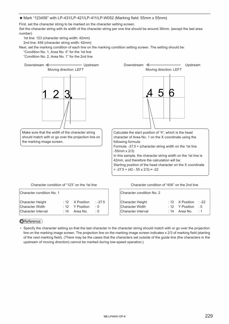
229
Mark “123456” with LP-431/LP-421/LP-411/LP-W052 (Marking field: 55mm x 55mm)First, set the character string to be marked on the character setting screen.Set the character string with its width of the character string per one line should be around 36mm. (except the last area number)
1st line: 123 (character string width: 42mm)2nd line: 456 (character string width: 42mm)
Next, set the marking condition of each line on the marking condition setting screen. The setting should be:“Condition No. 1, Area No. 0” for the 1st line“Condition No. 2, Area No. 1” for the 2nd line
4 5 61 2 3
Make sure that the width of the character string should match with or go over the projection line on the marking image screen.
Calculate the start position of “4”, which is the head character of Area No. 1 on the X coordinate using the following formula:Formula: -27.5 + (character string width on the 1st line -55mm x 2/3)In this sample, the character string width on the 1st line is 42mm, and therefore the calculation will be:Starting position of the head character on the X coordinate = -27.5 + (42 - 55 x 2/3) ≈ -22
Moving direction: LEFTDownstream Upstream
Moving direction: LEFTDownstream Upstream
Character condition of “123” on the 1st line Character condition of “456” on the 2nd line
Character condition No. 1
Character HeightCharacter WidthCharacter Interval
: 12: 12: 14
X PositionY PositionArea No.
: -27.5: 0: 0
Character condition No. 2
Character HeightCharacter WidthCharacter Interval
: 12: 12: 14
X PositionY PositionArea No.
: -22: 0: 1
Reference
• Specify the character setting so that the last character in the character string should match with or go over the projection line on the marking image screen. The projection line on the marking image screen indicates x 2/3 of marking field (starting of the next marking field). (There may be the cases that the characters set outside of the guide line (the characters in the upstream of moving direction) cannot be marked during low-speed operation.)
ME-LP400V-OP-6

230
Mark “1234567890ABCDEF” with LP-435/LP-425/LP-V15 (Marking field: 160mm x 160mm)First, set the character string to be marked on the character setting screen.Set the character string with its width of the character string per one line should be around 106mm. (except the last area number)
1st line: 12345678 (character string width: 112mm)2nd line: 90ABCDEF (character string width: 112mm)
Next, set the marking condition of each line on the marking condition setting screen. The setting should be:“Condition No. 1, Area No. 0” for the 1st line“Condition No. 2, Area No. 1” for the 2nd line
9 0 A B C D E F1 2 3 4 5 6 7 8
Make sure that the width of the character string should match with or go over the projection line on the marking image screen.
Calculate the start position of “9”, which is the head character of Area No. 1 on the X coordinate using the following formula:Formula: -80 + (character string width on the 1st line -160mm x 2/3)In this sample, the character string width on the 1st line is 112mm, and therefore the calculation will be:Starting position of the head character on the X coordinate = -80 + (112 - 160 x 2/3) ≈ -75
Moving direction: LEFTDownstream Upstream
Moving direction: LEFTDownstream Upstream
Character condition of “12345” on the 1st line Character condition of “67890” on the 2nd line
Character condition No. 1
Character HeightCharacter WidthCharacter Interval
: 12: 12: 14
X PositionY PositionArea No.
: -80: 0: 0
Character condition No. 2
Character HeightCharacter WidthCharacter Interval
: 12: 12: 14
X PositionY PositionArea No.
: -75: 0: 1
Reference
• Specify the character setting so that the last character in the character string should match with or go over the projection line on the marking image screen. The projection line on the marking image screen indicates x 2/3 of marking field (starting of the next marking field). (There may be the cases that the characters set outside of the guide line (the characters in the upstream of moving direction) cannot be marked during low-speed operation.)
ME-LP400V-OP-6

231
⿎ In case of marking studded character string:Setting example:Mark the characters at 100mm intervals with LP-V10U by using the concatenated marking function to the flying object.(In this example, Y position is stable. The origin of the character string is set to be “Left”, and the flying direction is set to be “LEFT”.)
Two-thirds of the marking field are concatenated with maximum 16 fields.Set the marking layout in these fields as shown below figure.
• f = Two-thirds of the marking field width
For LP-V10U (marking field width is 90mm), f = 60
• a = Spacing of the marking characters
When the distance between the characters is 100mm, a = 100
a
・・・
a
ff
A BC
Specify the marking condition of each line on the marking condition setting screen.In this case, the character string on the 1st line is specified as “Condition No. 1, Area No. 0” and that on the 2nd line is specified as “Condition No. 2, Area No. 1”, and that on the 4th line is specified as “Condition No. 4, Area No. 3”.Set the X-position of each condition number (Area number) so that the characters are placed at regular intervals in the row of two-third width of the marking field.
Setting Condition
Item 1st line 2nd line 3rd line 4th line
Character condition No. 1 2 3 4
X Position -45 -5 No character input -25
Y Position 0 0 No character input 0
Area No. 0 1 2 3
1st lineArea No.: 0
2nd lineArea No.: 1
3rd lineArea No.: 2
4th lineArea No.: 3
ME-LP400V-OP-6

232
4-13 Common SettingMarking condition set on common setting screen can be used reflecting to respective file number. This section describes common characters, the common counter setting, common lot setting, and common export date setting which can be set on the common setting screen.
Reference
• The contents set on the common setting screen are simultaneously saved when a file is saved on the file screen.
12
Description
1 Registration name:Input the common file name.Only one common file can be registered in the laser marker.As a file name, both alphabet including capital and small letters and numeric can switch between single- and double byte. Up to 20 characters can be input in case of inputting all single byte letter.Refer to “4-8-2 Character Input” (P.148) for the input method.
2 Common setting of functions: Set the following functions used commonly in several files.• Common character• Common expiry date• Common counter• Common lot
ME-LP400V-OP-6

233
4-13-1 Common Character SettingThis paragraph explains the common character setting which can be set in common for all files.The contents of the set characters are reflected to all files.
1
2
Description
1 Common Marking Character:Setting of ten lines is possible.
Setting Range 51 to 60
2 EDIT:Press this button for executing copy, paste, line insertion, line deletion, and edit.Input and edit methods are the same as that of the character setting screen. Input a marking character with reference to “4-8-2 Character Input” (P.148) of a character.
Reference
• The conditions (character size etc.) of the character set by common marking character setting are set on the character conditions of each file. Since there are 51 to 60 common setting lines, specify a line in each file and set the character conditions. Refer to “4-10-2 Character Conditions” (P.180).
ME-LP400V-OP-6

234
4-13-2 Common Expiry DateThis paragraph explains the setting of common expiry date which can be used for all files.This function allows to mark the add-subtract time/date to present time set in environment setting screen of “4-16-2 System Setting (Environment 2)” (P.258).
Reference
• After setting common expiry date condition here, input the functional character of expiry date in the character setting screen. Refer to “Current Date and Expiry Date” (P.153).
12
4
3
Description
1 Common Expi No. (Common Expiry No.) :4 expiry conditions can be set in 5 to 8 for all files.
2 Expi (Expiry Value) :Expiry values to be used for conditions described in “3” as unit.When the expiry number is set to negative value, it represents the past date.
Setting Range -999 to 999
3 Year/Month/Day/Hour/Min. :Sets unit of expiry.Ex) Mark the expiry date of 3 months.Set 3 to “Expi” and select Month for “Expiry unit”.
4 Today Included :Enables to select “Today Included” or “Today Not Included” for expiry in the case of selected the expiry unit, Year or Month. When Year or Month is not selected for the unit, this setting cannot be used.
Reference
• Basically, the expiry date indicates the same year, same month, or same date. When setting “Today”, the expiry is displayed with the previous date (when the expiry value is set with negative value, the expiry is displayed with the next date).
ME-LP400V-OP-6

235
4-13-3 Common CounterCommon counter is a counter which can be set in common for all files. This counter can be counted up/down by sequential number even if the file No. is changed.
Notice
• When the counter is interrupted by alarm occurrence etc., check the counter value for the next marking.
Reference
• The counter does not operate at test marking.• The current value of the counter is saved without overwriting the file.• After setting common counter condition here, input the functional character of counter in the character setting screen.
Refer to “Counter” (P.155).
16 7
24 5
3
Description
1 Common Counter No.4 counter conditions can be set in 4 to 7 for all files.
2 Curr (Current Value):Current counter value. The current value is subsequently marked. Set the current value within the initial value and end value.
Setting Range 0 to 999999
3 Init / End (Initial Value / End Value):The initial value and the end value of the counter. When the counter value reaches to the end value, the marking is started from initial value again.When the initial value is smaller than the end value: Counting upWhen the initial value is larger than the end value: Counting down
Setting Range 0 to 999999
Reference
• Set the different value to the initial and the end value. If the same value is set to both, the counter value does not change.
4 Step (Step Value):Sets the value to be changed per count.
Setting Range 0 to 999999
ME-LP400V-OP-6

236
Description
5 Source (Count Source) :Target for timing of counting up and counting down. The count-up or count-down is started at the timing of count source end. The count source can be switched by pressing button.
Setting Range
TRIG (Trigger) Counts up or counts down by trigger input.Counter 0
Counts up or counts down when counter 0, 1, 2 or 3 ends.Counter 1
Counter 2
Counter 3
Counter 4
Counts up or counts down when common counter 4, 5, 6 or 7 ends.Counter 5Counter 6Counter 7
6 Reset at Data Update:With checking on this function, the counter value is reset at the internal clock becomes “0:00”.
Reference
• When the date changes during the Time Hold function is effective, the counter value is reset at the timing of releasing Time Hold (the time hold input is OFF).
• The counter reset at update cannot apply to the marking to flying object.
7 RESET:Returns current value to initial value by pressing [RESET].
ME-LP400V-OP-6

237
4-13-4 Common LotThis clause explaining the setting of lot function which can be used in common for all files.This function divides the subject set in term by each term, and marks each term in the set character string.
Notice
• The following items, Date, Lot, and Expiry date are marked based on the internal clock of the laser marker. The internal clock might be deviated caused by the error of the internal parts or degree of the battery drain. Therefore, be sure to check the time of the internal clock before the operation without fail.
Reference
• After setting common lot condition here, input the functional character of lot in the character setting screen. Refer to “Lot” (P.157).
123
4 5
6
Description
1 Common Lot No.:4 lot conditions can be set in 4 to 7 for all files.
Setting Range 4 to 7
2 Period:Target period of the lot function.
Setting Range
Current : Specifies as target date set with current date.
Expiry No. 1 to 8 : Specifies as target date set with expiry No. 1 to 8.
Counter 0 to 7 : Specifies as target counter set with counter 0 to 7.
3 Unit:Select the unit for period to be performed lot function.
Period unit Maximum setting number Year 60
WB-year(week-based year)
60
Month 12Day 31Y. M 60
Period unit Maximum setting number M. D 60Hour 24Min. 60H. M 60Week 54
Day of Week 7
ME-LP400V-OP-6

238
Description
Reference
• When a lot subject is set to counter 0 to 7, setting of term condition is not necessary. In this case, max. dividing number is set to 60.
• When the period unit is “M.D”, do not input the non-existent date.• When week or WB-year (week-based year) is used for the period unit, set the update day and first week of the year in
environment settings screen beforehand. Refer to “Week Setting” (P.260).
4 Period:Set the both period of start and end.
Reference
• f the period is spanned, for example, when setting the period from 22 o’clock to 3 o’clock of the next day, it needs to set the period by diving into two, 22 to 23 o’clock and 0 to 3 o’clock.
• Saturday is defined as weekend day even whether the week renewal is set to either Monday or Sunday at “week” unit setting of “Lot” in “Function Setting” menu. For marking Monday through Friday as “Weekday” and Saturday and Sunday as “Holiday”, you should set respectively at three times as following order; Sunday is set as “Holiday” (1), Monday through Friday is set as “Weekday” (2), and Saturday is set as “Holiday” (3).
5 Marking Character:Set the character string to be marked. Double-click on the marking character string area, or select the input line and press [EDIT] to open the character input window.
Setting Range Up to 9 characters *
* Capital and small letters of alphabet, numerics, Katakana, Hiragana, Kanji (JIS level-1 and JIS level-2), symbols, user registration characters
6 AUTO:This “AUTO” is available when the unit of the expiry date is selected among “Year”, “Month”, “Day”, “Hour”, “Min.”, “Week”, or “Day of Week”. Pressing this button sets the start and end of the period with minimum unit automatically. Note that when the unit of the expiry date is set to “Year”, the period is set automatically calculating from the current year.
ME-LP400V-OP-6

239
4-14 Image Display ScreenThis is a screen for checking the image of character string/logo set in the character setting or condition setting.Image checking before marking is effective to reduce any errors.Position adjustment is also possible on this screen. Adequate position can be set by checking the image.
4-14-1 Image Display
1
3 45
6
7
9
8
2
10
11
Description
1 Image Screen :Image-displays the marking content set previously.
2 Magnification :Sets the magnification ratio of the image display.Press the numeric part of the magnification to set the arbitrary magnification on the screen.
3 Image Display Zoom-in/Zoom-out :The image can be zoomed in and out by 18 steps.
4 Center of Image Display :Set the origin center to image display position.
5 Image Display Position :Indicates where the current image is in the marking field.
6 Shift Display Position :Shifts image display part up and down, left and right. Pressing arrow shifts the image display part.
7 Area No. *1 :Displayed when marking on-the-fly is set in “Trigger setting”.It indicates the order of the marking field for the concatenated marking to flying object.Press [+] or [-] to select the desired area number. The image corresponding to the selected Area No. is displayed.Refer to “Concatenated Marking Setting” (P.226).
8 Auxiliary Line *1 :Auxiliary line used for setting marking to flying object.Refer to “Concatenated Marking Setting” (P.226).
9 Object (Adjustment Object) :Select the object to be fine adjusted.The data which shows in red character or image on the window is the selected object.
ME-LP400V-OP-6

240
Description
10 X/Y Position :Inputs the coordinate value of X or Y axis. Press the numerical value to display a ten-key pad.
11 X/Y Position Fine Adjustment :Fine-adjusts the target marking contents to up/down or right/left direction. (in 0.001mm pitch)
*1 : Displayed only with the setting for marking of flying object.
4-14-2 Work Image DisplayIn case there are data which you will see on the image display, but not be marked, such as the outline data of the marking object or characters, setting 0% to “Laser Power Correction”. Then, the data are showed with gray figure on the image display.The marking data which are set to 0% for “Laser Power Correction” are not marked. They do not affected the marking time etc. as well.
Reference
• When “Laser Power Cor.” is set to 0%, these character, logo, barcode or processing data are not traced with the guide laser “Marking Character” mode.
ME-LP400V-OP-6

241
4-15 USB MediaOn this screen, data saved in the laser marker such as setting files, log and font files can be exported and deleted. It is also possible to import externally saved data to the laser marker.To import and export the data, use a USB media.
Notice
• Do not remove the USB media from USB connector during data write/read. In addition, do not turn off the power supply of the main unit of laser marker during data write/read. Any losses or failures of data might be caused. Please note that we shall not be liable for any losses incurred due to loss or failure of data arising from use of this product.
• Do not insert/remove the USB media into/from the USB connector during marking, guide laser scanning or remote control. The laser marker may get unstable or stop.
• Do not start the laser marker with the USB media being connected into the USB connector. The laser marker may not start normally. Connect the USB media to the connector after the start-up is completed.
• Do not connect any other USB products for the purpose of data writing or reading than USB media and USB mouse to USB connector. Performance of the laser marker might be failed. Before using a USB media, check it for compatibility with the laser marker. We shall not be responsible for performance of all kinds of USB media.
• USB media with security features cannot be used.• USB hub cannot be used for this product. Use USB media directly connecting to the laser marker.
4-15-1 Registration FileRegistration files contain the marking data and conditions in one file number.Up to 2048 registration files can be saved in a laser marker.
Item Description
1 TO MEDIA Copies the selected file stored in the laser marker to the USB media.
2 FROM MEDIA Registers the selected file stored in the USB media to the laser marker.Files in the backup data can also registered individually to the laser marker.
3 DEL REGIST Deletes the selected file from the laser marker.Select the file to delete and click “EXECUTE”.
4 DEL MEDIA Deletes the selected file from the USB media.Select the file to delete and click “EXECUTE”.
5 File list Displays the all files stored in the laser marker.Clicking the title line of the list, the files are sorted in ascending or descending order by the following categories.• No.• Registration File• Modified Date
5
1 2 3 4
ME-LP400V-OP-6

242
4-15-2 Common FileCommon file contains the setting data for the functions such as expiry date, counter or lot using in several files.One common file can be saved in a laser marker.
4
1 2 3
Item Description
1 TO MEDIA Copies the selected common file stored in the laser marker to the USB media.
2 FROM MEDIA Registers the selected common file stored in the USB media to the laser marker.
3 DEL MEDIA Deletes the selected common file from the USB media. Select the file to delete and click “EXECUTE”.
4 Common file list Displays the common file stored in the laser marker.
ME-LP400V-OP-6

243
4-15-3 Logo FileLogo files contain the graphic data for the marking in VEC or DXF format.
Item Description
1 TO MEDIA Copies the selected logo file stored in the laser marker to the USB media.
2 FROM MEDIA Registers the selected logo file stored in the USB media to the laser marker.
3 DEL REGIST Deletes the selected logo file from the laser marker.Select the file to delete and click “EXECUTE”.
4 DEL MEDIA Deletes the selected logo file from the USB media.Select the file to delete and click “EXECUTE”.
5 Logo file list Displays the all logo files stored in the laser marker.Clicking the title line of the list, the files are sorted in ascending or descending order by the following categories.• Logo File • File Name• Modified Date
Reference
• Up to 2048 logo file can be registered into the laser marker.• Up to 1,445,376 byte logo file can be registered into the laser marker.
5
1 2 3 4
ME-LP400V-OP-6

244
4-15-4 Font FileFont files contain the font data for marking.
Font File RegistrationRegistration of the font file to the laser marker is necessary when marking is executed with the laser marker.
Register the fonts to the suitable font registration field as follows.In case the font type does not match the font registration field, some characters cannot be input properly.
Font reg. field Initial registered file (.FON) Font Type
Character Font 1 LP-4x0/4x5 type: ORG1LP-4x1 type: ORG2LP-V/LP-W series: ORG3
Font for the alphanumeric and symbols (called Original font in the laser marker):0 to 9, A to Z, a to z and some symbols
Character Font 2 LP-400/V series: ORG4LP-W series: ORG5
JIS Font JIS1 JIS Level 1 font:Hiragana, Katakana and Kanji characters for Japanese, special characters for Grecian and Russian
User Registration Font USER User Registration Character Font(newly created character by user)orJIS Level 2 font:Kanji characters for Japanese
2D Code Font 2DCODE Drawing pattern font for 2D code modules
Reference
• In case of using both JIS First Level font and JIS Second Level font at the same time, register JIS1.FON to the JIS font registration field and register JIS2.FON to the user registration characters registration field.
ME-LP400V-OP-6

245
Installed FontThe attached “Laser Marker Driver & Utility (CD-ROM)” contains the following font files.(For Font: [CD-ROM]\Font)Save the files into a USB media when registering it to the laser marker.
Character font
Alphanumeric and signal font of original for laser marker. (Original Font)(Refer to the Character Code Table of External Control Manual for the character kind and character code.)
For Japanese Font For English Font DescriptionORG1.FON ORG1_E.FON font suitable for multipurpose letter marking.ORG2.FON ORG2_E.FON font suitable for lower-case letter marking.ORG3.FON ORG3_E.FON font suitable for nameplate marking etc.ORG4.FON ORG4_E.FON font for high-speed marking.ORG5.FON ORG5_E.FON font suitable for micro lower-case letter.OCR1.FON OCR1_E.FON font suitable for confirming the processed image.
For only Japanese FontORG1S.FON 80% reduced-size font of Original1.ORG2S.FON 80% reduced-size font of Original2.ORG3S.FON 80% reduced-size font of Original3.
Reference
• Original 4 font contains some characters that can not be bold.• By using reduced size font, arrange a proper balance of character line when Kanji and alphanumeric characters are
used in the same character line.
JIS font
Font file of Hiragana, Katakana, Grecian, Russian, and Kanji.(Refer to the Character Code Table of External Control Manual for the character kind and character code.)
For Japanese Font For English FontJIS1.FON JIS1_E.FONJIS2.FON JIS2_E.FON
User Registration Character Font
The font file in which the user registers the font newly created with the font maker (refer to Font Maker Operation Manual.)* The following character fonts are previously registered at 8121(HEX) to 8129(HEX) in the character font by user
registration installed in the CD-ROM.
Shift JIS JIS 0 1 2 3 4 5 6 7 8 9 A B C D E F
UserRegistrationCharacter
F13F 8120F14F 8130F15F 8140F16F 8150
For Japanese Font For English FontUSER.FON USER_E.FON
2D Code Pattern Font
Pattern font for 2D code allocated to codes 2230(HEX) to 2239(HEX) and 8121(HEX) to 8152(HEX).* The pattern font for 2D code installed into CD-ROM is already registered the pattern font for 2D code allocated to codes
2230(HEX) to 2239(HEX) and 8121(HEX) to 8152(HEX).(Refer to “2D Code Pattern Font” (P.202) for the kind and code of character.)
For Japanese Font For English Font2DCODE.FON 2DCODE_E.FON
ME-LP400V-OP-6

246
4-15-5 File Management
⿎Copy to MediaThe file data registered in the laser marker is copied to USB media.
1. Select the file from the list and press [EXECUTE].For registration files, check the box of “Copy it with the logo file” to copy the logo files in the selected files.For logo files and font files, when pressing [ALL], the all files in the list are selected.
Reference
• For registration files and logo files, selecting the category title in the list and pressing [▲] [▼] displays the list by selected item in ascending/descending order.
2. Select the copy destination directory, and press [Copy].For the registration file and common file, input the file name to be saved on USB media. Then press [SET] and [COPY].Input possible with 8 characters of English capital letters or numeric letters, or 4 characters of Hiragana, Katakana, and Kanji.
Reference
• For the registration file and common file, following names can not be used as a file name. CLOCK$, CON, AUX, NUL, PRNCOM1 to COM9, LPT1 to LPT9
ME-LP400V-OP-6

247
⿎Register to InsideThe file data saved in USB media is registered to laser marker.
1. Select the file in the USB media after selecting directory, and press [EXECUTE].For logo files, when pressing [ALL], the all logo files are selected.
Reference
• Selecting the category title in the list and pressing [▲] [▼] displays the list by selected item in ascending/descending order.
• By selecting the directory in which the backup data is saved, it is possible to import an individual file from the backup data.
2. For registration files and font files, select the file number to be registered, and press [EXECUTE].
Reference
• When copying the registration file in that a logo file is used, register the logo file to the laser marker, too.• In case of transferring the registered file in the new version controller to the old version controller, settings of new
functions (of the new version controller) are not available (registered).• In case of transferring the registered file in the old version controller to the new version controller, settings of new
functions (of the new version controller) are set as default value.• Up to 2048 logo file can be registered into the laser marker.• Up to 1,445,376 byte logo file can be registered into the laser marker.
ME-LP400V-OP-6

248
⿎Delete RegistrationThe selected file data registered in the laser marker is deleted.
1. Select the file to be delete from the file list and then press [EXECUTE].For registration files and logo files, pressing [SLCT ALL], the all files are selected.
Reference
• For registration files and logo files, selecting the category title in the list and pressing [▲] [▼] displays the list by selected item in ascending/descending order.
2. Check the file and press [Yes].Pressing [No] does not delete the file and returns to Step 1.
3. The file is deleted from the laser marker.
⿎Delete MediaThe file data saved in USB media is deleted.
1. Select the file to be deleted from the file list after selecting directory, and then press [EXECUTE].When pressing [SLCT ALL], the all files are selected.
Reference
• Selecting the category title in the list and pressing [▲] [▼] displays the list by selected item in ascending/descending order.
2. Check the file and press [Yes].Pressing [No] does not delete the file and returns to Step 1.
3. The file is deleted from the USB media.
ME-LP400V-OP-6

249
4-15-6 BackupIn the menu of “OTHER”, the marking data stored in the laser marker can be saved as a backup file or a text file.
⿎BackupExecutes the exporting the backup data of the laser marker to USB media.The backup consists of the following data.• Setting files, Common files (The current value of the counter function is not included in backup data.)• Logo files• Font files• Environment settings (“Present time” and “Console” settings are not included in backup data.)
1. Insert the USB media into the USB port of the controller.
Reference
• Use the formatted empty FD (1.44MB) when using the USB compatible FDD (floppy disk drive).• If it needs to back up the data to the FD, more than two disks may be needed depending on the amount of data
registered.
2. Press [OTHER] and select [BACKUP].
3. Press [BACKUP].
4. Input the file name and press [SET].This file name is displayed when selecting the backup data for restoring.
5. The backup data is saved in the USB media with the following folder structure.USB media
“SUNX_BKUP” folderFolder (can be renamed)
“BACKUP” folder
SYSTEM.LOG
BKUP. INI
Notice
• Do not change the folder structure of the backup data. Changing or deleting data in the backup might be a cause of the reading error.
ME-LP400V-OP-6

250
⿎RestoreRestore (Overwrite) the file data (setting files, logo files, font files and environment settings) in the laser marker with the externally saved backup data by the following procedures.
1. Insert the USB media with the back up data into the USB port of the controller.The following folder structure of backup data can be read.
Reference
• Store “SUNX_BKUP” folder in the root directory of the USB media.
2. Press [RESTORE]. and the folders in “SUNX_BKUP” directory are displayed.
Select the folder in which the importing backup data is stored and press [CONFIRM].
3. Confirm screen is displayed. To execute restore press [OK].
4. Restore is conducted.
Reference
• When the restore is executed, the following files are not deleted and remains in the laser marker.• Marking files saved in the file numbers in which no marking files are existed in the backup data• Logo files whose file name (.vec or .dxf) is not existed in the backup data
• The following parameters are not restored at the importing of the backup data. For them the laser marker keeps the original setting.• Present time of internal clock (Environment setting)• Console setting (Environment setting)• Current value of counter function• Display language• Error log• System information
• If Ethernet is used, check the IP address, etc after the importing of the backup data. When the backup data is imported to the laser marker, communication parameter settings are overwritten with the backup data.
• In the case of restoring backup data from the other model, setting value beyond the setting range indicated in red. In such case, laser marker operates at the nearest upper or lower limit, or an error of the setting warning is occurred at the marking. Correct those value within the setting range according to the model.
• In case of restoring the backup file in the new version controller to the old version controller, settings of new functions are not available (restored).
• It is impossible to restore the backup file including DXF file to the laser marker whose controller version is 2.20 or previous version.
• It is possible to import an individual file from the backup data to the laser marker. Refer to “Register to Inside” (P.247).
USB media“SUNX_BKUP” folder
Folder (can be renamed)
“BACKUP” folder
SYSTEM.LOG
BKUP. INI
ME-LP400V-OP-6

251
⿎FD FormatFollow the procedures below to format FD (1.44MB) using FDD (floppy disk driver) that support USB.
1. Set the cable of FDD that supports USB to the USB media connector on the controller and insert a FD.
2. Press [EXECUTE].
3. Check the execution of formatting and then press [OK].Pressing [Cancel] does not format USB media and returns to Step 1.
4. Formatting is executed.
ME-LP400V-OP-6

252
⿎Text OutputThe selected file data is copied to USB media with text format.
1. Select the file to be text outputted from the file list, and press [EXECUTE].
2. Select the directory to be copied the file, and press the file name input column. After that, input the file name to be saved into USB media, and press [SET]. and then press [SAVE].Input possible with 8 characters of English capital letters or numeric letters, or 4 characters of Hiragana, Katakana, and Kanji.
3. The file data will be output to USB media in the text format.
Reference
• The data output into text format can be opened and read with “Notepad”, etc. of “Windows”.• The following names have been already reserved by system and can not be used as a file name.
CLOCK$, CON, AUX, NUL, PRN COM1 to COM9, LPT1 to LPT9
ME-LP400V-OP-6

253
4-16 Environment SettingThis function is used for environment setting of laser marker and checks the status of system.The setting parameters on this screen affect the settings on the other screens, operation or marking of character.The settings here should be previously checked, or changed if necessary.
4-16-1 Display Setting (Environment 1)
Reference
• Setting of Environment 1 is saved without overwriting.
⿎Operation Screen and Remote Screen
Description
1 Display mode :Select the display of the operation screen between marking characters and marking image.• Character: Refer to “4-3-1 Character Display” (P.126).• Image: Refer to “4-3-2 Image Display” (P.127).
2 Update Function Character :Select the updating on (Yes) / off (No) in the operation screen for the function character such as date, lot, counter.
3 Remote Screen :Select the display of the operation screen under the remote control mode.• Operation Screen: Refer to “4-3 Operation Screen” (P.126).• I/O Check Monitor: Refer to “4-5-1 I/O Check Monitor” (P.133).• File No.
Reference
• When selecting “Image” for the operation screen and displaying the operation screen in the remote control mode, the waiting time for the turning on the marking ready might become longer after editing the marking data or changing file No.
• When selecting “Yes” for the update of the function character, the idling time from the ending of the marking after inputting trigger until the timing of the starting of the next marking might become longer.
1 2
3
ME-LP400V-OP-6

254
⿎Operator Adjustment Screen/Adjustment Accepted ParametersThe setting parameters that can be set on the operator’s adjustment screen are selected. Refer to “4-4 Operator Adjustment Screen” (P.129).
1
2
Description
1 Setting permission: Check the respective boxes to make the adjustment on the operator’s adjustment screen possible.• Offset• Line Speed• Laser Power• Scan Speed• Laser Pulse Cycle (Only LP-V series)• Change File No.• Overwriting• Laser Check
2 Editable Lines:Sets the number of line possible to be edited at the edition of character setting on the operator’s adjustment screen.
Setting Range 0 to 50 lines
Reference
• Setting of password is useful to avoid unintentional change of setting by operator. Setting of parameters only the specified operators can change is possible, too. Refer to “4-16-1 Display Setting (Environment 1)” (P.253) or “4-3-3 Password to Open the Setting Screen” (P.128) for the setting of password.
ME-LP400V-OP-6

255
⿎PasswordThe function of password is used to avoid the unintentional change to the setting screens from operation screen.The password is required to change the screen from operation screen to the other setting screens.
Setting procedures
1. Press the password.
2. Input the password, and press [SET].A password consists of figures of maximum fifteen digits.To disable the password protection, delete all characters and press [SET].
ME-LP400V-OP-6

256
When password is forgotten
1. Turn the key switch on the controller to OFF.
2. Turn the No. 4 DIP switch on the rear of controller to ON.
3. Turn the key switch on the controller to ON.
4. Press on the password in the “ENVIRON1” on the environment setting screen.
5. The figures displayed on the setting of password indicate the currently registered password.
6. Check the password, and press [CANCEL].
7. Turn off the key switch on the controller and turn off DIP switch No. 4 to make the password valid.
Reference
• The setting is not changed if the DIP switch is turned to ON while the key switch is in the ON position. Turn the DIP switch to ON after turning off the power.
OFF
ON
OFF
ON
OFF
ON
ME-LP400V-OP-6

257
⿎Bar Code SettingWhen GS1 DataBar Limited or its composite code is selected as bar code type in bar code condition setting, specifies the ratio of guard pattern width to module width.The guard pattern indicates the spaces outside of the code symbol where is marked when the code is inverted.For the code symbol details, refer to “GS1 DataBar Limited” (P.316).
12 3
4 5
Item Description
1 Guard pattern specified method
: Select how to specify the ratio of guard pattern width to module width.• 2006: Auto setting according to the ratio defined by ISO/IEC 24724 2006.• 2011: Auto setting according to the ratio defined by ISO/IEC 24724 2011.• Custom: Set the arbitrary ratio of the left and right guard pattern width respectively.
Reference
• For better bar code reading quality, in this laser marker, the rightmost space of the right guard pattern consists of six modules, adding one extra module to that of the standard when it is set to ISO/IEC 24724 2011.
• For GS1 DataBar Limited when “2006” or “2011” is set and “Guard” in “Condition setting of GS1 DataBar” (P.193) is enabled, the guard pattern is expanded with the certain width in addition to the specified width of ISO/IEC 24724 2006 or 2011.
• When “Custom” is selected here, the “Guard” in “Condition setting of GS1 DataBar” (P.193) of GS1 DataBar Limited is fixed to “None”.
2 Left Guard3 Right Guard
: Applicable when “Custom” is selected. Specifies the ratio of guard pattern width to module width.
Setting Range 1.0 to 20.0
4 SET : Applies and saves the barcode setting to the laser marker and closes the window.
5 CANCEL : Closes the window without applying the change.
Reference
• When the guard pattern specified method is changed, it changes the center position of the code symbols, too. Confirm the marking position after this setting.
ME-LP400V-OP-6

258
4-16-2 System Setting (Environment 2)
Reference
• Setting of Environment 2 is saved without overwriting.
1 2
3 45 56 6
7 8
⿎Present timeThe setting of internal clock provided to the laser marker. The dominical year, month, date, era year, hour, minute and second can be set. The internal clock is used to mark the current date and expiry date set as the function character.
Notice
• The following items, Date, Lot, and Expire Date are marked based on the internal clock integrated in the laser marker. The internal clock might be deviated caused by the error of the internal parts or degree of the battery drain. Therefore, be sure to check the time of the internal clock before the operation without fail.
⿎ConsoleThe console connected to the laser marker is specified.
Item Description
1 Type : Specifies the type of console connected to the laser marker.LP-ADP20 g LP-ADP40 g 15” Monitor g 17” MonitorThe setting varies by pressing the setting field.
2 Backlight Timeout : Sets the period till the automatic back light OFF.The light is always turned on when “0” is specified here.The setting is possible for the specified console. (“LP-ADP20” or “LP-ADP40”)
Setting Range 0 to 60 min.
ME-LP400V-OP-6

259
⿎System OffsetThis screen specifies the offset of marking position and laser power to the all registered files.The functions are applicable to adjust the difference of laser power or displacement between laser marker and works in case multiple production lines are used.
Item and Description
3 Laser Power :Laser power offset. Offset the value of laser power set in each file.
Setting Range 50 to 200%
Reference
• The laser power offset refers to the function to correct not the maximum laser power [W] value, but the laser power setting value.
• “100” is specified if the value of “laser power (system offset)” × “laser power (laser setting)” is 100 or more.
4 Rotation Offset :Rotates the object to the rotation direction around the original point.
Setting Range -180.00 to +180.00 degree
+Y
-Y +X
-X
Rotation (+) Rotation (-)
5 X/Y Offset :Shifts the marking position to the X/Y direction.
Setting Range
-45.000 to +45.000 mm (LP-V10)-55.000 to +55.000 mm (LP-430 / LP-420 / LP-410)-80.000 to +80.000 mm (LP-435 / LP-425 / LP-V15)-27.500 to +27.500 mm (LP-431 / LP-421 / LP-411 / LP-W052)
6 X/Y Scale :Sets the offset scale of marking field (X and Y). Area is corrected by inputting magnification.
Setting Range 70.000 to 130.000%
Reference
• System offset is not offset on the image display.• When marking data is inside of marking field on image display screen and the error “Existed marking data outside of
marking field” is displayed. Check the setting value in system offset.
ME-LP400V-OP-6

260
⿎Week SettingWhen week or WB-year (week-based year) marking is set in the current date, expiry date or lot functions, the counting rule of the week is set in this screen.The-first-day-of-the-week setting and the-first-week-of-the-year can be specified.
Item Description
7 Update day Specifies the week renewal timing “the-first-day-of-the-week”.• Sunday: Renews at 0:00 a.m. of Sunday.• Monday: Renews at 0:00 a.m. of Monday.
8 First Week Specifies the-first-week-of-the-year.• January 1: Specifies the first week which contains January 1.
The week which contains December 31 is the last week of the year.• First Thursday: Specifies the first week which contains the first Thursday of the year.
This may cause that the date December 31 is in the first week of the year and the date January 1 is in the last week of the year.
Example: When January 1 is Sunday, week setting is as follows:
Setting The first week Remarks
• Update Day : Monday• First week : January 1
January 1. (Sun.) only The second week is from January 2. (Mon.) to January 8. (Sun.)
• Update Day : Monday• First week : First Thursday
From January 2. (Mon.) to January 8. (Sun.) which includes the first Thursday of January 5.
January 1. (Sun.) is in the last week of the last year.
Reference
• Saturday is defined as weekend day even whether the week renewal is set to either Monday or Sunday at “week” unit setting of “Lot” in “Function Setting” menu. For marking Monday through Friday as “Weekday” and Saturday and Sunday as “Holiday”, you should set respectively at three times as following order; Sunday is set as “Holiday” (1), Monday through Friday is set as “Weekday” (2), and Saturday is set as “Holiday” (3).
ME-LP400V-OP-6

261
4-16-3 Communication, I/O Setting (Environment 3)
Reference
• Setting of Environment 3 is saved without overwriting.
13
2
⿎ Input/OutputThis screen specifies the settings related to the signals on the output terminal and I/O connector.
Item Description
1 One-shot time : Sets the output duration for the following signals.There is a margin of error between the setting value and actual output time.• MARK END OUT• SET OK OUT• TRIG. WARNING of E800
Setting Range 2 to 510ms
Reference
• In case the marking time is shorter than the set one-shot output time, the marking output remains ON until the one-shot output time ends.
• “E623 Too narrow marking interval for proportioned flying object” is generated at equidistant marking to flying object when the setting of one-shot time is longer than the period in which the line moves the distance specified at “Interval”.
2 Detect TRIG. Warning during Marking
: Enabling this setting, the warning (E800) to show that the trigger cannot be accepted is output in case the trigger is input while the shutter is opened.If the invalid trigger is detected, the warning E800 occurs for the setting one-shot time. When this function is disabled, the warning does not occur if there is an invalid trigger input.
3 I/O Connector Setting
: Select the operation of I/O connector signal No. 35 from “Output Cntr 3 End” or “Output Date Dif.”. Pressing this button the following screen will appear.For the detailed description of each signal, refer to External Control Manual.
Output Cntr 3 End “Output Cntr 3 End” for the I/O connector No. 35.Output Date Dif. “Output Date Dif.” for the I/O connector No. 35.
ME-LP400V-OP-6

262
⿎RS-232CThis screen specifies the environmental setting of the RS-232C. To perform RS-232C communication, use the [RS-232C] tab and set the following items:
Reference
• For communication with external devices, select either RS-232C or Ethernet port. They cannot be used at the same time, or switched.
47
5 61 2 3
Item Description
1 Baud Rate : Specifies the baud rate.
Setting entry 1200, 2400, 4800, 9600, 19200, 38400 [bps]Initial setting 9600 bps
2 Data Length : Indicates the data length. 8-bit fixed.
3 Parity : Specifies the parity.
Setting entry None, Odd, EvenInitial setting None
4 Stop Bits : Specifies the stop bit.
Setting entry 1bit, 2bitInitial setting 1 bit
5 Delimit : Sets the delimiter (code to identify the end of telegraphic message).
Setting entry CR, CR+LFInitial setting CR
6 Check Sum : Specify ON/OFF of check sum (error detection information). Enable this function when using the check sum.Check Sum indicates the lower 1-byte of adding result of value (binary) from the start code to the last data by converting it to two characters for ASCII code.
7 BCS Command GS → FNC1
: This setting is available only when the barcode “GS1 DataMatrix” is used. To set the barcode character by using serial communication command “BCS”, select either “GS” (OFF) or “FNC1” (ON) as the separator of AI data with the variable length.
Setting Range ON: the separator of variable length AI data is “FNC1”.OFF: the separator of variable length AI data is “GS”.
ME-LP400V-OP-6

263
⿎EthernetThis screen specifies the Ethernet communication setting. Set this to perform Ethernet communication.Select the [Ethernet] and press [SETUP] button to show the Network Setting Screen.Press [OK] to save the settings. (Press [Cancel] to discard the changes.)
6
12345
Environment 3 Screen Network Setting Screen
Item Description
1 IP Address : Sets the IP address.
Setting Range 1.0.0.0 to 223.255.255.255 (except 127 in the 1st octet)Initial setting 192.168.1.5
2 Subnet Mask : Sets the subnet mask.
Setting Range 128.0.0.0 to 255.255.255.254 Initial setting 255.255.255.0
3 Default Gateway : Sets the default gateway.
Setting Range 1.0.0.0 to 223.255.255.255(except 127 in the 1st octet)Initial setting None (blank)
4 Port : Sets the port.
Setting Range 5001 to 65534 [except 9090 and 9091]Initial setting 9094
5 MAC Address : Displays currently set MAC Address.
6 BCS Command GS → FNC1
: This setting is available only when the barcode “GS1 DataMatrix” is used. To set the barcode character by using serial communication command “BCS”, select either “GS” (OFF) or “FNC1” (ON) as the separator of AI data with the variable length.
Setting Range ON: the separator of variable length AI data is “FNC1”.OFF: the separator of variable length AI data is “GS”.
Notice
• The communication control of the laser marker through the Ethernet should be performed in a secure network environment.
Reference
• “Octet” is a 3-figure value delimited by dots. From the beginning, it is called the “1st octet”, “2nd octet”, and so forth.• Depending on the combination, there are cases where IP Address and Subnet Mask values cannot be set even if they
are within the setting range.• Make sure that the IP address for the laser marker on the network is not overlapping the IP address for the PC.• When the backup data is restored to the laser marker, communication parameter settings are overwritten with the
backup data. After restoring, confirm the IP address and other parameters.
ME-LP400V-OP-6

264
<Example of Ethernet connection>
HUB (or router)
Straight cable
External control device (PC, etc.)
Laser marker controllers (connected more than one unit)
Example of communication environment setting: Make sure that the IP address for the laser marker on the network is not overlapping the IP address for the PC.
PC Laser Marker A Laser Marker B Laser Marker C Laser Marker DIP Address 192.168.1.10 192.168.1.5 192.168.1.6 192.168.1.7 192.168.1.8
Subnet Mask 255.255.255.0Default Gateway None
Port - 9094 9094 9094 9094
ME-LP400V-OP-6

265
4-16-4 Power check
[Function specific to LP-V / LP-W series]* This function is not implemented in the LP-400 series.
The current power of the laser marker against the output of the laser marker at shipping is possible to be checked. If the laser power decreases from the delivery state, the power setting value can be adjusted.
1
5678
92 3 4
Measurement result window
Item Description
1 Power Check : By pressing the button, Power Check Start screen will appear, and after executing the power check, the measurement result screen above will be displayed.
2 Auto Correction : If the laser power decreases from the delivery state, adjust the power setting value based on the auto calculated ratio.
3 Manual Correction : The power correction rate can be set arbitrarily.
4 Close : Returns to the environment setting screen.
5 Current Power : The current laser power ratio [%] relative to initial power is displayed. If this value is less than 100, correct the laser power.
6 Power after Correction
: The laser power ratio [%] after power correction is displayed. Make correction so that the value is as close to 100 as possible.
7 Correct Date : It denotes the date and time when the power is corrected.
8 Power Correct : It shows power correction ratio. Set the ratio so that the current power × power correction ratio = 100.
9 Laser Rad. Time (Laser Radiation Time)
: Displays the total time of the laser radiation.
To use this function• Power correction refers to the function to correct not the max. laser power [W] value but the laser power setting value.
Power correction cannot increase the output power at the maximum power setting.• The measurement results might have +/-5% difference with normal temperature (20 to 30 Celsius degree).• The +/-10% difference might occur under the high/low temperature. Correcting power under normal temperature (20 to
30 Celsius degree) is recommended.• The values shown in “Current Power” and “Corrected Power” fields are the relative value expressed as a percentage to
the initial power of the laser oscillator.• Power check function is available when laser pumping is completed and the internal shutter is closed.
ME-LP400V-OP-6

266
Laser Power CorrectionAfter the power check if the power decays lower than the delivery status, correct the laser power setting value.Select the correction mode from “Auto” or “Manual”.• Auto: Sets the power correction ratio with the auto-calculated value so as to set the power to the power output at
shipping.• Manual: Corrects the power setting with the given value [%].
WARNING• Laser is radiated with the internal shutter closed. Be sure to use the protective
goggle and enclosure in case of laser leakage. Also, do not place any objects around the radiating area.
1. Press [POWER CHECK].
2. The Confirm screen is displayed.
Press [START].The current laser marker power is measured.
3. The Power Monitor screen is displayed.
For the auto correction, Press “Auto”.For the manual correction, press “Manual” and input power correction value, then press [SET]. Setting range: 50 to 200[%]
4. Press [START].The correction ratio after power correction and correction date are updated.
ME-LP400V-OP-6

267
4-16-5 Output SimulationWith the output simulation you can check the output signals of the laser marker without an actual operation.Use this function to confirm the operation of the external devices connected with the laser marker.
1
23
4
Item Description
1 I/O Terminal2 I/O Connector
: In the table, the status “0” indicates output OFF and “1” indicates output ON. During the output simulation, the status display of the terminal changes to yellow.
3 Output ON/OFF : Click the output terminal name to simulate, then the output status of the laser marker changes.
4 STOP OUTPUT : Terminates the simulation mode and reset the ON/OFF status of the output signals.This button appears when output simulation is started.During the output simulation, other operation and settings are disabled.
Reference
• For the name of each signal, refer to “External Control Manual”.
ME-LP400V-OP-6

268
4-16-6 Adjustment of Touch PanelLong time use of the touch panel may cause misalignment (of touch panel buttons) due to stress. This section describes how to calibrate the touch panel.
1. Use a pen to touch the center of the cross at the lower left corner.
2. Use a pen to touch the center of the cross at the upper right corner.A message will appear asking you if you want to save the calibration result.
Notice
• Lightly touch the center of the cross with a pen whose tip radius is approx. 0.5. An excessive force applied to the touch panel may damage the panel.
3. Press [OK].Pressing [Cancel] or doing nothing for 10 seconds will cancel the calibration result.
Reference
• Out of synchronous on console is considered if the displacement of display position on the screen or bleeding of display occurs. Adjust the synchronous in accordance with the method described in the instruction manual of console.
ME-LP400V-OP-6

269
4-16-7 Language SelectionDisplay language can be selected between English and Japanese.
Notice
• When the display language is changed, the unregistered setting data under editing is cleared. Save the file data before changing the language.
1. Press [ENVIRON] and press [LANGUAGE] on the bottom edge of the screen.Language selection screen will appear.
2. Select the language and press [SET].
12
ME-LP400V-OP-6

270
4-16-8 System InformationDisplays the identification and operating information about the laser marker. Confirm them for the maintenance.
1
2
3
Description
1 Laser marker model information :• Model Name• Option (If customized specifications are installed, the custom software name is displayed.)• Serial No.
2 Version information of the internal software :• Controller• Logo data conversion• Galvano Controller• Galvano Controller IPL• ROM 1 to ROM 3• CPU 1 to CPU 3
3 Running information :• Capacity of Flash Memory• Free Space of Flash Memory• Total Laser Radiation Time • Total Laser Pumping Time
Reference
• The contents shown in the system information may partly vary depending on the models and versions.
2
ME-LP400V-OP-6

271
MEMO
ME-LP400V-OP-6

Maintenance
ME-LP400V-OP-6

273
Maintenance ItemsListed below are typical parts that require cleaning or replacement depending on the usage environment or duration of service of the laser marker. Some parts are maintainable by the customer, and other parts are required to be repaired or replaced by our service representative, depending on the types of parts and the defects.For purchasing replacement parts or requesting our service representative to repair or replace parts, contact our sales agency.
LP-400 Series
ui
y
y
e
e
o
ert
er
ert
e
et1)
q q
ui
Head (Standard Model)Head (Tower Model) Controller
LP-V/LP-W Series
ui
qw
y
o
er
ert
et1)
ControllerHead
No. Parts nameMain cause for degradation
Daily maintenance Replacement when degraded or defective
q Laser emission port (fθ lens) Contamination Cleaning Replacement at our service department
w Protection glass of the laser emission port *1
Contamination Cleaning Customer-replaceable
e Intake/exhaust vent Contamination Cleaning ―
r Air filter Contamination Cleaning Customer-replaceable
t Air-cooling fan Contamination ― Replacement at our service department
y Laser oscillator Aging Check output Replacement at our service department
u Galvano scanner Aging ― Replacement at our service department
i Internal shutter Aging ― Replacement at our service department
o Battery inside the controller Aging ― Replacement at our service department
1) Fuse Blown ― Customer-replaceable
1! Cable Broken ― Customer-replaceable
*1 : The protection glass of the laser emission port is available only for LP-V/LP-W series.
ME-LP400V-OP-6

274
Notice
• Be sure to use our specified replacement parts. If the user applies any other fuses than the specified one, failure might result.
Maintenance Details of Parts
WARNING
• Maintenance work must be conducted with the power to the laser marker turned OFF, and the controller power cable disconnected. Doing so may cause exposure to the laser beam or electrical shock.
• Do not insert your hands or objects to the exhaust port of each unit or the gaps between units during the maintenance work. This may result in injuries, electrical shock, or failure of the laser marker.
Laser emission port (fθ lens)An f θ lens is mounted at the laser emission port of the head section. The fθ lens condenses laser irradiated from the oscillator at the position of the work distance. On the lens surface, AR (anti-reflection) coating is applied in order to maintain appropriate transmittance.For LP-V/LP-W series, the protection glass of the laser emission port is attached to the laser aperture. It protects the fθ lens from dirt or damage. AR (anti-reflection) coating is applied to the glass surface.
⿎Effect from deteriorationLens (for LP-V/LP-W series, protection glass) surface may become contaminated or receive dust generated during marking. Using laser marker with the lens contaminated may cause the lens to get burned in. This may also scratch the lens surface, or even peel off the surface coating depending on how it is used or cleaned.Operations under these conditions will degrade transmittance of laser, which may lead to deterioration in quality of marking and processing.
⿎Replacement interval• Deterioration in quality of marking or processing (density reduction, incomplete marking or processing) is observed.• There is contamination or scratch that cannot be removed by cleaning.
⿎Replacement method• For LP-400 series: Replaced at our service department. Contact our sales office.• For LP-V/LP-W series: Refer to “Cleaning / Replacement of Laser Emission Port” (P.276) for the replacement of the
protection glass of the laser emission port.
ME-LP400V-OP-6

275
⿎Cleaning steps for laser emission port (Daily maintenance)In order to maintain stable marking quality, the laser emission port needs to be cleaned regularly according to the usage environment.
1. Turn OFF the key switch of the controller, and disconnect the controller power cable.
2. Clean the laser emission port with an air duster for optics, and wipe it lightly with a soft cloth. If a contamination is severe, use a soft cloth immersed in ethanol to wipe it.
• LP-400 Series • LP-V / LP-W Series
Soft cloth
Laser emission port
Soft cloth Laser emission port
Notice
• Do not wipe the laser emission port strongly, or touch it with a sharp pointed object. Laser marker might become faulty.
WARNING • Never use an inflammable air duster. The laser beam may ignite the gas, resulting in fire.
ME-LP400V-OP-6

276
Cleaning / Replacement of Laser Emission Port
[Specific to LP-V / LP-W series]* This procedures are not applicable for LP-400 series.
For LP-V/LP-W series, Protection glass of the laser emission port is attached to the laser aperture of this product.Clean the protection glass at regular intervals according to the using environment.In case that any contamination that cannot be cleaned adhering to the laser emission port or any damage on the glass surface, replace the protection glass. (The protection glass for the replacement is optional.)
⿎Models of replacement partsDepending on the manufactured period of the laser marker, the parts model of the protection glass is vary. Check the serial No. of the laser marker and contact our sales office.
Applicable laser marker Parts Names (Model)LP-V10U Series LP-ACV60 or LP-ACV20 or LP-ACV10LP-V15U Series LP-ACV25 or LP-ACV15LP-W Series LP-ACV12
1. Remove the protection glass of the laser emission port.
Notice• Do not touch the lens and the glass surface of the laser
emission port and the protection glass at installing or removing.
• If the cover is difficult to be loosened, use a commercially available belt wrench. In that case, avoid scratching the glass surface of the laser emission port.
2. Remove any dust and dirt on the glass with an air duster for optics.
WARNING • Never use an inflammable air duster. The laser beam may ignite the gas, resulting in fire.
3. When the protection glass is LP-ACV60, remove the O-ring installed in the inside groove of the protection glass.
O Ring
Groove
LP-ACV60
Notice• If it is difficult to remove the O-ring, use tweezers. In that case, avoid scratching the glass surface and the O-ring.• When the protection glass is removed, check that the O-ring is not left in the scanner unit.
Lens(Laser emission port)
Protection glass of the laser emission portTighten: Turn in a
clockwise direction.
Loosen: Turn in a counter-clockwise direction.
ME-LP400V-OP-6

277
4. Rinse the protection glass and remove any oil stain with neutral detergent. Fully wash out detergent with running water and then air-dry it.AR (anti-reflection) coating is applied to the surface of the protection glass. To prevent peeling of the coating, do not use sponge or the like and softly wash it with balls of your fingers.
Notice• Do not wipe the glass strongly, or wipe it with an object with sharp tip. The marking performance might be faulty.
5. When the protection glass is LP-ACV60, install a new O-ring (L) in the inside groove of the protection glass.
O Ring
Groove
LP-ACV60
Notice• The O-ring cannot be reused. Be sure to use new one. Replacement O-rings are attached with the replacement
protection glass of LP-ACV60.• Be sure to fit an O-ring in the inside groove of the protection glass without twisting it.
6. Install the protection glass to the laser emission port.Tighten the protection glass turning in a following direction. When the protection glass is LP-ACV60, tighten it until a resistance is felt. From that point, tighten the 10 to 20 mm (circumference).Be sure to tighten the glass properly and without looseness.
Laser Marker Model Protection Glass Model Protection Glass Model
LP-V10ULP-ACV60 9N・m or lessLP-ACV20
5N・m or lessLP-ACV10
LP-V15ULP-ACV25LP-ACV15
LP-W052U LP-ACV12
Notice• Do not touch the lens and the glass surface of the laser emission port and the protection glass at installing or removing.• Tighten the protection glass slowly with the equal tightness.• If the cover is difficult to be tightened, use a commercially available belt wrench. In that case, avoid scratching the glass
surface of the laser emission port.
Lens(Laser emission port)
Protection glass of the laser emission portTighten: Turn in a
clockwise direction.
Loosen: Turn in a counter-clockwise direction.
ME-LP400V-OP-6

278
Intake/exhaust ventAir-cooling system is used in the laser marker, thus the cooling effect will drop if dust or oil is adhered to the intake or exhaust vent and it may result in the failure of the laser marker. Clean them regularly according to the usage environment.
⿎Cleaning of the intake/exhaust vent (Daily maintenance)
1. Turn OFF the key switch of the controller, and disconnect the controller power cable.
2. Vacuum the intake/exhaust vent and remove the dust.
LP-400 series
Intake airExhaust
LP-V/LP-W series
Notice
• Do not blow air to the laser marker especially to the intake/exhaust vent. If the dust penetrates in the laser marker, it may results in failure.
3. Wipe the vent with a dried cloth. If a contamination is severe, use a cloth wrung out with neutral detergent to wipe it. Then, remove the detergent with a cloth wrung out of water.
Notice
• Keep water from entering the laser marker inside.
ME-LP400V-OP-6

279
Air filterAir filters are placed in the air-cooling areas each of the head and the controller.
⿎Effect from deteriorationThe air filter soiled with dust may reduce the cooling effect of the air-cooling fan. This may cause the marking performance to degrade, or failure of the laser marker.
⿎Replacement interval• There is a broken part, or contamination that cannot be removed by cleaning.
⿎Models of replacement partsFor details of purchasing air filters, please contact our sales agency.
Applicable laser marker Model Filter type and quantity
LP-400 series LP-AFT20• For the head: 2 large-size filters• For the controller: 1 middle-size filter and 1 small-size filter
LP-V seriesLP-W series
LP-AFT21• For the head: 1 small-size filter• For the controller: 1 large-size filter and 1 middle-size filter
⿎Steps for cleaning (Daily maintenance) and replacement of air filterClean air filters regularly according to the usage environment.
1. Turn OFF the key switch of the controller, and disconnect the controller power cable.
2. Loosen the screws of the filter cover panel and remove the panel and filter.Be aware of keeping the washers attached behind the panel.
Filter cover panel
Controller: 2 screws
Screw
Washer
Filter
Filter cover panel
Screw
Washer
Filter
LP-400 Series:2 screws on the head part 1 screw on the head part
Filter cover panel
Screw
Washer
Filter
LP-V/LP-W Series:
ME-LP400V-OP-6

280
3. Clean the filter with neutral detergent and air-dry it.
4. Set the dried air filter. Place the resin washers at the tip of the screws and tighten the filter cover panel.
Notice
• Do not attach the filter when it is wet. This may cause the cooling capacity to degrade, or failure of the laser marker.
Air-cooling fanThe air-cooling fan cools the laser oscillator and internal power circuit. The fans are installed in the head and the controller part respectively.
⿎Effect from deteriorationDepending on the usage environment, any dust or oil adhered onto the fan may impair air flow rate of the fan or even stop the rotation of the fan. When the cool performance decreases, the temperature in the electric circuit or laser oscillator will go up, which may cause an error or stoppage of laser radiation. Also, a temperature rise in the housing will foster deterioration in the internal parts, which may cause the marking performance to degrade, or failure of the equipment.
⿎Replacement interval• The fan does not rotate, or the rotating speed is low.• There is contamination on the fan.• Abnormal noise is generated from the fan.
⿎Replacement methodOur service representative handles the maintenance and replacement. Contact our sales office.
ME-LP400V-OP-6

281
Laser oscillatorThe following type of the laser oscillator is installed in the laser marker. The laser beam output from the oscillator is scanned and focused to mark or process the target materials.• LP-400 series: A CO2 (carbon dioxide) laser oscillator is installed in the head.• LP-V/LP-W series: A fiber laser oscillator is installed in the controller and the laser beam is delivered to the head through
the fiber cable.
⿎Effect from deteriorationLaser output characteristics such as laser power will deteriorate over time due to aging of oscillator. As the laser output characteristics deteriorate, symptoms such as ununiform marking density, chipped characters, or unstable processing quality, etc. may occur.Also, as cooling efficiency of the oscillator decreases because of the usage environment, the electronic parts in the oscillator may become defective and unable to irradiate the laser.
⿎Replacement interval• Deterioration in quality of marking or processing (density reduction, incomplete marking or processing) is observed.• Setting a large value for the laser power is not reflected in the quality of marking or processing.• The laser power measured with a commercial power meter has decreased by 20%, compared to the delivery status.• LP-400 series: Three to five years have passed since the date of delivery, or the total operating time of laser pumping
has exceeded 12,000 hours.*• LP-V/LP-W series: The total radiation time of laser has exceeded 30,000 hours.*• Alarm for laser error occurred.
* The replacement interval may differ depending on the usage environment and marking conditions.
⿎How to confirm operating hoursDisplay the “System information” on the “Environment setting” screen and check the total laser pumping time and radiation time.
⿎Replacement methodOur service representative handles the maintenance and replacement. Contact our sales office.
ME-LP400V-OP-6

282
⿎Confirm laser output (Daily inspection)Confirm the laser output regularly in order to maintain consistent marking quality.The laser output should be measured with a commercially available meter using the following steps:
Reference
• For LP-V/LP-W series, the current power ratio in comparison with the power at the delivery state can be checked by using “power check” function. Refer to Operation/Maintenance Manual “4-16-4 Power check” (P.265).
1. Prepare a commercially available power meter.
Notice
• Be sure to use the calibrated power meter.• The power meter with the detector having the damage threshold (maximum average power density) of more than 10kW/
cm2 should be used.• Also the size of the detector should be more than φ10mm.• A difference may arise under the high/low temperature. Measuring power with normal temperature (20 to 30 Celsius
degree) is recommended.• Before measuring the laser power, make sure there is no contamination in the laser emission port. If the laser emission
port is contaminated or damaged, an error may result in the measurement of the laser power.
2. Install the power meter.Put the detector of the laser power meter vertically down from the center of the laser emission port and place it at the one-third to half of the specified work distance of the laser marker.
Laser Marker Head
Detector of Power Meter
Laser Beam
Work
Installation Distance for Detector of Power Meter
Work Distance
Notice
• Do not install the power meter within the focal length (specified work distance) of the laser marker. This may cause destruction of the power meter.
ME-LP400V-OP-6

283
3. Use “dual pointer” of the guide laser function to confirm the setting position of the power meter detector. Set the detector so that the cross indication of the dual pointer radiates on the center of the detector. (Do not set it to the position where the dot indication and cross indication overlap.)
4. Press “ADJUST.” in the operation screen.
5. Press “LSR. CHK.”.
Press “START” in the laser radiation confirmation dialog to irradiate the laser.
Reference
• The power setting in the selected file is applied to the laser check radiation.
WARNING• Be sure to wear protective goggles.• During the radiation, the laser energy is concentrated to one point. Use due
caution with long period radiation, it may cause a fire or damage to the object.
6. Press “Stop” to stop laser radiation.Without “stop”, the laser radiation automatically stops after about one minute.
ME-LP400V-OP-6

284
7. Check the measurement results of the power meter. If the power decays lower than the default status, correct the laser power setting value using the “System Offset” of the “ENVIRON.” screen.Setting range of laser power correction: 50 to 200 [%]
Reference
• The laser power offset refers to the function to correct not the maximum laser power [W] value, but the laser power setting value.
• If the value of “Laser power correction” × “laser power” is equal to or larger than 100, the setting will be “100”.
Notice
• If the power decays more than 20%, compared to the default setting, the laser oscillator needs maintenance. Contact our sales office or representatives.
Galvano scannerGalvano scanner is a scanner for radiating the laser beam along the coordinates of marking data.The galvano scanner scans the setting data by controlling the angle of galvano mirror mounted onto the axis of rotation of motor with two axes to create characters and graphics for marking and processing.
⿎Effect from deteriorationUneven wear may occur on the bearing inside the galvano scanner depending upon marking frequency and conditions. If uneven wear develops, accurate reproducing may become difficult, resulting in skewness or misalignment of marking lines.
⿎Replacement interval
• Deterioration in quality of marking and processing (Characters crushed, streaking and density reduction of the marking, incomplete processing) is observed.
• Alarm for galvanometer error occurred.• Galvano scanner has been used for almost five years.*
* The replacement interval may differ depending on the usage environment and marking conditions.
⿎Replacement methodOur service representative handles the maintenance and replacement. Contact our sales office.
ME-LP400V-OP-6

285
Internal shutterThe internal shutter is opened and closed by the rotary solenoid to shut off the path of laser beam.
⿎Effect from deteriorationWhen the rotation torque of the rotary solenoid declines, the opening/closing speed of the internal shutter is decreased or the shutter may not work. In this case, an error “Internal shutter failure” occurs in the laser marker and marking cannot be performed.
⿎Replacement interval• Total number of opening/closing operations has exceeded two million.• Alarm for the shutter error occurred.
⿎Replacement methodOur service representative handles the maintenance and replacement. Contact our sales office.
Battery inside the controllerA lithium primary battery is contained inside the controller as battery for clock or calendar of the laser marker. Functional characters such as the current date/time, expiry date/time, and lot date/time are marked based on the time of this clock.
⿎Effect from deteriorationWhen the battery inside the controller runs out due to aging, the date and time of the internal clock may be out of synchronization when the laser marker is turned OFF. If you start the laser marker in such a condition, warning “E251” for the decrease in clock battery voltage may occur, and the date and time setting is required. The warning is temporarily released by resetting the date and time, however, once the power supply of the laser marker is turned to off, the warning will reoccur or the internal clock will show the wrong time.In some case, the laser marker system cannot start up due to the battery error.
⿎Replacement interval• Warning “E251” for the decrease in clock battery voltage occurred.• Almost five years have passed since delivery.
⿎Replacement methodOur service representative handles the maintenance and replacement. Contact our sales office.
ME-LP400V-OP-6

286
Replacement of fuseReplace fuse of the controller when blowing.The power of the laser marker cannot be turned on if the fuse is blown.
⿎Models of replacement partsDepending on the manufactured period of the laser marker, the available parts model of the fuse is vary. Check the ampere rating printed on the fuse holder part of the controller rear side and select the appropriate model form this table. If the user applies any other fuses than the specified one, failure might result.
Applicable laser marker Type ModelLP-400 series Time Lag Fuse (Rating: 250V 10A) 0215010
(made by Littelfuse)Type A of PSE (Rating: 250V 15A) GAB 250V 15
(made by Daito Communication Apparatus Co., Ltd)LP-V seriesLP-W series
Time Lag Fuse (Rating: 250V 6.3A) 021506.3MXP (made by Littelfuse)B Type Brown Glass Fuse (Rating: 250V 15A)
FGBO 250V15APBF (made by FUJI TERMINAL INDUSTRIES Co., LTD)
⿎Steps for replacement
1. Remove causes for fuse blowing.
2. Turn OFF the key switch of the controller, and disconnect the controller power cable.
3. Turn the fuse holder on the back side, and remove the fuse.
4. Replace it with new one.
5. Turn the fuse holder, and install the fuse.
Replacement of cableIf the cable connecting the head and controller is broken because of the usage conditions and installation environment, it needs to be replaced.
⿎Models of replacement partsFor details of purchasing cables, contact our sales office.
Type ModelHead Power Cable LP-ACP20-5Head Control Cable LP-ACS20-5
⿎Steps for replacementRefer to Operation/Maintenance Manual “2-2 Connecting Laser Marker” (P.72), and connect cables.
Fuse Holder
LP-400 Series LP-V/LP-W Series
ME-LP400V-OP-6

287
Obtaining Backup DataObtain and keep a backup of data registered in the laser marker periodically in case of replacing laser markers for repairing and maintaining purposes.Obtain and keep a backup of data registered in the laser marker periodically using the Laser Marker NAVI smart in case of replacing laser markers for repairing and maintaining purposes.
⿎Steps for obtaining backup data (daily maintenance)
1. Start up the laser marker and press “SETTING” - “USB”.
Reference
• If the laser marker has a floppy disk drive instead of the USB port, press “FD”.
2. Press “OTHER” - “BACKUP”.
3. Insert USB memory device into the USB port on the controller.
4. Press “BACKUP”.
5. Specify the name and storage destination for a backup file.
Reference
• For the backup and restoring operation, refer to Operation/Maintenance Manual “4-15-6 Backup” (P.249).
1
4
3
2
ME-LP400V-OP-6

288
Serial No. Checking MethodNotify our sales office or representatives of the laser marker serial No. for inspection or repair.The head and controller is delivered with the same serial numbers.
⿎Check it on laser marker main unitThe serial No. of the laser marker is written on the area marked by a circle in the figure below.
Head (Standard Model)Head (Tower Model)
LP-400 Series
LP-V/LP-W Series
Controller
LP-xxxxxSERIAL No.xxxxxxLOT No.xxxxxx
WORK DISTANCExxx mm
Panasonic Industrial Devices SUNX Co.,Ltd.
Head Controller
⿎Check it on screen
Start up the laser marker and press “SYSTEM INFO” on the “Environment Setting” screen.The serial number is displayed on the system information window.
ME-LP400V-OP-6

289
Disposal of Laser MarkerTo dispose of the laser marker, in accordance with the regional regulation, please request the industrial waste disposer. Dispose of the laser marker as industrial waste, and never discard it with regular trash.
Notice
• Be sure to delete all registered data when transferring or discarding the laser marker. Retained data might result in illegal read out and leaking of information by a third-party with malicious intent.
Cautions for separate disposal of head of LP-400 seriesLP-400 series have some parts containing Zinc selenide and other chemicals of concern for disposal.When you request the industrial waste disposer to dispose of this product, inform them that the following chemicals are used in the head, and segregate and dispose them appropriately.In some countries and regions these chemicals are designated as hazardous substance in some countries and regions.For the correct method of disposal, in accordance with the regional regulation, please contact your local municipality, waste disposal services, or the point of sale where you purchased the products.
e
e
w
w q
q
Standard ModelTower Head Model
Internal parts to be concerned for disposal
No. Name Containing materials
q CO2 laser oscillator ZnSe (zinc selenide)
w Lens in beam expander
e Laser emission port (f θ lens)
WARNING • When the lens is broken, wear gloves, a mask, and protective goggles to prevent swallowing or inhaling broken pieces/dust or the adherence to the skin.
Disposal of old equipment and batteries
Only for European Union and countries with recycling systems
These symbols on the products, packaging, and/or accompanying documents mean that used electrical and electronic products and batteries must not be mixed with general household waste.For proper treatment, recovery and recycling of old products and batteries, please take them to applicable collection points in accordance with your national legislation.By disposing of them correctly, you will help to save valuable resources and prevent any potential negative effects on human health and the environment.For more information about collection and recycling, please contact your local municipality.Penalties may be applicable for incorrect disposal of this waste, in accordance with national legislation.
Note for the battery symbol (bottom symbol)This symbol might be used in combination with a chemical symbol. In this case it complies with the requirement set by the Directive for the chemical involved.
ME-LP400V-OP-6

290
⿎Detaching Method of BatteriesIn case of disposal of laser marker in the European Union, remove the battery with the following procedures and
segregate it properly in accordance with the EU Battery Directive (2006/66/EC).
WARNING• When detaching the exhausted battery, be sure to disconnect the controller
power cable so that the power cannot be supplied to the device. There is a risk of electrical shock.
Notice• This method is never described with the replacing method of the battery. The customer should call our service
representative to replace the battery.
1. Remove the side cover of the controller.Remove 6 screws of the side cover as shown in the figure below, and then slide the cover backward.After removing the cover, the battery is installed in the position as shown in the right figure below (surrounded with circle).
2. Remove the used battery as shown in the figure below.Cut 2 banding bands by using the nipper. Then, remove the connector of the battery, and remove the battery from the board.
Battery
Tie Band
ME-LP400V-OP-6

Troubleshooting
ME-LP400V-OP-6

292
TroubleshootingIf any operation errors occur, check items below.When the problems cannot be resolved, please contact our sales office.
�Start-up
Troubles Causes Measures
• Power supply is not turned on.
• The unit does not start up.
Power cable is not connected. Connect the power supply cable.
Key switch is not turned on. Turn on the key switch.
Power is not supplied. Check the power supply.
Fuse is blown.Replace the fuse by following the procedures in Operation/Maintenance Manual.
�Laser pumping
Troubles Causes Measures
Laser is not pumped.
Emergency stop switch is pressed.Reset emergency stop switches located on the head and controller.
[IN COM.] [OUT COM.] of I/O terminal is not connected to the power supply.
Connect [IN COM.] and [OUT COM.] in I/O Terminal to internal power supply or supply power from outside.
Emergency stop input on I/O terminal is in OPEN status, or safety equipment such as door and switch connected to the Emergency stop input on I/O terminal is in OPEN status.
• Check the connection of [EMER.+] and [EMER.-] (for PNP type model, [OUT COM]) of I/O terminal.
• Restore the original condition of the safety equipment connected to the Emergency stop input.
Laser is not pumped in remote mode.
Laser pumping ON signals from the external control equipment are not input or not accepted in remote mode.
• Check connections with external equipment for mis-connection, disconnection or contact failure due to any loose connector.
• When controlling the laser pumping by I/O signal, turn off DIP switch No. 2 and turn on [LASER IN].
• When controlling the laser pumping by serial communication, turn on DIP switch No. 2 and transmit the laser pumping command (LSR).
• To change the DIP setting, the switch of the laser marker should be set at power OFF state.
ME-LP400V-OP-6

293
�Display
Troubles Causes Measures
Touch panel console shows nothing.
Laser marker has not be started.See remedial action against “Laser marker fails to start up”.
Power cable of console is not connected.
Check that console cable is securely connected to connector [CONSOLE] on front of controller.
Return harness is not connected.Connect return harness ([RETURN OUT] [VGA OUT] [(VGA+RETURN) IN]) on the rear of the controller.
Touch panel console does not respond to screen tap.
Return harness is not connected.Connect return harness ([RETURN OUT] [VGA OUT] [(VGA+RETURN) IN]) on the rear of the controller.
Monitor shows nothing.
Monitor is not turned on. Check power to monitor.
Monitor cable is not connected.Check that monitor cable is securely connected to connector [VGA OUT] on back of controller.
VGA-compatible monitor is not connected.
Connect a VGA-compatible monitor.
Mouse does not work.(When the controller is the PS/2 mouse supported type)
Mouse relay cable is not connected.(A mouse is plugged directly into mouse connector on back of controller.)
Use mouse adaptor cable for the PS/2 type mouse.
Mouse does not work.(When the controller is the USB mouse supported type)
The mouse is connected to the USB hub.
Connect the USB mouse to the laser marker controller directly without USB hub.
The mouse type is not supported by this product.
Use the USB mouse with Human interface device (HID) class.
ME-LP400V-OP-6

294
�Marking
Troubles Causes Measures
Marking cannot be done.(Even though the laser radiation indicator changes to the marking status, nothing marked on the object.)
Obstacle hinders laser beam.Remove obstacle between head of laser marker and object.
For LP-V / LP-W series:Lens cap has not been removed.
Remove lens cap.
Distance to object is not appropriate.Adjust distance between bottom surface of laser maker and target surface of object as specified.
Object is not in place.Correct position of object. Guide indication feature may be helpful for this purpose.
The laser marker is set for the marking on flying objects despite the static object.
Set “Moving direction” to “STILL.” on the Trigger Setting screen.
Laser power is insufficient.
• Increase laser power (including correction factor).
• Decrease scan speed (including correction factor).
Laser wavelength is not appropriate for material of objects.
Materials on which can be marked differ depending on wavelength and output power of laser marker.Applicable marking object is as follows;• FAYb laser marker (LP-V/LP-W series) : Metal,
resin (excluding transparent and translucent types)
• CO2 laser marker (LP-400 series) : Resin (including transparent and translucent types) and paper.
Marking cannot be done.(The laser radiation indicator does not change to the marking status.)
When the marking mode is TEST:The marking mode is “RUN”.
Select [TEST] of the marking mode.
When the marking mode is RUN:The run mode is not started or the marking trigger is not input.
Set the marking mode into [RUN] and press [Start].Then, input the marking trigger from [TRIG. IN] signal on the I/O terminal.
When the laser marker is under the remote mode or run mode:Marking trigger signal is not input.
Check connections with external equipment for mis-connection, disconnection or contact failure due to any loose connector.
When the marking trigger is input from the I/O terminal, check if marking trigger signal meets write conditions.• For Trigger Marking:
Check if one-shot signal of 10 ms or longer is provided per marking cycle.
• For Equidistant Marking:Check if status of the signal remains on during marking.
ME-LP400V-OP-6

295
Troubles Causes Measures
Marking cannot be done.(The laser radiation indicator does not change to the marking status.)
When the laser marker is under the remote mode or run mode:Next marking trigger signal is entered before completion of current marking cycle.(E800 occurs.)
Enter next marking trigger signal after making sure that READY output is on.
When the laser marker is under the remote mode:Marking trigger is input when the READY output is OFF status.
Refer to “READY signal is not turned to ON” in the External Control Troubleshooting.
�Marking quality
Troubles Causes Measures
Marking fades entirely/partially.
Laser emission port is not clean.
Refer to Operation/Maintenance Manual and clean contaminants off the laser emission port.If contaminants persist, replace lens and/or laser emission port protection glass (for LP-V/LP-W series only). Contact our sales office.
Fumes occurring during marking hinder laser beam.
Install dust collector.
Check that dust collector works well.
Distance to object is not appropriate.Adjust distance between bottom surface of laser maker and target surface of object.
Target surface of object is inclined.Make adjustment so that bottom surface of laser marker head and target surface of object are parallel with each other.
There are variations in properties of objects.• Object thickness• Distance to object• Object surface condition (including
roughness, gloss level, etc.)• Object material (including chemical
composition ratio)
Adjust marking conditions according to variations found.
Object feeder is not stable.Adjust object feeder so that position of objects become stable.
Performance of laser oscillator deteriorates due to aging.
• Increase laser power setting.• Decrease scan speed.
If initial marking quality cannot be reached even if laser power is set to the upper limit, laser oscillator must be replaced. Contact our sales office.
ME-LP400V-OP-6

296
Troubles Causes Measures
Character is partially chipped.
Obstacle hinders laser beam.Remove obstacle between head of laser marker and object.
Laser emission port is not clean.
Refer to Operation/Maintenance Manual and clean contaminants off the laser emission port.If contaminants persist, replace lens and/or protection glass of laser emission port (for LP-V/LP-W series only). Contact our sales office.
Marking is dotted.For LP-V series:Setting of laser pulse cycle and scan speed are inadequate.
Decrease scan speed or marking pulse interval.
Marking line runs over the intended start or end points.
The setting in marking quality adjustment parameter does not match the other marking conditions.
Input the suitable adjustment value in marking quality parameters such as start point, end point, or wait value in laser setting screen.
Marking disorder (Characters crushed, unreadable)
The Fixing strength of the laser marker head is insufficient.
• Fix the head part tightly with the specified torque value.
• Improve the strength of the stand on that the head is installed.
There are continuous vibrations coming from surrounding equipment such as motor and press.
Perform vibration prevention measures.There are irregular vibrations coming from surrounding equipment such as air cylinder and forklift.
Start and/or stop timing of feeder does not match with marking operation.(Marking is disturbed at beginning/end of marking.)
• When disturbed at the beginning of marking:Marking trigger signal is likely to be entered before object is fully stopped. Marking may disturbed due to remaining vibration even if object is in full stop. Use delay timer etc. so that marking trigger signal turns on after vibrations are completely damped.
• When disturbed at the end of marking:Object is likely to start moving before completion of marking.Delay start timing of feeder or decrease scan speed so that marking is finished before object starts moving.
There are noises coming from surrounding equipment.
Protect laser marker against noises as follows:• Securely ground frame ground (FG) of laser
marker or surrounding equipment.• Isolate power and signal lines from each other
if they have been routed in parallel.• Shield signal line.• Isolate power supply for laser marker from
other equipment.• Use noise cut transformer to absorb noises
from power supply.
ME-LP400V-OP-6

297
�Moving objects
Troubles Causes Measures
Marking cannot be done. Encoder signal is off. Check for proper connection to encoder.
Marking is sometimes skipped.(E800 occurs.)
Marking trigger signal is entered before current marking is finished.
• Increase scan speed setting of laser marker.• Decrease delay distance setting of laser
marker.• Reduce feeder speed.• Increase marking interval (interval between
objects on feeder).
Characters unreadable
Feed direction is not correct. Match feed direction with laser marker operation.
Speed changes at conveyor junction.If conveyors are coupled, avoid marking near conveyor junction.
Actual speed and preset speed for feeding objects are different due to slippage of objects.
Remove cause of object slippage.
Pulse setting of encoder is not correct.Measure the number of encoder pulses and adjust “Number of encoder pulses”.
Encoder is out of order. Check encoder for proper function.
Marking position is unstable.
Positional misalignment is likely to occur due to meandering motion of conveyor.
Secure objects to prevent misalignment.
Marking character pitch is unstable.
The line speed at the marking position is different from the speed at the installation site of the encoder.
Place the encoder as close as possible to the marking position.
Decrease the encoder resolution to block the effect of the line speed fluctuation.Note that the minimum value of the encoder pulse should be 10 P/mm.
Character is partially chipped.
Obstacle hinders laser beam.Remove obstacle between head of laser marker and object.
Actual spacing between characters is larger or small than setting.
Pulse setting of encoder is not correct.
Check setting to be sure that:• When using A phase only:
Number encoder pulses = Number of pulses/mm x 2
• When using A and B phases:Number encoder pulses = Number of pulses/mm x 4
Either A or B phase signal is refused. (A and B phase used)
Check that signal is applied to A and B phase terminals of encoder.
Measured number of encoder pulses differs from calculated one.
Increase or decrease values in “Encoder fine adjustment” field as appropriate.• When the character interval is wide:
Increase the setting.• When the character interval is narrow:
Decrease the setting.
ME-LP400V-OP-6

298
�External control
Troubles Causes Measures
Laser marker cannot be controlled by the external signal.
Laser marker is not in remote mode.Press Remote switch on front of controller or enter remote mode in a manner described in External Control Manual.
The wiring between the laser marker and the external control devices is incorrect.
Check connections with external equipment for mis-connection, disconnection or contact failure due to any loose connector.
Check for continuity using tester or the like.
There are noises coming from surrounding equipment.
Protect laser marker against noises as follows:• Securely ground frame ground (FG) of laser
marker or surrounding equipment.• Isolate power and signal lines from each other
if they have been routed in parallel.• Shield signal line.• Isolate power supply for laser marker from
other equipment.• Use noise cut transformer to absorb noises
from power supply.
Serial communication control fails
Selected communication port is inappropriate.
For communication with external devices, select either RS-232C or Ethernet port. (They cannot be used at the same time, or switched.)The port selected in the environment setting screen indicates the valid communication port.RS-232C is selected at factory shipment.
Type of connection cable used is in appropriate.
For RS-232C, use a commercially available cross cable.(A straight cable cannot be used.)Laser marker has three-wire connection. (Only pins Nos. 2, 3 and 5 of RS-232C connector are used.)
For Ethernet, check the followings:• To use an external device and the laser marker
one to one, connect them with a commercially available cross cable (STP cross cable of the Category 5e or higher is recommended).
• To use an external device and the laser markers one to many, prepare a hub or router compliant to 1000BASE-T, 100BASE-TX, or 10BASE-T and connect them with a commercially available straight cable (STP cross cable of the Category 5e or higher is recommended).
Communication parameter settings are incorrect.
• Match communication parameter settings to external equipment. Communication parameter settings of laser marker can be checked in the environment setting screen.
• When using RS-232C, specify the “Flow control” to “None” at the communication port settings of the external control device.
ME-LP400V-OP-6

299
Troubles Causes Measures
Serial communication control fails
The RS-232C cable is connected to the wrong connector (RETURN OUT).
Connect the RS-232C cable to “RS-232C” connector on the rear of the controller.
Communication parameter settings are changed when the backup data is restored to the laser marker.
Check the communication parameter settings.If Ethernet is used, confirm the IP address and other parameters.When the backup data is restored to the laser marker, communication parameter settings are overwritten with the backup data.
Command data is not received from external equipment.
Using commercially available line monitor or protocol analyzer, check if external equipment transmits data.
Communication data format is incorrect.
Check if format of communication data command transmitted from external equipment is correct.• Check if start code STX (02: HEX) is placed at
beginning of transmitted data.• Check if the delimiter is added to the end of the
transmission data. ([CR] (0D: HEX) or [CR+LF] (0D: HEX 0A: HEX) for RS-232C, [CR] (0D: HEX) for Ethernet)
READY signal is not turned to ON.
Alarm or error occurs.Release the alarm or warning referring to the measures for the corresponding error code.
Laser has not been pumped. Refer to “The laser is not pumped”.
Internal shutter is closed.
Open the internal shutter.• When controlling the shutter by I/O signal,
turn off DIP switch No. 2 and turn on terminal SHUTTER in terminal block.
• When controlling the shutter by serial communication, turn on DIP switch No. 2 and send shutter command (SHT).
* To change the DIP setting, the switch of the laser marker should be set at power OFF state.
The changing operation of the file data is unfinished.
It takes from tens of msec. to several seconds to complete the changing file data.During that time, READY output is in OFF status.Enter marking trigger signal after making sure that [READY] output is on if you want to change file to another one.
Marking data is not sent to the laser marker from the external devices, in case of using Rank Function, External Offset Function, or Serial Data Input Function.
If rank, external offset and serial data functions are enabled while marking conditions are not yet specified, enter respective data per marking cycle.Enter marking trigger signal after making sure that [READY] output is on or checking status of READY using status request command.
Under serial communication control:Mark trigger signal is ON while the command reception permission (MKM command) is set to “Reception mode ON”.
Set “reception mode OFF” for command reception permission (MKM command). Before entering marking trigger signal, use status request command [STS] to make sure that READY is on.
ME-LP400V-OP-6

300
Troubles Causes Measures
The sending command is not accepted by the laser marker. (NAK response)
DIP switch No. 2 on back of laser marker is off.
To control the following commands with the serial communication, turn ON DIP switch No. 2.• Laser Control [LSR]• Shutter Control [SHT]• Laser Check Radiation [SPT]• Guide LD Indication [GID]• Power Check [PWR]
“Reception mode ON” is not set for command reception permission (MKM command)
The laser marker does not accept commands except the following unless it is in the “reception mode ON” status.For command transmission, set “reception mode ON” for “command reception permission (MKM command)”.• File Change (No. Specified) [FNO]• File Change (Comment Specified) [FNN]• Shutter Control [SHT]• Command Reception Permission [MKM]• Laser Control [LSR]• Counter Reset [CTR]• Status Request [STS]• Marking Trigger [MRK]• Serial Data Input [SIN]• Error code [ECR]
Alarm or error occurs.
All commands except the following are refused while alarm or error is active.• When alarm occurred:
• Status Request [STS]• Error code [ECR]
• When warning occurred:• Status Request [STS]• Error code [ECR]• Shutter control [SHT] (for closing motion
only)• Command Reception Permission [MKM]
(Only for reception mode ON and reception mode readout)
Two or more command data are transmitted at the same time.
After sending the command, confirm the response data from the laser marker. Do not send the next command before receiving the response.
�Others
Troubles Causes Measures
Laser is emitted at unintended timing.
Photoelectric sensor for marking trigger signal malfunctions.
Fumes may cause malfunction of photoelectric sensor for marking trigger signal.• Install dust collector.• Check that dust collector works well.
Date is reset. Internal battery has run out.
Contact failure may also be a cause of this symptom. When laser marker have been in use for five years or more, internal battery is easy to run out.Contact our sales office for replacement of internal battery.
ME-LP400V-OP-6
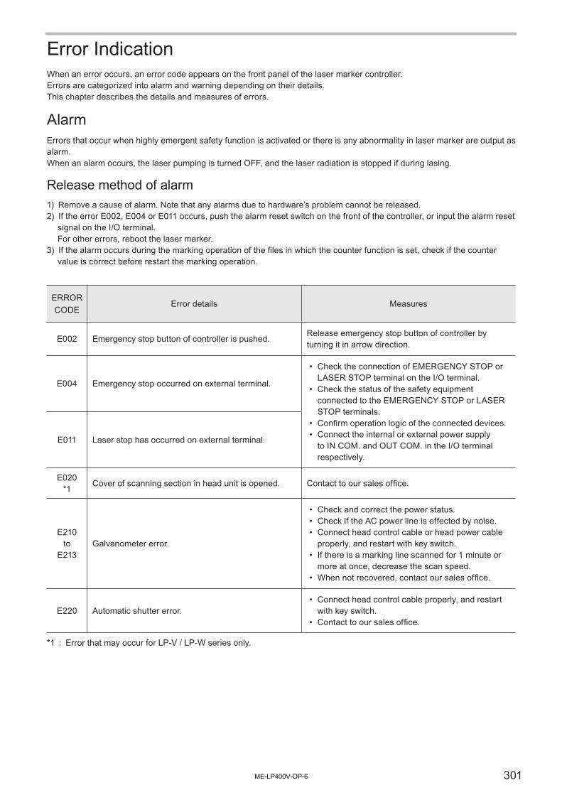
301
Error IndicationWhen an error occurs, an error code appears on the front panel of the laser marker controller.Errors are categorized into alarm and warning depending on their details.This chapter describes the details and measures of errors.
AlarmErrors that occur when highly emergent safety function is activated or there is any abnormality in laser marker are output as alarm.When an alarm occurs, the laser pumping is turned OFF, and the laser radiation is stopped if during lasing.
Release method of alarm1) Remove a cause of alarm. Note that any alarms due to hardware’s problem cannot be released.2) If the error E002, E004 or E011 occurs, push the alarm reset switch on the front of the controller, or input the alarm reset
signal on the I/O terminal. For other errors, reboot the laser marker.
3) If the alarm occurs during the marking operation of the files in which the counter function is set, check if the counter value is correct before restart the marking operation.
ERROR CODE
Error details Measures
E002 Emergency stop button of controller is pushed.Release emergency stop button of controller by turning it in arrow direction.
E004 Emergency stop occurred on external terminal.
• Check the connection of EMERGENCY STOP or LASER STOP terminal on the I/O terminal.
• Check the status of the safety equipment connected to the EMERGENCY STOP or LASER STOP terminals.
• Confirm operation logic of the connected devices.• Connect the internal or external power supply
to IN COM. and OUT COM. in the I/O terminal respectively.
E011 Laser stop has occurred on external terminal.
E020*1
Cover of scanning section in head unit is opened. Contact to our sales office.
E210to
E213Galvanometer error.
• Check and correct the power status.• Check if the AC power line is effected by noise.• Connect head control cable or head power cable
properly, and restart with key switch.• If there is a marking line scanned for 1 minute or
more at once, decrease the scan speed.• When not recovered, contact our sales office.
E220 Automatic shutter error.• Connect head control cable properly, and restart
with key switch.• Contact to our sales office.
*1 : Error that may occur for LP-V / LP-W series only.
ME-LP400V-OP-6

302
ERROR CODE
Error details Measures
E230to
E233
Laser error.• Temperature in the laser oscillator exceeds the
limit.• Instantaneous interruption of laser power supply is
detected.• Head control cable is not connected properly.• Fiber cable is broken. (only for LP-V/LP-W series)• Failure of laser oscillator is detected.• There might be occurred the malfunction of the
internal shutter.
Turn the key switch to the OFF position and check the followings: Cool the laser oscillator thoroughly before restarting the controller.• Check that the ambient temperature is in the
specified operating temperature.• Check the air filter, the air intake / exhaust port
and the fan of the cooling part for clogging.• Check and correct the power status.• Check if the AC power line is effected by noise.• Connect head control cable and head power cable
properly, and restart with key switch.• When not recovered, contact our sales office.
E235*2
There is a short line segment that cannot be marked.
Check and delete if there is an unnecessary short line segment in logo files.
Set scan speed smaller, or “0” to “Pre-Scan time” on Laser Setting.
E240E241
The temperature of the laser has reached its limit.
• Check that the ambient temperature is in the specified operating temperature.
• Make sure cooling fan operates.• When not recovered, contact our sales office.
E250 Detected a decrease in power supply voltage.
• Check and correct the power status.• Check if the AC power line is effected by noise.• Connect head power cable properly, and restart
with key switch.• When not recovered, contact our sales office.
E300A head is not connected. Shut off a power and connect a head.
Connect head control cable properly, and restart with key switch.
E310Unsupported head.Change either head or controller.
• Connect head control cable properly, and restart with key switch.
• Check if head with correct model has been connected. If it is wrong, replace head or controller with correct one.
E311System error.• Head control cable is not connected properly.• Wrong head has been connected to controller.
E312 System error.Restart the laser marker. When not recovered, contact to our sales office.
*2 : Error that may occur for LP-400 series only.
ME-LP400V-OP-6

303
ERROR CODE
Error details Measures
E320 Unit combination is incorrect.
• Connect head control cable properly, and restart with key switch.
• Check if head with correct model has been connected. If it is wrong, replace head or controller with correct one.
E410to
E443E990
toE999
System error.
Restart the laser marker.When not recovered,contact to our sales office.
E450to
E456Memory error.
E700 Unable to lase as laser pumping is turned OFF.
• Confirm that the laser pumping remains on during lasing operation.
• Check wiring and control procedure for the I/O terminal block, wiring to communication port, and the procedure of the communication command.
Reference
• When other error not listed in this section was occurred, restart the laser marker.• If the symptom persists after restart, contact our sales office.
ME-LP400V-OP-6

304
WarningErrors that notify of that the setting data are incorrect or laser radiation conditions are not met are output as warnings.Marking operation cannot be started while any warning is active. Laser pumping maintains the state before the warning.
Release method of warning1) Remove a cause of warning. If the warning cause is the wrong setting, correct the file data.2) When the laser marker is under the remote mode, close the shutter by I/O or serial communication control.
In case of the following warning, the shutter control is unnecessary.• E800: the warning occurs only while the specified one-shot output time and it is released automatically.• E811: the warning occurs only during the laser stop is opened, and then it is released automatically when the laser
stop is closed.3) If the warning occurs during the marking operation of the files in which the counter function is set, check if the counter
value is correct before restart the marking operation.4) In case that marking is executed again, make sure that the warning output is turned on, and then open the internal
shutter.
ERROR CODE
Error details Measures
E251Detected a decrease in clock battery voltage. Reset present time.
Contact to our sales office.While laser Marker power is on, reset “Present Time” in Environment Setting. When the power is off, reset “Present Time”.
E500There is not enough free space.The file cannot be registered.
Delete registered file and logo file.
E501 Cannot register setting because of memory error. • Restart with key switch.• When not recovered, contact our sales office.
E502E503
Invalid file format of font or logo file.
• Register the logo or font file again on the USB screen.
• For the logo file, convert the logo data to VEC format again with Logo data conversion software.
E600 No setting file.Set the marking data such as character, barcode and logo.
E601 No font file.• Register font file.• Set a registered font to the font in character
condition.
E602 Lack of font memory. Make font file smaller, or delete unnecessary font file.
E603 No logo file. Register logo file.
E604 Included character not registered into font file.Change characters.Or set the font file containing the setting characters.
E605Exceed valid number of characters.(Max. 30 characters/line.)
Make numbers of characters smaller.
ME-LP400V-OP-6

305
ERROR CODE
Error details Measures
E606 Existed marking data outside of marking area.
Contain marking data within marking area.• Change marking position.• Make characters smaller.• Narrow character interval.
* If there is no data out of the marking field in the image display, check the “system offset” in the environment setting. “System offset” value is not shown in the image display.
E607 Cannot create bolded character.
• Set any standard font without original 4 font.• Use Font Maker provided to create the proper
pattern font.• Set line width of bold character to quarter or below
of character height and width.• When marking the bold character, set the
comparison ratio between character height and width become 1/4 to 4.
• Check the line width of bold character not exceed the specified value.
E610E612
Lack of marking memory.• Marking data is too large.• The line length is too long. (spiral, etc.)
• Reduce numbers of characters and logo data.• Reduce numbers of step & repeat.• Reduce numbers of a start point and a end point
of characters or logo data.• Separate the long segment into short data.
E620E621
Flying object area over.(Can not follow line speed of flying object marking.)
• Shorten marking time with the following methods.• Speed up scan speed.• Narrow character interval.• Make characters smaller.• Reduce numbers of characters.• Change setting of curve/edge.• Reduce numbers of character lines.• Displace a start point of marking, etc.
• Adjust the line speed of the flying object.• Adjust the waiting time of the flying object.• Set the coordinate of the marking data close to the
center of the marking field.
E622Flying object time over.(Can not follow line speed of flying object marking.)
E623Too narrow marking interval for proportioned flying object.
Increase setting value of marking spacing. Shorten marking time with the following methods.• Speed up scan speed.• Narrow character interval.• Make characters smaller.• Reduce numbers of characters.• Change setting of curve/edge.• Reduce numbers of character lines.• Set smaller value to the one-shot output time, etc.
E630 Too much quantity of Step and Repeat marking.Reduce numbers of characters to be marked. (Max.: 1000)
ME-LP400V-OP-6

306
ERROR CODE
Error details Measures
E640 Invalid function for combining with flying object.
• With the marking to flying object, do not use the following functions.• Step & repeat• Reset at date update function• Arbitrary point radiation• Overwrite function
• With the equidistant marking to flying object, do not use the following functions.• Rank• External offset• Serial data marking
• Release flying object marking function with trigger setting.
E650 Invalid setting of processing element.Set the distance between start and end points of the arc smaller than double of radius.
E651 Too short line segment of processing element.Set the larger value to the length of the line than width of the line.
E660 Cannot convert dxf file.
• Save the DXF file with DXF-R12J, R13J or R14 format.
• Delete the entities which are not supported by laser marker in the DXF file.
• Read the DXF file again to the laser marker.
E690 Cannot finish measurement during specified time.• Reduce marking contents and measure marking
time.• Speed up scan speed.
E700 Unable to lase as laser pumping is turned OFF.Turn ON the laser pumping and after the laser pumping has completed, start marking.
E701*1
Started laser power check in laser pumping OFF state.
Turn ON the laser pumping and after the laser pumping has completed, start power check.
E800---------------------------(no message : Invalid input of marking trigger while Ready is OFF.)
• Change marking timing so that trigger input is performed after marking ready output is turned on.
• Check wiring and control procedure for I/O terminal, wiring to communication port, and the procedure of the communication command.
E811 Occurred laser stop from external terminal.• Check the wiring of the laser stop input terminal
and contact of the switch.• Confirm operation logic of connection device.
E900
Existed invalid function character for simultaneous use.The following combination of the functions are not available in one file.• Serial data marking function and rank function• Serial data marking function and external offset
function
Delete any one of these functions from the file.
E901 Existed invalid character for converting into 2D code. Set the character that can be converted into 2D code.
E902 Cannot create 2D code. Use the condition where 2D code can be created.
*1 : Error that may occur for LP-V / LP-W series only.
ME-LP400V-OP-6

307
ERROR CODE
Error details Measures
E903 No specified 2D code pattern.Specify 2D pattern code which has been already registered.
E910 Existed invalid character for converting into bar code. Set the character that can be bar coded.
E911 Cannot create bar code. Use the condition where a barcode can be created.
E912Too small dimension of narrow element/basic module width for bar code.
Specify the setting value for the width of the narrow element/basic module larger than that of the line width of the laser.
E913 No quiet zone in bar code.Set the proper value for “Quiet/Narrow Ratio”.With the inversion setting, set always quiet zone.
E914 Too small separate pattern or composite row height.
• Adjust the height of one step bar code.• Specify the proper value for “Separation Ptrn H/W”
so that the “Separation Pattern Height” becomes “0” or “Marking Width” is larger than “Separation Pattern Width”.
Reference
• When other error not listed in this section was occurred, restart the laser marker.• If the symptom persists after restart, contact our sales office.
ME-LP400V-OP-6

Appendix
ME-LP400V-OP-6

309
Description of Code Symbols
Reference
• For the details of each code symbol, refer to the corresponding ISO/IEC or JIS standards.
� CODE39
1. 2. 3. 2.4. 1.
Bar Code Symbol (entire width of bar code)
5. Character Gap
6. Bar Code Height
Data CharacterQuiet Zone Quiet ZoneStart Character
Check Character
Stop Character
Name Description
1 Quiet Zone Certain spacing is necessary for the back and forth to scan the barcode.
2 Start/Stop Character The particular characters to indicate the start and end of the bar code.
3 Data Character A bar or space on a bar code is called an “element”. On CODE39, a character consists of nine elements; five bars and four spaces (thee wide elements and six narrow elements).
4 Check Character Used to check if the read data is correct or not by putting the value calculated with the certain formula (modulus 43) on just before the stop character for re-calculation.
5 Character Gap The space between two adjacent characters. In this laser marker, it has the same width as the narrow element.
6 Bar Code Height Usually 5 mm or 15% of the symbol width excluding the quiet zone, whichever is greater.
Content of code data• The CODE39 bar code can indicate all 36 alphanumerical characters (A to Z and 0 to 9) and fixed characters (-, ., , $, /, +,
%).
ME-LP400V-OP-6

310
� ITF
Bar Code Symbol (entire width of bar code)
4. Bar Code Height
3. Data Character2. Start Character 2. Stop Character
1. Quiet Zone 1. Quiet Zone
Name Description
1 Quiet Zone Certain spacing is necessary for the back and forth to scan the barcode.
2 Start/Stop Character The particular characters to indicate the start and end of the bar code.
3 Data Character The first character is indicated by 5 bars and the second character by 5 spaces in those pairs. In these 5 elements (bars or spaces), two elements have the wide width.In case the number of data character is odd, “0” is added at the head to make it even number.
4 Bar Code Height Usually 5 mm or 15% of the symbol width excluding the quiet zone, whichever is greater.
Check Character Used to check if the read data is correct or not by putting the value calculated with the certain formula (modulus 10/ weight 3-1) on just before the stop character for re-calculation.
Content of code data• The ITF bar code can indicate only numerical characters (0 to 9).• The start character is “0000” and stop character is “100”. “0” is indicated with narrow bars or spaces. “1” is indicated with
wide bars or spaces.
ME-LP400V-OP-6

311
� CODE128
Bar Code Symbol (entire width of bar code)
6. Bar Code Height
3. Data Character 5. Check Character
2. Start Character 2. Stop Character
1. Quiet Zone 1. Quiet Zone
Name Description
1 Quiet Zone Certain spacing is necessary for the back and forth to scan the barcode.
2 Start/Stop Character The particular characters to indicate the start and end of the bar code.CODE128 has three types of start code (A, B, and C) and one stop code.Depending on the start character, the character code set is defined as “Code A”, “Code B” or “Code C”.The code set is determined by data character contents.The laser marker automatically selects the code set according to the input data.
3 Data Character On CODE128 bar code, a character consists of 11 modules (minimum unit consisting of bars and spaces). It has four types of element width from 1 to 4 modules.
4 Function Character Entering “FNC1” just before the data characters indicates that the code is UCC/EAN128 (GS1-128).
5 Check Character Used to check if the read data is correct or not by putting the value calculated with the certain formula (modulus 103) on just before the stop character for re-calculation.
6 Bar Code Height Usually 5 mm or 15% of the symbol width excluding the quiet zone, whichever is greater.
Content of code data• The CODE128 bar code can indicate 128 characters of ASCII code consisting of numerical characters, alphanumerical
characters (capitals and small letters), symbols and control code.
ME-LP400V-OP-6

312
� NW-7
Bar Code Symbol (entire width of bar code)
6. Bar Code Height
3. Data Character
5. Character Gap
4. Check Character2. Start Character
2. Stop Character
1. Quiet Zone 1. Quiet Zone
Name Description
1 Quiet Zone Certain spacing is necessary for the back and forth to scan the barcode.
2 Start/Stop Character The particular characters to indicate the start and end of the bar code.It has four types of start/stop characters (A, B, C, D). This product uses the same character for both start and stop characters.
3 Data Character On NW-7 bar code, a character consists of seven “Narrow” and “Wide” elements; four bars and three spaces.
4 Check Character Used to check if the read data is correct or not by putting the value calculated with the certain formula (modulus 16) on just before the stop character for re-calculation.
5 Character Gap The space between two adjacent characters. In this laser marker, it has the same width as the narrow element.
6 Bar Code Height Usually 5 mm or 15% of the symbol width excluding the quiet zone, whichever is greater.
Content of code data• The NW-7 bar code can indicate numerical characters (0 to 9) and symbols (-, $, :, /, . , +).
ME-LP400V-OP-6

313
� EAN
EAN-13 EAN-8
5. Bar Code Height
5. Bar Code Height
1. Q
uiet
Zon
e
1. Q
uiet
Zon
e
1. Q
uiet
Zon
e
1. Q
uiet
Zon
e
Cen
ter B
ar
Cen
ter B
ar
2. L
eft G
uard
Bar
2. L
eft G
uard
Bar
2. R
ight
Gua
rd B
ar
2. R
ight
Gua
rd B
ar
3. D
ata
Cha
ract
er
3. D
ata
Cha
ract
er
3. D
ata
Cha
ract
er
3. D
ata
Cha
ract
er
4. C
heck
Cha
ract
er
4. C
heck
Cha
ract
er
Name Description
1 Quiet Zone Certain spacing is necessary for the back and forth to scan the barcode.
2 Left/Right Guard Bar Identify the start and end of a bar code.
3 Data Character On EAN code, a character consists of 7 modules (minimum unit consisting of bars and spaces). A data character consists of two bars and two spaces. It has four types of element width from 1 to 4 modules. The data characters are displayed on either side of center bar.
4 Check Character Used to check if the read data is correct or not by putting the value calculated with the certain formula (modulus 10 / weight 3-1) on just before the stop character for re-calculation.
5 Bar Code Height The nominal bar height is specified as follows: • EAN-13, UPC-A and UPC-E symbols: 22.85 mm• EAN-8 symbols: 18.23 mm
Contents of EANStandard version (EAN-13) Abbreviated version (EAN-8)
Usable Data Characters Numerical characters 0 to 9
Digit number of Data Character, (including Check Character)
13-figure(6 digits for left/5 digits for right)
8-figure(4 digits for left/3 digits for right)
Quiet Zone11 modules or more on the left side
7 modules or more on respective sides7 modules or more on the right side
Left/Right Guard Bar “101”
Center Bar “01010”
ME-LP400V-OP-6

314
� GS1 DataBar
(15,4) (15,4)(16,4) (16,4)
4. Bar Code Height
1. L
eft G
uard
Pat
tern
1. R
ight
Gua
rd P
atte
rn
2. D
ata
Cha
ract
er
2. D
ata
Cha
ract
er
3. F
inde
r Pat
tern
3. F
inde
r Pat
tern
2. D
ata
Cha
ract
er
2. D
ata
Cha
ract
er
Name Description
1 Left/Right Guard Pattern
Provides the bar code area. It consists of bars and spaces of one module (minimum unit consisting on bars and spaces).
2 Data Character Has the (n, k) structure. “n” indicates the number of modules and “k” indicates that of bars and spaces that make up the character. As shown in the figure above, the data character is arranged so as to facing to the adjacent finder pattern (toward the arrow direction).
3 Finder Pattern Functions as a check character or segment identifier, too, which makes symbols to be easily recognized. It consists of five elements having 15 modules.
4 Bar Code Height In the standard case, the minimum value of bar code height is 33 times as high as the module width. For Truncated, Stacked, and Stacked Omnidirectional, it is 13, 13 and 69 times respectively.
GS1 DataBar symbols has the three type of version as shown below, in addition standard.
GS1 DataBar TruncatedGS1 DataBar Truncated lowers the bar code height of GS1 DataBar to meet the elongated marking field. The minimum value of bar code height is 13 times as high as the module width.
GS1 DataBar StackedGS1 DataBar Stacked is the two-tiered symbol consisting of halves of GS1 DataBar Truncated divided into two to meet the products with extremely narrow marking field. The upper tier consists of left half of GS1 DataBar Truncated. A guard pattern is added at its right end. The bottom tier consists of right half of GS1 DataBar Truncated. A guard pattern is added at its left end. The separator of one module height is inserted between tiers. The minimum value of bar code height is 13 times as high as the module width.
ME-LP400V-OP-6

315
GS1 DataBar Stacked OmnidirectionalGS1 DataBar Stacked Omnidirectional is the two-tiered symbol consisting of halves of standard GS1 DataBar divided into two. The three-tiered separator of one module high or more is inserted between tiers. The minimum value of bar code height is 69 times as high as the module width.
Content of code data• On GS1 DataBar bar code, one-digit package indicator is added before the 13-digit common product code “EAN”. The
14-digit product code is called as “GTIN (Global Trade Item Number)”.• It can indicate numerical characters (0 to 9).• The data consists of application identifier “01” and 13-figure numerical characters.• The application identifier indicates the content of data and automatically added.
ME-LP400V-OP-6

316
� GS1 DataBar Limited
5. Bar Code Height1.
Lef
t Gua
rd P
atte
rn
2. R
ight
Gua
rd P
atte
rn
3. D
ata
Cha
ract
er
4. C
heck
Cha
ract
er
3. D
ata
Cha
ract
er
(18,7) (26,7)(26,7)
Name Description
1 Left Guard Pattern Provides the bar code area of the left side. It consists of bars and spaces of one module (minimum unit consisting of bars and spaces).
2 Right Guard Pattern Provides the bar code area of the right side. ISO/IEC 24724 standard specifies it as follows. (The number in parentheses indicates the number of modules.)ISO/IEC 24724 2011: combination of (1) space, (1) bar, and (5) spaceISO/IEC 24724 2006: combination of (1) space and (1) bar
Reference
• For better bar code reading quality, in this laser marker, the rightmost space of the right guard pattern consists of six modules, adding one extra module to that of the standard when it is set to ISO/IEC 24724 2011.
3 Data Character Has the (n, k) structure. “n” indicates the number of modules and “k” indicates that of bars and spaces that make up the character. This data character is composed with 7 bars and spaces consisting with 26 modules. The element is arranged from left to right as shown in the figure above.
4 Check Character This check character is composed with 7 bars and spaces consisting with 18 modules, and it is set between 2 data characters. It is used to check if the read data is correct or not by putting the value calculated with the certain formula on just before the stop character for re-calculation.
5 Bar Code Height The minimum value of bar code height is 10 times as high as the module width.
Content of code data• GS1 DataBar Limited indicates the numerical (0 to 9).• The data consists of application identifier “01” and 13-figure numerical characters.• The application identifier indicates the content of data and automatically added.• The data that can be bar-coded is “0000000000000” to “1999999999999”. The data “2000000000000” or more cannot
be bar-coded.
ME-LP400V-OP-6

317
� GS1 DataBar Expanded
(17, 4)(17, 4)(17, 4)(17, 4)(17, 4)(17, 4)
5. Bar Code Height
1. L
eft G
uard
Pat
tern
1. R
ight
Gua
rd P
atte
rn
3. F
inde
r Pat
tern
3. F
inde
r Pat
tern
3. F
inde
r Pat
tern
2. C
heck
Cha
ract
er
4. D
ata
Cha
ract
er
4. D
ata
Cha
ract
er
4. D
ata
Cha
ract
er
4. D
ata
Cha
ract
er
4. D
ata
Cha
ract
er
Name Description
1 Left/Right Guard Pattern
Provides the bar code area. It consists of bars and spaces of one module (minimum unit consisting on bars and spaces).
2 Check Character This check character is composed with 7 bars and spaces consisting with 18 modules, and it is set between 2 data characters. It is used to check if the read data is correct or not by putting the value calculated with the certain formula on just before the stop character for re-calculation.
3 Finder Pattern Functions as a check character or segment identifier, too, which makes symbols to be easily recognized. It consists of five elements having 15 modules.
4 Data Character Has the (n, k) structure. “n” indicates the number of modules and “k” indicates that of bars and spaces that make up the character. As shown in the figure above, the data character is arranged so as to facing to the adjacent finder pattern (toward the arrow direction).
5 Bar Code Height The minimum value of bar code height is 34 times as high as the module width. For GS1 DataBar Expanded Stacked, the minimum value of one step of bar code is 34 times as high as the module width.
GS1 DataBar Expanded barcode has the additional version show below.
GS1 DataBar Expanded StackedGS1 DataBar Expanded Stacked is the multi-tier symbol consisting of GS1 DataBar Expanded content to meet the products with the narrow marking field. Up to 11 tiers can be piled up.
Content of code data
• GS1 DataBar Expanded bar code can indicate 0 to 9, A to Z, symbols (! “ % & ‘ ( ) * + , - . / : ; < = > ? _ ), space and function character (FNC1). Up to 60-figure of numerical characters or 40 alphabetical characters can be bar-coded.
ME-LP400V-OP-6

318
� QR Code
QR Code1. Margin
QR code: Four models on surrounding areaMicro QR code: Two modules on surrounding area
5. Data AreaBlack: Dark moduleWhite: Light module
2. Finder Pattern
3. Alignment Pattern
4. Timing Pattern
Micro QR Code
Name Description
1 Margin(Quiet Zone)
The space necessary to read the code. For QR code, four modules on surrounding area are needed and two modules are needed for Micro QR code.
2 Finder Pattern The pattern to detect the location of symbol. It allows high-speed scanning of code. It allows high-speed scanning of code.It has the size of 7 × 7 modules. The ratio of module width is 1:1:3:1:1 (see the figure below). When a finder pattern in created with the Font Maker, the entire character image is the finder pattern area of QR code.
1 1 1 13
3 Alignment Pattern The pattern to correct the strain of symbol.
4 Timing Pattern The pattern used to acquire the data density.
5 Data Area The area where data are coded. The black unit module (the minimum unit of code) is called as “dark module” and white as “light module”. When creating dark/light module patters with the Font Maker, the entire character image is the module pattern area of QR code.
Content of code data• It can include alphanumerical character, Kanji, Katakana, Hiragana, symbol, binary and control code.
ME-LP400V-OP-6

319
QR Code Version and Data CapacityThe relation versions and data capacity (the maximum number of character) is shown below.• Model 1 : Primary specification of QR code.• Model 2 : Enhanced version which improves the function of location correction, possible to deal with large
volume data.• Error Correction : Performs detection and recovery when the code gets dirty or damaged partially. For example, on
Level H, the data can be recovered even if about 30% of code area is corrupted. L (approx. 7%), M (15%), Q (25%) or H (30%) is selectable for QR code. For Micro QR code, only error correction can be performed on Version M1. The rate of corruption recoverable can be selected from 7% or 15% for M2 and M3, and 7%, 15%, or 25% for M4.
Reference
For the available character details of each mode, refer to “Code Type and Code Data” (P.190).
Micro QR Code
VersionNumerical mode Alphanumerical mode Binary mode Kanji mode
L M Q H L M Q H L M Q H L M Q HM1 (11 × 11) 5 ― ― ― ― ― ― ― ― ― ― ― ― ― ― ―M2 (13 × 13) 10 8 ― ― 6 5 ― ― ― ― ― ― ― ― ― ―M3 (15 × 15) 23 18 ― ― 14 11 ― ― 9 7 ― ― 6 4 ― ―M4 (17 × 17) 35 30 21 ― 21 18 13 ― 15 13 9 ― 9 8 5 ―
QR Code Model 1
VersionError
Correct. Level
Maximum data amount
NumericalAlpha-
numericalBinary Kanji
1(21 x 21)
L 40 24 17 10M 33 20 14 8Q 25 15 11 6H 16 10 7 4
2(25 x 25)
L 81 49 34 20M 66 40 28 17Q 52 31 22 13H 33 20 14 8
3(29 x 29)
L 131 79 55 33M 100 60 42 25Q 81 49 34 20H 52 31 22 13
4(33 x 33)
L 186 113 78 48M 138 84 58 35Q 114 69 48 29H 76 46 32 19
5(37 x 37)
L 253 154 106 65M 191 116 80 49Q 157 95 66 40H 105 63 44 27
6(41 x 41)
L 255 * 194 134 82M 249 151 104 64Q 201 122 84 51H 133 81 56 34
7(45 x 45)
L255 *
244 168 103M 188 130 80Q 253 154 106 65H 167 101 70 43
VersionError
Correct. Level
Maximum data amount
NumericalAlpha-
numericalBinary Kanji
8(49 x 49)
L255 *
255 * 206 126M 229 158 97Q 183 126 77H 203 123 85 52
9(53 x 53)
L255 *
255 *244 150
M 184 113Q 223 154 94H 239 145 100 61
10(57 x 57)
L
255 *255 *
255 * 177M 219 135Q 180 111H 176 121 74
11(61 x 61)
L
255 *255 *
255 * 205M 253 156Q 205 126H 207 142 87
12(65 x 65)
L
255 *255 *
255 *234
M 178Q 241 148H 236 162 100
13(69 x 69)
L
255 * 255 *255 *
255 *M 202Q 168H 189 116
14(73 x 73)
L
255 * 255 *255 *
255 *M 225Q 189H 207 127
* : Though the codes indicated with “255 *” can contain more than 255 digits based on their standard, in the laser marker 255 digits are the max. amount of the code data to be input.
ME-LP400V-OP-6

320
QR Code Model 2
VersionError
Correct. Level
Maximum data amount
NumericalAlpha-
numericalBinary Kanji
1(21 x 21)
L 41 25 17 10M 34 20 14 8Q 27 16 11 7H 17 10 7 4
2(25 x 25)
L 77 47 32 20M 63 38 26 16Q 48 29 20 12H 34 20 14 8
3(29 x 29)
L 127 77 53 32M 101 61 42 26Q 77 47 32 20H 58 35 24 15
4(33 x 33)
L 187 114 78 48M 149 90 62 38Q 111 67 46 28H 82 50 34 21
5(37 x 37)
L 255 154 106 65M 202 122 84 52Q 144 87 60 37H 106 64 44 27
6(41 x 41)
L 255 * 195 134 82M 255 154 106 65Q 178 108 74 45H 139 84 58 36
7(45 x 45)
L255 *
224 154 95M 178 122 75Q 207 125 86 53H 154 93 64 39
8(49 x 49)
L255 *
255 * 192 118M 221 152 93Q 157 108 66H 202 122 84 52
9(53 x 53)
L255 *
255 *230 141
M 180 111Q 189 130 80H 235 143 98 60
10(57 x 57)
L
255 *255 *
255 * 167M 213 131Q 221 151 93H 174 119 74
11(61 x 61)
L
255 *255 *
255 * 198M 251 155Q 177 109H 200 137 85
VersionError
Correct. Level
Maximum data amount
NumericalAlpha-
numericalBinary Kanji
12(65 x 65)
L
255 *255 *
255 *226
M 177Q 203 125H 227 155 96
13(69 x 69)
L
255 * 255 *255 *
255 *M 204Q 241 149H 177 109
14(73 x 73)
L
255 * 255 *255 *
255 *M 223Q 159H 194 120
15(77 x 77)
L
255 * 255 *255 *
255 *M 254Q 180H 220 136
16(81 x 81)
L
255 * 255 *255 *
255 *MQ 198H 250 154
17(85 x 85)
L
255 * 255 * 255 *255 *
MQ 224H 173
18(89 x 89)
L
255 * 255 * 255 *255 *
MQ 243H 191
19(93 x 93)
L
255 * 255 * 255 *255 *M
QH 208
20(97 x 97)
L
255 * 255 * 255 *255 M
QH 235
21(101 x 101)
L
255 * 255 * 255 *255 *M
QH 248
22(105 x 105)
L
255 * 255 * 255 * 255 *MQH
* : Though the codes indicated with “255 *” can contain more than 255 digits based on their standard, in the laser marker 255 digits are the max. amount of the code data to be input.
ME-LP400V-OP-6
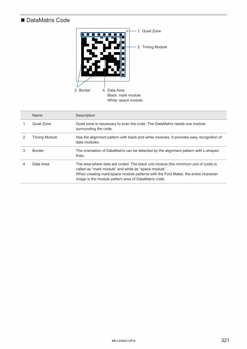
321
� DataMatrix Code
1. Quiet Zone
2. Timing Module
3. Border 4. Data AreaBlack: mark moduleWhite: space module
Name Description
1 Quiet Zone Quiet zone is necessary to scan the code. The DataMatrix needs one module surrounding the code.
2 Timing Module Has the alignment pattern with black and white modules. It provides easy recognition of data modules.
3 Border The orientation of DataMatrix can be detected by the alignment pattern with L-shaped lines.
4 Data Area The area where data are coded. The black unit module (the minimum unit of code) is called as “mark module” and white as “space module”.When creating mark/space module patterns with the Font Maker, the entire character image is the module pattern area of DataMatrix code.
ME-LP400V-OP-6

322
Symbol Size and Data CapacityThe relation between symbol size and data capacity (the maximum number of character) of DataMatrix code is shown below.
Symbol SizeNumeric: 0 to 9
(single byte)
Alphanumeric: 0 to 9, A to Z, space
(single byte) *2Kanji
Error correction overhead [%]
10 x 10 6 3 0 62.512 x 12 10 6 1 58.314 x 14 16 10 3 55.616 x 16 24 16 5 5018 x 18 36 25 8 43.820 x 20 44 31 10 4522 x 22 60 43 14 4024 x 24 72 52 17 4026 x 26 88 64 21 38.932 x 32 124 91 30 36.736 x 36 172 127 42 32.840 x 40 228 169 56 29.644 x 44
255 *
214 71 2848 x 48
255 *
86 28.152 x 52 101 29.264 x 64 138 28.672 x 72 182 28.180 x 80 226 29.688 x 88 255 * 288 x 18 10 6 1 58.38 x 32 20 13 4 52.412 x 26 32 22 7 46.712 x 36 44 31 10 4516 x 36 64 46 15 42.916 x 48 98 72 23 36.4
*1 : Though the codes indicated with “255 *” can contain more than 255 digits based on their standard, in the laser marker 255 digits are the max. amount of the code data to be input.
*2 : In Alphanumeric, according to the number (0 to 9) and capital alphabet (A to Z) combination, there is a case that the max. digits of the input data can exceed the number shown above list. If the code data includes lower-case characters, symbols or control codes, the available data capacity may be smaller than the above specified number.
ME-LP400V-OP-6

323
� CompositeComposite is a symbol that combines a linear bar code with 2D code as its meaning.[EAN-13, EAN-8, UPC-A, UPC-E, GS1 DataBar series, and UCC/EAN-128 (GS1-128)] can be used for a linear bar code, and it’s the composition shall be conformed to each standard. Three kinds [CC-A, CC-B, and CC-C] can be used for 2D code, and there is a difference in the volume of data etc. that can be encoded. CC-C is combined only with UCC/EAN-128 (GS1-128) though the combination of a linear bar code and 2D code is basically free.The following figure shows the typical example of [GS1 DataBar CC-A] to explain the configuration of the symbol.
5. Linear Bar Code (inside dashed area)
3. Data Pattern
2. Start Pattern 2. Stop Pattern
4. Separator
1. Quiet Zone1. Quiet Zone
Name Description
1 Quiet Zone Blank area necessary when reading bar code. Quiet zone for one module is necessary for the back and forth. (It is also necessary for the upper side in addition for CC-C.)
2 Start/Stop Pattern This pattern shows the start and end of the bar code.
3 Data Pattern This pattern has the characters contained in bar code and data for error correction.
4 Separator Pattern between a linear bar code and 2D code.
5 Linear Bar Code Size of quiet zone and the number of characters to be encoded, etc. are the same in case of using each bar code alone.
Content of code data• 0 to 9, A to Z, a to z, symbols (! “ % & ‘ ( ) * + , - . / : ; < = > ? _ ), space and function character (FNC1) can be encoded.
It differs according to the encoded character. It differs according to the encoded character. Examples of numeric, CC-A: Max. 56 characters, CC-B: Max. 338 characters, and CC-C: Max. 2361 characters.
• The directions for encoding the basic information like the commodity identification number for the linear bar code, and directions for encoding supplementary information like the expiration date and the lot number, etc. are designed. Please refer to EAN.UCC Composite Symbology of International Symbology Specification for details of the standard.
ME-LP400V-OP-6
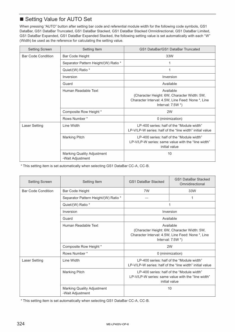
324
� Setting Value for AUTO SetWhen pressing “AUTO” button after setting bar code and referential module width for the following code symbols, GS1 DataBar, GS1 DataBar Truncated, GS1 DataBar Stacked, GS1 DataBar Stacked Omnidirectional, GS1 DataBar Limited, GS1 DataBar Expanded, GS1 DataBar Expanded Stacked, the following setting value is set automatically with each “W” (Width) be used as the reference for calculating the setting value.
Setting Screen Setting Item GS1 DataBar/GS1 DataBar Truncated
Bar Code Condition Bar Code Height 33W
Separator Pattern Height/(W) Ratio * 1
Quiet/(W) Ratio * 1
Inversion Inversion
Guard Available
Human Readable Text Available(Character Height: 6W, Character Width: 5W,
Character Interval: 4.5W, Line Feed: None *, Line Interval: 7.5W *)
Composite Row Height * 2W
Rows Number * 0 (minimization)
Laser Setting Line Width LP-400 series: half of the “Module width”LP-V/LP-W series: half of the “line width” initial value
Marking Pitch LP-400 series: half of the “Module width”LP-V/LP-W series: same value with the “line width”
initial value
Marking Quality Adjustment -Wait Adjustment
10
* This setting item is set automatically when selecting GS1 DataBar CC-A, CC-B.
Setting Screen Setting Item GS1 DataBar StackedGS1 DataBar Stacked
Omnidirectional
Bar Code Condition Bar Code Height 7W 33W
Separator Pattern Height/(W) Ratio * ― 1
Quiet/(W) Ratio * 1
Inversion Inversion
Guard Available
Human Readable Text Available(Character Height: 6W, Character Width: 5W,
Character Interval: 4.5W, Line Feed: None *, Line Interval: 7.5W *)
Composite Row Height * 2W
Rows Number * 0 (minimization)
Laser Setting Line Width LP-400 series: half of the “Module width”LP-V/LP-W series: half of the “line width” initial value
Marking Pitch LP-400 series: half of the “Module width”LP-V/LP-W series: same value with the “line width”
initial value
Marking Quality Adjustment -Wait Adjustment
10
* This setting item is set automatically when selecting GS1 DataBar CC-A, CC-B.
ME-LP400V-OP-6

325
Setting Screen Setting Item GS1 DataBar Limited
Bar Code Condition Bar Code Height 10W
Separator Pattern Height/(W) Ratio * 1
Quiet/(W) Ratio * 1
Inversion Inversion
Guard Available
Human Readable Text Available(Character Height: 6W, Character Width: 5W,
Character Interval: 4.5W, Line Feed: None *, Line Interval: 7.5W *)
Composite Row Height * 2W
Rows Number * 0 (minimization)
Laser Setting Line Width LP-400 series: half of the “Module width”LP-V/LP-W series: half of the “line width” initial value
Marking Pitch LP-400 series: half of the “Module width”LP-V/LP-W series: same value with the “line width”
initial value
Marking Quality Adjustment -Wait Adjustment
10
* This setting item is set automatically when selecting GS1 DataBar Limited CC-A, CC-B.
Setting Screen Setting Item GS1 DataBar ExpandedGS1 DataBar Expanded
Stacked
Bar Code Condition Bar Code Height 34W
Separator Pattern Height/(W) Ratio *
1
Quiet/(W) Ratio * 1
Inversion Inversion
Symbol Character Quantity ― 4
Guard Available
Human Readable Text Available(Character Height: 6W, Character Width: 5W, Character Interval: 4.5W, Line Feed: None *, Line Interval: 7.5W *)
Composite Row Height * 2W
Rows Number * 0 (minimization)
Laser Setting Line Width half of the “line width” initial value
Marking Pitch same value with the “line width” initial value
Marking Quality Adjustment -Wait Adjustment
10
* This setting item is set automatically when selecting GS1 DataBar Expanded CC-A, CC-B or GS1 DataBar Expanded Stacked CC-A, CC-B.
ME-LP400V-OP-6

326
Readable DXF FileThis laser marker can read the DXF format file described below.• DXF-R12J, R13, R14 format
The data created either by AutoCADLT (AutoCAD are produced by Autodesk, Inc.) is recommended to apply as the DXF format file data to be read. Followings are how to create DXF format file using AutoCADLT.• DXF-R12J, R13, R14 format
The DXF-R12J, R13J, R14J format file to be created by AutoCADLT can be prepared using the “Writing” function in “File” menu of AutoCADLT.At this time, select “AutoCADLT R2/R12J/R13J/R14DXF” from “File Format” in “Data Writing” dialog, and then click [Save] button.Refer to “Operation Method” that is appeared on the screen by searching the reference pages on the online help of AutoCADLT using the keyword such as “Writing”.
� Graphic Applied on AutoCADLT and Corresponding Table for Marking Object using Laser Marker
DXF Version Entity Name Graphic NameApplica- bility*
Remarks
R12J
3DFACE 3D face N
3DLINE 3D line N
ARC Arc Y Converted into segment and output.
ATTDEF Attribute definition N
ATTRIB Attribute N
CIRCLE Circle Y Converted into segment and output.
DIMENSION Dimension N
INSERT Insert graphic Y Converted into each graphic element and output.
LINE Segment Y Output with segment.
POINT Point N
POLYLINE2D Polyline Y
Converted arc into segment and output.Bold line is not supported.
3D Polyline N
SEQEND Close Y Applicable only for reproducing polyline.
SHAPE Shape N
SOLID 2D paint YOutput outline into segment and output internal into horizontal/vertical segment.
TEXT Character YConverted character with specified font into segment and output.
TRACE Bold line N
VERTEX Top Y Applicable only for reproducing polyline.
VIEWPORT View port N
ME-LP400V-OP-6

327
DXF Version Entity Name Graphic NameApplica- bility*
Remarks
R13J, R14
3DSOLID 3D paint N
ACAD_PROXY_ENTITY
Proxy graphic N
BODY Body N
ELLIPSE Ellipse Y Converted into segment and output.
HATCH Hatching YTarget graphic: segment, arc, ellipse only.Hatching pattern is reproduced for all painting.
IMAGE Image N
LEADER Lead line N
LWPOLYLINE Light Weight polyline YConverted arc into segment and output.Bold line is not correspondable.
MLINE Multi-line N
MTEXT Multi-text YConverted character with specified font into segment and output.
OLEFRAME OLE frame N
OLE2FRAME OLE2 frame N
RAY Radiation (half line) Y Output with segment.
REGION Region N
SPLINE Free curve Y Converted into segment and output.
TOLERANCE Geometric tolerance N
XLINE Line (straight line) Y Output with segment.
R14(Used Express Tools)
ARCALIGNEDTEXTCharacter string on arc
N
RTEXTReference character string
N
WIPEOUT Masking graphic N
* For the applicability of the function, “Y” means “applicable” and “N” means “not applicable for this laser marker”.
Reference
• The DXF file including entity not applicable to the laser marker cannot mark.• In the case of setting CAD marking magnification for laser marker to “under 1X”, the graphic including curve is not
marked as just the preset marking image.• In the case of marking the CAD data created/output by AutoCADLT after converting by the logo data conversion
software, all graphics might not be marked as just the preset marking images.
ME-LP400V-OP-6

Index
ME-LP400V-OP-6

329
Index
A
Adjustment of Touch Panel ………………………… 268AI (Application Identifier) …………………………… 205Air filter ………………………………………………… 279Alarm …………………………………………………… 301Alarm Reset Switch ……………………………………… 54Alignment ……………………………………………… 180Applicable Standards …………………………………… 9AutoCADLT …………………………………………… 326
B
Backup …………………………………………… 249, 287Bar Code Condition …………………………………… 188Battery ………………………………………… 37, 39, 289Baud Rate ……………………………………………… 262Bold Line Width ……………………………………… 181
C
Cable ……………………………………………… 45, 286Change File No. ……………………………………… 141Character Condition No. ……………………………… 180Character Conditions ………………………………… 180Character Display …………………………………… 126Character Height ……………………………………… 182Character Input ……………………………………… 148Character Interval Angle …………………………… 185Character Width ……………………………………… 182Check Digit …………………………………………… 161Check Sum …………………………………………… 262Class 2 ……………………………………………… 21, 23Class 4 ……………………………………………… 20, 23CODE39 ……………………………………………… 191CODE128 ……………………………………………… 191Common Counter …………………………………… 235Common Expiry Date ………………………………… 234Common file …………………………………………… 242Common Lot …………………………………………… 237Common Setting ……………………………………… 232Composite …………………………………………… 195Concatenated Marking ……………………………… 226Connecting Laser Marker ……………………………… 72Console …………………………………………… 46, 258Console Connector ……………………………………… 54Console Return Connector …………………………… 55Controller ………………………………………………… 53Controller Power Cable ………………………………… 45Copy and Paste ……………………………………… 151Counter ……………………………………… 101, 155, 164Current Date ……………………………………………… 91Curve Adjustment …………………………………… 217
D
Data Length …………………………………………… 262Delay Distance ………………………………………… 221Delay Time …………………………………………… 219Delete Media ………………………………………… 248Delete Registration …………………………………… 248Delimit ………………………………………………… 262DIP Switch ………………………………………… 56, 57Disposal ……………………………………………… 289Dual Pointer ……………………………………… 69, 136DXF …………………………………………………… 326
E
EAN/UPC ……………………………………………… 191Edge Adjustment ……………………………………… 217Emergency Stop Switch …………………………… 30, 54Encoder ……………………………………… 221, 222, 225Environment 1 ………………………………………… 253Equidistant Marking …………………………………… 223Error Indication ……………………………………… 301Error Log ……………………………………………… 134Ethernet………………………………………………… 263Ethernet Port …………………………………………… 55Expiry Date ………………………………… 94, 153, 162External Offset ………………………………………… 170
F
Fan ………………………………………………… 56, 280Fiber Cable ………………………………………… 52, 56FILE …………………………………………………… 140Flying Object …………………………………… 117, 220Flying Object Wait ……………………………… 216, 222Focus Adjusting Control …………………………… 50, 51Focus Dial …………………………………………… 50, 51Font ……………………………………………… 244, 245Frame Ground ……………………………………… 52, 56Function Character …………………………………… 153Fuse ……………………………………………… 56, 286
G
Galvano scanner ……………………………………… 284General Condition …………………………………… 173GS1 DataBar ………………………………………… 193Guide Laser ………………………………………… 69, 137
H
Head ……………………………………………………… 49Head Control Cable……………………………………… 45Head Power Cable ……………………………………… 45Human Readable Text ……………………………… 203
I
ME-LP400V-OP-6

330
Image Display ………………………………………… 239Inlet ……………………………………………………… 56Installation Method ………………………………… 61, 67Installation Space ………………………………… 63, 67Interlock System ………………………………………… 31Internal Shutter ………………………………………… 27Invert …………………………………………………… 193I/O Check Monitor …………………………………… 133I/O Connector …………………………………………… 56ITF ……………………………………………………… 191
J
Jump adjustment ……………………………………… 218Justify ………………………………………………… 182
K
Key Switch ……………………………………………… 53
L
Laser emission port …………………………… 50, 51, 274Laser oscillator ………………………………………… 281Laser Pointer Emission Port ……………………… 50, 51Laser Power …………………………………………… 214Laser Pulse Cycle …………………………………… 214Laser Pumping Switch ………………………………… 54Laser Radiation Indicator ………………… 27, 29, 50, 51laser safety manager …………………………………… 26Laser Setting ………………………………………… 214Laser Stop ……………………………………………… 30Line Interval …………………………………………… 185Line Speed ……………………………………… 132, 216Line Speed Fine Adjustment ………………………… 225Logo ……………………………………………… 110, 186Logo File ……………………………………………… 243Lot …………………………………………… 98, 157, 166
M
Magnification Specification of Image Screen ……… 132Maintenance …………………………………………… 133Marking Condition …………………………………… 158Marking Mode ………………………………………… 135Marking Shape ………………………………………… 180MATRIX PLACEMENT ……………………………… 172Max. Output ………………………………………… 20, 23Model ……………………………………………………… 33Moving direction: ……………………………………… 220
N
New Creation ………………………………………… 144NHZ ………………………………………………… 20, 23NOHD ……………………………………………… 20, 23NW-7 …………………………………………………… 191
O
Offset …………………………………………………… 174Operation Screen …………………………………… 126Operator Adjustment Screen …………………… 129, 254Optional items …………………………………………… 35Outer Dimensional Drawing …………………………… 40Output Simulation …………………………………… 267Overwriting …………………………………………… 174
P
Package ………………………………………………… 47Parity …………………………………………………… 262Password ………………………………………… 128, 255Point Radiation …………………………………… 212, 218Power Connector ……………………………… 50, 51, 56Pre-scan Time ………………………………………… 218Present time …………………………………………… 258Processing Condition ………………………………… 207Proportional …………………………………………… 182Protective enclosure …………………………………… 25protective goggles ……………………………………… 25
Q
QR Code ……………………………………………… 198
R
Radiation Information …………………………………… 20Radiation range …………………………………… 21, 22Rank ……………………………………………… 159, 168Register to Inside ……………………………………… 247Remote Switch …………………………………………… 54Restore ………………………………………………… 250Return Connector ……………………………………… 55RS-232C ……………………………………………… 262RS-232C Connector …………………………………… 55RUN Mode …………………………………………… 139
S
Safety Functions …………………………………… 27, 30Safety Protection Measures …………………………… 25Save …………………………………………………… 142Save to Different No. ………………………………… 143Scan Speed …………………………………………… 214Serial Data …………………………………………… 160Serial No. ……………………………………………… 288Shutter ………………………………………………… 285Signal Connector ……………………………… 50, 51, 56Start Angle …………………………………………… 185Start Point ……………………………………………… 216Step & Repeat ……………………………… 113, 175, 178Stop Bits ……………………………………………… 262Straight Line …………………………………………… 182
ME-LP400V-OP-6

331
System Information …………………………………… 270System Offset ………………………………………… 259
T
Terminal Block Connector ……………………………… 56Test Marking …………………………………………… 138Time Measurement …………………………………… 216Trademark ……………………………………………… 2Trigger Selection ……………………………………… 221Trigger Setting ………………………………………… 219Troubleshooting ……………………………………… 292
U
Update Function Character ………………………… 253USB Connector ………………………………………… 54USB Media …………………………………………… 241
V
VEC …………………………………………………… 186VGA Connector ………………………………………… 55
W
Waiting Time Adjustment …………………………… 217Warning ………………………………………………… 304Wavelength ………………………………………… 20, 23Week Setting ………………………………………… 260Work Image Display ………………………………… 240
X
X/Y Position …………………………………………… 182
ME-LP400V-OP-6

332
License Agreement for Microsoft Software• You have acquired a device (“DEVICE”) that includes software licensed by “Panasonic Industrial Devices SUNX Co., Ltd.” from an affiliate of
Microsoft Corporation (“MS”). Those installed software products of MS origin, as well as associated media, printed materials, and “online” or electronic documentation (“SOFTWARE”) are protected by international intellectual property laws and treaties. Manufacturer, MS and its suppliers (including Microsoft Corporation) own the title, copyright, and other intellectual property rights in the SOFTWARE. The SOFTWARE is licensed, not sold. All rights reserved.
• This EULA is valid and grants the end-user rights ONLY if the SOFTWARE is genuine and a genuine Certificate of Authenticity for the SOFTWARE is included. For more information on identifying whether your software is genuine, please see http://www.microsoft.com/piracy/howtotell.
• IF YOU DO NOT AGREE TO THIS END USER LICENSE AGREEMENT (“EULA”), DO NOT USE THE DEVICE OR COPY THE SOFTWARE. INSTEAD, PROMPTLY CONTACT “Panasonic Industrial Devices SUNX Co., Ltd.” FOR INSTRUCTIONS ON RETURN OF THE UNUSED DEVICE(S) FOR A REFUND. ANY USE OF THE SOFTWARE, INCLUDING BUT NOT LIMITED TO USE ON THE DEVICE, WILL CONSTITUTE YOUR AGREEMENT TO THIS EULA (OR RATIFICATION OF ANY PREVIOUS CONSENT).
• GRANT OF SOFTWARE LICENSE. This EULA grants you the following license:1. You may use the SOFTWARE only on the DEVICE.2. RESTRICTED FUNCTIONALITY. You are licensed to use the SOFTWARE to provide only the limited functionality (specific tasks or processes) for which
the DEVICE has been designed and marketed by “Panasonic Industrial Devices SUNX Co., Ltd.”. This license specifically prohibits any other use of the SOFTWARE programs or functions, or inclusion of additional software programs or functions that do not directly support the limited functionality on the DEVICE. Notwithstanding the foregoing, you may install or enable on the DEVICE systems utilities, resource management or similar software solely for the purpose of administration, performance enhancement and/or preventive maintenance of the DEVICE.
3. If you use the DEVICE to access or utilize the services or functionality of Microsoft Windows Server products (such as Microsoft Windows Server 2003), or use the DEVICE to permit workstation or computing devices to access or utilize the services or functionality of Microsoft Windows Server products, you may be required to obtain a Client Access License for the DEVICE and/or each such workstation or computing device. Please refer to the end user license agreement for your Microsoft Windows Server product for additional information.
4. NOT FAULT TOLERANT. THE SOFTWARE IS NOT FAULT TOLERANT. “Panasonic Industrial Devices SUNX Co., Ltd.” HAS INDEPENDENTLY DETERMINED HOW TO USE THE SOFTWARE IN THE DEVICE, AND MS HAS RELIED UPON “Panasonic Industrial Devices SUNX Co., Ltd.” TO CONDUCT SUFFICIENT TESTING TO DETERMINE THAT THE SOFTWARE IS SUITABLE FOR SUCH USE.
5. NO WARRANTIES FOR THE SOFTWARE. THE SOFTWARE is provided “AS IS” and with all faults. THE ENTIRE RISK AS TO SATISFACTORY QUALITY, PERFORMANCE, ACCURACY, AND EFFORT (INCLUDING LACK OF NEGLIGENCE) IS WITH YOU. ALSO, THERE IS NO WARRANTY AGAINST INTERFERENCE WITH YOUR ENJOYMENT OF THE SOFTWARE OR AGAINST INFRINGEMENT. IF YOU HAVE RECEIVED ANY WARRANTIES REGARDING THE DEVICE OR THE SOFTWARE, THOSE WARRANTIES DO NOT ORIGINATE FROM, AND ARE NOT BINDING ON, MS.
6. No Liability for Certain Damages. EXCEPT AS PROHIBITED BY LAW, MS SHALL HAVE NO LIABILITY FOR ANY INDIRECT, SPECIAL, CONSEQUENTIAL OR INCIDENTAL DAMAGES ARISING FROM OR IN CONNECTION WITH THE USE OR PERFORMANCE OF THE SOFTWARE. THIS LIMITATION SHALL APPLY EVEN IF ANY REMEDY FAILS OF ITS ESSENTIAL PURPOSE. IN NO EVENT SHALL MS BE LIABLE FOR ANY AMOUNT IN EXCESS OF U.S. TWO HUNDRED FIFTY DOLLARS (U.S.$250.00).
7. Restricted Uses. The SOFTWARE is not designed or intended for use or resale in hazardous environments requiring fail-safe performance, such as in the operation of nuclear facilities, aircraft navigation or communication systems, air traffic control, or other devices or systems in which a malfunction of the SOFTWARE would result in foreseeable risk of injury or death to the operator of the device or system, or to others.
8. Limitations on Reverse Engineering, Decompilation, and Disassembly. You may not reverse engineer, decompile, or disassemble the SOFTWARE, except and only to the extent that such activity is expressly permitted by applicable law notwithstanding this limitation.
9. SOFTWARE as a Component of the DEVICE - Transfer. This license may not be shared, transferred to or used concurrently on different computers. The SOFTWARE is licensed with the DEVICE as a single integrated product and may only be used with the DEVICE. If the SOFTWARE is not accompanied by a DEVICE, you may not use the SOFTWARE. You may permanently transfer all of your rights under this EULA only as part of a permanent sale or transfer of the DEVICE, provided you retain no copies of the SOFTWARE. If the SOFTWARE is an upgrade, any transfer must also include all prior versions of the SOFTWARE. This transfer must also include the Certificate of Authenticity label. The transfer may not be an indirect transfer, such as a consignment. Prior to the transfer, the end user receiving the SOFTWARE must agree to all the EULA terms.
10. Consent to Use of Data. You agree that MS, Microsoft Corporation and their affiliates may collect and use technical information gathered in any manner as part of product support services related to the SOFTWARE. MS, Microsoft Corporation and their affiliates may use this information solely to improve their products or to provide customized services or technologies to you. MS, Microsoft Corporation and their affiliates may disclose this information to others, but not in a form that personally identifies you.
11. Internet Gaming/Update Features. If the SOFTWARE provides, and you choose to utilize, the Internet gaming or update features within the SOFTWARE, it is necessary to use certain computer system, hardware, and software information to implement the features. By using these features, you explicitly authorize MS, Microsoft Corporation and/or their designated agent to use this information solely to improve their products or to provide customized services or technologies to you. MS or Microsoft Corporation may disclose this information to others, but not in a form that personally identifies you.
12. Internet-Based Services Components. The SOFTWARE may contain components that enable and facilitate the use of certain Internet-based services. You acknowledge and agree that MS, Microsoft Corporation or their affiliates may automatically check the version of the SOFTWARE and/or its components that you are utilizing and may provide upgrades or supplements to the SOFTWARE that may be automatically downloaded to your DEVICE. Microsoft Corporation or their affiliates do not use these features to collect any information that will be used to identify you or contact you. For more information about these features, please see the privacy statement at http://go.microsoft.com/fwlink/?LinkId=25243.
13. Links to Third Party Sites. You may link to third party sites through the use of the SOFTWARE. The third party sites are not under the control of MS or Microsoft Corporation, and MS or Microsoft are not responsible for the contents of any third party sites, any links contained in third party sites, or any changes or updates to third party sites. MS or Microsoft Corporation is not responsible for webcasting or any other form of transmission received from any third party sites. MS or Microsoft Corporation are providing these links to third party sites to you only as a convenience, and the inclusion of any link does not imply an endorsement by MS or Microsoft Corporation of the third party site.
14. Notice Regarding Security. To help protect against breaches of security and malicious software, periodically back up your data and system information, use security features such as firewalls, and install and use security updates.
15. No Rental/Commercial Hosting. You may not rent, lease, lend or provide commercial hosting services with the SOFTWARE to others.16. Separation of Components. The SOFTWARE is licensed as a single product. Its component parts may not be separated for use on more than one
computer.17. Additional Software/Services. This EULA applies to updates, supplements, add-on components, product support services, or Internet-based services
components (“Supplemental Components”), of the SOFTWARE that you may obtain from “Panasonic Industrial Devices SUNX Co., Ltd.”, MS, Microsoft Corporation or their subsidiaries after the date you obtain your initial copy of the SOFTWARE, unless you accept updated terms or another agreement governs. If other terms are not provided along with such Supplemental Components and the Supplemental Components are provided to you by MS, Microsoft Corporation or their subsidiaries then you will be licensed by such entity under the same terms and conditions of this EULA, except that (i) MS, Microsoft Corporation or their subsidiaries providing the Supplemental Components will be the licensor with respect to such Supplemental Components in lieu of the "COMPANY" for the purposes of the EULA, and (ii) TO THE MAXIMUM EXTENT PERMITTED BY APPLICABLE LAW, THE SUPPLEMENTAL COMPONENTS AND ANY (IF ANY) SUPPORT SERVICES RELATED TO THE SUPPLEMENTAL COMPONENTS ARE PROVIDED AS IS AND WITH ALL FAULTS. ALL OTHER DISCLAIMERS, LIMITATION OF DAMAGES, AND SPECIAL PROVISIONS PROVIDED BELOW AND/OR OTHERWISE WITH THE SOFTWARE SHALL APPLY TO SUCH SUPPLEMENTAL COMPONENTS. MS, Microsoft Corporation or their subsidiaries reserve the right to discontinue any Internet-based services provided to you or made available to you through the use of the SOFTWARE.
18. Recovery Media. If SOFTWARE is provided by “Panasonic Industrial Devices SUNX Co., Ltd.” on separate media and labeled “Recovery Media” you may use the Recovery Media solely to restore or reinstall the SOFTWARE originally installed on the DEVICE.
19. Backup Copy. You may make one (1) backup copy of the SOFTWARE. You may use this backup copy solely for your archival purposes and to reinstall the SOFTWARE on the DEVICE. Except as expressly provided in this EULA or by local law, you may not otherwise make copies of the SOFTWARE, including the printed materials accompanying the SOFTWARE. You may not loan, rent, lend or otherwise transfer the backup copy to another user.
20. End User Proof of License. If you acquired the SOFTWARE on a DEVICE, or on a compact disc or other media, a genuine Microsoft “Proof of License”/ Certificate of Authenticity label with a genuine copy of the SOFTWARE identifies a licensed copy of the SOFTWARE. To be valid, the label must be affixed to the DEVICE, or appear on “Panasonic Industrial Devices SUNX Co., Ltd.’s” software packaging. If you receive the label separately other than from “Panasonic Industrial Devices SUNX Co., Ltd.”, it is invalid. You should keep the label on the DEVICE or packaging to prove that you are licensed to use the SOFTWARE.
21. Product Support. Product support for the SOFTWARE is not provided by MS, Microsoft Corporation, or their affiliates or subsidiaries. For product support, please refer to “Panasonic Industrial Devices SUNX Co., Ltd.” support number provided in the documentation for the DEVICE. Should you have any questions concerning this EULA, or if you desire to contact “Panasonic Industrial Devices SUNX Co., Ltd.” for any other reason, please refer to the address provided in the documentation for the DEVICE.
22. Termination. Without prejudice to any other rights, “Panasonic Industrial Devices SUNX Co., Ltd.” may terminate this EULA if you fail to comply with the terms and conditions of this EULA. In such event, you must destroy all copies of the SOFTWARE and all of its component parts.
23. EXPORT RESTRICTIONS. You acknowledge that SOFTWARE is subject to U.S. and European Union export jurisdiction. You agree to comply with all applicable international and national laws that apply to the SOFTWARE, including the U.S. Export Administration Regulations, as well as end-user, end-use and destination restrictions issued by U.S. and other governments. For additional information see http://www.microsoft.com/exporting/.
No.9000-0062-14VME-LP400V-OP-6

No.9000-0062-14V

© Panasonic Industrial Devices SUNX Co., Ltd. 2003 - 2018
July, 2018
9000-0062-14V


![_P8LPI]P ;LP;LP;LP 5ZL1F DF8[ - WordPress.com](https://static.fdokumen.com/doc/165x107/631d1be4b8a98572c10d3520/p8lpip-lplplp-5zl1f-df8-wordpresscom.jpg)