DME 230 / 400 - Dunkermotoren
212
DME 230 / 400 Typ: Part No: DME 230x4-CO 81703.00100 DME 230x4-I/O 81703.00101 DME 230x4-EC 81703.00102 DME 230x4-PN 81703.00103 DME 400x8-CO 81703.00110 DME 400x8-EC 81703.00111 DME 400x8-PN 81703.00112 Functions and Parameters for servo drives series - BN6773 - BN6783 Publication Ref: 160616 Dunkermotoren GmbH | Allmendstraße 11 | D-79848 Bonndorf/ Schwarzwald Phone +49 (0) 7703 930-0 | Fax +49 (0) 7703 930-210/ 212 | [email protected]
-
Upload
khangminh22 -
Category
Documents
-
view
0 -
download
0
Transcript of DME 230 / 400 - Dunkermotoren

DME 230 / 400 Typ: Part No:
DME 230x4-CO 81703.00100
DME 230x4-I/O 81703.00101
DME 230x4-EC 81703.00102
DME 230x4-PN 81703.00103
DME 400x8-CO 81703.00110
DME 400x8-EC 81703.00111
DME 400x8-PN 81703.00112
Functions and Parameters
for servo drives series
- BN6773
- BN6783
Publication Ref: 160616
Dunkermotoren GmbH | Allmendstraße 11 | D-79848 Bonndorf/ Schwarzwald Phone +49 (0) 7703 930-0 | Fax +49 (0) 7703 930-210/ 212 | [email protected]

TrioDrive D/xS / MidiDrive D/xSTrioDrive D / MidiDrive D
MaxiDrive
Operating Instructions 6710.201, V 8.5
These operating instructions apply to• TrioDrive D/xS servo drives, compact design, BN 6755 to BN 6758 • MidiDrive D/xS servo drives, compact design, BN 6745 to BN 6749• TrioDrive D servo drives, compact design, BN 6751 to BN 6753 • MidiDrive D servo drives, compact design, BN 6741 to BN 6743 • MaxiDrive servo drives, compact design, BN 6721 to BN 6725• Operation via personal computer with SPP Windows software• Access to device functions via communication interfaces These operating instructions apply together with• Operating Instructions 6755.202, 6745.202, 6750.202, 6740.202, or 6710.202 (Connection and Commissioning)• and other operating instructions depending on the equipment
ESR Pollmeier GmbHLindenstr. 20
64372 Ober-Ramstadt
Federal Republic of Germany
Phone +49 6167 9306-0Fax +49 6167 9306-77
E-Mail [email protected]
Ple
ase n
ote
: T
hese O
pera
ting I
nstr
uctions c
orr
espond t
o t
he h
elp
text
of
SP
P W
indow
s.
You c
an a
lso a
ccess it
directly b
y u
sin
g t
he h
elp
function (
F1 k
ey)
within
the s
oft
ware
.
Digital Servo Drives for Direct Mains Connection
Functions and Parameters

ESR is a registered trade mark of ESR Pollmeier GmbH.
All rights reserved, including those of translation. No part of these operating instructions maybe copied, reproduced, stored, or processed in an information system, or transmitted in anyother form, without prior written permission by ESR Pollmeier GmbH.
These operating instructions have been prepared with care. However, ESR Pollmeier GmbHcan accept no liability for any errors in these operating instructions or possible consequen-ces. Neither can any liability be accepted for direct or indirect damage resulting from abuseof the device.
The relevant regulations concerning safety technology and electromagnetic compatibility mustbe complied with when using the device.
Subject to alteration.
Copyright by ESR Pollmeier GmbH, 64372 Ober-Ramstadt, Germany
ESR Pollmeier GmbH, 64372 Ober-Ramstadt, phone +49 6167 9306-0, fax +49 6167 9306-77, www.esr-pollmeier.de
2 Operating Instructions 6710.201, V 8.5

Operating Instructions 6710.201, V 8.5 3
ESR Pollmeier GmbH, 64372 Ober-Ramstadt, phone +49 6167 9306-0, fax +49 6167 9306-77, www.esr-pollmeier.de
Contents
Please, also refer to the index at the end of this document.
1 Preliminary Remarks 7
................................................................................................................................... 71.1 About this Description
................................................................................................................................... 81.2 Storing Data
................................................................................................................................... 81.3 Servo Drive System Packages
.................................................................................................................... 8Technical Specifications of the Servo Drive System Packages 1.3.1
.................................................................................................................... 8TrioDrive D/xS Servo Drive System Packages 1.3.2
.................................................................................................................... 9MidiDrive D/xS Servo Drive System Packages 1.3.3
.................................................................................................................... 9TrioDrive D Servo Drive System Packages 1.3.4
.................................................................................................................... 9MidiDrive D Servo Drive System Packages 1.3.5
.................................................................................................................... 10MaxiDrive Servo Drive System Packages 1.3.6
2 Safety Instructions 11
................................................................................................................................... 112.1 Type of Instructions
3 Functions: Overview and Structure 12
4 Drive System Functions 14
................................................................................................................................... 144.1 Setpoint Generator
................................................................................................................................... 154.2 Position Controller
................................................................................................................................... 154.3 Speed Controller
................................................................................................................................... 154.4 Current Controller (Torque Controller)
................................................................................................................................... 154.5 Autocommutation
................................................................................................................................... 174.6 Axis State Machine
.................................................................................................................... 20Axis Control Word 4.6.1
.................................................................................................................... 22Axis Status Word 4.6.2
.................................................................................................................... 25Running up the Axis State Machine (Example) 4.6.3
.................................................................................................................... 26Switching Between Operating Modes 4.6.4
................................................................................................................................... 274.7 Monitoring
................................................................................................................................... 274.8 Safety System (TrioDrive D/xS and MidiDrive D/xS, only)
5 Axis Operating Modes 29
................................................................................................................................... 305.1 Torque Mode / Force Mode
................................................................................................................................... 315.2 Velocity Mode Direct
................................................................................................................................... 325.3 Velocity Mode
................................................................................................................................... 335.4 Spindle Positioning

Operating Instructions 6710.201, V 8.54
ESR Pollmeier GmbH, 64372 Ober-Ramstadt, phone +49 6167 9306-0, fax +49 6167 9306-77, www.esr-pollmeier.de
................................................................................................................................... 345.5 Profile Position Mode
.................................................................................................................... 36Block Mode 5.5.1
.................................................................................................................... 37Setpoint Mode 5.5.2
................................................................................................................................... 385.6 Homing Mode
.................................................................................................................... 40Homing Mode Sequences 5.6.1
................................................................................................................................... 445.7 Electronic Gearing
................................................................................................................................... 465.8 Flying Shear
................................................................................................................................... 485.9 Velocity Profile
................................................................................................................................... 485.10 Timed Positioning Mode
................................................................................................................................... 505.11 Cyclic Synchronous Torque/Force Mode
................................................................................................................................... 525.12 Cyclic Synchronous Velocity Mode
................................................................................................................................... 545.13 Cyclic Synchronous Position Mode
.................................................................................................................... 56Activating Cyclic Synchronous Position Mode 5.13.1
.................................................................................................................... 56Deactivating Cyclic Synchronous Position Mode 5.13.2
................................................................................................................................... 565.14 Interpolated Position Mode
.................................................................................................................... 59Activating Interpolated Position Mode 5.14.1
.................................................................................................................... 59Deactivating Interpolated Position Mode 5.14.2
6 Device Operating Modes: Command Mode andProgram Mode 60
7 Input, Output, Trigger, Measuring, and TraceFunctions 61
................................................................................................................................... 617.1 Input/Output Function
.................................................................................................................... 61Digital Input/Output 7.1.1
.................................................................................................................... 63Analog Input 7.1.2
.................................................................................................................... 64Analog Output 7.1.3
................................................................................................................................... 647.2 Switching Points
................................................................................................................................... 647.3 Trigger and Measuring Functions
................................................................................................................................... 667.4 Trace Function
8 Setting the Machine Data During First Commissioning 67
................................................................................................................................... 678.1 Starting Command and Commissioning Software SPP Windows
................................................................................................................................... 678.2 Setting the Motor Data
.................................................................................................................... 67Selecting the Motor 8.2.1
.................................................................................................................... 68Entering the Motor Data 8.2.2
................................................................................................................................... 688.3 Setting the Basic Axis Data
................................................................................................................................... 718.4 Setting the Current Control Loop
................................................................................................................................... 748.5 Setting the Speed Control Loop
................................................................................................................................... 768.6 Setting Other Axis Data and Device Data

Operating Instructions 6710.201, V 8.5 5
ESR Pollmeier GmbH, 64372 Ober-Ramstadt, phone +49 6167 9306-0, fax +49 6167 9306-77, www.esr-pollmeier.de
9 Variable Descriptions 78
................................................................................................................................... 829.1 Variable Descriptions Control and Status Information
.................................................................................................................... 82Device Control and Status Information 9.1.1
.................................................................................................................... 83Axis Control and Status Information 9.1.2
................................................................................................................................... 869.2 Variable Descriptions Parameters and Actual Values
.................................................................................................................... 86Parameters and Actual Values Torque Mode 9.2.1
.................................................................................................................... 87Parameters and Actual Values Velocity Mode 9.2.2
.................................................................................................................... 89Parameters and Actual Values Profile Position Mode 9.2.3
.................................................................................................................... 92Parameters and Setpoints Interpolated Position Mode 9.2.4
.................................................................................................................... 93Parameters and Actual Values Timed Positioning Mode 9.2.5
.................................................................................................................... 94Parameters and Actual Values Cyclic Synchronous Torque/Force Mode 9.2.6
.................................................................................................................... 94Parameters and Actual Values Cyclic Synchronous Velocity Mode 9.2.7
.................................................................................................................... 95Parameters and Actual Values Input/Output Function 9.2.8
.................................................................................................................... 99Parameters and Actual Values Trigger and Measuring Functions 9.2.9
.................................................................................................................... 102Parameters of the Trace Function 9.2.10
................................................................................................................................... 1059.3 Variable Descriptions Basic Data
.................................................................................................................... 105General Actual and Measured Values 9.3.1
.................................................................................................................... 108Motor Machine Data 9.3.2
..................................................................................................... 109General Motor and Current Control Loop Data9.3.2.1
..................................................................................................... 118Motor Position Sensor Machine Data9.3.2.2
..................................................................................................... 124Motor Temperature Sensor Machine Data9.3.2.3
.................................................................................................................... 126Servo Drive Machine Data 9.3.3
.................................................................................................................... 129Shunt Resistor Machine Data 9.3.4
.................................................................................................................... 131Input/Output Function Machine Data 9.3.5
................................................................................................................................... 1419.4 Variable Descriptions Axis Machine Data
.................................................................................................................... 141Axis Control Machine Data 9.4.1
.................................................................................................................... 144Setpoint Sources Machine Data 9.4.2
.................................................................................................................... 149Position Measuring System Machine Data 9.4.3
.................................................................................................................... 155Drive System Machine Data 9.4.4
.................................................................................................................... 158Factors and Units Machine Data 9.4.5
.................................................................................................................... 161Positioning Range Machine Data 9.4.6
.................................................................................................................... 164Ramps Machine Data 9.4.7
.................................................................................................................... 167Speed Control Loop Machine Data 9.4.8
.................................................................................................................... 171Position Control Loop Machine Data 9.4.9
.................................................................................................................... 175Homing Mode Machine Data 9.4.10
.................................................................................................................... 176Electronic Gearing Machine Data 9.4.11
.................................................................................................................... 180Flying Shear Machine Data 9.4.12

Operating Instructions 6710.201, V 8.56
ESR Pollmeier GmbH, 64372 Ober-Ramstadt, phone +49 6167 9306-0, fax +49 6167 9306-77, www.esr-pollmeier.de
.................................................................................................................... 181Spindle Positioning Machine Data 9.4.13
.................................................................................................................... 183Output Encoder Signals Machine Data 9.4.14
.................................................................................................................... 184Switching Points Machine Data 9.4.15
.................................................................................................................... 186Interpolated Position Mode Machine Data 9.4.16
.................................................................................................................... 188Timed Positioning Mode Machine Data 9.4.17
10 Appendix 190
................................................................................................................................... 19010.1 Appendix A State Machines
................................................................................................................................... 19110.2 Appendix B Axis Fault Codes and Part Program Errors
................................................................................................................................... 19610.3 Appendix C Firmware Versions Regarding Functions and
Parameters................................................................................................................................... 20110.4 Appendix D Versions of the Document
11 Keyword Index 203

Operating Instructions 6710.201, V 8.5 7
ESR Pollmeier GmbH, 64372 Ober-Ramstadt, phone +49 6167 9306-0, fax +49 6167 9306-77, www.esr-pollmeier.de
1 Preliminary Remarks
1.1 About this Description
These Operating Instructions 6710.201 explain functions and parameters of theTrioDrive D/xS, MidiDrive D/xS, TrioDrive D, MidiDrive D, and MaxiDrive digitalservo drives with built-in power supply unit for direct connection to 230 V AC (BN6751 to BN 6758) or 3 × 400/480 V AC (BN 6741 to BN 6749, BN 6721 to BN6725).
They are applicable together with
• Operating Instructions “Connection and Commissioning” of the servo drive (in-cluded in the scope of delivery)
– Operating Instructions 6755.202 (TrioDrive D/xS),
– Operating Instructions 6745.202 (MidiDrive D/xS),
– Operating Instructions 6750.202 (TrioDrive D),
– Operating Instructions 6740.202 (MidiDrive D) or
– Operating Instructions 6710.202 (MaxiDrive)
• Operating Instructions “SPP Windows Command and Commissioning Soft-ware” (delivered with the optional command and commissioning softwareSPP Windows)
– 6710.207
as well as, according to the equipment
• Operating Instructions “Part Program” (running motion sequences independ-ent of a higher-level controller; delivered with the optional part program)
– Operating Instructions 6710.231
• Operating Instructions “Communication Functions” (access to device functionsvia communication interface COM2 and/or Interbus; delivered with the optionalInterbus interface)
– Operating Instructions 6710.204
• Operating Instructions “CANopen® Interface” (delivered with the optionalCANopen® interface)
– Operating Instructions 6710.205 or
– Operating Instructions 6745.205
• Operating Instructions “EtherCAT Interface” (delivered with the optional Ether-CAT interface)
– Operating Instructions 6745.232
• Operating Instructions “Ethernet Interface” (delivered with the optional Ethernetinterface)
– Operating Instructions 6745.236

Operating Instructions 6710.201, V 8.58
ESR Pollmeier GmbH, 64372 Ober-Ramstadt, phone +49 6167 9306-0, fax +49 6167 9306-77, www.esr-pollmeier.de
• Operating Instructions “Profibus DP Interface” (delivered with the optionalProfibus DP interface)
– Operating Instructions 6730.208
For the commissioning of the functions described in these operating instructions,a PC with command and commissioning software SPP Windows is required.Please, make sure that this requirement is met and the above-mentioned operat-ing instructions are available.
1.2 Storing Data
After the control supply voltage has been switched on, the machine data, the pro-gram variables, and, as far as included in the scope of delivery, the part programare loaded from the flash EPROM of the digital servo drive into its volatilememory (RAM). There, the data can be changed by command and commission-ing software SPP Windows or by variable access via the communication inter-faces.
These data can be saved on a data carrier (memory stick, hard disk of a PC,etc.) or in the flash EPROM of the servo drive using SPP Windows.
If machine data, part program, or program variables are not saved afterhaving been changed, these changes will get lost when the control sup-ply voltage is switched off.
For further information on storage media and storage, please see operating in-structions 6710.207 “Command and Commissioning Software SPP Windows”.
1.3 Servo Drive System Packages
1.3.1 Technical Specifications of the Servo Drive System Packages
The TrioDrive D/xS, MidiDrive D/xS, TrioDrive D, MidiDrive D, and MaxiDriveservo drives have different technical specifications. This also applies to type,number, and assignment of inputs and outputs.
For details on the technical specifications of the individual servo drive, pleasesee the corresponding operating instructions “Connection and Commissioning”6755.202 (TrioDrive D/xS), 6745.202 (MidiDrive D/xS), 6750.202 (TrioDrive D),6740.202 (MidiDrive D), or 6710.202 (MaxiDrive).
1.3.2 TrioDrive D/xS Servo Drive System Packages
TrioDrive D/xS servo drive system packages consist of
• the AC servo motor with coupled resolver, high-resolution incremental en-coder, Sincos (Hiperface) encoder, or EnDat encoder as motor positionsensor and

Operating Instructions 6710.201, V 8.5 9
ESR Pollmeier GmbH, 64372 Ober-Ramstadt, phone +49 6167 9306-0, fax +49 6167 9306-77, www.esr-pollmeier.de
• the digital servo drive with built-in power supply unit, CANopen®, EtherCAT,Ethernet, Profibus, or analog interface and integrated safety system.
The series includes
• drives for 4 different currents (0.8 Arms
to 6 Arms
) for connection to 230 V AC,
• drives with varying equipment (options).
1.3.3 MidiDrive D/xS Servo Drive System Packages
MidiDrive D/xS servo drive system packages consist of
• the AC servo motor with coupled resolver, high-resolution incremental en-coder, Sincos (Hiperface) encoder, or EnDat encoder as motor positionsensor and
• the digital servo drive with built-in power supply unit, CANopen®, EtherCAT,Ethernet, Profibus, or analog interface and integrated safety system.
The series includes
• drives for 5 different currents (2 Arms
to 32 Arms
) for connection to 3 ×
400/480 V AC,
• drives with varying equipment (options).
1.3.4 TrioDrive D Servo Drive System Packages
TrioDrive D servo drive system packages consist of
• the AC servo motor with coupled resolver, high-resolution incremental en-coder, Sincos (Hiperface) encoder, or EnDat encoder as motor positionsensor and
• the digital servo drive with built-in power supply unit.
The series includes
• drives for 3 different currents (2 Arms to
6 Arms
) for connection to 230 V AC,
• drives with varying equipment (options).
1.3.5 MidiDrive D Servo Drive System Packages
MidiDrive D servo drive system packages consist of
• the AC servo motor with coupled resolver, high-resolution incremental en-coder, Sincos (Hiperface) encoder, or EnDat encoder as motor positionsensor and
• the digital servo drive with built-in power supply unit.

Operating Instructions 6710.201, V 8.510
ESR Pollmeier GmbH, 64372 Ober-Ramstadt, phone +49 6167 9306-0, fax +49 6167 9306-77, www.esr-pollmeier.de
The series includes
• drives for 3 different currents (2 Arms
to 8 Arms
) for connection to 3 ×
400/480 V AC,
• drives with varying equipment (options).
1.3.6 MaxiDrive Servo Drive System Packages
MaxiDrive servo drive system packages consist of
• the AC servo motor with coupled resolver, high-resolution incremental en-coder, Sincos (Hiperface) encoder, or EnDat encoder as motor positionsensor and
• the digital servo drive with built-in power supply unit.
The series includes
• drives for 5 different currents (2 Arms
to 20 Arms
) for connection to 3 ×
400 V AC,
• drives with varying equipment (options).

Operating Instructions 6710.201, V 8.5 11
ESR Pollmeier GmbH, 64372 Ober-Ramstadt, phone +49 6167 9306-0, fax +49 6167 9306-77, www.esr-pollmeier.de
2 Safety InstructionsIn any case, observe the safety instructions as well as the warnings and hints inthe margins of the corresponding operating instructions “Connection and Com-missioning” (6755.202, 6745.202, 6750.202, 6740.202, or 6710.202) and allother operating instructions.
Commissioning and parameterization of the servo drives may trigger drivemovements. If drive system and/or machine have not been set up and securedproperly, health and life of persons may be endangered.
Therefore, working with the drive system is prohibited until the requirements ofthe machine directive have been met.
In bus systems (CANopen®, EtherCAT, Ethernet, Interbus, Profibus, etc.), a busparticipant can be influenced invisibly from outside. This can lead to an unexpec-ted (uncontrollable) system behavior. Do not put the bus into operation unlessyou have made sure that all participants are properly connected and configured.
2.1 Type of Instructions
The warnings and hints in the margin must be observed under any circum-stances:
• Danger to health and life due to electrical shock or motion of the drive. Whendisconnecting the device from the mains, wait for at least 2 minutes until theDC-bus capacitors have discharged before carrying out the measure de-scribed.
• Caution: Noncompliance violates the safety regulations or statutory provi-sions and can lead to personal injury or material damage.
• The CE marking requires compliance with the EMC limits for the first andsecond environment according to EN 61800-3 regarding emission and im-munity. The instructions marked with this symbol must be observed by allmeans. Otherwise, the facility in which the drive is operated has to bechecked for compliance with the EMC limits at the customer's own responsib-ility.
• Check: Prior to commissioning and in case of failures or problems, checkthese items first.
• Tip, useful hint.

Operating Instructions 6710.201, V 8.512
ESR Pollmeier GmbH, 64372 Ober-Ramstadt, phone +49 6167 9306-0, fax +49 6167 9306-77, www.esr-pollmeier.de
3 Functions: Overview and StructureThe following figure shows an overview of the functional structure of the digitalservo drives. Please, note that, depending on the equipment, not all axis operat-ing modes are available for the servo drives.
Figure 1: Structure of functions of the digital servo drives
Section Drive System Functions describes the drive system functions. Theaxis operating modes are described in section Axis Operating Modes . In sec-tion Device Operating Modes: Command Mode and Program Mode , you canfind a description of the device operating modes. The other functions are de-scribed in section Input, Output, Trigger, Measuring, and Trace Functions . Se-parate operating instructions (6710.231) with a description of the part programfunctions are delivered together with the optional part program.
The user can access the servo drive functions via variables which may consist ofonly one word (e. g. position control loop Kp) or many elements (e. g. part pro-gram).
In these operating instructions, the variables are printed in italics, described indetail, and – as far as reasonable and possible – assigned to the following vari-able types for a better clarity:
• Control and status information
Variables for basic device functions, e.g. axis control word or axis status word
14
29
60
61

Operating Instructions 6710.201, V 8.5 13
ESR Pollmeier GmbH, 64372 Ober-Ramstadt, phone +49 6167 9306-0, fax +49 6167 9306-77, www.esr-pollmeier.de
• Parameters and actual values
Input and output values for functions, e.g. target position or target velocity
• Machine data
Settings for the drive system, e. g. ramp and control loop settings, motor data,etc. These variables can be stored in the non-volatile memory of the servodrive.
The variables are summed up according to function groups and described in de-tail in section Variable Descriptions . Access by name is possible via the in-dex.
To find out whether or not a certain variable is valid in a certain operating mode,see the corresponding information in line “Valid:...” of the individual variable de-scription.
78
Operating Instructions 6710.201, V 8.514
ESR Pollmeier GmbH, 64372 Ober-Ramstadt, phone +49 6167 9306-0, fax +49 6167 9306-77, www.esr-pollmeier.de
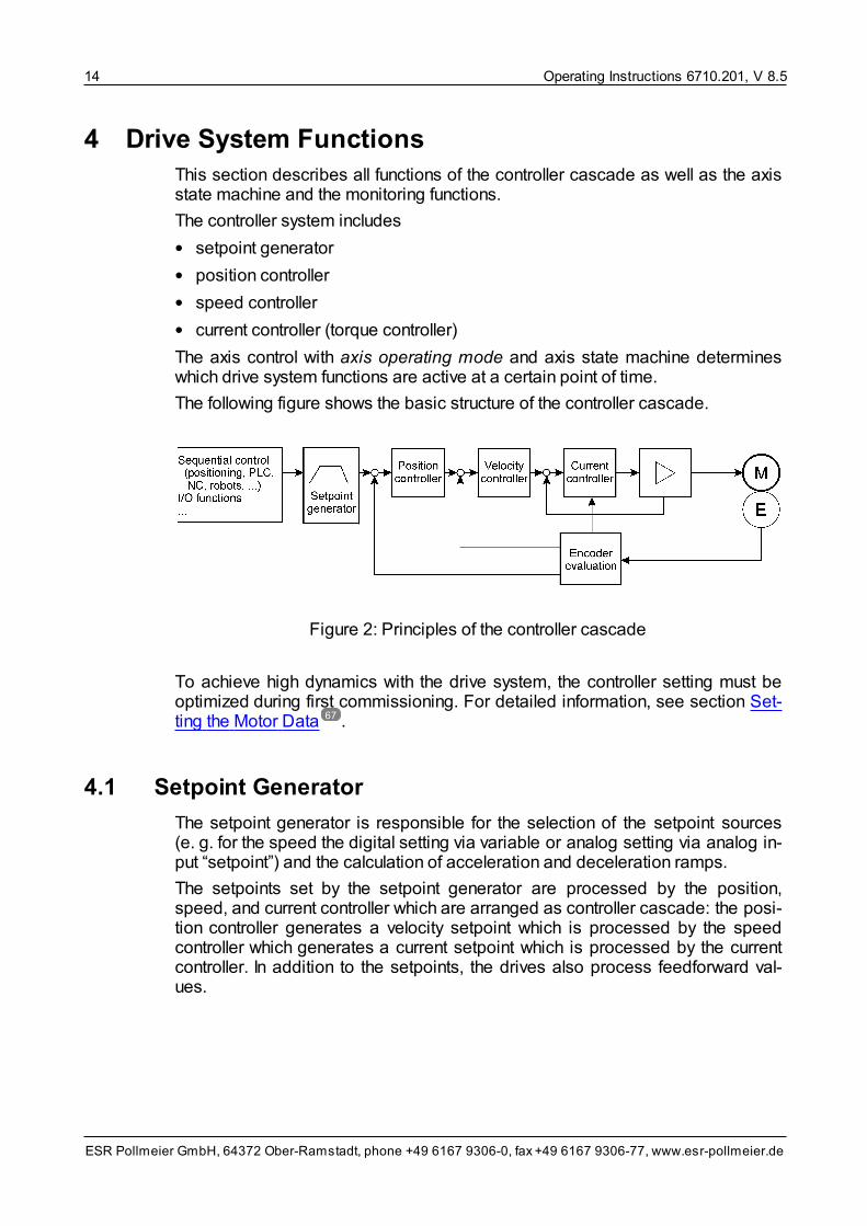
4 Drive System FunctionsThis section describes all functions of the controller cascade as well as the axisstate machine and the monitoring functions.
The controller system includes
• setpoint generator
• position controller
• speed controller
• current controller (torque controller)
The axis control with axis operating mode and axis state machine determineswhich drive system functions are active at a certain point of time.
The following figure shows the basic structure of the controller cascade.
Figure 2: Principles of the controller cascade
To achieve high dynamics with the drive system, the controller setting must beoptimized during first commissioning. For detailed information, see section Set-ting the Motor Data .
4.1 Setpoint Generator
The setpoint generator is responsible for the selection of the setpoint sources(e. g. for the speed the digital setting via variable or analog setting via analog in-put “setpoint”) and the calculation of acceleration and deceleration ramps.
The setpoints set by the setpoint generator are processed by the position,speed, and current controller which are arranged as controller cascade: the posi-tion controller generates a velocity setpoint which is processed by the speedcontroller which generates a current setpoint which is processed by the currentcontroller. In addition to the setpoints, the drives also process feedforward val-ues.
67

Operating Instructions 6710.201, V 8.5 15
ESR Pollmeier GmbH, 64372 Ober-Ramstadt, phone +49 6167 9306-0, fax +49 6167 9306-77, www.esr-pollmeier.de
4.2 Position Controller
The position controller is a PI controller. During commissioning, the user must ad-just the controller parameters to his machine. It is active in axis operating modesspindle positioning, profile position mode, electronic gearing, flyingshear, and interpolated position mode. The position controller receives set-points from the setpoint generator. In the controller cascade, the position control-ler is on a higher level than the speed controller.
4.3 Speed Controller
The speed controller is a PI controller. During commissioning, the user must ad-just the controller parameters to his machine. In axis operating modes velocitymode and velocity mode direct, it receives its setpoints from the setpoint gen-erator. In axis operating modes profile position mode, electronic gearing, fly-ing shear, and interpolated position mode, it receives the setpoints from theposition controller. In the controller cascade, the speed controller is on a lowerlevel than the position controller and on a higher level than the current controller.
4.4 Current Controller (Torque Controller)
The current controller is a PI controller. The controller parameters depend on theused motor, they are set by selecting the motor during parameterization. In axisoperating mode torque mode, the current controller receives its setpoints fromthe setpoint generator. In all other operating modes, it receives its setpoints fromthe speed controller which is on a higher level in the controller cascade.
4.5 Autocommutation
The current angular position of the rotor in relation to the stator or the position ofthe secondary part of the linear motor in relation to the primary part must beknown so that the servo drive can supply the appropriate current depending onthe desired torque or the desired force to the motor. For acquiring this commuta-tion reference after switch-on, various methods are applicable depending on mo-tor and position sensor type. These can be selected via parameter commutationreference:
• Absolute information
When the motor position sensor supplies an absolute information on the posi-tion (within one electrical period), it can be read out by the servo drive and ac-cepted as commutation reference. Usually, this applies to
– rotatory motors with resolver, Sincos (Hiperface) encoder, or EnDat en-coder as motor position sensor the mounting offset (i. e. the angle betweenzero point of the position sensor and phases U-V-W of the motor) of whichis known and

Operating Instructions 6710.201, V 8.516
ESR Pollmeier GmbH, 64372 Ober-Ramstadt, phone +49 6167 9306-0, fax +49 6167 9306-77, www.esr-pollmeier.de
– rotatory motors with high-resolution incremental encoders with Z track asmotor position sensor the mounting offset of which is known.
For
– rotatory motors with incremental encoders without Z track and
– linear motors without hall sensor
an absolute information on the position is usually not available. For these mo-tors, another method of commutation finding is required.
• Autocommutation (firmware V 8.5.94 and higher)
When autocommutation is used, reactive current is supplied to the motor andthe commutation reference is set in a way that no movement occurs. This con-trol algorithm causes a minimal movement of the axis depending on the resol-ution of the position sensor and other factors (e. g. friction).
The autocommutation is carried out automatically when after switch-on theaxis state machine is set to state “switched on” or “operation enabled” for thefirst time. For test purposes, the commutation reference can be set in a waythat the autocommutation is carried out with each change to “switched on” or“operation enabled”.
The autocommutation requires a motor axis freely movable in both directions.For
– motors with holding brake and
– linear motors that are not arranged horizontally
this is usually not true, another method of commutation finding is required.
For motor position sensors with a low resolution (e. g. an incremental encoderwith square-wave signals), execution and result of the autocommutation canbe unsatisfactory. In this case, it should be checked whether or not anothermethod of commutation finding would be more suitable.
• Zero point search using rotating field generator (firmware V 8.5.94 and higher)
When the motor position sensor does not supply an absolute information (e. g.incremental encoder without Z track), however, an autocommutation is notpossible or desired, the commutation reference can also be acquired via zeropoint search using rotating field generator.
For the zero point search using rotating field generator, a rotating field definedvia parameters rotating field generator frequency and rotating field generatorvoltage is supplied to the motor to make it move as soon as after switch-onthe axis state machine is in state “switched on” or “operation enabled” for thefirst time. After the index pulse has been reached, the commutation referenceis set and the drive system is stopped.
Prerequisite for zero point search using rotating field generator is a motor po-sition sensor supplying an index pulse.

Operating Instructions 6710.201, V 8.5 17
ESR Pollmeier GmbH, 64372 Ober-Ramstadt, phone +49 6167 9306-0, fax +49 6167 9306-77, www.esr-pollmeier.de
• Mounting offset at current position (firmware V 8.5.94 and higher)
If it is ensured that the motor is always at a certain position after switch-on,e. g.
– a vertically mounted linear motor without holding brake being in the lower fi-nal position without current or
– a motor without holding brake put in a defined position in current-free stateby a spring,
the commutation reference can be set to this position via the position sensormounting offset.
Caution: A plausibility check or the like is not carried out! If the motor is in an-other position during switch-on or position sensor mounting offset contains awrong value, the commutation reference is not correct and the motor can startrunning uncontrolled at maximum velocity and torque or force in operation!
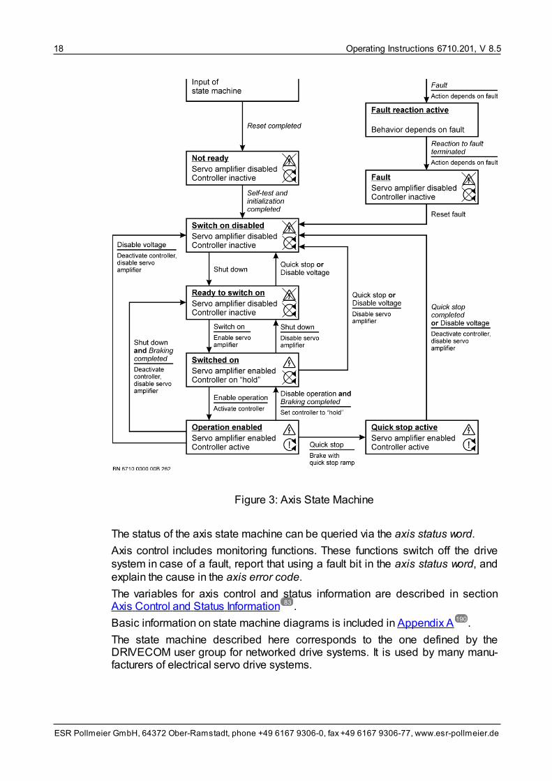
4.6 Axis State Machine
The control behavior of the axis is described using an axis state machine. Thecontrol behavior includes e. g. the steps for switching on the drive system and thedifferent possibilities of shutting down the drive system (with braking ramp,quick-stop ramp, or voltage switch-off).
The drive system is switched on and off via the axis control word which influ-ences the axis state machine.
Operating Instructions 6710.201, V 8.518
ESR Pollmeier GmbH, 64372 Ober-Ramstadt, phone +49 6167 9306-0, fax +49 6167 9306-77, www.esr-pollmeier.de
Figure 3: Axis State Machine
The status of the axis state machine can be queried via the axis status word.
Axis control includes monitoring functions. These functions switch off the drivesystem in case of a fault, report that using a fault bit in the axis status word, andexplain the cause in the axis error code.
The variables for axis control and status information are described in sectionAxis Control and Status Information .
Basic information on state machine diagrams is included in Appendix A .
The state machine described here corresponds to the one defined by theDRIVECOM user group for networked drive systems. It is used by many manu-facturers of electrical servo drive systems.
83
190

Operating Instructions 6710.201, V 8.5 19
ESR Pollmeier GmbH, 64372 Ober-Ramstadt, phone +49 6167 9306-0, fax +49 6167 9306-77, www.esr-pollmeier.de
The axis is always in a defined state displayed via a group of bits in the axisstatus word. A complete overview of the individual bits in the axis status word canbe found in section Axis Status Word .
The message that the axis state machine is in “operation enabled” state and theDC-bus voltage is above the switch-off threshold is communicated by a lit LED“Bereit / Ready” or “RDY” on the front panel of the servo drive (if at least one ofthese conditions is not fulfilled, LED “Bereit/Ready” or “RDY” flashes). This is aprerequisite for the start of an axis movement. For further details, see sec-tion Axis Control Word .
The states primarily determine the behavior of drive and motor as well as the en-abling of the axis. This is indicated by additional explanations regarding thestate. The following applies:
• Not ready
The power circuit of the servo drive is blocked, the drive is not active.
• Switch on disabled
The power circuit of the servo drive is blocked, the drive is not active.
• Ready to switch on
The power circuit of the servo drive is blocked, the drive is not active.
• Switched on
The power circuit is enabled, the drive is actively on hold.
• Operation enabled
The power circuit is enabled, the drive is actively on setpoint.
The drive system functions work according to the selected axis operating mode.Position, speed, and torque or force of the motor depend on setpoints and para-meters as well as the internal states of the drive system function.
A change between two states (a state transition) occurs when an event happens.During some changes, an action is carried out.
Possible events are
• a control command is given
– via the axis control word or
– input “enable”
• internal event in the servo drive
• external event at one of the servo drive interfaces
Control commands are usually given via the corresponding bit patterns in theaxis control word. A complete overview of the individual bits in the axis controlword can be found in section Axis Control Word .
For giving control commands via input “Enable” (“Ena”), the effect of the enableinput must be configured using machine date enable selection code.
Event “fault” (e. g. limit switch) may occur in each state, it leads to a transition intostate “fault reaction active”. To keep the figure clear, the corresponding arrowwas not drawn at each state but only once on top without own previous state.
22
20
20

Operating Instructions 6710.201, V 8.520
ESR Pollmeier GmbH, 64372 Ober-Ramstadt, phone +49 6167 9306-0, fax +49 6167 9306-77, www.esr-pollmeier.de
The internal and external events are described as follows:
• Reset completed
The reset of the servo drive after switch-on of the supply voltages is com-pleted, the communication is ready.
• Self-test and initialization completed
These processes are completed, the axis state machine is ready for receivingcontrol commands from the axis control word.
• Braking completed
After braking with the braking ramp (motion profile type, deceleration time,and ramps reference velocity parameters), the drive system has reachedzero velocity (velocity threshold, velocity threshold time parameters). In someaxis operating modes, this is indicated via bit “Velocity = 0” in the axis statusword.
• Quick stop completed
After braking with the quick stop ramp (motion profile type, quick stop time,and ramps reference velocity parameters), the drive system has reachedzero velocity (velocity threshold, velocity threshold time parameters). In someaxis operating modes, this is indicated via bit “Velocity = 0” in the axis statusword.
• Fault
A fault has occurred (e. g. limit switch). Parameter axis error code providesmore detailed information on the cause of the fault. Additionally, the fault is in-dicated by lighting or flashing of LED “Störung / Fault” or “FLT”.
• Fault reaction terminated
Each fault leads to a particular reaction of the servo drive. The end of this re-action is indicated by this event.
4.6.1 Axis Control Word
The axis control word can be used for
• influencing the axis state machine (so that the drive system is switched on oroff),
• influencing the part program state machine (so that the part program runningcan be controlled),
• resetting a fault
• some axis operating modes to give certain commands to the drive system (e.g. start going to home position in operating mode homing mode).
In the axis control word, the individual bits have the following meaning:

Operating Instructions 6710.201, V 8.5 21
ESR Pollmeier GmbH, 64372 Ober-Ramstadt, phone +49 6167 9306-0, fax +49 6167 9306-77, www.esr-pollmeier.de
Bit Axis Control Word (Bit Assignment)
0 Switch on (axis state machine)
1 Disable voltage (axis state machine)
2 Quick stop (axis state machine)
3 Enable operation (axis state machine)
4 .. 6 Meaning depends on the axis operating mode, see below
7 Reset fault (axis state machine)
8 .. 13 –
14 Part program start (short: PP start) (part program state machine)
15 Part program reset (short: PP reset) (part program state machine)
In the axis control word, bits 4 to 6 have the following meaning, depending on theaxis operating mode:
• Profile position mode
– Bit 4: New setpoint
– Bit 5: Change block immediately
– Bit 6: Absolute/relative
• Homing mode
– Bit 4: Start homing mode
• Electronic gearing
– Bit 4: Synchronize
• Interpolated Position Mode
– Bit 4: Enable interpolation
In all other operating modes, bits 4 to 6 in the axis control word do not have anymeaning.
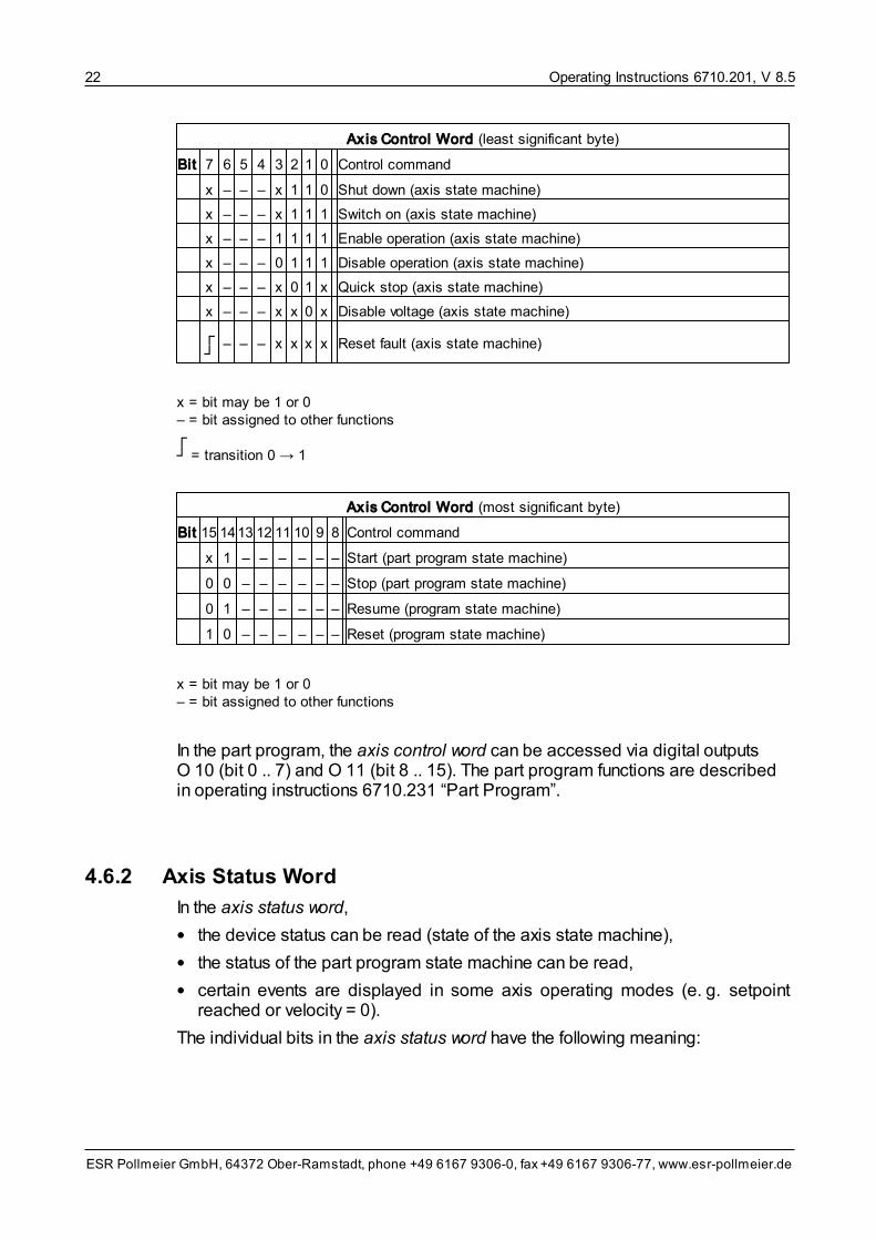
The following table lists all control commands in the axis control word.
Axis Control Word (least significant byte)
Bit 7 6 5 4 3 2 1 0 Control command
– 1 0┌┘
– – – –Accept target position (absolute) (in axis operating mode profile posi-tion mode/block mode)
– 0 0┌┘
– – – –Accept target position (relative) (in axis operating mode profile posi-tion mode/block mode)
– 1 1 1 – – – –Accept target position permanently (absolute) (in operating mode� pro-file position mode/setpoint mode)
– – – 1 – – – – Start homing mode (in axis operating mode homing mode)
– – – 1 – – – – Synchronize (in axis operating mode electronic gearing)
– – – ┌┘
– – – – Enable interpolation (in axis operating mode interpolated positionmode)
Operating Instructions 6710.201, V 8.522
ESR Pollmeier GmbH, 64372 Ober-Ramstadt, phone +49 6167 9306-0, fax +49 6167 9306-77, www.esr-pollmeier.de
Axis Control Word (least significant byte)
Bit 7 6 5 4 3 2 1 0 Control command
x – – – x 1 1 0 Shut down (axis state machine)
x – – – x 1 1 1 Switch on (axis state machine)
x – – – 1 1 1 1 Enable operation (axis state machine)
x – – – 0 1 1 1 Disable operation (axis state machine)
x – – – x 0 1 x Quick stop (axis state machine)
x – – – x x 0 x Disable voltage (axis state machine)
┌┘
– – – x x x x Reset fault (axis state machine)
x = bit may be 1 or 0– = bit assigned to other functions┌┘ = transition 0 → 1
Axis Control Word (most significant byte)
Bit 15 1413 12 1110 9 8 Control command
x 1 – – – – – – Start (part program state machine)
0 0 – – – – – – Stop (part program state machine)
0 1 – – – – – – Resume (program state machine)
1 0 – – – – – – Reset (program state machine)
x = bit may be 1 or 0– = bit assigned to other functions
In the part program, the axis control word can be accessed via digital outputsO 10 (bit 0 .. 7) and O 11 (bit 8 .. 15). The part program functions are describedin operating instructions 6710.231 “Part Program”.
4.6.2 Axis Status Word
In the axis status word,
• the device status can be read (state of the axis state machine),
• the status of the part program state machine can be read,
• certain events are displayed in some axis operating modes (e. g. setpointreached or velocity = 0).
The individual bits in the axis status word have the following meaning:

Operating Instructions 6710.201, V 8.5 23
ESR Pollmeier GmbH, 64372 Ober-Ramstadt, phone +49 6167 9306-0, fax +49 6167 9306-77, www.esr-pollmeier.de
Bit Axis Status Word (Bit Assignment)
0 Ready to switch on (axis state machine)
1 Switched on (axis state machine)
2 Operation enabled (axis state machine)
3 Fault (axis state machine)
4 Voltage disabled (axis state machine)
5 Quick stop (axis state machine)
6 Switch on disabled (axis state machine)
7 –
8 –
9 –
10 Setpoint reached (SR), depending on the axis operating mode, see below
11 –
12 .. 13 Meaning depends on the axis operating mode, see below
14 Part program running (short PP running) (part program state machine)
15 Part program idle (short PP idle) (part program state machine)
Depending on the axis operating mode, bit 10 (setpoint reached) in the axisstatus word stands for:
• Torque mode: torque reached
• Velocity mode direct: velocity reached
• Velocity mode: velocity reached
• Profile position mode: in position
• Electronic gearing: synchronized
• Flying shear: in position (return position)
Depending on the axis operating mode, bits 12 and 13 in the axis status wordhave the following meaning:
• Velocity mode direct
– Bit 12: velocity = 0
• Velocity mode
– Bit 12: velocity = 0
• Profile position mode
– Bit 12: setpoint acknowledgement
• Homing mode
– Bit 12: home position reached
– Bit 13: homing fault

Operating Instructions 6710.201, V 8.524
ESR Pollmeier GmbH, 64372 Ober-Ramstadt, phone +49 6167 9306-0, fax +49 6167 9306-77, www.esr-pollmeier.de
• Electronic gearing
– Bit 12: velocity = 0
• Cyclic synchronous torque mode
– Bit 12: setpoints are accepted
• Cyclic synchronous velocity mode
– Bit 12: setpoints are accepted
• Cyclic synchronous position mode
– Bit 12: setpoints are accepted
• Interpolated Position Mode
– Bit 12: setpoints are accepted (firmware V 8.5.9 and higher)
– Bit 13: homing mode
In all other operating modes, bits 10, 12, and 13 in the axis status word do nothave any meaning.
The following two tables show a list of all state codings for program state ma-chine and axis state machine.
Axis Status Word (least significant byte)
Bit 7 6 5 4 3 2 1 0 Status of the axis state machine
– 0 x – 0 0 0 0 Not ready
– 1 x – 0 0 0 0 Switch on disabled
– 0 1 – 0 0 0 1 Ready to switch on
– 0 1 – 0 0 1 1 Switched on
– 0 1 – 0 1 1 1 Operation enabled
– 0 0 – 0 1 1 1 Quick stop active
– 0 x – 1 1 1 1 Fault reaction active
– 0 x – 1 0 0 0 Fault
x = bit may be 1 or 0– = bit assigned to other functions
Axis Status Word (most significant byte)
Bit 15 14 131211 10 9 8 Status of the part program state machine
1 0 – – – – – – Idle (out of operation)
0 1 – – – – – – Running
0 0 – – – – – – Stopped
– = bit assigned to other functions
In the part program, the axis status word can be accessed via digital inputs I 10

Operating Instructions 6710.201, V 8.5 25
ESR Pollmeier GmbH, 64372 Ober-Ramstadt, phone +49 6167 9306-0, fax +49 6167 9306-77, www.esr-pollmeier.de
(bit 0 .. 7) and I 11 (bit 8 .. 15). The part program functions are described in oper-ating instructions 6710.231 “Part Program”.
4.6.3 Running up the Axis State Machine (Example)
To run up the axis state machine, proceed as follows:
• Fault query and management
Before running up the axis state machine, query the faults and, if required, re-act correspondingly:
– Condition: axis status word AND 004Fhex = 0008hex
In all following steps in which a certain status is waited for, the fault query andmanagement must be carried out, as well.
• Start with state “switch on disabled”
After the controller start, make sure that the axis state machine changes tostate “switch on disabled”, no matter in which state it was before:
– control command “quick stop” (axis control word: xxx2hex) or
– control command “disable voltage” (axis control word: xxx0hex)
• Wait until state “switch on disabled” has been reached Before the next control command is given, make sure that state “switch on dis-abled” has been reached.
– Condition: axis status word AND 004Fhex
= 0040hex
In “switch on disabled” state, the power circuit is not enabled (no voltage at themotor) and the control loops are not active (motor shaft can be moved manu-ally).
• Switch to state “ready to switch on”
– control command “hold” (axis control word: xxx6hex)
• Wait until “ready to switch on” state has been reached
Before the next control command is given, make sure that the “ready to switchon” state has been reached.
– Condition: axis status word AND 006Fhex = 0021hex
In the “ready to switch on” state, the power circuit is not enabled (no voltage atthe motor) and the control loops are not active (motor shaft can be movedmanually).
The function of state “ready to switch on” does not differ from state “switch ondisabled”. This additional step ensures that the drive system cannot beswitched to “switched on” state during a new start e. g. because control com-mand “switch on” still exists in the process data.
• Switch further to “operation enabled” state
The “switch on” and “enable operation” control commands can be given simul-
Operating Instructions 6710.201, V 8.526
ESR Pollmeier GmbH, 64372 Ober-Ramstadt, phone +49 6167 9306-0, fax +49 6167 9306-77, www.esr-pollmeier.de
taneously (see table “Coding of Control Commands for the Axis StateMachine”):
– Control command “enable operation” (axis control word: xxxFhex)
• Wait until “operation enabled” state has been reached
– Condition: axis status word AND 006Fhex = 0027hex
In state “operation enabled”, the power circuit is enabled (voltage exists at themotor). The control loops are active, the motor shaft is moved according to thedefined setpoints depending on the selected axis operating mode.
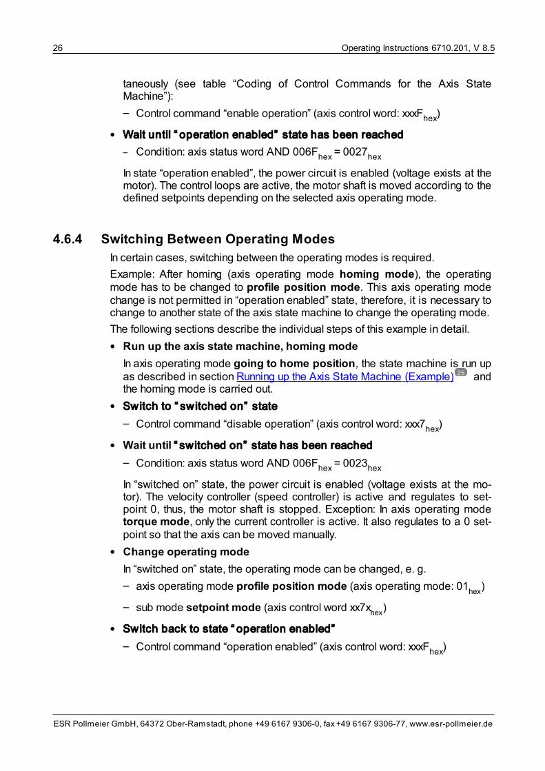
4.6.4 Switching Between Operating Modes
In certain cases, switching between the operating modes is required.
Example: After homing (axis operating mode homing mode), the operatingmode has to be changed to profile position mode. This axis operating modechange is not permitted in “operation enabled” state, therefore, it is necessary tochange to another state of the axis state machine to change the operating mode.
The following sections describe the individual steps of this example in detail.
• Run up the axis state machine, homing mode
In axis operating mode going to home position, the state machine is run upas described in section Running up the Axis State Machine (Example) andthe homing mode is carried out.
• Switch to “switched on” state
– Control command “disable operation” (axis control word: xxx7hex)
• Wait until “switched on” state has been reached
– Condition: axis status word AND 006Fhex = 0023hex
In “switched on” state, the power circuit is enabled (voltage exists at the mo-tor). The velocity controller (speed controller) is active and regulates to set-point 0, thus, the motor shaft is stopped. Exception: In axis operating modetorque mode, only the current controller is active. It also regulates to a 0 set-point so that the axis can be moved manually.
• Change operating mode
In “switched on” state, the operating mode can be changed, e. g.
– axis operating mode profile position mode (axis operating mode: 01hex
)
– sub mode setpoint mode (axis control word xx7xhex
)
• Switch back to state “operation enabled”
– Control command “operation enabled” (axis control word: xxxFhex)
25

Operating Instructions 6710.201, V 8.5 27
ESR Pollmeier GmbH, 64372 Ober-Ramstadt, phone +49 6167 9306-0, fax +49 6167 9306-77, www.esr-pollmeier.de
• Wait until “operation enabled” state has been reached
– Condition: axis status word AND 006Fhex = 0027hex
The motor shaft moves according to setpoint target position and parameterssuch as target velocity.
4.7 Monitoring
In case of a fault, monitoring functions switch off device and drive system and re-port a fault in bit 3 of the axis status word. Possible faults include excessive cur-rent in the motor circuit, overtemperature, or blocking of the motor, wrong con-nection of the motor position sensor, errors when going to home position or re-lated to limit switches, over- or undervoltage in the DC bus, overtemperature inpower circuit or shunt resistor, or errors in part program operation.
After the cause has been removed, the fault can be reset via the axis controlword.
In addition to axis operating modes and axis state machine, the axis control in-cludes functions providing information on the axis other than the state of the axisstate machine or controlling outputs. These are used for monitoring purposes.
• Output “fault”
When state “fault” has been reached, output “fault” will be activated. State“fault” (and thus the output) can be reset via a control command in the axiscontrol word or input “reset fault”.
• Axis error code
In case of a fault (axis state machine in “fault” state), the axis error code dis-plays the cause of the fault. It is displayed until the error has been removedand state “fault” has been left using control command “reset fault”. An overviewof the axis error codes can be found in Appendix B .
4.8 Safety System (TrioDrive D/xS and MidiDrive D/xS, only)
In the TrioDrive D/xS and MidiDrive D/xS servo drives, the wear-free electronicconception for “safe standstill” (corresponds to stop category 0 according toEN 954-1 or STO according to EN 61800-5-2) developed by ESR is used. Forthat, the control energy for the upper and lower power circuit bridge leg is sup-plied separately via safety inputs SI1 and SI2. If at least one of the two voltages isswitched off, current cannot flow into the motor winding any longer.
In the hardware (power circuit), safety inputs SI1 and SI2 trigger the “safe stand-still” function by disabling the power circuit as soon as at least one of inputs SI1or SI2 is active (= open = 0 V). This is stored and displayed by signal “safestandstill”.
The axis state machine changes to “switch on disabled” state.
Due to the two-channel design (safety category 4 according to EN 954-1), ac-
191
Operating Instructions 6710.201, V 8.528
ESR Pollmeier GmbH, 64372 Ober-Ramstadt, phone +49 6167 9306-0, fax +49 6167 9306-77, www.esr-pollmeier.de
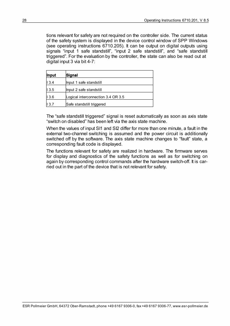
tions relevant for safety are not required on the controller side. The current statusof the safety system is displayed in the device control window of SPP Windows(see operating instructions 6710.205). It can be output on digital outputs usingsignals “input 1 safe standstill”, “input 2 safe standstill”, and “safe standstilltriggered”. For the evaluation by the controller, the state can also be read out at digital input 3 via bit 4-7:
Input Signal
I 3.4 Input 1 safe standstill
I 3.5 Input 2 safe standstill
I 3.6 Logical interconnection 3.4 OR 3.5
I 3.7 Safe standstill triggered
The “safe standstill triggered” signal is reset automatically as soon as axis state“switch on disabled” has been left via the axis state machine.
When the values of input SI1 and SI2 differ for more than one minute, a fault in theexternal two-channel switching is assumed and the power circuit is additionallyswitched off by the software. The axis state machine changes to “fault” state, acorresponding fault code is displayed.
The functions relevant for safety are realized in hardware. The firmware servesfor display and diagnostics of the safety functions as well as for switching onagain by corresponding control commands after the hardware switch-off. It is car-ried out in the part of the device that is not relevant for safety.

Operating Instructions 6710.201, V 8.5 29
ESR Pollmeier GmbH, 64372 Ober-Ramstadt, phone +49 6167 9306-0, fax +49 6167 9306-77, www.esr-pollmeier.de
5 Axis Operating ModesThe axis operating modes can be used for determining whether e. g. velocitiesor positions will be preset. Depending on the servo drive equipment, not all axisoperating modes are available. Possible axis operating modes are:
• Torque mode / force mode,
• Velocity mode direct,
• Velocity mode,
• Spindle positioning (sub mode),
• Profile position mode,
• Homing mode,
• Electronic gearing,
• Flying shear,
• Velocity profile,
• Timed positioning mode
• Cyclic synchronous torque/force mode
• Cyclic synchronous velocity mode
• Cyclic synchronous position mode, and
• Interpolated Position Mode
The axis operating mode is selected via variable axis operating mode. It may bechanged in states “switch on disabled”, “ready to switch on”, and “switched on”,only.
All axis operating modes use the drive functions responsible for the actual controland processing of setpoint and actual values. Different controllers are active, de-pending on the operating mode. You will find further details in section Drive Sys-tem Functions .
One condition for the drive to operate properly in these axis operating modes isthe setting of basic machine data during commissioning.
Actual values can be read in all axis operating modes via the following variables:
• actual position: actual position (position units, to be used preferably), positionsensor actual position (position sensor steps)
• actual velocity: actual velocity
• actual current: actual current
The units for position and velocity can be converted into practical units:
• The coordinate system can be adapted to the application via a factor and azero offset. Due to that, the user is not confined to the steps of the positionmeasuring system, but can define units of his own.
By default, the units are position sensor steps (PSS) preset by the evaluation of the position measuring system. Using the position factor and home offset
14

Operating Instructions 6710.201, V 8.530
ESR Pollmeier GmbH, 64372 Ober-Ramstadt, phone +49 6167 9306-0, fax +49 6167 9306-77, www.esr-pollmeier.de
variables, the position sensor steps can be converted into more useful units(e. g. mm or angular units). In the following, these units, which can be selectedby the user, are called position units (PU).
The zero offset is carried out via the home offset variable.
• The velocity units can be adapted to physical units (e.g. r.p.m. or mm/s) usingthe velocity factor setpoint variable. In the following, these units, which can beselected by the user, are called velocity units (VU).
For further details on how to set the conversion factors, see section Factors andUnits Machine Data .
In the variable descriptions of these operating instructions the units are stated forall variables containing position and velocity values.
The axis can be operated as
• linear axis or as
• circular axis.
The corresponding setting is carried out via the axis type variable. For further in-formation, see section Positioning Range Machine Data .
The control loops (and thus the drive functions) are only active when the axisstate machine is in “operation enabled” state. Furthermore, a motion can onlytake place if the bus voltage is high enough (i. e. in addition to the control supplyvoltage, the mains must be switched on).
The message that the state machine is in “operation enabled” state and the busvoltage is above the shutdown threshold is indicated by the lighting up of the “Bereit / Ready” or “RDY” LED on the front panel of the servo drive (a flashing“Bereit / Ready” or “RDY” LED indicates that one of these conditions is not met).
5.1 Torque Mode / Force Mode
In axis operating mode torque mode (or force mode for a linear motor), thetorque of the axis can be set via the torque setpoint parameter or analog input“setpoint”. The direction in which the torque is effective is specified by the sign.Whether the torque is to be preset as a digital or analog value can be selectedvia machine data torque setpoint source. Condition for the start of the motion isthat the drive is “Ready”.
If the torque is preset via analog input “setpoint”, the scaling of the analog value(assignment of the applied setpoint voltage to a specific speed) and the correc-tion of the offset can be achieved via the torque analog factor and torque analogoffset variables.
In torque mode, the axis control word does not contain any operating mode-de-pendent bits.
In the axis status word, bit 10 has the following special meaning:
• torque setpoint reached (bit 10 in the axis status word)
This message can also be output on a digital output, see signal selection digital
158
161
Operating Instructions 6710.201, V 8.5 31
ESR Pollmeier GmbH, 64372 Ober-Ramstadt, phone +49 6167 9306-0, fax +49 6167 9306-77, www.esr-pollmeier.de
output... in section Input/Output Function Machine Data .
In this operating mode, setpoint generator and current control loop work to-gether.
The speed in axis operating mode torque mode is currently not limited, thus, themaximum speed specified in the maximum motor speed variable may be ex-ceeded.
To find out whether or not a certain variable is valid in axis operating modetorque mode, see the corresponding information of the individual variable de-scriptions in line “Valid: ...”.
Operating mode torque mode is not suitable for realizing an (external) speedcontrol because the input values (analog input) are filtered which leads to delays.
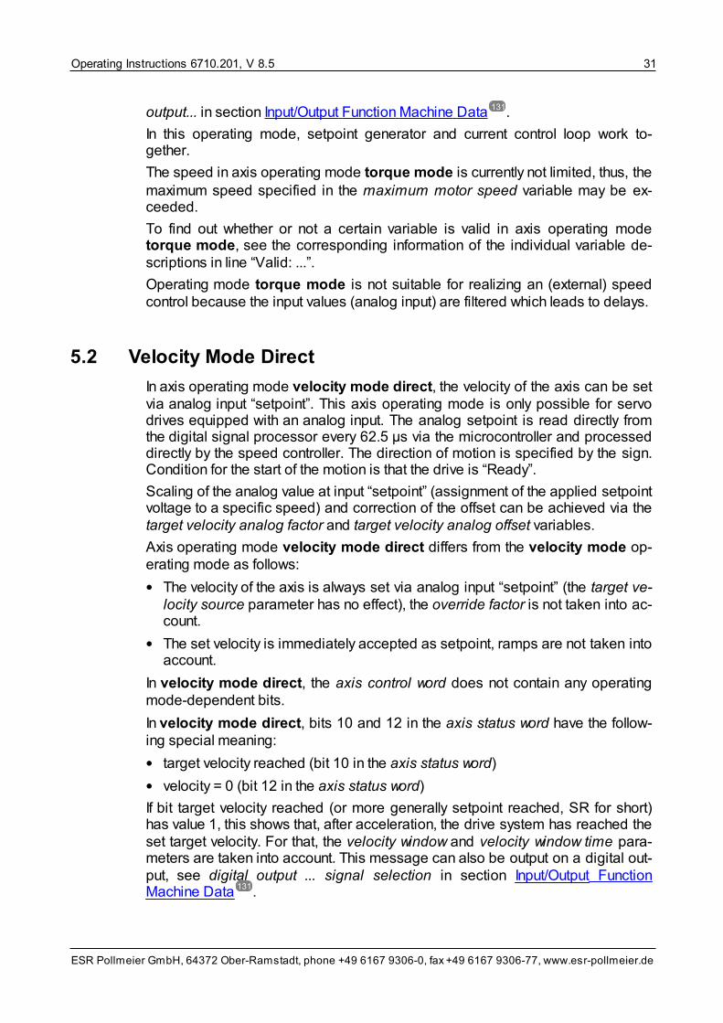
5.2 Velocity Mode Direct
In axis operating mode velocity mode direct, the velocity of the axis can be setvia analog input “setpoint”. This axis operating mode is only possible for servodrives equipped with an analog input. The analog setpoint is read directly fromthe digital signal processor every 62.5 μs via the microcontroller and processeddirectly by the speed controller. The direction of motion is specified by the sign.Condition for the start of the motion is that the drive is “Ready”.
Scaling of the analog value at input “setpoint” (assignment of the applied setpointvoltage to a specific speed) and correction of the offset can be achieved via thetarget velocity analog factor and target velocity analog offset variables.
Axis operating mode velocity mode direct differs from the velocity mode op-erating mode as follows:
• The velocity of the axis is always set via analog input “setpoint” (the target ve-locity source parameter has no effect), the override factor is not taken into ac-count.
• The set velocity is immediately accepted as setpoint, ramps are not taken intoaccount.
In velocity mode direct, the axis control word does not contain any operatingmode-dependent bits.
In velocity mode direct, bits 10 and 12 in the axis status word have the follow-ing special meaning:
• target velocity reached (bit 10 in the axis status word)
• velocity = 0 (bit 12 in the axis status word)
If bit target velocity reached (or more generally setpoint reached, SR for short)has value 1, this shows that, after acceleration, the drive system has reached theset target velocity. For that, the velocity window and velocity window time para-meters are taken into account. This message can also be output on a digital out-put, see digital output ... signal selection in section Input/Output FunctionMachine Data .
131
131

Operating Instructions 6710.201, V 8.532
ESR Pollmeier GmbH, 64372 Ober-Ramstadt, phone +49 6167 9306-0, fax +49 6167 9306-77, www.esr-pollmeier.de
If bit velocity = 0 is set, this shows that, after deceleration, the drive has reachedvelocity zero. For that, the velocity threshold and velocity threshold time para-meters are taken into account.
To safely determine that velocity zero has been reached after deceleration, thecorresponding velocity threshold and velocity threshold time variables must beset so that, even if the axis is subject to motion as a result of control oscillationsor an external force, this movement never exceeds the speed specified in the ve-locity threshold.
In operating mode velocity mode direct, the motions are influenced by the fol-lowing parameters:
• Speed control loop machine data with speed filter cut-off frequency, speedcontrol loop Kp, speed control loop Ki, speed control loop total amplification
– determine the controller behavior: smoothing of the actual speed, gain, andoptional I component (to compensate for any remaining control offset).
In operating mode velocity mode direct, setpoint generator and speed control-ler work together, the current controller is subordinate to the speed controller.
To find out whether or not a certain variable is valid in axis operating mode velo-city mode direct, see the corresponding information of the individual variabledescriptions in line “Valid: ...”.
5.3 Velocity Mode
In axis operating mode velocity mode, the velocity of the axis can be set viathe target velocity (digital) parameter or analog input “setpoint”. In both cases,the value is multiplied with the override factor. The direction of motion is spe-cified by the sign. Whether the velocity is to be set as a digital or analog valuecan be selected via machine data target velocity source. Condition for the startof the motion is that the drive is “Ready”.
If the target velocity is set via analog input “setpoint”, the scaling of the analogvalue (assignment of the applied setpoint voltage to a specific speed) and a cor-rection of the offset can be achieved via the target velocity analog factor and tar-get velocity analog offset variables.
Axis operating mode velocity mode differs from the velocity mode direct op-erating mode as follows:
• The velocity of the axis can be preset either via analog input “setpoint” or viathe target velocity (digital) parameter, the override factor is taken into ac-count.
• Acceleration and deceleration ramps are taken into account during internalsetpoint calculation.
In velocity mode, the axis control word does not contain any operating mode-dependent bits.
In velocity mode, bits 10 and 12 in the axis status word have the following spe-cial meaning:

Operating Instructions 6710.201, V 8.5 33
ESR Pollmeier GmbH, 64372 Ober-Ramstadt, phone +49 6167 9306-0, fax +49 6167 9306-77, www.esr-pollmeier.de
• target velocity reached (bit 10 in the axis status word)
• velocity = 0 (bit 12 in the axis status word)
If bit “target velocity reached” (or more generally, “setpoint reached”, SR forshort) has value 1, this shows that, after acceleration, the drive has reached theset target velocity. For that, the velocity window and velocity window time para-meters are taken into account. This message can also be output on a digital out-put, see signal selection digital output ... in section Input/Output FunctionMachine Data .
If bit “velocity = 0” is set, this shows that, after deceleration, the drive has reachedvelocity zero. For that, the velocity threshold and velocity threshold time para-meters are taken into account.
To safely determine that velocity zero has been reached after deceleration whilebraking, the corresponding velocity threshold and velocity threshold time vari-ables must be set in a way that, even if the axis is subject to motion as a result ofcontrol oscillations or an external force, this movement never exceeds the speedspecified in the velocity threshold.
In operating mode velocity mode, the motions are influenced by the followingparameters:
• Ramps machine data (section Ramps Machine Data ) with motion profiletype, acceleration time, deceleration time, quick stop time, and ramps refer-ence velocity
– determine how to reach the velocity and how to decelerate again.
• Speed control loop machine data (section Speed Control Loop Machine Data) with speed filter cut-off frequency, speed control loop Kp, speed control
loop Ki, speed control loop total amplification
– determine the controller behavior: smoothing of the actual speed, gain, andoptional I component (to compensate for any remaining control offset)
In operating mode velocity mode, setpoint generator and speed controller worktogether, the current controller is subordinate to the speed controller.
To find out whether or not a certain variable is valid in axis operating mode velo-city mode, see the corresponding information of the individual variable descrip-tions in line “Valid: ...”.
5.4 Spindle Positioning
The spindle positioning function is actually an axis sub mode. It serves for pre-paring the tool or the tool change and can be called up in axis operating modesvelocity mode and velocity mode direct (from firmware V 5.4a on).
With the axis rotating, a positioning process is started via the “spindle position”command. This positioning turns the axis into a defined spindle position. Forthat, the target velocity is increased or decreased to the spindle positioning velo-city. In a state of an active spindle positioning (input = 1), a target velocity mustnot be set from outside.
131
164
167

Operating Instructions 6710.201, V 8.534
ESR Pollmeier GmbH, 64372 Ober-Ramstadt, phone +49 6167 9306-0, fax +49 6167 9306-77, www.esr-pollmeier.de
Signal “spindle position reached” indicates that the target position has beenreached. For that, the spindle positioning window and the spindle positioningwindow time parameters are taken into account. When the drive has reachedzero velocity, signal “velocity = 0” is output. The velocity threshold and velocitythreshold time parameters are taken into account. Both messages can also beoutput on digital outputs.
The spindle positioning process is ended and the drive system returns to axisoperating mode velocity mode or velocity mode direct as soon as inputspindle positioning is reset to zero.
For spindle positioning, the axis must be operated as a circular axis. The corres-ponding setting is made via the axis type variable.
In spindle positioning, the bit assignment in axis control word and axis statusword corresponds to the bit assignment of axis operating modes velocity modeor velocity mode direct.
The motions during spindle positioning are influenced by the following para-meters:
• Ramps machine data (Ramps Machine Data ) with motion profile type, ac-celeration time, deceleration time, quick stop time, and ramps reference ve-locity
– determine how to achieve the spindle positioning velocity and how to decel-erate to velocity 0 on approaching target position.
• Speed control loop machine data (section Speed Control Loop Machine Data) with velocity threshold and velocity threshold time parameters.
– For activating the spindle positioning, the current velocity must be higherthan zero; the velocity threshold and velocity threshold time parametersdefine this state.
• Positioning range machine data (section Positioning Range Machine Data) with axis type, range limit min and range limit max
– axis type must be set to “circular axis”; the range limit min and range limitmax variables specify the valid range for the spindle position.
• Spindle positioning machine data (section Spindle Positioning Machine Data) with spindle positioning direction
– determine the direction of rotation during spindle positioning.
In the spindle positioning function, setpoint generator and position controllerwork together, speed controller and current controller are subordinate to the posi-tion controller.
5.5 Profile Position Mode
Axis operating mode profile position mode can be used for moving to a spe-cific position. This position is preset by the user via the target position. Bits 4to 6 in the axis control word ensure that, under certain conditions, the target posi-
164
167
161
181

Operating Instructions 6710.201, V 8.5 35
ESR Pollmeier GmbH, 64372 Ober-Ramstadt, phone +49 6167 9306-0, fax +49 6167 9306-77, www.esr-pollmeier.de
tion is transferred to the internal target position variable. The position in internaltarget position is then approached. Condition for the start of the motion is thatthe drive is “Ready”.
The velocity the target position is approached with is specified via the target ve-locity (digital) parameter or via analog input “setpoint”, depending on the settingin the machine data target velocity source. In both cases, the value is multipliedby the override factor.
Each time the axis operating mode is switched to profile position mode, theactual position is transferred to the internal target position. This keeps the axisat its current position until a new target position is set.
In profile position mode, bits 4 to 6 in the axis control word have the followingspecial meaning:
• new setpoint (bit 4 in the axis control word)
• change block immediately (bit 5 in the axis control word)
• absolute/relative (bit 6 in the axis control word)
Bit “change block immediately” selects one of the two sub-modes
• block mode (bit “change block immediately” = 0) or
• setpoint mode (bit “change block immediately” = 1).
The effect of the two bits “new setpoint” and “absolute/relative” depends on theselected sub-mode; these sub-modes are described in the next sections. Anoverview of the effect of these control bits is given in the following table.
Profile position mode – operating mode-dependent control bits
Transfer of target positionto internal target posi-tion...
Axis control word (least significant byte)
Bit 7 6 5 4 3 2 1 0sub-mode of the profile positionmode
...as absolute position – 1 0┌┘
– – – –
block mode
...as relative position – 0 0┌┘
– – – –
permanent acceptance(as absolute position)
– 1 1 1 – – – – setpoint mode
x = bit may be 1 or 0– = bit assigned to other functions┌┘ = transition 0 → 1
Bit names: Bit 6 =Bit 5 =
Bit 4 =
“absolute/relative”“change block immediately”“new setpoint”
In profile position mode, bits 10 and 12 in the axis status word have the follow-ing special meaning:
• setpoint reached (bit 10 in the axis status word)
• setpoint acknowledgment (bit 12 in the axis status word)

Operating Instructions 6710.201, V 8.536
ESR Pollmeier GmbH, 64372 Ober-Ramstadt, phone +49 6167 9306-0, fax +49 6167 9306-77, www.esr-pollmeier.de
With value 1, bit “position setpoint reached” (also “in position”, IP, or more gener-ally “setpoint reached”, SR) shows that the axis has reached the internal targetposition. For this decision, the positioning window and positioning window timeparameters are taken into account. This message can also be output on a digitaloutput, see signal selection digital output ... in section Input/Output FunctionMachine Data .
Bit “setpoint acknowledgment” shows the transfer of the target position to the in-ternal target position and is described in more detail under sub-modes blockmode and setpoint mode.
The sequence of motions when approaching a target position is influenced bythe following parameters:
• Target velocity (section Parameters and Actual Values Velocity Mode )
– determines the velocity at which the position specified in the internal targetposition is approached (if selected via target velocity source).
• Ramps machine data (section Ramps Machine Data ) with motion profiletype, acceleration time, deceleration time, quick stop time, and ramps refer-ence velocity
– determine how to achieve the target velocity and how to decelerate to velo-city 0 on approaching target position.
• Position control loop machine data (section Position Control Loop MachineData ) with position control loop Kp
– determine the controller action (gain).
In axis operating mode profile position mode, setpoint generator and positioncontroller work together, the speed and current controllers are subordinate to theposition controller.
Prerequisite for the proper functioning of axis operating mode profile positionmode is the correct setting of the speed controller. This is best carried out inaxis operating mode velocity mode.
Target position, internal target position, and the associated control bits as wellas target velocity can also be changed during an active positioning process; theaxis reacts immediately to these changes.
To find out whether or not a certain variable is valid in axis operating mode pro-file position mode, see the corresponding information of the individual variabledescriptions in line “Valid: ...”.
5.5.1 Block Mode
In block mode, the target position is transferred to the internal target position(and thus approached) when a rising edge is recognized in bit “new setpoint” ofthe axis control word.
The block mode is selected via bit “change block immediately” = 0 in the axiscontrol word.
131
87
164
171
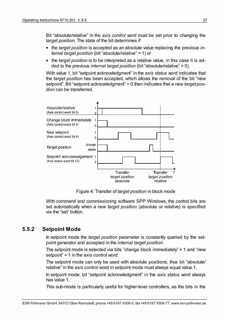
Operating Instructions 6710.201, V 8.5 37
ESR Pollmeier GmbH, 64372 Ober-Ramstadt, phone +49 6167 9306-0, fax +49 6167 9306-77, www.esr-pollmeier.de
Bit “absolute/relative” in the axis control word must be set prior to changing thetarget position. The state of the bit determines if
• the target position is accepted as an absolute value replacing the previous in-ternal target position (bit “absolute/relative” = 1) or
• the target position is to be interpreted as a relative value, in this case it is ad-ded to the previous internal target position (bit “absolute/relative” = 0).
With value 1, bit “setpoint acknowledgment” in the axis status word indicates thatthe target position has been accepted, which allows the removal of the bit “newsetpoint”. Bit “setpoint acknowledgment” = 0 then indicates that a new target pos-ition can be transferred.
Figure 4: Transfer of target position in block mode
With command and commissioning software SPP Windows, the control bits areset automatically when a new target position (absolute or relative) is specifiedvia the “set” button.
5.5.2 Setpoint Mode
In setpoint mode the target position parameter is constantly queried by the set-point generator and accepted in the internal target position.
The setpoint mode is selected via bits “change block immediately” = 1 and “newsetpoint” = 1 in the axis control word.
The setpoint mode can only be used with absolute positions, thus bit “absolute/relative” in the axis control word in setpoint mode must always equal value 1.
In setpoint mode, bit “setpoint acknowledgment” in the axis status word alwayshas value 1.
This sub-mode is particularly useful for higher-level controllers, as the bits in the
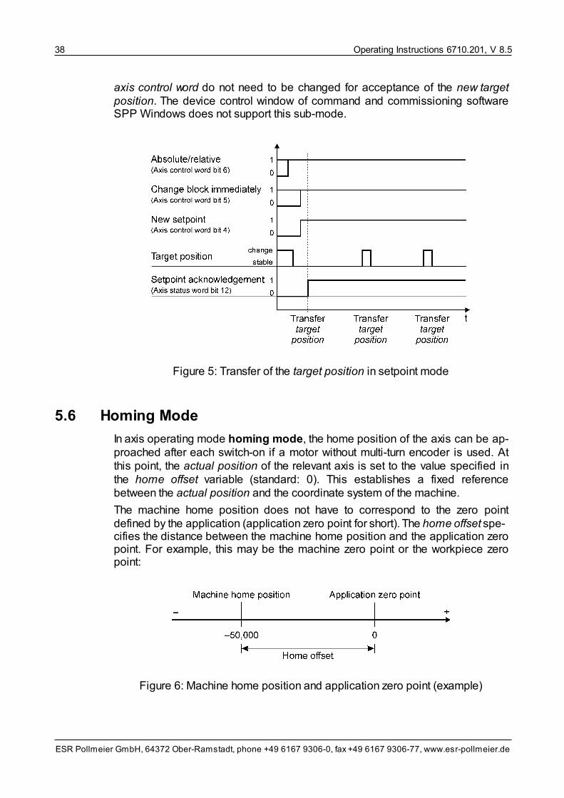
Operating Instructions 6710.201, V 8.538
ESR Pollmeier GmbH, 64372 Ober-Ramstadt, phone +49 6167 9306-0, fax +49 6167 9306-77, www.esr-pollmeier.de
axis control word do not need to be changed for acceptance of the new targetposition. The device control window of command and commissioning softwareSPP Windows does not support this sub-mode.
Figure 5: Transfer of the target position in setpoint mode
5.6 Homing Mode
In axis operating mode homing mode, the home position of the axis can be ap-proached after each switch-on if a motor without multi-turn encoder is used. Atthis point, the actual position of the relevant axis is set to the value specified inthe home offset variable (standard: 0). This establishes a fixed referencebetween the actual position and the coordinate system of the machine.
The machine home position does not have to correspond to the zero pointdefined by the application (application zero point for short). The home offset spe-cifies the distance between the machine home position and the application zeropoint. For example, this may be the machine zero point or the workpiece zeropoint:
Figure 6: Machine home position and application zero point (example)

Operating Instructions 6710.201, V 8.5 39
ESR Pollmeier GmbH, 64372 Ober-Ramstadt, phone +49 6167 9306-0, fax +49 6167 9306-77, www.esr-pollmeier.de
If the machine home position is -50,000 (in position units related to the applica-tion zero point), as shown in the figure above, -50,000 must be entered for thehome offset variable. If machine home position and application zero point arelocated at the same point, 0 is to be entered in home offset.
Because the application zero point can be shifted by the home offset, this is alsoreferred to as a zero offset.
If the homing switch is exactly on the index pulse to be approached or the nextreference signal of the motor position sensor or if the rotor position at the point ofthe machine home switch has a counter increment (+180 degrees to –180 de-grees), different homings can lead to different results. In this case, it is recom-mended to shift the homing switch.
The homing selection code parameter is used to specify how the machine homeposition is approached (from a positive or negative direction) and how the “pre-pulse” and “limit switch” inputs are evaluated. The tables in the following sectionshow the homing selection codes available and the corresponding processes.
The velocity of the homing mode is set via the homing velocity parameter, thevalue is multiplied by the override factor. Condition for the start of the motion isthat the drive is “Ready”.
In homing mode, bit 4 in the axis control word has the following special mean-ing:
• start homing mode (bit 4 in the axis control word)
Setting the bit “start homing mode” to 1 initiates the homing mode. Resetting thebit to 0 immediately stops homing, i. e. as a rule, this bit must not be reset untilthe machine home position has been reached.
In SPP Windows, you can start the homing mode by selecting axis operatingmode homing mode, changing to “operation enabled” and operating button“start homing”.
In homing mode, bits 12, and 13 in the axis status word have the following spe-cial meaning:
• home position reached (bit 12 in the axis status word)
• homing fault (bit 13 in the axis status word)
If bit “home position reached” is set, this indicates that the machine home posi-tion has been reached and that the actual position has been set to the value spe-cified in home offset. The axis is near the reference signal, the exact position de-pends on homing velocity and ramps.
If bit “homing fault” has value 1, this indicates that a fault has occurred while go-ing to home position. This means that the conditions for the sequence selectedvia the homing selection code have not been fulfilled.
In operating mode homing mode, the motions are influenced by the followingparameters:
• Ramps machine data (section Ramps Machine Data ) with motion profiletype, acceleration time, deceleration time, quick stop time, and ramps refer-ence velocity
164

Operating Instructions 6710.201, V 8.540
ESR Pollmeier GmbH, 64372 Ober-Ramstadt, phone +49 6167 9306-0, fax +49 6167 9306-77, www.esr-pollmeier.de
– determine how to reach the velocity and how to decelerate again.
In this operating mode, setpoint generator and speed controller work together,the current controller is subordinate to the speed controller.
To find out whether or not a certain variable is valid in axis operating mode hom-ing mode, see the corresponding information of the individual variable descrip-tions in line “Valid: ...”.
5.6.1 Homing Mode Sequences
If a motor position sensor in multi-turn design is used, going to home position isnot required because the position is read from the encoder after each switch-onof the control supply voltage.
In all other cases, a homing must be carried out before the drive can be used forabsolute positioning. While going to home position, the axis usually approachesa switch at homing velocity.
The homing selection code is used to define if this switch is a limit switch(opener) or a pre-pulse switch (closer) at input “pre-pulse”, in which direction go-ing to home position is started (start direction), and in which direction the finalposition is approached (approach direction). Going to home position is startedwith bit “start homing mode” in the axis control word.
After the machine home switch has been reached, the axis is braked andstopped. It comes to a standstill near, but not exactly on the machine homeswitch. To approach the application zero after homing, a positioning commandmust be appended.
• Selection codes 1 and 2 as well as 17 and 18: approach limit switch
Homingselection
codeSignal used as switch
Indexpulse
used*
Startdirec-tion
Approach di-rection of fi-nal position
1 Input “limit switch –“ the onewithin the
travel range
– +
2 Input “limit switch +“ + –
17 Input “limit switch –“none
– +
18 Input “limit switch +“ + –
* Index pulse (if available) of the motor position sensor used; for absolute encoders final positionof homing
A limit switch is approached in positive or negative direction. There, the drivesystem reverses and leaves the limit switch, again.
With a motor with absolute encoder (resolver, Sincos (Hiperface) encoder, orEnDat encoder), the axis is stopped and the actual position of the axis is set to

Operating Instructions 6710.201, V 8.5 41
ESR Pollmeier GmbH, 64372 Ober-Ramstadt, phone +49 6167 9306-0, fax +49 6167 9306-77, www.esr-pollmeier.de
the absolute position of the encoder under consideration of the home offset. Todetermine the exact position of a motor with incremental encoder, with selectioncodes 1 and 2 the next index pulse or the next reference signal of the motor posi-tion sensor is approached and the actual position value is set to the home offset.With selection codes 17 and 18, the reference point at the switch edge is de-termined with a time inaccuracy of 1 ms, to minimize the error, the homing velo-city should be low.
• Selection codes 3 to 6 as well as 19 to 22: approach pre-pulse switch(partly closed, partly opened)
Homingselection
codeSignal used as switch
Indexpulse
used*
Startdirec-tion
Approach di-rection of fi-nal position
3
Input“pre-pulse”
pre-pulseswitch
zero pulses*
1 depen-
ding onthe posi-tion of the
axis
–
4 2 +
5pre-pulse switch
zero pulses*
2depen-
ding onthe posi-tion of the
axis
+
6 1 –
19
Input“pre-pulse”
pre-pulse switch
none
depen-
ding onthe posi-tion of the
axis
–
20 +
21pre-pulse switch
depen-
ding onthe posi-tion of the
axis
+
22 –
* Index pulse (if available) of the motor position sensor used; for absolute encoders final positionof homing
A pre-pulse switch is approached in positive or negative direction. The pre-pulseswitch is closed on one part of the way, on the other part, it is opened so that thestart direction can be derived from the position of the axis. If required, the drivesystem reverses at the pre-pulse switch in order to reach the desired final posi-tion, the index pulse, or the reference signal in front of or behind the switchingedge.
With a drive system with absolute encoder (resolver, Sincos (Hiperface) en-coder, or EnDat encoder), the axis is stopped and the actual position of the axisis set to the absolute position of the encoder under consideration of the home

Operating Instructions 6710.201, V 8.542
ESR Pollmeier GmbH, 64372 Ober-Ramstadt, phone +49 6167 9306-0, fax +49 6167 9306-77, www.esr-pollmeier.de
offset. To determine the exact position of a drive system with incremental en-coder, with selection codes 3 to 6 the next index pulse or the next reference sig-nal of the motor position sensor used (if available) is approached and the actualposition value is set to the home offset. With selection codes 19 to 22, the refer-ence point at the switch edge is determined with a time inaccuracy of 1 ms, tominimize the error, the homing velocity should be low.
• Selection codes 7 to 14 as well as 23 to 30: approach pre-pulse switch(closed on one part of the way, only)
Homingselection
codeSignal used as switch
Indexpulseused*
Start direc-tion
Approach di-rection of fi-nal position
7
input“pre-pulse”
pre-pulseswitch
index pulses*
1
+**
–
8 2 +
10 4 +
11 Between index pulses 2 and 3, furtherindex pulses may occur. These are notconsidered.
4
–**
+
12 3 –
14 1 –
23
input“pre-pulse”
pre-pulseswitch
keiner
+**
–
24 +
26 +
27
–**
+
28 –
30 –
* Index pulse (if available) of the motor position sensor used; for absolute encoders final positionof homing** If the pre-pulse input is active during the start of homing, the drive system will start into theother direction, if required.
A pre-pulse switch is approached in positive or negative direction. The pre-pulseswitch is closed on a part of the way, otherwise, it is opened. The limit switches are used as reversing switches if the sequence requires that.
If required, the drive system reverses at the pre-pulse switch in order to reach thedesired final position, the index pulse, or the reference signal in front of or behindthe switching edge. With a drive system with absolute encoder (resolver, Sincos(Hiperface) encoder, or EnDat encoder), the axis is stopped and the actual posi-tion of the axis is set to the absolute position of the encoder under considerationof the home offset. To determine the exact position of a drive system with incre-mental encoder, with selection codes 7 to 14 the next index pulse or the next ref-erence signal of the motor position sensor used (if available) is approached.There, the actual position value is set to the home offset. With selection codes 23

Operating Instructions 6710.201, V 8.5 43
ESR Pollmeier GmbH, 64372 Ober-Ramstadt, phone +49 6167 9306-0, fax +49 6167 9306-77, www.esr-pollmeier.de
to 30, the reference point at the switch edge is determined with a time inaccur-acy of 1 ms, to minimize the error, the homing velocity should be low.
Homing speeds and brake ramps must be selected in a way that the axis comesto a standstill within the pre-pulse edges. Otherwise, the drive may not reverseand take the wrong index pulse or the wrong pre-pulse edge as reference.
• Selection codes –1 and –2 as well as 33 and 34: accept absolute posi-tion (within one revolution) or evaluate the first index pulse in start dir-ection
Homing
selection
codeSignal used as switch
Index
pulse
used*
Start
direc-
tion
Approachdirection of
final position
–1
nonethe first one
in start
direction
+ +
–2 – –
33 + +
34 – –
* Index pulse (if available) of the position sensor used
With these selection codes, the axis does not approach a pre-pulse or limitswitch. With a drive system with absolute encoder (resolver, Sincos (Hiperface)encoder, or EnDat encoder), the actual position of the axis is set to the absoluteposition of the encoder under consideration of the home offset, i. e. the axis isnot moved. With a drive system with incremental encoder, the first index pulse instart direction is evaluated and there, the actual position is set to the home offset.
• Selection codes –3 and –4: evaluate the first positive pre-pulse edge instart direction
Homing
selection
code
Signal used as switch
Index
pulse
used*
Start
direc-
tion
Approach di-
rection of thefinal position
–3 Input “pre-pulse”none
+ +
–4 Input “pre-pulse” – –
With these selection codes, the first positive pre-pulse edge in start direction isevaluated. At the pre-pulse switch, the drive system does not reverse, the axis issimply stopped. Index pulses are not considered, the machine home position isdetermined with a time inaccuracy of 1 ms. For minimizing the fault, a low hom-ing velocity should be selected.
• Selection codes –5 and –6: approach limit switch

Operating Instructions 6710.201, V 8.544
ESR Pollmeier GmbH, 64372 Ober-Ramstadt, phone +49 6167 9306-0, fax +49 6167 9306-77, www.esr-pollmeier.de
Homingselection
codeSignal used as switch
Indexpulseused
Start direc-tion
Approach di-rection of thefinal position
–5 Input “limit switch –“none
– –
–6 Input “limit switch +“ + +
A limit switch is approached in positive or negative direction. There, the drivesystem reverses and leaves the limit switch. After that, the axis is stopped. Indexpulses are not considered, the machine home position is determined with a timeinaccuracy of 1 ms. For minimizing the fault, a low homing velocity should be se-lected.
5.7 Electronic Gearing
In axis operating mode electronic gearing, the axis follows an externally set po-sition. The position is set via an external position sensor (input encoder signals).This is only true for servo drive systems equipped with an encoder signal input.
In axis operating mode electronic gearing, position and velocity of the axis fol-low the settings of this interface which is called master axis. The axis which is inaxis operating mode electronic gearing is called the slave axis (or gear axis).
The master axis can be a different servo drive system or just a position measur-ing system (position sensor), moved either by a drive system in the machine ormanually.
During the change from another axis operating mode into the electronic gear-ing operating mode, input “synchronize” or the control bit of the same name inthe axis control word are used to align the coordinate systems of master andslave axis. As soon as the drive is “ready”, the slave axis moves according to thesettings of the master axis.
• With TrioDrive D/xS, MidiDrive D/xS, TrioDrive D, and MidiDrive D, the posi-tion information is determined from the external position sensor directly aftersynchronization. This achieves an exact incremental synchronization.
• With MaxiDrive, the position information of the master axis is processed viathe software, in this case, processing times of up to 1 ms may occur. Insteadof using input “synchronize”, an exact incremental synchronization can also beinitiated via input “index pulse +/–“ (index pulse input of the incremental en-coder module, option L1/L2).
The acceleration of the slave axis takes into account the ramp time of the elec-tronic gearing, the lead of the master axis is made up for by increasing the velo-city.
In axis operating mode electronic gearing, bit 4 of the axis control word has thefollowing meaning:

Operating Instructions 6710.201, V 8.5 45
ESR Pollmeier GmbH, 64372 Ober-Ramstadt, phone +49 6167 9306-0, fax +49 6167 9306-77, www.esr-pollmeier.de
• synchronize (bit 4 in the axis control word).
This bit synchronizes the actual position of master and slave axis: during trans-ition from 0 to 1 for this bit, the position deviation of the slave axis is set to 0. Theslave axis then follows all subsequent position changes of the master axis, takinginto account the gear ratio of the electronic gearing.
In axis operating mode electronic gearing, bits 10 and 12 in the axis statusword have the following special meaning:
• synchronized (bit 10 in the axis status word)
• velocity = 0 (bit 12 in the axis status word)
With value 1, bit “synchronized” indicates that the drive of the slave axis hasreached the position specified by the master axis. For that, the positioning win-dow and positioning window time parameters are taken into account. This mes-sage can also be output on a digital output, see signal selection digital output ...in section Input/Output Function Machine Data .
• If a synchronized state is not or rarely reached, check the following:
– Is the positioning window large enough?
– Is the resolution of the external position sensor set correctly? (Positionsensor resolution)
– Is speed feedforward switched on? (speed control loop Kv electronic gear-ing = 1)
– Can the slave axis reach the necessary speed at all?
If bit “velocity = 0” is set, this shows that, after deceleration, the drive system hasreached velocity zero, for that, the velocity threshold and velocity threshold timeparameters are taken into account.
In axis operating mode electronic gearing, the following machine data are ef-fective for the slave axis:
• Electronic gearing machine data (section Electronic Gearing Machine Data) with external position sensor resolution, gear ratio, speed control loop
Kv electronic gearing, ramp time
– determine the position sensor resolution of the master axis, the gear ratiobetween the master and the slave axis, the force of the velocity feedforward(to compensate for any remaining control offset), and the slope during thesynchronization process.
• Position control loop machine data (section Position Control Loop MachineData ) with position control loop Kp
– determine the controller behavior (gain).
• Speed control loop machine data (section Speed Control Loop Machine Data) with speed filter cut-off frequency, speed control loop Kp, speed control
loop Ki, speed control loop total amplification
– determine the controller action: smoothing of the actual speed, gain, andoptional I component (to compensate for any remaining control offset).
131
176
171
167

Operating Instructions 6710.201, V 8.546
ESR Pollmeier GmbH, 64372 Ober-Ramstadt, phone +49 6167 9306-0, fax +49 6167 9306-77, www.esr-pollmeier.de
In axis operating mode electronic gearing, setpoint generator and position con-troller work together, the speed and current controllers are subordinate to the po-sition controller.
To find out whether or not a certain variable is valid in axis operating mode elec-tronic gearing, see the corresponding information of the individual variable de-scriptions in line “Valid: ...”.
5.8 Flying Shear
Axis operating mode flying shear is a special kind of axis synchronization(based on operating mode electronic gearing). It is used when a continuousmaterial flow, which is primarily transported by a master axis at a constant velo-city, is to be processed during movement (sawn, cut, printed etc.). For this pur-pose, during a specific phase in the overall operation, the slave axis runs syn-chronously with the master axis before returning to its starting position.
The positions at which the material is processed are called synchronizing points.The first synchronizing point is set when the flying shear mode is started. All othersynchronizing points are a cutting length distance apart.
The position of the master axis is set via an external position sensor (input en-coder signals). This is only true for servo drives equipped with an encoder signalinput.
Figure 7: Flying Shear, Velocity Time Diagram
The flying shear is started via input “enable saw”. Synchronization begins auto-matically at the event “synchronizing point reached” (time a in figure 7). The ac-celeration of the slave axis takes into account the ramp time of the electronicgearing, the lead of the master axis is made up for by increasing the velocity (b).As soon as the slave axis is synchronized with the master axis, signal “synchron-ized / apply saw” is generated (c). This message can also be output on a digitaloutput, see signal selection digital output ... in section Input/Output FunctionMachine Data . The material can now be processed. 131

Operating Instructions 6710.201, V 8.5 47
ESR Pollmeier GmbH, 64372 Ober-Ramstadt, phone +49 6167 9306-0, fax +49 6167 9306-77, www.esr-pollmeier.de
The return positioning of the flying shear is initiated (d) via input “start runningback”. The velocity is initially reduced to zero (e) via the deceleration ramp andthen accelerated to the return velocity through the usual acceleration ramp. Theflying shear is braked (f) at the starting position via the deceleration ramp andrestarted from there when the next synchronizing point is reached (= old syn-chronizing point + cutting length).
Alternatively, each synchronization can be started via input “flying shear externalsynchronization”, e. g. for material with different length or distance. Prerequisitefor that is the enabling of the external synchronization via the corresponding in-put.
The return velocity is specified via the target velocity (digital) parameter or the“setpoint” analog input, depending on the setting in the machine data target velo-city source.
Changing the cutting length is not possible during operation.
In axis operating mode flying shear, the axis control word does not contain anyoperating mode-dependent bits.
In axis operating mode flying shear, bit 10 in the axis status word has the follow-ing special meaning:
• position setpoint reached (bit 10 in the axis status word).
With value 1, this bit indicates that the axis has completed the return positioning.For that, the positioning window and positioning window time parameters aretaken into account. This message can also be output on a digital output, see sig-nal selection digital output ... in section Input/Output Function Machine Data .
In axis operating mode flying shear, the following parameters are effective forthe slave axis:
• Flying shear machine data (section Flying Shear Machine Data ) with cuttinglength, master velocity threshold
– determine the distance between two synchronizing points (in PU) and theminimum velocity of the master axis.
• Electronic gearing machine data (section Electronic Gearing Machine Data )with external position sensor resolution, gear ratio, speed control loop Kv,electronic gearing, ramp time
– determine the position sensor resolution of the master axis, the gear ratiobetween the master and the slave axis, the force of the velocity feedforward(to compensate for any remaining control offset), and the slope during thesynchronization process.
• Position control loop machine data (section Position Control Loop MachineData ) with position control loop Kp
– determine the controller action (gain).
• Speed control loop machine data (section Speed Control Loop Machine Data) with speed filter cut-off frequency, speed control loop Kp, speed control
loop Ki, speed control loop total amplification
131
180
176
171
167

Operating Instructions 6710.201, V 8.548
ESR Pollmeier GmbH, 64372 Ober-Ramstadt, phone +49 6167 9306-0, fax +49 6167 9306-77, www.esr-pollmeier.de
– determine the controller action: smoothing of the actual speed, gain, and op-tional I component (to compensate for any remaining control offset).
• Target velocity (section Parameters and Actual Values Velocity Mode )
– determines the return velocity (if selected via the target velocity source).
• Ramps machine data (section Ramps Machine Data ) with motion profiletype, acceleration time, deceleration time, quick stop time, and ramps refer-ence velocity
– determine how to reach the return velocity and decelerate again at the start-ing position.
In axis operating mode flying shear, setpoint generator and position controllerwork together, the speed and current controllers are subordinate to the positioncontroller.
To find out whether or not a certain variable is valid in axis operating mode elec-tronic gearing, see the corresponding information of the individual variable de-scriptions in line “Valid: ...”.
5.9 Velocity Profile
With axis operating mode velocity profile, a defined velocity time sequence canbe run. For each section of the profile, the acceleration or deceleration time aswell as the time with constant velocity is stated in milliseconds.
This axis operating mode can only be called up in program mode via the partprogram. For further information see operating instructions 6710.231 “Part Pro-gram”.
In axis operating mode velocity profile, axis control word and axis status worddo not contain any operating mode-dependent bits.
5.10 Timed Positioning Mode
With axis operating mode timed positioning mode, relative target positionscan be approached in specified times (point-to-point positioning). For the move-ment, a variety of curve forms in accordance with VDI manual Technology ofMechanism Design I: Transmission with Varying Velocity Ratio (VDI 2143, Blatt1, Kapitel 6.1.1 “Normierte symmetrische Bewegungsgesetze für Rast-in-Rast(R-R))“ is available.
The relative target position is defined via parameter position distance singlemovement, the duration of the movement via position time single movement.The target velocity is not specified, it results for a certain distance and a definedpositioning time from the curve form by which the driving behavior is specifiedindividually for each positioning:
87
164

Operating Instructions 6710.201, V 8.5 49
ESR Pollmeier GmbH, 64372 Ober-Ramstadt, phone +49 6167 9306-0, fax +49 6167 9306-77, www.esr-pollmeier.de
Curve form Advantages Disadvantages Cv
Ca
Cj
CM dy
n
–1: Linear (VDI 2143:“square parabola”)
lowest Ca value, i. e.
lowest inertia forces
not jerk-free (3 jerks), asa result e. g. vibrations,noises, wear and tear
2 4 ∞ 8
–2: Modified accelera-tion trapezoid
particularly low Ca
value, low inertiaforces
high Cj and C
M dyn values 2 4.89 61.4 8.09
–3: Modified sine particularly low Cv
and CM dyn
value, low
Ca value, suitable for
high velocities
high Cj value 1.76 5.53 69.5 5.4
–4: Inclined sine particularly low Cj
value, low-vibration,suitable for high velo-cities
high CM dyn
value 2 6.28 39.5 8.16
–5: 5th-grade polyno-mial
low Cv, C
a, and
CM dyn
value, suitable
for high velocities
high Cj value 1.88 5.78 60 6.69
The dynamic velocity characteristic value Cv (maximum value of the standardized
velocity) is a measure for the maximum velocity reached during positioning. Fora positioning at low velocity, a low C
v value must be reached.
The dynamic acceleration characteristic value Ca (maximum value of the stand-
ardized acceleration) describes the maximum acceleration, that means the de-sired torque or force. A higher value can mean that a more powerful motor is re-quired. (Example: a C
a value of 5.78 results in a torque or force requirement
44.5% higher than for a linear curve form with Ca = 4.)
The dynamic jerk characteristic value Cj (maximum value of the standardized jerk
function) reflects acceleration changes. Higher values can lead to vibrations,noises, and wear and tear.
The drive torque or drive force due to dynamic inertia forces depends on the dy-namic torque characteristic value C
M dyn (maximum value of the product of velo-
city(z) × acceleration(z)). The lowest possible value is desirable with regard tolow drive system costs.
The positioning is started with digital input “start positioning”, output “in position”reports the terminated positioning.
The operation can be configured as desired using the positioning mode func-tions at the digital inputs:

Operating Instructions 6710.201, V 8.550
ESR Pollmeier GmbH, 64372 Ober-Ramstadt, phone +49 6167 9306-0, fax +49 6167 9306-77, www.esr-pollmeier.de
• Positioning mode bit 0: positioning direction
0: clockwise / forward1: counterclockwise / backward
• Positioning mode bit 1:
0: single movement1: back and forth movement (total duration = 2 × positioning time)
• Positioning mode bit 2 (reserved)
• Positioning mode bit 3:
0: single step1: continuous movement (the movement will be stopped after input “start po-sitioning” has been set to 0 and the target position has been reached)
The functions and signals can be mapped on physical or logical inputs and out-puts.
During timed positioning mode, the motion sequence is influenced by the fol-lowing parameters:
• Position distance single movement, position time single movement, and curveform
– define the positioning sequence, a change of these values does not haveany effect on a running positioning
• Position control loop machine data with position control loop Kp
– define the drive behavior (amplification)
In operating mode timed positioning mode, setpoint generator and positioncontroller work together, speed and current controller are subordinate to the posi-tion controller. From firmware version V 8.5.9 on, the feedforward velocity can beinfluenced or switched off using the feedforward velocity factor.
Prerequisite for a trouble-free functioning of the timed positioning mode is thecorrect setting of the speed control loop.
5.11 Cyclic Synchronous Torque/Force Mode
Axis operating mode cyclic synchronous torque mode (according toCiA® 402; corresponds to a force mode for the linear motor) serves for operat-ing one or several axes at a higher-lever controller sending torque or force set-points to the drive at defined intervals. The control of velocity and position, if ap-plicable, takes place in the higher-level controller.
In cyclic synchronous torque mode, the PDOs are transmitted cyclically, withCANopen® synchronously to a SYNC message. In case of a fault or a break-down of the SYNC transmission, the drive keeps the latest setpoint until it re-ceives new data or a new SYNC message.
In cyclic synchronous torque mode, bit 12 in the axis status word has the fol-lowing special meaning:
• Setpoints are accepted

Operating Instructions 6710.201, V 8.5 51
ESR Pollmeier GmbH, 64372 Ober-Ramstadt, phone +49 6167 9306-0, fax +49 6167 9306-77, www.esr-pollmeier.de
With value 1, this bit indicates that the drive accepts the specified setpoints.(The axis state machine must be in state “operation enabled” so that the set-points can lead to a movement.)
In cyclic synchronous torque mode, the axis control word does not containany operating mode-dependent bits.
In operating mode cyclic synchronous torque mode, the fieldbus communica-tion is influenced by the following parameters:
• The mapping PDOs (PDO Mapping)
– serve for the transmission of axis status word and axis control word as wellas the setpoints (torque or force setpoint as well as feedforward accelera-tion) and actual velocity and position values.
• The machine data PDOs (Comm. Parameter, CANopen® only)
– control the synchronous transmission of above-mentioned PDOs (value nof transmission type = 1).
For variable PDO mapping, the objects
• Axis control word (index 6040)
• Torque setpoint / force setpoint (index 6071)
must be mapped in an RPDO. Object
• Torque offset / force offset (index 60B2)
can be mapped in an RPDO for feedforward torque or force. Objects
• Axis status word (index 6041)
• Actual velocity (index 606C)
• Position sensor actual position (index 6063)
can be mapped in a TPDO.
In axis operating mode cyclic synchronous torque mode, only the currentcontrol loop is active, see the following diagram.

Operating Instructions 6710.201, V 8.552
ESR Pollmeier GmbH, 64372 Ober-Ramstadt, phone +49 6167 9306-0, fax +49 6167 9306-77, www.esr-pollmeier.de
Figure 8: Cyclic synchronous torque mode with all cyclic-synchronously transmit-ted objects (simplified block diagram)
In axis operating mode cyclic synchronous torque mode, the servo drivescan be operated with controllers of various manufacturers. If required, pleasecontact ESR.
5.12 Cyclic Synchronous Velocity Mode
Axis operating mode cyclic synchronous velocity mode (according toIEC 61800-7-2) serves for operating one or several axes at a higher-level control-ler sending velocity setpoints to the drive at defined time intervals. The positioncontrol takes place in the higher-level controller.
In cyclic synchronous velocity mode, the PDOs are transmitted cyclically,with CANopen® synchronously to a SYNC message. In case of a fault or abreakdown of the SYNC transmission, the drive keeps the latest setpoint until itreceives new data or a new SYNC message.
In cyclic synchronous velocity mode, bit 12 in the axis status word has the fol-lowing special meaning:
• Setpoints are accepted
With value 1, this bit indicates that the drive accepts the specified setpoints.(The axis state machine must be in state “operation enabled” so that the set-points can lead to a movement.)
In cyclic synchronous velocity mode, the axis control word does not containany operating mode-dependent bits.
In operating mode cyclic synchronous velocity mode, the fieldbus commu-nication is influenced by the following parameters:

Operating Instructions 6710.201, V 8.5 53
ESR Pollmeier GmbH, 64372 Ober-Ramstadt, phone +49 6167 9306-0, fax +49 6167 9306-77, www.esr-pollmeier.de
• The mapping PDOs (PDO Mapping)
– serve for the transmission of axis status word and axis control word as wellas the setpoints (velocity setpoint, feedforward velocity and acceleration)and actual velocity and position values.
• The machine data PDOs (Comm. Parameter, CANopen® only)
– control the synchronous transmission of above-mentioned PDOs (value nof transmission type = 1).
For variable PDO mapping, the objects
• Axis control word (index 6040)
• Velocity setpoint (index 60FF)
must be mapped in an RPDO. Objects
• Velocity offset (index 60B1)
• Torque offset / force offset (index 60B2)
can be mapped in an RPDO for feedforward torque or force or feedforward velo-city. Objects
• Axis status word (index 6041)
• Actual velocity (index 606C)
• Position sensor actual position (index 6063)
can be mapped in a TPDO. Feedforward velocity can be influenced or switchedoff with the feedforward velocity factor.
In axis operating mode cyclic synchronous velocity mode, current controlloop and speed control loop are active, the current control loop is subordinate tothe speed control loop. See the following diagram.

Operating Instructions 6710.201, V 8.554
ESR Pollmeier GmbH, 64372 Ober-Ramstadt, phone +49 6167 9306-0, fax +49 6167 9306-77, www.esr-pollmeier.de
Figure 9: Cyclic synchronous velocity mode with all cyclic-synchronously transmit-ted objects (simplified block diagram)
In axis operating mode cyclic synchronous velocity mode, the servo drivescan be operated with controllers of various manufacturers. If required, pleasecontact ESR.
5.13 Cyclic Synchronous Position Mode
Axis operating mode cyclic synchronous position mode serves for operatingone or several axes for which a time interpolation of the position setpoints is re-quired (e. g. for contouring control). For that, the higher-level controller sends tar-get positions to the drive at defined intervals via an RPDO. In addition to thesepositions, the fine interpolator of the drive calculates further target positions atthe time interval of the position control loop (1 ms). In cyclic synchronous pos-ition mode, the target positions are given in position sensor steps (PSS), only,not in position units (pU).
In cyclic synchronous position mode, the PDOs are transmitted cyclically,with CANopen® synchronously to a SYNC message. In case of a failure or abreakdown of the SYNC transmission, the drive keeps the last target position un-til it receives new data or a new SYNC message
In cyclic synchronous position mode, bit 12 in the axis status word has thefollowing special meaning:
• Setpoints are accepted
With value 1, this bit indicates that the drive accepts the specified setpoints.(The axis state machine must be in state “operation enabled” so that the set-points can lead to a movement.)
The axis operating mode can only be changed when the state of the axis state
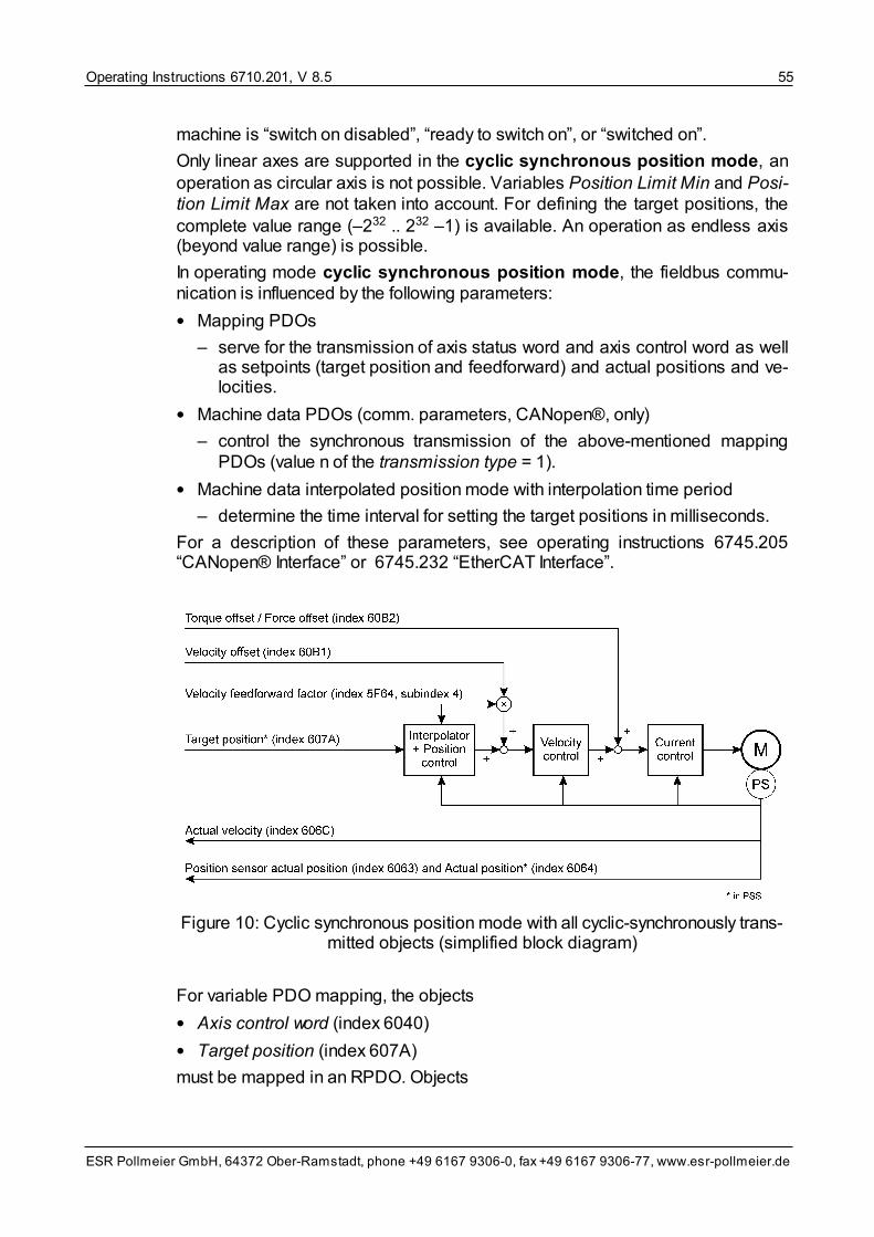
Operating Instructions 6710.201, V 8.5 55
ESR Pollmeier GmbH, 64372 Ober-Ramstadt, phone +49 6167 9306-0, fax +49 6167 9306-77, www.esr-pollmeier.de
machine is “switch on disabled”, “ready to switch on”, or “switched on”.
Only linear axes are supported in the cyclic synchronous position mode, anoperation as circular axis is not possible. Variables Position Limit Min and Posi-tion Limit Max are not taken into account. For defining the target positions, thecomplete value range (–232 .. 232 –1) is available. An operation as endless axis(beyond value range) is possible.
In operating mode cyclic synchronous position mode, the fieldbus commu-nication is influenced by the following parameters:
• Mapping PDOs
– serve for the transmission of axis status word and axis control word as wellas setpoints (target position and feedforward) and actual positions and ve-locities.
• Machine data PDOs (comm. parameters, CANopen®, only)
– control the synchronous transmission of the above-mentioned mappingPDOs (value n of the transmission type = 1).
• Machine data interpolated position mode with interpolation time period
– determine the time interval for setting the target positions in milliseconds.
For a description of these parameters, see operating instructions 6745.205“CANopen® Interface” or 6745.232 “EtherCAT Interface”.
Figure 10: Cyclic synchronous position mode with all cyclic-synchronously trans-mitted objects (simplified block diagram)
For variable PDO mapping, the objects
• Axis control word (index 6040)
• Target position (index 607A)
must be mapped in an RPDO. Objects

Operating Instructions 6710.201, V 8.556
ESR Pollmeier GmbH, 64372 Ober-Ramstadt, phone +49 6167 9306-0, fax +49 6167 9306-77, www.esr-pollmeier.de
• Torque offset / force offset (index 60B2)
• Velocity offset (index 60B1)
can be mapped in an RPDO for feedforward torque or force or feedforward velo-city. Objects
• Axis status word (index 6041)
• Position sensor actual position (index 6063)
• Actual velocity (index 606C)
can be mapped in a TPDO. If the velocity offset is not received via RPDO, the in-terpolation calculates the feedforward velocity from the target position of vari-able target position. Feedforward velocity can be influenced or switched off withthe feedforward velocity factor.
In axis operating mode cyclic synchronous position mode, the fine interpol-ator as setpoint generator acts together with the position control, speed and cur-rent control are subordinate to the position control.
In axis operating mode cyclic synchronous position mode, the servo drivescan be operated with controllers of various manufacturers. If required, pleasecontact ESR.
5.13.1 Activating Cyclic Synchronous Position Mode
As a prerequisite for controlling the axis state machine, the corresponding PDOsmust be activated.
1. If not set via machine date axis operating mode at startup, select axis operat-ing mode cyclic synchronous position mode.
2. By enabling the PDO communication by the master, the state machine of theNMT services or the ESM state machine is switched to “operational”.
3. For the initialization of the cyclic synchronous position mode, read out thecurrent actual position and write it into variable target position.
4. Switch the axis state machine to “operation enabled”.
5.13.2 Deactivating Cyclic Synchronous Position Mode
For deactivating the cyclic synchronous position mode, the axis state ma-chine has to be switched to state “switch on disabled”, “ready to switch on”, or“switched on”. With CANopen®, if required, switch the NMT state machine to“pre-operational”.
After that, the axis operating mode can be changed.
5.14 Interpolated Position Mode
Axis operating mode interpolated position mode serves for operating one orseveral axes for which a time interpolation of the position setpoints is required(e. g. for contouring control). For that, the higher-level controller sends target pos-

Operating Instructions 6710.201, V 8.5 57
ESR Pollmeier GmbH, 64372 Ober-Ramstadt, phone +49 6167 9306-0, fax +49 6167 9306-77, www.esr-pollmeier.de
itions to the drive at defined intervals via an RPDO. In addition to these positions,the fine interpolator of the drive calculates further target positions at the time in-terval of the position control loop (1 ms). In interpolated position mode, targetpositions are transmitted in position sensor steps (PSS), only, not in length units(LU).
In interpolated position mode, the PDOs are transmitted cyclically, withCANopen® synchronously to a SYNC message. In case of a failure or a break-down of the SYNC transmission, the drive keeps the last target position until it re-ceives new data or a new SYNC message
For devices with firmware versions lower than V 8.5.9, monitoring of hardwarelimit switches and function “measure position” are not active in operating modeinterpolated position mode.
For devices with firmware versions lower than V 8.5.9, operating mode-relatedbits do not exist for the interpolated position mode in the axis status word.From firmware version V 8.5.9 on, bit 12 in the axis status word has the followingspecial meaning in interpolated position mode:
• Setpoints are accepted
With value 1, this bit indicates that the drive accepts the specified setpoints.(The axis state machine must be in state “operation enabled” and the interpol-ation must be enabled via bit 4 in the axis control word so that the setpointscan lead to a movement.)
In the axis control word, bit 4 has the following special meaning:
• Enable interpolation
The interpolation is started by setting bit “enable interpolation”.
The axis operating mode can only be changed when the state of the axis statemachine is “switch on disabled”, “ready to switch on”, or “switched on”.
Only linear axes are supported in the interpolated position mode, an operationas circular axis is not possible. From firmware version V 8.5.9 on, variables posi-tion limit min and position limit max are not taken into account. In this case, fordefining the target positions, the complete value range (–232 .. 232 –1) is avail-able. An operation as endless axis (beyond value range) is possible.
In operating mode interpolated position mode, the fieldbus communication isinfluenced by the following parameters:
• Mapping PDOs
– serve for the transmission of axis status word and axis control word as wellas target positions (in interpolation data record) and actual positions.
• Machine data PDOs (comm. parameters, CANopen®, only)
– control the synchronous transmission of the above-mentioned mappingPDOs (value n of the transmission type = 1).
• Machine data interpolated position mode with interpolation time period
– determine the time interval for setting the target positions in milliseconds.

Operating Instructions 6710.201, V 8.558
ESR Pollmeier GmbH, 64372 Ober-Ramstadt, phone +49 6167 9306-0, fax +49 6167 9306-77, www.esr-pollmeier.de
For a description of these parameters, see operating instructions 6745.205“CANopen® Interface” or 6745.232 “EtherCAT Interface”.
For variable PDO mapping, the objects
• Axis control word (index 6040)
• Target position of the interpolation data record (index 60C1, subindex 1)
must be mapped in an RPDO. Objects
• Torque offset / force offset (index 60B2, in firmware version V 8.5.9 andhigher)
• Velocity offset (index 60B1)
can be mapped in an RPDO for feedforward torque or force or feedforward velo-city. Objects
• Axis status word (index 6041)
• Position sensor actual position (index 6063)
• Actual velocity (index 606C, in firmware version V 8.5.9 and higher updatedsynchronously)
can be mapped in a TPDO. If the velocity offset is not received via RPDO, the in-terpolation calculates the feedforward velocity from the target position of the in-terpolation data record. Feedforward velocity can be influenced or switched offwith the feedforward velocity factor.
In axis operating mode interpolated position mode, the fine interpolator assetpoint generator acts together with the position control, speed and current con-trol are subordinate to the position control. See the following block diagram.
Figure 11: Interpolated position mode with all cyclic-synchronously transmittedobjects (simplified block diagram)
In axis operating mode interpolated position mode, the servo drives can beoperated with controllers of various manufacturers. If required, please contactESR.

Operating Instructions 6710.201, V 8.5 59
ESR Pollmeier GmbH, 64372 Ober-Ramstadt, phone +49 6167 9306-0, fax +49 6167 9306-77, www.esr-pollmeier.de
5.14.1 Activating Interpolated Position Mode
As a prerequisite for controlling the axis state machine, the corresponding PDOsmust be activated.
1. If not set via machine date axis operating mode at startup, select axis operat-ing mode interpolated position mode.
2. By enabling the PDO communication by the master, the state machine of theNMT services or the ESM state machine is switched to “operational”.
3. For the initialization of the interpolated position mode, read out the currentactual position and write it into the interpolation data record.
4. Switch the axis state machine to “operation enabled”.
5. Activate the interpolation via “enable interpolation” (bit 4 in the axis controlword).
5.14.2 Deactivating Interpolated Position Mode
For deactivating the interpolated position mode, the axis state machine has tobe switched to state “switch on disabled”, “ready to switch on”, or “switched on”.With CANopen®, if required, switch the NMT state machine to “pre-operational”.
After that, the axis operating mode can be changed.

Operating Instructions 6710.201, V 8.560
ESR Pollmeier GmbH, 64372 Ober-Ramstadt, phone +49 6167 9306-0, fax +49 6167 9306-77, www.esr-pollmeier.de
6 Device Operating Modes: Command Mode andProgram Mode
With the device control, the way setpoints for the drive system functions are setcan be selected via the device operating mode. There are two device operatingmodes:
• Command mode
Device operating mode command mode permits a direct control of axismovements via single commands by a higher-level controller (PLC, PC).Commands and setpoints can be set via the communication interfaces (serialinterface, field bus) or the terminals (e. g. analog input setpoint for velocity andtorque setting).
In command mode, axis operating mode can be used for selecting whethere. g. velocities or positions are to be preset. The axis operating modes aredescribed in detail in section Axis Operating Modes .
In this case, the axis control word defines the way the drive system reacts onsetpoint changes. For further information on the axis control word, see sec-tion Axis Control Word .
• Program mode (automatic or single step)
With device operating mode program mode, special programs, so-calledpart programs, can be run on the servo drive. These part programs can beused to run motion sequences independent of a higher-level controller. Viaspecial commands or digital inputs/outputs, programs of a higher-level control-ler and part programs can communicate and synchronize their sequences. Forfurther information on the part program, see operating instructions 6710.231“Part Program”.
The device operating mode may only be changed in states “switch on disabled”,“ready to switch on” and “switched on”.
29
20

Operating Instructions 6710.201, V 8.5 61
ESR Pollmeier GmbH, 64372 Ober-Ramstadt, phone +49 6167 9306-0, fax +49 6167 9306-77, www.esr-pollmeier.de
7 Input, Output, Trigger, Measuring, and TraceFunctions
This section summarizes all functions which are not necessarily required for drivesystem movements in normal operation:
The input/output function permits communication with other field devices orcontrollers via inputs/outputs at the front panel and so-called logical inputs/out-puts.
Via the switching points, the digital outputs can be operated depending on theactual position.
Trigger and measuring functions permit e. g. a measurement of the actualposition via a fast input.
The trace function can be used for recording setpoints and actual values aswell as internal data in the drive system for a subsequent read-out and furtherprocessing. These trace functions are used e. g. by the oscilloscope function ofcommand and commissioning software SPP Windows.
7.1 Input/Output Function
7.1.1 Digital Input/Output
The digital input/output function provides access to the I x.x and O x.x inputs andoutputs of the servo drive.
These inputs and outputs can be used freely. They can be queried by a higher-level controller via the part program or the communication interfaces.
The following types of inputs and outputs exist:
• Physical inputs/outputs
These are inputs and outputs visibly located at the corresponding connector ofthe servo drive that can be connected to a signal line. With TrioDrive D/xS,MidiDrive D/xS, TrioDrive D, and MidiDrive D, these inputs are located atconnector X7, with MaxiDrive at connectors X4 and X5.
• Logical inputs/outputs
These are invisible internal inputs and outputs that can be set arbitrarily orevaluated by the controller in case of a communication via field bus.
• Linked inputs and outputs
These are invisible internal inputs and outputs connected with each other. If anoutput is set or deleted, this becomes visible at the correspondingly linked in-put. Linked inputs/outputs are e. g. used as markers in part programs or forcalling up a function automatically via an input using an output signal.

Operating Instructions 6710.201, V 8.562
ESR Pollmeier GmbH, 64372 Ober-Ramstadt, phone +49 6167 9306-0, fax +49 6167 9306-77, www.esr-pollmeier.de
InputTrioDrive D/xS, MidiDrive D/xS, TrioDrive D, MidiDrive D
MaxiDrive For freeuse
Drive-specificassignment
I 1.0 .. I 1.7 physical physical × ×
I 2.0 .. I 2.7 logical physical × –
I 3 logical* logical* × I 3.0**
I 4 logical logical × –
I 9.0 .. I 9.7 logical logical × ×
I 10, I 11*** logical logical × –
I 15 logical logical × ×
I 16 .. I 20 logical logical × –
* I 3.0 = physical = input “enable”** With TrioDrive D/xS and MidiDrive D/xS, inputs I 3.4 to I 3.7 have a drive-specific assign-
ment, too *** Inputs I 10 and I 11 are reserved for querying the axis status word.
OutputTrioDrive D/xS, MidiDrive D/xS, TrioDrive D, MidiDrive D
MaxiDrive For freeuse
Drive-specificassignment
O 1.0 .. O 1.3 physical physical × ×
O 2.0 .. O 2.3 logical physical × –
O 3 logical logical × –
O 4 logical logical × –
O 8.0 .. O 8.7 logical logical × ×
O 9.0 .. O 9.7 logical logical × ×
O 10, O 11* logical logical × –
O 15 logical logical × ×
O 16 .. O 20 logical logical × –
* Outputs O 10 and O 11 are reserved for changing the axis control word.
Via the machine data, the inputs can be configured individually so that a drive-specific assignment is activated (e. g. “limit switch +”). In this case, they have adrive-specific function and cannot be used freely any longer.
The use of digital inputs for stopping the drive system (e. g. as limit switch) doesnot meet the safety requirements of the machinery directive. If an emergency-stop or safety switch-off is required for the machine, the safety requirements ofthe machinery directive must be observed unconditionally.

Operating Instructions 6710.201, V 8.5 63
ESR Pollmeier GmbH, 64372 Ober-Ramstadt, phone +49 6167 9306-0, fax +49 6167 9306-77, www.esr-pollmeier.de
The digital outputs are no relay outputs. For controlling e. g. a brake using an out-put, an external relay is required.
The internal inputs I 15 to I 20 are interconnected with the corresponding internaloutputs O 15 to O 20. These inputs and outputs are used as markers, e. g. in partprograms.
From firmware V 7.5 on, drive system-specific functions can be assigned to theinternal inputs and outputs I 15.x or O 15.x so that another function linked with in-put I 15.x can be called up via output O 15.x.
Example: “trigger status fast position measurement” is to be output at digital out-put O 15.0. Digital input I 15.0 is linked with function “axis stop”. As soon as fastposition measurement has been triggered via the trigger input, output “triggerstatus fast position measurement” is set to 1. This, in turn, triggers function “axisstop”.
For details on the corresponding variables, see section Parameters and ActualValues of the Input/Output Function (Access to Inputs and Outputs) and sec-tion Input/Output Function Machine Data (Configuration of Inputs and Outputsincluding lists of all selectable functions and signals). For the technical specifica-tions of the digital inputs/outputs, please see operating instructions “Connectionand Commissioning” (6755.202, 6745.202, 6750.202, 6740.202, or 6710.202).
7.1.2 Analog Input
Analog inputs are available for devices with -A1 option, only. The analog inputfunction is responsible for the processing of signals from analog input “setpoint”.
Analog input “setpoint” can be used for one of the following tasks:
• Setting the target velocity under consideration of ramps etc. (in axis operatingmodes profile position mode, velocity mode, and flying shear)
• Setting the target velocity direct (in axis operating mode velocity mode dir-ect)
• Setting the torque setpoint (in axis operating mode torque mode)
• Setting the max current amount (in all axis operating modes)
• Further processing in the part program or via a higher-level controller (via vari-able analog inputs)
Via variables ...-analog factor and ... -analog offset, the scaling of the analogvalue and a correction of the zero point can be carried out.
In section Setpoint Sources Machine Data , the variables by which analog in-put “setpoint” is selected in the various axis operating modes as setpoint sourceare summarized.
The voltage applied to this input can also be output at an analog output or recor-ded using the trace function.
For technical specifications of analog input “setpoint”, please refer to operatinginstructions “Connection and Commissioning” (6755.202, 6745.202, 6750.202,6740.202, or 6710.202).
95
131
144

Operating Instructions 6710.201, V 8.564
ESR Pollmeier GmbH, 64372 Ober-Ramstadt, phone +49 6167 9306-0, fax +49 6167 9306-77, www.esr-pollmeier.de
7.1.3 Analog Output
Analog outputs are available for devices with -A1 option, only. The analog outputfunction can be used for the output of various signals via analog outputs “Ist1”and “Ist2” of the servo drive.
Machine data analog output 1 signal selection or analog output 2 signal selec-tion can be used for selecting the signals to be output on the corresponding out-put. Via parameters analog output 1 FP factor or analog output 2 FP factor, theoutput values can be scaled. Further details are described in section Input/OutputMachine Data .
For the technical specifications of analog outputs “actual values”, please refer tooperating instructions “Connection and Commissioning” (6755.202, 6745.202,6750.202, 6740.202, or 6710.202).
7.2 Switching Points
The switching points can be used for setting the switching outputs depending onthe actual position of the axis. 8 switching outputs are available (bits 0 to 7 in po-sition switching point status); to each switching output, two switching points posi-tion switching point positive, position switching point negative, and a switch forsignal inversion (bits 0 to 7 in position switching point inverted) are assigned.
A switching output is set according to the following condition:
switching output = ( (actual position ≥ position switching point positive)
AND (actual position < position switching point negative) )
XOR position switching point inverted
This means that the switching output delivers a 1 (if position switching point in-verted = 0) if the actual position is between the positive (lower limit) and the neg-ative switching point (upper limit). If it is outside this range, the switching outputdelivers a 0. This behavior is inverted if the switching point is inverted (if positionswitching point inverted = 1), i. e. a 0 is delivered if the actual position is withinthe range and a 1 if it is outside the range.
The actual position is queried at a sampling rate of 1 kHz which results in a max-imum delay time of 1 ms.
For the output of switching outputs on the digital outputs of the servo drive, seesection Input/Output Machine Data . Further details on the variables can befound in sections Device Control and Status Information , position switchingpoint status, and Switching Points Machine Data .
7.3 Trigger and Measuring Functions
The trigger and measuring functions can be used for measuring and storing thecurrent position of the axis with a signal at trigger input “measure position” or
131
131
82
184

Operating Instructions 6710.201, V 8.5 65
ESR Pollmeier GmbH, 64372 Ober-Ramstadt, phone +49 6167 9306-0, fax +49 6167 9306-77, www.esr-pollmeier.de
“measure position quickly”. The measured value is stated in the position sensormeasured value in position sensor steps, in the position sensor measuredvalue PU in length units defined by the user.
The trigger mask releases the measuring mechanism by setting the correspond-ing bit on 1 (time a in the figure below).
• Position measurement (trigger mask bit 0): The position measurement istriggered via trigger input “position measurement”. With the next positive edgeat the input, the actual position is stored in position sensor measured valueand position sensor measured value 1 PU (b).
The trigger input is scanned at the position sensor cycle (1 ms) which determ-ines the time accuracy of triggering.
Figure 12: Triggering the Measuring Function
• Fast position measurement (trigger mask bit 2): The position measurement istriggered via trigger input “fast position measurement”
Two different types of trigger events initiating a triggering are defined:
– edge: positive or negative
– pulse: positive or negative
The selection of the trigger event is defined via variable trigger mode selec-tion in which the actual position is stored.
– In an edge triggering, the actual position is stored with the correspondingedge in variables position sensor measured value1 and position sensormeasured value1 PU.
– In a pulse triggering, the actual position is stored with the first edge of thepulse in variables position sensor measured value1 and position sensormeasured value1 PU, the actual position at the point of time of the secondedge of the pulse is stored in variables position sensor measured value2and position sensor measured value2 PU.

Operating Instructions 6710.201, V 8.566
ESR Pollmeier GmbH, 64372 Ober-Ramstadt, phone +49 6167 9306-0, fax +49 6167 9306-77, www.esr-pollmeier.de
In this case, the trigger input is scanned at the signal processor cycle(62.5 μs) which determines the time accuracy of triggering.
The corresponding bit in the trigger status word indicates that a measurementhas been carried out. This bit is reset automatically by setting the release bit inthe trigger mask. This also deletes the position sensor measured value (c).
If several position measurements are ready for triggering at the same time, therespective bit in the trigger status word determines by which trigger input the ac-tual position was stored in the position sensor measured value. If several bitsare active simultaneously in the trigger status word, the value in the positionsensor measured value is undefined.
A fast position measurement is only possible if the motor position sensor is se-lected as position sensor, otherwise, the value remains undefined.
The position measurement is not supported by SPP Windows.
For further details on the parameters of the trigger and measuring functions, seesection Parameters and Actual Values Trigger and Measuring Functions .
To make a digital input available for measuring, its drive-specific assignmentmust be configured to “position measurement” or “fast position measurement”,see signal selection digital inputs ... in section Input/Output Machine Data .
7.4 Trace Function
The trace function can be used for recording certain actual values and paramet-ers of an axis (e. g. the actual velocity) in real-time in a memory area (the so-called trace buffer). These data can be read out later on and e. g. displayedgraphically to facilitate commissioning of the drive.
Three of these memory areas are available (trace buffer 1, trace buffer 2, andtrace buffer 3) so that three signals can be recorded simultaneously.
Command and commissioning software SPP Windows contains oscilloscopefunctions by which the recording of data and their on-screen display can be con-trolled in a dialog without having to deal with the following variables. In this case,the trace function can either be started directly in SPP Windows or via an ex-ternal trigger.
The trace function is released via bit 4 of the trigger mask or digital input “triggerrelease trace recording”. Trace recording is started via trace start or with a sig-nal at “trigger input trace”. The signals selected via trace index 1 to trace index 3are stored in the trace buffer. Trace time indicates the interval length in controllercycles.
For further details on the parameters of the trace function, see section Paramet-ers of the Trace Function .
99
131
102

Operating Instructions 6710.201, V 8.5 67
ESR Pollmeier GmbH, 64372 Ober-Ramstadt, phone +49 6167 9306-0, fax +49 6167 9306-77, www.esr-pollmeier.de
8 Setting the Machine Data During FirstCommissioning
One prerequisite for a proper operation of the drive system is the setting of basicmachine data during commissioning.
In many cases, a manual setting of machine data by the user is not required if theapplication data have been set by the manufacturer.
If a setting of machine data by the user is required, he has to consider that thesetting of some machine data (e. g. target position factor, target velocity factor)affects the setting of various other machine data. Therefore, it is important to pro-ceed in the order described below for first commissioning. This order corres-ponds to the arrangement of the machine data in command and commissioningsoftware SPP Windows.
Please, note that in monitoring mode changes in the machine data have to betransferred to the servo drive by the user, also note that all data transferred getlost when the 24 V are switched off unless they have been stored in the servodrive via “Communication/Save in device”.
This section gives only a short description of the variables, for detailed informa-tion on the individual variables see the variable descriptions in section VariableDescriptions .
8.1 Starting Command and Commissioning Software SPPWindows
Connect the servo drive with the serial interface of your PC.
Switch on the drive system and start command and commissioning softwareSPP Windows on your PC. (Information on installation of SPP Windows and up-date of databases can be found in operating instructions 6710.207.)
Establish a connection between servo drive and PC by confirming prompt “Es-tablish connection” with “OK”.
Now, you can load all data from the drive via “Communication/Load from device”.
8.2 Setting the Motor Data
8.2.1 Selecting the Motor
First of all, select the motor via menu item “Operate/Load motor data...”. There,you will find a list from which you can select the motor used by double-clicking thedesired motor name. In case you receive message “No corresponding motordatabase available” or your motor does not show up in the list, you have to enterthe motor data on your own, see next section.
Where required, a window appears with a list of additional data that can be
78

Operating Instructions 6710.201, V 8.568
ESR Pollmeier GmbH, 64372 Ober-Ramstadt, phone +49 6167 9306-0, fax +49 6167 9306-77, www.esr-pollmeier.de
loaded. Select the additional data you would like to load and confirm your selec-tion with “OK” or click on “No” or “Cancel” if you do not want to load additionaldata. A data set with the machine data of the used motor is loaded, now.
The machine data of the motor were acquired by the drive manufacturer. Withdevices with firmware versions below V 8.5.9 they cannot be changed individu-ally by the user.
To initialize the servo drive with the new motor data, it is recommended to savethem after transmission to the device via “Communication / Save in device” andto switch the servo drive (24 V control voltage) off an on again.
8.2.2 Entering the Motor Data
In case your motor is not included in the motor database or a motor database isnot available for your motor, you have to enter the technical data of the motoryourself. To do so, select “Operate / Parameterization...” and enter the data fromthe data sheet for your motor in “Motor data”.
For devices with firmware versions below V 8.5.9, the motor data cannot bechanged individually, instead, a list of the motors included in the database ap-pears. If your motor is not stated in this list, please contact ESR.
When entering the motor data, please make sure that you enter the correct val-ues and observe the defined physical units. By pressing the F1 key, you will getinformation on the individual parameters.
If the motor data are entered wrongly or incompletely, this may lead to an unex-pected (uncontrolled) system behavior and damages at motor and/or servodrive!
To initialize the servo drive with the new motor data, it is recommended to savethem after transmission to the device via “Communication / Save in device” andto switch the servo drive (24 V control voltage) off an on again.
8.3 Setting the Basic Axis Data
Then, set the axis data in window “Parameterization/Axis data”. The objects notrelevant for the used operating mode can be masked out using the operatingmode filter.
First of all, set the desired values for axis control using the following variables(variable description section Variable Descriptions Axis Machine Data ):
• Action enable inactive/active
If you would like to use input “enable” for switching the device on/off or for partprogram control, you can define the behavior using the enable selection code.By default, the enable input is switched ineffective, enabling is carried out viathe axis control word.
• Brake released at device status as well as brake activation time and brakerelease time
141

Operating Instructions 6710.201, V 8.5 69
ESR Pollmeier GmbH, 64372 Ober-Ramstadt, phone +49 6167 9306-0, fax +49 6167 9306-77, www.esr-pollmeier.de
If you use a motor with holding brake, you can use the release brake selectioncode to select in which states of the axis state machine the brake is released,i. e. the corresponding “brake” output is activated. The brake activation timeindicates the time required by the brake to build up the full holding torque. Thebrake release time indicates the time required for releasing the shaft.
• Axis operating mode at startup select
This variable can be used for defining which axis operating mode is activeafter the drive has been switched on.
• Stop axis selection code
If you would like to stop the axis via a digital input, this selection code can beused for selecting the way the axis is stopped.
If you use an external position sensor or would like to set target velocity, torque,or maximum current via analog input, make the corresponding settings in “set-point sources”, “position measuring system”, and “drive”.
Setpoint sources (variable description section Setpoint Sources Machine Data)
• Target velocity source
If you set the target velocity via an analog input (±10 V interface), select thatvia the target velocity source variable. In this case, set scaling and zero offsetin variables target velocity analog factor and target velocity analog offset.
• Torque setpoint source
If you set the torque via an analog input (±10 V interface), select that via thetorque setpoint source variable. In this case, set scaling and zero offset invariables torque analog factor and torque analog offset.
• Max current amount source
If you set the current limitation via an analog input (±10 V interface), select thatvia the max current amount source variable. In this case, set scaling and zerooffset in variables max current amount analog factor and max currentamount analog offset.
Position measuring system (variable description section PositionMeasuring System Machine Data )
• Position sensor source
If you have an external position sensor connected at input encoder signals(type code option L1 or L2), you can use this variable to select it as positionsensor source. (For devices with firmware versions below V 8.5.9, this para-meter can be found in setpoint sources.)
• Position sensor resolution
This variable is used for defining in how many position sensor steps (PSS) amotor revolution is resolved independent of the position sensor used. Informa-tion on the possible values can be found in the variable descriptions.
144
149
Operating Instructions 6710.201, V 8.570
ESR Pollmeier GmbH, 64372 Ober-Ramstadt, phone +49 6167 9306-0, fax +49 6167 9306-77, www.esr-pollmeier.de
• Gear ratio
In case you use an external position sensor connected with the motor shaft viaa gearbox as position sensor source, enter the gear ratio here so that the pos-ition information can be calculated for the motor shaft.
• Position sensor data external sensor
In case you use an external position sensor as position sensor source, enterthe technical data, here. By pressing the F1 key, you will get information on theindividual parameters.
• Encoder absolute type
If you use a multi-turn encoder operated as circular axis, the system will usethis encoder like a single-turn encoder.
• Motorposition sin/cos monitoring
This variable can be used for defining that the servo drive monitors the sine/cosine signals (if available) even if otherwise the digital signals of the motorposition sensor are evaluated.
Drive system (variable description section Drive System Machine Data)
• Polarities
If you use an external position sensor, the position polarity can be changed viathe counting direction of the encoder signals.
• With variables maximum motor speed, continuous current motor, max cur-rent amount, and max current amount2, speed and torque of the motor canbe set or limited.
As standard, the rated speed is accepted as maximum motor speed, andcontinuous and peak current are limited to 100% or 200% of the motor ratedcurrent respectively.
• Inertia load
If you enter the moment of inertia of the load, it will be considered automatic-ally on the control loops.
• Commutation reference
If the motor position sensor does not supply absolute information, you canenter the way the commutation reference will be determined, here.
With the factors and units, the indication of rated and actual values can be ad-justed to physical units. This must be done before values stated in these units arewritten into other variables. The following variables are available for that (variabledescription section Factors and Units Machine Data ):
• Position factor numerator / position factor denominator
These variables determine the number of position sensor steps (PSS) oneposition unit (PU) has (standard: 1 PU = 1 PSS).
155
158

Operating Instructions 6710.201, V 8.5 71
ESR Pollmeier GmbH, 64372 Ober-Ramstadt, phone +49 6167 9306-0, fax +49 6167 9306-77, www.esr-pollmeier.de
• Home offset
If homing is required for your application, you can define the home offset, here.The home offset is the distance between the machine home position ap-proached during homing and the application zero.
• Velocity factor numerator / velocity factor denominator
These variables are used for determining how many revolutions per minuteone velocity unit (VU) has (standard: 1 VU = 1 r.p.m.).
• Application coordinate system
If the coordinate system of the application differs from the counting direction ofthe axis, it can be reversed using this variable.
For positioning tasks, the positioning range must be set. For that, the followingvariables are available (variable description section Positioning Range MachineData ):
• Axis type
The axis type states whether the application is a circular or a linear axis (e. g.via spindle or toothed belt).
• If axis type “circular axis” is selected, the upper and lower limit of the valuerange (= one “revolution” from the perspective of the application) is set usingvariables range limit min and range limit max.
• If axis type “linear axis” is selected, the absolute position limits within whichpositioning is possible are set using variable position limit min/max.
The following variables are available for defining acceleration and decelerationramps (variable description section Ramps Machine Data ):
• The motion profile type specifies the process of accelerating and decelerat-ing (e. g. linear).
• The acceleration time specifies the time for accelerating from 0 to ramps ref-erence velocity.
• The deceleration time specifies the time for decelerating from ramps refer-ence velocity to 0.
• The quick stop time specifies the time for decelerating from ramp referencevelocity to 0. It is only effective if deceleration is executed using the “quickstop” control command in the axis control word or a quick standstill istriggered in case of a fault.
• The ramps reference velocity specifies the velocity to which parameters ac-celeration time, deceleration time, and quick stop time apply. Thus, the quo-tient from time and reference value defines the slope of the ramp.
8.4 Setting the Current Control Loop
In case the motor data could be loaded from a motor database, the current con-trol loop has already been set and this step can be skipped. In all other cases,the current control loop must be parameterized using commissioning tool current
161
164

Operating Instructions 6710.201, V 8.572
ESR Pollmeier GmbH, 64372 Ober-Ramstadt, phone +49 6167 9306-0, fax +49 6167 9306-77, www.esr-pollmeier.de
controller in command and commissioning software SPP Windows (menu Oper-ate / Commissioning / Current control).
Bild 13: Commissioning tool current control loop
The following must be provided and checked before commissioning tool currentcontrol loop can be run:
• Power supply cables and encoder cables must be connected properly (phaseorder U-V-W, shield, etc.).
• The technical specifications of motor and motor position sensor must bedefined in window „Parameterization“ in tab Motor data.
• If possible, the motor should be flanged on, its shaft should not be connectedto the machine yet.
As the autocommutation function does not work reliably until the current controllerparameters have been acquired, the commutation position of the motor is usuallyunknown when the current control loop commissioning is called up for the first

Operating Instructions 6710.201, V 8.5 73
ESR Pollmeier GmbH, 64372 Ober-Ramstadt, phone +49 6167 9306-0, fax +49 6167 9306-77, www.esr-pollmeier.de
time. In this case, 0 must be set as starting value for current control loop para-meters Kp and Ki before the run is triggered for the first time using button “Start”.
Caution: Wrong connection, incorrect data, or inappropriate operation can leadto an undesired behavior and possibly to a motor damage, too! For that reason,the commissioning tool may be used by expert personnel, only! Therefore, thisfunction is accessible for access right specialist, only.
Commissioning tool current controller creates a setpoint step change and the re-sponse of the servo drive system is recorded. For that, the idle current is excitedin order to avoid a movement of the shaft. Nevertheless, a movement of the shaftmust be expected. If possible, the shaft should be locked mechanically. (Pleasenote that an automatic search of the commutation angle is not possible without aparameterized current control loop.)
Optimize the controller parameters by triggering the setpoint step change via but-ton “Start” and evaluating the recorded data for variable und step response in theoscilloscope area of the window. Change the values for Kp and Ki correspond-ingly and repeat the procedure until you have reached a satisfying result.
Aim of the parameterization is to receive a step change reaching the setpointafter about four to six controller steps (one step corresponds to 62.5 μs). (Tip:Activate function “display points" by right-clicking on the graph in order to see thecontroller steps.) The step response should not overshoot by more than 25%(75% line) and reach the run-in state after 2 ms at most, see the figure on top.The other diagrams show typical scenarios for wrong controller settings:
• If proportional factor Kp is too low, the current needs too much time to get tothe desired setpoint.
• If proportional factor Kp is too high, the drive tends to oscillate.
• If integral factor Ki is too low, the current reaches the desired value too slowlyand without overshooting.
• If integral factor Ki is too high, the current oscillates around the desired set-point several times before finally reaching it.

Operating Instructions 6710.201, V 8.574
ESR Pollmeier GmbH, 64372 Ober-Ramstadt, phone +49 6167 9306-0, fax +49 6167 9306-77, www.esr-pollmeier.de
Figure 14: Current control loop optimization
Depending on motor, installed motor position sensor, etc., the diagrams mayshow a more or less intense “noise”. However, if the recorded step responselooks totally different from the examples, the parameters set for the current con-trol loop might be far below or above their optimal values. In this case, it is re-commended to cover a wider area of possible values in large steps. Also checkwhether or not the setpoint step change is set in a way that an appreciable outputof the power circuit is reached (approx. 20 to 80% PWM) without limitation by theservo drive.
In case the motor was locked mechanically, the lock can be removed now.
If required, the automatic commutation (autocommutation) can be activated whenthe correct parameters have been found. For motors with a high number of polepairs, this is usually desirable because a mechanical adjustment of the encodercan be difficult. After that, the current control loop should be parameterized againwith the autocommutation switched on for fine tuning. When the autocommutationworks properly, the shaft should not move when commissioning tool current con-trol loop is used, except for higher current values (rated current or higher).
8.5 Setting the Speed Control Loop
The speed control loop optimization is carried out using commissioning toolspeed control loop of command and commissioning software SPP Windows(menu Operate / Commissioning / Speed Control). Prerequisite is an optimizedcurrent control loop (see previous section).

Operating Instructions 6710.201, V 8.5 75
ESR Pollmeier GmbH, 64372 Ober-Ramstadt, phone +49 6167 9306-0, fax +49 6167 9306-77, www.esr-pollmeier.de
Figure 15: Commissioning tool speed control loop
For the speed control loop optimization, the motor must be flanged on, its shaftshould be connected to the machine. It must be able to turn several times withouthitting an obstacle. If the travel distance in the machine is limited, use function“return”. If the motor cannot be connected with the machine for the optimization, amass with a moment of inertia corresponding roughly to the machine part to bemoved should be mounted on the shaft.
Caution: If used inappropriately, the setpoint step changes can lead to an unex-pected behavior and machine damages. Therefore, the commissioning tool maybe used by qualified personnel, only! For that reason, the function is available foraccess right specialist, only.
With commissioning tool speed control loop, a setpoint step change is createdand the response of the servo drive is recorded. The speed should be selectedin a way that the required current does not exceed 100%. The duration should besufficient for the drive to reach a run-in state.
Optimize the controller parameters by triggering the setpoint step change via but-ton “Start” and evaluating the recorded data for variable und step change re-sponse in the oscilloscope area of the window. Change the values for Kp and Ki

Operating Instructions 6710.201, V 8.576
ESR Pollmeier GmbH, 64372 Ober-Ramstadt, phone +49 6167 9306-0, fax +49 6167 9306-77, www.esr-pollmeier.de
correspondingly and repeat the procedure until you have reached a satisfyingresult.
Aim of the parameterization is to receive a step change response reaching thesetpoint within a short period of time and overshooting by not more than approx.25%. The other diagrams show typical scenarios for wrong controller settings:
• If proportional factor Kp is too low, the speed needs too much time to get tothe desired setpoint.
• If proportional factor Kp is too high, the drive tends to oscillate.
• If integral factor Ki is too low, the speed reaches the desired value too slowlyand without overshooting.
• If integral factor Ki is too high, the speed oscillates around the desired set-point several times before finally reaching it.
Figure 16: Speed control loop optimization
Depending on motor, installed motor position sensor, load moment of inertia,etc., the diagrams may show distinctly more flat or inclined curves and a more orless intense “noise”. However, if the recorded step change response looks totallydifferent from the examples, the parameters set for the speed control loop mightbe far below or above their optimal values. In this case, it is recommended tocover a wider area of possible values in large steps. Also check whether or notthe setpoint step change is set in a way that an appreciable current is reachedwithout a limitation by the servo drive.
8.6 Setting Other Axis Data and Device Data
Depending on the application, further settings can be carried out in the axis data,subsequently, e.g.

Operating Instructions 6710.201, V 8.5 77
ESR Pollmeier GmbH, 64372 Ober-Ramstadt, phone +49 6167 9306-0, fax +49 6167 9306-77, www.esr-pollmeier.de
• Position control loop
For positioning tasks, proportional factor Kp must be set in a way that the po-sition is kept tightly without oscillating at standstill.
• Homing
If homing is required, select the corresponding selection code (see HomingMode Sequences ) and the homing speed, here.
In the device data, the function of the digital and analog inputs and outputs canbe set. In case you are using an external shunt resistor, the data must be entered,here.
40

Operating Instructions 6710.201, V 8.578
ESR Pollmeier GmbH, 64372 Ober-Ramstadt, phone +49 6167 9306-0, fax +49 6167 9306-77, www.esr-pollmeier.de
9 Variable DescriptionsThe following sections describe all variables in detail. The variable descriptionsare arranged according to control and status information, parameters and actualvalues, as well as machine data. The structure within the groups corresponds tothe structure of the variable lists of command and commissioning software SPPWindows. Access by name is possible via the key index.
In the following, the structure of the variable description is described in detail.Basic information on a variable is summarized in a table in the following form:
Name Index: 1234, Short name: VarName
SPP Windows Variable name value unit
Type ...
Array element n ...
Var. type ... access
Unit ...
Standard value ...
Valid in axis operating modes ...
Name: This contains the detailed variable name (bold type).
Index: The index is a hexadecimal number by which the variables canbe accessed during communication with the servo drive.
Short name: This is a short name which can be used instead of the index toaccess the variable using a special high-level language driverduring communication via the serial interface.
SPP Windows In the SPP Windows command and commissioning software,the variable is displayed as shown above. The line contains asample value for the variable (underlined).
Type: This line includes various information:
• Object code
– Simple Variable
The simple variable only contains one element of thespecified data type. When accessing a simple variablevia index/subindex, subindex 0 must be specified.
– Array
The array contains several elements of the specifieddata type. When accessing an array, the subindex of therequired element must be specified (1 or higher). Espe-cially with CANopen® variables, the number of ele-ments of the array can be read via subindex 0.
– Record
A record contains several elements of various datatypes. When accessing a record, the subindex of the

Operating Instructions 6710.201, V 8.5 79
ESR Pollmeier GmbH, 64372 Ober-Ramstadt, phone +49 6167 9306-0, fax +49 6167 9306-77, www.esr-pollmeier.de
required element must be specified (1 or higher). Espe-cially with CANopen® variables, the number of ele-ments of the record can be read via subindex 0.
• Data type
– Boolean (bool)
– Integer8 (i8) = byte in two's complement representation
– Integer16 (i16) = word in two's complement representa-tion
– Integer32 (i32) = double word in two's complement rep-resentation
– Unsigned8 (u8) = byte, unsigned
– Unsigned16 (u16) = word, unsigned
– Unsigned32 (u32) = double word, unsigned
– Float32 (f32) = floating-point number according to IEEE754 (bit 31 = sign, bit 30 .. 23 = exponent, bit 22 .. 0 =mantissa)
– Visible string (VisStr) with length = a sequence of bytescontaining text
– Octet string (OctStr) with length = a sequence of bytescontaining binary-coded information
Array element n: If the individual elements of an array have specific names and/or units, this is specified here.
Var. type: This line includes various information:
• Variable type
Possible values:
– data range, mapped to an array
– part program data range
– actual value
– constant (variable value does not change)
– axis machine data
– device machine data
– motor machine data
– drive machine data
– machine data
– setpoint or parameter for a function
– program variables
– status information
– control information
– adjustable value
• Access
Possible values:

Operating Instructions 6710.201, V 8.580
ESR Pollmeier GmbH, 64372 Ober-Ramstadt, phone +49 6167 9306-0, fax +49 6167 9306-77, www.esr-pollmeier.de
– read and write
– read only
– write only
Unit: The unit of measurement of the variable value as used intern-ally.
If the variable is accessed via command and commissioningsoftware SPP Windows, the unit is converted automatically bythe software, if required. The unit displayed there is valid, e. g.“A” (ampere), “mH” (millihenry), or “°C” (degrees centigrade).
If the variable is accessed directly, e. g. by the higher-level con-troller, the stated unit must be taken into account and the vari-able value must be converted, if required. Example: If “1 mA” isstated as unit, a variable value of 500 corresponds to a currentof 0.5 A. For unit “1 H”, a variable value of 0.2 corresponds toan inductance of 200 mH. For unit “0.1 °C”, a variable value of1200 corresponds to a temperature of 120 °C.
Other units used are:
• Position sensor steps (PSS)
One motor revolution is resolved into the number of stepsdefined in parameter position sensor resolution. Thatmeans if a setpoint or actual value has got the valuedefined in position sensor resolution, this corresponds toone motor revolution.
• Position units (PU for short)
The significance of the position units depends on the set-ting of the position factor variable. These can be dividedinto two categories:
– Position factor = 1 PSS / 1 PU (delivery state):
One position unit corresponds to one position sensorstep and thus depends exclusively on the set positionsensor resolution.
– Position factor ≠ 1 PSS / PU (application-specific):
One position unit corresponds to a specific number ofposition sensor steps (e. g. 10, 1/10, 27/33), which isset via the position factor variable. This can be used fordisplaying position values in physical units (e. g. mm,μm, º).
Examples for the application of position factor are given inthe corresponding section.
• 0.25 r.p.m. / 0.5 r.p.m. / 1.0 r.p.m.
Certain machine data (such as max motor speed) are setin defined fractions of revolutions per minute. Example: Aspeed of 3,000 r.p.m. corresponds to a parameter value of6,000 in case it is stated in 0.5 r.p.m. (3,000 / 0.5 = 6,000)

Operating Instructions 6710.201, V 8.5 81
ESR Pollmeier GmbH, 64372 Ober-Ramstadt, phone +49 6167 9306-0, fax +49 6167 9306-77, www.esr-pollmeier.de
or 12,000 in case it is stated in 0.25 r.p.m. In SPP Win-dows, input is always directly in r.p.m., conversion is auto-matic.
• Velocity units (VU for short)
The meaning of the velocity units depends on the setting ofthe target velocity factor variable. These can be dividedinto two categories:
– Target velocity factor = 1 r.p.m. / 1 VU
A velocity unit corresponds to 1 r.p.m., i. e., correspond-ing parameters are specified directly in revolutions perminute. Caution: because the numerator in target velo-city factor is specified internally in 0.5 or 0.25 r.p.m., 2or 4 must be entered respectively in this case (this con-version is not necessary in SPP Windows).
– Target velocity factor ≠ 1 r.p.m. / 1 VU
A velocity unit corresponds to a specific number of re-volutions per minute (e. g. 4, 400, 48/37), which is setvia the target velocity factor variable. This can be usedfor displaying velocity values in physical units (e. g. mm/s, m/s).
Examples for the application of target velocity factor aregiven in the corresponding section.
• Select
Only specific numerical values are permitted here. Whenworking with the SPP Windows software, permitted valuescan be selected from a list; knowledge of number codes isnot necessary.
Standard value: With the exception of machine data, the parameter value afterswitch-on is specified here.
In the case of machine data, after switching on, the value istransferred from the flash memory. The setting of the machinedata and their storage in the flash memory is carried out usingthe SPP Windows command and commissioning software.
Valid: This specifies the validity of the variable or its functionality inthe drive system depending on other parameters (e. g. selec-ted axis operating mode) or drives. For variables which did notexist in older software versions, the firmware version withwhich they were introduced is also specified.
Description: Finally, there is a short text describing the variable.
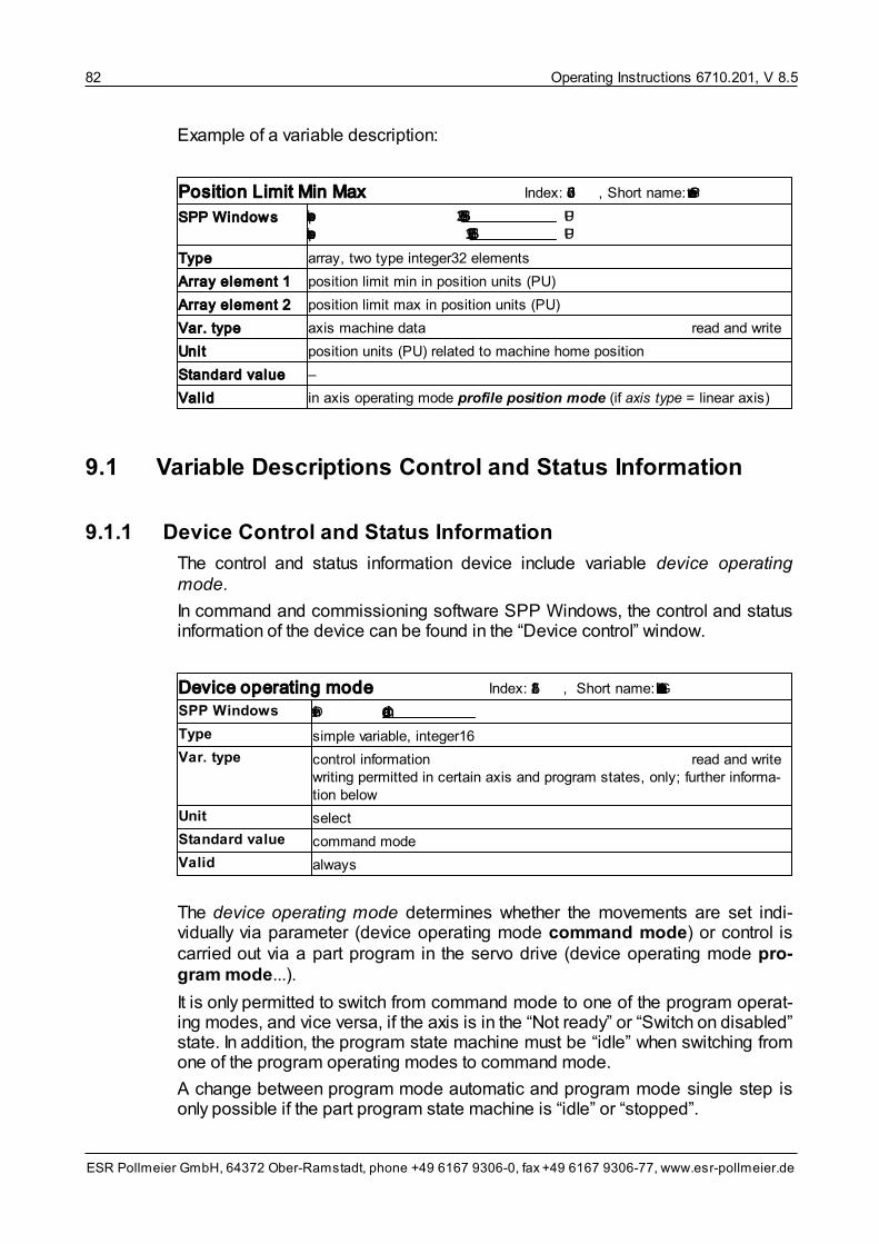
Operating Instructions 6710.201, V 8.582
ESR Pollmeier GmbH, 64372 Ober-Ramstadt, phone +49 6167 9306-0, fax +49 6167 9306-77, www.esr-pollmeier.de
Example of a variable description:
Position Limit Min Max Index: 607d, Short name: PosGrenzwert
SPP Windows position limit min -536,870,912 PUposition limit max 536,870,911 PU
Type array, two type integer32 elements
Array element 1 position limit min in position units (PU)
Array element 2 position limit max in position units (PU)
Var. type axis machine data read and write
Unit position units (PU) related to machine home position
Standard value –
Valid in axis operating mode profile position mode (if axis type = linear axis)
9.1 Variable Descriptions Control and Status Information
9.1.1 Device Control and Status Information
The control and status information device include variable device operatingmode.
In command and commissioning software SPP Windows, the control and statusinformation of the device can be found in the “Device control” window.
Device operating mode Index: 5f42, Short name: GeraetBAAuswahl
SPP Windows Dev.-md Command mode
Type simple variable, integer16
Var. type control information read and writewriting permitted in certain axis and program states, only; further informa-tion below
Unit select
Standard value command mode
Valid always
The device operating mode determines whether the movements are set indi-vidually via parameter (device operating mode command mode) or control iscarried out via a part program in the servo drive (device operating mode pro-gram mode...).
It is only permitted to switch from command mode to one of the program operat-ing modes, and vice versa, if the axis is in the “Not ready” or “Switch on disabled”state. In addition, the program state machine must be “idle” when switching fromone of the program operating modes to command mode.
A change between program mode automatic and program mode single step isonly possible if the part program state machine is “idle” or “stopped”.

Operating Instructions 6710.201, V 8.5 83
ESR Pollmeier GmbH, 64372 Ober-Ramstadt, phone +49 6167 9306-0, fax +49 6167 9306-77, www.esr-pollmeier.de
Permitted values:
Value Device operating mode
1 Command mode
2 Program mode automatic
3 Program mode single step
For a detailed description of the device operating modes, see section DeviceOperating Modes: Command and Program Mode .
9.1.2 Axis Control and Status Information
The following variables belong to the axis control and status information:
• Axis operating mode
• Axis control word
• Axis status word
• Position switching point status
• Axis error code
• Fault detail
In command and commissioning software SPP Windows, the control and statusinformation of the axis can be found in the “Device control”, “Fault”, or “Devicestatus” windows.
Axis operating mode Index: 6060, Short name: AchsBAAuswahl
SPP Windows Axis-md Velocity mode
Type simple variable, integer8 (V 8.5.9 or higher)
simple variable, integer16 (up to V 8.5.9)
Var. type control information read and writewriting permitted in certain axis and program states, only; further informa-tion below
Unit select
Standard value velocity mode
Valid in all axis operating modes
Via the axis operating mode, an operating mode can be selected for the corres-ponding axis.
The axis operating modes can only be changed in states “Switch on disabled”,“Ready to switch on”, or “Switched on”.
For a detailed description of the axis operating modes, see section Axis Operat-ing Modes .
60
29

Operating Instructions 6710.201, V 8.584
ESR Pollmeier GmbH, 64372 Ober-Ramstadt, phone +49 6167 9306-0, fax +49 6167 9306-77, www.esr-pollmeier.de
Permitted values:
Value Axis operating mode
–4 Torque mode
–3 Velocity mode direct (V 3.2 or higher)
–3 Velocity mode
–1 Profile position mode
–6 Homing mode
–1 Electronic gearing
–2 Flying shear (V 4.5 or higher)
–4 Velocity profile (V 5.95 or higher)
–5 Timed positioning mode (V 8.5.9 or higher)
10 Cyclic synchronous torque mode (V 8.5.999.53 or higher)
9 Cyclic synchronous velocity mode (V 8.5.999.54 or higher)
8 Cyclic synchronous position mode (V 8.5.999.62 or higher)
7 Interpolated Position Mode (V 5.95 or higher)
Axis control word Index: 6040, Short name: AchsSteuer
SPP Windows 8000 Control word
Type simple variable, octet string length 2
Var. type control information read and write
Unit –
Standard value 0000hex
Valid in all axis operating modes
Using bits and bit groups in the axis control word, the following functions are ex-ecuted for one axis:
• control of axis states (bit 0 .. 3 and 7)
• control of axis movement (bit 4 .. 6)
• control of part program (bit 14, 15)
An overview of the bit assignment of the axis control word can be found in sec-tion Axis Control Word .
Axis status word Index: 6041, Short name: AchsStatus
SPP Windows 9408 Status word
Type simple variable, octet string length 2
Var. type status information read only
Unit –
Standard value depends on axis state machines and possible faults
Valid in all axis operating modes
20

Operating Instructions 6710.201, V 8.5 85
ESR Pollmeier GmbH, 64372 Ober-Ramstadt, phone +49 6167 9306-0, fax +49 6167 9306-77, www.esr-pollmeier.de
Bits and bit groups in the axis status word report the states of axis and move-ments:
• indication of the states of the axis state machine set via the axis control word(bit 0 .. 3 und 5, 6; additional info in 4)
• indication of the states of movements depends on the individual axis operat-ing modes (bit 10 .. 12)
• indication of the states of the part program (bit 14, 15)
An overview of the bit assignment of the axis status word can be found in sectionAxis Status Word .
Position switching point status Index: 5f37, Short name: PosPSchaltStatus
SPP Windows –
Type simple variable, octet string length 2
Var. type status information read only
Unit –
Standard value –
Valid always; V 5.1 or higher
Bits 0 to 7 of variable position switching point status are assigned to switchingoutputs 1 to 8. The switching points can be used for setting the switching outputsdepending on the actual position of the axis.
General information on the switching points can be found in section SwitchingPoints . You will find further details on the switching points machine data insection Switching Points Machine Data . To output the switching outputs on thedigital outputs of the servo drive, see section Input/Output Function Machine Data
.
Axis error code Index: 603f, Short name: AchsStoerung
SPP Windows Code 7303 : Encoder fault
Type simple variable, octet string length 2
Var. type status information read only
Unit –
Standard value 0000hex
or a fault that may have occurred during switch-on
Valid in all axis operating modes
The axis error code is set to a specific value by a fault. Once the cause of thefault is eliminated, the axis error code can be reset to value 0 (no fault) via bit“Reset fault” in the axis control word. The code can also be reset by switching thecontrol supply voltage off and on.
If the axis is in the “Fault” state, the parameter contains a value other than 0. If the
22
64
184
131

Operating Instructions 6710.201, V 8.586
ESR Pollmeier GmbH, 64372 Ober-Ramstadt, phone +49 6167 9306-0, fax +49 6167 9306-77, www.esr-pollmeier.de
axis is not in the “Fault” state, the parameter contains value 0.
A fault is also indicated by the corresponding LED on the front panel of the servodrive. Whether the LED is permanently lit or flashing gives a rough indication ofthe type of fault:
• “Störung/Fault” or “FLT” LED flashing:
Programming, parameterization, or software fault
– fault codes 5520, 9010 as well as all fault codes 6xxx
• “Störung/Fault” or “FLT” LED permanently lit:
Drive, wiring, or hardware fault
– all fault codes except for 5520, 9010, and 6xxx
A list containing all possible fault codes and their descriptions can be found inAppendix C .
Fault detail Index: 5f81, Short name: StoerDetail
SPP Windows Fault detail
Type array, 4 type visible string length 16 elements
Var. type status information read only
Unit –
Standard value –
Valid in all axis operating modes; V 3.3 or higher
Some fault codes also contain additional information on the cause of the error inclear text.
9.2 Variable Descriptions Parameters and Actual Values
9.2.1 Parameters and Actual Values Torque Mode
The parameters and actual values of the torque mode include the following vari-ables:
• Torque setpoint / force setpoint
• Actual current
In command and commissioning software SPP Windows, the parameters andactual values of the torque mode can be found in the “Device control” window.
191

Operating Instructions 6710.201, V 8.5 87
ESR Pollmeier GmbH, 64372 Ober-Ramstadt, phone +49 6167 9306-0, fax +49 6167 9306-77, www.esr-pollmeier.de
Torque/force setpoint Index: 6071, Short name: Msoll
SPP Windows Torque setpoint: 50 % Set
Type simple variable, integer16
Var. type setpoint or parameter for a function read and write
Unit 0.1% of the rated torque or force of the motor
Standard value –
Valid in axis operating modes torque mode and cyclic synchronous torquemode
This variable specifies the torque or the force of the motor.
Actual current Index: 6078, Short name: IIst
SPP Windows Actual current 2.5 % 0 [ ] 200%
Type simple variable, integer16
Var. type actual value read only
Unit 0.1% of the rated current of the motor
Standard value –
Valid in all axis operating modes
The actual motor current can be read out here in all axis operating modes.
9.2.2 Parameters and Actual Values Velocity Mode
The parameters and actual values of the velocity mode include the following vari-ables:
• Target velocity
• Actual velocity
• Override factor
In command and commissioning software SPP Windows, the parameters andactual values of the velocity mode can be found in the “Device control” window.
Target velocity Index: 6081, Short name: VelVerfahr
SPP Windows Target velocity: 3000 VU Set
Type simple variable, integer32
Var. type setpoint or parameter for a function read and write
Unit velocity units (VU)
Standard value 0
Valid in axis operating modes velocity mode, profile position mode, andflying shear

Operating Instructions 6710.201, V 8.588
ESR Pollmeier GmbH, 64372 Ober-Ramstadt, phone +49 6167 9306-0, fax +49 6167 9306-77, www.esr-pollmeier.de
The target velocity specifies the speed of the axis in axis operating modes pro-file position mode or velocity mode, taking into account other parameterssuch as acceleration time.
In axis operating mode flying shear, it specifies the velocity for the return move-ment.
If analog input “Setpoint” is selected as target velocity source, the value read outat the input is continuously transferred to the target velocity variable in the spe-cified axis operating modes (and can be read out from there as well).
Actual velocity Index: 606c, Short name: VelIst
SPP Windows Actual vel. 2649 VU 0 [ ] 200%
Type simple variable, integer32
Var. type actual value read only
Unit velocity units (VU)
Standard value 0; changes when the axis is moved (even manually)
Valid in all axis operating modes
The actual velocity shows the actual velocity of the axis. It is acquired digitally bydifferentiating the position information of the position measuring system.
Override factor Index: 5efe, Short name: VelOverride
SPP Windows Override factor: 100,0 % Set
Type simple variable, unsigned16
Var. type setpoint or parameter for a function read and write
Unit 65535 (FFFFhex
) corresponds to 400% target velocity
Standard value 16383 (corresponds to 100%)
Valid in axis operating modes velocity mode, profile position mode, andhoming mode
Factor for influencing target velocity and homing velocity, affects the velocity ofthe drive.
The override factor can be used, among other things, to increase or decreasethe target velocity during a running part program.
Examples:
• 3276 (corresponds to 20%): The target velocity is reduced to 20% and re-layed to the drive; 3,000 r.p.m. target velocity produces 600 r.p.m. at the shaft.
• 16383 (corresponds to 100%): The target velocity is relayed unchanged to thedrive; 3,000 r.p.m. target velocity corresponds to 3,000 r.p.m. at the shaft.
• 24575 (corresponds to 150%): The target velocity is increased to 150% andrelayed to the drive; 3,000 r.p.m. target velocity produces 4,500 r.p.m. at theshaft.

Operating Instructions 6710.201, V 8.5 89
ESR Pollmeier GmbH, 64372 Ober-Ramstadt, phone +49 6167 9306-0, fax +49 6167 9306-77, www.esr-pollmeier.de
9.2.3 Parameters and Actual Values Profile Position Mode
The parameters and actual values of the profile position mode include the follow-ing variables:
• Target position
• Internal target position
• Actual position
• Position sensor actual position
• Actual position zeroing
In command and commissioning software SPP Windows, the parameters andactual values of the profile position mode can be found in the “Device control”window.
Target position Index: 607a, Short name: PosZiel
SPP Windows Target position: absolute 0 PU Set
Type simple variable, integer32
Var. type setpoint or parameter for a function read and write
Unit position units (PU), related to application zero point (in axis operatingmode profile position mode), or position sensor steps (PSS) (in axisoperating mode cyclic synchronous position mode)
Standard value 0
Valid in axis operating mode profile position mode and cyclic-synchronousposition mode
Using the target position, the user specifies the position the drive is to approachin axis operating mode profile position mode. In this case, other parameterssuch as target velocity and acceleration time are taken into account.
Information on when the target position is accepted in internal target positionand thus actually approached is included in section Target Position .
With command and commissioning software SPP Windows, the control bits foraccepting the target position into the internal target position are set automatic-ally as soon as a new target position (absolute or relative) is defined with the“Set” button.
34

Operating Instructions 6710.201, V 8.590
ESR Pollmeier GmbH, 64372 Ober-Ramstadt, phone +49 6167 9306-0, fax +49 6167 9306-77, www.esr-pollmeier.de
Internal target position Index: 5ef8, Short name: PosZielIntern
SPP Windows Target position (abs.) 1,000,000 LE
Type simple variable, integer32
Var. type setpoint or parameter for a function read only
Unit position units (PU), related to application zero point
Standard value 0
Valid in axis operating mode profile position mode
In axis operating mode profile position mode, the internal target position con-tains the position that is being approached by the axis. The target position istransferred to the internal target position via specific control bit combinations inthe axis control word. Information on when the target position is accepted in in-ternal target position and thus actually approached is included in section ProfilePosition Mode .
Depending on whether the profile position mode is absolute or relative, the in-ternal target position is set directly or via an addition from target position.
Selection is carried out via bit “absolute/relative” in the axis control word:
• Absolute profile position mode (bit “absolute/relative” = 1)
In this case, the target position directly specifies the position to be ap-proached by the drive. The internal target position parameter is set to targetposition prior to positioning:
internal target position = target position
After positioning, the actual position corresponds to the target position.
• Relative profile position mode (bit “absolute/relative” = 0)
In this case, the target position specifies the distance for the relative approachof the drive to the last absolute target position. The absolute target position iscalculated by the drive and stored in the internal target position parameter.The calculation is as follows:
internal target position = internal target position + target position
With command and commissioning software SPP Windows, the control bits foraccepting the target position into the internal target position are set automatic-ally as soon as a new target position (absolute or relative) is defined with the“Set” button.
34

Operating Instructions 6710.201, V 8.5 91
ESR Pollmeier GmbH, 64372 Ober-Ramstadt, phone +49 6167 9306-0, fax +49 6167 9306-77, www.esr-pollmeier.de
Actual position Index: 6064, Short name: PosIst
SPP Windows Position 23,567,385 PU
Type simple variable, integer32
Var. type actual value read only
Unit position units (PU), related to the application zero point
Standard value 0; changes when the axis is moved (even manually)
Valid in all axis operating modes
The actual position shows the current position of the axis in the position unitsdefined by the user.
Position sensor actual position Index: 6063, Short name: PosIstLg
SPP Windows –
Type simple variable, integer32
Var. type actual value read only
Unit position sensor steps (PSS), related to the application zero point
Standard value 0; changes when the axis is moved (even manually)
Valid in all axis operating modes
The position sensor actual position shows the current position of the axis in pos-ition sensor steps, the home offset is taken into account.
In general, the actual position should be used for reading the position. The posi-tion sensor actual position is useful for reading out the current position in posi-tion sensor steps and thus independent of the position factor.
Actual position zeroing Index: 5efc, Short name: PosIstReset
SPP Windows Reset actual pos.
Type simple variable, octet string length 1
Var. type setpoint or parameter for a function write only
Unit –
Standard value 0
Valid in all axis operating modes
Writing on this parameter (no matter which value) resets the actual position: forthe linear axis to home offset, for the circular axis to range limit min + home off-set.

Operating Instructions 6710.201, V 8.592
ESR Pollmeier GmbH, 64372 Ober-Ramstadt, phone +49 6167 9306-0, fax +49 6167 9306-77, www.esr-pollmeier.de
9.2.4 Parameters and Setpoints Interpolated Position Mode
The parameters and setpoints of the interpolated position mode include thefollowing variables:
• Interpolation data record
• Alternative interpolation data record
• Velocity offset
• Alternative for velocity offset
In command and commissioning software SPP Windows, the parameters andsetpoints of the interpolated position mode can be found in the “Parameteriza-tion” window under Axis data/Interpolated position mode.
Interpolation data record Index: 60c1, Short name: IpolDataRecord
SPP Windows –
Type record, 1 element (subindex 0 .. 1), integer32
Record element 1 target position absolute
Var. type setpoint or parameter for a function read and write
Unit PSS
Value range –224..224–1 PSS
Valid in axis operating mode interpolated position mode
Via this variable, the target positions (in position sensor steps) are transmitted.
Alternative interpolation data record Index: 5fc1, Short name: AltIpolDataRecord
SPP Windows –
Type record, 2 elements (subindex 0 .. 2)
Record element 1Record element 2
interpolation data record bit 0 .. 15, integer16interpolation data record bit 16 .. 23, integer8
Var. type setpoint or parameter for a function read and write
Unit PSS
Value range –224..224–1 PSS
Gültig in axis operating mode interpolated position mode
This variable can be used as an alternative for the 32-bit interpolation data re-cord in order to map this record with 24 bit, only.
That way, the values for interpolation data record, velocity offset, and controlword can be mapped into an 8-byte PDO together with the alternative for velo-city offset.

Operating Instructions 6710.201, V 8.5 93
ESR Pollmeier GmbH, 64372 Ober-Ramstadt, phone +49 6167 9306-0, fax +49 6167 9306-77, www.esr-pollmeier.de
Velocity offset Index: 60b1, Short name: VelocityOffset
SPP Windows –
Type simple variable, integer32
Var. type setpoint or parameter for a function read and write
Unit 0.25 r.p.m.
Standard value –
Valid in axis operating mode interpolated position mode
If this variable is mapped in interpolated position mode, the velocity feedfor-ward is taken from this value and the master has to supply valid values cyclicallywith the IpolDataRecord.
If this variable is not mapped, the velocity feedforward is calculated internally.
Alternative for velocity offset Index: 6fc2, Short name: AltVelocityOffset
SPP Windows –
Type record, 2 elements (subindex 0 .. 2)
Record element 1Record element 2
velocity offset bit 0 .. 15, integer16velocity offset bit 16 .. 23, integer8
Type setpoint or parameter for a function read and write
Var. type 0.25 r.p.m.
Standard value –
Valid in axis operating mode interpolated position mode
This variable can be used as an alternative for the 32-bit velocity offset in orderto map this record with 24 bits, only.
That way, the values for interpolation data record, velocity offset, and controlword can be mapped into an 8-byte PDO together with the alternative for velo-city offset.
9.2.5 Parameters and Actual Values Timed Positioning Mode
The parameters and actual values of the timed positioning mode include thefollowing variable:
• Velocity feedforward factor
In command and commissioning software SPP Windows, the parameters andactual values of the timed positioning mode can be found in the “Device con-trol” window.

Operating Instructions 6710.201, V 8.594
ESR Pollmeier GmbH, 64372 Ober-Ramstadt, phone +49 6167 9306-0, fax +49 6167 9306-77, www.esr-pollmeier.de
Velocity feedforward factor Index: 5F64, Subindex: 4, Short name: VelFFKp
SPP Windows –
Type simple variable, float32
Var. type setpoint or parameter for a function read and write
Unit 1.0
Standard value 1.0
Valid in axis operating modes timed positioning mode, cyclic synchronousvelocity mode, and interpolated position mode
With this variable, the velocity feedforward is influenced in the stated operatingmodes. The velocity feedforward can be switched off by setting the velocity feed-forward factor to 0.
9.2.6 Parameters and Actual Values Cyclic SynchronousTorque/Force Mode
The parameters and actual values of the cyclic synchronous torque/forcemode include the following variables:
• Torque offset / force offset
In command and commissioning software SPP Windows, the parameters andactual values of the cyclic synchronous torque/force mode can be found inthe “Device control” window.
Torque offset / Force offset Index: 60B2, Short name: TorqueOffset
SPP Windows –
Type simple variable, integer16
Var. type setpoint or parameter for a function read and write
Unit 0.1% of the rated torque or force of the motor
Standard value 0
Valid in axis operating modes cyclic synchronous torque mode, cyclic syn-chronous velocity mode, and interpolated position mode
With this variable, an additional torque or an additional force can be preset cyc-lically for acceleration feedforward.
9.2.7 Parameters and Actual Values Cyclic Synchronous VelocityMode
The parameters and actual values of the cyclic synchronous velocity modeinclude the following variables:
• Target velocity
• Velocity offset

Operating Instructions 6710.201, V 8.5 95
ESR Pollmeier GmbH, 64372 Ober-Ramstadt, phone +49 6167 9306-0, fax +49 6167 9306-77, www.esr-pollmeier.de
In command and commissioning software SPP Windows, the parameters andactual values of the cyclic synchronous velocity mode can be found in the“Device control” window.
Target velocity Index: 60FF, Short name: TargetVelocity
SPP Windows –
Type simple variable, integer32
Var. type setpoint or parameter for a function read and write
Unit VU
Standard value –
Valid in axis operating mode cyclic synchronous velocity mode
With this variable, the target velocity is preset cyclically.
Velocity offset Index: 60B1, Short name: VelocityOffset
SPP Windows –
Type simple variable, integer32
Var. type setpoint or parameter for a function read and write
Unit VU
Standard value 0
Valid in axis operating modes cyclic synchronous velocity mode and inter-polated position mode
With this variable, a velocity feedforward can be preset cyclically. The actually ef-fective value results from the multiplication with the velocity feedforward factor(see Parameters and Actual Values Timed Positioning Mode ).
9.2.8 Parameters and Actual Values Input/Output Function
The parameters and actual values of the input/output function include the follow-ing variables:
• Digital inputs
• Digital outputs
• Digital inputs acc. to CiA402
• Analog inputs
• Analog outputs
In command and commissioning software SPP Windows, the parameters andactual values of the input/output function can be found in the “Device control” win-dow.
For further information on the input and output function see section Input/OutputFunction . The variables for the corresponding machine data are described in
93
61

Operating Instructions 6710.201, V 8.596
ESR Pollmeier GmbH, 64372 Ober-Ramstadt, phone +49 6167 9306-0, fax +49 6167 9306-77, www.esr-pollmeier.de
section Input/Output Function Machine Data .
Digital inputs Index: 5f56, Short name: DEin
SPP Windows Digital inputs 1 00001110
Type array, 20 type unsigned8 elements
Array element 1 digital inputs I 1.x
Array element 2 digital inputs I 2.x
Array element 3 digital inputs I 3.x (I 3.0 = enable)
Array element 4 digital inputs I 4.x (software inputs)
Array element 5 .. 8 (reserved for future expansions)
Array element 9 digital inputs I 9.x (software inputs)
Array element 10 status word bit 0 .. 7 (I 10)
Array element 11 status word bit 8 .. 15 (I 11)
Array element 12 .. 14 (reserved for future expansions)
Array element 15 .. 20 linked inputs/outputs (read; write with O 15 .. O 20)
Var. type actual value read only
Unit –
Standard value –
Valid always
Via this variable, the state of the I x.x digital inputs can be queried. The individualinputs are assigned to bits in the above-mentioned array elements. I x.0 is as-signed to bit 0, I x.1 to bit 1 etc. 1 in a bit indicates that +24 V exist at the input.
The function of the digital inputs is defined via variables signal selection digitalinputs ... (see section Input/Output Function Machine Data ).
An input does not need to have a physical connector at the device. The statusword, for example, can be queried via inputs I 10 and I 11, inputs I 15 to I 20 canbe used as markers in the part program.
The state of the digital inputs is displayed independent of the configuration.
131
131

Operating Instructions 6710.201, V 8.5 97
ESR Pollmeier GmbH, 64372 Ober-Ramstadt, phone +49 6167 9306-0, fax +49 6167 9306-77, www.esr-pollmeier.de
Digital outputs Index: 5f54, Short name: DAus
SPP Windows Digital outputs 1 00000110
Type array, 20 type unsigned8 elements
Array element 1 digital outputs O 1.x
Array element 2 digital outputs O 2.x
Array element 3 digital outputs O 3.x (MaxiDrive: O 3.0 = brake control)
Array element 4 .. 7 (reserved for future expansions)
Array element 8 .. 9 digital outputs O 8.x, O 9.x (software outputs)
Array element 10 control word bit 0 .. 7 (O 10)
Array element 11 control word bit 8 .. 15 (O 11)
Array element 12 .. 14 (reserved for future expansions)
Array element 15 .. 20 linked inputs/outputs (read; write with I 15 .. O 20)
Var. type setpoint or parameter for a function read and write
Unit –
Standard value depending on the configuration
Valid always
Via this variable, the state of the O x.x digital outputs can be controlled. The indi-vidual outputs are assigned to bits in the above-mentioned array elements. O x.0is assigned to bit 0, O x.1 to bit 1 etc. “1” in a bit switches +24 V to the output.
Only the outputs configured as freely usable in variable signal selection digitaloutputs ... can be controlled via this variable. For the other outputs, the state isdefined via the selected signal (see section Input/Output Function Machine Data
).
An output does not need to have a physical connector at the device. The controlword, for example, can be changed via outputs O 10 and O 11, outputs O 15 toO 20 can be used as markers in the part program.
The state of the digital outputs can be read out independent of the configuration.
Digital Inputs Acc. To CiA402 Index: 60FD, Short name: DEin402
SPP Windows –
Type simple variable, unsigned32
Var. type actual value read only
Unit –
Standard value –
Valid always; V 8.5.997 or higher
Irrespective of the digital inputs configured as limit switch and/or pre-pulse, thisvariable displays the current state at the corresponding input.
131

Operating Instructions 6710.201, V 8.598
ESR Pollmeier GmbH, 64372 Ober-Ramstadt, phone +49 6167 9306-0, fax +49 6167 9306-77, www.esr-pollmeier.de
Bit Status
0 Limit switch–
1 Limit switch+
2 Pre-pulse
Value 1 indicates that the respective input function is active, i. e. bit 0 and bit 1are inverted regarding the physical states at inputs limit switch+ and limit switch–(opener).
Analog inputs Index: 5f52, Short name: AEin
SPP Windows Analog inputs 1 9.9951
Type array, 12 type integer16 elements
Array element 1 analog input “Setpoint” or “Setpoint1”, V 4.4 or higher
Array element 2 analog input “Setpoint2”
Array element 3 .. 12 (reserved for future expansions)
Var. type actual value read only
Unit –10 V .. +10 V = –32768 .. +32767
Standard value –
Valid always, V 4.4 or higher; for devices with -A1 option
In element 1 of variable analog inputs, the value of analog input “setpoint” or “set-point1” can be read. Element 2 contains the value of analog input “setpoint2”.
Please, pay attention to the technical specifications of analog input “setpoint” inoperating instructions “Connection and Commissioning” (6755.202, 6745.202,6750.202, 6740.202, or 6710.202). For options of using the “setpoint” analog in-put for setting setpoints, please read sections Analog Input and SetpointSource Machine Data .
Analog outputs Index: 5f50, Short name: AAus
SPP Windows Analog outputs 1 0
Type array, 4 type integer16 elements
Var. type setpoint or parameter for a function read and write
Unit –16384 .. +16383 = –5 V .. +5 V
Standard value –
Valid always; V 3.5 or higher; for devices with -A1 option
With the first two elements of variable analog outputs, voltages can be output atoutputs “Ist1” and “Ist2”.
If an actual value or another signal was mapped to the corresponding analog out-put using variables analog output 1 signal selection or analog output 2 signalselection, its value determines the output voltage at output “Ist1” or “Ist2”.
63
144

Operating Instructions 6710.201, V 8.5 99
ESR Pollmeier GmbH, 64372 Ober-Ramstadt, phone +49 6167 9306-0, fax +49 6167 9306-77, www.esr-pollmeier.de
9.2.9 Parameters and Actual Values Trigger and MeasuringFunctions
The parameters and actual values of the trigger and measuring functions includethe following variables:
• Trigger mask
• Trigger status
• Trigger mode selection
• Position sensor measured value1
• Position sensor measured value1 PU
• Position sensor measured value2
• Position sensor measured value2 PU
In command and commissioning software SPP Windows, parameter triggermode selection can be found in window “Parameterization/Device data”, theother variables are control and status functions which are not displayed.
Trigger mask Index: 5f7f, Short name: TriggerMaske
SPP Windows –
Type simple variable, octet string length 2
Var. type setpoint or parameter for a function read and write
Unit –
Standard value 0
Valid always; V 3.2 or higher
If bit 0 or bit 2 of the trigger mask is set to 1, it releases digital input “positionmeasurement” or “fast position measurement” to measure the position of the axisin the position sensor measured value.... Bit 4 of the trigger mask releases di-gital input “trigger input trace” for tracing. After the successful position measure-ment or tracing, the corresponding bit in the trigger status is set.
The function then disables itself until the corresponding bit of the trigger mask isset to 0 and then reset to 1.
A description of the function of this variable in conjunction with trigger status andposition sensor measured value... can be found in section Trigger and Measur-ing Functions .
The trace function is described in section Trace Function .
64
66

Operating Instructions 6710.201, V 8.5100
ESR Pollmeier GmbH, 64372 Ober-Ramstadt, phone +49 6167 9306-0, fax +49 6167 9306-77, www.esr-pollmeier.de
Trigger status Index: 5f80, Short name: TriggerStatus
SPP Windows –
Type simple variable, octet string length 2
Var. type actual value read only
Unit –
Standard value 0
Valid always; V 3.2 or higher
If bit 0 or bit 2 in the trigger status changes to 1, this indicates that the current po-sition was stored in position sensor measured value.... With value 1, bit 4 in thetrigger status indicates that triggering was initiated. The bit in the trigger statusremains on 1 until a new measurement is released by a change from 1 to 0 andback to 1 in the corresponding bit of the trigger mask.
A description of the function of these variables in conjunction with trigger maskand position sensor measured value... can be found in section Trigger andMeasuring Functions .
The trace function is described in section Trace Function .
Trigger mode selection Index: 5fb1, Short name: TriggerModus
SPP Windows Trigger mode position measurement positive edge selectTrigger mode fast position measurement positive edge selectTrigger mode trace function positive edge select
Type array, 16 type integer16 elements
Array element 1 trigger mode position measurement
Array element 3 trigger mode fast position measurement
Array element 5 trigger mode trace function
Var. type parameter read and write
Unit –
Standard value positive edge
Valid always; V 7.5 or higher
This variable is used for selecting the type of position measurement or the triggerfor the trace function.
Permitted values:
Value Function
0 positive edge
–1 negative edge
–2 positive pulse
–3 negative pulse
64
66
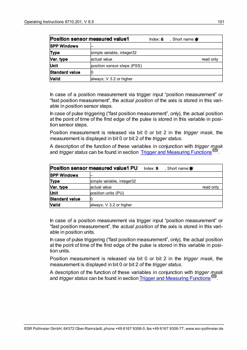
Operating Instructions 6710.201, V 8.5 101
ESR Pollmeier GmbH, 64372 Ober-Ramstadt, phone +49 6167 9306-0, fax +49 6167 9306-77, www.esr-pollmeier.de
Position sensor measured value1 Index: 5f1c, Short name: PosAblage
SPP Windows –
Type simple variable, integer32
Var. type actual value read only
Unit position sensor steps (PSS)
Standard value 0
Valid always; V 3.2 or higher
In case of a position measurement via trigger input “position measurement” or“fast position measurement”, the actual position of the axis is stored in this vari-able in position sensor steps.
In case of pulse triggering (“fast position measurement”, only), the actual positionat the point of time of the first edge of the pulse is stored in this variable in posi-tion sensor steps.
Position measurement is released via bit 0 or bit 2 in the trigger mask, themeasurement is displayed in bit 0 or bit 2 of the trigger status.
A description of the function of these variables in conjunction with trigger maskand trigger status can be found in section Trigger and Measuring Functions .
Position sensor measured value1 PU Index: 5e9f, Short name: PosAblageLE
SPP Windows –
Type simple variable, integer32
Var. type actual value read only
Unit position units (PU)
Standard value 0
Valid always; V 3.2 or higher
In case of a position measurement via trigger input “position measurement” or“fast position measurement”, the actual position of the axis is stored in this vari-able in position units.
In case of pulse triggering (“fast position measurement”, only), the actual positionat the point of time of the first edge of the pulse is stored in this variable in posi-tion units.
Position measurement is released via bit 0 or bit 2 in the trigger mask, themeasurement is displayed in bit 0 or bit 2 of the trigger status.
A description of the function of these variables in conjunction with trigger maskand trigger status can be found in section Trigger and Measuring Functions .
64
64

Operating Instructions 6710.201, V 8.5102
ESR Pollmeier GmbH, 64372 Ober-Ramstadt, phone +49 6167 9306-0, fax +49 6167 9306-77, www.esr-pollmeier.de
Position sensor measured value2 Index: 5e95, Short name: PosAblage2
SPP Windows –
Type simple variable, integer32
Var. type actual value read only
Unit position sensor steps (PSS)
Standard value –
Valid always; V 7.5 or higher
In case of a position measurement via trigger input “fast position measurement”,the actual position of the axis at the point of time of the second edge of the pulseis stored in this variable in position sensor steps.
Position measurement is released via bit 0 or bit 2 in the trigger mask, themeasurement is displayed in bit 0 or bit 2 of the trigger status.
A description of the function of these variables in conjunction with trigger maskand trigger status can be found in section Trigger and Measuring Functions .
Position sensor measured value2 PU Index: 5e96, Short name: PosAblage2LE
SPP Windows –
Type simple variable, integer32
Var. type actual value read only
Unit position units (PU)
Standard value –
Valid always; V 7.5 or higher
In case of a position measurement via trigger input “fast position measurement”,the actual position of the axis at the point of time of the second edge of the pulseis stored in this variable in position units.
Position measurement is released via bit 0 or bit 2 in the trigger mask, themeasurement is displayed in bit 0 or bit 2 of the trigger status.
A description of the function of these variables in conjunction with trigger maskand trigger status can be found in Trigger and Measuring Functions .
9.2.10 Parameters of the Trace Function
The parameters of the trace function include the following variables:
• Trace buffer 1
• Trace buffer 2
• Trace buffer 3
• Trace index 1
• Trace index 2
64
64

Operating Instructions 6710.201, V 8.5 103
ESR Pollmeier GmbH, 64372 Ober-Ramstadt, phone +49 6167 9306-0, fax +49 6167 9306-77, www.esr-pollmeier.de
• Trace index 3
• Trace time
• Trace start
• Controller cycle time
In command and commissioning software SPP Windows, the trace function isoperated via the “Trace oscilloscope” window.
For further information on the trace function see section Trace Function .
Trace buffer 1 Index: 5f43, Short name: TraceBuffer1
SPP Windows (used internally)
Type array, 16 type octet string length 128 elements
Var. type data range, mapped on an array read only
Unit –
Standard value 0
Valid always
Trace buffer 2 Index: 5f45, Short name: TraceBuffer2
SPP Windows (used internally)
Type array, 16 type octet string length 128 elements
Var. type data range, mapped on an array read only
Unit –
Standard value 0
Valid always
Trace buffer 3 Index: 5f47, Short name: TraceBuffer3
SPP Windows (used internally)
Type array, 16 type octet string length 128 elements
Var. type data range, mapped on an array read only
Unit –
Standard value 0
Valid always
Trace buffer 1 to trace buffer 3 are memory areas for recording certain signalsover time. The recording is started with signal trace start or via digital input “trig-ger input trace”.
66

Operating Instructions 6710.201, V 8.5104
ESR Pollmeier GmbH, 64372 Ober-Ramstadt, phone +49 6167 9306-0, fax +49 6167 9306-77, www.esr-pollmeier.de
Trace index 1 Index: 5f44, Short name: TraceIndex1
SPP Windows Channel Actual current
Type simple variable, unsigned16
Var. type setpoint or parameter for a function read and write
Unit –
Standard value actual current
Valid always
Trace index 2 Index: 5f46, Short name: TraceIndex2
SPP Windows Channel Actual speed
Type simple variable, unsigned16
Var. type setpoint or parameter for a function read and write
Unit –
Standard value actual speed
Valid always
Trace index 3 Index: 5f48, Short name: TraceIndex3
SPP Windows Channel Actual position
Type simple variable, unsigned16
Var. type setpoint or parameter for a function read and write
Unit –
Standard value actual position
Valid always
Trace index 1 to trace index 3 specify the signals to be recorded in the corres-ponding variables trace buffer 1 to trace buffer 3. The digital or analog signalsare selected via the selection codes as stated in signal selection digital output... and signal selection analog output ..., see section Input/Output FunctionMachine Data .
Trace time Index: 5f49, Short name: TraceTime
SPP Windows Sampling rate (ms) 2
Type simple variable, unsigned16
Var. type setpoint or parameter for a function read and write
Unit controller cycles
Standard value 1
Valid always
Trace time specifies the time cycle in which signals are recorded in trace buf-
131

Operating Instructions 6710.201, V 8.5 105
ESR Pollmeier GmbH, 64372 Ober-Ramstadt, phone +49 6167 9306-0, fax +49 6167 9306-77, www.esr-pollmeier.de
fer 1, trace buffer 2, and trace buffer 3 in controller cycle units (see controllercycle time). This value can be converted into time units using variable controllercycle time.
In SPP Windows, the trace time is stated in milliseconds, conversion is carriedout automatically using variable controller cycle time.
Trace start Index: 5f4a, Short name: TraceStart
SPP Windows “Trigger” button
Type simple variable, octet string length 1
Var. type control information write only
Unit –
Standard value –
Valid always
Writing on parameter trace start (no matter which value) starts the recording ofsignals in trace buffer 1, trace buffer 2, and trace buffer 3.
Alternatively, recording can be started via digital input “trigger input trace”, in thiscase, the start of the recording must be released via bit 4 in the trigger mask, be-fore.
Controller cycle time Index: 5f4b, Short name: ReglerZyklus
SPP Windows (used internally)
Type simple variable, unsigned16
Var. type adjustable value read only
Unit 1 μs
Standard value 1 ms
Valid always
This parameter permits reading out the controller cycle time of the position con-trol loop, it can be used for calculations related to trace time.
In SPP Windows, the controller cycle time is used for converting the samplingrate in milliseconds.
9.3 Variable Descriptions Basic Data
9.3.1 General Actual and Measured Values
The general actual and measured values include the following variables:
• DC-bus voltage
• Resolver voltage

Operating Instructions 6710.201, V 8.5106
ESR Pollmeier GmbH, 64372 Ober-Ramstadt, phone +49 6167 9306-0, fax +49 6167 9306-77, www.esr-pollmeier.de
• Heat sink temperature
• Motor temperature
• Resistance motor temperature sensor
• Shunt resistor loading
• I2t loading
In command and commissioning software SPP Windows, the general actual andmeasured values can be found in the “Device status” window.
Bus voltage Index: 6079, Short name: UZwKreis
SPP Windows Bus voltage 560 V
Type simple variable, unsigned16
Var. type actual value read only
Unit 1 V
Standard value –
Valid always
This variable shows the DC-bus voltage in volts.
Resolver voltage Index: 5f0a, Short name: UResolver
SPP Windows Resolver voltage 2.122 V
Type simple variable, unsigned16
Var. type actual value read only
Unit 1 mV
Standard value –
Valid always
The variable shows the resolver voltage in mV. The value should be in the range2 V ± 10% and not deviate more than 5% for one motor revolution. The resolvervoltage is monitored by the servo drive. If the voltage is too high or too low, thedevice switches off and reports an encoder fault.
The resolver voltage of other motor position sensors, if existing, is converted to astandard value of 2 V and shown in variable resolver voltage, too.

Operating Instructions 6710.201, V 8.5 107
ESR Pollmeier GmbH, 64372 Ober-Ramstadt, phone +49 6167 9306-0, fax +49 6167 9306-77, www.esr-pollmeier.de
Heat sink temperature Index: 5f0b, Short name: TKuehler
SPP Windows Heat sink temperature 23.4 ºC
Type simple variable, integer16
Var. type actual value read only
Unit 0.1 ºC
Standard value –
Valid always
The variable shows the temperature of the heat sink of the servo drive. The heatsink temperature is monitored by the servo drive. If the temperature is too high,the device switches off and reports an “overtemperature” fault.
Motor temperature Index: 5f0c, Short name: TMotor
SPP Windows Motor temperature 28.3 ºC
Type simple variable, integer16
Var. type actual value read only
Unit 0.1 ºC
Standard value –
Valid always; V 8.5 and higher
In case a motor temperature sensor with known resistance temperature charac-teristic is used (e.g. KTY-83 or KTY-84), the temperature of the motor is dis-played in this variable. The motor temperature is monitored by the servo drive. Ifthe temperature is too high, the device switches off and reports an “overtemper-ature motor” fault.
Resistance motor temperature sensor Index: 5f03, Short name: RMotor
SPP Windows Resistance motor temperature sensor 615 Ohm
Type simple variable, unsigned32
Var. type actual value read only
Unit 1Ω
Standard value –
Valid always; V 8.5 and higher
This variable shows the current resistance value used for monitoring the motortemperature. In case the resistance switching threshold overtemperature is ex-ceeded, the device switches off and reports an “overtemperature motor” fault.

Operating Instructions 6710.201, V 8.5108
ESR Pollmeier GmbH, 64372 Ober-Ramstadt, phone +49 6167 9306-0, fax +49 6167 9306-77, www.esr-pollmeier.de
Shunt resistor loading Index: 5f98, Short name: TBallast
SPP Windows Shunt resistor loading 0.0 %
Type simple variable, integer16
Var. type actual value read only
Unit 0.1% of possible continuous output
Standard value –
Valid always; V 5.1 or higher
The shunt resistor loading shows the power currently consumed by the shunt res-istor (internally or externally). The specification relates to the possible continuousoutput of the shunt resistor and is averaged via its thermal time constant. Thisway, the shunt resistor is also capable of short-term power consumption that ishigher than the permissible continuous output.
If the shunt resistor loading exceeds 100%, the software monitoring switches offthe power circuit and the device reports a fault.
If an external shunt resistor is used, resistance value, permissible continuous out-put, and thermal time constant must be entered in the shunt resistor machinedata (see section Shunt Resistor Machine Data ).
I2t Loading Index: 5E93, Short name: I2tAuslastung
SPP Windows I2t loading 0.0 %
Type simple variable, unsigned16
Var. type actual value read only
Unit 0.1%
Standard value –
Valid always; V 8.5 and higher
This variable shows the “fill level” of the integrator for I2t monitoring. From a valueof 100% on, the servo drive limits the motor current to the motor rated current anddisplays an “overload” (LED at the front panel) in order to protect the motor.
9.3.2 Motor Machine Data
In command and commissioning software SPP Windows, the motor machinedata can be found in the “Parameterization” window in Motor data.
During first commissioning with the SPP Windows command and commission-ing software, make sure that the motor used is listed in the motor machine data.
Motor data that have been taken from a motor database may possibly not bechanced individually by the user. In this case, they are displayed in SPP Win-dows for information, only.
SPP Windows supports two procedures for setting the motor data: the selectionof the motor via its type designation from a motor database and the individual in-
129
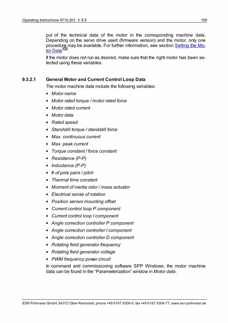
Operating Instructions 6710.201, V 8.5 109
ESR Pollmeier GmbH, 64372 Ober-Ramstadt, phone +49 6167 9306-0, fax +49 6167 9306-77, www.esr-pollmeier.de
put of the technical data of the motor in the corresponding machine data.Depending on the servo drive used (firmware version) and the motor, only oneprocedure may be available. For further information, see section Setting the Mo-tor Data .
If the motor does not run as desired, make sure that the right motor has been se-lected using these variables.
9.3.2.1 General Motor and Current Control Loop Data
The motor machine data include the following variables:
• Motor name
• Motor rated torque / motor rated force
• Motor rated current
• Motor data
• Rated speed
• Standstill torque / standstill force
• Max. continuous current
• Max. peak current
• Torque constant / force constant
• Resistance (P-P)
• Inductance (P-P)
• # of pole pairs / pitch
• Thermal time constant
• Moment of inertia rotor / mass actuator
• Electrical sense of rotation
• Position sensor mounting offset
• Current control loop P component
• Current control loop I component
• Angle correction controller P component
• Angle correction controller I component
• Angle correction controller D component
• Rotating field generator frequency
• Rotating field generator voltage
• PWM frequency power circuit
In command and commissioning software SPP Windows, the motor machinedata can be found in the “Parameterization” window in Motor data.
67

Operating Instructions 6710.201, V 8.5110
ESR Pollmeier GmbH, 64372 Ober-Ramstadt, phone +49 6167 9306-0, fax +49 6167 9306-77, www.esr-pollmeier.de
Motor name Index: 5ee6, Short name: MotorName
SPP Windows Motor name MR 7412U3N60G1 (without motor database)
Motor name MR 7412-U3-N060-G01 (with motor database)
Type simple variable, visible string length 16
Var. type motor machine data read and write / tool
Unit –
Standard value –
Valid always
The motor designation (short type code) is entered in variable motor name. Incase motor data from a motor database are used, this short description is evalu-ated by command and commissioning software SPP Windows. Using this in-formation, the software displays the motor name as listed in the SPP Windowsmotor database. The motor name displayed in the motor selection and the motordata includes all parts of the motor designation identifying motor and encodersystem:
• motor type and size
• DC-bus voltage
• rated speed
• external ventilation (if applicable)
• encoder system
Characters identifying equipment versions of the motor that have nothing to dowith power and control characteristics (e. g. keys, foot-mounting, connectors, orterminal boxes) are not displayed.
Motor rated torque / force Index: 6076, Short name: MNenn
SPP Windows Rated torque 0.700 Nm (for rotatory drive systems)
Rated force 500.000 N (for linear motors)
Type simple variable, unsigned32 (V 8.5.9 or higher)
simple variable, unsigned16 (up to V 8.5.9)
Var. type motor machine data read and write / tool
Unit 0.001 Nm or 0.001 N (V 8.5.9 or higher)
0.1 Nm (up to V 8.5.9)
Standard value –
Valid always
The rated torque or force of the motor is entered or displayed, here.
If the motor is operated with a servo drive with lower rated current (see followingvariable), the rated torque of the motor cannot be reached and a correspondinglylower value has to be entered.

Operating Instructions 6710.201, V 8.5 111
ESR Pollmeier GmbH, 64372 Ober-Ramstadt, phone +49 6167 9306-0, fax +49 6167 9306-77, www.esr-pollmeier.de
Motor rated current Index: 6075, Short name: INenn
SPP Windows Rated current 2.0 A
Type simple variable, unsigned32 (version V 8.5.9 or higher)
simple variable, unsigned16 (up to V 8.5.9)
Var. type motor machine data read and write / tool
Unit 1 mA (V 8.5.9 or higher)
0,1 A (up to V 8.5.9)
Standard value –
Valid in all axis operating modes
The rated current of the motor is entered or displayed, here.
The rated current of the motor must not exceed the rated current of the servodrive. In case a motor is operated at a servo drive with lower rated current, a cor-respondingly lower value has to be entered, here. In this case, the rated torque ofthe motor cannot be reached.
Relative current specifications in other variables refer to the motor rated current,that means the value indicated, here.
Motor data Index: 5E80, Short name: MotorData
Type record, 19 elements
Var. type motor machine data read and write
Valid in all axis operating modes; V 8.5.9 or higher
From firmware version V 8.5.9 on, the motor machine data are combined in re-cord variable motor data. The individual elements are described in the followingin the order in which they appear in the motor data of SPP Windows.
Rated speed Index: 5E80, Subindex: 9, Short name: MotorData9
SPP Windows Rated speed 6000.0 r.p.m. (for rotatory drive systems)
Rated speed 3.50 m/s (for linear motors)
Type record element, float32
Var. type motor machine data read and write
Unit 1 r.p.m. or 1 m/s
Standard value –
In case the motor data are not accepted from a motor database, enter the ratedspeed of the motor, here.

Operating Instructions 6710.201, V 8.5112
ESR Pollmeier GmbH, 64372 Ober-Ramstadt, phone +49 6167 9306-0, fax +49 6167 9306-77, www.esr-pollmeier.de
Motor rated speed Index: 5f19, Short name: VelNennMotor
SPP Windows Rated speed 6000.0 r.p.m.
Type simple variable, unsigned32
Var. type motor machine data tool
Unit 0.25 r.p.m. if rated speed ≤ 7,000 r.p.m.0.5 r.p.m. if 7,000 r.p.m. < rated speed ≤ 14,000 r.p.m.1.0 r.p.m. if rated speed > 14,000 r.p.m.
Standard value –
Valid in all axis operating modes; V 3.2 to V 8.5.9
For devices with firmware versions below V 8.5.9, the rated speed of the motorhas to be entered, here.
The machine data of the motor are factory preset. If, in special cases, new motordata has to be loaded, note the following:
• If the previous rated speed of the motor was lower than or equal to7,000 r.p.m. and the new speed is higher than 7,000 r.p.m.
or
• if the previous rated speed of the motor was higher than 7,000 r.p.m. but lowerthan or equal to 14,000 r.p.m. and the new speed is lower than or equal7000 r.p.m. or higher than 14,000 r.p.m.
or
• if the previous rated speed of the motor was higher than 14,000 r.p.m. and thenew speed is lower than 14,000 r.p.m.
• save the new data in the non-volatile memory of the servo drive and
• switch off the device and switch it on again in order to make the new datavalid.
Standstill torque / force Index: 5E80, Subindex: 11, Short name: MotorData11
SPP Windows Standstill torque 0.90 Nm (for rotatory drive systems)
Standstill force 600.00 N (for linear motors)
Type record element, float32
Var. type motor machine data read and write
Unit 1 Nm or 1 N
Standard value –
Enter the standstill torque or standstill force of the motor, here.

Operating Instructions 6710.201, V 8.5 113
ESR Pollmeier GmbH, 64372 Ober-Ramstadt, phone +49 6167 9306-0, fax +49 6167 9306-77, www.esr-pollmeier.de
Max. continuous current Index: 5E80, Subindex: 4, Short name: MotorData4
SPP Windows Max. continuous current 2,000 A
Type record element, float32
Var. type motor machine data read and write
Unit 1 A
Standard value –
The max. continuous current corresponds to the current the motor can be oper-ated with permanently under consideration of thermal limits. Usually, this valuecorresponds to the motor rated current.
Max. peak current Index: 5E80, Subindex: 5, Short name: MotorData5
SPP Windows Max. peak current 8.500 A
Type record element, float32
Var. type motor machine data read and write
Unit 1 A
Standard value –
The max. peak current corresponds to the current the motor can be operatedwith for a short period of time without consideration of the thermal limits.
Torque constant / Force constant
Index: 5E80, Subindex: 12, Short name: MotorData12
SPP Windows Torque constant 0.33 Nm/A (for rotatory drive systems)
Force constant 140.0 N/A (for linear motors)
Type record element, float32
Var. type motor machine data read and write
Unit 1 Nm/A or 1 N/A
Standard value –
Enter the torque constant or the force constant of the motor, here.
Resistance (P-P) Index: 5E80, Subindex: 2, Short name: MotorData2
SPP Windows Resistance (P-P) 12.500 Ohm
Type record element, float32
Var. type motor machine data read and write
Unit 1 Ω
Standard value –
Enter the resistance phase-phase, here. (If the resistance of only one phase is

Operating Instructions 6710.201, V 8.5114
ESR Pollmeier GmbH, 64372 Ober-Ramstadt, phone +49 6167 9306-0, fax +49 6167 9306-77, www.esr-pollmeier.de
specified in the motor data sheet, multiply the value by 2 and enter the result,here.)
Inductance (P-P) Index: 5E80, Subindex: 3, Short name: MotorData3
SPP Windows Inductance (P-P) 45.300 mH
Type record element, float32
Var. type motor machine data read and write
Unit 1 H
Standard value –
Enter the inductance phase-phase, here. (If the inductance of only one phase isspecified in the motor data sheet, multiply the value by 2 and enter the result,here.)
Number of pole pairs Index: 5E80, Subindex: 6, Short name: MotorData6
SPP Windows # of pole pairs 3
Type record element, unsigned16
Var. type motor machine data read and write
Unit –
Standard value –
Valid always; for rotatory drive systems, only
Enter the number of pole pairs for one full revolution of the motor. (If only the num-ber of poles is stated in the motor data sheet, divide the value by 2 and enter theresult, here.)
Pitch Index: 5E80, Subindex: 19, Short name: MotorData19
SPP Windows pitch 12.0 mm
Type record element, float32
Var. type motor machine data read and write
Unit 1 m
Standard value –
Valid always; for linear motors, only
Enter the magnet pitch (center distance between two adjacent magnet poles N-Sof the secondary part of the linear motor) here. (If magnet pitch N-N is defined inthe motor data sheet, divide it by 2 and enter the result here.)

Operating Instructions 6710.201, V 8.5 115
ESR Pollmeier GmbH, 64372 Ober-Ramstadt, phone +49 6167 9306-0, fax +49 6167 9306-77, www.esr-pollmeier.de
Thermal time constant Index: 5E80, Subindex: 8, Short name: MotorData8
SPP Windows Thermal time constant 600.0 s
Type record element, float32
Var. type motor machine data read and write
Unit 1 s
Standard value –
In case the motor data cannot be taken from a motor database, enter the thermaltime constant of the motor here. (If the thermal time constant is entered inminutes in the motor data sheet, multiply the value by 60 and enter the resulthere.)
The thermal time constant determines the overload capacity of the motor, it isconsidered for the I2t monitoring. In case of an overload, the peak current in-crease is switched back to the motor continuous current. This is indicated by the“Überlast/Overload” or “OVL” LED and can be signaled at output “overload”.
Thermal time constant Index: 5f05, Short name: ITk
SPP Windows Thermal time constant 10000 ms
Typ simple variable, unsigned16
Art motor machine data tool
Einheit 1 ms
Standardwert –
Gültig in all axis operating modes; up to V 8.5.9
For devices with firmware versions below V 8.5.9, the thermal time constant ofthe motor is entered, here.
Moment of inertia rotor / mass actuator
Index: 5E80, Subindex: 13, Short name: MotorData13
SPP Windows Moment of inertia rotor 1.96 E-005 kgm² (rotatory drives)
Mass actuator 2.0 kg (linear motors)
Type record element, float32
Var. type motor machine data read and write
Unit 1 kgm2 (rotatory) or 1 kg (linear)
Standard value –
Enter the moment of inertia of the rotor or the mass of the primary part here. (Ifthe moment of inertia is stated in 10-3 kg m2 in the motor data sheet, divide thevalue by 1,000 and enter the result here. If the moment of inertia is stated in10-4 kg m2 or in kg cm2 in the motor data sheet, divide the value by 10,000 andenter the result here.)

Operating Instructions 6710.201, V 8.5116
ESR Pollmeier GmbH, 64372 Ober-Ramstadt, phone +49 6167 9306-0, fax +49 6167 9306-77, www.esr-pollmeier.de
Electrical sense of rotation Index: 5E80, Subindex: 20, Short name: MotorData20
SPP Windows Electrical sense of rotation positive select
Type record element, integer16
Var. type motor machine data read and write
Unit –
Standard value 1
The “natural” sense of rotation of the motor results from the current feed of themotor phases U, V, and W (in this order) with three-phase current. If this positivesense of rotation corresponds with your application, select “positive” for the elec-trical sense of rotation, otherwise “negative”.
Permissible values are:
Value Electrical sense of rotation
1 positive
–1 negative
Position sensor mounting offset
Index: 5E80, Subindex: 7, Short nname: MotorData7
SPP Windows Position sensor mounting offset 0.00 ° (rotatory drives)
Position sensor mounting offset 0.0 mm (linear motors)
Type record element, float32
Var. type motor machine data read and write
Unit 1° (rotatory) or 1 m (linear)
Standard value –
If the zero point of the motor position sensor does not correspond with the zeropoint of the phase order U-V-W of the motor, the offset can be entered here. Theentered value is also used if “mounting offset at current position” was defined ascommutation reference.
Current control loop P component
Index: 5E80, Subindex: 14, Short name: MotorData14
SPP Windows Current control loop P component 720
Type record element, unsigned16
Var. type motor machine data read and write
Unit –
Standard value 0

Operating Instructions 6710.201, V 8.5 117
ESR Pollmeier GmbH, 64372 Ober-Ramstadt, phone +49 6167 9306-0, fax +49 6167 9306-77, www.esr-pollmeier.de
Current control loop I component
Index: 5E80, Subindex: 15, Short name: MotorData15
SPP Windows Current control loop I component 140
Type record element, unsigned16
Var. type motor machine data read and write
Unit –
Standard value 0
These parameters define the proportional amplification and the effect of the in-tegration of the digital current control loop as determined during the setting of thecurrent control loop. For further information, see section Setting the Current Con-trol Loop .
Angle correction controller P component
Index: 5E80, Subindex: 16, Short name: MotorData16
SPP Windows Angle correction controller P component 1
Type record element, unsigned16
Var. type motor machine data read and write
Unit –
Standard value 1
Angle correction controller I component
Index: 5E80, Subindex: 17, Short name: MotorData17
SPP Windows Angle correction controller I component 1
Type record element, unsigned16
Var. type motor machine data read and write
Unit –
Standard value 1
Angle correction controller D component
Index: 5E80, Subindex: 18, Short name: MotorData18
SPP Windows Angle correction controller D component 1
Type record element, unsigned16
Var. type motor machine data read and write
Unit –
Standard value 1
(Description in preparation)
71

Operating Instructions 6710.201, V 8.5118
ESR Pollmeier GmbH, 64372 Ober-Ramstadt, phone +49 6167 9306-0, fax +49 6167 9306-77, www.esr-pollmeier.de
Rotating field generator frequency
Index: 5E80, Subindex: 21, Short name: MotorData21
SPP Windows Rotating field generator frequency 2.0 Hz
Type record element, integer16
Var. type motor machine data read and write
Unit 0.1 Hz
Standard value 2.0 Hz
Valid for rotatory drive systems, only
Rotating field generator voltage
Index: 5E80, Subindex: 22, Short name: MotorData22
SPP Windows Rotating field generator voltage 4.0 % PWM
Type record element, unsigned16
Var. type motor machine data read and write
Unit 0.1 % of the DC-bus voltage
Standard value 4.0 %
Valid for rotatory drive systems, only
With these two variables, the rotating field is defined if “zero search using rotat-ing field generator” was define as commutation reference.
For motors with a very low inductance, a higher value for the frequency and/or alower value for the voltage might be required.
PWM frequency power circuit Index: 5F04, Short name: FPwmAuswahl
SPP Windows PWM frequency power circuit 16 kHz select
Type simple variable, integer16
Var. type motor machine data read and write
Unit –
Standard value 16 kHz
With this variable, you can select the switching frequency of the servo drivepower circuit.
Permissible values are:
Value PWM Frequency Power Circuit
1 16 kHz
0 8 kHz
9.3.2.2 Motor Position Sensor Machine Data
The motor position sensor machine data include the following variables:
• Encoder data

Operating Instructions 6710.201, V 8.5 119
ESR Pollmeier GmbH, 64372 Ober-Ramstadt, phone +49 6167 9306-0, fax +49 6167 9306-77, www.esr-pollmeier.de
• Measuring steps per revolution (for rotatory drive systems, only)
• Sine periods per revolution (for rotatory drive systems, only)
• Number of coded revolutions (for rotatory drive systems, only)
• Encoder type code
• Interface identification
• Manufacturer identification
• Position transmission motor sensor
• Measuring length
• Encoder data
• Position sensor selection code
• Encoder name
In command and commissioning software SPP Windows, the motor machinedata can be found in the “Parameterization” window in Motor data / Motor posi-tion sensor. Variables position sensor selection code and encoder name canbe found in window “Operate / Status”.
Encoder data Index: 5E81, Short name: EncoderData
Type record, 8 elements
Var. type motor machine data tool
Valid always; V 8.5.9 or higher
From firmware version V 8.5.9 on, the machine data of the motor position sensorare grouped in record variable encoder data. The individual elements are de-scribed in the following.
Measuring steps per revolution
Index: 5E81, Subindex: 1, Short name: EncoderData1
SPP Windows Measuring steps per revolution 0
Type record element, unsigned32
Var. type motor machine data tool
Unit 1 increment
Standard value –
Valid always; for rotatory drive systems, only
For absolute encoders (e. g. Sincos (Hiperface) encoders or EnDat encoders),the number of measuring steps (position values) per revolution of the connectedmotor position sensor is displayed. Example: 262,144 (18 bit), 8,388,608(23 bit), or 33,554,432 (25 bit).
For pure incremental encoders, this variable does not have any meaning.

Operating Instructions 6710.201, V 8.5120
ESR Pollmeier GmbH, 64372 Ober-Ramstadt, phone +49 6167 9306-0, fax +49 6167 9306-77, www.esr-pollmeier.de
Sine periods per revolution Index: 5E81, Subindex: 2, Short name: EncoderData2
SPP Windows Sine periods per revolution 1
Type record element, unsigned32
Var. type motor machine data read and write / tool
Unit –
Standard value –
Valid always; for rotatory drive systems, only
For motor position sensors with sine-cosine signals, the number of sine periodsper revolution is entered here. For Sincos (Hiperface) and EnDat encoders, thisentry is carried out automatically. For motor position sensors with square-wavesignals, the number of pulses per revolution must be entered. Examples: 32, 512,2048, 5000.
Number of coded revolutions
Index: 5E81, Subindex: 3, Short name: EncoderData3
SPP Windows Number of coded revolutions 1
Type record element, unsigned16
Var. type motor machine data read and write / tool
Unit –
Standard value –
Valid always; for rotatory drive systems, only
For singleturn encoders, 1 is entered here, for multiturn encoders the number ofrevolutions that can be acquired. For Sincos (Hiperface) encoders and EnDatencoders, the entry is carried out automatically.
Encoder type code Index: 5E81, Subindex: 4, Short name: EncoderData4
SPP Windows Encoder type code 0000
Type record element, unsigned16
Var. type motor machine data tool
Unit –
Standard value –
Identifies the used encoder system. Permissible values (others on request):
Value Encoder type
0000 Encoder type not defined (connected encoder was not recognized)
0001 Unknown encoder type
0002 Resolver, standard, 2-pin
010f Rotatory Hiperface encoder
110f Hiperface enocer for linear axes
020f Rotatory sine-cosine encoder with Z-track

Operating Instructions 6710.201, V 8.5 121
ESR Pollmeier GmbH, 64372 Ober-Ramstadt, phone +49 6167 9306-0, fax +49 6167 9306-77, www.esr-pollmeier.de
Value Encoder type
120f Sine-cosine encoder with Z-track or comparable (e. g. analog hall sensors) for linearaxes
030f Rotatory EnDat encoders
130f EnDat encoder for linear scales (absolute)
0a0f Sine-cosine encoder without Z track1)
1a0f Sine-cosine encoder without Z track or hall sensors for linear axes1)
0c0f Rotatory square-wave incremental encoder2)
1c0f Square-wave incremental encoder for linear axes2)
320f Sine-cosine encoder with digital hall sensors for linear axes
3d0f Square-wave incremental encoders with digital hall sensors for linear axes
1) Position sensor without absolute position information (autocommutation or similar required)2) Position sensor with zero pulse, without absolute position information (autocommutation, zeropulse search or similar required)
Interface identification Index: 5E81, Subindex: 5, Short name: EncoderData5
SPP Windows Interface identification 0
Type record element, unsigned16
Var. type motor machine data Tool
Unit –
Standard value depends on the -Rx option of the servo drive
The interface identification is set by the manufacturer.
Permissible values:
Value Interface
01 R1 = Resolver
02 R2 = Sincos (Hiperface) encoder (single- or multiturn)
03 R3 = High-resolution incremental encoder (sine-cosine signals)
04 R4 or R6 = EnDat encoder (single- or multiturn, or linear scale), R7 = BiSS
05 R5 = Incremental encoder with square-wave signals RS 422
Manufacturer identification Index: 5E81, Subindex: 6, Short name: EncoderData6
SPP Windows Manufacturer identification undefined select
Type record element, integer16
Var. type motor machine data tool
Unit –
Standard value depending on the motor position sensor used
Valid always
(Description in preparation)

Operating Instructions 6710.201, V 8.5122
ESR Pollmeier GmbH, 64372 Ober-Ramstadt, phone +49 6167 9306-0, fax +49 6167 9306-77, www.esr-pollmeier.de
Permissible values:
Value Transmission type
0 undefined
32768 EnDat
32771 BiSS-C unidir.
2 Hiperface SCS70
7 Hiperface SCM70
34 Hiperface SRS50
39 Hiperface SRM50
50 Hiperface SKS36
55 Hiperface SKM36
66 Hiperface SEK52
Position transmission motor sensor
Index: 5E81, Subindex: 9, Short name: EncoderData9
SPP Windows Position transmission motor sensor Auto (best resolution)
Type record element, integer16 read and write
Unit select
Standard value -2 = automatic (best resolution)
Valid always; for option -R6 and -R7, only
This parameter can be used for defining whether the digital or the analog signalsof the position sensor should be evaluated for the actual position:
Permissible values:
Value Transmission type
– 2 Automatic (best resolution)
– 1 Fully digital position evaluation
0 Interpolate position from sine - cosine signals
Measuring length Index: 5E81, Subindex: 10, Short name: EncoderData10
SPP Windows Measuring length 1000.0 mm
Type record element, float32
Var. type motor machine data read and write
Unit 1 µm
Standard value –
Valid always; for linear motors only
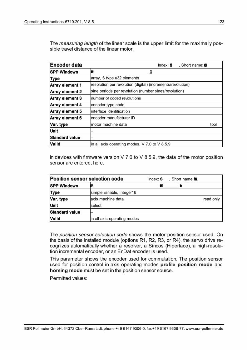
Operating Instructions 6710.201, V 8.5 123
ESR Pollmeier GmbH, 64372 Ober-Ramstadt, phone +49 6167 9306-0, fax +49 6167 9306-77, www.esr-pollmeier.de
The measuring length of the linear scale is the upper limit for the maximally pos-sible travel distance of the linear motor.
Encoder data Index: 5f3d, Short name: EncDat
SPP Windows Resolution per revolution 0
Type array, 6 type u32 elements
Array element 1 resolution per revolution (digital) (increments/revolution)
Array element 2 sine periods per revolution (number sines/revolution)
Array element 3 number of coded revolutions
Array element 4 encoder type code
Array element 5 interface identification
Array element 6 encoder manufacturer ID
Var. type motor machine data tool
Unit –
Standard value –
Valid in all axis operating modes, V 7.0 to V 8.5.9
In devices with firmware version V 7.0 to V 8.5.9, the data of the motor positionsensor are entered, here.
Position sensor selection code Index: 5f09, Short name: EncAuswahl
SPP Windows Position sensor selection code Resolver select
Type simple variable, integer16
Var. type axis machine data read only
Unit select
Standard value –
Valid in all axis operating modes
The position sensor selection code shows the motor position sensor used. Onthe basis of the installed module (options R1, R2, R3, or R4), the servo drive re-cognizes automatically whether a resolver, a Sincos (Hiperface), a high-resolu-tion incremental encoder, or an EnDat encoder is used.
This parameter shows the encoder used for commutation. The position sensorused for position control in axis operating modes profile position mode andhoming mode must be set in the position sensor source.
Permitted values:

Operating Instructions 6710.201, V 8.5124
ESR Pollmeier GmbH, 64372 Ober-Ramstadt, phone +49 6167 9306-0, fax +49 6167 9306-77, www.esr-pollmeier.de
Value Position sensor type
1 Resolver
2 Sincos (Hiperface) encoder
3 High-resolution incremental encoder
4 EnDat encoder
Encoder name Index: 5f3c, Short name: EncName
SPP Windows Designation encoder system resolver
Type simple variable, visible string length 40
Var. type axis machine data tool
Unit –
Standard value –
Valid always; V 6.7 or higher
The encoder name in the device control window shows a detailed designation ofthe used motor position sensor, it may contain more detailed information thanthe position sensor selection code.
9.3.2.3 Motor Temperature Sensor Machine Data
The motor temperature sensor machine data include the following variables:
• Motor temperature sensor data
• Temperature sensor type code
• Resistance switching threshold overtemp.
• Temperature switching threshold overtemp.
Motor temperature sensor data Index: 5F78, Short name: MTempSensorData
Type record, 4 elements
Var. type motor machine data read and write / tool
Valid always, V 8.5.3 and higher
The machine data of the motor temperature sensor are grouped in record vari-able motor temperature sensor data. The individual elements are described inthe following.

Operating Instructions 6710.201, V 8.5 125
ESR Pollmeier GmbH, 64372 Ober-Ramstadt, phone +49 6167 9306-0, fax +49 6167 9306-77, www.esr-pollmeier.de
Temperature sensor type code
Index: 5F78, Subindex: 1, Short name: MTempSensorData1
SPP Windows Temperature sensor type code PTC Sensor
Type record element, unsigned16
Var. type motor machine data read and write / tool
Unit select
Standard value –
Permissible values:
Value Temperature sensor type
1 PTC sensor
2 generical sensor with negative switching threshold
3 generical sensor with positive switching threshold
10 KTY83
11 KTY84
Resistance switching threshold overtemp.
Index: 5F78, Subindex: 2, Short name: MTempSensorData2
SPP Windows Resistance switching threshold overtemp. 2500 Ohm
Type record element, unsigned16
Var. type motor machine data read and write / tool
Unit 1 Ω
Standard value –
In case the resistance motor temperature sensor exceeds the value stated here,the device switches off and reports error “overtemperature motor”.
Temperature switching threshold overtemp.
Index: 5F78, Subindex: 3, Short name: MTempSensorData3
SPP Windows Temperature switching threshold overtemp. 0 °C
Type record element, unsigned16
Var. type motor machine data read and write / tool
Unit 0.1 °C
Standard value –
In case the motor temperature exceeds the value stated here, the deviceswitches off and reports error “overtemperature motor”.

Operating Instructions 6710.201, V 8.5126
ESR Pollmeier GmbH, 64372 Ober-Ramstadt, phone +49 6167 9306-0, fax +49 6167 9306-77, www.esr-pollmeier.de
9.3.3 Servo Drive Machine Data
The servo drive machine data include the following variables:
• Serial number
• Operating time
• Drive rated current
• Power monitoring
• Mains connection selection code
In command and commissioning software SPP Windows, the servo drive ma-chine data can be found in the “Device status” window.
The servo drive machine data are factory preset. They must not be changed bythe user. They are displayed in SPP Windows for the information of speciallytrained service personnel, only.
If the motor does not run as desired, make sure that the correct drive rated cur-rent (0.8, 2, 4, 8, 12, 16, 20, 32 A, depending on the device variant) has been se-lected for your motor and your application.
Serial number Index: –, Short name: SerienNummer
SPP Windows Serial number 631234
Type simple variable, unsigned32
Var. type servo drive machine data tool
Unit –
Standard value –
Valid always
The factory-preset serial number of the device can be read out here.
The serial number is also stated on the nameplate.
Operating time Index: –, Short name: OperatingTime
SPP Windows Operating time total 20.0 h
Operating time power circuit 10.0 h
Type array, 2 type unsigned32 elements
Array element 1 operating time total
Array element 2 operating time power circuit
Var. type actual value tool
Unit 1 s
Standard value –
Valid always; V 8.5.5 to V 8.5.9 as well as V 8.5.998 or higher
These variables count the total operating time (14 V control supply voltage on)
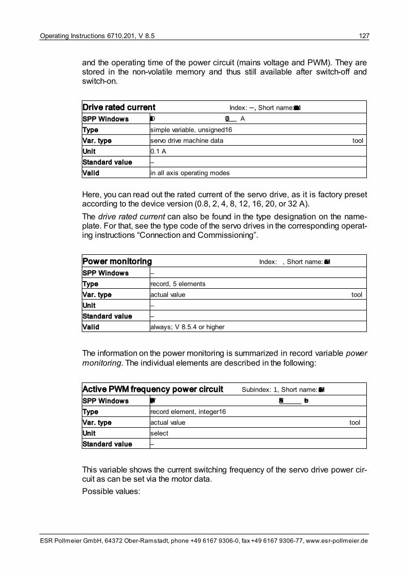
Operating Instructions 6710.201, V 8.5 127
ESR Pollmeier GmbH, 64372 Ober-Ramstadt, phone +49 6167 9306-0, fax +49 6167 9306-77, www.esr-pollmeier.de
and the operating time of the power circuit (mains voltage and PWM). They arestored in the non-volatile memory and thus still available after switch-off andswitch-on.
Drive rated current Index: –, Short name: INennVerstaerker
SPP Windows Drive rated current 8.0 A
Type simple variable, unsigned16
Var. type servo drive machine data tool
Unit 0.1 A
Standard value –
Valid in all axis operating modes
Here, you can read out the rated current of the servo drive, as it is factory presetaccording to the device version (0.8, 2, 4, 8, 12, 16, 20, or 32 A).
The drive rated current can also be found in the type designation on the name-plate. For that, see the type code of the servo drives in the corresponding operat-ing instructions “Connection and Commissioning”.
Power monitoring Index: –, Short name: PwrMonitor
SPP Windows –
Type record, 5 elements
Var. type actual value tool
Unit –
Standard value –
Valid always; V 8.5.4 or higher
The information on the power monitoring is summarized in record variable powermonitoring. The individual elements are described in the following:
Active PWM frequency power circuit Subindex: 1, Short name: PwrMonitor1
SPP Windows Active PWM frequency power circuit 16 kHz select
Type record element, integer16
Var. type actual value tool
Unit select
Standard value –
This variable shows the current switching frequency of the servo drive power cir-cuit as can be set via the motor data.
Possible values:

Operating Instructions 6710.201, V 8.5128
ESR Pollmeier GmbH, 64372 Ober-Ramstadt, phone +49 6167 9306-0, fax +49 6167 9306-77, www.esr-pollmeier.de
Value PWM frequency power circuit
1 16 kHz
0 8 kHz
Power limit Subindex: 2 to 5, Short name: PwrMonitor2 to PwrMonitor5
SPP Windows Continuous current limit servo drive 2.0 A
Peak current limit servo drive 6.0 A
Active continuous current limit 1.6 A
Active peak current limit 3.2 A
Type 4 type unsigned16 record elements
Var. type actual value tool
Unit 0.1 A
Standard value –
These variables show the maximally possible and the currently set power limitsfor continuous current and peak current. The first two values are specified byrated current and peak current of the servo drive. The active power limits resultfrom the rated current of the motor and the settings for continuous current motorand max current amount in the axis data.
Operating modes option Index: –, Short name: BAFreigabeStatus
SPP Windows Operating modes option B2
Type simple variable, unsigned32
Var. type servo drive machine data tool
Unit –
Standard value –
Valid always
This variable contains the value of the operating modes option of the servo drivein binary coding. This value is included in the type code of the servo drive andcan also be read from the type code.
Mains connection selection code Index: –, Short name: NetzanschlAuswahl
SPP Windows Mains connection selection code 400V/3-phase
Type simple variable, integer16
Var. type servo drive machine data tool
Unit –
Standard value –
Valid always; V 5.2 or higher

Operating Instructions 6710.201, V 8.5 129
ESR Pollmeier GmbH, 64372 Ober-Ramstadt, phone +49 6167 9306-0, fax +49 6167 9306-77, www.esr-pollmeier.de
The mains connection with which the servo drive is equipped can be read outhere.
Permitted values (automatically recognized and displayed):
Value Mains connection
–5 90 V three-phase
–4 230 V single-phase
–3 230 V three-phase
–2 400 V three-phase
–1 480 V three-phase
The mains connection can also be found in the type designation on the name-plate:
Type: Mains connection:
BN 675x 230 V single-phase (TrioDrive D/xS, TrioDrive D)
BN 674x 400 V three-phase (MidiDrive D/xS, MidiDrive D)
BN 672x 400 V three-phase (MaxiDrive)
9.3.4 Shunt Resistor Machine Data
The shunt resistor machine data include the following variables:
• Shunt resistor selection code
• Resistance external shunt resistor
• Continuous power external shunt resistor
• Thermal time constant external shunt resistor
In command and commissioning software SPP Windows, the shunt resistor ma-chine data can be found in the “Parameterization” window under Device data/Shunt resistor.
Shunt resistor selection code Index: 5f94, Short name: BallastAuswahl
SPP Windows Shunt resistor selection internal select
Type simple variable, integer16
Var. type device machine data read and write
Unit select
Standard value internal
Valid always; V 5.1 or higher
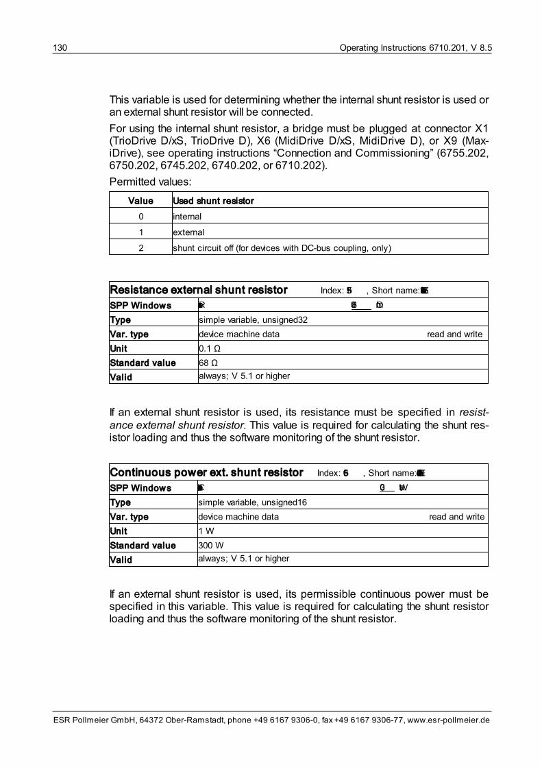
Operating Instructions 6710.201, V 8.5130
ESR Pollmeier GmbH, 64372 Ober-Ramstadt, phone +49 6167 9306-0, fax +49 6167 9306-77, www.esr-pollmeier.de
This variable is used for determining whether the internal shunt resistor is used oran external shunt resistor will be connected.
For using the internal shunt resistor, a bridge must be plugged at connector X1(TrioDrive D/xS, TrioDrive D), X6 (MidiDrive D/xS, MidiDrive D), or X9 (Max-iDrive), see operating instructions “Connection and Commissioning” (6755.202,6750.202, 6745.202, 6740.202, or 6710.202).
Permitted values:
Value Used shunt resistor
0 internal
1 external
2 shunt circuit off (for devices with DC-bus coupling, only)
Resistance external shunt resistor Index: 5f95, Short name: ExtBallastR
SPP Windows Resistance ext. shunt resistor 68.0 Ohm
Type simple variable, unsigned32
Var. type device machine data read and write
Unit 0.1 Ω
Standard value 68 Ω
Valid always; V 5.1 or higher
If an external shunt resistor is used, its resistance must be specified in resist-ance external shunt resistor. This value is required for calculating the shunt res-istor loading and thus the software monitoring of the shunt resistor.
Continuous power ext. shunt resistor Index: 5f96, Short name: ExtBallastPd
SPP Windows Continuous power ext. shunt resistor 300 Watt
Type simple variable, unsigned16
Var. type device machine data read and write
Unit 1 W
Standard value 300 W
Valid always; V 5.1 or higher
If an external shunt resistor is used, its permissible continuous power must bespecified in this variable. This value is required for calculating the shunt resistorloading and thus the software monitoring of the shunt resistor.

Operating Instructions 6710.201, V 8.5 131
ESR Pollmeier GmbH, 64372 Ober-Ramstadt, phone +49 6167 9306-0, fax +49 6167 9306-77, www.esr-pollmeier.de
Thermal time constant ext. shunt resist. Index: 5f97, Short name: ExtBallastTk
SPP Windows Thermal time constant ext. shunt resist. 208 s
Type simple variable, unsigned16
Var. type device machine data read and write
Unit 1 s
Standard value 208 s
Valid always; V 5.1 or higher
If an external shunt resistor is used, its thermal time constant must be specified inthis variable. This value is required for calculating the shunt resistor loading andthus the software monitoring of the shunt resistor.
9.3.5 Input/Output Function Machine Data
The machine data of the input/output function include the following variables:
• Signal selection digital inputs
• Control word user defined bit
• Signal selection digital outputs
• Status word user defined bit
• Linked inputs/outputs
• Analog output 1 signal selection
• Analog output 2 signal selection
• Analog output 1 FP factor
• Analog output 2 FP factor
• Analog output 1 Int factor
• Analog output 2 Int factor
• Limit frequency current filter
In command and commissioning software SPP Windows, the machine data ofthe input/output function can be found in window “Parameterization” underDevice data.
Signal selection digital inputs 1.x Index: 5faa, Short name: DEin1Auswahl
SPP Windows Signal selection digital inputs 1.0 reset fault
Type array, 8 type integer16 elements
Array element 1 .. 8 configuration digital inputs I 1.0 .. I 1.7
Var. type device machine data read and write
Unit select
Standard value reset fault (I 1.0), pre-pulse (I 1.1), enable saw (I 1.4), start running back(I 1.5), measure position (I 1.6)
Valid always (effect depending on axis operating mode); V 6.0 or higher

Operating Instructions 6710.201, V 8.5132
ESR Pollmeier GmbH, 64372 Ober-Ramstadt, phone +49 6167 9306-0, fax +49 6167 9306-77, www.esr-pollmeier.de
Signal selection digital inputs 9.0 Index: 5fac, Short name: DEin9Auswahl
SPP Windows Signal selection digital input 9.0 for free use
Type array, 8 type integer16 elements
Array element 1 .. 8 configuration digital inputs I 9.0 .. I 9.7
Var. type device machine data read and write
Unit select
Standard value for free use
Valid always (effect depending on axis operating mode); V 6.0 or higher
With variables signal selection digital inputs ..., certain drive functions can beassigned to the corresponding digital inputs (see table below). The value enteredin the respective variable determines the drive system function.
Control word user defined bit Index: 5fa8, Short name: DAus11Auswahl
SPP Windows Control word user defined bit 11 for free use
Type array, 8 type integer16 elements
Array element 4 .. 6 control word user defined bit 11 .. 13
Var. type device machine data read and write
Unit select
Standard value for free use
Valid always
The control word user defined bits 11 .. 13 permit an assignment of certain func-tions to bits 11, 12, and 13 in the axis control word.
The following functions can be selected:
Selection code Signal designation Remarks
–1 ffffhex
for free use –
102 66hex
spindle positioning in axis operating modes velocity mode� andvelocity mode direct
110 6ehex
limit switch + (opener)
111 6fhex
limit switch – (opener)
112 70hex
pre-pulse in homing mode
113 71hex
reset fault –
119 77hex
synchronize electronic gearing in axis operating mode electronic gearing,
can be assigned to I 1.4, only
114 72hex
enable saw in axis operating mode flying shear

Operating Instructions 6710.201, V 8.5 133
ESR Pollmeier GmbH, 64372 Ober-Ramstadt, phone +49 6167 9306-0, fax +49 6167 9306-77, www.esr-pollmeier.de
Selection code Signal designation Remarks
115 73hex
start running back in axis operating mode flying shear
116 74hex
position measurement –
135 87hex
fast position measurement can be assigned to I 1.4, only
117 75hex
mains voltage reduced mains voltage reduced to 90 V, the internalmonitoring thresholds are decreased so thatoperation can be enabled
140 8chex
positioning mode bit 0 (position-ing direction)
for timed positioning mode0: clockwise1: counterclockwise
141 8dhex
positioning mode bit 1 for timed positioning mode0: simple movement1: back and forth movement
142 8ehex
positioning mode bit 2 (reserved)
143 8fhex
positioning mode bit 3 for timed positioning mode0: single step1: continuous running
144 90hex
start positioning for timed positioning mode
148 94hex
selection max. current amount switches between max current amount andmax current amount 2
150 96hex
trigger input trace for the event-depending start of a trace re-cording
151 97hex
enable pulse acquisition L1 –
170 aahex
trigger release position meas-urement
corresponds to bit 0 in the trigger mask
172 achex
trigger release fast positionmeasurement
corresponds to bit 2 in the trigger mask
174 aehex
trigger release trace corresponds to bit 4 in the trigger mask
169 a9hex
stop axis according to axis stop selection code
178 b2hex
flying shear external synchron-ization
in axis operating mode flying shear
179 b3hex
enable external synchronization in axis operating mode flying shear
A drive function must not be assigned to more than one digital input. If a drivefunction is assigned to two or more inputs, the behavior of this function is un-defined if different values exist at the inputs.
Some drive functions cannot be assigned to any input for technical reasons,these functions are assigned to I 1.4.

Operating Instructions 6710.201, V 8.5134
ESR Pollmeier GmbH, 64372 Ober-Ramstadt, phone +49 6167 9306-0, fax +49 6167 9306-77, www.esr-pollmeier.de
Signal selection digital outputs 1.x Index: 5f99, Short name: DAus1Auswahl
SPP Windows Signal selection digital output 1.0 overload select
Type array, 8 type integer16 elements
Array element 1 .. 8 configuration digital outputs O 1.0 .. O 1.7
Var. type device machine data read and write
Unit select
Standard value overload (O 1.0), setpoint reached (O 1.1), position monitoring (O 1.2),synchronized/apply saw (O 1.3)
Valid always; V 5.1 or higher
Signal selection digital outputs 8.x Index: 5fa6, Short name: DAus8Auswahl
SPP Windows Signal selection digital output 8.0 for free use
Type array, 8 type integer16 elements
Array element 1 .. 8 configuration digital outputs O 8.0 .. O 8.7
Var. type device machine data read and write
Unit select
Standard value for free use
Valid always; V 5.1 or higher
Signal selection digital outputs 9.x Index: 5fa7, Short name: DAus9Auswahl
SPP Windows Signal selection digital output 9.0 for free use
Type array, 8 type integer16 elements
Array element 1 .. 8 configuration digital outputs O 9.0 .. O 9.7
Var. type device machine data read and write
Unit select
Standard value for free use
Valid always; V 5.1 or higher
Certain signals can be output at the corresponding digital outputs via variablessignal selection digital outputs ... (see table below).
Status word user defined bit Index: 5fad, Short name: DEin11Auswahl
SPP Windows Status word user defined bit 8 for free use
Type array, 8 type integer16 elements
Array element 1 .. 2 status word user defined bit 8 and 9
Var. type device machine data read and write
Unit select
Standard value for free use
Valid always
Status word user defined bits 8 and 9 can be used for assigning certain func-tions to bits 8 and 9 in the axis status word.

Operating Instructions 6710.201, V 8.5 135
ESR Pollmeier GmbH, 64372 Ober-Ramstadt, phone +49 6167 9306-0, fax +49 6167 9306-77, www.esr-pollmeier.de
The following signals can be selected:
Selection code Signal designation Remarks
–1 ffffhex
for free use –
45 2dhex
fault bit 3 in the axis status word
46 2ehex
setpoint reached bit 10 in the axis status word
47 2fhex
brake operates the holding brake of the motor ac-cording to release brake selection code
48 30hex
synchronized/apply saw in axis operating modes electronic gearing� and flying shear
49 31hex
overload =1 if the peak current rise switches back to continuous current motor
145 91hex
in position for timed positioning mode
50 32hex
position monitoring according to position monitoring and posi-tion monitoring time
51 33hex
waste signal in axis operating mode flying shear
52 34hex
velocity = 0 in axis operating modes velocity mode� dir-ect, velocity mode, and electronic gear-ing; bit 12 in the axis status word
53 35hex
spindle position reached with function “spindle positioning” in axis op-erating modes velocity mode direct andvelocity mode�
100 64hex
ready (BTB) = 1 if the DC-bus voltage is available andthe servo drive is not in state fault
60 3chex
switching point 1 –
61 3dhex
switching point 2 –
62 3ehex
switching point 3 –
63 3fhex
switching point 4 –
64 40hex
switching point 5 –
65 41hex
switching point 6 –
66 42hex
switching point 7 –
67 43hex
switching point 8 –
103 67hex
trace trigger output –
136 88hex
reference existing –
160 A0hex
trigger status position measure-ment
corresponds to bit 0 in the trigger status
161 A0hex
trigger status fast position meas-urement
corresponds to bit 2 in the trigger status
162 A0hex
trigger status trace recording corresponds to bit 4 in the trigger status

Operating Instructions 6710.201, V 8.5136
ESR Pollmeier GmbH, 64372 Ober-Ramstadt, phone +49 6167 9306-0, fax +49 6167 9306-77, www.esr-pollmeier.de
Selection code Signal designation Remarks
167 A7hex
synchronous point (flying shear) in axis operating mode flying shear
The signals of the drive-specific functions can also be output at the internalO 15.x outputs. These outputs are “interconnected” with the internal I 15.x inputs.This way, another function linked to input I 15.x can be called up using outputO 15.x.
Signal selection digital inputs 15.x Index: 5fb3, Short name: DEin15Auswahl
SPP Windows Signal selection digital input 15.0 for free use
Type array, 8 type integer16 elements
Array element configuration digital inputs I 15.0 .. I 15.7
Var. type device machine data read and write
Unit select
Standard value for free use
Valid always; V 7.5 or higher, not for MaxiDrive
Signal selection digital outputs 15.x Index: 5fb2, Short name: DAus15Auswahl
SPP Windows Signal selection digital output 15.0 for free use
Type array, 8 type integer16 elements
Array element configuration digital inputs I 15.0 .. I 15.7
Var. type device machine data read and write
Unit select
Standard value for free use
Valid always; V 7.5 or higher, not for MaxiDrive
The digital inputs and outputs I 15.x and O 15.x are linked outputs which are con-nected internally. Their functions correspond to the functions of the signal selec-tion digital inputs ... and signal selection digital outputs ... (see above).
Analog output 1 signal selection Index: 5f82, Short name: Ist1Auswahl
SPP Windows Analog output 1 signal selection Actual speed select
Type simple variable, integer16
Var. type device machine data read and write
Unit select
Standard value actual speed
Valid always; V 3.5 or higher; for devices with -A1 option

Operating Instructions 6710.201, V 8.5 137
ESR Pollmeier GmbH, 64372 Ober-Ramstadt, phone +49 6167 9306-0, fax +49 6167 9306-77, www.esr-pollmeier.de
Analog output 2 signal selection Index: 5f83, Short name: Ist2Auswahl
SPP Windows Analog output 2 signal selection Actual current select
Type simple variable, integer16
Var. type device machine data read and write
Unit select
Standard value actual current
Valid always; V 3.5 or higher; for devices with -A1 option
With variables analog output 1 signal selection and analog output 2 signal se-lection certain signals can be output at analog output 1 or 2 of the servo drive.The value entered in the respective variable determines which signal is output.The scaling can be changed via the analog output ... FP-factor variable (see be-low).
The following tables list all the signals which can be mapped to the analog out-puts and specify the associated selection codes.
Signals generated by the digital signal processor (DSP) in the speed and currentcontroller cycle (62.5 μs):
Selection code Signal designation Type Standardization and units
20 14hex
Actual current i16 1.5 V = 9676 corresponds tomax. continuous current of theservo drive, exception: fordevices TrioDrive D/xS 1.0 V =6451 corresponds to max. con-tinuous current of the servodrive
205 CDhex
Current setpoint
38 26hex
Current setpoint (DSP internal quant-ity) – in axis operating mode torquemode, only
39 27hex
Actual speed (actual velocity) i16 -5 V .. +5 V = –32768.. +32767 corresponds to-16384 .. +16383 r.p.m. (V8.5.9 or higher) or-8192 .. +8192 r.p.m. (up to V8.5.9)
37 25hex
Speed setpoint (DSP internal quant-ity) – not available in axis operatingmode velocity mode direct
24 18hex
Rotor position (of motor positionsensor) (resolver)
i16 -5 V .. +5 V = –32768.. +32767 position sensor steps(= 1 revolution)
21 15hex
Analog input “Setpoint” or “Setpoint 1” i16 –5 V .. +5 V = –32768.. +32767 corresponds to -10 V.. +10 V at the analog input set-point
81 51hex
Analog input “Setpoint 2”
Signals generated by the microcontroller in the position control loop cycle (1 ms).A processing time of approx. 5 ms for variables must be taken into account.
Selection code Signal designation Type Standardization and units
253 FDhex
Current setpoint filtered i16 1.5 V = 9676 corresponds to

Operating Instructions 6710.201, V 8.5138
ESR Pollmeier GmbH, 64372 Ober-Ramstadt, phone +49 6167 9306-0, fax +49 6167 9306-77, www.esr-pollmeier.de
Selection code Signal designation Type Standardization and units
35 23hex
Current output value torque function max. continuous current of theservo drive
30 1ehex
Torque setpoint variable (torque setpoint digital)
i16 0.15 V = 1000 corresponds tothe motor rated torque
0 00hex
Actual speed of DSP i16 -5 V .. +5 V = –32768.. +32767 corresponds to -16384 .. +16383 r.p.m. (V8.5.9 or higher) or-8192 .. +8192 r.p.m. (up to V8.5.9)
34 22hex
Actual speed input encoder signals(option Lx), derived from differentiationof position information (related to themaster axis)
43 2bhex
Feedforward speed electronic gear-ing� (related to slave axis)
31 1fhex
Target velocity variable (target velocity digital)
4 04hex
Speed setpoint for DSP (position con-trol loop output)
2 02hex
Actual position (related to applicationzero point)
i32 -5 V .. +5 V = -32768 .. +32767position sensor steps
27 1bhex
Position sensor actual position re-solver (option R1)
28 1chex
Position sensor actual position inputencoder signals (option Lx)
6 06hex
Internal target position variable (re-lated to application zero point) (posi-tion setpoint)
10 0ahex
Control offset of position control loop –not in the axis operating modes elec-tronic gearing� and� flying shear
12 0c hex Analog outputs variable, subindex 1(analog output value 1)
i16 -5 V .. +5 V = -16384 .. +16383
13 0d hex Analog outputs variable, subindex 2(analog output value 2)
14 0ehex
Analog outputs variable, subindex 3(analog output value 3
15 0fhex
Analog outputs variable, subindex 4(analog output value 4)
91 5Bhex
Encoder voltage i16 1:1
101 65hex
DC-bus voltage i16 -5 V .. +5 V correspond to aDC-bus voltage of -32786.. +32767 volts
If the product of the selected signal and the scaling factor analog output ... FPfactor (firmware V 5.4 or higher) or analog output ... Int factor exceeds the valuerange of –32768 .. +32767 (integer16), the limit values –32768 or +32767 areoutput instead.
These types of limit and overflow effects must be taken into account during selec-tion of the factors and interpretation of the output voltages.

Operating Instructions 6710.201, V 8.5 139
ESR Pollmeier GmbH, 64372 Ober-Ramstadt, phone +49 6167 9306-0, fax +49 6167 9306-77, www.esr-pollmeier.de
Please also note the information on output voltage range, resolution, and band-width of the analog outputs in operating instructions “Connection and Commis-sioning” (6755.202, 6745.202, 6750.202, 6740.202, or 6710.202).
Analog output 1 FP factor Index: 5fa1, Short name: FakAnaIst1
SPP Windows Analog output 1 FP factor 1.00000
Type simple variable, integer32
Var. type setpoint or parameter for a function read and write
Unit 65536 (10000hex
) corresponds to FP factor = 1.0
Standard value 65536 (corresponds to FP factor = 1.0)
Valid always; V 5.4 or higher; for devices with -A1 option
Analog output 2 FP factor Index: 5fa2, Short name: FakAnaIst2
SPP Windows Analog output 2 FP factor 1.00000
Type simple variable, integer32
Var. type setpoint or parameter for a function read and write
Unit 65536 (10000hex
) corresponds to FP factor = 1.0
Standard value 65536 (corresponds to FP factor = 1.0)
Valid always; V 5.4 or higher; for devices with -A1 option
Analog output 1 FP factor and analog output 2 FP factor serve for scaling thevoltage output at analog output “Ist1” or “Ist2” . A signal mapped to the output(see analog output ... signal selection variable above) is multiplied by this factorbefore output. In the case of a negative factor, the sign of the signal is inverted.
The output has a value range of –5 V .. +5 V, which corresponds to preset valuesof –32768 .. +32767 (integer16). This means that the following examples apply:
Value of the signal mapped to “ Ist1”
×Analog output 1
FP factor =
Signal ×factor
=Output“ Ist1”
32767 × 1.0 = 32767 = +5.0 V
32767 × 0.5 = 16383 = +2.5 V
3276 × –10.0 = –32760 = –5.0 V
No values higher than +32767 or lower than –32768 are output for the product ofsignal and factor. If the product exceeds the above value range, the limit values+32767 or –32768 are output instead. These types of limit effects must be takeninto account during selection of the factors and interpretation of the outputvoltages.
Please, also note the information on output voltage range, resolution, and band-width of the analog outputs in section “Analog outputs Ist1, Ist2” of operating in-structions “Connection and Commissioning” (6755.202, 6745.202, 6750.202,6740.202, or 6710.202).
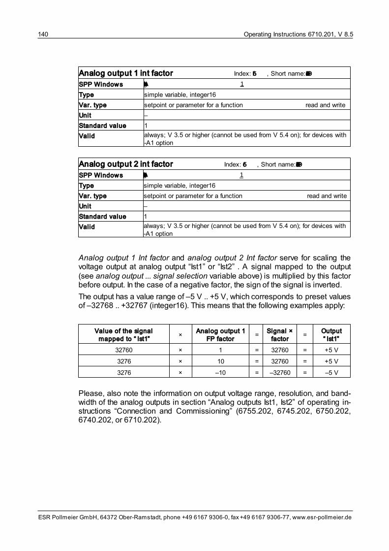
Operating Instructions 6710.201, V 8.5140
ESR Pollmeier GmbH, 64372 Ober-Ramstadt, phone +49 6167 9306-0, fax +49 6167 9306-77, www.esr-pollmeier.de
Analog output 1 int factor Index: 5f6b, Short name: DSPFakDac1
SPP Windows Analog output 1 Int factor 1
Type simple variable, integer16
Var. type setpoint or parameter for a function read and write
Unit –
Standard value 1
Valid always; V 3.5 or higher (cannot be used from V 5.4 on); for devices with -A1 option
Analog output 2 int factor Index: 5f6c, Short name: DSPFakDac2
SPP Windows Analog output 2 Int factor 1
Type simple variable, integer16
Var. type setpoint or parameter for a function read and write
Unit –
Standard value 1
Valid always; V 3.5 or higher (cannot be used from V 5.4 on); for devices with -A1 option
Analog output 1 Int factor and analog output 2 Int factor serve for scaling thevoltage output at analog output “Ist1” or “Ist2” . A signal mapped to the output(see analog output ... signal selection variable above) is multiplied by this factorbefore output. In the case of a negative factor, the sign of the signal is inverted.
The output has a value range of –5 V .. +5 V, which corresponds to preset valuesof –32768 .. +32767 (integer16). This means that the following examples apply:
Value of the signal mapped to “ Ist1”
×Analog output 1
FP factor =
Signal ×factor
=Output“ Ist1”
32760 × 1 = 32760 = +5 V
3276 × 10 = 32760 = +5 V
3276 × –10 = –32760 = –5 V
Please, also note the information on output voltage range, resolution, and band-width of the analog outputs in section “Analog outputs Ist1, Ist2” of operating in-structions “Connection and Commissioning” (6755.202, 6745.202, 6750.202,6740.202, or 6710.202).

Operating Instructions 6710.201, V 8.5 141
ESR Pollmeier GmbH, 64372 Ober-Ramstadt, phone +49 6167 9306-0, fax +49 6167 9306-77, www.esr-pollmeier.de
Limit frequency current filter Index: 5e94, Short name: FgIsqFilter
SPP Windows Limit frequency current filter 100.00 Hz
Type simple variable, float32
Var. type device machine data read and write
Unit Hz
Standard value 100 Hz
Valid always; V 8.5.999.59 or higher
This parameter is used for setting the limit frequency signal “current setpointfiltered” is filtered with (value range approx. 0.01 Hz .. 130 Hz).
9.4 Variable Descriptions Axis Machine Data
9.4.1 Axis Control Machine Data
The axis control machine data include the following variables:
• Enable selection code
• Release brake selection code
• Brake delay times
• Axis operating mode at startup
• Stop axis selection code
In command and commissioning software SPP Windows, the axis control ma-chine data can be found in the “Parameterization” window under Axis data/Axiscontrol.
Enable selection code Index: 5f15, Short name: FreiAuswahl
SPP Windows Action enable inactive/active no action/no action select
Type simple variable, integer16
Var. type axis machine data read and write
Unit select
Standard value no action / no action
Valid in all axis operating modes
With the enable selection code, the effect of the “enable” input can be specified.
Permitted values:
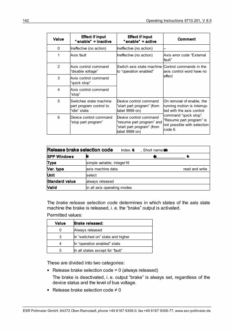
Operating Instructions 6710.201, V 8.5142
ESR Pollmeier GmbH, 64372 Ober-Ramstadt, phone +49 6167 9306-0, fax +49 6167 9306-77, www.esr-pollmeier.de
ValueEffect if input
“ enable” = inactiveEffect if input
“ enable” = activeComment
0 Ineffective (no action) Ineffective (no action) –
1 Axis fault Ineffective (no action) Axis error code “Externalfault”
2 Axis control command“disable voltage”
Switch axis state machineto “operation enabled”
Control commands in theaxis control word have noeffect
3 Axis control command“quick stop”
4 Axis control command“stop”
5 Switches state machinepart program control to“idle” state.
Device control command“start part program” (fromlabel 9999 on)
On removal of enable, therunning motion is interrup-ted with the axis controlcommand “quick stop”.“Resume part program” isnot possible with selectioncode 6.
6 Device control command“stop part program”
Device control command“resume part program” and“start part program” (fromlabel 9999 on)
Release brake selection code Index: 5f16, Short name: BremseLoesenAuswahl
SPP Windows Brake released at device status always released select
Type simple variable, integer16
Var. type axis machine data read and write
Unit select
Standard value always released
Valid in all axis operating modes
The brake release selection code determines in which states of the axis statemachine the brake is released, i. e. the “brake” output is activated.
Permitted values:
Value Brake released:
0 Always released
3 In “switched on” state and higher
4 In “operation enabled” state
5 In all states except for “fault”
These are divided into two categories:
• Release brake selection code = 0 (always released)
The brake is deactivated, i. e. output “brake” is always set, regardless of thedevice status and the level of bus voltage.
• Release brake selection code ≠ 0

Operating Instructions 6710.201, V 8.5 143
ESR Pollmeier GmbH, 64372 Ober-Ramstadt, phone +49 6167 9306-0, fax +49 6167 9306-77, www.esr-pollmeier.de
The brake is only released (output “brake” is set), if
– the device status corresponds to the condition in the release brake selec-tion code and
– the DC-bus voltage is sufficient and
– there is no fault.
Brake delay times Index: 5f18, Short name: BremseVerzZeit
SPP Windows Brake activation time 0 ms
Brake release time 0 ms
Type array, 2 type unsigned16 elements, 16, subindex 1 and 2
Element 1 brake release time
Element 2 brake activation time
Var. type axis machine data read and write
Unit ms
Standard value 0
Valid always
This variable can be used for compensating the physical response time (activa-tion of brake) and the release time (release brake) of emergency braking sys-tems.
Via subindex 1 (brake release time), the time between activation of the controland release of the brake is defined, via subindex 2 (brake activation time), thetime between activation of the brake and switch-off of the PWM is defined.
Please note: In case of a mains breakdown, the brake is activated immediately.In case of a fault, the brake is activated as soon as state fault reaction active isreached, i. e. brake ramps are not waited for.
Axis operating mode at startup Index: 5f35, Short name: AchsBAVorwahl
SPP Windows Axis operating mode at startup Velocity mode select
Type simple variable, integer8 (V 8.5.996 or higher)
simple variable, integer16 (up to V 8.5.995)
Var. type axis machine data read and write
Unit select
Standard value velocity mode
Valid always; V 5.1 or higher
Axis operating mode at startup defines the axis operating mode active after thedrive has been switched on.

Operating Instructions 6710.201, V 8.5144
ESR Pollmeier GmbH, 64372 Ober-Ramstadt, phone +49 6167 9306-0, fax +49 6167 9306-77, www.esr-pollmeier.de
Permitted values:
Value Axis operating mode
–4 Torque mode
–3 Velocity mode direct (V 3.2 or higher)
–3 Velocity mode
–1 Profile position mode
–6 Homing mode
–1 Electronic gearing
–2 Flying shear (V 4.5 or higher)
–4 Velocity profile (V 5.95 or higher)
–5 Timed positioning mode (V 8.5.9 or higher)
10 Cyclic synchronous torque mode (V 8.5.999.53 or higher)
9 Cyclic synchronous velocity mode (V 8.5.999.54 or higher)
8 Cyclic synchronous position mode (V 8.5.999.62 or higher)
7 Interpolated Position Mode (V 5.95 or higher)
Stop axis selection code Index: 5e97 Short name: StopAuswahl
SPP Windows Stop axis selection code no reaction select
Type simple variable, integer16
Var. type axis machine data read and write
Unit select
Standard value no reaction
Valid in all axis operating modes
The stop axis selection code determines the effect of input function “axis stop”,i. e. the way the axis is stopped as soon as the input is set.
Permitted values:
Value Stop axis
0 no reaction
1 stop without ramp
2 stop with brake ramp
3 quick stop
9.4.2 Setpoint Sources Machine Data
The setpoint sources machine data include the following variables:
• Target velocity source
• Target velocity analog factor
• Target velocity analog offset
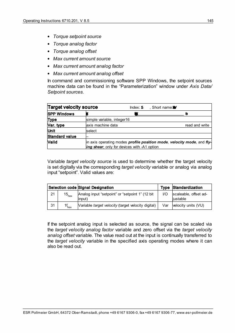
Operating Instructions 6710.201, V 8.5 145
ESR Pollmeier GmbH, 64372 Ober-Ramstadt, phone +49 6167 9306-0, fax +49 6167 9306-77, www.esr-pollmeier.de
• Torque setpoint source
• Torque analog factor
• Torque analog offset
• Max current amount source
• Max current amount analog factor
• Max current amount analog offset
In command and commissioning software SPP Windows, the setpoint sourcesmachine data can be found in the “Parameterization” window under Axis Data/Setpoint sources.
Target velocity source Index: 5f11, Short name: VelVerfahrAuswahl
SPP Windows Target velocity source Target velocity digital select
Type simple variable, integer16
Var. type axis machine data read and write
Unit select
Standard value –
Valid in axis operating modes profile position mode, velocity mode, and fly-ing shear; only for devices with -A1 option
Variable target velocity source is used to determine whether the target velocityis set digitally via the corresponding target velocity variable or analog via analoginput “setpoint”. Valid values are:
Selection code Signal Designation Type Standardization
21 15hex
Analog input “setpoint” or “setpoint 1” (12 bitinput)
I/O scaleable, offset ad-justable
31 1fhex
Variable target velocity (target velocity digital) Var velocity units (VU)
If the setpoint analog input is selected as source, the signal can be scaled viathe target velocity analog factor variable and zero offset via the target velocityanalog offset variable. The value read out at the input is continually transferred tothe target velocity variable in the specified axis operating modes where it canalso be read out.

Operating Instructions 6710.201, V 8.5146
ESR Pollmeier GmbH, 64372 Ober-Ramstadt, phone +49 6167 9306-0, fax +49 6167 9306-77, www.esr-pollmeier.de
Target velocity analog factor Index: 5f1b, Short name: AnaVelFaktor
SPP Windows Target velocity analog factor 100.0 %
Type simple variable, integer16
Var. type axis machine data read and write
Unit 0.1% of the motor rated speed at 10 V setpoint
Standard value 100%
Valid in axis operating modes profile position mode, velocity mode, velo-city mode direct, and flying shear; V 3.2 or higher; only for devices with-A1 option
The target velocity analog factor serves for scaling analog input “setpoint” if thisis selected as target velocity source. You can specify how many per thousand ofthe motor rated speed of the motor corresponds to a setpoint of 10 V.
Examples (for motor rated speed = 3,000 r.p.m.):
• Target velocity analog factor = 1000 (100%): 10 V at the analog input corres-pond to 3,000 r.p.m. setpoint
• Target velocity analog factor = 200 (20%): 10 V at the analog input corres-pond to 600 r.p.m. setpoint
Target velocity analog offset Index: 5f1e, Short name: AnaVelOffset
SPP Windows Target velocity analog offset 0.0 r.p.m.
Type simple variable, integer16
Var. type axis machine data read and write
Unit 0.5 r.p.m. (V 8.5.9 or higher)
0.25 r.p.m. (up to V 8.5.9)
Standard value 0
Valid axis operating modes profile position mode, velocity mode, velocitymode direct, and flying shear; V 3.2 or higher; only for devices with -A1option
The target velocity analog offset permits a zero offset for analog input “setpoint”if this input is selected as target velocity source. This compensates zero offsetsof the analog signals.
When servo drives are exchanged, an adjustment of this value may be requiredas the internal compensation can vary with the individual devices.
Torque setpoint source Index: 5f10, Short name: MsollAuswahl
SPP Windows Torque setpoint source Torque setpoint digital select
Type simple variable, integer16
Var. type axis machine data read and write
Unit select
Standard value –
Valid in axis operating mode torque mode; for devices with -A1 option, only

Operating Instructions 6710.201, V 8.5 147
ESR Pollmeier GmbH, 64372 Ober-Ramstadt, phone +49 6167 9306-0, fax +49 6167 9306-77, www.esr-pollmeier.de
Variable torque setpoint source is used for specifying whether the torque set-point is set digitally via the corresponding torque setpoint or analog via the “set-point” analog input. Valid values are:
Selection code Signal designation Type Standardization
21 15 hex Analog input “setpoint” or “setpoint 1” (12 bit in-put)
I/O scaleable, offset ad-justable
30 1e hex Variable torque setpoint (torque setpoint digital)
Var per thousand of motorrated current
If the “setpoint” analog input is selected as source, a scaling of the signal can becarried out via variable torque analog factor, a zero offset via variable torqueanalog offset.
Torque analog factor Index: 5f1a, Short name: AnaMFaktor
SPP Windows Torque analog factor 100.0 %
Type simple variable, integer16
Var. type axis machine data read and write
Unit 0.1% of motor rated torque at 10 V setpoint
Standard value 100%
Valid in axis operating mode torque mode; V 3.2 or higher; only for deviceswith -A1 option
The torque analog factor serves for scaling analog input “setpoint” if this input isselected as the torque setpoint source. You can specify how many per thousandof the motor rated torque correspond to a setpoint of 10 V.
Examples (for motor rated torque = 3.4 Nm):
• Torque analog factor = 1000 (100%): 10 V at the analog input correspond to3.4 Nm setpoint
• Torque analog factor = 200 (20%): 10 V at the analog input correspond to0.68 Nm setpoint
Torque analog offset Index: 5f1d, Short name: AnaMOffset
SPP Windows Torque analog offset 0.0 %
Type simple variable, integer16
Var. type axis machine data read and write
Unit 0.1% of motor rated torque
Standard value 0
Valid in axis operating mode torque mode; V 3.2 or higher; only for deviceswith A1 option

Operating Instructions 6710.201, V 8.5148
ESR Pollmeier GmbH, 64372 Ober-Ramstadt, phone +49 6167 9306-0, fax +49 6167 9306-77, www.esr-pollmeier.de
The torque analog offset permits a zero offset for analog input “setpoint” if this in-put is selected as torque setpoint source. This compensates for zero offsets ofthe analog signals.
When servo drives are exchanged, an adjustment of this value may be requiredas the compensation can vary with the individual devices.
Max current amount source Index: 5f28, Short name: IImpulsAuswahl
SPP Windows Max current amount source Variable “max current amount” select
Type simple variable, integer16
Var. type axis machine data read and write
Unit select
Standard value –
Valid in all axis operating modes; V 3.5 or higher; only for devices with -A1 op-tion
Variable max current amount source is used for specifying whether the currentlimit is set digitally via the corresponding current max amount variable or analogvia analog input “setpoint”. Valid values are:
Selection code Signal designation Type Standardization
21 15hex
Analog input “setpoint” or “setpoint 1” (12 bit in-put)
I/O scaleable, offset ad-justable
81 51hex
Analog input “setpoint 2” (12 bit input) I/O scaleable, offset ad-justable
44 2chex
Variable current max amount Var per thousand of motorrated current
If the “setpoint” analog input is selected as source, the signal can be scaled viathe max current amount analog factor variable and zero offset via the max cur-rent amount analog offset variable.
Max current amount analog factor Index: 5f26, Short name: AnaIImpFaktor
SPP Windows Max current amount analog factor 200.0 %
Type simple variable, integer16
Var. type axis machine data read and write
Unit 0.1% of motor rated current at 10 V
Standard value 100%
Valid in all axis operating modes; V 3.5 or higher; only for devices with -A1 op-tion
The max current amount analog factor serves for scaling analog input “setpoint”if this input is selected as max current amount source. You can specify to how

Operating Instructions 6710.201, V 8.5 149
ESR Pollmeier GmbH, 64372 Ober-Ramstadt, phone +49 6167 9306-0, fax +49 6167 9306-77, www.esr-pollmeier.de
many per thousand of the motor rated current the current is limited at a setpointof 10 V.
Examples:
• Max current amount analog factor = 1000 (100%): 10 V at the analog inputcorrespond to a current limit of 100% of the rated current
• Max current amount analog factor = 200 (20%): 10 V at the analog input cor-respond to a current limit of 20% of the rated current
Max current amount analog offset Index: 5f27, Short name: AnaIImpOffset
SPP Windows Max current amount analog offset 0.0 %
Type simple variable, integer16
Var. type axis machine data read and write
Unit 0.1% of motor rated current
Standard value 0
Valid in all axis operating modes; V 3.5 or higher; only for devices with -A1 op-tion
The max current amount analog offset permits a zero offset for analog input“setpoint” if this input is selected as max current amount source. This com-pensates for zero offsets of the analog signals.
When servo drives are exchanged, an adjustment of this value may be requiredas the compensation can vary with the individual devices.
9.4.3 Position Measuring System Machine Data
The position measuring system machine data include the following variables:
• Position sensor source
• Position sensor resolution
• Gear ratio motor shaft revolutions
• Gear ratio drive shaft revolutions
• Ext. sensor encoder data
• Ext. Sensor: Measuring steps per revolution
• Ext. Sensor: Sine periods per revolution
• Ext. Sensor: Number of coded revolutions
• Ext. Sensor: Encoder type code
• Ext. Sensor: Interface identification
• Ext. Sensor: Manufacturer identification
• Encoder absolute type
• Motorposition sin/cos monitoring
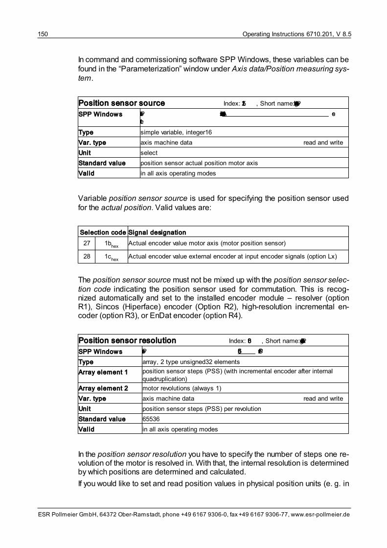
Operating Instructions 6710.201, V 8.5150
ESR Pollmeier GmbH, 64372 Ober-Ramstadt, phone +49 6167 9306-0, fax +49 6167 9306-77, www.esr-pollmeier.de
In command and commissioning software SPP Windows, these variables can befound in the “Parameterization” window under Axis data/Position measuring sys-tem.
Position sensor source Index: 5f12, Short name: PosIstLgAuswahl
SPP Windows Position sensor source Actual encoder value motor axis se-lect
Type simple variable, integer16
Var. type axis machine data read and write
Unit select
Standard value position sensor actual position motor axis
Valid in all axis operating modes
Variable position sensor source is used for specifying the position sensor usedfor the actual position. Valid values are:
Selection code Signal designation
27 1bhex
Actual encoder value motor axis (motor position sensor)
28 1chex
Actual encoder value external encoder at input encoder signals (option Lx)
The position sensor source must not be mixed up with the position sensor selec-tion code indicating the position sensor used for commutation. This is recog-nized automatically and set to the installed encoder module – resolver (optionR1), Sincos (Hiperface) encoder (Option R2), high-resolution incremental en-coder (option R3), or EnDat encoder (option R4).
Position sensor resolution Index: 608f, Short name: PosAufloesung
SPP Windows Position sensor resolution 65536 PSS/rev.
Type array, 2 type unsigned32 elements
Array element 1 position sensor steps (PSS) (with incremental encoder after internalquadruplication)
Array element 2 motor revolutions (always 1)
Var. type axis machine data read and write
Unit position sensor steps (PSS) per revolution
Standard value 65536
Valid in all axis operating modes
In the position sensor resolution you have to specify the number of steps one re-volution of the motor is resolved in. With that, the internal resolution is determinedby which positions are determined and calculated.
If you would like to set and read position values in physical position units (e. g. in

Operating Instructions 6710.201, V 8.5 151
ESR Pollmeier GmbH, 64372 Ober-Ramstadt, phone +49 6167 9306-0, fax +49 6167 9306-77, www.esr-pollmeier.de
mm, μm, or angular degrees), you can do so by specifying a conversion factorposition factor (see section Factors and Units Machine Data ). This conver-sion factor is used for converting the position sensor steps to your units.
From firmware V 8.5.9 on the position sensor resolution can be selected freelyby the user. It is recommended to select the highest one possible.
• If a resolver is used as position sensor, the upper limit is 65.536.
• If a position sensor with sine-cosine signals is used, the upper limit resultsfrom the number of sine periods multiplied by 8,192; for 512 sine periods4,194,304 and for 2048 sine periods 16,777,216.
• For position sensors with digital transmission of the actual position, the upperlimit is the number of transmitted position values per revolution, e.g. 524,288or 33,554,432.
For multiturn encoders, please make sure that the product of position sensorresolution and number of possible revolutions is lower than 536,870,912 (=229),e.g. for 4,096 possible revolutions, the position sensor resolution must be lowerthan 131,072.
For devices with firmware versions below V 8.5.9, the position sensor resolutioncannot be selected freely. If the motor position sensor (resolver, Sincos (Hiper-face) encoder, high-resolution incremental encoder, or EnDat encoder) is usedas position sensor, 65,536 must be preset, here. This means that each revolutionis resolved into 65,536 steps even if the motor position sensor offers a higherresolution.
You can also use an external position sensor (incremental encoder) as positionsensor instead of the motor position sensor. This external position sensor is con-nected to input encoder signals (option L1 or ZL1). In this case, the number ofsteps of the position sensor (incremental encoder) must be converted to thenumber of steps per motor revolution for the position sensor resolution. Further-more, it is also necessary to take into account that the steps in the servo driveare quadrupled. Example :
• motor with gearbox i = 5,
• incremental encoder with 1000 steps per revolution at gear output
=>One motor revolution corresponds to 1/5 revolution at the gear output, i. e.1000 / 5 = 200 steps of the incremental encoder. After quadruplication in theservo drive, this corresponds to 200 × 4 = 800 steps of a motor revolution, sothat, for the purposes of this example, 800 “position sensor steps” need to beentered in this variable.
From firmware version V 8.5.999.56 on, the gear ratio can be defined in vari-able gear ratio and does not have to be considered for conversion.
158

Operating Instructions 6710.201, V 8.5152
ESR Pollmeier GmbH, 64372 Ober-Ramstadt, phone +49 6167 9306-0, fax +49 6167 9306-77, www.esr-pollmeier.de
Gear ratio Index: 6091, Subindex: 2, Short name: GearRatio
SPP Windows Gear ratio motor shaft rev. 1
Gear ratio driving shaft rev. 1
Type array, 2 type unsigned32 elements
Array element 1
Array element 2
number revolutions motor shaft
number revolutions drive shaft
Var. type axis machine data read and write
Unit –
Standard value 1:1
Valid always; V 8.5.999.56 and higher
For gearboxes with external position sensor at the drive side, the gear ratio canbe entered here so that it is considered automatically for the position sensor res-olution.
Ext. sensor encoder data Index: 5E86, Short name: Encoder2Data
Type record, 5 elements
Var. type axis machine data read and write
Valid always; V 8.6 or higher
The machine data of the optional external position sensor are grouped in recordvariable Ext. sensor encoder data. The structure is based on the machine dataof the motor position sensor. The individual elements are described in the follow-ing.
Ext. sensor: measuring steps per revol. / meter Index: 5E86, Subindex: 1, Short name: Encoder2Data1
SPP Windows Ext. sensor: measuring steps per revol. 0
Type record element, unsigned32
Var. type axis machine data read and write / tool
Unit 1 increment, for linear length scales per meter
Standard value –
For incremental encoders with square-wave signals (e. g. option -L1 or -ZL1), thenumber of measuring steps resulting from internal quadruplication is enteredhere. Example: An encoder with 250 pulses per revolution (see below) supplies1.000 measuring steps per revolution.
For absolute encoders (e. g. EnDat encoder for option -ZL4), the number ofmeasuring steps (position values) per revolution is displayed here. Examples:262,144 (18 bit), 8,388,608 (23 bit), or 33,554.432 (25 bit).

Operating Instructions 6710.201, V 8.5 153
ESR Pollmeier GmbH, 64372 Ober-Ramstadt, phone +49 6167 9306-0, fax +49 6167 9306-77, www.esr-pollmeier.de
Ext. sensor: sine periods per revolution / meter Index: 5E86, Subindex: 2, Short name: Encoder2Data2
SPP Windows Ext. sensor: sine periods per revolution 1
Type record element, unsigned32
Var. type axis machine data read and write / tool
Unit –
Standard value –
For position sensors with square-wave signals (e. g. for option -L1 or -ZL1), thenumber of pulses per revolution is entered here. If an EnDat encoder is used foroption -ZL4, the number of sine periods per revolution is displayed here.Example: 16, 1024, 250.
Ext. sensor: number of coded revolutions Index: 5E86, Subindex: 3, Short name: Encoder2Data3
SPP Windows Ext. sensor: number of coded revolutions 1
Type record element, unsigned16
Var. type axis machine data read and write / tool
Unit –
Standard value –
For singleturn encoders, 1 is entered here, for multiturn encoders, the number ofrevolutions that can be acquired. For EnDat encoders, the entry is carried outautomatically. Whether or not the servo drive can evaluate several revolutions de-pends on the interface.
Ext. sensor: encoder type code
Index: 5E86, Subindex: 4, Short name: Encoder2Data4
SPP Windows Ext. sensor: encoder type code 0000
Type record element, unsigned16
Var. type axis machine data read and write / tool
Unit –
Standard value –
Ext. sensor: encoder type code uses the same assignment as Encoder typecode of the motor position sensor. For EnDat encoders, this entry is carried outautomatically.
Currently reasonable values (others on request):
Value Encoder type
0 enocder type not defined
External encoders for option -L1 or -ZL1:
0c0f rotatory square-wave incremental encoders
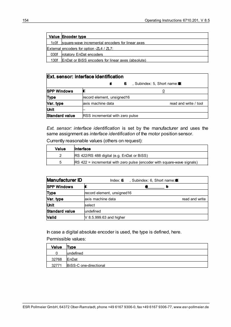
Operating Instructions 6710.201, V 8.5154
ESR Pollmeier GmbH, 64372 Ober-Ramstadt, phone +49 6167 9306-0, fax +49 6167 9306-77, www.esr-pollmeier.de
Value Encoder type
1c0f square-wave incremental encoders for linear axes
External encoders for option -ZL4 / ZL7:
030f rotatory EnDat encoders
130f EnDat or BiSS encoders for linear axes (absolute)
Ext. sensor: interface identification
Index: 5E86, Subindex: 5, Short name: Encoder2Data5
SPP Windows Ext. sensor: interface identification 0
Type record element, unsigned16
Var. type axis machine data read and write / tool
Unit –
Standard value RSS incremental with zero pulse
Ext. sensor: interface identification is set by the manufacturer and uses thesame assignment as interface identification of the motor position sensor.
Currently reasonable values (others on request):
Value Interface
2 RS 422/RS 488 digital (e.g. EnDat or BiSS)
5 RS 422 = incremental with zero pulse (encoder with square-wave signals)
Manufacturer ID Index: 5E86, Subindex: 6, Short name: Encoder2Data6
SPP Windows Ext. sensor: manufacturer ID undefined select
Type record element, unsigned16
Var. type axis machine data read and write
Unit select
Standard value undefined
Valid V 8.5.999.63 and higher
In case a digital absolute encoder is used, the type is defined, here.
Permissible values:
Value Type
0 undefined
32768 EnDat
32771 BiSS-C one-directional

Operating Instructions 6710.201, V 8.5 155
ESR Pollmeier GmbH, 64372 Ober-Ramstadt, phone +49 6167 9306-0, fax +49 6167 9306-77, www.esr-pollmeier.de
Encoder absolute type Index: 5e9d, Short name: PosAbsTyp
SPP Windows Encoder absolute type Auto select
Type simple variable, integer16
Var. type axis machine data read and write
Unit select
Standard value auto
Valid in all axis operating modes
If the position sensor actual position of the motor axis is selected as positionsensor source, this variable may be used for defining a multi-turn encoder assingle-turn for going to home position with a circular axis.
Permitted values:
Value Position sensor
0 Auto
1 Single-turn
9.4.4 Drive System Machine Data
The drive system machine data include the following variables:
• Polarities
• Maximum motor speed
• Continuous current motor
• Max current amount
• Max current amount 2
• Inertia load / Mass
• Commutation reference
In command and commissioning software SPP Windows, the drive system ma-chine data can be found in the “Parameterization” window under Axis data/Drive.
Polarities Index: 607e, Short name: Polaritaeten
SPP Windows Polarities negative (ext. encoder) select
Type simple variable, octet string length 1
Var. type axis machine data read and write
Unit select
Standard value “position negative” (bit 7 = 1)
Valid in all axis operating modes
The setpoint and actual values are multiplied by 1 or -1, depending on their polar-ity. This enables users to reverse the direction of orientation.

Operating Instructions 6710.201, V 8.5156
ESR Pollmeier GmbH, 64372 Ober-Ramstadt, phone +49 6167 9306-0, fax +49 6167 9306-77, www.esr-pollmeier.de
Bit 7: position polarity
• 0 = positive
• 1 = negative (standard value)
Bit 6: reserved
• intended for future expansions, currently without effect
The position polarity must not and does not need to be changed if the motor pos-ition sensor (resolver, Sincos (Hiperface) encoder, high-resolution incrementalencoder, or EnDat encoder) is implemented as position measuring system.
If an external position sensor is implemented at input encoder signals (option Lxor ZLx), the counting direction of the encoder signals can be changed via the po-sition polarity in order to close the position control loop, if necessary.
If the polarities are set incorrectly, the control loops do not close and the axis may“run away”, i. e. run at maximum speed.
Maximum motor speed Index: 6080, Short name: Nmax
SPP Windows Maximum motor speed 6000.0 r.p.m. (for rotatory drive systems)
Maximum speed 5.00 m/s (for linear motors)
Type simple variable, unsigned32
Var. type axis machine data read and write
Unit 0.5 r.p.m. or 1/4096 m/s (V 8.5.9 or higher)
0.25 r.p.m. (up to V 8.5.9)
Standard value –
Valid in all axis operating modes except for torque mode / force mode
The maximum speed is set for both directions of rotation together. It serves as aprotection for the motor and can be taken from the motor data sheet.
In axis operating mode torque mode and force mode, a speed limitation is notcarried out at the moment.
Monitoring of the speed via software, as is the case with this variable, does notcomply with the safety requirements of the machinery directive.
• If the speed is to be monitored at the machine, compliance with the safety re-quirements of the machinery directive is essential.
Continuous current motor Index: 5f02, Short name: IDauer
SPP Windows Continuous current motor 100.0 %I rated
Type simple variable, unsigned16
Var. type axis machine data read and write
Unit 0.1% of motor rated current
Standard value 100%
Valid in all axis operating modes

Operating Instructions 6710.201, V 8.5 157
ESR Pollmeier GmbH, 64372 Ober-Ramstadt, phone +49 6167 9306-0, fax +49 6167 9306-77, www.esr-pollmeier.de
The continuous current motor can be set here in per thousand of the motor ratedcurrent. Generally, 100% is set here, lower values can be used as a torque limit.
A limitation of the torque via software, as is the case with continuous current mo-tor, does not comply with the safety requirements of the machinery directive.
• If you want to limit the torque at the machine, compliance with the safety re-quirements of the machinery directive is essential.
Max current amount Index: 6073, Short name: IImpuls
SPP Windows Max current amount 200.0 %I rated
Type simple variable, unsigned16
Var. type axis machine data read and write
Unit 0.1% of motor rated current
Standard value 200%
Valid in all axis operating modes
The peak current of the servo drive can be set per thousand of the motor ratedcurrent using max current amount. Generally, 200% is set here, lower valuescan be used as a torque limit (e. g. 100%, if no increase in peak current beyondthe motor rated current is to occur).
Alternatively, the torque limit can be implemented via analog input “Setpoint”, seesection Setpoint Sources Machine Data .
A limitation of the torque via software, as is the case with max current amount,does not comply with the safety requirements of the machinery directive.
• If you want to limit the torque at the machine, compliance with the safety re-quirements of the machinery directive is essential.
Max current amount 2 Index: 5e9c, Short name: IImpuls2
SPP Windows Max current amount 2 200.0 %I rated
Type simple variable, unsigned16
Var. type axis machine data read and write
Unit 0.1% of motor rated current
Standard value 200%
Valid in all axis operating modes
If the max current amount selection function is used at a digital input, this inputcan be used for switching between variables max current amount (input not act-ive) and max current amount 2 (input active).
144

Operating Instructions 6710.201, V 8.5158
ESR Pollmeier GmbH, 64372 Ober-Ramstadt, phone +49 6167 9306-0, fax +49 6167 9306-77, www.esr-pollmeier.de
Inertia load or Mass Index: 5E82, Short name: InertiaLoad
SPP Windows Inertia load 0.0 kgm² (for rotatory drive systems)
Mass 0.0 kg (for linear motors)
Type simple variable, float32
Var. type axis machine data read and write
Unit 1 kgm2 or 1 kg
Standard value 0
Valid in all axis operating modes
Enter the moment of inertia or the mass of the carriage incl. load and primarypart, here. (If the moment of inertia is stated in 10-3 kg m2, divide the value by1,000 and enter the result here. If the moment of inertia is stated in 10-4 kg m2 orin kg cm2, divide the value by 10,000 and enter the result here.)
Commutation reference Index: 5E83, Short name: KommRefAuswahl
SPP Windows Commutation reference Absolute information
Type simple variable, integer16
Var. type axis machine data read and write
Unit select
Standard value absolute information
Valid in all axis operating modes
The method for commutation finding is selected using this variable. For detailedinformation, see section Autocommutation .
Permissible values:
Value Commutation finding
0 Absolute information (method determined by the applied encoder system)
–1 Autocommutation
–2 Zero point search using rotating field generator
–3 Autocommutation with each switch-on
–4 Zero point search using rotating field generator with each switch-on
–5 Always evaluate absolute information
–6 Mounting offset at current position
9.4.5 Factors and Units Machine Data
The factors and units machine data include the following variables:
• Position factor
• Home offset
• Velocity factor
In command and commissioning software SPP Windows, the factors and units
15

Operating Instructions 6710.201, V 8.5 159
ESR Pollmeier GmbH, 64372 Ober-Ramstadt, phone +49 6167 9306-0, fax +49 6167 9306-77, www.esr-pollmeier.de
machine data can be found in the “Parameterization” window under Axis data/Factors and units.
Position factor Index: 6093, Short name: PosFaktorSoll
SPP Windows Position factor numerator 1 PSSPosition factor denominator 1 PU
Type array, 2 type unsigned32 elements
Array element 1 numerator in position sensor steps (PSS)
Array element 2 denominator in position units (PU)
Var. type axis machine data read and write
Unit (see above)
Standard value 1 PSS / 1 PU
Valid in all axis operating modes
Variable position factor is used for specifying the meaning of the position units(PU). This permits an adaptation to physical units (e. g. mm or μm). The positionunits determine the representation of the variables target position and actual po-sition and most of the other variables that represent position values.
Two categories can be distinguished:
• Position factor = 1 PSS / 1 PU (on delivery):
One position unit corresponds to one position sensor step and thus dependsexclusively on the set resolution of the position measuring system.
• Position factor ≠ 1 PSS / 1 PU (application-specific):
One position unit corresponds to a specific number of position sensor steps(e. g. 10, 1/10, 27/33) which is set via this variable. This permits the display ofposition values in physical units (e. g. mm, μm).
Example 1: This example assumes a linear drive system where a motor drives acarriage via a spindle with the following values:
• Lead screw pitch = 5 mm (the carriage moves by 5 mm per motor revolution)
• Position sensor resolution = 65536 PSS (resolver)
In this case, a position factor of 65536/5000 means that
• 65536 increments (PSS), i. e. one motor revolution (= 5 mm), correspond to
• 5000 position units (PU)
Thus, 1 position unit (PU) corresponds exactly to 1 μm.
Example 2 (external position sensor): This example assumes a linear drive sys-tem where a motor drives a carriage via a spindle with the following values:
• Lead screw pitch = 5 mm (the carriage moves by 5 mm per motor revolution)
• Position sensor resolution = 4000 PSS (external position sensor with 1000steps, connected to the motor; pulse quadruplication in the servo drive pro-duces 4000 steps per motor revolution)

Operating Instructions 6710.201, V 8.5160
ESR Pollmeier GmbH, 64372 Ober-Ramstadt, phone +49 6167 9306-0, fax +49 6167 9306-77, www.esr-pollmeier.de
In this case, a position factor of 4/5 means that
• 4 increments (PSS) (= 1/1000 revolution = 5 μm) correspond to
• 5 position units
Thus, 1 position unit (PU) corresponds to exactly 1 μm.
The available value range is 1/268,435,456 (1/228) to 268,435,456/1 (228/1).
Any change to the position factor influences the settings of numerous other ma-chine data described in the following sections. For this reason, the positionfactor must always be set prior to these other machine data.
Home offset Index: 607c, Short name: PosRefOffset
SPP Windows Home offset 0 PU
Type simple variable, integer32
Var. type axis machine data read and write
Unit position units (PU)
Standard value 0
Valid in all axis operating modes
The home offset specifies the distance between the machine home position anda zero point defined by the application (application zero point for short). This maybe the machine zero point or the workpiece zero point. If machine home positionand application zero point are located at the same point, 0 is to be entered inhome offset.
Because the application zero point can be shifted by the home offset, this is alsoreferred to as a zero offset.
For a detailed description with an example, see section Homing Mode . Addi-tionally, please not the effects of a zero offset on the positioning range, see sec-tion Positioning Range Machine Data .
With multi-turn encoders, homing is not required. Even with those encoders, theabsolute position can be adjusted to the application zero using the home offset.
Velocity factor Index: 6094, Short name: VelFaktorSoll
SPP Windows Velocity factor numerator 1.0 r.p.m.Velocity factor denominator 1 VU
Type array, two type unsigned32 elements
Array element 1 numerator in 0.5 r.p.m. or 1/4096 m/s (V 8.5.9 or higher)
numerator in 0.25 r.p.m. (up to V 8.5.9)
Array element 2 denominator in velocity units (VU)
Var. type axis machine data read and write
Unit (see above)
Standard value 1 r.p.m. / 1 VU or 1/4096 m/s = 1 GE
Valid in all axis operating modes
38
161

Operating Instructions 6710.201, V 8.5 161
ESR Pollmeier GmbH, 64372 Ober-Ramstadt, phone +49 6167 9306-0, fax +49 6167 9306-77, www.esr-pollmeier.de
With variable velocity factor, the meaning of the velocity units (VU) is defined.This permits an adaptation to physical units (e. g. r.p.m. or mm/s). The velocityunits determine the representation of the variables target velocity, actual velo-city, and most other variables that represent velocities.
On delivery, the velocity factor of rotatory drive systems is set to 1 r.p.m. / 1 VU.Thus, a velocity unit always corresponds to 1 r.p.m.
Two categories can be distinguished:
• Target velocity factor = 1 r.p.m. / 1 VU
One velocity unit corresponds to 1 r.p.m., i. e., corresponding parameters arespecified directly in revolutions per minute.
• Target velocity factor ≠ 1 r.p.m. / 1 VU
One velocity unit corresponds to a specific number of revolutions per minute(e. g. 4, 400, 48/37) which is set via the velocity factor variable. This permitsthe display of velocity values in physical units (e. g. mm/s, m/s).
Example:
• A factor of 1/10 means: 1 r.p.m. corresponds to 10 velocity units (VU). Thus,the corresponding velocity values are represented in 0.1 r.p.m.
Any change to the velocity factor influences the settings of numerous other ma-chine data described in the following sections. For this reason the velocity factormust always be set prior to these other machine data.
9.4.6 Positioning Range Machine Data
The positioning range machine data include the following variables:
• Axis type
• Range limit
• Position limit
In command and commissioning software SPP Windows, the positioning rangemachine data can be found in the “Parameterization” window under Axis data/Positioning range.
Axis type Index: 5ef9, Short name: PosStreckentyp
SPP Windows Axis type Linear axis select
Type simple variable, integer16
Var. type axis machine data read and write
Unit select
Standard value linear axis
Valid in all axis operating modes
The axis type indicates to the profile position mode whether the axis is a linear

Operating Instructions 6710.201, V 8.5162
ESR Pollmeier GmbH, 64372 Ober-Ramstadt, phone +49 6167 9306-0, fax +49 6167 9306-77, www.esr-pollmeier.de
or a circular axis. Also see range limit and position limit min/max.
Permitted values:
Value Axis type
0 Linear axis
1 Circular axis with path optimization:Absolute preset target positions are approached via the shortest route (path optimiza-tion).
2 Circular axis without path optimization:Absolute preset target positions are approached in a positive direction if the targetposition is greater than the old target position (variable internal target position) and ina negative direction if it is smaller.
After changing an axis type or the range limit, you must first go to home positionbefore you can work in one of the other axis operating modes.
Range limit Index: 607b, Short name: PosBereichsGrenze
SPP Windows Range limit min 0 PURange limit max 65,535 PU
Type array, 2 type integer32 elements
Array element 1 range limit min in position units (PU)
Array element 2 range limit max in position units (PU)
Var. type axis machine data read and write
Unit position units (PU), range limit min = application zero point
Standard value 0 PU .. 65535 PU
Valid in all axis operating modes (if axis type = circular axis)
If axis type circular axis is selected, this variable is used for setting the upper andlower limit of the value range. If, for example, a circle is to be resolved with1/1000°, the following settings must be entered:
• range limit min = 0
• range limit max = 359,999
This example shows that, for the range limit on a circular axis, the values rangelimit min (0) and range limit max + 1 (360,000) coincide.
The following limits apply to profile position mode:
Positioning Min. target position Max. target position
absolute range limit min range limit max
relative -1 revolution +1 revolution
1 revolution is: range limit max – range limit min + 1.
Examples:

Operating Instructions 6710.201, V 8.5 163
ESR Pollmeier GmbH, 64372 Ober-Ramstadt, phone +49 6167 9306-0, fax +49 6167 9306-77, www.esr-pollmeier.de
Range limit Target position (absolute) Target position (relative)
min. max. min. max. min. max.
0 359 0 359 -360 +360
1 65,536 1 65,536 -65,536 +65,536
-1,799 1,800 -1,799 1,800 -3,600 +3,600
-50 49 -50 49 -100 +100
0 21,599 0 21,599 -21,600 +21,600
The value range for the upper and lower limit is between -1,073,741,824 and+1,073,741,823, range limit min must always be smaller than range limit max.
Before specifying the range limits, the position units must be defined via the pos-ition factor.
In order to prevent rounding errors, position factor and range limit must be selec-ted so that they can be converted to position sensor steps without remainders.
In case of a zero offset with the home offset and range limit min ≠ 0 it must beensured that range limit min is mapped to the application zero point.
After changing an axis type or the range limit, you must first go to home positionbefore you can work in one of the other axis operating modes.
Position limit Index: 607d, Short name: PosGrenzwert
SPP Windows Position limit min -536,870,912 PUPosition limit max 536,870,911 PU
Type array, 2 type integer32 elements
Array element 1 position limit min in position units (PU)
Array element 2 position limit max in position units (PU)
Var. type axis machine data read and write
Unit position units (PU) related to machine home position
Standard value -536,870.912 PU .. 536,870,911 PU
Valid in axis operating mode profile position mode (if axis type = linear axis)
If a linear axis is selected as axis type, position limit min and position limit maxare the absolute position limits between which the target positions (in absoluteform) must range. Each new target position is checked with regard to these lim-its.
The position limit values always relate to the machine home position. If the zeropoint of the coordinate system is shifted by a change of the home offset, the max-imally permissible positions related to the application remain unchanged. There-fore, if applicable, the home offset must be taken into account when presettingabsolute target positions.
Example: Position limit min = -1,000 PU
Position limit max = +1,000 PU

Operating Instructions 6710.201, V 8.5164
ESR Pollmeier GmbH, 64372 Ober-Ramstadt, phone +49 6167 9306-0, fax +49 6167 9306-77, www.esr-pollmeier.de
Home offset = 200 PU
=> permitted target positions = -800 .. 1,200 PU
Prior to defining the position limit values, the position units must be defined viathe position factor.
The value range for the upper and lower limit is -536,870,912 and +536,870,911position sensor steps (take into account conversion PU to PSS with positionfactor). However, these limits are virtually never reached as, at a resolution of1 μm, they correspond to a range of more than 1,000 m. Position limit min mustalways be smaller than position limit max.
If, when switching from another axis operating mode to operating mode profileposition mode, it cannot be ensured that the actual position is within the positionlimit values, you must first go to home position.
Monitoring of the limit positions via software, as is the case with position limit,does not comply with the safety requirements of the machinery directive.
• If the position is to be monitored at the machine, compliance with the safetyrequirements of the machinery directive is essential.
9.4.7 Ramps Machine Data
The ramps machine data include the following variables:
• Motion profile type
• Acceleration time
• Deceleration time
• Quick stop time
• Ramps reference velocity
In command and commissioning software SPP Windows, the ramps machinedata can be found in the “Parameterization” window under Axis data/Ramps.
Motion profile type Index: 6086, Short name: RampFormAuswahl
SPP Windows Motion profile type linear select
Type simple variable, integer16
Var. type axis machine data read and write
Unit select
Standard value linear
Valid in axis operating modes profile position mode, velocity mode, andhoming mode
The motion profile type specifies the behavior of the acceleration and decelera-tion process.

Operating Instructions 6710.201, V 8.5 165
ESR Pollmeier GmbH, 64372 Ober-Ramstadt, phone +49 6167 9306-0, fax +49 6167 9306-77, www.esr-pollmeier.de
Permitted values are:
Value Ramp type
–1 jump (no ramp)
–0 linear ramp
–1 sin2 ramp
Acceleration time
Index: 6083 (V 8.5.996 + higher)/5ef4 (to V 8.5.995), Short name: RampBeschlZeit
SPP Windows Acceleration time 250 ms
Type simple variable, unsigned32
Var. type axis machine data read and write
Unit 1 ms
Standard value 250 ms (value range 1 .. 32767)
Valid in axis operating modes profile position mode, velocity mode, andhoming mode
The acceleration time specifies the time needed to accelerate to the ramps ref-erence velocity. This ensures the same acceleration even with different target ve-locities.
Deceleration time
Index: 6084 (V 8.5.996 + higher)/5ef5 (up to V 8.5.995), Short name: RampVerzZeit
SPP Windows Deceleration time 250 ms
Type simple variable, unsigned32
Var. type axis machine data read and write
Unit 1 ms
Standard value 250 ms (value range 1 .. 32767)
Valid in axis operating modes profile position mode, velocity mode, andhoming mode
The deceleration time specifies the time needed to decelerate from the rampsreference velocity to 0. This ensures the same deceleration, even with differenttarget velocities.
If control command “quick stop” in the axis status word is used for decelerating,the quick stop time is used instead of the deceleration time.

Operating Instructions 6710.201, V 8.5166
ESR Pollmeier GmbH, 64372 Ober-Ramstadt, phone +49 6167 9306-0, fax +49 6167 9306-77, www.esr-pollmeier.de
Quick stop time
Index: 6085 (V 8.5.996 + higher)/5ef6 (to V 8.5.995), Short name: RampSchnellZeit
SPP Windows Quick stop time 200 ms
Type simple variable, unsigned32
Var. type axis machine data read and write
Unit 1 ms
Standard value 200 ms (value range 1 .. 32767)
Valid in axis operating modes profile position mode, velocity mode, andhoming mode
The quick stop time specifies the time needed for decelerating from the rampsreference velocity to 0. It is only effective in case of a deceleration using controlcommand “quick stop” in the axis control word. Otherwise, the deceleration timeis valid.
Ramps reference velocity Index: 5ef7, Short name: RampVelBezug
SPP Windows Ramps reference velocity 3000 VU
Type simple variable, unsigned32
Var. type axis machine data read and write
Unit velocity units (VU)
Standard value 3,000 VU (value range 1 .. 32767)
Valid in axis operating modes profile position mode, velocity mode, hom-ing mode, electronic gearing, and flying shear
In operating modes profile position mode, velocity mode, and homingmode, the ramps reference velocity specifies the velocity to which the accelera-tion time, deceleration time, and quick stop time parameters apply. In operatingmodes electronic gearing and flying shear, it is the reference value for ramptime el. gearing.

Operating Instructions 6710.201, V 8.5 167
ESR Pollmeier GmbH, 64372 Ober-Ramstadt, phone +49 6167 9306-0, fax +49 6167 9306-77, www.esr-pollmeier.de
Figure 17: Acceleration and Deceleration Ramps
When the ramps reference velocity is changed, the slope of all ramps changes,as well.
The ramps reference velocity is converted internally to r.p.m. and must not be setto “0”. Depending on the definition of the velocity units (VU), low values higherthan 0 VU can be rounded to 0 r.p.m.
To switch off the ramps, select motion profile type “jump” or set accelerationtime, deceleration time, and quick stop time to zero.
9.4.8 Speed Control Loop Machine Data
The speed control loop machine data include the following variables:
• Speed filter cut-off frequency
• Speed control loop Kp
• Speed control loop Ki
• Speed control loop total amplification
• Order of nonrecursive velocity filter
• Velocity threshold
• Velocity threshold time
• Velocity window
• Velocity window time
In command and commissioning software SPP Windows, the speed control loopmachine data can be found in the “Parameterization” window under Axis data/Speed control loop.
For details on the setting of the speed control loop parameters, see section Set-ting Current, Speed, and Position Control Loop .71

Operating Instructions 6710.201, V 8.5168
ESR Pollmeier GmbH, 64372 Ober-Ramstadt, phone +49 6167 9306-0, fax +49 6167 9306-77, www.esr-pollmeier.de
Speed filter cut-off frequency Index: 5f22, Short name: VelIstFilterF0
SPP Windows Speed filter cut-off frequency 100 Hertz
Type simple variable, unsigned16
Var. type axis machine data read and write
Unit 1 Hz
Standard value 100 Hz
Valid in all axis operating modes except for torque mode; V 3.4 to V 8.5.9
This machine date is used for setting the cut-off frequency of the low-pass filterwhich is used for smoothing the actual speed determined from the motor positionencoder signals. This is a digital low-pass of the second order; the 3 dB limitingfrequency of the low-pass corresponds to double the value specified here.
Speed control loop Kp Index: 5ef1, Short name: VelKp
SPP Windows Speed control loop Kp 0.9800
Type simple variable, unsigned16
Var. type axis machine data read and write
Unit V 8.5.9 or higher: 2048 (800hex
) corresponds to a value of 1.0
Standard value 1.0 = 2048 (V 8.5.9 or higher) or 2000 (permissible value range 1 .. 32767)
Valid in all axis operating modes except for torque mode
Parameter speed control loop Kp sets the proportional gain of the digital speedcontrol loop. Use commissioning aid speed control loop (see section Setting theSpeed Control Loop ).
Speed control loop Ki Index: 5ef2, Short name: VelKi
SPP Windows Speed control loop Ki 0.4900
Type simple variable, unsigned16
Var. type axis machine data read and write
Unit V 8.5.9 or higher: 4096 (1000hex
) corresponds to a value of 1.0
Standard value 1.0 = 4096 (8.5.9 or higher) or 4100 (permissible value range 1 .. 32767)
Valid in all axis operating modes except for torque mode
Parameter speed control loop Ki sets the gain of the integration of the digitalspeed control loop. Use commissioning aid speed control loop (see section Set-ting the Speed Control Loop ).
74
74

Operating Instructions 6710.201, V 8.5 169
ESR Pollmeier GmbH, 64372 Ober-Ramstadt, phone +49 6167 9306-0, fax +49 6167 9306-77, www.esr-pollmeier.de
Speed control loop total amplification
Index: 5f21 (axis 1), Short name: VelKGesamt
SPP Windows Speed control loop total amplification 1.000
Type simple variable, unsigned16
Var. type axis machine data read and write
Unit 2048 (800hex
) corresponds to a value of 1.0
Standard value 2048 (corresponds to 1.0)
Valid in all axis operating modes except for torque mode; V 3.4 to V 8.5.9
The speed control loop total amplification can be used for increasing the loopgain of the speed control loop by a factor of 1 to 16. A value of 2048 corres-ponds to a factor of 1.0, and a value of 32767 to a factor of 16; higher or lowervalues must not be set. Doubling the speed control loop total amplification hasthe same effect as a simultaneous doubling of the machine data speed controlloop Kp and speed control loop Ki.
It is particularly useful to change this machine date when machine data speedcontrol loop Kp or speed control loop Ki are set to the maximum value and a fur-ther increase in loop gain is required.
Order of nonrecursive velocity filter
Index: 5F66, Subindex: 11,Short name: VelFilter11
SPP Windows Order of nonrecursive velocity filter 250 µs
Type record element, unsigned16
Var. type axis machine data read and write
Unit select
Standard value 250 µs
Valid in all axis operating modes
The noise of the actual speed value can be influenced with this variable.
Higher times reduce the noise of the actual speed value. Lower times permit bet-ter speed dynamics. If applicable, higher amplification factors (Kp, Ki) of thespeed control loop are possible with lower times.
Permissible values:
Value Averaging via
1 1 current control loop cycles (62.5 μs)
2 2 current control loop cycles (125 μs)
4 4 current control loop cycles (250 μs)
8 8 current control loop cycles (500 μs)
16 16 current control loop cycles (1 ms)

Operating Instructions 6710.201, V 8.5170
ESR Pollmeier GmbH, 64372 Ober-Ramstadt, phone +49 6167 9306-0, fax +49 6167 9306-77, www.esr-pollmeier.de
Velocity threshold Index: 606f, Short name: VelSchwelle
SPP Windows Velocity threshold 20.0 ± r.p.m.
Type simple variable, unsigned32
Var. type axis machine data read and write
Unit 0.5 r.p.m. (V 8.5.9 or higher)
0.25 r.p.m. (up to V 8.5.9)
Standard value 20 r.p.m.
Valid in all axis operating modes except for torque mode
The velocity threshold specifies the actual velocity range around zero velocity atwhich “velocity = 0” is reported.
In axis operating mode velocity mode, this message is indicated with bit 12“Velocity = 0” in the axis status word.
This message is evaluated in all axis operating modes in order to generate theinternal events “braking completed” and “quick stop completed” (see sec-tion Axis State Machine ).
Message “velocity = 0” is only generated if the actual velocity is within the rangeof the velocity threshold at least for the velocity threshold time.
In order to safely determine that the velocity zero has been reached, the corres-ponding velocity threshold and velocity threshold time variables must be set ina way that, even if the axis is subject to motion as a result of control oscillationsor an external force, this movement never exceeds the speed specified in the ve-locity threshold.
Velocity threshold time Index: 6070, Short name: VelSchwelleZeit
SPP Windows Velocity threshold time 0 ms
Type simple variable, unsigned16
Var. type axis machine data read and write
Unit 1 ms
Standard value 0 ms
Valid in all axis operating modes except for torque mode
Message “velocity = 0” is only created if the actual velocity is within the range ofthe velocity threshold for at least the velocity threshold time.
17

Operating Instructions 6710.201, V 8.5 171
ESR Pollmeier GmbH, 64372 Ober-Ramstadt, phone +49 6167 9306-0, fax +49 6167 9306-77, www.esr-pollmeier.de
Velocity window Index: 606d, Short name: VelFenster
SPP Windows Velocity window 20.0 ± r.p.m.
Type simple variable, unsigned32
Var. type axis machine data read and write
Unit 0.5 r.p.m. (V 8.5.9 or higher)
0.25 r.p.m. (up to V 8.5.9)
Standard value ±20 r.p.m.
Valid in axis operating modes velocity mode, velocity mode direct, andelectronic gearing
The velocity window specifies the range of the actual velocity around the targetvelocity in which “target velocity reached” is reported with bit 10 of the axis statusword. This message can also be output at a digital output. For that, see signalselection digital output ... in section Input/Output Function Machine Data .
Message “target velocity reached” is only generated if the actual speed is withinthe range of the velocity window at least for the velocity window time.
Velocity window time Index: 606e, Short name: VelFensterZeit
SPP Windows Velocity window time 0 ms
Type simple variable, unsigned16
Var. type axis machine data read and write
Unit 1 ms
Standard value 0 ms
Valid in axis operating modes velocity mode, velocity mode direct, andelectronic gearing
Message “target velocity reached” is only generated if the actual speed is withinthe range of the velocity window at least for the velocity window time.
9.4.9 Position Control Loop Machine Data
The position control loop machine data include the following variables:
• Position control loop Kp
• Position control loop Kp Divisor
• Positioning window
• Positioning window time
• Position monitoring
• Position monitoring time
• Kp feedforward speed
• Following error window
131

Operating Instructions 6710.201, V 8.5172
ESR Pollmeier GmbH, 64372 Ober-Ramstadt, phone +49 6167 9306-0, fax +49 6167 9306-77, www.esr-pollmeier.de
• Following error time out
In command and commissioning software SPP Windows, the position controlloop machine data can be found in the “Parameterization” window under Axisdata/Position control loop.
Position control loop Kp Index: 5ef0, Short name: PosKpp
SPP Windows Position control loop Kp 10
Type simple variable, unsigned16 (by V 2.4: unsigned8)
Var. type axis machine data read and write
Unit –
Standard value 10
Valid in axis operating modes profile position mode and electronic gearing
Together with position control loop Kp divisor, parameter position control loopKp sets the gain of the position control loop.
Position control loop Kp divisor Index: 5f0d, Short name: PosKppDiv
SPP Windows Position control loop Kp divisor 60
Type simple variable, unsigned16
Var. type axis machine data read and write
Unit –
Standard value 60
Valid in axis operating modes profile position mode and electronic gearing;V 8.5.9 and higher
The amplification of the position control loop results from position control loopKp divided by position control loop Kp divisor.
Positioning window Index: 6067, Short name: PosFenster
SPP Windows Positioning window 100 ±PSS
Type simple variable, unsigned32
Var. type axis machine data read and write
Unit position sensor steps (PSS)
Standard value ±100 LgS
Valid in axis operating modes profile position mode and electronic gearing
The positioning window is placed symmetrically around the target position. Assoon as the actual position is within this positioning window, bit 10 “position set-point reached” or “synchronized” is set in the axis status word. This message canalso be output at a digital output. For that, see signal selection digital output ...in section Input/Output Function Machine Data .
131

Operating Instructions 6710.201, V 8.5 173
ESR Pollmeier GmbH, 64372 Ober-Ramstadt, phone +49 6167 9306-0, fax +49 6167 9306-77, www.esr-pollmeier.de
Message “position setpoint reached” or “synchronized” is only generated if theactual position is within the positioning window at least for the positioning windowtime.
Positioning window time Index: 6068, Short name: PosFensterZeit
SPP Windows Positioning window time 0 ms
Type simple variable, unsigned16
Var. type axis machine data read and write
Unit 1 ms
Standard value 0 ms
Valid in axis operating modes profile position mode and electronic gearing
The positioning window time prevents the setting of bit 10 “position setpointreached” or “synchronized” in the axis status word if the positioning window isonly briefly swept over. The axis has to be in the positioning window for the pre-set positioning window time before this bit is set.
Position monitoring Index: 5f1f, Short name: PosUeberwach
SPP Windows Position monitoring 100 ±PSS
Type simple variable, unsigned32
Var. type axis machine data read and write
Unit position sensor steps (PSS)
Standard value ±100 PSS
Valid in axis operating mode profile position mode; V 3.3b to V 8.5.995
The position monitoring is placed symmetrically around the target position. Assoon as the actual position is outside the position range specified by the posi-tion monitoring, output “position monitoring” is set.
Output “position monitoring” is only set when the actual position is outside therange of the position monitoring for at least the position monitoring time.
Position monitoring time Index: 5f20, Short name: PosUeberwachZeit
SPP Windows Position monitoring time 0 ms
Type simple variable, unsigned16
Var. type axis machine data read and write
Unit 1 ms
Standard value 0 ms
Valid in axis operating mode profile position mode; V 3.3b to V 8.5.995
The position monitoring time prevents the setting of output “position monitoring”

Operating Instructions 6710.201, V 8.5174
ESR Pollmeier GmbH, 64372 Ober-Ramstadt, phone +49 6167 9306-0, fax +49 6167 9306-77, www.esr-pollmeier.de
if the position area around the target position specified by the position monitor-ing parameter is left for a short period of time. The axis must be outside the posi-tion area specified by the position monitoring parameter for the position monit-oring time before this output is set.
Kp feedforward speed Index: 5F64, Subindex: 4, Short name: TimedPosition4
SPP Windows Kp feedforward speed 1.000
Type simple variable, float32
Var. type axis machine data read and write
Unit –
Standard value 1.0
Valid V 8.5.999.53 or higher
With this variable, the feedforward speed can be set.
Following Error Window Index: 6065, Short name: FollowingErrWindow
SPP Windows Following error window 4294967295 PSS
Type simple variable, unsigned32
Var. type axis machine data read and write
Unit PSS
Standard value 4294967295 (FFFF FFFFhex
)
Valid in axis operating modes interpolated position mode and cyclic syn-chronous position mode; V 8.5.997 or higher
The following error window is located symmetrically around the target position.As soon as the actual position is outside the position range defined by the follow-ing error window, the device changes to “fault“ state and reports error “followingerror position control loop“.
Error “following error position control loop“ is not executed unless the actual posi-tion is outside the range following error window for at least the following errortimeout.
Following Error Time Out Index: 6066, Short name: FollowingErrTimeout
SPP Windows Following error time out 0 ms
Type simple variable, unsigned16
Var. type axis machine data read and write
Unit ms
Standard value 0
Valid in axis operating modes interpolated position mode and cyclic syn-chronous position mode; V 8.5.997 or higher
The following error time out prevents that error “following error position control
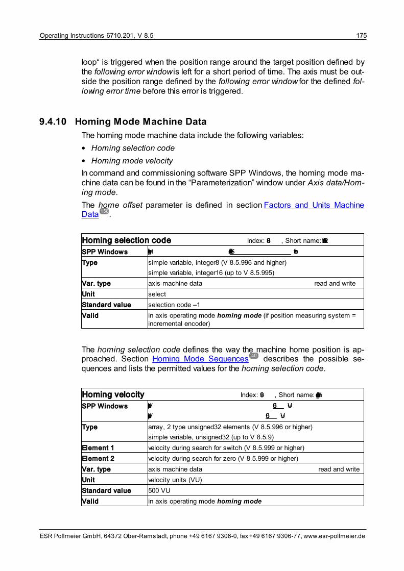
Operating Instructions 6710.201, V 8.5 175
ESR Pollmeier GmbH, 64372 Ober-Ramstadt, phone +49 6167 9306-0, fax +49 6167 9306-77, www.esr-pollmeier.de
loop“ is triggered when the position range around the target position defined bythe following error window is left for a short period of time. The axis must be out-side the position range defined by the following error window for the defined fol-lowing error time before this error is triggered.
9.4.10 Homing Mode Machine Data
The homing mode machine data include the following variables:
• Homing selection code
• Homing mode velocity
In command and commissioning software SPP Windows, the homing mode ma-chine data can be found in the “Parameterization” window under Axis data/Hom-ing mode.
The home offset parameter is defined in section Factors and Units MachineData .
Homing selection code Index: 6098, Short name: RefAuswahl
SPP Windows Homing selection code Selection code -1 select
Type simple variable, integer8 (V 8.5.996 and higher)
simple variable, integer16 (up to V 8.5.995)
Var. type axis machine data read and write
Unit select
Standard value selection code –1
Valid in axis operating mode homing mode (if position measuring system =incremental encoder)
The homing selection code defines the way the machine home position is ap-proached. Section Homing Mode Sequences describes the possible se-quences and lists the permitted values for the homing selection code.
Homing velocity Index: 6099, Short name: HomingSpeed
SPP Windows Velocity during search for switch 500 VU
Velocity during search for zero 500 VU
Type array, 2 type unsigned32 elements (V 8.5.996 or higher)
simple variable, unsigned32 (up to V 8.5.9)
Element 1 velocity during search for switch (V 8.5.999 or higher)
Element 2 velocity during search for zero (V 8.5.999 or higher)
Var. type axis machine data read and write
Unit velocity units (VU)
Standard value 500 VU
Valid in axis operating mode homing mode
158
40

Operating Instructions 6710.201, V 8.5176
ESR Pollmeier GmbH, 64372 Ober-Ramstadt, phone +49 6167 9306-0, fax +49 6167 9306-77, www.esr-pollmeier.de
The homing velocity specifies the velocity at which the machine home position isapproached. The velocity during search for switch defines the velocity at whichthe reference switch is approached. The velocity during search for zero definesthe velocity at which the zero point is approached. For devices with firmware ver-sions below V 8.5.9, only one homing velocity that can be set exists.
The homing velocity must be selected in a way that the frequency of the incre-mental encoder pulses does not exceed 35 kHz after internal quadruplication, sothat the machine home position can be clearly recognized. This corresponds to aspeed of 1050 r.p.m. with an incremental encoder resolution of 2000 pulses perrevolution after quadruplication (an incremental encoder with 500 pulses per re-volution).
9.4.11 Electronic Gearing Machine Data
The electronic gearing machine data include the following variables:
• External master axis selection code
• External position sensor resolution
• Gear ratio
• Speed control loop Kv electronic gearing
• Ramp time el. gearing
• Master velocity threshold
• Electronic gearing control
Parameter speed filter cut-off frequency master is not documented here as itdoes not have an effect.
In command and commissioning software SPP Windows, the electronic gearingmachine data can be found in the “Parameterization” window under Axis data/Electronic gearing.
External master axis selection code Index: 5f17, Short name: ElgExternAuswahl
SPP Windows External master axis external encoder select
Type simple variable, integer16
Var. type axis machine data read and write
Unit select
Standard value external encoder
Valid in axis operating modes electronic gearing and flying shear; only fordevices with -Lx or -ZLx option
Variable external master axis selection code is used for setting the interface viawhich the position setpoints are read in axis operating modes electronic gear-ing and flying shear.

Operating Instructions 6710.201, V 8.5 177
ESR Pollmeier GmbH, 64372 Ober-Ramstadt, phone +49 6167 9306-0, fax +49 6167 9306-77, www.esr-pollmeier.de
Valid values are:
Selectioncode
Signal designation
1 external encoder quadrature signal at the encoder signals input (op-tion Lx or ZLx)
2 process data field bus (currently not implemented)
3 external encoder pulse/direction (V 8.5.9 or higher)
External position sensor resolution Index: 5f72, Short name: PosAuflExtern
SPP Windows External position sensor resolution 4096 pulses/rev. orPSS/rev.
Type array, 2 type unsigned32 elements
Array element 1 pulses (V 8.5.9 or higher)
position sensor steps (PSS) (up to 8.5.9)
Array element 2 motor revolutions (always 1)
Var. type axis machine data read and write
Unit position sensor steps (PSS) per revolution
Standard value 4096
Valid in axis operating modes electronic gearing and flying shear; only fordevices with -Lx or -ZLx option
Depending on the firmware version, the external position sensor resolution canbe used for setting the resolution of the external encoder directly in pulses/revolu-tion or converted into position sensor steps (PSS) per revolution. If the masteraxis delivers quadrature signals, the number of position sensor steps is fourtimes higher that the number of pulses per revolution. Examples:
• For an encoder with 250 pulses per revolution, the value 250 pulses/rev. or1000 PSS/rev. is set for the external position sensor resolution.
• If a further servo drive with encoder emulation with 1024 pulses per revolutionis used as the master axis, value 1024 pulses/rev. or 4096 PSS/rev. must beentered as external position sensor resolution.

Operating Instructions 6710.201, V 8.5178
ESR Pollmeier GmbH, 64372 Ober-Ramstadt, phone +49 6167 9306-0, fax +49 6167 9306-77, www.esr-pollmeier.de
Gear ratio
Index: 5efa (V 8.5.999.3 + higher)/5f06 (up to V 8.5.999.08), Short name: ElgUeInkrem
SPP Windows Gear ratio numerator (slave axis) 1 PSSGear ratio denominator (master axis) 1 pulses or PSS
Type array, 2 type integer16 elements
Array element 1 numerator in position sensor steps (PSS) of the slave axis
Array element 2 denominator in impulses of the master axis (V 8.5.999.3 or higher)denominator in position sensor steps (PSS) of the master axis (up toV 8.5.999.08)
Var. type axis machine data read and write
Unit pulses or position sensor steps (PSS)
Standard value 1 : 1
Valid in axis operating modes electronic gearing and flying shear; only fordevices with -Lx or -ZLx option
The gear ratio is a quotient indicating the ratio position and velocity of the slaveaxis follow the values of the master axis. A value of 1:10 indicates that 1 step ofthe slave axis corresponds to 10 steps of the master axis. Please, note that thecoordinate systems of master and slave axis are usually different. For a gear ra-tio of 1:1 in revolutions, please enter a ratio of 65,536 PSS to the external posi-tion sensor resolution which considers the maximum value range (-32768.. +32767).
Example:
• position sensor resolution = 65,536 PSS/rev.
• external position sensor resolution = 4,000 pulses/rev.
• gear ratio numerator (slave axis) = 16,384 (= 65,536 : 4)
• gear ratio denominator (master axis) = 1,000 (= 4,000 : 4)
has the effect that 1 revolution of the master axis corresponds to 1 revolution ofthe slave axis.
The direction of rotation of the slave axis can be switched by a negative sign inthe numerator or denominator.
Basically, any value can be set for numerator and denominator, however, it mustbe ensured that design and dynamics of the drive of the slave axis are suitablefor following the step ratios.
Speed control loop Kv electronic gearing Index: 5f07, Short name: ElgKv
SPP Windows Speed control loop Kv electronic gearing 1.00000
Type simple variable, unsigned16
Var. type axis machine data read and write
Unit 0 corresponds to Kv = 0; 32767 corresponds to Kv = 1.0
Standard value 32767 (corresponds to Kv = 1.0)
Valid in axis operating modes electronic gearing and flying shear; V 4.2 or higher, only for devices with -Lx option

Operating Instructions 6710.201, V 8.5 179
ESR Pollmeier GmbH, 64372 Ober-Ramstadt, phone +49 6167 9306-0, fax +49 6167 9306-77, www.esr-pollmeier.de
For optimum operation of the slave axis in axis operating modes electronicgearing and flying shear, a velocity feedforward for the speed control loop isimplemented. This sets the velocity of the slave axis to that of the master axis un-der consideration of the set gear ratio. The influence of this feedforward can beadjusted via the speed control loop Kv electronic gearing parameter by meansof a gain factor with the value range 0 to 1.
Normally, the value is set to 1. Depending on the application, it can be reducedto 0, which switches off the velocity feedforward. In this case, the electronic gear-ing is adjusted by the position control loop via the position deviation of the slaveaxis. Generally, the gain speed control loop Kv electronic gearing should be leftat the default value 1.
The value range for the gain Kv is 0 .. 1; value 0 of this parameter corresponds toa gain of 0 and value 32767 (7FFF
hex) to a gain of 1.
Ramp time el. gearing Index: 5f32, Short name: FlsRampZeit
SPP Windows Ramp time 300 ms
Type simple variable, unsigned32
Var. type axis machine data read and write
Unit 1 ms
Standard value 300 ms
Valid in axis operating modes electronic gearing and flying shear; V 4.5 or higher, only for devices with -Lx or -ZLxoption
After the “synchronize” command in operating modes electronic gearing andflying shear, the slave axis is accelerated by the ramp set in the ramp time el.gearing. The reference quantity is (as for the other ramp times) the ramps refer-ence velocity from the ramps machine data, see section Ramps Machine Data
.
To catch up on the lead of the master axis, the slave axis is accelerated abovethe velocity of the master axis, deceleration to the target velocity is carried outwith the same ramp.
The ramp function is switched off by setting the ramp time el. gearing to 0.
Master axis velocity threshold Index: 5f33, Short name: VelElgSollSchwelle
SPP Windows Master velocity threshold 5.0 r.p.m.
Type simple variable, unsigned32
Var. type axis machine data read and write
Unit 0.25 r.p.m.
Standard value 5 r.p.m.
Valid in axis operating modes electronic gearing and flying shear; V 4.6 toV 8.5.9; only for devices with -Lx or -ZLx option
164

Operating Instructions 6710.201, V 8.5180
ESR Pollmeier GmbH, 64372 Ober-Ramstadt, phone +49 6167 9306-0, fax +49 6167 9306-77, www.esr-pollmeier.de
The master axis velocity threshold specifies the range around zero velocitywithin which the velocity of the master axis is evaluated as a standstill (comparethe velocity threshold variable in section Speed Control Loop Machine Data ).
The value should be at least 30% higher than the velocity, which produces an en-coder pulse frequency of 250 Hz. Example
• An encoder with 12000 PSS/rev. resolution generates 3000 pulses per revolu-tion. 250 pulses per second (250 Hz) are achieved as follows
250 pulses/sec / 3000 pulses/rev. = 0.083 rev./sec = 5 r.p.m.
Including a safety margin of 30%, the master axis velocity threshold must notbe set to less than 6.5 r.p.m.
Electronic gearing control Index: 5F08, Short name: ElgFreqOnly
SPP Windows Electronic gearing control Electronic gearing select
Type simple variable, integer16
Var. type axis machine data read and write
Unit select
Standard value electronic gearing
Valid in axis operating mode electronic gearing; V 8.5.9 or higher
(Description in preparation)
Permissible values:
Value Electronic gearing control
–1 Electronic gearing
–2 Velocity mode
9.4.12 Flying Shear Machine Data
The flying shear machine data include the following variable:
• Cutting length
In command and commissioning software SPP Windows, the flying shear ma-chine data can be found in the “Parameterization” window under Axis data/Fly-ing shear.
167
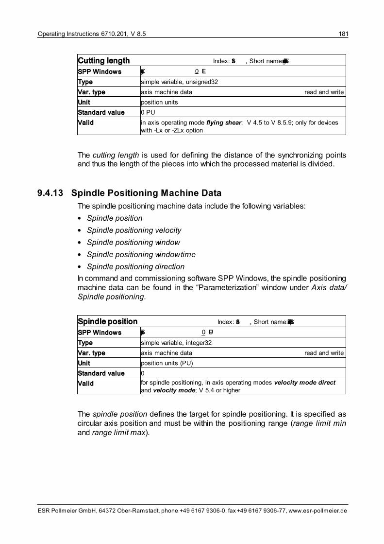
Operating Instructions 6710.201, V 8.5 181
ESR Pollmeier GmbH, 64372 Ober-Ramstadt, phone +49 6167 9306-0, fax +49 6167 9306-77, www.esr-pollmeier.de
Cutting length Index: 5f31, Short name: FlsSchnittLaenge
SPP Windows Cutting length 0 LE
Type simple variable, unsigned32
Var. type axis machine data read and write
Unit position units
Standard value 0 PU
Valid in axis operating mode flying shear; V 4.5 to V 8.5.9; only for deviceswith -Lx or -ZLx option
The cutting length is used for defining the distance of the synchronizing pointsand thus the length of the pieces into which the processed material is divided.
9.4.13 Spindle Positioning Machine Data
The spindle positioning machine data include the following variables:
• Spindle position
• Spindle positioning velocity
• Spindle positioning window
• Spindle positioning window time
• Spindle positioning direction
In command and commissioning software SPP Windows, the spindle positioningmachine data can be found in the “Parameterization” window under Axis data/Spindle positioning.
Spindle position Index: 5ea3, Short name: SpindelPosZiel
SPP Windows Spindle position 0 PU
Type simple variable, integer32
Var. type axis machine data read and write
Unit position units (PU)
Standard value 0
Valid for spindle positioning, in axis operating modes velocity mode directand velocity mode; V 5.4 or higher
The spindle position defines the target for spindle positioning. It is specified ascircular axis position and must be within the positioning range (range limit minand range limit max).

Operating Instructions 6710.201, V 8.5182
ESR Pollmeier GmbH, 64372 Ober-Ramstadt, phone +49 6167 9306-0, fax +49 6167 9306-77, www.esr-pollmeier.de
Spindle positioning velocity Index: 5ea4, Short name: SpindelVelVerfahr
SPP Windows Spindle positioning velocity 0 VU
Type simple variable, integer32
Var. type axis machine data read and write
Unit velocity units (VU)
Standard value 0
Valid for spindle positioning, in axis operating modes velocity mode directand velocity mode; V 5.4 or higher
With parameter spindle positioning velocity, the target velocity of spindle posi-tioning is set.
Spindle positioning window Index: 5ea5, Short name: SpindelPosFenster
SPP Windows Spindle positioning window 100 PSS
Type simple variable, integer32
Var. type axis machine data read and write
Unit position sensor steps (PSS)
Standard value 100
Valid for spindle positioning, in axis operating modes velocity mode directand velocity mode; V 5.4 or higher
The spindle positioning window is placed symmetrically around the spindle posi-tion. As soon as the actual position is within this spindle positioning window, sig-nal “in position” is generated. This message can also be output at a digital out-put, see signal selection digital output ... in section Input/Output FunctionMachine Data .
Spindle positioning window time Index: 5ea6, Short name: SpindelPosFenstZeit
SPP Windows Spindle positioning window time 0 ms
Type simple variable, unsigned16
Var. type axis machine data read and write
Unit 1 ms
Standard value 0
Valid for spindle positioning, in axis operating modes velocity mode directand velocity mode; V 5.4 or higher
The spindle positioning window time prevents the generation of signal “in posi-tion” if the spindle positioning window is only briefly swept over. The axis must bein the spindle positioning window for the set spindle positioning window time be-fore this signal is generated.
131

Operating Instructions 6710.201, V 8.5 183
ESR Pollmeier GmbH, 64372 Ober-Ramstadt, phone +49 6167 9306-0, fax +49 6167 9306-77, www.esr-pollmeier.de
Spindle positioning direction Index: 5ea7, Short name: SpindelPosParameter
SPP Windows Spindle positioning direction last direction of rotation select
Type simple variable, octet string length 2
Var. type axis machine data read and write
Unit select
Standard value last direction of rotation
Valid for spindle positioning, in axis operating modes velocity mode directand velocity mode; V 5.4 or higher
Parameter spindle positioning direction is used for setting the direction of rota-tion in which the spindle position is approached.
Permitted values:
Value Direction of rotation
0 to the right
1 to the left
3 last direction of rotation
9.4.14 Output Encoder Signals Machine Data
The output encoder signals machine data include the following variables:
• Pulses encoder signals
• Zero offset encoder signals
These machine data are only of significance for option Gx (output encoder sig-nals).
In command and commissioning software SPP Windows, the output encodersignals machine data can be found in the “Parameterization” window under Axisdata/Encoder emulation.
Pulses encoder signals Index: 5ecc, Short name: DSPIncPU
SPP Windows Pulses per revolution 1024
Type simple variable, integer16
Var. type axis machine data read and write
Unit pulses/motor revolution
Standard value 1024
Valid for output encoder signals (option Gx) with resolver as motor positionsensor (option R1)
This variable can be used for setting the number of pulses per motor revolutionoutput encoder signals (option Gx) outputs on channel A and B. The value rangefor this parameter is 50 .. 1024 pulses per motor revolution. If a controller is con-

Operating Instructions 6710.201, V 8.5184
ESR Pollmeier GmbH, 64372 Ober-Ramstadt, phone +49 6167 9306-0, fax +49 6167 9306-77, www.esr-pollmeier.de
nected, this value can be doubled or quadrupled through evaluation of the pulseedges.
The pulse encoder signals variable is only effective if a resolver (option R1) isimplemented as motor position sensor. If a Sincos (Hiperface) encoder (optionR2), a high-resolution incremental encoder (option R3), or an EnDat encoder isimplemented, the pulse number for output encoder signals (option Gx) corres-ponds to the number of sine periods of the motor position sensor (e.g. 512 or2048 sine periods per motor revolution).
Zero offset encoder signals Index: 5ecb, Short name: EncOffNull
SPP Windows Zero offset encoder signals 0 pulses
Type simple variable, unsigned16
Var. type axis machine data read and write
Unit pulses
Standard value 0
Valid for output encoder signals (option Gx) with resolver as motor positionsensor (option R1)
This variable can be used for offsetting the index pulse of the output encoder sig-nals from the mechanically preset position by a specific number of pulses. Thehighest permissible value is pulse encoder signals–1 (offset by almost one re-volution).
Zero offset encoder signals is only effective if a resolver (option R1) is imple-mented as motor position sensor. If a Sincos (Hiperface) or an EnDat encoder(option R2 or R4) is implemented, no index pulse is available at output encodersignals (option Gx), and thus it is not possible to carry out an index pulse shift.With a high-resolution incremental encoder (option R3), the index pulse cannotbe shifted.
9.4.15 Switching Points Machine Data
The switching points machine data include the following variables:
• Position switching point positive
• Position switching point negative
• Position switching point inverted
In command and commissioning software SPP Windows, the switching pointmachine data can be found in the “Parameterization” window under Axis data/Switching points.

Operating Instructions 6710.201, V 8.5 185
ESR Pollmeier GmbH, 64372 Ober-Ramstadt, phone +49 6167 9306-0, fax +49 6167 9306-77, www.esr-pollmeier.de
Position switching point positive Index: 5f36, Short name: PosPSchaltpunkt
SPP Windows Position switching point positive 1 0 PU
Type array, 16 type integer32 elements
Var. type axis machine data read and write
Unit position units (PU)
Standard value 0 PU
Valid always, V 5.1 or higher
Position switching point negative Index: 5f3a, Short name: PosNSchaltpunkt
SPP Windows Position switching point negative 1 2.147.483.647 PU
Type array, 16 type integer32 elements
Var. type axis machine data read and write
Unit position units (PU)
Standard value 2,147,483,647 PU
Valid always, V 5.4 or higher
Two positions are specified with position switching point positive and positionswitching point negative. If the actual position of the axis is between these twopositions, the associated bit in the position switching point status is set; if the ac-tual position is lower than position switching point positive or higher than orequal to position switching point negative, the corresponding bit is 0.
With position switching point inverted, this logic can be inverted.
Position switching point inverted Index: 5f3b, Short name: PosNOTSchaltpunkt
SPP Windows Position switching point inverted 00000000
Type simple variable, octet string length 2
Var. type axis machine data read and write
Unit –
Standard value 00000000
Valid always, V 5.4 or higher
The position switching point inverted variable can be used for inverting the logicfor each switching point:
• If the bit in position switching point inverted is 0, the associated bit in positionswitching point status indicates whether or not the actual position is locatedwithin the limits position switching point positive and position switching pointnegative.
• If the bit in position switching point inverted is 1, the associated bit in positionswitching point status indicates whether or not the actual position is locatedoutside the limits position switching point positive and position switching pointnegative.

Operating Instructions 6710.201, V 8.5186
ESR Pollmeier GmbH, 64372 Ober-Ramstadt, phone +49 6167 9306-0, fax +49 6167 9306-77, www.esr-pollmeier.de
9.4.16 Interpolated Position Mode Machine Data
The interpolated position mode machine data include the following variables:
• Interpolation Submode Select
• Interpolation Time Period
• Interpolation Sync Definition
• Interpolation Data Configuration
• Following error window
Description see Position Control Loop Machine Data
• Following error time out
Description see Position Control Loop Machine Data
In command and commissioning software SPP Windows, the interpolated pos-ition mode machine data can be found in the “Parameterization” window underAxis data/Interpolated position mode.
The individual CANopen® or EtherCAT variables such as e. g. transmit and re-ceive PDO can be found in operating instructions 6710.205 / 6745.205“CANopen® Interface” or 6745.232 “EtherCAT Interface”. In the SPP Windowssoftware, they can be found in window “Parameterization” under CANopen/EtherCAT. With TrioDrive D, MidiDrive D and MaxiDrive, this window is only dis-played if the servo drive is accessed via the fieldbus interface. Display of thesevariables with access via the serial interface is not possible with these devices.
Interpolation Sub Mode Select Index: 60c0, Short name:IpolSubmodeAuswahl
SPP Windows Interpolation Submode 0
Type simple variable, integer16, constant (variable value does not change)
Access read only, writing possible but without effects
Var. type axis machine data
Unit –
Standard value 0 (linear interpolation)
Valid in axis operating mode interpolated position mode; V 8.5.1 or higher
This variable determines the interpolation mode. Only linear interpolation is sup-ported.
171
171
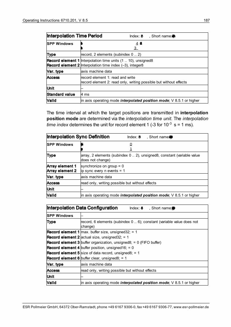
Operating Instructions 6710.201, V 8.5 187
ESR Pollmeier GmbH, 64372 Ober-Ramstadt, phone +49 6167 9306-0, fax +49 6167 9306-77, www.esr-pollmeier.de
Interpolation Time Period Index: 60c2, Short name: IpolTimePeriod
SPP Windows Interpolation Time Units 4 10^idx sInterpolation Time Index –3
Type record, 2 elements (subindex 0 .. 2)
Record element 1Record element 2
Interpolation time units (1 .. 10), unsigned8Interpolation time index (–3), integer8
Var. type axis machine data
Access record element 1: read and writerecord element 2: read only, writing possible but without effects
Unit –
Standard value 4 ms
Valid in axis operating mode interpolated position mode; V 8.5.1 or higher
The time interval at which the target positions are transmitted in interpolationposition mode are determined via the interpolation time unit. The interpolation
time index determines the unit for record element 1 (-3 for 10-3 s = 1 ms).
Interpolation Sync Definition Index: 60c3, Short name: IpolSyncDefinition
SPP Windows Synchronize on group 0 ip_sync every n events 1
Type array, 2 elements (subindex 0 .. 2), unsigned8, constant (variable valuedoes not change)
Array element 1Array element 2
synchronize on group = 0ip sync every n events = 1
Var. type axis machine data
Access read only, writing possible but without effects
Unit –
Valid in axis operating mode interpolated position mode; V 8.5.1 or higher
Interpolation Data Configuration Index: 60c4, Short name: IpolDataConfig
SPP Windows –
Type record, 6 elements (subindex 0 .. 6); constant (variable value does notchange)
Record element 1
Record element 2
Record element 3
Record element 4
Record element 5
Record element 6
max. buffer size, unsigned32; = 1
actual size, unsigned32; = 1
buffer organization, unsigned8; = 0 (FIFO buffer)
buffer position, unsigned16; = 0
size of data record, unsigned8; = 1
buffer clear, unsigned8; = 1
Var. type axis machine data
Access read only, writing possible but without effects
Unit –
Valid in axis operating mode interpolated position mode; V 8.5.1 or higher

Operating Instructions 6710.201, V 8.5188
ESR Pollmeier GmbH, 64372 Ober-Ramstadt, phone +49 6167 9306-0, fax +49 6167 9306-77, www.esr-pollmeier.de
These variables determine synchronization and configuration of the interpolatedposition mode. The values cannot be changed.
9.4.17 Timed Positioning Mode Machine Data
The timed positioning mode machine data include the following variables:
• Positioning distance single movement
• Positioning time single movement
• Curve form
• Kp velocity feedforward
In command and commissioning software SPP Windows, the timed position-ing mode machine data can be found in the “Parameterization” window underAxis data/Timed positioning mode.
Variable Kp velocity feedforward can be found under Axis data/Position controlloop.
Timed positioning mode Index: 5F64, Short name: TimedPosMode
Type record, 5 elements
Var. type axis machine data read and write
Valid in axis operating mode timed positioning mode; V 8.5.995 or higher
The parameters and actual values timed positioning mode are combined in re-cord variable timed positioning mode. The individual elements are described inthe following.
Position distance single movement
Index: 5F64, Subindex: 1, Short name: TimedPosMode1
SPP Windows Position distance single movement 0 LgS
Type simple variable, unsigned32
Var. type axis machine data read and write
Unit 1 PSS
Standard value –
For function timed positioning mode, the (relative) distance (single distance) ispreset via this variable.

Operating Instructions 6710.201, V 8.5 189
ESR Pollmeier GmbH, 64372 Ober-Ramstadt, phone +49 6167 9306-0, fax +49 6167 9306-77, www.esr-pollmeier.de
Position time single movement
Index: 5F64, Subindex: 2, Short name: TimedPosMode2
SPP Windows Position time single movement 0 ms
Type simple variable, unsigned32
Var. type axis machine data read and write
Unit 1 ms
Standard value –
For function timed positioning mode, the duration of the positioning (for thesingle movement) is preset using this variable.
Curve form Index: 5F64, Subindex: 3, Short name: TimedPosMode3
SPP Windows Curve form triangle select
Type simple variable, integer16
Var. type axis machine data read and write
Unit select
Standard value -1 (triangle)
For function timed positioning mode, the curve form is selected using this vari-able.
Permissible values are:
Value Curve form
–1 Triangle (linear VDI 2143: “quadratic parabola”)
–2 Modified acceleration trapezoid (acc. to VDI 2143)
–3 Modified sine curve (acc. to VDI 2143)
–4 Inclined sine curve (acc. to VDI 2143)
–5 5th degree polynomial (acc. to VDI 2143)

Operating Instructions 6710.201, V 8.5190
ESR Pollmeier GmbH, 64372 Ober-Ramstadt, phone +49 6167 9306-0, fax +49 6167 9306-77, www.esr-pollmeier.de
10 Appendix
10.1 Appendix A State Machines
State machines describe the behavior of systems. The graphical representationof a state machine is called state diagram.
The elements of a state machine are
• states
• transitions
• events
• actions
A representation of the elements of a state machine in the state diagramis shown in the following figure:
Figure 18: Elements of state machines
States (shown as a rectangle with the name of the state and further explanations,if required) can be changed by transitions (displayed as arrows). A transition isperformed when an event occurs. In the case of a transition, an action is carriedout (represented below the event, separated from it by a line). Transmissions forwhich an action is not carried out are also permitted.
In the application of state machines, the following types of events are differenti-ated:
• Control commands
These are events the user can trigger by writing the control command into acontrol word. Each control command is coded as bit pattern.
• Internal or external events
Internal or external events (represented in italics) are triggered by the servodrive or a component connected to one of its interfaces. This can be e. g. afault or the fact that a certain velocity has been reached.

Operating Instructions 6710.201, V 8.5 191
ESR Pollmeier GmbH, 64372 Ober-Ramstadt, phone +49 6167 9306-0, fax +49 6167 9306-77, www.esr-pollmeier.de
10.2 Appendix B Axis Fault Codes and Part Program Errors
If a fault occurs, the device status (displayed in the axis status word) switches tothe “Fault” state and the corresponding axis fault code is displayed. Once thecause of the fault is eliminated, the fault state can be reset by changing the “Re-set fault” bit from 0 to 1 in the axis control word.
In the case of faults occurring during startup or while the part program is running(axis error code 62...
hex), the program state machine switches to the “Idle” state
from where the part program can be restarted once the fault state is reset.
If a fault occurs while the part program is running, the “Program block numberdisplay” shows the corresponding block in the part program.
The following list shows the possible axis error codes (hexadecimal) with faultdesignation and a short explanation. They are grouped according to their func-tion:
• General fault codes
• Part program fault codes
• Other fault codes
• CANbus fault codes
• EtherCAT fault codes
• Profibus fault codes
General fault codes
0000hex
no fault
2320hex
Overcurrent motor phase
There is a short circuit in the motor circuit, or the chosen motor data donot match the connected motor.
2330hex
Earth fault motor phase
There is an earth fault in the motor circuit, or the chosen motor data donot match the connected motor.
3130hex
Phase failure
Failure of one or several phases L1, L2, or L3 at X1. Only for MidiDriveD/xS.
3210hex
Overvoltage in the DC-bus
Check whether or not the bridge between +R/Rint
at the shunt resistor
connection is implemented or the external shunt resistor is connectedcorrectly.
3220hex
Undervoltage in the DC-bus
Mains voltage is missing, check power supply and connection. If there isno fault: a fuse may have blown in the shunt circuit, please contact the

Operating Instructions 6710.201, V 8.5192
ESR Pollmeier GmbH, 64372 Ober-Ramstadt, phone +49 6167 9306-0, fax +49 6167 9306-77, www.esr-pollmeier.de
factory.
4210hex
Overtemperature power circuit (> 80 ºC)
The ambient temperature is too high or the motor supply cable is toolong (remedy: motor choke).
4310hex
Overtemperature motor (threshold depends on the temperature sensor inthe motor)
Insufficient heat dissipation in the motor or current limit set to an inad-missibly high value for the actual operating mode.
5110hex
Hardware fault low voltage supply
Check that the control supply voltage is +24 VDC
(see the technical spe-
cifications in the operating instructions of the servo drive). If there is nofault: please contact the factory.
5520hex
Hardware fault flash memory
Please contact the factory.
6010hex
Watchdog reset of the microcontroller
Please contact the factory.
Part program fault codes
6210hex
Unknown block type
The block type of a block cannot be executed with the existing firmwareversion of the servo drive. This may be due to the fact that the loadedpart program was created with SPP Windows using a newer version ofthe object directory (OD), which knows more (newer) block types thanthe existing firmware.
6220hex
Label not found
The label used by a block of type j ump to label, repeat, j ump on input,or subroutine call does not exist anywhere in the part program.
6221hex
Start label not found
The label necessary for starting the part program (program start label)does not exist anywhere in the part program.
6231hex
Subroutine stack overflow
The maximum nesting depth of 10 subroutine calls (block type sub-routine call) has been exceeded.
6232hex
Subroutine stack underflow
Failed to execute a block of type return from subroutine because therewas no subroutine call beforehand.
6233hex
Repeat list overflow
The maximum number of 10 simultaneously active iterations has beenexceeded by one block (block type repeat).

Operating Instructions 6710.201, V 8.5 193
ESR Pollmeier GmbH, 64372 Ober-Ramstadt, phone +49 6167 9306-0, fax +49 6167 9306-77, www.esr-pollmeier.de
6235hex
Object access fault
Fault with a block of the type obj ect access. This may be due to the fol-lowing causes:
The subindex is invalid for the specified index.
The type of access (read or write) is not permitted for the variable.
Access is not permitted due to the device status.
6236hex
Object does not exist
Fault with a block of type obj ect access. The variable with the specifiedindex does not exist in the servo drive.
6237hex
Object too long
Fault with a block of type obj ect access. The variable is larger than 4bytes and can therefore not be read or written to with this block type.
6250hex
Axis access fault
A fault has occurred while accessing an axis function (block types posi-tion, feed, go to reference point). Possible causes: selection of a non-existent axis or the target position is outside the position limit values.
6255hex
Fault while going to home position
A fault has occurred while going to home position (block type go to refer-ence point).
6257hex
Change of operating mode not permitted
The operating mode cannot be changed in the following states:
• operation enabled
• quick stop active
• fault reaction active
• fault
6270hex
Internal I/O access fault
A fault has occurred while accessing an I/O function in a block of type po-sition, M function, j ump on input, wait for input, switching point, or waitfor input value and j ump.
6275hex
Division by zero
Fault during execution of a mathematical operation.
6280hex
Internal timer fault
An internal fault has occurred in block type wait.
Other fault codes
54A1hex
Safe standstill SI1-Err inactive
Fault in the two-channel switching of the safety function: input SI2 active,

Operating Instructions 6710.201, V 8.5194
ESR Pollmeier GmbH, 64372 Ober-Ramstadt, phone +49 6167 9306-0, fax +49 6167 9306-77, www.esr-pollmeier.de
but SI1 inactive.
54A2hex
Safe standstill SI2-Err inactive
Fault in the two-channel switching of the safety function: input SI1 active,but SI2 inactive.
6310hex
Flash memory parameter loss
Please contact the factory.
6330hex
Data fault during initialization
For further details on the cause of this fault: refer to object “fault detail”.Please contact the factory.
6331hex
Data fault during initialization, object access
For further details on the cause of this fault: refer to the object “fault de-tail”. Please contact the factory.
7112hex
Overcurrent in the shunt circuit
A short circuit has occurred in the shunt circuit or the value of the externalshunt resistor is too low (see technical specifications in the operating in-structions of the servo drive).
7115hex
Overtemperature shunt resistor
The internal shunt resistor is overloaded, an external shunt resistor is re-quired.
7116hex
Overtemperature brake chopper
The external shunt resistor is overloaded, please contact the factory.
7121hex
Motor is blocked
Motor is at standstill for longer than 10 s at full rated torque (overload).
712Fhex
Autocommutation not successful
The commutation position could not be found by the selected autocom-mutation method. Check the settings and make sure that the axis canmove freely and is not blocked or stiff.
7303hex
Encoder fault motor position sensor
The motor position sensor is either connected not at all or not correctly,there is a cable break or a short circuit, or the voltage is too low. Anotherpossible cause might be interference signals in the encoder connectioncable e. g. due to a not or not correctly connected shield in the motorsupply cable (power).
7304hex
Transmission error or missing data for digital position transmission (en-coder)
The digital position data are wrong. Possible causes: the positionsensor is not connected correctly, a cable break or short circuit has oc-curred. Another possible cause might be interference signals in the en-coder connection cable, e.g. due to a not or not correctly connectedshield in the motor supply cable (power).
7305hex
SinCos voltage monitoring Z track / incorrect encoder voltage Z track
The motor position sensor is either connected not at all or not correctly,

Operating Instructions 6710.201, V 8.5 195
ESR Pollmeier GmbH, 64372 Ober-Ramstadt, phone +49 6167 9306-0, fax +49 6167 9306-77, www.esr-pollmeier.de
there is a cable break or the voltage is too low.
7314hex
Transmission error or missing data for digital position transmission (ext.encoder)
The digital position data are wrong. Possible causes: the positionsensor is not connected correctly, a cable break or short circuit has oc-curred. Another possible cause might be interference signals in the en-coder connection cable, e.g. due to a not or not correctly connectedshield in the motor supply cable (power).
7321hex
Sincos encoder parameter channel fault
The motor position sensor is either connected not at all or not correctly,or there is a cable break.
7322hex
Motor position sensor not supported
This firmware does not support the connected or parameterized encodersystem.
7323hex
Fault parameterization motor position sensor
The motor position sensor was parameterized with invalid data whichare not supported by this firmware.
7331hex
Fault parameter channel EnDat encoder (external encoder)
The position sensor is either connected not at all or not correctly or acable is broken.
7332hex
External encoder not supported
The connected or parameterized external encoder is not supported bythis firmware.
7333hex
Incorrect parameterization of the external encoder
The external encoder was parameterized with incorrect data not suppor-ted by this firmware version.
8611hex
Following error position control loop
Taking into account following error time out, the actual position is out-side the following error window.
9000hex
External fault
Enable canceled at enable selection code “1” (enable selection codevariable)
9010hex
Signal processor fault
Please contact the factory
A011hex
Limit switch configuration fault
Check that the limit switches are assigned correctly.
A012hex
“Limit switch +” approached
Input “limit switch +” of the servo drive interface inactive.
A013hex
“Limit switch –” approached
Input “limit switch –” of the servo drive interface inactive.

Operating Instructions 6710.201, V 8.5196
ESR Pollmeier GmbH, 64372 Ober-Ramstadt, phone +49 6167 9306-0, fax +49 6167 9306-77, www.esr-pollmeier.de
A020hex
Fault while going to home position
e. g. limit switch instead of machine home switch found.
Fault codes CAN bus
8130hex
CAN bus fault: Life Guarding
See operating instructions 6710.205 or 6745.205 “CANopen® inter-face”: “Life Guarding”.
8180hex
CAN bus fault: Bus-Off
See operating instructions 6710.205 or 6745.205 “CANopen® inter-face”: “Send and receive monitoring”.
Fault codes EtherCAT
A000 EtherCAT state machine transition error
Incorrect configuration of the sync managers for input or output processdata (e. g. wrong length)
Fault codes Profibus
8140hex
Profibus master WD timeout
The watchdog time of the master response monitoring was exceeded.
81B0hex
Profibus fatal error
Fault in the Profibus communication process.
10.3 Appendix C Firmware Versions Regarding Functions andParameters
This section summarizes notes on changes in the firmware with references to thecorresponding sections in the text. The latest modifications are listed first.
If you have worked with a servo drive with an older firmware, before (e. g. V 8.0)and have obtained a new servo drive with a new firmware (e. g. V 8.5.8), pleaseobserve all sections referring to changes between the two version numbers.
This appendix lists all firmware changes regarding the functions and parametersdescribed in these operating instructions. For further firmware modifications,also see the respective appendices of the other operating instructions for theservo drives.
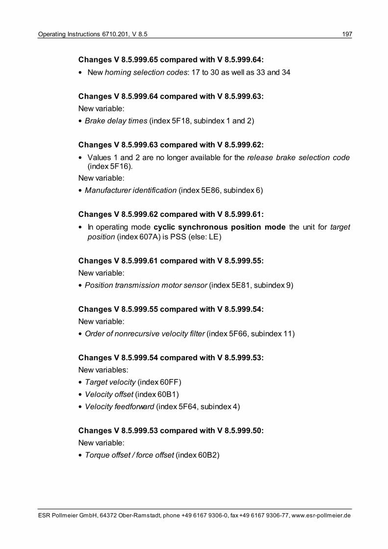
Operating Instructions 6710.201, V 8.5 197
ESR Pollmeier GmbH, 64372 Ober-Ramstadt, phone +49 6167 9306-0, fax +49 6167 9306-77, www.esr-pollmeier.de
Changes V 8.5.999.65 compared with V 8.5.999.64:
• New homing selection codes: 17 to 30 as well as 33 and 34
Changes V 8.5.999.64 compared with V 8.5.999.63:
New variable:
• Brake delay times (index 5F18, subindex 1 and 2)
Changes V 8.5.999.63 compared with V 8.5.999.62:
• Values 1 and 2 are no longer available for the release brake selection code(index 5F16).
New variable:
• Manufacturer identification (index 5E86, subindex 6)
Changes V 8.5.999.62 compared with V 8.5.999.61:
• In operating mode cyclic synchronous position mode the unit for targetposition (index 607A) is PSS (else: LE)
Changes V 8.5.999.61 compared with V 8.5.999.55:
New variable:
• Position transmission motor sensor (index 5E81, subindex 9)
Changes V 8.5.999.55 compared with V 8.5.999.54:
New variable:
• Order of nonrecursive velocity filter (index 5F66, subindex 11)
Changes V 8.5.999.54 compared with V 8.5.999.53:
New variables:
• Target velocity (index 60FF)
• Velocity offset (index 60B1)
• Velocity feedforward (index 5F64, subindex 4)
Changes V 8.5.999.53 compared with V 8.5.999.50:
New variable:
• Torque offset / force offset (index 60B2)

Operating Instructions 6710.201, V 8.5198
ESR Pollmeier GmbH, 64372 Ober-Ramstadt, phone +49 6167 9306-0, fax +49 6167 9306-77, www.esr-pollmeier.de
Changes V 8.5.999.50 compared with V 8.5.999.3:
New variable:
• External sensor encoder data (index 5E86)
Changes V 8.5.999.3 compared with V 8.5.999.08:
• In addition to “external quadrature encoder” (selection code 01) setting “ex-ternal impulse/direction encoder” (selection code 03) is available for variableexternal master axis (index 5F17).
• External position sensor resolution (index 5F72) includes the resolution of theexternal position sensor in pulses/revolutions (before: PSS/revolution).
• The index for variable gear ratio is 6091, the type is integer32 (before: index
5F06, type integer16). The unit for the denominator (master axis) is pulses (before:
PSS).
Changes V 8.5.999.08 compared with V 8.5.997:
New variable:
• Measuring length (index 5E81, subindex 10)
Changes V 8.5.997 compared with V 8.5.996:
New variables:
• Following error window (index 6065)
• Following error time out (index 6066)
• Digital inputs acc. to CiA402 (index 60FD)
Changes V 8.5.996 compared with V 8.5.995:
• The data type of axis operating mode at startup (index 5F35) is integer8 (be-
fore: integer16).
• The data type of homing selection code (Index 6098) is integer8 (before: in-
teger16).
• The index of acceleration time is 6083 (before: 5EF4), the function is the same.
• The index of deceleration time is 6084 (before: 5EF5), the function is the same.
• The index of quick stop time is 6085 (before: 5EF6), the function is the same.
• Homing velocity (index 6099) is an array with two elements (before: simple vari-
able).
New variables:
• Inertia load or mass (index 5E82)
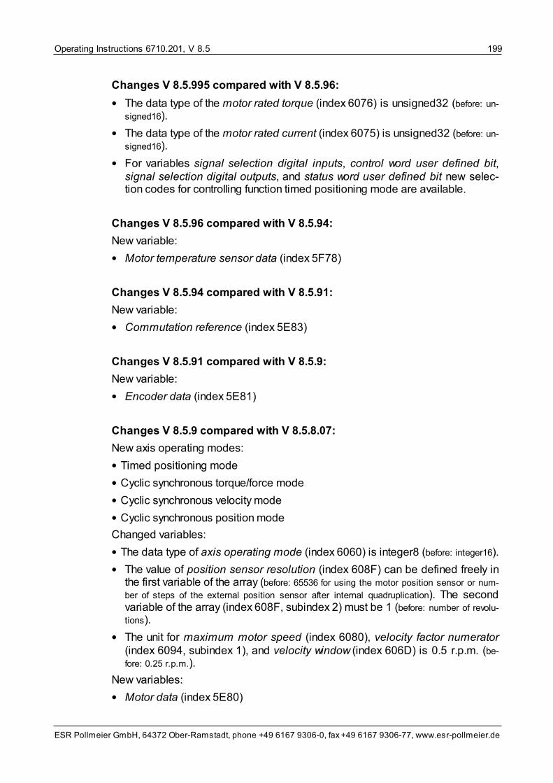
Operating Instructions 6710.201, V 8.5 199
ESR Pollmeier GmbH, 64372 Ober-Ramstadt, phone +49 6167 9306-0, fax +49 6167 9306-77, www.esr-pollmeier.de
Changes V 8.5.995 compared with V 8.5.96:
• The data type of the motor rated torque (index 6076) is unsigned32 (before: un-
signed16).
• The data type of the motor rated current (index 6075) is unsigned32 (before: un-
signed16).
• For variables signal selection digital inputs, control word user defined bit,signal selection digital outputs, and status word user defined bit new selec-tion codes for controlling function timed positioning mode are available.
Changes V 8.5.96 compared with V 8.5.94:
New variable:
• Motor temperature sensor data (index 5F78)
Changes V 8.5.94 compared with V 8.5.91:
New variable:
• Commutation reference (index 5E83)
Changes V 8.5.91 compared with V 8.5.9:
New variable:
• Encoder data (index 5E81)
Changes V 8.5.9 compared with V 8.5.8.07:
New axis operating modes:
• Timed positioning mode
• Cyclic synchronous torque/force mode
• Cyclic synchronous velocity mode
• Cyclic synchronous position mode
Changed variables:
• The data type of axis operating mode (index 6060) is integer8 (before: integer16).
• The value of position sensor resolution (index 608F) can be defined freely inthe first variable of the array (before: 65536 for using the motor position sensor or num-
ber of steps of the external position sensor after internal quadruplication). The secondvariable of the array (index 608F, subindex 2) must be 1 (before: number of revolu-
tions).
• The unit for maximum motor speed (index 6080), velocity factor numerator(index 6094, subindex 1), and velocity window (index 606D) is 0.5 r.p.m. (be-
fore: 0.25 r.p.m.).
New variables:
• Motor data (index 5E80)

Operating Instructions 6710.201, V 8.5200
ESR Pollmeier GmbH, 64372 Ober-Ramstadt, phone +49 6167 9306-0, fax +49 6167 9306-77, www.esr-pollmeier.de
• Electronic gearing control (index 5F08)
Changes V 8.5.8.0.7 compared with V 8.5.8.04:
• Brake control: consideration of brake delay times
• New variable: brake delay time
• Changed selection codes for release brake selection code
Changes V 8.5.8.0.4 compared with V 8.5.8.03:
• Support for Ethernet (option F8), ESR, and Modbus TCP protocols
• Permits switching to operating modes profile position mode and electronicgearing in standstill, however, in state operation enabled.
Changes V 8.5.8.03 compared with V 8.5.8.02:
• Modbus protocol via ZF8 module
Changes V 8.5.8.02 compared with V 8.5.8.01:
• New functions for flying shear: input signal 178 (synchronize flying shear ex-ternally) and 179 (enable external synchronization)
• Jerk-free synchronization
Changes V 8.5.8.01 compared with V 8.5.8:
• Flying shear now for TrioDrive D/xS / MidiDrive D/xS
Changes V 8.5.8 compared with V 8.5.7:
• New functions: DC-bus coupling (16 A and higher), permanent switch-off ofthe shunt circuit can be configured, shunt circuit is controlled even if the PWMis off .
• The unit of the velocity offset (index 60B1) is VU.
Changes V 8.5.7 compared with V 8.5.5:
• New variable: position encoder 2 value (index 5004)
Changes V 8.5.5 compared with V 8.5.3:
• MidiDrive D/xS with rated current 16 A and 32 A is supported
• Operating hours counter, total time and power circuit
• New selection code for input enable: disable operation/operation enabled

Operating Instructions 6710.201, V 8.5 201
ESR Pollmeier GmbH, 64372 Ober-Ramstadt, phone +49 6167 9306-0, fax +49 6167 9306-77, www.esr-pollmeier.de
Changes V 8.5.3 compared with V 8.5:
• Temperature sensors KTY 83 and KTY 84 for motor temperature measure-ment are supported
• New variables: speed control loop Kv electronic gearing (index 5f07), ex-ternal master axis selection code (index 5f17), gear ratio (index 5f06), andexternal position sensor resolution (index 5f72)
• Options G1 and L1 are supported
Changes V 8.5 compared with V 8.0:
• New communication objects: mains voltage (index 5f4f) and resistance motortemperature sensor (index 5f03)
• Free PDO mapping
• Interpolated position mode available for CANopen
• Remanent variables (index 5f60, subindex 1 to 255)
Changes V 8.0 compared with V 7.7:
• Variables digital inputs configuration, digital outputs configuration, positioncontrol loop Ki, and position control loop Ki range removed.
• New variable: I2t control
• Function safe standstill for TrioDrive D/xS and MidiDrive D/xS
10.4 Appendix D Versions of the Document
2000-10-27 V 5.7, MH for firmware V 5.7first English version, based on German ver-sion; references to SPP for DOS removed
2000-11-13 V 5.7a, MH Correction in type code; inputs/outputs I 8.x,O 8.x, O 9.x
2001-02-02 V 5.7b, MH Corrections in assignment of axis control wordand axis status word to digital I/O; OEM correc-tions
2008-10-28 V 8.0, KS for firmware V 8.0TrioDrive D/xS and MidiDrive D/xS added;DriveTerminal removed; completely new struc-ture; text, technical specifications, as well asvariables updated
2012-06-26 V 8.0e, KS Modified as online help document, drive BN

Operating Instructions 6710.201, V 8.5202
ESR Pollmeier GmbH, 64372 Ober-Ramstadt, phone +49 6167 9306-0, fax +49 6167 9306-77, www.esr-pollmeier.de
6755 added; Ethernet interface added; figuresnew, appendix List of Variables and Old Firm-ware Versions removed
2013-06-05 V 8.5, KS for firmware V 8.5.9
Appendix Firmware Versions Regarding Func-tions and Parameters added; section HomingMode Sequences updated; operating modeflying shear updated; operating mode torquemode updated; variables changed and newvariables added; sections Setting the CurrentControl Loop and Setting the Speed ControlLoop new; new operating modes: timed posi-tioning mode, cyclic synchronous torque/force mode, cyclic synchronous velocitymode, cyclic synchronous position mode,and interpolated position mode; fault codesupdated, BiSS encoder added

Operating Instructions 6710.201, V 8.5 203
ESR Pollmeier GmbH, 64372 Ober-Ramstadt, phone +49 6167 9306-0, fax +49 6167 9306-77, www.esr-pollmeier.de
11 Keyword IndexIn the keyword index, groups were set up to provide a better overview of certainkeywords in addition to the direct entry in alphabetical order:
• Outputs
Using the designation of an output, you can find out which functions are influ-encing it. Please, also see operating instructions “Connection and Commis-sioning” (6755.202, 6745.202, 6750.202, 6740.202, or 6710.202).
• Inputs
Using the designation of an input, you can find out which functions the inputacts on. Please, also see operating instructions “Connection and Commis-sioning” (6755.202, 6745.202, 6750.202, 6740.202, or 6710.202).
• LEDs
The designation of a LED can be used for finding information on which statesare indicated. Please, also see operating instructions “Connection and Com-missioning” (6755.202, 6745.202, 6750.202, 6740.202, or 6710.202).
• Variables
Using the designation of a variable, you can find the variable description of thecorresponding variable.
• Variable short names
Using the short name of a variable, you can find the variable description of thecorresponding variable.
Further groups were set up for an illustration of the connections.

Operating Instructions 6710.201, V 8.5204
ESR Pollmeier GmbH, 64372 Ober-Ramstadt, phone +49 6167 9306-0, fax +49 6167 9306-77, www.esr-pollmeier.de
Index
- A -
Acceleration time (variable) 165
Active PWM frequency power circuit (variable) 127
Actual current (variable) 87
Actual position (variable) 91
Actual position zeroing (variable) 91
Actual velocity (variable) 88
Alternative for velocity offset (variable) 93
Alternative interpolation data record (variable) 92
Analog input 63
Analog inputs (variable) 98
Analog output 64
Analog output 1 FP factor (variable) 139
Analog output 1 int factor (variable) 140
Analog output 1 signal selection (variable) 136
Analog output 2 FP factor (variable) 139
Analog output 2 int factor (variable) 140
Analog output 2 signal selection (variable) 137
Analog outputs (variable) 98
Angle correction controller D component (variable) 117
Angle correction controller I component (variable) 117
Angle correction controller P component (variable) 117
Array (object code of a variable) 78
Array element (of a variable) 79
Autocommutation 15
Axis control and status information (variable) 83
Axis control machine data (variables) 141
Axis control word (variable) 84
Axis error code (variable) 85
Axis machine data 141
Axis operating mode
Interpolated position mode 56
Axis operating mode (variable) 83
Axis operating mode at startup (variable) 143
Axis operating modes 29
Block mode 36
Cyclic synchronous position mode 54
Cyclic synchronous torque mode 50
Cyclic synchronous velocity mode 52
Electronic gearing 44
Flying shear 46
Homing mode 38
Profile position mode 34
Setpoint mode 37
Spindle positioning 33
Timed positioning mode 48
Torque mode 30
Velocity mode 32
Velocity mode direct 31
Velocity profile 48
Axis state machine 17
figure 18
running up 25
Axis status word (variable) 84
Axis type (variable) 161
- B -
Block mode 36
Bool (data type of a variable) 79
Boolean (data type of a variable) 79
Brake delay time (variable) 143
Bus voltage (variable) 106
- C -
Caution (safety instruction) 11
CE marking (safety instruction) 11
Check (safety instruction) 11
Command mode 60
Commutation reference (variable) 158
Continuous current motor (variable) 156
Continuous power ext. shunt resistor (variable) 130
Control and status information device (variable) 82
Control word user defined bit (variable) 132
Controller cycle time (variable) 105
Current control loop
setting 71
Current control loop I component (variable) 117
Current control loop P component (variable) 116
Current controller 15
Curve form (variable) 189
Cutting length (variable) 181
Cyclic synchronous position mode 54
activating 56
deactivating 56
Cyclic synchronous torque mode 50
Cyclic synchronous velocity mode 52
- D -
Danger (safety instruction) 11
Data type (of a variable) 79

Operating Instructions 6710.201, V 8.5 205
ESR Pollmeier GmbH, 64372 Ober-Ramstadt, phone +49 6167 9306-0, fax +49 6167 9306-77, www.esr-pollmeier.de
Deceleration time (variable) 165
Device operating mode (variable) 82
Device operating modes 60
Command mode 60
Program mode 60
Digital input/output 61
Digital inputs (variable) 96
Digital inputs acc. to CiA402 (variable) 97
Digital outputs (variable) 97
Drive machine data 155
Drive rated current (variable) 127
Drive system functions 14
- E -
Electrical sense of rotation (variable) 116
Electronic gearing 44
Electronic gearing control (variable) 180
Electronic gearing machine data 176
EMC (safety instruction) 11
Enable selection code (variable) 141
Encoder absolute type (variable) 155
Encoder data (variable) 119, 123
Encoder name (variable) 124
Encoder type code (variable) 120
Ext. sensor encoder data (variable) 152
Ext. sensor encoder type code (variable) 153
Ext. sensor interface identification (variable) 154
Ext. sensor measuring steps per revolution/meter(variable) 152
Ext. sensor number of coded revolutions (variable) 153
Ext. sensor sine periods per revolution/meter (variable) 153
External master axis selection code (variable) 176
External position sensor resolution (variable) 177
External torque setpoint (variable) 87
- F -
Factors and units machine data 158
Fault detail (variable) 86
Float32 (data type of a variable) 79
Flying shear 46
Flying shear machine data 180
Following error time out (variable) 174
Following error window (variable) 174
Force constant (variable) 113
Force offset (variable) 94
Function structure of the servo drive 12
Functions 12
Input/output function 61
Switching points 64
Trace function 66
Trigger and measuring functions 64
- G -
Gear ratio (variable) 152, 178
General actual and measured values 105
- H -
Heat sink temperature (variable) 107
Home offset (variable) 160
Homing mode 38
Homing mode machine data 175
Homing selection code (variable) 175
Homing velocity (variable) 175
- I -
i16 (data type of a variable) 79
I2t Loading (variable) 108
i32 (data type of a variable) 79
i8 (data type of a variable) 79
Index (of a variable) 78
Inductance (P-P) (variable) 114
Inertia load (variable) 158
Input/output function machine data 131
Integer16 (data type of a variable) 79
Integer32 (data type of a variable) 79
Integer8 (data type of a variable) 79
Interface identification (variable) 121
Internal target position (variable) 90
Interpolated Position Mode 56
activating 59
deactivating 59
Interpolated position mode machine data 186
Interpolation Data Configuration (variable) 187
Interpolation data record (variable) 92
Interpolation Sub Mode Select (variable) 186
Interpolation Sync Definition (variable) 187
Interpolation Time Period (variable) 187
- K -
Kp feedforward (variable) 174
- L -
Limit frequency current filter (Variable) 141
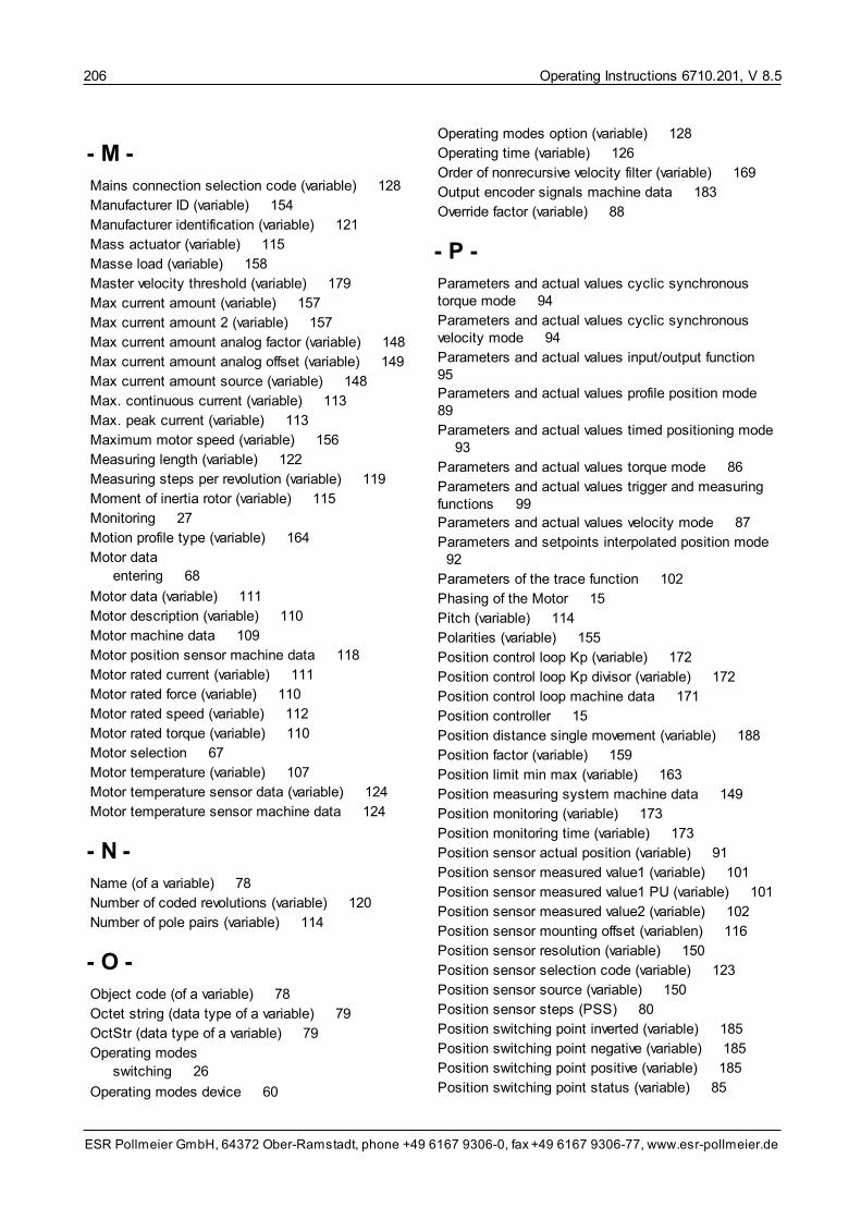
Operating Instructions 6710.201, V 8.5206
ESR Pollmeier GmbH, 64372 Ober-Ramstadt, phone +49 6167 9306-0, fax +49 6167 9306-77, www.esr-pollmeier.de
- M -
Mains connection selection code (variable) 128
Manufacturer ID (variable) 154
Manufacturer identification (variable) 121
Mass actuator (variable) 115
Masse load (variable) 158
Master velocity threshold (variable) 179
Max current amount (variable) 157
Max current amount 2 (variable) 157
Max current amount analog factor (variable) 148
Max current amount analog offset (variable) 149
Max current amount source (variable) 148
Max. continuous current (variable) 113
Max. peak current (variable) 113
Maximum motor speed (variable) 156
Measuring length (variable) 122
Measuring steps per revolution (variable) 119
Moment of inertia rotor (variable) 115
Monitoring 27
Motion profile type (variable) 164
Motor data
entering 68
Motor data (variable) 111
Motor description (variable) 110
Motor machine data 109
Motor position sensor machine data 118
Motor rated current (variable) 111
Motor rated force (variable) 110
Motor rated speed (variable) 112
Motor rated torque (variable) 110
Motor selection 67
Motor temperature (variable) 107
Motor temperature sensor data (variable) 124
Motor temperature sensor machine data 124
- N -
Name (of a variable) 78
Number of coded revolutions (variable) 120
Number of pole pairs (variable) 114
- O -
Object code (of a variable) 78
Octet string (data type of a variable) 79
OctStr (data type of a variable) 79
Operating modes
switching 26
Operating modes device 60
Operating modes option (variable) 128
Operating time (variable) 126
Order of nonrecursive velocity filter (variable) 169
Output encoder signals machine data 183
Override factor (variable) 88
- P -
Parameters and actual values cyclic synchronoustorque mode 94
Parameters and actual values cyclic synchronousvelocity mode 94
Parameters and actual values input/output function 95
Parameters and actual values profile position mode 89
Parameters and actual values timed positioning mode 93
Parameters and actual values torque mode 86
Parameters and actual values trigger and measuringfunctions 99
Parameters and actual values velocity mode 87
Parameters and setpoints interpolated position mode 92
Parameters of the trace function 102
Phasing of the Motor 15
Pitch (variable) 114
Polarities (variable) 155
Position control loop Kp (variable) 172
Position control loop Kp divisor (variable) 172
Position control loop machine data 171
Position controller 15
Position distance single movement (variable) 188
Position factor (variable) 159
Position limit min max (variable) 163
Position measuring system machine data 149
Position monitoring (variable) 173
Position monitoring time (variable) 173
Position sensor actual position (variable) 91
Position sensor measured value1 (variable) 101
Position sensor measured value1 PU (variable) 101
Position sensor measured value2 (variable) 102
Position sensor mounting offset (variablen) 116
Position sensor resolution (variable) 150
Position sensor selection code (variable) 123
Position sensor source (variable) 150
Position sensor steps (PSS) 80
Position switching point inverted (variable) 185
Position switching point negative (variable) 185
Position switching point positive (variable) 185
Position switching point status (variable) 85

Operating Instructions 6710.201, V 8.5 207
ESR Pollmeier GmbH, 64372 Ober-Ramstadt, phone +49 6167 9306-0, fax +49 6167 9306-77, www.esr-pollmeier.de
Position transmission motor sensor (variable) 122
Position units (PU) 80
Positioning range machine data 161
Positioning time single movement (variable) 189
Positioning window (variable) 172
Positioning window time (variable) 173
Power limit (variable) 128
Power monitoring (variable) 127
Profile position mode 34
Program mode 60
Pulses encoder signals (variable) 183
PWM frequency power circuit (variable) 118
- Q -
Quick stop time (variable) 166
- R -
Ramp time el. gearing (variable) 179
Ramps machine data 164
Ramps reference velocity (variable) 166
Range limit (variable) 162
Rated speed (variable) 111
Record (object code of a variable) 78
Release brake selection code (variable) 142
Resistance (P-P) (variable) 113
Resistance external shunt resistor (variable) 130
Resistance motor temperature sensor (variable) 107
Resistance switching threshold overtemp. (variable) 125
Resolver voltage (variable) 106
Rotating field generator frequency (variable) 118
Rotating field generator voltage (variable) 118
- S -
Safety instructions
Caution 11
CE marking 11
Check 11
Danger 11
EMC 11
Tip 11
Safety system 27
Selecting the motor 67
Serial number (variable) 126
Servo drive function structure 12
Servo drive machine data 126
Setpoint generator 14
Setpoint mode 37
Setpoint sources machine data 144
Setting the axis data 68
Setting the current control loop 71
Setting the speed control loop 74
Settings (commissioning) 67
Axis data 68
Motor selection 67
Selecting the motor 67
Short name (of a variable) 78
Shunt resistor loading (variable) 108
Shunt resistor machine data 129
Shunt resistor selection code (variable) 129
Signal selection digital inputs 1.x (variable) 131
Signal selection digital inputs 15.x (variable) 136
Signal selection digital inputs 9.0 (variable) 132
Signal selection digital outputs 1.x (variable) 134
Signal selection digital outputs 15.x (variable) 136
Signal selection digital outputs 8.x (variable) 134
Signal selection digital outputs 9.x (variable) 134
Simple variable (object code of a variable) 78
Sine periods per revolution (variable) 120
Speed control loop
setting 74
Speed control loop Ki (variable) 168
Speed control loop Kp (variable) 168
Speed control loop Kv electronic gearing (variable) 178
Speed control loop machine data 167
Speed control loop total amplification (variable) 169
Speed controller 15
Speed filter cut-off frequency (variable) 168
Spindle position (variable) 181
Spindle positioning 33
Spindle positioning direction (variable) 183
Spindle positioning machine data 181
Spindle positioning velocity (variable) 182
Spindle positioning window (variable) 182
Spindle positioning window time (variable) 182
Standard value (of a variable) 81
Standstill force (variable) 112
Standstill torque (variable) 112
Status word user defined bit (variable) 134
Stop axis selection code (variable) 144
Switching between operating modes 26
Switching points 64
Switching points machine data 184
- T -
Target position (variable) 89
Target velocity (variable) 87, 95

Operating Instructions 6710.201, V 8.5208
ESR Pollmeier GmbH, 64372 Ober-Ramstadt, phone +49 6167 9306-0, fax +49 6167 9306-77, www.esr-pollmeier.de
Target velocity analog factor (variable) 146
Target velocity analog offset (variable) 146
Target velocity source (variable) 145
Temperature sensor type code (variable) 125
Temperature switching threshold overtemp. (variable) 125
Thermal time constant (variable) 115
Thermal time constant ext. shunt resist. (variable) 131
Timed positioning mode 48
Timed positioning mode (variable) 188
Timed positioning mode machine data 188
Tip (safety instruction) 11
Torque analog factor (variable) 147
Torque analog offset (variable) 147
Torque constant (variable) 113
Torque mode 30
Torque offset (variable) 94
Torque setpoint source (variable) 146
Trace buffer 1 (variable) 103
Trace buffer 2 (variable) 103
Trace buffer 3 (variable) 103
Trace function 66
Trace index 1 (variable) 104
Trace index 2 (variable) 104
Trace index 3 (variable) 104
Trace start (variable) 105
Trace time (variable) 104
Trigger and measuring functions 64
Trigger mask (variable) 99
Trigger mode selection (variable) 100
Trigger status (variable) 100
Type (of a variable) 78, 79
- U -
u16 (data type of a variable) 79
u32 (data type of a variable) 79
u8 (data type of a variable) 79
Unit (of a variable) 80
Factors and units machine data 158
Units (of a variable)
Position sensor steps (PSS) 80
Position units (PU) 80
Valid 81
Velocity units (VU) 81
Unsigned16 (data type of a variable) 79
Unsigned32 (data type of a variable) 79
Unsigned8 (data type of a variable) 79
- V -
Valid (unit of a variable) 81
Variable descriptions 78
Axis control and status information 83
Axis machine data 141
Basic data 105
Control and status information device 82
Drive machine data 155
Electronic gearing machine data 176
Factors and units machine data 158
Flying shear machine data 180
General actual and measured values 105
Homing mode machine data 175
Input/output function machine data 131
Interpolated position mode machine data 186
Motor machine data 109
Motor position sensor machine data 118
Motor temperature sensor machine data 124
Output encoder signals machine data 183
Parameters and actual values 86
Parameters and actual values cyclic synchronoustorque mode 94
Parameters and actual values cyclic synchronousvelocity mode 94
Parameters and actual values input/outputfunction 95
Parameters and actual values profile positionmode 89
Parameters and actual values timed positioningmode 93
Parameters and actual values torque mode 86
Parameters and actual values trigger andmeasuring functions 99
Parameters and actual values velocity mode 87
Parameters and setpoints interpolated positionmode 92
Parameters of the trace function 102
Position control loop machine data 171
Position measuring system machine data 149
Positioning range machine data 161
Ramps machine data 164
Servo drive machine data 126
Setpoint sources machine data 144
Shunt resistor machine data 129
Speed control loop machine data 167
Spindle positioning machine data 181
Switching points machine data 184
Timed positioning mode machine data 188
Variable type 79

Operating Instructions 6710.201, V 8.5 209
ESR Pollmeier GmbH, 64372 Ober-Ramstadt, phone +49 6167 9306-0, fax +49 6167 9306-77, www.esr-pollmeier.de
Variable types (description) 78
Variable unit 80
Variablen
Velocity Offset 93
Variables 78
Acceleration time 165
Active PWM frequency power circuit 127
Actual current 87
Actual position 91
Actual position zeroing 91
Actual velocity 88
Alternative for velocity offset 93
Alternative interpolation data record 92
Analog inputs 98
Analog output 1 FP factor 139
Analog output 1 int factor 140
Analog output 1 signal selection 136
Analog output 2 FP factor 139
Analog output 2 int factor 140
Analog output 2 signal selection 137
Analog outputs 98
Angle correction controller D component 117
Angle correction controller I component 117
Angle correction controller P component 117
Axis control machine data 141
Axis control word 84
Axis error code 85
Axis operating mode 83
Axis operating mode at startup 143
Axis status word 84
Axis type 161
Brake delay times 143
Bus voltage 106
Commutation reference 158
Continuous current motor 156
Continuous power ext. shunt resistor 130
Control and status information 82
Control word user defined bit 132
Controller cycle time 105
Current control loop I component 117
Current control loop P component 116
Curve form 189
Cutting length 181
Deceleration time 165
Device operating mode 82
Digital inputs 96
Digital inputs acc. to CiA402 97
Digital outputs 97
Drive rated current 127
Electrical sense of rotation 116
Electronic gearing control 180
Enable selection code 141
Encoder absolute type 155
Encoder data 119, 123
Encoder name 124
Encoder type code 120
Ext. sensor encoder data 152
Ext. sensor encoder type code 153
Ext. sensor interface identification 154
Ext. sensor measuring steps per revolution/meter 152
Ext. sensor number of coded revolutions 153
Ext. sensor sine periods per revolution/meter 153
External master axis selection code 176
External position sensor resolution 177
External torque setpoint 87
Fault detail 86
Following error time out 174
Following error window 174
Force constant 113
Force offset 94
Gear ratio 152, 178
Heat sink temperature 107
Home offset 160
Homing selection code 175
Homing velocity 175
I2t Loading 108
Inductance (P-P) 114
Inertia load 158
Interface identification 121
Internal target position 90
Interpolation Data Configuration 187
Interpolation data record 92
Interpolation Sub Mode Select 186
Interpolation Sync Definition 187
Interpolation Time Period 187
Kp feedforward 174
Limit frequency current filter 141
Mains connection selection code 128
Manuafcturer ID 154
Manufacturer identification 121
Mass actuator 115
Mass load 158
Master velocity threshold 179
Max current amount 157
Max current amount 2 157
Max current amount analog factor 148
Max current amount analog offset 149
Max current amount source 148

Operating Instructions 6710.201, V 8.5210
ESR Pollmeier GmbH, 64372 Ober-Ramstadt, phone +49 6167 9306-0, fax +49 6167 9306-77, www.esr-pollmeier.de
Variables 78
Max. continuous current 113
Max. peak current 113
Maximum motor speed 156
Measuring length 122
Measuring steps per revolution 119
Moment of inertia rotor 115
Motion profile type 164
Motor data 111
Motor description 110
Motor rated current 111
Motor rated force 110
Motor rated speed 112
Motor rated torque 110
Motor temperature 107
Motor temperature sensor data 124
Number of coded revolutions 120
Number of pole pairs 114
Operating modes option 128
Operating time 126
Order of nonrecursive velocity filter 169
Override factor 88
Pitch 114
Polarities 155
Position control loop Kp 172
Position control loop Kp divisor 172
Position distance single movement 188
Position factor 159
Position limit min max 163
Position monitoring 173
Position monitoring time 173
Position sensor actual position 91
Position sensor measured value1 101
Position sensor measured value1 PU 101
Position sensor measured value2 102
Position sensor measured value2 PU 102
Position sensor mounting offset 116
Position sensor resolution 150
Position sensor selection code 123
Position sensor source 150
Position switching point inverted 185
Position switching point negative 185
Position switching point positive 185
Position switching point status 85
Position transmission motor sensor 122
Positioning time single movement 189
Positioning window 172
Positioning window time 173
Power limit 128
Power monitoring 127
Pulses encoder signals 183
PWM frequency power circuit 118
Quick stop time 166
Ramp time el. gearing 179
Ramps reference velocity 166
Range limit 162
Rated speed 111
Release brake selection code 142
Resistance (P-P) 113
Resistance external shunt resistor 130
Resistance motor temperature sensor 107
Resistance switching threshold overtemp. 125
Resolver voltage 106
Rotating field generator frequency 118
Rotating field generator voltage 118
Serial number 126
Shunt resistor loading 108
Shunt resistor selection code 129
Signal selection digital inputs 1.x 131
Signal selection digital inputs 15.x 136
Signal selection digital inputs 9.0 132
Signal selection digital outputs 1.x 134
Signal selection digital outputs 15.x 136
Signal selection digital outputs 8.x 134
Signal selection digital outputs 9.x 134
Sine periods per revolution 120
Speed control loop Ki 168
Speed control loop Kp 168
Speed control loop Kv electronic gearing 178
Speed control loop total amplification 169
Speed filter cut-off frequency 168
Spindle position 181
Spindle positioning direction 183
Spindle positioning velocity 182
Spindle positioning window 182
Spindle positioning window time 182
Standstill force 112
Standstill torque 112
Status word user defined bit 134
Stop axis selection code 144
Target position 89
Target velocity 87, 95
Target velocity analog factor 146
Target velocity analog offset 146
Target velocity source 145
Temperature sensor type code 125
Temperature switching threshold overtemp. 125
Thermal time constant 115
Thermal time constant ext. shunt resist. 131
Timed positioning mode 188

Operating Instructions 6710.201, V 8.5 211
ESR Pollmeier GmbH, 64372 Ober-Ramstadt, phone +49 6167 9306-0, fax +49 6167 9306-77, www.esr-pollmeier.de
Variables 78
Torque analog factor 147
Torque analog offsett 147
Torque constant 113
Torque offset 94
Torque setpoint source 146
Trace buffer 1 103
Trace buffer 2 103
Trace buffer 3 103
Trace index 1 104
Trace index 2 104
Trace index 3 104
Trace start 105
Trace time 104
Trigger mask 99
Trigger mode selection 100
Trigger status 100
Velocity factor 160
Velocity feedforward factor 94
Velocity offset 95
Velocity threshold 170
Velocity threshold time 170
Velocity window 171
Velocity window time 171
Zero offset encoder signals 184
Velocity factor (variable) 160
Velocity feedforward factor (variable) 94
Velocity mode 32
Velocity mode direct 31
Velocity offset (variable) 93, 95
Velocity profile 48
Velocity threshold (variable) 170
Velocity threshold time (variable) 170
Velocity units (VU) 81
Velocity window (variable) 171
Velocity window time (variable) 171
Visible string (data type of a variable) 79
VisStr (data type of a variable) 79
- Z -
Zero offset encoder signals (variable) 184