
DME Server Administration Reference 3.5
297
DME version 3.5 SP 8 DME Server Administration Reference 3.5 Installing DME Created on 03-03-2011
-
Upload
khangminh22 -
Category
Documents
-
view
0 -
download
0
Transcript of DME Server Administration Reference 3.5
DME version 3.5 SP 8
DME Server Administration Reference 3.5
Installing DME
Created on 03-03-2011

Contents i
Contents
Introduction 7
Copyright information .................................................................................................................................. 7 Company information ................................................................................................................................... 7 Typographical conventions ........................................................................................................................... 8 About DME .................................................................................................................................................. 8
Features and benefits ......................................................................................................................... 9 About the DME Server ................................................................................................................................. 9
Supported platforms ........................................................................................................................ 10
DME server architecture 11
One server, many connectors ...................................................................................................................... 11 The DME server ......................................................................................................................................... 12 The connector ............................................................................................................................................. 13
The group graph .............................................................................................................................. 13 Load balancing and failover ............................................................................................................ 14
Multiple domains and directory servers ...................................................................................................... 14 Connector broadcasting ................................................................................................................... 15 Connector routing ............................................................................................................................ 15
DME services .............................................................................................................................................. 16
Navigating the Web interface 19
Logging in to the DME server .................................................................................................................... 19 Elements of the Web interface .................................................................................................................... 20
Main tabs ......................................................................................................................................... 21 Page menu ....................................................................................................................................... 21 Table ................................................................................................................................................ 22 Toolbars ........................................................................................................................................... 22 About DME ..................................................................................................................................... 23
Keyboard shortcuts ..................................................................................................................................... 24 Online help.................................................................................................................................................. 24
Devices 27
Columns ...................................................................................................................................................... 28 User ................................................................................................................................................. 28 Device .............................................................................................................................................. 30 Phone number .................................................................................................................................. 31 Last sync. ......................................................................................................................................... 31 Version ............................................................................................................................................ 31 License ............................................................................................................................................. 31 Push ................................................................................................................................................. 32 Key .................................................................................................................................................. 32
Tab actions .................................................................................................................................................. 33 New group ....................................................................................................................................... 33 New user .......................................................................................................................................... 33 New device ...................................................................................................................................... 35 Bootstrap devices ............................................................................................................................. 36 New device signing key ................................................................................................................... 38 Delete group .................................................................................................................................... 38 Remove user .................................................................................................................................... 39 Remove device ................................................................................................................................ 39 Detach user from device .................................................................................................................. 39
ii Contents
Remove device signing key ............................................................................................................. 39 Toggle user lock .............................................................................................................................. 39 Toggle device lock .......................................................................................................................... 40 Toggle license .................................................................................................................................. 40 Toggle push to device ...................................................................................................................... 40 Search for device ............................................................................................................................. 40 Collapse/expand groups ................................................................................................................... 40
Page menu ................................................................................................................................................... 41 Setup ................................................................................................................................................ 41 Groups ............................................................................................................................................. 49 Push to device .................................................................................................................................. 52 LDAP filter ...................................................................................................................................... 61
Setting up devices ....................................................................................................................................... 61 Information ...................................................................................................................................... 62 Settings ............................................................................................................................................ 65 Files ................................................................................................................................................. 65 Applications ..................................................................................................................................... 66 Sync. table ....................................................................................................................................... 67 Schedule .......................................................................................................................................... 67 SIM .................................................................................................................................................. 68 Users ................................................................................................................................................ 68 Group ............................................................................................................................................... 68 Asset ................................................................................................................................................ 69 OMA DM ........................................................................................................................................ 69 iPhone MDM ................................................................................................................................... 71
Setting up users ........................................................................................................................................... 74 User ................................................................................................................................................. 75 Collab.conf. ..................................................................................................................................... 77 Devices ............................................................................................................................................ 79 Filter groups..................................................................................................................................... 79
Setting up groups ........................................................................................................................................ 80 Information ...................................................................................................................................... 81 Settings ............................................................................................................................................ 81 Schedule .......................................................................................................................................... 81 Files ................................................................................................................................................. 81 Applications ..................................................................................................................................... 81 License ............................................................................................................................................. 82
Provisioning 83
Installing software ...................................................................................................................................... 83 SSL certificates ................................................................................................................................ 84 Bootstrapping devices...................................................................................................................... 86 DM on different platforms ............................................................................................................... 87 Installing software on new devices .................................................................................................. 88 Installing DME on existing devices ................................................................................................. 90
MDM on Apple iOS ................................................................................................................................... 94 Participating in the iDEP program ................................................................................................... 95 Generating an APNS certificate....................................................................................................... 95 Server configuration for Apple MDM ............................................................................................. 99 Enrolling devices ........................................................................................................................... 101
Software .................................................................................................................................................... 104 DME .............................................................................................................................................. 104 Other .............................................................................................................................................. 113 Installation log ............................................................................................................................... 114 Errors ............................................................................................................................................. 114 Device types .................................................................................................................................. 115
Access points ............................................................................................................................................ 117 GPRS ............................................................................................................................................. 118 WLAN ........................................................................................................................................... 120
Contents iii
DDF configurations .................................................................................................................................. 121 DDF XML ..................................................................................................................................... 122 Configurations ............................................................................................................................... 124 Status ............................................................................................................................................. 126
iPhone profiles .......................................................................................................................................... 127 iPhone profiles ............................................................................................................................... 128 Status ............................................................................................................................................. 131
Log 133
Finding information .................................................................................................................................. 134 Columns .................................................................................................................................................... 134 Log categories ........................................................................................................................................... 135
Adaptive push ................................................................................................................................ 135 Audit .............................................................................................................................................. 136 Central Services ............................................................................................................................. 136 Collaboration ................................................................................................................................. 137 Connector ...................................................................................................................................... 138 Device ............................................................................................................................................ 138 Network ......................................................................................................................................... 139 Notification .................................................................................................................................... 141 Provisioning ................................................................................................................................... 141 Software install .............................................................................................................................. 141 Synchronizing ................................................................................................................................ 142 System ........................................................................................................................................... 144
Analyzer 145
Statistics .................................................................................................................................................... 145 DME traffic ................................................................................................................................... 145 Voice traffic ................................................................................................................................... 150 Messaging traffic ........................................................................................................................... 151 Data traffic ..................................................................................................................................... 152
Analyzer reports ........................................................................................................................................ 152 Manage reports .............................................................................................................................. 153 View reports .................................................................................................................................. 155
Device statistics ........................................................................................................................................ 157 View device list ............................................................................................................................. 157
Server 159
Server ........................................................................................................................................................ 159 Server configuration ...................................................................................................................... 159 Notifications .................................................................................................................................. 180 Notifications on iPhone ................................................................................................................. 195
Certificates ................................................................................................................................................ 197 Install root certificate ..................................................................................................................... 198 S/MIME certificates ...................................................................................................................... 198
License ...................................................................................................................................................... 201 Manage licenses ............................................................................................................................. 202
Runtime .................................................................................................................................................... 205 SMS commands ............................................................................................................................. 205 Active clients ................................................................................................................................. 205 Show LDAP groups ....................................................................................................................... 206
Connector 207
Routes ....................................................................................................................................................... 207 Connectors ..................................................................................................................................... 207
iv Contents
Users .............................................................................................................................................. 209 Connector tab actions................................................................................................................................ 210
Remove connector ......................................................................................................................... 210 Flush routes for selected connector(s) or user(s) ........................................................................... 210 Toggle connector lock ................................................................................................................... 211
Setting up connectors ................................................................................................................................ 211 Main............................................................................................................................................... 211 Domain .......................................................................................................................................... 213 Authentication ............................................................................................................................... 218 Functions ....................................................................................................................................... 220 Search ............................................................................................................................................ 232 Log................................................................................................................................................. 234
Appendix A: Device settings 235
Calendar settings ....................................................................................................................................... 235 Contacts settings ....................................................................................................................................... 236 Desktop settings ........................................................................................................................................ 237 E-mail settings .......................................................................................................................................... 237 E-mail folder settings ................................................................................................................................ 239 File sync. settings ...................................................................................................................................... 241 General settings ........................................................................................................................................ 242 Scheduled sync. settings ........................................................................................................................... 245 Security settings ........................................................................................................................................ 246 Shortcuts settings ...................................................................................................................................... 249 SmartEncrypt settings ............................................................................................................................... 250 SmartLink settings .................................................................................................................................... 252 To-do settings ........................................................................................................................................... 252 VoiceExtender settings ............................................................................................................................. 253
Appendix B: Self-provisioning 255
Setting up .................................................................................................................................................. 255 Requesting software or configuration ....................................................................................................... 255 Examples .................................................................................................................................................. 256
Appendix C: File synchronization 259
Rules ......................................................................................................................................................... 259 New file sync rule .......................................................................................................................... 260 On the device ................................................................................................................................. 265 Delete file sync rule ....................................................................................................................... 266
Files .......................................................................................................................................................... 266 New file upload ............................................................................................................................. 267 Maximum file size ......................................................................................................................... 267 Delete file ...................................................................................................................................... 268
Contents v
Appendix D: Traffic logging 269
Enabling traffic logging ............................................................................................................................ 269 Voice traffic .............................................................................................................................................. 270 GPRS traffic.............................................................................................................................................. 270 Messaging traffic ...................................................................................................................................... 271 MCC, MNC and operator names .............................................................................................................. 272
Appendix E: myDME 273
Brief introduction to S/MIME .................................................................................................................. 273 Receiving signed e-mail ................................................................................................................ 274 Sending signed e-mail ................................................................................................................... 274 Receiving encrypted e-mail ........................................................................................................... 275 Sending encrypted e-mail .............................................................................................................. 275 Signed and encrypted e-mail ......................................................................................................... 276
S/MIME and DME ................................................................................................................................... 276 Using myDME .......................................................................................................................................... 277
Appendix F: AdaptivePush™ 279
The technology behind AdaptivePush™ .................................................................................................. 279 Troubleshooting network push ................................................................................................................. 280
Appendix G: The Basic MDM client 283
Basic MDM client features ....................................................................................................................... 283 Settings synchronization ................................................................................................................ 283 Cost control ................................................................................................................................... 284 Security .......................................................................................................................................... 284 Asset management ......................................................................................................................... 284 File synchronization ...................................................................................................................... 285
Managing Basic MDM clients .................................................................................................................. 285 Deploying Basic MDM ................................................................................................................. 285 Anonymous users .......................................................................................................................... 285
List of procedures 287
Glossary of terms 289
Index 293

Introduction 7
Introduction
Welcome to the reference manual for the DME server. This manual goes through
every feature of the DME Server version 3.5 SP 8, describing how they are used, and
making recommendations of best practise. The manual describes the latest minor
release (build or service pack) of the DME server - small variations in the user
interface may occur between minor releases.
Copyright information
Copyright © 2007-11 Excitor A/S.
All rights reserved.
Due to continued product development, this information may change without notice.
The information and intellectual property contained herein is confidential between
Excitor A/S and the client, and remains the exclusive property of Excitor A/S.
If you find any problems in the documentation, please report them to us through our
customer support services. Excitor A/S does not warrant that this document is
error-free. Furthermore, Excitor A/S does not warrant that the illustrations and
screenshots used in this document reflect your version or the latest version of the
program described. For the latest version of this product documentation, go to the
DME website DME http://www.excitor.com.
No part of this publication may be reproduced, stored in a retrieval system, or
transmitted in any form or by any means, electronic, mechanical, photocopying,
recording or otherwise without the prior written permission of Excitor A/S.
DME, DME Sync, VoiceExtender, SmartEncrypt, and AdaptivePush are trademarks
of Excitor A/S.
Microsoft SQL Server, Microsoft Exchange, Windows, Windows Server 2003, and
Active Directory are trademarks or registered trademarks of the Microsoft Corporation
in the United States and other countries.
Lotus Notes® and Domino® are trademarks or registered trademarks of IBM
Corporation, registered in the U.S. and other countries.
Apple, Apple iPhone, iPod touch, and iPad are trademarks or registered trademarks of
Apple Inc., registered in the U.S. and other countries.
All other trademarks are property of their respective owners.
Company information
12, Spotorno Allé
2630 Taastrup
Denmark
8
DME Server Administration Reference 3.5 : ©2011 Excitor A/S
Phone: +45 70 21 68 00
E-mail: [email protected]
Website: DME http://www.excitor.com
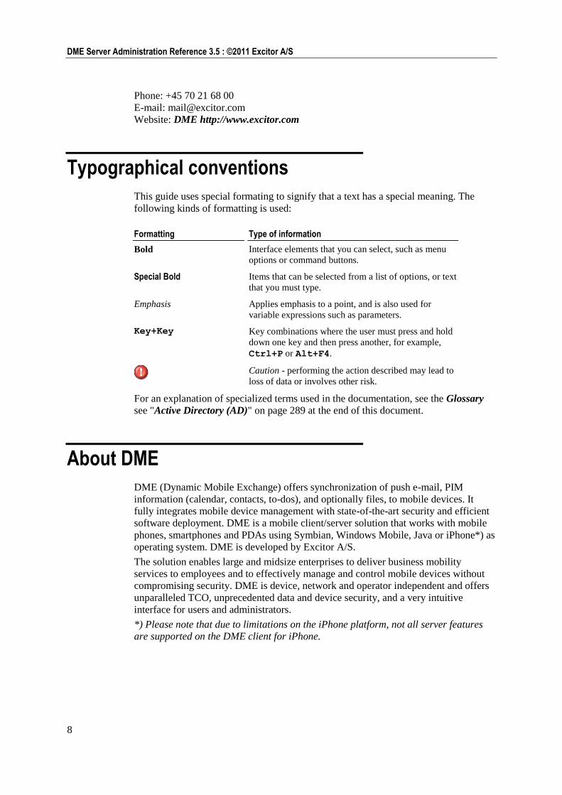
Typographical conventions
This guide uses special formating to signify that a text has a special meaning. The
following kinds of formatting is used:
Formatting Type of information
Bold Interface elements that you can select, such as menu
options or command buttons.
Special Bold Items that can be selected from a list of options, or text
that you must type.
Emphasis Applies emphasis to a point, and is also used for
variable expressions such as parameters.
Key+Key Key combinations where the user must press and hold
down one key and then press another, for example,
Ctrl+P or Alt+F4.
Caution - performing the action described may lead to
loss of data or involves other risk.
For an explanation of specialized terms used in the documentation, see the Glossary
see "Active Directory (AD)" on page 289 at the end of this document.
About DME
DME (Dynamic Mobile Exchange) offers synchronization of push e-mail, PIM
information (calendar, contacts, to-dos), and optionally files, to mobile devices. It
fully integrates mobile device management with state-of-the-art security and efficient
software deployment. DME is a mobile client/server solution that works with mobile
phones, smartphones and PDAs using Symbian, Windows Mobile, Java or iPhone*) as
operating system. DME is developed by Excitor A/S.
The solution enables large and midsize enterprises to deliver business mobility
services to employees and to effectively manage and control mobile devices without
compromising security. DME is device, network and operator independent and offers
unparalleled TCO, unprecedented data and device security, and a very intuitive
interface for users and administrators.
*) Please note that due to limitations on the iPhone platform, not all server features
are supported on the DME client for iPhone.
9
Introduction : About the DME Server
Features and benefits Convenient for the user: Push e-mail, calendar, contacts and to dos
With DME on your mobile phone, smartphone, or PDA, you get your most critical
and often used office tools in your pocket wherever you are, whenever you need it.
E-mails appear on your phone the moment they hit your office mailbox.
Quickly back in the game: Instant service recovery
Should your phone get lost or stolen, a new DME client can be pushed to a new
phone in a few minutes after you purchase a new DME supported phone or borrow
one from someone else – no matter where it happens.
Fretless security: Mobile security policy enforcement
E-mails are encrypted over the air and on the device itself using full encryption
(AES 128-bit or stronger). Shell protection of the entire phone, requiring domain
password to access all features except picking up calls, gives you further security
options.
Freedom and ease-of-use: Effective control of all devices
Gain a complete overview of your devices – regardless of make, model, or
platform. Information about the device model, versions and programs installed on
the device is listed in the Web-based DME control center for easy administration.
Features, settings and available applications and network connections are all
controlled centrally and can only be changed by the users to the extent this is
allowed by centrally applied security policies. Dividing the devices into groups
makes it easy to change settings/features for many devices at a time.
Ease-of-use comes in many flavors: Simple support and administration
Push software and upgrades via SMS or WAP to the users, permit them to serve
themselves, or automatically upgrade software when the users log on. For support
purposes, retrieval of device configurations and connection set-up makes it
possible for you to help users who cannot connect, and a log of user actions assists
you in identifying the problems and solving them. Notification of changes to
server status can be sent to the DME administrators to ensure they are alerted to
problems quickly.
Cost containment: Control of ongoing mobile cost
Data and voice logging allows you to monitor activity levels real-time, and
identify ―expensive‖ behavior which can be reduced. Heavily-used operators can
be determined and connection preferences can be set as default. Build advanced
reports to get a clear view of your organization‘s mobile traffic using the
integrated BI reporting tools.
Freedom of choice: Versatility
Works on any available network (WLAN/Wi-Fi, GSM, GPRS, 3G/UMTS,
EDGE...), operator, and on most devices from leading manufacturers. Works on
Lotus Domino and/or Microsoft Exchange collaboration systems.
Please note that the above applies to the full DME client. Note also that due to
limitations specific to the iPhone platform, a few of the features mentioned above are
not supported on DME for iPhone.
About the DME Server
DME is a client/server application. The DME users, who receive secure push e-mail
and PIM information on their devices, and the secure connection to the devices, are
called the clients. The devices and connections are managed on the server.
10
DME Server Administration Reference 3.5 : ©2011 Excitor A/S
The server provides a secure link between a collaboration system (Microsoft
Exchange or IBM Lotus Domino) and the clients.
The server is controlled through the DME Server Web Administration Interface,
which is described in this manual. The DME server interface gives you control of all
the many features of the DME server:
Access the interface securely (via HTTPS) from anywhere
Easy remote control of device functionality
Theft/loss protection – flush data on mobile device
Push device clients, software upgrades and other applications to existing or new
mobile devices
Enforce company policies by controlling device settings and blocking applications
Send out OTA (see Glossary on page 290) (for example GPRS settings) and SMS
messages to any device
Search and filter information
View detailed log of all user actions – provide better user support
Statistics module for monitoring cost of ownership
– and much more.
In this manual, the term DME server or just DME is used for the DME Server Web
Administration Interface.
Supported platforms For current information about DME requirements in terms of server hardware,
connector hardware, operating systems, browsers, collaboration systems, and database
systems, please download the DME System Requirements document from the Excitor
website at Excitor - Technical Requirements
http://www.excitor.com/Technical_Requirements-31.aspx.
For current information about supported DME clients, see the Excitor - Supported
Devices http://www.excitor.com/Supported_Devices-47.aspx page at the Excitor
website.
The DME Server Installation Guide contains information about how to install the server
and connect it to various subsystems. The latest installation guides can be found at the
DME Install site http://install.excitor.dk along with related information.
For further information, please contact your DME partner.
DME server architecture 11
DME server architecture
The DME Server is designed to be so flexible that it can be installed into almost any
existing IT infrastructure, even when the infrastructure is different at different sites in
an enterprise. The price of flexibility is complexity, and the DME Server is a complex
system. Reading this section will be helpful to get a deeper understanding of how the
DME Server is designed.
One server, many connectors
A key feature of the DME server is that it can be installed into enterprises which are
geographically separated into many locations and segmented into many networks,
possibly using different operating systems and even different collaboration systems.
The cause of this flexibility lies in the DME connector. This concept of connectors,
which was introduced in DME Server 3.0, allows for the installation of a "DME
module" wherever the circumstances call for it. The only requirement for installing a
DME connector is that the DME users for the connector in question are found in the
same LDAP/AD directory as that of the main DME server. There is no such thing as a
"stand-alone DME server" - at least one connector must be installed to service the
users, but it may be installed on the same machine as the DME server.
A few examples:
1 The head office is situated in Cape Town, South Africa, and this is also where the
DME server is installed. A branch office in Burundi suffers from expensive and
unstable international phone lines. A DME connector is installed in the Burundi
office, servicing the employees working out of that office only. The connector
connects to the DME server at regular intervals, and the connector handles the
notification and synchronization using local phone lines.
2 The head office in London, UK, is connected with a branch office across town
using a private wide-area network (WAN). However, because the IT security
policy restricts the use of firewall rules for incoming traffic from the DME server,
a DME connector is installed at the branch office. Since the connector always
initiates communication with the DME server, no rules for incoming traffic need
to be defined on the head office firewall.
3 A company running Lotus Domino acquires a company which runs MS Exchange.
Before the two systems are integrated, a DME connector is set up at the acquired
company to service mobile Exchange users.
4 A large company can split the processing load by installing the DME server and
database on one machine, and a number of DME connectors on one or more server
machines.
So there can be many reasons to set up connectors instead of letting all users run on
the same DME server: Cost control, stability, security, compatibility, and
performance.
12
DME Server Administration Reference 3.5 : ©2011 Excitor A/S
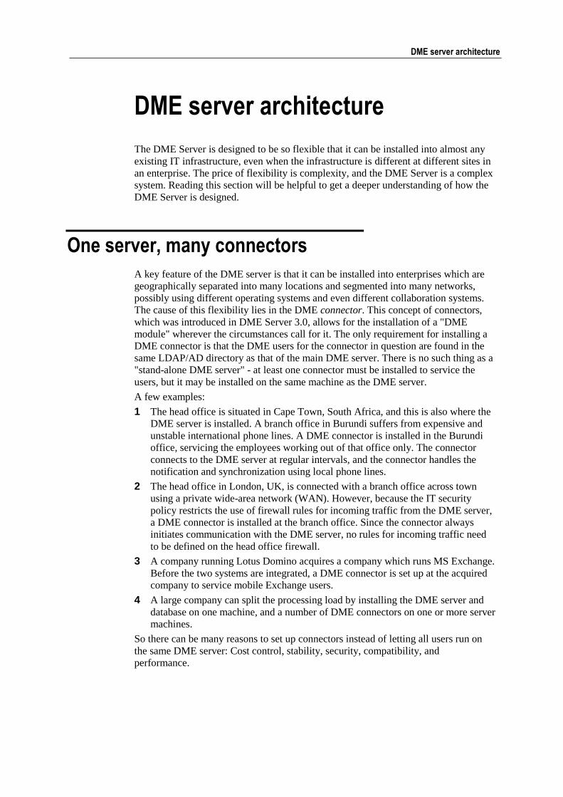
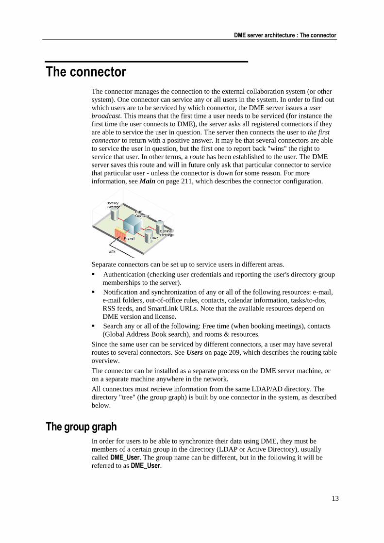
The DME architecture shown by the above examples can be illustrated thus:
The following sections go into more detail about the server and the connector
components.
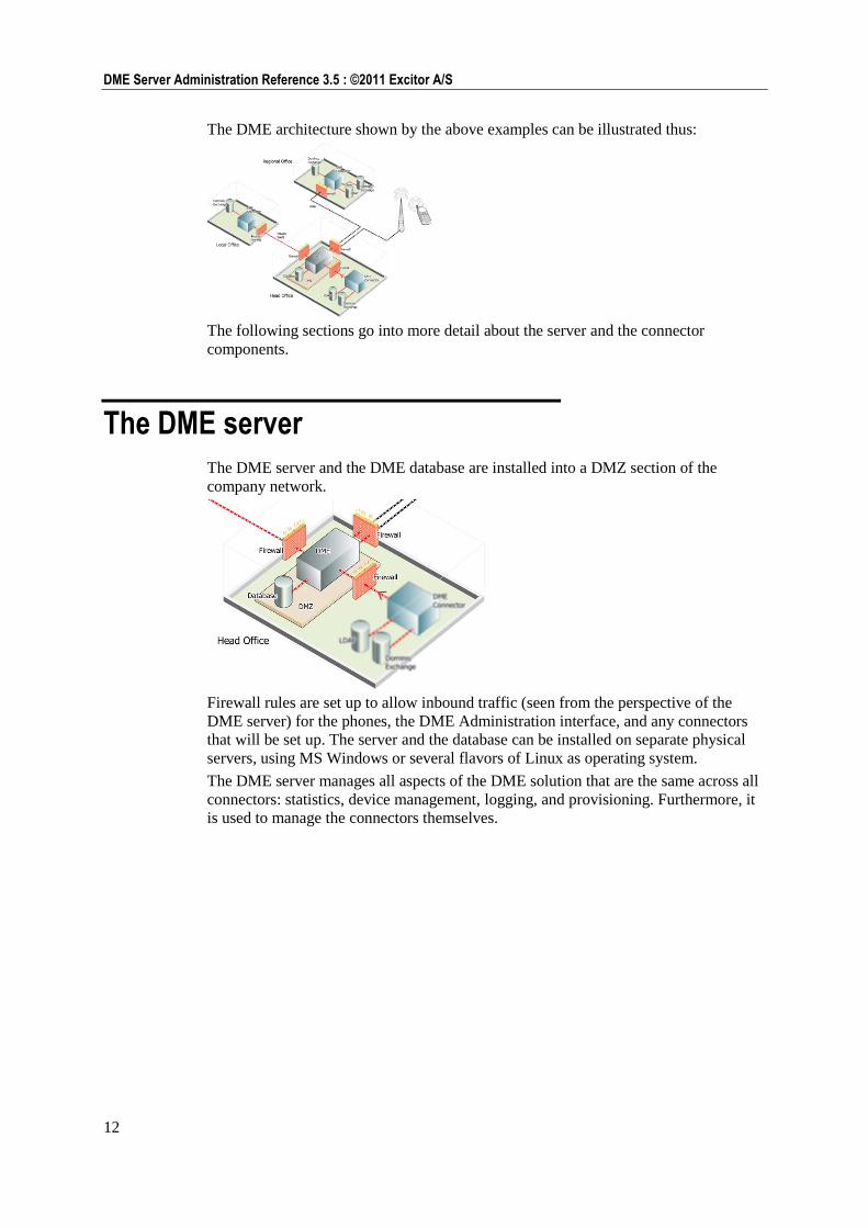
The DME server
The DME server and the DME database are installed into a DMZ section of the
company network.
Firewall rules are set up to allow inbound traffic (seen from the perspective of the
DME server) for the phones, the DME Administration interface, and any connectors
that will be set up. The server and the database can be installed on separate physical
servers, using MS Windows or several flavors of Linux as operating system.
The DME server manages all aspects of the DME solution that are the same across all
connectors: statistics, device management, logging, and provisioning. Furthermore, it
is used to manage the connectors themselves.
13
DME server architecture : The connector
The connector
The connector manages the connection to the external collaboration system (or other
system). One connector can service any or all users in the system. In order to find out
which users are to be serviced by which connector, the DME server issues a user
broadcast. This means that the first time a user needs to be serviced (for instance the
first time the user connects to DME), the server asks all registered connectors if they
are able to service the user in question. The server then connects the user to the first
connector to return with a positive answer. It may be that several connectors are able
to service the user in question, but the first one to report back "wins" the right to
service that user. In other terms, a route has been established to the user. The DME
server saves this route and will in future only ask that particular connector to service
that particular user - unless the connector is down for some reason. For more
information, see Main on page 211, which describes the connector configuration.
Separate connectors can be set up to service users in different areas.
Authentication (checking user credentials and reporting the user's directory group
memberships to the server).
Notification and synchronization of any or all of the following resources: e-mail,
e-mail folders, out-of-office rules, contacts, calendar information, tasks/to-dos,
RSS feeds, and SmartLink URLs. Note that the available resources depend on
DME version and license.
Search any or all of the following: Free time (when booking meetings), contacts
(Global Address Book search), and rooms & resources.
Since the same user can be serviced by different connectors, a user may have several
routes to several connectors. See Users on page 209, which describes the routing table
overview.
The connector can be installed as a separate process on the DME server machine, or
on a separate machine anywhere in the network.
All connectors must retrieve information from the same LDAP/AD directory. The
directory "tree" (the group graph) is built by one connector in the system, as described
below.
The group graph In order for users to be able to synchronize their data using DME, they must be
members of a certain group in the directory (LDAP or Active Directory), usually
called DME_User. The group name can be different, but in the following it will be
referred to as DME_User.
14
DME Server Administration Reference 3.5 : ©2011 Excitor A/S
Some LDAP servers only return the group of which a particular user is a direct
member. In most enterprises, however, the DME_User group would consist of other
groups, resulting in a nested structure. In order to be able to verify that users belong in
the DME_User group, even when the group is nested several layers deep, DME system
builds a so-called "group graph". The group graph provides an efficient way to
evaluate if a subgroup is actually given the right to synchronize or not.
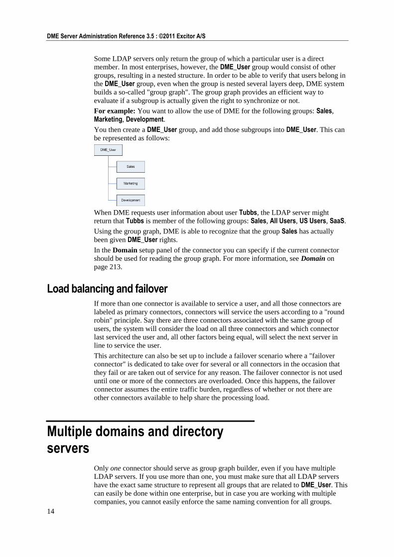
For example: You want to allow the use of DME for the following groups: Sales,
Marketing, Development.
You then create a DME_User group, and add those subgroups into DME_User. This can
be represented as follows:
When DME requests user information about user Tubbs, the LDAP server might
return that Tubbs is member of the following groups: Sales, All Users, US Users, SaaS.
Using the group graph, DME is able to recognize that the group Sales has actually
been given DME_User rights.
In the Domain setup panel of the connector you can specify if the current connector
should be used for reading the group graph. For more information, see Domain on
page 213.
Load balancing and failover If more than one connector is available to service a user, and all those connectors are
labeled as primary connectors, connectors will service the users according to a "round
robin" principle. Say there are three connectors associated with the same group of
users, the system will consider the load on all three connectors and which connector
last serviced the user and, all other factors being equal, will select the next server in
line to service the user.
This architecture can also be set up to include a failover scenario where a "failover
connector" is dedicated to take over for several or all connectors in the occasion that
they fail or are taken out of service for any reason. The failover connector is not used
until one or more of the connectors are overloaded. Once this happens, the failover
connector assumes the entire traffic burden, regardless of whether or not there are
other connectors available to help share the processing load.
Multiple domains and directory servers
Only one connector should serve as group graph builder, even if you have multiple
LDAP servers. If you use more than one, you must make sure that all LDAP servers
have the exact same structure to represent all groups that are related to DME_User. This
can easily be done within one enterprise, but in case you are working with multiple
companies, you cannot easily enforce the same naming convention for all groups.
15
DME server architecture : Multiple domains and directory servers
In that latter case, for multiple companies (domains), you can build a group graph if
you have one central LDAP for all companies (such as Hosted Exchange).
When you have distributed LDAP servers, the only way to ensure that users are
authenticated correctly is to manually specify which users are serviced by a specific
connector. This is of course only feasible and manageable for companies with a very
limited number of users (see also the section Connector routing on page 15 below).
Connector broadcasting The default way for a connector to find which users to service is to use broadcasting,
as mentioned in the section The connector on page 13 above. By this method, the
DME server poses a request to the joint grouped of connectors, asking: "Which of you
is able to synchronize e-mail (or calendar, etc.) for user xxx ?". As each function
(authentication, e-mail, calendar, contacts, etc.) is independent of the others, there
could potentially be a different connector for each function, even for the same user.
When a DME connector sends a positive reply, a route is saved for this combination
of user and function for the connector.
For example, in order to check if the password of a new user is valid, the DME server
asks all the connectors for which the "Authentication" function is enabled to check if
they are able to authenticate this user.
Since each connector may in principle be configured to a different domain, the DME
server sends the user name as entered in the DME client, which is usually the short
name for the user.
Then the specific domain name is appended by each connector, and the credentials are
tested against the defined Authentication LDAP server.
Note
In a setup that involves multiple companies, this is a major security risk, since the user
name and password are sent to all connectors.
See below for alternative configuration options.
Connector routing As an alternative to using connector broadcasting for a multi-company setup, you can
configure connectors to service specific groups or users. This requires that the user
group membership information is known in order for DME to correctly send the
request to the appropriate connector.
Group configuration
As an example of configuring connectors for specific groups, consider an example
where you need to support both Exchange and Domino users. You want to configure
DME in such a way that members of the DME_Exchange group are served by the
connector named DME Exchange, and members of the DME_Domino group are served
by the connector named DME Domino.
In this scenario, you would have two LDAP servers: Active Directory and Domino
Directory.
As explained in the section about the group graph (see The group graph on page 13),
you need to build a group graph "tree" in which DME_Exchange and DME_Domino are
members of the same company, so that users of both groups can synchronize with
DME.
16
DME Server Administration Reference 3.5 : ©2011 Excitor A/S
In this example, we furthermore want to force a specific connector to service only
members of a specific group.
You can configure each connector to be responsible for one or the other group only.
This is not recommended, for the following reason:
if both connectors are set to build the group graph, only the partial method can be used
(see Main on page 211), as the default group names in AD and Domino LDAP are
different. If both connectors try to send the full list to DME, the DME Server is not
able to figure out which list (AD or Domino groups) is valid.
When using the partial group graph mode, and both connectors are building the group
graph, the same group structure must be present in both LDAP servers, and all groups
must be created (DME_Exchange and DME_Domino).
DME caches the group-to-user relationship in order to send the request to the correct
connector. In the above example, when an unknown user tries to connect to DME, the
DME server is not able to find that the user is member or DME_Exchange or
DME_Domino, because the user has not yet been cached. Therefore you will get an
error in the log, saying that "No route for user is available".
However, if you use broadcasting instead of a fixed group/connector relationship, both
connectors are asked, and only one can provide information about the user from the
correct LDAP server.
Therefore the recommendation is to use Broadcasting, and to add DME_Exchange and
DME_Domino, respectively, as the LDAP group in which the connector should look for
user information. This is done in the field Additional DME_User group in the
connector setup panel Domain (see Domain on page 213). This way, the members of
DME_Exchange would only be served by the connector where DME_Exchange is
specified as additional DME_User group.
Individual user configuration
When you configure a connector to route to a specific list of users, you are not limited
by the above mentioned LDAP issues. DME is using the information provided by the
DME client, that is the user name, and can match that against the LDAP server
defined for the connector.
This way, the DME Server knows that all requests for this user have to be passed to
the specific connector. You still need a LDAP server to gather information such as the
full user name and e-mail address for the user, as well as group membership to check
if the user is member of DME_User and thus able to synchronize.
DME services
The DME Server and the DME connectors are run as services on the operating system.
If you should need to restart them for any reason, use the following commands.
On Windows, the services are stopped, started, and restarted through the Services
control panel in Windows, or you can use net start <service> or net stop
<service> from a command prompt. The service names are the following:

17
DME server architecture : DME services
The DME Server: dmeserver
The DME connector: dmeconnector
On Linux, the installer creates start/stop scripts named after the server instance. The
default instance name is base.
The DME Server:
service dme_<instance_name> start or service dme_<instance_name> stop
The DME connector:
sh dmec_<instance>.sh start or sh dmec_<instance>.sh stop
The script must be found in the /etc/init.d folder.

Navigating the Web interface 19
Navigating the Web interface
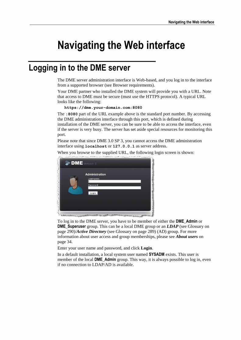
Logging in to the DME server
The DME server administration interface is Web-based, and you log in to the interface
from a supported browser (see Browser requirements).
Your DME partner who installed the DME system will provide you with a URL. Note
that access to DME must be secure (must use the HTTPS protocol). A typical URL
looks like the following:
https://dme.your-domain.com:8080
The :8080 part of the URL example above is the standard port number. By accessing
the DME administration interface through this port, which is defined during
installation of the DME server, you can be sure to be able to access the interface, even
if the server is very busy. The server has set aside special resources for monitoring this
port.
Please note that since DME 3.0 SP 3, you cannot access the DME administration
interface using localhost or 127.0.0.1 as server address.
When you browse to the supplied URL, the following login screen is shown:
To log in to the DME server, you have to be member of either the DME_Admin or
DME_Superuser group. This can be a local DME group or an LDAP (see Glossary on
page 290)/Active Directory (see Glossary on page 289) (AD) group. For more
information about user access and group memberships, please see About users on
page 34.
Enter your user name and password, and click Login.
In a default installation, a local system user named SYSADM exists. This user is
member of the local DME_Admin group. This way, it is always possible to log in, even
if no connection to LDAP/AD is available.
20
DME Server Administration Reference 3.5 : ©2011 Excitor A/S
Elements of the Web interface
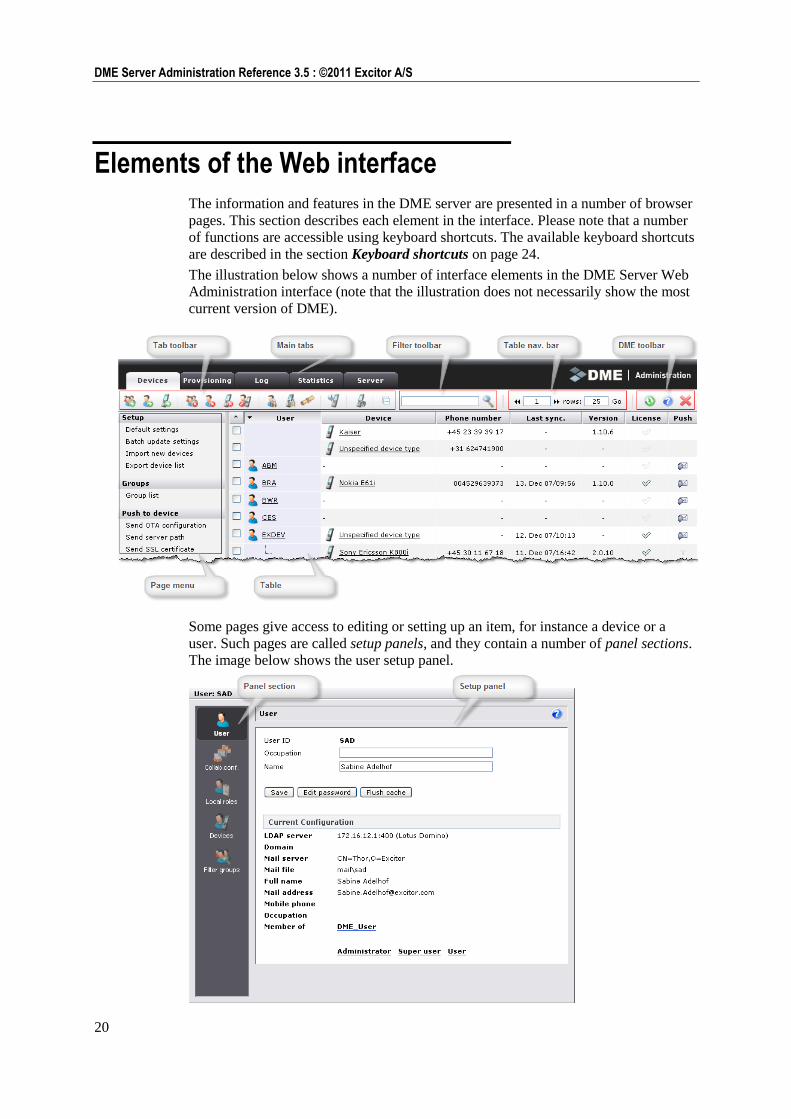
The information and features in the DME server are presented in a number of browser
pages. This section describes each element in the interface. Please note that a number
of functions are accessible using keyboard shortcuts. The available keyboard shortcuts
are described in the section Keyboard shortcuts on page 24.
The illustration below shows a number of interface elements in the DME Server Web
Administration interface (note that the illustration does not necessarily show the most
current version of DME).
Some pages give access to editing or setting up an item, for instance a device or a
user. Such pages are called setup panels, and they contain a number of panel sections.
The image below shows the user setup panel.
21
Navigating the Web interface : Elements of the Web interface
Main tabs All DME control options in the DME server are divided into tabs along the top edge
of the window. The currently selected tab is shown in a contrasting color, as in the
example below where the Server tab is selected.
When you open the DME Server Web Administration Interface, the default tab is
Devices. You can switch to another tab by clicking the name of the tab. To refresh the
data shown in a tab, click the tab again.
This manual is structured around tabs, describing each tab in its order of appearance.
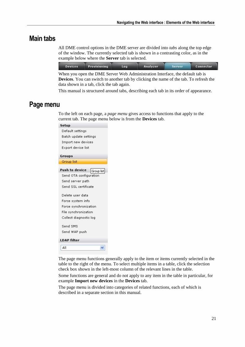
Page menu To the left on each page, a page menu gives access to functions that apply to the
current tab. The page menu below is from the Devices tab.
The page menu functions generally apply to the item or items currently selected in the
table to the right of the menu. To select multiple items in a table, click the selection
check box shown in the left-most column of the relevant lines in the table.
Some functions are general and do not apply to any item in the table in particular, for
example Import new devices in the Devices tab.
The page menu is divided into categories of related functions, each of which is
described in a separate section in this manual.
22
DME Server Administration Reference 3.5 : ©2011 Excitor A/S
Table A tab may contain information in a table, for example a table listing the devices
owned by your company. The table is divided into items (rows) and columns. The first
column (not counting the check box column for item selection) in the table usually
contains the item key, the unique identifier of the item of the current type - for instance
the user ID of a user.
Most tables can be sorted. To sort a table, click the header of the column by which you
want to sort the information.
1 Click once to sort in ascending order.
2 Click again to sort in descending order.
3 Click once again to return the column to the unsorted state.
As mentioned above, the first column in the table consists of a check box. This is
used for selecting one or more items in the table on which you want to perform a
function from the page menu. By clicking the header of the check box column
you can select or deselect all shown items in the table at once.
Toolbars A number of toolbars are displayed below the main tabs area.
Tab toolbar
In the Devices and Provisioning tabs, as well as in several setup panels and
elsewhere, a tab toolbar contains actions that apply to the current tab or item being
edited - for instance, creating, deleting, or editing an item. The tab toolbar actions
apply to the currently selected item or items, or to the item currently being edited in a
setup panel. The tab toolbar shown above is the largest of the toolbars, the main
Devices tab toolbar.
The tab toolbar may change depending on which function is selected in the page menu
or which panel section is opened.
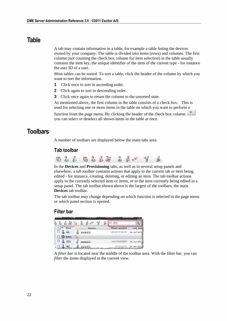
Filter bar
A filter bar is located near the middle of the toolbar area. With the filter bar, you can
filter the items displayed in the current view.
23
Navigating the Web interface : Elements of the Web interface
In the text filter box you can enter a text and click the magnifying glass icon. The table
will then only show items that contain the text you entered. The text can be found in
any column. For example, in the Devices tab you can type "N95" and press Enter or
click the magnifying glass icon to reduce the list to only show all your Nokia E72
devices, who is currently holding them, etc. To disable the filter, click the magnifying
glass icon again. If you filter for a telephone number, you should note that DME
automatically spaces numbers below a certain number of digits in sets of two numbers,
for instance "30 91 42 22". If you want to filter for that number, you must leave out
the spaces, and enter "30914222", which is the way it is actually stored in the
database.
Whenever a filter is applied to a table view, the magnifying glass icon is shown with a
recessed background. To turn the filter off, click the magnifying glass icon again.
If you switch to another tab that contains a text filter box, any selection in the filter bar
will be retained, and the table will be filtered according to your selection.
The text filter box applies to the Devices, Provisioning, Log, and Statistics/Analyzer
tabs. In the Devices tab, it only applies when at least one group is expanded.
In some tabs, you can also filter by LDAP group. If you filter by LDAP group, the
table will only show items that pertain to users from the selected LDAP group. For
more information, see LDAP filter on page 61.
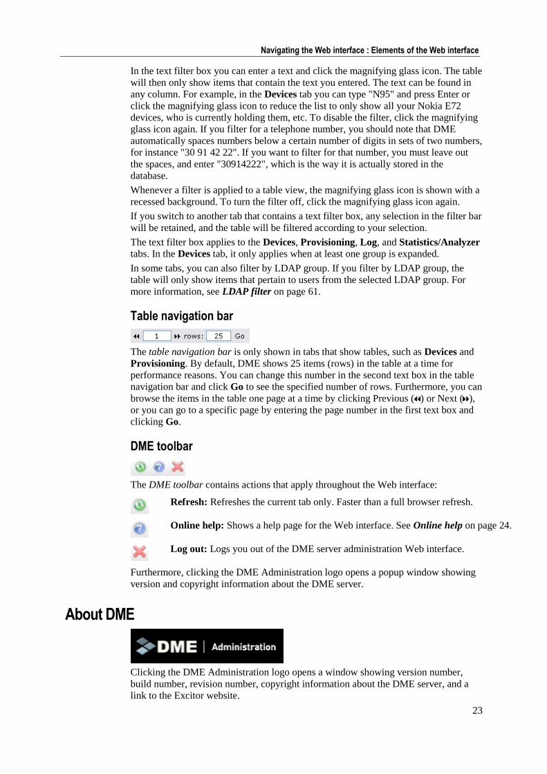
Table navigation bar
The table navigation bar is only shown in tabs that show tables, such as Devices and
Provisioning. By default, DME shows 25 items (rows) in the table at a time for
performance reasons. You can change this number in the second text box in the table
navigation bar and click Go to see the specified number of rows. Furthermore, you can
browse the items in the table one page at a time by clicking Previous ( ) or Next ( ),
or you can go to a specific page by entering the page number in the first text box and
clicking Go.
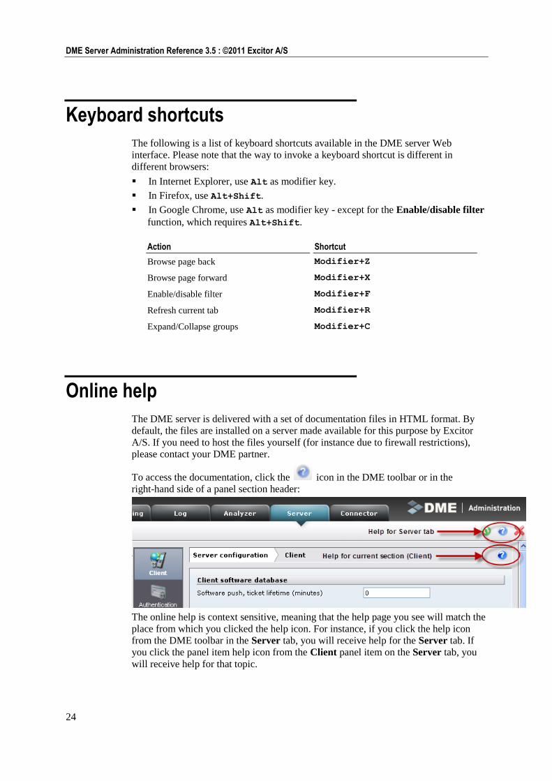
DME toolbar
The DME toolbar contains actions that apply throughout the Web interface:
Refresh: Refreshes the current tab only. Faster than a full browser refresh.
Online help: Shows a help page for the Web interface. See Online help on page 24.
Log out: Logs you out of the DME server administration Web interface.
Furthermore, clicking the DME Administration logo opens a popup window showing
version and copyright information about the DME server.
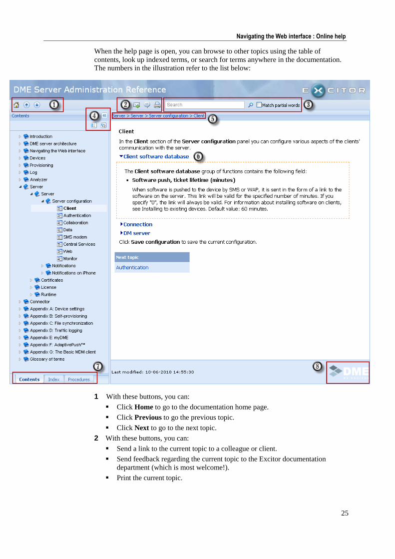
About DME
Clicking the DME Administration logo opens a window showing version number,
build number, revision number, copyright information about the DME server, and a
link to the Excitor website.
24
DME Server Administration Reference 3.5 : ©2011 Excitor A/S
Keyboard shortcuts
The following is a list of keyboard shortcuts available in the DME server Web
interface. Please note that the way to invoke a keyboard shortcut is different in
different browsers:
In Internet Explorer, use Alt as modifier key.
In Firefox, use Alt+Shift.
In Google Chrome, use Alt as modifier key - except for the Enable/disable filter
function, which requires Alt+Shift.
Action Shortcut
Browse page back Modifier+Z
Browse page forward Modifier+X
Enable/disable filter Modifier+F
Refresh current tab Modifier+R
Expand/Collapse groups Modifier+C
Online help
The DME server is delivered with a set of documentation files in HTML format. By
default, the files are installed on a server made available for this purpose by Excitor
A/S. If you need to host the files yourself (for instance due to firewall restrictions),
please contact your DME partner.
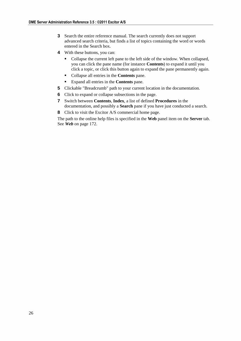
To access the documentation, click the icon in the DME toolbar or in the
right-hand side of a panel section header:
The online help is context sensitive, meaning that the help page you see will match the
place from which you clicked the help icon. For instance, if you click the help icon
from the DME toolbar in the Server tab, you will receive help for the Server tab. If
you click the panel item help icon from the Client panel item on the Server tab, you
will receive help for that topic.
25
Navigating the Web interface : Online help
When the help page is open, you can browse to other topics using the table of
contents, look up indexed terms, or search for terms anywhere in the documentation.
The numbers in the illustration refer to the list below:
1 With these buttons, you can:
Click Home to go to the documentation home page.
Click Previous to go the previous topic.
Click Next to go to the next topic.
2 With these buttons, you can:
Send a link to the current topic to a colleague or client.
Send feedback regarding the current topic to the Excitor documentation
department (which is most welcome!).
Print the current topic.
26
DME Server Administration Reference 3.5 : ©2011 Excitor A/S
3 Search the entire reference manual. The search currently does not support
advanced search criteria, but finds a list of topics containing the word or words
entered in the Search box.
4 With these buttons, you can:
Collapse the current left pane to the left side of the window. When collapsed,
you can click the pane name (for instance Contents) to expand it until you
click a topic, or click this button again to expand the pane permanently again.
Collapse all entries in the Contents pane.
Expand all entries in the Contents pane.
5 Clickable "Breadcrumb" path to your current location in the documentation.
6 Click to expand or collapse subsections in the page.
7 Switch between Contents, Index, a list of defined Procedures in the
documentation, and possibly a Search pane if you have just conducted a search.
8 Click to visit the Excitor A/S commercial home page.
The path to the online help files is specified in the Web panel item on the Server tab.
See Web on page 172.
Devices 27
Devices
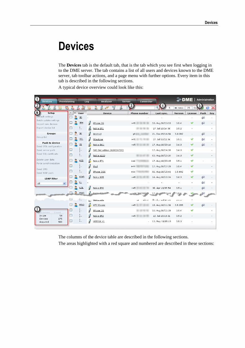
The Devices tab is the default tab, that is the tab which you see first when logging in
to the DME server. The tab contains a list of all users and devices known to the DME
server, tab toolbar actions, and a page menu with further options. Every item in this
tab is described in the following sections.
A typical device overview could look like this:
The columns of the device table are described in the following sections.
The areas highlighted with a red square and numbered are described in these sections:
28
DME Server Administration Reference 3.5 : ©2011 Excitor A/S
1 Main tabs - see Main tabs on page 21.
2 The tab toolbar, containing the actions that are available in the current context -
see Tab toolbar on page 22.
3 The filter bar, which lets you filter for relevant information - see Filter bar on
page 22.
4 The table navigation bar, which lets you browse through the devices - see Table
navigation bar on page 23.
5 The DME toolbar with general options - see DME toolbar on page 23.
6 The page menu with the functions that are available in the current context - see
Device page menu see "Page menu" on page 41.
7 License statistics - At the bottom left on the page, a small table shows license
statistics:
Number of licenses in use
Number of licensed devices
Number of acquired licenses
These figures give you a quick overview to help you decide when to release the
license from unused devices (see Toggle license on page 40) and acquire new
licenses.
Columns
The list contains a number of columns, which are described in the following.
User The User column shows which user is associated with which device(s).
A field (row) in the User column may have three states: It can be empty, it can show
the name of a user, or it can show a dotted, L-shaped line. These are explained below.
1 Grey user
If the user field shows a grey user, it means that no user is associated with
(uses) the device of the line in question. For instance, if a device is "between
users" and the user has been detached from the device (see Detach user from
device on page 39), it will be shown with no associated user in this way. You can
click the device and go to the Users panel section to see the device's history of
users. You can click the grey user icon to assign a user to the device. See the
following section.
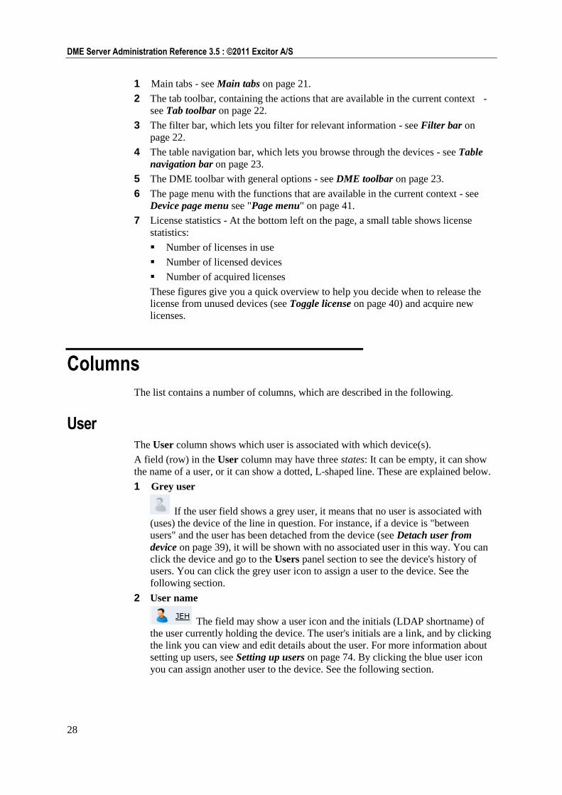
2 User name
The field may show a user icon and the initials (LDAP shortname) of
the user currently holding the device. The user's initials are a link, and by clicking
the link you can view and edit details about the user. For more information about
setting up users, see Setting up users on page 74. By clicking the blue user icon
you can assign another user to the device. See the following section.
29
Devices : Columns
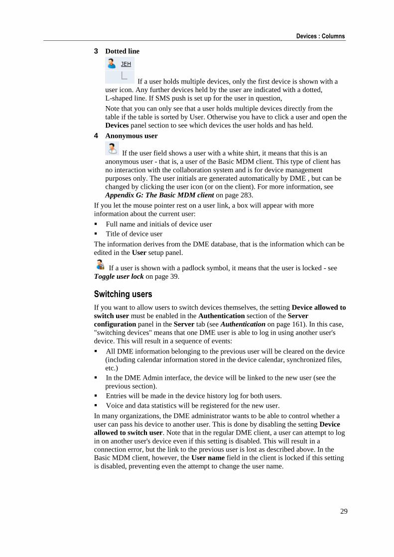
3 Dotted line
If a user holds multiple devices, only the first device is shown with a
user icon. Any further devices held by the user are indicated with a dotted,
L-shaped line. If SMS push is set up for the user in question,
Note that you can only see that a user holds multiple devices directly from the
table if the table is sorted by User. Otherwise you have to click a user and open the
Devices panel section to see which devices the user holds and has held.
4 Anonymous user
If the user field shows a user with a white shirt, it means that this is an
anonymous user - that is, a user of the Basic MDM client. This type of client has
no interaction with the collaboration system and is for device management
purposes only. The user initials are generated automatically by DME , but can be
changed by clicking the user icon (or on the client). For more information, see
Appendix G: The Basic MDM client on page 283.
If you let the mouse pointer rest on a user link, a box will appear with more
information about the current user:
Full name and initials of device user
Title of device user
The information derives from the DME database, that is the information which can be
edited in the User setup panel.
If a user is shown with a padlock symbol, it means that the user is locked - see
Toggle user lock on page 39.
Switching users
If you want to allow users to switch devices themselves, the setting Device allowed to
switch user must be enabled in the Authentication section of the Server
configuration panel in the Server tab (see Authentication on page 161). In this case,
"switching devices" means that one DME user is able to log in using another user's
device. This will result in a sequence of events:
All DME information belonging to the previous user will be cleared on the device
(including calendar information stored in the device calendar, synchronized files,
etc.)
In the DME Admin interface, the device will be linked to the new user (see the
previous section).
Entries will be made in the device history log for both users.
Voice and data statistics will be registered for the new user.
In many organizations, the DME administrator wants to be able to control whether a
user can pass his device to another user. This is done by disabling the setting Device
allowed to switch user. Note that in the regular DME client, a user can attempt to log
in on another user's device even if this setting is disabled. This will result in a
connection error, but the link to the previous user is lost as described above. In the
Basic MDM client, however, the User name field in the client is locked if this setting
is disabled, preventing even the attempt to change the user name.
30
DME Server Administration Reference 3.5 : ©2011 Excitor A/S
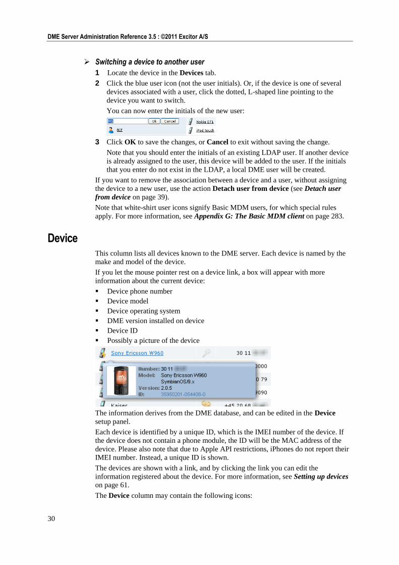
Switching a device to another user
1 Locate the device in the Devices tab.
2 Click the blue user icon (not the user initials). Or, if the device is one of several
devices associated with a user, click the dotted, L-shaped line pointing to the
device you want to switch.
You can now enter the initials of the new user:
3 Click OK to save the changes, or Cancel to exit without saving the change.
Note that you should enter the initials of an existing LDAP user. If another device
is already assigned to the user, this device will be added to the user. If the initials
that you enter do not exist in the LDAP, a local DME user will be created.
If you want to remove the association between a device and a user, without assigning
the device to a new user, use the action Detach user from device (see Detach user
from device on page 39).
Note that white-shirt user icons signify Basic MDM users, for which special rules
apply. For more information, see Appendix G: The Basic MDM client on page 283.
Device This column lists all devices known to the DME server. Each device is named by the
make and model of the device.
If you let the mouse pointer rest on a device link, a box will appear with more
information about the current device:
Device phone number
Device model
Device operating system
DME version installed on device
Device ID
Possibly a picture of the device
The information derives from the DME database, and can be edited in the Device
setup panel.
Each device is identified by a unique ID, which is the IMEI number of the device. If
the device does not contain a phone module, the ID will be the MAC address of the
device. Please also note that due to Apple API restrictions, iPhones do not report their
IMEI number. Instead, a unique ID is shown.
The devices are shown with a link, and by clicking the link you can edit the
information registered about the device. For more information, see Setting up devices
on page 61.
The Device column may contain the following icons:
31
Devices : Columns
A device is associated with the current user. If notification is enabled for
the user on this device (see SMS see "Push" on page 32), it is currently
using SMS push notification.
A device is associated with the current user, and it is currently connected
(using network push).
A device is associated with the current user, and the device has been
bootstrapped.
The device is currently synchronizing with the server.
The user's device is locked. Perhaps the user is under notice. See Toggle
device lock on page 40.
- If the Device column is empty, the user does not currently hold a device.
Some icons may overlap. For instance, a bootstrapped device may also be connected
with network push.
The icon is followed by the device type. This is the type reported by the device. The
DME client may adjust or change the device type. For instance, the client adds
(Jailbroken) to iPhone devices that have been jailbroken (and thus not formally
supported), and adds (Rooted) to rooted Android devices. Such devices can be locked
automatically - see Authentication on page 161.
Phone number This is the phone number of the device. The phone number is used for notifications,
provisioning, and other information pushed to the device by SMS or WAP. The device
user can change the phone number from within the DME client on the device (for
instance if a new SIM card is installed in the device).
Last sync. The date and time shown in this field is the date and time of the last synchronization
of the device with the server. For more information about synchronization, see
Schedule on page 182 and Setting up devices on page 61.
If a user holds multiple devices, and push mail has been enabled for the user (see User
Collab.conf. see "Collab.conf." on page 77), the e-mail push is sent to the device that
synchronized last.
Version This field shows the version number of the DME client running on the device on the
current line. For more information about upgrading software on the devices, see
Provisioning on page 83.
License This field shows if the current device occupies a license. If the field shows a colored
check mark icon , the device occupies a license. If the check mark is grey , the
device does not occupy a license. You can see the number of free licenses in the
bottom left corner of the page.
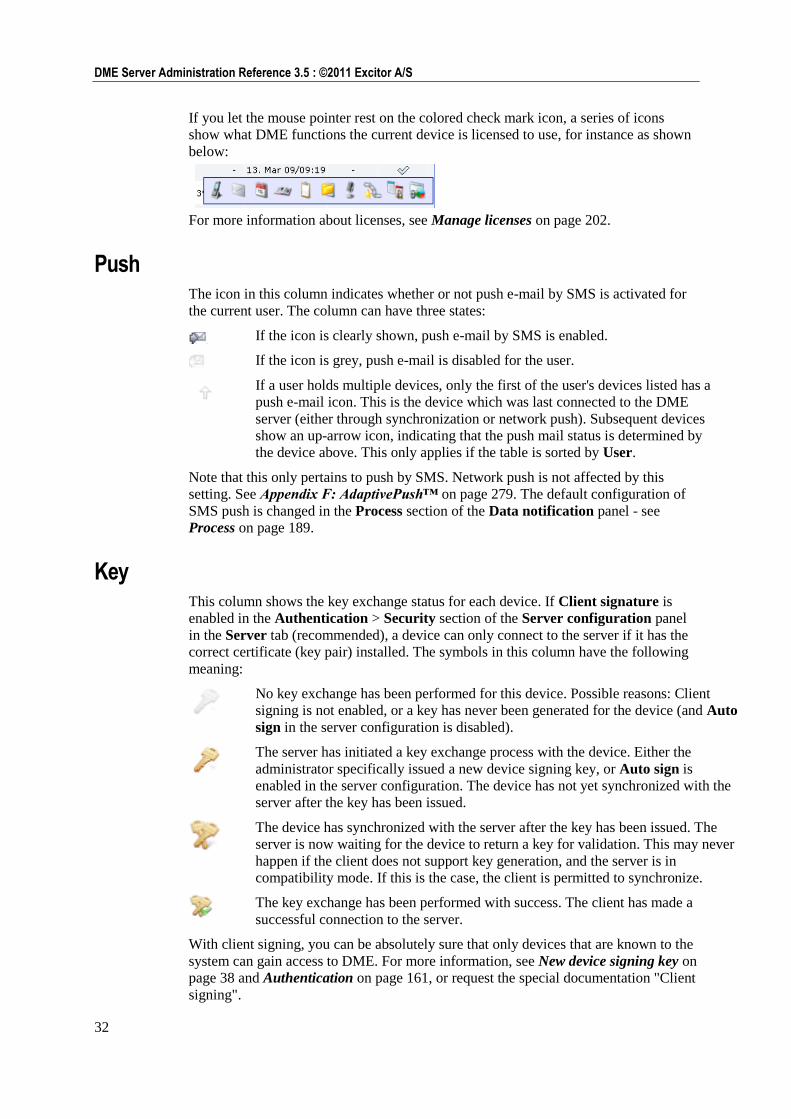
32
DME Server Administration Reference 3.5 : ©2011 Excitor A/S
If you let the mouse pointer rest on the colored check mark icon, a series of icons
show what DME functions the current device is licensed to use, for instance as shown
below:
For more information about licenses, see Manage licenses on page 202.
Push The icon in this column indicates whether or not push e-mail by SMS is activated for
the current user. The column can have three states:
If the icon is clearly shown, push e-mail by SMS is enabled.
If the icon is grey, push e-mail is disabled for the user.
If a user holds multiple devices, only the first of the user's devices listed has a
push e-mail icon. This is the device which was last connected to the DME
server (either through synchronization or network push). Subsequent devices
show an up-arrow icon, indicating that the push mail status is determined by
the device above. This only applies if the table is sorted by User.
Note that this only pertains to push by SMS. Network push is not affected by this
setting. See Appendix F: AdaptivePush™ on page 279. The default configuration of
SMS push is changed in the Process section of the Data notification panel - see
Process on page 189.
Key This column shows the key exchange status for each device. If Client signature is
enabled in the Authentication > Security section of the Server configuration panel
in the Server tab (recommended), a device can only connect to the server if it has the
correct certificate (key pair) installed. The symbols in this column have the following
meaning:
No key exchange has been performed for this device. Possible reasons: Client
signing is not enabled, or a key has never been generated for the device (and Auto
sign in the server configuration is disabled).
The server has initiated a key exchange process with the device. Either the
administrator specifically issued a new device signing key, or Auto sign is
enabled in the server configuration. The device has not yet synchronized with the
server after the key has been issued.
The device has synchronized with the server after the key has been issued. The
server is now waiting for the device to return a key for validation. This may never
happen if the client does not support key generation, and the server is in
compatibility mode. If this is the case, the client is permitted to synchronize.
The key exchange has been performed with success. The client has made a
successful connection to the server.
With client signing, you can be absolutely sure that only devices that are known to the
system can gain access to DME. For more information, see New device signing key on
page 38 and Authentication on page 161, or request the special documentation "Client
signing".
33
Devices : Tab actions
Tab actions
The selection of actions on the tab toolbar depend on context - whether the main
Devices table is shown, or whether you have first selected a function in the page
menu. In many cases the tab toolbar is not available after a function has been selected.
The main Devices tab toolbar contains the following actions.
New group
When you click the New group action, you can create a new group in the page Group
list, and optionally connect the group to an existing directory group. For information
about adding groups in DME, see Adding a new group on page 50.
For more information about groups in general, see Groups on page 49.
New user
Click the New user action from the main Devices tab or from the User setup panel to
create a new user manually. DME usually retrieves the users from the AD/LDAP
directory system to which DME is connected. However, you may want to add users
manually in the following cases:
1 To ensure availability
If, for some reason, DME is not connected properly to the LDAP system, you need
to have a user in the system with access to the DME server. Otherwise you will not
be able to correct any connection setup errors in the DME interface.
2 To add external users
If you need to add users who have not been created in the LDAP system to DME
for device management purposes. This could for example be a third-party
consultant who has been given a mobile phone but has not been created in the mail
system.
3 To host users
If you host users that are not part of your collaboration system and therefore not
members of your directory.
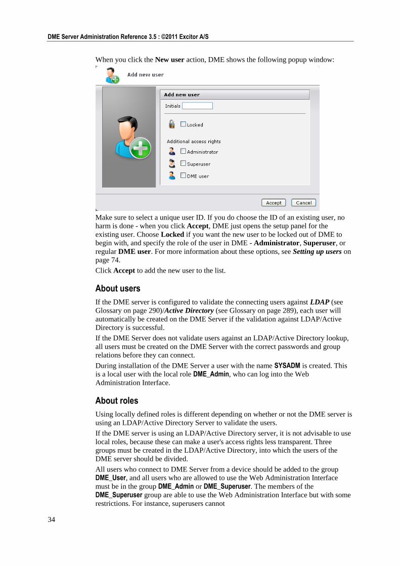
34
DME Server Administration Reference 3.5 : ©2011 Excitor A/S
When you click the New user action, DME shows the following popup window:
Make sure to select a unique user ID. If you do choose the ID of an existing user, no
harm is done - when you click Accept, DME just opens the setup panel for the
existing user. Choose Locked if you want the new user to be locked out of DME to
begin with, and specify the role of the user in DME - Administrator, Superuser, or
regular DME user. For more information about these options, see Setting up users on
page 74.
Click Accept to add the new user to the list.
About users
If the DME server is configured to validate the connecting users against LDAP (see
Glossary on page 290)/Active Directory (see Glossary on page 289), each user will
automatically be created on the DME Server if the validation against LDAP/Active
Directory is successful.
If the DME Server does not validate users against an LDAP/Active Directory lookup,
all users must be created on the DME Server with the correct passwords and group
relations before they can connect.
During installation of the DME Server a user with the name SYSADM is created. This
is a local user with the local role DME_Admin, who can log into the Web
Administration Interface.
About roles
Using locally defined roles is different depending on whether or not the DME server is
using an LDAP/Active Directory Server to validate the users.
If the DME server is using an LDAP/Active Directory server, it is not advisable to use
local roles, because these can make a user's access rights less transparent. Three
groups must be created in the LDAP/Active Directory, into which the users of the
DME server should be divided.
All users who connect to DME Server from a device should be added to the group
DME_User, and all users who are allowed to use the Web Administration Interface
must be in the group DME_Admin or DME_Superuser. The members of the
DME_Superuser group are able to use the Web Administration Interface but with some
restrictions. For instance, superusers cannot
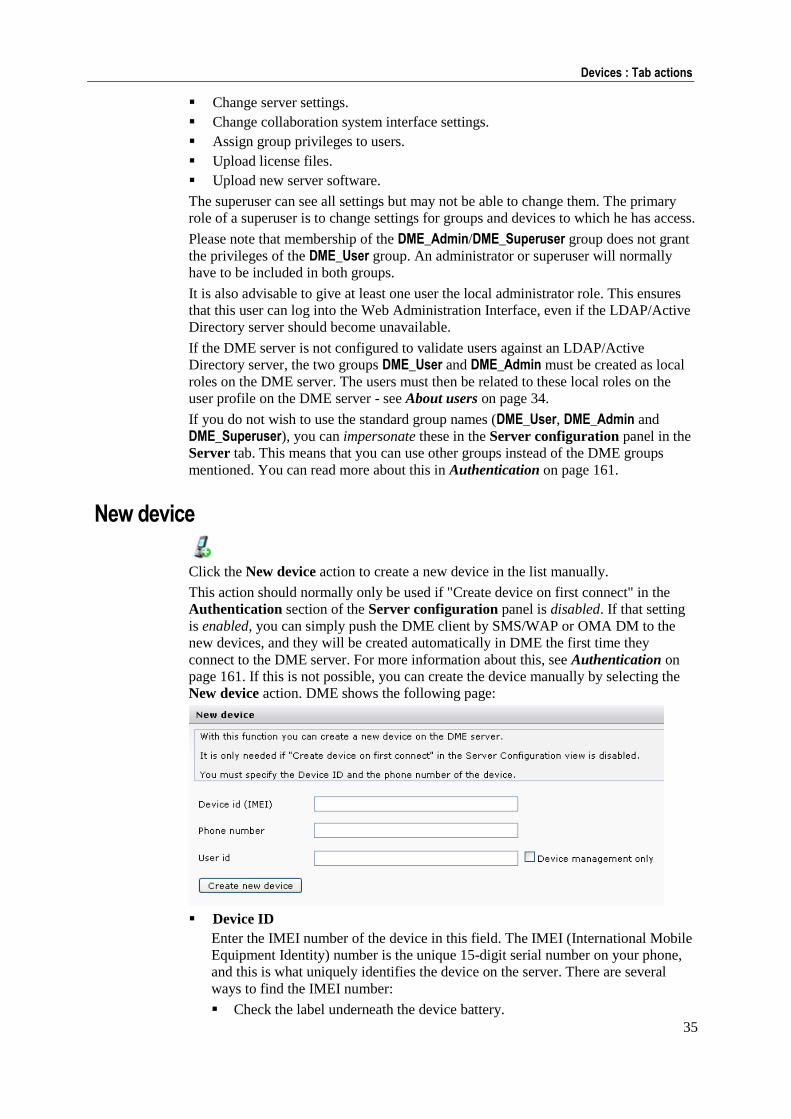
35
Devices : Tab actions
Change server settings.
Change collaboration system interface settings.
Assign group privileges to users.
Upload license files.
Upload new server software.
The superuser can see all settings but may not be able to change them. The primary
role of a superuser is to change settings for groups and devices to which he has access.
Please note that membership of the DME_Admin/DME_Superuser group does not grant
the privileges of the DME_User group. An administrator or superuser will normally
have to be included in both groups.
It is also advisable to give at least one user the local administrator role. This ensures
that this user can log into the Web Administration Interface, even if the LDAP/Active
Directory server should become unavailable.
If the DME server is not configured to validate users against an LDAP/Active
Directory server, the two groups DME_User and DME_Admin must be created as local
roles on the DME server. The users must then be related to these local roles on the
user profile on the DME server - see About users on page 34.
If you do not wish to use the standard group names (DME_User, DME_Admin and
DME_Superuser), you can impersonate these in the Server configuration panel in the
Server tab. This means that you can use other groups instead of the DME groups
mentioned. You can read more about this in Authentication on page 161.
New device
Click the New device action to create a new device in the list manually.
This action should normally only be used if "Create device on first connect" in the
Authentication section of the Server configuration panel is disabled. If that setting
is enabled, you can simply push the DME client by SMS/WAP or OMA DM to the
new devices, and they will be created automatically in DME the first time they
connect to the DME server. For more information about this, see Authentication on
page 161. If this is not possible, you can create the device manually by selecting the
New device action. DME shows the following page:
Device ID
Enter the IMEI number of the device in this field. The IMEI (International Mobile
Equipment Identity) number is the unique 15-digit serial number on your phone,
and this is what uniquely identifies the device on the server. There are several
ways to find the IMEI number:
Check the label underneath the device battery.
36
DME Server Administration Reference 3.5 : ©2011 Excitor A/S
Enter *#06# on your phone's keypad. When the final # is entered, a 15-digit
number with the title "IMEI number" or "Serial number" will appear.
On Motorola devices, you may have to enter #,*,[menu] and then the right
arrow very quickly.
iPhone or iPod Touch devices do not have IMEI numbers. Instead, use their
UDID (Unique Device Identifier), which you can find printed on the box they
came in, or through iTunes.
Phone number
The phone number is used when you push information to the device.
User ID
Id you specify a user ID while creating the device, the device will be assigned to
the user in question as it is created. If the user does not exist, it will be created as a
DME user or a Basic MDM user (see below).
Device management only
If this field is selected, the user specified in the User ID field above is created as a
Basic MDM user (see Appendix G: The Basic MDM client on page 283). The
user created is shown with a white shirt. An MDM user can later be converted to a
regular DME user.
If the field is not selected, the user is created as a regular DME user. A regular
DME user cannot be converted to an MDM user.
Click Create new device. DME adds the device to the list, and you can then set up the
device as described in the section Setting up devices on page 61. To cancel the
creation of a new device, click the Devices tab.
Se also Import new devices.
Bootstrap devices
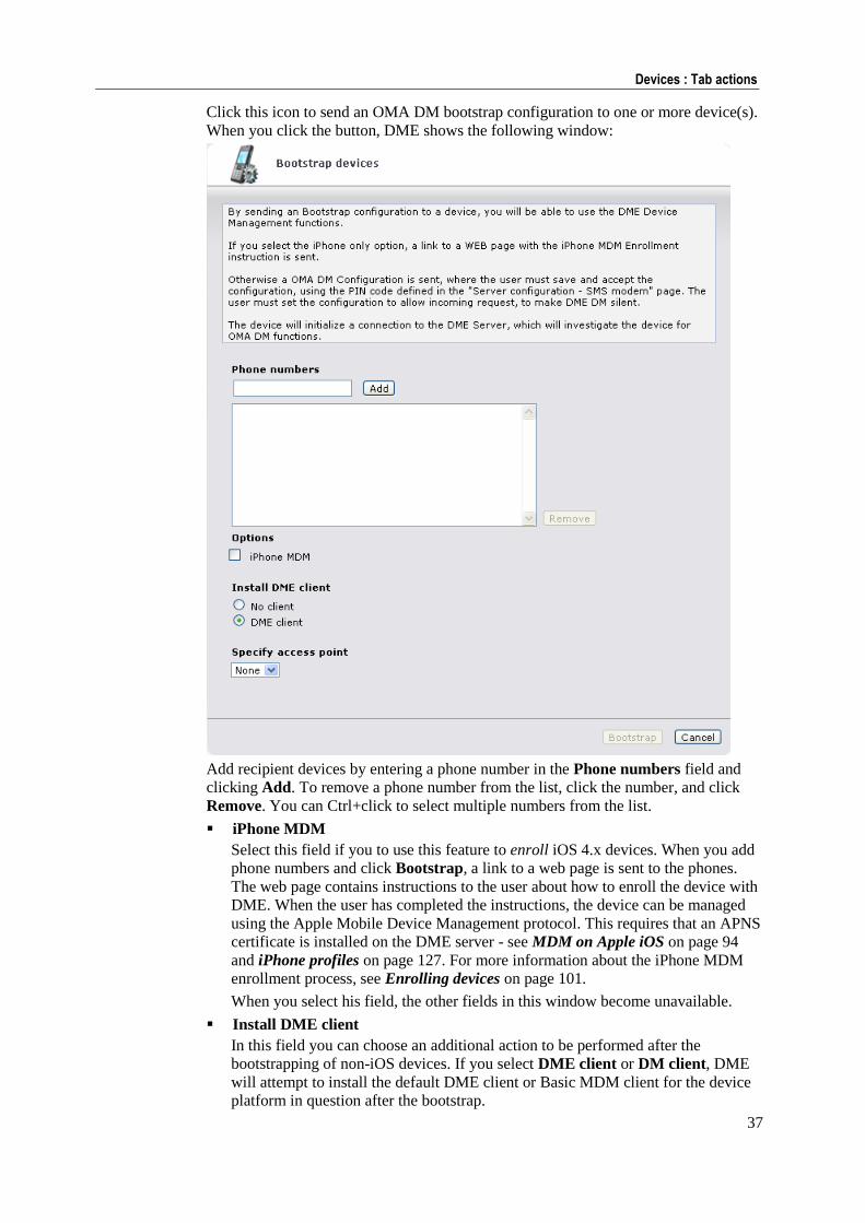
37
Devices : Tab actions
Click this icon to send an OMA DM bootstrap configuration to one or more device(s).
When you click the button, DME shows the following window:
Add recipient devices by entering a phone number in the Phone numbers field and
clicking Add. To remove a phone number from the list, click the number, and click
Remove. You can Ctrl+click to select multiple numbers from the list.
iPhone MDM
Select this field if you to use this feature to enroll iOS 4.x devices. When you add
phone numbers and click Bootstrap, a link to a web page is sent to the phones.
The web page contains instructions to the user about how to enroll the device with
DME. When the user has completed the instructions, the device can be managed
using the Apple Mobile Device Management protocol. This requires that an APNS
certificate is installed on the DME server - see MDM on Apple iOS on page 94
and iPhone profiles on page 127. For more information about the iPhone MDM
enrollment process, see Enrolling devices on page 101.
When you select his field, the other fields in this window become unavailable.
Install DME client
In this field you can choose an additional action to be performed after the
bootstrapping of non-iOS devices. If you select DME client or DM client, DME
will attempt to install the default DME client or Basic MDM client for the device
platform in question after the bootstrap.
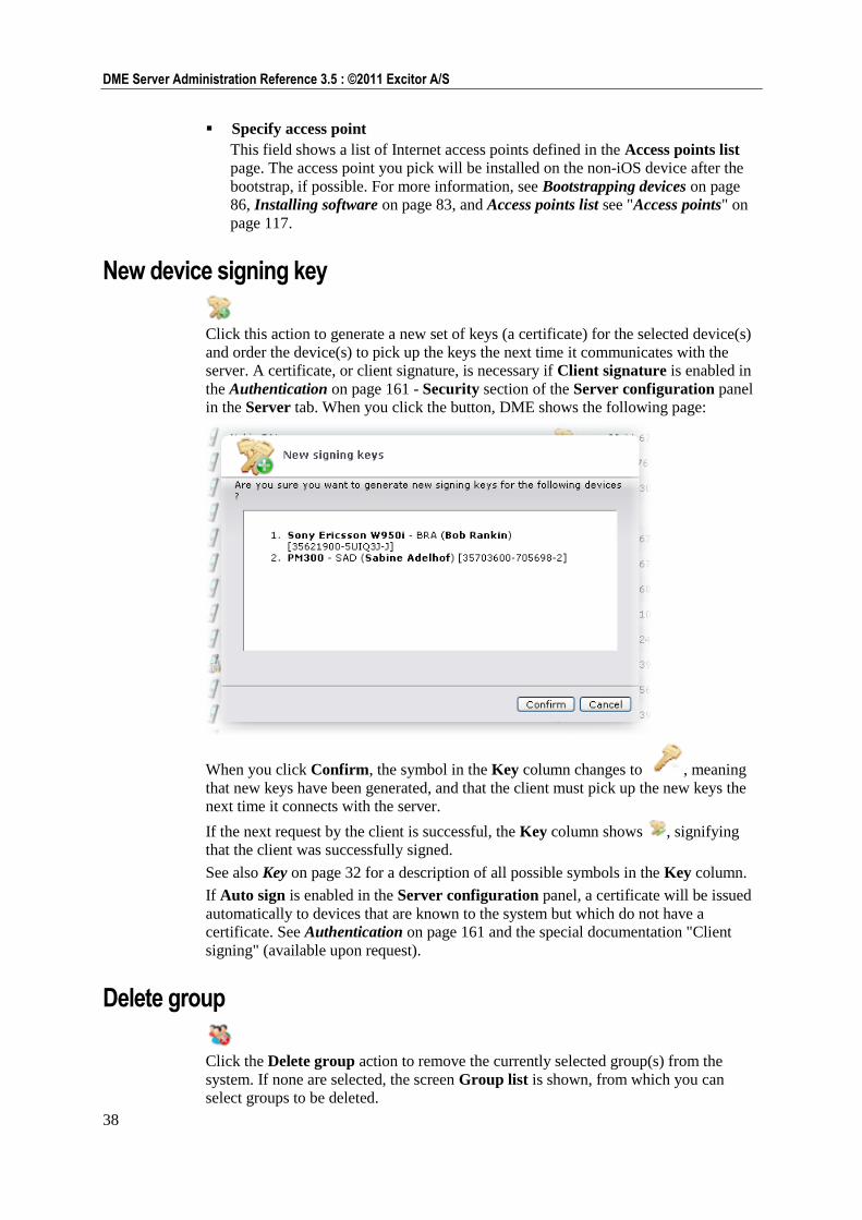
38
DME Server Administration Reference 3.5 : ©2011 Excitor A/S
Specify access point
This field shows a list of Internet access points defined in the Access points list
page. The access point you pick will be installed on the non-iOS device after the
bootstrap, if possible. For more information, see Bootstrapping devices on page
86, Installing software on page 83, and Access points list see "Access points" on
page 117.
New device signing key
Click this action to generate a new set of keys (a certificate) for the selected device(s)
and order the device(s) to pick up the keys the next time it communicates with the
server. A certificate, or client signature, is necessary if Client signature is enabled in
the Authentication on page 161 - Security section of the Server configuration panel
in the Server tab. When you click the button, DME shows the following page:
When you click Confirm, the symbol in the Key column changes to , meaning
that new keys have been generated, and that the client must pick up the new keys the
next time it connects with the server.
If the next request by the client is successful, the Key column shows , signifying
that the client was successfully signed.
See also Key on page 32 for a description of all possible symbols in the Key column.
If Auto sign is enabled in the Server configuration panel, a certificate will be issued
automatically to devices that are known to the system but which do not have a
certificate. See Authentication on page 161 and the special documentation "Client
signing" (available upon request).
Delete group
Click the Delete group action to remove the currently selected group(s) from the
system. If none are selected, the screen Group list is shown, from which you can
select groups to be deleted.
39
Devices : Tab actions
Remove user
Click the Remove user action to remove the currently selected user(s) from the list.
You should only use this action if you are absolutely sure that you want to remove the
user from the DME system. Even though you can easily recreate the user, all statistical
information about usage, devices, and so on will no longer be associated with the user
that you recreate.
Remove device
Click the Remove device action to remove the currently selected device(s) from the
list. You should only use this action if you are absolutely sure that you want to remove
the device. Even though you can easily recreate the device, all statistical information
about device usage, voice traffic, and so on will no longer be associated with the
device that you recreate.
Detach user from device
If you click this action, you break the link between the currently selected user or users
and his or her device(s). This means that the connection between the user and the
device is severed, and the user and his device will appear on separate lines in the
Devices tab. Any statistics that affect the user or the device will no longer have any
influence on the other. This action is necessary if users want to switch devices and
Device allowed to switch user is disabled in the Authentication section of the
Server configuration panel in the Server tab (see Authentication on page 161).
Remove device signing key
Click this action to remove the signing key from the currently selected device(s) in the
list. The device will no longer be able to connect to the server until a new signing key
has been issued from the server, and the old key has been removed from the device.
To remove the signing key from a device, select Tools > Settings > Security in the
DME client, and then select Client certificate. For more information, see
Authentication on page 161, the user guide for your client, and the special
documentation "Client signing" (available upon request).
Toggle user lock
Click the Toggle user lock action to toggle the locked status of the currently selected
user(s). Locking a user can be useful in case the user is suspended or terminated, and
the user should not be able to read corporate e-mail.
40
DME Server Administration Reference 3.5 : ©2011 Excitor A/S
Toggle device lock
Click the Toggle device lock action to toggle the locked status of the currently
selected device(s). You can for instance lock a device if it is temporarily out of
service, but you do not wish to revoke its license. If devices are created on first
connection, they may be initially locked. For more information, see Authentication on
page 161.
Toggle license
Click this action to grant a license to or revoke a license from the currently selected
device(s). In the License column you can see if a device occupies a license. For more
information about licenses, see License on page 201.
Toggle push to device
Clicking this action toggles the SMS Push status of the device or selected devices. If a
user has multiple devices, only the top device listed for the user will be toggled. For
more information, see Process on page 189 (Enable SMS fallback).
Search for device
Clicking this action copies the device ID of the currently selected device to the filter
bar and turns on the filter. You can then for example click the Log tab to see log
entries for the selected device only.
Finding the device ID manually
1 If you let the mouse pointer rest on a device, the device ID is part of the
information shown.
or
2 Click the device and see the device ID in the Information panel section. The ID is
shown in the panel header.
Collapse/expand groups
/
With the Collapse/Expand groups action (keyboard shortcut: Alt+Shift+C) you can
toggle the display of groups in the table. If you click Collapse groups , the list of
devices and users will only display the group headers of any groups defined in the
system. You can then expand one group at a time by clicking the plus icon to the left
of the group name to see the devices that make up the group. Click Expand groups
to expand all the groups (which is the default view).
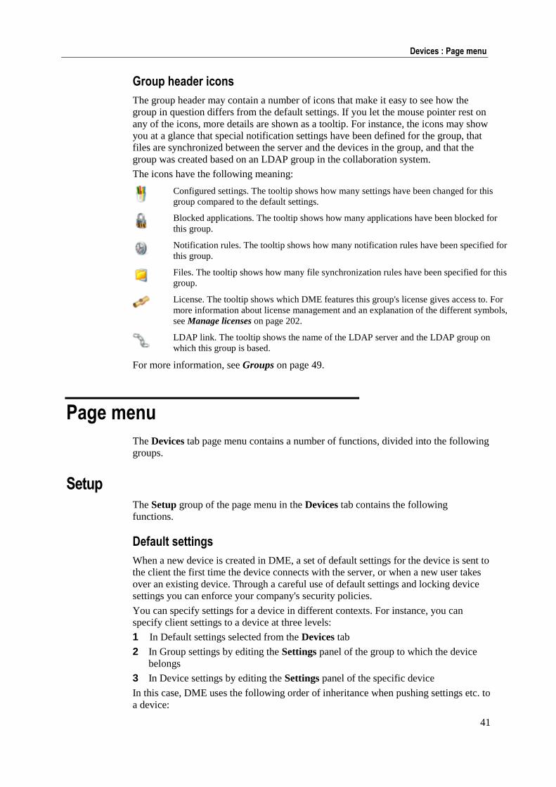
41
Devices : Page menu
Group header icons
The group header may contain a number of icons that make it easy to see how the
group in question differs from the default settings. If you let the mouse pointer rest on
any of the icons, more details are shown as a tooltip. For instance, the icons may show
you at a glance that special notification settings have been defined for the group, that
files are synchronized between the server and the devices in the group, and that the
group was created based on an LDAP group in the collaboration system.
The icons have the following meaning:
Configured settings. The tooltip shows how many settings have been changed for this
group compared to the default settings.
Blocked applications. The tooltip shows how many applications have been blocked for
this group.
Notification rules. The tooltip shows how many notification rules have been specified for
this group.
Files. The tooltip shows how many file synchronization rules have been specified for this
group.
License. The tooltip shows which DME features this group's license gives access to. For
more information about license management and an explanation of the different symbols,
see Manage licenses on page 202.
LDAP link. The tooltip shows the name of the LDAP server and the LDAP group on
which this group is based.
For more information, see Groups on page 49.
Page menu
The Devices tab page menu contains a number of functions, divided into the following
groups.
Setup The Setup group of the page menu in the Devices tab contains the following
functions.
Default settings
When a new device is created in DME, a set of default settings for the device is sent to
the client the first time the device connects with the server, or when a new user takes
over an existing device. Through a careful use of default settings and locking device
settings you can enforce your company's security policies.
You can specify settings for a device in different contexts. For instance, you can
specify client settings to a device at three levels:
1 In Default settings selected from the Devices tab
2 In Group settings by editing the Settings panel of the group to which the device
belongs
3 In Device settings by editing the Settings panel of the specific device
In this case, DME uses the following order of inheritance when pushing settings etc. to
a device:
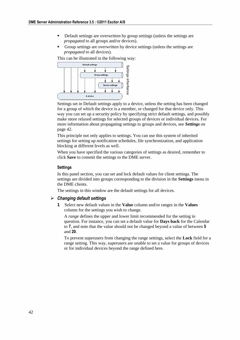
42
DME Server Administration Reference 3.5 : ©2011 Excitor A/S
Default settings are overwritten by group settings (unless the settings are
propagated to all groups and/or devices).
Group settings are overwritten by device settings (unless the settings are
propagated to all devices).
This can be illustrated in the following way:
Settings set in Default settings apply to a device, unless the setting has been changed
for a group of which the device is a member, or changed for that device only. This
way you can set up a security policy by specifying strict default settings, and possibly
make more relaxed settings for selected groups of devices or individual devices. For
more information about propagating settings to groups and devices, see Settings on
page 42.
This principle not only applies to settings. You can use this system of inherited
settings for setting up notification schedules, file synchronization, and application
blocking at different levels as well.
When you have specified the various categories of settings as desired, remember to
click Save to commit the settings to the DME server.
Settings
In this panel section, you can set and lock default values for client settings. The
settings are divided into groups corresponding to the division in the Settings menu in
the DME clients.
The settings in this window are the default settings for all devices.
Changing default settings
1 Select new default values in the Value column and/or ranges in the Values
column for the settings you wish to change.
A range defines the upper and lower limit recommended for the setting in
question. For instance, you can set a default value for Days back for the Calendar
to 7, and note that the value should not be changed beyond a value of between 5
and 20.
To prevent superusers from changing the range settings, select the Lock field for a
range setting. This way, superusers are unable to set a value for groups of devices
or for individual devices beyond the range defined here.
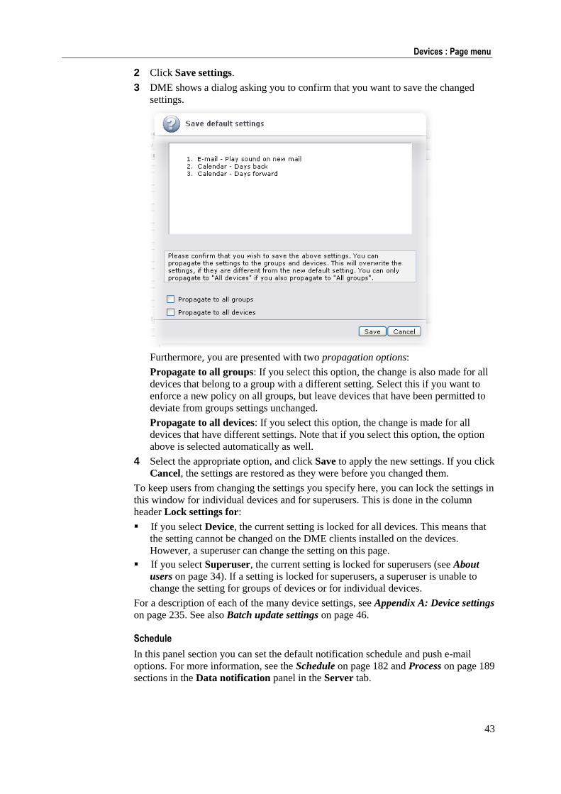
43
Devices : Page menu
2 Click Save settings.
3 DME shows a dialog asking you to confirm that you want to save the changed
settings.
Furthermore, you are presented with two propagation options:
Propagate to all groups: If you select this option, the change is also made for all
devices that belong to a group with a different setting. Select this if you want to
enforce a new policy on all groups, but leave devices that have been permitted to
deviate from groups settings unchanged.
Propagate to all devices: If you select this option, the change is made for all
devices that have different settings. Note that if you select this option, the option
above is selected automatically as well.
4 Select the appropriate option, and click Save to apply the new settings. If you click
Cancel, the settings are restored as they were before you changed them.
To keep users from changing the settings you specify here, you can lock the settings in
this window for individual devices and for superusers. This is done in the column
header Lock settings for:
If you select Device, the current setting is locked for all devices. This means that
the setting cannot be changed on the DME clients installed on the devices.
However, a superuser can change the setting on this page.
If you select Superuser, the current setting is locked for superusers (see About
users on page 34). If a setting is locked for superusers, a superuser is unable to
change the setting for groups of devices or for individual devices.
For a description of each of the many device settings, see Appendix A: Device settings
on page 235. See also Batch update settings on page 46.
Schedule
In this panel section you can set the default notification schedule and push e-mail
options. For more information, see the Schedule on page 182 and Process on page 189
sections in the Data notification panel in the Server tab.
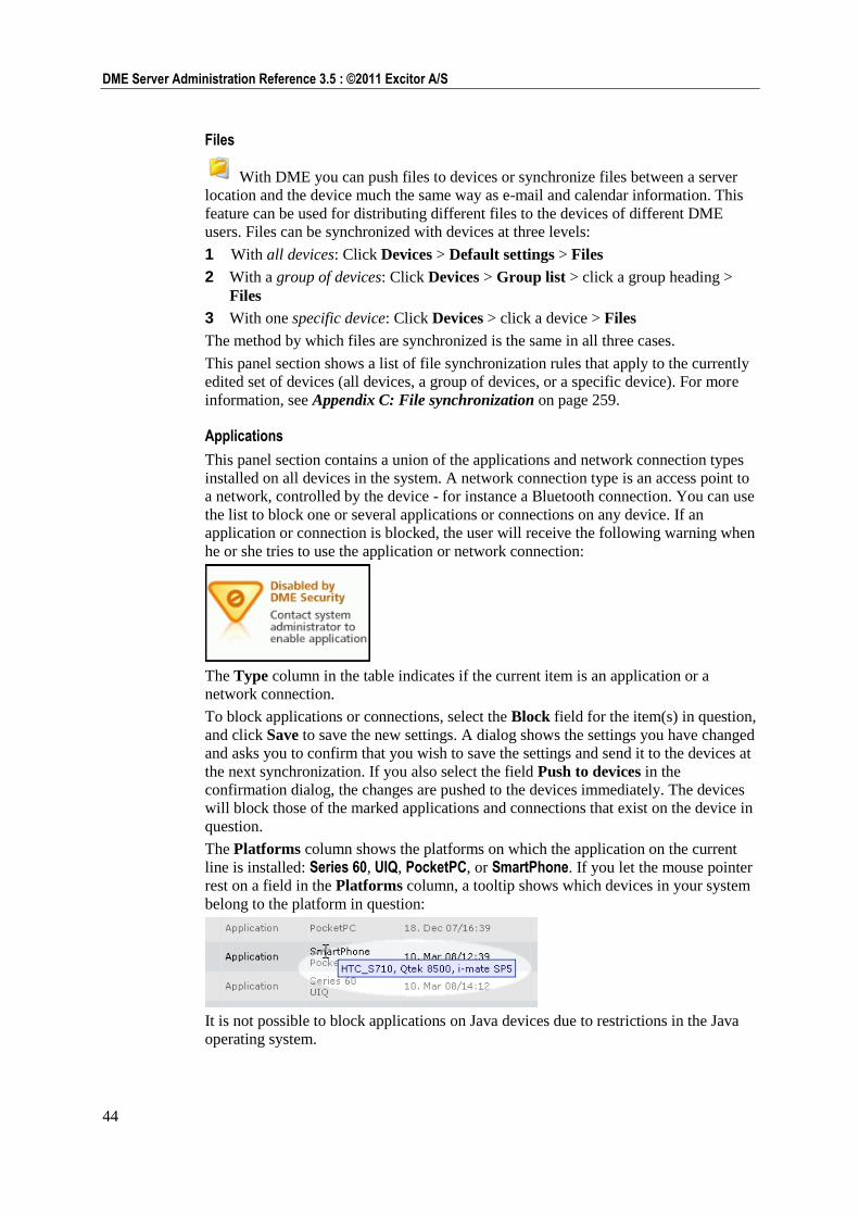
44
DME Server Administration Reference 3.5 : ©2011 Excitor A/S
Files
With DME you can push files to devices or synchronize files between a server
location and the device much the same way as e-mail and calendar information. This
feature can be used for distributing different files to the devices of different DME
users. Files can be synchronized with devices at three levels:
1 With all devices: Click Devices > Default settings > Files
2 With a group of devices: Click Devices > Group list > click a group heading >
Files
3 With one specific device: Click Devices > click a device > Files
The method by which files are synchronized is the same in all three cases.
This panel section shows a list of file synchronization rules that apply to the currently
edited set of devices (all devices, a group of devices, or a specific device). For more
information, see Appendix C: File synchronization on page 259.
Applications
This panel section contains a union of the applications and network connection types
installed on all devices in the system. A network connection type is an access point to
a network, controlled by the device - for instance a Bluetooth connection. You can use
the list to block one or several applications or connections on any device. If an
application or connection is blocked, the user will receive the following warning when
he or she tries to use the application or network connection:
The Type column in the table indicates if the current item is an application or a
network connection.
To block applications or connections, select the Block field for the item(s) in question,
and click Save to save the new settings. A dialog shows the settings you have changed
and asks you to confirm that you wish to save the settings and send it to the devices at
the next synchronization. If you also select the field Push to devices in the
confirmation dialog, the changes are pushed to the devices immediately. The devices
will block those of the marked applications and connections that exist on the device in
question.
The Platforms column shows the platforms on which the application on the current
line is installed: Series 60, UIQ, PocketPC, or SmartPhone. If you let the mouse pointer
rest on a field in the Platforms column, a tooltip shows which devices in your system
belong to the platform in question:
It is not possible to block applications on Java devices due to restrictions in the Java
operating system.
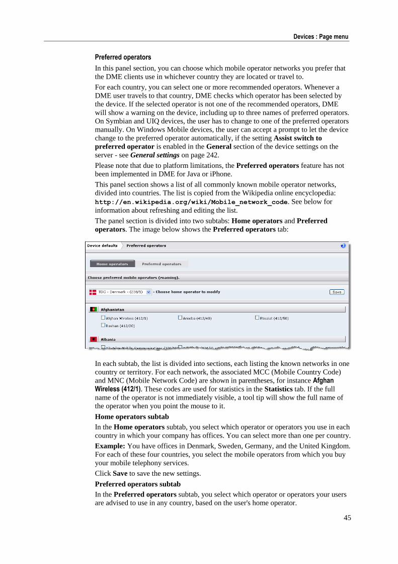
45
Devices : Page menu
Preferred operators
In this panel section, you can choose which mobile operator networks you prefer that
the DME clients use in whichever country they are located or travel to.
For each country, you can select one or more recommended operators. Whenever a
DME user travels to that country, DME checks which operator has been selected by
the device. If the selected operator is not one of the recommended operators, DME
will show a warning on the device, including up to three names of preferred operators.
On Symbian and UIQ devices, the user has to change to one of the preferred operators
manually. On Windows Mobile devices, the user can accept a prompt to let the device
change to the preferred operator automatically, if the setting Assist switch to
preferred operator is enabled in the General section of the device settings on the
server - see General settings on page 242.
Please note that due to platform limitations, the Preferred operators feature has not
been implemented in DME for Java or iPhone.
This panel section shows a list of all commonly known mobile operator networks,
divided into countries. The list is copied from the Wikipedia online encyclopedia:
http://en.wikipedia.org/wiki/Mobile_network_code. See below for
information about refreshing and editing the list.
The panel section is divided into two subtabs: Home operators and Preferred
operators. The image below shows the Preferred operators tab:
In each subtab, the list is divided into sections, each listing the known networks in one
country or territory. For each network, the associated MCC (Mobile Country Code)
and MNC (Mobile Network Code) are shown in parentheses, for instance Afghan Wireless (412/1). These codes are used for statistics in the Statistics tab. If the full
name of the operator is not immediately visible, a tool tip will show the full name of
the operator when you point the mouse to it.
Home operators subtab
In the Home operators subtab, you select which operator or operators you use in each
country in which your company has offices. You can select more than one per country.
Example: You have offices in Denmark, Sweden, Germany, and the United Kingdom.
For each of these four countries, you select the mobile operators from which you buy
your mobile telephony services.
Click Save to save the new settings.
Preferred operators subtab
In the Preferred operators subtab, you select which operator or operators your users
are advised to use in any country, based on the user's home operator.
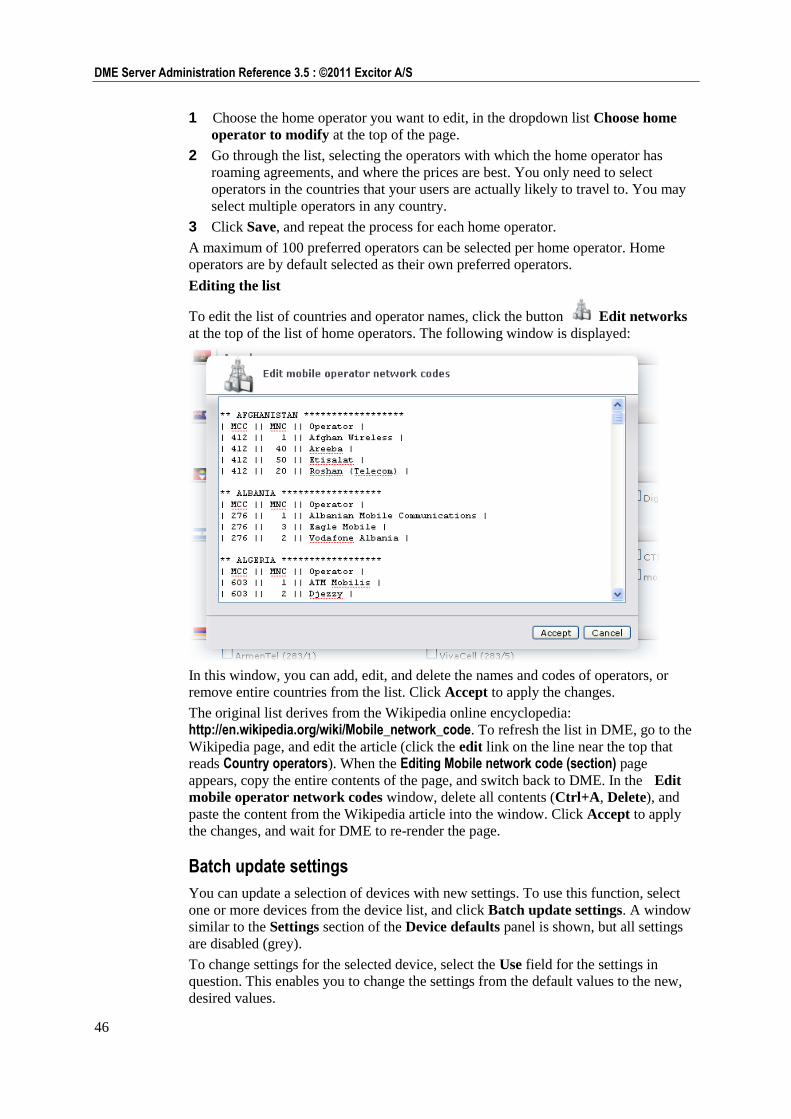
46
DME Server Administration Reference 3.5 : ©2011 Excitor A/S
1 Choose the home operator you want to edit, in the dropdown list Choose home
operator to modify at the top of the page.
2 Go through the list, selecting the operators with which the home operator has
roaming agreements, and where the prices are best. You only need to select
operators in the countries that your users are actually likely to travel to. You may
select multiple operators in any country.
3 Click Save, and repeat the process for each home operator.
A maximum of 100 preferred operators can be selected per home operator. Home
operators are by default selected as their own preferred operators.
Editing the list
To edit the list of countries and operator names, click the button Edit networks
at the top of the list of home operators. The following window is displayed:
In this window, you can add, edit, and delete the names and codes of operators, or
remove entire countries from the list. Click Accept to apply the changes.
The original list derives from the Wikipedia online encyclopedia:
http://en.wikipedia.org/wiki/Mobile_network_code. To refresh the list in DME, go to the
Wikipedia page, and edit the article (click the edit link on the line near the top that
reads Country operators). When the Editing Mobile network code (section) page
appears, copy the entire contents of the page, and switch back to DME. In the Edit
mobile operator network codes window, delete all contents (Ctrl+A, Delete), and
paste the content from the Wikipedia article into the window. Click Accept to apply
the changes, and wait for DME to re-render the page.
Batch update settings
You can update a selection of devices with new settings. To use this function, select
one or more devices from the device list, and click Batch update settings. A window
similar to the Settings section of the Device defaults panel is shown, but all settings
are disabled (grey).
To change settings for the selected device, select the Use field for the settings in
question. This enables you to change the settings from the default values to the new,
desired values.
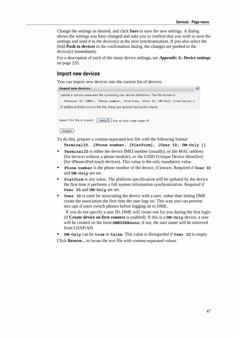
47
Devices : Page menu
Change the settings as desired, and click Save to save the new settings. A dialog
shows the settings you have changed and asks you to confirm that you wish to save the
settings and send it to the device(s) at the next synchronization. If you also select the
field Push to devices in the confirmation dialog, the changes are pushed to the
device(s) immediately.
For a description of each of the many device settings, see Appendix A: Device settings
on page 235.
Import new devices
You can import new devices into the current list of devices.
To do this, prepare a comma-separated text file with the following format:
TerminalID, [Phone number, [Platform], [User ID, DM-Only ]]
TerminalID is either the device IMEI number (usually), or the MAC-address
(for devices without a phone module), or the UDID (Unique Device Identifier)
(for iPhone/iPod touch devices). This value is the only mandatory value.
Phone number is the phone number of the device, if known. Required if User ID
and DM-Only are set.
Platform is any value. The platform specification will be updated by the device
the first time it performs a full system information synchronization. Required if
User ID and DM-Only are set.
User ID is used for associating the device with a user, rather than letting DME
create the association the first time the user logs on. This way you can prevent
mix-ups if users switch phones before logging on to DME.
If you do not specify a user ID, DME will create one for you during the first login
(if Create device on first connect is enabled). If this is a DM-Only device, a user
will be created on the form DMEUSERnnnn; if not, the user name will be retrieved
from LDAP/AD.
DM-Only can be true or false. This value is disregarded if User ID is empty.
Click Browse... to locate the text file with comma-separated values.
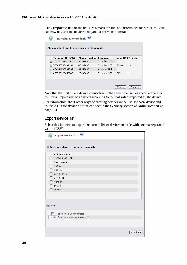
48
DME Server Administration Reference 3.5 : ©2011 Excitor A/S
Click Import to import the list. DME reads the file, and determines the structure. You
can now deselect the devices that you do not want to install:
Note that the first time a device connects with the server, the values specified here in
the initial import will be adjusted according to the real values reported by the device.
For information about other ways of creating devices in the list, see New device and
the field Create device on first connect in the Security section of Authentication on
page 161.
Export device list
Select this function to export the current list of devices to a file with comma-separated
values (CSV).
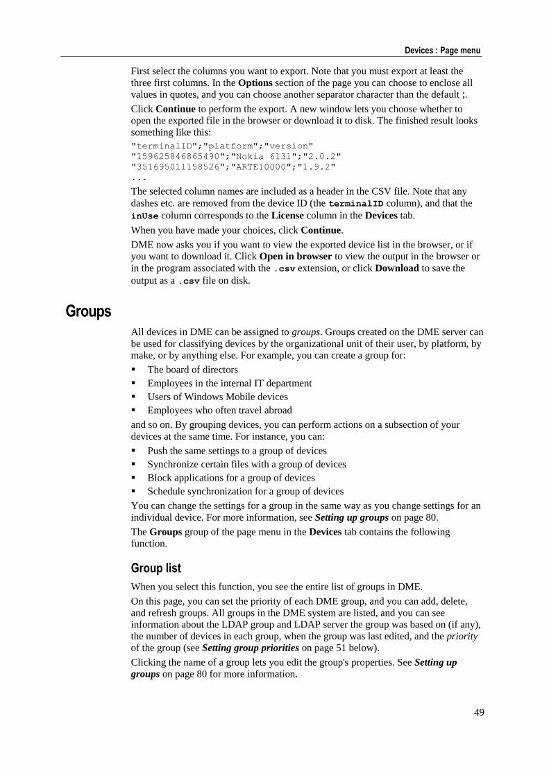
49
Devices : Page menu
First select the columns you want to export. Note that you must export at least the
three first columns. In the Options section of the page you can choose to enclose all
values in quotes, and you can choose another separator character than the default ;.
Click Continue to perform the export. A new window lets you choose whether to
open the exported file in the browser or download it to disk. The finished result looks
something like this:
"terminalID";"platform";"version"
"159625846865490";"Nokia 6131";"2.0.2"
"351695011158526";"ARTE10000";"1.9.2"
...
The selected column names are included as a header in the CSV file. Note that any
dashes etc. are removed from the device ID (the terminalID column), and that the
inUse column corresponds to the License column in the Devices tab.
When you have made your choices, click Continue.
DME now asks you if you want to view the exported device list in the browser, or if
you want to download it. Click Open in browser to view the output in the browser or
in the program associated with the .csv extension, or click Download to save the
output as a .csv file on disk.
Groups All devices in DME can be assigned to groups. Groups created on the DME server can
be used for classifying devices by the organizational unit of their user, by platform, by
make, or by anything else. For example, you can create a group for:
The board of directors
Employees in the internal IT department
Users of Windows Mobile devices
Employees who often travel abroad
and so on. By grouping devices, you can perform actions on a subsection of your
devices at the same time. For instance, you can:
Push the same settings to a group of devices
Synchronize certain files with a group of devices
Block applications for a group of devices
Schedule synchronization for a group of devices
You can change the settings for a group in the same way as you change settings for an
individual device. For more information, see Setting up groups on page 80.
The Groups group of the page menu in the Devices tab contains the following
function.
Group list
When you select this function, you see the entire list of groups in DME.
On this page, you can set the priority of each DME group, and you can add, delete,
and refresh groups. All groups in the DME system are listed, and you can see
information about the LDAP group and LDAP server the group was based on (if any),
the number of devices in each group, when the group was last edited, and the priority
of the group (see Setting group priorities on page 51 below).
Clicking the name of a group lets you edit the group's properties. See Setting up
groups on page 80 for more information.
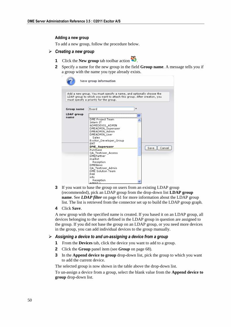
50
DME Server Administration Reference 3.5 : ©2011 Excitor A/S
Adding a new group
To add a new group, follow the procedure below.
Creating a new group
1 Click the New group tab toolbar action .
2 Specify a name for the new group in the field Group name. A message tells you if
a group with the name you type already exists.
3 If you want to base the group on users from an existing LDAP group
(recommended), pick an LDAP group from the drop-down list LDAP group
name. See LDAP filter on page 61 for more information about the LDAP group
list. The list is retrieved from the connector set up to build the LDAP group graph.
4 Click Save.
A new group with the specified name is created. If you based it on an LDAP group, all
devices belonging to the users defined in the LDAP group in question are assigned to
the group. If you did not base the group on an LDAP group, or you need more devices
in the group, you can add individual devices to the group manually.
Assigning a device to and un-assigning a device from a group
1 From the Devices tab, click the device you want to add to a group.
2 Click the Group panel item (see Group on page 68).
3 In the Append device to group drop-down list, pick the group to which you want
to add the current device.
The selected group is now shown in the table above the drop-down list.
To un-assign a device from a group, select the blank value from the Append device to
group drop-down list.
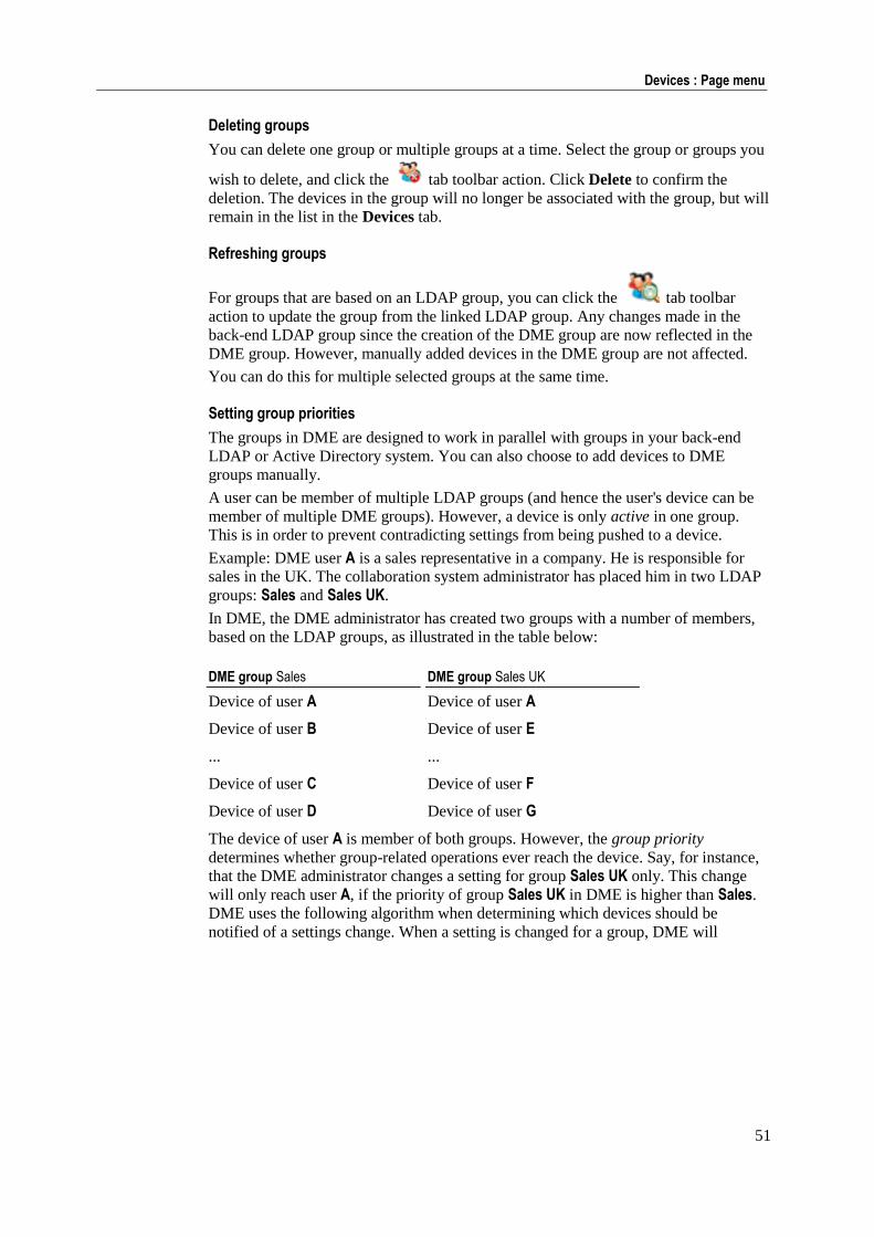
51
Devices : Page menu
Deleting groups
You can delete one group or multiple groups at a time. Select the group or groups you
wish to delete, and click the tab toolbar action. Click Delete to confirm the
deletion. The devices in the group will no longer be associated with the group, but will
remain in the list in the Devices tab.
Refreshing groups
For groups that are based on an LDAP group, you can click the tab toolbar
action to update the group from the linked LDAP group. Any changes made in the
back-end LDAP group since the creation of the DME group are now reflected in the
DME group. However, manually added devices in the DME group are not affected.
You can do this for multiple selected groups at the same time.
Setting group priorities
The groups in DME are designed to work in parallel with groups in your back-end
LDAP or Active Directory system. You can also choose to add devices to DME
groups manually.
A user can be member of multiple LDAP groups (and hence the user's device can be
member of multiple DME groups). However, a device is only active in one group.
This is in order to prevent contradicting settings from being pushed to a device.
Example: DME user A is a sales representative in a company. He is responsible for
sales in the UK. The collaboration system administrator has placed him in two LDAP
groups: Sales and Sales UK.
In DME, the DME administrator has created two groups with a number of members,
based on the LDAP groups, as illustrated in the table below:
DME group Sales DME group Sales UK
Device of user A Device of user A
Device of user B Device of user E
... ...
Device of user C Device of user F
Device of user D Device of user G
The device of user A is member of both groups. However, the group priority
determines whether group-related operations ever reach the device. Say, for instance,
that the DME administrator changes a setting for group Sales UK only. This change
will only reach user A, if the priority of group Sales UK in DME is higher than Sales.
DME uses the following algorithm when determining which devices should be
notified of a settings change. When a setting is changed for a group, DME will
52
DME Server Administration Reference 3.5 : ©2011 Excitor A/S
1 Determine which devices are potentially affected (the members of the affected
group).
2 For each device, see if the device is also member of another group.
3 If a device is member of another group, check the priority of that other group.
4 If the other group has a higher priority, it means that the device should receive
settings from that group, and the change made here will not affect the device.
5 If a device is added to another group manually, then that group will always take
priority over any other group.
It is recommended that groups are assigned priorities from specific toward general
groups (in the example above, Sales UK should have a higher priority than Sales). This
makes it easier and more transparent to design a hierarchy of settings.
Setting group priorities
1 To move a group up in the priority list, click the icon in the Priority column
in the group list.
2 To move a group down in the priority list, click the icon in the Priority
column in the group list.
Push to device The Push to device section of the page menu contains the following functions:
Send OTA configuration
Select this function to configure WAP/GPRS/MMS settings on the devices. When a
device is new or it needs to be reconfigured, it is a good idea to be able to maintain the
GPRS connection parameters on the device. This can be achieved by sending an OMA
or OTA (see Glossary on page 290) message to the device, containing a GPRS
configuration. OMA is an open configuration protocol defined by the Open Mobile
Alliance. OTA is an earlier, similar protocol defined by Nokia and Ericsson. DME
supports version 7 of the OTA protocol. In the following, OTA (which means
Over-the-Air) is used as a common name for OMA and OTA configurations.
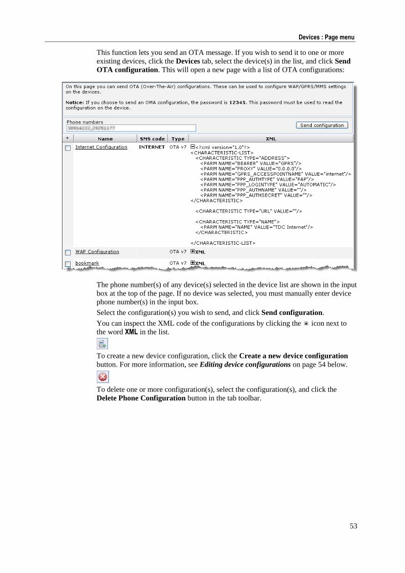
53
Devices : Page menu
This function lets you send an OTA message. If you wish to send it to one or more
existing devices, click the Devices tab, select the device(s) in the list, and click Send
OTA configuration. This will open a new page with a list of OTA configurations:
The phone number(s) of any device(s) selected in the device list are shown in the input
box at the top of the page. If no device was selected, you must manually enter device
phone number(s) in the input box.
Select the configuration(s) you wish to send, and click Send configuration.
You can inspect the XML code of the configurations by clicking the icon next to
the word XML in the list.
To create a new device configuration, click the Create a new device configuration
button. For more information, see Editing device configurations on page 54 below.
To delete one or more configuration(s), select the configuration(s), and click the
Delete Phone Configuration button in the tab toolbar.
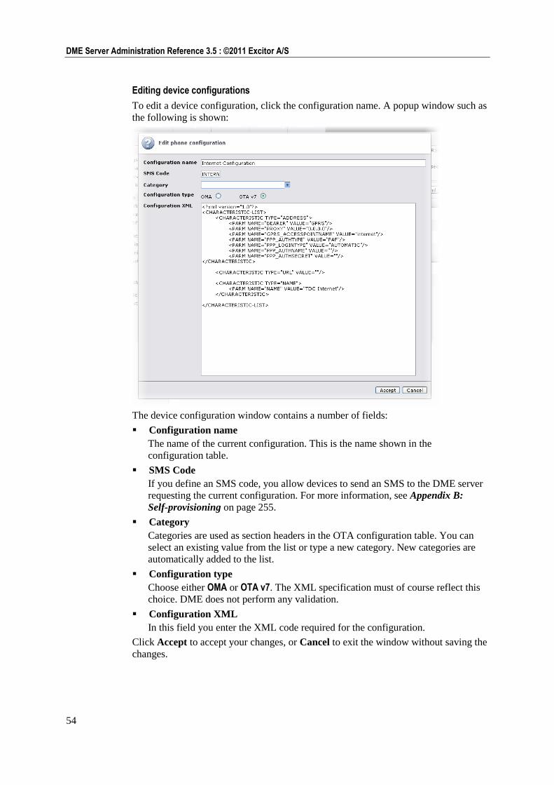
54
DME Server Administration Reference 3.5 : ©2011 Excitor A/S
Editing device configurations
To edit a device configuration, click the configuration name. A popup window such as
the following is shown:
The device configuration window contains a number of fields:
Configuration name
The name of the current configuration. This is the name shown in the
configuration table.
SMS Code
If you define an SMS code, you allow devices to send an SMS to the DME server
requesting the current configuration. For more information, see Appendix B:
Self-provisioning on page 255.
Category
Categories are used as section headers in the OTA configuration table. You can
select an existing value from the list or type a new category. New categories are
automatically added to the list.
Configuration type
Choose either OMA or OTA v7. The XML specification must of course reflect this
choice. DME does not perform any validation.
Configuration XML
In this field you enter the XML code required for the configuration.
Click Accept to accept your changes, or Cancel to exit the window without saving the
changes.
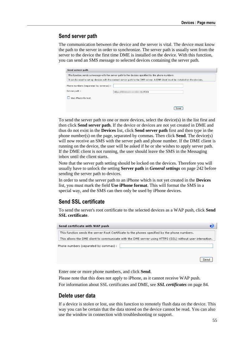
55
Devices : Page menu
Send server path
The communication between the device and the server is vital. The device must know
the path to the server in order to synchronize. The server path is usually sent from the
server to the device the first time DME is installed on the device. With this function,
you can send an SMS message to selected devices containing the server path.
To send the server path to one or more devices, select the device(s) in the list first and
then click Send server path. If the device or devices are not yet created in DME and
thus do not exist in the Devices list, click Send server path first and then type in the
phone number(s) on the page, separated by commas. Then click Send. The device(s)
will now receive an SMS with the server path and phone number. If the DME client is
running on the device, the user will be asked if he or she wishes to apply server path.
If the DME client is not running, the user should leave the SMS in the Messaging
inbox until the client starts.
Note that the server path setting should be locked on the devices. Therefore you will
usually have to unlock the setting Server path in General settings on page 242 before
sending the server path to devices.
In order to send the server path to an iPhone which is not yet created in the Devices
list, you must mark the field Use iPhone format. This will format the SMS in a
special way, and the SMS can then only be used by iPhone devices.
Send SSL certificate
To send the server's root certificate to the selected devices as a WAP push, click Send
SSL certificate.
Enter one or more phone numbers, and click Send.
Please note that this does not apply to iPhone, as it cannot receive WAP push.
For information about SSL certificates and DME, see SSL certificates on page 84.
Delete user data
If a device is stolen or lost, use this function to remotely flush data on the device. This
way you can be certain that the data stored on the device cannot be read. You can also
use the window in connection with troubleshooting or support.
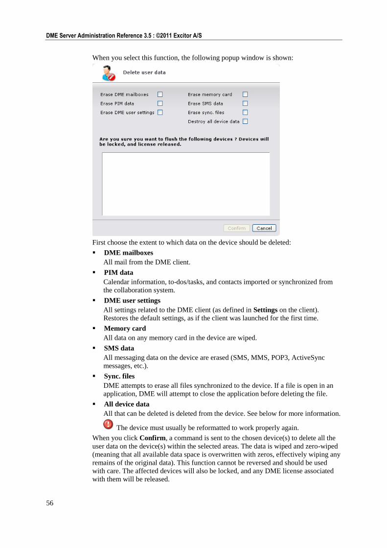
56
DME Server Administration Reference 3.5 : ©2011 Excitor A/S
When you select this function, the following popup window is shown:
First choose the extent to which data on the device should be deleted:
DME mailboxes
All mail from the DME client.
PIM data
Calendar information, to-dos/tasks, and contacts imported or synchronized from
the collaboration system.
DME user settings
All settings related to the DME client (as defined in Settings on the client).
Restores the default settings, as if the client was launched for the first time.
Memory card
All data on any memory card in the device are wiped.
SMS data
All messaging data on the device are erased (SMS, MMS, POP3, ActiveSync
messages, etc.).
Sync. files
DME attempts to erase all files synchronized to the device. If a file is open in an
application, DME will attempt to close the application before deleting the file.
All device data
All that can be deleted is deleted from the device. See below for more information.
The device must usually be reformatted to work properly again.
When you click Confirm, a command is sent to the chosen device(s) to delete all the
user data on the device(s) within the selected areas. The data is wiped and zero-wiped
(meaning that all available data space is overwritten with zeros, effectively wiping any
remains of the original data). This function cannot be reversed and should be used
with care. The affected devices will also be locked, and any DME license associated
with them will be released.
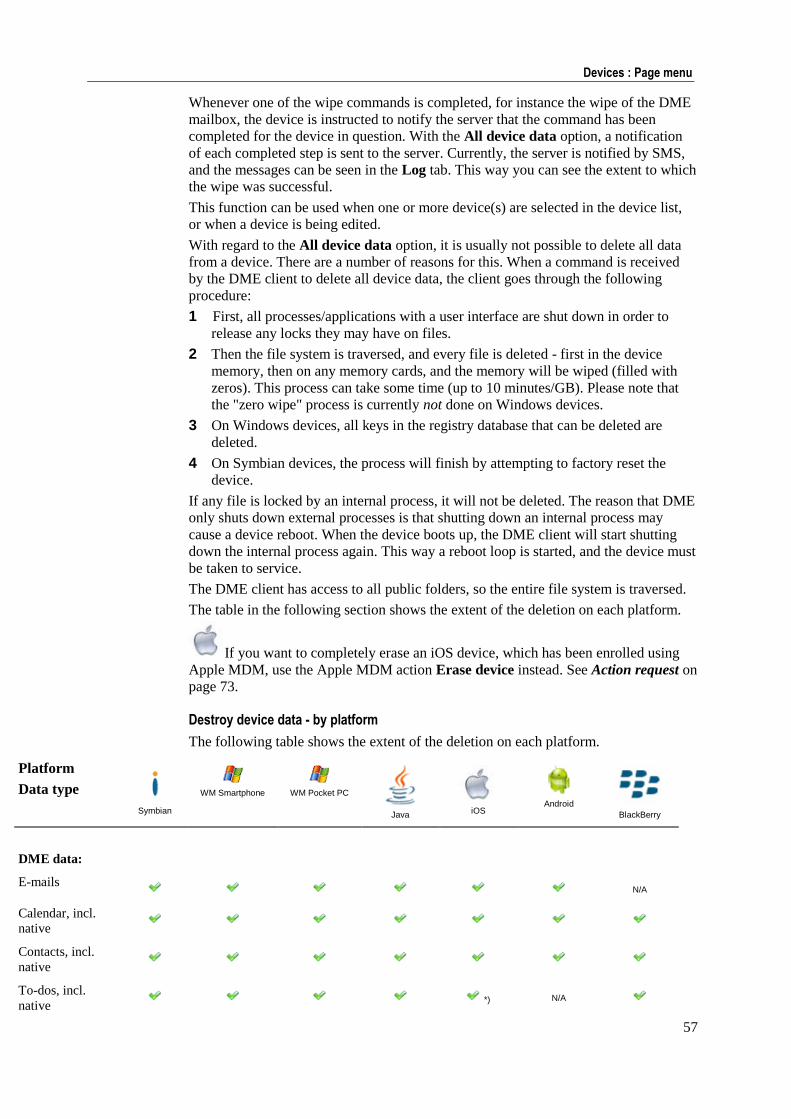
57
Devices : Page menu
Whenever one of the wipe commands is completed, for instance the wipe of the DME
mailbox, the device is instructed to notify the server that the command has been
completed for the device in question. With the All device data option, a notification
of each completed step is sent to the server. Currently, the server is notified by SMS,
and the messages can be seen in the Log tab. This way you can see the extent to which
the wipe was successful.
This function can be used when one or more device(s) are selected in the device list,
or when a device is being edited.
With regard to the All device data option, it is usually not possible to delete all data
from a device. There are a number of reasons for this. When a command is received
by the DME client to delete all device data, the client goes through the following
procedure:
1 First, all processes/applications with a user interface are shut down in order to
release any locks they may have on files.
2 Then the file system is traversed, and every file is deleted - first in the device
memory, then on any memory cards, and the memory will be wiped (filled with
zeros). This process can take some time (up to 10 minutes/GB). Please note that
the "zero wipe" process is currently not done on Windows devices.
3 On Windows devices, all keys in the registry database that can be deleted are
deleted.
4 On Symbian devices, the process will finish by attempting to factory reset the
device.
If any file is locked by an internal process, it will not be deleted. The reason that DME
only shuts down external processes is that shutting down an internal process may
cause a device reboot. When the device boots up, the DME client will start shutting
down the internal process again. This way a reboot loop is started, and the device must
be taken to service.
The DME client has access to all public folders, so the entire file system is traversed.
The table in the following section shows the extent of the deletion on each platform.
If you want to completely erase an iOS device, which has been enrolled using
Apple MDM, use the Apple MDM action Erase device instead. See Action request on
page 73.
Destroy device data - by platform
The following table shows the extent of the deletion on each platform.
Platform
Data type
Symbian
WM Smartphone
WM Pocket PC
Java
iOS
Android
BlackBerry
DME data:
E-mails N/A
Calendar, incl.
native
Contacts, incl.
native
To-dos, incl.
native *) N/A
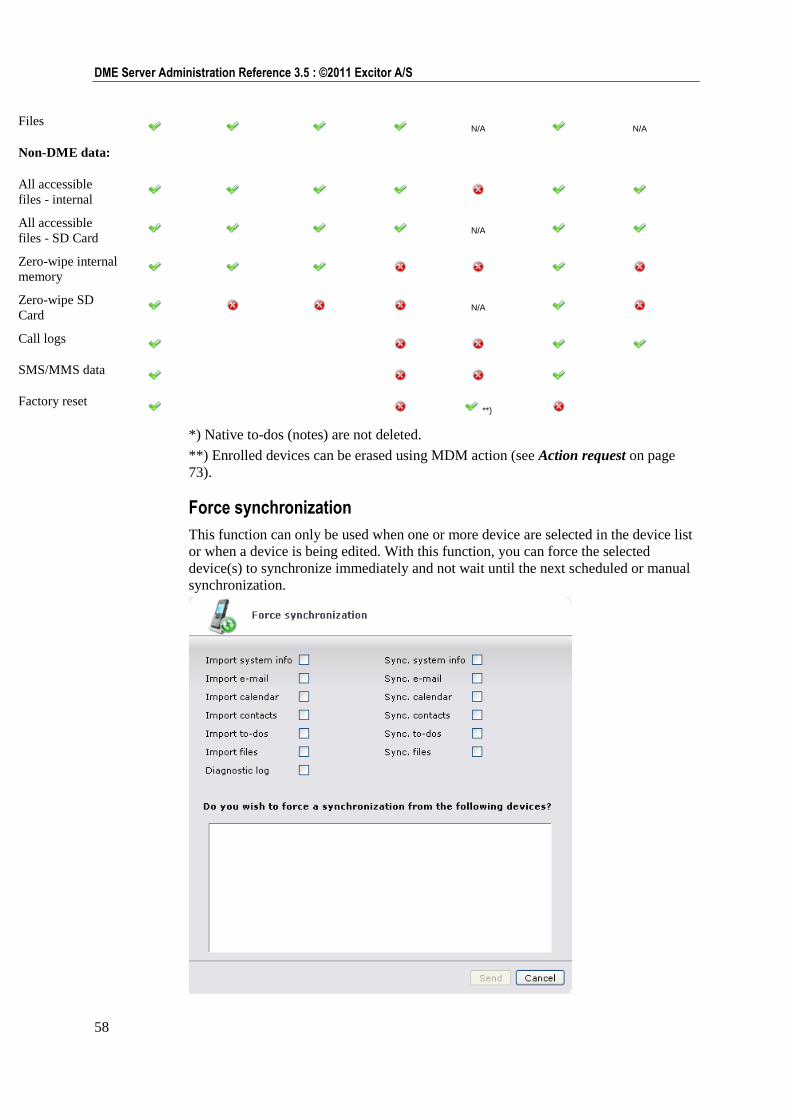
58
DME Server Administration Reference 3.5 : ©2011 Excitor A/S
Files N/A N/A
Non-DME data:
All accessible
files - internal
All accessible
files - SD Card N/A
Zero-wipe internal
memory
Zero-wipe SD
Card N/A
Call logs
SMS/MMS data
Factory reset **)
*) Native to-dos (notes) are not deleted.
**) Enrolled devices can be erased using MDM action (see Action request on page
73).
Force synchronization
This function can only be used when one or more device are selected in the device list
or when a device is being edited. With this function, you can force the selected
device(s) to synchronize immediately and not wait until the next scheduled or manual
synchronization.
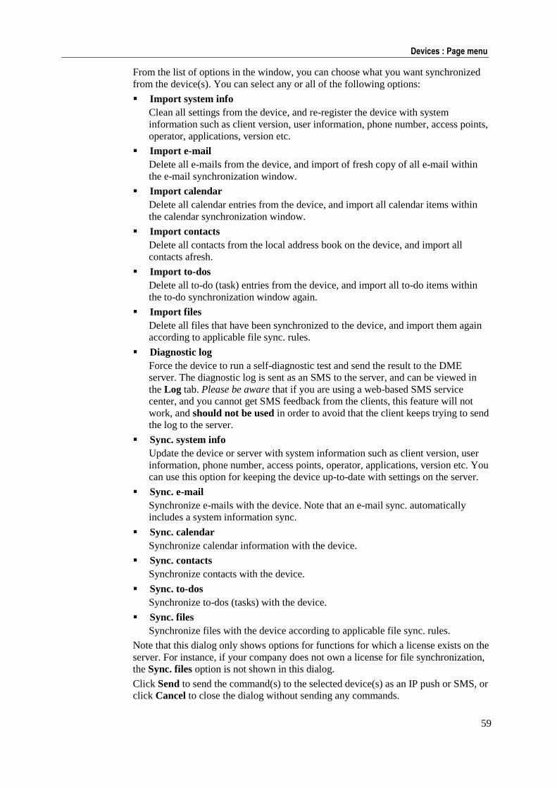
59
Devices : Page menu
From the list of options in the window, you can choose what you want synchronized
from the device(s). You can select any or all of the following options:
Import system info
Clean all settings from the device, and re-register the device with system
information such as client version, user information, phone number, access points,
operator, applications, version etc.
Import e-mail
Delete all e-mails from the device, and import of fresh copy of all e-mail within
the e-mail synchronization window.
Import calendar
Delete all calendar entries from the device, and import all calendar items within
the calendar synchronization window.
Import contacts
Delete all contacts from the local address book on the device, and import all
contacts afresh.
Import to-dos
Delete all to-do (task) entries from the device, and import all to-do items within
the to-do synchronization window again.
Import files
Delete all files that have been synchronized to the device, and import them again
according to applicable file sync. rules.
Diagnostic log
Force the device to run a self-diagnostic test and send the result to the DME
server. The diagnostic log is sent as an SMS to the server, and can be viewed in
the Log tab. Please be aware that if you are using a web-based SMS service
center, and you cannot get SMS feedback from the clients, this feature will not
work, and should not be used in order to avoid that the client keeps trying to send
the log to the server.
Sync. system info
Update the device or server with system information such as client version, user
information, phone number, access points, operator, applications, version etc. You
can use this option for keeping the device up-to-date with settings on the server.
Sync. e-mail
Synchronize e-mails with the device. Note that an e-mail sync. automatically
includes a system information sync.
Sync. calendar
Synchronize calendar information with the device.
Sync. contacts
Synchronize contacts with the device.
Sync. to-dos
Synchronize to-dos (tasks) with the device.
Sync. files
Synchronize files with the device according to applicable file sync. rules.
Note that this dialog only shows options for functions for which a license exists on the
server. For instance, if your company does not own a license for file synchronization,
the Sync. files option is not shown in this dialog.
Click Send to send the command(s) to the selected device(s) as an IP push or SMS, or
click Cancel to close the dialog without sending any commands.
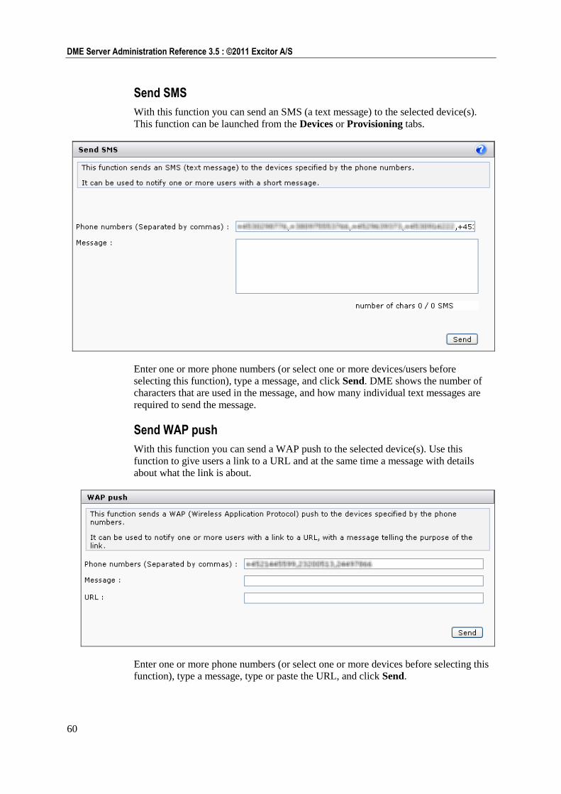
60
DME Server Administration Reference 3.5 : ©2011 Excitor A/S
Send SMS
With this function you can send an SMS (a text message) to the selected device(s).
This function can be launched from the Devices or Provisioning tabs.
Enter one or more phone numbers (or select one or more devices/users before
selecting this function), type a message, and click Send. DME shows the number of
characters that are used in the message, and how many individual text messages are
required to send the message.
Send WAP push
With this function you can send a WAP push to the selected device(s). Use this
function to give users a link to a URL and at the same time a message with details
about what the link is about.
Enter one or more phone numbers (or select one or more devices before selecting this
function), type a message, type or paste the URL, and click Send.
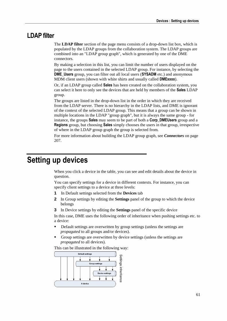
61
Devices : Setting up devices
LDAP filter The LDAP filter section of the page menu consists of a drop-down list box, which is
populated by the LDAP groups from the collaboration system. The LDAP groups are
combined into an "LDAP group graph", which is generated by one of the DME
connectors.
By making a selection in this list, you can limit the number of users displayed on the
page to the users contained in the selected LDAP group. For instance, by selecting the
DME_Users group, you can filter out all local users (SYSADM etc.) and anonymous
MDM client users (shown with white shirts and usually called DMExxxx).
Or, if an LDAP group called Sales has been created on the collaboration system, you
can select it here to only see the devices that are held by members of the Sales LDAP
group.
The groups are listed in the drop-down list in the order in which they are received
from the LDAP server. There is no hierarchy in the LDAP lists, and DME is ignorant
of the context of the selected LDAP group. This means that a group can be shown in
multiple locations in the LDAP "group graph", but it is always the same group - for
instance, the groups Sales may seem to be part of both a Corp_DMEUsers group and a
Regions group, but choosing Sales simply chooses the users in that group, irrespective
of where in the LDAP group graph the group is selected from.
For more information about building the LDAP group graph, see Connectors on page
207.
Setting up devices
When you click a device in the table, you can see and edit details about the device in
question.
You can specify settings for a device in different contexts. For instance, you can
specify client settings to a device at three levels:
1 In Default settings selected from the Devices tab
2 In Group settings by editing the Settings panel of the group to which the device
belongs
3 In Device settings by editing the Settings panel of the specific device
In this case, DME uses the following order of inheritance when pushing settings etc. to
a device:
Default settings are overwritten by group settings (unless the settings are
propagated to all groups and/or devices).
Group settings are overwritten by device settings (unless the settings are
propagated to all devices).
This can be illustrated in the following way:
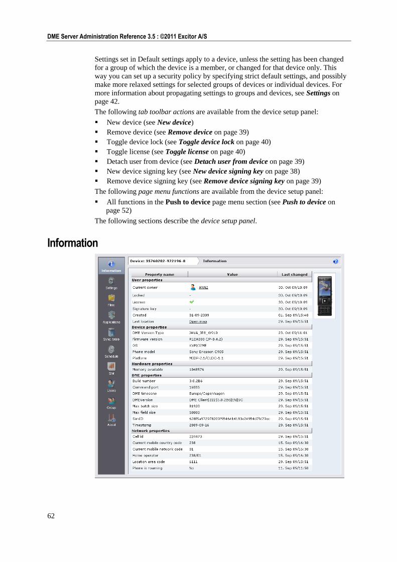
62
DME Server Administration Reference 3.5 : ©2011 Excitor A/S
Settings set in Default settings apply to a device, unless the setting has been changed
for a group of which the device is a member, or changed for that device only. This
way you can set up a security policy by specifying strict default settings, and possibly
make more relaxed settings for selected groups of devices or individual devices. For
more information about propagating settings to groups and devices, see Settings on
page 42.
The following tab toolbar actions are available from the device setup panel:
New device (see New device)
Remove device (see Remove device on page 39)
Toggle device lock (see Toggle device lock on page 40)
Toggle license (see Toggle license on page 40)
Detach user from device (see Detach user from device on page 39)
New device signing key (see New device signing key on page 38)
Remove device signing key (see Remove device signing key on page 39)
The following page menu functions are available from the device setup panel:
All functions in the Push to device page menu section (see Push to device on
page 52)
The following sections describe the device setup panel.
Information
63
Devices : Setting up devices
This panel item provides an overview of the selected device. The information is
updated every time a full system info is transferred from the client, or at least once
every three days.
The information is divided into different sections:
User properties: Information about the user — current owner, licensing, client
signature status, and location (see Location on page 63 below).
Device properties: Information about the device - model, platform, operating
system, language, number of applications, etc.
Hardware properties: Information about the device hardware — processor,
drives, etc.
DME properties: Long version of the DME client information, useful in a
support context.
Network properties: Current cell ID and location information of the device. Here
you can see if the phone is currently roaming, based on the selection of home
operator - see Preferred operators on page 45.
Device servers: List of servers running on the device (if any).
The information collected from the device in these sections varies according to the
type of device and is not described in detail here. For every piece of information, the
date of when the property was last changed is shown.
Uploading a picture of the device
If a picture of the device has been uploaded to the server, it is shown next to the
device properties section. A picture is usually shown if the device has been
bootstrapped (see Bootstrapping devices on page 86). If a picture is not shown,
you can upload a picture yourself as described below.
1 Click Upload device picture at the bottom of the screen (only available if DME
could not find a picture).
2 Browse to the picture.
You can download a picture from the DME website to your disk by clicking the
Pictures can be downloaded here link in the dialog.
3 Click Accept.
The picture is uploaded to the server and can be seen next to the information table and
in the mouse-over info box from the Devices tab and elsewhere.
Location
Many companies have a Corporate Social Responsibility strategy, in which they
commit themselves to being able to quickly locate travelling employees in case of
natural disasters, national unrest, or terrorist attacks in the area in which the employee
may be travelling. With DME, the last known location of the device can quickly be
shown.
The feature can also simply be used as a help locating a lost device.
Based on the network information sent in by the device with the full system
information sync, which is listed in the Network properties section of the device
information page, DME is able to build a link to Google Maps, pinpointing the
approximate location of the device. The link is built using the open source database of
cell IDs and locations at http://www.opencellid.org. Please note that in order to use
this functionality, the DME server's firewall must allow traffic to that website over
HTTP, as specified in the installation documentation.
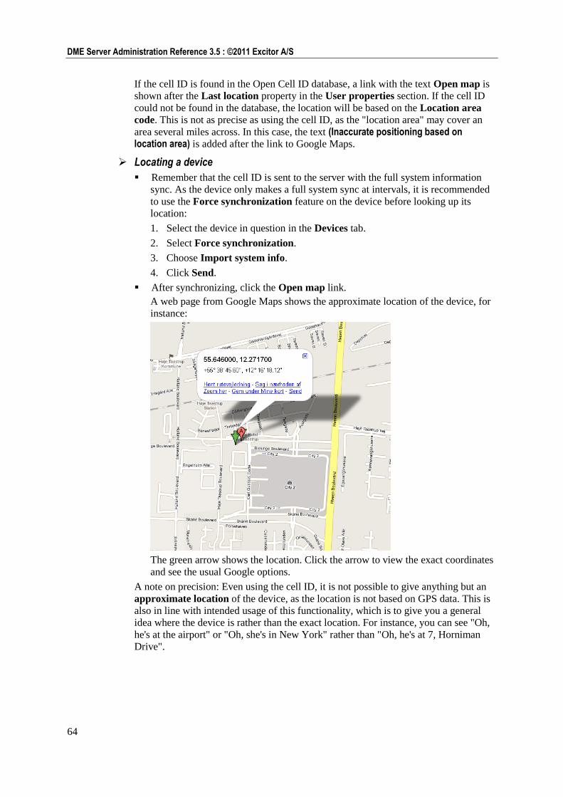
64
DME Server Administration Reference 3.5 : ©2011 Excitor A/S
If the cell ID is found in the Open Cell ID database, a link with the text Open map is
shown after the Last location property in the User properties section. If the cell ID
could not be found in the database, the location will be based on the Location area
code. This is not as precise as using the cell ID, as the "location area" may cover an
area several miles across. In this case, the text (Inaccurate positioning based on location area) is added after the link to Google Maps.
Locating a device
Remember that the cell ID is sent to the server with the full system information
sync. As the device only makes a full system sync at intervals, it is recommended
to use the Force synchronization feature on the device before looking up its
location:
1. Select the device in question in the Devices tab.
2. Select Force synchronization.
3. Choose Import system info.
4. Click Send.
After synchronizing, click the Open map link.
A web page from Google Maps shows the approximate location of the device, for
instance:
The green arrow shows the location. Click the arrow to view the exact coordinates
and see the usual Google options.
A note on precision: Even using the cell ID, it is not possible to give anything but an
approximate location of the device, as the location is not based on GPS data. This is
also in line with intended usage of this functionality, which is to give you a general
idea where the device is rather than the exact location. For instance, you can see "Oh,
he's at the airport" or "Oh, she's in New York" rather than "Oh, he's at 7, Horniman
Drive".
65
Devices : Setting up devices
Settings
In this panel section you can configure the settings of the individual device. The
settings shown are the settings available on the device. Some of these settings are only
shown on the server, not on the device - these settings do not have an associated Lock
function. The settings are grouped into categories similar to those of the Settings
menu on the device.
When a new device connects to the server for the first time, it will be set to use the
default settings (see the section Default settings on page 41). These settings can be
changed both here and on the device, unless they are marked as locked in this window.
Note also that you can change settings for multiple devices by selecting the devices in
the Devices tab and clicking Batch update settings in the page menu. For more
information, see Batch update settings on page 46.
As stated above, devices are the last link in the chain of inheritance. If you change a
setting for a device, the setting will override any setting that might apply for the
device in Default settings of Group settings. The Status column shows the origin of
each setting:
The default setting applies to this device.
The current setting has been set for a group of which this device is a member
(for all devices in a group), overriding default settings.
The current setting has been set for this device (overriding group and default
settings).
To change the setting for a device (possibly overriding a default or group value),
select the Use field for the setting in question. The icon in the Status column will
change to the device icon (if it was not already), and you can now change the setting
for this device.
By removing the check mark from the Use column, you can reset the device to default
or group settings.
To prevent the user from changing the setting again, select the Lock field for the
setting in question.
Change the settings as desired, and click Save to save the new settings. A dialog
shows the settings you have changed and asks you to confirm that you wish to save the
settings and send it to the device(s) at the next synchronization. If you also select the
field Push to devices in the confirmation dialog, the changes are pushed to the
device(s) immediately.
The available settings are described further in Appendix A: Device settings on page
235.
Files
With DME you can push files to devices or synchronize files between a server
location and the device much the same way as e-mail and calendar information. This
feature can be used for distributing different files to the devices of different DME
users. Files can be synchronized with devices at three levels:
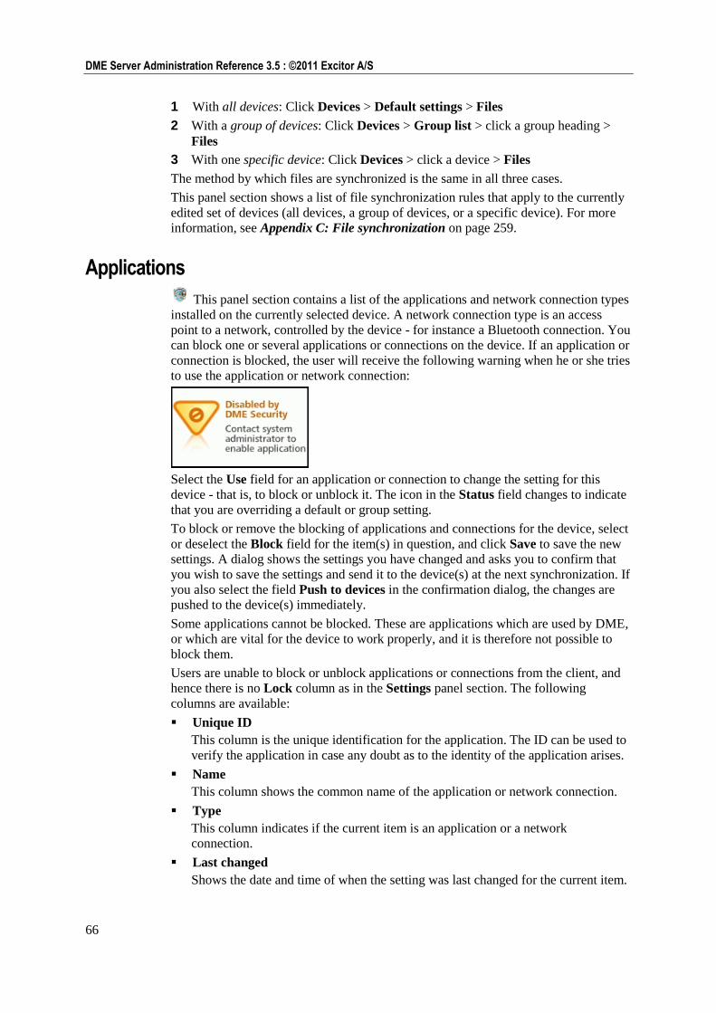
66
DME Server Administration Reference 3.5 : ©2011 Excitor A/S
1 With all devices: Click Devices > Default settings > Files
2 With a group of devices: Click Devices > Group list > click a group heading >
Files
3 With one specific device: Click Devices > click a device > Files
The method by which files are synchronized is the same in all three cases.
This panel section shows a list of file synchronization rules that apply to the currently
edited set of devices (all devices, a group of devices, or a specific device). For more
information, see Appendix C: File synchronization on page 259.
Applications
This panel section contains a list of the applications and network connection types
installed on the currently selected device. A network connection type is an access
point to a network, controlled by the device - for instance a Bluetooth connection. You
can block one or several applications or connections on the device. If an application or
connection is blocked, the user will receive the following warning when he or she tries
to use the application or network connection:
Select the Use field for an application or connection to change the setting for this
device - that is, to block or unblock it. The icon in the Status field changes to indicate
that you are overriding a default or group setting.
To block or remove the blocking of applications and connections for the device, select
or deselect the Block field for the item(s) in question, and click Save to save the new
settings. A dialog shows the settings you have changed and asks you to confirm that
you wish to save the settings and send it to the device(s) at the next synchronization. If
you also select the field Push to devices in the confirmation dialog, the changes are
pushed to the device(s) immediately.
Some applications cannot be blocked. These are applications which are used by DME,
or which are vital for the device to work properly, and it is therefore not possible to
block them.
Users are unable to block or unblock applications or connections from the client, and
hence there is no Lock column as in the Settings panel section. The following
columns are available:
Unique ID
This column is the unique identification for the application. The ID can be used to
verify the application in case any doubt as to the identity of the application arises.
Name
This column shows the common name of the application or network connection.
Type
This column indicates if the current item is an application or a network
connection.
Last changed
Shows the date and time of when the setting was last changed for the current item.
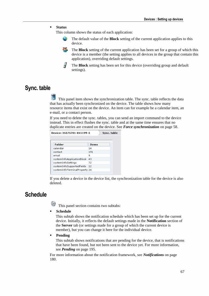
67
Devices : Setting up devices
Status
This column shows the status of each application:
The default value of the Block setting of the current application applies to this
device.
The Block setting of the current application has been set for a group of which this
device is a member (the setting applies to all devices in the group that contain this
application), overriding default settings.
The Block setting has been set for this device (overriding group and default
settings).
Sync. table
This panel item shows the synchronization table. The sync. table reflects the data
that has actually been synchronized on the device. The table shows how many
resource items that exist on the device. An item can for example be a calendar item, an
e-mail, or a contact person.
If you need to delete the sync. tables, you can send an import command to the device
instead. This in effect flushes the sync. table and at the same time ensures that no
duplicate entries are created on the device. See Force synchronization on page 58.
If you delete a device in the device list, the synchronization table for the device is also
deleted.
Schedule
This panel section contains two subtabs:
Schedule
This subtab shows the notification schedule which has been set up for the current
device. Initially, it reflects the default settings made in the Notification section of
the Server tab (or settings made for a group of which the current device is
member), but you can change it here for the individual device.
Pending
This subtab shows notifications that are pending for the device, that is notifications
that have been found, but not been sent to the device yet. For more information,
see Pending on page 195.
For more information about the notification framework, see Notifications on page
180.
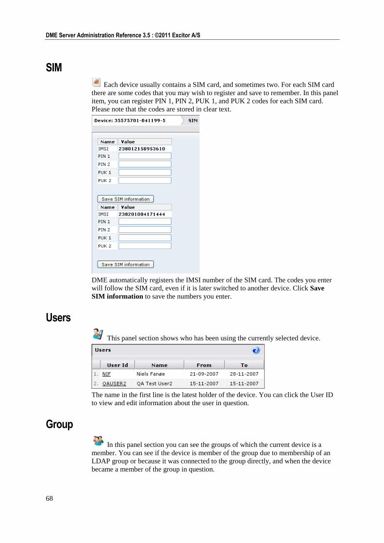
68
DME Server Administration Reference 3.5 : ©2011 Excitor A/S
SIM
Each device usually contains a SIM card, and sometimes two. For each SIM card
there are some codes that you may wish to register and save to remember. In this panel
item, you can register PIN 1, PIN 2, PUK 1, and PUK 2 codes for each SIM card.
Please note that the codes are stored in clear text.
DME automatically registers the IMSI number of the SIM card. The codes you enter
will follow the SIM card, even if it is later switched to another device. Click Save
SIM information to save the numbers you enter.
Users
This panel section shows who has been using the currently selected device.
The name in the first line is the latest holder of the device. You can click the User ID
to view and edit information about the user in question.
Group
In this panel section you can see the groups of which the current device is a
member. You can see if the device is member of the group due to membership of an
LDAP group or because it was connected to the group directly, and when the device
became a member of the group in question.
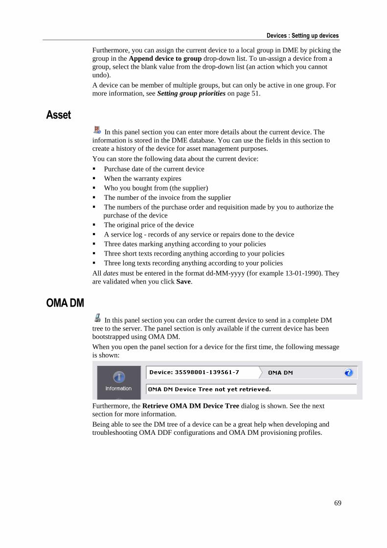
69
Devices : Setting up devices
Furthermore, you can assign the current device to a local group in DME by picking the
group in the Append device to group drop-down list. To un-assign a device from a
group, select the blank value from the drop-down list (an action which you cannot
undo).
A device can be member of multiple groups, but can only be active in one group. For
more information, see Setting group priorities on page 51.
Asset
In this panel section you can enter more details about the current device. The
information is stored in the DME database. You can use the fields in this section to
create a history of the device for asset management purposes.
You can store the following data about the current device:
Purchase date of the current device
When the warranty expires
Who you bought from (the supplier)
The number of the invoice from the supplier
The numbers of the purchase order and requisition made by you to authorize the
purchase of the device
The original price of the device
A service log - records of any service or repairs done to the device
Three dates marking anything according to your policies
Three short texts recording anything according to your policies
Three long texts recording anything according to your policies
All dates must be entered in the format dd-MM-yyyy (for example 13-01-1990). They
are validated when you click Save.
OMA DM
In this panel section you can order the current device to send in a complete DM
tree to the server. The panel section is only available if the current device has been
bootstrapped using OMA DM.
When you open the panel section for a device for the first time, the following message
is shown:
Furthermore, the Retrieve OMA DM Device Tree dialog is shown. See the next
section for more information.
Being able to see the DM tree of a device can be a great help when developing and
troubleshooting OMA DDF configurations and OMA DM provisioning profiles.
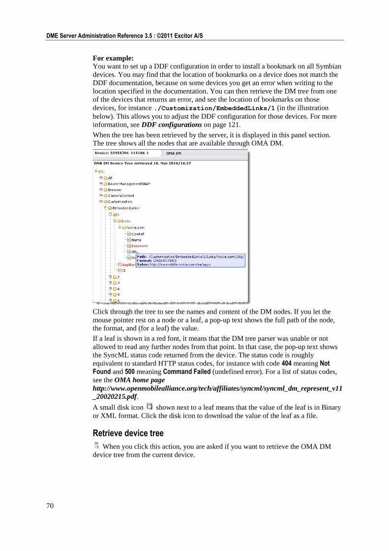
70
DME Server Administration Reference 3.5 : ©2011 Excitor A/S
For example: You want to set up a DDF configuration in order to install a bookmark on all Symbian
devices. You may find that the location of bookmarks on a device does not match the
DDF documentation, because on some devices you get an error when writing to the
location specified in the documentation. You can then retrieve the DM tree from one
of the devices that returns an error, and see the location of bookmarks on those
devices, for instance ./Customization/EmbeddedLinks/1 (in the illustration
below). This allows you to adjust the DDF configuration for those devices. For more
information, see DDF configurations on page 121.
When the tree has been retrieved by the server, it is displayed in this panel section.
The tree shows all the nodes that are available through OMA DM.
Click through the tree to see the names and content of the DM nodes. If you let the
mouse pointer rest on a node or a leaf, a pop-up text shows the full path of the node,
the format, and (for a leaf) the value.
If a leaf is shown in a red font, it means that the DM tree parser was unable or not
allowed to read any further nodes from that point. In that case, the pop-up text shows
the SyncML status code returned from the device. The status code is roughly
equivalent to standard HTTP status codes, for instance with code 404 meaning Not Found and 500 meaning Command Failed (undefined error). For a list of status codes,
see the OMA home page
http://www.openmobilealliance.org/tech/affiliates/syncml/syncml_dm_represent_v11
_20020215.pdf.
A small disk icon shown next to a leaf means that the value of the leaf is in Binary
or XML format. Click the disk icon to download the value of the leaf as a file.
Retrieve device tree
When you click this action, you are asked if you want to retrieve the OMA DM
device tree from the current device.
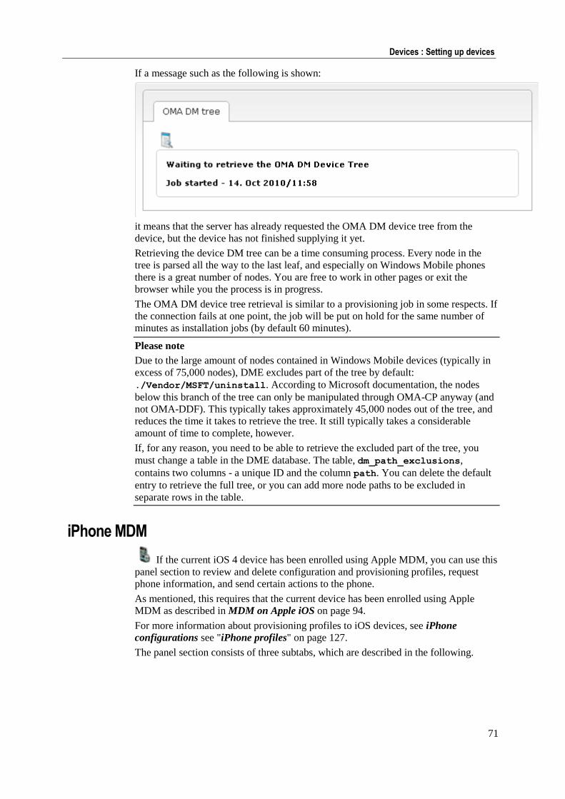
71
Devices : Setting up devices
If a message such as the following is shown:
it means that the server has already requested the OMA DM device tree from the
device, but the device has not finished supplying it yet.
Retrieving the device DM tree can be a time consuming process. Every node in the
tree is parsed all the way to the last leaf, and especially on Windows Mobile phones
there is a great number of nodes. You are free to work in other pages or exit the
browser while you the process is in progress.
The OMA DM device tree retrieval is similar to a provisioning job in some respects. If
the connection fails at one point, the job will be put on hold for the same number of
minutes as installation jobs (by default 60 minutes).
Please note
Due to the large amount of nodes contained in Windows Mobile devices (typically in
excess of 75,000 nodes), DME excludes part of the tree by default:
./Vendor/MSFT/uninstall. According to Microsoft documentation, the nodes
below this branch of the tree can only be manipulated through OMA-CP anyway (and
not OMA-DDF). This typically takes approximately 45,000 nodes out of the tree, and
reduces the time it takes to retrieve the tree. It still typically takes a considerable
amount of time to complete, however.
If, for any reason, you need to be able to retrieve the excluded part of the tree, you
must change a table in the DME database. The table, dm_path_exclusions,
contains two columns - a unique ID and the column path. You can delete the default
entry to retrieve the full tree, or you can add more node paths to be excluded in
separate rows in the table.
iPhone MDM
If the current iOS 4 device has been enrolled using Apple MDM, you can use this
panel section to review and delete configuration and provisioning profiles, request
phone information, and send certain actions to the phone.
As mentioned, this requires that the current device has been enrolled using Apple
MDM as described in MDM on Apple iOS on page 94.
For more information about provisioning profiles to iOS devices, see iPhone
configurations see "iPhone profiles" on page 127.
The panel section consists of three subtabs, which are described in the following.
72
DME Server Administration Reference 3.5 : ©2011 Excitor A/S
List request
The List request subtab contains a number of actions, with which you can retrieve
various information from the iOS device. The result of clicking the actions is also
displayed in this subtab.
Using the actions in this subtab, you can request various lists from the current device.
When you click an action, an Apple Push request for the selected type of list is sent to
the device. In the corresponding part of the subtab below, DME adds the text Request
to device - [Date/Time] - Status : Push sent, indicating that DME is waiting for the
device to respond.
Click Refresh to update the page and view the results of the request (or click the
iPhone MDM panel section).
Retrieve configuration profile list
The Configuration profile part of the subtab shows the date and time of when
profiles were requested from the phone, and the content of the configuration
profile(s).
A configuration profile is sent to the device using the iPhone profiles panel in the
Provisioning tab. See iPhone profiles on page 127 for more information. It is
used for setting security and other settings (Payloads) on the enrolled iPhone.
You can now study the content of the configuration profile. If a icon is shown
after the profile name, you can click it to delete the profile from the phone. Please
note that if you delete the profile called DME Mobile Device Management
Configuration, you will need to re-enroll the phone before you can contact it
again. Furthermore, anything that has been installed using the MDM profile will
be removed from the device. To update a profile, you must delete it from this
panel section and re-send the edited profile from Provisioning > iPhone profiles.
Retrieve provisioning profile list
The Provisioning profile part of the subtab shows the date and time of when the
provisioning profiles were requested from the phone, and the content of the
profile(s).
You can now study the content of the configuration profile. If a icon is shown
after the profile name, you can click it to delete the profile from the phone. To
update a profile, you must delete it from this panel section and re-send the edited
profile from Provisioning > iPhone profiles.
A provisioning profile is required for running in-house enterprise apps on the
device. With Apple MDM you can deliver up-to-date profiles to users so they do
not have to manually install the profiles to run the apps, or upgrade them when
they expire.
Retrieve application list
The Installed applications list shows the applications installed on the current
device.
Retrieve certificate list
The Installed certificates list shows the certificates installed on the current
device.
73
Devices : Setting up devices
Retrieve profile restrictions list
The Restriction information list shows the restrictions imposed on the current
device. If shown, it is divided into a Global section (showing the restrictions that
apply) and a Profile section (the total content (both restrictions and permissions)
of a profile sent to the device).
Query request
The Query request subtab contains a number of actions, with which you can retrieve
various information from the iOS device. The result of clicking the actions is also
displayed in this subtab.
When you click an action, an Apple Push request for the selected type of list is sent to
the device. In the corresponding part of the subtab below, DME adds the text Request
to device - [Date/Time] - Status : Push sent, indicating that DME is waiting for the
device to respond.
Click Refresh to update the page and view the results of the request (or click the
iPhone MDM panel section).
Retrieve device information
Click this action to send a request for the device to send in information about
itself. This information includes
General information: Device model, version, capacity (in base-1024
gigabytes), name (as user has defined it in iTunes).
Network information: Bluetooth and WiFi MAC addresses, carrier
information, phone number, and MCC/MNC information.
Retrieve security information
Click this action to send a request for the device to send in information about
itself. This information includes information about hardware encryption features
on the device and about passcode settings.
Hardware encryption: A device can be protected at Block level, File level, or
both (called Data Protection, if a passcode is also set).
Passcode compliant: This is true if the user's passcode complies with all
requirements on the device.
Passcode compliant with profiles: This is true if the user's passcode complies
with all requirements received from profiles.
Passcode present: This is true if the device is protected by a passcode.
Action request
The Action request subtab contains three actions, with which you can execute
different actions on the iOS device. The device returns a status messages, which is
also displayed in this subtab.
When you click an action, an Apple Push request for the selected type of list is sent to
the device. In the corresponding part of the subtab below, DME adds the text Request
to device - [Date/Time] - Status : Push sent, indicating that DME is waiting for the
device to respond. Click Refresh to update the page and view the results of the request
(or click the iPhone MDM panel section).
Lock device
Click this action to lock the current device. If a passcode is set, the user will need
to enter the passcode to open the device.
74
DME Server Administration Reference 3.5 : ©2011 Excitor A/S
Clear passcode
Click this action to clear the current passcode from the device. This is useful if you
have sent a configuration profile to the device which changes the passcode
requirements. If you have not sent such a configuration profile, the passcode is
simply removed.
Erase device
Click this action to erase the device completely. This can take a long time. After
being erased, the device needs to be connected to a computer with iTunes to work
again. No warning is given to the user, and the command is performed
immediately even if the device is locked.
Setting up users
When you click a user ID in the table, you can see and edit details about the user in
question.
The following tab toolbar actions are available from the user setup panel:
New user (see New user on page 33)
Remove user (see Remove user on page 39)
Toggle user lock (see Toggle user lock on page 39)
The following page menu function is available from the user setup panel:
Send SMS (see Send SMS on page 60)
The following sections describe the user setup panel.
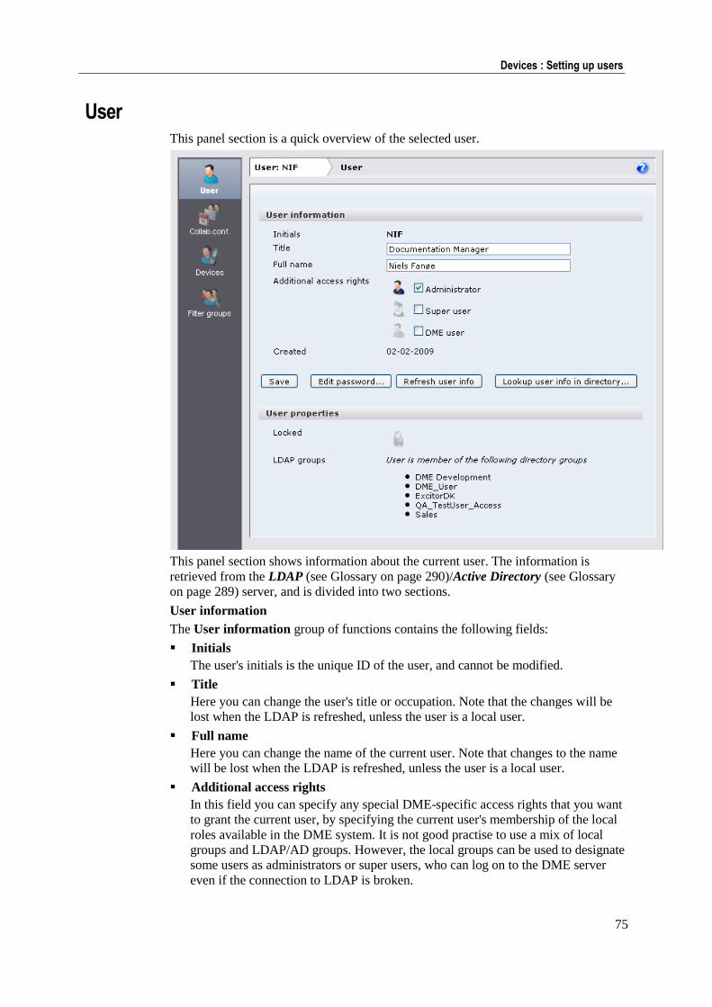
75
Devices : Setting up users
User This panel section is a quick overview of the selected user.
This panel section shows information about the current user. The information is
retrieved from the LDAP (see Glossary on page 290)/Active Directory (see Glossary
on page 289) server, and is divided into two sections.
User information
The User information group of functions contains the following fields:
Initials
The user's initials is the unique ID of the user, and cannot be modified.
Title
Here you can change the user's title or occupation. Note that the changes will be
lost when the LDAP is refreshed, unless the user is a local user.
Full name
Here you can change the name of the current user. Note that changes to the name
will be lost when the LDAP is refreshed, unless the user is a local user.
Additional access rights
In this field you can specify any special DME-specific access rights that you want
to grant the current user, by specifying the current user's membership of the local
roles available in the DME system. It is not good practise to use a mix of local
groups and LDAP/AD groups. However, the local groups can be used to designate
some users as administrators or super users, who can log on to the DME server
even if the connection to LDAP is broken.
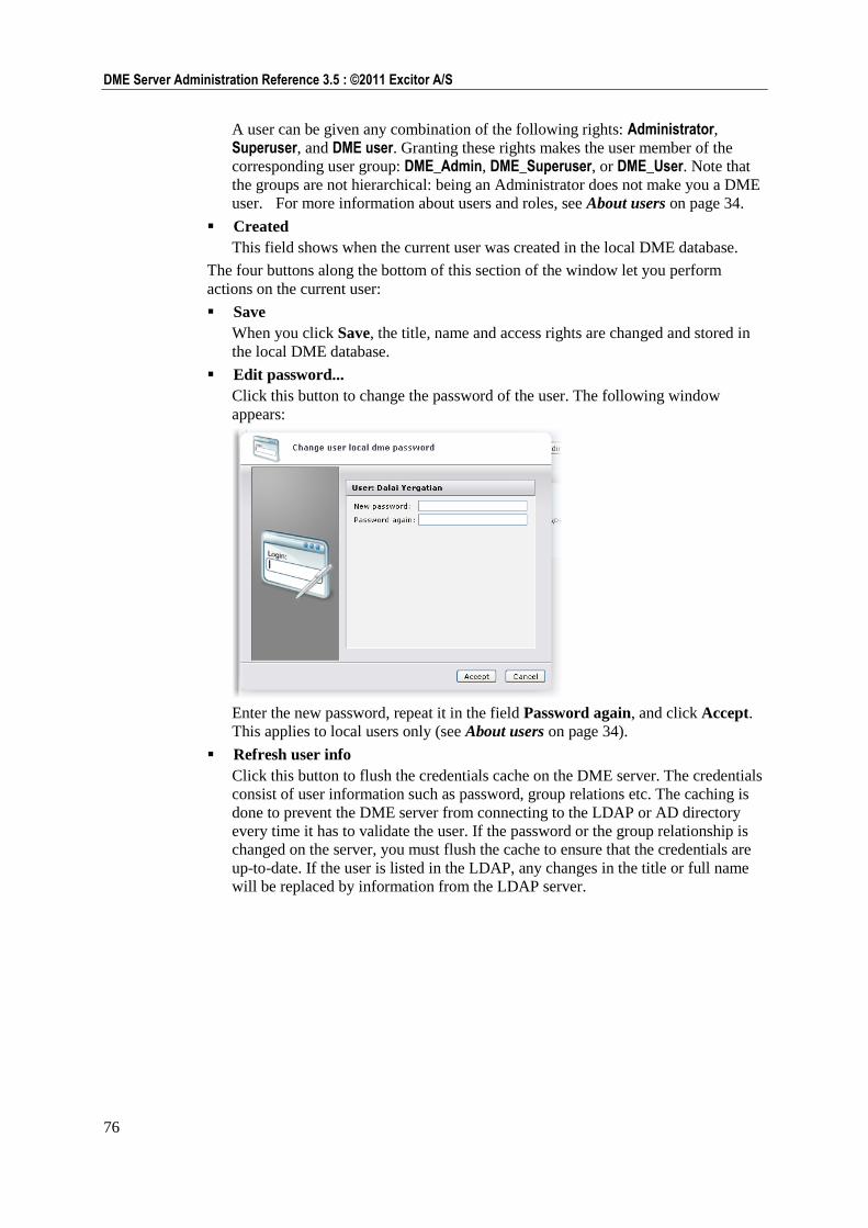
76
DME Server Administration Reference 3.5 : ©2011 Excitor A/S
A user can be given any combination of the following rights: Administrator, Superuser, and DME user. Granting these rights makes the user member of the
corresponding user group: DME_Admin, DME_Superuser, or DME_User. Note that
the groups are not hierarchical: being an Administrator does not make you a DME
user. For more information about users and roles, see About users on page 34.
Created
This field shows when the current user was created in the local DME database.
The four buttons along the bottom of this section of the window let you perform
actions on the current user:
Save
When you click Save, the title, name and access rights are changed and stored in
the local DME database.
Edit password...
Click this button to change the password of the user. The following window
appears:
Enter the new password, repeat it in the field Password again, and click Accept.
This applies to local users only (see About users on page 34).
Refresh user info
Click this button to flush the credentials cache on the DME server. The credentials
consist of user information such as password, group relations etc. The caching is
done to prevent the DME server from connecting to the LDAP or AD directory
every time it has to validate the user. If the password or the group relationship is
changed on the server, you must flush the cache to ensure that the credentials are
up-to-date. If the user is listed in the LDAP, any changes in the title or full name
will be replaced by information from the LDAP server.
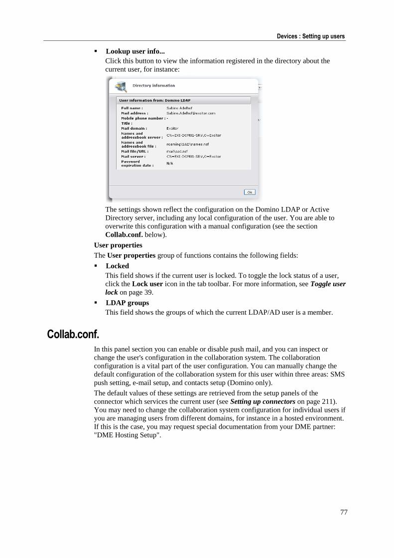
77
Devices : Setting up users
Lookup user info...
Click this button to view the information registered in the directory about the
current user, for instance:
The settings shown reflect the configuration on the Domino LDAP or Active
Directory server, including any local configuration of the user. You are able to
overwrite this configuration with a manual configuration (see the section
Collab.conf. below).
User properties
The User properties group of functions contains the following fields:
Locked
This field shows if the current user is locked. To toggle the lock status of a user,
click the Lock user icon in the tab toolbar. For more information, see Toggle user
lock on page 39.
LDAP groups
This field shows the groups of which the current LDAP/AD user is a member.
Collab.conf. In this panel section you can enable or disable push mail, and you can inspect or
change the user's configuration in the collaboration system. The collaboration
configuration is a vital part of the user configuration. You can manually change the
default configuration of the collaboration system for this user within three areas: SMS
push setting, e-mail setup, and contacts setup (Domino only).
The default values of these settings are retrieved from the setup panels of the
connector which services the current user (see Setting up connectors on page 211).
You may need to change the collaboration system configuration for individual users if
you are managing users from different domains, for instance in a hosted environment.
If this is the case, you may request special documentation from your DME partner:
"DME Hosting Setup".
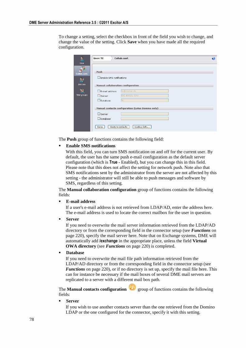
78
DME Server Administration Reference 3.5 : ©2011 Excitor A/S
To change a setting, select the checkbox in front of the field you wish to change, and
change the value of the setting. Click Save when you have made all the required
configuration.
The Push group of functions contains the following field:
Enable SMS notifications
With this field, you can turn SMS notification on and off for the current user. By
default, the user has the same push e-mail configuration as the default server
configuration (which is True - Enabled), but you can change this in this field.
Please note that this does not affect the setting for network push. Note also that
SMS notifications sent by the administrator from the server are not affected by this
setting - the administrator will still be able to push messages and software by
SMS, regardless of this setting.
The Manual collaboration configuration group of functions contains the following
fields:
E-mail address
If a user's e-mail address is not retrieved from LDAP/AD, enter the address here.
The e-mail address is used to locate the correct mailbox for the user in question.
Server
If you need to overwrite the mail server information retrieved from the LDAP/AD
directory or from the corresponding field in the connector setup (see Functions on
page 220), specify the mail server here. Note that on Exchange systems, DME will
automatically add /exchange in the appropriate place, unless the field Virtual
OWA directory (see Functions on page 220) is completed.
Database
If you need to overwrite the mail file path information retrieved from the
LDAP/AD directory or from the corresponding field in the connector setup (see
Functions on page 220), or if no directory is set up, specify the mail file here. This
can for instance be necessary if the mail boxes of several DME mail servers are
replicated to a server with a different mail box path.
The Manual contacts configuration group of functions contains the following
fields:
Server
If you wish to use another contacts server than the one retrieved from the Domino
LDAP or the one configured for the connector, specify it with this setting.
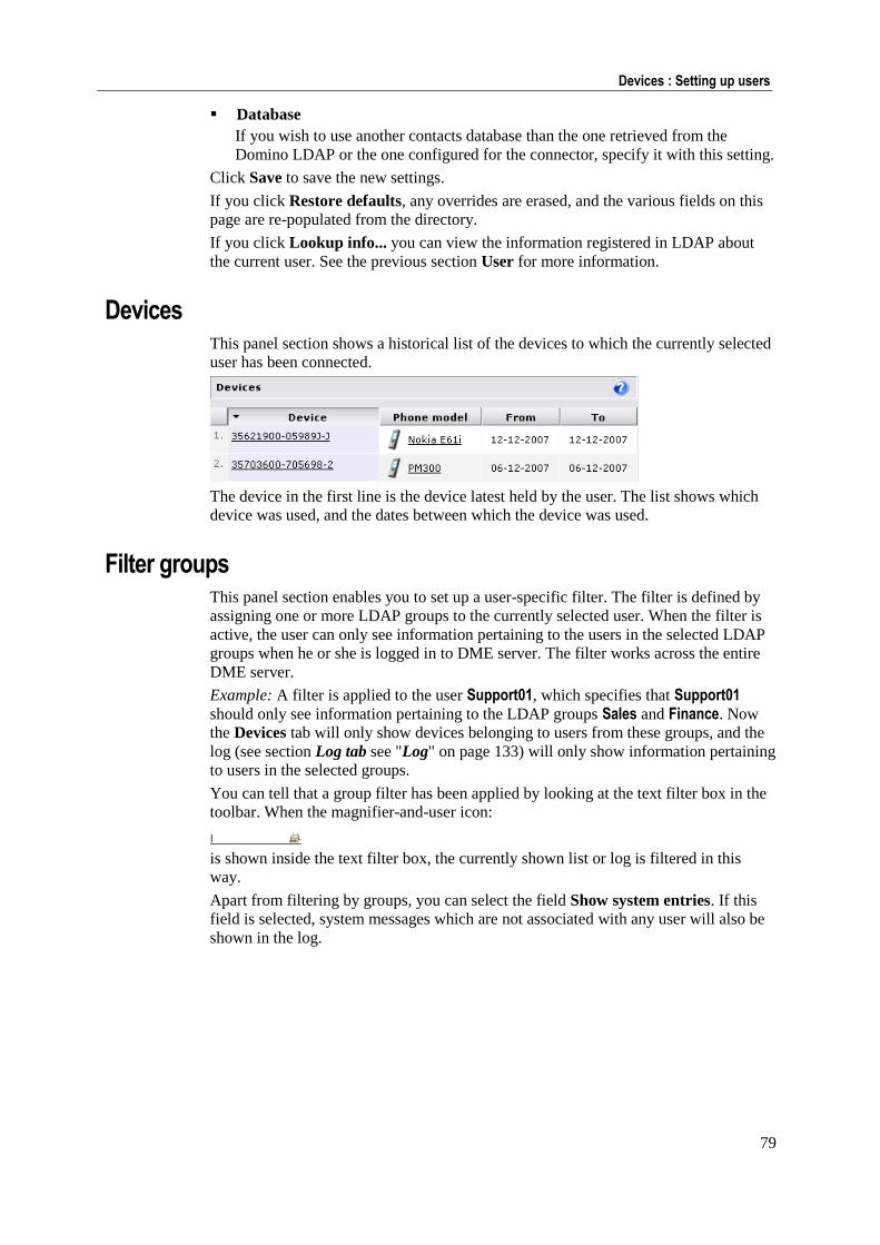
79
Devices : Setting up users
Database
If you wish to use another contacts database than the one retrieved from the
Domino LDAP or the one configured for the connector, specify it with this setting.
Click Save to save the new settings.
If you click Restore defaults, any overrides are erased, and the various fields on this
page are re-populated from the directory.
If you click Lookup info... you can view the information registered in LDAP about
the current user. See the previous section User for more information.
Devices This panel section shows a historical list of the devices to which the currently selected
user has been connected.
The device in the first line is the device latest held by the user. The list shows which
device was used, and the dates between which the device was used.
Filter groups This panel section enables you to set up a user-specific filter. The filter is defined by
assigning one or more LDAP groups to the currently selected user. When the filter is
active, the user can only see information pertaining to the users in the selected LDAP
groups when he or she is logged in to DME server. The filter works across the entire
DME server.
Example: A filter is applied to the user Support01, which specifies that Support01
should only see information pertaining to the LDAP groups Sales and Finance. Now
the Devices tab will only show devices belonging to users from these groups, and the
log (see section Log tab see "Log" on page 133) will only show information pertaining
to users in the selected groups.
You can tell that a group filter has been applied by looking at the text filter box in the
toolbar. When the magnifier-and-user icon:
is shown inside the text filter box, the currently shown list or log is filtered in this
way.
Apart from filtering by groups, you can select the field Show system entries. If this
field is selected, system messages which are not associated with any user will also be
shown in the log.
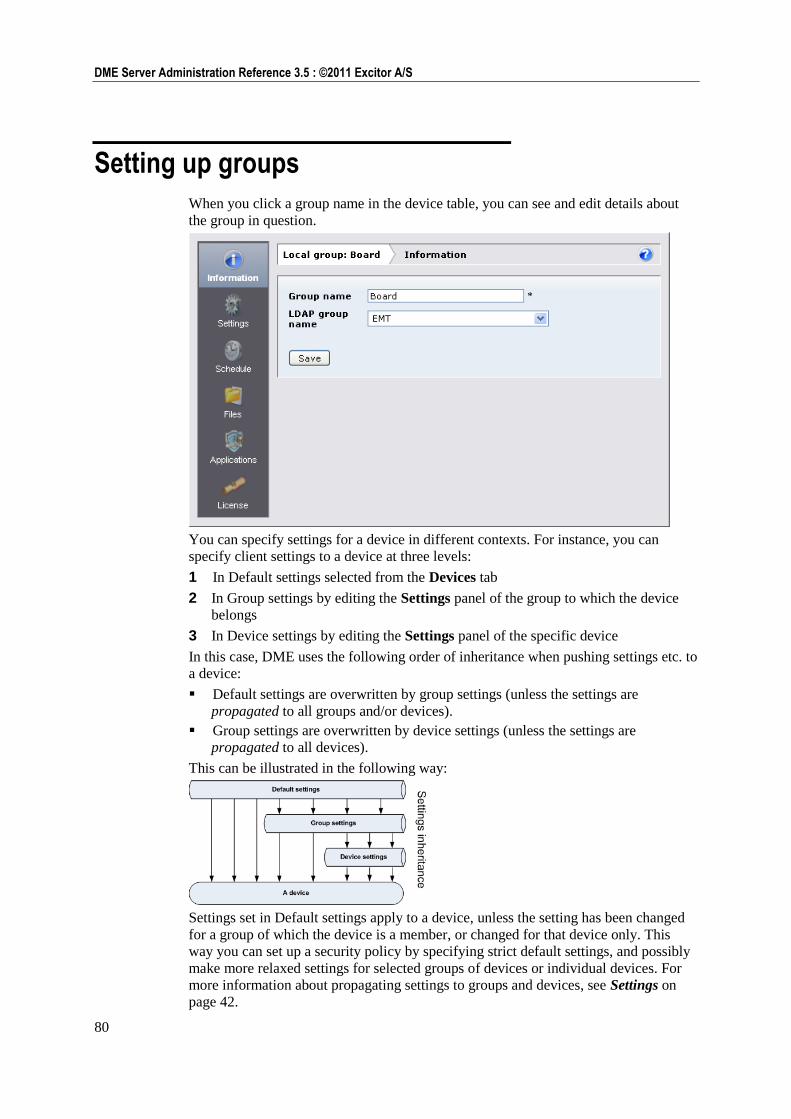
80
DME Server Administration Reference 3.5 : ©2011 Excitor A/S
Setting up groups
When you click a group name in the device table, you can see and edit details about
the group in question.
You can specify settings for a device in different contexts. For instance, you can
specify client settings to a device at three levels:
1 In Default settings selected from the Devices tab
2 In Group settings by editing the Settings panel of the group to which the device
belongs
3 In Device settings by editing the Settings panel of the specific device
In this case, DME uses the following order of inheritance when pushing settings etc. to
a device:
Default settings are overwritten by group settings (unless the settings are
propagated to all groups and/or devices).
Group settings are overwritten by device settings (unless the settings are
propagated to all devices).
This can be illustrated in the following way:
Settings set in Default settings apply to a device, unless the setting has been changed
for a group of which the device is a member, or changed for that device only. This
way you can set up a security policy by specifying strict default settings, and possibly
make more relaxed settings for selected groups of devices or individual devices. For
more information about propagating settings to groups and devices, see Settings on
page 42.

81
Devices : Setting up groups
When you have specified settings for a group, the group's header in the Devices tab
shows the areas in which you have altered the settings compared to the default
settings. For more information, see Group header icons.
The following tab toolbar actions are available from the group setup panel:
New group (see New group on page 33)
Delete group (see Delete group on page 38)
The following page menu functions are available from the group setup panel:
All functions in the page menu
The following sections describe the group setup panel. For more information about
groups, see Groups on page 49.
Information In this panel section, you can see and edit the current group's association with a group
defined in your LDAP server. The fields in this panel section correspond to the fields
used when creating a group (described in the section Adding a new group on page
50). This panel section contains the following fields:
Group name
In this field you can edit the name of the current group.
LDAP group name
In this field you can choose an LDAP/AD group on which to base the local group
in DME. The list of groups shown is the LDAP group graph generated by one of
the connectors. See Domain on page 213.
Click Save to save the new settings.
Settings In this panel section you can override the default settings, for the current group. The
functionality of this panel section corresponds to that of the Settings panel section for
individual devices. For more information, see Settings on page 65.
Schedule In this panel section you can override the default notification schedule settings, for the
current group. The functionality of this panel section corresponds to that of the
Schedule panel section for individual devices. See Schedule on page 67.
Files In this panel section you can override the default file synchronization settings, for the
current group. The functionality of this panel section corresponds to that of the Files
panel section for individual devices. See Files on page 44.
Applications In this panel section you can override the default application and connection blocking,
for the current group. The functionality of this panel section corresponds to that of the
Applications panel section for individual devices. See Applications on page 44.
82
DME Server Administration Reference 3.5 : ©2011 Excitor A/S
License In this panel section you can assign the current group (and the devices in it) to one of
the licenses purchased by your company. A number of different licenses may be
installed on the DME server, each of which covers one set of features in DME. This
means that you can for instance create a group containing devices that are permitted to
do file synchronization, or which are currently only created for device management
purposes, or similar. For more information about managing licenses, see License on
page 201.
The current group can belong to one license. To assign the group to another license,
simply click the radio button in the Use column for the license in question. For
information about the meaning of each column, see License columns on page 202.
Provisioning 83
Provisioning
The Provisioning tab is the central software repository and the place from which you
can deploy DME and other software to your devices. The DME server provides a
mechanism for distributing applications - including the DME client - to devices. The
devices can be existing devices – devices that already exist as entries in the DME
system – or they can be new devices – devices that have never connected to the DME
system before.
The overall process of provisioning – or deploying – software to a device is as
follows:
1 Upload the software package to the DME server. See Upload software on page
105.
2 Select one or more software packages, and select the Install software icon. See
Installing software on page 83.
3 Monitor the installation status. See Initializing on page 109.
From this tab you can also access functions to push information to devices. Those
functions (under the Push to device heading in the page menu) are described under
the Devices tab - see Push to device on page 52.
For a detailed description of how to deploy DME on different device platforms, see
the DME Client Deployment Guide
http://install.excitor.dk/documentation/install/docs/13/index.htm#5181 at the Excitor
install site.
Installing software
In order to be able to manage your devices properly you need to know what software
is running on the devices, and you need a method of upgrading existing devices and
installing software on devices that are not yet known to the DME system. DME uses
the Device Management (DM) protocol defined by the Open Mobile Alliance (OMA)
to acquire a deep knowledge of each device and to make silent installs and upgrades if
possible. In this section, we describe the deployment process.
Not all devices support the use of OMA DM. Because of this, DME will fall back to
the installation methods known from previous versions of DME in case the OMA DM
method fails.
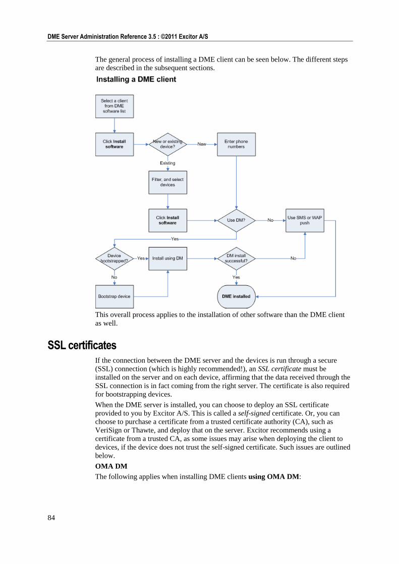
84
DME Server Administration Reference 3.5 : ©2011 Excitor A/S
The general process of installing a DME client can be seen below. The different steps
are described in the subsequent sections.
This overall process applies to the installation of other software than the DME client
as well.
SSL certificates If the connection between the DME server and the devices is run through a secure
(SSL) connection (which is highly recommended!), an SSL certificate must be
installed on the server and on each device, affirming that the data received through the
SSL connection is in fact coming from the right server. The certificate is also required
for bootstrapping devices.
When the DME server is installed, you can choose to deploy an SSL certificate
provided to you by Excitor A/S. This is called a self-signed certificate. Or, you can
choose to purchase a certificate from a trusted certificate authority (CA), such as
VeriSign or Thawte, and deploy that on the server. Excitor recommends using a
certificate from a trusted CA, as some issues may arise when deploying the client to
devices, if the device does not trust the self-signed certificate. Such issues are outlined
below.
OMA DM
The following applies when installing DME clients using OMA DM:
85
Provisioning : Installing software
Non-commercial, self-signed certificates from Excitor or others are not native to
any mobile devices. The device management (DM) client built into the devices
requires a known root certificate in order to process OMA provisioning commands
from the DME server. Therefore, if you want to provision the DME software to
the devices using OMA DM, you need to either use a commercial CA from
VeriSign or others (recommended), or to send the root certificate to your devices
using the Send SSL certificate function prior to installing any software using
OMA DM. See Send SSL certificate on page 55 for more information.
OMA DM deployment does not apply to Apple iOS devices, and the Send SSL
certificate function cannot be used with iPhone, as iPhone cannot receive WAP push.
The following applies when installing DME clients using the self-signed Excitor
certificate and using SMS push:
Symbian (S60 and UIQ) devices: Installing the DME client will automatically
install the Excitor root certificate without user interaction. If you are not using the
Excitor certificate, or if the certificate you use cannot be verified, the Symbian
device will behave as a Java device (see below).
Java devices: These devices do not allow the automatic installation of root
certificates, so the user will need to trust the connection every time he or she
connects to the DME server (or every time DME is launched, depending on device
model). For a solution to this issue, send the certificate to the devices using the
Send SSL certificate function as mentioned in the paragraph about OMA DM
above.
Windows Mobile devices: When the DME client makes the first connection to the
server, the user will be asked if he or she wants to accept the untrusted connection
to the server. The device will remember the user's choice.
Apple iOS devices
DME for iPhone and other iOS devices (iPod touch, iPad) cannot be installed using
SMS push or OMA DM, but is installed through Apple AppStore. When the user
launches the client for the first time, and enters the server path, the DME client 3.5.4
and later silently accepts the self-signed Excitor certificate (and certificates from any
trusted CA).
In previous versions of the DME client for iOS, the user would be asked if he or she
wanted to accept the untrusted connection to the server at the first connection to the
server. The device would then download the self-signed certificate, and remember the
user's choice.
Android devices
it is not possible to install root certificates on Android devices. It might be possible in
the future if Google decides to implement it, but until that happens, the DME servers
must use SSL certificates signed by a major certificate vendor such as Thawte or
VeriSign, which have their root certificates pre-installed on Android devices. This
means that no self-signed certificates are valid for connecting with the DME server.
This means that you need to install a certificate from a major certificate vendor on
your DME server in order to connect using the DME client for Android. Note that
different device vendors preinstall different root certificates, so you should contact
your device vendor to make sure that the device you intend to purchase supports the
certificate installed on your DME server.
If you already own a device, you can try opening the browser on the device and access
a secure SSL website using a certificate from the certificate vendor you intend to use
on the DME server. If the browser accepts the certificate, the Android device will also
be able to establish a secure connection to DME using that certificate. If the browser
issues any kind of security warning, the device will not be able to connect to DME.
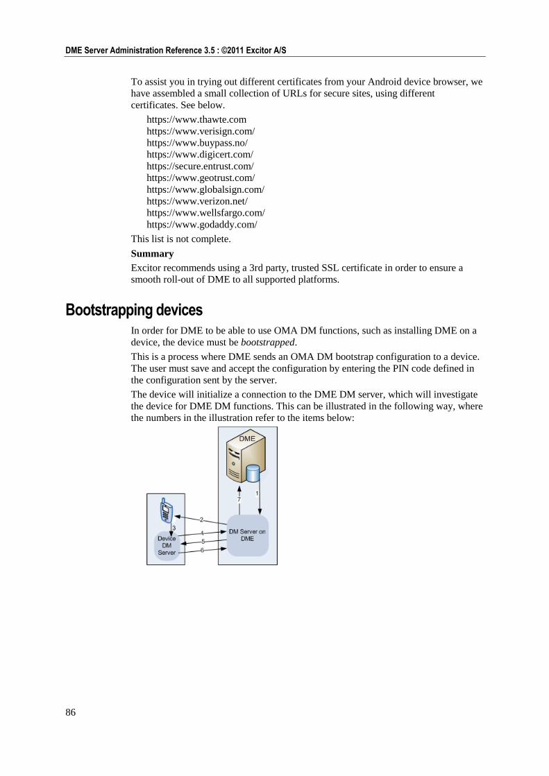
86
DME Server Administration Reference 3.5 : ©2011 Excitor A/S
To assist you in trying out different certificates from your Android device browser, we
have assembled a small collection of URLs for secure sites, using different
certificates. See below.
https://www.thawte.com
https://www.verisign.com/
https://www.buypass.no/
https://www.digicert.com/
https://secure.entrust.com/
https://www.geotrust.com/
https://www.globalsign.com/
https://www.verizon.net/
https://www.wellsfargo.com/
https://www.godaddy.com/
This list is not complete.
Summary
Excitor recommends using a 3rd party, trusted SSL certificate in order to ensure a
smooth roll-out of DME to all supported platforms.
Bootstrapping devices In order for DME to be able to use OMA DM functions, such as installing DME on a
device, the device must be bootstrapped.
This is a process where DME sends an OMA DM bootstrap configuration to a device.
The user must save and accept the configuration by entering the PIN code defined in
the configuration sent by the server.
The device will initialize a connection to the DME DM server, which will investigate
the device for DME DM functions. This can be illustrated in the following way, where
the numbers in the illustration refer to the items below:
87
Provisioning : Installing software
1 The DME administrator chooses to bootstrap a device in the DME web interface,
and DME passes the order to the DM server on the DME server machine.
2 The DM server sends an OMA DM bootstrap configuration to the device. The
configuration contains the path to the DM server and a password.
3 The user accepts the configuration, and enters the PIN code defined in the field
OMA PIN in the SMS modem section of the Server configuration panel (see
SMS modem on page 169). This transfers control to the built-in DM server on the
device.
4 The device DM server connects to the DME DM server using the credentials given
in item 2, and checks if there are any tasks to do. This tells the DME DM server
that the initial bootstrap has been successful.
5 The DME DM server sends a list of tasks to the device.
6 The device DM server returns the results of the tasks to the device. Based on the
results, the DME DM server can compile a list of actions that are possible to
perform on the device, and how the device needs to perform the actions. This way,
the DME DM server for instance knows exactly how to perform a silent upgrade
of DME on the device, and if it is possible.
7 The DME DM server reports back to DME, and the DME web interface is updated
to reflect the new knowledge about the bootstrapped device.
The bootstrap process will be performed in the following cases:
When you attempt to install DME or any other software using OMA DM on new
devices.
When you attempt to install DME or any other software using OMA DM on
existing devices which have not been bootstrapped before.
When you choose to bootstrap one or more devices from the Devices tab. When
you do this, you can choose to install the DME client at the same time (see
Bootstrap devices on page 36).
You can monitor the bootstrapping process in the installation status subtabs of the
DME or Other panel sections (see DME on page 104).
For information about bootstrapping (enrolling) Apple iOS devices, see Enrolling
devices on page 101.
DM on different platforms The OMA DM protocol is supported in different ways on different platforms, and this
is reflected in the way DME supports Device Management on the various platforms.
Symbian S60
Bootstrap Supported.
DME silent install Supported. Some devices require the existence of an
HTTPS certificate.
Install non-DME software Supported.
Symbian UIQ
Not supported.
Windows Mobile
Bootstrap Supported.
88
DME Server Administration Reference 3.5 : ©2011 Excitor A/S
DME silent install Supported on devices running WM 6.x. Use the DME
client designed for DM installation, called
xx.Silent.CAB.
Install non-DME software Supported. Requires that the software is signed, and
that a certificate is installed on the client.
Java
Bootstrap Supported.
DME silent install DME installation is supported, but it cannot be silent,
and will not work on a HTTPS connection. The user
receives a link by SMS. After entering the PIN code,
the user must execute the software download link,
and proceed with a regular installation.
Install non-DME software Supported, with the same limitations as above.
iPhone
Does not apply.
Android
Does not apply.
BlackBerry
BlackBerry does not support DM.
Installing software on new devices This description covers the installation of both the DME/MDM client and other
software on new devices.
It is possible to create devices in DME manually without installing DME (for asset
management purposes), but that is not described here (nor recommended). See New
device for more information.
Installing software on one or more new devices
The recommended way to install DME software on new devices is to use the
Bootstrap devices function from the Devices tab. The reason for this is that this
allows DME to choose the correct client for the new (and as such unknown) device.
See Bootstrap devices on page 36 for more information. The following method only
applies if you know which client to install on the new device (or if you are installing
non-DME software).
1 Select a DME client in the Software list subtab of the DME panel section in the
Provisioning tab.
or
Select a software package in the Software list subtab of the Other panel section in
the Provisioning tab.
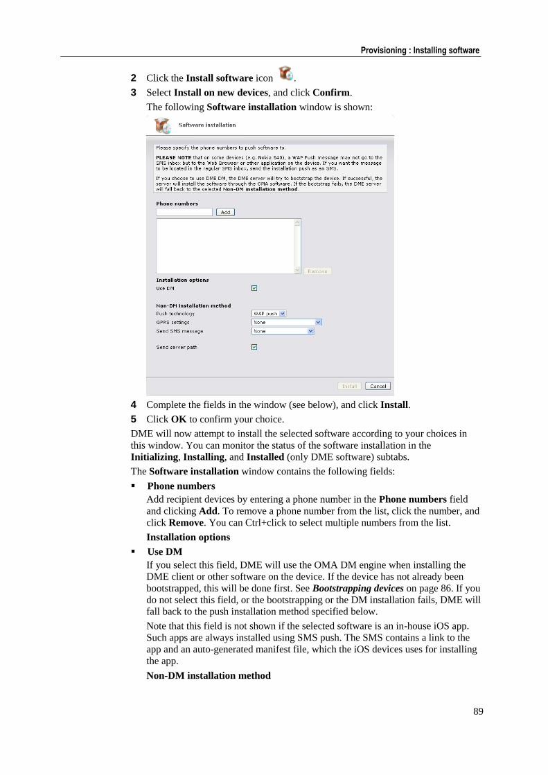
89
Provisioning : Installing software
2 Click the Install software icon .
3 Select Install on new devices, and click Confirm.
The following Software installation window is shown:
4 Complete the fields in the window (see below), and click Install.
5 Click OK to confirm your choice.
DME will now attempt to install the selected software according to your choices in
this window. You can monitor the status of the software installation in the
Initializing, Installing, and Installed (only DME software) subtabs.
The Software installation window contains the following fields:
Phone numbers
Add recipient devices by entering a phone number in the Phone numbers field
and clicking Add. To remove a phone number from the list, click the number, and
click Remove. You can Ctrl+click to select multiple numbers from the list.
Installation options
Use DM
If you select this field, DME will use the OMA DM engine when installing the
DME client or other software on the device. If the device has not already been
bootstrapped, this will be done first. See Bootstrapping devices on page 86. If you
do not select this field, or the bootstrapping or the DM installation fails, DME will
fall back to the push installation method specified below.
Note that this field is not shown if the selected software is an in-house iOS app.
Such apps are always installed using SMS push. The SMS contains a link to the
app and an auto-generated manifest file, which the iOS devices uses for installing
the app.
Non-DM installation method
90
DME Server Administration Reference 3.5 : ©2011 Excitor A/S
Push technology
If the DM bootstrap or installation fails, or if the Use OMA DM field is not
selected, DME will install the selected software by the push technology selected in
this drop-down list. This means that the device will receive a message with a
unique link to the software. By clicking that link, the user downloads the software
in question. The link is only valid for the amount of time specified in the field
Software push, ticket lifetime in the Client section of the Server configuration
panel (see Client on page 159).
In this drop-down list, you can choose between SMS push and WAP push. SMS push is generally recommended, since it does not require a server path, and the
users generally find it easier to work with SMS messages than WAP messages.
Note that if you do choose WAP push, you must also specify a server path in the
field Send server path, which is only shown if WAP push is selected.
GPRS settings
The device needs the GPRS settings to connect to the Internet using GPRS. The
list of GPRS settings is the same list that is shown when you click Send OTA
configuration in the page menu. See Send OTA configuration on page 52.
Send SMS message
You can send an information SMS to the users with a default message, or you can
write your own message. The message should be slightly different depending on
the installation method. It should say that a link will be sent to the device by SMS
or WAP (if DM is not used), and that it is OK to click the link to download the
software.
If you choose Default SMS message, the window is expanded to include an
SMS message field, showing the default message that will be sent to the users.
You can edit the default message by selecting the field Create new default
message. This opens the SMS message field for editing. When you click
Install, the edited message is saved as a new default message.
If you choose Write your own, you can send a custom message, but you cannot
save it as a new default message.
Send server path
This field is only visible if you are installing a DME client, and only if WAP push
is selected as push technology. If you select this field, DME will send the server
path for the DME server to the device. The server path is needed for the client to
locate the DME server on the Internet.
If you use WAP push, you should select this field, as the server path cannot be
contained in the download link itself when using WAP. In case of SMS push and
DM installation, the server path is automatically sent along with the DME client
software.
Installing DME on existing devices If you want to upgrade or install the DME client on devices that are already registered
in the DME system, follow the guidelines below. Note that the installation of software
listed in the Other panel section is described separately.
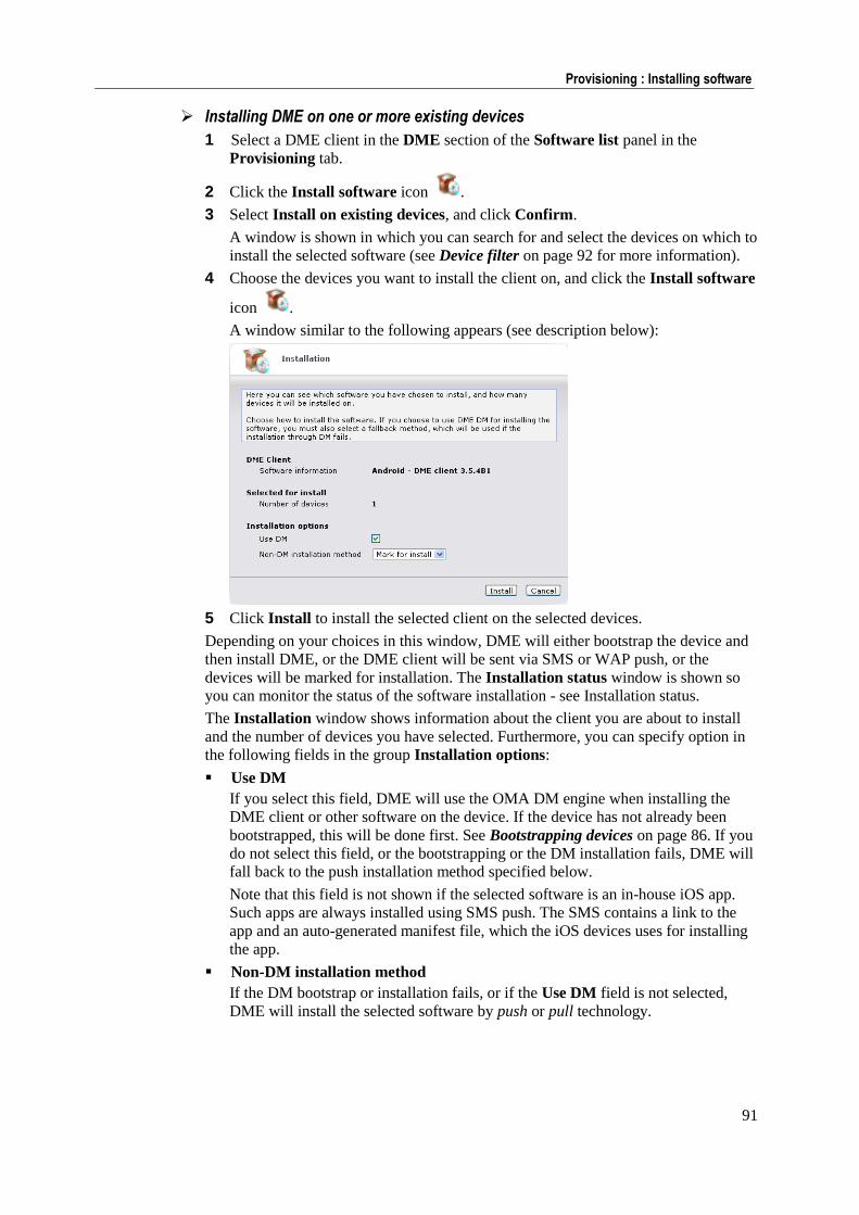
91
Provisioning : Installing software
Installing DME on one or more existing devices
1 Select a DME client in the DME section of the Software list panel in the
Provisioning tab.
2 Click the Install software icon .
3 Select Install on existing devices, and click Confirm.
A window is shown in which you can search for and select the devices on which to
install the selected software (see Device filter on page 92 for more information).
4 Choose the devices you want to install the client on, and click the Install software
icon .
A window similar to the following appears (see description below):
5 Click Install to install the selected client on the selected devices.
Depending on your choices in this window, DME will either bootstrap the device and
then install DME, or the DME client will be sent via SMS or WAP push, or the
devices will be marked for installation. The Installation status window is shown so
you can monitor the status of the software installation - see Installation status.
The Installation window shows information about the client you are about to install
and the number of devices you have selected. Furthermore, you can specify option in
the following fields in the group Installation options:
Use DM
If you select this field, DME will use the OMA DM engine when installing the
DME client or other software on the device. If the device has not already been
bootstrapped, this will be done first. See Bootstrapping devices on page 86. If you
do not select this field, or the bootstrapping or the DM installation fails, DME will
fall back to the push installation method specified below.
Note that this field is not shown if the selected software is an in-house iOS app.
Such apps are always installed using SMS push. The SMS contains a link to the
app and an auto-generated manifest file, which the iOS devices uses for installing
the app.
Non-DM installation method
If the DM bootstrap or installation fails, or if the Use DM field is not selected,
DME will install the selected software by push or pull technology.
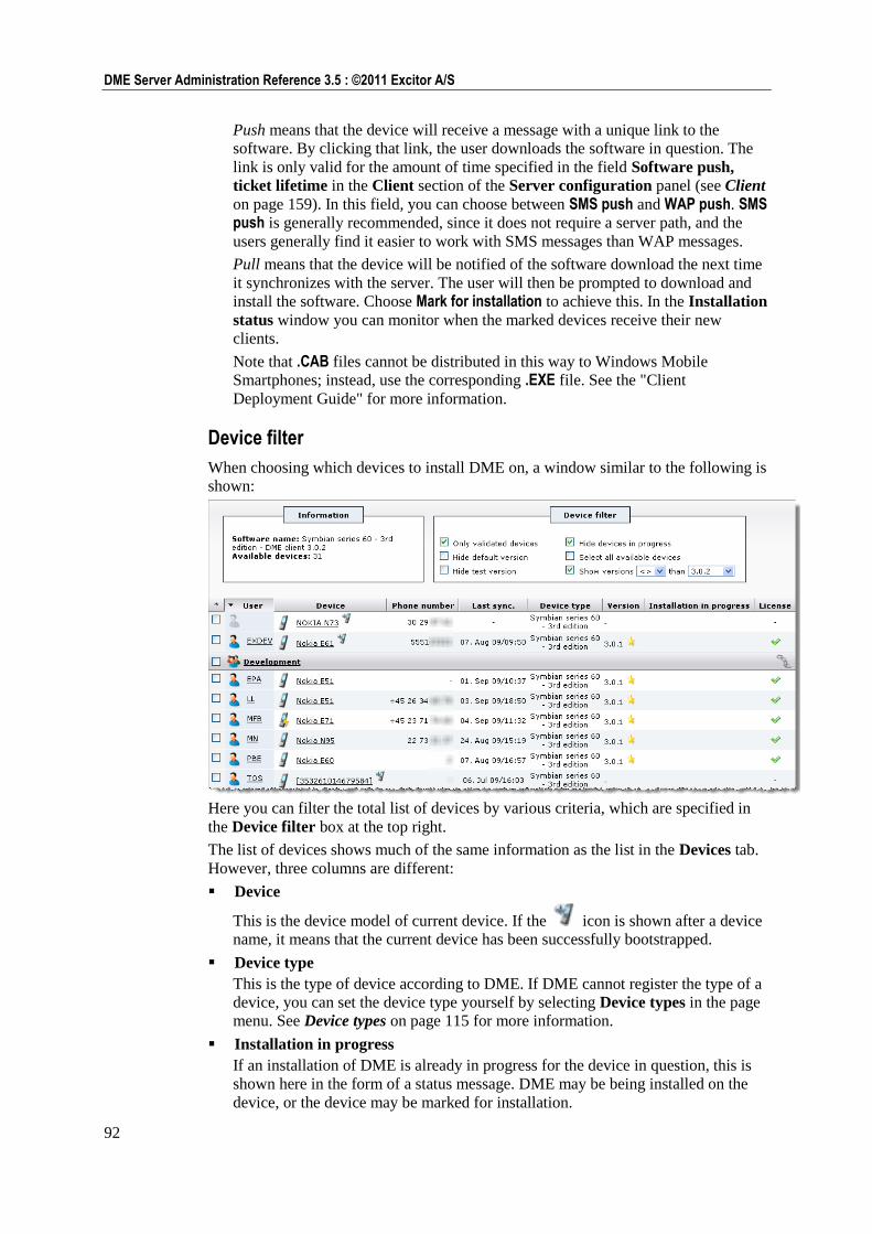
92
DME Server Administration Reference 3.5 : ©2011 Excitor A/S
Push means that the device will receive a message with a unique link to the
software. By clicking that link, the user downloads the software in question. The
link is only valid for the amount of time specified in the field Software push,
ticket lifetime in the Client section of the Server configuration panel (see Client
on page 159). In this field, you can choose between SMS push and WAP push. SMS push is generally recommended, since it does not require a server path, and the
users generally find it easier to work with SMS messages than WAP messages.
Pull means that the device will be notified of the software download the next time
it synchronizes with the server. The user will then be prompted to download and
install the software. Choose Mark for installation to achieve this. In the Installation
status window you can monitor when the marked devices receive their new
clients.
Note that .CAB files cannot be distributed in this way to Windows Mobile
Smartphones; instead, use the corresponding .EXE file. See the "Client
Deployment Guide" for more information.
Device filter
When choosing which devices to install DME on, a window similar to the following is
shown:
Here you can filter the total list of devices by various criteria, which are specified in
the Device filter box at the top right.
The list of devices shows much of the same information as the list in the Devices tab.
However, three columns are different:
Device
This is the device model of current device. If the icon is shown after a device
name, it means that the current device has been successfully bootstrapped.
Device type
This is the type of device according to DME. If DME cannot register the type of a
device, you can set the device type yourself by selecting Device types in the page
menu. See Device types on page 115 for more information.
Installation in progress
If an installation of DME is already in progress for the device in question, this is
shown here in the form of a status message. DME may be being installed on the
device, or the device may be marked for installation.
93
Provisioning : Installing software
Furthermore, some devices can be marked with a star (indicating that it is running
the default version of the client for its platform), or a magnifying glass
(indicating that it is running a test version of the client for its platform).
When you have selected the devices on which you want to install the selected client,
click the Install software icon to continue the installation process.
The Information box contains the following fields:
Software name
This is the name of the DME client which you chose to install in the Software list.
The name consists of the device type (platform) the client is intended for, the name
of the software (always DME Client), and the client version.
Available devices
This is the number of devices in the DME system on which the selected client may
be installed, according to your selections in the filter boxes to the right.
The Device filter box contains the following fields:
Only validated devices
If you select this field, DME shows only devices where the device model is known
to be able to run the currently selected client. This means that they must be listed
in the window Device types with the currently selected client specified as DME
version type. See Device types on page 115 for more information.
If you do not select this field, DME shows all devices, regardless of device type, if
they match the other filtering criteria. Furthermore, the fields Hide default
version and Hide test version are disabled, as "default" and "test" versions cannot
be guaranteed to have the same DME version type as the selected software.
Hide default version
If you select this field, DME hides all devices where the default version of the
selected client software is already installed (indicated with a star ). This is
useful if you want to install the default client version on devices that are not
already running the default version.
Hide test version
If you select this field, DME hides all devices where the test version of the
selected client software is installed (indicated with a magnifying glass ). This
is useful if you want to install the default client version on all devices of a certain
type, except those that are currently testing a different client version.
Hide devices in progress
If you select this field, DME hides those devices in the list where a message is
shown in the column Installation in progress (see above). You typically do not
want to make a new installation on a client that is already busy with a DME DM
task, or which is marked for installation. If you need to cancel a task in progress,
you can do so in one of the installation status subtabs (see Installation status tab
actions on page 112).
Select all available devices
If you select this field, all devices that fit the criteria are selected, even if they are
not shown on the page due to a restriction to the number of rows displayed in the
table navigation bar.
94
DME Server Administration Reference 3.5 : ©2011 Excitor A/S
Show versions
If you select this field, you can choose to only see devices on which a certain
range of DME versions is installed. Use the drop-down list boxes to choose an
operator (greater than, less than, equal to, or different from) and a version number.
This can for instance be useful if you want to upgrade all devices running a client
version earlier than the current version.
In addition to the filtering options, you can use the standard filtering options: the filter
bar, a filter group, or a directory group restriction for limiting the number of devices in
the list. (Note that the filter in the filter bar does not work for all columns.)
MDM on Apple iOS
DME supports the Apple MDM APNS protocol, which enables Apple iOS 4 devices
(iPhone, iPod, iPad) to enroll with (enter into a trusted relationship with) a server,
which may then issue commands to the devices without user interaction. This
resembles the "bootstrap" which applies to Symbian, Windows, and Java devices,
which also creates a trust between server and device.
Security settings and other settings which the administrator wants to implement on
iOS devices are defined in XML profiles using the Apple iPhone Configuration Utility
and then distributed to the users using the iPhone profiles window (see iPhone
profiles on page 127). Previously - before the introduction of Apple MDM - sending
configuration files required that the users accept the installation of the profile. Profiles
are now installed silently on enrolled devices. You can also distribute links to in-house
apps and provisioning profiles this way.
To become enrolled, a device user must accept the installation of a DME MDM
Configuration Profile. When that profile is installed, the iOS 4 device completes an
enrollment process using the Simple Certificate Enrollment Protocol (SCEP), during
which DME validates the device and generates a device certificate. DME can then
manage and monitor the iOS 4 device without further user involvement. Device
settings profiles can be updated transparently, and device information can be obtained
and registered by DME. The Apple Push Notification Service (APNS) is used to
enable the communication between devices and DME.
A number of prerequisites must be in place before you can reap the benefits of Apple
MDM:
1 Obtain an Apple Enterprise Developer account (see Participating in the iDEP
program on page 95).
2 Create an application certificate (see Generating an APNS certificate on page 95).
3 Install the certificate on the server, and configure the server (see Server
configuration for Apple MDM on page 99).
4 The devices must run iOS 4.
5 An SSL certificate from a trusted vendor (such as VeriSign) must be installed on
the DME server.
95
Provisioning : MDM on Apple iOS
Participating in the iDEP program In order to be able to manage your iOS devices through DME (or any other system),
your company must participate in the Apple iOS Developer Enterprise Program
(iDEP). With an iDEP membership, you can go to the Apple website to generate a
certificate, which must be installed on the DME server. This certificate is used for
establishing the trust relationship between the device and DME.
To get an iDEP account, go to the Apple iOS Developer Enterprise Program website
http://developer.apple.com/programs/ios/enterprise/.
Click the Apply Now button, and read the requirements for participation. According
to this web page, you may sign up for participation in the iDEP program if:
You plan to only distribute your iOS apps within your company or
organization
"Your" iOS app, in this case, is DME.
Your company has a DUNS Number
You will be required to provide your Dun & Bradstreet (DUNS) number during
the enrollment process. The Dun & Bradstreet company register supposedly
contains all companies in the world, and you can find your company at their
website www.dnb.com and have your DUNS number e-mailed to you (for free -
but registration at the D&B website is required).
You have authority to bind your company to the legal agreements
You must be in a position to enter into a binding agreement on behalf of your
company.
If these conditions are fulfilled, you can click Continue.
Follow the guide, until you have successfully activated the iDEP program. The annual
fee for participating in the program is currently USD $299.
Generating an APNS certificate Now that you are an iDEP member, you can generate your own Apple iOS APNS
certificate for use with DME. This certificate, which is uniquely assigned to you, is
required to manage your iOS 4 devices using the Apple Push Notification System
(APNS).
Please note: You are required to renew the certificate once every year by working
through this process!
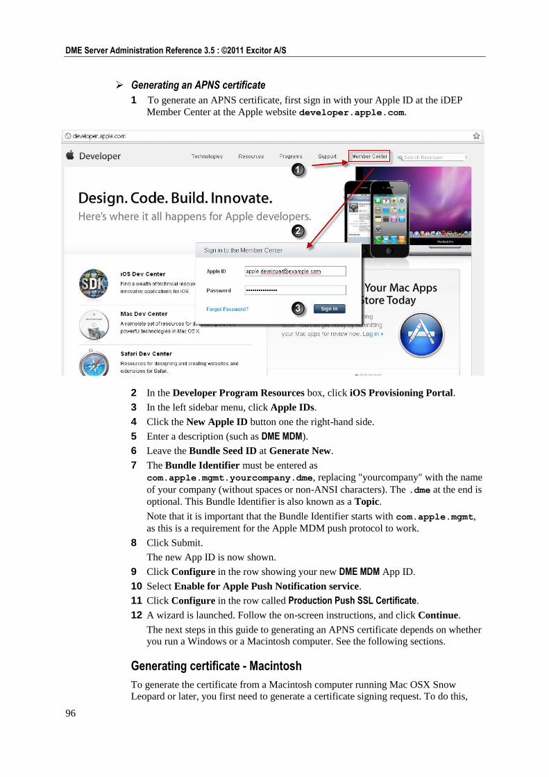
96
DME Server Administration Reference 3.5 : ©2011 Excitor A/S
Generating an APNS certificate
1 To generate an APNS certificate, first sign in with your Apple ID at the iDEP
Member Center at the Apple website developer.apple.com.
2 In the Developer Program Resources box, click iOS Provisioning Portal.
3 In the left sidebar menu, click Apple IDs.
4 Click the New Apple ID button one the right-hand side.
5 Enter a description (such as DME MDM).
6 Leave the Bundle Seed ID at Generate New.
7 The Bundle Identifier must be entered as
com.apple.mgmt.yourcompany.dme, replacing "yourcompany" with the name
of your company (without spaces or non-ANSI characters). The .dme at the end is
optional. This Bundle Identifier is also known as a Topic.
Note that it is important that the Bundle Identifier starts with com.apple.mgmt,
as this is a requirement for the Apple MDM push protocol to work.
8 Click Submit.
The new App ID is now shown.
9 Click Configure in the row showing your new DME MDM App ID.
10 Select Enable for Apple Push Notification service.
11 Click Configure in the row called Production Push SSL Certificate.
12 A wizard is launched. Follow the on-screen instructions, and click Continue.
The next steps in this guide to generating an APNS certificate depends on whether
you run a Windows or a Macintosh computer. See the following sections.
Generating certificate - Macintosh
To generate the certificate from a Macintosh computer running Mac OSX Snow
Leopard or later, you first need to generate a certificate signing request. To do this,
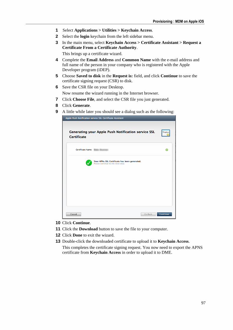
97
Provisioning : MDM on Apple iOS
1 Select Applications > Utilities > Keychain Access.
2 Select the login keychain from the left sidebar menu.
3 In the main menu, select Keychain Access > Certificate Assistant > Request a
Certificate From a Certificate Authority.
This brings up a certificate wizard.
4 Complete the Email Address and Common Name with the e-mail address and
full name of the person in your company who is registered with the Apple
Developer program (iDEP).
5 Choose Saved to disk in the Request is: field, and click Continue to save the
certificate signing request (CSR) to disk.
6 Save the CSR file on your Desktop.
Now resume the wizard running in the Internet browser.
7 Click Choose File, and select the CSR file you just generated.
8 Click Generate.
9 A little while later you should see a dialog such as the following:
10 Click Continue.
11 Click the Download button to save the file to your computer.
12 Click Done to exit the wizard.
13 Double-click the downloaded certificate to upload it to Keychain Access.
This completes the certificate signing request. You now need to export the APNS
certificate from Keychain Access in order to upload it to DME.
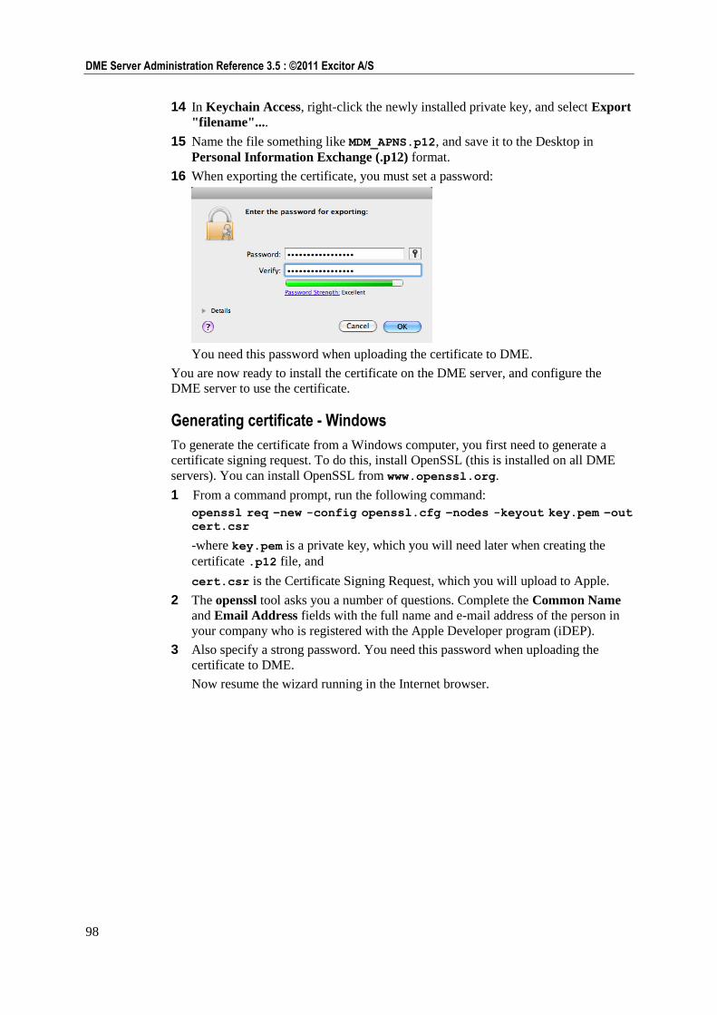
98
DME Server Administration Reference 3.5 : ©2011 Excitor A/S
14 In Keychain Access, right-click the newly installed private key, and select Export
"filename"....
15 Name the file something like MDM_APNS.p12, and save it to the Desktop in
Personal Information Exchange (.p12) format.
16 When exporting the certificate, you must set a password:
You need this password when uploading the certificate to DME.
You are now ready to install the certificate on the DME server, and configure the
DME server to use the certificate.
Generating certificate - Windows
To generate the certificate from a Windows computer, you first need to generate a
certificate signing request. To do this, install OpenSSL (this is installed on all DME
servers). You can install OpenSSL from www.openssl.org.
1 From a command prompt, run the following command:
openssl req –new -config openssl.cfg –nodes -keyout key.pem –out
cert.csr
-where key.pem is a private key, which you will need later when creating the
certificate .p12 file, and
cert.csr is the Certificate Signing Request, which you will upload to Apple.
2 The openssl tool asks you a number of questions. Complete the Common Name
and Email Address fields with the full name and e-mail address of the person in
your company who is registered with the Apple Developer program (iDEP).
3 Also specify a strong password. You need this password when uploading the
certificate to DME.
Now resume the wizard running in the Internet browser.
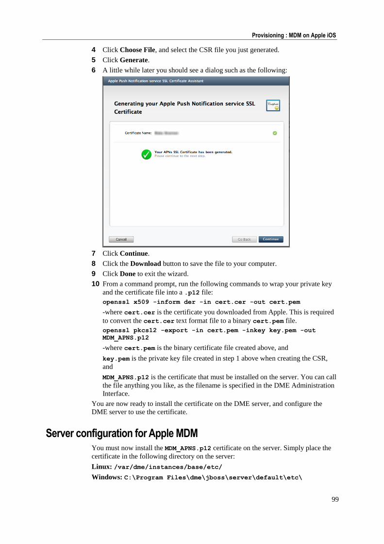
99
Provisioning : MDM on Apple iOS
4 Click Choose File, and select the CSR file you just generated.
5 Click Generate.
6 A little while later you should see a dialog such as the following:
7 Click Continue.
8 Click the Download button to save the file to your computer.
9 Click Done to exit the wizard.
10 From a command prompt, run the following commands to wrap your private key
and the certificate file into a .p12 file:
openssl x509 -inform der -in cert.cer -out cert.pem
-where cert.cer is the certificate you downloaded from Apple. This is required
to convert the cert.cer text format file to a binary cert.pem file.
openssl pkcs12 -export -in cert.pem -inkey key.pem -out
MDM_APNS.p12
-where cert.pem is the binary certificate file created above, and
key.pem is the private key file created in step 1 above when creating the CSR,
and
MDM_APNS.p12 is the certificate that must be installed on the server. You can call
the file anything you like, as the filename is specified in the DME Administration
Interface.
You are now ready to install the certificate on the DME server, and configure the
DME server to use the certificate.
Server configuration for Apple MDM You must now install the MDM_APNS.p12 certificate on the server. Simply place the
certificate in the following directory on the server:
Linux: /var/dme/instances/base/etc/
Windows: C:\Program Files\dme\jboss\server\default\etc\
100
DME Server Administration Reference 3.5 : ©2011 Excitor A/S
On GNU/Linux, you must then specify the file ownership after uploading the
certificate file. Use the following command as root:
chown jboss:jboss /var/dme/* -R
Restart the server. DME detects the presence of the certificate, and automatically turns
MDM APNS on. You can see the APNS connection status by selecting the Server tab
> Server configuration > Monitor > Server properties. The field Apple MDM
push notification status changes from Disconnected to Connected. See Monitor on
page 174.
Important legal notice: Apple is very clear that a certificate can be installed on ONE
server only. This means that if you for instance run a test server and a production
server, you will need two separate certificates.
Firewall setup:
The introduction of DME Central Services in DME Server 3.5 SP 3 made it possible
to run APNS using the DME Central Services server, which in turn enabled you to
close the firewall ports to the Apple APNS server.
However, the Apple MDM system requires that no proxy (the role played by the DME
Central Services server) may stand between the Apple APNS server and the MDM
server (DME). This makes it necessary to (re)open your firewall to the following
URIs:
gateway.push.apple.com:2195 feedback.push.apple.com:2196
DME Administration Interface setup:
To specify the location and other details of the certificate, select the Server tab >
Server configuration > Client. In the iPhone MDM Server group of fields, specify
the following:
APNS MDM Topic
In this field you specify the Topic of your APNS certificate. This is what you
entered during the creation of the certificate signing request (CSR), something like
com.apple.mgmt.yourcompany.dme. During the creation of the CSR, this was
entered in a field called Bundle ID. Inside the certificate (if you look into the
certificate using a utility such as Keytool), the topic is listed as a User ID. It is
very important to get this name right. The field is pre-filled with the first,
mandatory part of the topic name: com.apple.mgmt.
APNS MDM Certificate filename
In this field you can specify the filename of the APNS MDM certificate you have
installed in the /var/dme/../etc or \dme\jboss\..\etc directory on the
DME server. By default, this is MDM_APNS.p12.
APNS MDM Certificate password
In this field you must specify the password for the .p12 certificate file you created
from the Apple Keychain Access tool or using openssl on Windows. DME needs
this password for accessing the certificate.
Click Save configuration to apply the new settings.
After a server restart, or after the certificate has been used by a client once, the Apple
MDM push notification status in the Monitor page (see above) will display
Connected, and device enrollments and configuration can start.
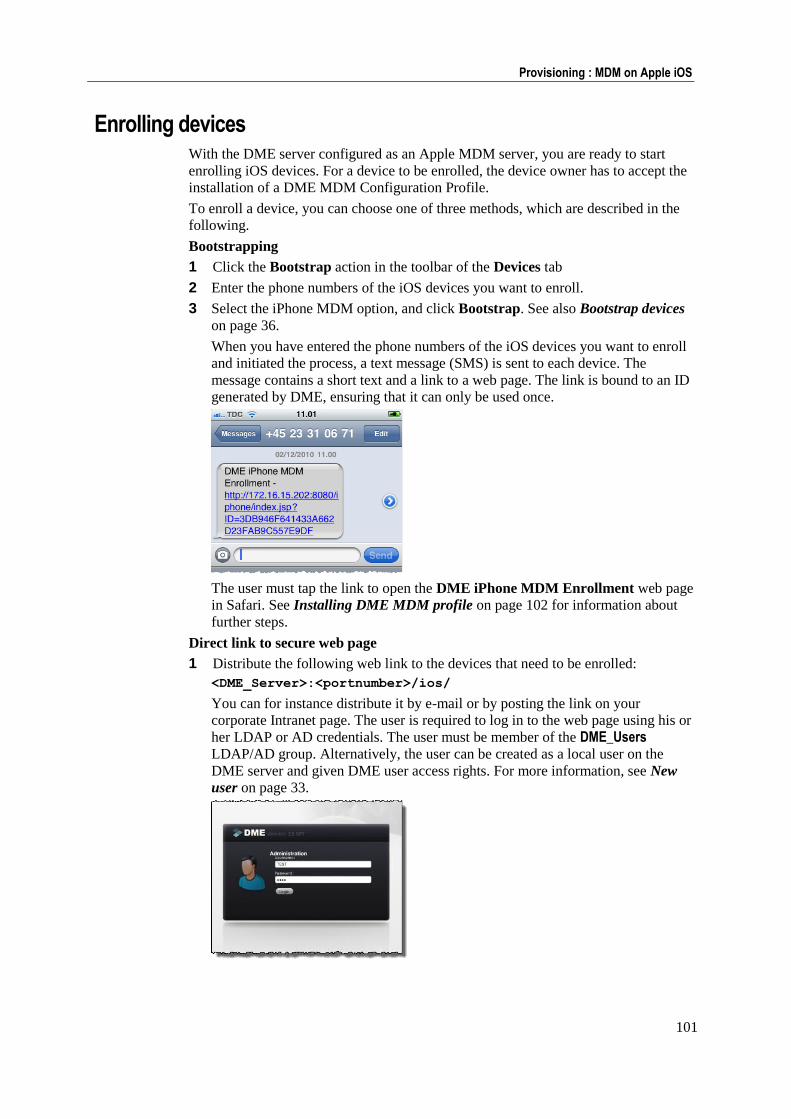
101
Provisioning : MDM on Apple iOS
Enrolling devices With the DME server configured as an Apple MDM server, you are ready to start
enrolling iOS devices. For a device to be enrolled, the device owner has to accept the
installation of a DME MDM Configuration Profile.
To enroll a device, you can choose one of three methods, which are described in the
following.
Bootstrapping
1 Click the Bootstrap action in the toolbar of the Devices tab
2 Enter the phone numbers of the iOS devices you want to enroll.
3 Select the iPhone MDM option, and click Bootstrap. See also Bootstrap devices
on page 36.
When you have entered the phone numbers of the iOS devices you want to enroll
and initiated the process, a text message (SMS) is sent to each device. The
message contains a short text and a link to a web page. The link is bound to an ID
generated by DME, ensuring that it can only be used once.
The user must tap the link to open the DME iPhone MDM Enrollment web page
in Safari. See Installing DME MDM profile on page 102 for information about
further steps.
Direct link to secure web page
1 Distribute the following web link to the devices that need to be enrolled:
<DME_Server>:<portnumber>/ios/
You can for instance distribute it by e-mail or by posting the link on your
corporate Intranet page. The user is required to log in to the web page using his or
her LDAP or AD credentials. The user must be member of the DME_Users
LDAP/AD group. Alternatively, the user can be created as a local user on the
DME server and given DME user access rights. For more information, see New
user on page 33.
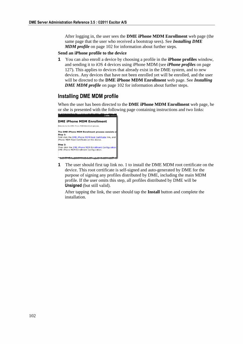
102
DME Server Administration Reference 3.5 : ©2011 Excitor A/S
After logging in, the user sees the DME iPhone MDM Enrollment web page (the
same page that the user who received a bootstrap sees). See Installing DME
MDM profile on page 102 for information about further steps.
Send an iPhone profile to the device
1 You can also enroll a device by choosing a profile in the iPhone profiles window,
and sending it to iOS 4 devices using iPhone MDM (see iPhone profiles on page
127). This applies to devices that already exist in the DME system, and to new
devices. Any devices that have not been enrolled yet will be enrolled, and the user
will be directed to the DME iPhone MDM Enrollment web page. See Installing
DME MDM profile on page 102 for information about further steps.
Installing DME MDM profile
When the user has been directed to the DME iPhone MDM Enrollment web page, he
or she is presented with the following page containing instructions and two links:
1 The user should first tap link no. 1 to install the DME MDM root certificate on the
device. This root certificate is self-signed and auto-generated by DME for the
purpose of signing any profiles distributed by DME, including the main MDM
profile. If the user omits this step, all profiles distributed by DME will be
Unsigned (but still valid).
After tapping the link, the user should tap the Install button and complete the
installation.
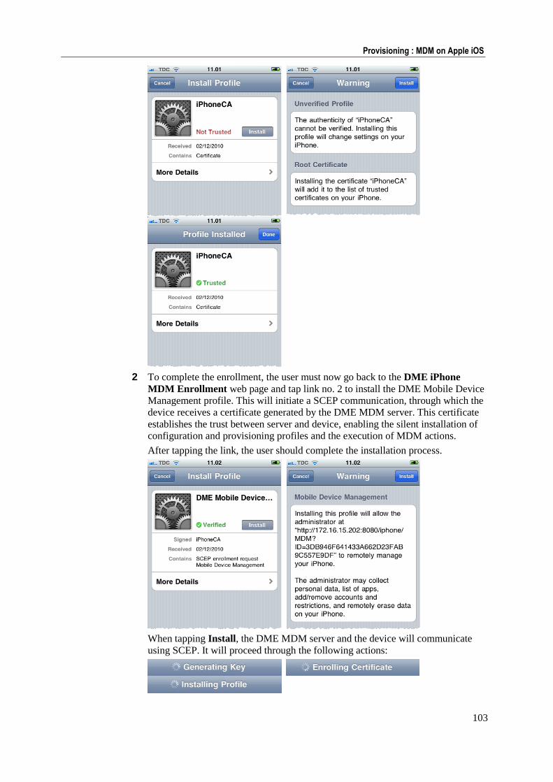
103
Provisioning : MDM on Apple iOS
2 To complete the enrollment, the user must now go back to the DME iPhone
MDM Enrollment web page and tap link no. 2 to install the DME Mobile Device
Management profile. This will initiate a SCEP communication, through which the
device receives a certificate generated by the DME MDM server. This certificate
establishes the trust between server and device, enabling the silent installation of
configuration and provisioning profiles and the execution of MDM actions.
After tapping the link, the user should complete the installation process.
When tapping Install, the DME MDM server and the device will communicate
using SCEP. It will proceed through the following actions:
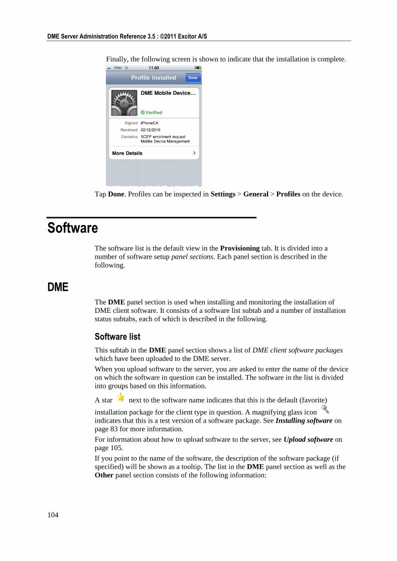
104
DME Server Administration Reference 3.5 : ©2011 Excitor A/S
Finally, the following screen is shown to indicate that the installation is complete.
Tap Done. Profiles can be inspected in Settings > General > Profiles on the device.
Software
The software list is the default view in the Provisioning tab. It is divided into a
number of software setup panel sections. Each panel section is described in the
following.
DME The DME panel section is used when installing and monitoring the installation of
DME client software. It consists of a software list subtab and a number of installation
status subtabs, each of which is described in the following.
Software list
This subtab in the DME panel section shows a list of DME client software packages
which have been uploaded to the DME server.
When you upload software to the server, you are asked to enter the name of the device
on which the software in question can be installed. The software in the list is divided
into groups based on this information.
A star next to the software name indicates that this is the default (favorite)
installation package for the client type in question. A magnifying glass icon
indicates that this is a test version of a software package. See Installing software on
page 83 for more information.
For information about how to upload software to the server, see Upload software on
page 105.
If you point to the name of the software, the description of the software package (if
specified) will be shown as a tooltip. The list in the DME panel section as well as the
Other panel section consists of the following information:
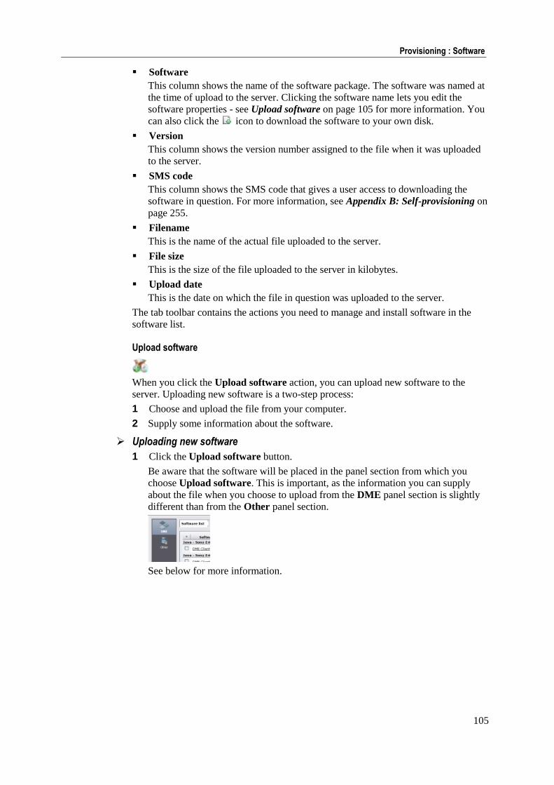
105
Provisioning : Software
Software
This column shows the name of the software package. The software was named at
the time of upload to the server. Clicking the software name lets you edit the
software properties - see Upload software on page 105 for more information. You
can also click the icon to download the software to your own disk.
Version
This column shows the version number assigned to the file when it was uploaded
to the server.
SMS code
This column shows the SMS code that gives a user access to downloading the
software in question. For more information, see Appendix B: Self-provisioning on
page 255.
Filename
This is the name of the actual file uploaded to the server.
File size
This is the size of the file uploaded to the server in kilobytes.
Upload date
This is the date on which the file in question was uploaded to the server.
The tab toolbar contains the actions you need to manage and install software in the
software list.
Upload software
When you click the Upload software action, you can upload new software to the
server. Uploading new software is a two-step process:
1 Choose and upload the file from your computer.
2 Supply some information about the software.
Uploading new software
1 Click the Upload software button.
Be aware that the software will be placed in the panel section from which you
choose Upload software. This is important, as the information you can supply
about the file when you choose to upload from the DME panel section is slightly
different than from the Other panel section.
See below for more information.
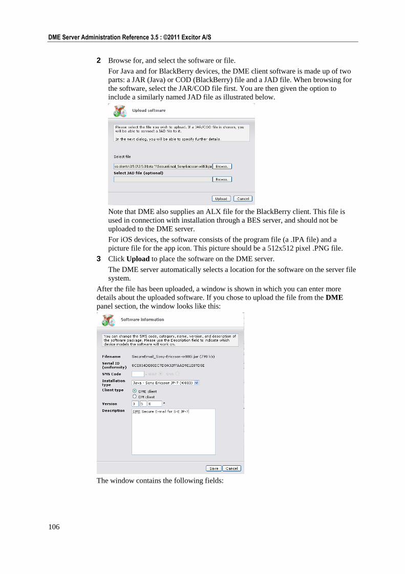
106
DME Server Administration Reference 3.5 : ©2011 Excitor A/S
2 Browse for, and select the software or file.
For Java and for BlackBerry devices, the DME client software is made up of two
parts: a JAR (Java) or COD (BlackBerry) file and a JAD file. When browsing for
the software, select the JAR/COD file first. You are then given the option to
include a similarly named JAD file as illustrated below.
Note that DME also supplies an ALX file for the BlackBerry client. This file is
used in connection with installation through a BES server, and should not be
uploaded to the DME server.
For iOS devices, the software consists of the program file (a .IPA file) and a
picture file for the app icon. This picture should be a 512x512 pixel .PNG file.
3 Click Upload to place the software on the DME server.
The DME server automatically selects a location for the software on the server file
system.
After the file has been uploaded, a window is shown in which you can enter more
details about the uploaded software. If you chose to upload the file from the DME
panel section, the window looks like this:
The window contains the following fields:
107
Provisioning : Software
Filename
DME automatically enters the filename. Please note that when you subsequently
edit the software properties, a small icon appears after the filename: By
clicking this icon, you can download the software to your own disk.
Serial ID
The serial number is automatically entered by DME. It ensures that you do not
upload the same file several times under different names.
SMS code
You can specify an SMS code to enable users to send an SMS with a request for
the software to be download to the device. After entering a code into the field, you
can choose if the software download initiated by the server as a result of a
self-provisioning SMS from a user should be pushed by SMS or WAP. For more
information, see Appendix B: Self-provisioning on page 255.
Installation type/Category
If you chose to upload the file from the DME panel section, you can select from a
list of currently available clients. In the software list, the uploaded software will be
entered under the heading you choose in this field. This list is maintained by
Excitor, and reflects the device types currently supported by a DME client.
If you chose to upload the file from the Other panel section, you can divide your
software into self-defined categories. The list of categories is dynamically
extended with any new category you add in the field. In the software list, the
software is grouped into the defined categories.
Client type/Name
If you chose to upload the file from the DME panel section, you can choose
between DME client (the regular DME client) and DM client (the Basic MDM client
- see Appendix G: The Basic MDM client on page 283). The software is placed in
the appropriate subcategory in the software list.
If you chose to upload the file from the Other panel section, you can freely enter a
name for the uploaded software in this field.
Identifier
If you have uploaded software for Apple iOS devices, you must specify the app
identifier in this field in the form of the token registered by the provisioning
profile of this app - something like com.apple.yourcompany. The identifier
specified for the app must match the provisioning profile in order to run on the
client device.
Version
For DME software, it is important to specify the correct version of the software,
because the DME server uses these version numbers to compare and update the
device(s).
Description
In this field you should specify the device types on which the application in
question can run. The information in this field is shown as a tooltip in the software
list.
When you have completed the form, click Save to upload the software with the
specified information. You are returned to the software list.
Editing software properties
1 To edit the properties of a software package, click the name of the software in the
software list.
You can now edit the information you supplied when you uploaded the software.
108
DME Server Administration Reference 3.5 : ©2011 Excitor A/S
2 To download the software to your own disk, click the small icon which appears
after the filename: .
3 Click Save to save the edited software properties.
You are returned to the software list.
Delete software
Click the Delete software action to delete the currently selected software package(s)
from the list. You are asked to confirm your action. The software is also removed
from the DME server.
Make default version
All clients uploaded to the the DME panel section are divided into groups
corresponding to the device platforms supported by DME (Symbian Series 60,
Windows Mobile Pocket PC, and so on). In each of these groups of DME clients, one
client should be made the default client. This is the client that will be installed by
default when an bootstrap + client installation request is made, and it is typically the
most recent version of the DME client. See Bootstrap devices on page 36 and
Installing software on page 83. Furthermore, you can use the default status as an
option when choosing devices on which to install a DME client - see Device filter on
page 92.
Select a client in a group, and click the Make default version icon to make that client
the default client. The default client is marked with a star icon: .
Make test version
You can designate one or more software packages in each group of clients in the
DME panel section to be test clients. When you for instance upload a new version of a
DME client to the DME server, you may want to test it on selected devices before
making it generally available. To do this, select one or more clients in the list, and
click the Make test version action. A Test mark is applied to the software in
question. You can use the test status as an option when choosing devices on which to
install a DME client - see Device filter on page 92.
A test client cannot also be a default client.
Install software
Click the Install software action when you want to install software on one or more
new or existing devices. You must select the software package to install before
selecting this action. For more information, see Installing software on page 83.
109
Provisioning : Software
Initializing
The Initializing subtab shows a list of devices to which a bootstrap instruction and/or
an instruction to download and install a software package has been sent. Such an
instruction is called an installation job.The list is divided into time blocks based on the
date and time on which the installation job was sent to the device - in ever-increasing
intervals ranging from 0-1 minutes, 1-10 minutes, 10-30 minutes, and so on up to
more than a year.
The installation jobs are automatically removed from this list when their status
changes. Normally, an installation job will be moved to the Processing subtab. If an
OMA DM error occurs during bootstrapping, it will be moved to the Errors panel
section. See Errors on page 114 for more information. If the status of an installation
job does not change, it is clear that something has gone wrong, and you can take
appropriate action. You can then remove the installation job from the list using the
Remove installation jobs action in the tab toolbar. See Installation status tab actions
on page 112 for a description of the tab toolbar actions in this subtab.
This subtab is very similar for DME software and Other software, only some of the
status messages differ. The columns in this subtab contain the following information:
Device
The device to which the installation job was sent. If you let the mouse pointer rest
on a device link, a box appears with more information about the device in
question.
User
The user who owns the device to which the installation job was sent. If you let the
mouse pointer rest on a user link, a box appears with more information about the
user in question.
Phone number
The phone number of the device to which the installation job was sent.
Install type (fallback)
The type of installation that was attempted on the current device, possibly
followed by a fallback installation type in parentheses. The following installation
types can be seen:
DM install: If the installation job is sent to the device as an OMA DM
installation job. The fallback option will be shown in parentheses after the DM install - either WAP push or SMS push for new or existing devices, or Mark for install for existing devices. If the fallback method is written in a grey text, it
means that the fallback was not used; otherwise, the fallback method was used
because the OMA DM installation failed.
Mark for install: A Mark for installation push was sent to the device. This applies
to existing devices only. The next time the device synchronizes, the user will
be prompted to upgrade the client.
WAP/SMS push: A software download push was sent to the device by SMS or
WAP. The link to download software expires after a certain amount of time,
which is called the Time To Live (TTL) value. This value can be set in the
Client section of the Server configuration panel (see Client on page 159).
The download link expiry time (TTL) is shown after the installation type. If
the TTL is written in red text, it means that the link is now invalid (and the
user has not yet used the link to download the software). When this happens,
you can use the action Resend installation jobs in the tab toolbar to send a
new link to the device.
110
DME Server Administration Reference 3.5 : ©2011 Excitor A/S
Bootstrap: If the installation job is only a bootstrap, and no software will be
installed.
Software
This is the name of the software package which the device is supposed to install.
The name is composed of the software category and the name given to it when it
was uploaded to the DME server.
Software version
The version of the software as specified when the software was uploaded to the
DME server.
Status
This is the status of the installation job. In this subtab, the status can be Waiting for download or Waiting for bootstrap. When the installation job is no longer
"waiting", it is moved to the Installing subtab.
Date
This is the date and time on which the installation job was created. The TTL is
calculated from this time.
Processing
The Processing subtab shows a list of devices which have responded to a bootstrap
instruction and/or an instruction to download and install a software package. Such an
instruction is called an installation job.The list is divided into time blocks based on the
date and time on which the installation job was sent to the device - in ever-increasing
intervals ranging from 0-1 minutes, 1-10 minutes, 10-30 minutes, and so on up to
more than a year.
The installation jobs are automatically removed from this list when their status
changes. Normally, an installation job will be moved to the Done subtab when it has
been processed (DME software only). If an OMA DM error occurs during
bootstrapping, it will be moved to the Errors panel section (see Initializing on page
109). If the status of an installation job does not change, it is clear that something has
gone wrong, and you can take appropriate action. You can then remove the installation
job from the list, resend the job, or re-notify the client about the job. See Installation
status tab actions on page 112 for a description of the tab toolbar actions in this
subtab.
This subtab is very similar for DME software and Other software, only some of the
status messages differ. The columns in this subtab contain the following information:
Device
The device to which the installation job was sent. If you let the mouse pointer rest
on a device link, a box appears with more information about the device in
question.
User
The user who owns the device to which the installation job was sent. If you let the
mouse pointer rest on a user link, a box appears with more information about the
user in question.
Phone number
The phone number of the device to which the installation job was sent.
Install type (fallback)
The type of installation that was attempted on the current device, possibly
followed by a fallback installation type in parentheses. The following installation
types can be seen:
111
Provisioning : Software
DM install: If the installation job is sent to the device as an OMA DM
installation job. The fallback option will be shown in parentheses after the DM install - either WAP push or SMS push for new or existing devices, or Mark for install for existing devices. If the fallback method is written in a grey text, it
means that the fallback was not used; otherwise, the fallback method was used
because the OMA DM installation failed.
Mark for install: A Mark for installation push was sent to the device. This applies
to existing devices only. The next time the device synchronizes, the user will
be prompted to upgrade the client.
WAP/SMS push: A software download push was sent to the device by SMS or
WAP.
Software
This is the name of the software package which the device is supposed to install.
The name is composed of the software category and the name given to it when it
was uploaded to the DME server.
Software version
The version of the software as specified when the software was uploaded to the
DME server.
Status
This is the status of the installation job. In this subtab, the status can be Installing software (if installing Other software or installing DME software without using
DM) or Installed - Waiting for verification (if installing DME software using DM).
When the installation job has been installed and/or verified, it is moved to the
Done subtab.
Date
This is the date and time on which the installation job was created.
Done
The Done subtab shows a list of devices which have completed a bootstrap instruction
and/or an instruction to download and install a software package. Such an instruction
is called an installation job.The list is divided into time blocks based on the date and
time on which the installation job was sent to the device - in ever-increasing intervals
ranging from 0-1 minutes, 1-10 minutes, 10-30 minutes, and so on up to more than a
year.
If an OMA DM error occurs during bootstrapping, it will be moved to the Errors
panel section (see Initializing on page 109). You can then remove the installation job
from the list using the Remove installation jobs action in the tab toolbar.
The columns in this subtab contain the following information:
Device
The device to which the installation job was sent. If you let the mouse pointer rest
on a device link, a box appears with more information about the device in
question.
User
The user who owns the device to which the installation job was sent. If you let the
mouse pointer rest on a user link, a box appears with more information about the
user in question.
Phone number
The phone number of the device to which the installation job was sent.
112
DME Server Administration Reference 3.5 : ©2011 Excitor A/S
Install type (fallback)
The type of installation that was attempted on the current device, possibly
followed by a fallback installation type in parentheses. The following installation
types can be seen:
DM install: If the installation job is sent to the device as an OMA DM
installation job. The fallback option will be shown in parentheses after the DM install - either WAP push or SMS push for new or existing devices, or Mark for install for existing devices. If the fallback method is written in a grey text, it
means that the fallback was not used; otherwise, the fallback method was used
because the OMA DM installation failed.
Mark for install: A Mark for installation push was sent to the device. This applies
to existing devices only. The next time the device synchronizes, the user will
be prompted to upgrade the client.
WAP/SMS push: A software download push was sent to the device by SMS or
WAP.
Software
This is the name of the software package which the device is supposed to install.
The name is composed of the software category and the name given to it when it
was uploaded to the DME server.
Software version
The version of the software as specified when the software was uploaded to the
DME server.
Status
This is the status of the installation job. In this subtab, the status can be Installed or
Installed - Waiting for verification (if installing DME software using DM). When the
DME client has exchanged system information with the server the first time, the
status will change to Installed.
Date
This is the date and time on which the installation job was created.
Installation status tab actions
The tab toolbar in the Initializing, Processing, and Done subtabs contains the
following actions.
Remove installation jobs
To clean up the list of installation jobs, you can remove jobs by selecting them and
clicking the Remove installation job action in the tab toolbar. You are prompted to
confirm the deletion.
The installation jobs are automatically cleaned out from the list after two weeks.
Resend installation job
If something has gone wrong with an installation job, for instance if a user did not use
the software download link before the link timed out, you can select the installation
job (or multiple jobs) and click the Resend installation job action in the tab toolbar.
This will delete the original installation job, create an identical job, and send it again
to the selected devices, including any options you have set for the job.
113
Provisioning : Software
Note that DME cannot verify all installation jobs, and thus the installation job might
have been completed even if you selected the job from the Initializing or Processing
subtabs.
This action is not available in the Done subtab.
Notify DM client
DME uses the standard push setting for notifying about DM installation jobs.
However, if the DME client is not available on the device, the DM engine on the
device will never be notified of the installation job. Use this action to send a
notification message by SMS directly to the DM engine on the device. Launch the job
as usual, select the jobs that need special notification in the Initializing subtab, and
select this action.
Apart from sending SMS to the DM framework, you can choose to repeat the standard
notification to the DME client. This is similar to resending the job, but the original job
is not deleted. You may want to do this if the original notification was not received for
some reason.
This action is not available in the Done subtab.
Other The Other panel section is used when installing and monitoring the installation of
non-DME client software. This could be DME add-ons such as SmartEncrypt or
VoiceExtender, virus definition files, or any software that can be deployed on a phone.
This panel section consists of a number of subtabs, each of which is described in the
following.
Software list
This subtab in the Other panel section shows a list of non-DME client software
packages which have been uploaded to the DME server.
When you upload software to the server, you are asked to enter the name of the device
on which the software in question can be installed. The software in the list is divided
into groups based on this information. For information about how to upload software
to the server, see Upload software on page 105.
If you point to the name of the software, the description of the software package (if
specified) will be shown as a tooltip. The list in this panel section as well as the DME
panel section consists of the following information:
Software
This column shows the name of the software package. The software was named at
the time of upload to the server. Clicking the software name lets you edit the
software properties - see Upload software on page 105 for more information. You
can also click the icon to download the software to your own disk.
Version
This column shows the version number assigned to the file when it was uploaded
to the server.
SMS code
This column shows the SMS code that gives a user access to downloading the
software in question. For more information, see Appendix B: Self-provisioning on
page 255.
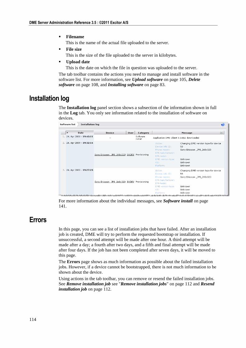
114
DME Server Administration Reference 3.5 : ©2011 Excitor A/S
Filename
This is the name of the actual file uploaded to the server.
File size
This is the size of the file uploaded to the server in kilobytes.
Upload date
This is the date on which the file in question was uploaded to the server.
The tab toolbar contains the actions you need to manage and install software in the
software list. For more information, see Upload software on page 105, Delete
software on page 108, and Installing software on page 83.
Installation log The Installation log panel section shows a subsection of the information shown in full
in the Log tab. You only see information related to the installation of software on
devices.
For more information about the individual messages, see Software install on page
141.
Errors In this page, you can see a list of installation jobs that have failed. After an installation
job is created, DME will try to perform the requested bootstrap or installation. If
unsuccessful, a second attempt will be made after one hour. A third attempt will be
made after a day; a fourth after two days, and a fifth and final attempt will be made
after four days. If the job has not been completed after seven days, it will be moved to
this page.
The Errors page shows as much information as possible about the failed installation
jobs. However, if a device cannot be bootstrapped, there is not much information to be
shown about the device.
Using actions in the tab toolbar, you can remove or resend the failed installation jobs.
See Remove installation job see "Remove installation jobs" on page 112 and Resend
installation job on page 112.
115
Provisioning : Software
Device types In this window you can see how each device in the DME system is registered with
regard to DM and platform details.
DME ships with a list of pre-defined device models. Whenever a device is added to
DME, the device model is reported to DME by the DME client installed on the device.
The device model is matched against the list of models. If the model is found, the
device will be given the settings (including a device image) that apply to the device
model, and you cannot change those. If the model is not found, you will be able to
specify which type of DME client that fits with the device model in question in this
window, and you can assign an image to the device model.
You want to be sure that each device is registered with the correct device model for
two reasons:
1 When you choose to bootstrap a device and install the default DME client on the
device at the same time, DME needs to know which DME version type to install.
Otherwise the client installation will fail.
2 When you install DME software on existing clients, one of the steps is to select the
devices on which you want to install the DME client. The window in which you
select devices is described in the section Device filter on page 92. In that window,
you can choose to only see validated devices. A device is said to be validated if a
value other than Unknown is listed in the field DME version type.
The device type table contains the following columns:
DME phone model
This is the device model which is reported to DME by the DME client installed on
the device, for instance Nokia E51. All phone models are matched against the list
of device models built into DME. If found in the list, the other columns in this
window are filled in from the device model list, a device image is assigned to the
device model, and the device model is locked for changes (the selection boxes in
the other columns are disabled).
If you let the mouse pointer rest on the model in this column, the DM
manufacturer column, or the DM model column, and if the device model is
known by DME, a picture of the device model in question is shown.
DM manufacturer
This is the name of the manufacturer of the DM engine on the current device
model, for instance NOKIA. If the current device model is locked, this information
came from the built-in device model list; otherwise it is derived from the
bootstrapping of a device of this model.
DM model
This is the name of the DM engine model on the current device model, for
instance E51. If the current device model is locked, this information came from the
built-in device model list; otherwise it is derived from the bootstrapping of a
device of this model.
Platform
This is the hardware platform of the device model in question, for instance S60 3rd. FP1. If the current device model is locked, this information came from the
built-in device model list; otherwise it is derived from information reported by the
DME client. You may change the information in this field, but note that the field is
not relevant in this version of DME.
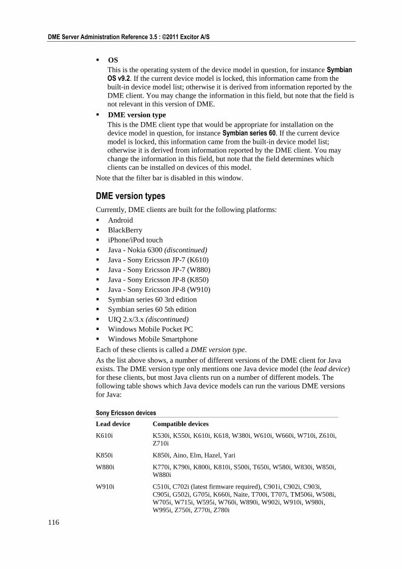
116
DME Server Administration Reference 3.5 : ©2011 Excitor A/S
OS
This is the operating system of the device model in question, for instance Symbian OS v9.2. If the current device model is locked, this information came from the
built-in device model list; otherwise it is derived from information reported by the
DME client. You may change the information in this field, but note that the field is
not relevant in this version of DME.
DME version type
This is the DME client type that would be appropriate for installation on the
device model in question, for instance Symbian series 60. If the current device
model is locked, this information came from the built-in device model list;
otherwise it is derived from information reported by the DME client. You may
change the information in this field, but note that the field determines which
clients can be installed on devices of this model.
Note that the filter bar is disabled in this window.
DME version types
Currently, DME clients are built for the following platforms:
Android
BlackBerry
iPhone/iPod touch
Java - Nokia 6300 (discontinued)
Java - Sony Ericsson JP-7 (K610)
Java - Sony Ericsson JP-7 (W880)
Java - Sony Ericsson JP-8 (K850)
Java - Sony Ericsson JP-8 (W910)
Symbian series 60 3rd edition
Symbian series 60 5th edition
UIQ 2.x/3.x (discontinued)
Windows Mobile Pocket PC
Windows Mobile Smartphone
Each of these clients is called a DME version type.
As the list above shows, a number of different versions of the DME client for Java
exists. The DME version type only mentions one Java device model (the lead device)
for these clients, but most Java clients run on a number of different models. The
following table shows which Java device models can run the various DME versions
for Java:
Sony Ericsson devices
Lead device Compatible devices
K610i K530i, K550i, K610i, K618, W380i, W610i, W660i, W710i, Z610i,
Z710i
K850i K850i, Aino, Elm, Hazel, Yari
W880i K770i, K790i, K800i, K810i, S500i, T650i, W580i, W830i, W850i,
W880i
W910i C510i, C702i (latest firmware required), C901i, C902i, C903i,
C905i, G502i, G705i, K660i, Naite, T700i, T707i, TM506i, W508i,
W705i, W715i, W595i, W760i, W890i, W902i, W910i, W980i,
W995i, Z750i, Z770i, Z780i
117
Provisioning : Access points
Nokia S40 devices
6300 6300 only (native client - discontinued)
Only clients compatible with DME 3.5 SP 8 are shown in this list.
Tab actions
Two tab actions are associated with the Device types window:
Remove device type
When you click this action, the selected device model is removed from the list.
Note that you cannot remove device models that are already identified by DME's
built-in list of device models.
Upload image for device type
When you click this action, you can upload an image of the selected device model.
Note that you cannot add or change the image of a device model that is identified
in DME's built-in list of device models. For more information about adding an
image to a device model, see the procedure Uploading a picture of the device in
Information (device panel) see "Information" on page 62.
Access points
Select the Access points item in the page menu to see the list of GPRS or WLAN
access points available for provisioning to the clients.
When installing the DME client on Symbian phones, the installer tries to set up
three possible access points in the client settings automatically. This applies to client
3.0.2 and above only. The installation process evaluates any existing internet access
points (IAP) on the DME client, and places three access points in the General settings
page on the device. The IAPs are selected and placed based on their perceived cost,
according to the following scheme:
WLAN IAPs are selected first. A maximum of 2 WLAN IAPs are selected and
placed as preferred access points 1 and 2.
For the remaining access point (or points, if less than two WLAN access points
were found), the installation process finds one or more IAPs where the name
contains the word "internet" or "www", and uses it or them as subsequent access
points.
If no such IAP is found, then the first available IAP is used for the remaining
access points.
With this scheme, the IAP incurring the lowest cost is probably picked first,
namely the corporate WLAN, and then possibly the user's home WLAN is picked
next. The third access point is then the general GPRS IAP.
However, the administrator can choose to name a GPRS and/or WLAN access
point as "DME_AP_(something)". If this access point is pushed to the phone along
with the installation command, it will be installed as first choice. If more than one
access point starts with "DME_AP", they will be selected in random order as first,
second, and third access point.
The user can change the selections later.
118
DME Server Administration Reference 3.5 : ©2011 Excitor A/S
The list of access points is divided into two panel sections, which are described in the
following.
GPRS In this panel section you can manage GPRS access points. You can define them on the
DME server, remove them from the server, and distribute them to DME clients - see
the following sections for information about this.
The list in the GPRS panel section consists of the following information:
Name
This column shows the name of the access point. This is the name given to the
access point when it was defined on the DME server. Clicking the access point
name lets you edit the access point in question, using the same window as when
the access point was originally defined.
See Access points above for the special meaning of access points where the name
begins with DME_AP.
APN name
This column shows the name of the mobile network to which the current access
point gives access.
Proxy
This column is reserved for future use.
Security
If you specify Use authentication in the access point, this column will say PAP
(which is the currently supported security model). Otherwise, this column will say
None.
Last changed
This column shows date of when the current access point was last changed.
New GPRS access point
When you click the New GPRS access point action, you can define a new GPRS
access point to be stored the server. Please note that you should not define a WAP
access point, as these will not work on the clients. Only define those with which a
client can successfully access the Web. The access point definition window consists of
the following fields:
Name
In this field enter a descriptive name for the access point you are defining. This
field is shown in the list of GPRS access points. See Access points list above for
the special meaning of access points where the name begins with DME_AP.
APN name
In this field enter the APN (access point name) supplied by the mobile operator.
The APN could for instance be internet. This field is shown in the list of GPRS
access points.
Use authentication
If you select this check box, you specify that the current access point requires
authentication, and the following two fields are enabled:
Authentication name: Enter the name of the user
Authentication password: Enter the password required for the user above.
119
Provisioning : Access points
If this information is completed, the list of GPRS access points shows PAP in the
Security column.
Remove GPRS access point
If one or more GPRS access points are shown in the list, you can select one or more of
them, and click this action to remove them from the list. You are asked to confirm
your action.
Install access point
Click the Install GPRS/WLAN access point action when you want to send an access
point to one or more new or existing devices. You must select the access point to
install before selecting this action.
When installing on new or existing devices, the access point is installed using OMA-CP
technology. This means that the user must accept a prompt to install the access point,
and the user must enter the PIN code defined as OMA PIN in the SMS modem panel
section of the Server configuration page in the Server tab (see SMS modem on page
169). The default PIN code is 12345.
Installing an access point on new devices
1 Select an access point in the GPRS or WLAN panel section in the Access points
list.
2 Click the Install GPRS/WLAN access point action.
3 Leave the choice at Install on new devices, and click Confirm.
4 The GPRS/WLAN access point installation window is shown.
5 Add recipient devices by entering a phone number in the Phone numbers field
and clicking Add. To remove a phone number from the list, click the number, and
click Remove. You can Ctrl+click to select multiple numbers from the list.
6 Click Install to initiate the installation of the access point on the devices whose
phone numbers you entered.
Installing an access point on existing devices
1 Select an access point in the GPRS or WLAN panel section in the Access points
list.
2 Click the Install GPRS/WLAN access point action.
3 Choose Install on existing devices, and click Confirm.
4 A device filter page is shown, in which you can select the devices you want to
install the access point on. This page is similar to the page shown when installing
software to existing devices - see Device filter on page 92. However, the Device
filter box on the page only contains one option:
Select all available devices: If you select this check box, all devices that fit
the criteria are selected, even if they are not shown on the page due to a
restriction to the number of rows displayed in the table navigation bar.
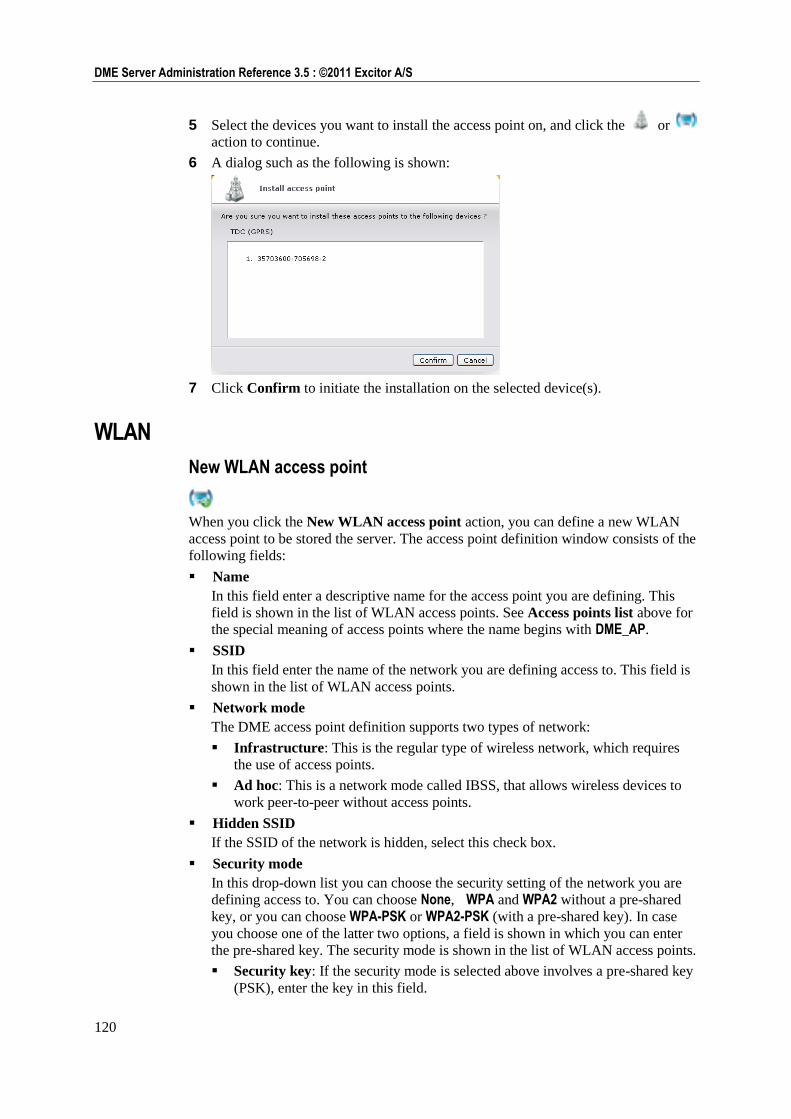
120
DME Server Administration Reference 3.5 : ©2011 Excitor A/S
5 Select the devices you want to install the access point on, and click the or
action to continue.
6 A dialog such as the following is shown:
7 Click Confirm to initiate the installation on the selected device(s).
WLAN
New WLAN access point
When you click the New WLAN access point action, you can define a new WLAN
access point to be stored the server. The access point definition window consists of the
following fields:
Name
In this field enter a descriptive name for the access point you are defining. This
field is shown in the list of WLAN access points. See Access points list above for
the special meaning of access points where the name begins with DME_AP.
SSID
In this field enter the name of the network you are defining access to. This field is
shown in the list of WLAN access points.
Network mode
The DME access point definition supports two types of network:
Infrastructure: This is the regular type of wireless network, which requires
the use of access points.
Ad hoc: This is a network mode called IBSS, that allows wireless devices to
work peer-to-peer without access points.
Hidden SSID
If the SSID of the network is hidden, select this check box.
Security mode
In this drop-down list you can choose the security setting of the network you are
defining access to. You can choose None, WPA and WPA2 without a pre-shared
key, or you can choose WPA-PSK or WPA2-PSK (with a pre-shared key). In case
you choose one of the latter two options, a field is shown in which you can enter
the pre-shared key. The security mode is shown in the list of WLAN access points.
Security key: If the security mode is selected above involves a pre-shared key
(PSK), enter the key in this field.
121
Provisioning : DDF configurations
Remove WLAN access point
If one or more WLAN access points are shown in the list, you can select one or more
of them, and click this icon to remove them from the list. You are asked to confirm
your action.
Install WLAN access point
Click the Install WLAN access point action when you want to send an access point
to one or more new or existing devices. You must select the access point to install
before selecting this action. The installation process is similar as when installing
GPRS access points. See Install access point on page 119 for more information.
DDF configurations
A DDF (Device Description Framework) configuration is an Open Mobile Alliance
(OMA http://www.openmobilealliance.org/default.aspx) standard, which enables
service providers (such as DME) to provision and configure software and settings on
mobile phones.
Select the DDF configurations item in the page menu to see a list of OMA DM DDF
configurations, which are available for provisioning to the clients. You can define the
configurations on the DME server, remove them from the server, and distribute them
to DME clients - see the following sections for information about this.
Most device models require different instructions. It is therefore necessary to
configure DDF configurations for individual device models, and to test them before
provisioning them to many devices.
For information about exactly which instructions are supported by each device model,
use the Retrieve device tree action to get a copy of the DM tree of that particular
model. DME will then request the DM tree from that device. You can do this for every
device model for which you want to develop a DDF configuration. For more
information, see OMA DM on page 69.
DDF XML files are used as a starting point when creating the DDF configurations
which can be sent to devices. Excitor A/S makes a few sample DDF XML files
available on request: one for setting up Mail for Exchange on S60 devices, and one for
creating access points on S60 devices. DME does not guarantee the usefulness or
functionality of either of these files. Contact DME Support if you want to see these
samples.
If you need to set up configurations for providing 3rd party software, for instance
antivirus software, you should request DDF XML files from the software vendor.
Sometimes you can also find such files on the Internet, or you can build them from
scratch using the specifications on the Open Mobile Alliance home page.
The workflow for provisioning DDF configurations is as follows:
122
DME Server Administration Reference 3.5 : ©2011 Excitor A/S
1 Upload a DDF XML file to the server.
2 Create a DDF configuration based on the DDF XML file.
3 Install the configuration on one or more devices.
4 Monitor the installation status.
Each step is described in the following sections.
DDF XML In this panel section you can upload and manage OMA DM DDF XML files.
The list in the DDF XML panel section consists of the following information about
uploaded files:
Name
This is the name you gave the XML file during upload.
File name
This is the physical name of the XML file.
Size
This is the size of the XML file in bytes.
Configurations
This is the number of configurations that are based on this file.
Changed
This is the date of the latest change to the XML file.
The DDF XML contains the management tree. By editing the nodes in the tree, you
can create a DDF configuration, which is specific to one or more device models. The
XML files are edited (converted into configurations) in the Configurations panel
section.
Upload DDF file
When you click the Upload DDF file action, you can browse to an OMA DM DDF
XML file and upload it to the server.
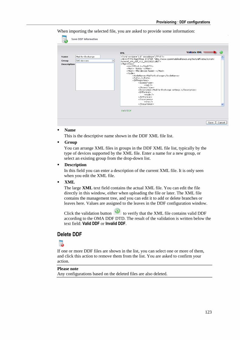
123
Provisioning : DDF configurations
When importing the selected file, you are asked to provide some information:
Name
This is the descriptive name shown in the DDF XML file list.
Group
You can arrange XML files in groups in the DDF XML file list, typically by the
type of devices supported by the XML file. Enter a name for a new group, or
select an existing group from the drop-down list.
Description
In this field you can enter a description of the current XML file. It is only seen
when you edit the XML file.
XML
The large XML text field contains the actual XML file. You can edit the file
directly in this window, either when uploading the file or later. The XML file
contains the management tree, and you can edit it to add or delete branches or
leaves here. Values are assigned to the leaves in the DDF configuration window.
Click the validation button to verify that the XML file contains valid DDF
according to the OMA DDF DTD. The result of the validation is written below the
text field: Valid DDF or Invalid DDF.
Delete DDF
If one or more DDF files are shown in the list, you can select one or more of them,
and click this action to remove them from the list. You are asked to confirm your
action.
Please note Any configurations based on the deleted files are also deleted.
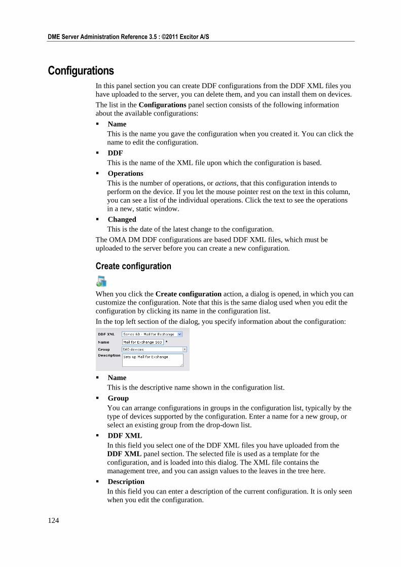
124
DME Server Administration Reference 3.5 : ©2011 Excitor A/S
Configurations In this panel section you can create DDF configurations from the DDF XML files you
have uploaded to the server, you can delete them, and you can install them on devices.
The list in the Configurations panel section consists of the following information
about the available configurations:
Name
This is the name you gave the configuration when you created it. You can click the
name to edit the configuration.
DDF
This is the name of the XML file upon which the configuration is based.
Operations
This is the number of operations, or actions, that this configuration intends to
perform on the device. If you let the mouse pointer rest on the text in this column,
you can see a list of the individual operations. Click the text to see the operations
in a new, static window.
Changed
This is the date of the latest change to the configuration.
The OMA DM DDF configurations are based DDF XML files, which must be
uploaded to the server before you can create a new configuration.
Create configuration
When you click the Create configuration action, a dialog is opened, in which you can
customize the configuration. Note that this is the same dialog used when you edit the
configuration by clicking its name in the configuration list.
In the top left section of the dialog, you specify information about the configuration:
Name
This is the descriptive name shown in the configuration list.
Group
You can arrange configurations in groups in the configuration list, typically by the
type of devices supported by the configuration. Enter a name for a new group, or
select an existing group from the drop-down list.
DDF XML
In this field you select one of the DDF XML files you have uploaded from the
DDF XML panel section. The selected file is used as a template for the
configuration, and is loaded into this dialog. The XML file contains the
management tree, and you can assign values to the leaves in the tree here.
Description
In this field you can enter a description of the current configuration. It is only seen
when you edit the configuration.
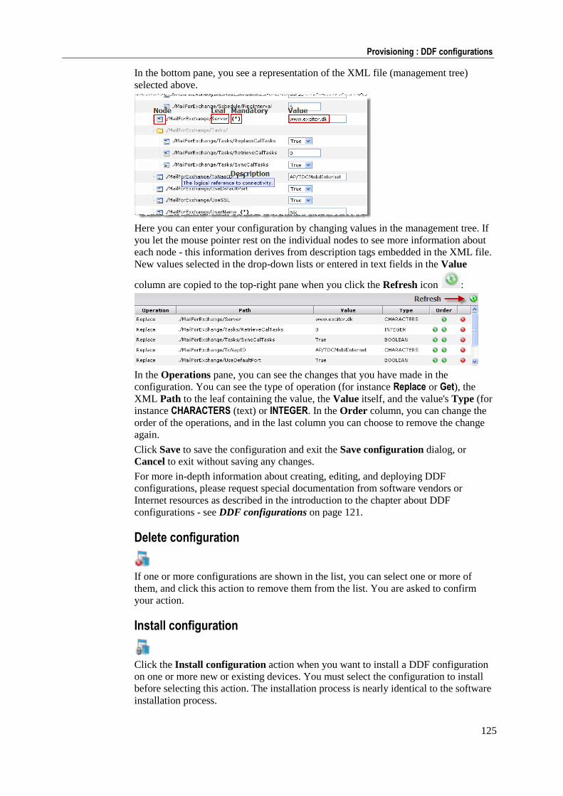
125
Provisioning : DDF configurations
In the bottom pane, you see a representation of the XML file (management tree)
selected above.
Here you can enter your configuration by changing values in the management tree. If
you let the mouse pointer rest on the individual nodes to see more information about
each node - this information derives from description tags embedded in the XML file.
New values selected in the drop-down lists or entered in text fields in the Value
column are copied to the top-right pane when you click the Refresh icon :
In the Operations pane, you can see the changes that you have made in the
configuration. You can see the type of operation (for instance Replace or Get), the
XML Path to the leaf containing the value, the Value itself, and the value's Type (for
instance CHARACTERS (text) or INTEGER. In the Order column, you can change the
order of the operations, and in the last column you can choose to remove the change
again.
Click Save to save the configuration and exit the Save configuration dialog, or
Cancel to exit without saving any changes.
For more in-depth information about creating, editing, and deploying DDF
configurations, please request special documentation from software vendors or
Internet resources as described in the introduction to the chapter about DDF
configurations - see DDF configurations on page 121.
Delete configuration
If one or more configurations are shown in the list, you can select one or more of
them, and click this action to remove them from the list. You are asked to confirm
your action.
Install configuration
Click the Install configuration action when you want to install a DDF configuration
on one or more new or existing devices. You must select the configuration to install
before selecting this action. The installation process is nearly identical to the software
installation process.
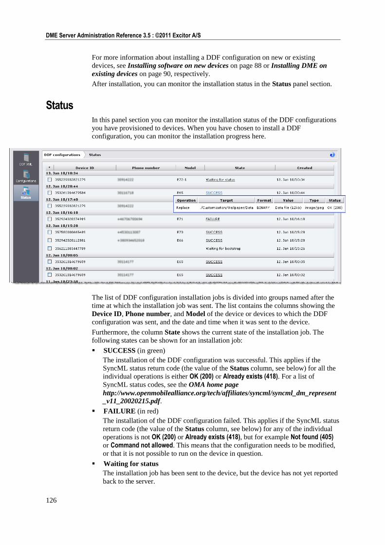
126
DME Server Administration Reference 3.5 : ©2011 Excitor A/S
For more information about installing a DDF configuration on new or existing
devices, see Installing software on new devices on page 88 or Installing DME on
existing devices on page 90, respectively.
After installation, you can monitor the installation status in the Status panel section.
Status In this panel section you can monitor the installation status of the DDF configurations
you have provisioned to devices. When you have chosen to install a DDF
configuration, you can monitor the installation progress here.
The list of DDF configuration installation jobs is divided into groups named after the
time at which the installation job was sent. The list contains the columns showing the
Device ID, Phone number, and Model of the device or devices to which the DDF
configuration was sent, and the date and time when it was sent to the device.
Furthermore, the column State shows the current state of the installation job. The
following states can be shown for an installation job:
SUCCESS (in green)
The installation of the DDF configuration was successful. This applies if the
SyncML status return code (the value of the Status column, see below) for all the
individual operations is either OK (200) or Already exists (418). For a list of
SyncML status codes, see the OMA home page
http://www.openmobilealliance.org/tech/affiliates/syncml/syncml_dm_represent
_v11_20020215.pdf.
FAILURE (in red)
The installation of the DDF configuration failed. This applies if the SyncML status
return code (the value of the Status column, see below) for any of the individual
operations is not OK (200) or Already exists (418), but for example Not found (405) or Command not allowed. This means that the configuration needs to be modified,
or that it is not possible to run on the device in question.
Waiting for status
The installation job has been sent to the device, but the device has not yet reported
back to the server.
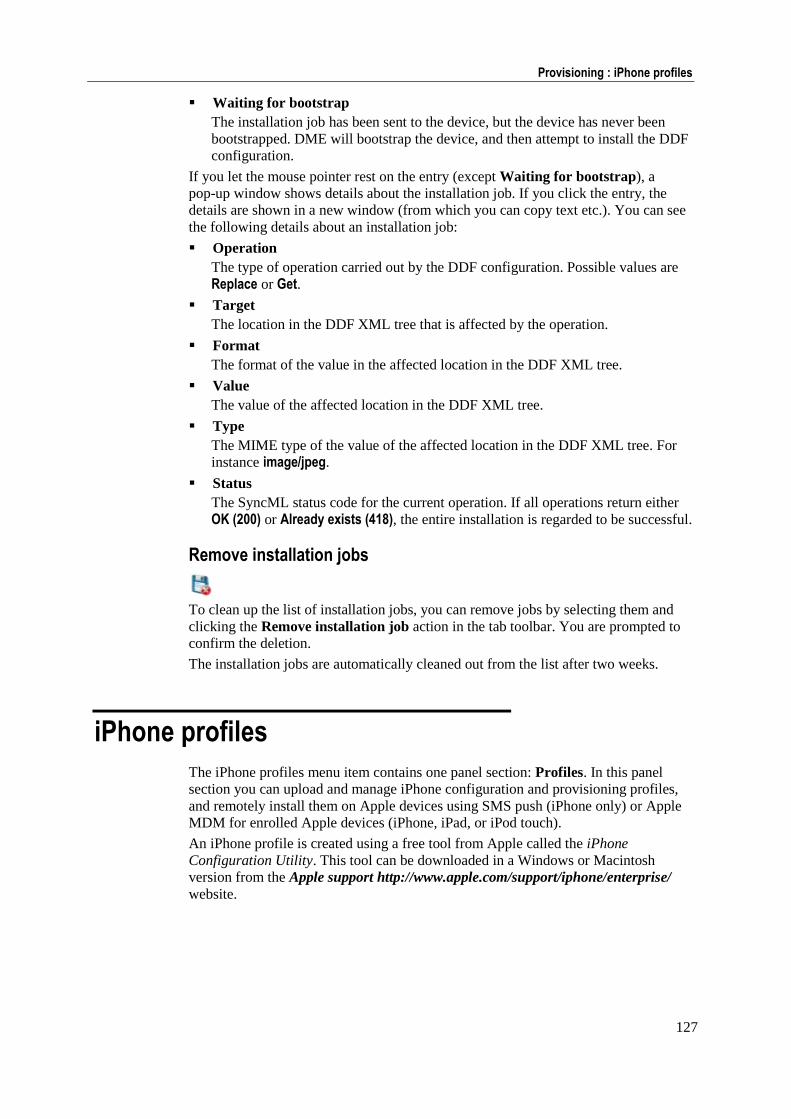
127
Provisioning : iPhone profiles
Waiting for bootstrap
The installation job has been sent to the device, but the device has never been
bootstrapped. DME will bootstrap the device, and then attempt to install the DDF
configuration.
If you let the mouse pointer rest on the entry (except Waiting for bootstrap), a
pop-up window shows details about the installation job. If you click the entry, the
details are shown in a new window (from which you can copy text etc.). You can see
the following details about an installation job:
Operation
The type of operation carried out by the DDF configuration. Possible values are
Replace or Get.
Target
The location in the DDF XML tree that is affected by the operation.
Format
The format of the value in the affected location in the DDF XML tree.
Value
The value of the affected location in the DDF XML tree.
Type
The MIME type of the value of the affected location in the DDF XML tree. For
instance image/jpeg.
Status
The SyncML status code for the current operation. If all operations return either
OK (200) or Already exists (418), the entire installation is regarded to be successful.
Remove installation jobs
To clean up the list of installation jobs, you can remove jobs by selecting them and
clicking the Remove installation job action in the tab toolbar. You are prompted to
confirm the deletion.
The installation jobs are automatically cleaned out from the list after two weeks.
iPhone profiles
The iPhone profiles menu item contains one panel section: Profiles. In this panel
section you can upload and manage iPhone configuration and provisioning profiles,
and remotely install them on Apple devices using SMS push (iPhone only) or Apple
MDM for enrolled Apple devices (iPhone, iPad, or iPod touch).
An iPhone profile is created using a free tool from Apple called the iPhone
Configuration Utility. This tool can be downloaded in a Windows or Macintosh
version from the Apple support http://www.apple.com/support/iphone/enterprise/
website.

128
DME Server Administration Reference 3.5 : ©2011 Excitor A/S
With the iPhone Configuration Utility, you can configure a profile, complete with
wireless network settings, access points, VPN settings, private certificates, native PIN
code activation, security settings etc. When the profile has been configured, it can be
exported as a .mobileconfig file (for configuration profiles) or as a
.mobileprovision file (for provisioning profiles). These are the files that can be
managed by DME. Please refer to the Apple website for information about using the
utility.
DME supports installing both signed and unsigned configuration files. Signing the
configuration file is not really necessary, as it will be provisioned from the trusted
DME server over a HTTPS connection.
iPhone profiles In the iPhone profiles subtab of the Profiles panel section you can upload and
manage iPhone configuration files. Note that configuration files can be pushed to all
enrolled Apple devices, not just iPhones.
The information you see in the table is entered during upload of the configuration file
(see below). To edit the information, click the name of the profile you wish to change.
Upload iPhone profile file
When you click the Upload iPhone profile file action, you can browse to an iPhone
configuration (.mobileconfig or .mobileprovision) file, and upload it to the
server. The configuration file need not be signed.
Please note that if your DME server is set up in a load balanced cluster environment,
you need to choose this action from a single node, not the main server path (which is
the address of the load balancer). Otherwise the load balancer may mix up session IDs,
and the operation will fail. See separate cluster setup documentation.
You are asked to provide some information:
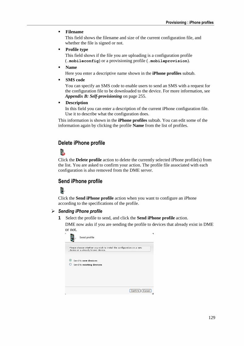
129
Provisioning : iPhone profiles
Filename
This field shows the filename and size of the current configuration file, and
whether the file is signed or not.
Profile type
This field shows if the file you are uploading is a configuration profile
(.mobileconfig) or a provisioning profile (.mobileprovision).
Name
Here you enter a descriptive name shown in the iPhone profiles subtab.
SMS code
You can specify an SMS code to enable users to send an SMS with a request for
the configuration file to be downloaded to the device. For more information, see
Appendix B: Self-provisioning on page 255.
Description
In this field you can enter a description of the current iPhone configuration file.
Use it to describe what the configuration does.
This information is shown in the iPhone profiles subtab. You can edit some of the
information again by clicking the profile Name from the list of profiles.
Delete iPhone profile
Click the Delete profile action to delete the currently selected iPhone profile(s) from
the list. You are asked to confirm your action. The profile file associated with each
configuration is also removed from the DME server.
Send iPhone profile
Click the Send iPhone profile action when you want to configure an iPhone
according to the specifications of the profile.
Sending iPhone profile
1 Select the profile to send, and click the Send iPhone profile action.
DME now asks if you are sending the profile to devices that already exist in DME
or not.
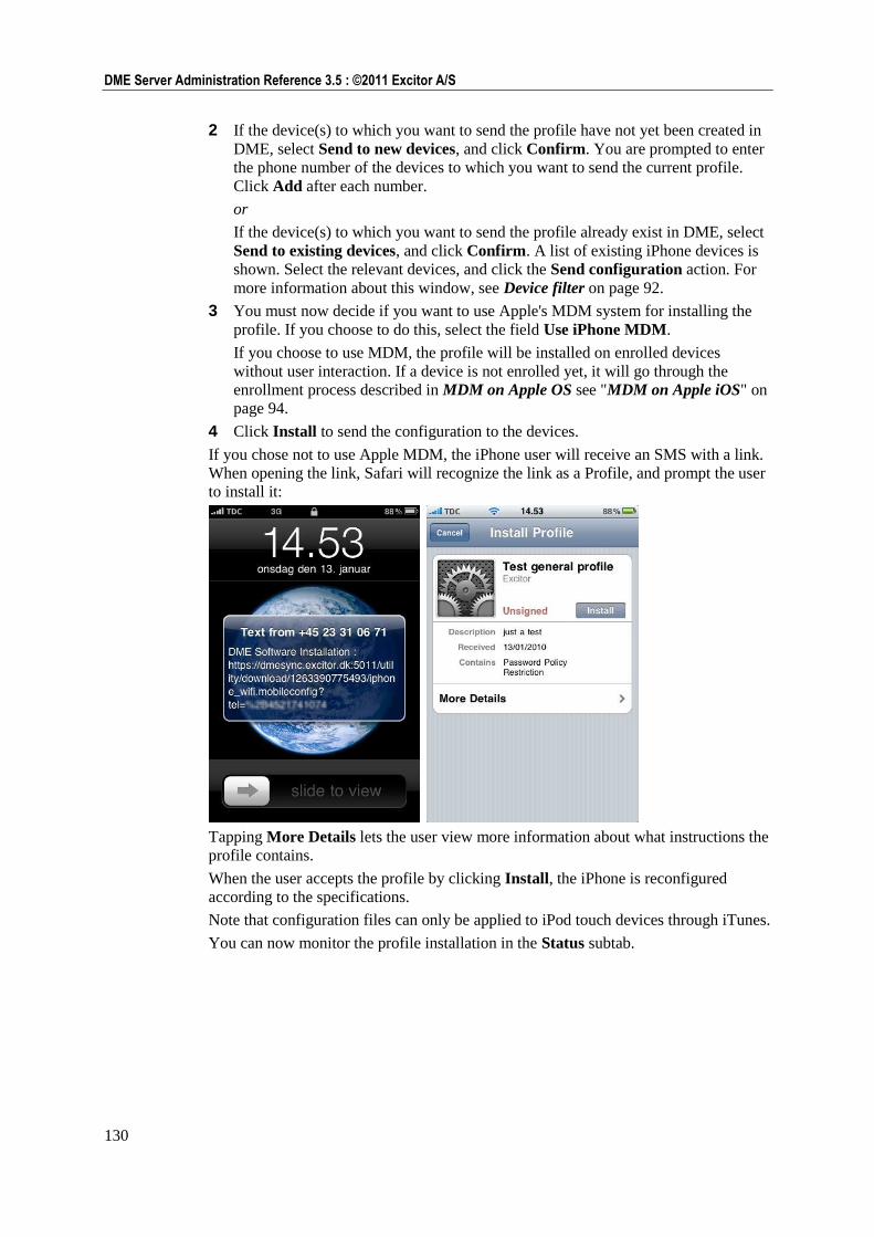
130
DME Server Administration Reference 3.5 : ©2011 Excitor A/S
2 If the device(s) to which you want to send the profile have not yet been created in
DME, select Send to new devices, and click Confirm. You are prompted to enter
the phone number of the devices to which you want to send the current profile.
Click Add after each number.
or
If the device(s) to which you want to send the profile already exist in DME, select
Send to existing devices, and click Confirm. A list of existing iPhone devices is
shown. Select the relevant devices, and click the Send configuration action. For
more information about this window, see Device filter on page 92.
3 You must now decide if you want to use Apple's MDM system for installing the
profile. If you choose to do this, select the field Use iPhone MDM.
If you choose to use MDM, the profile will be installed on enrolled devices
without user interaction. If a device is not enrolled yet, it will go through the
enrollment process described in MDM on Apple OS see "MDM on Apple iOS" on
page 94.
4 Click Install to send the configuration to the devices.
If you chose not to use Apple MDM, the iPhone user will receive an SMS with a link.
When opening the link, Safari will recognize the link as a Profile, and prompt the user
to install it:
Tapping More Details lets the user view more information about what instructions the
profile contains.
When the user accepts the profile by clicking Install, the iPhone is reconfigured
according to the specifications.
Note that configuration files can only be applied to iPod touch devices through iTunes.
You can now monitor the profile installation in the Status subtab.
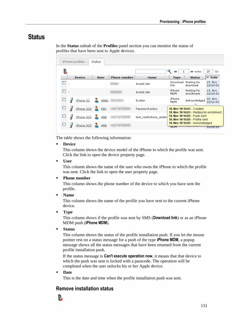
131
Provisioning : iPhone profiles
Status In the Status subtab of the Profiles panel section you can monitor the status of
profiles that have been sent to Apple devices.
The table shows the following information:
Device
This column shows the device model of the iPhone to which the profile was sent.
Click the link to open the device property page.
User
This column shows the name of the user who owns the iPhone to which the profile
was sent. Click the link to open the user property page.
Phone number
This column shows the phone number of the device to which you have sent the
profile.
Name
This column shows the name of the profile you have sent to the current iPhone
device.
Type
This column shows if the profile was sent by SMS (Download link) or as an iPhone
MDM push (iPhone MDM).
Status
This column shows the status of the profile installation push. If you let the mouse
pointer rest on a status message for a push of the type iPhone MDM, a popup
message shows all the status messages that have been returned from the current
profile installation push.
If the status message is Can't execute operation now, it means that that device to
which the push was sent is locked with a passcode. The operation will be
completed when the user unlocks his or her Apple device.
Date
This is the date and time when the profile installation push was sent.
Remove installation status
132
DME Server Administration Reference 3.5 : ©2011 Excitor A/S
To clean up the list of installation jobs, you can remove jobs by selecting them and
clicking the Remove installation status action in the tab toolbar. You are prompted to
confirm the deletion.
The installation jobs are automatically cleaned out from the list after two weeks.
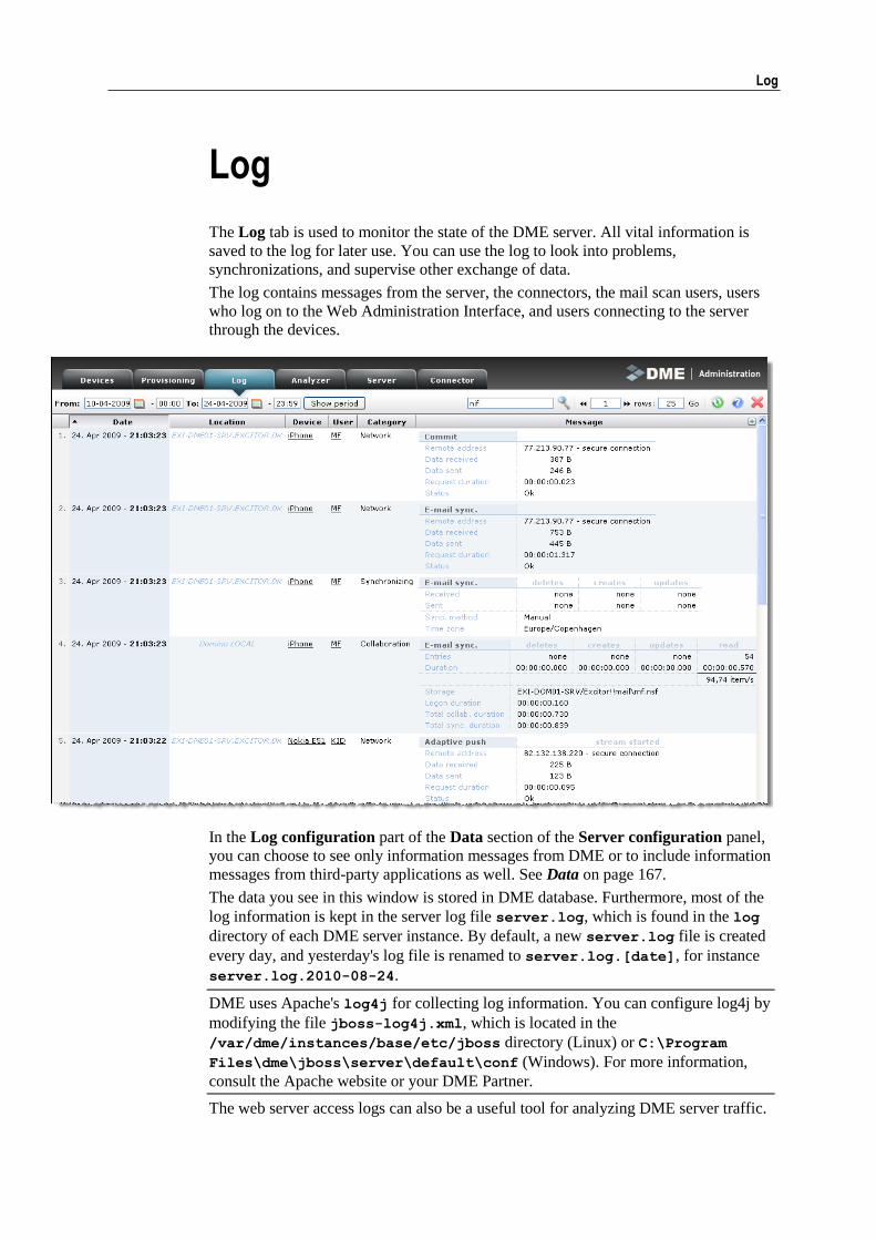
Log 133
Log
The Log tab is used to monitor the state of the DME server. All vital information is
saved to the log for later use. You can use the log to look into problems,
synchronizations, and supervise other exchange of data.
The log contains messages from the server, the connectors, the mail scan users, users
who log on to the Web Administration Interface, and users connecting to the server
through the devices.
In the Log configuration part of the Data section of the Server configuration panel,
you can choose to see only information messages from DME or to include information
messages from third-party applications as well. See Data on page 167.
The data you see in this window is stored in DME database. Furthermore, most of the
log information is kept in the server log file server.log, which is found in the log
directory of each DME server instance. By default, a new server.log file is created
every day, and yesterday's log file is renamed to server.log.[date], for instance
server.log.2010-08-24.
DME uses Apache's log4j for collecting log information. You can configure log4j by
modifying the file jboss-log4j.xml, which is located in the
/var/dme/instances/base/etc/jboss directory (Linux) or C:\Program
Files\dme\jboss\server\default\conf (Windows). For more information,
consult the Apache website or your DME Partner.
The web server access logs can also be a useful tool for analyzing DME server traffic.
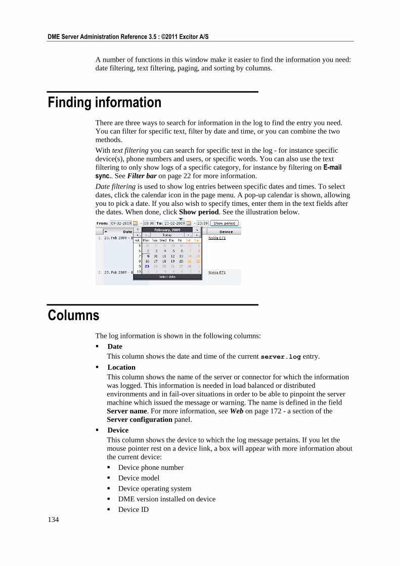
134
DME Server Administration Reference 3.5 : ©2011 Excitor A/S
A number of functions in this window make it easier to find the information you need:
date filtering, text filtering, paging, and sorting by columns.
Finding information
There are three ways to search for information in the log to find the entry you need.
You can filter for specific text, filter by date and time, or you can combine the two
methods.
With text filtering you can search for specific text in the log - for instance specific
device(s), phone numbers and users, or specific words. You can also use the text
filtering to only show logs of a specific category, for instance by filtering on E-mail sync.. See Filter bar on page 22 for more information.
Date filtering is used to show log entries between specific dates and times. To select
dates, click the calendar icon in the page menu. A pop-up calendar is shown, allowing
you to pick a date. If you also wish to specify times, enter them in the text fields after
the dates. When done, click Show period. See the illustration below.
Columns
The log information is shown in the following columns:
Date
This column shows the date and time of the current server.log entry.
Location
This column shows the name of the server or connector for which the information
was logged. This information is needed in load balanced or distributed
environments and in fail-over situations in order to be able to pinpoint the server
machine which issued the message or warning. The name is defined in the field
Server name. For more information, see Web on page 172 - a section of the
Server configuration panel.
Device
This column shows the device to which the log message pertains. If you let the
mouse pointer rest on a device link, a box will appear with more information about
the current device:
Device phone number
Device model
Device operating system
DME version installed on device
Device ID
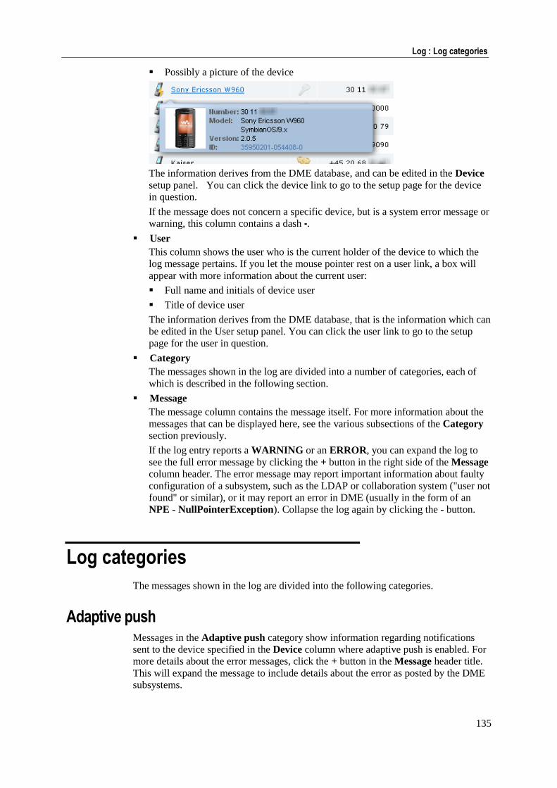
135
Log : Log categories
Possibly a picture of the device
The information derives from the DME database, and can be edited in the Device
setup panel. You can click the device link to go to the setup page for the device
in question.
If the message does not concern a specific device, but is a system error message or
warning, this column contains a dash -.
User
This column shows the user who is the current holder of the device to which the
log message pertains. If you let the mouse pointer rest on a user link, a box will
appear with more information about the current user:
Full name and initials of device user
Title of device user
The information derives from the DME database, that is the information which can
be edited in the User setup panel. You can click the user link to go to the setup
page for the user in question.
Category
The messages shown in the log are divided into a number of categories, each of
which is described in the following section.
Message
The message column contains the message itself. For more information about the
messages that can be displayed here, see the various subsections of the Category
section previously.
If the log entry reports a WARNING or an ERROR, you can expand the log to
see the full error message by clicking the + button in the right side of the Message
column header. The error message may report important information about faulty
configuration of a subsystem, such as the LDAP or collaboration system ("user not
found" or similar), or it may report an error in DME (usually in the form of an
NPE - NullPointerException). Collapse the log again by clicking the - button.
Log categories
The messages shown in the log are divided into the following categories.
Adaptive push Messages in the Adaptive push category show information regarding notifications
sent to the device specified in the Device column where adaptive push is enabled. For
more details about the error messages, click the + button in the Message header title.
This will expand the message to include details about the error as posted by the DME
subsystems.
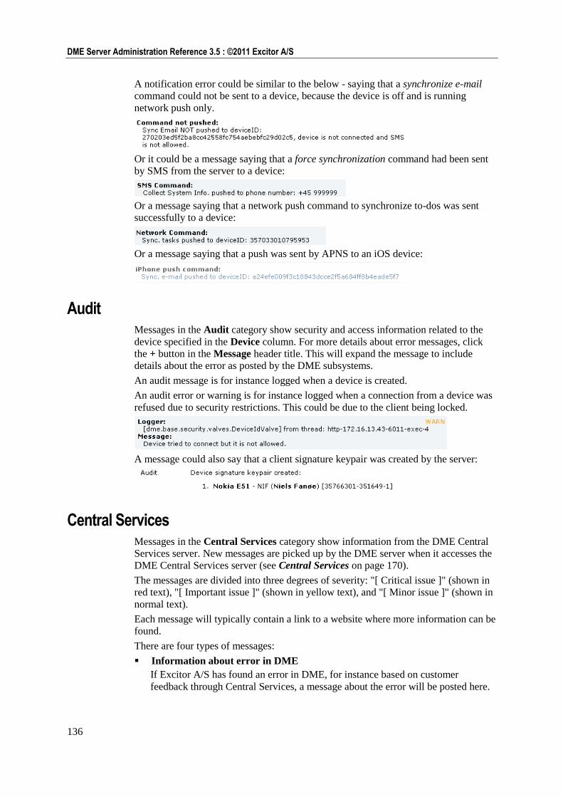
136
DME Server Administration Reference 3.5 : ©2011 Excitor A/S
A notification error could be similar to the below - saying that a synchronize e-mail
command could not be sent to a device, because the device is off and is running
network push only.
Or it could be a message saying that a force synchronization command had been sent
by SMS from the server to a device:
Or a message saying that a network push command to synchronize to-dos was sent
successfully to a device:
Or a message saying that a push was sent by APNS to an iOS device:
Audit Messages in the Audit category show security and access information related to the
device specified in the Device column. For more details about error messages, click
the + button in the Message header title. This will expand the message to include
details about the error as posted by the DME subsystems.
An audit message is for instance logged when a device is created.
An audit error or warning is for instance logged when a connection from a device was
refused due to security restrictions. This could be due to the client being locked.
A message could also say that a client signature keypair was created by the server:
Central Services Messages in the Central Services category show information from the DME Central
Services server. New messages are picked up by the DME server when it accesses the
DME Central Services server (see Central Services on page 170).
The messages are divided into three degrees of severity: "[ Critical issue ]" (shown in
red text), "[ Important issue ]" (shown in yellow text), and "[ Minor issue ]" (shown in
normal text).
Each message will typically contain a link to a website where more information can be
found.
There are four types of messages:
Information about error in DME
If Excitor A/S has found an error in DME, for instance based on customer
feedback through Central Services, a message about the error will be posted here.
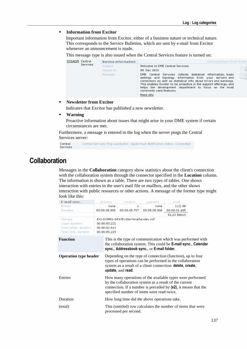
137
Log : Log categories
Information from Excitor
Important information from Excitor, either of a business nature or technical nature.
This corresponds to the Service Bulletins, which are sent by e-mail from Excitor
whenever an announcement is made.
This message type is also issued when the Central Services feature is turned on:
Newsletter from Excitor
Indicates that Excitor has published a new newsletter.
Warning
Proactive information about issues that might arise in your DME system if certain
circumstances are met.
Furthermore, a message is entered in the log when the server pings the Central
Services server:
Collaboration Messages in the Collaboration category show statistics about the client's connection
with the collaboration system through the connector specified in the Location column.
The information is shown as a table. There are two types of tables. One shows
interaction with entries in the user's mail file or mailbox, and the other shows
interaction with public resources or other actions. A message of the former type might
look like this:
Function This is the type of communication which was performed with
the collaboration system. This could be E-mail sync., Calendar sync., Addressbook sync., or E-mail folder.
Operation type header Depending on the type of connection (function), up to four
types of operations can be performed in the collaboration
system as a result of a client connection: delete, create,
update, and read.
Entries How many operations of the available types were performed
by the collaboration system as a result of the current
connection. If a number is preceded by (x2), it means that the
specified number of items were read twice.
Duration How long time did the above operations take.
(total) This (untitled) row calculates the number of items that were
processed per second.
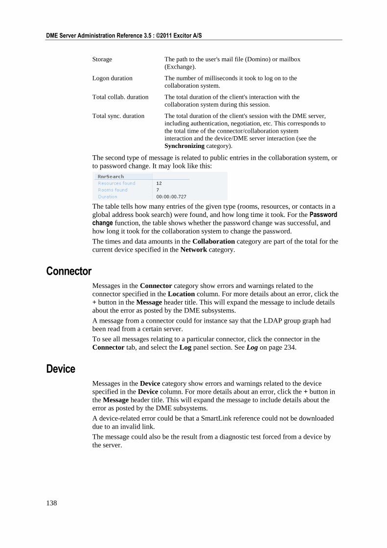
138
DME Server Administration Reference 3.5 : ©2011 Excitor A/S
Storage The path to the user's mail file (Domino) or mailbox
(Exchange).
Logon duration The number of milliseconds it took to log on to the
collaboration system.
Total collab. duration The total duration of the client's interaction with the
collaboration system during this session.
Total sync. duration The total duration of the client's session with the DME server,
including authentication, negotiation, etc. This corresponds to
the total time of the connector/collaboration system
interaction and the device/DME server interaction (see the
Synchronizing category).
The second type of message is related to public entries in the collaboration system, or
to password change. It may look like this:
The table tells how many entries of the given type (rooms, resources, or contacts in a
global address book search) were found, and how long time it took. For the Password change function, the table shows whether the password change was successful, and
how long it took for the collaboration system to change the password.
The times and data amounts in the Collaboration category are part of the total for the
current device specified in the Network category.
Connector Messages in the Connector category show errors and warnings related to the
connector specified in the Location column. For more details about an error, click the
+ button in the Message header title. This will expand the message to include details
about the error as posted by the DME subsystems.
A message from a connector could for instance say that the LDAP group graph had
been read from a certain server.
To see all messages relating to a particular connector, click the connector in the
Connector tab, and select the Log panel section. See Log on page 234.
Device Messages in the Device category show errors and warnings related to the device
specified in the Device column. For more details about an error, click the + button in
the Message header title. This will expand the message to include details about the
error as posted by the DME subsystems.
A device-related error could be that a SmartLink reference could not be downloaded
due to an invalid link.
The message could also be the result from a diagnostic test forced from a device by
the server.
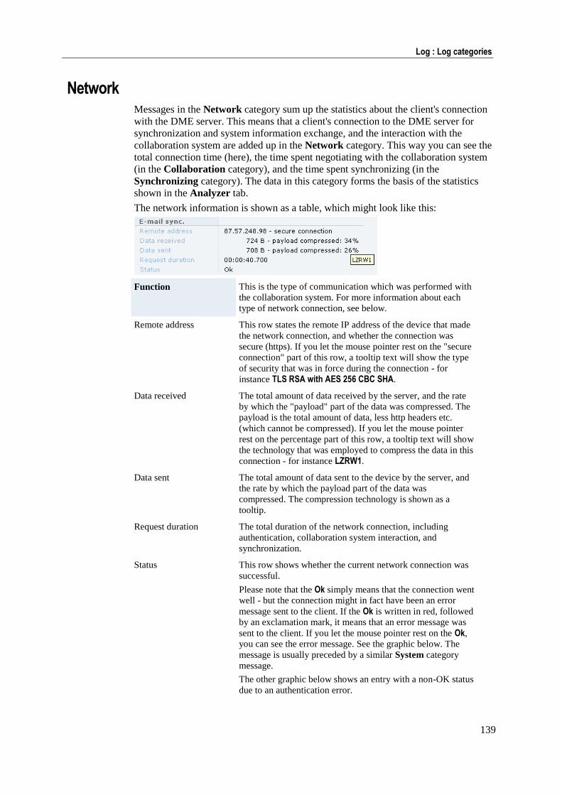
139
Log : Log categories
Network Messages in the Network category sum up the statistics about the client's connection
with the DME server. This means that a client's connection to the DME server for
synchronization and system information exchange, and the interaction with the
collaboration system are added up in the Network category. This way you can see the
total connection time (here), the time spent negotiating with the collaboration system
(in the Collaboration category), and the time spent synchronizing (in the
Synchronizing category). The data in this category forms the basis of the statistics
shown in the Analyzer tab.
The network information is shown as a table, which might look like this:
Function This is the type of communication which was performed with
the collaboration system. For more information about each
type of network connection, see below.
Remote address This row states the remote IP address of the device that made
the network connection, and whether the connection was
secure (https). If you let the mouse pointer rest on the "secure
connection" part of this row, a tooltip text will show the type
of security that was in force during the connection - for
instance TLS RSA with AES 256 CBC SHA.
Data received The total amount of data received by the server, and the rate
by which the "payload" part of the data was compressed. The
payload is the total amount of data, less http headers etc.
(which cannot be compressed). If you let the mouse pointer
rest on the percentage part of this row, a tooltip text will show
the technology that was employed to compress the data in this
connection - for instance LZRW1.
Data sent The total amount of data sent to the device by the server, and
the rate by which the payload part of the data was
compressed. The compression technology is shown as a
tooltip.
Request duration The total duration of the network connection, including
authentication, collaboration system interaction, and
synchronization.
Status This row shows whether the current network connection was
successful.
Please note that the Ok simply means that the connection went
well - but the connection might in fact have been an error
message sent to the client. If the Ok is written in red, followed
by an exclamation mark, it means that an error message was
sent to the client. If you let the mouse pointer rest on the Ok,
you can see the error message. See the graphic below. The
message is usually preceded by a similar System category
message.
The other graphic below shows an entry with a non-OK status
due to an authentication error.
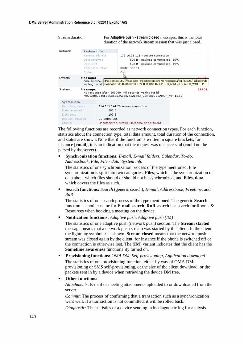
140
DME Server Administration Reference 3.5 : ©2011 Excitor A/S
Stream duration For Adaptive push - stream closed messages, this is the total
duration of the network stream session that was just closed.
The following functions are recorded as network connection types. For each function,
statistics about the connection type, total data amount, total duration of the connection,
and status are shown. Note that if the function is written in square brackets, for
instance [email], it is an indication that the request was unsuccessful (could not be
parsed by the server).
Synchronization functions: E-mail, E-mail folders, Calendar, To-do,
Addressbook, File, File - data, System info
The statistics of one synchronization process of the type mentioned. File
synchronization is split into two categories: Files, which is the synchronization of
data about which files should or should not be synchronized, and Files, data,
which covers the files as such.
Search functions: Search (generic search), E-mail, Addressbook, Freetime, and
RnR
The statistics of one search process of the type mentioned. The generic Search
function is another name for E-mail search. RnR search is a search for Rooms &
Resources when booking a meeting on the device.
Notification functions: Adaptive push, Adaptive push (IM)
The statistics of one adaptive push (network push) session. The Stream started
message means that a network push stream was started by the client. In the client,
the lightning symbol is shown. Stream closed means that the network push
stream was closed again by the client, for instance if the phone is switched off or
the connection is otherwise lost. The (IM) variant indicates that the client has the
Sametime awareness functionality turned on.
Provisioning functions: OMA DM, Self-provisioning, Application download
The statistics of one provisioning function, either by way of OMA DM
provisioning or SMS self-provisioning, or the size of the client download, or the
packets sent in by a device when retrieving the device DM tree.
Other functions:
Attachments: E-mail or meeting attachments uploaded to or downloaded from the
server.
Commit: The process of confirming that a transaction such as a synchronization
went well. If a transaction is not committed, it will be rolled back.
Diagnostic: The statistics of a device sending in its diagnostic log for analysis.
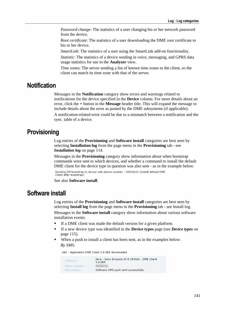
141
Log : Log categories
Password change: The statistics of a user changing his or her network password
from the device.
Root certificate: The statistics of a user downloading the DME root certificate to
his or her device.
SmartLink: The statistics of a user using the SmartLink add-on functionality.
Statistic: The statistics of a device sending in voice, messaging, and GPRS data
usage statistics for use in the Analyzer view.
Time zones: The server sending a list of known time zones to the client, so the
client can match its time zone with that of the server.
Notification Messages in the Notification category show errors and warnings related to
notifications for the device specified in the Device column. For more details about an
error, click the + button in the Message header title. This will expand the message to
include details about the error as posted by the DME subsystems (if applicable).
A notification-related error could be due to a mismatch between a notification and the
sync. table of a device.
Provisioning Log entries of the Provisioning and Software install categories are best seen by
selecting Installation log from the page menu in the Provisioning tab - see
Installation log on page 114.
Messages in the Provisioning category show information about when bootstrap
commands were sent to which devices, and whether a command to install the default
DME client for the device type in question was also sent - as in the example below.
See also Software install.
Software install Log entries of the Provisioning and Software install categories are best seen by
selecting Install log from the page menu in the Provisioning tab - see Install log.
Messages in the Software install category show information about various software
installation events:
If a DME client was made the default version for a given platform.
If a new device type was identified in the Device types page (see Device types on
page 115).
When a push to install a client has been sent, as in the examples below:
By SMS:
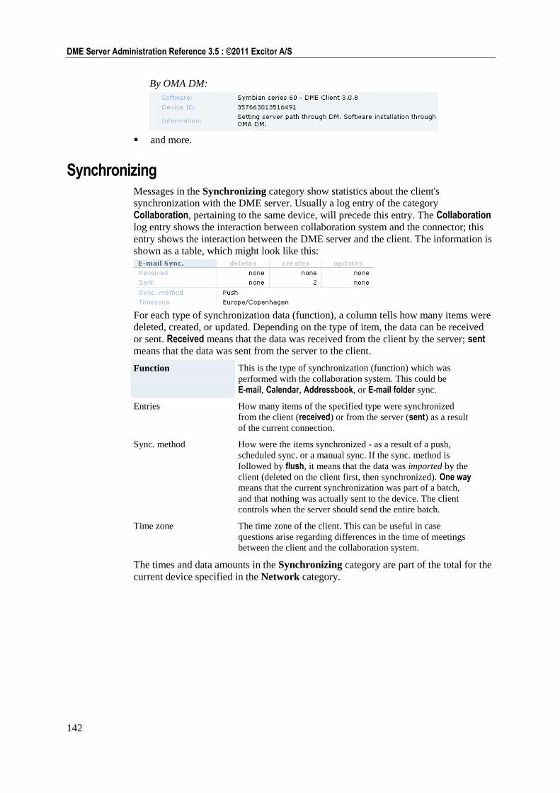
142
DME Server Administration Reference 3.5 : ©2011 Excitor A/S
By OMA DM:
and more.
Synchronizing Messages in the Synchronizing category show statistics about the client's
synchronization with the DME server. Usually a log entry of the category
Collaboration, pertaining to the same device, will precede this entry. The Collaboration
log entry shows the interaction between collaboration system and the connector; this
entry shows the interaction between the DME server and the client. The information is
shown as a table, which might look like this:
For each type of synchronization data (function), a column tells how many items were
deleted, created, or updated. Depending on the type of item, the data can be received
or sent. Received means that the data was received from the client by the server; sent means that the data was sent from the server to the client.
Function This is the type of synchronization (function) which was
performed with the collaboration system. This could be
E-mail, Calendar, Addressbook, or E-mail folder sync.
Entries How many items of the specified type were synchronized
from the client (received) or from the server (sent) as a result
of the current connection.
Sync. method How were the items synchronized - as a result of a push,
scheduled sync. or a manual sync. If the sync. method is
followed by flush, it means that the data was imported by the
client (deleted on the client first, then synchronized). One way
means that the current synchronization was part of a batch,
and that nothing was actually sent to the device. The client
controls when the server should send the entire batch.
Time zone The time zone of the client. This can be useful in case
questions arise regarding differences in the time of meetings
between the client and the collaboration system.
The times and data amounts in the Synchronizing category are part of the total for the
current device specified in the Network category.
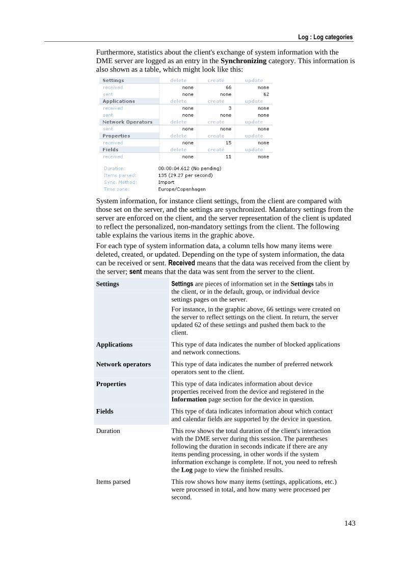
143
Log : Log categories
Furthermore, statistics about the client's exchange of system information with the
DME server are logged as an entry in the Synchronizing category. This information is
also shown as a table, which might look like this:
System information, for instance client settings, from the client are compared with
those set on the server, and the settings are synchronized. Mandatory settings from the
server are enforced on the client, and the server representation of the client is updated
to reflect the personalized, non-mandatory settings from the client. The following
table explains the various items in the graphic above.
For each type of system information data, a column tells how many items were
deleted, created, or updated. Depending on the type of system information, the data
can be received or sent. Received means that the data was received from the client by
the server; sent means that the data was sent from the server to the client.
Settings Settings are pieces of information set in the Settings tabs in
the client, or in the default, group, or individual device
settings pages on the server.
For instance, in the graphic above, 66 settings were created on
the server to reflect settings on the client. In return, the server
updated 62 of these settings and pushed them back to the
client.
Applications This type of data indicates the number of blocked applications
and network connections.
Network operators This type of data indicates the number of preferred network
operators sent to the client.
Properties This type of data indicates information about device
properties received from the device and registered in the
Information page section for the device in question.
Fields This type of data indicates information about which contact
and calendar fields are supported by the device in question.
Duration This row shows the total duration of the client's interaction
with the DME server during this session. The parentheses
following the duration in seconds indicate if there are any
items pending processing, in other words if the system
information exchange is complete. If not, you need to refresh
the Log page to view the finished results.
Items parsed This row shows how many items (settings, applications, etc.)
were processed in total, and how many were processed per
second.
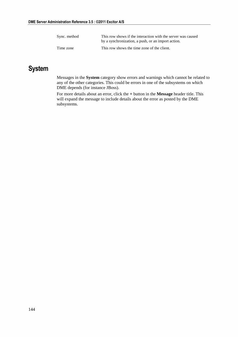
144
DME Server Administration Reference 3.5 : ©2011 Excitor A/S
Sync. method This row shows if the interaction with the server was caused
by a synchronization, a push, or an import action.
Time zone This row shows the time zone of the client.
System Messages in the System category show errors and warnings which cannot be related to
any of the other categories. This could be errors in one of the subsystems on which
DME depends (for instance JBoss).
For more details about an error, click the + button in the Message header title. This
will expand the message to include details about the error as posted by the DME
subsystems.
Analyzer 145
Analyzer
The Analyzer tab shows traffic statistics and lets you run custom Analyzer reports
using the BIRT reporting framework.
Statistical data with regard to DME data is always collected. Statistics with regard to
voice, messaging, and general (non-DME) data traffic, is an optional setting which can
be turned on or off using the Log traffic option in the General section of the settings
for devices, groups, or default devices. For more information, see Appendix D:
Traffic logging on page 269.
Statistics
The Statistics page menu contains functions to let you see traffic statistics, divided
into four categories: DME traffic, Voice traffic, Messaging traffic and Data traffic.
The page menu contains a date filter similar to that in the Log tab (see Finding
information on page 134), with the addition of a number of preset date filters: Today,
Yesterday, Week, Month, and Year. The data shown in the Statistics pages are
always limited by the dates selected in the date filter, and the current date range is
shown at the top of each subtab in the Statistics pages.
DME traffic The DME traffic statistics page is divided into a number of subtabs, each of which
showing the statistics from a different perspective.
The DME traffic statistics cover data from all communication between the client and
the DME server, whether the communication is over the air as GPRS or Wi-Fi or
through a direct cable connection. DME seeks to make as precise a measurement as
possible, but some variance must be anticipated. DME traffic statistics are always
collected, for all clients.
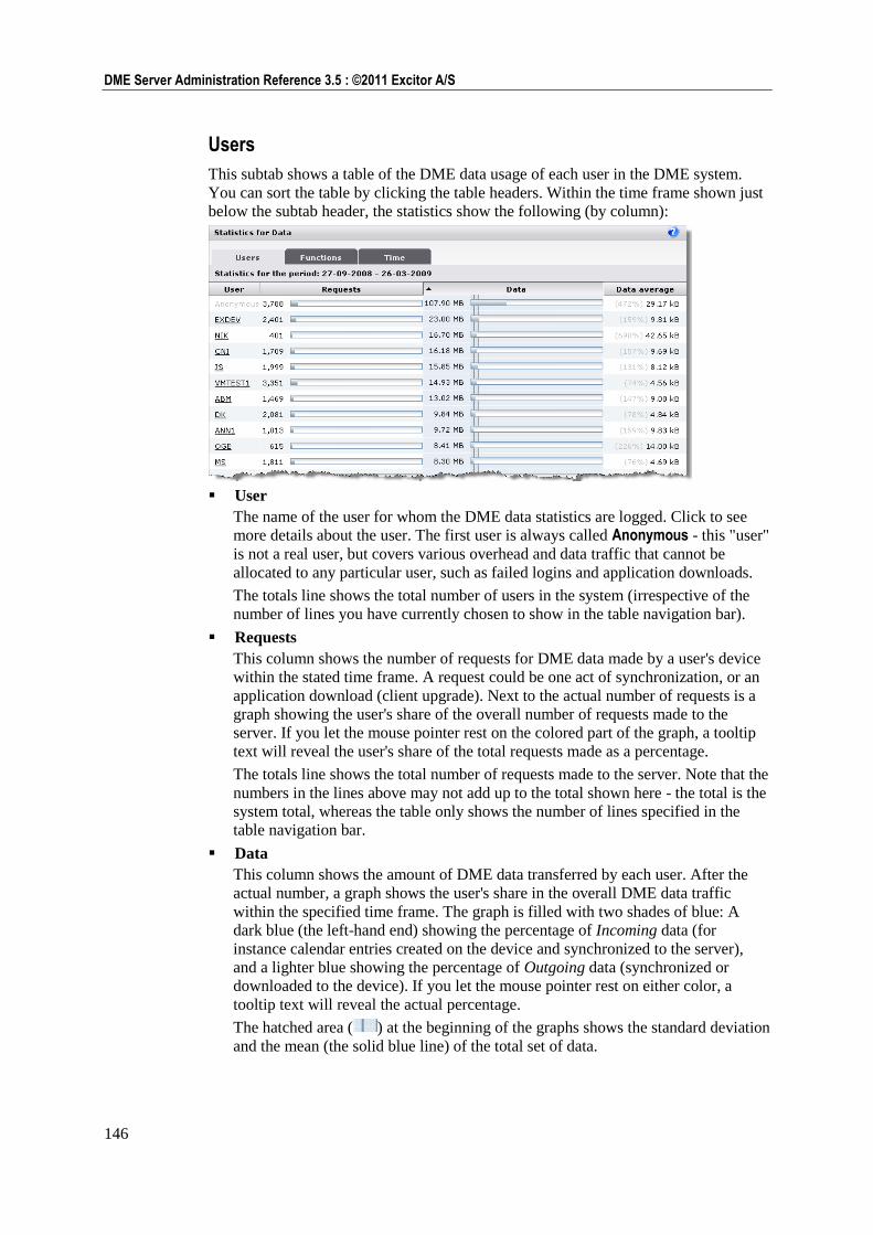
146
DME Server Administration Reference 3.5 : ©2011 Excitor A/S
Users
This subtab shows a table of the DME data usage of each user in the DME system.
You can sort the table by clicking the table headers. Within the time frame shown just
below the subtab header, the statistics show the following (by column):
User
The name of the user for whom the DME data statistics are logged. Click to see
more details about the user. The first user is always called Anonymous - this "user"
is not a real user, but covers various overhead and data traffic that cannot be
allocated to any particular user, such as failed logins and application downloads.
The totals line shows the total number of users in the system (irrespective of the
number of lines you have currently chosen to show in the table navigation bar).
Requests
This column shows the number of requests for DME data made by a user's device
within the stated time frame. A request could be one act of synchronization, or an
application download (client upgrade). Next to the actual number of requests is a
graph showing the user's share of the overall number of requests made to the
server. If you let the mouse pointer rest on the colored part of the graph, a tooltip
text will reveal the user's share of the total requests made as a percentage.
The totals line shows the total number of requests made to the server. Note that the
numbers in the lines above may not add up to the total shown here - the total is the
system total, whereas the table only shows the number of lines specified in the
table navigation bar.
Data
This column shows the amount of DME data transferred by each user. After the
actual number, a graph shows the user's share in the overall DME data traffic
within the specified time frame. The graph is filled with two shades of blue: A
dark blue (the left-hand end) showing the percentage of Incoming data (for
instance calendar entries created on the device and synchronized to the server),
and a lighter blue showing the percentage of Outgoing data (synchronized or
downloaded to the device). If you let the mouse pointer rest on either color, a
tooltip text will reveal the actual percentage.
The hatched area ( ) at the beginning of the graphs shows the standard deviation
and the mean (the solid blue line) of the total set of data.
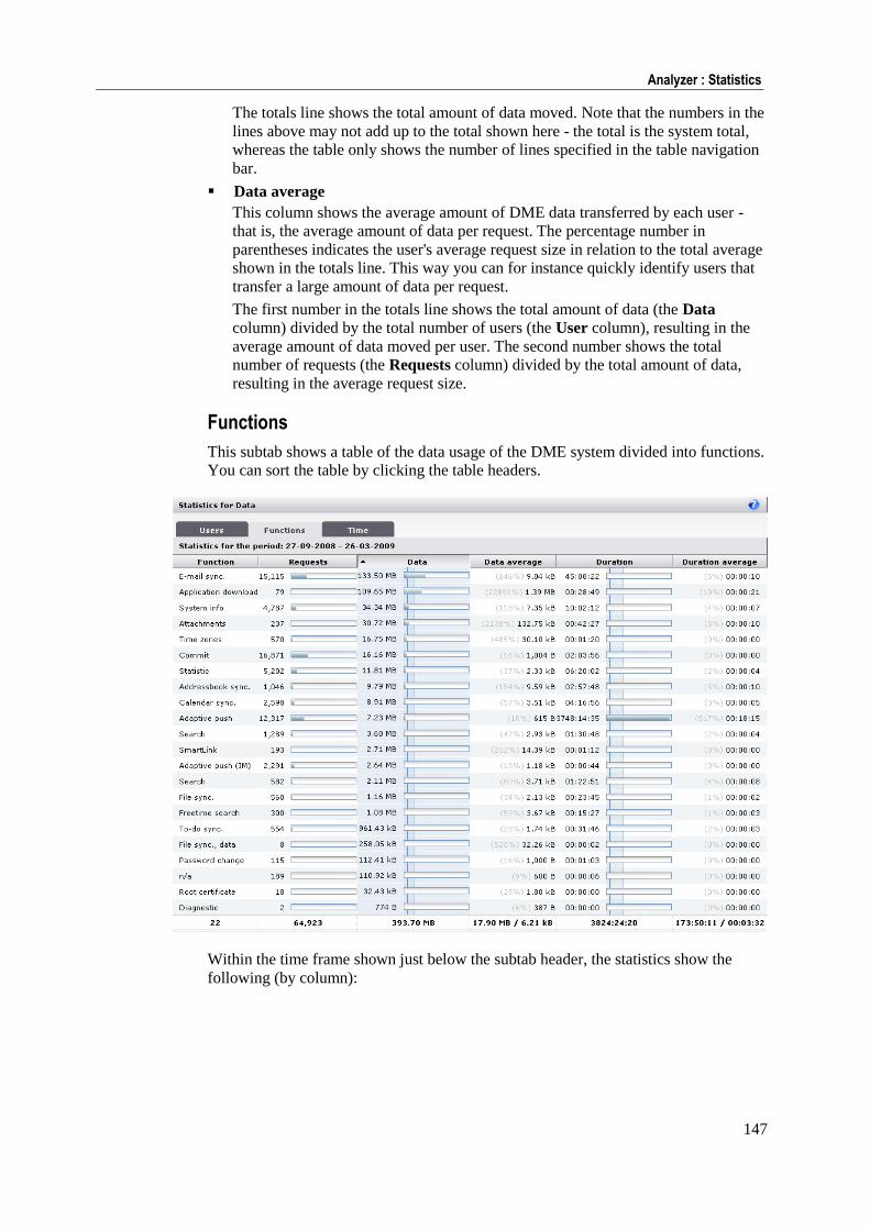
147
Analyzer : Statistics
The totals line shows the total amount of data moved. Note that the numbers in the
lines above may not add up to the total shown here - the total is the system total,
whereas the table only shows the number of lines specified in the table navigation
bar.
Data average
This column shows the average amount of DME data transferred by each user -
that is, the average amount of data per request. The percentage number in
parentheses indicates the user's average request size in relation to the total average
shown in the totals line. This way you can for instance quickly identify users that
transfer a large amount of data per request.
The first number in the totals line shows the total amount of data (the Data
column) divided by the total number of users (the User column), resulting in the
average amount of data moved per user. The second number shows the total
number of requests (the Requests column) divided by the total amount of data,
resulting in the average request size.
Functions
This subtab shows a table of the data usage of the DME system divided into functions.
You can sort the table by clicking the table headers.
Within the time frame shown just below the subtab header, the statistics show the
following (by column):
148
DME Server Administration Reference 3.5 : ©2011 Excitor A/S
Function
The name of the DME function that gave rise to data traffic. The statistics are
accumulated from log entries of the category Network. For information about
each function, see Network on page 139. The "function" called n/a is not a
function as such, but means that some traffic could not be attributed to a function -
this could be errors, attempts at anonymous logins, etc. Such data is attributed to
the n/a "function" and the Anonymous "user".
The totals line shows the total number of functions in the system for which
statistics were collected within the specified time frame.
Requests
This column shows the number of data requests made, divided into the different
functions, within the stated time frame. Next to the actual number of requests is a
graph showing the function's share of the overall number of requests made to the
server. If you let the mouse pointer rest on the colored part of the graph, a tooltip
text will reveal the function's share of the total requests made as a percentage.
The totals line shows the total number of requests made to the server.
Data
This column shows the amount of DME data transferred on account of each
function. After the actual number, a graph shows the function's share in the overall
DME data traffic within the specified time frame. The graph is filled with two
shades of blue: A dark blue (the left-hand end) showing the percentage of
Incoming data (for instance calendar entries created on the device and
synchronized to the server), and a lighter blue showing the percentage of Outgoing
data (synchronized or downloaded to the device). If you let the mouse pointer rest
on either color, a tooltip text will reveal the actual percentage.
The hatched area ( ) at the beginning of the graphs shows the standard deviation
and the mean (the solid blue line) of the total set of data.
The totals line shows the total amount of data moved.
Data average
This column shows the average amount of DME data transferred by each function
- that is, the average amount of data per request. The percentage number in
parentheses indicates the function's average request size in relation to the total
average shown in the totals line.
The first number in the totals line shows the total amount of data (the Data
column) divided by the total number of functions (the Function column), resulting
in the average amount of data moved per function. The second number shows the
total number of requests (the Requests column) divided by the total amount of
data, resulting in the average request size.
Duration
This column shows the duration of the connection between device and server on
account of each function, shown in the format HH:MM:SS. After the actual
number, a graph shows the function's share in the overall DME connection time
within the specified time frame. If you let the mouse pointer rest on the colored
part of the graph, a tooltip text will reveal the function's share of the total
connection duration as a percentage. Please note that the function Adaptive push is
not included in this, as the nature of the network push aspect of the adaptive push
connection is to keep a persistent data connection open.
The hatched area ( ) at the beginning of the graphs shows the standard deviation
and the mean (the solid blue line) of the total set of data.
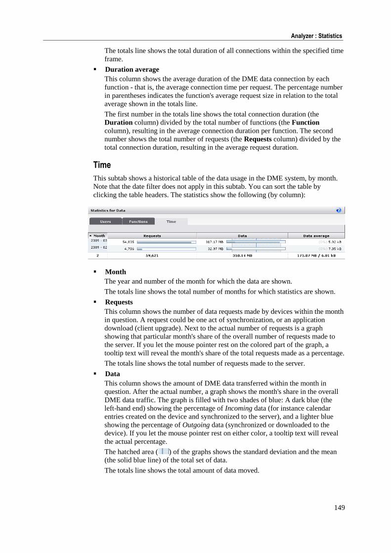
149
Analyzer : Statistics
The totals line shows the total duration of all connections within the specified time
frame.
Duration average
This column shows the average duration of the DME data connection by each
function - that is, the average connection time per request. The percentage number
in parentheses indicates the function's average request size in relation to the total
average shown in the totals line.
The first number in the totals line shows the total connection duration (the
Duration column) divided by the total number of functions (the Function
column), resulting in the average connection duration per function. The second
number shows the total number of requests (the Requests column) divided by the
total connection duration, resulting in the average request duration.
Time
This subtab shows a historical table of the data usage in the DME system, by month.
Note that the date filter does not apply in this subtab. You can sort the table by
clicking the table headers. The statistics show the following (by column):
Month
The year and number of the month for which the data are shown.
The totals line shows the total number of months for which statistics are shown.
Requests
This column shows the number of data requests made by devices within the month
in question. A request could be one act of synchronization, or an application
download (client upgrade). Next to the actual number of requests is a graph
showing that particular month's share of the overall number of requests made to
the server. If you let the mouse pointer rest on the colored part of the graph, a
tooltip text will reveal the month's share of the total requests made as a percentage.
The totals line shows the total number of requests made to the server.
Data
This column shows the amount of DME data transferred within the month in
question. After the actual number, a graph shows the month's share in the overall
DME data traffic. The graph is filled with two shades of blue: A dark blue (the
left-hand end) showing the percentage of Incoming data (for instance calendar
entries created on the device and synchronized to the server), and a lighter blue
showing the percentage of Outgoing data (synchronized or downloaded to the
device). If you let the mouse pointer rest on either color, a tooltip text will reveal
the actual percentage.
The hatched area ( ) of the graphs shows the standard deviation and the mean
(the solid blue line) of the total set of data.
The totals line shows the total amount of data moved.
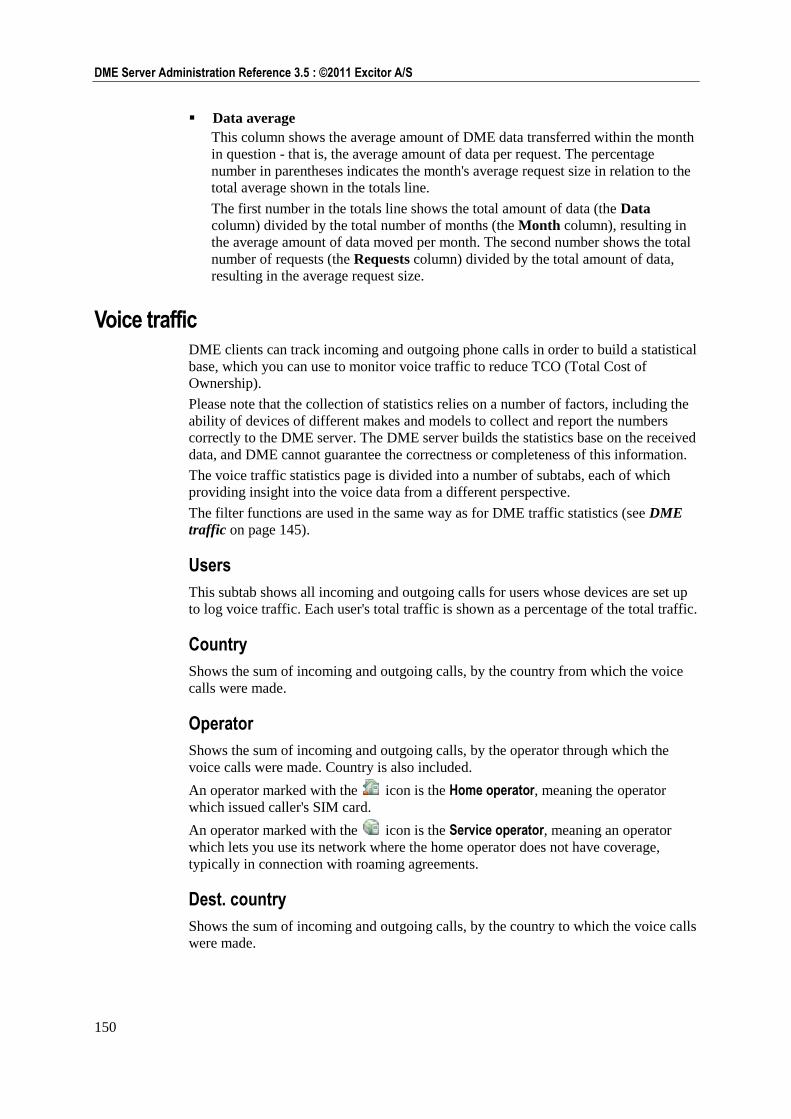
150
DME Server Administration Reference 3.5 : ©2011 Excitor A/S
Data average
This column shows the average amount of DME data transferred within the month
in question - that is, the average amount of data per request. The percentage
number in parentheses indicates the month's average request size in relation to the
total average shown in the totals line.
The first number in the totals line shows the total amount of data (the Data
column) divided by the total number of months (the Month column), resulting in
the average amount of data moved per month. The second number shows the total
number of requests (the Requests column) divided by the total amount of data,
resulting in the average request size.
Voice traffic DME clients can track incoming and outgoing phone calls in order to build a statistical
base, which you can use to monitor voice traffic to reduce TCO (Total Cost of
Ownership).
Please note that the collection of statistics relies on a number of factors, including the
ability of devices of different makes and models to collect and report the numbers
correctly to the DME server. The DME server builds the statistics base on the received
data, and DME cannot guarantee the correctness or completeness of this information.
The voice traffic statistics page is divided into a number of subtabs, each of which
providing insight into the voice data from a different perspective.
The filter functions are used in the same way as for DME traffic statistics (see DME
traffic on page 145).
Users
This subtab shows all incoming and outgoing calls for users whose devices are set up
to log voice traffic. Each user's total traffic is shown as a percentage of the total traffic.
Country
Shows the sum of incoming and outgoing calls, by the country from which the voice
calls were made.
Operator
Shows the sum of incoming and outgoing calls, by the operator through which the
voice calls were made. Country is also included.
An operator marked with the icon is the Home operator, meaning the operator
which issued caller's SIM card.
An operator marked with the icon is the Service operator, meaning an operator
which lets you use its network where the home operator does not have coverage,
typically in connection with roaming agreements.
Dest. country
Shows the sum of incoming and outgoing calls, by the country to which the voice calls
were made.
151
Analyzer : Statistics
Incoming
This subtab shows a detailed sum of incoming calls. The sum is based on the call
operator and country.
The table should be read like this: A DME user located in country A receives a call
from country B. For instance, line two in the table above states that three calls have
been placed from Denmark to numbers in Norway using the N NetCom operator. The $
sign in the arrow means that the mobile phone was roaming when the call was made.
This is important, as the call receiver pays for roaming calls.
Another example: In the last line but one, a call from Sweden was placed to a recipient
in Sweden. However, the recipient was not a native of Sweden, so the call was
roaming.
For an explanation of the operator icons, see Operator on page 150.
Outgoing
Corresponds to the Incoming subtab, but shows outgoing calls.
Messaging traffic The Messaging traffic statistics page shows the number of SMS and MMS messages
that have been sent and received from the client devices. The page is divided into a
number of subtabs. Each subtab shows how many messages were sent or received
from a different perspective.
152
DME Server Administration Reference 3.5 : ©2011 Excitor A/S
Please note that the collection of statistics relies on a number of factors, including the
ability of devices of different makes and models to collect and report the numbers
correctly to the DME server. The DME server builds the statistics base on the received
data, and DME cannot guarantee the correctness or completeness of this information.
The filter functions are used in the same way as for DME traffic statistics (see DME
traffic on page 145).
The subtabs show the same as for Voice traffic statistics. However, instead of minutes
of voice traffic, the subtabs show the number of messages sent and received.
Data traffic The Data traffic statistics page shows the amount of data traffic that the client devices
have used. The page is divided into a number of subtabs, each showing data traffic
from a different perspective.
Please note that the collection of statistics relies on a number of factors, including the
ability of devices of different makes and models to collect and report the numbers
correctly to the DME server. The DME server builds the statistics base on the received
data, and DME cannot guarantee the correctness or completeness of this information.
The filter functions are used in the same way as for DME traffic statistics (see DME
traffic on page 145).
The subtabs show the same as for Voice traffic statistics. However, instead of minutes
of voice traffic, the subtabs show the duration of data connections in minutes.
Analyzer reports
DME integrates with a third-party, open source project called BIRT ("Business
Intelligence and Reporting Tools"). With BIRT, it is possible to develop and run
custom reports on the DME database.
BIRT is an open source reporting system for web applications, especially those based
on Java and J2EE. BIRT has two main components: a report designer based on
Eclipse™, and a runtime component that can be added to an application server (such
as DME). BIRT also contains a charting engine that lets you add charts to your
reports.
Furthermore, a number of standard reports are included with DME. These reports are
fully functional, and can furthermore be used as a basis for further development. Note
that when the reports are run, the dates and times selected in the Period filter are used
as parameter for the report. This means that if you change the date and time and click
Show period, the report will be run again showing data for the new span of time. See
Standard reports on page 156.
If you want to develop your own reports or customize the template reports supplied by
Excitor A/S, do the following:
1 Download the BIRT reporting package from the Eclipse BIRT website
http://www.eclipse.org/birt/phoenix/.
Note that you must get BIRT version 2.3.2 (no later).
153
Analyzer : Analyzer reports
2 Install BIRT.
3 Install a JDBC driver for your DME database (can be obtained from the MySQL
or Microsoft websites).
4 Register the JDBC driver in Eclipse.
It is highly recommended that you work with BIRT using a read-only user account on
the database in order to prevent accidental data loss. Ask your Database Administrator
about this.
For help on using the BIRT report designer, see the built-in online help for that
product, or visit the Eclipse BIRT website http://www.eclipse.org/birt/phoenix/.
New reports When you have made a new report, use the Upload report action to load it to the
DME server (see Upload report on page 154).
Editing existing reports To edit an existing report, first download the report file to your local drive, edit it, and
then upload it to the DME server again (see Edit report on page 154).
DME upgrades Whenever DME releases a server upgrade (a new version or a Service Pack), the
template reports shipped with DME are included in the database of the new
installation. The reports may have been amended compared with the previous version,
or new ones added. When you launch DME for the first time after the upgrade, any
new template reports are extracted from the database and installed into the report
directory. However, in order to not overwrite any customization made by you in the
template reports, DME only installs reports that do not already exist in the reports
directory:
C:\Program Files\dme\jboss\server\default\filestore\reports
(Windows)
/var/dme/instances/base/filestore/reports (Linux)
This means that if you want DME to install a fresh copy of a report, you must delete
the existing report file (<reportname>.rptdesign) from the reports directory, and
restart the DME server. This will cause DME to re-install the template report from the
database and make it available from the DME web interface.
The following sections describe the Analyzer reports page menu, which contains
functions to manage and view BIRT reports in DME.
Manage reports This page shows a list of the reports available to the DME system. The reports are
grouped into one of four pre-defined categories: Comparison reports, Summary reports, Usage statistics, User reports, or in a user-defined category.
The tab toolbar in the Manage reports view contains the following actions.
Run report
Run the selected report. This corresponds to selecting a report in the View reports
window. For more information, see View reports on page 155.
You must pick a report in the list before selecting this action.
154
DME Server Administration Reference 3.5 : ©2011 Excitor A/S
Upload report
Click the Upload report icon to upload a new report to the server.
Uploading a new BIRT report to the server
1 Click the Upload report icon.
2 Browse to the location of the new report, and select it.
3 Supply a name and category for the report, and click Save.
Note that this is for uploading new reports only. If you want to replace an existing
report with an updated version of the same report, you must select the report you want
to update, click Edit report, and upload it from that window. For more information,
see Edit report on page 154.
Edit report
Click the Edit report icon to edit details about the currently selected report, or to
upload a new version of the selected report.
Editing BIRT report details and updating reports
1 Select a report in the list.
2 Click the Edit report icon.
3 In the field Report name, you can edit the external name of the report, that is the
name shown in the report list.
4 In the Category field, select one of the pre-defined categories, or type the name of
an existing or new category in the field New category. In the report list, the
reports are grouped by categories.
5 The field Report file shows the physical name of the report design file on the
DME server. If your browser supports showing XML, clicking the report file name
will display the report design file in XML format.
If you want to edit the report in the BIRT framework, right-click the link,
download the report file to your disk, and load it into BIRT. When you are done
editing the report, upload the edited report file for this report by clicking the
Upload report icon in the tab toolbar.
6 If you select the field Is runnable, the current report is visible in the View reports
list.
A report which is not runnable is typically a drill-down report, that is a report
which is run when you make a selection within another report, for instance
clicking a user name in a voice traffic report. The report passes the user name
parameter to the drill-down report. The text [drill-down] is automatically added to
the name of such reports.
7 Click Save.
Delete report(s)
To delete one or more reports, select it or them, click the Delete report(s) icon, and
confirm that you want to delete the selected report(s).
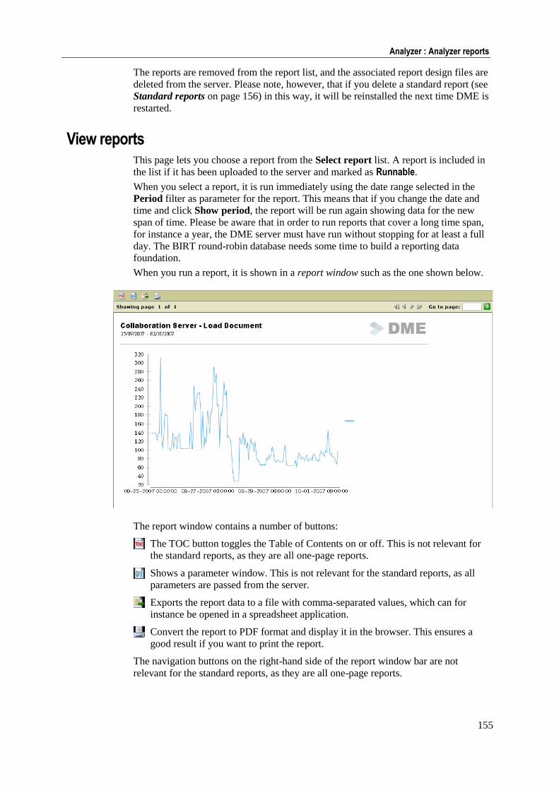
155
Analyzer : Analyzer reports
The reports are removed from the report list, and the associated report design files are
deleted from the server. Please note, however, that if you delete a standard report (see
Standard reports on page 156) in this way, it will be reinstalled the next time DME is
restarted.
View reports This page lets you choose a report from the Select report list. A report is included in
the list if it has been uploaded to the server and marked as Runnable.
When you select a report, it is run immediately using the date range selected in the
Period filter as parameter for the report. This means that if you change the date and
time and click Show period, the report will be run again showing data for the new
span of time. Please be aware that in order to run reports that cover a long time span,
for instance a year, the DME server must have run without stopping for at least a full
day. The BIRT round-robin database needs some time to build a reporting data
foundation.
When you run a report, it is shown in a report window such as the one shown below.
The report window contains a number of buttons:
The TOC button toggles the Table of Contents on or off. This is not relevant for
the standard reports, as they are all one-page reports.
Shows a parameter window. This is not relevant for the standard reports, as all
parameters are passed from the server.
Exports the report data to a file with comma-separated values, which can for
instance be opened in a spreadsheet application.
Convert the report to PDF format and display it in the browser. This ensures a
good result if you want to print the report.
The navigation buttons on the right-hand side of the report window bar are not
relevant for the standard reports, as they are all one-page reports.
156
DME Server Administration Reference 3.5 : ©2011 Excitor A/S
Standard reports
Currently, DME includes the following standard reports, divided into groups:
Comparison reports:
Compare settings
Shows groups and devices with settings that are different from the default settings
or notification schedule. Clicking the groups or devices lets you edit the group or
device in question.
Summary reports:
Summary report
Shows a summary of a number of DME key performance indicators (KPI's):
Traffic totals, top users. response times, memory usage, and service failures.
Several of the KPI's include graphs for further details.
Devices per OS and model
Lets you pick one or all device OS and/or device models, and shows a list of the
selected device types. Grouped by device type, details are shown about each
device found.
Usage statistics:
Client notification methods
Pie chart showing the proportion of devices that receive notifications by SMS or
network push, respectively.
Data usage by operation
Shows a breakdown of the total amount of data handled by the DME server into
data traffic types, for example e-mail synchronization, application download, etc.
Roaming and Domestic calls per month
A dynamic cross-tab report showing the relation between roaming and domestic
calls per year and month with groups, users in the groups. Numbers are
color-coded - more than 500 domestic calls are shown in yellow, more than 1000
are red; more than 50 roaming calls are yellow, and more than 100 are red.
Top 25 data users
Shows a graph of the top 25 users of data traffic. You can click a bar to drill down
to a breakdown of the individual user's data traffic.
Top 25 voice users
Shows a graph of the top 25 users of voice traffic. You can click a bar to drill
down to a breakdown of the individual user's voice traffic by destination country.
From here you can drill down to a list of the most frequently dialed numbers
within the country in question.
Voice calls by country
Shows a breakdown of voice traffic by country.
Voice usage, for user/country
Lets you select a range of dates, a user ID, and a country ID (you can see a list of
country IDs in the window Preferred operators - see Preferred operators on
page 45) to see a list of phone calls made by that user to the specified country.
User reports:
Current country and operator
Shows the latest known country and operator for all users.
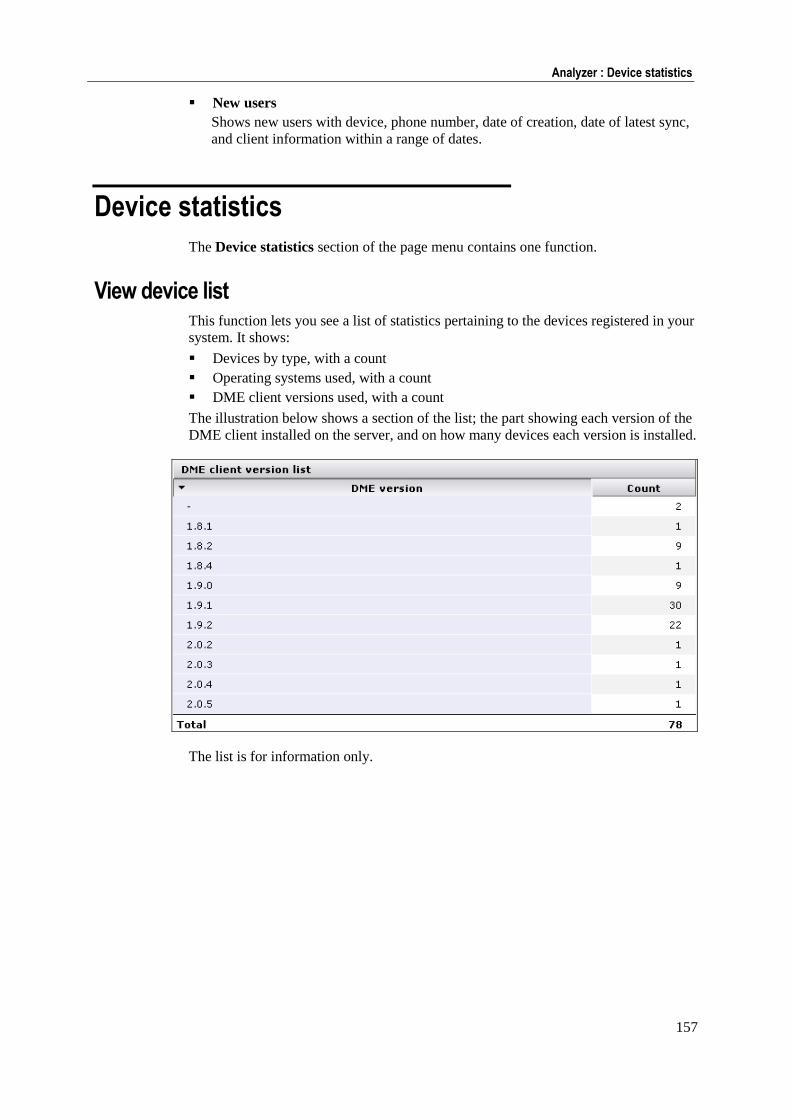
157
Analyzer : Device statistics
New users
Shows new users with device, phone number, date of creation, date of latest sync,
and client information within a range of dates.
Device statistics
The Device statistics section of the page menu contains one function.
View device list This function lets you see a list of statistics pertaining to the devices registered in your
system. It shows:
Devices by type, with a count
Operating systems used, with a count
DME client versions used, with a count
The illustration below shows a section of the list; the part showing each version of the
DME client installed on the server, and on how many devices each version is installed.
The list is for information only.

Server 159
Server
The Server tab contains functions and information used for managing the DME
server.
If you are using the Web Administration Interface with the role of DME_Superuser, you are not able to change the server configuration.
Server
The Server section of the page menu contains the following functions:
Server configuration The Server configuration panel is a list of grouped settings, which make you able to
configure various aspects of the DME Server. After configuring a group of settings,
click Save configuration to save your settings.
Note that the default values specified here are not necessarily the best values for your
setup. Always consult your DME partner or an Excitor consultant before changing the
values. The DME Support http://www.excitor.com site also contains a rule-of-thumb
guide to the best settings of key parameters for installations of different sizes.
This is the default function, that is the function shown when you click the Server tab.
Client
In the Client section of the Server configuration panel you can configure various
aspects of the clients' communication with the server.
Client software database
The Client software database group of functions contains the following field:
Software push, ticket lifetime (minutes)
When software is pushed to the device by SMS or WAP, it is sent in the form of a
link to the software on the server. This link will be valid for the specified number
of minutes. If you specify "0", the link will always be valid. For information about
installing software on clients, see Installing to existing devices. Default value: 60
minutes.
Connection
The Connection group of functions contains the following fields:
Client request linger (seconds, client output cache)
To prevent the DME server from overloading the collaboration server, a
mechanism exists to prevent excessive pulling or in case of unstable GPRS
connections. This setting defines the number of seconds that data to the client
should be cached on the server. If a user tries to synchronize before the cache is
flushed, the user will get the results from the cache instead of performing an actual
synchronization, thus saving a connection to the collaboration server. Default
value: 300 seconds. For more information about the cache, see Clients online.
160
DME Server Administration Reference 3.5 : ©2011 Excitor A/S
Client request timeout (seconds)
The maximum amount of time in seconds that a synchronization request can exist
before it is returned to the client as a timeout error. This typically happens if the
collaboration system fails to respond. Default value: 300 seconds.
Max. number of concurrent client processes
This setting defines the maximum number of concurrent client connections from
the DME server against the collaboration server. Please note this setting only has
effect if set higher than maxThreads in server.xml. Note also that apart from
this number of processes, the collaboration server needs to be able to handle the
number of notification processes defined in the Process section of the
Notifications setup panel. For more information, see Process on page 189. Default
value: 100.
Upon busy server, retry after min. seconds
Upon busy server, retry after max. seconds
With these two settings, you define a range of seconds. If a client process has been
denied access to the server because the number of concurrent client processes has
been exceeded (see above), the server tells the process to try again after a random
number of seconds between the minimum and maximum number of seconds
specified in these fields.
Network minimum keep-alive time (minutes)
In this field you can set the minimum time the server should wait before sending a
keep-alive signal through the network push port. Default value is 3 minutes. In
some configurations, this value and especially the maximum keep-alive time value
can cause problems in connection with firewalls, proxies and other network
equipment. For more information, see Appendix F: AdaptivePush™ on page 279.
Network maximum keep-alive time (minutes)
In this field you can set the maximum time the server should wait before sending a
keep-alive signal through the network push port. Default value is 30 minutes. The
maximum value is 35 minutes. If the server waited longer than 35 minutes,
Symbian devices would crash due to a limitation in the Symbian OS.
DM server
The DM server group of functions contains the following field:
Port
In this field you can specify the network port you want to use for OMA DM
traffic. If the field is blank, DME uses the same port as for synchronization traffic
(5011 by default). In a DME cluster setup, you may be required to use a separate
OMA DM port, if the load balancer cannot handle multiple types of rules (both
cookie and URL stickiness in this case). The load balancer needs to keep a
persistent connection between the client and the DME server node providing the
software requested by the DM engine.
If you change the port in this field, we recommend using port 5031 - this is the
port used in the cluster configuration documentation, which is available at the
Excitor Partner website. Note that you may need to change your firewall
configuration as well.
iPhone MDM Server
Before completing the fields below, make sure you read the section Server
configuration for Apple MDM on page 99. This section contains important further
information which you need to know.
The iPhone MDM Server group of functions contains the following fields:
161
Server : Server
APNS MDM Topic
In this field you specify the Topic of your APNS certificate. This is what you
entered during the creation of the certificate signing request (CSR), something like
com.apple.mgmt.yourcompany.dme. During the creation of the CSR, this was
entered in a field called Bundle ID. Inside the certificate (if you look into the
certificate using a utility such as Keytool), the topic is listed as a User ID. It is
very important to get this name right. The field is pre-filled with the first,
mandatory part of the topic name: com.apple.mgmt.
APNS MDM Certificate filename
In this field you can specify the filename of the APNS MDM certificate you have
installed in the /var/dme/../etc or \dme\jboss\..\etc directory on the
DME server. By default, this is MDM_APNS.p12.
APNS MDM Certificate password
In this field you must specify the password for the .p12 certificate file you created
from the Apple Keychain Access tool or using openssl on Windows. DME needs
this password for accessing the certificate.
For general information about the Apple iOS MDM system, see MDM on Apple iOS
on page 94.
Click Save configuration to save the current configuration.
Authentication
In the Authentication item of the Server configuration panel you can configure how
devices are authenticated in the DME system.
Security
The Security group of functions contains the following fields:
Create device on first connect
If this field is set to True, the DME server will automatically add devices in the
Devices tab, the first time a user logs on to the server with a device which is not
known to the system already (that is, with an unknown IMEI number). The device
is assigned to the user. Unknown users are always created automatically if they
pass the LDAP authentication.
If this field is set to Locked, new devices will be created with device ID in the
Devices tab, but locked and without any user being assigned to the device. This is
because no LDAP lookup of the user credentials are made. In order to enable
regular synchronization with the device, the device must be unlocked by the DME
Administrator using the function Toggle device lock on page 40 in the Devices
tab. Furthermore, if client signing is enabled, the DME Administrator must send a
new signing key to the device using the function New device signing key on page
38. The next time the user synchronizes his or her device, the device is signed and
assigned to the user, and regular synchronization is possible.
If the field Send mail on creation below is True, the DME Administrator will be
notified whenever a device is created or changes users. Note that the device is
assigned to a user, which implies that an LDAP lookup must be made.
If this field is set to False, you must create devices manually or import them in the
Devices tab.
Automatically created users are initially locked
If this field is set to True, users who are created automatically (via LDAP) are
initially locked, meaning that they are unable to log on to the DME server until the
lock is cleared by an administrator in the Devices tab. If this field is set to False,
users can start using DME immediately. Default: False.
162
DME Server Administration Reference 3.5 : ©2011 Excitor A/S
Device allowed to switch user
If this field is set to True, devices can change hands - users are permitted to switch
or exchange devices. If this field is set to False, a device is bound to a user, and it
cannot connect to the server if the user logging in is different from what is
registered in the Devices tab. In order for a device to be passed to another user, it
must be detached from the user first by a DME Administrator (see Detach user
from device on page 39).
Allow Basic MDM devices
If this field is set to True, Basic MDM devices are permitted access to DME. Basic
MDM devices do not require authentication, and are created with "anonymous
users" in the Devices tab. They are used for device management purposes, for
gathering traffic statistics, and to some extent for synchronizing files. For more
information, see Appendix G: The Basic MDM client on page 283. If this field is
set to False, no "anonymous" devices are allowed on the DME server.
Client signature
In this field you can specify if you want to require signed communication between
clients and the server. Client signing is a process where the server confirms that
the client is a valid user of the system, before any LDAP/AD authentication of the
user takes place. This prevents Denial of Service (DOS) attacks on the LDAP
system.
Important note about iPhone: This feature is supported by the DME client for
iPhone from version 3.5.4. If you turn this feature on, any iPhone clients with
DME clients older than 3.5.4 in your system will not be able to connect. The
reason for this is that iPhone does not support keys generated using the DSS
standard, and support for RSA keys was not implemented until version 3.5 SP2 of
DME (see below).
Client signing builds on a system of public and private keys, issued by the DME
server. Each client receives a unique key from the server. When the client connects
to DME, the server will verify the key presented to the server by the client. If the
key is not validated, access is denied immediately.
For more information about the architecture behind the client signature feature,
please request special documentation: "Client Signing" (NDA applies).
False: The server does not expect the communication between server and
client to be signed.
Compatible: The server expects the communication between server and client
to be signed, but only for compatible clients, that is DME clients version 2.0
and above running on the platforms mentioned above. This setting should only
be used in a transition phase, for example during an upgrade from an earlier
version of DME. When a certificate has been installed on all clients, you
should change this field to True.
True: Every connection made by the client to the server is signed according to
DSS (Digital Signature Standard). This means that before establishing the
connection and looking the user up in LDAP, the server verifies that the client
is in fact known by the system using a system of public and private keys.
See also Auto sign below.
When client signatures are enabled, a challenge can arise when the user changes
his or her network password using a PC (not the device). If the network password
is changed, the user may be unable to connect to DME. There are two variations of
this scenario:
163
Server : Server
The DME client has been closed (the device has been rebooted or the DME
application has been switched off): In this case, the user must start the DME
client, log in using the OLD password, log out, and then log in using the NEW
password. If the user tries to verify a new password without have used the old
password first (which is stored encrypted on the device), then the DME server
will reject the device because the client signature certificate on the client does
not match the one on the server.
The DME client has not been closed since the user changed his or her network
password: In this case, the user must log out, and then log in to DME using the
NEW password.
The important thing to remember is that you should not try to "help" the user by
removing the signature key from the device in DME.
If the user is unable to log in to the device because the server is unable to verify
the new password (because the client certificate cannot be verified by the server),
then you must flush the device using the Destroy all device data option in the
Delete user data dialog, and reinstall DME (see Delete user data on page 55) or
contact DME Support.
Auto sign
If this field is set to True, unsigned devices should be provided with a certificate
(key pair) when they connect for the first time. If Client signature is enabled (see
above), you can enable this setting in a transition period until all existing,
compatible devices have been provided with a signature. If this field is set to
False, you must use the tab function New device signing key on page 38 in the
Devices tab to generate a key pair for a device.
Send e-mail on creation
If this field is set to True, an e-mail is sent to an administrator when a device is
created, a device changes users, or a new device signing key is generated. The
DME Administrator can then verify the change, unlock any locked devices, or
generate new keys for devices. The e-mail address is specified in the Alert e-mail
section of the Collaboration on page 164 panel section.
Store user password (encrypted)
If this field is set to True, DME will store an encrypted version of each user's
mailbox password in the local DME database. The password is stored the first time
a user synchronizes his device. This way DME can employ the user's own
password for scanning mailboxes instead of having to grant access to the DME
server user. The password is only used for mailbox scans. See Collaboration on
page 164 for more information about the DME server user.
Note that if you change this setting from True to False, DME will flush all stored
passwords. If you switch it back to True, the process of collecting the individual
users' passwords starts over.
Lock Jailbroken/Rooted devices
DME relies on the clients for information about which clients are jailbroken (iOS)
or rooted (Android), and which are not. The client reports that a device is
jailbroken or rooted by adding (Jailbroken) or (Rooted), respectively, to the device
name - for instance iPhone 3GS (Jailbroken).
If this field is set to True, DME will lock all devices that have been reported to be
jailbroken or rooted. When you enable this setting, DME will lock all existing
jailbroken and rooted devices the next time they contact the DME server, and
create new devices as locked if they are jailbroken or rooted.
If the setting has been enabled, and you disable it again, you must manually
unlock the locked devices.
164
DME Server Administration Reference 3.5 : ©2011 Excitor A/S
Click Save configuration to save the current configuration.
Collaboration
In the Collaboration section of the Server configuration panel you can configure
how the DME server should manage S/MIME certificates, interact with the IBM
Sametime instant messaging system, and send system-generated e-mails.
S/MIME
The S/MIME (see Glossary on page 291) group of functions contains the following
fields:
Secondary LDAP Certificate Store
In this field you can enter the URL to a secondary certificate store based on the
LDAP protocol. For instance, VeriSign maintains a list (a public directory) here:
ldap://directory.verisign.com. By entering this URL, you entrust an external
partner (VeriSign) to maintain a list of trusted public keys. A description of this
concept can be found here:
http://www.verisign.com/stellent/groups/public/documents/guides/005327.pdf
This way you do not have to install all root and external certificates on the DME
server.
Automatically store unknown certificates
If this field is set to True, DME will automatically store certificates from "external
people". External people (sometimes called "other people") are here defined as
people who are not users in the DME system. Say that an external accountant
sends a signed e-mail to the CFO of your company. The accountant's certificate
will then be stripped from his mail and stored here as an external certificate. Now
every user in the DME system will be able to receive signed messages from the
accountant, and DME certificate holders will be able to send signed and encrypted
messages to the accountant without further setup.
Perform CRL/OCSP lookups
If this field is set to True, DME will look up certificate revocation lists (CRL) and
certificate status using the Online Certificate Status Protocol (OCSP) to check if
external certificates are valid. However, if the server does not have access to the
Internet, you should set this option to False to keep the server from attempting
something that is not possible anyway.
Accept certificate even if CRL lookup fails
If this field is set to True, DME will accept a public certificate from an external
person, even if the certificate's CRL is unavailable at the moment, for instance if
the CRL home page is down, or an Internet connection is temporarily down. Note
that if the CRL is available, and the external person is found in the CRL, the
certificate will naturally still be rejected.
Instant messaging
The Instant messaging group of functions contains the following fields:
IM server
In this field you can enter the path to your instant messaging (IM) server (currently
only IBM Sametime is supported). This enables IM presence in the clients, so
users of the DME client can see the status of other users of the instant messaging
server entered in this field.
165
Server : Server
IM username
In this field you can enter the user name used for logging in to the Instant
Messaging service user. The service user is used for acquiring the IM status of the
users shown in client mailboxes.
IM password
In this field you can enter the password of the Instant Messaging service user. The
service user is used for acquiring the IM status of the users shown in client
mailboxes.
SMTP relay
The SMTP relay group of functions contains the following fields:
SMTP mail relay server
This is the external name of the mail server used by DME for sending system
administration messages (see Alert e-mail below). Note that this mail server must
allow relays from the DME server IP address.
Note also that using a corresponding field on the Main section of the connectors'
setup page you can set up a mail relay server for each connector, which will
handle system-generated messages about calendar conflicts and name resolution
errors. See Main on page 211.
SMTP mail sender
In this field you can enter a name you want to show as sender when a user receives
a system-generated message as described above. For instance, you can enter DME Administrator or similar as sender to make it obvious to the user that the message
is system-generated. If you leave the field empty, system-generated messages will
be sent with root@DME-Server as sender.
Please take steps to ensure that e-mails from this sender are not evaluated as spam
by the recipients' e-mail clients, for instance by instructing the DME users to add
this sender to the "Safe Senders list" or similar. E-mail in spam mailboxes is rarely
read, and almost never synchronized to DME clients, so there is a risk that
important information is missed by the users.
Alert e-mail
The Alert e-mail group of functions contains the following fields:
E-mail from
In this field you enter the sender name of e-mails sent by the server to inform an
administrator that a client was created on the server or a new client signing key
was generated by the server. The e-mail is sent using the SMTP mail server
specified in the field SMTP mail server above. As sender name, you can for
instance choose the name of the current server. If you leave it blank, DME uses the
name entered in the SMTP mail sender field above.
E-mail to
In this field you enter the recipient of the administrative server e-mails mentioned
above.
Pre-caching sync. data
The Pre-caching sync. data group of functions contains the following field:
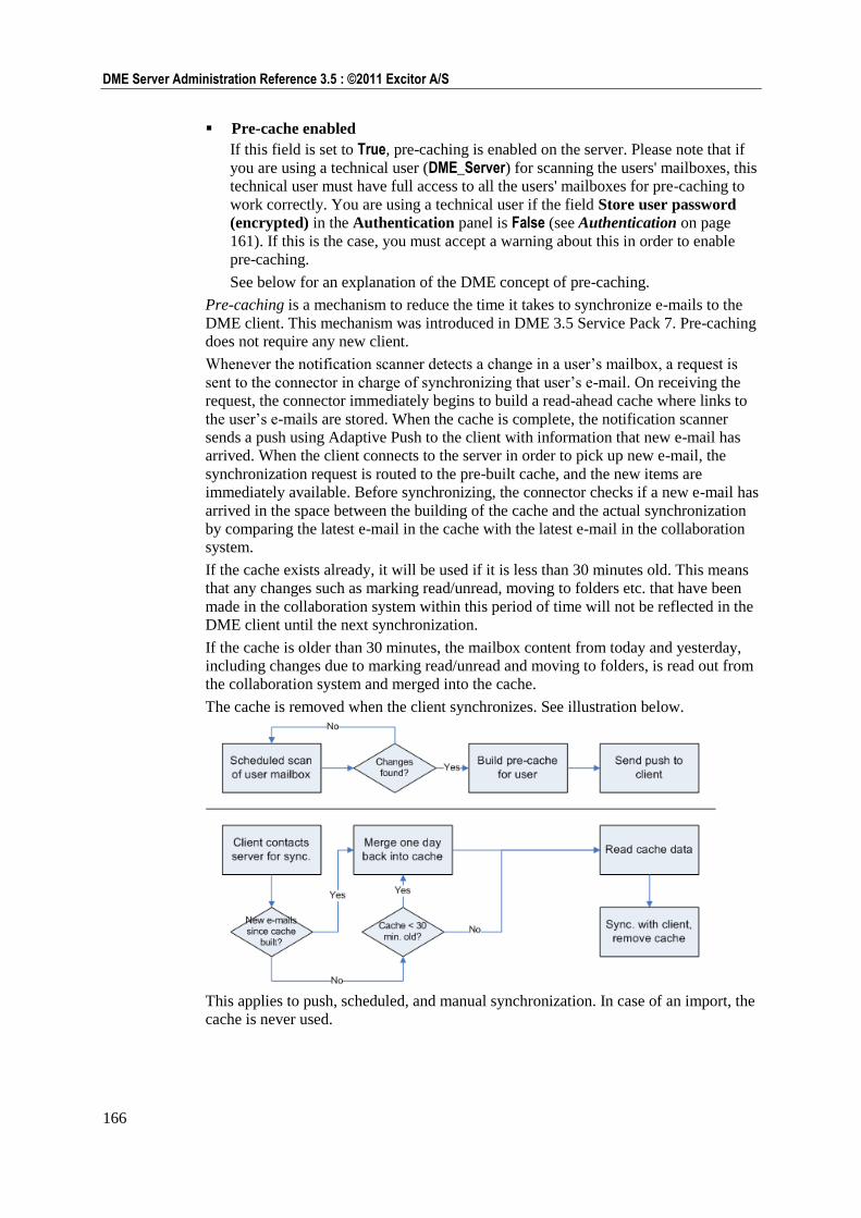
166
DME Server Administration Reference 3.5 : ©2011 Excitor A/S
Pre-cache enabled
If this field is set to True, pre-caching is enabled on the server. Please note that if
you are using a technical user (DME_Server) for scanning the users' mailboxes, this
technical user must have full access to all the users' mailboxes for pre-caching to
work correctly. You are using a technical user if the field Store user password
(encrypted) in the Authentication panel is False (see Authentication on page
161). If this is the case, you must accept a warning about this in order to enable
pre-caching.
See below for an explanation of the DME concept of pre-caching.
Pre-caching is a mechanism to reduce the time it takes to synchronize e-mails to the
DME client. This mechanism was introduced in DME 3.5 Service Pack 7. Pre-caching
does not require any new client.
Whenever the notification scanner detects a change in a user‘s mailbox, a request is
sent to the connector in charge of synchronizing that user‘s e-mail. On receiving the
request, the connector immediately begins to build a read-ahead cache where links to
the user‘s e-mails are stored. When the cache is complete, the notification scanner
sends a push using Adaptive Push to the client with information that new e-mail has
arrived. When the client connects to the server in order to pick up new e-mail, the
synchronization request is routed to the pre-built cache, and the new items are
immediately available. Before synchronizing, the connector checks if a new e-mail has
arrived in the space between the building of the cache and the actual synchronization
by comparing the latest e-mail in the cache with the latest e-mail in the collaboration
system.
If the cache exists already, it will be used if it is less than 30 minutes old. This means
that any changes such as marking read/unread, moving to folders etc. that have been
made in the collaboration system within this period of time will not be reflected in the
DME client until the next synchronization.
If the cache is older than 30 minutes, the mailbox content from today and yesterday,
including changes due to marking read/unread and moving to folders, is read out from
the collaboration system and merged into the cache.
The cache is removed when the client synchronizes. See illustration below.
This applies to push, scheduled, and manual synchronization. In case of an import, the
cache is never used.
167
Server : Server
Benefit
The user will experience significantly faster e-mail synchronization when receiving a
push, because the server can compare the contents of the client's mailbox with the
cache and does not need to contact the collaboration system for anything other than
getting the new e-mails (or information about deleted or read e-mails, or whatever is
required by the changes discovered in the mailbox). This speed optimization is
especially significant on devices that do not support e-mail synchronization as a
background process (as in Apple's iOS).
Security
The cache stored on the connector does not include the e-mails as such, only an MD5
checksum and a reference to the e-mail (a so-called minimal note). The e-mail content
is stored securely in the collaboration system mailstores.
S/MIME
Due to the way in which S/MIME e-mails are handled by the collaboration system,
enabling pre-caching will not benefit overall system performance if most of your
e-mails are S/MIME. In other words, if your users primarily send and receive S/MIME
e-mails, you should not enable pre-caching on the server.
Click Save configuration to save the current configuration.
Data
In the Data section of the Server configuration panel you can view the amount of
data used by the DME database, configure the DME data cleanup thread, specify
directories for data storage, determine the volume of log entries, set the maximum size
of file uploads, and configure the obfuscation of phone numbers in the statistics
database.
Database usage
The Database usage group of fields shows the current size of three tables in the DME
database. The size is shown as a ratio between the current size and the maximum
amount available for the table in question. On systems based on the MySQL database,
the maximum size is typically 4 GB. On systems based on MS SQL Server, the table
size can usually be expanded dynamically, and you must ask your database
administrator for information about the maximum size of each table.
Log table
A graphical view of the ratio between the actual and the maximum amount of data
in the log.
Statistics table
A graphical view of the ratio between the actual and the maximum amount of data
in the statistics table.
Voice statistics table
A graphical view of the ratio between the actual and the maximum amount of data
in the voice statistics table.
Log configuration
The Log configuration section contains one option:
Only show info messages from DME
If this field is set to True, only information about DME is shown in the log.
If this field is set to False, information from a number of third-party applications
will also be included in the log, such as information about JBoss, Domino,
CORBA and so on, as configured in the jboss-log4j.xml file on the connector.
This information is also available elsewhere, that is in other log files. See the
documentation for the third-party application in question.
168
DME Server Administration Reference 3.5 : ©2011 Excitor A/S
Default: True.
Database maintenance
The settings in the Database maintenance group of fields are used by the internal
cleanup thread, which cleans out old log entries and statistics that have lost their
relevance. This group of functions contains the following fields:
Delete log older than (days)
This setting specifies how old a log entry must be to be cleaned out of the database
automatically. Default is 180, which is about six months. However, if you run an
active system with many users, it is a good idea to reduce the number of days to 90
or even 30 days, as the database log table will otherwise grow very large.
Delete statistics older than (days)
The functionality of this field is similar to that of the field field Delete log older
than (days) above, but applies to statistics entries.
Delete old log & statistics every (hours)
In this field you can specify (in hours) how often the cleanup thread should be
launched to clean out old log and statistics entries. Default is 24 hours, meaning
that the server will clean out log entries and statistics older than the number of
days specified above daily.
Data storage directories
The Data storage directories group of functions contains the following fields:
Local data directory
The directory in which DME stores local data, including files for synchronization,
device images, and device statistics.
Local temporary data directory
The directory in which DME stores temporary data, such as files being uploaded,
temporary cache data, etc.
Data limits
The Data limits group of functions contains the following field:
Max. file size for upload to server
In this field you can specify the maximum size of files uploaded to the server. This
limit applies to all files uploaded to the server, either as a result of a file
synchronization rule or as an attachment to an e-mail sent from a DME client.
If you are using MySQL for your DME database, and you set this value to above
the default 16 MB, you will probably need to change the configuration the
max_allowed_packet value for your database accordingly to prevent errors. For
instance, if you change the value here to 32 MB, enter the following command in
the database shell:
mysql --max_allowed_packet=32M
For more information, see the following article on the MySQL home page: Packet
too large http://dev.mysql.com/doc/refman/5.0/en/packet-too-large.html.
Statistical data
The Statistical data group of functions contains the following field:
Hide no. of phone number digits
In statistical reports using the BIRT reporting framework it is possible to create
reports that allow drill-down to individual phone calls. In many countries, it is not
permitted to display the entire phone number in such reports for reasons of
privacy.
169
Server : Server
In this field, you can enter the number of digits that DME should hide from the
phone numbers stored in the statistics database. The phone numbers are obfuscated
by replacing the digits with an X. The digits are replaced from right to left. If you
enter 0 in this field, the phone numbers will be fully displayed.
Click Save configuration to save the current configuration.
SMS modem
In the SMS modem section of the Server configuration panel you can configure the
SMS server attached to the DME server. DME supports Kannel and Now SMS
(Windows only) as SMS server. The SMS server was installed together with the DME
application, and you can configure some of the options here.
SMS modem
The SMS modem group of functions contains the following fields:
Phone country code
The default phone country code used for the SMS gateway.
SMS server
The DNS name or IP address of the SMS gateway.
Username
The user name giving access to using the SMS gateway.
Password
The password giving access to using the SMS gateway.
OMA PIN
Some devices require a PIN code to be able to open OMA configuration messages.
The default OMA PIN code is "12345". See below and Appendix B:
Self-provisioning on page 255.
SMS Service PIN
You can permit devices to use SMS codes for initiating downloads of
configuration files and software (see Appendix B: Self-provisioning on page 255).
By setting a PIN code in this field you can require that the SMS sent from the
device must be followed by a PIN code (to enhance security). If you do this, the
download request SMS sent from the device must have the following form:
<SMS Code> <PIN>
-and be sent to the number specified in the field Modem phone number below.
SMS gateway POST PIN
For enhanced security, you can define a PIN code which must be part of the URL
for the SMS gateway.
Modem phone number
The phone number of the SMS modem attached to the SMS server. This is also the
number used by the clients to report their phone number to the server, if the phone
number in Settings > General for the device is blank (see Phone number in
General settings). This means that if this field is blank, devices cannot report their
phone number to the server.
Please be aware that if you are using a web-based SMS service center, and you
cannot get SMS feedback from the clients, this field must be blank in order to
avoid that the client keeps trying to report its phone number to the server.
SMS gateway configuration
The SMS gateway configuration group of functions contains the following field:
170
DME Server Administration Reference 3.5 : ©2011 Excitor A/S
Choose gateway interface
In this dropdown list you can choose which SMS gateway has been installed for
sending out SMS messages and SMS/WAP push to the clients: Kannel or Now SMS. Then fill in the fields that apply to the SMS gateway you have chosen.
Kannel
The settings in this group of fields apply if you have installed Kannel as SMS gateway
on the server. See also the documentation for the Kannel gateway.
The Kannel group of functions contains the following fields:
WAP push path
The path to the WAP Push script on the Kannel server.
OTA path
The path to the Send OTA (see Glossary on page 290) script on the Kannel server.
SMS path
The path to the Send SMS script on the Kannel server.
Does the Kannel server use delivery reports
If this field is set to True, Kannel will expect a confirmation message from the
operator that each SMS has been transmitted correctly.
DME host for delivery reports
If the use of delivery reports is enabled, enter the DME host name or IP address
open for receiving delivery reports, that is the server where Kannel is installed. If
empty, the external DME server address (the "server path" is assumed).
Bind SMS gateway input to IP address
In this list, you can choose to bind the SMS gateway only to a specific connector
or to them all. In this way you can make sure that the SMS gateway can only be
accessed from inside the company. The list is built from settings in the server
configuration files, which are specified during the installation of DME.
Now SMS
This setting applies if you have installed the Now SMS/MMS Gateway (NowSMS) as
SMS gateway on the server. See also the documentation for the Now SMS/MMS
Gateway at http://www.nowsms.com.
The NowSMS group of functions contains the following field:
NowSMS server port
In this field you can specify the port number for the NowSMS web interface
(default is 8800).
Click Save configuration to save the current configuration.
Central Services
In the Central Services section of the Server configuration panel you can configure
feedback to DME Central Services (CS), and turn Apple Push Notification on or off.
DME Central Services (CS) is a customer installation feedback service provided by
Excitor A/S. When enabled, your DME server will automatically collect information
about your system settings, your device mix, generic usage statistics, and system
errors and warnings. This information is posted regularly to the DME CS server,
which is run by Excitor. The information is collected from all participating DME
customers. Note that this is strictly one-way traffic - the DME Central Services server
will never contact a DME server.
171
Server : Server
With this information, Excitor gets more accurate background data about the server
environment of their customers. The information is available to a group of DME
support staff, who use it to access up-to-date data when helping our customers, and
selected lead developers, who use the data to constantly improve DME.
It is very important to stress that the collected information is completely anonymous.
In the Installation information upload section below you can read more about which
information is uploaded, and how Excitor uses it for your benefit.
Apple Push Notification Service (APNS)
The Apple Push Notification Service (APNS) group of functions contains the
following field:
APNS
Set this field to True to enable Apple Push Notification Service, which is required
for iOS devices to receive push notifications from DME. For more information
about further requirements, see Notifications on iPhone on page 195.
Please note that you can disable APNS for individual devices or groups of devices
using the Apple Push Notification setting in the Device settings page (see
General settings on page 242).
Installation information upload
The Installation information upload group of functions contains the following
fields. Note that all fields are set to False by default, so you must enable them to take
advantage of the Central Services statistics and error reporting features. Note also that
all data that is sent to the CS server is anonymized. For instance, device IDs are
hashed so that it is not possible to connect individual devices with their owners.
Upload basic installation information
If you set this field to True, DME will connect to the CS server 2-24 hours after
the installation of DME 3.5 SP 3, and 2-24 hours after every subsequent server
restart. The two-hour delay enables you to turn this feature off if you have a reason
not to keep it enabled.
The following information about your system is sent:
Server settings: The status of some of the settings in the Server configuration
panel. Security-related settings from the Authentication section are not included.
License information: The number and type of licenses acquired, and how many
free licenses are available.
Upload basic topology information (requires installation info)
In order to enable the collection of topology information, the field Upload basic
installation information above must be enabled also. If you set this field to True,
DME will connect to the CS server once every two weeks and send the following
information about your system:
System properties and environment: DME server version, Java version, etc.
(largely the information shown in the Monitor > Server properties section).
Database properties: Version, type, and JDBC driver version.
Connector properties: Some of the settings made for each connector (no
security-related settings).
Device properties: For each device, its client version, platform, type, and settings
such as what DME features are enabled (e-mail sync, calendar sync, etc.). Device
IDs are hashed (made anonymous).
172
DME Server Administration Reference 3.5 : ©2011 Excitor A/S
Upload usage statistics (requires topology info)
In order to enable the collection of usage statistics, the field Upload basic
topology information above must be enabled also. If you set this field to True,
DME will connect to the CS server once every two weeks and send the following
information about your system:
Usage statistics: The same statistics that form the basis for the built-in trend
graphs on the Monitor page. Note again that the statistics are completely
anonymous.
Upload error/warning log statistics (requires installation info)
In order to enable the collection of errors and warnings, the field Upload basic
installation information above must be enabled also. If you set this field to True,
DME will scan your system's log files and send the following information to the
CS server once a day:
Errors and warnings: The errors and warnings that occur most frequently (up to
20 of them) are picked out from the log files, and each error is hashed and given a
special ID. This ID is then sent to the CS along with a list containing the following
information: One instance of the complete error message; a time stamp for each
occurrence of the error (max. 500 time stamps); a list of affected device types and
how many times each type is affected by the error.
With this information, Excitor can gain a deeper understanding of how our customers
use DME, and what your needs are. This understanding is essential for the future
development of DME.
As a more immediate benefit to you, Excitor will analyze the error messages that are
reported. With this information, Excitor can build fixes for those particular errors, and
send the fixes to those customers that are affected by the error.
The URL address of the DME Central Services (CS) server is cs.excitor.com.
This cannot be changed. Port 443 (SSL) must be open from the DME server to the
DME CS server. DME pings the CS server once every hour. If there is no response
from the CS server, a message is written in the log.
Click Save configuration to save the current configuration. Click Start upload to
upload the installation information to the Central Services server immediately.
Web
In the Web section of the Server configuration panel you can configure various
aspects of the DME server Web administration interface and of logging.
Web administration
The Web administration group of functions contains the following fields:
Show statistics no. of days
The default number of days for which statistics are shown on the Analyzer tab.
Search logs no. of days
The default number of days for which logs are searchable on the Log tab.
Installation name
In this field you can specify the name of the installation managed by these
administration pages. It is the name shown in title bar of the web browser,
typically the name of your company. The name is initially entered by the DME
Setup Wizard, but you can change it here.
Note that you can have multiple instances of DME running on the same machine,
for instance a production instance and a test instance. Entering different names for
different instances makes it easier to distinguish between them.
173
Server : Server
Server name
In this field you can specify the name of the server on which the current
installation is run. If the server name is empty (default), DME uses the server
hostname as defined in the server OS. In a cluster setup, we recommend that you
change the name in this field to a short name, which helps you to identify the
server easily.
The server name is printed on every entry in the server log, and can been seen on
the entries visible in the Log tab. The server name is also added as the first part of
the name of the different statistics you can see in the Monitor panel section.
The inclusion of the server name in log entries makes it easier for a load balancer
to distribute the server load and for a fail-over system to cease using a defective
server. In a cluster, you set up all servers (virtual or physical) with the same
installation name, but different server names. For more information, please request
special cluster setup documentation.
Refresh user/group membership (minutes or time hh:mm)
The way that individual devices are structured into groups is important when
notification schedules have been set up for individual groups. For instance, if a
user is member of the LDAP group Sales, and a special notification schedule has
been set up for this group, then it is important that DME knows which users are
member of Sales in order to notify the users' devices about new e-mail etc.
DME refreshes the relationship between users and groups by scanning the
LDAP/AD system at regular intervals as defined in this field. You can either enter
the number of minutes that should pass between each refresh, or you can enter a
specific time of day in hh:mm format, and DME will then perform the user/group
refresh at that time. You could for instance specify that DME should refresh the
user/group memberships every night at 02:00.
If you want to make sure that the user/group memberships are up-to-date, click the
Run now button to perform a manual refresh. You may want to do this if you
change the relationship of a device to a group (by adding devices to or removing
devices from a group, or by changing the priority of a group), or if you switch
users in or out of groups in the LDAP/AD system.
Server documentation url
In this field you can specify the path to the online documentation for the DME
server. Excitor A/S maintains a website with the documentation for the different
versions of the DME server and other documentation. By default, the server path is
set to http://documentation.dmesync.com/server/[ServerVersion], where
[ServerVersion] is the version of the current DME server, with underscores
replacing the periods - for instance 3_5. In case firewall restrictions or other issues
makes it impossible to access the Excitor documentation site, you can request a
copy of the online documentation for installation on the local machine. No Web
server is required.
The online help is shown when you click a question mark icon in the page. For
more information, see Online help on page 24.
Bind admin site to IP address
With this setting, you can choose the port you want to use for accessing the DME
web administration interface, typically 8080. By binding the web interface to a
specific port, you exclude access from other ports which are used for other
purposes, for instance the 5011 sync port. The chosen port can for instance be
configured by a firewall to be available from inside the company only (and not the
internet). Please note that you must not choose the port which is used for network
push (5021 by default), as this will lead to undesired effects in the Web
Administration Interface.
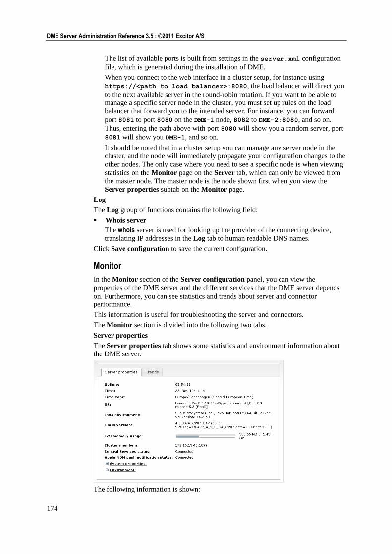
174
DME Server Administration Reference 3.5 : ©2011 Excitor A/S
The list of available ports is built from settings in the server.xml configuration
file, which is generated during the installation of DME.
When you connect to the web interface in a cluster setup, for instance using
https://<path to load balancer>:8080, the load balancer will direct you
to the next available server in the round-robin rotation. If you want to be able to
manage a specific server node in the cluster, you must set up rules on the load
balancer that forward you to the intended server. For instance, you can forward
port 8081 to port 8080 on the DME-1 node, 8082 to DME-2:8080, and so on.
Thus, entering the path above with port 8080 will show you a random server, port
8081 will show you DME-1, and so on.
It should be noted that in a cluster setup you can manage any server node in the
cluster, and the node will immediately propagate your configuration changes to the
other nodes. The only case where you need to see a specific node is when viewing
statistics on the Monitor page on the Server tab, which can only be viewed from
the master node. The master node is the node shown first when you view the
Server properties subtab on the Monitor page.
Log
The Log group of functions contains the following field:
Whois server
The whois server is used for looking up the provider of the connecting device,
translating IP addresses in the Log tab to human readable DNS names.
Click Save configuration to save the current configuration.
Monitor
In the Monitor section of the Server configuration panel, you can view the
properties of the DME server and the different services that the DME server depends
on. Furthermore, you can see statistics and trends about server and connector
performance.
This information is useful for troubleshooting the server and connectors.
The Monitor section is divided into the following two tabs.
Server properties
The Server properties tab shows some statistics and environment information about
the DME server.
The following information is shown:
175
Server : Server
Uptime
The DME server has been running for this amount of time. The time is shown as a
number of days plus a number of hours, minutes, and seconds.
Time
This is the current server time.
Time zone
This is the current server time zone.
OS
The full name of the operating system on which DME is installed.
Java environment
The Java version installed on the server.
JBoss version
The version of the Java application server JBoss from Red Hat. Note that as of
DME 3.5, DME uses the Enterprise Edition of JBoss - in previous versions, we
used the Community Edition.
JVM memory usage
This is the memory usage of the Java Virtual Machine.
For instance, if the numbers are 1.15 GB of 1.22 GB, it means the following: 1.22
GB is the maximum amount of memory available for Java objects in the JVM. The
JVM itself takes up memory, but that is not included in this amount. Out of the
1.24 GB, 1.15 GB is actually being used by JBoss and DME. Please note that for
performance reasons, the JVM will not release memory (from no-longer-used Java
objects etc.) until it is necessary, and therefore the usage will often seem to be
higher than it actually is.
Cluster members
This field lists the IP addresses of the online, active members of the DME cluster.
The server listed first is the primary server in the cluster (the master node). If the
master node is down, number two in the list will take over and become the master
node. This does not change, even when the original master node is back online.
If DME is not set up with multiple servers, only the current server is listed in this
field.
Central Services status
If the DME server has been configured to connect with DME Central Services,
this fields shows if the connection was successful (Connected). Among other
things, this has an impact on Apple Push Notification Services. For more
information, see Setting up notifications on iPhone on page 197 and Central
Services on page 170.
Apple MDM push notification status
If an Apple MDM APNS certificate has been installed on the server, this fields
shows Connected. It is then possible to enroll and configure iOS devices. For more
information, see MDM on Apple iOS on page 94.
System properties
Click to expand this field. The field shows information about the Java system
installed on the server, as reported by Java.
Environment
Click to expand this field. The field shows information about the server
environment as reported by Java.
Trends
176
DME Server Administration Reference 3.5 : ©2011 Excitor A/S
The Trends tab shows a collection of statistic trends and key performance indicators
concerning the DME server and connectors.
The list of statistics contains four columns:
Statistic
This is the name of the statistic. Click the name to view the statistic (as explained
below).
Location
The DME component to which the current statistic pertains. This could be the
DME server, which is shown with a server icon and the name of the server, or a
connector, which is shown with a connector icon and the name of the connector.
Trend 4h
An arrow in this column shows if the trend has been rising or falling over the last 4
hours. The trend analysis is based on a linear regression analysis of the
measurements. If the result of the regression analysis is at least 5% above the
measured average, the trend is rising, and a grey upward arrow is displayed. If the
result is at least 5% below the measured average, the trend is falling, and a grey
downward arrow is shown. If no significant change has occurred, no arrow is
shown.
Avg 4h
This column shows the average over the last 4 hours. An icon in this column
means that the average cannot be calculated due to lack of data.
When you click the name of a statistic, an interactive graph is shown below the name.
All statistics are created using the RRD4J tool, which makes use of round-robin
databases for dynamic collection and display of data. For a technical explanation of
the principles behind the collection and display of data, please see the following
tutorial: RRD4J Tutorial https://rrd4j.dev.java.net/tutorial.html.
Each trend graph contains three trend blocks: Days, Hours, and Minutes. You can
switch between them by clicking the D, H, or M button at the bottom left of the graph.
Each trend block contains four windows showing data for a span of time. The Days
trend block contains a total time span of 2 years, split into 4 windows of 6 months
each. The Hours trend block contains a total time span of 4 weeks, split into 4
windows of 1 week each. The Minutes trend block, which is the default view, contains
a total time span of 8 hours, split into 4 windows of 2 hours each.
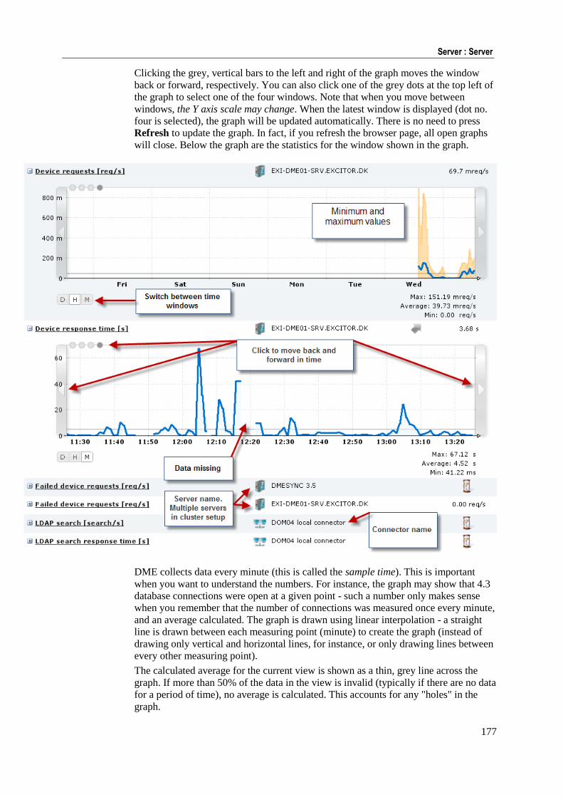
177
Server : Server
Clicking the grey, vertical bars to the left and right of the graph moves the window
back or forward, respectively. You can also click one of the grey dots at the top left of
the graph to select one of the four windows. Note that when you move between
windows, the Y axis scale may change. When the latest window is displayed (dot no.
four is selected), the graph will be updated automatically. There is no need to press
Refresh to update the graph. In fact, if you refresh the browser page, all open graphs
will close. Below the graph are the statistics for the window shown in the graph.
DME collects data every minute (this is called the sample time). This is important
when you want to understand the numbers. For instance, the graph may show that 4.3
database connections were open at a given point - such a number only makes sense
when you remember that the number of connections was measured once every minute,
and an average calculated. The graph is drawn using linear interpolation - a straight
line is drawn between each measuring point (minute) to create the graph (instead of
drawing only vertical and horizontal lines, for instance, or only drawing lines between
every other measuring point).
The calculated average for the current view is shown as a thin, grey line across the
graph. If more than 50% of the data in the view is invalid (typically if there are no data
for a period of time), no average is calculated. This accounts for any "holes" in the
graph.
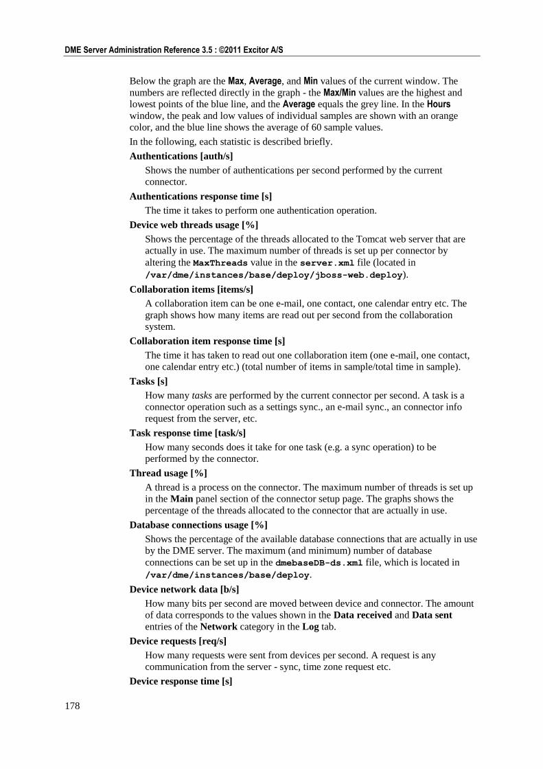
178
DME Server Administration Reference 3.5 : ©2011 Excitor A/S
Below the graph are the Max, Average, and Min values of the current window. The
numbers are reflected directly in the graph - the Max/Min values are the highest and
lowest points of the blue line, and the Average equals the grey line. In the Hours
window, the peak and low values of individual samples are shown with an orange
color, and the blue line shows the average of 60 sample values.
In the following, each statistic is described briefly.
Authentications [auth/s]
Shows the number of authentications per second performed by the current
connector.
Authentications response time [s]
The time it takes to perform one authentication operation.
Device web threads usage [%]
Shows the percentage of the threads allocated to the Tomcat web server that are
actually in use. The maximum number of threads is set up per connector by
altering the MaxThreads value in the server.xml file (located in
/var/dme/instances/base/deploy/jboss-web.deploy).
Collaboration items [items/s]
A collaboration item can be one e-mail, one contact, one calendar entry etc. The
graph shows how many items are read out per second from the collaboration
system.
Collaboration item response time [s]
The time it has taken to read out one collaboration item (one e-mail, one contact,
one calendar entry etc.) (total number of items in sample/total time in sample).
Tasks [s]
How many tasks are performed by the current connector per second. A task is a
connector operation such as a settings sync., an e-mail sync., an connector info
request from the server, etc.
Task response time [task/s]
How many seconds does it take for one task (e.g. a sync operation) to be
performed by the connector.
Thread usage [%]
A thread is a process on the connector. The maximum number of threads is set up
in the Main panel section of the connector setup page. The graphs shows the
percentage of the threads allocated to the connector that are actually in use.
Database connections usage [%]
Shows the percentage of the available database connections that are actually in use
by the DME server. The maximum (and minimum) number of database
connections can be set up in the dmebaseDB-ds.xml file, which is located in
/var/dme/instances/base/deploy.
Device network data [b/s]
How many bits per second are moved between device and connector. The amount
of data corresponds to the values shown in the Data received and Data sent
entries of the Network category in the Log tab.
Device requests [req/s]
How many requests were sent from devices per second. A request is any
communication from the server - sync, time zone request etc.
Device response time [s]
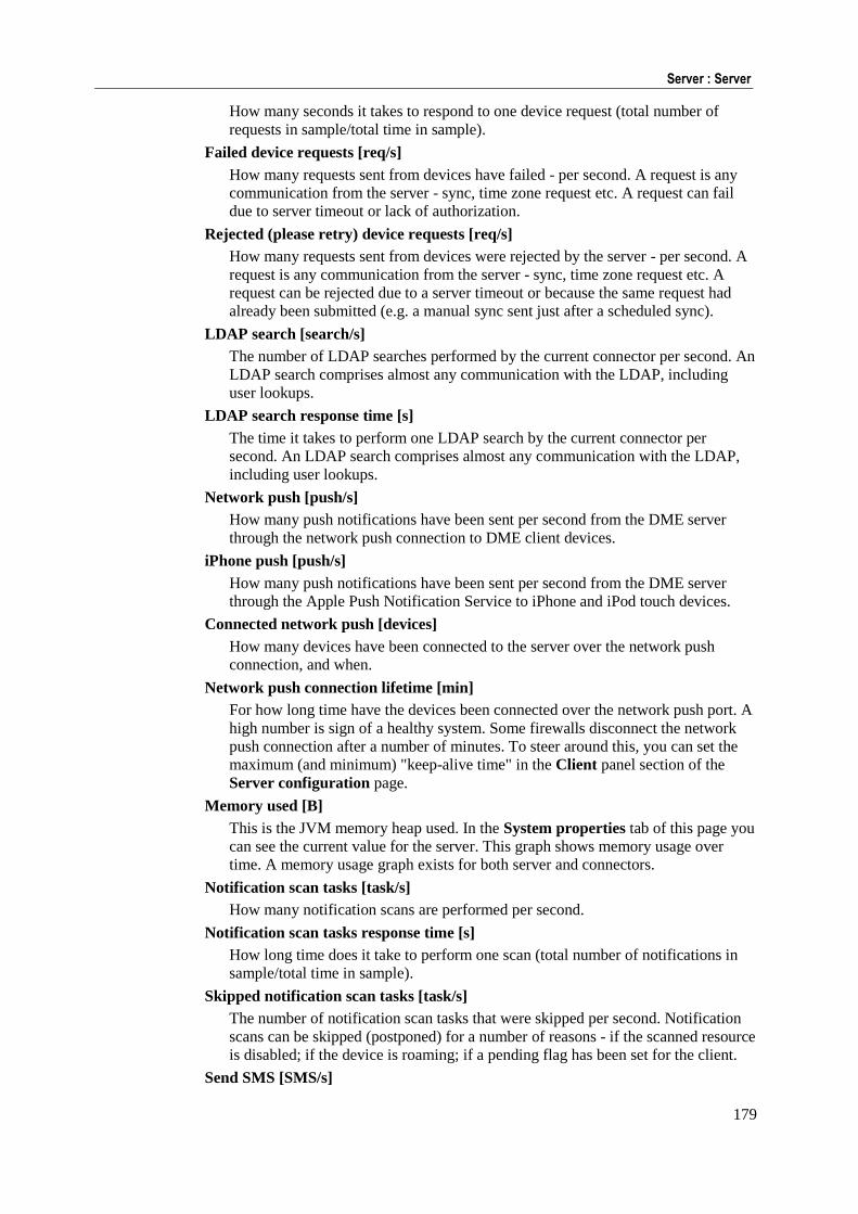
179
Server : Server
How many seconds it takes to respond to one device request (total number of
requests in sample/total time in sample).
Failed device requests [req/s]
How many requests sent from devices have failed - per second. A request is any
communication from the server - sync, time zone request etc. A request can fail
due to server timeout or lack of authorization.
Rejected (please retry) device requests [req/s]
How many requests sent from devices were rejected by the server - per second. A
request is any communication from the server - sync, time zone request etc. A
request can be rejected due to a server timeout or because the same request had
already been submitted (e.g. a manual sync sent just after a scheduled sync).
LDAP search [search/s]
The number of LDAP searches performed by the current connector per second. An
LDAP search comprises almost any communication with the LDAP, including
user lookups.
LDAP search response time [s]
The time it takes to perform one LDAP search by the current connector per
second. An LDAP search comprises almost any communication with the LDAP,
including user lookups.
Network push [push/s]
How many push notifications have been sent per second from the DME server
through the network push connection to DME client devices.
iPhone push [push/s]
How many push notifications have been sent per second from the DME server
through the Apple Push Notification Service to iPhone and iPod touch devices.
Connected network push [devices]
How many devices have been connected to the server over the network push
connection, and when.
Network push connection lifetime [min]
For how long time have the devices been connected over the network push port. A
high number is sign of a healthy system. Some firewalls disconnect the network
push connection after a number of minutes. To steer around this, you can set the
maximum (and minimum) "keep-alive time" in the Client panel section of the
Server configuration page.
Memory used [B]
This is the JVM memory heap used. In the System properties tab of this page you
can see the current value for the server. This graph shows memory usage over
time. A memory usage graph exists for both server and connectors.
Notification scan tasks [task/s]
How many notification scans are performed per second.
Notification scan tasks response time [s]
How long time does it take to perform one scan (total number of notifications in
sample/total time in sample).
Skipped notification scan tasks [task/s]
The number of notification scan tasks that were skipped per second. Notification
scans can be skipped (postponed) for a number of reasons - if the scanned resource
is disabled; if the device is roaming; if a pending flag has been set for the client.
Send SMS [SMS/s]
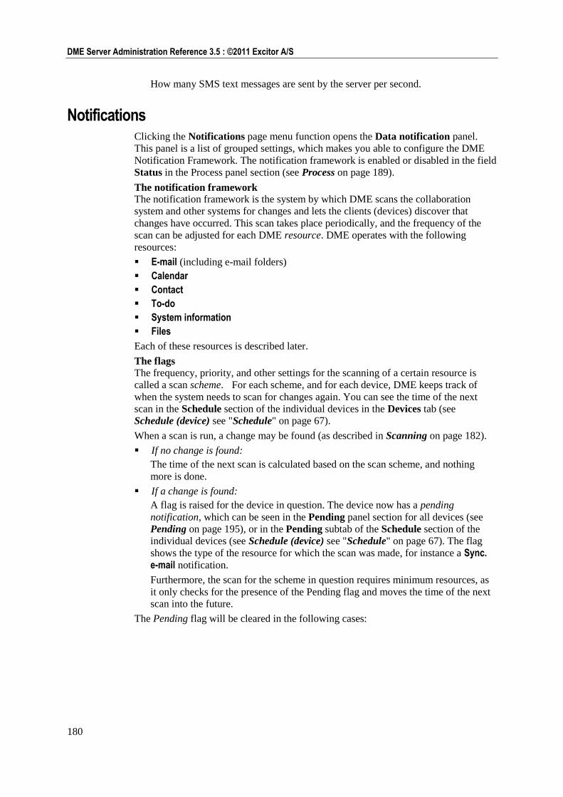
180
DME Server Administration Reference 3.5 : ©2011 Excitor A/S
How many SMS text messages are sent by the server per second.
Notifications Clicking the Notifications page menu function opens the Data notification panel.
This panel is a list of grouped settings, which makes you able to configure the DME
Notification Framework. The notification framework is enabled or disabled in the field
Status in the Process panel section (see Process on page 189).
The notification framework The notification framework is the system by which DME scans the collaboration
system and other systems for changes and lets the clients (devices) discover that
changes have occurred. This scan takes place periodically, and the frequency of the
scan can be adjusted for each DME resource. DME operates with the following
resources:
E-mail (including e-mail folders)
Calendar
Contact
To-do
System information
Files
Each of these resources is described later.
The flags The frequency, priority, and other settings for the scanning of a certain resource is
called a scan scheme. For each scheme, and for each device, DME keeps track of
when the system needs to scan for changes again. You can see the time of the next
scan in the Schedule section of the individual devices in the Devices tab (see
Schedule (device) see "Schedule" on page 67).
When a scan is run, a change may be found (as described in Scanning on page 182).
If no change is found:
The time of the next scan is calculated based on the scan scheme, and nothing
more is done.
If a change is found:
A flag is raised for the device in question. The device now has a pending
notification, which can be seen in the Pending panel section for all devices (see
Pending on page 195), or in the Pending subtab of the Schedule section of the
individual devices (see Schedule (device) see "Schedule" on page 67). The flag
shows the type of the resource for which the scan was made, for instance a Sync. e-mail notification.
Furthermore, the scan for the scheme in question requires minimum resources, as
it only checks for the presence of the Pending flag and moves the time of the next
scan into the future.
The Pending flag will be cleared in the following cases:
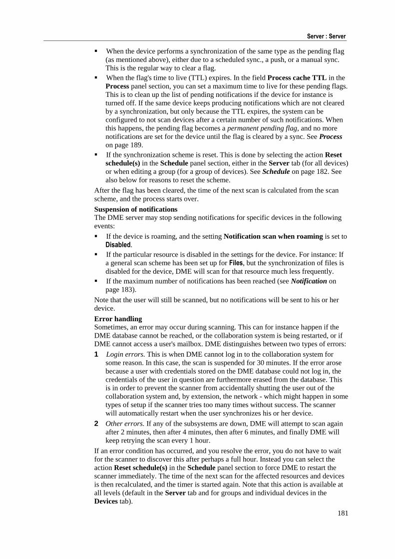
181
Server : Server
When the device performs a synchronization of the same type as the pending flag
(as mentioned above), either due to a scheduled sync., a push, or a manual sync.
This is the regular way to clear a flag.
When the flag's time to live (TTL) expires. In the field Process cache TTL in the
Process panel section, you can set a maximum time to live for these pending flags.
This is to clean up the list of pending notifications if the device for instance is
turned off. If the same device keeps producing notifications which are not cleared
by a synchronization, but only because the TTL expires, the system can be
configured to not scan devices after a certain number of such notifications. When
this happens, the pending flag becomes a permanent pending flag, and no more
notifications are set for the device until the flag is cleared by a sync. See Process
on page 189.
If the synchronization scheme is reset. This is done by selecting the action Reset
schedule(s) in the Schedule panel section, either in the Server tab (for all devices)
or when editing a group (for a group of devices). See Schedule on page 182. See
also below for reasons to reset the scheme.
After the flag has been cleared, the time of the next scan is calculated from the scan
scheme, and the process starts over.
Suspension of notifications The DME server may stop sending notifications for specific devices in the following
events:
If the device is roaming, and the setting Notification scan when roaming is set to
Disabled.
If the particular resource is disabled in the settings for the device. For instance: If
a general scan scheme has been set up for Files, but the synchronization of files is
disabled for the device, DME will scan for that resource much less frequently.
If the maximum number of notifications has been reached (see Notification on
page 183).
Note that the user will still be scanned, but no notifications will be sent to his or her
device.
Error handling Sometimes, an error may occur during scanning. This can for instance happen if the
DME database cannot be reached, or the collaboration system is being restarted, or if
DME cannot access a user's mailbox. DME distinguishes between two types of errors:
1 Login errors. This is when DME cannot log in to the collaboration system for
some reason. In this case, the scan is suspended for 30 minutes. If the error arose
because a user with credentials stored on the DME database could not log in, the
credentials of the user in question are furthermore erased from the database. This
is in order to prevent the scanner from accidentally shutting the user out of the
collaboration system and, by extension, the network - which might happen in some
types of setup if the scanner tries too many times without success. The scanner
will automatically restart when the user synchronizes his or her device.
2 Other errors. If any of the subsystems are down, DME will attempt to scan again
after 2 minutes, then after 4 minutes, then after 6 minutes, and finally DME will
keep retrying the scan every 1 hour.
If an error condition has occurred, and you resolve the error, you do not have to wait
for the scanner to discover this after perhaps a full hour. Instead you can select the
action Reset schedule(s) in the Schedule panel section to force DME to restart the
scanner immediately. The time of the next scan for the affected resources and devices
is then recalculated, and the timer is started again. Note that this action is available at
all levels (default in the Server tab and for groups and individual devices in the
Devices tab).
182
DME Server Administration Reference 3.5 : ©2011 Excitor A/S
Schedule
In the Schedule section of the Data notification panel you can define the default
schedule for all devices. If you need to specify a different schedule for an individual
device or a group of devices, you can do so in the Devices tab.
The notification schedule includes different types of information:
The resource to which it applies (see Scanning on page 182).
The method by which the devices are notified of changes (see Notification on
page 183).
The scheme of the notification cycle (when the scan is run - see Frequency on
page 183 and Setting the scheme on page 185).
The schedules defined create scan jobs, which are fed into a scanning queue. This
queue can be seen in the Clients section (see Clients on page 188).
Scanning
Scanning is the process where DME checks to see if a change has occurred in the
collaboration system or in DME, affecting the device being processed. If a change has
occurred in the collaboration system, DME will notify the device about the change as
a push (if enabled), and raise a "flag" that a change has occurred. This flag is detected
if the device is pushed or polls for changes, and removed when the synchronization
has taken place. You can monitor the scanning process in the sections Clients on page
188, Process on page 189, History on page 194, and Pending on page 195. If the user
initiates a manual synchronization, a full scan is always performed.
A change may occur in several different areas, called resources:
E-mail: Has a new e-mail arrived in the user's mailbox, or has a change in the
e-mail folder structure occurred?
Calendar: Has a meeting been created, deleted, accepted, declined, or updated?
Contact: Has a contact been created, deleted, or updated?
To-do: Has a to-do been created, deleted, or updated?
System information: Has a change been made on the DME server, which affects
the device? This could be a change in a setting, an application block, or a Mark for
Installation.
Files: Has any file sync. rule detected that one or more files should be
synchronized? Note that this option is only shown if a license for file
synchronization is installed on the server.
One or more scanning schemes can be set up for each resource individually.
In order to know if a change has occurred for any of the resources except System information and Files, DME scans the mailbox of the user who holds the device. The
mailbox scan can take place in one of two ways:
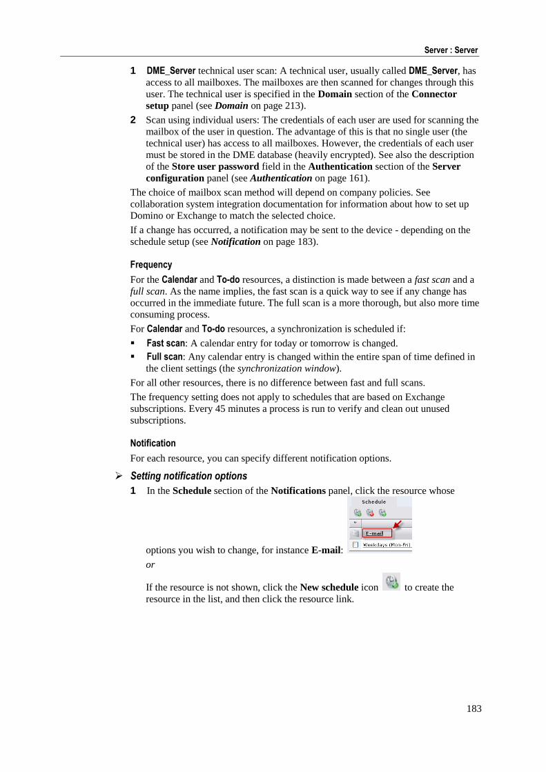
183
Server : Server
1 DME_Server technical user scan: A technical user, usually called DME_Server, has
access to all mailboxes. The mailboxes are then scanned for changes through this
user. The technical user is specified in the Domain section of the Connector
setup panel (see Domain on page 213).
2 Scan using individual users: The credentials of each user are used for scanning the
mailbox of the user in question. The advantage of this is that no single user (the
technical user) has access to all mailboxes. However, the credentials of each user
must be stored in the DME database (heavily encrypted). See also the description
of the Store user password field in the Authentication section of the Server
configuration panel (see Authentication on page 161).
The choice of mailbox scan method will depend on company policies. See
collaboration system integration documentation for information about how to set up
Domino or Exchange to match the selected choice.
If a change has occurred, a notification may be sent to the device - depending on the
schedule setup (see Notification on page 183).
Frequency
For the Calendar and To-do resources, a distinction is made between a fast scan and a
full scan. As the name implies, the fast scan is a quick way to see if any change has
occurred in the immediate future. The full scan is a more thorough, but also more time
consuming process.
For Calendar and To-do resources, a synchronization is scheduled if:
Fast scan: A calendar entry for today or tomorrow is changed.
Full scan: Any calendar entry is changed within the entire span of time defined in
the client settings (the synchronization window).
For all other resources, there is no difference between fast and full scans.
The frequency setting does not apply to schedules that are based on Exchange
subscriptions. Every 45 minutes a process is run to verify and clean out unused
subscriptions.
Notification
For each resource, you can specify different notification options.
Setting notification options
1 In the Schedule section of the Notifications panel, click the resource whose
options you wish to change, for instance E-mail:
or
If the resource is not shown, click the New schedule icon to create the
resource in the list, and then click the resource link.
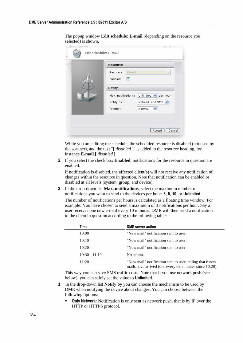
184
DME Server Administration Reference 3.5 : ©2011 Excitor A/S
The popup window Edit schedule: E-mail (depending on the resource you
selected) is shown.
While you are editing the schedule, the scheduled resource is disabled (not used by
the scanner), and the text "[ disabled ]" is added to the resource heading, for
instance E-mail [ disabled ].
2 If you select the check box Enabled, notifications for the resource in question are
enabled.
If notification is disabled, the affected client(s) will not receive any notification of
changes within the resource in question. Note that notification can be enabled or
disabled at all levels (system, group, and device).
3 In the drop-down list Max. notifications, select the maximum number of
notifications you want to send to the devices per hour: 3, 5, 10, or Unlimited.
The number of notifications per hours is calculated as a floating time window. For
example: You have chosen to send a maximum of 3 notifications per hour. Say a
user receives one new e-mail every 10 minutes. DME will then send a notification
to the client in question according to the following table:
Time DME server action
10:00 "New mail" notification sent to user.
10:10 "New mail" notification sent to user.
10:20 "New mail" notification sent to user.
10:30 - 11:19 No action.
11:20 "New mail" notification sent to user, telling that 6 new
mails have arrived (one every ten minutes since 10:20).
This way you can save SMS traffic costs. Note that if you use network push (see
below), you can safely set the value to Unlimited.
1 In the drop-down list Notify by you can choose the mechanism to be used by
DME when notifying the device about changes. You can choose between the
following options:
Only Network: Notification is only sent as network push, that is by IP over the
HTTP or HTTPS protocol.
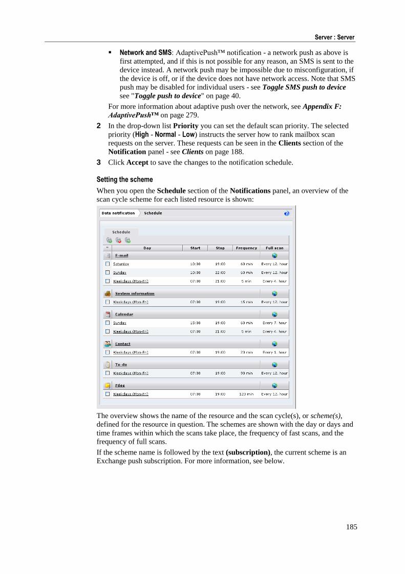
185
Server : Server
Network and SMS: AdaptivePush™ notification - a network push as above is
first attempted, and if this is not possible for any reason, an SMS is sent to the
device instead. A network push may be impossible due to misconfiguration, if
the device is off, or if the device does not have network access. Note that SMS
push may be disabled for individual users - see Toggle SMS push to device
see "Toggle push to device" on page 40.
For more information about adaptive push over the network, see Appendix F:
AdaptivePush™ on page 279.
2 In the drop-down list Priority you can set the default scan priority. The selected
priority (High - Normal - Low) instructs the server how to rank mailbox scan
requests on the server. These requests can be seen in the Clients section of the
Notification panel - see Clients on page 188.
3 Click Accept to save the changes to the notification schedule.
Setting the scheme
When you open the Schedule section of the Notifications panel, an overview of the
scan cycle scheme for each listed resource is shown:
The overview shows the name of the resource and the scan cycle(s), or scheme(s),
defined for the resource in question. The schemes are shown with the day or days and
time frames within which the scans take place, the frequency of fast scans, and the
frequency of full scans.
If the scheme name is followed by the text (subscription), the current scheme is an
Exchange push subscription. For more information, see below.
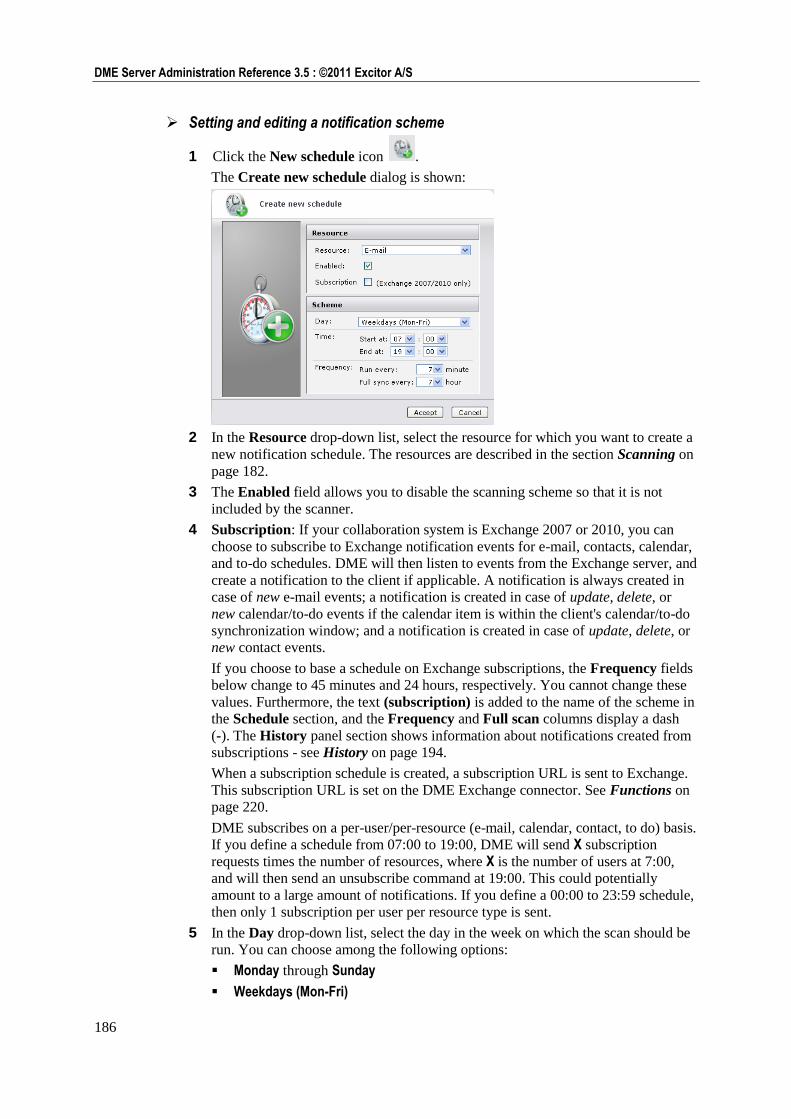
186
DME Server Administration Reference 3.5 : ©2011 Excitor A/S
Setting and editing a notification scheme
1 Click the New schedule icon .
The Create new schedule dialog is shown:
2 In the Resource drop-down list, select the resource for which you want to create a
new notification schedule. The resources are described in the section Scanning on
page 182.
3 The Enabled field allows you to disable the scanning scheme so that it is not
included by the scanner.
4 Subscription: If your collaboration system is Exchange 2007 or 2010, you can
choose to subscribe to Exchange notification events for e-mail, contacts, calendar,
and to-do schedules. DME will then listen to events from the Exchange server, and
create a notification to the client if applicable. A notification is always created in
case of new e-mail events; a notification is created in case of update, delete, or
new calendar/to-do events if the calendar item is within the client's calendar/to-do
synchronization window; and a notification is created in case of update, delete, or
new contact events.
If you choose to base a schedule on Exchange subscriptions, the Frequency fields
below change to 45 minutes and 24 hours, respectively. You cannot change these
values. Furthermore, the text (subscription) is added to the name of the scheme in
the Schedule section, and the Frequency and Full scan columns display a dash
(-). The History panel section shows information about notifications created from
subscriptions - see History on page 194.
When a subscription schedule is created, a subscription URL is sent to Exchange.
This subscription URL is set on the DME Exchange connector. See Functions on
page 220.
DME subscribes on a per-user/per-resource (e-mail, calendar, contact, to do) basis.
If you define a schedule from 07:00 to 19:00, DME will send X subscription
requests times the number of resources, where X is the number of users at 7:00,
and will then send an unsubscribe command at 19:00. This could potentially
amount to a large amount of notifications. If you define a 00:00 to 23:59 schedule,
then only 1 subscription per user per resource type is sent.
5 In the Day drop-down list, select the day in the week on which the scan should be
run. You can choose among the following options:
Monday through Sunday
Weekdays (Mon-Fri)
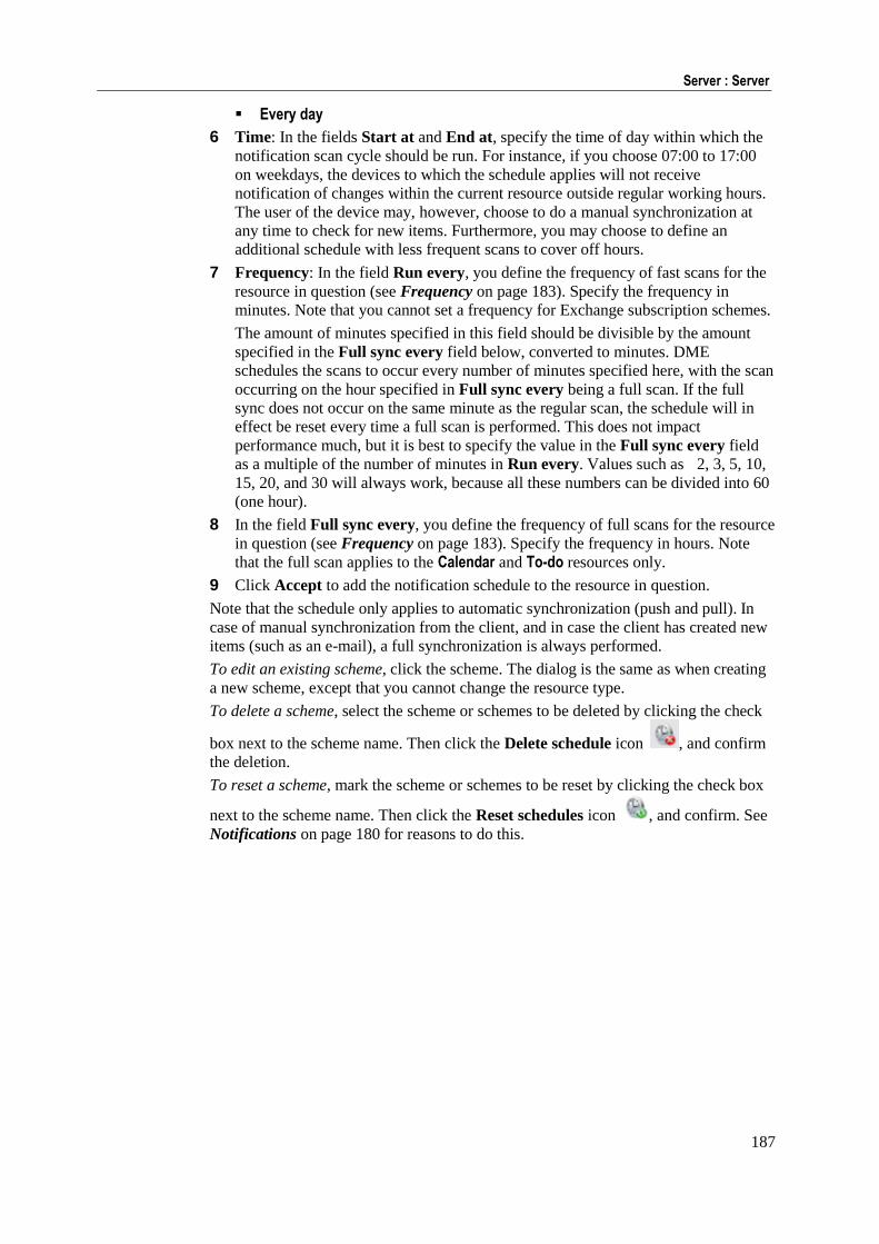
187
Server : Server
Every day
6 Time: In the fields Start at and End at, specify the time of day within which the
notification scan cycle should be run. For instance, if you choose 07:00 to 17:00
on weekdays, the devices to which the schedule applies will not receive
notification of changes within the current resource outside regular working hours.
The user of the device may, however, choose to do a manual synchronization at
any time to check for new items. Furthermore, you may choose to define an
additional schedule with less frequent scans to cover off hours.
7 Frequency: In the field Run every, you define the frequency of fast scans for the
resource in question (see Frequency on page 183). Specify the frequency in
minutes. Note that you cannot set a frequency for Exchange subscription schemes.
The amount of minutes specified in this field should be divisible by the amount
specified in the Full sync every field below, converted to minutes. DME
schedules the scans to occur every number of minutes specified here, with the scan
occurring on the hour specified in Full sync every being a full scan. If the full
sync does not occur on the same minute as the regular scan, the schedule will in
effect be reset every time a full scan is performed. This does not impact
performance much, but it is best to specify the value in the Full sync every field
as a multiple of the number of minutes in Run every. Values such as 2, 3, 5, 10,
15, 20, and 30 will always work, because all these numbers can be divided into 60
(one hour).
8 In the field Full sync every, you define the frequency of full scans for the resource
in question (see Frequency on page 183). Specify the frequency in hours. Note
that the full scan applies to the Calendar and To-do resources only.
9 Click Accept to add the notification schedule to the resource in question.
Note that the schedule only applies to automatic synchronization (push and pull). In
case of manual synchronization from the client, and in case the client has created new
items (such as an e-mail), a full synchronization is always performed.
To edit an existing scheme, click the scheme. The dialog is the same as when creating
a new scheme, except that you cannot change the resource type.
To delete a scheme, select the scheme or schemes to be deleted by clicking the check
box next to the scheme name. Then click the Delete schedule icon , and confirm
the deletion.
To reset a scheme, mark the scheme or schemes to be reset by clicking the check box
next to the scheme name. Then click the Reset schedules icon , and confirm. See
Notifications on page 180 for reasons to do this.
188
DME Server Administration Reference 3.5 : ©2011 Excitor A/S
Clients
In the Clients section of the Data notification panel you can view information about
the scanning to be performed for clients. A client is a term used for the connection
between one user and one device.
This section shows an overview of which users' mailboxes are to be scanned next
according to the current notification schedule. This is called the scan queue, and the
list contains the following information:
Device
The current device of the user whose mailbox (or file sync. rules or system
information) is to be scanned. Click the device to see how the device is set up. If
you let the mouse pointer rest on a device link, a box with more information about
the current device is shown.
User
The user whose mailbox (etc.) is to be scanned. Click the user to see more
information about the user. If you let the mouse pointer rest on a user link, a box
with more information about the current user is shown.
Function
The resource being scanned: E-mail, Calendar, Contacts, To-do, System information, or File.
Priority
The priority here reflects the corresponding setting for the device - either Low,
Medium, or High. See Schedule (device) see "Schedule" on page 67.
Next
When is the next scan scheduled. Scans that are being passed to a scanning thread
are shown above a thin grey line with the text run next candidates.
The scan time is color coded. It the timestamp is green, the time for the next scan
is close to "now". If it is 1 minute behind "now", the timestamp is yellow - or if
your sample time as defined in the Process section is more than 1 minute, it
becomes yellow when the sample time has passed. If it is more than 5 minutes
behind, or if the sample time is greater than 5 minutes and the sample time has
passed, the timestamp is red. You can use this information to determine whether
you need to adjust notification settings (see Process on page 189).
Last
The date and time of the last scan.
189
Server : Server
Notification hist.
A historic list of the last notifications sent to the device in question. The number of
notifications shown in the list depends on the setting of the field Max.
notifications per hour in the Schedule panel section in the Server tab or for
individual devices (see Schedule on page 182). If, for example, a maximum of 5
notifications are sent per hour, the notification history list will record the time of 5
notifications. If Unlimited is selected, this window will not show any notification
history.
(no name)
The last column shows an e-mail icon, calendar icon, or to-do icon if the device
has a pending notification. If it does, it is moved to the bottom of the scanning
queue. Furthermore, a warning icon or information icon may be shown. In this
case, point the mouse to the icon to see the warning or information message.
For more information about pending notifications, see Pending on page 195.
The jobs scheduled for scanning are processed by notification scanner threads, which
can be monitored in the Process section. See Process on page 189.
Process
In the Process section of the Data notification panel you can specify features of the
way DME scans the collaboration system for changes in users' mailboxes etc. You can
turn scanning on or off, and you get a live view of the scanning processes (the scanner
threads).
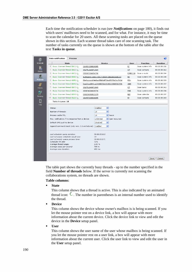
190
DME Server Administration Reference 3.5 : ©2011 Excitor A/S
Each time the notification scheduler is run (see Notifications on page 180), it finds out
which users' mailboxes need to be scanned, and for what. For instance, it may be time
to scan the calendar for 20 users. All these scanning tasks are placed on the queue
shown in this section. Each scanner thread takes care of one scanning task. The
number of tasks currently on the queue is shown at the bottom of the table after the
text Tasks in queue.
The table part shows the currently busy threads - up to the number specified in the
field Number of threads below. If the server is currently not scanning the
collaborations system, no threads are shown.
Table columns:
State
This column shows that a thread is active. This is also indicated by an animated
thread icon: . The number in parentheses is an internal number used to identify
the thread.
Device
This column shows the device whose owner's mailbox is is being scanned. If you
let the mouse pointer rest on a device link, a box will appear with more
information about the current device. Click the device link to view and edit the
device in the Device setup panel.
User
This column shows the user name of the user whose mailbox is being scanned. If
you let the mouse pointer rest on a user link, a box will appear with more
information about the current user. Click the user link to view and edit the user in
the User setup panel.
191
Server : Server
Function
This column shows the item type that is scanned for (E-mail, Calendar, etc.).
Duration
This column shows the duration of the scan. This duration is used as a basis for the
statistics below, among other things.
Using the fields below the table, you can enable or disable scanning, tune the server's
use of threads, etc. After changing values, click Save to commit the new settings to the
DME server.
Fields:
Status
This might be called the "notification framework main switch". This field is
initially set to Disabled (after installing the DME server). When the server has
been set up and is working as intended, change the status to Enabled in order to
start the notification framework and enable push notification to the clients.
Number of threads
In this field you choose the number of threads to be used for client connections.
You can choose numbers in increasing intervals between 1 and 50. The higher the
number, the greater the load on the server. The number of threads should be
balanced with the number of users, the tightness of the notification schedules, and
the capabilities of the server hardware.
Process cache TTL
TTL means "Time To Live". This setting adjusts the length of time the Pending
flag is allowed to exist before it is cleared. For more information, see the Pending
on page 195 panel section.
Max. notifications if no response from a device
In this field you can specify the number times the server will send a notification to
a device that does not respond by synchronizing. If a device is off for a long time,
for instance if the device holder is on a 2-week vacation without his device, the
server will stop sending notifications to the device after the specified number of
notifications. This saves SMS and traffic costs. The number of notifications is
reset every time the device has contact with the server.
Enable SMS fallback
If this field is Enabled, the server will fall back to notification by SMS push if
network push (IP push) is unavailable (this is Adaptive Push™). If this field is
Disabled, clients will not receive notification by SMS. Push by SMS can be turned
on or off for individual devices - see Toggle SMS push to device see "Toggle
push to device" on page 40.
Append command stack
If this field is Disabled, the server will process the synchronization commands
from the client in the sequence in which the arrive, and only process that which the
client asks for. This corresponds to pre-3.0 functionality.
If the field is Enabled, DME uses a command stack - a list of commands to be
processed when the client connects to the server. Please note that this applies to
clients version 3.0 and above only. For more information, see the next section:
Command stack priorities on page 192.
Finally, a number of statistics are shown in the bottom pane. You can use these
statistics when tuning the server.
192
DME Server Administration Reference 3.5 : ©2011 Excitor A/S
Statistics:
Last scheduler query duration
How long time did it take for the scheduler to read "who" and "when" to scan from
the DME database. The duration applies to the result currently shown in the
window.
Last queue size
How many tasks were added to the queue. The queue size applies to the last time a
non-zero number of tasks were found.
Last queue process time
How long time did it take to process the entire queue. The process time applies to
the number of tasks in the field Last queue size above.
Scheduler hit rate
How many times does a query for tasks result in new tasks. For instance: If the
result is 50%, it means that half the queries to the DME database find new entries
in the scanning queue.
Average thread usage
How many of the maximum number of threads (from the field Number of
threads) are used on average. This average is based on a round-robin principle.
Thread usage is sampled frequently, and the average is calculated over one hour's
worth of samplings.
Average scans per second
How many scans are performed per second. For instance, a value of 789m means
that in one second, DME scans 789 "millitasks" - almost 0.8 task per second. This
average is also based on a round-robin principle, and calculated over one hour's
worth of samplings.
Average scan duration
How long time does each scan take on average. For instance, a value of 652m
means one scan per 652 milliseconds - about 0.65 second. This average is also
based on a round-robin principle, and calculated over one hour's worth of
samplings.
In the trends graph Notification scanner thread usage, you can see some of these
statistics graphically over time. See Monitor on page 174.
Command stack priorities
The description below presumes that the Append command stack setting is enabled
in the Process setup panel (recommended).
When a client connects to the server for any purpose - for instance to synchronize
e-mail - DME checks the command stack for the device in question before executing
the client request. The reason for this is to check if any other commands with a higher
priority are waiting for execution on the client - for instance a device flush, which
would be more important than an e-mail sync.
The following is a general description of the way DME gives priority to the various
commands.
193
Server : Server
If a client is unknown to the server, it is forced to send in full system info before
anything else, except if a Flush data command has been issued to it. A device is
unknown for as long as a full system information has never been received from the
device.
If a device has a pending e-mail import and it tries to perform an e-mail sync, the
import will be performed first.
If a device has a pending flush data, the device data will always be flushed.
Actions that are force-sent from the server to the client never time out (they have
no Process cache TTL (see Process and Pending).
The full command stack is always sent to the client after each successful
synchronization.
The general list of priorities is as follows:
1 Flush data takes precedence over all other commands.
2 Send full system info/Import system info takes precedence over all other commands
apart from 1 (Flush data).
3 Synchronize system info takes precedence over all other commands apart from 1
and 2.
4 Import e-mail takes precedence over Synchronize e-mail only.
5 Import calendar takes precedence over Synchronize calendar only
6 Import to-dos takes precedence over Synchronize to-dos only
7 Import contacts takes precedence over Synchronize contacts only
8 Import files takes precedence over Synchronize files only
The command stack sent from the server can include other commands, for instance
Get software update. The list of commands sent to the client is ordered according to
the above list of priorities.
One result of the command stack is that if a user synchronizes e-mail (for instance), he
or she may experience that a calendar sync is performed afterwards. This is because a
pending calendar notification existed, and the server makes use of the existing
connection to synchronize. This saves time and resources on the client.
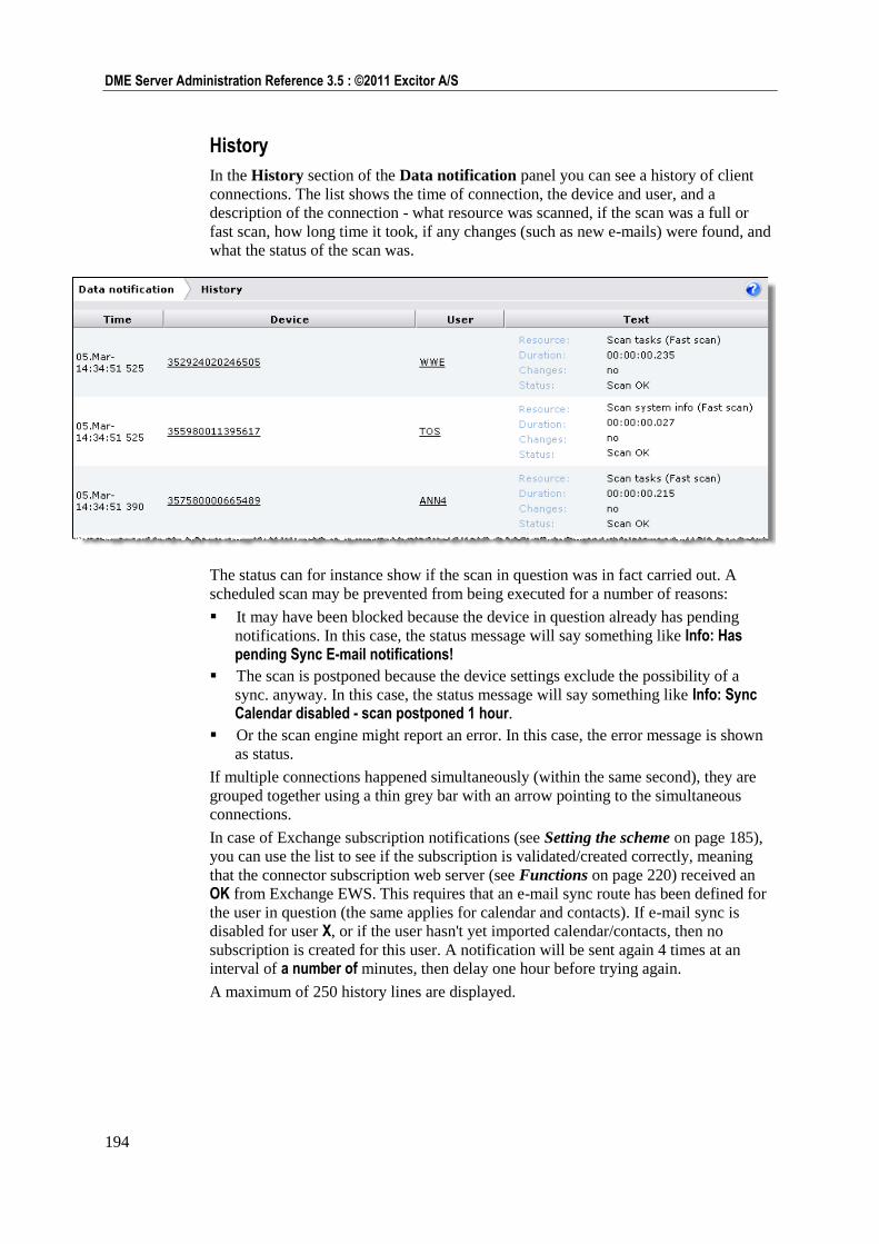
194
DME Server Administration Reference 3.5 : ©2011 Excitor A/S
History
In the History section of the Data notification panel you can see a history of client
connections. The list shows the time of connection, the device and user, and a
description of the connection - what resource was scanned, if the scan was a full or
fast scan, how long time it took, if any changes (such as new e-mails) were found, and
what the status of the scan was.
The status can for instance show if the scan in question was in fact carried out. A
scheduled scan may be prevented from being executed for a number of reasons:
It may have been blocked because the device in question already has pending
notifications. In this case, the status message will say something like Info: Has pending Sync E-mail notifications!
The scan is postponed because the device settings exclude the possibility of a
sync. anyway. In this case, the status message will say something like Info: Sync Calendar disabled - scan postponed 1 hour.
Or the scan engine might report an error. In this case, the error message is shown
as status.
If multiple connections happened simultaneously (within the same second), they are
grouped together using a thin grey bar with an arrow pointing to the simultaneous
connections.
In case of Exchange subscription notifications (see Setting the scheme on page 185),
you can use the list to see if the subscription is validated/created correctly, meaning
that the connector subscription web server (see Functions on page 220) received an
OK from Exchange EWS. This requires that an e-mail sync route has been defined for
the user in question (the same applies for calendar and contacts). If e-mail sync is
disabled for user X, or if the user hasn't yet imported calendar/contacts, then no
subscription is created for this user. A notification will be sent again 4 times at an
interval of a number of minutes, then delay one hour before trying again.
A maximum of 250 history lines are displayed.
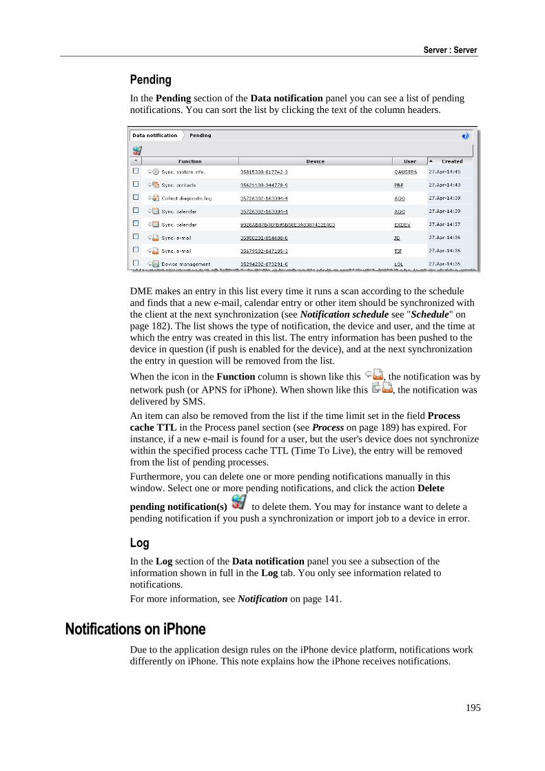
195
Server : Server
Pending
In the Pending section of the Data notification panel you can see a list of pending
notifications. You can sort the list by clicking the text of the column headers.
DME makes an entry in this list every time it runs a scan according to the schedule
and finds that a new e-mail, calendar entry or other item should be synchronized with
the client at the next synchronization (see Notification schedule see "Schedule" on
page 182). The list shows the type of notification, the device and user, and the time at
which the entry was created in this list. The entry information has been pushed to the
device in question (if push is enabled for the device), and at the next synchronization
the entry in question will be removed from the list.
When the icon in the Function column is shown like this , the notification was by
network push (or APNS for iPhone). When shown like this , the notification was
delivered by SMS.
An item can also be removed from the list if the time limit set in the field Process
cache TTL in the Process panel section (see Process on page 189) has expired. For
instance, if a new e-mail is found for a user, but the user's device does not synchronize
within the specified process cache TTL (Time To Live), the entry will be removed
from the list of pending processes.
Furthermore, you can delete one or more pending notifications manually in this
window. Select one or more pending notifications, and click the action Delete
pending notification(s) to delete them. You may for instance want to delete a
pending notification if you push a synchronization or import job to a device in error.
Log
In the Log section of the Data notification panel you see a subsection of the
information shown in full in the Log tab. You only see information related to
notifications.
For more information, see Notification on page 141.
Notifications on iPhone Due to the application design rules on the iPhone device platform, notifications work
differently on iPhone. This note explains how the iPhone receives notifications.
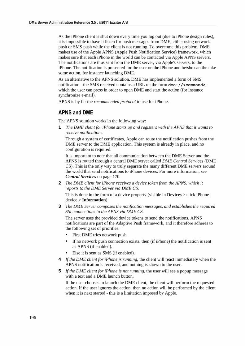
196
DME Server Administration Reference 3.5 : ©2011 Excitor A/S
As the iPhone client is shut down every time you log out (due to iPhone design rules),
it is impossible to have it listen for push messages from DME, either using network
push or SMS push while the client is not running. To overcome this problem, DME
makes use of the Apple APNS (Apple Push Notification Service) framework, which
makes sure that each iPhone in the world can be contacted via Apple APNS servers.
The notifications are thus sent from the DME server, via Apple's servers, to the
iPhone. The notification is presented for the user on the iPhone and he/she can the take
some action, for instance launching DME.
As an alternative to the APNS solution, DME has implemented a form of SMS
notification - the SMS received contains a URL on the form dme://<command>,
which the user can press in order to open DME and start the action (for instance
synchronize e-mail).
APNS is by far the recommended protocol to use for iPhone.
APNS and DME
The APNS solution works in the following way:
1 The DME client for iPhone starts up and registers with the APNS that it wants to
receive notifications.
Through a system of certificates, Apple can route the notification pushes from the
DME server to the DME application. This system is already in place, and no
configuration is required.
It is important to note that all communication between the DME Server and the
APNS is routed through a central DME server called DME Central Services (DME
CS). This is the only way to truly separate the many different DME servers around
the world that send notifications to iPhone devices. For more information, see
Central Services on page 170.
2 The DME client for iPhone receives a device token from the APNS, which it
reports to the DME Server via DME CS.
This is done in the form of a device property (visible in Devices > click iPhone
device > Information).
3 The DME Server composes the notification messages, and establishes the required
SSL connections to the APNS via DME CS.
The server uses the provided device tokens to send the notifications. APNS
notifications are part of the Adaptive Push framework, and it therefore adheres to
the following set of priorities:
First DME tries network push.
If no network push connection exists, then (if iPhone) the notification is sent
as APNS (if enabled).
Else it is sent as SMS (if enabled).
4 If the DME client for iPhone is running, the client will react immediately when the
APNS notification is received, and nothing is shown to the user.
5 If the DME client for iPhone is not running, the user will see a popup message
with a text and a DME launch button.
If the user chooses to launch the DME client, the client will perform the requested
action. If the user ignores the action, then no action will be performed by the client
when it is next started - this is a limitation imposed by Apple.
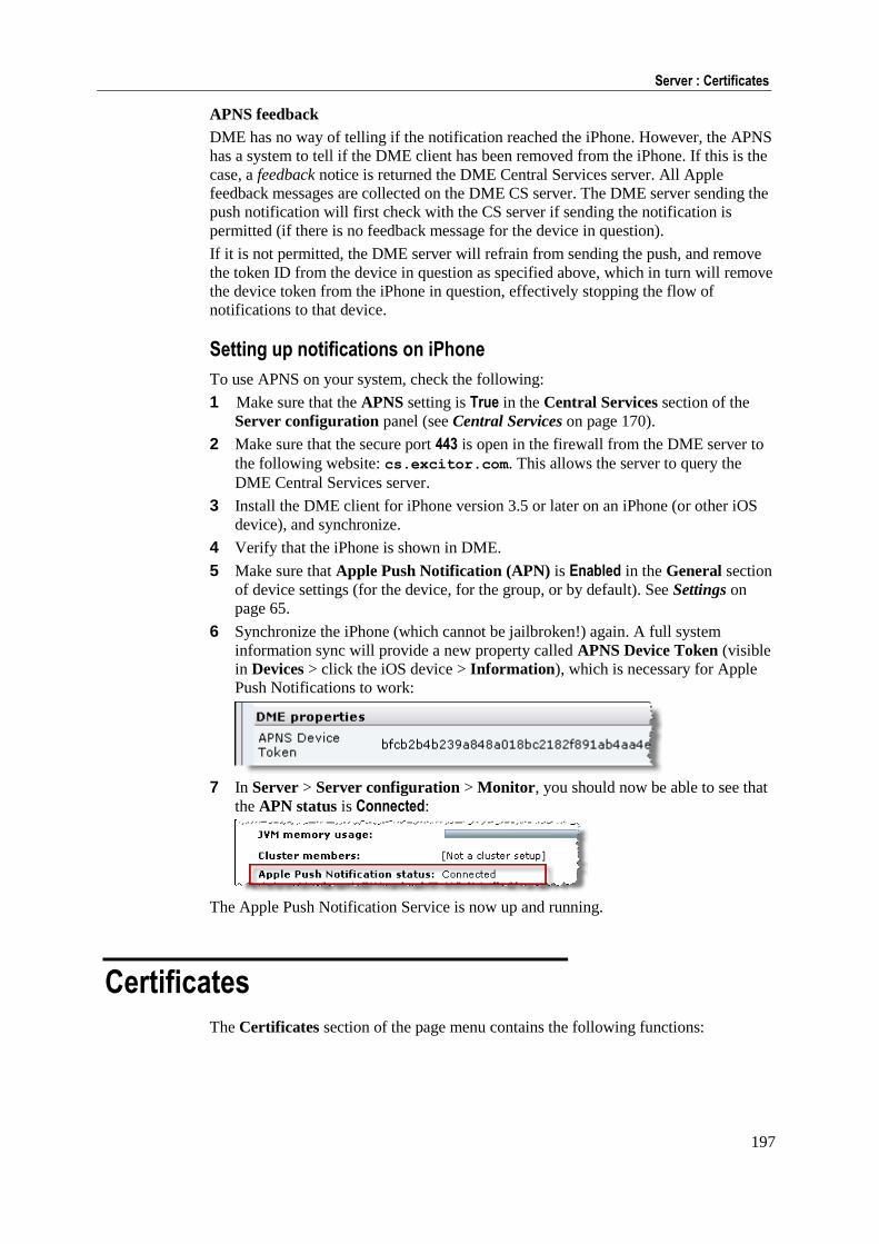
197
Server : Certificates
APNS feedback
DME has no way of telling if the notification reached the iPhone. However, the APNS
has a system to tell if the DME client has been removed from the iPhone. If this is the
case, a feedback notice is returned the DME Central Services server. All Apple
feedback messages are collected on the DME CS server. The DME server sending the
push notification will first check with the CS server if sending the notification is
permitted (if there is no feedback message for the device in question).
If it is not permitted, the DME server will refrain from sending the push, and remove
the token ID from the device in question as specified above, which in turn will remove
the device token from the iPhone in question, effectively stopping the flow of
notifications to that device.
Setting up notifications on iPhone
To use APNS on your system, check the following:
1 Make sure that the APNS setting is True in the Central Services section of the
Server configuration panel (see Central Services on page 170).
2 Make sure that the secure port 443 is open in the firewall from the DME server to
the following website: cs.excitor.com. This allows the server to query the
DME Central Services server.
3 Install the DME client for iPhone version 3.5 or later on an iPhone (or other iOS
device), and synchronize.
4 Verify that the iPhone is shown in DME.
5 Make sure that Apple Push Notification (APN) is Enabled in the General section
of device settings (for the device, for the group, or by default). See Settings on
page 65.
6 Synchronize the iPhone (which cannot be jailbroken!) again. A full system
information sync will provide a new property called APNS Device Token (visible
in Devices > click the iOS device > Information), which is necessary for Apple
Push Notifications to work:
7 In Server > Server configuration > Monitor, you should now be able to see that
the APN status is Connected:
The Apple Push Notification Service is now up and running.
Certificates
The Certificates section of the page menu contains the following functions:
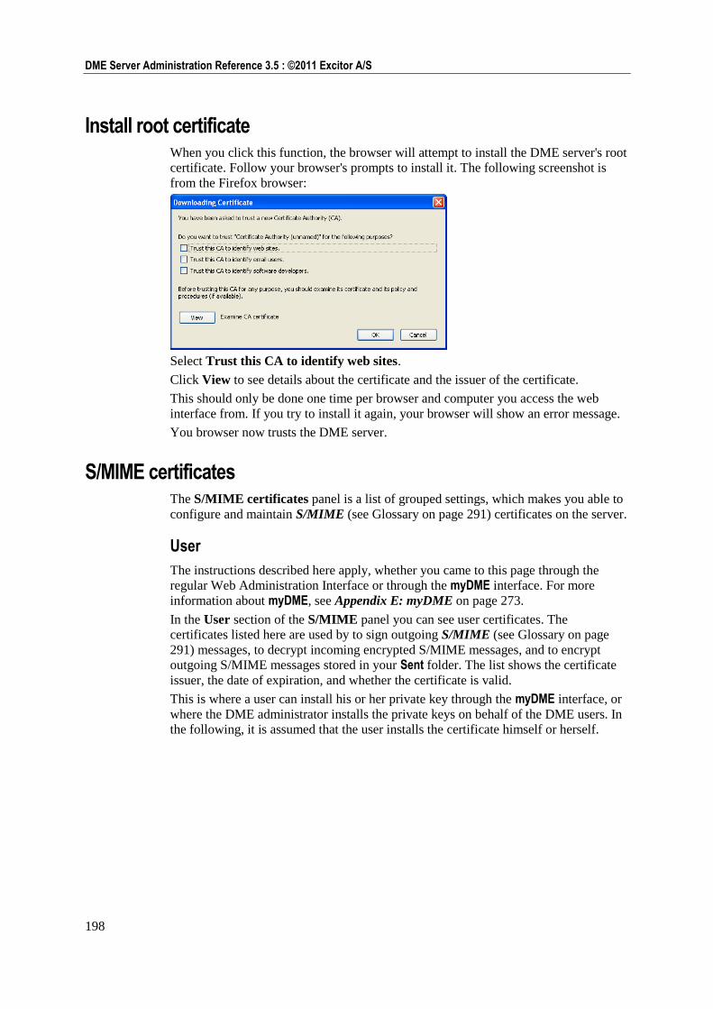
198
DME Server Administration Reference 3.5 : ©2011 Excitor A/S
Install root certificate When you click this function, the browser will attempt to install the DME server's root
certificate. Follow your browser's prompts to install it. The following screenshot is
from the Firefox browser:
Select Trust this CA to identify web sites.
Click View to see details about the certificate and the issuer of the certificate.
This should only be done one time per browser and computer you access the web
interface from. If you try to install it again, your browser will show an error message.
You browser now trusts the DME server.
S/MIME certificates The S/MIME certificates panel is a list of grouped settings, which makes you able to
configure and maintain S/MIME (see Glossary on page 291) certificates on the server.
User
The instructions described here apply, whether you came to this page through the
regular Web Administration Interface or through the myDME interface. For more
information about myDME, see Appendix E: myDME on page 273.
In the User section of the S/MIME panel you can see user certificates. The
certificates listed here are used by to sign outgoing S/MIME (see Glossary on page
291) messages, to decrypt incoming encrypted S/MIME messages, and to encrypt
outgoing S/MIME messages stored in your Sent folder. The list shows the certificate
issuer, the date of expiration, and whether the certificate is valid.
This is where a user can install his or her private key through the myDME interface, or
where the DME administrator installs the private keys on behalf of the DME users. In
the following, it is assumed that the user installs the certificate himself or herself.
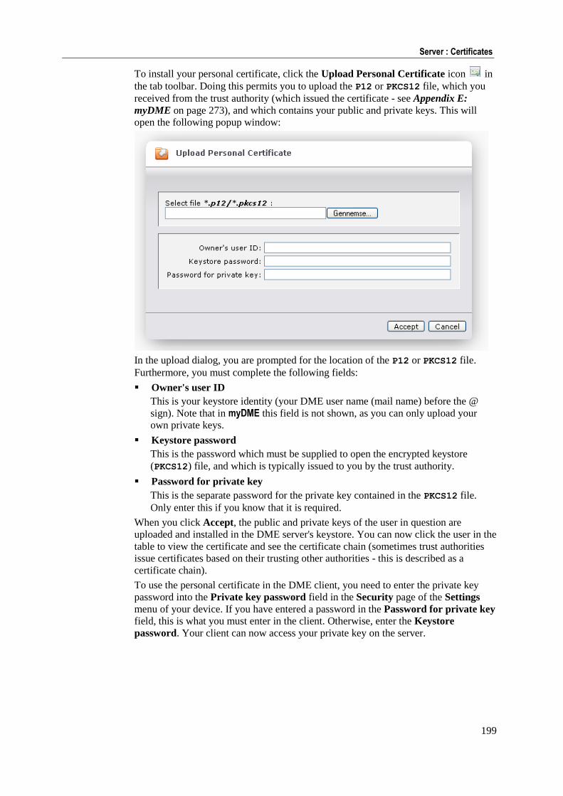
199
Server : Certificates
To install your personal certificate, click the Upload Personal Certificate icon in
the tab toolbar. Doing this permits you to upload the P12 or PKCS12 file, which you
received from the trust authority (which issued the certificate - see Appendix E:
myDME on page 273), and which contains your public and private keys. This will
open the following popup window:
In the upload dialog, you are prompted for the location of the P12 or PKCS12 file.
Furthermore, you must complete the following fields:
Owner's user ID
This is your keystore identity (your DME user name (mail name) before the @
sign). Note that in myDME this field is not shown, as you can only upload your
own private keys.
Keystore password
This is the password which must be supplied to open the encrypted keystore
(PKCS12) file, and which is typically issued to you by the trust authority.
Password for private key
This is the separate password for the private key contained in the PKCS12 file.
Only enter this if you know that it is required.
When you click Accept, the public and private keys of the user in question are
uploaded and installed in the DME server's keystore. You can now click the user in the
table to view the certificate and see the certificate chain (sometimes trust authorities
issue certificates based on their trusting other authorities - this is described as a
certificate chain).
To use the personal certificate in the DME client, you need to enter the private key
password into the Private key password field in the Security page of the Settings
menu of your device. If you have entered a password in the Password for private key
field, this is what you must enter in the client. Otherwise, enter the Keystore
password. Your client can now access your private key on the server.
200
DME Server Administration Reference 3.5 : ©2011 Excitor A/S
External
In the External section of the S/MIME certificates panel you can view the public
certificates of external persons (sometimes called "other people") - here defined as a
person identified by an e-mail address which is not part of the DME system. Say that
an external accountant sends a signed e-mail to the CFO of your company. The
accountant's public certificate will then be extracted from his mail and stored here as
the public certificate of an external person. Now every user in the DME system will be
able to receive signed messages from the accountant, and DME users who have
uploaded their personal certificates will be able to send signed and encrypted
messages to the accountant without further setup, simply by selecting the appropriate
functions in their client.
The certificates of external persons are automatically stored here, if the option
Automatically store unknown certificates is selected in the Collaboration section
of the Server configuration panel (see Collaboration on page 164).
Otherwise you can upload a public certificate by clicking the Import Certificates
icon in the tab toolbar. If you do this, the imported certificates are trusted if their
issuing certificate authority (CA) exists in the DME certificate store (see Root on page
200).
Root
In the Root section of the S/MIME certificates panel you can view root certificates.
Root certificates are the public certificates of certificate authorities that we trust. For
instance, if an e-mail is received by the system with a certificate issued by trust
authority A, DME scans the list of trusted authorities for A. If A is not found, the
certificate is rejected, and the e-mail will not appear to be signed when opened by the
recipient.
Just as user certificates, you can upload trusted root certificates in this section of the
S/MIME certificates panel.
CRL
In the CRL section of the S/MIME certificates panel you can view the public CRL -
Certificate Revocation List. Every trust authority maintains a list of certificates that
are no longer valid for some reason. Such a list is called a "Certificate Revocation
List" (CRL). The URL to the list is embedded in the certificate. The CRL of each trust
authority known by the DME system is listed here. The CRL is checked automatically
when a certificate is found in an e-mail sent to the DME system.
If the DME server succeeds in looking up the CRL, and the certificate is found in the
CRL, the message is rejected.
The DME may be unable to look up the CRL for some reason (such as bad URL
specified in certificate, spelling error, or connection error). A setting called Accept
certificate even if CRL lookup fails in the Collaboration section of the Server
configuration panel specifies whether the certificate (and, by extension, the message)
should be accepted even if the DME server could not reach the CRL. See
Collaboration on page 164.
If you let the mouse pointer rest on the CRL source URL, information about the CRL
issuer is displayed in a pop-up information box.
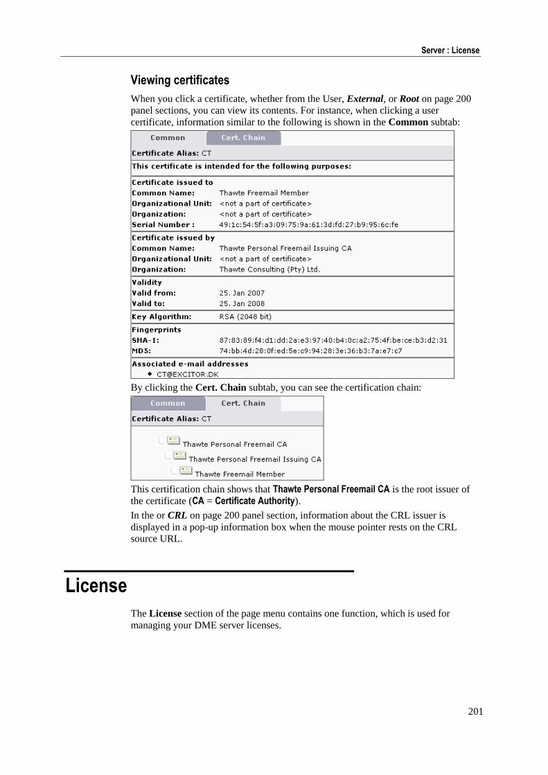
201
Server : License
Viewing certificates
When you click a certificate, whether from the User, External, or Root on page 200
panel sections, you can view its contents. For instance, when clicking a user
certificate, information similar to the following is shown in the Common subtab:
By clicking the Cert. Chain subtab, you can see the certification chain:
This certification chain shows that Thawte Personal Freemail CA is the root issuer of
the certificate (CA = Certificate Authority).
In the or CRL on page 200 panel section, information about the CRL issuer is
displayed in a pop-up information box when the mouse pointer rests on the CRL
source URL.
License
The License section of the page menu contains one function, which is used for
managing your DME server licenses.
202
DME Server Administration Reference 3.5 : ©2011 Excitor A/S
Manage licenses On this page, you administer your DME licenses. To use DME you must have one or
more valid licenses. A license file grants access for a defined number of users to use a
specific set of features in DME. If you do not have a license file, you are able to log
on to the Web Administration Interface, but you will not be able to synchronize any
devices. The licenses are bound to the physical server. In a load-balanced system
(cluster) you need identical license files on each of the servers in the cluster.
It is possible to obtain multiple licenses for DME, depending on how you wish to use
the system. All license types include device management. To obtain a license file,
contact your DME software partner.
If you own multiple licenses, one license must be designated Default. This means that
new devices created in the system are automatically granted a license of the type in
question.
Say that you have 300 users. 200 of them need the full functionality of DME,
including e-mail sync, PIM sync, and file sync. 60 users do not require
synchronization of contacts or files. Finally, you want to be able to manage the
devices of the remaining 40 users in a central location, but the users do not need
synchronization features. In this scenario, your company would obtain 3 types of
licenses:
200 licenses Device management, e-mail, calendar, contacts, to-do, file sync
60 licenses Device management, e-mail, calendar sync
40 licenses Device management
You would then designate the license with max. 200 users as the default license. For
the other license types, you create two groups, and add each device that takes one of
the additional licenses to one of these groups. In the group list, you can edit the groups
and specify which license type they should take. For more information about this, see
Setting up groups on page 80.
No matter which license type is assigned to a device, the device must run the DME
client. The client only shows the features to which the license grants access. For
instance, if calendar synchronization is not permitted, the client will not show menu
items involving the calendar, such as Synchronize Calendar and Import Calendar.
A device management license means that the device is shown in the Devices tab. You
can use many of the features in the Push to device page menu section with the device,
except the ones that involve synchronization. Furthermore, you can use DME to block
applications and networks on the device (see Applications on page 44), if the device
supports this feature. Note that the DME client must still be installed on the device. In
this case, the DME client will consist of a login screen, some setup options, and a
splash screen.
License columns
The Manage licenses page contains the following columns:
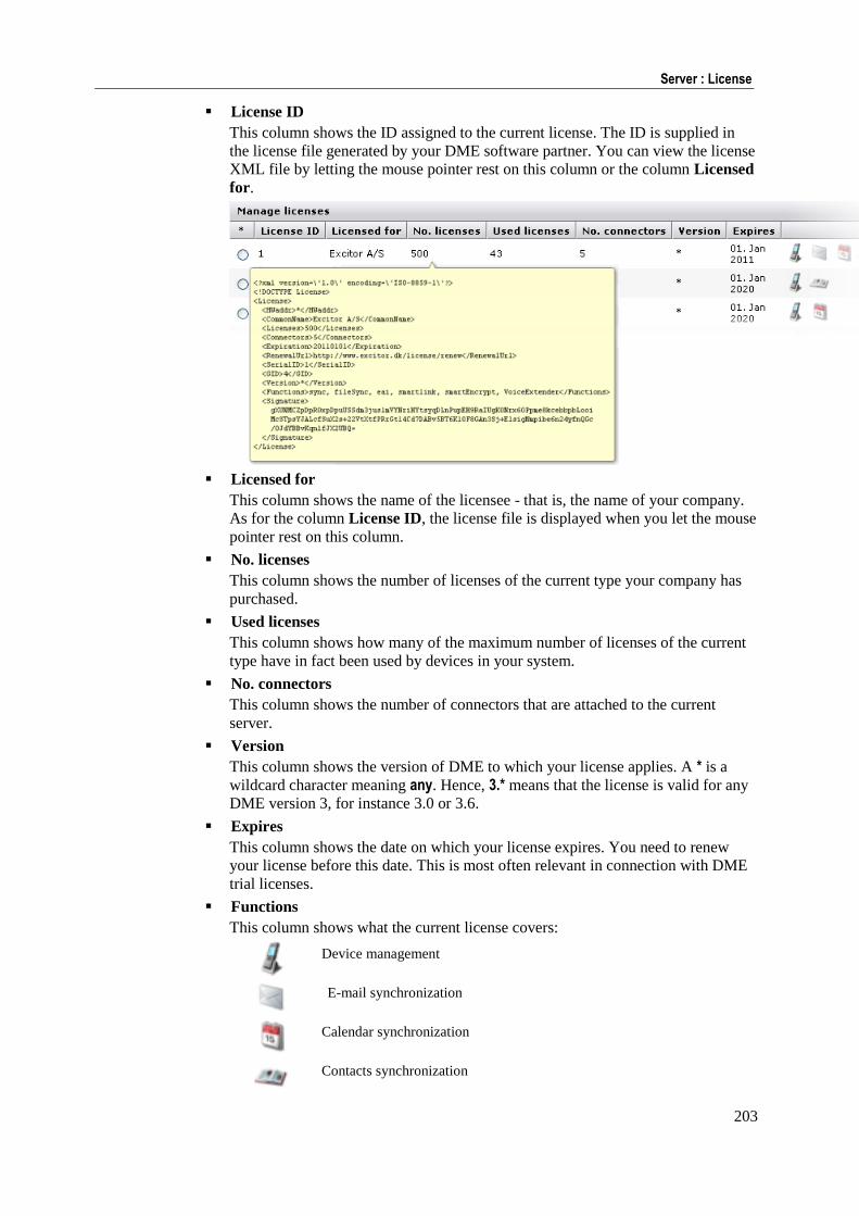
203
Server : License
License ID
This column shows the ID assigned to the current license. The ID is supplied in
the license file generated by your DME software partner. You can view the license
XML file by letting the mouse pointer rest on this column or the column Licensed
for.
Licensed for
This column shows the name of the licensee - that is, the name of your company.
As for the column License ID, the license file is displayed when you let the mouse
pointer rest on this column.
No. licenses
This column shows the number of licenses of the current type your company has
purchased.
Used licenses
This column shows how many of the maximum number of licenses of the current
type have in fact been used by devices in your system.
No. connectors
This column shows the number of connectors that are attached to the current
server.
Version
This column shows the version of DME to which your license applies. A * is a
wildcard character meaning any. Hence, 3.* means that the license is valid for any
DME version 3, for instance 3.0 or 3.6.
Expires
This column shows the date on which your license expires. You need to renew
your license before this date. This is most often relevant in connection with DME
trial licenses.
Functions
This column shows what the current license covers:
Device management
E-mail synchronization
Calendar synchronization
Contacts synchronization
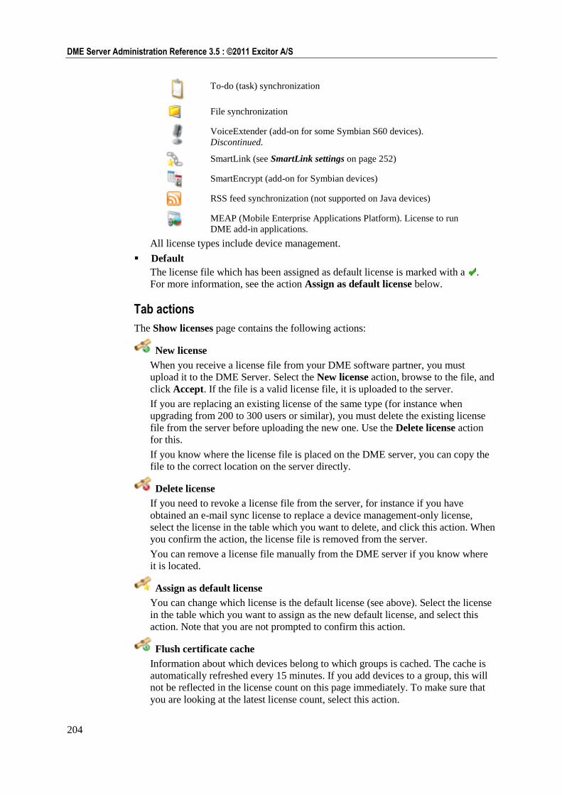
204
DME Server Administration Reference 3.5 : ©2011 Excitor A/S
To-do (task) synchronization
File synchronization
VoiceExtender (add-on for some Symbian S60 devices).
Discontinued.
SmartLink (see SmartLink settings on page 252)
SmartEncrypt (add-on for Symbian devices)
RSS feed synchronization (not supported on Java devices)
MEAP (Mobile Enterprise Applications Platform). License to run
DME add-in applications.
All license types include device management.
Default
The license file which has been assigned as default license is marked with a .
For more information, see the action Assign as default license below.
Tab actions
The Show licenses page contains the following actions:
New license
When you receive a license file from your DME software partner, you must
upload it to the DME Server. Select the New license action, browse to the file, and
click Accept. If the file is a valid license file, it is uploaded to the server.
If you are replacing an existing license of the same type (for instance when
upgrading from 200 to 300 users or similar), you must delete the existing license
file from the server before uploading the new one. Use the Delete license action
for this.
If you know where the license file is placed on the DME server, you can copy the
file to the correct location on the server directly.
Delete license
If you need to revoke a license file from the server, for instance if you have
obtained an e-mail sync license to replace a device management-only license,
select the license in the table which you want to delete, and click this action. When
you confirm the action, the license file is removed from the server.
You can remove a license file manually from the DME server if you know where
it is located.
Assign as default license
You can change which license is the default license (see above). Select the license
in the table which you want to assign as the new default license, and select this
action. Note that you are not prompted to confirm this action.
Flush certificate cache
Information about which devices belong to which groups is cached. The cache is
automatically refreshed every 15 minutes. If you add devices to a group, this will
not be reflected in the license count on this page immediately. To make sure that
you are looking at the latest license count, select this action.
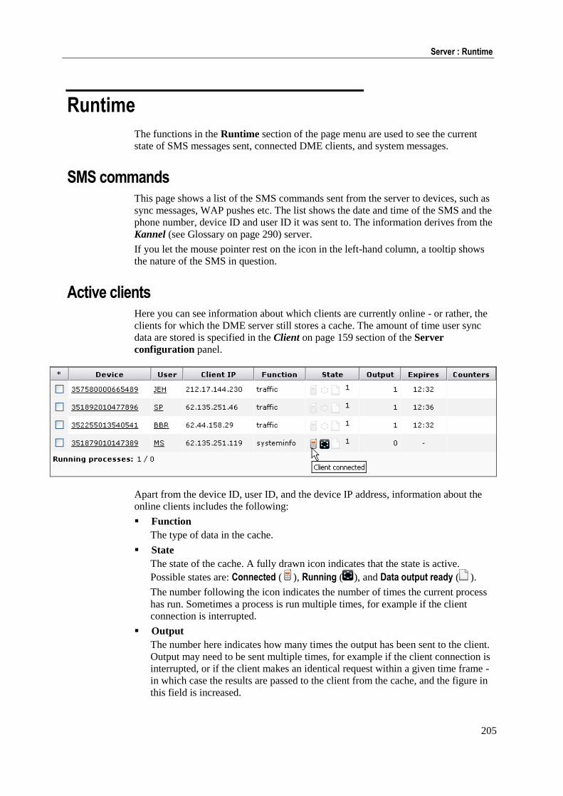
205
Server : Runtime
Runtime
The functions in the Runtime section of the page menu are used to see the current
state of SMS messages sent, connected DME clients, and system messages.
SMS commands This page shows a list of the SMS commands sent from the server to devices, such as
sync messages, WAP pushes etc. The list shows the date and time of the SMS and the
phone number, device ID and user ID it was sent to. The information derives from the
Kannel (see Glossary on page 290) server.
If you let the mouse pointer rest on the icon in the left-hand column, a tooltip shows
the nature of the SMS in question.
Active clients Here you can see information about which clients are currently online - or rather, the
clients for which the DME server still stores a cache. The amount of time user sync
data are stored is specified in the Client on page 159 section of the Server
configuration panel.
Apart from the device ID, user ID, and the device IP address, information about the
online clients includes the following:
Function
The type of data in the cache.
State
The state of the cache. A fully drawn icon indicates that the state is active.
Possible states are: Connected ( ), Running ( ), and Data output ready ( ).
The number following the icon indicates the number of times the current process
has run. Sometimes a process is run multiple times, for example if the client
connection is interrupted.
Output
The number here indicates how many times the output has been sent to the client.
Output may need to be sent multiple times, for example if the client connection is
interrupted, or if the client makes an identical request within a given time frame -
in which case the results are passed to the client from the cache, and the figure in
this field is increased.
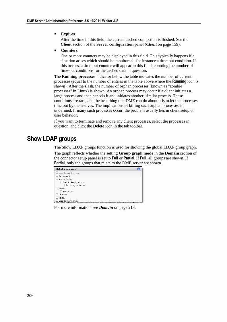
206
DME Server Administration Reference 3.5 : ©2011 Excitor A/S
Expires
After the time in this field, the current cached connection is flushed. See the
Client section of the Server configuration panel (Client on page 159).
Counters
One or more counters may be displayed in this field. This typically happens if a
situation arises which should be monitored - for instance a time-out condition. If
this occurs, a time-out counter will appear in this field, counting the number of
time-out conditions for the cached data in question.
The Running processes indicator below the table indicates the number of current
processes (equal to the number of entries in the table above where the Running icon is
shown). After the slash, the number of orphan processes (known as "zombie
processes" in Linux) is shown. An orphan process may occur if a client initiates a
large process and then cancels it and initiates another, similar process. These
conditions are rare, and the best thing that DME can do about it is to let the processes
time out by themselves. The implications of killing such orphan processes is
undefined. If many such processes occur, the problem usually lies in client setup or
user behavior.
If you want to terminate and remove any client processes, select the processes in
question, and click the Delete icon in the tab toolbar.
Show LDAP groups The Show LDAP groups function is used for showing the global LDAP group graph.
The graph reflects whether the setting Group graph mode in the Domain section of
the connector setup panel is set to Full or Partial. If Full, all groups are shown. If
Partial, only the groups that relate to the DME server are shown.
For more information, see Domain on page 213.
Connector 207
Connector
The Connector tab contains functions and information used for managing each
connector attached to the DME server. For more information about connectors, see
DME server architecture on page 11.
The default page in this tab is the Routes page.
Routes
The Routes page in the Connector tab is the default page, and shows a list of the
currently defined connectors. Click the name of a connector to view and edit its
properties. For more information, see Setting up connectors on page 211.
The page contains two subtabs: Connectors, which shows a list of all connectors
known to the DME server, and Users, which shows detailed routing information about
each user serviced by a connector.
Connectors The Connectors subtab contains a list of all connectors known to the DME server.
The following columns show information about each connector:
Connector
This column contains the name of the connector. This is originally specified
during the installation of the connector, but can be changed in the Main section of
the connector's Connector settings page. To view and edit the properties of the
connector, click the name.
The icons associated with each connector have the following meaning:
Primary connector with broadcast (supported users are selected
automatically)
Failover connector with broadcast
Locked connector (see below)
Primary connector, supporting a list of named users
Failover connector, supporting a list of named users
Primary connector, supporting the users of a specified LDAP
group
Failover connector, supporting the users of a specified LDAP
group
For information about the difference between the types of connectors, see Setting
up connectors on page 211.
Enabled
This column uses an icon to show the status of the connector on the current line.
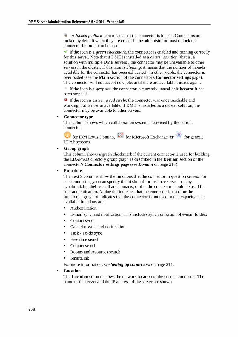
208
DME Server Administration Reference 3.5 : ©2011 Excitor A/S
A locked padlock icon means that the connector is locked. Connectors are
locked by default when they are created - the administrator must unlock the
connector before it can be used.
If the icon is a green checkmark, the connector is enabled and running correctly
for this server. Note that if DME is installed as a cluster solution (that is, a
solution with multiple DME servers), the connector may be unavailable to other
servers in the cluster. If this icon is blinking, it means that the number of threads
available for the connector has been exhausted - in other words, the connector is
overloaded (see the Main section of the connector's Connector settings page).
The connector will not accept new jobs until there are available threads again.
If the icon is a grey dot, the connector is currently unavailable because it has
been stopped.
If the icon is an x in a red circle, the connector was once reachable and
working, but is now unavailable. If DME is installed as a cluster solution, the
connector may be available to other servers.
Connector type
This column shows which collaboration system is serviced by the current
connector:
for IBM Lotus Domino, for Microsoft Exchange, or for generic
LDAP systems.
Group graph
This column shows a green checkmark if the current connector is used for building
the LDAP/AD directory group graph as described in the Domain section of the
connector's Connector settings page (see Domain on page 213).
Functions
The next 9 columns show the functions that the connector in question serves. For
each connector, you can specify that it should for instance serve users by
synchronizing their e-mail and contacts, or that the connector should be used for
user authentication. A blue dot indicates that the connector is used for the
function; a grey dot indicates that the connector is not used in that capacity. The
available functions are:
Authentication
E-mail sync. and notification. This includes synchronization of e-mail folders
Contact sync.
Calendar sync. and notification
Task / To-do sync.
Free time search
Contact search
Rooms and resources search
SmartLink
For more information, see Setting up connectors on page 211.
Location
The Location column shows the network location of the current connector. The
name of the server and the IP address of the server are shown.
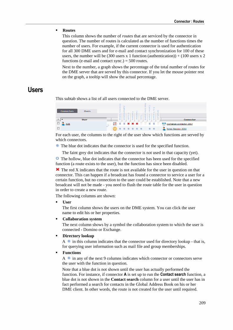
209
Connector : Routes
Routes
This column shows the number of routes that are serviced by the connector in
question. The number of routes is calculated as the number of functions times the
number of users. For example, if the current connector is used for authentication
for all 300 DME users and for e-mail and contact synchronization for 100 of these
users, the number will be (300 users x 1 function (authentication)) + (100 users x 2
functions (e-mail and contact sync.) = 500 routes.
Next to the number, a graph shows the percentage of the total number of routes for
the DME server that are served by this connector. If you let the mouse pointer rest
on the graph, a tooltip will show the actual percentage.
Users This subtab shows a list of all users connected to the DME server.
For each user, the columns to the right of the user show which functions are served by
which connectors.
The blue dot indicates that the connector is used for the specified function.
The faint grey dot indicates that the connector is not used in that capacity (yet).
The hollow, blue dot indicates that the connector has been used for the specified
function (a route exists to the user), but the function has since been disabled.
The red X indicates that the route is not available for the user in question on that
connector. This can happen if a broadcast has found a connector to service a user for a
certain function, but no connection to the user could be established. Note that a new
broadcast will not be made - you need to flush the route table for the user in question
in order to create a new route.
The following columns are shown:
User
The first column shows the users on the DME system. You can click the user
name to edit his or her properties.
Collaboration system
The next column shows by a symbol the collaboration system to which the user is
connected - Domino or Exchange.
Directory lookup
A in this column indicates that the connector used for directory lookup - that is,
for querying user information such as mail file and group memberships.
Functions
A in any of the next 9 columns indicates which connector or connectors serve
the user with the function in question.
Note that a blue dot is not shown until the user has actually performed the
function. For instance, if connector A is set up to run the Contact search function, a
blue dot is not shown in the Contact search column for a user until the user has in
fact performed a search for contacts in the Global Address Book on his or her
DME client. In other words, the route is not created for the user until required.
210
DME Server Administration Reference 3.5 : ©2011 Excitor A/S
Connector
This column shows the connectors that apply to the current user (that is, at least
one column is marked with or ). You can click the connector name to edit its
properties.
Connector tab actions
The main Connector tab toolbar contains the following actions:
Remove connector
Clicking the Remove connector action removes any selected connector(s) in the list.
If you have selected users in the Users subtab, DME will remove the connectors that
service the users in question.
Before removing the connector(s), DME will ask you to confirm your choice. After
clicking Confirm, the connectors are removed, and the DME server no longer has a
record of the location of the connector. The connector must be reinstalled in order to
appear in the list again.
Flush routes for selected connector(s) or user(s)
As described in the section about the DME server architecture (see DME server
architecture on page 11) and about the main connector Routes page (see Routes on
page 207), each user has a route to one or more connectors - a route to each connector
that serves the user in question within a given function area (e-mail, search, etc. as
specified in the routing columns).
You can select one or more connectors and choose this action to flush all routes from
the selected connector(s). You may for instance want to do this when carrying out
major changes in your network infrastructure (for instance if you ease the load on your
mail server load by moving a number of users to a new server).
Or you can select one or more users and choose this action to flush their routes to all
connectors. You may for instance want to do this if one or more users need to move to
another connector (for instance because they have relocated to a different branch
office, and you divide your users up by LDAP group membership).
211
Connector : Setting up connectors
When you select this action, DME will show a confirmation dialog with details about
the routes you are flushing.
Click Confirm to execute the route flushing.
The route from user to connector is created again at the time of the user's first
synchronization.
Toggle connector lock
The first time a connector connects the the DME server after having been installed,
DME creates the connector in this list in a locked state. This is shown by a locked
padlock icon in the Enabled column, and is a security precaution.
The DME administrator must manually toggle the lock status of the connector by
selecting the connector and then choosing this action from the Connectors subtab.
Setting up connectors
Click the name of a connector in the Connectors subtab to view and edit its
properties. The following sections describe the connector setup panel.
Please note that some fields and groups of fields only apply to one particular
collaboration system or LDAP. Such fields are marked with a symbol in this manual:
for Lotus Domino
for Microsoft Exchange
for generic LDAP
Main In the Main section of the Connector settings panel you can configure various
properties of the current connector. All fields in this section are mandatory.
Connector
The Connector group of functions contains the following fields:
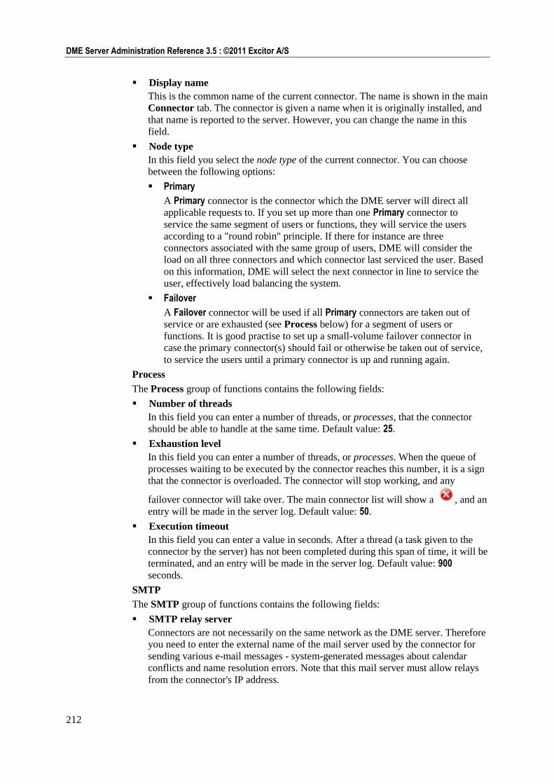
212
DME Server Administration Reference 3.5 : ©2011 Excitor A/S
Display name
This is the common name of the current connector. The name is shown in the main
Connector tab. The connector is given a name when it is originally installed, and
that name is reported to the server. However, you can change the name in this
field.
Node type
In this field you select the node type of the current connector. You can choose
between the following options:
Primary
A Primary connector is the connector which the DME server will direct all
applicable requests to. If you set up more than one Primary connector to
service the same segment of users or functions, they will service the users
according to a "round robin" principle. If there for instance are three
connectors associated with the same group of users, DME will consider the
load on all three connectors and which connector last serviced the user. Based
on this information, DME will select the next connector in line to service the
user, effectively load balancing the system.
Failover
A Failover connector will be used if all Primary connectors are taken out of
service or are exhausted (see Process below) for a segment of users or
functions. It is good practise to set up a small-volume failover connector in
case the primary connector(s) should fail or otherwise be taken out of service,
to service the users until a primary connector is up and running again.
Process
The Process group of functions contains the following fields:
Number of threads
In this field you can enter a number of threads, or processes, that the connector
should be able to handle at the same time. Default value: 25.
Exhaustion level
In this field you can enter a number of threads, or processes. When the queue of
processes waiting to be executed by the connector reaches this number, it is a sign
that the connector is overloaded. The connector will stop working, and any
failover connector will take over. The main connector list will show a , and an
entry will be made in the server log. Default value: 50.
Execution timeout
In this field you can enter a value in seconds. After a thread (a task given to the
connector by the server) has not been completed during this span of time, it will be
terminated, and an entry will be made in the server log. Default value: 900
seconds.
SMTP
The SMTP group of functions contains the following fields:
SMTP relay server
Connectors are not necessarily on the same network as the DME server. Therefore
you need to enter the external name of the mail server used by the connector for
sending various e-mail messages - system-generated messages about calendar
conflicts and name resolution errors. Note that this mail server must allow relays
from the connector's IP address.
213
Connector : Setting up connectors
Messages in connection with client creation alerts etc. are sent by the SMTP relay
server defined in the corresponding setting for the DME server (see Collaboration
on page 164).
SMTP mail sender
In this field you can enter a name you want to show as sender when a user receives
a system-generated message as described above. For instance, you can enter DME Administrator or similar as sender to make it obvious to the user that the message
is system-generated. If you leave the field empty, system-generated messages will
be sent with root@DME-Server as sender.
Please take steps to ensure that e-mails from this sender are not evaluated as spam
by the recipients' e-mail clients, for instance by instructing the DME users to add
this sender to the "Safe Senders list" or similar. E-mail in spam mailboxes is rarely
read, and almost never synchronized to DME clients, so there is a risk that
important information is missed by the users.
Info
This section contains information about the current connector.
The Info group of functions contains the following fields:
Connector ID is an internal identifier of the connector used by the DME server. It
is very important that this ID is unique across the entire DME system. The ID is
written in the connector's configuration file dme-config.xml when the
connector is installed.
The Version field contains the version number of the connector. This version
number can be used to verify that the current connector is compatible with the
DME server. The number should match the version and build number of the DME
server (which can be seen by clicking the DME Administration logo (see About
DME on page 23)).
Click Save to save the new settings.
Domain In the Domain section of the Connector settings panel you define the directory
(LDAP/AD) settings of the current connector, and the generation of the directory
group graph. All fields in this section are mandatory.
LDAP server
The LDAP server group of functions contains the following fields:
Domain info LDAP server
In this field you must enter the DNS name or IP address of the directory server
(LDAP/AD) used by the current connector. You can specify a non-standard port
by adding a port number (:<port>). Different directories can be used for different
connector functions. The directory specified here is used for looking up each user's
mail file and group membership.
User for domain info queries
In this field you enter the name of the user which performs the directory lookups.
For more information about creating this user, see the separate Domino and
Exchange Integration documentation issued by Excitor A/S. This user should have
access to querying the directory for information such as mail file location and
group memberships. By convention, this user is most often called DME_Server.
Password
In this field you specify the password of the directory query user specified above.
214
DME Server Administration Reference 3.5 : ©2011 Excitor A/S
Follow referrals
One LDAP repository can refer to other LDAP repositories for information. This
is especially the case for Active Directory environments. By default, DME allows
this, but in some cases it may not be desirable. If you disable this field, DME will
only search for information in the LDAP specified above, and not follow any
chain of LDAP referrals.
Test connection
Click this button to verify that the connection to the LDAP server can in fact be
established with the connection information you have entered for this connector.
You should do this before clicking Save. Note that the function only tests the
LDAP specified in the Domain info LDAP server field, and not all LDAP servers
that this DME server can reach. This way, you can test the connection against one
connector at a time.
Enter the name of a user that you know exists in the LDAP directory. DME
suggests the DME query user, but you for instance enter your own user name.
Click Test. If the connection to LDAP is successful, the result page will show
various information about the user, retrieved from LDAP. If the connection failed,
the result page will show an exception which may help you pinpoint the problem.
Click Back to try with another user, or click Cancel to end the test.
Generic LDAP setup
The Generic LDAP setup group of functions contain options for setting up a generic
LDAP system. This is typically used if:
DME is used for device management only, and is therefore not connected to a
collaboration system, and
You cannot use the Basic MDM client solutions, because you need to be able to
authenticate users.
If you have these two requirements, you can authenticate users against any directory
system, such as Open LDAP or Novell eDirectory, using the fields below.
When the user has been granted access through the directory server specified in the
Authentication field in the Authentication section, the user's domain information is
looked up. The information is looked up by the administrative user specified in the
LDAP server group of fields above.
In the following fields, you can specify how this lookup should take place.
User search query
In order to find domain information for the user in question, this is the search
string DME uses to query the generic LDAP system. The string is written in the
LDAP query language. {0} is a placeholder, representing the user name employed
by the user for logging in to the DME client. Example: (&(objectclass=person)(cn={0}))
Please note that if multiple users have the same CN, but different domains, you
must set up a generic LDAP connector per domain. For instance, CN=John
Smith, OU=XYZ and CN=John Smith, OU=WQJ must be serviced by different
connectors.
User search DN
The user in question must be member of the DN specified here. Example: dc=example,dc=com
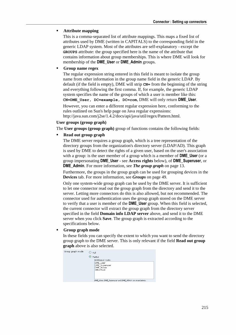
215
Connector : Setting up connectors
Attribute mapping
This is a comma-separated list of attribute mappings. This maps a fixed list of
attributes used by DME (written in CAPITALS) to the corresponding field in the
generic LDAP system. Most of the attributes are self-explanatory - except the
GROUPS attribute: the group specified here is the name of the attribute that
contains information about group memberships. This is where DME will look for
membership of the DME_User or DME_Admin groups.
Group name regex
The regular expression string entered in this field is meant to isolate the group
name from other information in the group name field in the generic LDAP. By
default (if the field is empty), DME will strip CN= from the beginning of the string
and everything following the first comma. If, for example, the generic LDAP
system specifies the name of the groups of which a user is member like this:
CN=DME_User, DC=example, DC=com, DME will only return DME_User.
However, you can enter a different regular expression here, conforming to the
rules outlined on Sun's help page on Java regular expressions:
http://java.sun.com/j2se/1.4.2/docs/api/java/util/regex/Pattern.html.
User groups (group graph)
The User groups (group graph) group of functions contains the following fields:
Read out group graph
The DME server requires a group graph, which is a tree representation of the
directory groups from the organization's directory server (LDAP/AD). This graph
is used by DME to detect the rights of a given user, based on the user's association
with a group: is the user member of a group which is a member of DME_User (or a
group impersonating DME_User - see Access rights below), of DME_Superuser, or
DME_Admin. For more information, see The group graph on page 13.
Furthermore, the groups in the group graph can be used for grouping devices in the
Devices tab. For more information, see Groups on page 49.
Only one system-wide group graph can be used by the DME server. It is sufficient
to let one connector read out the group graph from the directory and send it to the
server. Letting more connectors do this is also allowed, but not recommended. The
connector used for authentication uses the group graph stored on the DME server
to verify that a user is member of the DME_User group. When this field is selected,
the current connector will extract the group graph from the directory server
specified in the field Domain info LDAP server above, and send it to the DME
server when you click Save. The group graph is extracted according to the
specifications below.
Group graph mode
In these fields you can specify the extent to which you want to send the directory
group graph to the DME server. This is only relevant if the field Read out group
graph above is also selected.
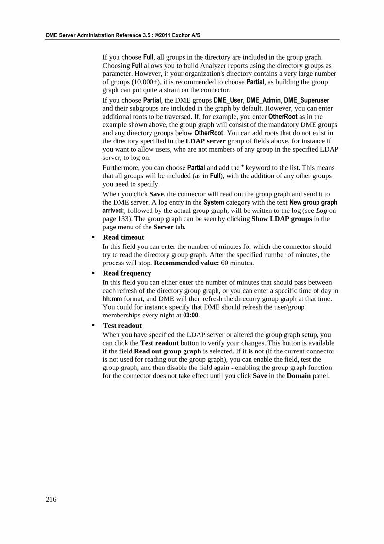
216
DME Server Administration Reference 3.5 : ©2011 Excitor A/S
If you choose Full, all groups in the directory are included in the group graph.
Choosing Full allows you to build Analyzer reports using the directory groups as
parameter. However, if your organization's directory contains a very large number
of groups (10,000+), it is recommended to choose Partial, as building the group
graph can put quite a strain on the connector.
If you choose Partial, the DME groups DME_User, DME_Admin, DME_Superuser and their subgroups are included in the graph by default. However, you can enter
additional roots to be traversed. If, for example, you enter OtherRoot as in the
example shown above, the group graph will consist of the mandatory DME groups
and any directory groups below OtherRoot. You can add roots that do not exist in
the directory specified in the LDAP server group of fields above, for instance if
you want to allow users, who are not members of any group in the specified LDAP
server, to log on.
Furthermore, you can choose Partial and add the * keyword to the list. This means
that all groups will be included (as in Full), with the addition of any other groups
you need to specify.
When you click Save, the connector will read out the group graph and send it to
the DME server. A log entry in the System category with the text New group graph arrived:, followed by the actual group graph, will be written to the log (see Log on
page 133). The group graph can be seen by clicking Show LDAP groups in the
page menu of the Server tab.
Read timeout
In this field you can enter the number of minutes for which the connector should
try to read the directory group graph. After the specified number of minutes, the
process will stop. Recommended value: 60 minutes.
Read frequency
In this field you can either enter the number of minutes that should pass between
each refresh of the directory group graph, or you can enter a specific time of day in
hh:mm format, and DME will then refresh the directory group graph at that time.
You could for instance specify that DME should refresh the user/group
memberships every night at 03:00.
Test readout
When you have specified the LDAP server or altered the group graph setup, you
can click the Test readout button to verify your changes. This button is available
if the field Read out group graph is selected. If it is not (if the current connector
is not used for reading out the group graph), you can enable the field, test the
group graph, and then disable the field again - enabling the group graph function
for the connector does not take effect until you click Save in the Domain panel.
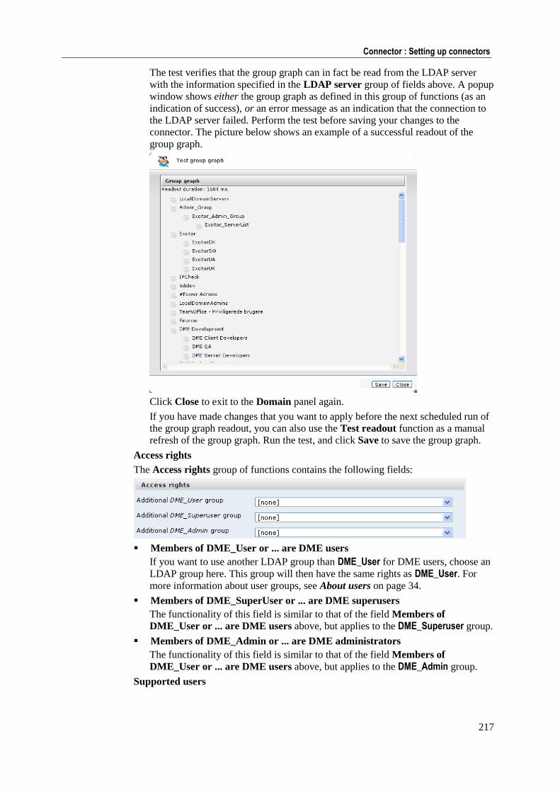
217
Connector : Setting up connectors
The test verifies that the group graph can in fact be read from the LDAP server
with the information specified in the LDAP server group of fields above. A popup
window shows either the group graph as defined in this group of functions (as an
indication of success), or an error message as an indication that the connection to
the LDAP server failed. Perform the test before saving your changes to the
connector. The picture below shows an example of a successful readout of the
group graph.
Click Close to exit to the Domain panel again.
If you have made changes that you want to apply before the next scheduled run of
the group graph readout, you can also use the Test readout function as a manual
refresh of the group graph. Run the test, and click Save to save the group graph.
Access rights
The Access rights group of functions contains the following fields:
Members of DME_User or ... are DME users
If you want to use another LDAP group than DME_User for DME users, choose an
LDAP group here. This group will then have the same rights as DME_User. For
more information about user groups, see About users on page 34.
Members of DME_SuperUser or ... are DME superusers
The functionality of this field is similar to that of the field Members of
DME_User or ... are DME users above, but applies to the DME_Superuser group.
Members of DME_Admin or ... are DME administrators
The functionality of this field is similar to that of the field Members of
DME_User or ... are DME users above, but applies to the DME_Admin group.
Supported users
218
DME Server Administration Reference 3.5 : ©2011 Excitor A/S
The Supported users group of functions lets you specify which users should be
serviced by the current connector (the route users) - either manually or by letting the
connector broadcast for users to be serviced.
If you have a central directory server and a local mail server for a specific
office/location, you can for instance configure a specific group in your directory for
users of this office/location, and configure a DME connector to service users of this
group only.
DME user domain
You can limit the connector to only serving users from a specific domain.
This allows you to run one DME server for multiple domains. For instance, if your
DME server hosts users from multiple distinct companies, you can set up one
connector per company by only allowing the connector to create routes to users
from a certain domain only.
The domain must be entered on the form domain.com. For Domino users, this
must match the e-mail address of the user. For Exchange users, this must match
the UserPrincipalName.
For instance, if domain.com is entered here, a user logging in as
[email protected] can be serviced by this connector; a user logging in as
[email protected] cannot.
Route users
The DME Connector has a built-in priority where the more specific user selection
has the higher priority - that is, a list of users will be used prior to a group
member, who in turn has a higher priority than Automatic (broadcast) users.
Users
In this field you can specify a comma separated list of users that should be
serviced by this connector. The users should be specified as they would be
displayed in the User column in the Devices tab. A list could for instance be
NIF,LL,MFB. In this case, only the users NIF, LL, and MFB would be serviced by
this connector. This could for instance be used for debugging purposes in
connection with the setup of a new DME connector.
Members of
In this field you can specify a group from the directory specified in the field
Domain info directory server above. The effect is similar to that of the field
Users above, and should only be used in the same circumstances - while testing a
new installation. Only users that are members of the selected group are serviced by
this connector. This only applies if the field Automatic below is not checked.
Automatic
If this field is selected (default), the fields Users and Members of above are
ignored. Instead, the DME server determines which users should be serviced by
which connector by way of a user broadcast, as described in the section about the
DME server architecture - see DME server architecture on page 11.
Click Save to save the new settings.
Authentication In the Authentication section of the Connector settings panel you define whether the
current connector is used for authentication. All fields in this section are mandatory,
except the Password change section in Exchange setups.
Function
219
Connector : Setting up connectors
The Function group of functions contains the following field:
Authentication
If you select this field, the current connector will by used for authentication
purposes, meaning that it will accept user authentication requests from the DME
server. The connector will verify the username and password of the user, and will
detect which directory groups the user is member of. The groups are matched
against the directory group graph stored on the server to see if the user is member
of DME_User. At least one DME connector must have this role.
Authentication
The Authentication group of functions contains the following fields:
LDAP server
This is the LDAP server used by the connector for authenticating users. This may
or may not be the directory server from which the group graph is derived.
The user's group membership is sent to the server for comparison with the
directory group graph for verification that the user is in fact member of the
DME_User group (or equivalent) and thus has access to the system. Note that if
you just enter an IP address or a hostname without indication of protocol in this
field, DME will prepend the IP address with ldap://.
If your system is set up to use secure LDAP, you must enter ldaps:// yourself,
change to a secure port, and configure the firewall accordingly. The secure LDAP
path has the following format:
ldaps://LDAP_SERVER_HOSTNAME:SECURE_LDAP_PORT (the secure port is
typically 636, but this may be different in your setup). For more information,
contact DME Support http://www.excitor.com.
AD domain
Enter the AD domain in this field. This must be in UPN suffix format, which is
usually the same as your DNS domain, for instance your.domain.com or
something similar to ad.domain.local. Do not use the old Windows 2000
format such as DOMAIN\ .
The login information from the DME client usually only consists of your user
name, which is passed to the DME server. In order for the DME server and
connector to successfully authenticate against the Active Directory or the
Exchange server, it is necessary that the AD domain (UPN suffix) is appended to
this user name (for example your.domain.com), giving the unique
UserPrincipalName of [email protected]. You must enter the AD
domain information in this field, even if you only use one domain.
Follow referrals
One LDAP repository can refer to other LDAP repositories for information. This
is especially the case for Active Directory environments. By default, DME allows
this, but in some cases it may not be desirable. If you disable this field, DME will
only search for information in the LDAP specified above, and not follow any
chain of LDAP referrals.
Test login
Click this button to open the Test authentication window, in which you can
attempt a login process against the authentication LDAP server specified in the
LDAP server field.
Enter the user name and password of a user in the corresponding fields, and click
Test. If the test is successful, the window shows some information about the user,
and the amount of time it took to retrieve the information. If the test failed, an
error message is shown to help you pinpoint the problem.
220
DME Server Administration Reference 3.5 : ©2011 Excitor A/S
Click Back to try with another user, or Cancel to exit the window.
Authentication setup for generic LDAP
In the Authentication setup for generic LDAP group of fields you can configure the
way users log in to DME when using generic LDAP.
Login name expression
In this field you can specify the composition of the user name applied when
attempting a login to the generic LDAP system, which is specified in the field
LDAP server above. The user name is often composed of CN and DC specifiers.
In this field, {0} is a placeholder for the login name used by the DME users on the
client.
As an example, assume that the user name used when logging in to the DME client
is Sabine Adelhof, and this field contains the following expression:
cn={0},dc=example,dc=com
In this example, the complete user name used for attempting a login will be
cn=Sabine Adelhof,dc=example,dc=com. The generic LDAP system is
further set up in the Domain section (see Domain on page 213).
Password change
The Password change group of functions contains the following fields:
Administrator user name
The DME client uses the users' AD password for authentication. At regular
intervals, this password will expire according to company security policies. In
order to ensure uninterrupted access to e-mail and calendar from the DME client,
the client users are able to change their AD password from the client.
If you leave this field and the field Administrator password blank, the users have
access to changing the password for as long as it is not completely expired yet -
that is, when the users have received a warning that the password is about to
expired in x days.
If you enter the user name of an AD administrator and a password in these fields,
the users will be able to change their AD password, even if the password has
expired completely (the flag ‗User must change password on next logon‘ is
marked on the user's account in AD).
Please note that the password change functionality requires a secure connection to
your AD through the LDAPS protocol. The path to your secure LDAP server must
be specified in the LDAP server field (above).
Administrator password
In this field you can specify the password of the AD administrator entered above.
Click Save to save the new settings.
Functions In the Functions section of the Connector settings panel you define the scope of the
synchronization tasks of the current connector, and how the connector is to integrate
with the collaboration system with regard to e-mail and PIM synchronization.
Functions
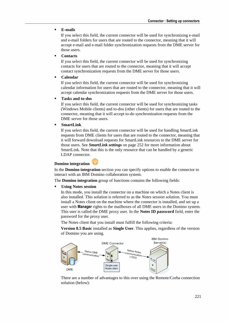
221
Connector : Setting up connectors
E-mails
If you select this field, the current connector will be used for synchronizing e-mail
and e-mail folders for users that are routed to the connector, meaning that it will
accept e-mail and e-mail folder synchronization requests from the DME server for
those users.
Contacts
If you select this field, the current connector will be used for synchronizing
contacts for users that are routed to the connector, meaning that it will accept
contact synchronization requests from the DME server for those users.
Calendar
If you select this field, the current connector will be used for synchronizing
calendar information for users that are routed to the connector, meaning that it will
accept calendar synchronization requests from the DME server for those users.
Tasks and to-dos
If you select this field, the current connector will be used for synchronizing tasks
(Windows Mobile clients) and to-dos (other clients) for users that are routed to the
connector, meaning that it will accept to-do synchronization requests from the
DME server for those users.
SmartLink
If you select this field, the current connector will be used for handling SmartLink
requests from DME clients for users that are routed to the connector, meaning that
it will forward download requests for SmartLink resources to the DME server for
those users. See SmartLink settings on page 252 for more information about
SmartLink. Note that this is the only resource that can be handled by a generic
LDAP connector.
Domino integration
In the Domino integration section you can specify options to enable the connector to
interact with an IBM Domino collaboration system.
The Domino integration group of functions contains the following fields:
Using Notes session
In this mode, you install the connector on a machine on which a Notes client is
also installed. This solution is referred to as the Notes session solution. You must
install a Notes client on the machine where the connector is installed, and set up a
user with Manager rights to the mailboxes of all DME users in the Domino system.
This user is called the DME proxy user. In the Notes ID password field, enter the
password for the proxy user.
The Notes client that you install must fulfill the following criteria:
Version 8.5 Basic installed as Single User. This applies, regardless of the version
of Domino you are using.
There are a number of advantages to this over using the Remote/Corba connection
solution (below):
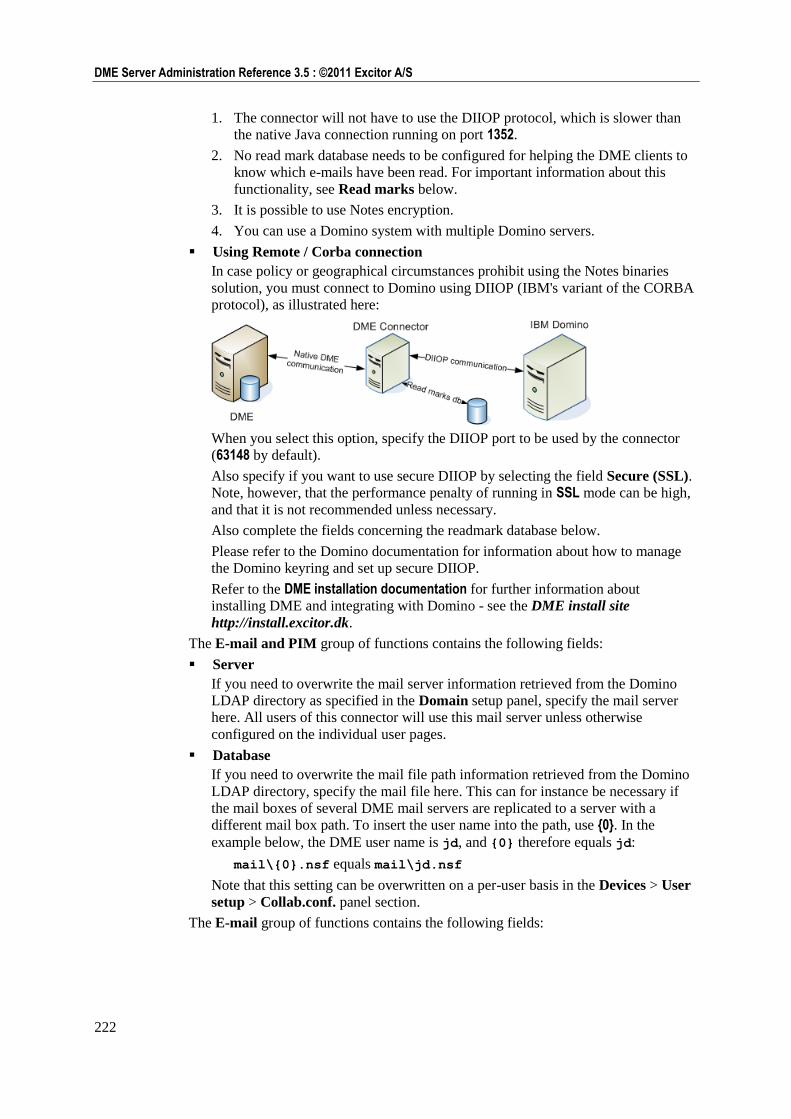
222
DME Server Administration Reference 3.5 : ©2011 Excitor A/S
1. The connector will not have to use the DIIOP protocol, which is slower than
the native Java connection running on port 1352.
2. No read mark database needs to be configured for helping the DME clients to
know which e-mails have been read. For important information about this
functionality, see Read marks below.
3. It is possible to use Notes encryption.
4. You can use a Domino system with multiple Domino servers.
Using Remote / Corba connection
In case policy or geographical circumstances prohibit using the Notes binaries
solution, you must connect to Domino using DIIOP (IBM's variant of the CORBA
protocol), as illustrated here:
When you select this option, specify the DIIOP port to be used by the connector
(63148 by default).
Also specify if you want to use secure DIIOP by selecting the field Secure (SSL).
Note, however, that the performance penalty of running in SSL mode can be high,
and that it is not recommended unless necessary.
Also complete the fields concerning the readmark database below.
Please refer to the Domino documentation for information about how to manage
the Domino keyring and set up secure DIIOP.
Refer to the DME installation documentation for further information about
installing DME and integrating with Domino - see the DME install site
http://install.excitor.dk.
The E-mail and PIM group of functions contains the following fields:
Server
If you need to overwrite the mail server information retrieved from the Domino
LDAP directory as specified in the Domain setup panel, specify the mail server
here. All users of this connector will use this mail server unless otherwise
configured on the individual user pages.
Database
If you need to overwrite the mail file path information retrieved from the Domino
LDAP directory, specify the mail file here. This can for instance be necessary if
the mail boxes of several DME mail servers are replicated to a server with a
different mail box path. To insert the user name into the path, use {0}. In the
example below, the DME user name is jd, and {0} therefore equals jd:
mail\{0}.nsf equals mail\jd.nsf
Note that this setting can be overwritten on a per-user basis in the Devices > User
setup > Collab.conf. panel section.
The E-mail group of functions contains the following fields:
223
Connector : Setting up connectors
Mail domain
The name of your Domino Mail Domain. This domain will be appended to all sent
mails, to instruct the Domino server to evaluate the recipients. This way DME
does not have to query the LDAP directory every time. Only use this option if you
have only one corporate domain.
Sender address format
This parameter determines how the sender addresses should be displayed in the
DME client.
If you select Domino format, then Internet address, the sender's address will be
shown as John Smith/Headquarters/Domain if possible in the From field of the
e-mails you receive; otherwise it will be shown in the form
[email protected]. Note that the addresses of other recipients of the e-mail
(in the CC or BCC fields) are always shown in Domino format (John Smith/Headquarters/Domain).
If you select Internet address, then Domino format (default), the sender's address
will be shown in the form [email protected] if possible; otherwise it will be
shown as John Smith/Headquarters/Domain.
Extract embedded images as attachments
When a user receives an e-mail with embedded images, the images are not visible
in the DME client unless this field is selected. If this field is set to True, images
that are embedded into received e-mails are extracted from the e-mail and included
as attachments in the client. Attaching embedded images will naturally increase
the load on the DME connector.
Please note that Lotus Notes imposes a limitation to this feature. If the size of the
e-mail document (including attachments) exceeds 12 MB, the extraction of
embedded images will not work, and a number of "Unable to execute request"
error messages will be written to the server log.
Add attachments from document links
In Notes, you may add links to Notes documents in an e-mail. If this field is True,
DME will check if linked Notes documents contain any attachments, such as Word
documents, image files, etc. If one or more attachments exist, they are added as
attachments in the e-mail synchronized to the clients, and they are thus available
for download on the clients. This is for instance useful if you use a shared
document database and want to send Notes document links instead of sending the
actual files. Performing this check for linked Notes documents will naturally
increase the load on the DME connector.
The Calendar group of functions contains the following fields:
Add room to location
In the synchronization process, DME does not pass information in the Rooms field
back to the client. This means that if a user books a room but leaves the Location
field empty, the DME client user will not be able to see where the meeting is held
(even though the room is booked correctly). To get around this issue, you can
specify in this field if you want to concatenate (join) the information from the
Rooms and Location fields into the Location field of calendar entries in the DME
client.
If you select Never, DME will not concatenate information in the Rooms and
Location fields.
If you select If Location field is empty, DME will copy the value of the Rooms
field to the Location field on the client, but only if the Location field is empty.
224
DME Server Administration Reference 3.5 : ©2011 Excitor A/S
If you select Always, DME will always concatenate information in Rooms and
Location. For instance, if the Rooms value is Meeting Room 4, and the Location
value is 4th floor, the Location field in the DME client will say 4th floor (Meeting Room 4). If the user changes the Location field and synchronizes, DME will
attempt to split the value of the Location field into the Location and the Rooms
fields on the collaboration system. If DME fails to split the value, for instance if
the user removed a parenthesis from the value, the entire value will be entered into
the Location field on the collaboration server.
Add chair and participants
If you select this field, DME will include information about who is chair and
which other participants were invited for a meeting, in the calendar entries
synchronized with the client. This information is visible in calendar entries on the
client. The information is not included if a meeting has no other participants than
the chair, which is the case for personal appointments, all-day events, etc.
The Contacts group of functions contains the following fields:
Server
If you wish to use another contacts server than the one retrieved from the Domino
LDAP as specified in the Domain setup panel, specify it with this setting.
Database
If you wish to use another contacts file/URL than the one retrieved from the
Domino LDAP, specify it with this setting. You can use {0} to substitute the user
name.
Use roaming settings if available
In this field you can specify DME reads the personal address book location from
the roaming settings in the LDAP user profile. This is the default, but you can
switch this feature off by removing the checkmark from this field, in which case
the user's mail database is used as address book.
Use Domino 7 address mapping
In Domino 7 and earlier, there are only two address fields available. As of Domino
8, there are three. This means that with Domino 8, contact addresses map easily to
the device contact fields Home, Work, and Other. However, if you run a Domino
version before 8, DME employs the usual "Work/Home scheme" for addresses as
well as for e-mail addresses, phone numbers, mobile phone numbers, and fax
numbers. For more information, see "Contact mapping" in the "Client deployment guide".
If this field is set to True, DME uses the work/home scheme for addresses as well.
Applies to Domino installations earlier than version 8.
Allow failover to mail database
If this field is set to True, DME will attempt to read contacts from the mail
database if the contacts database specified above cannot be reached.
Sync. primary phone number
In the DME client, the user can dial a number by pressing the green Call key
when, for instance, an e-mail is highlighted in the Inbox. The client will then check
if the e-mail address of the e-mail sender can be found in the local contacts, and
prompt to dial the number of the associated contact. If not found in the local
contacts, the client will ask if the user wants to search the Global Address Book
for the contact. If more than one number is associated with a contact, DME shows
a list of numbers that the user can choose from.
The first number on that list is the default number. There are three ways to specify
a default number:
225
Connector : Setting up connectors
1. The DME administrator can enforce the use of a certain phone number field as
primary number by changing the contact sync mapping file, for instance to
ensure that the users dial a low-cost number as their first choice when calling a
contact. For more information, see separate documentation about Custom Mapping, which is available to DME Partners.
2. If you use Domino as collaboration system, you can use the primary number
set in Notes to specify the default number in DME. This applies to all device
platforms, except iPhone. See more below.
3. The user can specify his or her own default numbers directly in the native
phonebook application. This feature, however, is only available on Symbian
devices. The administrator-enforced default number will always take
precedence over any user-specified default number.
The default number is stored on the collaboration system as well. On Exchange
systems, the default number is stored in a hidden field, and is only applied if the
user chooses to import his or her contacts. On Lotus Domino systems, however,
Lotus Notes also supports a default number; here it is called the primary number.
You can choose to synchronize the Notes primary number and the phone default
number, ensuring that they are the same.
If this field is set to False, DME will not synchronize the Lotus Notes primary
number with the devices. Instead, the users' or the administrator's choice of default
number is saved in a hidden field in Notes (as for Exchange), kept updated during
contact synchronization, and applied when the user chooses to import his or her
contacts to the device.
If this field is set to True, DME will synchronize the choice of primary number in
Lotus Notes with the default number on the phone, keeping them identical. If a
mapping file exists, the administrator's choice will be reflected in Lotus Notes. If a
mapping file does not exist, selecting this field will synchronize the choice of
default numbers on Symbian devices, and add the default number functionality
within DME to devices on platforms that do not support default numbers by using
the Notes primary number as default number.
For more information about using DME to place calls, see the separate client
guides.
Use device platform specific contact mappings
If this field is set to True, the connector will look for contact and search mapping
files that have been customized for specific device models or device platforms.
The connector looks for files with special file names. For more information, see
the document "Custom mapping of fields in DME", which is available from the
Excitor website.
The Read marks group of functions contains the following fields:
If the connector services e-mail, you may need to install a special DME Unreadmark
database, which is available from the DME Install site http://install.excitor.dk, in
order for e-mails in the client to be marked as read or unread. The DME Unreadmark
database supports the following platforms: Windows 32-bit, Linux, AS/400 (with
support library), Solaris, and AIX.
To see if you need to install this database and specify its location, see the following
table:
DIIOP (Remote/Corba) mode Notes session mode
Domino 7.x Specify Database Specify Server and Database
Domino 8.x Specify Database Specify nothing (remove any information
in the fields)
226
DME Server Administration Reference 3.5 : ©2011 Excitor A/S
This means that:
1 If the connector communicates with any supported version of Domino using
DIIOP, you must specify the name of the UnreadMark database in the Database
field, leaving the Server field blank.
2 If the connector is running as a Notes session, AND your Domino version is less
than version 8, you must specify the name of the UnreadMark database in the
Database field and the name of the server on which it is installed in the Server
field.
3 If the connector is running as a Notes session, AND your Domino version is
version 8 or above, the Server and Database fields must both be blank.
Server
If you are running Domino 7.x in Notes session mode, you must specify the server
on which the UnreadMark database is installed. If you leave this field blank, and a
file path is specified in the field Database below, DME will look for the
UnreadMark database on the user's mail server, and the UnreadMark database must
be located on all mail servers accessed by DME.
In DIIOP (Remote/Corba) mode, you should not specify any server in this field.
This field must be blank when running Domino 8.x in Notes session mode.
Database
This field contains the path to and name of the UnreadMark database, relative to
Domino's data directory. The path to and name of the database must be the same
on all Domino servers.
This field must be blank when running Domino 8.x in Notes session mode.
The Notes encryption group of functions contains the following fields:
There are two ways in which a user can send and receive Notes-encrypted e-mail on
his or her device. In both cases, DME needs access the user's Notes ID file. Here you
can choose which method you want to use for gaining access to the ID files.
Get user ID files from iNotes
If you select this option, you can instruct the users to use the iNotes webmail
interface to upload his or her user ID file. For instructions how to do this, see the
Domino integration guide at the DME install site http://install.excitor.dk.
Use ID storage database
If you select this option, you can enter the location of a special IDStorage database,
which you can obtain from the DME install site http://install.excitor.dk. With this
in place, the user can upload his or her ID file to a special Domino database. DME
will then use the uploaded Notes ID file when encrypting e-mail sent from the
device and decrypting e-mail synchronized to the device. This removes the need
for the ID file to be stored on each device. The ID files are stored in such as way
that it is only possible for the user himself/herself to access the ID file.
For instructions how to use this database, see the Domino integration guide at the
DME install site http://install.excitor.dk.
When the user has supplied his or her Notes ID file, he or she must enter the password
for the ID file in the field Private key password in Settings on the device. The user is
then ready to receive and send encrypted e-mail on the device.
ID temp directory
This is the location where DME stores a temporary copy of the ID file while using
it for encryption or decryption.
227
Connector : Setting up connectors
Shred ID files after use
If you select this option, the ID files in the temporary directory will be shredded
after use. Shredding means that the file is first altered in random ways, and then
deleted. This makes it impossible to restore the file.
The Advanced group of functions contains the following fields:
Recipient separator
This field is mainly used for Exchange installations, but it is possible to specify the
same option for Domino installations. Microsoft Exchange permits e-mail
addresses such as lastname, firstname <[email protected]>. According to e-mail
standards, e-mail addresses containing a comma should be enclosed in double
quotes (or similar). Since Exchange does not enforce this standard, addresses such
as the above would be misinterpreted by DME. In order to circumvent this, you
can use this field to define permitted separators between e-mail recipients. You
can choose to allow comma only, semicolon only, or both comma and semicolon.
Connector temp directory
The connector will use this directory for storing the cache if pre-caching is enabled
on the server. See Collaboration on page 164.
Exchange integration
In the Exchange integration section you can specify options to enable the connector
to interact with a Microsoft Exchange 2003 or 2007/2010 collaboration system.
The Exchange integration section contains functions divided into the following
groups:
The E-mail and PIM group of functions contains the following fields:
Server
If you need to overwrite the mail server information retrieved from the Active
Directory as specified in the Domain setup panel, specify the mail server here. All
users of this connector will use this mail server unless otherwise configured on the
individual user pages.
For Exchange 2003, you must enter the name or IP address of the frontend (OWA)
server, if you have both frontend and backend servers.
For Exchange 2007/2010, you must enter the name or IP address of the server or
cluster with CAS role.
This field can only be left blank if you have an "all-in-one" Exchange server,
where both frontend and backend are on the same machine.
Database
If you need to overwrite the mail file path information retrieved from the Active
Directory, specify the mail file here. To insert the user name into the path, use {0}.
In the example below, the DME user name is jd, and {0} therefore equals jd:
{0}_mail results in the WebDAV (see Glossary on page 291) folder .../exchange/jd_mail/...
This field should usually be left blank.
AD domain
Enter the AD domain in this field. This must be in UPN suffix format, which is
usually the same as your DNS domain, for instance your.domain.com or
something similar to ad.domain.local. Do not use the old Windows 2000
format such as DOMAIN\ .
228
DME Server Administration Reference 3.5 : ©2011 Excitor A/S
The login information from the DME client usually only consists of your user
name, which is passed to the DME server. In order for the DME server and
connector to successfully authenticate against the Active Directory or the
Exchange server, it is necessary that the AD domain (UPN suffix) is appended to
this user name (for example your.domain.com), giving the unique
UserPrincipalName of [email protected]. You must enter the AD
domain information in this field, even if you only use one domain.
The Connection group of functions contains the following fields:
Protocol
In this field you can specify the protocol type of the version of Exchange you are
using: Exchange 2003 (WebDAV), Exchange 2007 (Web service) or Exchange 2007 (Web service). If you do not choose the correct version in this field, the integration
to your Exchange system will not work. The default value in this field is Auto detection. However, it is recommended to switch the value to the protocol type
you actually use, as the DME server at regular intervals will use some resources on
testing which system you are running.
Auth. scheme
In this field you can choose how the connector should authenticate against
Microsoft Internet Information Server (IIS). Exchange exposes the collaboration
system to DME through the IIS (in the form of Outlook Web Access (Exchange
2003) or Web Services (Exchange 2007 and above)), so DME needs access to the
IIS web server.
On the Authentication Methods page of the IIS Manager you define how users
(such as the DME connector) can access IIS. In this field you must choose a
corresponding value. Note that DME only supports NTLM (which corresponds to
Integrated Windows authentication) and Basic authentication.
If you run Exchange 2003 and have enabled Forms Based Authentication (FBA)
in your OWA setup, you must choose Basic in this field. If you run Exchange
2007 and above, DME communicates with IIS directly through web services
(EWS), and the OWA interface is not used (and thus FBA does not apply at all).
Please note that you must choose Basic in this field when you are running
Exchange 2010, and IIS must have anonymous access to the EWS. See the
Exchange 2007/2010 integration documentation.
Mailbox naming scheme
(This field was called OWA mailbox in previous versions of DME). In this field
you can specify how your Outlook Web Access mailboxes are set up on Exchange
2003. DME supports the use of the following naming schemes to point to the
users' OWA mailboxes. In the examples, the John Smith uses his Windows login
ID JS as an e-mail alias for his regular e-mail address [email protected]:
Mailbox alias. Example: http://exchangeserver/exchange/js/
Name part of e-mail address. Example: http://exchangeserver/exchange/john.smith/
E-mail address where the full e-mail address is used in the path to the inbox.
Example: http://exchangeserver/exchange/[email protected]/
Note that on Exchange 2007 systems, this value in this field is used for getting the
size of e-mail attachments through the WebDAV protocol. If you use Exchange
2007, you should set this field to E-mail address. Exchange 2010 does not require
the WebDAV protocol.
229
Connector : Setting up connectors
Virtual OWA directory
If your Exchange 2003 server is using virtual directories in OWA, the virtual
domain must be specified in this field. For instance, a hosting company may use
virtual directories to host the Exchange mail for many customers, on the form
mail.hosting.com/customer-name. In this case, you would enter
customer-name in this field to substitute the default /exchange path. The
connector can now access the user mailboxes on
mail.hosting.com/customer-name/<username>.
Note that on Exchange 2007 systems, the value in this field is used for getting the
size of e-mail attachments through the WebDAV protocol. Exchange 2010 does
not require the WebDAV protocol.
This field should be left blank in most installations.
EWS URL (2007/2010)
This field is most likely only used if you have a hosted environment and a virtual
directory pointing to the Exchange standard /EWS web service. This field should
be left blank in most installations.
Whatever you enter in this field will replace the /EWS part of the standard
Exchange server URL. A standard URL could look like this:
http://exch.domain.com:80/EWS/exchange.aspx
(derived from Active Directory or from the fields in the E-mail and PIM group of
fields above). You can for instance enter the name of a company whose Exchange
you are hosting in this field: /Excitor/exchange.aspx
DME will then change the URL to the following:
http://exch.domain.com:80/Excitor/exchange.aspx
This applies to Exchange 2007 and 2010.
Subscription URL (2007/2010)
If you want to subscribe to Exchange push mail events (see Setting the scheme on
page 185 in the section about notification), you must enter the URL and port
number to which Exchange should send push mail events for the users serviced by
the current connector. These events generate notifications for DME users. Enter
the URL and port number of the current connector (which acts as a small web
server). Note that any firewall between the connector and Exchange must have an
open port from the Exchange CAS server to the connector.
Example: http://<IP or DNS name of the connector machine>:<port number>, for
instance http:/172.16.10.10:8888. Make sure the port number on the connector
machine is not already in use. There is no default value.
Note that DME does not support the use of the HTTPS protocol for this URL -
HTTPS is not necessary, as the data exchanged between Exchange and the
connector only contains push information and token values.
When a subscription schedule is created, the URL entered here is sent to the
Exchange EWS server, asking to send events when new items (such as e-mails)
are received. The reason that the complete URL is sent is that this way it will not
be converted to another URL if a NAT table is set up between the connector and
the Exchange system.
Secure (SSL)
If the Exchange 2003 and 2007 WebDAV service or the Exchange 2007 and 2010
CAS server require a secure SSL (HTTPS) connection, this field must be Enabled.
Exchange 2007 and 2010 use SSL by default. For more information, see the
Exchange 2007/2010 Integration documentation.
230
DME Server Administration Reference 3.5 : ©2011 Excitor A/S
Trust all servers/certificates
If you select this field, DME will trust all servers and certificates - always trusting
connections from the servers you have set up for this connector. This is the
recommended setting in order to prevent errors if for instance the issuer name of
the SSL certificate is unknown. If the certificate is expired, a warning will be
written to the log, but the connection will be accepted.
The Advanced group of functions contains the following fields:
Recipient separator
Microsoft Exchange permits e-mail addresses such as lastname, firstname <[email protected]>. According to e-mail standards, e-mail addresses containing
a comma should be enclosed in double quotes (or similar). Since Exchange does
not enforce this standard, addresses such as the above would be misinterpreted by
DME. In order to circumvent this, you can use this field to define permitted
separators between e-mail recipients. You can choose to allow comma only,
semicolon only, or both comma and semicolon.
Connector temp directory
The connector will use this directory for storing the cache if pre-caching is enabled
on the server. See Collaboration on page 164.
Server regexp
DME uses a regular expression to get the name of the mail server from the users'
LDAP. If the default regular expression should fail, you can enter another
expression here. The expression is interpreted by Java. For more information about
Java regular expressions, see
http://java.sun.com/j2se/1.4.2/docs/api/java/util/regex/Pattern.html.
Read attachment sizes (2007 only)
The Exchange 2007 Web Service (EWS) API offers no way to read out the size of
attachments. Therefore DME uses WebDAV to read out attachment sizes - the
way it is done in Exchange 2003 - in order for users to be able to see the size of
attachments on the DME client. However, if you do not want to do this, or
WebDAV is not available, you can disable this feature to save some processing
time.
Use device platform specific contact mappings
If this field is set to True, the connector will look for contact and search mapping
files that have been customized for specific device models or device platforms.
The connector looks for files with special file names. For more information, see
the document "Custom mapping of fields in DME", which is available from the
Excitor website.
Disclaimer
The Disclaimer group of functions contains the following field:
E-mail disclaimer
In this field you can write a standard disclaimer message which is appended to
every e-mail message sent from the device through DME. The disclaimer is
appended after any signature that may be automatically appended in the client
(either the DME client or a regular e-mail client), and after any other text such as
e-mail history.
Click Save to save the new settings.
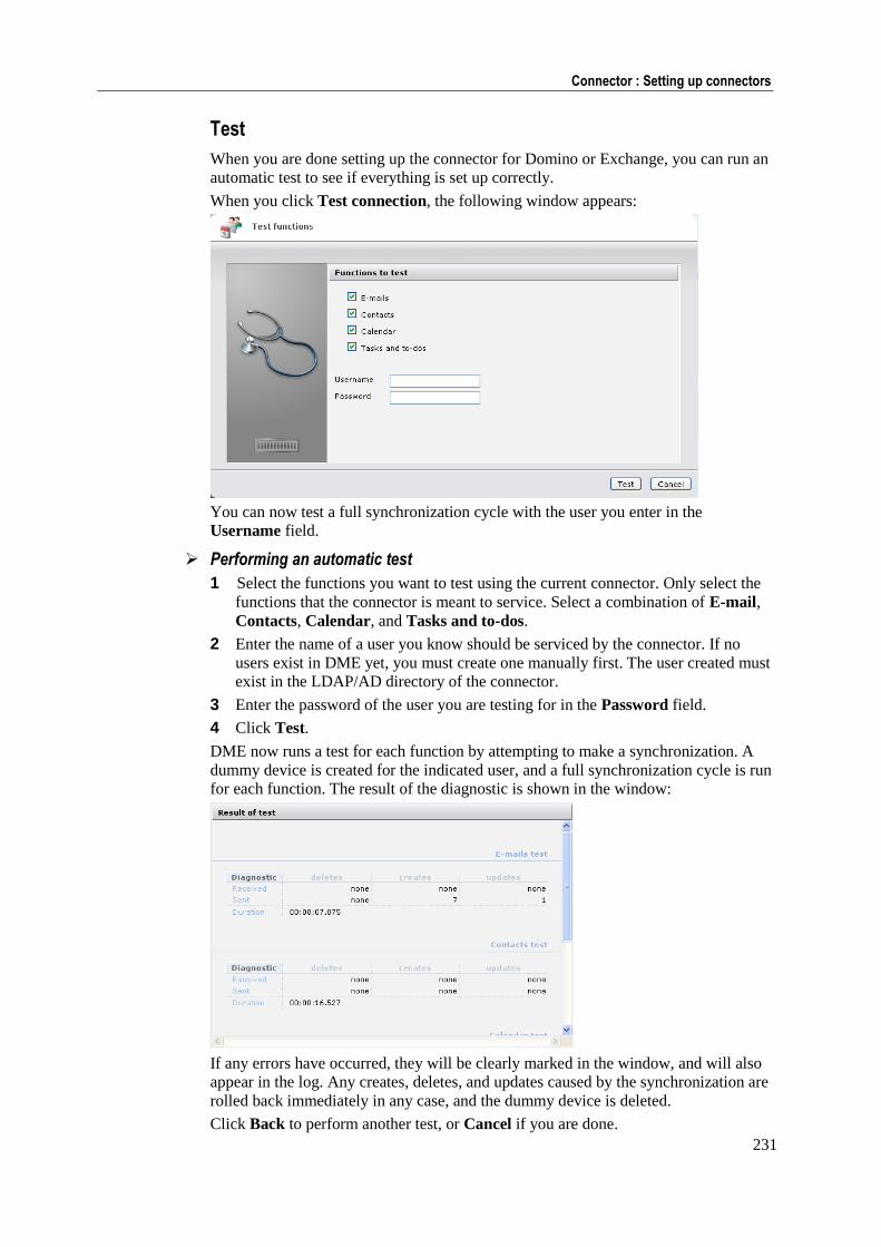
231
Connector : Setting up connectors
Test
When you are done setting up the connector for Domino or Exchange, you can run an
automatic test to see if everything is set up correctly.
When you click Test connection, the following window appears:
You can now test a full synchronization cycle with the user you enter in the
Username field.
Performing an automatic test
1 Select the functions you want to test using the current connector. Only select the
functions that the connector is meant to service. Select a combination of E-mail,
Contacts, Calendar, and Tasks and to-dos.
2 Enter the name of a user you know should be serviced by the connector. If no
users exist in DME yet, you must create one manually first. The user created must
exist in the LDAP/AD directory of the connector.
3 Enter the password of the user you are testing for in the Password field.
4 Click Test.
DME now runs a test for each function by attempting to make a synchronization. A
dummy device is created for the indicated user, and a full synchronization cycle is run
for each function. The result of the diagnostic is shown in the window:
If any errors have occurred, they will be clearly marked in the window, and will also
appear in the log. Any creates, deletes, and updates caused by the synchronization are
rolled back immediately in any case, and the dummy device is deleted.
Click Back to perform another test, or Cancel if you are done.
232
DME Server Administration Reference 3.5 : ©2011 Excitor A/S
Search In the Search section of the Connector settings panel you define the scope of the
search tasks of the current connector, and how the connector is to integrate with the
collaboration system with regard to searching.
Functions
Free time search
If you select this field, the current connector will be used for making free time
searches for participants in meetings scheduled by users that are routed to the
connector, meaning that it will accept free time search requests from the DME
server for those users.
Contact search
If you select this field, the current connector will be used for making Global
Address Book searches on behalf of users that are routed to the connector,
meaning that it will accept GAB search requests from the DME server for those
users.
Rooms and resource search
If you select this field, the current connector will be used for making searches for
rooms and resources for meetings scheduled by users that are routed to the
connector, meaning that it will accept R&R search requests from the DME server
for those users.
Contact search
The Contact search group of functions contains the following fields:
Server
In this field you can specify the directory server to use for the searches of the
current type. The field must be completed.
AD domain
Enter the AD domain in this field. This must be in UPN suffix format, which is
usually the same as your DNS domain, for instance your.domain.com or
something similar to ad.domain.local. Do not use the old Windows 2000
format such as DOMAIN\ .
The login information from the DME client usually only consists of your user
name, which is passed to the DME server. In order for the DME server and
connector to successfully authenticate against the Active Directory or the
Exchange server, it is necessary that the AD domain (UPN suffix) is appended to
this user name (for example your.domain.com), giving the unique
UserPrincipalName of [email protected]. You must enter the AD
domain information in this field, even if you only use one domain.
Search DN
For LDAP-based systems, you can minimize the search to a certain branch of
the LDAP Server tree by specifying a DN (Distinguished Name) in this field.
With Active Directory, you must enter a value in this field for Contact search
to function correctly from the devices. The value should typically be the value of
the AD key distinguishedName.
233
Connector : Setting up connectors
Example: Say you have a domain called learn.excitor.com. The default
search DN for the built-in AD view Users on this domain would be: CN=Users,
DC=learn, DC=excitor, DC=com, which you must enter in this field.
If you have created specific Organization Units, for instance an OU called
Exch2007 under group of users called 2007 Users, and you want to limit the
search to these users, the DN is OU=Exch2007, OU=2007 Users, DC=learn,
DC=local - and this is what you should enter in this field.
Find result that
In this field you can select when DME should return the result to the client: Either
if the search term is found anywhere within the result (option Contain client terms)
or if the search term is found at the beginning of the result (option Start with client terms). The latter option reduces the time it takes the collaboration server to return
results to DME, but requires a more precise search on the part of the client.
Max. number of returned rows
In this field you can specify the maximum number of results to be returned by a
search (default value: 25).
Search timeout
In this field you can specify the maximum time (in seconds) a search is allowed to
run on the collaboration system before timing out (default is 30 seconds).
Follow referrals
One LDAP repository can refer to other LDAP repositories for information. This
is especially the case for Active Directory environments. By default, DME allows
this, but in some cases it may not be desirable. If you disable this field, DME will
only search for information in the LDAP specified above, and not follow any
chain of LDAP referrals.
Domino wildcard search: Use like operator at
In this field you can specify the number of characters that must be entered before
DME performs a 'LIKE' (fuzzy) search. A LIKE search is able to find contacts
even if some search criteria are misspelled. For example, a LIKE search will find
contacts with similar names (e.g. Suzanna and Susanna), but will not attempt a
LIKE search if the search term is short. Please note that this applies to Domino
collaboration systems only.
Advanced
Custom query
You may want to filter the results returned from the Global Address Book before
they are returned to the user, for instance in order to remove service accounts and
similar and only return names with valid e-mail addresses. To do this, enter a text
string in this field: For a match to be returned as part of a Global Address Book
search, the string entered in this field must exist in the LDAP/AD entry of the
match. The string entered here is appended to the string in the Search DN field.
For instance, you could enter O=Exchange in this field to specify that in order to be
returned as a match, the entry must have O (Organization) set to "Exchange". The
syntax of the query string must follow standard LDAP Query. For examples, see
the Microsoft TechNet website
http://technet.microsoft.com/en-us/library/aa996205(EXCHG.65).aspx.
Rooms and resource search
The Rooms and resource search group of functions contains the following fields:
Server
In this field you can specify the directory server to use for the searches of the
current type. The field must be completed.
234
DME Server Administration Reference 3.5 : ©2011 Excitor A/S
AD domain
Enter the AD domain in this field. This must be in UPN suffix format, which is
usually the same as your DNS domain, for instance your.domain.com or
something similar to ad.domain.local. Do not use the old Windows 2000
format such as DOMAIN\ .
The login information from the DME client usually only consists of your user
name, which is passed to the DME server. In order for the DME server and
connector to successfully authenticate against the Active Directory or the
Exchange server, it is necessary that the AD domain (UPN suffix) is appended to
this user name (for example your.domain.com), giving the unique
UserPrincipalName of [email protected]. You must enter the AD
domain information in this field, even if you only use one domain.
Room DN
In this field you can specify the distinguished name or names where rooms are
found. Separate the list of DNs with ;.
Resource DN
In this field you can specify the distinguished name or names where resources are
found. Separate the list of DNs with ;.
Max. number of returned rows
In this field you can specify the maximum number of results to be returned by a
search (default value: 25).
Sorting locale
In this field you can specify the locale by which the list of rooms and resources
should be sorted in the client. This especially applies to languages that use
non-English characters. The sort order should be specified in the common ISO
format: a language code as specified by ISO-639 and a country code as specified
by ISO-3166, separated by an underscore. For instance, Danish is specified as
da_DK; Canadian French as fr_CA.
For a list of language codes, see for instance
http://ftp.ics.uci.edu/pub/ietf/http/related/iso639.txt
For a list of country codes, see for instance
http://userpage.chemie.fu-berlin.de/diverse/doc/ISO_3166.html (second column).
Follow referrals
One LDAP repository can refer to other LDAP repositories for information. This
is especially the case for Active Directory environments. By default, DME allows
this, but in some cases it may not be desirable. If you disable this field, DME will
only search for information in the LDAP specified above, and not follow any
chain of LDAP referrals.
Click Save to save the new settings.
Log In the Log section of the Connector settings panel you can see a subsection of the
main server log. Only log entries pertaining to the current connector are shown. For
more information, see Log on page 133.
Appendix A: Device settings 235
Appendix A: Device settings
This appendix is a description of each device setting in the DME server. Some settings
can only be changed at the server, and not on the client. Such settings are marked as
Server only. Note that not all devices support all the settings described here. If a
setting is supported by a client, it is shown in the Settings page for the device in
question.
Many of the listed settings include an indication of Recommended value:. This value
is what is recommended for a DME system of up to 500 users with medium load on
the collaboration system. In most cases, this value is also the default value.
The settings are grouped in the same way as on the clients.
Calendar settings
Calendar sync.
If this field is set to Enabled, scheduled calendar synchronization is enabled.
Recommended value: Enabled.
Days back
In this field you can specify how many days back the DME client should
synchronize calendar entries. Note that with higher numbers, the load on the DME
server will increase. Recommended value: 7.
Days forward
In this field you can specify how many days ahead the DME client should
synchronize calendar entries (the calendar synchronization window). Note that
with higher numbers, the load on the DME server will increase.
Note that the maximum number of days that Microsoft Exchange 2003 and
above allows a user to synchronize is 729 days. This synchronization window is
calculated from the date furthest back in time. This means that if the user sets a
very high value for Days back, for instance 700 days, DME is only able to
synchronize calendar entries 29 days ahead in time, regardless of the setting in the
field Days forward.
Calendar pull
If this field is set to Enabled, client-initiated (pull) synchronization of calendar
items is enabled. This corresponds to the Scheduled sync. see "Scheduled sync.
settings" on page 245, but is independent of the synchronization schedule set up
on the DME server. Recommended value: Disabled.
If Enabled, a Pull synchronization of your calendar only is defined, based on the
following settings:
Pull interval (min.)
In this field you can specify how often the pull should be executed. You can
choose from 10 to 120 minutes. Note that the load on the DME server will
increase, the lower a number you specify. Recommended value: 60.
Start time (hours:minutes)
236
DME Server Administration Reference 3.5 : ©2011 Excitor A/S
In this field you can specify the time of day at which calendar pull should start.
You can for instance choose to start checking for calendar updates at 8 in the
morning. Use together with the fields End time and Run on weekends.
End time (hours:minutes)
In this field you can specify the time of day at which calendar pull should stop.
You can for instance choose to not check for new calendar updates after your
regular work hours. Use together with the fields Start time and Run on
weekends.
Run on weekends
If this field is set to Yes, the client will pull for calendar updates in the
weekend also, except during the interval specified by the Start time and End
time settings.
Calendar mode
In this field you can choose the level of interaction between the device native
calendar and the DME calendar. Open means full integration. Mixed means that the
meeting times are shown in the native calendar, but you must see the title and
descriptions etc. in DME. Secure means that there is no integration between the
native and the DME calendar. For more information, see the Client User Guide.
Alarm sound
If this field is set to Enabled, the device will sound an alarm when the calendar
shows a notification for an upcoming event (applies to iOS and Android devices).
Alarm vibration
If this field is set to Enabled, the device will vibrate when the calendar shows a
notification for an upcoming event (applies to Android devices).
Alarm flashing LED light
If this field is set to Enabled, the device will flash the LED light when the calendar
shows a notification for an upcoming event (applies to Android devices).
Contacts settings
Contacts sync.
If this field is set to Enabled, scheduled contacts synchronization is enabled.
Recommended value: Disabled.
Device address book
In this field you can choose the level of interaction between the native address
book on the device and the DME Address Book.
Copy all fields: All information synchronized between the DME Address Book
and the collaboration system is reflected in the device address book. Changes,
deletions, and additions made in the device address book are copied to the DME
Address Book and synchronized to the collaboration system.
Copy name and phone numbers: All contacts synchronized between the DME
Address Book and the collaboration system are copied to the device address book.
However, only name and phone numbers are shown - e-mail addresses and other
information are only kept in the DME Address Book. If the user edits the name or
phone number in the device address book, this information will be synchronized to
the DME Address Book. However, if any other information is added to the native
contacts, this information will be removed again by DME. In other words, only
DME should be used for maintaining contacts.
237
Appendix A: Device settings : Desktop settings
Do not use: There is no interaction between the device address book and the DME
Address Book. This option should be chosen if you want users to keep private
contacts completely separate from corporate contacts, whether for reasons of
security or work/life balance. This lets the users keep business contacts in DME in
sync with the collaboration system, while letting them synchronize personal
contacts with other applications.
This field applies to iOS devices only.
Desktop settings
Log in to
In this field you can specify which screen you want the user to see after logging in
to the DME client. You can choose between the following two options:
Desktop: DME starts in the Desktop view after logging in.
Inbox: DME opens the Inbox after logging in.
Background
In this field you can specify the color of the Desktop background. You can choose
between the following two options:
Dark: The Desktop is shown with a dark background.
Light: The Desktop is shown with a light background.
The Desktop background is not affected by the user's choice of theme on the
phone.
Startup sound
If this field is set to Enabled, DME will play a sound when the user launches the
client.
E-mail settings
E-mail sync.
If this field is set to Enabled, scheduled e-mail synchronization is enabled. This
setting affects push mail, e-mail pull, manual synchronization, and scheduled sync.
Recommended value: Enabled. If you select Disabled, e-mails are never
synchronized.
Days back
In this field you can specify how many days back the DME client should
synchronize e-mails. You can choose from 0 to 99 days. Note that with higher
numbers, the load on the DME server will increase. Recommended value: 1.
Play sound on new mail
If this field is set to Enabled, the device will play a sound every time a new e-mail
arrives in the DME client. On most devices, you can specify which sound to play
in the e-mail settings on the client. Recommended value: Enabled.
Send immediately
In this field you can choose if new e-mails and meeting invitations composed on
the DME client should be synchronized to the server immediately when the user
presses Send. The field has three options:
No
238
DME Server Administration Reference 3.5 : ©2011 Excitor A/S
New e-mails are not sent immediately, but are queued in the device Outbox for
the next scheduled or manual synchronization.
Send & Receive
When the user presses Send, a full e-mail synchronization is initiated.
Send only
When the user presses Send, the new e-mail is synchronized to the server, but
the server is not queried for new e-mail or system information. This
significantly reduces the load on the server and the time it takes to
synchronize.
Recommended value: Send only.
Delete only locally
If this field is set to Yes, e-mails deleted on the DME client are not deleted from
the collaboration system. Recommended value: Yes. If set to No, e-mails deleted
in the DME Inbox on the device will also be deleted on the collaboration system.
E-mail pull
If this field is set to Enabled, client-initiated (pull) synchronization of e-mail is
enabled. This corresponds to the Scheduled sync. see "Scheduled sync. settings"
on page 245, but is independent of the synchronization schedule set up on the
DME server. Recommended value: Disabled. If Enabled, a Pull synchronization
of your e-mail only is defined, based on the following settings:
Pull interval (min.)
In this field you can specify how often the pull should be executed. You can
choose from 10 to 120 minutes. Note that the load on the DME server will
increase, the lower a number you specify. Recommended value: 60.
Start time (hours:minutes)
In this field you can specify the time of day at which e-mail pull should start.
You can for instance choose to start checking for new mail at 8 in the morning.
End time (hours:minutes)
In this field you can specify the time of day at which e-mail pull should stop.
You can for instance choose to not check for new mail after your regular work
hours. Use together with the field Start time and Run on weekends.
Run on weekends
If this field is set to Yes, the client will pull for e-mails in the weekend also,
during the interval specified by the Start time and End time settings.
E-mail signature
In this field you can enter a text which should be used as an e-mail signature on
the client. You can create a separate signature for different groups in the system,
so that for instance separate departments have separate signatures. The signature is
inserted below the text of e-mails that you write on the client, but above any
existing text (if you reply to or forward an e-mail). See also Functions on page
220 in the DME Administration Reference.
Alert volume
In this field you can specify the volume of the alerts the user hears when a new
e-mail arrives.
Alerts start/end
In this field you can specify the time of day from which you want the user to begin
and stop receiving audible alerts when a new e-mail arrives.
239
Appendix A: Device settings : E-mail folder settings
Vibrating alert
If this field is set to Enabled, the device vibrator will be activated when a new mail
is received by DME.
Font size
In this field you can choose the font size used in the DME client. Choose between
Small, Normal (default), and Large.
Call privacy
In this field you can specify whether the device should send the caller ID when
calling a number directly from an e-mail.
Phone default: Use the settings from the device to determine whether to use
the network operator's settings, send, or hide the user‘s number.
Always ask: Ask the user whether or not to send the caller ID.
Send my number: Send caller ID whenever possible.
Hide my number: Never send caller ID.
Show received time
If this field is set to Enabled, a column is added to the mailbox folders with the
date on which the e-mail was sent or received.
Quick reply type
In this field you can specify the function of the option Quick reply in an open
e-mail. You can choose among the following options:
1. To sender with history
2. To sender without history
3. To all with history
4. To all without history
When the user selects Quick reply in an open e-mail, DME will perform the
function specified in this field.
Mark as read when shown in preview pane
On the Apple iPad, the e-mail interface in horizontal position is a 3-pane view - a
folders list, a mailbox folder, and a preview pane. If this setting is Enabled,
showing an e-mail in the Preview pane will mark the e-mail as read. If this setting
is Disabled, an e-mail is only marked as read when the user double-taps to open it.
E-mail folder settings
E-mail folder sync.
With e-mail folder synchronization you can synchronize e-mails from any folder
in your collaboration system mailbox, instead of only from the Inbox. As for the
Inbox, you can limit the number of synchronized e-mails in folders by specifying a
maximum age of the e-mails to be synchronized. This is specified as a default
number of days for all e-mail folders, but you can allow the number to be changed
on a per-folder basis on the clients. Furthermore, you can specify if you want to
receive notification of new e-mails in sub-folders - for instance, if a mailbox rule
on the collaboration system automatically moves incoming e-mails to sub-folders,
you will not receive a notification unless you choose to. See also Allow individual
settings below.
Please note that synchronizing e-mail folders requires a special license.
240
DME Server Administration Reference 3.5 : ©2011 Excitor A/S
If this field is set to Enabled, scheduled synchronization of folders on your
collaboration system is enabled. When enabled, the folder tree structure will be
made part of the synchronization of e-mails. Note that the synchronization of the
folder tree structure is one-way; the folder structure on the device will always be
updated to reflect the collaboration system, as it is not possible to create or delete
folders on the device.
It should be noted that if you select Disabled, the folder structure will still be
synchronized, but not shown on the device. This is in order to enable searching in
e-mail sub-folders. If you do not want to be able to limit e-mail searches to certain
folders, you can set this setting to Disabled, and enter 0 in the Maximum folders
on device setting (see below). This will disable the folder synchronization entirely.
If you use Lotus Domino as your collaboration system, please note the following:
1. In Domino, it is possible to have the same document (e-mail) located in
multiple folders - it is essentially the same document, and therefore it has the
same ID in the collaboration system. In DME, an e-mail is only shown in one
location in the mailbox folder tree, even if it has been copied to multiple
folders in Domino.
2. S/MIME messages sent from the device will not be deleted from the Sent mailbox folder on the client even if it is removed in Lotus Notes. It must be
removed manually from the client if desired.
3. In Lotus Notes, you cannot manually move an e-mail to the Sent mailbox
folder. This is possible in the DME client (even if not recommended).
Furthermore, if you send an e-mail from the device, the e-mail is moved to the
Sent mailbox folder on the device, even if the collaboration system is for some
reason unable to send it after synchronization.
Days back in folder (default value)
In this field you can specify how many days back the DME client should
synchronize e-mails in sub-folders, when this is enabled. You can choose from
0 to 99 days. Note that with higher numbers, the load on the DME server will
increase. Note also that this number may be overwritten on a per-folder basis
on the device, if the field Allow individual settings below is selected.
Recommended value: 1.
Sync. e-mail in folder (default value)
If this field is set to Yes, synchronization of the e-mails residing in folders is
enabled (if E-mail folder sync. is also enabled). If E-mail folder sync. is
enabled, the folder structure is synchronized to the client. When this setting is
enabled, the actual e-mails in the folders are included in the synchronization. If
you select No, e-mails in folders are never synchronized, only the folder
structure. Note that this setting may be overwritten on a per-folder basis on the
device, if the field Allow individual settings below is selected.
Scan folder for changes (default value)
If this field is set to Yes, folders are scanned for the arrival of new e-mails on
the server. If folder scan is not enabled, users will not receive notification of
new e-mails in sub-folders on the collaboration system. It is recommended to
let the individual clients determine which folders it is necessary to receive
notifications for. See Allow individual settings below.
Maximum folders on device
241
Appendix A: Device settings : File sync. settings
In this field you can specify the maximum number of folders to be
synchronized to the clients. Symbian devices cannot handle large numbers of
folders (more than about 300-500), and they will crash if this number is
exceeded. The actual number of possible folders differs from device to device,
but is usually somewhat higher than 300.
There is no way to specify that an "unlimited number" of folders is allowed.
To work around this, you can enter a large number (for instance 10,000) in this
field.
Please note that your collaboration system determines which folders are
synchronized to the client if you have more folders than specified in this field.
IBM Domino will synchronize as many entire sub-folder "trees" (a "tree"
being a root folder and all folders contained in it, at all levels) as possible, in
alphabetical order by root folder, until the folder limit is reached. Microsoft
Exchange will synchronize folders by age - that is, the oldest folders up until
the folder limit are synchronized to the devices.
If you set this field to 0 (zero), the folder structure will not be available for
searching for e-mails from the client either.
Allow individual settings
If this field is set to Yes, the DME users can modify the e-mail folder
synchronization settings on a per-folder basis. From the server, you can only
allow or disallow the synchronization of e-mail in all sub-folders. To set up
e-mail folder support in the most efficient way, it is recommended that you
enable e-mail folder synchronization, disable the synchronization of e-mails in
folders, and enable this field to allow the users to pick which folders they need
to keep synchronized.
Please note that if you change this setting from Yes to No, all folders with
individual settings on a device will be overwritten with the default settings on
the client devices. Note also that if a device user chooses to import folders, the
same thing happens - all individual folder settings will be overwritten, and the
user must redefine individual settings on a per-folder basis.
Furthermore, the client contains a function called Apply to all folders now.
When that function is selected, the settings for Days back and Sync. e-mail in
folder in the Settings > Folders window/tab are propagated to all e-mail
folders on the client.
File sync. settings
File sync.
If this field is set to Enabled, file synchronization is enabled. This requires that file
synchronization is enabled as an add-on in the server license file. Recommended
value: Enabled if possible. This setting affects push notification, manual
synchronization, and scheduled sync.
242
DME Server Administration Reference 3.5 : ©2011 Excitor A/S
General settings
Server path
The server path is the URL by which the DME client can reach the DME server.
This is the external DME server address, including the port number. /nam_xml
must not be added to it (this was a requirement in previous versions of DME). This
value must be correct, otherwise your DME clients will not be able to connect to
the DME server after the first synchronization. It is highly recommend to lock this
setting so users cannot change it. As of DME Server 2.0 Service Pack 2, this
setting has been locked on the devices by default. The server path is usually
provisioned to the device along with the client software using OMA DM or SMS
push. See also Send server path on page 55.
Network push
If this field is set to Enabled, network push is enabled. This means that
notifications and server commands are sent over the GPRS network if available.
For more information, see Appendix F: AdaptivePush™ on page 279. If not
enabled, or if the GPRS network is unavailable, notifications are sent by SMS.
Network push support has been removed from the DME client for iOS as of
version 3.5.6 of the client. See also Apple Push Notification below.
Network push path
In this field you can specify the network path used for network push. Network
push requires a separate connection to the server. Be aware that the path and
port must be given access through the corporate firewall. For more
information, see Appendix F: AdaptivePush™ on page 279.
Apple Push Notification (APN)
If this field is set to Enabled, Apple Push Notification (APN) is enabled. This is
required if you want users of iOS devices to be able to receive notifications
through the Apple Push Notification Service (APNS). For more information about
further requirements, see Notifications on iPhone on page 195.
Phone number
This is the phone number for the device. This value naturally cannot be set in the
default or group settings on the server. It is either entered by the user when
installing the DME client or later by entering the number in Settings on the
device, or it is registered by the server during OMA DM or SMS push installation
of the DME client and subsequently synchronized to the client.
If no phone number is registered for the device in the client, the client will send an
SMS to the server's SMS modem, which responds with the number from which the
SMS was sent. This number is then synchronized to the server at the next sysinfo
sync. The phone number must be set in order for SMS-based features, including
DM actions, to work correctly on the device. Please note that for the device to
discover its own phone number, the SMS modem phone number must be
registered on the server (Server > Server configuration > SMS modem). See
SMS modem on page 169 for more information.
Launch on startup
If this field is set to Yes, the DME client will launch immediately after start or
reboot of the device. Recommended value: Yes.
If Lock device when logout in the Security group of settings is enabled, this
setting must be enabled also (does not apply to the Basic MDM client).
243
Appendix A: Device settings : General settings
GPRS timeout
By default, the GPRS connection times out after 1 minute for cost reasons, but you
can choose to never close the connection. Recommended value: After 1 minute to
reduce data costs and save battery lifetime. This setting does not affect network
push, which runs on a different connection.
Log traffic (server only)
If this field is set to Enabled, the client logs incoming and outgoing traffic for use
in Traffic statistics (see Statistics). If Enabled, make sure this feature does not
conflict with local data protections laws.
Instant messaging awareness
In this field you can specify if the device should keep track of the online presence
and online status of selected users. If this field is set to Enabled, the server will
include the online status of e-mail senders in the mailbox of the recipient device
when synchronizing e-mails. A colored dot is shown next to the e-mail sender's
name. The color is green if the sender's online status is Available or equivalent, red
if the status is Away or equivalent, and yellow if the status is Do no disturb or
equivalent.
Currently, the instant messaging application Sametime from IBM is supported.
Note that enabling this function only has effect if the device uses network push.
The location of the instant messaging server is entered in the Instant messaging
part of the Collaboration on page 164 section of the Server configuration page.
Background sync. when roaming
If this field is set to Disabled, the device will not perform background
synchronization when using a roaming network. Background synchronization
covers scheduled synchronization, e-mail and PIM pull, and SMS push
notification. If Manual sync. when roaming is enabled, the user will still be able
to synchronize manually.
The roaming status of the device is stored on the server. The first background sync
performed while roaming will therefore be carried out normally, but will also
inform the server that the device is roaming, effectively cutting the device off from
further background synchronization. This means that the server is unable to detect
that the device is back in the home network, unless the user performs a manual
sync. When using this cost-saving feature, it is important to instruct the users to
perform a manual sync when they return to their home network.
Manual sync. when roaming
If this field is set to Disabled, the user will not be able to perform manual
synchronization when using a roaming network. When roaming, a user trying to
perform a manual sync will see a message saying that synchronization is not
allowed when roaming.
The device uses information from the SIM card when checking if it is currently
roaming. As soon as the phone is no longer roaming, the user is able to
synchronize manually again. Performing a manual sync will also inform the server
that the device is no longer roaming, which is necessary for re-enabling
background sync. See also Background sync. when roaming.
Network push when roaming
As a cost-saving feature, you can disable the network (IP) connection when the
device is roaming. You can do this by selecting Disabled in this field. If Notify
when roaming (below) is enabled, the server will resort to SMS push (if permitted
by the notification schedule that applies to the device) or Apple Push. If Notify
when roaming is disabled also , the device will receive no notification at all.
244
DME Server Administration Reference 3.5 : ©2011 Excitor A/S
The current roaming status of the device can be seen in the device Information
page (see Information (device panel) see "Information" on page 62). To update
the roaming status, the user can perform a manual synchronization when he or she
returns to his or her home network.
Notify when roaming
As a cost-saving feature, you can disable push notification when the device is
roaming. The client will not receive any notifications by network push, SMS, or
Apple Push.
If this field is set to Enabled, DME will send notifications about new e-mail and
other items, even when the device is roaming. If Network push when roaming
(above) is Disabled, the notifications will not be pushed by network push, but only
by Apple Push (iPhone) and SMS (if permitted by the notification schedule that
applies to the device).
Assist switch to preferred operator (server only)
If this field is set to Enabled, the client will help the user switch to an operator
among the choices made in the list of mobile operators. This only applies to
Windows Mobile clients. If this field is set to Disabled, or on other platforms than
Windows Mobile, it is up to the user to switch to the preferred operator. See
Preferred operators on page 45 for more information.
Desktop "Close" key action
In this field you can specify the action of the secondary device action button when
the Desktop is shown. This setting does not apply to iPhone. The following
choices are available:
Lock: This is the default setting. Pressing the secondary action button locks
DME and shows the Login screen.
Hide: If you select this option, pressing the secondary action button will hide
(minimize) DME without logging out the user.
Login "Close" key action
In this field you can specify the action of the device action buttons when the Login
screen is shown. This setting does not apply to iPhone. The following choices are
available:
Exit: This is the default setting. Pressing the secondary action button exits the
DME application.
Hide: If you select this option, pressing the secondary action button will hide
(minimize) DME without logging out the user. Note that by selecting this, both
the Exit action and the Login action are moved to the primary action button,
which is then called Options.
E-mail key
If this field is set to Enabled, the user can select the DME application as the
program to be launched when he or she presses the Mail one-touch button on
the Symbian device.
Homescreen integration
With this setting, you can choose to show a notification with the number of new
e-mails in DME. The notification pops up on the Nokia homescreen when a new
e-mail arrives. When the user clicks the navigation key (or taps the notification
area - 5th edition only), DME opens or is brought to the foreground. If the user
presses any other key (or taps outside the notification area - 5th edition only), the
notification disappears, and the user can continue working with the phone.
You can choose among the following options:
245
Appendix A: Device settings : Scheduled sync. settings
Enabled: The notification is shown for approx. 30 seconds every time the user
goes to the homescreen. This means that the notification will reappear
whenever the user navigates to the homescreen from another application;
when the phone wakes from screensaver mode; or when the user presses any
button after the notification has disappeared by itself (that is, after 30 seconds).
The notification will be removed when the user opens DME and reads any of
the new e-mails.
Show once: The notification only appears once - when the user clicks (or taps)
something to make the notification disappear, it will not reappear until a new
e-mail arrives.
Disable: The homescreen integration feature is disabled.
1.-3. access point
In this field you can specify the primary, secondary, and tertiary access point used
to connect to the DME server. It is recommended to enter the fastest and/or
cheapest access point as the primary access point, such as WLAN, and let it fall
back to GPRS as a secondary access point. Note that if you fill in these fields, you
must be certain that all the Symbian devices that use this property have the access
points in question installed.
Run upon startup/resume
(iOS clients only) With this setting you can specify which action the DME client
for iOS (3.5.6 and later) should perform after launch or after resuming from
minimized state. To provide the fastest check for server commands after startup of
the client, set this to E-mail sync. This requires that the notification framework has
a schedule for e-mail scans - otherwise the option System info sync is faster.
Please note that in version 3.5.6 of the DME client, the value None is interpreted
as a System info sync.
Scheduled sync. settings
Scheduled sync.
If this field is set to Enabled, the DME client will initiate synchronization of the
enabled resources (e-mail, calendar, etc.) according to the schedule specified
below.
If you select Disabled, the synchronization of resources relies on client-initiated
sync (pull, where applicable), manual synchronization, or push notification from
the mail system. If Enabled, the scheduled synchronization is based on the
following settings:
Interval (hours)
In this field you can specify how often scheduled sync. should be executed.
Start time (hours:minutes)
In this field you can specify the time of day at which the scheduled sync
should start. You can for instance choose to start scheduled sync at 8 in the
morning. Use together with the fields End time and Run on weekends.
End time (hours:minutes)
In this field you can specify the time of day at which the scheduled sync
should stop. You can for instance choose to not sync after your regular work
hours. Use together with the fields Start time and Run on weekends.
Run on weekends
246
DME Server Administration Reference 3.5 : ©2011 Excitor A/S
If this field is set to Yes, the client will perform a scheduled sync in the
weekend also, during the interval specified by the Start time and End time
settings.
Security settings
Logout timeout (min.)
In this field you can specify the number of minutes after which the DME client
automatically logs the user out of the DME client. You can enter a number
between 0 (never) and 60. Recommended value: 10.
Action on SIM card change
In this field you can choose how the DME client should react when a new SIM
card is inserted into the device. A user may need more than one SIM card, for
instance if the user travels and uses local prepaid SIM cards, or if the user switches
between a private and a company SIM card. However, simply allowing SIM card
changes poses a security threat, as a malevolent user might steal a device and
insert his own SIM card in order to (potentially) gain access to files and other data
on the device. Therefore you can choose among three options in this field:
None
If you select this option, the DME client will do nothing when a user changes
SIM cards. This is usually not recommended for the above stated reasons.
Lock device
When the DME client detects the SIM card change, the client automatically
switches to Lock device mode (Shell protection). The user now has to log in to
DME in order to use the device. It is recommended to use the option Limit on
password attempts to deter malevolent users from trying to guess a password.
Just before logging in, DME checks if the current SIM card has been used
before. If it has not, the user is prompted to enter the phone number for the
new SIM card. This phone number and the SIM card identification number are
stored and thus recognized the next time the SIM card is inserted. A maximum
of 62 pairs of phone numbers and SIM card IDs can be stored in this way. This
option does not apply to the Basic MDM client.
Flush data
If you select this option, the DME client will flush (delete all data from) the
device if another SIM card is inserted. The device will be flushed as if you had
pushed the Destroy all device data command to the device (see Delete user
data on page 55).
On Java devices, only devices running Java Platform 7.2 or above support this
functionality as described above. Devices running older versions of the Java
Platform can only detect a change of SIM cards if the new SIM card is from a
different operator.
This option does not apply to iPhone devices.
Lock Messaging
If this field is set to Enabled, the device messaging (SMS/MMS) application can
only be opened if you are logged in to the DME client. Symbian devices only.
247
Appendix A: Device settings : Security settings
Lock Calendar
If this field is set to Enabled, the device calendar can only be opened if you are
logged in to the DME client. On Symbian devices, this is the Calendar application.
On Windows Mobile, this is the Outlook Pocket PC, which also locks Contacts
and To-dos (Tasks).
Lock Contacts
If this field is set to Enabled, the device contacts application can only be opened if
you are logged in to the DME client. On Symbian devices, this is the Contacts
application. On Windows Mobile, this is the Outlook Pocket PC, which also locks
Calendar and To-dos (Tasks).
Lock To-do
If this field is set to Enabled, the device to-do application can only be opened if
you are logged in to the DME client. On Symbian devices, this is the To-Do
application. On Windows Mobile, this is the Outlook Pocket PC (Tasks), which
also locks Calendar and Contacts.
Lock VoiceExtender
If this field is set to Enabled, the VoiceExtender™ application can only be opened
if you are logged in to the DME client. This only applies to Symbian devices. The
DME VoiceExtender is an answering machine for S60 devices. For more
information, please see separate VoiceExtender documentation.
Lock device on logout
If this field is set to Enabled, the device will be locked when you log out of the
DME client. This is also known as shell protection. Locked means that you are
only able to receive voice calls, make emergency calls, receive (but not view) text
messages, and respond to calendar alarm messages. If this setting is enabled, you
must enable the setting Launch on startup in the General group of settings also.
This way, this level of security is maintained even if the device is rebooted.
Furthermore, the DME client will automatically restart if it should crash.
Show username on logout (server only)
If this field is set to Enabled, the user name remains visible in the Login screen
when the user has logged out.
Limit on password attempts (0 = no limit) (server only)
In this field you can specify the permitted number of login attempts to the DME
client. "0" is no limit. Note that when the limit is reached, the DME client will
flush (delete all data from) the device. The device will be flushed as if you had
pushed the Destroy all device data command to the device (see Delete user data
on page 55).
Disable 'Send' button in attachments view (server only)
If this field is set to Enabled, the user is not permitted to forward attachments on
the device by Bluetooth, Infrared etc.
Allow attachment download (server only)
If this field is set to Enabled, the user is permitted to download attachments in
e-mails.
Allow attachment upload (server only)
If this field is set to Enabled, the user is permitted to add attachments from the
device in e-mails. The maximum file size is by default 16 MB, but this may be
changed in the Data on page 167 section of the Server configuration page.
248
DME Server Administration Reference 3.5 : ©2011 Excitor A/S
Prevent uninstall of DME Client (server only)
If this setting is Disabled, the user can freely remove the DME client from the
device. You can choose to remove the possibility to uninstall the DME client
under any circumstances (Enabled - Always), or only if the user cannot log in to the
DME client and thus prove that he or she is a registered user of the system
(Enabled - Unless when logged in).
Allow change password (server only)
If this field is set to Enabled, the user is permitted to use the Change password
functionality in the client. Note that to use this feature, certain requirements must
be fulfilled.
Domino: Users need write access to the LDAP. See the Domino Integration
Guide for details.
Exchange: You need secure access to the AD, using the LDAPS protocol.
Furthermore, to allow users to change passwords when the password has
expired (and not only during the grace period), you must enter an administrator
user name and password on the Exchange connector. See Authentication on
page 218.
Days before to show expiration warning (server only)
In this field you can specify the number of days a user should be warned that he
must change his network password. On the client, the user can then choose the
Change password function and change the password remotely, making direct
access to the network unnecessary. This is only supported on systems based on
Active Directory.
Allow global address book search (server only)
If this field is set to Enabled, the user is permitted to perform searches in the global
address book.
Allow use of PIN code/swipe
Your company security rules may require users to enter a long, complex password
with a mix of letters and special symbols to gain access to the network and
collaboration system. This may be easy to enter on a full PC keyboard, but can be
difficult to enter using your phone keypad.
Instead of using the collaboration system password for logging in, it is possible to
substitute the password for another passcode of your choice (a PIN code). The
minimum length for the PIN code can be set (see below), but the users are free to
define a PIN code that is easier to enter using the keypad. On iOS devices, you can
choose between a PIN code and a swipe code - a pattern drawn with the finger
across a set of tiles shown on the screen.
In order to maintain high security on the device, the following special conditions
apply when using the PIN code instead of the regular password:
The PIN code defined by the user will expire after some time, which you
specify (see below).
If the users attempts to log in using his or her PIN code, but he or she enters
the PIN code wrong, the user must use his or her regular password for the next
attempt to log in. The PIN code is not invalidated, however, and can be used
the next time the user attempts to log in to DME.
249
Appendix A: Device settings : Shortcuts settings
Important note about using this feature on iOS devices: Due to the
multitasking limitations inherent in the iOS platform, DME on iOS is typically
shut down more frequently than DME on other platforms. Therefore the decision
was made to allow the user to keep the encrypted password in the iOS device
storage, even when DME is shut down. If the use of PIN code is disabled, the
network password is only kept in memory and not stored when the user exits
DME. The encryption of the stored password is not strong when using the
PIN/swipe code feature, and it is possible for a hacker to break the password,
if he gets access to the phone. From a security point of view, it is therefore not
recommended to use this feature on iOS devices.
If this field is set to Enabled, the use of PIN codes or swipe patterns as a
supplement to the regular password is permitted with the restrictions specified
below.
PIN code/swipe minimum length
In this field you can specify the minimum length of the PIN code chosen by
the user, if the use of PIN code is Enabled. If the user tries to define a PIN
code shorter than this value, it will be rejected by the client. On iOS devices
using the swipe functionality, the number here is the number of tiles that must
be touched when defining the swipe pattern. Recommended value: 4.
PIN code/swipe time out (hours)
In this field you can specify you can set the validity period of the PIN code or
swipe pattern (Apple iOS) set by the user. The validity period is specified in
hours, and begins when the user logs in to DME using his or her regular
password. After this, the user can use his or her PIN code/swipe pattern to log
in to DME, until the validity period runs out. Then the user has to use his or
her regular password again in order to reset the validity period. The user does
not have to change the PIN code/swipe. The Login screen will always make it
clear if the regular password is required, or if the user can choose between the
regular password and the PIN code/swipe.
Require trusted certificate (server only)
If this field is set to Enabled, DME clients will only connect to the server if it has a
certificate from a trusted certificate provider.
If this field is set to Disabled, the client will either accept all certificates (including
self-signed certificates), or ask the user to accept the certificates.
See also SSL certificates on page 84.
Shortcuts settings
In the fields Shortcut 0 to Shortcut 9 is screen, you can change the shortcuts defined
for the device using these settings. For each of the fields, you can select one of the
available options:
Shortcut option Action
None Removes any existing shortcut definition. The shortcut will do
nothing.
Sync. e-mail Synchronize e-mail.
New e-mail Create a new e-mail.
250
DME Server Administration Reference 3.5 : ©2011 Excitor A/S
Open inbox Open the Inbox.
View folders Open the Folders screen to change to another e-mail folder.
Open calendar Open the internal DME calendar.
Open contacts Open the Contacts application.
Global Address Book Search the Global Address Book to find a contact.
Search e-mails Search for e-mails on the collaboration system.
Mark read Mark selected e-mail or e-mails as read.
Mark unread Mark selected e-mail or e-mails as unread.
Move to folder Move selected e-mail or e-mails to an e-mail folder of your choice.
New meeting Create a new meeting invitation.
Sync. calendar Synchronize the calendar according to settings.
Sync. contacts Synchronize your contacts.
Sync. to-do Synchronize to-dos according to settings.
Sync. files Synchronize files according to settings.
Sync. all Synchronize everything according to settings.
SmartEncrypt settings
SmartEncrypt is an add-on product to DME, which provides on-the-fly encryption of
any number of folders on a mobile device. SmartEncrypt can be used on any Symbian
device (Nokia S60 or UIQ) on which the DME client application is also installed and
in operation.
SmartEncrypt enables users to keep any folders on their device inaccessible
(encrypted), unless they have logged in to DME. Even if they should lose their device,
nobody can access their confidential files. For more information, see the separate
documentation for SmartEncrypt.
SmartEncrypt
If this field is set to Enabled, the SmartEncrypt application is enabled for those
Symbian client users who have installed the SmartEncrypt add-on application.
Allow access to encrypted folders
In this field you can specify the extent to which the encrypted files should be
inaccessible to users.
Only when DME logged in
With this option, a person can only view files in encrypted folders on the
phone for as long as somebody is logged in to the DME client. This is the most
secure setting. If the user should lose his or her phone, the files will be
inaccessible to anyone as soon as DME logs out automatically.
When logged in once
251
Appendix A: Device settings : SmartEncrypt settings
With this option, the encrypted files are accessible at any time, provided that
DME is installed on the phone, and that a user has logged in to DME at least
once since turning on the phone.
Encrypted folders
In this field you can specify a set of folders which must be encrypted. The way in
which the internal drive and the memory card is specified varies between device
platforms. For this reason, the alias [PHONEMEMORY] must be used to indicate the
internal drive (usually the C: drive), and [MEMORYCARD] is used to indicate the
memory card (usually the D: or E: drive).
Any path below the internal drive and the memory card can be appended
immediately to the alias, for instance [PHONEMEMORY]Documents. Subfolders
below the first folder are separated using the backslash \ character. All subfolders
below the specified folder are encrypted as well.
You can specify multiple folders by separating the paths with the pipe character: |
Example of a full list of encrypted folders:
[PHONEMEMORY]Documents|[PHONEMEMORY]Images|[MEMORYCARD]
This list will encrypt the Documents folder and Images folders on the internal
drive (including all subfolders to these folders), and the entire memory card.
Encryption key
This field stores a backup copy of the encryption key SmartEncrypt uses to
encrypt and files on-the-fly. This can be useful in the following instances:
The DME client is removed from the phone, for instance due to a firmware
upgrade:
In this case, you can reinstall DME. When logging in, the user's SmartEncrypt
key is automatically restored to the device.
A user moves a memory card protected by SmartEncrypt to a new device, for
instance because the user gets a new device model or the old one is out of
service:
In this case, you can find the SmartEncrypt key in the DME database. The
record where the key is stored has a combination of the user and the user's
previous device as database key (for more information, please contact your
DME partner). When the user has installed DME and SmartEncrypt and made
the initial synchronization on the new device, DME creates a record about the
new device in the DME database. The SmartEncrypt key from the old device
can then be pasted into this field for the user's current device. At the next
synchronization, the key will be transferred to the client, and the user will be
able to access the encrypted files on the memory card.
Another user logs in to the phone and cannot access folders protected by the
previous user using SmartEncrypt, for instance if a the original user is under
notice, or the device is a temporary device while the other is being serviced
(note that DME generally does not recommend the exchange of devices
between users):
In this case, the previous user can log in again. The user's SmartEncrypt key is
automatically restored to the device. The user can then unprotect the folders,
log out, and hand the device back for the new user to log in.
This field is only available in the individual device settings.
252
DME Server Administration Reference 3.5 : ©2011 Excitor A/S
SmartLink settings
SmartLink
If this field is set to Enabled, the SmartLink functionality is enabled on the server.
SmartLinks are special URLs in the body text of e-mails, which are handled in a
special way by the client and by the server. Typically, SmartLinks will point to
Word documents, PDF files, or other binary files that are only available on the
corporate intranet. When the URL link (SmartLink) is clicked in the client, the
client will download the file, much like an attachment, and open it using the
default application – for instance Pocket Word or QuickOffice – instead of
attempting to open the resource in a browser.
SmartLink sites
In this field, you can define such SmartLinks. The links are defined as match
strings, meaning that links that contain part or all of the text in a defined match
string will be recognized as a SmartLink by the client. Note that to be recognized
as a link at all, the link must begin with a text that can be identified as a link by the
client, for instance http:, https:, or www..
You can specify multiple folders by separating the paths with the pipe character: |
Examples of SmartLink match strings
https://intranet.company.com/ All documents in this domain can be
downloaded to the client.
http://documents.company.com/doc.aspx?docid= Documents that are part of a corporate CMS can
be downloaded. The document ID pinpoints the
correct document.
Some SmartLinks require entries in a configuration file on the server. Please
request special documentation from DME Support.
To-do settings
For a to-do to be included in the synchronization from the collaboration system to the
device, the following criteria must be fulfilled by the to-do on the collaboration
system:
1 A due date has not been specified, and it has not been marked as complete
(Domino only).
2 Or the to-do is overdue and not marked as complete, regardless of the values in the
starting date and due date fields.
3 Regardless of the above, a to-do is included if either the starting date or the due
date is within the time span set in To-do settings (the sync window).
Examples:
The sync window is set to 10 days in To-do settings, and today is April 15th.
253
Appendix A: Device settings : VoiceExtender settings
1 A to-do on the collaboration system was created on March 23rd with a due date on
April 17th. This to-do is synchronized to the device because the due date is within
the 10-day sync window specified in the To-do settings.
2 Another to-do was created on March 3rd, with a due date of March 16th. It has not
been marked as completed. This to-do is synchronized to the device. When it is
marked as completed, it will no longer appear on the device.
Settings:
To-do sync.
If this field is set to True, scheduled to-do synchronization is enabled. This setting
affects push notification, manual synchronization, and scheduled sync.
If you select Disabled, to-dos are never synchronized.
Days back
In this field you can specify how many days back the DME client should
synchronize to-do entries. You can choose between 0 and 99 days, calculated
from the starting or due date of the to-do (if one of the dates is within the
specified range). Note that with higher numbers, the load on the DME server
will increase. Recommended value: 7.
Days forward
In this field you can specify how many days ahead the DME client should
synchronize to-do entries. You can choose between 0 and 999 days, calculated
from the starting or due date of the to-do (if one of the dates is within the
specified range). Note that with higher numbers, the load on the DME server
will increase. Recommended value: 30.
VoiceExtender settings
VoiceExtender
If this field is set to True, use of the VoiceExtender™ is permitted on Nokia S60
devices. The DME VoiceExtender is an answering machine for Nokia S60
devices. For more information, see separate documentation.

Appendix B: Self-provisioning 255
Appendix B: Self-provisioning
DME supports the concept of self-provisioning, meaning that users can request
software and OTA (see Glossary on page 290) configurations on demand. To achieve
this, a user needs to know four items of information: An SMS Code, the server's phone
number (the phone number of the Kannel (see Glossary on page 290) modem), a
download code, and a PIN code.
Please note that self-provisioning by SMS is not supported on installations where the
Kannel SMS gateway is installed on Windows servers. Only Kannel on Linux and
NowSMS on Windows are supported.
Setting up
You can set up self-provisioning for software and for OTA configurations.
Setting up software for self-provisioning
1 In the Provisioning tab, upload new software, or edit an existing software
package by clicking the software in question. See Provisioning on page 83 in the
DME Web Administration Reference for more information.
2 In the SMS Code field in the Software information window, enter a short code
which the users will use when requesting the software in question. This could for
instance be S60 for the latest DME client for Nokia S60 devices.
3 Specify whether the users should get the software as an SMS push or as a WAP
push when they request the software by SMS.
When you click Save, the software is set up for self-provisioning.
Setting up OTA configurations for self-provisioning
1 In the Devices or Provisioning tab, create a new configuration (for instance a
bookmark or an access point), or edit an existing configuration by clicking the
configuration in question. See Send OTA configuration on page 52 in the DME
Web Administration Reference for more information.
2 In the SMS Code field in the Edit phone configuration window, enter a short
code which the users will use when requesting the configuration in question. This
could for instance be TDC for the common configuration settings for the TDC
phone operator.
When you click Accept, the configuration is set up for self-provisioning.
Requesting software or configuration
In order to be able to request software or phone configurations from the DME server, a
user needs to know the following information:
256
DME Server Administration Reference 3.5 : ©2011 Excitor A/S
An SMS Code
The SMS code is what you set up in the previous section.
The server's phone number
You can find the phone number of the server's SMS server in the Server tab -
click Server configuration > SMS modem. The field Modem phone number
field contains the number you need. See SMS modem on page 169 in the DME
Web Administration Reference.
A download code
There are three different download codes: TST, DWL, and CON. For more
information, see the examples below.
A PIN code
A PIN code may be required by the SMS modem. A separate PIN code can be set
for software (in the field SMS Service PIN) and for configuration downloads (in
the field OMA PIN).
Testing that you have the right phone number for the SMS server
1 Send the following SMS message to the number you believe belongs to the SMS
modem:
TST
If the phone number is correct, the server will reply with the message "This is a TEST
reply".
Requesting a software download
1 Send an SMS to the server requesting a software download on the following form:
DWL <SMS code> [PIN]
The PIN code is only required if the SMS modem has been set up to require an
SMS Service PIN.
The server will reply with an SMS and/or a WAP service message containing a
temporary link to the requested software.
Requesting a phone configuration
1 Send an SMS to the server requesting a configuration download on the following
form:
CON <SMS code> [PIN]
The PIN code is only required if the SMS modem has been set up to require an
OMA PIN.
The server will reply with an SMS configuration message containing the requested
configuration.
It is possible to send multiple requests in the same SMS - see the examples in the next
section.
Examples
Use the examples below as a guide to using the SMS commands. The examples
assume the following:
257
Appendix B: Self-provisioning : Examples
Server modem phone number: 12345678
SMS code for DME software: S60
SMS code for OTA configuration: TDC
SMS service PIN: 1234
OMA PIN: 12345
Sending a test message to the server modem
Send
TST
to 12345678. The server should respond with the message "This is a TEST reply".
Requesting DME software
Send
DWL S60 1234
to 12345678. The server should respond with a push to download the requested client.
Requesting OTA configuration
Send
CON TDC 12345
to 12345678. The server should respond with a push to install the requested OTA
configuration.
Requesting both DME software and OTA configuration
Send
DWL S60 1234 CON TDC 12345
to 12345678. Note that the commands must be on separate lines.

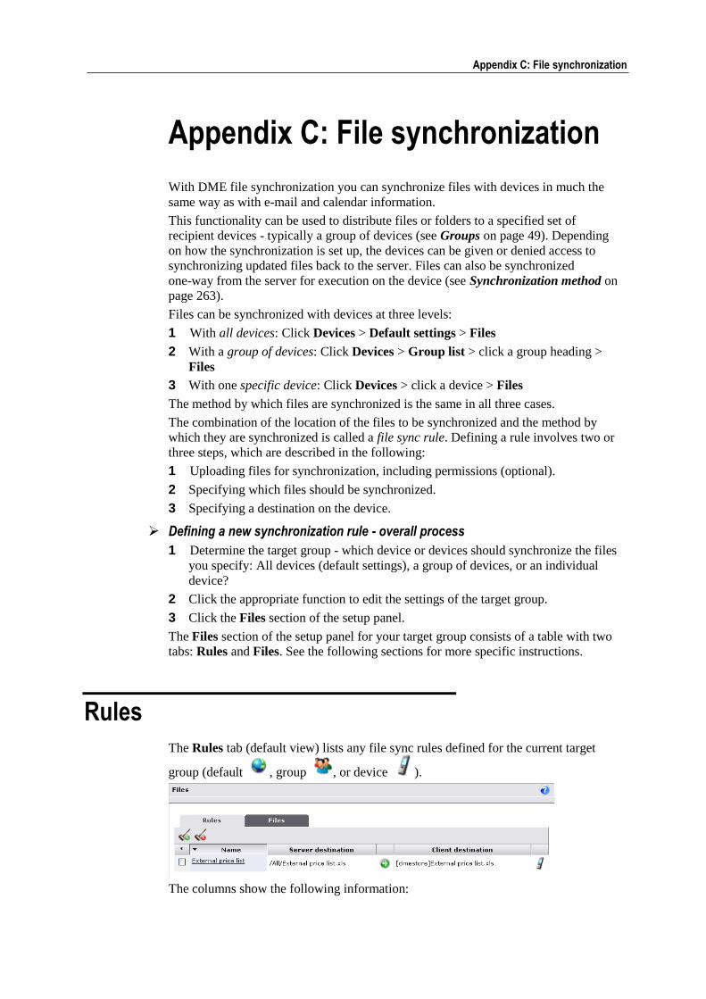
Appendix C: File synchronization 259
Appendix C: File synchronization
With DME file synchronization you can synchronize files with devices in much the
same way as with e-mail and calendar information.
This functionality can be used to distribute files or folders to a specified set of
recipient devices - typically a group of devices (see Groups on page 49). Depending
on how the synchronization is set up, the devices can be given or denied access to
synchronizing updated files back to the server. Files can also be synchronized
one-way from the server for execution on the device (see Synchronization method on
page 263).
Files can be synchronized with devices at three levels:
1 With all devices: Click Devices > Default settings > Files
2 With a group of devices: Click Devices > Group list > click a group heading >
Files
3 With one specific device: Click Devices > click a device > Files
The method by which files are synchronized is the same in all three cases.
The combination of the location of the files to be synchronized and the method by
which they are synchronized is called a file sync rule. Defining a rule involves two or
three steps, which are described in the following:
1 Uploading files for synchronization, including permissions (optional).
2 Specifying which files should be synchronized.
3 Specifying a destination on the device.
Defining a new synchronization rule - overall process
1 Determine the target group - which device or devices should synchronize the files
you specify: All devices (default settings), a group of devices, or an individual
device?
2 Click the appropriate function to edit the settings of the target group.
3 Click the Files section of the setup panel.
The Files section of the setup panel for your target group consists of a table with two
tabs: Rules and Files. See the following sections for more specific instructions.
Rules
The Rules tab (default view) lists any file sync rules defined for the current target
group (default , group , or device ).
The columns show the following information:
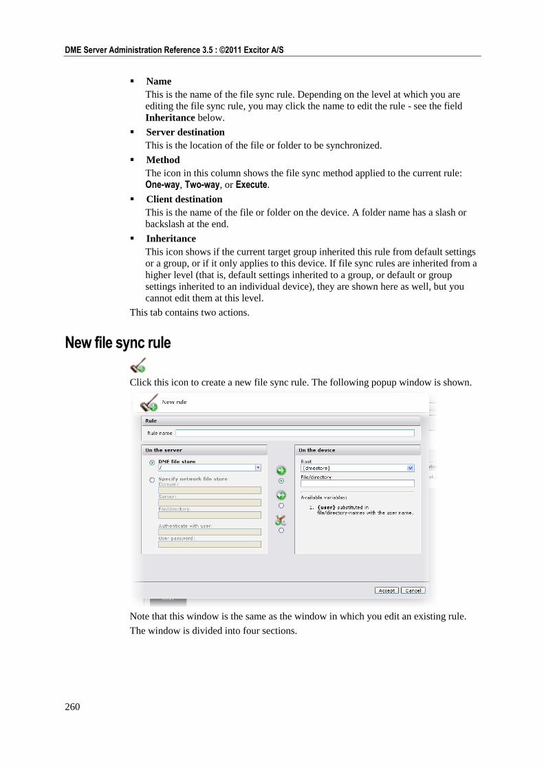
260
DME Server Administration Reference 3.5 : ©2011 Excitor A/S
Name
This is the name of the file sync rule. Depending on the level at which you are
editing the file sync rule, you may click the name to edit the rule - see the field
Inheritance below.
Server destination
This is the location of the file or folder to be synchronized.
Method
The icon in this column shows the file sync method applied to the current rule:
One-way, Two-way, or Execute.
Client destination
This is the name of the file or folder on the device. A folder name has a slash or
backslash at the end.
Inheritance
This icon shows if the current target group inherited this rule from default settings
or a group, or if it only applies to this device. If file sync rules are inherited from a
higher level (that is, default settings inherited to a group, or default or group
settings inherited to an individual device), they are shown here as well, but you
cannot edit them at this level.
This tab contains two actions.
New file sync rule
Click this icon to create a new file sync rule. The following popup window is shown.
Note that this window is the same as the window in which you edit an existing rule.
The window is divided into four sections.
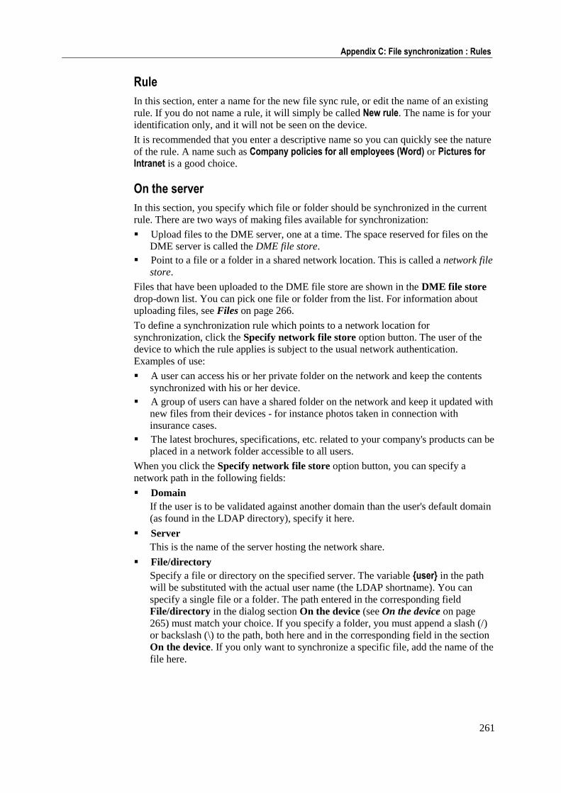
261
Appendix C: File synchronization : Rules
Rule
In this section, enter a name for the new file sync rule, or edit the name of an existing
rule. If you do not name a rule, it will simply be called New rule. The name is for your
identification only, and it will not be seen on the device.
It is recommended that you enter a descriptive name so you can quickly see the nature
of the rule. A name such as Company policies for all employees (Word) or Pictures for Intranet is a good choice.
On the server
In this section, you specify which file or folder should be synchronized in the current
rule. There are two ways of making files available for synchronization:
Upload files to the DME server, one at a time. The space reserved for files on the
DME server is called the DME file store.
Point to a file or a folder in a shared network location. This is called a network file
store.
Files that have been uploaded to the DME file store are shown in the DME file store
drop-down list. You can pick one file or folder from the list. For information about
uploading files, see Files on page 266.
To define a synchronization rule which points to a network location for
synchronization, click the Specify network file store option button. The user of the
device to which the rule applies is subject to the usual network authentication.
Examples of use:
A user can access his or her private folder on the network and keep the contents
synchronized with his or her device.
A group of users can have a shared folder on the network and keep it updated with
new files from their devices - for instance photos taken in connection with
insurance cases.
The latest brochures, specifications, etc. related to your company's products can be
placed in a network folder accessible to all users.
When you click the Specify network file store option button, you can specify a
network path in the following fields:
Domain
If the user is to be validated against another domain than the user's default domain
(as found in the LDAP directory), specify it here.
Server
This is the name of the server hosting the network share.
File/directory
Specify a file or directory on the specified server. The variable {user} in the path
will be substituted with the actual user name (the LDAP shortname). You can
specify a single file or a folder. The path entered in the corresponding field
File/directory in the dialog section On the device (see On the device on page
265) must match your choice. If you specify a folder, you must append a slash (/)
or backslash (\) to the path, both here and in the corresponding field in the section
On the device. If you only want to synchronize a specific file, add the name of the
file here.
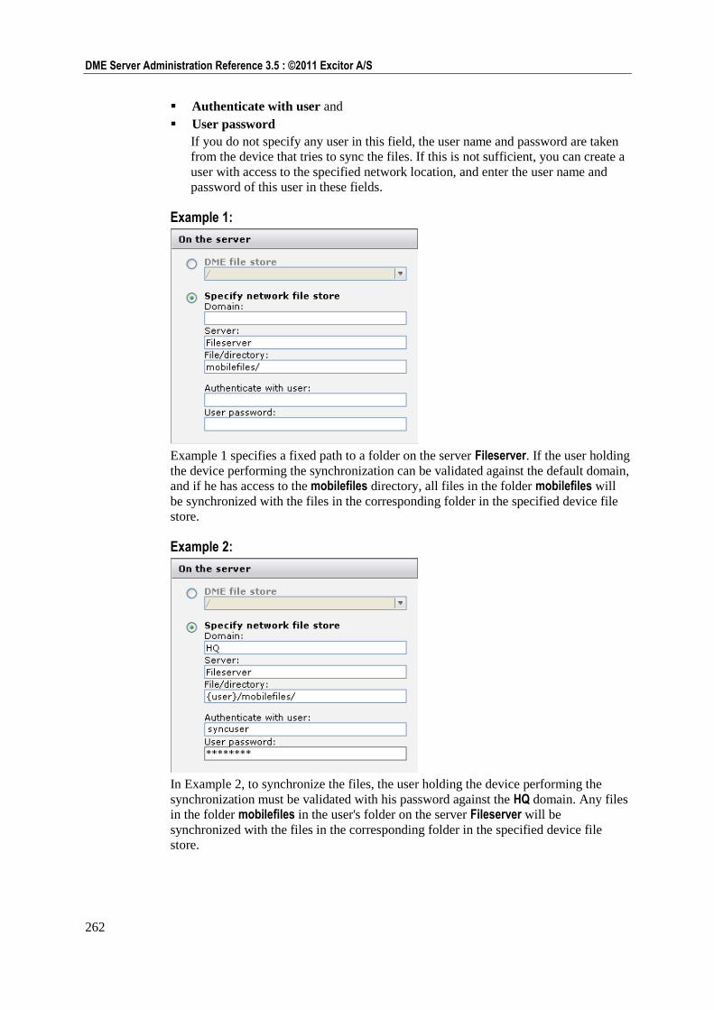
262
DME Server Administration Reference 3.5 : ©2011 Excitor A/S
Authenticate with user and
User password
If you do not specify any user in this field, the user name and password are taken
from the device that tries to sync the files. If this is not sufficient, you can create a
user with access to the specified network location, and enter the user name and
password of this user in these fields.
Example 1:
Example 1 specifies a fixed path to a folder on the server Fileserver. If the user holding
the device performing the synchronization can be validated against the default domain,
and if he has access to the mobilefiles directory, all files in the folder mobilefiles will
be synchronized with the files in the corresponding folder in the specified device file
store.
Example 2:
In Example 2, to synchronize the files, the user holding the device performing the
synchronization must be validated with his password against the HQ domain. Any files
in the folder mobilefiles in the user's folder on the server Fileserver will be
synchronized with the files in the corresponding folder in the specified device file
store.
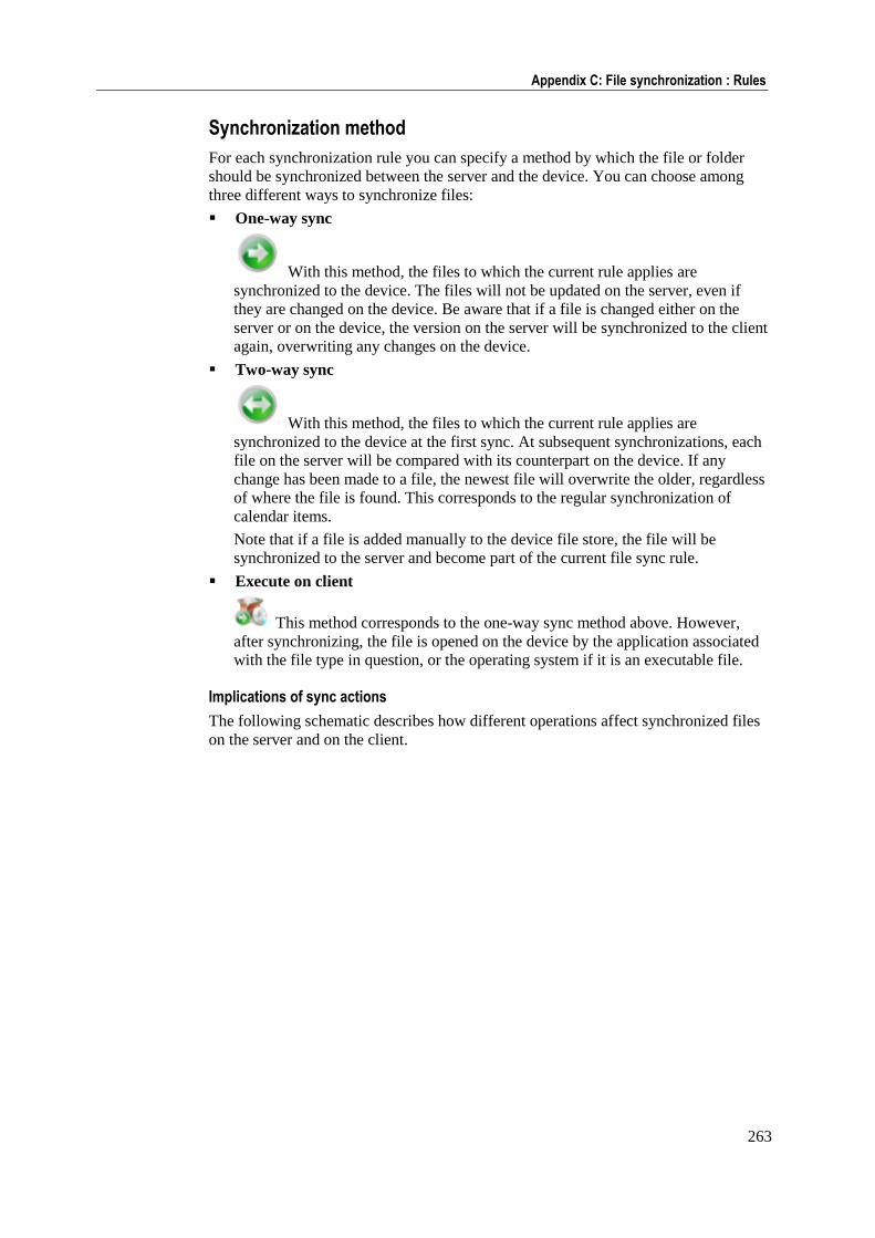
263
Appendix C: File synchronization : Rules
Synchronization method
For each synchronization rule you can specify a method by which the file or folder
should be synchronized between the server and the device. You can choose among
three different ways to synchronize files:
One-way sync
With this method, the files to which the current rule applies are
synchronized to the device. The files will not be updated on the server, even if
they are changed on the device. Be aware that if a file is changed either on the
server or on the device, the version on the server will be synchronized to the client
again, overwriting any changes on the device.
Two-way sync
With this method, the files to which the current rule applies are
synchronized to the device at the first sync. At subsequent synchronizations, each
file on the server will be compared with its counterpart on the device. If any
change has been made to a file, the newest file will overwrite the older, regardless
of where the file is found. This corresponds to the regular synchronization of
calendar items.
Note that if a file is added manually to the device file store, the file will be
synchronized to the server and become part of the current file sync rule.
Execute on client
This method corresponds to the one-way sync method above. However,
after synchronizing, the file is opened on the device by the application associated
with the file type in question, or the operating system if it is an executable file.
Implications of sync actions
The following schematic describes how different operations affect synchronized files
on the server and on the client.
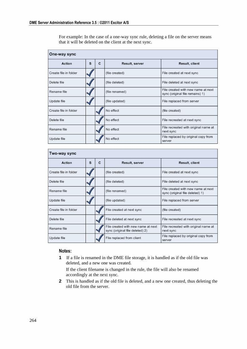
264
DME Server Administration Reference 3.5 : ©2011 Excitor A/S
For example: In the case of a one-way sync rule, deleting a file on the server means
that it will be deleted on the client at the next sync.
Notes:
1 If a file is renamed in the DME file storage, it is handled as if the old file was
deleted, and a new one was created.
If the client filename is changed in the rule, the file will also be renamed
accordingly at the next sync.
2 This is handled as if the old file is deleted, and a new one created, thus deleting the
old file from the server.
265
Appendix C: File synchronization : Rules
On the device In this section, you specify where the files involved in the current file sync rule are
stored on the client. The file store specification consists of a base path and a relative
path and/or a filename.
1 In the field Root, specify one of five aliases, which point to different locations on
the device.
[dmestore]: This path is specific to the device platform in question:
Windows Mobile: My Device\Program Files\Dme\Data\files\
S60: C:\Data\Others\DME\PUBLIC\
UIQ: C:\Media files\Other\DME\Public\
Java: C:\
Note that some Java devices from Sony Ericsson do not allow access to the
root, so for such devices you need to add a subfolder to the [dmestore] root.
[internal]: On the device, this will be translated to the name of the internal flash
memory.
Windows Mobile: My Device\
S60: C:\Data\
UIQ: C:\Media files\
Java: Same as [dmestore].
[external]: On the device, this will translated to the root of the external flash
memory, such as a memory storage card.
[internalroot]: On the device, this will be translated to the name of the internal
flash memory. On Symbian devices, this is the root of the system drive (C:);
on other platforms, it corresponds to [internal].
[externalroot]: Same as [external].
2 In the field File/directory, append a folder or filename, which is relative to the
base path. Note that if you are synchronizing a single file, you can specify any
filename as the device file store file name. The file will be renamed in the
synchronization process.
3 Finally, append a slash (/) or backslash (\) to the path if you are synchronizing a
folder. Do not append a slash or backslash if you synchronize a single file.
If a folder does not exist on the device, it is created at the first synchronization.
Examples of paths to the device file store:
[internal]syncdox\
The files on the server are kept in sync with files in the folder syncdox in the root
of the internal flash memory drive.
[external]syncdox\prices2007.xls
The spreadsheet file prices2007.xls in the folder syncdox in the root of the external
memory card drive is kept in sync with (or updated by) a file in the DME file store
or a network file store.
[dmestore]prices2007.xls
The spreadsheet file prices2007.xls in the folder specified for the device platform
in question is kept in sync with (or updated by) a file in the DME file store or a
network file store.

266
DME Server Administration Reference 3.5 : ©2011 Excitor A/S
Delete file sync rule
Click this icon to delete the selected file sync rule(s). The following popup window is
shown.
Note the checkbox Keep synchronized files on device, which is selected by default.
If this field is not selected, all synchronized files comprised by the rule will be deleted
from all affected devices when you delete the rule. This can have adverse effects, for
instance if you have synchronized a folder to the [internal] root folder without
specifying further directories. If this field was not selected, all files in the [internal] directory would be deleted.
Files
The Files tab lists all files that have been made available for selection in file sync rules
in the DME file store.
The columns show the following information:
Name
This is the name of the uploaded file. Click the name to edit the properties of the
uploaded file. The files are automatically grouped by the folders in which they are
placed on the DME file store. If you click the file icon, you download the file.
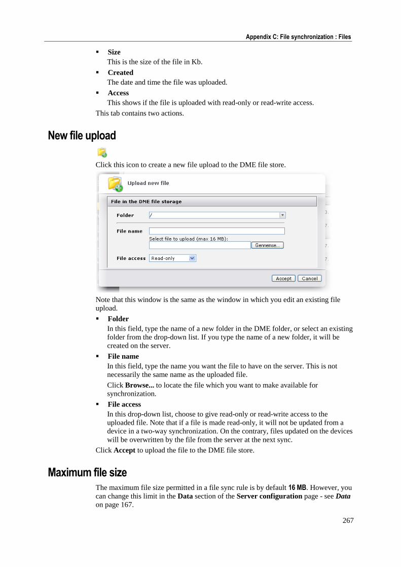
267
Appendix C: File synchronization : Files
Size
This is the size of the file in Kb.
Created
The date and time the file was uploaded.
Access
This shows if the file is uploaded with read-only or read-write access.
This tab contains two actions.
New file upload
Click this icon to create a new file upload to the DME file store.
Note that this window is the same as the window in which you edit an existing file
upload.
Folder
In this field, type the name of a new folder in the DME folder, or select an existing
folder from the drop-down list. If you type the name of a new folder, it will be
created on the server.
File name
In this field, type the name you want the file to have on the server. This is not
necessarily the same name as the uploaded file.
Click Browse... to locate the file which you want to make available for
synchronization.
File access
In this drop-down list, choose to give read-only or read-write access to the
uploaded file. Note that if a file is made read-only, it will not be updated from a
device in a two-way synchronization. On the contrary, files updated on the devices
will be overwritten by the file from the server at the next sync.
Click Accept to upload the file to the DME file store.
Maximum file size The maximum file size permitted in a file sync rule is by default 16 MB. However, you
can change this limit in the Data section of the Server configuration page - see Data
on page 167.
268
DME Server Administration Reference 3.5 : ©2011 Excitor A/S
Delete file
Click this icon to delete the selected file or files. Note that when you delete files that
are associated with file sync rules, you should delete the associated rules also in order
to avoid synchronization errors.
Appendix D: Traffic logging 269
Appendix D: Traffic logging
The DME server always collects and stores information about how the devices use
DME.
In addition, some device platforms collect information about voice calls, messaging,
and GPRS usage, and if you enable traffic logging on the clients, this information will
be sent to the DME server. The information can be used for traffic analysis, either by
using the built-in reports in the DME Administration interface or by using custom
BIRT reports (see Reporting see "Analyzer reports" on page 152). The results of the
statistical analysis give an overview of expected costs of device usage, perhaps as a
basis for negotiating new rates with your operator or for optimizing your use of
network operators.
For more information about the presentation of the traffic logging data in the DME
server, see Statistics and Reporting see "Analyzer reports" on page 152.
Please note that the collection of statistics relies on a number of factors, including the
ability of devices of different makes and models to collect and report the numbers
correctly to the DME server. The DME server builds the statistics base on the received
data, and DME cannot guarantee the correctness or completeness of this information.
The following types of usage information may be collected:
Voice traffic
GPRS (data) traffic
Messaging (SMS and MMS) traffic
Each traffic type is described in the following.
Enabling traffic logging
Like most other settings, traffic logging can be enabled or disabled per device, per
group, or generally.
To enable traffic logging, go to the Settings panel of a device or group, or choose
Default settings in the page menu in the Devices tab (see Default settings on page
41).
In the General section, make sure that the option Traffic logging is Enabled, and
click Save.
The devices collect the information regardless of this setting. The setting only controls
whether the device is to send the information to the server. If enabled, the information
is sent to the server at every system information synchronization, and is then deleted
from the device. If disabled, the device automatically deletes the oldest traffic log
entry as it adds the latest traffic log entry, after a device-specific, fixed upper limit to
log content size has been reached. The process is automatic, and the device user
cannot alter this setting.
Specific notes about client platforms:
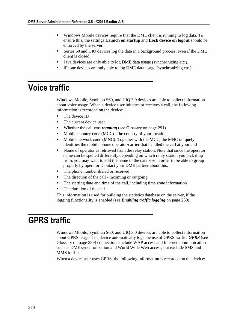
270
DME Server Administration Reference 3.5 : ©2011 Excitor A/S
Windows Mobile devices require that the DME client is running to log data. To
ensure this, the settings Launch on startup and Lock device on logout should be
enforced by the server.
Series 60 and UIQ devices log the data in a background process, even if the DME
client is closed.
Java devices are only able to log DME data usage (synchronizing etc.).
iPhone devices are only able to log DME data usage (synchronizing etc.).
Voice traffic
Windows Mobile, Symbian S60, and UIQ 3.0 devices are able to collect information
about voice usage. When a device user initiates or receives a call, the following
information is recorded on the device:
The device ID
The current device user
Whether the call was roaming (see Glossary on page 291)
Mobile country code (MCC) - the country of your location
Mobile network code (MNC). Together with the MCC, the MNC uniquely
identifies the mobile phone operator/carrier that handled the call at your end
Name of operator as retrieved from the relay station. Note that since the operator
name can be spelled differently depending on which relay station you pick it up
from, you may want to edit the name in the database in order to be able to group
properly by operator. Contact your DME partner about this.
The phone number dialed or received
The direction of the call - incoming or outgoing
The starting date and time of the call, including time zone information
The duration of the call
This information is used for building the statistics database on the server, if the
logging functionality is enabled (see Enabling traffic logging on page 269).
GPRS traffic
Windows Mobile, Symbian S60, and UIQ 3.0 devices are able to collect information
about GPRS usage. The device automatically logs the use of GPRS traffic. GPRS (see
Glossary on page 289) connections include WAP access and Internet communication
such as DME synchronization and World Wide Web access, but exclude SMS and
MMS traffic.
When a device user uses GPRS, the following information is recorded on the device:
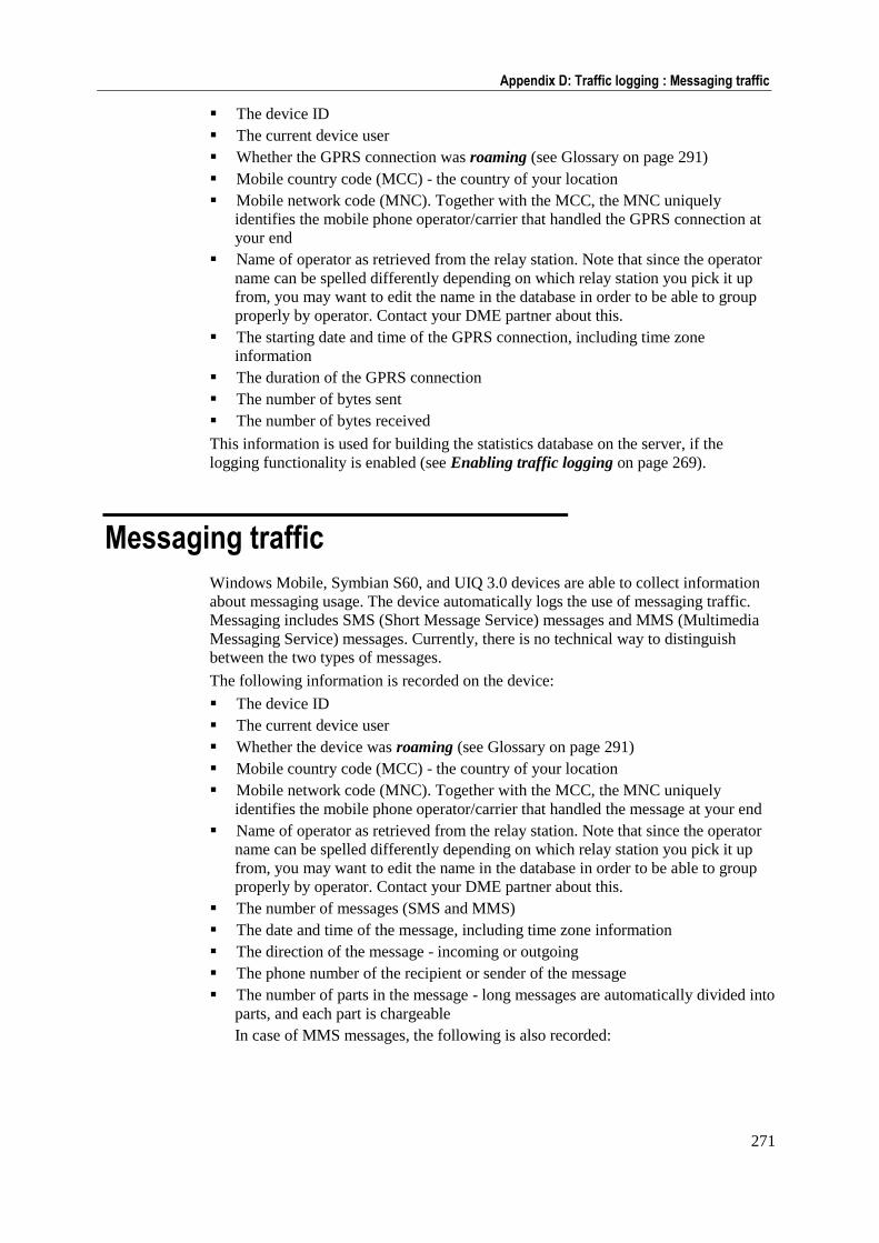
271
Appendix D: Traffic logging : Messaging traffic
The device ID
The current device user
Whether the GPRS connection was roaming (see Glossary on page 291)
Mobile country code (MCC) - the country of your location
Mobile network code (MNC). Together with the MCC, the MNC uniquely
identifies the mobile phone operator/carrier that handled the GPRS connection at
your end
Name of operator as retrieved from the relay station. Note that since the operator
name can be spelled differently depending on which relay station you pick it up
from, you may want to edit the name in the database in order to be able to group
properly by operator. Contact your DME partner about this.
The starting date and time of the GPRS connection, including time zone
information
The duration of the GPRS connection
The number of bytes sent
The number of bytes received
This information is used for building the statistics database on the server, if the
logging functionality is enabled (see Enabling traffic logging on page 269).
Messaging traffic
Windows Mobile, Symbian S60, and UIQ 3.0 devices are able to collect information
about messaging usage. The device automatically logs the use of messaging traffic.
Messaging includes SMS (Short Message Service) messages and MMS (Multimedia
Messaging Service) messages. Currently, there is no technical way to distinguish
between the two types of messages.
The following information is recorded on the device:
The device ID
The current device user
Whether the device was roaming (see Glossary on page 291)
Mobile country code (MCC) - the country of your location
Mobile network code (MNC). Together with the MCC, the MNC uniquely
identifies the mobile phone operator/carrier that handled the message at your end
Name of operator as retrieved from the relay station. Note that since the operator
name can be spelled differently depending on which relay station you pick it up
from, you may want to edit the name in the database in order to be able to group
properly by operator. Contact your DME partner about this.
The number of messages (SMS and MMS)
The date and time of the message, including time zone information
The direction of the message - incoming or outgoing
The phone number of the recipient or sender of the message
The number of parts in the message - long messages are automatically divided into
parts, and each part is chargeable
In case of MMS messages, the following is also recorded:
272
DME Server Administration Reference 3.5 : ©2011 Excitor A/S
The duration of the GPRS connection required to send or receive the MMS
The number of bytes sent
The number of bytes received
This information is used for building the statistics database on the server, if the
logging functionality is enabled (see Enabling traffic logging on page 269).
MCC, MNC and operator names
Lists of mobile country codes (MCC) and mobile network codes (MNC) are stored in
tables in the DME server database. This is done as part of the DME server installation.
A list of operator names is also stored in a table in the DME server database.
However, this list is built dynamically by gleaning the information from the data sent
in by the devices. As part of the traffic logging, the device sends in the friendly
operator name of the MNC. The first device to send in the operator name of a MNC
wins - meaning that the name of that particular MNC will not be changed by other
devices.
The device gets this operator name from the network relay station. However, the relay
stations can contain errors, such as spelling mistakes or outdated operator names. For
instance, a relay station may report the name of MCC 238 - MNC 01 as TDK-MOBIL, but
the operator now calls itself TDC.
If the list of MCC and MNC is flawed, or if the operator name is wrong, you can
change the information in the DME server database. For more information, contact
your DME partner.
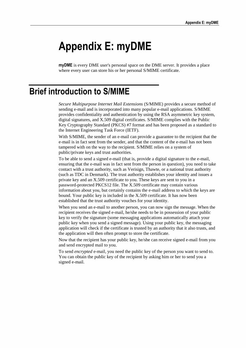
Appendix E: myDME 273
Appendix E: myDME
myDME is every DME user's personal space on the DME server. It provides a place
where every user can store his or her personal S/MIME certificate.
Brief introduction to S/MIME
Secure Multipurpose Internet Mail Extensions (S/MIME) provides a secure method of
sending e-mail and is incorporated into many popular e-mail applications. S/MIME
provides confidentiality and authentication by using the RSA asymmetric key system,
digital signatures, and X.509 digital certificates. S/MIME complies with the Public
Key Cryptography Standard (PKCS) #7 format and has been proposed as a standard to
the Internet Engineering Task Force (IETF).
With S/MIME, the sender of an e-mail can provide a guarantee to the recipient that the
e-mail is in fact sent from the sender, and that the content of the e-mail has not been
tampered with on the way to the recipient. S/MIME relies on a system of
public/private keys and trust authorities.
To be able to send a signed e-mail (that is, provide a digital signature to the e-mail,
ensuring that the e-mail was in fact sent from the person in question), you need to take
contact with a trust authority, such as Verisign, Thawte, or a national trust authority
(such as TDC in Denmark). The trust authority establishes your identity and issues a
private key and an X.509 certificate to you. These keys are sent to you in a
password-protected PKCS12 file. The X.509 certificate may contain various
information about you, but certainly contains the e-mail address to which the keys are
bound. Your public key is included in the X.509 certificate. It has now been
established that the trust authority vouches for your identity.
When you send an e-mail to another person, you can now sign the message. When the
recipient receives the signed e-mail, he/she needs to be in possession of your public
key to verify the signature (some messaging applications automatically attach your
public key when you send a signed message). Using your public key, the messaging
application will check if the certificate is trusted by an authority that it also trusts, and
the application will then often prompt to store the certificate.
Now that the recipient has your public key, he/she can receive signed e-mail from you
and send encrypted mail to you.
To send encrypted e-mail, you need the public key of the person you want to send to.
You can obtain the public key of the recipient by asking him or her to send you a
signed e-mail.
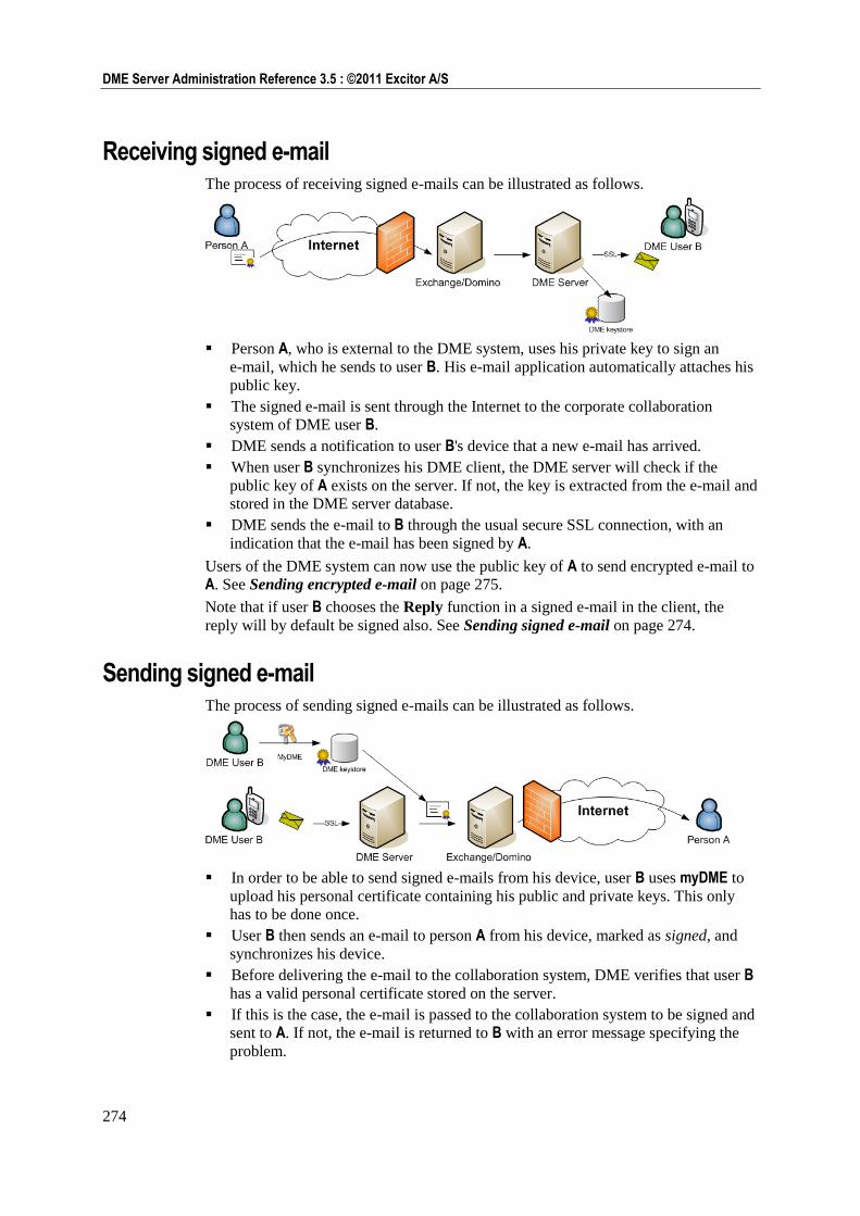
274
DME Server Administration Reference 3.5 : ©2011 Excitor A/S
Receiving signed e-mail The process of receiving signed e-mails can be illustrated as follows.
Person A, who is external to the DME system, uses his private key to sign an
e-mail, which he sends to user B. His e-mail application automatically attaches his
public key.
The signed e-mail is sent through the Internet to the corporate collaboration
system of DME user B.
DME sends a notification to user B's device that a new e-mail has arrived.
When user B synchronizes his DME client, the DME server will check if the
public key of A exists on the server. If not, the key is extracted from the e-mail and
stored in the DME server database.
DME sends the e-mail to B through the usual secure SSL connection, with an
indication that the e-mail has been signed by A.
Users of the DME system can now use the public key of A to send encrypted e-mail to
A. See Sending encrypted e-mail on page 275.
Note that if user B chooses the Reply function in a signed e-mail in the client, the
reply will by default be signed also. See Sending signed e-mail on page 274.
Sending signed e-mail The process of sending signed e-mails can be illustrated as follows.
In order to be able to send signed e-mails from his device, user B uses myDME to
upload his personal certificate containing his public and private keys. This only
has to be done once.
User B then sends an e-mail to person A from his device, marked as signed, and
synchronizes his device.
Before delivering the e-mail to the collaboration system, DME verifies that user B
has a valid personal certificate stored on the server.
If this is the case, the e-mail is passed to the collaboration system to be signed and
sent to A. If not, the e-mail is returned to B with an error message specifying the
problem.
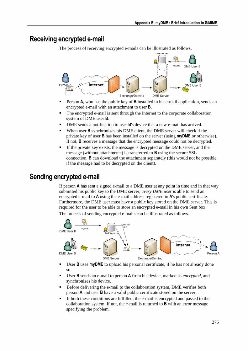
275
Appendix E: myDME : Brief introduction to S/MIME
Receiving encrypted e-mail The process of receiving encrypted e-mails can be illustrated as follows.
Person A, who has the public key of B installed in his e-mail application, sends an
encrypted e-mail with an attachment to user B.
The encrypted e-mail is sent through the Internet to the corporate collaboration
system of DME user B.
DME sends a notification to user B's device that a new e-mail has arrived.
When user B synchronizes his DME client, the DME server will check if the
private key of user B has been installed on the server (using myDME or otherwise).
If not, B receives a message that the encrypted message could not be decrypted.
If the private key exists, the message is decrypted on the DME server, and the
message (without attachments) is transferred to B using the secure SSL
connection. B can download the attachment separately (this would not be possible
if the message had to be decrypted on the client).
Sending encrypted e-mail If person A has sent a signed e-mail to a DME user at any point in time and in that way
submitted his public key to the DME server, every DME user is able to send an
encrypted e-mail to A using the e-mail address registered in A's public certificate.
Furthermore, the DME user must have a public key stored on the DME server. This is
required for the user to be able to store an encrypted e-mail in his own Sent box.
The process of sending encrypted e-mails can be illustrated as follows.
User B uses myDME to upload his personal certificate, if he has not already done
so.
User B sends an e-mail to person A from his device, marked as encrypted, and
synchronizes his device.
Before delivering the e-mail to the collaboration system, DME verifies both
person A and user B have a valid public certificate stored on the server.
If both these conditions are fulfilled, the e-mail is encrypted and passed to the
collaboration system. If not, the e-mail is returned to B with an error message
specifying the problem.
276
DME Server Administration Reference 3.5 : ©2011 Excitor A/S
Signed and encrypted e-mail A DME user can also receive and send e-mail which is both signed and encrypted.
To receive signed and encrypted e-mail, the DME user's personal certificate
containing his public and private keys must be stored on the DME server through
myDME.
To send signed and encrypted e-mail, the recipient's public key must furthermore be
located on the DME server.
S/MIME and DME
Imagine the setup described above in a DME setting. For a user to read a signed
and/or encrypted e-mail on a mobile device, the user would need to download and
install certificates on the device. Furthermore, to send an signed e-mail, the user‘s
private key would need to be installed on the mobile device. This is impractical for a
number of reasons:
1 Security: If your mobile device is lost, your private key is in danger of being
stolen. If that happens, another user could in theory digitally pose as you (―identity
theft‖).
2 Security: Not all users in a mail system knows about certificates, S/MIME and all
that, and may tend to just accept any prompt to install certificates.
3 Security: Spam and virus filters are unable to scan S/MIME e-mails.
4 Administration: Why should all users have the trouble of managing certificates on
their mobile devices?
Instead of users storing certificates on their mobile devices, DME stores all certificates
on the server. There are a number of advantages to this:
277
Appendix E: myDME : Using myDME
1 Certificates are not stored on the devices, and therefore they cannot be lost.
2 The administrator gets to decide which trust authorities to include in the trusted
list.
3 Spam and virus filters can be applied to e-mails after decryption on the server.
4 If an external person (that is, a person identified by an e-mail address which is not
part of the DME system) exists on the DME system, every user in the DME
system can send encrypted messages to that external person. The public certificate
from the external person is automatically accepted by the server.
5 The certificate part of a signed message sent to several DME users is stored on the
DME server, and only the e-mail as such is passed on to the users - saving traffic
costs. The last part of the e-mail‘s journey to the reader is subject to the heavy
encryption and security schemes of DME anyway.
6 The attachments of encrypted messages sent to a DME user are stored encrypted
on the server, and only the e-mail as such is passed on to the user - saving traffic
costs and storage and processing power on the devices. The user can choose to
download the decrypted attachments separately.
When DME administers the keys, the users‘ personal certificates holding their public
and private keys must be uploaded to DME in order for the users to be able to send
signed and encrypted messages. This is where myDME comes in. With myDME, users
upload their own personal certificates with additional password protection. This
additional password protection means that an administrator cannot access the private
keys, even though he has physical access to the server on which the keys are stored.
In order to be able to send signed messages from or decrypt received messages on the
device, the user needs to enter the password for the private key, which he entered
when uploading the personal certificate. This password is entered in the security
settings page of the client.
Using myDME
myDME is every DME user's personal space on the DME server. It provides a place
where every user can store his or her personal S/MIME certificate.
As an administrator or superuser, you must enter the URL to the Administration
Interface, followed by /my_dme/smime.jsp or simply /my_dme/ into the address
field of a browser in order to access myDME:
https://dme.your-domain.com:8080/my_dme/
Regular users simply enter the URL to the Administration Interface:
https://dme.your-domain.com:8080
A login window is shown. Enter your regular mail user name and your mail password.
A window very similar to the Administration Interface is shown, but with only one
tab: MyDME. This tab contains only one function in the page menu: S/MIME
certificates.
You can now upload/import and delete personal certificates. For a description of how
to do this, see S/MIME setup.

Appendix F: AdaptivePush™ 279
Appendix F: AdaptivePush™
AdaptivePush™ is a technology which enables mobile devices to receive notification
of e-mail, calendar entries, contacts etc. as they occur in the collaboration system by
network push (or: IP push) using the GPRS network, falling back to using SMS push
in case the GPRS network is unavailable.
In large organizations, the cost of SMS push can be considerable. Therefore it makes
good sense to make use of the GPRS network to connect the mobile device with the
collaboration system. The price for one SMS is usually fixed; on the GPRS network,
you pay according to the volume of traffic. According to most calculations, using the
GPRS network pays off if you receive just a single e-mail a day.
Furthermore, sending commands over the GPRS network is much faster than sending
via SMS.
Devices that are connected to the DME server using network push are shown with the
following icon in the Devices tab:
Please note that special considerations apply for iPhone. See Notifications
on iPhone on page 195 for more information.
The technology behind AdaptivePush™
AdaptivePush™ works in the following way.
1 On the server, AdaptivePush™ is enabled for a client device.
2 The client receives the new setting at next synchronization.
3 In response to the new setting, the client initiates an HTTP connection to the
server. This connection must be over a separate port from the port used for
synchronization (which is 5011 by default). The default port used for network push
is 5021 (6011 in DME 2.0).
4 When initiating the connection, the client receives any commands that are ready
for the client - such as e-mail sync commands, settings, or other commands, over
the GPRS network.
5 The client does not break the connection, but keeps it open.
However, the connection may be broken due to network problems, flight mode
situations, or if the device is shut off.
280
DME Server Administration Reference 3.5 : ©2011 Excitor A/S
6 The server tests whether the connection is still open according to a schedule of
sign-of-life signals. First, a signal (an HTTP packet) is sent after one minute.
Then, three packets are sent at intervals of 3 minutes. Then, five packets at
intervals of 5 minutes. This scheme of ever-increasing intervals continues until a
sign-of-life signal is sent every 30 minutes. The packet which is sent from the
server contains information about when the server will contact the client again.
7 If the server does not contact the client after the specified period of time, the client
tries to reconnect to the server every minute for 10 minutes before giving up.
8 When the client is turned back on or the network connection is restored, the HTTP
connection with the server is also restored. Until then, the server pushes new
e-mail commands and other commands by means of SMS messages (or, in the
case of iPhone, possibly using APNS).
If, for some reason, the network push functionality is turned off on the server, the
server tells the client to shut down the connection, and resorts to SMS push again.
To set up the server to enable network push, enable the setting Network push active,
and configure the Network push path in Settings (see General settings on page 242).
For each resource in the notification framework, you can set up whether to use
network push only or adaptive push (that is, with fallback to notification by SMS). See
Notification on page 183.
Troubleshooting network push
Please read this section if you find that the network push connection over the network
push port is not stable. As previously described, the interval between network push
keep-alive signals should gradually build up to about 30 minutes. If this process is
interrupted, it will begin over again and again, which can cause various problems on
the device:
Excessive battery drain
General instability
Out-of-memory situations
Eventually device reboot
The problems appear differently on different devices.
Two things especially can cause problems:
1 The firewall/proxy through which the network push connection is routed to the
DME server is unable to keep connections for long period of times. This can be a
default configuration in the firewall/proxy or NAT settings.
This is the most likely root to the problem. The firewall or network administrator
is able to monitor the connections to the network push port on DME, and see
where the connection is cut off after a time with no activity. If it is a global
configuration, this could also affect any VPN connections that time out if they do
not have a "server ping" setting to keep the connection alive.
Solution: Configure the firewall to only cut the connection if the connection is
idle for a period of time that exceeds the maximum keep-alive time. This
keep-alive time is set in the Connection section of the Client setup panel of the
Server configuration page. For more information, see Client on page 159.
281
Appendix F: AdaptivePush™ : Troubleshooting network push
2 The mobile network is not set up to allow long connections, and automatically
disconnects after a fixed number of seconds/minutes - this is a mobile operator
setting.
If there is a lot of traffic on the local mobile network, or if you have a
misconfigured GSM antenna or network, then the network is unable to service all
clients. The network then disconnects any clients that are not actively using the
data connection. The network will not close a data sync connection, but it may
close the network push connection.
Solution: To resolve this, you need to discuss a network upgrade with your mobile
operator.

Appendix G: The Basic MDM client 283
Appendix G: The Basic MDM client
This appendix describes the DME Basic Mobile Device Management client – in the
following called the Basic MDM client.
In many organizations, the users of mobile devices can divided into three groups:
Some users need to have a continually updated copy of their corporate e-mail and
calendar in their pocket. Such users need the full DME client on their devices - the
number of features available can be controlled through the license file.
Other users do not require advanced DME features on their mobile devices.
However, the DME administrator wants to be able to manage the devices and
monitor how they are used. Such users need the Basic MDM client on their
devices.
Yet other users have another system for e-mail synchronization installed on their
devices. The system administrators want to be able to manage the devices and
monitor data consumption etc. Such users also need the Basic MDM client on their
devices.
The Basic MDM client is an economical way to add more mobile assets to the
portfolio of devices that can be managed by DME. Apart from keeping track of your
assets, you can track voice and data usage, block applications on the devices, transfer
files to the devices (option), wipe the device in case of theft or loss, and provision
software to the client. Furthermore, it is easy to upgrade to the full DME client for
e-mail and PIM synchronization features.
Basic MDM client features
The Basic MDM client supports a core set of DME features. The user interface
contains a splash screen/About box and the following menu items:
Synchronize (triggering synchronization of all available types: system
information, files, and traffic log)
Settings (see below)
Tools
Import (triggering synchronization of all available types: system information,
files, and traffic log)
Log (showing log of communication with server)
About (showing version information)
Close (hide the client)
The following is a brief description of the features of the Basic MDM client.
Settings synchronization The Basic MDM client synchronizes settings with the DME server at every scheduled
sync. The following settings can be set for the Basic MDM client.
User name
The user's ability to change the user name depends on the setting Device allowed
to switch user on the server. See Anonymous users on page 285.
284
DME Server Administration Reference 3.5 : ©2011 Excitor A/S
Phone number
The Basic MDM client is able to retrieve the phone number of the device by
sending an SMS to the server's SMS modem, which responds with the number
from which the SMS was sent. The phone number is necessary for SMS-based
features, including DM actions, to work correctly on the device.
Please refer to Appendix A - General settings for a description for the following
settings (see General settings on page 242):
Server path (can be changed on device if permitted)
Launch on startup (can be changed on device if permitted)
GPRS timeout (can be changed on device if permitted)
Network push active (can be changed on device if permitted)
Network push path (can be changed on device if permitted)
Log traffic
Background sync. when roaming
Network push when roaming
Apart from these settings, certain device specific settings may exist on the client (such
as access points sequence on Symbian devices).
Please refer to Appendix A -Security settings for a description for the following settings
(see Security settings on page 246):
Action on SIM card change (can be changed on device if permitted)
Prevent uninstall of DME client
Require trusted certificate
Furthermore, all settings in the File sync. and Scheduled sync. sections are
synchronized with the server, and they can be changed on the client (see File sync.
settings on page 241 and Scheduled sync. settings on page 245).
Cost control Statistics in the form of voice/data traffic and consumption are transferred to the
server at every synchronization. These statistics can be used in combination with the
Analyzer tool in any number of ways - you can for instance monitor for extraordinary
usage patterns, use the data as input to budgets, or use the data when negotiating
contracts with mobile operators. See Appendix D: Traffic logging on page 269 for
more information.
Furthermore, you can specify various cost-reducing parameters to the use of the
device when a user is roaming. See the Roaming section in the user guide for any
DME 3.0 client (except iPhone).
Security The Basic MDM client should always auto-start when the device is turned on. Only
when the client is active can the DME administrator block applications, wipe the
device in case of loss or theft, and specify an action in case of a SIM card change.
Asset management The Basic MDM client will send in information about itself, just like regular DME
clients do - information about the make and model of the device, firmware, etc. See
Information on page 62 for more on this topic.
285
Appendix G: The Basic MDM client : Managing Basic MDM clients
Furthermore, you can use the Asset panel section to register further information about
the device throughout its lifetime (see Asset on page 69 for more information).
File synchronization If the file synchronization add-on is enabled for the device, files can be synchronized
between the device and the DME server file store.
To synchronize files between the device and a server that requires user-specific
authentication, use the Authenticate with user option in the file sync rule. Due to the
fact that the Basic MDM client user is anonymous, the client user cannot authenticate
directly against a file server. For more information, see Appendix C: File
synchronization on page 259.
Managing Basic MDM clients
Managing Basic MDM clients is much the same as for full DME clients, with one
notable difference: the devices are not bound to real, identifiable users. Full clients are
bound to an LDAP user in order to synchronize with the right mailbox. MDM clients,
however, are only bound to the device, and can freely be moved between users.
The following sections describe how the MDM client is integrated into DME.
Deploying Basic MDM The Basic MDM client can be provisioned to the devices in the same way as for
regular DME clients, complete with the required root certificate and access points. The
installation process is completely silent.
Due to the fact that there is no user authentication when using the Basic MDM client,
it is recommended to set both the Create device on first connect setting and the
Client signature setting to True. This will ensure that only clients that are known to
the DME system can make a connection. For more information, see Authentication on
page 161.
On Symbian devices, where a DME client is not installed already, the
installation process evaluates any existing internet access points (IAPs) on the device,
and chooses three access points which are entered in the General settings page on the
device. For more information, see Access points list see "Access points" on page 117.
The user can change the selections later.
Anonymous users The first time a device connects to the DME server, a "user name" is assigned to the
device. DME creates user names sequentially - "DME0001", "DME0002", etc. For
Windows Mobile users, the information in the device's Owner information field will
be used as user name, if available.
In the Devices tab, the Basic MDM "users" are shown as wearing white shirts:
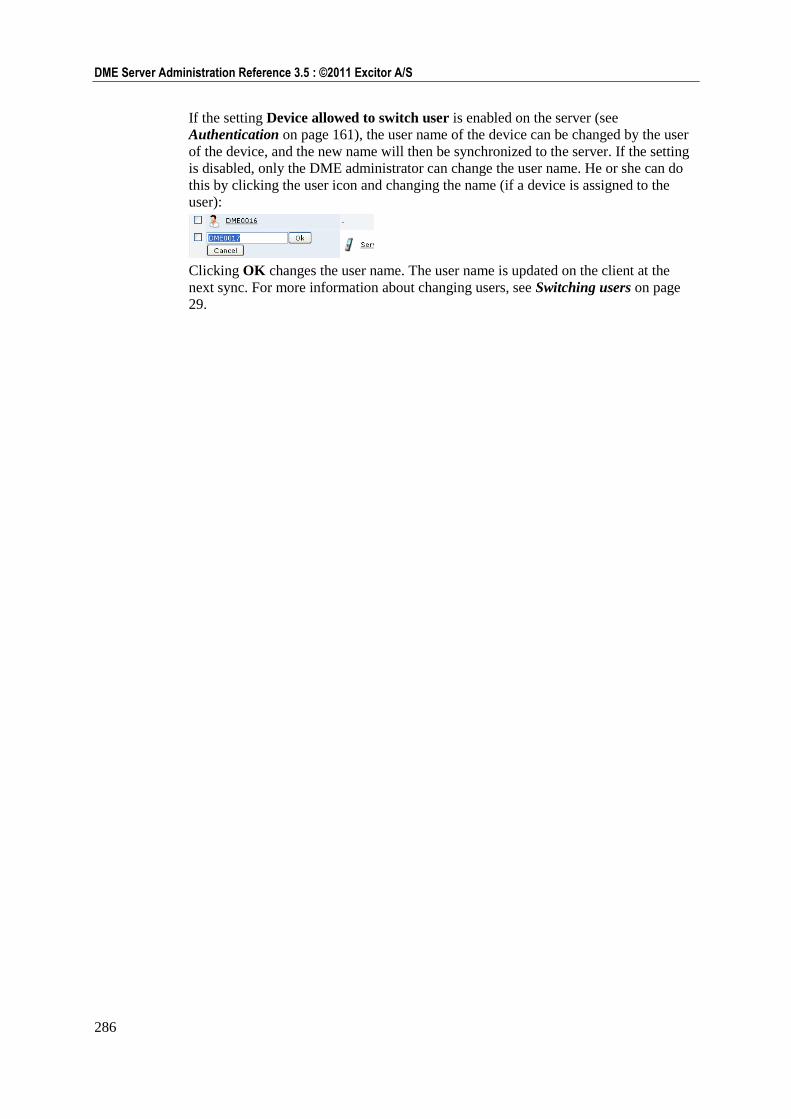
286
DME Server Administration Reference 3.5 : ©2011 Excitor A/S
If the setting Device allowed to switch user is enabled on the server (see
Authentication on page 161), the user name of the device can be changed by the user
of the device, and the new name will then be synchronized to the server. If the setting
is disabled, only the DME administrator can change the user name. He or she can do
this by clicking the user icon and changing the name (if a device is assigned to the
user):
Clicking OK changes the user name. The user name is updated on the client at the
next sync. For more information about changing users, see Switching users on page
29.
List of procedures 287
List of procedures
Switching a device to another user ................................................... 30 Finding the device ID manually ....................................................... 40 Changing default settings ................................................................. 42 Creating a new group ....................................................................... 50 Assigning a device to and un-assigning a device from a group ....... 50 Setting group priorities ..................................................................... 52 Uploading a picture of the device ..................................................... 63 Locating a device ............................................................................. 64 Installing software on one or more new devices .............................. 88 Installing DME on one or more existing devices ............................. 91 Generating an APNS certificate ....................................................... 96 Uploading new software ................................................................. 105 Editing software properties ............................................................ 107 Installing an access point on new devices ...................................... 119 Installing an access point on existing devices ................................ 119 Sending iPhone profile ................................................................... 129 Uploading a new BIRT report to the server ................................... 154 Editing BIRT report details and updating reports .......................... 154 Setting notification options ............................................................ 183 Setting and editing a notification scheme ....................................... 186 Performing an automatic test .......................................................... 231 Setting up software for self-provisioning ....................................... 255 Setting up OTA configurations for self-provisioning .................... 255 Testing that you have the right phone number for the SMS server 256 Requesting a software download .................................................... 256 Requesting a phone configuration .................................................. 256 Sending a test message to the server modem ................................. 257 Requesting DME software ............................................................. 257 Requesting OTA configuration ...................................................... 257 Requesting both DME software and OTA configuration ............... 257 Defining a new synchronization rule - overall process .................. 259

289
Glossary of terms 289
Glossary of terms
A
Active Directory (AD)
Active Directory™ is Microsoft's trademark
directory service; it is a central component of
the Windows platform. Active Directory's
directory service provides the means to
manage the identities and relationships that
make up network environments. Active
Directory is an LDAP-compliant directory
supporting the core LDAP specifications.
C
Corba
CORBA (Common Object Request Broker
Architecture) is an open, vendor-independent
specification used by computer applications to
communicate together over networks. CORBA
is aimed at supporting interoperability between
software applications. The specification allows
a CORBA-based program from any vendor, on
almost any computer, operating system,
programming language, and network, to
interoperate with a CORBA-based program
from the same or another vendor, on almost
any other computer, operating system,
programming language, and network.
With regards to DME, the CORBA session
created between the DME Server and a
Domino server allows the DME Server to
create objects and call methods on those
objects; however, the processing is left to the
Domino server.
CORBA is developed and maintained by the
Object Management Group (OMG), a
consortium with a membership of more than
700 companies.
Links:
Corba organization http://www.corba.org
Open Management Group
http://www.omg.org
D
DIIOP
DIIOP (Domino Internet Inter-ORB Protocol)
is a server task that runs on the server and
works with the Domino Object Request Broker
to allow communication between Java applets
created with the Notes Java classes and the
Domino server. Browser users and Domino
servers use IIOP to communicate and to
exchange object data.
IIOP (Internet Inter-ORB Protocol) is a
protocol developed by the Object Management
Group (OMG) to implement CORBA solutions
over the World Wide Web. IIOP enables
browsers and servers to exchange integers,
arrays, and more complex objects, unlike
HTTP, which only supports transmission of
text.
Link:
Object Management Group
http://www.omg.org
G
GPRS
GPRS (General Packet Radio Service) is a
service available to users of GSM and IS-136
mobile phones. GPRS data transfer is typically
charged per megabyte of transferred data,
while data communication via traditional
circuit switching is billed per minute of
connection time, independent of whether the
user has actually transferred data or has been
in an idle state. GPRS can be used for services
such as Wireless Application Protocol (WAP)
access, Short Message Service (SMS),
Multimedia Messaging Service (MMS), and
for Internet communication services such as
DME synchronization and World Wide Web
access.
I
IMEI
The IMEI (International Mobile Equipment
Identity) number is the unique 15-digit serial
number on your phone. There are several ways
to find the IMEI number:
290
290 Glossary of terms
Check the label underneath the device
battery.
Enter *#06# on your phone's key pad.
When the final # is entered, a 15-digit
number with the title "IMEI number" or
"Serial number" will appear.
On Motorola devices, you may have to
enter #,*,[menu] and then the right arrow
very quickly.
Usually the device will report its IMEI number
to the DME server the first time it connects to
the server.
IOR
In distributed computing, an IOR
(Interoperable Object Reference) is a reference
to a CORBA or RMI-IIOP object.
The typical IOR contains the internet address
of the remote host, the number of the remote
port on which the CORBA server is listening.
IORs may be ―stringified,‖ or represented by a
string of printable characters, to facilitate
sharing of object references by non-CORBA
mechanisms such as HTTP, FTP, and e-mail.
Stringified IORs consist of the prefix IOR:
followed by a sequence of hexadecimal digits.
J
J2EE
J2EE (Java 2 Enterprise Edition) is a
platform-independent, Java-centric
environment from Sun for developing,
building and deploying Web-based enterprise
applications online. The J2EE platform
consists of a set of services, APIs, and
protocols that provide the functionality for
developing multitiered, Web-based
applications.
Link:
J2EE at Sun
http://java.sun.com/j2ee/index.jsp
JBoss
JBoss is a widely used Java application server.
It is an open source implementation of J2EE
that relies on the Enterprise Java Beans
specification for functionality.
Link:
JBoss.org http://www.jboss.org
K
Kannel
Kannel is an open source WAP and SMS
server, used for sending short messages (SMS)
and pushing WAP service indications. The
Kannel project was founded by Wapit Ltd. in
June, 1999. Wapit no longer exists, and the
project is coordinated by the members of the
Kannel Group. The Kannel Group is in the
process of forming a legal body for the Kannel
Project, the Kannel Software Foundation.
Link:
The Kannel Group see The Kannel Group
- http://www.kannel.org
L
LDAP
LDAP (Lightweight Directory Access
Protocol) is a protocol used to access a
directory and through that enable users or
programs to locate people, organizations, and
other resources in an Internet or intranet
directory. The protocol could be used for
retrieving information such as addresses,
phone numbers, etc. from a corporate address
book.
An LDAP directory is a hierarchical directory of
names that can reflect an organization's
structure or geography and that is accessed via
the LDAP protocol.
N
NTLM
With Integrated Windows authentication
(formerly called NTLM, and also known as
Windows NT Challenge/Response
authentication), the user name and password
(credentials) are hashed before being sent
across the network. When you enable
Integrated Windows authentication, the client
browser proves its knowledge of the password
through a cryptographic exchange with your
Web server, involving hashing. Applies to
Microsoft Exchange servers.
291
Glossary of terms 291
O
OTA
Over-the-Air. A protocol for extending the
capabilities of mobile devices. New
configurations or functionality can be
transmitted to the device "over the air".
R
Roaming
Most network operators provide a roaming
service, which allows users to use their phone
even if they are not in their home coverage
area. When roaming, the user of the phone
effectively rents the use of the network of
another network operator.
When a user is outside his home coverage area,
for instance if a French DME user goes on a
trip to Norway, he will not only have to pay a
roaming for calls that he makes, but also for
calls that he receives.
S
S/MIME
Secure Multipurpose Internet Mail Extensions
(S/MIME) provides a secure method of
sending e-mail and is incorporated into many
popular e-mail applications. S/MIME provides
confidentiality and authentication by using the
RSA asymmetric key system, digital
signatures, and X.509 digital certificates.
S/MIME complies with the Public Key
Cryptography Standard (PKCS) #7 format and
has been proposed as a standard to the Internet
Engineering Task Force (IETF).
In other words, the sender of an e-mail can
provide a guarantee to the recipient that the
e-mail is in fact sent from the sender, and that
the content of the e-mail has not been
tampered with on the way to the recipient.
S/MIME relies on a system of public/private
keys and trust authorities.
W
WebDAV
WebDAV (Web-based Distributed Authoring
and Versioning) is a set of extensions to the
HTTP protocol, which allows users to
collaboratively edit and manage files on
remote Web servers. This protocol is used by
the OWA (Outlook Web App - Outlook
webmail) in Microsoft Exchange 2003, and for
extracting the size of attachments in Exchange
2007.
Link:
WebDAV http://www.webdav.org

293
Index : A―I 293
Index
A
Access points • 117
DME_AP • 117
Adaptive push • 279
Analyzer reports • 152
Apple Push Notification • 196
Automatic test • 231
B
BIRT reporting • 152
Upgrading • 152
C
Cache • 159
Central Services • 170
Central Services log • 136
Change password • 218
Collapsing groups • 40
command stack • 192
Configuring the server • 159
Client settings • 159
External DME server address • 159
Software push ticket lifetime • 159
Connectors • 207
Flush routes • 210
Routes • 207
Custom reports • 154
D
Data statistics • 145
Device DM tree • 69
Devices
Device file setup • 44
Device notification schedule • 43
Device settings • 42
Device statistics • 157
Device users • 68
Force synchronization • 58
Group membership • 68
Provisioning • 83, 255
Remove • 39
DME
About the product • 9
DME version information • 23
DME toolbar • 23
DME users
Anonymous • 285
Basic MDM • 285
DME_Admin • 34
DME_Superuser • 34
DME_User • 34
SYSADM • 34
DME version information • 23
DME_AP • 117
Domino wildcard search • 232
E
Exchange event subscription • 185
Excitor - the company • 7
Expanding groups • 40
F
Files • 44, 259
Filter toolbar • 22
Filtering text • 22
Folders • 239
Follow referrals • See LDAP
Force synchronization • 58
G
GPRS access points • 118
GPRS statistics • 152
Groups • 49
Collapsing groups • 40
Expanding groups • 40
Files • 44, 259
New group • 33
H
Hiding page menu • 21
I
Installing software
By SMS • 255
On clients • 83
Using OMA DM • See OMA DM
Interface
Keyboard shortcuts • 24
Logging in • 19
Overview • 20
Page • 20
Page menu • 21
Setup panel • 20
Tables • 22
Tabs • 21
Toolbars • 22
iPhone
294
294 Index : L―U
Certificates • 84
iPhone configurations • 127
iPhone notifications • 195
L
LDAP • 161
Secure LDAP • 161
Licenses • 202
Lock • 39, 40
Log
Log entries • 135
Logging in • 19
M
Messaging statistics • 151
N
Network push • 279
Notification framework • 180
Apple Push Notification • 196
Notification framework, • 182
Pending notifications • 195
Subscription • 185
Switch on/off • 189
O
OMA DM • 86
Device DM tree • 69
OMA DFF • 121
OMA/OTA configuration • 52
Editing • 54
Operator usage • 150
Overview • 20
P
Page • 20
Page menu • 21
Pre-caching • 164
Provisioning • 83, 255
Access points • 117
Removing software from server • 108
Push
Force synchronization • 58
Notification framework • 180
OMA/OTA configuration • 52
Send SMS • 60
Server path • 55
Software push ticket lifetime • 159
Switch on/off • 189
WAP • 60
R
Reporting with BIRT
Custom reports • 154
Running reports • 153, 155
Upgrading • 152
Roles • 34
Routes • 207
Flush routes • 210
S
Scanning • 182
Secure LDAP • 161
Self-provisioning • 255
By SMS • 255
Setup • 255
Setting up devices • 41
In batch • 46
Setting up users • 74
Setup panel • 20
Shortcuts • 24
Showing page menu • 21
SmartLink • 220, 252
Sorting tables • 22
SSL • See Certificates
Statistics
Data statistics • 145
GPRS statistics • 152
Messaging statistics • 151
Voice statistics • 150
Subscription • 185
Superusers • 34
Synchronize
Files • 44, 259
Force synchronization • 58
SYSADM • 34
T
Tab toolbar • 22
Table navigation bar • 23
Tables • 22
Sorting • 22
Tabs • 21
Analyzer • 145
Provisioning • 83
Server • 159
Toolbars • 22
DME toolbar • 23
Filter toolbar • 22
Tab toolbar • 22
Table navigation bar • 23
Traffic logging • 269
U
Users
295
Index : V―W 295
Device users • 68
DME_Admin • 34
DME_Superuser • 34
DME_User • 34
Manually created • 34
Remove • 39
Roles • 34
SYSADM • 34
V
Voice statistics • 150
W
WAP • 60
WLAN access points • 120