ProStar 220/230/240 Solvent Delivery Module
128
Varian, Inc. 2700 Mitchell Drive Walnut Creek, CA 94598-1675/usa ©Varian, Inc. 2000 - 2004 Printed in U.S.A. 03-914778-00:Rev. 3 ProStar 220/230/240 Solvent Delivery Module Operation Manual
-
Upload
khangminh22 -
Category
Documents
-
view
0 -
download
0
Transcript of ProStar 220/230/240 Solvent Delivery Module
Varian, Inc. 2700 Mitchell Drive Walnut Creek, CA 94598-1675/usa
©Varian, Inc. 2000 - 2004 Printed in U.S.A. 03-914778-00:Rev. 3
ProStar 220/230/240 Solvent Delivery Module
Operation Manual
Declaration of Conformity We hereby Declare that the equipment listed below complies with the requirements of:
The Low Voltage Directive 73/23/EEC (93/68/EEC) The EMC Directive 89/336/EEC (92/31/EEC and 93/68/EEC)
Applicable Standards
LVD EN 61010-1
EMC EN 50082-1 EN 55011
Type of Equipment: ProStar Solvent Delivery Module Model: 220/230/240
Authorized Representative in the EU
Print Name: G. A. Wassink Signed: Position: Quality Manager Date: October 16, 2001
Company Name:Address:
Varian B.V. Herculesweg 8 P.O. Box 8033 4330 EA Middelburg The Netherlands
Telephone:Fax:
+31(0) 118 671 000 +31(0) 118 633 118
Manufacturer Print Name: John Mills Signed:
Position: General Manager Date: August 11, 2004
Company Name:Address:
Telephone:Fax:
Varian, Inc. 2700 Mitchell Drive Walnut Creek, California 94598 USA 925-939-2400 925-945-2168
03-914535-27:6 SPEC. 03-914411-00 1:2:3:4n

03-914451-00:4 1 of 1
Quality Systems At Varian, Inc. The ISO 9000 series standards were created in Geneva in 1987 to cut through a morass of conflicting
quality definitions. These standards define a model for quality assurance systems in product design, development, manufacturing, installation, service, and customer support. They are now the worldwide quality assurance benchmark used to gauge the strength of a company's commitment to quality, and the value of its quality systems.
Various organizations around the world, such as the British Standards Institution (BSI), provide certified, objective auditors to scrutinize quality procedures, product development, manufacturing processes, and customer satisfaction programs. No company can claim ISO 9000 series registration unless it receives a stamp of approval from the demanding quality assessors of BSI or similar accredited examining body. ISO 9000 series registration constitutes an objective third-party report to determine the level of a supplier's commitment to quality.
In 1992, Varian, Inc., Analytical Instruments became registered to the most comprehensive of the ISO 9000 series standards — ISO 9001. ISO 9001 registration means that every stage of our quality system, including product development, manufacturing, final test, shipping, and parts and supplies has been rigorously examined against the most exacting set of internationally recognized standards. It means we live up to a standard of quality that you can count on today, and into the future. Our Quality System has received ISO 9001 certification number FM21797.
The quality systems that earned us ISO 9001 registration have direct benefits for our customers:
♦ We can speed instruments to you faster than ever before. Emergency orders can be processed even faster.
♦ We fill your orders promptly and completely.
♦ We have implemented a system of continuous feedback from our customers — we are aware of your needs today and tomorrow.
♦ We have improved your productivity by cutting systems failure rates in half and speeding service response time.
♦ We have embedded continuous improvement into the fabric of our organization so that we can achieve even higher levels of quality in the future.
♦ We are embedding GLP requirements into our products and services to help you meet your regulatory compliance requirements.
ISO 9001 registration is not enough. For us, quality is defined by our customers. We are not satisfied unless you are satisfied. We are striving to understand customer needs, using independent surveys, user groups, customer advisory boards, and our “Hallmark of Quality” response program, in addition to individual face-to-face customer contact. Our products and our processes are configured to meet those needs. We know that you are seeking more than the most advanced processes and top-notch applications expertise. You want to join forces with a partner committed to delivering world-class quality, reliability, and value — on time, every time.
Our overriding aim is to be that partner.
Varian, Inc. Analytical Instrument Warranty
03-914412-00:2 1 of 1
Hardware Products All analytical instruments sold by Varian, Inc. are warranted to be free from defects in material and workmanship for the periods specified and in accordance with the terms on the face of Varian's quotation or as otherwise agreed upon in writing between Varian and the Customer. The warranty period begins on the date of shipment from Varian to the original Customer. However, where installation is paid for by the Customer or included in the purchase price, the warranty period begins upon completion of installation. If the Customer schedules installation to start later than 30 days after delivery or if such delay is caused through the Customer's inability to provide adequate facilities or utilities or through failure to comply with Varian's reasonable pre-installation instructions or through other omissions by Customer, then the warranty period starts on the 31st day from date of shipment. Moreover Varian will charge the Customer for labor and other expenses involved in making multiple or follow-up installation service calls.
Software Products Where software is provided within the frame of a license agreement concluded between the Customer and Varian, any warranty shall be strictly in accordance with the terms of such agreement.
In the absence of a license agreement and unless an alternate warranty period is agreed upon in writing between Varian and the Customer, the warranty period is as specified on the face of Varian's quotation. Varian warrants such software products, if used with and properly installed on Varian hardware or other hardware as specified by Varian to perform as described in the accompanying Operator's Manual and to be substantially free of those defects which cause failure to execute respective programming instructions; however, Varian does not warrant uninterrupted or error-free operation.
Remedies The sole and exclusive remedy under hardware warranty shall be repair of instrument malfunctions which in Varian's opinion are due or traceable to defects in original materials or workmanship or, at Varian's option, replacement of the respective defective parts, provided that Varian may as an alternative elect to refund an equitable portion of the purchase price of the instrument or accessory.
Repair or replacement under warranty does not extend the original warranty period.
Repair or replacement under warranty claims shall be made in Varian's sole discretion either by sending a Customer Support Representative to the site or by authorizing the Customer to return the defective accessory or instrument to Varian or to send it to a designated service facility. The Customer shall be responsible for loss or damage in transit and shall prepay shipping cost. Varian will return the accessory or instrument to the Customer prepaid and insured. Claims for loss or damage in transit shall be filed by the Customer. To correct software operation anomalies, Varian will issue software revisions where such revisions exist and where, in Varian's opinion, this is the most efficient remedy.
Limitation of Warranty This warranty does not cover software supplied by the Customer, equipment and software warranted by another manufacturer or replacement of expendable items and those of limited life, such as but not limited to: Filters, glassware, instrument status lamps, source lamps, septa, columns, fuses, chart paper and ink, nebulizers, flow cells, pistons, seals, fittings, valves, burners, sample tubes, probe inserts, print heads, glass lined tubing, pipe and tube fittings, variable temperature dewars, transfer lines, flexible discs, magnetic tape cassettes, electron multipliers, filaments, vacuum gaskets, seats and all parts exposed to samples and mobile phases.
This warranty shall be void in the event of accident, abuse, alteration, misuse, neglect, breakage, improper operation or maintenance, unauthorized or improper modifications or tampering, use in an unsuitable physical environment, use with a marginal power supply or use with other inadequate facilities or utilities. Reasonable care must be used to avoid hazards.
This warranty is expressly in lieu of and excludes all other express or implied warranties, including but not limited to warranties of merchantability and of fitness for particular purpose, use or application, and all other obligations or liabilities on the part of Varian, unless such other warranties, obligations or liabilities are expressly agreed to in writing by Varian.
Limitation of Remedies and Liability The remedies provided herein are the sole and exclusive remedies of the Customer. In no case will Varian be liable for incidental or consequential damages, loss of use, loss of production or any other loss incurred.

03-914603-00:10 1 of 4
Safety Information
Operating Instructions This instruction manual is provided to help you establish operating conditions which will permit safe and efficient use of your equipment. Special considerations and precautions are also described in the manual, which appear in the form of NOTES, CAUTIONS, and WARNINGS as described below. It is important that you operate your equipment in accordance with this instruction manual and any additional information which may be provided by Varian. Address any questions regarding the safe and proper use of your equipment to your local Varian office.
NOTE Information to aid you in obtaining optimal performance from your instrument.
Alerts you to situations that may cause moderate injury and/or equipment damage, and how to avoid these situations.
Alerts you to potentially hazardous situations that could result in serious injury, and how to avoid these situations.
Warning Symbol Warning Description
Hazardous voltages are present inside instrument. Disconnect from main power before removing screw-attached panels.
Hazardous chemicals may be present. Avoid contact, especially when replenishing reservoirs. Use proper eye and skin protection.
Very hot or cryogenically cold surfaces may be exposed. Use proper skin protection.
Eye damage could occur either from flying particles, chemicals, or UV radiation. Use proper eye and face protection.
The potential for fire may be present. Follow manual instructions for safe operation.
The potential for explosion may exist because of type of gas or liquid used.
Ionizing radiation source is present. Follow manual instructions for safe operation.
Keep hands and fingers away.

2 of 4 03-914603-00:10
General Safety Precautions Follow these safety practices to ensure safe equipment operation.
Perform periodic leak checks on all supply lines and pneumatic plumbing. Do not allow gas lines to become kinked or punctured. Place lines away from foot traffic
and extreme heat or cold. Store organic solvents in fireproof, vented and clearly labeled cabinets so they are easily
identified as toxic and/or flammable materials. Do not accumulate waste solvents. Dispose of such materials through a regulated disposal
program and not through municipal sewage lines.
NOTICE: This instrument has been tested per applicable requirements of EMC Directive as required to carry the European Union CE Mark. As such, this equipment may be susceptible to radiation/interference levels or frequencies which are not within the tested limits.
This instrument is designed for chromatographic analysis of appropriately prepared samples. It must be operated using appropriate gases and/or solvents and within specified maximum ranges for pressure, flows, and temperatures as described in this manual. If the equipment is used in a manner not specified by the manufacturer, the protection provided by the equipment may be impaired.
It is the responsibility of the Customer to inform Varian Customer Support Representatives if the instrument has been used for the analysis of hazardous biological, radioactive, or toxic samples, prior to any instrument service being performed or when an instrument is being returned to the Service Center for repair.
Electrical Hazards Disconnect the instrument from all power sources before removing protective panels to avoid
exposure to potentially dangerous voltages. When it is necessary to use a non-original power cord plug, make sure the replacement cord adheres
to the color coding and polarity described in the manual and all local building safety codes. Replace blown fuses with fuses of the size and rating stipulated on the fuse panel or in the manual. Replace faulty or frayed power cords immediately with the same type and rating. Make sure that voltage sources and line voltage match the value for which the instrument is wired.
Compressed Gas Cylinders Store and handle compressed gases carefully and in strict adherence to safety codes. Secure cylinders to an immovable structure or wall. Store and move cylinders in an upright, vertical position. Before transport, remove regulators
and install cylinder cap. Store cylinders in a well-ventilated area away from heat, direct sunshine, freezing
temperatures, and ignition sources. Mark cylinders clearly so there is no doubt as to their contents. Use only approved regulators and connections. Use only connector tubing that is chromatographically clean (Varian Part Number 03-918326-00)
and has a pressure rating significantly greater than the highest outlet pressure from the regulator.

03-914603-00:10 3 of 4
GC Safety Practices Exhaust System No special exhaust ducting is necessary for GC detectors installed in a well-ventilated room except when the detectors are used to test hazardous chemicals. If you do install ducting:
Use only fireproof ducting. Install a blower at the duct outlet. Locate duct intakes such that their vibration or air
movement does not effect detector operation. Check periodically for proper operation of the duct. Ensure proper ventilation in lab area.
Radioactive Source Detectors
Read carefully and comply with all NOTES, CAUTIONS, and WARNINGS in the Ni63 ECD manual.
Perform the tests for removable radioactive contamination described in the Ni63 ECD manual.
Comply with leak test schedules and procedures.
Burn Hazard Heated or cryogenically cooled zones of gas chromatographs can remain hot or cold for a considerable time after instrument power is turned off. To prevent painful burns, ensure that all heated or cooled areas have returned to room temperature or wear adequate hand protection before you touch potentially hot or cold surfaces.
LC Safety Practices High Pressure Hazard
• If a line ruptures, a relief device opens, or a valve opens accidentally under pressure, potentially hazardous high liquid pressures can be generated by the pump causing a high velocity stream of volatile and/or toxic liquids.
Wear face protection when you inject samples or perform routine maintenance.
Never open a solvent line or valve under pressure. Stop the pump first and let the pressure drop to zero.
Use shatter-proof reservoirs capable of operating at 50-60 psi.
Keep the reservoir enclosure closed when the reservoir is under pressure.
Read and adhere to all NOTES, CAUTIONS, and WARNINGS in the manual.
Flash Chromatography The operator should be familiar with the physico-chemical properties of the components of the mobile phase.
Keep solvents from direct contact with the polyurethane supply tubing as certain solvents will cause weakening and leaks with possible bursting.
All components of the system should be connected to a common power supply and common ground. This ground must be a true ground rather than a floating ground.
Non-polar solvents can develop a static charge when pumped through the system. All vessels that contain mobile phase (including tubing and collection vessels) must be grounded to dissipate static electricity.
Employ static measuring and static discharge devices (e.g., air ionizers) to safeguard against the buildup of static electricity.
Ultraviolet Radiation Liquid chromatograph detectors that use an ultraviolet light source have shielding to prevent radiation exposure to personnel.
For continued protection:
Ensure that protective lamp covers of variable and fixed wavelength detectors are in place during operation.
Do not look directly into detector fluid cells or at the UV light source. When inspecting the light source or fluid cell, always use protective eye covering such as borosilicate glass or polystyrene.
The following is a Federal Communications Commission advisory: This equipment has been tested and found to comply with the limits of a Class A computing device, pursuant to part 15 of the FCC Rules. These limits are designed to provide reasonable protection against harmful interference when the equipment is operated in a commercial environment. This equipment generates, uses, and can radiate radio frequency energy and, if not installed and used in accordance with the instruction manual, may cause harmful interference to radio communications. Operation of this equipment in a residential area is likely to cause harmful interference in which case the user will be required to correct the interference at his own expense.

4 of 4 03-914603-00:10
Spare Parts Availability It is the policy of Varian to provide operational spare parts for any instrument and major accessory for a period of five (5) years after shipment of the final production run of that instrument. Spare parts will be available after this five (5) year period but on an as available basis. Operational spare parts are defined as those individual electrical or mechanical parts that are susceptible to failure during their normal operation. Examples include relays, lamps, temperature probes, detector elements, motors, etc. Sheet metal parts, structural members or assemblies and castings, printed circuit boards, and functional modules are normally capable of being rebuilt to like-new condition throughout their useful life and therefore will be supplied only on an as available basis after the final production run of the instrument.
Service Availability Varian provides a variety of services to support its customers after warranty expiration. Repair service can be provided by attractively priced service contracts or on a time and material basis. Technical support and training can be provided by qualified personnel on both a contractual or as-needed basis.
Varian, Inc. Analytical Instruments Sales Offices For Sales or Service assistance and to order Parts and Supplies, contact your local Varian office.
Argentina Buenos Aires Tel. +54.11.4.783.5306
Australia Mulgrave, Victoria Tel. +61.3.9566.1134
Austria Vösendorf bei Wien Tel. +43.1.699.9669
Benelux Bergen Op Zoom Tel. +31.164.282.800
Brazil and Latin America (S) São Paulo Tel. +55.11.820.0444
Canada Mississauga, Ontario Tel. 800.387.2216
China Beijing Tel. +86.106209.1727
Europe Middelburg, The Netherlands Tel. +31.118.671.000
France Les Ulis Cédex Tel. +33.1.6986.3838
Germany Darmstadt Tel. +49.6151.7030
India Mumbai Tel. +91.22.857.0787/88/89
Italy Torino Tel. +39.011.997.9111
Japan Tokyo Tel. +81.3.5232.1211
Korea Seoul Tel. +82.2.345.22452
Mexico and Latin America (N) Mexico City Tel. +52.5.523.9465
Russian Federation Moscow Tel. +7.095.937.4280
Spain Madrid Tel. +34.91.472.7612
Sweden Solna Tel. +46.8.445.1620
Switzerland Varian AG Tel. +41.848.803.800
Taiwan Taipei Hsien Tel. +886.2.698.9555
United Kingdom and Ireland Walton-on-Thames Tel. +44.1932.898000
Venezuela Valencia Tel. +58.41.257.608
United States Walnut Creek, California, USA Tel. +1.800.926.3000 (GC and GC/MS)
Tel. +1.800.367.4752 (LC)
www.varianinc.com

03-914603-81:10 1 of 4
Sicherheitsinformationen
Arbeitsanleitungen Diese Arbeitsanleitung will Ihnen bei der Aufstellung solcher Arbeitsbedingungen helfen, die einen sicheren und wirkungsvollen Gebrauch Ihrer Geräte ermöglichen. Besondere Überlegungen und Vorsichtsmaßnahmen erscheinen in diesem Handbuch in Form von HINWEIS, ACHTUNG und WARNUNG, wie unten beschrieben. Es ist wichtig, daß Sie Ihr Gerät in Übereinstimmung mit dieser Arbeitsanleitung und allen möglichen zusätzlichen Informationen von Varian betreiben. Alle Fragen bezüglich Sicherheit und Handhabung Ihres Gerätes richten Sie an Ihr Varian Büro.
HINWEIS ACHTUNG WARNUNG
Eine Information, um einen optimalen Wirkungsgrad Ihres Instruments zu erzielen.
Weist auf Situationen, die zu mäßiger Beeinträchtigung und/oder zu Geräteschäden führen und auf die Vermeidung dieser Situationen hin.
Weist auf mögliche Gefahrensituationen, die zu ernsthaften Verletzungen führen können und auf die Vermeidung dieser Situationen hin.
Warnungssymbol Warnungsbeschreibung
WARNUNGELEKTRISCHERSCHLAG
Gefährliche Spannungen bestehen innerhalb des Instruments. Trennen Sie das Gerät vom Netz, bevor Sie abschraubbare Paneele entfernen.
Gefährliche Chemikalien können vorhanden sein. Vermeiden Sie jeden Kon-takt, besonders beim Auffüllen der Reservoirs. Benutzen Sie wirksamen Augen und Hautschutz.
WARNUNGVERBRENNUNGSGEFAHR
Sehr heiße oder tiefstgekühlte Oberflächen können freigelegt sein. Benutzen Sie einen wirksamen Hautschutz.
Herumfliegende Partikel, Chemikalien oder UV-Strahlung können Augenschäden verursachen. Tragen Sie deshalb einen geeigneten Schutz für Augen und Gesicht.
WARNUNGFEUERGEFAHR
Es besteht eine mögliche Feuergefahr. Beachten Sie die Vorschriften im Handbuch für eine gefahrlose Benutzung.
WARNUNGEXPLOSIONSGEFAHR
Eine mögliche Explosionsgefahr besteht infolge der benutzten Gas- oder Flüssigkeitsart.
WARNUNGSTRAHLUNGSQUELLE
Es besteht eine ionisierende Strahlungsquelle. Beachten Sie die Vorschriften im Handbuch für eine gefahrlose Benutzung.
WARNUNGBEWEGTE TEILE
Bleiben Sie mit Ihren Händen und Fingern weg.

2 of 4 03-914603-81:10
Allgemeine Sicherheitsmaßnahmen Befolgen Sie diese Sicherheitspraktiken für eine gefahrlose Gerätebenutzung.
Prüfen Sie regelmäßig alle Versorgungs und Pneumatikleitungen auf Lecks. Gasleitungen dürfen nicht geknickt oder angestochen werden. Verlegen Sie die Leitungen außer-
halb von Laufwegen und abseits von extremer Hitze oder Kälte. Lagern Sie organische Lösungsmittel in feuerfesten, belüfteten und eindeutig bezeichneten
Schränken, damit sie leicht als toxische und/oder brennbare Materialien erkannt werden. Sammeln Sie keine Lösungsmittelabfälle. Entsorgen Sie solche Materialien über ein geregeltes Ent-
sorgungsprogramm und nicht über die öffentlichen Abwasserleitungen.
HINWEIS: Dies Instrument wurde nach den zutreffenden Vorschriften der EMC Direktive getestet, die zum Führen des CE Zeichens der Europäischen Union berechtigen. Dieses Gerät kann an sich auf Strahlungs-/Störpegel oder Frequenzen außerhalb der getesteten Grenzen reagieren.
WARNUNG
Dies Instrument ist für chromatographische Analysen entsprechend präparierter Proben ge-dacht. Es muß mit geeigneten Gasen und/oder Lösungsmitteln und innerhalb der im Handbuch spezifizierten maximalen Werte für Druck, Flüsse und Temperaturen betrieben werden.
WARNUNG
Der Kunde ist vor der Durchführung irgendeines Geräteservices verpflichtet den Varian Kundendienstvertreter zu informieren, wenn das Instrument für Analysen gefährlicher biologischer, radioaktiver oder toxischer Proben benutzt worden ist.
Elektrische Gefahren Lösen Sie das Instrument von allen Stromquellen, bevor Sie Schutzpaneele entfernen, damit Sie nicht mit
potentiell gefährlichen Spannungen in Berührung kommen.
Wenn ein Nicht-Original Netzkabelstecker benutzt werden muß, muß das Austauschkabel die im Handbuch beschriebene Farbcodierung und Polarität beibehalten und alle örtlichen Sicherheitsvorschriften erfüllen.
Ersetzen Sie durchgebrannte Sicherungen nur mit Sicherungen der Werte, die am Sicherungspaneel oder im Handbuch angegeben sind.
Ersetzen Sie fehlerhafte oder durchgescheuerte Netzkabel sofort durch Kabel gleicher Art.
Sorgen Sie dafür, daß Spannungsquellen und die Netzspannung den gleichen Wert haben, für den das In-strument verdrahtet ist.
Gasdruckflaschen Lagern und handhaben Sie komprimierte Gase vorsichtig und in strikter Einhaltung der
Sicherheitsvorschriften.
Befestigen Sie die Gasflaschen an feststehenden Aufbauten oder an Wänden.
Lagern und transportieren Sie Gasflaschen in aufrechter Stellung. Druckregler zuvor abnehmen.
Lagern Sie Gasflaschen in gut durchlüfteten Räumen, weit genug weg von Heizungen, direktem Sonnenschein, Frosttemperaturen und Entzündungszonen.
Kennzeichnen Sie die Flaschen so eindeutig, daß kein Zweifel über deren Inhalt bestehen kann.
Benutzen Sie nur geprüfte Druckminderer und Verbindungsstücke.
Benutzen Sie nur chromatographisch reines Verbindungsrohr (Varian Part Number 03-918326-00), das wesentlich höheren Druck als den höchsten Ausgangsdruck des Druckminderers aushält.

03-914603-81:10 3 of 4
GC Sicherheitspraktiken Abgassystem Für GC Detektoren, die in einem gut durchlüfteten Raum installiert sind, ist keine spezielle Abgasführung erforderlich, außer wenn die Detektoren zum Testen gefährlicher Chemikalien benutzt werden. Wenn Sie eine Abgasführung installieren:
Benutzen Sie nur feuerfeste Führungen. Installieren Sie ein Gebläse am Ausgang. Ordnen Sie die Ansaugöffnung so an, daß ihre Er-
schütterungen oder Luftströmungen nicht die De-tektorfunktion beeinträchtigen.
Prüfen Sie regelmäßig die einwandfreie Arbeits-weise der Abgasführung.
Sorgen Sie für gute Entlüftung im Laborbereich.
Radioaktive Detektoren Lesen Sie sorgfältig und befolgen Sie alle
HINWEISE, ACHTUNGEN und WARNUNGEN im Ni63 ECD Handbuch.
Führen Sie die Tests für zu beseitigende radioak-tive Kontamination durch, die im Ni63 ECD Hand-buch beschrieben sind.
Erfüllen Sie die Zeitpläne und Verfahren zur Di-chtigkeitsprüfung.
Verbrennungsgefahr Beheizte oder tieftemperaturgekühlte Zonen des Gas-chromatographen können beträchtlich lange heiß oder kalt bleiben, nachdem das Instrument bereits ab-geschaltet ist. Zur Vermeidung schmerzhafter Verbren-nungen müssen Sie darauf achten, daß alle beheizten oder gekühlten Zonen auf Raumtemperatur zurück-gegangen sind oder Sie müssen ausreichenden Hand-schutz benutzen, bevor Sie möglicherweise heiße oder kalte Oberflächen berühren.
LC Sicherheitspraktiken Gefahr durch hohen Druck Wenn eine Leitung bricht, eine Entlüftungseinheit sich öffnet oder ein Ventil sich unbeabsichtigt unter Druck öffnet, kann durch die Pumpe möglicherweise ein ge-fährlich hoher Flüssigkeitsdruck entstehen, der einen Strahl flüchtiger und/oder toxischer Flüssigkeiten von hoher Stömungsgeschwindigkeit verursacht.
Tragen Sie einen Gesichtsschutz, wenn Sie Proben injizieren oder Routinewartungen durchführen.
Öffnen Sie niemals eine unter Druck stehende Lösungsmittelleitung oder ein Ventil. Halten Sie zuerst die Pumpe an und lassen Sie den Druck auf Null abfallen.
Benutzen Sie splittersichere Reservoirs, die für einen Druck von 3,4 bis 4,1 bar ausgelegt sind.
Halten Sie die Reservoirverkleidung geschlossen, wenn die Reservoirs unter Druck stehen.
Lesen Sie und befolgen Sie alle HINWEISE, ACHTUNGEN und WARNUNGEN im Handbuch.
Blitzlicht-Chromatographie Der Bediener sollte mit den physikalisch-chemischen Eigenschaften der Komponenten vertraut sein, aus denen sich die mobile Phase zusammensetzt.
Vermeiden Sie direkten Kontakt der Lösungsmittel mit den Zuführungsleitungen aus Polyurethan, da einige Lösungsmittel das Material der Leitungen schwächen und damit Undichtigkeiten oder Brüche hervorrufen können.
Alle Systemkomponenten sollten an der gleichen Netzstromquelle und einer gemeinsamen Erdung angeschlossen sein. Dabei muss es sich um eine echte, nicht um eine schwebende Erdung handeln.
Nicht-polare Lösungsmittel können sich beim Pumpen durch das System statisch aufladen. Alle Gefäße, die mobile Phase enthalten (einschließlich Leitungen und Sammelgefäße), müssen zur Ableitung elektro-statischer Aufladungen geerdet sein.
Setzen Sie Geräte zur Messung und Ableitung elektrostatischer Aufladungen (z.B. Geräte zur Luftionisierung) als Maßnahmen gegen den Aufbau statischer Elektrizität ein.
Ultraviolette Strahlung Detektoren in Liquidchromatographen, die eine ultraviolette Lichtquelle benutzen, besitzen eine Abschirmung, die das Bedienungspersonal gegen Abstrahlungen schützt. Zum ständigen Schutz:
Achten Sie darauf, daß die schützende Lampenab-deckung der Detektoren mit variablen und festen Wellenlängen während des Betriebs an ihrem Platz ist.
Schauen Sie nicht direkt in die Flüssigkeitszellen im Detektor oder in die UV Lampe. Zum In-spizieren der Lichtquelle oder der Flüssigkeitszelle benutzen Sie immer einen wirksamen Augenschutz, wie er durch Borsilikatglas oder Polystyrol gewähr-leistet wird.

4 of 4 03-914603-81:10
Verfügbarkeit von Ersatzteilen Es ist Varian’s Grundsatz, Ersatzteile für alle Instrumente und die wichtig-sten Zubehöre für einen Zeitraum von fünf (5) Jahren nach dem Fertigung-sauslauf dieser Geräteserie verfügbar zu haben. Nach diesem Zeitraum von fünf (5) Jahren können Ersatzteile auf der Basis solange vorhanden be-zogen werden. Als Ersatzteil werden hier solche elektrischen und mecha-nischen Einzelteile verstanden, die unter normalen Bedingungen ausfallen können. Beispiele sind Relais, Lampen, Temperaturfühler, Detektorele-mente, Motore usw. Metallbleche, Formteile oder Baugruppen und Gußteile, PC Boards und Funktionsmodule können normalerweise neu-wertähnlich für eine brauchbare Lebensdauer instandgesetzt werden und werden deshalb nur auf der Basis solange vorhanden nach dem Produk-tionsauslauf des Instruments geliefert werden.
Serviceverfügbarkeit Varian bietet seinen Kunden auch nach dem Auslaufen der Garantie eine Vielfalt von Serviceleistungen an. Reparaturservice kann zu attrak-tiven Preisen über eine Wartungs-vereinbarung oder nach Zeit- und Materialaufwand zur Verfügung gestellt werden. Technische Unter-stützung und Training bieten wir Ihnen durch qualifizierte Chemiker sowohl auf einer Kontraktbasis als auch nach Ihren Erfordernissen an.
Varian Analytical Instruments Verkaufsbüros Für Verkaufs oder Servicehilfe und zum Bestellen von Teilen und Zubehören setzen Sie sich bitte mit Ihrem Varian Büro in Verbindung.
Argentina Buenos Aires Tel. +54.11.4.783.5306
Australia Mulgrave, Victoria Tel. +61.3.9566.1134
Austria Vösendorf bei Wien Tel. +43.1.699.9669
Benelux Bergen Op Zoom Tel. +31.164.282.800
Brazil and Latin America (S) São Paulo Tel. +55.11.820.0444
Canada Mississauga, Ontario Tel. 800.387.2216
China Beijing Tel. +86.106209.1727
Europe Middelburg, The Netherlands Tel. +31.118.671.000
France Les Ulis Cédex Tel. +33.1.6986.3838
Germany Darmstadt Tel. +49.6151.7030
India Mumbai Tel. +91.22.857.0787/88/89
Italy Torino Tel. +39.011.997.9111
Japan Tokyo Tel. +81.3.5232.1211
Korea Seoul Tel. +82.2.345.22452
Mexico and Latin America (N) Mexico City Tel. +52.5.523.9465
Russian Federation Moscow Tel. +7.095.937.4280
Spain Madrid Tel. +34.91.472.7612
Sweden Solna Tel. +46.8.445.1620
Switzerland Varian AG Tel. +41.848.803.800
Taiwan Taipei Hsien Tel. +886.2.698.9555
United Kingdom and Ireland Walton-on-Thames Tel. +44.1932.898000
Venezuela Valencia Tel. +58.41.257.608
United States Walnut Creek, California, USA Tel. +1.800.926.3000 (GC and GC/MS)
Tel. +1.800.367.4752 (LC)
www.varianinc.com

03-914603-82:10 1 of 4
Informations et mesures de sécurité
Instructions de fonctionnement Ce manuel d’instruction est conçu pour aider l’utilisateur à créer des conditions opératoires lui permettant de faire fonctionner le matériel efficacement et en toute sécurité. Il contient entre autres certaines observations spéciales présentées sous forme de NOTES, MISES EN GARDE et AVERTISSEMENTS. Il est important de faire fonctionner ce matériel conformément aux instructions du présent manuel et à toute autre information émanant de Varian. S’adresser au bureau régional Varian pour toute question relative à la sécurité ou à l’utilisation correcte du matériel.
NOTE Information destinée à tirer le meilleur parti du matériel sur le plan des performances
Attire l’attention sur une situation pouvant occasionner des dommages corporels légers et/ou des dégâts mineurs à l’appareil et indique comment remédier à cette situation
Attire l’attention sur une situation potentiellement dangereuse pouvant occasionner des dommages corporels importants et indique comment remédier à cette situation
Symboles d’avertissement Description
ATTENTIONRISQUED'ELECTROCUTION
Exposition à des tensions dangereuses. Débrancher le matériel du secteur avant de dévisser les panneaux protecteurs.
Présence éventuelle de substances chimiques dangereuses. Eviter tout contact, en particulier lors du remplissage des réservoirs. Prendre les mesures de protection adéquates pour les yeux et la peau.
ATTENTIONRISQUE DE BRÛLURES
Exposition à des surfaces chaudes ou traitées cryogéniquement. Prendre les mesures de protection adéquates pour la peau.
Les dommages causées aux yeux sont de deux natures différentes : jet de particules et de produits chimiques ou radiations UV. Utiliser des protections du visage et des yeux appropriées.
ATTENTIONRISQUE D'INCENDIE
Risque potentiel d’incendie. Se conformer aux instructions du manuel pour faire fonctionner le matériel en toute sécurité.
ATTENTIONRISQUE D'EXPLOSION
Risque potentiel d’explosion en raison du type de gaz ou de liquide utilisé.
ATTENTIONSOURCE DE RADIATION
Présence d’une source de radiation ionisante. Se conformer aux instructions du manuel pour faire fonctionner le matériel en toute sécurité.
ATTENTIONPIECES EN MOUVEMENT
Garder les mains et les doigts hors de portée.

2 of 4 03-914603-82:10
Précautions générales en matière de sécurité Les pratiques suivantes garantissent une utilisation sans risques du matériel:
Effectuer régulièrement des essais d’étanchéité de tous les conduits d’alimentation et de tous les tuyaux du système pneumatique.
Ne pas travailler avec des conduits de gaz déformés ou percés. Installer les conduits de gaz à l’écart des allées et venues et à l’abri du chaud ou du froid.
Conserver les solvants organiques dans des récipients à l’épreuve du feu, bien ventilés et portant mention de la nature de leur contenu, en particulier lorsque lesdits solvants sont toxiques et/ou inflammables.
Ne pas accumuler les solvants de rebut. Les éliminer conformément à un programme agréé d’élimination des déchets et non via les égouts municipaux.
NOTE: Ce matériel a été testé conformément aux dispositions de la directive CME afin de pouvoir porter le sigle CE de l’Union européenne. Il en résulte qu’il peut être sensible à des niveaux de radiation/d’interférence ou à des fréquences se situant hors des limites testées.
ATTENTION
Ce matériel est conçu pour effectuer des analyses chromatographiques d’échantillons préparés selon des méthodes appropriées. Il convient de le faire fonctionner avec les gaz et/ou les solvants adéquats et dans les limites des pressions, des débits et des températures maximales spécifiées dans le présent manuel.
ATTENTION
Le client est tenu d’informer le service Varian d’assistance à la clientèle que son matériel a été utilisé pour l’analyse d’échantillons biologiques dangereux, radioactifs ou toxiques avant que n’en soit effectué la maintenance.
Risques de chocs électriques Déconnecter le matériel de toute source d’alimentation avant d’en démonter les panneaux de protection, sous
peine de s’exposer à des tensions dangereuses. En cas d’utilisation d’un cordon d’alimentation n’étant pas d’origine, s’assurer que celui-ci soit conforme à la
polarité et au codage des couleurs décrits dans le manuel d’utilisation ainsi qu’à toutes les normes régionales de sécurité régissant le secteur de la construction.
Remplacer les fusibles sautés par des fusibles de même type que ceux stipulés sur le panneau des fusibles ou dans le manuel d’utilisation.
Remplacer les cordons d’alimentation défectueux ou dénudés par des cordons d’alimentation de même type. S’assurer que les sources de tension et la tension de secteur correspondent à la tension de fonctionnement du
matériel.
Bouteilles à gaz comprimé Ranger et manipuler les bouteilles à gaz comprimé avec précaution et conformément aux normes de sécurité. Fixer les bouteilles à gaz comprimé à un mur ou à une structure inamovible. Ranger et déplacer les bouteilles à gaz comprimé en position verticale. Avant de transporter les bouteilles à
gaz comprimé, retirer leur régulateur. Ranger les bouteilles dans un endroit bien ventilé et à l’abri de la chaleur, des rayons directs du soleil, du gel
ou des sources d’allumage. Marquer les bouteilles de manière à n’avoir aucun doute quant à leur contenu. N’utiliser que des connexions et régulateurs agréés. N’utiliser que des tuyaux de raccordement propres sur le plan chromatographique (Varian P/N 03-918326-00) et
pouvant supporter des pressions sensiblement plus élevées que la plus haute pression de sortie du régulateur.
03-914603-82:10 3 of 4
Mesures de sécurité en CPG Système d’échappement Les détecteurs CPG installés dans une pièce bien ventilée ne nécessitent pas de conduits spéciaux d’échappement excepté lorsqu’ils sont destinés à analyser des substances chimiques dangereuses. Lors de l’installation de tels conduits:
N’utiliser que des conduits à l’épreuve du feu
Installer un ventilateur à la sortie du conduit.
Placer les orifices d’aspiration de manière à ce que les vibrations ou les mouvements d’air n’affectent pas le fonctionnement du détecteur.
Vérifier périodiquement l’état du conduit.
S’assurer que le laboratoire est correctement ventilé.
Détecteurs à source radioactive
Se conformer au manuel d’utilisation de l’ECD Ni63, en particulier à ses NOTES, MISES EN GARDE ET AVERTISSEMENTS.
Effectuer les tests de décontamination radioactive décrits dans le manuel d’utilisation de l’ECD Ni63.
Se conformer aux procédures et au calendrier des essais d’étanchéité.
Risque de brûlures Les zones des chromatographes à gaz chauffées ou traitées cryogéniquement peuvent rester très chaudes ou très froides durant une période plus ou moins longue après la mise hors tension du matériel. Pour éviter les brûlures, s’assurer que ces zones sont revenues à température ambiante ou utiliser un dispositif adéquat de protection des mains avant de les toucher.
Mesures de sécurité en CPL Risques liés aux hautes pressions En cas de rupture d’un tuyau ou en cas d’ouverture accidentelle d’une vanne alors que le système est sous pression, la pompe peut occasionner des dommages en expulsant à grande vitesse des jets de liquides volatiles et/ou toxiques.
Mettre un masque de protection lors de l’injection des échantillons ou en effectuant les opérations de maintenance de routine.
Ne jamais déconnecter un conduit de solvant ou une vanne sous pression. Arrêter préalablement la pompe et laisser la pression descendre à zéro.
Utiliser des réservoirs incassables à 50-60 psi.
Laisser l’enceinte du réservoir fermée lorsque le réservoir est sous pression.
Se conformer aux NOTES, MISES EN GARDE ET AVERTISSEMENTS du manuel d’utilisation.
Chromatographie Flash L’utilisateur aura la connaissance des propriétés physico-chimiques des constituants de la phase mobile.
Eviter le contact direct des solvants avec les tuyaux en polyuréthane : certains solvants sont susceptibles de provoquer des faiblesses et des fuites avec risques d’explosion.
Tous les constituants du système devront être connectés à une source de courant commune et à une prise de terre commune. Cette prise de terre devra être fixe et non mobile.
Les solvants non-polaires peuvent produire de l’électricité statique lorsqu’ils passent au travers du système. Les bouteilles qui contiennent la phase mobile (incluant les tuyaux et les flacons de collecte de fractions) doivent être mises à la terre pour éliminer l’électricité statique.
Utiliser des appareils de mesure et de décharge d’électricité statique (par exemple des ionisateurs d’air) pour combattre la formation d’électricité statique.
Radiations ultraviolettes Les détecteurs CPL utilisant une source lumineuse ultraviolette comportent un écran destiné à se prémunir contre les expositions aux rayonnements.
Pour s’assurer une protection permanente:
Vérifier que le couvercle de protection de la lampe des détecteurs opérant à des longueurs d’onde variables et fixes soit bien en place durant le fonctionnement du matériel.
Ne pas regarder directement les cellules du détecteur ou la source d’UV. Se protéger systématiquement les yeux lors du contrôle de la source lumineuse ou des cellules, par exemple au moyen de verres borosilicatés ou en polystyrène.

4 of 4 03-914603-82:10
Disponibilité des pièces de rechange La politique de Varian consiste à fournir des pièces de rechange pour tous les appareils et accessoires majeurs durant une période de cinq (5) ans après livraison de leur production finale. Les pièces de rechange ne sont fournies au terme de cette période de cinq (5) ans que suivant les disponibilités. Il faut entendre par pièces de rechange les pièces individuelles électriques ou mécaniques susceptibles de défaillance au cours de leur utilisation normale. Par exemple, les relais, les lampes, les sondes thermiques, les éléments de détecteur, les moteurs, etc. Les parties en tôles, les éléments ou assemblages structurels et les pièces de fonderie, les cartes à circuits imprimés et les modules fonctionnels sont normalement susceptibles d’être remis à l’état neuf pendant toute la durée de leur vie utile et ne sont dès lors fournies, au terme de la production finale des appareils, que suivant les disponibilités.
Service d’assistance à la clientèle Varian fournit divers services destinés à aider sa clientèle après expiration de la garantie: service de réparation sur base de contrats de maintenance à prix attractifs ou sur base d’accords à durée limitée portant sur du matériel spécifique; support technique et service de formation assurés par des chimistes qualifiés sur base contractuelle ou en fonction des besoins spécifiques.
Points de vente des instruments analytiques Varian Contactez votre point de vente régional Varian pour toute question commerciale ou de service d’assistance à la clientèle ou pour passer commande de pièces et de fournitures.
Argentina Buenos Aires Tel. +54.11.4.783.5306
Australia Mulgrave, Victoria Tel. +61.3.9566.1134
Austria Vösendorf bei Wien Tel. +43.1.699.9669
Benelux Bergen Op Zoom Tel. +31.164.282.800
Brazil and Latin America (S) São Paulo Tel. +55.11.820.0444
Canada Mississauga, Ontario Tel. 800.387.2216
China Beijing Tel. +86.106209.1727
Europe Middelburg, The Netherlands Tel. +31.118.671.000
France Les Ulis Cédex Tel. +33.1.6986.3838
Germany Darmstadt Tel. +49.6151.7030
India Mumbai Tel. +91.22.857.0787/88/89
Italy Torino Tel. +39.011.997.9111
Japan Tokyo Tel. +81.3.5232.1211
Korea Seoul Tel. +82.2.345.22452
Mexico and Latin America (N) Mexico City Tel. +52.5.523.9465
Russian Federation Moscow Tel. +7.095.937.4280
Spain Madrid Tel. +34.91.472.7612
Sweden Solna Tel. +46.8.445.1620
Switzerland Varian AG Tel. +41.848.803.800
Taiwan Taipei Hsien Tel. +886.2.698.9555
United Kingdom and Ireland Walton-on-Thames Tel. +44.1932.898000
Venezuela Valencia Tel. +58.41.257.608
United States Walnut Creek, California, USA Tel. +1.800.926.3000 (GC and GC/MS)
Tel. +1.800.367.4752 (LC)
www.varianinc.com

03-914603-83:10 1 of 4
Informazioni sulla Sicurezza
Instruzioni per l’Uso Questo manuale ha lo scopo di aiutare l’operatore ad utilizzare lo strumento in modo sicuro ed efficiente. Le considerazioni e le precauzioni speciali vengono presentate in questo manuale sotto forma di avvisi di NOTA, CAUTELA e ATTENZIONE. E’ importante che lo strumento venga utilizzato rispettando le istruzioni fornite in questo manuale o che verranno fornite successivamente dalla Varian. Per ogni eventuale chiarimento sull’uso o sulla sicurezza, si prega di contattare la Varian di Leinì (TO).
NOTA Sono informazioni utili ad ottenere le prestazioni migliori da parte dello strumento.
ATTENZIONE
Allerta l’operatore su situazioni che potrebbero causare ferite leggere e danni limitati allo strumento ed il modo di evitarle.
ATTENZIONE
Allerta l’operatore su situazioni potenzialmente pericolose che possono causare danni molto seri ed il modo di evitarle.
Segnali di ATTENZIONE Descrizione del Pericolo ATTENZIONEPericolo di folgorazioni
Nello strumento sono presenti tensioni pericolose. Scollegare il cavo di alimentazione prima di togliere il pannello fissato con le viti.
Possono essere presenti composti chimici pericolosi. Evitare il contatto, specialmente quando si riempiono i contenitori. Usare protezioni opportune per la pelle e per gli occhi.
ATTENZIONEPericolo di scottature
Pericolo di esposizione a superfici molto calde o raffreddate criogenicamente. Usare protezioni opportune per la pelle.
Particelle volanti, agenti chimici o radiazioni UV possono danneggiare gli occhi. Vanno quindi utilizzate le opportune protezioni per gli occhi e per il volto.
ATTENZIONEPericolo di incendio
Pericolo potenziale di incendio. Seguire le istruzioni del manuale per lavorare con una maggiore sicurezza.
ATTENZIONEPericolo di esplosioni
C’è pericolo di esplosioni a causa del tipo di gas o liquido utilizzato.
ATTENZIONEPericolo di radiazioni
E’ presente una radiazione ionizzante. Seguire le istruzioni del manuale per lavorare con una maggiore sicurezza.
Parti in movimentoATTENZIONE
Non tenere le mani o le dita vicino.

2 of 4 03-914603-83:10
Norme di Sicurezza Per lavorare in modo sicuro sullo strumento, Vi consigliamo si adottare le seguenti procedure.
Verificare periodicamente che non ci siano perdite sulle linee e sui raccordi pneumatici. Evitare che le linee dei gas vengano piegate o forate. Le linee vanno posizionate in modo tale
da non essere calpestate e lontane da sorgenti o troppo calde o troppo fredde. I solventi organici vanno conservati in armadi speciali antiincendio, ventilati e con indicazioni
chiare sul contenuto di materiali tossici e/o infiammabili. Non accumulare i solventi utilizzati. Adottare un programma regolare di smaltimento, ma mai
nelle acque di scarico.
AVVERTENZA: Questo strumento è stato testato secondo le Direttive EMC allo scopo di poter utilizzare il Marchio CE della Comunità Europea. Questo strumento può essere suscettibile a radiazioni/interferenze o frequenze che non sono entro i limiti collaudati.
ATTENZIONE
Questo strumento è progettato per l’analisi cromatografica di campioni opportunamente preparati. Deve essere utilizzato usando gas e solventi adatti a questo scopo ed entro i limiti massimi di pressione, flusso e temperatura riportati in questo manuale. Se lo strumento non viene utilizzato secondo le modalità specificate dal costruttore, le condizioni di sicurezza previste potranno non essere sufficienti.
ATTENZIONE
E’ responsabilità del Cliente informare il Servizio Tecnico Varian, prima di qualsiasi intervento di riparazione, se lo strumento è stato utilizzato per l’analisi di campioni biologicamente pericolosi, radioattivi o tossici.
Pericoli Elettrici Prima di togliere i pannelli di protezione, scollegare lo strumento da tutte le alimentazioni
elettriche in modo da evitare l’esposizione a voltaggi potenzialmente pericolosi. Quando si rende necessario sostituire il cavo di alimentazione, assicurarsi che il nuovo cavo
rispetti sia le codifiche di colore e di polarità riportate nel manuale di istruzioni che quelle stabilite dalle norme di sicurezza del laboratorio.
Sostituire i fusibili bruciati solo con fusibili che abbiano le stesse caratteristiche; queste ultime sono riportate sul pannello dei fusibili e/o nel manuale di istruzioni.
Sostituire immediatamente i cavi di alimentazione difettosi o consumati con cavi dello stesso tipo e con le stesse caratteristiche.
Assicurarsi che il voltaggio del pannello di alimentazione corrisponda a quello dello strumento da collegare.
Bombole dei Gas Occorre prestare molta attenzione quando si spostano bombole di gas compressi. Rispettare tutte le
norme di sicurezza. Assicurare le bombole ad una parete o ad una struttura fissa. Spostare e conservare le bombole sempre in posizione verticale. Togliere i manometri prima di
spostare le bombole. Conservare le bombole in un’area ben ventilata, non infiammabile, lontana da sorgenti di calore,
non esposta a temperature troppo fredde o alla luce diretta del sole. Evidenziare in modo chiaro e che non lasci dubbi il contenuto di ogni bombola. Usare solo manometri e raccordi di qualità. Usare solo tubazioni cromatograficamente pulite (Numero di Parte Varian 03-918326-00) e calibrate
per pressioni superiori a quella massima di uscita dal manometro.

03-914603-83:10 3 of 4
Procedure di Sicurezza in GC Scarico dei Gas Per i rivelatori GC non è richiesto alcun sistema particolare di scarico dei gas, se lo strumento è installato in una stanza ben ventilata e se non viene utilizzato per l’analisi di sostanze chimiche pericolose. Se si deve installare un sistema di scarico dei gas:
Usare condutture non infiammabili Installare un aspiratore in uscita Posizionare la presa d’aria in modo che le
vibrazioni e il movimento dell’aria non disturbino il rivelatore.
Eseguire verifiche periodiche per garantire un funzionamento corretto.
Garantire una buona ventilazione nel laboratorio.
Rivelatori a Sorgente Radioattiva Leggere e rispettare tutte gli avvisi di NOTA,
CAUTELA e ATTENZIONE riportati nel manuale del rivelatore ECD al Ni63.
Eseguire tutti i test di contaminazione radioattiva rimovibile descritti nel manuale dell’ECD al Ni63.
Rispettare tutte le procedure e le scadenze di verifica per eventuali perdite.
Pericolo di Scottature Le zone calde o raffreddate criogenicamente del gascromatografo possono mantenere la loro temperatura per parecchio tempo, dopo aver spento lo strumento. Per evitare scottature, assicurarsi che le zone riscaldate o raffreddate siano a temperatura ambiente oppure indossare delle protezioni adeguate prima di toccare tali superfici.
Procedure di Sicurezza in LC Pericolo di Alte Pressioni In caso di rottura di una linea o di apertura accidentale di una valvola, quando il sistema è sotto pressione, la pompa può liberare liquidi tossici e/o volatili molto pericolosi.
E’ opportuno adottare un sistema di protezione del viso quando si inietta il campione o si esegue una manutenzione routinaria del sistema.
Non smontare mai una linea del solvente od una valvola quando il sistema è sotto pressione. Fermare prima la pompa ed aspettare che la pressione scenda a zero.
Usare dei contenitori per solventi infrangibili ed in grado di lavorare a 50-60 psi.
Quando i contenitori sono sotto pressione, usare una protezione esterna.
Leggere e rispettare tutti gli avvisi di NOTA, CAUTELA e ATTENZIONE.
Cromatografia Flash L’operatore deve conoscere le proprietà fisico-chimiche delle componenti della fase mobile.
I solventi non vanno messi in contatto diretto con il tubo di erogazione in poliuretano, dal momento che alcuni solventi possono causare indebolimento e perdite con possibili scoppi.
Tutte le componenti del sistema vanno collegate ad una fonte di alimentazione e ad una messa a terra comuni. E’ meglio che per quest’ultima venga utilizzata una spina con polo di terra.
I solventi non-polari possono sviluppare una carica statica quando vengono pompati attraverso il sistema. Tutti i recipienti che contengono la fase mobile (inclusi i tubi e i recipienti di raccolta) devono avere una messa a terra per disperdere l’elettricità statica.
Vanno utilizzati dispositivi di misurazione e scarico (ad esempio ionizzatori d’aria) per evitare l’aumento di elettricità statica.
Radiazioni Ultraviolette I rivelatori di cromatografia liquida che usano sorgenti a luce ultravioletta montano degli schermi di protezione per evitare che gli operatori siano esposti a radiazioni pericolose.
Per una protezione sicura:
Assicurarsi che i coperchi delle lampade dei rivelatori a lunghezza fissa e variabile siano sempre al loro posto, quando si lavora.
Non guardare mai direttamente dentro le celle o alla sorgente di luce UV. Quando si vuole ispezionare la lampada o le celle, usare sempre delle protezioni adatte per gli occhi, quali vetro in borosilicato e polistirolo.

4 of 4 03-914603-83:10
Disponibilità delle Parti di Ricambio E’ politica della Varian il fornire le parti di ricambio per lo strumento ed i suoi accessori per un periodo di cinque (5) anni a partire dalla data di produzione dell’ultima unità della serie. Le parti di ricambio saranno disponibili anche dopo questo periodo di cinque (5) anni ma solo in base alla disponibilità delle stesse. Per parti di ricambio si intendono i componenti elettrici e meccanici soggetti ad usura durante l’uso, in condizioni normali, dello strumento. Come esempio, citiamo i relay, le lampade, i probe di temperatura , i componenti del rivelatore, i motorini, ecc. Le parti strutturali o da fusione, le schede elettroniche ed i moduli funzionali possono essere ricostruiti e rimessi a nuovo durante tutto il loro periodo di vita e perciò sarà possibile acquistarli, dopo la produzione dell’ultima unità delle serie, solo in base alla loro disponibilità.
Servizi Tecnico La Varian, alla scadenza del periodo di garanzia, è in grado di fornire ai suoi clienti un’ampia scelta di opzioni. Le riparazioni possono essere effettuate sulla base di contratti di manutenzione particolar-mente vantaggiosi od in base ad una tariffa oraria piu’ il costo delle parti. A richiesta, si possono avere corsi per operatori sia sotto forma di contratto che a tariffe da concordare.
Uffici Vendite della Divisione Strumenti Analitici della Varian Per informazioni relative alla Vendita, al Servizio Tecnico o all’acquisto di Parti di ricambio, si prega di contattare l’ufficio Varian piu’ vicino.
Argentina Buenos Aires Tel. +54.11.4.783.5306
Australia Mulgrave, Victoria Tel. +61.3.9566.1134
Austria Vösendorf bei Wien Tel. +43.1.699.9669
Benelux Bergen Op Zoom Tel. +31.164.282.800
Brazil and Latin America (S) São Paulo Tel. +55.11.820.0444
Canada Mississauga, Ontario Tel. 800.387.2216
China Beijing Tel. +86.106209.1727
Europe Middelburg, The Netherlands Tel. +31.118.671.000
France Les Ulis Cédex Tel. +33.1.6986.3838
Germany Darmstadt Tel. +49.6151.7030
India Mumbai Tel. +91.22.857.0787/88/89
Italy Torino Tel. +39.011.997.9111
Japan Tokyo Tel. +81.3.5232.1211
Korea Seoul Tel. +82.2.345.22452
Mexico and Latin America (N)Mexico City Tel. +52.5.523.9465
Russian Federation Moscow Tel. +7.095.937.4280
Spain Madrid Tel. +34.91.472.7612
Sweden Solna Tel. +46.8.445.1620
Switzerland Varian AG Tel. +41.848.803.800
Taiwan Taipei Hsien Tel. +886.2.698.9555
United Kingdom and Ireland Walton-on-Thames Tel. +44.1932.898000
Venezuela Valencia Tel. +58.41.257.608
United States Walnut Creek, California, USA Tel. +1.800.926.3000 (GC and GC/MS)
Tel. +1.800.367.4752 (LC)
www.varianinc.com

03-914603-84:10 1 of 4
Instrucciones de Seguridad
Instrucciones de Operación Este Manual de Instrucciones está diseñado para ayudarle a establecer las condiciones de operación que le permitan operar su instrumento de forma segura y eficaz. Así mismo, se describen consideraciones especiales ó precauciones, que aparecen en forma de NOTA, PRECAUCION, y ATENCION como se indica más abajo.Es importante que utilice el instrumento de acuerdo con este Manual de Operación y cualquier otra información que le proporcione Varian. Remita a la Oficina Local de Varian cualquier cuestión que tenga respecto al correcto uso de su equipo.
NOTA Información para ayudarle a obtener unas prestaciones óptimas de su instrumento.
¡PRECAUCION!
Le alerta de situaciónes que pueden causar daños moderados a la salud ó al equipo, y cóm evitar esas situaciones.
ATENCI NÓ
Le alerta de potenciales situaciones peligrosas que pueden causar serios daños, y cómo evitar esas situaciones.
Símbolo Descripción
ATENCIÓNPELIGRO DEDESCARGA ELÉCTRICA
El instrumento utiliza voltages peligrosos. Desconecte el interruptor general antes de retirar los paneles atornillados.
Peligro de productos químicos. Evite el contacto, especialmente cuando rellene los depósitos. utilice protección de ojos y piel.
ATENCIÓNPELIGRO DEQUEMADURAS
Superficies posiblemente calientes ó frías (criogénico). Utilice protección para la piel.
Las partículas volátiles, productos químicos o radiación UV pueden causar daños en los ojos. Usar las debidas protecciones para la cara y los ojos.
ATENCIÓNPELIGRO DE FUEGO
Peligro potencial de fuego. Siga las instrucciones del Manual de Operación para su seguro funcionamiento.
ATENCIÓNPELIGRO DE EXPLOSIÓN
Peligro potencial de explosión debido al tipo de gas ó líquido empleado.
ATENCIÓNPELIGRO DE RADIACIÓN
Peligro por Fuente de radiación. Siga las instrucciones del Manual de Operación para su seguro funcionamiento.
ATENCIÓNPARTES EN MOVIMIENTO Mantenga alejados los dedos y las manos.

2 of 4 03-914603-84:10
Precauciones Generales de Seguridad Siga estas indicaciones de seguridad para una correcta operación del equipo.
Realice verificaciones periódicas de fugas en todas las líneas de suministro y tuberías.
No permita que las líneas de gas se doblen ó pinchen. Manténgalas alejadas de zonas de paso y del calor ó frío excesivo.
Guarde los disolventes orgánicos en cabinas ventiladas, a prueba de fuego, y etiquetadas para que puedan ser fácilmente identificadas como material tóxico y/ó inflamable.
No acumule disolventes inservibles. Deseche todo el material inservible a través de un programa especial de desechos y no a través del sistema convencional.
NOTA: Este instrumento ha sido testado bajo las normas de la Directiva EMC según requerimientos de la Marca CE de la Unión Europea. Por lo tanto, este equipo puede ser sensible a niveles de radiaciones / interferencias ó frecuencias que no estén incluidas dentro de los límites testados.
ATENCI NÓ
Este instrumento está diseñado para análisis cromatográfico de muestras preparadas apropiadamente. Debe ser operado usando gases y/ó disolventes apropiados y con unos niveles máximos de presión, flujos y temperaturas, según se describe en este manual.
ATENCI NÓ
El Usuario tiene la obligación de informar al Servicio Técnico de Varian cuando el instrumento vaya a ser empleado para análisis de muestras peligrosas de origen biológico, radioactivo ó tóxico, antes de comenzar a realizar cualquier análisis.
Peligros Eléctricos Desconecte el instrumento de todos las conexiones eléctricas a la red antes de retirar los
paneles para evitar la posible exposición a peligrosos voltages. Cuando sea necesario emplear una clavija eléctrica no original, asegurese de colocar los
cables de acuerdo con el código de colores y polaridades descritos en el manual y los códigos de seguridad de la red eléctrica.
Sustituya los fusibles fundidos con fusibles del tipo y tamaño estipulados en el panel de fusibles ó en el manual.
Sustituya los cables deteriorados inmediatamente con cables del mismo tipo y graduación.
Asegureses de que los valores de las líneas de electricidad se ajustan a los valores para los que el Instrumento ha sido preparado.
Botellas de Gas Comprimido Guarde y maneje las botellas de gas con cuidado y de acuerdo con las normas de seguridad. Asegure las botellas a una estructura inmovil ó a la pared. Guarde y mueva las botellas en posición vertical. Retire los reguladores antes de
transportarlas. Guarde las botellas en un área ventilada, lejos de fuentes de calor, de luz solar directa y de
temperaturas extremadamente bajas. Identifique las botellas claramente para evitar cualquier duda sobre su contenido. Utilice sólamente reguladores y conexiones aprobadas. Utilice sólo tubos de conexión cromatográficamente límpios (Varian p/n 03-918326-00) y que
tengan una graduación de presión significativamente mayor que la mayor presión del regulador.

03-914603-84:10 3 of 4
GC Prácticas de Seguridad Sistema de Extracción No se necesita un sistema de extracción para los detectores GC instalados en un laboratorio bien ventilado, excepto cuando se analicen muestras químicas peligrosas. Si instala un sistema de extracción:
Utilice conductos a prueba de fuego.
Instale un ventilador al final del sistema.
Instale entradas de aire cuya vibración no afecte al trabajo del detector.
Compruebe periódicamente el correcto funcionamiento del sistema.
Asegurese de una correcta ventilación del laboratorio.
Detectores con fuentes radioctivas
Lea con cuidado y cumpla todas las NOTAS, PRECAUCION, y ATENCION del Manual del Detector Ni63 ECD.
Realice los test de contaminación radioactiva descritos en el Manual del Detector Ni63 ECD.
Cumpla con los plazos y procedimientos de test de fugas.
Peligro de Quemaduras Las zonas de calor ó frío (criogénicas) del Cromatógrafo de Gases pueden permanecer calientes ó frías durante bastante tiempo después de apagar el instrumento. Para evitar quemaduras asegureses de que todas las áreas que se calienten ó enfríen han vuelto a la temperatura ambiente, ó protejase adecuadamente las manos, antes de tocar las superficies potencialmente calientes ó frías.
LC Prácticas de Seguridad Peligro de Alta Presión Si se rompe una línea de presión, ó se abre una válvula de seguridad accidentalmente bajo presión, la bomba puede generar líquidos a alta presión potencialmente peligrosos, produciendo un chorro a alta velocidad de líquidos volátiles y/ó tóxicos.
Lleve protección facial cuando inyecte muestras ó realice mantenimiento de rutina.
Nunca abra una línea ó una válvula bajo presión. Apague la bomba antes y deje que la presión baje a cero.
Utilice depósitos irrompibles que sean capaces de operar a 50-60 psi.
Mantenga cerrada la junta del depósito cuando se haye bajo presión.
Lea y cumpla todas las NOTA, PRECAUCION, y ATENCION del manual.
Cromatografía Flash El operador debe familiarizarse con las propiedades físico-químicas de los componentes de la fase móvil.
Alejar los disolventes del contacto directo con los tubos de poliuretano ya que ciertos disolventes pueden causar reblandecimiento de los tubos o posibles fugas con riesgo de explosión.
Todos los componentes del sistema deben estar conectados a un enchufe común con toma de tierra común. Esta toma de tierra debe ser una toma de tierra verdadera en lugar de flotante.
Los disolventes no-polares pueden originar carga estática cuando son bombeados por el sistema. Todos los recipientes que contienen fase móvil (incluyendo los tubos y los recipientes de recogida) deben estar conectados a tierra para disipar la electricidad estática.
Utilizar medidores de carga estática y los debidos dispositivos de descarga (por Ej., ionizadores de aire) para salvaguardarse contra la creación de electricidad estática.
Radiación Ultravioleta Los detectores del Cromatógrafo de Líquidos que utilizan una fuente de luz ultravioleta disponen de protección para prevenir exposiciones radioactivas al personal.
Para una correcta protección:
Asegurese de que las cubiertas de protección de la lámpara de los detectores está correctamente situada durante su funcionamiento.
No mire directamente a las celdas del detector ó a la fuente de luz UV. Cuando inspeccione la fuente de luz ó la celda, utilice siempre una protección para los ojos como gafas de borosilicato ó poliestireno.

4 of 4 03-914603-84:10
Disponibilidad de Recambios Es Política de Varian disponer de Recambios para cualquier instrumento y la mayoría de los accesorios por un periodo de cinco (5) años después del último instrumento fabricado. Los recambios durante esos cinco años estarán disponibles, pero siempre bajo el sistema “Según disponibilidad”. Los Recambios están definidos como todas aquellas partes individuales mecánicas ó eléctricas que son susceptibles de fallo durante su normal proceso de operación. Por ejemplo, relés, lámparas, sondas de temperatura, elementos del detector, motores, etc. Las planchas de metal, partes de la estructura, placas de circuitos integrados, y otros módulos funcionales son normalmente susceptibles de reparación y por lo tanto sólo estarán disponibles bajos el sistema “Según disponibilidad” después del último instrumento fabricado.
Disponibilidad de Servicio Varian ofrece una gran variedad de sistemas de Servicio para mantener el soporte a sus usuarios tras el periodo de garantía. El Soporte de Servicio se ofrece a través de atractivos Contratos de Servicio ó bajo un sistema de facturación de mano de obra y materiales. El mantenimiento y el entrenamiento se realiza por ingenieros cualificados bajo Contrato ó petición.
Oficinas de Instrumentación Analítica Varian Para cualquier consulta sobre Instrumentación Analítica, Servicio Técnico ó Recambios y Accesorios, contacte con su oficina local: Argentina Buenos Aires Tel. +54.11.4.783.5306
Australia Mulgrave, Victoria Tel. +61.3.9566.1134
Austria Vösendorf bei Wien Tel. +43.1.699.9669
Benelux Bergen Op Zoom Tel. +31.164.282.800
Brazil and Latin America (S) São Paulo Tel. +55.11.820.0444
Canada Mississauga, Ontario Tel. 800.387.2216
China Beijing Tel. +86.106209.1727
Europe Middelburg, The Netherlands Tel. +31.118.671.000
France Les Ulis Cédex Tel. +33.1.6986.3838
Germany Darmstadt Tel. +49.6151.7030
India Mumbai Tel. +91.22.857.0787/88/89
Italy Torino Tel. +39.011.997.9111
Japan Tokyo Tel. +81.3.5232.1211
Korea Seoul Tel. +82.2.345.22452
Mexico and Latin America (N)Mexico City Tel. +52.5.523.9465
Russian Federation Moscow Tel. +7.095.937.4280
Spain Madrid Tel. +34.91.472.7612
Sweden Solna Tel. +46.8.445.1620
Switzerland Varian AG Tel. +41.848.803.800
Taiwan Taipei Hsien Tel. +886.2.698.9555
United Kingdom and Ireland Walton-on-Thames Tel. +44.1932.898000
Venezuela Valencia Tel. +58.41.257.608
United States Walnut Creek, California, USA Tel. +1.800.926.3000 (GC and GC/MS)
Tel. +1.800.367.4752 (LC)
www.varianinc.com

ProStar 220/230/240 Solvent Delivery Module i
Table of Contents
Introduction.............................................................................................. 1 General .........................................................................................................................1
Installation................................................................................................ 5 General .........................................................................................................................5 Receiving Inspection.....................................................................................................5 Unpacking .....................................................................................................................6 Site Preparation ............................................................................................................7
Location of Solvent Delivery Module ...................................................................7 Power Supply.......................................................................................................7
Electrical Connections ..................................................................................................9 General ................................................................................................................9 Checking the Voltage Selection...........................................................................9 Checking and/or Changing Power Fuses (F1) ....................................................9 Power Connections............................................................................................10
Signal Cable Connections (Rear Panel) .....................................................................10 Connection to the Star Workstation ...................................................................11 Synchronization Cabling ....................................................................................11 Relay Contact Closure Outputs: ........................................................................14 Pressure Monitor................................................................................................14
Solvent Line Connections ...........................................................................................15 Reservoir(s) to Pump.........................................................................................15 Drain Line from Prime Valve..............................................................................18 Damper Outlet to Mixer/Filter (230 and 240 SDM) ............................................18
Mounting Peripheral Components ..............................................................................19 Post Installation Leak Check.......................................................................................19
System Description ............................................................................... 21 General .......................................................................................................................21 Pump Hardware ..........................................................................................................21
Piston Stroke Control .........................................................................................22 Solvent Proportioning by ProStar 230 and 240 SDM ........................................23 Isocratic Solvent Delivery (ProStar 220 SDM)...................................................24 Standard and Inert Pathway Materials...............................................................24
Front Panel Display.....................................................................................................25 Front Panel Keys.........................................................................................................26 Rear Panel Connectors...............................................................................................30 Synchronization Signals at J9 and J10.......................................................................31

ii 03-914778-00:3
Operation................................................................................................ 35 General .......................................................................................................................35 Starting Up ..................................................................................................................36
Warm Start .........................................................................................................36 Cold Start ...........................................................................................................36
Starting Pump Flow.....................................................................................................37 Priming and Purging....................................................................................................37
Purpose..............................................................................................................37 230 & 240 SDM Priming ...................................................................................37 230 & 240 SDM Purging ....................................................................................38 220 SDM Priming and Purging ..........................................................................39
The Status Displays ....................................................................................................40 Table Selections..........................................................................................................41
% ABC FLOW (Flow and Composition) (230 & 240 SDM)................................41 Set Conditions....................................................................................................45 Configure Menu .................................................................................................46 METHOD ACTIONS (Method Actions Menu and Selections) ...........................47 RELAYS.............................................................................................................49 Automation Menu...............................................................................................52
Proportioning Mode Selection (230 & 240 SDM)........................................................53
Maintenance and Troubleshooting ...................................................... 59 General .......................................................................................................................59 Fuse Replacement ......................................................................................................59 Solvent Recommendations .........................................................................................60
Quality and General Considerations..................................................................60 Preparation.........................................................................................................60 Miscibility............................................................................................................61 Solvent and Pump Compatibility ........................................................................61 Optional Inert Pump Components: ....................................................................61 Viscosity .............................................................................................................62 Spectral Characteristics .....................................................................................62 Aqueous Buffers ................................................................................................62
Preventive Maintenance .............................................................................................63 Recommended Spares ......................................................................................64 Recommended Preventive Maintenance Schedule...........................................64 Log Sheets .........................................................................................................68
Troubleshooting Procedures.......................................................................................70 The Importance of Good Documentation...........................................................70 The Systematic Approach..................................................................................70 Hydraulic Component Tests: .............................................................................70 General System Troubleshooting Techniques ..................................................75 Diagnosing the Problem.....................................................................................75

TABLE OF CONTENTS
ProStar 220/230/240 Solvent Delivery Module iii
Electronic Faults/Cold Start Diagnostics............................................................75 Performance Parameters...................................................................................76
Appendices ............................................................................................ 83 Specifications ..............................................................................................................83
General ..............................................................................................................83 Performance ......................................................................................................83 Physical..............................................................................................................84
Extended Diagnostics .................................................................................................84 Fault Table ..................................................................................................................89 Advisory Displays........................................................................................................93 ProStar 220/230/240 Options and Accessories..........................................................98


ProStar 220/230/240 Solvent Delivery Module 1
Introduction
General The ProStar 220, 230 and 240 Solvent Delivery Modules are stand-alone modular units (Figure 1 and Figure 2) that feature a reciprocating single piston pump. This manual describes these 200-series pumps in stand-alone service, and provides installation and operating instructions for this mode only. The module can, however, be integrated into an HPLC system controlled remotely by the Star Chromatography Workstation, with the LC Control Software option. Integrated system installation and operation is described in the Workstation Operator’s Manual.
NOTE: The initials SDM stand for Solvent Delivery Module. When not preceded by a specific pump model number, the information is applicable to all modules.
The single piston pump, coupled with efficient pulse damping hardware, delivers flow in a linear dynamic range of 10 µL/min to 10 mL/min. Proportioned delivery of multiple solvents can be achieved by the 230 and 240 pumps. The 220 is designed for isocratic (single solvent) applications only.
All controls for setting pump operating conditions and building methods are located on the front panel below a 2-line, 40-character display. Signal cable and power line connections are made on the rear panel.

2 03-914778-00:3
All pump and method building parameters are pre-defined and stored in memory. Values and options for each field are selected with the INCREASE and DECREASE keys and become a part of the method when the cursor leaves the field. The range of values or options for each field are given in the System Description section of this manual. Under this system of field entry, no illegal entries are possible.
Figure 1 Front Panel of the ProStar 220 Solvent Delivery Module
Prime Purge Valve
To injector: damper outlet port (pumped mobile phase exit)
Pumphead
Power Switch
Drain Line
Solvent Line from Reservoir

INTRODUCTION
ProStar 220/230/240 Solvent Delivery Module 3
Figure 2 Front Panel of the ProStar 240 Quaternary Solvent Delivery Module
NOTE: The ProStar 230 Tertiary Solvent Delivery Module has an identical layout except it has no Solvent Select Valve and its connections.
To injector: ( mobile phase exit) Prime/Purge Valve
Mixer/Filter
Damper outlet port
Solvent Selection Valve
Power Switch
Solvent lines from reservoir
Pumphead Proportioning Valve A B C
Solvent lines from reservoir
A B
C

4 03-914778-00:3

ProStar 220/230/240 Solvent Delivery Module 5
Installation
General These instructions describe the general installation steps for the ProStar 220, 230 and 240 Solvent Delivery Modules. Also included are specific directions for configurations that do not include a computer-based Workstation. When the Star Workstation is part of the overall configuration, please consult the Workstation system manuals for specific installation details.
Installation of the ProStar 220, 230 and 240 consists of:
• Receiving Inspection
• Unpacking
• Site Preparation
• Electrical Connections
• Solvent Line Connections
• Mounting Peripheral Components
• Post installation Leak Check
Receiving Inspection Inspection and unpacking instructions have been provided in the Pre-Installation Instructions you received prior to delivery. It is summarized here.

6 03-914778-00:3
Upon receipt of the Solvent Delivery Module, carefully the packaging for any evidence of shipping damage, i.e., crushed corners, forklift punctures, tears or cuts, and water stains. If such evidence is present, do not open the carton, but report your findings to the carrier, and to:
Varian, Inc. 2700 Mitchell Drive Walnut Creek, California 94598-1675 Attention: Customer Service Phone (925) 939-2400 or, your local Sales/Service Center
Unpacking Your Pre-Installation Instructions, sent prior to delivery, provided instructions for unpacking this instrument in greater detail. Continue with unpacking your instrument as follows:
1. Remove the top tray containing the Standard Accessory Kit, cables included in the order, and this manual.
2. Lift the outer shell of the shipping carton straight up and out of the bottom base tray.
3. Lift the inner shell straight up. Remove the front panel protective cover.
After you have removed the shipping carton from the instrument, check to be sure you have the following items:
• Solvent Delivery Module
NOTE: The contents of the Standard Accessory Kit are itemized in a list enclosed in the kit package. Report any missing items as instructed above.

INSTALLATION
ProStar 220/230/240 Solvent Delivery Module 7
• One Standard Accessory Kit:
Model Number Kit Number 220 0393613495 230 0393613491 230 Inert 0393613492 240 0393613493 240 Inert 0393613494
Site Preparation Site preparation is limited to providing adequate bench space for the pump and its associated components, and assuring that required power and compatible receptacles are available.
Location of Solvent Delivery Module The SDM module should be placed on a sturdy, vibration-free bench.
Allow at least 6 inches (15 cm) behind the SDM to permit module ventilation and access to the rear panel services.
Allow enough space adjacent to the module for the solvent reservoirs. The optional solvent reservoir holder (P/N 03-919252-00) provides for the orderly and compact arrangement of 3 one -liter solvent reservoirs.
Power Supply
The ProStar 220/230/240 SDM units are configured at the factory for the standard power voltage of the shipping destination. These units are rated at a power consumption level of 170 VA.
A power cord is provided with either the parallel blade, 3-prong power plug for U.S.A. and Canada service, or the two-prong design for international service (Figure 3). Appropriate receptacles must be available at the installation site.

8 03-914778-00:3
Figure 3 Power Cord Plugs for 120 and 220 Vac Service
If it is necessary to change the power cord plug to make it compatible with existing power outlet configurations, be sure that the polarity shown in Figure 4 is followed.
Figure 4 Power Receptacle Polarity
Dangerous voltages exposed when cover is removed. Unplug power cord.
Hot (Line)
GroundPin
Ground (green/yellow or green)
Hot (brown or black)
Hot (Line)
Neutral(light blue or white)
Neutral
15 Amps 120 Vac Nominal
60 Hz
International Service
U.S.A. and Canada
220 Vac Nominal50 Hz
Ground
Neutral

INSTALLATION
ProStar 220/230/240 Solvent Delivery Module 9
Electrical Connections
General Installation of the SDM requires power delivery configuration and connection of appropriate signal cables to other devices.
Power delivery configuration requires careful attention to setting the power inlet module on the SDM with the proper voltage selection and fuse to match the supplied power from the laboratory.
Connection of signal cables depends on the types and functions of the peripheral devices with which the SDM will communicate. Descriptions of the SDM connectors and cables are given here. For more detailed information on the SDM communication capabilities and suggestions for communication configurations, please refer to the System Description section.
Checking the Voltage Selection The ProStar 220/230 and 240 pumps may be wired for either 115V ±10%, 50/60 Hz single phase, 230V ±10%, 50/60 Hz ± 2% single phase, or 220V, 50/60 Hz two phase (phase/phase) operating voltage. Generally, units manufactured for USA/Canada users are wired for 120V and units manufactured for non-domestic markets are wired for 115V ±10% service. Some European areas use two phase power. Instruments shipped to those sites are protected by two fuses. A label stating the operating power rating of your instrument (as wired in the factory) is affixed to the rear panel adjacent to the power receptacle and voltage selection assembly (J1).
Checking and/or Changing Power Fuses (F1) The fuse rating and operating voltage is printed on the rear panel next to the power receptacle.
If your instrument fails to power up when the power switch is turned on, check that the power cord is properly connected. Check for power at the wall receptacle, then check the main power fuse (F1), see page 59.

10 03-914778-00:3
Power Connections Check that the ON/OFF power switch is off (in the O position).
Connect the power cord to the back panel of the ProStar 220/230/240 SDM and plug it into a grounded power socket. A good ground connection is necessary to ensure safety for users and proper communications.
Signal Cable Connections (Rear Panel) The next installation step configures communication among the SDM with the other modules and devices in the entire LC system. The connectors on the rear panel of the SDM (Figure 5) support communication configurations to a wide range of Varian modules and non-Varian devices, such as AutoSamplers, detectors, valves, and injectors. See the System description section of this manual for more information on the rear panel connectors.
Figure 5 Rear Panel Connectors

INSTALLATION
ProStar 220/230/240 Solvent Delivery Module 11
Consider all of the components of your LC system and then choose how the ProsStar SDM will participate in the system’s communication scheme. The communication configurations supported by the ProStar SDM, its connectors, and the appropriate cables are described below.
NOTE: Turn off the power to the SDM before making signal cable connections.
Connection to the Star Workstation SDM Connectors: S201, Device Address Switch, J201, GPIB port
This switch and port are present on the SDM rear panel when the GPIB Board has been installed and the SDM is to be interfaced through GPIB communication cables to the Star Chromatography Workstation. Detailed instructions for installation of GPIB cables are supplied in the Workstation manual. When the Workstation provides LC system control, the synchronization cables from SDM connectors J9 and J10 described below are not used.
Synchronization Cabling SDM Connectors: J9 and J10
Bidirectional synchronization signals from J9 and J10 can be used in the absence of the GPIB Workstation interface. J9 provides connections when the SDM acts as a “slave” and receives control from another module. J10 provides connections when the SDM acts as a “master” and sends control to another device. J9 is a nine pin male "D" shell connector that requires a cable terminated with a matching female connector. J10 is a nine pin female "D" shell connector requiring its matching cable connector. Pin designations of J9 and J10 are described in greater detail in the System Description section of this manual.
To provide compatibility with the wide range of devices to which a ProStar SDM unit may be connected, connections may be made using an I/O Adapter board and the cable originating from another device. Alternatively, a Dedicated cable, can be used if available for the particular application.
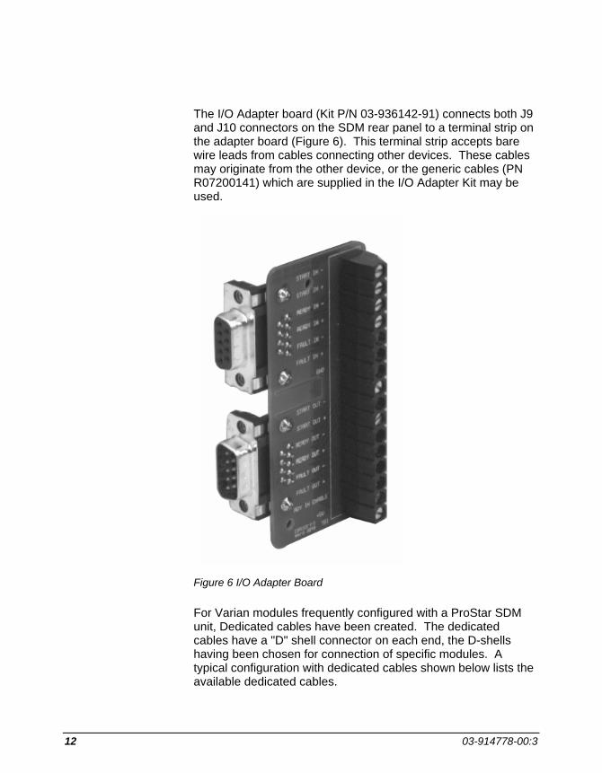
12 03-914778-00:3
The I/O Adapter board (Kit P/N 03-936142-91) connects both J9 and J10 connectors on the SDM rear panel to a terminal strip on the adapter board (Figure 6). This terminal strip accepts bare wire leads from cables connecting other devices. These cables may originate from the other device, or the generic cables (PN R07200141) which are supplied in the I/O Adapter Kit may be used.
Figure 6 I/O Adapter Board
For Varian modules frequently configured with a ProStar SDM unit, Dedicated cables have been created. The dedicated cables have a "D" shell connector on each end, the D-shells having been chosen for connection of specific modules. A typical configuration with dedicated cables shown below lists the available dedicated cables.

INSTALLATION
ProStar 220/230/240 Solvent Delivery Module 13
Figure 7 Typical Configuration using Dedicated Cables
Refer to the table below to choose the cabling options for configuring synchronization signals between the ProStar 220, 230, 240 SDM and a second module:
Table 1 Cabling Options Second Module Use AutoSamplers ProStar 400 Cable Kit P/N 03-909126-90 ProStar 410 I/O Adapter Kit P/N 03-936142-91 ProStar 420 I/O Adapter Kit P/N 03-936142-91 ProStar 430 I/O Adapter Kit P/N 03-936142-91 Detectors ProStar 310 Cable Kit P/N 03-919948-00 ProStar 320 I/O Adapter Kit P/N 0 3-936142-91 ProStar 330 Cable P/N 03-935717-01 ProStar 340/345 I/O Adapter Kit P/N 03-936142-91 ProStar 350/352 I/O Adapter Kit P/N 03-936142-91 ProStar 360 I/O Adapter Kit P/N 03-936142-91 ProStar 370 I/O Adapter Kit P/N 03-936142-91 Miscellaneous Rheodyne Position Sensing Switch Cable Kit P/N 03-919947-90 500 Column Valve Module I/O Adapter Kit P/N 03-936142-91 and cable
P/N 02-001954-00 for each relay used
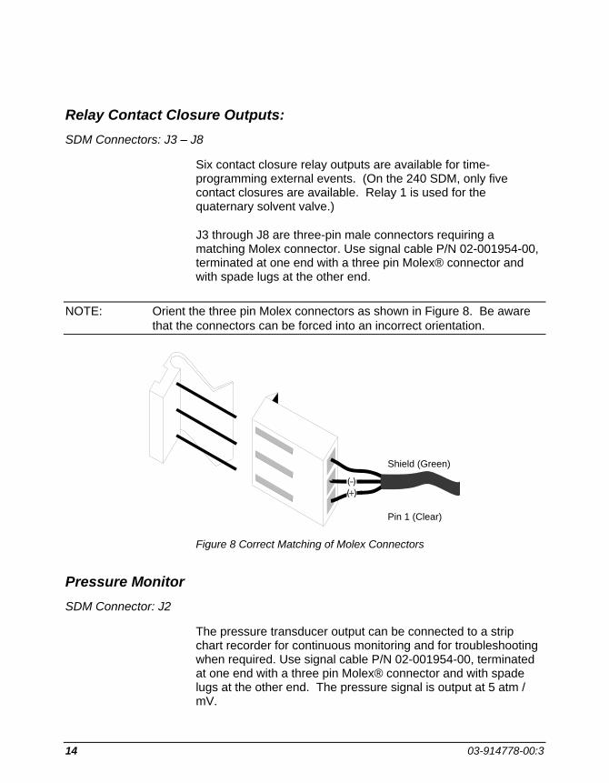
14 03-914778-00:3
Relay Contact Closure Outputs: SDM Connectors: J3 – J8
Six contact closure relay outputs are available for time-programming external events. (On the 240 SDM, only five contact closures are available. Relay 1 is used for the quaternary solvent valve.)
J3 through J8 are three-pin male connectors requiring a matching Molex connector. Use signal cable P/N 02-001954-00, terminated at one end with a three pin Molex® connector and with spade lugs at the other end.
NOTE: Orient the three pin Molex connectors as shown in Figure 8. Be aware that the connectors can be forced into an incorrect orientation.
Figure 8 Correct Matching of Molex Connectors
Pressure Monitor SDM Connector: J2
The pressure transducer output can be connected to a strip chart recorder for continuous monitoring and for troubleshooting when required. Use signal cable P/N 02-001954-00, terminated at one end with a three pin Molex® connector and with spade lugs at the other end. The pressure signal is output at 5 atm / mV.
Pin 1 (Clear)
Shield (Green)
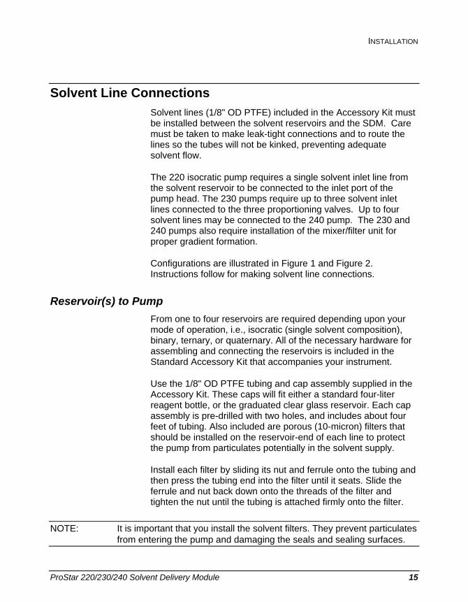
INSTALLATION
ProStar 220/230/240 Solvent Delivery Module 15
Solvent Line Connections Solvent lines (1/8" OD PTFE) included in the Accessory Kit must be installed between the solvent reservoirs and the SDM. Care must be taken to make leak-tight connections and to route the lines so the tubes will not be kinked, preventing adequate solvent flow.
The 220 isocratic pump requires a single solvent inlet line from the solvent reservoir to be connected to the inlet port of the pump head. The 230 pumps require up to three solvent inlet lines connected to the three proportioning valves. Up to four solvent lines may be connected to the 240 pump. The 230 and 240 pumps also require installation of the mixer/filter unit for proper gradient formation.
Configurations are illustrated in Figure 1 and Figure 2. Instructions follow for making solvent line connections.
Reservoir(s) to Pump From one to four reservoirs are required depending upon your mode of operation, i.e., isocratic (single solvent composition), binary, ternary, or quaternary. All of the necessary hardware for assembling and connecting the reservoirs is included in the Standard Accessory Kit that accompanies your instrument.
Use the 1/8" OD PTFE tubing and cap assembly supplied in the Accessory Kit. These caps will fit either a standard four-liter reagent bottle, or the graduated clear glass reservoir. Each cap assembly is pre-drilled with two holes, and includes about four feet of tubing. Also included are porous (10-micron) filters that should be installed on the reservoir-end of each line to protect the pump from particulates potentially in the solvent supply.
Install each filter by sliding its nut and ferrule onto the tubing and then press the tubing end into the filter until it seats. Slide the ferrule and nut back down onto the threads of the filter and tighten the nut until the tubing is attached firmly onto the filter.
NOTE: It is important that you install the solvent filters. They prevent particulates from entering the pump and damaging the seals and sealing surfaces.

16 03-914778-00:3
Attach the other end to of the 1/8" OD tubing to the pump head following the instructions below. Note that the proportioning valve positions are labeled A, B, and C. Be sure that solvent reservoirs (which also should be labeled A, B, and C) are connected to the matching proportioning valve.
• 220 SDM: Install the 1/8" Tefzel® nut and ferrule on the pump end of the 1/8" OD reservoir tubing. Note that the tapered end of the ferrule must face the nut (see figure below).
Thread the nut and solvent line into the pump head port finger tight only. Before tightening the nut, be sure the solvent line is inserted as far as it will go into the pump head port.
Figure 9 Solvent Line Connection to Pumphead (220 SDM).
• 230 SDM: Use the 1/8" PTFE ferrule with stainless steel nut, supplied in kit 03-936402-01, to connect each solvent tubing
Pumphead
Ferrule PN 28-211515-00
Nut P/N 28-211518-00
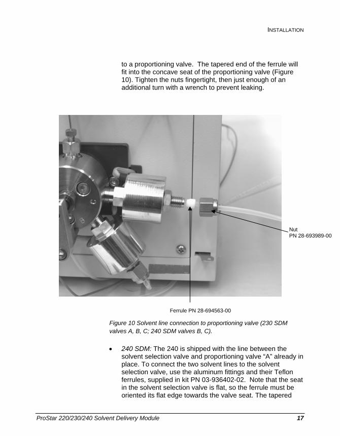
INSTALLATION
ProStar 220/230/240 Solvent Delivery Module 17
to a proportioning valve. The tapered end of the ferrule will fit into the concave seat of the proportioning valve (Figure 10). Tighten the nuts fingertight, then just enough of an additional turn with a wrench to prevent leaking.
Figure 10 Solvent line connection to proportioning valve (230 SDM valves A, B, C; 240 SDM valves B, C).
• 240 SDM: The 240 is shipped with the line between the solvent selection valve and proportioning valve “A” already in place. To connect the two solvent lines to the solvent selection valve, use the aluminum fittings and their Teflon ferrules, supplied in kit PN 03-936402-02. Note that the seat in the solvent selection valve is flat, so the ferrule must be oriented its flat edge towards the valve seat. The tapered
Ferrule PN 28-694563-00
Nut PN 28-693989-00

18 03-914778-00:3
end of the ferrule will be captured by the aluminum fitting (Figure 10). Thread the fitting into the Teflon body of the solvent selection valve very carefully so as not to strip the valve’s inner threads. Tighten to fingertight only. Before tightening the nut, be sure the solvent line is inserted as far as it will go into the valve.
To connect solvent lines directly to the proportioning valves B and C, follow the instructions for the 230 SDM connections.
Figure 11 Solvent line connection to solvent select valve (240 SDM).
Drain Line from Prime Valve Remove the shipping tie from the 1/16" OD PTFE drain line attached to the Prime Valve. Check the line fitting to make sure it is snug and then route the drain line into an appropriate waste solvent container.
Damper Outlet to Mixer/Filter (230 and 240 SDM) Connect the mixer/filter to the damper outlet using the 1/16" tubing, nuts, and ferrules from the standard accessory kit. Use pre-bent stainless steel PN 03-936257-01 (or Titanium tubing
Nut PN 28-211505-00
Ferrule PN 28-211509-00
Solvent Select Valve
INSTALLATION
ProStar 220/230/240 Solvent Delivery Module 19
PN 03-936257-02 for inert systems). Position the mixer/filter in a horizontal position as shown in Figure 2 to optimize mixing.
Mounting Peripheral Components Columns, purge valves, and loop valve injectors may be mounted in varied configurations downstream from the Mixer/Filter (or directly from the Damper Outlet connector on the 220 SDM). For most applications, use 0.020" ID tubing for all connections up to the injector and 0.010" or smaller ID tubing for all connections downstream of the injector.
Post Installation Leak Check Before running analyses, check of the system for solvent leaks around all connections with the pump running. See the Operation Section for instructions on starting the pump. If a leak is found, tighten the fitting just enough to correct the leak. DO NOT OVER TIGHTEN.
Leaks appearing, or dripping from the pump head usually indicate internal leaks that require seal replacement.

20 03-914778-00:3

ProStar 220/230/240 Solvent Delivery Module 21
System Description
General The ProStar 220, 230 and 240 Solvent Delivery Modules are single piston pumps which deliver flow in a linear dynamic range for 10 µL/min to 10 mL/min. The 220 is designed for isocratic (single solvent) applications only.
Proportioned delivery of multiple solvents can be achieved by the 230 and 240 pumps. Up to 3 solvent may be run isocratically or in gradients with the ProStar 230 SDM. The 240 SDM is a quaternary HPLC system which allows the user to run any of 4 solvents isocratically or to proportion and run a gradient with 3 solvents. A low pressure 2-position solvent switching valve is connected to the “A” proportioning valve and relay 1 is used to select between the two solvents.
The ProStar 220/230/240 Solvent Delivery Modules can be run as independent units or may be configured for control by the Star Workstation.
Pump Hardware Solvent is delivered by a single-piston, reciprocating pump. Piston design and electronically controlled stroke provide a nearly pulseless flow. Incorporation of a pulse damper further reduces any pump pulses inherent in the system. A mixing chamber assures adequate mixing of solvents prior to sample injection, and finally, a pressure transducer converts the pressure in the system to an electrical output that is digitally displayed on the front panel.

22 03-914778-00:3
Piston Stroke Control The piston stroke is controlled by the rotation of the piston cam. A full pump cycle consists of a fill stroke in which the piston is traveling in a reverse (out of the pump head) direction, and a pump stroke in which the piston is traveling in a forward direction (into the pump head). During the pump stroke solvent is discharged through the outlet check valve.
The rotation of the piston cam is determined by a software-controlled stepper motor (Figure 12). Pump head and valving details are shown (Figure 13).
Figure 12 Pump Components

SYSTEM DESCRIPTION
ProStar 220/230/240 Solvent Delivery Module 23
Figure 13 Pump Head Valving, Cutaway View
Solvent Proportioning by ProStar 230 and 240 SDM The pump head is ported to accommodate three proportioning valves. Solvent delivery may be selected from any combination of the three.
The proportioning valves admit solvents from the specified reservoirs during the fill stroke. Three reservoirs are used for ternary gradient analyses, one or two reservoirs for isocratic or binary applications. Each valve is opened by an electrically driven magnetic coil energized by the circuit logic according to the programmed solvent composition entered in the % ABC FLOW table. A cross-sectional diagram of the proportioning valve and the solvent path through it are shown in Figure 14.

24 03-914778-00:3
Figure 14 Proportioning Valve Solvent Path
Isocratic Solvent Delivery (ProStar 220 SDM) A single solvent line from a single solvent reservoir is connected directly to the inlet port of the pump head.
Standard and Inert Pathway Materials The wetted materials in the standard 220, 230 and 240 pumps are passivated 316 stainless steel, sapphire, ruby, and inert polymers, fluoropolymers, and perfluoroelastomers.
In the optional Inert SDM models, stainless steel components have been replaced with titanium parts wherever possible, making over 99.99% of the wetted surface inert to most mobile phases. Frits contribute over 99% of the wetted surface area. The ProStar SDM units with inert components feature commercially pure Titanium frits throughout. Other materials contacted by mobile phase and sample include sapphire, ruby, gold, inert polymers leaving only a minute amount of exposed stainless steel. The table below lists the optional inert parts used in the inert ProStar SDM units.

SYSTEM DESCRIPTION
ProStar 220/230/240 Solvent Delivery Module 25
Component Construction Part Number 1 Solvent Reservoir Filter
10µ (4 required) Construction is sintered commercially pure titanium with PEEK fitting body
28-211524-00
2 Pump head Commercially pure titanium 03-919607-00 3 Inlet Valve Titanium solvent manifold 03-919604-90 4 Outlet Check Valve Titanium body and filter element 03-919600-90 5 High Pressure Tubing
(damper to mixer) Titanium (Identified by yellow band)
03-936257-02
6 Tubing Teflon 03-919508-00 7 Prime/Purge Valve PEEK body with Kel-F® parts 03-919612-00 8 Mixer/Filter Assembly PEEK body with aluminum retaining
body and end caps 03-919622-00
9 Fittings Upchurch Fittings: PEEK Ferrules 28-211523-00 Nut (1/16" SST) 15-001410-00 10 Pump Seal Fluoroloy G™ seal material with gold
plated spring 03-919609-00
11 Low Pressure Solvent Switching valve
PEEK Body 03-919746-01
12 Fittings Kel-F Bushing Aluminum Nut (not exposed to solvent)
28-211509-00 28-211505-00
Front Panel Display Communication from the 220/230/240 SDM to the operator is by way of the two line, forty character Liquid Crystal Display (LCD). All entries are displayed in fields. Use the INCREASE and DECREASE keys to select options and values in each selected field.
The cursor is identified as a flashing dash underlining a character. Its home, or initial, position when bringing up a display is the last character in the first programmable field. Move the cursor horizontally along a line with the right and left arrow keys, and from line to line with the PREVIOUS LINE or NEXT LINE keys.

26 03-914778-00:3
A display contrast control that rotates clockwise to increase screen and character intensity and counterclockwise to decrease intensity is located under and at midpoint of the display.
Front Panel Keys All operator inputs are generated by front panel key selections. In addition to the keys are Light Emitting Diode (LED) indicators that keep the operator alerted as to instrument and method states. Input keys are conveniently grouped according to specific function, i.e., instrument operation, method editing, and table selection (Figure 15).
Figure 15 Front Panel Keys and LEDs

SYSTEM DESCRIPTION
ProStar 220/230/240 Solvent Delivery Module 27
Following are brief descriptions of the response of each key when pressed.
Keys located in the OPERATION section of the front panel
START Starts the method clock when the method is STOPPED or READY.
STOP Stops the method clock and pump.
STATUS Puts Status Line 1 on the display. Use PREVIOUS LINE and NEXT LINE keys to selectively view the other three status lines.
RESET Resets the method to time=0 conditions.
PURGE Starts the pump running at 10 mL/min at the composition specified by the Flow and Composition Table. See page 37, Priming and Purging.
PRIME Pressing PRIME A pumps 100% solvent A at 10 mL/min. The PRIME indicator lights when the pump is in the priming mode. PRIME B and PRIME C function in the same way. The display shows which of the three solvents is being pumped to prime the system. See page 37, Priming and Purging.
PUMP Solvent pumping does not start when the module main power is turned on. After power has been turned on, press the PUMP key to start the pump. Press the STOP key to stop the pump flow.
Keys located in the EDIT section of the front panel
CURSOR Left and right arrow keys move the cursor, field-by-field, in the selected direction. The cursor (underline) will rest under the last character in the field. When the cursor rests in the last field, pressing the right cursor key will cause the cursor to "wrap-around" to the first field of the sequence.

28 03-914778-00:3
PREVIOUS LINE
Moves the previous line into the display.
NEXT LINE Moves the next line into the display.
SELECT Press this key to select a menu item, or to select a method to activate, delete, or copy.
CLEAR Clears a field value on the flow/composition line. See page 44 for more information on the Clear Key.
INSERT LINE Adds a new line and increases the line number of all existing following lines by one. This key also increases the time to the next whole minute and copies all of the field values of the line showing when the key is pressed.
DELETE LINE Deletes the displayed line from a method table.
NOTE: The delete key is ignored if an attempt is made to delete a Time=0.00 line.
INCREASE/ DECREASE
Causes the value of the field at which the cursor rests to increase or decrease if numeric, or, change if the field is alphabetic.
SHIFT The SHIFT key is used to increase the size of incremental changes when applied to fields of numbers. For example: the normal incremental change for all time values is 0.01 minute. When the SHIFT key is pressed and active, incremental steps for time are 1.0 minute for values less than 100 minutes, and 5.0 minutes for values greater than 100 minutes. The SHIFT indicator is lit during all periods when the SHIFT feature is in effect. Press the key to activate, press again to deactivate the SHIFT mode.

SYSTEM DESCRIPTION
ProStar 220/230/240 Solvent Delivery Module 29
AUTOMATION MENU
Displays the Automation Menu with the cursor in the first, or farthest left field of the display.
AUTOMATION ACTIVATE
Starts the automation sequence, and the AUTOMATION LED lights. Pressing the key when automation is active stops the automation sequence and the current method continues to run.
Keys located in the TABLE SELECT section of the front panel
% ABC FLOW Displays the heading line and the first line of the Flow and Composition Table. The first line is displayed with default, or preset values until changed by the user.
When the %ABC FLOW key is pressed on the 220 SDM, an isocratic flow table is displayed. %ABC headings do not appear.
RELAYS Displays the heading and first line of the Relay Table with the cursor resting in the farthest left field. Each relay is treated as a field since each can be set independently.
CONFIGURE MENU (Configuration Menu)
Displays the basic set-up menu, and allows you to enable or disable the keyboard "beeper".
SET CONDITIONS
Displays the Set Conditions Table. The column heading line and the current values for Endtime, Endtime Action, Pmin and Pmax, and Equilibration Time are displayed.
METHOD ACTIONS (Method Actions Menu and Selections)
Displays the Method Actions Menu. The cursor rests at selection (1) Method Select field. See page 47 for more information.

30 03-914778-00:3
Key located in the CONTROL section of the front panel
LOCAL If the 220/230/240 is under remote (Workstation) control, the REMOTE indicator will be on. To use other functions from the keypad, such as PURGE or PRIME keys, press the REMOTE key and wait for the REMOTE LED to turn off.
Rear Panel Connectors Rear Panel Connectors: Descriptions (refer to Figure 5)
J1 J1 is a power input filter.
J2 J2 is the Pressure 5 atm/mV Connector. The output voltage signal of the pressure transducer is accessed at this port for connection to an external recording device, e.g., a strip chart recorder.
J3-J8 J3-J8 are the connectors for Relays 1 through 6. The open or closed modes for these relays are time programmed in the Relays Table. Up to six external events may be controlled from these ports.
J9 J9 is a nine pin "D" shell connector used with synchronization signal cables. Additional information is presented below and in the Installation Section of this manual.
J10 J10 is a nine pin "D" shell connector used with synchronization cables. Additional information is presented below and in the Installation Section of this manual.
J201 GPIB IEEE 488 PORT
A connector is present at this location on the rear panel if an optional GPIB (General Purpose Interface Bus) has been installed, enabling remote operation from a central Workstation.

SYSTEM DESCRIPTION
ProStar 220/230/240 Solvent Delivery Module 31
TeleDiagnostics™ Serial Connector
Actively using this feature requires the installation of a modem, Kit Number 03-919555-90. The Modem enables a Varian Customer Support Representative at a remote service center to view and diagnose the Extended Diagnostic menu on his terminal via the telephone. Complete installation instructions are included with the modem kit.
Synchronization Signals at J9 and J10 These signals are used to synchronize the actions of a group of instruments that are not interfaced with a Star Workstation by GPIB Boards and cables.
An input is activated or said to be present when its two signal wires are connected together, quite often done by a relay contact closure. If the inputs are driven from another instrument with optical isolators, or other polarized devices, then attention must be paid to the polarity of the signal wire connections. The positive (+) output signal must connect to the positive (+) input signal, and the negative (-) output to the negative (-) input.
The outputs are optical isolators and simulate a relay contact closure when they are activated.
Enable In This polarized input signal enables the Ready In input signal.
When Enable In is not present, the Ready In signal is ignored and is equivalent to a constantly present Ready In. The SDM is not dependent on receiving an outside Ready signal.
When Enable In is present, the SDM requires a Ready In signal before it can go to the READY state.
Enable Out This is a non-polarized, constantly active output (a short). It can be used to activate Enable In on the next instrument in the system.

32 03-914778-00:3
Ready In When Enable In is present, this polarized input signal must be present before the SDM will go to the READY state.
Specifically, activating Ready In will cause the SDM to go from the "Not Ready-Method Waiting-Pump Running" state (equilibration complete) to the READY state. It must stay active until the SDM starts. Ready In will be ignored in all other states.
Ready Out This polarized output signal indicates that the SDM is in the READY state and is ready to start a time program.
Start In This polarized edge-triggered input signal will start the SDM active method if it is in the READY state.
Start Out This polarized output signal will be activated for 600 milliseconds when the SDM starts a time program.
Fault In This polarized edge-triggered input signal informs the SDM that a fault condition exists in another instrument. The SDM will stop the pump, halt the time program, and send a Fault Out signal. If the SDM also has a fault, a Fault Out signal will not be sent.
Fault Out This polarized output signal will activate for 600 milliseconds when one or the other of the following events occurs:
• The SDM detects an internal fault condition that warrants stopping the pump, or,
• The SDM receives a Fault In signal and has no internal fault condition itself.
Refer to Figure 16 , J9 and J10 pin designations of the synchronization signals described above.
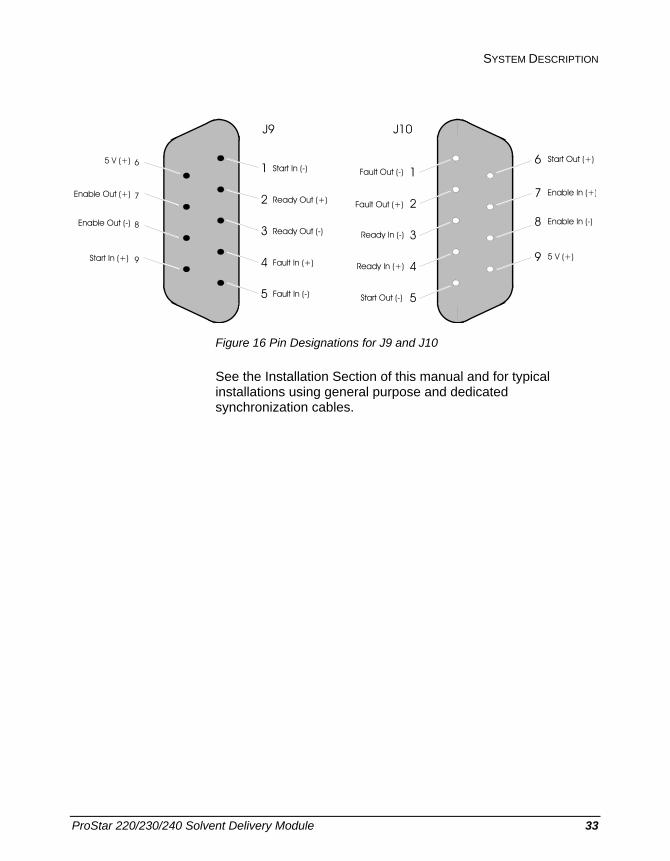
SYSTEM DESCRIPTION
ProStar 220/230/240 Solvent Delivery Module 33
Ready Out (+)2
Start In (-)1
Ready Out (-)3
Fault In (+)4
Fault In (-)5
5 V (+) 6
Enable Out (+) 7
Enable Out (-) 8
Start In (+) 9
J9
Start Out (+)6
Enable In (+)7
Enable In (-)8
5 V (+)9
Start Out (-) 5
Ready In (+) 4
Ready In (-) 3
Fault Out (+) 2
Fault Out (-) 1
J10
Figure 16 Pin Designations for J9 and J10
See the Installation Section of this manual and for typical installations using general purpose and dedicated synchronization cables.

34 03-914778-00:3

ProStar 220/230/240 Solvent Delivery Module 35
Operation
General The parameters that control the pump are grouped together to form a method. There is always one active method, either one with preset values, or one with your entered parameters. Only the method that is currently active can be edited.
The pump is controlled locally using the front panel keypad. Four tables that control solvent delivery conditions may be accessed and changed. Access to the method editing tables is gained by pressing any of the keys in the TABLE SELECT section of the front panel. The following operating instructions assume that you are using the ProStar 220, 230 or 240 Solvent Delivery Module in the "local" mode. Under this condition the REMOTE indicator in the lower right corner will be off. See Figure 15 for key locations in the TABLE SELECT section of the front panel.
You have five tables from which to select the method parameters. All five of these tables are accessed by the keys grouped under the heading TABLE SELECT. There is no fixed order for selecting the pump conditions. It is assumed that all of the necessary installation procedures for "stand alone" operation have been completed.
NOTE: 220 SDM users disregard references to setting composition.

36 03-914778-00:3
Starting Up The assumption is made that all installation procedures have been completed. Only the stand-alone mode of the ProStar 220, 230 and 240 Solvent Delivery Modules operation is covered in this manual.
Warm Start Turn on the main power switch on the front panel. "Self Test" will appear on the display. During Self Test, a brief (about 30 seconds) diagnostic routine is being performed to check the integrity of the electronics and hardware. If no faults are detected during this Self Test period, a warm start occurs and "Methods Saved" appears as shown in the 230 display below:
VARIAN Solvent Delivery Module Rev. B 1.4, Methods Saved
Cold Start A cold start is initiated by turning on the main power while simultaneously pressing and holding down the RESET key until the first audible double beep is heard. With a cold start, all fields are restored to preset values, and the display informs you that method presets are loaded.
VARIAN Solvent Delivery Module Rev. B 1.4, Method Presets Loaded
A cold start is a convenient way to replace all of your entered values and selections with the preset parameters. All methods will be set to preset values and the proportioning mode will be set to one stroke.
When first starting up, it will be necessary to prime the pump then purge the hydraulics of the entire pumping system. Special function keys in the OPERATION section of the keypad enable you to perform these operations directly.
OPERATION
ProStar 220/230/240 Solvent Delivery Module 37
Starting Pump Flow The pump does not start pumping when instrument power is turned on. To start the pump, press the PUMP key on the front panel. The PUMP key will not turn the pump off. To stop the pump, press STOP.
Priming and Purging
Purpose Priming and purging are two related operations to quickly configure the proper initial solvents through the pump pathways.
Priming the pump rapidly brings a single solvent from its reservoir through the solvent lines and the pumphead exiting out the drain line from the opened Prime Valve. The priming process allows bubbles and old solvent to be cleared from the lines as a continuous column of fresh solvent is established through the pump. The Prime valve is opened so that bubbles and old solvent exit to the drain line. Since priming and purging operate at the preset rate of 10 mL/min, opening the Prime Valve also keeps the system pressure from becoming too high.
Purging is performed after priming on the 230 and 240 SDM. Solvent again is pumped at the rate of 10 mL/min, but the proportioning valves are activated so that the solvent delivered from the pumphead is the composition specified for the initial conditions of the active method. Purging is useful to bring the proper mixed solvent through the lines to the point where the column will be attached. This assures that the column will exposed to only the desired solvent compositions.
For the following detailed instructions on priming and purging, refer to Figure 1, page 2, and Figure 2, page 3.
230 & 240 SDM Priming Open the Prime Valve by turning the valve handle counterclockwise about one turn. Run the waste drain line to a beaker or other waste receiver during the priming process.

38 03-914778-00:3
PRIME is branched to three separate keys labeled A, B, and C. When any one of these keys is pressed, the selected solvent will be pumped through the system at a preset rate of 10 mL/min from its reservoir bottle.
Press PRIME A. The pump will start, the PRIME indicator will go on, and liquid will be discharged through the drain line. Continue priming until the liquid flow is regular and free of bubbles. Repeat the procedure for PRIME B and C if reservoirs for them are in place.
Press the STOP key after priming is complete to halt the flow of solvent. Rotate the Prime Valve handle clockwise to close it.
NOTE: No changes are required in the Flow and Composition Table for the priming process.
230 & 240 SDM Purging
NOTE: Before you can purge the system using a specified mixture of solvents, you must make changes in the Flow and Composition Table. For a detailed discussion on procedures for modifying this table refer to page 41.
After priming is complete, Purging will pump solvents from the reservoirs selected in the Flow and Composition Table at the specified composition. The first time the instrument is turned on, the Flow and Composition Table is preset to 100% A. Until this table is changed to a different solvent composition, the system will be purged with solvent A only.
The purge operation must be carried out before the column is installed in your system because at the purge flow rate of 10 mL/min pressure would exceed the maximum pressure of 410 atmospheres and shut off the pump. Typically, the column inlet tubing and outlet tubing are joined with a connector so the entire pathway through the detector can be purged. Check to be sure that your detector flow cell can accept a flow of 10 mL/min.
With the PRIME valve closed, pump your selected solvent composition through the entire system. Observe the flow from

OPERATION
ProStar 220/230/240 Solvent Delivery Module 39
the detector discharge line, and continue pumping until the flow is constant and free of bubbles.
The system is now ready for column installation and the development of methods for your specific applications.
220 SDM Priming and Purging Open the Prime Valve by turning the valve handle counterclockwise about one turn. Run the waste drain line to a beaker or other waste receiver during the priming process.
PRIME is branched to three separate keys labeled A, B, and C. When any one of these keys is pressed, the one solvent to the 220 SDM will be pumped through the system at a preset rate of 10 mL/min from its reservoir bottle.
For example, press PRIME A. The pump will start, the PRIME indicator will go on, and liquid will be discharged through the drain line. Continue priming until the liquid flow is regular and free of bubbles.
Press the STOP key after priming is complete to halt the flow of solvent. Rotate the Prime Valve handle clockwise to close it.
The Purge process clears the lines after the Prime Valve. Since the 220 is an isocratic pump and has only one solvent, either the PURGE or PRIME key will result in the same pump action.
NOTE: The Purge process must be carried out before the column is installed in your system because at the purge flow rate of 10 mL/min pressure would exceed the maximum pressure of 410 atmospheres and shut off the pump. Typically, the column inlet tubing and outlet tubing are joined with a connector so the entire pathway through the detector can be purged. Check to be sure that your detector flow cell can accept a flow of 10 mL/min.
With the PRIME valve closed, pump your solvent through the entire system. Observe the flow from the detector discharge line, and continue pumping until the flow is constant and free of bubbles.

40 03-914778-00:3
The system is now ready for column installation and the development of methods for your specific applications.
The Status Displays Four status displays are provided to give status information for the current pump conditions. Status information includes the active method number, method state, run time, pump state, flow composition, flow rate, pressure, relay states, pressure minimum/maximum, automation status, and the number of pump strokes since the last piston seal replacement.
The Status displays are read-only and cannot be edited.
When you press the STATUS key, the first of four Status lines is displayed. You can view any of the four lines by pressing the NEXT LINE and PREVIOUS LINE keys.
The following are typical layouts of the four Status displays.
Meth %A %B %C Flow Press Relays Time 1 100 0 0 0.00 0 -- 0.00
or for 220 SDM
Method Flow Pres Relays Time 1 0.00 0 --- 0.00
The three following displays are common to all 220, 230 and 240 Solvent Delivery Modules.
Line Method 1 Pump Runtime Endtime 2 Not Ready Stopped 0.00 20.00
Line Automation Line Method Run Loop 3 Off 1 1 1/ 1 1/ 1
Line Pump Strokes 4 4321
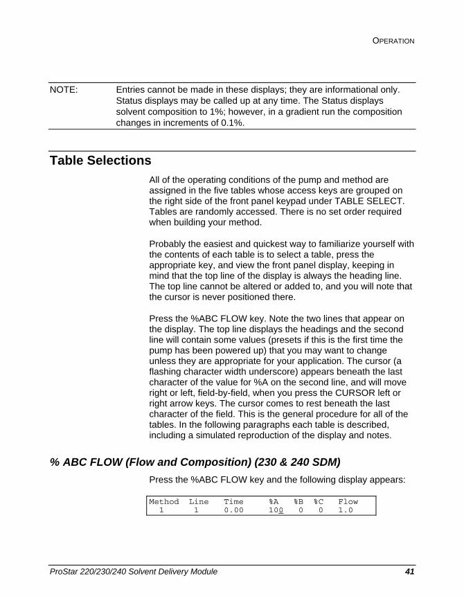
OPERATION
ProStar 220/230/240 Solvent Delivery Module 41
NOTE: Entries cannot be made in these displays; they are informational only. Status displays may be called up at any time. The Status displays solvent composition to 1%; however, in a gradient run the composition changes in increments of 0.1%.
Table Selections All of the operating conditions of the pump and method are assigned in the five tables whose access keys are grouped on the right side of the front panel keypad under TABLE SELECT. Tables are randomly accessed. There is no set order required when building your method.
Probably the easiest and quickest way to familiarize yourself with the contents of each table is to select a table, press the appropriate key, and view the front panel display, keeping in mind that the top line of the display is always the heading line. The top line cannot be altered or added to, and you will note that the cursor is never positioned there.
Press the %ABC FLOW key. Note the two lines that appear on the display. The top line displays the headings and the second line will contain some values (presets if this is the first time the pump has been powered up) that you may want to change unless they are appropriate for your application. The cursor (a flashing character width underscore) appears beneath the last character of the value for %A on the second line, and will move right or left, field-by-field, when you press the CURSOR left or right arrow keys. The cursor comes to rest beneath the last character of the field. This is the general procedure for all of the tables. In the following paragraphs each table is described, including a simulated reproduction of the display and notes.
% ABC FLOW (Flow and Composition) (230 & 240 SDM) Press the %ABC FLOW key and the following display appears:
Method Line Time %A %B %C Flow 1 1 0.00 100 0 0 1.0

42 03-914778-00:3
For Solvent A Choice for 240 SDM:
For the 240 SDM, the choice of solvent A is determined by the solvent selection valve status as controlled by Relay 1. See the Relay subsection below.
Notes on the %ABC FLOW Table for both 230 and 240 SDM.
1. Solvent compositions are settable to 1%. During a gradient run the solvent composition actually changes by increments of 0.1%.
2. When the Flow and Composition Table is initially displayed by pressing the %ABC FLOW key, the cursor rests in the %A field since LINE 1 and TIME 0.00 cannot be changed. Changes can be made only in the Composition and Flow fields. To add lines, press the INSERT LINE key. Line 1 will advance to Line 2 and you may now position the cursor in the Time field and build your table. The current lines are displayed by pressing the NEXT LINE or PREVIOUS LINE keys. The Method number (1 to 5) is selected in the Method Actions menu.
3. The total number of lines for all events in any given method table is between 37 and 72, depending upon which tables are used. When all events have been used, any attempt to insert another line with the INSERT LINE key will result in the message TABLE FULL appearing in the Line and Time fields. Moving the cursor out of the last field of the last line into lowered numbered lines, or pressing other function keys will eliminate the TABLE FULL message.
4. Changing values with the INCREASE and DECREASE keys will change values only in the field in which the cursor rests, with one exception. Since the total % of A, B, and C must always equal 100, any change in %A will cause a compensating change in %B. Likewise, a change in %B will cause a change in %C such that the total will equal 100%. A change in %C will cause %A to change. An attempt to change %B when %A equals 100 will result in the advisory message "DECREASE %A COMPOSITION". To return to the %ABC FLOW display, press one of the CURSOR arrow keys.
OPERATION
ProStar 220/230/240 Solvent Delivery Module 43
5. Changes to the Flow and Composition Table are executed as follows:
• With the method not running, and the run time=0, any change to the Time=0 line will take place immediately with an equilibration step carried out if included in the method. Note: Values or selections entered in a field do not take effect until the cursor leaves that field.
• With the method running, if a change is made to a line with a Time greater than the current run time, the change will take effect when the run time equals the new time change.
• With the method running, if a change is made to a line with a Time less than the current run time, no change will take effect until the next time the method is run.
6. DUP Message. If the Time field value of one line is changed to equal the Time field value of another existing line, the message DUP is displayed at the right side of the Time field. This indicates to you that somewhere in the existing lines there is another line with the same (duplicate) time value. If the cursor is moved from the Time field, the line containing the DUP message is retained. If the time is changed in the DUP line, the line that was duplicated is retained.
7. To create a new line, use the INSERT LINE key. The Time of the inserted line is increased to the next whole minute. The NEXT LINE key is used for displaying existing lines only. Example: If Line 4 had a Time of 2.25 minutes then your newly created Line 5 (by pressing the INSERT LINE key) will have a Time value of 3.00.
8. Data entered in a field is activated when the cursor leaves that field. All field values are selected by the INCREASE and DECREASE keys.
9. The INSERT LINE key is ignored if the Time field value of 1440.00 (upper time limit) is displayed.

44 03-914778-00:3
10. The number of digits displayed for the flow rate value will depend upon the flow rate setting. From 0.01 to 0.99 mL/min flow rates will be displayed to 0.01 mL/min. Above 1.0 mL/min flow rates will be displayed to 0.1 mL/min.
NOTE: The SHIFT key may be used when setting times or flow rates to increase the size of the incremental change when a broad range change is to be made. Example: For the Time field, with the SHIFT active (SHIFT indicator light on) the normal incremental change of 0.01 (unshifted) is increased a hundredfold to 1.0 in the 0-100 range and 5.0 above 100. See System Description, Front panel Keys, for a broader description of the SHIFT key operation.
11. CLEAR key. This key enables you to clear either (not both simultaneously) the composition fields or the flow rate field. Since composition and flow rate are two independent variables that are displayed on a single line, you may want to vary one over a specified time without varying the other.
Certain conditions apply to the CLEAR key:
• The CLEAR key only affects the composition and flow fields.
• The CLEAR key cannot be used on the 0.00 Time line since this line must contain valid values in all fields.
• When the composition fields are cleared, pressing the INCREASE or DECREASE keys will enter 100% in the composition field the cursor is in.
NOTE: When the %ABC FLOW key is pressed on the 220 SDM, only the flow rate may be changed. The display will not show composition values, i.e., % A, B, or C headings or values are not displayed.

OPERATION
ProStar 220/230/240 Solvent Delivery Module 45
Set Conditions When you press the SET CONDITIONS key, the following table is displayed:
Meth Endtime Action Pmin/Pmax Equiltime 1 20.00 Stop 6/400 atm 10.00
In this table you set the Endtime, the Endtime Action you have selected to take place at the end of the run, minimum and maximum pressures (Pmin/Pmax), and Equilibration Time.
Notes on the Set Conditions Table
1. The Endtime defines when the Endtime Action takes place.
2. Equil (in the Endtime Action column) causes the Method to go to READY after performing an equilibration step. When you select Equil as an Endtime Action, an equilibration period of the time entered in the last field of the Set Conditions Table is performed before a method moves to the READY state. During this equilibration period a gradient change from the current solvent composition and flow rate to the Time=0 composition and flow rate occurs. The gradient composition change takes 10% of the equilibration time, with the new conditions being held for the remaining 90% of the time.
This programmed equilibration is intended to cause a smooth changeover in solvent composition in automated applications, and is executed when a new method with a different flow rate or composition is activated. Equilibration is not done if the current conditions are the same as the T=0 conditions or the Equilibration value is set to 0. An equilibration can be forced at Time=0 by changing the equilibration time. An equilibration in progress can be terminated by pressing the RESET key.
3. HOLD (Endtime Action column) stops the method clock and holds the last specified conditions with the pump running.
4. STOP (Endtime Action column) stops the pump and the method clock at the Endtime.

46 03-914778-00:3
NOTE: The End Action selected is valid for manual operation only. When Automation is active, equilibration is always done regardless of the choice entered in the Set Conditions Table.
5. Pmin is always less than Pmax. The range for Pmin is 0-409 (Pmax -1) atmospheres; therefore, the range for Pmax must be Pmin plus 1 to 410 atmospheres. Pmin and Pmax are independent variables and resetting the value of one does not affect the other.
6. Again, in this table, the SHIFT key may be used to increase the size of incremental steps where large range changes are required. For example, the standard increment for Pmin and Pmax is 1 atmosphere. The shifted increment for both fields is 10 atmospheres. Also, shifted increments for time values of .01-99.99 minutes is 1 minute. Shifted increments for time values of greater than 100 minutes is 5.00 minutes.
Configure Menu The options in this table allow you to enable or disable a keyboard beeper that gives audible indication of positive keystrokes or to set the proportioning mode to be used by the pump.
Press the CONFIGURE MENU key. The following display appears.
Keyboard Proportioning Beeper Mode
Make your choice from the menu with the cursor arrow keys and press SELECT. If you choose Keyboard Beeper, the following is displayed.
Keyboard beeper state: Enabled
Use the INCREASE/DECREASE keys to make your selection. Upon leaving this display, any change to the beeper state will take effect.
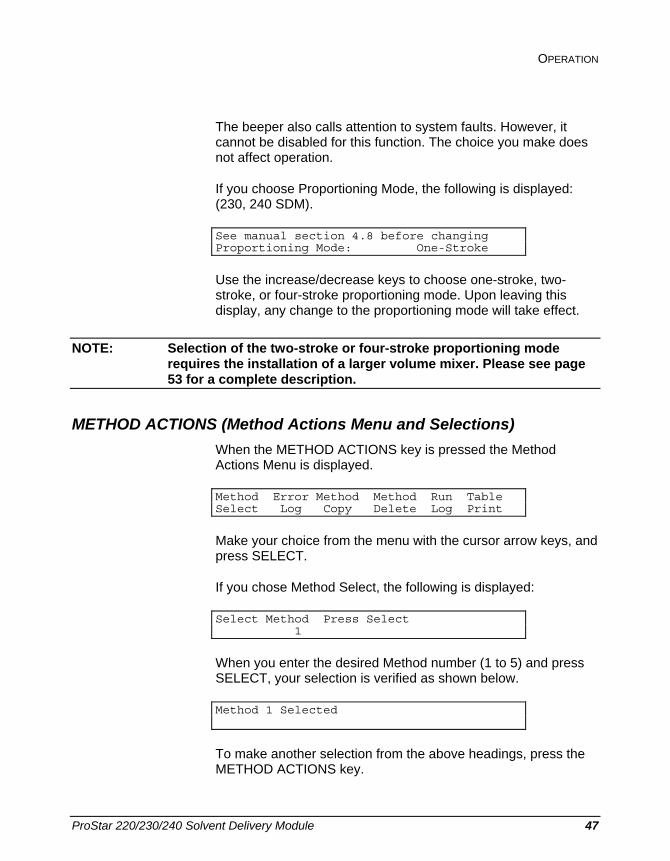
OPERATION
ProStar 220/230/240 Solvent Delivery Module 47
The beeper also calls attention to system faults. However, it cannot be disabled for this function. The choice you make does not affect operation.
If you choose Proportioning Mode, the following is displayed: (230, 240 SDM).
See manual section 4.8 before changing Proportioning Mode: One-Stroke
Use the increase/decrease keys to choose one-stroke, two-stroke, or four-stroke proportioning mode. Upon leaving this display, any change to the proportioning mode will take effect.
NOTE: Selection of the two-stroke or four-stroke proportioning mode requires the installation of a larger volume mixer. Please see page 53 for a complete description.
METHOD ACTIONS (Method Actions Menu and Selections) When the METHOD ACTIONS key is pressed the Method Actions Menu is displayed.
Method Error Method Method Run Table Select Log Copy Delete Log Print
Make your choice from the menu with the cursor arrow keys, and press SELECT.
If you chose Method Select, the following is displayed:
Select Method Press Select 1
When you enter the desired Method number (1 to 5) and press SELECT, your selection is verified as shown below.
Method 1 Selected
To make another selection from the above headings, press the METHOD ACTIONS key.

48 03-914778-00:3
When you select Error Log you obtain a record of any errors detected during the run. Time, description, and the codes of the detected error(s) are presented in the following format:
Time Error Description Error Code
The NEXT LINE key may be used to look for more than one error.
NOTE: This is a read-out display only. No changes can be made to the fields of this table.
When you select Method Copy the display below appears:
Copy Method From To Press Select 1 3
Enter the Method number you want to copy, and the Method number it is to be copied to, press SELECT, and the copy action is verified as shown in the following display:
Method 1 Copied to 2
Move the cursor to Method Delete and press SELECT. The following is displayed:
Delete Method - Use Inc/Dec to Choose, 2 Then Press Select
Enter the Method number to be deleted with the INCREASE/DECREASE keys and press SELECT. The verification of the deleted method is displayed as shown below:
Method 2 Deleted
NOTE: When a Method is "deleted" by this command, it is not erased. It is restored to preset values.

OPERATION
ProStar 220/230/240 Solvent Delivery Module 49
The Run Log provides a quick way to review the conditions of the run just completed. The table lists Time, Event, and Value of run parameters in the following format.
Time Event Value
Events listed in the table are: %A, %B, %C, Flow, Relays On, Pmin, Pmax, and Proportioning Mode. Values appearing in the Value column will be those entered and executed in the last run completed.
The contents of the table are viewed by scanning with the NEXT LINE and PREVIOUS LINE keys.
NOTE: The contents of this display can only be viewed. No changes can be made to the fields in this table.
Notes on the Method Actions Menu
1. Error Log and Run Log displays may be viewed only, not changed.
2. There are cases when certain actions are not allowed and are described in Exception Displays.
3. The Error Log will contain an error code and a description of the fault that has occurred. The Pmin and Pmax errors occur when the pressure either drops below Pmin or exceeds the Pmax values specified in the Set Conditions menu. For a complete list of faults see Section 8, paragraph 8.2.
4. All pump errors are "fatal", that is, the pump goes to the STOPPED state, and the method goes to NOT READY or STOPPED. Also, all background diagnostic errors (faults) are reported in the Error Log.
RELAYS This table provides you open and closed contact control of six external event relays. Relays may be time programmed to open and close to control a series of external events.
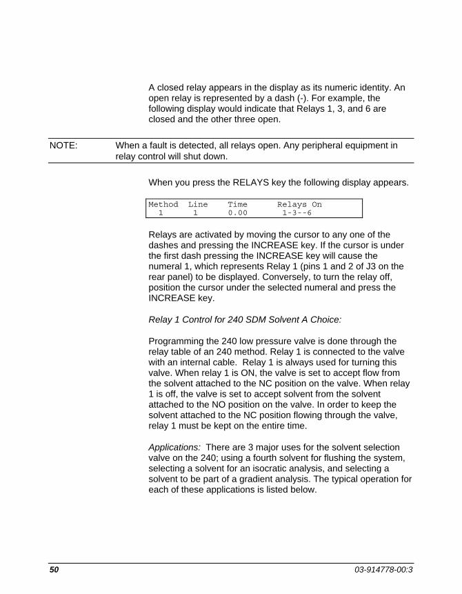
50 03-914778-00:3
A closed relay appears in the display as its numeric identity. An open relay is represented by a dash (-). For example, the following display would indicate that Relays 1, 3, and 6 are closed and the other three open.
NOTE: When a fault is detected, all relays open. Any peripheral equipment in relay control will shut down.
When you press the RELAYS key the following display appears.
Method Line Time Relays On 1 1 0.00 1-3--6
Relays are activated by moving the cursor to any one of the dashes and pressing the INCREASE key. If the cursor is under the first dash pressing the INCREASE key will cause the numeral 1, which represents Relay 1 (pins 1 and 2 of J3 on the rear panel) to be displayed. Conversely, to turn the relay off, position the cursor under the selected numeral and press the INCREASE key.
Relay 1 Control for 240 SDM Solvent A Choice:
Programming the 240 low pressure valve is done through the relay table of an 240 method. Relay 1 is connected to the valve with an internal cable. Relay 1 is always used for turning this valve. When relay 1 is ON, the valve is set to accept flow from the solvent attached to the NC position on the valve. When relay 1 is off, the valve is set to accept solvent from the solvent attached to the NO position on the valve. In order to keep the solvent attached to the NC position flowing through the valve, relay 1 must be kept on the entire time.
Applications: There are 3 major uses for the solvent selection valve on the 240; using a fourth solvent for flushing the system, selecting a solvent for an isocratic analysis, and selecting a solvent to be part of a gradient analysis. The typical operation for each of these applications is listed below.

OPERATION
ProStar 220/230/240 Solvent Delivery Module 51
System clean up
The main application for the solvent selection valve is for system clean-up. After a series of analyses, especially those containing buffers, water should be pumped through the system before the system is shut down. To do this most efficiently, pure water should be put in one of the reservoirs attached to the solvent selection valve and the buffer or one of the buffers should be put in the other reservoir
A wash method should be built either in the 240 or in the Star Workstation. This method should start at the final conditions of the previous method and then switch in the wash solvent (water if appropriate) using relay 1. The wash solvent should be flushed through the system for at least 20 column volumes. The solvent should then be changed to the solvent for storing the column and the system should be flushed with another 20 column volumes.
Choice of solvents for isocratic operation
The solvent selection valve can be used to choose between different isocratic mobile phases. The switch should be done using a short program that will equilibrate the column with the new solvent. This program should set the relay to the proper position (on or off for the new solvent) at time = 0.00 and should pump 10 to 20 column volumes or solvent through the column. This program will only be run once. If an AutoSampler is being used, a blank sample can be injected and the run should be labeled a blank run. It is important that the two mobile phases connected to the solvent selection valve be compatible and miscible.
Solvent selection for gradient operation
In a manner similar to the isocratic solvent choice described above, either solvent attached to the solvent selection valve can be used as part of a gradient or proportioned isocratic application. A special change over program should be used to equilibrate the HPLC system to the new starting mobile phase. The change over program should be constructed so as to avoid any possibility of solvent incompatibilities and should equilibrate the system for 10 to 20 column volumes.

52 03-914778-00:3
Mid-run solvent switching
The solvent selection valve cannot be used to proportion both solvents attached to it at the same time. It can however, be used to switch between the two solvents attached to it during a run so long as proper consideration is given for the increased delay volume. The tube between the solvent selection value and the “A” proportioning valve is about 1 mL in volume. This extra volume must be taken into account when selecting the time for switching the value during a run.
Automation Menu The Automation Menu is a scheduler that enables you to program a series of methods in a prescribed order. A sequence table is displayed that lists the methods you select to be run in the order you want them run when the ACTIVATE key is pressed.
Press AUTOMATION MENU and the following display is presented:
Automation Automation Setup Table Parameters
Position the cursor under Table and press SELECT to see the display below:
Line Method Runs 1 1 2
Position the cursor under Parameters and press SELECT to see the display below.
# Loops Self Start Completion Action 1 No Keep Pump Running
1. Up to five lines can be entered in the Automation Table with the INSERT LINE key. If you attempt the insert more than five lines you will get a TABLE FULL message.
2. Use the NEXT LINE key to move from one line to another, if you have more than one line. If only one line exists, pressing

OPERATION
ProStar 220/230/240 Solvent Delivery Module 53
the NEXT LINE key will result in the message: TO ADD LINE PRESS INSERT LINE KEY.
3. Under Line and Method, select 1 to 5. Under Runs, select 1 to 99.
4. In the Automation Setup Parameters fields you select 1-99 for #Loops, Yes or No for Self Start, and Keep Pump Running or Stop Pump in the Completion Action Field. Self Start is useful when the pump controls the filling of the sample loop. When set to Yes, the automation sequence will start when the pump goes to the READY state.
Generally, if an AutoSampler is used in the system, it will provide the start signal and the Self Start parameter will be set to No.
5. The value you enter in the #Loops field determines the number of times a complete Automation Table will repeat itself.
6. Completion Action (action to be taken at the end of the automation sequence): The pump may be left running, or may be stopped after the last method has been run to completion. This allows an automation sequence to be run which will terminate in an orderly fashion in the absence of an attending operator.
Proportioning Mode Selection (230 & 240 SDM) The 230 and 240 SDM has the capability to select among one-, two-, and four-stroke proportioning modes. The one-stroke mode is preferred for most isocratic work and gradient work at flow rates of 1 mL/min and below because the lower delay volume may save analysis and column equilibration time. The four-stroke mode is useful for applications where the highest retention time reproducibility or the lowest pressure pulsations are required. When the four-stroke mode is selected, a larger volume mixer must be added to the system (e.g., PN 00-997876-00). The rest of this section describes the different proportioning modes in more detail.

54 03-914778-00:3
What are one-, two-, and four-stroke proportioning modes?
The metering of different solvents into the pump is done according to a one-, two-, or four-stroke cycle. As an example, a proportioned isocratic solvent mixture of 90%A and 10%B would be metered as follows:
Mode Stroke #1 A B
Stroke #2 A B
Stroke #3 A B
Stroke #4 A B
Amount of B
One-stroke
90% 10% 90% 10% 90% 10% 90% 10% 10%/1 = 10%
Two-stroke
80% 20% 100% 0% 80% 20% 100% 0% 20%/2 = 10%
Four-stroke
60% 40% 100% 0% 100% 0% 100% 0% 40%/4 = 10%
In the one-stroke mode, the complete solvent composition is proportioned on each fill stroke- i.e. each fill stroke contains 10% B. In the two-stroke mode, the complete solvent composition is divided over two fill strokes, with twice as much B solvent metered on one fill stroke and then none on the next stroke- i.e. alternating fill strokes of 20% B and 0%B, which average out to 10%B. In the four-stroke mode, the complete solvent composition is proportioned over four fill strokes, with four times as much B solvent metered on one fill stroke and then none on the next three strokes, i.e., one stroke of 40%B, followed by three strokes of 0%B, which average out to 10%B. In all cases, the average concentration of solvent is the same, 10%B. Only the metering sequence has been changed. This proportioning across one, two, or four strokes is done for both isocratic proportioned compositions and gradient formation when using two or three solvents.

OPERATION
ProStar 220/230/240 Solvent Delivery Module 55
What Parameters are optimized with the 1-, 2-, or 4-Stroke Proportioning Modes?
Optimized Parameter Best Mode to Use
Next Best Mode
Next Best Mode
Delay & Flushout 1 2 4
Mixing Noise 1 2 4
Pressure Pulsations 2, 4 1
Gradient Linearity 4 2 1
Step Accuracy and Precision 4 2 1
What are the advantages of each proportioning mode?
The one-stroke mode was optimized for low delay and flushout volume and has the advantage of low fluctuations in the average composition of the mobile phase coming out of the pump head. This requires a very low mixing volume and is particularly useful when a low delay and flushout volume are desired, as when operating with 2 mm ID columns. (Delay volume is the volume between the pump head and the sample injector valve that a change in solvent composition must pass through in order to reach the column. It may also be referred to by the term delay time, as long as the flow rate is specified.)
The constant metering used by the one-stroke mode also leads to lower fluctuations on the detector baseline caused by inhomogeneity in the mobile phase, especially if one of the solvents has an appreciable detector response.
However, operation with this low delay volume requires that the refill time of the pump be made longer, leading to larger fluctuations in the column pressure. These pressure fluctuations are not a problem for the ProStar 310 UV-Vis Detector, but may be significant when operating with detectors which are more flow sensitive, such as refractive index or electrochemical detectors.
The two- and four-stroke modes both have a shorter refill time and, therefore, lower pressure pulsations. However, since the solvents are metered over a multiple refill stroke sequence, a larger mixing volume is required to achieve adequate mixing of the mobile phase. The entire fill stroke sequence must be mixed

56 03-914778-00:3
in order to arrive at the desired composition. Because multiple solvents are only metered every second or fourth refill stroke, these modes offer the highest degree of proportioning accuracy and precision. For compounds with a very high sensitivity of k' to changes in solvent composition, these modes may give better retention time precision.
What hardware changes are required when changing proportioning modes?
Proportioning Mode
Mixer Part Number Mixer Volume System Delay Volume
one-stroke low volume 03-919468-00 0.2 mL 1 mL
two-stroke static open tube 03-905985-90 1.2 mL 2 mL
four-stroke dynamic or high performance static
00-997876-00 1.2 mL 2 mL*
* While the delay volume is the same for both two- and four-stroke modes,, solvent changes will take longer to reach their equilibrium value with four-stroke mode due to slower flushout of the dynamic and high performance static mixers.
For the two-stroke mode, a mixer volume of approximately 1-1.5 mL is sufficient to produce a homogeneous mobile phase, adding only about 1 minute to the gradient delay time for a flow rate of 1 mL/min on a 4 mm ID column. An empty stainless steel tube (4.6 mm ID by 85 mm long) will provide adequate mixing for most solvents when using the two-stroke mode. Therefore, the two-stroke mode represents a good compromise between pressure pulsations and mixing noise.
The four-stroke mode also requires a mixer volume of approximately 1-1.5 mL. Either a dynamic mixer or a high performance static mixer may be used. A mixer with higher performance than an empty tube is needed for best solvent mixing. With a flow rate of 1 mL/min on a 4 mm ID column, the delay time is about two minutes.
NOTE: Operation of the 230/240 in two- or four-stroke proportioning mode with a mixer which is too small may result in sinusoidal fluctuations on the detector baseline due to incompletely mixed mobile phase.

OPERATION
ProStar 220/230/240 Solvent Delivery Module 57
How are the different proportioning modes selected?
The different proportioning modes are selected from the Configure Menu. The proportioning mode will be saved in battery backed-up memory, even when the power is turned off. Once selected, a specific proportioning mode is used for all methods until it is either changed by the user or the value is returned to preset in the battery backed-up memory due to a) battery failure, b) a user-performed "cold start", or c) any time the message: "Methods Lost" is displayed. When any of these events occur, the mode will automatically return to one-stroke proportioning.
What fill time is used with each proportioning mode?
Flow Rate Range
Configuration Menu Selection 0.01 - 0.09 mL/min 0.1 - 5.0 mL/min 5.1 - 10 mL/min
One 1-stroke (400 ms) 1-stroke (400 ms) 2-stroke (200 ms)
Two 2-stroke (400 ms) 2-stroke (200 ms) 2-stroke (200 ms)
Four 4-stroke (400 ms) 4-stroke (200 ms) 4-stroke (200 ms)
NOTE: When the one-stroke proportioning mode is selected at flow rates above 5 mL/min, the two-stroke mode is automatically used. This change is necessary because of the reduced time available for refilling the pump at the higher flow rates. When one-stroke proportioning mode is selected and only one solvent reservoir is used, the fill time is 200 ms.

58 03-914778-00:3

ProStar 220/230/240 Solvent Delivery Module 59
Maintenance and Troubleshooting
General This section covers maintenance and repair procedures that are easily performed by the user. Several kits are available that contain all of the necessary parts for a given repair or replacement procedure. These kits are listed in Table 1. Included in this section are recommended procedures and time schedules for preventive maintenance procedures, and a section on diagnosing problems with an HPLC system, with special attention given to problems that might occur with the 220/230/240 pumps.
Fuse Replacement If the ProStar 220/230/240 does not operate when the power cord is connected and the power switch is on, the fuse(s) may need replacing. Fuses are located in the power module on the back panel.
USA: 3A, slo-blow, 250V Europe: 1.6A, T-Type, 250V, 2 ea
WARNING:SHOCK HAZARD
To avoid the danger of electrical shock, remove the power cord before replacing the fuse.

60 03-914778-00:3
Solvent Recommendations
Quality and General Considerations Use only HPLC grade solvents. The time saved from not having to diagnose unpredictable results caused by other grades of solvents will more than offset the higher cost of good solvents.
Check the column manufacturer's recommendations for any limitations on the allowable solvents for that particular column.
Easily oxidized solvents such as dioxane and THF (tetrahydrofuran) require either the use of an anti-oxidant such as BHT (butylated hydroxytoluene), or continuous sparging with nitrogen or helium to prevent the build-up of peroxides. For detector operation at low UV wavelengths, sparging is preferred over the use of solvents containing anti-oxidants.
Freshly prepared HPLC grade water must be used to obtain the maximum performance and lifetime of an HPLC system, especially for high-sensitivity gradient work. Never store water in plastic carboys or other containers that may release plasticizers or other contaminants. Sterile techniques should always be used and water checked daily for bacterial growth.
Water can be checked for HPLC suitability by pumping 20-30 mL of water through a C18 column, followed by a gradient up to 100% of the organic solvent used. Peaks indicate impurities in the water which may be concentrated in differing amounts at the beginning of each gradient run.
Preparation HPLC grade solvents may be used directly from the bottle without further preparation (unless degassing or sparging is required by the application).
All buffers should be filtered after preparation. HPLC grade water produced by an in-house purification system should have as its final step passage over an activated carbon column followed by filtration.
MAINTENANCE AND TROUBLESHOOTING
ProStar 220/230/240 Solvent Delivery Module 61
Miscibility Care must be taken to not introduce solvents into the pump which are not miscible with each other. For example, when switching from hexane to water, a mutually miscible solvent such as isopropanol must first be flushed through the hydraulic system. In some cases more than one intermediate solvent will be required. Sufficient time must be allowed for the hydraulics to be completely flushed with each solvent.
Solvent manufacturers' literature contains data on solvent miscibility. For example, American Burdick & Jackson publishes a High Purity Solvent Guide.
Solvent and Pump Compatibility The wetted materials in the 220, 230, and 240 pumps are passivated 316 stainless steel, sapphire, ruby, and inert polymers, fluoropolymers, and perfluoroelastomers. Any solvents used must be compatible with these materials.
Avoid using solvents which corrode stainless steel. These include:
• Halide-containing buffers or acids (F-, Cl-, Br-, I-) at a concentration exceeding 2 M or at a pH less than 2
• Solvents that can form HCl, such as carbon tetrachloride or chloroform
Optional Inert Pump Components: Greater than 99.99% of the wetted surface of the Inert 230/240 is inert to most mobile phases. Frits contribute over 99% of the wetted surface area. The Inert 230/240 features commercially pure Titanium frits throughout. Other materials contacted by mobile phase and sample include sapphire, ruby, gold, inert polymers and a small amount of stainless steel.
NOTE: Avoid using halide-containing buffers or acids (F-, Cl-, Br-, I-) at a concentration exceeding 2 M or at a pH less than 2.

62 03-914778-00:3
Viscosity Solvents vary in viscosity (resistance to flow). This means that the pressure will change when the solvent is changed. During gradients the pressure will often be higher than it is for either pure solvent. This is especially true for gradients between water and organic solvents such as methanol, isopropanol, or acetonitrile.
Spectral Characteristics Purity of solvents is important in order to take advantage of high sensitivity HPLC detectors. Consult the solvent manufacturer's data sheets for appropriate wavelength ranges. Dissolved oxygen can increase the absorbance in the low UV (nm). [See, for example, S.E. Walker, R.A. Mowery, and R.K. Bade, J. Chrom. Sci, 18, 639 (1980).] Sparging may be necessary to achieve the highest sensitivities in this region. Oxygen absorption will cause both short-term and long-term drift and will be very temperature dependent. This effect may be accentuated when the solvent is vacuum degassed and then used in contact with the atmosphere. The oxygen concentration will then vary from an extremely low level immediately after degassing to the equilibrium level for that temperature and solvent. [This effect is described by J.N. Brown, M. Hewins, J.H.M. van der Linden, and R.J. Lynch in J. Chrom. 204,115 (1981).]
Ion-pairing salts such as tetramethylammonium salts (TMA) may contain UV-absorbing impurities. Use only the highest purity available.
Aqueous Buffers Preparation: After preparing an aqueous buffer, filter it through a 0.2 micron filter to remove any undissolved particulates. Adding 0.002% sodium azide or a small amount of isopropanol, methanol, or acetonitrile at a level known to inhibit bacterial or fungal growth is recommended. Use sterile reservoirs, solvent filters, and plumbing.
Special precautions (solubility and precipitation): The solubility of the buffer salt in the mobile phase decreases rapidly as the percentage of the organic solvent increases. In most

MAINTENANCE AND TROUBLESHOOTING
ProStar 220/230/240 Solvent Delivery Module 63
organic/buffer solvent systems, there will be a concentration of the organic solvent above which the buffer will actually precipitate. Should this occur in the pump, hydraulics, or column, the pressure will rapidly increase as the tubing or column plugs up. Care must be taken to keep the concentration of the organic solvent below this point at all times. The maximum allowable concentration of organic solvent can be easily measured by mixing buffer and solvent in a beaker and visually checking for the formation of precipitate. A goal of using a concentration of organic no higher than 90% of the precipitation point is recommended.
Analyses where buffers are proportioned may be made more trouble free by premixing the buffered mobile phase into the organic mobile phase at the maximum concentration (determined as described above). This way, gradients can still be run between the pure buffer and the organic/buffer reservoirs, but the concentration of organic solvent in the system can never exceed that which will cause precipitation.
Daily flushing: At the end of each operating period, preferably daily, flush the LC system with water followed by a miscible organic solvent such as acetonitrile or methanol. To start the system back up, use the reverse procedure. Storing the pump and column in organic solvent will greatly reduce the amount of bacterial growth. Buffers should be made fresh periodically and discarded whenever evidence of bacterial growth is seen.
Preventive Maintenance Follow the procedures in this section to maintain your instrument.

64 03-914778-00:3
Recommended Spares Refer to the following table for the recommended spares and their kit part numbers. The recommended interval of change is also listed.
Component Replacement Kit or Kit P/N
Number of Kits Recommended
Recommended Change Interval
0.5 µm Filter, for mixer 03-919491-90 1 3-6 months, depending on solvent used
Piston Seal Repair Kit 03-919101-90 3 6 months
10 µm Reservoir Filter UCA220 5 3-12 months, depending on solvent used
Mixer/Filter Assembly 03-919468-00 1 After 5-10 filter replacements
Check Valve Filter Replacement Kit
03-919594-90 1 Note: For latest version valves only.
The following components will only need infrequent replacement or repair. These kits may also be kept on hand as spares.
Spare Outlet Check Valve 03-919465-90 1 —
Spare Inlet Valve 03-919085-90 1 —
Spare Damper 03-919675-90 1 —
Proportioning Valve Repair Kit 03-919496-90 1 —
Purge/Prime Valve Repair Kit 27-189153-00 1 —
Spare Piston Kit 03-919102-90 1 —
Recommended Preventive Maintenance Schedule Daily: For a set of conditions which are used for a routine analysis.
• Check and record the column pressure at the standard conditions.
• Observe and record the overall shape of the pressure trace on a recorder at a fairly slow chart speed (0.5-2 cm/min). A pressure trace with a uniform envelope indicates that the

MAINTENANCE AND TROUBLESHOOTING
ProStar 220/230/240 Solvent Delivery Module 65
system is functioning properly, while a trace that has an erratic envelope or varying pressure indicates a filter or frit in the high pressure hydraulic path which is becoming plugged and needs to be replaced.
• Record the detector noise level on the recorder or data system at the same standard conditions. Replace the detector lamp when the noise level becomes unacceptably high. Refer to the detector operator's manual for details on this procedure. The ProStar 310 detector status displays the number of hours on the deuterium lamp. Generally these lamps should be replaced every 1000 hours for best results.
• Inject a blank sample. Check for spurious peaks.
• Inject a standard mixture at the standard conditions. Calculate the k' and peak heights/areas of the components.
• At the end of the day, set up a program to flush the system with water and then with acetonitrile or methanol and leave the system in this organic solvent. If the instrument is in use 24-hours per day, this wash procedure needs to be performed less often.
Weekly: Flush any proportioning valves that have been used with buffer solutions. Pump water first followed by acetonitrile or methanol.
• If buffers are in use, flush the back of the piston seal using a wash bottle of water. The inlet for the flushing port is in the top of the pump head toward the rear, just to the left of the outlet check valve. The flush liquid will then drain off of the dark brown plastic skirt beneath the pump head. See Figure 1.
• Check the reservoir filters for free flow according to the procedure on page 70.

66 03-914778-00:3
Figure 17 Flushing Port on Pumphead
Monthly: Clean the reservoir filters in an ultrasonic bath, then backflush with distilled water and clean air.
• Rinse detector flow cell with dilute phosphoric acid. Refer to the procedure in the detector manual.
• Check the priming capability of the pump to test for an obstructed outlet check valve filter. Replace if the filter is plugged.
Every 6 months:
• Replace piston seal, mixer filter and check valve filter screen (latest version only).
Flushing port

MAINTENANCE AND TROUBLESHOOTING
ProStar 220/230/240 Solvent Delivery Module 67
Every 12 months:
WARNING
Refer the following maintenance to qualified service personnel.
Dangerous voltages exposed when cover is removed. Unplug power cord.
Piston and valve slider lubrication: Disconnect power from the pump and remove the pump cover to view the pump from the right side of the unit. Inject lubricating oil (P/N 88-299423-00) into the ports of both the piston slider, and the inlet valve slider (see
• Figure 18) with the 1 cc syringe and blunt needle provided in the Accessory Kit. To do this, fill the syringe with approximately 350 µL of oil and inject this amount into each port. This will overfill the reservoir, but it will ensure an adequate amount of oil is contained within. Note that the pump must be on bottom dead center (BDC) to line up the lubricating port on the spring housing and the piston slider. Bottom dead center is the normal stopped position of the piston slider with the power off. If these holes are not aligned, make certain the pump is on the BDC by manually rotating the pump stepper motor until the holes line up visually.
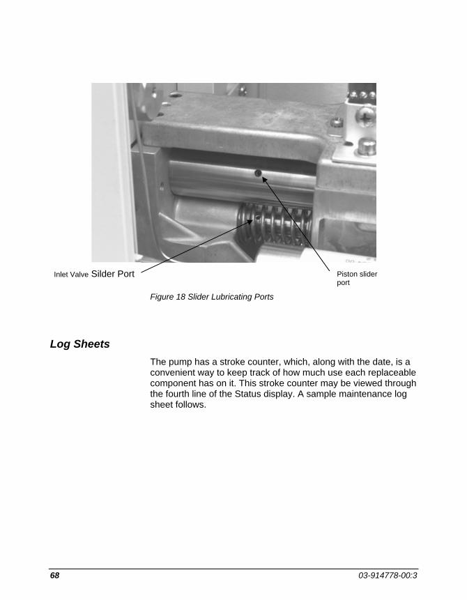
68 03-914778-00:3
Figure 18 Slider Lubricating Ports
Log Sheets The pump has a stroke counter, which, along with the date, is a convenient way to keep track of how much use each replaceable component has on it. This stroke counter may be viewed through the fourth line of the Status display. A sample maintenance log sheet follows.
Piston slider port
Inlet Valve Silder Port

MAINTENANCE AND TROUBLESHOOTING
ProStar 220/230/240 Solvent Delivery Module 69
Sample Maintenance Log Sheet Starting Stroke
Counter Reading Ending Stroke Counter Reading
Difference
Date
Piston Seal
Mixer Filter
Inlet Valve
Outlet Check Valve

70 03-914778-00:3
Troubleshooting Procedures For a more complete discussion of troubleshooting HPLC problems, see, for example, Maintenance and Troubleshooting HPLC Systems by Dennis Runser.
The Importance of Good Documentation Good documentation will help to avoid many potential problems and will allow the user to spot trends that may be developing. This includes such things as writing down the instrument settings, including detector wavelength, attenuation, and time constant, recorder settings, the solvent composition and flow rate, the injection volume, and any other parameter set by the user. It also includes operational variables such as the column pressure recorded on a daily basis.
The Systematic Approach Whenever a problem is encountered, the fastest way to reach a resolution is to approach the problem systematically. This means changing only one variable at a time. Often the easiest way to show whether or not a component is functioning properly is to swap it for a known good component. If the swap does not solve the problem, then something else is probably the cause.
Hydraulic Component Tests: 10 Micron Reservoir Filter Test
Test the reservoir filter for free flow by disconnecting the primed 1/8" OD Teflon® tube from the pump and holding this end of the tube up. Measure the time required for the liquid to flow back into the reservoir bottle. If it takes more than 15 seconds for the solvent in the line to reach the level of the solvent in the bottle, then the filter needs to be replaced. As a short-term solution, the filter may also be cleaned by either sonicating or by back flushing with air or solvent at high flow rate. Otherwise the filter needs to be replaced. Clogged filters generally occur more often in pure water or buffer reservoirs than they do in organic solvents due to bacterial growth in the aqueous mobile phases.

MAINTENANCE AND TROUBLESHOOTING
ProStar 220/230/240 Solvent Delivery Module 71
Mixer Filter Flow Resistance Test
Disconnect the 1/16" OD tubing from the outlet of the mixer. With a container to catch the solvent held below the outlet, start the pump at 5 mL/min. If the pressure reading on the display is more than 30 atmospheres, it is time to replace the filter cartridge in the mixer.
Damper Test
Disconnect the 1/16" OD tubing from the outlet of the damper. Start the pump at 1 mL/min. The pressure reading on the display should read less than 20 atmospheres. If it reads more than 20 atmospheres, stop the pump. If the pressure drops to zero, the damper is still functional and should be tested periodically. If the pressure does not decrease, loosen the fitting at the entrance to the damper. If the pressure drops, the damper is plugged and needs to be replaced. If the pressure stays high, continue loosening fittings one at a time, working back toward the pressure transducer until the plugged fitting is located.
Outlet Check Valve Filter Test
Disconnect the 1/8" OD Teflon line at the A proportioning valve. Raise it up so the liquid flows back into the reservoir bottle. Reconnect the line to the proportioning valve. Open the prime valve 1 full turn. Press prime A. If the pump does not prime in 2 minutes, the filter located in the outlet check valve is plugged and either the check valve assembly must be replaced or the replaceable filter screen must be replaced depending on the version of the check valve. As a short-term fix for earlier version check valves which have non-removable filters, the surface of the filter may be rinsed with a wash bottle.
Locating a Plugged Component
Starting at the detector, with the pump running, loosen fittings one at a time, observing the pressure on the pump display. When the plugged component is removed from the flow path, the pressure will drop dramatically.

72 03-914778-00:3
System Leak Test
A system leak test is available through the Extended Diagnostics (see page 84 for details on other tests). It can operate in either of two modes: constant pressure or pressure decay.
In the constant pressure mode, the pump operates to maintain the set pressure. The reported leak rate (in microliters per minute) is the flow rate required to maintain the set pressure. It is suggested that the constant pressure mode leak test be run first.
In the pressure decay mode, the pump pressurizes the hydraulics to the set pressure and then stops. The decay of the pressure is then monitored as a function of time. The pressure decay mode is useful for further diagnosis if the system fails the constant pressure mode test.
Either leak test may be performed on the entire high pressure flow path (from the inlet valve to the outlet of the column) or only on the SDM itself (from the inlet valve to the outlet of the damper). Because most detector flow cells are not designed to operate at high pressure, when testing the entire system, the plug must be placed upstream from the detector.
Hazardous chemicals under pressure. Use proper eye and skin protection.
To run the leak test in either constant pressure mode or pressure decay mode:
1. Carefully inspect the system for leaks (drips or salt crystals). Any obvious leaks must be corrected before continuing. Locations to check include the piston seal drain, the prime/purge valve, and all nuts and ferrules.
2. Connect the solvent to be used for the leak test to the A proportioning valve. Prime the pump and purge solvent through the entire system to remove any air. Any solvent may be used for the leak test.

MAINTENANCE AND TROUBLESHOOTING
ProStar 220/230/240 Solvent Delivery Module 73
3. Remove the fitting from the outlet side of the farthest downstream component to be tested and replace it with a plug such as (P/N 28-211489-00) found in the optional installation Kit.
The hydraulic path must be plugged in such a way that the pressure transducer is always included in the closed system. Operation of the leak test without the pressure transducer in line could result in damage to the pump.
4. Turn off the main power switch. Press and hold the SELECT key while simultaneously turning on the power. This will display the Extended Diagnostics Menu.
5. Scroll to the Leak Test using the NEXT LINE key. Press START.
6. Select either Constant Pressure or Pressure Decay mode using the increment/decrement keys. Press NEXT LINE.
7. Set the pressure for the leak test. The pressure may be set from 10 to 410 atm. A good test pressure would be slightly higher than the expected operating pressure. Typically 200 atm is used. Press NEXT LINE.
8. Close the Prime valve (if it is open). Press START. After the pressure has stabilized, determine if a leak exists. If so, look for visible signs of solvent leaking at one of the fittings. If a leak is found, tighten the fitting just enough to correct the leak. DO NOT OVERTIGHTEN.
9. When the leak test has been completed, press STOP. Slowly release the pressure by carefully opening the prime valve. After the pressure has dropped to zero, remove the plug and reconnect the solvent line. Turn off the power switch and then turn it back on to restore normal operation of the SDM.
Interpreting leak test results
The constant pressure leak test displays the leak rate directly in µL/min. Because of the extreme sensitivity of this test, care must

74 03-914778-00:3
be taken in interpreting the reported leak rate. By relating the leak rate to the operational flow rate, a decision can be made about the significance of a reported value. For example, a leak rate of less than 1 µL/min will be unimportant at a flow rate of 1 mL/min.
The pressure decay mode displays a pressure drop and an elapsed time. If the standard damper is included as part of the hydraulics being tested, the leak rate in µL/min may be estimated by multiplying the pressure drop (in atmospheres) by 1 µL/atm and dividing by the elapsed time.
Both test modes are sensitive to fluctuations in ambient temperature which may lead to thermal expansion or contraction of the liquid in a closed system. This may cause small fluctuations in the pressure or leak rate readings, but if there is truly a leak, it should become apparent after the system has been under pressure for 5 or 10 minutes. As a rule of thumb, a drop of water is approximately 50 µL. For organic solvents or mixtures of organic and water, a drop is typically smaller than 50 µL. Therefore, with a leak rate exceeding 25 µL/min, liquid should be visible at one of the fittings after several minutes of test. Lower leak rates with a high percentage of organic solvent may not allow a visible amount of solvent to accumulate because of evaporation. If no visible leak is seen, then the pump head may be leaking internally (piston seal or inlet valve) or, if included in the test, the injector valve may be leaking internally.
If the constant pressure leak test produces a higher leak rate than is tolerable after running it for 10 minutes and no visible leaks can be found, run the pressure decay leak test. If the results of this test are acceptable, then the fittings between the outlet check valve and the plug are leak tight and an internal leak in the pump head is indicated. Check carefully around the drain passage at the bottom of the pump head. If no leakage is seen here, then the inlet valve may be leaking, since leaks here can not be seen externally. If the results of the tests are not conclusive, the leak tests should be repeated before changing any of the hardware in the pump head.
MAINTENANCE AND TROUBLESHOOTING
ProStar 220/230/240 Solvent Delivery Module 75
General System Troubleshooting Techniques Baseline Run
Run the pump and data system through a gradient without turning on the injector. This will test the effect of changing the solvent on the baseline and test for spurious peaks coming from the solvents.
Blank Injection
Inject a blank sample (sample prepared by the usual method but without sample in it). This will test for artifacts added during sample preparation.
Carryover Test
Fill the sample loop with the initial mobile phase and inject. This tests the carryover of the injector.
Correlation of Effects with Flow Rate
Change the flow rate on the pump to see if the character of the problem also changes. This is particularly useful for diagnosing detector noise.
Diagnosing the Problem
Electronic Faults/Cold Start Diagnostics
Each time the instrument is turned on, the system performs a Self Test to check the functionality of the SDM electronics. If any faults are detected during the self test, the fault LED will flash and the audible beeper will sound periodically. The faults detected will be entered in the Error Log, along with its unique code number. The detected faults may be displayed by pressing the METHOD ACTIONS key, moving the cursor to Error Log, and pressing SELECT. If more than one fault has been detected, the last one detected is displayed. Pressing NEXT LINE or PREVIOUS LINE will display any additional faults. All faults are listed beginning on page 89.
If the instrument will not power up:

76 03-914778-00:3
• Check to be sure power cord is connected
• Check wall outlet for power
Performance Parameters Symptom Possible Cause Pressure Too High
Pressure reading is higher than it should be or Pmax shutdown of pump (fault code 66) or Hardware overpressure shutdown of pump (fault code 72) or Pump stalls repeatedly once it reaches pressure
• Plugged 0.5 µm filter in mixer — test for restriction replace as necessary.
• Plugged column frit or pre-column frit — backflush or replace frit. Filter solvents and sample.
• Inappropriate flow rate — check column ID and solvent program.
• Higher viscosity solvent — a different, higher viscosity solvent may be in use from when the method was developed.
• Pressure maximum during gradient — mixtures of water and many organic solvents exhibit higher viscosities than either pure solvent.
• Plugged tubing— isolate problem by working from detector back toward pump.
• Failed damper — measure restriction Replace damper if necessary.
Pressure Too Low
Pressure reading lower than it should be or Pmin shutdown of pump (fault code 67)
• Leak in system — check visually for leaks at fittings.
• Pump not primed — check for bubbles in inlet lines.
• Purge or prime valve open. • Low viscosity solvent. • Piston seal leak — check for external
leakage behind pump head- usually seen as solvent dripping from plastic skirt.
• Outlet check valve failure — exchange with new valve.
• Inlet valve failure — exchange with new valve.
• Proportioning valve plugged — lack of a clicking sound on each fill stroke indicates a stuck poppet — clean by sonicating in water or replace if required.

MAINTENANCE AND TROUBLESHOOTING
ProStar 220/230/240 Solvent Delivery Module 77
Symptom Possible Cause • Solvent level too low in one reservoir —
check for air bubbles in inlet lines; refill reservoirs.
• Reservoir filter plugged — test accordingly, then clean or replace.
• Pump loses prime — clean or replace reservoir filter.
Can't Prime Pump
• Prime valve not opened. • Outlet check valve filter plugged — clean
filter by rinsing with a wash bottle or replace check valve, or in the case of the latest design valve; replace the filter.
• Reservoir filter plugged — test, then clean or replace.
• Outlet check valve failed — replace check valve.
Pump Frequently Loses Prime
• Reservoir filter plugged — test, then clean or replace.
• Bubbles visible in solvent line — degas mobile phase
Pressure Pulsations Too Large
• Pressure too low to get good damping for a specific application (<50 atm at 1 mL/min) — add a restrictor coil or column between the mixer and the injector. If pulsations are still too large, add another damper between the mixer and the injector.
• High flow rate - Higher flow rates may require additional dampers to reduce pressure pulsations.
• Failed outlet check valve — replace check valve if measured flow rate is lower than set flow rate.
External Leaks
• Leak at a fitting — tighten fitting only until leak stops. If leak cannot be stopped with moderate tightening, then the fitting must be replaced.
• Leak out of a proportioning valve — if the proportioning valve continues to leak after it is properly tightened into the head, it indicates that the inlet valve is leaking and should be replaced.

78 03-914778-00:3
Symptom Possible Cause • Leak out of the inlet valve — replace inlet
valve. • Leak from behind pump head (usually
drips off plastic skirt) — replace piston seal.
• Leak out of injector — increase tension on rotor or replace rotor.
Clacking Noises (sharp, clacking sound on each fill stroke)
• Failed outlet check valve — replace check valve.
• Sticking piston - if noise does not occur when solvent is switched to IPA, change the piston seal. If noise continues with IPA at low pressure, call a Varian Customer Support Representative.
Excessive Detector Baseline Noise
Random noise • Incorrect time constant setting on detector.
• Aging detector lamp — may show up as increased high frequency noise or as actual low frequency steps in detector output.
• Improper detector hook-up — may indicate a ground loop.
• High background level caused by operating at a wavelength below the solvent cutoff.
• Dirty flowcell (contamination). Flush with dilute nitric or phosphoric acid according to the detector manual.
• Two immiscible solvents in system. Flush the system with a solvent that is miscible with both solvents.
Periodic noise (correlates to pump strokes)
• Two- or four-stroke proportioning mode selected with low volume mixer installed. Install a larger volume mixer or use one-stroke proportioning.
• Bubble(s) in the flow cell. Check the backpressure restrictor on the outlet of the detector flow cell for proper operation.
• Mixing noise caused by strong absorbance of one solvent. Change solvents or detection wavelength or add a larger mixing volume before the injector.
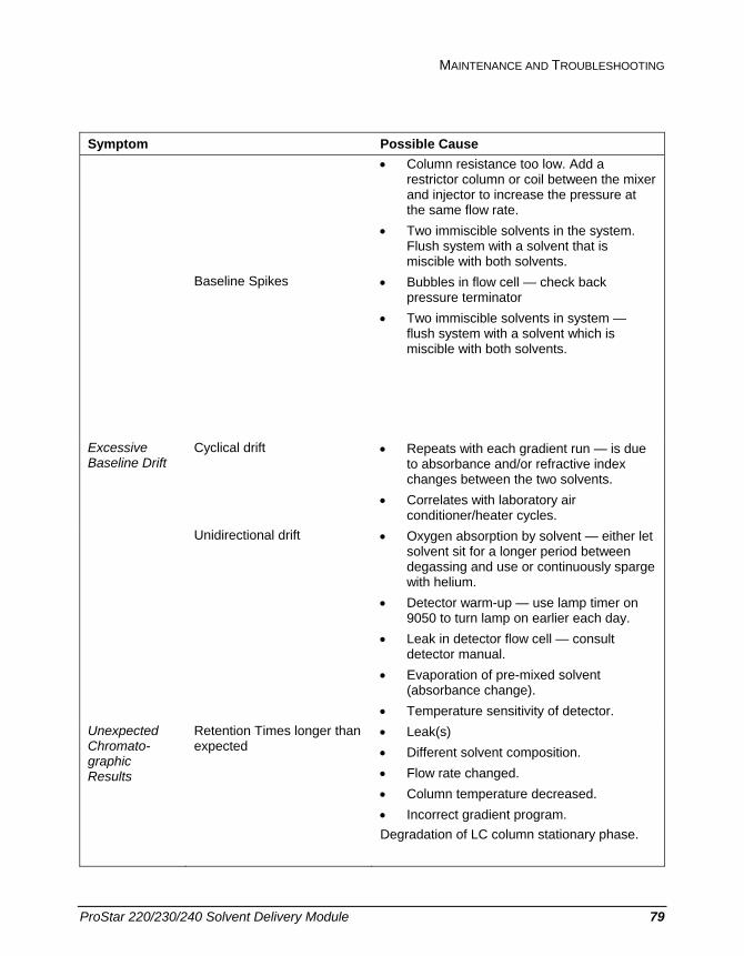
MAINTENANCE AND TROUBLESHOOTING
ProStar 220/230/240 Solvent Delivery Module 79
Symptom Possible Cause • Column resistance too low. Add a
restrictor column or coil between the mixer and injector to increase the pressure at the same flow rate.
• Two immiscible solvents in the system. Flush system with a solvent that is miscible with both solvents.
Baseline Spikes
• Bubbles in flow cell — check back pressure terminator
• Two immiscible solvents in system — flush system with a solvent which is miscible with both solvents.
Excessive Baseline Drift
Cyclical drift • Repeats with each gradient run — is due to absorbance and/or refractive index changes between the two solvents.
• Correlates with laboratory air conditioner/heater cycles.
Unidirectional drift • Oxygen absorption by solvent — either let solvent sit for a longer period between degassing and use or continuously sparge with helium.
• Detector warm-up — use lamp timer on 9050 to turn lamp on earlier each day.
• Leak in detector flow cell — consult detector manual.
• Evaporation of pre-mixed solvent (absorbance change).
• Temperature sensitivity of detector. Unexpected Chromato-graphic Results
Retention Times longer than expected
• Leak(s) • Different solvent composition. • Flow rate changed. • Column temperature decreased. • Incorrect gradient program. Degradation of LC column stationary phase.

80 03-914778-00:3
Symptom Possible Cause Retention Times shorter
than expected • Different solvent composition. • Flow rate changed. • Insufficient regeneration time after
gradient elution. • Column temperature increased. • Degradation of LC column stationary
phase. Reduced Peak Areas or Heights
Retention Times the same -- All peaks change
• Sample: Evaporation of solvent and sample.
• Degradation of sample during storage. • Injection: Wrong syringe volume/ wrong
loop volume. • Unintended partial filling of loop. • Internal valve leak. • Sample siphoning out of loop. • Incorrect syringe needle gauge. • Column: Loss of efficiency (peak height
reduced, but area remains constant) — may be caused by a void or plugged inlet frit.
• Detector: Leak in flow cell. • Wrong range or attenuation setting.
Retention Times the same --Only some peaks change
• Sample: Chemical decomposition (decomposition by-products may become obvious in the chromatogram).
• Column: Sample adsorption. • Detector: Wrong wavelength.
Resolution Decreased
• Increased flow rate. • Sample overload. • Loss of column efficiency.

MAINTENANCE AND TROUBLESHOOTING
ProStar 220/230/240 Solvent Delivery Module 81
Symptom Possible Cause Selectivity Changed
• Wrong solvents. • Column not equilibrated. • Sample decomposed. • pH of mobile phase changed — use a
buffered mobile phase. • Secondary separation mechanism
operating — add ion-pairing reagent. • Degradation of LC column stationary
phase. Poor Peak Shape
• Column is overloaded. Decrease sample concentration.
• Column is physically degrading (void at top of column). Top off column with more packing or replace column.
• Inappropriate pH. Check to see if a buffer is required.
• Tubing ID is too large. Use 0.010" or smaller ID tubing for all connections downstream of the injector.
• Secondary separation mechanism operating. Add ion-pairing reagent.
• Sample dissolved in strong organic solvent. Dissolve in mobile phase.
Spurious Peaks
• System contamination. • Contaminated solvents. Run a blank
gradient. • Injection carryover. Run carryover test. • Peaks added during sample work-up.
Inject a sample blank. • RI peaks caused by solvent front. Dissolve
sample in mobile phase.

82 03-914778-00:3
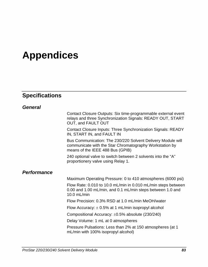
ProStar 220/230/240 Solvent Delivery Module 83
Appendices
Specifications
General Contact Closure Outputs: Six time-programmable external event relays and three Synchronization Signals: READY OUT, START OUT, and FAULT OUT Contact Closure Inputs: Three Synchronization Signals: READY IN, START IN, and FAULT IN Bus Communication: The 230/220 Solvent Delivery Module will communicate with the Star Chromatography Workstation by means of the IEEE 488 Bus (GPIB) 240 optional valve to switch between 2 solvents into the “A” proportionery valve using Relay 1.
Performance Maximum Operating Pressure: 0 to 410 atmospheres (6000 psi) Flow Rate: 0.010 to 10.0 mL/min in 0.010 mL/min steps between 0.00 and 1.00 mL/min, and 0.1 mL/min steps between 1.0 and 10.0 mL/min Flow Precision: 0.3% RSD at 1.0 mL/min MeOH/water Flow Accuracy: ± 0.5% at 1 mL/min isopropyl alcohol Compositional Accuracy: ±0.5% absolute (230/240) Delay Volume: 1 mL at 0 atmospheres Pressure Pulsations: Less than 2% at 150 atmospheres (at 1 mL/min with 100% isopropyl alcohol)

84 03-914778-00:3
Physical Dimensions: Width in./(cm) 11.5/(29.2)
Depth in./(cm) 20/(51)
Height in./(cm) 11.5/(29.2)
Shipping Weight 53 lbs (19.8 Kg)
Electrical Source Requirements: The SDM module requires 108-132 Vac (120 ±10%), 50/60 Hz ± 2%), single phase, 198-242 Vac (220 ±10%), 50/60 Hz ± 2% single phase, or 220 Vac, 50/60 Hz ± 2% two phase (phase/phase) unless otherwise stated.
Power Consumption: 170 VA
Environment: Operation within specifications from 10° to 35°C at all column pressures. Non-operational storage from -20° to 65°C. Operates in relative humidities from 5% to 95%.
Extended Diagnostics Extended diagnostics include routines to assist the user in maintenance operations as well as test procedures that may pinpoint component level electronic malfunctions or failures. These tests, for many cases, will require the services of a Varian Customer Support Representative (CSR).
To access the extended diagnostics, first turn off the main power switch, then press and hold the SELECT key while simultaneously turning the power switch to ON.
Scroll through the following by pressing the NEXT LINE key. Press START to run the selected test.

APPENDICES
ProStar 220/230/240 Solvent Delivery Module 85
EXTENDED MENU
Maintenance Log (use to reset the pump stroke counter to zero) TeleDiagnostics™(use to allow a Varian CSR to run the extended diagnostics tests remotely via a modem) Display Test (use to test the LEDs and two line display) Leak Test (use to test the pump or entire system for leaks) Retract Piston (use for Seal Replacement) Extend Piston (use for Inlet Gap Adjustment) Keyboard Test (use to verify operation of all keys on the keyboard) Print Pattern Test Relays Test Fault Signals Test Start Signals Test Ready Signals Test Ready Enable Test ADC Test ROM Test RAM Test GPIB Board Test GPIB Address Switch Test GPIB Echo Test MVD Gates Test MVD Valves Test Printer Port Loopback Test Cold Start Loop (stops on fault)
Maintenance Log
Press RESET to zero entry, STOP to exit
Pump Strokes : xx STOP NEXT LINE
Telediagnostics START
Modem not connected. Press STOP. STOP NEXT LINE
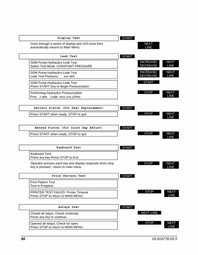
86 03-914778-00:3
Display Test START
Goes through a series of display and LED tests then automatically returns to Main Menu.
NEXT LINE
Leak Test START
SDM Pump-Hydraulics Leak Test Select Test Mode: CONSTANT PRESSURE
INCREASE/ DECREASE
NEXT LINE
SDM Pump-Hydraulics Leak Test Leak Test Pressure: xxx atm
INCREASE/ DECREASE
NEXT LINE
SDM Pump-Hydraulics Leak Test Press START Key to Begin Pressurization
START
Performing Hydraulics Pressurization Pres x atm Leak: xxxx.xxx µl/min
STOP NEXT LINE
Retract Piston (for Seal Replacement) START
Press START when ready, STOP to quit STOP NEXT LINE
Extend Piston (for Inlet Gap Adjust) START
Press START when ready, STOP to quit STOP NEXT LINE
Keyboard Test START
Keyboard Test: Press any key-Press STOP to Exit
Operator presses each key and display responds when stop key is pressed - return to main menu
STOP NEXT LINE
Print Pattern Test START
Print Pattern Test Test in Progress
PRINTER TEST FAILED: Printer Timeout Press STOP to return to MAIN MENU.
STOP NEXT LINE
Relays Test START
Closed all relays. Check continuity. Press any key to continue:
NEXT LINE
Opened all relays. Check for open. Press STOP to return to MAIN MENU.
STOP NEXT LINE

APPENDICES
ProStar 220/230/240 Solvent Delivery Module 87
Fault Signals Test START
Fault Signals Test: FAULT SGNL Err: NO INTERRUPT
STOP NEXT LINE
Start Signals Test START
Start Signals Test: START SGNL Err: NO INTERRUPT
STOP NEXT LINE
Ready Signals Test START
Ready Signals Test: READY SGNL Err: INPUT LEVEL
STOP NEXT LINE
Ready Enable Test START
Ready Enable Test: READY ENABLE disconnected
STOP NEXT LINE
ADC Test START
PRS(atm) REF(v) BAT(v) PRL(v) x.xxx x.xxx x.xxx x.xxx
STOP NEXT LINE
ROM Test START
ROM Test: ROM Bank 0/1/2 Hi/Lo Byte Test Passes
STOP NEXT LINE
RAM Test START
RAM Test: RAM BANK 0/2 Passes
STOP NEXT LINE
GPIB Board Test START
GPIB Test: Test Passes
STOP NEXT LINE
GPIB Address Switch Test START
GPIB Board Switch Test: Current Switch setting is: xx
STOP NEXT LINE
GPIB Echo Test START
A GPIB Communication Test
Connect and turn-on Workstation

88 03-914778-00:3
Run GPIBECHO on the Workstation
Press START when ready START
Waiting for message STOP NEXT LINE
MVD Gates Test START
MVD Gates Test: PH2GTB: PASSED
STOP NEXT LINE
MVD Valves Test START
MVD Valves Test: VALVE A/B/C: PASSED
STOP NEXT LINE
Printer Port Loopback Test START
SIO Loop Back Test: H/W HANDSHAKE TEST: Both Failed TRANSMIT/RECEIVE TEST: Char never Recd
STOP NEXT LINE
Cold start Loop (stops on fault) START
Goes through series of LED lights STOP NEXT LINE
Maintenance Log
(beginning of test series)

APPENDICES
ProStar 220/230/240 Solvent Delivery Module 89
Fault Table At the conclusion of the Self Test diagnostic routine, and during the running of a method, faults may be detected that will terminate the run and cause the FAULT indicator to flash and the fault beeper to sound (a double beep every several seconds, and ceases after a few minutes).
When a fault is detected it is registered in the Error Log as an Error Code number and a brief message identifying it. To display the fault and its code number, access the Error Log by pressing the METHOD ACTIONS key, then moving the cursor to Error Log in the menu. Press SELECT. Press NEXT LINE to check for multiple fault messages. Faults are cleared by pressing the RESET key.
The table below provides additional descriptive information for each Error Code number and any possible action the operator may take to correct the fault. In most cases the action will be limited to changing the affected circuit board or calling Varian.
When contacting Varian, provide them with the displayed message and Error Code number. From this information the Customer Support Representative can advise you of necessary actions to take to get you up and running.
Fault # Message User Action
0 Rom0: Bank 0, Hi Byte Replace U100
1 Rom1: Bank 0, Lo Byte Replace U107
2 Ram Bank 1-3 Replace U97, U104
3 Ram Bank 0 Replace U99, U106
4 Rom2: Bank 1, Hi Byte Replace U101
5 Rom3: Bank 1, Lo Byte Replace U108
6 Rom4: Bank 2, Hi Byte Replace U102
7 Rom5: Bank 2, Lo Byte Replace U109
8 SBC-clear int lv7 Call Varian

90 03-914778-00:3
Fault # Message User Action
9 SBC-clear int lv6 Call Varian
10 SBC-clear int lv5 Call Varian
11 SBC-clear int lv4 Call Varian
12 SBC-clear int lv3 Call Varian
13 SBC-clear int lv2 Call Varian
14 SBC-clear int lv1 Call Varian
15 SBC-auto vec lev7 Call Varian
16 SBC-auto vec lev6 Call Varian
17 SBC-auto vec lev5 Call Varian
18 SBC-auto vec lev4 Call Varian
19 SBC-auto vec lev3 Call Varian
20 SBC-auto vec lev2 Call Varian
21 SBC-auto vec lev1 Call Varian
22 SBC-Int prioritizer Call Varian
23 CPU +15V regulator Call Varian
24 CPU -15V regulator Call Varian
25 SBC-68681 DUART U29
26 SBC-8253, U31, T0 U31
27 SBC-8253, U31, T1 U31
28 SBC-8253, U32, T2 U31
29 SBC-8253, U32, T2 U32
30 SBC-AD574 ADC U10
31 Battery Dead Replace Battery
32 Motor Rate Gen U33
33 Cam Pos. Cntr. U32
34 Cam Evt. Cntr. U32
35 Diagnostic Mux Replace SBC Board

APPENDICES
ProStar 220/230/240 Solvent Delivery Module 91
Fault # Message User Action
36 Diagnostic Timer Replace U33
37 Prop. Valve A Replace SBC Board
38 Prop. Valve B Replace SBC Board
39 Prop. Valve C Replace SBC Board
40 Prop. Valve D Replace SBC Board
41 Valve State Machin Replace SBC Board
42 8255 PIO IC U7
43 FPB-Presence Make sure J15 Ribbon Cable is connected
44 FPB-LCD Disp RAM Replace display unit
45 FPB-8279 Interfac Replace Front Panel Board U19
46 MVD Not Present Make sure J17 Ribbon Cable is connected
47 Mtr Phase 1 Sign Replace MVD Board
48 Mtr Phase 2 Sign Replace MVD Board
49 MVD 5V Regulator Replace MVD Board
50 MVD 15V Regulator Replace MVD Board
51 MVD 26V Regulator Replace MVD Board
52 Dac 1 High Rail Replace MVD Board
53 Dac 1 Low Rail Replace MVD Board
54 Dac 2 High Rail Replace MVD Board
55 Dac 2 Low Rail Replace MVD Board
56 Motor Clock Replace MVD Board
57 GPIB Not Present Make sure J13 Ribbon Cable is connected
58 GPIB Board Dtack Replace GPIB Board
59 GPIB-Board Bus Replace GIPB Board
60 8291A Talker/Listener Replace GPIB Board
61 Motor TDC Replace SBC Board
62 Battery Low Replace Battery

92 03-914778-00:3
Fault # Message User Action
63 (not used)
64 Power Failed Power failed or Instrument was turned off during last run; check last run results.
65 Methods Lost Check Battery
66 PMAX violation Check hydraulics for clogged lines
67 PMIN violation Check for leaks or loss of prime
68 Pump Stall Fault Check hydraulics for clogged lines
69 (not used)
70 (not used)
71 H/W Over Temperature Check exhaust fan for proper operation
72 H/W Over Pressure Check hydraulics for clogged lines
73 Pump Strokes Uninit Initialize Pump Stroke Count in maintenance log
74 External Fault The Fault In rear panel closure was actuated. Does not cause the FAULT indicator to flash.
75 Coldstart Passes
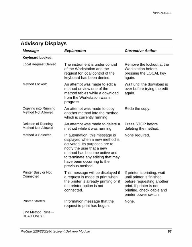
APPENDICES
ProStar 220/230/240 Solvent Delivery Module 93
Advisory Displays Message Explanation Corrective Action
Keyboard Locked: Local Request Denied The instrument is under control
of the Workstation and the request for local control of the keyboard has been denied.
Remove the lockout at the Workstation before pressing the LOCAL key again.
Method Locked: An attempt was made to edit a method or view one of the method tables while a download from the Workstation was in progress.
Wait until the download is over before trying the edit again.
Copying into Running Method Not Allowed
An attempt was made to copy another method into the method which is currently running.
Redo the copy.
Deletion of Running Method Not Allowed
An attempt was made to delete a method while it was running.
Press STOP before deleting the method.
Method X Selected In automation, this message is displayed when a new method is activated. Its purposes are to notify the user that a new method has become active and to terminate any editing that may have been occurring to the previous method.
None required.
Printer Busy or Not Connected
This message will be displayed if a request is made to print when the printer is already printing or if the printer option is not connected.
If printer is printing, wait until printer is finished before requesting another print. If printer is not printing, check cable and printer power switch.
Printer Started Information message that the request to print has begun.
None.
Line Method Runs -- READ ONLY !
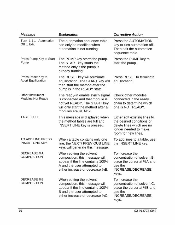
94 03-914778-00:3
Message Explanation Corrective Action
Turn 1 1 1 Automation Off to Edit
The automation sequence table can only be modified when automation is not running.
Press the AUTOMATION key to turn automation off. Then edit the automation sequence table.
Press Pump Key to Start Pump
The PUMP key starts the pump. The START key starts the method only if the pump is already running.
Press the PUMP key to start the pump.
Press Reset Key to Abort Equilibration
The RESET key will terminate equilibration. The START key will then start the method after the pump is in the READY state.
Press RESET to terminate equilibration.
Other Instrument Modules Not Ready
The ready-in enable synch signal is connected and that module is not yet READY. The START key will only start the method after all modules are READY.
Check other modules connected in the ready chain to determine which one is NOT READY.
TABLE FULL This message is displayed when the method tables are full and INSERT LINE key is pressed.
Either edit existing lines to the desired conditions or delete lines which are no longer needed to make room for new lines.
TO ADD LINE PRESS INSERT LINE KEY
When a table contains only one line, the NEXT/ PREVIOUS LINE keys will generate this message.
To add lines to a table, use the INSERT LINE key.
DECREASE %A COMPOSITION
When editing the solvent composition, this message will appear if the line contains 100% A and the user attempted to either increase or decrease %B.
To increase the concentration of solvent B, place the cursor at %A and use the INCREASE/DECREASE keys.
DECREASE %B COMPOSITION
When editing the solvent composition, this message will appear if the line contains 100% B and the user attempted to either increase or decrease %C.
To increase the concentration of solvent C, place the cursor at %B and use the INCREASE/DECREASE keys.

APPENDICES
ProStar 220/230/240 Solvent Delivery Module 95
Message Explanation Corrective Action
DECREASE %C COMPOSITION
When editing the solvent composition, this message will appear if the line contains 100% C and the user attempted to either increase or decrease %A.
To increase the concentration of solvent A, place the cursor at %C and use the INCREASE/DECREASE keys.
DUP This message appears just to the right of the time as a warning that the time of the line in the display is the same as the time of another line which cannot be seen.
Because only one line can exist at each time, the user must decide which one is the desired course of action. To keep the previous line intact, the time must be changed to some other value before moving the cursor or changing the display. Any other action will result in the displayed line overwriting the unseen line.
Method X Copied to Y Informational message that the requested copy has taken place.
None required.
Method X Deleted Informational message that the specified method has been deleted.
None required.

96 03-914778-00:3
Note that each fault has a unique number associated with the error message text. Fault Message Code Explanation Corrective Action
Power Failed 64 Either the power switch was turned off and on or the laboratory power failed and came back on while the pump was running.
Press RESET to clear fault message.
Methods Lost 65 When the power was restored to the pump, the methods in memory could not be saved.
The methods must be re-entered from the key panel or re-downloaded from the Workstation. Press RESET to clear fault message.
PMAX violation 66 The column pressure exceeded the PMAX setpoint.
Check for one or more of the following: plugged filter, plugged column, plugged tubing, flow rate too high, setpoint too low. Press RESET to clear fault message.
PMIN violation 67 Column pressure has dropped below the PMIN setpoint.
Check for leaks, prime valve left open, setpoint too high, or air in solvent line (indicating loss of prime in the pump). Press RESET to clear fault message.
Pump Stall Fault 68 The position sensor in the pump has determined that the pump stalled.
Check for a plugged outlet check valve filter. Press RESET to clear fault message.
H/W Over Temperature
71 The temperature inside the pump module has exceeded 55°C.
Check the cooling fan for proper operation.

APPENDICES
ProStar 220/230/240 Solvent Delivery Module 97
H/W Over Pressure 72 The column pressure has exceeded 548 atm on a very rapid pressure rise.
Check for one or more of the following: plugged filter, plugged column, plugged tubing, flow rate too high. Turn power off and on to reset pump.
Pump Strokes Unit 73 The pump stroke counter is uninitialized-the value in memory could not be saved at the time power was restored.
Re-initialize the pump stroke counter from within the Extended Diagnostics. Press RESET to clear fault message.
External Fault 74 A module connected using the synchronization signals has sent out a fault message. The pump has stopped pumping until the fault is attended to.
Clear the fault on the offending module and press RESET on the pump to clear the fault message.
Cold Start Passes 75 The diagnostics automatically done on power-on have been successfully completed.
None required.

98 03-914778-00:3
ProStar 220/230/240 Options and Accessories
0391907900 GPIB Kit, Factory installed Required for Star Workstation control. 0391907990 GPIB Kit, Field Installation 0393614291 I/O Control Board for
ProStar 230, 240, 310
0391994890 Sync Cable Kit Provides synchronization of 220/230/240 to 310 if Workstation control is not used. Only one cable kit required.
0391970101 High Sensitivity Accessory Stand alone accessory containing two solid core pulse dampers. Includes all connecting tubing, fittings and ferrules. May be needed with Mass Spectrometer interfaces, RI detectors, electrochemical detectors, or any other detector which requires extremely pulseless flow. NOT necessary with Varian optical absorbance detectors.
0391970102 Ultra High Sensitivity Accessory
Stand alone accessory containing three solid core pulse dampers. Includes all connecting tubing, fittings and ferrules. May be needed with Mass Spectrometer interfaces, RI detectors, electrochemical detectors, or any other detector which requires extremely pulseless flow. NOT necessary with Varian optical absorbance detectors.
0391970190 High Sensitivity Upgrade Kit Upgrades a High Sensitivity Accessory to an Ultra High Sensitivity Accessory Includes: pulse damper and necessary tubing
0391949590 Solvent Reservoirs and Holder
Includes: Three one liter solvent reservoirs and support bracket.
0391955590 TeleDiagnostics Modem Kit Allows access to all diagnostics from a remote PC. Requires: {03-919636-00 } or { 03-919636-90 } RS-232
0391963600 RS-232 Option, factory installed
Provides TeleDiagnostics communication capability through RS-232 port
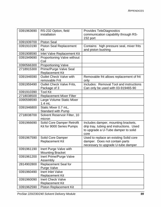
APPENDICES
ProStar 220/230/240 Solvent Delivery Module 99
0391963690 RS-232 Option, field installation
Provides TeleDiagnostics communication capability through RS-232 port
0391939700 Piston Seal 0391910190 Piston Seal Replacement
Kit Contains: high pressure seal, mixer frits and piston bushing
0391908590 Inlet Valve Replacement Kit 0391949690 Proportioning Valve without
Coil
0390566300 Proportioning Valve 2718915300 Prime/Purge Valve Seal
Replacement Kit
0391946590 Outlet Check Valve with removable Frit
Removable frit allows replacement of frit only
0391959490 Outlet Check Valve Frits, Package of 3
Includes: Removal Tool and instructions Can only be used with 03-919465-90
0391910390 Tool Kit 2718038500 Replacement Mixer Filter 0390598590 Large Volume Static Mixer
1.4 mL
0391946800 Static Mixer 0.7 mL, Standard with Pump
2718038700 Solvent Reservoir Filter, 10 micron
0391966690 Solid Core Damper Retrofit Kit for 9000 Series Pumps
Includes damper, mounting brackets, drip tray, tubing and instructions. Used to upgrade a U-Tube damper to solid core
0391967590 Solid Core Damper Replacement Kit
Used to replace an existing Solid core damper. Does not contain parts necessary to upgrade U-tube damper
0391961190 Inert Purge Valve with Mounting Bracket
0391961200 Inert Prime/Purge Valve Assembly
2814902800 Replacement Seal for Purge Valve
0391960490 Inert Inlet Valve Replacement Kit
0391960090 Inert Check Valve Replacement Kit
0391962590 Piston Replacement Kit
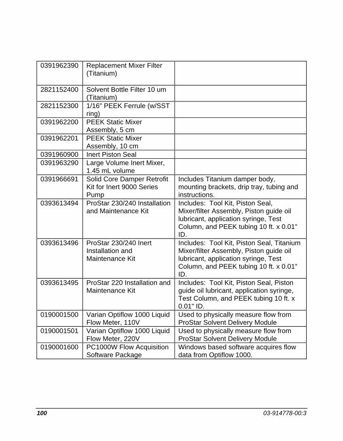
100 03-914778-00:3
0391962390 Replacement Mixer Filter (Titanium)
2821152400 Solvent Bottle Filter 10 um (Titanium)
2821152300 1/16" PEEK Ferrule (w/SST ring)
0391962200 PEEK Static Mixer Assembly, 5 cm
0391962201 PEEK Static Mixer Assembly, 10 cm
0391960900 Inert Piston Seal 0391963290 Large Volume Inert Mixer,
1.45 mL volume
0391966691 Solid Core Damper Retrofit Kit for Inert 9000 Series Pump
Includes Titanium damper body, mounting brackets, drip tray, tubing and instructions.
0393613494 ProStar 230/240 Installation and Maintenance Kit
Includes: Tool Kit, Piston Seal, Mixer/filter Assembly, Piston guide oil lubricant, application syringe, Test Column, and PEEK tubing 10 ft. x 0.01" ID.
0393613496 ProStar 230/240 Inert Installation and Maintenance Kit
Includes: Tool Kit, Piston Seal, Titanium Mixer/filter Assembly, Piston guide oil lubricant, application syringe, Test Column, and PEEK tubing 10 ft. x 0.01" ID.
0393613495 ProStar 220 Installation and Maintenance Kit
Includes: Tool Kit, Piston Seal, Piston guide oil lubricant, application syringe, Test Column, and PEEK tubing 10 ft. x 0.01" ID.
0190001500 Varian Optiflow 1000 Liquid Flow Meter, 110V
Used to physically measure flow from ProStar Solvent Delivery Module
0190001501 Varian Optiflow 1000 Liquid Flow Meter, 220V
Used to physically measure flow from ProStar Solvent Delivery Module
0190001600 PC1000W Flow Acquisition Software Package
Windows based software acquires flow data from Optiflow 1000.