NUVAIR LP-LP 12 20 hp Honda Nitrox Generator User Manual
40
NUVAIR LP-LP 12 20 hp Honda Nitrox Generator User Manual Rev 02.16
-
Upload
khangminh22 -
Category
Documents
-
view
5 -
download
0
Transcript of NUVAIR LP-LP 12 20 hp Honda Nitrox Generator User Manual

NUVAIR LP-LP 12 20 hp Honda
Nitrox Generator User Manual
Rev 02.16

NUVAIR LP-LP 12
NUVAIR www.nuvair.com
If you have any questions on this equipment please contact Technical Support at:
Nuvair 1600 Beacon Place Oxnard, CA 93033 Phone: +1 805 815 4044 Fax: +1 805 486 0900 Email: [email protected] Hours: Monday through Friday
8:00 AM to 5:00 PM PST USA
This User Manual contains important safety information and should always be available to those personnel operating this equipment. Read, understand, and retain all instructions before operating this equipment to prevent injury or equipment damage.
Every effort was made to ensure the accuracy of the information contained within. Nuvair, however, retains the right to modify its contents without notice. If you have problems or questions after reading the manual, stop and call for information.
WARNING

NUVAIR LP-LP 12
NUVAIR www.nuvair.com
Table of Contents Introduction 1.0 Introduction 2.0 Safety Warnings System Components 3.0 Safety and Operation Precautions 4.0 Legal Precautions 5.0 System Components and Overview 6.0 Theory Of Operation 7.0 Membrane System Flow Chart 8.0 System Drawing/Schematic Setup, Operation, and Maintenance 9.0 Assembly Preparation 10.0 Set-Up and Assembly
10.1 Power Connections 10.2 Air Intake and Mixing Tube 10.3 Oxygen Analyzer Mounting and Connections
11.0 Operation 12.0 Pumping Nitrox 13.0 Operation Notes
13.1 Correlation of Input Pressure to Oxygen Content 14.0 Maintenance
14.1 Routine Maintenance 14.2 Compressor Lubricant 14.3 LP Filtration 14.4 Spare Parts List 14.5 Service Record Log
Appendix
Supply and Breathing Air Specifications Filter Element Life Factors Owner’s Warranty Responsibilities Warranty
Separate Manuals Included: Nuvair Pro O2 Oxygen Analyzer User Manual Pick o2 Oxygen Analyzer User Manual
Compressor User & Maintenance Instructions Honda 20 hp Manual

NUVAIR LP-LP 12
NUVAIR www.nuvair.com
1.0 Introduction: This manual will assist you in the proper set-up, operation and maintenance of the Nuvair LP-LP 12. Be sure to read the entire manual. Throughout this manual we will use certain words to call your attention to conditions, practices or techniques that may directly affect your safety. Pay particular attention to information introduced by the following signal words: Indicates an imminently hazardous situation, which if not avoided, will result in serious personal injury or death. Indicates a potentially hazardous situation, which if not avoided, could result in serious personal injury or death. Indicates a potentially hazardous situation, which if not avoided, may result in minor or moderate injury. It may also be used to alert against unsafe practices. Notifies people of installation, operation or maintenance information which is important but not hazard-related.
DANGER
WARNING
CAUTION
NOTICE
NUVAIR LP-LP 12
NUVAIR www.nuvair.com
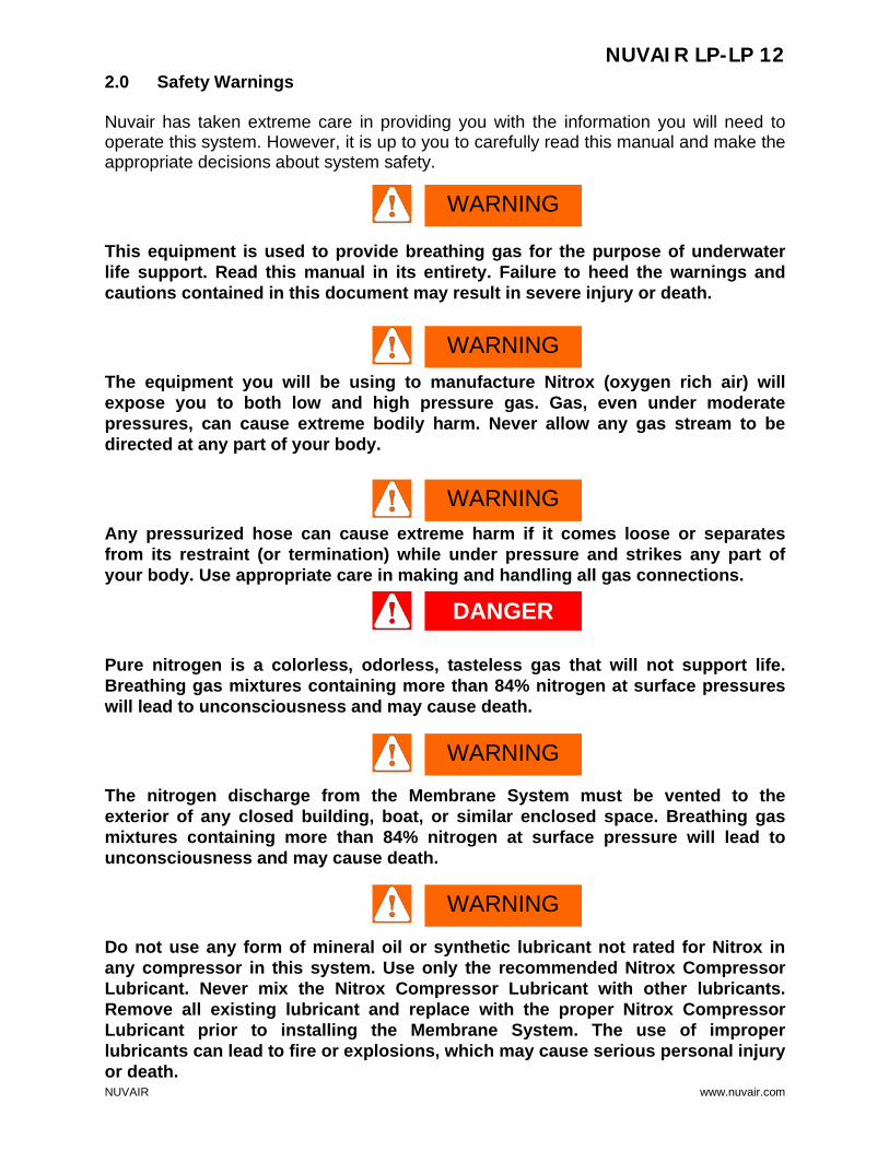
2.0 Safety Warnings Nuvair has taken extreme care in providing you with the information you will need to operate this system. However, it is up to you to carefully read this manual and make the appropriate decisions about system safety. This equipment is used to provide breathing gas for the purpose of underwater life support. Read this manual in its entirety. Failure to heed the warnings and cautions contained in this document may result in severe injury or death. The equipment you will be using to manufacture Nitrox (oxygen rich air) will expose you to both low and high pressure gas. Gas, even under moderate pressures, can cause extreme bodily harm. Never allow any gas stream to be directed at any part of your body. Any pressurized hose can cause extreme harm if it comes loose or separates from its restraint (or termination) while under pressure and strikes any part of your body. Use appropriate care in making and handling all gas connections. Pure nitrogen is a colorless, odorless, tasteless gas that will not support life. Breathing gas mixtures containing more than 84% nitrogen at surface pressures will lead to unconsciousness and may cause death. The nitrogen discharge from the Membrane System must be vented to the exterior of any closed building, boat, or similar enclosed space. Breathing gas mixtures containing more than 84% nitrogen at surface pressure will lead to unconsciousness and may cause death. Do not use any form of mineral oil or synthetic lubricant not rated for Nitrox in any compressor in this system. Use only the recommended Nitrox Compressor Lubricant. Never mix the Nitrox Compressor Lubricant with other lubricants. Remove all existing lubricant and replace with the proper Nitrox Compressor Lubricant prior to installing the Membrane System. The use of improper lubricants can lead to fire or explosions, which may cause serious personal injury or death.
WARNING
WARNING
WARNING
WARNING
WARNING
DANGER

NUVAIR LP-LP 12
NUVAIR www.nuvair.com
Do not use this system to produce Nitrox mixtures containing more than 40% oxygen. Pumping Nitrox mixtures with higher concentrations of oxygen may lead to fires or explosions, which can cause serious personal injury or death. The use of enriched air Nitrox does not eliminate the risk of decompression sickness (DCS) in diving. Decompression sickness can lead to permanent disability or death. Do not pump Nitrox mixtures at pressures above the compressor manufacturer’s rating, and never above 3600 P.S.I. (250 bar). The system is not rated for pressures above 3600 P.S.I. (250 bar). Higher pressures may lead to explosions which may cause serious personal injury or death. Some compressors are not suitable for compressing oxygen-rich air, i.e., Nitrox. Use of an unsuitable compressor may lead to possible compressor damage and/or fires or explosion. This can lead to serious personal injury or death. If there is any doubt regarding the use of an existing compressor, contact Nuvair or the compressor manufacturer before you connect your Membrane System to your machinery. Ambient room temperature should never exceed 100oF (38oC) during operation of the Nitrox System. Operation at higher temperatures may lead to system damage and malfunction. A damaged membrane will not produce the correct Nitrox mixture which can lead to severe personal injury if the gas is used for diving purposes without proper analysis. Do not operate unit if any part on the system is not operating properly. Call the factory.
CAUTION
WARNING
WARNING
WARNING
WARNING
WARNING

NUVAIR LP-LP 12
NUVAIR www.nuvair.com
3.0 Safety And Operation Precautions Because a Compressor is a piece of machinery with moving and rotating parts, the same precautions should be observed as with any piece of machinery of this type where carelessness in operations or maintenance is hazardous to personnel. In addition to the many obvious safety precautions, those listed below must also be observed: 1) Read all instructions completely before operating any compressor or Nitrox System. 2) For installation, follow all local electrical and safety codes, as well as the National Electrical Code
(NEC) and the Occupational Safety and Health Administration (OSHA) standards. 3) Electric motors must be securely and adequately grounded. This can be accomplished by wiring with
a grounded, metal-clad raceway system to the compressor starter; by using a separate ground wire connected to the bare metal of the motor frame; or other suitable means.
4) Protect all power cables from coming in contact with sharp objects. Do not kink power cables and never allow the cables to come in contact with oil, grease, hot surfaces, or chemicals.
5) Make certain that power source conforms to the requirements of your equipment. 6) Pull main electrical disconnect switch and disconnect any separate control lines, if used, before
attempting to work or perform maintenance. “Tag Out” or “Lock Out” all power sources. 7) Do not attempt to remove any parts without first relieving the entire system of pressure. 8) Do not attempt to service any part while System is in an operational mode. 9) Do not operate the System at pressures in excess of its rating. 10) Do not operate compressor at speeds in excess of its rating. 11) Periodically check all safety devices for proper operation. Do not change pressure setting or restrict
operation in any way. 12) Be sure no tools, rags or loose parts are left on the Nitrox System. 13) Do not use flammable solvents for cleaning the Air Inlet Filters or elements and other parts. 14) Exercise cleanliness during maintenance and when making repairs. Keep dirt away from parts by
covering parts and exposed openings with clean cloth or Kraft paper. 15) Do not operate the compressor without guards, shields, and screens in place. 16) Do not install a shut-off valve in the compressor discharge line, unless a pressure relief valve, of
proper design and size, is installed in the line between the compressor unit and shut-off valve. 17) Do not operate in areas where there is a possibility of inhaling carbon monoxide, carbon dioxide,
nitrogen, or flammable or toxic fumes. 18) Be careful when touching the exterior of a recently run electric, gasoline, or diesel motor - it may be
hot enough to be painful or cause injury. With modern motors this condition is normal if operated at rated load - modern motors are built to operate at higher temperatures.
19) Inspect unit daily to observe and correct any unsafe operating conditions found. 20) Do not “play around” with compressed air, nor direct air stream at body, because this can cause
injuries. 21) Compressed air from this machine absolutely must not be used for food processing or breathing air
without adequate downstream filters, purifiers and controls and periodic air quality testing. 22) Always use an air pressure-regulating device at the point of use, and do not use air pressure greater
than marked maximum pressure. 23) Check hoses for weak or worn conditions before each use and make certain that all connections are
secure. The user of any Compressor or Membrane System manufactured by Nuvair is hereby warned that failure to follow the preceding Safety and Operation Precautions can result in injuries or equipment damage. However, Nuvair does not state as fact or does not mean to imply that the preceding list of Safety and Operation Precautions is all-inclusive, and further that the observance of this list will prevent all injuries or equipment damage.

NUVAIR LP-LP 12
NUVAIR www.nuvair.com
4.0 Legal Precautions It is highly recommended that a Nitrox log be maintained when using Nitrox on a job site to document the following information. This log must be of permanent binding style with no loose pages.
♦ Date and time of day ♦ Job Name & Number ♦ Supplier’s check of oxygen content (%O2) plus signature and date ♦ User’s check of oxygen content (%O2) plus signature and date ♦ MOD (Maximum Operating Depth) in user’s handwriting
Proper air/NITROX gas analysis tested on a quarterly basis and comprehensive maintenance is the best way to assure proper, safe, and economical Nitrox production.

NUVAIR LP-LP 12
NUVAIR www.nuvair.com
5.0 System Components and Overview The LP-LP 12 Nitrox package is designed to be portable yet rugged and open with good access to components, yet good moving part protection while it is running. This package is for use to supply Nitrox to a high or low pressure compressor that will pump the Nitrox to pressure. The operator should be able to produce Nitrox with a minimum of start-up hassles. LP>LP Nitrox: • 1 x 230 Semi-permeable Membrane • (2) O2 Analyzers • Air Supply and Regulated Air Input Gauges • 110/220 volt Heater with Auto Thermostatic Control • 700 Watt Inverter • Air Intake Filter & Static Mixing Tube • NUVAIR 455 FDA Approved Food Grade Compressor Lubricant • Aluminum Frame with Stainless Steel Compressor Plate • Vibration Isolation Mounts • 2 x Low-pressure Two Stage Compressors • 2 x 30 Gallon ASME LP Volume Tank with Drain & Gauges (Optional 2 x 60 gallon tanks) • 2 x Air Cooler Specifications: ♦ Produces 24% -40% Nitrox @ 20CFM ♦ Upgraded Purification ♦ Parker LP To LP Regulator ♦ Norgren LP Filtration to .003 PPM Oil Vapor (optional 2nd set for divers) ♦ Mix Accurate To 1/10th Percent ♦ Honda Gas 20hp Low Pressure Feed Air Compressor Technical Data: • LP Compressor – 15 hp gas–23 CFM @ 175 psi
Maximum Block Output Pressure: 175 psi Maximum Block Rated Output @13KW 23 CFM Final System Discharge Pressure: 155-175 psi Dual Control Headunloaders Number of Stages: 2 Number of Cylinders: 4 Lubricant: NUVAIR 455 Condensate Drain Manual Supplying Grade D Air to Membrane

NUVAIR LP-LP 12
NUVAIR www.nuvair.com
Final Low Pressure Nitrox/Air Compressor Technical Data: • LP Compressor – 5 hp gas–12 CFM @ 175 psi
Maximum Block Output Pressure: 175 psi Maximum Block Rated Output 14 CFM Final System Discharge Pressure: 155-175 psi Dual Control Headunloaders Number of Stages: 2 Number of Cylinders: 2 Package Free Air Delivered Max: 11.5 SCFM @ 36% 02 Lubricant: NUVAIR 455 Condensate Drain Manual
♦ Weight - 624 lbs. ♦ Dimensions (L x W x H): 53 x 22 x 57 in Suggested Maintenance Intervals: Replace NUVAIR 455 Lubricant: 100 Hours LP Filtration Elements 50-75 Hours Typical Specification For Grade-D Air:
• O2 Percentage: 20-22 • CO2: 1000 PPM • CO: 10 PPM • Hydrocarbons: 25 PPM • Odor: None
Membrane Technical Data: ♦ Membrane Operating Temperature Range 90-120 Fahrenheit ♦ Input Operating Pressure Range: 100 - 300 psi ♦ Input Gas Composition: Grade-D Air ♦ Input Gas Consumption: 10-34 SCFM ♦ Output Gas Delivery to Nitrox Compressor: Nitrox: 24% - 40% ♦ Power Requirements: 110-230 VAC Single Phase 5amps ♦ Lubricant: NUVAIR 455 **** **** Proprietary high pressure FDA approved synthetic.

NUVAIR LP-LP 12
NUVAIR www.nuvair.com
System Overview: The LP-LP 12 Nitrox production system is a self-contained, portable, low pressure delivery package capable of supplying Nitrox in oxygen percentages between 24% and 36% to the intake of a second compressor. The system utilizes two low pressure compressors that are mounted together with 20hp Honda Gas Engine and a permeable membrane in a rigid, aluminum frame. The system components include: (1) low to low pressure regulator, (2) low pressure air filtration, (3) gas stream temperature stabilizer (heater), (4) permeable membrane, (5) mixing tube, (6) air intake filter, (7) in line sensor/o2 analyzer, (8) compressor intake porting and (9) two low-pressure compressors. All of the component assemblies and parts are mounted to facilitate easy set-up, operation, and transport.
Inline O2% Analyzer
Membrane
Regulated air input pressure gauge to
membrane
On/Off valve for filtered supply air to Nitrox system
110 Volt Power for Auto Drains & Heater, Digital
Heater Controller under here
Input Pressure Regulator. Adjust
O2% here.
Nitrox compressor air intake
200 psi Over Pressure
Relief
Tach/Hour Meter
Air/Nitrox Out to Nitrox
Volume Tank
Load Genie
6.5 Gallon Fuel Tank
with Gauge
Condensate Drain
Feed Air compressor air intake

NUVAIR LP-LP 12
NUVAIR www.nuvair.com
Pilot Valve - Adjust LP Differential Pressure Here.
See Compressor Manual
4 Stage Norgren Filtration –
Montior daily
Flow Reducer to Test Final o2%
being delivered to divers.
Attach analyzer here.
Pressure of Nitrox/air being delivered to
divers
Manifold On/Off
Nitrox/air flow to divers
Volume Tank Drain Drain Daily
Compressor air intakes. Do not allow intakes to suck in
exhaust from Honda. Run separate suction hoses
away from compressor if necessary.
Honda Exhaust. Keep exhaust away from compressor air intakes.
Increase height if necessary
CO in Exhaust Can Kill
ASME Rated Air/Nitrox
Volume Tank

NUVAIR LP-LP 12
NUVAIR www.nuvair.com
6.0 Theory Of Operation: The LP-LP 12 is a turnkey package that produces oxygen-rich air (Nitrox) at low pressure of up to 175psi for surface supply use to divers. The Nitrox System allows for efficient and cost effective Nitrox production without the hazards or expense of blending with stored high-pressure oxygen (O2). Instead, the system uses a Semi-Permeable Membrane to produce Nitrox from air. A portion of the nitrogen in air is separated out, leaving an oxygen rich Nitrox mixture. The Nitrox System uses 2 x Low Pressure Reciprocating (piston) Compressors, 2 x Air Aftercoolers, 2 x Volume Tanks, and Filtration to provide the Membrane System with a source of clean, pressurized air for separation. The air is filtered to CGA Grade D air quality prior to entering the Membrane System so it will not damage or plug the Membrane fibers. Specifications for Grade D air are provided in the Appendix. It is then compressed for surface supply to divers. The Membrane System is rated for a maximum supply pressure of 300 P.S.I. (20 bar) and works well with the 175psi (12 bar) maximum pressure from the LP Supply Compressor. An Input Back Pressure Regulator reduces these pressures to appropriate levels for Nitrox production. Excess air being pumped by the Air Compressor will be vented to the atmosphere. The air is then heated to a temperature that provides stability over a wide range of ambient conditions, is optimal for membrane permeation and provides protection to the membrane from condensate. The heated air enters the Membrane, which is made up of thousands of miniature hollow fibers. The walls of these fibers are semi-permeable and designed for different gases to move through them (or permeate) at different speeds. The resulting gas mixture is known as the “permeate”. As air flows through the hollow fibers, both oxygen and nitrogen permeate through the fiber walls. The oxygen permeates faster than the nitrogen, which produces permeate with an oxygen content greater than air. The gas that reaches the end of the hollow fibers without permeating is almost entirely nitrogen and is discharged. The flow rate of this discharge is set by the factory via a fixed orifice, which controls the permeate to contain a constant 44% O2 under normal operating conditions. The permeate is a concentrated mixture that must be diluted with additional air prior to entering the Nitrox Compressor. It exits the Membrane at ambient to slightly negative pressure and travels into the Mixing Tube, where it mixes homogeneously with filtered outside air. The amount of dilution, and thus final %O2, is obtained by adjusting the Input Pressure Regulator. As pressure is increased, permeate flow increases, air flow decreases, and a higher %O2 Nitrox is produced. As pressure is decreased, permeate flow decreases, air flow increases, and a lower %O2 Nitrox is produced. This relationship between permeate flow and air flow exists because the total of these two flow rates will always equal the intake flow rate demanded by the Nitrox Compressor. The resulting Nitrox mixture is analyzed for %O2 before entering the Nitrox Compressor for approximate content and again when pumping Nitrox for precise content. A unique feature of Nuvair Nitrox Systems is that the input pressure that correlates to a specific Nitrox %O2 is repeatable. For example, if your Nitrox Compressor pumps 36% O2 when the input pressure is at 125 P.S.I. (9 bar), then adjusting the Regulator to 125 P.S.I. (9 bar) during the next use will produce the same mixture.

NUVAIR LP-LP 12
NUVAIR www.nuvair.com
LP Aftercooler Removes Moisture
LP Air Filtration Produces Grade D Air
LP Volume Tank Collects Moisture and Delivers
Supply Air
BP Regulator Reduces Pressure and Adjusts Desired Nitrox O2%
Thermostat Controlled Heater Heats Air to 110ºF (43ºC)
Membrane Separates Supply Air Into Permeate and
Nitrogen Rich Gas
Permeate Exits Membrane Containing 44% O2
Nitrogen Rich Gas Exits Through Fixed Orifice
Mixing Tube Mixes Air & Permeate to Create Nitrox
Containing 24-40% O2
Air Intake Delivers Filtered Ambient Air to Mixing Tube
Inline O2 Analyzer Monitors Nitrox before
Compression to +/- 2% O2
LP Nitrox Compressor with Moisture Removal &
Filtration Compresses Nitrox
Fill O2 Analyzer Monitors Nitrox Mixture to +/- 1% O2
LP Nitrox Delivered to Divers
LP Nitrox Delivered to Volume Tank
Optional Vacuum Pump or Blower
LP Air Compressor Produces LP Supply Air
LP Supply On/Off Flow Valve Controls Supply Air
7.0 Membrane System Flow Chart

NUVAIR LP-LP 12
NUVAIR www.nuvair.com
Final Or Nitrox
Compressor
8.0 System Drawing/ Schematic
Optional HP Feed

NUVAIR LP-LP 12
NUVAIR www.nuvair.com
NNUUVVAAIIRR LLPP--LLPP 1122 NNiittrrooxx
SSeettuupp,, OOppeerraattiioonn aanndd MMaaiinntteennaannccee SStteepp--bbyy--SStteepp

NUVAIR LP-LP 12
NUVAIR www.nuvair.com
9.0 Assembly Preparation: 1. First familiarize yourself with the components of the system
in the first section of the LP>LP Nitrox manual. 2. Please read and follow instructions in compressor manual. 3. Unpack the LP>LP Nitrox System and remove from the
pallet. 4. Visually inspect the system to make sure there has been no
damage during shipping.* 5. Follow the remaining step by step instructions for initial set up and operation.
*Please contact NUVAIR to file a damage report if necessary.

NUVAIR LP-LP 12
NUVAIR www.nuvair.com
10.0 Set-up and Assembly 10.1 STEP 1: Power Connection
Requirement: 110/220 volt AC. Check voltage for proper connection. The Heater requires an alternate 110 VAC source. If the Nitrox System is used without an electric power source for the heater, there may be slow o2% fluctuations due to temperature changes. This package is supplied with a 700 watt inverter to supply the 110 volt power. The package must be hooked up to 12 volt DC power for the Honda electric start and inverter to function properly. Red Is Positive! Connecting the wrong leads may damage circuitry.
A. Honda Operation: See Honda Manual
10.2 STEP 2: Air Intake and Mixing Tube:
1) The LP>LP membrane system is supplied with two air intake locations. They are all female pipe thread to allow for remote intake locations.
2) The Nitrox compressor air intake allows air to mix with the o2 rich gas exiting the membrane permeate port.
3) The o2 rich mix then passes by the inline sensor/analyzer where it is analyzed and an o2% reading is supplied to the operator on the inline o2 analyzer.
4) The gas then enters into the intake of the Nitrox low pressure compressor.
5) The o2% is determined by adjusting the regulator. Increasing the input pressure by turning clockwise will increase the o2%. Decreasing the pressure by turning CC will lower the o2%. With no input pressure the compressor will be pumping air.
Regulator
Inverter ON/Off Switch

NUVAIR LP-LP 12
NUVAIR www.nuvair.com
Never expose the Oxygen Analyzer Sensor to pressure or you may cause damage and/or false readings. Damaged sensors will not provide accurate gas analysis. Inaccurate gas analysis can lead to serious personal injury or death. 10.3 STEP 3: Oxygen Analyzer Mounting And Connections: Two oxygen analyzers have been provided with your system. The analyzers are used to determine the oxygen percentages that you are producing. For more information see Pro o2 Manual in Appendix.
A. Calibrate the Inline Sensor/Analyzer while both compressors are
running, pumping air and pulling fresh air across the sensor, with the Feed Air On/Off Ball Valve is Closed. Push the calibrate button.
B. The Final Fill O2 Analyzer should be installed to supply a reading off the
divers air/Nitrox manifold. It has been supplied with a flow restrictor or optional flow meter that has a ¼” NPT fitting.
C. Calibrate the fill or divers air/Nitrox (final) analyzer to 20.9%
as follows: Remove the fitting covering the sensor. • Expose the sensor to ambient air for approximately (15)
seconds. • Adjust the potentiometer until the reading stabilizes to 20.9%. • Re-connect the sensor fitting to the analyzer. • The Final Analyzer Supplies the IMPORTANT READING.
Inline Sensor/Analyzer
O2 Analyzer Flow Reducer on Divers Air/Nitrox Volume Tank
Nitrox/Air Flow to Divers
WARNING
Pro O2 Analyzer Reference: Pro O2 Manual
NUVAIR LP-LP 12
NUVAIR www.nuvair.com
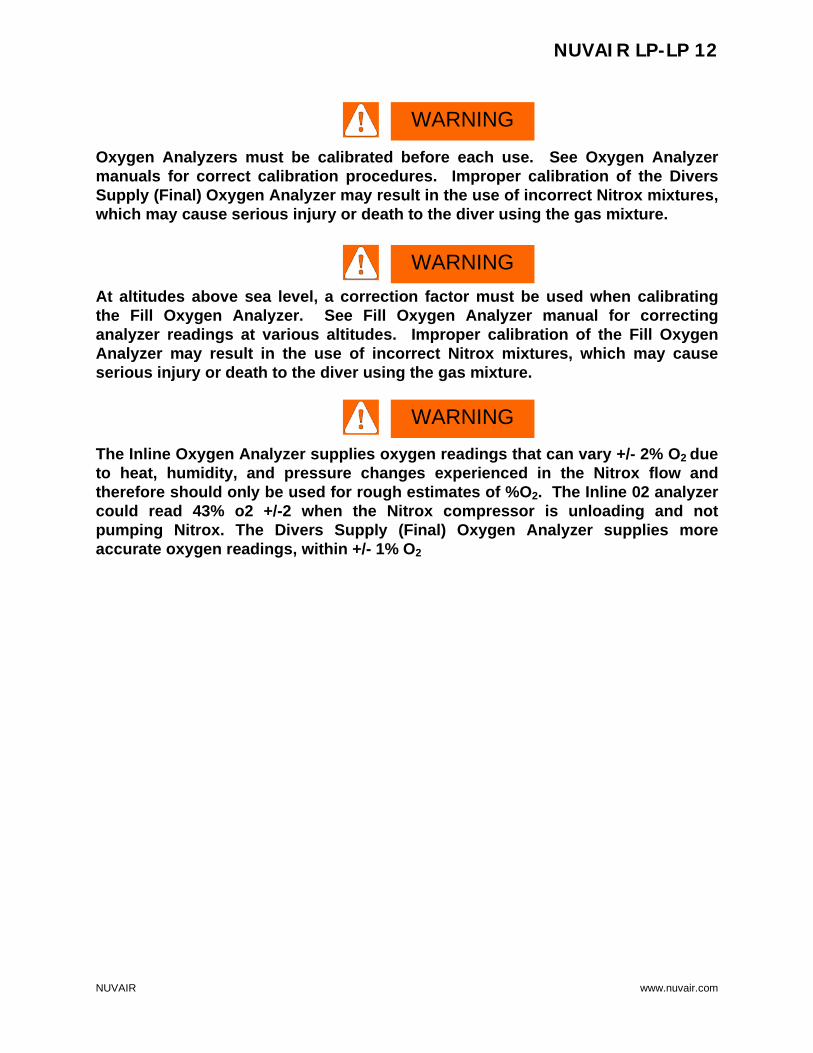
Oxygen Analyzers must be calibrated before each use. See Oxygen Analyzer manuals for correct calibration procedures. Improper calibration of the Divers Supply (Final) Oxygen Analyzer may result in the use of incorrect Nitrox mixtures, which may cause serious injury or death to the diver using the gas mixture. At altitudes above sea level, a correction factor must be used when calibrating the Fill Oxygen Analyzer. See Fill Oxygen Analyzer manual for correcting analyzer readings at various altitudes. Improper calibration of the Fill Oxygen Analyzer may result in the use of incorrect Nitrox mixtures, which may cause serious injury or death to the diver using the gas mixture. The Inline Oxygen Analyzer supplies oxygen readings that can vary +/- 2% O2 due to heat, humidity, and pressure changes experienced in the Nitrox flow and therefore should only be used for rough estimates of %O2. The Inline 02 analyzer could read 43% o2 +/-2 when the Nitrox compressor is unloading and not pumping Nitrox. The Divers Supply (Final) Oxygen Analyzer supplies more accurate oxygen readings, within +/- 1% O2
WARNING
WARNING
WARNING

NUVAIR LP-LP 12
NUVAIR www.nuvair.com
11.0 Operation
Once you have read through this manual, the compressor manuals, the Honda manual, the o2 analyzer manual, made the necessary set-up connections, and you understand how the system functions; follow the steps below to operate the system:
1. Close feed air supply on/off ball valve.
2. Release spring pressure on BP regulator by turning knob counter
clockwise. 3. Turn on power to the inverter. 4. Start both compressors as per directions in Honda Engine manual. 5. Slightly open the ball valve on the diver air/Nitrox manifold, maintaining
a pressure of 125 psi or more in the divers air/Nitrox volume tank and venting the remainder to the atmosphere.(shown in open position above)
6. While the Nitrox compressor is pumping air through the manifold valve,
calibrate both o2 analyzers as per instructions in the Pro o2 manual and on page 20.
7. Slowly open the feed air supply ball valve to membrane.
Regulated supply air pressure gauge to
membrane
1. Feed Air Supply on/off valve
2. BP Regulator Control
4. Divers air/Nitrox Manifold
Final o2 analyzer test point

NUVAIR LP-LP 12
NUVAIR www.nuvair.com
The On/Off Flow Valve on the Membrane System must be opened slowly. A sudden rush of gas can damage the Membrane and other system components. A damaged membrane will not produce the correct Nitrox mixture which can lead to severe personal injury if the gas is used for diving purposes without proper analysis. The Heater Thermostat Control green indicator light will stay on until operating temperature is reached.
Do not change the temperature setting on the Thermostat Control without contacting Nuvair. Changes in temperature settings may cause Membrane damage. A damaged membrane will not produce the correct Nitrox mixture which can lead to severe personal injury if the gas is used for diving purposes without proper analysis.
8. Slowly turn the BP regulator control handle clockwise to increase input pressure. Watch the Inline sensor/o2 analyzer (page 20). Increase pressure until the analyzer reads the o2% desired. The regulated input air pressure must be over 80 psi initially for the heater to operate.
9. Check the A419 Thermostat Control to see if it is operating
10. The Nitrox will slowly make its way through the
compressor and filtration. It will take 3-8 minutes for the o2% to stabilize as air in the Nitrox Volume Tank is slowly be replaced with Nitrox.
11. When both o2 analyzers are within 1% of each other. 12. Close the manifold valve and dive.
NOTICE
CAUTION
CAUTION
A419 Thermostat
Control Factory Set Nitrogen
Relief Valve

NUVAIR LP-LP 12
NUVAIR www.nuvair.com
OSHA Regulations require an emergency back up source of breathing gas for the diver in case of an emergency or compressor malfunction. 13. Monitor compressor operation at all times. Note tank pressure on the
first compressor, feed air input pressure on air going to the membrane, divers air/Nitrox tank pressure and o2%.
14. During the dive, monitor both analyzers to ensure they stay within 1% of each other. Lightly fine tune the input pressure to get the exact desire o2% on the final analyzer. The Final analyzer indicates the o2% going to the diver. This is the important reading. During the operation the analyzer sensor may warm slightly and require recalibration. Remove the cap and recalibrate as per the manual. The inline sensor will also warm and start to supply a reading that is higher than the actual o2%. This sensor can only be recalibrated by turning off the air flow to the membrane while the compressor is running. This should never be done while divers are breathing the Nitrox. During this period rely on the final o2 analyzer reading. A third analyzer can be used to check the final analyzer’s accuracy at any time by removing the cap from the final analyzer and attaching it to another analyzer.
15. After completion, close feed air ball valve.
16. Shut off the Feed Air Valve and Divers Nitrox Valve. Turn the
regulator control knob counter clockwise to the unloaded position. Turn
the Honda off.
17. Turn off the inverter.
WARNING

NUVAIR LP-LP 12
NUVAIR www.nuvair.com
12.0 Pumping Nitrox
The use of enriched air Nitrox does not eliminate the risk of decompression sickness (DCS) in diving. Decompression sickness can lead to permanent disability or death. The Inline O2 Analyzer supplies oxygen readings that can vary +/- 2% O2 due to heat, humidity, and pressure changes in the Nitrox flow and should only be used for rough estimates of %O2. The Fill O2 Analyzer supplies the accurate reading, within +/- 1% O2. Use an additional o2 analyzer at the divers manifold. Do not use this system to produce Nitrox mixtures containing more than 40% oxygen. Pumping Nitrox mixtures with higher concentrations of oxygen may lead to fires or explosions, which can cause serious personal injury or death. No oxygen cleaning of standard cylinders or plumbing is mandatory when using the Nitrox System to produce Nitrox containing a maximum of 40% oxygen. When filling oxygen clean cylinders, hyper-purification of the Nitrox is required using an optional Oxygen Compatible Air purification system available from Nuvair. Only provide Nitrox to divers who have proof of Nitrox training and certification. Improper use of Nitrox can be fatal.
WARNING
WARNING
NOTICE
WARNING
WARNING
NUVAIR LP-LP 12
NUVAIR www.nuvair.com
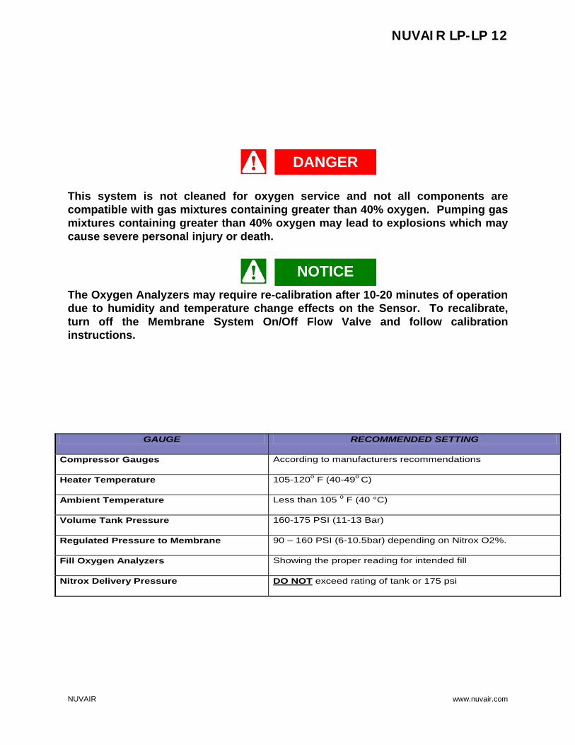
GAUGE RECOMMENDED SETTING
Compressor Gauges According to manufacturers recommendations
Heater Temperature 105-120o F (40-49o C)
Ambient Temperature Less than 105 o F (40 °C)
Volume Tank Pressure 160-175 PSI (11-13 Bar)
Regulated Pressure to Membrane 90 – 160 PSI (6-10.5bar) depending on Nitrox O2%.
Fill Oxygen Analyzers Showing the proper reading for intended fill
Nitrox Delivery Pressure DO NOT exceed rating of tank or 175 psi
This system is not cleaned for oxygen service and not all components are compatible with gas mixtures containing greater than 40% oxygen. Pumping gas mixtures containing greater than 40% oxygen may lead to explosions which may cause severe personal injury or death. The Oxygen Analyzers may require re-calibration after 10-20 minutes of operation due to humidity and temperature change effects on the Sensor. To recalibrate, turn off the Membrane System On/Off Flow Valve and follow calibration instructions.
DANGER
NOTICE

NUVAIR LP-LP 12
NUVAIR www.nuvair.com
13.0 Operation Notes:
♦ Utilizes standard Norgren filtration
Do NOT use any substitute.
♦ Bleed condensate drain on the volume tanks daily.
♦ Do NOT use this system to produce greater than 40% oxygen
concentration.
♦ Use only NUVAIR 455 compressor lubricant in this system, do NOT
substitute.
♦ Final discharge pressure is factory set. Do NOT alter setting.
13.1 Correlation of Input Pressure to Oxygen Content
After the 10 hour break-in period for your Nitrox System, you will notice that specific Nitrox 02 percentages always match specific input pressures once the System has warmed up. These pressures will be repeatable. If you find that the Fill Oxygen Analyzer reads 36% O2 when the input pressure is at 125 P.S.I. (9 bar), record this pressure or make a mark on the input pressure gauge indicating the %O2. Do this for each %O2 that you normally make, making sure System has warmed up first. The next time Nitrox with 36% O2 is needed, adjust the regulator to 125 P.S.I. (9 bar) and wait for the Oxygen Analyzer reading to stabilize. You will find the analyzer reading to be very close to 36% O2, requiring only minor adjustments of the regulator to achieve the exact desired %O2. Use the Diver Supply (Final) Oxygen Analyzer to verify the Nitrox oxygen percentage prior to delivery to divers. When using the input pressure reading to obtain specific oxygen percentage, minor adjustments of the input pressure regulator may be required to obtain the exact percentage desired.
NOTICE
NUVAIR LP-LP 12
NUVAIR www.nuvair.com
14. Maintenance
14.1 Routine Maintenance
Use only the specified Nuvair Lubricants in this system. The use of incompatible lubricants presents a risk of fire and/or explosion, and may result in system damage. This can lead to severe personal injury and death. Be sure that all pressure has been relieved from the system prior to opening any filtration canister. Failure to vent pressure from the system prior to opening the canister can lead to serious personal injury or death.
If system is located in an area where there is high humidity and high heat, the life of all Filtration Elements may be as little as 35% of rated operating capacity. Check the compressor manual and Appendix for details on Filter Element Life Factors. 1) LP Compressor Lubricant: Change Compressor Lubricant after the first 100 hour
break in period and every 200 hours thereafter. Only use Lubricants rated for use with breathing air/Nitrox systems such as NUVAIR455 TM. Never mix Compressor Lubricants. See LP Compressor manual for details.
2) LP Filtration Inspection: On a weekly basis, inspect each Filter Bowl for the presence of moisture and each Element for any unusual degradation or wetness.
3) LP Filtration Elements: Change LP Filter Elements every 50-75 hours to maintain CGA Grade D air standards. Visual differential pressure (DP) indicators on the coalescing filters assist with monitoring replacement intervals. See Section 14.3 for details. If the Nitrox System is operated in high humidity and/or high temperature, Filter Elements must be changed more often. See Appendix for details on Filter Element Life Factors.
4) Semi-Permeable Membrane: No maintenance required. Service life exceeds 20 years if LP Filtration is properly serviced to maintain Grade D standards.
5) Membrane System Air Intake Filter: Inspect filter element every 3 months for visible particles. Change every 12 months or sooner if particles are visible.
6) Oxygen Analyzers: Replace Oxygen Sensor and Battery as required. See manual included with Nitrox System.
CAUTION
WARNING
WARNING

NUVAIR LP-LP 12
NUVAIR www.nuvair.com
Do not swallow (ingest) either the electrolyte from the Oxygen Sensor or the Sensor itself. The Potassium Hydroxide chemical contained in the Sensor can cause severe injury or death. If electrolyte or the Sensor is swallowed, seek medical attention immediately. If after handling the Oxygen Analyzer or Sensor, you find that your fingers or other parts of your body feel “slippery” or the skin or eyes sting, immediately flush affected area with clean, fresh water for at least 15 minutes. The stinging or slippery sensation is an indication of a leaking Sensor. The Potassium Hydroxide chemical contained in the Sensor can cause severe injury or death. Seek immediate medical attention if eye contact is made or skin stinging persists.
DANGER
DANGER

NUVAIR LP-LP 12
NUVAIR www.nuvair.com
14.2 Compressor Lubricant: Change with NUVAIR 455 Nitrox rated lubricant
every 100 hours or minimum once per year. Do not mix brands.
1) Check oil and gas levels before operation. 2) Drain Volume tank daily. 3) Start and warm to operating temperature before Nitrox preparation.
Refer to Honda Engine manual for
proper oil and maintenance.
Oil Drain
Oil Level Sight Gauge
Oil Fill Plug See manual for
Honda Maintenance
Oil Level Dipstick and Fill Port –
We recommend using an oil
evacuator through this hole to remove the
majority of oil during oil changes as the drain hole at the bottom of the block is quite
small and oil flows from it very slowly

NUVAIR LP-LP 12
NUVAIR www.nuvair.com
14.3 LP Filtration Special attention needs to be given to the arrangement of the four LP Supply Air Filtration Elements and Bowls. Properly reinstall each Element and Bowl to the correct Housing. Improper sequence can cause damage to downstream components The use of Grade D or better supply air is critical to prevent the passing of any residual oil vapor into the Membrane System. Three stages of Norgren LP filtration are used to produce Grade D air:
1) Particle Removal to 1 micron 2) Coalescing & Water/Oil Vapor
Removal to 0.01 micron 3) Oil Vapor Removal to 0.003 PPM
Filtration Inspection Open each Filter and inspect as follows: 1. Inspect Bowl for the presence of moisture. There should be no moisture
build-up in the Oil Vapor filter element. Any evidence of moisture in the Oil Vapor Filter indicates the air is not cooling properly and moisture is not properly being removed by the Coalescing filters or the filter elements are due to be changed. Excess moisture will prevent the Oil Vapor filter from operating properly.
Housing
CAUTION
4341-01 Oil/Vapor Removal
4338-04 Coalescing &
Water Removal
Bowl
Element
4344-02 Particle/Oil Removal
NUVAIR LP-LP 12
NUVAIR www.nuvair.com
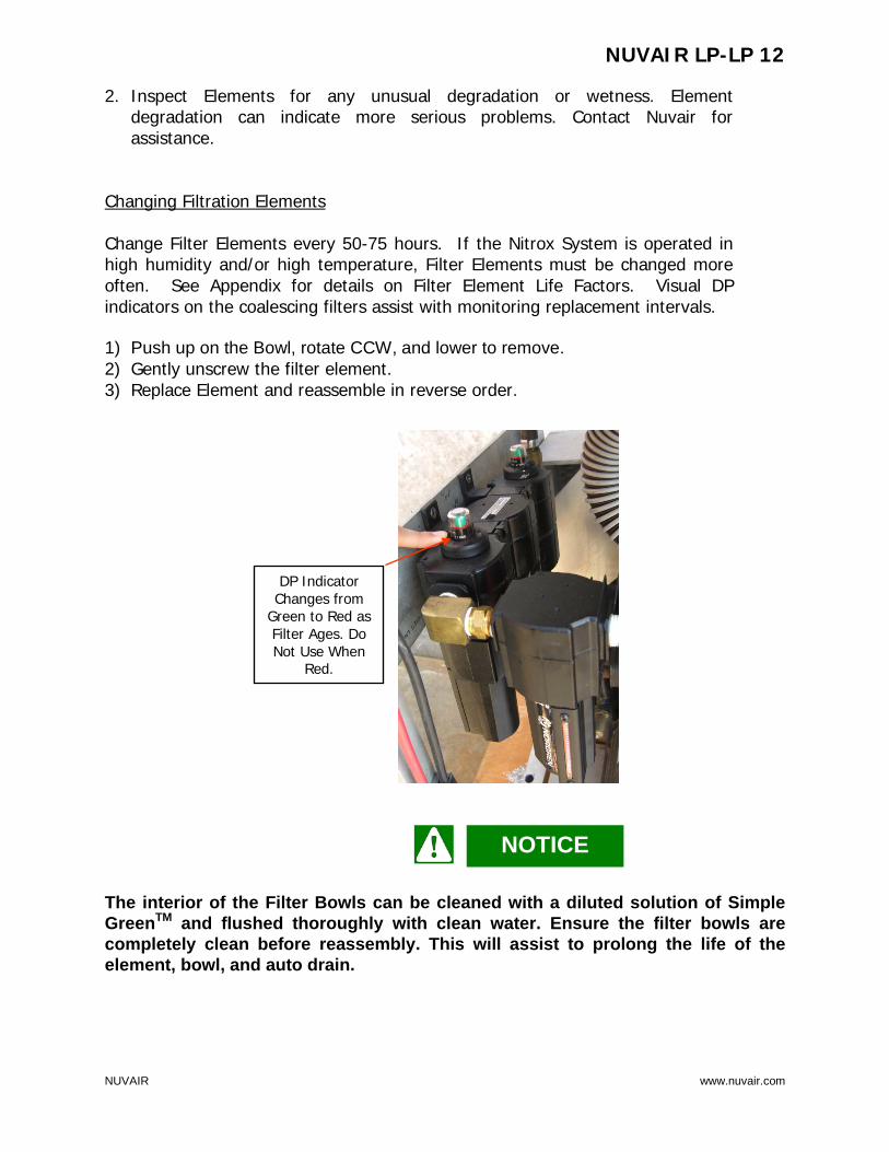
2. Inspect Elements for any unusual degradation or wetness. Element degradation can indicate more serious problems. Contact Nuvair for assistance.
Changing Filtration Elements Change Filter Elements every 50-75 hours. If the Nitrox System is operated in high humidity and/or high temperature, Filter Elements must be changed more often. See Appendix for details on Filter Element Life Factors. Visual DP indicators on the coalescing filters assist with monitoring replacement intervals. 1) Push up on the Bowl, rotate CCW, and lower to remove. 2) Gently unscrew the filter element. 3) Replace Element and reassemble in reverse order. The interior of the Filter Bowls can be cleaned with a diluted solution of Simple GreenTM and flushed thoroughly with clean water. Ensure the filter bowls are completely clean before reassembly. This will assist to prolong the life of the element, bowl, and auto drain.
NOTICE
DP Indicator Changes from
Green to Red as Filter Ages. Do Not Use When
Red.
NUVAIR LP-LP 12
NUVAIR www.nuvair.com
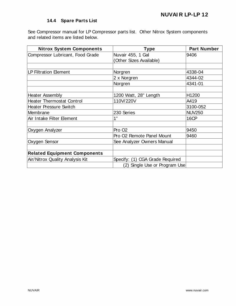
14.4 Spare Parts List See Compressor manual for LP Compressor parts list. Other Nitrox System components and related items are listed below.
Nitrox System Components Type Part Number Compressor Lubricant, Food Grade Nuvair 455, 1 Gal
(Other Sizes Available) 9406
LP Filtration Element Norgren 4338-04 2 x Norgren 4344-02 Norgren 4341-01 Heater Assembly 1200 Watt, 28" Length H1200 Heater Thermostat Control 110V/220V A419 Heater Pressure Switch 3100-052 Membrane 230 Series NUV250 Air Intake Filter Element 1” 16CP Oxygen Analyzer Pro O2 9450 Pro O2 Remote Panel Mount 9460 Oxygen Sensor See Analyzer Owners Manual Related Equipment Components Air/Nitrox Quality Analysis Kit Specify: (1) CGA Grade Required
(2) Single Use or Program Use
NUVAIR LP-LP 12
NUVAIR www.nuvair.com
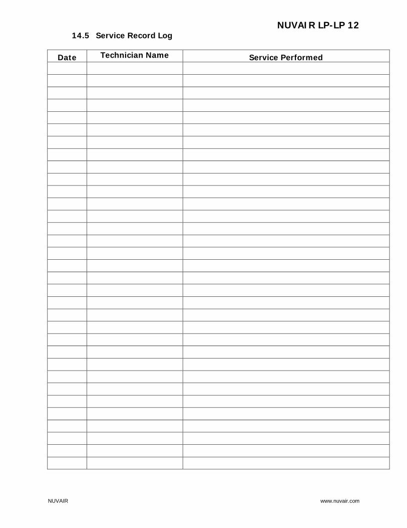
14.5 Service Record Log
Date Technician Name Service Performed
NUVAIR LP-LP 12
NUVAIR www.nuvair.com
Appendix
Supply and Breathing Air Specifications
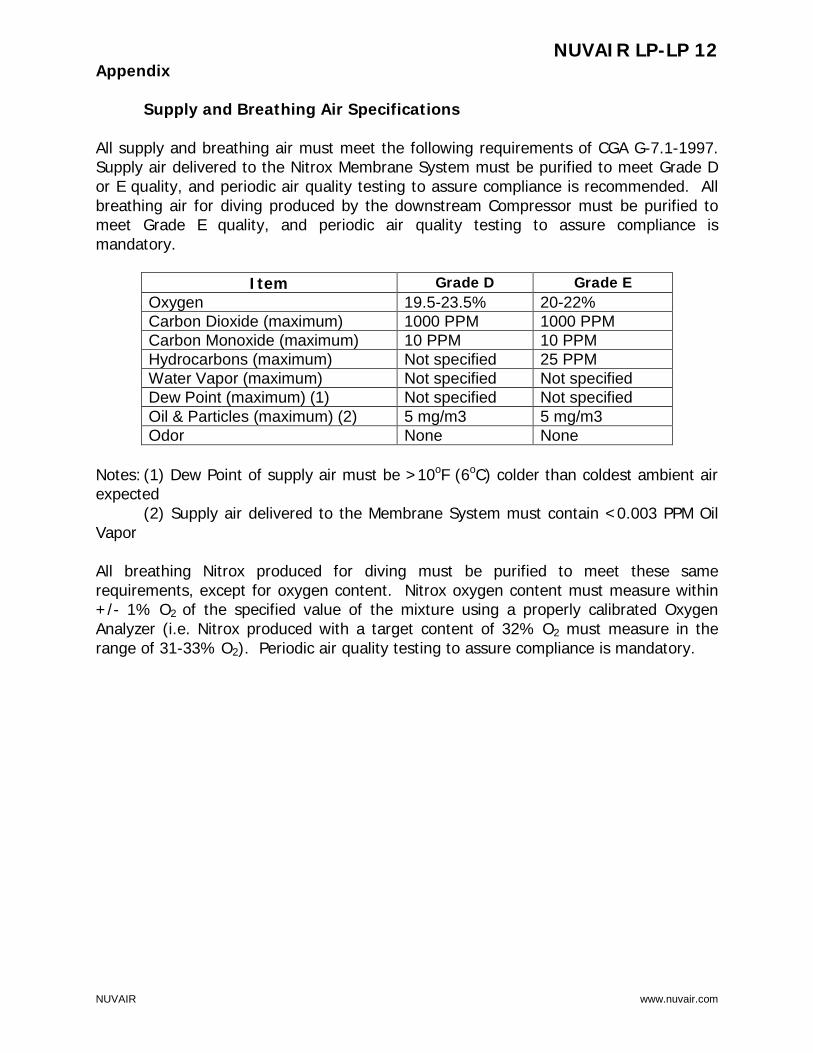
All supply and breathing air must meet the following requirements of CGA G-7.1-1997. Supply air delivered to the Nitrox Membrane System must be purified to meet Grade D or E quality, and periodic air quality testing to assure compliance is recommended. All breathing air for diving produced by the downstream Compressor must be purified to meet Grade E quality, and periodic air quality testing to assure compliance is mandatory.
Item Grade D Grade E Oxygen 19.5-23.5% 20-22% Carbon Dioxide (maximum) 1000 PPM 1000 PPM Carbon Monoxide (maximum) 10 PPM 10 PPM Hydrocarbons (maximum) Not specified 25 PPM Water Vapor (maximum) Not specified Not specified Dew Point (maximum) (1) Not specified Not specified Oil & Particles (maximum) (2) 5 mg/m3 5 mg/m3 Odor None None
Notes: (1) Dew Point of supply air must be >10oF (6oC) colder than coldest ambient air expected (2) Supply air delivered to the Membrane System must contain <0.003 PPM Oil Vapor All breathing Nitrox produced for diving must be purified to meet these same requirements, except for oxygen content. Nitrox oxygen content must measure within +/- 1% O2 of the specified value of the mixture using a properly calibrated Oxygen Analyzer (i.e. Nitrox produced with a target content of 32% O2 must measure in the range of 31-33% O2). Periodic air quality testing to assure compliance is mandatory.
NUVAIR LP-LP 12
NUVAIR www.nuvair.com
Filter Element Life Factors
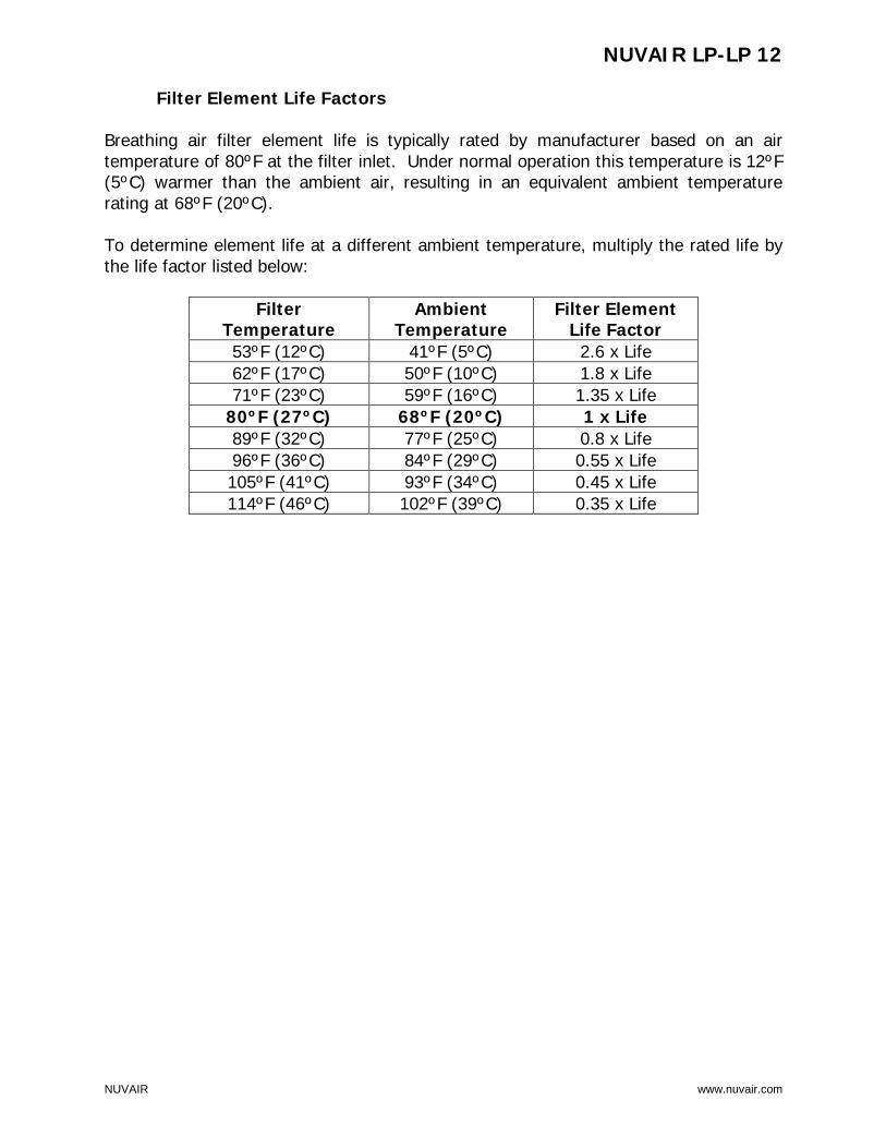
Breathing air filter element life is typically rated by manufacturer based on an air temperature of 80ºF at the filter inlet. Under normal operation this temperature is 12ºF (5ºC) warmer than the ambient air, resulting in an equivalent ambient temperature rating at 68ºF (20ºC). To determine element life at a different ambient temperature, multiply the rated life by the life factor listed below:
Filter Temperature
Ambient Temperature
Filter Element Life Factor
53ºF (12ºC) 41ºF (5ºC) 2.6 x Life 62ºF (17ºC) 50ºF (10ºC) 1.8 x Life 71ºF (23ºC) 59ºF (16ºC) 1.35 x Life
80ºF (27ºC) 68ºF (20ºC) 1 x Life 89ºF (32ºC) 77ºF (25ºC) 0.8 x Life 96ºF (36ºC) 84ºF (29ºC) 0.55 x Life 105ºF (41ºC) 93ºF (34ºC) 0.45 x Life 114ºF (46ºC) 102ºF (39ºC) 0.35 x Life

NUVAIR LP-LP 12
NUVAIR www.nuvair.com
OWNER’S WARRANTY RESPONSIBILITIES Failure of the owner to prevent equipment damage by complying with the procedures outlined below and in the Operation Manual will void the Nitrox System warranty. Installation:
• All set up requirements and procedures provided in the Nitrox System Operation Manual must be followed in their entirety including supply air cleanliness, Compressor preparation, and installation of the Nitrox System.
• Supply air to the Membrane must be properly filtered to CGA Grade D air quality or better to prevent damage to the Membrane. Air quality testing of the supply air should be performed periodically and documented to assure compliance.
• If there is any doubt regarding the suitability of a HP Compressor for compressing Nitrox, contact Nuvair or the Compressor manufacturer before you connect your Nitrox System.
• Electrical wiring and connections should be made by a qualified electrician in accordance with all national and local electrical codes.
• Do not change the temperature setting on the Heater Thermostat Control. Changes in temperature settings may cause Membrane damage.
• To prevent Compressor damage, only use the Compressor Intake Hose provided. If a longer hose is required, contact Nuvair for assistance.
Operation:
• Do not use the Nitrox System to supply a HP Compressor with Nitrox mixtures containing more than 40% oxygen. Compressing higher concentrations of oxygen may cause severe Compressor damage.
• Do not pump Nitrox mixtures at pressures above the compressor manufacturer’s rating, and never above 3600 P.S.I. Compressing Nitrox at higher pressures may cause severe HP Compressor damage.
• To prevent Membrane damage, drain all low pressure filter and volume tank condensate on a daily basis.
• Do not use system if there is any broken or poorly functioning part. Contact the factory.
Maintenance:
• Change low pressure filter elements on a schedule determined by filter capacity and ambient temperature and humidity. Contact Nuvair if you need assistance establishing a schedule for your equipment and location.
• Replace Membrane System Air Intake Filter on a regular basis to prevent flow obstruction.
• Keep all nuts, bolts, fittings, connectors, and clamps tight. • Keep a service record book showing that regular maintenance work has been
carried out. If a warranty claim becomes necessary, it will aid in demonstrating that damage has not been caused by insufficient maintenance. Proof of maintenance may be required prior to determining the validity of a warranty request.

NUVAIR LP-LP 12
NUVAIR www.nuvair.com
NUVAIR NITROX SYSTEM WARRANTY
NUVAIR extends a limited warranty, which warrants the Nitrox System to be free from defects in materials and workmanship under normal use and service for a limited period. The specific Membrane Component of the Nitrox System is warranted according to the pro-rated terms as set forth below. All other Original Equipment Manufacturer (OEM) components used in the system are warranted only to the extent of the OEM’s warranty to NUVAIR. NUVAIR makes no warranty with respect to these OEM components, and only warrants the workmanship that NUVAIR has employed in the installation or use of any OEM component. This warranty is not transferable. NUVAIR will, at it’s discretion and according to the terms as set forth within, replace or repair any materials which fail under normal use and service and do not exhibit any signs of improper maintenance, misuse, accident, alteration, weather damage, tampering, or use for any other than the intended purpose. Determination of failure is the responsibility of NUVAIR, which will work together with the customer to adequately address warranty issues. When any materials are repaired or replaced during the warranty period, they are warranted only for the remainder of the original warranty period. This warranty shall be void and NUVAIR shall have no responsibility to repair or replace damaged materials resulting directly or indirectly from the use of repair or replacement parts not approved by NUVAIR. Pro-Rated Terms: NUVAIR warrants the Membrane Component of the Nitrox System to be free from defects in material and workmanship for a period of thirty-six (36) months from date of installation or forty-two (42) months from date of shipment by NUVAIR, whichever may occur first. The warranty covers parts only and is prorated as follows:
• First Year Repair or replacement free of charge • Second Year Warranty allowance of 70% of the current Membrane Component
list price • Third Year Warranty allowance of 40% of the current Membrane Component
list price A warranty registration card, supplied with system documentation, must be filled out and submitted to NUVAIR for the warranty to be in full effect. If the warranty registration card is not received within thirty (30) days of installation, the thirty-six (36) month warranty will begin with the date of shipment from NUVAIR. Maintenance Items: Any materials which are consumed, or otherwise rendered not warrantable due to processes applied to them, are considered expendable and are not covered under the terms of this policy. This includes maintenance and consumable items listed as part of a suggested maintenance program included with system documentation.

NUVAIR LP-LP 12
NUVAIR www.nuvair.com
Return Policy: Application for warranty service can be made by contacting NUVAIR during regular business hours and requesting a Return Material Authorization number. Materials that are found to be defective must be shipped, freight pre-paid, to the NUVAIR office in Oxnard, California. Upon inspection and determination of failure, NUVAIR shall exercise its options under the terms of this policy. Warranty serviced materials will be returned to the customer via NUVAIR’s preferred shipping method, at NUVAIR’s expense. Any expedited return shipping arrangements to be made at customer’s expense must be specified in advance. Limitation of Warranty and Liability: Repair, replacement or refund in the manner and within the time provided shall constitute NUVAIR’S sole liability and the Purchaser’s exclusive remedy resulting from any nonconformity or defect. NUVAIR shall not in any event be liable for any damages, whether based on contract, warranty, negligence, strict liability or otherwise, including without limitation any consequential, incidental or special damages, arising with respect to the equipment or its failure to operate, even if NUVAIR has been advised of the possibility thereof. NUVAIR makes no other warranty or representation of any kind, except that of title, and all other warranties, express or implied, including warranties of merchantability and fitness for a particular purpose, are hereby expressly disclaimed. No salesman or other representative of NUVAIR has authority to make any warranties.


Nuvair Phone +1 805 815 4044 Fax +1 805 486 0900 1600 Beacon Place Oxnard, CA 93033
USA [email protected] www.nuvair.com Revision 05.19