Service Bulletin - Honda Owners
14
CUSTOMER INFORMATION: The information in this bulletin is intended for use only by skilled technicians who have the proper tools, equipment, and training to correctly and safely maintain your vehicle. These procedures should not be attempted by “do-it-yourselfers,” and you should not assume this bulletin applies to your vehicle, or that your vehicle has the condition described. To determine whether this information applies, contact an authorized Honda automobile dealer. © 2021 American Honda Motor Co., Inc. – All Rights Reserved Page 1 of 14 Service Bulletin 21-013 February 18, 2021 Version 1 Warranty Extension: 2018-20 Odyssey MOST Bus Network Connectors AFFECTED VEHICLES Year Model Trim Level VIN Range 2018-20 Odyssey ALL except LX Check the iN VIN status for eligibility. BACKGROUND A loose connection in the MOST bus network is causing a popping or crackling from the speakers or no sound from the audio system. There may also be a Network Loss message and/or display issues. American Honda is extending the warranty for the MOST bus network connectors on these vehicles to 5 years or 60,000 miles from the original date of purchase, whichever comes first. CUSTOMER NOTIFICATION Owners of affected vehicles will be sent a notification of this campaign. Do an iN VIN status inquiry to make sure the vehicle is shown as eligible. CORRECTIVE ACTION Install the FAKRA connector set and the MOST service cords. PARTS INFORMATION Part Name Part Number Quantity FAKRA Service Housing 39817-TJB-AC0 3 TOOL INFORMATION NOTE: The tools listed below are a required tool that should be in your dealer inventory. Order additional tools only if your tools are damaged and need replacement. Tool Name Tool Number Quantity Straight FAKRA Puller 07AAC-THRA200 1 Cargo Cap Screw Socket 07AAA-SEPA100 1
-
Upload
khangminh22 -
Category
Documents
-
view
0 -
download
0
Transcript of Service Bulletin - Honda Owners

CUSTOMER INFORMATION: The information in this bulletin is intended for use only by skilled technicians who have the proper tools, equipment, and training to correctly and safely maintain your vehicle. These procedures should not be attempted by “do-it-yourselfers,” and you should not assume this bulletin applies to your vehicle, or that your vehicle has the condition described. To determine whether this information applies, contact an authorized Honda automobile dealer.
© 2021 American Honda Motor Co., Inc. – All Rights Reserved Page 1 of 14
Service Bulletin 21-013 February 18, 2021 Version 1
Warranty Extension: 2018-20 Odyssey MOST Bus Network Connectors
AFFECTED VEHICLES
Year Model Trim Level VIN Range 2018-20 Odyssey ALL except LX Check the iN VIN status for eligibility.
BACKGROUND
A loose connection in the MOST bus network is causing a popping or crackling from the speakers or no sound from the audio system. There may also be a Network Loss message and/or display issues. American Honda is extending the warranty for the MOST bus network connectors on these vehicles to 5 years or 60,000 miles from the original date of purchase, whichever comes first.
CUSTOMER NOTIFICATION
Owners of affected vehicles will be sent a notification of this campaign. Do an iN VIN status inquiry to make sure the vehicle is shown as eligible.
CORRECTIVE ACTION
Install the FAKRA connector set and the MOST service cords.
PARTS INFORMATION
Part Name Part Number Quantity FAKRA Service Housing 39817-TJB-AC0 3
TOOL INFORMATION NOTE: The tools listed below are a required tool that should be in your dealer inventory. Order additional tools only if your tools are damaged and need replacement.
Tool Name Tool Number Quantity Straight FAKRA Puller 07AAC-THRA200 1
Cargo Cap Screw Socket 07AAA-SEPA100 1
Page 2 of 14
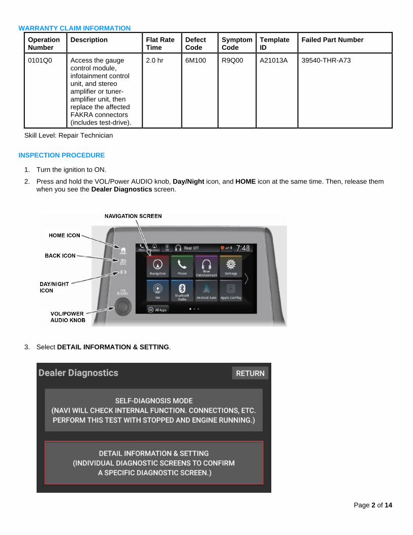
WARRANTY CLAIM INFORMATION Operation Number
Description Flat Rate Time
Defect Code
Symptom Code
Template ID
Failed Part Number
0101Q0 Access the gauge control module, infotainment control unit, and stereo amplifier or tuner-amplifier unit, then replace the affected FAKRA connectors (includes test-drive).
2.0 hr 6M100 R9Q00 A21013A 39540-THR-A73
Skill Level: Repair Technician
INSPECTION PROCEDURE
1. Turn the ignition to ON.
2. Press and hold the VOL/Power AUDIO knob, Day/Night icon, and HOME icon at the same time. Then, release them when you see the Dealer Diagnostics screen.
3. Select DETAIL INFORMATION & SETTING.

Page 3 of 14
4. Scroll down the menu, and select SHUTDOWN REASON.
In this example, the cause of the failure can be identified as Meter:SUDDEN_SIGNAL_OFF.
Write down any failures; they will be collected on the warranty claim. Then, clear the data.

Page 4 of 14
REPAIR PROCEDURE
1. Remove the lower vent covers.
2. Loosen the upper column cover.
3. Disengage the clips around the meter bezel. Then, remove it with the upper column cover as one piece.

Page 5 of 14
4. Remove the three screws holding the gauge control module.
5. Turn the gauge control module to access the rear connectors. Then, using the straight FAKRA tool, disconnect the red
and green FAKRA connectors, and remove them from the gauge control module. Do not pull on the units while the FAKRA connectors are connected to help prevent communication issues.
NOTE: For more information on using the FAKRA tools, see the job aid, Using the MOST Connector Tools.
.
6. Remove the cover above the center display unit.
Page 6 of 14
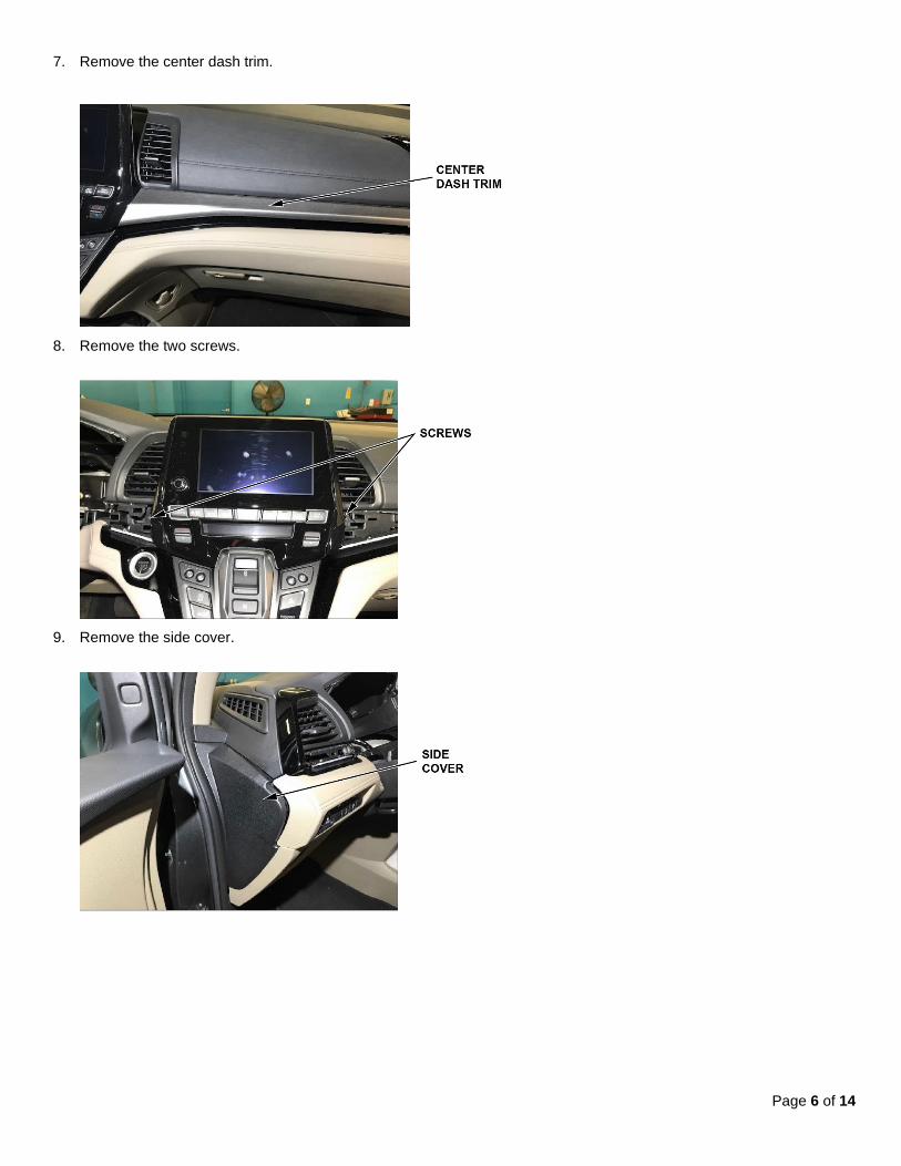
7. Remove the center dash trim.
8. Remove the two screws.
9. Remove the side cover.

Page 7 of 14
10. Remove the two screws.
11. Remove the lower dash panel.
12. Remove the passenger lower panel.

Page 8 of 14
13. Remove the driver lower console panel and the passenger lower console panel.
14. Pull back the cover, and remove the bolt.
15. Remove the rubber liner, and pull back the lower console cover.

Page 9 of 14
16. Remove the two screws from the dashboard center pocket, then pull back the panel.
17. Remove the two upper screws, and loosen the two lower screws.
NOTE: Some models will have a CD player, DVD player or center pocket.
18. Remove the DVD player, CD player or center pocket to gain access to the two 8 mm bolts holding the infotainment
unit.

Page 10 of 14
19. While looking upward from underneath where the DVD player, CD player, or center pocket was removed, loosen the two 8 mm bolts holding the infotainment unit, then remove the unit.
20. In the rear cargo area, remove the rear trim panel.
21. On the right rear quarter panel, remove the hook bolts. If needed, use Cargo Cap Screw Socket
(T/N 07AAA-SEPA100) to loosen the bolts.
22. Remove the covers then remove the two screws from the passenger side inner rear quarter panel.

Page 11 of 14
23. Remove the lower passenger sliding door trim.
24. Remove the right quarter inner panel, then disconnect the connectors.

Page 12 of 14
25. Disconnect the red and green FAKRA connectors from the stereo amplifier (Elite) or tuner-amplifier unit (EX, EX-L, Touring), gauge control module, and infotainment unit using the straight FAKRA puller. Do not pull on the units while the FAKRA connectors are connected to help prevent communication issues.
NOTE: Disassemble the connectors one at a time to avoid swapping the green and red wires.

Page 13 of 14
26. Using a small screwdriver, remove the secondary lock, then break off the tab as shown. Then, discard the housing and lock.
27. Pull and twist the housing counterclockwise to remove it from the wire.
28. Select the correct color FAKRA housing, then slide the new terminal onto the wire until it clicks into place.
29. Line up the locking tabs on the FAKRA housing with the new terminal, then push the terminal into the housing until it
clicks into place.
30. Repeat steps 26 thru 29 for the other connectors. Then, install the FAKRA connectors to the gauge control module,
infotainment unit, and stereo amplifier or tuner-amplifier unit.

Page 14 of 14
31. Install all of the removed parts in the reverse order of removal. When installing units, make sure the harness is routed correctly, as a missrouted harness can put pressure on the connectors which may cause a connection issue. Do not pull on the units while the FAKRA connectors are connected to help prevent communication issues.
32. Test-drive the vehicle to confirm the repair. If the repair is not successful, continue with normal troubleshooting based
on customer symptom(s).
END