OWNERS MANUAL FOR
22
MAC700 - 02/04 OWNERS MANUAL FOR Oil Lubricated Air Compressor MODEL NO. MAC700 | MAC2400 | MAC5200 Model No. MAC700 MAC2400 MAC5200 Horsepower 2 2.5 3 SCFM @ 40 PSIG 3.8 4.8 6.9 SCFM @ 90 PSIG 3.3 4.2 6.5 Cut-In Pressure 100 PSI 100 PSI 110 PSI Cut-Out Pressure 130 PSI 130 PSI 140 PSI Bore 47 mm 51 mm 47 mm Stroke 44 mm 44 mm 44 mm Voltage -Single Phase 120 120 120 Motor RPM 1720 1720 3420 Amperage @ max pressure 12.4 12.3 13.8 Tank Size 2.6 Gallon 4.2 Gallon 5.2 Gallon CSA/US Listed Yes Yes Yes SPECIFICATION CHART Minimum Circuit Requirement: 15 AMPS * A circuit breaker is preferred. Use only a fuse or circuit breaker that is the same rating as the branch circuit the air compressor is operated on. If the air compressor is connected to a circuit protected by fuses, use time delay fuses. IMPORTANT: Read the Safety Guidelines and ALL instructions carefully before operating. www.makitatools.com
-
Upload
independent -
Category
Documents
-
view
2 -
download
0
Transcript of OWNERS MANUAL FOR

MAC700 - 02/04
OWNERS MANUAL FOROil Lubricated Air Compressor
MODEL NO.
MAC700 | MAC2400 | MAC5200
Model No. MAC700 MAC2400 MAC5200
Horsepower 2 2.5 3
SCFM @ 40 PSIG 3.8 4.8 6.9
SCFM @ 90 PSIG 3.3 4.2 6.5
Cut-In Pressure 100 PSI 100 PSI 110 PSI
Cut-Out Pressure 130 PSI 130 PSI 140 PSI
Bore 47 mm 51 mm 47 mm
Stroke 44 mm 44 mm 44 mm
Voltage -Single Phase 120 120 120
Motor RPM 1720 1720 3420
Amperage @ max pressure 12.4 12.3 13.8
Tank Size 2.6 Gallon 4.2 Gallon 5.2 Gallon
CSA/US Listed Yes Yes Yes
SPECIFICATION CHART
Minimum Circuit Requirement: 15 AMPS
* A circuit breaker is preferred. Use only a fuse or circuit breaker that is the same ratingas the branch circuit the air compressor is operated on. If the air compressor isconnected to a circuit protected by fuses, use time delay fuses.
IMPORTANT:Read the Safety Guidelines and ALL
instructions carefully before operating.www.makitatools.com

2
TABLE OF CONTENTS OWNERS MANUAL
MAKITA - MAC700 / MAC2400 / MAC5200
TABLE OF CONTENTS
SAFETY INSTRUCTIONS . . . . . . . . . . . . . . . . . . . . . . . . . . . . . . . . . . . . . . . . . . . . . . . 3
Warning Chart . . . . . . . . . . . . . . . . . . . . . . . . . . . . . . . . . . . . . . . . . . . . . . . . . . . . . . 3
GLOSSARY . . . . . . . . . . . . . . . . . . . . . . . . . . . . . . . . . . . . . . . . . . . . . . . . . . . . . . . . . . 7
DUTY CYCLE . . . . . . . . . . . . . . . . . . . . . . . . . . . . . . . . . . . . . . . . . . . . . . . . . . . . . . . . . 7
ON RECEIPT INSPECTION . . . . . . . . . . . . . . . . . . . . . . . . . . . . . . . . . . . . . . . . . . . . . . 7
STORAGE . . . . . . . . . . . . . . . . . . . . . . . . . . . . . . . . . . . . . . . . . . . . . . . . . . . . . . . . . . . 8
DESCRIPTION OF OPERATION . . . . . . . . . . . . . . . . . . . . . . . . . . . . . . . . . . . . . . . . . . 8
INSTALLATION AND BREAK IN PROCEDURES . . . . . . . . . . . . . . . . . . . . . . . . . . . . 9
Location of the air compressor . . . . . . . . . . . . . . . . . . . . . . . . . . . . . . . . . . . . . . . . . 9
Lubrication and oil . . . . . . . . . . . . . . . . . . . . . . . . . . . . . . . . . . . . . . . . . . . . . . . . . . . 9
Initial start up procedure . . . . . . . . . . . . . . . . . . . . . . . . . . . . . . . . . . . . . . . . . . . . . 10
Extension cords . . . . . . . . . . . . . . . . . . . . . . . . . . . . . . . . . . . . . . . . . . . . . . . . . . . . 10
Piping . . . . . . . . . . . . . . . . . . . . . . . . . . . . . . . . . . . . . . . . . . . . . . . . . . . . . . . . . . . . 11
Grounding instructions . . . . . . . . . . . . . . . . . . . . . . . . . . . . . . . . . . . . . . . . . . . . . . . 11
OPERATING PROCEDURES . . . . . . . . . . . . . . . . . . . . . . . . . . . . . . . . . . . . . . . . . . . 11
Daily start up checklist . . . . . . . . . . . . . . . . . . . . . . . . . . . . . . . . . . . . . . . . . . . . . . . 11
MAINTENANCE . . . . . . . . . . . . . . . . . . . . . . . . . . . . . . . . . . . . . . . . . . . . . . . . . . . . . . 12
ROUTINE MAINTENANCE SCHEDULE . . . . . . . . . . . . . . . . . . . . . . . . . . . . . . . . 13
Filling with oil . . . . . . . . . . . . . . . . . . . . . . . . . . . . . . . . . . . . . . . . . . . . . . . . . . . . . . 13
Changing the oil . . . . . . . . . . . . . . . . . . . . . . . . . . . . . . . . . . . . . . . . . . . . . . . . . . . 13
COLD WEATHER CONDITIONS . . . . . . . . . . . . . . . . . . . . . . . . . . . . . . . . . . . . . . . . . 13
SERVICE INSTRUCTIONS . . . . . . . . . . . . . . . . . . . . . . . . . . . . . . . . . . . . . . . . . . . . . 14
TROUBLESHOOTING GUIDE . . . . . . . . . . . . . . . . . . . . . . . . . . . . . . . . . . . . . . . . . . . 15
FACTORY SERVICE CENTERS . . . . . . . . . . . . . . . . . . . . . . . . . . . . . . . . . . . . . . . . . 18
WARRANTY . . . . . . . . . . . . . . . . . . . . . . . . . . . . . . . . . . . . . . . . . . . . . . . . . . . . . . . . . 20

SAFETY INSTRUCTIONS
3
OWNERS MANUAL
MAKITA - MAC700 / MAC2400 / MAC5200
SAFETY INSTRUCTIONS
IMPORTANT SAFETY INSTRUCTIONS*** SAVE THESE INSTRUCTIONS ***
WARNINGIMPROPER OPERATION OR MAINTENANCE OF THIS PRODUCT COULD RESULT IN SERIOUS
INJURY AND PROPERTY DAMAGE. READ AND UNDERSTAND ALL WARNINGS AND OPERATING INSTRUCTIONS BEFORE
USING THIS EQUIPMENT.
HAZARD WHAT CAN HAPPEN HOW TO PREVENT IT
Risk of UnsafeOperation.
Unsafe operation of your aircompressor could lead toserious injury to you or others.
• Review and understand allinstructions and warnings inthis manual.
• Become familiar with theoperation and controls of theair compressor.
• Keep operating area clear ofall persons, pets, andobstacles.
• Keep children away from theair compressor at all times.
• Do not operate the productwhen fatigued or under theinfluence of alcohol or drugs.Stay alert at all times.
• Never defeat the safetyfeatures of this product.
• Equip area of operation witha fire extinguisher.
• Do not operate machine withmissing, broken, orunauthorized parts.

4
SAFETY INSTRUCTIONS OWNERS MANUAL
MAKITA - MAC700 / MAC2400 / MAC5200
HAZARD WHAT CAN HAPPEN HOW TO PREVENT IT
Risk of Air TankBursting.
Risk of Attachmentsand AccessoriesBursting.
The following conditions couldlead to a weakening of thetank, and
RESULT IN A VIOLENT TANKEXPLOSION RESULTING INSERIOUS INJURY TO YOUOR OTHERS:
• Failure to properly draincondensed water from thetank, causing rust andthinning of the tank wall.
• Modifications or attemptedrepairs to the tank.
• Unauthorized modifications tothe pressure switch, safetyvalve, or any othercomponents, which controltank pressure.
Exceeding the pressure ratingof air tools, spray guns, airoperated accessories, tiresAND other inflatables cancause them to explode or flyapart, and could result inserious injury to you andothers.
• Drain the tank DAILY orafter each use. If tankdevelops a leak, replace itimmediately with a newtank or new compressorunit.
• Never drill into, weld, ormake any modifications tothe tank or its attachments.Never attempt to repair adamaged or leaking tank.Replace with a new tank.
• The tank is designed towithstand specific operatingpressures. Never makeadjustments or partssubstitutions to alter thefactory set operatingpressures.
• For essential control of airpressure, you must install apressure regulator andregulated air pressuregauge to the air outlet ofyour compressor.
• Follow the equipmentmanufacturersrecommendation and neverexceed the maximumallowable pressure rating ofattachments. Never use thecompressor to inflate smalllow-pressure objects suchas children’s toys, footballs,basketballs, etc.

SAFETY INSTRUCTIONS
5
OWNERS MANUAL
MAKITA - MAC700 / MAC2400 / MAC5200
HAZARD WHAT CAN HAPPEN HOW TO PREVENT IT
Risk of Electric Shock.
Risk of Explosion orFire.
Risk to Breathing.
• Your air compressor ispowered by electricity. Likeany other electricallypowered device, if it is notused properly, it may causeelectrical shock.
• Electrical grounding: failureto provide adequategrounding to this productcould increase the risk ofelectric shock.
It is normal for electricalcontact within the motor andpressure switch to spark,whenever the compressorstarts or stops. Never operatethe compressor in anatmosphere where flammablevapors are present. Doing socan result in serious injury toyou or others.
• The compressed air fromyour compressor is not safefor breathing. The air streammay contain carbonmonoxide or other vapors, orparticles from the tank orother components.
• Sprayed materials such aspaint, paint solvents, paintremover, insecticides, weedkillers, etc., contain harmfulvapors and poisons.
• Any electrical wiring orrepairs required to thisproduct should be performedby qualified servicepersonnel or a licensedelectrician, in accordancewith national and localelectrical codes.
• Make certain that theelectrical circuit to which thecompressor is connectedprovides proper electricalgrounding, correct voltage,and adequate fuseprotection.
• Never operate thecompressor outdoors when itis raining, or in a wetenvironment.
• Always operate thecompressor in a well-ventilated area, free ofgasoline or solvent vapors.
• If spraying flammablematerials, locate compressorat least 20 feet away fromspray area.
• Store flammable materials ina secure location away fromcompressor.
• Never inhale air from thecompressor, either directly orfrom a breathing deviceconnected to the compressor.Work in an area equippedwith good cross ventilation.
• Read and follow the safetyinstructions provided on thelabel or safety data sheet forthe material you are spraying.

6
SAFETY INSTRUCTIONS OWNERS MANUAL
MAKITA - MAC700 / MAC2400 / MAC5200
HAZARD WHAT CAN HAPPEN HOW TO PREVENT IT
Risk to Breathing.(Continued)
Risk fromCompressed Air.
Risk fromMoving Parts.
Risk of Burn.
• Breathing compressor orsprayed materials vapor canresult in serious injury.
The compressed air streamcan cause soft tissue damage,and can propel dirt, chips,loose particles and smallobjects at high speed, resultingin property damage or personalinjury.
The compressor cyclesautomatically when thepressure switch is in theon/auto position. If you attemptrepair or maintenance while thecompressor is operating orplugged in, you can exposeyourself to moving parts. Thesemoving parts can causeserious injury.
Contact with hot parts such asthe compressor head or outlettubes could result in a seriousskin burn.
• Use an approved respiratordesigned for use with yourspecific application.
• Always wear approved safetyglasses with side shieldswhen using the compressor.
• Never point any nozzle orsprayer toward any part ofthe body or at other people oranimals.
• Always turn the compressoroff and bleed pressure fromthe air line before attemptingmaintenance, attaching toolsor accessories.
• Always unplug thecompressor and release airpressure from the tank andany attachments beforeattempting any maintenanceor repair.
• Never operate thecompressor with guards orcovers which are damaged orremoved.
• Never touch hot componentsduring or immediately afteroperation of the compressor.Do not reach aroundprotective shrouds or attemptmaintenance until unit hasbeen allowed to cool.

GLOSSARY - DUTY CYCLE - ON RECEIPT INSPECTION
7
OWNERS MANUAL
MAKITA - MAC700 / MAC2400 / MAC5200
GLOSSARY
DUTY CYCLE
GENERAL INFORMATION
ON RECEIPT INSPECTION
CFM: Cubic feet per minute.
SCFM: Standard cubic feet per minute; aunit of measure of air delivery.
PSIG: Pounds per square inch gauge; aunit of measure of pressure.
CUT-IN PRESSURE: While the motor is off,air tank pressure drops as you continue touse your accessory or air tool. When thetank pressure drops to a certain level themotor will restart automatically re-started iscalled "cut-in pressure".
CUT-OUT PRESSURE: When you turn onyour air compressor, it begins to run, airpressure in the air tank begins to build. Itbuilds to a certain pressure before the motorautomatically shuts off - protecting your airtank from pressure higher than its designrating. The pressure at which the motorshuts off is called "cut-out pressure".
All Makita manufactured air compressors are recommended to be operated on not more than a50% duty cycle. This means an air compressor that pumps air more than 50% of one hour isconsidered misuse because the air compressor is undersized for the required air demand.
This air compressor requires oil. Now you can enjoy all the benefits of having an oil lubricatedprofessional air compressor. When oil is changed regularly, it will give you long, trouble-free life.
Your air compressor can be used for operating paint spray guns, air tools, caulking guns, greaseguns, air brushes, sandblaster, inflating tires or spraying weed killers, insecticides, etc. An airpressure regulator is supplied for these applications.
Separate air transformers which combine the functions of air regulation and/or moisture and dirtremoval should be used where applicable.
DAMAGE: Each air compressor outfit is carefully tested and checked before shipment. Withimproper handling, damage may result in transit and cause problems with compressor operation.
Immediately upon arrival, check equipment for both concealed and visible damages to avoidexpenses being incurred to correct such problems. This should be done regardless of any visiblesigns of damage to the shipping container. If this

8
STORAGE - DESCRIPTION OF OPERATION OWNERS MANUAL
MAKITA - MAC700 / MAC2400 / MAC5200
ON RECEIPT INSPECTION ... Continued
STORAGE
DESCRIPTION OF OPERATION
product was shipped directly to you, report any damages to the carrier and arrange forinspection of goods immediately.
Before you store the air compressor, make sure you do the following:
DRAIN VALVE: The drain valve is located at the bottom of the air tank and is used to draincondensation at the end of each use.
MOTOR THERMAL OVERLOAD PROTECTOR: The electric motor has a manual thermaloverload protector. If the motor overheats for any reason, the thermal overload protector will shutoff the motor. Turn pressure switch to the “off” position and wait for unit to cool before pushingthe reset button and restarting the compressor.
ON/AUTO - OFF SWITCH: Turn this switch to “on” to provide automatic power to the pressureswitch and to “off” to remove power when finished using the compressor or when compressorwill be left unattended.
AIR INTAKE FILTER: This filter is designed to clean air coming into the compressor pump. Thisfilter must always be clean and free from obstructions. See “Maintenance”.
AIR COMPRESSOR PUMP: To compress air, the piston moves up and down in the cylinder. Onthe down stroke, air is drawn in through the air intake valve. The exhaust valve remains closed.On the upstroke of the piston, air is compressed. The intake valve closes and compressed air isforced out through the exhaust valve, through the outlet tube, through the check valve and intothe air tank. Useable air is not available until the compressor has raised the air tank pressureabove that required at the air outlet.
CHECK VALVE: When the air compressor is operating, the check valve is “open”, allowingcompressed air to enter the air tank. When the air compressor reaches “cut-out” pressure, thecheck valve “closes”, allowing air pressure to remain inside the air tank.
Review the “Maintenance” and “Operating Procedures” sections and performmaintenance necessary.Be sure to drain water from the air tank.
Protect the electrical cord and air hose from damage (such as being steppedon or run over).Store the air compressor in a clean and dry location.
1)
2)

INSTALLATION AND BREAK-IN PROCEDURES
9
OWNERS MANUAL
MAKITA - MAC700 / MAC2400 / MAC5200
DESCRIPTION OF OPERATION ... Continued
INSTALLATION AND BREAK-IN PROCEDURES
PRESSURE SWITCH UNLOADING VALVE: The pressure switch unloading valve located onthe side of the pressure switch, is designed to automatically release compressed air from thecompressor head and the outlet tube when the air compressor reaches “cut-out” pressure.
PRESSURE SWITCH: The pressure switch automatically starts the motor when the air tankpressure drops to the factory set “cut-in” pressure. It stops the motor when the air tank pressurereaches the factory set “cut-out” pressure.
SAFETY VALVE: If the pressure switch does not shut off the air compressor at its “cut-out”pressure setting, the safety valve will protect against high pressure by “popping out” at its factoryset pressure (slightly higher than the pressure switch “cut-out” setting).
OUTLET PRESSURE GAUGE: The outlet pressure gauge indicates the air pressure available atthe outlet side of the regulator. This pressure is controlled by the regulator and is always less orequal to the tank pressure. See “Operating Procedures”.
TANK PRESSURE GAUGE: The tank pressure gauge indicates the air pressure in the tank.
REGULATOR: The air pressure coming from the air tank is controlled by the regulator knob.Turn the knob clockwise to increase pressure and counter-clockwise to decrease pressure. Toavoid minor re-adjustment after making a change in pressure setting, always approach thedesired pressure from a lower pressure. When reducing from a higher to a lower setting, firstreduce to some pressure less than desired pressure. Depending on the air requirements of eachparticular accessory, the outlet regulated air pressure may have to be adjusted while you areoperating the accessory.
LOCATION OF THE AIR COMPRESSOR:
Locate the air compressor in a clean, dry and well-ventilated area. The air filter must be keptclear of obstructions, which could reduce air delivery of the air compressor. The air compressorshould be located at least 12 inches away from the wall or other obstructions that will interferewith the flow of air. The air compressor head and shroud are designed to allow for propercooling. If humidity is high, an air filter can be installed on the air outlet adapter to removeexcessive moisture. Follow the instructions packaged with the air filter for proper installation.
LUBRICATION AND OIL:
CAUTION: Do not attempt to operate this air compressor without first adding oil to thecrankcase. Serious damage will result from even limited operation unless filled with oil andbroken in correctly. Make sure to closely follow initial start-up procedures. Compressor oil isprovided; on a level surface, please fill the crankcase to proper level indicated on the sight glass.
WARNING: Compressors are shipped without oil. A small amount of oil may be present in thepump upon receipt of the air compressor. This is due to factory testing and does not mean thepump contains oil.

10
INSTALLATION AND BREAK-IN PROCEDURES OWNERS MANUAL
MAKITA - MAC700 / MAC2400 / MAC5200
INSTALLATION AND BREAK-IN PROCEDURES ... Cont’d
CAUTION: Multi-Viscosity motor oils, like 10W30, should not be used in an air compressor. Theyleave carbon deposits on critical components, thus reducing performance and compressor life.Use air compressor oil only.
Initial Start Up Procedure:
Extension Cords:
To avoid voltage drop, power loss, and overheating of the motor, use extra air hose instead of anextension cord. Low voltage can cause damage to the motor.
If an extension cord must be used:
Please see the chart below as the MINIMUM requirements:
Open the air receiver's drain valve.
Plug power supply cord into correct power source.
Run the compressor for a minimum of twenty (20) minutes in the no-loadcondition to lubricate the bearings and pistons, and to seat the piston rings.
Close air receiver drain valve. Your compressor is now ready for use.
1)
2)
Use only an approved 3-wire extension cord that has a 3-blade groundingplug and a 3-slot receptacle that will accept the plug on the air compressor.
Make sure the extension cord is in good condition.
3)
4)
Amp Rating Length of cord in feet
(120 volts) 25’ 50’ 100’ 150’
10 - 12 16 14 10 8
12 - 14 16 12 10 8
14 - 16 16 12 10 8
16 - 18 14 12 8 8
18 - 20 14 12 8 8

OPERATING PROCEDURES
11
OWNERS MANUAL
MAKITA - MAC700 / MAC2400 / MAC5200
INSTALLATION AND BREAK-IN PROCEDURES ... Cont’d
OPERATING PROCEDURES
Piping:
Plastic or PVC pipe is not designed for use with compressed air. Regardless of its indicatedpressure rating, plastic pipe can burst from air pressure. Use only metal pipe for air distributionlines. If a pipe line is necessary, use pipe that is the same size, or larger than, the air tank outlet.Piping that is too small will restrict the flow of air. If piping is over 100 feet long, use the nextlarger size. Bury underground lines below the frost line and avoid pockets where condensationcan gather and freeze. Apply pressure before underground lines are covered to make sure allpipe joints are free of leaks.
Grounding Instruction:
WARNING: Risk of electric shock!
In the event if a short circuit, grounding reduces the risk of shock by providing an escape wirefor the electric current. This air compressor must be properly grounded. The air compressor isequipped with a cord having a grounding wire with an appropriate grounding plug. The plug mustbe used with an outlet that has been installed and grounded in accordance with all local codesand ordinances. The outlet must have the same configuration as the plug.DO NOT USE AN ADAPTER.
Inspect the plug and cord before each use. Do not use if there are signs of damage.
DANGER: Improper grounding can result in electrical shock. Do not modify the plug that hasbeen provided. If it does not fit the available outlet, the correct outlet should be installed by aqualified electrician.
Daily Start-Up Checklist:
Before attaching air hose or accessories, make sure the pressure switch leveris set to “OFF” and the air regulator or shut-off valve is closed.
Attach hose and accessories. Too much air pressure causes a hazardous riskof bursting. Check the manufacturer's maximum pressure rating for air toolsand accessories. The regulator outlet pressure must never exceed themaximum pressure rating.
Turn the pressure switch lever to “ON/AUTO” and allow tank pressure to build.Motor will stop when tank pressure reaches “cut-out” pressure.
Open the regulator by turning it clockwise. Adjust the regulator to the correctpressure setting. Your compressor is ready for use.
Always operate the air compressor in well-ventilated areas; free of gasoline orother solvent vapors. Do not operate the compressor near the spray area.
1)
2)
3)
4)
5)

12
MAINTENANCE OWNERS MANUAL
MAKITA - MAC700 / MAC2400 / MAC5200
OPERATING PROCEDURES ... Continued
MAINTENANCE
When you are finished:
Set the pressure switch lever to “OFF”.
Using the air tool or accessory, bleed the tank pressure down to zero.
Remove the air tool or accessory.
Drain water from air tank by opening drain cock valve on bottom of tank.
WATER WILL CONDENSE IN THE AIR TANK. IF NOT DRAINED, WATERWILL CORRODE AND WEAKEN THE AIR TANK CAUSING A RISK OF AIRTANK RUPTURE.
Note:If drain cock valve is plugged, release all air pressure. The valve can then beremoved, cleaned, then reinstalled.
After the water has been drained, close the drain valve. The air compressorcan now be stored.
6)
7)
8)
9)
10)
WARNING: UNIT CYCLES AUTOMATICALLY WHEN POWER IS ON. WHENDOING MAINTENANCE,YOU MAY BE EXPOSED TO VOLTAGE SOURCES,COMPRESSED AIR OR MOVING PARTS. PERSONAL INJURIES CAN OCCUR.BEFORE PERFORMING ANY MAINTENANCE OR REPAIR, UNPLUG THE COM-PRESSOR AND BLEED OFF ALL AIR PRESSURE.
To ensure efficient operation and longer life of the air compressor unit, a routinemaintenance schedule should be prepared and followed. The following routinemaintenance schedule is geared to a unit in a normal working environment operating ona daily basis. If necessary, the schedule should be modified to suit the conditions underwhich your compressor is used. The modifications will depend upon the hours ofoperation and the working environment. Compressor units in an extremely dirty and/orhostile environment will require a greater frequency of all maintenance checks.

ROUTINE MAINTENANCE SCHEDULE
13
OWNERS MANUAL
MAKITA - MAC700 / MAC2400 / MAC5200
ROUTINE MAINTENANCE SCHEDULE
COLD WEATHER CONDITIONS
Drain water from the air tank, any moisture separators or transformers.
Check for any unusual noise and/or vibration.
Manually check all safety valves to make sure they are operating properly.
Inspect air filter, replace if necessary.
Inspect air lines and fittings for leaks; correct as necessary.
1)
2)
3)
4)
5)
Remove the oil filler plug.
Slowly pour the proper oil into the pump crankcase.
Always keep oil level in the middle of the sight glass.
1)
2)
3)
Remove the oil drain plug. Allow oil to drain completely.
Replace the oil drain plug (The use of a sealing compound or Teflon tape toavoid leakage is recommended.)
Refill with the recommended oil to the proper level.
1)
2)
3)
Each year of operation or if a problem is suspected:
Filling with oil:
Changing the oil:
Note: Every 300 hours or 3 months, whichever comes first.
Check condition of air compressor pump intake and exhaust valves.
Check condition of check valve. Replace if damaged or worn out.
Ambient Temperatures atPoint of operation
SAEViscosity
ISOViscosity
-16°C TO 0°C (3.2°F - 32°F) SAE 10W ISO 32
1°C TO 26°C (33.8°F - 78.8°F) SAE 20W ISO 68
ABOVE 27°C (80.6°F) SAE 30W ISO 100

14
SERVICE INSTRUCTIONS OWNERS MANUAL
MAKITA - MAC700 / MAC2400 / MAC5200
SERVICE INSTRUCTIONS
Release all air pressure from air tank and unplug outfit. Remove shroud.Loosen the top and bottom nut of the outlet tube and remove.Remove the pressure release tube and fitting.Unscrew the check valve (turn counterclockwise) using a socket wrench.Check that the valve disc moves freely inside the check valve and that thespring holds the disc in the upper, closed position. The check valve may becleaned with a suitable solvent.Apply sealant to the check valve threads. Reinstall the check valve (turnclockwise).Replace the pressure release tube and fitting.Replace the outlet tube and tighten top and bottom nuts. Replace the shroud.
1)2)
The motor does not get up to full power or speed.Fuses blow out when starting the motor; lights dim and remain dim whenmotor is started and is running.
1)2)
3)4)5)6)
7)
8)9)
10)
Units with External Brass Check Valve Replacement:
Motor:
The motor has a manual reset thermal overload protector switch. If the motor overheats for anyreason, the overload protector will shut off the motor. The motor must be allowed to cool downbefore resetting the overload switch and restarting. If the overload protector shuts the motor offfrequently, check for a possible voltage problem. Low voltage can also be suspected when:
Air Filter - Inspection and Replacement:
Keep the air filter clean at all times. Do not operate the compressor with theair filter removed.
A dirty air filter will not allow the compressor to operate at full capacity. Beforeyou use the compressor, check the air filter to be sure it is clean.
If it is dirty, check and replace the filter element.
WARNING: Safety Valve – Inspection ... IF THE SAFETY VALVE DOES NOTWORK PROPERLY, OVER-PRESSURIZATION MAY OCCUR, CAUSING AIR TANKRUPTURE OR AN EXPLOSION. OCCASIONALLY PULL THE RING ON THESAFETY VALVE TO MAKE SURE THAT THE SAFETY VALVE OPERATESFREELY. IF THE VALVE IS STUCK OR DOES NOT OPERATE SMOOTHLY, ITMUST BE REPLACED WITH THE SAME TYPE OF VALVE.

TROUBLESHOOTING GUIDE
15
OWNERS MANUAL
MAKITA - MAC700 / MAC2400 / MAC5200
TROUBLESHOOTING GUIDE
PERFORMING REPAIRS MAY EXPOSE VOLTAGE SOURCES, MOVING PARTS OR COM-PRESSED AIR SOURCES. PERSONAL INJURY MAY OCCUR. PRIOR TO ATTEMPTING ANY
REPAIRS, UNPLUG THE COMPRESSOR AND BLEED OFF TANK AIR PRESSURE.
PROBLEM CAUSE CORRECTION
Excessive tank pressure -safety valve pops off.
Air leaks at fittings.
Air leaks at or inside checkvalve.
Air leaks at pressure switchunloader valve.
Air leaks in air tank or at airtank welds.
Air leaks between head andvalve plate.
Defective pressure switch.
Improper wiring.
Fittings are not tight enough.
Defective or dirty check valve.
Defective pressure switchunloader valve, or defectivecheck valve.
Defective air tank.
Blown head gasket.
Move the pressure switchlever to the "OFF" position. Ifthe unit doesn't shut off,unplug. If the electricalcontacts are welded together,replace the pressure switch.
If the contacts are good, checkto see if the pin in the pressurerelease valve is stuck. If itdoes not move freely, replacethe valve.
Adjust or replace pressureswitch.
Tighten fittings where air canbe heard escaping. Checkfittings with a soap and watersolution.DO NOT OVER TIGHTEN.
A defective check valve resultsin a constant air leak at thepressure release valve wherethere is a pressure in the tankand the compressor is shut off.Remove and clean or replacecheck valve.DO NOT OVER TIGHTEN.
Contact a trained servicetechnician.
Air tank must be replaced. Donot repair the leak. WARNINGDO NOT DRILL INTO, WELDOR OTHERWISE MODIFYAIR TANK OR IT WILLWEAKEN. THE TANK CANRUPTURE OR EXPLODE.
Replace gasket or contactAuthorized Service Technician.

16
TROUBLESHOOTING GUIDE OWNERS MANUAL
MAKITA - MAC700 / MAC2400 / MAC5200
PROBLEM CAUSE CORRECTION
Pressure reading on theregulated pressure gaugedrops when accessory is used.
Air leak from safety valve.
Compressor is not supplyingenough air to operateaccessories.
Motor will not run.
It is normal for "some"pressure drop to occur.
Possible defective safety valve.
Prolonged excessive use of air.
Compressor is not largeenough for air requirement.
Restricted air intake filter.
Unit is not plugged in.
Hole in hose.
Check valve restricted.
Air leaks.
Motor overload protectionswitch has tripped.
Tank pressure exceedspressure switch "cut-in"pressure.
If there is an excessiveamount of pressure drop whenthe accessory is used, adjustthe regulator following theinstructions.
Note: Adjust the regulatedpressure under flow conditions(while accessory is beingused).
Operate safety valve manuallyby pulling on ring. If valve stillleaks, it should be replaced.
Decrease amount of air usage.
Check the accessory airrequirement. If it is higher thanthe SCFM or pressuresupplied by your aircompressor, you need a largercompressor.
Clean or replace air intakefilter. Do not operate the aircompressor in the paint sprayarea.
Plug unit into "live" electricaloutlet.
Check and replace if required.
Remove and clean, or replace.
Tighten fittings. (See Air Leakssection of troubleshootingguide).
Let motor cool off and resetoverload switch.
Motor will start automaticallywhen tank pressure dropsbelow "cut-in" pressure ofpressure switch.
TROUBLESHOOTING GUIDE
17
OWNERS MANUAL
MAKITA - MAC700 / MAC2400 / MAC5200
PROBLEM CAUSE CORRECTION
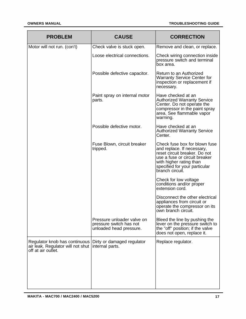
Motor will not run. (con’t)
Regulator knob has continuousair leak. Regulator will not shutoff at air outlet.
Check valve is stuck open.
Loose electrical connections.
Possible defective capacitor.
Paint spray on internal motorparts.
Possible defective motor.
Fuse Blown, circuit breakertripped.
Pressure unloader valve onpressure switch has notunloaded head pressure.
Dirty or damaged regulatorinternal parts.
Remove and clean, or replace.
Check wiring connection insidepressure switch and terminalbox area.
Return to an AuthorizedWarranty Service Center forinspection or replacement ifnecessary.
Have checked at anAuthorized Warranty ServiceCenter. Do not operate thecompressor in the paint sprayarea. See flammable vaporwarning.
Have checked at anAuthorized Warranty ServiceCenter.
Check fuse box for blown fuseand replace. If necessary,reset circuit breaker. Do notuse a fuse or circuit breakerwith higher rating thanspecified for your particularbranch circuit.
Check for low voltageconditions and/or properextension cord.
Disconnect the other electricalappliances from circuit oroperate the compressor on itsown branch circuit.
Bleed the line by pushing thelever on the pressure switch tothe "off" position; if the valvedoes not open, replace it.
Replace regulator.

18
FACTORY SERVICE CENTERS OWNERS MANUAL
MAKITA - MAC700 / MAC2400 / MAC5200
1-800-4-MAKITA - RETAIN THIS PORTION FOR YOUR RECORDS
Arizona3707 E. Broadway Road,Suite 6Phoenix, AZ 85040(602) 437-2850
California41850 Christy StreetFremont, CA 94538-5107(510) 657-9881
14930 Northam StreetLa Mirada, CA 90638-5753(714) 522-8088
1970 Fulton AvenueSacramento, CA 95825(916) 482-5197
7674 Clairemont Mesa BoulevardSan Diego, CA 92111(858) 278-4471
16735 Saticoy Street,Suite 105Van Nuys, CA 91406(818) 782-2440
Colorado11839 E. 51st AvenueDenver, CO 80239-2709(303) 371-2850
Florida750 East Sample RoadPompano Beach, FL 33064(954) 781-6333
Georgia4680 River Green Parkway NWDuluth, GA 30096(770) 476-8911
Illinois1450 Feehanville Drive Mt. Prospect, IL 60056-6011(847) 297-3100
Maryland7397 Washington BoulevardSuite 104 Elkridge, MD 21075(410) 796-4401
Massachusetts232 Providence HighwayWestwood, MA 02090(781) 461-9754
Minnesota6427 Penn Avenue SouthRichfield, MN 55423(612) 869-5199
Missouri9876 Watson Road St. Louis, MO 63126(314) 909-9889
Nebraska4129 S. 84th Street Omaha, NE 68127(402) 597-2925
Nevada3375 S. Decatur Boulevard Suites 22-24 Las Vegas, NV 89102(702) 368-4277
New Jersey251 Herrod Boulevard Dayton, NJ 08810-1539(609) 655-1212
New York4917 Genesee StreetCheektowaga, NY 14225(716) 685-9503
Oregon828 19th Avenue, N.W.Portland, OR 97209(503) 222-1823
Pennsylvania1904 Babcock BoulevardPittsburgh, PA 15209(412) 822-7370
Puerto Rico200 Guayama Street Hato Rey, PR 00917(787) 250-8776
Tennessee1120 Elm Hill Pike, Suite 170Nashville, TN 37210(615) 248-3321
Texas12801 Stemmons Fwy. Suite 809 Farmers Branch, TX 75234(972) 243-1150
12701 Directors DriveStafford, TX 77477-3701 (281) 565-8665
3453 IH-35 North, Suite 101San Antonio, TX 78219(210) 228-0676
Wisconsin2245 S. 108th StreetWest Allis, WI 53227(414) 541-4776
When you need service: Sendcomplete tool (prepaid) to one of theMakita Factory Service Centers listed,or to an Authorized Makita ServiceCenter. Be sure to attach a letter to theoutside of the carton detailing theproblem with your tool.
Date Purchased:
Dealer’s Name and Address:
Model No.
Serial No.

WARNING - NOTES
19
OWNERS MANUAL
MAKITA - MAC700 / MAC2400 / MAC5200
WARNINGSome dust created by power sanding, sawing, grinding, drilling, and other construction activitiescontains chemicals known to the State of California to cause cancer, birth defects or otherreproductive harm. Some examples of these chemicals are:
• lead from lead-based paints,• crystalline silica from bricks and cement and other masonry products, and• arsenic and chromium from chemically-treated lumber.
Your risk from these exposures varies, depending on how often you do this type of work. Toreduce your exposure to these chemicals: work in a well ventilated area, and work withapproved safety equipment, such as those dust masks that are specially designed to filter outmicroscopic particles.
NOTES

20
WARRANTY OWNERS MANUAL
MAKITA - MAC700 / MAC2400 / MAC5200
MAKITA LIMITED ONE YEAR WARRANTYWarranty Policy
Every Makita tool is thoroughly inspected and tested before leaving the factory. It is warrantedto be free of defects from workmanship and materials for the period of ONE YEAR from thedate of original purchase. Should any trouble develop during this one year period, return theCOMPLETE tool, freight prepaid, to one of Makita’s Factory or Authorized Service Centers. Ifinspection shows the trouble is caused by defective workmanship or material, Makita willrepair, (or at our option, replace), without charge.
This warranty does not apply where:
• Repairs have been made or attempted by others;• Repairs are required because of normal wear and tear;• The tool has been abused, misused or improperly maintained;• Alterations have been made to the tool.
IN NO EVENT SHALL MAKITA BE LIABLE FOR ANY INDIRECT, INCIDENTAL ORCONSEQUENTIAL DAMAGES FROM THE SALE OR USE OF THE PRODUCT. THIS
DISCLAIMER APPLIES BOTH DURING AND AFTER THE TERM OF THIS WARRANTY.
MAKITA DISCLAIMS LIABILITY FOR ANY IMPLIED WARRANTIES, INCLUDING IMPLIEDWARRANTIES OF "MERCHANTABILITY" AND "FITNESS FOR A SPECIFIC PURPOSE,"
AFTER THE ONE YEAR TERM OF THIS WARRANTY.
This Warranty gives you specific legal rights, and you may also have other rights which varyfrom state to state. Some states do not allow the exclusion or limitation of incidental orconsequential damages, so the above limitation or exclusion may not apply to you. Somestates do not allow limitation on how long an implied warranty lasts, so the above limitationmay not apply to you.
Makita Corporation3-11-8, Sumiyoshi-cho,
Anjo, Aichi 446-8502 Japan

2) Use of this product is intended for:Construction TradeIndustrial MaintenanceHome MaintenanceHobbyOther
5) Any comments:
AREA CODE: -TELEPHONE:
SERIAL NO.
MODEL NO.
1) This product was purchased from:Home CenterHardware/Lumber StoreTool DistributorIndustrial SupplyConstruction SupplyOther
MAIL THIS PORTIONYour answers to the following questions are appreciated.
3) How did you learn about this product:Magazine Radio Dealer ExhibitionNewspaper From Friend Store Display Previous UsageCatalogueOther
4) Most favored points are:Design Repair Service Features DurabilitySize Power Price Makita BrandOther
DATE PURCHASED
MONTH
INTL.
AGE: Under 19 Over 6020 - 29 30 - 39 40 - 49 50 - 59
ADDRESS:
STATUSMarried Single
SEXMale FemaleLAST NAME / COMPANY NAME
DAY YEAR
CITY: STATE / PROVINCE:
ZIP / POSTAL CODE: COUNTRY:
BE SURE TO COMPLETE THE CUSTOMER’S PORTION OF THIS FORM AND RETAIN FOR YOUR RECORDSPlease return this portion by facsimile or mail ... Facsimile Number (714) 522-8133

Makita U.S.A., Inc.14930 Northam StreetLa Mirada, CA 90638-5753
First Class Postage Required
Post Office will not deliver
without properpostage