2022 STANDARDS & OPTIONS 2022 OWNERS MANUAL
168
2022 STANDARDS & OPTIONS 2022 OWNERS MANUAL
-
Upload
khangminh22 -
Category
Documents
-
view
0 -
download
0
Transcript of 2022 STANDARDS & OPTIONS 2022 OWNERS MANUAL

2022 STANDARDS & OPTIONS2022 OWNERS MANUAL
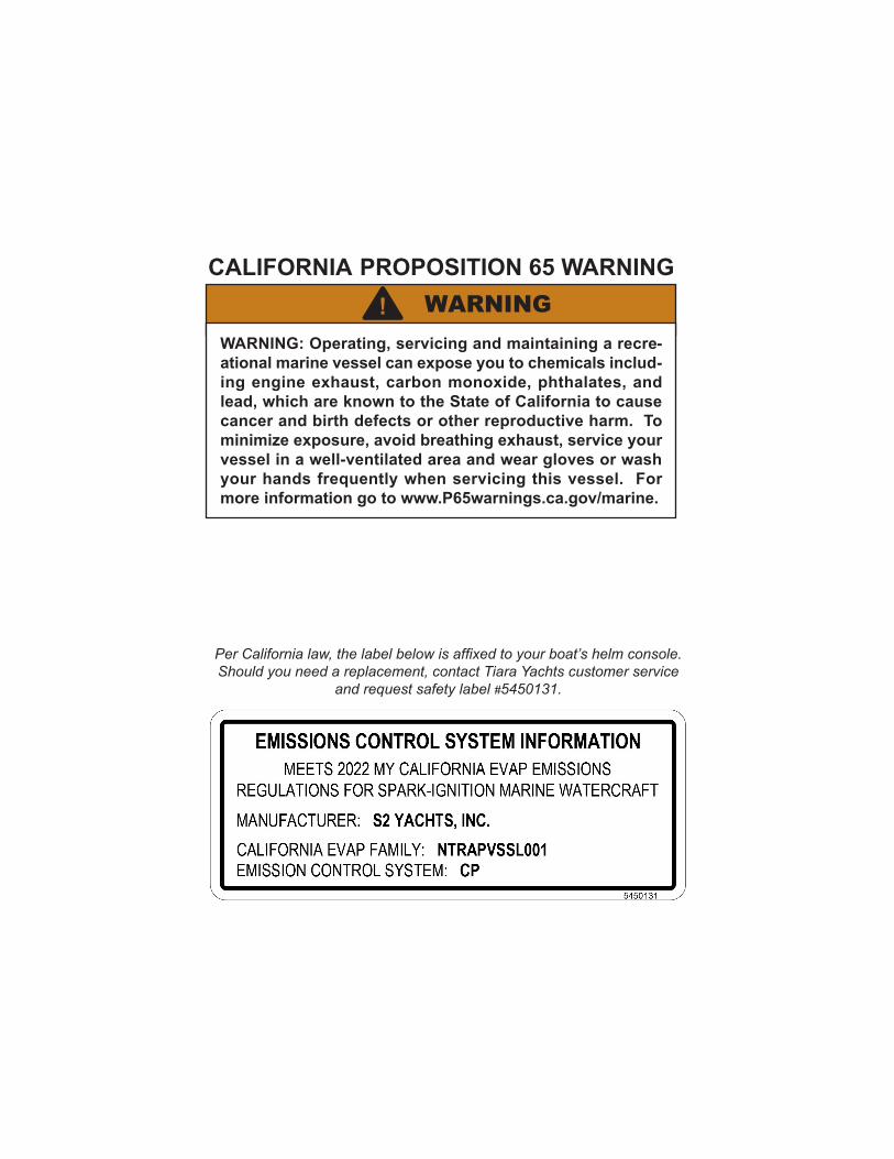
Per California law, the label below is affixed to your boat’s helm console. Should you need a replacement, contact Tiara Yachts customer service
and request safety label #5450131.
CALIFORNIA PROPOSITION 65 WARNINGWARNING!
WARNING: Operating, servicing and maintaining a recre-ational marine vessel can expose you to chemicals includ-ing engine exhaust, carbon monoxide, phthalates, and lead, which are known to the State of California to cause cancer and birth defects or other reproductive harm. To minimize exposure, avoid breathing exhaust, service your vessel in a well-ventilated area and wear gloves or wash your hands frequently when servicing this vessel. For more information go to www.P65warnings.ca.gov/marine.
Welcome to the family of Tiara Yachts boat owners and congratulations on your purchase of your new Tiara.
We understand there are many choices available to you, and we appreciate the investment that you’ve made and the subsequent faith and confidence that you’ve placed into our product. Hopefully, during the selection and buying process, you discovered that each Tiara has been designed, engineered, and built with care and precision.
When our company was started, it was the goal of my father, Leon Slikkers, to provide you with the finest quality boat available. We want to be the best and deliver the best to you. And part of that includes a delightful ownership experience. Everything we have achieved since our humble beginnings has been with this same goal in mind.
The information within this owner’s manual was assembled to assist you in understanding how to operate your boat to obtain the maximum enjoyment of your Tiara. So please take time to read the manual completely and please operate your boat safely and courteously.
I would also like to ask you a personal favor. Shortly, you will receive a survey asking for your opinion about the sales process you experienced when you purchased your boat. Approximately nine months later, you’ll be sent another survey inquiring about your ownership experience. By taking a few minutes to complete these surveys, you will be providing us with valuable information.
Best wishes for many happy hours aboard your new Tiara Yacht,
Thomas B. SlikkersCEO/President S2 Yachts

This page intentionally left blank.

3188
1230
.1
2022
MO
DELS
S2
YA
CH
TS, I
NC
. LIM
ITED
WA
RR
AN
TY C
OVE
RA
GE
S2 Y
acht
s, In
c. (S
2) p
rovi
des
limite
d w
arra
nty
cove
rage
on
Tiar
a Ya
chts
pro
duct
s so
ld f
or u
se b
y re
tail
(non
-com
mer
cial
) cu
stom
ers,
as
desc
ribed
in
this
Lim
ited
War
rant
y. F
or c
usto
mer
s in
th
e U
.S.:
this
war
rant
y gi
ves
you
spec
ific
lega
l rig
hts;
you
als
o m
ay h
ave
othe
r rig
hts,
whi
ch v
ary
from
sta
te t
o st
ate.
For
cus
tom
ers
in t
he E
urop
ean
Uni
on:
the
purc
hase
r m
ay h
ave
addi
tiona
l le
gal r
ight
s un
der a
pplic
able
nat
iona
l leg
isla
tion
gove
rnin
g th
e sa
le o
f con
sum
er g
oods
, and
thos
e rig
hts
(if a
pplic
able
) are
not
affe
cted
by
this
war
rant
y.
This
war
rant
y is
pro
vide
d on
ly to
the
orig
inal
pur
chas
er o
f the
boa
t fro
m a
n au
thor
ized
S2
Yach
ts
deal
er, b
ut c
an b
e tra
nsfe
rred
to s
ubse
quen
t ow
ners
. Con
tact
S2’
s C
usto
mer
Rel
atio
ns D
epar
tmen
t if
you
need
inf
orm
atio
n ab
out
trans
ferri
ng t
his
war
rant
y. N
o w
arra
nty
cove
rage
is
prov
ided
to
subs
eque
nt o
wne
rs u
nles
s th
ey fo
llow
S2’
s tra
nsfe
r pro
cedu
res.
Thi
s w
arra
nty
does
not
ext
end
or
appl
y to
any
one
else
. The
term
s of
this
writ
ten
war
rant
y ca
nnot
be
chan
ged
or m
odifi
ed, e
xcep
t by
a w
ritte
n ag
reem
ent s
igne
d by
an
offic
er o
f S2
Yach
ts, I
nc.
CO
VER
ED P
RO
DUC
TS A
ND
LIM
ITAT
ION
S:
S2’s
lim
ited
war
rant
y co
vera
ge a
pplie
s on
ly to
:
1.
Def
ects
in m
ater
ials
and
wor
kman
ship
in th
e bo
at a
nd a
ll co
mpo
nent
s an
d ac
cess
orie
s (e
xcep
t fo
r the
exc
lude
d ite
ms
desc
ribed
bel
ow) f
or a
per
iod
of tw
o (2
) yea
rs;
2.
Stru
ctur
al d
efec
ts in
mat
eria
ls a
nd w
orkm
ansh
ip in
the
hull a
nd d
eck
for a
per
iod
of fi
ve (5
) yea
rs;
3.
Blis
terin
g du
e to
def
ects
in m
ater
ial a
nd w
orkm
ansh
ip in
the
gelc
oat s
urfa
ce o
f the
hul
l bot
tom
for
a pe
riod
of fi
ve (5
) yea
rs, p
rovi
ded
that
the
gelc
oat s
urfa
ce h
as n
ot b
een
alte
red
in a
ny w
ay s
uch
as s
andi
ng, s
andb
last
ing
or a
pplic
atio
n of
a c
oatin
g ot
her t
han
stan
dard
ant
ifoul
ing
pain
t, an
y of
w
hich
will
void
this
war
rant
y.
Each
of t
he w
arra
nty
cove
rage
per
iods
runs
from
the
date
of p
urch
ase
of th
e bo
at fr
om a
n au
thor
ized
S2
Yac
hts
deal
er a
nd a
pplie
s on
ly t
o w
arra
nted
def
ects
tha
t fir
st m
anife
st t
hem
selv
es a
nd a
re
repo
rted
to S
2 w
ithin
the
app
licab
le w
arra
nty
perio
d. S
2 re
tain
s th
e rig
ht t
o de
term
ine
to i
ts
reas
onab
le s
atis
fact
ion
whe
ther
any
cla
imed
def
ect i
s co
vere
d by
this
war
rant
y.
Cer
tain
item
s ar
e ex
clud
ed fr
om w
arra
nty
cove
rage
by
S2, a
nd th
is li
mite
d w
arra
nty
cove
rage
doe
s no
t app
ly to
:
1.
Engi
nes,
tra
nsm
issi
ons,
ge
nera
tors
, ai
r co
nditi
onin
g sy
stem
s,
swim
pl
atfo
rms
and
lifts
, se
akee
ping
sys
tem
s, e
lect
roni
cs a
nd b
atte
ries.
The
se p
rodu
cts
may
com
e w
ith s
epar
ate
war
rant
ies
from
thei
r man
ufac
ture
rs; s
ee th
e O
wne
r Pac
ket f
or w
arra
nty
regi
stra
tion
requ
irem
ents
an
d de
tails
on
thes
e pr
oduc
ts.
2.
Dea
ler f
inal
ass
embl
y an
d pr
e-de
liver
y co
mm
issi
onin
g, a
nd d
eale
r ins
talle
d co
mpo
nent
s.
3.
Scra
tchi
ng, c
hipp
ing,
dis
colo
ratio
n or
flak
ing
of a
ny p
owde
r coa
ted
or p
aint
ed s
urfa
ce in
clud
ing
engi
nes
and
hard
top
com
pone
nts.
4.
G
elco
at s
tress
cra
ckin
g, c
halk
ing,
fadi
ng o
r dis
colo
ratio
n. T
his
incl
udes
bilg
e ge
lcoa
t. 5.
D
amag
e ca
used
by
acci
dent
, wea
r, st
orm
dam
age,
gro
undi
ng, t
owin
g, c
omm
erci
al u
se o
f the
bo
at, o
r m
isus
e or
abu
se, o
r de
terio
ratio
n re
sulti
ng fr
om n
orm
al u
se (
incl
udin
g ga
sket
s, s
eals
, sp
rings
, wip
ers
and
seal
ants
). 6.
M
aint
enan
ce,
adju
stm
ents
or
real
ignm
ents
to
any
com
pone
nts
incl
udin
g la
tche
s, h
inge
s,
hatc
hes,
doo
rs a
nd d
rive
train
com
pone
nts.
7.
M
old,
mild
ew, u
phol
ster
y da
mag
e or
det
erio
ratio
n an
d cl
eani
ng.
8.
Dam
age
or d
eter
iora
tion
resu
lting
from
env
ironm
enta
l con
ditio
ns, i
nclu
ding
ele
ctro
lysi
s, c
revi
ce
or g
alva
nic
corro
sion
, any
det
erio
ratio
n of
und
erw
ater
equ
ipm
ent,
or a
ny d
amag
e or
det
erio
ratio
n re
sulti
ng fr
om a
ny fa
ilure
to u
nder
take
reas
onab
le, r
outin
e m
aint
enan
ce.
9.
Any
repa
irs, a
djus
tmen
ts, a
ltera
tions
or m
odifi
catio
ns m
ade
by a
nyon
e ot
her t
han
an e
mpl
oyee
of
S2 Y
acht
s, o
r an
auth
oriz
ed S
2 Ya
chts
dea
ler w
ith S
2’s
prio
r, w
ritte
n au
thor
izat
ion.
10
. Dam
age
whi
ch h
as o
ccur
red
as a
res
ult o
f th
e bo
at b
eing
ope
rate
d as
a d
emon
stra
tor
and/
or
disp
laye
d fo
r sal
e.
11. D
amag
e or
det
erio
ratio
n of
the
hull
or d
eck
stru
ctur
e du
e to
the
atta
chm
ent o
f har
dwar
e or
oth
er
com
pone
nts.
12
. Wei
ght,
spee
d, fu
el c
onsu
mpt
ion
or o
ther
per
form
ance
cha
ract
eris
tics.
13
. Dam
age
or d
eter
iora
tion
resu
lting
from
impr
oper
trai
lerin
g, h
aulin
g, la
unch
ing
or s
tora
ge.
14. B
oats
pur
chas
ed o
r use
d fo
r com
mer
cial
or g
over
nmen
tal p
urpo
ses
or u
ses.
REM
EDIE
S U
ND
ER T
HIS
LIM
ITED
WAR
RAN
TY
If a
defe
ct c
over
ed b
y th
is w
arra
nty
occu
rs, S
2 (o
r one
of i
ts a
utho
rized
dea
lers
, as
dete
rmin
ed b
y S2
) w
ill re
pair
and
repl
ace
the
defe
ctiv
e co
mpo
nent
, in
its
sole
dis
cret
ion.
Thi
s ‘re
pair
or r
epla
cem
ent’
rem
edy
is t
he e
xclu
sive
rem
edy
unde
r th
is w
arra
nty.
S2
has
no r
espo
nsib
ility
or l
iabi
lity
for
any
cons
eque
ntia
l or i
ncid
enta
l dam
ages
, suc
h as
loss
of u
se, s
tora
ge c
harg
es, i
nter
est o
r fin
ance
cha
rges
, in
sura
nce
or d
epre
ciat
ion,
tran
spor
tatio
n or
lodg
ing
char
ges,
or c
harg
es fo
r tow
ing
or h
aulin
g ou
t, et
c.
whi
ch a
re s
peci
fical
ly e
xclu
ded
and
disc
laim
ed fr
om th
is w
arra
nty.
For
cus
tom
ers
in th
e U
.S.:
som
e st
ates
do
not a
llow
the
excl
usio
n or
lim
itatio
n of
inci
dent
al o
r co
nseq
uent
ial d
amag
es, s
o th
e ab
ove
limita
tion
or e
xclu
sion
may
not
app
ly to
you
. UN
DER
CER
TAIN
APP
LIC
ABLE
LAW
S, T
HER
E M
AY B
E N
O IM
PLIE
D W
ARR
ANTI
ES O
R G
UAR
ANTE
ES F
RO
M S
2 AP
PLIC
ABLE
TO
YO
UR
BO
AT, A
ND
ALL
IM
PLIE
D O
R S
TATU
TOR
Y C
ON
DIT
ION
S AN
D W
ARR
ANTI
ES (
INC
LUD
ING
AN
Y W
ARR
ANTY
OF
MER
CH
ANTA
BILI
TY O
R F
ITN
ESS
FOR
A P
ARTI
CU
LAR
PU
RPO
SE)
AND
GU
ARAN
TIES
AR
E D
ISC
LAIM
ED W
HER
E AL
LOW
ED B
Y LA
W. T
O T
HE
FULL
EST
EXTE
NT
ALLO
WED
BY
LAW
, AN
Y AN
D A
LL A
PPLI
CAB
LE I
MPL
IED
WAR
RAN
TIES
AN
D G
UAR
ANTI
ES (
IF A
NY)
, IN
CLU
DIN
G A
NY
IMPL
IED
WAR
RAN
TY O
F M
ERC
HAN
TABI
LITY
OR
PAR
TIC
ULA
R P
UR
POSE
, AR
E LI
MIT
ED I
N
DU
RAT
ION
TO
TH
E D
UR
ATIO
N
OF
THE
APPL
ICAB
LE
PRO
VISI
ON
S O
F TH
IS
WR
ITTE
N
WAR
RAN
TY. F
or c
usto
mer
s in
the
U.S
.: so
me
stat
es d
o no
t allo
w li
mita
tions
on
how
long
an
impl
ied
war
rant
y la
sts,
so
the
abov
e lim
itatio
n m
ay n
ot a
pply
to y
ou.
RES
PON
SIB
ILIT
Y O
F PU
RC
HAS
ER
1.
No
war
rant
y co
vera
ge is
pro
vide
d by
S2
unle
ss th
e cu
stom
er a
nd d
eale
r com
plet
e an
d re
turn
all
Vess
el R
egis
tratio
n an
d C
usto
mer
Acc
epta
nce
Form
s to
S2
Yach
ts, I
nc. w
ithin
thirt
y (3
0) d
ays
afte
r del
iver
y of
the
boat
to th
e or
igin
al p
urch
aser
. 2.
Th
e or
igin
al p
urch
aser
or
appr
oved
tran
sfer
ee m
ust n
otify
the
S2 Y
acht
s de
aler
from
whi
ch th
e bo
at w
as p
urch
ased
of a
ny c
laim
ed d
efec
t with
in fi
fteen
(15)
day
s af
ter f
irst d
etec
ting
the
clai
med
de
fect
. War
rant
y w
ork
in e
xces
s of
$50
0 re
quire
s S2
’s p
rior w
ritte
n ap
prov
al.
3.
If th
e de
aler
fails
to s
atis
fact
orily
repa
ir th
e cl
aim
ed d
efec
t with
in fi
fteen
(15)
day
s, w
ritte
n no
tice
mus
t th
en b
e pr
ompt
ly g
iven
dire
ctly
to S
2. S
2 is
not
resp
onsi
ble
for u
nrep
orte
d w
arra
nted
def
ects
. 4.
Th
e bo
at, i
nclu
ding
any
cla
imed
def
ectiv
e pa
rt, m
ust b
e re
turn
ed to
the
S2 Y
acht
s de
aler
from
whi
ch
the
boat
was
pur
chas
ed (o
r to
anot
her d
eale
r or f
acilit
y as
dire
cted
by
S2 Y
acht
s) w
ithin
the
war
rant
y pe
riod
for i
nspe
ctio
n an
d w
arra
nty
serv
ice.
The
exp
ense
of r
etur
ning
and
tran
spor
ting
the
boat
or
any
part
for w
arra
nty
serv
ice,
and
the
expe
nse
of re
turn
ing
and
trans
porti
ng it
bac
k to
the
owne
r af
ter r
epai
r or r
epla
cem
ent,
is th
e re
spon
sibi
lity
of th
e ow
ner,
and
will
not b
e re
imbu
rsed
by
S2.
5.
If th
e de
aler
from
who
m th
e bo
at w
as p
urch
ased
is n
o lo
nger
an
auth
oriz
ed S
2 Ya
chts
dea
ler,
cont
act S
2 fo
r ins
truct
ions
on
how
to o
btai
n w
arra
nty
serv
ice.
S2 r
eser
ves
the
right
to im
prov
e its
pro
duct
s th
roug
h ch
ange
s in
des
ign
or m
ater
ials
with
out b
eing
ob
ligat
ed to
the
owne
rs o
f the
boa
ts o
f sim
ilar o
r the
sam
e m
odel
of p
rior m
anuf
actu
re. W
e m
ay b
e co
ntac
ted
as f
ollo
ws:
Tia
ra C
usto
mer
Rel
atio
ns D
epar
tmen
t, 72
5 Ea
st 4
0th
Stre
et,
Hol
land
, M
ichi
gan
4942
3 (6
16/3
94-7
460)
.
LIM
ITED
WA
RR
AN
TY

SUPPLEMENTAL LIMITED WARRANTY INFORMATION ON FINISHED WOOD COMPONENTS
Your Tiara Yachts® Boat may be furnished with certain finished wood panels and components that require periodic maintenance and refinishing to maintain their appearance and finish. S2 Yachts, Inc.’s Limited Warranty coverage does not include the match-ing of wood grains, or the condition or durability of any finishes for such panels and components. This statement supplements S2 Yachts, Inc.’s Limited Warranty with respect to these wood panels and components. All other terms of S2 Yachts, Inc.’s Limited Warranty remain in effect, and you should refer to the Limited Warranty for other terms, conditions and requirements
CALIFORNIA EVAPORATIVE EMISSIONS CONTROL SYSTEM WARRANTY STATEMENT: YOUR WARRANTY RIGHTS AND OBLIGATIONS
The California Air Resources Board and S2 Yachts, Inc. is pleased to explain the evaporative emission control system’s warranty on your 2022 model year spark-ignition marine watercraft. In California, new spark-ignition marine watercraft (SIMW) must be designed, built, and equipped to meet the State’s stringent anti-smog standards. S2 Yachts, Inc. must warrant the evaporative emission control system on your spark-ignition marine watercraft for the period listed below provided there has been no abuse, neglect, or improper maintenance of your SIMW.
Your evaporative emissions control system may include parts such as: canisters, carburetors, clamps, connectors, filters, fuel caps, fuel lines, fuel tanks, valves, vapor hoses, and other associated evaporative emissions control system components.
MANUFACTURER’S WARRANTY COVERAGE:
This evaporative emission control system is warranted for two years. If any evaporative emission-related part on your SIMW is defective, the part will be repaired or replaced by S2 Yachts, Inc.
OWNER’S WARRANTY RESPONSIBILITIES:
• As the spark-ignition marine watercraft owner, you are responsible for performance of the required maintenance listed in your owner’s manual. S2 Yachts, Inc. recommends that you retain all receipts covering maintenance on your spark-ignition marine watercraft, but S2 Yachts, Inc. cannot deny warranty solely for the lack of receipts.
• As the spark-ignition marine watercraft owner, you should however be aware that S2 Yachts, Inc. may deny you warranty coverage if your spark-ignition marine watercraft or a part has failed due to abuse, neglect, or improper maintenance or unapproved modifications.
• You are responsible for presenting your spark-ignition marine watercraft to a S2 Yachts, Inc. dealer or authorized service center as soon as the problem exists. The warranty repairs should be completed in a reasonable amount of time, not to exceed 30 days. If you have a question regarding your warranty coverage, you should contact S2 Yachts, Inc. at 1-616-392-7163.
The California evaporative emissions control system warranty covers the following list of components:
(1) Canister Mounting Brackets (2) Carbon Canister (3) Carburetor Purge Port Connector (4) Clamps*(5) Control Cables* (6) Control Linkages* (7) Control Solenoids* (8) Control Valves* (9) Electronic Controls* (10) Fuel Cap (11) Fuel Line
(12) Fuel Line Fittings (13) Fuel Tank(14) Liquid/Vapor Separator (15) Pressure Relief Valves* (16) Purge Valves (17) Vacuum Control Diaphragms* (18) Vapor Hoses (19) All other parts not listed that may affect the evaporative
emissions control system
*Note: As they relate to the evaporative emissions control system.

i
IMPORTANT INFORMATION
Your Tiara Owner’s Manual has been written to include a number of safety in-structions to assure the safe operation and maintenance of your boat. These instructions are in the form of WARNING and CAUTION statements. The follow-ing definitions apply:
All instructions given in this book are as seen from the stern looking toward the bow, with starboard being to your right, and port to your left. A glossary of boating terms is included in the Appendix.
DANGER!DANGER INDICATES A HAZARDOUS SITUATION WHICH, IF NOT AVOIDED, WILL RESULT IN DEATH OR SERIOUS INJURY.
WARNING!WARNING INDICATES HAZARDS OR UNSAFE PRACTICES WHICH COULD RESULT IN SEVERE PERSONAL INJURY OR DEATH.
CAUTION!CAUTION indicates hazards or unsafe practices which could result in minor personal injury, or product and property damage.
NOTICENOTICE is used to address best practices not related to physical
IMPORTANT NOTE: Your boat uses internal combustion engines and flammable fuel. Every precaution has been taken by Tiara Yachts to reduce the risks as-

IMPORTANT INFORMATION
ii
sociated with possible injury and damage from fire or explosion, but your own precaution and good maintenance procedures are necessary in order to enjoy safe operation of your boat.
If for any reason you have trouble with your Tiara Owner’s Manual, or require re-placement pages, please contact our Customer Service department at the address on the cover page. We will be happy to supply replacement pages at no charge.
This manual has been compiled to help you to operate your craft with safety and pleasure. It contains details of the craft, the equipment supplied or fitted, its sys-tems, and information on its operation and maintenance. Please read it carefully, and familiarize yourself with the craft before using it.
If this is your first craft, or you are changing to a type of craft you are not familiar with, for your own comfort and safety, please ensure that you obtain handling and operating experience before assuming command of the craft. Your dealer or national sailing federation or yacht club will be pleased to advise you of local sea schools, competent instructors, and reference material.
PLEASE KEEP THIS MANUAL IN A SECURE PLACE, AND PRESENT IT TO THE NEW OWNER WHEN YOU SELL THE CRAFT.
Owner’s manuals for the installed equipment on your boat have also been pro-vided for your reference. They have been stored in a valise that is included in your new boat. Please read this information, and also hand them over to the new owner when you sell the boat.

i53 COUPE
Safety Label Locations
The following safety label locations can be found on the Tiara 53 Coupe. The numbers correspond to the list on Table 1. To obtain replacement labels refer to the part number of the label in Table 1 and contact your Tiara Yachts dealer.
1
INTERIOR
27
1
1

SAFETY LABEL LOCATIONS
ii 53 COUPE
EXTERIOR
4
5
6
10
11
12
13
15
7
20
1
25
28
29
30
31
32
33
3419
1
14
8
18
9
26 16
21

SAFETY LABEL LOCATIONS
iii53 COUPE
1010
22
2424
24241616
22
2317
12
3
23
22
20

SAFETY LABEL LOCATIONS
iv 53 COUPE
1
FIRE EXTINGUISHER INSIDEP/N: 5452010
Location: Master stateroom hanging locker, vip stateroom hanging locker, port galley, starboard
aft facing seat in aft cockpit.
2NO SMOKINGP/N: 5451130
Location: Port & starboard fuel fill
3NOTICE: ANCHOR LINE LOSS
P/N: 5453180Location: Underside of anchor hatch
4NOTICE: FIRE EXTINGUISHING SYSTEM
P/N: 5453300Location: Helm
5BOATERS CHECK LIST
P/N: 5453130Location: Helm
6YACHT CERTIFICATION PLATE
P/N: 5450570Location: Helm
7PRIDE OF OWNERSHIP
P/N: 5450058Location: Port galley
TABLE 1

SAFETY LABEL LOCATIONS
v53 COUPE
8DANGER: CARBON MONOXIDE
P/N: 5453670Location: Trunk lid under stern light
9WARNING: SEAT USE WHILE UNDERWAY
P/N: 5455875Location: Sun pad
10
WARNING: CLOSE TRANSOM DOOR(S). P/N: 5453220
Location: Helm & near port and starboard transom doors.
11WARNING: LEAKING FUEL
P/N: 5453150Location: Helm
12WARNING: ROTATING PROPELLERS
P/N: 5455130Location: Helm, starboard side of swim platform
13WARNING: CARBON MONOXIDE
P/N: 5453690Location: Helm
14WARNING: CARBON MONOXIDE
P/N: 5453680Location: Port galley
15WARNING: SUNSHADE STOWAGE
P/N: 5450054Location: Under port covering board aft cockpit

SAFETY LABEL LOCATIONS
vi 53 COUPE
16
WARNING: HARDTOPP/N: 5453160
Location: Helm, underside of hardtop port & underside of hardtop starboard
17WARNING: FUEL VAPORS
P/N: 5453240Location: Inside trunk at top of opening
18WARNING: OPEN TRUNK
P/N: 5455620Location: Trunk lid under stern light
19WARNING: GRILL SHOCK AND FIRE
P/N: 5455876Location: Underside of grill lid
20
WARNING: HAZARDOUS VOLTAGEP/N: 5451110
Location: Port shore power locker & optional forward shore power connection
21LOCK SEAT
P/N: 5454050Location: Salon port end table
22
FRESH WATERP/N: 5455490
Location: Starboard aft cockpit water connection locker & optional forward wash down connection
23
RAW WATERP/N: 5455480
Location: Starboard aft cockpit water connection locker & optional forward wash down connection

SAFETY LABEL LOCATIONS
vii53 COUPE
24SLING
P/N: 5450240Location: Port & starboard hull sides
25DISCHARGE OF OIL PROHIBITED
P/N: 5450190Location: Underside of engine room hatch
26DUMPING TRASH OVERBOARD
P/N: 5451640Location: Galley trash cabinet
27TAG: OVERBOARD DISCHARGE OF SEWAGE
P/N: 5450050Location: Optional overboard discharge seacock
28TAG: BATTERY MOUNTING REQUIREMENTS
P/N: 5450160Location: Batteries in the engine room
29TAG: FUEL SYSTEM STBD WITHDRAWAL
P/N: 5451290Location: Forward engine room bulkhead
30TAG: FUEL SYSTEM STBD RETURN
P/N: 5451300Location: Forward engine room bulkhead
31TAG: FUEL SYSTEM PORT WITHDRAWAL
P/N: 5451310Location: Forward engine room bulkhead

SAFETY LABEL LOCATIONS
viii 53 COUPE
32TAG: FUEL SYSTEM PORT RETURN
P/N: 5451320Location: Forward engine room bulkhead
33TAG: FUEL SYSTEM GENERATOR WTHDRWL
P/N: 5451350Location: Forward engine room bulkhead
34TAG: FUEL SYSTEM GENERATOR RETURN
P/N: 5451360Location: Forward engine room bulkhead

TOC-153 COUPE
Table of Contents
Introduction: BEFORE CRUISE
SAFETY EQUIPMENT ................................................................................. iFire Suppression System .......................................................................... iFire Extinguishers ......................................................................................ii
Chapter 1: EQUIPMENT AND FEATURES
1.1 POWER CONTROL PANEL ...............................................................1-1
1.2 HELM AREA .......................................................................................1-21.2.1 Engine Controls ............................................................................1-21.2.2 Engine Monitoring with the Multi-Function Displays (MFDs) ........1-31.2.3 Steering: Volvo® IPS Engines .......................................................1-3
1.2.3.1 Volvo® IPS Steering Wheel Driving ........................................1-31.2.3.2 Volvo® IPS Joystick Driving ....................................................1-4
1.2.4 Steering: Cummins® Engines .......................................................1-51.2.4.1 Cummins® Hydraulic Steering Wheel Driving .........................1-6
1.2.5 Power Distribution Panels ............................................................1-61.2.6 Helm Controls and Lights .............................................................1-61.2.7 Compass ......................................................................................1-81.2.8 Blower & Bilge Pump Controls .....................................................1-81.2.9 Seakeeper® Gyro Stabilization System (optional) ........................1-81.2.10 Spotlight Control Pad (optional) .................................................1-81.2.11 Outboard of the Helm .................................................................1-91.2.12 Helm Seat ...................................................................................1-91.2.13 Helm Seat Cabinet .....................................................................1-9
1.2.13.1 Stereo ...................................................................................1-9
1.3 SALON .............................................................................................1-101.3.1 Lights ..........................................................................................1-101.3.2 Adjustable Port Companion Seat ................................................1-101.3.3 Port L-Lounge ............................................................................. 1-11
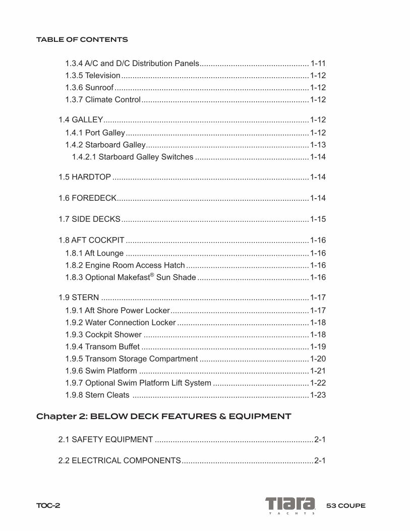
TABLE OF CONTENTS
TOC-2 53 COUPE
1.3.4 A/C and D/C Distribution Panels ................................................. 1-111.3.5 Television ....................................................................................1-121.3.6 Sunroof .......................................................................................1-121.3.7 Climate Control ...........................................................................1-12
1.4 GALLEY ............................................................................................1-121.4.1 Port Galley ..................................................................................1-121.4.2 Starboard Galley .........................................................................1-13
1.4.2.1 Starboard Galley Switches ...................................................1-14
1.5 HARDTOP ........................................................................................1-14
1.6 FOREDECK ......................................................................................1-14
1.7 SIDE DECKS ....................................................................................1-15
1.8 AFT COCKPIT ..................................................................................1-161.8.1 Aft Lounge ..................................................................................1-161.8.2 Engine Room Access Hatch .......................................................1-161.8.3 Optional Makefast® Sun Shade ..................................................1-16
1.9 STERN .............................................................................................1-171.9.1 Aft Shore Power Locker ..............................................................1-171.9.2 Water Connection Locker ...........................................................1-181.9.3 Cockpit Shower ..........................................................................1-181.9.4 Transom Buffet ...........................................................................1-191.9.5 Transom Storage Compartment .................................................1-201.9.6 Swim Platform ............................................................................1-211.9.7 Optional Swim Platform Lift System ...........................................1-221.9.8 Stern Cleats ...............................................................................1-23
Chapter 2: BELOW DECK FEATURES & EQUIPMENT
2.1 SAFETY EQUIPMENT .......................................................................2-1
2.2 ELECTRICAL COMPONENTS ...........................................................2-1

TABLE OF CONTENTS
TOC-353 COUPE
2.3 ATRIUM ..............................................................................................2-3
2.4 CLIMATE CONTROL ..........................................................................2-4
2.5 MASTER STATEROOM .....................................................................2-4
2.6 MASTER HEAD ..................................................................................2-5
2.7 VIP STATEROOM ...............................................................................2-7
2.8 V.I.P. HEAD .........................................................................................2-8
2.9 UTILITY ROOM ..................................................................................2-8
2.10 OPTIONAL THIRD STATEROOM ..................................................2-10
Chapter 3: ENGINE ROOM
3.1 GENERAL ARRANGEMENT ..............................................................3-13.1.1 Forward of Engines ......................................................................3-13.1.2 Between the Engines ....................................................................3-43.1.3 Aft of Engines ...............................................................................3-43.1.4 Starboard, Outboard of Engine .....................................................3-53.1.5 Port, Outboard of Engine ..............................................................3-63.1.6 Lazarette .......................................................................................3-6
Chapter 4: ELECTRICAL SYSTEMS
4.1 THE 12V DC SYSTEM .......................................................................4-14.1.1 Power Supply ...............................................................................4-14.1.2 Battery Charging ...........................................................................4-24.1.3 Distribution ....................................................................................4-34.1.4 Automatic Charging Relay ............................................................4-44.1.5 Emergency Battery Bank Interconnect .........................................4-54.1.6 Operating Notes ...........................................................................4-6
4.2 THE 120/240V AC SYSTEM ..............................................................4-7

TABLE OF CONTENTS
TOC-4 53 COUPE
4.2.1 AC Power Supply ..........................................................................4-74.2.2 Distribution ....................................................................................4-84.2.3 Operating Notes ...........................................................................4-84.2.4 Optional Inverter ...........................................................................4-8
4.3 BONDING SYSTEM ...........................................................................4-9
Chapter 5: OPERATING YOUR BOAT
5.1 WHEN ARRIVING AT YOUR BOAT ...................................................5-15.1.1 Connecting to Shore Power ..........................................................5-25.1.2 Fueling Your Boat .........................................................................5-55.1.3 Fuel System ..................................................................................5-75.1.4 Starting Your Engines ...................................................................5-85.1.5 Transmission and Throttle Operations ........................................ 5-115.1.6 Operating the Generator ............................................................. 5-115.1.7 Filling Your Water Tank ...............................................................5-14
5.2 LEAVING AND RETURNING TO THE DOCK ..................................5-14
5.3 WHILE UNDERWAY .........................................................................5-155.3.1 Waste Disposal ...........................................................................5-165.3.2 Anchoring ....................................................................................5-17
5.4 AFTER RETURNING TO THE DOCK ..............................................5-18
Chapter 6: COMMISSIONING YOUR BOAT
6.1 BEFORE LAUNCHING YOUR BOAT .................................................6-16.1.1 Bottom Paint ................................................................................6-16.1.2 Bilge Areas ...................................................................................6-16.1.3 Electrical Systems ........................................................................6-26.1.4 Installing the Propellers ................................................................6-2
6.1.4.1 Volvo® Engines .......................................................................6-2

TABLE OF CONTENTS
TOC-553 COUPE
6.1.4.2 Cummins® Engines .................................................................6-2
6.2 LIFTING YOUR BOAT ........................................................................6-5
6.3 AFTER LAUNCHING YOUR BOAT ...................................................6-56.3.1 Fresh Water System .....................................................................6-56.3.2 Electrical Systems ........................................................................6-96.3.3 Engines, Transmissions, and IPS Drive Units ............................6-10
6.3.3.1 Volvo® Engines .....................................................................6-106.3.3.2 Cummins® Engines ...............................................................6-10
6.3.4 Interior Equipment ......................................................................6-106.3.5 Exterior Equipment ..................................................................... 6-11
Chapter 7: ROUTINE MAINTENANCE
7.1 FUEL SYSTEM ...................................................................................7-17.1.1 Engine Fuel Filter / Water Separators ..........................................7-17.1.2 Generator Fuel Filter / Water Separator .......................................7-4
7.2 FRESH WATER SYSTEM ..................................................................7-5
7.3 ELECTRICAL SYSTEM ......................................................................7-77.3.1 The DC System ............................................................................7-77.3.2 The AC System .............................................................................7-8
7.4 EXTERIOR SURFACES AND EQUIPMENT ......................................7-87.4.1 Gel Coat .......................................................................................7-97.4.2 Imron® Marine Finish ....................................................................7-97.4.3 Plexiglas® & Acrylic .....................................................................7-107.4.4 Hardware .................................................................................... 7-117.4.5 Canvas & Upholstery .................................................................. 7-117.4.6 Hull Bottom .................................................................................7-127.4.7 Underwater Gear ........................................................................7-127.4.8 Washdown Hoses .......................................................................7-13
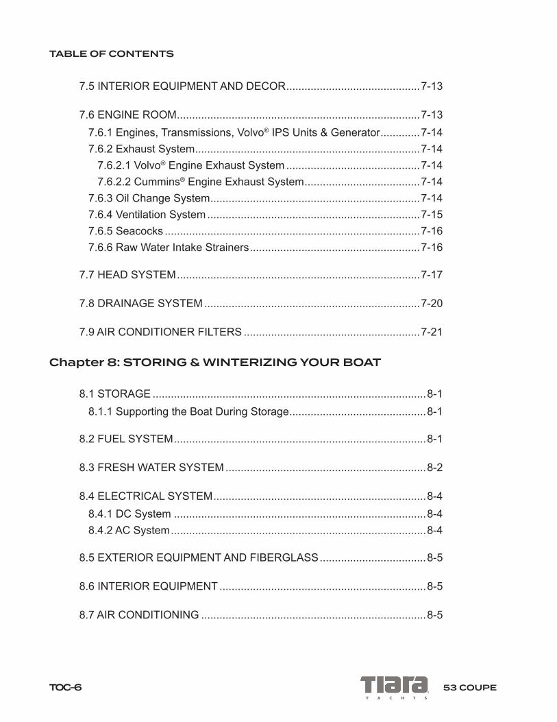
TABLE OF CONTENTS
TOC-6 53 COUPE
7.5 INTERIOR EQUIPMENT AND DECOR ............................................7-13
7.6 ENGINE ROOM ................................................................................7-137.6.1 Engines, Transmissions, Volvo® IPS Units & Generator .............7-147.6.2 Exhaust System ..........................................................................7-14
7.6.2.1 Volvo® Engine Exhaust System ............................................7-147.6.2.2 Cummins® Engine Exhaust System ......................................7-14
7.6.3 Oil Change System .....................................................................7-147.6.4 Ventilation System ......................................................................7-157.6.5 Seacocks ....................................................................................7-167.6.6 Raw Water Intake Strainers ........................................................7-16
7.7 HEAD SYSTEM ................................................................................7-17
7.8 DRAINAGE SYSTEM .......................................................................7-20
7.9 AIR CONDITIONER FILTERS ..........................................................7-21
Chapter 8: STORING & WINTERIZING YOUR BOAT
8.1 STORAGE ..........................................................................................8-18.1.1 Supporting the Boat During Storage .............................................8-1
8.2 FUEL SYSTEM ...................................................................................8-1
8.3 FRESH WATER SYSTEM ..................................................................8-2
8.4 ELECTRICAL SYSTEM ......................................................................8-48.4.1 DC System ...................................................................................8-48.4.2 AC System ....................................................................................8-4
8.5 EXTERIOR EQUIPMENT AND FIBERGLASS ...................................8-5
8.6 INTERIOR EQUIPMENT ....................................................................8-5
8.7 AIR CONDITIONING ..........................................................................8-5

TABLE OF CONTENTS
TOC-753 COUPE
8.8 WASTE SYSTEM ...............................................................................8-6
8.9 ENGINES, DRIVELINE AND GENERATOR .......................................8-78.9.1 Exhaust Systems ..........................................................................8-7
8.9.1.1 Volvo® Engines .......................................................................8-78.9.1.2 Cummins® Engines .................................................................8-8
8.9.2 Steering System ...........................................................................8-8
8.10 RAW WATER SYSTEMS ..................................................................8-9
8.11 ENGINE ROOM AND BILGE AREAS .............................................8-10
Appendices Specifications ........................................................................................... A-1Glossary ................................................................................................... B-1Maintenance Guides ................................................................................C-1Maintenance Schedules...........................................................................D-1Accident Report ....................................................................................... E-1Float Plan ................................................................................................. F-1Troubleshooting Guide .............................................................................G-1

TABLE OF CONTENTS
TOC-8 53 COUPE
This page intentionally left blank.

i
IntroductionBEFORE CRUISE
Before casting off on your voyage ensure the proper safety gear is onboard. Inspect all safety gear and make sure it is up to date and not expired. It is impor-tant that you are familiar with the location and operation of all safety equipment, engine controls, steering operation, starting procedure, and how to interface with the Multi-Function Displays (MFDs). Understand local regulations and waterways and review the contents of this owner’s manual, your engine user manual, and the MFD user manual before casting off.
All boat owners should take a course with a certified training service to understand boating and the ‘rules of the road’ on the water. For more information contact your Tiara Yachts dealer; a licensed professional captain; United States Coast Guard Auxiliary; or United States Power Squadron. We strongly recommend purchasing and reading the current edition of Chapman Piloting & Seamanship.
The maiden voyage should be approached on a calm weather day. Learn to ma-neuver the boat in calm open water using the steering wheel, throttle controls, and joystick.
SAFETY EQUIPMENT
Fire Suppression System
The fire suppression system status indicator is located below the steering wheel on the helm. The indicator provides system status information and an override switch to allow for engine restart if the system has discharged. The fire suppression system is located on the forward engine room bulkhead and operates automatically. To manually discharge the fire suppression system, remove the pin and pull the red handle on the starboard salon wall outboard of the helm. For more information, refer to the fire suppression system user manual.
Manual fire system discharge

BEFORE CRUISE
ii
Fire Extinguishers
There are four (4) or five (5) portable fire extinguishers installed on your Tiara depending on the boats configuration.
The portable fire extinguishers are located:• Inside the starboard cockpit aft facing seat base• Inside the port aft galley storage cabinet• Inside the forward hanging locker in the master stateroom• Inside the starboard hanging locker in the VIP stateroom
If your Tiara is equipped with the optional third stateroom there is an additional portable fire extinguisher located inside the third stateroom storage cabinet.
IF A FIRE SHOULD OCCUR, TURN OFF ALL MAIN ELECTRICAL SWITCHES AND SHUT DOWN THE GENERATOR. DO NOT OPEN THE ENGINE ACCESS HATCH. ALLOW THE CHEMICAL TO SOAK THE ENGINE COMPARTMENT FOR AT LEAST FIFTEEN (15) MINUTES.
WARNING!
FIRE SUPPRESSION CHEMICALS, SMOKE FROM A FIRE, AND EN-GINE EXHAUST DURING A FIRE GIVE OFF TOXIC GASES AND CAN CAUSE ASPHYXIATION OR OTHER SERIOUS HEALTH PROBLEMS. IF A FIRE SHOULD OCCUR, OR IF THE FIRE SUPPRESSION SYSTEM DISCHARGES, SEEK FRESH AIR IMMEDIATELY. DO NOT BREATHE THE FUMES.
WARNING!

1-153 COUPE
Chapter 1EQUIPMENT AND FEATURES
1.1 POWER CONTROL PANEL
The Power Control Panel (Figure 1-1) is located in the galley peninsula cabinet, located forward of the port galley. To access the power control panel, open the cabinet and slide the pantry shelves outboard. See chapter 5 for more information.
The power control panel includes:
• BATTERY BUTTONS: Press the PORT, STBD, or HOUSE BATTERY buttons to turn ON the batteries. These battery buttons remotely turn on the main battery switches located below the Master DC panel in the engine room. Battery but-ton lights will blink and then remain steady once batteries are engaged. NOTE: Turn bat-teries ON before connecting to shore power.
• SHORE POWER: First, turn all batteries ON, then make a secure connection to shore power. Press the SHORE POWER button to connect the boat’s electrical sys-tem to shore power. See chapter 5 for more information.
• GENERATOR POWER: Turn all batteries ON, then START the generator fol-lowing the procedure in chapter 5. Once the generator is operating, press the GENERATOR button to connect the boat’s electrical system to the generator. The button light will blink and then remain steady once the generator is con-nected. If the system detects insufficient voltage, the generator will not start. See chapter 5 for more information.
• Battery and shore power monitors: The power monitors display information about the batteries and shore power connections. See the monitor manufac-turer’s user manual for more information.
Figure 1-1: Power control panel

EQUIPMENT AND FEATURES
1-2 53 COUPE
1.2 HELM AREA
The helm is on the starboard side of the forward salon (Figure 1-2).
Figure 1-2: Helm area
CAUTION!Service or repairs to helm-area equipment should be performed by your Tiara Yachts Dealer or other qualified marine repair technician. Failure to do so could result in damage to equipment used to safely operate the boat.
1.2.1 Engine Controls
The engine control head is located on the starboard side of the helm seat. The control head has two levers; the port side lever controls the port engine and the starboard side lever controls the starboard engine. The ignition buttons are located on the helm, to starboard of the steering wheel. The PORT ignition

EQUIPMENT AND FEATURES
1-353 COUPE
button is for the port engine and the STARBOARD button is for the starboard engine. Review chapter 5 and your engine user manual for starting and operat-ing procedures.
TRIM TABS: The Lenco™ switches, marked BOW UP/DOWN, are located aft of the engine control head and operate the port and starboard trim tabs. The elec-trically actuated trim tabs control the fore and aft ‘trim’ and port and starboard ‘heel’ of your boat while it is on plane. Refer to the Lenco™ user manual for more information.
CAUTION!Before backing your boat at more than idle speed, depress both trim switches to UP to fully retract the trim tabs. Failure to do so could result in damage to trim tab actuators.
1.2.2 Engine Monitoring with the Multi-Function Displays (MFDs)
The Multi-Function Displays (MFDs) allow you to monitor engine functions, operate the stereo system, and more. Interact with the MFDs by touching the screens or by using the GRID (Garmin® Remote Input Device) found on the helm seat armrest. On boats equipped with Volvo® engines, review the Volvo® Glass Cockpit electronics package user manual(s) thoroughly before operating your boat. On boats equipped with Cummins® engines, review the Garmin® electronics package user manual(s) thoroughly before operating your boat.
1.2.3 Steering: Volvo® IPS Engines
Boats equipped with the Volvo® Inboard Performance System (IPS) engine package may be steered using the steering wheel, joystick control, or engine controls. For detailed information, see the engine user manual.
1.2.3.1 Volvo® IPS Steering Wheel Driving
Steering wheel responsiveness can be quick. Aggressive steering can turn and heel the boat dramatically. While underway, maneuverability is highly responsive to the skipper’s command.

EQUIPMENT AND FEATURES
1-4 53 COUPE
Tilt the steering wheel to a comfortable position by pushing the tilt catch on the 6 o’clock position of the wheel base.
The steering wheel sends a digital signal to the Electronic Vessel Control (EVC) computer, which sends commands to the IPS drives to rotate accordingly. The steering wheel will rotate in either direction limitlessly, but a digital stop has been encoded. No matter how many turns the wheel is given in either direction, the drives will stop rotating once the digital stop point has been realized. At higher engine speeds the steering turning degree is more controlled: that is to say, the angles of turning will be limited at higher engine revolutions (RPMs). At higher engine speeds a built-in resistance will interface with the wheel, giving the helmsman the analog feel of force when turning.
The rudder angle indicator on the Multi-Function Displays (MFDs) shows an approximation of the drive angle.
When the ignitions are turned off, the IPS drive units automatically center.
1.2.3.2 Volvo® IPS Joystick Driving
The Volvo® IPS joystick (Figure 1-3) is located on the starboard side of the helm. All joystick buttons are ON-OFF switches. Press once for ON and a second time for OFF.
1. The joystick control may be used to steer the boat in place of the steering wheel, allowing the driver to steer while seated at the helm seat. The joy-stick also makes docking easier, with intuitive maneuvering that allows the boat to move sideways or spin on its own axis. When using the joystick to steer, the throttles still control the engine RPMs. To steer gradually, twist the joystick in the desired direction. To dodge or turn quickly, push the joystick to port or starboard and the boat will quickly turn hard. The steer-ing wheel is in a standby position while joystick driving. To use the steer-ing wheel, simply turn it and it will become fully available, deactivating the joystick.
2. The joystick activation button activates and deactivates joystick steering and engages the autopilot function. The joystick autopilot function is au-tomatically engaged if the joystick is released, and continues on the last heading of the joystick. Further joystick driving will adjust the autopilot heading.
EQUIPMENT AND FEATURES
1-553 COUPE
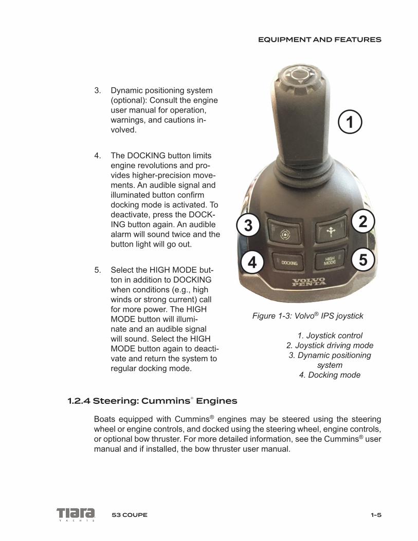
3. Dynamic positioning system (optional): Consult the engine user manual for operation, warnings, and cautions in-volved.
4. The DOCKING button limits engine revolutions and pro-vides higher-precision move-ments. An audible signal and illuminated button confirm docking mode is activated. To deactivate, press the DOCK-ING button again. An audible alarm will sound twice and the button light will go out.
5. Select the HIGH MODE but-ton in addition to DOCKING when conditions (e.g., high winds or strong current) call for more power. The HIGH MODE button will illumi-nate and an audible signal will sound. Select the HIGH MODE button again to deacti-vate and return the system to regular docking mode.
1.2.4 Steering: Cummins® Engines
Boats equipped with Cummins® engines may be steered using the steering wheel or engine controls, and docked using the steering wheel, engine controls, or optional bow thruster. For more detailed information, see the Cummins® user manual and if installed, the bow thruster user manual.
Figure 1-3: Volvo® IPS joystick
1. Joystick control2. Joystick driving mode3. Dynamic positioning
system4. Docking mode
3
4
1
5
2

EQUIPMENT AND FEATURES
1-6 53 COUPE
1.2.4.1 Cummins® Hydraulic Steering Wheel Driving
Cummins® hydraulic assist steering uses a traditional straight-drive steering system that controls the rudders, which steer the boat.
1.2.5 Power Distribution Panels
The AC Distribution Panel and DC Distribution Panel are located beneath the starboard salon loveseat (Figure 1-4). To access the panels, lift the inboard edge of the base seat cushion to raise the seat up, then lift the panel cover. See section 1.3.4 and chapter 4 for more information.
Figure 1-4: AC and DC Distribution Panels
1.2.6 Helm Controls and Lights
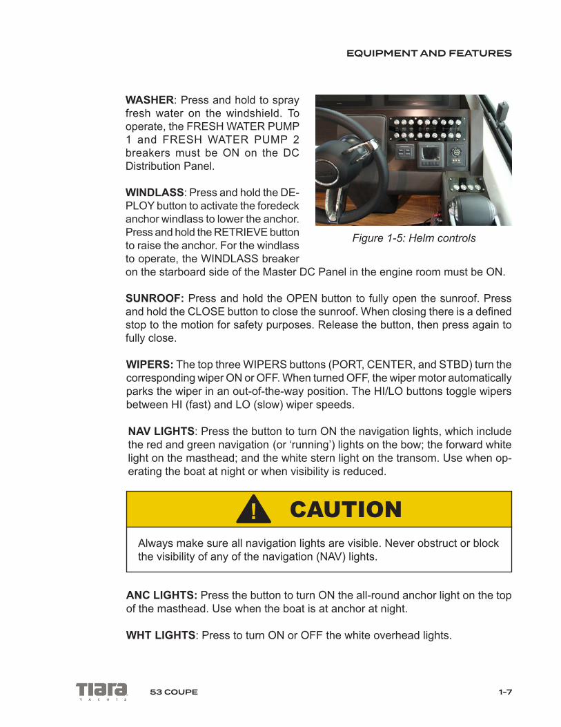
There are a number of buttons on the helm (Figure 1-5). For any of the buttons to function, the associated breaker must be switched ON on the AC Distribution Panel or DC Distribution Panel.
HORN: Press to sound the boat’s horn.
EQUIPMENT AND FEATURES
1-753 COUPE
WASHER: Press and hold to spray fresh water on the windshield. To operate, the FRESH WATER PUMP 1 and FRESH WATER PUMP 2 breakers must be ON on the DC Distribution Panel.
WINDLASS: Press and hold the DE-PLOY button to activate the foredeck anchor windlass to lower the anchor. Press and hold the RETRIEVE button to raise the anchor. For the windlass to operate, the WINDLASS breaker on the starboard side of the Master DC Panel in the engine room must be ON.
SUNROOF: Press and hold the OPEN button to fully open the sunroof. Press and hold the CLOSE button to close the sunroof. When closing there is a defined stop to the motion for safety purposes. Release the button, then press again to fully close.
WIPERS: The top three WIPERS buttons (PORT, CENTER, and STBD) turn the corresponding wiper ON or OFF. When turned OFF, the wiper motor automatically parks the wiper in an out-of-the-way position. The HI/LO buttons toggle wipers between HI (fast) and LO (slow) wiper speeds. NAV LIGHTS: Press the button to turn ON the navigation lights, which include the red and green navigation (or ‘running’) lights on the bow; the forward white light on the masthead; and the white stern light on the transom. Use when op-erating the boat at night or when visibility is reduced.
CAUTION!Always make sure all navigation lights are visible. Never obstruct or block the visibility of any of the navigation (NAV) lights.
ANC LIGHTS: Press the button to turn ON the all-round anchor light on the top of the masthead. Use when the boat is at anchor at night.
WHT LIGHTS: Press to turn ON or OFF the white overhead lights.
Figure 1-5: Helm controls

EQUIPMENT AND FEATURES
1-8 53 COUPE
RED LIGHTS: Press to turn ON or OFF the red overhead lights, for use during night navigation.
BLUE LIGHTS: Press to turn ON or OFF the blue accent lights.
ACC: Press to operate optional accessory equipment, if installed.
1.2.7 Compass
The compass is located at the top of the helm and indicates the direction the bow of your boat is headed. The compass should be compensated by an authorized Tiara Yachts dealer, or other qualified marine service facility, for magnetic devia-tion associated with your particular location.
1.2.8 Blower & Bilge Pump Controls
The blower and bilge pump buttons are located outboard of the helm, forward of the engine control head.
BLOWER: Press the button ON to activate the engine room exhaust blowers. The button will light up blue when the blower is ON.
BILGE (FWD, MID, AFT): Press the appropriate button to manually activate the corresponding bilge pump. Bilge pumps are located (from forward to aft): under the master stateroom floor hatch (FWD); forward in the engine room (MID); and in the lazarette area (AFT). The bilge button will light up red if the bilge pump has been automatically activated.
1.2.9 Seakeeper® Gyro Stabilization System (optional)
To operate the optional Seakeeper® Gyro Stabilization System, if installed, use the control panel located on the helm. Refer to the Seakeeper user manual for more information.
1.2.10 Spotlight Control Pad (optional)
Press the ON/OFF button to turn the optional spotlight ON or OFF, if installed. Use the up, down, left and right arrows to control the orientation of the spotlight, and the SPEED button to control rotation speed.
EQUIPMENT AND FEATURES
1-953 COUPE
1.2.11 Outboard of the Helm
The area outboard of the helm houses the Garmin card reader, Fireboy fire su-pression system override switch and status indicator, VHF radio, 12v outlet, helm air vent, and drink holder. Refer to the manufacturers’ user manuals for more information.
1.2.12 Helm Seat
The helm seat may be adjusted forward and aft using the unmarked buttons located to starboard of the seat, aft of and below the trim tabs.
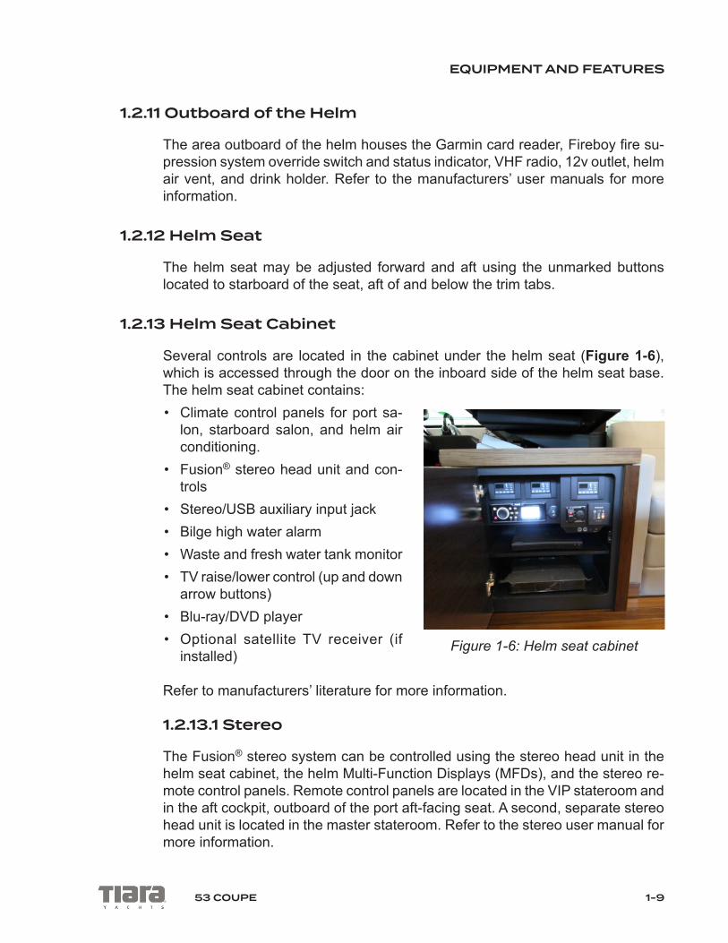
1.2.13 Helm Seat Cabinet
Several controls are located in the cabinet under the helm seat (Figure 1-6), which is accessed through the door on the inboard side of the helm seat base. The helm seat cabinet contains:• Climate control panels for port sa-
lon, starboard salon, and helm air conditioning.
• Fusion® stereo head unit and con-trols
• Stereo/USB auxiliary input jack• Bilge high water alarm• Waste and fresh water tank monitor• TV raise/lower control (up and down
arrow buttons)• Blu-ray/DVD player • Optional satellite TV receiver (if
installed)
Refer to manufacturers’ literature for more information.
1.2.13.1 Stereo
The Fusion® stereo system can be controlled using the stereo head unit in the helm seat cabinet, the helm Multi-Function Displays (MFDs), and the stereo re-mote control panels. Remote control panels are located in the VIP stateroom and in the aft cockpit, outboard of the port aft-facing seat. A second, separate stereo head unit is located in the master stateroom. Refer to the stereo user manual for more information.
Figure 1-6: Helm seat cabinet

EQUIPMENT AND FEATURES
1-10 53 COUPE
1.3 SALON
1.3.1 Lights
The salon’s dimmable overhead lights are controlled by light switches in the gal-ley and at the top of the companionway stairs. Press and hold UP/DOWN on the switch to adjust the brightness of the lights.
1.3.2 Adjustable Port Companion Seat
The port companion seat can be moved fore and aft; slide until the seat locks into place. The seat backrest is adjustable for facing forward or aft (Figure 1-7).
To move the seat backrest:
1. Lift the backrest cushion straight up until it stops.
2. Guide the backrest cushion aft while keeping it raised.
3. Lower the backrest back down onto the seat until the mechanism bottoms out.
4. Slide the backrest into its final position.
Figure 1-7: Adjustable port companion seat

EQUIPMENT AND FEATURES
1-1153 COUPE
1.3.3 Port L-Lounge
The port L-Lounge has seating for five and a teak table (Figure 1-8). The aft sofa base cushion opens up to storage underneath.
The teak table features an actuated hi-lo pedestal. Use the switch located out-board of the port end table to adjust.
Figure 1-8: Port lounge
1.3.4 A/C and D/C Distribution Panels
The A/C and D/C Distribution Panels are located under the starboard salon love-seat (Figure 1-4). Lift the inboard edge of the base seat cushion in order to raise the loveseat up. To access the distribution panels, lift the Plexiglas panel cover.
NOTE: The A/C switching box, located aft of the A/C Distribution Panel, should be accessed by qualified personnel only.
Three GFCI outlets are located inboard of the A/C Distribution Panel. If a circuit is overloaded (indicated by a red light on the outlet), press the outlet’s ‘reset’ button to reset.

EQUIPMENT AND FEATURES
1-12 53 COUPE
1.3.5 Television
The flat-screen TV is housed outboard of the loveseat, on a hi-lo actuator. To raise or lower the TV, use the controls (marked with up and down arrows) found in the helm seat cabinet (Figure 1-6). The TV must be in the stowed position while operating the boat above idle speeds.
The Blu-ray/DVD player and optional satellite TV receiver are located in the helm seat cabinet.
Refer to the manufacturers’ user manuals for more information.
1.3.6 Sunroof
The sunroof is actuated using the SUNROOF buttons on the helm. Press and hold the OPEN button to fully open the sunroof. Press and hold the CLOSE but-ton to close the sunroof. When closing there is a defined stop to the motion for safety purposes. Release the button, then press again to fully close.
1.3.7 Climate Control
The salon contains three air conditioning systems: port, starboard, and helm. All systems are operated using the control panels found in the helm seat cabinet (Figure 1-6).
1.4 GALLEY
The galley is located to port and starboard in the aft salon.
1.4.1 Port Galley
The port galley features:
• Overhead storage cabinets• Sinks with hot/cold water faucet and optional garbage disposal• Quartz countertops and lids for the sinks and cooktop• Storage for quartz lids in the compartment under the cooktop• Recessed three-burner electric cooktop with exhaust fan

EQUIPMENT AND FEATURES
1-1353 COUPE
• Microwave/convection oven • AC outlets• Wastebasket
Refer to the manufacturers’ user manuals for more information.
Switches to operate the exhaust fan and optional garbage disposal are located on the port galley backsplash.
The lid for the cooktop activates a safety switch that disables cooktop operation when it is in place. Always allow the cooktop to cool before covering with the lid. Lids may be stowed under the cooktop when not in use.
Do not set the quartz lid over a warm cooktop. Allow the cooktop to cool completely before covering. Failure to follow this notice could result in damage to the lid, cooktop, or both.
NOTICE
The galley peninsula, located forward of the port side galley, houses the Power Control Panel. See section 1.1 for details.
1.4.2 Starboard Galley
The starboard galley features the following equipment:
• Overhead storage cabinets• Dual Isotherm® 120V drawer units (one with two refrigerator drawers, one with
a refrigerator drawer and a freezer drawer)• Optional ice maker• Optional beverage cooler• Countertop accent lighting• AC outlets

EQUIPMENT AND FEATURES
1-14 53 COUPE
1.4.2.1 Starboard Galley Switches
The following switches are located on the starboard galley backsplash:
SALON LIGHT: Press and hold UP/DOWN on the switch to adjust the brightness of the salon’s dimmable overhead lights.
COUNTERTOP ACC LIGHTS: Press to turn ON or OFF the galley countertop accent lights.
HARDTOP OVERHANG LIGHTS: An ON-OFF-ON switch that, when switched ON, activates the WHITE/BLUE lights in the hardtop overhang.
COCKPIT COURTESY LIGHTING: Press ON to activate the WHITE/BLUE cockpit courtesy lighting. To change between WHITE/BLUE, cycle the switch OFF and back ON.
1.5 HARDTOP
The hardtop is designed to carry typical marine electronic components, antennas, and similar items. Do not climb on the hardtop.
THE HARDTOP IS NOT A WEATHER DECK. FALLING FROM THE HARDTOP CAN RESULT IN SERIOUS PERSONAL INJURY OR DEATH. STAY OFF HARDTOP.
WARNING!
1.6 FOREDECK
The foredeck includes the sunpad, an escape/ventilation hatch, mooring cleats, navigation lights, anchor locker, and bow rail.
DO NOT OCCUPY THE SUNPAD WHILE UNDERWAY AT SPEEDS EX-CEEDING 5 MPH.
WARNING!

EQUIPMENT AND FEATURES
1-1553 COUPE
THE CLEATS ON YOUR BOAT HAVE NOT BEEN DESIGNED FOR, AND ARE NOT INTENDED TO BE USED FOR, TOWING. USING THEM FOR THIS PURPOSE COULD RESULT IN PERSONAL INJURY OR DAMAGE TO YOUR BOAT. REFER TO Chapman Piloting & Seamanship FOR PROPER TOWING PROCEDURES.
WARNING!
To adjust the sunpad backrest, unsnap the three snaps securing the top flap and lift the backrest up until the backrest support engages. Return the backrest to its flat, snapped position when the boat is underway at speeds above 5 mph.
The anchor locker at the bow houses the windlass and windlass remote control. Refer to chapter 5 and the windlass user manual for operating instructions. The anchor locker also contains the optional forward shore power connection and optional fresh and raw water wash down connections (if equipped).
1.7 SIDE DECKS
Handrails are located port and starboard on and around the hardtop, for use while moving about the side decks.
Cleats are located on the toe rail. Nonskid texture has been provided on all walk-ing surfaces.
DIESEL fuel fill fittings are provided on the port and starboard side decks for convenient filling of the fuel tank from either side.
The WASTE tank pump out fitting is located on the forward starboard side deck walkway.
EQUIPMENT AND FEATURES
1-16 53 COUPE
1.8 AFT COCKPIT
1.8.1 Aft Lounge
The port aft-facing seat features a cooler underneath.
A fire extinguisher and storage area are located under the starboard aft-facing seat. A mount for the optional cockpit TV is located above the starboard aft-facing seat. The optional cockpit TV is stored in the master stateroom hanging locker, and should be stowed whenever the boat is underway.
The aft cockpit table may be adjusted up and down using the switch located in-board of the starboard aft-facing seat.
1.8.2 Engine Room Access Hatch
The engine room access hatch is located on centerline on the aft cockpit floor. The engine room lights turn ON automatically when the hatch is opened and turn OFF when the hatch is closed. The main battery switches must be ON for the engine room lights to operate.
1.8.3 Optional Makefast® Sun Shade
The optional Makefast® sun shade is electrically powered and extends to shade the aft cockpit. To extend or retract the sun shade, switch ON the SUN SHADE breaker on the DC Distribution Panel, then use the switch located on the inboard face of the starboard aft-facing cockpit seat.
CAUTION!The sun shade must be retracted when boat speeds exceed 5 mph or dur-ing severely windy conditions.

EQUIPMENT AND FEATURES
1-1753 COUPE
1.9 STERNThe transom area features stainless steel transom gates. Lift a gate up to swing it into one of three positions. The gate will drop down and stay stationary in the aft or forward open position or the closed position.
DO NOT OPERATE YOUR BOAT UNDER POWER WITH THE TRAN-SOM GATES OPEN. OPERATION OF THE BOAT WITH TRANSOM GATES OPEN MAY ALLOW PERSONS TO FALL OVERBOARD AND INTO BOAT PROPELLERS OR TO BE LOST IN THE OPEN WATER.
WARNING!
1.9.1 Aft Shore Power LockerThe aft shore power locker (Figure 1-9) is located behind a door outboard of the port cockpit gangway. This locker contains the aft shore power cable, aft shore power cable recoil control switch, aft shore power breaker, ELCI power reset button (Figure 1-10), and cable TV inlet. See chapter 5 for detailed shore power instructions.
The ELCI (equipment leakage current interrupter) uncouples the boat’s power system from shore power if a problem is detected. Use the ELCI power reset button (Figure 1-10) to restore power if it has been tripped. See chapter 4 for electrical systems information.
Use the power recoil switch, located just forward of the shore power cable inlet, to release or retrieve the shore power cable. Place the switch in the middle posi-tion when not moving the cable.
Figure 1-9: Aft shore power locker Figure 1-10: Breaker & ELCI reset
EQUIPMENT AND FEATURES
1-18 53 COUPE
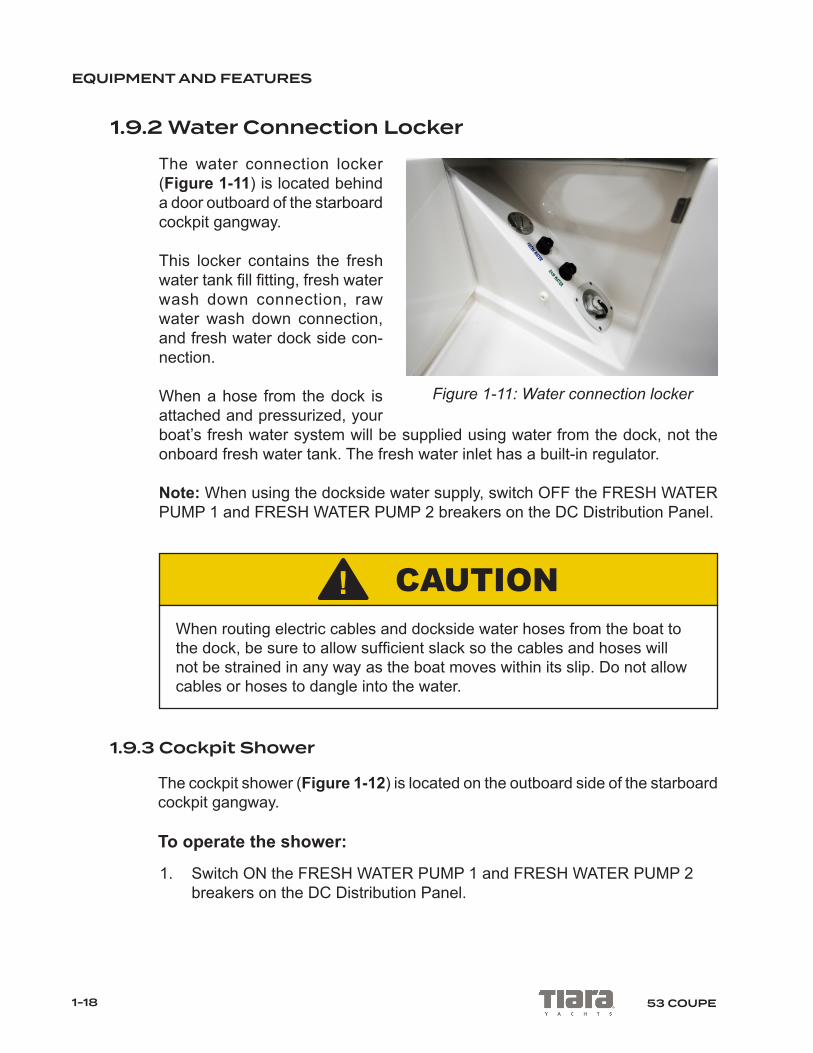
1.9.2 Water Connection LockerThe water connection locker (Figure 1-11) is located behind a door outboard of the starboard cockpit gangway.
This locker contains the fresh water tank fill fitting, fresh water wash down connection, raw water wash down connection, and fresh water dock side con-nection.
When a hose from the dock is attached and pressurized, your boat’s fresh water system will be supplied using water from the dock, not the onboard fresh water tank. The fresh water inlet has a built-in regulator.
Note: When using the dockside water supply, switch OFF the FRESH WATER PUMP 1 and FRESH WATER PUMP 2 breakers on the DC Distribution Panel.
CAUTION!When routing electric cables and dockside water hoses from the boat to the dock, be sure to allow sufficient slack so the cables and hoses will not be strained in any way as the boat moves within its slip. Do not allow cables or hoses to dangle into the water.
1.9.3 Cockpit Shower
The cockpit shower (Figure 1-12) is located on the outboard side of the starboard cockpit gangway.
To operate the shower:
1. Switch ON the FRESH WATER PUMP 1 and FRESH WATER PUMP 2 breakers on the DC Distribution Panel.
Figure 1-11: Water connection locker

EQUIPMENT AND FEATURES
1-1953 COUPE
2. Switch ON the WATER HEATER breaker on the AC Distribution Panel.
3. Pull the shower wand out of the holder.
4. Twist the shower wand to start the flow of water and adjust the tempera-ture.
5. Ensure the shower wand is shut OFF completely before placing it back into the holder. Failure to do so will cause the fresh water pumps to run and water to leak into the bilge.
1.9.4 Transom Buffet
The transom buffet (Figure 1-13) features a Corian® countertop, an optional electric grill, and optional ice maker or optional refrigerator.
To operate the electric grill:
1. Lift up the Corian® lid cov-ering the grill.
2. Switch ON the DECK GRILL breaker on the AC Distribution Panel.
3. Turn the grill ON using the controls built into the grill unit.
When finished, let the grill cool, clean the top, empty the drip pan contents, and lower the lid. Lowering the Corian® lid on the grill activates a safety switch that turns the DECK GRILL breaker OFF. The grill GFCI is located in the transom storage compartment, near the top of the port sidewall. Refer to the grill user manual for more information.
Figure 1-12: Cockpit shower
Figure 1-13: Transom buffet

EQUIPMENT AND FEATURES
1-20 53 COUPE
After cooking, clean the grill surface. Empty the contents of the drip pan located below the grill. Lift the grill grate up and carefully remove the fully cooled drip pan. Allow the grill to cool off before closing the lid. Failure to do so could result in damage to the grill or grill area.
NOTICE
The transom buffet houses the following switches, on the port side of the back-splash:
UNDERWATER LIGHTS (optional): Switch ON to turn on the optional underwater lights on the transom.
SWIM PLATFORM (optional): Switch UP to raise or DOWN to lower the optional hydraulic swim platform lift. NOTE: Before operating this switch, be aware of pinch points and people and objects located around the swim platform. Be cer-tain all people, pets, and items are cleared away from the swim platform before using this switch. Refer to section 1.9.7 and the manufacturer’s user manual for more information.
HATCH: Switch UP to open or DOWN to close the transom storage compartment hatch. NOTE: When operating this switch be aware of pinch points and people or pets near the hatch.
1.9.5 Transom Storage Compartment
The transom storage compartment is located in the transom buffet. Lines, fenders, and other items may be accessed quickly by lifting the Corian® countertop. Use the hatch button on the transom buffet backsplash to lift the compartment hatch.
The storage compartment light switch is located on the starboard sidewall inside the storage compartment.

EQUIPMENT AND FEATURES
1-2153 COUPE
The transom storage compartment features:• Storage for dock lines, fenders, dock poles, etc.• AC power outlet• Access to the lazarette area containing:
• Volvo® IPS pod units (for boats equipped with Volvo® engines)• Steering components (for boats equipped with Cummins® engines)• Generator• Optional hydraulic swim platform lift system pump
FUEL VAPORS ARE A FIRE AND EXPLOSION HAZARD THAT CAN RESULT IN SERIOUS INJURY, BURNS, OR DEATH. DO NOT STORE CONTAINERS OF FUEL OR OTHER FLAMMABLE LIQUIDS IN THE TRANSOM STORAGE COMPARTMENT OR THE ENGINE ROOM.
WARNING!
CAUTION!When raising the transom storage hatch make sure no items are placed on the buffet. Failure to do so could result in damage or injury.
1.9.6 Swim Platform
The swim ladder is located under the starboard side of the platform. Release the catch to extend the ladder. Lower the extended ladder down into the water to assist in boarding the boat from the water.

EQUIPMENT AND FEATURES
1-22 53 COUPE
CARBON MONOXIDE (CO) CAN CAUSE BRAIN DAMAGE OR DEATH. ENGINE AND GENERATOR EXHAUST CONTAIN ODORLESS, COL-ORLESS CARBON MONOXIDE GAS. CARBON MONOXIDE WILL BE PRESENT AROUND THE BOAT STERN WHEN ENGINES OR GENERA-TOR ARE RUNNING. TURN OFF ENGINES AND GENERATOR WHEN THE SWIM PLATFORM IS IN USE. SWIMMERS SHOULD NOT ENTER THE CAVITY UNDER THE SWIM PLATFORM. MOVE TO FRESH AIR IF YOU FEEL NAUSEA, HEADACHE, DIZZINESS, OR DROWSINESS.
DANGER!
1.9.7 Optional Swim Platform Lift System
The optional swim platform lift system raises and lowers the swim platform. Al-ways be sure the swim platform is in the UP and LOCKED position prior to getting underway.
The swim platform hydraulic power unit is located under the center floor hatch inside the transom storage compartment on boats equipped with Volvo® engines and inside the engine room on boats equipped with Cummins® engines. Lift the red switch cover and flip the switch ON to turn on the power unit. Refer to the manufacturer’s user manual for more information. Before operating the swim platform lift system, switch ON the SWIM PLATFORM breaker on the starboard side of the Master DC Panel on the forward engine room bulkhead. Activate the swim platform lift using the switch located on the port side of the transom buffet backsplash (see section 1.9.4), or by using the wireless remote control.

EQUIPMENT AND FEATURES
1-2353 COUPE
1.9.8 Stern Cleats
Four cleats are installed at the stern of your boat: two cleats on the transom corners and two pop-up cleats at the base of the transom buffet. The cleats are designed to handle the loads associated with mooring your boat. Do not use these cleats for towing.
THE CLEATS ON YOUR BOAT HAVE NOT BEEN DESIGNED FOR, AND ARE NOT INTENDED TO BE USED FOR, TOWING. USING THEM FOR THIS PURPOSE COULD RESULT IN PERSONAL INJURY OR DAMAGE TO YOUR BOAT. REFER to Chapman Piloting & Seamanship FOR PROPER TOWING PROCEDURES.
WARNING!

EQUIPMENT AND FEATURES
1-24 53 COUPE
This page intentionally left blank.
2-153 COUPE
Chapter 2BELOW DECK FEATURES & EQUIPMENT
2.1 SAFETY EQUIPMENT
Familiarize yourself with the safety equipment found in the cabin. A smoke alarm and carbon monoxide alarm are located on the headliner in the master stateroom, VIP stateroom, and optional third stateroom. Fire extinguishers are located in the master stateroom forward storage cabinet, in the VIP stateroom starboard hang-ing locker, inside the optional third stateroom and in the galley aft port storage compartment. There is also a fire extinguisher located below the seat cushion of the aft-facing starboard companion seat in the aft cockpit.
THE CARBON MONOXIDE MONITORING SYSTEM IS ONLY A SUPPLE-MENTAL SAFETY AID. MAKE SURE YOU FOLLOW ALL SAFETY PRO-CEDURES FOUND IN THIS MANUAL. CARBON MONOXIDE IS A LE-THAL, TOXIC GAS THAT WILL CAUSE DEATH AT CERTAIN LEVELS.
WARNING!
A deck escape hatch is located in the middle of the VIP stateroom headliner. To open, disengage the two locking levers and push up. Slide the berths together to use the hatch as an emergency exit.
2.2 ELECTRICAL COMPONENTS
In order to operate any of your boat’s electrical components, the associated breaker needs to be in the ON position (or pushed to reset). Breakers are located on the AC Distribution Panel and DC Distribution Panel beneath the starboard salon loveseat. To access, lift the inboard edge of the loveseat cushion to raise the seat up, then raise the panel cover. Refer to the component user manuals for more information. All the outlets are GFCI protected; to test or reset the GFCI protection, use the TEST or RESET buttons on the outlets beneath the starboard salon loveseat.
For more information on electrical systems, see chapter 4.

BELOW DECK FEATURES & EQUIPMENT
2-2 53 COUPE
1
2
3
4
5
6
7
8
Figure 2-1: Below Deck Layout
1. VIP Stateroom2. VIP Hanging Locker
3. VIP Head4. Master Stateroom
5. Master Stateroom Lounge6. Master Head
7. Atrium8. Utility Room or Third Stateroom

BELOW DECK FEATURES & EQUIPMENT
2-353 COUPE
2.3 ATRIUM
The companionway staircase leads from the salon down to the atrium (Figure 2-2).
Three light switches are located on the starboard side of the compan-ionway staircase. The light switches control the atrium overhead lights, the dimmable salon overhead light-ing and the companionway staircase light (found on the underside of the handrail).
A floor hatch in the atrium floor provides access to the waste tank and filter. To open, lift up on the handle and slide the hatch leaves forward. Secure the hatch by inserting the straps through the eyes and engaging the snaps (Figure 2-3 and Figure 2-4).
Figure 2-3: Hatch straps
STRAPS
Figure 2-4: Hatch eyes and snaps
EYES
SNAPS
Figure 2-2: Atrium
BELOW DECK FEATURES & EQUIPMENT
2-4 53 COUPE
2.4 CLIMATE CONTROL
Switch ON the AIR COND 1, 2, 3, 4, and 5, and AIR COND PUMP breakers on the AC Distribution Panel. Adjust the temperature using the control panels.
The master stateroom temperature is adjusted using the control panel located in the master stateroom entryway.
The VIP stateroom temperature is adjusted using the control panel located on the port forward-facing wall of the VIP stateroom.
The salon temperature is adjusted using the three control panels in the helm seat cabinet.
Refer to the air conditioning user manual for operating instructions.
2.5 MASTER STATEROOM
The master stateroom (Figure 2-5) has a private entrance aft of the atrium, and features:
• Queen berth• Flat screen TV with Blu-Ray DVD player• Private Fusion® stereo with control head and AUX input located in aft nightstand• Port settee (standard) • Port dresser with drawer storage and optional combination washer/dryer• Cedar-backed hanging locker forward with fire extinguisher• Storage compartment below berth• Two reading lights with switches on the lamps• Hullside windows with operable portlights to port and starboard; port side win-
dow blind is controlled with a wireless remote• Light switches on the starboard entryway wall• Climate control pad on starboard entryway wall• AC outlets are located in each nightstand and on the forward-facing wall above
the port storage cabinets• Carpeted floor

BELOW DECK FEATURES & EQUIPMENT
2-553 COUPE
The stateroom door has a latch that secures it in the closed position. The door must be secured while underway.
Figure 2-5: Master stateroom
2.6 MASTER HEAD
The master head (Figure 2-6) has a private entrance in the master stateroom, and features:
• A fiberglass stall shower with glass door, teak seat and adjustable-height slid-ing hand-held shower head
• Teak countertop with Corian® accents• Vessel sink with hot/cold water faucet• Lower storage cabinets• Mirror• Solid teak floor• Air conditioning vent (controls in master stateroom)• Upper medicine cabinet with lights

BELOW DECK FEATURES & EQUIPMENT
2-6 53 COUPE
• Vacuflush® toilet• Exhaust fan• Light switches are located on the right side of the sink• AC outlet outboard, under the countertop• Operable portlight• Toilet tissue roll mount installed on backside of lower vanity cabinet door.
Use the switches to the right of the sink to control the overhead lighting, accent lighting and the exhaust fan.
Figure 2-6: Master head
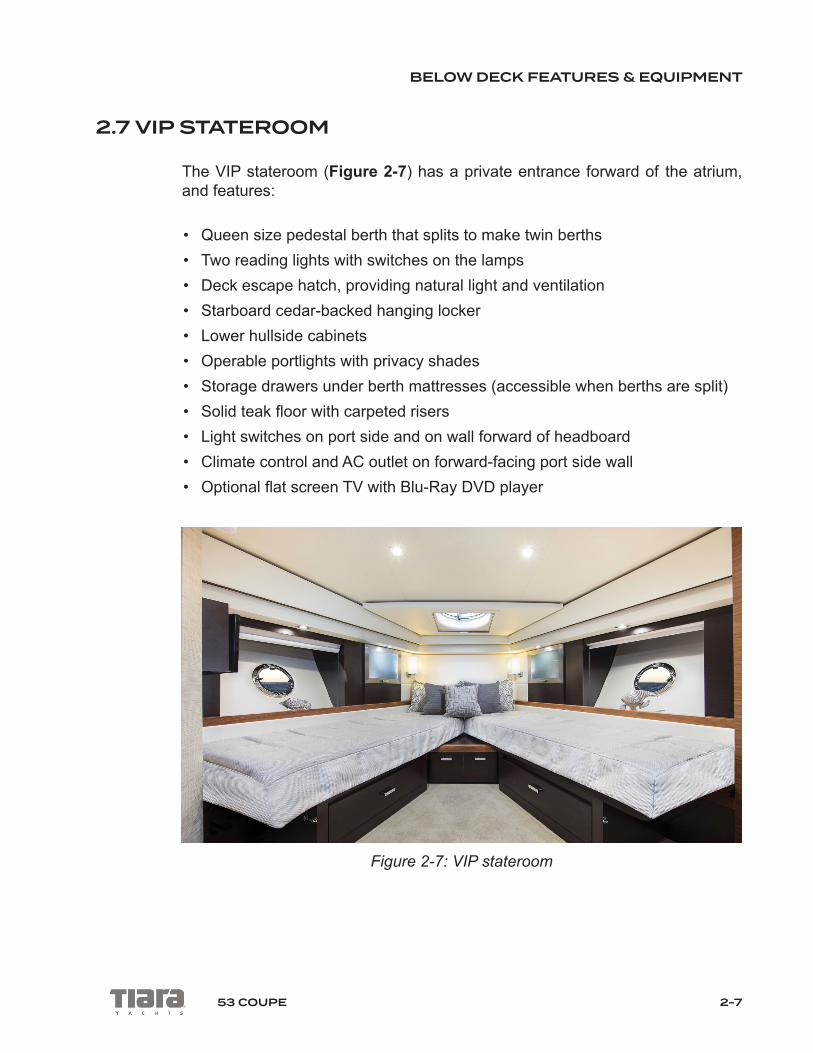
BELOW DECK FEATURES & EQUIPMENT
2-753 COUPE
2.7 VIP STATEROOM
The VIP stateroom (Figure 2-7) has a private entrance forward of the atrium, and features:
• Queen size pedestal berth that splits to make twin berths• Two reading lights with switches on the lamps• Deck escape hatch, providing natural light and ventilation• Starboard cedar-backed hanging locker • Lower hullside cabinets• Operable portlights with privacy shades• Storage drawers under berth mattresses (accessible when berths are split)• Solid teak floor with carpeted risers• Light switches on port side and on wall forward of headboard• Climate control and AC outlet on forward-facing port side wall• Optional flat screen TV with Blu-Ray DVD player
Figure 2-7: VIP stateroom
BELOW DECK FEATURES & EQUIPMENT
2-8 53 COUPE
2.8 V.I.P. HEAD
The VIP head (Figure 2-8) is located to starboard of the atrium and accessed from the VIP stateroom and the atrium. The VIP head features:
• A fiberglass stall shower with glass door, teak seat and adjustable-height slid-ing hand-held shower head (and sump pump?)
• Teak and Corian® countertop• Sink with hot/cold water faucet• Solid teak floor• Air conditioning vent (controls are in VIP stateroom)• Lighted upper medicine cabinet with mirror• Lower vanity storage cabinet• Operable portlight• VacuFlush®Toilet • Exhaust fan• AC outlet under the sink• Toilet tissue roll mount installed on backside of lower vanity cabinet door.
Use the switches on the lower vanity cabinet to control the overhead lighting, accent lighting, and exhaust fan.
2.9 UTILITY ROOM
The utility room features a stacked washer/dryer and space for storage Refer to the manufacturer’s user manual for more information.
2.10 OPTIONAL THIRD STATEROOM
The optional third stateroom, in lieu of the utility room, includes a bunk bed with reading lights, storage cabinet with fire extinguisher, and optional flat-screen TV with Blu-Ray DVD player.

3-153 COUPE
Chapter 3ENGINE ROOM
The engine room of your Tiara is entered through a hatch in the aft cockpit floor. The ladder is removable for ease in moving around once inside.
This chapter provides an overview of the engine room layout and components. Review your engine and component user manuals for operating instructions. Refer to chapter 7 for engine room maintenance instructions. Your authorized Tiara Yachts dealer can also provide you with specific information regarding any system or component in your boat.
FUEL VAPORS ARE A FIRE AND EXPLOSION HAZARD THAT CAN RESULT IN SERIOUS INJURY, BURNS, OR DEATH. DO NOT STORE CONTAINERS OF FUEL OR OTHER FLAMMABLE LIQUIDS IN THE EN-GINE ROOM COMPARTMENT.
WARNING!
3.1 GENERAL ARRANGEMENT
The engine room arrangement will vary slightly depending on your engine option.
3.1.1 Forward of Engines
The battery charger, fuel water separators and Fireboy® fire suppression system bottle are on the forward engine room bulkhead (Figure 3-1). The fuel valves are located through the top of the bulkhead on the fuel tank.
CAUTION!Engines and equipment in the engine room may be hot to the touch and might burn your skin. Care must be taken to avoid these areas while in the engine room.

ENGINE ROOM
3-2 53 COUPE
Figure 3-1: Forward engine room bulkhead
The Master DC Panel and main battery bank switches are located on centerline (Figure 3-2). The panel contains the main breakers for the boat’s DC-powered components. For all practical purposes, these breakers should be left in the ON position during use of the boat. Refer to chapter 4 for more information about the boat’s electrical system.
A bilge pump is located on centerline between the inboard stringers under the Master DC Panel (Figure 3-3).
Figure 3-2: Master DC Panel and main battery bank switches Figure 3-3: Bilge pump

ENGINE ROOM
3-353 COUPE
If equipped, the optional gyro (Figure 3-4) is installed on centerline forward of the engines.
The following equipment is installed forward of the starboard engine (Fig-ure 3-5):
• Starboard engine raw water intake seacock and strainer
• Generator raw water intake sea-cock and strainer
• Raw water wash down seacock, strainer and pump
• Gyro (optional) raw water intake seacock, strainer and pump
• Air compressor tank automatic drain
The horn and sunroof air compressor system and the fresh water system pumps and strainers are located outboard of the engine on the starboard chine shelf.
Figure 3-5: Forward and outboard of starboard engine
Figure 3-4: Gyro (optional)

ENGINE ROOM
3-4 53 COUPE
The following equipment is installed forward of the port engine (Figure 3-6):
• Port engine raw water intake seacock and strainer• Air conditioning system’s raw water intake seacock, strainer and pump
The water heater and shore cord storage tub are located outboard of the engine on the port chine shelf.
Figure 3-6: Forward and outboard of port engine
3.1.2 Between the Engines
A removable floor between the engines provides access to the battery banks on boats equipped with Volvo® engines.
3.1.3 Aft of Engines
The generator is installed on centerline aft of the engines (Figure 3-7). Refer to the generator user manual for operating instructions. The aft side of the generator can be accessed through the floor hatch in the transom storage compartment.
The oil changing system is located under the generator. Refer to the oil changer user manual for operating instructions.

ENGINE ROOM
3-553 COUPE
Figure 3-7: Aft of engines
3.1.4 Starboard, Outboard of Engine
The following components are located outboard of the starboard engine (Figure 3-8):
• Hull side air intake plenum, which provides fresh air to the engine and ventilation for the engine room while separating and draining sea water overboard
• Horn and sunroof air compressor• Fresh water system pumps and
strainers• Fresh water tank
Refer to the component user manuals for operating instructions.
Figure 3-8: Air compressor and fresh water pumps

ENGINE ROOM
3-6 53 COUPE
3.1.5 Port, Outboard of Engine
The following components are located outboard of the port engine (Figure 3-9):
• Hull side air intake plenum, which provides fresh air to the engine and ventila-tion for the engine room while separating and draining sea water overboard
• Water heater• Aft shore power cable recoiling system with storage tub• Fresh water tank
Refer to the component user manuals for operating instructions.
Figure 3-9: Outboard of port engine
3.1.6 Lazarette
The following components are located in the lazarette area below the tran-som storage compartment:
• Volvo® IPS units with emergency steering access (if installed)• Aft side of generator• Generator wet exhaust discharge seacock• Swim platform lift system hydraulic power unit
Refer to the component user manuals for operating instructions.

4-153 COUPE
Chapter 4ELECTRICAL SYSTEMS
The electrical systems in your Tiara have been designed and built to the recom-mendations of the American Boat and Yacht Council (ABYC) and requirements of the United States Coast Guard, and have received National Marine Manu-facturers Association (NMMA) Yacht Certification. They have been developed to supply all the boat’s electrical needs at the dock, at anchor, and underway. While this manual will not attempt to describe all of the electrical engineering that went into the system, a basic understanding will help assure trouble-free operation.
All of the electrical functions on your boat are part of three basic systems: 12V DC, 120/240V AC, and bonding.
ALL SERVICE WORK ON THE ELECTRICAL SYSTEMS IN YOUR TIARA SHOULD BE PERFORMED ONLY BY AN AUTHORIZED TIARA YACHTS DEALER OR OTHER QUALIFIED MARINE ELECTRICAL SERVICE FA-CILITY. FAILURE TO DO SO MAY RESULT IN PERSONAL INJURY OR DEATH.
WARNING!
4.1 THE 12V DC SYSTEM
4.1.1 Power SupplyYour boat’s DC electrical system is powered by battery banks (Table 4-1). The port and starboard engine battery banks provide the power needed to operate your vessel safely while underway. The house battery bank supplies power to all the boat’s comfort and convenience functions such as lighting, pumps, actua-tors, 12V stereo, and electronics. The house bank should also be used to power any aftermarket electronics.
Each engine bank is comprised of two 12V wet flooded cell batteries. The house bank is comprised of two 12V 8D AGM batteries. See Chapter 7 for battery maintenance information.

ELECTRICAL SYSTEMS
4-2 53 COUPE
BatteryBank
Number ofBatteries
PowerSupplied Location Power
Distribution
PortEngine 2 24 volts Port Side of Engine
Room
Port Engine, Wipers, Trim Tabs, Navigation Lights,
Bilge Pumps, Horn
StarboardEngine 2 24 volts Center of Engine
Room Starboard Engine
House 2 12 volts Center of Engine Room
Lighting, Pumps, Actuators, 12V Stereo, Electronics
Table 4-1: Battery Specifications
The Garmin® Multi-Function Displays (MFDs) will indicate low voltage. Inves-tigate low voltage situations immediately, and contact your authorized Tiara Yachts dealer or other qualified marine electrical service facility for service.
CAUTION!All aftermarket electrical components should be installed by your Tiara Yachts dealer or other qualified marine electrical service facility. They must be installed to be powered from the house battery bank only. The engine battery banks are reserved strictly for engine power only.
4.1.2 Battery Charging
Battery power is replenished in two ways. While the engines are running, each engine alternator charges its respective battery bank. The Automatic Charging Relay (ACR) allows the port engine alternator to also charge the starboard engine battery bank. See section 4.1.4 for more information.

ELECTRICAL SYSTEMS
4-353 COUPE
When the boat is using its generator or a shore power connection, the 120V AC battery charger may be used. To oper-ate the AC battery charger, switch ON the three BATTERY CHARGER breakers on the Master DC Panel on the forward engine room bulkhead (Figure 4-1), and the BATTERY CHARGER breaker on the AC Distribution Panel located beneath the starboard salon loveseat (Figure 4-2).
It is important that your batteries be kept in a state of full charge as much as possible. Fully charged 12V batteries will indicate a voltage in excess of 12.6 volts with no load, or while being charged.
Prolonged periods of discharge will cause the batteries to deteriorate rapidly, and will result in their inability to hold a charge for the expected amount of time. This can hap-pen easily if excessive DC loads (such as lights) are left on while the battery charger is off.
Always leave your boat connected to shore power with the battery charger ON when leaving for any extended pe-riod of time.
4.1.3 Distribution
Power from the battery banks supplies the red main battery switches at the bottom of the Master DC Panel (Figure 4-1), located on the forward engine room bulkhead. Power from each engine bank is connected to its respective engine battery bank switch, and power from the house bank is connected to the house battery bank switch. The red main battery switches are controlled remotely by the PORT BATTERY, HOUSE BATTERY, and STBD BATTERY buttons on the Power Control Panel in the galley peninsula cabinet. (Figure 4-3).
Figure 4-1: Master DC Panel
Figure 4-2: AC Distribution Panel

ELECTRICAL SYSTEMS
4-4 53 COUPE
When these buttons are OFF, all DC power to the rest of the boat is disconnected, with one exception:
Exception: The port engine battery bank directly supplies power to the forward, mid, and aft automatic bilge pumps. The house battery bank directly sup-plies power to the Volvo® Active Corrosion Protection (if Volvo® engines are installed). Shutting OFF the main battery switches will not disconnect power to these items.
Power is distributed from the house battery bank switch on the Master DC Panel to the DC Distribution Panel located beneath the starboard salon loveseat (Figure 4-4). Power to DC components is further distrib-uted from the DC Distribution Panel.
4.1.4 Automatic Charging Relay
Your Tiara is equipped with an Automatic Charging Relay (ACR). An ACR automati-cally parallels (combines) battery banks during charging, and isolates them when charging has stopped and battery voltage has fallen. An ACR is intended to keep a load from discharging both of the battery banks it is connected to. The ACR is con-nected to the port engine battery bank and the starboard engine battery bank. The ACR, when in REMOTE MODE, continu-ously monitors the voltage in the battery banks and, if needed, automatically charges the starboard engine battery bank when the port engine is running. The ACR can be accessed from the bottom of the Master DC Panel on the forward engine room bulkhead (Figure 4-5).
Figure 4-3: Power control panel
Figure 4-4: DC Distribution Panel

ELECTRICAL SYSTEMS
4-553 COUPE
Figure 4-5: Yellow ACR control knob under Master DC Panel
The ACR should be kept in REMOTE MODE (automatic) unless the boat is in storage or being serviced by an authorized Tiara dealer, or the battery banks need to be interconnected in an emergency situation. For REMOTE MODE (automatic), the Yellow Override Knob should be oriented to starboard as shown in Figure 4-6.
Figure 4-6: ACR in REMOTE MODE
LOC
K O
FFLO
CK
OFF
RE
MO
TER
EM
OTE
Figure 4-7: ACR in LATCH ON MODE
LOC
K O
FFLO
CK
OFF
RE
MO
TER
EM
OTE
4.1.5 Emergency Battery Bank Interconnect
If an engine battery bank is discharged and will not start its engine, the ACR can be used to manually interconnect the engine battery banks for additional power to start the engine. You can interconnect the port engine bank with the starboard engine bank.
LOC
K O
FFLO
CK
OFF
RE
MO
TER
EM
OTE
Figure 4-8: ACR in LOCK OFF MODE

ELECTRICAL SYSTEMS
4-6 53 COUPE
To combine battery banks: Locate the ACR (Figure 4-5) and, with the Yellow Override Knob in REMOTE (starboard) position, push the center of the button until latched (Figure 4-7).
To prevent automatic operation:Rotate the Yellow Override Knob to LOCK OFF (port) position (Figure 4-8).
To isolate battery banks that are combined:Rotate the Yellow Override Knob to LOCK OFF (port) position (Figure 4-8) to release the center button from LATCH ON MODE (the button will pop out). Then rotate the Yellow Override Knob back to REMOTE (starboard) position (Figure 4-6).
To secure for servicing:Rotate the Yellow Override Knob to LOCK OFF (port) position (Figure 4-8). Pass a cable tie through the hole.
WHEN BATTERY BANKS ARE INTERCONNECTED, ALL NON-ESSEN-TIAL LOADS SHOULD BE TURNED OFF UNTIL THE PROBLEM WITH THE FAILED BANK IS CORRECTED. FAILURE TO DO SO CAN RE-SULT IN RAPID DEPLETION OF THE BATTERY POWER NEEDED TO SAFELY OPERATE THE BOAT. FAILURE TO DO SO MAY RESULT IN PERSONAL INJURY OR DEATH.
WARNING!
4.1.6 Operating Notes
Monitor your battery voltages when you first arrive at your boat and periodically while using your boat. For 12V batteries, voltages below 12 volts with no load on the bank may indicate a problem condition that is preventing battery replenish-ment. Investigate and correct the problem immediately.When leaving the boat for any extended period, connect the boat to shore power and switch ON the battery charger(s). Refer to chapter 5 for instructions. Turning OFF the batteries also disables power to the helm, preventing operation of the engines and other helm functions.

ELECTRICAL SYSTEMS
4-753 COUPE
4.2 THE 120/240V AC SYSTEM
CAUTION!Operating your AC electrical system with low or high voltage may damage some onboard AC electrical components and appliances.
4.2.1 AC Power Supply
AC power is supplied to the AC Distribution Panel (Figure 4-2) in the following ways:• Connecting the aft shore power cable or optional forward shore power cable to
a dockside power outlet. See chapter 5 for shore power connection directions.• Running the onboard generator. See the generator’s user manual for operat-
ing instructions.• Using the optional inverter.
The AC system is designed so that only one power source can be selected at a time. Choose the power source by flipping ON the AFT SHOREPOWER, GEN-ERATOR, or (optional) FWD SHOREPOWER breaker on the AC Distribution Panel.
Use 240V-50A shore power whenever possible to allow full functionality of your boat’s AC system.
Using a 120V-30A adapter will reduce the functionality of the AC system. The 120V-30A connection will allow the use of only the battery charger, refrigerator/freezer, 120V outlets, microwave, and deck grill.
4.2.2 Distribution
Power is supplied from the selected main power source (aft shore power, genera-tor, optional forward shore power or optional inverter) to the AC Distribution Panel (Figure 4-2). The individual components on the boat are powered via breakers on the AC Distribution Panel.

ELECTRICAL SYSTEMS
4-8 53 COUPE
4.2.3 Operating Notes
Monitor the available AC voltage and amperage (load applied) periodically, in order to detect abnormal operating conditions early. To check the voltage and amper-age, consult shore power monitor on the Power Control Panel. See the monitor manufacturer’s user manual for more information. The monitor will indicate the current voltage of the power source and the load currently being applied to that source. The batteries must be switched ON to use the power monitors.
If the voltage being supplied while using the 240V-50A connection is lower than 210V or higher than 260V, discontinue use and correct the problem as soon as possible.
4.2.4 Optional Inverter
If the optional inverter is installed, and you are using the generator or shore power, the INVERTER breaker on the AC Distribution Panel (Figure 4-2) must be switched ON to provide power to the REFRIGERATOR, OUTLETS 1, OUTLETS 2, MICROWAVE and DECK GRILL breakers.
To use the optional inverter, switch OFF the AFT SHOREPOWER, GENERATOR and FWD SHOREPOWER (if equipped) breaker, then switch ON the INVERTER breaker on the AC Distribution Panel. Switch the inverter ON using the Inverter Control Panel (Figure 4-9) located inside the port storage cabinet in the atrium.
Using the optional inverter will reduce the functionality of the AC system. The in-verter will allow the use of only the refrigerator/freezer, 120V outlets, microwave and deck grill.
The amount of time these items will be powered depends on the charge level of the house battery bank. Monitor the house battery bank voltage (see section
Figure 4-9: Inverter control panel

ELECTRICAL SYSTEMS
4-953 COUPE
4.2.3) frequently during inverter operation. If the voltage drops below 11.5 volts, discontinue inverter use.
4.3 BONDING SYSTEM
Your boat’s bonding system provides a low-resistance electrical path between otherwise isolated metallic objects, particularly those in common contact with sea water and subject to possible galvanic corrosion.
The bonding system is connected to two large zinc sacrificial anodes mounted to the transom of your boat. These anodes are provided to purposely deteriorate over time, to assure that other components do not. The anodes must be checked periodically to determine their status and be replaced when they become depleted by 50% or more. Active corrosion protection is provided for the Volvo® IPS drives (in boats equipped with the Volvo® engine package), as they are not connected to the bonding system. The trim tabs and optional swim platform lift system have their own anodes for added protection. These anodes must be checked periodi-cally as well, and replaced when they become depleted by 50% or more.
The bonding system is connected to the main DC grounding buss and the AC grounding buss. This establishes the water as ground potential and helps prevent the existence of electrical potential on exposed metallic hardware and electrical equipment.
Your Tiara is equipped with an Electrical Leakage Circuit Interrupter (ELCI) and a Galvanic Isolator that protect the boat from galvanic corrosion and shore power shock hazards. The ELCI prevents AC electrical current from ‘leaking’ out from your boat into the water. The Galvanic Isolator keeps stray current in the water from entering your boat.
THE AC GROUNDING BUSS MUST REMAIN CONNECTED TO THE MAIN DC GROUNDING BUSS AT ALL TIMES. DO NOT CUT THE GREEN WIRE IN THE SHORE POWER CORD, OR RELATED EQUIP-MENT. DOING SO CAN CAUSE LETHAL VOLTAGE TO BE PRESENT ON BOAT EQUIPMENT, OR IN THE WATER AROUND THE BOAT.
WARNING!
ELECTRICAL SYSTEMS
4-10 53 COUPE
CAUTION!All owner-installed metallic components that are installed through the hull below the waterline must be connected to the bonding system. Compa-rable wire sizes and terminals must be used, and should be connected directly to the nearest bonding system terminal strip. Failure to do so may result in severe galvanic corrosion of the item and possible premature failure, resulting in a water leak.

5-153 COUPE
Chapter 5OPERATING YOUR BOAT
This chapter describes the basic operation of your boat. Before operating any Tiara for the first time, review the proper safe operation of all features and systems with your Tiara Yachts dealer.
BEFORE LEAVING THE DOCK, REVIEW THE PROPER SAFE OPERA-TION OF ALL FEATURES AND SYSTEMS ON THE BOAT. IMPROPER OPERATION OR UNSAFE PRACTICES COULD RESULT IN SEVERE PERSONAL INJURY OR DEATH.
WARNING!
5.1 WHEN ARRIVING AT YOUR BOAT
Before taking your boat out, follow these operating preparation instructions:
1. Press ON the 12V DC main battery buttons: PORT BATTERY, STBD BAT-TERY, and HOUSE BATTERY, on the Power Control Panel in the galley peninsula cabinet. These main battery buttons remotely turn ON the bat-tery switches in the engine room.
2. Switch ON all breakers on the Master DC Panel in the engine room, except the OIL CHANGE PUMP breaker if installed. The OIL CHANGE PUMP breaker should remain OFF unless using the oil change pump.
Note: Boats with Cummins® engines do not have a separate OIL CHANGE PUMP breaker if the optional oil changer is installed.
3. Switch ON all breakers (except the WASTE PUMPOUT breaker, if in-stalled) on the DC Distribution Panel, located beneath the starboard salon loveseat. If installed, the WASTE PUMPOUT breaker must remain OFF at all times unless using the optional overboard waste discharge macerator system.
4. Check the condition of your batteries using the system monitors on the Power Control Panel. For 12V batteries, voltages below 12 volts with no load on the bank may indicate a problem. Investigate and correct any problems immediately.
5. Switch ON any necessary AC breakers on the AC Distribution Panel un-derneath the starboard salon loveseat.

OPERATING YOUR BOAT
5-2 53 COUPE
6. Check the bilge areas of your boat—forward, aft, and in the engine room —for unexpected water or debris.
7. Check and open any seacocks that may have been shut off (closed) when you last left your boat.
8. Check the levels of the port and starboard engine oil, coolant, transmis-sion fluid and, if installed, IPS unit oil. Also check the generator oil and coolant levels. Inspect for any fuel fumes or other unusual smells; if de-tected, investigate the cause and correct any problems.
9. At the helm area, activate equipment switches and check to see that all equipment (horn, wipers, navigation lights, etc.) is functioning properly. Refer to the equipment manufacturers’ user manuals for more information.
5.1.1 Connecting to Shore Power
Use 240V-50A shore power whenever available to allow full functionality of your boat’s AC system. A 240V-50A shore power cable is located in the aft port shore power locker on the deck and is connected to a powered cable recoil system. To pay out or retrieve the cord, the CABLEMASTER breaker on the DC Distribution Panel must be ON.
To connect to shore power:
1. Switch OFF the shore power breaker labeled AFT SHORECORD and, if installed, the FWD SHORECORD breaker on the AC Distribution Panel.
2. Switch OFF the shore power breaker (Figure 5-1) in the aft port shore power locker (Figure 5-2). If using the optional forward shore power connec-tion, switch OFF the additional break-er (Figure 5-1) located in the anchor locker.
3. If there is a breaker switch at the dockside shore power station (on the dock), verify that it is in the OFF position.
4. Determine the voltage/amperage available from the dockside shore power station (240V-50A or 120V-30A).
Figure 5-1: Shore power breaker and selector switch
Figure 5-2: Aft port shore power locker and cable master switch

OPERATING YOUR BOAT
5-353 COUPE
Note: Using 120V-30A shore power will reduce the function-ality of your Tiara’s AC elec-trical system. Use 240V-50A shore power whenever avail-able to allow full functionality of your Tiara’s AC system.
5. Extend the shore power cord. Open the cover. Flip the cablemaster switch, located near the shore power cord cover, to the OUT position (Figure 5-2). When sufficient cable is extended to reach the shore power station, return the cablemaster switch to the neutral or center position. The optional for-ward shore power connection is equipped with a separate cable. If using the forward cable, plug the cable into the receptacle located in the anchor locker.
CAUTION!When routing electric cables and dockside water hoses from the boat to the dock, be sure to allow sufficient slack so the cables and hoses will not be strained in any way as the boat moves within its slip. Do not allow cables or hoses to dangle into the water.
6. Plug the cable into the dockside shore power station outlet.
7. Switch ON the breaker(s) at the dockside shore power station outlet.
8. Switch ON the shore power breaker (Figure 5-1) in the aft port shore power locker or anchor locker.
9. Check the shore power indicator lights on the AC Distribution Panel. Be sure the green AVAIL light for the applicable shore power source (AFT SHORECORD or optional FWD SHORECORD), is lit.
Note: If the REV polarity indicator is illuminated red, do not proceed. Turn OFF all breakers and contact marina personnel immediately.
6. Check the bilge areas of your boat—forward, aft, and in the engine room —for unexpected water or debris.
7. Check and open any seacocks that may have been shut off (closed) when you last left your boat.
8. Check the levels of the port and starboard engine oil, coolant, transmis-sion fluid and, if installed, IPS unit oil. Also check the generator oil and coolant levels. Inspect for any fuel fumes or other unusual smells; if de-tected, investigate the cause and correct any problems.
9. At the helm area, activate equipment switches and check to see that all equipment (horn, wipers, navigation lights, etc.) is functioning properly. Refer to the equipment manufacturers’ user manuals for more information.
5.1.1 Connecting to Shore Power
Use 240V-50A shore power whenever available to allow full functionality of your boat’s AC system. A 240V-50A shore power cable is located in the aft port shore power locker on the deck and is connected to a powered cable recoil system. To pay out or retrieve the cord, the CABLEMASTER breaker on the DC Distribution Panel must be ON.
To connect to shore power:
1. Switch OFF the shore power breaker labeled AFT SHORECORD and, if installed, the FWD SHORECORD breaker on the AC Distribution Panel.
2. Switch OFF the shore power breaker (Figure 5-1) in the aft port shore power locker (Figure 5-2). If using the optional forward shore power connec-tion, switch OFF the additional break-er (Figure 5-1) located in the anchor locker.
3. If there is a breaker switch at the dockside shore power station (on the dock), verify that it is in the OFF position.
4. Determine the voltage/amperage available from the dockside shore power station (240V-50A or 120V-30A).
Figure 5-1: Shore power breaker and selector switch
Figure 5-2: Aft port shore power locker and cable master switch
OPERATING YOUR BOAT
5-4 53 COUPE
10. Switch ON the AFT SHORECORD breaker (or optional FWD SHORE-CORD breaker) on the AC Distribution Panel.
DO NOT MAKE CONNECTIONS IN WET WEATHER, WITH WET HANDS, OR WITH WET CABLES AND CONNECTIONS. ALWAYS USE A 3-WIRE ELECTRICAL SYSTEM CONNECTED TO A GROUND. DO NOT USE WORN OR DAMAGED CABLES. FAILURE TO HEED THIS WARN-ING CAN RESULT IN AN ELECTRICAL SHOCK INJURY OR DEATH.
WARNING!
To disconnect shore power:
1. Switch OFF the AFT SHORECORD breaker and, if installed, the FWD SHORECORD breaker on the AC Distribution Panel.
2. Switch OFF the shore power breaker (Figure 5-1) in the aft port shore power locker or anchor locker.
3. Switch OFF any breaker(s) at the dockside shore power station outlet.
4. Disconnect the shore power cable from the dockside shore power station outlet.
5. Return the aft shorepower cable to the boat and carefully retract it by flip-ping the cablemaster switch to IN (Figure 5-2). When fully retracted, flip the cablemaster switch to the neutral or center position, and replace the cover.
6. The optional forward shore power connection does not have a cable recoil system. After disconnecting from the dockside shore power sta-tion, remove the separate cable from the receptacle located in the anchor locker. Coil up and stow the cable.
5.1.2 Fueling Your Boat
Fuel tank fills are located on the port and starboard deck walkway amidships. Use either to fill the boat’s fuel tank. Both fills are labeled DIESEL (Figure 5-3).

OPERATING YOUR BOAT
5-553 COUPE
FUEL IS FLAMMABLE. DO NOT SMOKE. NEVER FILL THE TANK WHILE THE ENGINES, BLOWERS, GENERATOR, OR OTHER EQUIP-MENT IS OPERATING. DO NOT FILL NEAR OPEN FLAMES.
WARNING!
To fill the fuel tank:
1. Turn off all breakers on the AC and DC Distribution Panels.
2. Make sure the generator is OFF.
3. Make sure your boat is securely moored.
4. Close all port lights, hatches and doors.
5. Estimate how much fuel will be needed to fill the tank.
6. Insert the provided fill cap key into the slot in the fuel fill cap, turn the key counterclockwise, and remove the cap.
BE SURE THAT THE FUEL FILL IS IN CONTACT WITH THE FUEL NOZZLE TO PREVENT ANY STATIC SPARKS DURING THE FUELING OPERATION. FAILURE TO HEED THIS WARNING COULD RESULT IN A STATIC ELECTRICITY CHARGE THAT COULD LEAD TO INJURY, DAM-AGE OR DEATH.
WARNING!
7. Insert the fuel nozzle into the fuel fill and dispense the fuel until the tank is full. Verify that the tank is full by reading the fuel gauge and/or by the sound of the fuel fill filling up. If your tank takes significantly more fuel than expected, investigate the cause immediately.
8. Remove the nozzle and replace the fuel fill cap. Tighten securely with the provided key.
Figure 5-3: Fuel fill

OPERATING YOUR BOAT
5-6 53 COUPE
9. Check the engine room and bilge areas for fuel odors. If you smell fuel, do not start the engines or other electrical equipment. Investigate and correct the problem, and completely ventilate the bilge area before proceeding.
THE FEDERAL WATER POLLUTION CONTROL ACT PROHIBITS THE DISCHARGE OF OIL OR OILY WASTE INTO OR UPON THE NAVI-GABLE WATERS OF THE UNITED STATES, OR THE WATERS OF THE CONTIGUOUS ZONE, OR WHICH MAY AFFECT NATURAL RESOURC-ES BELONGING TO, APPERTAINING TO, OR UNDER THE EXCLUSIVE MANAGEMENT AUTHORITY OF THE UNITED STATES, IF SUCH DIS-CHARGE CAUSES A FILM OR DISCOLORATION OF THE SURFACE OF THE WATER OR CAUSES A SLUDGE OR EMULSION BENEATH THE SURFACE OF THE WATER. VIOLATORS ARE SUBJECT TO SUBSTAN-TIAL CIVIL PENALTIES AND/OR CRIMINAL SANCTIONS, INCLUDING FINES AND IMPRISONMENT. REPORT ALL DISCHARGES TO THE NA-TIONAL RESPONSE CENTER AT 1-800-424-8802 OR TO YOUR LOCAL U.S. COAST GUARD OFFICE BY PHONE OR VHF RADIO, CHANNEL 16.
WARNING!
CAUTION!A no-spill vent system is used so that fuel will not spill out of the vents when filling; however, fuel will exit the fuel fill pipe if overfilling occurs. When filling the fuel tanks listen carefully for fuel filling up in the fill pipe.
Be careful not to spill any fuel outside the boat into the water. If you do, clean up the fuel immediately in the manner prescribed by your local regu-lations.
NOTICE

OPERATING YOUR BOAT
5-753 COUPE
To prevent damage to your fuel system, use only a quality grade of fuel as recommended by the engine manufacturer. Do not use a fuel which contains harsh additives. Damage to your fuel system as a result of using these fuels will not be covered by your warranty.
NOTICE
5.1.3 Fuel System
Note that when a fuel valve is closed, the handle is perpendicular to its associated fitting. When a fuel valve is open the handle is parallel to its associated fitting. Reference Figure 5-4 for the location of fuel system components.
Figure 5-4: Fuel valves, lines and filters in the forward engine room
A. Generator returnB. Port engine returnC. Generator supply
D. Port engine supplyE. Starboard engine supply
F. Starboard engine returnG. Generator fuel filter
H. Port engine fuel filterI. Starboard engine fuel filter
A B C D E F
GH I
DO NOT START THE ENGINES UNTIL YOU ARE SURE THERE ARE NO FUEL FUMES IN THE BILGE OR ENGINE COMPARTMENT OF YOUR BOAT. FUEL VAPORS ARE EXPLOSIVE AND MAY IGNITE DUR-ING ENGINE START-UP CAUSING SERIOUS INJURY OR DEATH.
WARNING!

OPERATING YOUR BOAT
5-8 53 COUPE
CAUTION!To reduce the risk of fire, investigate all fuel odors immediately and do not start the engines, generator or other electrical equipment if fuel odors are present.
5.1.4 Starting Your Engines
Before starting your engines, be sure that you have read your engine owner’s manual and performed all the maintenance and safety checks listed under Sec-tion 5.1, When Arriving at Your Boat.
To Start the Volvo® Engines:
1. Open all hatches to the bilge area. Investigate and remedy any fuel vapors that are detected.
2. Check the engine and IPS drive units’ oil levels.
3. Check the engines’ coolant level.
4. Open the engines’ raw water seacocks.
5. Open the engines’ fuel supply and return valves. The fuel valves are lo-cated in the forward engine room (Figure 5-4).
CAUTION!Prior to starting engines, ensure fuel supply and return valves are in the open position. A fuel valve is open when it is parallel to its associated fit-ting. Failure to open all fuel valves will damage the engine.
6. Switch ON all breakers except the OIL CHANGE PUMP breaker on the Master DC Panel in the engine room.
7. Switch ON the PORT BATTERY, STBD BATTERY, and HOUSE BATTERY switches on the Power Control Panel.
8. Confirm that the ELECTRONICS, 24VDC MAIN, TRIM TABS, WIPER PORT, WIPER CENTER, WIPER STBD, and both ENG ROOM FAN breakers on the DC Distribution Panel are ON.

OPERATING YOUR BOAT
5-953 COUPE
9. Press ON the BLOWER button forward of the engine control head. Run the blower for five minutes prior to starting the engines.
10. Make sure the engine control levers are in the neutral position (Figure 5-5).
11. Hold the Volvo® e-Key (Figure 5-6) in front of the Volvo® e-Key control panel (Figure 5-7) to unlock the system. A sound confirms the sys-tem is unlocked.
12. Press the IGNITION buttons on the e-Key control panel to switch the ignitions ON. Make sure the green light on the IGNITION buttons indicates the ignitions are ON.
13. To start, press each of the two START/STOP buttons.
14. Check the voltage and amperage for each battery bank using the system monitors on the Power Control Panel. If the voltage is below 12 volts or above 15 volts, stop the engines and investigate the cause before pro-ceeding. Refer to the system monitor manufacturer’s user manual for more information.
15. Monitor all engine-related gauges and data on the Multi-Function Displays at the helm. If anything seems abnormal, stop the engines and investigate the cause before proceeding.
16. Let the engines run at idle for several minutes before leaving the slip.
Figure 5-6: Volvo® e-Key Figure 5-7: Volvo® e-Key control panel
Figure 5-5: Volvo® engine control lever

OPERATING YOUR BOAT
5-10 53 COUPE
To Start the Cummins® Engines:
1. Open all hatches to the bilge area. Investigate and remedy any fuel vapors that are detected.
2. Check the engines’ oil levels.
3. Check the engines’ coolant level.
4. Open the engines’ raw water seacocks.
5. Open the engine fuel supply and return valves. The fuel valves are located in the forward engine room (Figure 5-4).
CAUTION!Prior to starting engines, ensure fuel supply and return valves are in the open position. A fuel valve is open when it is parallel to its associated fit-ting. Failure to open all fuel valves will damage the engine.
6. Switch ON all breakers on the Master DC Panel in the engine room, in-cluding the STEERING breaker located on the starboard side of the Mas-ter DC Panel Box.
7. Switch ON the PORT BATTERY, STBD BATTERY, and HOUSE BATTERY switches on the Power Control Panel.
8. Check the voltage and amperage for each battery bank using the system monitors on the Power Control Panel. If the voltage is below 12 volts or above 15 volts, stop the engines and investigate the cause before pro-ceeding. Refer to the system monitor manufacturer’s user manual for more information.
9. Press ON the BLOWER button forward of the engine control head. Run the blower for five minutes prior to starting the engines.
10. Make sure the engine control levers are in the neutral position.
11. Turn the port ignition key to the ON position (the first position clockwise). Wait five seconds.

OPERATING YOUR BOAT
5-1153 COUPE
12. Turn the port ignition key clockwise to the START position and release when the engine starts.
13. Repeat for the starboard engine.
14. Check the voltage and amperage for each battery bank using the system monitors on the Power Control Panel. If the voltage is below 12 volts or above 15 volts, stop the engines and investigate the cause before pro-ceeding. Refer to the system monitors manufacturer’s user manual for more information.
15. Monitor all engine-related gauges and data on the Multi-Function Displays at the helm. If anything seems abnormal, stop the engines and investigate the cause before proceeding.
16. Let the engines run at idle for several minutes before leaving the slip.
5.1.5 Transmission and Throttle Operations
The engine control head includes two levers; the port side lever controls the port engine and the starboard side lever controls the starboard engine. The engine control levers are in neutral when they are in the center position. Shifting the le-vers forward engages the engines in forward gear; speed is increased the further forward the throttle levers are advanced. Shifting aft from neutral engages the reverse gears to back the boat up.
Refer to your engine manufacturer’s user manual for more detailed information.
5.1.6 Operating the Generator
Refer to the generator manufacturer’s user manual for starting instructions. The generator controls (Figure 5-8) are located in the galley peninsula cabinet.
DO NOT START THE GENERATOR UNTIL YOU ARE SURE THERE ARE NO FUEL FUMES IN THE BILGE OR ENGINE COMPARTMENT. FUEL VAPORS ARE EXPLOSIVE AND MAY IGNITE DURING GENERATOR START-UP, CAUSING SERIOUS INJURY OR DEATH.
WARNING!

OPERATING YOUR BOAT
5-12 53 COUPE
CAUTION!To reduce the risk of fire, investigate all fuel odors immediately and do not start the engines, generator or other electrical equipment if fuel odors are present.
To start the generator:
1. Open all hatches to the bilge area. Investigate and remedy any fuel vapors that are detected.
2. Check the generator oil and coolant levels.
3. Open the generator raw water seacock.
4. Open the generator fuel supply and return valves. The fuel valves are located in the forward engine room (Figure 5-4).
CAUTION!Before starting the generator, ensure the fuel supply and return valves are open. A fuel valve is open when it is parallel to its associated fitting. Fail-ure to open all fuel valves will damage the generator.
5. Press OFF the GENERATOR POWER button on the Power Control Panel.
6. Switch ON all breakers except the OIL CHANGE PUMP breaker on the Master DC Panel in the engine room.
7. Press ON the PORT BATTERY, STBD BATTERY, and HOUSE BATTERY buttons on the Power Control Panel.
Figure 5-8: Generator control panel

OPERATING YOUR BOAT
5-1353 COUPE
8. Press ON the BLOWER button outboard of the helm, forward of the en-gine control head. Run the blower for five minutes prior to starting the generator.
9. Press and hold the START button on the generator control panel (Figure 5-8) until the generator starts. The generator status light will blink and the display will read ‘STARTING’ while the engine is preheating and cranking. The generator status light will stay on and the display will read ‘RUNNING’ once the generator starts and is running.
CAUTION!If the generator fails to start after 60 seconds of cranking, cease opera-tion. Before attempting to crank again, drain the water from the genera-tor’s muffler. Failure to do so could result in raw water contamination of the generator’s cylinders and damage the engine.
10. Press ON the GENERATOR POWER button on the Power Control Panel.
11. Switch ON the main GENERATOR breaker on the AC Distribution Panel.
12. The boat’s AC system is now being powered by the generator.
To stop the generator:
1. Switch OFF the main GENERATOR breaker on the AC Distribution Panel.
2. Allow the generator to run for two minutes without load to cool down.
3. Press and release the STOP button on the generator control panel (Figure 5-8).
4. The generator status light will go out and the display will read ‘STOPPED’ instead of ‘RUNNING.’
The engines and the generator share the same fuel tank. The generator fuel withdrawal tube is designed to stop drawing fuel when the tank is one quarter (1/4) full with the boat sitting at rest. Cruising attitudes and sea conditions may affect when this occurs. The system was designed in this manner to allow for a margin of safety so the generator does not deplete the engines’ fuel supply.

OPERATING YOUR BOAT
5-14 53 COUPE
5.1.7 Filling Your Water Tank
The fill fitting for the water tank is located in the water connection locker outboard of the starboard cockpit gangway and is labeled WATER.
To fill the water tank:
1. Using the fill cap key provided, insert the key into the slot in the water fill cap, turn the key counterclockwise, and remove the cap.
2. Select a source of fresh potable water (typically found on a dock pedestal) and connect a hose.
3. Flush the hose with fresh potable water by letting water run through it for one minute before filling your fresh water tank.
4. Insert the hose into the water fill fitting and turn the supply source ON.
5. Fill the fresh water tank with clean, fresh water. The tank should be filled until water runs out of the fill fitting.
6. Remove the hose, replace the cap and tighten.
5.2 LEAVING AND RETURNING TO THE DOCK
Before leaving on a short cruise or an extended trip, you should leave information regarding your trip (including who is aboard, where you intend to cruise, and when you plan to return) with someone who will be staying ashore. See the Float Plan Appendix at the end of this manual. This information will be extremely valuable should you run into trouble while away from the dock.
Before you cast off, be certain that you have planned your trip so that you know when you will to need fuel and where you will purchase it. Fuel docks are not always as convenient as gas stations are on the road! You should also do a last-minute double check to see that all necessary safety items are on board, especially Coast Guard approved life vests, of the proper sizes, for everyone on board.
Specific procedures as to the maneuvers needed to leave the dock and return to the dock vary with each situation. Information on the best procedures can be found in Chapman Piloting & Seamanship and by attending safe boating classes offered in your area by the U.S. Coast Guard Auxiliary or the Power Squadron. For information on the courses offered in your area, call the Boat U.S. Foundation’s Boating Course Hotline at 1-800-336-2628. Refer to chapter 1 of this manual for further information regarding boating safety.

OPERATING YOUR BOAT
5-1553 COUPE
While maneuvering around the dock, have all guests on board remain in the cockpit, or cabin areas, if they are not involved in the handling of mooring lines.
5.3 WHILE UNDERWAY
As the skipper of your boat, everyone on board is your responsibility. Their safety and enjoyment of the trip depends on your ability to operate your boat properly. You must stay aware of the weather and sea conditions, surrounding boating traffic, navigation of area waters, and the condition of your boat, its equipment and its engines.
When operating your boat at night, or when visibility is significantly reduced, display the proper running lights. For specific information on which lights and signals are needed for different conditions, refer to information from the U.S. Coast Guard, or see Chapman Piloting & Seamanship.
DO NOT OPERATE YOUR BOAT WHILE UNDER THE INFLUENCE OF ALCOHOL. DOING SO MAY CAUSE SERIOUS PERSONAL INJURY, PROPERTY DAMAGE, AND/OR DEATH. SMART SKIPPERS STAY SO-BER!
WARNING!
Remember:
1. Alcohol severely reduces the ability to react to several different signals at once.
2. Alcohol makes it difficult to correctly judge speed and distance, or track moving objects.
3. Alcohol reduces night vision and the ability to distinguish red from green.
Keep a watchful eye on the wake that your boat produces when underway. When boating around or near docks and seawalls, it is important to operate at or near idle RPMs in order to minimize your boat’s wake. Most local governments hold you responsible for damage caused by your boat’s wake. Control the size of your wake when boating around smaller craft to avoid capsizing the smaller vessel.

OPERATING YOUR BOAT
5-16 53 COUPE
Your engines produce both noise and exhaust gas emissions. While your boat is equipped with the latest in engine technology, and has an excellent exhaust system muffler, it still emits noise and gasses that may be an annoyance to your fellow boaters or people on shore. As the operator you are responsible for these factors and must consider them when operating your boat.
5.3.1 Waste Disposal
While away from the dock, it is important that you endeavor to preserve our natural resources and maintain our waterways by properly disposing of all trash. Under the MARPOL agreement and U.S. federal law, it is illegal for any vessel to discharge plastic or garbage containing plastics into any waters. Additional restrictions on dumping non-plastic waste are outlined in Figure 5-9. Refer to chapter 7 for head pump-out procedures.
Consult the literature published by the United States Coast Guard and understand the regulations mandated by the official maritime agency in the region where you are boating.
Figure 5-9: Waste discharge information

OPERATING YOUR BOAT
5-1753 COUPE
Any person who violates waste disposal requirements is liable for a civil penalty of up to $25,000, a fine of up to $50,000, and imprisonment for up to five years for each violation. Regional, state, and local restrictions on garbage discharges also may apply.
NOTICE
5.3.2 Anchoring
Use the anchor and anchor rode provided to anchor your boat while away from the dock. The anchor locker (Figure 5-10) is accessed via a hatch located in the foredeck. This locker is large enough to store all of the anchor rope/chain rode. The anchor, when stowed, is integrated into the bow stem.
Specifics regarding the proper techniques, equipment and con-ditions for safe anchoring can be found in Chapman Piloting & Seamanship, or through a boat-ing safety course.
The safety cable must be re-moved before anchoring.
To operate the anchor windlass, switch ON the WINDLASS breaker on the star-board side of the Master DC Distribution Panel. Remove the safety cable (Figure 5-10). Use the WINDLASS DEPLOY or RETRIEVE helm button or the windlass remote (located in the anchor locker) to activate the windlass to either lower or raise the anchor. Please refer to the windlass manufacturer’s user manual for operating instructions.
Figure 5-10: Anchor locker with windlass, mooring cleat and safety cable

OPERATING YOUR BOAT
5-18 53 COUPE
BE CAREFUL TO KEEP HANDS AND FEET AWAY FROM THE WIND-LASS DURING OPERATION. FAILURE TO DO SO CAN RESULT IN SERIOUS INJURY.
WARNING!
Windlasses are not designed to hold high loads while a boat is at anchor. When the windlass is not in use and the boat is at anchor, the rope rode must be properly tied off to the cleat inside the anchor locker (Figure 5-10). If your boat is equipped with the optional all-chain rode, the rode must be secured using the pro-vided snubber—a short length of nylon line (Figure 5-11).
The anchor must be stowed and secure when not in use. To secure the anchor, use the safety cable permanently attached to the boat as a secondary positive means to hold the anchor in the stowed position.
5.4 AFTER RETURNING TO THE DOCK
In order to maintain the finish and function of your boat, thoroughly wash it with boat soap and fresh water when you have returned to the dock. After washing, in order to reduce spotting and optimize your boat’s appearance, dry all surfaces with a dry soft towel or chamois. See chapter 7 for cleaning instructions.
Before leaving your boat:
1. Check the bilge pumps and surrounding areas for debris that could clog the pumps.
2. Visually inspect the gray water macerator boxes (shower sump boxes) and look for debris that could clog the pumps.
Figure 5-11: Snubber provided with optional all-chain rode

OPERATING YOUR BOAT
5-1953 COUPE
3. Listen carefully and visually inspect for water leaks in the forward and aft bilge areas and the engine room. Pay particular attention to any hull pen-etrations.
4. Close all unnecessary seacocks. If you are leaving the air conditioning on, make sure the air conditioning system raw water seacock remains OPEN.
5. Switch OFF all unnecessary breakers on the AC Distribution Panel.
6. Switch OFF all unnecessary breakers on the DC Distribution Panel.
7. Ensure the BILGE FWD, BILGE MID and BILGE AFT breakers are switched ON on the Master DC Panel in the engine room.
8. Check all bilge pump float switches to ensure they are turning the bilge pumps on and off properly. If they are not working, do not leave your boat unattended until they are fixed. Refer to the float switch user manual for test procedures. If you have questions or concerns, contact your Tiara Yachts dealer.
9. Check the security of all hatches and doors.
10. Check to see that all mooring lines are secure and that your boat is prop-erly positioned in the slip. Failure to do so may cause the boat to make contact with the dock during tidal changes and storms, damaging the hull.
11. Check to see that shore power cable(s) and dockside water hoses have sufficient slack, if left attached.
12. Turn OFF dockside water supply.
When leaving the boat for any extended period, press OFF the PORT BATTERY, STBD BATTERY, and HOUSE BATTERY buttons on the Power Control Panel. Turning OFF the batteries also disables power to the helm, preventing operation of the engines and other helm functions. If possible, leave the boat connected to shore power with the battery chargers on, by switching ON the BATTERY CHARGER breakers on the Master DC Panel in the engine room and the AC Distribution Panel. This will maintain the battery voltage in the proper state, and allow for the operation of the automatic bilge pumps.

OPERATING YOUR BOAT
5-20 53 COUPE
This page intentionally left blank.

6-153 COUPE
Chapter 6COMMISSIONING YOUR BOAT
6.1 BEFORE LAUNCHING YOUR BOAT
The procedures described in this chapter should be completed before launching your boat for the first time, and are best accomplished by your Tiara Yachts dealer or other qualified marine service facility. Your engine and Volvo® IPS drives, if installed, should be prepared according to the engine user manual.
Your Tiara Yachts dealer must provide S2 Yachts with your boat registration and signed customer acceptance form within 30 days of registration in order to acti-vate your warranty.
6.1.1 Bottom Paint
If your boat is equipped with a factory-applied first coat of bottom paint, a second coat should be applied over the first, just before launching. Paint has been pro-vided by Tiara for this purpose. Follow the paint manufacturer’s recommendations for preparation and application. Applying the second coat right before launching maximizes the paint’s anti-fouling properties.
If your boat has not been ordered with factory-applied bottom paint, and will be kept in the water for three weeks or more at a time, the bottom should be painted. We recommend having your Tiara Yachts dealer or other qualified marine service facility apply the paint. Choose a primer-type paint system that does not require any sanding or abrading of the gel coat surface. Follow the paint manufacturer’s recommendations for preparation and application. Your Tiara comes with a war-ranty against gel coat blistering that may be voided by breaking (e.g., sanding) the gel coat surface.
6.1.2 Bilge Areas
Close all seacocks before launching the boat. This Tiara is not equipped with a garboard drain plug.
6.1.3 Electrical Systems
Check to see that the batteries are fully charged. If not, charge them by con-necting to shore power (see chapter 5, Operating Your Boat) and by operating the 120V AC battery charger (see chapter 4, Electrical Systems).

COMMISSIONING YOUR BOAT
6-2 53 COUPE
Check each battery cell, making sure the electrolyte levels meet the recommen-dations in chapter 7.
6.1.4 Installing the Propellers
We recommend having the propellers installed by your Tiara Yachts dealer or other qualified marine service facility.
6.1.4.1 Volvo® Engines
To install the propellers, follow the procedure outlined in the engine user manual.
6.1.4.2 Cummins® Engines
Before beginning, be sure to install the propellers on the correct shafts. If they are installed on the wrong shafts, the boat will move in reverse when shifted into forward.
To install the propellers (Figure 6-1):
1. Remove adhesive tape, jam nuts and cotter pin from the propeller end of the shaft.
2. Remove adhesive tape and pull the key out of the keyway.
3. Clean the shaft end, especially the tapered surfaces, to remove all for-eign material.
4. Clean the internal taper of the propeller hub. Check for burrs or machin-ing imperfections. Deburr and correct any imperfections.
5. If lap fitting the propellers is desired, execute it at this time.
6. With key removed, install the propeller on the shaft. By hand, push the propeller onto the shaft until it is seated on the taper. With a fine point marker such as a Sharpie®, mark the location of the forward end of the propeller hub on the shaft.
7. Remove the propeller.

COMMISSIONING YOUR BOAT
6-353 COUPE
COTTER PIN
THIN NUT
LOCK NUT
PROPELLER!"#
PROPELLER SHAFT
KEYWAY
Figure 6-1: Propeller installation on shaft
8. Install the key into the shaft keyway. The key fit should be a light press fit. Use a nylon or brass hammer if needed. Gently tap the key into the keyway until the key is properly seated. Ensure the key bottoms out in the flat section of the keyway, away from the spooned radius at the end of the keyway.
CAUTION!Do not install the propeller with a poorly fitted key in the keyway. A poorly fitted key may cause vibration underway, unexpected propeller shaft stress, and possible shaft failure.
CAUTION!Do not allow the key to slide forward in the shaft keyway and ride up on the radius at the forward end of the shaft keyway. Failure to prevent this may cause unacceptable shaft stresses and possible shaft and/or propel-ler failure.

COMMISSIONING YOUR BOAT
6-4 53 COUPE
9. Reinstall the propeller. Push the propeller on the shaft until it seats on the taper.
10. Check the front edge of the propeller hub to see if it lines up with the mark made in step 6.a. If the front edge of the hub is at the mark, go to step 11.b. If the front edge of the hub is beyond (covering) the mark, go back to
step 3 and repeat the procedure.c. If the front edge of the hub is behind (not to) the mark, go back to
step 3 and repeat the procedure. If this is the second time you have tried these steps, determine the cause of the problem:i. Make sure the key is completely seated in the flat section of the
keyway.ii. Make sure no debris or foreign material is between the key, shaft
keyway and propeller hub keyway. iii. Measure the key height, shaft keyway depth, and prop hub
keyway depth. The prop shaft keyway depth plus the prop hub keyway depth should be 0.010" to 0.015" greater than the key height. If it is not, contact your Tiara Yachts dealer for further as-sistance.
11. Install the shortest brass propeller jam nut on the threaded shaft end and tighten to the propeller. Apply torque to tighten the propeller jam nut, taking care to not bend the shaft or deflect the boat bottom. If the applied torque causes the shaft to bend or the boat bottom to deflect, the shaft may come out of its specified straightness tolerance, resulting in drivetrain vibration at some speeds.
12. Install the second-thickest brass propeller jam nut. The same care should be taken when tightening this jam nut as in step 11.
13. Install the cotter pin in the hole provided at the end of the propeller shaft. Bend only one of the legs of the pin to secure it in place.
Repeat for the other propeller.
Ensure the propellers are installed on the correct shaft before putting the boat in the water. If they are on the wrong shaft, the boat will move in reverse when shifted into forward.

COMMISSIONING YOUR BOAT
6-553 COUPE
6.2 LIFTING YOUR BOAT
Once your boat is ready to launch, it needs to be lifted into the water with a ma-rine hoist or travel lift. This should be done only by your Tiara Yachts dealer or a qualified marine service facility.
Lifting your boat is accomplished with the use of slings. Place slings in the lo-cations indicated by the sling labels on the boat’s hull sides, at port, starboard, forward and aft. Hold the slings apart with the hoist or spreader bars at a distance at least as wide as the boat’s beam. Place pads at the chine corners to ease the pressure while lifting.
CAUTION!Failure to follow the proper lifting procedures while lifting your boat may result in structural damage to the hull and deck or underwater gear.
6.3 AFTER LAUNCHING YOUR BOAT
Check the bilge area and all thru-hulls, seacocks, and IPS rings (if present), to ensure there are no leaks.
Open all seacocks and make sure the hoses and fittings are not leaking. Switch ON all three BILGE PUMP breakers (BILGE FWD, BILGE MID, BILGE AFT) on the Master DC Panel in the engine room. Verify all three bilge pumps are opera-tional by manually activating the automatic float switch at each pump.
6.3.1 Fresh Water System
The fresh water system must be disinfected before first use and yearly at the beginning of each season. A clean sanitized fresh water system will greatly re-duce the risk of developing coliform bacteria or other disease-causing organisms (pathogens) and will help protect the health of everyone onboard.

COMMISSIONING YOUR BOAT
6-6 53 COUPE
DISINFECT THE ENTIRE FRESH (POTABLE) WATER SYSTEM PRIOR TO USE AND YEARLY AT THE BEGINNING OF EACH SEASON. FAIL-URE TO DO SO CAN RESULT IN DEVELOPING COLIFORM BACTE-RIA OR OTHER DISEASE-CAUSING ORGANISMS (PATHOGENS) IN THE WATER SYSTEM. CONSUMPTION OF CONTAMINATED WATER COULD RESULT IN SEVERE PERSONAL INJURY OR DEATH.
WARNING!
Follow this procedure to disinfect the fresh water system, kill bacteria that may be present, and prepare the system for operation:
Note: The fresh water system may be filled with nontoxic potable water an-tifreeze. If antifreeze was not used, skip to step 7.
1. Turn both water heater valves fully counterclockwise to the normal opera-tion position (Figure 6-2).
Figure 6-2: Water heater valves in normal operation position
Figure 6-3: Water heater valves in bypass position
2. Open all faucets (hot & cold), setting single faucets to the warm position.
3. Switch ON the FRESH WATER PUMP 1 & 2 breakers, located on the DC Distribution Panel. The pumps are self-priming.
4. When anti-freeze stops flowing out of the faucets, switch the pump break-ers OFF. Do not close faucets.

COMMISSIONING YOUR BOAT
6-753 COUPE
5. Fill the fresh water tank with clean, fresh water. The fill fitting for the water tank is in the water connection locker, labeled WATER. The tank should be filled until water runs out of the water fill fitting.
6. Keeping all faucets open, switch ON the FRESH WATER PUMP 1 & 2 breakers and empty the water tank. When the water tank is empty turn the pump breakers OFF.
7. Repeat steps 5 and 6 until all nontoxic potable water antifreeze is re-moved from the system.
8. Ensure the water system, including the water heater and pumps, is drained completely.
9. Close all faucets.
CAUTION!Notify all persons aboard that the fresh water system is being sanitized. Do not allow anyone to drink from the fresh water system during the sani-tizing process.
10. Prepare a chlorine sanitizing solution: in a container with 1 gallon of fresh water, mix 1/4 cup of Clorox® or Purex® regular unscented household bleach (5% sodium hypochlorite solution) for each 15 gallons of water tank capacity (Table 6-1).
11. Fill the fresh water tank halfway with clean, fresh water.
12. Pour the sanitizing solution into the water tank through the WATER fill fitting.
13. Fill the remainder of the tank with clean, fresh water. The tank should be filled until water runs out of the fill fitting.
14. Switch ON the FRESH WATER PUMP 1 & 2 breakers.
15. At each faucet, run about 1/2 gallon of water out of each tap (hot and cold), then close the tap. You should be able to smell chlorine out of each tap.
Water Tank Capacity
Cups of Bleach
15 Gal 1/4 Cup30 Gal 1/2 Cup45 Gal 3/4 Cup60 Gal 1 Cup75 Gal 1-1/4 Cups90 Gal 1-1/2 Cups
105 Gal 1-3/4 Cups120 Gal 2 Cups135 Gal 2-1/4 Cups150 Gal 2-1/2 Cups
Table 6-1: Tank capacity vs. cups of bleach
COMMISSIONING YOUR BOAT
6-8 53 COUPE
16. Switch OFF the FRESH WATER PUMP 1 & 2 breakers.
17. Allow the chlorine sanitizing solution to sit in the system for three (3) hours. A shorter time period will require a greater concentration of chlorine sanitizing solution to disinfect the water system.
18. Drain the chlorine sanitizing solution by opening all faucets (hot & cold), setting single faucets to the warm position, and empty the water tank. When the water tank is empty switch the pump breakers OFF.
19. Ensure the water system, including the water heater and pumps, is drained completely.
20. Fill the fresh water tank with clean, fresh water. The tank should be filled until water runs out of the fill fitting.
21. Keeping all faucets open, switch ON the FRESH WATER PUMP 1 & 2 breakers and empty the water tank. When the water tank is empty, switch the pump breakers OFF.
22. Repeat steps 21 and 22.
23. Final fill: Fill the fresh water tank with clean, fresh water. The tank should be filled until water runs out of the fill fitting.
24. Switch ON the FRESH WATER PUMP 1 & 2 breakers.
25. Open each faucet. When a smooth flow of water is observed from each hot and cold tap, close the faucet. When all faucets are closed, the pump will shut off as the system pressure increases. Any air should now be purged from the system. Leave the FRESH WATER PUMP 1 & 2 breakers ON.
The fresh water system is now commissioned and ready for use.
To remove excessive chlorine taste or odor that might remain in the system, do the following:
1. Ensure the water tank has enough available capacity to accept 10 addi-tional gallons. If there is ample room in the tank, proceed to step 3, below.
2. Drain at least 10 gallons of water out of the system so the following vinegar solution will have room to be added. To do this switch ON the FRESH WATER PUMP 1 & 2 breakers and open a faucet. When at least 10 gallons has been drained, close the faucet and turn the pump break-ers OFF.

COMMISSIONING YOUR BOAT
6-953 COUPE
3. Prepare a solution of one (1) quart vinegar to five (5) gallons fresh water.
4. Pour the vinegar solution into the water tank through the WATER fill fit-ting.
5. Repeat steps 3 and 4 (10 gallons of vinegar solution total).
6. Allow the vinegar solution to agitate in the tank for 24 hours.
7. Drain the vinegar solution by opening all faucets (hot & cold), setting single faucets to the warm position, and empty the water tank. When the water tank is empty, switch the pump breakers OFF.
8. Close all faucets.
9. Fill the fresh water tank with clean, fresh water. The tank should be filled until water runs out of the fill fitting.
10. Switch ON the FRESH WATER PUMP 1 & 2 breakers.
11. Open each faucet. When a smooth flow of water is observed from the hot and cold tap, close the faucet. When all faucets are closed, the pump will shut off as the system pressure increases. Any air should now be purged from the system. Leave the FRESH WATER PUMP 1 & 2 breakers ON.
6.3.2 Electrical SystemsConnect to shore power following the directions in chapter 5. Power up all AC and DC components to ensure they operate correctly. Report any problems or questions to your Tiara Yachts dealer.
Follow the start-up procedures recommended in the generator user manual, including a check of generator fluids. Start your generator and confirm that all AC components are operating correctly.

COMMISSIONING YOUR BOAT
6-10 53 COUPE
TROUBLESHOOTING AND REPAIR OF YOUR BOAT’S ELECTRI-CAL SYSTEMS AND CIRCUITS SHOULD BE DONE ONLY BY A TIARA YACHTS DEALER OR OTHER QUALIFIED MARINE ELECTRICAL RE-PAIR PERSONNEL. FAILURE TO DO SO CAN RESULT IN EQUIPMENT DAMAGE, FIRE, SEVERE ELECTRICAL SHOCK AND DEATH.
WARNING!
6.3.3 Engines, Transmissions, and IPS Drive Units
6.3.3.1 Volvo® Engines
Consult with your Tiara Yachts dealer to understand engine and IPS drive unit commissioning. Review the engine user manual for fluid level information, start-up and break-in procedures. Start the engines and check to confirm they are operating properly. See chapter 5 for engine starting procedures.
6.3.3.2 Cummins® Engines
Consult with your Tiara Yachts dealer to understand engine, transmission and driveline commissioning. Review the engine user manual for fluid level informa-tion, start-up and break-in procedures. Start the engines and check to confirm they are operating properly. See chapter 5 for engine starting procedures.
Although the alignment between each transmission flange and propeller shaft flange (Figure 6-4) is set before the boat leaves the factory, the boat may settle after shipment and when launched. This alignment must be checked and adjusted, if necessary, by your Tiara Yachts dealer or a qualified marine service facility before the boat leaves the dock for the first time. Wait until the boat has been in the water for at least 24 hours before checking the alignment.
The alignment should be checked again at 25 engine hours; whenever the boat has been out of the water for an extended period; or at least once a year. If the alignment is not within the tolerances indicated in Figure 6-4, it must be adjusted.
6.3.4 Interior Equipment
Follow the instructions in the toilet and waste system user manuals and test the system for proper operation.

COMMISSIONING YOUR BOAT
6-1153 COUPE
Figure 6-4: Transmission and propeller shaft flange alignment
0.002" $0.05MM%
MAXPROPELLER SHAFT FLANGE
TRANSMISSIONFLANGE
6.3.5 Exterior EquipmentSet up any canvas and vinyl enclosures to be sure they all fit properly. Clean the entire boat and wax all smooth gel coated or painted surfaces (hull and deck). For best results, wax hull sides just prior to launch. Refer to chapter 7 for main-tenance of gel coated and painted surfaces.
Do not use abrasive cleaners on smooth fiberglass surfaces. They will dull the surface and allow dirt to penetrate the surface.
NOTICE

COMMISSIONING YOUR BOAT
6-12 53 COUPE
This page intentionally left blank.
7-153 COUPE
Chapter 7ROUTINE MAINTENANCE
Your Tiara features a variety of systems and components that require routine or scheduled maintenance. Refer to provided user manuals and Appendix C of this manual for more information.
THIS VESSEL CONTAINS CHEMICALS KNOWN TO THE STATE OF CALIFORNIA TO CAUSE CANCER AND BIRTH DEFECTS AND OTHER REPRODUCTIVE HARM.
WARNING!
7.1 FUEL SYSTEM
Your Tiara has one aluminum fuel tank. Fuel tank fills labeled DIESEL are located on the port and starboard deck walkway. Fuel system vents are located below the fuel fills in the hull sides.
Inspect the condition of the fuel hoses and clamps annually. Check that all hose clamps and fill and vent fittings are tight.
FUEL IS EXTREMELY FLAMMABLE. ANY PROBLEMS WITH THE FUEL SYSTEM MUST BE CORRECTED IMMEDIATELY. FAILURE TO DO SO CAN RESULT IN SERIOUS INJURY OR DEATH.
WARNING!
7.1.1 Engine Fuel Filter / Water Separators
The fuel filter/water separators for the main engines are located on the forward engine room bulkhead (Figure 7-1). The filter elements should be changed either every 500 engine hours; at every other oil change; annually; or if a power loss is noticed, whichever comes first. Refer to the engine and filter user manuals for additional information.

ROUTINE MAINTENANCE
7-2 53 COUPE
Inspect or drain the collection bowl of water daily or as necessary. The collection bowl must be drained before contaminants reach the top of the turbine. The con-tamination level of the fuel will determine how frequently the bowl must be drained.
To drain water from the fuel filter/water separators:
1. Ensure all engines are OFF.
2. Turn OFF engine fuel valves (Figure 7-1).
3. Open the drain on the bottom of the bowl with a suitable container in place.
4. Close the drain after all the water and contaminants have been evacuated.
NOTE: DO NOT leave the drain open too long as it will eventually drain the entire filter assembly of water and fuel, and possibly drain the en-tire fuel tank.
5. Follow ’priming instructions’ below.
Priming instructions:
1. Ensure all engines are OFF.
2. Turn OFF engine fuel valves (Figure 7-1).
3. Remove the T-handle and lid from the top of the filter assembly.
4. Fill the filter assembly with clean fuel.
5. Lubricate the lid gasket and T-handle O-ring with clean fuel or motor oil.
6. Replace the lid and T-handle and tighten snugly by hand only —do not use tools.
7. Turn ON engine fuel valves (Figure 7-1).
8. If applicable, refer to the engine user manual to complete the fuel priming procedure.
9. Start the engine and check for fuel system leaks.
10. Shut the engine OFF and check for fuel system leaks.
11. Correct any leaks as necessary with all engines OFF and pressure re-lieved from the filter assembly.

ROUTINE MAINTENANCE
7-353 COUPE
To change the engine fuel filter elements:
1. Ensure all engines are OFF.
2. Turn OFF engine fuel valves (Figure 7-1).
3. Remove the T-handle and lid from the top of the filter assembly.
4. Remove the element by holding the bail handles and slowly pulling upward with a twisting motion.
5. Dispose of the old element properly.
6. Replace the old lid gasket and T-handle O-ring with new seals (supplied with the new element).
7. Lubricate both seals with motor oil or diesel fuel before installation.
8. Follow ’priming instructions’ above.
NOTE: We recommend having extra filter elements on hand, as one tank-ful of excessively contaminated fuel can require multiple element changes.
Figure 7-1: Fuel Filter / Water Separators:
A: Generator filterB: Port engine filter
C: Starboard engine filterD: Fuel valves
D
B CA
D
ROUTINE MAINTENANCE
7-4 53 COUPE
7.1.2 Generator Fuel Filter / Water Separator
The generator fuel filter/water separator is located on the forward engine room bulkhead (Figure 7-1). The filter element should be changed either every 400 engine hours; at every generator oil change; or annually, whichever comes first. Refer to the generator user manual for additional information.
Check the sediment bowl periodically and drain if water is present. Water and contaminates settle to the bottom of the bowl.
To drain water from the generator fuel filter/water separator:
1. Ensure all engines are OFF.
2. Remove the drain plug on the bottom.
3. Drain the bowl into a proper receptacle and discard according to local laws and regulations. (Drain one cup of fuel and check for consistency in color; if water is visible, drain out more fuel until clean fuel is present).
4. Reprime the unit by following the generator priming instructions below.
To prime the generator:
1. Ensure all engines are OFF.
2. Spin the filter element/bowl assembly off the mounting head and fill with clean fuel.
3. Spin the filter element/bowl assembly back onto the mounting head and tighten snugly by hand only —do not use tools.
4. Verify all other connections are tight.
5. Start the generator and check for fuel system leaks.
6. Correct as necessary with all engines off.
To change the generator fuel filter element:
1. Turn OFF generator fuel valves (Figure 7-1). See chapter 3 for valve loca-tion.
2. Remove the drain plug on the bottom.
3. Remove the filter element/bowl assembly from the head/mounting bracket.
ROUTINE MAINTENANCE
7-553 COUPE
4. Remove the bowl and discard of the filter properly.
5. Clean the bowl and the bowl O-ring gland.
6. Lubricate the O-ring with clean motor oil or diesel fuel and place it in the bowl gland.
7. Spin the bowl onto the new filter element and tighten snugly by hand only —do not use tools.
8. Lubricate the element gasket with clean motor oil or diesel fuel.
9. Prime the fuel filter system by filling the bowl/element assembly with clean fuel.
10. Spin the bowl/element assembly onto the head/mounting bracket. Tighten snugly by hand only —do not use tools.
11. Turn the generator fuel valves ON.
12. Start the generator and check for fuel system leaks.
13. Correct any leaks with the generator OFF.
7.2 FRESH WATER SYSTEM
The fresh water system requires very little maintenance. The most common issue is that the water in the water tank is not used up and replenished often enough, and becomes stale. To combat this problem, drain and refill the tank periodically or add a water conditioner to the tank. Water conditioners are available at your Tiara Yachts dealer and marine or recreational vehicle supply stores.
The water heater, in-line water filters, and fresh water pumps require routine maintenance. Refer to the appropriate user manuals for details.
Change the in-line water filters annually. See chapter 3 for water filter locations.
The fresh water system strainers need to be cleaned annually. The strainers are attached directly to the fresh water pumps ( ̧Figure 7-2). See chapter 3 for pumps location.

ROUTINE MAINTENANCE
7-6 53 COUPE
To clean the strainers:
1. Switch OFF the FRESH WATER PUMP 1 & 2 breakers on the DC Distri-bution Panel located under the starboard salon love-seat.
2. Switch OFF the WATER HEATER breaker on the AC Distribution Panel lo-cated under the starboard salon loveseat.
3. Depressurize the fresh wa-ter system by opening the galley faucet in the warm position.
4. Locate the strainer sight glasses (Figure 7-2).
5. Have towels ready and placed under the sight glasses.
6. Carefully unscrew the sight glasses.
7. Remove the strainer screens.
8. Clean the screens with mild soap and fresh water. Rinse with fresh water.
9. Replace the strainer screens and screw the sight glasses back into place.
10. With galley faucet open in the warm position, switch ON the FRESH WA-TER PUMP 1 & 2 breakers.
11. After observing a steady flow of water through the hot and cold tap, close the galley faucet.
12. Continue to open the hot and cold taps of all remaining faucets one at a time. After observing a steady flow of water from each tap, close the fau-cet.
13. Switch ON the WATER HEATER breaker.
Figure 7-2: Fresh water pump and strainer (indicated by arrow)

ROUTINE MAINTENANCE
7-753 COUPE
7.3 ELECTRICAL SYSTEM
7.3.1 The DC System
Wet flooded cell batteries are the source of electrical power on your Tiara, and require periodic maintenance. In warmer climates, the electrolyte levels should be checked on a monthly basis. In cooler climates, the electrolyte should be checked twice a year. The battery terminals need to be cleaned twice a year.
To check and fill your wet flooded cell batteries:
1. Unscrew the round screw-in top on each battery cell.
2. Each cell of the battery contains lead plates. Visually inspect the electro-lyte level to ensure the lead plates are covered. If the lead plates are not visible, the cell is adequately filled. Proceed to step 4. If the lead plates are visible, the electrolyte level is low and must be filled.
3. Fill each low cell with distilled water until the lead plates are no longer visible. Leave an air space between the distilled water electrolyte and the cap, being sure not to fill the cells to the top.
4. Replace the round screw-in top on each battery cell.
5. Repeat for every cell in all batteries on the boat.
NOTE: If the cells are overfilled, the electrolyte could boil over during charg-ing and cause damage to the battery or surrounding equipment. Leave an air space between the distilled water electrolyte and the cap. Do not fill the cells to the top.
To clean the battery terminals:
1. Press OFF the PORT BATTERY, HOUSE BATTERY, and STBD BATTERY buttons on the Power Control Panel in the galley peninsula cabinet.
2. Disconnect the batteries.
3. Use a cloth with a solution of baking soda and water to wipe the tops of the batteries.
4. Clean all battery terminals.
5. Reconnect all battery cables to the terminals and tighten.
6. Refer to the battery user manual for additional maintenance instructions.

ROUTINE MAINTENANCE
7-8 53 COUPE
Confirm that all the boat’s DC components function properly every time you use your boat. If you find a problem, contact your Tiara Yachts dealer or a qualified marine electrical service for repair.
7.3.2 The AC System
Check the shore power cord for cracks and chafing of the insulation, and check the cord terminals for corrosion or heat damage, before every use.
Refer to the generator user manual for regular maintenance instructions.
Confirm that all the boat’s AC components function properly every time you use your boat. If you find a problem, contact your Tiara Yachts dealer or a qualified marine electrical service to repair.
7.4 EXTERIOR SURFACES AND EQUIPMENT
The exterior of your Tiara is made up of many different materials and finishes. Each material should be maintained by following the recommendations in the appropriate user manual.
After each use:
1. Rinse the boat exterior with clean, fresh water.
2. Wash all exterior surfaces and hardware with a sponge or soft bristle brush and a solution of fresh water and mild detergent. Nonskid areas may be scrubbed with a stiff bristle brush.
3. Rinse the boat with fresh water.
Apply a premium marine wax to all smooth fiberglass surfaces (gel coat and/or painted) at least once a year. Follow the directions supplied with the wax.
Do not use abrasive cleaners on smooth fiberglass surfaces. They will dull the surface and allow dirt to penetrate the surface.
NOTICE

ROUTINE MAINTENANCE
7-953 COUPE
Most of the shiny white surfaces on your Tiara are gel coated. The deck, hardtop exterior and swim platform are a few examples. Depending on the build of your boat, the hull sides may be gel coated with a painted boot line or entirely painted. If you are unsure about your boat’s finishes, contact your Tiara Yachts dealer.
7.4.1 Gel Coat
Time and exposure to the sunlight may cause the gel-coated surfaces to fade, dull, or chalk. Regular applications of a premium marine wax will minimize this. If you find a noticeable chalking of the gel coat you may choose to have it buffed to bring back the original luster. We recommend contacting your Tiara Yachts dealer or other marine service facility if your finish needs attention.
CAUTION!Experience is required to buff your Tiara. Do not buff your boat unless you have been properly trained and are using an industrial strength buffer with the appropriate pads and polishing materials.
After buffing, apply a coat of premium marine wax to all smooth surfaces, follow-ing the instructions included with the wax. Refer to gel coat care card that came with your boat.
If the fiberglass or gel coated surface should need repair, contact your Tiara Yachts dealer or another qualified marine service facility.
7.4.2 Imron® Marine Finish
Imron® polyurethane marine finishes provide superior protection against the ele-ments your boat will face throughout its long life. To ensure you maximize the benefits of Imron®, use the following guide. If you are unsure about your boat’s finishes, contact your Tiara Yachts dealer.
To maintain your painted hull finish:• During the first 30 days following the boat’s manufacture, when the finish is
still fresh, clean the boat with a water rinse only.• Do not wax for the first 60 days following the boat’s manufacture.
ROUTINE MAINTENANCE
7-10 53 COUPE
• Do not use a pressure washer for the first 60 days following the boat’s manu-facture. Using high pressure while the paint is still fresh could affect the finish. Also avoid high pressure too close to areas with visible chips or cracks.
• Wash your boat often, especially when exposed to dusty, acidic or alkaline environments.
• When washing your boat, use non-abrasive, neutral pH (non acidic or alkaline) detergent. Do not use solvent-based solutions for washing.
• Do not wash the boat with extremely hot water or while the surface is hot.• Avoid washing with stiff bristles. Soft cloth and soft brushes are recommended.• Do not allow spilled gasoline, oil, anti-freeze, hydraulic fluid, or windshield
washer fluid to sit on the paint or gel coat; remove immediately by rinsing with water. With some oils and hydraulic fluids, the allowable exposure time before staining occurs is significantly shortened if the fluid or the painted surface is hot.
• Have any paint chips, nicks or scratches repaired as soon as they occur to protect against future degradation.
Should your boat’s finish become damaged, have it repaired as soon as pos-sible. Contact your Tiara Yachts dealer or a marine service facility and specify the same Imron® polyurethane marine finish as used for the original finish.
7.4.3 Plexiglas® & Acrylic
The hatches and portlights in your boat are made of Plexiglas® and must be cleaned with mild soap and water or Plexiglas® cleaner only.
CAUTION!Keep all strong solvents such as acetone, and window cleaners containing ammonia (such as Windex®), away from Plexiglas® and acrylic surfaces. They can cloud and cause crazing in the Plexiglas® and acrylic surfaces.
ROUTINE MAINTENANCE
7-1153 COUPE
7.4.4 Hardware
Clean exterior chrome hardware with any available chrome cleaner. If exterior stainless steel hardware begins to show signs of ‘bleeding,’ scrub with a mild, nonabrasive cleaner, such as Bon Ami®, to remove any tarnish. Follow with a coat of wax, as you would the fiberglass surfaces.
NOTE: Many parts of your boat, including the cleats and bow rail, are made of stainless steel. All metals in the marine environment, including stainless steel, require proper maintenance to look their best and remain functional.
To inhibit the corrosion of stainless steel:
• Wash with a mild soap and fresh water followed by a thorough rinsing with fresh water; dry with a chamois cloth.
• Wax stainless steel parts every two to three months with a nonabrasive polish such as a premium marine wax.
• Use a rust inhibitor spray on areas that cannot be waxed.
7.4.5 Canvas & Upholstery
Clean the exterior upholstery following the steps outlined below. Always rinse well with clean, fresh water.
To maintain upholstery and canvas:
• For light soiling, use a solution of 10% household liquid dish soap in warm water, applied with a soft damp cloth. Rub gently and rinse with a fresh water-dampened cloth.
• For heavy soiling, dampen a soft white cloth with a one-to-one (1:1) solution of Formula 409® and fresh water, or Fantastik® and fresh water. Rub gently and rinse with a fresh water-dampened cloth.
• For more difficult stains, dampen a soft white cloth with a solution of household bleach (10% bleach and 90% fresh water). Rub gently and rinse with a fresh water-dampened cloth to remove bleach concentration.
• Do not use alcohol-based cleaning agents!
• Apply vinyl conditioner regularly to protect and prolong the life of vinyl uphol-stery and help restore it to its original condition.

ROUTINE MAINTENANCE
7-12 53 COUPE
• Do not allow upholstery to come in contact with dirt or wet environments for prolonged periods of time during storage or while in use.
• Brush dirt off fabrics before it becomes embedded. Wipe up spills and spot-clean stains immediately.
• Hose off exterior fabrics with clean, fresh water on a monthly basis, to delay the need for deep or vigorous cleaning. Allow fabrics to dry completely.
• Dry-brush the undersides of canvas, if installed, frequently, as this will help prevent the combination of dirt and condensation from staining the fabric.
• Wax all zippers occasionally to keep them working well.• Stow all canvas and enclosures, if installed, in the bags supplied, or hang
neatly in a dry location. • For additional cleaning tactics and recommendations, consult your Tiara
Yachts dealer.
7.4.6 Hull Bottom
The portion of the hull below the water line should be kept clean and free of marine growth with the use of antifouling, or ‘bottom,’ paint. Refer to the paint manufacturer’s instructions and your Tiara Yachts dealer for recommended clean-ing procedures. Typically, the bottom will need to be repainted once a year and then cleaned a few times during the year. Contact your Tiara Yachts dealer for recommended cleaning service providers. Failure to keep the bottom clean will result in loss of boat performance and fuel economy.
NOTE: Do not apply bottom paint to the sacrificial anodes.
7.4.7 Underwater Gear
The Volvo® IPS drives (if installed) must be painted with antifouling paint. Contact your Tiara Yachts dealer for information.
Sacrificial anodes are installed on the trim tabs, transom, Volvo® IPS drive ex-haust tunnels (if installed), and Cummins® propeller shafts (if installed). Anodes prevent galvanic corrosion of underwater hardware and should be replaced when they become depleted by 50% or more. Inspect the sacrificial anodes regularly to monitor their condition. Contact your Tiara Yachts dealer or qualified marine service facility for replacement when necessary.

ROUTINE MAINTENANCE
7-1353 COUPE
NOTE: Do not apply bottom paint to the sacrificial anodes.
The optional underwater lights, if installed, are located in the transom.
7.4.8 Washdown Hoses
Keep the O-ring on the insert end of the washdown hoses lubricated. Apply a mild liquid soap (such as a liquid dish soap or boat wash) to the insert on the hose end. For a long-term lubrication solution, apply petroleum jelly such as Vasoline®. Apply a light coat to the hose connection and insert it into the washdown port. Depending on your location and usage, a monthly application may be necessary.
7.5 INTERIOR EQUIPMENT AND DECOR
The interior of your boat should be maintained much like the inside of your home. The major difference is that your boat interior is subjected to moisture not found at home. Periodically, put cushions, blankets, sheets, etc., out in the sun to dry thoroughly and air out well. If they get wet with salt water, rinse with fresh water to remove the salt crystals, and dry thoroughly. Salt crystals retain moisture and will damage the material.
Your Tiara’s teak trim was coated with polyurethane varnish before leaving the factory and should only need occasional dusting with furniture polish.
Carpet (if installed) should be vacuumed periodically and cleaned just the same as carpet inside a home.
Quartz and Corian® surfaces should be cleaned with a mild soap and water. Use a nonabrasive cleaner such as Bon Ami® for difficult stains.
See section 7.4.3 for Plexiglas® and acrylic cleaning instructions.
7.6 ENGINE ROOM
Keep the engine room clean and free of debris. A clean engine room assures that the engines and generator will receive a clean supply of air while running, and that any problems or leaks will be immediately obvious during routine engine fluid checks.

ROUTINE MAINTENANCE
7-14 53 COUPE
7.6.1 Engines, Transmissions, Volvo® IPS Units & Generator
Check your engine, transmission, and generator fluids every time you use the boat, and daily on long trips (see chapter 5 for more information). If the engines and Volvo® IPS units (if installed) are kept clean, leaks and other problems are easier to spot. Review and follow the oil, coolant, and filter change intervals outlined in your engine and generator user manuals. Have all engine, IPS units, and generator maintenance performed by your Tiara Yachts dealer or other qualified marine service facility.
7.6.2 Exhaust System
7.6.2.1 Volvo® Engine Exhaust System
The main engine exhaust system is comprised of an exhaust riser at the engine turbo charger outlet; raw water inlet hoses that add raw water to the exhaust gas at the riser; and an exhaust hose that carries the wet exhaust to the IPS drive units. Periodically check the hose clamps for proper tightness. Refer to your engine user manual for maintenance information.
7.6.2.2 Cummins® Engine Exhaust System
The main engine exhaust system is comprised of an exhaust riser at the engine turbo charger outlet; hoses and an elbow that connect the riser to a muffler; and a hose connecting the muffler to the transom outlet. Refer to your engine user manual for maintenance information.
7.6.3 Oil Change System
An oil change system for the main engines, transmissions, and generator is in-stalled in the engine room (see chapter 3). Refer to the oil change system user manual for use and maintenance information.
Note: Be certain to clean up any oil spilled in the bilge during oil changing opera-tions. Failure to do so can allow the bilge pumps to transfer oil into the surround-ing water. Properly dispose of any oil-contaminated rags per local environmental requirements.

ROUTINE MAINTENANCE
7-1553 COUPE
THE FEDERAL WATER POLLUTION CONTROL ACT PROHIBITS THE DISCHARGE OF OIL OR OILY WASTE INTO OR UPON THE NAVI-GABLE WATERS OF THE UNITED STATES, OR THE WATERS OF THE CONTIGUOUS ZONE, OR WHICH MAY AFFECT NATURAL RESOURC-ES BELONGING TO, APPERTAINING TO, OR UNDER THE EXCLUSIVE MANAGEMENT AUTHORITY OF THE UNITED STATES, IF SUCH DIS-CHARGE CAUSES A FILM OR DISCOLORATION OF THE SURFACE OF THE WATER OR CAUSES A SLUDGE OR EMULSION BENEATH THE SURFACE OF THE WATER. VIOLATORS ARE SUBJECT TO SUBSTAN-TIAL CIVIL PENALTIES AND/OR CRIMINAL SANCTIONS, INCLUDING FINES AND IMPRISONMENT. REPORT ALL DISCHARGES TO THE NA-TIONAL RESPONSE CENTER AT 1-800-424-8802 OR TO YOUR LOCAL U.S. COAST GUARD OFFICE BY PHONE OR VHF RADIO, CHANNEL 16.
WARNING!
CAUTION!Always return the oil change system valves to the closed position after using the system. Failure to do so can result in transfer of oil between the engines and/or generator due to crankcase pressures.
CAUTION!Always use the correct amount and type of oil recommended by the equip-ment manufacturer. Failure to do so can result in premature equipment failure and loss of equipment warranty.
7.6.4 Ventilation System
The engine room ventilation system is comprised of port and starboard air inlet plenums. The engine room intake plenums are designed to remove moisture from the incoming air and drain it overboard. The plenum drains are located in the bottom of each plenum at the aft end, and run aft to a thru-hull fitting. Check the hoses twice a year for secure connections. Refer to section 7.8 for drainage maintenance information.

ROUTINE MAINTENANCE
7-16 53 COUPE
7.6.5 Seacocks
Your boat includes raw water seacocks for the engines, air conditioners, gen-erator, raw water washdown, optional overboard waste discharge, and optional Seakeeper® Gyro. See chapter 3 for seacock locations. Open and close all the seacocks monthly to ensure that they do not become seized. Debris and marine growth can accumulate and hinder the proper operation of the seacocks. If they are difficult to operate, contact your Tiara Yachts dealer and have them serviced.
7.6.6 Raw Water Intake Strainers
The engine raw water intakes, generator raw water intake, air conditioning raw water intake, and raw water washdown pump intake are equipped with strainers. Check the strainers each time you use the boat to assure that no debris has ac-cumulated that may block the flow. See chapter 3 for intake strainer locations.
To clean clogged strainers:
1. Turn OFF the related engine or pump.
2. Close the raw water seacock, in the hull bottom, to stop the flow of water to the strainer.
3. Remove the filter basket cap by unscrewing it counterclockwise. A span-ner wrench has been provided for this purpose.
4. Lift the filter basket out by the top handle.
5. Remove any debris from the filter basket and rinse with clean water.
6. Use only mild soapy water to clean the sight glass.
7. Check to be sure that the O-ring under the cap is intact and replace if necessary.
8. Apply a water-proof grease that is silicon or Teflon™ based (do not use petroleum-based grease) to the cap threads and O-ring seasonally, to assure easy cap loosening for inspections and cleaning.
9. Install the filter basket.
10. Install the cap, and tighten by hand.
11. Snug the cap with the spanner wrench.
12. Open the seacock.

ROUTINE MAINTENANCE
7-1753 COUPE
13. Start the related engine or pump, and check the system for leaks.
14. If the strainer is leaking, immediately close the related seacock. Then verify the filter cap is installed correctly with a good O-ring.
7.7 HEAD SYSTEM
Review the head system user guide for operating and maintenance instructions.
Pump out the waste tank when the tank monitor (Figure 7-3), located inside the helm seat cabinet, indicates the waste tank is full.
Figure 7-3: Dometic® Tank Monitor Panel
Lights indicate the fill levels of the waste tank and fresh water tank. The graphic guide on the left of
the panel indicates if the tank is full or empty.
To pump out the waste tank:
1. At a marine facility pump-out station, remove the cap from the WASTE deck plate, located on the starboard side deck walkway, with the provid-ed spanner wrench. Turn counterclockwise until the cap is loose; remove the cap and set it in a safe place.
2. Insert the pump-out station hose into the WASTE deck plate opening.
3. Turn the pump-out station pump equipment on. Remove all waste from the holding tank (check the tank monitor for progress).
4. Insert the pump-out station’s water hose into the WASTE deck plate open-ing. Fill the tank with clean water and repeat steps 2-3.
5. Replace the deck plate cap and tighten with the spanner wrench.
Replace the holding tank vent air filter (Figure 7-4) annually for the most effective odor control. The tank vent air filter is located on the aft end of the waste tank accessed through the atrium floor hatch (Figure 7-5).

ROUTINE MAINTENANCE
7-18 53 COUPE
It is illegal to discharge raw sewage from a vessel within a three mile limit of the territorial waters of the United States of America. It is illegal to dis-charge raw sewage from a vessel within the navigable waters and rivers of the United States including the Great Lakes. When in international wa-ters it is the responsibility of the vessel owner/operator to follow all local laws and restrictions.
NOTICE
To pump waste overboard if the op-tional macerator system is installed:
1. Ensure your vessel is in a legal raw sewage discharge area.
2. To access the overboard dis-charge seacock, grab the out-board edge of the carpet forward of the pedestal berth. Pull carpet to port, exposing the floor hatch. Re-move the floor hatch by pulling up.
3. Locate the overboard discharge seacock (Figure 7-6).
Figure 7-4: Waste tank vent air filter indicated by the arrow.
Figure 7-5: Atrium floor hatch and waste tank indicated by the arrow.

ROUTINE MAINTENANCE
7-1953 COUPE
4. Remove the cable tie securing the overboard discharge seacock handle (Figure 7-7).
5. Open the overboard discharge seacock by pulling the handle to the vertical position.
6. Switch ON the WASTE PUMPOUT breaker on the DC Distribution Panel. Allow the discharge pump to run until the waste tank is empty. The sound of the pump’s motor load and speed will change when the tank becomes empty.
Note: Should the pump not activate, check to see that the seacock is in the OPEN position and that the WASTE deck plate cover is tightened securely. Oth-erwise the discharge system will not operate properly.
7. When the tank is empty, switch OFF the WASTE PUMPOUT breaker.
8. Close the overboard discharge seacock by pushing the handle to the horizontal position, and secure it (Figure 7-7). The overboard discharge seacock MUST be closed to prevent water from being forced back into the system.
Note: The optional overboard discharge seacock is secured in the closed position before leaving the factory.
Figure 7-6: Overboard discharge seacock under master stateroom
floor hatch
Figure 7-7: Seacock in closed position and secured with cable tie

ROUTINE MAINTENANCE
7-20 53 COUPE
Some local regulations require overboard discharge systems to be physi-cally secured in a closed position during use of the boat in waters desig-nated as “no discharge” areas. Check with local boating regulations. Refer to the system user manual for additional information.
NOTICE
7.8 DRAINAGE SYSTEM
The drainage system consists of the forward, mid, and aft bilge pumps; the shower sump box (graywater macerator drain box); and passive drains.
Before leaving the boat, check all bilge pumps and surrounding bilge areas for debris that might clog the pumps. Follow the testing procedure in the float switch user manual to confirm that the switches are turning the pumps on and off prop-erly. Do not leave your boat unattended until any inoperative bilge pumps are repaired.
The shower sump box collects drainage, filters some debris, and discharges the solution overboard (Figure 7-8). The sump box is located in the mid-bilge area, accessible through the master stateroom floor hatch. Both shower drains, and condensation from the interior air conditioners, run into the sump box.
The shower sump box should be inspected monthly and cleared of any clogging debris. Refer to the sump box user manual for clearing instructions.

ROUTINE MAINTENANCE
7-2153 COUPE
Figure 7-8: Graywater macerator drain box (shower sump)
Check all passive drains and hoses every other month to be sure they are drain-ing properly. If clogged, use pressurized water to clear them.
7.9 AIR CONDITIONER FILTERS
Each air conditioning unit has a thin plastic mesh filter on the air intake side. The filters should be removed and cleaned periodically. Carefully remove the filter by sliding it upward, taking care not to bend the aluminum grill behind the filter. Clean the filter and slide it back into the air conditioning unit.
Your Tiara has the following self-contained air conditioning units:
• A 10K BTU unit in the VIP stateroom• A 16K BTU unit in the master stateroom• A 16K BTU unit in the port salon• A 16K BTU unit in the starboard salon• An 8K BTU unit at the helm station

ROUTINE MAINTENANCE
7-22 53 COUPE
This page intentionally left blank.

8-153 COUPE
Chapter 8STORING & WINTERIZING YOUR BOAT
Special preparation is required before storing your boat, to prevent the dam-age that can result from cold and/or lack of use. Take the steps outlined in this chapter if you plan to store your boat out of the water for an extended period. If temperatures reach below freezing, any water left in the boat’s systems could freeze and cause damage. The procedures described in this chapter are best performed by your Tiara Yachts dealer. If you have questions, please contact your Tiara Yachts dealer.
To lift the boat properly, follow the instructions provided in chapter 6.
8.1 STORAGE
It is important that the boat be well ventilated during storage. If the boat is to be stored indoors, be sure the facility has sufficient ventilation.
If the boat is to be stored outdoors, a proper cover is necessary to protect the boat from the elements. Construct a frame over the top of the boat to support a canvas or plastic cover. The frame should be slightly wider than the outside of the boat. The cover should be fastened securely, as a loose cover can flap and damage the gelcoat surface.
8.1.1 Supporting the Boat During Storage
The best way to support your boat when it is out of the water is on a cradle, made specifically for this purpose. The cradle must be well supported, placed on a level surface and in the correct fore and aft position to properly support the hull. When the boat is properly placed in the cradle, the bunks will uniformly touch the bot-tom of the hull. Custom-made cradles, with protective padding on the bunks, are available through your Tiara Yachts dealer.
8.2 FUEL SYSTEM
The fuel tank should be filled to near capacity before storage in order to minimize fuel deterioration. The addition of an appropriate fuel conditioner will also prolong fuel life. Refer to the engine and generator user manuals for fuel system treat-ment recommendations.

STORING & WINTERIZING
8-2 53 COUPE
8.3 FRESH WATER SYSTEM
Before storing your boat, the water system needs to be drained and winterized.
HOT WATER WILL CAUSE BURNS. DO NOT FOLLOW THESE PROCE-DURES UNTIL WATER IN THE WATER HEATER TANK IS COOL.
WARNING!
CAUTION!Do not operate the water heater without water in the water heater tank. Failure to do so could damage the water heater.
To drain the fresh water system:
1. Switch OFF the WATER HEATER breaker on the AC Distribution Panel under the starboard salon loveseat.
2. Open all fresh water faucets (hot and cold). Set combination faucets to warm position. Leave the faucets open.
3. Switch ON the FRESH WATER PUMP 1 & 2 breakers on the DC Distribu-tion Panel under the starboard salon loveseat.
4. Allow the water to run until the tank is empty. The tank is empty when all faucets no longer produce a stream of water.
5. Switch OFF the FRESH WATER PUMP 1 & 2 breakers.
6. Remove the hoses from the input and output sides of the fresh water pumps, and let the pumps and hoses drain into the bilge. See chapter 3 for pumps location.
7. Switch ON the FRESH WATER PUMP 1 & 2 breakers for 3-5 seconds to remove the water from the bottom of the pump housings and then turn OFF the FRESH WATER PUMP 1 & 2 breakers.
8. Drain all water from the water heater. Refer to the water heater user man-ual for the draining procedure.

STORING & WINTERIZING
8-353 COUPE
Next, flush the system with potable water antifreeze:
1. Close all fresh water system faucets.
2. Reconnect the hoses to the water pumps.
3. If you have an optional ice maker:a. Disconnect the ice maker water supply and plug the supply line.b. Switch ON the ICE MAKER breaker on the AC Distribution Panel.c. Allow the unit to run for an hour.d. Remove any cubes that may have been ejected during this period.e. Switch OFF the breaker and prop the door open to let the unit defrost.f. After the ice maker has defrosted, wipe it dry.
NOTE: At no time should potable water antifreeze be allowed to enter into the ice maker. Follow the ice maker user manual for winterization procedure.
4. Pour five (5) gallons of potable water antifreeze into the water tank via the WATER fill fitting in the water connection locker.
5. Turn both water heater valves fully clockwise to the bypass position (Fig-ure 8-2).
6. Switch ON the FRESH WATER PUMP 1 & 2 breakers on the DC Distribu-tion Panel.
7. Open all faucets in the system (hot and cold), one at a time, until the anti-freeze begins to come out, and then close.
8. Switch OFF the FRESH WATER PUMP 1 & 2 breakers.
Figure 8-1: Water heater valves turned fully counterclockwise, in the normal
operation position
Figure 8-2: Water heater valves turned fully clockwise, in the bypass position

STORING & WINTERIZING
8-4 53 COUPE
To protect the shower sump box from freezing:
1. Pour potable water antifreeze into the shower drain.
2. Monitor the shower sump discharge thru-hull on the hullside amidships.
3. When the antifreeze is forced out of the thru hull via the shower sump, repeat the procedure in the second shower until the antifreeze is again forced out of the thru hull.
8.4 ELECTRICAL SYSTEM
8.4.1 DC System
The only major component of your DC system that needs preparation for winter storage are the batteries.
To prepare the batteries for storage:
1. Make sure the batteries are fully charged.
2. Press OFF the PORT BATTERY, HOUSE BATTERY, and STBD BATTERY buttons on the Power Control Panel in the galley peninsula cabinet.
3. Disconnect the batteries.
4. Clean the battery terminals. Apply a coat of petroleum jelly to the termi-nals, or spray liberally with Boeshield® T9.
5. Make sure that all battery electrolyte cells are filled to specification. See chapter 7 for battery maintenance.
6. Leave the batteries disconnected during storage. If left connected they should be recharged periodically to prevent discharge over time, which can damage the batteries.
Refer to the battery user guide for additional winterizing instructions. Review the user guides provided with all installed electronics; if low temperatures might damage them, remove and store in a clean, dry area that will protect them from low temperatures.
8.4.2 AC System
With the exception of the generator, the AC electrical system does not require any winterizing. Refer to section 8.9 for generator winterization information.

STORING & WINTERIZING
8-553 COUPE
8.5 EXTERIOR EQUIPMENT AND FIBERGLASS
The entire exterior of your boat should be completely washed and dried before storage. All exterior hardware should be protected with a coat of premium marine wax.
Inspect all fiberglass surfaces, exterior hardware, anti-fouling bottom paint, zincs and underwater gear for damage. Inform your Tiara Yachts dealer of any neces-sary repairs. Anti-fouling paint is most effective if applied just before launching. Refer to the anti-fouling paint manufacturer for application information.
8.6 INTERIOR EQUIPMENT
Carefully clean the interior before storage. Clean all upholstery, vacuum all car-peting, empty all cabinets and wipe clean. Any bilge area accessible from the interior should also be wiped clean.
Leave all interior drawers, lockers, and cabinets open to allow them to properly ventilate and stay fresh, whether the boat is stored inside or outside. If possible, remove all upholstery, carpeting, and cushions and store in a clean, dry environ-ment.
8.7 AIR CONDITIONING
Your Tiara has the following self-contained air conditioning units:• A 16K BTU unit in the master stateroom • A 10K BTU unit in the VIP stateroom• A 16K BTU unit in the port salon• A 16K BTU unit in the starboard salon• An 8K BTU unit at the helm station
Refer to chapter 3 for the location of the air conditioning raw water intake sea-cocks, strainers and pumps in the engine room.
To winterize the air conditioning units:
1. After hauling the boat, open the raw water seacocks, unscrew the drain plugs from the strainer sight glasses (Figure 8-3), and disconnect the raw water pumps intake hoses.

STORING & WINTERIZING
8-6 53 COUPE
2. Remove all water from the hoses, seacock and strainer.
3. Disconnect the outlet hose from the raw water pump and drain all water from the air conditioning units.
4. Switch ON the AIR COND PUMP breaker on the AC Distribution Panel for 3-5 seconds to remove any water left in the pump housing and then turn OFF the AIR COND PUMP breaker. Reconnect the hoses to the pump and screw the drain back into the strainer.
5. Fill the system with potable water antifreeze. Refer to the air condi-tioning user manual for the recom-mended procedure.
6. Fill the condensate drain system, including the sump box pump and discharge hose, with potable water antifreeze.
See chapter 7 for additional air conditioning maintenance recommendations.
WHEN RECONNECTING RAW WATER HOSES, BE CERTAIN ALL HOSE CLAMPS ARE PROPERLY TIGHTENED. FAILURE TO DO SO COULD CAUSE A WATER LEAK AND CAN SINK THE BOAT.
WARNING!
8.8 WASTE SYSTEM
To winterize the waste system:
1. Pump out the waste holding tank and thoroughly flush with fresh water. See chapter 7 for instructions.
2. If not already complete, winterize the fresh water system by following the instructions in section 8.3.
Figure 8-3: Raw water strainer sight glass drain plug.
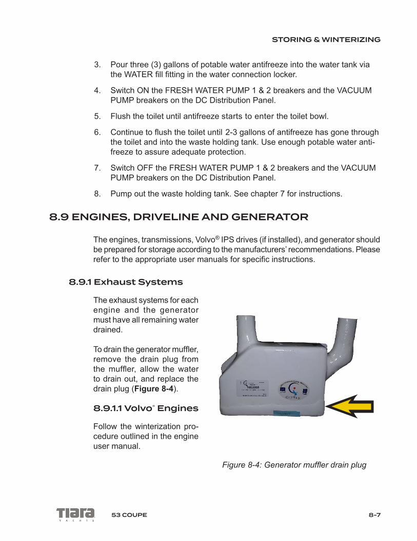
STORING & WINTERIZING
8-753 COUPE
3. Pour three (3) gallons of potable water antifreeze into the water tank via the WATER fill fitting in the water connection locker.
4. Switch ON the FRESH WATER PUMP 1 & 2 breakers and the VACUUM PUMP breakers on the DC Distribution Panel.
5. Flush the toilet until antifreeze starts to enter the toilet bowl.
6. Continue to flush the toilet until 2-3 gallons of antifreeze has gone through the toilet and into the waste holding tank. Use enough potable water anti-freeze to assure adequate protection.
7. Switch OFF the FRESH WATER PUMP 1 & 2 breakers and the VACUUM PUMP breakers on the DC Distribution Panel.
8. Pump out the waste holding tank. See chapter 7 for instructions.
8.9 ENGINES, DRIVELINE AND GENERATOR
The engines, transmissions, Volvo® IPS drives (if installed), and generator should be prepared for storage according to the manufacturers’ recommendations. Please refer to the appropriate user manuals for specific instructions.
8.9.1 Exhaust Systems
The exhaust systems for each engine and the generator must have all remaining water drained.
To drain the generator muffler, remove the drain plug from the muffler, allow the water to drain out, and replace the drain plug (Figure 8-4).
8.9.1.1 Volvo® Engines
Follow the winterization pro-cedure outlined in the engine user manual.
Figure 8-4: Generator muffler drain plug

STORING & WINTERIZING
8-8 53 COUPE
8.9.1.2 Cummins® Engines
Follow the winterization procedure outlined in the engine user manual. Water remaining in the mufflers must be drained. To drain, remove the drain plug from the muffler, allow the water to drain out, and replace the drain plug.
BE CERTAIN THAT THE EXHAUST DRAIN PLUGS ARE INSTALLED TIGHTLY. FAILURE TO DO SO WILL ALLOW ENGINE EXHAUST GAS-ES CONTAINING CARBON MONOXIDE AND WATER INTO THE BILGE AREA.
WARNING!
CAUTION!Prior to transporting your vessel by truck and trailer the engine mufflers must be drained to prevent sea water reversion into the engines.
8.9.2 Steering System
The steering system for the Cummins® engine package is located in the lazarette area, underneath the trunk floor hatch.
To prepare the Cummins® steering system for storage:
1. Use clean water and mild soap to wash off the steering arms and linkage. Dry with a clean cloth.
2. Apply a light coat of petroleum jelly to the piston rod.
3. Lubricate the pivot points and upper rudder bearings with a lightweight oil.
4. Inspect the packing glands for wear. If worn, replace with new packing.
5. Coat all components with a light coat of corrosion-inhibiting material such as Boeshield® T-9 or WD-40®.

STORING & WINTERIZING
8-953 COUPE
8.10 RAW WATER SYSTEMS
The raw water cooling system for each engine and the generator must be drained before storage. The raw water washdown system must also be drained before storage. See chapter 3 for raw water system components.
To drain the cooling systems:
1. Open the raw water intake seacock.
2. Drain the raw water intake strainer.
3. Remove and clean the strainer filter.
4. Disconnect the hoses, if necessary, to remove all water.
5. Reconnect all hoses and reassemble the strainer.
Repeat this procedure for each engine and the generator.
Consult the engine and generator user manual for more information on recom-mended winterization procedures.
To drain the raw water washdown system:
1. Connect the hose to the raw water washdown connection inside the water connection locker.
2. Ensure the end of the hose is open, or open the spray nozzle if installed.
3. Open the raw water washdown seacock in the engine room.
4. Disconnect the hoses from the intake and outlet sides of the pump and let the water drain out. Use compressed air, if necessary, to remove all the water.
5. Run the pump for 3-5 seconds to remove all water from the pump body.
6. Lubricate the pump impeller per instructions in the pump’s user manual.
7. Reconnect all hoses and tighten the clamps securely.

STORING & WINTERIZING
8-10 53 COUPE
WHEN RECONNECTING RAW WATER HOSES, BE CERTAIN ALL HOSE CLAMPS ARE PROPERLY TIGHTENED. FAILURE TO DO SO COULD CAUSE A WATER LEAK AND CAN SINK THE BOAT.
WARNING!
CAUTION!Be very careful when using compressed air to blow water out of the sys-tem. Using too much air pressure or volume can damage the raw water system.
8.11 ENGINE ROOM AND BILGE AREAS
All accessible bilge areas (engine room, aft lazarette area, and forward under the cabin floor) should be wiped clean. Any remaining bilge water should be removed and wiped dry.

A-153 COUPE
SPECIFICATIONS
A.1 ENGINE AND GENERAL SPECIFICATIONS
A.1.1 ENGINE OPTIONS
Twin Volvo® IPSII 950 with Glass Cockpit, Joystick Plus® Control & ACP ..............................725 HP
A.1.2 GENERAL SPECIFICATIONS
L.O.A. with Standard Swim Platform ...................... 54’6” (16.61 meters)Beam ........................................................................15’11” (4.85 meters)Draft (Fully Loaded) .................................................... 4’8” (1.42 meters)Height from Waterline to Top of Std. Hardtop ..... 12’2-1/2” (3.72 meters)Height from Waterline to Top of Std. Radar... ............ 13’9” (4.19 meters)Height from Waterline to Top of Std.
Anchor/Navigation Light... .......................... 14’6-1/2” (4.43 meters)
Approximate Dry Weight ................................45,300 lbs. (20,547.73 kg)Fuel Capacity ...................................... 650 U.S. gallons (2,460.52 liters)Water Capacity ....................................... 150 U.S. gallons (567.81 liters)Holding Tank Capacity ............................. 86 U.S. gallons (325.55 liters)Deadrise at Transom ....................................................................... 14.8°
Sleeping AccommodationsStandard Foor Plan ........................................................................4Third Stateroom ..............................................................................6
A.2 COMPONENT SPECIFICATIONS
Boat Serial No: SSUXA037G617

APPENDIX A: SPECIFICATIONS
A-2 53 COUPE
MATERIAL DESCRIPTION SERIAL NO
A/C UNIT, DLU16-2361-410 LOW 230V ............................................63297937A/C UNIT, DLU16-2361-410 LOW 230V ............................................63297938A/C UNIT, DTU10-2361-410A, 230V 60HZ ........................................62499787A/C UNIT, DTU16-2361-410A, 230V 60HZ ........................................63099002A/C UNIT, DTU8-2361-410A, 230V 60HZ .........................................62698677CHARGER VICTRON CENTAUR 24V/16A ..............................HQ1525UC18KCHARGER, BATTERY CENTAUR 12/80 .................................HQ1607CD1EQENGINE, VOLVO D11 725HP IPS2 950 PORT 53 ........................ 7011379773ENGINE, VOLVO D11 725HP IPS2 950 STBD 53 ......................... 7011379825FRIDGE/FREEZE, ISO DRWR 160 LITE HANDLE .............................6220015FRIDGE/FREEZE/ICE MKR,ISO DRWR, HANDLE .............................6100107GARMIN ARRAY, 4’ GMR X HD2 ANTENNA ...................................421003728GARMIN CHARTPLOTTER, VOLVO DISPLAY ...............................476000128GARMIN CHARTPLOTTER, VOLVO DISPLAY ...............................176000138GARMIN PEDESTAL, GMR624XHD/626XHD ................................ 42N001351GARMIN SOUNDER, GSD24 010-00957-00 ...................................294020484GARMIN VHF 300 BLACK NORTH AMERICA .............................. 1MK006617GENERATOR, 13.5KW/60HZ QD SHLD IB .................................. E160959922GRILL, KENYON ELECTRIC SS WO/LID #B70060 ..............................735023REFRIGERATOR, DRAWER #CRO65DV54D ..................................... 6130113SEAKEEPER, SC9.......................................................................................968STOVE, 3-BURNER 240V #B40509 ......................................................T34751SWIMPLATFORM LIFT, 53 COUPE IPS NS103431 ................................31890TRANSMISSION SER NO - PORT ENG .......................................3950002550TRANSMISSION SER NO - STBD ENG ........................................3950002551WASHER DRYER, COMBO SPLENDIDE WD2100XC ...................604051359WATER HEATER, 20 GAL 240V #H2050EWTY ................................70716461WINDLASS LEWMAR CPX 3 .............................................. 703B16613282-15
Glossary of Terms Appendix B
B-1
Aft: In, near, or toward the stern of a boat.
Aground: A boat stuck on the bottom.
Amidships: In or toward the part of a boat midway between the bow and stern.
Anchor: A specially shaped heavy metal device designed to dig efficiently into the bot-tom under a body of water and hold a boat in place.
Anchor locker: a locker, usually located in the bow of a boat, used for stowing the anchor line or chain
Anchorage: An area specifically designated by governmental authorities in which boats may anchor.
Ashore: On shore.
Astern: Behind the boat, to move back-wards.
Athwartship: At right angles to the center line of the boat.
Barnacles: Small, hard-shelled marine animals which are found in salt water attached to pilings, docks and bottoms of boats.
Beam: The breadth of a boat usually mea-sured at its widest part.
Beamy: boats of greater than normal beam
Bearing: The direction of an object from the boat, either relative to the boat’s direction or to compass degrees.
Berth: A bunk or a bed on a boat.
Bilge: The bottom of the boat below the flooring.
Bilge Pump: A pump that removes water that collects in the bilge.
Boarding: Entering or climbing into a boat.
Boarding Ladder: Set of steps temporarily fitted over the side of a boat to assist persons coming aboard.
Boat Hook: Short shaft of wood or metal with a hook fitting at one end shaped to aid in extending one’s reach from the side of the boat.
Bow: The front end of a boat’s hull.
Bow Line: A line that leads forward from the bow of the boat.
Bow Rail: Knee high rails of solid tubing to aid in preventing people from falling over-board.
Bridge: The area from which a boat is steered and controlled.
Bridge Deck: A deck forward and usually above the cockpit deck.
Broach: When the boat is sideways to the seas and in danger of capsizing; a very dan-gerous situation that should be avoided.
Bulkhead: Vertical partition or wall separat-ing compartments of a boat.
Cabin: Enclosed superstructure above the main deck level.
Capsize: When a boat lays on its side or turns over.
Chapman’s: Chapman Piloting & Seaman-ship, by Chapman and Jonathon Eaton; pub-lished by Hearst.
Chain locker: See anchor locker.
Chock: A deck fitting, usually of metal, with inward curving arms through which mooring or anchor lines are passed so as to lead them in the proper direction both onboard and off the boat.
Appendix B Glossary of Terms
B-2
Cleat: A deck fitting, usually of metal with projecting arms used for securing anchor and mooring lines.
Closed Cooling System: A separate sup-ply of fresh water that is used to cool the engine and circulates only within the engine.
Coaming: A vertical piece around the edges of cockpit, hatches, etc., to stop water on deck from running below.
Cockpit: An open space, usually in the aft deck, outside of the cabin.
Companionway: Opening in the deck of a boat to provide access below.
Compartment: The interior of a boat divided off by bulkheads.
Cradle: A framework designed to support a boat as she is hauled out or stored.
Cutlass Bearing: A rubber bearing in the strut that supports the propeller shaft.
Deck: The floor-like platform of a boat that covers the hull.
Displacement: The volume of water dis-placed by the hull. The displacement weight is the weight of this volume of water.
Draft: The depth of water a boat needs to float.
Drydock: A dock that can be pumped dry during boat construction or repair.
Dry Rot: A fungus attack on wood areas.
Electrical Ground: A connection between an electrical connector and the earth.
Engine Beds: Sturdy structural members running fore and aft on which the inboard engines are mounted.
EPIRB: Emergency Position Indicating Radio Beacon. Operates as a part of a world-wide satellite distress system.
Even Keel: When a boat floats properly as designed.
Fathom: A measure of depth. One Fathom = 6 feet.
Fender: A soft object of rubber or plastic used to protect the topsides from scarring and rubbing against a dock or another vessel.
Fend off: To push or hold the boat off from the dock or another boat.
Flying Bridge: A control station above the level of the deck or cabin.
Flukes: The broad portions of an anchor which dig into the ground.
Following Sea: A sea that comes up from the stern and runs in the same direction that the boat is going.
Fore: Applies to the forward portions of a boat near the bow.
Foundering: When a boat fills with water and sinks.
Fuel pump: feeds fuel under pressure
Freeboard: The height from the waterline to the lowest part of the deck.
Galley: The kitchen of a boat.
Grab Rail: Hand-hold fittings mounted on cabin tops or sides for personal safety when moving around the boat, both on deck and below.
Ground Tackle: A general term includ-ing anchors, lines, and other gear used in anchoring.

Glossary of Terms Appendix B
B-3
Grounds: A boat touches the bottom.
Gunwale: The upper edge of a boat’s side.
Hand Rail: Rail mounted on the boat, for grabbing with your hand, to steady you while walking about the boat.
Harbor: An anchorage which provides rea-sonably good protection for a boat, with shel-ter from wind and sea.
Hatch: An opening in the deck with a door or lid to allow for access down into a compart-ment of a boat.
Head: A toilet on a boat.
Heat Exchanger: Used to transfer the heat that is picked up by the closed cooling system to the raw cooling water.
Helm: The steering and control area of a boat.
Hull: The part of the boat from the deck down.
Inboard: A boat with the engine mounted within the hull of the boat. Also refers to the center of the boat away from the sides.
Inboard/outboard: Also stern drive or I/O. A boat with an inboard engine attached to an outboard drive unit.
Keel: A plate or timber plate running length-wise along the center of the bottom of a boat.
Knot: Unit of speed indicating nautical miles per hour. 1 knot = 1 nautical mile per hour (1.15 miles per hour). A nautical mile is equal to one minute of latitude: 6076 feet. Knots times 1.15 equals miles per hour. Miles per hour times .87 equals knots.
Lay-up: To decommission a boat for the winter (usually in northern climates).
Leeward: The direction toward which the wind is blowing.
Length On The Waterline (LWL): A length measurement of a boat at the water-line from the stern to where the hull breaks the water near the bow.
Length Overall (LOA): a length measure-ment of a boat from the fore part of the stem to the after part of the stern
Life Preserver: provides additional buoy-ancy to keep a person afloat when he/she is in the water
Limber Hole: A passage cut into the lower edges of floors and frames next to the keel to allow bilge water to flow to the lowest point of the hull where it can be pumped overboard.
Line: The term used to describe a rope when it is on a boat.
Lists: A boat that inclines to port or starboard while afloat.
Locker: A closet, chest or box aboard a boat.
Loran: An electronic navigational instrument which monitors the boat’s position using sig-nals emitted from pairs of transmitting sta-tions.
Lunch hook: A small light weight anchor typically used instead of the working anchor. Normally used in calm waters with the boat attended.
Marina: A protected facility primarily for recreational small craft.
Marine Ways or Railways: Inclined planes at the water’s edge onto which boats are hauled.

Appendix B Glossary of Terms
B-4
Midships: The center of the boat.
Moored: A boat secured with cables, lines or anchors.
Mooring: An anchor permanently embed-ded in the bottom of a harbor that is used to secure a boat.
Nautical Mile: A unit of measure equal to one minute of latitude. (6076 feet)
Nun Buoy: A red or red-striped buoy of con-ical shape.
Oil Pump: Supplies lubricating oil where needed within the engine.
Outboard: A boat designed for an engine to be mounted on the transom. Also a term that refers to objects away from the center line or beyond the hull sides of a boat.
Overhead: the ceiling of a cabin or compart-ment,
Pad Eye: A deck fitting consisting of a metal eye permanently secured to the boat.
Personal Flotation Device (PFD): For example, a life preserver or throwable device.
Pier: A structure which projects out from the shoreline.
Pile or Piling: A long column driven into the bottom to which a boat can be tied.
Pitch: The measure of the angle of a propel-ler blade. Refers to the theoretical distance the boat travels with each revolution of the propeller.
Pitching: The fore and aft rocking motion of a boat as the bow rises and falls.
Plenum: a chamber for directing air flow, as in engine intake air plenum
Port: The left side of the boat when facing the bow.
Porthole (port): The opening in the side of a boat to allow the admittance of light and air.
Propeller: A device having two or more blades that is attached to the engine and used for propelling a boat.
Propeller Shaft: Shaft which runs from the back of the engine gear box, aft, through the stuffing box, shaft log, struts, and onto which the propeller is attached.
Pyrotechnic Distress Signals: Distress signals that resemble the brilliant display of flares or fireworks.
Raw Water Cooled: Refers to an engine cooling system that draws sea water in through a hull fitting or engine drive unit, cir-culates the water in the engine, and then dis-charges it overboard.
Reduction Gear: Often combined with the reverse gear so that the propeller turns at a slower rate than the engine.
Reverse Gear: Changes the direction of rotation of the propeller to provide thrust in the opposite direction for stopping the boat or giving it sternway.
Roll: A boat’s sideways rotational motion in rough water.
Rope Locker: See anchor locker.
Rubrail: Railing (often rubber or hard plas-tic) that runs along the boat’s sheer to protect the hull when coming alongside docks, piers, or other boats.

Glossary of Terms Appendix B
B-5
Rudder: A movable flat surface that is attached vertically at or near the stern for steering.
Sea anchor: An anchor that does not touch the bottom. Provides drag to hold the bow in the most favorable position in heavy seas.
Scupper: An opening in the hull side or tran-som of the boat through which water on deck or in the cockpit is drained overboard.
Seacock: Safety valves installed just inside the thru-hull fittings and ahead of the piping or hose running from the fittings.
Shaft Log: Pipe through which the propeller shaft passes.
Sheer: The uppermost edge of the hull.
Sling: A strap which will hold the boat securely while being lifted, lowered, or car-ried.
Slip: A boat’s berth between two pilings or piers.
Sole: The deck of a cockpit or interior cabin.
Spring Line: A line that leads from the bow aft or from the stern forward to prevent the boat from moving ahead or astern.
Starboard: The right side of a boat when facing the bow.
Steerageway: Sufficient speed to keep the boat responding to the rudder or drive unit.
Stem: The vertical portion of the hull at the bow.
Stern: The rear end of a boat.
Stern line: a line that leads aft from the stern of the boat
Stow: To pack away neatly.
Stringer: Longitudinal members fas-tened inside the hull for additional structural strength.
Strut: Mounted to the hull which supports the propeller shaft in place.
Strut Bearing: See “cutlass bearing.”
Stuffing Box: Prevents water from entering at the point where the propeller shaft passes through the shaft log.
Superstructure: Something built above the main deck level.
Swamps: When a boat fills with water from over the side.
Swimming Ladder: Much the same as the boarding ladder except that it extends down into the water.
Taffrail: Rail around the rear of the cockpit.
Thru-hull: A fitting used to pass fluids (usu-ally water) through the hull surface, either above or below the waterline.
Topsides: The side skin of a boat between the waterline or chine and deck.
Transom: A flat stern at right angles to the keel.
Travel Lift: A machine used at boat yards to hoist boats out of and back into the water.
Trim: Refers to the boat’s angle or the way it is balanced.
Trough: The area of water between the crests of waves and parallel to them.
Twin-Screw Craft: A boat with two propel-lers on two separate shafts.

Appendix B Glossary of Terms
B-6
Underway: When a boat moves through the water.
Wake: Disrupted water that a boat leaves astern as a result of its motion.
Wash: The flow of water that results from the action of the propeller or propellers.
Waterline: The plane of a boat where the surface of the water touches the hull when it is afloat on even keel.
Water pump: circulates cooling water
Watertight Bulkhead: Bulkheads secured so tightly so as not to let water pass.
Wharf: A structure generally parallel to the shore.
Windlass: A winch used to raise and lower the anchor.
Windward: Toward the direction from which the wind is coming.
Working Anchor: An anchor carried on a boat for most normal uses. Refers to the anchor used in typical anchoring situations.
Yacht Basin: A protected facility primarily for recreational small craft.
Yaw: Side-to-side movement, usually caused by rough seas.

Maintenance Guides Appendix C
C-1
Maintenance Guides
As the world’s premier gel coat supplier, Polynt Composites has provided this brochure as a guide to properly maintain and care for your gel coat surface.
Owner’s Guide:Care & Upkeep of Fiberglass Products
Gel Coats provide a protective layer against weathering on a surface. Over time, exposure to sunlight, water, dust and chemicals cause wear and tear on the gel coat surface. This results in chalking, discoloration, yellowing or loss of gloss. By following simple, regular maintenance procedures, you can minimize these effects.
Basic MaintenanceWhen not in use, keep the gel coat surface out of the sun or covered with a canvas tarp. Do not use plastic sheeting or other non-porous materials as they trap moisture between the cover and the surface, causing damage to the gel coat.
For best results, use a cleaner recommended for use with fiberglass and follow label instructions. Alternatively, you can wash the surface with a mild detergent, such as dishwashing soap.
DO NOT use automatic dishwasher detergent, abrasive cleaners, bleach, strong acids or bases (i.e. TSP or ammonia). Only use pH neutral cleaners.
Wax at least twice a year to restore gloss and protect the finish. Only use a wax that is recommended for gel coat surfaces and follow instructions carefully. NEVER wax a gel coat surface in direct sunlight.
Corrective Procedures*ChalkingA fine rubbing compound as well as a mild detergent will reduce the weathering and chalking accumulated on the surface. Use only a fine grit compound and follow label directions carefully. DO NOT apply rubbing compound in direct sunlight. For best results, wax after applying compound. When applying wax, remove excess compound and apply a thin layer of wax using a clean cloth. It is recommended to use a wax designed for fiberglass.
Scratches, Nicks and StainsMost scratches and nicks can be removed by using a rubbing compound followed by waxing as described above. Deep marks or gouges should be professionally repaired.
Most stains can be removed by washing with mild detergent. For stubborn stains, use a fine abrasive household cleanser designed for fiberglass products, followed by waxing to restore its original luster.
Non-water soluble stains such as grease and oil, rubber heel marks, etc., can be removed by using a solvent such as acetone, rubbing alcohol, toluene or xylene, followed by a mild detergent. If these solvents are not effective, try a rubbing compound or fine sanding followed by a rubbing compound and then waxing.
If you have questions, consult your local dealer.
*Always try a test spot first
Polynt Composites USA99 E. Cottage Ave Carpentersville, IL 60110 800-322-8103

Appendix C Maintenance Guides
C-2
Operator Notes

Maintenance Schedule Appendix D
D-1
Maintenance Schedule
Maintenance Each Use Weekly Monthly Semi
Annually Yearly As Needed
Clean hull below the waterline X
Bottom paint X X
Check sacrificial anodes X
Replace sacrificial anodes X
Wash boat canvas & hardware X X
Wax exterior gelcoat X X
Clean & protect hardware X
Polish & protect plastic glass X X
Clean exterior upholstery X X
Clean cabin & interior upholstery X
Flush engine with fresh water X
Spray metal components in bilge witha protector X
Clean bilge X X
Check bilge for leaks X X
Inspect & operate thru-hull valves X
Inspect steering & control systems X
Service steering & control systems X
Inspect fuel system for leaks X
Inspect & service fuel system X
Inspect fuel tank vents & screens X`
Replace fuel filters X
Lubricate fuel fill o-rings X
Inspect fire extinguisher X
Test bilge pump auto switches X
Inspect & protect electrical components, wire & battery connections X
Check battery electrolyte & service X
Test and inspect AC electrical system & shore power cord X
Inspect water systems for leaks X
Check neutral safety switch X
Check trim tab fluid level X

Appendix D Maintenance Schedule
D-2
Date Hours Dealer Service / Repairs

Maintenance Schedule Appendix D
D-3
Date Hours Dealer Service / Repairs

Appendix D Maintenance Schedule
D-4
Date Hours Dealer Service / Repairs

Boating Accident Report Appendix E
E-1
Boating Accident Report
'(3$570(17�2)�+20(/$1'�6(&85,7<�8�6��&RDVW�*XDUG� 20%�&RQWURO�1XPEHU������������
RECREATIONAL BOATING ACCIDENT REPORT ([SLUHV� �� ������ �
INSTRUCTIONS��8VH��5HSRUW�UHTXLUHG�EHFDXVH��VHFWLRQ�EHORZ�WR�GHWHUPLQH�LI�D�UHSRUW�LV�UHTXLUHG�IRU�\RXU�DFFLGHQW�� ,I�UHTXLUHG��SOHDVH�KDYH�HDFK�YHVVHO�RZQHU�RU�RSHUDWRU�LQYROYHG�LQ�WKH�DFFLGHQW�VXEPLW�D�UHSRUW�WR�WKHLU�VWDWH�UHSRUWLQJ�DXWKRULW\�� (DFK�ERDW�RSHUDWRU�RZQHU�LQYROYHG�LQ�DQ�DFFLGHQW�VKRXOG�VXEPLW�D�VHSDUDWH�UHSRUW�� )RU�HDFK�TXHVWLRQ�EHORZ��SOHDVH�SURYLGH�DQVZHUV�LI�DSSOLFDEOH�DQG�LI�NQRZQ��RWKHUZLVH�OHDYH�EODQN��
Privacy Act Notice Authority: ��� 8�6�&�������DQG����&)5����������DXWKRUL]H�WKH�FROOHFWLRQ�RI�LQIRUPDWLRQ�RQ�ERDWLQJ�DFFLGHQWV��Purpose: 7KH�&RDVW�*XDUG�XVHV�WKLV�LQIRUPDWLRQ�IRU�VWDWLVWLFDO�SXUSRVHV��FKLHIO\�WR�LQIRUP�WKH�SXEOLF��WR�PHDVXUH�WKH�3URJUDPV�HIIRUWV��DQG�WR�UHJXODWH�LVVXHV�UHODWLQJ�WR�
ERDWLQJ�VDIHW\��Routine Uses: 7KH�&RDVW�*XDUG�VKDUHV�WKLV�LQIRUPDWLRQ�ZLWKLQ�WKH�DJHQF\��DQG�LI�VWDWH�DQG�IHGHUDO�ODZ�SHUPLW�LW��WR�WKH�SXEOLF��
REPORT SUBMISSION Report required because (select all that apply):
$W�OHDVW�RQH�SHUVRQ�LQ�WKLV�DFFLGHQW�died�� ,I�VR��KRZ�PDQ\"�BBBBBBB�$W�OHDVW�RQH�LQMXUHG�SHUVRQ�LQ�WKLV�DFFLGHQW�required or was in need of treatment beyond first aid�� ,I�VR��KRZ�PDQ\"�BBBBBBB�$W�OHDVW�RQH�SHUVRQ�LQ�WKLV�DFFLGHQW�disappeared DQG�KDV�QRW�\HW�EHHQ�UHFRYHUHG�� ,I�VR��KRZ�PDQ\"�BBBBBBB�All ERDW�DQG�RWKHU�SURSHUW\�damage (e.g., fishing/hunting gear) FDXVHG�E\�WKLV�DFFLGHQW�totaled (or likely totaled) �������RU�PRUH��
$SSUR[LPDWH�YDOXH�RI�GDPDJH�WR�your ERDW�� $BBBBBBBBBB�$SSUR[LPDWH�YDOXH�RI�GDPDJH�WR�your RWKHU�SURSHUW\�� $BBBBBBBBBB�
<RXU�RU�DQRWKHU�boat LQ�WKLV�DFFLGHQW�ZDV�(or likely was) D�total loss Report submitted by (select all that apply)��
%RDW�2SHUDWRU�(required if possible) %RDW�2ZQHU�(if operator unable, or same as operator) 2WKHU�(describe)��BBBBBBBBBBBBBBBBBBBBBBBBBBBBBBBBBBBBBBBBBB�
BBBBBBBBBBBBBBBBBBBBBBBBBBBBBBBBBBBBBBBBBB�
To be submitted within: ���KRXUV�(if injury, disappearance or death) ���GD\V�(if boat/property damage only) 7R�EH�VXEPLWWHG�WR��(Local State Reporting Authority)
3KRQH��<RX�PD\�VXEPLW�DQ\�FRPPHQWV�FRQFHUQLQJ�WKH�DFFXUDF\�RI�WKH�EXUGHQ�HVWLPDWH�RU�DQ\�VXJJHVWLRQV�IRU�UHGXFLQJ�WKH�EXUGHQ�WR��&RPPDQGDQW��&*�%6;������8�6��&RDVW�*XDUG��:DVKLQJWRQ��'&������������RU�2IILFH�RI�0DQDJHPHQW�DQG�%XGJHW��3DSHUZRUN�5HGXFWLRQ�3URMHFW��������������:DVKLQJWRQ��'&�������� 4XHVWLRQV�UHODWLQJ�WR�WKH�FROOHFWLRQ�RI�WKLV�GDWD�VKRXOG�EH�VHQW�WR�WKH�&RDVW�*XDUG��
For State Agency Use Only First Name Last Name
Phone��)LUVW�1DPH� /DVW�1DPH� 3KRQH� Primary Cause of Accident
ACCIDENT SUMMARY WHEN ACCIDENT DESCRIPTION�� Briefly GHVFULEH�WKLV�DFFLGHQW�
(attach extra pages if necessary) 'DWH�� 7LPH�� DP� SP�(mm/dd/yyyy) (select one) WHERE %RG\�RI�:DWHU�1DPH�
/RFDWLRQ�(on water) GHVFULSWLRQ� DAMAGE TO YOUR BOAT��Briefly VXPPDUL]H�DQ\�GDPDJH�WR�\RXU�ERDW�
1HDUHVW�FLW\�WRZQ�
&RXQW\�� 6WDWH��
YOUR BOAT – PEOPLE DAMAGE TO YOUR OTHER PROPERTY: (NOT BOAT) Briefly VXPPDUL]H�DQ\�GDPDJH�WR�\RXU�RWKHU�SURSHUW\�(not boat) ��SHRSOH�on board (including operator)��
��SHRSOH�being towed (e.g., on tubes, skis)��
��SHRSOH�wearing lifejackets (on board or towed)��OTHER BOATS INVOLVED IN ACCIDENT ��RI�other ERDWV�LQYROYHG��
&*������� �� 3DJH���RI���
Reset
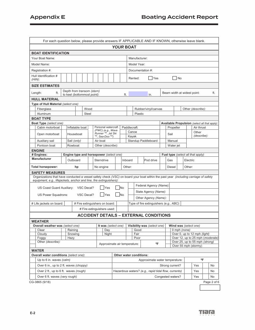
Appendix E Boating Accident Report
E-2
For each question below, please provide answers IF APPLICABLE AND IF KNOWN, otherwise leave blank.
YOUR BOAT BOAT IDENTIFICATION Your Boat Name: Manufacturer:
Model Name: Model Year:
Registration #: Documentation #:
Hull Identification # (HIN): Rented: Yes No
SIZE ESTIMATES
Length: ft. Depth from transom (stern) to keel (bottommost point): ft. in. Beam width at widest point: ft.
HULL MATERIAL Type of Hull Material (select one)
Fiberglass Wood Rubber/vinyl/canvas Other (describe): Aluminum Steel Plastic
BOAT TYPE Boat Type (select one) Available Propulsion (select all that apply)
Cabin motorboat Inflatable boat Personal watercraft (PWC) (e.g., Wave Runner TM, Jet Ski TM, Sea-Doo TM)
Paddlecraft: Propeller Air thrust
Open motorboat Houseboat Canoe
Sail Other (describe):Kayak
Auxiliary sail Sail (only) Air boat Standup Paddleboard Manual Pontoon boat Rowboat Other (describe): Water jet
ENGINE # Engines: Engine type and horsepower (select one) Fuel type (select all that apply) Manufacturer Outboard Sterndrive Inboard Pod drive Gas Electric
Total horsepower: hp No engine Other: Diesel Other:
SAFETY MEASURES Organizations that have conducted a vessel safety check (VSC) on board your boat within the past year (including carriage of safety equipment, e.g., lifejackets, anchor and line, fire extinguishers):
US Coast Guard Auxiliary: VSC Decal? Yes No
US Power Squadrons: VSC Decal? Yes No
Federal Agency (Name):
State Agency (Name):
Other Agency (Name):
# Life jackets on board: # Fire extinguishers on board: Type of fire extinguishers (e.g., ABC):
# Fire extinguishers used:
ACCIDENT DETAILS – EXTERNAL CONDITIONS WEATHER Overall weather was (select one) It was (select one) Visibility was (select one) Wind was (select one)
Clear Raining Day Good 0 mph (none) Cloudy Snowing Night Fair Over 0, up to 12 mph (light) Foggy Hazy Poor Over 12, up to 25 mph (moderate) Other (describe):
Approximate air temperature: ºF Over 25, up to 55 mph (strong) Over 55 mph (stormy)
WATER Overall water conditions (select one): Other water conditions:
Up to 6 in. waves (calm) Approximate water temperature: ºF
Over 6 in., up to 2 ft. waves (choppy) Strong current? Yes No
Over 2 ft., up to 6 ft. waves (rough) Hazardous waters? (e.g., rapid tidal flow, currents) Yes No
Over 6 ft. waves (very rough) Congested waters? Yes No
CG-3865 (9/18) Page 2 of 6
Reset

Boating Accident Report Appendix E
E-3
For each question below, please provide answers IF APPLICABLE AND IF KNOWN, otherwise leave blank.
ACCIDENT DETAILS – ACTIVITIES AND OPERATIONS ON YOUR BOAT OPERATOR/PASSENGER ACTIVITIES Operator/passenger activities on your boat at time of accident:
Activities were �VHOHFW�RQH�� Operator/Passenger activities �VHOHFW�DOO�WKDW�DSSO\��Recreational Fishing Tubing Starting engine Commercial Hunting Water Skiing Making repairs
White water activity �H�J���UDIWLQJ�� Relaxing Other �OLVW���
BOAT OPERATIONS Your boat operations at time of accident �VHOHFW�DOO�WKDW�DSSO\��
Cruising �XQGHUZD\�XQGHU�SRZHU�� Drifting Racing Towing another vessel Changing direction At anchor Rowing/paddling Launching Changing speed Being towed Docking/undocking Tied to dock/mooring Sailing Other �OLVW�:
ACCIDENT DETAILS – CONTRIBUTING FACTORS ON YOUR BOAT CONTRIBUTING FACTORS Indicate factors on your boat which may have contributed to this accident �VHOHFW�DOO�WKDW�DSSO\��
Alcohol use Improper lookout Dam/lock Starting in gear Drug use Operator inattention Force of wake/wave Sharp turn Excessive speed Operator inexperience Hazardous waters Restricted vision �H�J���IRJ��Improper anchoring Language barrier Heavy weather Mission/inadequate aids to
navigation �H�J���EXR\��GD\PDUNHU��Improper loading Navigation rules violation Ignition of fuel or
vapor Inadequate on-board navigation lights
Overloading Failure to vent Hull failure People on gunwale, bow or transom Other �GHVFULEH�:
ACCIDENT DETAILS –YOUR BOAT MACHINERY/EQUIPMENT FAILURE Failure of the following machinery/equipment on your boat contributed to this accident �VHOHFW�DOO�WKDW�DSSO\��
Engine Onboard lights Shift Sound equipment �H�J���KRUQ��ZKLVWOH��Electrical system Seats Radio Auxiliary equipment Fuel system Steering Fire extinguisher Other (OLVW): Sail/mast Throttle Ventilation Onboard navigation aids �H�J���*36��
ACCIDENT DETAILS – EVENTS ON YOUR BOAT ACCIDENT EVENTS Types of events occurring to/on your boat during accident �VHOHFW�DOO�WKDW�DSSO\��
Collision with recreational boat Flooding/swamping Person fell overboard
Collision with commercial boat �H�J���WXJ��EDUJH�� Fire/explosion ± fuel Person fell on/within boat
Collision with fixed object �H�J���GRFN��EULGJH�� Fire/explosion ± non-fuel Sudden medical condition
Collision with submerged object �H�J���VWXPS��FDEOH��
Carbon monoxide exposure Person struck by boat
Collision with floating object �H�J���ORJ��EXR\�� Mishap of skier, tuber, wake boarder, etc.
Person struck by propeller or propulsion unit
Capsizing Person left boat voluntarily Person electrocuted
Grounding Person ejected from boat �FDXVHG�E\�FROOLVLRQ�RU�PDQHXYHU��
Sinking Other �GHVFULEH�:
CG-3865 ( /1 ) Page 3 of 6
Reset

Appendix E Boating Accident Report
E-4
For each question below, please provide answers IF APPLICABLE AND IF KNOWN, otherwise leave blank.
ACCIDENT DETAILS –YOUR BOAT-INJURED PEOPLE RECEIVING OR IN NEED OF TREATMENT BEYOND FIRST AID
5HSRUW�RQO\�injured people on, struck by, or being towed by \RXU�ERDW, receiving RU�LQ�QHHG�RI�treatment beyond first aid. 'R�QRW�UHSRUW�injured people on, struck by, or being towed by DQRWKHU�ERDW�RU�QR�ERDW�(e.g., swimmers, people on a dock). ,I�PRUH�WKDQ�RQH�injured person to report, attach additional copies of this page. ,I�QRQH, SKIP INJURED PEOPLE section.
INJURED PERSON First Name MI Last Name
Street
City State Zip
Phone Date of Birth �PP�GG�\\\\��
Age
INJURY DETAILS Injury caused when person �VHOHFW�DOO�WKDW�DSSO\�� Nature of most serious injury �VHOHFW�RQH��
Struck the �H�J���ERDW��ZDWHU��� Scrape/bruise Dislocation
Was struck by a �H�J���ERDW��SURSHOOHU��� Cut Internal organ injury
Was exposed to carbon monoxide poisoning Sprain/strain Amputation
Received an electric shock Concussion/brain injury Burn
Other �GHVFULEH��� Spinal cord injury Other �GHVFULEH���Person was wearing lifejacket? Yes No Broken/fractured bone Person received treatment beyond first aid? Yes No Body part of PRVW�VHULRXV�injury �H�J���KHDG��WUXQN��OHJ���
Person was admitted to a hospital? Yes No
ACCIDENT DETAILS – YOUR BOAT – DEATHS/DISAPPEARANCES 2QO\�report deaths/disappearances of people on, struck by, or being towed by \RXU�ERDW. If more than one death/disappearance to report, attach additional copies of this page. ,I�QRQH, SKIP DEATHS/DISAPPEARANCES section.
PERSON WHO DIED/DISAPPEARED First Name MI Last Name
Street
City State Zip
Phone Date of Birth �PP�GG�\\\\��
Age
DETAILS OF DEATH/DISAPPEARANCE Injury caused when person �VHOHFW�DOO�WKDW�DSSO\�� Nature of death/disappearance �VHOHFW�RQH��
Struck the �H�J���ERDW��ZDWHU��� Death ± by drowning
Was struck by a �H�J���ERDW��SURSHOOHU���
Death ± other likely cause �GHVFULEH��
Was exposed to carbon monoxide poisoning
Received an electric shock Disappeared and not yet recovered Other �GHVFULEH���
Person was wearing lifejacket? Yes No
CG-3865 ( /1 ) Page 4 of 6
Reset

Boating Accident Report Appendix E
E-5
For each question below, please provide answers IF APPLICABLE AND IF KNOWN, otherwise leave blank.
ACCIDENT DETAILS – YOUR BOAT OPERATOR OPERATOR INSTRUCTION OPERATOR SAFETY MEASURES Boating safety instruction completed �VHOHFW�DOO�WKDW�DSSO\�� On board, prior to accident, was operator wearing:
None A lifejacket? Yes No
State course An engine cut-off switch �/DQ\DUG�RU�ZLUHOHVV�GHYLFH��if equipped? Yes No
USCG Auxiliary course On board, prior to accident, was operator using:
Alcohol? Yes NoUS Power Squadrons course
Internet �QDPH�RI�VSRQVRULQJ�RUJDQL]DWLRQ�� Drugs? Yes No
Other �GHVFULEH�� Operator arrested for Boating Under the Influence? Yes No
Weather reports consulted prior to accident? Yes No
OPERATOR EXPERIENCE Experience operating this type of boat �VHOHFW�RQH��
0 to 10 hours Over 10, up to 100 hours Over 100, up to 500 hours Over 500 hours
ACCIDENT DETAILS – OTHER KEY PEOPLE 2QO\�UHSRUW�other key people QRW�DOUHDG\�GRFXPHQWHG�as injured, died, disappeared or operator/owner of \RXU�boat. If more than two other key people to report, attach additional copies of this page.
NAME/ADDRESS This other key person was a(n) �VHOHFW�DOO�WKDW�DSSO\��
2WKHU�boat operator 2WKHU�boat owner Owner of RWKHU�damaged property Passenger on \RXU�boat Witness
First Name MI Last Name
Street
City State Zip Phone
2WKHU�boat name �LI�DQ\�� 2WKHU�boat registration # �LI�DQ\��
NAME/ADDRESS This other key person was a(n) �VHOHFW�DOO�WKDW�DSSO\��
2WKHU�boat operator 2WKHU�boat owner Owner of RWKHU�damaged property Passenger on \RXU�boat Witness
First Name MI Last Name
Street
City State Zip Phone
2WKHU�boat name �LI�DQ\�� 2WKHU�boat registration # �LI�DQ\��
CG-3865 ( /1 ) Page 5 of 6
Reset

Appendix E Boating Accident Report
E-6
For each question below, please provide answers IF APPLICABLE AND IF KNOWN, otherwise leave blank.
YOUR BOAT OPERATOR NAME/ADDRESS First Name MI Last Name
Street
City State Zip
AGE/GENDER/PHONE Date of Birth �PP�GG�\\\\��
Age Gender Male Female Phone
YOUR BOAT OWNER If same as \RXU�boat RSHUDWRU�SKIP rest of YOUR BOAT OWNER section.
NAME/ADDRESS/PHONE First Name MI Last Name
Street
City State Zip Phone
PERSON SUBMITTING THIS REPORT If same as \RXU�boat RSHUDWRU�OR RZQHU, SKIP rest of PERSON SUBMITTING THIS REPORT section.
NAME/ADDRESS/PHONE/ROLE First Name MI Last Name
Street
City State Zip Phone
I was a(n) �VHOHFW�RQH��Other person on board WKLV�boat
Accident witness QRW�on board WKLV�boat Other �GHVFULEH���
SIGNATURE OF PERSON SUBMITTING THIS REPORT Your signature Date �PP�GG�\\\\��
An Agency may not conduct or sponsor and a person is not required to respond to an information collection, unless it displays a currently valid OMB Control Number.
The Coast Guard estimates that the average burden for this report form is 30 minutes. You may submit any comments concerning the accuracy of this burden estimate or any suggestions for reducing the burden to: Commandant (CG-%6;�2�), U.S. Coast Guard, Washington, DC 20593-0001 or Office of Management and Budget, Paperwork Reduction Project (1625-0003), Washington, DC 20503.
CG-3865 ( /1 ) Page 6 of 6
Reset

Float Plan Appendix F
F-1
Float Plan

Appendix F Float Plan
F-2

Float Plan Appendix F
F-3
Provided as a courtesy by:
S2 Yachts, Inc.Holland, MI
(616) 392-7163
Get a Vessel Safety Check before you go boating.

Appendix F Float Plan
F-4
Operator Notes
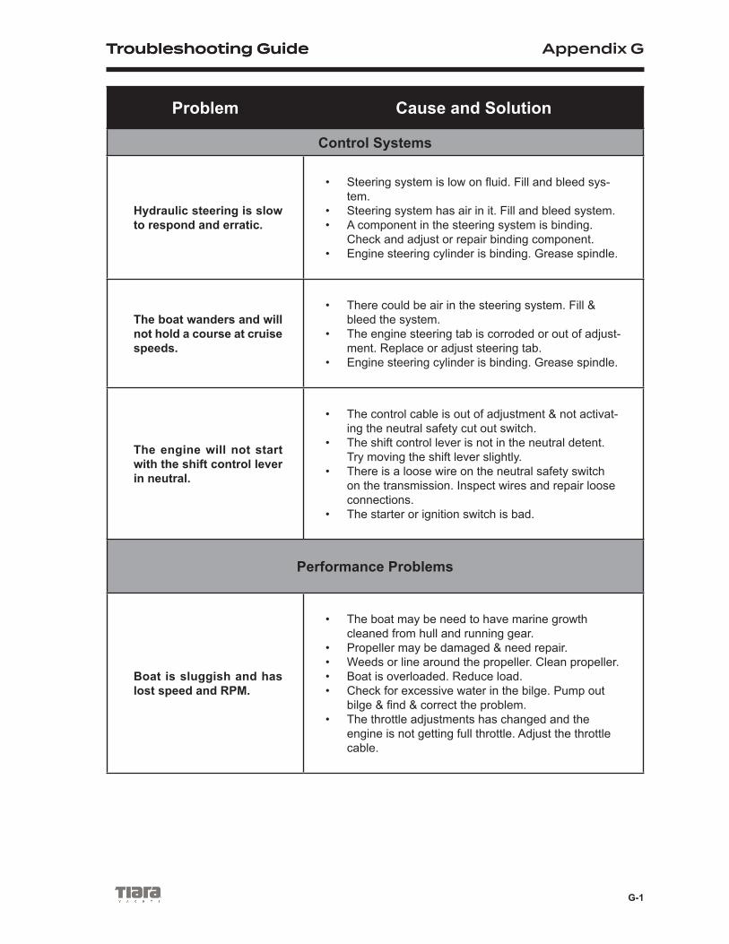
Troubleshooting Guide Appendix G
G-1
Troubleshooting Guide
Problem Cause and Solution
Control Systems
Hydraulic steering is slow to respond and erratic.
• Steering system is low on fluid. Fill and bleed sys-tem.
• Steering system has air in it. Fill and bleed system. • A component in the steering system is binding.
Check and adjust or repair binding component. • Engine steering cylinder is binding. Grease spindle.
The boat wanders and will not hold a course at cruise speeds.
• There could be air in the steering system. Fill & bleed the system.
• The engine steering tab is corroded or out of adjust-ment. Replace or adjust steering tab.
• Engine steering cylinder is binding. Grease spindle.
The engine will not start with the shift control lever in neutral.
• The control cable is out of adjustment & not activat-ing the neutral safety cut out switch.
• The shift control lever is not in the neutral detent. Try moving the shift lever slightly.
• There is a loose wire on the neutral safety switch on the transmission. Inspect wires and repair loose connections.
• The starter or ignition switch is bad.
Performance Problems
Boat is sluggish and has lost speed and RPM.
• The boat may be need to have marine growth cleaned from hull and running gear.
• Propeller may be damaged & need repair.• Weeds or line around the propeller. Clean propeller.• Boat is overloaded. Reduce load.• Check for excessive water in the bilge. Pump out
bilge & find & correct the problem.• The throttle adjustments has changed and the
engine is not getting full throttle. Adjust the throttle cable.

Appendix G Troubleshooting Guide
G-2
Problem Cause and Solution
The boat vibrates at cruis-ing speeds.
• Propeller may be damaged and need repair.• The propeller or propeller shaft is bent. Repair or
replace damaged components.• The running gear is fouled by marine growth or
rope. Clean running gear.• The engine is not trimmed properly. Trim the en-
gine.
Engine Problems
The engine is running too hot.
• The engine raw water pick-up strainer up is clogged with marine growth. Clean pick-up.
• The engine raw water pump impeller is worn or damaged. Repair the pump.
• The engine thermostat is faulty and needs to be replaced.
The engine alternator is not charging properly.
• The battery cable is loose or corroded. Clean and tighten battery cables.
• The alternator is not charging and must be re-placed.
• The engine battery isolator in the charging system is not working properly. Replace the isolator.
• The battery is defective. Replace the battery.• The alternator breaker may be in the OFF position.
The engine suddenly will not operate over 2000 RPM.
• The engine emergency system has been activated. The onboard computer has sensed a problem and has limited the RPM to protect the engine. Find & correct the problem.
• The tachometer is bad and needs to be replaced.
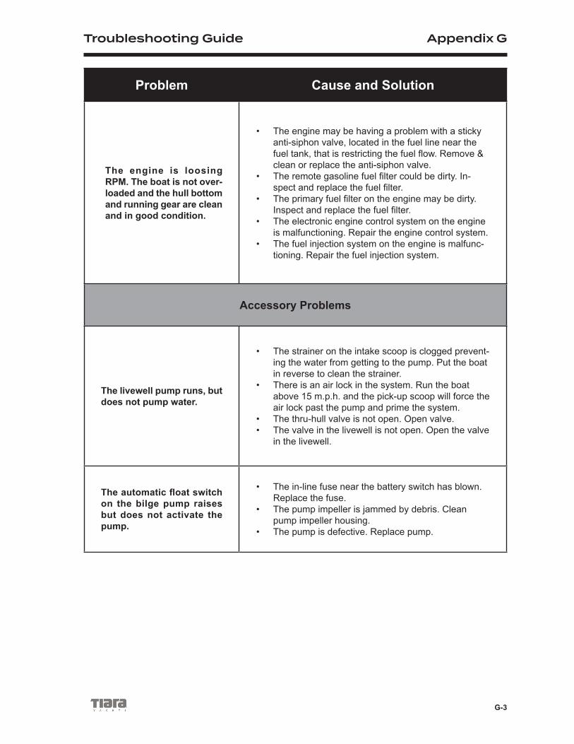
Troubleshooting Guide Appendix G
G-3
Problem Cause and Solution
The engine is loosing RPM. The boat is not over-loaded and the hull bottom and running gear are clean and in good condition.
• The engine may be having a problem with a sticky anti-siphon valve, located in the fuel line near the fuel tank, that is restricting the fuel flow. Remove & clean or replace the anti-siphon valve.
• The remote gasoline fuel filter could be dirty. In-spect and replace the fuel filter.
• The primary fuel filter on the engine may be dirty. Inspect and replace the fuel filter.
• The electronic engine control system on the engine is malfunctioning. Repair the engine control system.
• The fuel injection system on the engine is malfunc-tioning. Repair the fuel injection system.
Accessory Problems
The livewell pump runs, but does not pump water.
• The strainer on the intake scoop is clogged prevent-ing the water from getting to the pump. Put the boat in reverse to clean the strainer.
• There is an air lock in the system. Run the boat above 15 m.p.h. and the pick-up scoop will force the air lock past the pump and prime the system.
• The thru-hull valve is not open. Open valve.• The valve in the livewell is not open. Open the valve
in the livewell.
The automatic float switch on the bilge pump raises but does not activate the pump.
• The in-line fuse near the battery switch has blown. Replace the fuse.
• The pump impeller is jammed by debris. Clean pump impeller housing.
• The pump is defective. Replace pump.

Appendix G Troubleshooting Guide
G-4
Operator Notes

Operator Notes

725 E 40th Street, Holland, MI 49423 | 616.392.7163tiarayachts.com