ELLA MASSAGE WALK IN BATHS OWNERS MANUAL
32
93057 L / 93058 R Deluxe 2017 93107 L / 93108 R Elite 93117 L / 93118 R Royal 93085 Companion REPRESENTING THESE MODEL NUMBERS: ELLA MASSAGE WALK IN BATHS OWNERS MANUAL IMPORTANT Warranty Activation Form MUST be completed for both the Owner and Installer to validate the warranty. Failure to complete both pages will void the warranty on this bathtub. Completed Ella Warranty Activation Forms can be emailed to [email protected], faxed to 312.666.3551, OR mailed to 2101 S. Carpenter St., Chicago, IL 60608 93167 L / 931688 R Petite
-
Upload
khangminh22 -
Category
Documents
-
view
3 -
download
0
Transcript of ELLA MASSAGE WALK IN BATHS OWNERS MANUAL

93057 L / 93058 R Deluxe
2017
93107 L / 93108 R Elite
93117 L / 93118 R Royal
93085Companion
REPRESENTING THESE MODEL NUMBERS:
ELLA MASSAGE WALK IN BATHSOWNERS MANUAL
IMPORTANTWarranty Activation Form MUST be completed for both the Owner and Installer to validate the warranty.
Failure to complete both pages will void the warranty on this bathtub.
Completed Ella Warranty Activation Forms can be emailed to [email protected], faxed to 312.666.3551, OR mailed to 2101 S. Carpenter St., Chicago, IL 60608
93167 L / 931688 R Petite

Table of Contents
Unpack and Inspect ......................................................................................................................................... 1
Move your Ella Walk in Bath ............................................................................................................................ 2
Important Safety Instructions ....................................................................................................................... 3-4
Before Installation ............................................................................................................................................ 5
Drain and Plumbing ........................................................................................................................................ 6
Preparing the Sub-floor................................................................................................................................... 7
Service Access and Ventilation ..................................................................................................................... 8
Door Seal ........................................................................................................................................................... 8
Hydro Massage System Diagram .................................................................................................................... 9
Air Massage System Diagram ........................................................................................................................ 10
LED Chromatherapy System Diagram .......................................................................................................... 11
Ozone Generator System Diagram ............................................................................................................... 12
Ella Walk in Bath Electrical System Diagram ................................................................................................ 13
Electrical Box Diagram (option 1) .................................................................................................................. 14
Electrical Box Diagram (option 2) ................................................................................................................. 15
Heated Seat and Backrest Option Diagram ............................................................................................... 16
Water Supply Lines .......................................................................................................................................... 17
Installation of Spout ......................................................................................................................................... 18
Installation of Deck Mount Grab Bar ............................................................................................................ 19
Installing Extension Kits ....................................................................................................................................20
Finishing Installation......................................................................................................................................... 21
Operating Instructions ...............................................................................................................................22-24
Cleaning and Maintenance .......................................................................................................................... 26
Warranty Information ...................................................................................................................................... 27
Warranty Activation Form ........................................................................................................................ 29-30
www.ellasbubbles.com 09/17

NOTE: Returns are only accepted in original packaging used for shipping. Use caution so as not to damage cardboard crate or its wooden pallet. Do not dispose of shipping material until installation is complete. Please visit our website, www.ellasbubbles.com for complete details of return/exchange policy.
Unpack and Inspect
www.ellasbubbles.com Page 1 09/17

Large Access Panel (1)
Small Access Panel (2)End Access Panel (4)
White Screw Caps
Toe Kick Access (3)
- Access to parts- Option to lower the Threshold
•Remove all four (4) access panels beforemoving the tub
•Take off the screw caps•Unscrew the screws with a Philips head screwdriver•Remove the end access panel
Screw Washer Cap
WARNING: Do not carry the walk in tub by the panels. Be careful when carrying the tub, avoid front panel contact with the floor or stairs to prevent damages. Make sure no loose parts are hanging down. Remove all four (4)access panels before carrying the tub to prevent them from falling out and breaking.
Slide On Brackets
Deck
Frame
Access PanelScrew-OnSupport Brackets
Water Supply Lines
End Access Panel
WARNING: Lift and carry the tub only by the frame. Protect the bottom of the tub to avoid breaking the air jets positioned on the bottom of the tub.
Move your Ella Walk in Bath
www.ellasbubbles.com Page 2 09/17

WARNING:***Read through the entire manual completely before beginning installation.***
Contract a licensed plumber and electrician for installation. Be sure you and your contractor are aware and follow all local plumbing and electrical codes. Your Ella Walk in Bath is not intended for outdoor use. Install the tub in accordance with the instructions in the manual. Use ONLY the parts and accessories provided or as recommended by the manufacturer.
CAUTION:When using this product, basic precautions should always be followed. Read and follow all instructions pertaining to risk of fire, electric shock and injury. Make sure and have your licensed electrician test all connections to the dedicated line, including the GFCI.
Risk of electric shock; Do not permit electric appliances within 3 feet (1.5m) of the tub. i.e.: hair dryers, lamps, phones, radios, televisions, etc.
To reduce the risk of injury, do not permit children or persons with disabilities to use this product unless they are supervised by an able-bodied adult at all times. Never drop or insert any objects into any openings.
Do not turn on the Hydro jets without water reaching the waterline. The waterline is the point where all jets are covered with water.
DANGER:Temperature in excess of 100.4 Fahrenheit (38 Celsius) may be harmful to your health. Check and adjust the temperature before use. Consult your physician before using your Ella Walk in Bath if you have a heart condition or other health issues. People using medications, herbal remedies, sleep aids, and/or having adverse medical history should consult a physician before using this product.
Pregnant women should NOT use this product before consulting their physician. Avoid the use of alcohol, drugs or other medications while using your walk in bath.
Be aware, hyperthermia is a risk when raising body temperature. Do no keep body submerged in heated bath for extended periods of time. The symptoms of hyperthermia include an increase in body temperature which can cause dizziness, lethargy, drowsiness and fainting. Avoid using the heated bath after strenuous activity.
Exercise caution while entering and exiting your Ella Walk in Bath.
Important Safety Instructions
www.ellasbubbles.com Page 3 09/17

WARNING: To prevent stripping the PVC threads, ONLY hand tighten the drain elbow. DO NOT tighten with tools.
Important Safety Instructions Continued
www.ellasbubbles.com Page 4 09/17

Protecting the BathCover and protect the bath shell and fixtures from scratches or other damages during the installation and tests. Remove the access panels when moving the Walk in Bath and always lift the bathtub from the frame (Page #2).
Water TestFill tub for a minimum of 20 minutes to test that the Hydro and Air Pumps are functioning properly before final in-wall installation to avoid unnecessary repairs or removal.
ElectricalThe unit MUST be connected to a circuit protected by a ground fault circuit interrupter (GFCI) provided and installed by a licensed electrician and tested periodically (refer to instructions provided by GFCI manufacturer). A separate 120 Volt and 30 Amp. GFCI breaker is required. A dedicated line must be run from a breaker to the unit’s electrical junction box following your local building and electrical codes. Usually, the black/brown (two) wire is live/hot. The blue/white wire (in the middle) is neutral, and the green wire (bottom) is the ground wire. A licensed electrician for your area is required to install and test the electrical installation process.
DO NOT use any kind of extension cords to power the unit.
Operating the pumps without first filling the bath to above the jets can cause permanent damage to your equipment.
Push the GFCI “test” button into “reset” mode. If the GFCI fails to operate in this manner, there is a ground current flow or a device malfunction, indicating the possibility of electrical shock. If this occurs, turn OFF the power and do not use the bathtub until the source of the problem has been identified and corrected.
Water Heater SuggestionsMODEL # DESCRIPTION SINGLE BATHER*
93057/93058 DELUXE 60*93107/93108 ELITE 50*93167/93168 PETITE 40*93117/93118 ROYAL 60*
93085 COMPANION 60**For households with additional bathers, it is recommended you have the next size available water heater
Before Installation
www.ellasbubbles.com Page 5 09/17

Drain and Plumbing
Disclaimer: In an effort to continually improve our product, specifications and configurations are subject to change without notice. Before ordering or installing, consider future access to essential equipment.
Make sure that the drain rough in has been placed at the proper location. The specifications and drawings shown below and on page #7 are for the Ella Deluxe (each model comes with separate specifications, please refer each model's specification). The dual drain can be connected with a “T” or “Y” connection into existing house drain. Proper materials must be used based on local plumbing code requirements.
NOTE: Flexible drains are not permitted in some areas. The customer and their contractor are responsible for using the appropriate solution to meet the current local construction and plumbing code requirements, proper drainage, and rodding access to the drain. The contractor and customer is responsible for testing the house drain prior the installation of the walk-in bathtub to assure proper drainage of the bathtub. The drainage time varies due to condition of the house drain. The stated drainage time of 80 seconds only applies under ideal plumbing conditions.
Two Drain Openers with Overflows
To P Trap Below Floor
Drain Elbow OptionsNOTE: Deluxe Model ShownSpecifications vary by model, please refer to the drawing that matches the model being installed.
Front
Two 2" Drains
12" 2 1/4" Threaded Connection of 2" Drain for Elbow or Drain Pipe Connection
28 3
/4"
9 1/2" 8 1/2"
Ella’s Elbow Drain
3-1/
4" 7/16"
2-3/8"
2-5/16"
2-3/16"1-7/8"
1-1/2"
1"
5-1/2"1-1/4"
2-3/
8"
2-5/
8"
1-11
/16"
www.ellasbubbles.com Page 6 09/17

Preparing the Sub-floor
Prepare the sub-floor for the drain and ensure that the area is level. The supporting sub-floor must be able to support the total weight of the bathtub, bather and water.
Use a level and make sure that the sub-floor below the tub is leveled. If the floor is not perfectly level, adjust the appropriate leveling legs to re-align the tub to perfect level. It is important that all of the leveling legs are completely supporting the tub (touching the floor with equal weight distribution) and the tub is leveled for the door seal to work properly. If the tub is not perfectly leveled, it could result in water leakage and void the warranty.
NOTE: Drawing above shows frame layout for Deluxe walk in bath. The Companion, Elite, Petite and Royal frame and drain layouts may very. Please reference appropriate specification drawings for proper drain locations. Adjust the legs and lower the bath to within 1/16th of an inch above the floor or tile. Seal with white silicone or caulking if appropriate. If the sub-floor does not support the total weight of the bath, bather and the water, it can result in warping of the shell, misalignment of the door and/or create leaks and damages to the building structure.
Disclaimer: In an effort to continually improve
our product, specifications and configurations are subject to change
without notice. Before ordering or installing, consider future access to
essential equipment.
Black Nut
Adjustable Height Leg
Make sure all 8 legs are level
Air PumpBrackets Hydro Pump
Brackets
www.ellasbubbles.com Page 7 09/17

It is the responsibility of the installer or owner to provide access for service required, per code. Ella is not responsible for any costs related to obtaining access for repair. The owner shall assume responsibility for such costs, and if appropriate, must seek recovery from the installer.
Do not insulate around the tub equipment. The tub, frame and all parts have been engineered to provide the proper ventilation. Any obstructions may cause the pumps or other electrical components to overheat.
Door SealPlease keep in mind that the door has been closed for an extended period of time throughout shipping and the bathtub has been stored in various temperatures. It is possible for the silicone seal to stick to the frame when stored for extended periods of time. When the bathtub is received, the door seal should be checked for deformations from shipping and re-formed and adjusted where necessary. To restore the door seal, the seal must be released and allowed to relax with the door open. This is done by squeezing the seal with your finger tips and pulling it away from the door frame to regain its flexibility and original form. It is recommended that the door be kept open when not in use to increase the lifetime of the door seal and maintain its flexibility.
Service Access and Ventilation
www.ellasbubbles.com Page 8 09/17

Air and Water Dual Massage ElectricalConnection with LED Light, Ozone, and
Push Control
Hydr
o Pu
mp
120
V5
A
Wat
er In
Out
In-L
ine
Wat
er H
eate
rO
ut
Air
Out
to J
ets
Ozo
neO
ut to
Hyd
ro
Syst
em
LED
Lig
ht12
0 V
.4 A
Ozo
neG
ener
ator
To P
ower
Out
let
Thre
e Pr
ong
Cho
rd11
0-12
0 V
20 A
On/
Off
Push
C
ontro
l
Hydr
oA
irLig
ht
650
W5.
5 A
Air
Pum
p11
0-12
0 V
4.5
A
To H
ydro
Jet
sTo
Hyd
ro J
ets
Air
Hose
Elec
trica
l Cor
d
Wal
l Out
let
GFC
I Pro
tect
edD
edic
ated
Lin
e
Sof
twar
e an
d C
ontro
l Box
Elec
trica
lPl
ugEl
ectri
cal C
ord
Air
and
Wat
er D
ual M
assa
ge
Elec
trica
l Con
nect
ion
with
LED
Light
, Ozo
ne, a
nd P
ush
Con
trol
www.ellasbubbles.com Page 9 09/17

Air and Water Dual Massage ElectricalConnection with LED Light, Ozone, and
Digital Control System Diagram
Hyd
ro
Pum
p
Wat
er In
Out
In-L
ine
Wat
er H
eate
rO
ut
Air
Out
to J
ets
Dig
ital
Con
trolle
r
LED
Lig
ht
Ozo
neG
ener
ator
To P
ower
Out
letT
hree
Pro
ng C
ord
110-
120
V20
A
To H
ydro
Jet
sTo
Hy
dro
Jet
s
Sof
twar
e an
d
Con
trol B
ox
Air
Pum
p11
0-12
0 V
4.5
A
Elec
trica
l Cor
d
Air
Flow
Hyd
ro
Mas
sage
Inte
nsity
Dia
l Con
trol
Elec
trica
l Pl
ug
Low
Vol
tage
Pow
er C
ord
12 V
5.5
A65
0 W
Elec
trica
l Cor
d
Air
Hose
Wal
l Out
let
GFC
I Pro
tect
edD
edic
ated
Lin
e
Ozo
neO
ut to
Hyd
ro
Syst
em
Air
and
Wat
er D
ual M
assa
ge
Elec
trica
l Con
nect
ion
with
LED
Lig
ht, O
zone
, and
Dig
ital C
ontro
l
www.ellasbubbles.com Page 10 09/17

Hydro Massage System Diagram with In-Line Water Heater System Diagram
110v
. A/C
Elec
trica
lSw
itch
Hyd
ro P
ump
5 A
Wat
er In
Out
To H
yrd
ro J
ets
In-L
ine
Wat
er H
eate
r
To H
yrd
ro J
ets
Out
On/
Off
Push
Con
trol
Air
Hos
e
Pum
p
Heat
er
5.5
A65
0 W
Hyd
ro M
assa
ge
Inte
nsity
Air
Flow
D
ial C
ontro
l
Air
Hose
To P
ower
Out
let
Thre
e Pr
ong
Cor
d
110-
120
V20
AW
all O
utle
tG
FCI P
rote
cted
Ded
icat
ed L
ine
Hydr
o M
assa
ge S
yste
m D
iagr
am
with
In-L
ine
Wat
er H
eate
r
www.ellasbubbles.com Page 11 09/17

Infusion™ MicroBubble Therapy System Diagram
Elec
trica
lSw
itch
Low
Pre
ssur
e Pu
mp
110-
120
V10
A
Wat
er In
Out
On/
Off
Push
Con
trol
To P
ower
Out
let
110-
120
V15
AM
icro
Bubb
les
Out
to
Jet
Mic
roBu
bble
Pres
sure
Tan
k
Air
Hose
Wal
l Out
let
GFC
I Pro
tect
edD
edic
ated
Lin
e
Infu
sion™
Mic
robu
bble
Ther
apy
Syst
em D
iagr
am
www.ellasbubbles.com Page 12 09/17

Heated Seat and Backrest(Optional Feature)
Seat and Backrest Heater
Controller Box
LED Push Keypad
Heated seat and backrest come assembled with a digital push control usually installed on the large access panel.
www.ellasbubbles.com Page 13 09/17

Ella Dual Massage Walk in Baths with the Standard Ella Faucet (Thermostatic Control Valve) include two 4 ft. long 1/2” I.P.S. connection flexible water supply lines. Please note: The 5-Piece Fast Fill Roman and 5-Piece Traditional Roman Fauce Sets do not include the I.P.S.connection flexible water supply lines.
NOTE: It is recommended that shut off valves are installed behind the opening and in reach from the small access panel.
Water Supply Lines
Air Flow Control Dial
Air Pump ON/OFF
LED ON/OFF
Hydro Pump ON/OFF
5' Hand ShowerPull Out Hose
LED Fixture and Bulb(bulb can be replaced from here)
Cold Water Line
Hot Water Line
Small FrontAccess Panel
4' Long 1/2" Flexible StainlessSteel Braided Hose with 1/2"I.P.S. Connector to Shut Off Valves
This side covered with end access panel for 2 wall installation option.
Pull OutHand Shower
ThermostaticControl Valve
Hand ShowerDiverter Spout
SpoutDiverter
www.ellasbubbles.com Page 14 09/17

ALWAYS INSTALL SPOUT BEFORE THE WALK IN BATH IS IN PLACE.Parts List: Rubber gasket x (1)
Rubber washer x (1)Brass mounting nut x (1)
To Install the supplied spout, first place the rubber gasket on the bottom of the spout and make sure it is properly seated in its groove. Put the spout in through the hole in the tub shell (shown in the drawing above). Install the rubber washer and then the brass mounting nut. Locate the water line from the spout diverter and connect it to the threading on the bottom of the spout. Tighten all fittings and check for leaks.
*NOTE: Rubber gasket only comes with the Elite, Royal and Petite models. Spout must betightened down prior to installation of tub.
WARNING: Do not over tighten the water supply line. To tighten properly, it should be hand tight plus about a half a turn.
Installation of Spout
Thermostatic Control Valve
SpoutDiverter
Spout
SpoutWater Line
Nut
Tub Shell
Rubber Gasket
Spout
Rubber Washer
*
www.ellasbubbles.com Page 15 09/17

Parts List: Chrome grab bar x (1)Escutcheon x (2)Rubber washers x (4)Metal washers x (2)Bolts x (2)
To install the supplied grab bar first locate all the parts needed for installation. See drawing shown above. Ready the bolt assembly by first placing a metal washer onto the bolt followed by a rubber washer. Feed the bolt up through the tub shell and place another rubber washer over the extruded bolt followed by the escutcheon. You may start the threading into the grab bar to hold the assembly loosely in position and then repeat the process for the second bolt. Once the entire assembly is in place, tighten the bolts with the supplied Allen wrench.
WARNING: Under no circumstances install the grab bar without the large metal washer underneath the tub shell. Doing so will leave the tub shell vulnerable to cracking and void the warranty.
Installation of Deck Mount Grab Bar
www.ellasbubbles.com Page 16 09/17
Grab Bar
Escutcheon
RubberWasher
RubberWasherMetal Washer*Bolt
Tub Shell

1.
3. & 4.
Deluxe Dimensions: 5"W x 29 1/2"L x 37"HElite Dimensions: 7"W x 29 3/4"L x 37 3/4"HRoyal Dimensions: 7"W x 31 3/4"L x 37 3/4"HPetite Dimensions: 7"W x 27 2/4"L x 37 3/4"H
L" Stainless Steel Brackets ...........................L" Acrylic Bracket ........................................1" x 1/8" Bolts ...............................................1" x 1/4" Bolts ...............................................1" Screw .......................................................1/2" Nuts .......................................................3/8" Nuts .......................................................Medium Washers .........................................Small Washers ..............................................Plastic Washer .............................................Plastic Cap ...................................................
Installing Extension Kits
Qty (3)Qty (1)Qty (7)Qty (7)Qty (1)Qty (9)Qty (7)Qty (14)Qty (14)Qty (1)Qty (1)
1. Install 3 extension supportbracketsprovides in the kit.
2. Clamp in place, theextension panel to the walkin tub shell, lining up thefacade of top and front.
3. Pre-drill (+3/8") slightly widerholes than mounting screwsto allow for final adjustmentto the panel.
4. Mount extension with 7screws, washers and bolts.
5. Apply Silicone or whitecaulking as needed.
The extension kit can be installed as needed. Opening can be filled as desired.www.ellasbubbles.com
D e l u x e . E l i t e . R o y a l . P e t i t e . C o m p a n i o n
Installing Extension Kits
4
(Image 4)
www.ellasbubbles.com Page 17 09/17

Finishing Installation
www.ellasbubbles.com Page 18 09/17
After all of the water and electrical testing is completed and all fixtures are checked, the tub can be installed to the surrounding wall or walls. Ella Walk in Baths come with low rise tile flange which allows for two or one wall installations. The extension panel of the bathtub can be installed as needed for 60" openings.
The tub can be finished and tiled over as shown in images. Caulking must be applied to joints as needed after the bathtub is installed.
Threshold Lowering OptionLowering the threshold is an option that can be chosen during installation. Because your Ella Walk in Bath is set up for easy installation, lowering the threshold requires the drain option to be set up below the floor (Page #6). To lower the Walk in Bath threshold; First, remove the toe kick panel to expose the adjustable leg supports. Adjust the height of the tub while keeping the Walk in Bath plumb level on all four corners. Finish the installation with baseboard.
NOTE: Any alterations or installed additions are the responsibility of the installer. Ella Accessible Bathrooms is not responsible for any damage to the unit or for water damage, which could occur due to improper installation.
Drywall
Glue
Tile
Caulking
5/8”Tub Lip
Stud Stud Stud
Drywall Drywall
Glue Glue
Tile Tile
5/8”Tub Lip 5/8”Tub LipCaulking Caulking
Panel On Panel Off Lowered Threshold Baseboard On (not supplied)

Operating Instructions
www.ellasbubbles.com Page 19 09/17
1. Thermostatic Control Valve:Before turning on the water, please adjust the thermostatic control valve to the desiredwater temperature. To raise the temperature above the preset 100.4 Fahrenheit, pressand hold in the button handle while turning. For hotter water turn counterclockwise.Conversely, turn the valve clockwise for colder water. The thermostatic control valve ispre-set to 100.4 Fahrenheit for your safety.
Button Handle
Round Knob
2. Using the Door:Entering the walk in bath, the door can be closed and locked with the handle from aseated or standing position. Do not apply any body weight on the door when enteringor exiting the walk in bath. The door hinges are well built and are very durable, howeverleaning on or applying weight on the door may damage and mis-align the door andcreate leaks. Such damages are not covered by the warranty.
3. Using the Diverter Valves:Close the door and fill up the bathtub with water by moving the faucet diverter handle into the ON position. The faucet and hand shower may be used individually or at the sametime.
4. Using the Pull out Hand Held Shower:To use the pullout hand held shower turn its diverter handle to the ON position. The hand held shower is equipped with a 5 ft. long retractable flex hose. The pressure of the shower can be adjusted by turning the round shower head of the hand unit.
WARNING: Do NOT attach the hand held shower to the wall. This may cause water to leak behind your walk in tub.
*The button knob stops here at 100.4 Fahrenheit. To adjust to a hotter temperature past 100.4 F,press the button knob in while turning the handle counter clockwise
*
ON OFF
- On / Off Diverter Positions -
For both the faucet and the hand shower
ON OFF
WARNING: Cleaning and replacement of TCV cartridge due to calcium or other particle buildup in water is the customer’s responsibility. Ella’s Bubbles will provide cleaning of the cartridges or replacement of TCV at no cost if they are shipped to Ella’s Bubbles facility.

Operating Instructions Continued
www.ellasbubbles.com Page 20 09/17
5. Using the Hydro Massage:To activate and deactivate the hydro massage pump, push the on/off the control button(Page #9). There are two types of hydro jets in your walk in bath; adjustable and non-adjustable types. Simply push on the head of an adjustable jet and turn the head in thedesired position. The in-line water heater will activate with the Hydro pump. An air flowrate control dial can be found over the shoulder of the seating area. Turning the knobclockwise will reduce the amount of air introduced into the hydro system. Adjust accordingto personal preference.
6. Using the Air MassageTo activate and deactivate the air massage pump, push the on/off control button (Page#10). Notice, when adding cool air into the bath water it can lower the water temperature.
7. Using the Ozone SterilizationTo activate and deactivate the ozone sterilization, push the on/off control button(Page #12). Turn the ozone on for 10 minutes for every 30 minutes of tub use.
8. Using the Heated Backseat (Optional Feature)To activate and deactivate the heated backseat, push the on/off control button(Page #14). Turn on for warmth while the tub is filling up and draining.
NOTE: When the other pumps (air and hydro) are off and the Ozone generator is left on, you will be able to hear the buzzing of the Ozone generator, this is normal and only needs to be turned off.

Operating Instructions Continued
www.ellasbubbles.com Page 21 09/17
9. Using the LED systemThe LED Chromatherapy light system may be controlled manually. Push the on/offcontrol button (Page # 11).
10.Draining the Walk in BathTo drain your Ella Walk in Bath. Begin by turning OFF the massage systems. Open each of the drains by turning the drain openers clockwise from a down position, upward one half turn until fully open. Remain in the tub until the water has dropped below the door sill.
11. Exiting the BathGetting out of your Ella Walk in Bath is as easy as getting in to it. Wait for the water to drain below the door sill. Unlock the door by using the door handle. Fully open the door first then stand up and exit your Ella Walk in Bath.
NOTE: It is recommended to leave the door fully open when not in use to keep the door seal fresh and promote a longer lifetime for the door seal.
Air Flow Control Dial
Air Pump ON/OFF
LED ON/OFF
Hydro Pump ON/OFF
Pull OutHand Shower
ThermostaticControl Valve
Hand ShowerDiverter Spout
SpoutDiverter

Recommended Acrylic CleanersUse only cleaning products whose labels state that they are SAFE for ACRYLIC. Always test products on a small are of skirt before applying to complete bath area.
• White Vinegar & Water(Recommended)
• ZEP Professional strength showertub & tile cleaner
• Dawn dish detergent• Rubbermaid commercial strength
shower tub & tile cleaner• Home Depot HDX shower tub & tile
cleaner• Scrub free original soap scum remover• Kaboom shower tub & tile cleaner with
oxy clean• Simple green all purpose cleaners
(any scent)• Simple green lime scale remover• Simple green natural bathroom cleaner• All tilex products• All Pine-Sol Products• All Fragranzia Products
DO NOT USE the following on your ACRYLIC Bath System. The use of the following chemicals will cause a dull surface or chemical cracks. The use of these products will VOID YOUR WARRANTY.
• Any product containing ammonia• Dow scrubbing bubbles• Abrasive Cleaners• Ajax• Comet• Fantistik• Soft Scrub• Mr. Clean• Nail Polish Remover• Scouring Pads• Ammonia• Tough Act• Powder or Crystal Drain Cleaners• Greenworks Bathroom Cleaner• Scrub Free w/Bleach• Seventh generation bathroom
cleaner - regular• Magic Eraser
Cleaning and Maintenance
www.ellasbubbles.com Page 22 09/17
Monthly MaintenanceIt is recommended that once a month the tub is flushed. As well, with every month of normal use, clean out the pumps inlet cover (shown right) by unscrewing the cover (counter clockwise) and removing any hair and debris from the cover and housing. Remount the cover in place. Never operate the system with the cover off, as the pump creates a strong suction and damage to the pump or injury may occur.

Page 1
TOUCHSTONE Dual Load Controller
Owner’s Manual
NuWhirl Systems Corp • www.nuwhirl.com • 951-817-5600 900150-CIMC-296-01-XX-01 C1 Rev 3/22/2016
CIMC-296-01-01-01 (15 Amp) CIMC-296-01-02-01 (20 Amp)
Configuration #1 Single Speed Pump
Variable Speed Blower

Page 2
PLEASE READ CAREFULLY PRIOR TO Troubleshooting and Servicing Electrical Equipment
Definitions: WARNING (May cause serious injuries or death)
CAUTION (May cause property damage)
For information on NuWhirl Instructions, see: www.nuwhirl.com/docs/product-instructions.html
When installing and using this electrical equipment, basic safety precautions should always be followed, including:
Important Safety Instructions
WARNING: Keep dry. Replace control if exposed to water, moisture or contamination.
WARNING: Use and follow these instructions along with all instructions that have been provided with your whirlpool bathtub in order to fully enjoy the bathtub safely.
WARNING: Electronic control system components should be installed as per local and national Electrical Codes, in a location not to be subjected to splashing or flooding. Exposure to water or splashing will void all product certifications and warranties.
There are no user serviceable parts inside. Opening, modifying, or tampering with control system components will void all product certifications and warranties.
WARNING: Risk of electric shock. Connect only to a ground type receptacle or power supply junction box protected by a Ground-Fault Circuit Interrupter (GFCI). Contact aqualified electrician if you cannot verify that the power supply is protected by a GFCI.The GFCI should be tested on a routinebasis. Consult the GFCI manufacturer’s instructions for correct testing andoperation.
For electrical connections, see applicable wiring diagram. See www.nuwhirl.com/docs/product-instructions.html
Do not use an extension cord to connect the product to the electric supply; provide a properly located receptacle or junction box.
WARNING: Failure to install in strict accordance with each and every instruction above may compromise the system, which may cause injury to persons and/or property.
The tub may be supplied from more than one power source. Before working on any electrical device, make sure all power to the control system is off.
Use this unit only for its intended use as described in this manual. Do not use attachments not recommended by the manufacturer. Any improper installation or misuse of the equipment may result in injury to the user and will void the warranty.
Do not run unit dry. Always be certain that the pump casing is filled with water before starting the unit. If pump fails to prime within 30 seconds, turn it off. Check if there is an airlock, clogged plumbing, or closed valve.
Save these instructions.
Page 3
TOUCHSTONE Dual Load Bath Control System Configuration #1 Owner’s Manual
Your whirlpool bathtub has been equipped with TOUCHSTONE Electronic Controls to provide features that allow you to customize your bathing experience to your individual preference. Please familiarize yourself with the features and operating instructions below in order to maximize the enjoyment you receive from your bath. These operating instructions should be used in conjunction with the other instructions and warnings provided with your whirlpool bathtub in order to fully understand and safely utilize the bathtub.
System Features Air Button or Electronic Keypad Options Independent Function Timers Single-Speed Pump Variable-Speed Blower Automatic Dry Cycle Multicolor LED Tub Lights
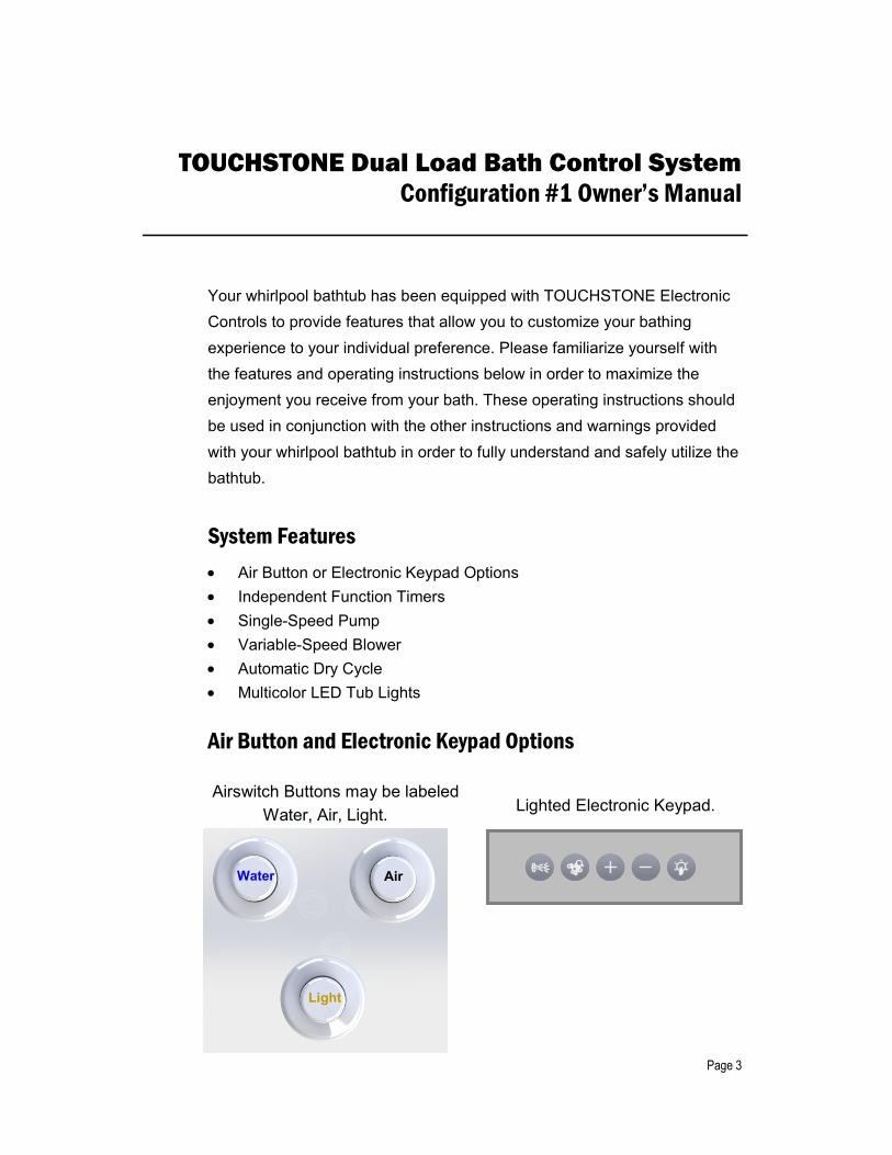
Air Button and Electronic Keypad Options
Water Air
Light
Airswitch Buttons may be labeled Water, Air, Light. Lighted Electronic Keypad.

Page 4
Air Button Operating Instructions Single Speed Pump (Water): The Whirlpool Water System is activated by pressing the Water Button. Ensure first that there is sufficient water in the Tub to at least cover the Jets. (If not, the Water Detection Function will prevent the Pump from starting dry). This will turn on the Pump, and activate its 20-minute timer. The Whirlpool Water System will stop automatically when its timer expires. To turn off this function earlier, press the Water System Button at any time.
Variable-Speed Air Blower (Air):The Air system is activated by pressing the Air Button.(The Air System runs independantly of the Tub Water Level).This will turn on the Blower, and activate its 20-minute timer.To change the Speed of the Blower, press and hold to start the Blower, and then ramp its Speed down. Release at the desired setting.To activate the "Massage Mode", press and hold to start the Blower, and then ramp its Speed down to the lowest setting, pause, then release.To turn off the Air System earlier, press the Air Button at any time.
Automatic Dry Cycle: 15 minutes after the Water and/or Air systems are turned off, or the tub is drained, the Air Blower will automatically come on for 2 minutes. This will purge out any residual moisture in the air system, making the system fresh and ready for the next bath.
Multi-color Tub Light (Light) The LED Multi-Color Tub Light is activated by pressing the Light Button. The first press will start its 60-minute timer, and activate the Tub Light in a “Rainbow” mode. Subsequent presses will change the color to Blue, White, Blue, Aqua, Green, Yellow, Red, Magenta, and off. To turn off this function earlier, press and hold the Light Button at any time.
Light
Air
Water

Page
6
Syst
em Id
entif
icat
ion:
CIM
C-2
96-0
1-[0
1 or
02]
-01
Con
figur
atio
n #1
Syst
em fe
atur
es: A
ir B
utto
ns o
r Ele
ctro
nic
Key
pad,
Inde
pend
ent T
imer
s, S
ingl
eC
ondu
ctiv
e W
ater
Det
ect.
Note
: For
inst
ruct
ions
on
setti
ng th
e C
onfig
urat
ion
# se
e “C
ontro
l Con
figur
atio
n Se
lect
ion
and
Setti
ng G
uide
Inst
alla
tion
Diag
ram
:
Air B
utto
n O
ptio
n
TO P
UMP
Max
15
AMPS
Loa
d
NO
TES:
1.
PUM
PS e
quip
ped
with
air
switc
h m
ust b
e in
the
“ON
” po
sitio
n pr
ior t
o pl
uggi
ng in
to th
e co
ntro
ller.
2.Th
e co
mbi
ned
ratin
g of
bot
h Lo
ads
mus
t not
exc
eed
the
Con
trolle
r’s A
mpe
rage
Rat
ing.
3.C
onne
ct c
able
s to
por
ts a
s sh
own.
Ins
talla
tion
may
not
requ
ire th
e us
e of
all
conn
ectio
n po
rts.
Failu
re to
con
nect
cab
les
to p
orts
as
show
n, m
ay d
amag
e th
e co
ntro
l box
and
its
com
pone
nts.
Air
Ligh
t
Wat
er
Fem
ale
Cor
d
Plug
lo
cate
d on
TO
P
Page
7
TOU
CHST
ON
E D
ual L
oad
Cont
rol S
yste
m
Inst
alla
tion
Inst
ruct
ions
01C
onfig
urat
ion
#1
Air
But
tons
or E
lect
roni
c K
eypa
d, In
depe
nden
t Tim
ers,
Sing
le-S
peed
Pum
p, V
aria
ble-
Spee
d Bl
ower
, Mul
ti-C
olor
LED
Tub
Lig
hts,
Con
trol C
onfig
urat
ion
Sele
ctio
n an
d Se
tting
Gui
de”
Mal
e C
ord
posi
tion
prio
r to
plug
ging
into
the
cont
rolle
r. s
Ampe
rage
Rat
ing.
Con
nect
cabl
es to
por
ts a
ssh
own.
Inst
alla
tion
may
not
requ
ire th
e us
e of
all
conn
ectio
n po
rts.
Failu
re to
con
nect
cab
les
topo
rts
assh
own,
may
dam
age
the
cont
rol b
ox a
nd it
sco
mpo
nent
s.
CC
BL-
366
x2 d
aisy
ch
aine
d or
C
CB
L-37
6 “Y
” Spl
itter
Elec
troni
c Ke
ypad
Opt
ion
CIC
L-29
7 Tu
b Li
ghts
x2
Max
.
To 1
20V
GFC
I Pr
otec
ted
Rec
epta
cle
15A
or 2
0A
Acco
rdin
g To
Th
e C
ontr
olle
r M
odel
Fe
mal
e C
ord Plug
s lo
cate
d on
R
EAR
TO B
LOW
ER
Max
8 A
MPS
Loa
d
CC
BL-
372
CC
BL-
143
C
ondu
ctiv
e W
ater
D
etec
t

The Manufacturer will not be responsible for any water damage to structures or property for any reason including but not limited to manufacturer defect or improper installation. Manufacturer will assume no responsibility for the loss of the system, inconvenience due to loss, damage to real or personal property or any other consequential damage. Manufacturer will not be liable for any incidental expenses or material charges in connection with removal or replacement of the purchased part or any part or parts of the system. This warranty shall not apply to any type of failure resulting from negligence, abuse, misuse, misapplication, improper installation, alteration or modification, chemical corrosion or improper maintenance. There will be a charge for replacement parts or replacement of the entire electrical unit of the defective unit is returned for any of the reasons listed above. Ella’s Bubbles reserves the sole authority to make any type of warranties or representations concerning its products and will not be responsible for any warranties or representations made by any outside source including dealers, retailers, distributors or contractors. Ella’s Bubbles does not warrant the installation of any of our products. Items include: all plumbing or electrical related connections, improper or negligent installation of the product. Alteration made of, or alterations or modifications made to the system, may cause the product or the system to malfunction. Such problems are not covered by warranty.
TO THE EXTENT PERMITTED BY LAW, ALL IMPLIED WARRANTIES INCLUDING THOSE OF MERCHANTABILITY AND FITNESS FOR A PARTICULAR PURPOSE ARE HEREBY DISCLAIMED.
Ella’s Bubbles and seller hereby disclaim any liability for special, incidental, or consequential damages. Some states/provinces do not allow limitations on how long an implied warranty lasts, or the exclusion or limitation of special, incidental or consequential damages, so these limitations and exclusions may not apply to you. This warranty gives you specific legal rights. You may have other rights, which vary from state/province to state/province.
Disclaimer: Limited lifetime or 5 year parts warranty does not apply to thermostatic control valve (TCV).
TCV warranty is (1) year limited warranty which does not cover cartridge malfunction due to contaminated water with calcium, iron or other found heavy particles in the water resulting in cartridge getting stuck and TCV not operating properly. The TCV must be protected with filter or mesh in the water lines which must be cleaned periodically. Ella's Bubbles offers cleaning service for the cartridges for a nominal fee: labor + shipping. The cartridge cleaning is done at Ella's Bubbles facility, or it can be done by the contractor hired by customer. The removal and cleaning of TCV should only be performed by a licensed and insured contractor or plumber following online instructions here:
This limited lifetime warranty is extended to the first purchaser to be free from defects in workmanship and material under normal use and conditions from the date of the original purchase. This warranty is nontransferable and applies only to the original owner and to the original installation place – address only and does not extend to products previously used as display models or products that have been modified or repaired by anyone elsebut Ella’s Bubbles. The warranty is void if the ownership or original installation location is changed (tub is relocated). This warranty relates to all fittings and components included with the tub from the manufacturer. The bathtub shell, frame, door seal, and finish are covered by limited lifetime warranty. The door is covered by a limited lifetime warranty under normal use and conditions. All supporting equipment, motors, pumps, fixtures, electronic controls, faucet, waste, overflow, and all plated finishes, are covered by a limited five (5) year warranty. This warranty is nontransferable and applies only to the original owner. The finish warranty does not apply to fading, cracking, delaminating or blistering due to excessive wear, sun fading or scouring due to cleaning. This warranty shall not apply to any failure resulting from negligence, abuse, misuse, misapplication, alteration, or modification or improper maintenance. The door warranty is valid only if the alignment of the door is not changed by applying pressure or user’s weight hold user’s weight to the door or by wrong installation. The door is designed to hold its own weight and not designed to hold user’s weight.Should service be required for any reason of any defect or malfunction of the product during the first five years, Ella’s Bubbles will ship the part to the original customer’s address without charge (subject to verification of the defect or malfunction). Ella’s Bubbles will not be liable for any incidental expenses or material charges in connection with removal or replacement of the product or parts. Delivery time is based on parts availability and location. Normally parts are sent out immediately. Emailed or mailed photos of defective product and description of the problem is required. defective product and description of the problem is required.
All mailing notification must be sent via certified mail to:Ella’s Bubbles, LLC.
2101 S. Carpenter Street Chicago, IL 60608Email: [email protected]
August 2017 TOLL FREE: 800-480-6850
Ella Acrylic Walk In Bath Warranty Information

Warranty Activation Form 1 of 2
INSTALLER'S INFORMATION
_______________________________________________________________________________________ Name
_______________________________________________________________________________________ Address City State Zip
_________________________________ _________________________________________________ Telephone Email
_________________________________ _________________________________________________ Date Signature
Upon completing the installation of an Ella Walk In Bath, the following Warranty Activation Form must be completed, signed by both the customer and installer, and returned to Ella’s Bubbles, LLC. In order for the Warranty to be activated (faxed, scanned, or emailed, or hard copy mailed).
To be initialed by the installer(s)
____Tub is level in all directions and all support legs are touching the ground. ____Tub is installed on a dedicated 30 Amp GFCI protected circuit using 10 gauge wire ____Frame of the tub has been properly grounded. ____ Door Seal has been cleaned with rubbing alcohol to remove any dust or debris left
over from construction. ____Temperature Control Valve operated on both hot and cold settings. ____Both diverters function properly. ____Hand Shower functions on all settings without leaking. ____All supply lines have been checked for leaks while both diverters are on. ____ Drains open and close properly, and the locking nut has been tightened on both
stoppers. ____Door seal is water tight after tub has been filled for a minimum of 20 minutes. ____ After running for a minimum of 20 Minutes both the Hydro and Air Pumps are
functioning properly and all connections to the pumps and jets are water tight. ____ Chromatherapy Light and the Ozone Sterilization are working properly. (When the
Ozone is on by itself it will make a light humming noise). ____All drain fittings have been checked for leaks while the tub is draining. ____Unit is installed with access to both plumbing and electrical connections.
www.ellasbubbles.com 10/15

Warranty Activation Form 2 of 2
OWNER'S INFORMATION
_______________________________________________________________________________________ Name
_______________________________________________________________________________________ Address City State Zip
_________________________________ _________________________________________________ Telephone Email
_________________________________ _________________________________________________ Date Signature
Model: ___________________________________ Serial Number: ______________________________
Purchase Date: ___________________________ Purchase Price: _____________________________
Place of Purchase: _____________________________________________________________________
Contact Name: ___________________________ Phone Number: _____________________________
Copy of sales receipt must be included with warranty activation forms.
To activate manufacturer's warranty, please complete both pages and use one of the options below to submit.
Via mail: Ella's Bubbles, LLC. Warranty Department 2101 S. Carpenter St., Chicago, IL 60608
Via fax: 1-312-666-3551
Via email: [email protected]
www.ellasbubbles.com 10/15