
2007_cr250r.pdf - Honda Owners
149
FOR COMPETITION USE ONLY This motorcycle is designed and manufactured for closed-course competition conducted under the auspices of a recognized body or by permit. It does not conform to federal motor vehicle standards, and operation on public streets, roads, or highways is illegal. This vehicle is sold “as is” with no warranties. FOR EXPERIENCED RIDERS, NO PASSENGERS This motorcycle is designed as an operator-only vehicle and for use by experienced riders only. The load limit and seating configuration do not safely permit the carrying of a passenger. IMPORTANT NOTICES This manual should be considered a permanent part of the motorcycle and should remain with the motorcycle when it is resold. All information in this publication is based on the latest product information available at the time of approval for printing. Honda Motor Co., Ltd. reserves the right to make changes at any time without notice and without incurring any obligation. No part of this publication may be reproduced without written permission. The vehicle pictured on the front cover may not match your vehicle. ©Honda Motor Co., Ltd., 2006
-
Upload
khangminh22 -
Category
Documents
-
view
3 -
download
0
Transcript of 2007_cr250r.pdf - Honda Owners

FOR COMPETITION USE ONLYThis motorcycle is designed and manufactured for closed-course competition conducted under theauspices of a recognized body or by permit. It does not conform to federal motor vehicle standards,and operation on public streets, roads, or highways is illegal. This vehicle is sold “as is” with nowarranties.
FOR EXPERIENCED RIDERS, NO PASSENGERSThis motorcycle is designed as an operator-only vehicle and for use by experienced riders only. Theload limit and seating configuration do not safely permit the carrying of a passenger.
IMPORTANT NOTICES
This manual should be considered a permanent part of the motorcycle and should remain with the motorcycle when it is resold.
All information in this publication is based on the latest product information available at the time of approval for printing. Honda MotorCo., Ltd. reserves the right to make changes at any time without notice and without incurring any obligation.
No part of this publication may be reproduced without written permission.
The vehicle pictured on the front cover may not match your vehicle.
©Honda Motor Co., Ltd., 2006
*CR250/IMPORTANT NOTI(31KSK63 6/2/06 9:53 AM Page b

2007Honda CR250ROWNER’S MANUAL & COMPETITION HANDBOOK
*CR250/00-23(31KSK630).qxd 6/2/06 9:54 AM Page c

IntroductionCongratulations on choosing your Honda CRmotocross motorcycle.
When you own a Honda, you’re part of aworldwide family of satisfied customers - peoplewho appreciate Honda’s reputation for buildingquality into every product.
Your CR is a high performance racingmotorcycle that utilizes the latest motocrosstechnology and is intended for competition use insanctioned, closed-course events by experiencedriders only.
Be aware that motocross is a physicallydemanding sport that requires more than just afine CR. To do well, you must be in excellentphysical condition and be a skillful rider. For thebest results, work diligently on your physicalconditioning and practice frequently.
Before riding, take time to get acquainted withyour CR and how it works. To protect yourinvestment, we urge you to take responsibility forkeeping your CR well maintained. Scheduledservice is a must, of course. But it’s just asimportant to observe the break-in guidelines, andperform all the pre-ride and other periodic checksdetailed in this manual.
You should also read the owner’s manual beforeyou ride. It’s full of facts, instructions, safetyinformation, and helpful tips. To make it easy touse, the manual contains a table of contents, adetailed list of topics at the beginning of eachsection, and an index at the back of the book.
As you read this manual, you will findinformation that is preceded by a symbol. This information is intended to help youavoid damage to your CR, other property, or theenvironment.
Unless you are mechanically qualified and havethe proper tools, you should see your Hondadealer for the service and adjustment proceduresdiscussed in this manual.
The official Honda Service Manual for your CRis available (page 136). It is the same manualyour dealer uses. If you plan to do any serviceon your CR beyond the standard maintenanceprocedures in this manual, you will find theService Manual a valuable reference.
If you have any questions, or if you ever need aspecial service or repairs, remember that yourHonda dealer knows your CR best and isdedicated to your complete satisfaction.
Please report any change of address or ownershipto your Honda dealer so we will be able tocontact you concerning important productioninformation.
You may also want to visit our website atwww.honda.com.
Happy riding!
California Proposition 65 WarningWARNING: This product contains or emitschemicals known to the State of California tocause canser and birth defects or otherreproductive harm.
NOTICE
Introduction
*CR250/00-23(31KSK630).qxd 6/2/06 9:54 AM Page d

A Few Words About SafetyYour safety, and the safety of others, is very important. And operating this motorcycle safely is an important responsibility.
To help you make informed decisions about safety, this manual contains a section devoted to Motorcycle Safety, as well as a number of Safety Messagesthroughout the manual.
Safety Messages are preceded by a safety alert symbol and one of three signal words: DANGER, WARNING, or CAUTION.
These signal words mean:
You WILL be KILLED or SERIOUSLY HURT if you don’t follow instructions.
You CAN be KILLED or SERIOUSLY HURT if you don’t follow instructions.
You CAN be HURT if you don’t follow instructions.
Of course, it is not practical or possible to warn you about all hazards associated with operating or maintaining a motorcycle. You must use your own goodjudgement.
Safety Messages
DANGER
WARNING
CAUTION
*CR250/00-23(31KSK630).qxd 6/2/06 9:54 AM Page e

ContentsMOTORCYCLE SAFETY................................1Important Safety Information...............................2
Important Safety Precautions..........................2Accessories & Modifications ...............................3Safety Labels ........................................................4
OPERATING CONTROLS...............................5Operation Component Locations .........................6
BEFORE RIDING..............................................7Are You Ready to Ride?.......................................8Is Your Motorcycle Ready to Ride? .....................9
Pre-ride Inspection..........................................9
BASIC OPERATING INSTRUCTIONS........11Safe Riding Precautions .....................................12Starting & Stopping the Engine .........................13
Preparation ....................................................13Starting Procedure ........................................13Flooded Engine.............................................13How to Stop the Engine................................14
Break-in Guidelines ...........................................15
SERVICING YOUR HONDA .........................17Before You Service Your HondaThe Importance of Maintenance ........................18Maintenance Safety ............................................19
Important Safety Precautions........................19Maintenance Schedule .......................................20General Competition Maintenance ....................22Before & After Competition Maintenance.........26
Between Motos & Practice Maintenance .....26After Competition Maintenance ...................27
Service PreparationsMaintenance Component Locations...................28Seat Removal......................................................29Fuel Tank Removal ............................................30Subframe Removal .............................................32
Service ProceduresFluid & FiltersFuel System........................................................34Transmission Oil ................................................36Coolant ...............................................................38Air Cleaner .........................................................40
EngineThrottle ...............................................................42Clutch System ....................................................44Spark Plug ..........................................................48Cylinder System .................................................49RC Valve.............................................................55Reed Valve..........................................................58
ChassisSuspension..........................................................60Brakes.................................................................65Wheels ................................................................69Tires & Tubes .....................................................70Drive Chain ........................................................72Expansion Chamber ...........................................75Additional Maintenance Procedures ..................76
Appearance Care ................................................78
ADJUSTMENTS FOR COMPETITION ......81Front Suspension Adjustments...........................82Rear Suspension Adjustments ............................95Suspension Adjustments for Track Conditions ..99Suspension Adjustment Guidelines..................100Carburetor Adjustments & Tuning Tips ...........103Chassis Adjustments.........................................110Gearing .............................................................111Tire Selection for Track Conditions.................112Personal Fit Adjustments .................................113
TIPS ................................................................115Transporting Your Motorcycle .........................116Storing Your Honda..........................................117You & the Environment ...................................118Troubleshooting................................................119
TECHNICAL INFORMATION ...................121Vehicle Identification .......................................122Specifications ...................................................123Torque Specifications .......................................124High Altitude Carburetor Adjustment ..............127Oxygenated Fuels.............................................128Competition Logbook ......................................129Optional Parts List............................................131Spare Parts & Equipment .................................132Wiring Diagram................................................133
CONSUMER INFORMATION ....................135Authorized Manuals .........................................136Contacting Honda.............................................137Your Honda Dealer...........................................138The Honda Rider’s Club (USA only) ..............139
TABLE OF CONTENTS ...............................140
INDEX .............................................................141
QUICK REFERENCE
Contents
*CR250/00-23(31KSK630).qxd 6/2/06 9:54 AM Page f

Motorcycle Safety 1
Motorcycle SafetyThis section presents some of the most importantinformation and recommendations to help youride your CR safely. Please take a few momentsto read these pages. This section also includesinformation about the location of safety labels onyour CR.
Important Safety Information...............................2Important Safety Precautions..........................2
Accessories & Modifications ...............................3Safety Labels ........................................................4
*CR250/00-23(31KSK630).qxd 6/2/06 9:54 AM Page 1

Important Safety Information
Important Safety Precautions
Your CR can provide many years of pleasure, ifyou take responsibility for your own safety andunderstand the challenges you can meet incompetitive racing.
As an experienced rider, you know there is muchyou can do to protect yourself when you ride.The following are a few precautions we considermost important.
Never Carry a Passenger.Your CR is designed for one operator only.Carrying a passenger can cause an accident inwhich you and others can be hurt.
Wear Protective Gear.Whether you’re practicing to improve your skills,or riding in competition, always wear anapproved helmet, eye protection, and properprotective gear.
Take Time to Get to Know Your CR.Because every motorcycle is unique, take time tobecome thoroughly familiar with how this oneoperates and responds to your commands beforeplacing your machine, and yourself, incompetition.
Learn and Respect Your Limits.Never ride beyond your personal abilities orfaster than conditions warrant. Remember thatalcohol, drugs, illness and fatigue can reduceyour ability to perform well and ride safety.
Don’t Drink and Ride.Alcohol and riding don’t mix. Even one drinkcan reduce your ability to respond to changingconditions, and your reaction time gets worsewith every additional drink. So don’t drink andride, and don’t let your friends drink and rideeither.
Keep Your Honda in Safe Condition. Maintaining your CR properly is critical to yoursafety. A loose bolt, for example, can cause abreakdown in which you can be seriously injured.
2 Motorcycle Safety
*CR250/00-23(31KSK630).qxd 6/2/06 9:54 AM Page 2

Accessories & ModificationsInstalling non-Honda accessories, removingoriginal equipment, or modifying your CR in anyway that would change its design or operation,could seriously impair your CR’s handling,stability, and braking, making it unsafe to ride.
Motorcycle Safety 3
WARNINGImproper accessories or modificationscan cause a crash in which you can beseriously hurt or killed.
Follow all instructions in this owner’smanual regarding modifications andaccessories.
*CR250/00-23(31KSK630).qxd 6/2/06 9:54 AM Page 3

Safety Labels
4 Motorcycle Safety4 Motorcycle Safety
Read these labels carefully and don’t remove them.
If the label comes off or becomes hard to read, contact your Honda dealer for replacement.
*CR250/00-23(31KSK630).qxd 6/2/06 9:54 AM Page 4

Operating Controls 5
Operating ControlsRead this section carefully before you ride. Itpresents the location of the basic controls on yourCR.
Operation Component Locations .........................6
*CR250/00-23(31KSK630).qxd 6/2/06 9:54 AM Page 5

6 Operating Controls
Operation Component Locations
clutch lever
kickstarter
engine stop button
fuel valve rear brake pedal
throttle grip
front brake lever
choke knob
shift lever
*CR250/00-23(31KSK630).qxd 6/2/06 9:54 AM Page 6

Before Riding 7
Before each ride, you need to make sure you andyour CR are both ready to ride. To help get youprepared, this section discusses how to evaluateyour riding readiness, and what items you shouldcheck on your CR.
For information about suspension, carburetor andother adjustments, see page 81.
Before RidingAre You Ready to Ride?.......................................8Is Your Motorcycle Ready to Ride? .....................9
Pre-ride Inspection .............................................9
*CR250/00-23(31KSK630).qxd 6/2/06 9:54 AM Page 7

8 Before Riding
Are You Ready to Ride?Before riding your CR for the first time, westrongly recommend that you read this owner’smanual, make sure you understand the safetymessages, and know how to operate the controls.
Before each ride, it’s also important to make sureyou and your CR are both ready to ride.
For information about suspension, carburetor, andother adjustments, see page 81.
Whether you’re preparing for competition or forpractice, always make sure you are:
• In good physical and mental condition
• Free of alcohol and drugs
• Wearing an approved helmet, eye protection,and other appropriate riding gear
Although complete protection is not possible,wearing the proper gear can reduce the chance orseverity of injury when you ride.
WARNINGNot wearing a helmet increases thechance of serious injury or death in acrash.
Be sure you always wear a helmet, eyeprotection and other protective apparelwhen you ride.
*CR250/00-23(31KSK630).qxd 6/2/06 9:54 AM Page 8

Before Riding 9
Is Your Motorcycle Ready to Ride?Competitive riding can be tough on a motorcycle,so it’s important to inspect your CR and correctany problems you find before each ride. Checkthe following items (page numbers are at theright):
Pre-ride Inspection
Check the following before each ride: • Transmission oil level ...................................37• Coolant for proper level................................38• Cooling system and hoses for condition.......39• Spark plug for proper heat range, carbon
fouling and high tension cord terminal forlooseness .......................................................48
• Air cleaner for condition and contamination................................................40
• Clutch lever adjustment and freeplay ...........44• Steering head bearings and related parts
for condition..................................................76• Carburetor throttle operation ........................42• Tires for damage or improper inflation
pressure ........................................................70• Spokes for looseness.....................................69• Rim locks for looseness................................69• Front and rear suspension for proper
operation .................................................60, 61• Front and rear brakes, check operation ........65• Drive chain for correct slack and adequate
lubrication .....................................................72• Drive chain guide, sliders and guide rollers
for damage or wear .......................................72• Expansion chamber springs for damage or
lack of tension...............................................75• Every possible part for looseness (such as
cylinder head nuts, carburetor insulator bolts,engine mounting bolts, axle nuts, handlebarholder bolts, fork triple clamp bolts, drivechain adjuster, drive chain guide, wire harnessconnectors, kickstarter mounting bolt) .......124
WARNINGImproperly maintaining this motorcycle orfailing to correct a problem before ridingcan cause a crash in which you can beseriously hurt or killed.
Always perform a pre-ride inspectionbefore every ride and correct any problems.
*CR250/00-23(31KSK630).qxd 6/2/06 9:54 AM Page 9

10 Before Riding
*CR250/00-23(31KSK630).qxd 6/2/06 9:54 AM Page 10

Basic Operating Instructions 11Basic Operating Instructions 11
Basic Operating InstructionsThis section gives basic information on how tostart and stop your engine as well as break-inguidelines.
Safe Riding Precautions .....................................12Starting & Stopping the Engine .........................13
Preparation ....................................................13Starting Procedure ........................................13Flooded Engine.............................................13How to Stop the Engine................................14
Break-in Guidelines ...........................................15
*CR250/00-23(31KSK630).qxd 6/2/06 9:54 AM Page 11

12 Basic Operating Instructions12 Basic Operating Instructions
Safe Riding PrecautionsBefore riding your CR for the first time, pleasereview the Important Safety Precautionsbeginning on page 2 and the previous section,titled Before Riding.
For your safety, avoid starting or operating theengine in an enclosed area such as a garage.Your CR’s exhaust contains poisonous carbonmonoxide gas which can collect rapidly in anenclosed area and cause illness or death.
*CR250/00-23(31KSK630).qxd 6/2/06 9:54 AM Page 12

Basic Operating Instructions 13Basic Operating Instructions 13
Starting & Stopping the EngineAlways follow the proper starting proceduredescribed below.
Your CR can be kickstarted with the transmissionin gear by pulling in the clutch lever beforeoperating the kickstarter.
Preparation
Make sure that the transmission is in neutral.Turn the fuel valve ON.
Starting Procedure
Check the transmission oil and coolant levelsbefore starting the engine (page 37, 38).
Cold Engine Starting1. Turn the fuel valve (1) ON.2. Shift the transmission into neutral. 3. Pull the choke knob (2) up. 4. With throttle closed, operate the kickstarter.
Starting from the top of the kickstarter stroke,kick through to the bottom with a rapid, continuous motion.
5. After the engine starts, the choke knob shouldbe pushed down as soon as possible to prevent spark plug fouling.
6. Allow the engine to warm up for at least 2minutes before riding off, preferably until theside of the cylinder is very warm to the touchthrough your riding glove. Slowly increaserpm and don’t blip the throttle. Warming theengine is important to prevent cold seizures.
Warm Engine Starting1. Turn the fuel valve ON. 2. Shift the transmission into neutral.3. Push the choke knob down. 4. Open the throttle (1/8 – 1/4) and operate the
kickstarter.
Flooded Engine
If the engine fails to start after repeated attempts,it may be flooded with excess fuel. To clear aflooded engine:
1. Push the choke knob down all the way toOFF.
2. Open the throttle fully. 3. While pushing the engine stop button, crank
the engine several times with the kickstarter. 4. Release the engine stop button. 5. Follow the Warm Engine Starting procedure.
(1) fuel valve (2) choke knob
(1)
(2)
*CR250/00-23(31KSK630).qxd 6/2/06 9:54 AM Page 13

14 Basic Operating Instructions
Starting & Stopping the Engine
14 Basic Operating Instructions
How to Stop the Engine
Normal Engine Stop1. Shift the transmission into neutral. 2. Turn the fuel valve OFF. 3. Lightly open the throttle grip (1) two or three
times, and then close it. 4. Depress and hold the engine stop button (2)
until the engine stops completely.
Failure to close the fuel valve may cause the carburetor to overflow, fill the crankcase withfuel and result in hard starting.
Emergency Engine StopTo stop the engine in an emergency, press theengine stop button.
(1) throttle grip (2) engine stop button
(1)
(2)
*CR250/00-23(31KSK630).qxd 6/2/06 9:54 AM Page 14
Basic Operating Instructions 15
Break-in GuidelinesHelp assure your CR’s future reliability andperformance by paying extra attention to howyou ride during the first operating day or 15miles (25 km).During this period, avoid full-throttle starts andrapid acceleration.
This same procedure should be followed eachtime when:• piston is replaced• piston ring is replaced• cylinder is replaced• crankshaft or crank bearings are replaced
*CR250/00-23(31KSK630).qxd 6/2/06 9:54 AM Page 15

16 Basic Operating Instructions
*CR250/00-23(31KSK630).qxd 6/2/06 9:54 AM Page 16

Servicing Your Honda 17Servicing Your Honda 17
Servicing Your HondaKeeping your CR well maintained is absolutelyessential to your safety. It’s also a good way toprotect your investment, get maximumperformance, avoid breakdowns, and have morefun.
To help keep your CR in good shape, this sectionincludes a Maintenance Schedule for requiredservicing and step-by-step instructions forspecific maintenance tasks. You’ll also findimportant safety precautions, information on oils,and tips for keeping your CR looking good.
An ECU (Engine Control Unit) system is used onthis motorcycle; consequently, routine ignitiontiming adjustment is unnecessary. If you want tocheck the ignition timing, refer to the HondaService Manual (page 136).
An optional tool kit may be avaiable. Check withyour Honda dealer’s parts department.
Before You Service Your HondaThe Importance of Maintenance ........................18Maintenance Safety ............................................19
Important Safety Precautions........................19Maintenance Schedule .......................................20General Competition Maintenance ....................22Before & After Competition Maintenance.........26
Between Motos & Practice Maintenance .....26After Competition Maintenance ...................27
Service PreparationsMaintenance Component Locations...................28Seat Removal......................................................29Fuel Tank Removal ............................................30Subframe Removal .............................................32
Service ProceduresFluids & FiltersFuel System........................................................34Transmission Oil ................................................36Coolant ...............................................................38Air Cleaner .........................................................40
EngineThrottle ...............................................................42Clutch System ....................................................44Spark Plug ..........................................................48Cylinder System .................................................49RC Valve.............................................................55Reed Valve..........................................................58
ChassisSuspension..........................................................60Brakes.................................................................65Wheels ................................................................69Tires & Tubes .....................................................70Drive Chain ........................................................72Expansion Chamber ...........................................75Additional Maintenance Procedures ..................76
Appearance Care ................................................78
*CR250/00-23(31KSK630).qxd 6/2/06 9:54 AM Page 17

18 Servicing Your Honda18 Servicing Your Honda
WARNINGImproperly maintaining this motorcycle orfailing to correct a problem before youride can cause a crash in which you canbe seriously hurt or killed.
Always follow the inspection and maintenance recommendations andschedules in this owner’s manual.
The Importance of MaintenanceKeeping your CR well-maintained is absolutelyessential to your safety. It’s also a good way toget maximum performance during each moto.Careful pre-ride inspections and goodmaintenance are especially important becauseyour CR is designed to be ridden in off-roadcompetition.
Remember, proper maintenance is yourresponsibility. Be sure to inspect your CR beforeeach ride and follow the Maintenance Schedulein this section.
*CR250/00-23(31KSK630).qxd 6/2/06 9:54 AM Page 18

Servicing Your Honda 19Servicing Your Honda 19
Maintenance SafetyThis section includes instructions on how toperform some important maintenance tasks.Some of the most important safety precautionsfollow. However, we cannot warn you of everyconceivable hazard that can arise in performingmaintenance. Only you can decide whether ornot you should perform a given task.
Important Safety Precautions
• Make sure the engine is off before you beginany maintenance or repairs. This will helpeliminate several potential hazards:
Carbon monoxide poisoning from engineexhaust. Be sure there is adequate ventilationwhenever you operate the engine.
Burns from hot motorcycle parts. Let theengine and exhaust system cool beforetouching.
Injury from moving parts. Do not run theengine unless instructed to do so.
• Read the instructions before you begin, andmake sure you have the tools and skillsrequired.
• To help prevent the motorcycle from fallingover, park it on a firm, level surface, using theoptional work stand or a maintenance stand toprovide support.
• To reduce the possibility of a fire orexplosion, be careful when working aroundgasoline. Use only a non-flammable (highflash point) solvent such as kerosene —notgasoline— to clean parts. Keep cigarettes,sparks, and flames away from all fuel-relatedparts.
WARNINGFailure to properly follow maintenanceinstructions and precautions can causeyou to be seriously hurt or killed.
Always follow the procedures andprecautions in this owner’s manual.
*CR250/00-23(31KSK630).qxd 6/2/06 9:54 AM Page 19
20 Servicing Your Honda
Maintenance ScheduleTo maintain the safety and reliability of your CR,regular inspection and service is required asshown in the Maintenance Schedule that follows.
The Maintenance Schedule lists items that can beperformed with basic mechanical skills and handtools. Procedures for these items are provided inthis manual.
The Maintenance Schedule also includes itemsthat involve more extensive procedures and mayrequire special training, tools, and equipment.Therefore, we recommend that you have yourHonda dealer perform these tasks unless youhave advanced mechanical skills and the requiredtools. Procedures for items in this schedule areprovided in a service manual available forpurchase from your Honda dealer (page 136).
Service intervals in the maintenance schedule areexpressed in terms of races and riding hours. Toavoid overlooking required service, we urge youto develop a convenient way to record thenumber of races and/or hours you ride.
If you do not feel capable of performing a giventask or need assistance, remember that yourHonda dealer knows your CR best and is fullyequipped to maintain and repair it. If you decideto do your own maintenance, use only genuineHonda parts or their equivalents for repair orreplacement to ensure the best quality andreliability.
Perform the pre-ride inspection (page 9) at eachscheduled maintenance period.
Summary of Maintenance Schedule Notes andProcedures:
Notes:1. Clean after every moto for dusty riding
conditions. 2. Replace every 2 years. Replacement requires
mechanical skill. 3. Replace after the first break-in ride.
Maintenance Procedures:I: inspect and clean, adjust, lubricate, or replace,
if necessaryC: cleanL: lubricateR: replace
*CR250/00-23(31KSK630).qxd 6/2/06 9:54 AM Page 20

Servicing Your Honda 21Servicing Your Honda 21
Maintenance SchedulePerform the Pre-ride Inspection at each scheduled maintenance period. I: Inspect and Clean, Adjust, Lubricate or Replace if necessary. C: Clean. L: Lubricate. R: Replace.
Frequency
Items
Throttle Operation
Air Cleaner
Spark Plug
Radiator Coolant
Cooling System
Cylinder Head Decarbonizing
Exhaust Valve and Linkage Decarbonizing
Piston and Piston Ring
Piston Pin and Connecting Rod Small End Bearing
Reed Valve Only
Transmission Oil
Drive Chain
Drive Chain Sliders
Drive Chain Rollers
Drive Sprocket
Driven Sprocket
Brake Fluid
Brake Pad Wear
Brake System
Clutch System
Control Cables
Expansion Chamber/Silencer
Suspension
Swingarm/Shock Linkage
Fork OilFork Tube/Slider
Damper
Nuts, Bolts, Fasteners
Wheels/Tires
Steering Head Bearing
This maintenance schedule is based upon average riding condition. Machines subjected to severe use require more frequent servicing. NOTE: 1. Clean after every moto for dusty riding conditions.
2. Replace every 2 years. Replacement requires mechanical skill. 3. Replace after the first break-in ride.
Ref. page
42
40
48
38
39
51
56
51
51, 52
58
36
72
72
73
74
74
66
68
65
44
76
75
60, 61
25, 61
62
86
77, 124
69, 70
76
Every 9 races or about
22.5 hours
R
R
I
Every 3 races or about 7.5 hours
R
C
C
R
R
R
R
L
R
Each race or about 2.5 hours
I
C
I
I
I
I, L
I
I
I
I
I
I
I
I
I, L
I
I
I
I
Note
(Note 1)
(Note 2)
(Note 2)
(Note 3)
*CR250/00-23(31KSK630).qxd 6/2/06 9:54 AM Page 21

22 Servicing Your Honda22 Servicing Your Honda
General Competition MaintenancePerform maintenance on firm, level ground usingthe optional workstand, or equivalent support.
When tightening bolts, nuts or screws, start withthe larger diameter or inner fasteners, and tightenthem to the specified torque using a crisscrosspattern.
Use genuine Honda parts or their equivalentwhen servicing your CR.
Clean parts in non-flammable (high flash point)cleaning solvent (such as kerosene) when disassembling. Lubricate any sliding surface, O-rings, and seals before reassembling. Greaseparts by coating or filling where specified.
After any engine disassembly, always install newgaskets, O-rings, cotter pins, piston pin clips,snap rings, etc. when reassembling. Afterreassembly, check all parts for proper installationand operation.
All Pre-ride Inspection ItemsRefer to Pre-ride Inspection (page 9).
*CR250/00-23(31KSK630).qxd 6/2/06 9:54 AM Page 22

Servicing Your Honda 23Servicing Your Honda 23
General Competition MaintenanceHandgripsAlways use Pro Honda Handgrip Cement orequivalent when replacing handgrips.
Throttle GripAlign the index mark on the throttle grip with theedge of the throttle cable guide.
Left Handlebar GripAlign the “>” mark on the left handlebar grip withthe paint mark on the handlebar. Refer to the Service Manual for installation instructions.
For added security, you may choose to bind thehandgrips to the handlebar and throttle pipe withsafety wire to prevent the possibility of themloosening. Position the twisted wire ends away fromyour palms and be sure to bend the wire ends wellinto the handgrip rubber so they will not snag yourglove.
Air Cleaner Clean and oil your air cleaner regularly because the volumeof air able to pass through it has a great effect on performance. Both engine performance and long term durability may be affected by an air cleaner that has deteriorated and allows dirt to pass. Inspect the cleanerclosely each time it’s serviced for evidence of small tears orseam separation. Keep a spare air cleaner oiled and ready toinstall, sealed in a plastic bag. Riding in dusty conditionsmay require servicing the air cleaner or replacing it with apre-serviced air cleaner between motos. Be careful not toover oil the air cleaner. While it is important to oil the aircleaner thoroughly, over oiling will cause an overall richrunning condition, probably more noticeable off idle and inlow rpm performance. Follow the servicing instructions inthe Maintenance section. Use Pro Honda Foam Filter Oil oran equivalent. Be sure to grease the air cleaner flange whereit contacts the air cleaner housing. Pro Honda WhiteLithium Grease, or an equivalent, is handy for this becauseany dirt that penetrates this sealing area will show up clearly(page 40). Use the Honda genuine air cleaner or an equivalent aircleaner specified for your model. Using the wrong Honda air cleaner or a non-Honda aircleaner which does not have equivalent quality may cause premature engine wear or performance problems.
Transmission Oil Drain and replace transmission oil often to ensure the greatest service life of the transmission and clutch. Frequentchanges will also assure consistent performance of bothshifting and clutch action (page 36).
Air Cleaner Housing Sealing Remove and reseal the air cleaner connecting boot where itconnects to the air cleaner housing with silicone sealer ifthere is any doubt to its sealing integrity. Inspect the aircleaner and air intake tract regularly for signs ofdeterioration or dirt penetration.
Throttle ControlRemove the throttle control every few rides, clean the insideof the throttle pipe and handlebar thoroughly, and apply alight coating of silicone lubricant. Inspect the cable carefullyfor kinks or other damage that may restrict throttle control inany way. Move the handlebar from lock to lock to be surethere is no cable interference. Check to be sure the top ofthe carburetor is screwed on tight. Make certain the throttleoperation is perfect after servicing and inspecting.
*CR250/00-23(31KSK630).qxd 6/2/06 9:54 AM Page 23

24 Servicing Your Honda
General Competition Maintenance
Electrical ConnectorsClean electrical connectors and wrap them with electricaltape to reduce the possibility of unwanted disconnections,water shorts or corrosion. Additional corrosion protection isoffered by using Pro Honda Dielectric Grease on allelectrical connections.
Engine Mounting BoltsMake sure the engine mounting bolts are tightened to theproper torque specification. For added peace of mind,remove the nuts, clean the threads, and apply Pro HondaHondalock or an equivalent prior to torquing the nuts.
GasketsAlways use new gaskets when reassembling components.
Cylinder RemovalPut a little grease on the cylinder mounting dowels toprevent corrosion from dissimilar metals. The tolerances arequite tight, so it’s important to keep these dowels absolutelyclean (page 50).
IgnitionRemove the alternator cover and keep it off for a few hoursafter each washing to let condensation evaporate. Pull theflywheel rotor every few rides and clean it and its crankshaftmounting surface, the alternator stator, the ignition pulsegenerator pickup and the entire ignition cavity thoroughly.The presence of dirt between the ignition pulse generatorand the flywheel makes the ignition control modulecompensate to maintain the ignition curve. Cleaning dirtfrom the ignition side main seal helps to prevent prematureseal wear. Close inspection of this seal can reveal a leakageproblem before engine damage occurs.
Fuel FilterPeriodically drain the fuel from the tank, remove and cleanthe fuel valve/filter. Replace the fuel valve O-ring if thereare any signs of damage or deterioration (page 35).
Fuel ContaminationPeriodically drain the float chamber and inspect thecarburetor for contamination from dirt (page 35).
Inlet Tract SealingAir leaks around the carburetor insulator and reed valveassembly should be cured by disassembling, cleaning andresealing with new gaskets and some sealing agent. Becareful not to overtighten the mounting bolts — this is themost common cause for leaks here.
Pressure/Vacuum Leak-Down TestPerform this test at regular intervals to minimize thepossibility of engine damage from air leaks.
Spark Plug Some non-resistor plugs may cause ignition problems.Refer to the recommendations elsewhere in this manual forspecific types so you will be sure to use the proper reachand heat range. Replace periodically as specified in theMaintenance Schedule (page 21, 48).
Spark Plug Cap Install a small plastic tie-wrap around the spark plug cap toreduce any possibility of it loosening or of waterpenetration.
*CR250R/24-48(31KSK630) 6/2/06 9:55 AM Page 24

Servicing Your Honda 25
Brake Fluid ReplacementRefer to Brake Pad Wear on page 68. Brake Caliper Inspection: Be sure both the front and rearcalipers are able to move freely on the caliper bracket pins.Check pad thickness periodically and replace the pads whenminimum thickness is reached. If the brakes fade when theyare hot, inspect the pads for glazing or damage, and replaceif necessary. Brake Fluid Replacement: Replace the hydraulic fluid in thebrake system every two years. Replace the fluid morefrequently if you subject your brakes to severe use. Heavybraking heats the brake fluid and it may deteriorate soonerthan expected. Any type of riding, that requires frequent useof the brakes, such as in tight woods, can shorten the servicelife of brake fluid.
Water Pump Inspection HoleAfter every race, check the inspection hole, located justbelow the water pump cover on the right crankcase cover.Clean away any clogged dirt or sand, if necessary. Look forcoolant or oil leakage. Leaking coolant indicates a worn ordamaged water seal. Leaking oil indicates a badtransmission oil seal. If replacement is necessary, both sealsshould be replaced.
General Competition MaintenanceSwingarm Pivot LubricationClean, inspect and lubricate when servicing suspensionlinkage pivots. Be sure all of the suspension pivot seals arein good condition. Use Honda Moly 60 paste (U.S.A. only)or molybdenum disulfide paste (containing more than 40%molybdenum disulfide additive).
Suspension Linkage LubricationDisassemble, clean, inspect and lubricate all pivot bearingsafter each 7.5 hours of running time in order to maintainproper suspension performance and minimize componentwear. Use Honda Moly 60 paste (U.S.A. only) ormolybdenum disulfide paste (containing more than 40%molybdenum disulfide additive).
SwingarmDo not attempt to weld or otherwise repair a damaged swingarm.Welding will weaken the swingarm.
FootpegsWorn footpeg teeth can be repaired by filing the groovesbetween the teeth with a triangular-shaped file. Be aware that filing them too sharp will reduce boot solelifespan. Sharpen only the points of the teeth. Filing thegrooves deeper will weaken the footpegs. Be sure the pegsare free to pivot freely and that the pivot pin retaining cotterpins are in good condition.
Steering Head BearingsPeriodically clean, inspect and regrease the steering headbearings — especially if wet, muddy or extremely dustycourses are encountered often. Use Urea based multi-purpose grease with extreme pressure (example: KyodoYushi EXCELITE EP2, Shell stamina EP2 or equivalent).
Fork Oil/PerformanceDisassemble, clean and inspect the front fork and replace oilregularly. Contamination due to the tiny metal particlesproduced from the normal action of the fork, as well asnormal oil breakdown, will deteriorate the performance ofthe suspension. Refer to the Honda Service Manual. Useonly Pro Honda HP Fork Oil 5W (U.S.A. only) orequivalent which contains special additives to assuremaximum performance of your CR’s front suspension.
FrameBecause your CR is a high-performance machine, the frameshould not be overlooked as part of your overall competitionmaintenance program. Periodically inspect the frameclosely for possible cracking or other damage. It makesgood racing sense.
SpokesCheck spoke tension frequently between the first few rides.As the spokes, spoke nuts and rim contact points seat-in, thespokes may need to be retightened. Once past this initialseating-in period, the spokes should hold their tension. Still,be sure your race maintenance program includes checkingspoke tension and overall wheel condition on a regular basis(page 69).
Nuts, Bolts, EtcApplication of a thread locking agent to essential fastenersoffers added assurance and security. Remove the nuts, cleanthe threads of both the nuts and bolts, apply Pro HondaHondalock or an equivalent and tighten to the specifiedtorque.
*CR250R/24-48(31KSK630) 6/2/06 9:55 AM Page 25

Between Motos & Practice Maintenance
After practice or between motos you have achance to make additional checks andadjustments.
• Clean accumulated dirt from under thefenders, wheels, suspension components, handgrips, controls and footpegs. A stiff, nylonparts cleaning brush works well.
• Check tire air pressure.
• Check spoke tension and rim lock nut security.• Check sprocket bolt and nut security.• Clean the sides of the drive chain with a stiff,
nylon parts-cleaning brush. Lubricate andadjust the chain as necessary.
Do not perform maintenance while engine isrunning. Injury to your fingers or hands mayresult.
• After adjustment, check that the chain adjusterindex marks (1) are in the same position oneach side. This will ensure that the rear wheelis in proper alignment and allow maximumperformance from the rear disc brake.Maintaining proper wheel alignment will alsoextend brake pad wear.
(1) chain adjuster index marks
• Suspend the front wheel above the ground anduse the pressure release screws (2) to releasethe built-up pressure (in excess of normal atmospheric pressure: 0 psi) in the fork tubes.This pressure is caused by normal fork actionwhile riding. (If you are riding at higheraltitude, remember that fork pressure of 0 atsea level will increase as elevation increases.)
(2) pressure release screws
• Be sure the fuel and oil is mixed well by agitating it thoroughly before pouring pre-mixinto the fuel tank.
26 Servicing Your Honda
Before & After Competition Maintenance
(1)
(2)
WARNINGGasoline is highly flammable andexplosive. You can be burned orseriously injured when handling fuel.
• Stop the engine and keep heat, sparksand flame away.
• Handle fuel only outdoors.• Wipe up spills immediately.
*CR250R/24-48(31KSK630) 6/2/06 9:55 AM Page 26

After Competition Maintenance
It is important to the long term performance ofyour CR to practice a consistent maintenanceprogram. Right after the event is a good time tobegin your next maintenance cycle.
After Race LubricationApply a light coating of rust-inhibiting oil to thedrive sprocket and any steel portions of the chassis or engine where the paint has worn away.This will prevent rusting of the exposed metal.Apply rust-inhibiting oil more heavily if theevent was particularly wet or muddy. Take careto avoid spraying any oil near the brake pads orthe brake discs.
Remove the drive chain, clean and lubricate it(page 73). Be sure the chain is wiped clean andis dry before lubricating the chain.
Take care to prevent catching your fingersbetween the chain and sprockets.
Routine CleaningIf your CR is only slightly dirty, it is best to cleanit by hand with the aid of a stiff bristled nylonbrush and some clean rags.
Take care to prevent catching your fingersbetween the chain and sprockets.
A variety of reasonably priced cleaning brushesare available from variety, drug, food, and hardware stores. Some of these brushes areextremely useful in removing dirt from the manytight contours of the metal pieces of your CR. Avoid using stiff, abrasive brushes on theplastic or rubber parts.
If your CR was exposed to sea air or salt water,rinse it as soon as possible after the event, dry it,and apply a spray lubricant to all metal parts.
If you decide to wash your CR or use cleaners,refer to Appearance Care (page 78).
Servicing Your Honda 27
Before & After Competition Maintenance
*CR250R/24-48(31KSK630) 6/2/06 9:55 AM Page 27

28 Servicing Your Honda
Maintenance Component Locations
clutch lever
radiator cap
rear brake pedal
throttle grip
front brake lever
front brake fluidreservoir
air cleaner
drive chain
transmission oil drain bolt
rear brakecaliper
rear suspension rebound damping adjuster
front suspension compression damping adjuster
front brakecaliper
rear brakefluid reservoir
transmissionoil filler cap
rear suspension springpre-load adjuster
spark plug
transmissionoil check bolt
fuel fill cap
rear suspension high speed compression damping adjusterrear suspension low speed compression damping adjuster
front suspension rebounddamping adjuster
front suspensioncompression dampingadjuster
carburetor
front suspension rebound damping adjuster
*CR250R/24-48(31KSK630) 6/2/06 9:55 AM Page 28

Refer to Safety Precautions on page 19.
Removal1. Remove the seat bolts (1) and collars (2).2. Slide the seat (3) back.
(1) seat bolts (3) seat(2) collars
Installation1. Slide the seat front prong (4) onto the seat
bracket (5) and the seat rear prong (6) ontothe tabs (7) by pushing down and forward onthe seat in each of these areas.
2. Install the collars and tighten the seat bolts tothe specified torque:20 lbf·ft (27 N·m, 2.8 kgf·m)
(4) seat front prong(5) seat bracket(6) seat rear prong(7) tabs
Servicing Your Honda 29
Seat Removal
(3)
(1)
(2)
(4)
(6)(5)
(7)
*CR250R/24-48(31KSK630) 6/2/06 9:55 AM Page 29
30 Servicing Your Honda
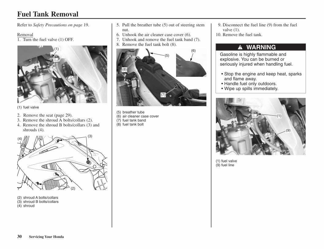
Fuel Tank RemovalRefer to Safety Precautions on page 19.
Removal1. Turn the fuel valve (1) OFF.
(1) fuel valve
2. Remove the seat (page 29).3. Remove the shroud A bolts/collars (2).4. Remove the shroud B bolts/collars (3) and
shrouds (4).
(2) shroud A bolts/collars(3) shroud B bolts/collars(4) shroud
5. Pull the breather tube (5) out of steering stemnut.
6. Unhook the air cleaner case cover (6).7. Unhook and remove the fuel tank band (7).8. Remove the fuel tank bolt (8).
(5) breather tube(6) air cleaner case cover(7) fuel tank band(8) fuel tank bolt
9. Disconnect the fuel line (9) from the fuelvalve (1).
10. Remove the fuel tank.
(1) fuel valve(9) fuel line
WARNINGGasoline is highly flammable and explosive. You can be burned orseriously injured when handling fuel.
• Stop the engine and keep heat, sparksand flame away.
• Handle fuel only outdoors.• Wipe up spills immediately.
(4)(3)
(2)
(5)
(8)
(7)
(1)
(9)
(1) (6)
*CR250R/24-48(31KSK630) 6/2/06 9:55 AM Page 30

Servicing Your Honda 31
Installation1. Install the fuel tank on the frame.2. Connect the fuel line (1) to the fuel valve (2).
(1) fuel line(2) fuel valve
3. Install the fuel tank bolt (3).4. Hook the fuel tank band (4).5. Hook the air cleaner case cover (5).6. Put the breather tube (6) in the steering stem
nut.
(3) fuel tank bolt(4) fuel tank band(5) air cleaner case cover(6) breather tube
7. Install the shrouds (7) and shroud B bolts/collars (8).
8. Install the shroud A bolts/collars (9).
(7) shroud(8) shroud B bolts/collars(9) shroud A bolts/collars
9. Install the seat (page 29).
Fuel Tank Removal
(2)
(1)
(9)
(8)(7)
(6)
(3)
(4)
(5)
*CR250R/24-48(31KSK630) 6/2/06 9:55 AM Page 31

32 Servicing Your Honda
Refer to Safety Precautions on page 19.
Removal1. Remove the seat (page 29).2. Remove the right side cover (1) by removing
the bolt/collar (2).
(1) right side cover(2) bolt/collar
3. Remove the bolt/washer (3) and silencer (4).
(3) bolt/washer(4) silencer
4. Loosen the screw (5) on the air cleaner connecting tube clamp (6).
(5) screw(6) connecting tube clamp
5. Remove the lower subframe mounting bolts(7) and upper subframe mounting bolt (8).
6. Remove the subframe (9) by pulling it straightbackward.
(7) lower subframe mounting bolts(8) upper subframe mounting bolt(9) subframe
Installation1. Loosely attach the upper and lower ends of
the subframe to the mainframe while connecting the air cleaner connecting tube tothe carburetor.
2. Tighten the screw (1) on the connecting tubeclamp (2).
(1) screw(2) connecting tube clamp
Subframe Removal
(1) (2)
(3)
(4)
(6)
(5)
(8)
(9)
(7)
(2)
(1)
*CR250R/24-48(31KSK630) 6/2/06 9:55 AM Page 32

Servicing Your Honda 33
Subframe Removal3. Align the subframe (3) with the rear wheel
and install the upper subframe mounting bolt(4) and lower subframe mounting bolts (5).
4. Tighten the upper subframe mounting bolt tothe specified torque:22 lbf·ft (30 N·m, 3.1 kgf·m)
5. Tighten the lower subframe mounting bolts tothe specified torque:22 lbf·ft (30 N·m, 3.1 kgf·m)
(3) subframe(4) upper subframe mounting bolt(5) lower subframe mounting bolts
6. Connect the silencer (6) to the expansionchamber with the sealing rubber.
7. Install and tighten the bolt/washer (7).
(6) silencer (7) bolt/washer
8. Install the right side cover (8) and bolt/collar(9).
(8) right side cover (9) bolt/collar
9. Install the seat (page 29).
(7)
(6)
(8) (9)
(5)
(4)
(3)
*CR250R/24-48(31KSK630) 6/2/06 9:55 AM Page 33

Refer to Safety Precautions on page 19.
Fuel Recommendation
We recommend that you use unleaded fuelbecause it produces fewer engine deposits andextends the life of exhaust system components.
Your engine is designed to use any gasoline thathas a pump octane number of 91 or higher.Gasoline pumps at service stations normallydisplay the pump octane number. Forinformation on the use of oxygenated fuels, seepage 128.
Use of lower octane gasoline can cause persistent“pinging” or “spark knock” (a louder rappingnoise) which, if severe, can lead to enginedamage. (Light pinging experienced whileoperating under a heavy load, such as climbing ahill, is no cause for concern.)
If pinging or spark knock occurs at a steadyengine speed under normal load, change brandsof gasoline. If pinging or spark knock persists,consult your Honda dealer.
Never use stale or contaminated gasoline. Avoidgetting dirt, dust, or water in the fuel tank.
Premix gasoline and oil in a ratio of 32:1.Prepare the fuel mixture in a clean container, andshake until thoroughly mixed before filling thefuel tank.
USE PRO HONDA HP2 2-STROKE OIL(32:1) OR AN EQUIVALENT.
Too much oil will cause excessive smoking andspark plug fouling. Too little oil will causeengine damage or premature wear.
Vegetable oils separate from gasoline more easilythan mineral oils, especially in cold weather. It isadvisable to use mineral oil when ambienttemperatures below 32°F (0°C) are expected.
If the gasoline-oil mixture is left standing in acontainer for a long period of time, lubricity willdeteriorate. Use the mixture within 24 hours-orthe time period recommended by the oilmanufacturer.
Once an oil container is opened, the oil must beused within one month, since oxidation mayoccur.
32:1 FUEL OIL MIXING CHART
Fuel Oil32 1
Gallons Liters Ounces cm3
0.5 1.89 2.0 591.0 3.79 4.0 1181.5 5.68 6.0 1772.0 7.57 8.0 2372.5 9.46 10.0 2963.0 11.36 12.0 3553.5 13.24 14.0 4144.0 15.14 16.0 4734.5 17.03 18.0 5325.0 18.92 20.0 5915.5 20.81 22.0 6516.0 22.71 24.0 710
NOTICE
Type unleaded
Pump Octane Number 91 (or higher)
34 Servicing Your Honda
Fuel System
*CR250R/24-48(31KSK630) 6/2/06 9:55 AM Page 34

Servicing Your Honda 35
Refueling Procedure
Fuel Tank Capacity: 2.0 US gal (7.7R)
(1) fuel fill cap (3) steering stem nut(2) breather tube
1. To open the fuel fill cap (1), pull the breathertube (2) out of the steering stem nut (3). Turnthe fuel fill cap counterclockwise and removeit.
2. Add fuel until the level reaches the bottom ofthe filler neck. Avoid overfilling the tank.There should be no fuel in the filler neck.
3. Close the fuel fill cap and insert the breathertube to the steering stem nut.
Fuel Line
(1) fuel valve (2) fuel line
1. Check the fuel valve (1) and fuel filter forcontamination.
2. Check for leaks. 3. Check the fuel line (2) for cracks,
deterioration, damage, or leakage. Replace thefuel line, if necessary.
4. Check for interference between the frame andtank and adjust if necessary.
Fuel Filter
The fuel filter is included in the fuel valvemounted on the bottom left side of the fuel tank.Dirt accumulated in the filter will restrict theflow of the fuel to the carburetor.
To service the fuel filter:1. Drain the fuel from the fuel tank into an
approved gasoline container. Disconnect thefuel line.
2. Remove the fuel valve (1) by removing thebolts (2). Wash the fuel filter (3) in highflash-point cleaning solvent.
(1) fuel valve (3) fuel filter(2) bolt (4) O-ring
3. Reassemble the fuel valve in the reverse orderof removal. Make sure the O-ring (4) is inplace. Install the fuel valve in the fuel tank.Refill the fuel tank. Attach the fuel line and turn the fuel valve toON; check for leaks.
Fuel System
WARNINGGasoline is highly flammable and explosive. You can be burned or seriously injured when handling fuel.
• Stop the engine and keep heat, sparksand flame away.
• Handle fuel only outdoors. • Wipe up spills immediately.
(2)
(1) (2)
(3)
(1)(3)
(1)(2)
(4)
*CR250R/24-48(31KSK630) 6/2/06 9:55 AM Page 35

36 Servicing Your Honda
Refer to Safety Precautions on page 19.
Using the proper oil, and regularly checking,adding, and changing oil will help extend theservice life of the transmission and clutch. Eventhe best oil wears out. Changing oil helps get ridof dirt and deposits. Operating the engine withold or dirty oil can damage your engine.Running the engine with insufficient oil cancause serious damage to the transmission.
Oil Recommendation
* Suggested 4–stroke engine oils are equalperformance to SJ oils that are not labeled asenergy conserving on the circular API servicelabel.
• Your CR does not need oil additives.Use the recommended oil.
• Do not use oils with graphite or molybdenumadditives. They may adversely affect clutchoperation.
• Do not use API SH or higher 4–stroke engineoils displaying a circular API “energyconserving” service label on the container. Theymay affect lubrication and clutch performance.
NOT RECOMMENDED OK
Other viscosities shown in the following chartmay be used when the average temperature inyour riding area is within the indicated range.
Transmission Oil
30
Type
API classification(4–stroke engine oilonly)
Viscosity(weight)
JASO T903standard (4–strokeengine oil only)
others
suggested oil*
transmission oil or 4–strokeengine oil
SG or higher except oilslabeled as energyconserving on the circularAPI service label
SAE 10W–30
MA
without friction modifiers asmolybdenum additives
Pro Honda HP Trans oil,Pro Honda GN4 4–strokeengine oil or an equivalent
*CR250R/24-48(31KSK630) 6/2/06 9:55 AM Page 36
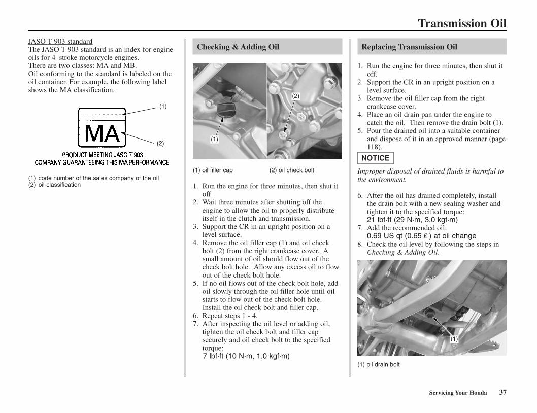
Servicing Your Honda 37
JASO T 903 standardThe JASO T 903 standard is an index for engineoils for 4–stroke motorcycle engines.There are two classes: MA and MB.Oil conforming to the standard is labeled on theoil container. For example, the following labelshows the MA classification.
(1) code number of the sales company of the oil(2) oil classification
Checking & Adding Oil
(1) oil filler cap (2) oil check bolt
1. Run the engine for three minutes, then shut itoff.
2. Wait three minutes after shutting off theengine to allow the oil to properly distributeitself in the clutch and transmission.
3. Support the CR in an upright position on alevel surface.
4. Remove the oil filler cap (1) and oil checkbolt (2) from the right crankcase cover. Asmall amount of oil should flow out of thecheck bolt hole. Allow any excess oil to flowout of the check bolt hole.
5. If no oil flows out of the check bolt hole, addoil slowly through the oil filler hole until oilstarts to flow out of the check bolt hole.Install the oil check bolt and filler cap.
6. Repeat steps 1 - 4. 7. After inspecting the oil level or adding oil,
tighten the oil check bolt and filler capsecurely and oil check bolt to the specifiedtorque:7 lbf·ft (10 N·m, 1.0 kgf·m)
Replacing Transmission Oil
1. Run the engine for three minutes, then shut itoff.
2. Support the CR in an upright position on alevel surface.
3. Remove the oil filler cap from the rightcrankcase cover.
4. Place an oil drain pan under the engine tocatch the oil. Then remove the drain bolt (1).
5. Pour the drained oil into a suitable containerand dispose of it in an approved manner (page118).
Improper disposal of drained fluids is harmful tothe environment.
6. After the oil has drained completely, installthe drain bolt with a new sealing washer andtighten it to the specified torque: 21 lbf·ft (29 N·m, 3.0 kgf·m)
7. Add the recommended oil:0.69 US qt (0.65R) at oil change
8. Check the oil level by following the steps inChecking & Adding Oil.
(1) oil drain bolt
NOTICE
Transmission Oil
(1)
(1)
(2)
(2)
(1)
*CR250R/24-48(31KSK630) 6/2/06 9:55 AM Page 37
38 Servicing Your Honda
Your CR’s liquid cooling system dissipatesengine heat through the coolant jacket thatsurrounds the cylinder and cylinder head.
Maintaining the coolant will allow the coolingsystem to work properly and prevent freezing,overheating, and corrosion.
Coolant Recommendation
Use Pro Honda HP coolant or an equivalent highquality ethylene glycol antifreeze containingcorrosion protection inhibitors specificallyrecommended for use in aluminum engines.Check the antifreeze container label.
Use only distilled water as a part of the coolantsolution. Water that is high in mineral content orsalt may be harmful to the aluminum engine.
Using coolant with silicate inhibitors may causepremature wear of radiator pump seals orblockage of radiator passages. Using tap watermay cause engine damage.
The factory provides a 50/50 solution ofantifreeze and water in this motorcycle. Thiscoolant solution is recommended for mostoperating temperatures and provides goodcorrosion protection.
Decreasing the concentration of antifreeze to lessthan 40% will not provide proper corrosionprotection.
Increasing the concentration of antifreeze is notrecommended because it decreases coolingsystem performance. Higher concentrations ofantifreeze (up to 60%) should only be used toprovide additional protection against freezing.Check the cooling system frequently duringfreezing weather.
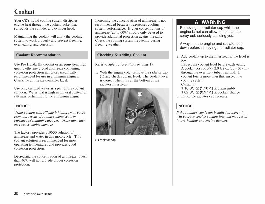
Checking & Adding Coolant
Refer to Safety Precautions on page 19.
1. With the engine cold, remove the radiator cap(1) and check coolant level. The coolant levelis correct when it is at the bottom of theradiator filler neck.
(1) radiator cap
2. Add coolant up to the filler neck if the level islow. Inspect the coolant level before each outing.A coolant loss of 0.7 - 2.0 US oz (20 - 60 cm3)through the over flow tube is normal. Ifcoolant loss is more than this, inspect thecooling system. Capacity: 1.16 US qt (1.10R) at disassembly1.02 US qt (0.97R) at coolant change
3. Install the radiator cap securely.
If the radiator cap is not installed properly, itwill cause excessive coolant loss and may resultin overheating and engine damage.
NOTICENOTICE
Coolant
WARNINGRemoving the radiator cap while theengine is hot can allow the coolant tospray out, seriously scalding you.
Always let the engine and radiator cooldown before removing the radiator cap.
(1)
*CR250R/24-48(31KSK630) 6/2/06 9:55 AM Page 38

Servicing Your Honda 39
Cooling System Inspection
1. Check the cooling system for leaks (see theHonda Service Manual for troubleshooting ofleaks).
2. Check water hoses (1) for cracks,deterioration, and clamp bands for looseness.
3. Check the radiator mount for looseness. 4. Make sure the overflow tube (2) is connected
and not clogged. 5. Check the radiator fins for clogging. 6. Check the water leakage check hole (3) below
the water pump cover (4) for leakage. Makesure the hole remains open. If water leaksthrough the check hole, the water pump seal isdamaged. If oil leaks through the check hole,the transmission oil seal is damaged. See theHonda Service Manual or consult your Hondadealer for replacing the water pump seal orthe transmission oil seal. Both seals shouldbe replaced at the same time.
(1) water hoses (4) water pump cover(2) overflow tube(3) water leakage check hole
Coolant Replacement
Refer to Safety Precautions on page 19.
Coolant should be replaced by your Honda dealer, unless you have the proper tools and service data and are mechanically qualified.Refer to the official Honda Service Manual (page136).
To properly dispose of drained coolant, refer toYou & the Environment, page 118.
Improper disposal of drained fluids is harmful tothe environment.
NOTICE
Coolant
WARNINGRemoving the radiator cap while theengine is hot can allow the coolant tospray out, seriously scalding you.
Always let the engine and radiator cooldown before removing the radiator cap. (1)
(2)
(4)(3)
*CR250R/24-48(31KSK630) 6/2/06 9:55 AM Page 39

40 Servicing Your Honda
Refer to Safety Precautions on page 19.
The air cleaner uses polyurethane inner and outerpieces which can’t be separated. A dirty air cleaner will reduce engine power.
Proper air cleaner maintenance is very importantfor off-road vehicles. A dirty, water-soaked,worn-out, or defective air cleaner will allow dirt,dust, mud, and other impurities to pass into theengine.
Service the air cleaner more frequently if youride in unusually wet or dusty areas. Your Hondadealer can help you determine the correct serviceinterval for your riding conditions.
Your CR’s air cleaner has very specificperformance requirements. Use a new genuineHonda air cleaner specified for your model or anair cleaner of equal quality.
Proper air cleaner maintenance can preventpremature engine wear or damage, expensiverepairs, low engine power, poor gas mileage, andspark plug fouling.
Improper or lack of proper air cleaner maintenance can cause poor performance andpremature engine wear.
Cleaning
1. Remove the seat (page 29). 2. Loosen the air cleaner retaining bolt (1). 3. Remove the air cleaner assembly (2).
(1) air cleaner retaining bolt(2) air cleaner assembly
4. Remove the air cleaner (3) from the aircleaner holder (4).
(1) air cleaner retaining bolt(3) air cleaner(4) air cleaner holder
5. Wash the air cleaner in clean non-flammablecleaning solvent. Then wash in hot, soapywater, rinse well, and allow to dry thoroughly.The air cleaner is made in two pieces: innerand outer which can’t be separated.
6. Clean the inside of the air cleaner housing. 7. Allow the air cleaner to dry thoroughly. After
drying, soak the air cleaner in clean ProHonda Foam Filter Oil or an equivalent aircleaner oil. Apply air cleaner oil to the entire surface,inner and outer, and rub it with both hands tosaturate the air cleaner with oil. Squeeze outexcess oil.
NOTICE
Air Cleaner
(2)
(1)
(4)
(1)
(3)
*CR250R/24-48(31KSK630) 6/2/06 9:55 AM Page 40

8. Apply a thin coat of Pro Honda WhiteLithium Grease or an equivalent, to thesealing surface.
9. Assemble the air cleaner and holder. Insert the pin (5) to the hole (6), and the aircleaner retaining bolt through the assembly.
(5) pin (6) hole
10. Insert the pin in the air cleaner housing hole(7) and install the assembly into the aircleaner housing (8) while aligning the tab (9)on the air cleaner and the reference mark (10)on the air cleaner housing. Tighten theretaining bolt securely.Carefully position the sealing flange of theelement to prevent dirt intrusion.
Improper installation of the air cleaner assemblymay allow dirt and dust to enter the engine andcause rapid wear of the piston rings and cylinder.
(3) air cleaner (8) air cleaner housing(4) air cleaner holder (9) tab(5) pin (10) reference mark(7) air cleaner housing hole
11. Reinstall the seat (page 29), making sure it issecurely attached.
NOTICE
Servicing Your Honda 41
Air Cleaner
(6)
(5)
(10)
(7)
(5)(9)
(3)
(8) (3)
(4)
*CR250R/24-48(31KSK630) 6/2/06 9:55 AM Page 41

Refer to Safety Precautions on page 19.
Throttle Freeplay
(1) freeplay
InspectionCheck freeplay (1).Freeplay: 1/8 - 3/16 in (3 - 5 mm)
If necessary, adjust to the specified range.
Upper AdjustmentMinor adjustments are generally made with theupper adjuster.
(2) dust cover (+) increase(3) lock nut (–) decrease(4) upper adjuster
1. Pull the rubber dust cover (2) back.2. Loosen the upper lock nut (3) on the throttle
cable mechanism.3. Turn the upper adjuster (4).
Turning the adjuster in direction (–) willdecrease freeplay and turning it in direction(+) will increase freeplay.
4. Tighten the lock nut. Return the dust cover toits normal position.
5. After adjustment, check for smooth rotation ofthe throttle grip from fully closed to fullyopen in all steering positions.If the adjuster is threaded out near its limit orthe correct freeplay cannot be reached, turnthe adjuster all the way in and back out oneturn. Tighten the lock nut, install the dustcover and make the adjustment with the loweradjuster.
Lower AdjustmentThe lower adjuster is used for major freeplayadjustment, such as after replacing the throttlecables or removing the carburetor. It is also usedif you cannot get the proper adjustment with theupper adjuster.
(5) rubber cap (+) increase(6) lock nut (–) decrease(7) adjuster
1. Pull up the rubber cap (5) on the carburetorcap and loosen the lock nut (6).
2. Turn the adjuster (7) in direction (–) todecrease freeplay, and in direction (+) toincrease freeplay.
3. Tighten the lock nut.4. Reinstall the rubber cap securely after
adjustment.5. Operate the throttle grip to ensure that it
functions smoothly and returns completely.
If you can’t get the freeplay within the specifiedrange, contact your Honda dealer.
42 Servicing Your Honda
Throttle
RIGHT SIDE (3)(4)
(–)
(+)
(2)
(5)
(6)(7)
(+)(–)
(1)
*CR250R/24-48(31KSK630) 6/2/06 9:55 AM Page 42

Servicing Your Honda 43
Throttle Inspection
(1) throttle grip
1. Check that the throttle assembly is positionedproperly and the securing bolts are tight.
2. Check for smooth rotation of the throttle grip(1) from fully open to fully closed in allsteering positions. If there is a problem, seeyour Honda dealer.
3. Inspect the condition of the throttle cable fromthe throttle grip down to the carburetor. If thecable is kinked or chafed, have it replaced.
4. Check the cable for tension or stress in allsteering positions.
5. Lubricate the cable with a commercially-available cable lubricant to prevent prematurerust and corrosion.
Throttle
(1)
*CR250R/24-48(31KSK630) 6/2/06 9:55 AM Page 43

(4)(+)
(–)(5)
(3)
(+)
(–)
44 Servicing Your Honda
Clutch SystemRefer to Safety Precautions on page 19.
Clutch Lever Adjustment
The distance between the tip of the clutch leverand the grip may be adjusted.
Make sure to adjust the clutch lever freeplay afterthe clutch lever position adjustment or clutchcable is disconnected.
(1) lock nut (2) adjuster
1. Loosen the lock nut (1).2. To position the clutch lever farther away from
the handgrip, turn the adjuster (2)counterclockwise. To position the clutch levercloser to the handgrip, turn the adjusterclockwise.
3. Tighten the lock nut.
4. Turn the cable end adjuster (3) in direction (+)until it seats lightly and then turn it out 5turns.
Cable end adjuster:
(3) cable end adjuster(+) increase freeplay(–) decrease freeplay
5. Loosen the lock nut (4) and turn the integralcable adjuster (5) to adjust the clutch leverfreeplay 3/8 – 3/4 in (10 – 20 mm) at the tipof lever. Tighten the lock nut.
Integral cable adjuster:
(4) lock nut(5) integral cable adjuster(+) increase freeplay(–) decrease freeplay
6. Adjust the cable end adjuster for minoradjustment.
Clutch Lever Freeplay
(1) clutch lever
InspectionCheck freeplay:Freeplay: 3/8 – 3/4 in (10 – 20 mm)
If necessary, adjust to the specified range.Improper freeplay adjustment can causepremature clutch wear.
Make sure to adjust the clutch lever (1) freeplayafter the clutch cable is disconnected.
(1) (2)
(1)
*CR250R/24-48(31KSK630) 6/2/06 9:55 AM Page 44

Servicing Your Honda 45
Cable End AdjustmentMinor adjustments are generally made with theclutch cable end adjuster.
Cable end adjuster:
(2) cable end adjuster(+) increase freeplay(–) decrease freeplay
Turning the cable end adjuster (2) in direction (+)will increase freeplay and turning it in direction(–) will decrease freeplay.
If the adjuster is threaded out near its limit or thecorrect freeplay cannot be reached, turn theadjuster all the way in and back out one turn andmake the adjustment with the integral cableadjuster.
Integral Cable AdjustmentThe integral cable adjuster is used if the cableend adjuster is threaded out near its limit — orthe correct freeplay cannot be obtained.
Integral cable adjuster:
(3) lock nut (+) increase freeplay(4) integral cable adjuster (–) decrease freeplay
1. Turn the cable end adjuster in direction (+)until it seats lightly and then turn it out 5turns.
2. Loosen the lock nut (3).3. Turn the integral cable adjuster (4) to obtain
the specified freeplay 3/8 – 3/4 in (10 – 20mm).
4. Tighten the lock nut. Check the adjustment.5. Start the engine, pull the clutch lever in, and
shift into gear. Make sure the engine does notstall and the motorcycle does not creep.Gradually release the clutch lever and openthe throttle. Your CR should move smoothlyand accelerate gradually.
If you can’t get proper adjustment, or the clutchdoes not work properly, the cable may be kinkedor worn, or the clutch discs may be worn. Seeyour Honda dealer or refer to the official HondaService Manual (page 134).
Other Inspections & Lubrication
• Check that the clutch lever assembly ispositioned properly and the securing bolts aretight.
• Check the clutch cable for kinks or signs ofwear. If necessary, have it replaced.
• Lubricate the clutch cable with a commercially-available cable lubricant to prevent prematurewear and corrosion.
Clutch Operation
1. Check for smooth clutch lever operation. Ifnecessary, lubricate the clutch lever pivot orclutch cable.
2. Check the clutch cable for deterioration,kinks, or damage.
Clutch System
(2)
(+)
(–) (3)(+)
(–)(4)
*CR250R/24-48(31KSK630) 6/2/06 9:55 AM Page 45

46 Servicing Your Honda
Clutch Cover/Disc/Plate Removal
1. Drain the transmission oil (page 37).2. Remove the rear brake pedal (1) and washer
(2) by removing its pivot bolt (3).
(1) rear brake pedal (3) pivot bolt(2) washer
3. Remove the six clutch cover bolts (4) andclutch cover (5).
(4) clutch cover bolts (5) clutch cover
4. Remove the six clutch spring bolts (6) andclutch springs.
Loosen the bolts in a crisscross pattern in 2 or 3progressive steps.
5. Remove the clutch pressure plate (7).
(6) clutch spring bolts(7) clutch pressure plate
6. Remove the clutch lifter (8) and clutch lifterrod (9).
7. Remove the eight clutch discs and sevenclutch plates (10).
Turn the lifter bearing plate of the clutch lifterbearing with your finger. The bearing plateshould turn smoothly and quietly. Discard theclutch lifter if the bearing plate does not turnsmoothly.
(8) clutch lifter (10) clutch discs and plates(9) clutch lifter rod
Clutch Disc/Plate Inspection
Replace the clutch discs (1) if they show signs ofscoring or discoloration.Measure the thickness of each clutch disc.Service Limit: 0.112 in (2.85 mm)
Replace the clutch discs and clutch plates as anassembly.
(1) clutch disc
Check the clutch plate (2) for excessive warpageor discoloration.Check the plate warpage on a surface plate usinga feeler gauge.Measure the thickness of the clutch plates.Service Limit: 0.008 in (0.20 mm)
Replace the clutch discs and plates as a set.
(2)clutch plate
Clutch System
(10)
(8)
(9)
(7)
(6)
(3)
(1)
(4)
(5)
(2)
(1)
(2)
*CR250R/24-48(31KSK630) 6/2/06 9:55 AM Page 46
Servicing Your Honda 47
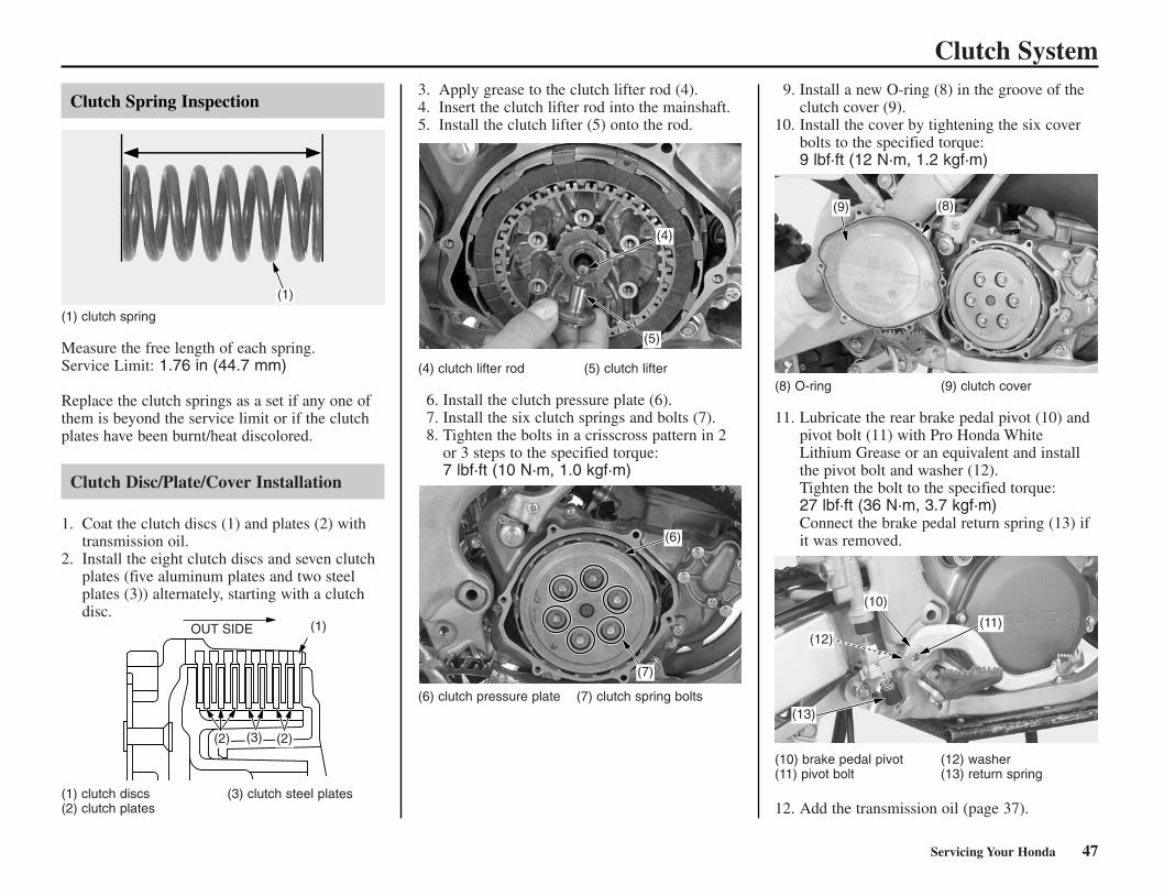
Clutch Spring Inspection
(1) clutch spring
Measure the free length of each spring.Service Limit: 1.76 in (44.7 mm)
Replace the clutch springs as a set if any one ofthem is beyond the service limit or if the clutchplates have been burnt/heat discolored.
Clutch Disc/Plate/Cover Installation
1. Coat the clutch discs (1) and plates (2) withtransmission oil.
2. Install the eight clutch discs and seven clutchplates (five aluminum plates and two steelplates (3)) alternately, starting with a clutchdisc.
(1) clutch discs (3) clutch steel plates(2) clutch plates
3. Apply grease to the clutch lifter rod (4).4. Insert the clutch lifter rod into the mainshaft.5. Install the clutch lifter (5) onto the rod.
(4) clutch lifter rod (5) clutch lifter
6. Install the clutch pressure plate (6).7. Install the six clutch springs and bolts (7).8. Tighten the bolts in a crisscross pattern in 2
or 3 steps to the specified torque:7 lbf·ft (10 N·m, 1.0 kgf·m)
(6) clutch pressure plate (7) clutch spring bolts
9. Install a new O-ring (8) in the groove of theclutch cover (9).
10. Install the cover by tightening the six coverbolts to the specified torque:9 lbf·ft (12 N·m, 1.2 kgf·m)
(8) O-ring (9) clutch cover
11. Lubricate the rear brake pedal pivot (10) andpivot bolt (11) with Pro Honda WhiteLithium Grease or an equivalent and installthe pivot bolt and washer (12).Tighten the bolt to the specified torque:27 lbf·ft (36 N·m, 3.7 kgf·m)Connect the brake pedal return spring (13) ifit was removed.
(10) brake pedal pivot (12) washer(11) pivot bolt (13) return spring
12. Add the transmission oil (page 37).
Clutch System
(13)
(7)
(6)
(2)
(1)
(4)
(5)
(9) (8)
(11)
(10)
(1)
(3)(2)
OUT SIDE(12)
*CR250R/24-48(31KSK630) 6/2/06 9:55 AM Page 47

48 Servicing Your Honda
Refer to Safety Precautions on page 19.
Spark Plug Recommendation
The recommended standard spark plug issatisfactory for most racing conditions.
Use only the recommended type of spark plug inthe recommended heat range.
Using a spark plug with an improper heat rangeor incorrect reach can cause engine damage.Using a non-resistor spark plug may causeignition problems.
1. Measure spark plug gap (1) with a feelergauge, and adjust by carefully bending theside electrode (2).The recommended spark plug gap is:0.027 - 0.031 in (0.7 - 0.8 mm)
2. Check the electrode for wear or deposits, thegasket (3) for damage, and the insulator forcracks.
(1) plug gap (3) sealing gasket(2) side electrode
3. To obtain accurate spark plug readings,accelerate up to speed on a straightaway.Push the engine stop button and disengage theclutch by pulling the lever in.If you’re using a new plug, ride for at least tenminutes before taking a plug reading; a brand-new plug will not color initially.
4. Coast to a stop, then remove and inspect thespark plug. The porcelain insulator aroundthe center electrode should appear tan ormedium gray.If the electrodes appear burnt, or the insulatoris white or light gray (lean) or the electrodesand insulator are black or fouled (rich), thereis a problem elsewhere (page 109). Check thefuel/oil mixture, carburetor and fuel system,and ignition timing.
5. Tighten the spark plug (4):• If the old plug is good:
1/8 turn after is seats.• If installing a new plug, tighten it twice to
prevent loosening:a) First, tighten the plug:
NGK: 3/4 turn after it seats.b) Then loosen the plug.c) Next, tighten the plug again:
1/8 turn after it seats.
(4) spark plug
6. Reinstall the sparkplug cap. Take care to avoidpinching any cables or wires.
NOTICE
Spark Plug
Standard BR9EG-N-8 (NGK) (2)
(1)
(3)
(4)
*CR250R/24-48(31KSK630) 6/2/06 9:55 AM Page 48

(7)
(6)(6)
(8)
Servicing Your Honda 49
Refer to Safety Precautions on page 19.
Cylinder Head Removal
Clean the area above the engine before disassemblyto prevent dirt falling into the engine.
1. Drain the radiator coolant (page 39).2. Remove the seat and fuel tank (page 29, 30).3. Loosen the water hose clamp and remove the
water hose (1) from the cylinder head.4. Disconnect the spark plug cap (2) and remove
the spark plug.
(1) water hose (2) spark plug cap
5. Remove the upper engine hanger plate boltsand nuts (3), then remove the clamp (4) andhanger plates (5).
(3) hanger plate bolts and nuts (5) hanger plates(4) clamp
6. Remove the cylinder head nuts A (6) andcylinder head nuts B/washers (7) using thetechnique described below, and remove thecylinder head (8).
To avoid warping the cylinder head, use acrisscross pattern to loosen each nut about 1/4,then remove the nuts.
(6) cylinder head nuts A (8) cylinder head(7) cylinder head nuts B/washers
7. Remove the cylinder head gasket (9) anddowel pins (10).
(9) gasket (10) dowel pins
Cylinder System
(1)
(2)
(9)
(10)
(3)(4)
(5)
*CR250R/49~59(31KSK630).qxd 6/2/06 9:56 AM Page 49

Cylinder System
Cylinder Removal
1. Remove the expansion chamber (page 75).2. Remove the exhaust gasket (1).
(1) exhaust gasket
3. Remove the bolts (2), clamp (3), RC cover (4)and gasket (5).
(2) bolts (4) RC cover(3) clamp (5) gasket
4. Loosen the lock nuts (6) and disconnect theRC valve control cables (7) from the RCvalve pulley (8).
(6) lock nuts (8) RC valve pulley(7) control cables
5. Loosen the radiator hose clamp screw (9) anddisconnect the radiator hose (10).
6. Remove the radiator grills (11) on both sides.7. Loosen the upper mounting bolts (12) on
both sides.8. Remove the lower mounting bolts (13), then
swing the radiators (14) forward on bothsides.
(9) screw (12) upper mounting bolt(10) radiator hose (13) lower mounting bolt(11) radiator grill (14) radiator
9. Remove the cylinder (15) by removing thefour flange nuts (16).
(15) cylinder (16) flange nuts
10. Remove the gasket (17) and dowel pins (18).
(17) gasket (18) dowel pins
50 Servicing Your Honda
(1)
(2)
(3)
(4)(5)
(7)
(8)
(9)
(10)
(15)
(16)
(17)
(18)
(14)(12)
(11)
(13)
(6)
*CR250R/49~59(31KSK630).qxd 6/2/06 9:56 AM Page 50

Cylinder System
Piston Removal
1. Place the shop towel in the crankcase.2. Remove the piston pin clip (1) using a pair of
needle-nose pliers. Press the piston pin (2)out of the piston (3), and remove the piston.
3. Remove the connecting rod small end bearing(4).
Under racing conditions, the piston and ringshould be replaced after 7.5 hours of running.Replace the piston pin and connecting rod smallend bearing after 22.5 hours of running.
(1) piston pin clip (4) connecting rod smallend bearing(2) piston pin
(5) piston ring(3) piston
4. Spread the piston ring (5) and remove bylifting it up at a point just opposite the gap.
The piston ring may be damaged if the ends arespread too far.
Cylinder Head/Cylinder Decarbonizing
1. Remove the carbon deposits from the cylinderhead (1) and piston dome.Take care to avoid scratching the cylinderhead piston dome, or the head gasket surface.
(1) cylinder head
2. Clean carbon deposits from the exhaust port (2)area.
(2) exhaust port
Cylinder/Piston/Piston Pin/Piston RingInspection
We recommend you consult the Service Manualor your Honda dealer for correct Service Limitmeasurements.
NOTICE
Servicing Your Honda 51
(2)
(3)
(5)
(1)
(1)
(2)
(4)
*CR250R/49~59(31KSK630).qxd 6/2/06 9:56 AM Page 51

(2)
(1)
(3)
(4)
52 Servicing Your Honda
Connecting Rod Inspection
1. Temporarily remove the shop towel.2. Install the small end bearing (1) and piston
pin (2) in the connecting rod small end andcheck for excessive play while holding theconnecting rod.If it feels loose, replace the piston pin andsmall end bearing.
(1) small end bearing (2) piston pin
3. Place the shop towel back in the crankcase.
Cylinder Head Inspection
Check the cylinder head (1) for warpage in diagonal directions with a straight edge (2) and afeeler gauge (3).Service Limit: 0.002 in (0.05 mm)
(1) cylinder head (3) feeler gauge(2) straight edge
Piston Installation
1. Clean the piston ring groove.2. Lubricate the piston ring and piston ring
groove with clean 2-stroke oil.3. Install the piston ring on the piston with the
marks facing up.Locate the piston ring end gap on the pin inthe ring groove.
4. Lubricate the small end bearing and piston pin(1) with clean 2-stroke oil.
5. Install the connecting rod small end bearing,piston and piston pin.Install the piston with the “IN” mark (2)facing the intake side.If the “IN” mark is not found on the piston,install the piston with the hole (3) facing theintake side.
6. Install new piston pin clips (4) (Never reuseold clips.)Take care so that the clips do not fall into thecrankcase.Do not align the piston pin clip end gap withthe piston cut-out.
(1) piston pin (3) hole(2) “IN” mark (4) piston pin clip
Cylinder Installation
1. Clean off any gasket material from the gasketsurface of the crankcase, being careful not tolet any material fall into the crankcase.Be careful not to remove any metal from thegasket surface.
2. Remove the shop towel. Do not let any gasketdebris fall into the crankcase.
3. Place the new cylinder base gasket (1) anddowel pins (2) on the crankcase.
(1) cylinder base gasket (2) dowel pin
4. Lubricate the piston and ring with 2-strokeoil. Align the ring end gap with the pistonring pin (3) in the ring groove and slip thecylinder (4) over the piston whilecompressing the piston ring.
Do not rotate the cylinder, since this may causethe piston ring to snag a cylinder port and break.
NOTICE
Cylinder System
(1)
(2)
(3)
(1)
(2)
(1)
(2)
*CR250R/49~59(31KSK630).qxd 6/2/06 9:56 AM Page 52
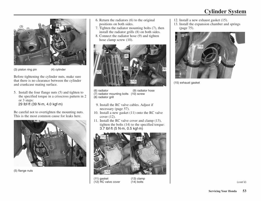
(3) piston ring pin (4) cylinder
Before tightening the cylinder nuts, make surethat there is no clearance between the cylinderand crankcase mating surface.
5. Install the four flange nuts (5) and tighten tothe specified torque in a crisscross pattern in 2or 3 steps:29 lbf·ft (39 N·m, 4.0 kgf·m)
Be careful not to overtighten the mounting nuts.This is the most common cause for leaks here.
(5) flange nuts
6. Return the radiators (6) to the originalpositions on both sides.
7. Tighten the radiator mounting bolts (7), theninstall the radiator grills (8) on both sides.
8. Connect the radiator hose (9) and tightenhose clamp screw (10).
(6) radiator (9) radiator hose(7) radiator mounting bolts (10) screw(8) radiator grill
9. Install the RC valve cables. Adjust ifnecessary (page 57).
10. Install a new gasket (11) onto the RC valvecover (12).
11. Install the RC valve cover and clamp (13),tighten the bolts (14) to the specified torque:3.7 lbf·ft (5 N·m, 0.5 kgf·m)
(11) gasket (13) clamp(12) RC valve cover (14) bolts
12. Install a new exhaust gasket (15).13. Install the expansion chamber and springs
(page 75).
(15) exhaust gasket
Servicing Your Honda 53
Cylinder System
(3)(4)
(5)
(10)
(9)
(11)
(12)
(14)
(6)
(8)(7)
(cont’d)
(13)
(15)
*CR250R/49~59(31KSK630).qxd 6/2/06 9:56 AM Page 53

54 Servicing Your Honda
Cylinder System
Cylinder Head Installation
1. Clean the cylinder head mating surface andinstall the dowel pins (1).
2. Install the new cylinder head gasket (2) withits “UP” mark (3) facing up and locating tab(4) facing rearward.
(1) dowel pins (3) “UP” mark(2) cylinder head gasket (4) tab
3. Install the cylinder head (5) and tighten thecylinder head nuts A (6) and cylinder headnuts B/washers (7) to the specified torque in acrisscross pattern in 2 or 3 steps:20 lbf·ft (27 N·m, 2.8 kgf·m)
(5) cylinder head (7) cylinder head nuts B/(6) cylinder head nuts A washers
4. Install the clamp (8), hanger plates (9) andtighten the nuts (10) to the specified torque:Engine side: 40 lbf·ft (54 N·m, 5.5 kgf·m)Frame side: 25 lbf·ft (34 N·m, 3.5 kgf·m)
5. Connect the water hose (11) to the cylinderhead.
6. Install the spark plug and spark plug cap (12).
(8) clamp (11) water hose(9) hanger plates (12) spark plug cap
(10) nuts
7. Pour the recommended coolant mixture intothe radiator up to the correct level (page 38).
8. Install the fuel tank and seat (page 29, 30).9. Start the engine and check for the following:
– compression leaks– abnormal engine noise– secondary air leaks– coolant leaks
(1)
(2)
(3) (4)
(7)
(6)
(8)
(9)
(12)
(11)
(10)
(5)
*CR250R/49~59(31KSK630).qxd 6/2/06 9:56 AM Page 54

Servicing Your Honda 55
Refer to Safety Precautions on page 19.
The exhaust valves open and close according toengine speed to ensure sufficient torquethroughout the entire engine rpm range. Thevalves should be fully closed at low rpm andfully open at high rpm.
The exhaust valve system is a precisionassembly. Before beginninginspection/decarbonizing, please study thefollowing text and illustrations carefully.Before attempting complete disassembly, werecommend you consult the service manual oryour Honda dealer. Mismatching of parts onreassembly can measurably affect engineperformance.
Operating Inspection
Before inspection, clean the engine thoroughly tokeep dirt from entering the engine.
1. Warm up the engine to operating temperature.2. Stop the engine, and remove the RC valve
cover.3. Connect the tachometer.4. Start the engine and check that the RC valve
pulley (1) is in the fully closed position.5. Increase the engine speed until about 8,000
rpm and check that the RC valve pulley turnsto the fully open position.
(1) RC valve pulley
6. Disconnect the cables from the RC valvepulley. Check that the exhaust valve turnssmoothly. If the exhaust valve does not turnsmoothly, remove the exhaust valve anddecarbonize the RC valve (2) and valve shaftassembly (3).
(2) RC valve (3) valve shaft assembly
Exhaust Valve Removal
1. Remove the cylinder (page 50).2. Remove the socket bolt (1) and stopper plate
(2).
(1) socket bolt (2) stopper plate
3. Remove the valve shaft assembly (3) from thecylinder.
4. Remove the cylinder cover (4) by removingbolts A (5) and bolts B (6). Remove the RCvalve (7) and O-rings (8).
(3) valve shaft assembly (6) bolts B(4) cylinder cover (7) RC valve(5) bolts A (8) O-rings
RC Valve
(2)
(1)
(7)
(3)
(5)
(1)
(2)
(3)
(8)
(6)
(4)
*CR250R/49~59(31KSK630).qxd 6/2/06 9:56 AM Page 55

56 Servicing Your Honda
Exhaust Valve/Cylinder Decarbonizing
1. Remove the carbon deposits from the valveshaft assembly (1), RC valve (2), cylinder portand cylinder cover.
Decarbonize the valve shaft assembly, RC valvecylinder port and cylinder cover every 3 races.
2. Inspect the RC valve, valve shaft assembly forwear or damage.
(1) valve shaft assembly
(2) RC valve
Valve Shaft Oil Seal Inspection
Check the valve shaft oil seal (1) for wear ordamage.Replace the oil seal, if necessary.
(1) valve shaft oil seal
Exhaust Valve Assembly
1. Clean any gasket material from the matingsurfaces of the cylinder and cylinder cover.
2. Apply a thin coat of molybdenum disulfide oilto the hole of RC valve and valve shaft.
3. Apply silicone sealer (Three Bond 1207B orequivalent) (1) to the mating surface of thecylinder as shown.
(1) silicone sealer
4. For ease of RC valve installation, place thecylinder upside down. Set the RC valve (2)onto the cylinder cover (3) and O-rings (4) tothe cylinder.
(2) RC valve (4) O-rings(3) cylinder cover
5. Install the cylinder cover carefully to thecylinder.
6. Install the valve shaft assembly. Make surethat the valve shaft and RC valve are aligned.
7. Tighten the bolts A (5) and bolts B (6) to thespecified torque:9 lbf·ft (12 N·m, 1.2 kgf·m)
(5) bolts A (6) bolts B
RC Valve
(1)
(2)
(3)
(4)
(5)
(6)
(1)(2)
(1)
*CR250R/49~59(31KSK630).qxd 6/2/06 9:56 AM Page 56

Servicing Your Honda 57
8. Install the stopper plate (7) and tighten thesocket bolt (8) to the specified torque:7 lbf·ft (10 N·m, 1.0 kgf·m)
(7) stopper plate(8) socket bolt
9. Check that the RC valve and valve shaftmove smoothly.
10. Install the cylinder (page 52).
RC Valve Cable
Rear RC Valve cable
1. Turn the outer lock nut (1) until it seatsagainst the adjuster (2). Connect the rear RCvalve cable (3) to the RC valve pulley (4).
2. Turn the RC valve pulley counterclockwisefully.Turn the adjuster clockwise until the innerlock nut (5) seats against the cylinder (6).
3. Tighten the outer lock nut securely.
(1) outer lock nut (4) RC valve pulley(2) adjuster (5) inner lock nut(3) rear RC valve cable (6) cylinder
Front RC Valve cable
1. Turn the RC valve pulley (1) clockwise fullyuntil the RC valve pulley stops against the pin(2).
2. Loosen the inner lock nut (3) until it reachesthe end of the cable threads.
3. Connect the front RC valve cable (spring/seat)(4) to the RC valve pulley.
4. Install the seat (5) to the cable guide (6) whilecompressing the spring.
5. Tighten the adjuster (7) until the inner locknut seats to the cylinder (8).
6. Tighten the outer lock nut (9) securely.
(1) RC valve pulley (6) cable guide(2) pin (7) adjuster(3) inner lock nut (8) cylinder(4) front RC valve cable (9) outer lock nut(5) seat
RC Valve
(7)
(8)
(4)
(3)
(2)
(1)
(6)
(5)
0 mm
0 mm
0 mm
0 mm
(9)
(8)
(3)
(5)
(4) (1)
(7)
(6)
(2)
*CR250R/49~59(31KSK630).qxd 6/2/06 9:57 AM Page 57

Reed ValveRefer to Safety Precautions on page 19.
Reed Valve Removal
1. Remove the carburetor (page 107).2. Remove the insulator (1) and reed valve (2)
from the cylinder by removing the sixcarburetor insulator mounting bolts (3).
3. Remove the gasket.
(1) insulator(2) reed valve
Reed Valve Inspection
1. Check the reed valves (1) for damage orfatigue and replace them if necessary.
2. Replace the reed valve with new ones if theseats are cracked or damaged.
(1) reed valves
Reed Valve Disassembly/Assembly
1. Remove the reed valve mounting screws (1),stopper (2), sub-reed valve (3), reed valve (4)and the spacer (5) on one side of the reedvalve.
2. Align the cut-outs (6) between the reed valvesand stoppers, then install them onto the cage.
(1) reed valve mounting screws (4) reed valve(2) stopper (5) spacer(3) sub-reed valve (6) cut-out
3. Apply a locking agent to the reed valvemounting screw threads.
4. Install and tighten the mounting screws to thespecified torque:0.7 lbf·ft (1 N·m, 0.1 kgf·m)
5. Make sure that the clearance between the reedvalve and cage (7) is less than the 0.008 in(0.2 mm).
(4) reed valve (7) cage
58 Servicing Your Honda
(2)
(1)(3)
(1)
(6)
(3)
(7)
(4)
(1)
(2)
(3)
(3) carburetor insulatormounting bolts
(5)(4)
(4)(2)
(1)
(6)
0.008 in(0.2 mm)
*CR250R/49~59(31KSK630).qxd 6/2/06 9:57 AM Page 58

Reed Valve
Reed Valve Installation
1. Install the new gasket (1) to the crankcase (2).2. Install the reed valve assembly (3) to the
crankcase.
(1) gasket (3) reed valve assembly(2) crankcase
3. Install the insulator (4), six carburetorinsulator mounting bolts (5) and tighten to thespecified torque in a crisscross pattern:9 lbf·ft (12 N·m, 1.2 kgf·m)
After installation, check for secondary air leaksaround the reed cage and insulator.
(4) insulator(5) carburetor insulator mounting bolts
4. Install the carburetor (page 107).
Servicing Your Honda 59
(2)
(1)
(3)(4)
(5)
UP
LEFT
*CR250R/49~59(31KSK630).qxd 6/2/06 9:57 AM Page 59

Refer to Safety Precautions on page 19.
Loose, worn, or damaged suspension componentsmay adversely affect the handling and stability ofyour CR. If any suspension components appearworn or damaged, see your Honda dealer forfurther inspection. Your dealer is qualified todetermine whether or not replacement parts orrepairs are needed.
Front Suspension Inspection
• When your CR is new, break it in forapproximately one hour to ensure that thesuspension has worked in (page 15).
• After break-in, test run your CR with the frontsuspension at the standard setting beforeattempting any adjustments.
• For optimum fork performance, werecommend that you disassemble and cleanthe fork after riding your CR for 3 hours. See page 83 for fork disassembly.
• Replace the fork oil every 3 races or 7.5 hoursof running. See page 62 for oil leveladjustment after changing the fork oil.
• Replace the damper fork oil every 9 races or22.5 hours of running. See page 86 fordamper fork oil replacement.
• Use Pro Honda HP Fork Oil 5W or anequivalent which contains special additives toassure maximum performance of your CR’sfront suspension.
• Periodically check and clean all frontsuspension parts to assure top performance.Check the dust seals for dust, dirt, and foreignmaterials. Check the oil for anycontamination.
• Refer to Suspension Adjustment Guidelines(page 100). Make all rebound andcompression damping adjustments in one-click increments. (Adjusting two or moreclicks at a time may cause you to pass overthe best adjustment.) Test ride after eachadjustment.
• If you become confused about adjustmentsettings, return to the standard position andstart over.
• If the fork is still too stiff/soft after adjustingcompression damping, determine whichportion of the travel is still too stiff/soft. Thisis an important step that will help you solvesuspension problems.
1. Make sure that the fork protectors (1) and dustseals (2) are clean and not packed with mudand dirt.
2. Check for signs of oil leakage. Damaged orleaking fork seals should be replaced beforeyour CR is ridden.
(1) fork protector (2) dust seal
3. Inspect the wear rings (3) for wear or damage.Replace the wear ring if it is 0.06 in (1.5 mm)or flat with the outer tube (4).Install the wear ring with its end gap facingrearward.
(3) wear ring (4) outer tube
(3) wear rings
4. Make a quick check of fork operation bylocking the front brake and pushing down onthe handlebar several times.
60 Servicing Your Honda
Suspension
(2)
(1)
(4)
(3)
(3)
(3)
0.06 in (1.5 mm)
*CR250R/60-71(31KSK630).qxd 6/2/06 9:58 AM Page 60

Rear Suspension Inspection
The swingarm is controlled by one hydraulicshock absorber with an aluminum reservoir foroil and nitrogen gas pressure. The gas pressurein the reservoir is contained within a rubberbladder.
The shock absorber’s spring preload and dampingadjustments (compression and rebound) shouldbe adjusted for the rider’s weight and trackconditions (page 99).
Do not attempt to disassemble, service, ordispose of the damper; see your Honda dealer.The instructions found in this owner’s manual arelimited to adjustments of the shock assembly only.
• When your CR is new, break it in forapproximately one hour with the standardsuspension settings before attempting toadjust the rear suspension.
• Make all compression and rebound dampingadjustments in the specified increment orturns described in pages 96. (Adjusting twoor more increments or turns at a time maycause you to pass over the best adjustment.)Test ride after each adjustment.
• If the rear suspension is too stiff/soft, adjust itby turning all the compression and reboundadjusters according to the proceduresdescribed in page 96. After adjusting theadjusters simultaneously, suspension may befine-tuned by turning one of the compressionand rebound damping adjusters in one clickincrements.
• If you have a problem finding an acceptableadjustment, return to the standard position andbegin again.
1. Bounce the rear of the motorcycle up and downand check for smooth suspension action.
2. Remove the subframe (page 32).3. Check for a broken or collapsed spring.4. Check the shock for a bent shaft or oil leaks.
(1) rear shock absorber
5. Push the rear wheel sideways to check forworn or loose swingarm bearings. Thereshould be no movement. If there is, have thebearings replaced by your Honda dealer.
Servicing Your Honda 61
Suspension
(1)
*CR250R/60-71(31KSK630).qxd 6/2/06 9:58 AM Page 61

(1)
(8)
Recommended Fork Oil
Fork Oil Change
Refer to Suspension Removal on page 83.
1. Clean the fork assembly, especially the slidingsurface of the slider and dust seal.
2. Hold the outer tube (1), then remove the forkdamper (2) from the outer tube using a locknut wrench (3). Gently slide the outer tubedown onto the lower end of the slider (4).
(1) outer tube (3) lock nut wrench(2) fork damper (4) slider, lower end
The outer tube can drop on the slider anddamage the fork dust seal and guide bushingwhen the fork damper is removed. To avoiddamage, hold both the outer tube and slider whenremoving the fork damper.
(1) outer tube (6) guide bushing(5) dust seal (7) slider
3. Pour the fork oil from the outer tube (1).Pour the fork oil from the oil hole (8) of thefork damper.
(1) outer tube (8) oil hole
4. Drain the fork oil by turning the outer tube (1)upside down. (About 12 cm3 of fork oil willbe left in the outer tube when it is left invertedfor about 20 minutes at 20°C/68°F.)
(1) outer tube
Amount of fork oil left in the fork(within damper and spring) unit: cm3
NOTICE
62 Servicing Your Honda
Suspension
viscosity (weight) 5 W
suggested oil Pro Honda HP Fork Oil orequivalent
minute
°C/°F5 10 20 35 55 85 145
30/86 27 15.3 10.6 9.4 8.3 7.9 7.920/68 29.4 16.5 11.8 10.6 9.4 8.2 8.210/50 28.2 21.2 16.5 15.3 12.9 11.8 11.80/32 30.6 22.4 18.8 16.5 16.5 15.3 14.1
(1)
(2)
(3)
(1)
(4)
(5)
(6)
(7)
NO GOOD
NO GOOD
(1)
0°C/32°F10°C/50°F
20°C/68°F30°C/86°F
0 20 40 60 80 100 120 140 16005
101520253035
Inverted time (minutes)
(cm3)
Am
ou
nt
of
fork
oil
(1)
*CR250R/60-71(31KSK630).qxd 6/2/06 9:58 AM Page 62

5. Pour the recommended fork oil into the outertube (1).
(1) outer tube
Fork Oil Capacity:Standard (0.44 kgf/mm) Fork Spring
Optional Softer (0.42 kgf/mm) Fork Spring
Optional Stiffer (0.46 kgf/mm) Fork Spring
Be sure the oil capacity is the same in both forklegs.
Servicing Your Honda 63
Suspension
( )No mark(factory products)
Standard oilcapacityMaximum oilcapacity
Minimum oilcapacity
13.3 US oz(394 cm3)14.5 US oz(430 cm3)
11.2 US oz(331 cm3)
Slightly stiffer as itnears fullcompression.Slightly softer as itnears fullcompression.
( )1 scribe mark
Standard oilcapacityMaximum oilcapacity
Minimum oilcapacity
13.5 US oz(399 cm3)14.7 US oz(435 cm3)
11.4 US oz(336 cm3)
Slightly stiffer as itnears fullcompression.Slightly softer as itnears fullcompression.
( )2 scribe marks
Standard oilcapacityMaximum oilcapacity
Minimum oilcapacity
13.2 US oz(389 cm3)14.4 US oz(425 cm3)
11.0 US oz(326 cm3)
Slightly stiffer as itnears fullcompression.Slightly softer as itnears fullcompression.
(cont’d)
(1)
3 scribe marks(aftermarket parts)
*CR250R/60-71(31KSK630).qxd 6/2/06 9:58 AM Page 63

64 Servicing Your Honda
Suspension6. Check that the O-ring (9) on the fork damper
(2) is in good condition. Apply therecommended fork oil to the O-ring.
(2) fork damper (9) o-ring
7. Tighten the fork damper using the specialtool, to the specified torque:25 lb·ft (34 N·m, 3.5 kgf·m)
(2)
(9)
*CR250R/60-71(31KSK630).qxd 6/2/06 9:58 AM Page 64

Servicing Your Honda 65
BrakesRefer to Safety Precautions on page 19.
Both the front and rear brakes are the hydraulicdisc type. As the brake pads wear, the brakefluid level will drop. A leak in the system willalso cause the level to drop.
Frequently inspect the system to ensure there areno fluid leaks. Periodically inspect the brakefluid level and the brake pads for wear.
If the front brake lever or rear brake pedalfreeplay does not feel within the normal rangewhile riding, check the brake pads. If they arenot worn beyond the recommended limit (page68), there is probably air in the brake system.Refer to the Honda Service Manual or see yourHonda dealer to have the air bled from thesystem.
Front Brake Lever Adjustment
(1) lock nut (3) piston(2) adjuster
1. Loosen the lock nut (1).2. To position the brake lever farther away from
the handgrip, turn the adjuster (2) clockwise.To position the brake lever closer to thehandgrip, turn the adjuster counterclockwise.
3. Tighten the lock nut.4. Apply the brake, release it, then spin the
wheel and check that it rotates freely. Repeatthis procedure several times.
5. Check freeplay by pulling in slowly on thefront brake lever until the brake starts toengage.Freeplay: Less than 0.8 in (20 mm)
6. Apply grease to the contacting faces of theadjuster and piston (3).
If the brake lever freeplay exceeds 0.8 in (20 mm),there is probably air in the brake system and itmust be bled. Refer to the Honda Service Manualor see your Honda dealer for brake bleeding.
Brake Pedal Height
The brake pedal height should be approximatelylevel with the right footpeg.
1. Loosen the lock nut (1) and turn the adjustingbolt (2) in direction (+) to raise the pedal (3)or in direction (–) to lower it.
2. Tighten the lock nut at the desired pedalheight.
(1) lock nut (+) raise the pedal height(2) adjusting bolt (–) lower the pedal height(3) rear brake pedal
(1)
(2)
(3)(3)
(2) (1)
(+)(–)
LESSTHAN0.8 in(20 mm)
*CR250R/60-71(31KSK630).qxd 6/2/06 9:58 AM Page 65

66 Servicing Your Honda
Fluid Level Inspection
Front Brake Fluid Level Check
(1) LOWER level mark
With the motorcycle in an upright position, checkthe fluid level.It should be above the LOWER level mark (1). Ifthe level is at or below the LOWER level mark,check the brake pads for wear (page 68).Worn brake pads should be replaced. If the padsare not worn, have your brake system inspectedfor leaks.If the brake lever freeplay exceeds 0.8 in (20 mm), there is probably air in the brakesystem and it must be bled. Refer to the HondaService Manual or see your Honda dealer forbrake bleeding.
Rear Brake Fluid Level Check
(2) LOWER level mark
With the motorcycle in an upright position, checkthe fluid level.It should be above the LOWER level mark (2). Ifthe level is at or below the LOWER level mark,check the brake pads for wear (page 68).Worn brake pads should be replaced. If the padsare not worn, have your brake system inspectedfor leaks.If the brake pedal freeplay exceeds 0.8 in (20 mm), there is probably air in the brakesystem and it must be bled. Refer to the HondaService Manual or see your Honda dealer forbrake bleeding.
Brakes
(1)
(2)
*CR250R/60-71(31KSK630).qxd 6/2/06 9:58 AM Page 66

BrakesAdding Front Brake FluidThe recommended brake fluid is Pro Honda DOT4 brake fluid from a sealed container, or anequivalent.When adding brake fluid be sure the reservoir ishorizontal before the cap is removed or brakefluid may spill out.
(1) screws (3) upper level mark(2) reservoir cap
1. Remove the screws (1), reservoir cap (2) anddiaphragm.
2. Fill the reservoir with DOT 4 brake fluid tothe upper level mark (3). Do not overfill.
3. Reinstall the diaphragm and reservoir cap.4. Tighten the screws to the specified torque:
0.7 lbf·ft (1 N·m, 0.1 kgf·m)
Adding Rear Brake FluidThe recommended brake fluid is Pro Honda DOT4 brake fluid from a sealed container, or anequivalent.When adding brake fluid be sure the reservoir ishorizontal before the cap is removed or brakefluid may spill out.
(4) bolts (6) upper level mark(5) reservoir cap
1. Remove the bolts (4) reservoir cap (5) anddiaphragm.
2. Fill the reservoir with DOT 4 brake fluid tothe upper level mark (6). Do not overfill.
3. Reinstall the diaphragm and reservoir cap.4. Tighten the bolts to the specified torque:
0.7 lbf·ft (1 N·m, 0.1 kgf·m)
Other Inspection• Make sure there are no fluid leaks.• Check for deterioration or cracks in the hoses
and fittings.
Servicing Your Honda 67
(1)(3)
(2)
(6)(4) (5)
*CR250R/60-71(31KSK630).qxd 6/2/06 9:58 AM Page 67

Brakes
Brake Pad Wear
Brake pad wear depends on the severity of usageand track conditions. (Generally, the pads willwear faster on wet and dirty tracks) Inspect thepads at each regular maintenance interval (page21).
Front Brake PadsInspect the pads (1) through the front wheel todetermine the pad wear. If either pad is wornanywhere to a thickness of 0.04 in (1 mm), bothpads must be replaced.
(1) brake pads (3) brake disc(2) front brake caliper
Rear Brake PadsInspect the pads (4) from the rear side of thecaliper to determine the pad wear. If either padis worn anywhere to a thickness of 0.04 in (1 mm), both pads must be replaced.
(4) brake pads (6) brake disc(5) rear brake caliper
Other Inspections
Check that the front lever and rear pedalassemblies are positioned properly and thesecuring bolts are tight.
Make sure there are no fluid leaks. Check fordeterioration or cracks in the hoses and fittings.
68 Servicing Your Honda
(3)
(2)
minimum thicknessindicator
0.04 in(1 mm)
replace
(1)
wear indicator grooves
0.04 in(1 mm)
(1)replace
(5)
(4)replace
0.04 in(1 mm)
minimum thicknessindicator
(6)
(4)
*CR250R/60-71(31KSK630).qxd 6/2/06 9:58 AM Page 68

WheelsRefer to Safety Precautions on page 19.
Maintenance of spoke tension and wheel trueness(roundness) is critical to safe motorcycleoperation. During the first 100 miles (150 km),spokes will loosen more rapidly due to the initialseating of the parts. Excessively loose spokesmay result in instability at high speeds and thepossible loss of control. It’s also important thatthe rim locks are secure to prevent tire slippage.
It is not necessary to remove the wheels toperform the recommended service in theMaintenance Schedule (page 21). However,information for wheel removal is provided foremergency situations.
Wheel Rims & Spokes
(1) wheel rim (3) spoke nipple(2) spoke (4) rim lock nut
1. Inspect the wheel rims (1) and spokes (2) fordamage.
2. Tighten any loose spoke nipples (3) and rimlock nuts (4) to the specified torque:Front spoke nipple: 2.7 lbf·ft (3.68 N·m, 0.4 kgf·m)Rear spoke nipple: 2.7 lbf·ft (3.7 N·m, 0.4 kgf·m)Rim lock nuts:9 lbf·ft (12 N·m, 1.2 kgf·m)
3. Check wheel rim runout. If runout isnoticeable, see the Honda Service Manual forinspection instructions.
Axles & Wheel Bearings
See the Honda Service Manual for inspectioninformation:
1. Check the axle for runout.2. Check the condition of the wheel bearings.
Servicing Your Honda 69
(4)
(3)
(2)
(1)
*CR250R/60-71(31KSK630).qxd 6/2/06 9:58 AM Page 69

Tires & TubesRefer to Safety Precautions on page 19.
To safely operate your CR, the tires must be theproper type (off-road) and size, in good conditionwith adequate tread, and correctly inflated.
The following pages give detailed information onhow and when to check your air pressure, how toinspect your tires for wear and damage, and ourrecommendations on tire repair and replacement.
Air Pressure
Properly inflated tires provide the bestcombination of handling, tread life, and ridingcomfort. Generally, underinflated tires wearunevenly, adversely affect handling, and are morelikely to fail from being overheated.Underinflated tires can also cause wheel damageon hard terrain. Overinflated tires make your CRride harshly, are more prone to damage fromsurface hazards, and wear unevenly.
Make sure the valve stem caps are secure. Ifnecessary, install a new cap.
Always check air pressure when your tires are“cold.” If you check air pressure when your tiresare “warm” — even if your CR has only beenridden for a few miles — the readings will behigher. If you let air out of warm tires to matchthe recommended cold pressures, the tires will beunderinflated.The correct “cold” tire pressures are:
If you decide to adjust tire pressures for aparticular riding condition, make changes a littleat a time.
Inspection
Take time to inspect your tires and wheels beforeyou ride.
(1) tire tread depth
• Inspect carefully for bumps or bulges in theside of the tire or the tread. Replace any tirethat has a bump or bulge.
• Look closely for cuts, slits, or cracks in thetires. Replace a tire if you can see fabric orcord.
• Check for rocks or other objects embedded inthe tire or tread. Remove any objects.
• Measure tread depth (1). Replace the tirebefore depth at the center reaches 0.12 in (3mm), or any time you notice a reduction intraction.
• Check the position of both valve stems. Atilted valve stem indicates the tube is slippinginside the tire or the tire is slipping on therim.
70 Servicing Your Honda
WARNINGUsing tires that are excessively worn orimproperly inflated can cause a crash inwhich you can be seriously hurt or killed.
Follow all instructions in this owner’smanual regarding tire inflation andmaintenance.
Front 15 psi (100 kPa, 1.0 kgf/cm2)
Rear 15 psi (100 kPa, 1.0 kgf/cm2)
(1)
*CR250R/60-71(31KSK630).qxd 6/2/06 9:58 AM Page 70

Tires & Tubes
Tube Replacement
If a tube is punctured or damaged, you shouldreplace it as soon as possible. A repaired tubemay not have the same reliability as a new one,and it may fail while you are riding.
Use a replacement tube equivalent to the original.
Tire Replacement
The tires that came on your CR were designed toprovide a good combination of handling, braking,durability, and comfort across a broad range ofriding conditions.
• Use a replacement tire equivalent to theoriginal.
• Replace the tube any time you replace a tire.The old tube will probably be stretched and, ifinstalled in a new tire, could fail.
Servicing Your Honda 71
Front 80/100-21 51M
Rear 110/90-19 62M
Type bias-ply, tube
*CR250R/60-71(31KSK630).qxd 6/2/06 9:58 AM Page 71

72 Servicing Your Honda
Refer to Safety Precautions on page 19.
The service life of the chain depends on properlubrication and adjustment. Poor maintenancecan cause premature wear or damage to the drivechain or sprockets.
When the motorcycle is ridden on unusuallydusty or muddy tracks, more frequentmaintenance will be necessary.
Before servicing your drive chain, turn the engineOFF, raise the rear wheel off the ground byplacing the optional workstand or equivalentsupport under the engine and check that yourtransmission is in neutral.
Inspection
1. Turn the engine off, raise the rear wheel offthe ground by placing the optional workstandor equivalent support under the engine andshift the transmission into neutral.
2. Check slack (1) in the upper drive chain runmidway between the sprockets (2)(3). Drivechain slack should allow the following verticalmovement by hand:1 - 1 3/8 in (25 - 35 mm)
(1) drive chain slack (3) driven sprocket(2) drive sprocket
3. Check drive chain slack at several pointsalong the chain. The slack should remainconstant. If it isn’t, some links may be kinkedand binding. Lubricating the chain will ofteneliminate binding and kinking.
Excessive chain slack may allow the drive chainto damage the engine cases.
4. Inspect the drive chain for:• damaged rollers• loose pins• dry or rusted links• kinked or binding links• excessive wear
Replace the drive chain (page 74) if it hasdamaged rollers, loose pins, or kinks that cannotbe freed. Lubricate the drive chain (page 73) if itappears dry or shows signs of rust. Lubricate anykinked or binding links and work them free.Adjust chain slack if needed.
5. Check the chain slider (4) for wear.If the wear is 3/16 in (5 mm) or more, replaceit.
(4) chain slider
6. Check the chain guide slider (5) for wear.Replace the chain guide slider if it is worn tothe bottom of the wear limit groove (6).
(5) chain guide slider (6) wear limit groove
NOTICE
Drive Chain
(1)
(2)
(3)
(4)
(5)
(6)
*CR250R/72-80(31KSK630).qxd 6/2/06 9:59 AM Page 72

Servicing Your Honda 73
7. Check the upper drive chain roller (7) andlower drive chain roller (8) for wear ordamage. Replace if necessary.Upper roller: 1.0 in (25 mm)Lower roller: 1.2 in (31 mm)
(7) upper drive chain roller (8) lower drive chain roller
Install the upper and lower drive chain rollers ifthey were removed.Upper and lower rollers:9 lbf·ft (12 N·m, 1.2 kgf·m)
(7) upper drive chain roller (8) lower drive chain roller
8. Check the driven sprocket nut torque valuesafter each race:24 lbf·ft (32 N·m, 3.3 kgf·m)
Adjustment
1. Loosen the rear axle nut (1).2. Loosen both the lock nuts (2) and turn the
adjusting bolts (3) counterclockwise todecrease slack or clockwise to increase slack.Align the index marks (4) of the axle plates(5) with the same reference marks (6) on bothsides of the swingarm.
(1) rear axle nut (4) index mark(2) lock nut (5) axle plate(3) adjusting bolt (6) reference marks
3. Tighten the rear axle nut to the specifiedtorque:94 lbf·ft (128 N·m, 13.1 kgf·m)
4. Recheck chain slack and adjust as necessary.5. Loosen the adjusting bolt counterclockwise
lightly until it touches the axle plate. Then,while holding the adjusting bolt with awrench, tighten the lock nut to the specifiedtorque:20 lbf·ft (27 N·m, 2.8 kgf·m)
Lubrication
Commercially prepared drive chain lubricantsmay be purchased at most motorcycle shops andshould be used in preference to motor oil. ProHonda Chain Lube or an equivalent, or SAE 80or 90 gear oil is recommended.
Saturate each chain joint so that the lubricantpenetrates the space between adjacent surfaces ofthe link plates and rollers.
Drive Chain
(7)
(5)
(2)
(3)
(4) (1)
(6)
(8)
(7)
(8)
*CR250R/72-80(31KSK630).qxd 6/2/06 9:59 AM Page 73
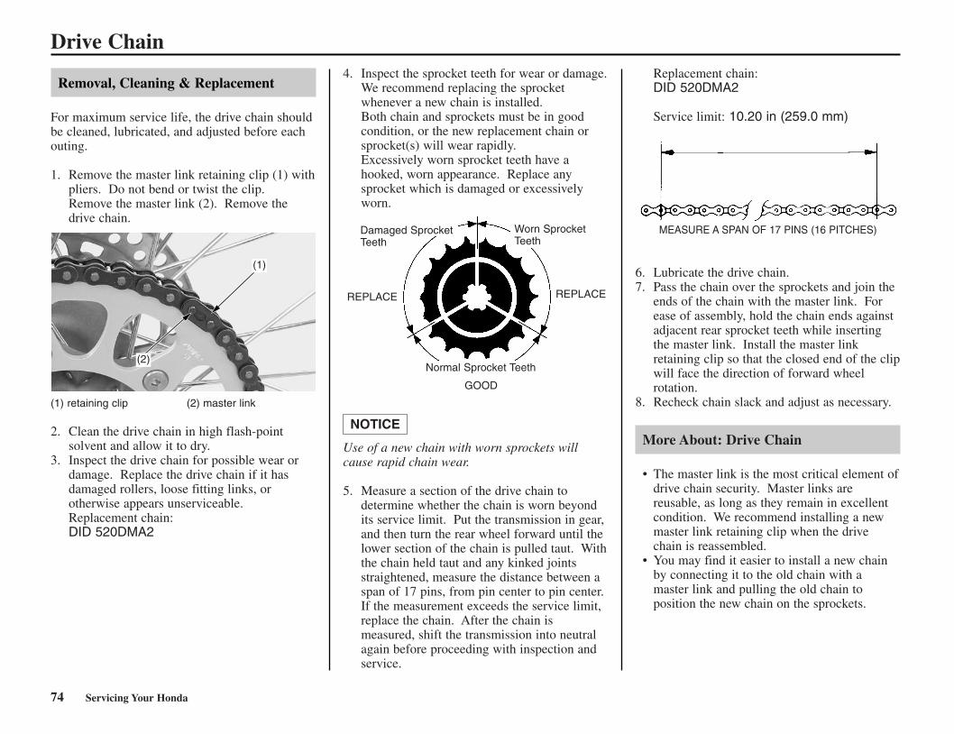
74 Servicing Your Honda
Removal, Cleaning & Replacement
For maximum service life, the drive chain shouldbe cleaned, lubricated, and adjusted before eachouting.
1. Remove the master link retaining clip (1) withpliers. Do not bend or twist the clip. Remove the master link (2). Remove thedrive chain.
(1) retaining clip (2) master link
2. Clean the drive chain in high flash-pointsolvent and allow it to dry.
3. Inspect the drive chain for possible wear ordamage. Replace the drive chain if it hasdamaged rollers, loose fitting links, orotherwise appears unserviceable.Replacement chain:DID 520DMA2
4. Inspect the sprocket teeth for wear or damage.We recommend replacing the sprocketwhenever a new chain is installed.Both chain and sprockets must be in goodcondition, or the new replacement chain orsprocket(s) will wear rapidly.Excessively worn sprocket teeth have ahooked, worn appearance. Replace anysprocket which is damaged or excessivelyworn.
Use of a new chain with worn sprockets willcause rapid chain wear.
5. Measure a section of the drive chain todetermine whether the chain is worn beyondits service limit. Put the transmission in gear,and then turn the rear wheel forward until thelower section of the chain is pulled taut. Withthe chain held taut and any kinked jointsstraightened, measure the distance between aspan of 17 pins, from pin center to pin center.If the measurement exceeds the service limit,replace the chain. After the chain ismeasured, shift the transmission into neutralagain before proceeding with inspection andservice.
Replacement chain:DID 520DMA2
Service limit: 10.20 in (259.0 mm)
MEASURE A SPAN OF 17 PINS (16 PITCHES)
6. Lubricate the drive chain.7. Pass the chain over the sprockets and join the
ends of the chain with the master link. Forease of assembly, hold the chain ends againstadjacent rear sprocket teeth while insertingthe master link. Install the master linkretaining clip so that the closed end of the clipwill face the direction of forward wheelrotation.
8. Recheck chain slack and adjust as necessary.
More About: Drive Chain
• The master link is the most critical element ofdrive chain security. Master links arereusable, as long as they remain in excellentcondition. We recommend installing a newmaster link retaining clip when the drivechain is reassembled.
• You may find it easier to install a new chainby connecting it to the old chain with amaster link and pulling the old chain toposition the new chain on the sprockets.
NOTICE
Drive Chain
Damaged SprocketTeeth
Worn SprocketTeeth
Normal Sprocket Teeth
GOOD
REPLACE REPLACE
(2)
(1)
*CR250R/72-80(31KSK630).qxd 6/2/06 9:59 AM Page 74

Servicing Your Honda 75
Refer to Safety Precautions on page 19.
Expansion Chamber Inspection
1. Check the expansion chamber springs, andreplace them if they are damaged or stretched.
2. Check the mounting bolts for tightness.3. Check the expansion chamber for cracks or
deformation.A damaged chamber may decrease engineperformance.
Expansion Chamber Removal
1. Remove the expansion chamber by removingthe expansion chamber springs (1) andmounting bolts (2).
2. Remove the exhaust gasket.
(1) springs (2) bolts
3. Remove carbon deposits from the head pipeof the expansion chamber.Check the O-rings (3) on the head pipe forwear.
(3) O-rings
Expansion Chamber Installation
Install the expansion chamber in the reverse orderof removal.
Expansion Chamber
(2)
(1)
(3)
*CR250R/72-80(31KSK630).qxd 6/2/06 9:59 AM Page 75

Additional Maintenance ProceduresRefer to Safety Precautions on page 19.
Steering Head Bearing Inspection
1. With your CR on a box or optional workstand(front wheel elevated), turn the handlebar tothe right and left to check for roughness in thesteering head bearings.
2. Stand in front of your CR, grab the fork (atthe axle), look at the steering head, and pushthe fork in and out (toward the engine) tocheck for play in the steering head bearings.If any roughness or play is felt, but you donot see any movement in the steering head,the fork bushings may be worn. Refer to theHonda Service Manual for replacement oradjustment procedures, or see your Hondadealer.
Handlebar Inspection
1. Remove the handlebar pad.2. Check the handlebar (1) for bends or cracks.3. Check that the handlebar has not moved from
its proper position (by inspecting the punchmark).
4. Tighten the front bolt first.5. Check the torque of the upper holder bolts (2):
16 lbs·ft (22 N·m, 2.2 kgf·m)
(1) handlebar (2) handlebar upper holder bolts
Control Cables
Periodically, disconnect the throttle and clutchcables at their upper ends. Thoroughly lubricatethe cable pivot points with a commercially-available cable lubricant. If the clutch lever andthrottle operation is not smooth, replace thecable.Be sure the throttle returns freely from fully opento fully closed automatically, in all steeringpositions.
76 Servicing Your Honda
(1)(2)
*CR250R/72-80(31KSK630).qxd 6/2/06 9:59 AM Page 76

Servicing Your Honda 77
Nuts, Bolts, Fasteners
Check and tighten nuts, bolts, and fastenersbefore every outing.
LEFT SIDE
(1) cylinder head nut (6) RC cover bolt(2) cylinder mounting nut(3) carburetor insulator bolt
RIGHT SIDE
(4) clutch cover bolt(5) water pump cover bolt
Additional Maintenance Procedures
Item
ENGINE1 Cylinder head nut2 Cylinder mounting
nut3 Carburetor
insulator bolt4 Clutch cover bolt5 Water pump cover
bolt6 RC cover bolt
kgf·m
2.8
4.0
1.21.2
1.20.5
N·m
27
39
1212
125
lbf·ft
20
29
99
93.7
TorqueRemarks
(1)
(3)
(2)
(6)
(4)
(5)
*CR250R/72-80(31KSK630).qxd 6/2/06 9:59 AM Page 77

78 Servicing Your Honda
Refer to Safety Precautions on page 19.
Frequent cleaning and polishing will keep yourHonda looking newer longer. Frequent cleaningalso identifies you as an owner who values hismotorcycle. A clean CR is also easier to inspectand service.
While you’re cleaning, be sure to look for damage, wear, and gasoline or oil leaks.
General Recommendations
• To clean your CR you may use:– water– a mild, neutral detergent and water– a mild spray and wipe cleaner/polisher– a mild spray and rinse cleaner/degreaser and
water• Avoid products that contain harsh detergents
or chemical solvents that could damage themetal, paint, and plastic on your CR or discolor the seat and decals.
• If your CR is still warm from recentoperation, give the engine and exhaust systemtime to cool off.
• We recommend the use of a garden hose towash your CR. High pressure washers (likethose at coin-operated car washes) candamage certain parts of your CR. The forceof water under extreme pressure can penetratethe dust seals of the suspension pivot pointsand steering head bearings-driving dirt inside and needed lubrication out.
If you use a high pressure washer, avoid sprayingthe following areas:
• wheel hubs• expansion chamber outlet• area under seat• engine stop button• brake master cylinders• under fuel tank• drive chain• carburetor• steering head bearings• suspension pivot points
(1) steering head bearings(2) suspension pivot points
High pressure water (or air) can damage certain parts of your CR.
You may use Pro Honda Hondabrite, a multi-surface cleaner/degreaser, to remove bothdirt and petroleum-based grime from paint, alloy,plastic, and rubber surfaces. Wet any heavydeposits with water first. Then spray on theHondabrite and rinse with a garden hose at fullpressure. Stubborn deposits may require a quickwipe with a sponge.
Washing Your Motorcycle with a MildDetergent
1. Rinse your CR thoroughly with cool water toremove loose dirt.
2. Fill a bucket with cool water. Mix in a mild,neutral detergent, such as dish washing liquidor a product made especially for washingmotorcycles or automobiles.
3. Wash your CR with a sponge or a soft towel.As you wash, check for heavy grime. Ifnecessary, use a mild cleaner/degreaser toremove the grime.
Do not use steel wool to clean the frame as itcould damage or discolor the frame surface.A muffler stain remover should only be used forremoving stains on the non-coated aluminumframe.
4. After washing, rinse your CR thoroughly withplenty of clean water to remove any residue.
5. Dry your CR with a chamois or a soft towel.6. Lubricate the drive chain to prevent rusting.7. Start the engine and let it idle for several
minutes. The engine heat will help dry moistareas.
8. As a precaution, ride at a slow speed andapply the brakes several times. This will helpdry the brakes and restore normal brakingperformance.
NOTICE
Appearance Care
(1)
(2)
*CR250R/72-80(31KSK630).qxd 6/2/06 9:59 AM Page 78

Servicing Your Honda 79
Condensation Control
Changes in temperature combined with humidityallow moisture to form in some confined areas onyour CR. The most affected area is the alternator/ignition cavity in the left side of the crankcases.
Each time you wash your CR you should removethe alternator cover (1), wipe out any visiblemoisture, and allow the cavity to air dry for atleast a couple of hours before installing the cover.Replace the gasket with a new one if it is not ingood condition before installing the cover.
Some condensation can form within thetransmission cavity as well. This is natural andjust one more reason you should change thetransmission oil often.
(1) alternator cover
After Cleaning Lubrication
There are some things you should do just afterwashing your CR to help prevent rust andcorrosion.
Once your CR is clean and dry, you shouldprotect any bare steel from rusting by applying alight coating of a rust-inhibitor. Lubricate thedrive chain and drive sprocket after removing andthoroughly cleaning in solvent. Be sure the chainis wiped clean and is dry before applying thechain lube.
Follow the suggestions given in the pages of thismanual for lubricating items such as the brakeand clutch lever pivot points and footpeg pivotpins.
Aluminum Frame Maintenance
Aluminum corrodes when it comes in contactwith dust, mud and road salt.
To remove stains, use Scotch-Brite Hand Pad#7447 (maroon) or an equivalent.Wet the pad and polish the surface using strokesparallel to the length of the frame.
Clean the frame using a wet sponge and a milddetergent, then rinse well with clean water. Drythe frame with a soft clean cloth, using strokesparallel to the length of the frame.
Do not use steel wool to clean the frame as itcould damage or discolor the frame surface.Muffler stain remover (Scotch-Brite Hand Pad#7447-maroon) is for removing stains on thenon-coated aluminum frame only.
NOTICE
Appearance Care
(1)
*CR250R/72-80(31KSK630).qxd 6/2/06 9:59 AM Page 79

80 Servicing Your Honda
*CR250R/72-80(31KSK630).qxd 6/2/06 9:59 AM Page 80
Adjustments for Competition 81
This section tells you how to fine tune your CRfor maximum competition performance.
Initial suspension adjustments should beperformed after a minimum of two hours of easybreak-in time.
Optional front and rear suspension springs areavailable in both firmer and softer than standardrates, in order to tailor your CR specifically foryour weight, riding style and course conditions.
Follow the instructions given in the rearsuspension sag setting section of RearSuspension Adjustments to determine if yourcombined rider and sprung machine weight (riderfully dressed for competition and machinecoolant, oil and fuel levels ready for competition)requires an optional firmer or softer rear spring.The need for either optional rear spring may needto be balanced by installing the optional forksprings of a similar rate.
Front Suspension Adjustments...........................82Rear Suspension Adjustments ............................95Suspension Adjustments for Track Conditions ..99Suspension Adjustments Guidelines ................100Carburetor Adjustments & Tuning Tips ...........103Chassis Adjustments.........................................110Gearing .............................................................111Tire Selection for Track Conditions.................112Personal Fit Adjustments .................................113
Adjustments for Competition
*CR250R/81-84(31KSK630) 6/2/06 10:00 AM Page 81
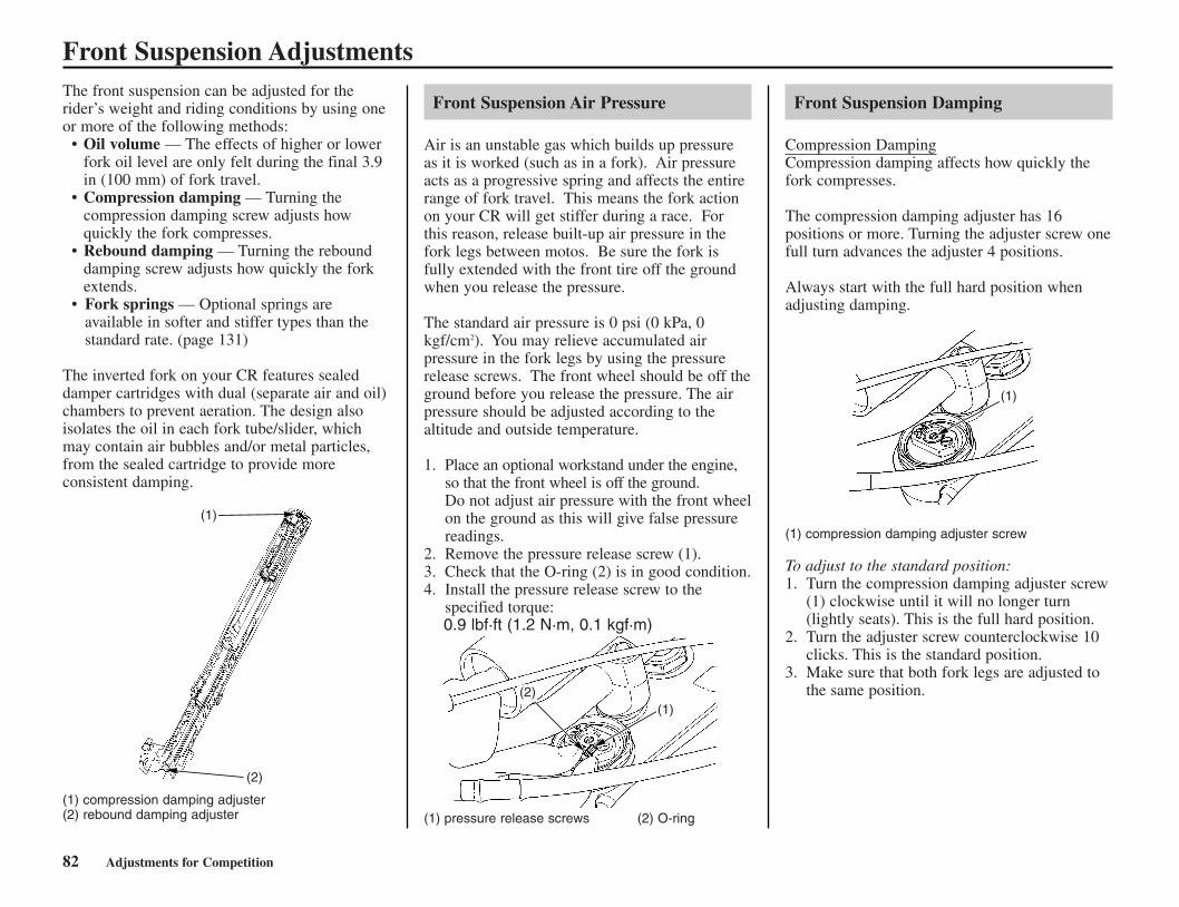
82 Adjustments for Competition
The front suspension can be adjusted for therider’s weight and riding conditions by using oneor more of the following methods:
• Oil volume — The effects of higher or lowerfork oil level are only felt during the final 3.9in (100 mm) of fork travel.
• Compression damping — Turning thecompression damping screw adjusts howquickly the fork compresses.
• Rebound damping — Turning the rebounddamping screw adjusts how quickly the forkextends.
• Fork springs — Optional springs areavailable in softer and stiffer types than thestandard rate. (page 131)
The inverted fork on your CR features sealeddamper cartridges with dual (separate air and oil)chambers to prevent aeration. The design alsoisolates the oil in each fork tube/slider, whichmay contain air bubbles and/or metal particles,from the sealed cartridge to provide moreconsistent damping.
(1) compression damping adjuster(2) rebound damping adjuster
Front Suspension Air Pressure
Air is an unstable gas which builds up pressureas it is worked (such as in a fork). Air pressureacts as a progressive spring and affects the entirerange of fork travel. This means the fork actionon your CR will get stiffer during a race. Forthis reason, release built-up air pressure in thefork legs between motos. Be sure the fork isfully extended with the front tire off the groundwhen you release the pressure.
The standard air pressure is 0 psi (0 kPa, 0kgf/cm2). You may relieve accumulated airpressure in the fork legs by using the pressurerelease screws. The front wheel should be off theground before you release the pressure. The airpressure should be adjusted according to thealtitude and outside temperature.
1. Place an optional workstand under the engine,so that the front wheel is off the ground.Do not adjust air pressure with the front wheelon the ground as this will give false pressurereadings.
2. Remove the pressure release screw (1).3. Check that the O-ring (2) is in good condition.4. Install the pressure release screw to the
specified torque:0.9 lbf·ft (1.2 N·m, 0.1 kgf·m)
(1) pressure release screws (2) O-ring
Front Suspension Damping
Compression DampingCompression damping affects how quickly thefork compresses.
The compression damping adjuster has 16positions or more. Turning the adjuster screw onefull turn advances the adjuster 4 positions.
Always start with the full hard position whenadjusting damping.
(1) compression damping adjuster screw
To adjust to the standard position:1. Turn the compression damping adjuster screw
(1) clockwise until it will no longer turn(lightly seats). This is the full hard position.
2. Turn the adjuster screw counterclockwise 10clicks. This is the standard position.
3. Make sure that both fork legs are adjusted tothe same position.
Front Suspension Adjustments
(1)(2)
(1)
(1)
(2)
*CR250R/81-84(31KSK630) 6/2/06 10:00 AM Page 82

Front Suspension AdjustmentRebound DampingRebound damping effects how quickly the forkrebounds.
The rebound damping adjuster has 16 positionsor more. Turning the adjuster screw one full turnclockwise advances the adjuster 4 positions.
Always start with the full hard position whenadjusting damping.
(2) rebound damping adjuster screw
To adjust to the standard position:1. Turn the rebound damping adjuster screw (2)
clockwise until it will no longer turn (lightlyseats). This is the full hard position.
2. Turn the adjuster screw counterclockwise 14clicks. This is the standard position.
3. Make sure both fork legs are adjusted to thesame position.
Fork Springs
The fork springs in CR’s are about right forriders weighing between 150 and 160 lbs (lessriding gear). So if you’re a heavier rider, youhave to go up on the oil level or get a stifferspring. Do not use less oil than the minimumspecified for each spring or there will be a loss ofrebound damping control near full extension. If the fork is too hard on big bumps, turn thedamping adjuster counterclockwise 1-turn andlower the oil level in increments of 0.2oz (5 cm3)in both fork legs until the desired performance isobtained. Do not, however, lower the oil levelbelow the minimum oil level.
Minimum oil capacityStandard spring: 11.2 US oz (331 cm3)Softer spring: 11.4 US oz (336 cm3)Stiffer spring: 11.0 US oz (326 cm3)
When adjusting oil levels, bear in mind that theair in the fork will increase in pressure whileriding; therefore, the higher the oil level, thehigher the eventual pressure of any air in thefork.
Front Suspension Disassembly
• If your CR is brand-new, put enough part-throttle break-in time (about one hour) onit to ensure that the suspension has worked in.
• For optimum performance, and extended forklife, the fork should be completelydisassembled and cleaned after the first threehours of riding. See the Service Manual oryour Honda dealer for this service.
1. Place your CR on the optional workstand orequivalent support with the front wheel off theground.
2. Remove the number plate bolt (1) and numberplate(2).
(1) number plate bolt(2) number plate
Adjustments for Competition 83
(cont’d)
(2)
(2)
(1)
*CR250R/81-84(31KSK630) 6/2/06 10:00 AM Page 83

Front Suspension Adjustments3. Remove the handlebar pad.
Remove the washers/handlebar holder nuts(3), mounting rubbers and handlebar (4).
Keep the master cylinder upright to prevent airfrom entering system.
(3) washers/handlebar holder nuts(4) handlebar
4. Loosen the upper pinch bolts (5).5. Loosen the fork damper (6), but do not
remove them yet.
Do not use an adjustable wrench to loosen thefork damper: it may damage them.Loosen the upper pinch bolts before looseningthe fork damper to avoid damping the fork cap.
(5) upper pinch bolts (6) fork damper
6. Remove the disc cover (7) by removing thedisc cover bolts (8).
(7) disc cover (8) disc cover bolts
7. Remove the front axle nut (9) and loosen thefront axle pinch bolts (10) on both forks. Pull the front axle shaft (11) out of the wheelhub and remove the front wheel.
(9) axle nut (11) front axle shaft(10) axle pinch bolts
8. Remove the fork protector bolts (12), brakehose clamp bolts (13) and fork protectors(14).
9. Remove the brake caliper bolts (15) and brakecaliper (16).
Do not support the brake caliper by the brakehose. Do not operate the brake lever after thefront wheel is removed. To do so will causedifficulty in fitting the brake disc between thebrake pads.
(12) fork protector bolts (15) brake caliper bolts(13) brake hose clamp bolts (16) brake caliper(14) fork protectors
10. Loosen the fork leg lower pinch bolts (17),then pull the fork legs down and out.
(17) lower pinch bolts
NOTICE
NOTICE
NOTICE
84 Adjustments for Competition
(7)
(8)
(10)
(10)
(9)(11)(17)
(4)
(3)
(6)(5)
(14)
(15)
(13)
(16)(12)
(12)
*CR250R/81-84(31KSK630) 6/2/06 10:00 AM Page 84

Adjustments for Competition 85
Front Suspension Adjustments11. Clean the fork assembly, especially the sliding
surface of the slider (18) and dust seal (19).
The outer tube can drop on the slider anddamage the fork dust seal and guide bushingwhen the fork damper is removed. To avoiddamage, hold both the outer tube and slider whenremoving the fork damper.
(18) slider (20) outer tube(19) dust seal (21) guide bushing
12. Record the compression and rebounddamping adjuster positions and turn theadjusters counterclockwise until they stop.
13. Measure the length (22) between the axleholder and outer tube and record it beforedisassembling the fork.
(22) length
14. Hold the outer tube (23), then remove thefork damper (24) from the outer tube using alock nut wrench (25). Gently slide the outertube down onto the lower end of the slider(26).
(23) outer tube (25) lock nut wrench(24) fork damper (26) slider, lower end
15. Pour the fork oil from the outer tube (23).Pour the fork oil from the oil hole (24) of thefork damper.
(23) outer tube (24) oil hole
16. Temporarily install the fork damper to theouter tube.
17. Set the lower end (axle holder) (25) of theslider in a vise with a piece of wood or softjaws to avoid damage to it.
Over-tightening the vise can damage the axleholder.
18. Loosen the fork center bolt (26).
(25) axle holder (26) fork center bolt
19. Push out the fork center bolt from the axleholder of the slider by pushing the forkdamper.
20. Make the mechanic’s stopper tool out of athin piece of steel (1.0 mm thick) as shown ifyou do not have the special tool.
Thickness: 1.0 mm
NOTICE
NOTICE
(19)
(18)
(24)
(25)
(26)
NO GOOD
NO GOOD
(22)
(24)
(25)
(23)
(23)
(26)
55 mm
25 mm
30 m
m
12.2
mm
R 7.55 – 7.6 mm
(cont’d)
(21)
(20)
(23)
CR250R/085-103(31KSK630) 6/2/06 10:01 AM Page 85

21. Apply pressure to the fork damper and inserta special tool or mechanic’s stopper tool (27)between the axle holder (25) and lock nut(28).
22. Hold the lock nut and remove the fork centerbolt (26) from the fork damper.
Do not remove the lock nut from the fork damperpiston rod. If the lock nut is removed, the pistonrod will fall in the fork damper and you cannotreassemble the fork damper.
(25) axle holder (27) stopper tool(26) fork center bolt (28) lock nut
23. Remove the push rod (29) from the forkdamper.
24. Remove the special tool or mechanic’sstopper tool between the axle holder (25) andlock nut (28) while applying pressure to thefork cap.
Be careful not to damage the lock nut and forkcenter bolt hole.
(25) axle holder (28) lock nut(27) stopper tool (29) push rod
25. Remove the fork damper assembly (30) fromthe fork assembly (31).Remove the fork from the vise.Remove the fork spring (32) from the forkdamper.
(30) fork damper assembly(31) fork assembly(32) fork spring
Damper Oil Change
(1) fork cap (3) lock nut wrench(2) fork damper
Check the lock nut installation. If the lock nut isremoved, the piston rod will fall in the forkdamper and you cannot reassemble the forkdamper.
1. Loosen the fork cap (1) by turning the forkdamper (2) using the lock nut wrench (3).
Make sure the compression damping adjuster isset the softest position.
NOTICE
NOTICE
NOTICE
86 Adjustments for Competition
Front Suspension Adjustments
(25) (28)
(26)
(27)
(27)
(25)
(28)
(29)
(31)
(30)
(32)
(1)
(3)(2)
CR250R/085-103(31KSK630) 6/2/06 10:01 AM Page 86

2. Remove the fork cap assembly (4) from thefork damper (2).
Be careful not to damage the fork cap bushing.Do not disassemble the fork cap assembly.Replace the fork cap as an assembly if it isdamaged.
(2) fork damper (4) fork cap assembly
3. Empty the fork oil from the fork damper (2)by pumping the damper and rod several times.
(2) fork damper
4. Clean the fork cap and fork damper threads.
5. Extend the fork damper piston rod tomaximum. Pour the recommended fork oilinto the fork damper.Recommended Oil:Pro Honda HP Fork oil 5 W or equivalentRecommended Amount:6.6 US oz (195 cm3)
(2) fork damper
6. Pump the fork damper piston rod (5) slowlyseveral times to bleed the air from the forkdamper (2).
(2) fork damper (5) piston rod
7. Extend the fork damper piston rod tomaximum. Adjust the oil level of the forkdamper (2) as shown.Oil Level: 1.65 – 1.85 in (42 – 47 mm)
(2) fork damper
8. Apply fork oil to the bushing and new O-ringon the fork cap assembly (4).Extend the fork damper piston rod tomaximum length and while holding it, installthe fork cap assembly to the fork damper (2).
Be careful not to damage the fork cap bushing. If it is difficult to install the fork cap assembly,the fork damper oil level might be higher thanstandard oil level. Inspect the fork damper oillevel again.
(2) fork damper (4) fork cap assembly
Adjustments for Competition 87
Front Suspension Adjustments
(cont’d)
(4)
(2)
(2)
(4)
(2)
(2)
(2)
(5)
(2)
1.65 – 1.85 in(42 – 47 mm)
CR250R/085-103(31KSK630) 6/2/06 10:01 AM Page 87

(7)
(8)
88 Adjustments for Competition
Front Suspension Adjustments9. Tighten the fork cap (1) while holding the cut
out of the fork damper (2) using the lock nutwrench (3) to the specified torque:22 lbf·ft (30 N·m, 3.1 kgf·m)
(1) fork cap (3) lock nut wrench(2) fork damper
10. Hold the fork damper (2) in an uprightposition and pump the fork piston rod (5) to3.9 in (100 mm) slowly several times.
(2) fork damper (5) piston rod
11. Screw in the lock nut (6) to the fork damperpiston rod (5) fully.
(5) piston rod (6) lock nut
Check the fork damper piston rod sliding surfacefor damage.Apply fork oil to the fork damper piston rodsliding surface.Cover the fork piston rod end with soft jaws toprevent fork damage.
Be careful not to bend or damage the forkdamper piston rod when the piston rod is stroked.
12. Drain the extra oil off to the fork damper (2)spring chamber (7) by pumping the forkdamper piston rod to full stroke.
(2) fork damper (7) spring chamber
13. Drain the extra oil from the fork damperspring chamber oil hole.
By doing this procedure, about 17 cm3 of forkfluid will be drained from the damper springchamber through the oil hole and cause 178 cm3
of fork fluid to be left in the chamber.
14. Blow out the oil from the fork damper springchamber (7) using compressed air to the oilhole (8). Wipe the oil completely off the forkdamper.
(7) spring chamber (8) oil hole
15. If you can not use compressed air, removethe pressure release screw (9) on the fork cap(10).Turn the fork damper upside down for 10minutes and drain the oil from the forkdamper spring chamber.
(9) pressure release screw (10) fork cap
NOTICE
(5)
(6)
(2)(1)
(3)
3.9 in (100 mm)
(7)
(2)(10)
(9)
(2)
(5)
CR250R/085-103(31KSK630) 6/2/06 10:01 AM Page 88

Adjustments for Competition 89
Front Suspension Adjustments
Fork Assembly
1. Drain the fork oil from the outer tube/slider(1) by placing it upside down.(About 7 cm3 of fork oil will be left in theouter tube/slider when it is left inverted forabout 20 minutes at 20°C/68°F)
(1) outer tube/slider
Amount of fork oil left in the fork(without damper and spring) unit: cm3
2. Tighten the lock nut (2) fully by hand andmeasure the thread length.Standard: 0.43 – 0.51 in (11 – 13 mm)
Wipe the oil completely off the fork damper.
(2) lock nut
3. Wipe the oil completely off the fork spring(3).Install the fork spring to the fork damper.Install the fork damper (4) to the outertube/slider (1).
(1) outer tube/slider (4) fork damper assembly(3) fork spring
(cont’d)
(2)
(3)
(4)
(1)
(1)
0.43 – 0.51 in(11 – 13 mm)
°C/°F
minute5 10 20 35 55 85 145
30/86
20/68
10/50
0/32
7.1
10.6
11.8
12.9
5.9
8.2
8.3
10.6
4.7
7.1
7.2
9.4
4.2
5.9
6.2
8.2
3.5
5.6
5.8
7.9
3.5
4.7
4.9
7.1
3.5
4.7
4.8
5.9
Am
ou
nt
of
fork
oil
(cm3)0°C/32°F
10°C/50°F20°C/68°F
30°C/86°F
Inverted time (minutes)0 20 40 60 80 100 120 140 160
0
2
4
8
6
10
12
14 16
CR250R/085-103(31KSK630) 6/2/06 10:01 AM Page 89

Front Suspension Adjustments4. Set the lower end (axle holder) of the slider in
a vise with a piece of wood or soft jaws toavoid to damage.
Do not overtighten the axle holder.
5. Temporarily install the fork damper to thefork.Push out the fork damper piston rod from theaxle holder of the slider by pushing the forkdamper.Apply pressure to the fork damper and insertthe special tool or mechanic’s stopper tool (5)between the axle holder and lock nut (2).Measure the thread length again.Standard: 0.43 – 0.51 in (11 – 13 mm)
6. Install the push rod (6) into the piston rod (7)until it stops. Check the push rod installationby turning the push rod right and left.
7. Install the new O-ring (8) to the fork centerbolt (9).Install the fork center bolt to the fork damperpiston rod aligning the center bolt adjustingrod to the push rod. Tighten the center boltfully by hand.
(2) lock nut (7) piston rod(5) stopper tool (8) O-ring(6) push rod (9) fork center bolt
8. Make sure that there is clearance between thelock nut (2) and center bolt (9).Clearance: 0.06 – 0.08 in (1.5 – 2.0 mm)
If the clearance is out of specification, check thelock nut and center bolt installation.
(2) lock nut (9) center bolt
9. Tighten the lock nut (2) to the fork center bolt(9) closely by hand. Tighten the lock nut tothe specified torque:16 lbf·ft (22 N·m, 2.2 kgf·m)
(2) lock nut(9) fork center bolt
10. Apply fork oil to the fork center bolt (9) O-ring.Remove the special tool or mechanic’sstopper tool while applying pressure to thefork damper.Install the center bolt to the axle holder andtighten it to the specified torque:51 lbf·ft (69 N·m, 7.0 kgf·m)
(9) fork center bolt
11. Measure the length between the axle holderand outer tube.Standard: 12.4 in (315 mm)Compare the length (10) at assembly and atdisassembly. They should be the same length.
If the length at assembly is longer than atdisassembly, check the center bolt and lock nutinstallation.
(10) length
NOTICE
90 Adjustments for Competition
(5)
(6)
(9)
(8)
(2)
(9)
(9)
(7)
(2)
(9)
(10)(2)
0.06 – 0.08 in(1.5 – 2.0 mm)
CR250R/085-103(31KSK630) 6/2/06 10:01 AM Page 90

12. Pour the recommended fork oil (11) into theouter tube/slider (1).
Recommended Oil:Pro Honda HP Fork Oil 5W or equivalent.
(1) outer tube/slider (11) fork oil
Fork Oil Capacity:Standard (0.44 kgf/mm) Fork Spring
Optional Softer (0.42 kgf/mm) Fork Spring
Optional Stiffer (0.46 kgf/mm) Fork Spring
Be sure the oil capacity is the same in both forklegs.
13. Install the fork damper as described inDamper Oil Change (page 86 – 88).
Adjustments for Competition 91
Front Suspension Adjustments
(cont’d)
( )No mark(factory products)
Standard oilcapacityMaximum oilcapacity
Minimum oilcapacity
13.3 US oz(394 cm3)14.5 US oz(430 cm3)
11.2 US oz(331 cm3)
Slightly stiffer as itnears fullcompression.Slightly softer as itnears fullcompression.
( )1 scribe mark
Standard oilcapacityMaximum oilcapacity
Minimum oilcapacity
13.5 US oz(399 cm3)14.7 US oz(435 cm3)
11.4 US oz(336 cm3)
Slightly stiffer as itnears fullcompression.Slightly softer as itnears fullcompression.
( )2 scribe marks
Standard oilcapacityMaximum oilcapacity
Minimum oilcapacity
13.2 US oz(389 cm3)14.4 US oz(425 cm3)
11.0 US oz(326 cm3)
Slightly stiffer as itnears fullcompression.Slightly softer as itnears fullcompression.
(1)
(11)
3 scribe marks(aftermarket parts)
CR250R/085-103(31KSK630) 6/2/06 10:01 AM Page 91

14. Check that the O-ring (12) on the forkdamper assembly (4) is in good condition.Apply the recommended fork oil to the O-ring.
(1) outer tube/slider (12) O-ring(4) fork damper assembly
15. Temporarily thread the fork damper (4) intothe outer tube (1). Insert both fork legs intothe fork clamps. Align the groove in the outertube with the top surface of the upper forkclamp.If installing the optional 20 inch wheel, alignthe top of the outer tube (not the top of thefork cap) with the top surface of the upperfork clamp.
16. Temporarily tighten the fork lower pinchbolts (13) and then tighten the fork damper(4) to the specified torque using the lock nutwrench.Actual:25 lbf·ft (34 N·m, 3.5 kgf·m)Torque wrench scale reading:23 lbf·ft (31 N·m, 3.2 kgf·m), using 20 in(50 cm) long torque wrench.
When using the lock nut wrench, use a 20-incheslong deflecting beam type torque wrench. Thelock nut wrench increases the torque wrench’sleverage, so the torque wrench reading will beless than the torque actually applied to the forkdamper.
For ease of releasing air pressure after the forksare installed, loosen the lower pinch bolts andposition the outer tubes so that the pressurerelease screws are in front of the rebounddamping adjusters.
17. Tighten the fork lower pinch bolts (13) to thespecified torque:15 lbf·ft (20 N·m, 2.0 kgf·m)
18. Tighten the fork upper pinch bolts (14) to thespecified torque:16 lbf·ft (22 N·m, 2.2 kgf·m)
Tighten the bolts alternately in 2 or 3 steps.
Over-tightening the pinch bolts can deform theouter tubes. Deformed outer tubes must bereplaced.
(4) folk damper (14) upper pinch bolts(13) lower pinch bolts
19. Position the wear ring (15) with its end gapfacing rearward.
(15) wear ring
NOTICE
92 Adjustments for Competition
Front Suspension Adjustments
(4)
(12)
(1)
(14)
(15)
(4)
(13)
CR250R/085-103(31KSK630) 6/2/06 10:01 AM Page 92

20. Clean the threads of the fork protector bolts(16) and axle holder thoroughly.Apply locking agent to the bolt threads.Install the fork protectors (17), fork protectorbolts and brake hose clamp bolts (18).Tighten the fork protector bolts to thespecified torque:5.2 lbf·ft (7 N·m, 0.7 kgf·m)
(16) fork protector bolts (18) brake hose clamp bolts(17) fork protectors
21. Clean the surfaces where the axle and axleclamps contact each other.Install the left and right side collars into thewheel hub. Insert the front axle shaft throughthe wheel hub from the right side. Make surethe front axle shaft is seated firmly onto theleft fork leg clamp inner surface. Tighten theaxle nut (19) to the specified torque:65 lbf·ft (88 N·m, 9.0 kgf·m)
(19) axle nut
22. Align the brake caliper (20) and hose withthe left fork leg, making sure that the brakehose is not twisted. An improperly routedbrake hose may rupture and cause a loss ofbraking efficiency. Route the hose carefully.
23. Clean the threads of the brake calipermounting bolts (21) and brake caliperthoroughly.Apply locking agent to the bolt threads.Install the brake caliper on the slider andtighten the brake caliper mounting bolts tothe specified torque:22 lbf·ft (30 N·m, 3.1 kgf·m)
Fit the brake caliper over the disc, taking care notto damage the brake pads.
(20) brake caliper(21) brake caliper mounting bolts
Adjustments for Competition 93
Front Suspension Adjustments
(cont’d)
(20)
(21)
(17)
(19)
(18)
(16) (16)
CR250R/085-103(31KSK630) 6/2/06 10:01 AM Page 93

24. Install the handlebar (22) mounting rubbers(23), washers and handlebar holder nuts (24)and tighten the handlebar holder nuts to thespecified torque:32 lbf·ft (44 N·m, 4.5 kgf·m)
(22) handlebar(23) mounting rubbers(24) washers/handlebar holder nuts
25. Install the number plate (25) by aligning itshole (26) with the tab (27) on the steeringstem.
(25) number plate (27) tab(26) hole
26. Install and tighten the number plate bolt (28).Install the handlebar pad (29).
(28) number plate bolt(29) handlebar pad
27. With the front brake applied. pump the forkup and down several times to seat the axleand check front brake operation.
28. First, tighten the left axle pinch bolts (30)alternately.While keeping the forks parallel, alternatelytighten the right axle pinch bolts to thespecified torque:15 lbf·ft (20 N·m, 2.0 kgf·m)
(30) axle pinch bolts
To avoid damage when torquing the axle pinchbolts, be sure the axle is seated firmly onto theleft fork leg clamp inner surface.
29. Clean the threads of the disc cover bolts andaxle holder thoroughly.
30. Apply locking agent to the disc cover boltthreads.
31. Install the disc cover (31) and tighten thedisc cover bolts (32) to the specified torque:10 lbf·ft (13 N·m, 1.3 kgf·m)
(31) disc cover (32) disc cover bolts
32. Turn the compression and rebound dampingadjusters back to their original settings.
NOTICE
94 Adjustments for Competition
Front Suspension Adjustments
(30)(30)
(31)
(32)
(22)
(23)
(24)
(25)
(26)
(27)
(29)
(28)
CR250R/085-103(31KSK630) 6/2/06 10:01 AM Page 94

The rear suspension can be adjusted for therider’s weight and riding conditions by changingthe spring pre-load and the rebound andcompression damping.
The rear shock absorber assembly includes adamper unit that contains high pressure nitrogengas. Do not attempt to disassemble, service, ordispose of the damper; see your Honda dealer.The instructions found in this owner’s manual arelimited to adjustments of the shock assemblyonly.
Puncture or exposure to flame may also result inan explosion, causing serious injury.Service or disposal should only be done by yourauthorized Honda dealer or a qualified mechanic,equipped with the proper tools, safety equipmentand the official Honda Service Manual.
If your CR is new, put enough part-throttle break-in time (about one hour) on it to ensurethat the suspension has worked in.
Rear Suspension Spring Pre-Load
Pre-load should be adjusted when the engine iscold because it is necessary to remove thesilencer (page 32).An optional pin spanner is available for turningthe lock nut and adjusting nut to adjust springpre-load.
1. Place an optional workstand under the engineto raise the rear wheel off the ground.
2. Loosen the connecting tube clamp screw andremove the rear subframe’s three mountingbolts, then remove the subframe. See page32.
3. Check that the spring preload is adjusted tothe standard length. Adjust as necessary byloosening the lock nut (1) and turning theadjusting nut (2).Each complete turn of the adjusting nutchanges the spring length by 1/16 in (1.5mm).
(1) lock nut (3) pin spanner(2) adjusting nut (4) spring length
To increase spring pre-load:Loosen the lock nut with the optional pin spanner(3) and turn the adjusting nut to shorten thespring length (4). Do not shorten to less than:9.9 in (252 mm)
To decrease spring pre-load:Loosen the lock nut with the optional pin spanner(3) and turn the adjusting nut to increase thespring length (4). Do not increase to more than:10.2 in (259.1 mm)
Each turn of the adjuster changes spring lengthand spring pre-load. One turn equals: springlength/spring pre-load:1/16 in (1.5 mm) / 17.2 lbs (7.8 kg)
Pin spanners should be used for turning the locknut and adjusting nut. See page 131 for optionalpin spanners.
Spring preload length (Standard spring)Standard: 10.2 in (258.1 mm)Min. : 9.9 in (252 mm)
Spring preload length (Optional spring)Min. (Softer, 5.0 kgf/mm): 9.7 in (246 mm)Min. (Stiffer, 5.4 kgf/mm): 9.7 in (247 mm)Min. (Stiffer, 5.6 kgf/mm): 9.8 in (249 mm)
Adjustments for Competition 95
Rear Suspension Adjustments
(2)
(1)
(3) (4)
CR250R/085-103(31KSK630) 6/2/06 10:01 AM Page 95

Rear Suspension Adjustments
Rear Suspension Damping
Compression DampingCompression damping may be adjusted in twostages with separate adjusters.
The high speed damping adjuster (1) is effectivewhen damping adjustment is desired for highspeed operation. The low speed dampingadjuster (2) should be used when dampingadjustment is desired at relatively low speeds.
• Both the high and low speed compressiondamping can be increased by turning theappropriate adjuster clockwise.
• Adjust the high speed compression adjuster in1/12 turn increments.
(1) high speed damping adjuster(2) low speed damping adjuster
High Speed Damping:The high speed damping can be adjusted byturning the hexagonal portion of the compressionadjuster.
The high speed compression damping adjusterhas 3 1/2 turns or more.
To adjust to the standard position:1. Turn the adjuster clockwise until it will no
longer turn (lightly seats). This is the full hardsetting.
2. Turn the adjuster counterclockwise 2 5/12—2 11/12 turns and the punch marks arealigned.
Low Speed Damping:The low speed damping can be adjusted byturning the center screw of the compressionadjuster.
The low speed compression adjuster has 13positions or more.Turning the adjuster one full turn clockwiseadvances the adjuster 4 positions.
To adjust to the standard position:1. Turn the adjuster clockwise until it will no
longer turn (lightly seats). This is the full hardsetting.
2. Turn the adjuster counterclockwise 7 clicksand the punch marks are aligned.
Rebound DampingThe rebound damping adjuster (3) is located atthe lower end of the shock absorber.
It has 17 positions or more. Turning the adjusterone full turn advances the adjuster 4 positions.
• Rebound damping can be increased by turningthe adjuster clockwise.
(3) rebound damping adjuster
To adjust to the standard position:1. Turn the adjuster clockwise until it will no
longer turn (lightly seats). This is the full hardposition.
2. Turn the adjuster counterclockwise 5 – 8clicks with the punch marks on the adjusterand the shock absorber aligned.
96 Adjustments for Competition
(2)
(1)
(3)
CR250R/085-103(31KSK630) 6/2/06 10:01 AM Page 96
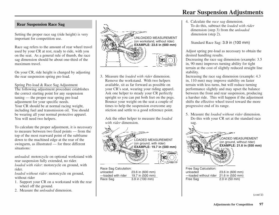
Rear Suspension Adjustments
Rear Suspension Race Sag
Setting the proper race sag (ride height) is veryimportant for competition use.
Race sag refers to the amount of rear wheel travelused by your CR at rest, ready to ride, with youon the seat. As a general rule of thumb, the racesag dimension should be about one-third of themaximum travel.
On your CR, ride height is changed by adjustingthe rear suspension spring pre-load.
Spring Pre-load & Race Sag AdjustmentThe following adjustment procedure establishesthe correct starting point for any suspensiontuning — the proper rear spring pre-loadadjustment for your specific needs.Your CR should be at normal racing weight,including fuel and transmission oil. You shouldbe wearing all your normal protective apparel.You will need two helpers.
To calculate the proper adjustment, it is necessaryto measure between two fixed points — from thetop of the most rearward point of the subframedown to the machined edge at the rear of theswingarm, as illustrated — for three differentsituations:
unloaded: motorcycle on optional workstand withrear suspension fully extended, no rider.loaded with rider: motorcycle on ground, withrider.loaded without rider: motorcycle on ground,without rider1. Support your CR on a workstand with the rear
wheel off the ground.2. Measure the unloaded dimension.
3. Measure the loaded with rider dimension.Remove the workstand. With two helpersavailable, sit as far forward as possible onyour CR’s seat, wearing your riding apparel.Ask one helper to steady your CR perfectlyupright so you can put both feet on the pegs.Bounce your weight on the seat a couple oftimes to help the suspension overcome anystiction and settle to a good reference point.
Ask the other helper to measure the loadedwith rider dimension.
Race Sag Calculation:unloaded 23.6 in (600 mm)—loaded with rider 19.7 in (500 mm)Race Sag 3.9 in (100 mm)
4. Calculate the race sag dimension.To do this, subtract the loaded with riderdimension (step 3) from the unloadeddimension (step 2).
Standard Race Sag: 3.9 in (100 mm)
Adjust spring pre-load as necessary to obtain thedesired handling results.Decreasing the race sag dimension (example: 3.5in, 90 mm) improves turning ability for tightterrain at the cost of slightly reduced straight linestability.Increasing the race sag dimension (example: 4.3in, 110 mm) may improve stability on fasterterrain with less turns, but will reduce turningperformance slightly and may upset the balancebetween the front and rear suspension, producinga harsher ride. This will happen if the adjustmentshifts the effective wheel travel toward the moreprogressive end of its range.
5. Measure the loaded without rider dimension.Do this with your CR set at the standard racesag.
Free Sag Calculation:unloaded 23.6 in (600 mm)—loaded without rider 21.6 in (550 mm)Free Sag 2.0 in (50 mm)
Adjustments for Competition 97
UNLOADED MEASUREMENT(on workstand, without rider)EXAMPLE: 23.6 in (600 mm)
LOADED MEASUREMENT(on ground, with rider)EXAMPLE: 19.7 in (500 mm)
LOADED MEASUREMENT(on ground, without rider)EXAMPLE: 21.6 in (550 mm)
(cont’d)
CR250R/085-103(31KSK630) 6/2/06 10:01 AM Page 97
Rear Suspension Adjustments6. Calculate the free sag dimension.
To do this, subtract the loaded without riderdimension (step 5) from the unloadeddimension (step 2).Free sag indicates the distance your rearsuspension should sag from the weight of thesprung portion of your CR.With the spring pre-load set to obtain theproper race sag, the rear suspension should:Sag: 0.4 to 1.0 in (10 to 25 mm)
If the rear of your CR sags more than 1.0 in(25 mm) from its own weight, the spring istoo stiff for your weight. It is not compressedenough, even though you have the proper racesag adjustment. As a result, the rearsuspension will not extend as far as it should.
Spring RatesIf you are lighter or heavier than the averagerider and cannot set the proper ride heightwithout altering the correct spring pre-load,consider an aftermarket shock absorber spring.
A spring that is too soft for your weight forcesyou to add excessive spring pre-load to get theright race sag and, as a result, the rear end of themotorcycle is raised. This can cause the rearwheel to unload too much in the air and top outas travel rebounds. The rear end may top outfrom light braking, or kick sideways over lipsand square-edged terrain. It may even top-outwhen you dismount your CR.
Because of the great absorption quality of theshock bumper rubber, it may be difficult for youto notice when your CR’s suspension isbottoming. Some riders may think the dampingor perhaps the leverage ratio is too harsh. Inreality, the problem is most likely insufficientspring pre-load or a spring that is too soft. Eithersituation prevents utilizing the full travel.
Keep in mind that a properly adjusted suspensionsystem may bottom slightly every few minutes atfull speed. Adjusting the suspension to avoid thisoccasional bottoming may cost more in overallsuspension performance than it is worth.
A spring that is too firm for your weight will notallow the rear tire to hook up under accelerationand will pass more bumps on to you.
98 Adjustments for Competition
CR250R/085-103(31KSK630) 6/2/06 10:01 AM Page 98

Suspension Adjustments for Track ConditionsSoft SurfaceOn soft ground, sand, and especially mud,consider increasing compression damping frontand rear.
Sand often requires a bit more rebound dampingto minimize rear end kick. Although sand bumpsare usually larger, there’s more distance betweenthem, giving the shock more time to recover.
You may want a little bit stiffer front suspensionfor sand tracks to help keep the front end up andimprove straight-line stability.
In a muddy event, stiffer aftermarket springsfront and rear may help, especially if you areheavier than the average rider. Your CR may beundersprung because of the added weight of theclinging mud. This additional weight maycompress the suspension too much and affecttraction.
Hard SurfaceFor a fast, hard track with no large jumps, youcan probably run the same spring as normal, butrun softer damping both ways-compression andrebound. If you run softer rebound damping, thewheel will follow the rough ground and smallbumps much better, and you will hook up better.With a lot of rebound damping, the wheel returnsvery slowly and doesn’t contact the groundquickly enough after each bump. The result is aloss of traction and slower lap times.
Adjustments for Competition 99
CR250R/085-103(31KSK630) 6/2/06 10:01 AM Page 99

Suspension Adjustment GuidelinesFollow the procedures described below to accurately adjust your CR, using the methods described on pages 82 - 99. Remember to make all adjustments inone-click increments. Test ride after each adjustment.
Front Suspension AdjustmentAdjustments for Type of Track
100 Adjustments for Competition
Adjustments for Too Soft/Stiff Damping
Hard-surfaced track
Sand track
Mud track
Begin with the standard setting. If the suspension is too stiff/soft, adjust according to the chart below.
Adjust to a stiffer position.Example: – Turn the compression damping adjuster to a stiffer position.
– Install the optional stiff spring. (Adjust compression damping to a softer position and rebound damping to a harder position atthis time.)
Adjust to a stiffer position because mud build-up increases your CR’s weight.Example: – Turn the compression damping adjuster to a stiffer setting.
– Install the optional stiff spring.
Soft suspension
Symptom
Initial travel too soft:• Steering is too quick.• Front end darts while cornering or riding in a straight line.
Middle travel too soft:• Front end dives when cornering.
Final travel too soft:• Bottoms on landings.• Bottoms on large bumps, especially downhill bumps.
Entire travel too soft:• Front end shakes.• Fork bottoms over any type of terrain.
Action
– Test stiffer compression damping adjustments in one-click increments.– Test stiffer rebound damping adjustments in one-click increments.
If suspension isn’t stiff in initial travel:– Test stiffer compression damping adjustments in one-click increments.If initial travel becomes stiff because of the above adjustment:– Reduce the rebound damping in one click increments.– Test softer compression damping adjustments in one-click increments.If that doesn’t solve the problem, install the optional stiff spring.
If initial and middle travel aren’t stiff:– Test stiffer compression damping adjustments in one-click increments.If initial and middle travel are stiff:– Install the optional stiff spring.If initial travel is stiff after installing the optional stiff spring:– Test soft compression damping adjustments in one-click increments.If initial travel is still soft after installing the optional stiff spring:– Test stiffer compression damping adjustments in one-click increments.If final travel is still soft after installing the optional stiff spring:– Increase the fork oil level in increments of 0.2 oz (5 cm3).
– Install the optional stiff spring.– Test stiffer compression damping adjustments in one-click increments.– Increase rebound damping in one-click increments.
CR250R/085-103(31KSK630) 6/2/06 10:01 AM Page 100

Suspension Adjustment Guidelines
Adjustments for Competition 101
Stiffsuspension
Symptom
Initial travel too stiff:• Stiff on small bumps while riding at full throttle in a straight line.• Stiff on small cornering bumps.• Front end wanders while riding at full throttle in a straight line.
Middle travel too stiff:• Stiff on bumps when cornering.• Front end wanders when cornering.• Stiff suspension on bumps, especially downhill bumps.• While braking, front end dives during initial travel, then feels stiff.
Final travel too stiff:• Doesn’t bottom on landings, but feels stiff.• Stiff on large bumps, especially downhill bumps.• Stiff on large bumps when cornering.
Entire travel too stiff:• Stiff suspension on any type of terrain.
Action
– Test softer compression damping adjustments in one-click increments.– Reduce the rebound damping adjustments in one-click increments.– Check for dirt in the dust seals. Check the fork oil for any contamination.• If the front end dives while cornering, reduce the rebound damping in one click
increments. If that doesn’t solve the problem, install the optional stiff spring.• If the stiff spring makes the suspension too stiff over the full range of travel:
test softer compression damping adjustments in one-click increments until thedesired compression damping for initial travel is obtained.
If initial travel isn’t stiff:– Test stiffer compression damping adjustments in one-click increments. (This
should produce smooth fork action from initial to middle travel.)If initial and middle travel is stiff:– Test softer compression damping adjustments in one-click increments.– Reduce the rebound damping in one-click increments.
If initial and middle travel aren’t stiff:– Test stiffer compression damping adjustments in one-click increments. (This
should produce smooth fork action from initial to middle travel.)If final travel is still stiff after the above adjustment, orIf initial and middle travel becomes stiff:– Install the optional soft spring.– Test softer compression damping adjustments in one-click increments.If the entire travel feels stiff after the above adjustment:– Test softer compression damping adjustments in one-click increments until the
desired initial travel compression damping is obtained.– Lower the oil level by 0.2 oz (5 cm3).
– Test softer compression damping adjustments in one-click increments.– Reduce the rebound damping in one-click increments.– Lower the oil level by 0.2 oz (5 cm3).
CR250R/085-103(31KSK630) 6/2/06 10:01 AM Page 101

Suspension Adjustment Guidelines
102 Adjustments for Competition
Rear Suspension AdjustmentAdjustments for Type of Track
Symptoms and Adjustment• Always begin with the standard settings.• Turn the low speed compression and rebound adjusters in one-click increments, and the high speed compression adjuster in 1/6 turn increments at a time. Adjusting two or
more clicks or turns at a time may cause you to pass over the best adjustment. Test ride after each adjustment.• If, after setting, the suspension feels unusual, find the corresponding symptom in the table and test stiffer or softer compression and/or rebound damping adjustments until
the correct settings are obtained as described.
Hard-surfaced track
Sand track
Mud track
Begin with the standard settings. If the suspension is too stiff/soft, adjust according to the chart below.
Lower the rear end (to improve front wheel stability) by increasing Race Sag (reduce spring preload).Example: – Turn the compression damping adjuster and, especially, rebound damping adjuster to a stiffer setting.
– Increase standard Race Sag (+0.2 to 0.4 in/5 to 10 mm).
Adjust to a stiffer position because mud build-up increases your CR’s weight.Example: – Adjust the compression and rebound damping adjusters to stiffer settings.
– Install the optional stiff spring.– Reduce standard Race Sag (–0.2 to 0.4 in/5 to 10 mm).
Stiff suspension
Soft suspension
Suspension bottoms
Symptom
Suspension feels stiff on smallbumps
Suspension feels stiff on largebumps
Entire travel too stiff
Entire travel too soft
Rear end sways
Suspension bottoms at landingafter jumping
Suspension bottoms after landing
Suspension bottoms after end ofcontinuous bumps
Action
1. Test softer low speed compression adjustment.2. If it still feels stiff, further test softer low and high speed compression adjustments simultaneously.
1. Test softer high speed compression adjustment.2. If it still feels stiff, further test softer low and high speed compression adjustments simultaneously.
1. Test softer high and low speed compression adjustments and rebound adjustment simultaneously.2. If it still feels stiff, replace the spring with a softer spring (optional) and begin with the standard settings to
softer settings.
1. Test stiffer high and low speed compression adjustments simultaneously.2. If it still feels soft, replace the spring with a stiffer spring (optional) and begin with the standard settings to
stiffer setting.
1. Test stiffer high and low speed compression adjustments and rebound adjustment to stiffer settingssimultaneously.
1. Test stiffer high speed compression adjustment.2. If it still bottoms, test stiffer high and low speed compression adjustments, and replace the spring with a
stiffer spring (optional) if necessary.
1. Test stiffer low speed compression adjustment.2. If it still bottoms, test stiffer high and low speed compression adjustments, and replace the spring with a
stiffer spring (optional) if necessary.
1. Test softer rebound dumping adjustment.2. If it still bottoms, test stiffer high and low speed compression adjustments and softer rebound damping
adjustment, and replace the spring with a stiffer spring (optional) if necessary.
CR250R/085-103(31KSK630) 6/2/06 10:01 AM Page 102

Carburetor Adjustments & Tuning TipsThe carburetor on your CR should performsuitably with the standard recommended settingsunder average load, climatic, and barometricconditions. However, to fine tune the engine’spower output, the carburetor may requireadjustments for specific competition needs.
Optional main jets and slow jets are available foryour CR. See your Honda dealer.
Any engine or airbox modifications or the use ofan aftermarket exhaust system may requirejetting changes.
Carburetor Components
Starting CircuitA very rich mixture must be delivered to thecylinder when the engine is being started. Whenthe choke knob (1) is pulled up, fuel is meteredby the starter jet (2) and is mixed with air fromthe air passage (3) to provide a rich mixture forstarting. The mixture discharges through theorifice (4) into the cylinder.
(1) choke knob (3) air passage(2) starter jet (4) orifice
Slow CircuitFuel is metered by the slow jet (5) and is mixedwith air that has been metered by the air screw(6). The mixture enters the venturi through thebypass (7) and slow jet outlet (8).
(5) slow jet (7) bypass(6) air screw (8) slow jet outlet
Main CircuitFuel is metered by the main jet (9), jet needle(10) and needle jet (11). It is then mixed with aircoming from the air jet (12) and enters theventuri past the needle jet.
Baffle PlateThe baffle plate (13) prevents foaming of fuel orabnormal fuel level around the main jet.
Float ChamberThe float (14) and float valve (15) operate tomaintain a constant level of fuel in the floatchamber.
(9) main jet (13) baffle plate(10) jet needle (14) float(11) needle jet (15) float valve(12) air jet
Carburetor Circuit Functions
The carburetor has several major circuits, eachproviding the fuel/air mixture over a givenportion of throttle valve opening.
These major circuits overlap as shown below.
Main JetThe main jet affects fuel/air ratio from half (1/2)to full throttle (4/4). The size should be reducedat higher altitudes.
Your CR’s carburetor jet sizes are numbered inincrements of 10. When changing the main jetsize, increase or decrease it gradually until thedesired jetting is obtained. Because your CR’s jetsize numbers do not correspond with othercarburetor manufacturer’s jet size numbers, usegenuine Honda CR250R jets.
Adjustments for Competition 103
(1)(4)
(3)
(2)
(7)
(8)(6)
(5)
(12)
(15) (11)
(14)
(10)(13)
(9)
MAIN JET
JET NEEDLE (TAPERED SECTION)
JET NEEDLE(STRAIGHT SECTION)
SLOW JET AND AIR SCREW
FULLYCLOSE
FULLYOPENED
1/8 1/4 1/2 3/4
(cont’d)
CR250R/085-103(31KSK630) 6/2/06 10:01 AM Page 103

104 Adjustments for Competition
Carburetor Adjustments & Tuning TipsJet NeedleThe jet needle controls fuel/air mixture fromfully closed to 3/4 throttle. The straight section(1) affects throttle response at smaller throttleopenings. By changing the position of the clip(2) in its groove, you can improve acceleration atmedium low and medium speed.
(1) straight section (2) clip
Slow Jet and Air ScrewRefer to Carburetor Minor Adjustments (Page106).
Standard Tuning Recommendations
For the following recommendations to beaccurate, you must use the standard settings as abaseline. Also, don’t change any of the settingsuntil you’ve determined what changes arenecessary.
(2)
(1)
LEANER
RICHER
1st2nd3rd4th5th
Adjustment
Air screw opening
Slow jet
Jet needle
Needle clip position
Main jet
Float level
Identification number
Standard settings
2 turns out
#40
6DGY26-65
3rd groove
#420
0.30 in (7.5 mm)
TMX11A
TEMPERATURE
ALTITUDE
10,000 ft (3,050 m)to7,500 ft (2,300 m)
7,499 ft (2,299 m)to5,000 ft (1,500 m)
4,999 ft (1,499 m)to2,500 ft (750 m)
2,499 ft (749 m)to1,000 ft (300 m)
999 ft (299 m)toSea Level (0 m)
FAHR.
AS:SJ:NC:JN:MJ:
AS:SJ:NC:JN:MJ:
AS:SJ:NC:JN:MJ:
AS:SJ:NC:JN:MJ:
AS:SJ:NC:JN:MJ:
–21° g 0°
2 403
6DGY26-65420
1 3/4403
6DGY26-65430
2 42.5
36DGY27-65
440
1 3/442.5
46DGY26-65
450
2 454
6DGY26-64460
–1° g 20°
2 403
6DGY26-65410
2 403
6DGY26-65420
1 3/4403
6DGY26-65430
2 42.5
36DGY27-65
440
1 3/442.5
46DGY26-65
450
19° g 40°
2 37.5
36DGY26-66
400
2 403
6DGY26-65410
2 403
6DGY26-65420
1 3/4403
6DGY26-65430
2 42.5
36DGY27-65
440
39° g 60°
2 1/437.5
26DGY27-66
390
2 37.5
36DGY26-66
400
2 403
6DGY26-65410
2 403
6DGY26-65420
1 3/4403
6DGY26-65430
59° g 80°
2 1/237.5
26DGY27-67
390
2 1/437.5
26DGY27-66
390
2 37.5
36DGY26-66
400
2 403
6DGY26-65410
2 403
6DGY26-65420
79° g 100°
2 1/2352
6DGY26-67380
2 1/237.5
26DGY27-67
390
2 1/437.5
26DGY27-66
390
2 37.5
36DGY26-66
400
2 403
6DGY26-65410
99° g 120°
2 1/2352
6DGY26-68370
2 1/2352
6DGY26-67380
2 1/237.5
26DGY27-67
390
2 1/437.5
26DGY27-66
390
2 37.5
36DGY26-66
400STA
ND
AR
D
JETT
ING
LegendAS: Air Screw opening from fully seatedSJ: Slow JetNC: Needle Clip positionJN: Jet NeedleMJ: Main Jet
All jetting is based on• Standard Jetting• 32:1 Fuel/Oil Ratio• Unmodified Engine (Including Porting, Exhaust and Timing)
CENT. –30°g–17° –18°g–6° –7° g 5° 4° g 16° 15° g 27° 26° g 38° 37° g 49°
CR250R/104-114(31KSK630) 6/2/06 10:02 AM Page 104

Adjustments for Competition 105
Carburetor Adjustments & Tuning Tips
Adjustments for Altitude & Temperature
All jetting recommendations are based onstandard jetting with an unmodified engine. Thefollowing conditions can affect the fuel mixture.
Special Tuning Conditions
There are some unique atmospheric conditions orsituations that may require additionaladjustments.
It should not be necessary to go more than onejet size richer or leaner to fine tune your CR. Iflarger jetting changes are necessary, check for airleaks, blocked or restricted exhaust or fuelsystems, or a dirty air cleaner.
Once you’ve adjusted the carburetor fortemperature and altitude, it shouldn’t need majorreadjustment unless race conditions changedrastically. However, there are some uniqueatmospheric conditions or race day situations thatmay require additional adjustments. They are asfollows.
To prevent engine damage, always adjust themain jet before adjusting the jet needle. Alwayschoose the next richer jet if there is any doubt sothere is a margin for safety.
Main Jet • Go richer on the main jet, by onenumber, when: the track has a verylong straightaway or uphill section,a high percentage of sand, or thetrack is muddy.
• Go leaner on the main jet, by onenumber, when: it is very humid orraining, or it is hotter than 113degrees F.
After using the chart, and making anyadjustments for special conditions, it shouldn’t benecessary to go more than one jet size richer orleaner to fine tune your CR. If larger jettingchanges are necessary, check for worn crankshaftseals, air leaks, blocked or restricted exhaust orfuel systems, or a dirty air cleaner.
Pre-Adjustment Checks
Before adjusting carburetor settings, check thefollowing:
• air cleaner • air leaks• float level• clogged carburetor jets• spark plug fouling (improper heat range or
other cause)• freshness of fuel and fuel/oil ratio• owner modifications (such as exhaust system,
holes in the air box, etc.)• ignition timing• compression
If the above check out, then, adjust the carburetorfor your specific racing conditions. Engineresponse and appearance of the firing end of aspark plug are highly indicative of the enginecondition.
Refer to the list on page 131 for the optionalcarburetor parts.
To prevent engine damage, always adjust themain jet before adjusting the jet needle. If thereis any doubt — always choose the next richer jetso there is a margin for safety.
Condition
Cold temperature
Warm temperature
Dry air
High humidity
High altitude
Mixture will be
Lean
Rich
Lean
Rich
Rich
Adjust to
Richen
Lean
Richen
Lean
Lean
Component affected
Main jet(jet needle stage)
Condition
long straights
uphill sections
sand
mud
high humidity
raining
hotter than 113 °F (45 °C)
Main Jet Adjustment
next larger
next smaller
CR250R/104-114(31KSK630) 6/2/06 10:03 AM Page 105

106 Adjustments for Competition
Carburetor Adjustments & Tuning Tips
Carburetor Minor Adjustments
• The standard carburetor settings are ideal forthe following conditions: 32-to-1 premix ratiousing Pro Honda HP2 2-stroke oil or itsequivalent, sea level altitude, and 68 °F (20°C) air temperature. If your conditions aredifferent, you may need to adjust thecarburetor settings, using the tuninginformation on page 104 and 105. Confirmyour settings are correct before proceeding.
Minor Adjustments1. Adjust the carburetor setting using the turning
information on page 104 and 105.2. When the engine is warm enough to run
without the choke, push the choke knob downto its off position.
3. Loosen the lock nut (1) and turn the throttlestop screw (2) to obtain the smoothest idle:– To decrease idle speed, turn the screw
counterclockwise.– To increase idle speed, turn the screw
clockwise.4. Tighten the lock nut while holding the throttle
stop screw to the specified torque:1.5 lbf·ft (2 N·m, 0.2 kgf·m)
5. Adjust the air screw (3) to obtain the best off-idle performance.– If the engine blubbers (rich) exiting a
corner, turn the air screw counterclockwiseto lean the mixture.
– If the engine surges (lean) exiting a corner,turn the air screw clockwise to richen themixture.
(1) lock nut (+) increase(2) throttle stop screw (–) decrease(3) air screw
The minimum to maximum range of air screwadjustments is 1 to 3 turns out from the lightlyseated position. If you exceed 3 turns out, thenext smaller slow jet is needed. If you are under1 turn out, the next larger slow jet is needed.
Adjustment Procedure1. Warm up the engine.2. Make 2 – 3 laps of a course with the standard
setting or corrected jetting (page 104) andspark plug. Note engine acceleration andother engine conditions in relation to throttleopening. Verify carburetion by removing thespark plug and reading its firing end (page 48,109). It may take more than 2 – 3 laps to get agood spark plug reading with a new sparkplug.
3. Change carburetor settings or select suitablecarburetor jets, taking into consideration theengine conditions and factors for temperatureand altitude (page 104).
4. If you’ve determined that the main and slowjets must be changed, you must remove thefloat chamber plug.Removing the float chamber plug will allowthe fuel in the float chamber to drain. Do notremove the plug if the engine is hot.
5. Turn the fuel valve OFF, and disconnect thefuel line from the fuel valve.
6. Loosen the connecting and insulator bandscrews. Rotate the carburetor. Remove thefloat chamber plug (4).
(4) float chamber plug
(2)
(1)
(+)(–)
WARNINGGasoline is highly flammable andexplosive. You can be burned orseriously injured when handling fuel.
• Stop the engine and keep heat, sparksand flame away.
• Handle fuel only outdoors.• Wipe up spills immediately.
(4)
(3)
CR250R/104-114(31KSK630) 6/2/06 10:03 AM Page 106

Adjustments for Competition 107
Carburetor Adjustments & Tuning Tips7. Change the main jet (5) and slow jet (6) as
required.
(5) main jet (6) slow jet
8. Check the O-ring for wear, then reinstall thefloat chamber plug securely.
9. Remove the carburetor top, throttle valve andcable holder (this page), and then change thejet needle clip position as required.
10. Reinstall the jet needle, throttle valve, cableholder and carburetor top (page 108).
11. Turn the carburetor upright and tighten itsclamp screws.
12. Adjust the air screw opening required.Reconnect the fuel line at the carburetor.
13. Repeat steps 2 through 12 until the enginegives maximum power with the correct sparkplug reading. It is always better to jet a littlerich than a little lean. It is advisable torecord the settings, course conditions, laptimes, and climatic and barometric conditionsfor future reference.
Carburetor Disassembly/Assembly
1. Remove the fuel tank. (Page 30)2. Remove the subframe. (Page 32)3. Loosen the insulator band screw (1).
(1) insulator band screw
4. Disconnect the throttle sensor connector (2)and remove the wire band (3) and clamp (4).
(2) throttle sensor connector(3) wire band(4) clamp
5. Loosen the screws (5) and remove thecarburetor top (6).
(5) screws (6) carburetor top
6. Pull up the throttle position sensor arm (7),then pull out the throttle valve (8) from thecarburetor body.
(7) throttle position sensor arm(8) throttle valve
(6) (5)
(1)
(2)
(3)
(6)
(cont’d)
(4)
(5)
(7)
(8)
CR250R/104-114(31KSK630) 6/2/06 10:03 AM Page 107

108 Adjustments for Competition
7. Remove the throttle cable (9) and collar (10)from the cable holder (11).
8. Remove the collar and throttle valve spring(12) from the throttle cable.
9. Remove the throttle cable holder and jetneedle (13) from the throttle valve (14).
(9) throttle cable (12) throttle valve spring(10) collar (13) jet needle(11) cable holder (14) throttle valve
10. Remove the carburetor to the left side.
Be careful not to damage around the throttlesensor.Do not assemble or move the carburetor whileholding the throttle sensor lead.
11. Remove the float chamber screws (15) andfloat chamber (16).
(15) float chamber screws (16) float chamber
12. Use a float level gauge (17) to measure thefloat level (18) with the float tab justcontacting the float valve and the carburetorintake (19) facing up. The float level shouldbe 0.30 in (7.5 mm). Adjust the float level bybending the float tab carefully.
(17) float level gauge (19) carburetor intake(18) float level
13. To assemble, reverse the disassemblyprocedures.To install the carburetor, reverse the removalprocedures.
Carburetor Adjustments & Tuning Tips
WARNINGGasoline is highly flammable andexplosive. You can be burned orseriously injured when handling fuel.
• Stop the engine and keep heat, sparksand flame away.
• Handle fuel only outdoors.• Wipe up spills immediately.
(10)
(14)(9)
(12)
(11)
(13)
(15)
(16)
(19)
(17)
(18)
CR250R/104-114(31KSK630) 6/2/06 10:03 AM Page 108

Adjustments for Competition 109
Carburetor Adjustments & Tuning TipsAfter installing the carburetor, check the air venthoses (20) and overflow hose (21) for kinking orpinching and correct routing as necessary.
(20) air vent hoses (21) overflow hose
Spark Plug Reading
Refer to Spark Plug, page 48.
Check any jetting change by reading the sparkplug. The following procedure is recommended.You may not get an accurate reading if yousimply turn off the engine and pull the plug forinspection.
Use a new spark plug. Inspect the plug beforeinstalling it.
Using spark plugs with an improper heat rangeor incorrect reach can cause engine damage.
Before removing the spark plug, clean the sparkplug area thoroughly to prevent dirt from enteringthe cylinder.
Ride for 10 - 15 minutes before taking a plugreading. A new plug will not color immediately.
To obtain an accurate reading of a new sparkplug:1. Accelerate at full throttle on a straight.2. Push the engine stop button and pull the
clutch lever in to release the clutch.3. Coast to a stop.4. Remove the spark plug.5. Use a magnifying glass to inspect the spark
plug. The porcelain insulator (1) around thecenter electrode (2) should appear clean andcolorless with a gray ring around the centerelectrode where it exits the porcelain.Metallic specks indicate lean jetting that isremoving metal from the piston. Black sootystreaks on the porcelain indicate rich jetting.
An improperly tightened spark plug can damagethe engine. If a plug is too loose, a piston maybe damaged. If a plug is too tight, the threadsmay be damaged.
(1) insulator (3) side electrode(2) center electrode
Spark Plug Coloring Guidelines
Remember that in addition to improper jetting:• A lean condition can be caused by air leaks in
the inlet tract, in the center crankcase jointand leaking ignition side crank seal.
• A rich condition may be caused by a leakingprimary drive side seal — that drawstransmission oil into the fuel/air mixture.Excessive smoking will occur.
The same simple throttle opening identificationsystem used in the Break-In section of thismanual can also be used to accurately identifywhere carburetion problems occur, should theyarise (page 15).
NOTICE
NOTICE
(2)
(3)(1)
Condition
Normal
Overheating(Lean)
Wet(Rich)
Spark Plug Appearance
Dark brown to light tancolor with dry electrode
Light gray or white color
Wet or sooty
Mixture
correct
lean
rich
(20)
(21)
CR250R/104-114(31KSK630) 6/2/06 10:03 AM Page 109

110 Adjustments for Competition
The following suggestions may improve aspecific concern. Subtle changes in overallhandling may also be noted.
Rear End
If you have a problem with rear wheel traction,raise the rear end of your CR by increasing therear spring pre-load. Instead of running 3.9 in(100 mm) of sag, you can run 3.5 in (90 mm) sothe rear of the bike will sit a little higher. Thisshould produce more traction because of thechange to the swingarm and the location of yourCR’s center of gravity.
If you have a problem with the steering headshaking when you use the front brake hard or ifyour CR wants to turn too quickly, lower the rearof the motorcycle by reducing the rear springpre-load. This will increase fork rake and trailand should improve stability in a straight line.The effective suspension travel will be transferredtoward the firmer end of wheel travel.
Keep the race sag adjustment (page 97) in the 3.5– 3.9 in (90 – 100 mm) range.
Fork Height/Angle
The position of the fork tubes in the clamps isnot adjustable.
Standard PositionThe standard position (1) aligns the index groove(2) with the top of the upper clamp (3).
Standard Position For Optional Front WheelIf you install the optional 20 inch wheel, alignthe top of the fork tube (5) (not the top of thefork cap) with the top of the upper fork clamp(6).
Wheelbase
Adjusting your CR’s wheelbase can offer subtlechanges in overall handling. You may adjustwheelbase by adding or removing links on thedrive chain. If you change the wheelbase, besure to re-check race sag and adjust, if necessary.
In the past, a general rule was lengthen thewheelbase to add straight line stability, shortenthe wheelbase to improve turning. However, wesuggest you do not lengthen the wheelbase ofyour CR unless you are racing on a track withmore fast sections than normal.
As a general recommendation, keep thewheelbase as short as possible. This positionsthe wheels closer together, improves turningresponse, increases weighting (traction) on therear wheel, and lightens weighting on the frontwheel.
With your CR, you will probably find that thestandard setting or a shorter wheelbase will offermore overall benefits.
Chassis Adjustments
(1) standard position0.3 in (7 mm)
(2) index groove(3) upper fork clamp
(4) standard positionfor optional frontwheel 0 in (0 mm)
(5) top of fork tube(6) top of upper fork
clamp
(3)
(1) (2)
(4) (5)(6)
CR250R/104-114(31KSK630) 6/2/06 10:03 AM Page 110

Adjustments for Competition 111
You can “adjust” the power delivery of thestandard engine to suit track conditions bychanging gearing. This allows you to utilize adifferent portion of the engine’s power range at agiven throttle setting. New gearing may providethe change you are looking for without the needto consider further modifications.
The portion of your engine’s power range youuse can be adjusted by changing the final driveratio with different sized rear sprockets. Gearingchanges allow you to more closely match thetype of terrain and the available traction.Normally, a change of one tooth on the rearsprocket will be sufficient.
There is a choice of both higher and lower finaldrive ratios with two optional aluminum drivensprockets. For muddy or sandy courses, there isa more durable steel driven sprocket with thestandard number of teeth. Like the optionalsprings, these sprockets are listed in the OptionalParts List section of this manual.
Unless you have the required mechanicalknowhow, tools, and an official Honda ServiceManual, sprocket changing should be done byyour Honda dealer.
Higher Gearing (less rear sprocket teeth)• increases top speed in each gear (provided the
engine will pull the higher gearing)• reduces frequency of shifting (wider gear
ratios) • reduces engine rpm at a given throttle setting
or ground speed (which may allow better rearwheel traction on slippery or loose terrain)
However:• the engine may not pull the higher gearing• the spacing between gears may be too wide• engine rpm may be too low
Lower Gearing (more rear sprocket teeth)• decrease top speed in each gear• increases frequency of shifting (narrower gear
ratios)• increases engine rpm at a given throttle
setting or ground speed (which may providemore power-to-the-ground on good tractionsurfaces)
However:• spacing between gears may be too narrow• engine rpm may be too high
Some tracks may be watered heavily prior to thefirst race, then lightly or not at all during the day.This results in a track surface that is slipperyduring the first few races, then changes fromgood to great and back to good and possibly endsthe day with a slick rock-hard consistency.Ideally, your gearing should be adjusted to suitall these conditions.
• Wet and slippery or sandy conditions: use ahigher gear (less teeth) to keep engine rpmdown, and avoid unwanted wheelspin. Theengine may bog in certain corners so you’llneed to slip the clutch to compensate;downshifting may be too drastic a change inspeed.
• Average conditions: use the standard sprocket.• Hard (but not slippery) track conditions: use
lower gearing (more teeth) to keep the enginerpm high where the engine produces the mostpower. This may require an extra upshift oncertain sections or perhaps you can just rev itout a bit longer.
For tight tracks, consider lower gearing to avoidhaving to slip the clutch frequently. Repeatedfanning or pulling of the clutch lever in a turn toraise engine rpm may eventually damage theclutch system.
A gearing change may help for riding in sand,where you want to keep the front end light so itcan float from the peak of one sand whoop to thenext. Generally, with higher gearing, it is easierto maintain that perfect attitude (maximum rearwheel traction and a light front end) because youremain in the powerband longer in each gear.The higher gearing allows you to steer moreefficiently with throttle control and body English.
If you are riding a track with sections where youchoose to over-rev the engine temporarily ratherthan shifting up, higher gearing might help.
Sometimes you have to sacrifice performance onone section of the track to gain a better overalltime. Your goal is the fastest overall lap time,even if the cost is some sections where thegearing feels wrong.
If you decide to try a gearing change, havesomeone check your times with a stopwatch(before and after the change) to get an accurateappraisal of the change. “Seat-of-the-pants”feelings can’t be trusted. Eliminating wheelspinwith a gearing change can make you feel likeyou’re going slower when, in reality, you’vedecreased your time by increasing your speedwith better traction.
These gearing recommendations should beevaluated by considering your ability, your ridingstyle, and the track.
Gearing
CR250R/104-114(31KSK630) 6/2/06 10:03 AM Page 111
112 Adjustments for Competition
Choosing the correct tire tread pattern and rubbercompound can affect your placing in competition.The tires on your CR offer a “happy medium” forthe variety of soil conditions the majority ofriders are likely to encounter.
Experienced competitors often switch to tiresdeveloped for specific terrain conditions. If youdo switch, stay with the factory recommendedsizes. Other tires may affect handling oracceleration.
Be aware that tire sizes (width and aspect ratio)do vary from manufacturer to manufacturer oreven among tires made by the samemanufacturer. Variations in tires, especially thesidewall profile, can change the attitude of yourCR and its handling. Tire variations that raise orlower the rear of your CR have a more significanteffect on handling than variations in front tireswhich, generally, don’t vary as much.Often, you can see or feel the change in tire size.Another way to check is to measure the rollingcircumference of the old and new tires. A higherprofile tire will have a larger rollingcircumference.
If you do switch to tires designed for specialterrain use, remember they will be less acceptablein other circumstances. For example, anaggressive mud tire will give excellent grip onwet, loamy terrain, but less impressive grip on ahard surface.
If you choose a tire with a sticky compound foradded traction, remember that it may transferadditional loads to the transmission because itgrips so well, especially when riding in situationsthat normally place unusual demands on thetransmission.
Complete consumer information can be obtainedfrom the various tire manufacturer representativesand dealers.
Some general recommendations for specificterrain follow:
Hard, Slick SoilUse tires with many relatively short knobs thatare close together in order to obtain the largestpossible contact patch on the surface. The rubbercompound needs to be softer for hard ground inorder to hook up, but not so soft that the knobsroll over easily and affect holding a straight line.These tires tend to wear more quickly thanstandard tires because of the combination of softrubber and hard terrain.
Muddy SoilUse a more open tread pattern to avoid clogging. For these conditions, the relatively long knobswill probably be made from a harder rubbercompound to reduce any tendency to bend backunder acceleration or wear quickly.
Loose, Sandy SoilUse a tire that is similar in construction to thoseneeded for tacky soil and mud, but with a fewmore knobs.
Tire Selection for Track Conditions
CR250R/104-114(31KSK630) 6/2/06 10:03 AM Page 112

Adjustments for Competition 113
The following suggestions may make your rideboth more comfortable and more responsive toyour control input.
Control Positioning
• Position the control levers so that you can usethem comfortably when seated and standing.
• Adjust the mounting bolts torque of the clutchand brake lever assemblies so that they canrotate on the handlebar in a fall. If anassembly does not rotate, it may bend orbreak a control lever. Make sure that the boltsare torqued securely enough to preventslippage during normal operation.
Apply Honda Thread Lock or an equivalent tothe threads of these bolts prior to adjustment tohelp ensure the correct torque is retained.Tighten the top bolts first.
(1) control lever mounting bolts
As an alternative, consider wrapping thehandlebar area under the control assemblies withteflon tape. Then tighten the assemblies to theirnormal torque. Upon impact, the fully-tightenedassemblies should rotate on the Teflon tape.
• Position the shift lever and brake pedal sothey are close to your boot for rapid access,but not so close that either is depressed whensitting or standing comfortably on your CR.
Handlebar Position, Width & Shape
• Position the handlebar so that both grippingthe bar and operating the controls iscomfortable while both seated and standing,while riding straight ahead and turning.Tighten the forward bolts first.
• The handlebar position may be moved 3 mmforward or backward, using optionalhandlebar lower holders. Refer to the ServiceManual for installation instructions. Be sure tocheck control cable and wiring harnessrouting after the adjustment.
• Handlebar width can be trimmed with ahacksaw to better suit your particular shoulderwidth and riding preference. Think thisthrough carefully and cut off just a smallamount at a time from both sides equally. It isobviously much easier to make the handlebarnarrower than it is to add material.
• Chamfer the edges to remove burrs and otherirregularities or roughness after sawing thehandlebar.
• An alternate handlebar shape, through varyingrise or rearward sweep dimensions, willprovide further adjustment to riding positionand may better suit your particular body sizeor riding style. Each of the ergonomicdimensions of the machine were determinedto suit the greatest possible number of ridersbased on an average size rider.
Personal Fit Adjustments
(1)
CR250R/104-114(31KSK630) 6/2/06 10:03 AM Page 113

114 Adjustments for Competition
CR250R/104-114(31KSK630) 6/2/06 10:03 AM Page 114
Tips 115
Here’s helpful advice on how to transport andstore your Honda, as well as two troubleshootingflow charts.
Transporting Your Motorcycle .........................116Storing Your Honda..........................................117You & the Environment ...................................118Troubleshooting................................................119
Tips 115
Tips
CR250R/115-120(31KSK630) 6/2/06 10:04 AM Page 115
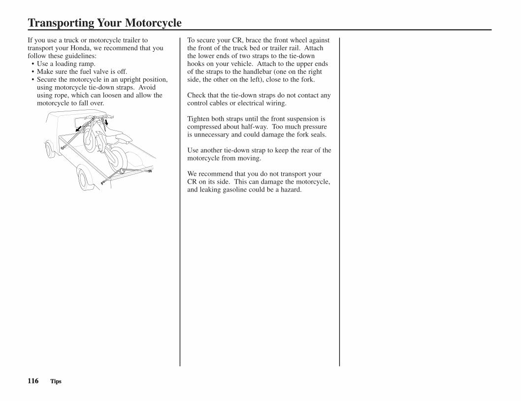
If you use a truck or motorcycle trailer totransport your Honda, we recommend that youfollow these guidelines:
• Use a loading ramp.• Make sure the fuel valve is off.• Secure the motorcycle in an upright position,
using motorcycle tie-down straps. Avoidusing rope, which can loosen and allow themotorcycle to fall over.
To secure your CR, brace the front wheel againstthe front of the truck bed or trailer rail. Attachthe lower ends of two straps to the tie-downhooks on your vehicle. Attach to the upper endsof the straps to the handlebar (one on the rightside, the other on the left), close to the fork.
Check that the tie-down straps do not contact anycontrol cables or electrical wiring.
Tighten both straps until the front suspension iscompressed about half-way. Too much pressureis unnecessary and could damage the fork seals.
Use another tie-down strap to keep the rear of themotorcycle from moving.
We recommend that you do not transport yourCR on its side. This can damage the motorcycle,and leaking gasoline could be a hazard.
116 Tips116 Tips
Transporting Your Motorcycle
CR250R/115-120(31KSK630) 6/2/06 10:04 AM Page 116

If you won’t be riding for an extended period,such as during the winter, thoroughly inspectyour Honda and correct any problem beforestoring it. That way, needed repairs won’t beforgotten and it will be easier to get your CRrunning again.
To reduce or prevent deterioration that can occurduring storage, also follow the followingprocedures.
Preparation for Storage
1. Completely clean all parts of your CR. Ifyour CR has been exposed to sea air or saltwater, wash it down with fresh water and wipedry.
2. Replace the transmission oil (page 37).3. Drain the fuel tank and carburetor into an
approved gasoline container.Turn the fuel valve OFF and remove thecarburetor drain plug. Drain gasoline into anapproved container. Reinstall the drain plug.
4. Remove the radiator cap and coolant drain bolt(1) at the water pump (2) to drain coolant.After the coolant has been completelydrained, ensure that the drain bolt sealingwasher is in good condition and reinstall thedrain bolt and radiator cap.
(1) drain bolt (2) water pump
5. Lubricate the drive chain.6. Remove the spark plug and pour a
tablespoon (0.51 - 0.68 US oz; 15 - 20 cm3)of clean 2-stroke oil into the cylinder. Withthe spark plug grounded or the engine stopbutton pressed in, crank the engine severaltimes to distribute the oil, then reinstall thespark plug.
7. Inflate the tires to their recommendedpressures.
8. Place your CR on the optional workstand orequivalent to raise both tires off the ground.
9. Stuff a rag into the silencer outlet. Then tie aplastic bag over the end of the silencer toprevent moisture from entering.
10. Store your CR in an unheated area, free ofdampness, away from sunlight, with aminimum of daily temperature variation.
11. Cover your CR with a porous material.Avoid using plastic or similar non-breathing,coated materials that restrict air flow andallow heat and moisture to accumulate.
Removal from Storage
1. Uncover and clean your CR.Change the transmission oil if more than 4months have passed since the start of storage.
2. Uncover the end of the silencer and removethe rag from the silencer outlet.
3. Fill the fuel tank with pre-mixed fuel (page 34).
4. Pour a fresh recommended coolant mixture(page 38) slowly into the radiator filler holeup to the filler neck.Capacity:1.16 US qt (1.10R) at disassembly1.02 US qt (0.97R) at draining
Lean your CR slightly right and left several timesto bleed trapped air in the cooling system.If the coolant level lowers, add coolant and repeatthe above procedure.Install the radiator cap securely.
5. Perform all maintenance checks (page 9).
Tips 117Tips 117
Storing Your Honda
WARNINGGasoline is highly flammable andexplosive. You can be burned orseriously injured when handling fuel.
• Stop the engine and keep heat, sparksand flame away.
• Handle fuel only outdoors.• Wipe up spills immediately.
(1)
(2)
CR250R/115-120(31KSK630) 6/2/06 10:04 AM Page 117

You & the EnvironmentOwning and riding a motorcycle can beenjoyable, but you must do your part to protectnature. When you show respect for the land,wildlife, and other people, you also help preservethe sport of off-road riding.
Following are tips on how you can be anenvironmentally-responsible motorcycle owner.
• Choose Sensible Cleaners. Use abiodegradable detergent when you wash yourCR. Avoid aerosol spray cleaners that containchlorofluorocarbons (CFCs) which damagethe atmosphere’s protective ozone layer. Don’tthrow cleaning solvents away; see thefollowing guidelines for proper disposal.
• Recycle Wastes. It’s illegal and thoughtless toput used engine oil in the trash, down a drain,or on the ground. Used oil, gasoline, andcleaning solvents contain poisons that can hurtrefuse workers and contaminate our drinkingwater, lakes, rivers, and oceans.Before changing your oil, make sure you havethe proper containers. Put oil and other toxicwastes in separate sealed containers and takethem to a recycling center. Call your local orstate office of public works or environmentalservices to find a recycling center in your areaand get instructions on how to dispose ofnonrecyclable wastes.
Improper disposal of drained fluids is harmful tothe environment.
NOTICE
118 Tips
CR250R/115-120(31KSK630) 6/2/06 10:04 AM Page 118

Tips 119Tips 119
TroubleshootingThe items that are serviceable using this Manual arefollowed by the page number reference in parenthesis. Theitems that require use of the Honda Service Manual arefollowed by an asterisk (*)
CHECK1. Check ignition
timing*
2. Check carburetorair screwadjustment (P. 106)
3. Check if air isleaking past manifold
4. Try spark test
5. Check the throttleposition sensor*
6. Check the RCvalve system (P. 55)
POSSIBLE CAUSES• Improper ignition
timing (Faulty enginecontrol unit)*
• Faulty alternator*
• Fuel-air mixture toolean (Turn the airscrew in) (P. 106)
• Fuel-air mixture toorich (Turn the airscrew out) (P. 106)
• Deteriorated reedvalve gasket
• Loose insulatorclamp
• Faulty insulator
• Faulty, carbon or wetfouled spark plug (P. 48)
• Faulty engine controlunit*
• Faulty alternator*• Faulty ignition coil*• Broken or shorted
spark plug wire
• Faulty throttleposition sensor*
• Faulty RC valvecables
• Excessive carbonbuild-up on the RCvalve
• Faulty RC valve
POOR PERFORMANCE AT LOW AND IDLE SPEEDS
CORRECT
CORRECT
NOT LEAKING
GOOD SPARK
CORRECT
INCORRECT
INCORRECT
LEAKING
WEAK OR INTERMITTENTSPARK
INCORRECT
CHECK1. Check ignition
timing*
2. Disconnect fuelline at carburetorand check forclogging (P. 35)
3. Remove aircleaner (P. 40)
4. Check carburetorjets for clogging
5. Install a largercarburetor mainjet (P. 106)
6. Check the RCvalve system (P. 55)
POSSIBLE CAUSES• Faulty alternator*• Faulty engine control
unit*• Faulty ignition pulse
generator*
• Lack of fuel in tank (P. 35)• Clogged fuel line (P. 35)• Clogged fuel fill cap
breather tube (P. 35)• Clogged fuel valve (P. 35)• Clogged fuel filter (P. 35)
• Not cleaned frequently enough(P. 40)
• Contaminants in thefuel
• Jet size wrong, rejetin the opposite direction (P. 106)
• Faulty RC valvecables
• Faulty RC valve
POOR PERFORMANCE AT HIGH SPEED
CORRECT
UNRESTRICTEDFUEL FLOW
AIR CLEANERNOT DIRTY
NOT CLOGGED
CORRECT
INCORRECT
FUEL FLOWRESTRICTED
DIRTY
CLOGGED
CONDITIONWORSE
CORRECT
INCORRECT
INCORRECT
CORRECT
CR250R/115-120(31KSK630) 6/2/06 10:04 AM Page 119

120 Tips
CR250R/115-120(31KSK630) 6/2/06 10:04 AM Page 120

Technical Information 121
Technical InformationThis section contains dimensions, capacities, andother technical data.
Vehicle Identification .......................................122Specifications ...................................................123Torque Specifications .......................................124High Altitude Carburetor Adjustment ..............127Oxygenated Fuels.............................................128Competition Logbook ......................................129Optional Parts List............................................131Spare Parts & Equipment .................................132Wiring Diagram................................................133
CR250R/121-144(31KSK630) 6/2/06 10:04 AM Page 121

122 Technical Information
Vehicle Identification
Serial Numbers
The VIN and engine serial numbers are requiredwhen you register your CR. They may also berequired when ordering replacement parts. Youmay record these numbers in the QuickReference section at the rear of this manual.
The VIN (vehicle identification number) (1) isstamped on the right side of the steering head andalso appears on the Safety Certification Labelattached to the right side of the frame.
RIGHT SIDE
(1) VIN
RIGHT SIDE
(1) VIN
The engine number (2) is stamped on the leftcrankcase.
LEFT SIDE
(2) engine number
(1)
(1)
(2)
CR250R/121-144(31KSK630) 6/2/06 10:04 AM Page 122

Technical Information 123
Specifications
ItemDimensionOverall lengthOverall widthOverall heightWheelbaseSeat heightFoot peg heightGround clearanceFrameType
F. suspension
R. suspension
F. tire size, pressurepsi (kPa, kgf/cm2)R. tire size, pressurepsi (kPa, kgf/cm2)Tire type
F. brake, swept area
R. brake, swept area
Fuel capacity
Caster angleTrail lengthFork oil capacity(except fork damperper leg)
English Metric
86.0 in 2,185 mm32.3 in 821 mm50.1 in 1,275 mm58.5 in 1,487 mm37.4 in 950 mm16.9 in 429 mm13.6 in 347 mm
Twin tubeTelescopic fork,
travel 11.0 in (280 mm)stroke 12.4 in (315 mm)
Pro-link,travel 12.4 in (316 mm)
80/100-21 51M15 (100, 1.0)
110/90-19 62M15 (100, 1.0)bias-ply, tube
Single disc brake51.8 in2 (334.5 cm2)Single disc brake
60.6 in2 (391.1 cm2)
2.0 US gal 7.7 liter
27°08′4.4 in 111.7 mm
13.3 US oz 394 cm3
ItemEngineTypeCylinder arrangement
Bore and strokeDisplacementCompression ratioTransmission oilcapacityAfter drainingAfter disassemblyCarburetorTypeIdentification numberMain jet (standard)Slow jet (standard)Air screw openingFloat heightDrive trainClutch typeTransmissionPrimary reductionGear ratio IGear ratio IIGear ratio IIIGear ratio IVGear ratio V
English Metric
Liquid cooled, 2-strokeSingle 9° inclined from
vertical2.61 × 2.83 in 66.4 × 72.0 mm
15.21 cu-in 249.3 cm3
9.0 : 1
0.69 US qt 0.65R0.74 US qt 0.70R
Piston valveTMX11A
#420#40
2 turns out0.30 in 7.5 mm
Wet, multi-plate type5-speed, constant mesh
3.0001.8001.4701.2101.0000.869
ItemDrive trainFinal reduction
Gear shift pattern
ElectricallgnitionStarting system
Spark plug: Standard
Spark plug gap
English Metric
3.769Left foot-operated return
system 1-N-2-3-4-5
CDIKickstarter
NGKBR9EG-N-8
0.027-0.031 in(0.7-0.8 mm)
CR250R/121-144(31KSK630) 6/2/06 10:04 AM Page 123

Torque SpecificationsNuts, Bolts, FastenersCheck and tighten nuts, bolts, fasteners before every outing.
Engine
LEFT SIDE
RIGHT SIDE
124 Technical Information
Item
ENGINE1 Cylinder head nut2 Cylinder mounting
nut3 Carburetor
insulator bolt4 Clutch cover bolt5 Water pump cover
bolt6 RC cover bolt
kgf·m
2.8
4.0
1.21.2
1.20.5
N·m
27
39
1212
125
lbf·ft
20
29
99
93.7
TorqueRemarks
(1)
(4)
(3)
(5)
(2)
(6)
CR250R/121-144(31KSK630) 6/2/06 10:04 AM Page 124

Technical Information 125
Torque Specifications(1)
(4)(2)
(3)
(18)
(13)(10)
(6)
(7)
(12) (11)
(20)(21)
(15)
(19)(17)
(14)
(16)(9)(8)
Torque
lbf•ft kgf•mN•m
108
22
20
22
44
201282754
54
4444883430
5353
534438
9.934
FRAMESteering stem nutFork bridge upper pinchboltsFork bridge lower pinchboltsHandlebar upperholdersHandlebar lower holder nut
Front axle pinch boltsRear axle nutChain adjuster lock nutEngine mounting boltsEngine hanger platebolt (Engine side)
Shock absorber (upper)(lower)
Swingarm pivot nutFork (fork damper)
(fork cap)Rear shock arm
(swingarm side)(shock link side)
Rear shock link nuts(Frame side)
Shock spring lock nutKickstarter arm boltFront brake mastercylinder holderBrake hose bolts
12
3
4
5
789
1011
13
1415
16
17
181920
21
Item
NOTES:
2. Apply oil to the threads and flange surface.3. Stake.4. U-nut.5. UBS nut.6. SH bolt.
11.0
2.2
2.0
2.2
4.5
2.013.12.85.5
5.5
4.54.59.03.53.1
5.45.4
5.44.53.9
1.03.5
80
16
15
16
32
15942040
40
3232652522
3939
393228
7.325
Remarks
NOTE 4NOTE 5
NOTE 4NOTE 4NOTE 4
NOTE 2,4NOTE 2,4
NOTE 2,4
88Front axle nut6 9.065
34Engine hanger platebolts (Flame side)
123.525
1. Apply Pro Honda Hondalock or an equivalent to the threads.
Frame
(5)
CR250R/121-144(31KSK630) 6/2/06 10:04 AM Page 125

126 Technical Information
Torque Specifications
Torque
lbf•ft kgf•mN•m
301616363.683.71230306922137
3227
1.0
1.01.2 12 12
FRAMECaliper mount boltsFront brake disc nutsRear brake disc nutsBrake pedal pivot boltSpokes (front)
(rear)Rim locksSubframe bolt (upper)
(lower)Fork center boltFork center lock nutDisc cover boltFork protector boltsSprocket nutsSeat mounting boltsFront brake reservoircap screwRear brake reservoircap boltFork air plugUpper chain rollerLower chain roller
2223242526
2728
29303132333435
36
373839
Item
NOTES:
2. Apply oil to the threads and flange surface.3. Stake.4. U-nut.5. UBS nut.6. SH bolt.
3.11.61.63.70.40.41.23.13.17.02.21.30.73.32.8
0.1
0.10.11.21.2
221212272.72.7922225116105.22420
0.7
0.70.9 9 9
Remarks
NOTE 1NOTE 4NOTE 4
NOTE 1NOTE 4
NOTE 6NOTE 4
1. Apply Pro Honda Hondalock or an equivalent to the threads.
(37)
(28)
(34)
(33)
(22)
(23)
(31)
(34) (36) (35)
(24)(25)
(27)
(26)(32)
(30)
(29)
(38)(39)
(26)
Frame
CR250R/121-144(31KSK630) 6/2/06 10:04 AM Page 126
Technical Information 127
High Altitude Carburetor AdjustmentWhen operating this motorcycle at high altitude,the air-fuel mixture becomes overly rich.
Above 6,500 feet (2,000 m), driveability andperformance may be reduced and fuelconsumption increased. The carburetor can bemodified to compensate for this high altituderichness.
However, the carburetor must be returned tostandard factory specifications when loweraltitude riding is desired. See your Honda dealerfor high altitude modification.
Sustained operation at altitudes below 5,000 feet(1,500 m) with high altitude carburetormodifications may cause engine overheating anddamage.
NOTICE
CR250R/121-144(31KSK630) 6/2/06 10:04 AM Page 127

128 Technical Information
Oxygenated FuelsSome conventional gasolines are being blendedwith alcohol or an ether compound. Thesegasolines are collectively referred to asoxygenated fuels. To meet clean air standards,some areas of the United States and Canada useoxygenated fuels to help reduce emissions.
If you use an oxygenated fuel, be sure it isunleaded and meets the minimum octane ratingrequirement.
Before using an oxygenated fuel, try to confirmthe fuel’s contents. Some states/provincesrequire this information to be posted on thepump.
The following are the EPA-approved percentagesof oxygenates:
ETHANOL (ethyl or grain alcohol) 10% byVolumeYou may use gasoline containing up to 10%ethanol by volume. Gasoline containing ethanolmay be marketed under the name “Gasohol”.
MTBE (Methyl Tertiary Butyl Ether) 15% byVolumeYou may use gasoline containing up to 15%MTBE by volume.
METHANOL (methyl or wood alcohol) 5% byVolumeYou may use gasoline containing methanolcontaining up to 15% methanol by volume aslong as it contains cosolvents and corrosioninhibitors to protect the fuel system. Gasolinecontaining more than 5% methanol by volumemay cause starting and/or performance problems.It may also damage metal, rubber, and plasticparts of your fuel system.
If you notice any undesirable operatingsymptoms, try another service station or switchto another brand of gasoline.
Fuel system damage or performance problemsresulting from the use of an oxygenated fuelcontaining more than the percentages ofoxygenates mentioned above are not coveredunder warranty.
Oxygenated the fuels can damage paint andplastic. Be careful not to spill fuel when fillingthe fuel tank. Wipe up any spills immediately.
Oxygenated fuels can damage paint and plastic.
NOTICE
CR250R/121-144(31KSK630) 6/2/06 10:04 AM Page 128

Technical Information 129
Any serious competition effort relies heavily onthe knowledge gained and compiled fromprevious racing events. The best way to organizethe many bits of information is to record them ina logbook.
Your logbook can include such information assuspension adjustments, carburetor adjustments,gearing, and tire selection. This detailedinformation, along with your comments, canprove valuable when you compete at the sametrack or on similar terrain.
Your logbook can also tell you whenmaintenance was performed and when it will benecessary again. Your logbook also lets yourecord any repairs and lets you keep track of therunning time on the engine and suspensioncomponents.
If you choose to sell your CR, the accuratemaintenance records in your logbook might bethe deciding deal-maker for a potential buyer.
Consider using different color pens or pencils torecord important information on specific subjects.For example, record results in black, jettingchanges in red, suspension/chassis settings inblue, and gearing selections in green. Colorcodes will help you identify the information youwant with a glance.
Tuning & Adjustment RecordsKeep track of the settings and adjustments thatworked best at a particular location. These itemsinclude:
• basic track conditions, altitude, andtemperature
• carburetion changes• suspension settings• chassis adjustments tested and selected• gearing• tire selection• air pressure
Competition Records• your placings• thoughts to improve performance next time:
both yours and your CR’s• strategy notes
Maintenance Records• regular interval maintenance• repairs• running time on engine• running time on suspension components
TimekeepingThis Manual lists maintenance intervals forevery-so-many races or every-so-many hours ofrunning.
Because all races are not the same, the mosteffective way to schedule maintenance is by thehours you have run your CR.
An official “guestimate” is close enough for ourtimekeeping purposes. You may choose to recordyour time the same way aircraft operators do (butwithout the benefit of an electrical hourmeter).All running time is broken down into hours andtenths of an hour (each six minutes representsone tenth of an hour).
Racing RecordsInformation worth recording for this section ofyour logbook may include:
• your placing in each moto and overallfinishing position
• thoughts on what you could do to improveyour performance next time
• notes on any patterns noted in choice ofstarting gate positions or in riding portions ofthe course as the day progressed that mayprove helpful in future events
• any places on the course where you chose thewrong line and were passed too easily
• notes on strategy used by your competition orby riders in another event that are worthremembering
Maintenance RecordsRegular maintenance items you’ll want to recordin your logbook should include:
• dates and results of cylinder, piston and ringexaminations
• patterns for frequency of need fordecarbonization with a particular oil
• when you last performed shock linkage andswingarm pivot bearing maintenance
• transmission, fork and suspension oil changes• chain, sprocket, chain guide and slider
replacements• coolant changes and related component
replacements• spark plug, brake pad and control cable
replacements
In addition, you should record any irregularitiesnoted in component wear so you’ll remember tokeep a close eye on these areas in the future.
Competition Logbook
CR250R/121-144(31KSK630) 6/2/06 10:04 AM Page 129

130 Technical Information
Competition Logbook
Date Running Location/Event Comments (Jetting, Suspension Settings, Gearing, Chassis Adjustments, Maintenance Time Performed, etc.)
(Make several photocopies of this page for future use)
CR250R/121-144(31KSK630) 6/2/06 10:04 AM Page 130

Technical Information 131
Optional Parts List
Jet needle number (1/2 clip position richerthan standard series at1/8 to 3/4 throttle)
6DGY27-62ø 2.620 mm
6DGY27-63ø 2.630 mm
6DGY27-64ø 2.640 mm
6DGY27-65ø 2.650 mm
6DGY27-66ø 2.660 mm
6DGY27-67ø 2.670 mm
6DGY27-68ø 2.680 mm
CARBURETOR
Main jet(Standard: #420)
Slow jet(Standard: #40)
Jet NeedlesStandard needle: 6DGY26-65Straight diameter: ø2.650 mm
Remarks
#360—480 (in increments of10)
#32.5—#45(in increments of 2.5)#50, #55
Jet needle number(standard series)
6DGY26-62ø 2.620 mm
6DGY26-63ø 2.630 mm
6DGY26-64ø 2.640 mm
(standard needle)6DGY26-65ø 2.650 mm
6DGY26-66ø 2.660 mm
6DGY26-67ø 2.670 mm
6DGY26-68ø 2.680 mm
Remarks
< >: Drive chain links48 Teeth, Aluminum <114>
49 Teeth, Aluminum <114>
50 Teeth, Aluminum <114>
no offset
3 mm offset
21 inchFork height: 0.3 in (7.0 mm)(align the index groove with thetop of the upper clamp)
20 inch• wheel assembly
(except brake disk)• tire tube• tire flap• rim lock (bead stopper)• front tire (90/100—20)
Fork height: 0 in (0 mm)(align the top of the fork tubewith the top of the upper clamp)
FRAME
Driven sprocketHigher gearing
Standard
Lower gearing
Handlebar lowerholder
Standard
Optional
Front wheel Standard
Optional
Remarks
291.2 lbf/in (5.2 kgf/mm)No mark(factory products)
or Blackpaint(aftermarket parts)
280.0 lbf/in (5.0 kgf/mm)
Whitepaint
302.4 lbf/in (5.4 kgf/mm)Greenpaint
313.6 lbf/in (5.6 kgf/mm)Pinkpaint
24.64 lbf/in (0.44 kgf/mm)No mark(factory products)
or3 scribe marks(aftermarket parts)
23.52 lbf/in (0.42 kgf/mm)
1 scribe mark
25.76 lbf/in (0.46 kgf/mm)
2 scribe marks
FRAME
Shock springStandard
OptionalSofter
Stiffer
Fork springStandard
OptionalSofter
Stiffer
Remarks
To adjust shock spring preload.(two spanners required)
For maintenance
For checking tire air pressure.
TOOLS
Pin spanner A
Workstand
Air gauge
The standard fork spring and shock spring mounted onthe motorcycle when it leaves the factory are notmarked. Before replacing the springs, be sure to markthem so they can be distinguished from other optionalsprings.
These parts and tools may be ordered from yourHonda dealer.
Jet needle number
Gen
eral
flo
w c
hara
cter
istic
sLe
aner
Ric
her
420
CR250R/121-144(31KSK630) 6/2/06 10:04 AM Page 131

132 Technical Information
Spare Parts & EquipmentThere are numerous spare parts you can take toan event to help ensure you get in a full day ofriding. In addition to the usual nuts and bolts,consider the following:
Spare Parts
spark plugsair cleaner (clean & oiled, sealed in a plastic bag)optional carburetor jets/needleschain & masterlinkschain guide sliderchain guidechain rollersinner tubes (front & rear)fendersfootpegsfront & side number plateshandlebargripslevers (brake & clutch)clutch lever handlebar mountclutch cablethrottle assemblythrottle cableshift leverbrake pedalspokes (front & rear, each side)sprockets (larger & smaller than standard, forgearing changes & collision damagereplacement) assorted nuts, bolts, washers, screws and cotterpins
Additional Sparesbrake master cylinders (front & rear)brake assemblies (front & rear)wheels & tires (front & rear, mounted)clutch plates & transmission oilseatignition componentstop end-completeradiator hosesradiator shrouds (left & right)brake hoses (front & rear)
General Tools
sockets (3/8 in drive)screwdrivers: blade & Phillips No. 1, 2, 3wrench, large adjustablewrenches: open end & boxwrenches: hex (Allen)wrench, spoketorque wrench (metric scale, click-stop style)pliers: standard, needle-nose, channel-lock typehammer-plastic headsyringe with adjustable stoptire pressure gaugetire ironstire pump or air tankfeeler gauge setVernier caliper (metric)pressure/vacuum testing equipment (U.S.A. only)
Honda Special Tools
Any special tools for your CR purchased fromyour Honda dealer.spoke wrench, 6.6 mm 070MA-KZ30100spoke wrench, 5.8 x 6.1 mm 07701-0020300lock nut wrench 50 mm 07WMA-KZ30100piston base 07958-2500001fork rod stopper 07AMB-KZ3A100 (U.S.A. only)
Chemical Products
Pro Honda HP Trans Oil or Pro Honda GN4 4-stroke oilPro Honda HP Fork Oil 5WPro Honda HP2 2-stroke OilPro Honda HP CoolantPro Honda DOT 4 Brake FluidPro Honda Chain LubePro Honda Foam Filter OilHonda brite CleanerHonda Contact CleanerHonda Dielectric CompoundPro Honda Handgrip CementPro Honda HondalockHonda Moly 60 Paste (U.S.A. only) or molybdenum disulfide paste (containing morethan 40% molybdenum disulfide additive)Pro Honda White Lithium GreaseWheel Bearing GreaseSilicone Sealerhigh-temperature greaseUrea based multi-purpose grease with extremepressure
Other Products
pliers-safety wiresafety wiremechanic’s wireduct tapeplastic tie-wrapshose clampsdrop lightelectrical tape
CR250R/121-144(31KSK630) 6/2/06 10:04 AM Page 132
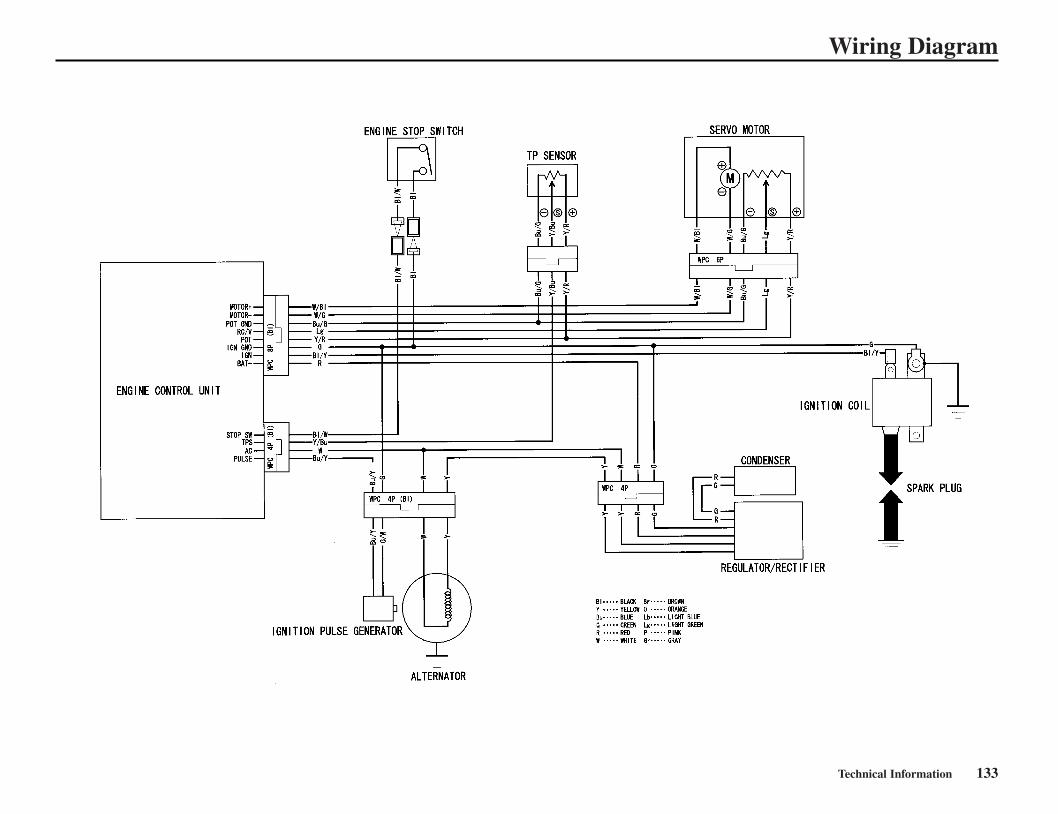
Technical Information 133
Wiring Diagram
CR250R/121-144(31KSK630) 6/2/06 10:04 AM Page 133

134 Technical Information
CR250R/121-144(31KSK630) 6/2/06 10:04 AM Page 134

Consumer Information 135
This section contains information aboutcontacting Honda and how to get an officialHonda service manual.
Authorized Manuals .........................................136Contacting Honda.............................................137Your Honda Dealer...........................................138The Honda Rider’s Club (USA only) ..............139
Consumer Information
CR250R/121-144(31KSK630) 6/2/06 10:04 AM Page 135

136 Consumer Information
The Service Manual used by your Honda dealer is available from Helm, Inc.
Also available, but not necessary to service your model is the Honda CommonService Manual, which explains theory of operation and basic serviceinformation for various systems common to all Honda motorcycles, motorscooters and ATVs.
These Honda manuals are written for the professional technician, but mostmechanically-capable owners should find them helpful if they have the propertools and skills. Special Honda tools are necessary for some procedures.
Order On-Line: www.helminc.comOrder Toll Free: 1-888-CYCLE93 (1-888-292-5393)
(NOTE: For Credit Card Orders Only)Monday - Friday 8:00 AM - 6:00 PM EST
ORBy completing this form you can order the materials desired. You can pay bycheck or money order, or charge to your credit card. Mail to Helm,Incorporated, at the address shown on this order form.Canada: See your Honda dealer to order authorized manuals.
Authorized Manuals
Publication Item No. Description Price Each*
61KSK52 2007 CR250R Service Manual $48.00
61CM002 Common Manual $48.00
31KSK630 2007 CR250R Owner’s Manual $16.00
*Prices are subject to change without notice and without incurring obligation.
Publication Item Description Qty.
Price TotalItem No. Each* Price
Sub TotalPurchaser’s Sales TaxMich. Add 6% Calif. Add 8.25 %
Handling $5.00ChargeGrand Total
*Prices are subject to change without notice andwithout incurring obligation.
Orders are mailed within 10 days. Please allowadequate time for delivery.
SHIP
TO
NOTE: Dealers and Companies, please provide dealer or company name, and also thename of the person to whose attention the shipment should be sent. For purchasesoutside U.S.A., please write to the address shown below for a quotation.
Customer Name
Attention
Street Address-No P.O. Box Number Apt. #
City State Zip Code
Daytime Telephone Number ( )
PAYMENT
Check or money order enclosed payable to Helm, Inc. U.S. funds only. Do notsend cash.
MasterCard
Account Number
VISAVISA Discover
Check here if your billingaddress is different from theshipping address shown above.
Expiration Date: Mo. Yr
Customer Signature Date
—
These Publications cannot be returned for credit without receiving advance authorization within14 days of delivery. On returns, a restocking fee may be applied against the original order.
HELM P.O. BOX 07280 • DETROIT • MI 48207
CR250R/121-144(31KSK630) 6/2/06 10:04 AM Page 136

Contacting Honda
Consumer Information 137
Your owner’s manual was written to cover mostof the questions you might ask about yourHonda. Any questions not answered in theowner’s manual can be answered by your Hondadealer. If he doesn’t have the answer right away,he will get it for you.
If you have a difference of opinion with yourdealer, please remember that each dealership isindependently owned and operated. That’s whyit’s important to work to resolve any differencesat the dealership level.
If you wish to comment on your experiences withyour Honda or with your dealer, please send yourcomments to the following address (USA only):
Motorcycle Division, American Honda MotorCo., Inc., P.O. Box 2220, Torrance, CA 90509-2220, mailstop: 100-4W-5B, telephone: (866) 784-1870.
Canada: Refer to the warranty booklet that wassupplied with your vehicle.
Please include the following information in yourletter:
• name, address, and telephone number• product model, year, and VIN• date of purchase• dealer name and address
We will likely ask your Honda dealer to respond,or possibly acknowledge your comments directly.
CR250R/121-144(31KSK630) 6/2/06 10:04 AM Page 137
Your Honda DealerOnce you purchase your new Honda, get familiarwith the organization of your Honda dealer soyou can utilize the full range of servicesavailable.
The service department is there to performregular maintenance and unexpected repairs. Ithas the latest available service information fromHonda.
The parts department offers Genuine Hondaparts, Pro Honda products, Hondaline accessories(USA only), and Honda accessories and products(Canada only). The same quality that went intoyour Honda can be found in Genuine Hondareplacement parts. You’ll also find comparablequality in the accessories and products availablefrom the parts department.
Your dealer can inform you about competitionevents in your area. You’ll also find that yourdealer is a source of information (USA only) theHonda Rider’s Club of America.
We’re sure you’ll be as pleased with the serviceyour Honda dealer continues to provide after thesale as you are with the quality and dependabilityof your Honda.
138 Consumer Information
CR250R/121-144(31KSK630) 6/2/06 10:04 AM Page 138

Consumer Information 139
The Honda Rider’s Club (USA only)One of the best ways to get the most enjoymentfrom owning and riding your Honda is throughthe Honda Rider’s Club of America. Yourpurchase of a new motorcycle, scooter, ATV orPWC from a participating U.S. Honda dealerentitles you to a complimentary one-yearmembership in the Club. There are hundreds ofHRCA Chapter-sponsoring dealers across theUSA with events and activities almost everyweekend. Membership benefits include:
• 24-hour, toll-free roadside assistance for yournew Honda (includes roadside assistance foryour transport vehicle [up to one ton] as longas your Honda is aboard or in tow). For street-legal motorcycles and scooters only.
• An exclusive HRCA website complete withaccess to the official Honda Common ServiceManual, contests, insider information andmore.
• Reimbursement (up to $75) for successfulcompletion of a Motorcycle SafetyFoundation training course. Separate,complimentary training from the SpecialtyVehicle Institute of America for purchasers ofnew ATVs.
• One full year of Honda Red Rider magazine(six issues).
• Discounts from HRCA partners forexperienced rider courses.
• Discounted vehicle insurance from theHRCA’s insurance partner.
• Racing contingency programs and assistanceat selected dual-sport, off-road and motocrossevents for off-road motorcycles and selectedATVs.
If you purchased an off-road motorcycle, ATV orPWC, your benefits do not include roadsideassistance or trip interruption protection.
Contact your Honda dealer for more informationor call: 1-800-847-4722 or log on towww.hrca.honda.com.
CR250R/121-144(31KSK630) 6/2/06 10:04 AM Page 139

Table of ContentsThe following presents the contents of eachsection of your owner’s manual.
MOTORCYCLE SAFETY................................1Important Safety Information...............................2
Important Safety Precautions..........................2Accessories & Modifications ...............................3Safety Labels ........................................................4
OPERATING CONTROLS...............................5Operation Component Locations .........................6
BEFORE RIDING..............................................7Are You Ready to Ride?.......................................8Is Your Motorcycle Ready to Ride? .....................9
Pre-ride Inspection..........................................9
BASIC OPERATING INSTRUCTIONS........11Safe Riding Precautions .....................................12Starting & Stopping the Engine .........................13
Preparation ....................................................13Starting Procedure ........................................13Flooded Engine.............................................13How to Stop the Engine................................14
Break-in Guidelines ...........................................15
SERVICING YOUR HONDA .........................17Before You Service Your HondaThe Importance of Maintenance ........................18Maintenance Safety ............................................19
Important Safety Precautions........................19Maintenance Schedule .......................................20General Competition Maintenance ....................22Before & After Competition Maintenance.........26
Between Motos & Practice Maintenance .....26After Competition Maintenance ...................27
Service PreparationsMaintenance Component Locations...................28Seat Removal......................................................29Fuel Tank Removal ............................................30Subframe Removal .............................................32
Service ProceduresFluids & FiltersFuel System........................................................34Transmission Oil ................................................36Coolant ...............................................................38Air Cleaner .........................................................40
EngineThrottle ...............................................................42Clutch System ....................................................44Spark Plug ..........................................................48Cylinder System .................................................49RC Valve.............................................................55Reed Valve..........................................................58
ChassisSuspension..........................................................60Brakes.................................................................65Wheels ................................................................69Tires & Tubes .....................................................70Drive Chain ........................................................72Expansion Chamber ...........................................75Additional Maintenance Procedures ..................76
Appearance Care ................................................78
ADJUSTMENTS FOR COMPETITION ......81Front Suspension Adjustments...........................82Rear Suspension Adjustments ............................95Suspension Adjustments for Track Conditions.....99Suspension Adjustment Guidelines..................100Carburetor Adjustments & Turning Tips..........103Chassis Adjustments.........................................110Gearing .............................................................111Tire Selection for Track Conditions.................112Personal Fit Adjustments .................................113
TIPS ................................................................115Transporting Your Motorcycle .........................116Storing Your Honda..........................................117You & the Environment ...................................118Troubleshooting................................................119
TECHNICAL INFORMATION ...................121Vehicle Identification .......................................122Specifications ...................................................123Torque Specifications .......................................124High Altitude Carburetor Adjustment ..............127Oxygenated Fuels.............................................128Competition Logbook ......................................129Optional Parts List............................................131Spare Parts & Equipment .................................132Wiring Diagram................................................133
CONSUMER INFORMATION ....................135Authorized Manuals .........................................136Contacting Honda.............................................137Your Honda Dealer...........................................138The Honda Rider’s Club (USA only) ..............139
TABLE OF CONTENTS ...............................140
INDEX .............................................................141
QUICK REFERENCE
140 Table of contents
CR250R/121-144(31KSK630) 6/2/06 10:04 AM Page 140
Index 141
accessories ..........................................................3adjustments,
altitude and temperature ............................105carburetor ..................................................103chassis ........................................................110control freeplay ................................42, 44, 65for competition ............................................81gearing........................................................111high altitude carburetor ..............................127personal fit..................................................113suspension, front ..........................................82suspension, rear............................................95suspension, track conditions ........................99tire selection ..............................................112
after competition maintenance ..........................27air cleaner ..........................................................40air pressure,
front suspension ..........................................82tires ..............................................................70
American Honda, contacting ..........................137apparel, protective ..............................................2coolant ..............................................................38appearance care ................................................78authorized manuals..........................................136
basic operation ..................................................11before riding ........................................................7between motos & practice maintenance ..........26brakes,
fluid level ....................................................66lever, front adjustment..................................65pad wear ......................................................68pedal height ..................................................65
break-in guidelines ............................................15
capacity, fuel ....................................................35carburetor,
adjustment ..................................................104circuit functions ........................................103components ..............................................103disassembly/assembly ................................107high altitude adjustment ............................127idle speed....................................................106maintenance................................................107minor adjustments ......................................106
care, appearance ................................................78chain drive ........................................................72chassis adjustment for track conditions ............99choke knob ........................................................13cleaner, air ........................................................40cleaning, appearance care ................................78clutch system, adjustment ................................44component locations,
maintenance..................................................28operation ........................................................6
competition logbook........................................129consumer information ....................................135contacting Honda ............................................137controls, operating ..............................................5coolant ..............................................................38customer service..............................................138cylinder system..................................................49
damping adjustments,front ..............................................................82rear................................................................96
dealer, your Honda ..........................................138diagram, wiring ..............................................133drive chain ........................................................72
engine,flooded ........................................................13idle speed....................................................106number ......................................................122pinging ........................................................48starting..........................................................13stop button....................................................14stopping ........................................................14won’t start ....................................................13
environment, protecting ..................................118expansion chamber............................................75
filter,air ................................................................40
flooded engine, starting ....................................13fork,
front suspension adjustment ........................82front suspension inspection..........................60oil recommendation......................................62
front brake lever adjustment..............................65front suspension maintenance ..........................83fuel,
line................................................................35filter ..............................................................35recommendation ..........................................34refueling ......................................................35system ..........................................................34oxygenated ................................................128tank capacity ................................................35valve ............................................................35
F
E
D
C
B
A
Index
CR250R/121-144(31KSK630) 6/2/06 10:04 AM Page 141

142 Index
gap, spark plug ..................................................48gasohol ............................................................128gasoline ..............................................................34gearing..............................................................111guidelines, suspension adjustment ..................100
handlebar inspection ..........................................76high altitude carburetor adjustment..................127Honda,
contacting ....................................................137Rider’s Club ................................................139Service Manual ..........................................136your dealer ..................................................138
identification, vehicle ......................................122idle speed, engine ............................................106inspection, pre-ride ..............................................9
labels, safety ........................................................4locations, component
maintenance ..................................................28operation..........................................................6
logbook, competition........................................129
maintenance,additional procedures ....................................76after competition ..........................................27before & after competition............................26between motos & practice ............................26compornent locations ....................................28general competition ......................................22importance ....................................................18safety ............................................................19schedule ........................................................20
manual, service ................................................136modifications ........................................................3
oil,fork ................................................................62transmission ..................................................36
operation compornent locations ..........................6operating,
controls............................................................5instructions ....................................................11
optional,parts list ......................................................131sprockets......................................................131
oxygenated fuels ..............................................128
pads, brake..........................................................68parts, optional ..................................................131personal fit adjustments....................................113pinging, engine ..................................................34plug, spark ..........................................................48pre-load, rear suspension....................................95pre-ride inspection................................................9protective apparel ................................................2
RC valve ............................................................55RC valve cables..................................................57rear suspension maintenance..............................61reed valve ..........................................................58Rider’s Club Honda..........................................139riding,
apparel ............................................................2basic operation ..............................................11before ..............................................................7important safety information ..........................2safety precautions............................................2
safety,important information ....................................2important precautions......................................2labels ..............................................................4maintenance ..................................................19riding precautions..........................................12
schedule, maintenance........................................20serial numbers ..................................................122service,
customer ......................................................138manuals ......................................................136
spare parts ........................................................132spark knock ........................................................48spark plug
maintenance ..................................................48reading ........................................................109
specifications ....................................................123spring pre-load, rear suspension ........................95starting,
engine ............................................................13troubleshooting............................................119
steering stem inspection ....................................76stopping engine ..................................................14storage ..............................................................117subframe ............................................................32
S
R
P
O
M
L
I
H
G
Index
CR250R/121-144(31KSK630) 6/2/06 10:04 AM Page 142

Index 143
suspension,front ..............................................................60rear ................................................................61
suspension adjustment,front ..............................................................82rear ................................................................95for track conditions ......................................99guidelines ....................................................100
transmission oil ..................................................36tuning tips ........................................................103throttle,
freeplay..........................................................42inspection ......................................................43
tires,air pressure ....................................................70flat ................................................................70selection ......................................................112
tools ................................................................132torque specifications ........................................124transporting ......................................................116troubleshooting ................................................119tubes, replacing ..................................................71
valve, fuel ..........................................................35valve, RC............................................................55valve, reed ..........................................................58vehicle identification no. (VIN) ......................122
washing your motorcycle ..................................78wheels ................................................................69writing diagram ................................................133
W
V
T
Index
CR250R/121-144(31KSK630) 6/2/06 10:04 AM Page 143

Quick Reference
The following is a brief, but important collectionof information you need to know about yourHonda. You’ll also find space to recordimportant notes.
How To Avoid Costly Repairs
The engine of your Honda can be the mostexpensive component to repair. Propermaintenance, especially the use of therecommended fluids and filters, preventspremature wear and damage.
Frequent causes of costly engine repairs are: • Transmission oil & premix oil: insufficient
quantity, improper oil.• Air cleaner: dirty, leaking because of
improper installation (poor seal).
Quick ReferenceRecord important information here:
VIN
Engine No.
Owner’s:
Name
Address
City/State
Phone
Dealer’s:
Name
Address
City/State
Phone
Service Mgr.
Maintenance
Pre-ride Inspection
Fuel/Capacity
Transmission oil
Tires
Tire Pressure (cold)
Spark Plug
Drive Chain
The maintenance schedule (page 20) lists service frequencies for: each race or about 2.5 hours,every 3 races or about 7.5 hours, andevery 9 races or about 22.5 hours
Check the items listed on the Pre-Ride inspection checklist each time before you ride (page 9):tires, spokes & rims, leaks, transmission oil, fuel, drive chain, drive chain guide & sliders &guide rollers, cables, nuts & bolts, spark plug and cap, throttle, brakes, clutch lever, expansionchamber.
unleaded gasoline, pump octane number of 91 or higherPremix: Pro Honda HP2 2-stroke oil (32 : 1)Tank: 2.0 US gal (7.7R)
Pro Honda HP Trans oil, Pro Honda GN4 4-stroke oil or an equivalent.
Front: 80/100-21 51M, Rear: 110/90-19 62MType: bias-ply, tube
Front: 15 psi (100 kPa, 1.0kgf/cm2)Rear: 15 psi (100 kPa, 1.0kgf/cm2)
Standard: BR9EG-N-8 (NGK)
DID 520DMA2
CR250R/121-144(31KSK630) 6/2/06 10:05 AM Page 144