AFRICA TWIN - Honda
377
EN AFRICA TWIN OWNER’S MANUAL AFRICA TWIN
-
Upload
khangminh22 -
Category
Documents
-
view
1 -
download
0
Transcript of AFRICA TWIN - Honda

H4 H1
EN
AFR
ICA
TW
IN
OWNER’S MANUAL
AFRICA TWIN
32MKS60000X32-MKS-6000
eY4000.2019.07.LPRINTED IN JAPAN
00X32-MKS-6000_CRF1100A_Cover.indd 100X32-MKS-6000_CRF1100A_Cover.indd 1 2019/07/10 13:58:102019/07/10 13:58:10

This manual should be considered a permanent part of the vehicleand should remain with the vehicle when it is resold.
This publication includes the latest production information availablebefore printing. Honda Motor Co., Ltd. reserves the right to makechanges at any time without notice and without incurring anyobligation.
No part of this publication may be reproduced without writtenpermission.
The vehicle pictured in this owner’s manual may not match youractual vehicle.
© 2019 Honda Motor Co., Ltd.
20190704203539_32MKS6000_eng_BOOK Page 1 Thursday, July 04 2019 20:57:26 JST

WelcomeCongratulations on your purchase of a newHonda vehicle. Your selection of a Hondamakes you part of a worldwide family ofsatisfied customers who appreciate Honda'sreputation for building quality into everyproduct.
To ensure your safety and riding pleasure:● Read this owner's manual carefully.● Follow all recommendations and
procedures contained in this manual.● Pay close attention to safety messages
contained in this manual and on thevehicle.
20190704203539_32MKS6000_eng_BOOK Page 2 Thursday, July 04 2019 20:57:26 JST

● The following codes in this manualindicate each country.
● The illustrations here in are based on theCRF1100D4 II ED type.
Country CodesCode CountryCRF1100A
ED, II EDEuropean direct sales,France, South Africa,Turkey
CRF1100A2
ED, II EDEuropean direct sales,France, South Africa,Turkey
CRF1100A4
ED, II EDEuropean direct sales,France, South Africa,Turkey
CRF1100D
ED, II EDEuropean direct sales,France, South Africa,Turkey
CRF1100D2
ED, II EDEuropean direct sales,France, South Africa,Turkey
CRF1100D4
ED, II EDEuropean direct sales,France, South Africa,Turkey
*The specifications may vary with each locale.
20190704203539_32MKS6000_eng_BOOK Page 3 Thursday, July 04 2019 20:57:26 JST

A Few Words About SafetyYour safety, and the safety of others, is veryimportant. Operating this vehicle safely is animportant responsibility.To help you make informed decisions aboutsafety, we have provided operatingprocedures and other information on safetylabels and in this manual. This informationalerts you to potential hazards that couldhurt you or others.Of course, it is not practical or possible towarn you about all hazards associated withoperating or maintaining a vehicle. You mustuse your own good judgement.
You will find important safety information in avariety of forms, including:● Safety labels on the vehicle● Safety Messages preceded by a safety alert
symbol and one of three signal words:DANGER, WARNING, or CAUTION.These signal words mean:
3DANGERYou WILL be KILLED or SERIOUSLYHURT if you don’t follow instructions.
3WARNINGYou CAN be KILLED or SERIOUSLYHURT if you don’t follow instructions.
3CAUTIONYou CAN be HURT if you don’t followinstructions.
Other important information isprovided under the following titles:
NOTICE Information to help you avoiddamage to your vehicle, otherproperty, or the environment.
20190704203539_32MKS6000_eng_BOOK Page 4 Thursday, July 04 2019 20:57:26 JST

20190704203539_32MKS6000_eng_BOOK Page 5 Thursday, July 04 2019 20:57:26 JST

Contents
Vehicle Safety P. 2
Operation Guide P. 20
Maintenance P. 232
Troubleshooting P. 298
Information P. 339
Specifications P. 359
Index P. 365
20190704203539_32MKS6000_eng_BOOK Page 6 Thursday, July 04 2019 20:57:26 JST

Safety Guidelines .................................................P. 3Image Labels.........................................................P. 7Safety Precautions.............................................P. 12Riding Precautions ............................................P. 13Accessories & Modifications...........................P. 17Off-Road Safety .................................................P. 18Loading ................................................................P. 19
20190704203539_32MKS6000_eng_BOOK Page 7 Thursday, July 04 2019 20:57:26 JST
This section contains important information for safe riding of your vehicle.Please read this section carefully.
Vehicle Safety

Safety GuidelinesFollow these guidelines to enhance your safety:● Perform all routine and regular inspections
specified in this manual.● Stop the engine and keep sparks and flame
away before filling the fuel tank.● Do not run the engine in enclosed or partly
enclosed areas. Carbon monoxide inexhaust gases is toxic and can kill you.
Always Wear a HelmetIt's a proven fact: helmets and protectiveapparel significantly reduce the number andseverity of head and other injuries. So alwayswear an approved helmet and protectiveapparel. 2 P. 12
Before RidingMake sure that you are physically fit, mentallyfocused and free of alcohol and drugs. Checkthat you and your passenger are both wearingan approved helmet and protective apparel.Instruct your passenger on holding onto thegrab rail or your waist, leaning with you in turns,and keeping their feet on the footpegs, evenwhen the vehicle is stopped.
Take Time to Learn & PracticeEven if you have ridden other vehicles, practiceriding in a safe area to become familiar withhow this vehicle works and handles, and tobecome accustomed to the vehicle's size andweight.
Ride DefensivelyAlways pay attention to other vehicles aroundyou, and do not assume that other drivers seeyou. Be prepared to stop quickly or perform anevasive maneuver.
20190704203539_32MKS6000_eng_BOOK Page 8 Thursday, July 04 2019 20:57:26 JST
Safety GuidelinesVehicle Safety
3Continued

Make Yourself Easy to SeeMake yourself more visible, especially at night,by wearing bright reflective clothing, positioningyourself so other drivers can see you, signalingbefore turning or changing lanes, and usingyour horn when necessary.
Be Alert for Off-road HazardsThe terrain can be present a variety ofchallenges when you ride off-road.Continually “read” the terrain for unexpectedturns, drop-offs, rocks, ruts and other hazards.Always keep your speed low enough to allowtime to see and react to hazards.
Ride within Your LimitsNever ride beyond your personal abilities orfaster than conditions warrant. Fatigue andinattention can impair your ability to use goodjudgement and ride safely.
Don't Drink and RideAlcohol and riding don't mix. Even one alcoholicdrink can reduce your ability to respond tochanging conditions, and your reaction timegets worse with every additional drink. Don'tdrink and ride, and don't let your friends drinkand ride either.
Keep Your Honda in Safe ConditionIt's important to keep your vehicle properlymaintained and in safe riding condition.Having a breakdown can be difficult, especiallyif you are stranded off-road far from your base.Inspect your vehicle before every ride andperform all recommended maintenance. Neverexceed load limits (2 P. 19), and do not modifyyour vehicle or install accessories that wouldmake your vehicle unsafe (2 P. 17).
20190704203539_32MKS6000_eng_BOOK Page 9 Thursday, July 04 2019 20:57:26 JST
Safety Guidelines
Vehicle Safety
4

If You are Involved in a CrashPersonal safety is your first priority. If you oranyone else has been injured, take time toassess the severity of the injuries and whether itis safe to continue riding. Call for emergencyassistance if needed. Also follow applicable lawsand regulations if another person or vehicle isinvolved in the crash.
If you decide to continue riding, first turn theignition switch to the (Off) position, andevaluate the condition of your vehicle. Inspectfor fluid leaks, check the tightness of critical nutsand bolts, and check the handlebar, controllevers, brakes, and wheels. Ride slowly andcautiously.Your vehicle may have suffered damage that isnot immediately apparent. Have your vehiclethoroughly checked at a qualified service facilityas soon as possible.
Lithium-Ion (Li-Ion) BatteryIf you smell an unusual odor coming from thelithium-ion (li-ion) battery, park your vehicle in asafe place outside and away from flammableobjects, then turn the ignition switch to the (Off) position. Have your vehicle inspected byyour dealer immediately.
20190704203539_32MKS6000_eng_BOOK Page 10 Thursday, July 04 2019 20:57:26 JST
Safety GuidelinesVehicle Safety
5Continued

Carbon Monoxide HazardExhaust contains poisonous carbon monoxide, acolourless, odorless gas. Breathing carbonmonoxide can cause loss of consciousness andmay lead to death.
If you run the engine in confined or even partlyenclosed area, the air you breathe couldcontain a dangerous amount of carbonmonoxide.Never run your vehicle inside a garage or otherenclosure.
3WARNINGRunning the engine of your vehiclewhile in an enclosed or even partiallyenclosed area can cause a rapid build-up of toxic carbon monoxide gas.
Breathing this colourless, odorless gascan quickly cause unconsciousness andlead to death.
Only run your vehicle's engine when itis located in a well ventilated areaoutdoors.
20190704203539_32MKS6000_eng_BOOK Page 11 Thursday, July 04 2019 20:57:26 JST
Safety Guidelines
Vehicle Safety
6

Image LabelsThe following pages describe the labelmeanings. Some labels warn you ofpotential hazards that could cause seriousinjury. Others provide important safetyinformation. Read this information carefullyand don't remove the labels.
If a label comes off or becomes hard toread, contact your dealer for a replacement.
There is a specific symbol on each label.The meanings of each symbol and label areas follows.
Read instructions contained in Owner'sManual carefully.
Read instructions contained in Shop Manualcarefully. In the interest of safety, take thevehicle to be serviced only by your dealer.
DANGER (with RED background)You WILL be KILLED or SERIOUSLY HURT ifyou don't follow instructions.WARNING (with ORANGE background)You CAN be KILLED or SERIOUSLY HURT ifyou don't follow instructions.CAUTION (with YELLOW background)You CAN be HURT if you don't followinstructions.
20190704203539_32MKS6000_eng_BOOK Page 12 Thursday, July 04 2019 20:57:26 JST
Image LabelsVehicle Safety
7Continued

BATTERY LABELDANGER• Do not dismantle, modify or solder the main unit and battery terminals.
Doing so may cause leakage, heat generation, explosion, fire or loss ofvision due to leaked electrolyte.If electrolyte gets into one's eye, immediately wash the eye with plentyof water, and receive treatment from an eye specialist(ophthalmologist) as soon as possible.
• Keep this product away from fires and high temperature heat sources.Do not bring or cause fires (matches, lighters, cigarettes, sparks atterminals or from welding machines or grinders) close to the battery.Doing so may cause heat generation, explosion or fire.
• Carefully read this manual.If this product is handled incorrectly, it may lead to damage to thevehicle, heat generation, explosion, fire, loss of vision or burns.
RADIATOR CAP LABELDANGERNEVER OPEN WHEN HOT.Hot coolant will scald you.Relief pressure valve begins to open at 1.1 kgf/cm2.
20190704203539_32MKS6000_eng_BOOK Page 13 Thursday, July 04 2019 20:57:26 JST
Image Labels
Vehicle Safety
8

ACCESSORIES AND LOADING WARNING LABELWARNINGACCESSORIES AND LOADING
CRF1100A/D
CRF1100A2/A4/D2/D4
• The safety stability and handling of this vehicle may be affectedby the addition of accessories and luggage.
• Read carefully the instructions contained in user's manual andinstallation guide before installing any accessory.
• CRF1100A/DThe total weight of accessories and luggage added to rider's andpassenger's weight should not exceed 220 kg (485 lb), which isthe maximum weight capacity.CRF1100A2/A4/D2/D4The total weight of accessories and luggage added to rider's andpassenger's weight should not exceed 218 kg (481 lb), which isthe maximum weight capacity.
• The luggage weight must not exceed 29 kg (64 lb) under anycircumstances.
• The fitting of large fork-mounted or large handlebar mountedfairing is not recommended.
20190704203539_32MKS6000_eng_BOOK Page 14 Thursday, July 04 2019 20:57:26 JST
Image LabelsVehicle Safety
9Continued

REAR CUSHION LABELGAS FILLEDDo not open. Do not heat.
TYRE LABELWARNINGIf M+S tyres are installed, keep maximum speed to less than160 km/h (99 mph).
20190704203539_32MKS6000_eng_BOOK Page 15 Thursday, July 04 2019 20:57:26 JST
Image Labels
Vehicle Safety
10

TYRE INFORMATION & DRIVE CHAIN LABELCold tyre pressure:[Driver only]
Front 225 kPa (2.25 kgf/cm2, 33 psi)Rear 250 kPa (2.50 kgf/cm2, 36 psi)
[Driver and passenger]Front 225 kPa (2.25 kgf/cm2, 33 psi)Rear 280 kPa (2.80 kgf/cm2, 41 psi)
Keep chain adjusted and lubricated.Freeplay 35 - 45 mm (1.4 - 1.8 in)SAFETY REMINDER LABELFor your protection, always wear helmet, protective apparel.FUEL LABELUnleaded petrol onlyETHANOL up to 10 % by volume
REAR CARRIER LABELCRF1100A2/A4/D2/D4Do not exceed 10 kg (22 lb).
20190704203539_32MKS6000_eng_BOOK Page 16 Thursday, July 04 2019 20:57:26 JST
Image LabelsVehicle Safety
11

Safety Precautions● Ride cautiously and keep your hands on the
handlebar and feet on the footpegs.● Keep passenger's hands onto the grab rail
or your waist, passenger's feet on thefootpegs while riding.
● Always consider the safety of yourpassenger, as well as other drivers andriders.
Protective ApparelMake sure that you and any passenger arewearing an approved helmet, eye protection,and high-visibility protective clothing. Ridedefensively in response to weather and roadconditions.
# HelmetSafety-standard certified, high-visibility, correctsize for your head● Must fit comfortably but securely, with the
chin strap fastened.
● Face shield with unobstructed field of visionor other approved eye protection
3WARNINGNot wearing a helmet increases thechance of serious injury or death in acrash.
Make sure that you and any passengeralways wear an approved helmet andprotective apparel.
# GlovesFull-finger leather gloves with high abrasionresistance
# Boots or Riding ShoesSturdy boots with non-slip soles and ankleprotection
20190704203539_32MKS6000_eng_BOOK Page 17 Thursday, July 04 2019 20:57:26 JST
Safety Precautions
Vehicle Safety
12

# Jacket and TrousersProtective, highly visible, long-sleeved jacketand durable trousers for riding (or a protectivesuit)
# Additional Off-road GearOn-road apparel may also be suitable for casualoff-road riding. But if you plan on any seriousoff-road riding you will need more serious off-road gear. In addition to your helmet and eyeprotection, we recommend off-road motorcycleboots and gloves, riding pants with knee andhip pads, a jersey with elbow pads, and a chest/shoulder protector.
Riding PrecautionsRunning-in Period
During the first 500 km (300 miles) of running,follow these guidelines to ensure your vehicle'sfuture reliability and performance.● Avoid full-throttle starts and rapid
acceleration.● Avoid hard braking and rapid down-shifts.● Ride conservatively.
BrakesObserve the following guidelines:● Avoid excessively hard braking and
downshifting.u Sudden braking can reduce the vehicle's
stability.u Where possible, reduce speed before
turning; otherwise you risk sliding out.
20190704203539_32MKS6000_eng_BOOK Page 18 Thursday, July 04 2019 20:57:26 JST
Riding PrecautionsVehicle Safety
13Continued

● Exercise caution on low traction surfaces.u The tyres slip more easily on such
surfaces and braking distances arelonger.
● Avoid continuous braking.u Repeated braking, such as when
descending long, steep slopes canseriously overheat the brakes, reducingtheir effectiveness. Use engine brakingwith intermittent use of the brakes toreduce speed.
● For full braking effectiveness, operate boththe front and rear brakes together.
# Anti-lock Brake System (ABS)This model is equipped with an Anti-lock BrakeSystem (ABS) designed to help prevent thebrakes from locking up during hard braking.The ABS functions with information provided bythe IMU (Inertia Measurement Unit).● ABS does not reduce braking distance. In
certain circumstances, ABS may result in alonger stopping distance.
● ABS does not function at speeds below 10km/h (6 mph).
● The brake lever and pedal may recoil slightlywhen applying the brakes. This is normal.
● Always use the recommended front/reartyres and sprockets to ensure correct ABSoperation.
# Engine BrakingEngine braking helps slow your vehicle downwhen you release the throttle. For furtherslowing action, downshift to a lower gear. Useengine braking with intermittent use of thebrakes to reduce speed when descending long,steep slopes.# Wet or Rainy ConditionsRoad surfaces are slippery when wet, and wetbrakes further reduce braking efficiency.Exercise extra caution when braking in wetconditions.If the brakes get wet, apply the brakes whileriding at low speed to help them dry.
20190704203539_32MKS6000_eng_BOOK Page 19 Thursday, July 04 2019 20:57:26 JST
Riding Precautions
Vehicle Safety
14

Parking● Park on a firm, level surface.● If you must park on a slight incline or loose
surface, park so that the vehicle cannotmove or fall over.
● Make sure that high-temperature partscannot come into contact with flammablematerials.
● Do not touch the engine, muffler, brakesand other high-temperature parts until theycool down.
● To reduce the likelihood of theft, always lockthe handlebar and remove the key whenleaving the vehicle unattended.Use of an anti-theft device is alsorecommended.
# Parking with the Side Stand1. Stop the engine.2. Push the side stand down.3. Slowly lean the vehicle to the left until its
weight rests on the side stand.
4. Turn the handlebar fully to the left.u Turning the handlebar to the right
reduces stability and may cause thevehicle to fall.
5. Turn the ignition switch to the (Lock)position and remove the key. 2 P. 121
Refuelling and Fuel GuidelinesFollow these guidelines to protect the engine,fuel system and catalytic converter:● Use only unleaded petrol.● Use recommended octane number. Using
lower octane petrol will result in decreasedengine performance.
● Do not use fuels containing a highconcentration of alcohol. 2 P. 353
● Do not use stale or contaminated petrol oran oil/petrol mixture.
● Avoid getting dirt or water in the fuel tank.
20190704203539_32MKS6000_eng_BOOK Page 20 Thursday, July 04 2019 20:57:26 JST
Riding PrecautionsVehicle Safety
15Continued

Honda selectable torque controlWhen the Honda selectable torque control(Torque Control) detects rear wheel spin duringacceleration, the system will limit the amount oftorque applied to the rear wheel based on theTorque Control level selected.Additionally, the system ease the rapid motionduring the wheelie when accelerating based onthe Torque Control level selected.
Torque Control will allow some wheel spinduring acceleration at the lower Torque Controllevels settings. Select a level that is appropriatefor your skill and riding conditions.
Torque Control does not work duringdeceleration and will not prevent the rear wheelfrom skidding due to engine braking. Do notclose the throttle suddenly, especially whenriding on slippery surfaces.
Torque Control may not compensate for roughroad conditions or rapid throttle operation.Always consider road and weather conditions,as well as your skills and condition, whenapplying throttle.If your vehicle gets stuck in mud, snow or sand,it may be easier to free it by turning off theTorque Control temporarily.Temporarily turning off Torque Control alsomay help you maintain control and balancewhen riding on off-road terrain.
Always use the recommended tyres andsprockets to ensure correct Torque Controloperation.
20190704203539_32MKS6000_eng_BOOK Page 21 Thursday, July 04 2019 20:57:26 JST
Riding Precautions
Vehicle Safety
16

Accessories &ModificationsWe strongly advise that you do not add anyaccessories that were not specifically designedfor your vehicle by Honda or makemodifications to your vehicle from its originaldesign. Doing so can make it unsafe.Modifying your vehicle may also void yourwarranty and make your vehicle illegal tooperate on public roads. Before deciding toinstall accessories on your vehicle be certain themodification is safe and legal.
3WARNINGImproper accessories or modificationscan cause a crash in which you can beseriously hurt or killed.
Follow all instructions in this owner'smanual regarding accessories andmodifications.
Do not pull a trailer with, or attach a sidecar to,your vehicle. Your vehicle was not designed forthese attachments, and their use can seriouslyimpair your vehicle's handling.
20190704203539_32MKS6000_eng_BOOK Page 22 Thursday, July 04 2019 20:57:26 JST
Accessories & ModificationsVehicle Safety
17

Off-Road SafetyLearn to ride in an uncongested off-road areafree of obstacles before venturing ontounfamiliar terrain.● Always obey local off-road riding laws and
regulations.● Obtain permission to ride on private
property. Avoid posted areas and obey “NOTrespassing” signs.
● Ride with a friend on another vehicle so thatyou can assist each other in case of trouble.
● Familiarity with your vehicle is criticallyimportant should a problem occur far fromhelp.
● Never ride beyond your ability andexperience or faster than conditions warrant.
● If you are not familiar with the terrain, ridecautiously. Hidden rocks, holes, or ravinescould spell disaster.
● A muffler is required in most off-road areas.Don't modify your exhaust system.Remember that excessive noise botherseveryone and creates a bad image formotorcycling.
20190704203539_32MKS6000_eng_BOOK Page 23 Thursday, July 04 2019 20:57:26 JST
Off-Road Safety
Vehicle Safety
18

Loading● Carrying extra weight affects your vehicle's
handling, braking and stability.Always ride at a safe speed for the load youare carrying.
● Avoid carrying an excessive load and keepwithin specified load limits.Maximum weight capacity / Maximumluggage weight 2 P. 359
● Tie all luggage securely, evenly balancedand close to the centre of the vehicle.
● Do not place objects near the lights or themuffler.
Also follow these guidelines when you ride off-road on rough terrain:● Do not carry a passenger.● Keep cargo small and light weight.
Make sure it cannot easily be caught onbrush or other objects, and that it does notinterfere with your ability to shift position tomaintain balance and stability.
3WARNINGOverloading or improper loading cancause a crash and you can be seriouslyhurt or killed.
Follow all load limits and other loadingguidelines in this manual.
20190704203539_32MKS6000_eng_BOOK Page 24 Thursday, July 04 2019 20:57:26 JST
LoadingVehicle Safety
19

Parts Location
20190704203539_32MKS6000_eng_BOOK Page 25 Thursday, July 04 2019 20:57:26 JST
Operation Guide
20
Document bag (P.229)
Fuse puller, Hex wrench,Standard/Phillips screwdriver,Screwdriver handle (P.230)
Throttle grip (P.282)
Rear suspension compressiondamping adjuster CRF1100A/A2/D/D2(P.294)
Data linkconnector
Front suspension compressiondamping adjusters CRF1100A/A2/D/D2(P.288)
Clutch oil filter CRF1100D/D2/D4(P.264)
Battery box cover (P.251)

Continued
20190704203539_32MKS6000_eng_BOOK Page 26 Thursday, July 04 2019 20:57:26 JST
Operation Guide
21
Engine oil filter (P.262)
Coolant reserve tank (P.266)
Rear brake pedal
FI fuse & Main 2 & DCT main fuseCRF1100D/D2/D4 (P.338)
FI fuse & Main 2 fuse CRF1100A/A2/A4(P.337)
Crankcase breather (P.283)
Main fuse & ABS main fuse (P.336)
Front brake fluid reservoir (P.268)
Rear brake fluid reservoir (P.268)

20190704203539_32MKS6000_eng_BOOK Page 27 Thursday, July 04 2019 20:57:26 JST
Operation Guide
22
Parts Location (Continued)
Skid plate (P.257)
Clutch lever CRF1100A/A2/A4 (P.279)
Parking brake lever CRF1100D/D2/D4(P.270)
Accessory socket CRF1100A2/A4/D2/D4(P.225)
Windscreen lock leverCRF1100A2/A4/D2/D4 (P.296)USB socket (P.226)
Rear suspension spring preloadadjuster CRF1100A/A2/D/D2 (P.290)
Rear suspension rebound dampingadjuster CRF1100A/A2/D/D2 (P.293)
Side stand (P.272)
Crankcase breathers (P.283)

20190704203539_32MKS6000_eng_BOOK Page 28 Thursday, July 04 2019 20:57:26 JST
Operation Guide
23
Front suspension spring preload/rebound damping adjustersCRF1100A/A2/D/D2 (P.286) (P.287)Fuel fill cap (P.224)
Tool kit/Tool box (P.230)(P.259)
Fuse box & ABS FSR fuse (P.335)
Engine oil fill cap (P.260)
Battery (P.250)
Drive chain (P.273)Engine oil drain bolts (P.262)Engine oil dipstick (P.260)
Shift leverCRF1100A/A2/A4(P.208)
Front seat (P.253)
Rear seat (P.255)
Front brake lever (P.285)

Instruments
20190704203539_32MKS6000_eng_BOOK Page 29 Thursday, July 04 2019 20:57:26 JST
Operation Guide
24
Display CheckWhen the ignition switch is turned to the (On) position, all the mode and digitalsegments will show. If any part of these displays does not come on when it should, haveyour dealer check for problems.
Speedometer
Odometer [TOTAL]Total distance ridden. When“ ” is displayed, have yourdealer check for problems.
AT indicatorCRF1100D/D2/D4Comes on when the AT MODE. (P.211)

20190704203539_32MKS6000_eng_BOOK Page 30 Thursday, July 04 2019 20:57:26 JST
Operation Guide
25Continued
If the “-” indicator is blinking in the gear position window while riding: (P.305)
CRF1100A/A2/A4The gear position is shown in the gear position indicator.
Gear position indicator
u “-” appears when the transmission is not shifted properly.
This is normal. To operate the system again, turn the ignition switch to the (Off)position, and then to the (On) position again.
u The front wheel leaves the ground.u You turn the wheel while the vehicle is upright on the stand.
CRF1100D/D2/D4The gear position is shown in the gear position indicator when the MT MODE is selected.The indicator may flash if:
S mode level indicator (P.211)CRF1100D/D2/D4
D is shown in the gear position indicator when the D mode is selected in the AT MODE.S is shown in the gear position indicator when the S mode is selected in the AT MODE.

Multi-information displayYour vehicle is equipped with a multi-information display that presents variousfunctions and settings.The multi-information display is a screen. Youcan operate by touching the screen.● Certain manual functions and settings are
disabled or inoperable while the vehicle isin motion. You cannot select a greyed-outmenu until the vehicle is stopped.
When the ignition switch is turned (On), theNotice message appears on the screen for afew seconds.Read the Notice message, and then press theENT switch or touch [OK] on the screen.
20190704203539_32MKS6000_eng_BOOK Page 31 Thursday, July 04 2019 20:57:26 JST
Operation Guide
26
Instruments (Continued)

# Home ScreenFrom this screen, you can go to variousfunctions and setup options.To return to the Home screen: (P.38)
# Riding InformationYou can go back to the riding information.Riding information has 3 displays, Goldimage display, Silver image display andBronze image display.These displays are switched according toriding mode.Gold image display (P.28)Silver image display (P.32)Bronze image display (P.35)To change the display setting on each ridingmode (P.81)
# PhoneYou can make calls using a Bluetooth®connected Bluetooth® audio devices.
# MediaYou can play music from Bluetooth® devices.
# SettingsYou can select various settings.
20190704203539_32MKS6000_eng_BOOK Page 32 Thursday, July 04 2019 20:57:26 JST
Operation Guide
27Continued

20190704203539_32MKS6000_eng_BOOK Page 33 Thursday, July 04 2019 20:57:26 JST
Operation Guide
28
Instruments (Continued)
Gold image display
Riding mode display(P.142)
Side stand indicator(P.66)
Clock (12-hour or 24-hour display)To set the clock: (P.90)
Cruise Control Set SpeedThe speed set for cruisecontrol is displayed.Cruise Control: (P.215) Speedometer
Sub-informationindicator (P.41)
Air temperature gauge(P.66)
# Riding Information

20190704203539_32MKS6000_eng_BOOK Page 34 Thursday, July 04 2019 20:57:26 JST
Operation Guide
29Continued
TachometerNOTICEDo not operate the engine in the Tachometer red zone.Excessive engine speed can adversely affect engine life.
Tachometer red zone(excessive engine rpm range)
Coolant temperature gaugeWhen the coolant is over specified temperature, all segments turn red and the H (6th) segment flashes and high coolant temperature indicator lamps. (P.300)If the coolant temperature gauge indicator flashes: (P.307)
Fuel gaugeRemaining fuel when only E (1st) segment starts flashing:Approximately 3.6 L (0.95 US gal, 0.79 Imp gal) (CRF1100A/D )Approximately 3.9 L (1.03 US gal, 0.86 Imp gal) (CRF1100A2/A4/D2/D4 )If the fuel gauge indicator flashes: (P.306)
NOTICEYou should refuel when the reading approaches the E (1st) segment.Running out of fuel can cause the engine to misfire, damaging thecatalytic converter.

20190704203539_32MKS6000_eng_BOOK Page 35 Thursday, July 04 2019 20:57:26 JST
Operation Guide
30
Instruments (Continued)
[P] [Power] level indicator(P.142)When the indicator flashes,have your dealer check forproblems.
[EB] [Engine Brake] levelindicator (P.142)When the indicator flashes,have your dealer check forproblems.
Torque Control level [T] indicator (P.133)When the indicator flashes, have your dealer check for problems.
G switch [G] indicator (P.126) CRF1100D/D2/D4When the indicator flashes, have your dealer check for problems.ABS mode [ABS] indicator (P.142)When the indicator flashes, have your dealer check for problems.[S] [Overall] indicator (P.142) CRF1100A4/D4When the indicator flashes, have your dealer check for problems.

20190704203539_32MKS6000_eng_BOOK Page 36 Thursday, July 04 2019 20:57:26 JST
Operation Guide
31Continued
If the “-” indicator is blinking in the gear position window while riding: (P.305)
CRF1100A/A2/A4The gear position is shown in the gear position indicator.
Gear position indicator
u “-” appears when the transmission is not shifted properly.
This is normal. To operate the system again, turn the ignition switch to the (Off)position, and then to the (On) position again.
u The front wheel leaves the ground.u You turn the wheel while the vehicle is upright on the stand.
CRF1100D/D2/D4The gear position is shown in the gear position indicator.The indicator may flash if:
D is shown in the gear position indicator when the D mode is selected in the AT MODE.S is shown in the gear position indicator when the S mode is selected in the AT MODE.
S mode level indicator (P.211)
Handle grip heater status iconCRF1100A2/A4/D2/D4The handle grip heater status icon will appear while the handle grip heater is on. (P.132)If the handle grip heater status icon flashes: (P.307)

20190704203539_32MKS6000_eng_BOOK Page 37 Thursday, July 04 2019 20:57:26 JST
Operation Guide
32
Instruments (Continued)Silver image display
Riding mode display(P.142)
Clock (12-hour or 24-hour display)To set the clock: (P.90)
Fuel gaugeRemaining fuel when only E (1st) segment starts flashing:Approximately 3.6 L (0.95 US gal, 0.79 Imp gal) (CRF1100A/D )Approximately 3.9 L (1.03 US gal, 0.86 Imp gal) (CRF1100A2/A4/D2/D4 )If the fuel gauge indicator flashes: (P.306)
NOTICEYou should refuel whenthe reading approachesthe E (1st) segment.Running out of fuel cancause the engine tomisfire, damaging thecatalytic converter.
Side stand indicator(P.66)

20190704203539_32MKS6000_eng_BOOK Page 38 Thursday, July 04 2019 20:57:26 JST
Operation Guide
33Continued
TachometerNOTICEDo not operate the engine in the Tachometer red zone.Excessive engine speed can adversely affect engine life.
Tachometer red zone(excessive engine rpm range)
Air temperature gauge (P.66)
SpeedometerCruise Control Set SpeedThe speed set for cruise control is displayed.Cruise Control: (P.215)
Handle grip heater status iconCRF1100A2/A4/D2/D4The handle grip heater status icon will appear while the handle grip heater is on.(P.132)If the handle grip heater status icon flashes: (P.307)

20190704203539_32MKS6000_eng_BOOK Page 39 Thursday, July 04 2019 20:57:26 JST
Operation Guide
34
Instruments (Continued)
[S] [Overall] indicator (P.142)CRF1100A4/D4When the indicator flashes, have your dealercheck for problems.
Sub-informationindicator (P.41)
ABS mode [ABS] indicator(P.142)When the indicator flashes, have yourdealer check for problems.
Torque Control level [T] indicator (P.133)When the indicator flashes, have your dealer check for problems.[EB] [Engine Brake] levelindicator (P.142)When the indicator flashes,have your dealer check forproblems.[P] [Power] levelindicator (P.142)When the indicator flashes,have your dealer check forproblems.

20190704203539_32MKS6000_eng_BOOK Page 40 Thursday, July 04 2019 20:57:26 JST
Operation Guide
35Continued
Clock (12-hour or 24-hour display)To set the clock: (P.90)
Side stand indicator(P.66)
Riding mode display(P.142)
Bronze image display
Cruise Control Set SpeedThe speed set for cruisecontrol is displayed.Cruise Control: (P.215)

20190704203539_32MKS6000_eng_BOOK Page 41 Thursday, July 04 2019 20:57:26 JST
Operation Guide
36
Instruments (Continued)
[P] [Power] level indicator (P.142)When the indicator flashes, have your dealer check for problems.Torque Control level [T] indicator (P.133)When the indicator flashes, have your dealer check for problems.
Handle grip heaterstatus iconCRF1100A2/A4/D2/D4The handle grip heaterstatus icon will appear whilethe handle grip heater is on.(P.132)If the handle grip heaterstatus icon flashes:(P.307)
[S] [Overall] indicator (P.142)CRF1100A4/D4When the indicator flashes, have your dealer check for problems.

20190704203539_32MKS6000_eng_BOOK Page 42 Thursday, July 04 2019 20:57:26 JST
Operation Guide
37Continued
TachometerNOTICEDo not operate the engine in the Tachometer red zone.Excessive engine speed can adversely affect engine life.
Tachometer red zone(excessive engine rpm range)
Air temperature gauge (P.66)
Fuel gaugeRemaining fuel when only E (1st) segment starts flashing:Approximately 3.6 L (0.95 US gal, 0.79 Imp gal) (CRF1100A/D )Approximately 3.9 L (1.03 US gal, 0.86 Imp gal) (CRF1100A2/A4/D2/D4 )If the fuel gauge indicator flashes: (P.306)
NOTICEYou should refuel when the reading approaches the E (1st) segment.Running out of fuel can cause the engine to misfire, damaging thecatalytic converter.

# Basic OperationsYou can operate and set the variousfunctions of your vehicle using the switcheson the left handlebar and function switchon the right handlebar or touch screen.However, you cannot operate some functionswhile the vehicle is in motion.
To Return to the Home ScreenTo return to the Home screen:Pull backward and hold the page switchon the left handlebar or touch the clock areaof the multi-information display with yourvehicle stopped.
20190704203539_32MKS6000_eng_BOOK Page 43 Thursday, July 04 2019 20:57:26 JST
Operation Guide
38
Instruments (Continued)
Function switch Page switch

To Select a Desired Setting MenuTo operate with the sel up switch or sel down switch on the left handlebar:Press or to select the availablechoices.To operate with the sel left/rightswitch on the left handlebar:Push or to select the availablechoices.
To operate with the touch screen:Touch the menu to be selected on the touchscreen.
To Set Your SelectionTo operate with the ENT switch on the lefthandlebar:Press the ENT switch on the left handlebarto set your selection.
20190704203539_32MKS6000_eng_BOOK Page 44 Thursday, July 04 2019 20:57:26 JST
Operation Guide
39Continued
Sel left/right switch
Sel down switch
Sel up switchENT switch

To operate with the touch screen:Touch the menu to be selected on the touchscreen.
To Exit the Setting MenuTo return to the riding information:Pull backward the page switch on theleft handlebar.To return to the Home screen:Pull backward and hold the page switchon the left handlebar.To return the previous screen:Press the back switch on the lefthandlebar.
To operate with the touch screen:Touch the to be selected on the touchscreen.Also, the setting mode ends when yourvehicle speed reaches approximately 6 km/h(4 mph).
20190704203539_32MKS6000_eng_BOOK Page 45 Thursday, July 04 2019 20:57:26 JST
Operation Guide
40
Instruments (Continued) Page switch
Back switch

# Page 1:Page 1 shows the following items: TripmeterA [TRIP A] and three items related toTripmeter A [TRIP A] and Tripmeter B [TRIPB]. (P.86)• Tripmeter A average fuel mileage [AVG.
CONS.] display (P.46)• Tripmeter A average speed [AVG. SPD.]
display (P.52)• Tripmeter A current fuel mileage [CONS.]
display (P.48)• Tripmeter A elapsed [ELAPSED] display(P.49)
20190704203539_32MKS6000_eng_BOOK Page 46 Thursday, July 04 2019 20:57:26 JST
Operation Guide
41Continued

# Page 2:Page 2 shows the following items: Tripmeter B[TRIP B] and three items related to TripmeterB [TRIP B]. (P.86)• Tripmeter B average fuel mileage [AVG.
CONS.] display (P.51)• Tripmeter B average speed [AVG. SPD.]
display (P.52)• Tripmeter B current fuel mileage [CONS.]
display (P.53)• Tripmeter B elapsed [ELAPSED] display(P.54)
20190704203539_32MKS6000_eng_BOOK Page 47 Thursday, July 04 2019 20:57:26 JST
Operation Guide
42
Instruments (Continued)

# Page 3:Page 3 shows four items selected from thefollowing items. (P.86)• Current fuel mileage [INST. CONS.]
display (P.55)• Available driving distance [RANGE] display(P.56)
• Battery voltage [VOLTAGE] display(P.57)
• Date [DATE] display (P.57)• Average fuel mileage [AVG. CONS.]
display (P.58)• Fuel consumption [CONS.] display(P.59)
• Elapsed time [ELAPSED] display (P.59)• Subtraction trip [-TRIP] display (P.60)
20190704203539_32MKS6000_eng_BOOK Page 48 Thursday, July 04 2019 20:57:26 JST
Operation Guide
43Continued

# Page 4:Page 4 shows the setting values of thefollowing items.• ABS function on the rear wheel [ABS RR]
display (P.61)• Honda Selectable Torque Control level
[HSTC] display (P.62)• Wheelie Control level [W] display(P.63)
• CRF1100A4/D4Rear suspension preload level [PRELOAD]display (P.64)
• CRF1100D/D2/D4G switch [G] display (P.65)
20190704203539_32MKS6000_eng_BOOK Page 49 Thursday, July 04 2019 20:57:26 JST
Operation Guide
44
Instruments (Continued)

# To Switch the Page of Displaya Select the gold image display. (P.81)b Push the or of the sel left/
right switch until the desired page isdisplayed.
You can also perform the above settings byusing the touch screen.
# To Switch the Page 1 or Fuel Gaugea Select the silver image display. (P.81)b Push the or of the sel left/
right switch to switch the page or fuelgauge.
# Tripmeter A [TRIP A]Distance ridden since the tripmeter A wasreset.
When “---.-” flashes, have your dealer checkfor problems.
To reset the tripmeter A [TRIP A]:(P.68)
20190704203539_32MKS6000_eng_BOOK Page 50 Thursday, July 04 2019 20:57:26 JST
Operation Guide
45Continued

# Tripmeter A Average Fuel Mileage[AVG. CONS.]
Displays the average fuel mileage since thetripmeter A was reset.The average fuel mileage will be calculatedbased on the value displayed on the selectedtripmeter A. Also, the average fuel mileagefor tripmeter A will be displayed when theodometer is selected.Display range: 0.0 to 299.9 l/100 km (km/l,mpg or mile/L)● Initial display: “---.-” is displayed.● More than 299.9 l/100 km (km/l, mpg or
mile/L): “299.9” is displayed.● When the tripmeter A is reset: “---.-” is
displayed.
When “---.-” flashes, have your dealer checkfor problems.
To reset the tripmeter A average fuelmileage [AVG. CONS.]: (P.68)
20190704203539_32MKS6000_eng_BOOK Page 51 Thursday, July 04 2019 20:57:26 JST
Operation Guide
46
Instruments (Continued)

# Tripmeter A Average Speed [AVG.SPD.]
Displays the average speed since thetripmeter A was reset.The average speed will be calculated basedon the value displayed on the selectedtripmeter A.Also, the average speed for tripmeter A willbe displayed when the odometer is selected.● Initial display: “0” is displayed.
Display range: 0 to 299 km/h or 0 to 186 mph
To reset the tripmeter A average speed[AVG. SPD.]: (P.68)
20190704203539_32MKS6000_eng_BOOK Page 52 Thursday, July 04 2019 20:57:26 JST
Operation Guide
47Continued

# Tripmeter A Fuel Consumption[CONS.]
Displays the tripmeter A fuel consumptionsince the tripmeter A was reset.Display range: 0.0 to 300.0 L (gal)● Above 300.0 L (gal): “300.0” is displayed.● When the tripmeter A fuel consumption is
reset: “---.-” is displayed.
To reset the tripmeter A fuelconsumption [CONS.]: (P.68)
20190704203539_32MKS6000_eng_BOOK Page 53 Thursday, July 04 2019 20:57:26 JST
Operation Guide
48
Instruments (Continued)

# Tripmeter A Elapsed [ELAPSED]Displays the tripmeter A elapsed since thetripmeter A was reset.Display range: 00:00 to 99:59 (hours:minutes)● The display locks at “99:59” when the
read-out exceeds 99:59.
When “00:00” flashes, have your dealer checkfor problems.
To reset the tripmeter A elapsed[ELAPSED]: (P.68)
20190704203539_32MKS6000_eng_BOOK Page 54 Thursday, July 04 2019 20:57:26 JST
Operation Guide
49Continued

# Tripmeter B [TRIP B]Distance ridden since the tripmeter B wasreset.
When “---.-” flashes, have your dealer checkfor problems.
To reset the tripmeter B [TRIP B]:(P.69)
20190704203539_32MKS6000_eng_BOOK Page 55 Thursday, July 04 2019 20:57:26 JST
Operation Guide
50
Instruments (Continued)

# Tripmeter B Average Fuel Mileage[AVG. CONS.]
Displays the average fuel mileage since thetripmeter B was reset.The average fuel mileage will be calculatedbased on the value displayed on the selectedtripmeter B. Also, the average fuel mileagefor tripmeter B will be displayed when theodometer is selected.Display range: 0.0 to 299.9 l/100 km (km/l,mpg or mile/L)● Initial display: “---.-” is displayed.● More than 299.9 l/100 km (km/l, mpg or
mile/L): “299.9” is displayed.● When the tripmeter B is reset: “---.-” is
displayed.
When “---.-” flashes, have your dealer checkfor problems.
To reset the tripmeter B average fuelmileage [AVG. CONS.]: (P.69)
20190704203539_32MKS6000_eng_BOOK Page 56 Thursday, July 04 2019 20:57:26 JST
Operation Guide
51Continued

# Tripmeter B Average Speed [AVG.SPD.]
Displays the average speed since thetripmeter B was reset.The average speed will be calculated basedon the value displayed on the selectedtripmeter B.Also, the average speed for tripmeter B willbe displayed when the odometer is selected.● Initial display: “0” is displayed.
Display range: 0 to 299 km/h or 0 to 186 mph
To reset the tripmeter B average speed[AVG. SPD.]: (P.69)
20190704203539_32MKS6000_eng_BOOK Page 57 Thursday, July 04 2019 20:57:26 JST
Operation Guide
52
Instruments (Continued)

# Tripmeter B Fuel Consumption[CONS.]
Displays the tripmeter B fuel consumptionsince the tripmeter B was reset.Display range: 0.0 to 300.0 L (gal)● Above 300.0 L (gal): “300.0” is displayed.● When the tripmeter B fuel consumption is
reset: “---.-” is displayed.
To reset the tripmeter B fuelconsumption [CONS.]: (P.69)
20190704203539_32MKS6000_eng_BOOK Page 58 Thursday, July 04 2019 20:57:26 JST
Operation Guide
53Continued

# Tripmeter B Elapsed [ELAPSED]Displays the tripmeter B elapsed since thetripmeter B was reset.Display range: 00:00 to 99:59 (hours:minutes)● The display locks at “99:59” when the
read-out exceeds 99:59.
When “00:00” flashes, have your dealer checkfor problems.
To reset the tripmeter B elapsed[ELAPSED]: (P.69)
20190704203539_32MKS6000_eng_BOOK Page 59 Thursday, July 04 2019 20:57:26 JST
Operation Guide
54
Instruments (Continued)

# Current Fuel Mileage [INST. CONS.]Displays the current instant fuel mileageDisplay range: 0.0 to 299.9 l/100 km (km/l,mpg or mile/L)● When your speed is less than 3 km/h (1
mph): “--.-” is displayed.● Above 299.9 l/100 km (km/l, mpg or
mile/L):“299.9” is displayed.
When “---.-” flashes, have your dealer checkfor problems.
20190704203539_32MKS6000_eng_BOOK Page 60 Thursday, July 04 2019 20:57:26 JST
Operation Guide
55Continued

# Available Driving Distance [RANGE]Displays the estimated distance you cantravel on the remaining fuel.Display range: 999 to 0 km (999 to 0 mile)● Above 999 km (mile): “999” is displayed.● Initial display: “0” is displayed.● When the available driving distance is
below 5 km (3 mile) or the amount ofremaining fuel is below 1.0 L (0.2 gal),“---” is displayed.
20190704203539_32MKS6000_eng_BOOK Page 61 Thursday, July 04 2019 20:57:26 JST
Operation Guide
56
Instruments (Continued)

# Battery Voltage [VOLTAGE]Displays the current battery voltage.Display range: 7.5 to 18.5 V
When “---.-” flashes, have your dealer checkfor problems.
# Date [DATE]Displays today's date.
To set the current date: (P.90)
20190704203539_32MKS6000_eng_BOOK Page 62 Thursday, July 04 2019 20:57:26 JST
Operation Guide
57Continued

# Average Fuel Mileage [AVG. CONS.]Displays the average fuel mileage since theengine was started.Display range: 0.1 to 299.9 l/100 km (km/l,mpg or mile/L)● Initial display: “---.-” is displayed.● More than 299.9 l/100 km (km/l, mpg or
mile/L): “299.9” is displayed.● When the average fuel mileage [AVG.
CONS.] is reset: “---.-” is displayed.
When “---.-” flashes, have your dealer checkfor problems.
To reset the average fuel mileage [AVG.CONS.]: (P.70)
20190704203539_32MKS6000_eng_BOOK Page 63 Thursday, July 04 2019 20:57:26 JST
Operation Guide
58
Instruments (Continued)

# Fuel Consumption [CONS.]Displays the fuel consumption since theengine was started.Display range: 0.0 to 300.0 L or 0.0 to 300.0gal● Above 300.0 L (gal): “300.0” is displayed.● When the engine is starts: “---.-” is
displayed.
# Elapsed Time [ELAPSED]Displays operating time since the engine wasstarted.Display range: 00:00 to 99:59 (hours:minutes)● The display locks at “99:59” when the
read-out exceeds 99:59.
When “00:00” flashes, have your dealer checkfor problems.
20190704203539_32MKS6000_eng_BOOK Page 64 Thursday, July 04 2019 20:57:26 JST
Operation Guide
59Continued

# Subtraction Trip [-TRIP]Distance travelled is subtracted from a presetfigure, since the subtraction trip was set up.Display range: 1,607.3 to -1,609.0 km or 999.0to -1,000.0 mileThe display locks at “-1609.0” km (“-1000.0”mile) when the read-out exceeds -1609.0 km(-1000.0 mile).
To set the subtraction trip: (P.78)
Default: 000
20190704203539_32MKS6000_eng_BOOK Page 65 Thursday, July 04 2019 20:57:26 JST
Operation Guide
60
Instruments (Continued)

# ABS Function on the Rear Wheel [ABSRR]
Displays the selected status of the ABSfunction on the rear wheel [ABS RR].
Available settings: [ACTIVE]/[CANCEL]Default: [ACTIVE]
To select the ABS function on the rearwheel [ABS RR]: (P.122)
20190704203539_32MKS6000_eng_BOOK Page 66 Thursday, July 04 2019 20:57:26 JST
Operation Guide
61Continued

# Honda Selectable Torque Control Level[HSTC]
Display the selected value of the HondaSelectable Torque Control level [HSTC].
Setting range: Level 1 to 7 or 0 (Off)
To select the Honda Selectable TorqueControl level [HSTC]: (P.133)
20190704203539_32MKS6000_eng_BOOK Page 67 Thursday, July 04 2019 20:57:26 JST
Operation Guide
62
Instruments (Continued)

# Wheelie Control Level [W]Display the selected value of the wheeliecontrol level [W].
Setting range: Level 1 to 3 or 0 (Off)
To select the wheelie control level [W]:(P.138)
20190704203539_32MKS6000_eng_BOOK Page 68 Thursday, July 04 2019 20:57:26 JST
Operation Guide
63Continued

# Rear Suspension Preload Mode[PRELOAD]
CRF1100A4/D4Displays the selected status of the rearsuspension preload mode [PRELOAD].
Status icon Riding condition
Rider only(Minimum preload)
Rider and luggage
Rider andpassenger
Rider, passengerand luggage
(Maximum preload)
Default: Rider only
To select the rear suspension preloadmode [PRELOAD]: (P.291)
20190704203539_32MKS6000_eng_BOOK Page 69 Thursday, July 04 2019 20:57:26 JST
Operation Guide
64
Instruments (Continued)

# G Switch [G]CRF1100D/D2/D4Displays the selected status of the G switch[G].
Available settings: [ACTIVE]/[CANCEL]Default:• [TOUR MODE]: [CANCEL]• [URBAN MODE]: [CANCEL]• [GRAVEL MODE]: [CANCEL]• [OFF ROAD MODE]: [ACTIVE]• [USER 1 MODE]: [CANCEL]• [USER 2 MODE]: [CANCEL]
To select the G switch [G]: (P.126)
20190704203539_32MKS6000_eng_BOOK Page 70 Thursday, July 04 2019 20:57:26 JST
Operation Guide
65Continued

# Side Stand IndicatorThe side stand indicator comes on when theside stand is put down. It goes off when theside stand is raised.
# Air temperature gaugeDisplays the ambient temperature.
20190704203539_32MKS6000_eng_BOOK Page 71 Thursday, July 04 2019 20:57:26 JST
Operation Guide
66
Instruments (Continued)
Side stand indicator
Air temperaturegauge

Display range: -10 ºC to 50 ºC● Below -11ºC: “---” is displayed● Above 50ºC: 50ºC flashes
Road heat and exhaust from another vehiclecan affect the temperature reading whenyour vehicle speed is less than 30 km/h (19mph). It may take several minutes for thedisplay to be updated after the temperaturereading has stabilized.
# Cruise Control Set SpeedThe speed set for cruise control is displayed.
To set the cruise control set speed:(P.217)
20190704203539_32MKS6000_eng_BOOK Page 72 Thursday, July 04 2019 20:57:26 JST
Operation Guide
67Continued
Cruise control set speed

# To Reset the Tripmeter A [TRIP A],Tripmeter A Average Fuel Mileage[AVG. CONS.], Tripmeter A AverageSpeed [AVG. SPD.], Tripmeter A FuelConsumption [CONS.] and Tripmeter AElapsed [ELAPSED]
To reset the tripmeter A [TRIP A], tripmeter Aaverage fuel mileage [AVG. CONS.],tripmeter A average speed [AVG. SPD.],tripmeter A fuel consumption [CONS.] andtripmeter A elapsed [ELAPSED], press andhold the ENT switch while page 1 isdisplayed or touch and hold the page 1 area.
20190704203539_32MKS6000_eng_BOOK Page 73 Thursday, July 04 2019 20:57:26 JST
Operation Guide
68
Instruments (Continued)

# To Reset the Tripmeter B [TRIP B],Tripmeter B Average Fuel Mileage[AVG. CONS.], Tripmeter B AverageSpeed [AVG. SPD.], Tripmeter B FuelConsumption [CONS.] and Tripmeter BElapsed [ELAPSED]
To reset the tripmeter B [TRIP B], tripmeter Baverage fuel mileage [AVG. CONS.],tripmeter B average speed [AVG. SPD.],tripmeter B fuel consumption [CONS.] andtripmeter B elapsed [ELAPSED], press andhold the ENT switch while page 2 isdisplayed or touch and hold the page 2 area.
20190704203539_32MKS6000_eng_BOOK Page 74 Thursday, July 04 2019 20:57:26 JST
Operation Guide
69Continued

# To Reset the Average Fuel Mileage[AVG. CONS.]
To reset the average fuel mileage [AVG.CONS.], press and hold the ENT switch whilepage 3 is displayed or touch and hold thepage 3 area.
20190704203539_32MKS6000_eng_BOOK Page 75 Thursday, July 04 2019 20:57:26 JST
Operation Guide
70
Instruments (Continued)

Setting mode
# To Shift to the Menu of the Multi-Information Display
20190704203539_32MKS6000_eng_BOOK Page 76 Thursday, July 04 2019 20:57:26 JST
Operation Guide
71Continued
Pull backward and hold the page switch or touch the clockarea of the multi-informationdisplay.
Press the sel up switch.Press the sel down switch.
Select [Riding Information], and thenpress the ENT switch or touch the[Riding Information] of the multi-information display.Pull backward the page switch.
Riding Information
Media (P.27)
Phone (P.27)
Settings
Home screen
Riding information

20190704203539_32MKS6000_eng_BOOK Page 77 Thursday, July 04 2019 20:57:26 JST
Operation Guide
72
Instruments (Continued)
Press the sel down switch.Press the sel up switch.Press the back switch or touch the of the multi-information display.Press the ENT switch.
Settings User Modes
-Trip
Auto Cancel Turn Signal
HISS indicator
Function(P.76)

20190704203539_32MKS6000_eng_BOOK Page 78 Thursday, July 04 2019 20:57:26 JST
Operation Guide
73Continued
Favourite Switch
Display Mode
Brightness
Background
Favourite Information
Display(P.81)
Settings

20190704203539_32MKS6000_eng_BOOK Page 79 Thursday, July 04 2019 20:57:26 JST
Operation Guide
74
Instruments (Continued)
Restore Default Settings
Date and Time
Units
Volume
Language
General(P.90)
Settings

20190704203539_32MKS6000_eng_BOOK Page 80 Thursday, July 04 2019 20:57:26 JST
Operation Guide
75Continued
Equipment
System Information
Service mode
Initialise
DTC
MaintenanceService(P.107)
Settings
ConnectedServices(P.195)
Bluetooth(P.158)
Regulatory(P.107)

# FunctionFollowing items can be changed sequentially.• User Modes (this page)• -Trip (P.78)• Auto Cancel Turn Signal (P.79)• HISS indicator (P.80)
User ModesYou can change the [Power], [Engine Brake],[Overall], [Front], [Rear], [ABS], [Preload]values in [USER 1 MODE] and [USER 2MODE].
20190704203539_32MKS6000_eng_BOOK Page 81 Thursday, July 04 2019 20:57:26 JST
Operation Guide
76
Instruments (Continued)

a Select [User Modes], and then press theENT switch.
b Select [User 1] or [User 2] using the selup or sel down switch, and then pressthe ENT switch.
c Press the sel up switch or sel downswitch to select a setting menu.
d Push the or of the sel left/right switch until the desired value isdisplayed.u Push and hold the or of the
sel left/right switch to advance thefigure fast.
e Return to the riding information, previousscreen or Home screen. (P.40)
You can also perform the above settings byusing the touch screen.
Available settings: (P.146)Default: (P.144)
20190704203539_32MKS6000_eng_BOOK Page 82 Thursday, July 04 2019 20:57:26 JST
Operation Guide
77Continued

-TripYou can also adjust value of the subtractiontrip [-TRIP].
a Select [-Trip], and then press the ENTswitch.
b Select the digits using the or of the sel left/right switch.
c To increase value: Press the sel upswitch, until the desired value is displayed.To decrease value: Press the sel downswitch, until the desired value is displayed.
u Press and hold the sel up switch orsel down switch to advance thefigure fast.
d Return to the riding information, previousscreen or Home screen. (P.40)
You can also perform the above settings byusing the touch screen.
Setting range: 000 to 999Default: 000
20190704203539_32MKS6000_eng_BOOK Page 83 Thursday, July 04 2019 20:57:26 JST
Operation Guide
78
Instruments (Continued)

Auto Cancel Turn SignalYou can enable/disable turn signal automaticcancellation.
a Select [Auto Cancel Turn Signal], and thenpress the ENT switch to [ON] (enable) or[OFF] (disable) the function.
b Return to the riding information, previousscreen or Home screen. (P.40)
You can also perform the above settings byusing the touch screen.
Available settings: [ON]/[OFF]Default: [ON]
20190704203539_32MKS6000_eng_BOOK Page 84 Thursday, July 04 2019 20:57:26 JST
Operation Guide
79Continued

HISS IndicatorYou can select the blink or off the HISSindicator.
a Select [HISS Indicator], and then press theENT switch to select [ON] (blink) or [OFF](off) the function.
b Return to the riding information, previousscreen or Home screen. (P.40)
You can also perform the above settings byusing the touch screen.
Available settings: [ON]/[OFF]Default: [ON]
20190704203539_32MKS6000_eng_BOOK Page 85 Thursday, July 04 2019 20:57:26 JST
Operation Guide
80
Instruments (Continued)

# DisplayFollowing items can be changed sequentially.• Display Mode (this page)• Brightness (P.83)• Background (P.84)• Favourite Information (P.86)• Favourite Switch (P.88)
Display ModeYou can select the riding information image.
20190704203539_32MKS6000_eng_BOOK Page 86 Thursday, July 04 2019 20:57:26 JST
Operation Guide
81Continued

a Select [Display Mode], and then press theENT switch.
b Press the sel up switch or sel downswitch to select a setting menu.
c Push the or of the sel left/right switch to select your desired display.
d Return to the riding information, previousscreen or Home screen. (P.40)
You can also perform the above settings byusing the touch screen.
Available settings: Gold image/Silverimage/Bronze imageDefault:• [TOUR MODE]: Gold image• [URBAN MODE]: Silver image• [GRAVEL MODE]: Silver image• [OFF ROAD MODE]: Bronze image• [USER 1 MODE]: Silver image• [USER 2 MODE]: Bronze image
20190704203539_32MKS6000_eng_BOOK Page 87 Thursday, July 04 2019 20:57:26 JST
Operation Guide
82
Instruments (Continued)

BrightnessYou can select the backlight brightness.
The display can become dark when thedisplay is very hot. If it does not restore theoriginal brightness, contact your dealer.
Automatic Brightness Control: (P.345)
a Select [Brightness], and then press the ENTswitch.
b Select [Auto], and then press the ENTswitch to [ON] (auto) or [OFF] (manual) thefunction.
20190704203539_32MKS6000_eng_BOOK Page 88 Thursday, July 04 2019 20:57:26 JST
Operation Guide
83Continued

c If you select to [OFF] (manual) push the or of the sel left/right switch toselect your preferred level.u Push and hold the or of the
sel left/right switch to advance thefigure fast.
d Return to the riding information, previousscreen or Home screen. (P.40)
You can also perform the above settings byusing the touch screen.
Setting range: Level 1 to 8 or [Auto]Default: [Auto]
BackgroundYou can select the background.
Automatic Background Control:(P.345)
20190704203539_32MKS6000_eng_BOOK Page 89 Thursday, July 04 2019 20:57:26 JST
Operation Guide
84
Instruments (Continued)

a Select [Background], and then press theENT switch.
b Select [Auto], and then press the ENTswitch to [ON] (auto) or [OFF] (manual) thefunction.
c If you select to [ON] (auto), push the or of the sel left/right switch to
select your preferred level.u Push and hold the or of the
sel left/right switch to advance thefigure fast.
If you select to [OFF] (manual), press the sel up switch or sel down switch to
select the [White] or [Black].
d Return to the riding information, previousscreen or Home screen. (P.40)
You can also perform the above settings byusing the touch screen.
Setting range: Auto Level 1 to 7, White orBlackDefault: Auto 1
20190704203539_32MKS6000_eng_BOOK Page 90 Thursday, July 04 2019 20:57:26 JST
Operation Guide
85Continued
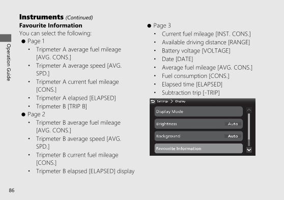
Favourite InformationYou can select the following:● Page 1• Tripmeter A average fuel mileage
[AVG. CONS.]• Tripmeter A average speed [AVG.
SPD.]• Tripmeter A current fuel mileage
[CONS.]• Tripmeter A elapsed [ELAPSED]• Tripmeter B [TRIP B]
● Page 2• Tripmeter B average fuel mileage
[AVG. CONS.]• Tripmeter B average speed [AVG.
SPD.]• Tripmeter B current fuel mileage
[CONS.]• Tripmeter B elapsed [ELAPSED] display
● Page 3• Current fuel mileage [INST. CONS.]• Available driving distance [RANGE]• Battery voltage [VOLTAGE]• Date [DATE]• Average fuel mileage [AVG. CONS.]• Fuel consumption [CONS.]• Elapsed time [ELAPSED]• Subtraction trip [-TRIP]
20190704203539_32MKS6000_eng_BOOK Page 91 Thursday, July 04 2019 20:57:26 JST
Operation Guide
86
Instruments (Continued)

a Select [Favourite Information], and thenpress the ENT switch.
b Push the or of the sel left/right switch until the desired page isdisplayed.
c Press / to select the availablechoices, and then press the ENT switch.
d Press / to select the availablechoices, and then press the ENT switch.
e Return to the riding information, previousscreen or Home screen. (P.40)
You can also perform the above settings byusing the touch screen.
20190704203539_32MKS6000_eng_BOOK Page 92 Thursday, July 04 2019 20:57:26 JST
Operation Guide
87Continued

Default:• Page 1• Tripmeter A average fuel mileage
[AVG. CONS.]• Tripmeter A average speed [AVG.
SPD.]• Tripmeter A current fuel mileage
[CONS.]• Page 2• Tripmeter B average fuel mileage
[AVG. CONS.]• Tripmeter B average speed [AVG.
SPD.]• Tripmeter B current fuel mileage
[CONS.]• Page 3• Current fuel mileage [INST. CONS.]• Available driving distance [RANGE]• Battery voltage [VOLTAGE]• Date [DATE]
Favourite Switch
20190704203539_32MKS6000_eng_BOOK Page 93 Thursday, July 04 2019 20:57:26 JST
Operation Guide
88
Instruments (Continued)

a Select [Favourite Switch], and then press theENT switch.
b Press the sel up switch or sel downswitch to select your desired mode.
c Return to the riding information, previousscreen or Home screen. (P.40)
You can also perform the above settings byusing the touch screen.
Available settings: [HSTC]/[Wheelie Control]/[Riding Mode]/[G Switch] CRF1100D/D2/D4
Default: [HSTC]
20190704203539_32MKS6000_eng_BOOK Page 94 Thursday, July 04 2019 20:57:26 JST
Operation Guide
89Continued

# GeneralFollowing items can be changed sequentially.• Date and Time (this page)• Units (P.93)• Volume (P.95)• Language (P.97)
Date and TimeThe multi-information display receives signalsfrom GPS satellites and updates the date andtime automatically.You can also adjust the date and timemanually.
20190704203539_32MKS6000_eng_BOOK Page 95 Thursday, July 04 2019 20:57:26 JST
Operation Guide
90
Instruments (Continued)

To [ON] (auto) or [OFF] (manual) adjust timeautomatically function:a Select [Date and Time], and then press the
ENT switch.b Select [Adjust Time Automatically], and then
press the ENT switch to [ON] (auto) or[OFF] (manual) the function.
When GPS cannot be located. Read thenotice message, and then press the ENTswitch.
c Return to the riding information, previousscreen or Home screen. (P.40)
You can also perform the above settings byusing the touch screen.
20190704203539_32MKS6000_eng_BOOK Page 96 Thursday, July 04 2019 20:57:26 JST
Operation Guide
91Continued

To adjust the clock manually:a Select [Date and Time], and then press the
ENT switch.b Select [Adjust Time Automatically], and then
press the ENT switch to [OFF] (manual) thefunction.
c Press / on the sel left/rightswitch to select a day, month, year, hour,minute or time format section.● To advance the day, month, year, hour
or minute: Press the sel up switch,and then press the ENT switch untilthe desired value is displayed.To delay the day, month, year, hour orminute: Press the sel down switch,and then press the ENT switch untilthe desired value is displayed.u Press and hold the ENT switch to
advance the figure fast.● To select the time format: Press the
sel up switch or sel downswitch, and then press the ENT switchuntil the desired time format isdisplayed.u Press and hold the ENT switch to
advance the figure fast.
20190704203539_32MKS6000_eng_BOOK Page 97 Thursday, July 04 2019 20:57:26 JST
Operation Guide
92
Instruments (Continued)

d Return to the riding information, previousscreen or Home screen. (P.40)
You can also perform the above settings byusing the touch screen.
Available settings: [ON] (auto)/[OFF](manual)Default: [ON] (auto)
UnitsYou can change the following units.● [Speed]: [km/h] or [mph]● [Fuel Consumption]: [l/100 km] or [km/l]
If the [mph] for speed is selected, the fuelmileage shown by [mpg] or [mile/L].
20190704203539_32MKS6000_eng_BOOK Page 98 Thursday, July 04 2019 20:57:26 JST
Operation Guide
93Continued

a Select [Units], and then press the ENTswitch.
b Press the sel up switch or sel downswitch to select a setting menu.
c Push the or of the sel left/right switch to select your desired unit.
d Return to the riding information, previousscreen or Home screen. (P.40)
You can also perform the above settings byusing the touch screen.
Available settings:● [Speed]: [km/h]/[mph]● [Fuel Consumption]: [l/100 km]/[km/l]/
[mpg]/[mil/L]Default:● [Speed]: [km/h]● [Fuel Consumption]: [l/100 km]
20190704203539_32MKS6000_eng_BOOK Page 99 Thursday, July 04 2019 20:57:26 JST
Operation Guide
94
Instruments (Continued)

VolumeSelects the volume setting to automaticallyincrease volume from the headsets as thespeed of the vehicle increases.
To [Off] (disable), [Low] or [High] automaticvolume function:a Select [Volume], and then press the ENT
switch.b Select [Automatic Volume], and then press
the ENT switch.
c Press the sel up switch or sel downswitch to set your selection.
20190704203539_32MKS6000_eng_BOOK Page 100 Thursday, July 04 2019 20:57:26 JST
Operation Guide
95Continued

d Return to the riding information, previousscreen or Home screen. (P.40)
You can also perform the above settings byusing the touch screen.
Available settings: [Off] (disable)/[Low]/[High]Default: [Off] (disable)
To adjust the volume:a Select [Volume], and then press the ENT
switch.b Press the sel up switch or sel down
switch to select a setting menu.c Push the or of the sel left/
right switch to select your preferred level.u Push and hold the or of the
sel left/right switch to advance thefigure fast.
20190704203539_32MKS6000_eng_BOOK Page 101 Thursday, July 04 2019 20:57:26 JST
Operation Guide
96
Instruments (Continued)

d Return to the riding information, previousscreen or Home screen. (P.40)
You can also perform the above settings byusing the touch screen.
VOLUME level range:Other than Microphone: Level 0 to 30Micro phone: Level 0 to 14
Default:● Music: 7● Phone: 7● System: 7● Ringtone: 7● Voice: 7● CarPlay: 7● Microphone: 7
LanguageChanges the system language.
a Select [Language], and then press the ENTswitch.
b Press the sel up switch or sel downswitch to select the display language thatyou want to use on the .screen
20190704203539_32MKS6000_eng_BOOK Page 102 Thursday, July 04 2019 20:57:26 JST
Operation Guide
97Continued

c Return to the riding information, previousscreen or Home screen. (P.40)
You can also perform the above settings byusing the touch screen.
Default: [UK English]
Restore Default SettingsThe set values can be returned to defaultsettings.
a Select [Restore Default Settings], and thenpress the ENT switch.
20190704203539_32MKS6000_eng_BOOK Page 103 Thursday, July 04 2019 20:57:26 JST
Operation Guide
98
Instruments (Continued)

b Select the [No] (not restore) or [Yes](restore) using the sel up or sel downswitch.
c When the [No] is selectedPress the ENT switch.The set value is maintained, and then thedisplay returns to the [General] menuscreen.When the [Yes] is selectedPress the ENT switch.The display changes to the confirmationscreen.
d Select the [No] (not restore) or [Yes](restore) using the sel up or sel downswitch on the confirmation screen.
e When the [No] is selectedPress the ENT switch.The set value is maintained, and then thedisplay returns to the [General] menuscreen.When the [Yes] is selectedPress the ENT switch.The set value return to default setting, andthen the display returns to the [General]menu screen.
20190704203539_32MKS6000_eng_BOOK Page 104 Thursday, July 04 2019 20:57:26 JST
Operation Guide
99Continued

f Return to the riding information, previousscreen or Home screen. (P.40)
You can also perform the above settings byusing the touch screen.Default setting values:● -TRIP: 000● Display mode:
u [TOUR MODE]: Gold imageu [URBAN MODE]: Silver imageu [GRAVEL MODE]: Silver imageu [OFF ROAD MODE]: Bronze imageu [USER 1 MODE]: Silver imageu [USER 2 MODE]: Bronze image
● Brightness: Auto● Background: Auto 1● Favourite information:
u Page 1:- Tripmeter A average fuel mileage
[AVG. CONS.]- Tripmeter A average speed [AVG.
SPD.]- Tripmeter A current fuel mileage
[CONS.]u Page 2:
- Tripmeter B average fuel mileage[AVG. CONS.]
- Tripmeter B average speed [AVG.SPD.]
- Tripmeter B current fuel mileage[CONS.]
u Page 3:- Current fuel mileage [INST. CONS.]- Available driving distance [RANGE]- Battery voltage [VOLTAGE]- Date [DATE]
20190704203539_32MKS6000_eng_BOOK Page 105 Thursday, July 04 2019 20:57:26 JST
Operation Guide
100
Instruments (Continued)

● Favourite switch: [HSTC]● Automatic Volume: [OFF]● Periodic Maintenance:• Distance: "-----"• Date: "----/---"
● Oil Change:• Distance: "-----"• Date: "----/---"
● Delete the Bluetooth® paired device
# ServiceFollowing items can be changed sequentially.• Maintenance (P.102)• DTC (P.104)• Initialise (P.105)• Service mode (P.106)• Equipment (P.107)• System Information (P.107)
20190704203539_32MKS6000_eng_BOOK Page 106 Thursday, July 04 2019 20:57:26 JST
Operation Guide
101Continued

MaintenanceYou can check the next periodic inspectiontime and next engine oil change.You can change the setting of the nextperiodic inspection and next engine oilchange.
a Select [Maintenance], and then press theENT switch.
b Press the sel up switch or sel downswitch to select a setting menu, and thenpress the ENT switch.
c Press or of the sel left/rightswitch to select a distance, month or yearsection.
20190704203539_32MKS6000_eng_BOOK Page 107 Thursday, July 04 2019 20:57:26 JST
Operation Guide
102
Instruments (Continued)

● To dvance the distance, month oryear: Press the sel up switch, andthen press the ENT switch until thedesired value is displayed.To delay the distance, month or year:Press the sel down switch, andthen press the ENT switch until thedesired value is displayed.u Press and hold the ENT switch to
advance the figure fast.
d Return to the riding information, previousscreen or Home screen. (P.40)
You can also perform the above settings byusing the touch screen.
Setting range:● Periodic Maintenance:• Distance: 100 to 12,000 km or 100 to
8,000 mile• Date: 2000/JAN to 2099/DEC
● Oil Change:• Distance: 100 to 12,000 km or 100 to
8,000 mile• Date: 2000/JAN to 2099/DEC
Default:● Periodic Maintenance:• Distance: "-----"• Date: "----/---"
● Oil Change:• Distance: "-----"• Date: "----/---"
20190704203539_32MKS6000_eng_BOOK Page 108 Thursday, July 04 2019 20:57:26 JST
Operation Guide
103Continued

DTCYou can check for a current problem with thePGM-FI system.If your vehicle has problem, DTC index isdisplayed.Reduce speed and have your vehicleinspected by your dealer as soon as possible.
a Select [DTC], and then press the ENTswitch.
b Return to the riding information, previousscreen or Home screen. (P.40)
You can also perform the above settings byusing the touch screen.
20190704203539_32MKS6000_eng_BOOK Page 109 Thursday, July 04 2019 20:57:26 JST
Operation Guide
104
Instruments (Continued)

InitialiseYou can calibrate of the touch screen.
a Select [Initialise], and then press the ENTswitch.
b Select [Touchscreen Calibration], and thenpress the ENT switch.
20190704203539_32MKS6000_eng_BOOK Page 110 Thursday, July 04 2019 20:57:26 JST
Operation Guide
105Continued

c Touch the centre of the cross four times.u The screen flashes green when calibration is
complete.If calibration fails, the screen flashes red.Try step c again.
d Return to the riding information, previousscreen or Home screen. (P.40)
You can also perform the above settings byusing the touch screen.
Service ModeThe DRL and cornering light(CRF1100A2/A4/D2/D4 ) can be turned onwhen the vehicle is stopped for inspection.
a Start the engine. (P.206)b Stop the vehicle.c Select [Service Mode], and then press the
ENT switch.
20190704203539_32MKS6000_eng_BOOK Page 111 Thursday, July 04 2019 20:57:26 JST
Operation Guide
106
Instruments (Continued)

d CRF1100A2/A4/D2/D4Press the sel up switch or sel downswitch to select a menu.
e Press the ENT switch.The light of the selected menu lights up.
u The service mode will automaticallystop in 5 minutes.
f Return to the riding information, previousscreen or Home screen. (P.40)
You can also perform the above settings byusing the touch screen.
EquipmentThis menu cannot be selected.
System InformationShows various information of the multi-information display.● [Software Version]● [Software update]: Cannot be selected.● [Hardware Information]● [GPS Reception Status]● [EULAs]● [Copyright and Acknowledgements]
# RegulatoryShows regulatory information of the multi-information display.
20190704203539_32MKS6000_eng_BOOK Page 112 Thursday, July 04 2019 20:57:26 JST
Operation Guide
107Continued

Pop-up informationIn the following cases, pop-up information is displayed at the bottom of the multi-informationdisplay.● Maintenance information:
When the inspection time of your vehicle is approaching.Maintenance information
Indication Explanation RemedyWhen the periodicinspection time ofyour vehicle isapproaching
Have your vehicleinspected by yourdealer.
When the oil changetime of your vehicle isapproaching
Change the engine oil.(P.262)
20190704203539_32MKS6000_eng_BOOK Page 113 Thursday, July 04 2019 20:57:26 JST
Operation Guide
108
Instruments (Continued)

20190704203539_32MKS6000_eng_BOOK Page 114 Thursday, July 04 2019 20:57:26 JST
Operation Guide
109

Indicators
20190704203539_32MKS6000_eng_BOOK Page 115 Thursday, July 04 2019 20:57:26 JST
Operation Guide
110
If one of these indicators does not come on when it should, haveyour dealer check for problems.
Left turn signalindicator
PGM-FI (Programmed Fuel Injection) malfunction indicator lamp (MIL)
High coolanttemperature indicatorComes on briefly when theignition switch is turned tothe (On) position.If it comes on whileriding: (P.300)
Comes on briefly when the ignition switch is turned to the (On) position.If it comes on or flashes while engine is running: (P.302)

20190704203539_32MKS6000_eng_BOOK Page 116 Thursday, July 04 2019 20:57:26 JST
Operation Guide
111Continued
High beam indicator
DRL indicator (P.222)
If it comes on while riding: (P.304)
Torque Control indicator● Comes on when the ignition switch is turned to the (On) position. Goes off
when your speed reaches approximately 5 km/h (3 mph) to indicate TorqueControl is ready to work.
● Blinks when Torque Control is operating.
Torque Control OFF Indicator● Comes on when the Torque Control is turned Off.
Right turn signal indicator

20190704203539_32MKS6000_eng_BOOK Page 117 Thursday, July 04 2019 20:57:26 JST
Operation Guide
112
Indicators (Continued)
Low fuel indicator
If the indicator comes on and the fuel gauge indicator flashes: (P.306)
● Comes on when there is only reserve fuel left in the fuel tank. Remaining fuel when lowfuel indicator comes on: Approximately 3.6 L (0.95 US gal, 0.79 Imp gal) (CRF1100A/D )Approximately 3.9 L (1.03 US gal, 0.86 Imp gal) (CRF1100A2/A4/D2/D4 )
● Comes on briefly when the ignition switch is turned to the (On) position.
Parking brake indicatorCRF1100D/D2/D4Lights as a reminder that youhave not released the parkingbrake lever.
Comes on when thetransmission is in Neutral.
Neutral indicator

20190704203539_32MKS6000_eng_BOOK Page 118 Thursday, July 04 2019 20:57:26 JST
Operation Guide
113Continued
ABS (Anti-lock Brake System) indicator
If it comes on while riding: (P.303)● Goes off when your speed reaches approximately 10 km/h (6 mph).● Comes on briefly when the ignition switch is turned to the (On) position.
Rear ABS (Anti-lock Brake System) OFF Indicator● Comes on briefly when the ignition switch is turned to the (On) position.● Comes on when the ABS function on the rear wheel is turned off. (P.122)
SET Cruise control SET indicatorComes on if you have set a speed for cruise control.Cruise Control: (P.215)
Cruise control main indicatorComes on when you press cruise control main switch.Cruise Control: (P.215)

20190704203539_32MKS6000_eng_BOOK Page 119 Thursday, July 04 2019 20:57:26 JST
Operation Guide
114
Indicators (Continued)
Low oil pressure indicator
If it comes on while engine isrunning: (P.301)
● Comes on when the ignitionswitch is turned to the (On)position.
● Goes off when the engine starts.
HISS indicator (P.342)● Comes on briefly when the ignition switch is
turned to the (On) position. Goes off if theignition key has the correct coding.
● Flashes every 2 seconds for 24 hours when theignition switch is turned to the (Off) position.
Suspension indicator CRF1100A4/D4● Comes on when the suspension initialization is waiting.● Stop your vehicle and wait for a few seconds until the indicator turns
off.If indicator dose not turn off, contact your dealer.

20190704203539_32MKS6000_eng_BOOK Page 120 Thursday, July 04 2019 20:57:26 JST
Operation Guide
115
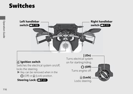
Switches
20190704203539_32MKS6000_eng_BOOK Page 121 Thursday, July 04 2019 20:57:26 JST
Operation Guide
116
Turns electrical systemon for starting/riding.
Turns engine off. (Off)
(On)
(Lock)Locks steering.Steering Lock: (P.121)
u Key can be removed when in the (Off) or (Lock) position.
Switches the electrical system on/off,locks the steering.
Ignition switch
Left handlebarswitch (P.118)
Right handlebarswitch (P.117)

20190704203539_32MKS6000_eng_BOOK Page 122 Thursday, July 04 2019 20:57:26 JST
Operation Guide
117Continued
Engine stop switch/START button
u In an emergency, switchto the (Stop) positionto stop the engine.
Should normally remain inthe (Run) position.
Function switchPress to display the pop-up informationon the multi-information display.
AT/MT switchCRF1100D/D2/D4To shift between the ATMODE and MT MODE.(P.212)
N-D switchCRF1100D/D2/D4To shift between Neutraland AT MODE. (P.212)
Cruise control main switchPress to activate the cruise controlsystem. (P.215)
Cruise control leverPush up or down to set the speed or adjustthe set speed. (P.217)
# Right handlebar switch
u To start the engine.(P.206)

20190704203539_32MKS6000_eng_BOOK Page 123 Thursday, July 04 2019 20:57:26 JST
Operation Guide
118
Switches (Continued)
Horn button
# Left handlebar switch Favourite switch
Turn signal switchThe turn signal will automatically stopwhen you complete the turn. (Youcan manually cancel the lights bypressing the switch in.) When usedfor a lane change, the turn signal willautomatically stop in 7 seconds orafter riding 120 m (131 yards). In somecases, the timing at which the turnsignal stops could be less or more.Always use the recommended tyresto ensure correct automaticcancellation operation.
Hazard switchSwitchable when the ignition switch is turned tothe (On) position. Can be turned to offregardless of the ignition switch position.u The signals continue flashing with the ignition
switch in (Off) or (Lock) after the hazardswitch is on.
Shift down switch (-)CRF1100D/D2/D4To shift down the gear. (P.214)
Favourite switch can be assigned to the HSTC switch,wheelie control switch, riding mode switch or Gswitch. (P.88)

20190704203539_32MKS6000_eng_BOOK Page 124 Thursday, July 04 2019 20:57:26 JST
Operation Guide
119Continued
Shift up switch (+)CRF1100D/D2/D4To shift up the gear. (P.214)
● Pull backward to return to the riding information oraudio screen. (P.40)
● Pull backward and hold to go to the Home screenor Apple CarPlay screen. (P.38)
● Push forward to receive, reject or end a call. (P.189)● Push forward to start Siri if Apple CarPlay is
available. (P.204)
Function lever
Headlight dimmer/Passinglight control switch• : High beam• : DRL auto or off (low beam) (P.222)• : Flashes the high beam headlight.
● Push forward or pull backward to adjust the audio system volume. (P.156)● Push forward to select the [AUTO] of DRL or pull backward to select
[Dismiss] for DRL. (P.222)● Push forward or pull backward to adjust the grip heater level. (P.131)
Voice control switch / Page switch

20190704203539_32MKS6000_eng_BOOK Page 125 Thursday, July 04 2019 20:57:26 JST
Operation Guide
120
Switches (Continued)
Sel up switchPress the sel up switch to select the available choices. (P.39)
Sel down switchPress the sel down switch to select the available choices. (P.39)
ENT switchPress to set your selection. (P.39)
Sel left/right switchPress the sel left/right switch in the / directions to select the available choices. (P.39)
Skip switchSkips to the next song or to move rapidlywithin a track. (P.179)
Back switchPress to return to the previous screen.(P.40)
Goes back switchGoes back to the beginning of the current or previoussong or to move rapidly within a track. (P.179)

Steering LockLock the steering when parking to helpprevent theft.A U-shaped wheel lock or similar device isalso recommended.
# Lockinga Turn the handlebar all the way to the left.b Push the key down, and turn the ignition
switch to the (Lock) position.u Jiggle the handlebar if the lock is difficult
to engage.c Remove the key.
# UnlockingInsert the key, push it in, and turn the ignitionswitch to the (Off) position.
20190704203539_32MKS6000_eng_BOOK Page 126 Thursday, July 04 2019 20:57:26 JST
Operation Guide
121
Ignition key
Turn
a
b
Push

ABS function on the rear wheelThe ABS function on the rear wheel can beoptionally turned off for off-road riding.You can turn off the rear wheel ABS functionin [OFF ROAD MODE], [USER 1 MODE] or[USER 2 MODE].u Each time the ignition switch is turned to the
(On) position, the ABS function on bothwheels will automatically be turned on[ACTIVE], but the ABS will maintain the rearwheel [CANCEL] off-function when enginestopped by using the engine stop switch.
u Select [ON ROAD] of ABS mode [ABS], theABS function on both wheels [ABS RR] willautomatically be turned on [ACTIVE].
u When changing the riding mode, the ABSfunction on both wheels will automaticallybe turned on [ACTIVE].
To turn off the ABS function on the rearwheela Stop the vehicle and close the throttle
completely.b Select [OFF ROAD MODE], [USER 1 MODE]
or [USER 2 MODE] mode of riding mode.(P.148)If [USER 1 MODE] or [USER 2 MODE] isselected, select [OFF ROAD] for ABSmode [ABS]. (P.76)
c Select the gold image display. (P.81)d Select page 4. (P.45)
20190704203539_32MKS6000_eng_BOOK Page 127 Thursday, July 04 2019 20:57:26 JST
Operation Guide
122

e Press the ENT switch.f Select [ABS RR].g Press on the sel left/right switch
to select [CANCEL] (off).
h Read the notice message.i Select [Yes], and then press the ENT switch.
j Press the back switch.u The rear ABS OFF indicator is on, when
the ABS function on the rear wheel [ABSRR] is turned [CANCEL] (off).
You can also perform the above settings byusing the touch screen.
20190704203539_32MKS6000_eng_BOOK Page 128 Thursday, July 04 2019 20:57:26 JST
Operation Guide
123Continued

To turn on the ABS function on bothwheelsa Stop the vehicle and close the throttle
completely.b Select the gold image display. (P.81)c Select page 4. (P.45)
d Press the ENT switch.e Select [ABS RR].f Press on the sel left/right switch
to select [ACTIVE] (on).u The rear ABS OFF indicator flashes
several times, and then off, when theABS function on the rear wheel [ABS RR]is turned on [ACTIVE].
20190704203539_32MKS6000_eng_BOOK Page 129 Thursday, July 04 2019 20:57:26 JST
Operation Guide
124
ABS function on the rear wheel (Continued)

g Press the back switch.You can also perform the above settingsby using the touch screen.
Available settings: [ACTIVE]/[CANCEL]Default: [ACTIVE]
20190704203539_32MKS6000_eng_BOOK Page 130 Thursday, July 04 2019 20:57:26 JST
Operation Guide
125
ABS function onboth wheels is[ACTIVE] (on).
ABS function onrear wheel is[CANCEL] (off).
When the gold image is selected:

G switchCRF1100D/D2/D4The G switch can change the enginecharacteristics of your vehicle to helpimprove traction and machine control for off-road riding by reducing the amount of clutchslip during throttle operation.u Other than USER 1 and USER 2 MODE
Each time the ignition switch is turned tothe (On) position, the G switch [G] willautomatically be set to default setting.USER 1 and USER 2 MODEThe G switch [G] setting will bemaintained even if the ignition switch isturned to the (Off) position.
u The G switch [G] may not compensate forrough road conditions.Always consider road and weatherconditions, as well as your skills andcondition, when applying throttle.
G switch on or off● When using the favourite switch.
a Stop the vehicle and close the throttlecompletely.
b Select [G Switch] of the favouriteswitch. (P.88)
c Press the favourite switch.
20190704203539_32MKS6000_eng_BOOK Page 131 Thursday, July 04 2019 20:57:26 JST
Operation Guide
126
Favourite switch

● When using the multi-information display:a Stop the vehicle and close the throttle
completely.b Select the gold image display. (P.81)c Select page 4. (P.45)d Press the ENT switch.e Select [G].
f Press on the sel left/rightswitch to select [CANCEL] (off).Press on the sel left/rightswitch to select [ACTIVE] (on).
g Press the back switch.You can also perform the above settingsby using the touch screen.
20190704203539_32MKS6000_eng_BOOK Page 132 Thursday, July 04 2019 20:57:26 JST
Operation Guide
127Continued

Available settings: [ACTIVE]/[CANCEL]Default:● [TOUR MODE]: [CANCEL]● [URBAN MODE]: [CANCEL]● [GRAVEL MODE]: [CANCEL]● [OFF ROAD MODE]: [ACTIVE]● [USER 1 MODE]: [CANCEL]● [USER 2 MODE]: [CANCEL]
20190704203539_32MKS6000_eng_BOOK Page 133 Thursday, July 04 2019 20:57:26 JST
Operation Guide
128
G switch (Continued)
G switch [G][CANCEL] (off)
G switch [G][ACTIVE] (on)
When the gold image is selected:

Parking BrakeCRF1100D/D2/D4
Parking Brake LeverBe sure the parking brake is applied whileparking and warming up the engine.u Make sure the parking brake lever is
released before riding.
To apply the parking brakeSqueeze the parking brake lever (a) fullythen rotate the lock lever (b) clockwise untilit engages the slot on the parking brake leverbracket back to lock the rear wheel.u The parking brake lock will not function if
the parking brake is not adjusted properly.(P.270)
To release the parking brakeSqueeze the parking brake lever until thelock lever is released from the slot on theparking brake lever bracket.u Before riding, check that the parking brake
indicator is turned off and make sure thatthe parking brake is fully released so there isno drag on the rear wheel.
20190704203539_32MKS6000_eng_BOOK Page 134 Thursday, July 04 2019 20:57:26 JST
Operation Guide
129
Lock lever
Parking brake lever
Slot

Handle Grip HeaterCRF1100A2/A4/D2/D4This vehicle is equipped with a handle gripheater that warms up your hands during ride.Wear gloves to protect your hands from theheated grips.
Handle grip heater indicator:The selected heater level is indicated by thenumber of times the indicator blinks whenthe heater is turned on and the heater level ischanged. For example, If you select heaterlevel 5, the indicator blinks 5 times andrepeats it 7 times.
Heater level:The selected heater level is indicated for afew seconds in the clock area, when thehandle grip heater switch is operated.
Handle grip heater status icon: (P.132)Displayed when the handle grip heater is on.
20190704203539_32MKS6000_eng_BOOK Page 135 Thursday, July 04 2019 20:57:26 JST
Operation Guide
130
Handle grips

# To operate handle grip heatera Start the engine. (P.206)b Select the handle grip heater display of pop-
up information using the function switch.
c Push forward or pull backward the function lever to select the handle gripheater level.u The status icon will be appeared on the
display when the handle grip heateroperates.
u Do not leave the handle grip heater inthe high position for a long time on awarm day.
20190704203539_32MKS6000_eng_BOOK Page 136 Thursday, July 04 2019 20:57:26 JST
Operation Guide
131Continued
Function switch
Function lever

# To turn off handle grip heatera Select the handle grip heater display of pop-
up information using the function switch.b Pull backward the function lever several
times to select the handle grip heater off.Do not use the handle grip heater with theengine at idle for a long time. It may result ina low (or dead) battery.
Maintains the selected level when the ignitionswitch is turned to the (Off) position.u The heater level is not changed if the
ignition switch is turned to the (Off)position within 5 seconds after heater levelchanged.
20190704203539_32MKS6000_eng_BOOK Page 137 Thursday, July 04 2019 20:57:26 JST
Operation Guide
132
Handle Grip Heater (Continued)
No indication (Off)
lowest temperature
highest temperature
Level 1
Level 2
Level 3
Level 4
Level 5
Pull backward the function lever
Push forward the function lever

Honda selectable torque controlTorque Control level (engine power control)can be selected or turned on/off.u Do not change the Torque Control level
while riding.Stop the vehicle first, turn the TorqueControl off or on and select the desiredlevel.
u The Torque Control setting cannot bechanged or turned off when the system isactivated (Torque Control indicator flashing).
u In the following cases, the Torque Controlwill be turned on and the specific TorqueControl level will automatically be set asbelow.• Each time the ignition switch is turned
to the (On) position, the TorqueControl level will automatically be setto level it was set to. However, if thelevel was set to [0] (off), it will becomelevel 1.
u When the Torque Control is turned from the[0] (off) position to the on position, it willautomatically be set to level of beforeturning off the Torque Control.
20190704203539_32MKS6000_eng_BOOK Page 138 Thursday, July 04 2019 20:57:26 JST
Operation Guide
133Continued

Torque Control level setting● When using the favourite switch:
a Stop the vehicle.b Select the [HSTC] of the favourite
switch. (P.88)c Press the favourite switch.
u 7: the maximum Torque Control levelu 1: the minimum Torque Control level
● When using the multi-information display:a Stop the vehicle.b Select the gold image display. (P.81)c Select page 4. (P.45)d Press the ENT switch.e Select [HSTC].f Push the or of the sel
left/right switch to select your preferredlevel.
20190704203539_32MKS6000_eng_BOOK Page 139 Thursday, July 04 2019 20:57:26 JST
Operation Guide
134
Honda selectable torque control (Continued)
Favourite switch

g Press the back switch.You can also perform the above settingsby using the touch screen.
Torque Control on and offa Stop the vehicle.b Select the gold image display. (P.81)c Select page 4. (P.45)d Press the ENT switch.e Select [HSTC].f Press and hold on the sel left/
right switch to set the [0] (off).Press and hold on the sel left/right switch to set to level of beforeturning [0] (off) the Torque Control.
g Press the back switch.You can also perform the above settingsby using the touch screen.
Setting range: Level 1 to 7 or 0 (Off)
20190704203539_32MKS6000_eng_BOOK Page 140 Thursday, July 04 2019 20:57:26 JST
Operation Guide
135Continued

20190704203539_32MKS6000_eng_BOOK Page 141 Thursday, July 04 2019 20:57:26 JST
Operation Guide
136
Honda selectable torque control (Continued)
Level [2]
[0] (Off)Push on the sel left/right switch
Push and hold on the sel left/right switch
Push on the sel left/right switch orpress the favourite switchPush and hold on the sel left/right switch
Level [1] Level [3]
Level [7] Level [6] Level [5] Level [4]

20190704203539_32MKS6000_eng_BOOK Page 142 Thursday, July 04 2019 20:57:26 JST
Operation Guide
137

Wheelie ControlWheelie Control level [W] can be selected orturned on/off.u Do not change the wheelie control level [W]
while riding.Stop the vehicle first, then select the wheeliecontrol level [W].
u In the following cases, the wheelie control[W] will be turned on and the specificwheelie control level [W] will automaticallybe set as below.• Each time the ignition switch is turned
to the (On) position, the wheeliecontrol level [W] will automatically beset to level it was set to. However, ifthe level was set to 0 (off), it willautomatically be set to level of beforeturning off the wheelie control level[W].
u When the wheelie control [W] is turned fromthe [0] (off) position to the on position, it willautomatically be set to level of beforeturning off the wheelie control [W].
20190704203539_32MKS6000_eng_BOOK Page 143 Thursday, July 04 2019 20:57:26 JST
Operation Guide
138

Wheelie Control Level setting● When using the favourite switch:
a Stop the vehicle.b Select the [W] of the favourite switch.(P.88)
c Press the favourite switch.u 3: the maximum wheelie control level
[W]u 1: the minimum wheelie control level
[W]
● When using the multi-information display:a Stop the vehicle.b Select the gold image display. (P.81)c Select page 4. (P.45)d Press the ENT switch.e Select [W].f Push the or of the sel
left/right switch to select your preferredlevel.
20190704203539_32MKS6000_eng_BOOK Page 144 Thursday, July 04 2019 20:57:26 JST
Operation Guide
139Continued
Favourite switch

g Press the back switch.You can also perform the above settingsby using the touch screen.
Wheelie Control on and offa Stop the vehicle.b Select the gold image display. (P.81)c Select page 4. (P.45)d Press the ENT switch.e Select [W].f Press and hold on the sel left/
right switch to set the [0] (off).Press and hold on the sel left/right switch to set to level of beforeturning [0] (off) the wheelie control.
g Press the back switch.You can also perform the above settingsby using the touch screen.
Setting range: Level 1 to 3 or 0 (Off)
20190704203539_32MKS6000_eng_BOOK Page 145 Thursday, July 04 2019 20:57:26 JST
Operation Guide
140
Wheelie Control (Continued)

20190704203539_32MKS6000_eng_BOOK Page 146 Thursday, July 04 2019 20:57:26 JST
Operation Guide
141
Level [2]
[0] (Off)Push on the sel left/right switch
Push and hold on the sel left/right switch
Push on the sel left/right switch orpress the favourite switchPush and hold on the sel left/right switch
Level [1]
Level [3]

Riding modeYou can change the riding mode.The riding mode consists of the followingparameters.
[P] Power: Engine output level[EB] Engine brake: Engine brake levelCRF1100A4/D4
[S] [Overall]: Suspension damping[Front]: Suspension damping[Rear]: Suspension damping
CRF1100D/D2/D4[G] G switch: (P.126)
[ABS] ABS mode:• [OFF ROAD]: Off road mode• [ON ROAD]: On road mode
CRF1100A4/D4[PRELOAD] [Preload]: Rear suspensionpreload• (Rider): Rider only (Minimum preload)• (Rider+Cargo): Rider and luggage• (Rider+Passenger): Rider and
passenger• (Rider+Passenger+Cargo): Rider,
passenger and luggage (Maximumpreload)
20190704203539_32MKS6000_eng_BOOK Page 147 Thursday, July 04 2019 20:57:26 JST
Operation Guide
142

Riding mode has 6 modes.Available riding modes: [TOUR MODE],[URBAN MODE], [GRAVEL MODE], [OFFROAD MODE], [USER 1 MODE] and [USER 2MODE]
[TOUR MODE], [URBAN MODE], [GRAVELMODE] and [OFF ROAD MODE]u [TOUR MODE]: Enables smooth
acceleration even when riding with apassenger or a full load of luggage.
u [URBAN MODE]: Standard, all-roundmode for a variety of situations.
u [GRAVEL MODE]: Good for stable ridingon slippery surfaces such as dirt roads.
u [OFF ROAD MODE]: Suitable for enjoyingoff-road sports riding.
Each initial setting value cannot be changed.
[USER 1 MODE] and [USER 2 MODE]Each initial setting value can be changed.
20190704203539_32MKS6000_eng_BOOK Page 148 Thursday, July 04 2019 20:57:26 JST
Operation Guide
143Continued
Current riding mode
[P] [Power]value
[G] G switch
[EB] [EngineBrake] value
[ABS] ABS mode[S] Overall

Initial setting
Riding modes[P]
[Power]value
[EB][EngineBrake]value
Suspension damping [ABS]ABS
mode[G] G
switch *2[S][Overall] *1 [Front] *1 [Rear] *1
[TOUR MODE] 1 2 H STD STD ON ROAD CANCEL*3
[URBAN MODE] 2 2 M STD STD ON ROAD CANCEL*3
[GRAVEL MODE] 4 3 S STD STD OFF ROAD CANCEL*3
[OFF ROAD MODE] 3 3 O STD STD OFF ROAD ACTIVE*3
[USER 1 MODE] 2*3 2*3 M*3 STD*3 STD*3 ONROAD*3 CANCEL*3
[USER 2 MODE] 4*3 3*3 S*3 STD*3 STD*3 OFFROAD*3 CANCEL*3
Notes:*1 : CRF1100A4/D4*2 : CRF1100D/D2/D4*3 : Value can be changed.
20190704203539_32MKS6000_eng_BOOK Page 149 Thursday, July 04 2019 20:57:26 JST
Operation Guide
144
Riding mode (Continued)

Riding modes[PRELOAD][Preload](Rider) *1
[PRELOAD][Preload]
(Rider+Cargo) *1
[PRELOAD][Preload](Rider+
Passenger) *1
[PRELOAD][Preload](Rider+
Passenger+Cargo) *1
[TOUR MODE] 5 10 15 20[URBAN MODE] 5 10 15 20[GRAVEL MODE] 5 10 15 20
[OFF ROAD MODE] 5 10 15 20[USER 1 MODE] 5*2 10*2 15*2 20*2
[USER 2 MODE] 5*2 10*2 15*2 20*2
Notes:*1 : CRF1100A4/D4*2 : Value can be changed.
20190704203539_32MKS6000_eng_BOOK Page 150 Thursday, July 04 2019 20:57:26 JST
Operation Guide
145Continued

[P] Power value (Engine output level)[P] Power value has four setting levels.Available setting range: 1 to 4u Level 1 has the maximum power.u Level 4 has the minimum power.
[EB] Engine brake value (Engine brakelevel)EB value has three setting levels.Available setting range: 1 to 3u Level 1 has the strongest engine braking
effect.u Level 3 has the weakest engine braking
effect.
[S] Overall: suspension dampingCRF1100A4/D4[S] Overall value has four setting levels.Available setting range: [H] Hard / [M]Medium / [S] Soft / [O] Off Roadu [H] Hard has the maximum suspension
damping.u [S] Soft has the minimum suspension
damping.u [O] Off Road is for off road settings.
[Front]: suspension dampingCRF1100A4/D4[Front] has three setting levels.Available setting range: - / STD / +u + has the maximum suspension damping.u - has the minimum suspension damping.
20190704203539_32MKS6000_eng_BOOK Page 151 Thursday, July 04 2019 20:57:26 JST
Operation Guide
146
Riding mode (Continued)

[Rear]: suspension dampingCRF1100A4/D4[Rear] has three setting levels.Available setting range: - / STD / +u + has the maximum suspension damping.u - has the minimum suspension damping.
ABS mode [ABS]ABS mode [ABS] has two setting levels.Available setting range: [OFF ROAD] or [ONROAD]u [OFF ROAD] is for off road settings.u [ON ROAD] is for on road settings.[G] G switch (P.126)
[PRELOAD] [Preload] (Rider), (Rider+Cargo), (Rider+Passenger) and (Rider+Passenger+Cargo): rear suspensionpreloadCRF1100A4/D4[PRELOAD] [Preload] Preload has twenty foursetting levels.Available setting range: 1 to 24u Level 24 has the maximum suspension
preload.u Level 1 has the minimum suspension
preload.
20190704203539_32MKS6000_eng_BOOK Page 152 Thursday, July 04 2019 20:57:26 JST
Operation Guide
147Continued

Selecting the riding modeWhen change the riding mode, the rearwheel ABS function [ABS RR] willautomatically be set to [ACTIVE].● When using the sel up switch and
sel down switch:a Press the sel up switch or sel
down switch.
You can also perform the above settingsby using the touch screen.
● When using the favourite switch:a Select the [Riding Mode] of the
favourite switch. (P.88)b Press the favourite switch.
20190704203539_32MKS6000_eng_BOOK Page 153 Thursday, July 04 2019 20:57:26 JST
Operation Guide
148
Riding mode (Continued)
sel up switch
sel downswitch
Favouriteswitch

Setting the riding modeYou can change the [P] [Power], [EB] [EngineBrake], [S] [Overall], [Front], [Rear], ABS mode[ABS] and [PRELOAD] [Preload] on the [USER1 MODE] and [USER 2 MODE] of the ridingmode. (P.76)
20190704203539_32MKS6000_eng_BOOK Page 154 Thursday, July 04 2019 20:57:26 JST
Operation Guide
149
Press the sel up switch orpress the favourite switchPress the sel down switch

Audio System# About Your Audio SystemThis audio system can play audio files onBluetooth® audio devices (mobile phone,digital audio player or equivalents).The audio system can pair with Bluetooth®sound devices (speakers, headsets,communication devices or equivalents).
You can operate the audio system from theswitches on the left handlebar and multi-information display. However, you cannotoperate some functions by the touch screenwhile the vehicle is in motion.• Local laws may prohibit the operation of
handheld electronic devices whileoperating a vehicle.
• Only operate audio switches when safe todo so.
• Set the volume at a level that still allowshorns and emergency vehicles to beheard.
• Some audio devices, iPhone andBluetooth® sound devices may not becompatible.
• We shall not be liable for any damages ortrouble in the use of audio device.
• iPhone, iPad, iPad Air, iPad Mini, iPod,iPod touch, iPod classic, iPod shuffle andiPod nano are trademarks of Apple Inc.
20190704203539_32MKS6000_eng_BOOK Page 155 Thursday, July 04 2019 20:57:26 JST
Operation Guide
150

About Bluetooth® audio• Only one Bluetooth® audio device and
two Bluetooth® sound devices can bepaired with the audio system at a time.When another device is paired, theinformation on the previously registereddevice is cancelled.
• If you receive a call to a paired phonewhile playing an audio, the paired phonemay stop playing.
• When unable to connect your Bluetooth®device to the audio system or whensounds skip or noises mix while playing,change the storage location of theBluetooth® device.
Bluetooth® Wireless TechnologyThe Bluetooth® word mark and logos areregistered trademarks owned by BluetoothSIG, Inc., and any use of such marks byHonda Motors Co., Ltd., is under license.Other trademarks and trade names are thoseof their respective owners.
20190704203539_32MKS6000_eng_BOOK Page 156 Thursday, July 04 2019 20:57:26 JST
Operation Guide
151Continued

Audio System Location
20190704203539_32MKS6000_eng_BOOK Page 157 Thursday, July 04 2019 20:57:26 JST
Operation Guide
152
Audio System (Continued)
iPhone
USB connection(P.201)
Multi-informationdisplay
Bluetooth® connection (P.160)
Left handlebarswitches
Rider Bluetooth® headset
Passenger Bluetooth®headset
USB connectoriPhone/Mobile phone/Bluetooth® audio device, etc.
Bluetooth® connection (P.165)
Bluetooth®connection(P.165)
GPS antenna

20190704203539_32MKS6000_eng_BOOK Page 158 Thursday, July 04 2019 20:57:26 JST
Operation Guide
153Continued
USB connection for Apple CarPlay
Headset supported profiles:
● A2DP ver. 1.2● HFP ver. 1.7
● PBAP ver. 1.0● AVRCP ver. 1.4● A2DP ver. 1.2● HFP ver. 1.5
Audio system supported profiles:

# Basic OperationsYou can operate and set the variousfunctions of the audio system using the touchscreen and/or switches on the left handlebar.However, you cannot operate some functionsby the touch screen while the vehicle is inmotion.
20190704203539_32MKS6000_eng_BOOK Page 159 Thursday, July 04 2019 20:57:26 JST
Operation Guide
154
Audio System (Continued)
[1] Function lever
[7] Voice control switch /[8] Page switch
[2] Sel up switch
[3] Sel down switch
[4] Skipswitch
[5] Goesback switch
[6] ENT switch
[9] Backswitch

[1] Function lever: Push forward or pullbackward the lever to adjust the volume.● To increase the volume: Push forward the
lever.● To decrease the volume: Pull backward the
lever.● To increase the volume rapidly: Push
forward and hold the lever.● To decrease the volume rapidly: Pull
backward and hold the lever.[2] Sel up switch: Press the switch to selecta menu item.[3] Sel down switch: Press the switch toselect a menu item.[4] Skip switch:● To skip to the next song: Press the switch.● To move rapidly within a track: Press and
hold the switch.[5] Goes back switch:● To go back to the beginning of the current
or previous song: Press the switch.
● To move rapidly within a track: Press andhold the switch
[6] ENT switch: Press to set your selection.[7] Voice control switch:● To receive or end a call. Starts Siri if Apple
CarPlay is available: Push forward theswitch.
● To reject a call: Push forward and hold theswitch.
[8] Page switch:● To return to the riding information or
audio screen: Pull backward the switch.● To return to the home screen or Apple
CarPlay screen: Pull backward and hold theswitch.
[9] Back switch:● To return to the previous screen: Press the
switch.● To return to the audio screen: Press and
hold the switch.
20190704203539_32MKS6000_eng_BOOK Page 160 Thursday, July 04 2019 20:57:26 JST
Operation Guide
155Continued

# To Adjust the VolumeYou can adjust the volume settings for theheadsets.The system has the following unique volumelevels.Adjust the volume while in the individualmodes.● [Music]● [Phone]● [System]● [Ringtone]● [Voice]● [CarPlay]● [Microphone]
Each volume can also be set from the menu.(P.95)
When you push forward or pull backward the function lever, the volume control level
appears on the pop-up information.
20190704203539_32MKS6000_eng_BOOK Page 161 Thursday, July 04 2019 20:57:26 JST
Operation Guide
156
Audio System (Continued)
Push forward the function leverPull backward the function lever

To increase the volume: push forward the function lever.u To increase the volume rapidly, push
forward and hold the function lever.To decrease the volume: pull backward the
function lever.u To decrease the volume rapidly, pull
backward and hold the function lever.
Volume level range:Other than Micro phone: Level 0 to 30Microphone: Level 0 to 14
# Automatic VolumeSelects the volume setting to automaticallyincrease volume from the headsets as thespeed of the vehicle increases.To select the Automatic Volume:(P.95)
Available settings: [Off]/[Low]/[High]Default: [Off]
20190704203539_32MKS6000_eng_BOOK Page 162 Thursday, July 04 2019 20:57:26 JST
Operation Guide
157Continued
Functionlever

Bluetooth® Audio
# Bluetooth® SettingYou can connect with your Bluetooth® audio device (mobile phone, digital audio player orequivalents) and Bluetooth® headsets via Bluetooth®.Available devices are as follows:● [Phone Pairing] (For Bluetooth® audio device) (P.160)● [Headset Pairing] (For rider headset and passenger headset) (P.165)
20190704203539_32MKS6000_eng_BOOK Page 163 Thursday, July 04 2019 20:57:26 JST
Operation Guide
158
Audio System (Continued)

Supported Bluetooth® version/profilesBluetooth® version Bluetooth 2.1 + EDR
Bluetooth® profiles (ForiPhone, mobile phone orBluetooth® device)
HFP (Hand Free Profile) ver. 1.5A2DP (Advanced Audio Distribution Profile) ver. 1.2AVRCP (Audio/Video Remote Control Profile) ver. 1.4PBAP (Phone Book Access Profile) ver. 1.0
Bluetooth® profiles (Forrider and passengerheadsets)
HFP (Hand Free Profile) ver. 1.7
A2DP (Advanced Audio Distribution Profile) ver. 1.2
● You cannot pair a Bluetooth® device and Bluetooth® headsets while the vehicle is moving.When pairing, park your vehicle in a safe place.
● Bluetooth® connection cannot be established while launching Apple CarPlay.● Your vehicle is not equipped an with intercom function. If you want to use the intercom
function, use the intercom function of your headset.● Some local governments prohibit the use of a headset by the operator of a motor vehicle.
Always obey applicable laws and regulations.
20190704203539_32MKS6000_eng_BOOK Page 164 Thursday, July 04 2019 20:57:26 JST
Operation Guide
159Continued

Phone PairingYou can establish a Bluetooth® connection intwo ways.● [Visible]: Search from the device.● [Phone Pairing]: Search from the system.
This function is disabled while the vehicle is inmotion.
a Enable the Bluetooth® function on yourdevice.u For details, refer to the instruction
manual of your device.b Select [Bluetooth], and then press the ENT
switch.
20190704203539_32MKS6000_eng_BOOK Page 165 Thursday, July 04 2019 20:57:26 JST
Operation Guide
160
Audio System (Continued)
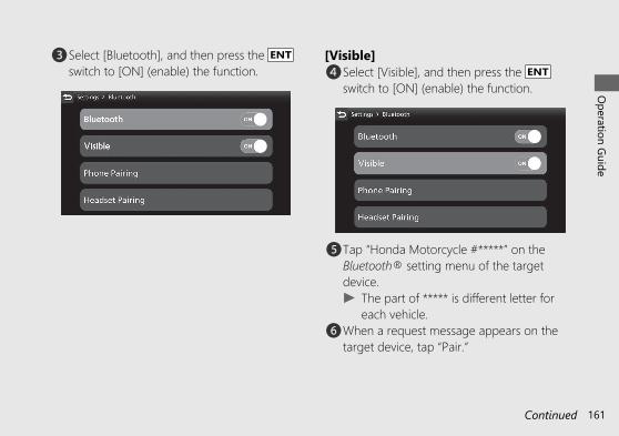
c Select [Bluetooth], and then press the ENTswitch to [ON] (enable) the function.
[Visible]d Select [Visible], and then press the ENT
switch to [ON] (enable) the function.
e Tap “Honda Motorcycle #*****” on theBluetooth® setting menu of the targetdevice.u The part of ***** is different letter for
each vehicle.f When a request message appears on the
target device, tap “Pair.”
20190704203539_32MKS6000_eng_BOOK Page 166 Thursday, July 04 2019 20:57:26 JST
Operation Guide
161Continued

g The device name and Pass Key appear onthe screen. Select [Yes], and then press theENT switch.
h When the pairing is complete, the name ofthe paired device are displayed.Icon status:
: Phone function connected
: Music function connected
i Return to the riding information, previousscreen or Home screen. (P.40)
You can also perform the above settings byusing the touch screen.
20190704203539_32MKS6000_eng_BOOK Page 167 Thursday, July 04 2019 20:57:26 JST
Operation Guide
162
Audio System (Continued)

[Phone Pairing]
d Select [Phone Pairing], and then press theENT switch.
e Select [+Add a device], and then press theENT switch.
f The names of the detected device aredisplayed.u If many Bluetooth® devices are
detected, the target device may bedetected under the list, scroll down thelist.
20190704203539_32MKS6000_eng_BOOK Page 168 Thursday, July 04 2019 20:57:26 JST
Operation Guide
163Continued

g Select a target device name, and then pressthe ENT switch.
h Select [Yes], and then press the ENT switch.
i When a request message appears on thetarget device, tap “Pair.”
j When the pairing is complete, the name ofthe paired device are displayed.Icon status:
: Phone function connected
: Music function connected
k Return to the riding information, previousscreen or Home screen. (P.40)
20190704203539_32MKS6000_eng_BOOK Page 169 Thursday, July 04 2019 20:57:26 JST
Operation Guide
164
Audio System (Continued)

You can also perform the above settings byusing the touch screen.
To disconnect the phone: (P.168)
Headset PairingThis function is disabled while the vehicle is inmotion.a Enable the Bluetooth® function on your
device.u For details, refer to the instruction
manual of your device.b Select [Bluetooth], and then press the ENT
switch.
20190704203539_32MKS6000_eng_BOOK Page 170 Thursday, July 04 2019 20:57:26 JST
Operation Guide
165Continued

c Select [Bluetooth], and then press the ENTswitch to [ON] (enable) the function.
d Select [Headset Pairing], and then press theENT switch.
e Select [+ Add a device], and then press theENT switch.
f The names of the detected device aredisplayed.u If many Bluetooth® devices are
detected, the target device may bedetected under the list, scroll down thelist.
20190704203539_32MKS6000_eng_BOOK Page 171 Thursday, July 04 2019 20:57:26 JST
Operation Guide
166
Audio System (Continued)

g Select a target device name, and then pressthe ENT switch.
h When the pairing is complete, a message toinform you that pairing was successfulappears on the screen.
Rider When pairing rider headsetPassenger When pairing passenger headset
i Return to the riding information, previousscreen or Home screen. (P.40)
You can also perform the above settings byusing the touch screen.
To disconnect the headset: (P.168)
20190704203539_32MKS6000_eng_BOOK Page 172 Thursday, July 04 2019 20:57:26 JST
Operation Guide
167Continued

To Reconnect a Paired DeviceAutomaticallyWhen the ignition switch is turned (On)position, the system reconnects withregistered devices automatically.u If the system finds multiple paired devices,
the system will reconnect with the devicethat was connected last.
u After reconnecting, the song that was lastplayed will be played automatically.
To Connect/Disconnect AvailableFunctions IndividuallyDepending on the connected device, thisfunction may not be able to establish aconnection.a Select [Bluetooth], and then press the ENT
switch.
20190704203539_32MKS6000_eng_BOOK Page 173 Thursday, July 04 2019 20:57:26 JST
Operation Guide
168
Audio System (Continued)

To connect functions:b [Phone Pairing]
1. Select [Phone Pairing], and then pressthe ENT switch to enter the settingmenu.
2. Select the paired device, and thenpress the ENT switch.
20190704203539_32MKS6000_eng_BOOK Page 174 Thursday, July 04 2019 20:57:26 JST
Operation Guide
169Continued

3. Select [Connect a Phone] or [ConnectMusic], and then press the ENT switchto [ON] (enable) the function.
b [Headset Pairing]1. Select [Headset Pairing], and then
press the ENT switch to enter thesetting menu.
20190704203539_32MKS6000_eng_BOOK Page 175 Thursday, July 04 2019 20:57:26 JST
Operation Guide
170
Audio System (Continued)

2. Select the paired device, and thenpress the ENT switch.
3. Select [Designate as a Rider] or[Connect Headset], and then press theENT switch to [ON] (enable) thefunction.
c Return to the riding information, previousscreen or Home screen. (P.40)
You can also perform the above settings byusing the touch screen.
20190704203539_32MKS6000_eng_BOOK Page 176 Thursday, July 04 2019 20:57:26 JST
Operation Guide
171Continued

To disconnect functions:b [Phone Pairing]
1. Select [Phone Pairing], and then pressthe ENT switch to enter the settingmenu.
2. Select the paired device, and thenpress the ENT switch.
20190704203539_32MKS6000_eng_BOOK Page 177 Thursday, July 04 2019 20:57:26 JST
Operation Guide
172
Audio System (Continued)

3. Select [Connect a Phone] or [ConnectMusic], and then press the ENT switchto [OFF] (disable) the function.
b [Headset Pairing]1. Select [Headset Pairing], and then
press the ENT switch to enter thesetting menu.
20190704203539_32MKS6000_eng_BOOK Page 178 Thursday, July 04 2019 20:57:26 JST
Operation Guide
173Continued

2. Select the paired device, and thenpress the ENT switch.
3. Select [Designate as a Rider] or[Connect Headset], and then press theENT switch to [OFF] (disable) thefunction.
c Return to the riding information, previousscreen or Home screen. (P.40)
You can also perform the above settings byusing the touch screen.
20190704203539_32MKS6000_eng_BOOK Page 179 Thursday, July 04 2019 20:57:26 JST
Operation Guide
174
Audio System (Continued)

To Delete Connected Devicea Select [Bluetooth], and then press the ENT
switch.
b Select [Phone Pairing] or [Headset Pairing],and then press the ENT switch to enter thesetting menu.
c Select the paired device, and then press theENT switch.
d Select [Delete Connected Device], and thenpress the ENT switch.
20190704203539_32MKS6000_eng_BOOK Page 180 Thursday, July 04 2019 20:57:26 JST
Operation Guide
175Continued

e The name of the device disappears from thescreen.
f Return to the riding information, previousscreen or Home screen. (P.40)
You can also perform the above settings byusing the touch screen.
Playing AudioThe audio system can play music stored on adevice connected via Bluetooth®.
20190704203539_32MKS6000_eng_BOOK Page 181 Thursday, July 04 2019 20:57:26 JST
Operation Guide
176
Audio System (Continued)
[3] Album title
[4] Play time
[2] Artist name [5] Progressbar
[6] Total time
[1] Song title

Screen InformationThe information displayed on the screendiffers depending on the connected deviceand the type of file being played back.The system supports ID3 tag information. If atrack does not have an ID3 tag, the song titleor file name is displayed.[1] Song title[2] Artist name[3] Album title (Folder name)[4] Play time[5] Progress bar[6] Total time
# To Play a Tracka Connect the device you want to play from.
Bluetooth® setting: (P.168)b Select [Media], and then press the ENT
switch.
20190704203539_32MKS6000_eng_BOOK Page 182 Thursday, July 04 2019 20:57:26 JST
Operation Guide
177Continued

c Select , and then press the ENT switch.
d Return to the riding information, previousscreen or Home screen. (P.40)
You can also perform the above settings byusing the touch screen.
# To Pause a TrackSelect , and then press the ENT switch.You can also perform the above settings byusing the touch screen.
20190704203539_32MKS6000_eng_BOOK Page 183 Thursday, July 04 2019 20:57:26 JST
Operation Guide
178
Audio System (Continued)

# To Change a Track● To skip to the next song: Press the
skip switch.● To move rapidly within a track: Press and
hold the skip switch.● To go back to the beginning of the
current or previous song: Press the goes back switch.
● To move rapidly within a track: Press andhold the goes back switch.
You can also perform the above settings byusing the touch screen.
# To Select the Play ModeYou can select repeat and random modes.The audio play mode status icon or colour ofthe audio play mode status icon changes.
20190704203539_32MKS6000_eng_BOOK Page 184 Thursday, July 04 2019 20:57:26 JST
Operation Guide
179Continued
Audio play modestatus icons

Cycles through the play modes as follows:Select , and then press the ENT switch.
(Black) No repeat mode: Norepeat.
(Blue) Album repeat play mode:Repeats all tracks in the currentplaylist ([Artists], [Albums] or[Songs], etc.).
(Blue) Track repeat play mode:Repeats the current track.
Select , and then press the ENT switch.(Black) Normal play mode: Playstracks in original order.
(Blue) Random play mode: Playstracks randomly.
You can also perform the above settings byusing the touch screen.
20190704203539_32MKS6000_eng_BOOK Page 185 Thursday, July 04 2019 20:57:26 JST
Operation Guide
180
Audio System (Continued)

Handsfree CallingUsing Bluetooth® Handsfree CallingBluetooth® handsfree calling allows you tomake and receive phone calls using yourvehicle's audio system, without handling yourmobile phone.To use the handsfree calling, you need aBluetooth® compatible mobile phone andBluetooth® headsets.● You cannot operate the handsfree calling
functions by the touch screen while thevehicle is in motion.
● If Bluetooth® connection is unstable dueto surrounding conditions or radio waveconditions, the handsfree calling functionsmay not be available.
● While talking, you may be hard to heardue to wind noise during running orexternal noise. In that case, try to changethe position of the microphone or toadjust the windscreen height(CRF1100A2/A4/D2/D4 ). (P.296)
20190704203539_32MKS6000_eng_BOOK Page 186 Thursday, July 04 2019 20:57:26 JST
Operation Guide
181Continued

# Preparationa Connect with the paired mobile phone.(P.160)u The phonebook is updated after every
connection. Call history is updated afterevery connection or call.
b Connect the paired rider headset. (P.165)c Select [Phone], and then press the ENT
switch.
d Return to the riding information, previousscreen or Home screen. (P.40)
You can also perform the above settings byusing the touch screen.
# Making a CallYou can make calls by inputting a phonenumber or by using the phonebook, callhistory or speed dial entries.
To change the call mode, push or onthe sel left/right switch.Changes the call modes as follows:[Call History] [Speed Dial] [Contacts]
[Dial Number] [Settings]● Certain manual functions are disabled
while the vehicle is in motion. You cannotselect a greyed-out option until thevehicle is stopped.
● Only previously stored speed dial entriesand call history can be called while thevehicle is in motion.
To adjust the phone volume: (P.95)
20190704203539_32MKS6000_eng_BOOK Page 187 Thursday, July 04 2019 20:57:26 JST
Operation Guide
182
Audio System (Continued)

To Make a Call Using the Call History[Call History]You can make a call using the call historywhile the vehicle is in motion.Call history displays the last 30 dialled,received, or missed calls.
a Select [Call History].b Select the phone number you want to call,
and then press the ENT switch.(blue): Dialled call
(blue): Received call
(red): Missed call
c To end the call, push forward the voice control switch on the left handlebar.u The same action can be done by
selecting [End Call] on the screen.d Return to the riding information, previous
screen or Home screen. (P.40)You can also perform the above settings byusing the touch screen.
20190704203539_32MKS6000_eng_BOOK Page 188 Thursday, July 04 2019 20:57:26 JST
Operation Guide
183Continued

To Make a Call Using a Speed Dial Entry[Speed Dial]You can make a call using the speed dialwhile the vehicle is in motion.To make a call using the speed dial, youneed to store the speed dial number inadvance. (P.187)Up to 20 speed dial numbers can be stored.a Select [Speed Dial].b Select a person you want to call, and then
press the ENT switch.Dialling starts automatically.
c To end the call, push forward the voice control switch on the left handlebar.u The same action can be done by
selecting [End Call] on the screen.d Return to the riding information, previous
screen or Home screen. (P.40)You can also perform the above settings byusing the touch screen.
20190704203539_32MKS6000_eng_BOOK Page 189 Thursday, July 04 2019 20:57:26 JST
Operation Guide
184
Audio System (Continued)

To Make a Call Using the Phonebook[Contacts]This function is disabled while the vehicle is inmotion.a Stop the vehicle.b Select [Contacts].c The phonebook is stored alphabetically.
Select a name, and then press the ENTswitch to set your selection.
d Select the phone number you want to call,and then press the ENT switch.
e To end the call, push forward the voice control switch on the left handlebar.u The same action can be done by
selecting [End Call] on the screen.f Return to the riding information, previous
screen or Home screen. (P.40)You can also perform the above settings byusing the touch screen.
20190704203539_32MKS6000_eng_BOOK Page 190 Thursday, July 04 2019 20:57:26 JST
Operation Guide
185Continued
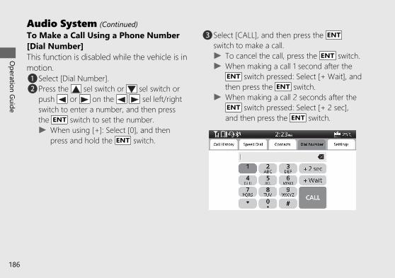
To Make a Call Using a Phone Number[Dial Number]This function is disabled while the vehicle is inmotion.a Select [Dial Number].b Press the sel switch or sel switch or
push or on the sel left/rightswitch to enter a number, and then pressthe ENT switch to set the number.u When using [+]: Select [0], and then
press and hold the ENT switch.
c Select [CALL], and then press the ENTswitch to make a call.u To cancel the call, press the ENT switch.u When making a call 1 second after the
ENT switch pressed: Select [+ Wait], andthen press the ENT switch.
u When making a call 2 seconds after theENT switch pressed: Select [+ 2 sec],and then press the ENT switch.
20190704203539_32MKS6000_eng_BOOK Page 191 Thursday, July 04 2019 20:57:26 JST
Operation Guide
186
Audio System (Continued)

d To end the call, push forward the voice control switch on the left handlebar.u The same action can be done by
selecting [End Call] on the screen.e Return to the riding information, previous
screen or Home screen. (P.40)You can also perform the above settings byusing the touch screen.
To Store a Phone Number in the SpeedDial ListSpeed dial numbers can be stored.a Select [Speed Dial].b Select [Add Speed Dial], and then press the
ENT switch.
c The phonebook appears.
20190704203539_32MKS6000_eng_BOOK Page 192 Thursday, July 04 2019 20:57:26 JST
Operation Guide
187Continued

d Select the phone number you want to store,and then press and hold the ENT switch.The phone number will be stored in thespeed dial list.
e Return to the riding information, previousscreen or Home screen. (P.40)
You can also perform the above settings byusing the touch screen.
To Delete a Stored Speed Dial Numbera Select [Settings].b Select the [Edit Speed Dial], and then press
the ENT switch.
20190704203539_32MKS6000_eng_BOOK Page 193 Thursday, July 04 2019 20:57:26 JST
Operation Guide
188
Audio System (Continued)

c Select the phone number you want todelete, and then press and hold the ENTswitch.
d Return to the riding information, previousscreen or Home screen. (P.40)
You can also perform the above settings byusing the touch screen.
# Receiving a CallWhen there is an incoming call, an audiblenotification sounds and the Incoming Callscreen appears.
20190704203539_32MKS6000_eng_BOOK Page 194 Thursday, July 04 2019 20:57:26 JST
Operation Guide
189Continued

Ring ToneIf the connected mobile phone supports “inband ring tone”, the ring tone stored on thephone sounds automatically while receiving acall.If “in band ring tone” is not supported, thering tone stored in the audio system sounds.
To Receive a Calla When a call comes in, push forward the
voice control switch on the lefthandlebar to receive the call.u The same action can be done by
selecting [Answer] on the screen.
To adjust the phone volume: (P.95)
20190704203539_32MKS6000_eng_BOOK Page 195 Thursday, July 04 2019 20:57:26 JST
Operation Guide
190
Audio System (Continued)

To Decline a Calla When a call comes in, push forward and
hold the voice control switch on theleft handlebar to reject a call.u The same action can be done by
selecting [Decline] on the screen.
To End a Calla While talking, push forward the voice
control switch on the left handlebar to endthe call.u The same action can be done by
selecting [End Call] on the screen.
20190704203539_32MKS6000_eng_BOOK Page 196 Thursday, July 04 2019 20:57:26 JST
Operation Guide
191Continued

Apple CarPlayIf you connect an Apple CarPlay-compatibleiPhone to the system via USB, you can usethe multi-information display, instead of theiPhone display, to make phone calls, listen tomusic, view maps (navigation), and accessmessages.● Only iPhone 5 or newer versions with iOS
10 or later are compatible with AppleCarPlay.
● Park your vehicle in a safe place beforeconnecting your iPhone to Apple CarPlayand when launching any compatible apps.
● In no event shall Honda be liable for anydamage or trouble that occurs in the useof iPhone.
● If a mobile network communication isunstable due to surrounding conditions orsignal strength conditions, Apple CarPlayfunctions may not be available.
● To use Apple CarPlay, a headsetconnection is necessary. If headsetconnection is broken due to headsetbattery depletion or communicationfailure, Apple CarPlay cannot be useduntil the connection is restored.
● You cannot operate Apple CarPlay by thetouch screen while the vehicle is inmotion.
20190704203539_32MKS6000_eng_BOOK Page 197 Thursday, July 04 2019 20:57:26 JST
Operation Guide
192
Audio System (Continued)

● Application and menu items displayed onthe screen may differ depending on theconnected device and iOS version.
● While connected to Apple CarPlay, callsare only made through Apple CarPlay. Ifyou want to make a call with Bluetooth®handsfree calling, disconnect the USBcable from your iPhone and connect youriPhone via Bluetooth®.To connect the paired device:(P.160)
● For details on countries and regionswhere Apple CarPlay is available, as wellas information pertaining to function,refer to the Apple homepage.
● Apple CarPlay is a trademark of Apple Inc.
20190704203539_32MKS6000_eng_BOOK Page 198 Thursday, July 04 2019 20:57:26 JST
Operation Guide
193Continued

# Apple CarPlay OperatingRequirements & Limitations
Apple CarPlay requires a compatible iPhonewith an active cellular connection and dataplan. Your carrier’s rate plans will apply.
Changes in operating systems, hardware,software, and other technology integral toproviding Apple CarPlay functionality, as wellas new or revised governmental regulations,may result in a decrease or cessation ofApple CarPlay functionality and services.Honda cannot and does not provide anywarranty or guarantee of future AppleCarPlay performance or functionality.
It is possible to use 3rd party apps if they arecompatible with Apple CarPlay. Refer to theApple homepage for information oncompatible apps.
# Use of User and Vehicle InformationThe use and handling of user and vehicleinformation transmitted to/from your iPhoneby Apple CarPlay is governed by the AppleiOS terms and conditions and Apple’s PrivacyPolicy.
20190704203539_32MKS6000_eng_BOOK Page 199 Thursday, July 04 2019 20:57:26 JST
Operation Guide
194
Audio System (Continued)

# Connected Services SettingsFrom this screen, you can go to various setupoptions for Apple CarPlay.
# To Setup Apple CarPlayUse of Apple CarPlay will result in thetransmission of certain user and vehicleinformation (such as vehicle location, speed,and status) to your iPhone to enhance theApple CarPlay experience. You will need toconsent to the sharing of this information onthe screen.
a Pair the headsets. (P.165)b Connect your iPhone using a certified cable
to the USB socket. (P.201)u If the following screen is displayed, Apple
CarPlay can not be used, but USB powercan be supplied.
1. Select [OK], and then press the ENTswitch.
To enable Apple CarPlay: (P.197)
20190704203539_32MKS6000_eng_BOOK Page 200 Thursday, July 04 2019 20:57:26 JST
Operation Guide
195Continued

c When the disclaimer message appears onthe screen, select [Enable], and then pressthe ENT switch.u Set [Remember My Choice] to ON so
that you will not be asked the next timeyou connect.
[Enable] when [Remember MyChoice] is [OFF]: Allows only once.(Prompt shows again next time.)[Enable] when [Remember MyChoice] is [ON]: Allows anytime.(Prompt does not show again.)[Disable] when [Remember MyChoice] is [OFF]: Does not allow thisconsent.[Disable] when [Remember MyChoice] is [ON]: Does not allow anytime.(Prompt does not show again.)
d Enable the Apple CarPlay setting. (P.197)e Apple CarPlay menu screen appears.You can also perform the above settings byusing the touch screen.
To display the prompt: (P.199)
20190704203539_32MKS6000_eng_BOOK Page 201 Thursday, July 04 2019 20:57:26 JST
Operation Guide
196
Audio System (Continued)

To Enable or Disable Apple CarPlaya Select [Connected Services], and then press
the ENT switch.
b Select [Apple CarPlay], and then press theENT switch.
c Select a target device name, and then pressthe ENT switch.
20190704203539_32MKS6000_eng_BOOK Page 202 Thursday, July 04 2019 20:57:26 JST
Operation Guide
197Continued

To enable Apple CarPlay:d Select [Enable Apple CarPlay], and then
press the ENT switch to [ON] (enable) thefunction.
e Return to the riding information, previousscreen or Home screen. (P.40)
You can also perform the above settings byusing the touch screen.
To disable Apple CarPlay:d Select [Enable Apple CarPlay], and then
press the ENT switch to [OFF] (disable) thefunction.
e Return to the riding information, previousscreen or Home screen. (P.40)
You can also perform the above settings byusing the touch screen.
20190704203539_32MKS6000_eng_BOOK Page 203 Thursday, July 04 2019 20:57:26 JST
Operation Guide
198
Audio System (Continued)

To Select Ask On or Ask Off of theApple CarPlay disclaimer Screena Select [Connected Services], and then press
the ENT switch.
b Select [Apple CarPlay], and then press theENT switch.
c Select a target device name, and then pressthe ENT switch.
20190704203539_32MKS6000_eng_BOOK Page 204 Thursday, July 04 2019 20:57:26 JST
Operation Guide
199Continued

To ask on connection:d Select [Ask on Connection], and then press
the ENT switch to [ON] (ask on) thefunction.
e Return to the riding information, previousscreen or Home screen. (P.40)
You can also perform the above settings byusing the touch screen.
To ask off connection:d Select [Ask on Connection], and then press
the ENT switch to [OFF] (ask off) thefunction.
e Return to the riding information, previousscreen or Home screen. (P.40)
You can also perform the above settings byusing the touch screen.
20190704203539_32MKS6000_eng_BOOK Page 205 Thursday, July 04 2019 20:57:26 JST
Operation Guide
200
Audio System (Continued)

# To Connect Your iPhone● Do not leave your device in the vehicle
(under the front seat or under the rearseat etc.). High heat will damage it.
● We recommend backing up your databefore playing it.
● iPhone can be charged with the USBcable when the ignition switch is in the (On) position. The charging time may belonger than usual.
● We recommend covering your deviceswith an audio pouch, or soft fabric orcover to protect them from damage.
● Be careful to not get the USB connectorwet.
● Do not connect with a hub.● Do not connect incompatible devices.● If the audio system does not recognise
the iPhone, try reconnecting it a few timesor reboot the device.
To connect your iPhone: (P.226)
# To Disconnect Your iPhoneYou can disconnect your iPhone at any time.Make sure to follow the device’s instructionson how to disconnect the device from thecable.
20190704203539_32MKS6000_eng_BOOK Page 206 Thursday, July 04 2019 20:57:26 JST
Operation Guide
201Continued

20190704203539_32MKS6000_eng_BOOK Page 207 Thursday, July 04 2019 20:57:26 JST
Operation Guide
202
Audio System (Continued)# Apple CarPlay Menu
Apple CarPlay menu screen
Maps
Go back to Apple CarPlaymenu screen
Go back to Home screen
MessagesMusicPhone
Home screen
Go to Apple CarPlaymenu screen

PhoneAccess the contact list, make phone calls, or listen to voice mail.
MusicPlay music stored on your iPhone.
MapsDisplay Apple CarPlay map and use the navigation function just as you would on your iPhone.
MessagesCheck and reply to text messages, or have messages read to you.
HondaGo back to the Home screen.
Go back to the Apple CarPlay menu screen.
20190704203539_32MKS6000_eng_BOOK Page 208 Thursday, July 04 2019 20:57:26 JST
Operation Guide
203Continued

# Operating Apple CarPlay with SiriTo activate Siri, pairing with device such as aheadset (for rider) must be paired. (P.165)To Activate Siria Start Apple CarPlay. (P.195)b Unlock your iPhone and enable Siri.
u For details, refer to the iPhone UserGuide, etc.
c Push forward the voice control switchon the left handlebar.
d Say a voice command through the pairedheadset.Siri may not be recognised correctly dueto the effect of wind noise during runningor external noise. In that case, try tochange the position of the microphone orto adjust the windscreen height(CRF1100A2/A4/D2/D4 ). (P.296)
20190704203539_32MKS6000_eng_BOOK Page 209 Thursday, July 04 2019 20:57:26 JST
Operation Guide
204
Audio System (Continued)

Below Are Examples of Questions andCommands for SiriPlease visit www.apple.com/ios/siri.
To Deactivate Siria Push forward the voice control switch
on the left handlebar.You can also perform the above settings byusing the touch screen.
Siri is a trademark of Apple Inc.
20190704203539_32MKS6000_eng_BOOK Page 210 Thursday, July 04 2019 20:57:26 JST
Operation Guide
205

Starting the EngineCRF1100A/A2/A4Start your engine using the following procedure,regardless of whether the engine is cold or warm.
NOTICE• If the engine does not start within 5 seconds, turn
the ignition switch to the (Off) position and wait10 seconds before trying to start the engine again torecover battery voltage.
• Extended fast idling and revving the engine candamage the engine, and the exhaust system.
• Snapping the throttle or fast idling for more than about5 minutes may cause exhaust pipe discolouration.
• The engine will not start if the throttle is fully open.
a Make sure the engine stop switch is in the (Run) position.
b Turn the ignition switch to the (On)position.
c Shift the transmission to Neutral ( Nindicator come on). Alternatively, pull in theclutch lever to start your vehicle with thetransmission in gear so long as the sidestand is raised.
d Press the START button with the throttlecompletely closed.
If the engine does not start:aOpen the throttle fully and press the START
button for 5 seconds.bRepeat the normal starting procedure.c If the engine starts, open the throttle slightly
if idling is unstable.d If the engine does not start, wait 10 seconds
before trying steps a & b again.
# If Engine Will Not Start (P.299)
20190704203539_32MKS6000_eng_BOOK Page 211 Thursday, July 04 2019 20:57:26 JST
Operation Guide
206

CRF1100D/D2/D4Start your engine using the following procedure,regardless of whether the engine is cold or warm.
NOTICE• If the engine does not start within 5 seconds, turn
the ignition switch to the (Off) position and wait10 seconds before trying to start the engine again torecover battery voltage.
• Extended fast idling and revving the engine candamage the engine, and the exhaust system.
• Snapping the throttle or fast idling for more than about5 minutes may cause exhaust pipe discolouration.
• The engine will not start if the throttle is fully open.
a Make sure the engine stop switch is in the (Run) position.
b Turn the ignition switch to the (On) position.c Check the transmission in Neutral ( N
indicator come on).d Press the START button with the throttle
completely closed.e Make sure the parking brake lever is
released before riding. (P.129)
# If Engine Does Not Start (P.206)
When you stop the engineaTo stop the engine, shift the transmission to
Neutral ( N indicator comes on).u If you turn the ignition switch to the
(Off) position when the vehicle in gear,the engine will shut off with the clutchdisengaged.
bTurn the ignition switch to the (Off)position.
cSet the parking brake when you park thevehicle. 2 P. 129
20190704203539_32MKS6000_eng_BOOK Page 212 Thursday, July 04 2019 20:57:26 JST
Operation Guide
207

Shifting GearsCRF1100A/A2/A4Your vehicle transmission has 6 forwardgears in a one-down, five-up shift pattern.
If you put the vehicle in gear with the sidestand down, the engine will shut off.
CRF1100D/D2/D4Your vehicle is equipped with anautomatically controlled 6-speedtransmission. It can be shifted automatically(by AT MODE) or manually (by MT MODE).
20190704203539_32MKS6000_eng_BOOK Page 213 Thursday, July 04 2019 20:57:26 JST
Operation Guide
208
N
1
2 34 5 6

Dual Clutch TransmissionCRF1100D/D2/D4In order to respond to rider demands in abroad range of situations, the transmission isequipped with three operating modes, ATMODE (including D mode for regularoperation and three levels of S mode forsporty riding); and MT MODE (MT mode fora 6-speed manual operation), which deliversthe same shift feel as a manual transmission.u Always use the recommended tyres and
sprockets to ensure correct Dual ClutchTransmission operation.
The Dual Clutch Transmission system runs aself check immediately after starting theengine.
“ ” appears in the gear position indicatorwindow for a few seconds, then goes out.While “ ” appears, you cannot shift intogear.
20190704203539_32MKS6000_eng_BOOK Page 214 Thursday, July 04 2019 20:57:26 JST
Operation Guide
209Continued
N-D switchAT/MT switch
ATMODE
MTMODE
Level 1
Level 2
Level 3

Neutral (N): Neutral is selectedautomatically when you turn the ignitionswitch to the (On) position.If neutral is not selected when you turnthe ignition switch to the (On)position.u Turn the ignition switch to the (Off)
position and then to the (On) positionagain.
u If neutral is still not selected after turning theignition switch to the (Off) position, andthen to the (On) position again. (P.305)You may hear (click) noises when thetransmission shifts to Neutral (N). This isnormal.
When you can change between N and Du Vehicle is stopped and the engine is idling.u Throttle is completely closed. It is not
possible to change from Neutral to D modewhile the throttle is applied.
u You cannot change between N and D modewhile the wheels are rotating.
u Side stand is raised.NOTICETo prevent clutch damage, do not use thethrottle to keep the vehicle stopped uphill.
20190704203539_32MKS6000_eng_BOOK Page 215 Thursday, July 04 2019 20:57:26 JST
Operation Guide
210
Shifting Gears (Continued)

AT MODE: In this mode the gears areshifted automatically according to your ridingconditions.And also using the shift up switch (+) or shiftdown switch (−), you can temporarily shift upor down in AT MODE by using the shiftswitch. These switches are convenient whenyou want to temporarily down-shift in frontof a curve, etc. (P.214)You can choose between two modes withinAT MODE: D mode and S mode.D mode (AT): This is the standard modewhen AT MODE is selected. Select D modefor regular operation and efficient fueleconomy.
S mode (AT): Select this mode while ridingin AT MODE when you need more power,such as when overtaking, climbing hills,pulling away.S mode has three levels of adjustment.MT MODE: MT MODE (6-speed manualoperation) You can choose between 6 gearsin this mode.
20190704203539_32MKS6000_eng_BOOK Page 216 Thursday, July 04 2019 20:57:26 JST
Operation Guide
211Continued

Changing between Neutral and ATMODE/MT MODE
Changing from Neutral (N) to AT MODEPress the D-S side of the N-D switch (a).The D mode indicator comes on, “1” is shownin the gear position indicator and first gear isselected.Changing from AT or MT MODE toNeutralPress N on the N-D switch (b).
Changing between D mode and S modewhile in AT MODEPress the D-S side of the N-D switch. The Sor D is shown in the gear position indicator.(c, d).
Changing between AT MODE and MTMODEPress the AT/MT switch (e).The AT indicator goes out while MT MODE isselected (f).The gear position is displayed on the gear positionindicator while MT MODE is selected (f).
20190704203539_32MKS6000_eng_BOOK Page 217 Thursday, July 04 2019 20:57:26 JST
Operation Guide
212
Shifting Gears (Continued)
AT/MTSwitch

S mode level selecting while in ATMODEWhile in S mode, press and hold the D-Sside of the N-D (a) switch.u Close the throttle completely. Then select
the desired level of the S mode.
The selected level is maintained even whenthe ignition switch is turned to the (Off)position, or transmission is switched to out ofS mode.
20190704203539_32MKS6000_eng_BOOK Page 218 Thursday, July 04 2019 20:57:26 JST
Operation Guide
213Continued
Level 1
Level 2
Level 3
Press and hold the D-S side of theN-D switchPress the D-S side of the N-Dswitch
N-D switch
Level 1 Level 2 Level 3
Higher engine RPM can be used byincreasing the level.

Riding in MT MODEShift up and down with the shift up switch (+)and shift down switch (−).The selected gear is shown on the gearposition indicator.u If the MT MODE is selected, the transmission
does not shift up automatically. Do not allowthe engine revs to go into the red zone.
u The transmission automatically shifts downwhen you slow down, even in MT MODE.
u You will start from 1st gear even if MTMODE is selected.
Gear shift operationShifting Up:Press the shift up switch (+) (g).Shifting Down:Press the shift down switch (−) (h).You cannot continue shifting gear by keepingthe shift switch pressed.To continue shifting gear release the switchand press it again.
Shift LimitYou cannot downshift if the engine willexceed the rev limit.
20190704203539_32MKS6000_eng_BOOK Page 219 Thursday, July 04 2019 20:57:26 JST
Operation Guide
214
Shifting Gears (Continued)

Cruise ControlThe cruise control system allows you tomaintain a steady speed within a specifiedrange.The available speed setting range andoperating gear are listed below:CRF1100A/A2/A4Available Speedsetting range
50 – 160 km/h (30 -100 mph)
Operating gear From 4th to 6th gearCRF1100D/D2/D4Available Speedsetting range
50 – 160 km/h (30 -100 mph)
Operating gear From 3rd to 6th gear
When cruise control is on, your speed will stillvary slightly, particularly going up and downhills.
Cruise control is intended for use only onstraight, uncongested highways. Do not usecruise control on city streets, winding roads,during bad weather, or at any other timewhen you need total control of the throttle.
3WARNINGImproper use of the cruise control canlead to a crash in which you could beseriously hurt or killed.
Use the cruise control only whentravelling on open highways in goodweather.
20190704203539_32MKS6000_eng_BOOK Page 220 Thursday, July 04 2019 20:57:26 JST
Operation Guide
215Continued

# To Set Cruise Controla Make sure the travelling speed and
operating gear are conformed to therequirements of the system.Any speed other than the available rangewill not be memorised.
b Press the cruise control main switch.(The cruise control main indicator willcome on.)
c Accelerate to the desired speed.d Push the cruise control
lever to side. (The cruise controlSET indicator will come on.) Your currenttravelling speed is memorised.
20190704203539_32MKS6000_eng_BOOK Page 221 Thursday, July 04 2019 20:57:26 JST
Operation Guide
216
Cruise Control (Continued)
Cruise controlmain indicator
SET Cruise controlSET indicator
Cruise controlmain switch
Cruise controllever

# To Change the Set SpeedTo Fine Tune the Set Speeda Select the riding information. (P.40)b Display the cruise control set speed on the
multi-information display.c To increase the set speed: tap the
cruise control lever to side.To decrease the set speed: tap the
cruise control lever to side.
d The set speed is displayed in the multi-information display.
Each quick tap (brief push and release) oneither side will change your speed by 1 km/hor 1 mph (depending on mileage meter setunit).Any speed other than the possible settingrange will not be indicated (stops at theupper or lower limit speed).
The system will accelerate your vehicleautomatically. When you reach thedesired speed, release the
cruise control lever.To Change the Set Speed Continuously● To increase the set speed: push and hold
the cruise control leverto side.If the cruise controllever is pushed and held to sidecontinuously, the set speed indicated inthe multi-information display stops at theupper limit of the possible setting range.
20190704203539_32MKS6000_eng_BOOK Page 222 Thursday, July 04 2019 20:57:26 JST
Operation Guide
217Continued
Cruise control set speed

● To decrease speed: push and hold the cruise control lever to
side. The system willautomatically slow your motorcycle. Whenyou reach the desired speed, release the
cruise control lever.If the cruise controllever is pushed and held to sidecontinuously, the set speed indicated inthe multi-information display stops at thelower limit of the possible setting range.
To Manually Increase the Set Speeda Use the throttle to accelerate until you reach
the desired speed.b Push and release the
cruise control lever to side.
To Manually Increase Vehicle Speeda Use the throttle in the normal manner to
accelerate.b To return to the set speed, close the throttle
and coast without applying the brakes. Thecruise system will maintain the speed youpreviously set.
# To Cancel Cruise ControlTo Disengage the System● Press the cruise control main switch. (The
cruise control main indicator goes offand the set speed will be erased frommemory.)
20190704203539_32MKS6000_eng_BOOK Page 223 Thursday, July 04 2019 20:57:26 JST
Operation Guide
218
Cruise Control (Continued)

To Temporarily Disengage the Systema Perform one of the following operations to
disengage the system temporarily. ( SETCruise control SET indicator temporarilygoes off but the set speed remains inmemory.)● Apply the brake lever or pedal.● Rotate the throttle grip past the
automatically closed position in thedeceleration direction.
● CRF1100A/A2/A4Disengage the clutch or operate theshift lever.
b To resume cruise control:● If you are still over 50 km/h (30 mph),
push and release the cruise control lever to side.
● If you are under 50 km/h (30 mph),use the throttle to increase road speedabove 50 km/h (30 mph) and thenpush and release the
cruise control lever to side.
20190704203539_32MKS6000_eng_BOOK Page 224 Thursday, July 04 2019 20:57:26 JST
Operation Guide
219

When the system activates:
Emergency Stop SignalEmergency stop signal activates when thesystem detects hard braking about 50 km/h(31 mph) or above to alert drivers behind youabout sudden braking by rapidly flashingboth turn signal lights. This may help to alertdrivers behind you to take appropriatemeans to avoid a possible collision with yourvehicle.
The emergency stop signal stops operatingwhen:● You release the brake lever and pedal.● The ABS is deactivated.● Your vehicle's decelerating speed
becomes moderate.● You press the hazard switch.
20190704203539_32MKS6000_eng_BOOK Page 225 Thursday, July 04 2019 20:57:26 JST
Operation Guide
220
Hard braking
Brakelight come on
Both turn signals flash
Both turn signal indicators blink

u The emergency stop signal is not a systemthat can prevent a possible rear-endcollision caused by your hard braking. It isalways recommended to avoid hard brakingunless it is absolutely necessary.
u The emergency stop signal does not activatewith the hazard switch pressed in.
u If the ABS stops working for a certain periodduring braking, the emergency stop signalmay not activate at all.
20190704203539_32MKS6000_eng_BOOK Page 226 Thursday, July 04 2019 20:57:26 JST
Operation Guide
221

DRL (Daytime Running Light)When the headlight dimmer/passing lightcontrol switch is turned to the position, the headlights and DRL are switchedautomatically according to the ambientbrightness.When it gets brighter, DRL lights up, andwhen it gets dark, low beam lights up andDRL decreases to the brightness of theposition light.
To select the DRL auto and offEach time the ignition switch is turned to the (On) position, the DRL will automatically beset to on.a Start the engine.b Select the DRL of pop-up information using
the function switch.c Push forward or pull backward the
function lever to select the [AUTO] or[Dismiss] of the DRL.
20190704203539_32MKS6000_eng_BOOK Page 227 Thursday, July 04 2019 20:57:26 JST
Operation Guide
222
DRLs
Push forward the function leverPull backward the function lever

Cornering LightThe cornering light lights up the direction oftravel of the vehicle when cornering.Operating conditions:When the headlights are on:● Vehicle has been ridden at a speed of
over 10 km/h (6 mph).● When the vehicle banking left or right.
Three-step lighting state is switched by thebank angle.
Cornering light adjusting screw location
20190704203539_32MKS6000_eng_BOOK Page 228 Thursday, July 04 2019 20:57:26 JST
Operation Guide
223
Cornering lightadjusting screw
Cornering light

Refuelling
Do not fill with fuel above the level plate.Fuel type: Unleaded petrol onlyFuel octane number: Your vehicle isdesigned to use Research Octane Number(RON) 91 or higher.Tank capacity:CRF1100A/D 18.8 L (4.97 US gal, 4.14 Imp gal)CRF1100A2/A4/D2/D4 24.8 L (6.55 US gal, 5.46 Imp gal)
# Refuelling and Fuel Guidelines (P.15)
Opening the Fuel Fill CapOpen the lock cover, insert the ignition key,and turn it clockwise to open the fuel fill cap.
Closing the Fuel Fill Capa After refuelling, push the fuel fill cap closed
until it locks.b Remove the key and close the lock cover.
u The key cannot be removed if the fuel fillcap is not locked.
3WARNINGPetrol is highly flammable andexplosive. You can be burned orseriously injured when handling fuel.
• Stop the engine, and keep heat,sparks, and flame away.
• Handle fuel only outdoors.• Wipe up spills immediately.
20190704203539_32MKS6000_eng_BOOK Page 229 Thursday, July 04 2019 20:57:26 JST
Operation Guide
224
Ignition key Lock cover
Fuel fill capLevel plate

Accessory SocketCRF1100A2/A4/D2/D4The accessory socket is located in the leftside inner panel cover.Use accessory devices at your own risk. In noevent shall Honda be liable for any damagesto your accessory device when in use.
Open the cover to access the socket.Rated capacity is24 W (12 V, 2 A).
u To prevent the battery from becoming weak(or dead), keep the engine running whiledrawing current from the socket.
u To prevent entry of foreign matter into thesocket, be sure to close the cover when thesocket is not used.
u Carefully secure all connected devices, asvibration may cause damage to them orthey could shift unexpectedly.
NOTICE• Using any heat-generating accessory or
improperly rated accessory can damage thesocket.
• Do not use the socket in wet conditions,when or while washing or any other wetconditions as these will damage the socket.
• Do not allow the accessory's harness tobecome pinched or trapped.
• Do not allow the accessory's harness tointerfere with the steering or controls.
20190704203539_32MKS6000_eng_BOOK Page 230 Thursday, July 04 2019 20:57:26 JST
Operation Guide
225
Cover
Accessory socket

USB SocketThe USB socket is located in the right sidefront turn signal light cover (CRF1100A/D ) orright side inner panel cover(CRF1100A2/A4/D2/D4 ).Use USB devices at your own risk. In no eventshall Honda be liable for any damage to yourUSB device when in use.
Only USB devices within the followingspecifications can be connected.Open the cover to access the socket.Rated capacity is7.5 W (5 V, 1.5 A).
To connect your USB devicea Open the cover to access the USB socket.
20190704203539_32MKS6000_eng_BOOK Page 231 Thursday, July 04 2019 20:57:26 JST
Operation Guide
226
Cover
USB socket

b Connect a certified USB cable to the socket.c Route the USB cable along the recess.d Pass the USB cable through the cover slit
and close the cover.
u To prevent the battery from becoming weak(or dead), keep the engine running whiledrawing current from the socket.
u To prevent entry of foreign matter into thesocket, be sure to close the cover.
u Carefully secure all connected devices, asvibration may cause damage to them orthey could shift unexpectedly.
NOTICE• Using any heat-generating USB devices or
improperly rated USB devices can damagethe socket.
• Do not use the USB socket in wet conditions,when or while washing or any other wetconditions as these will damage the USBsocket.
• Do not allow the USB's harness to becomepinched or trapped.
• Do not allow the USB's harness to interferewith the steering or controls.
20190704203539_32MKS6000_eng_BOOK Page 232 Thursday, July 04 2019 20:57:26 JST
Operation Guide
227
USB cable
Cover
SlitRecess

Storage EquipmentHelmet holderA helmet holder is located under the rearseat.
u Use the helmet holder only when parked.
# Removing the rear seat (P.255)
3WARNINGRiding with a helmet attached to theholder can interfere with your ability tosafely operate the vehicle and couldlead to a crash in which you can beseriously hurt or killed.
Use the helmet holder only whileparked. Do not ride with a helmetsecured by the holder.
20190704203539_32MKS6000_eng_BOOK Page 233 Thursday, July 04 2019 20:57:26 JST
Operation Guide
228
Helmet set wire
Helmet D-ring
Helmet set wire
Helmet holder

Helmet Set WireThe helmet set wire is secured on the rearfender under the rear seat.
# Removing the rear seat (P.255)
Document BagThe document bag is located on theunderside of the front seat.
# Removing the front seat (P.253)
20190704203539_32MKS6000_eng_BOOK Page 234 Thursday, July 04 2019 20:57:26 JST
Operation Guide
229Continued
Helmet setwire Document bag

Fuse Puller, Hex Wrench,Standard/Phillips Screwdriver,Screwdriver HandleThe fuse puller, hex wrench, standard/phillipsscrewdriver and screwdriver handle arelocated on the underside of the rear seat.
# Removing the rear seat (P.255)
Tool KitThe tool kit is located in the tool box.
# Removing the tool box (P.259)
20190704203539_32MKS6000_eng_BOOK Page 235 Thursday, July 04 2019 20:57:26 JST
Operation Guide
230
Storage Equipment (Continued)
Hex wrench
Fuse pullerScrewdriver handle
Standard/Phillipsscrewdriver
Tool box
Tool kit

Rear CarrierCRF1100A2/A4/D2/D4Never exceed the maximum weight limit.Maximum Weight: 10 kg (22 lb)
20190704203539_32MKS6000_eng_BOOK Page 236 Thursday, July 04 2019 20:57:26 JST
Operation Guide
231
Rear carrier

Importance of Maintenance .........................P. 233Maintenance Schedule...................................P. 234Maintenance Fundamentals .........................P. 237Tool.....................................................................P. 249Removing & Installing Body Components ...................................................P. 250
Battery.................................................................. P. 250Battery Box Cover ............................................. P. 251Clip........................................................................ P. 252Front Seat............................................................ P. 253Rear Seat ............................................................. P. 255Skid Plate............................................................. P. 257Tool Box .............................................................. P. 259
Engine Oil ..........................................................P. 260
Coolant ..............................................................P. 266Brakes.................................................................P. 268Side Stand .........................................................P. 272Drive Chain .......................................................P. 273Wheels ...............................................................P. 277Clutch .................................................................P. 279Throttle ..............................................................P. 282Crankcase Breather .........................................P. 283Other Adjustments..........................................P. 284
Adjusting the Headlight Aim.......................... P. 284Adjusting the Brake Lever ............................... P. 285Adjusting the Front Suspension .................... P. 286Adjusting the Rear Suspension...................... P. 290Adjusting the Windscreen Height ................. P. 296
20190704203539_32MKS6000_eng_BOOK Page 237 Thursday, July 04 2019 20:57:26 JST
Please read “Importance of Maintenance” and “Maintenance Fundamentals” carefullybefore attempting any maintenance. Refer to “Specifications” for service data.
Maintenance

Importance of Maintenance
Importance of MaintenanceKeeping your vehicle well-maintained isabsolutely essential to your safety and toprotect your investment, obtain maximumperformance, avoid breakdowns, and reduce airpollution. Maintenance is the owner'sresponsibility. Be sure to inspect your vehiclebefore each ride, and perform the periodicchecks specified in the Maintenance Schedule.2 P. 234
3WARNINGImproperly maintaining your vehicle orfailing to correct a problem before youride can cause a crash in which you canbe seriously hurt or killed.
Always follow the inspection andmaintenance recommendations andschedules in this owner's manual.
Maintenance SafetyAlways read the maintenance instructionsbefore you begin each task, and make sure thatyou have the tools, parts, and skills required.We cannot warn you of every conceivablehazard that can arise in performingmaintenance. Only you can decide whether ornot you should perform a given task.
Follow these guidelines when performingmaintenance.● Stop the engine and remove the key.● Place your vehicle on a firm, level surface
using the side stand or a maintenance standto provide support.
● Allow the engine, muffler, brakes, and otherhigh-temperature parts to cool beforeservicing as you can get burned.
● Run the engine only when instructed, anddo so in a well-ventilated area.
20190704203539_32MKS6000_eng_BOOK Page 238 Thursday, July 04 2019 20:57:26 JST
Maintenance
233

Maintenance ScheduleThe maintenance schedule specifies themaintenance requirements necessary to ensuresafe, dependable performance, and properemission control.
Maintenance work should be performed inaccordance with Honda's standards andspecifications by properly trained and equippedtechnicians. Your dealer meets all of theserequirements. Keep an accurate record ofmaintenance to help ensure that your vehicle isproperly maintained.Make sure that whomever performs themaintenance completes this record.
All scheduled maintenance is considered anormal owner operating cost and will becharged to you by your dealer. Retain allreceipts. If you sell the vehicle, these receiptsshould be transferred with the vehicle to thenew owner.
Honda recommends that your dealer shouldroad test your vehicle after each periodicmaintenance is carried out.
20190704203539_32MKS6000_eng_BOOK Page 239 Thursday, July 04 2019 20:57:26 JST
Maintenance
234

ItemsPre-rideCheck
2 P. 237
Frequency*1AnnualCheck
RegularReplace
Referto
page× 1,000 km 1 12 24 36 48× 1,000 mi 0.6 8 16 24 32
Fuel Line –Fuel Level 224Throttle Operation 282Air Cleaner *2 248Crankcase Breather*3 283Spark Plug –Valve Clearance –Engine Oil 262Engine Oil Filter 262Clutch Oil Filter*6 264Engine Idle Speed –Radiator Coolant *5 3 Years 266Cooling System –Secondary Air Supply System –Evaporative Emission Control System –
Maintenance Level Maintenance Legend: Intermediate. We recommend service by your dealer, unless
you have the necessary tools and are mechanically skilled.Procedures are provided in an official Honda Shop Manual.
::::
Inspect (clean, adjust, lubricate, or replace, if necessary)LubricateReplaceClean: Technical. In the interest of safety, have your vehicle
serviced by your dealer.
20190704203539_32MKS6000_eng_BOOK Page 240 Thursday, July 04 2019 20:57:26 JST
Maintenance ScheduleM
aintenance
235Continued

ItemsPre-rideCheck
2 P. 237
Frequency*1AnnualCheck
RegularReplace
Referto
page× 1,000 km 1 12 24 36 48× 1,000 mi 0.6 8 16 24 32
Exhaust Gas Control Actuator Cable –Drive Chain*4 Every 1,000 km (600 mi): 273Drive Chain Slider*4 276Brake Fluid *5 2 Years 268Brake Pads Wear 269Brake System 237Brakelight Switch 271Brake Lock Operation*6 270Headlight Aim 284Lights/Horn –Engine Stop Switch –Clutch System*7 279Side Stand 272Suspension –Nuts, Bolts, Fasteners*4 –
Wheels/Tyres*4 Every 6,000 km (4,000 mi): 245,277
Steering Head Bearings –
Notes:*1 : At higher odometer readings, repeat at the frequency interval
established here.*2 : Service more frequently when riding in unusually wet or dusty
areas.*3 : Service more frequently when riding in rain or at full throttle.
*4 : Service more frequently when riding OFF-ROAD.*5 : Replacement requires mechanical skill.*6 : CRF1100D/D2/D4 only*7 : CRF1100A/A2/A4 only
20190704203539_32MKS6000_eng_BOOK Page 241 Thursday, July 04 2019 20:57:26 JST
Maintenance Schedule
Maintenance
236

Maintenance Fundamentals
Pre-ride InspectionTo ensure safety, it is your responsibility toperform a pre-ride inspection and make surethat any problem you find is corrected. A pre-ride inspection is a must, not only for safety, butbecause having a breakdown, or even a flattyre, can be a major inconvenience.
Check the following items before you get onyour vehicle:● Fuel level - Fill fuel tank when necessary.
2 P. 224● Throttle - Check for smooth opening and
full closing in all steering positions. 2 P. 282● Engine oil level - Add engine oil if necessary.
Check for leaks. 2 P. 260● Coolant level - Add coolant if required.
Check for leaks. 2 P. 266
● Drive chain - Check condition and slack,adjust and lubricate if necessary. 2 P. 273
● Brakes - Check operation;Front and Rear: check brake fluid level andpads wear. 2 P. 268, 2 P. 269
● Lights and horn - Check that lights,indicators and horn function properly.
● Engine stop switch - Check for properfunction. 2 P. 117
● CRF1100A/A2/A4Clutch - Check operation;Adjust freeplay if necessary. 2 P. 279
● Side stand ignition cut-off system - Checkfor proper function. 2 P. 272
● Wheels and tyres - Check condition, airpressure and adjust if necessary. 2 P. 245
20190704203539_32MKS6000_eng_BOOK Page 242 Thursday, July 04 2019 20:57:26 JST
Maintenance
237Continued

Before riding off-road check all of the precedingplus the following:● Make sure spokes are tight. Check the rims
for any damage. 2 P. 277● Be sure the fuel fill cap is securely fastened.
2 P. 224● Check for loose cables and other parts, and
anything that appears abnormal.● Use a wrench to check the tightness of all
accessible nuts, bolts and fasteners.
Replacing PartsAlways use Honda Genuine Parts or theirequivalents to ensure reliability and safety.When ordering coloured components, specifythe model name, colour, and code mentionedon the colour label.The colour label is attached to the rear fenderunder the rear seat. 2 P. 255
3WARNINGInstalling non-Honda parts may makeyour vehicle unsafe and cause a crash inwhich you can be seriously hurt orkilled.
Always use Honda Genuine Parts orequivalents that have been designedand approved for your vehicle.
20190704203539_32MKS6000_eng_BOOK Page 243 Thursday, July 04 2019 20:57:26 JST
Maintenance Fundamentals
Maintenance
238
Colour label

Lithium-Ion (Li-Ion) BatteryYour vehicle has a lithium-ion (li-ion) battery.Clean the battery terminals if they become dirtyor corroded.
This symbol on the battery meansthat this product must not be treatedas household waste.
NOTICEAn improperly disposed of battery can beharmful to the environment and human health.Always confirm local regulations for properbattery disposal instruction.
# What to do in an emergencyIf any of the following occurs, immediately seeyour doctor.● Electrolyte splashes into your eyes:
u Wash your eyes repeatedly with coolwater for at 15 minutes. Using waterunder pressure can damage your eyes.
● Electrolyte splashes onto your skin:u Remove affected clothing and wash your
skin thoroughly using water.
● Electrolyte splashes into your mouthu Rinse mouth thoroughly with water, and
do not swallow.
3WARNINGThe battery contains flammable organicsolvent as electrolyte.
You can be burned or seriously injuredif the battery is handled improperly.
● Keep the battery away from heat,sparks, and flame.
● Keep the battery out of the reach ofchildren.
● Do not disassemble or modify thebattery or battery terminals.
● Do not short-circuit the battery withmetal tools or other metal objects.
● Do not subject the battery toimpacts.
20190704203539_32MKS6000_eng_BOOK Page 244 Thursday, July 04 2019 20:57:26 JST
Maintenance FundamentalsM
aintenance
239Continued

# Cleaning the Battery Terminals1. Remove the battery. 2 P. 2502. If the terminals are starting to corrode and
are coated with a white substance, washwith warm water and wipe clean.
3. If the terminals are heavily corroded, cleanand polish the terminals with a wire brush orsandpaper. Wear safety glasses.
4. After cleaning, reinstall the battery.The battery has a limited life span. Consult yourdealer about when you should replace thebattery. Always replace the battery with anotherlithium-ion (li-ion) battery of the same type.
NOTICEInstalling non-Honda electrical accessories canoverload the electrical system, discharging thebattery and possibly damaging the system.
FusesFuses protect the electrical circuits on yourvehicle. If something electrical on your vehiclestops working, check for and replace any blownfuses. 2 P. 335
20190704203539_32MKS6000_eng_BOOK Page 245 Thursday, July 04 2019 20:57:26 JST
Maintenance Fundamentals
Maintenance
240

# Inspecting and Replacing FusesTurn the ignition switch to the (Off) positionto remove and inspect fuses. If a fuse is blown,replace with a fuse of the same rating. For fuseratings, see “Specifications.” 2 P. 364
NOTICEReplacing a fuse with one that has a higherrating greatly increases the chance of damage tothe electrical system.
If a fuse fails repeatedly, you likely have anelectrical fault. Have your vehicle inspected byyour dealer.
Engine OilEngine oil consumption varies and oil qualitydeteriorates according to riding conditions andtime elapsed.Check the engine oil level regularly, and add therecommended engine oil if necessary. Dirty oil orold oil should be changed as soon as possible.
# Selecting the Engine OilFor recommended engine oil, see“Specifications.” 2 P. 363
If you use non-Honda engine oil, check thelabel to make sure that the oil satisfies all of thefollowing standards:● JASO T 903 standard*1: MA● SAE standard*2: 10W-30● API classification*3: SG or higher*1. The JASO T 903 standard is an index for engine
oils for 4-stroke motorcycle engines. There aretwo classes: MA and MB. For example, thefollowing label shows the MA classification.
20190704203539_32MKS6000_eng_BOOK Page 246 Thursday, July 04 2019 20:57:26 JST
Maintenance FundamentalsM
aintenance
241Continued
Blownfuse

*2. The SAE standard grades oils by their viscosity.*3. The API classification specifies the quality and
performance rating of engine oils. Use SG orhigher oils, excluding oils marked as “EnergyConserving” or “Resource Conserving” on thecircular API service symbol.
Brake FluidDo not add or replace brake fluid, except in anemergency. Use only fresh brake fluid from asealed container. If you do add fluid, have thebrake system serviced by your dealer as soon aspossible.
NOTICEBrake fluid can damage plastic and paintedsurfaces.Wipe up spills immediately and wash thoroughly.
Recommended brake fluid:Honda DOT 4 Brake Fluid or equivalent
20190704203539_32MKS6000_eng_BOOK Page 247 Thursday, July 04 2019 20:57:26 JST
Maintenance Fundamentals
Maintenance
242
Oil codeOil classification
Not recommended Recommended

Drive ChainThe drive chain must be inspected andlubricated regularly. Inspect the chain morefrequently if you often ride on bad roads, ride athigh speed, or ride with repeated fastacceleration. 2 P. 273If the chain does not move smoothly, makesstrange noises, has damaged rollers, has loosepins, has missing O-rings, or kinks, have thechain inspected by your dealer.
Also inspect the drive sprocket and drivensprocket. If either has worn or damaged teeth,have the sprocket replaced by your dealer.
NOTICEUse of a new chain with worn sprockets will causerapid chain wear.
# Cleaning and LubricatingAfter inspecting the slack, clean the chain andsprockets while rotating the rear wheel. Use a drycloth with chain cleaner designed specifically forO-ring chains, or neutral detergent. Use a softbrush if the chain is dirty.After cleaning, wipe dry and lubricate with therecommended lubricant.
Recommended lubricant:Drive chain lubricant designedspecifically for O-ring chainsIf not available, use SAE 80 or 90 gear oil.
20190704203539_32MKS6000_eng_BOOK Page 248 Thursday, July 04 2019 20:57:26 JST
Maintenance FundamentalsM
aintenance
243Continued
Normal(GOOD)
Worn(REPLACE)
Damaged(REPLACE)

Do not use a steam cleaner, a high pressurecleaner, a wire brush, volatile solvent such aspetrol and benzene, abrasive cleaner, chaincleaner or lubricant NOT designed specificallyfor O-ring chains as these can damage therubber O-ring seals.Avoid getting lubricant on the brakes or tyres.Avoid applying excess chain lubricant to preventspray onto your clothes and the vehicle.
Recommended CoolantPro Honda HP Coolant is a pre-mixed solutionof antifreeze and distilled water.
Concentration:50% antifreeze and 50% distilled water
A concentration of antifreeze below 40% willnot provide proper corrosion and coldtemperature protection.
A concentration of up to 60% will provide betterprotection in colder climates.
NOTICEUsing coolant not specified for aluminiumengines or tap/mineral water can causecorrosion.
20190704203539_32MKS6000_eng_BOOK Page 249 Thursday, July 04 2019 20:57:26 JST
Maintenance Fundamentals
Maintenance
244

Crankcase BreathersService more frequently when riding in rain, atfull throttle, or after the vehicle is washed oroverturned. Service if the deposit level can beseen in the transparent section of the draintube.If the drain tube overflows, the air filter maybecome contaminated with engine oil causingpoor engine performance. 2 P. 283
Tyres (Inspecting/Replacing)# Checking the Air PressureVisually inspect your tyres and use an airpressure gauge to measure the air pressurebefore each off-road ride and whenever youreturn to pavement after riding off-road. If youonly ride on pavement, check the pressure atleast once a month or any time you think thetyres look low. Always check air pressure whenyour tyres are cold.
If you decide to adjust the tyre pressure for aparticular off-road riding condition, makechanges a little at a time.CRF1100A2/A4/D2/D4Even if the direction of the valve stem ischanged, do not return it to the originalposition. Have your vehicle inspected by yourdealer.
20190704203539_32MKS6000_eng_BOOK Page 250 Thursday, July 04 2019 20:57:26 JST
Maintenance FundamentalsM
aintenance
245Continued
Right side

# Inspecting for DamageInspect the tyres forcuts, slits, or cracks thatexposes fabric orcords, or nails or otherforeign objectsembedded in the sideof the tyre or the tread.
Also inspect for any unusual bumps or bulges inthe side walls of the tyres.# Inspecting for Abnormal Wear
Inspect the tyres forsigns of abnormal wearon the contact surface.
# Inspecting Tread DepthInspect the tread wear indicators. If theybecome visible, replace the tyres immediately.For safe riding, you should replace the tyreswhen the minimum tread depth is reached.
20190704203539_32MKS6000_eng_BOOK Page 251 Thursday, July 04 2019 20:57:26 JST
Maintenance Fundamentals
Maintenance
246
Wear indicatorlocation mark
or TWI

# Inspecting Rims and Valve StemsInspect the rims for damage and loose spokes.Also inspect the valve stems for their positions.A tilted valve stem indicates the tube is slippinginside the tyre or the tyre is slipping on the rim.See your dealer.
3WARNINGRiding on tyres that are excessivelyworn or improperly inflated can cause acrash in which you can be seriously hurtor killed.
Follow all instructions in this owner'smanual regarding tyre inflation andmaintenance.
GermanyGerman law prohibits use of tyres whose treaddepth is less than 1.6 mm.
Have your tyres replaced by your dealer.For recommended tyres, air pressure andminimum tread depth, see “Specifications.”2 P. 360Follow these guidelines whenever you replacetyres.● Use the recommended tyres or equivalents
of the same size, construction, speed rating,and load range.
● Have the wheel balanced with HondaGenuine balance weights or equivalent afterthe tyre is installed.
● CRF1100A2/A4/D2/D4Do not install a tube inside a tubeless tyreon this vehicle. Excessive heat build-up cancause the tube to burst.
● CRF1100A2/A4/D2/D4Use only tubeless tyres on this vehicle.The rims are designed for tubeless tyres,and during hard acceleration or braking, atube-type tyre could slip on the rim andcause the tyre to rapidly deflate.
20190704203539_32MKS6000_eng_BOOK Page 252 Thursday, July 04 2019 20:57:26 JST
Maintenance FundamentalsM
aintenance
247Continued
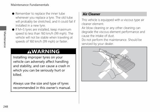
● Remember to replace the inner tubewhenever you replace a tyre. The old tubewill probably be stretched, and it could fail ifinstalled in a new tyre.
● If M+S tyres are installed, keep maximumspeed to less than 160 km/h (99 mph). Thevehicle will not be stable when traveling atspeeds of 160 km/h (99 mph) or faster.
3WARNINGInstalling improper tyres on yourvehicle can adversely affect handlingand stability, and can cause a crash inwhich you can be seriously hurt orkilled.
Always use the size and type of tyresrecommended in this owner's manual.
Air CleanerThis vehicle is equipped with a viscous type aircleaner element.Air blow cleaning or any other cleaning candegrade the viscous element performance andcause the intake of dust.Do not perform the maintenance. Should beserviced by your dealer.
20190704203539_32MKS6000_eng_BOOK Page 253 Thursday, July 04 2019 20:57:26 JST
Maintenance Fundamentals
Maintenance
248

ToolThe tool kit is stored in the tool box. 2 P. 230
You can perform some roadside repairs, minoradjustments and parts replacement with theprovided tools.
● Spark plug wrench● 10 × 14 mm Open end wrench● 14 × 17 mm Open end wrench● 19 mm Box end wrench
The helmet set wire is secured with the rearfender under the rear seat. 2 P. 229● Helmet set wire
The 5 mm hex wrench, standard/phillipsscrewdriver, screwdriver handle and fuse pullerare located on the underside of the rear seat.2 P. 230● 5 mm Hex wrench● Standard/Phillips screwdriver● Screwdriver handle● Fuse puller
20190704203539_32MKS6000_eng_BOOK Page 254 Thursday, July 04 2019 20:57:26 JST
Maintenance
249

Removing & Installing Body Components
Battery
# RemovalMake sure the ignition switch is in the (Off) position.
1. Remove the tool box. 2 P. 2592. Disconnect the negative - terminal from
the battery.3. Disconnect the positive + terminal from
the battery.4. Remove the clip. 2 P. 2525. Open the battery box band.6. Remove the battery from the battery case
taking care not to drop the terminal nuts.
# InstallationInstall the parts in the reverse order ofremoval. Always connect the positive +terminal first.Make sure that bolts and nuts are tight.Make sure the clock information is correctafter the battery is reconnected. 2 P. 90
20190704203539_32MKS6000_eng_BOOK Page 255 Thursday, July 04 2019 20:57:26 JST
Maintenance
250
Battery box band
Positive terminal
Negativeterminal
BatteryBolts
Terminal nuts
Clip

For proper handling of the battery, see“Maintenance Fundamentals.” 2 P. 239“Battery Goes Dead.” 2 P. 331
Battery Box Cover
# Removal1. Remove the bolts using the hex wrench
provided on the underside of the rearseat. 2 P. 230
2. Remove the battery box cover.
# InstallationInstall the parts in the reverse order ofremoval.
20190704203539_32MKS6000_eng_BOOK Page 256 Thursday, July 04 2019 20:57:26 JST
Removing & Installing Body Components u Battery Box CoverM
aintenance
251
Battery box cover
Bolts

Clip# Removal1. Remove the pin by a Phillips screwdriver.2. Pull the clip out of the hole.
# Installation1. Insert the clip into the hole.2. Push the pin in.
20190704203539_32MKS6000_eng_BOOK Page 257 Thursday, July 04 2019 20:57:26 JST
Removing & Installing Body Components u Clip
Maintenance
252
a b
a b

Front Seat# Removal
1. Remove the rear seat. 2 P. 2552. Remove the front seat while pulling it
backward and upward.
# Installation1. When setting the high seat position:
Insert the front lower prong and centrelower prongs into the front stay andcentre stays on the fuel tank, and insertthe rear hooks into the upper slot.When setting the low seat position:Insert the front upper prong and centreupper prongs into the front stay andcentre stays on the fuel tank, and insertthe rear hooks into the lower slot.
20190704203539_32MKS6000_eng_BOOK Page 258 Thursday, July 04 2019 20:57:26 JST
Removing & Installing Body Components u Front SeatM
aintenance
253Continued
Front seat

20190704203539_32MKS6000_eng_BOOK Page 259 Thursday, July 04 2019 20:57:26 JST
Removing & Installing Body Components u Front Seat
Maintenance
254
High position:
Frontlowerprong
Rearhooks
Frontseat
Front stay
Upper slots
Centrelowerprongs
Centre stays
Low position:
Centre stays
Centreupperprongs
Lower slots
Front stay
Frontseat
RearhooksFront
upperprong

2. Install the front seat while pushing itforward and downward.u Make sure that the seat is locked
securely in position by pulling it uplightly.
Rear Seat
20190704203539_32MKS6000_eng_BOOK Page 260 Thursday, July 04 2019 20:57:26 JST
Removing & Installing Body Components u Rear SeatM
aintenance
255Continued
Rear seat
Seat lock
Ignition key
Tabs
Recesses
Seat strap(Original position)
CRF1100A/D
Tabs
Recesses

# Removal1. CRF1100A/D
Move the seat strap forward.2. Insert the ignition key into the seat lock.3. Turn the ignition key clockwise, then push
the rear seat forward and up.
# Installation1. Insert the tabs into the recesses.2. Push down on the front of the rear seat
until it locks in place.u Make sure that the seat is locked
securely in position by pulling it uplightly.
3. CRF1100A/DMove the seat strap to its originalposition.
The seat locks automatically when closed.Take care not to lock your key in thecompartment under the rear seat.
20190704203539_32MKS6000_eng_BOOK Page 261 Thursday, July 04 2019 20:57:26 JST
Removing & Installing Body Components u Rear Seat
Maintenance
256
CRF1100A2/A4/D2/D4
Recesses
Tabs
Recesses
Tabs
Ignition key
Seat lock
Rear seat

Skid Plate
20190704203539_32MKS6000_eng_BOOK Page 262 Thursday, July 04 2019 20:57:26 JST
Removing & Installing Body Components u Skid PlateM
aintenance
257Continued
Prong
Washers
Skid plate
Grommet
Collar
CRF1100A/D
Bolts A
Prong
Washer
Bolt B
Skidplate
GrommetCollar
CRF1100A2/A4/D2/D4
Bolts AWashers

# Removal1. CRF1100A/D
Remove the bolts A and washers. usingthe hex wrench provided on theunderside of the rear seat. 2 P. 255
2. CRF1100A2/A4/D2/D4Remove the bolt B, bolts A and washers.using the hex wrench provided on theunderside of the rear seat. 2 P. 255
3. Remove the collar.4. Remove the skid plate by releasing its
grommet from the prong.
# Installation1. Install the skid plate in the reverse order
of removal.2. Install the collar.3. Install the washers onto the bolts A.4. Tighten the bolts A.
Torque: 26 N·m (2.7 kgf·m, 19 lbf·ft).
5. CRF1100A2/A4/D2/D4Tighten the bolt B.
Torque: 12 N·m (1.2 kgf·m, 9 lbf·ft).
20190704203539_32MKS6000_eng_BOOK Page 263 Thursday, July 04 2019 20:57:26 JST
Removing & Installing Body Components u Skid Plate
Maintenance
258

Tool Box # Removal1. Remove the bolts using the hex wrench
provided on the underside of the rearseat. 2 P. 230
2. Remove the tool box by releasing its slotsfrom the tabs.
# InstallationInstall the parts in the reverse order ofremoval.
20190704203539_32MKS6000_eng_BOOK Page 264 Thursday, July 04 2019 20:57:26 JST
Removing & Installing Body Components u Tool BoxM
aintenance
259
Tool box
BoltsTabs
Slots

Engine Oil
Checking the Engine Oil1. Place your vehicle on its side stand on a
firm, level surface.2. If the engine is cold, idle the engine for 3
to 5 minutes.3. Turn the ignition switch to the (Off)
position and wait for 2 to 3 minutes.4. Place your vehicle in an upright position
on a firm, level surface.5. Remove the dipstick and wipe it clean.6. Insert the dipstick until it seats, but don't
screw it in.7. Check that the oil level is between the
upper level and lower level marks on thedipstick.
8. Securely install the dipstick.
20190704203539_32MKS6000_eng_BOOK Page 265 Thursday, July 04 2019 20:57:26 JST
Maintenance
260
Oil fill capUpperlevel
Lowerlevel
Dipstick

Adding Engine OilIf the engine oil is below or near the lowerlevel mark, add the recommended engine oil.2 P. 241, 2 P. 3631. Remove the oil fill cap. Add the
recommended oil until it reaches theupper level mark.u Place your vehicle in an upright
position on a firm, level surface whenchecking the oil level.
u Do not overfill above the upper levelmark.
u Make sure no foreign objects enter theoil filler opening.
u Wipe up any spills immediately.
2. Securely reinstall the oil fill cap.NOTICEOverfilling with oil or operating with insufficientoil can cause damage to your engine. Do not mixdifferent brands and grades of oil. They mayaffect lubrication and clutch operation.
For the recommended oil and oil selectionguidelines, see “Maintenance Fundamentals.”2 P. 241
20190704203539_32MKS6000_eng_BOOK Page 266 Thursday, July 04 2019 20:57:26 JST
Engine Oil u Adding Engine OilM
aintenance
261

Changing Engine Oil & FilterChanging the oil and filter requires specialtools. We recommend that you have yourvehicle serviced by your dealer.
Use a new Honda Genuine oil filter orequivalent specified for your model.
NOTICEUsing the wrong oil filter can result in seriousdamage to the engine.
1. Remove the skid plate. 2 P. 2572. If the engine is cold, idle the engine for 3
to 5 minutes.3. Turn the ignition switch to the (Off)
position and wait for 2 to 3 minutes.4. Place your vehicle on a firm, level surface.5. Place a drain pan under the drain bolts.
6. Remove the oil fill cap, drain bolts, andsealing washers to drain the oil.
7. Remove the oil filter with a filter wrenchand let the remaining oil drain out. Makesure the prior seal is not stuck to theengine.u Discard the oil and oil filter at an
approved recycling centre.
20190704203539_32MKS6000_eng_BOOK Page 267 Thursday, July 04 2019 20:57:26 JST
Engine Oil u Changing Engine Oil & Filter
Maintenance
262
Sealing washers
Drain bolts

8. Apply a thin coat of engine oil to therubber seal of a new oil filter.
9. Install the new oil filter and tighten.
Torque: 26 N·m (2.7 kgf·m, 19 lbf·ft)
10. Install new sealing washers onto the drainbolts. Tighten the drain bolts.
Torque: 30 N·m (3.1 kgf·m, 22 lbf·ft)
11.Fill the crankcase with the recommendedoil (2 P. 241, 2 P. 363) and install the oil fillcap.
Required oilWhen changing oil & engine oilfilter:CRF1100A/A2/A44.0 L (4.2 US qt, 3.5 Imp qt)CRF1100D/D2/D44.2 L (4.4 US qt, 3.7 Imp qt)When changing oil only:CRF1100A/A2/A43.9 L (4.1 US qt, 3.4 Imp qt)CRF1100D/D2/D44.0 L (4.2 US qt, 3.5 Imp qt)
12.Check the oil level. 2 P. 26013.Check that there are no oil leaks.14. Install the skid plate. 2 P. 257
20190704203539_32MKS6000_eng_BOOK Page 268 Thursday, July 04 2019 20:57:26 JST
Engine Oil u Changing Engine Oil & FilterM
aintenance
263
Rubber seal
Oil filter

Changing Clutch Oil FilterCRF1100D/D2/D4Use a new Honda Genuine clutch oil filter orequivalent specified for your model.
NOTICEUsing the wrong clutch oil filter can result inserious damage to the transmission.
1. Follow the steps 1-7 of Changing EngineOil & Filter. 2 P. 262
2. Remove the clutch oil filter cover, clutchoil filter and spring by removing theclutch oil filter cover bolts.u Discard the oil and clutch oil filter at an
approved recycling centre.
20190704203539_32MKS6000_eng_BOOK Page 269 Thursday, July 04 2019 20:57:26 JST
Engine Oil u Changing Clutch Oil Filter
Maintenance
264
Clutch oilfilter cover
Rubber seal“OUT-SIDE”mark
O-ring
Clutch oil filter
Spring
Bolts

3. Install the new clutch oil filter with therubber seal facing in, toward the engine.You will see “OUT-SIDE” mark on theclutch oil filter body, toward the filtercover.
4. Replace the O-ring and apply a thin coatof engine oil to the new O-ring whenbefore installing it.
5. Install the spring and the clutch oil filtercover.
6. Install the clutch oil filter cover bolts andtighten.
Torque: 12 N·m (1.2 kgf·m, 9 lbf·ft)7. Apply a thin coat of engine oil to the
rubber seal of a new engine oil filter.2 P. 263
8. Install a new engine oil filter and tighten.Torque: 26 N·m (2.7 kgf·m, 19 lbf·ft)
9. Install a new sealing washers onto thedrain bolts. Tighten the drain bolts.
Torque: 30 N·m (3.1 kgf·m, 22 lbf·ft)10.Fill the crankcase with the recommended
oil (2 P. 241, 2 P. 363) and install the oil fillcap.
Required oilWhen changing oil, engine oil filter& clutch oil filter:4.2 L (4.4 US qt, 3.7 Imp qt)
11.Check the oil level. 2 P. 26012.Check that there are no oil leaks.13. Install the skid plate. 2 P. 257
20190704203539_32MKS6000_eng_BOOK Page 270 Thursday, July 04 2019 20:57:26 JST
Engine Oil u Changing Clutch Oil FilterM
aintenance
265

Coolant
Checking the CoolantCheck the coolant level in the reserve tankwhile the engine is cold.1. Place your vehicle on a firm, level surface.2. Hold your vehicle in an upright position.3. Check that the coolant level is between
the UPPER level and LOWER level markson the reserve tank.
If the coolant level is dropping noticeably or thereserve tank is empty, you likely have a seriousleak. Have your vehicle inspected by yourdealer.
Adding CoolantIf the coolant level is below the LOWER levelmark, add the recommended coolant (2 P. 244)until the level reaches the UPPER level mark.Add fluid only from the reserve tank cap anddo not remove the radiator cap.
20190704203539_32MKS6000_eng_BOOK Page 271 Thursday, July 04 2019 20:57:26 JST
Maintenance
266
UPPER level
Reserve tank
Reserve tankLOWER level

1. Remove the reserve tank cap and addfluid while monitoring the coolant level.u Do not overfill above the UPPER level
mark.u Make sure no foreign objects enter the
reserve tank opening.2. Securely reinstall the reserve tank cap.
3WARNINGRemoving the radiator cap while theengine is hot can cause the coolant tospray out, potentially scalding you.
Always let the engine and radiator cooldown before removing the radiator cap.
Changing CoolantHave your dealer change the coolant unlessyou have the proper tools and aremechanically qualified.
20190704203539_32MKS6000_eng_BOOK Page 272 Thursday, July 04 2019 20:57:26 JST
Coolant u Changing CoolantM
aintenance
267
Reserve tank cap

Brakes
Checking Brake Fluid1. Place your vehicle in an upright position
on a firm, level surface.2. Front Check that the brake fluid reservoir
is horizontal and that the fluid level isabove the LOWER level mark.Rear Check that the brake fluid reservoiris horizontal and that the fluid level isbetween the LOWER level and UPPERlevel marks.
If the brake fluid level in either reservoir isbelow the LOWER level mark or the brakelever and pedal freeplay becomes excessive,inspect the brake pads for wear.If the brake pads are not worn, you mostlikely have a leak. Have your vehicleinspected by your dealer.
20190704203539_32MKS6000_eng_BOOK Page 273 Thursday, July 04 2019 20:57:26 JST
Maintenance
268
Front brake fluid reservoir
LOWERlevel mark
UPPERlevel mark
LOWERlevel mark
Rear brake fluid reservoirFront Rear

Inspecting the Brake PadsCheck the condition of the brake pad wearindicators.Front The pads need to be replaced if abrake pad is worn to the bottom of theindicator.Rear The pads need to be replaced if a brakepad is worn to the indicator.
1. Front Inspect the brake pads from in frontof the brake caliper.u Always inspect both left and right
brake calipers.2. Rear Inspect the brake pads from the rear
right of the vehicle.If necessary have the pads replaced by yourdealer.Always replace both left and right brake padsat the same time.
20190704203539_32MKS6000_eng_BOOK Page 274 Thursday, July 04 2019 20:57:26 JST
Brakes u Inspecting the Brake PadsM
aintenance
269
Front RearBrake Pads
Wearindicator
Wearindicators
Wearindicators
Disc
Disc

Checking the Parking BrakeCRF1100D/D2/D4
Place your vehicle on a firm, level surface.Stop the engine and push your vehicle whileset the parking brake to check the efficacy ofthe parking brake.
If the efficacy of the parking brake becomesweak, have the brake adjusted by yourdealer.
20190704203539_32MKS6000_eng_BOOK Page 275 Thursday, July 04 2019 20:57:26 JST
Brakes u Checking the Parking Brake
Maintenance
270
Parking brakelever
Lock lever

Adjusting the Brakelight SwitchCheck the operation of the brakelight switch.Hold the brakelight switch and turn theadjusting nut in the direction A if the switchoperates too late, or turn the nut in thedirection B if the switch operates too soon.
20190704203539_32MKS6000_eng_BOOK Page 276 Thursday, July 04 2019 20:57:26 JST
Brakes u Adjusting the Brakelight SwitchM
aintenance
271
Brakelight switch
Adjustingnut
B A

Side Stand
Checking the Side Stand
1. Check that the side stand operatessmoothly. If the side stand is stiff orsqueaky, clean the pivot area andlubricate the pivot bolt with clean grease.
2. Check the spring for damage or loss oftension.
3. CRF1100A/A2/A4Sit on the vehicle, shift the transmission toNeutral, and raise the side stand.CRF1100D/D2/D4
4. Sit on the vehicle and raise the side stand.5. CRF1100A/A2/A4
Start the engine, pull the clutch lever in,and shift the transmission into gear.CRF1100D/D2/D4Start the engine and press the D-S sideof N-D switch to switch the transmissioninto D mode.
6. Lower the side stand all the way. Theengine should stop as you lower the sidestand. If the engine doesn't stop, haveyour vehicle inspected by your dealer.
20190704203539_32MKS6000_eng_BOOK Page 277 Thursday, July 04 2019 20:57:26 JST
Maintenance
272
Side stand spring

Drive Chain
Inspecting the Drive ChainSlackCheck the drive chain slack at several pointsalong the chain. If the slack is not constant atall points, some links may be kinked andbinding.Have the chain inspected by your dealer.
1. Shift the transmission to Neutral. Stop theengine.
2. Place your vehicle on its side stand on afirm, level surface.
3. Check the slack in the lower half of thedrive chain midway between thesprockets.
Drive chain slack:35 - 45 mm (1.4 - 1.8 in)
u Do not ride your vehicle if the slackexceeds 60 mm (2.4 in).
4. Roll the vehicle forward and check thatthe chain moves smoothly.
20190704203539_32MKS6000_eng_BOOK Page 278 Thursday, July 04 2019 20:57:26 JST
Maintenance
273Continued

5. Inspect the sprockets. 2 P. 2436. Clean and lubricate the drive chain.
2 P. 243
Adjusting the Drive Chain SlackAdjusting the chain requires special tools.Have the drive chain slack adjusted by yourdealer.When adjusting the drive chain slack, becareful not to damage the wheel speedsensor and pulser ring.
1. Shift the transmission to Neutral. Stop theengine.
2. Place your vehicle on its side stand on afirm, level surface.
3. Loosen the rear axle nut.4. Loosen the lock nuts on both adjusting
bolts.
20190704203539_32MKS6000_eng_BOOK Page 279 Thursday, July 04 2019 20:57:26 JST
Drive Chain u Adjusting the Drive Chain Slack
Maintenance
274
Lock nut
Adjustingbolt
Rear axle nut
Adjusting plate
Scale graduations
Wheel speedsensorPulser ring
Adjusting plate
Scale graduations
Adjusting bolt
Lock nut

5. Turn both adjusting bolts an equalnumber of turns until the correct drivechain slack is obtained. Turn the adjustingbolts counterclockwise to tighten thechain. Turn the adjusting bolts clockwiseand push the rear wheel toward the frontto provide more slack.Adjust the slack at a point midwaybetween the drive sprocket and thedriven sprocket.Check the drive chain slack. 2 P. 273
6. Check rear axle alignment by making surethe indicator groove on the chainadjusting plate aligns with the scalegraduations on both sides of theswingarm.Both marks should correspond. If the axleis misaligned, turn the right or leftadjusting bolt until the marks are alignedand recheck chain slack.
7. Tighten the rear axle nut.
Torque: 100 N·m (10.2 kgf·m, 74 lbf·ft)
8. Hold the adjusting bolts and tighten thelock nuts.
Torque: 27 N·m (2.8 kgf·m, 20 lbf·ft)
9. Recheck drive chain slack.
If a torque wrench was not used forinstallation, see your dealer as soon aspossible to verify proper assembly.Improper assembly may lead to loss ofbraking capacity.
20190704203539_32MKS6000_eng_BOOK Page 280 Thursday, July 04 2019 20:57:26 JST
Drive Chain u Adjusting the Drive Chain SlackM
aintenance
275Continued

# Checking the Drive Chain WearCheck the chain wear label when adjustingthe drive chain. If the indicator groove on theadjusting plate enters the red zone on thelabel after the chain has been adjusted to theproper slack, the chain is excessively wornand must be replaced.
Chain: DID 525HV3
If necessary have the drive chain replaced byyour dealer.
Checking the Drive Chain SliderCheck the condition of the drive chain slider.The drive chain slider will need to bereplaced if the chain slider is worn to thewear limit line.If necessary have the drive chain sliderreplaced by your dealer.
20190704203539_32MKS6000_eng_BOOK Page 281 Thursday, July 04 2019 20:57:26 JST
Drive Chain u Checking the Drive Chain Slider
Maintenance
276
Indicatorgroove
Red zone
Drive chain slider
Wear limit line

Wheels
Wheels Rims & SpokesKeeping the wheels true (round) andmaintaining correct spoke tension is critical tosafe vehicle operation.Excessively loose spokes may result ininstability at high speeds and possible loss ofcontrol.It is not necessary to remove the wheels toperform the recommended service in theMaintenance Schedule. However, informationfor wheel removal is provided for emergencysituations. 2 P. 310
1. Inspect the wheel rims and spokes fordamage.
2. Tighten any loose spokes.u CRF1100A2/A4/D2/D4
Use the ballpoint hexagon wrench witha length of 140 mm or more.
3. Rotate the wheel slowly to see if itappears to “wobble.” If it does, the rim isout of round or not “true.” If the wobble isnoticeable, see your dealer for inspection.
20190704203539_32MKS6000_eng_BOOK Page 282 Thursday, July 04 2019 20:57:26 JST
Maintenance
277Continued

20190704203539_32MKS6000_eng_BOOK Page 283 Thursday, July 04 2019 20:57:26 JST
Wheels u Wheels Rims & Spokes
Maintenance
278
WheelrimSpoke
CRF1100A/D
Wheelrim
Spoke
CRF1100A2/A4/D2/D4

Clutch
Checking the ClutchCRF1100A/A2/A4
# Checking the Clutch Lever FreeplayCheck the clutch lever freeplay.
Freeplay at the clutch lever:10 - 20 mm (0.4 - 0.8 in)
Check the clutch cable for kinks or signs ofwear. If necessary have it replaced by yourdealer.Lubricate the clutch cable with acommercially available cable lubricant toprevent premature wear and corrosion.
NOTICEImproper freeplay adjustment can causepremature clutch wear.
20190704203539_32MKS6000_eng_BOOK Page 284 Thursday, July 04 2019 20:57:26 JST
Maintenance
279
Clutch lever
Freeplay

Adjusting the Clutch LeverFreeplayCRF1100A/A2/A4
# Upper AdjustmentAttempt adjustment with the upper clutchcable adjuster first.
1. Loosen the upper lock nut.2. Turn the upper clutch cable adjuster until
the freeplay is 10 - 20 mm (0.4 - 0.8 in).3. Tighten the upper lock nut and check the
freeplay again. # Lower AdjustmentIf the upper clutch cable adjuster is threadedout near its limit, or the correct freeplaycannot be obtained, attempt adjustment withthe lower clutch cable adjusting nut.
20190704203539_32MKS6000_eng_BOOK Page 285 Thursday, July 04 2019 20:57:26 JST
Clutch u Adjusting the Clutch Lever Freeplay
Maintenance
280
Upper clutch cable adjuster
Upper lock nut
+
–

1. Loosen the upper lock nut and turn theupper clutch cable adjuster all the way in(to provide maximum freeplay). Tightenthe upper lock nut.
2. Loosen the lower lock nut.3. Turn the lower clutch cable adjusting nut
until the clutch lever freeplay is 10 - 20mm (0.4 - 0.8 in).
4. Tighten the lower lock nut and check theclutch lever freeplay.
5. Start the engine, pull the clutch lever in,and shift into gear. Make sure the enginedoes not stall and the vehicle does notcreep. Gradually release the clutch leverand open the throttle. Your vehicle shouldmove smoothly and accelerate gradually.
If proper adjustment cannot be obtained orthe clutch does not work correctly, see yourdealer.
20190704203539_32MKS6000_eng_BOOK Page 286 Thursday, July 04 2019 20:57:26 JST
Clutch u Adjusting the Clutch Lever FreeplayM
aintenance
281
Lower lock nut
Lower adjusting nut
+
–

Throttle
Checking the ThrottleWith the engine off, check that the throttlerotates smoothly from fully closed to fullyopen. If the throttle does not move smoothly,close automatically, have the vehicleinspected by your dealer.
20190704203539_32MKS6000_eng_BOOK Page 287 Thursday, July 04 2019 20:57:26 JST
Maintenance
282
Throttle

Crankcase Breather
Cleaning the CrankcaseBreather1. Place a suitable container to receive
deposits.2. Remove the crankcase breather tube
plugs from the tubes and drain depositsinto the container.
3. Reinstall the crankcase breather tubeplugs.
20190704203539_32MKS6000_eng_BOOK Page 288 Thursday, July 04 2019 20:57:26 JST
Maintenance
283
Crankcasebreathertube plugs
Left
Right
Crankcase breather tube plug

Other Adjustments
Adjusting the Headlight AimYou can adjust vertical aim of the headlightfor proper alignment. Turn the knobs in orout as necessary.Obey local laws and regulations.
20190704203539_32MKS6000_eng_BOOK Page 289 Thursday, July 04 2019 20:57:26 JST
Maintenance
284
KnobsRaiseLower LowerRaise

Adjusting the Brake LeverYou can adjust the distance between the tipof the brake lever and handle grip.
# Adjustment methodTurn the adjuster until the numbers align withthe index mark while pushing the leverforward in the desired position.After adjustment, check that the leveroperates correctly before riding.
NOTICEDo not turn the adjuster beyond its natural limit.
20190704203539_32MKS6000_eng_BOOK Page 290 Thursday, July 04 2019 20:57:26 JST
Other Adjustments u Adjusting the Brake LeverM
aintenance
285
Adjuster
Index mark
Forward
Brake lever
Handle grip

Adjusting the Front Suspension# Spring PreloadCRF1100A/A2/D/D2You can adjust the spring preload by theadjuster to suit the load or the road surface.Turn the adjuster using the box end wrenchprovided in the tool kit. 2 P. 249The spring preload adjuster has 15 turns.Turnclockwise to increase spring preload (hard),or turn counterclockwise to decrease springpreload (soft).CRF1100AThe standard position is the 2 turns from thefull soft position.CRF1100A2/DThe standard position is the 5 turns from thefull soft position.
CRF1100D2The standard position is the 8 turns from thefull soft position.
NOTICEDo not turn the adjuster beyond its limits.Adjust both left and right forks to the samespring preload.
20190704203539_32MKS6000_eng_BOOK Page 291 Thursday, July 04 2019 20:57:26 JST
Other Adjustments u Adjusting the Front Suspension
Maintenance
286
Adjuster

# Rebound DampingCRF1100A/A2/D/D2You can adjust the rebound damping by theadjuster to suit the load or the road surface.Turn the adjuster using the Standard/Phillipsscrewdriver provided on the underside of therear seat. 2 P. 230The rebound damping adjuster has 3 turns ormore.Turn clockwise to increase rebound damping(hard), or turn counterclockwise to decreaserebound damping (soft).CRF1100A/DThe standard position is 2 3/4 turns from themaximum setting so that the punch mark onthe adjuster aligns with the reference punchmark.
CRF1100A2/D2The standard position is 2 1/4 turns from themaximum setting so that the punch mark onthe adjuster aligns with the reference punchmark.
NOTICEDo not turn the adjuster beyond its limits.Adjust both left and right forks to the samerebound damping.
20190704203539_32MKS6000_eng_BOOK Page 292 Thursday, July 04 2019 20:57:26 JST
Other Adjustments u Adjusting the Front SuspensionM
aintenance
287Continued
Adjusters
Referencepunch mark
Punch mark

# Compression DampingCRF1100A/A2/D/D2You can adjust the compression damping bythe adjuster to suit the load or the roadsurface.Turn the adjuster using the Standard/Phillipsscrewdriver provided on the underside of therear seat. 2 P. 230The compression damping adjuster has 12position or more.Turn clockwise to increase compressiondamping (hard), or turn counterclockwise todecrease compression damping (soft).CRF1100A/DThe standard position is 9 clicks from themaximum setting.CRF1100A2/D2The standard position is 7 clicks from themaximum setting.
NOTICEDo not turn the adjuster beyond its limits.Adjust both left and right forks to the samecompression damping.
20190704203539_32MKS6000_eng_BOOK Page 293 Thursday, July 04 2019 20:57:26 JST
Other Adjustments u Adjusting the Front Suspension
Maintenance
288
Adjuster

# DampingCRF1100A4/D4● When the riding mode is changed, front
suspension damping is automaticallyselected to a setting corresponding to theriding mode. 2 P. 148
● You can change the [S] [Overall] and[Front] on the [USER 1 MODE] and [USER2 MODE] of the riding mode. 2 P. 76
• Available setting range:[Overall]: [H] Hard / [M] Medium / [S]Soft / [O] Off Road[Front]: [-]/[STD]/[+]
• Default:[Overall]
[USER 1 MODE]: [M] Medium[USER 2 MODE]: [S] Soft
[Front]: [STD]
20190704203539_32MKS6000_eng_BOOK Page 294 Thursday, July 04 2019 20:57:26 JST
Other Adjustments u Adjusting the Front SuspensionM
aintenance
289

Adjusting the Rear Suspension# Spring PreloadCRF1100A/A2/D/D2You can adjust the spring preload by theadjuster knob to suit the load or the roadsurface. The spring preload adjuster has 35position or more. Turn the clockwise toincrease spring preload (high), or turncounterclockwise to decrease spring preload(low).Turn the adjuster counterclockwise (low) untilit will no longer turn (lightly seat). Turn theadjuster clockwise (high) until it clicks. Thisclick is position 0.The standard position is 7 clicks from theminimum setting.
NOTICEDo not turn the adjuster beyond its limits.
NOTICEThe rear shock absorber damper unit containshigh pressure nitrogen gas. Do not attempt todisassemble, service, or improperly dispose ofthe damper. See your dealer.
20190704203539_32MKS6000_eng_BOOK Page 295 Thursday, July 04 2019 20:57:26 JST
Other Adjustments u Adjusting the Rear Suspension
Maintenance
290
Adjuster knob

CRF1100A4/D4The electrical adjustable suspension allowsthe preload of the rear suspension to beadjusted in four levels according to ridingand load conditions.
The rear suspension spring preloadadjustment can be changed only when yourvehicle is stopped.1. Stop the vehicle.2. Select the gold image display. 2 P. 813. Select page 4. 2 P. 454. Press the ENT switch.
5. Select [PRELOAD].6. Push the or of the sel left/
right switch until the desired value isdisplayed.
7. Press the back switch.You can also perform the above settings byusing the touch screen.
20190704203539_32MKS6000_eng_BOOK Page 296 Thursday, July 04 2019 20:57:26 JST
Other Adjustments u Adjusting the Rear SuspensionM
aintenance
291Continued

The rear suspension adjustment provides thefollowing settings.
Status icon Riding conditionRider only
(Minimum preload)
Rider and luggage
Rider andpassenger
Rider, passengerand luggage
(Maximum preload)
Default: Rider only● You can change the [PRELOAD] [Preload]
on the [USER 1 MODE] and [USER 2MODE] of the riding mode. 2 P. 76
NOTICEThe rear shock absorber damper unit containshigh pressure nitrogen gas. Do not attempt todisassemble, service, or improperly dispose ofthe damper. See your dealer.
20190704203539_32MKS6000_eng_BOOK Page 297 Thursday, July 04 2019 20:57:26 JST
Other Adjustments u Adjusting the Rear Suspension
Maintenance
292

# Rebound DampingCRF1100A/A2/D/D2You can adjust the rebound damping by theadjuster to suit the load or the road surface.Turn the adjuster using the Standard/Phillipsscrewdriver provided on the underside of therear seat. 2 P. 230Turn clockwise to increase rebound damping(hard), or turn counterclockwise to decreaserebound damping (soft).The standard position is 8 clicks from themaximum setting so that the punch mark onthe adjuster aligns with the reference punchmark.
NOTICEDo not turn the adjuster beyond its limits.
NOTICEThe rear shock absorber damper unit containshigh pressure nitrogen gas. Do not attempt todisassemble, service, or improperly dispose ofthe damper. See your dealer.
20190704203539_32MKS6000_eng_BOOK Page 298 Thursday, July 04 2019 20:57:26 JST
Other Adjustments u Adjusting the Rear SuspensionM
aintenance
293Continued
Referencepunch mark
Punch markAdjuster

# Compression DampingCRF1100A/A2/D/D2You can adjust the compression damping bythe adjuster to suit the load or the roadsurface.Turn the adjuster using the Standard/Phillipsscrewdriver provided on the underside of therear seat. 2 P. 230Turn clockwise to increase compressiondamping (hard), or turn counterclockwise todecrease compression damping (soft).The standard position is 12 from themaximum setting so that the punch mark onthe adjuster aligns with the reference punchmark.
NOTICEDo not turn the adjuster beyond its limits.
NOTICEThe rear shock absorber damper unit containshigh pressure nitrogen gas. Do not attempt todisassemble, service, or improperly dispose ofthe damper. See your dealer.
20190704203539_32MKS6000_eng_BOOK Page 299 Thursday, July 04 2019 20:57:26 JST
Other Adjustments u Adjusting the Rear Suspension
Maintenance
294
Adjuster
Referencepunchmark
Punch mark

# DampingCRF1100A4/D4● When the riding mode is changed, rear
suspension damping is automaticallyselected to a setting corresponding to theriding mode. 2 P. 148
● You can change the [S] [Overall] and[Rear] on the [USER 1 MODE] and [USER 2MODE] of the riding mode. 2 P. 76
• Available setting range:[Overall]: [H] Hard / [M] Medium / [S]Soft / [O] Off Road[Rear]: [-]/[STD]/[+]
• Default:[Overall]
[USER 1 MODE]: [M] Medium[USER 2 MODE]: [S] Soft
[Rear]: [STD]NOTICEThe rear shock absorber damper unit containshigh pressure nitrogen gas. Do not attempt todisassemble, service, or improperly dispose ofthe damper. See your dealer.
20190704203539_32MKS6000_eng_BOOK Page 300 Thursday, July 04 2019 20:57:26 JST
Other Adjustments u Adjusting the Rear SuspensionM
aintenance
295

Adjusting the WindscreenHeightCRF1100A2/A4/D2/D4You can adjust the windscreen height 1 of 5positions.Windscreen height indicator shows thewindscreen height.The standard position is 1.u Do not adjust the windscreen while riding.
1. Push the right and left lock levers tounlock the screen.
2. Continue to push the right and left locklevers, move the right and left lock leversupward or downward to raise or lowerthe windscreen.
3. Release the right and left lock levers atthe desired position while checking heightthe indicator.u Make sure that the windscreen is
locked securely by slightly moving theright and left lock levers up or down.
20190704203539_32MKS6000_eng_BOOK Page 301 Thursday, July 04 2019 20:57:26 JST
Other Adjustments u Adjusting the Windscreen Height
Maintenance
296
Windscreen
Left locklever
Right locklever
Slider 1 2 3
45
Windscreenheightindicator

If the windscreen does not move smoothly,clean the sliders using a sponge or a softtowel with neutral detergent to remove dust.u Do not apply a lubricant to the sliders.If the windscreen does not move smoothlyafter cleaning the sliders, have your vehicleinspected by your dealer.
20190704203539_32MKS6000_eng_BOOK Page 302 Thursday, July 04 2019 20:57:26 JST
Other Adjustments u Adjusting the Windscreen HeightM
aintenance
297

Engine Will Not Start (HISS indicator stays on).....................................................................P. 299
Overheating (Segment H flashes in coolanttemperature gauge) .....................................P. 300
Warning Indicators On or Flashing.............P. 301Low Oil Pressure Indicator .............................. P. 301PGM-FI (Programmed Fuel Injection)Malfunction Indicator Lamp (MIL)............... P. 302
ABS (Anti-lock Brake System) Indicator ....... P. 303Torque Control Indicator................................. P. 304
If the “–” Indicator is Blinking in the GearPosition Window While Riding..................P. 305
Other Warning Indications ...........................P. 306Fuel Gauge Failure Indication......................... P. 306
Coolant Temperature Gauge Failure Indication .......................................................... P. 307
Handle Grip Heater Failure Indication ......... P. 307Tyre Puncture ...................................................P. 308Audio System Trouble....................................P. 318Electrical Trouble.............................................P. 331
Battery Goes Dead............................................ P. 331Burned-out Light Bulb ..................................... P. 331Blown Fuse.......................................................... P. 335
20190704203539_32MKS6000_eng_BOOK Page 303 Thursday, July 04 2019 20:57:26 JST
Troubleshooting

Engine Will Not Start (HISS indicator stays on)
Starter Motor Operates ButEngine Does Not StartCheck the following items:● Check the correct engine starting
sequence. 2 P. 206● Check that there is petrol in the fuel tank.● Check if the PGM-FI malfunction indicator
lamp (MIL) is on.u If the indicator lamp is on, contact
your dealer as soon as possible.● Check if the HISS indicator stays on.
u Turn the ignition switch to the (Off)position and remove the key. Reinsertthe key and turn the ignition switch tothe (On) position. If the indicator stillstays on, check the following:Check if there is no another HISS key(including spare key) close to theignition switch.
Check if there are no any metallic sealsor stickers on the key.If the HISS indicator still stays on, haveyour vehicle inspected by your dealer.
Starter Motor Does NotOperateCheck the following items:● Check the correct engine starting
sequence. 2 P. 206● Make sure engine stop switch is in the
(Run) position. 2 P. 116● Check for a blown fuse. 2 P. 335● Check for a loose battery connection
(2 P. 250) or battery terminal corrosion(2 P. 240).
● Check the condition of the battery.2 P. 331
If the problem continues, have your vehicleinspected by your dealer.
20190704203539_32MKS6000_eng_BOOK Page 304 Thursday, July 04 2019 20:57:26 JST
Troubleshooting
299

Overheating (Segment H flashes in coolant temperature gauge)The engine is overheating when the followingoccurs:● All segments turn red and the segment H
flashes in the coolant temperature gauge.● Acceleration becomes sluggish.
If this occurs, pull safely to the side of theroad and perform the followingprocedure.
Extended fast idling may cause the segmentH to flash.
NOTICEContinuing to ride with an overheated enginecan cause serious damage to the engine.
1. Stop the engine using the ignition switch,and then turn the ignition switch to the (On) position.
2. Check that the radiator fan is operating,and then turn the ignition switch to the (Off) position.If the fan is not operating:Suspect a fault. Do not start the engine.Transport your vehicle to your dealer.If the fan is operating:Allow the engine to cool with the ignitionswitch in the (Off) position.
3. After the engine has cooled, inspect theradiator hose and check if there is a leak.2 P. 266If there is a leak:Do not start the engine. Transport yourvehicle to your dealer.
4. Check the coolant level in the reservetank. 2 P. 266u Add coolant as necessary.
5. If 1-4 check normal, you may continueriding, but closely monitor thetemperature gauge.
20190704203539_32MKS6000_eng_BOOK Page 305 Thursday, July 04 2019 20:57:26 JST
Troubleshooting
300

Warning Indicators On or Flashing
Low Oil Pressure IndicatorIf the low oil pressure indicator comes on,pull safely to the side of the road and stopthe engine.
NOTICEContinuing to ride with low oil pressure cancause serious damage to the engine.
1. Check the engine oil level, and add oil asnecessary. 2 P. 260, 2 P. 261
2. Start the engine.u Only continue riding if the low oil
pressure indicator goes off.
Rapid acceleration may momentarily causethe low oil pressure indicator to come on,especially if the oil is at or near the low level.If the low oil pressure indicator stays on whenthe oil level is at the proper level, stop theengine and contact your dealer.If the engine oil level goes down rapidly, yourvehicle may have a leak or another seriousproblem. Have your vehicle inspected byyour dealer.
20190704203539_32MKS6000_eng_BOOK Page 306 Thursday, July 04 2019 20:57:26 JST
Troubleshooting
301

PGM-FI (Programmed FuelInjection) MalfunctionIndicator Lamp (MIL)Reasons for the indicator lamp to comeon or blink● Comes on if there is a problem with the
engine emissions control system.● Blinks when engine misfiring is detected.
What to do when the indicator lampcomes onAvoid high speeds and immediately get yourvehicle inspected at a dealer.What to do when the indicator lampblinksPark the vehicle in a safe place with noflammable items and wait at least 10 minuteswith the engine stopped until it cools.
NOTICEIf you drive with the malfunction indicator lampon, the emissions control system and the enginecould be damaged.
NOTICEIf the malfunction indicator lamp blinks againwhen restarting the engine, drive to the nearestdealer at 50 km/h (31 mph) or less. Have yourvehicle inspected.
20190704203539_32MKS6000_eng_BOOK Page 307 Thursday, July 04 2019 20:57:26 JST
Warning Indicators On or Flashing u PGM-FI (Programmed Fuel Injection) Malfunction Indicator Lamp (MIL)
Troubleshooting
302

ABS (Anti-lock Brake System)IndicatorIf the indicator operates in one of thefollowing ways, you may have a seriousproblem with the ABS. Reduce your speedand have your vehicle inspected by yourdealer as soon as possible.
● Indicator comes on or starts flashing whileriding.
● Indicator does not come on when theignition switch is in the (On) position.
● Indicator does not go off at speeds above10 km/h (6 mph).
If the ABS indicator stays on, your brakes willcontinue to work as a conventional system,but without the anti-locking function.
The ABS indicator may flash if you turn therear wheel while the rear wheel is lifted offthe ground. In this case, turn the ignitionswitch to the (Off) position, and then tothe (On) position again. The ABS indicatorwill go off after your speed reaches 30 km/h(19 mph).
20190704203539_32MKS6000_eng_BOOK Page 308 Thursday, July 04 2019 20:57:26 JST
Warning Indicators On or Flashing u ABS (Anti-lock Brake System) IndicatorTroubleshooting
303

Torque Control IndicatorIf the indicator operates in one of thefollowing ways, you may have a seriousproblem with the Torque Control. Reduceyour speed and have your vehicle inspectedby your dealer as soon as possible.
● Indicator comes and stays on (solid) whileriding.
● Indicator does not come on when theignition switch is turned to the (On)position.
● Indicator does not go off at speeds above5 km/h (3 mph).
Even when the Torque Control indicator ison, your vehicle will have normal riding abilitywithout Torque Control function.u When the indicator comes on while the
Torque Control is in operation, you willhave to completely close the throttle toregain normal riding ability.
The Torque Control indicator may come on ifyou rotate the rear wheel while your vehicleis lifted off the ground. In this case, turn theignition switch to the (Off) position, andthen to the (On) position again. The TorqueControl indicator will go off after your speedreaches 5 km/h (3 mph).
20190704203539_32MKS6000_eng_BOOK Page 309 Thursday, July 04 2019 20:57:26 JST
Warning Indicators On or Flashing u Torque Control Indicator
Troubleshooting
304

If the “–” Indicator is Blinking in the Gear Position Window While Riding
CRF1100D/D2/D4If the “–” indicator is blinking while riding, youmay have a serious problem with the DualClutch Transmission system.Park your vehicle in a safe place and haveyour vehicle inspected by dealer immediately.It may be possible to ride your vehicle byfollowing the steps below.1. Turn the ignition switch to the (Off)
position.2. Turn the ignition switch to the (On)
position and start the engine.
If you cannot start the engine:Turn the ignition switch to the (Off)position and move the vehicle back and forthslightly (to disengage the gears).Turn the ignition switch to the (On) positionagain and start the engine.
If you still cannot start the engine:Start the engine while applying the brakelever or pressing the brake pedal.
If you can shift from N to D mode:When a gear position is shown in the gearposition indicator, you can ride in that gear.Take your vehicle to your dealer riding at asafe speed.
If you can't shift from N to D mode and the “–”indicator is blinking:Damage is preventing you from riding. Haveyour vehicle inspected by your dealerimmediately.
20190704203539_32MKS6000_eng_BOOK Page 310 Thursday, July 04 2019 20:57:26 JST
Troubleshooting
305

Other Warning Indications
Fuel Gauge Failure IndicationIf the fuel system has an error, all segmentswill blink as shown in the illustration.If these occur, see your dealer as soon aspossible.
20190704203539_32MKS6000_eng_BOOK Page 311 Thursday, July 04 2019 20:57:26 JST
Troubleshooting
306

Coolant Temperature GaugeFailure IndicationIf the cooling system has an error, allsegments will blink as shown in theillustration.If this occurs, see your dealer as soon aspossible.
Handle Grip Heater FailureIndicationCRF1100A2/A4/D2/D4If the handle grip heater system has an error,the handle grip heater status icon will blink. Ifthese occur, see your dealer as soon aspossible.
20190704203539_32MKS6000_eng_BOOK Page 312 Thursday, July 04 2019 20:57:26 JST
Other Warning Indications u Coolant Temperature Gauge Failure IndicationTroubleshooting
307
Gold image only

Tyre PunctureRepairing a puncture or removing a wheelrequires special tools and technical expertise.We recommend you have this type of serviceperformed by your dealer.After an emergency repair, always have thetyre inspected/replaced by your dealer.
Emergency Repair Using a TyreRepair KitCRF1100A2/A4/D2/D4If your tyre has a minor puncture, you canmake an emergency repair using a tubelesstyre repair kit.Follow the instructions provided with theemergency tyre repair kit.
Riding your vehicle with a temporary tyrerepair is very risky. Do not exceed 50 km/h(30 mph). Have the tyre replaced by yourdealer as soon as possible.
3WARNINGRiding your vehicle with a temporarytyre repair can be risky. If the temporaryrepair fails, you can crash and beseriously injured or killed.
If you must ride with a temporary tyrerepair, ride slowly and carefully and donot exceed 50 km/h (30 mph) until thetyre is replaced.
20190704203539_32MKS6000_eng_BOOK Page 313 Thursday, July 04 2019 20:57:26 JST
Troubleshooting
308

Tube Repair and ReplacementCRF1100A/DIf a tube is punctured or damaged, youshould replace it as soon as possible. A tubethat is repaired may not have the samereliability as a new one, and it may fail whileyou are riding.If you need to make a temporary repair bypatching a tube or using an aerosol sealant,ride cautiously at reduced speed and havethe tube replaced before you ride again.
Anytime a tube is replaced, the tyre shouldbe carefully inspected as described.
3WARNINGRiding your vehicle with a temporarytyre or tube repair can be risky. If thetemporary repair fails, you can crashand be seriously injured or killed.
If you must ride with a temporary tyreor tube repair, ride slowly and carefullyand do not exceed 50 km/h (30 mph)until the tyre or tube is replaced.
20190704203539_32MKS6000_eng_BOOK Page 314 Thursday, July 04 2019 20:57:26 JST
Tyre Puncture u Tube Repair and ReplacementTroubleshooting
309

Removing WheelsFollow these procedures if you need toremove a wheel in order to repair apuncture.
When removing and installing the wheel, becareful not to damage the wheel speedsensor and pulser ring.
# Front WheelRemoval1. Place your vehicle on a firm, level surface.
2. Cover both sides of the front wheel,spoke and brake caliper with protectivetape or cloth.
3. On the left side, remove the mountingbolts and remove the brake caliper.
20190704203539_32MKS6000_eng_BOOK Page 315 Thursday, July 04 2019 20:57:26 JST
Tyre Puncture u Removing Wheels
Troubleshooting
310
Mounting bolts
Brake caliper Tape or cloth
Wheel speed sensor
Pulser ring

Continued
4. On the right side, remove the mountingbolts and remove the brake caliper.u Support the brake caliper assembly so
that it doesn’t hang from the brakehose. Do not twist the brake hose.
u Avoid getting grease, oil, or dirt on thedisc or pad surfaces.
u Do not pull the brake lever while thebrake caliper is removed.
u Take care to prevent the brake caliperfrom scratching the wheel duringremoval.
5. Remove the front axle nut cap.6. Remove the front axle nut.7. Loosen the left axle pinch bolts.8. Support your vehicle securely and raise
the front wheel off the ground using amaintenance stand or a hoist.
20190704203539_32MKS6000_eng_BOOK Page 316 Thursday, July 04 2019 20:57:26 JST
Tyre Puncture u Removing WheelsTroubleshooting
311
Axle pinch bolts
Front axlenut
Front axlenut capLeft side
collar

9. Loosen the right axle pinch bolts.10.On the right side, loosen and withdraw
the front axle shaft, and remove the sidecollars and wheel.
Installation1. Attach the side collars to the wheel.2. On the right side, place the wheel
between the fork legs and insert thelightly greased front axle shaft to the end,through the right fork leg and wheel hub.
3. Align the end of the front axle shaft withthe surface of the fork leg.
20190704203539_32MKS6000_eng_BOOK Page 317 Thursday, July 04 2019 20:57:26 JST
Tyre Puncture u Removing Wheels
Troubleshooting
312
Axle pinch bolts
Front axleshaft Right side
collar
End of frontaxle shaft
Surface offork leg

Continued
4. Tighten the right axle pinch bolts to holdthe axle.
5. Tighten the axle nut.
Torque: 65 N·m (6.6 kgf·m, 48 lbf·ft).
6. Loosen the right axle pinch bolts.7. Tighten the left axle pinch bolts.
Torque: 22 N·m (2.2 kgf·m, 16 lbf·ft).
8. Install the right brake caliper and tightennew mounting bolts.
Torque: 45 N·m (4.6 kgf·m, 33 lbf·ft).
9. Install the left brake caliper and tightennew mounting bolts.
Torque: 45 N·m (4.6 kgf·m, 33 lbf·ft).
u Take care to prevent the brake caliperfrom scratching the wheel duringinstallation.
u Use new mounting bolts wheninstalling the brake caliper.
NOTICEWhen installing a wheel or caliper into originalposition, carefully fit the brake disc between thepads to avoid scratching them.
10.Lower the front wheel on the ground.11.Apply the brake lever several times. Then,
pump the fork several times.12.Retighten the right axle pinch bolts.
Torque: 22 N·m (2.2 kgf·m, 16 lbf·ft).
20190704203539_32MKS6000_eng_BOOK Page 318 Thursday, July 04 2019 20:57:26 JST
Tyre Puncture u Removing WheelsTroubleshooting
313

13.Raise the front wheel off the groundagain, and check that the wheel rotatesfreely after you release the brake.
14. Install the front axle nut cap.15.Remove the protective tape or cloth.
If a torque wrench was not used forinstallation, see your dealer as soon aspossible to verify proper assembly.Improper assembly may lead to loss ofbraking capacity.
# Rear WheelRemoval1. Support your vehicle securely and raise
the rear wheel off the ground using amaintenance stand or a hoist.
2. CRF1100D/D2/D4Release the parking brake. 2 P. 129
3. CRF1100A/A2/A4Cover both sides of the rear wheel, spokeand brake caliper with protective tape orcloth.CRF1100D/D2/D4Cover both sides of the rear wheel, spokeand brake calipers with protective tape orcloth.
20190704203539_32MKS6000_eng_BOOK Page 319 Thursday, July 04 2019 20:57:26 JST
Tyre Puncture u Removing Wheels
Troubleshooting
314
Tape or cloth

Continued
4. Remove the bolts using the hex wrenchprovided on the underside of the rearseat. 2 P. 230
5. Remove the chain cover.
6. Loosen the rear axle nut, lock nuts andturn the adjusting bolts so the rear wheelcan be moved all the way forward formaximum drive chain slack.
7. Remove the rear axle nut and washer.
8. Remove the drive chain from the drivensprocket by pushing the rear wheelforward.
9. Remove the rear axle shaft and adjustingplates.
20190704203539_32MKS6000_eng_BOOK Page 320 Thursday, July 04 2019 20:57:26 JST
Tyre Puncture u Removing WheelsTroubleshooting
315
Bolts
Chain cover Adjusting bolt
Rear axle nutWasher
Locknut
Adjusting plate
Sidecollar
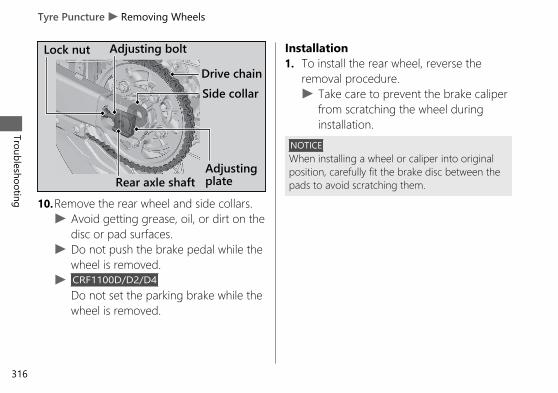
10.Remove the rear wheel and side collars.u Avoid getting grease, oil, or dirt on the
disc or pad surfaces.u Do not push the brake pedal while the
wheel is removed.u CRF1100D/D2/D4
Do not set the parking brake while thewheel is removed.
Installation1. To install the rear wheel, reverse the
removal procedure.u Take care to prevent the brake caliper
from scratching the wheel duringinstallation.
NOTICEWhen installing a wheel or caliper into originalposition, carefully fit the brake disc between thepads to avoid scratching them.
20190704203539_32MKS6000_eng_BOOK Page 321 Thursday, July 04 2019 20:57:26 JST
Tyre Puncture u Removing Wheels
Troubleshooting
316
Lock nut Adjusting bolt
Drive chain
Rear axle shaftAdjustingplate
Side collar

2. Make sure that the slot on the brakecaliper bracket is positioned in the lug onthe swingarm.
3. Adjust the drive chain. 2 P. 2744. Install and tighten the rear axle nut.
Torque: 100 N·m (10.2 kgf·m, 74 lbf·ft).
5. Install the chain cover and tighten bolts.6. After installing the wheel, apply the brake
pedal several times, then check if thewheel rotates freely. Recheck the wheel ifthe brake drags or if the wheel does notrotate freely.
If a torque wrench was not used forinstallation, see your dealer as soon aspossible to verify proper assembly.Improper assembly may lead to loss ofbraking capacity.
20190704203539_32MKS6000_eng_BOOK Page 322 Thursday, July 04 2019 20:57:26 JST
Tyre Puncture u Removing WheelsTroubleshooting
317
Lug
Swingarm
Brake caliper bracket
Slot

Audio System Trouble
Symptom Cause/remedy
Unable to pair Bluetooth®device
Some Bluetooth® devices and application software you use maybe incompatible with the audio system and/or the operablefunctions may be limited.Check that the audio system and Bluetooth® device are both inpairing mode. 2 P. 160 2 P. 165The audio system may not be properly connected when anotherBluetooth® device is being paired at the same time. Check yoursurroundings to make sure no other device being paired ispresent before re-pairing. Presence of a Bluetooth® device in thevicinity sometimes affects the pairing due to radio waveinterference, etc.When connecting a Bluetooth® device, make sure no otherBluetooth® device readied for pairing is present. Presence of aBluetooth® device in the vicinity sometimes affects the pairingdue to radio wave interference, etc.When you repeatedly fail in pairing, delete the paired deviceonce, then try pairing again. 2 P. 160 2 P. 165
20190704203539_32MKS6000_eng_BOOK Page 323 Thursday, July 04 2019 20:57:26 JST
Troubleshooting
318

Symptom Cause/remedy
Unable to connectBluetooth® device
Depending on the Bluetooth® device and application softwareyou use, it may take some time for the audio system to connectto a device and to start playing an audio file.The connection may be temporarily disconnected when startingthe engine, which is normal and not a malfunction. TheBluetooth® device will be reconnected after the engine is started.Check that your Bluetooth® device has been paired. Refer to theinstruction manual of your Bluetooth® device and check thatyour Bluetooth® device is in connectable state.
20190704203539_32MKS6000_eng_BOOK Page 324 Thursday, July 04 2019 20:57:26 JST
Audio System TroubleTroubleshooting
319Continued

Symptom Cause/remedy
Unable to connectBluetooth® phone device
Some Bluetooth® devices and application software you use maynot connect automatically. For connecting, follow the instructionsin the instruction manual of your Bluetooth® device.The Bluetooth® devices that can be connected at the same timeare limited to one Bluetooth® device and two Bluetooth®headsets.If the problem continues after the above-described inspection,delete the paired device once, then try pairing again. 2 P. 1602 P. 165The Bluetooth® connection cannot be established whilelaunching Apple CarPlay. Quit Apple CarPlay, then try pairingagain. 2 P. 197 2 P. 160While connected to Apple CarPlay, Bluetooth® function isdisabled.
20190704203539_32MKS6000_eng_BOOK Page 325 Thursday, July 04 2019 20:57:26 JST
Audio System Trouble
Troubleshooting
320

Symptom Cause/remedy
Connected, but does notplay.
Some Bluetooth® devices and application software you use maybe incompatible with the audio system and/or audio files may notbe played properly. Check the recommended specifications.2 P. 159Depending on the Bluetooth® device and application softwareyou use, an audio file may not play automatically. For playing,follow the instructions in the instruction manual of yourBluetooth® device.Depending on the Bluetooth® device and application softwareyou use, an audio file may not play normally after receiving atelephone call, etc. Check that your Bluetooth® device is inplayable state.
Takes some time to startplaying after turning thepower on or changing theaudio mode.
Right after the power is turned on or the audio mode is changed,the audio system may take some time to connect to an audiodevice and to start playing an audio file. Also, the audio systemmay not allow any audio control operation while preparing toplay an audio file.
20190704203539_32MKS6000_eng_BOOK Page 326 Thursday, July 04 2019 20:57:26 JST
Audio System TroubleTroubleshooting
321Continued

Symptom Cause/remedy
Sounds skipNoises mix
Presence of another Bluetooth® device or a device that emitselectromagnetic waves such as communication equipment in thevicinity sometimes affects the communication.Due to the characteristics of Bluetooth®, though in rare cases,the system operation may become unstable. When it remainsunstable, turn off the power to the audio system or the devicebeing used, and then turn it on again.The storage location of the Bluetooth® device sometimes affectsthe audio system and communication. When sounds skip ornoises mix, change the location of the device. For example, whenthe device is kept in a pocket of clothing sandwiched in betweenthe rider and passenger, the communication may be affected.Also, weather, buildings in the vicinity, road conditions, etc. cansometimes affect the communication.
20190704203539_32MKS6000_eng_BOOK Page 327 Thursday, July 04 2019 20:57:26 JST
Audio System Trouble
Troubleshooting
322

Symptom Cause/remedy
Sounds skipNoises mix
Depending on the Bluetooth® device and application softwareyou use, an audio file may not play normally after receiving atelephone call, etc. Turn off the power to the audio system andthen turn it on again. If the skipping of sounds or mixing of noisescontinues, check the status of your Bluetooth® device.If the skipping of sounds or mixing of noises continues, delete thepaired device once, then try pairing again. 2 P. 168Check the recommended specifications. 2 P. 159Noise sometimes mixes at places where radio waves are weak.
20190704203539_32MKS6000_eng_BOOK Page 328 Thursday, July 04 2019 20:57:26 JST
Audio System TroubleTroubleshooting
323Continued

Symptom Cause/remedy
Audio volume fromheadset is low/high.
Adjust the volume while in the individual modes. 2 P. 95Check the volume setting of the Bluetooth® audio device.Check the volume setting of the paired headset.
No or inaccurate display
Depending on the audio device and the audio file, nothing maybe displayed or the display may be inaccurate in some cases.Check the information on available tags. 2 P. 177When the information in an audio file such as the artist name andtrack title is in a non-compliant tag format, it may be indicated by“ ” or no information will be shown.
20190704203539_32MKS6000_eng_BOOK Page 329 Thursday, July 04 2019 20:57:26 JST
Audio System Trouble
Troubleshooting
324

Symptom Cause/remedy
Bluetooth® handsfreecalling cannot be available.
Connected Bluetooth® device may be an unsupported device.Check the supported Bluetooth® version/profiles. 2 P. 159When the Bluetooth® connection is unstable due to surroundingconditions or radio wave conditions, the handsfree callingfunctions may not be available.To use Bluetooth® handsfree calling, a headset connection isnecessary. Connect a paired headset. 2 P. 165
During a call, headsetvolume is low/high. Adjust the volume during a call. 2 P. 95
Passenger's headset is nosound
Passenger headset only outputs music. Music playback isinterrupted while using the handsfree phone or Siri.
20190704203539_32MKS6000_eng_BOOK Page 330 Thursday, July 04 2019 20:57:26 JST
Audio System TroubleTroubleshooting
325Continued
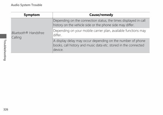
Symptom Cause/remedy
Bluetooth® HandsfreeCalling
Depending on the connection status, the times displayed in callhistory on the vehicle side or the phone side may differ.Depending on your mobile carrier plan, available functions maydiffer.A display delay may occur depending on the number of phonebooks, call history and music data etc. stored in the connecteddevice.
20190704203539_32MKS6000_eng_BOOK Page 331 Thursday, July 04 2019 20:57:26 JST
Audio System Trouble
Troubleshooting
326

Symptom Cause/remedy
Apple CarPlay is not beavailable.
Connected iPhone may be an unsupported model. Check themodels compatible with Apple CarPlay. 2 P. 192Connected iPhone may be an unsupported iOS version. Updatethe iPhone to the newer version.To use Apple CarPlay, a headset connection is necessary.Connect a paired headset. 2 P. 165When a mobile network communication is unstable due tosurrounding conditions or signal strength conditions, AppleCarPlay functions may not be available.
20190704203539_32MKS6000_eng_BOOK Page 332 Thursday, July 04 2019 20:57:26 JST
Audio System TroubleTroubleshooting
327Continued

Symptom Cause/remedy
Apple CarPlay is not beavailable.
When the paired headset connection is broken due to headsetbattery depletion or communication failure, Apple CarPlay cannotbe used until the connection is restored.The screen will not switch to Apple CarPlay automatically, otherthan when the ignition switch is turned to (Off) with AppleCarPlay activated.Some USB cables may be incompatible with Apple CarPlay. Usecertified cable to connect the iPhone.You have not agreed to enable Apple CarPlay. Reconnect theiPhone and enable CarPlay on the disclaimer screen. 2 P. 195Apple CarPlay setting on your iPhone may be disabled.Disconnect iPhone and enable the Apple CarPlay setting on youriPhone.
20190704203539_32MKS6000_eng_BOOK Page 333 Thursday, July 04 2019 20:57:26 JST
Audio System Trouble
Troubleshooting
328

Symptom Cause/remedy
Connected, but does notoperate Apply CarPlay.
You cannot operate Apple CarPlay by the touch panel while thevehicle is in motion. Operate with the left handlebar switches orpark your vehicle in a safe place, then operate.
Some functions of AppleCarPlay not available.
Some functions may be limited due to condition of mobilenetwork communication.
Apple CarPlay screen is toodark/bright
Selecting [Background] menu in [Settings], you can select whitemode or black mode in the navigation map or an applicationsuch as Maps, also adjust backlight brightness by [Brightness]menu in [Settings] 2 P. 84 2 P. 83.
Audio system cannotoperate.
Certain manual functions and settings are disabled or inoperablewhile the vehicle is in motion. You cannot select a greyed-outmenu until the vehicle is stopped.
When turning the ignitionswitch to (Off) and (On) continuously.
Since the system restart takes time, it may take time until thescreen is appeared.
20190704203539_32MKS6000_eng_BOOK Page 334 Thursday, July 04 2019 20:57:26 JST
Audio System TroubleTroubleshooting
329Continued

Symptom Cause/remedy
High temperature/overcurrent protection
To protect the system, some operations may be limitedtemporarily. The system automatically recovers after the cause issolved.
Software update The statements in this owner's manual may not match yourvehicle's Audio System after performing the software update.
If the problem continues after the above-described inspection, have your vehicle inspected byyour dealer.
20190704203539_32MKS6000_eng_BOOK Page 335 Thursday, July 04 2019 20:57:26 JST
Audio System Trouble
Troubleshooting
330

Electrical Trouble
Battery Goes DeadBattery charging is needed.A battery charger recommended by yourlithium-ion (li-ion) battery manufacturer isneeded for battery charging.Contact your dealer before charging thebattery.Remove the battery from the vehicle beforecharging.
NOTICEOnly use a charger recommended by yourlithium-ion (li-ion) battery manufacturer. Using abattery charger that is not recommended cancause permanent damage to your battery.
If the battery does not recover afterrecharging, contact your dealer.
NOTICEDo not jump-start, as this can damage yourvehicle's electrical system and battery.
Burned-out Light BulbAll light bulbs on the vehicle are LEDs. Ifthere is an LED which is not turned on, seeyour dealer for servicing.Turn the ignition switch to the (Off) or (Lock) position.
20190704203539_32MKS6000_eng_BOOK Page 336 Thursday, July 04 2019 20:57:26 JST
Troubleshooting
331Continued

# Headlight
The headlights use several LEDs.If there is a LED which is not turned on, seeyour dealer for this service.
# DRL
The DRLs use several LEDs.If there is a LED which is not turned on, seeyour dealer for this service.
20190704203539_32MKS6000_eng_BOOK Page 337 Thursday, July 04 2019 20:57:26 JST
Electrical Trouble u Burned-out Light Bulb
Troubleshooting
332
Headlights DRLs

# Cornering LightCRF1100A2/A4/D2/D4
The cornering lights use several LEDs.If there is a LED which is not turned on, seeyour dealer for this service.
# Brakelight/Taillight/License PlateLight
The brakelight, taillight and license plate lightuse several LEDs.If there is a LED which is not turned on, seeyour dealer for this service.
20190704203539_32MKS6000_eng_BOOK Page 338 Thursday, July 04 2019 20:57:26 JST
Electrical Trouble u Burned-out Light BulbTroubleshooting
333Continued
Cornering Lights Brakelight/Taillight
License plate light

# Front/Rear Turn Signal
The front and rear turn signals use severalLEDs.If there is a LED which is not turned on, seeyour dealer for this service.
20190704203539_32MKS6000_eng_BOOK Page 339 Thursday, July 04 2019 20:57:26 JST
Electrical Trouble u Burned-out Light Bulb
Troubleshooting
334
Turn signal

Blown FuseBefore handling fuses, see “Inspecting andReplacing Fuses.” 2 P. 241
# Fuse Box Fuses & ABS FSR Fuse1. Remove the front seat. 2 P. 2532. Open the fuse box covers.3. Pull the fuses out with the fuse puller
provided on the underside of the rearseat (2 P. 230) one by one check for ablown fuse. Always replace a blown fusewith a spare fuse of the same rating.
4. Close the fuse box covers.5. Reinstall the front seat.
20190704203539_32MKS6000_eng_BOOK Page 340 Thursday, July 04 2019 20:57:26 JST
Electrical Trouble u Blown FuseTroubleshooting
335Continued
Spare fuses
Fuseboxcover
Fuse boxcover

# Main Fuse & ABS Main Fuse 1. Remove the battery box cover. 2 P. 2512. Pull the starter magnetic switch out.3. Remove the starter magnetic switch
cover.4. Pull the main fuse and ABS main fuse out
with the fuse puller provided on theunderside of the rear seat (2 P. 230) oneby one check for a blown fuse. Alwaysreplace a blown fuse with a spare fuse ofthe same rating.u Spare main fuse and spare ABS main
fuse are provided in the startermagnetic switch.
5. Reinstall parts in the reverse order ofremoval.
20190704203539_32MKS6000_eng_BOOK Page 341 Thursday, July 04 2019 20:57:26 JST
Electrical Trouble u Blown Fuse
Troubleshooting
336
Starter magnetic switch
Sparefuse
Mainfuse
Starter magneticswitch coverABS mainfuse

# FI Fuse & Main 2 FuseCRF1100A/A2/A4
1. Remove the battery box cover. 2 P. 2512. Pull the FI fuse box and main 2 fuse box
suspension out.3. Open the fuse box cover.4. Pull the FI fuse and main 2 fuse out with
the fuse puller provided on the undersideof the rear seat (2 P. 230) and check for ablown fuse. Always replace a blown fusewith a spare fuse of the same rating.u Spare FI fuse is provided in the fuse
box under the front seat.u Spare main 2 fuse is provided in the
starter magnetic switch.5. Reinstall parts in the reverse order of
removal.
20190704203539_32MKS6000_eng_BOOK Page 342 Thursday, July 04 2019 20:57:26 JST
Electrical Trouble u Blown FuseTroubleshooting
337Continued
FI fuseMain 2 fuse
Fuse box covers
FI fuse box andmain 2 fuse boxsuspension

# FI Fuse & Main 2 Fuse & DCT MainFuse
CRF1100D/D2/D4
1. Remove the battery box cover. 2 P. 2512. Pull the main 2 fuse/FI main fuse box and
DCT fuse box suspension out.3. Open the fuse box covers.4. Pull the FI fuse, main 2 fuse and DCT main
fuse out with the fuse puller provided onthe underside of the rear seat (2 P. 230)one by one check for a blown fuse.Always replace a blown fuse with a sparefuse of the same rating.u Spare FI fuse is provided in the fuse
box under the front seat.u Spare main 2 fuse and spare DCT
main fuse are provided in the startermagnetic switch.
5. Reinstall parts in the reverse order ofremoval.
NOTICEIf a fuse fails repeatedly, you likely have anelectrical problem. Have your vehicle inspectedby your dealer.
20190704203539_32MKS6000_eng_BOOK Page 343 Thursday, July 04 2019 20:57:26 JST
Electrical Trouble u Blown Fuse
Troubleshooting
338
DCT main fuse
FI fuseMain 2 fuse
Fuse box covers
Main 2 fuse/FI mainfuse box and DCTfuse box suspension

Keys.....................................................................P. 340Instruments, Controls, & Other Features...P. 341Caring for Your Vehicle..................................P. 345Storing Your Vehicle.......................................P. 349Transporting Your Vehicle ............................P. 350You & the Environment .................................P. 351Serial Numbers ................................................P. 352Fuels Containing Alcohol ..............................P. 353Catalytic Converter .........................................P. 354
20190704203539_32MKS6000_eng_BOOK Page 344 Thursday, July 04 2019 20:57:26 JST
Information

Service DiagnosticRecordersThis vehicle is equipped with service-relateddevices that record information aboutpowertrain performance. The data can be usedto verify emissions law requirements and/orhelp technicians diagnose and solve serviceproblems. It may also be combined with datafrom other sources for research purposes, but itremains confidential. Some diagnostic andmaintenance information is uploaded to Hondaupon vehicle start up.
KeysIgnition Key
This vehicle has two ignition keys and a key tagwith a key number and a bar code.
The ignition key contains a special coded chip thatis recognized by the immobilizer system (HISS) inorder to start the engine. Handle the key carefullyto prevent damaging the HISS components.● Do not bend keys or subject them to undue
stress.● Avoid prolonged exposure to sunlight or high
temperatures.● Do not grind, drill or in any way alter their
shape.● Do not expose to strong magnetic objects.
If you lose all ignition keys and the key tag, thePGM-FI unit/ignition control module must bereplaced by your dealer. To avoid this, keep aduplicate key.
20190704203539_32MKS6000_eng_BOOK Page 345 Thursday, July 04 2019 20:57:26 JST
Service Diagnostic Recorders
Information
340

If you lose a key, make another duplicate keyimmediately.
To make a duplicate key and register it withyour HISS system, take the spare key, the keytag, and the vehicle to your dealer.u Store the key tag in a safe location.
A metal key holder may cause damage to the areasurrounding the ignition switch.
Instruments, Controls, &Other FeaturesIgnition Switch
Leaving the ignition switch in the (On) positionwith the engine stopped will drain the battery.Do not turn the key while riding.
Engine Stop SwitchDo not use the engine stop switch except in anemergency. Doing so when riding will cause theengine to suddenly turn off, making ridingunsafe.If you stop the engine using the engine stopswitch, turn the ignition switch to the (Off)position. Failing to do so will drain the battery.
20190704203539_32MKS6000_eng_BOOK Page 346 Thursday, July 04 2019 20:57:26 JST
Instruments, Controls, & Other FeaturesInform
ation
341Continued
Ignition key Key tag
Key number and bar code

OdometerThe display locks at 999,999 when the read-outexceeds 999,999.
TripmeterThe tripmeters return to 0.0 when each read-out exceeds 9,999.9.
HISSThe Honda Ignition Security System (HISS)immobilizes the engine's ignition system if animproperly-coded key is used to try and startthe engine. When the ignition switch is turnedto the (Off) position, the HISS immobilizersystem is always alert, even if the HISS indicatoris not flashing.If the ignition switch is turned to the (On)position with the engine stop switch in the (Run) position, the HISS indicator turns on andgoes off after a few seconds to indicate it is OKto start the engine. HISS Indicator Does NotTurn off 2 P. 299
The HISS indicator starts flashing every 2seconds for 24 hours after the ignition switch isturned to the (Off) position. You can turn thisfeature on or off. 2 P. 80EU DirectiveThis immobilizer system complies with the RE(Radio Equipment) Directive (2014/53/EU).
20190704203539_32MKS6000_eng_BOOK Page 347 Thursday, July 04 2019 20:57:26 JST
Instruments, Controls, & Other Features
Information
342

The declaration of conformity to RE Directive isprovided to the owner at the time of purchase.The declaration of conformity should be kept ata safe place. When the declaration ofconformity is lost or is not provided, contactyour dealer.
South Africa only
Morocco only
Audio systemEU DirectiveThis audio system complies with the RE (RadioEquipment) Directive (2014/53/EU).
The declaration of conformity to RE Directive isprovided to the owner at the time of purchase.The declaration of conformity should be kept ata safe place. When the declaration ofconformity is lost or is not provided, contactyour dealer.
South Africa only
20190704203539_32MKS6000_eng_BOOK Page 348 Thursday, July 04 2019 20:57:26 JST
Instruments, Controls, & Other FeaturesInform
ation
343Continued

Document BagThe owner’s manual, registration, and insuranceinformation can be stored in the plasticdocument bag located on the underside of thefront seat. 2 P. 229
Ignition Cut-off SystemIMU (Inertia Measurement Unit) sensorautomatically stops the engine and fuel pump ifthe vehicle falls over. To reset the IMU, youmust turn the ignition switch to the (Off)position and back to the (On) position beforethe engine can be restarted.
If a failure of the IMU is detected, the engineand fuel pump will not stop automatically whenthe vehicle falls over.
Assist-slipper Clutch SystemCRF1100A/A2/A4The assist-slipper clutch system helps to preventthe rear tyre from locking up when thedeceleration of your vehicle produces a strongengine braking effect. It also makes the clutchlever operation feel lighter.
Use only MA classification engine oil for yourvehicle. Using engine oil other than MAclassification oil could result in damage to theassist-slipper clutch system.
Throttle by Wire SystemThis model is equipped with a Throttle by WireSystem.Do not put magnetized items or itemssusceptible to magnetic interference near theright handlebar switches.
20190704203539_32MKS6000_eng_BOOK Page 349 Thursday, July 04 2019 20:57:26 JST
Instruments, Controls, & Other Features
Information
344

DRL, Automatic Brightness Control andBackground Control
Ambient brightness is detected by thephotosensor.Do not damage or cover the photosensor.Otherwise, the DRL, automatic brightnesscontrol and background control may not workproperly.
Caring for Your VehicleFrequent cleaning and polishing is important toensure the life of your Honda. A clean vehiclemakes it easier to spot potential problems.In particular, seawater and salts used to preventice on roads promote the formation ofcorrosion. Always wash your vehicle thoroughlyafter riding on coastal or treated roads.
20190704203539_32MKS6000_eng_BOOK Page 350 Thursday, July 04 2019 20:57:26 JST
Caring for Your VehicleInform
ation
345Continued
Photosensor

WashingAllow the engine, muffler, brakes, and otherhigh-temperature parts to cool before washing.1. Rinse your vehicle thoroughly using a low
pressure garden hose to remove loose dirt.2. If necessary, use a sponge or a soft towel
with mild cleaner to remove road grime.u Clean the windscreen, headlight lens,
panels, and other plastic componentswith extra care to avoid scratching them.Avoid directing water into the air cleaner,muffler, and electrical parts.
3. Thoroughly rinse your vehicle with plenty ofclean water and dry with a soft, clean cloth.
4. After the vehicle dries, lubricate any movingparts.u Make sure that no lubricant spills onto
the brakes or tyres. Brake discs, pads,drum or shoes contaminated with oil willsuffer greatly reduced brakingeffectiveness and can lead to a crash.
5. Lubricate the drive chain immediately afterwashing and drying the vehicle.
6. Apply a coat of wax to prevent corrosion.u Avoid products that contain harsh
detergents or chemical solvents. Thesecan damage the metal, paint, and plasticon your vehicle.Keep the wax clear of the tyres andbrakes.
u If your vehicle has any mat painted parts,do not apply a coat of wax to the matpainted surface.
20190704203539_32MKS6000_eng_BOOK Page 351 Thursday, July 04 2019 20:57:26 JST
Caring for Your Vehicle
Information
346

# Washing PrecautionsFollow these guidelines when washing:● Do not use high-pressure washers:
u High-pressure water cleaners candamage moving parts and electricalparts, rendering them inoperable.
u Water in the air intake can be drawn intothe throttle body and/or enter the aircleaner.
● Do not direct water at the muffler:u Water in the muffler can prevent starting
and causes rust in the muffler.● Dry the brakes:
u Water adversely affects brakingeffectiveness. After washing, apply thebrakes intermittently at low speed tohelp dry them.
● Do not direct water under the seat:u Water in the under seat compartment
can damage your documents and otherbelongings.
● Do not direct water at the air cleaner:u Water in the air cleaner can prevent the
engine from starting.● Do not direct water near the headlight:
u The headlight's inside lens may fogtemporarily after washing or while ridingin the rain. This does not impact theheadlight function.However, if you see a large amount ofwater or ice accumulated inside thelens(es), have your vehicle inspected byyour dealer.
● Do not use wax or polishing compounds onmat painted surface:u Use a soft cloth or sponge, plenty of
water, and a mild detergent to clean matpainted surfaces. Dry with a soft cleancloth.
20190704203539_32MKS6000_eng_BOOK Page 352 Thursday, July 04 2019 20:57:26 JST
Caring for Your VehicleInform
ation
347Continued

Aluminium ComponentsAluminium will corrode from contact with dirt,mud, or road salt. Clean aluminium partsregularly and follow these guidelines to avoidscratches:● Do not use stiff brushes, steel wool, or
cleaners containing abrasives.● Avoid riding over or scraping against curbs.
PanelsFollow these guidelines to prevent scratchesand blemishes:● Wash gently using a soft sponge and plenty
of water.● To remove stubborn stains, use diluted
detergent and rinse thoroughly with plentyof water.
● Avoid getting petrol, brake fluid, ordetergents on the instruments, panels, orheadlight.
WindscreenUsing plenty of water, clean the windscreen witha soft cloth or sponge. (Avoid using detergentsor any kind of chemical cleaner on thewindscreen.) Dry with a soft, clean cloth.
NOTICETo avoid possible scratching or other damage,use only water and a soft cloth or sponge toclean the windscreen.
For a dirtier windscreen, use a diluted neutraldetergent with a sponge and plenty of water.Make sure to wash off all the detergent.(Detergent residue may cause windscreencracks.)
Replace the windscreen if scratches cannot beremoved and they obstruct clear vision.
Take care to keep battery electrolyte, brakefluid, or other chemical solvents off thewindscreen and screen garnish. They willdamage the plastic.
20190704203539_32MKS6000_eng_BOOK Page 353 Thursday, July 04 2019 20:57:26 JST
Caring for Your Vehicle
Information
348

Exhaust Pipe and MufflerThe exhaust pipe and muffler are stainless steelbut may become stained by mud or dust.
To remove mud or dust, use a wet sponge anda liquid kitchen abrasive, then rinse well withclean water. Dry with chamois or a soft towel.
If necessary, remove heat stains by using acommercially available fine texture compound. Thenrinse by the same manner as removing mud or dust.
When the exhaust pipe and muffler are painted,do not use a commercially available abrasivekitchen cleaning compound. Use a neutraldetergent to clean the painted surface on theexhaust pipe and muffler. If you are not sure ifyour exhaust pipe and muffler are painted,contact your dealer.
NOTICEEven though the exhaust is made of stainlesssteel, it can become stained. Remove all marksand blemishes as soon as they are noticed.
Storing Your VehicleIf you store your vehicle outdoors, you shouldconsider using a full-body cover.If you won't be riding for an extended period,follow these guidelines:● Wash your vehicle and wax all painted
surfaces (except mat painted surfaces). Coatchrome pieces with rust-inhibiting oil.
● Lubricate the drive chain. 2 P. 243● Place your vehicle on a maintenance stand
and position a block so that both tyres areoff the ground.
● After rain, remove the body cover and allowthe vehicle to dry.
20190704203539_32MKS6000_eng_BOOK Page 354 Thursday, July 04 2019 20:57:26 JST
Storing Your VehicleInform
ation
349Continued

● Remove the battery (2 P. 250) to preventdischarge. Fully charge the battery and thenplace it in a shaded, well-ventilated area.u If you leave the battery in place,
disconnect the negative - terminal toprevent discharge.
After removing your vehicle from storage,inspect all maintenance items required by theMaintenance Schedule.
Transporting Your VehicleIf your vehicle needs to be transported, itshould be carried on a motorcycle trailer or aflatbed truck or trailer that has a loading rampor lifting platform, and motorcycle tie-downstraps. Never try to tow your vehicle with awheel or wheels on the ground.
NOTICETowing your vehicle can cause serious damageto the transmission.
20190704203539_32MKS6000_eng_BOOK Page 355 Thursday, July 04 2019 20:57:26 JST
Transporting Your Vehicle
Information
350

You & the EnvironmentOwning and riding a vehicle can be enjoyable,but you must do your part to protect theenvironment.
Choose Sensible CleanersUse a biodegradable detergent when you washyour vehicle. Avoid aerosol spray cleaners thatcontain chlorofluorocarbons (CFCs) whichdamage the atmosphere's protective ozonelayer.
Recycle WastesPut oil and other toxic wastes in approvedcontainers and take them to a recycling centre.Call your local or state office of public works orenvironmental services to find a recycling centrein your area, and to get instructions on how todispose of non-recyclable wastes. Do not placeused engine oil in the trash, or pour it down adrain or on the ground. Used oil, petrol,coolant, and cleaning solvents contain poisonsthat can hurt refuse workers and contaminatedrinking water, lakes, rivers, and oceans.
20190704203539_32MKS6000_eng_BOOK Page 356 Thursday, July 04 2019 20:57:26 JST
You & the EnvironmentInform
ation
351

Serial NumbersThe frame and engine serial numbers uniquelyidentify your vehicle and are required in orderto register your vehicle. They may also berequired when ordering replacement parts.You should record these numbers and keepthem in a safe place.
20190704203539_32MKS6000_eng_BOOK Page 357 Thursday, July 04 2019 20:57:26 JST
Serial Numbers
Information
352
Frame number
Engine number

Fuels Containing AlcoholSome conventional fuels blended with alcoholare available in some locales to help reduceemissions to meet clean air standards. If youplan to use blended fuel, check that it isunleaded and meets the minimum octanerating requirement.
The following fuel blends can be used in yourvehicle:● Ethanol (ethyl alcohol) up to 10% by volume.
u Petrol containing ethanol may bemarketed under the name Gasohol.
The use of petrol containing more than 10%ethanol may:● Damage the painting of the fuel tank.● Damage the rubber tubes of the fuel line.● Cause corrosion of the fuel tank.● Cause poor drivability.NOTICEUse of blended fuels containing higher thanapproved percentages can damage metal,rubber, plastic parts of your fuel system.
If you notice any undesirable operatingsymptoms or performance problems, try adifferent brand of petrol.
20190704203539_32MKS6000_eng_BOOK Page 358 Thursday, July 04 2019 20:57:26 JST
Fuels Containing AlcoholInform
ation
353

Catalytic ConverterThis vehicle is equipped with two three-waycatalytic converters. Each catalytic convertercontains precious metals that serve as catalystsin high temperature chemical reactions thatconvert hydrocarbons (HC), carbon monoxide(CO), and oxides of nitrogen (NOx) in theexhaust gasses into safe compounds.
A defective catalytic converter contributes to airpollution and can impair your engine'sperformance. A replacement unit must be anoriginal Honda part or equivalent.
Follow these guidelines to protect your vehicle'scatalytic converters.● Always use unleaded petrol. Leaded petrol
will damage the catalytic converters.● Keep the engine in good running condition.● Have your vehicle serviced if your engine is
misfiring, backfiring, stalling, or otherwisenot running properly, stop riding and turnoff the engine.
20190704203539_32MKS6000_eng_BOOK Page 359 Thursday, July 04 2019 20:57:26 JST
Catalytic Converter
Information
354

Legal Information onApple CarPlayOWNER’S MANUAL LICENSE/LIABILITYSTATEMENTS
USE OF APPLE CARPLAY IS SUBJECT TO YOURAGREEMENT TO THE CARPLAY TERMS OF USE,WHICH ARE INCLUDED AS PART OF THEAPPLE iOS TERMS OF USE. IN SUMMARY, THECARPLAY TERMS OF USE DISCLAIM APPLEAND ITS SERVICE PROVIDERS’ LIABILITY IF THESERVICES FAIL TO PERFORM CORRECTLY ORARE DISCONTINUED, STRICTLY LIMIT APPLEAND ITS SERVICE PROVIDERS’ OTHERLIABILITIES, DESCRIBE THE KINDS OF USERINFORMATION (INCLUDING, FOR EXAMPLE,VEHICLE LOCATION, VEHICLE SPEED, ANDVEHICLE STATUS) BEING GATHERED ANDSTORED BY APPLE AND ITS SERVICEPROVIDERS, AND DISCLOSE CERTAINPOSSIBLE RISKS ASSOCIATED WITH THE USE
OF CARPLAY, INCLUDING THE POTENTIAL FORDRIVER DISTRACTION.SEE APPLE’S PRIVACY POLICY FOR DETAILSREGARDING APPLE'S USE AND HANDLING OFDATA UPLOADED BY CARPLAY.
20190704203539_32MKS6000_eng_BOOK Page 360 Thursday, July 04 2019 20:57:26 JST
Legal Information on Apple CarPlayInform
ation
355Continued

DISCLAIMER OF WARRANTIES;LIMITATION ON LIABILITY
YOU EXPRESSLY ACKNOWLEDGE AND AGREETHAT USE OF APPLE CARPLAY (“THEAPPLICATIONS”) IS AT YOUR SOLE RISK ANDTHAT THE ENTIRE RISK AS TO SATISFACTORYQUALITY, PERFORMANCE, ACCURACY ANDEFFORT IS WITH YOU TO THE MAXIMUMEXTENT PERMITTED BY APPLICABLE LAW, ANDTHAT THE APPLICATIONS AND INFORMATIONON THE APPLICATIONS IS PROVIDED “AS IS”AND “AS AVAILABLE,” WITH ALL FAULTS ANDWITHOUT WARRANTY OF ANY KIND, ANDHONDA HEREBY DISCLAIMS ALL WARRANTIESAND CONDITIONS WITH RESPECT TO THEAPPLICATIONS AND INFORMATION ON THEAPPLICATIONS, EITHER EXPRESS, IMPLIED ORSTATUTORY, INCLUDING, BUT NOT LIMITEDTO, THE IMPLIED WARRANTIES AND/ORCONDITIONS OF MERCHANTABILITY,SATISFACTORY QUALITY, FITNESS FOR APARTICULAR PURPOSE, ACCURACY, QUIET
ENJOYMENT, AND NONINFRINGEMENT OFTHIRD PARTY RIGHTS. NO ORAL OR WRITTENINFORMATION OR ADVICE GIVEN BY HONDAOR AN AUTHORIZED REPRESENTATIVE SHALLCREATE A WARRANTY. AS EXAMPLES, ANDWITHOUT LIMITATION, HONDA DISCLAIMSANY WARRANTY REGARDING THE ACCURACYOF DATA PROVIDED BY THE APPLICATIONS,SUCH AS THE ACCURACY OF DIRECTIONS,ESTIMATED TRAVEL TIME, SPEED LIMITS, ROADCONDITIONS, NEWS, WEATHER, TRAFFIC, OROTHER CONTENT PROVIDED BY APPLE, THEIRAFFILIATES, OR THIRD PARTY PROVIDERS;HONDA DOES NOT GUARANTEE AGAINSTLOSS OF APPLICATION DATA, WHICH MAY BELOST AT ANY TIME; HONDA DOES NOTGUARANTEE THAT THE APPLICATIONS ORANY SERVICES PROVIDED THROUGH THEMWILL BE PROVIDED AT ALL TIMES OR THATANY OR ALL SERVICES WILL BE AVAILABLE ATANY PARTICULAR TIME OR LOCATION.
20190704203539_32MKS6000_eng_BOOK Page 361 Thursday, July 04 2019 20:57:26 JST
Legal Information on Apple CarPlay
Information
356

FOR EXAMPLE, SERVICES MAY BE SUSPENDEDOR INTERRUPTED WITHOUT NOTICE FORREPAIR, MAINTENANCE, SECURITY FIXES,UPDATES, ETC., SERVICES MAY BEUNAVAILABLE IN YOUR AREA OR LOCATION,ETC. IN ADDITION, YOU UNDERSTAND THATCHANGES IN THIRD PARTY TECHNOLOGY ORGOVERNMENT REGULATION MAY RENDERTHE SERVICES AND/OR APPLICATIONSOBSOLETE AND/OR UNUSABLE.
TO THE EXTENT NOT PROHIBITED BY LAW, INNO EVENT SHALL HONDA OR ITS AFFILIATESBE LIABLE FOR PERSONAL INJURY, OR ANYINCIDENTAL, SPECIAL, INDIRECT ORCONSEQUENTIAL DAMAGES WHATSOEVER,INCLUDING, WITHOUT LIMITATION, DAMAGESFOR LOSS OF PROFITS, CORRUPTION OR LOSSOF DATA, FAILURE TO TRANSMIT OR RECEIVEANY DATA, BUSINESS INTERRUPTION OR ANYOTHER COMMERCIAL DAMAGES OR LOSSES,ARISING OUT OF OR RELATED TO THEAPPLICATIONS OR YOUR USE OF OR INABILITY
TO USE THE APPLICATIONS OR INFORMATIONON THE APPLICATIONS, HOWEVER CAUSED,REGARDLESS OF THE THEORY OF LIABILITY(CONTRACT, TORT OR OTHERWISE) ANDEVEN IF HONDA WERE ADVISED OF THEPOSSIBILITY OF SUCH DAMAGES. SOMEREGIONS AND JURISDICTIONS MAY DISALLOWTHE EXCLUSION OR LIMITATION OF LIABILITYFOR DAMAGES, SO THESE LIMITATIONS ANDEXCLUSIONS MAY NOT APPLY TO YOU. THEFOREGOING LIMITATIONS WILL APPLY EVEN IFTHE ABOVE STATED REMEDY FAILS OF ITSESSENTIAL PURPOSE.
20190704203539_32MKS6000_eng_BOOK Page 362 Thursday, July 04 2019 20:57:26 JST
Legal Information on Apple CarPlayInform
ation
357

Software UpgradesUpgrades
Honda is continually expanding the scope of thesystem software. The softwares are updated tocorrespond with new version releases.For the software updates, contact your dealer.
20190704203539_32MKS6000_eng_BOOK Page 363 Thursday, July 04 2019 20:57:26 JST
Software Upgrades
Information
358

Specifications■ Main ComponentsOverall length 2,330 mm (91.7 in)Overall width 960 mm (37.8 in)
Overall heightCRF1100A/D1,395 mm (54.9 in)CRF1100A2/A4/D2/D41,560 mm (61.4 in)
Wheelbase 1,575 mm (62.0 in)Minimum ground clearance 250 mm (9.8 in)Caster angle 27° 30’Trail 113 mm (4.4 in)
Curb weight
CRF1100A 226 kg (498 lb)CRF1100D 236 kg (520 lb)CRF1100A2 238 kg (525 lb)CRF1100D2 248 kg (547 lb)CRF1100A4 240 kg (529 lb)CRF1100D4 250 kg (551 lb)
Maximum weight capacity *1
CRF1100A/D220 kg (485 lb)CRF1100A2/A4/D2/D4218 kg (481 lb)
Maximum luggage weight *229 kg (64 lb)CRF1100A2/A4/D2/D4Rear carrier 10 kg (22 lb)
Passenger capacity Rider and 1 passengerMinimum turning radius 2.6 m (8.5 ft)Displacement 1,084 cm3 (66.1 cu-in)Bore x stroke 92.0 x 81.5 mm (3.62 x 3.21 in)Compression ratio 10.1:1
Fuel Unleaded petrolRecommended: 91 RON or higher
Fuels containing alcohol ETHANOL up to 10 % by volume
Tank capacityCRF1100A/D18.8 L (4.97 US gal, 4.14 Imp gal)CRF1100A2/A4/D2/D424.8 L (6.55 US gal, 5.46 Imp gal)
*1 : Including rider, passenger, all luggage, and accessories*2 : Includes the weight of the luggage and added accessories
20190704203539_32MKS6000_eng_BOOK Page 364 Thursday, July 04 2019 20:57:26 JST
Specifications
359

Battery HY11012 V-6 Ah (20 HR)
Gear ratios
CRF1100A/A2/A41st 2.8662nd 1.8883rd 1.4804th 1.2305th 1.0646th 0.972CRF1100D/D2/D41st 2.5622nd 1.7613rd 1.3754th 1.1335th 0.9726th 0.882
Reduction ratios(primary / final)
CRF1100A/A2/A41.717 / 2.625CRF1100D/D2/D41.863 / 2.625
■ Service Data
Tyre size
Front
CRF1100A/D90/90-21M/C 54HM+S90/90-21M/C 54S
CRF1100A2/A4/D2/D490/90-21M/C 54HM+S90/90-21M/C 54T
Rear150/70R18M/C 70HM+S150/70B18M/C 70Q
20190704203539_32MKS6000_eng_BOOK Page 365 Thursday, July 04 2019 20:57:26 JST
Specifications
Specifications
360

Tyre type
Front
CRF1100A/DBias-ply, tubeM+SBias-ply, tube
CRF1100A2/A4/D2/D4Bias-ply, tubelessM+SBias-ply, tubeless
Rear
CRF1100A/DRadial, tubeM+SBias-ply, tube
CRF1100A2/A4/D2/D4Radial, tubelessM+SBias-ply, tubeless
RecommendedTyres Front
CRF1100A/DBRIDGESTONE BATTLAXADVENTURECROSS TOURERAX41TF GMETZELER KAROO STREETM+SContinental TKC80 Twinduro
CRF1100A2/A4/D2/D4BRIDGESTONE BATTLAXADVENTURECROSS TOURERAX41TF LMETZELER KAROO STREETM+SContinental TKC80 Twinduro
20190704203539_32MKS6000_eng_BOOK Page 366 Thursday, July 04 2019 20:57:26 JST
SpecificationsSpecifications
361

RecommendedTyres Rear
CRF1100A/DBRIDGESTONE BATTLAXADVENTURECROSS TOURERAX41TR GMETZELER KAROO STREETM+SContinental TKC80 Twinduro
CRF1100A2/A4/D2/D4BRIDGESTONE BATTLAXADVENTURECROSS TOURERAX41TR LMETZELER KAROO STREETM+SContinental TKC80 Twinduro
Tyre categoryof use *1
Normal PermittedSpecial Not PermittedSnow *2
(M+S on thetyre sidewallmarking)
Permitted
Moped Not PermittedTyre airpressure(Driver only)
Front 225 kPa (2.25 kgf/cm2, 33 psi)Rear 250 kPa (2.50 kgf/cm2, 36 psi)
Tyre airpressure(Driver andpassenger)
Front 225 kPa (2.25 kgf/cm2, 33 psi)
Rear 280 kPa (2.80 kgf/cm2, 41 psi)
Minimum treaddepth
Front1.5 mm (0.06 in)M+S3.0 mm (0.12 in)
Rear2.0 mm (0.08 in)M+S3.0 mm (0.12 in)
*1 : Categorized by UNECE Regulation No. 75*2 : Snow is not limited as snow, but includes DP (Dual Purpose),
M+S, MS, M&S (mud and snow)
20190704203539_32MKS6000_eng_BOOK Page 367 Thursday, July 04 2019 20:57:26 JST
Specifications
Specifications
362

Spark plugs (standard) SILMAR8A9S (NGK)Spark plug gap (non-
adjustable) 0.8 - 0.9 mm (0.03 - 0.04 in)Idle speed 1,250 ± 100 rpm
Recommendedengine oil
Honda 4-stroke motorcycle oil API ServiceClassification SG or higher, excluding oilsmarked as “Energy Conserving” or “ResourceConserving,” SAE 10W-30, JASO T 903standard MA
Engine oilcapacity
CRF1100A/A2/A4After draining 3.9 L (4.1 US qt, 3.4 Imp
qt)After draining &engine oil filterchange
4.0 L (4.2 US qt, 3.5 Impqt)
After disassembly 4.8 L (5.1 US qt, 4.2 Impqt)
CRF1100D/D2/D4After draining 4.0 L (4.2 US qt, 3.5 Imp
qt)After draining &engine oil filterchange
4.2 L (4.4 US qt, 3.7 Impqt)
After draining,engine & clutchoil filter change
4.2 L (4.4 US qt, 3.7 Impqt)
After disassembly 5.2 L (5.5 US qt, 4.6 Impqt)
Recommendedbrake fluid Honda DOT 4 Brake Fluid
Cooling systemcapacity 1.81 L (1.91 US qt, 1.59 Imp qt)
Recommendedcoolant Pro Honda HP Coolant
Recommendeddrive chainlubricant
Drive chain lubricant designed specifically forO-ring chains. If not available, use SAE 80 or90 gear oil.
Drive chainslack 35 - 45 mm (1.4 - 1.8 in)
Standard drivechain
DID 525HV3No. of links 124
Standardsprocket size
Drive sprocket 16TDriven sprocket 42T
20190704203539_32MKS6000_eng_BOOK Page 368 Thursday, July 04 2019 20:57:26 JST
SpecificationsSpecifications
363

■ BulbsHeadlight LEDDRL LEDCornering light LEDBrakelight/Taillight LEDFront turn signal LEDRear turn signal LEDLicense plate light LED
■ FusesMain fuse 30 AOther fuses 30 A, 20 A, 15 A, 10 A
■ Torque SpecificationsSkid plate bolt A 26 N·m (2.7 kgf·m, 19 lbf·ft)Skid plate bolt BCRF1100A2/A4/D2/D4 12 N·m (1.2 kgf·m, 9 lbf·ft)
Oil filter 26 N·m (2.7 kgf·m, 19 lbf·ft)Engine oil drain bolt 30 N·m (3.1 kgf·m, 22 lbf·ft)Clutch oil filter cover boltCRF1100D/D2/D4 12 N·m (1.2 kgf·m, 9 lbf·ft)
Rear wheel axle nut 100 N·m (10.2 kgf·m, 74 lbf·ft)Drive chain adjusting lock nut 27 N·m (2.8 kgf·m, 20 lbf·ft)Front wheel axle nut 65 N·m (6.6 kgf·m, 48 lbf·ft)Front wheel axle pinch bolt 22 N·m (2.2 kgf·m, 16 lbf·ft)Front wheel brake calipermounting bolt 45 N·m (4.6 kgf·m, 33 lbf·ft)
20190704203539_32MKS6000_eng_BOOK Page 369 Thursday, July 04 2019 20:57:26 JST
Specifications
Specifications
364

IndexAABS (Anti-lock Brake System)....................... 14ABS (Anti-lock Brake System) Indicator................................................ 113, 303
ABS Function on the Rear Wheel .............. 122Accessories ........................................................ 17Accessory Socket ........................................... 225Air Cleaner....................................................... 248Air Temperature Ggauge............................... 66Apple CarPlay ................................................. 192AT indicator....................................................... 24AT MODE............. 24, 25, 31, 209, 211, 212, 213Automatic Background Control ........ 345, 345
BBattery.............................................................. 250Battery Box Cover.......................................... 251Bluetooth® Audio......................................... 158Brake Lever...................................................... 285Brakelight Switch........................................... 271Brakes
Fluid .................................................. 242, 268, 360Lever Adjustment............................................. 285Pad Wear ........................................................... 269
Parking ............................................................... 129Braking ............................................................... 13Bulb
Brakelight........................................................... 333Cornering Light ................................................ 333DRL...................................................................... 332Front Turn Signal ............................................. 334Headlight ........................................................... 332License Plate Light........................................... 333Rear Turn Signal............................................... 334Taillight ............................................................... 333
CCatalytic Converter........................................ 354Clutch Oil Filter .............................................. 264Colour Label.................................................... 238Coolant............................................................. 266Coolant Temperature Gauge ........................ 29Cornering Light .............................................. 223Crankcase Breather ....................................... 283Crash ..................................................................... 5Cruise Control................................................. 215Cruise Control Main Indicator .................... 113Cruise Control SET Indicator....................... 113
20190704203539_32MKS6000_eng_BOOK Page 370 Thursday, July 04 2019 20:57:26 JST
Index
365

DD Mode ........................................... 209, 211, 212Drive Chain ............................................. 243, 273Drive Chain Slider .......................................... 276DRL.................................................................... 345DRL (Daytime Running Light)..................... 222DRL Indicator.................................................. 111
EElectrical Trouble ........................................... 331Emergency Stop Signal ................................ 220Engine
Number.............................................................. 352Oil ........................................................................ 241Oil Filter.............................................................. 262Overheats .......................................................... 300Starting............................................................... 206Stop Switch ............................ 117, 206, 207, 341Stopping ............................................................ 341Will Not Start .................................................... 299
Environment ................................................... 351Equipment
Document Bag ................................................. 229Fuse Puller ......................................................... 230
Helmet Holder.................................................. 228Helmet Set Wire............................................... 229Hex Wrench ...................................................... 230Rear Carrier ....................................................... 231Screwdriver handle.......................................... 230Standard/Phillips screwdriver ....................... 230Tool Kit ............................................................... 230
FFlooded Engine .............................................. 206Frame Number ............................................... 352Frame number................................................ 352Front Suspension........................................... 286Fuel
Gauge...................................................... 29, 32, 37Recommended................................................. 224Remaining .............................................. 29, 32, 37Tank Capacity ................................................... 224
Fuels Containing Alcohol............................. 353Fuses......................................................... 240, 335
GG Indicator......................................................... 30G Switch ........................................................... 126
20190704203539_32MKS6000_eng_BOOK Page 371 Thursday, July 04 2019 20:57:26 JST
Index
366

Gasohol ............................................................ 353Gear Position Indicator ............................ 25, 31
HHandle Grip Heater ....................................... 130Handsfree Calling .......................................... 181Headlight Aim ................................................ 284Helmet Holder................................................ 228High Beam Indicator..................................... 111High Coolant Temperature Indicator ....... 110HISS Indicator ........................................ 114, 299Horn Button.................................................... 118
IIgnition Cut-off System
IMU (Inertia Measurement Unit) .................. 344Side Stand ......................................................... 272
Ignition Key..................................................... 340Ignition Switch...................... 116, 206, 207, 341Image Labels ....................................................... 7Indicators......................................................... 110Instruments ....................................................... 24Instruments, Controls, &Other Features ......................................................... 341
LLabels.................................................................... 7Left Handrbar Switch.................................... 118Legal Information on Apple CarPlay ........ 355Load Limits ........................................................ 19Loading Guidelines.......................................... 19Low Oil Pressure Indicator.................. 114, 301
MMaintenance
Fundamentals ................................................... 237Importance........................................................ 233Safety .................................................................. 233Schedule ............................................................ 234
Maximum Weight Limit ................................. 19Modifications.................................................... 17MT MODE.................. 25, 31, 209, 211, 212, 214Multi-Information Display............................. 26
NN-D Switch ...................................................... 117Neutral Indicator ........................................... 112
20190704203539_32MKS6000_eng_BOOK Page 372 Thursday, July 04 2019 20:57:26 JST
Index
367

OOdometer.................................................. 24, 342Off-Road Safety ............................................... 18Oil
Engine ....................................................... 241, 260Overheating .................................................... 300
PParking ............................................................... 15Parking Brake ................................................. 129Parking Brake Indicator ............................... 112Parking Brake Lever ...................................... 129Parts Location................................................... 20Passing Light Control Switch...................... 119Petrol ................................................................ 224PGM-FI (Programmed Fuel Injection)Malfunction Indicator Lamp (MIL) ....................................................... 110, 302
Protective Apparel........................................... 12
RRear ABS (Anti-lock Brake System) OFFIndicator ........................................................ 113
Rear Suspension ............................................ 290
RecommendedCoolant............................................................... 244Engine Oil ................................................. 241, 260Fuel...................................................................... 224Oil ........................................................................ 241
Refuelling ........................................................ 224Removal
Battery ................................................................ 250Battery Box Cover............................................ 251Clip ...................................................................... 252Front Seat .......................................................... 253Rear Seat............................................................ 255Skid Plate ........................................................... 257Tool Box ............................................................. 259
Riding Mode........................................... 142, 144Riding Precautions .......................................... 13Right Handrbar Switch................................. 117
SS Indicator ......................................................... 25S Mode....................... 25, 31, 209, 211, 212, 213Safety Guidelines ............................................... 3Safety Precautions........................................... 12Serial Numbers............................................... 352
20190704203539_32MKS6000_eng_BOOK Page 373 Thursday, July 04 2019 20:57:26 JST
Index
368

Service Diagnostic Recorders ..................... 340Shifting Gears ................................................. 208Side Stand ....................................................... 272Side Stand Ignition Cut-off System .......... 272Side Stand Indicator........................................ 66Software Upgrades ....................................... 358Specifications.................................................. 359Speedometer........................................ 24, 28, 33Start Button.................................... 117, 206, 207Starting the Engine ....................................... 206Steering Lock.................................................. 121Stopping Engine ............................................ 341Storage
Equipment ......................................................... 228Fuse Puller ......................................................... 230Helmet Holder.................................................. 228Helmet Set Wire............................................... 229Hex Wrench ...................................................... 230Owner's Manual............................................... 229Rear Carrier ....................................................... 231Screwdriver handle.......................................... 230Standard/Phillips screwdriver ....................... 230Tool Kit ............................................................... 230
Storing Your Vehicle ..................................... 349
Suspension Indicator .................................... 114Switch
AT/MT Switch ................................................... 117Back Switch........................................................ 120Cruise Control Main Switch........................... 117ENT Switch ........................................................ 120Favourite Switch............................................... 118Function Lever .................................................. 119Function Switch ................................................ 117Goes Back Switch............................................. 120Hazard Switch................................................... 118Headlight Dimmer Switch.............................. 119Page Switch....................................................... 119Sel Down Switch............................................... 120Sel Left/Right Switch ....................................... 120Sel Up Switch .................................................... 120Shift Down Switch (-) ...................................... 118Shift Up Switch (+)........................................... 119Skip Switch......................................................... 120Turn Signal Switch ........................................... 118Voice Control Switch....................................... 119
Switches ........................................................... 116
20190704203539_32MKS6000_eng_BOOK Page 374 Thursday, July 04 2019 20:57:26 JST
Index
369

TTachometer .......................................... 29, 33, 37Throttle ............................................................ 282Torque Control ........................................ 16, 133Torque Control Indicator .................... 111, 304Torque Control OFF Indicator .................... 111Transporting Your Vehicle........................... 350Tripmeter......................................................... 342Troubleshooting ............................................ 298Turn Signal Indicators.......................... 110, 111Tyres
Air Pressure ....................................................... 245Puncture............................................................. 308Replacing.................................................. 245, 308
UUSB Socket ...................................................... 226
WWashing Your Vehicle .................................. 346Weight Limit............................................. 19, 359Wheelie Control ............................................. 138Wheels
Front Removal .................................................. 310
Rear Removal.................................................... 314Rims & Spokes.................................................. 277
20190704203539_32MKS6000_eng_BOOK Page 375 Thursday, July 04 2019 20:57:26 JST
Index
370

H4 H1
EN
AFR
ICA
TW
IN
OWNER’S MANUAL
AFRICA TWIN
32MKS60000X32-MKS-6000
eY4000.2019.07.LPRINTED IN JAPAN
00X32-MKS-6000_CRF1100A_Cover.indd 100X32-MKS-6000_CRF1100A_Cover.indd 1 2019/07/10 13:58:102019/07/10 13:58:10