Fuel and Emissions - honda-stream.ru
375
Fuel and Emissions Fuel and Emissions Systems PGM-FI System Electronic Throttle Control System VTEC Idle Control System Fuel Supply System Intake Air System Catalytic Converter System EGR System PCV System EVAP System .................................................. ........ ......................... ................ ....................................... ....................... .................................................. ........ ......................... ................ ....................................... ....................... Special Tools . 11-2 General Troubleshooting Information . 11-3 DTC Troubleshooting Index . 11-10 Symptom Troubleshooting Index . 11-14 System Description . 11-16 How to Set Readiness Codes . 11-54 .......................... .................................... ......................... ........................ .................................... .............................. .................... .......................... .......................... ......................... .............................. ............................. ............................ ............................ ......................................... .......................... .................................... ......................... ........................ .................................... .............................. .................... .......................... .......................... ......................... .............................. ............................. ............................ ............................ ......................................... Component Location Index . 11-57 DTC Troubleshooting . 11-59 MIL Circuit Troubleshooting . 11-184 DLC Circuit Troubleshooting . 11-194 Injector Replacement . 11-197 A/F Sensor Replacement . 11-199 Secondary HO2S Replacement . 11-200 ECT Sensor 1 Replacement . 11-201 ECT Sensor 2 Replacement . 11-201 Knock Sensor Replacement . 11-202 IAT Sensor Replacement . 11-202 CKP Sensor Replacement . 11-203 CMP Sensor Replacement . 11-203 MAP Sensor Replacement . 11-204 PCM Replacement . 11-205 .......................... .................................... ...................... ............................. .......................... .................................... ...................... ............................. Component Location Index . 11-207 DTC Troubleshooting . 11-208 APP Sensor Signal Inspection . 11-248 APP Sensor Replacement . 11-249 .......................... .................................... .............................................. ................................. .......................... .................................... .............................................. ................................. Component Location Index . 11-250 DTC Troubleshooting . 11-251 Rocker Arm Oil Control Solenoid (VTEC Solenoid Valve) Replacement . 11-261 Rocker Arm Oil Pressure Switch (VTEC Oil Pressure Switch) Removal/Installation . 11-261 .......................... .................................... ............. ........................................ ........................................ ................ .................................... ............................ .......................... .................................... ............. ........................................ ........................................ ................ .................................... ............................ Component Location Index . 11-262 DTC Troubleshooting . 11-263 A/C Signal Circuit Troubleshooting . 11-266 Alternator FR Signal Circuit Troubleshooting . 11-267 PSP Switch Signal Circuit Troubleshooting . 11-268 Brake Pedal Position Switch Signal Circuit Troubleshooting . 11-270 Idle Speed Inspection . 11-272 PCM Idle Learn Procedure . 11-273 .......................... .................................... ............. ................................ ......................................... ........................................ ...................................... .......................... .................................... ............. ................................ ......................................... ........................................ ...................................... Component Location Index . 11-274 DTC Troubleshooting . 11-276 Fuel Pump Circuit Troubleshooting . 11-282 Fuel Pressure Relieving . 11-286 Fuel Pressure Test . 11-288 Fuel Tank Draining . 11-289 Fuel Line Inspection . 11-290 ................................................. ...................................................... .................................................. .... ........ ................................ .............................................. ................................ ..................... ................................. ................................................. ...................................................... .................................................. .... ........ ................................ .............................................. ................................ ..................... ................................. Fuel Line/Quick-Connect Fitting Precautions . 11-292 Fuel Line/Quick-Connect Fitting Removal . 11-293 Fuel Line/Quick-Connect Fitting Installation . 11-295 Fuel Tank Unit Removal and Installation . 11-297 Fuel Pressure Regulator Replacement . 11-299 Fuel Filter Replacement . 11-299 Fuel Pump/Fuel Gauge Sending Unit Replacement . 11-300 Fuel Tank Replacement . 11-301 Fuel Gauge Sending Unit Test . 11-302 Low Fuel Indicator Test . 11-303 .......................... .................................... ......................................... ................................. ................. ........................... ........... ........................... ........................... ............ ............. .... ................... .......................... .................................... ......................................... ................................. ................. ........................... ........... ........................... ........................... ............ ............. .... ................... Component Location Index . 11-304 DTC Troubleshooting . 11-305 Throttle Body Test . 11-314 Throttle Body Cleaning . 11-314 Air Cleaner Removal/Installation . 11-315 Air Cleaner Element Inspection/Replacement . 11-315 Air Intake Duct Removal/Installation . 11-316 IMT Actuator Replacement . 11-316 Throttle Cable Adjustment . 11-317 Throttle Cable Removal/Installation . 11-317 Throttle Body Removal/Installation . 11-319 Throttle Body Disassembly/Reassembly . 11-320 Accelerator Pedal Replacement . 11-321 .......................... .................................... .......... .......................... .................................... .......... Component Location Index . 11-322 DTC Troubleshooting . 11-323 Warm Up TWC Removal/Installation . 11-325 .......................... .................................... ............................... .......................... .................................... ............................... Component Location Index . 11-327 DTC Troubleshooting . 11-328 EGR Valve Replacement . 11-342 .......................... .................................... .................................... ............................... .......................... .................................... .................................... ............................... Component Location Index . 11-343 DTC Troubleshooting . 11-344 PCV Valve Inspection . 11-345 PCV Valve Replacement . 11-345 .......................... .................................... ........................ ............................. .............................................. .............................................. .......................... .................................... ........................ ............................. .............................................. .............................................. Component Location Index . 11-346 DTC Troubleshooting . 11-347 EVAP Canister Replacement . 11-373 FTP Sensor Replacement . 11-374 EVAP Canister Purge Valve Replacement . 11-374 EVAP Canister Vent Shut Valve Replacement . 11-375
-
Upload
khangminh22 -
Category
Documents
-
view
1 -
download
0
Transcript of Fuel and Emissions - honda-stream.ru

SJC8A000000000J1101ZCAT00
Fuel and Emissions
Fuel and Emissions Systems
PGM-FI System
Electronic Throttle Control System
VTEC
Idle Control System
Fuel Supply System
Intake Air System
Catalytic Converter System
EGR System
PCV System
EVAP System
..........................................................
.........................................
..............................................................
..........................................................
.........................................
..............................................................
Special Tools . 11-2General Troubleshooting Information . 11-3DTC Troubleshooting Index . 11-10Symptom Troubleshooting Index . 11-14System Description . 11-16How to Set Readiness Codes . 11-54
..............................................................
.................................................
..................................................................
.................................................................................................
...................................................................................................................
.........................................
..............................................................
.................................................
..................................................................
.................................................................................................
...................................................................................................................
.........................................
Component Location Index . 11-57DTC Troubleshooting . 11-59MIL Circuit Troubleshooting . 11-184DLC Circuit Troubleshooting . 11-194Injector Replacement . 11-197A/F Sensor Replacement . 11-199Secondary HO2S Replacement . 11-200ECT Sensor 1 Replacement . 11-201ECT Sensor 2 Replacement . 11-201Knock Sensor Replacement . 11-202IAT Sensor Replacement . 11-202CKP Sensor Replacement . 11-203CMP Sensor Replacement . 11-203MAP Sensor Replacement . 11-204PCM Replacement . 11-205
..............................................................
...................................................
..............................................................
...................................................
Component Location Index . 11-207DTC Troubleshooting . 11-208APP Sensor Signal Inspection . 11-248APP Sensor Replacement . 11-249
..............................................................
..............................................
.................................
..............................................................
..............................................
.................................
Component Location Index . 11-250DTC Troubleshooting . 11-251Rocker Arm Oil Control Solenoid
(VTEC Solenoid Valve)Replacement . 11-261
Rocker Arm Oil Pressure Switch(VTEC Oil Pressure Switch)Removal/Installation . 11-261
..............................................................
.............
........................................
........................................
....................................................
............................
..............................................................
.............
........................................
........................................
....................................................
............................
Component Location Index . 11-262DTC Troubleshooting . 11-263A/C Signal Circuit Troubleshooting . 11-266Alternator FR Signal Circuit
Troubleshooting . 11-267PSP Switch Signal Circuit
Troubleshooting . 11-268Brake Pedal Position Switch
Signal Circuit Troubleshooting . 11-270Idle Speed Inspection . 11-272PCM Idle Learn Procedure . 11-273
..............................................................
.............................................
.......................................................................................................................
..............................................................
.............................................
.......................................................................................................................
Component Location Index . 11-274DTC Troubleshooting . 11-276Fuel Pump Circuit Troubleshooting . 11-282Fuel Pressure Relieving . 11-286Fuel Pressure Test . 11-288Fuel Tank Draining . 11-289Fuel Line Inspection . 11-290
.................................................
......................................................
......................................................
........................................
..............................................................................
......................................................
Fuel Line/Quick-Connect FittingPrecautions . 11-292
Fuel Line/Quick-Connect FittingRemoval . 11-293
Fuel Line/Quick-Connect FittingInstallation . 11-295
Fuel Tank Unit Removal and Installation . 11-297Fuel Pressure Regulator Replacement . 11-299Fuel Filter Replacement . 11-299Fuel Pump/Fuel Gauge Sending Unit
Replacement . 11-300Fuel Tank Replacement . 11-301Fuel Gauge Sending Unit Test . 11-302Low Fuel Indicator Test . 11-303
..............................................................
..........................................................................
.................
......................................
...........................
....................................................
.......................
..............................................................
..........................................................................
.................
......................................
...........................
....................................................
.......................
Component Location Index . 11-304DTC Troubleshooting . 11-305Throttle Body Test . 11-314Throttle Body Cleaning . 11-314Air Cleaner Removal/Installation . 11-315Air Cleaner Element
Inspection/Replacement . 11-315Air Intake Duct Removal/Installation . 11-316IMT Actuator Replacement . 11-316Throttle Cable Adjustment . 11-317Throttle Cable Removal/Installation . 11-317Throttle Body Removal/Installation . 11-319Throttle Body Disassembly/Reassembly . 11-320Accelerator Pedal Replacement . 11-321
..............................................................
..........
..............................................................
..........
Component Location Index . 11-322DTC Troubleshooting . 11-323Warm Up TWC Removal/Installation . 11-325
..............................................................
...............................
..............................................................
...............................
Component Location Index . 11-327DTC Troubleshooting . 11-328EGR Valve Replacement . 11-342
..................................................................................................
...............................
..................................................................................................
...............................
Component Location Index . 11-343DTC Troubleshooting . 11-344PCV Valve Inspection . 11-345PCV Valve Replacement . 11-345
..............................................................
.....................................................
..............................................
..............................................
..............................................................
.....................................................
..............................................
..............................................
Component Location Index . 11-346DTC Troubleshooting . 11-347EVAP Canister Replacement . 11-373FTP Sensor Replacement . 11-374EVAP Canister Purge Valve
Replacement . 11-374EVAP Canister Vent Shut Valve
Replacement . 11-375
07/05/09 16:45:48 61SJC020_110_0001
-
010101
010101
01
SJC8A000000000J1101PAAT00
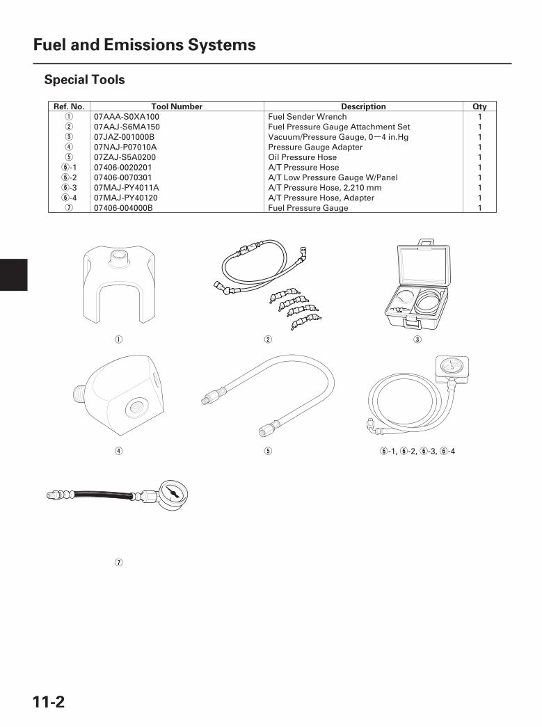
Ref. No. Tool Number Description Qty
11-2
Fuel and Emissions Systems
Special Tools
07AAA-S0XA100 Fuel Sender Wrench 107AAJ-S6MA150 Fuel Pressure Gauge Attachment Set 107JAZ-001000B Vacuum/Pressure Gauge, 0 4 in.Hg 107NAJ-P07010A Pressure Gauge Adapter 107ZAJ-S5A0200 Oil Pressure Hose 1
-1 07406-0020201 A/T Pressure Hose 1-2 07406-0070301 A/T Low Pressure Gauge W/Panel 1-3 07MAJ-PY4011A A/T Pressure Hose, 2,210 mm 1-4 07MAJ-PY40120 A/T Pressure Hose, Adapter 1
07406-004000B Fuel Pressure Gauge 1
-1, -2, -3, -4
07/05/09 16:45:49 61SJC020_110_0002
-01
*01
SJC8A00K77100000000BBAT10
Intermittent Failures
Service Information
Opens and Shorts
How to Use the HDS (Honda DiagnosticSystem)
If the MIL (malfunction indicator lamp) has come on
If the MIL did not stay on
If you can’t duplicate the DTC
11-3
General Troubleshooting Information
A
A
The term ‘‘intermittent failure’’ means a system mayhave had a failure, but it checks OK now. If themalfunction indicator lamp (MIL) on the dash does notcome on, check for poor connections or loose pins at allconnectors related to the circuit that you aretroubleshooting. If the MIL was on but then went out,the original problem may have been intermittent.
Some DTCs or symptoms can be caused by acombination of PCM software and specific drivinghabits. Periodically, new PCM software or new serviceprocedures may become available. Always checkonline for the latest software or service informationrelated to the DTCs or symptoms you aretroubleshooting.
‘‘Open’’ and ‘‘short’’ are common electrical terms. Anopen is a break in a wire or at a connection. A short isan accidental connection of a wire to ground or toanother wire. In simple electronics, this usually meanssomething won’t work at all. With complex electronics(such as PCMs) this can sometimes mean somethingworks, but not the way it’s supposed to.
1. Start the engine, and check the MIL (A).
NOTE: If the ignition switch is turned ON (II), andthe engine is not started, the MIL stays on for15 20 seconds (see page 11-54).
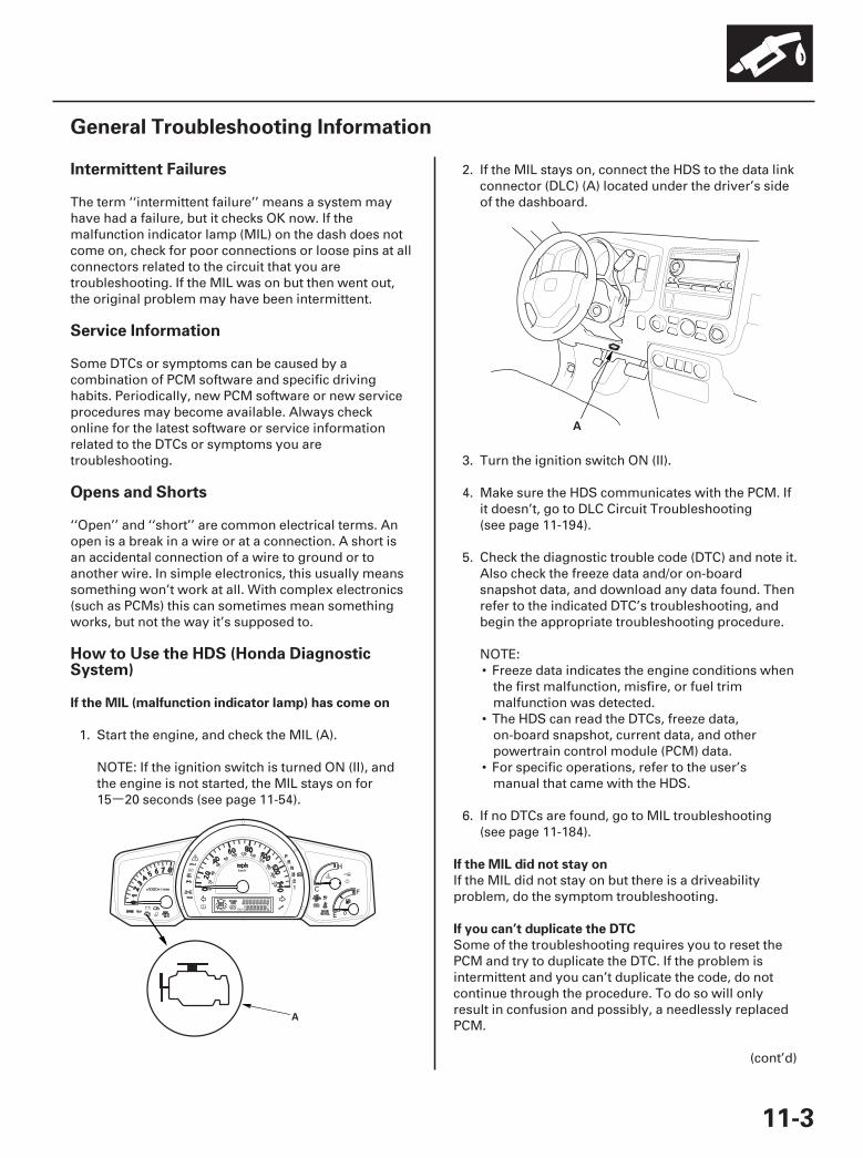
2. If the MIL stays on, connect the HDS to the data linkconnector (DLC) (A) located under the driver’s sideof the dashboard.
3. Turn the ignition switch ON (II).
4. Make sure the HDS communicates with the PCM. Ifit doesn’t, go to DLC Circuit Troubleshooting(see page 11-194).
5. Check the diagnostic trouble code (DTC) and note it.Also check the freeze data and/or on-boardsnapshot data, and download any data found. Thenrefer to the indicated DTC’s troubleshooting, andbegin the appropriate troubleshooting procedure.
NOTE:• Freeze data indicates the engine conditions when
the first malfunction, misfire, or fuel trimmalfunction was detected.
• The HDS can read the DTCs, freeze data,on-board snapshot, current data, and otherpowertrain control module (PCM) data.
• For specific operations, refer to the user’smanual that came with the HDS.
6. If no DTCs are found, go to MIL troubleshooting(see page 11-184).
If the MIL did not stay on but there is a driveabilityproblem, do the symptom troubleshooting.
Some of the troubleshooting requires you to reset thePCM and try to duplicate the DTC. If the problem isintermittent and you can’t duplicate the code, do notcontinue through the procedure. To do so will onlyresult in confusion and possibly, a needlessly replacedPCM.
(cont’d)
07/05/09 16:45:50 61SJC020_110_0003
*02
HDS Clear Command
Scan Tool Clear Command
DTC Clear
PCM Reset
Crank (CKP) Pattern Clear/Crank (CKP)Pattern Learn
Clear/Learn Procedure (with the HDS)
11-4
Fuel and Emissions Systems
General Troubleshooting Information (cont’d)
A
The PCM stores various specific data to correct thesystem even if there is no electrical power such aswhen the battery negative terminal or No. 8 FI ECU(15 A) fuse are disconnected. Stored data based onfailed parts should be cleared by using the ‘‘CLEARCOMMAND’’ of the HDS, if parts are replaced.
The HDS has three kinds of clear commands to meetthis purpose. They are DTC clear, PCM reset, and crank(CKP) pattern clear. DTC clear command erases allstored DTC codes, freeze data, on-board snapshot, andreadiness codes. This must be done with the HDS afterreproducing the DTC during troubleshooting.The PCM reset command erases all stored DTC codes,freeze data, on-board snapshot, readiness codes, andall specific data to correct the system except crank(CKP) pattern. If the crank (CKP) pattern data in the PCMwas cleared, you must do the crank (CKP) pattern learnprocedure. The crank (CKP) pattern clear commanderases only crank (CKP) pattern data. This command isfor repair of a misfire or the CKP sensor.
If you are using a generic scan tool to clear commands,be aware that there is only one setting for clearing thePCM, and it clears all commands at the same time(crank (CKP) pattern learn, idle learn, readiness codes,freeze data, on-board snapshot, and DTCs). After youclear all commands, you then need to do theseprocedures, in this order: PCM idle learn procedure(see page 11-273); crank (CKP) pattern learn procedure;test-drive to set readiness codes to complete (see page11-54).
1. Clear the DTC with the HDS while the engine isstopped.
2. Turn the ignition switch OFF.
3. Turn the ignition switch ON (II), and wait30 seconds.
4. Turn the ignition switch OFF, and disconnect theHDS from the DLC.
1. Reset the PCM with the HDS while the engine isstopped.
2. Turn the ignition switch OFF.
3. Turn the ignition switch ON (II), and wait30 seconds.
4. Turn the ignition switch OFF, and disconnect theHDS from the DLC.
5. Do the PCM idle learn procedure (see page 11-273).
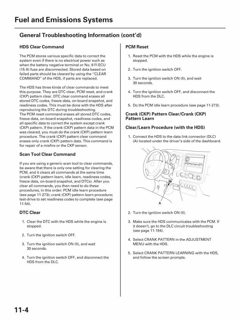
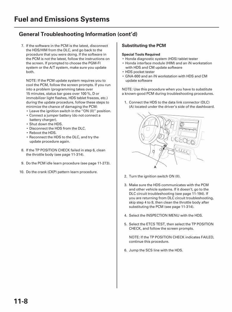
1. Connect the HDS to the data link connector (DLC)(A) located under the driver’s side of the dashboard.
2. Turn the ignition switch ON (II).
3. Make sure the HDS communicates with the PCM. Ifit doesn’t, go to the DLC circuit troubleshooting(see page 11-194).
4. Select CRANK PATTERN in the ADJUSTMENTMENU with the HDS.
5. Select CRANK PATTERN LEARNING with the HDS,and follow the screen prompts.
07/05/09 16:45:50 61SJC020_110_0004

Learn Procedure (without the HDS) How to End a Troubleshooting Session(required after any troubleshooting)
11-5
1. Start the engine. Hold the engine speed at3,000 rpm without load (in Park or neutral) until theradiator fan comes on.
2. Test-drive the vehicle on a level road: Decelerate(with the throttle fully closed) from an engine speedof 2,500 rpm down to 1,000 rpm with thetransmission in 2 position.
3. Test-drive the vehicle on a level road: Decelerate(with the throttle fully closed) from an engine speedof 5,000 rpm down to 3,000 rpm with thetransmission in 2 position.
4. Repeat steps 2 and 3 several times.
5. Turn the ignition switch OFF.
6. Turn the ignition switch ON (II), and wait30 seconds.
1. Reset the PCM with the HDS.
2. Do the PCM idle learn procedure (see page 11-273).
3. Turn the ignition switch OFF.
4. Disconnect the HDS from the DLC.
NOTE: The PCM is part of the immobilizer system.If you replace the PCM, it will have a differentimmobilizer code. In order for the engine to start,you must rewrite the immobilizer code with theHDS.
(cont’d)
07/05/09 16:45:50 61SJC020_110_0005
□△ ○
19
05
04
How to Troubleshoot Circuits at the PCMConnectors
11-6
Fuel and Emissions Systems
General Troubleshooting Information (cont’d)
A
B
A
A
CB
NOTE:• The PCM overwrites data and monitors the EVAP
system for up to 15 minutes after the ignition switchis turned OFF. Jumping the SCS line after turning theignition switch OFF cancels this function.Disconnecting the PCM during this function, withoutjumping the SCS line first, can damage the PCM.
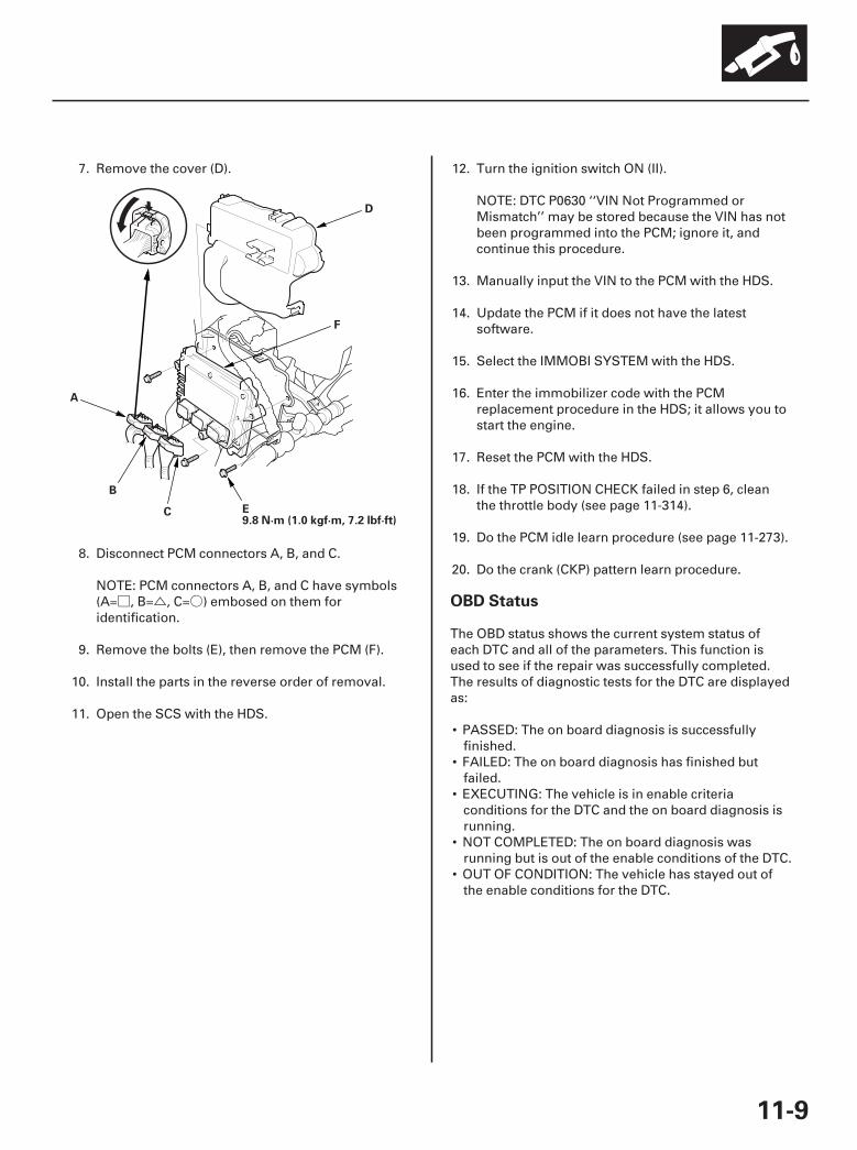
• PCM connectors A, B, and C have symbols (A= ,B= , C= ) embosed on them for identification.
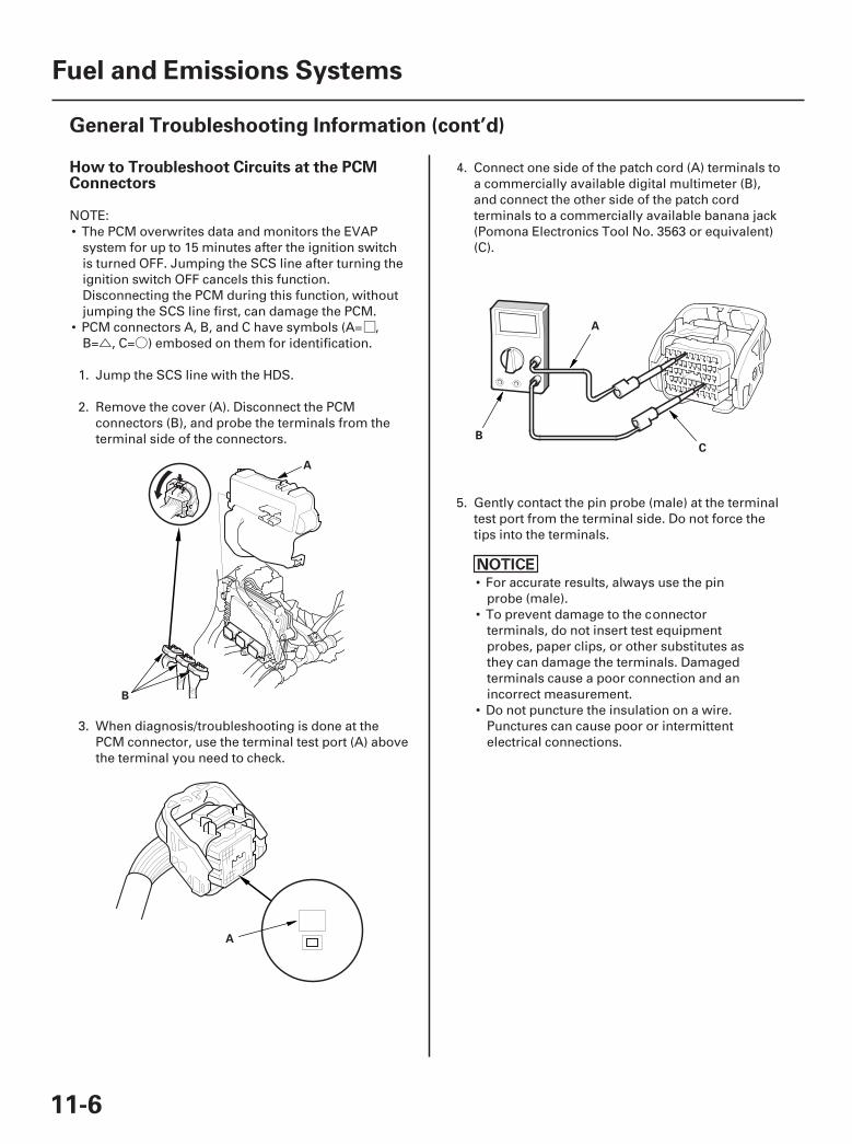
1. Jump the SCS line with the HDS.
2. Remove the cover (A). Disconnect the PCMconnectors (B), and probe the terminals from theterminal side of the connectors.
3. When diagnosis/troubleshooting is done at thePCM connector, use the terminal test port (A) abovethe terminal you need to check.
4. Connect one side of the patch cord (A) terminals toa commercially available digital multimeter (B),and connect the other side of the patch cordterminals to a commercially available banana jack(Pomona Electronics Tool No. 3563 or equivalent)(C).
5. Gently contact the pin probe (male) at the terminaltest port from the terminal side. Do not force thetips into the terminals.
• For accurate results, always use the pinprobe (male).
• To prevent damage to the connectorterminals, do not insert test equipmentprobes, paper clips, or other substitutes asthey can damage the terminals. Damagedterminals cause a poor connection and anincorrect measurement.
• Do not puncture the insulation on a wire.Punctures can cause poor or intermittentelectrical connections.
07/05/09 16:45:51 61SJC020_110_0006
#
*03
Updating the PCM
Special Tools Required
11-7
A
• Honda diagnostic system (HDS) tablet tester• Honda interface module (HIM) and an iN workstation
with HDS and CM update software• HDS pocket tester• GNA-600 and an iN workstation with HDS and CM
update software
NOTE:• Use this procedure when you have to update the PCM
during troubleshooting procedures.• Make sure the HDS/HIM has the latest software
version downloaded from the iN (interactive network).• Before you update the PCM, make sure the battery in
the vehicle is fully charged, and connect a jumperbattery (not a battery charger).
• Never turn the ignition switch OFF during the update.If there is a problem with the update, leave theignition switch ON.
• To prevent PCM damage, do not operate anythingelectrical (headlights, audio system, brakes, A/C,power windows, door locks, etc.) during the update.
• To ensure the latest program is installed, do a PCMupdate whenever the PCM is substituted or replaced.
• You cannot update a PCM with a program it alreadyhas. It will only accept a new program.
• If you need to diagnose the Honda interface module(HIM) because the HIM’s red ( 3) light came on orwas flashed during the update, leave the ignitionswitch in the ON (II) position when you disconnect theHIM from the data link connector (DLC). This willprevent PCM damage.
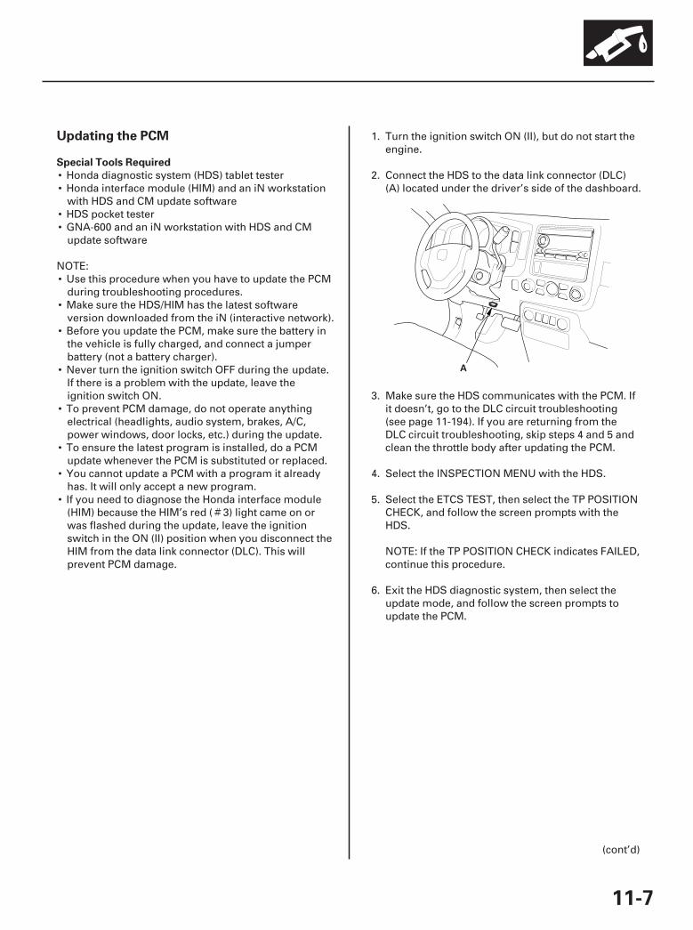
1. Turn the ignition switch ON (II), but do not start theengine.
2. Connect the HDS to the data link connector (DLC)(A) located under the driver’s side of the dashboard.
3. Make sure the HDS communicates with the PCM. Ifit doesn’t, go to the DLC circuit troubleshooting(see page 11-194). If you are returning from theDLC circuit troubleshooting, skip steps 4 and 5 andclean the throttle body after updating the PCM.
4. Select the INSPECTION MENU with the HDS.
5. Select the ETCS TEST, then select the TP POSITIONCHECK, and follow the screen prompts with theHDS.
NOTE: If the TP POSITION CHECK indicates FAILED,continue this procedure.
6. Exit the HDS diagnostic system, then select theupdate mode, and follow the screen prompts toupdate the PCM.
(cont’d)
07/05/09 16:45:51 61SJC020_110_0007
*04
Substituting the PCM
Special Tools Required
11-8
Fuel and Emissions Systems
General Troubleshooting Information (cont’d)
A
7. If the software in the PCM is the latest, disconnectthe HDS/HIM from the DLC, and go back to theprocedure that you were doing. If the software inthe PCM is not the latest, follow the instructions onthe screen. If prompted to choose the PGM-FIsystem or the A/T system, make sure you updateboth.
NOTE: If the PCM update system requires you tocool the PCM, follow the screen prompts. If you runinto a problem (programming takes over15 minutes, status bar goes over 100 %, D orimmobilizer light flashes, HDS tablet freezes, etc.)during the update procedure, follow these steps tominimize the chance of damaging the PCM:• Leave the ignition switch in the ‘‘ON (II)’’ position.• Connect a jumper battery (do not connect a
battery charger).• Shut down the HDS.• Disconnect the HDS from the DLC.• Reboot the HDS.• Reconnect the HDS to the DLC, and try the
update procedure again.
8. If the TP POSITION CHECK failed in step 6, cleanthe throttle body (see page 11-314).
9. Do the PCM idle learn procedure (see page 11-273).
10. Do the crank (CKP) pattern learn procedure.
• Honda diagnostic system (HDS) tablet tester• Honda interface module (HIM) and an iN workstation
with HDS and CM update software• HDS pocket tester• GNA-600 and an iN workstation with HDS and CM
update software
NOTE: Use this procedure when you have to substitutea known-good PCM during troubleshooting procedures.
1. Connect the HDS to the data link connector (DLC)(A) located under the driver’s side of the dashboard.
2. Turn the ignition switch ON (II).
3. Make sure the HDS communicates with the PCMand other vehicle systems. If it doesn’t, go to theDLC circuit troubleshooting (see page 11-194). Ifyou are returning from DLC circuit troubleshooting,skip step 4 to 8, then clean the throttle body aftersubstituting the PCM (see page 11-314).
4. Select the INSPECTION MENU with the HDS.
5. Select the ETCS TEST, then select the TP POSITIONCHECK, and follow the screen prompts.
NOTE: If the TP POSITION CHECK indicates FAILED,continue this procedure.
6. Jump the SCS line with the HDS.
07/05/09 16:45:52 61SJC020_110_0008
□ △ ○
21
OBD Status
11-9
E9.8 N·m (1.0 kgf·m, 7.2 lbf·ft)
A
D
F
B
C
7. Remove the cover (D).
8. Disconnect PCM connectors A, B, and C.
NOTE: PCM connectors A, B, and C have symbols(A= , B= , C= ) embosed on them foridentification.
9. Remove the bolts (E), then remove the PCM (F).
10. Install the parts in the reverse order of removal.
11. Open the SCS with the HDS.
12. Turn the ignition switch ON (II).
NOTE: DTC P0630 ‘‘VIN Not Programmed orMismatch’’ may be stored because the VIN has notbeen programmed into the PCM; ignore it, andcontinue this procedure.
13. Manually input the VIN to the PCM with the HDS.
14. Update the PCM if it does not have the latestsoftware.
15. Select the IMMOBI SYSTEM with the HDS.
16. Enter the immobilizer code with the PCMreplacement procedure in the HDS; it allows you tostart the engine.
17. Reset the PCM with the HDS.
18. If the TP POSITION CHECK failed in step 6, cleanthe throttle body (see page 11-314).
19. Do the PCM idle learn procedure (see page 11-273).
20. Do the crank (CKP) pattern learn procedure.
The OBD status shows the current system status ofeach DTC and all of the parameters. This function isused to see if the repair was successfully completed.The results of diagnostic tests for the DTC are displayedas:
• PASSED: The on board diagnosis is successfullyfinished.
• FAILED: The on board diagnosis has finished butfailed.
• EXECUTING: The vehicle is in enable criteriaconditions for the DTC and the on board diagnosis isrunning.
• NOT COMPLETED: The on board diagnosis wasrunning but is out of the enable conditions of the DTC.
• OUT OF CONDITION: The vehicle has stayed out ofthe enable conditions for the DTC.
07/05/09 16:45:52 61SJC020_110_0009
――――――○
――――――○
――――――――――――○○○
―――
―――
―――
―――
○
―――
○
―――
―――
○
○
○
―――
○○○○
――――――○
○○○○○○
―――
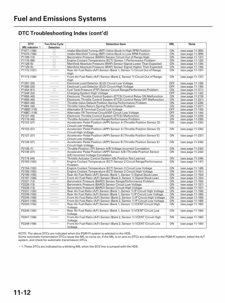
SJC8A00A20300000000GAAT00
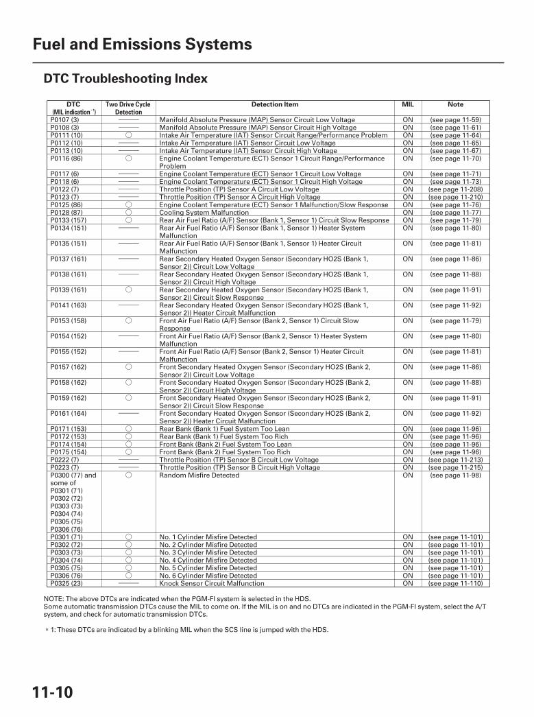
DTC Detection Item MIL Note(MIL indication )1
Two Drive CycleDetection
11-10
Fuel and Emissions Systems
DTC Troubleshooting Index
P0107 (3) Manifold Absolute Pressure (MAP) Sensor Circuit Low Voltage ON (see page 11-59)P0108 (3) Manifold Absolute Pressure (MAP) Sensor Circuit High Voltage ON (see page 11-61)P0111 (10) Intake Air Temperature (IAT) Sensor Circuit Range/Performance Problem ON (see page 11-64)P0112 (10) Intake Air Temperature (IAT) Sensor Circuit Low Voltage ON (see page 11-65)P0113 (10) Intake Air Temperature (IAT) Sensor Circuit High Voltage ON (see page 11-67)P0116 (86) Engine Coolant Temperature (ECT) Sensor 1 Circuit Range/Performance
ProblemON (see page 11-70)
P0117 (6) Engine Coolant Temperature (ECT) Sensor 1 Circuit Low Voltage ON (see page 11-71)P0118 (6) Engine Coolant Temperature (ECT) Sensor 1 Circuit High Voltage ON (see page 11-73)P0122 (7) Throttle Position (TP) Sensor A Circuit Low Voltage ON (see page 11-208)P0123 (7) Throttle Position (TP) Sensor A Circuit High Voltage ON (see page 11-210)P0125 (86) Engine Coolant Temperature (ECT) Sensor 1 Malfunction/Slow Response ON (see page 11-76)P0128 (87) Cooling System Malfunction ON (see page 11-77)P0133 (157) Rear Air Fuel Ratio (A/F) Sensor (Bank 1, Sensor 1) Circuit Slow Response ON (see page 11-79)P0134 (151) Rear Air Fuel Ratio (A/F) Sensor (Bank 1, Sensor 1) Heater System
MalfunctionON (see page 11-80)
P0135 (151) Rear Air Fuel Ratio (A/F) Sensor (Bank 1, Sensor 1) Heater CircuitMalfunction
ON (see page 11-81)
P0137 (161) Rear Secondary Heated Oxygen Sensor (Secondary HO2S (Bank 1,Sensor 2)) Circuit Low Voltage
ON (see page 11-86)
P0138 (161) Rear Secondary Heated Oxygen Sensor (Secondary HO2S (Bank 1,Sensor 2)) Circuit High Voltage
ON (see page 11-88)
P0139 (161) Rear Secondary Heated Oxygen Sensor (Secondary HO2S (Bank 1,Sensor 2)) Circuit Slow Response
ON (see page 11-91)
P0141 (163) Rear Secondary Heated Oxygen Sensor (Secondary HO2S (Bank 1,Sensor 2)) Heater Circuit Malfunction
ON (see page 11-92)
P0153 (158) Front Air Fuel Ratio (A/F) Sensor (Bank 2, Sensor 1) Circuit SlowResponse
ON (see page 11-79)
P0154 (152) Front Air Fuel Ratio (A/F) Sensor (Bank 2, Sensor 1) Heater SystemMalfunction
ON (see page 11-80)
P0155 (152) Front Air Fuel Ratio (A/F) Sensor (Bank 2, Sensor 1) Heater CircuitMalfunction
ON (see page 11-81)
P0157 (162) Front Secondary Heated Oxygen Sensor (Secondary HO2S (Bank 2,Sensor 2)) Circuit Low Voltage
ON (see page 11-86)
P0158 (162) Front Secondary Heated Oxygen Sensor (Secondary HO2S (Bank 2,Sensor 2)) Circuit High Voltage
ON (see page 11-88)
P0159 (162) Front Secondary Heated Oxygen Sensor (Secondary HO2S (Bank 2,Sensor 2)) Circuit Slow Response
ON (see page 11-91)
P0161 (164) Front Secondary Heated Oxygen Sensor (Secondary HO2S (Bank 2,Sensor 2)) Heater Circuit Malfunction
ON (see page 11-92)
P0171 (153) Rear Bank (Bank 1) Fuel System Too Lean ON (see page 11-96)P0172 (153) Rear Bank (Bank 1) Fuel System Too Rich ON (see page 11-96)P0174 (154) Front Bank (Bank 2) Fuel System Too Lean ON (see page 11-96)P0175 (154) Front Bank (Bank 2) Fuel System Too Rich ON (see page 11-96)P0222 (7) Throttle Position (TP) Sensor B Circuit Low Voltage ON (see page 11-213)P0223 (7) Throttle Position (TP) Sensor B Circuit High Voltage ON (see page 11-215)P0300 (77) andsome ofP0301 (71)P0302 (72)P0303 (73)P0304 (74)P0305 (75)P0306 (76)
Random Misfire Detected ON (see page 11-98)
P0301 (71) No. 1 Cylinder Misfire Detected ON (see page 11-101)P0302 (72) No. 2 Cylinder Misfire Detected ON (see page 11-101)P0303 (73) No. 3 Cylinder Misfire Detected ON (see page 11-101)P0304 (74) No. 4 Cylinder Misfire Detected ON (see page 11-101)P0305 (75) No. 5 Cylinder Misfire Detected ON (see page 11-101)P0306 (76) No. 6 Cylinder Misfire Detected ON (see page 11-101)P0325 (23) Knock Sensor Circuit Malfunction ON (see page 11-110)
NOTE: The above DTCs are indicated when the PGM-FI system is selected in the HDS.Some automatic transmission DTCs cause the MIL to come on. If the MIL is on and no DTCs are indicated in the PGM-FI system, select the A/Tsystem, and check for automatic transmission DTCs.
1: These DTCs are indicated by a blinking MIL when the SCS line is jumped with the HDS.
07/05/09 16:45:52 61SJC020_110_0010
――――――――――――――――――○○
―――
○○
―――○
――――――○○○
―――
――――――○○
―――
―――
○○
――――――
――――――
――――――――――――○
――――――
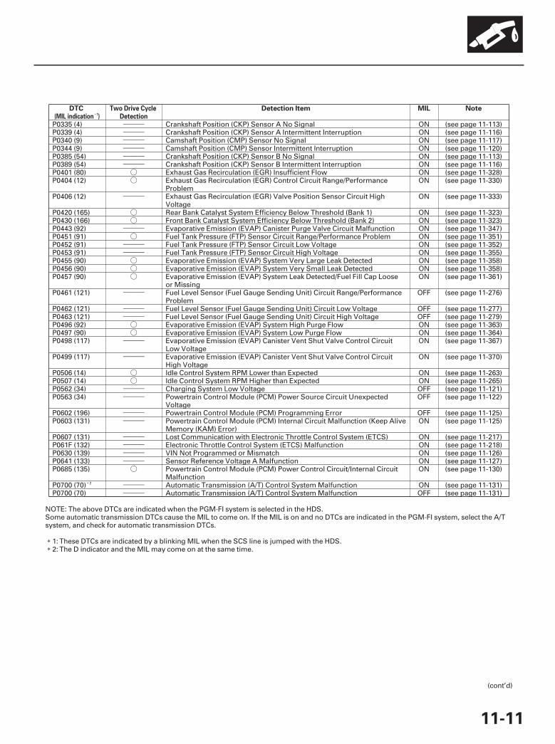
DTC Detection Item MIL Note(MIL indication )1
Two Drive CycleDetection
11-11
P0335 (4) Crankshaft Position (CKP) Sensor A No Signal ON (see page 11-113)P0339 (4) Crankshaft Position (CKP) Sensor A Intermittent Interruption ON (see page 11-116)P0340 (9) Camshaft Position (CMP) Sensor No Signal ON (see page 11-117)P0344 (9) Camshaft Position (CMP) Sensor Intermittent Interruption ON (see page 11-120)P0385 (54) Crankshaft Position (CKP) Sensor B No Signal ON (see page 11-113)P0389 (54) Crankshaft Position (CKP) Sensor B Intermittent Interruption ON (see page 11-116)P0401 (80) Exhaust Gas Recirculation (EGR) Insufficient Flow ON (see page 11-328)P0404 (12) Exhaust Gas Recirculation (EGR) Control Circuit Range/Performance
ProblemON (see page 11-330)
P0406 (12) Exhaust Gas Recirculation (EGR) Valve Position Sensor Circuit HighVoltage
ON (see page 11-333)
P0420 (165) Rear Bank Catalyst System Efficiency Below Threshold (Bank 1) ON (see page 11-323)P0430 (166) Front Bank Catalyst System Efficiency Below Threshold (Bank 2) ON (see page 11-323)P0443 (92) Evaporative Emission (EVAP) Canister Purge Valve Circuit Malfunction ON (see page 11-347)P0451 (91) Fuel Tank Pressure (FTP) Sensor Circuit Range/Performance Problem ON (see page 11-351)P0452 (91) Fuel Tank Pressure (FTP) Sensor Circuit Low Voltage ON (see page 11-352)P0453 (91) Fuel Tank Pressure (FTP) Sensor Circuit High Voltage ON (see page 11-355)P0455 (90) Evaporative Emission (EVAP) System Very Large Leak Detected ON (see page 11-358)P0456 (90) Evaporative Emission (EVAP) System Very Small Leak Detected ON (see page 11-358)P0457 (90) Evaporative Emission (EVAP) System Leak Detected/Fuel Fill Cap Loose
or MissingON (see page 11-361)
P0461 (121) Fuel Level Sensor (Fuel Gauge Sending Unit) Circuit Range/PerformanceProblem
OFF (see page 11-276)
P0462 (121) Fuel Level Sensor (Fuel Gauge Sending Unit) Circuit Low Voltage OFF (see page 11-277)P0463 (121) Fuel Level Sensor (Fuel Gauge Sending Unit) Circuit High Voltage OFF (see page 11-279)P0496 (92) Evaporative Emission (EVAP) System High Purge Flow ON (see page 11-363)P0497 (90) Evaporative Emission (EVAP) System Low Purge Flow ON (see page 11-364)P0498 (117) Evaporative Emission (EVAP) Canister Vent Shut Valve Control Circuit
Low VoltageON (see page 11-367)
P0499 (117) Evaporative Emission (EVAP) Canister Vent Shut Valve Control CircuitHigh Voltage
ON (see page 11-370)
P0506 (14) Idle Control System RPM Lower than Expected ON (see page 11-263)P0507 (14) Idle Control System RPM Higher than Expected ON (see page 11-265)P0562 (34) Charging System Low Voltage OFF (see page 11-121)P0563 (34) Powertrain Control Module (PCM) Power Source Circuit Unexpected
VoltageOFF (see page 11-122)
P0602 (196) Powertrain Control Module (PCM) Programming Error OFF (see page 11-125)P0603 (131) Powertrain Control Module (PCM) Internal Circuit Malfunction (Keep Alive
Memory (KAM) Error)ON (see page 11-125)
P0607 (131) Lost Communication with Electronic Throttle Control System (ETCS) ON (see page 11-217)P061F (132) Electronic Throttle Control System (ETCS) Malfunction ON (see page 11-218)P0630 (139) VIN Not Programmed or Mismatch ON (see page 11-126)P0641 (133) Sensor Reference Voltage A Malfunction ON (see page 11-127)P0685 (135) Powertrain Control Module (PCM) Power Control Circuit/Internal Circuit
MalfunctionON (see page 11-130)
P0700 (70) ON (see page 11-131)P0700 (70) OFF (see page 11-131)
NOTE: The above DTCs are indicated when the PGM-FI system is selected in the HDS.Some automatic transmission DTCs cause the MIL to come on. If the MIL is on and no DTCs are indicated in the PGM-FI system, select the A/Tsystem, and check for automatic transmission DTCs.
1: These DTCs are indicated by a blinking MIL when the SCS line is jumped with the HDS.2: The D indicator and the MIL may come on at the same time.
(cont’d)
2
07/05/09 16:45:52 61SJC020_110_0011
Automatic Transmission (A/T) Control System MalfunctionAutomatic Transmission (A/T) Control System Malfunction
○○
―――○○○
―――
―――
――――――○
――――――――――――――――――――――――――――――
―――
―――
―――
――――――
―――○
――――――――――――○
―――――――――――――――――――――
―――
―――
―――
DTC Detection Item MIL Note(MIL indication )1
Two Drive CycleDetection
11-12
Fuel and Emissions Systems
DTC Troubleshooting Index (cont’d)
P1077 (106) Intake Manifold Tuning (IMT) Valve Stuck in High RPM Position ON (see page 11-305)P1078 (106) Intake Manifold Tuning (IMT) Valve Stuck in Low RPM Position ON (see page 11-309)P1109 (13) Barometric Pressure (BARO) Sensor Circuit Out of Range High ON (see page 11-131)P1116 (86) Engine Coolant Temperature (ECT) Sensor 1 Performance Problem ON (see page 11-132)P1128 (5) Manifold Absolute Pressure (MAP) Sensor Signal Lower Than Expected ON (see page 11-134)P1129 (5) Manifold Absolute Pressure (MAP) Sensor Signal Higher Than Expected ON (see page 11-135)P1172 (157) Rear Air Fuel Ratio (A/F) Sensor (Bank 1, Sensor 1) Circuit Out of Range
HighON (see page 11-137)
P1174 (158) Front Air Fuel Ratio (A/F) Sensor (Bank 2, Sensor 1) Circuit Out of RangeHigh
ON (see page 11-137)
P1297 (20) Electrical Load Detector (ELD) Circuit Low Voltage OFF (see page 11-138)P1298 (20) Electrical Load Detector (ELD) Circuit High Voltage OFF (see page 11-140)P1454 (91) Fuel Tank Pressure (FTP) Sensor Circuit Range/Performance Problem ON (see page 11-371)P1549 (34) Charging System High Voltage OFF (see page 11-142)P1658 (40) Electronic Throttle Control System (ETCS) Control Relay ON Malfunction ON (see page 11-219)P1659 (40) Electronic Throttle Control System (ETCS) Control Relay OFF Malfunction ON (see page 11-221)P1683 (40) Throttle Valve Default Position Spring Performance Problem ON (see page 11-226)P1684 (40) Throttle Valve Return Spring Performance Problem ON (see page 11-227)P16BB (116) Alternator B Terminal Circuit Low Voltage OFF (see page 11-143)P16BC (116) Alternator FR Terminal Circuit/IGP Circuit Low Voltage OFF (see page 11-144)P2101 (40) Electronic Throttle Control System (ETCS) Malfunction ON (see page 11-228)P2118 (40) Throttle Actuator Current Range/Performance Problem ON (see page 11-230)P2122 (37) Accelerator Pedal Position (APP) Sensor A (Throttle Position Sensor D)
Circuit Low VoltageON (see page 11-232)
P2123 (37) Accelerator Pedal Position (APP) Sensor A (Throttle Position Sensor D)Circuit High Voltage
ON (see page 11-235)
P2127 (37) Accelerator Pedal Position (APP) Sensor B (Throttle Position Sensor E)Circuit Low Voltage
ON (see page 11-237)
P2128 (37) Accelerator Pedal Position (APP) Sensor B (Throttle Position Sensor E)Circuit High Voltage
ON (see page 11-240)
P2135 (7) Throttle Position (TP) Sensor A/B Voltage Incorrect Correlation ON (see page 11-242)P2138 (37) Accelerator Pedal Position (APP) Sensor A/B (Throttle Position Sensor
D/E) Incorrect Voltage CorrelationON (see page 11-244)
P2176 (40) Throttle Actuator Control System Idle Position Not Learned ON (see page 11-246)P2183 (192) Engine Coolant Temperature (ECT) Sensor 2 Circuit Range/Performance
ProblemON (see page 11-147)
P2184 (192) Engine Coolant Temperature (ECT) Sensor 2 Circuit Low Voltage ON (see page 11-149)P2185 (192) Engine Coolant Temperature (ECT) Sensor 2 Circuit High Voltage ON (see page 11-151)P2195 (155) Rear Air Fuel Ratio (A/F) Sensor (Bank 1, Sensor 1) Signal Stuck Lean ON (see page 11-154)P2197 (156) Front Air Fuel Ratio (A/F) Sensor (Bank 2, Sensor 1) Signal Stuck Lean ON (see page 11-154)P2227 (13) Barometric Pressure (BARO) Sensor Range/Performance Problem ON (see page 11-155)P2228 (13) Barometric Pressure (BARO) Sensor Circuit Low Voltage ON (see page 11-157)P2229 (13) Barometric Pressure (BARO) Sensor Circuit High Voltage ON (see page 11-157)P2237 (155) Rear Air Fuel Ratio (A/F) Sensor (Bank 1, Sensor 1) IP Circuit High Voltage ON (see page 11-158)P2238 (155) Rear Air Fuel Ratio (A/F) Sensor (Bank 1, Sensor 1) IP Circuit Low Voltage ON (see page 11-160)P2240 (156) Front Air Fuel Ratio (A/F) Sensor (Bank 2, Sensor 1) IP Circuit High Voltage ON (see page 11-158)P2241 (156) Front Air Fuel Ratio (A/F) Sensor (Bank 2, Sensor 1) IP Circuit Low Voltage ON (see page 11-160)P2243 (155) Rear Air Fuel Ratio (A/F) Sensor (Bank 1, Sensor 1) VCENT Circuit High
VoltageON (see page 11-162)
P2245 (155) Rear Air Fuel Ratio (A/F) Sensor (Bank 1, Sensor 1) VCENT Circuit LowVoltage
ON (see page 11-164)
P2247 (156) Front Air Fuel Ratio (A/F) Sensor (Bank 2, Sensor 1) VCENT Circuit HighVoltage
ON (see page 11-162)
P2249 (156) Front Air Fuel Ratio (A/F) Sensor (Bank 2, Sensor 1) VCENT Circuit LowVoltage
ON (see page 11-164)
NOTE: The above DTCs are indicated when the PGM-FI system is selected in the HDS.Some automatic transmission DTCs cause the MIL to come on. If the MIL is on and no DTCs are indicated in the PGM-FI system, select the A/Tsystem, and check for automatic transmission DTCs.
1: These DTCs are indicated by a blinking MIL when the SCS line is jumped with the HDS.
07/05/09 16:45:53 61SJC020_110_0012

―――
―――
―――
―――
○
○
○
○
○○○
――――――
―――
―――
―――
―――
―――
―――
―――
○
○
――――――――――――
DTC Detection Item MIL Note(MIL indication )1
Two Drive CycleDetection
11-13
P2251 (155) Rear Air Fuel Ratio (A/F) Sensor (Bank 1, Sensor 1) VS Circuit HighVoltage
ON (see page 11-166)
P2252 (155) Rear Air Fuel Ratio (A/F) Sensor (Bank 1, Sensor 1) VS Circuit LowVoltage
ON (see page 11-168)
P2254 (156) Front Air Fuel Ratio (A/F) Sensor (Bank 2, Sensor 1) VS Circuit HighVoltage
ON (see page 11-166)
P2255 (156) Front Air Fuel Ratio (A/F) Sensor (Bank 2, Sensor 1) VS Circuit LowVoltage
ON (see page 11-168)
P2270 (161) Rear Secondary Heated Oxygen Sensor (Secondary HO2S) (Bank 1,Sensor 2) Circuit Signal Stuck Lean
ON (see page 11-170)
P2271 (161) Rear Secondary Heated Oxygen Sensor (Secondary HO2S) (Bank 1,Sensor 2) Circuit Signal Stuck Rich
ON (see page 11-170)
P2272 (162) Front Secondary Heated Oxygen Sensor (Secondary HO2S) (Bank 2,Sensor 2) Circuit Signal Stuck Lean
ON (see page 11-170)
P2273 (162) Front Secondary Heated Oxygen Sensor (Secondary HO2S) (Bank 2,Sensor 2) Circuit Signal Stuck Rich
ON (see page 11-170)
P2279 (109) Intake Air System Leak ON (see page 11-344)P2413 (12) Exhaust Gas Recirculation (EGR) System Malfunction ON (see page 11-335)P2422 (117) Evaporative Emission (EVAP) Canister Vent Shut Valve Close Malfunction ON (see page 11-371)P2610 (132) Powertrain Control Module (PCM) Internal Power Off Timer Malfunction ON (see page 11-171)P2627 (155) Rear Air Fuel Ratio (A/F) Sensor (Bank 1, Sensor 1) LABEL Circuit Low
VoltageON (see page 11-172)
P2628 (155) Rear Air Fuel Ratio (A/F) Sensor (Bank 1, Sensor 1) LABEL Circuit HighVoltage
ON (see page 11-174)
P2630 (156) Front Air Fuel Ratio (A/F) Sensor (Bank 2, Sensor 1) LABEL Circuit LowVoltage
ON (see page 11-172)
P2631 (156) Front Air Fuel Ratio (A/F) Sensor (Bank 2, Sensor 1) LABEL Circuit HighVoltage
ON (see page 11-174)
P2646 (22) Rocker Arm Oil Pressure Switch (VTEC Oil Pressure Switch) Circuit LowVoltage
ON (see page 11-251)
P2647 (22) Rocker Arm Oil Pressure Switch (VTEC Oil Pressure Switch) Circuit HighVoltage
ON (see page 11-254)
P2648 (21) Rocker Arm Oil Control Solenoid (VTEC Solenoid Valve) Circuit LowVoltage
ON (see page 11-257)
P2649 (21) Rocker Arm Oil Control Solenoid (VTEC Solenoid Valve) Circuit HighVoltage
ON (see page 11-259)
P2A00 (157) Rear Air Fuel Ratio (A/F) Sensor (Bank 1, Sensor 1) Circuit Range/Performance Problem
ON (see page 11-176)
P2A03 (158) Front Air Fuel Ratio (A/F) Sensor (Bank 2, Sensor 1) Circuit Range/Performance Problem
ON (see page 11-176)
U0073 (126) F-CAN Malfunction (BUS-OFF) OFF (see page 11-177)U0114 (126) F-CAN Malfunction (VTM-4 Control Unit-PCM) OFF (see page 11-180)U0122 (126) F-CAN Malfunction (VSA modulator-control unit-PCM) OFF (see page 11-182)U0155 (126) F-CAN Malfunction (Gauge Control Module-PCM) OFF (see page 11-177)
NOTE: The above DTCs are indicated when the PGM-FI system is selected in the HDS.Some automatic transmission DTCs cause the MIL to come on. If the MIL is on and no DTCs are indicated in the PGM-FI system, select the A/Tsystem, and check for automatic transmission DTCs.
1: These DTCs are indicated by a blinking MIL when the SCS line is jumped with the HDS.
07/05/09 16:45:53 61SJC020_110_0013
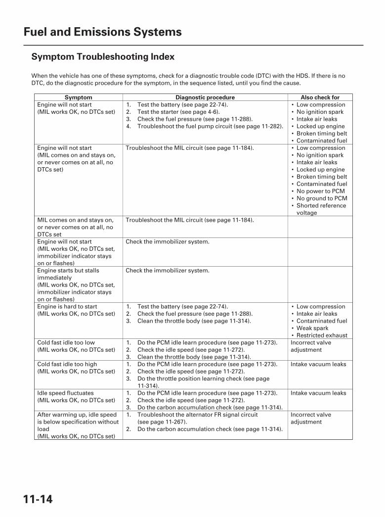
SJC8A00A20300000000HBAT01
Symptom Diagnostic procedure Also check for
11-14
Fuel and Emissions Systems
Symptom Troubleshooting Index
When the vehicle has one of these symptoms, check for a diagnostic trouble code (DTC) with the HDS. If there is noDTC, do the diagnostic procedure for the symptom, in the sequence listed, until you find the cause.
•••••••••••••••
•••••
Engine will not start(MIL works OK, no DTCs set)
1.2.3.4.
Test the battery (see page 22-74).Test the starter (see page 4-6).Check the fuel pressure (see page 11-288).Troubleshoot the fuel pump circuit (see page 11-282).
Low compressionNo ignition sparkIntake air leaksLocked up engineBroken timing beltContaminated fuel
Engine will not start(MIL comes on and stays on,or never comes on at all, noDTCs set)
Troubleshoot the MIL circuit (see page 11-184). Low compressionNo ignition sparkIntake air leaksLocked up engineBroken timing beltContaminated fuelNo power to PCMNo ground to PCMShorted referencevoltage
MIL comes on and stays on,or never comes on at all, noDTCs set
Troubleshoot the MIL circuit (see page 11-184).
Engine will not start(MIL works OK, no DTCs set,immobilizer indicator stayson or flashes)
Check the immobilizer system.
Engine starts but stallsimmediately(MIL works OK, no DTCs set,immobilizer indicator stayson or flashes)
Check the immobilizer system.
Engine is hard to start(MIL works OK, no DTCs set)
1.2.3.
Test the battery (see page 22-74).Check the fuel pressure (see page 11-288).Clean the throttle body (see page 11-314).
Low compressionIntake air leaksContaminated fuelWeak sparkRestricted exhaust
Cold fast idle too low(MIL works OK, no DTCs set)
1.2.3.
Do the PCM idle learn procedure (see page 11-273).Check the idle speed (see page 11-272).Clean the throttle body (see page 11-314).
Incorrect valveadjustment
Cold fast idle too high(MIL works OK, no DTCs set)
1.2.3.
Do the PCM idle learn procedure (see page 11-273).Check the idle speed (see page 11-272).Do the throttle position learning check (see page11-314).
Intake vacuum leaks
Idle speed fluctuates(MIL works OK, no DTCs set)
1.2.3.
Do the PCM idle learn procedure (see page 11-273).Check the idle speed (see page 11-272).Do the carbon accumulation check (see page 11-314).
Intake vacuum leaks
After warming up, idle speedis below specification withoutload(MIL works OK, no DTCs set)
1.
2.
Troubleshoot the alternator FR signal circuit(see page 11-267).Do the carbon accumulation check (see page 11-314).
Incorrect valveadjustment
07/05/09 16:45:53 61SJC020_110_0014
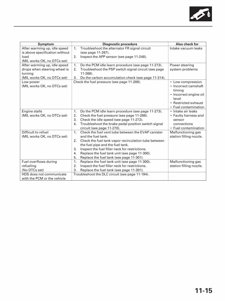
Symptom Diagnostic procedure Also check for
11-15
••
•
••••
•
After warming up, idle speedis above specification withoutload(MIL works OK, no DTCs set)
1.
2.
Troubleshoot the alternator FR signal circuit(see page 11-267).Inspect the APP sensor (see page 11-248).
Intake vacuum leaks
After warming up, idle speeddrops when steering wheel isturning(MIL works OK, no DTCs set)
1.2.
3.
Do the PCM idle learn procedure (see page 11-273).Troubleshoot the PSP switch signal circuit (see page11-268).Do the carbon accumulation check (see page 11-314).
Power steeringsystem problems
Low power(MIL works OK, no DTCs set)
Check the fuel pressure (see page 11-288). Low compressionIncorrect camshafttimingIncorrect engine oillevelRestricted exhaustFuel contamination
Engine stalls(MIL works OK, no DTCs set)
1.2.3.4.
Do the PCM idle learn procedure (see page 11-273).Check the fuel pressure (see page 11-288).Check the idle speed (see page 11-272).Troubleshoot the brake pedal position switch signalcircuit (see page 11-270).
Intake air leaksFaulty harness andsensorconnectionsFuel contamination
Difficult to refuel(MIL works OK, no DTCs set)
1.
2.
3.4.5.
Check the fuel vent tube between the EVAP canisterand the fuel tank.Check the fuel tank vapor recirculation tube betweenthe fuel pipe and the fuel tank.Inspect the fuel filler neck for restrictions.Replace the fuel tank unit (see page 11-300).Replace the fuel tank (see page 11-301).
Malfunctioning gasstation filling nozzle.
Fuel overflows duringrefueling(No DTCs set)
1.2.3.
Replace the fuel tank unit (see page 11-300).Inspect the fuel filler neck for restrictions.Replace the fuel tank (see page 11-301).
Malfunctioning gasstation filling nozzle.
HDS does not communicatewith the PCM or the vehicle
Troubleshoot the DLC circuit (see page 11-194).
07/05/09 16:45:53 61SJC020_110_0015
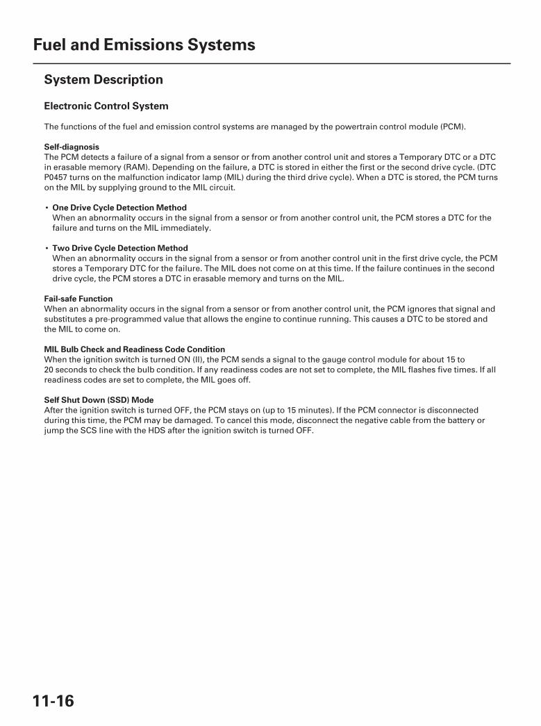
SJC8A00A20300000000CAAT00
Electronic Control System
Self-diagnosis
One Drive Cycle Detection Method
Two Drive Cycle Detection Method
Fail-safe Function
MIL Bulb Check and Readiness Code Condition
Self Shut Down (SSD) Mode
11-16
Fuel and Emissions Systems
System Description
The functions of the fuel and emission control systems are managed by the powertrain control module (PCM).
The PCM detects a failure of a signal from a sensor or from another control unit and stores a Temporary DTC or a DTCin erasable memory (RAM). Depending on the failure, a DTC is stored in either the first or the second drive cycle. (DTCP0457 turns on the malfunction indicator lamp (MIL) during the third drive cycle). When a DTC is stored, the PCM turnson the MIL by supplying ground to the MIL circuit.
•When an abnormality occurs in the signal from a sensor or from another control unit, the PCM stores a DTC for thefailure and turns on the MIL immediately.
•When an abnormality occurs in the signal from a sensor or from another control unit in the first drive cycle, the PCMstores a Temporary DTC for the failure. The MIL does not come on at this time. If the failure continues in the seconddrive cycle, the PCM stores a DTC in erasable memory and turns on the MIL.
When an abnormality occurs in the signal from a sensor or from another control unit, the PCM ignores that signal andsubstitutes a pre-programmed value that allows the engine to continue running. This causes a DTC to be stored andthe MIL to come on.
When the ignition switch is turned ON (II), the PCM sends a signal to the gauge control module for about 15 to20 seconds to check the bulb condition. If any readiness codes are not set to complete, the MIL flashes five times. If allreadiness codes are set to complete, the MIL goes off.
After the ignition switch is turned OFF, the PCM stays on (up to 15 minutes). If the PCM connector is disconnectedduring this time, the PCM may be damaged. To cancel this mode, disconnect the negative cable from the battery orjump the SCS line with the HDS after the ignition switch is turned OFF.
07/05/09 16:45:54 61SJC020_110_0016
01
+
+
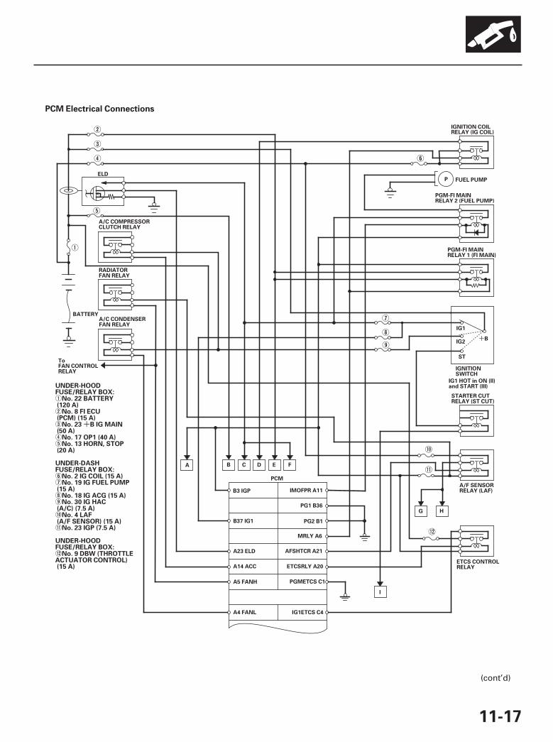
PCM Electrical Connections
11-17
PG1 B36
PG2 B1
MRLY A6
IMOFPR A11
AFSHTCR A21
ETCSRLY A20
B3 IGP
B37 IG1
A14 ACC
A5 FANH
PCM
A23 ELD
A4 FANL
IGNITIONSWITCH
IG1
ST
BIG2
STARTER CUTRELAY (ST CUT)
IG1 HOT in ON (II)and START (III)
IGNITION COILRELAY (IG COIL)
ELD
PGMETCS C1
PGM-FI MAINRELAY 2 (FUEL PUMP)
P FUEL PUMP
PGM-FI MAINRELAY 1 (FI MAIN)
A/F SENSORRELAY (LAF)
I
ETCS CONTROLRELAY
H
IG1ETCS C4
G
FECB DA
BATTERYA/C CONDENSERFAN RELAY
RADIATORFAN RELAY
A/C COMPRESSORCLUTCH RELAY
ToFAN CONTROLRELAY
UNDER-HOODFUSE/RELAY BOX:
No. 22 BATTERY(120 A)
No. 8 FI ECU(PCM) (15 A)
No. 23 B IG MAIN(50 A)
No. 17 OP1 (40 A)No. 13 HORN, STOP
(20 A)
UNDER-DASHFUSE/RELAY BOX:
No. 2 IG COIL (15 A)No. 19 IG FUEL PUMP
(15 A)No. 18 IG ACG (15 A)No. 30 IG HAC
(A/C) (7.5 A)No. 4 LAF
(A/F SENSOR) (15 A)No. 23 IGP (7.5 A)
UNDER-HOODFUSE/RELAY BOX:
No. 9 DBW (THROTTLEACTUATOR CONTROL)(15 A)
(cont’d)
07/05/09 16:45:54 61SJC020_110_0017
02
+
-
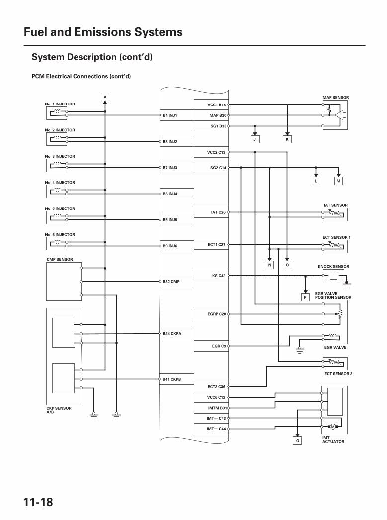
PCM Electrical Connections (cont’d)
11-18
Fuel and Emissions Systems
System Description (cont’d)
A
No. 1 INJECTOR
No. 2 INJECTOR
No. 3 INJECTOR
No. 4 INJECTOR
CMP SENSOR
No. 5 INJECTOR
No. 6 INJECTOR
ECT1 C27
IAT C26
SG2 C14
SG1 B33
MAP B30
VCC1 B18
B7 INJ3
B8 INJ2
B4 INJ1
B6 INJ4
B32 CMP
B5 INJ5
B9 INJ6
KS C42
VCC2 C13
ECT SENSOR 1
IAT SENSOR
MAP SENSOR
EGR VALVEPOSITION SENSOR
EGR VALVE
M
KNOCK SENSOR
P
IMTACTUATOR
L
J K
ON
ECT SENSOR 2
Q
CKP SENSORA/B
EGRP C20
ECT2 C36
B41 CKPB
B24 CKPA
VCC6 C12
IMT C43
IMT C44
EGR C9
IMTM B31
07/05/09 16:45:55 61SJC020_110_0018

03
11-19
EVAP CANISTERPURGE VALVE
EVAP CANISTERVENT SHUT VALVE
ALTERNATOR
D
ICM
ToSPARKPLUG
No. 1 IGNITION COIL
ToSPARKPLUG ICM
No. 2 IGNITION COIL
ToSPARKPLUG ICM
No. 3 IGNITION COIL
ToSPARKPLUG ICM
No. 4 IGNITION COIL
ToSPARKPLUG ICM
No. 5 IGNITION COIL
ToSPARKPLUG ICM
No. 6 IGNITION COIL
A10 VSV
C37 PCS
B42 ALTL
C41 ALTF
B26 IGPLS1
B27 IGPLS2
B20 IGPLS3
B21 IGPLS4
C38 ALTC
B2 VBSOL
B10 IGPLS5
B11 IGPLS6
C G
R
LG1 C40
LG2 B43
VTS C24
ROCKER ARM OILCONTROL SOLENOID(VTEC SOLENOID VALVE)
VTPSW B23
M
REAR A/F SENSOR(BANK 1, SENSOR 1)
REAR SECONDARY HO2S(BANK 1, SENSOR 2)
H
P
VLBLB1 C10
VSB1 B13
VCENTB1 B38
IPB1 B28
AFSHTCB1 C6
SHO2SB1 B15
SO2SHTCB1 C5
VSB2 B14
AFSHTCB2 C8
VLBLB2 C11
IPB2 B29
VCENTB2 B22
FRONT SECONDARY HO2S(BANK 2, SENSOR 2)
SHO2SB2 B16
SO2SHTCB2 C7
FRONT A/F SENSOR(BANK 2, SENSOR 1)
SG6 C39
Q
ROCKER ARM OILPRESSURE SWITCH(VTEC OILPRESSURE SWITCH)
(cont’d)
07/05/09 16:45:55 61SJC020_110_0019

04
+
-
PCM Electrical Connections (cont’d)
11-20
Fuel and Emissions Systems
System Description (cont’d)
PSP SWITCH
PSPSW A38
A/C PRESSURESWITCH
PDSW A37
VCC3 A24
APSA A17
SG3 A34
VCC4 A25
APP SENSOR A/B
A43 K-LINE
A42 WEN
A31 SCSDATA LINKCONNECTOR
THROTTLEBODY
TP SENSOR A/B
THROTTLEACTUATOR
APSB A18
SG4 A35
B12 TPSB
B19 VCC5
B17 TPSA
B34 SG5
C2 ETCSM
C3 ETCSM
LG3 A22
A
B
R
ToVTM-4 CONTROLUNIT
BBRAKE PEDALPOSITION SWITCH
BKSW A8
BKSWNC A7
F
IMOCD A44
VSSOUT A29ToVTM-4 CONTROLUNIT
A1 CANL
GAUGE CONTROL MODULE
FTP SENSOR
A19 VCC7
A33 FTP
A9 SG7
A36 CANH
E
NEP A28
D3 SWITCH
A13 D3SW
To IMMOBILIZERCONTROLUNIT-RECEIVER
To IMMOBILIZERCONTROLUNIT-RECEIVER
07/05/09 16:45:56 61SJC020_110_0020
05
□ △ ○
11-21
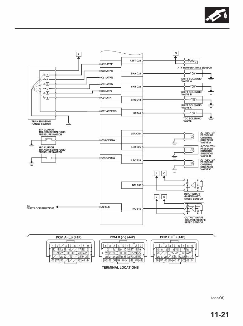
N
ATFT C28
SHA C25
SHB C23
SHC C18
LC B44
ATF TEMPERATURE SENSOR
SHIFT SOLENOIDVALVE A
SHIFT SOLENOIDVALVE B
SHIFT SOLENOIDVALVE C
TCC SOLENOIDVALVE
C17 ATPFWD
C33 ATP2
C32 ATPD
C31 ATPN
C30 ATPR
A12 ATPP
TRANSMISSIONRANGE SWITCH
I
P
R
N
D
2
1 C34 ATP1
A/T CLUTCHPRESSURECONTROLSOLENOIDVALVE A
LSA C19
A/T CLUTCHPRESSURECONTROLSOLENOIDVALVE B
A/T CLUTCHPRESSURECONTROLSOLENOIDVALVE C
LSB B25
LSC B35
NC B40
NM B39
K
OUTPUT SHAFT(COUNTERSHAFT)SPEED SENSOR
O
INPUT SHAFT(MAINSHAFT)SPEED SENSOR
L
J
C16 OP4SW
3RD CLUTCHTRANSMISSION FLUIDPRESSURE SWITCH
C15 OP3SW
4TH CLUTCHTRANSMISSION FLUIDPRESSURE SWITCH
ToSHIFT LOCK SOLENOID
A2 SLS
TERMINAL LOCATIONS
PCM A ( ) (44P) PCM B ( ) (44P) PCM C ( ) (44P)
(cont’d)
07/05/09 16:45:56 61SJC020_110_0021
06
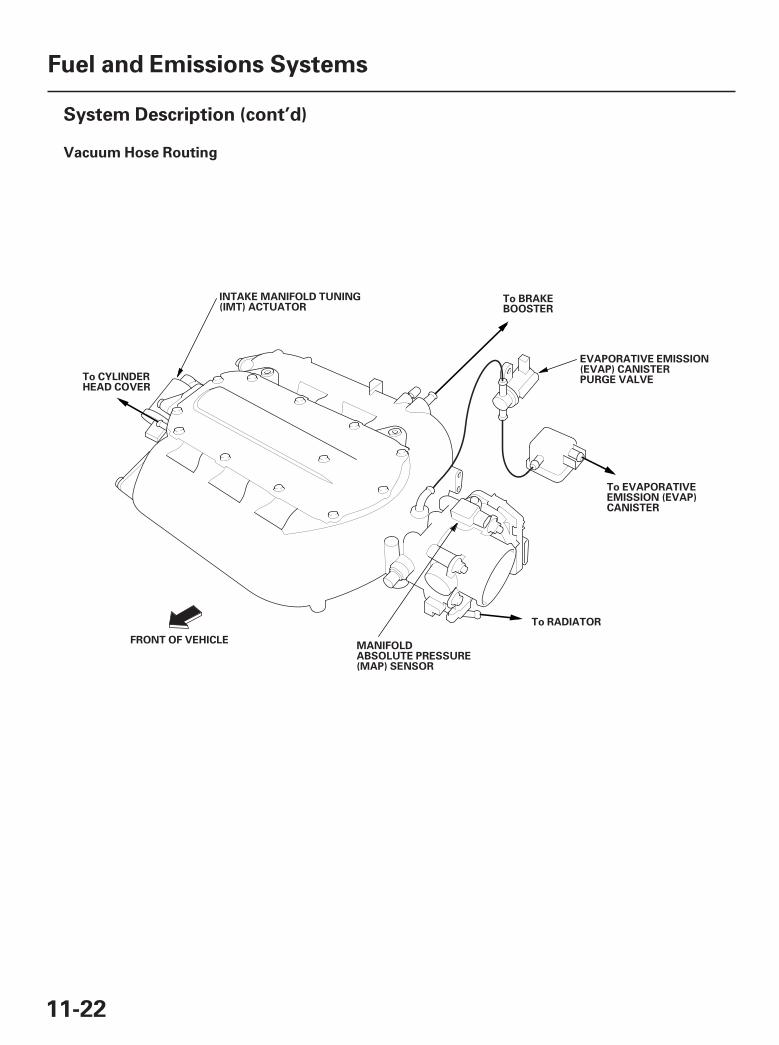
Vacuum Hose Routing
11-22
Fuel and Emissions Systems
System Description (cont’d)
To CYLINDERHEAD COVER
To BRAKEBOOSTER
EVAPORATIVE EMISSION(EVAP) CANISTERPURGE VALVE
To EVAPORATIVEEMISSION (EVAP)CANISTER
To RADIATOR
MANIFOLDABSOLUTE PRESSURE(MAP) SENSOR
FRONT OF VEHICLE
INTAKE MANIFOLD TUNING(IMT) ACTUATOR
07/05/09 16:45:56 61SJC020_110_0022
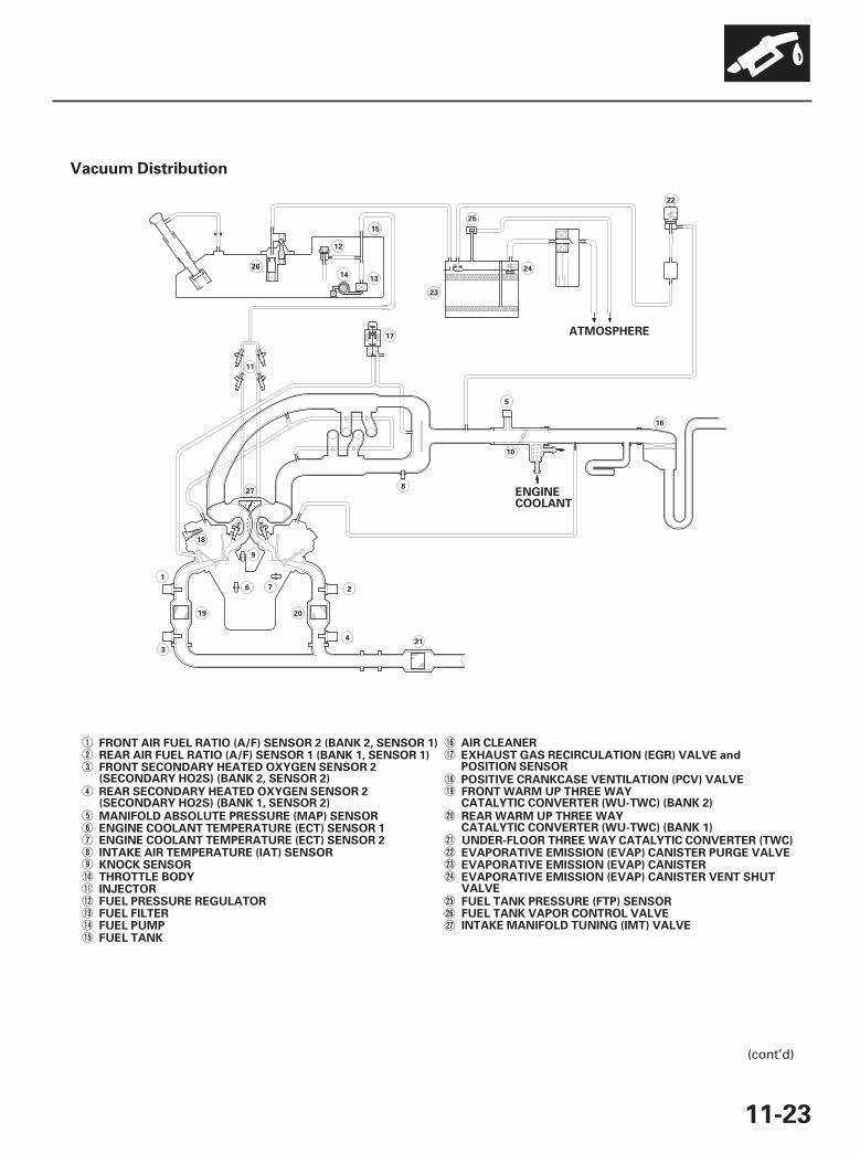
06Vacuum Distribution
11-23
ENGINECOOLANT
ATMOSPHERE
FRONT AIR FUEL RATIO (A/F) SENSOR 2 (BANK 2, SENSOR 1)REAR AIR FUEL RATIO (A/F) SENSOR 1 (BANK 1, SENSOR 1)FRONT SECONDARY HEATED OXYGEN SENSOR 2(SECONDARY HO2S) (BANK 2, SENSOR 2)
MANIFOLD ABSOLUTE PRESSURE (MAP) SENSORENGINE COOLANT TEMPERATURE (ECT) SENSOR 1
INTAKE AIR TEMPERATURE (IAT) SENSORKNOCK SENSORTHROTTLE BODYINJECTORFUEL PRESSURE REGULATORFUEL FILTERFUEL PUMP
AIR CLEANEREXHAUST GAS RECIRCULATION (EGR) VALVE andPOSITION SENSORPOSITIVE CRANKCASE VENTILATION (PCV) VALVE
UNDER-FLOOR THREE WAY CATALYTIC CONVERTER (TWC)EVAPORATIVE EMISSION (EVAP) CANISTER PURGE VALVEEVAPORATIVE EMISSION (EVAP) CANISTEREVAPORATIVE EMISSION (EVAP) CANISTER VENT SHUTVALVEFUEL TANK PRESSURE (FTP) SENSORFUEL TANK VAPOR CONTROL VALVEINTAKE MANIFOLD TUNING (IMT) VALVE
REAR WARM UP THREE WAYCATALYTIC CONVERTER (WU-TWC) (BANK 1)
REAR SECONDARY HEATED OXYGEN SENSOR 2(SECONDARY HO2S) (BANK 1, SENSOR 2)
ENGINE COOLANT TEMPERATURE (ECT) SENSOR 2
FUEL TANK
FRONT WARM UP THREE WAYCATALYTIC CONVERTER (WU-TWC) (BANK 2)
5
8
10
1
3
19
6 2
4
20
21
18
9
27
11
17
7
16
25
22
23
12
1413
26
15
24
(cont’d)
07/05/09 16:45:57 61SJC020_110_0023
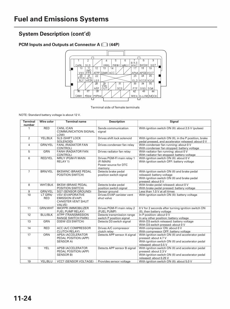
08□PCM Inputs and Outputs at Connector A ( ) (44P)
Terminalnumber
Wire color Terminal name Description Signal
11-24
Fuel and Emissions Systems
System Description (cont’d)
NOTE: Standard battery voltage is about 12 V.
1 RED CANL (CANCOMMUNICATION SIGNALLOW)
Sends communicationsignal
With ignition switch ON (II): about 2.5 V (pulses)
2 YEL/BLK SLS (SHIFT LOCKSOLENOID)
Drives shift lock solenoid With ignition switch ON (II), in the P position, brakepedal pressed, and accelerator released: about 0 V
4 GRN/YEL FANL (RADIATOR FANCONTROL)
Drives condenser fan relay With condenser fan running: about 0 VWith condenser fan stopped: battery voltage
5 GRN FANH (RADIATOR FANCONTROL)
Drives radiator fan relay With radiator fan running: about 0 VWith radiator fan stopped: battery voltage
6 RED/YEL MRLY (PGM-FI MAINRELAY 1)
Drives PGM-FI main relay 1(FI MAIN)Power source for DTCmemory
With ignition switch ON (II): about 0 VWith ignition switch OFF: battery voltage
7 BRN/YEL BKSWNC (BRAKE PEDALPOSITION SWITCH)
Detects brake pedalposition switch signal
With ignition switch ON (II) and brake pedalreleased: battery voltageWith ignition switch ON (II) and brake pedalpressed: about 0 V
8 WHT/BLK BKSW (BRAKE PEDALPOSITION SWITCH)
Detects brake pedalposition switch signal
With brake pedal released: about 0 VWith brake pedal pressed: battery voltage
9 GRN/YEL SG7 (SENSOR GROUND) Sensor ground Less than 1.0 V at all times10 LT GRN/
REDVSV (EVAPORATIVEEMISSION (EVAP)CANISTER VENT SHUTVALVE)
Drives EVAP canister ventshut valve
With ignition switch ON (II): battery voltage
11 GRN/WHT IMOFPR (IMMOBILIZERFUEL PUMP RELAY)
Drives PGM-FI main relay 2(FUEL PUMP)
0 V for 2 seconds after turning ignition switch ON(II), then battery voltage
12 BLU/BLK ATPP (TRANSMISSIONRANGE SWITCH PARK)
Detects transmission rangeswitch P position signal
In P position: about 0 VIn any other position: battery voltage
13 GRN D3SW (D3 SWITCH) Detects D3 switch signal With D3 switch released: battery voltageWith D3 switch pressed: about 0 V
14 RED ACC (A/C COMPRESSORCLUTCH RELAY)
Drives A/C compressorclutch relay
With compressor ON: about 0 VWith compressor OFF: battery voltage
17 ORN APSA (ACCELERATORPEDAL POSITION (APP)SENSOR A)
Detects APP sensor A signal With ignition switch ON (II) and accelerator pedalpressed: about 4.7 VWith ignition switch ON (II) and accelerator pedalreleased: about 0.5 V
18 YEL APSB (ACCELERATORPEDAL POSITION (APP)SENSOR B)
Detects APP sensor B signal With ignition switch ON (II) and accelerator pedalpressed: about 2.3 VWith ignition switch ON (II) and accelerator pedalreleased: about 0.25 V
19 YEL/BLU VCC7 (SENSOR VOLTAGE) Provides sensor voltage With ignition switch ON (II): about 5.0 V
Terminal side of female terminals
07/05/09 16:45:57 61SJC020_110_0024

-
09□PCM Inputs and Outputs at Connector A ( ) (44P)
Terminalnumber
Wire color Terminal name Description Signal
11-25
NOTE: Standard battery voltage is about 12 V.
20 BRN ETCSRLY (ELECTRONICTHROTTLE CONTROLSYSTEM (ETCS) CONTROLRELAY)
Drives electronic throttlecontrol system (ETCS)control relay
With ignition switch ON (II): about 0 V
21 ORN AFSHTCR (AIR FUEL RATIO(A/F) SENSOR HEATERCONTROL RELAY)
Drives A/F sensor relay With ignition switch ON (II): about 0 V
22 BRN/YEL LG3 (LOGIC GROUND) Ground circuit for PCM Less than 1.0 V at all times23 BLU/BLK ELD (ELECTRICAL LOAD
DETECTOR (ELD))Detects ELD signal With ignition switch ON (II): about 0.1 4.8 V
(depending on electrical load)24 GRN VCC3 (SENSOR VOLTAGE) Provides sensor voltage With ignition switch ON (II): about 5.0 V25 WHT VCC4 (SENSOR VOLTAGE) Provides sensor voltage With ignition switch ON (II): about 5.0 V28 BLU NEP (ENGINE SPEED
PULSE)Outputs engine speedpulses
With engine running: pulses
29 BLU/WHT VSSOUT (VEHICLE SPEEDSIGNAL OUTPUT)
Sends vehicle speed sensorsignal
Depending on vehicle speed: pulses
31 BRN SCS (SERVICE CHECKSIGNAL)
Detects service check signal With service check signal shorted using the HDS:about 0 VWith service check signal opened: about 5.0 V
(cont’d)
Terminal side of female terminals
07/05/09 16:45:58 61SJC020_110_0025
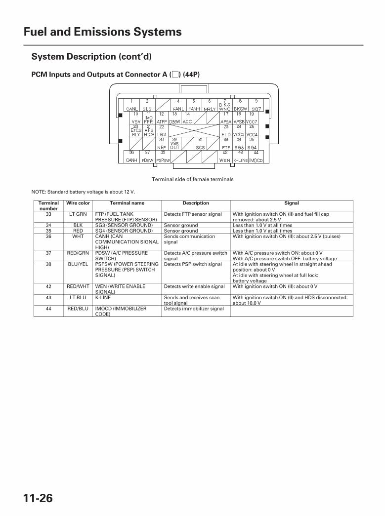
10□PCM Inputs and Outputs at Connector A ( ) (44P)
Terminalnumber
Wire color Terminal name Description Signal
11-26
Fuel and Emissions Systems
System Description (cont’d)
NOTE: Standard battery voltage is about 12 V.
33 LT GRN FTP (FUEL TANKPRESSURE (FTP) SENSOR)
Detects FTP sensor signal With ignition switch ON (II) and fuel fill capremoved: about 2.5 V
34 BLK SG3 (SENSOR GROUND) Sensor ground Less than 1.0 V at all times35 RED SG4 (SENSOR GROUND) Sensor ground Less than 1.0 V at all times36 WHT CANH (CAN
COMMUNICATION SIGNALHIGH)
Sends communicationsignal
With ignition switch ON (II): about 2.5 V (pulses)
37 RED/GRN PDSW (A/C PRESSURESWITCH)
Detects A/C pressure switchsignal
With A/C pressure switch ON: about 0 VWith A/C pressure switch OFF: battery voltage
38 BLU/YEL PSPSW (POWER STEERINGPRESSURE (PSP) SWITCHSIGNAL)
Detects PSP switch signal At idle with steering wheel in straight aheadposition: about 0 VAt idle with steering wheel at full lock:battery voltage
42 RED/WHT WEN (WRITE ENABLESIGNAL)
Detects write enable signal With ignition switch ON (II): about 0 V
43 LT BLU K-LINE Sends and receives scantool signal
With ignition switch ON (II) and HDS disconnected:about 10.0 V
44 RED/BLU IMOCD (IMMOBILIZERCODE)
Detects immobilizer signal
Terminal side of female terminals
07/05/09 16:45:58 61SJC020_110_0026

+-
+-
11△PCM Inputs and Outputs at Connector B ( ) (44P)
Terminalnumber
Wire color Terminal name Description Signal
11-27
NOTE: Standard battery voltage is about 12 V.
1 BLK PG2 (POWER GROUND) Ground circuit for PCMcircuit
Less than 1.0 V at all times
2 BLK/YEL VBSOL (POWER SOURCEFOR SOLENOID VALVES)
Power source for solenoidvalve
With ignition switch ON (II): battery voltage
3 YEL/BLK IGP (POWER SOURCE) Power source for PCMcircuit
With ignition switch ON (II): battery voltage
4 BRN INJ1 (No. 1 INJECTOR) Drives No. 1 injector At idle: duty controlledWith ignition switch ON (II): battery voltage5 BLK/RED INJ5 (No. 5 INJECTOR) Drives No. 5 injector
6 YEL INJ4 (No. 4 INJECTOR) Drives No. 4 injector7 BLU INJ3 (No. 3 INJECTOR) Drives No. 3 injector8 RED INJ2 (No. 2 INJECTOR) Drives No. 2 injector9 WHT/BLU INJ6 (No. 6 INJECTOR) Drives No. 6 injector
10 BLK/RED IGPLS5 (No. 5 IGNITIONCOIL PULSE)
Drives No. 5 ignition coil With ignition switch ON (II): about 0 VWith engine running: pulses
11 BRN/WHT IGPLS6 (No. 6 IGNITIONCOIL PULSE)
Drives No. 6 ignition coil
12 RED/BLU TPSB (THROTTLEPOSITION (TP) SENSOR B)
Detects TP sensor B signal With throttle fully open: about 4.1 VWith throttle fully closed: about 1.7 V
13 BLU VSB1 (VS CELL BANK 1) Detects rear A/F sensor(Bank 1, sensor 1) VS CELLsignal
With fully warmed up engine running:about 3.4 4.8 V
14 RED/BLU VSB2 (VS CELL BANK 2) Detects front A/F sensor(Bank 2, sensor 1) VS CELLsignal
With fully warmed up engine running:about 3.4 4.8 V
15 GRN SHO2SB1 (REARSECONDARY HEATEDOXYGEN SENSOR (REARSECONDARY HO2S)BANK 1, SENSOR 2)
Detects rear secondaryHO2S (Bank 1, sensor 2)signal
With throttle fully opened at idle and fully warmedup engine: about 0.6 VWith throttle quickly closed: below 0.4 V
16 WHT SHO2SB2 (FRONTSECONDARY HEATEDOXYGEN SENSOR (FRONTSECONDARY HO2S)BANK 2, SENSOR 2)
Detects front secondaryHO2S (Bank 2, sensor 2)signal
With throttle fully opened at idle and fully warmedup engine: about 0.6 VWith throttle quickly closed: below 0.4 V
17 RED/BLK TPSA (THROTTLEPOSITION (TP) SENSOR A)
Detects TP sensor A signal With throttle fully open: about 3.9 VWith throttle fully closed: about 0.9 V
18 YEL/RED VCC1 (SENSOR VOLTAGE) Provides sensor voltage With ignition switch ON (II): about 5.0 V
(cont’d)
Terminal side of female terminals
07/05/09 16:45:58 61SJC020_110_0027
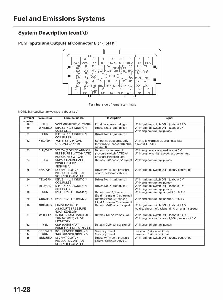
-
+ -
+ -
12△PCM Inputs and Outputs at Connector B ( ) (44P)
Terminalnumber
Wire color Terminal name Description Signal
11-28
Fuel and Emissions Systems
System Description (cont’d)
NOTE: Standard battery voltage is about 12 V.
19 BLU VCC5 (SENSOR VOLTAGE) Provides sensor voltage With ignition switch ON (II): about 5.0 V20 WHT/BLU IGPLS3 (No. 3 IGNITION
COIL PULSE)Drives No. 3 ignition coil With ignition switch ON (II): about 0 V
With engine running: pulses21 BRN IGPLS4 (No. 4 IGNITION
COIL PULSE)Drives No. 4 ignition coil
22 RED/WHT VCENTB2 (VIRTUALGROUND BANK 2)
Reference voltage supplyfor front A/F sensor (Bank 2,sensor 1)
With fully warmed up engine at idle:about 3.4 4.8 V
23 BLU/WHT VTPSW (ROCKER ARM OILPRESSURE SWITCH) (VTECPRESSURE SWITCH)
Detects rocker arm oilpressure switch (VTEC oilpressure switch) signal
With engine at low speed: about 0 VWith engine at high speed: battery voltage
24 BLU CKPA (CRANKSHAFTPOSITION (CKP)SENSOR A)
Detects CKP sensor A signal With engine running: pulses
25 BRN/WHT LSB (A/T CLUTCHPRESSURE CONTROLSOLENOID VALVE B)
Drives A/T clutch pressurecontrol solenoid valve B
With ignition switch ON (II): duty controlled
26 YEL/GRN IGPLS1 (No. 1 IGNITIONCOIL PULSE)
Drives No. 1 ignition coil With ignition switch ON (II): about 0 VWith engine running: pulses
27 BLU/RED IGPLS2 (No. 2 IGNITIONCOIL PULSE)
Drives No. 2 ignition coil With ignition switch ON (II): about 0 VWith engine running: pulses
28 GRN IPB1 (IP CELL BANK 1) Detects rear A/F sensor(Bank 1, sensor 1) pump cell
With engine running: about 2.0 5.6 V
29 GRN/RED IPB2 (IP CELL BANK 2) Detects front A/F sensor(Bank 2, sensor 1) pump cell
With engine running: about 2.0 5.6 V
30 GRN/RED MAP (MANIFOLDABSOLUTE PRESSURE(MAP) SENSOR)
Detects MAP sensor signal With ignition switch ON (II): about 3.0 VAt idle: about 1.0 V (depending on engine speed)
31 WHT/BLK IMTM (INTAKE MANIFOLDTUNING (IMT) VALVEMONITOR)
Detects IMT valve position With ignition switch ON (II): about 5.0 VWith engine speed above 4,000 rpm: about 0 V
32 YEL CMP (CAMSHAFTPOSITION (CMP) SENSOR)
Detects CMP sensor signal With engine running: pulses
33 GRN/WHT SG1 (SENSOR GROUND) Sensor ground Less than 1.0 V at all times34 GRN SG5 (SENSOR GROUND) Sensor ground Less than 1.0 V at all times35 GRN/RED LSC (A/T CLUTCH
PRESSURE CONTROLSOLENOID VALVE C)
Drives A/T clutch pressurecontrol solenoid valve C
With ignition switch ON (II): duty controlled
Terminal side of female terminals
07/05/09 16:45:59 61SJC020_110_0028

-
13△PCM Inputs and Outputs at Connector B ( ) (44P)
Terminalnumber
Wire color Terminal name Description Signal
11-29
NOTE: Standard battery voltage is about 12 V.
36 BLK PG1 (POWER GROUND) Ground circuit for PCMcircuit
Less than 1.0 V at all times
37 BLK/YEL IG1 (IGNITION SIGNAL) Detects ignition signal With ignition switch ON (II): battery voltage38 RED VCENTB1 (VIRTUAL
GROUND BANK 1)Reference voltage supplyfor rear A/F sensor (Bank 1,sensor 1)
With fully warmed up engine at idle:about 3.4 3.8 V
39 RED NM (INPUT SHAFT(MAINSHAFT) SPEEDSENSOR)
Detects input shaft(mainshaft) speed sensorsignal
With ignition switch ON (II): about 0 V or about 5.0 VWith engine idling in N position:about 2.5 V (pulses)
40 BLU NC (OUTPUT SHAFT(COUNTERSHAFT) SPEEDSENSOR)
Detects output shaft(countershaft) speed sensorsignals
With ignition switch ON (II): pulsesWith vehicle moving: about 2.5 V (pulses)
41 BLU/RED CKPB (CRANKSHAFTPOSITION (CKP)SENSOR B)
Detects CKP sensor B signal With engine running: pulses
42 WHT/BLU ALTL (ALTERNATOR LSIGNAL)
Detects alternator L signal With ignition switch ON (II): about 0 VWith engine running: battery voltage
43 BRN/YEL LG2 (LOGIC GROUND) Ground circuit for PCMcircuit
Less than 1.0 V at all times
44 YEL LC (TORQUE CONVERTERCLUTCH (TCC) SOLENOID)
Drives TCC solenoid valve During lock-up condition: battery voltageDuring no lock-up condition: about 0 V
(cont’d)
Terminal side of female terminals
07/05/09 16:45:59 61SJC020_110_0029

++
--
-
-
14○PCM Inputs and Outputs at Connector C ( ) (44P)
Terminalnumber
Wire color Terminal name Description Signal
11-30
Fuel and Emissions Systems
System Description (cont’d)
NOTE: Standard battery voltage is about 12 V.
••
1 BLK PGMETCS (POWERGROUND ETCS)
Ground circuit for PCMcircuit
Less than 1.0 V at all times
2 BLU ETCSM (THROTTLEACTUATOR SIDE)
Drives throttle actuator With ignition switch ON (II): about 0 V
3 GRN ETCSM (THROTTLEACTUATOR SIDE)
Ground for throttle actuator With ignition switch ON (II): about 0 V
4 YEL/GRN IG1ETCS (IGNITIONSIGNAL ETCS)
Detects ignition signal With ignition switch ON (II): battery voltage
5 BLK/WHT SO2SHTCB1 (REARSECONDARY HEATEDOXYGEN SENSOR (REARSECONDARY HO2S)HEATER)
Drives rear secondaryHO2S heater (Bank 1,sensor 2)
With ignition switch ON (II): battery voltageWith fully warmed up engine running:duty controlled
6 BLK/WHT AFSHTCB1 (REAR AIR FUELRATIO (REAR A/F) SENSORHEATER CONTROL BANK 1,SENSOR 1)
Drives rear A/F sensorheater (Bank 1, sensor 1)
With ignition switch ON (II): battery voltageWith fully warmed up engine running:about 0 V or pulses
7 GRN/RED SO2SHTCB2 (FRONTSECONDARY HEATEDOXYGEN SENSOR(SECONDARY HO2S)HEATER)
Drives front secondaryHO2S heater (Bank 2,sensor 2)
With ignition switch ON (II): battery voltageWith fully warmed up engine running:duty controlled
8 GRN/WHT AFSHTCB2 (FRONT AIRFUEL RATIO (FRONT A/F)SENSOR HEATERCONTROL BANK 2,SENSOR 1)
Drives front A/F sensorheater (Bank 2, sensor 1)
With ignition switch ON (II): battery voltageWith fully warmed up engine running:about 0 V or pulses
9 BLU/RED EGR (EXHAUST GASRECIRCULATION (EGR)VALVE)
Drives EGR valve With EGR operating: duty controlledWith EGR not operating: about 0 V
10 WHT VLBLB1 (LABEL RESISTERBANK 1)
Detects rear A/F sensor(Bank 1, sensor 1) LABELsignal
With engine running: about 0.4 4.6 V
11 WHT/RED VLBLB2 (LABEL RESISTERBANK 2)
Detects front A/F sensor(Bank 2, sensor 1) LABELsignal
With engine running: about 0.4 4.6 V
12 YEL/BLU VCC6 (SENSOR VOLTAGE) Provides sensor voltage With ignition switch ON (II): about 5.0 V13 YEL/BLU VCC2 (SENSOR VOLTAGE) Provides sensor voltage With ignition switch ON (II): about 5.0 V14 GRN/YEL SG2 (SENSOR GROUND) Sensor ground Less than 1.0 V at all times15 BLU/WHT OP3SW (3RD CLUTCH
TRANSMISSION FLUIDPRESSURE SWITCH)
Detects 3rd clutchtransmission fluid pressureswitch input
With ignition switch ON (II):Without 3rd clutch pressure: about 5.0 VWith 3rd clutch pressure: about 0 V
Terminal side of female terminals
07/05/09 16:45:59 61SJC020_110_0030
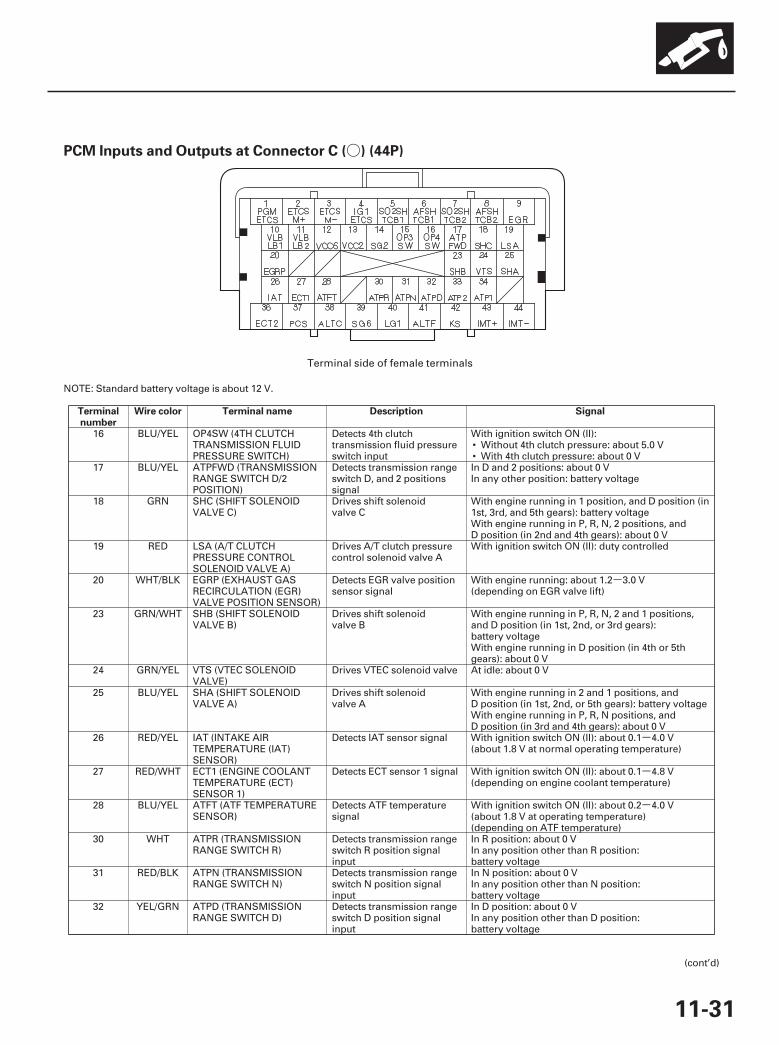
-
-
-
-
15○PCM Inputs and Outputs at Connector C ( ) (44P)
Terminalnumber
Wire color Terminal name Description Signal
11-31
NOTE: Standard battery voltage is about 12 V.
••
16 BLU/YEL OP4SW (4TH CLUTCHTRANSMISSION FLUIDPRESSURE SWITCH)
Detects 4th clutchtransmission fluid pressureswitch input
With ignition switch ON (II):Without 4th clutch pressure: about 5.0 VWith 4th clutch pressure: about 0 V
17 BLU/YEL ATPFWD (TRANSMISSIONRANGE SWITCH D/2POSITION)
Detects transmission rangeswitch D, and 2 positionssignal
In D and 2 positions: about 0 VIn any other position: battery voltage
18 GRN SHC (SHIFT SOLENOIDVALVE C)
Drives shift solenoidvalve C
With engine running in 1 position, and D position (in1st, 3rd, and 5th gears): battery voltageWith engine running in P, R, N, 2 positions, andD position (in 2nd and 4th gears): about 0 V
19 RED LSA (A/T CLUTCHPRESSURE CONTROLSOLENOID VALVE A)
Drives A/T clutch pressurecontrol solenoid valve A
With ignition switch ON (II): duty controlled
20 WHT/BLK EGRP (EXHAUST GASRECIRCULATION (EGR)VALVE POSITION SENSOR)
Detects EGR valve positionsensor signal
With engine running: about 1.2 3.0 V(depending on EGR valve lift)
23 GRN/WHT SHB (SHIFT SOLENOIDVALVE B)
Drives shift solenoidvalve B
With engine running in P, R, N, 2 and 1 positions,and D position (in 1st, 2nd, or 3rd gears):battery voltageWith engine running in D position (in 4th or 5thgears): about 0 V
24 GRN/YEL VTS (VTEC SOLENOIDVALVE)
Drives VTEC solenoid valve At idle: about 0 V
25 BLU/YEL SHA (SHIFT SOLENOIDVALVE A)
Drives shift solenoidvalve A
With engine running in 2 and 1 positions, andD position (in 1st, 2nd, or 5th gears): battery voltageWith engine running in P, R, N positions, andD position (in 3rd and 4th gears): about 0 V
26 RED/YEL IAT (INTAKE AIRTEMPERATURE (IAT)SENSOR)
Detects IAT sensor signal With ignition switch ON (II): about 0.1 4.0 V(about 1.8 V at normal operating temperature)
27 RED/WHT ECT1 (ENGINE COOLANTTEMPERATURE (ECT)SENSOR 1)
Detects ECT sensor 1 signal With ignition switch ON (II): about 0.1 4.8 V(depending on engine coolant temperature)
28 BLU/YEL ATFT (ATF TEMPERATURESENSOR)
Detects ATF temperaturesignal
With ignition switch ON (II): about 0.2 4.0 V(about 1.8 V at operating temperature)(depending on ATF temperature)
30 WHT ATPR (TRANSMISSIONRANGE SWITCH R)
Detects transmission rangeswitch R position signalinput
In R position: about 0 VIn any position other than R position:battery voltage
31 RED/BLK ATPN (TRANSMISSIONRANGE SWITCH N)
Detects transmission rangeswitch N position signalinput
In N position: about 0 VIn any position other than N position:battery voltage
32 YEL/GRN ATPD (TRANSMISSIONRANGE SWITCH D)
Detects transmission rangeswitch D position signalinput
In D position: about 0 VIn any position other than D position:battery voltage
(cont’d)
Terminal side of female terminals
07/05/09 16:46:40 61SJC020_110_0031
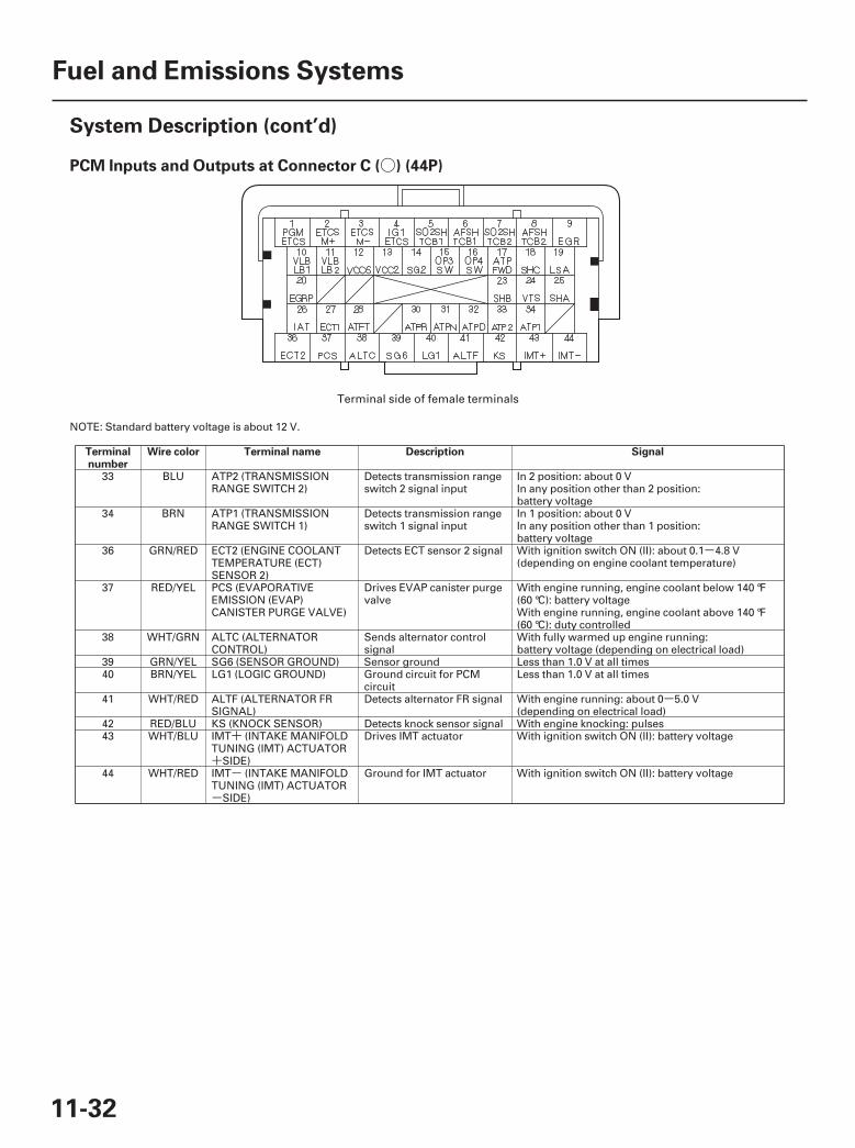
-
-
+
+-
-
16○PCM Inputs and Outputs at Connector C ( ) (44P)
Terminalnumber
Wire color Terminal name Description Signal
11-32
Fuel and Emissions Systems
System Description (cont’d)
NOTE: Standard battery voltage is about 12 V.
33 BLU ATP2 (TRANSMISSIONRANGE SWITCH 2)
Detects transmission rangeswitch 2 signal input
In 2 position: about 0 VIn any position other than 2 position:battery voltage
34 BRN ATP1 (TRANSMISSIONRANGE SWITCH 1)
Detects transmission rangeswitch 1 signal input
In 1 position: about 0 VIn any position other than 1 position:battery voltage
36 GRN/RED ECT2 (ENGINE COOLANTTEMPERATURE (ECT)SENSOR 2)
Detects ECT sensor 2 signal With ignition switch ON (II): about 0.1 4.8 V(depending on engine coolant temperature)
37 RED/YEL PCS (EVAPORATIVEEMISSION (EVAP)CANISTER PURGE VALVE)
Drives EVAP canister purgevalve
With engine running, engine coolant below 140 °F(60 °C): battery voltageWith engine running, engine coolant above 140 °F(60 °C): duty controlled
38 WHT/GRN ALTC (ALTERNATORCONTROL)
Sends alternator controlsignal
With fully warmed up engine running:battery voltage (depending on electrical load)
39 GRN/YEL SG6 (SENSOR GROUND) Sensor ground Less than 1.0 V at all times40 BRN/YEL LG1 (LOGIC GROUND) Ground circuit for PCM
circuitLess than 1.0 V at all times
41 WHT/RED ALTF (ALTERNATOR FRSIGNAL)
Detects alternator FR signal With engine running: about 0 5.0 V(depending on electrical load)
42 RED/BLU KS (KNOCK SENSOR) Detects knock sensor signal With engine knocking: pulses43 WHT/BLU IMT (INTAKE MANIFOLD
TUNING (IMT) ACTUATORSIDE)
Drives IMT actuator With ignition switch ON (II): battery voltage
44 WHT/RED IMT (INTAKE MANIFOLDTUNING (IMT) ACTUATOR
SIDE)
Ground for IMT actuator With ignition switch ON (II): battery voltage
Terminal side of female terminals
07/05/09 16:46:40 61SJC020_110_0032
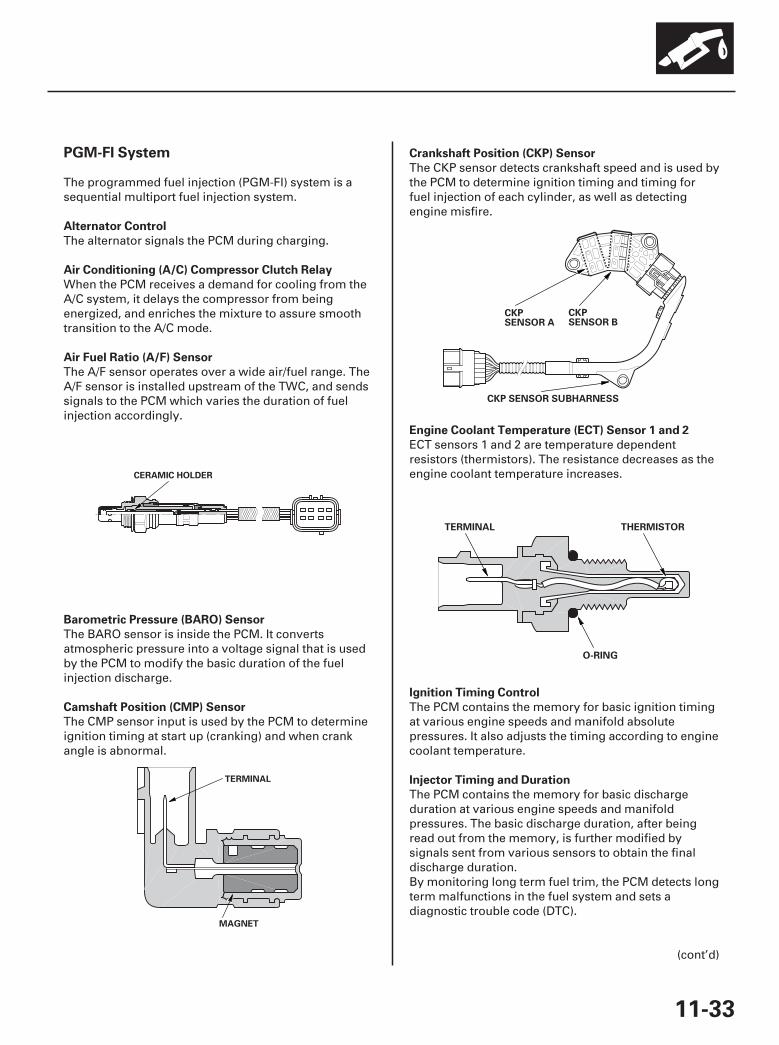
17
18
*08
20
PGM-FI System
Alternator Control
Air Conditioning (A/C) Compressor Clutch Relay
Air Fuel Ratio (A/F) Sensor
Barometric Pressure (BARO) Sensor
Camshaft Position (CMP) Sensor
Crankshaft Position (CKP) Sensor
Engine Coolant Temperature (ECT) Sensor 1 and 2
Ignition Timing Control
Injector Timing and Duration
11-33
CERAMIC HOLDER
MAGNET
TERMINAL
CKPSENSOR A
CKPSENSOR B
CKP SENSOR SUBHARNESS
THERMISTORTERMINAL
O-RING
The programmed fuel injection (PGM-FI) system is asequential multiport fuel injection system.
The alternator signals the PCM during charging.
When the PCM receives a demand for cooling from theA/C system, it delays the compressor from beingenergized, and enriches the mixture to assure smoothtransition to the A/C mode.
The A/F sensor operates over a wide air/fuel range. TheA/F sensor is installed upstream of the TWC, and sendssignals to the PCM which varies the duration of fuelinjection accordingly.
The BARO sensor is inside the PCM. It convertsatmospheric pressure into a voltage signal that is usedby the PCM to modify the basic duration of the fuelinjection discharge.
The CMP sensor input is used by the PCM to determineignition timing at start up (cranking) and when crankangle is abnormal.
The CKP sensor detects crankshaft speed and is used bythe PCM to determine ignition timing and timing forfuel injection of each cylinder, as well as detectingengine misfire.
ECT sensors 1 and 2 are temperature dependentresistors (thermistors). The resistance decreases as theengine coolant temperature increases.
The PCM contains the memory for basic ignition timingat various engine speeds and manifold absolutepressures. It also adjusts the timing according to enginecoolant temperature.
The PCM contains the memory for basic dischargeduration at various engine speeds and manifoldpressures. The basic discharge duration, after beingread out from the memory, is further modified bysignals sent from various sensors to obtain the finaldischarge duration.By monitoring long term fuel trim, the PCM detects longterm malfunctions in the fuel system and sets adiagnostic trouble code (DTC).
(cont’d)
07/05/09 16:46:41 61SJC020_110_0033
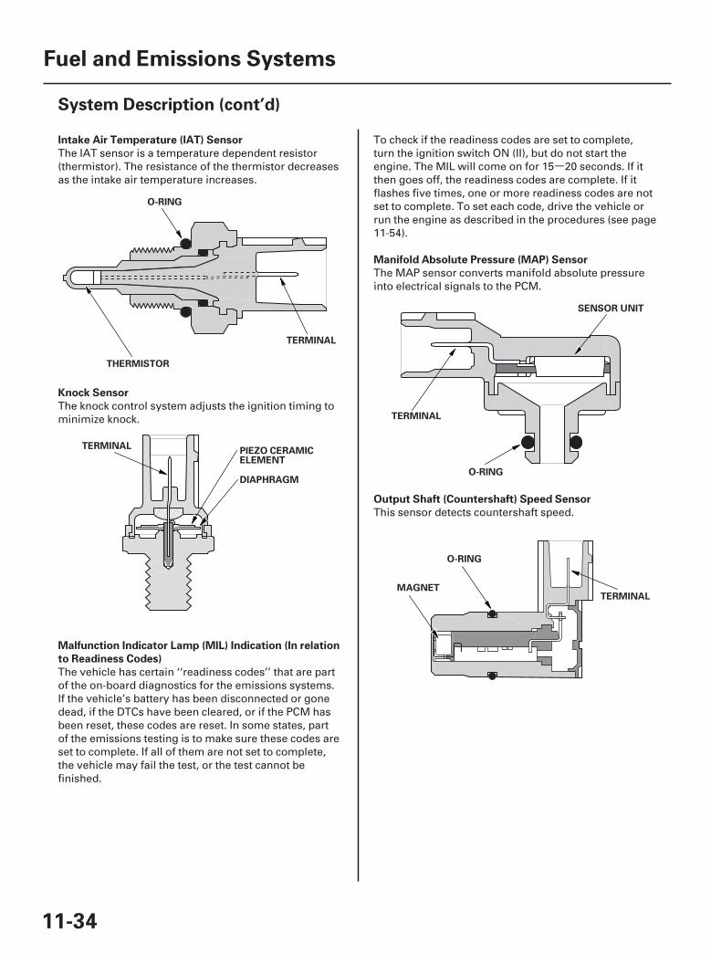
-
21
22
23
50
Intake Air Temperature (IAT) Sensor
Knock Sensor
Malfunction Indicator Lamp (MIL) Indication (In relation
to Readiness Codes)
Manifold Absolute Pressure (MAP) Sensor
Output Shaft (Countershaft) Speed Sensor
11-34
Fuel and Emissions Systems
System Description (cont’d)
THERMISTOR
TERMINAL
O-RING
PIEZO CERAMICELEMENT
DIAPHRAGM
TERMINAL
TERMINAL
SENSOR UNIT
O-RING
TERMINALMAGNET
O-RING
The IAT sensor is a temperature dependent resistor(thermistor). The resistance of the thermistor decreasesas the intake air temperature increases.
The knock control system adjusts the ignition timing tominimize knock.
The vehicle has certain ‘‘readiness codes’’ that are partof the on-board diagnostics for the emissions systems.If the vehicle’s battery has been disconnected or gonedead, if the DTCs have been cleared, or if the PCM hasbeen reset, these codes are reset. In some states, partof the emissions testing is to make sure these codes areset to complete. If all of them are not set to complete,the vehicle may fail the test, or the test cannot befinished.
To check if the readiness codes are set to complete,turn the ignition switch ON (II), but do not start theengine. The MIL will come on for 15 20 seconds. If itthen goes off, the readiness codes are complete. If itflashes five times, one or more readiness codes are notset to complete. To set each code, drive the vehicle orrun the engine as described in the procedures (see page11-54).
The MAP sensor converts manifold absolute pressureinto electrical signals to the PCM.
This sensor detects countershaft speed.
07/05/09 16:46:42 61SJC020_110_0034
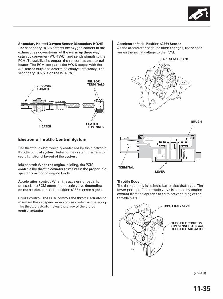
24
25
26
27
Secondary Heated Oxygen Sensor (Secondary HO2S) Accelerator Pedal Position (APP) Sensor
Throttle Body
Electronic Throttle Control System
11-35
HEATER
ZIRCONIAELEMENT
SENSORTERMINALS
HEATERTERMINALS
APP SENSOR A/B
BRUSH
LEVER
TERMINAL
THROTTLE VALVE
THROTTLE POSITION(TP) SENSOR A/B andTHROTTLE ACTUATOR
The secondary HO2S detects the oxygen content in theexhaust gas downstream of the warm up three waycatalytic converter (WU-TWC), and sends signals to thePCM. To stabilize its output, the sensor has an internalheater. The PCM compares the HO2S output with theA/F sensor output to determine catalyst efficiency. Thesecondary HO2S is on the WU-TWC.
The throttle is electronically controlled by the electronicthrottle control system. Refer to the system diagram tosee a functional layout of the system.
Idle control: When the engine is idling, the PCMcontrols the throttle actuator to maintain the proper idlespeed according to engine loads.
Acceleration control: When the accelerator pedal ispressed, the PCM opens the throttle valve dependingon the accelerator pedal position (APP) sensor signal.
Cruise control: The PCM controls the throttle actuator tomaintain the set speed when cruise control is operating.The throttle actuator takes the place of the cruisecontrol actuator.
As the accelerator pedal position changes, the sensorvaries the signal voltage to the PCM.
The throttle body is a single-barrel side draft type. Thelower portion of the throttle valve is heated by enginecoolant from the cylinder head to prevent icing of thethrottle plate.
(cont’d)
07/05/09 16:46:42 61SJC020_110_0035

07
08
Idle Control System
Fuel Supply System
Catalytic Converter System
Brake Pedal Position Switch
Power Steering Pressure (PSP) Switch
Fuel Cutoff Control
Fuel Pump Control
PGM-FI Main Relay 1 and 2
Warm Up/Three Way Catalytic Converter (WU-TWC)
and Under-Floor Three Way Catalytic Converter (TWC)
WU-TWC
TWC
11-36
Fuel and Emissions Systems
System Description (cont’d)
HOUSING
WARM UPTHREE WAYCATALYSTFRONT(Bank 2)
WARM UP THREE WAYCATALYST REAR(Bank 1)
FRONT OFVEHICLE
FRONT OFVEHICLE
UNDER-FLOORTHREE WAYCATALYST
HOUSING
When the engine is cold, the A/C compressor is on, thetransmission is in gear, the brake pedal is pressed, thepower steering load is high, or the alternator ischarging, the PCM sends signals to the throttle actuatorto maintain the correct idle speed.
The brake pedal position switch signals the PCM whenthe brake pedal is pressed.
The PSP switch signals the PCM when the powersteering load is high.
During deceleration with the throttle valve closed,current to the injectors is cut off to improve fueleconomy at engine speeds over 950 rpm. Fuel cutoffcontrol also occurs when the engine speed exceeds6,500 rpm, regardless of the position of the throttlevalve, to protect the engine from over-revving. Whenthe vehicle is stopped, the PCM cuts the fuel at enginespeeds over 5,000 rpm. Engine speed of fuel cut islower on a cold engine.
When the ignition is turned on, the PCM groundsPGM-FI main relay 2 (FUEL PUMP) which feeds currentto the fuel pump for 2 seconds to pressurize the fuelsystem. With the engine running, the PCM groundsPGM-FI main relay 2 (FUEL PUMP) and feeds current tothe fuel pump. When the engine is not running and theignition is on, the PCM cuts ground to PGM-FI mainrelay 2 (FUEL PUMP) which cuts current to the fuelpump.
PGM-FI main relay 1 (FI MAIN) is energized wheneverthe ignition switch is ON (II) to supply battery voltage tothe PCM, power to the injectors, and power for PGM-FImain relay 2 (FUEL PUMP). PGM-FI main relay 2 (FUELPUMP) is energized to supply power to the fuel pumpfor 2 seconds when the ignition switch is turned ON (II),and when the engine is cranking or running.
The WU-TWC/TWC converts hydrocarbons (HC), carbonmonoxide (CO), and oxides of nitrogen (NOx) in theexhaust gas to carbon dioxide (CO ), nitrogen (N ), andwater vapor.
2 2
07/05/09 16:46:43 61SJC020_110_0036
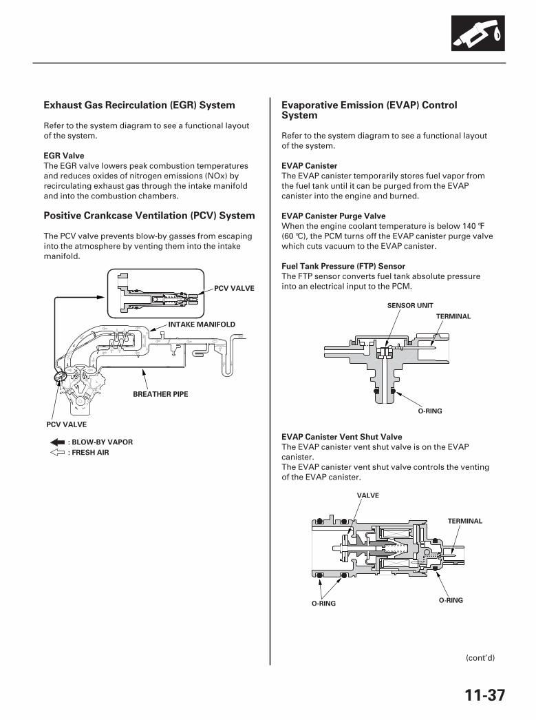
30
31
32
Exhaust Gas Recirculation (EGR) System
Positive Crankcase Ventilation (PCV) System
Evaporative Emission (EVAP) ControlSystem
EGR Valve
EVAP Canister
EVAP Canister Purge Valve
Fuel Tank Pressure (FTP) Sensor
EVAP Canister Vent Shut Valve
11-37
PCV VALVE
BREATHER PIPE
INTAKE MANIFOLD
PCV VALVE
: BLOW-BY VAPOR
: FRESH AIR
O-RING
TERMINAL
SENSOR UNIT
O-RINGO-RING
VALVE
TERMINAL
Refer to the system diagram to see a functional layoutof the system.
The EGR valve lowers peak combustion temperaturesand reduces oxides of nitrogen emissions (NOx) byrecirculating exhaust gas through the intake manifoldand into the combustion chambers.
The PCV valve prevents blow-by gasses from escapinginto the atmosphere by venting them into the intakemanifold.
Refer to the system diagram to see a functional layoutof the system.
The EVAP canister temporarily stores fuel vapor fromthe fuel tank until it can be purged from the EVAPcanister into the engine and burned.
When the engine coolant temperature is below 140 °F(60 °C), the PCM turns off the EVAP canister purge valvewhich cuts vacuum to the EVAP canister.
The FTP sensor converts fuel tank absolute pressureinto an electrical input to the PCM.
The EVAP canister vent shut valve is on the EVAPcanister.The EVAP canister vent shut valve controls the ventingof the EVAP canister.
(cont’d)
07/05/09 16:46:44 61SJC020_110_0037

09
10
Fuel Cap Warning Message To make the message go off (with the HDS)
To make the message go off (without theHDS) (’06 model)
To make the message go off (without theHDS) (’07-08 models)
First drive cycle
’06 model
’07-08 models
Procedure
Procedure
Procedure
11-38
Fuel and Emissions Systems
System Description (cont’d)
A
Shows ’’CHECK FUEL CAP’’ in the
information display and stores
Temporary DTC
A
Shows ’’TIGHTEN FUEL CAP’’ in the
information display and stores
Temporary DTC
outside temperature display. If the PCM detects a smallvolume leak, the MIL may come on during the thirddrive cycle, and store a DTC.
During the first drive cycle after a cold start, the PCMalerts the driver to check the fuel fill cap by showing a‘‘CHECK FUEL CAP’’ (’06 model) or a ‘‘TIGHTEN FUELCAP’’ (’07-08 models) message on the multi-information display (A), and it stores Temporary DTCP0457 ‘‘Evaporative Emission (EVAP) System LeakDetected/Fuel Fill Cap Loose or Missing.’’ Tighteningthe fuel cap does not make the message go offimmediately.
1. Tighten the fuel fill cap until it clicks.
2. Clear the Temporary DTC with the HDS.
3. Verify there is no leak by doing the EVAPFUNCTION TEST in the INSPECTION MENU withthe HDS.
1. Tighten the fuel fill cap until it clicks.
2. The message should go off after several daysnormal driving.
1. Tighten the fuel fill cap until it clicks.
2. Turn the ignition switch ON (II), then turn theignition switch OFF.
3.
07/05/09 16:46:44 61SJC020_110_0038
Do step 2 two more times.
The PCM detects a loose or missing fuel fill cap
by showing the information in the odometer/under certain conditions, and alerts the driver
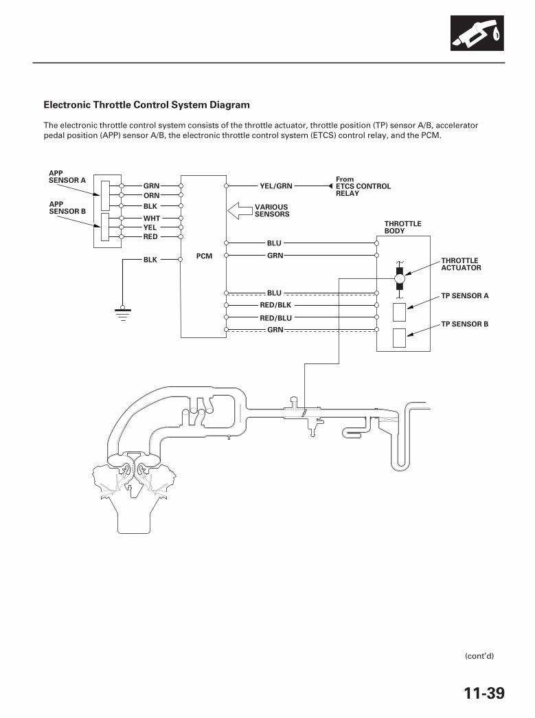
35
Electronic Throttle Control System Diagram
11-39
GRN
ORN
BLK
WHT
YEL
RED
BLK
YEL/GRN
BLU
GRN
BLU
RED/BLK
RED/BLU
GRN
THROTTLEBODY
THROTTLEACTUATOR
TP SENSOR A
TP SENSOR B
APPSENSOR A
APPSENSOR B
FromETCS CONTROLRELAY
PCM
VARIOUSSENSORS
The electronic throttle control system consists of the throttle actuator, throttle position (TP) sensor A/B, acceleratorpedal position (APP) sensor A/B, the electronic throttle control system (ETCS) control relay, and the PCM.
(cont’d)
07/05/09 16:46:45 61SJC020_110_0039
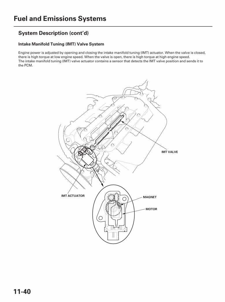
36
Intake Manifold Tuning (IMT) Valve System
11-40
Fuel and Emissions Systems
System Description (cont’d)
IMT VALVE
IMT ACTUATOR MAGNET
MOTOR
Engine power is adjusted by opening and closing the intake manifold tuning (IMT) actuator. When the valve is closed,there is high torque at low engine speed. When the valve is open, there is high torque at high engine speed.The intake manifold tuning (IMT) valve actuator contains a sensor that detects the IMT valve position and sends it tothe PCM.
07/05/09 16:46:45 61SJC020_110_0040

37
Exhaust Gas Recirculation (EGR) System Diagram
11-41
YEL/BLU
GRN/YEL
WHT/BLK
BLU/REDEGR VALVE
BLK
EGR VALVEPOSITIONSENSOR
VARIOUSSENSORS
BLK
INTAKEMANIFOLD
PCM
The EGR system reduces oxides of nitrogen (NOx) emissions by recirculating exhaust gas through the EGR valve andthe intake manifold into the combustion chambers. The PCM memory contains the ideal EGR valve position forvarious operating conditions.
The EGR valve position sensor detects the amount of EGR valve lift, and sends it to the PCM. The PCM then comparesit with the ideal lift in its memory (based on signals sent from other sensors). If there is any difference between the two,the PCM cuts current to the EGR valve.
(cont’d)
07/05/09 16:46:45 61SJC020_110_0041

38
Evaporative Emission (EVAP) Control Diagram
11-42
Fuel and Emissions Systems
System Description (cont’d)
ATMOSPHERE
From A/F SENSORRELAY (LAF)
No. 18 IGACG (15 A) FUSE(in theunder-dash fuse/relay box)
VARIOUSSENSORS
EVAP CANISTERFILTER
FTP SENSOR
EVAP CANISTERVENT SHUT VALVE
FUEL TANK VAPORCONTROL VALVE
FUEL FILLCAP
FUEL TANKVAPORRECIRCULATIONTUBE
FUEL TANKEVAP CANISTER
EVAPCANISTERPURGEVALVE
PCM
YEL/BLU
LT GRN
GRN/YEL
LT GRN/RED
RED/YEL
WHT/BLKBLK
BLK/YEL
The EVAP controls minimize the amount of fuel vapor escaping to the atmosphere. Vapor from the fuel tank istemporarily stored in the EVAP canister until it can be purged from the canister into the engine and burned.
• The EVAP canister is purged by drawing fresh air through it and into a port on the intake manifold.The purging vacuum is controlled by the EVAP canister purge valve, which operates whenever engine coolanttemperature is above 140 °F (60 °C).
• During refueling, the fuel tank vapor control valve opens with the pressure in the fuel tank, and feeds the fuel vaporto the EVAP canister.
07/05/09 16:46:46 61SJC020_110_0042
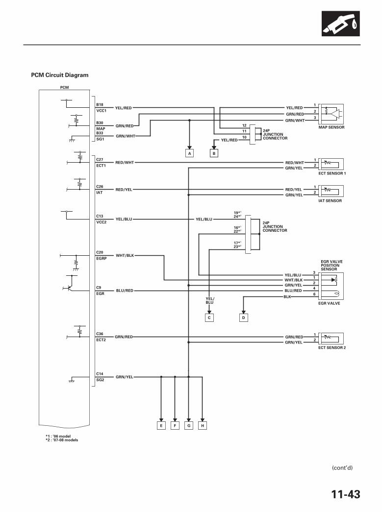
*01PCM Circuit Diagram
11-43
YEL/BLU
GRN/YEL
GRN/YEL
GRN/YEL
RED/WHT
YEL/RED
WHT/BLK
YEL/RED
BLK
GRN/RED
GRN/WHT
RED/YEL
BLU/RED
MAP SENSOR
VCC1
MAP
SG1
ECT1
IAT
VCC2
EGRP
EGR
SG2
YEL/RED
GRN/RED
GRN/WHT
RED/WHT
RED/YEL
WHT/BLK
YEL/BLU
GRN/YEL
B18
B30
B33
C27
C26
C13
C20
C9
C14
B
BLU/RED
ECT SENSOR 1
IAT SENSOR
EGR VALVEPOSITIONSENSOR
EGR VALVE
3
1
2
4
6
1
2
1
2
3
2
1
24PJUNCTIONCONNECTOR
12
11
10
PCM
D
YEL/BLU
G
C
YEL/BLU24*19*
24PJUNCTIONCONNECTOR
FE H
A
GRN/YEL
GRN/REDECT2
GRN/REDC36
ECT SENSOR 2
1
2
22*16*
23*17*
*2 : ’07-08 models*1 : ’06 model
2
1
2
1
2
1
(cont’d)
07/05/09 16:46:46 61SJC020_110_0043
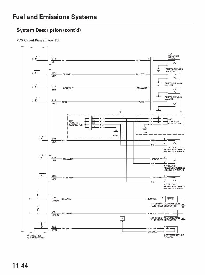
*02PCM Circuit Diagram (cont’d)
11-44
Fuel and Emissions Systems
System Description (cont’d)
24PJUNCTIONCONNECTOR
9
8
7
G101
BLK
A/T CLUTCHPRESSURE CONTROLSOLENOID VALVE A
LSARED
C19
LSBBRN/WHT
B25
LSC
B35
TCCSOLENOIDVALVE
YELLC
B44
SHIFT SOLENOIDVALVE C
SHCGRN
C18
SHIFT SOLENOIDVALVE A
SHABLU/YEL
C25
SHIFT SOLENOIDVALVE B
SHBGRN/WHT
C23
GRN/RED
1
2
1
2
2
BLU/YELOP4SW
C16
OP3SWBLU/WHT
C15
4TH CLUTCH TRANSMISSIONFLUID PRESSURE SWITCH
3RD CLUTCH TRANSMISSIONFLUID PRESSURE SWITCH
1
1
ATF TEMPERATURESENSOR
ATFT
C28
RED
BRN/WHT
GRN/RED
BLK
BLK
BLK
BLU/YEL
BLU/WHT
BLU/YEL BLU/YEL
GRN/YEL
E
2
1
1
A/T CLUTCHPRESSURE CONTROLSOLENOID VALVE B
A/T CLUTCHPRESSURE CONTROLSOLENOID VALVE C
YEL
GRN
BLU/YEL
GRN/WHT
BLK
BLK
BLK
BLK
G101
24
21
22
20
24PJUNCTIONCONNECTOR
*2 *1
*2 : ’07-08 models*1 : ’06 model
BLK
BLK
3
4
1
2
07/05/09 16:46:47 61SJC020_110_0044

14
11-45
NM
NC
RED
BLU
INPUT SHAFT(MAINSHAFT)SPEED SENSOR
B39
B40
No. 1 INJECTOR
No. 6 INJECTORINJ6
INJ1
WHT/BLU
BRN
YEL/BLK
YEL/BLK
No. 2 INJECTORINJ2
RED
YEL/BLK
No. 3 INJECTORINJ3
BLU
YEL/BLK
No. 4 INJECTOR
YELINJ4
YEL/BLK
No. 5 INJECTORINJ5
BLK/RED
YEL/BLK
B4
B8
B7
B6
B9
B5
YEL/BLU
YEL/RED
1
2
1
2
1
2
1
2
1
2
1
2
1
2
3
1
2
3
WHT/BLU
BRN
RED
BLU
YEL
BLK/RED
RED
BLU
GRN/YEL
GRN/WHT
OUTPUT SHAFT(COUNTERSHAFT)SPEED SENSOR
24PJUNCTIONCONNECTOR
YEL/BLKIGP
B3
YEL/BLK
1
2
3
4
5
6
9
8
7
11YEL/BLK
YEL/BLK
YEL/BLK10
17
YEL/BLK
CKJI
FBAL
C101
(cont’d)
07/05/09 16:46:47 61SJC020_110_0045
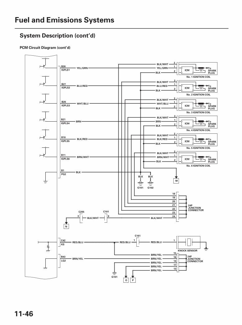
15PCM Circuit Diagram (cont’d)
11-46
Fuel and Emissions Systems
System Description (cont’d)
3
ICMToSPARKPLUG
No. 1 IGNITION COIL
ICMToSPARKPLUG
No. 2 IGNITION COIL
ICMToSPARKPLUG
No. 3 IGNITION COIL
ICMToSPARKPLUG
No. 4 IGNITION COIL
ICMToSPARKPLUG
No. 5 IGNITION COIL
ICMToSPARKPLUG
No. 6 IGNITION COIL
BLK/WHT
BLK
B26
IGPLS1
B27
IGPLS2
B21
IGPLS4
B10
IGPLS5
B11
IGPLS6
B20
IGPLS3
BLU/RED
YEL/GRN
WHT/BLU
BRN
BLK
BLK
BLK
BLK
BLK
BLK/RED
BRN/WHT
3
1
2
3
1
2
3
1
2
3
1
2
1
2
3
1
2
BLK/WHT
BLK/WHT
BLK/WHT
BLK/WHT
BLK/WHT
BLU/RED
YEL/GRN
WHT/BLU
BRN
BLK/RED
BRN/WHT
B1
PG2BLK
24PJUNCTIONCONNECTOR
BLK/WHT
G102
KNOCK SENSOR
KSRED/BLU RED/BLU
C42
18
19
20
21
22
23
24
11RED/BLU
O
C161
M
15
16
14
G101
LG2
B43BRN/YEL
BRN/YEL
BRN/YEL
24PJUNCTIONCONNECTOR
BRN/YEL
G101
9BLK/WHT
3
N
C101
17
13BRN/YEL
BRN/YEL
P
C205
BLKBLK
07/05/09 16:46:48 61SJC020_110_0046
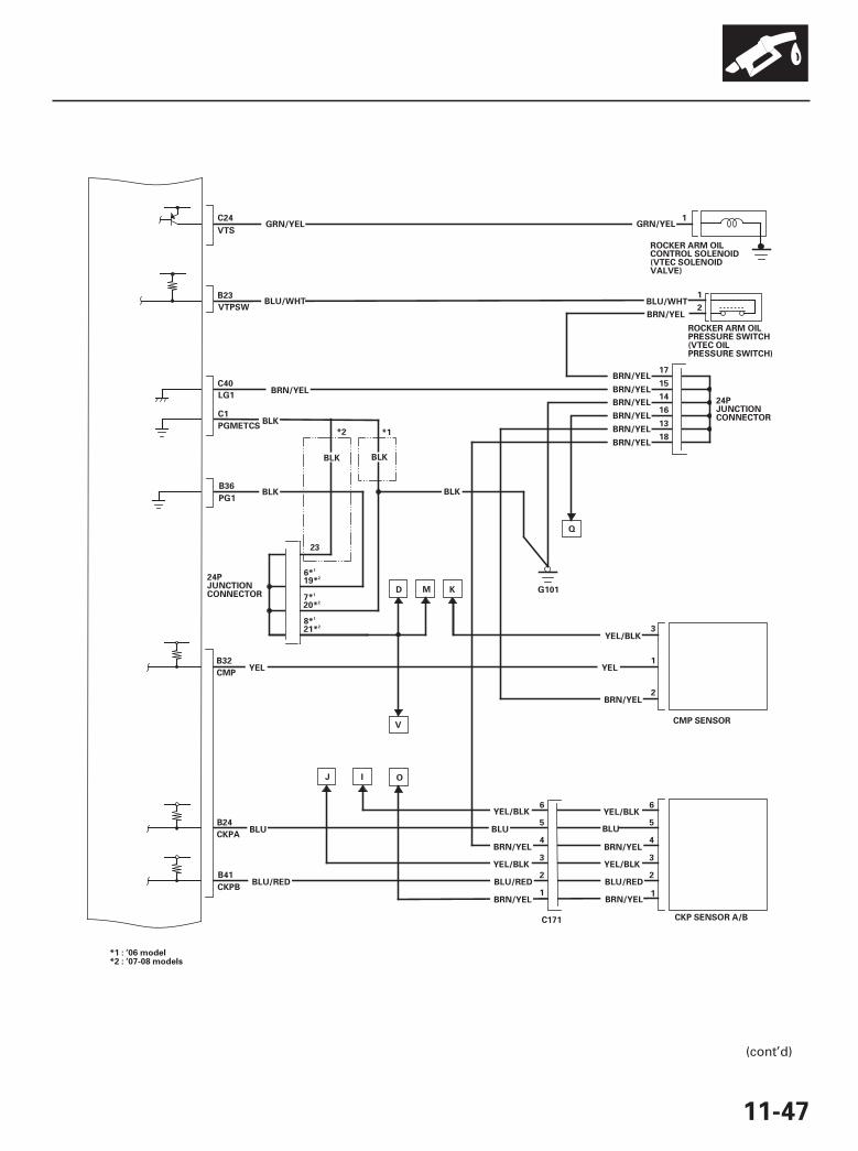
*03
11-47
BRN/YELLG1
BLU/WHT
GRN/YEL
G101
B36
C40
B23
VTPSW
C24
PG1BLK BLK
24PJUNCTIONCONNECTOR
VTS
23
19*D
CMP
YEL/BLK
YEL
BRN/YEL
K
3
1
2
YEL
YEL/BLK
BLU
6
5
4BRN/YEL
YEL/BLK
BRN/YEL
BLU/RED
3
2
YEL/BLK
BLU
6
5
4BRN/YEL
YEL/BLK
BRN/YEL
BLU/RED
3
2
1
BLU
BLU/RED
B32
CKPA
B24
CKPB
B41
CMP SENSOR
CKP SENSOR A/BC171
C1
PGMETCSBLK
M
V
I OJ
6*
ROCKER ARM OILCONTROL SOLENOID(VTEC SOLENOIDVALVE)
BRN/YEL
24PJUNCTIONCONNECTOR
1
2
1
13
BLU/WHT
GRN/YEL
BRN/YEL
BRN/YEL
BRN/YEL
BRN/YEL
BRN/YEL
17
15
14
16
Q
18BRN/YEL
1
ROCKER ARM OILPRESSURE SWITCH(VTEC OILPRESSURE SWITCH)
BLK BLK
*2 *1
20*7*
21*8*
*2 : ’07-08 models*1 : ’06 model
2
1
2
1
2
1
(cont’d)
07/05/09 16:46:48 61SJC020_110_0047
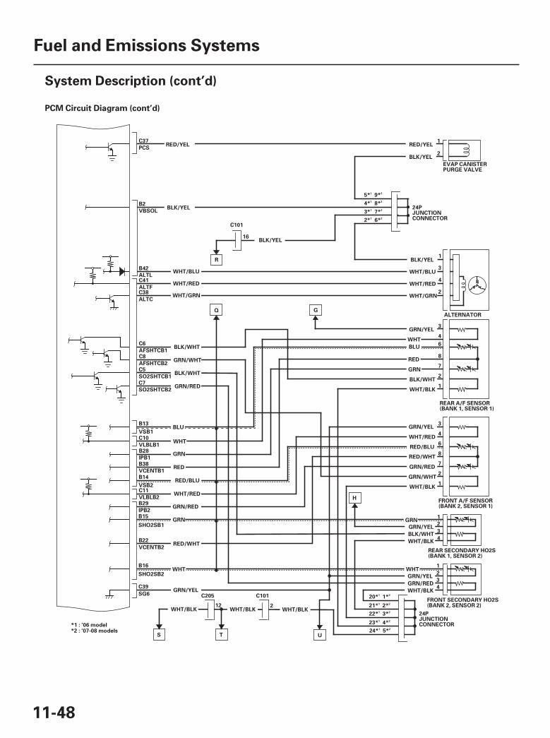
*04PCM Circuit Diagram (cont’d)
11-48
Fuel and Emissions Systems
System Description (cont’d)
C37
PCS
B2
VBSOL
RED/YEL
BLK/YEL
EVAP CANISTERPURGE VALVE
RED/YEL1
BLK/YEL2
BLK/YEL
R
16
B42
ALTLC41
ALTFC38
ALTC
24PJUNCTIONCONNECTOR
WHT/BLU
WHT/RED
WHT/GRN
6
ALTERNATOR
BLK/YEL1
3
WHT/RED4
WHT/GRN2
GRN/YEL3
WHT4
RED8
GRN7
BLU
WHT/BLU
G
C6
AFSHTCB1C8
AFSHTCB2C5
SO2SHTCB1
C7
SO2SHTCB2
Q
GRN/RED
BLK/WHT
GRN/WHT
BLK/WHT
REAR SECONDARY HO2S(BANK 1, SENSOR 2)
REAR A/F SENSOR(BANK 1, SENSOR 1)
24PJUNCTIONCONNECTOR
BLK/WHT2
WHT/BLK1
FRONT A/F SENSOR(BANK 2, SENSOR 1)
3
WHT/RED4
RED/BLU6
RED/WHT8
GRN/RED7
GRN/WHT2
WHT/BLK1
WHT/BLK
GRN1
GRN/YEL2
BLK/WHT3
WHT/BLK4
WHT1
GRN/YEL2
GRN/RED3
4
FRONT SECONDARY HO2S(BANK 2, SENSOR 2)
GRN/YEL
B15
SHO2SB1
B16
SHO2SB2
B22
VCENTB2
B29
IPB2
B14
VSB2C11
VLBLB2
C10
VLBLB1B28
IPB1B38
VCENTB1
B13
VSB1BLU
WHT
C39
SG620* 1*
H
WHT/BLK
GRN/RED
WHT
RED/WHT
GRN
GRN
RED
WHT/RED
RED/BLU
2WHT/BLK
12WHT/BLK
S
C205 C101
UT
GRN/YEL
C101
21* 2*
22* 3*
23* 4*
24* 5**2 : ’07-08 models*1 : ’06 model
2* 6*
3* 7*
4* 8*
5* 9*
1 2
1 2
1 2
1 2
1 2
1 2
1 2
1 2
1 2
07/05/09 16:46:49 61SJC020_110_0048
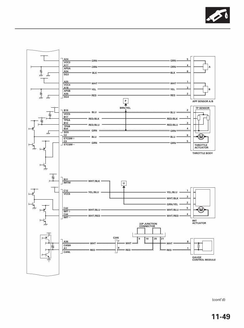
*05
-
+
-
+
11-49
C44
IMT
A36
CANH
A1
CANL
8
1
WHT
RED
22P JUNCTIONCONNECTOR
9 10 20 217
8
WHT
RED
WHT
RED
P
BRN/YEL
6
5
4
A34
SG3
A24
VCC3
A17
APSA
APP SENSOR A/B
A35
SG4
A25
VCC4
A18
APSB
GRN
ORN
WHT
YEL
RED
GRN
ORN
WHT
YEL
RED2
1
3
B12
TPSB
B19
VCC5
B17
TPSA
C3
B34
SG5
C2
ETCSM
ETCSM
BLU
GRN
BLU
GRN
3
2
1
5
4
6
RED/BLK
RED/BLU
B31
IMTM
C12
VCC6
C43
IMT
WHT/BLK
YEL/BLU
WHT/BLU
WHT/RED
YEL/BLU
WHT/BLK
GRN/YEL
WHT/BLU
WHT/RED
U
2
1
3
5
4
TP SENSOR
THROTTLEACTUATOR
THROTTLE BODY
IMTACTUATOR
BLK
BLU
RED/BLK
RED/BLU
GRN
BLU
GRN
BLK
C205
GAUGECONTROL MODULE
A
B
(cont’d)
07/05/09 16:46:50 61SJC020_110_0049
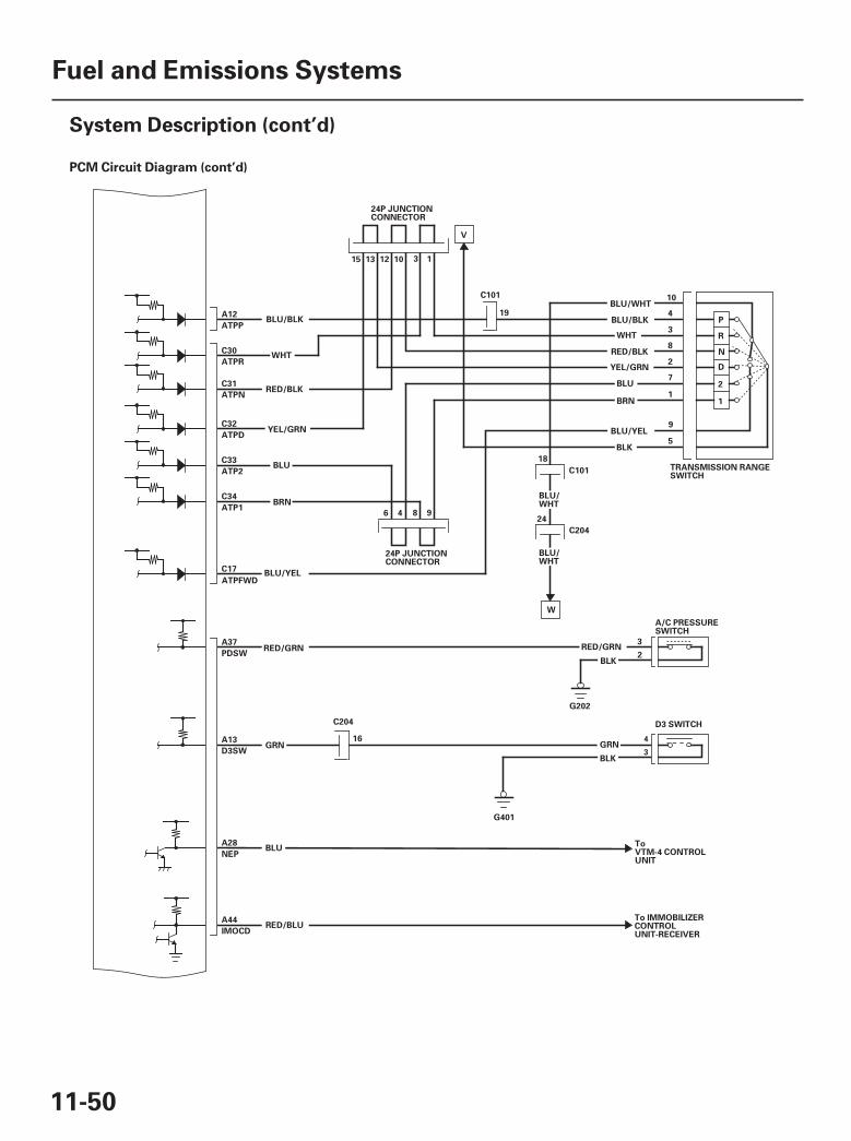
19PCM Circuit Diagram (cont’d)
11-50
Fuel and Emissions Systems
System Description (cont’d)
C101
BLU/WHT
18
24
C204
P
R
N
D
TRANSMISSION RANGESWITCH
2
A12
ATPP
C31
ATPN
C32
ATPD
C30
ATPR
C33
ATP2
C17
ATPFWD
BLU/BLK
WHT
RED/BLK
YEL/GRN
BLU
BLU/YEL
BLU/WHT10
BLU/BLK4
WHT3
RED/BLK8
2YEL/GRN
7
BLU/YEL9
BLK5
W
A/C PRESSURESWITCH
3
BLK2
G202
ToVTM-4 CONTROLUNIT
A37
PDSW
A28
NEP
A44
IMOCD
RED/GRN
RED/BLU
BLU/WHT
RED/GRN
C34
ATP1BRN
3 1
24P JUNCTIONCONNECTOR
V
C101
19
BLU
BRN1
A13
D3SWGRN
BLU
16
C204
G401
BLK
GRN
D3 SWITCH
1
15 13 12 10
24P JUNCTIONCONNECTOR
6 4 8 9
To IMMOBILIZERCONTROLUNIT-RECEIVER
4
3
07/05/09 16:46:50 61SJC020_110_0050
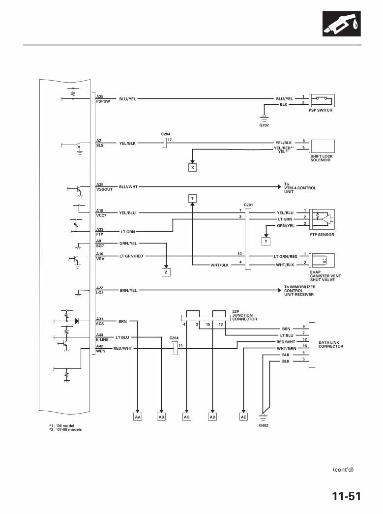
*06
11-51
BLU/YEL1
PSP SWITCH
BLK2
G202
FTP SENSOR
ToVTM-4 CONTROLUNIT
EVAPCANISTER VENTSHUT VALVE
1
2
1
A22
LG3
T
GRN/YEL
A38
PSPSW
A2
SLS
A29
VSSOUT
A33
FTP
YEL/BLU
BLU/YEL
6
SHIFT LOCKSOLENOID
YEL/BLK5
YEL/BLK
YEL/RED*
A19
VCC7
A9
SG7
X
A10
VSV
BLU/WHT
LT GRN
LT GRN/RED
BRN/YEL
WHT/BLK
7
3
10
4
3
2
YEL/BLU
GRN/YEL
LT GRN
WHT/BLK
To IMMOBILIZERCONTROLUNIT-RECEIVER
DATA LINKCONNECTOR
9
7
12
16
4
5
BRN
BLK
BLK
RED/WHT
22PJUNCTIONCONNECTOR
11
C204
BRNA31
SCS
A43
A42
WEN
K-LINE
RED/WHT
LT BLU
4 3 15 13
AA AB AC AD AE
G402
C201
17
Y
Z
LT GRN/RED
LT BLU
WHT/GRN
C204
YEL*
*1 : ’06 model*2 : ’07-08 models
1
2
(cont’d)
07/05/09 16:46:51 61SJC020_110_0051
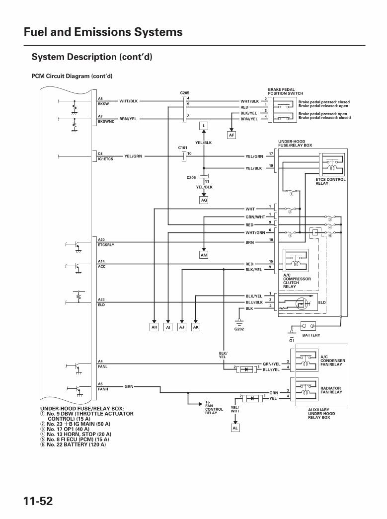
21
+
PCM Circuit Diagram (cont’d)
11-52
Fuel and Emissions Systems
System Description (cont’d)
BRAKE PEDALPOSITION SWITCH
Brake pedal pressed: closedBrake pedal released: open
Brake pedal pressed: openBrake pedal released: closed
WHT/BLK
RED
BLK/YEL
BRN/YEL
AF
ELD
UNDER-HOODFUSE/RELAY BOX
BATTERY
G1
A/CCOMPRESSORCLUTCHRELAY
ETCS CONTROLRELAY
L
YEL/BLK
YEL/GRN
YEL/BLK
WHT
GRN/WHT
RED
WHT/GRN
BRN
RED
BLK/YEL
BLK/YEL
BLU/BLK
BLK
AG
YEL/BLK
11
4
9
2
10
G202
AM
AKAJAIAH
A/CCONDENSERFAN RELAY
RADIATORFAN RELAY
AUXILIARYUNDER-HOODRELAY BOX
GRN/YEL
BLU/YEL
GRN
YEL
AL
WHT/BLK
BRN/YEL
YEL/GRN
C205
C205
C101
GRN
2
1
3
4
17
19
1
1
9
6
10
15
9
1
3
2
3
4
3
4
YEL/WHT
2 1
2 1
BLK/YEL
A5
FANH
A4
FANL
A23
ELD
A20
ETCSRLY
C4
IG1ETCS
A7
BKSWNC
A8
BKSW
A14
ACC
ToFANCONTROLRELAY
UNDER-HOOD FUSE/RELAY BOX:No. 9 DBW (THROTTLE ACTUATORCONTROL) (15 A)No. 23 B IG MAIN (50 A)No. 17 OP1 (40 A)No. 13 HORN, STOP (20 A)No. 8 FI ECU (PCM) (15 A)No. 22 BATTERY (120 A)
07/05/09 16:46:51 61SJC020_110_0052
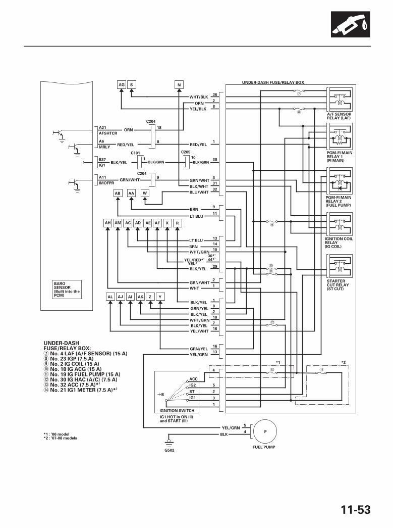
*07
+
11-53
A/F SENSORRELAY (LAF)
PGM-FI MAINRELAY 2(FUEL PUMP)
IGNITION COILRELAY(IG COIL)
STARTERCUT RELAY(ST CUT)
PGM-FI MAINRELAY 1(FI MAIN)
UNDER-DASH FUSE/RELAY BOX
A6
MRLY
B37
IG1
A11
IMOFPR
A21
AFSHTCR
BAROSENSOR(Built into thePCM)
RED/YEL1
38
GRN/WHT3
BRN14
10
GRN/WHT2
WHT1
BLK/YEL1
8
BLK/YEL2
10
BLK/YEL7
ACAH
ZAKAIAJ
WHT/BLK36
2
YEL/BLK8
AE
NSAG
R
AL
YEL/GRN13
IGNITION SWITCH
IG2
STB
IG1
5
2
3
FUEL PUMP
PYEL/GRN
5
BLK4
G502
16YEL/WHT
IG1 HOT in ON (II)and START (III)
BLK/WHT31
32
BRN9
11LT BLU
13
ORN
BLU/WHT
LT BLU
WHT/GRN
GRN/YEL
WHT/GRN
AB AA W
AM AD
BLK/YEL
ORN18
8
1
9
C204
C101
C204
10
C205
RED/YEL
GRN/WHT
AF X
YEL/RED*
BLK/YEL
36*
29
GRN/YEL16
Y
4
1
ACC
*1 : ’06 model*2 : ’07-08 models
YEL*44*
*1 *2
UNDER-DASHFUSE/RELAY BOX:
No. 4 LAF (A/F SENSOR) (15 A)No. 23 IGP (7.5 A)No. 2 IG COIL (15 A)No. 18 IG ACG (15 A)No. 19 IG FUEL PUMP (15 A)No. 30 IG HAC (A/C) (7.5 A)No. 32 ACC (7.5 A)*No. 21 IG1 METER (7.5 A)*
1
2
BLK/GRNBLK/GRN
1
1
2
2
07/05/09 16:46:52 61SJC020_110_0053

-
-
SJC8A00A20326939901BBAT00
Malfunction Indicator Lamp (MIL) Indication(In relation to Readiness Codes)
Catalytic Converter Monitor and ReadinessCode
Enable Criteria
Procedure
11-54
Fuel and Emissions Systems
How to Set Readiness Codes
The vehicle has certain ‘‘readiness codes’’ that are partof the on-board diagnostics for the emissions systems.If the vehicle’s battery has been disconnected or gonedead, if the DTCs have been cleared, or if the PCM hasbeen reset, these readiness codes are reset toincomplete. In some states, part of the emissionstesting is to make sure these codes are set to complete.If all of them are not set to complete, the vehicle mayfail the emission test, or the test cannot be finished.
To check if the readiness codes are set to complete,turn the ignition switch ON (II), but do not start theengine. The MIL will come on for 15 20 seconds. If itthen goes off, the readiness codes are set to complete.If it flashes five times, one or more readiness codes arenot set to complete. To set readiness codes fromincomplete to complete, do the procedure for theappropriate code.
To check the status of a specific DTC system, check theOBD status in the DTC MENU with the HDS (see page11-9). This screen displays the code, the current data listof the enable criteria, and the status of the readinesstesting.
NOTE:• Do not turn the ignition switch off during the
procedure.• All readiness codes are cleared when the battery is
disconnected, if the DTCs have been cleared, or if thePCM is reset with the HDS.
• Low ambient temperatures or excessive stop-and-gotraffic may increase the drive time needed to switchthe readiness code from incomplete to complete.
• The readiness code will not switch to complete untilall the enable criteria are met.
• If a fault in the secondary HO2S system caused theMIL to come on, the readiness code cannot be set tocomplete until you correct the fault.
• ECT SENSOR 1 at 158 °F (70 °C) or more.• IAT SENSOR at 20 °F ( 7 °C) or more.• Vehicle speed sensor (VSS) above 25 mph (40 km/h).
1. Connect the HDS to the vehicle’s data linkconnector (DLC), and bring up the READINESSCODEs screen for Catalyst in the DTCs MENU.
2. Start the engine.
3. Test-drive the vehicle under stop-and-go conditionswith short periods of steady cruise. After about5 miles (8 km), the readiness code should switch tocomplete.
4. If the readiness code is still not set to complete,check for a Temporary DTC with the HDS. If there isno DTC, one or more of the enable criteria wereprobably not met; repeat the procedure.
07/05/09 16:46:52 61SJC020_110_0054

Evaporative Emission (EVAP) ControlSystem Monitor and Readiness Code
Air Fuel Ratio (A/F) Sensor Monitor andReadiness Code
Enable Criteria
Procedure
Enable Criteria
Procedure
11-55
NOTE: All readiness codes are cleared when the batteryis disconnected, if the DTCs have been cleared, or if thePCM is reset with the HDS.
• Battery voltage is more than 10.5 V.• Engine at idle.• ECT SENSOR 1 and 2 between 176 °F (80 °C) and
212 °F (100 °C).• MAP SENSOR less than 46.6 kPa (14 in.Hg,
350 mmHg).• VSS 0 mph (0 km/h).• IAT SENSOR between 32 °F (0 °C) and 212 °F (100 °C).
1. Connect the HDS to the DLC.
2. Start the engine.
3. Select EVAP TEST in the INSPECTION MENU withthe HDS, then select the FUNCTION TEST in theEVAP TEST MENU.
• If the result is normal, readiness is complete.• If the result is not normal, go to the next step.
4. Check for a Temporary DTC. If there is no DTC, oneor more of the enable criteria were probably notmet; repeat the procedure.
NOTE:• Do not turn the ignition switch off during the
procedure.• All readiness codes are cleared when the battery is
disconnected, if the DTCs have been cleared, or if thePCM is reset with the HDS.
ECT SENSOR 1 at 140 °F (60 °C) or more.
1. Start the engine.
2. Test-drive the vehicle under stop-and-go conditionswith short periods of steady cruise. During thedrive, decelerate (with the throttle fully closed) for5 seconds. After about 3.5 miles (5.6 km), thereadiness code should switch from incomplete tocomplete.
3. Check the readiness codes screen for the AIR FUELRATIO (A/F) SENSOR in the DTCs MENU with theHDS.
• If the screen shows complete, readiness iscomplete.
• If the screen shows not complete, go to the nextstep.
4. Check for a Temporary DTC. If there is no DTC, theenable criteria was probably not met. Select theDATA LIST Menu. Check the ECT in the ALL DATALIST with the HDS. If the ECT is less than 140 °F(60 °C), run the engine until it is more than 140 °F(60 °C), then repeat the procedure.
(cont’d)
07/05/09 16:46:52 61SJC020_110_0055
- -
Air Fuel Ratio (A/F) Sensor Heater MonitorReadiness Code
Misfire Monitor and Readiness Code
Fuel System Monitor and Readiness Code
Comprehensive Component Monitor andReadiness Code
EGR Monitor and Readiness Code
Procedure
Enable Criteria
Procedure
11-56
Fuel and Emissions Systems
How to Set Readiness Codes (cont’d)
NOTE: All readiness codes are cleared when the batteryis disconnected, if the DTCs have been cleared, or if thePCM is reset with the HDS.
1. Start the engine, and let it idle for 1 minute. Thereadiness code should switch from incomplete tocomplete.
2. If the readiness code is still not set to complete,check for a Temporary DTC. If there is no DTC,repeat the procedure.
• This readiness code is always set to availablebecause misfiring is continuously monitored.
• Monitoring pauses, and the misfire counter resets, ifthe vehicle is driven over a rough road.
• Monitoring also pauses, and the misfire counterholds at its current value, if the throttle positionchanges more than a predetermined value, or ifdriving conditions fall outside the range of anyrelated enable criteria.
• This readiness code is always set to availablebecause the fuel system is continuously monitoredduring closed loop operation.
• Monitoring pauses when the catalytic converter,EVAP control system, and A/F sensor monitors areactive.
• Monitoring also pauses when any related enablecriteria are not being met. Monitoring resumes whenthe enable criteria is again being met.
This readiness code is always set to available becausethe comprehensive component monitor is continuouslyrunning whenever the engine is cranking or running.
NOTE:• Do not turn the ignition switch off during the
procedure.• All readiness codes are cleared when the battery is
disconnected, if the DTCs have been cleared, or if thePCM is reset with the HDS.
ECT SENSOR 1 at 176 °F (80 °C) or more.
1. Connect the HDS to the DLC.
2. Start the engine.
3. Drive at a steady speed with the transmission inD position, at 50 62 mph (80 100 km/h) or abovefor more than 10 seconds.
4. With the transmission in D position, deceleratefrom 62 mph (100 km/h) or above by completelyreleasing the throttle for at least 5 seconds. If theengine is stopped during this procedure, go tostep 3 and do the procedure again.
5. Check the OBD status screen for DTC P0401 in theDTC’s MENU with the HDS.
• If it is passed, readiness is complete.• If it is not passed, go to step 3 and retest.
07/05/09 16:46:53 61SJC020_110_0056
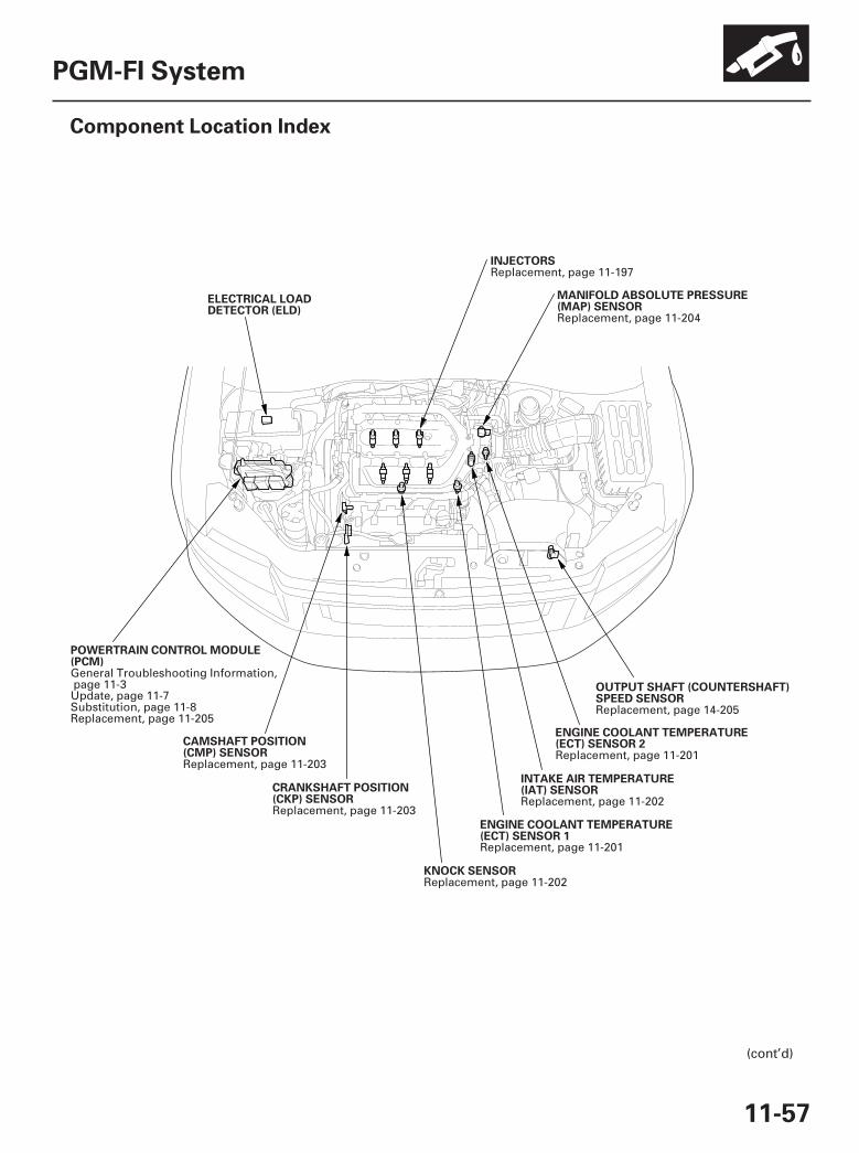
*01
SJC8A00A20326900000DAAT00
11-57
PGM-FI System
Component Location Index
INTAKE AIR TEMPERATURE(IAT) SENSOR
ELECTRICAL LOADDETECTOR (ELD)
CAMSHAFT POSITION(CMP) SENSOR
KNOCK SENSOR
ENGINE COOLANT TEMPERATURE(ECT) SENSOR 1
CRANKSHAFT POSITION(CKP) SENSOR
POWERTRAIN CONTROL MODULE(PCM)
MANIFOLD ABSOLUTE PRESSURE(MAP) SENSOR
INJECTORS
OUTPUT SHAFT (COUNTERSHAFT)SPEED SENSOR
ENGINE COOLANT TEMPERATURE(ECT) SENSOR 2
(cont’d)
Replacement, page 11-202
Replacement, page 11-203
Replacement, page 11-202
Replacement, page 11-201
Replacement, page 11-203
General Troubleshooting Information,page 11-3Update, page 11-7Substitution, page 11-8Replacement, page 11-205
Replacement, page 11-204
Replacement, page 11-197
Replacement, page 14-205
Replacement, page 11-201
07/05/09 16:46:56 61SJC020_110_0057
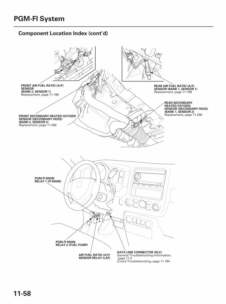
*02
*03
11-58
PGM-FI System
Component Location Index (cont’d)
REAR AIR FUEL RATIO (A/F)SENSOR (BANK 1, SENSOR 1)
FRONT AIR FUEL RATIO (A/F)SENSOR(BANK 2, SENSOR 1)
REAR SECONDARYHEATED OXYGENSENSOR (SECONDARY HO2S)(BANK 1, SENSOR 2)
FRONT SECONDARY HEATED OXYGENSENSOR (SECONDARY HO2S)(BANK 2, SENSOR 2)
PGM-FI MAINRELAY 1 (FI MAIN)
AIR FUEL RATIO (A/F)SENSOR RELAY (LAF)
PGM-FI MAINRELAY 2 (FUEL PUMP)
DATA LINK CONNECTOR (DLC)
Replacement, page 11-199Replacement, page 11-199
Replacement, page 11-200
Replacement, page 11-200
General Troubleshooting Information,page 11-3Circuit Troubleshooting, page 11-194
07/05/09 16:46:58 61SJC020_110_0058
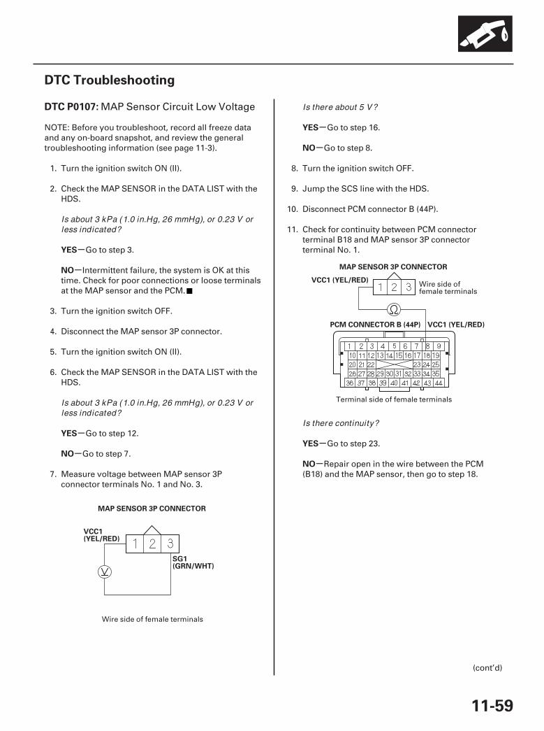
01
02
SJC8A00K77100090107FAAT30
-
-
-
-
-
-
-
-
DTC P0107:
YES
NO
YES
NO
YES
NO
YES
NO
11-59
DTC Troubleshooting
MAP SENSOR 3P CONNECTOR
VCC1(YEL/RED)
SG1(GRN/WHT)
VCC1 (YEL/RED)
PCM CONNECTOR B (44P)
MAP SENSOR 3P CONNECTOR
VCC1 (YEL/RED)
MAP Sensor Circuit Low Voltage
NOTE: Before you troubleshoot, record all freeze dataand any on-board snapshot, and review the generaltroubleshooting information (see page 11-3).
1. Turn the ignition switch ON (II).
2. Check the MAP SENSOR in the DATA LIST with theHDS.
Go to step 3.
Intermittent failure, the system is OK at thistime. Check for poor connections or loose terminalsat the MAP sensor and the PCM.
3. Turn the ignition switch OFF.
4. Disconnect the MAP sensor 3P connector.
5. Turn the ignition switch ON (II).
6. Check the MAP SENSOR in the DATA LIST with theHDS.
Go to step 12.
Go to step 7.
7. Measure voltage between MAP sensor 3Pconnector terminals No. 1 and No. 3.
Go to step 16.
Go to step 8.
8. Turn the ignition switch OFF.
9. Jump the SCS line with the HDS.
10. Disconnect PCM connector B (44P).
11. Check for continuity between PCM connectorterminal B18 and MAP sensor 3P connectorterminal No. 1.
Go to step 23.
Repair open in the wire between the PCM(B18) and the MAP sensor, then go to step 18.
(cont’d)
Wire side of female terminals
Wire side offemale terminals
Terminal side of female terminals
Is about 3 kPa (1.0 in.Hg, 26 mmHg), or 0.23 V orless indicated?
Is about 3 kPa (1.0 in.Hg, 26 mmHg), or 0.23 V orless indicated?
Is there about 5 V?
Is there continuity?
07/05/09 16:46:58 61SJC020_110_0059

03
-
-
-
-
-
-
YES
NO
YES
NO
YES
NO
11-60
PGM-FI System
DTC Troubleshooting (cont’d)
MAP(GRN/RED)
MAP SENSOR 3P CONNECTOR
12. Turn the ignition switch OFF.
13. Jump the SCS line with the HDS.
14. Disconnect PCM connector B (44P).
15. Check for continuity between MAP sensor 3Pconnector terminal No. 2 and body ground.
Repair short in the wire between the PCM(B30) and the MAP sensor, then go to step 18.
Go to step 23.
16. Turn the ignition switch OFF.
17. Replace the MAP sensor (see page 11-204).
18. Reconnect all connectors.
19. Turn the ignition switch ON (II).
20. Reset the PCM with the HDS.
21. Do the PCM idle learn procedure (see page 11-273).
22. Check for Temporary DTCs or DTCs with the HDS.
Check for poor connections or looseterminals at the MAP sensor and the PCM, then goto step 1.
Troubleshooting is complete. If any otherTemporary DTCs or DTCs are indicated, go to theindicated DTC’s troubleshooting.
23. Reconnect all connectors.
24. Update the PCM if it does not have the latestsoftware (see page 11-7), or substitute a known-good PCM (see page 11-8).
25. Check for Temporary DTCs or DTCs with the HDS.
Check for poor connections or looseterminals at the MAP sensor and the PCM. If thePCM was updated, substitute a known-good PCM(see page 11-8), then recheck. If the PCM wassubstituted, go to step 1.
If the PCM was updated, troubleshooting iscomplete. If the PCM was substituted, replace theoriginal PCM (see page 11-205). If any otherTemporary DTCs or DTCs are indicated, go to theindicated DTC’s troubleshooting.
Wire side of female terminals
Is there continuity?
Is DTC P0107 indicated?
Is DTC P0107 indicated?
07/05/09 16:46:58 61SJC020_110_0060
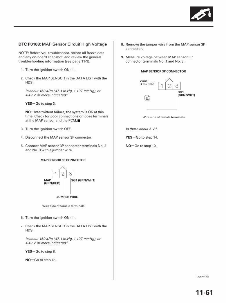
01
02
SJC8A00K77100090108FAAT30
-
-
-
-
-
-
DTC P0108:
YES
NO
YES
NO
YES
NO
11-61
MAP(GRN/RED)
JUMPER WIRE
SG1 (GRN/WHT)
MAP SENSOR 3P CONNECTOR
VCC1(YEL/RED)
SG1(GRN/WHT)
MAP SENSOR 3P CONNECTOR
MAP Sensor Circuit High Voltage
NOTE: Before you troubleshoot, record all freeze dataand any on-board snapshot, and review the generaltroubleshooting information (see page 11-3).
1. Turn the ignition switch ON (II).
2. Check the MAP SENSOR in the DATA LIST with theHDS.
Go to step 3.
Intermittent failure, the system is OK at thistime. Check for poor connections or loose terminalsat the MAP sensor and the PCM.
3. Turn the ignition switch OFF.
4. Disconnect the MAP sensor 3P connector.
5. Connect MAP sensor 3P connector terminals No. 2and No. 3 with a jumper wire.
6. Turn the ignition switch ON (II).
7. Check the MAP SENSOR in the DATA LIST with theHDS.
Go to step 8.
Go to step 18.
8. Remove the jumper wire from the MAP sensor 3Pconnector.
9. Measure voltage between MAP sensor 3Pconnector terminals No. 1 and No. 3.
Go to step 14.
Go to step 10.
(cont’d)
Wire side of female terminals
Wire side of female terminals
Is about 160 kPa (47.1 in.Hg, 1,197 mmHg), or4.49 V or more indicated?
Is about 160 kPa (47.1 in.Hg, 1,197 mmHg), or4.49 V or more indicated?
Is there about 5 V?
07/05/09 16:47:48 61SJC020_110_0061
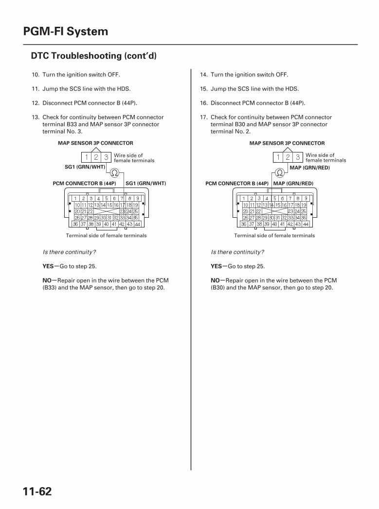
03 04
-
-
-
-
YES
NO
YES
NO
11-62
PGM-FI System
DTC Troubleshooting (cont’d)
SG1 (GRN/WHT)
PCM CONNECTOR B (44P)
MAP SENSOR 3P CONNECTOR
SG1 (GRN/WHT)
MAP (GRN/RED)
PCM CONNECTOR B (44P)
MAP SENSOR 3P CONNECTOR
MAP (GRN/RED)
10. Turn the ignition switch OFF.
11. Jump the SCS line with the HDS.
12. Disconnect PCM connector B (44P).
13. Check for continuity between PCM connectorterminal B33 and MAP sensor 3P connectorterminal No. 3.
Go to step 25.
Repair open in the wire between the PCM(B33) and the MAP sensor, then go to step 20.
14. Turn the ignition switch OFF.
15. Jump the SCS line with the HDS.
16. Disconnect PCM connector B (44P).
17. Check for continuity between PCM connectorterminal B30 and MAP sensor 3P connectorterminal No. 2.
Go to step 25.
Repair open in the wire between the PCM(B30) and the MAP sensor, then go to step 20.
Wire side offemale terminals
Terminal side of female terminals
Wire side offemale terminals
Terminal side of female terminals
Is there continuity? Is there continuity?
07/05/09 16:47:48 61SJC020_110_0062

-
-
-
-
YES
NO
YES
NO
11-63
18. Turn the ignition switch OFF.
19. Replace the MAP sensor (see page 11-204).
20. Reconnect all connectors.
21. Turn the ignition switch ON (II).
22. Reset the PCM with the HDS.
23. Do the PCM idle learn procedure (see page 11-273).
24. Check for Temporary DTCs or DTCs with the HDS.
Check for poor connections or looseterminals at the MAP sensor and the PCM, then goto step 1.
Troubleshooting is complete. If any otherTemporary DTCs or DTCs are indicated, go to theindicated DTC’s troubleshooting.
25. Reconnect all connectors.
26. Update the PCM if it does not have the latestsoftware (see page 11-7), or substitute a known-good PCM (see page 11-8).
27. Check for Temporary DTCs or DTCs with the HDS.
Check for poor connections or looseterminals at the MAP sensor and the PCM. If thePCM was updated, substitute a known-good PCM(see page 11-8), then recheck. If the PCM wassubstituted, go to step 1.
If the PCM was updated, troubleshooting iscomplete. If the PCM was substituted, replace theoriginal PCM (see page 11-205). If any otherTemporary DTCs or DTCs are indicated, go to theindicated DTC’s troubleshooting.
Is DTC P0108 indicated?
Is DTC P0108 indicated?
07/05/09 16:47:49 61SJC020_110_0063
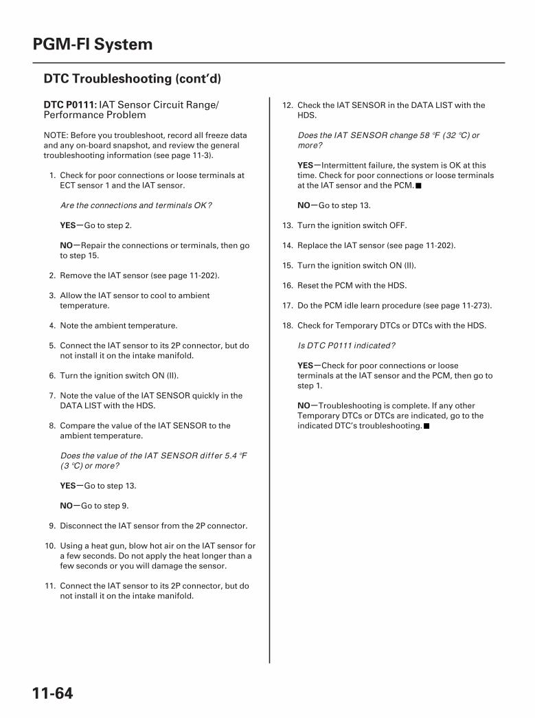
SJC8A00K77100090111FAAT00
-
-
-
-
-
-
-
-
DTC P0111:
YES
NO
YES
NO
YES
NO
YES
NO
11-64
PGM-FI System
DTC Troubleshooting (cont’d)
IAT Sensor Circuit Range/Performance Problem
NOTE: Before you troubleshoot, record all freeze dataand any on-board snapshot, and review the generaltroubleshooting information (see page 11-3).
1. Check for poor connections or loose terminals atECT sensor 1 and the IAT sensor.
Go to step 2.
Repair the connections or terminals, then goto step 15.
2. Remove the IAT sensor (see page 11-202).
3. Allow the IAT sensor to cool to ambienttemperature.
4. Note the ambient temperature.
5. Connect the IAT sensor to its 2P connector, but donot install it on the intake manifold.
6. Turn the ignition switch ON (II).
7. Note the value of the IAT SENSOR quickly in theDATA LIST with the HDS.
8. Compare the value of the IAT SENSOR to theambient temperature.
Go to step 13.
Go to step 9.
9. Disconnect the IAT sensor from the 2P connector.
10. Using a heat gun, blow hot air on the IAT sensor fora few seconds. Do not apply the heat longer than afew seconds or you will damage the sensor.
11. Connect the IAT sensor to its 2P connector, but donot install it on the intake manifold.
12. Check the IAT SENSOR in the DATA LIST with theHDS.
Intermittent failure, the system is OK at thistime. Check for poor connections or loose terminalsat the IAT sensor and the PCM.
Go to step 13.
13. Turn the ignition switch OFF.
14. Replace the IAT sensor (see page 11-202).
15. Turn the ignition switch ON (II).
16. Reset the PCM with the HDS.
17. Do the PCM idle learn procedure (see page 11-273).
18. Check for Temporary DTCs or DTCs with the HDS.
Check for poor connections or looseterminals at the IAT sensor and the PCM, then go tostep 1.
Troubleshooting is complete. If any otherTemporary DTCs or DTCs are indicated, go to theindicated DTC’s troubleshooting.
Are the connections and terminals OK ?
Does the value of the IAT SENSOR dif f er 5.4 °F(3 °C) or more?
Does the IAT SENSOR change 58 °F (32 °C) ormore?
Is DTC P0111 indicated?
07/05/09 16:47:49 61SJC020_110_0064
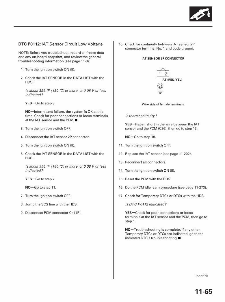
01
SJC8A00K77100090112FAAT30
-
-
-
-
-
-
-
-
DTC P0112:
YES
NO
YES
NO
YES
NO
YES
NO
11-65
IAT SENSOR 2P CONNECTOR
IAT (RED/YEL)
IAT Sensor Circuit Low Voltage
NOTE: Before you troubleshoot, record all freeze dataand any on-board snapshot, and review the generaltroubleshooting information (see page 11-3).
1. Turn the ignition switch ON (II).
2. Check the IAT SENSOR in the DATA LIST with theHDS.
Go to step 3.
Intermittent failure, the system is OK at thistime. Check for poor connections or loose terminalsat the IAT sensor and the PCM.
3. Turn the ignition switch OFF.
4. Disconnect the IAT sensor 2P connector.
5. Turn the ignition switch ON (II).
6. Check the IAT SENSOR in the DATA LIST with theHDS.
Go to step 7.
Go to step 11.
7. Turn the ignition switch OFF.
8. Jump the SCS line with the HDS.
9. Disconnect PCM connector C (44P).
10. Check for continuity between IAT sensor 2Pconnector terminal No. 1 and body ground.
Repair short in the wire between the IATsensor and the PCM (C26), then go to step 13.
Go to step 18.
11. Turn the ignition switch OFF.
12. Replace the IAT sensor (see page 11-202).
13. Reconnect all connectors.
14. Turn the ignition switch ON (II).
15. Reset the PCM with the HDS.
16. Do the PCM idle learn procedure (see page 11-273).
17. Check for Temporary DTCs or DTCs with the HDS.
Check for poor connections or looseterminals at the IAT sensor and the PCM, then go tostep 1.
Troubleshooting is complete. If any otherTemporary DTCs or DTCs are indicated, go to theindicated DTC’s troubleshooting.
(cont’d)
Wire side of female terminals
Is about 356 °F (180 °C) or more, or 0.08 V or lessindicated?
Is about 356 °F (180 °C) or more, or 0.08 V or lessindicated?
Is there continuity?
Is DTC P0112 indicated?
07/05/09 16:47:49 61SJC020_110_0065
-
-
YES
NO
11-66
PGM-FI System
DTC Troubleshooting (cont’d)
18. Reconnect all connectors.
19. Update the PCM if it does not have the latestsoftware (see page 11-7), or substitute a known-good PCM (see page 11-8).
20. Check for Temporary DTCs or DTCs with the HDS.
Check for poor connections or looseterminals at the IAT sensor and the PCM. If the PCMwas updated, substitute a known-good PCM(see page 11-8), then recheck. If the PCM wassubstituted, go to step 1.
If the PCM was updated, troubleshooting iscomplete. If the PCM was substituted, replace theoriginal PCM (see page 11-205). If any otherTemporary DTCs or DTCs are indicated, go to theindicated DTC’s troubleshooting.
Is DTC P0112 indicated?
07/05/09 16:47:49 61SJC020_110_0066
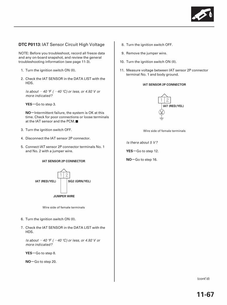
- -
- -
01
02
SJC8A00K77100090113FAAT30
-
-
-
-
-
-
DTC P0113:
YES
NO
YES
NO
YES
NO
11-67
IAT SENSOR 2P CONNECTOR
IAT (RED/YEL) SG2 (GRN/YEL)
JUMPER WIRE
IAT SENSOR 2P CONNECTOR
IAT (RED/YEL)
IAT Sensor Circuit High Voltage
NOTE: Before you troubleshoot, record all freeze dataand any on-board snapshot, and review the generaltroubleshooting information (see page 11-3).
1. Turn the ignition switch ON (II).
2. Check the IAT SENSOR in the DATA LIST with theHDS.
Go to step 3.
Intermittent failure, the system is OK at thistime. Check for poor connections or loose terminalsat the IAT sensor and the PCM.
3. Turn the ignition switch OFF.
4. Disconnect the IAT sensor 2P connector.
5. Connect IAT sensor 2P connector terminals No. 1and No. 2 with a jumper wire.
6. Turn the ignition switch ON (II).
7. Check the IAT SENSOR in the DATA LIST with theHDS.
Go to step 8.
Go to step 20.
8. Turn the ignition switch OFF.
9. Remove the jumper wire.
10. Turn the ignition switch ON (II).
11. Measure voltage between IAT sensor 2P connectorterminal No. 1 and body ground.
Go to step 12.
Go to step 16.
(cont’d)
Wire side of female terminals
Wire side of female terminals
Is about 40 °F ( 40 °C) or less, or 4.92 V ormore indicated?
Is about 40 °F ( 40 °C) or less, or 4.92 V ormore indicated?
Is there about 5 V?
07/05/09 16:47:49 61SJC020_110_0067

03 04
-
-
-
-
YES
NO
YES
NO
11-68
PGM-FI System
DTC Troubleshooting (cont’d)
PCM CONNECTOR C (44P)
IAT SENSOR 2P CONNECTOR
SG2 (GRN/YEL)
SG2 (GRN/YEL)
PCM CONNECTOR C (44P)
IAT SENSOR 2P CONNECTOR
IAT (RED/YEL)
IAT (RED/YEL)
12. Turn the ignition switch OFF.
13. Jump the SCS line with the HDS.
14. Disconnect PCM connector C (44P).
15. Check for continuity between PCM connectorterminal C14 and IAT sensor 2P connector terminalNo. 2.
Go to step 27.
Repair open in the wire between the PCM(C14) and the IAT sensor, then go to step 22.
16. Turn the ignition switch OFF.
17. Jump the SCS line with the HDS.
18. Disconnect PCM connector C (44P).
19. Check for continuity between PCM connectorterminal C26 and IAT sensor 2P connector terminalNo. 1.
Go to step 27.
Repair open in the wire between the PCM(C26) and the IAT sensor, then go to step 22.
Wire side offemale terminals
Terminal side of female terminals
Wire side offemale terminals
Terminal side of female terminals
Is there continuity? Is there continuity?
07/05/09 16:47:50 61SJC020_110_0068

-
-
-
-
YES
NO
YES
NO
11-69
20. Turn the ignition switch OFF.
21. Replace the IAT sensor (see page 11-202).
22. Reconnect all connectors.
23. Turn the ignition switch ON (II).
24. Reset the PCM with the HDS.
25. Do the PCM idle learn procedure (see page 11-273).
26. Check for Temporary DTCs or DTCs with the HDS.
Check for poor connections or looseterminals at the IAT sensor and the PCM, then go tostep 1.
Troubleshooting is complete. If any otherTemporary DTCs or DTCs are indicated, go to theindicated DTC’s troubleshooting.
27. Reconnect all connectors.
28. Update the PCM if it does not have the latestsoftware (see page 11-7), or substitute a known-good PCM (see page 11-8).
29. Check for Temporary DTCs or DTCs with the HDS.
Check for poor connections or looseterminals at the IAT sensor and the PCM. If the PCMwas updated, substitute a known-good PCM(see page 11-8), then recheck. If the PCM wassubstituted, go to step 1.
If the PCM was updated, troubleshooting iscomplete. If the PCM was substituted, replace theoriginal PCM (see page 11-205). If any otherTemporary DTCs or DTCs are indicated, go to theindicated DTC’s troubleshooting.
Is DTC P0113 indicated?
Is DTC P0113 indicated?
07/05/09 16:47:50 61SJC020_110_0069
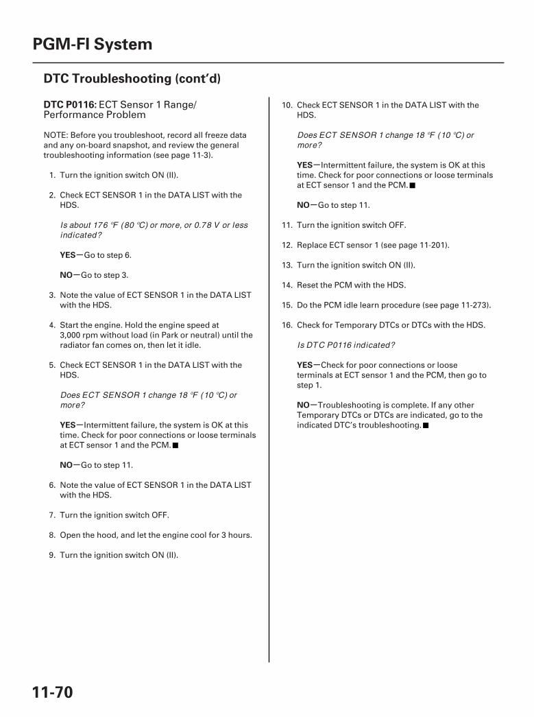
SJC8A00K77100090116FAAT30
-
-
-
-
-
-
-
-
DTC P0116:
YES
NO
YES
NO
YES
NO
YES
NO
11-70
PGM-FI System
DTC Troubleshooting (cont’d)
ECT Sensor 1 Range/Performance Problem
NOTE: Before you troubleshoot, record all freeze dataand any on-board snapshot, and review the generaltroubleshooting information (see page 11-3).
1. Turn the ignition switch ON (II).
2. Check ECT SENSOR 1 in the DATA LIST with theHDS.
Go to step 6.
Go to step 3.
3. Note the value of ECT SENSOR 1 in the DATA LISTwith the HDS.
4. Start the engine. Hold the engine speed at3,000 rpm without load (in Park or neutral) until theradiator fan comes on, then let it idle.
5. Check ECT SENSOR 1 in the DATA LIST with theHDS.
Intermittent failure, the system is OK at thistime. Check for poor connections or loose terminalsat ECT sensor 1 and the PCM.
Go to step 11.
6. Note the value of ECT SENSOR 1 in the DATA LISTwith the HDS.
7. Turn the ignition switch OFF.
8. Open the hood, and let the engine cool for 3 hours.
9. Turn the ignition switch ON (II).
10. Check ECT SENSOR 1 in the DATA LIST with theHDS.
Intermittent failure, the system is OK at thistime. Check for poor connections or loose terminalsat ECT sensor 1 and the PCM.
Go to step 11.
11. Turn the ignition switch OFF.
12. Replace ECT sensor 1 (see page 11-201).
13. Turn the ignition switch ON (II).
14. Reset the PCM with the HDS.
15. Do the PCM idle learn procedure (see page 11-273).
16. Check for Temporary DTCs or DTCs with the HDS.
Check for poor connections or looseterminals at ECT sensor 1 and the PCM, then go tostep 1.
Troubleshooting is complete. If any otherTemporary DTCs or DTCs are indicated, go to theindicated DTC’s troubleshooting.
Is about 176 °F (80 °C) or more, or 0.78 V or lessindicated?
Does ECT SENSOR 1 change 18 °F (10 °C) ormore?
Does ECT SENSOR 1 change 18 °F (10 °C) ormore?
Is DTC P0116 indicated?
07/05/09 16:47:50 61SJC020_110_0070

01
SJC8A00K77100090117FAAT30
-
-
-
-
-
-
-
-
DTC P0117:
YES
NO
YES
NO
YES
NO
YES
NO
11-71
ECT SENSOR 1 2P CONNECTOR
ECT1 (RED/WHT)
ECT Sensor 1 Circuit Low Voltage
NOTE: Before you troubleshoot, record all freeze dataand any on-board snapshot, and review the generaltroubleshooting information (see page 11-3).
1. Turn the ignition switch ON (II).
2. Check ECT SENSOR 1 in the DATA LIST with theHDS.
Go to step 3.
Intermittent failure, the system is OK at thistime. Check for poor connections or loose terminalsat ECT sensor 1 and the PCM.
3. Turn the ignition switch OFF.
4. Disconnect the ECT sensor 1 2P connector.
5. Turn the ignition switch ON (II).
6. Check ECT SENSOR 1 in the DATA LIST with theHDS.
Go to step 7.
Go to step 11.
7. Turn the ignition switch OFF.
8. Jump the SCS line with the HDS.
9. Disconnect PCM connector C (44P).
10. Check for continuity between ECT sensor 1 2Pconnector terminal No. 1 and body ground.
Repair short in the wire between ECTsensor 1 and the PCM (C27), then go to step 13.
Go to step 18.
11. Turn the ignition switch OFF.
12. Replace ECT sensor 1 (see page 11-201).
13. Reconnect all connectors.
14. Turn the ignition switch ON (II).
15. Reset the PCM with the HDS.
16. Do the PCM idle learn procedure (see page 11-273).
17. Check for Temporary DTCs or DTCs with the HDS.
Check for poor connections or looseterminals at ECT sensor 1 and the PCM, then go tostep 1.
Troubleshooting is complete. If any otherTemporary DTCs or DTCs are indicated, go to theindicated DTC’s troubleshooting.
(cont’d)
Wire side of female terminals
Is about 356 °F (180 °C) or more, or 0.08 V or lessindicated?
Is about 356 °F (180 °C) or more, or 0.08 V or lessindicated?
Is there continuity?
Is DTC P0117 indicated?
07/05/09 16:47:50 61SJC020_110_0071

-
-
YES
NO
11-72
PGM-FI System
DTC Troubleshooting (cont’d)
18. Reconnect all connectors.
19. Update the PCM if it does not have the latestsoftware (see page 11-7), or substitute a known-good PCM (see page 11-8).
20. Check for Temporary DTCs or DTCs with the HDS.
Check for poor connections or looseterminals at ECT sensor 1 and the PCM. If the PCMwas updated, substitute a known-good PCM(see page 11-8), then recheck. If the PCM wassubstituted, go to step 1.
If the PCM was updated, troubleshooting iscomplete. If the PCM was substituted, replace theoriginal PCM (see page 11-205). If any otherTemporary DTCs or DTCs are indicated, go to theindicated DTC’s troubleshooting.
Is DTC P0117 indicated?
07/05/09 16:47:50 61SJC020_110_0072
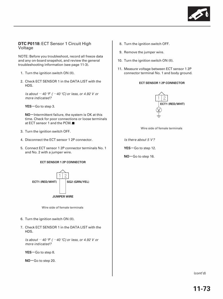
- -
- -
01
02
SJC8A00K77100090118FAAT30
-
-
-
-
-
-
DTC P0118:
YES
NO
YES
NO
YES
NO
11-73
SG2 (GRN/YEL)
JUMPER WIRE
ECT SENSOR 1 2P CONNECTOR
ECT1 (RED/WHT)
ECT SENSOR 1 2P CONNECTOR
ECT1 (RED/WHT)
ECT Sensor 1 Circuit HighVoltage
NOTE: Before you troubleshoot, record all freeze dataand any on-board snapshot, and review the generaltroubleshooting information (see page 11-3).
1. Turn the ignition switch ON (II).
2. Check ECT SENSOR 1 in the DATA LIST with theHDS.
Go to step 3.
Intermittent failure, the system is OK at thistime. Check for poor connections or loose terminalsat ECT sensor 1 and the PCM.
3. Turn the ignition switch OFF.
4. Disconnect the ECT sensor 1 2P connector.
5. Connect ECT sensor 1 2P connector terminals No. 1and No. 2 with a jumper wire.
6. Turn the ignition switch ON (II).
7. Check ECT SENSOR 1 in the DATA LIST with theHDS.
Go to step 8.
Go to step 20.
8. Turn the ignition switch OFF.
9. Remove the jumper wire.
10. Turn the ignition switch ON (II).
11. Measure voltage between ECT sensor 1 2Pconnector terminal No. 1 and body ground.
Go to step 12.
Go to step 16.
(cont’d)
Wire side of female terminals
Wire side of female terminals
Is about 40 °F ( 40 °C) or less, or 4.92 V ormore indicated?
Is about 40 °F ( 40 °C) or less, or 4.92 V ormore indicated?
Is there about 5 V?
07/05/09 16:47:51 61SJC020_110_0073

03 04
-
-
-
-
YES
NO
YES
NO
11-74
PGM-FI System
DTC Troubleshooting (cont’d)
PCM CONNECTOR C (44P)
ECT SENSOR 1 2P CONNECTOR
SG2 (GRN/YEL)
SG2 (GRN/YEL)
PCM CONNECTOR C (44P)
ECT1 (RED/WHT)
ECT SENSOR 1 2P CONNECTOR
ECT1 (RED/WHT)
12. Turn the ignition switch OFF.
13. Jump the SCS line with the HDS.
14. Disconnect PCM connector C (44P).
15. Check for continuity between PCM connectorterminal C14 and ECT sensor 1 2P connectorterminal No. 2.
Go to step 27.
Repair open in the wire between the PCM(C14) and ECT sensor 1, then go to step 22.
16. Turn the ignition switch OFF.
17. Jump the SCS line with the HDS.
18. Disconnect PCM connector C (44P).
19. Check for continuity between PCM connectorterminal C27 and ECT sensor 1 2P connectorterminal No. 1.
Go to step 27.
Repair open in the wire between the PCM(C27) and ECT sensor 1, then go to step 22.
Wire side offemale terminals
Terminal side of female terminals
Wire side offemale terminals
Terminal side of female terminals
Is there continuity? Is there continuity?
07/05/09 16:47:51 61SJC020_110_0074

-
-
-
-
YES
NO
YES
NO
11-75
20. Turn the ignition switch OFF.
21. Replace ECT sensor 1 (see page 11-201).
22. Reconnect all connectors.
23. Turn the ignition switch ON (II).
24. Reset the PCM with the HDS.
25. Do the PCM idle learn procedure (see page 11-273).
26. Check for Temporary DTCs or DTCs with the HDS.
Check for poor connections or looseterminals at ECT sensor 1 and the PCM, then go tostep 1.
Troubleshooting is complete. If any otherTemporary DTCs or DTCs are indicated, go to theindicated DTC’s troubleshooting.
27. Reconnect all connectors.
28. Update the PCM if it does not have the latestsoftware (see page 11-7), or substitute a known-good PCM (see page 11-8).
29. Check for Temporary DTCs or DTCs with the HDS.
Check for poor connections or looseterminals at ECT sensor 1 and the PCM. If the PCMwas updated, substitute a known-good PCM(see page 11-8), then recheck. If the PCM wassubstituted, go to step 1.
If the PCM was updated, troubleshooting iscomplete. If the PCM was substituted, replace theoriginal PCM (see page 11-205). If any otherTemporary DTCs or DTCs are indicated, go to theindicated DTC’s troubleshooting.
Is DTC P0118 indicated?
Is DTC P0118 indicated?
07/05/09 16:47:51 61SJC020_110_0075

-
SJC8A00K77100090125FAAT30
-
-
-
-
-
-
-
-
DTC P0125:
YES
NO
YES
NO
YES
NO
YES
NO
11-76
PGM-FI System
DTC Troubleshooting (cont’d)
ECT Sensor 1 Malfunction/SlowResponse
NOTE: Before you troubleshoot, record all freeze dataand any on-board snapshot, and review the generaltroubleshooting information (see page 11-3).
1. Start the engine, and let it idle for 5 minutes ormore.
2. Check ECT SENSOR 1 in the DATA LIST with theHDS.
Go to step 9.
Go to step 3.
3. Allow the engine to cool to 104 °F (40 °C) or less.
4. Note the value of ECT SENSOR 1 and ECTSENSOR 2 in the DATA LIST with the HDS.
5. Start the engine, and let it idle.
6. Let the engine idle until ECT SENSOR 1 goes up49 °F (27 °C) or more from the recordedtemperature.
7. Note the value of ECT SENSOR 2 in the DATA LISTwith the HDS.
8. Compare ECT SENSOR 2 and the recordedtemperature.
Intermittent failure, the system is OK at thistime. Check for poor connections or loose terminalsat ECT sensor 1, ECT sensor 2, and the PCM.
Test the thermostat (see page 10-4). If thethermostat is OK, go to step 9. If you replaced thethermostat, go to step 11.
9. Turn the ignition switch OFF.
10. Replace ECT sensor 1 (see page 11-201).
11. Turn the ignition switch ON (II).
12. Reset the PCM with the HDS.
13. Do the PCM idle learn procedure (see page 11-273).
14. Allow the engine to cool to the ambienttemperature.
15. Start the engine, and let it idle 20 minutes.
16. Check for Temporary DTCs or DTCs with the HDS.
Check for poor connections or looseterminals at ECT sensor 1, ECT sensor 2, and thePCM, then go to step 1.
Go to step 17.
17. Monitor the OBD STATUS for DTC P0125 in theDTCs MENU with the HDS.
Troubleshooting is complete. If any otherTemporary DTCs or DTCs were indicated in step 16,go to the indicated DTC’s troubleshooting.
If the screen indicates FAILED, check for poorconnections or loose terminals at ECT sensor 1,ECT sensor 2, and the PCM, then go to step 1. If thescreen indicates NOT COMPLETED, go to step 15.
Is about 10 °F ( 12 °C) or less, or 4.45 V or moreindicated?
Did ECT SENSOR 2 change 17 °F (9.5 °C) ormore?
Is DTC P0125 indicated?
Does the screen indicate PASSED?
07/05/09 16:47:51 61SJC020_110_0076
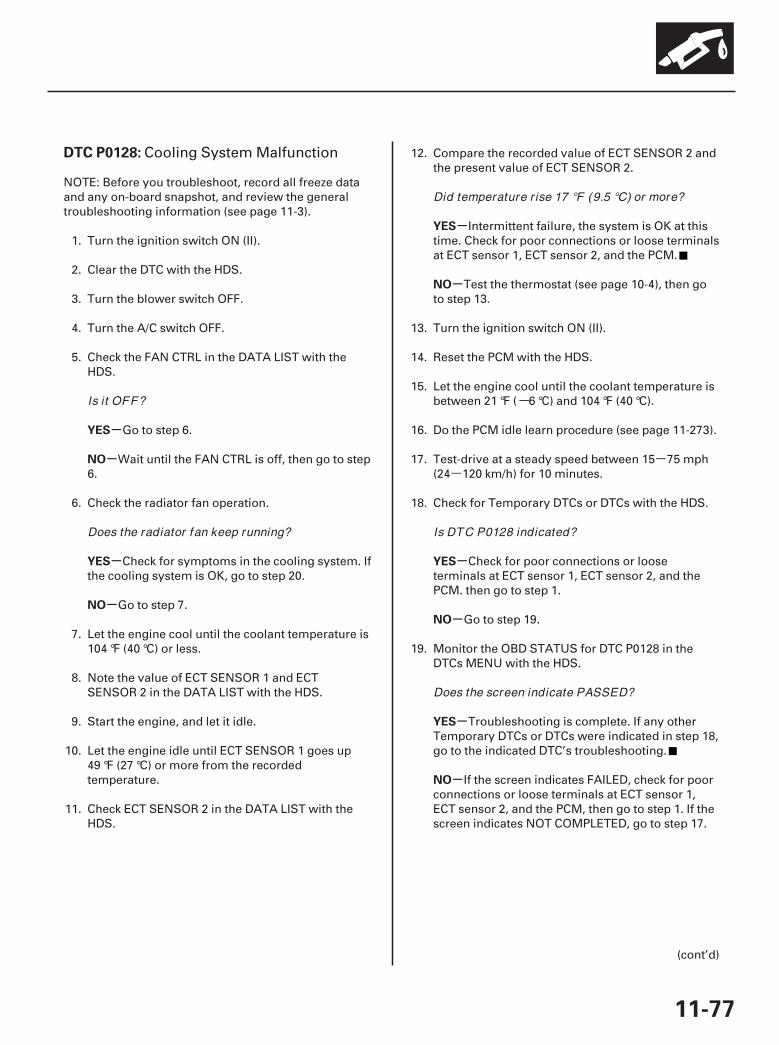
-
--
SJC8A00K77100090128FAAT30
-
-
-
-
-
-
-
-
-
-
DTC P0128:
YES
NO
YES
NO
YES
NO
YES
NO
YES
NO
11-77
Cooling System Malfunction
NOTE: Before you troubleshoot, record all freeze dataand any on-board snapshot, and review the generaltroubleshooting information (see page 11-3).
1. Turn the ignition switch ON (II).
2. Clear the DTC with the HDS.
3. Turn the blower switch OFF.
4. Turn the A/C switch OFF.
5. Check the FAN CTRL in the DATA LIST with theHDS.
Go to step 6.
Wait until the FAN CTRL is off, then go to step6.
6. Check the radiator fan operation.
Check for symptoms in the cooling system. Ifthe cooling system is OK, go to step 20.
Go to step 7.
7. Let the engine cool until the coolant temperature is104 °F (40 °C) or less.
8. Note the value of ECT SENSOR 1 and ECTSENSOR 2 in the DATA LIST with the HDS.
9. Start the engine, and let it idle.
10. Let the engine idle until ECT SENSOR 1 goes up49 °F (27 °C) or more from the recordedtemperature.
11. Check ECT SENSOR 2 in the DATA LIST with theHDS.
12. Compare the recorded value of ECT SENSOR 2 andthe present value of ECT SENSOR 2.
Intermittent failure, the system is OK at thistime. Check for poor connections or loose terminalsat ECT sensor 1, ECT sensor 2, and the PCM.
Test the thermostat (see page 10-4), then goto step 13.
13. Turn the ignition switch ON (II).
14. Reset the PCM with the HDS.
15. Let the engine cool until the coolant temperature isbetween 21 °F ( 6 °C) and 104 °F (40 °C).
16. Do the PCM idle learn procedure (see page 11-273).
17. Test-drive at a steady speed between 15 75 mph(24 120 km/h) for 10 minutes.
18. Check for Temporary DTCs or DTCs with the HDS.
Check for poor connections or looseterminals at ECT sensor 1, ECT sensor 2, and thePCM. then go to step 1.
Go to step 19.
19. Monitor the OBD STATUS for DTC P0128 in theDTCs MENU with the HDS.
Troubleshooting is complete. If any otherTemporary DTCs or DTCs were indicated in step 18,go to the indicated DTC’s troubleshooting.
If the screen indicates FAILED, check for poorconnections or loose terminals at ECT sensor 1,ECT sensor 2, and the PCM, then go to step 1. If thescreen indicates NOT COMPLETED, go to step 17.
(cont’d)
Is it OFF?
Does the radiator fan keep running?
Did temperature r ise 17 °F (9.5 °C) or more?
Is DTC P0128 indicated?
Does the screen indicate PASSED?
07/05/09 16:47:51 61SJC020_110_0077
-
--
-
-
-
-
YES
NO
YES
NO
11-78
PGM-FI System
DTC Troubleshooting (cont’d)
20. Update the PCM if it does not have the latestsoftware (see page 11-7), or substitute a known-good PCM (see page 11-8).
21. Let the engine cool until the coolant temperature isbetween 21 °F ( 6 °C) and 104 °F (40 °C).
22. Start the engine. Hold the engine speed at3,000 rpm without load (in Park or neutral) until theradiator fan comes on, then let it idle.
23. Test-drive at a steady speed between 15 75 mph(24 120 km/h) for 10 minutes.
24. Check for Temporary DTCs or DTCs with the HDS.
Check for poor connections or looseterminals at ECT sensor 1, ECT sensor 2, and thePCM. If the PCM was updated, substitute a known-good PCM (see page 11-8), then go to step 21. If thePCM was substituted, go to step 1.
Go to step 25.
25. Monitor the OBD STATUS for DTC P0128 in theDTCs MENU with the HDS.
If the PCM was updated, troubleshooting iscomplete. If the PCM was substituted, replace theoriginal PCM (see page 11-205). If any otherTemporary DTCs or DTCs were indicated in step 24,go to the indicated DTC’s troubleshooting.
If the screen indicates FAILED, check for poorconnections or loose terminals at ECT sensor 1,ECT sensor 2, and the PCM. If the PCM was updated,substitute a known-good PCM (see page 11-8), thengo to step 21. If the PCM was substituted, go to step1. If the screen indicates NOT COMPLETED, go tostep 21.
Is DTC P0128 indicated?
Does the screen indicate PASSED?
07/05/09 16:47:51 61SJC020_110_0078
- -
- -
SJC8A00K77100090133FAAT30
-
-
-
-
-
-
DTC P0133:
DTC P0153:
YES
NO
YES
NO
YES
NO
11-79
Rear A/F Sensor (Bank 1,Sensor 1) Circuit Slow Response
Front A/F Sensor (Bank 2,Sensor 1) Circuit Slow Response
NOTE:• Before you troubleshoot, record all freeze data and
any on-board snapshot, and review the generaltroubleshooting information (see page 11-3).
• If DTC P0139 and/or P0159 is stored at the same timeas DTC P0133 and/or P0153 , troubleshoot DTC P0139and/or P0159 first, then recheck for DTC P0133 and/or P0153 .
• Information marked with an asterisk ( ) applies to thefront bank (Bank 2).
1. Turn the ignition switch ON (II).
2. Clear the DTC with the HDS.
3. Start the engine. Hold the engine speed at3,000 rpm without load (in Park or neutral) until theradiator fan comes on, then let it idle.
4. Test-drive under these conditions:
• Engine coolant temperature (ECT SENSOR 1)above 176 °F (80 °C)
• Transmission in D position• Drive the vehicle at 25 mph (40 km/h) or less for
5 minutes, then drive at a steady speed between26 81 mph (41 130 km/h)
5. Monitor the OBD STATUS for DTC P0133 and/orP0153 in the DTCs MENU with the HDS.
Go to step 6.
If the screen indicates PASSED, intermittentfailure, the system is OK at this time. Check forpoor connections or loose terminals at the A/Fsensor (Sensor 1) and the PCM. If the screenindicates EXECUTING, keep driving until a resultcomes on. If the screen indicates OUT OFCONDITION, go to step 3 and recheck.
6. Turn the ignition switch OFF.
7. Replace the A/F sensor (Sensor 1) (see page11-199).
8. Turn the ignition switch ON (II).
9. Reset the PCM with the HDS.
10. Do the PCM idle learn procedure (see page 11-273).
11. Start the engine. Hold the engine speed at3,000 rpm without load (in Park or neutral) until theradiator fan comes on, then let it idle.
12. Test-drive under these conditions:
• Engine coolant temperature (ECT SENSOR 1)above 176 °F (80 °C)
• Transmission in D position• Drive the vehicle at 25 mph (40 km/h) or less for
5 minutes, then drive at a steady speed between26 81 mph (41 130 km/h)
13. Check for Temporary DTCs or DTCs with the HDS.
Check for poor connections or looseterminals at the A/F sensor (Sensor 1) and the PCM,then go to step 1.
Go to step 14.
14. Monitor the OBD STATUS for DTC P0133 and/orP0153 in the DTCs MENU with the HDS.
Troubleshooting is complete. If any otherTemporary DTCs or DTCs were indicated in step 13,go to the indicated DTC’s troubleshooting.
If the screen indicates FAILED, check for poorconnections or loose terminals at the A/F sensor(Sensor 1) and the PCM, then go to step 1. If thescreen indicates EXECUTING, keep driving until aresult comes on. If the screen indicates OUT OFCONDITION, go to step 12.
Does the screen indicate FAILED?
Is DTC P0133 and/ or P0153 indicated?
Does the screen indicate PASSED?
07/05/09 16:47:52 61SJC020_110_0079
SJC8A00K77100090134FAAT30
-
-
-
-
-
-
DTC P0134:
DTC P0154:
YES
NO
YES
NO
YES
NO
11-80
PGM-FI System
DTC Troubleshooting (cont’d)
Rear A/F Sensor (Bank 1,Sensor 1) Heater System Malfunction
Front A/F Sensor (Bank 2,Sensor 1) Heater System Malfunction
NOTE:• Before you troubleshoot, record all freeze data and
any on-board snapshot, and review the generaltroubleshooting information (see page 11-3).
• If DTC P2251, P2237, P2240 , and/or P2254 is storedat the same time as DTC P0134 and/or P0154 ,troubleshoot DTC P2251, P2237, P2240 and/orP2254 first, then recheck for P0134 and/or P0154 .
• Information marked with an asterisk ( ) applies to thefront bank (Bank 2).
1. Turn the ignition switch ON (II).
2. Clear the DTC with the HDS.
3. Start the engine, and let it idle without load (in Parkor neutral) until the radiator fan comes on.
4. Check for Temporary DTCs or DTCs with the HDS.
Go to step 5.
Intermittent failure, the system is OK at thistime. Check for poor connections or loose terminalsat the A/F sensor (Sensor 1), the A/F sensor relay(LAF), the under-dash fuse/relay box, and thePCM.
5. Turn the ignition switch OFF.
6. Replace the A/F sensor (Sensor 1) (see page11-199).
7. Turn the ignition switch ON (II).
8. Reset the PCM with the HDS.
9. Do the PCM idle learn procedure (see page 11-273).
10. Start the engine. Hold the engine speed at3,000 rpm without load (in Park or neutral) until theradiator fan comes on, then let it idle.
11. Check for Temporary DTCs or DTCs with the HDS.
Check for poor connections or looseterminals at the A/F sensor (Sensor 1), the A/Fsensor relay (LAF), the under-dash fuse/relay box,and the PCM, then go to step 1.
Go to step 12.
12. Monitor the OBD STATUS for DTC P0134 and/orP0154 in the DTCs MENU with the HDS.
Troubleshooting is complete. If any otherTemporary DTCs or DTCs were indicated in step 11,go to the indicated DTC’s troubleshooting.
If the screen indicates FAILED, check for poorconnections or loose terminals at the A/F sensor(Sensor 1), the A/F sensor relay (LAF), the under-dash fuse/relay box, and the PCM, then go to step1. If the screen indicates NOT COMPLETED, keepidling until a result comes on.
Is DTC P0134 and/ or P0154 indicated?
Is DTC P0134 and/ or P0154 indicated?
Does the screen indicate PASSED?
07/05/09 16:47:52 61SJC020_110_0080
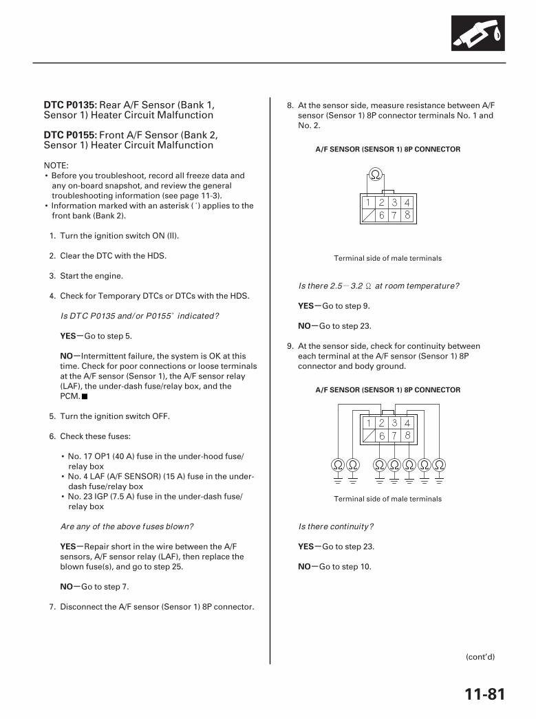
-
01
02
SJC8A00K77100090135FAAT30
-
-
-
-
-
-
-
-
DTC P0135:
DTC P0155:
YES
NO
YES
NO
YES
NO
YES
NO
11-81
A/F SENSOR (SENSOR 1) 8P CONNECTOR
A/F SENSOR (SENSOR 1) 8P CONNECTOR
Rear A/F Sensor (Bank 1,Sensor 1) Heater Circuit Malfunction
Front A/F Sensor (Bank 2,Sensor 1) Heater Circuit Malfunction
NOTE:• Before you troubleshoot, record all freeze data and
any on-board snapshot, and review the generaltroubleshooting information (see page 11-3).
• Information marked with an asterisk ( ) applies to thefront bank (Bank 2).
1. Turn the ignition switch ON (II).
2. Clear the DTC with the HDS.
3. Start the engine.
4. Check for Temporary DTCs or DTCs with the HDS.
Go to step 5.
Intermittent failure, the system is OK at thistime. Check for poor connections or loose terminalsat the A/F sensor (Sensor 1), the A/F sensor relay(LAF), the under-dash fuse/relay box, and thePCM.
5. Turn the ignition switch OFF.
6. Check these fuses:
• No. 17 OP1 (40 A) fuse in the under-hood fuse/relay box
• No. 4 LAF (A/F SENSOR) (15 A) fuse in the under-dash fuse/relay box
• No. 23 IGP (7.5 A) fuse in the under-dash fuse/relay box
Repair short in the wire between the A/Fsensors, A/F sensor relay (LAF), then replace theblown fuse(s), and go to step 25.
Go to step 7.
7. Disconnect the A/F sensor (Sensor 1) 8P connector.
8. At the sensor side, measure resistance between A/Fsensor (Sensor 1) 8P connector terminals No. 1 andNo. 2.
Go to step 9.
Go to step 23.
9. At the sensor side, check for continuity betweeneach terminal at the A/F sensor (Sensor 1) 8Pconnector and body ground.
Go to step 23.
Go to step 10.
(cont’d)
Terminal side of male terminals
Terminal side of male terminals
Is DTC P0135 and/ or P0155 indicated?
Are any of the above fuses blown?
Is there 2.5 3.2 at room temperature?
Is there continuity?
07/05/09 16:47:52 61SJC020_110_0081

03
04
05
06
-
-
-
-
-
-
YES
NO
YES
NO
YES
NO
11-82
PGM-FI System
DTC Troubleshooting (cont’d)
A/F SENSOR (SENSOR 1) 8P CONNECTOR
PCM CONNECTOR C (44P)
AFSHTCB1(BLK/WHT)
AFSHTCB2(GRN/WHT)*
AFSHTCB1 (BLK/WHT)
AFSHTCB2 (GRN/WHT)*
JUMPER WIRE
A/F SENSOR (SENSOR 1) 8P CONNECTOR
PCM CONNECTOR C (44P)
AFSHTCB1(BLK/WHT)
AFSHTCB2(GRN/WHT)*
10. At the sensor side, check for continuity betweenA/F sensor (Sensor 1) 8P connector terminals No. 1and No. 3, No. 1 and No. 4, No. 1 and No. 6, No. 1and No. 7, and No. 1 and No. 8 individually.
Go to step 23.
Go to step 11.
11. Jump the SCS line with the HDS.
12. Disconnect PCM connector C (44P).
13. Check for continuity between PCM connectorterminal C6 (C8) and body ground.
Repair short in the wire between the PCM(C6 (C8) ) and the A/F sensor (Sensor 1), then go tostep 24.
Go to step 14.
14. Connect A/F sensor (Sensor 1) 8P connectorterminal No. 2 to body ground with a jumper wire.
15. Check for continuity between PCM connectorterminal C6 (C8) and body ground.
Go to step 16.
Repair open in the wire between the PCM(C6 (C8) ) and the A/F sensor (Sensor 1), then go tostep 24.
Terminal side of male terminals
Terminal side of female terminals
Wire side of female terminals
Terminal side of female terminals
Is there continuity?
Is there continuity?
Is there continuity?
07/05/09 16:47:53 61SJC020_110_0082
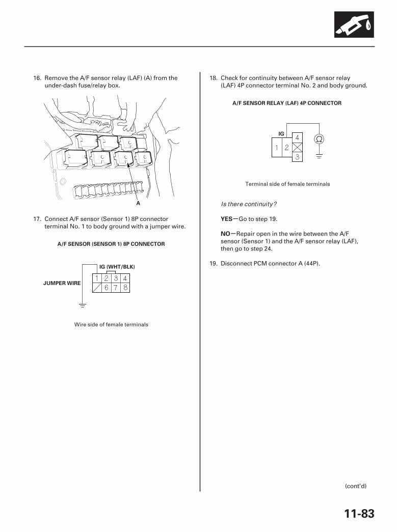
08
07
09
-
-
YES
NO
11-83
A
IG (WHT/BLK)
JUMPER WIRE
A/F SENSOR (SENSOR 1) 8P CONNECTOR
A/F SENSOR RELAY (LAF) 4P CONNECTOR
IG
16. Remove the A/F sensor relay (LAF) (A) from theunder-dash fuse/relay box.
17. Connect A/F sensor (Sensor 1) 8P connectorterminal No. 1 to body ground with a jumper wire.
18. Check for continuity between A/F sensor relay(LAF) 4P connector terminal No. 2 and body ground.
Go to step 19.
Repair open in the wire between the A/Fsensor (Sensor 1) and the A/F sensor relay (LAF),then go to step 24.
19. Disconnect PCM connector A (44P).
(cont’d)
Wire side of female terminals
Terminal side of female terminals
Is there continuity?
07/05/09 16:47:53 61SJC020_110_0083
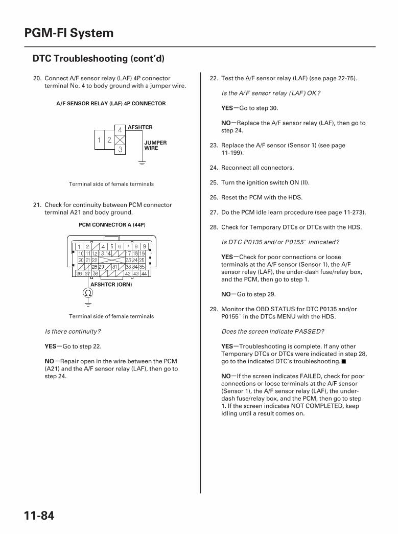
10
11
-
-
-
-
-
-
-
-
YES
NO
YES
NO
YES
NO
YES
NO
11-84
PGM-FI System
DTC Troubleshooting (cont’d)
AFSHTCR
JUMPERWIRE
A/F SENSOR RELAY (LAF) 4P CONNECTOR
PCM CONNECTOR A (44P)
AFSHTCR (ORN)
20. Connect A/F sensor relay (LAF) 4P connectorterminal No. 4 to body ground with a jumper wire.
21. Check for continuity between PCM connectorterminal A21 and body ground.
Go to step 22.
Repair open in the wire between the PCM(A21) and the A/F sensor relay (LAF), then go tostep 24.
22. Test the A/F sensor relay (LAF) (see page 22-75).
Go to step 30.
Replace the A/F sensor relay (LAF), then go tostep 24.
23. Replace the A/F sensor (Sensor 1) (see page11-199).
24. Reconnect all connectors.
25. Turn the ignition switch ON (II).
26. Reset the PCM with the HDS.
27. Do the PCM idle learn procedure (see page 11-273).
28. Check for Temporary DTCs or DTCs with the HDS.
Check for poor connections or looseterminals at the A/F sensor (Sensor 1), the A/Fsensor relay (LAF), the under-dash fuse/relay box,and the PCM, then go to step 1.
Go to step 29.
29. Monitor the OBD STATUS for DTC P0135 and/orP0155 in the DTCs MENU with the HDS.
Troubleshooting is complete. If any otherTemporary DTCs or DTCs were indicated in step 28,go to the indicated DTC’s troubleshooting.
If the screen indicates FAILED, check for poorconnections or loose terminals at the A/F sensor(Sensor 1), the A/F sensor relay (LAF), the under-dash fuse/relay box, and the PCM, then go to step1. If the screen indicates NOT COMPLETED, keepidling until a result comes on.
Terminal side of female terminals
Terminal side of female terminals
Is there continuity?
Is the A/ F sensor relay (LAF) OK ?
Is DTC P0135 and/ or P0155 indicated?
Does the screen indicate PASSED?
07/05/09 16:47:54 61SJC020_110_0084
-
-
-
-
YES
NO
YES
NO
11-85
30. Reconnect all connectors.
31. Update the PCM if it does not have the latestsoftware (see page 11-7), or substitute a known-good PCM (see page 11-8).
32. Check for Temporary DTCs or DTCs with the HDS.
Check for poor connections or looseterminals at the A/F sensor (Sensor 1), the A/Fsensor relay (LAF), the under-dash fuse/relay box,and the PCM. If the PCM was updated, substitute aknown-good PCM (see page 11-8), then recheck. Ifthe PCM was substituted, go to step 1.
Go to step 33.
33. Monitor the OBD STATUS for DTC P0135 and/orP0155 in the DTCs MENU with the HDS.
If the PCM was updated, troubleshooting iscomplete. If the PCM was substituted, replace theoriginal PCM (see page 11-205). If any otherTemporary DTCs or DTCs were indicated in step 32,go to the indicated DTC’s troubleshooting.
If the screen indicates FAILED, check for poorconnections or loose terminals at the A/F sensor(Sensor 1), the A/F sensor relay (LAF), the under-dash fuse/relay box, and the PCM. If the PCM wasupdated, substitute a known-good PCM (see page11-8), then recheck. If the PCM was substituted, goto step 1. If the screen indicates NOT COMPLETED,keep idling until a result comes on.
Is DTC P0135 and/ or P0155 indicated?
Does the screen indicate PASSED?
07/05/09 16:47:54 61SJC020_110_0085
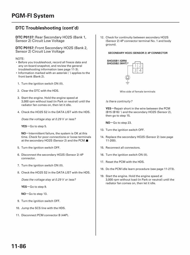
01
SJC8A00K77100090137FAAT30
-
-
-
-
-
-
DTC P0137:
DTC P0157:
YES
NO
YES
NO
YES
NO
11-86
PGM-FI System
DTC Troubleshooting (cont’d)
SECONDARY HO2S (SENSOR 2) 4P CONNECTOR
SHO2SB1 (GRN)SHO2SB2 (WHT)*
Rear Secondary HO2S (Bank 1,Sensor 2) Circuit Low Voltage
Front Secondary HO2S (Bank 2,Sensor 2) Circuit Low Voltage
NOTE:• Before you troubleshoot, record all freeze data and
any on-board snapshot, and review the generaltroubleshooting information (see page 11-3).
• Information marked with an asterisk ( ) applies to thefront bank (Bank 2).
1. Turn the ignition switch ON (II).
2. Clear the DTC with the HDS.
3. Start the engine. Hold the engine speed at3,000 rpm without load (in Park or neutral) until theradiator fan comes on, then let it idle.
4. Check the HO2S S2 in the DATA LIST with the HDS.
Go to step 5.
Intermittent failure, the system is OK at thistime. Check for poor connections or loose terminalsat the secondary HO2S (Sensor 2) and the PCM.
5. Turn the ignition switch OFF.
6. Disconnect the secondary HO2S (Sensor 2) 4Pconnector.
7. Turn the ignition switch ON (II).
8. Check the HO2S S2 in the DATA LIST with the HDS.
Go to step 9.
Go to step 13.
9. Turn the ignition switch OFF.
10. Jump the SCS line with the HDS.
11. Disconnect PCM connector B (44P).
12. Check for continuity between secondary HO2S(Sensor 2) 4P connector terminal No. 1 and bodyground.
Repair short in the wire between the PCM(B15 (B16) ) and the secondary HO2S (Sensor 2),then go to step 15.
Go to step 23.
13. Turn the ignition switch OFF.
14. Replace the secondary HO2S (Sensor 2) (see page11-200).
15. Reconnect all connectors.
16. Turn the ignition switch ON (II).
17. Reset the PCM with the HDS.
18. Do the PCM idle learn procedure (see page 11-273).
19. Start the engine. Hold the engine speed at3,000 rpm without load (in Park or neutral) until theradiator fan comes on, then let it idle.
Wire side of female terminals
Does the voltage stay at 0.29 V or less?
Does the voltage stay at 0.29 V or less?
Is there continuity?
07/05/09 16:47:54 61SJC020_110_0086

-
-
-
-
-
-
-
-
-
-
YES
NO
YES
NO
YES
NO
YES
NO
11-87
20. Test-drive under these conditions:
• Engine coolant temperature (ECT SENSOR 1)above 176 °F (80 °C)
• Transmission in D position• Engine speed at 1,500 3,000 rpm• Drive 1 minute or more
21. Check for Temporary DTCs or DTCs with the HDS.
Check for poor connections or looseterminals at the secondary HO2S (Sensor 2) andthe PCM, then go to step 1.
Go to step 22.
22. Monitor the OBD STATUS for DTC P0137 and/orP0157 in the DTCs MENU with the HDS.
Troubleshooting is complete. If any otherTemporary DTCs or DTCs were indicated in step 21,go to the indicated DTC’s troubleshooting.
If the screen indicates FAILED, check for poorconnections or loose terminals at the secondaryHO2S (Sensor 2) and the PCM, then go to step 1. Ifthe screen indicates EXECUTING, keep driving untila result comes on. If the screen indicates OUT OFCONDITION, go to step 20.
23. Reconnect all connectors.
24. Update the PCM if it does not have the latestsoftware (see page 11-7), or substitute a known-good PCM (see page 11-8).
25. Start the engine. Hold the engine speed at3,000 rpm without load (in Park or neutral) until theradiator fan comes on, then let it idle.
26. Test-drive under these conditions:
• Engine coolant temperature (ECT SENSOR 1)above 176 °F (80 °C)
• Transmission in D position• Engine speed at 1,500 3,000 rpm• Drive 1 minute or more
27. Check for Temporary DTCs or DTCs with the HDS.
Check for poor connections or looseterminals at the secondary HO2S (Sensor 2) andthe PCM. If the PCM was updated, substitute aknown-good PCM (see page 11-8), then go to step24. If the PCM was substituted, go to step 1.
Go to step 28.
28. Monitor the OBD STATUS for DTC P0137 and/orP0157 in the DTCs MENU with the HDS.
If the PCM was updated, troubleshooting iscomplete. If the PCM was substituted, replace theoriginal PCM (see page 11-205). If any otherTemporary DTCs or DTCs were indicated in step 27,go to the indicated DTC’s troubleshooting.
If the screen indicates FAILED, check for poorconnections or loose terminals at the secondaryHO2S (Sensor 2) and the PCM. If the PCM wasupdated, substitute a known-good PCM (see page11-8), then go to step 24. If the PCM was substituted,go to step 1. If the screen indicates NOTCOMPLETED, go to step 24.
Is DTC P0137 and/ or P0157 indicated?
Does the screen indicate PASSED?Is DTC P0137 and/ or P0157 indicated?
Does the screen indicate PASSED?
07/05/09 16:47:54 61SJC020_110_0087

01
02
SJC8A00K77100090138FAAT30
-
-
-
-
-
-
DTC P0138:
DTC P0158:
YES
NO
YES
NO
YES
NO
11-88
PGM-FI System
DTC Troubleshooting (cont’d)
SECONDARY HO2S (SENSOR 2) 4P CONNECTOR
SG2 (GRN/YEL)SG6 (GRN/YEL)*
JUMPER WIRE
SHO2SB1 (GRN)SHO2SB2 (WHT)*
SECONDARY HO2S (SENSOR 2) 4P CONNECTOR
SHO2SB1 (GRN)SHO2SB2 (WHT)*
JUMPER WIRE
Rear Secondary HO2S (Bank 1,Sensor 2) Circuit High Voltage
Front Secondary HO2S (Bank 2,Sensor 2) Circuit High Voltage
NOTE:• Before you troubleshoot, record all freeze data and
any on-board snapshot, and review the generaltroubleshooting information (see page 11-3).
• Information marked with an asterisk ( ) applies to thefront bank (Bank 2).
1. Turn the ignition switch ON (II).
2. Clear the DTC with the HDS.
3. Start the engine. Hold the engine speed at3,000 rpm without load (in Park or neutral) until theradiator fan comes on, then let it idle.
4. Check the HO2S S2 in the DATA LIST with the HDS.
Go to step 5.
Intermittent failure, the system is OK at thistime. Check for poor connections or loose terminalsat the secondary HO2S (Sensor 2) and the PCM.
5. Turn the ignition switch OFF.
6. Disconnect the secondary HO2S (Sensor 2) 4Pconnector.
7. Connect secondary HO2S (Sensor 2) 4P connectorterminals No. 1 and No. 2 with a jumper wire.
8. Turn the ignition switch ON (II).
9. Check the HO2S S2 in the DATA LIST with the HDS.
Go to step 10.
Go to step 19.
10. Turn the ignition switch OFF.
11. Remove the jumper wire from the secondary HO2S(Sensor 2) 4P connector.
12. Connect secondary HO2S (Sensor 2) 4P connectorterminal No. 1 to body ground with a jumper wire.
13. Turn the ignition switch ON (II).
14. Check the HO2S S2 in the DATA LIST with the HDS.
Go to step 15.
Repair open in the wire between the PCM(C14 (C39) ) and the secondary HO2S (Sensor 2),then go to step 21.
Wire side of female terminals
Wire side of female terminals
Does the voltage stay at 1.25 V or more?
Does the voltage stay at 1.25 V or more?
Does the voltage stay at 1.25 V or more?
07/05/09 16:47:55 61SJC020_110_0088
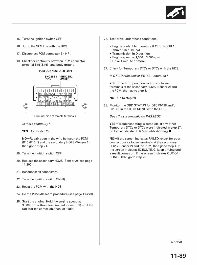
-
03
-
-
-
-
-
-
YES
NO
YES
NO
YES
NO
11-89
PCM CONNECTOR B (44P)
SHO2SB1(GRN)
SHO2SB2(WHT)*
15. Turn the ignition switch OFF.
16. Jump the SCS line with the HDS.
17. Disconnect PCM connector B (44P).
18. Check for continuity between PCM connectorterminal B15 (B16) and body ground.
Go to step 29.
Repair open in the wire between the PCM(B15 (B16) ) and the secondary HO2S (Sensor 2),then go to step 21.
19. Turn the ignition switch OFF.
20. Replace the secondary HO2S (Sensor 2) (see page11-200).
21. Reconnect all connectors.
22. Turn the ignition switch ON (II).
23. Reset the PCM with the HDS.
24. Do the PCM idle learn procedure (see page 11-273).
25. Start the engine. Hold the engine speed at3,000 rpm without load (in Park or neutral) until theradiator fan comes on, then let it idle.
26. Test-drive under these conditions:
• Engine coolant temperature (ECT SENSOR 1)above 176 °F (80 °C)
• Transmission in D position• Engine speed at 1,500 3,000 rpm• Drive 1 minute or more
27. Check for Temporary DTCs or DTCs with the HDS.
Check for poor connections or looseterminals at the secondary HO2S (Sensor 2) andthe PCM, then go to step 1.
Go to step 28.
28. Monitor the OBD STATUS for DTC P0138 and/orP0158 in the DTCs MENU with the HDS.
Troubleshooting is complete. If any otherTemporary DTCs or DTCs were indicated in step 27,go to the indicated DTC’s troubleshooting.
If the screen indicates FAILED, check for poorconnections or loose terminals at the secondaryHO2S (Sensor 2) and the PCM, then go to step 1. Ifthe screen indicates EXECUTING, keep driving untila result comes on. If the screen indicates OUT OFCONDITION, go to step 25.
(cont’d)
Terminal side of female terminals
Is there continuity?
Is DTC P0138 and/ or P0158 indicated?
Does the screen indicate PASSED?
07/05/09 16:47:55 61SJC020_110_0089
-
-
-
-
-
YES
NO
YES
NO
11-90
PGM-FI System
DTC Troubleshooting (cont’d)
29. Reconnect all connectors.
30. Update the PCM if it does not have the latestsoftware (see page 11-7), or substitute a known-good PCM (see page 11-8).
31. Start the engine. Hold the engine speed at3,000 rpm without load (in Park or neutral) until theradiator fan comes on, then let it idle.
32. Test-drive under these conditions:
• Engine coolant temperature (ECT SENSOR 1)above 176 °F (80 °C)
• Transmission in D position• Engine speed at 1,500 3,000 rpm• Drive 1 minute or more
33. Check for Temporary DTCs or DTCs with the HDS.
Check for poor connections or looseterminals at the secondary HO2S (Sensor 2) andthe PCM. If the PCM was updated, substitute aknown-good PCM (see page 11-8), then go to step32. If the PCM was substituted, go to step 1.
Go to step 34.
34. Monitor the OBD STATUS for DTC P0138 and/orP0158 in the DTCs MENU with the HDS.
If the PCM was updated, troubleshooting iscomplete. If the PCM was substituted, replace theoriginal PCM (see page 11-205). If any otherTemporary DTCs or DTCs were indicated in step 33,go to the indicated DTC’s troubleshooting.
If the screen indicates FAILED, check for poorconnections or loose terminals at the secondaryHO2S (Sensor 2) and the PCM. If the PCM wasupdated, substitute a known-good PCM (see page11-8), then go to step 32. If the PCM was substituted,go to step 1. If the screen indicates NOTCOMPLETED, go to step 32.
Is DTC P0138 and/ or P0158 indicated?
Does the screen indicate PASSED?
07/05/09 16:47:55 61SJC020_110_0090
--
--
SJC8A00K77100090139FAAT30
-
-
-
-
-
-
DTC P0139:
DTC P0159:
YES
NO
YES
NO
YES
NO
11-91
Rear Secondary HO2S (Bank 1,Sensor 2) Slow Response
Front Secondary HO2S (Bank 2,Sensor 2) Slow Response
NOTE:• Before you troubleshoot, record all freeze data and
any on-board snapshot, and review the generaltroubleshooting information (see page 11-3).
• Information marked with an asterisk ( ) applies to thefront bank (Bank 2).
1. Turn the ignition switch ON (II).
2. Clear the DTC with the HDS.
3. Start the engine. Hold the engine speed at3,000 rpm without load (in Park or neutral) until theradiator fan comes on, then let it idle.
4. Test-drive under these conditions:
• Engine coolant temperature (ECT SENSOR 1)above 176 °F (80 °C)
• Transmission in D position• Vehicle speed between 35 55 mph
(56 88 km/h)• Drive 5 minutes or more
5. Monitor the OBD STATUS for DTC P0139 and/orP0159 in the DTCs MENU with the HDS.
Go to step 6.
If the screen indicates PASSED, intermittentfailure, the system is OK at this time. Check forpoor connections or loose terminals at thesecondary HO2S (Sensor 2) and the PCM. If thescreen indicates EXECUTING, keep driving until aresult comes on. If the screen indicates OUT OFCONDITION, go to step 3 and recheck.
6. Turn the ignition switch OFF.
7. Replace the secondary HO2S (Sensor 2) (see page11-200).
8. Turn the ignition switch ON (II).
9. Reset the PCM with the HDS.
10. Do the PCM idle learn procedure (see page 11-273).
11. Start the engine. Hold the engine speed at3,000 rpm without load (in Park or neutral) until theradiator fan comes on, then let it idle.
12. Test-drive under these conditions:
• Engine coolant temperature (ECT SENSOR 1)above 176 °F (80 °C)
• Transmission in D position• Vehicle speed between 35 55 mph
(56 88 km/h)• Drive 5 minutes or more
13. Check for Temporary DTCs or DTCs with the HDS.
Check for poor connections or looseterminals at the secondary HO2S (Sensor 2) andthe PCM, then go to step 1.
Go to step 14.
14. Monitor the OBD STATUS for DTC P0139 and/orP0159 in the DTCs MENU with the HDS.
Troubleshooting is complete. If any otherTemporary DTCs or DTCs were indicated in step 13,go to the indicated DTC’s troubleshooting.
If the screen indicates FAILED, check for poorconnections or loose terminals at the secondaryHO2S (Sensor 2) and the PCM, then go to step 1. Ifthe screen indicates EXECUTING, keep driving untila result comes on. If the screen indicates OUT OFCONDITION, go to step 11.
Does the screen indicate FAILED?
Is DTC P0139 and/ or P0159 indicated?
Does the screen indicate PASSED?
07/05/09 16:48:47 61SJC020_110_0091

-
01
02
SJC8A00K77100090141FAAT30
-
-
-
-
-
-
-
-
DTC P0141:
DTC P0161:
YES
NO
YES
NO
YES
NO
YES
NO
11-92
PGM-FI System
DTC Troubleshooting (cont’d)
SECONDARY HO2S (SENSOR 2) 4P CONNECTOR
SECONDARY HO2S (SENSOR 2) 4P CONNECTOR
Rear Secondary HO2S (Bank 1,Sensor 2) Heater Circuit Malfunction
Front Secondary HO2S (Bank 2,Sensor 2) Heater Circuit Malfunction
NOTE:• Before you troubleshoot, record all freeze data and
any on-board snapshot, and review the generaltroubleshooting information (see page 11-3).
• Information marked with an asterisk ( ) applies to thefront bank (Bank 2).
1. Turn the ignition switch ON (II).
2. Clear the DTC with the HDS.
3. Start the engine.
4. Check for Temporary DTCs or DTCs with the HDS.
Go to step 5.
Intermittent failure, the system is OK at thistime. Check for poor connections or loose terminalsat the secondary HO2S (Sensor 2), the A/F sensorrelay (LAF), the under-dash fuse/relay box, and thePCM.
5. Turn the ignition switch OFF.
6. Check these fuses:
• No. 17 OP1 (40 A) fuse in the under-hood fuse/relay box
• No. 4 LAF (A/F SENSOR) (15 A) fuse in the under-dash fuse/relay box
• No. 23 IGP (7.5 A) fuse in the under-dash fuse/relay box
Repair short in the wire between the A/Fsensors, A/F sensor relay (LAF) and the fuse, thengo to step 23.
Go to step 7.
7. Disconnect the secondary HO2S (Sensor 2) 4Pconnector.
8. At the secondary HO2S (Sensor 2) side, measureresistance between secondary HO2S (Sensor 2) 4Pconnector terminals No. 3 and No. 4.
Go to step 9.
Go to step 22.
9. Check for continuity between body ground andsecondary HO2S (Sensor 2) 4P connector terminalsNo. 3 and No. 4 individually.
Go to step 22.
Go to step 10.
Terminal side of male terminals
Terminal side of male terminals
Is DTC P0141 and/ or P0161 indicated?
Are any of the fuses blown?
Is there 5.4 6.6 at room temperature?
Is there continuity?
07/05/09 16:48:48 61SJC020_110_0092
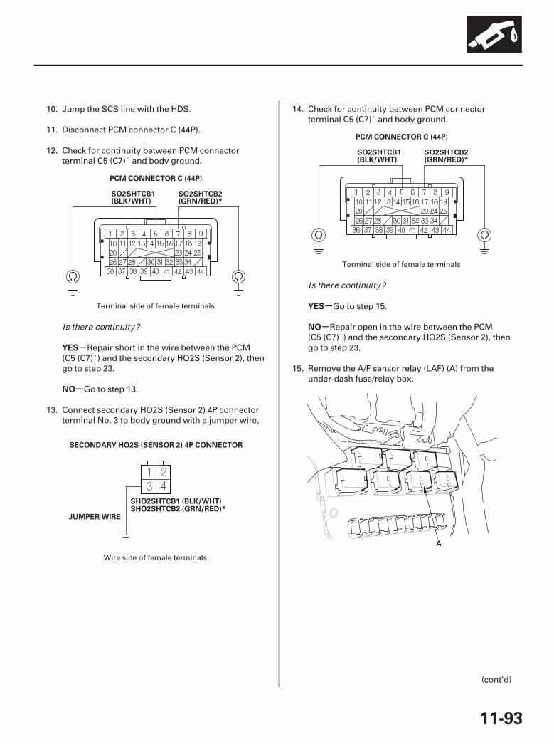
03
04
05
07
-
-
-
-
YES
NO
YES
NO
11-93
PCM CONNECTOR C (44P)
SO2SHTCB1(BLK/WHT)
SO2SHTCB2(GRN/RED)*
SECONDARY HO2S (SENSOR 2) 4P CONNECTOR
SHO2SHTCB1 (BLK/WHT)SHO2SHTCB2 (GRN/RED)*
JUMPER WIRE
PCM CONNECTOR C (44P)
SO2SHTCB1(BLK/WHT)
SO2SHTCB2(GRN/RED)*
A
10. Jump the SCS line with the HDS.
11. Disconnect PCM connector C (44P).
12. Check for continuity between PCM connectorterminal C5 (C7) and body ground.
Repair short in the wire between the PCM(C5 (C7) ) and the secondary HO2S (Sensor 2), thengo to step 23.
Go to step 13.
13. Connect secondary HO2S (Sensor 2) 4P connectorterminal No. 3 to body ground with a jumper wire.
14. Check for continuity between PCM connectorterminal C5 (C7) and body ground.
Go to step 15.
Repair open in the wire between the PCM(C5 (C7) ) and the secondary HO2S (Sensor 2), thengo to step 23.
15. Remove the A/F sensor relay (LAF) (A) from theunder-dash fuse/relay box.
(cont’d)
Terminal side of female terminals
Wire side of female terminals
Terminal side of female terminals
Is there continuity?
Is there continuity?
07/05/09 16:48:48 61SJC020_110_0093
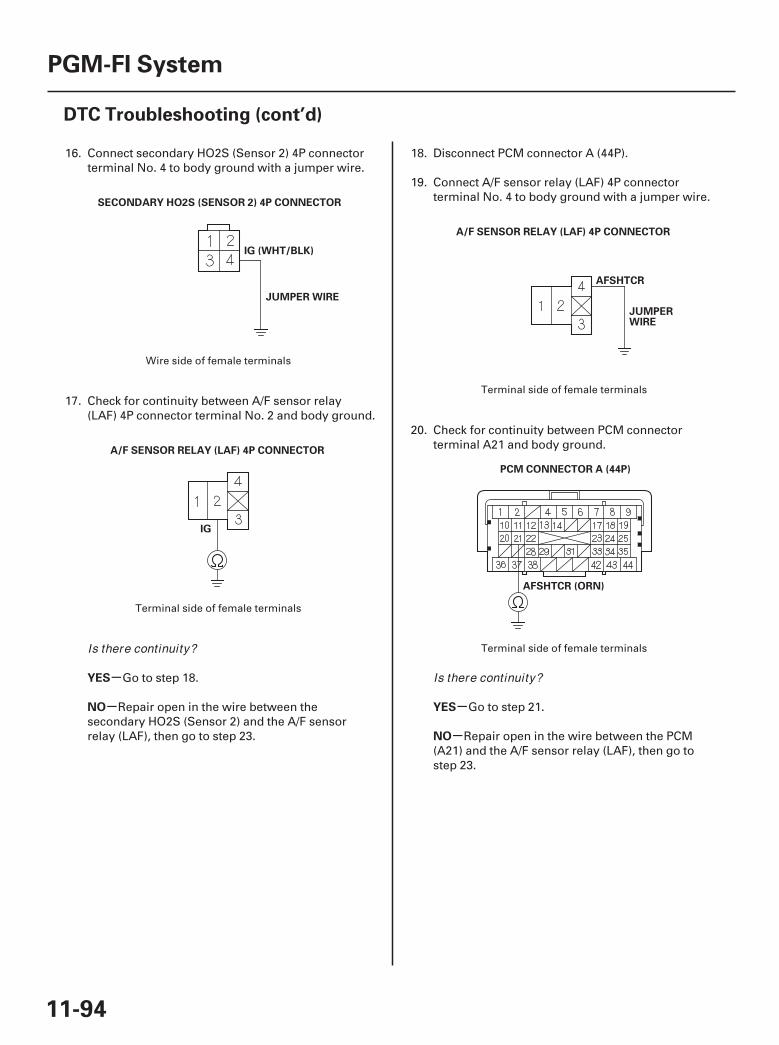
06
08
09
10
-
- -
-
YES
NO YES
NO
11-94
PGM-FI System
DTC Troubleshooting (cont’d)
SECONDARY HO2S (SENSOR 2) 4P CONNECTOR
IG (WHT/BLK)
JUMPER WIRE
IG
A/F SENSOR RELAY (LAF) 4P CONNECTOR
AFSHTCR
JUMPERWIRE
A/F SENSOR RELAY (LAF) 4P CONNECTOR
PCM CONNECTOR A (44P)
AFSHTCR (ORN)
16. Connect secondary HO2S (Sensor 2) 4P connectorterminal No. 4 to body ground with a jumper wire.
17. Check for continuity between A/F sensor relay(LAF) 4P connector terminal No. 2 and body ground.
Go to step 18.
Repair open in the wire between thesecondary HO2S (Sensor 2) and the A/F sensorrelay (LAF), then go to step 23.
18. Disconnect PCM connector A (44P).
19. Connect A/F sensor relay (LAF) 4P connectorterminal No. 4 to body ground with a jumper wire.
20. Check for continuity between PCM connectorterminal A21 and body ground.
Go to step 21.
Repair open in the wire between the PCM(A21) and the A/F sensor relay (LAF), then go tostep 23.
Wire side of female terminals
Terminal side of female terminals
Terminal side of female terminals
Terminal side of female terminalsIs there continuity?
Is there continuity?
07/05/09 16:48:49 61SJC020_110_0094

-
-
-
-
-
-
-
-
-
-
YES
NO
YES
NO
YES
NO
YES
NO
YES
NO
11-95
21. Test the A/F sensor relay (LAF) (see page 22-75).
Go to step 29.
Replace the A/F sensor relay (LAF), then go tostep 23.
22. Replace the secondary HO2S (Sensor 2) (see page11-200).
23. Reconnect all connectors.
24. Turn the ignition switch ON (II).
25. Reset the PCM with the HDS.
26. Do the PCM idle learn procedure (see page 11-273).
27. Check for Temporary DTCs or DTCs with the HDS.
Check for poor connections or looseterminals at the secondary HO2S (Sensor 2), theA/F sensor relay (LAF), and the PCM, then go tostep 1.
Go to step 28.
28. Monitor the OBD STATUS for DTC P0141 and/orP0161 in the DTCs MENU with the HDS.
Troubleshooting is complete. If any otherTemporary DTCs or DTCs were indicated in step 27,go to the indicated DTC’s troubleshooting.
If the screen indicates FAILED, check for poorconnections or loose terminals at the secondaryHO2S (Sensor 2), the A/F sensor relay (LAF), andthe PCM, then go to step 1. If the screen indicatesNOT COMPLETED, keep idling until a result comeson.
29. Reconnect all connectors.
30. Update the PCM if it does not have the latestsoftware (see page 11-7), or substitute a known-good PCM (see page 11-8).
31. Check for Temporary DTCs or DTCs with the HDS.
Check for poor connections or looseterminals at the secondary HO2S (Sensor 2), theA/F sensor relay (LAF), and the PCM. If the PCMwas updated, substitute a known-good PCM(see page 11-8), then recheck. If the PCM wassubstituted, go to step 1.
Go to step 32.
32. Monitor the OBD STATUS for DTC P0141 and/orP0161 in the DTCs MENU with the HDS.
If the PCM was updated, troubleshooting iscomplete. If the PCM was substituted, replace theoriginal PCM (see page 11-205). If any otherTemporary DTCs or DTCs were indicated in step 31,go to the indicated DTC’s troubleshooting.
If the screen indicates FAILED, check for poorconnections or loose terminals at the secondaryHO2S (Sensor 2), the A/F sensor relay (LAF), andthe PCM. If the PCM was updated, substitute aknown-good PCM (see page 11-8), then recheck. Ifthe PCM was substituted, go to step 1. If the screenindicates NOT COMPLETED, keep idling until aresult comes on.
Is the A/ F sensor relay (LAF) OK ?
Is DTC P0141 and/ or P0161 indicated?
Does the screen indicate PASSED?
Is DTC P0141 and/ or P0161 indicated?
Does the screen indicate PASSED?
07/05/09 16:48:49 61SJC020_110_0095
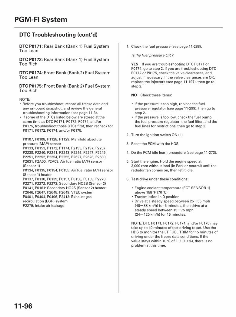
--
--
SJC8A00K77100090171FAAT30
-
-
DTC P0171:
DTC P0172:
DTC P0174:
DTC P0175:
YES
NO
11-96
PGM-FI System
DTC Troubleshooting (cont’d)
Rear Bank (Bank 1) Fuel SystemToo Lean
Rear Bank (Bank 1) Fuel SystemToo Rich
Front Bank (Bank 2) Fuel SystemToo Lean
Front Bank (Bank 2) Fuel SystemToo Rich
NOTE:• Before you troubleshoot, record all freeze data and
any on-board snapshot, and review the generaltroubleshooting information (see page 11-3).
• If some of the DTCs listed below are stored at thesame time as DTC P0171, P0172, P0174, and/orP0175, troubleshoot those DTCs first, then recheck forP0171, P0172, P0174, and/or P0175.
P0107, P0108, P1128, P1129: Manifold absolutepressure (MAP) sensorP0133, P0153, P1172, P1174, P2195, P2197, P2237,P2238, P2240, P2241, P2243, P2245, P2247, P2249,P2251, P2252, P2254, P2255, P2627, P2628, P2630,P2631, P2A00, P2A03: Air fuel ratio (A/F) sensor(Sensor 1)P0134, P0135, P0154, P0155: Air fuel ratio (A/F) sensor(Sensor 1) heaterP0137, P0138, P0139, P0157, P0158, P0159, P2270,P2271, P2272, P2273: Secondary HO2S (Sensor 2)P0141, P0161: Secondary HO2S (Sensor 2) heaterP2646, P2647, P2648, P2649: VTEC systemP0401, P0404, P0406, P2413: Exhaust gasrecirculation (EGR) systemP2279: Intake air leakage
1. Check the fuel pressure (see page 11-288).
If you are troubleshooting DTC P0171 orP0174, go to step 2. If you are troubleshooting DTCP0172 or P0175, check the valve clearances, andadjust if necessary. If the valve clearances are OK,replace the injectors (see page 11-197), then go tostep 2.
Check these items:
• If the pressure is too high, replace the fuelpressure regulator (see page 11-299), then go tostep 2.
• If the pressure is too low, check the fuel pump,the fuel pressure regulator, the fuel filter, and thefuel lines for restrictions, then go to step 2.
2. Turn the ignition switch ON (II).
3. Reset the PCM with the HDS.
4. Do the PCM idle learn procedure (see page 11-273).
5. Start the engine. Hold the engine speed at3,000 rpm without load (in Park or neutral) until theradiator fan comes on, then let it idle.
6. Test-drive under these conditions:
• Engine coolant temperature (ECT SENSOR 1)above 158 °F (70 °C)
• Transmission in D position• Drive at a steady speed between 25 55 mph
(40 88 km/h) for 5 minutes, then drive at asteady speed between 15 75 mph(24 120 km/h) for 15 minutes.
NOTE: DTC P0171, P0172, P0174, and/or P0175 maytake up to 40 minutes of test driving to set. Use theHDS to monitor the LT FUEL TRIM for 15 minutes ofdriving under the freeze data conditions. If thevalue stays within 10 % of 1.0 (0.0 %), there is noproblem at this time.
Is the fuel pressure OK ?
07/05/09 16:48:49 61SJC020_110_0096
-
-
-
-
-
-
YES
NO
YES
NO
YES
NO
11-97
7. Check for Temporary DTCs or DTCs with the HDS.
Go to step 8.
Troubleshooting is complete. If any otherTemporary DTCs or DTCs are indicated, go to theindicated DTC’s troubleshooting.
8. Check for poor connections or loose terminals atthe PCM.
Go to step 9.
Repair the connections or terminals, then step2.
9. Check the fuel quality.
Replace the injectors (see page 11-197), thengo to step 2.
Drain the fuel tank (see page 11-289), replacethe fuel, then go to step 2.
Is DTC P0171, P0172, P0174, or P0175indicated?
Are the connections and terminals OK ?
Is the fuel quality OK ?
07/05/09 16:48:49 61SJC020_110_0097
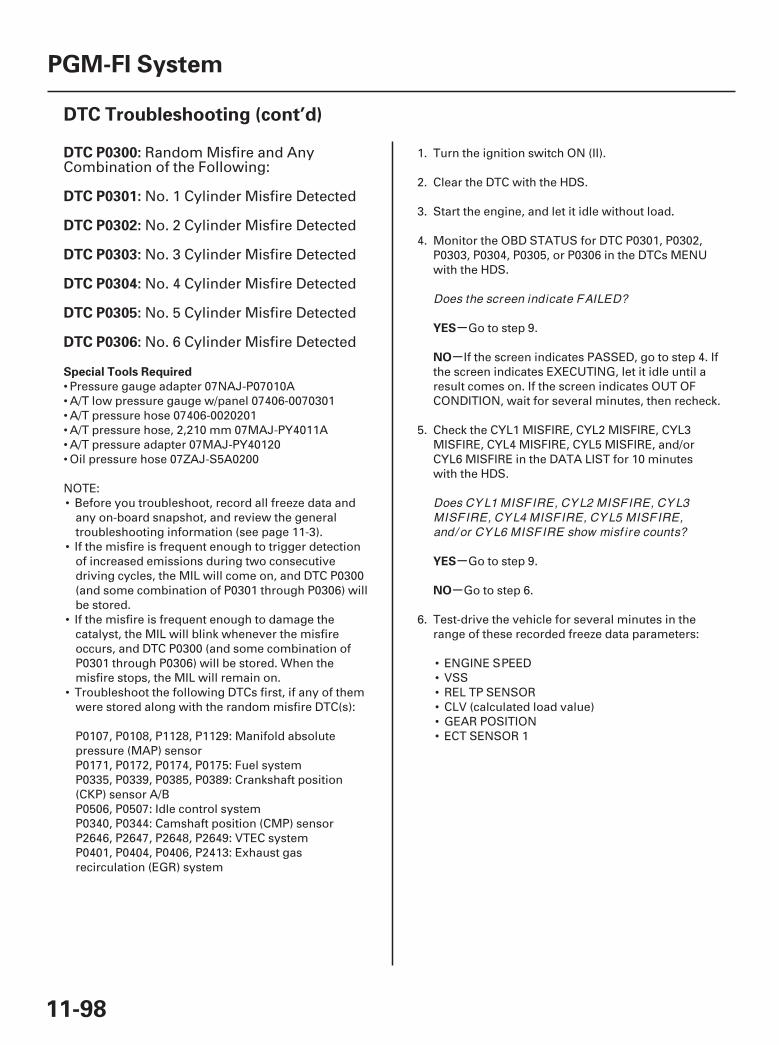
SJC8A00K77100090300FAAT30
-
-
-
-
DTC P0300:
DTC P0301:
DTC P0302:
DTC P0303:
DTC P0304:
DTC P0305:
DTC P0306:
Special Tools Required
YES
NO
YES
NO
11-98
PGM-FI System
DTC Troubleshooting (cont’d)
Random Misfire and AnyCombination of the Following:
No. 1 Cylinder Misfire Detected
No. 2 Cylinder Misfire Detected
No. 3 Cylinder Misfire Detected
No. 4 Cylinder Misfire Detected
No. 5 Cylinder Misfire Detected
No. 6 Cylinder Misfire Detected
• Pressure gauge adapter 07NAJ-P07010A• A/T low pressure gauge w/panel 07406-0070301• A/T pressure hose 07406-0020201• A/T pressure hose, 2,210 mm 07MAJ-PY4011A• A/T pressure adapter 07MAJ-PY40120• Oil pressure hose 07ZAJ-S5A0200
NOTE:• Before you troubleshoot, record all freeze data and
any on-board snapshot, and review the generaltroubleshooting information (see page 11-3).
• If the misfire is frequent enough to trigger detectionof increased emissions during two consecutivedriving cycles, the MIL will come on, and DTC P0300(and some combination of P0301 through P0306) willbe stored.
• If the misfire is frequent enough to damage thecatalyst, the MIL will blink whenever the misfireoccurs, and DTC P0300 (and some combination ofP0301 through P0306) will be stored. When themisfire stops, the MIL will remain on.
• Troubleshoot the following DTCs first, if any of themwere stored along with the random misfire DTC(s):
P0107, P0108, P1128, P1129: Manifold absolutepressure (MAP) sensorP0171, P0172, P0174, P0175: Fuel systemP0335, P0339, P0385, P0389: Crankshaft position(CKP) sensor A/BP0506, P0507: Idle control systemP0340, P0344: Camshaft position (CMP) sensorP2646, P2647, P2648, P2649: VTEC systemP0401, P0404, P0406, P2413: Exhaust gasrecirculation (EGR) system
1. Turn the ignition switch ON (II).
2. Clear the DTC with the HDS.
3. Start the engine, and let it idle without load.
4. Monitor the OBD STATUS for DTC P0301, P0302,P0303, P0304, P0305, or P0306 in the DTCs MENUwith the HDS.
Go to step 9.
If the screen indicates PASSED, go to step 4. Ifthe screen indicates EXECUTING, let it idle until aresult comes on. If the screen indicates OUT OFCONDITION, wait for several minutes, then recheck.
5. Check the CYL1 MISFIRE, CYL2 MISFIRE, CYL3MISFIRE, CYL4 MISFIRE, CYL5 MISFIRE, and/orCYL6 MISFIRE in the DATA LIST for 10 minuteswith the HDS.
Go to step 9.
Go to step 6.
6. Test-drive the vehicle for several minutes in therange of these recorded freeze data parameters:
• ENGINE SPEED• VSS• REL TP SENSOR• CLV (calculated load value)• GEAR POSITION• ECT SENSOR 1
Does the screen indicate FAILED?
Does CY L1 MISFIRE, CY L2 MISFIRE, CY L3MISFIRE, CY L4 MISFIRE, CY L5 MISFIRE,and/ or CY L6 MISFIRE show misf ire counts?
07/05/09 16:48:50 61SJC020_110_0098
-
-
-
-
-
-
-
-
-
-
YES
NO
YES
NO
YES
NO
YES
NO
YES
NO
11-99
7. Monitor the OBD STATUS for DTC P0301, P0302,P0303, P0304, P0305, or P0306 in the DTCs MENUwith the HDS.
Go to step 9.
If the screen indicates PASSED, go to step 8. Ifthe screen indicates EXECUTING, keep driving untila result comes on. If the screen indicates OUT OFCONDITION, go to step 6 and recheck.
8. Check the CYL1 MISFIRE, CYL2 MISFIRE, CYL3MISFIRE, CYL4 MISFIRE, CYL5 MISFIRE, and/orCYL6 MISFIRE in the DATA LIST for 10 minuteswith the HDS.
Go to step 9.
Intermittent failure, the system is OK at thistime.
9. Turn the ignition switch OFF.
10. Check the fuel quality.
Go to step 11.
Drain the tank, and fill it with a known-goodfuel, then go to step 20.
11. Inspect the spark plugs (see page 4-22). If the sparkplugs are fouled or worn, replace them.
12. Test-drive the vehicle for several minutes in therange of these recorded freeze data parameters:
• ENGINE SPEED• VSS• REL TP SENSOR• CLV (calculated load value)• ECT SENSOR 1• APP SENSOR
13. Check the CYL1 MISFIRE, CYL2 MISFIRE, CYL3MISFIRE, CYL4 MISFIRE, CYL5 MISFIRE, and/orCYL6 MISFIRE in the DATA LIST for 10 minuteswith the HDS.
Go to step 14.
Go to step 20.
14. Check the fuel pressure (see page 11-288).
Go to step 15.
• If the pressure is too high, replace the fuelpressure regulator (see page 11-299), then go tostep 20.
• If the pressure is too low, check the fuel pump,the fuel feed lines, and the fuel filter. If they areOK, replace the fuel pressure regulator (see page11-299), then go to step 20.
15. Turn the ignition switch OFF.
(cont’d)
Does the screen indicate FAILED?
Does CY L1 MISFIRE, CY L2 MISFIRE, CY L3MISFIRE, CY L4 MISFIRE, CY L5 MISFIRE,and/ or CY L6 MISFIRE show misf ire counts?
Is the quality good?
Does CY L1 MISFIRE, CY L2 MISFIRE, CY L3MISFIRE, CY L4 MISFIRE, CY L5 MISFIRE,and/ or CY L6 MISFIRE show misf ire counts?
Is the fuel pressure OK ?
07/05/09 16:48:50 61SJC020_110_0099
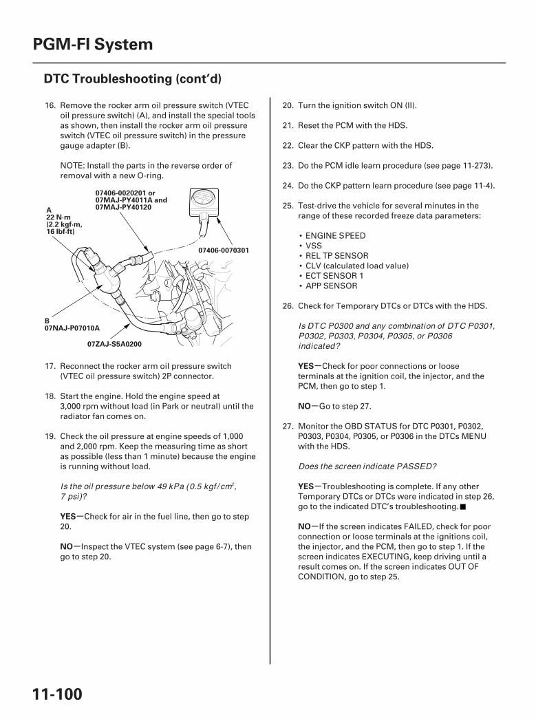
*01
-
-
-
-
-
-YES
NO
YES
NO
YES
NO
11-100
PGM-FI System
DTC Troubleshooting (cont’d)
07406-0070301
07ZAJ-S5A0200
07406-0020201 or07MAJ-PY4011A and07MAJ-PY40120A
22 N·m(2.2 kgf·m,16 lbf·ft)
B07NAJ-P07010A
16. Remove the rocker arm oil pressure switch (VTECoil pressure switch) (A), and install the special toolsas shown, then install the rocker arm oil pressureswitch (VTEC oil pressure switch) in the pressuregauge adapter (B).
NOTE: Install the parts in the reverse order ofremoval with a new O-ring.
17. Reconnect the rocker arm oil pressure switch(VTEC oil pressure switch) 2P connector.
18. Start the engine. Hold the engine speed at3,000 rpm without load (in Park or neutral) until theradiator fan comes on.
19. Check the oil pressure at engine speeds of 1,000and 2,000 rpm. Keep the measuring time as shortas possible (less than 1 minute) because the engineis running without load.
Check for air in the fuel line, then go to step20.
Inspect the VTEC system (see page 6-7), thengo to step 20.
20. Turn the ignition switch ON (II).
21. Reset the PCM with the HDS.
22. Clear the CKP pattern with the HDS.
23. Do the PCM idle learn procedure (see page 11-273).
24. Do the CKP pattern learn procedure (see page 11-4).
25. Test-drive the vehicle for several minutes in therange of these recorded freeze data parameters:
• ENGINE SPEED• VSS• REL TP SENSOR• CLV (calculated load value)• ECT SENSOR 1• APP SENSOR
26. Check for Temporary DTCs or DTCs with the HDS.
Check for poor connections or looseterminals at the ignition coil, the injector, and thePCM, then go to step 1.
Go to step 27.
27. Monitor the OBD STATUS for DTC P0301, P0302,P0303, P0304, P0305, or P0306 in the DTCs MENUwith the HDS.
Troubleshooting is complete. If any otherTemporary DTCs or DTCs were indicated in step 26,go to the indicated DTC’s troubleshooting.
If the screen indicates FAILED, check for poorconnection or loose terminals at the ignitions coil,the injector, and the PCM, then go to step 1. If thescreen indicates EXECUTING, keep driving until aresult comes on. If the screen indicates OUT OFCONDITION, go to step 25.
Is the oil pressure below 49 kPa (0.5 kgf / cm ,7 psi)?
Is DTC P0300 and any combination of DTC P0301,P0302, P0303, P0304, P0305, or P0306indicated?
Does the screen indicate PASSED?
2
07/05/09 16:48:50 61SJC020_110_0100

SJC8A00K77100090301FAAT30
-
-
-
-
-
-
-
-
DTC P0301:
DTC P0302:
DTC P0303:
DTC P0304:
DTC P0305:
DTC P0306:
YES
NO
YES
NO
YES
NO
YES
NO
11-101
No. 1 Cylinder Misfire Detected
No. 2 Cylinder Misfire Detected
No. 3 Cylinder Misfire Detected
No. 4 Cylinder Misfire Detected
No. 5 Cylinder Misfire Detected
No. 6 Cylinder Misfire Detected
NOTE: Before you troubleshoot, record all freeze dataand any on-board snapshot, and review the generaltroubleshooting information (see page 11-3).
1. Turn the ignition switch ON (II).
2. Clear the DTC with the HDS.
3. Start the engine, and let it idle without load for2 minutes (in Park or neutral).
4. Monitor the OBD STATUS for DTC P0301, P0302,P0303, P0304, P0305, or P0306 in the DTCs MENUwith the HDS.
Go to step 9.
If the screen indicates PASSED, go to step 4. Ifthe screen indicates EXECUTING, keep idling untila result comes on. If the screen indicates OUT OFCONDITION, wait for several minutes, and recheck.
5. Check the CYL1 MISFIRE, CYL2 MISFIRE, CYL3MISFIRE, CYL4 MISFIRE, CYL5 MISFIRE, and/orCYL6 MISFIRE in the DATA LIST for 10 minuteswith the HDS.
Go to step 9.
Go to step 6.
6. Test-drive the vehicle for several minutes in therange of these recorded freeze data parameters:
• ENGINE SPEED• VSS• REL TP SENSOR• CLV (calculated load value)• GEAR POSITION• ECT SENSOR 1
7. Monitor the OBD STATUS for DTC P0301, P0302,P0303, P0304, P0305, or P0306 in the DTCs MENUwith the HDS.
Go to step 9.
If the screen indicates PASSED, go to step 8. Ifthe screen indicates EXECUTING, keep driving untila result comes on. If the screen indicates OUT OFCONDITION, go to step 6.
8. Check the CYL1 MISFIRE, CYL2 MISFIRE, CYL3MISFIRE, CYL4 MISFIRE, CYL5 MISFIRE, and/orCYL6 MISFIRE in the DATA LIST for 10 minuteswith the HDS.
Go to step 9.
Intermittent failure, the system is OK at thistime. Check the fuel and ignition system circuitconnectors for loose wires or poor connections.
9. Turn the ignition switch OFF.
10. Exchange the ignition coil from the problemcylinder with one from another cylinder.
11. Reconnect all connectors.
(cont’d)
Does the screen indicate FAILED?
Does CY L1 MISFIRE, CY L2 MISFIRE, CY L3MISFIRE, CY L4 MISFIRE, CY L5 MISFIRE,and/ or CY L6 MISFIRE show misf ire counts?
Does the screen indicate FAILED?
Does CY L1 MISFIRE, CY L2 MISFIRE, CY L3MISFIRE, CY L4 MISFIRE, CY L5 MISFIRE,and/ or CY L6 MISFIRE show misf ire counts?
07/05/09 16:48:50 61SJC020_110_0101
-
-
-
-
-
-
-
-
YES
NO
YES
NO
YES
NO
YES
NO
11-102
PGM-FI System
DTC Troubleshooting (cont’d)
12. Test-drive the vehicle for several minutes in therange of these recorded freeze data parameters:
• ENGINE SPEED• VSS• REL TP SENSOR• CLV (calculated load value)• GEAR POSITION• ECT SENSOR 1
13. Check the CYL1 MISFIRE, CYL2 MISFIRE, CYL3MISFIRE, CYL4 MISFIRE, CYL5 MISFIRE, and/orCYL6 MISFIRE in the DATA LIST for 10 minuteswith the HDS.
Go to step 14.
Intermittent failure due to poor contact at theignition coil contactor (no misfire at this time).Make sure that the ignition coil connectors aresecure.
14. Determine which cylinder had the misfire.
Replace the faulty ignition coil (see page4-19), then go to step 54.
Go to step 15.
15. Turn the ignition switch OFF.
16. Exchange the spark plug from the problem cylinderwith the one from another cylinder.
17. Reconnect all connectors.
18. Test-drive the vehicle for several minutes in therange of these recorded freeze data parameters:
• ENGINE SPEED• VSS• REL TP SENSOR• CLV (calculated load value)• GEAR POSITION• ECT SENSOR 1
19. Check the CYL1 MISFIRE, CYL2 MISFIRE, CYL3MISFIRE, CYL4 MISFIRE, CYL5 MISFIRE, and/orCYL6 MISFIRE in the DATA LIST for 10 minuteswith the HDS.
Go to step 20.
Intermittent failure due to spark plug fouling(no misfire at this time).
20. Determine which cylinder had the misfire.
Replace the faulty spark plug, then go to step54.
Go to step 21.
21. Turn the ignition switch OFF.
22. Disconnect the ignition coil 3P connector from theproblem cylinder.
23. Turn the ignition switch ON (II).
Does CY L1 MISFIRE, CY L2 MISFIRE, CY L3MISFIRE, CY L4 MISFIRE, CY L5 MISFIRE,and/ or CY L6 MISFIRE show misf ire counts?
Does the misf ire occur in the cylinder where theignition coil was moved?
Does CY L1 MISFIRE, CY L2 MISFIRE, CY L3MISFIRE, CY L4 MISFIRE, CY L5 MISFIRE,and/ or CY L6 MISFIRE show misf ire counts?
Does the misf ire occur in the cylinder where theignition coil was moved?
07/05/09 16:48:50 61SJC020_110_0102

01
02
03
-
-
-
--
-
YES
NO
YES
NO
PROBLEM
CYLINDER
DTC PCM
TERMINAL
WIRE
COLOR
YES
NO
11-103
IGNITION COIL 3P CONNECTOR
IG(BLK/WHT)
IGNITION COIL 3P CONNECTOR
GND(BLK)
PCM CONNECTOR B (44P)
IGPLS3 (WHT/BLU)
IGPLS1 (YEL/GRN)
IGPLS5 (BLK/RED)
IGPLS4 (BRN)
IGPLS2 (BLU/RED)
IGPLS6 (BRN/WHT)
24. Measure voltage between ignition coil 3Pconnector terminal No. 3 and body ground.
Go to step 25.
Repair open in the wire between the ignitioncoil and the ignition coil relay, then go to step 54.
25. Turn the ignition switch OFF.
26. Check for continuity between ignition coil 3Pconnector terminal No. 2 and body ground.
Go to step 27.
Repair open in the wire between the ignitioncoil, G101, and G102, then go to step 54.
27. Jump the SCS line with the HDS.
28. Disconnect PCM connector B (44P).
29. Check for continuity between body ground and theappropriate PCM connector terminal (see table).
No. 1 P0301 B26 YEL/GRNNo. 2 P0302 B27 BLU/REDNo. 3 P0303 B20 WHT/BLUNo. 4 P0304 B21 BRNNo. 5 P0305 B10 BLK/REDNo. 6 P0306 B11 BRN/WHT
Repair short in the wire between the PCMand the ignition coil, then go to step 54.
Go to step 30.
(cont’d)
Wire side of female terminals
Wire side of female terminals
Terminal side of female terminals
Is there battery voltage?
Is there continuity?Is there continuity?
07/05/09 16:48:51 61SJC020_110_0103
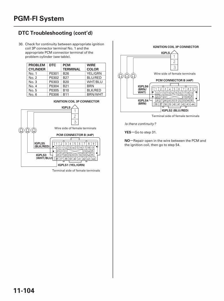
*01
*02
-
-
PROBLEM
CYLINDER
DTC PCM
TERMINAL
WIRE
COLOR
YES
NO
11-104
PGM-FI System
DTC Troubleshooting (cont’d)
IGNITION COIL 3P CONNECTOR
IGPLS
PCM CONNECTOR B (44P)
IGPLS5(BLK/RED)
IGPLS1 (YEL/GRN)
IGPLS3(WHT/BLU)
IGNITION COIL 3P CONNECTOR
IGPLS
PCM CONNECTOR B (44P)
IGPLS6(BRN/WHT)
IGPLS2 (BLU/RED)
IGPLS4(BRN)
30. Check for continuity between appropriate ignitioncoil 3P connector terminal No. 1 and theappropriate PCM connector terminal of theproblem cylinder (see table).
No. 1 P0301 B26 YEL/GRNNo. 2 P0302 B27 BLU/REDNo. 3 P0303 B20 WHT/BLUNo. 4 P0304 B21 BRNNo. 5 P0305 B10 BLK/REDNo. 6 P0306 B11 BRN/WHT
Go to step 31.
Repair open in the wire between the PCM andthe ignition coil, then go to step 54.
Terminal side of female terminals
Wire side of female terminals
Terminal side of female terminals
Wire side of female terminals
Is there continuity?
07/05/09 16:48:51 61SJC020_110_0104
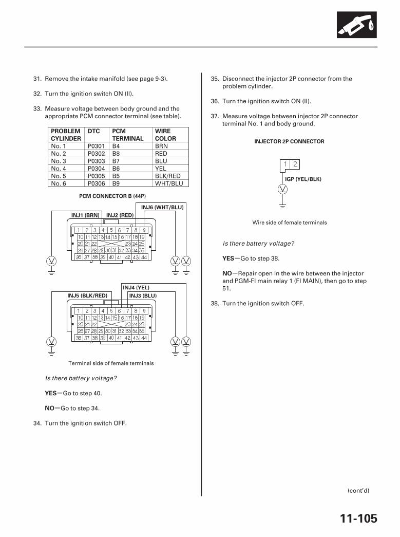
06
07
-
-
-
-
PROBLEM
CYLINDER
DTC PCM
TERMINAL
WIRE
COLOR
YES
NO
YES
NO
11-105
PCM CONNECTOR B (44P)
INJ1 (BRN)
INJ6 (WHT/BLU)
INJ2 (RED)
INJ5 (BLK/RED) INJ3 (BLU)
INJ4 (YEL)
IGP (YEL/BLK)
INJECTOR 2P CONNECTOR
31. Remove the intake manifold (see page 9-3).
32. Turn the ignition switch ON (II).
33. Measure voltage between body ground and theappropriate PCM connector terminal (see table).
No. 1 P0301 B4 BRNNo. 2 P0302 B8 REDNo. 3 P0303 B7 BLUNo. 4 P0304 B6 YELNo. 5 P0305 B5 BLK/REDNo. 6 P0306 B9 WHT/BLU
Go to step 40.
Go to step 34.
34. Turn the ignition switch OFF.
35. Disconnect the injector 2P connector from theproblem cylinder.
36. Turn the ignition switch ON (II).
37. Measure voltage between injector 2P connectorterminal No. 1 and body ground.
Go to step 38.
Repair open in the wire between the injectorand PGM-FI main relay 1 (FI MAIN), then go to step51.
38. Turn the ignition switch OFF.
(cont’d)
Terminal side of female terminals
Wire side of female terminals
Is there battery voltage?
Is there battery voltage?
07/05/09 16:48:52 61SJC020_110_0105
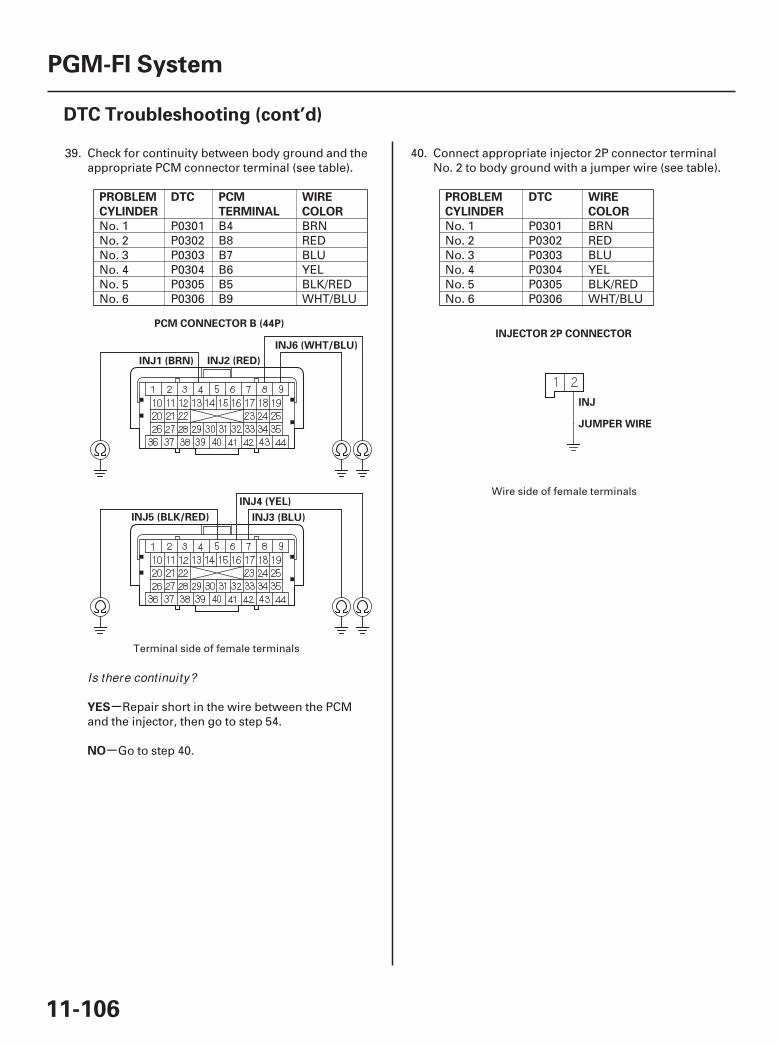
08 09
-
-
PROBLEM
CYLINDER
DTC PCM
TERMINAL
WIRE
COLOR
YES
NO
PROBLEM
CYLINDER
DTC WIRE
COLOR
11-106
PGM-FI System
DTC Troubleshooting (cont’d)
PCM CONNECTOR B (44P)
INJ1 (BRN)
INJ6 (WHT/BLU)
INJ2 (RED)
INJ5 (BLK/RED) INJ3 (BLU)
INJ4 (YEL)
INJECTOR 2P CONNECTOR
INJ
JUMPER WIRE
39. Check for continuity between body ground and theappropriate PCM connector terminal (see table).
No. 1 P0301 B4 BRNNo. 2 P0302 B8 REDNo. 3 P0303 B7 BLUNo. 4 P0304 B6 YELNo. 5 P0305 B5 BLK/REDNo. 6 P0306 B9 WHT/BLU
Repair short in the wire between the PCMand the injector, then go to step 54.
Go to step 40.
40. Connect appropriate injector 2P connector terminalNo. 2 to body ground with a jumper wire (see table).
No. 1 P0301 BRNNo. 2 P0302 REDNo. 3 P0303 BLUNo. 4 P0304 YELNo. 5 P0305 BLK/REDNo. 6 P0306 WHT/BLU
Terminal side of female terminals
Wire side of female terminals
Is there continuity?
07/05/09 16:48:52 61SJC020_110_0106
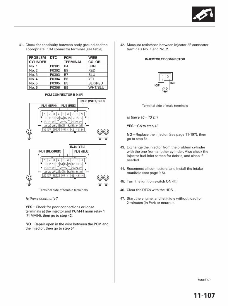
-
10
11
-
-
-
-
PROBLEM
CYLINDER
DTC PCM
TERMINAL
WIRE
COLOR
YES
NO
YES
NO
11-107
PCM CONNECTOR B (44P)
INJ1 (BRN)
INJ6 (WHT/BLU)
INJ2 (RED)
INJ5 (BLK/RED) INJ3 (BLU)
INJ4 (YEL)
IGPINJ
INJECTOR 2P CONNECTOR
41. Check for continuity between body ground and theappropriate PCM connector terminal (see table).
No. 1 P0301 B4 BRNNo. 2 P0302 B8 REDNo. 3 P0303 B7 BLUNo. 4 P0304 B6 YELNo. 5 P0305 B5 BLK/REDNo. 6 P0306 B9 WHT/BLU
Check for poor connections or looseterminals at the injector and PGM-FI main relay 1(FI MAIN), then go to step 42.
Repair open in the wire between the PCM andthe injector, then go to step 54.
42. Measure resistance between injector 2P connectorterminals No. 1 and No. 2.
Go to step 43.
Replace the injector (see page 11-197), thengo to step 54.
43. Exchange the injector from the problem cylinderwith the one from another cylinder. Also check theinjector fuel inlet screen for debris, and clean ifneeded.
44. Reconnect all connectors, and install the intakemanifold (see page 9-5).
45. Turn the ignition switch ON (II).
46. Clear the DTCs with the HDS.
47. Start the engine, and let it idle without load for2 minutes (in Park or neutral).
(cont’d)
Terminal side of female terminals
Terminal side of male terminals
Is there continuity?
Is there 10 13 ?
07/05/09 16:48:52 61SJC020_110_0107
-
-
-
-
-
-
-
-
-
-
YES
NO
YES
NO
YES
NO
YES
NO
YES
NO
11-108
PGM-FI System
DTC Troubleshooting (cont’d)
48. Test-drive the vehicle for several minutes in therange of these recorded freeze data parameters:
• ENGINE SPEED• VSS• REL TP SENSOR• CLV (calculated load value)• GEAR POSITION• ECT SENSOR 1
49. Check the CYL1 MISFIRE, CYL2 MISFIRE, CYL3MISFIRE, CYL4 MISFIRE, CYL5 MISFIRE, and/orCYL6 MISFIRE in the DATA LIST for 10 minuteswith the HDS.
Go to step 50.
Intermittent failure due to poor contact in theinjector connector (no misfire at this time). Checkfor poor connections or loose terminals at theinjector.
50. Determine which cylinder had the misfire.
Replace the faulty injector (see page 11-197),then go to step 54.
Go to step 51.
51. Turn the ignition switch OFF.
52. Do an engine compression and a cylinder leakdowntest (see page 6-6).
Go to step 53.
Repair the engine, then go to step 54.
53. Do the VTEC rocker arm test (see page 6-7).
Go to step 62.
Repair the VTEC rocker arm, then go to step54.
54. Reconnect all connectors.
55. Reset the PCM with the HDS.
56. Clear the CKP pattern with the HDS.
57. Do the PCM idle learn procedure (see page 11-273).
58. Do the CKP pattern learn procedure (see page 11-4).
59. Test-drive the vehicle for several minutes in therange of these recorded freeze data parameters:
• ENGINE SPEED• VSS• REL TP SENSOR• CLV (calculated load value)• GEAR POSITION• ECT SENSOR 1
60. Check for Temporary DTCs or DTCs with the HDS.
Check for poor connections or looseterminals at the ignition coil, the injector, and thePCM, then go to step 1.
Go to step 61.
Does CY L1 MISFIRE, CY L2 MISFIRE, CY L3MISFIRE, CY L4 MISFIRE, CY L5 MISFIRE,and/ or CY L6 MISFIRE show misf ire counts?
Does the misf ire occur in the cylinder where theinjector was moved?
Did the engine pass both tests?
Did the engine pass the test?
Is DTC P0301, P0302, P0303, P0304, P0305, orP0306 indicated?
07/05/09 16:48:52 61SJC020_110_0108
-
-
-
-
-
-
YES
NO
YES
NO
YES
NO
11-109
61. Monitor the OBD STATUS for DTC P0301, P0302,P0303, P0304, P0305, or P0306 in the DTCs MENUwith the HDS.
Troubleshooting is complete. If any otherTemporary DTCs or DTCs were indicated in step 60,go to the indicated DTC’s troubleshooting.
If the screen indicates FAILED, check for poorconnections or loose terminals at the ignition coil,the injector, and the PCM, then go to step 1. If thescreen indicates EXECUTING, keep driving until aresult comes on. If the screen indicates OUT OFCONDITION, go to step 59.
62. Reconnect all connectors.
63. Update the PCM if it does not have the latestsoftware (see page 11-7), or substitute a known-good PCM (see page 11-8).
64. Test-drive the vehicle for several minutes in therange of these recorded freeze data parameters:
• ENGINE SPEED• VSS• REL TP SENSOR• CLV (calculated load value)• GEAR POSITION• ECT SENSOR 1
65. Check for Temporary DTCs or DTCs with the HDS.
Check for poor connections or looseterminals at the ignition coil, the injector, and thePCM. If the PCM was updated, substitute a known-good PCM (see page 11-8), then go to step 64. If thePCM was substituted, go to step 1.
Go to step 66.
66. Monitor the OBD STATUS for DTC P0301, P0302,P0303, P0304, P0305, or P0306 in the DTCs MENUwith the HDS.
If the PCM was updated, troubleshooting iscomplete. If the PCM was substituted, replace theoriginal PCM (see page 11-205). If any otherTemporary DTCs or DTCs were indicated in step 65,go to the indicated DTC’s troubleshooting.
If the screen indicates FAILED, check for poorconnections or loose terminals at the ignition coil,the injector, and the PCM. If the PCM was updated,substitute a known-good PCM (see page 11-8), thengo to step 65. If the PCM was substituted, go to step1. If the screen indicates EXECUTING, keep drivinguntil a result comes on. If the screen indicates OUTOF CONDITION, go to step 65.
Does the screen indicate PASSED?
Is DTC P0301, P0302, P0303, P0304, P0305, orP0306 indicated?
Does the screen indicate PASSED?
07/05/09 16:48:53 61SJC020_110_0109

-
01
02
SJC8A00K77100090325FAAT30
-
-
-
-
DTC P0325:
YES
NO
YES
NO
11-110
PGM-FI System
DTC Troubleshooting (cont’d)
PCM CONNECTOR C (44P)
KS (RED/BLU)
KNOCK SENSOR SUBHARNESS1P CONNECTOR
KS (RED/BLU)JUMPER WIRE
Knock Sensor Circuit Malfunction
NOTE: Before you troubleshoot, record all freeze dataand any on-board snapshot, and review the generaltroubleshooting information (see page 11-3).
1. Turn the ignition switch ON (II).
2. Clear the DTC with the HDS.
3. Start the engine. Hold the engine speed at3,000 rpm without load (in Park or neutral) until theradiator fan comes on, then let it idle.
4. Hold the engine speed at 3,000 4,000 rpm for atleast 10 seconds.
5. Check for Temporary DTCs or DTCs with the HDS.
Go to step 6.
Intermittent failure, the system is OK at thistime. Check for poor connections or loose terminalsat the knock sensor and the PCM.
6. Turn the ignition switch OFF.
7. Jump the SCS line with the HDS.
8. Disconnect the knock sensor subharness 1Pconnector.
9. Disconnect PCM connector C (44P).
10. Check for continuity between PCM connectorterminal C42 and body ground.
Repair short in the wire between the PCM(C42) and the knock sensor subharness, then go tostep 19.
Go to step 11.
11. Connect the knock sensor subharness 1P connectorterminal to body ground with a jumper wire.
Terminal side of female terminals
Wire side of female terminals
Is DTC P0325 indicated?
Is there continuity?
07/05/09 16:48:53 61SJC020_110_0110
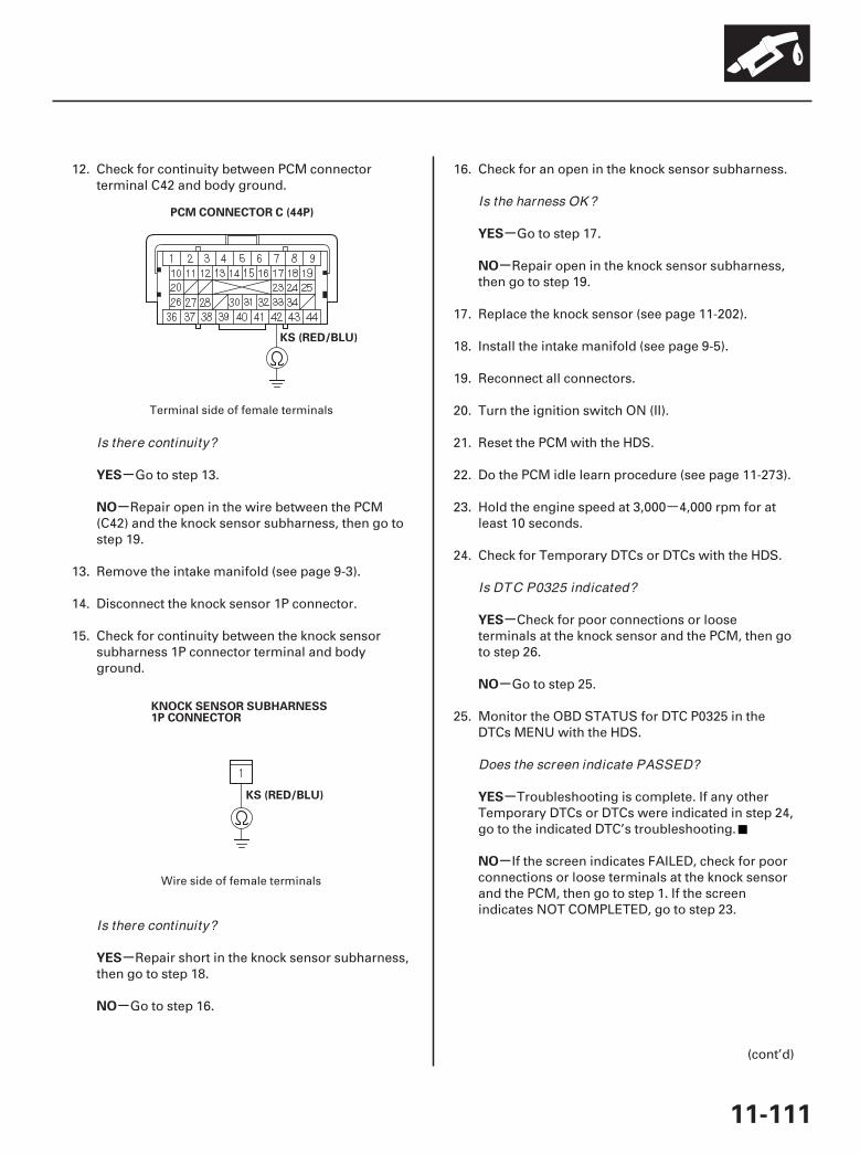
-
03
04
-
-
-
-
-
-
-
-
-
-
YES
NO
YES
NO
YES
NO
YES
NO
YES
NO
11-111
PCM CONNECTOR C (44P)
KS (RED/BLU)
KNOCK SENSOR SUBHARNESS1P CONNECTOR
KS (RED/BLU)
12. Check for continuity between PCM connectorterminal C42 and body ground.
Go to step 13.
Repair open in the wire between the PCM(C42) and the knock sensor subharness, then go tostep 19.
13. Remove the intake manifold (see page 9-3).
14. Disconnect the knock sensor 1P connector.
15. Check for continuity between the knock sensorsubharness 1P connector terminal and bodyground.
Repair short in the knock sensor subharness,then go to step 18.
Go to step 16.
16. Check for an open in the knock sensor subharness.
Go to step 17.
Repair open in the knock sensor subharness,then go to step 19.
17. Replace the knock sensor (see page 11-202).
18. Install the intake manifold (see page 9-5).
19. Reconnect all connectors.
20. Turn the ignition switch ON (II).
21. Reset the PCM with the HDS.
22. Do the PCM idle learn procedure (see page 11-273).
23. Hold the engine speed at 3,000 4,000 rpm for atleast 10 seconds.
24. Check for Temporary DTCs or DTCs with the HDS.
Check for poor connections or looseterminals at the knock sensor and the PCM, then goto step 26.
Go to step 25.
25. Monitor the OBD STATUS for DTC P0325 in theDTCs MENU with the HDS.
Troubleshooting is complete. If any otherTemporary DTCs or DTCs were indicated in step 24,go to the indicated DTC’s troubleshooting.
If the screen indicates FAILED, check for poorconnections or loose terminals at the knock sensorand the PCM, then go to step 1. If the screenindicates NOT COMPLETED, go to step 23.
(cont’d)
Terminal side of female terminals
Wire side of female terminals
Is there continuity?
Is there continuity?
Is the harness OK ?
Is DTC P0325 indicated?
Does the screen indicate PASSED?
07/05/09 16:48:53 61SJC020_110_0111
-
-
-
-
-
YES
NO
YES
NO
11-112
PGM-FI System
DTC Troubleshooting (cont’d)
26. Update the PCM if it does not have the latestsoftware (see page 11-7), or substitute a known-good PCM (see page 11-8).
27. Start the engine. Hold the engine speed at3,000 rpm without load (in Park or neutral) until theradiator fan comes on, then let it idle.
28. Hold the engine speed at 3,000 4,000 rpm for atleast 10 seconds.
29. Check for Temporary DTCs or DTCs with the HDS.
Check for poor connections or looseterminals at the ignition coil, the injector, and thePCM. If the PCM was updated, substitute a known-good PCM (see page 11-8), then go to step 28. If thePCM was substituted, go to step 1.
Go to step 30.
30. Monitor the OBD STATUS for DTC P0325 in theDTCs MENU with the HDS.
If the PCM was updated, troubleshooting iscomplete. If the PCM was substituted, replace theoriginal PCM (see page 11-205). If any otherTemporary DTCs or DTCs were indicated in step 29,go to the indicated DTC’s troubleshooting.
If the screen indicates FAILED, check for poorconnections or loose terminals at the ignition coil,the injector, and the PCM. If the PCM was updated,substitute a known-good PCM (see page 11-8), thengo to step 28. If the PCM was substituted, go to step1. If the screen indicates NOT COMPLETED, go tostep 28.
Is DTC P0325 indicated?
Does the screen indicate PASSED?
07/05/09 16:48:54 61SJC020_110_0112
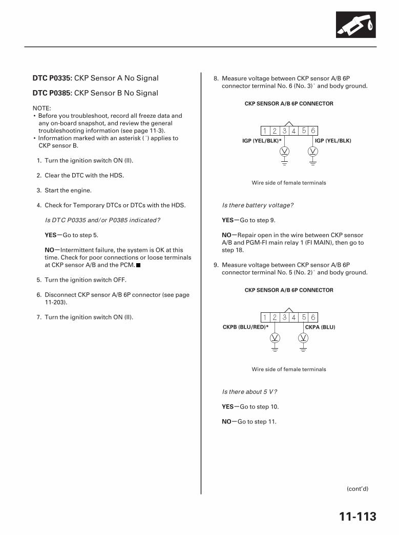
01
02
SJC8A00K77100090335FAAT30
-
-
-
-
-
-
DTC P0335:
DTC P0385:
YES
NO
YES
NO
YES
NO
11-113
CKP SENSOR A/B 6P CONNECTOR
IGP (YEL/BLK)* IGP (YEL/BLK)
CKP SENSOR A/B 6P CONNECTOR
CKPB (BLU/RED)* CKPA (BLU)
CKP Sensor A No Signal
CKP Sensor B No Signal
NOTE:• Before you troubleshoot, record all freeze data and
any on-board snapshot, and review the generaltroubleshooting information (see page 11-3).
• Information marked with an asterisk ( ) applies toCKP sensor B.
1. Turn the ignition switch ON (II).
2. Clear the DTC with the HDS.
3. Start the engine.
4. Check for Temporary DTCs or DTCs with the HDS.
Go to step 5.
Intermittent failure, the system is OK at thistime. Check for poor connections or loose terminalsat CKP sensor A/B and the PCM.
5. Turn the ignition switch OFF.
6. Disconnect CKP sensor A/B 6P connector (see page11-203).
7. Turn the ignition switch ON (II).
8. Measure voltage between CKP sensor A/B 6Pconnector terminal No. 6 (No. 3) and body ground.
Go to step 9.
Repair open in the wire between CKP sensorA/B and PGM-FI main relay 1 (FI MAIN), then go tostep 18.
9. Measure voltage between CKP sensor A/B 6Pconnector terminal No. 5 (No. 2) and body ground.
Go to step 10.
Go to step 11.
(cont’d)
Wire side of female terminals
Wire side of female terminals
Is DTC P0335 and/ or P0385 indicated?
Is there battery voltage?
Is there about 5 V?
07/05/09 16:48:54 61SJC020_110_0113
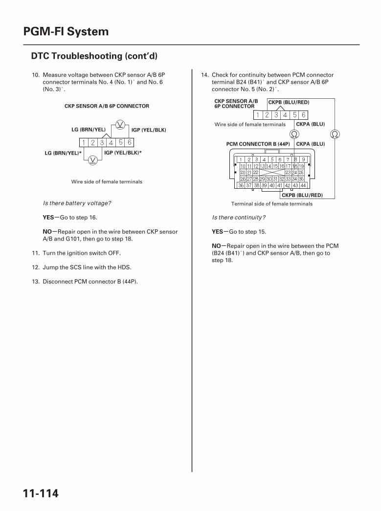
03 04
-
- -
-
YES
NO YES
NO
11-114
PGM-FI System
DTC Troubleshooting (cont’d)
IGP (YEL/BLK)*
IGP (YEL/BLK)LG (BRN/YEL)
LG (BRN/YEL)*
CKP SENSOR A/B 6P CONNECTORCKP SENSOR A/B6P CONNECTOR
PCM CONNECTOR B (44P)
CKPB (BLU/RED)
CKPA (BLU)
CKPB (BLU/RED)
CKPA (BLU)
10. Measure voltage between CKP sensor A/B 6Pconnector terminals No. 4 (No. 1) and No. 6(No. 3) .
Go to step 16.
Repair open in the wire between CKP sensorA/B and G101, then go to step 18.
11. Turn the ignition switch OFF.
12. Jump the SCS line with the HDS.
13. Disconnect PCM connector B (44P).
14. Check for continuity between PCM connectorterminal B24 (B41) and CKP sensor A/B 6Pconnector No. 5 (No. 2) .
Go to step 15.
Repair open in the wire between the PCM(B24 (B41) ) and CKP sensor A/B, then go tostep 18.
Wire side of female terminals
Wire side of female terminals
Terminal side of female terminalsIs there battery voltage?
Is there continuity?
07/05/09 16:48:54 61SJC020_110_0114
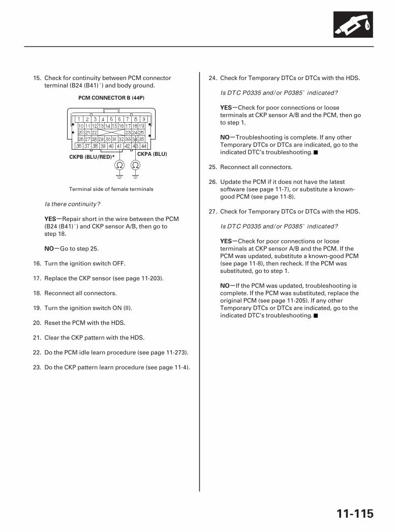
*01
-
-
-
-
-
-
YES
NO
YES
NO
YES
NO
11-115
PCM CONNECTOR B (44P)
CKPA (BLU)CKPB (BLU/RED)*
15. Check for continuity between PCM connectorterminal (B24 (B41) ) and body ground.
Repair short in the wire between the PCM(B24 (B41) ) and CKP sensor A/B, then go tostep 18.
Go to step 25.
16. Turn the ignition switch OFF.
17. Replace the CKP sensor (see page 11-203).
18. Reconnect all connectors.
19. Turn the ignition switch ON (II).
20. Reset the PCM with the HDS.
21. Clear the CKP pattern with the HDS.
22. Do the PCM idle learn procedure (see page 11-273).
23. Do the CKP pattern learn procedure (see page 11-4).
24. Check for Temporary DTCs or DTCs with the HDS.
Check for poor connections or looseterminals at CKP sensor A/B and the PCM, then goto step 1.
Troubleshooting is complete. If any otherTemporary DTCs or DTCs are indicated, go to theindicated DTC’s troubleshooting.
25. Reconnect all connectors.
26. Update the PCM if it does not have the latestsoftware (see page 11-7), or substitute a known-good PCM (see page 11-8).
27. Check for Temporary DTCs or DTCs with the HDS.
Check for poor connections or looseterminals at CKP sensor A/B and the PCM. If thePCM was updated, substitute a known-good PCM(see page 11-8), then recheck. If the PCM wassubstituted, go to step 1.
If the PCM was updated, troubleshooting iscomplete. If the PCM was substituted, replace theoriginal PCM (see page 11-205). If any otherTemporary DTCs or DTCs are indicated, go to theindicated DTC’s troubleshooting.
Terminal side of female terminals
Is there continuity?
Is DTC P0335 and/ or P0385 indicated?
Is DTC P0335 and/ or P0385 indicated?
07/05/09 16:48:54 61SJC020_110_0115
SJC8A00K77100090339FAAT30
-
-
-
-
-
-
-
-
DTC P0339:
DTC P0389:
YES
NO
YES
NO
YES
NO
YES
NO
11-116
PGM-FI System
DTC Troubleshooting (cont’d)
CKP Sensor A IntermittentInterruption
CKP Sensor B IntermittentInterruption
NOTE:• Before you troubleshoot, record all freeze data and
any on-board snapshot, and review the generaltroubleshooting information (see page 11-3).
• Information marked with an asterisk ( ) applies toCKP sensor B.
1. Turn the ignition switch ON (II).
2. Clear the DTC with the HDS.
3. Test-drive the vehicle for 10 minutes in the range ofthese recorded freeze data parameters:
• ENGINE SPEED• VSS
4. Check for Temporary DTCs or DTCs with the HDS.
Go to step 5.
Intermittent failure, the system is OK at thistime. Check for poor connections or loose terminalsat CKP sensor A/B and the PCM.
5. Check for poor or loose connections at theseconnectors and terminals:
• CKP sensor A/B• PCM• Engine ground• Body ground
Go to step 6.
Reconnect the connectors or terminals, thengo to step 9.
6. Check for damage to the CKP sensor A/B pulseplate on the timing belt drive pulley (see page 6-25).
Replace the CKP sensor A/B pulse plate/timing belt drive pulley (see page 6-25), then go tostep 9.
Go to step 7.
7. Turn the ignition switch OFF.
8. Replace CKP sensor A/B (see page 11-203).
9. Turn the ignition switch ON (II).
10. Reset the PCM with the HDS.
11. Clear the CKP pattern with the HDS.
12. Do the PCM idle learn procedure (see page 11-273).
13. Do the CKP pattern learn procedure (see page 11-4).
14. Test-drive the vehicle for 10 minutes in the range ofthese recorded freeze data parameters:
• ENGINE SPEED• VSS
15. Check for Temporary DTCs or DTCs with the HDS.
Check for poor connections or looseterminals at CKP sensor A/B and the PCM, then goto step 1.
Troubleshooting is complete. If any otherTemporary DTCs or DTCs are indicated, go to theindicated DTC’s troubleshooting.
Is DTC P0339 and/ or P0389 indicated?
Are the connections OK ?
Is there damage?
Is DTC P0339 and/ or P0389 indicated?
07/05/09 16:48:55 61SJC020_110_0116
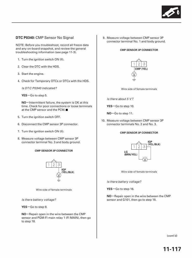
01
02
03
SJC8A00K77100090340FAAT30
-
-
-
-
-
-
-
-
DTC P0340:
YES
NO
YES
NO
YES
NO
YES
NO
11-117
CMP SENSOR 3P CONNECTOR
IGP(YEL/BLK)
CMP SENSOR 3P CONNECTOR
CMP (YEL)
CMP SENSOR 3P CONNECTOR
IGP(YEL/BLK)
LG(BRN/YEL)
CMP Sensor No Signal
NOTE: Before you troubleshoot, record all freeze dataand any on-board snapshot, and review the generaltroubleshooting information (see page 11-3).
1. Turn the ignition switch ON (II).
2. Clear the DTC with the HDS.
3. Start the engine.
4. Check for Temporary DTCs or DTCs with the HDS.
Go to step 5.
Intermittent failure, the system is OK at thistime. Check for poor connections or loose terminalsat the CMP sensor and the PCM.
5. Turn the ignition switch OFF.
6. Disconnect the CMP sensor 3P connector.
7. Turn the ignition switch ON (II).
8. Measure voltage between CMP sensor 3Pconnector terminal No. 3 and body ground.
Go to step 9.
Repair open in the wire between the CMPsensor and PGM-FI main relay 1 (FI MAIN), then goto step 18.
9. Measure voltage between CMP sensor 3Pconnector terminal No. 1 and body ground.
Go to step 10.
Go to step 11.
10. Measure voltage between CMP sensor 3Pconnector terminals No. 2 and No. 3.
Go to step 16.
Repair open in the wire between the CMPsensor and G101, then go to step 18.
(cont’d)
Wire side of female terminals
Wire side of female terminals
Wire side of female terminals
Is DTC P0340 indicated?
Is there battery voltage?
Is there about 5 V?
Is there battery voltage?
07/05/09 16:48:55 61SJC020_110_0117

04
05
-
-
-
-
YES
NO
YES
NO
11-118
PGM-FI System
DTC Troubleshooting (cont’d)
CMP SENSOR 3P CONNECTOR
PCM CONNECTOR B (44P)
CMP (YEL)
CMP (YEL)
CMP SENSOR 3P CONNECTOR
CMP (YEL)
11. Turn the ignition switch OFF.
12. Jump the SCS line with the HDS.
13. Disconnect PCM connector B (44P).
14. Check for continuity between PCM connectorterminal B32 and CMP sensor 3P connectorterminal No. 1.
Go to step 15.
Repair open in the wire between the PCM(B32) and the CMP sensor, then go to step 18.
15. Check for continuity between CMP sensor 3Pconnector terminal No. 1 and body ground.
Repair short in the wire between the PCM(B32) and the CMP sensor, then go to step 18.
Go to step 26.
16. Turn the ignition switch OFF.
17. Replace the CMP sensor (see page 11-203).
18. Reconnect all connectors.
19. Turn the ignition switch ON (II).
20. Reset the PCM with the HDS.
21. Clear the CKP pattern with the HDS.
22. Do the PCM idle learn procedure (see page 11-273).
23. Do the CKP pattern learn procedure (see page 11-4).
24. Start the engine.
Wire side offemale terminals
Terminal side of female terminals
Wire side of female terminals
Is there continuity?
Is there continuity?
07/05/09 16:48:55 61SJC020_110_0118
-
-
-
-
YES
NO
YES
NO
11-119
25. Check for Temporary DTCs or DTCs with the HDS.
Check for poor connections or looseterminals at the CMP sensor and the PCM, then goto step 1.
Troubleshooting is complete. If any otherTemporary DTCs or DTCs are indicated, go to theindicated DTC’s troubleshooting.
26. Reconnect all connectors.
27. Update the PCM if it does not have the latestsoftware (see page 11-7), or substitute a known-good PCM (see page 11-8).
28. Check for Temporary DTCs or DTCs with the HDS.
Check for poor connections or looseterminals at the CMP sensor and the PCM. If thePCM was updated, substitute a known-good PCM(see page 11-8), then recheck. If the PCM wassubstituted, go to step 1.
If the PCM was updated, troubleshooting iscomplete. If the PCM was substituted, replace theoriginal PCM (see page 11-205). If any otherTemporary DTCs or DTCs are indicated, go to theindicated DTC’s troubleshooting.
Is DTC P0340 indicated?
Is DTC P0340 indicated?
07/05/09 16:48:56 61SJC020_110_0119

SJC8A00K77100090344FAAT30
-
-
-
-
-
-
-
-
DTC P0344:
YES
NO
YES
NO
YES
NO
YES
NO
11-120
PGM-FI System
DTC Troubleshooting (cont’d)
CMP Sensor IntermittentInterruption
NOTE: Before you troubleshoot, record all freeze dataand any on-board snapshot, and review the generaltroubleshooting information (see page 11-3).
1. Turn the ignition switch ON (II).
2. Clear the DTC with the HDS.
3. Test-drive the vehicle for 10 minutes in the range ofthese recorded freeze data parameters:
• ENGINE SPEED• VSS
4. Check for Temporary DTCs or DTCs with the HDS.
Go to step 4.
Intermittent failure, the system is OK at thistime. Check for poor connections or loose terminalsat the CMP sensor and the PCM.
5. Check for poor or loose connections at theseconnectors and terminals:
• CMP sensor• PCM• Engine ground• Body ground
Go to step 6.
Reconnect or repair the connectors orterminals, then go to step 9.
6. Check for damage to the CMP sensor pulseprojection on the front camshaft pulley (see page11-203).
Replace the front camshaft pulley (see page6-11), then go to step 9.
Go to step 7.
7. Turn the ignition switch OFF.
8. Replace the CMP sensor (see page 11-203).
9. Turn the ignition switch ON (II).
10. Reset the PCM with the HDS.
11. Clear the CKP pattern with the HDS.
12. Do the PCM idle learn procedure (see page 11-273).
13. Do the CKP pattern learn procedure (see page 11-4).
14. Test-drive the vehicle for 10 minutes in the range ofthese recorded freeze data parameters:
• ENGINE SPEED• VSS
15. Check for Temporary DTCs or DTCs with the HDS.
Check for poor connections or looseterminals at the CMP sensor and the PCM, then goto step 1.
Troubleshooting is complete. If any otherTemporary DTCs or DTCs are indicated, go to theindicated DTC’s troubleshooting.
Is DTC P0344 indicated?
Are the connections OK ?
Is there damage?
Is DTC P0344 indicated?
07/05/09 16:48:56 61SJC020_110_0120
SJC8A00K77100090562FAAT00
-
-
-
-
DTC P0562:
YES
NO
YES
NO
11-121
Charging System Low Voltage
NOTE:• Before you troubleshoot, record all freeze data and
any on-board snapshot, and review the generaltroubleshooting information (see page 11-3).
• If any high current load accessories are installed, thisDTC can be set.
• If DTC P16BB and/or P16BC is stored at the same timeas DTC P0562, troubleshoot DTC P16BB and/or P16BCfirst, then recheck for DTC P0562.
1. Turn the ignition switch ON (II).
2. Clear the DTC with the HDS.
3. Start the engine.
4. Check under these conditions:
• A/C on• Temperature control at maximum cool• Blower fan at maximum speed• Headlights on high beam
5. Hold the engine speed at 2,000 rpm (in Park orneutral) for 1 minute.
6. Check for Temporary DTCs or DTCs with the HDS.
Replace the alternator (see page 4-34), thengo to step 7.
Intermittent failure, the system is OK at thistime. Check for poor connections or loose terminalsat the alternator and the under-hood fuse/relay box,and check the battery performance (see page22-74).
7. Turn the ignition switch ON (II).
8. Reset the PCM with the HDS.
9. Do the PCM idle learn procedure (see page 11-273).
10. Start the engine.
11. Check under these conditions:
• A/C on• Temperature control at maximum cool• Blower fan at maximum speed• Headlights on high beam
12. Hold the engine speed at 2,000 rpm (in Park orneutral) for 1 minute.
13. Check for Temporary DTCs or DTCs with the HDS.
Check for poor connections or looseterminals at the alternator and the under-hoodfuse/relay box, then go to step 1.
Troubleshooting is complete. If any otherTemporary DTCs or DTCs are indicated, go to theindicated DTC’s troubleshooting.
Is DTC P0562 indicated?
Is DTC P0562 indicated?
07/05/09 16:49:54 61SJC020_110_0121
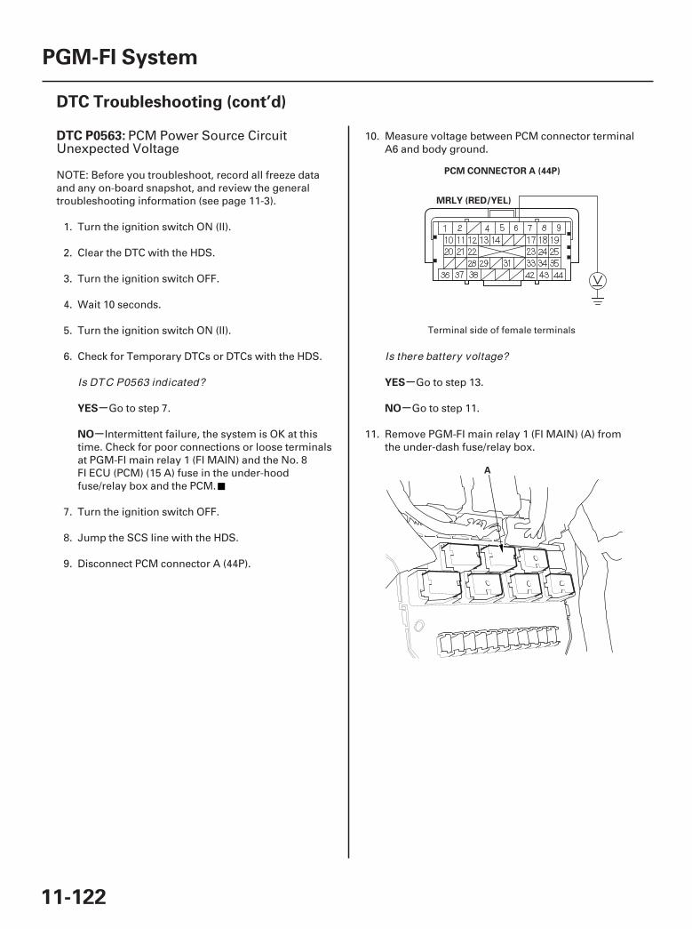
01
02
SJC8A00K77100090563FAAT30
-
-
-
-
DTC P0563:
YES
NO
YES
NO
11-122
PGM-FI System
DTC Troubleshooting (cont’d)
PCM CONNECTOR A (44P)
MRLY (RED/YEL)
A
PCM Power Source CircuitUnexpected Voltage
NOTE: Before you troubleshoot, record all freeze dataand any on-board snapshot, and review the generaltroubleshooting information (see page 11-3).
1. Turn the ignition switch ON (II).
2. Clear the DTC with the HDS.
3. Turn the ignition switch OFF.
4. Wait 10 seconds.
5. Turn the ignition switch ON (II).
6. Check for Temporary DTCs or DTCs with the HDS.
Go to step 7.
Intermittent failure, the system is OK at thistime. Check for poor connections or loose terminalsat PGM-FI main relay 1 (FI MAIN) and the No. 8FI ECU (PCM) (15 A) fuse in the under-hoodfuse/relay box and the PCM.
7. Turn the ignition switch OFF.
8. Jump the SCS line with the HDS.
9. Disconnect PCM connector A (44P).
10. Measure voltage between PCM connector terminalA6 and body ground.
Go to step 13.
Go to step 11.
11. Remove PGM-FI main relay 1 (FI MAIN) (A) fromthe under-dash fuse/relay box.
Terminal side of female terminals
Is DTC P0563 indicated?
Is there battery voltage?
07/05/09 16:49:54 61SJC020_110_0122

03
05
06
-
-
-
-
YES
NO
YES
NO
11-123
PCM CONNECTOR A (44P)
MRLY (RED/YEL) PCM CONNECTOR B (44P)
IGP (YEL/BLK)
A
12. Check for continuity between PCM connectorterminal A6 and body ground.
Repair short in the wire between the PCM(A6) and PGM-FI main relay 1 (FI MAIN), then go tostep 19.
Go to step 18.
13. Reconnect PCM connector A (44P).
14. Disconnect PCM connector B (44P).
15. Measure voltage between PCM connector terminalB3 and body ground.
Go to step 16.
Go to step 26.
16. Remove PGM-FI main relay 1 (FI MAIN) (A) fromthe under-dash fuse/relay box.
(cont’d)
Terminal side of female terminals
Terminal side of female terminalsIs there continuity?
Is there battery voltage?
07/05/09 16:49:55 61SJC020_110_0123
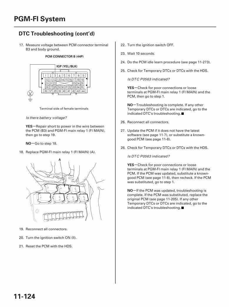
07
08
-
-
-
-
-
-
YES
NO
YES
NO
YES
NO
11-124
PGM-FI System
DTC Troubleshooting (cont’d)
PCM CONNECTOR B (44P)
IGP (YEL/BLK)
A
17. Measure voltage between PCM connector terminalB3 and body ground.
Repair short to power in the wire betweenthe PCM (B3) and PGM-FI main relay 1 (FI MAIN),then go to step 19.
Go to step 18.
18. Replace PGM-FI main relay 1 (FI MAIN) (A).
19. Reconnect all connectors.
20. Turn the ignition switch ON (II).
21. Reset the PCM with the HDS.
22. Turn the ignition switch OFF.
23. Wait 10 seconds.
24. Do the PCM idle learn procedure (see page 11-273).
25. Check for Temporary DTCs or DTCs with the HDS.
Check for poor connections or looseterminals at PGM-FI main relay 1 (FI MAIN) and thePCM, then go to step 1.
Troubleshooting is complete. If any otherTemporary DTCs or DTCs are indicated, go to theindicated DTC’s troubleshooting.
26. Reconnect all connectors.
27. Update the PCM if it does not have the latestsoftware (see page 11-7), or substitute a known-good PCM (see page 11-8).
28. Check for Temporary DTCs or DTCs with the HDS.
Check for poor connections or looseterminals at PGM-FI main relay 1 (FI MAIN) and thePCM. If the PCM was updated, substitute a known-good PCM (see page 11-8), then recheck. If the PCMwas substituted, go to step 1.
If the PCM was updated, troubleshooting iscomplete. If the PCM was substituted, replace theoriginal PCM (see page 11-205). If any otherTemporary DTCs or DTCs are indicated, go to theindicated DTC’s troubleshooting.
Terminal side of female terminals
Is there battery voltage?
Is DTC P0563 indicated?
Is DTC P0563 indicated?
07/05/09 16:49:55 61SJC020_110_0124

SJC8A00K77100090602FAAT00 SJC8A00K77100090603FAAT30
-
-
-
-
-
-
DTC P0602: DTC P0603:
YES
NO
YES
NO
YES
NO
11-12511-125
PCM Programming Error PCM Internal Circuit Malfunction(Keep Alive Memory (KAM) Error)
NOTE:• Before you troubleshoot, record all freeze data and
any on-board snapshot, and review the generaltroubleshooting information (see page 11-3).
• This DTC is indicated when a PCM update is notcompleted.
• Do not turn the ignition switch OFF while updatingthe PCM. If you turn the ignition switch OFF beforecompletion, the PCM can be damaged.
1. Do the PCM update procedure (see page 11-7).
2. Check for Temporary DTCs or DTCs with the HDS.
Replace the original PCM (see page 11-205).
The update is complete.
NOTE: Before you troubleshoot, record all freeze dataand any on-board snapshot, and review the generaltroubleshooting information (see page 11-3).
1. Turn the ignition switch ON (II).
2. Clear the DTC with the HDS.
3. Check for Temporary DTCs or DTCs with the HDS.
Go to step 4.
Intermittent failure, the system is OK at thistime.
4. Update the PCM if it does not have the latestsoftware (see page 11-7), or substitute a known-good PCM (see page 11-8).
5. Check for Temporary DTCs or DTCs with the HDS.
If the PCM was updated, substitute a known-good PCM (see page 11-8), then recheck. If the PCMwas substituted, go to step 1.
If the PCM was updated, troubleshooting iscomplete. If the PCM was substituted, replace theoriginal PCM (see page 11-205). If any otherTemporary DTCs or DTCs are indicated, go to theindicated DTC’s troubleshooting.
Is DTC P0602 indicated?
Are any Temporary DTCs or DTCs indicated?
Is DTC P0603 indicated?
07/05/09 16:49:55 61SJC020_110_0125
SJC8A00K77100090630FAAT30
-
-
-
-
-
-
-
-
-
-
DTC P0630:
YES
NO
YES
NO
YES
NO
YES
NO
YES
NO
11-126
PGM-FI System
DTC Troubleshooting (cont’d)
VIN Not Programmed orMismatch
NOTE:• Before you troubleshoot, record all freeze data and
any on-board snapshot, and review the generaltroubleshooting information (see page 11-3).
• This DTC is stored only when the PCM does not havethe VIN information of the vehicle. Use the HDS toinput the missing VIN information.
1. Turn the ignition switch ON (II).
2. Check the VIN with the HDS.
Go to step 5.
Go to step 3.
3. Input the VIN to the PCM with the HDS.
Go to step 5.
Go to step 4.
4. Check for DTCs with the HDS.
Do the troubleshooting for P0603 (see page11-125).
Go to step 9.
5. Clear the DTC with the HDS.
6. Turn the ignition switch OFF.
7. Turn the ignition switch ON (II), and wait 5 seconds.
8. Check for Temporary DTCs or DTCs with the HDS.
Go to step 9.
Intermittent failure, the system is OK at thistime. If any other Temporary DTCs or DTCs areindicated, go to the indicated DTC’stroubleshooting.
9. Update the PCM if it does not have the latestsoftware (see page 11-7), or substitute a known-good PCM (see page 11-8).
10. Check for Temporary DTCs or DTCs with the HDS.
If the PCM was updated, substitute a known-good PCM (see page 11-8), then recheck. If the PCMwas substituted, go to step 1.
If the PCM was updated, troubleshooting iscomplete. If the PCM was substituted, replace theoriginal PCM (see page 11-205). If any otherTemporary DTCs or DTCs are indicated, go to theindicated DTC’s troubleshooting.
Does the HDS show the vehicle’s V IN?
Does the screen show COMPLETE?
Is DTC P0603 indicated?
Is DTC P0603 indicated?
Is DTC P0630 indicated?
07/05/09 16:49:56 61SJC020_110_0126
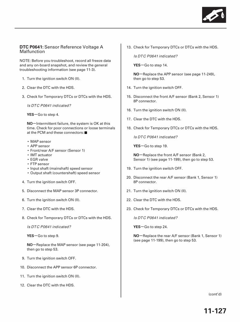
SJC8A00K77100090641FAAT30
-
-
-
-
-
-
-
-
-
-
DTC P0641:
YES
NO
YES
NO
YES
NO
YES
NO
YES
NO
11-127
Sensor Reference Voltage AMalfunction
NOTE: Before you troubleshoot, record all freeze dataand any on-board snapshot, and review the generaltroubleshooting information (see page 11-3).
1. Turn the ignition switch ON (II).
2. Clear the DTC with the HDS.
3. Check for Temporary DTCs or DTCs with the HDS.
Go to step 4.
Intermittent failure, the system is OK at thistime. Check for poor connections or loose terminalsat the PCM and these connectors:
• MAP sensor• APP sensor• Front/rear A/F sensor (Sensor 1)• IMT actuator• EGR valve• FTP sensor• Input shaft (mainshaft) speed sensor• Output shaft (countershaft) speed sensor
4. Turn the ignition switch OFF.
5. Disconnect the MAP sensor 3P connector.
6. Turn the ignition switch ON (II).
7. Clear the DTC with the HDS.
8. Check for Temporary DTCs or DTCs with the HDS.
Go to step 9.
Replace the MAP sensor (see page 11-204),then go to step 53.
9. Turn the ignition switch OFF.
10. Disconnect the APP sensor 6P connector.
11. Turn the ignition switch ON (II).
12. Clear the DTC with the HDS.
13. Check for Temporary DTCs or DTCs with the HDS.
Go to step 14.
Replace the APP sensor (see page 11-249),then go to step 53.
14. Turn the ignition switch OFF.
15. Disconnect the front A/F sensor (Bank 2, Sensor 1)8P connector.
16. Turn the ignition switch ON (II).
17. Clear the DTC with the HDS.
18. Check for Temporary DTCs or DTCs with the HDS.
Go to step 19.
Replace the front A/F sensor (Bank 2,Sensor 1) (see page 11-199), then go to step 53.
19. Turn the ignition switch OFF.
20. Disconnect the rear A/F sensor (Bank 1, Sensor 1)8P connector.
21. Turn the ignition switch ON (II).
22. Clear the DTC with the HDS.
23. Check for Temporary DTCs or DTCs with the HDS.
Go to step 24.
Replace the rear A/F sensor (Bank 1, Sensor 1)(see page 11-199), then go to step 53.
(cont’d)
Is DTC P0641 indicated?
Is DTC P0641 indicated?
Is DTC P0641 indicated?
Is DTC P0641 indicated?
Is DTC P0641 indicated?
07/05/09 16:49:56 61SJC020_110_0127

-
-
-
-
-
-
-
-
-
-
YES
NO
YES
NO
YES
NO
YES
NO
YES
NO
11-128
PGM-FI System
DTC Troubleshooting (cont’d)
24. Turn the ignition switch OFF.
25. Disconnect the IMT actuator 5P connector.
26. Turn the ignition switch ON (II).
27. Clear the DTC with the HDS.
28. Check for Temporary DTCs or DTCs with the HDS.
Go to step 29.
Replace the IMT actuator (see page 11-316),then go to step 53.
29. Turn the ignition switch OFF.
30. Disconnect the EGR valve 6P connector.
31. Turn the ignition switch ON (II).
32. Clear the DTC with the HDS.
33. Check for Temporary DTCs or DTCs with the HDS.
Go to step 34.
Replace the EGR valve (see page 11-342),then go to step 53.
34. Turn the ignition switch OFF.
35. Disconnect the FTP sensor 3P connector.
36. Turn the ignition switch ON (II).
37. Clear the DTC with the HDS.
38. Check for Temporary DTCs or DTCs with the HDS.
Go to step 39.
Replace the FTP sensor (see page 11-374),then go to step 53.
39. Turn the ignition switch OFF.
40. Disconnect the input shaft (mainshaft) speedsensor 3P connector.
41. Turn the ignition switch ON (II).
42. Clear the DTC with the HDS.
43. Check for Temporary DTCs or DTCs with the HDS.
Go to step 44.
Replace the input shaft (mainshaft) speedsensor (see page 14-205), then go to step 53.
44. Turn the ignition switch OFF.
45. Disconnect the output shaft (countershaft) speedsensor 3P connector.
46. Turn the ignition switch ON (II).
47. Clear the DTC with the HDS.
48. Check for Temporary DTCs or DTCs with the HDS.
Go to step 49.
Replace the output shaft (countershaft) speedsensor (see page 14-205), then go to step 53.
49. Turn the ignition switch OFF.
50. Jump the SCS line with the HDS.
51. Disconnect PCM connectors A (44P), B (44P), andC (44P).
Is DTC P0641 indicated?
Is DTC P0641 indicated?
Is DTC P0641 indicated?
Is DTC P0641 indicated?
Is DTC P0641 indicated?
07/05/09 16:49:56 61SJC020_110_0128
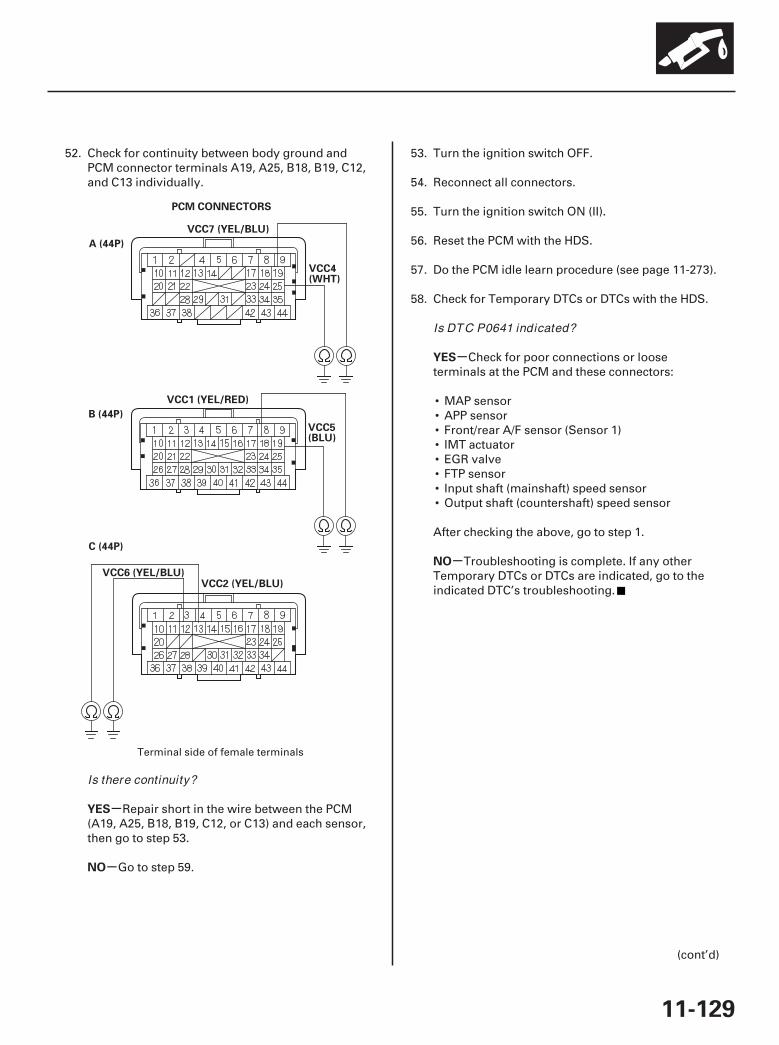
*01
-
-
-
-
YES
NO
YES
NO
11-129
PCM CONNECTORS
VCC4(WHT)
A (44P)
VCC7 (YEL/BLU)
B (44P)
C (44P)
VCC1 (YEL/RED)
VCC5(BLU)
VCC6 (YEL/BLU)VCC2 (YEL/BLU)
52. Check for continuity between body ground andPCM connector terminals A19, A25, B18, B19, C12,and C13 individually.
Repair short in the wire between the PCM(A19, A25, B18, B19, C12, or C13) and each sensor,then go to step 53.
Go to step 59.
53. Turn the ignition switch OFF.
54. Reconnect all connectors.
55. Turn the ignition switch ON (II).
56. Reset the PCM with the HDS.
57. Do the PCM idle learn procedure (see page 11-273).
58. Check for Temporary DTCs or DTCs with the HDS.
Check for poor connections or looseterminals at the PCM and these connectors:
• MAP sensor• APP sensor• Front/rear A/F sensor (Sensor 1)• IMT actuator• EGR valve• FTP sensor• Input shaft (mainshaft) speed sensor• Output shaft (countershaft) speed sensor
After checking the above, go to step 1.
Troubleshooting is complete. If any otherTemporary DTCs or DTCs are indicated, go to theindicated DTC’s troubleshooting.
(cont’d)
Terminal side of female terminals
Is there continuity?
Is DTC P0641 indicated?
07/05/09 16:49:56 61SJC020_110_0129
SJC8A00K77100090685FAAT30
-
-
-
-
-
-
YES
NO
YES
NO
YES
NO
DTC P0685:
11-13011-130
PGM-FI System
DTC Troubleshooting (cont’d)
59. Reconnect all connectors.
60. Update the PCM if it does not have the latestsoftware (see page 11-7), or substitute a known-good PCM (see page 11-8).
61. Check for Temporary DTCs or DTCs with the HDS.
Check for poor connections or looseterminals at the PCM and these connectors:
• MAP sensor• APP sensor• Front/rear A/F sensor (Sensor 1)• IMT actuator• EGR valve• FTP sensor• Input shaft (mainshaft) speed sensor• Output shaft (countershaft) speed sensor
If the PCM was updated, substitute a known-goodPCM (see page 11-8), then recheck. If the PCM wassubstituted, go to step 1.
If the PCM was updated, troubleshooting iscomplete. If the PCM was substituted, replace theoriginal PCM (see page 11-205). If any otherTemporary DTCs or DTCs are indicated, go to theindicated DTC’s troubleshooting.
NOTE:• Before you troubleshoot, record all freeze data and
any on-board snapshot, and review the generaltroubleshooting information (see page 11-3).
• If the problem does not return after clearing the DTC,or if this DTC is stored intermittently, check for looseterminals at the IGP line connectors before youreplace the PCM.
1. Turn the ignition switch ON (II).
2. Clear the DTC with the HDS.
3. Check for Temporary DTCs or DTCs with the HDS.
Go to step 4.
Intermittent failure, the system is OK at thistime. If any other Temporary DTCs or DTCs areindicated, go to the indicated DTC’stroubleshooting.
4. Update the PCM if it does not have the latestsoftware (see page 11-7), or substitute a known-good PCM (see page 11-8).
5. Check for Temporary DTCs or DTCs with the HDS.
If the PCM was updated, substitute a known-good PCM (see page 11-8), then recheck. If the PCMwas substituted, go to step 1.
If the PCM was updated, troubleshooting iscomplete. If the PCM was substituted, replace theoriginal PCM (see page 11-205). If any otherTemporary DTCs or DTCs are indicated, go to theindicated DTC’s troubleshooting.
PCM Power Control Circuit/Internal Circuit Malfunction
Is DTC P0641 indicated?
Is DTC P0685 indicated?
Is DTC P0685 indicated?
07/05/09 16:49:56 61SJC020_110_0130
SJC8A00K77100090700FAAT00 SJC8A00K77100091109FAAT00
-
-
-
-
DTC P0700: DTC P1109:
YES
NO
YES
NO
11-13111-131
A/T Control System Malfunction BARO Sensor Circuit Out ofRange High
NOTE:• Before you troubleshoot, record all freeze data and
any on-board snapshot, and review the generaltroubleshooting information (see page 11-3).
• This DTC is stored when there is a problem in the A/Tcontrol system. Check for A/T DTCs with the HDS, andgo to the indicated DTC’s troubleshooting.
NOTE: Before you troubleshoot, record all freeze dataand any on-board snapshot, and review the generaltroubleshooting information (see page 11-3).
1. Reset the PCM with the HDS.
2. Start the engine.
3. Check for Temporary DTCs or DTCs with the HDS.
Go to step 4.
Intermittent failure, the system is OK at thistime. If any other Temporary DTCs or DTCs areindicated, go to the indicated DTC’stroubleshooting.
4. Update the PCM if it does not have the latestsoftware (see page 11-7), or substitute a known-good PCM (see page 11-8).
5. Check for Temporary DTCs or DTCs with the HDS.
If the PCM was updated, substitute a known-good PCM (see page 11-8), then recheck. If the PCMwas substituted, go to step 1.
If the PCM was updated, troubleshooting iscomplete. If the PCM was substituted, replace theoriginal PCM (see page 11-205). If any otherTemporary DTCs or DTCs are indicated, go to theindicated DTC’s troubleshooting.
Is DTC P1109 indicated?
Is DTC P1109 indicated?
07/05/09 16:49:56 61SJC020_110_0131
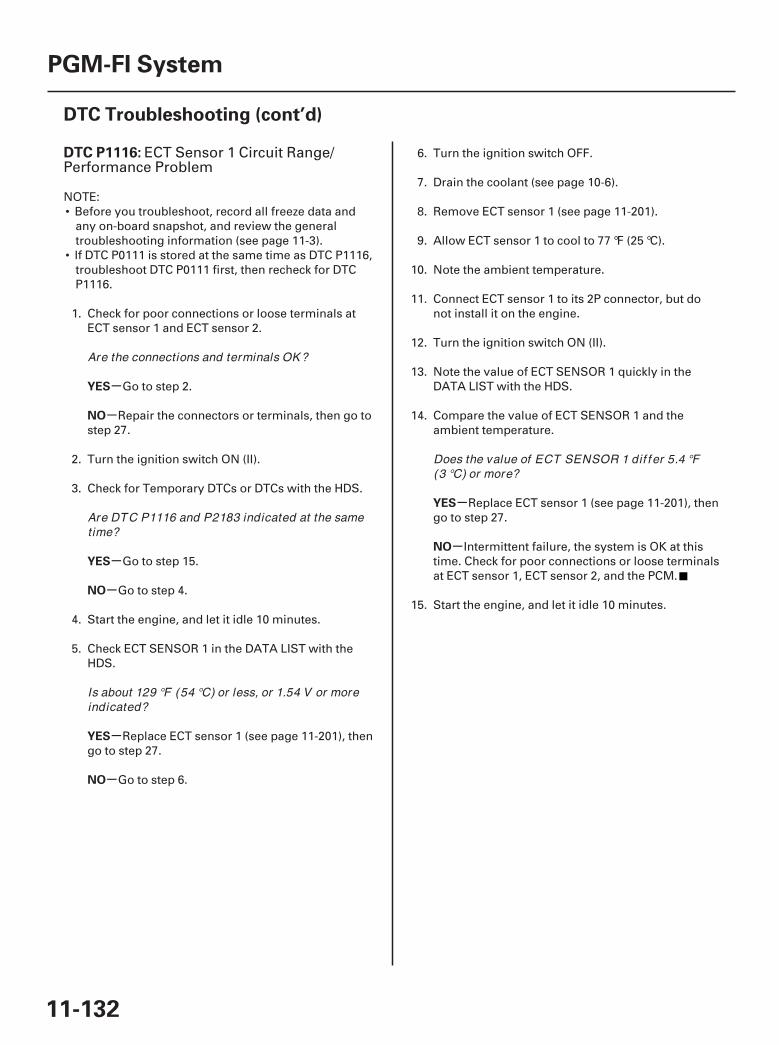
SJC8A00K77100091116FAAT00
-
-
-
-
-
-
-
-
DTC P1116:
YES
NO
YES
NO
YES
NO
YES
NO
11-132
PGM-FI System
DTC Troubleshooting (cont’d)
ECT Sensor 1 Circuit Range/Performance Problem
NOTE:• Before you troubleshoot, record all freeze data and
any on-board snapshot, and review the generaltroubleshooting information (see page 11-3).
• If DTC P0111 is stored at the same time as DTC P1116,troubleshoot DTC P0111 first, then recheck for DTCP1116.
1. Check for poor connections or loose terminals atECT sensor 1 and ECT sensor 2.
Go to step 2.
Repair the connectors or terminals, then go tostep 27.
2. Turn the ignition switch ON (II).
3. Check for Temporary DTCs or DTCs with the HDS.
Go to step 15.
Go to step 4.
4. Start the engine, and let it idle 10 minutes.
5. Check ECT SENSOR 1 in the DATA LIST with theHDS.
Replace ECT sensor 1 (see page 11-201), thengo to step 27.
Go to step 6.
6. Turn the ignition switch OFF.
7. Drain the coolant (see page 10-6).
8. Remove ECT sensor 1 (see page 11-201).
9. Allow ECT sensor 1 to cool to 77 °F (25 °C).
10. Note the ambient temperature.
11. Connect ECT sensor 1 to its 2P connector, but donot install it on the engine.
12. Turn the ignition switch ON (II).
13. Note the value of ECT SENSOR 1 quickly in theDATA LIST with the HDS.
14. Compare the value of ECT SENSOR 1 and theambient temperature.
Replace ECT sensor 1 (see page 11-201), thengo to step 27.
Intermittent failure, the system is OK at thistime. Check for poor connections or loose terminalsat ECT sensor 1, ECT sensor 2, and the PCM.
15. Start the engine, and let it idle 10 minutes.
Are the connections and terminals OK ?
Are DTC P1116 and P2183 indicated at the sametime?
Is about 129 °F (54 °C) or less, or 1.54 V or moreindicated?
Does the value of ECT SENSOR 1 dif f er 5.4 °F(3 °C) or more?
07/05/09 16:49:57 61SJC020_110_0132
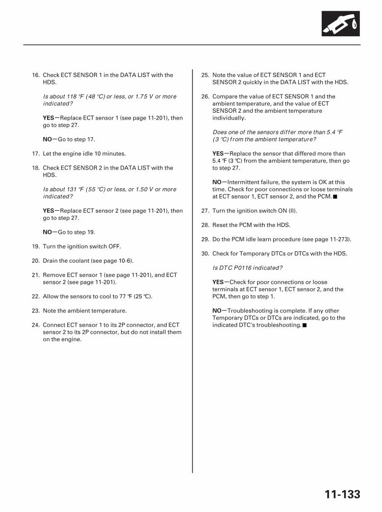
-
-
-
-
-
-
-
-
YES
NO
YES
NO
YES
NO
YES
NO
11-133
16. Check ECT SENSOR 1 in the DATA LIST with theHDS.
Replace ECT sensor 1 (see page 11-201), thengo to step 27.
Go to step 17.
17. Let the engine idle 10 minutes.
18. Check ECT SENSOR 2 in the DATA LIST with theHDS.
Replace ECT sensor 2 (see page 11-201), thengo to step 27.
Go to step 19.
19. Turn the ignition switch OFF.
20. Drain the coolant (see page 10-6).
21. Remove ECT sensor 1 (see page 11-201), and ECTsensor 2 (see page 11-201).
22. Allow the sensors to cool to 77 °F (25 °C).
23. Note the ambient temperature.
24. Connect ECT sensor 1 to its 2P connector, and ECTsensor 2 to its 2P connector, but do not install themon the engine.
25. Note the value of ECT SENSOR 1 and ECTSENSOR 2 quickly in the DATA LIST with the HDS.
26. Compare the value of ECT SENSOR 1 and theambient temperature, and the value of ECTSENSOR 2 and the ambient temperatureindividually.
Replace the sensor that differed more than5.4 °F (3 °C) from the ambient temperature, then goto step 27.
Intermittent failure, the system is OK at thistime. Check for poor connections or loose terminalsat ECT sensor 1, ECT sensor 2, and the PCM.
27. Turn the ignition switch ON (II).
28. Reset the PCM with the HDS.
29. Do the PCM idle learn procedure (see page 11-273).
30. Check for Temporary DTCs or DTCs with the HDS.
Check for poor connections or looseterminals at ECT sensor 1, ECT sensor 2, and thePCM, then go to step 1.
Troubleshooting is complete. If any otherTemporary DTCs or DTCs are indicated, go to theindicated DTC’s troubleshooting.
Is about 118 °F (48 °C) or less, or 1.75 V or moreindicated?
Is about 131 °F (55 °C) or less, or 1.50 V or moreindicated?
Does one of the sensors dif f er more than 5.4 °F(3 °C) f rom the ambient temperature?
Is DTC P0116 indicated?
07/05/09 16:49:57 61SJC020_110_0133
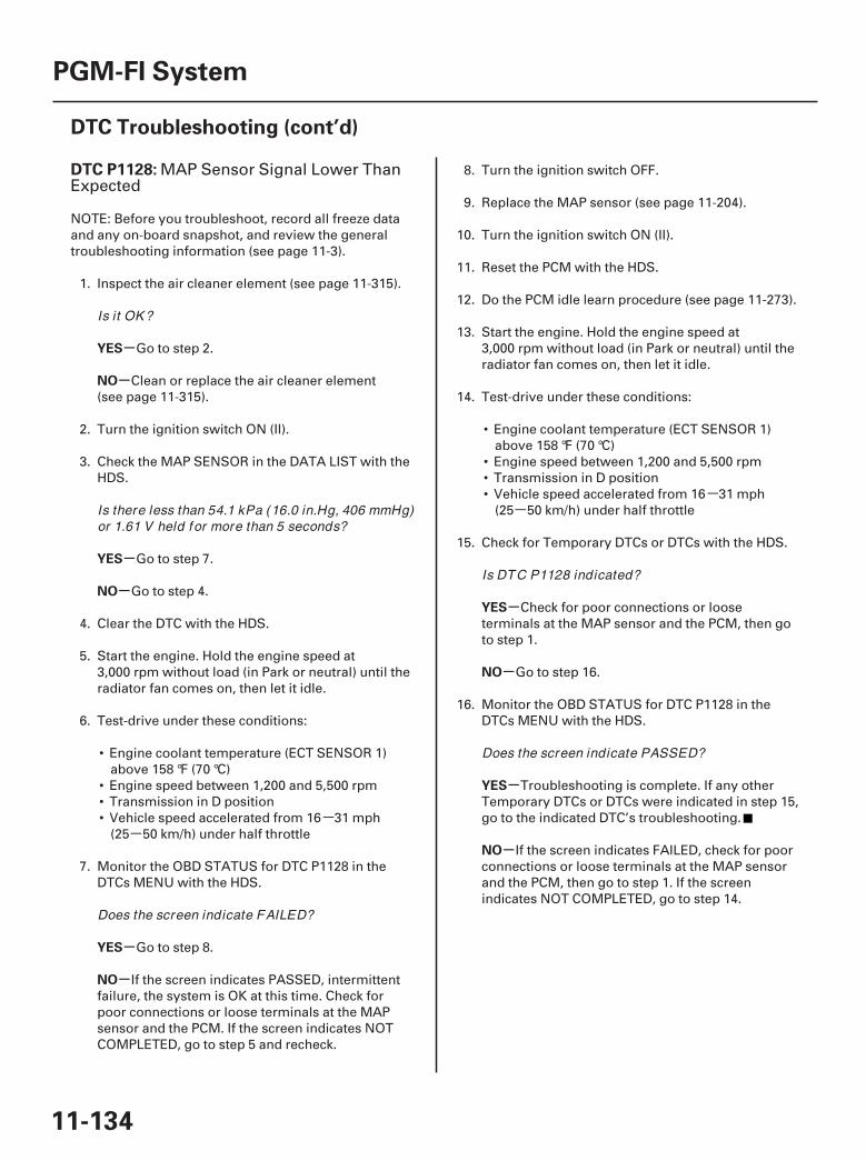
--
--
SJC8A00K77100091128FAAT30
-
-
-
-
-
-
-
-
-
-
DTC P1128:
YES
NO
YES
NO
YES
NO
YES
NO
YES
NO
11-134
PGM-FI System
DTC Troubleshooting (cont’d)
MAP Sensor Signal Lower ThanExpected
NOTE: Before you troubleshoot, record all freeze dataand any on-board snapshot, and review the generaltroubleshooting information (see page 11-3).
1. Inspect the air cleaner element (see page 11-315).
Go to step 2.
Clean or replace the air cleaner element(see page 11-315).
2. Turn the ignition switch ON (II).
3. Check the MAP SENSOR in the DATA LIST with theHDS.
Go to step 7.
Go to step 4.
4. Clear the DTC with the HDS.
5. Start the engine. Hold the engine speed at3,000 rpm without load (in Park or neutral) until theradiator fan comes on, then let it idle.
6. Test-drive under these conditions:
• Engine coolant temperature (ECT SENSOR 1)above 158 °F (70 °C)
• Engine speed between 1,200 and 5,500 rpm• Transmission in D position• Vehicle speed accelerated from 16 31 mph
(25 50 km/h) under half throttle
7. Monitor the OBD STATUS for DTC P1128 in theDTCs MENU with the HDS.
Go to step 8.
If the screen indicates PASSED, intermittentfailure, the system is OK at this time. Check forpoor connections or loose terminals at the MAPsensor and the PCM. If the screen indicates NOTCOMPLETED, go to step 5 and recheck.
8. Turn the ignition switch OFF.
9. Replace the MAP sensor (see page 11-204).
10. Turn the ignition switch ON (II).
11. Reset the PCM with the HDS.
12. Do the PCM idle learn procedure (see page 11-273).
13. Start the engine. Hold the engine speed at3,000 rpm without load (in Park or neutral) until theradiator fan comes on, then let it idle.
14. Test-drive under these conditions:
• Engine coolant temperature (ECT SENSOR 1)above 158 °F (70 °C)
• Engine speed between 1,200 and 5,500 rpm• Transmission in D position• Vehicle speed accelerated from 16 31 mph
(25 50 km/h) under half throttle
15. Check for Temporary DTCs or DTCs with the HDS.
Check for poor connections or looseterminals at the MAP sensor and the PCM, then goto step 1.
Go to step 16.
16. Monitor the OBD STATUS for DTC P1128 in theDTCs MENU with the HDS.
Troubleshooting is complete. If any otherTemporary DTCs or DTCs were indicated in step 15,go to the indicated DTC’s troubleshooting.
If the screen indicates FAILED, check for poorconnections or loose terminals at the MAP sensorand the PCM, then go to step 1. If the screenindicates NOT COMPLETED, go to step 14.
Is it OK ?
Is there less than 54.1 kPa (16.0 in.Hg, 406 mmHg)or 1.61 V held for more than 5 seconds?
Does the screen indicate FAILED?
Is DTC P1128 indicated?
Does the screen indicate PASSED?
07/05/09 16:49:57 61SJC020_110_0134
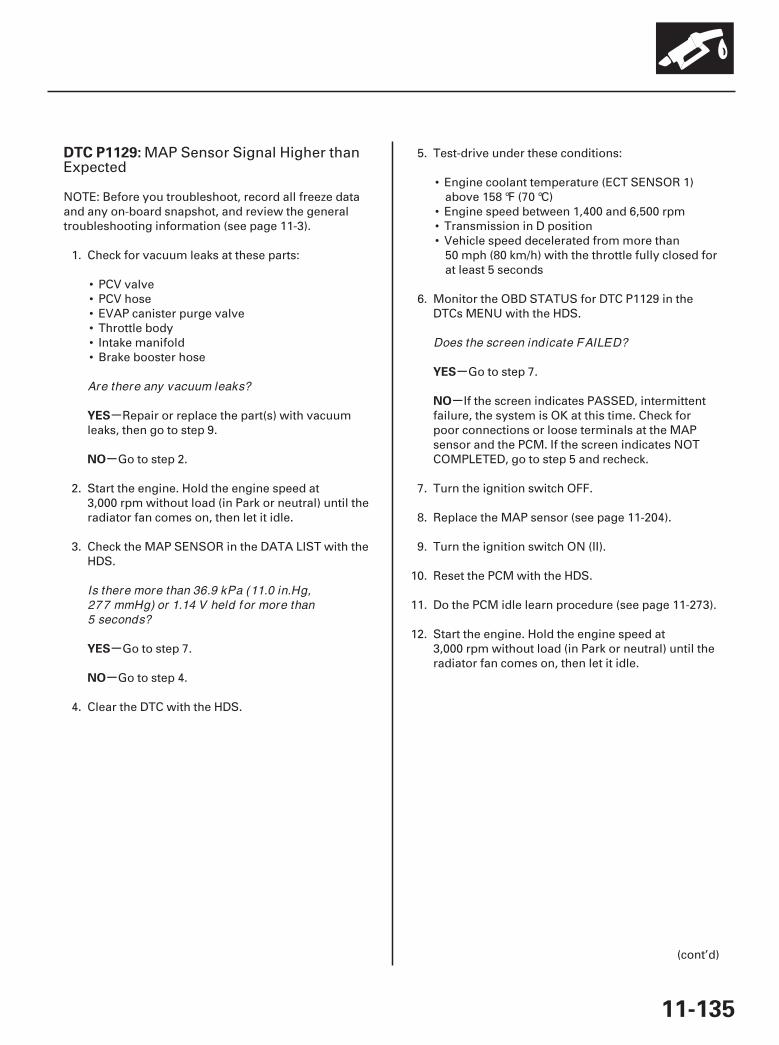
SJC8A00K77100091129FAAT30
-
-
-
-
-
-
DTC P1129:
YES
NO
YES
NO
YES
NO
11-135
MAP Sensor Signal Higher thanExpected
NOTE: Before you troubleshoot, record all freeze dataand any on-board snapshot, and review the generaltroubleshooting information (see page 11-3).
1. Check for vacuum leaks at these parts:
• PCV valve• PCV hose• EVAP canister purge valve• Throttle body• Intake manifold• Brake booster hose
Repair or replace the part(s) with vacuumleaks, then go to step 9.
Go to step 2.
2. Start the engine. Hold the engine speed at3,000 rpm without load (in Park or neutral) until theradiator fan comes on, then let it idle.
3. Check the MAP SENSOR in the DATA LIST with theHDS.
Go to step 7.
Go to step 4.
4. Clear the DTC with the HDS.
5. Test-drive under these conditions:
• Engine coolant temperature (ECT SENSOR 1)above 158 °F (70 °C)
• Engine speed between 1,400 and 6,500 rpm• Transmission in D position• Vehicle speed decelerated from more than
50 mph (80 km/h) with the throttle fully closed forat least 5 seconds
6. Monitor the OBD STATUS for DTC P1129 in theDTCs MENU with the HDS.
Go to step 7.
If the screen indicates PASSED, intermittentfailure, the system is OK at this time. Check forpoor connections or loose terminals at the MAPsensor and the PCM. If the screen indicates NOTCOMPLETED, go to step 5 and recheck.
7. Turn the ignition switch OFF.
8. Replace the MAP sensor (see page 11-204).
9. Turn the ignition switch ON (II).
10. Reset the PCM with the HDS.
11. Do the PCM idle learn procedure (see page 11-273).
12. Start the engine. Hold the engine speed at3,000 rpm without load (in Park or neutral) until theradiator fan comes on, then let it idle.
(cont’d)
Are there any vacuum leaks?
Is there more than 36.9 kPa (11.0 in.Hg,277 mmHg) or 1.14 V held for more than5 seconds?
Does the screen indicate FAILED?
07/05/09 16:49:57 61SJC020_110_0135
-
-
-
-
YES
NO
YES
NO
11-136
PGM-FI System
DTC Troubleshooting (cont’d)
13. Test-drive under these conditions:
• Engine coolant temperature (ECT SENSOR 1)above 158 °F (70 °C)
• Engine speed between 1,400 and 6,500 rpm• Transmission in D position• Vehicle speed decelerated from more than
50 mph (80 km/h) with the throttle fully closed forat least 5 seconds
14. Check for Temporary DTCs or DTCs with the HDS.
Check for poor connections or looseterminals at the MAP sensor and the PCM, then goto step 1.
Go to step 15.
15. Monitor the OBD STATUS for DTC P1129 in theDTCs MENU with the HDS.
Troubleshooting is complete. If any otherTemporary DTCs or DTCs were indicated in step 14,go to the indicated DTC’s troubleshooting.
If the screen indicates FAILED, check for poorconnections or loose terminals at the MAP sensorand the PCM, then go to step 1. If the screenindicates NOT COMPLETED, go to step 13.
Is DTC P1129 indicated?
Does the screen indicate PASSED?
07/05/09 16:49:57 61SJC020_110_0136
SJC8A00K77100091172FAAT00
-
-
-
-
-
-
DTC P1172:
DTC P1174:
YES
NO
YES
NO
YES
NO
11-137
Rear A/F Sensor (Bank 1,Sensor 1) Circuit Out of Range High
Front A/F Sensor (Bank 2,Sensor 1) Circuit Out of Range High
NOTE:• Before you troubleshoot, record all freeze data and
any on-board snapshot, and review the generaltroubleshooting information (see page 11-3).
• Information marked with an asterisk ( ) applies to thefront bank (Bank 2).
1. Turn the ignition switch ON (II).
2. Clear the DTC with the HDS.
3. Start the engine. Hold the engine speed at3,000 rpm without load (in Park or neutral) until theradiator fan comes on, then let it idle.
4. Monitor the OBD STATUS for P1172 and/or P1174in the DTCs MENU with the HDS.
Go to step 5.
If the screen indicates PASSED, intermittentfailure, the system is OK at this time. Check forpoor connections or loose terminals at the A/Fsensor (Sensor 1) and the PCM. If the screenindicates EXECUTING, keep driving until a resultcomes on. If the screen indicates OUT OFCONDITION, go to step 3 and recheck.
5. Turn the ignition switch OFF.
6. Replace the A/F sensor (Sensor 1) (see page11-199).
7. Turn the ignition switch ON (II).
8. Reset the PCM with the HDS.
9. Do the PCM idle learn procedure (see page 11-273).
10. Start the engine. Hold the engine speed at3,000 rpm without load (in Park or neutral) until theradiator fan comes on, then let it idle.
11. Check for Temporary DTCs or DTCs with the HDS.
Check for poor connections or looseterminals at the A/F sensor (Sensor 1) and the PCM,then go to step 1.
Go to step 12.
12. Monitor the OBD STATUS for DTC P1172 and/orP1174 in the DTCs MENU with the HDS.
Troubleshooting is complete. If any otherTemporary DTCs or DTCs were indicated in step 11,go to the indicated DTC’s troubleshooting.
If the screen indicates FAILED, check for poorconnections or loose terminals at the A/F sensor(Sensor 1) and the PCM, then go to step 1. If thescreen indicates EXECUTING or OUT OFCONDITION, keep idling until a result comes on.
Does the screen indicate FAILED?
Is DTC P1172 and/ or P1174 indicated?
Does the screen indicate PASSED?
07/05/09 16:49:57 61SJC020_110_0137
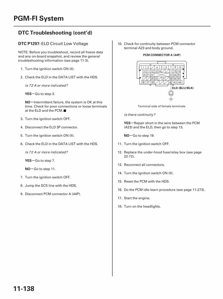
01
SJC8A00K77100091297FAAT30
-
-
-
-
-
-
DTC P1297:
YES
NO
YES
NO
YES
NO
11-138
PGM-FI System
DTC Troubleshooting (cont’d)
PCM CONNECTOR A (44P)
ELD (BLU/BLK)
ELD Circuit Low Voltage
NOTE: Before you troubleshoot, record all freeze dataand any on-board snapshot, and review the generaltroubleshooting information (see page 11-3).
1. Turn the ignition switch ON (II).
2. Check the ELD in the DATA LIST with the HDS.
Go to step 3.
Intermittent failure, the system is OK at thistime. Check for poor connections or loose terminalsat the ELD and the PCM.
3. Turn the ignition switch OFF.
4. Disconnect the ELD 3P connector.
5. Turn the ignition switch ON (II).
6. Check the ELD in the DATA LIST with the HDS.
Go to step 7.
Go to step 11.
7. Turn the ignition switch OFF.
8. Jump the SCS line with the HDS.
9. Disconnect PCM connector A (44P).
10. Check for continuity between PCM connectorterminal A23 and body ground.
Repair short in the wire between the PCM(A23) and the ELD, then go to step 13.
Go to step 19.
11. Turn the ignition switch OFF.
12. Replace the under-hood fuse/relay box (see page22-72).
13. Reconnect all connectors.
14. Turn the ignition switch ON (II).
15. Reset the PCM with the HDS.
16. Do the PCM idle learn procedure (see page 11-273).
17. Start the engine.
18. Turn on the headlights.
Terminal side of female terminals
Is 72 A or more indicated?
Is 72 A or more indicated?
Is there continuity?
07/05/09 16:49:58 61SJC020_110_0138
-
-
-
-
YES
NO
YES
NO
11-139
19. Check for Temporary DTCs or DTCs with the HDS.
Check for poor connections or looseterminals at the ELD unit and the PCM, then go tostep 1.
Troubleshooting is complete. If any otherTemporary DTCs or DTCs are indicated, go to theindicated DTC’s troubleshooting.
20. Reconnect all connectors.
21. Update the PCM if it does not have the latestsoftware (see page 11-7), or substitute a known-good PCM (see page 11-8).
22. Start the engine.
23. Turn on the headlights.
24. Check for Temporary DTCs or DTCs with the HDS.
Check for poor connections or looseterminals at the ELD unit and the PCM. If the PCMwas updated, substitute a known-good PCM(see page 11-8), then go to step 22. If the PCM wassubstituted, go to step 1.
If the PCM was updated, troubleshooting iscomplete. If the PCM was substituted, replace theoriginal PCM (see page 11-205). If any otherTemporary DTCs or DTCs are indicated, go to theindicated DTC’s troubleshooting.
Is DTC P1297 indicated?
Is DTC P1297 indicated?
07/05/09 16:49:58 61SJC020_110_0139
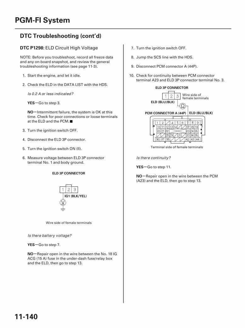
01
02
SJC8A00K77100091298FAAT30
-
-
-
-
-
-
DTC P1298:
YES
NO
YES
NO
YES
NO
11-140
PGM-FI System
DTC Troubleshooting (cont’d)
ELD 3P CONNECTOR
IG1 (BLK/YEL)
PCM CONNECTOR A (44P)
ELD 3P CONNECTOR
ELD (BLU/BLK)
ELD (BLU/BLK)
ELD Circuit High Voltage
NOTE: Before you troubleshoot, record all freeze dataand any on-board snapshot, and review the generaltroubleshooting information (see page 11-3).
1. Start the engine, and let it idle.
2. Check the ELD in the DATA LIST with the HDS.
Go to step 3.
Intermittent failure, the system is OK at thistime. Check for poor connections or loose terminalsat the ELD and the PCM.
3. Turn the ignition switch OFF.
4. Disconnect the ELD 3P connector.
5. Turn the ignition switch ON (II).
6. Measure voltage between ELD 3P connectorterminal No. 1 and body ground.
Go to step 7.
Repair open in the wire between the No. 18 IGACG (15 A) fuse in the under-dash fuse/relay boxand the ELD, then go to step 13.
7. Turn the ignition switch OFF.
8. Jump the SCS line with the HDS.
9. Disconnect PCM connector A (44P).
10. Check for continuity between PCM connectorterminal A23 and ELD 3P connector terminal No. 3.
Go to step 11.
Repair open in the wire between the PCM(A23) and the ELD, then go to step 13.
Wire side of female terminals
Wire side offemale terminals
Terminal side of female terminals
Is 0.2 A or less indicated?
Is there battery voltage?
Is there continuity?
07/05/09 16:49:58 61SJC020_110_0140
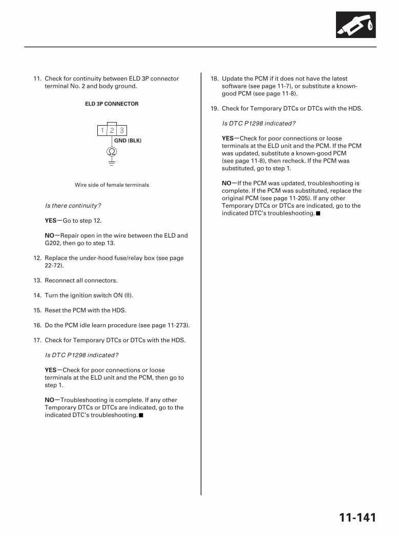
03
-
-
-
-
-
-
YES
NO
YES
NO
YES
NO
11-141
ELD 3P CONNECTOR
GND (BLK)
11. Check for continuity between ELD 3P connectorterminal No. 2 and body ground.
Go to step 12.
Repair open in the wire between the ELD andG202, then go to step 13.
12. Replace the under-hood fuse/relay box (see page22-72).
13. Reconnect all connectors.
14. Turn the ignition switch ON (II).
15. Reset the PCM with the HDS.
16. Do the PCM idle learn procedure (see page 11-273).
17. Check for Temporary DTCs or DTCs with the HDS.
Check for poor connections or looseterminals at the ELD unit and the PCM, then go tostep 1.
Troubleshooting is complete. If any otherTemporary DTCs or DTCs are indicated, go to theindicated DTC’s troubleshooting.
18. Update the PCM if it does not have the latestsoftware (see page 11-7), or substitute a known-good PCM (see page 11-8).
19. Check for Temporary DTCs or DTCs with the HDS.
Check for poor connections or looseterminals at the ELD unit and the PCM. If the PCMwas updated, substitute a known-good PCM(see page 11-8), then recheck. If the PCM wassubstituted, go to step 1.
If the PCM was updated, troubleshooting iscomplete. If the PCM was substituted, replace theoriginal PCM (see page 11-205). If any otherTemporary DTCs or DTCs are indicated, go to theindicated DTC’s troubleshooting.
Wire side of female terminals
Is there continuity?
Is DTC P1298 indicated?
Is DTC P1298 indicated?
07/05/09 16:49:58 61SJC020_110_0141
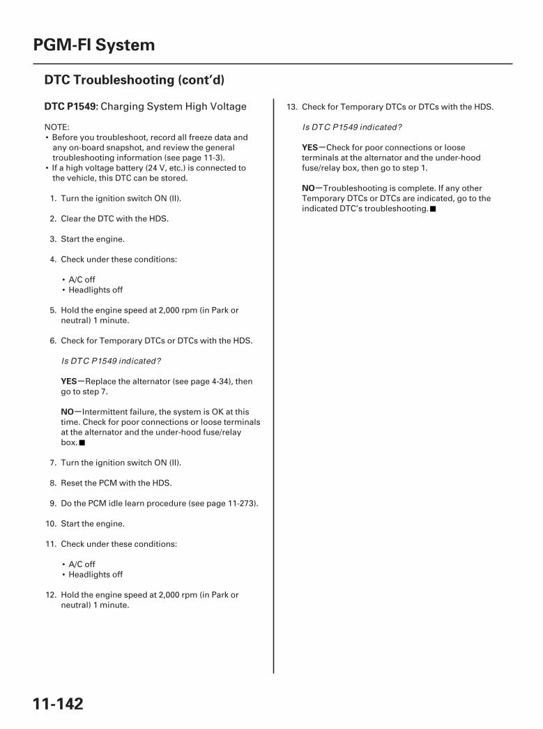
SJC8A00K77100091549FAAT00
-
-
-
-
DTC P1549:
YES
NO
YES
NO
11-142
PGM-FI System
DTC Troubleshooting (cont’d)
Charging System High Voltage
NOTE:• Before you troubleshoot, record all freeze data and
any on-board snapshot, and review the generaltroubleshooting information (see page 11-3).
• If a high voltage battery (24 V, etc.) is connected tothe vehicle, this DTC can be stored.
1. Turn the ignition switch ON (II).
2. Clear the DTC with the HDS.
3. Start the engine.
4. Check under these conditions:
• A/C off• Headlights off
5. Hold the engine speed at 2,000 rpm (in Park orneutral) 1 minute.
6. Check for Temporary DTCs or DTCs with the HDS.
Replace the alternator (see page 4-34), thengo to step 7.
Intermittent failure, the system is OK at thistime. Check for poor connections or loose terminalsat the alternator and the under-hood fuse/relaybox.
7. Turn the ignition switch ON (II).
8. Reset the PCM with the HDS.
9. Do the PCM idle learn procedure (see page 11-273).
10. Start the engine.
11. Check under these conditions:
• A/C off• Headlights off
12. Hold the engine speed at 2,000 rpm (in Park orneutral) 1 minute.
13. Check for Temporary DTCs or DTCs with the HDS.
Check for poor connections or looseterminals at the alternator and the under-hoodfuse/relay box, then go to step 1.
Troubleshooting is complete. If any otherTemporary DTCs or DTCs are indicated, go to theindicated DTC’s troubleshooting.
Is DTC P1549 indicated?
Is DTC P1549 indicated?
07/05/09 16:49:58 61SJC020_110_0142
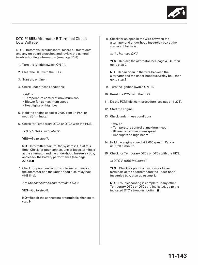
+
SJC8A00K771000916BBFAAT00
-
-
-
-
-
-
-
-
DTC P16BB:
YES
NO
YES
NO
YES
NO
YES
NO
11-143
Alternator B Terminal CircuitLow Voltage
NOTE: Before you troubleshoot, record all freeze dataand any on-board snapshot, and review the generaltroubleshooting information (see page 11-3).
1. Turn the ignition switch ON (II).
2. Clear the DTC with the HDS.
3. Start the engine.
4. Check under these conditions:
• A/C on• Temperature control at maximum cool• Blower fan at maximum speed• Headlights on high beam
5. Hold the engine speed at 2,000 rpm (in Park orneutral) 1 minute.
6. Check for Temporary DTCs or DTCs with the HDS.
Go to step 7.
Intermittent failure, the system is OK at thistime. Check for poor connections or loose terminalsat the alternator and the under-hood fuse/relay box,and check the battery performance (see page22-74).
7. Check for poor connections or loose terminals atthe alternator and the under-hood fuse/relay box( B line).
Go to step 8.
Repair the connectors or terminals, then go tostep 9.
8. Check for an open in the wire between thealternator and under-hood fuse/relay box at thestarter subharness.
Replace the alternator (see page 4-34), thengo to step 9.
Repair open in the wire between thealternator and the under-hood fuse/relay box, thengo to step 9.
9. Turn the ignition switch ON (II).
10. Reset the PCM with the HDS.
11. Do the PCM idle learn procedure (see page 11-273).
12. Start the engine.
13. Check under these conditions:
• A/C on• Temperature control at maximum cool• Blower fan at maximum speed• Headlights on high beam
14. Hold the engine speed at 2,000 rpm (in Park orneutral) 1 minute.
15. Check for Temporary DTCs or DTCs with the HDS.
Check for poor connections or looseterminals at the alternator and the under-hoodfuse/relay box, then go to step 1.
Troubleshooting is complete. If any otherTemporary DTCs or DTCs are indicated, go to theindicated DTC’s troubleshooting.
Is DTC P16BB indicated?
Are the connections and terminals OK ?
Is the harness OK ?
Is DTC P16BB indicated?
07/05/09 16:49:59 61SJC020_110_0143
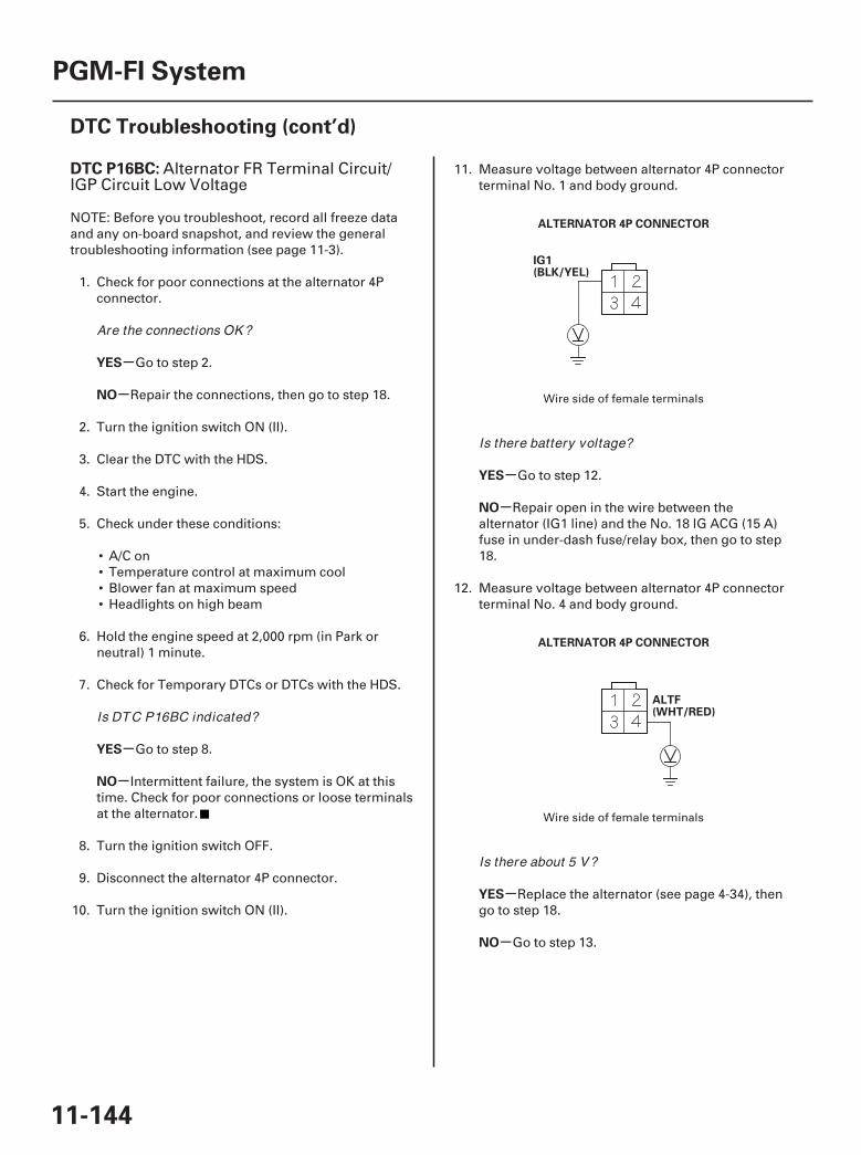
01
02
SJC8A00K771000916BCFAAT00
-
-
-
-
-
-
-
-
DTC P16BC:
YES
NO
YES
NO
YES
NO
YES
NO
11-144
PGM-FI System
DTC Troubleshooting (cont’d)
ALTERNATOR 4P CONNECTOR
IG1(BLK/YEL)
ALTERNATOR 4P CONNECTOR
ALTF(WHT/RED)
Alternator FR Terminal Circuit/IGP Circuit Low Voltage
NOTE: Before you troubleshoot, record all freeze dataand any on-board snapshot, and review the generaltroubleshooting information (see page 11-3).
1. Check for poor connections at the alternator 4Pconnector.
Go to step 2.
Repair the connections, then go to step 18.
2. Turn the ignition switch ON (II).
3. Clear the DTC with the HDS.
4. Start the engine.
5. Check under these conditions:
• A/C on• Temperature control at maximum cool• Blower fan at maximum speed• Headlights on high beam
6. Hold the engine speed at 2,000 rpm (in Park orneutral) 1 minute.
7. Check for Temporary DTCs or DTCs with the HDS.
Go to step 8.
Intermittent failure, the system is OK at thistime. Check for poor connections or loose terminalsat the alternator.
8. Turn the ignition switch OFF.
9. Disconnect the alternator 4P connector.
10. Turn the ignition switch ON (II).
11. Measure voltage between alternator 4P connectorterminal No. 1 and body ground.
Go to step 12.
Repair open in the wire between thealternator (IG1 line) and the No. 18 IG ACG (15 A)fuse in under-dash fuse/relay box, then go to step18.
12. Measure voltage between alternator 4P connectorterminal No. 4 and body ground.
Replace the alternator (see page 4-34), thengo to step 18.
Go to step 13.
Wire side of female terminals
Wire side of female terminals
Are the connections OK ?
Is DTC P16BC indicated?
Is there battery voltage?
Is there about 5 V?
07/05/09 16:49:59 61SJC020_110_0144
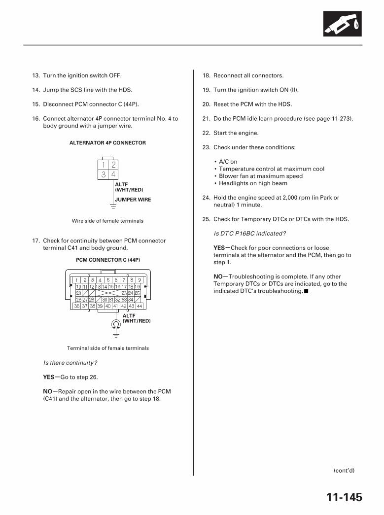
03
04
-
-
-
-
YES
NO
YES
NO
11-145
ALTERNATOR 4P CONNECTOR
ALTF(WHT/RED)
JUMPER WIRE
PCM CONNECTOR C (44P)
ALTF(WHT/RED)
13. Turn the ignition switch OFF.
14. Jump the SCS line with the HDS.
15. Disconnect PCM connector C (44P).
16. Connect alternator 4P connector terminal No. 4 tobody ground with a jumper wire.
17. Check for continuity between PCM connectorterminal C41 and body ground.
Go to step 26.
Repair open in the wire between the PCM(C41) and the alternator, then go to step 18.
18. Reconnect all connectors.
19. Turn the ignition switch ON (II).
20. Reset the PCM with the HDS.
21. Do the PCM idle learn procedure (see page 11-273).
22. Start the engine.
23. Check under these conditions:
• A/C on• Temperature control at maximum cool• Blower fan at maximum speed• Headlights on high beam
24. Hold the engine speed at 2,000 rpm (in Park orneutral) 1 minute.
25. Check for Temporary DTCs or DTCs with the HDS.
Check for poor connections or looseterminals at the alternator and the PCM, then go tostep 1.
Troubleshooting is complete. If any otherTemporary DTCs or DTCs are indicated, go to theindicated DTC’s troubleshooting.
(cont’d)
Wire side of female terminals
Terminal side of female terminals
Is there continuity?
Is DTC P16BC indicated?
07/05/09 16:49:59 61SJC020_110_0145
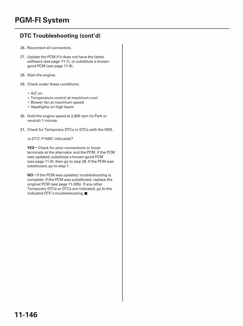
-
-
YES
NO
11-146
PGM-FI System
DTC Troubleshooting (cont’d)
26. Reconnect all connectors.
27. Update the PCM if it does not have the latestsoftware (see page 11-7), or substitute a known-good PCM (see page 11-8).
28. Start the engine.
29. Check under these conditions:
• A/C on• Temperature control at maximum cool• Blower fan at maximum speed• Headlights on high beam
30. Hold the engine speed at 2,000 rpm (in Park orneutral) 1 minute.
31. Check for Temporary DTCs or DTCs with the HDS.
Check for poor connections or looseterminals at the alternator and the PCM. If the PCMwas updated, substitute a known-good PCM(see page 11-8), then go to step 28. If the PCM wassubstituted, go to step 1.
If the PCM was updated, troubleshooting iscomplete. If the PCM was substituted, replace theoriginal PCM (see page 11-205). If any otherTemporary DTCs or DTCs are indicated, go to theindicated DTC’s troubleshooting.
Is DTC P16BC indicated?
07/05/09 16:49:59 61SJC020_110_0146
SJC8A00K77100092183FAAT00
-
-
-
-
-
-
-
-
-
-
-
-
DTC P2183:
YES
NO
YES
NO
YES
NO
YES
NO
YES
NO
YES
NO
11-147
ECT Sensor 2 Circuit Range/Performance Problem
NOTE:• Before you troubleshoot, record all freeze data and
any on-board snapshot, and review the generaltroubleshooting information (see page 11-3).
• If DTC P0111 is stored at the same time as DTC P2183,troubleshoot DTC P0111 first, then recheck for DTCP2183.
1. Check for poor connections or loose terminals atECT sensor 1 and ECT sensor 2.
Go to step 2.
Repair the connectors or terminals, then go tostep 27.
2. Turn the ignition switch ON (II).
3. Check for Temporary DTCs or DTCs with the HDS.
Go to step 15.
Go to step 4.
4. Start the engine, and let it idle 10 minutes.
5. Check ECT SENSOR 2 in the DATA LIST with theHDS.
Replace ECT sensor 2 (see page 11-201), thengo to step 27.
Go to step 6.
6. Turn the ignition switch OFF.
7. Drain the coolant (see page 10-6).
8. Remove ECT sensor 2 (see page 11-201).
9. Allow ECT sensor 2 to cool to ambient temperature.
10. Note the ambient temperature.
11. Connect ECT sensor 2 to its 2P connector, but donot install it on the engine.
12. Turn the ignition switch ON (II).
13. Note the value of ECT SENSOR 2 quickly in theDATA LIST with the HDS.
14. Compare the value of ECT SENSOR 2 and theambient temperature.
Replace ECT sensor 2 (see page 11-201), thengo to step 27.
Intermittent failure, the system is OK at thistime. Check for poor connections or loose terminalsat ECT sensor 1, ECT sensor 2, and the PCM.
15. Start the engine, and let it idle 10 minutes.
16. Check ECT SENSOR 1 in the DATA LIST with theHDS.
Replace ECT sensor 1 (see page 11-201), thengo to step 27.
Go to step 17.
17. Let the engine idle 10 minutes.
18. Check ECT SENSOR 2 in the DATA LIST with theHDS.
Replace ECT sensor 2 (see page 11-201), thengo to step 27.
Go to step 19.
(cont’d)
Are the connections and terminals OK ?
Are DTC P1116 and P2183 indicated at the sametime?
Is about 131 °F (55 °C) or less, or 1.50 V or moreindicated?
Does ECT SENSOR 2 dif f er 5.4 °F (3 °C) ormore?
Is about 118 °F (48 °C) or less, or 1.75 V or moreindicated?
Is about 131 °F (55 °C) or less, or 1.50 V or moreindicated?
07/05/09 16:49:59 61SJC020_110_0147
-
-
-
-
YES
NO
YES
NO
11-148
PGM-FI System
DTC Troubleshooting (cont’d)
19. Turn the ignition switch OFF.
20. Drain the coolant (see page 10-6).
21. Remove ECT sensor 1 (see page 11-201), and ECTsensor 2 (see page 11-201).
22. Allow the sensors to cool to ambient temperature.
23. Note the ambient temperature.
24. Connect ECT sensor 1 to its 2P connector, and ECTsensor 2 to its 2P connector, but do not install themon the engine.
25. Note the value of ECT SENSOR 1 and ECTSENSOR 2 quickly in the DATA LIST with the HDS.
26. Compare the value of ECT SENSOR 1 and theambient temperature, and the value of ECTSENSOR 2 and the ambient temperatureindividually.
Replace the sensor that differed more than5.4 °F (3 °C) from the ambient temperature, then goto step 27.
Intermittent failure, the system is OK at thistime. Check for poor connections or loose terminalsat ECT sensor 1, ECT sensor 2, and the PCM.
27. Turn the ignition switch ON (II).
28. Reset the PCM with the HDS.
29. Do the PCM idle learn procedure (see page 11-273).
30. Check for Temporary DTCs or DTCs with the HDS.
Check for poor connections or looseterminals at ECT sensor 1, ECT sensor 2, and thePCM, then go to step 1.
Troubleshooting is complete. If any otherTemporary DTCs or DTCs are indicated, go to theindicated DTC’s troubleshooting.
Does one of the sensor dif f er more than 5.4 °F(3 °C) f rom the ambient temperature?
Is DTC P2183 indicated?
07/05/09 16:50:00 61SJC020_110_0148
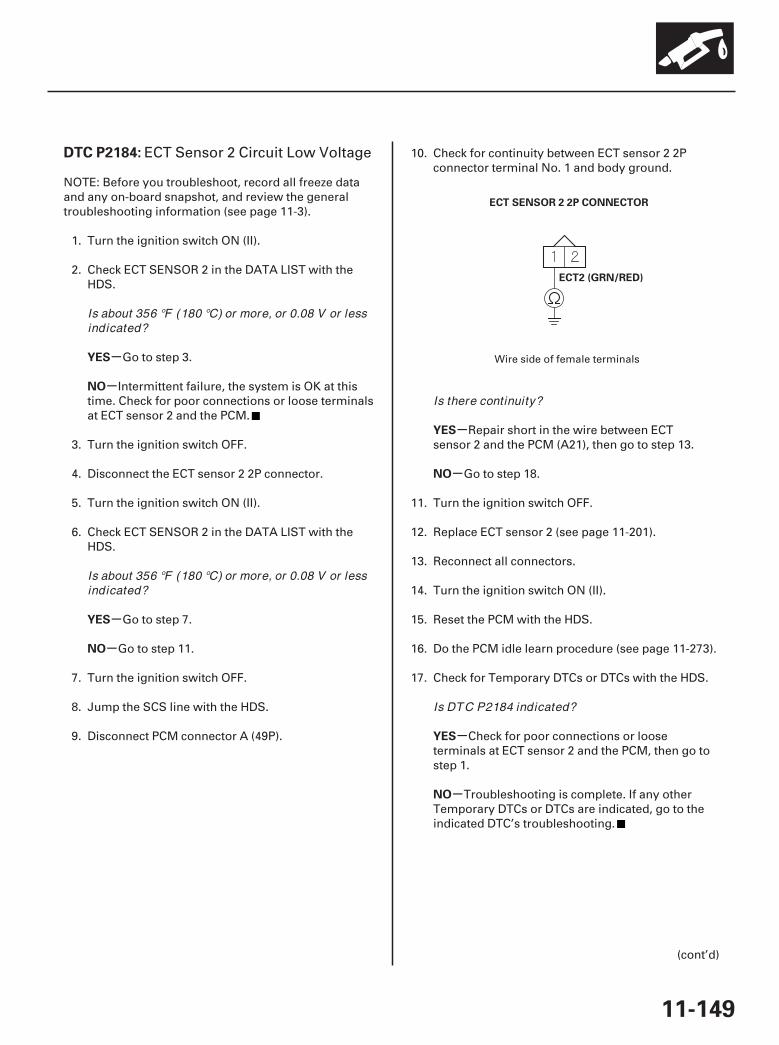
*01
SJC8A00K77100092184FAAT00
-
-
-
-
-
-
-
-
DTC P2184:
YES
NO
YES
NO
YES
NO
YES
NO
11-149
ECT SENSOR 2 2P CONNECTOR
ECT2 (GRN/RED)
ECT Sensor 2 Circuit Low Voltage
NOTE: Before you troubleshoot, record all freeze dataand any on-board snapshot, and review the generaltroubleshooting information (see page 11-3).
1. Turn the ignition switch ON (II).
2. Check ECT SENSOR 2 in the DATA LIST with theHDS.
Go to step 3.
Intermittent failure, the system is OK at thistime. Check for poor connections or loose terminalsat ECT sensor 2 and the PCM.
3. Turn the ignition switch OFF.
4. Disconnect the ECT sensor 2 2P connector.
5. Turn the ignition switch ON (II).
6. Check ECT SENSOR 2 in the DATA LIST with theHDS.
Go to step 7.
Go to step 11.
7. Turn the ignition switch OFF.
8. Jump the SCS line with the HDS.
9. Disconnect PCM connector A (49P).
10. Check for continuity between ECT sensor 2 2Pconnector terminal No. 1 and body ground.
Repair short in the wire between ECTsensor 2 and the PCM (A21), then go to step 13.
Go to step 18.
11. Turn the ignition switch OFF.
12. Replace ECT sensor 2 (see page 11-201).
13. Reconnect all connectors.
14. Turn the ignition switch ON (II).
15. Reset the PCM with the HDS.
16. Do the PCM idle learn procedure (see page 11-273).
17. Check for Temporary DTCs or DTCs with the HDS.
Check for poor connections or looseterminals at ECT sensor 2 and the PCM, then go tostep 1.
Troubleshooting is complete. If any otherTemporary DTCs or DTCs are indicated, go to theindicated DTC’s troubleshooting.
(cont’d)
Wire side of female terminals
Is about 356 °F (180 °C) or more, or 0.08 V or lessindicated?
Is about 356 °F (180 °C) or more, or 0.08 V or lessindicated?
Is there continuity?
Is DTC P2184 indicated?
07/05/09 16:50:00 61SJC020_110_0149

-
-
YES
NO
11-150
PGM-FI System
DTC Troubleshooting (cont’d)
18. Reconnect all connectors.
19. Update the PCM if it does not have the latestsoftware (see page 11-7), or substitute a known-good PCM (see page 11-8).
20. Check for Temporary DTCs or DTCs with the HDS.
Check for poor connections or looseterminals at ECT sensor 2 and the PCM. If the PCMwas updated, substitute a known-good PCM(see page 11-8), then recheck. If the PCM wassubstituted, go to step 1.
If the PCM was updated, troubleshooting iscomplete. If the PCM was substituted, replace theoriginal PCM (see page 11-205). If any otherTemporary DTCs or DTCs are indicated, go to theindicated DTC’s troubleshooting.
Is DTC P2184 indicated?
07/05/09 16:50:00 61SJC020_110_0150
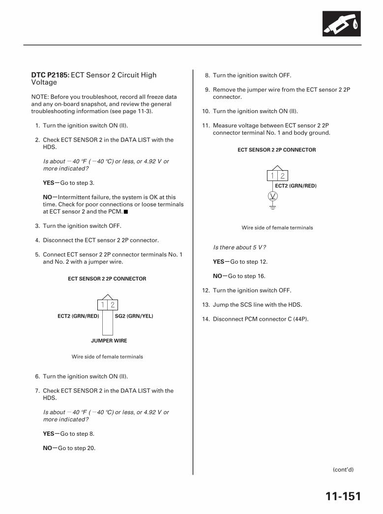
- -
- -
01
02
SJC8A00K77100092185FAAT00
-
-
-
-
-
-
DTC P2185:
YES
NO
YES
NO
YES
NO
11-151
ECT SENSOR 2 2P CONNECTOR
ECT2 (GRN/RED) SG2 (GRN/YEL)
JUMPER WIRE
ECT SENSOR 2 2P CONNECTOR
ECT2 (GRN/RED)
ECT Sensor 2 Circuit HighVoltage
NOTE: Before you troubleshoot, record all freeze dataand any on-board snapshot, and review the generaltroubleshooting information (see page 11-3).
1. Turn the ignition switch ON (II).
2. Check ECT SENSOR 2 in the DATA LIST with theHDS.
Go to step 3.
Intermittent failure, the system is OK at thistime. Check for poor connections or loose terminalsat ECT sensor 2 and the PCM.
3. Turn the ignition switch OFF.
4. Disconnect the ECT sensor 2 2P connector.
5. Connect ECT sensor 2 2P connector terminals No. 1and No. 2 with a jumper wire.
6. Turn the ignition switch ON (II).
7. Check ECT SENSOR 2 in the DATA LIST with theHDS.
Go to step 8.
Go to step 20.
8. Turn the ignition switch OFF.
9. Remove the jumper wire from the ECT sensor 2 2Pconnector.
10. Turn the ignition switch ON (II).
11. Measure voltage between ECT sensor 2 2Pconnector terminal No. 1 and body ground.
Go to step 12.
Go to step 16.
12. Turn the ignition switch OFF.
13. Jump the SCS line with the HDS.
14. Disconnect PCM connector C (44P).
(cont’d)
Wire side of female terminals
Wire side of female terminals
Is about 40 °F ( 40 °C) or less, or 4.92 V ormore indicated?
Is about 40 °F ( 40 °C) or less, or 4.92 V ormore indicated?
Is there about 5 V?
07/05/09 16:51:05 61SJC020_110_0151
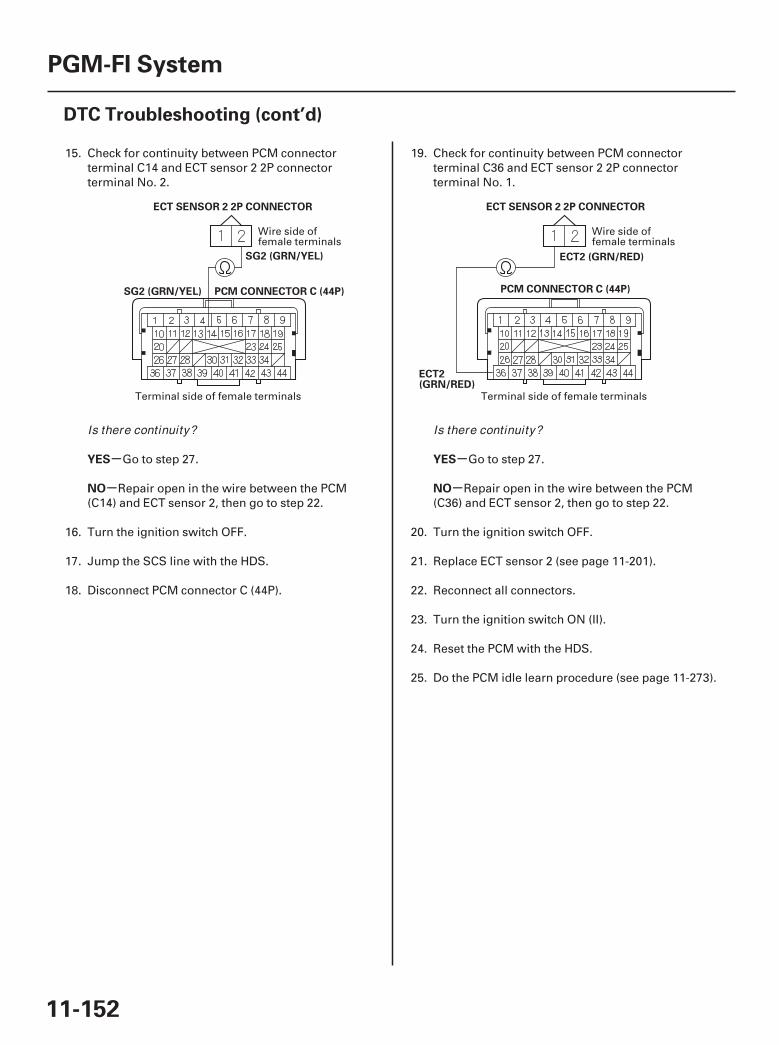
03 04
-
-
-
-
YES
NO
YES
NO
11-152
PGM-FI System
DTC Troubleshooting (cont’d)
PCM CONNECTOR C (44P)
ECT SENSOR 2 2P CONNECTOR
SG2 (GRN/YEL)
SG2 (GRN/YEL) PCM CONNECTOR C (44P)
ECT2 (GRN/RED)
ECT SENSOR 2 2P CONNECTOR
ECT2(GRN/RED)
15. Check for continuity between PCM connectorterminal C14 and ECT sensor 2 2P connectorterminal No. 2.
Go to step 27.
Repair open in the wire between the PCM(C14) and ECT sensor 2, then go to step 22.
16. Turn the ignition switch OFF.
17. Jump the SCS line with the HDS.
18. Disconnect PCM connector C (44P).
19. Check for continuity between PCM connectorterminal C36 and ECT sensor 2 2P connectorterminal No. 1.
Go to step 27.
Repair open in the wire between the PCM(C36) and ECT sensor 2, then go to step 22.
20. Turn the ignition switch OFF.
21. Replace ECT sensor 2 (see page 11-201).
22. Reconnect all connectors.
23. Turn the ignition switch ON (II).
24. Reset the PCM with the HDS.
25. Do the PCM idle learn procedure (see page 11-273).
Wire side offemale terminals
Terminal side of female terminals
Wire side offemale terminals
Terminal side of female terminals
Is there continuity? Is there continuity?
07/05/09 16:51:05 61SJC020_110_0152

-
-
-
-
YES
NO
YES
NO
11-153
26. Check for Temporary DTCs or DTCs with the HDS.
Check for poor connections or looseterminals at ECT sensor 2 and the PCM, then go tostep 1.
Troubleshooting is complete. If any otherTemporary DTCs or DTCs are indicated, go to theindicated DTC’s troubleshooting.
27. Reconnect all connectors.
28. Update the PCM if it does not have the latestsoftware (see page 11-7), or substitute a known-good PCM (see page 11-8).
29. Check for Temporary DTCs or DTCs with the HDS.
Check for poor connections or looseterminals at ECT sensor 2 and the PCM. If the PCMwas updated, substitute a known-good PCM(see page 11-8), then recheck. If the PCM wassubstituted, go to step 1.
If the PCM was updated, troubleshooting iscomplete. If the PCM was substituted, replace theoriginal PCM (see page 11-205). If any otherTemporary DTCs or DTCs are indicated, go to theindicated DTC’s troubleshooting.
Is DTC P2185 indicated?
Is DTC P2185 indicated?
07/05/09 16:51:05 61SJC020_110_0153
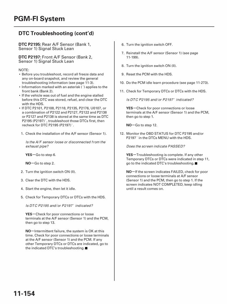
SJC8A00K77100092195FAAT30
-
-
-
-
-
-
-
-
DTC P2195:
DTC P2197:
YES
NO
YES
NO
YES
NO
YES
NO
11-154
PGM-FI System
DTC Troubleshooting (cont’d)
Rear A/F Sensor (Bank 1,Sensor 1) Signal Stuck Lean
Front A/F Sensor (Bank 2,Sensor 1) Signal Stuck Lean
NOTE:• Before you troubleshoot, record all freeze data and
any on-board snapshot, and review the generaltroubleshooting information (see page 11-3).
• Information marked with an asterisk ( ) applies to thefront bank (Bank 2).
• If the vehicle was out of fuel and the engine stalledbefore this DTC was stored, refuel, and clear the DTCwith the HDS.
• If DTC P2101, P2108, P2118, P2135, P2176, U0107, ora combination of P2122 and P2127, P2122 and P2138or P2127 and P2138 is stored at the same time as DTCP2195 (P2197) , troubleshoot those DTCs first, thenrecheck for DTC P2195 (P2197) .
1. Check the installation of the A/F sensor (Sensor 1).
Go to step 6.
Go to step 2.
2. Turn the ignition switch ON (II).
3. Clear the DTC with the HDS.
4. Start the engine, then let it idle.
5. Check for Temporary DTCs or DTCs with the HDS.
Check for poor connections or looseterminals at the A/F sensor (Sensor 1) and the PCM,then go to step 13.
Intermittent failure, the system is OK at thistime. Check for poor connections or loose terminalsat the A/F sensor (Sensor 1) and the PCM. If anyother Temporary DTCs or DTCs are indicated, go tothe indicated DTC’s troubleshooting.
6. Turn the ignition switch OFF.
7. Reinstall the A/F sensor (Sensor 1) (see page11-199).
8. Turn the ignition switch ON (II).
9. Reset the PCM with the HDS.
10. Do the PCM idle learn procedure (see page 11-273).
11. Check for Temporary DTCs or DTCs with the HDS.
Check for poor connections or looseterminals at the A/F sensor (Sensor 1) and the PCM,then go to step 1.
Go to step 12.
12. Monitor the OBD STATUS for DTC P2195 and/orP2197 in the DTCs MENU with the HDS.
Troubleshooting is complete. If any otherTemporary DTCs or DTCs were indicated in step 11,go to the indicated DTC’s troubleshooting.
If the screen indicates FAILED, check for poorconnections or loose terminals at A/F sensor(Sensor 1) and the PCM, then go to step 1. If thescreen indicates NOT COMPLETED, keep idlinguntil a result comes on.
Is the A/ F sensor loose or disconnected f rom theexhaust pipe?
Is DTC P2195 and/ or P2197 indicated?
Is DTC P2195 and/ or P2197 indicated?
Does the screen indicate PASSED?
07/05/09 16:51:05 61SJC020_110_0154
SJC8A00K77100092227FAAT30
-
-
-
-
-
-
-
-
YES
NO
YES
NO
YES
NO
YES
NO
DTC P2227:
11-15511-155
13. Update the PCM if it does not have the latestsoftware (see page 11-7), or substitute a known-good PCM (see page 11-8).
14. Start the engine, then let it idle for 2 minutes.
15. Check for Temporary DTCs or DTCs with the HDS.
Check for poor connections or looseterminals at the A/F sensor (Sensor 1) and the PCM.If the PCM was updated, substitute a known-goodPCM (see page 11-8), then go to step 14. If the PCMwas substituted, go to step 1.
Go to step 16.
16. Monitor the OBD STATUS for DTC P2195 and/orP2197 in the DTCs MENU with the HDS.
If the PCM was updated, troubleshooting iscomplete. If the PCM was substituted, replace theoriginal PCM (see page 11-205). If any otherTemporary DTCs or DTCs were indicated in step 15,go to the indicated DTC’s troubleshooting.
If the screen indicates FAILED, check for poorconnections or loose terminals at the A/F sensor(Sensor 1) and the PCM. If the PCM was updated,substitute a known-good PCM (see page 11-8), thenrecheck. If the PCM was substituted, go to step 1. Ifthe screen indicates NOT COMPLETED, keep idlinguntil a result comes on.
NOTE:• Before you troubleshoot, record all freeze data and
any on-board snapshot, and review the generaltroubleshooting information (see page 11-3).
• If DTC P0107, P0108, P1128, and/or P1129 are storedat the same time as DTC P2227, troubleshoot thoseDTCs first, then recheck for DTC P2227.
1. Turn the ignition switch ON (II), and wait 2 seconds.
2. Check the BARO SENSOR in the DATA LIST withthe HDS.
Go to step 3.
Update the PCM if it does not have the latestsoftware (see page 11-7), or substitute a known-good PCM (see page 11-8), then recheck. If thesymptom/indication goes away with a known-goodPCM, replace the original PCM (see page 11-205).
3. Clear the DTC with the HDS.
4. Start the engine. Hold the engine speed at3,000 rpm without load (in Park or neutral) until theradiator fan comes on, then let it idle.
5. Test-drive under these conditions:
• Engine coolant temperature (ECT SENSOR 1)above 158 °F (70 °C)
• Transmission in D position• Throttle position between 14 degrees and
45 degrees for 2 seconds
6. Monitor the OBD STATUS for DTC P2227 in theDTCs MENU with the HDS.
Intermittent failure, the system is OK at thistime.
If the screen indicates FAILED, go to step 7. Ifthe screen indicates NOT COMPLETED, go to step5.
(cont’d)
BARO Sensor Circuit Range/Performance Problem
Is DTC P2195 and/ or P2197 indicated?
Does the screen indicate PASSED?
Is about 101 kPa (29.9 in.Hg, 760 mmHg), or about2.9 V at sea level indicated?
Does the screen indicate PASSED?
07/05/09 16:51:06 61SJC020_110_0155
-
-
-
-
-
-
YES
NO
YES
NO
YES
NO
11-156
PGM-FI System
DTC Troubleshooting (cont’d)
7. Check the condition of the air cleaner element.
Go to step 8.
Replace the air cleaner element (see page11-315).
8. Update the PCM if it does not have the latestsoftware (see page 11-7), or substitute a known-good PCM (see page 11-8).
9. Reset the PCM with the HDS.
10. Do the PCM idle learn procedure (see page 11-273).
11. Start the engine. Hold the engine speed at3,000 rpm without load (in Park or neutral) until theradiator fan comes on, then let it idle.
12. Test-drive under these conditions:
• Engine coolant temperature (ECT SENSOR 1)above 158 °F (70 °C)
• Transmission in D position• Throttle position between 14 degrees and
45 degrees for 2 seconds
13. Check for Temporary DTCs or DTCs with the HDS.
If the PCM was updated, substitute a known-good PCM (see page 11-8), then go to step 11. If thePCM was substituted, go to step 1.
Go to step 14.
14. Monitor the OBD STATUS for DTC P2227 in theDTCs MENU with the HDS.
If the PCM was updated, troubleshooting iscomplete. If the PCM was substituted, replace theoriginal PCM (see page 11-205). If any otherTemporary DTCs or DTCs were indicated in step 13,go to the indicated DTC’s troubleshooting.
If the screen indicates FAILED, check for poorconnections or loose terminals at the PCM. If thePCM was updated, substitute a known-good PCM(see page 11-8), then go to step 11. If the PCM wassubstituted, go to step 1. If the screen indicatesNOT COMPLETED, go to step 11.
Is the air cleaner element OK ?
Is DTC P2227 indicated?
Does the screen indicate PASSED?
07/05/09 16:51:06 61SJC020_110_0156
SJC8A00K77100092228FAAT30 SJC8A00K77100092229FAAT30
-
-
-
-
-
-
-
-
DTC P2228: DTC P2229:
YES
NO
YES
NO
YES
NO
YES
NO
11-15711-157
BARO Sensor Circuit Low Voltage BARO Sensor Circuit HighVoltage
NOTE: Before you troubleshoot, record all freeze dataand any on-board snapshot, and review the generaltroubleshooting information (see page 11-3).
1. Turn the ignition switch ON (II).
2. Check the BARO SENSOR in the DATA LIST withthe HDS.
Go to step 3.
Intermittent failure, the system is OK at thistime.
3. Update the PCM if it does not have the latestsoftware (see page 11-7), or substitute a known-good PCM (see page 11-8).
4. Check for Temporary DTCs or DTCs with the HDS.
Check for poor connections or looseterminals at the PCM. If the PCM was updated,substitute a known-good PCM (see page 11-8), thenrecheck. If the PCM was substituted in step 3, go tostep 1.
If the PCM was updated, troubleshooting iscomplete. If any other Temporary DTCs or DTCs areindicated, go to the indicated DTC’stroubleshooting.
Is about 53 kPa (15.6 in.Hg, 397 mmHg), or 1.58 Vor less indicated?
Is DTC P2228 indicated?
Is about 160 kPa (47.2 in.Hg, 1,200 mmHg), or4.49 V , or more indicated?
Is DTC P2229 indicated?
07/05/09 16:51:06 61SJC020_110_0157
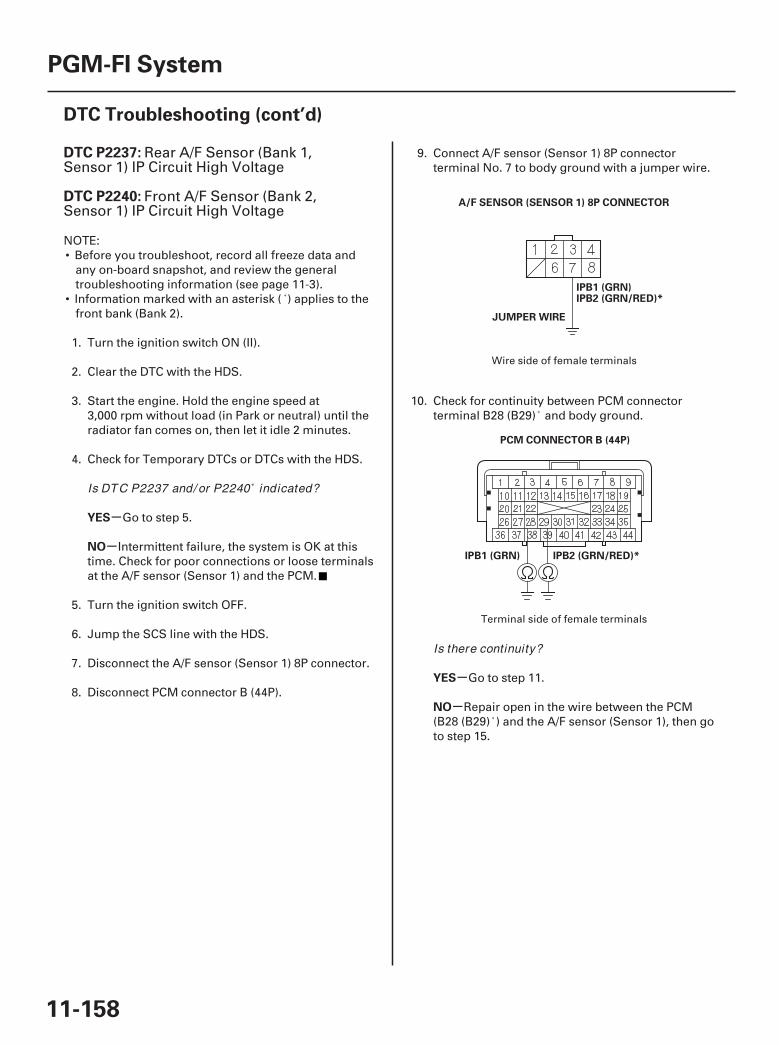
01
02
SJC8A00K77100092237FAAT30
-
-
-
-
DTC P2237:
DTC P2240:
YES
NO
YES
NO
11-158
PGM-FI System
DTC Troubleshooting (cont’d)
IPB1 (GRN)
JUMPER WIRE
A/F SENSOR (SENSOR 1) 8P CONNECTOR
IPB2 (GRN/RED)*
PCM CONNECTOR B (44P)
IPB2 (GRN/RED)*IPB1 (GRN)
Rear A/F Sensor (Bank 1,Sensor 1) IP Circuit High Voltage
Front A/F Sensor (Bank 2,Sensor 1) IP Circuit High Voltage
NOTE:• Before you troubleshoot, record all freeze data and
any on-board snapshot, and review the generaltroubleshooting information (see page 11-3).
• Information marked with an asterisk ( ) applies to thefront bank (Bank 2).
1. Turn the ignition switch ON (II).
2. Clear the DTC with the HDS.
3. Start the engine. Hold the engine speed at3,000 rpm without load (in Park or neutral) until theradiator fan comes on, then let it idle 2 minutes.
4. Check for Temporary DTCs or DTCs with the HDS.
Go to step 5.
Intermittent failure, the system is OK at thistime. Check for poor connections or loose terminalsat the A/F sensor (Sensor 1) and the PCM.
5. Turn the ignition switch OFF.
6. Jump the SCS line with the HDS.
7. Disconnect the A/F sensor (Sensor 1) 8P connector.
8. Disconnect PCM connector B (44P).
9. Connect A/F sensor (Sensor 1) 8P connectorterminal No. 7 to body ground with a jumper wire.
10. Check for continuity between PCM connectorterminal B28 (B29) and body ground.
Go to step 11.
Repair open in the wire between the PCM(B28 (B29) ) and the A/F sensor (Sensor 1), then goto step 15.
Wire side of female terminals
Terminal side of female terminals
Is DTC P2237 and/ or P2240 indicated?
Is there continuity?
07/05/09 16:51:06 61SJC020_110_0158

03
-
-
-
-
-
-
-
-
-
-
YES
NO
YES
NO
YES
NO
YES
NO
YES
NO
11-159
A/F SENSOR (SENSOR 1) 8P CONNECTOR
IPB1 (GRN)IPB2 (GRN/RED)*
11. Remove the jumper wire from the A/F sensor(Sensor 1) 8P connector, then reconnect PCMconnector B (44P).
12. Start the engine. Hold the engine speed at3,000 rpm without load (in Park or neutral) until theradiator fan comes on, then let it idle 2 minutes.
13. Measure voltage between A/F sensor (Sensor 1) 8Pconnector terminal No. 7 and body ground.
Go to step 21.
Go to step 14.
14. Replace the A/F sensor (Sensor 1) (see page11-199).
15. Reconnect all connectors.
16. Turn the ignition switch ON (II).
17. Reset the PCM with the HDS.
18. Do the PCM idle learn procedure (see page 11-273).
19. Check for Temporary DTCs or DTCs with the HDS.
Check for poor connections or looseterminals at the A/F sensor (Sensor 1) and the PCM,then go to step 1.
Go to step 20.
20. Monitor the OBD STATUS for DTC P2237 and/orP2240 in the DTCs MENU with the HDS.
Troubleshooting is complete. If any otherTemporary DTCs or DTCs were indicated in step 19,go to the indicated DTC’s troubleshooting.
If the screen indicates FAILED, check for poorconnections or loose terminals at the A/F sensor(Sensor 1) and the PCM, then go to step 1. If thescreen indicates NOT COMPLETED, keep idlinguntil a result comes on.
21. Turn the ignition switch OFF.
22. Reconnect all connectors.
23. Update the PCM if it does not have the latestsoftware (see page 11-7), or substitute a known-good PCM (see page 11-8).
24. Check for Temporary DTCs or DTCs with the HDS.
Check for poor connections or looseterminals at the A/F sensor (Sensor 1) and the PCM.If the PCM was updated, substitute a known-goodPCM (see page 11-8), then recheck. If the PCM wassubstituted, go to step 1
Go to step 25.
25. Monitor the OBD STATUS for DTC P2237 and/orP2240 in the DTCs MENU with the HDS.
If the PCM was updated, troubleshooting iscomplete. If the PCM was substituted, replace theoriginal PCM (see page 11-205). If any otherTemporary DTCs or DTCs were indicated in step 24,go to the indicated DTC’s troubleshooting.
If the screen indicates FAILED, check for poorconnections or loose terminals at the A/F sensor(Sensor 1) and the PCM. If the PCM was updated,substitute a known-good PCM (see page 11-8), thenrecheck. If the PCM was substituted, go to step 1. Ifthe screen indicates NOT COMPLETED, keep idlinguntil a result comes on.
Wire side of female terminals
Is there about 0.2 V or less?
Is DTC P2237 and/ or P2240 indicated?
Does the screen indicate PASSED?
Is DTC P2237 and/ or P2240 indicated?
Does the screen indicate PASSED?
07/05/09 16:51:06 61SJC020_110_0159
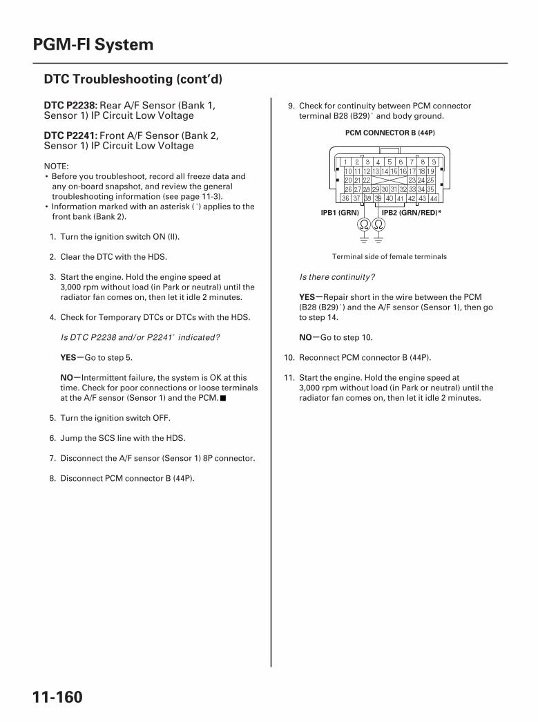
01
SJC8A00K77100092238FAAT30
-
-
-
-
DTC P2238:
DTC P2241:
YES
NO
YES
NO
11-160
PGM-FI System
DTC Troubleshooting (cont’d)
PCM CONNECTOR B (44P)
IPB2 (GRN/RED)*IPB1 (GRN)
Rear A/F Sensor (Bank 1,Sensor 1) IP Circuit Low Voltage
Front A/F Sensor (Bank 2,Sensor 1) IP Circuit Low Voltage
NOTE:• Before you troubleshoot, record all freeze data and
any on-board snapshot, and review the generaltroubleshooting information (see page 11-3).
• Information marked with an asterisk ( ) applies to thefront bank (Bank 2).
1. Turn the ignition switch ON (II).
2. Clear the DTC with the HDS.
3. Start the engine. Hold the engine speed at3,000 rpm without load (in Park or neutral) until theradiator fan comes on, then let it idle 2 minutes.
4. Check for Temporary DTCs or DTCs with the HDS.
Go to step 5.
Intermittent failure, the system is OK at thistime. Check for poor connections or loose terminalsat the A/F sensor (Sensor 1) and the PCM.
5. Turn the ignition switch OFF.
6. Jump the SCS line with the HDS.
7. Disconnect the A/F sensor (Sensor 1) 8P connector.
8. Disconnect PCM connector B (44P).
9. Check for continuity between PCM connectorterminal B28 (B29) and body ground.
Repair short in the wire between the PCM(B28 (B29) ) and the A/F sensor (Sensor 1), then goto step 14.
Go to step 10.
10. Reconnect PCM connector B (44P).
11. Start the engine. Hold the engine speed at3,000 rpm without load (in Park or neutral) until theradiator fan comes on, then let it idle 2 minutes.
Terminal side of female terminals
Is DTC P2238 and/ or P2241 indicated?
Is there continuity?
07/05/09 16:51:07 61SJC020_110_0160
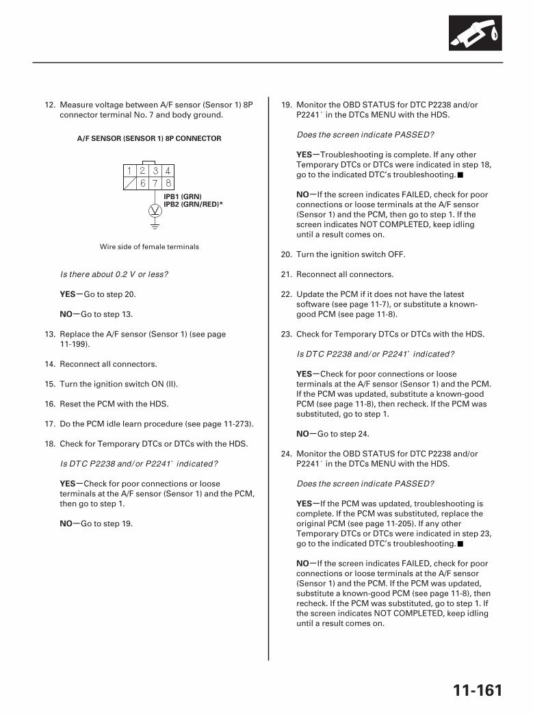
02
-
-
-
-
-
-
-
-
-
-
YES
NO
YES
NO
YES
NO
YES
NO
YES
NO
11-161
A/F SENSOR (SENSOR 1) 8P CONNECTOR
IPB1 (GRN)IPB2 (GRN/RED)*
12. Measure voltage between A/F sensor (Sensor 1) 8Pconnector terminal No. 7 and body ground.
Go to step 20.
Go to step 13.
13. Replace the A/F sensor (Sensor 1) (see page11-199).
14. Reconnect all connectors.
15. Turn the ignition switch ON (II).
16. Reset the PCM with the HDS.
17. Do the PCM idle learn procedure (see page 11-273).
18. Check for Temporary DTCs or DTCs with the HDS.
Check for poor connections or looseterminals at the A/F sensor (Sensor 1) and the PCM,then go to step 1.
Go to step 19.
19. Monitor the OBD STATUS for DTC P2238 and/orP2241 in the DTCs MENU with the HDS.
Troubleshooting is complete. If any otherTemporary DTCs or DTCs were indicated in step 18,go to the indicated DTC’s troubleshooting.
If the screen indicates FAILED, check for poorconnections or loose terminals at the A/F sensor(Sensor 1) and the PCM, then go to step 1. If thescreen indicates NOT COMPLETED, keep idlinguntil a result comes on.
20. Turn the ignition switch OFF.
21. Reconnect all connectors.
22. Update the PCM if it does not have the latestsoftware (see page 11-7), or substitute a known-good PCM (see page 11-8).
23. Check for Temporary DTCs or DTCs with the HDS.
Check for poor connections or looseterminals at the A/F sensor (Sensor 1) and the PCM.If the PCM was updated, substitute a known-goodPCM (see page 11-8), then recheck. If the PCM wassubstituted, go to step 1.
Go to step 24.
24. Monitor the OBD STATUS for DTC P2238 and/orP2241 in the DTCs MENU with the HDS.
If the PCM was updated, troubleshooting iscomplete. If the PCM was substituted, replace theoriginal PCM (see page 11-205). If any otherTemporary DTCs or DTCs were indicated in step 23,go to the indicated DTC’s troubleshooting.
If the screen indicates FAILED, check for poorconnections or loose terminals at the A/F sensor(Sensor 1) and the PCM. If the PCM was updated,substitute a known-good PCM (see page 11-8), thenrecheck. If the PCM was substituted, go to step 1. Ifthe screen indicates NOT COMPLETED, keep idlinguntil a result comes on.
Wire side of female terminals
Is there about 0.2 V or less?
Is DTC P2238 and/ or P2241 indicated?
Does the screen indicate PASSED?
Is DTC P2238 and/ or P2241 indicated?
Does the screen indicate PASSED?
07/05/09 16:51:07 61SJC020_110_0161
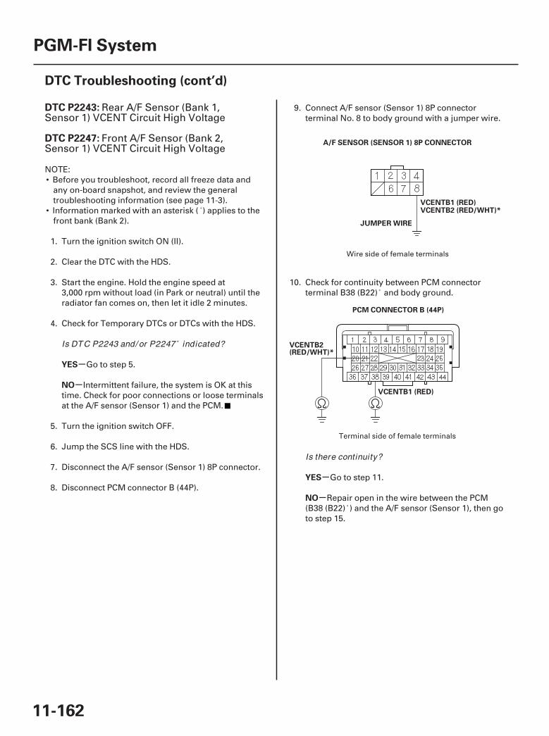
01
02
SJC8A00K77100092243FAAT30
-
-
-
-
DTC P2243:
DTC P2247:
YES
NO
YES
NO
11-162
PGM-FI System
DTC Troubleshooting (cont’d)
VCENTB1 (RED)
A/F SENSOR (SENSOR 1) 8P CONNECTOR
VCENTB2 (RED/WHT)*
JUMPER WIRE
PCM CONNECTOR B (44P)
VCENTB1 (RED)
VCENTB2(RED/WHT)*
Rear A/F Sensor (Bank 1,Sensor 1) VCENT Circuit High Voltage
Front A/F Sensor (Bank 2,Sensor 1) VCENT Circuit High Voltage
NOTE:• Before you troubleshoot, record all freeze data and
any on-board snapshot, and review the generaltroubleshooting information (see page 11-3).
• Information marked with an asterisk ( ) applies to thefront bank (Bank 2).
1. Turn the ignition switch ON (II).
2. Clear the DTC with the HDS.
3. Start the engine. Hold the engine speed at3,000 rpm without load (in Park or neutral) until theradiator fan comes on, then let it idle 2 minutes.
4. Check for Temporary DTCs or DTCs with the HDS.
Go to step 5.
Intermittent failure, the system is OK at thistime. Check for poor connections or loose terminalsat the A/F sensor (Sensor 1) and the PCM.
5. Turn the ignition switch OFF.
6. Jump the SCS line with the HDS.
7. Disconnect the A/F sensor (Sensor 1) 8P connector.
8. Disconnect PCM connector B (44P).
9. Connect A/F sensor (Sensor 1) 8P connectorterminal No. 8 to body ground with a jumper wire.
10. Check for continuity between PCM connectorterminal B38 (B22) and body ground.
Go to step 11.
Repair open in the wire between the PCM(B38 (B22) ) and the A/F sensor (Sensor 1), then goto step 15.
Wire side of female terminals
Terminal side of female terminals
Is DTC P2243 and/ or P2247 indicated?
Is there continuity?
07/05/09 16:51:07 61SJC020_110_0162
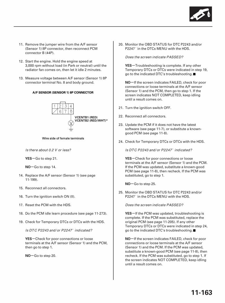
03
-
-
-
-
-
-
-
-
-
-
YES
NO
YES
NO
YES
NO
YES
NO
YES
NO
11-163
A/F SENSOR (SENSOR 1) 8P CONNECTOR
VCENTB1 (RED)
A/F SENSOR (SENSOR 1) 8P CONNECTOR
VCENTB2 (RED/WHT)*
11. Remove the jumper wire from the A/F sensor(Sensor 1) 8P connector, then reconnect PCMconnector B (44P).
12. Start the engine. Hold the engine speed at3,000 rpm without load (in Park or neutral) until theradiator fan comes on, then let it idle 2 minutes.
13. Measure voltage between A/F sensor (Sensor 1) 8Pconnector terminal No. 8 and body ground.
Go to step 21.
Go to step 14.
14. Replace the A/F sensor (Sensor 1) (see page11-199).
15. Reconnect all connectors.
16. Turn the ignition switch ON (II).
17. Reset the PCM with the HDS.
18. Do the PCM idle learn procedure (see page 11-273).
19. Check for Temporary DTCs or DTCs with the HDS.
Check for poor connections or looseterminals at the A/F sensor (Sensor 1) and the PCM,then go to step 1.
Go to step 20.
20. Monitor the OBD STATUS for DTC P2243 and/orP2247 in the DTCs MENU with the HDS.
Troubleshooting is complete. If any otherTemporary DTCs or DTCs were indicated in step 19,go to the indicated DTC’s troubleshooting.
If the screen indicates FAILED, check for poorconnections or loose terminals at the A/F sensor(Sensor 1) and the PCM, then go to step 1. If thescreen indicates NOT COMPLETED, keep idlinguntil a result comes on.
21. Turn the ignition switch OFF.
22. Reconnect all connectors.
23. Update the PCM if it does not have the latestsoftware (see page 11-7), or substitute a known-good PCM (see page 11-8).
24. Check for Temporary DTCs or DTCs with the HDS.
Check for poor connections or looseterminals at the A/F sensor (Sensor 1) and the PCM.If the PCM was updated, substitute a known-goodPCM (see page 11-8), then recheck. If the PCM wassubstituted, go to step 1.
Go to step 25.
25. Monitor the OBD STATUS for DTC P2243 and/orP2247 in the DTCs MENU with the HDS.
If the PCM was updated, troubleshooting iscomplete. If the PCM was substituted, replace theoriginal PCM (see page 11-205). If any otherTemporary DTCs or DTCs were indicated in step 24,go to the indicated DTC’s troubleshooting.
If the screen indicates FAILED, check for poorconnections or loose terminals at the A/F sensor(Sensor 1) and the PCM. If the PCM was updated,substitute a known-good PCM (see page 11-8), thenrecheck. If the PCM was substituted, go to step 1. Ifthe screen indicates NOT COMPLETED, keep idlinguntil a result comes on.
Wire side of female terminalsWire side of female terminals
Is there about 0.2 V or less?
Is DTC P2243 and/ or P2247 indicated?
Does the screen indicate PASSED?
Is DTC P2243 and/ or P2247 indicated?
Does the screen indicate PASSED?
07/05/09 16:51:08 61SJC020_110_0163
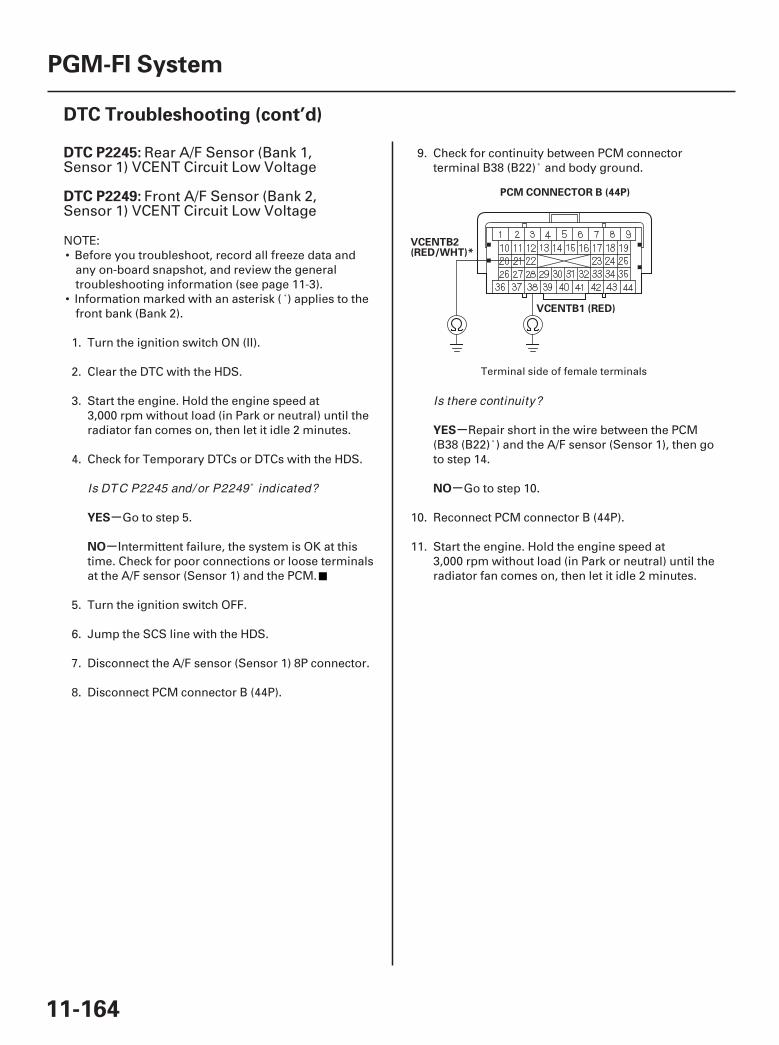
01
SJC8A00K77100092245FAAT30
-
-
-
-
DTC P2245:
DTC P2249:
YES
NO
YES
NO
11-164
PGM-FI System
DTC Troubleshooting (cont’d)
PCM CONNECTOR B (44P)
VCENTB1 (RED)
VCENTB2(RED/WHT)*
Rear A/F Sensor (Bank 1,Sensor 1) VCENT Circuit Low Voltage
Front A/F Sensor (Bank 2,Sensor 1) VCENT Circuit Low Voltage
NOTE:• Before you troubleshoot, record all freeze data and
any on-board snapshot, and review the generaltroubleshooting information (see page 11-3).
• Information marked with an asterisk ( ) applies to thefront bank (Bank 2).
1. Turn the ignition switch ON (II).
2. Clear the DTC with the HDS.
3. Start the engine. Hold the engine speed at3,000 rpm without load (in Park or neutral) until theradiator fan comes on, then let it idle 2 minutes.
4. Check for Temporary DTCs or DTCs with the HDS.
Go to step 5.
Intermittent failure, the system is OK at thistime. Check for poor connections or loose terminalsat the A/F sensor (Sensor 1) and the PCM.
5. Turn the ignition switch OFF.
6. Jump the SCS line with the HDS.
7. Disconnect the A/F sensor (Sensor 1) 8P connector.
8. Disconnect PCM connector B (44P).
9. Check for continuity between PCM connectorterminal B38 (B22) and body ground.
Repair short in the wire between the PCM(B38 (B22) ) and the A/F sensor (Sensor 1), then goto step 14.
Go to step 10.
10. Reconnect PCM connector B (44P).
11. Start the engine. Hold the engine speed at3,000 rpm without load (in Park or neutral) until theradiator fan comes on, then let it idle 2 minutes.
Terminal side of female terminals
Is DTC P2245 and/ or P2249 indicated?
Is there continuity?
07/05/09 16:51:08 61SJC020_110_0164
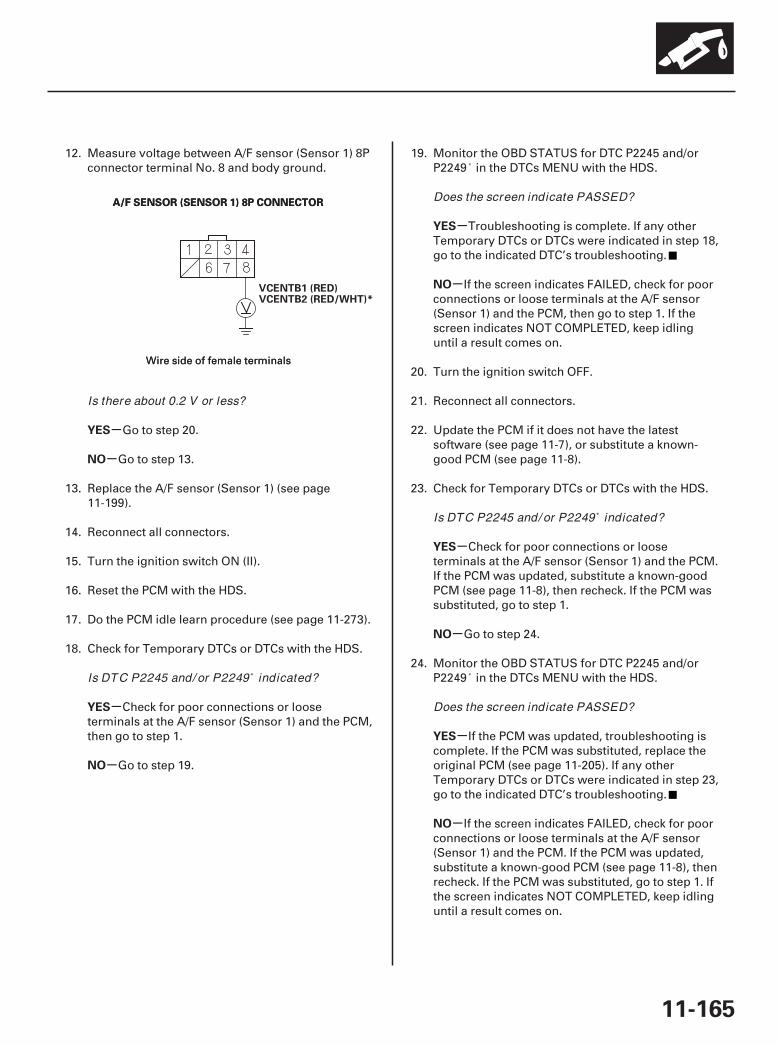
02
-
-
-
-
-
-
-
-
-
-
YES
NO
YES
NO
YES
NO
YES
NO
YES
NO
11-165
A/F SENSOR (SENSOR 1) 8P CONNECTORA/F SENSOR (SENSOR 1) 8P CONNECTOR
VCENTB1 (RED)VCENTB2 (RED/WHT)*
12. Measure voltage between A/F sensor (Sensor 1) 8Pconnector terminal No. 8 and body ground.
Go to step 20.
Go to step 13.
13. Replace the A/F sensor (Sensor 1) (see page11-199).
14. Reconnect all connectors.
15. Turn the ignition switch ON (II).
16. Reset the PCM with the HDS.
17. Do the PCM idle learn procedure (see page 11-273).
18. Check for Temporary DTCs or DTCs with the HDS.
Check for poor connections or looseterminals at the A/F sensor (Sensor 1) and the PCM,then go to step 1.
Go to step 19.
19. Monitor the OBD STATUS for DTC P2245 and/orP2249 in the DTCs MENU with the HDS.
Troubleshooting is complete. If any otherTemporary DTCs or DTCs were indicated in step 18,go to the indicated DTC’s troubleshooting.
If the screen indicates FAILED, check for poorconnections or loose terminals at the A/F sensor(Sensor 1) and the PCM, then go to step 1. If thescreen indicates NOT COMPLETED, keep idlinguntil a result comes on.
20. Turn the ignition switch OFF.
21. Reconnect all connectors.
22. Update the PCM if it does not have the latestsoftware (see page 11-7), or substitute a known-good PCM (see page 11-8).
23. Check for Temporary DTCs or DTCs with the HDS.
Check for poor connections or looseterminals at the A/F sensor (Sensor 1) and the PCM.If the PCM was updated, substitute a known-goodPCM (see page 11-8), then recheck. If the PCM wassubstituted, go to step 1.
Go to step 24.
24. Monitor the OBD STATUS for DTC P2245 and/orP2249 in the DTCs MENU with the HDS.
If the PCM was updated, troubleshooting iscomplete. If the PCM was substituted, replace theoriginal PCM (see page 11-205). If any otherTemporary DTCs or DTCs were indicated in step 23,go to the indicated DTC’s troubleshooting.
If the screen indicates FAILED, check for poorconnections or loose terminals at the A/F sensor(Sensor 1) and the PCM. If the PCM was updated,substitute a known-good PCM (see page 11-8), thenrecheck. If the PCM was substituted, go to step 1. Ifthe screen indicates NOT COMPLETED, keep idlinguntil a result comes on.
Wire side of female terminalsWire side of female terminals
Is there about 0.2 V or less?
Is DTC P2245 and/ or P2249 indicated?
Does the screen indicate PASSED?
Is DTC P2245 and/ or P2249 indicated?
Does the screen indicate PASSED?
07/05/09 16:51:08 61SJC020_110_0165
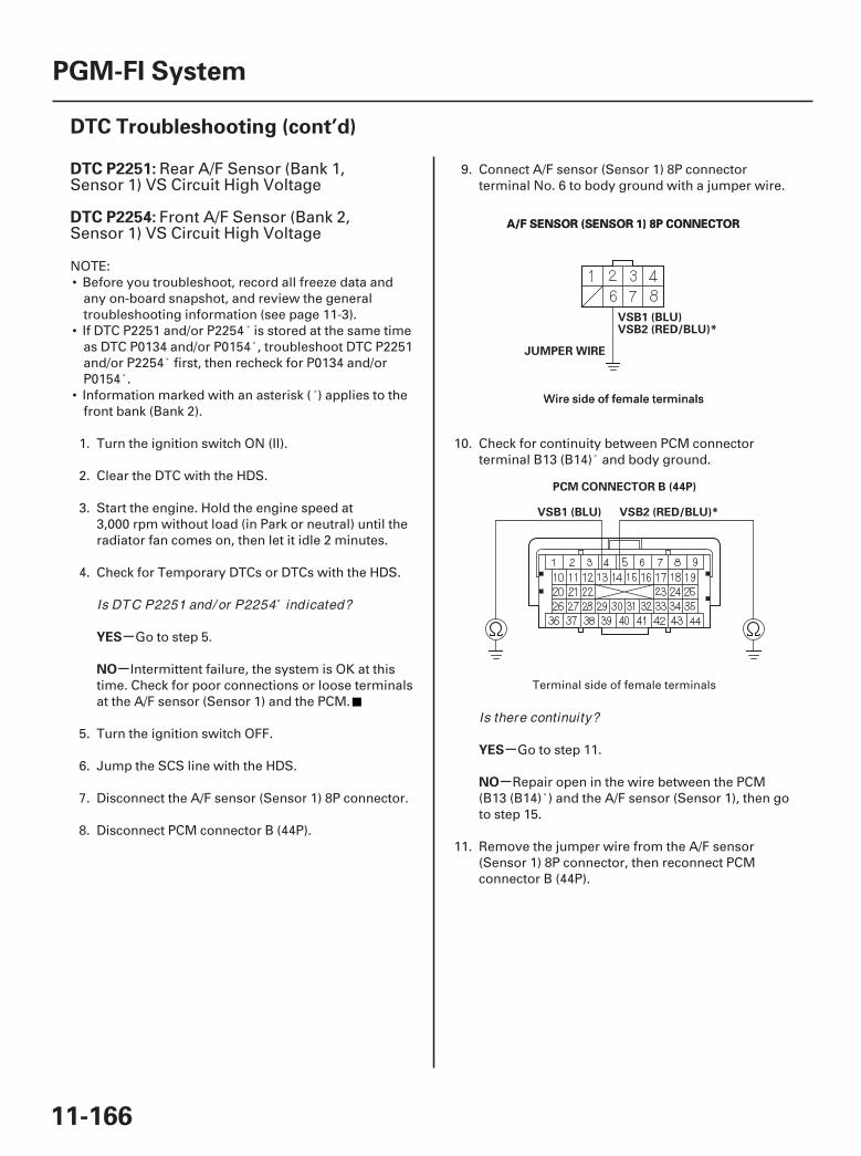
01
02
SJC8A00K77100092251FAAT30
-
-
-
-
DTC P2251:
DTC P2254:
YES
NO
YES
NO
11-166
PGM-FI System
DTC Troubleshooting (cont’d)
A/F SENSOR (SENSOR 1) 8P CONNECTORA/F SENSOR (SENSOR 1) 8P CONNECTOR
VSB1 (BLU)VSB2 (RED/BLU)*
JUMPER WIRE
PCM CONNECTOR B (44P)
VSB2 (RED/BLU)*VSB1 (BLU)
Rear A/F Sensor (Bank 1,Sensor 1) VS Circuit High Voltage
Front A/F Sensor (Bank 2,Sensor 1) VS Circuit High Voltage
NOTE:• Before you troubleshoot, record all freeze data and
any on-board snapshot, and review the generaltroubleshooting information (see page 11-3).
• If DTC P2251 and/or P2254 is stored at the same timeas DTC P0134 and/or P0154 , troubleshoot DTC P2251and/or P2254 first, then recheck for P0134 and/orP0154 .
• Information marked with an asterisk ( ) applies to thefront bank (Bank 2).
1. Turn the ignition switch ON (II).
2. Clear the DTC with the HDS.
3. Start the engine. Hold the engine speed at3,000 rpm without load (in Park or neutral) until theradiator fan comes on, then let it idle 2 minutes.
4. Check for Temporary DTCs or DTCs with the HDS.
Go to step 5.
Intermittent failure, the system is OK at thistime. Check for poor connections or loose terminalsat the A/F sensor (Sensor 1) and the PCM.
5. Turn the ignition switch OFF.
6. Jump the SCS line with the HDS.
7. Disconnect the A/F sensor (Sensor 1) 8P connector.
8. Disconnect PCM connector B (44P).
9. Connect A/F sensor (Sensor 1) 8P connectorterminal No. 6 to body ground with a jumper wire.
10. Check for continuity between PCM connectorterminal B13 (B14) and body ground.
Go to step 11.
Repair open in the wire between the PCM(B13 (B14) ) and the A/F sensor (Sensor 1), then goto step 15.
11. Remove the jumper wire from the A/F sensor(Sensor 1) 8P connector, then reconnect PCMconnector B (44P).
Wire side of female terminalsWire side of female terminals
Terminal side of female terminals
Is DTC P2251 and/ or P2254 indicated?
Is there continuity?
07/05/09 16:51:08 61SJC020_110_0166
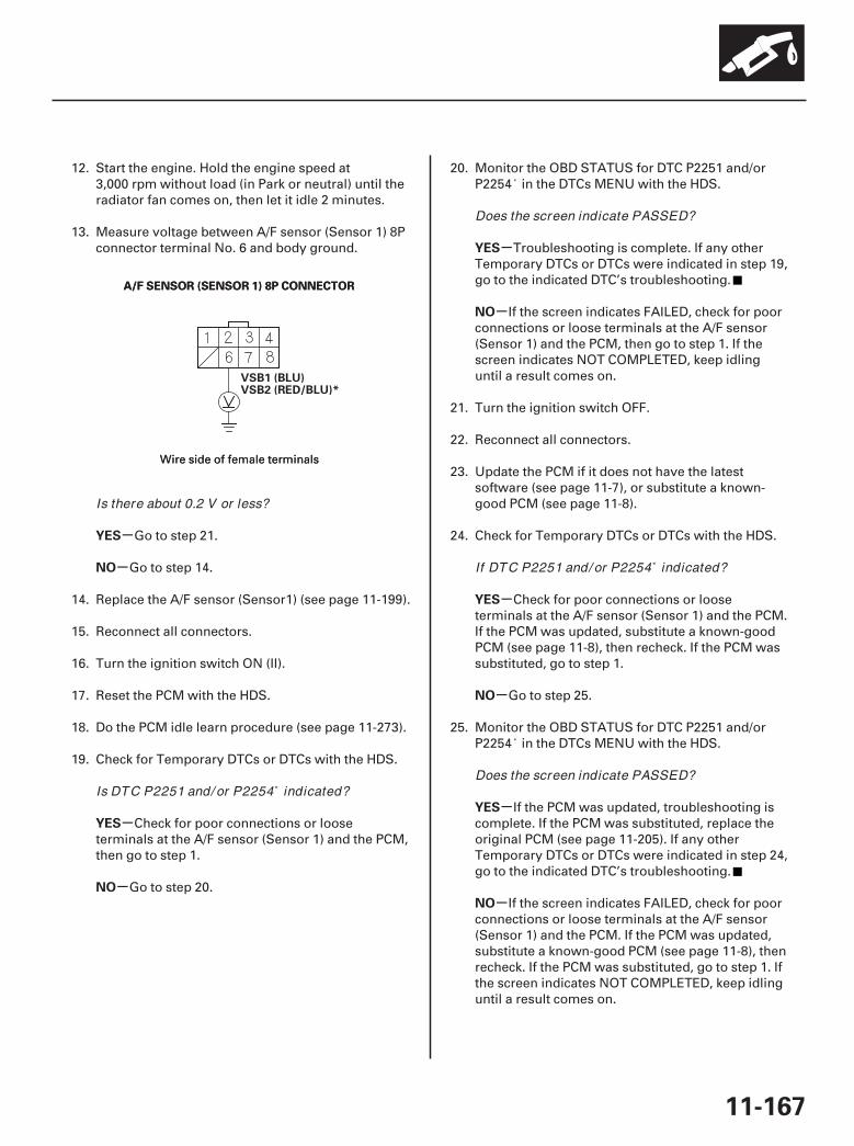
03
-
-
-
-
-
-
-
-
-
-
YES
NO
YES
NO
YES
NO
YES
NO
YES
NO
11-167
A/F SENSOR (SENSOR 1) 8P CONNECTORA/F SENSOR (SENSOR 1) 8P CONNECTOR
VSB1 (BLU)VSB2 (RED/BLU)*
12. Start the engine. Hold the engine speed at3,000 rpm without load (in Park or neutral) until theradiator fan comes on, then let it idle 2 minutes.
13. Measure voltage between A/F sensor (Sensor 1) 8Pconnector terminal No. 6 and body ground.
Go to step 21.
Go to step 14.
14. Replace the A/F sensor (Sensor1) (see page 11-199).
15. Reconnect all connectors.
16. Turn the ignition switch ON (II).
17. Reset the PCM with the HDS.
18. Do the PCM idle learn procedure (see page 11-273).
19. Check for Temporary DTCs or DTCs with the HDS.
Check for poor connections or looseterminals at the A/F sensor (Sensor 1) and the PCM,then go to step 1.
Go to step 20.
20. Monitor the OBD STATUS for DTC P2251 and/orP2254 in the DTCs MENU with the HDS.
Troubleshooting is complete. If any otherTemporary DTCs or DTCs were indicated in step 19,go to the indicated DTC’s troubleshooting.
If the screen indicates FAILED, check for poorconnections or loose terminals at the A/F sensor(Sensor 1) and the PCM, then go to step 1. If thescreen indicates NOT COMPLETED, keep idlinguntil a result comes on.
21. Turn the ignition switch OFF.
22. Reconnect all connectors.
23. Update the PCM if it does not have the latestsoftware (see page 11-7), or substitute a known-good PCM (see page 11-8).
24. Check for Temporary DTCs or DTCs with the HDS.
Check for poor connections or looseterminals at the A/F sensor (Sensor 1) and the PCM.If the PCM was updated, substitute a known-goodPCM (see page 11-8), then recheck. If the PCM wassubstituted, go to step 1.
Go to step 25.
25. Monitor the OBD STATUS for DTC P2251 and/orP2254 in the DTCs MENU with the HDS.
If the PCM was updated, troubleshooting iscomplete. If the PCM was substituted, replace theoriginal PCM (see page 11-205). If any otherTemporary DTCs or DTCs were indicated in step 24,go to the indicated DTC’s troubleshooting.
If the screen indicates FAILED, check for poorconnections or loose terminals at the A/F sensor(Sensor 1) and the PCM. If the PCM was updated,substitute a known-good PCM (see page 11-8), thenrecheck. If the PCM was substituted, go to step 1. Ifthe screen indicates NOT COMPLETED, keep idlinguntil a result comes on.
Wire side of female terminalsWire side of female terminals
Is there about 0.2 V or less?
Is DTC P2251 and/ or P2254 indicated?
Does the screen indicate PASSED?
If DTC P2251 and/ or P2254 indicated?
Does the screen indicate PASSED?
07/05/09 16:51:09 61SJC020_110_0167
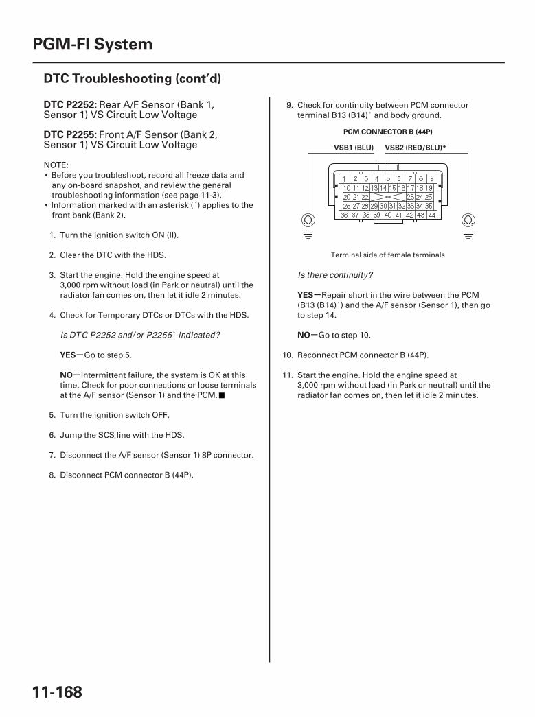
01
SJC8A00K77100092252FAAT30
-
-
-
-
DTC P2252:
DTC P2255:
YES
NO
YES
NO
11-168
PGM-FI System
DTC Troubleshooting (cont’d)
PCM CONNECTOR B (44P)
VSB2 (RED/BLU)*VSB1 (BLU)
Rear A/F Sensor (Bank 1,Sensor 1) VS Circuit Low Voltage
Front A/F Sensor (Bank 2,Sensor 1) VS Circuit Low Voltage
NOTE:• Before you troubleshoot, record all freeze data and
any on-board snapshot, and review the generaltroubleshooting information (see page 11-3).
• Information marked with an asterisk ( ) applies to thefront bank (Bank 2).
1. Turn the ignition switch ON (II).
2. Clear the DTC with the HDS.
3. Start the engine. Hold the engine speed at3,000 rpm without load (in Park or neutral) until theradiator fan comes on, then let it idle 2 minutes.
4. Check for Temporary DTCs or DTCs with the HDS.
Go to step 5.
Intermittent failure, the system is OK at thistime. Check for poor connections or loose terminalsat the A/F sensor (Sensor 1) and the PCM.
5. Turn the ignition switch OFF.
6. Jump the SCS line with the HDS.
7. Disconnect the A/F sensor (Sensor 1) 8P connector.
8. Disconnect PCM connector B (44P).
9. Check for continuity between PCM connectorterminal B13 (B14) and body ground.
Repair short in the wire between the PCM(B13 (B14) ) and the A/F sensor (Sensor 1), then goto step 14.
Go to step 10.
10. Reconnect PCM connector B (44P).
11. Start the engine. Hold the engine speed at3,000 rpm without load (in Park or neutral) until theradiator fan comes on, then let it idle 2 minutes.
Terminal side of female terminals
Is DTC P2252 and/ or P2255 indicated?
Is there continuity?
07/05/09 16:51:09 61SJC020_110_0168

02
-
-
-
-
-
-
-
-
-
-
YES
NO
YES
NO
YES
NO
YES
NO
YES
NO
11-169
A/F SENSOR (SENSOR 1) 8P CONNECTORA/F SENSOR (SENSOR 1) 8P CONNECTOR
VSB1 (BLU)VSB2 (RED/BLU)*
12. Measure voltage between A/F sensor (Sensor 1) 8Pconnector terminal No. 6 and body ground.
Go to step 20.
Go to step 13.
13. Replace the A/F sensor (Sensor 1) (see page11-199).
14. Reconnect all connectors.
15. Turn the ignition switch ON (II).
16. Reset the PCM with the HDS.
17. Do the PCM idle learn procedure (see page 11-273).
18. Check for Temporary DTCs or DTCs with the HDS.
Check for poor connections or looseterminals at the A/F sensor (Sensor 1) and the PCM,then go to step 1.
Go to step 19.
19. Monitor the OBD STATUS for DTC P2252 and/orP2255 in the DTCs MENU with the HDS.
Troubleshooting is complete. If any otherTemporary DTCs or DTCs were indicated in step 18,go to the indicated DTC’s troubleshooting.
If the screen indicates FAILED, check for poorconnections or loose terminals at the A/F sensor(Sensor 1) and the PCM, then go to step 1. If thescreen indicates NOT COMPLETED, keep idlinguntil a result comes on.
20. Turn the ignition switch OFF.
21. Reconnect all connectors.
22. Update the PCM if it does not have the latestsoftware (see page 11-7), or substitute a known-good PCM (see page 11-8).
23. Check for Temporary DTCs or DTCs with the HDS.
Check for poor connections or looseterminals at the A/F sensor (Sensor 1) and the PCM.If the PCM was updated, substitute a known-goodPCM (see page 11-8), then recheck. If the PCM wassubstituted, go to step 1.
Go to step 24.
24. Monitor the OBD STATUS for DTC P2252 and/orP2255 in the DTCs MENU with the HDS.
If the PCM was updated, troubleshooting iscomplete. If the PCM was substituted, replace theoriginal PCM (see page 11-205). If any otherTemporary DTCs or DTCs were indicated in step 23,go to the indicated DTC’s troubleshooting.
If the screen indicates FAILED, check for poorconnections or loose terminals at the A/F sensor(Sensor 1) and the PCM. If the PCM was updated,substitute a known-good PCM (see page 11-8), thenrecheck. If the PCM was substituted, go to step 1. Ifthe screen indicates NOT COMPLETED, keep idlinguntil a result comes on.
Wire side of female terminalsWire side of female terminals
Is there about 0.2 V or less?
Is DTC P2252 and/ or P2255 indicated?
Does the screen indicate PASSED?
Is DTC P2252 and/ or P2255 indicated?
Does the screen indicate PASSED?
07/05/09 16:51:09 61SJC020_110_0169
--
--
SJC8A00K77100092270FAAT00
-
-
-
-
-
-
DTC P2270:
DTC P2271:
DTC P2272:
DTC P2273:
YES
NO
YES
NO
YES
NO
11-170
PGM-FI System
DTC Troubleshooting (cont’d)
Rear Secondary HO2S (Bank 1,Sensor 2) Circuit Signal Stuck Lean
Rear Secondary HO2S (Bank 1,Sensor 2) Circuit Signal Stuck Rich
Front Secondary HO2S (Bank 2,Sensor 2) Circuit Signal Stuck Lean
Front Secondary HO2S (Bank 2,Sensor 2) Circuit Signal Stuck Rich
NOTE:• Before you troubleshoot, record all freeze data and
any on-board snapshot, and review the generaltroubleshooting information (see page 11-3).
• Information marked with an asterisk ( ) applies to thefront bank (Bank 2).
1. Turn the ignition switch ON (II).
2. Clear the DTC with the HDS.
3. Start the engine. Hold the engine speed at3,000 rpm without load (in Park or neutral) until theradiator fan comes on, then let it idle.
4. Test-drive under these conditions:
• Engine coolant temperature (ECT SENSOR 1)above 176 °F (80 °C)
• Vehicle speed between 35 55 mph(56 88 km/h)
• Drive 1 minute or more
5. Monitor the OBD STATUS for DTC P2270, P2271,P2272 , and/or P2273 in the DTCs MENU with theHDS.
Go to step 6.
If the screen indicates PASSED, intermittentfailure, the system is OK at this time. Check forpoor connections or loose terminals at thesecondary HO2S (Sensor 2) and the PCM. If thescreen indicates EXECUTING, keep driving until aresult comes on. If the screen indicates OUT OFCONDITION, go to step 3 and recheck.
6. Turn the ignition switch OFF.
7. Replace the secondary HO2S (Sensor 2) (see page11-200).
8. Turn the ignition switch ON (II).
9. Reset the PCM with the HDS.
10. Do the PCM idle learn procedure (see page 11-273).
11. Start the engine. Hold the engine speed at3,000 rpm without load (in Park or neutral) until theradiator fan comes on, then let it idle.
12. Test-drive under these conditions:
• Engine coolant temperature (ECT SENSOR 1)above 176 °F (80 °C)
• Vehicle speed between 35 55 mph(56 88 km/h)
• Drive 1 minute or more
13. Check for Temporary DTCs or DTCs with the HDS.
Check for poor connections or looseterminals at the secondary HO2S (Sensor 2) andthe PCM, then go to step 1.
Go to step 14.
14. Monitor the OBD STATUS for DTC P2270, P2271,P2272 , and/or P2273 in the DTCs MENU with theHDS.
Troubleshooting is complete. If any otherTemporary DTCs or DTCs were indicated in step 13,go to the indicated DTC’s troubleshooting.
If the screen indicates FAILED, check for poorconnections or loose terminals at the secondaryHO2S (Sensor 2) and the PCM, then go to step 1. Ifthe screen indicates EXECUTING, keep driving untila result comes on. If the screen indicates OUT OFCONDITION, go to step 11.
Does the screen indicate FAILED?
Is DTC P2270, P2271, P2272 , and/ or P2273indicated?
Does the screen indicate PASSED?
07/05/09 16:51:09 61SJC020_110_0170

SJC8A00K77100092610FAAT30
-
-
-
-
DTC P2610:
YES
NO
YES
NO
11-171
PCM Internal Power Off TimerMalfunction
NOTE: Before you troubleshoot, record all freeze dataand any on-board snapshot, and review the generaltroubleshooting information (see page 11-3).
1. Turn the ignition switch ON (II).
2. Clear the DTC with the HDS.
3. Check for Temporary DTCs or DTCs with the HDS.
Go to step 4.
Intermittent failure, the system is OK at thistime. If any other Temporary DTCs or DTCs areindicated, go to the indicated DTC’stroubleshooting.
4. Update the PCM if it does not have the latestsoftware (see page 11-7), or substitute a known-good PCM (see page 11-8).
5. Check for Temporary DTCs or DTCs with the HDS.
If the PCM was updated, substitute a known-good PCM (see page 11-8), then recheck. If the PCMwas substituted, go to step 1.
If the PCM was updated, troubleshooting iscomplete. If the PCM was substituted, replace theoriginal PCM (see page 11-205). If any otherTemporary DTCs or DTCs are indicated, go to theindicated DTC’s troubleshooting.
Is DTC P2610 indicated?
Is DTC P2610 indicated?
07/05/09 16:51:10 61SJC020_110_0171
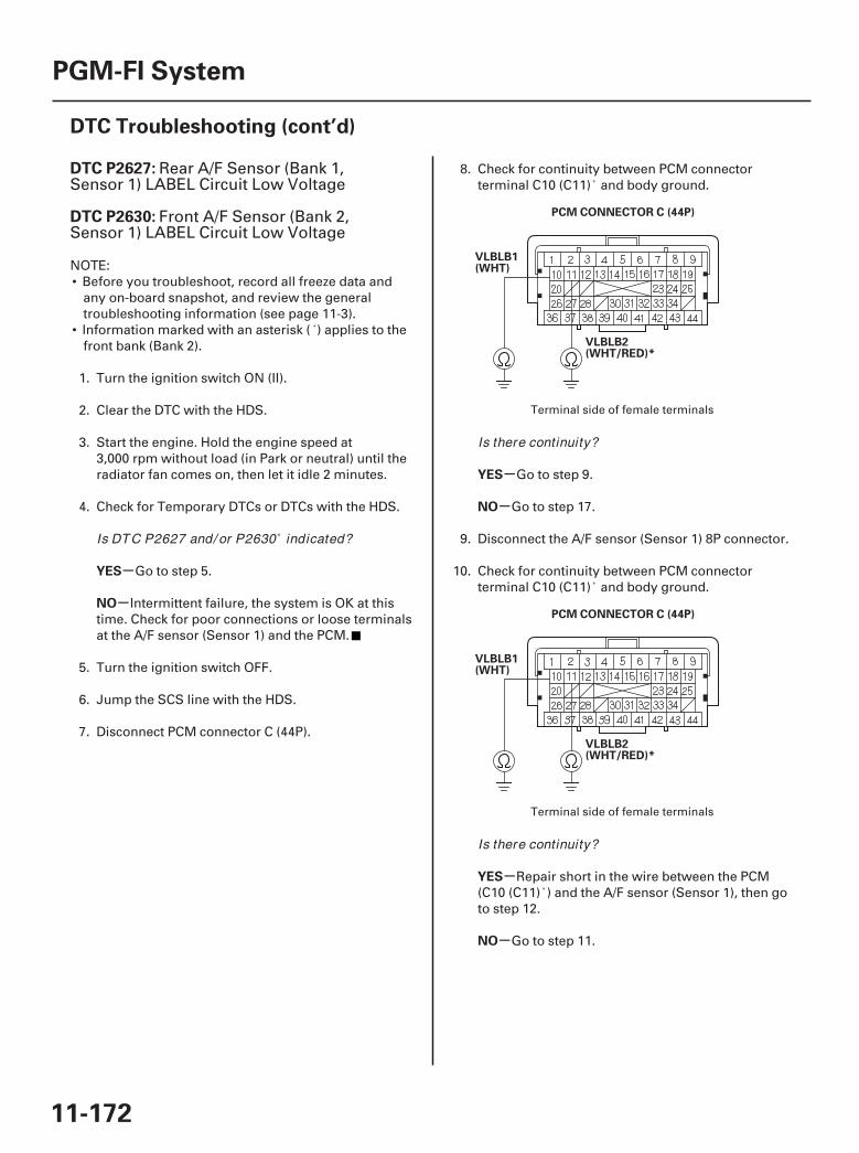
01
02
SJC8A00K77100092627FAAT30
-
-
-
-
-
-
DTC P2627:
DTC P2630:
YES
NO
YES
NO
YES
NO
11-172
PGM-FI System
DTC Troubleshooting (cont’d)
PCM CONNECTOR C (44P)
VLBLB1(WHT)
VLBLB2(WHT/RED)*
PCM CONNECTOR C (44P)
VLBLB1(WHT)
VLBLB2(WHT/RED)*
Rear A/F Sensor (Bank 1,Sensor 1) LABEL Circuit Low Voltage
Front A/F Sensor (Bank 2,Sensor 1) LABEL Circuit Low Voltage
NOTE:• Before you troubleshoot, record all freeze data and
any on-board snapshot, and review the generaltroubleshooting information (see page 11-3).
• Information marked with an asterisk ( ) applies to thefront bank (Bank 2).
1. Turn the ignition switch ON (II).
2. Clear the DTC with the HDS.
3. Start the engine. Hold the engine speed at3,000 rpm without load (in Park or neutral) until theradiator fan comes on, then let it idle 2 minutes.
4. Check for Temporary DTCs or DTCs with the HDS.
Go to step 5.
Intermittent failure, the system is OK at thistime. Check for poor connections or loose terminalsat the A/F sensor (Sensor 1) and the PCM.
5. Turn the ignition switch OFF.
6. Jump the SCS line with the HDS.
7. Disconnect PCM connector C (44P).
8. Check for continuity between PCM connectorterminal C10 (C11) and body ground.
Go to step 9.
Go to step 17.
9. Disconnect the A/F sensor (Sensor 1) 8P connector.
10. Check for continuity between PCM connectorterminal C10 (C11) and body ground.
Repair short in the wire between the PCM(C10 (C11) ) and the A/F sensor (Sensor 1), then goto step 12.
Go to step 11.
Terminal side of female terminals
Terminal side of female terminals
Is DTC P2627 and/ or P2630 indicated?
Is there continuity?
Is there continuity?
07/05/09 16:51:10 61SJC020_110_0172
-
-
-
-
YES
NO
YES
NO
11-173
11. Replace the A/F sensor (Sensor 1) (see page11-199).
12. Reconnect all connectors.
13. Turn the ignition switch ON (II).
14. Reset the PCM with the HDS.
15. Do the PCM idle learn procedure (see page 11-273).
16. Check for Temporary DTCs or DTCs with the HDS.
Check for poor connections or looseterminals at the A/F sensor (Sensor 1) and the PCM,then go to step 1.
Troubleshooting is complete. If any otherTemporary DTCs or DTCs are indicated, go to theindicated DTC’s troubleshooting.
17. Reconnect all connectors.
18. Update the PCM if it does not have the latestsoftware (see page 11-7), or substitute a known-good PCM (see page 11-8).
19. Check for Temporary DTCs or DTCs with the HDS.
Check for poor connections or looseterminals at the A/F sensor (Sensor 1) and the PCM.If the PCM was updated, substitute a known-goodPCM (see page 11-8), then recheck. If the PCM wassubstituted, go to step 1.
If the PCM was updated, troubleshooting iscomplete. If the PCM was substituted, replace theoriginal PCM (see page 11-205). If any otherTemporary DTCs or DTCs are indicated, go to theindicated DTC’s troubleshooting.
Is DTC P2627 and/ or P2630 indicated?
Is DTC P2627 and/ or P2630 indicated?
07/05/09 16:51:10 61SJC020_110_0173
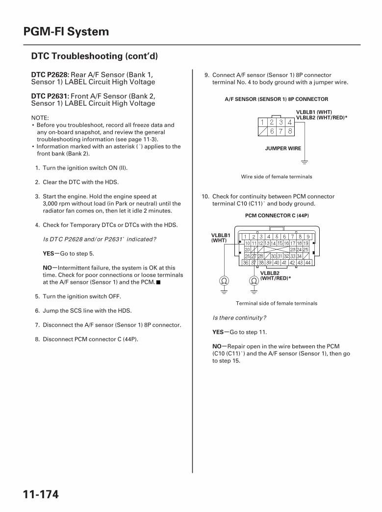
01
02
SJC8A00K77100092628FAAT30
-
-
-
-
DTC P2628:
DTC P2631:
YES
NO
YES
NO
11-174
PGM-FI System
DTC Troubleshooting (cont’d)
VLBLB1 (WHT)
JUMPER WIRE
A/F SENSOR (SENSOR 1) 8P CONNECTOR
VLBLB2 (WHT/RED)*
PCM CONNECTOR C (44P)
VLBLB1(WHT)
VLBLB2(WHT/RED)*
Rear A/F Sensor (Bank 1,Sensor 1) LABEL Circuit High Voltage
Front A/F Sensor (Bank 2,Sensor 1) LABEL Circuit High Voltage
NOTE:• Before you troubleshoot, record all freeze data and
any on-board snapshot, and review the generaltroubleshooting information (see page 11-3).
• Information marked with an asterisk ( ) applies to thefront bank (Bank 2).
1. Turn the ignition switch ON (II).
2. Clear the DTC with the HDS.
3. Start the engine. Hold the engine speed at3,000 rpm without load (in Park or neutral) until theradiator fan comes on, then let it idle 2 minutes.
4. Check for Temporary DTCs or DTCs with the HDS.
Go to step 5.
Intermittent failure, the system is OK at thistime. Check for poor connections or loose terminalsat the A/F sensor (Sensor 1) and the PCM.
5. Turn the ignition switch OFF.
6. Jump the SCS line with the HDS.
7. Disconnect the A/F sensor (Sensor 1) 8P connector.
8. Disconnect PCM connector C (44P).
9. Connect A/F sensor (Sensor 1) 8P connectorterminal No. 4 to body ground with a jumper wire.
10. Check for continuity between PCM connectorterminal C10 (C11) and body ground.
Go to step 11.
Repair open in the wire between the PCM(C10 (C11) ) and the A/F sensor (Sensor 1), then goto step 15.
Wire side of female terminals
Terminal side of female terminals
Is DTC P2628 and/ or P2631 indicated?
Is there continuity?
07/05/09 16:51:10 61SJC020_110_0174
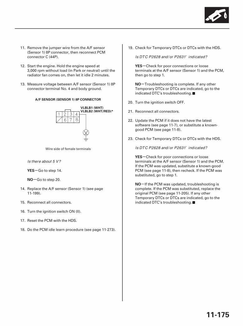
03
-
-
-
-
-
-
YES
NO
YES
NO
YES
NO
11-175
VLBLB1 (WHT)
A/F SENSOR (SENSOR 1) 8P CONNECTOR
VLBLB2 (WHT/RED)*
11. Remove the jumper wire from the A/F sensor(Sensor 1) 8P connector, then reconnect PCMconnector C (44P).
12. Start the engine. Hold the engine speed at3,000 rpm without load (in Park or neutral) until theradiator fan comes on, then let it idle 2 minutes.
13. Measure voltage between A/F sensor (Sensor 1) 8Pconnector terminal No. 4 and body ground.
Go to step 14.
Go to step 20.
14. Replace the A/F sensor (Sensor 1) (see page11-199).
15. Reconnect all connectors.
16. Turn the ignition switch ON (II).
17. Reset the PCM with the HDS.
18. Do the PCM idle learn procedure (see page 11-273).
19. Check for Temporary DTCs or DTCs with the HDS.
Check for poor connections or looseterminals at the A/F sensor (Sensor 1) and the PCM,then go to step 1.
Troubleshooting is complete. If any otherTemporary DTCs or DTCs are indicated, go to theindicated DTC’s troubleshooting.
20. Turn the ignition switch OFF.
21. Reconnect all connectors.
22. Update the PCM if it does not have the latestsoftware (see page 11-7), or substitute a known-good PCM (see page 11-8).
23. Check for Temporary DTCs or DTCs with the HDS.
Check for poor connections or looseterminals at the A/F sensor (Sensor 1) and the PCM.If the PCM was updated, substitute a known-goodPCM (see page 11-8), then recheck. If the PCM wassubstituted, go to step 1.
If the PCM was updated, troubleshooting iscomplete. If the PCM was substituted, replace theoriginal PCM (see page 11-205). If any otherTemporary DTCs or DTCs are indicated, go to theindicated DTC’s troubleshooting.
Wire side of female terminals
Is there about 5 V?
Is DTC P2628 and/ or P2631 indicated?
Is DTC P2628 and/ or P2631 indicated?
07/05/09 16:51:11 61SJC020_110_0175
SJC8A00K77100092A00FAAT30
-
-
-
-
-
-
DTC P2A00:
DTC P2A03:
YES
NO
YES
NO
YES
NO
11-176
PGM-FI System
DTC Troubleshooting (cont’d)
Rear A/F Sensor (Bank 1,Sensor 1) Circuit Range/PerformanceProblem
Front A/F Sensor (Bank 2,Sensor 1) Circuit Range/PerformanceProblem
NOTE:• Before you troubleshoot, record all freeze data and
any on-board snapshot, and review the generaltroubleshooting information (see page 11-3).
• Information marked with an asterisk ( ) applies to thefront bank (Bank 2).
1. Turn the ignition switch ON (II).
2. Clear the DTC with the HDS.
3. Start the engine. Hold the engine speed at3,000 rpm without load (in Park or neutral) until theradiator fan comes on, then let it idle.
4. Test-drive under these conditions:
• Engine coolant temperature (ECT SENSOR 1)above 158 °F (70 °C)
• Transmission in D position• Vehicle speed at 30 mph (48 km/h) or more, and
engine speed at 2,600 rpm or less• Drive at an engine speed of 1,600 rpm.
Accelerate to full open throttle for 5 seconds,then slow down with the throttle completelyclosed.
5. Monitor the OBD STATUS for DTC P2A00 and/orP2A03 in the DTCs MENU with the HDS.
Go to step 6.
If the screen indicates PASSED, intermittentfailure, the system is OK at this time. Check forpoor connections or loose terminals at the A/Fsensor (Sensor 1) and the PCM. If it is EXECUTING,keep driving until a result comes on. If the screenindicates OUT OF CONDITION, go to step 3 andrecheck.
6. Turn the ignition switch OFF.
7. Replace the A/F sensor (Sensor 1) (see page11-199).
8. Turn the ignition switch ON (II).
9. Reset the PCM with the HDS.
10. Do the PCM idle learn procedure (see page 11-273).
11. Test-drive under these conditions:
• Engine coolant temperature (ECT SENSOR 1)above 158 °F (70 °C)
• Transmission in D position• Vehicle speed at 30 mph (48 km/h) or more, and
engine speed at 2,600 rpm or less• Drive at an engine speed of 1,600 rpm.
Accelerate to full open throttle for 5 seconds,then slow down with the throttle completelyclosed.
12. Check for Temporary DTCs or DTCs with the HDS.
Check for poor connections or looseterminals at the A/F sensor (Sensor 1) and the PCM,then go to step 1.
Go to step 13.
13. Monitor the OBD STATUS for DTC P2A00 and/orP2A03 in the DTCs MENU with the HDS.
Troubleshooting is complete. If any otherTemporary DTCs or DTCs were indicated in step 12,go to the indicated DTC’s troubleshooting.
If the screen indicates FAILED, check for poorconnections or loose terminals at the A/F sensor(Sensor 1) and the PCM, then go to step 1. If thescreen indicates EXECUTING, keep driving until aresult comes on. If the screen indicates OUT OFCONDITION, go to step 11.
Does the screen indicate FAILED?
Is DTC P2A00 and/ or P2A03 indicated?
Does the screen indicate PASSED?
07/05/09 16:51:11 61SJC020_110_0176
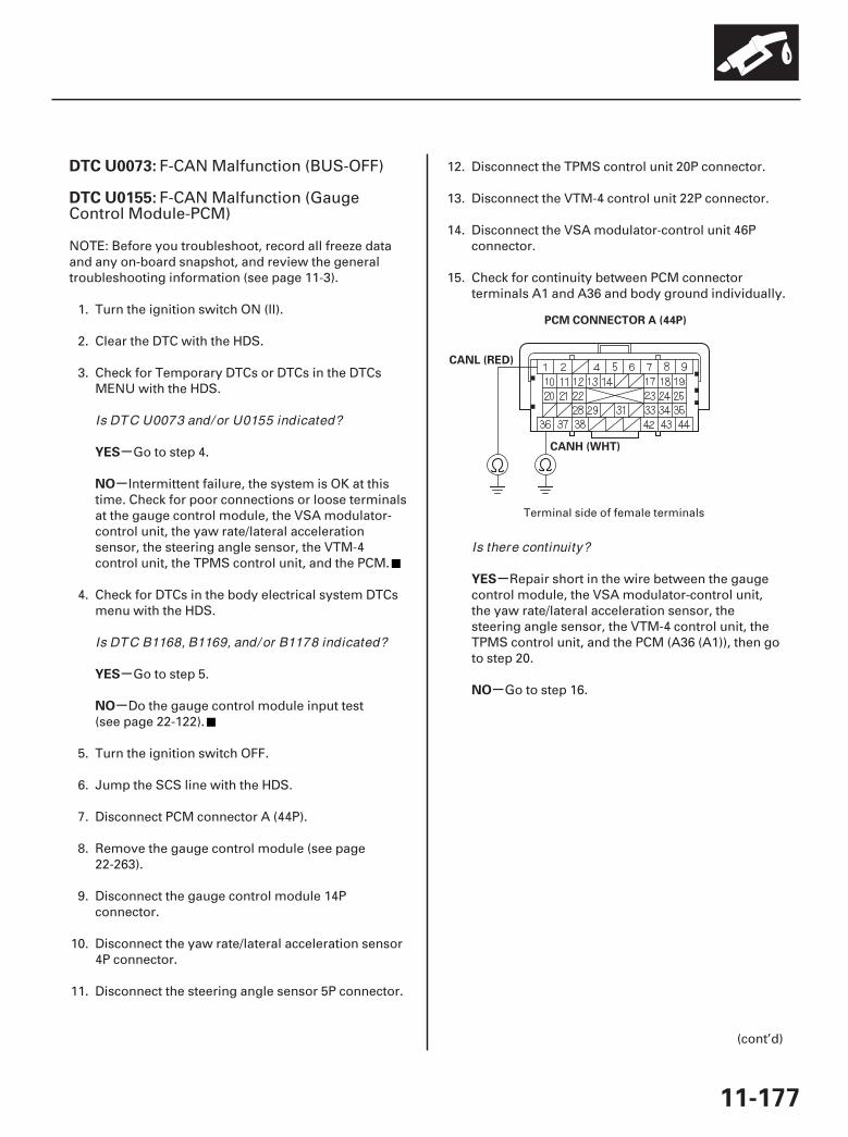
01
SJC8A00K771000U0073FAAT30
-
-
-
-
-
-
DTC U0073:
DTC U0155:
YES
NO
YES
NO
YES
NO
11-177
PCM CONNECTOR A (44P)
CANL (RED)
CANH (WHT)
F-CAN Malfunction (BUS-OFF)
F-CAN Malfunction (GaugeControl Module-PCM)
NOTE: Before you troubleshoot, record all freeze dataand any on-board snapshot, and review the generaltroubleshooting information (see page 11-3).
1. Turn the ignition switch ON (II).
2. Clear the DTC with the HDS.
3. Check for Temporary DTCs or DTCs in the DTCsMENU with the HDS.
Go to step 4.
Intermittent failure, the system is OK at thistime. Check for poor connections or loose terminalsat the gauge control module, the VSA modulator-control unit, the yaw rate/lateral accelerationsensor, the steering angle sensor, the VTM-4control unit, the TPMS control unit, and the PCM.
4. Check for DTCs in the body electrical system DTCsmenu with the HDS.
Go to step 5.
Do the gauge control module input test(see page 22-122).
5. Turn the ignition switch OFF.
6. Jump the SCS line with the HDS.
7. Disconnect PCM connector A (44P).
8. Remove the gauge control module (see page22-263).
9. Disconnect the gauge control module 14Pconnector.
10. Disconnect the yaw rate/lateral acceleration sensor4P connector.
11. Disconnect the steering angle sensor 5P connector.
12. Disconnect the TPMS control unit 20P connector.
13. Disconnect the VTM-4 control unit 22P connector.
14. Disconnect the VSA modulator-control unit 46Pconnector.
15. Check for continuity between PCM connectorterminals A1 and A36 and body ground individually.
Repair short in the wire between the gaugecontrol module, the VSA modulator-control unit,the yaw rate/lateral acceleration sensor, thesteering angle sensor, the VTM-4 control unit, theTPMS control unit, and the PCM (A36 (A1)), then goto step 20.
Go to step 16.
(cont’d)
Terminal side of female terminals
Is DTC U0073 and/ or U0155 indicated?
Is DTC B1168, B1169, and/ or B1178 indicated?
Is there continuity?
07/05/09 16:51:11 61SJC020_110_0177
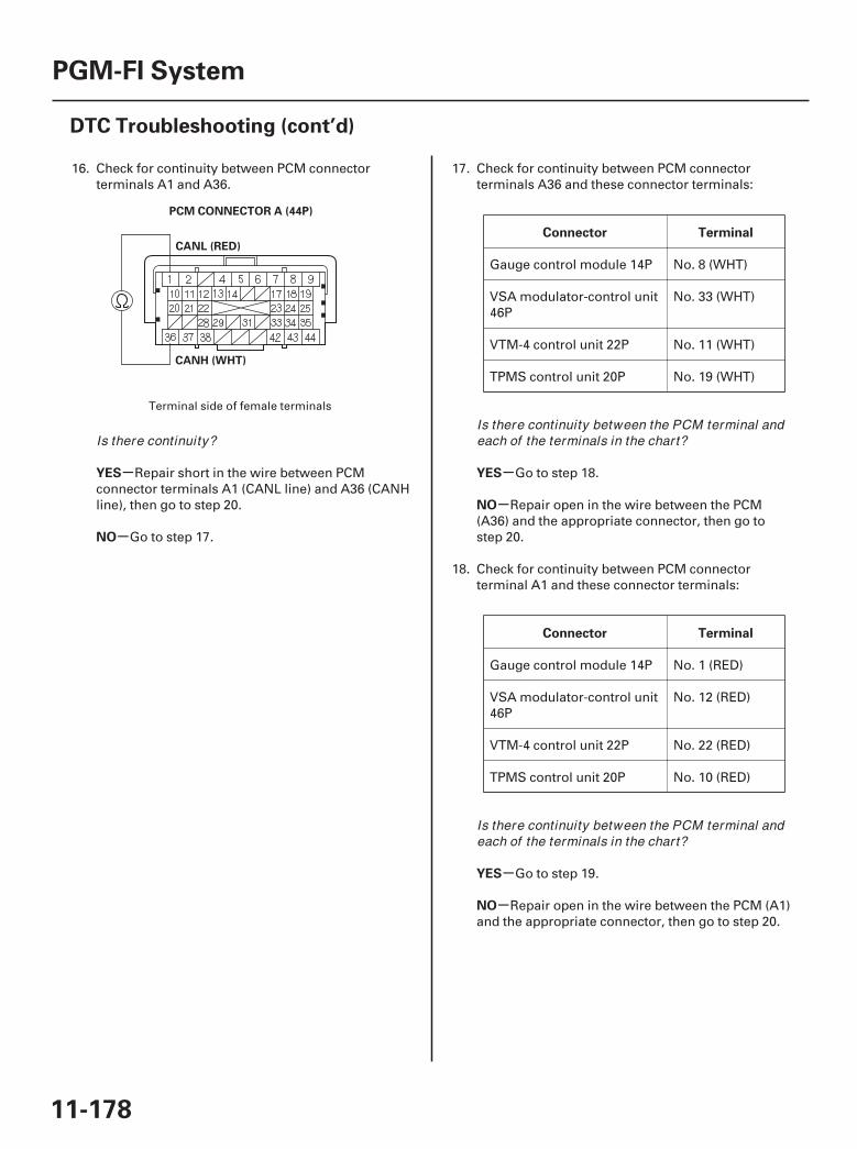
02
-
-
-
-
-
-
YES
NO
Connector Terminal
YES
NO
Connector Terminal
YES
NO
11-178
PGM-FI System
DTC Troubleshooting (cont’d)
PCM CONNECTOR A (44P)
CANL (RED)
CANH (WHT)
16. Check for continuity between PCM connectorterminals A1 and A36.
Repair short in the wire between PCMconnector terminals A1 (CANL line) and A36 (CANHline), then go to step 20.
Go to step 17.
17. Check for continuity between PCM connectorterminals A36 and these connector terminals:
Gauge control module 14P No. 8 (WHT)
VSA modulator-control unit46P
No. 33 (WHT)
VTM-4 control unit 22P No. 11 (WHT)
TPMS control unit 20P No. 19 (WHT)
Go to step 18.
Repair open in the wire between the PCM(A36) and the appropriate connector, then go tostep 20.
18. Check for continuity between PCM connectorterminal A1 and these connector terminals:
Gauge control module 14P No. 1 (RED)
VSA modulator-control unit46P
No. 12 (RED)
VTM-4 control unit 22P No. 22 (RED)
TPMS control unit 20P No. 10 (RED)
Go to step 19.
Repair open in the wire between the PCM (A1)and the appropriate connector, then go to step 20.
Terminal side of female terminals
Is there continuity?Is there continuity between the PCM terminal andeach of the terminals in the chart?
Is there continuity between the PCM terminal andeach of the terminals in the chart?
07/05/09 16:51:11 61SJC020_110_0178

-
-
-
-
PGM-FI VSA VTM-4 TPMS Body
Electrical
Control
module
YES
NO
YES
NO
11-179
19. Referring to the chart below, select the row thatmost closely represents the combination of DTCsretrieved from the PGM-FI, VSA, VTM-4, TPMS, andBody Electrical systems. Then check theconnections at the control module indicated in thelast column. If all the connections are OK,substitute the control module. After substituting thecontrol module, check for DTCs with the HDS.
U0073U0155
86 41-141-2
85 B1168B1169B1178
Gaugecontrolmodule
U0073U0114U0122U0155
6886
41-141-2
85 B1168B1169B1178
PCM
U0073U0122U0155
6886
41-141-2
85 B1168B1170
U0073U0114U0155
6886
41-141-2
85 B1168 VTM-4control
unitU0073U0155
6886
41-141-2
85 B1168B1173
TPMScontrol
unit
Substitute the remaining control modules,one at time, until the DTCs are no longer present,then replace the control module that made theDTCs go away. After replacing the faulty controlmodule, go to step 20.
Replace the faulty control module, then go tostep 20.
20. Reconnect all connectors.
21. Turn the ignition switch ON (II).
22. Reset the PCM with the HDS.
23. Do the PCM idle learn procedure (see page 11-273).
24. Check for Temporary DTCs or DTCs with the HDS.
Check for poor connections or looseterminals at the gauge control module, the VSAmodulator-control unit, the yaw rate/lateralacceleration sensor, the steering angle sensor, theVTM-4 control unit, the TPMS control unit, and thePCM, then go to step 1.
Troubleshooting is complete. If any otherTemporary DTCs or DTCs are indicated, go to theindicated DTC’s troubleshooting.
VSAmodulator-
controlunit
Are the DTCs stil l indicated?
Is DTC U0073 and/ or U0155 indicated?
07/05/09 16:51:11 61SJC020_110_0179
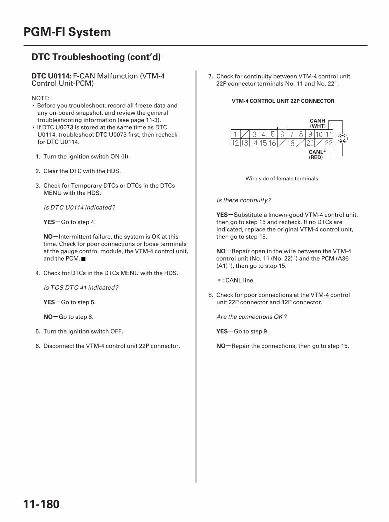
01
SJC8A00K771000U0114FAAT00
-
-
-
-
-
-
-
-
DTC U0114:
YES
NO
YES
NO
YES
NO
YES
NO
11-180
PGM-FI System
DTC Troubleshooting (cont’d)
VTM-4 CONTROL UNIT 22P CONNECTOR
CANH(WHT)
CANL*(RED)
F-CAN Malfunction (VTM-4Control Unit-PCM)
NOTE:• Before you troubleshoot, record all freeze data and
any on-board snapshot, and review the generaltroubleshooting information (see page 11-3).
• If DTC U0073 is stored at the same time as DTCU0114, troubleshoot DTC U0073 first, then recheckfor DTC U0114.
1. Turn the ignition switch ON (II).
2. Clear the DTC with the HDS.
3. Check for Temporary DTCs or DTCs in the DTCsMENU with the HDS.
Go to step 4.
Intermittent failure, the system is OK at thistime. Check for poor connections or loose terminalsat the gauge control module, the VTM-4 control unit,and the PCM.
4. Check for DTCs in the DTCs MENU with the HDS.
Go to step 5.
Go to step 8.
5. Turn the ignition switch OFF.
6. Disconnect the VTM-4 control unit 22P connector.
7. Check for continuity between VTM-4 control unit22P connector terminals No. 11 and No. 22 .
Substitute a known-good VTM-4 control unit,then go to step 15 and recheck. If no DTCs areindicated, replace the original VTM-4 control unit,then go to step 15.
Repair open in the wire between the VTM-4control unit (No. 11 (No. 22) ) and the PCM (A36(A1) ), then go to step 15.
: CANL line
8. Check for poor connections at the VTM-4 controlunit 22P connector and 12P connector.
Go to step 9.
Repair the connections, then go to step 15.
Wire side of female terminals
Is DTC U0114 indicated?
Is TCS DTC 41 indicated?
Is there continuity?
Are the connections OK ?
07/05/09 16:51:12 61SJC020_110_0180
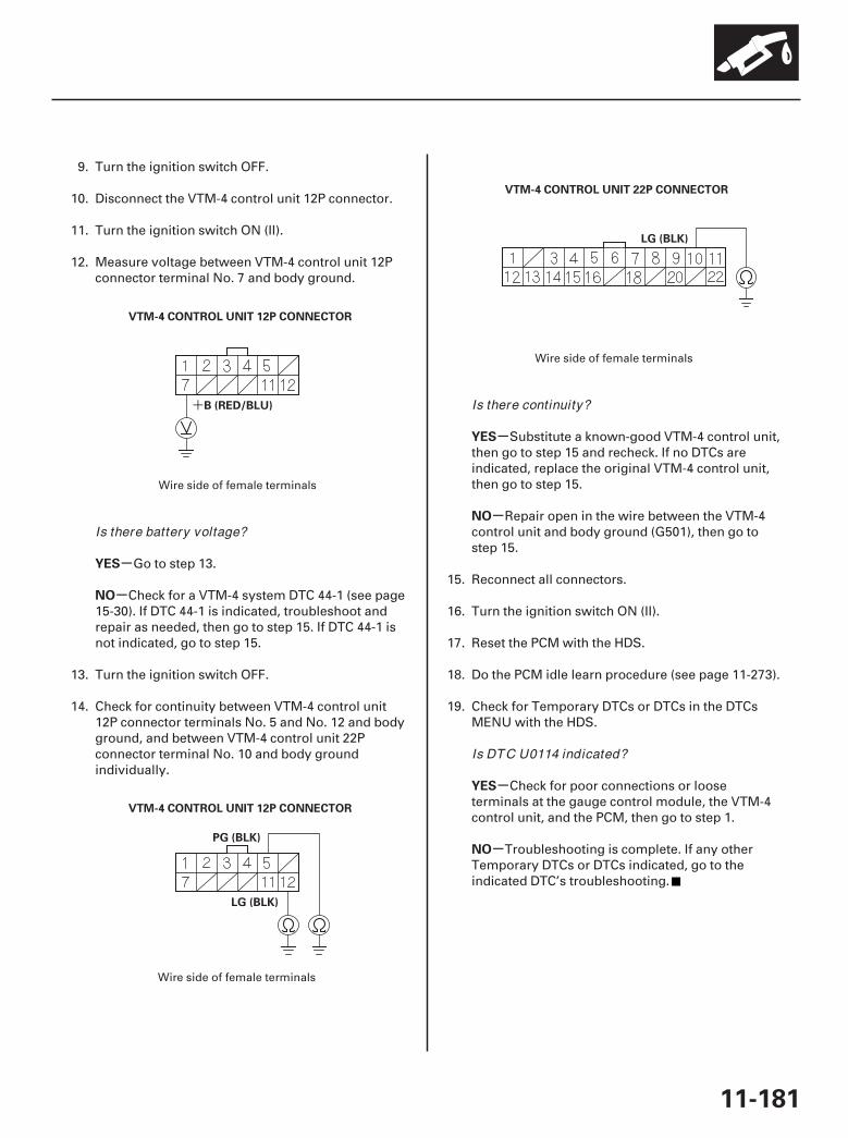
02
03
04
+
-
-
-
-
-
-
YES
NO
YES
NO
YES
NO
11-181
VTM-4 CONTROL UNIT 12P CONNECTOR
B (RED/BLU)
VTM-4 CONTROL UNIT 12P CONNECTOR
PG (BLK)
LG (BLK)
VTM-4 CONTROL UNIT 22P CONNECTOR
LG (BLK)
9. Turn the ignition switch OFF.
10. Disconnect the VTM-4 control unit 12P connector.
11. Turn the ignition switch ON (II).
12. Measure voltage between VTM-4 control unit 12Pconnector terminal No. 7 and body ground.
Go to step 13.
Check for a VTM-4 system DTC 44-1 (see page15-30). If DTC 44-1 is indicated, troubleshoot andrepair as needed, then go to step 15. If DTC 44-1 isnot indicated, go to step 15.
13. Turn the ignition switch OFF.
14. Check for continuity between VTM-4 control unit12P connector terminals No. 5 and No. 12 and bodyground, and between VTM-4 control unit 22Pconnector terminal No. 10 and body groundindividually.
Substitute a known-good VTM-4 control unit,then go to step 15 and recheck. If no DTCs areindicated, replace the original VTM-4 control unit,then go to step 15.
Repair open in the wire between the VTM-4control unit and body ground (G501), then go tostep 15.
15. Reconnect all connectors.
16. Turn the ignition switch ON (II).
17. Reset the PCM with the HDS.
18. Do the PCM idle learn procedure (see page 11-273).
19. Check for Temporary DTCs or DTCs in the DTCsMENU with the HDS.
Check for poor connections or looseterminals at the gauge control module, the VTM-4control unit, and the PCM, then go to step 1.
Troubleshooting is complete. If any otherTemporary DTCs or DTCs indicated, go to theindicated DTC’s troubleshooting.
Wire side of female terminals
Wire side of female terminals
Wire side of female terminals
Is there battery voltage?
Is there continuity?
Is DTC U0114 indicated?
07/05/09 16:52:01 61SJC020_110_0181

01
SJC8A00K771000U0122FAAT00
-
-
-
-
-
-
-
-
DTC U0122:
YES
NO
YES
NO
YES
NO
YES
NO
11-182
PGM-FI System
DTC Troubleshooting (cont’d)
VSA MODULATOR-CONTROL UNIT 46P CONNECTOR
CANL* (RED)
CANH (WHT)
F-CAN Malfunction (VSAModulator-Control Unit-PCM)
NOTE:• Before you troubleshoot, record all freeze data and
any on-board snapshot, and review the generaltroubleshooting information (see page 11-3).
• If DTC U0073 is stored at the same time as DTCU0122, troubleshoot DTC U0073 first, then recheckfor DTC U0122.
1. Turn the ignition switch ON (II).
2. Clear the DTC with the HDS.
3. Check for Temporary DTCs or DTCs in the DTCsMENU with the HDS.
Go to step 4.
Intermittent failure, the system is OK at thistime. Check for poor connections or loose terminalsat the gauge assembly, the VSA modulator-controlunit, and the PCM.
4. Check for DTCs in the DTCs MENU with the HDS.
Go to step 5.
Go to step 8.
5. Turn the ignition switch OFF.
6. Disconnect the VSA modulator-control unit 46Pconnector.
7. Check for continuity between VSA modulator-control unit 46P connector terminals No. 12 andNo. 33.
Substitute a known-good VSA modulator-control unit, then go to step 15 and recheck. If noDTCs are indicated, replace the original VSAmodulator-control unit, then go to step 15.
Repair open in the wire between the VSAmodulator-control unit (No. 35 (No. 14) ) and thePCM (A36 (A1) ), then go to step 15.
: CANL line
8. Check for a poor connection at the VSA modulator-control unit 46P connector.
Go to step 9.
Repair the connection(s), then go to step 15.
Wire side of female terminals
Is DTC U0122 indicated?
Is VSA DTC 86 indicated?
Is there continuity?
Are the connections OK ?
07/05/09 16:52:02 61SJC020_110_0182
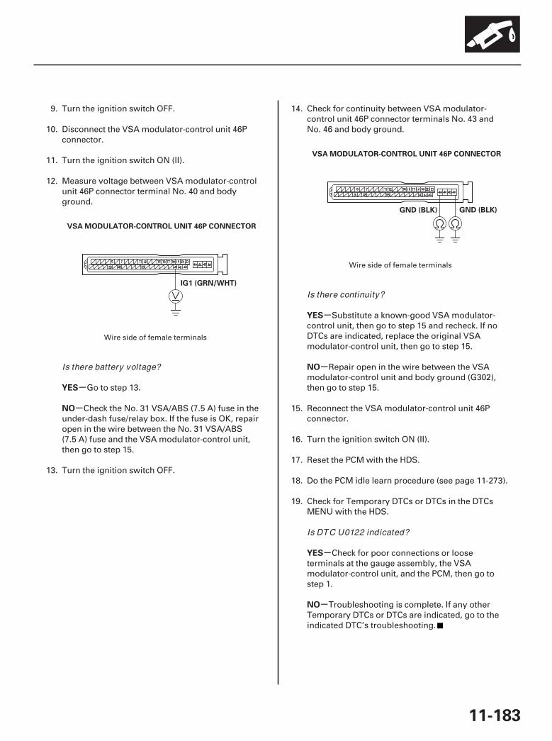
02
03
-
-
-
-
-
-
YES
NO
YES
NO
YES
NO
11-183
VSA MODULATOR-CONTROL UNIT 46P CONNECTOR
IG1 (GRN/WHT)
VSA MODULATOR-CONTROL UNIT 46P CONNECTOR
GND (BLK)GND (BLK)
9. Turn the ignition switch OFF.
10. Disconnect the VSA modulator-control unit 46Pconnector.
11. Turn the ignition switch ON (II).
12. Measure voltage between VSA modulator-controlunit 46P connector terminal No. 40 and bodyground.
Go to step 13.
Check the No. 31 VSA/ABS (7.5 A) fuse in theunder-dash fuse/relay box. If the fuse is OK, repairopen in the wire between the No. 31 VSA/ABS(7.5 A) fuse and the VSA modulator-control unit,then go to step 15.
13. Turn the ignition switch OFF.
14. Check for continuity between VSA modulator-control unit 46P connector terminals No. 43 andNo. 46 and body ground.
Substitute a known-good VSA modulator-control unit, then go to step 15 and recheck. If noDTCs are indicated, replace the original VSAmodulator-control unit, then go to step 15.
Repair open in the wire between the VSAmodulator-control unit and body ground (G302),then go to step 15.
15. Reconnect the VSA modulator-control unit 46Pconnector.
16. Turn the ignition switch ON (II).
17. Reset the PCM with the HDS.
18. Do the PCM idle learn procedure (see page 11-273).
19. Check for Temporary DTCs or DTCs in the DTCsMENU with the HDS.
Check for poor connections or looseterminals at the gauge assembly, the VSAmodulator-control unit, and the PCM, then go tostep 1.
Troubleshooting is complete. If any otherTemporary DTCs or DTCs are indicated, go to theindicated DTC’s troubleshooting.
Wire side of female terminals
Wire side of female terminals
Is there battery voltage?
Is there continuity?
Is DTC U0122 indicated?
07/05/09 16:52:02 61SJC020_110_0183
SJC8A00A20326939902FAAT00
-
-
-
-
-
-
-
-
-
-
-
-
-
-
YES
NO
YES
NO
YES
NO
YES
NO
YES
NO
YES
NO
YES
NO
11-184
PGM-FI System
MIL Circuit Troubleshooting
1. Turn the ignition switch ON (II).
2. Do the gauge self-diagnostic procedure (see page22-244).
Go to step 3.
Substitute a known-good gauge controlmodule, and recheck. If the MIL circuit is OK,replace the original gauge control module.
3. Turn the ignition switch OFF.
4. Turn the ignition switch ON (II), and watch the MIL.
Go to step 17.
Go to step 5.
5. Turn the ignition switch OFF.
6. Turn the ignition switch ON (II), wait 20 seconds,and watch the MIL.
Go to step 7.
The MIL circuit is OK.
7. Turn the ignition switch OFF.
8. Connect the HDS to the DLC (see page 11-3).
9. Turn the ignition switch ON (II), and read the HDS.
Go to step 10.
Go to ‘‘DLC Circuit Troubleshooting’’(see page 11-194).
10. Check for Temporary DTCs or DTCs with the HDS.
Go to the indicated DTC’s troubleshooting.
Go to step 11.
11. Check the MIL in the DATA LIST with the HDS.
Go to step 12.
Substitute a known-good gauge controlmodule, and recheck. If the MIL circuit is OK,replace the original gauge control module.
12. Check the SCS in the DATA LIST with the HDS.
Go to step 13.
Update the PCM if it does not have the latestsoftware (see page 11-7), or substitute a known-good PCM (see page 11-8), then recheck. If thesymptom/indication goes away with a known-goodPCM, replace the original PCM (see page 11-205).
13. Turn the ignition switch OFF.
14. Jump the SCS line with the HDS.
15. Disconnect PCM connector A (44P), then disconnectthe HDS.
Does the MIL indicator f lash?
Does the MIL stay of f?
Does the MIL stay on or f lash more than 5 times?
Does the HDS communicate with the PCM?
Are any Temporary DTCs or DTCs indicated?
Does it indicate ON?
Is a short indicated?
07/05/09 16:52:02 61SJC020_110_0184
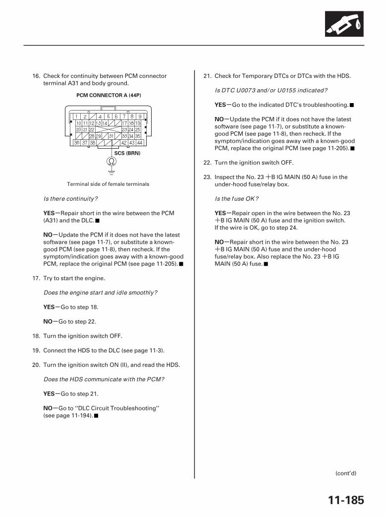
+
+
++
01
-
-
-
-
-
-
-
-
-
-
YES
NO
YES
NO
YES
NO
YES
NO
YES
NO
11-185
PCM CONNECTOR A (44P)
SCS (BRN)
16. Check for continuity between PCM connectorterminal A31 and body ground.
Repair short in the wire between the PCM(A31) and the DLC.
Update the PCM if it does not have the latestsoftware (see page 11-7), or substitute a known-good PCM (see page 11-8), then recheck. If thesymptom/indication goes away with a known-goodPCM, replace the original PCM (see page 11-205).
17. Try to start the engine.
Go to step 18.
Go to step 22.
18. Turn the ignition switch OFF.
19. Connect the HDS to the DLC (see page 11-3).
20. Turn the ignition switch ON (II), and read the HDS.
Go to step 21.
Go to ‘‘DLC Circuit Troubleshooting’’(see page 11-194).
21. Check for Temporary DTCs or DTCs with the HDS.
Go to the indicated DTC’s troubleshooting.
Update the PCM if it does not have the latestsoftware (see page 11-7), or substitute a known-good PCM (see page 11-8), then recheck. If thesymptom/indication goes away with a known-goodPCM, replace the original PCM (see page 11-205).
22. Turn the ignition switch OFF.
23. Inspect the No. 23 B IG MAIN (50 A) fuse in theunder-hood fuse/relay box.
Repair open in the wire between the No. 23B IG MAIN (50 A) fuse and the ignition switch.
If the wire is OK, go to step 24.
Repair short in the wire between the No. 23B IG MAIN (50 A) fuse and the under-hood
fuse/relay box. Also replace the No. 23 B IGMAIN (50 A) fuse.
(cont’d)
Terminal side of female terminals
Is there continuity?
Does the engine start and idle smoothly?
Does the HDS communicate with the PCM?
Is DTC U0073 and/ or U0155 indicated?
Is the fuse OK ?
07/05/09 16:52:03 61SJC020_110_0185
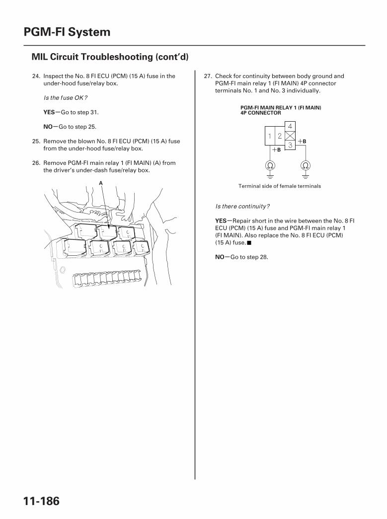
02
03
+
+
-
-
-
-
YES
NO
YES
NO
11-186
PGM-FI System
MIL Circuit Troubleshooting (cont’d)
A
PGM-FI MAIN RELAY 1 (FI MAIN)4P CONNECTOR
B
B
24. Inspect the No. 8 FI ECU (PCM) (15 A) fuse in theunder-hood fuse/relay box.
Go to step 31.
Go to step 25.
25. Remove the blown No. 8 FI ECU (PCM) (15 A) fusefrom the under-hood fuse/relay box.
26. Remove PGM-FI main relay 1 (FI MAIN) (A) fromthe driver’s under-dash fuse/relay box.
27. Check for continuity between body ground andPGM-FI main relay 1 (FI MAIN) 4P connectorterminals No. 1 and No. 3 individually.
Repair short in the wire between the No. 8 FIECU (PCM) (15 A) fuse and PGM-FI main relay 1(FI MAIN). Also replace the No. 8 FI ECU (PCM)(15 A) fuse.
Go to step 28.
Terminal side of female terminals
Is the fuse OK ?
Is there continuity?
07/05/09 16:52:03 61SJC020_110_0186
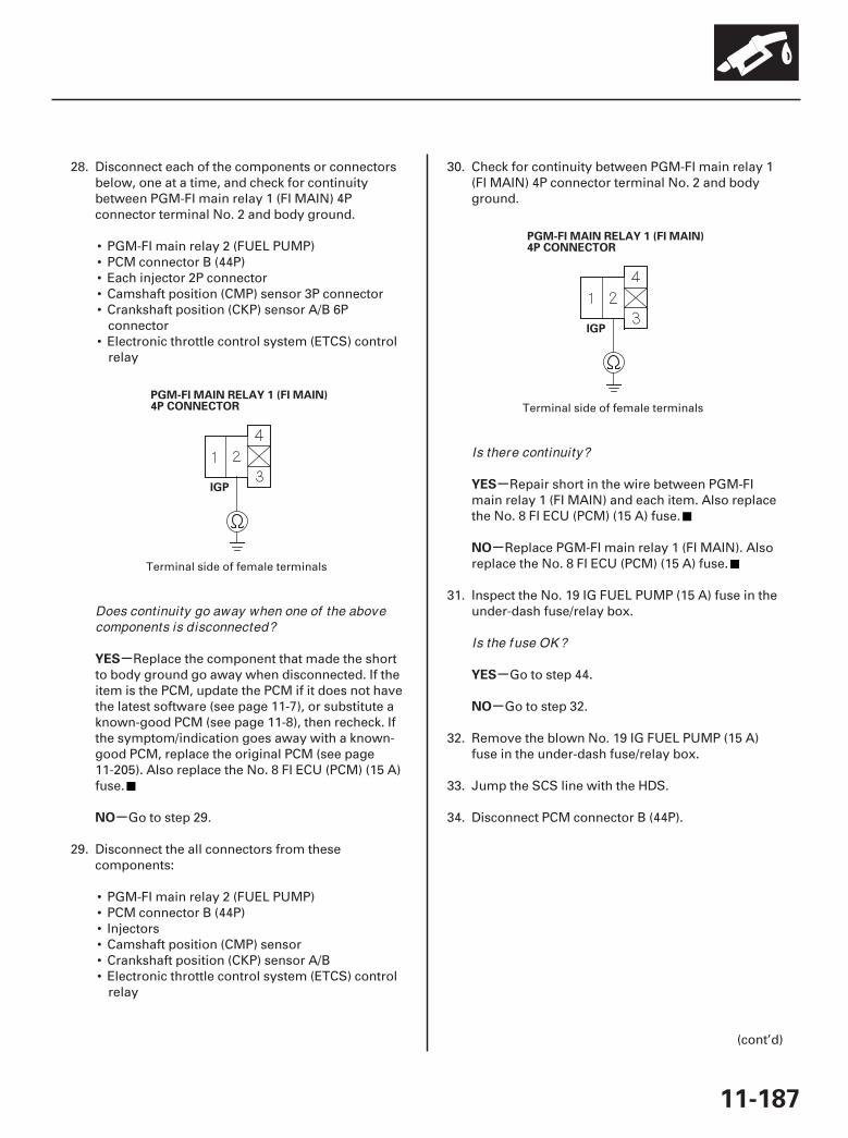
04
05
-
-
-
-
-
-
YES
NO
YES
NO
YES
NO
11-187
PGM-FI MAIN RELAY 1 (FI MAIN)4P CONNECTOR
IGP
PGM-FI MAIN RELAY 1 (FI MAIN)4P CONNECTOR
IGP
28. Disconnect each of the components or connectorsbelow, one at a time, and check for continuitybetween PGM-FI main relay 1 (FI MAIN) 4Pconnector terminal No. 2 and body ground.
• PGM-FI main relay 2 (FUEL PUMP)• PCM connector B (44P)• Each injector 2P connector• Camshaft position (CMP) sensor 3P connector• Crankshaft position (CKP) sensor A/B 6P
connector• Electronic throttle control system (ETCS) control
relay
Replace the component that made the shortto body ground go away when disconnected. If theitem is the PCM, update the PCM if it does not havethe latest software (see page 11-7), or substitute aknown-good PCM (see page 11-8), then recheck. Ifthe symptom/indication goes away with a known-good PCM, replace the original PCM (see page11-205). Also replace the No. 8 FI ECU (PCM) (15 A)fuse.
Go to step 29.
29. Disconnect the all connectors from thesecomponents:
• PGM-FI main relay 2 (FUEL PUMP)• PCM connector B (44P)• Injectors• Camshaft position (CMP) sensor• Crankshaft position (CKP) sensor A/B• Electronic throttle control system (ETCS) control
relay
30. Check for continuity between PGM-FI main relay 1(FI MAIN) 4P connector terminal No. 2 and bodyground.
Repair short in the wire between PGM-FImain relay 1 (FI MAIN) and each item. Also replacethe No. 8 FI ECU (PCM) (15 A) fuse.
Replace PGM-FI main relay 1 (FI MAIN). Alsoreplace the No. 8 FI ECU (PCM) (15 A) fuse.
31. Inspect the No. 19 IG FUEL PUMP (15 A) fuse in theunder-dash fuse/relay box.
Go to step 44.
Go to step 32.
32. Remove the blown No. 19 IG FUEL PUMP (15 A)fuse in the under-dash fuse/relay box.
33. Jump the SCS line with the HDS.
34. Disconnect PCM connector B (44P).
(cont’d)
Terminal side of female terminals
Terminal side of female terminals
Does continuity go away when one of the abovecomponents is disconnected?
Is there continuity?
Is the fuse OK ?
07/05/09 16:52:03 61SJC020_110_0187

06
07
08
-
-
-
-
YES
NO
YES
NO
11-188
PGM-FI System
MIL Circuit Troubleshooting (cont’d)
PCM CONNECTOR B (44P)
IG1 (BLK/YEL)
A
PCM CONNECTOR B (44P)
IG1 (BLK/YEL)
35. Check for continuity between PCM connectorterminal B37 and body ground.
Go to step 36.
Replace the No. 19 IG FUEL PUMP (15 A) fuse,and update the PCM if it does not have the latestsoftware (see page 11-7), or substitute a known-good PCM (see page 11-8), then recheck. If thesymptom/indication goes away with a known-goodPCM, replace the original PCM (see page 11-205).
36. Remove PGM-FI main relay 2 (FUEL PUMP) (A)from the driver’s under-dash fuse/relay box.
37. Check for continuity between PCM connectorterminal B37 and body ground.
Repair short in the wire between the No. 19IG FUEL PUMP (15 A) fuse and the PCM (B37),between the No. 19 IG FUEL PUMP (15 A) fuse andPGM-FI main relay 2 (FUEL PUMP), or between theNo. 19 IG FUEL PUMP (15 A) fuse and theimmobilizer control unit-receiver. Also replace theNo. 19 IG FUEL PUMP (15 A) fuse.
Go to step 38.
38. Remove the rear seat (see page 20-117).
39. Remove the access panel from the floor.
40. Disconnect the fuel pump 5P connector.
Terminal side of female terminals Terminal side of female terminals
Is there continuity? Is there continuity?
07/05/09 16:52:04 61SJC020_110_0188
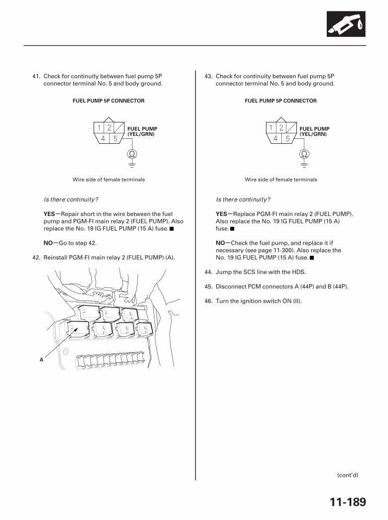
09
10
11
-
-
-
-
YES
NO
YES
NO
11-189
FUEL PUMP 5P CONNECTOR
FUEL PUMP(YEL/GRN)
A
FUEL PUMP 5P CONNECTOR
FUEL PUMP(YEL/GRN)
41. Check for continuity between fuel pump 5Pconnector terminal No. 5 and body ground.
Repair short in the wire between the fuelpump and PGM-FI main relay 2 (FUEL PUMP). Alsoreplace the No. 19 IG FUEL PUMP (15 A) fuse.
Go to step 42.
42. Reinstall PGM-FI main relay 2 (FUEL PUMP) (A).
43. Check for continuity between fuel pump 5Pconnector terminal No. 5 and body ground.
Replace PGM-FI main relay 2 (FUEL PUMP).Also replace the No. 19 IG FUEL PUMP (15 A)fuse.
Check the fuel pump, and replace it ifnecessary (see page 11-300). Also replace theNo. 19 IG FUEL PUMP (15 A) fuse.
44. Jump the SCS line with the HDS.
45. Disconnect PCM connectors A (44P) and B (44P).
46. Turn the ignition switch ON (II).
(cont’d)
Wire side of female terminals Wire side of female terminals
Is there continuity? Is there continuity?
07/05/09 16:52:04 61SJC020_110_0189

12
13
14
15
+
-
-
-
-
-
-
YES
NO
YES
NO
YES
NO
11-190
PGM-FI System
MIL Circuit Troubleshooting (cont’d)
PCM CONNECTOR B (44P)
IG1 (BLK/YEL)
PCM CONNECTOR A (44P)
MRLY (RED/YEL)
A
PGM-FI MAIN RELAY 1 (FI MAIN)4P CONNECTOR
B
47. Measure voltage between PCM connector terminalB37 and body ground.
Go to step 48.
Repair open in the wire between the No. 19 IGFUEL PUMP (15 A) fuse and the PCM (B37).
48. Measure voltage between PCM connector terminalA6 and body ground.
Go to step 54.
Go to step 49.
49. Turn the ignition switch OFF.
50. Remove PGM-FI main relay 1 (FI MAIN) (A) fromthe under-dash fuse/relay box.
51. Measure voltage between PGM-FI main relay 1(FI MAIN) 4P connector terminal No. 3 and bodyground.
Go to step 52.
Repair open in the wire between the No. 8FI ECU (PCM) (15 A) fuse and PGM-FI mainrelay 1 (FI MAIN).
Terminal side of female terminals
Terminal side of female terminals
Terminal side of female terminals
Is there battery voltage?
Is there battery voltage?
Is there battery voltage?
07/05/09 16:52:05 61SJC020_110_0190

16
17
18
19
-
-
-
-
YES
NO
YES
NO
11-191
PGM-FI MAIN RELAY 1 (FI MAIN)4P CONNECTOR
MRLY
JUMPER WIRE
PCM CONNECTOR A (44P)
MRLY (RED/YEL)
PCM CONNECTOR B (44P)
IGP (YEL/BLK)
A
52. Connect PGM-FI main relay 1 (FI MAIN) 4Pconnector terminal No. 4 to body ground with ajumper wire.
53. Check for continuity between PCM connectorterminal A6 and body ground.
Test PGM-FI main relay 1 (FI MAIN)(see page 22-75). If the relay is OK, update the PCMif it does not have the latest software (see page11-7), or substitute a known-good PCM (see page11-8), then recheck. If the symptom/indication goesaway with a known-good PCM, replace the originalPCM (see page 11-205).
Repair open in the wire between PGM-FI mainrelay 1 (FI MAIN) and the PCM (A6).
54. Reconnect PCM connector A (44P).
55. Turn the ignition switch ON (II).
56. Measure voltage between body ground and PCMconnector terminal B3.
Go to step 64.
Go to step 57.
57. Turn the ignition switch OFF.
58. Remove PGM-FI main relay 1 (FI MAIN) (A) fromthe under-dash fuse/relay box.
59. Turn the ignition switch ON (II).
(cont’d)
Terminal side of female terminals
Terminal side of female terminals
Terminal side of female terminals
Is there continuity?
Is there battery voltage?
07/05/09 16:52:06 61SJC020_110_0191
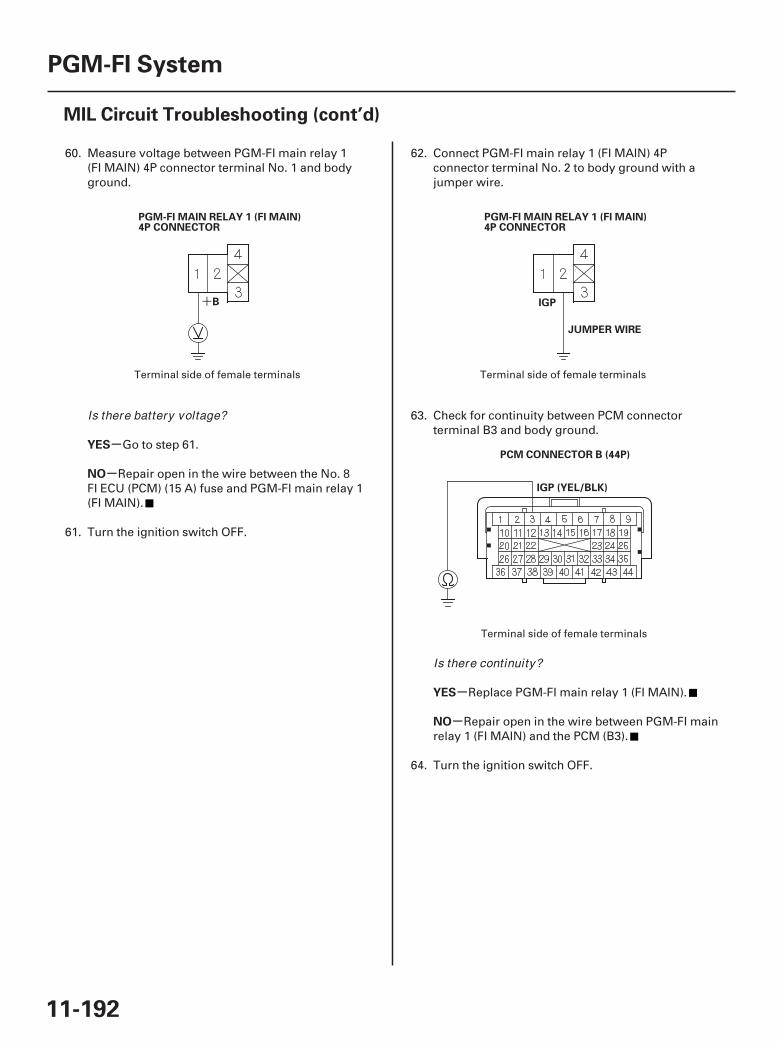
20 21
22
+
-
-
-
-
YES
NO
YES
NO
11-192
PGM-FI System
MIL Circuit Troubleshooting (cont’d)
PGM-FI MAIN RELAY 1 (FI MAIN)4P CONNECTOR
B
PGM-FI MAIN RELAY 1 (FI MAIN)4P CONNECTOR
IGP
JUMPER WIRE
PCM CONNECTOR B (44P)
IGP (YEL/BLK)
60. Measure voltage between PGM-FI main relay 1(FI MAIN) 4P connector terminal No. 1 and bodyground.
Go to step 61.
Repair open in the wire between the No. 8FI ECU (PCM) (15 A) fuse and PGM-FI main relay 1(FI MAIN).
61. Turn the ignition switch OFF.
62. Connect PGM-FI main relay 1 (FI MAIN) 4Pconnector terminal No. 2 to body ground with ajumper wire.
63. Check for continuity between PCM connectorterminal B3 and body ground.
Replace PGM-FI main relay 1 (FI MAIN).
Repair open in the wire between PGM-FI mainrelay 1 (FI MAIN) and the PCM (B3).
64. Turn the ignition switch OFF.
Terminal side of female terminals Terminal side of female terminals
Terminal side of female terminals
Is there battery voltage?
Is there continuity?
07/05/09 16:52:06 61SJC020_110_0192
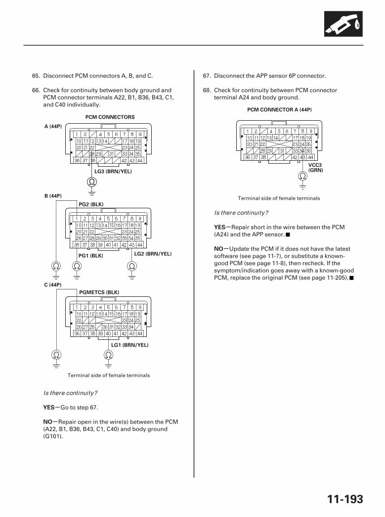
*0126
-
-
-
-
YES
NO
YES
NO
11-193
A (44P)
B (44P)
C (44P)
PGMETCS (BLK)
LG3 (BRN/YEL)
PG1 (BLK)
PG2 (BLK)
LG2 (BRN/YEL)
LG1 (BRN/YEL)
PCM CONNECTORS
PCM CONNECTOR A (44P)
VCC3(GRN)
65. Disconnect PCM connectors A, B, and C.
66. Check for continuity between body ground andPCM connector terminals A22, B1, B36, B43, C1,and C40 individually.
Go to step 67.
Repair open in the wire(s) between the PCM(A22, B1, B36, B43, C1, C40) and body ground(G101).
67. Disconnect the APP sensor 6P connector.
68. Check for continuity between PCM connectorterminal A24 and body ground.
Repair short in the wire between the PCM(A24) and the APP sensor.
Update the PCM if it does not have the latestsoftware (see page 11-7), or substitute a known-good PCM (see page 11-8), then recheck. If thesymptom/indication goes away with a known-goodPCM, replace the original PCM (see page 11-205).
Terminal side of female terminals
Terminal side of female terminals
Is there continuity?
Is there continuity?
07/05/09 16:52:07 61SJC020_110_0193
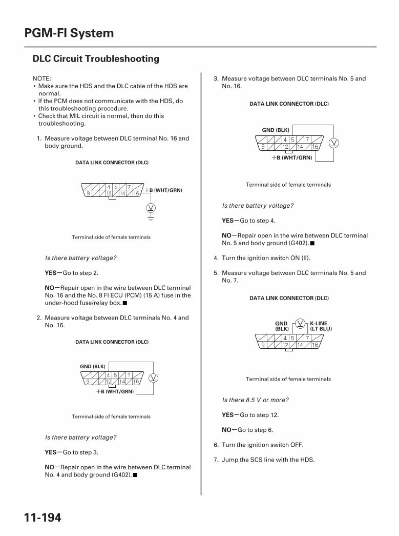
01
02
03
04
SJC8A00A20326919461FAAT00
+
+
+
-
-
-
-
-
-
-
-
YES
NO
YES
NO
YES
NO
YES
NO
11-194
PGM-FI System
DLC Circuit Troubleshooting
DATA LINK CONNECTOR (DLC)
B (WHT/GRN)
GND (BLK)
B (WHT/GRN)
DATA LINK CONNECTOR (DLC)
GND (BLK)
B (WHT/GRN)
DATA LINK CONNECTOR (DLC)
K-LINE(LT BLU)
GND(BLK)
DATA LINK CONNECTOR (DLC)
NOTE:• Make sure the HDS and the DLC cable of the HDS are
normal.• If the PCM does not communicate with the HDS, do
this troubleshooting procedure.• Check that MIL circuit is normal, then do this
troubleshooting.
1. Measure voltage between DLC terminal No. 16 andbody ground.
Go to step 2.
Repair open in the wire between DLC terminalNo. 16 and the No. 8 FI ECU (PCM) (15 A) fuse in theunder-hood fuse/relay box.
2. Measure voltage between DLC terminals No. 4 andNo. 16.
Go to step 3.
Repair open in the wire between DLC terminalNo. 4 and body ground (G402).
3. Measure voltage between DLC terminals No. 5 andNo. 16.
Go to step 4.
Repair open in the wire between DLC terminalNo. 5 and body ground (G402).
4. Turn the ignition switch ON (II).
5. Measure voltage between DLC terminals No. 5 andNo. 7.
Go to step 12.
Go to step 6.
6. Turn the ignition switch OFF.
7. Jump the SCS line with the HDS.
Terminal side of female terminals
Terminal side of female terminals
Terminal side of female terminals
Terminal side of female terminals
Is there battery voltage?
Is there battery voltage?
Is there battery voltage?
Is there 8.5 V or more?
07/05/09 16:52:07 61SJC020_110_0194
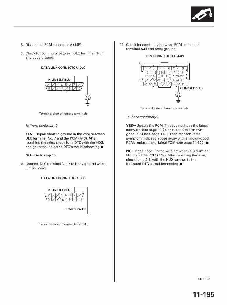
05
06
07
-
-
-
-
YES
NO
YES
NO
11-195
DATA LINK CONNECTOR (DLC)
K-LINE (LT BLU)
DATA LINK CONNECTOR (DLC)
K-LINE (LT BLU)
JUMPER WIRE
PCM CONNECTOR A (44P)
K-LINE (LT BLU)
8. Disconnect PCM connector A (44P).
9. Check for continuity between DLC terminal No. 7and body ground.
Repair short to ground in the wire betweenDLC terminal No. 7 and the PCM (A43). Afterrepairing the wire, check for a DTC with the HDS,and go to the indicated DTC’s troubleshooting.
Go to step 10.
10. Connect DLC terminal No. 7 to body ground with ajumper wire.
11. Check for continuity between PCM connectorterminal A43 and body ground.
Update the PCM if it does not have the latestsoftware (see page 11-7), or substitute a known-good PCM (see page 11-8). then recheck. If thesymptom/indication goes away with a known-goodPCM, replace the original PCM (see page 11-205).
Repair open in the wire between DLC terminalNo. 7 and the PCM (A43). After repairing the wire,check for a DTC with the HDS, and go to theindicated DTC’s troubleshooting.
(cont’d)
Terminal side of female terminals
Terminal side of female terminals
Terminal side of female terminals
Is there continuity?
Is there continuity?
07/05/09 16:52:08 61SJC020_110_0195
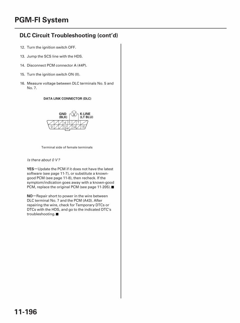
08
-
-
YES
NO
11-196
PGM-FI System
DLC Circuit Troubleshooting (cont’d)
K-LINE(LT BLU)
GND(BLK)
DATA LINK CONNECTOR (DLC)
12. Turn the ignition switch OFF.
13. Jump the SCS line with the HDS.
14. Disconnect PCM connector A (44P).
15. Turn the ignition switch ON (II).
16. Measure voltage between DLC terminals No. 5 andNo. 7.
Update the PCM if it does not have the latestsoftware (see page 11-7), or substitute a known-good PCM (see page 11-8), then recheck. If thesymptom/indication goes away with a known-goodPCM, replace the original PCM (see page 11-205).
Repair short to power in the wire betweenDLC terminal No. 7 and the PCM (A43). Afterrepairing the wire, check for Temporary DTCs orDTCs with the HDS, and go to the indicated DTC’stroubleshooting.
Terminal side of female terminals
Is there about 0 V?
07/05/09 16:52:08 61SJC020_110_0196

01
SJC8A00A20326934595KBAT00
11-197
Injector Replacement
A
B
D
E
C9.8 N·m(1.0 kgf·m, 7.2 lbf·ft)
1. Relieve fuel pressure (see page 11-286).
2. Remove the intake manifold (see page 9-3).
3. Disconnect the connectors from the injectors (A).
4. Disconnect the quick-connect fitting (B).
5. Remove the fuel rail mounting bolts (C) from the fuel rail (D).
6. Remove the injector clip (E) from the fuel rail.
7. Remove the injectors from the rails.
(cont’d)
07/05/09 16:52:08 61SJC020_110_0197
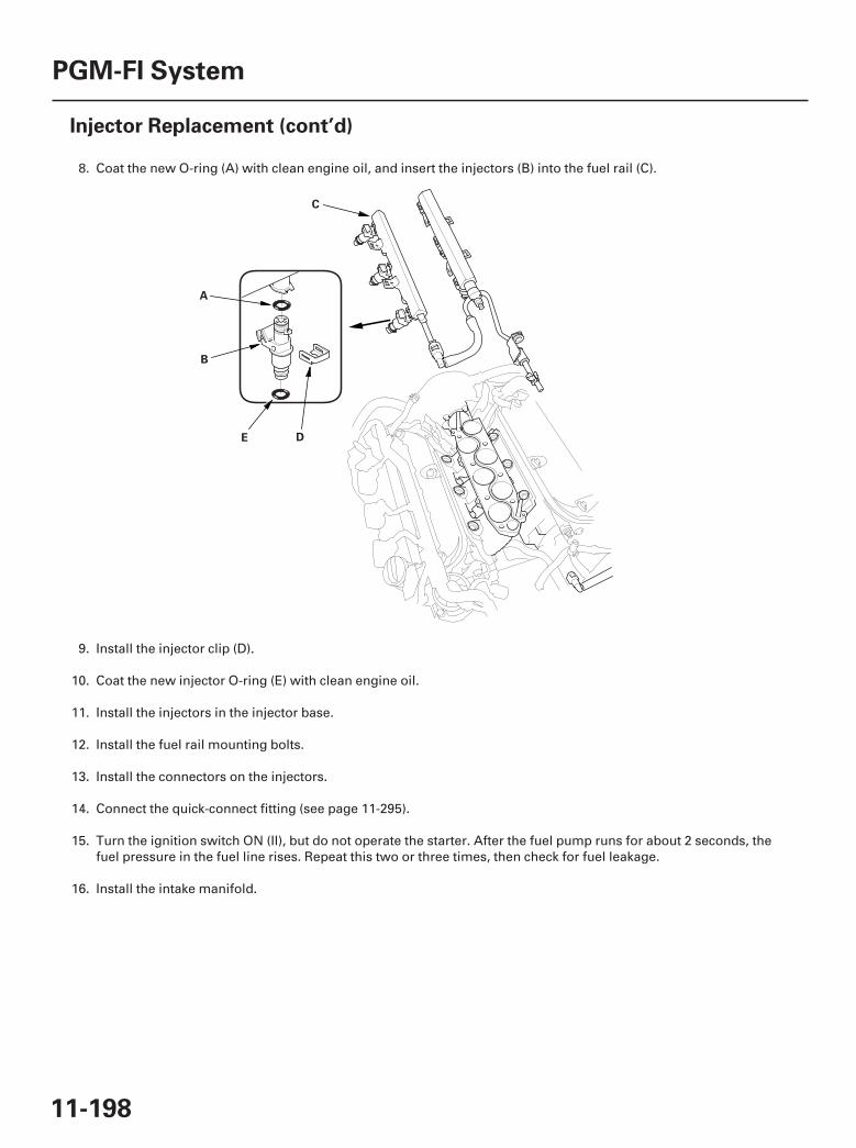
02
11-198
PGM-FI System
Injector Replacement (cont’d)
A
B
DE
C
8. Coat the new O-ring (A) with clean engine oil, and insert the injectors (B) into the fuel rail (C).
9. Install the injector clip (D).
10. Coat the new injector O-ring (E) with clean engine oil.
11. Install the injectors in the injector base.
12. Install the fuel rail mounting bolts.
13. Install the connectors on the injectors.
14. Connect the quick-connect fitting (see page 11-295).
15. Turn the ignition switch ON (II), but do not operate the starter. After the fuel pump runs for about 2 seconds, thefuel pressure in the fuel line rises. Repeat this two or three times, then check for fuel leakage.
16. Install the intake manifold.
07/05/09 16:52:09 61SJC020_110_0198

01
02
SJC8A00A20326912151KBAT01
Special Tools Required
Front Bank (Bank 2)
Rear Bank (Bank 1)
11-199
A/F Sensor Replacement
A
B44 N·m(4.5 kgf·m, 33 lbf·ft)
A
B44 N·m(4.5 kgf·m, 33 lbf·ft)
O2 sensor socket wrench, Snap-on YA8875, SP Tools93750, or equivalent, commercially available
1. Disconnect the front A/F sensor 8P connector (A),then remove the A/F sensor (B).
2. Install the parts in the reverse order of removal.
1. Disconnect the rear A/F sensor 8P connector (A),then remove the rear A/F sensor (B).
2. Install the parts in the reverse order of removal.
07/05/09 16:52:09 61SJC020_110_0199
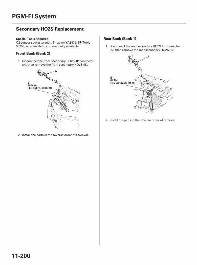
01
02
SJC8A00A20326931312KBAT02
Special Tools Required
Front Bank (Bank 2)
Rear Bank (Bank 1)
11-200
PGM-FI System
Secondary HO2S Replacement
A
B44 N·m(4.5 kgf·m, 33 lbf·ft)
A
B44 N·m(4.5 kgf·m, 33 lbf·ft)
O2 sensor socket wrench, Snap-on YA8875, SP Tools93750, or equivalent, commercially available
1. Disconnect the front secondary HO2S 4P connector(A), then remove the front secondary HO2S (B).
2. Install the parts in the reverse order of removal.
1. Disconnect the rear secondary HO2S 4P connector(A), then remove the rear secondary HO2S (B).
2. Install the parts in the reverse order of removal.
07/05/09 16:52:10 61SJC020_110_0200
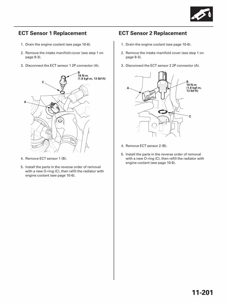
01
SJC8A00A20326924711KBAT10
01
SJC8A00A14426124711KBAT00
11-20111-201
ECT Sensor 1 Replacement ECT Sensor 2 Replacement
A
C
B18 N·m(1.8 kgf·m, 13 lbf·ft)
B18 N·m(1.8 kgf·m,13 lbf·ft)
A
C
1. Drain the engine coolant (see page 10-6).
2. Remove the intake manifold cover (see step 1 onpage 9-3).
3. Disconnect the ECT sensor 1 2P connector (A).
4. Remove ECT sensor 1 (B).
5. Install the parts in the reverse order of removalwith a new O-ring (C), then refill the radiator withengine coolant (see page 10-6).
1. Drain the engine coolant (see page 10-6).
2. Remove the intake manifold cover (see step 1 onpage 9-3).
3. Disconnect the ECT sensor 2 2P connector (A).
4. Remove ECT sensor 2 (B).
5. Install the parts in the reverse order of removalwith a new O-ring (C), then refill the radiator withengine coolant (see page 10-6).
07/05/09 16:52:10 61SJC020_110_0201
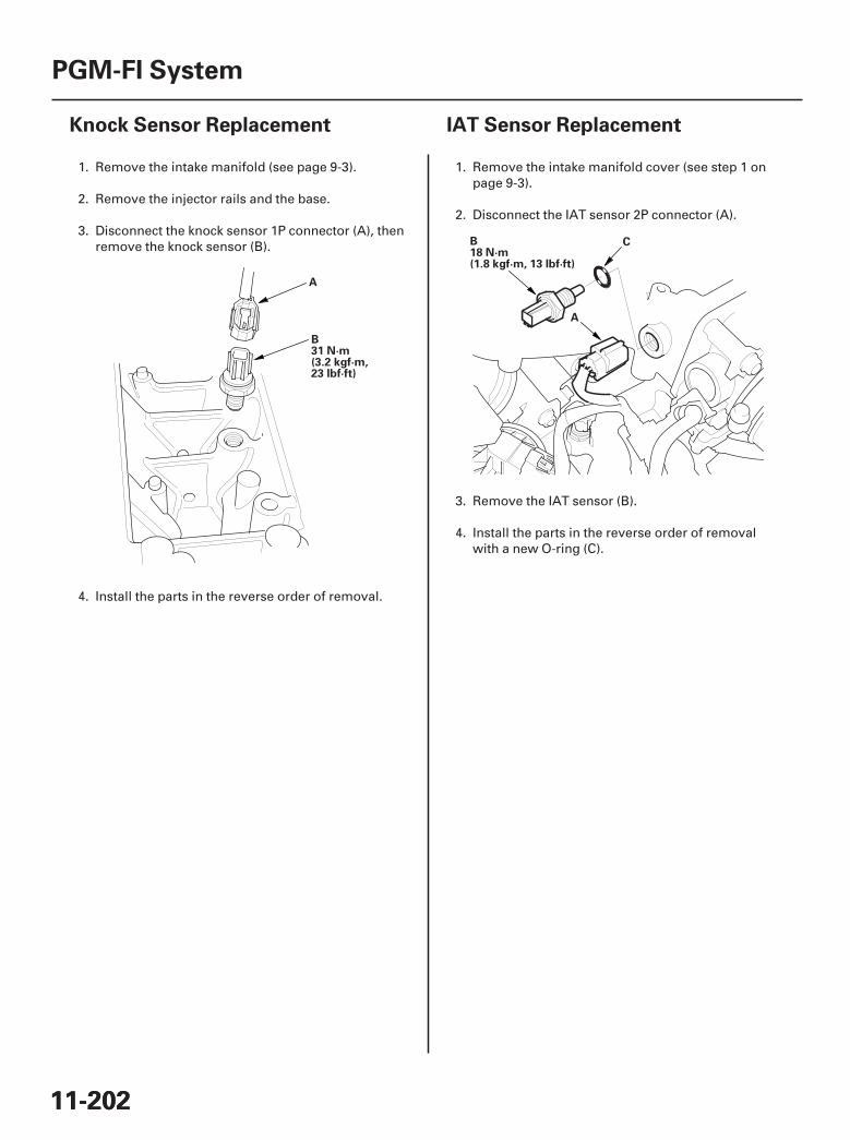
01
SJC8A00A20326936301KBAT20
01
SJC8A00A20326934901KBAT01
11-20211-202
PGM-FI System
Knock Sensor Replacement IAT Sensor Replacement
A
B31 N·m(3.2 kgf·m,23 lbf·ft)
A
CB18 N·m(1.8 kgf·m, 13 lbf·ft)
1. Remove the intake manifold (see page 9-3).
2. Remove the injector rails and the base.
3. Disconnect the knock sensor 1P connector (A), thenremove the knock sensor (B).
4. Install the parts in the reverse order of removal.
1. Remove the intake manifold cover (see step 1 onpage 9-3).
2. Disconnect the IAT sensor 2P connector (A).
3. Remove the IAT sensor (B).
4. Install the parts in the reverse order of removalwith a new O-ring (C).
07/05/09 16:52:11 61SJC020_110_0202
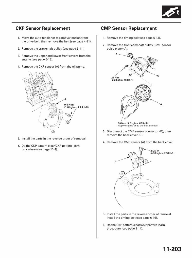
01
SJC8A00A20326917523KBAT20
01
*01
SJC8A00A20326916081KBAT00
11-20311-203
CKP Sensor Replacement CMP Sensor Replacement
9.8 N·m(1.0 kgf·m, 7.2 lbf·ft)
A
A
B
C22 N·m(2.2 kgf·m, 16 lbf·ft)
90 N·m (9.2 kgf·m, 67 lbf·ft)
A
3.5 N·m(0.35 kgf·m, 2.5 lbf·ft)
1. Move the auto-tensioner to remove tension fromthe drive belt, then remove the belt (see page 4-31).
2. Remove the crankshaft pulley (see page 6-11).
3. Remove the upper and lower front covers from theengine (see page 6-13).
4. Remove the CKP sensor (A) from the oil pump.
5. Install the parts in the reverse order of removal.
6. Do the CKP pattern clear/CKP pattern learnprocedure (see page 11-4).
1. Remove the timing belt (see page 6-13).
2. Remove the front camshaft pulley (CMP sensorpulse plate) (A).
3. Disconnect the CMP sensor connector (B), thenremove the back cover (C).
4. Remove the CMP sensor (A) from the back cover.
5. Install the parts in the reverse order of removal.Install the timing belt (see page 6-16).
6. Do the CKP pattern clear/CKP pattern learnprocedure (see page 11-4).
Apply engine oil to the bolt threads.
07/05/09 16:52:11 61SJC020_110_0203
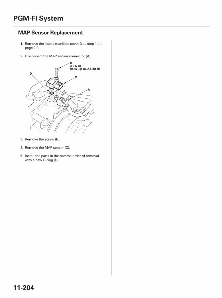
01
SJC8A00A20326940001KBAT00
11-204
PGM-FI System
MAP Sensor Replacement
B3.5 N·m(0.35 kgf·m, 2.5 lbf·ft)
A
C
D
1. Remove the intake manifold cover (see step 1 onpage 9-3).
2. Disconnect the MAP sensor connector (A).
3. Remove the screw (B).
4. Remove the MAP sensor (C).
5. Install the parts in the reverse order of removalwith a new O-ring (D).
07/05/09 16:52:12 61SJC020_110_0204

□ △ ○
01
02
SJC8A00A20300047201KBAT00
Special Tools Required
11-205
PCM Replacement
A
E9.8 N·m (1.0 kgf·m, 7.2 lbf·ft)
A
D
F
B
C
• Honda diagnostic system (HDS) tablet tester• Honda interface module (HIM) and an iN workstation
with HDS and CM update software• HDS pocket tester• GNA-600 and an iN workstation with HDS and CM
update software
NOTE:• Make sure the HDS is loaded with the latest software
version.• If you are replacing the PCM after substituting a
known-good PCM, reinstall the original PCM, then dothis procedure.
• During the procedure, if any READ DATA, WRITEDATA, or other data checks fail, note the failure, thencontinue.
1. Connect the HDS to the data link connector (DLC)(A) located under the driver’s side of the dashboard.
2. Turn the ignition switch ON (II).
3. Make sure the HDS communicates with the PCMand other vehicle systems. If it doesn’t, go to theDLC circuit troubleshooting (see page 11-194). Ifyou are returning from DLC circuit troubleshooting,skip steps 4 through 9, 16 through 18, 21, and 22,then do this after replacing the PCM:
• Replace the engine oil (see page 8-6) and theengine oil filter (see page 8-7).
• Clean the throttle body (see page 11-314).
4. Select the PGM-FI system with the HDS.
5. Select the INSPECTION MENU with the HDS.
6. Select the ETCS TEST, then select the TP POSITIONCHECK, and follow the screen prompts.
NOTE: If the TP POSITION CHECK indicates FAILED,continue with this procedure.
7. Select the REPLACE PCM MENU, then select READDATA and follow the screen prompts.
NOTE:• Doing this step copies (READS) the engine oil life
data from the original PCM so you can laterdownload (WRITE) it into the new PCM.
• If READ DATA indicates FAILED, continue withthis procedure.
8. Turn the ignition switch OFF.
9. Jump the SCS line with the HDS.
10. Remove the cover (D).
11. Disconnect PCM connectors A, B, and C.
NOTE: PCM connectors A, B, and C have symbols(A= , B= , C= ) embosed on them foridentification.
12. Remove the bolts (E), then remove the PCM (F).
(cont’d)
07/05/09 16:52:12 61SJC020_110_0205

11-206
PGM-FI System
PCM Replacement (cont’d)
13. Install the parts in the reverse order of removal.
14. Turn the ignition switch ON (II).
15. Manually input the VIN to the PCM with the HDS.
NOTE: DTC P0630 ‘‘VIN Not Programmed orMismatch’’ may be stored because the VIN has notbeen programmed into the PCM, ignore it, andcontinue this procedure.
16. If the READ DATA (engine oil life) failed in step 7,go to step 19. Otherwise, go to step 17.
17. Select the PGM-FI system with the HDS.
18. Select the REPLACE PCM MENU, then select WRITEDATA and follow the screen prompts.
NOTE: If the WRITE DATA indicates FAILED,continue this procedure.
19. Select IMMOBI system with the HDS.
20. Enter the immobilizer code with the PCMreplacement procedure in the HDS, it allows you tostart the engine.
21. If the TP POSITION CHECK failed in step 6, cleanthe throttle body (see page 11-314), then go to step22.
22. If the READ DATA failed in step 7 or the WRITEDATA failed in step 18, replace the engine oil(see page 8-6) and engine oil filter (see page 8-7),then go to step 23.
23. Select PGM-FI system, and reset the PCM with theHDS.
24. Update the PCM if it does not have the latestsoftware (see page 11-7).
25. Do the PCM idle learn procedure (see page 11-273).
26. Do the CKP pattern learn procedure (see page 11-4).
07/05/09 16:52:12 61SJC020_110_0206

*01
SJC8A00A20324100000DAAT00
11-207
Electronic Throttle Control System
Component Location Index
THROTTLE ACTUATOR CONTROL MODULE(Contains THROTTLE ACTUATOR andTHROTTLE POSITION (TP) SENSOR)
ELECTRONIC THROTTLECONTROL SYSTEM (ETCS)CONTROL RELAY ACCELERATOR PEDAL POSITION (APP) SENSOR
POWERTRAIN CONTROL MODULE (PCM)
Replacement, page 11-249Signal Inspection, page 11-248
Update, page 11-7Substitution, page 11-8Replacement, page 11-205
07/05/09 16:52:14 61SJC020_110_0207
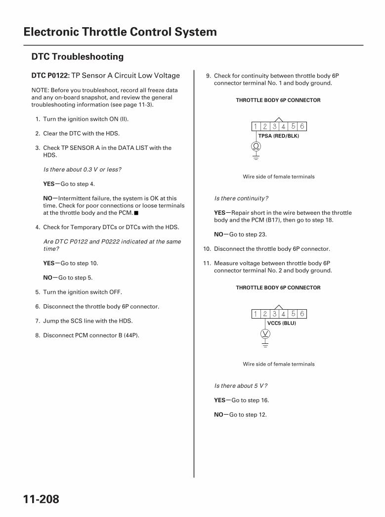
01
02
SJC8A00K77100090122FAAT30
-
-
-
-
-
-
-
-
DTC P0122:
YES
NO
YES
NO
YES
NO
YES
NO
11-208
Electronic Throttle Control System
DTC Troubleshooting
THROTTLE BODY 6P CONNECTOR
TPSA (RED/BLK)
THROTTLE BODY 6P CONNECTOR
VCC5 (BLU)
TP Sensor A Circuit Low Voltage
NOTE: Before you troubleshoot, record all freeze dataand any on-board snapshot, and review the generaltroubleshooting information (see page 11-3).
1. Turn the ignition switch ON (II).
2. Clear the DTC with the HDS.
3. Check TP SENSOR A in the DATA LIST with theHDS.
Go to step 4.
Intermittent failure, the system is OK at thistime. Check for poor connections or loose terminalsat the throttle body and the PCM.
4. Check for Temporary DTCs or DTCs with the HDS.
Go to step 10.
Go to step 5.
5. Turn the ignition switch OFF.
6. Disconnect the throttle body 6P connector.
7. Jump the SCS line with the HDS.
8. Disconnect PCM connector B (44P).
9. Check for continuity between throttle body 6Pconnector terminal No. 1 and body ground.
Repair short in the wire between the throttlebody and the PCM (B17), then go to step 18.
Go to step 23.
10. Disconnect the throttle body 6P connector.
11. Measure voltage between throttle body 6Pconnector terminal No. 2 and body ground.
Go to step 16.
Go to step 12.
Wire side of female terminals
Wire side of female terminals
Is there about 0.3 V or less?
Are DTC P0122 and P0222 indicated at the sametime?
Is there continuity?
Is there about 5 V?
07/05/09 16:52:14 61SJC020_110_0208
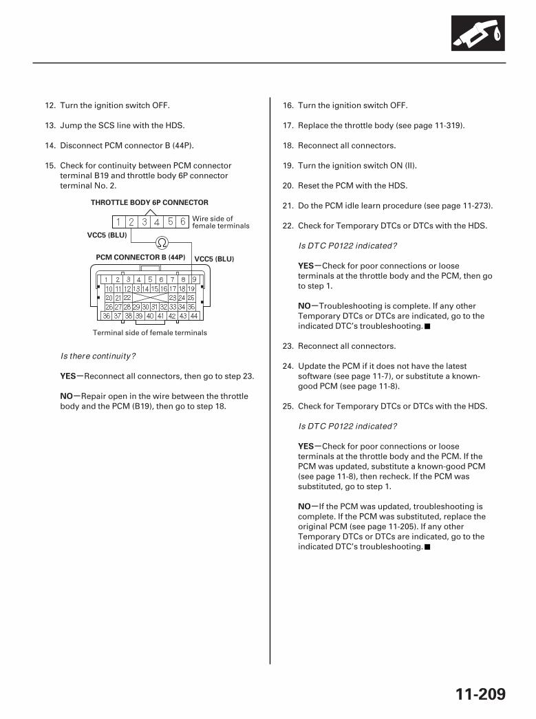
03
-
-
-
-
-
-
YES
NO
YES
NO
YES
NO
11-209
PCM CONNECTOR B (44P)
THROTTLE BODY 6P CONNECTOR
VCC5 (BLU)
VCC5 (BLU)
12. Turn the ignition switch OFF.
13. Jump the SCS line with the HDS.
14. Disconnect PCM connector B (44P).
15. Check for continuity between PCM connectorterminal B19 and throttle body 6P connectorterminal No. 2.
Reconnect all connectors, then go to step 23.
Repair open in the wire between the throttlebody and the PCM (B19), then go to step 18.
16. Turn the ignition switch OFF.
17. Replace the throttle body (see page 11-319).
18. Reconnect all connectors.
19. Turn the ignition switch ON (II).
20. Reset the PCM with the HDS.
21. Do the PCM idle learn procedure (see page 11-273).
22. Check for Temporary DTCs or DTCs with the HDS.
Check for poor connections or looseterminals at the throttle body and the PCM, then goto step 1.
Troubleshooting is complete. If any otherTemporary DTCs or DTCs are indicated, go to theindicated DTC’s troubleshooting.
23. Reconnect all connectors.
24. Update the PCM if it does not have the latestsoftware (see page 11-7), or substitute a known-good PCM (see page 11-8).
25. Check for Temporary DTCs or DTCs with the HDS.
Check for poor connections or looseterminals at the throttle body and the PCM. If thePCM was updated, substitute a known-good PCM(see page 11-8), then recheck. If the PCM wassubstituted, go to step 1.
If the PCM was updated, troubleshooting iscomplete. If the PCM was substituted, replace theoriginal PCM (see page 11-205). If any otherTemporary DTCs or DTCs are indicated, go to theindicated DTC’s troubleshooting.
Wire side offemale terminals
Terminal side of female terminals
Is there continuity?
Is DTC P0122 indicated?
Is DTC P0122 indicated?
07/05/09 16:52:15 61SJC020_110_0209
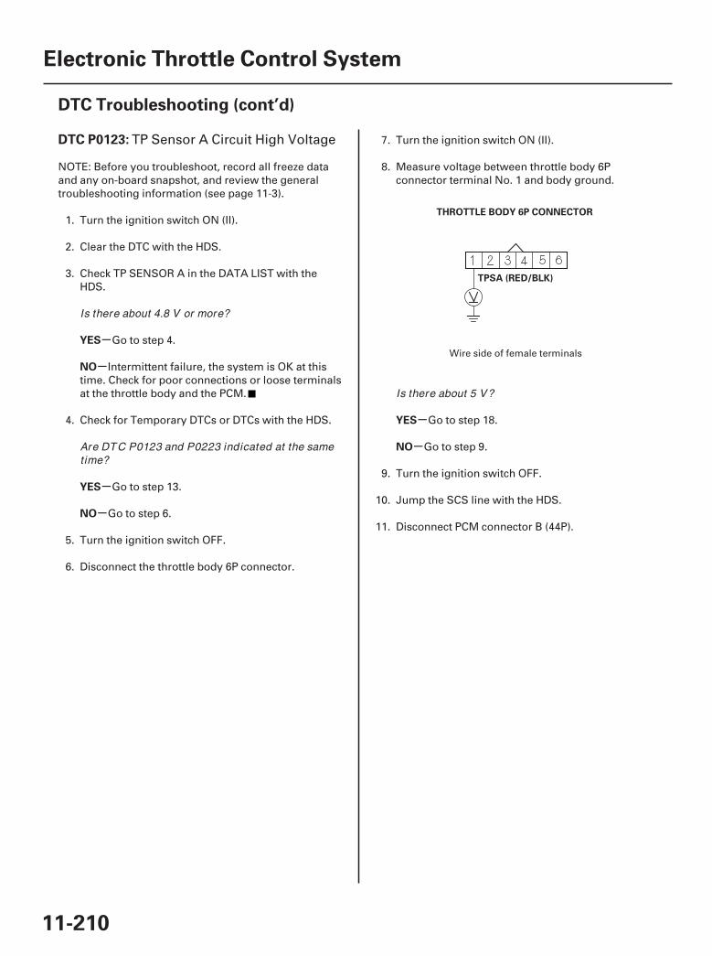
01
SJC8A00K77100090123FAAT30
-
-
-
-
-
-
DTC P0123:
YES
NO
YES
NO
YES
NO
11-210
Electronic Throttle Control System
DTC Troubleshooting (cont’d)
THROTTLE BODY 6P CONNECTOR
TPSA (RED/BLK)
TP Sensor A Circuit High Voltage
NOTE: Before you troubleshoot, record all freeze dataand any on-board snapshot, and review the generaltroubleshooting information (see page 11-3).
1. Turn the ignition switch ON (II).
2. Clear the DTC with the HDS.
3. Check TP SENSOR A in the DATA LIST with theHDS.
Go to step 4.
Intermittent failure, the system is OK at thistime. Check for poor connections or loose terminalsat the throttle body and the PCM.
4. Check for Temporary DTCs or DTCs with the HDS.
Go to step 13.
Go to step 6.
5. Turn the ignition switch OFF.
6. Disconnect the throttle body 6P connector.
7. Turn the ignition switch ON (II).
8. Measure voltage between throttle body 6Pconnector terminal No. 1 and body ground.
Go to step 18.
Go to step 9.
9. Turn the ignition switch OFF.
10. Jump the SCS line with the HDS.
11. Disconnect PCM connector B (44P).
Wire side of female terminals
Is there about 4.8 V or more?
Are DTC P0123 and P0223 indicated at the sametime?
Is there about 5 V?
07/05/09 16:52:15 61SJC020_110_0210
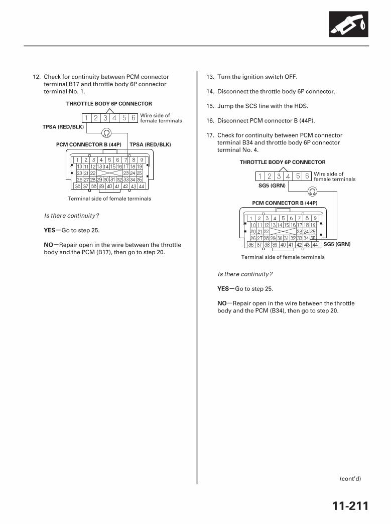
02
03
-
-
-
-
YES
NO
YES
NO
11-211
PCM CONNECTOR B (44P)
THROTTLE BODY 6P CONNECTOR
TPSA (RED/BLK)
TPSA (RED/BLK)
PCM CONNECTOR B (44P)
THROTTLE BODY 6P CONNECTOR
SG5 (GRN)
SG5 (GRN)
12. Check for continuity between PCM connectorterminal B17 and throttle body 6P connectorterminal No. 1.
Go to step 25.
Repair open in the wire between the throttlebody and the PCM (B17), then go to step 20.
13. Turn the ignition switch OFF.
14. Disconnect the throttle body 6P connector.
15. Jump the SCS line with the HDS.
16. Disconnect PCM connector B (44P).
17. Check for continuity between PCM connectorterminal B34 and throttle body 6P connectorterminal No. 4.
Go to step 25.
Repair open in the wire between the throttlebody and the PCM (B34), then go to step 20.
(cont’d)
Wire side offemale terminals
Terminal side of female terminals
Wire side offemale terminals
Terminal side of female terminals
Is there continuity?
Is there continuity?
07/05/09 16:53:08 61SJC020_110_0211

-
-
-
-
YES
NO
YES
NO
11-212
Electronic Throttle Control System
DTC Troubleshooting (cont’d)
18. Turn the ignition switch OFF.
19. Replace the throttle body (see page 11-319).
20. Reconnect all connectors.
21. Turn the ignition switch ON (II).
22. Reset the PCM with the HDS.
23. Do the PCM idle learn procedure (see page 11-273).
24. Check for Temporary DTCs or DTCs with the HDS.
Check for poor connections or looseterminals at the throttle body and the PCM, then goto step 1.
Troubleshooting is complete. If any otherTemporary DTCs or DTCs are indicated, go to theindicated DTC’s troubleshooting.
25. Reconnect all connectors.
26. Update the PCM if it does not have the latestsoftware (see page 11-7), or substitute a known-good PCM (see page 11-8).
27. Check for Temporary DTCs or DTCs with the HDS.
Check for poor connections or looseterminals at the throttle body and the PCM. If thePCM was updated, substitute a known-good PCM(see page 11-8), then recheck. If the PCM wassubstituted, go to step 1.
If the PCM was updated, troubleshooting iscomplete. If the PCM was substituted, replace theoriginal PCM (see page 11-205). If any otherTemporary DTCs or DTCs are indicated, go to theindicated DTC’s troubleshooting.
Is DTC P0123 indicated?
Is DTC P0123 indicated?
07/05/09 16:53:08 61SJC020_110_0212
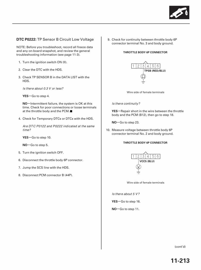
01
01
SJC8A00K77100090222FAAT30
-
-
-
-
-
-
-
-
DTC P0222:
YES
NO
YES
NO
YES
NO
YES
NO
11-213
THROTTLE BODY 6P CONNECTOR
TPSB (RED/BLU)
THROTTLE BODY 6P CONNECTOR
VCC5 (BLU)
TP Sensor B Circuit Low Voltage
NOTE: Before you troubleshoot, record all freeze dataand any on-board snapshot, and review the generaltroubleshooting information (see page 11-3).
1. Turn the ignition switch ON (II).
2. Clear the DTC with the HDS.
3. Check TP SENSOR B in the DATA LIST with theHDS.
Go to step 4.
Intermittent failure, the system is OK at thistime. Check for poor connections or loose terminalsat the throttle body and the PCM.
4. Check for Temporary DTCs or DTCs with the HDS.
Go to step 10.
Go to step 5.
5. Turn the ignition switch OFF.
6. Disconnect the throttle body 6P connector.
7. Jump the SCS line with the HDS.
8. Disconnect PCM connector B (44P).
9. Check for continuity between throttle body 6Pconnector terminal No. 3 and body ground.
Repair short in the wire between the throttlebody and the PCM (B12), then go to step 18.
Go to step 23.
10. Measure voltage between throttle body 6Pconnector terminal No. 2 and body ground.
Go to step 16.
Go to step 11.
(cont’d)
Wire side of female terminals
Wire side of female terminals
Is there about 0.3 V or less?
Are DTC P0122 and P0222 indicated at the sametime?
Is there continuity?
Is there about 5 V?
07/05/09 16:53:08 61SJC020_110_0213
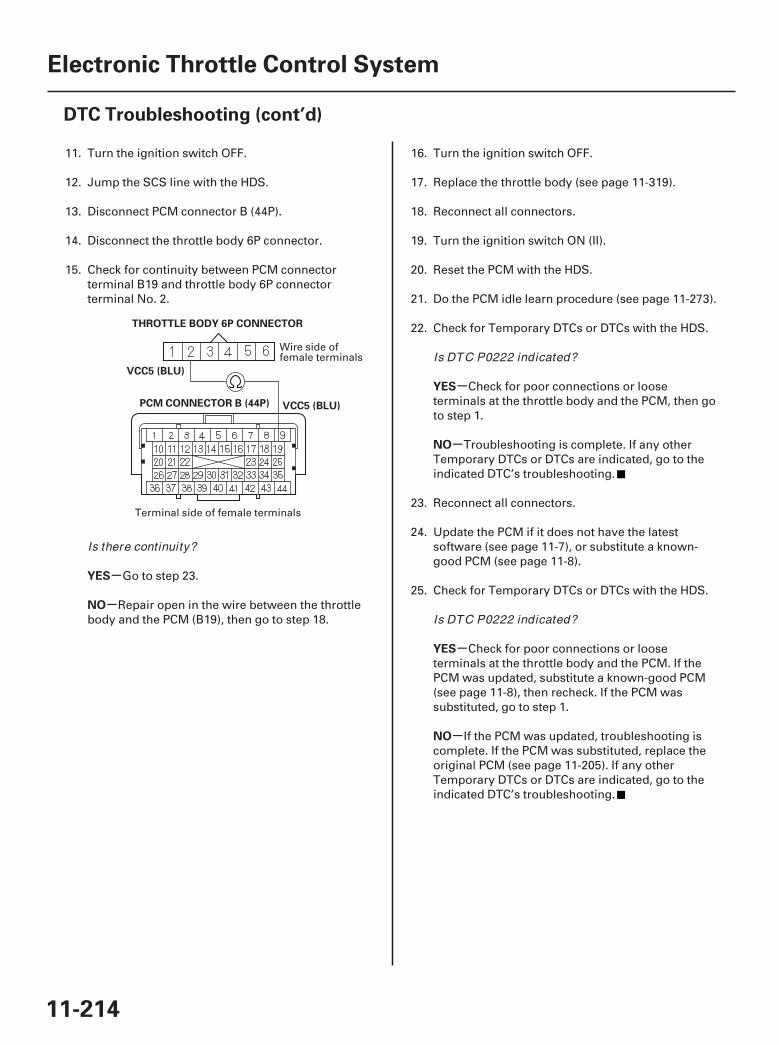
02
-
-
-
-
-
-
YES
NO
YES
NO
YES
NO
11-214
Electronic Throttle Control System
DTC Troubleshooting (cont’d)
PCM CONNECTOR B (44P)
THROTTLE BODY 6P CONNECTOR
VCC5 (BLU)
VCC5 (BLU)
11. Turn the ignition switch OFF.
12. Jump the SCS line with the HDS.
13. Disconnect PCM connector B (44P).
14. Disconnect the throttle body 6P connector.
15. Check for continuity between PCM connectorterminal B19 and throttle body 6P connectorterminal No. 2.
Go to step 23.
Repair open in the wire between the throttlebody and the PCM (B19), then go to step 18.
16. Turn the ignition switch OFF.
17. Replace the throttle body (see page 11-319).
18. Reconnect all connectors.
19. Turn the ignition switch ON (II).
20. Reset the PCM with the HDS.
21. Do the PCM idle learn procedure (see page 11-273).
22. Check for Temporary DTCs or DTCs with the HDS.
Check for poor connections or looseterminals at the throttle body and the PCM, then goto step 1.
Troubleshooting is complete. If any otherTemporary DTCs or DTCs are indicated, go to theindicated DTC’s troubleshooting.
23. Reconnect all connectors.
24. Update the PCM if it does not have the latestsoftware (see page 11-7), or substitute a known-good PCM (see page 11-8).
25. Check for Temporary DTCs or DTCs with the HDS.
Check for poor connections or looseterminals at the throttle body and the PCM. If thePCM was updated, substitute a known-good PCM(see page 11-8), then recheck. If the PCM wassubstituted, go to step 1.
If the PCM was updated, troubleshooting iscomplete. If the PCM was substituted, replace theoriginal PCM (see page 11-205). If any otherTemporary DTCs or DTCs are indicated, go to theindicated DTC’s troubleshooting.
Wire side offemale terminals
Terminal side of female terminals
Is there continuity?
Is DTC P0222 indicated?
Is DTC P0222 indicated?
07/05/09 16:53:09 61SJC020_110_0214

01
SJC8A00K77100090223FAAT30
-
-
-
-
-
-
DTC P0223:
YES
NO
YES
NO
YES
NO
11-215
THROTTLE BODY 6P CONNECTOR
TPSB (RED/BLU)
TP Sensor B Circuit High Voltage
NOTE: Before you troubleshoot, record all freeze dataand any on-board snapshot, and review the generaltroubleshooting information (see page 11-3).
1. Turn the ignition switch ON (II).
2. Clear the DTC with the HDS.
3. Check TP SENSOR B in the DATA LIST with theHDS.
Go to step 4.
Intermittent failure, the system is OK at thistime. Check for poor connections or loose terminalsat the throttle body and the PCM.
4. Check for Temporary DTCs or DTCs with the HDS.
Go to step 11.
Go to step 5.
5. Turn the ignition switch OFF.
6. Disconnect the throttle body 6P connector.
7. Turn the ignition switch ON (II).
8. Measure voltage between throttle body 6Pconnector terminal No. 3 and body ground.
Go to step 16.
Go to step 7.
9. Turn the ignition switch OFF.
10. Jump the SCS line with the HDS.
11. Disconnect PCM connector B (44P).
(cont’d)
Wire side of female terminalsIs there about 4.8 V or more?
Are DTC P0123 and P0223 indicated at the sametime?
Is there about 5 V?
07/05/09 16:53:09 61SJC020_110_0215
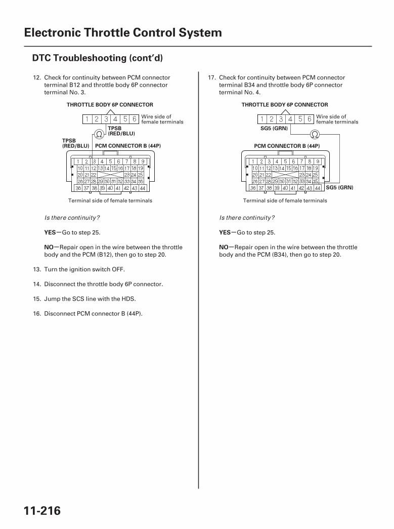
02 03
-
-
-
-
YES
NO
YES
NO
11-216
Electronic Throttle Control System
DTC Troubleshooting (cont’d)
PCM CONNECTOR B (44P)
THROTTLE BODY 6P CONNECTOR
TPSB(RED/BLU)
TPSB(RED/BLU) PCM CONNECTOR B (44P)
THROTTLE BODY 6P CONNECTOR
SG5 (GRN)
SG5 (GRN)
12. Check for continuity between PCM connectorterminal B12 and throttle body 6P connectorterminal No. 3.
Go to step 25.
Repair open in the wire between the throttlebody and the PCM (B12), then go to step 20.
13. Turn the ignition switch OFF.
14. Disconnect the throttle body 6P connector.
15. Jump the SCS line with the HDS.
16. Disconnect PCM connector B (44P).
17. Check for continuity between PCM connectorterminal B34 and throttle body 6P connectorterminal No. 4.
Go to step 25.
Repair open in the wire between the throttlebody and the PCM (B34), then go to step 20.
Wire side offemale terminals
Terminal side of female terminals
Wire side offemale terminals
Terminal side of female terminals
Is there continuity? Is there continuity?
07/05/09 16:53:09 61SJC020_110_0216
SJC8A00K77100090607FAAT00
-
-
-
-
-
-
-
-
YES
NO
YES
NO
YES
NO
YES
NO
DTC P0607:
11-21711-217
18. Turn the ignition switch OFF.
19. Replace the throttle body (see page 11-319).
20. Reconnect all connectors.
21. Turn the ignition switch ON (II).
22. Reset the PCM with the HDS.
23. Do the PCM idle learn procedure (see page 11-273).
24. Check for Temporary DTCs or DTCs with the HDS.
Check for poor connections or looseterminals at the throttle body and the PCM, then goto step 1.
Troubleshooting is complete. If any otherTemporary DTCs or DTCs are indicated, go to theindicated DTC’s troubleshooting.
25. Reconnect all connectors.
26. Update the PCM if it does not have the latestsoftware (see page 11-7), or substitute a known-good PCM (see page 11-8).
27. Check for Temporary DTCs or DTCs with the HDS.
Check for poor connections or looseterminals at the throttle body and the PCM. If thePCM was updated, substitute a known-good PCM(see page 11-8), then recheck. If the PCM wassubstituted, go to step 1.
If the PCM was updated, troubleshooting iscomplete. If the PCM was substituted, replace theoriginal PCM (see page 11-205). If any otherTemporary DTCs or DTCs are indicated, go to theindicated DTC’s troubleshooting.
NOTE: Before you troubleshoot, record all freeze dataand any on-board snapshot, and review the generaltroubleshooting information (see page 11-3).
1. Turn the ignition switch ON (II).
2. Clear the DTC with the HDS.
3. Check for Temporary DTCs or DTCs with the HDS.
Go to step 4.
Intermittent failure, the system is OK at thistime. Check for poor connections or loose terminalsat the throttle body and the PCM. If any otherTemporary DTCs or DTCs are indicated, go to theindicated DTC’s troubleshooting.
4. Update the PCM if it does not have the latestsoftware (see page 11-7), or substitute a known-good PCM (see page 11-8).
5. Check for Temporary DTCs or DTCs with the HDS.
Check for poor connections or looseterminals at the throttle body and the PCM. If thePCM was updated, substitute a known-good PCM(see page 11-8), then recheck. If the PCM wassubstituted, go to step 1.
If the PCM was updated, troubleshooting iscomplete. If the PCM was substituted, replace theoriginal PCM (see page 11-205). If any otherTemporary DTCs or DTCs are indicated, go to theindicated DTC’s troubleshooting.
Lost Communication withElectronic Throttle Control System (ETCS)
Is DTC P0223 indicated?
Is DTC P0223 indicated?
Is DTC P0607 indicated?
Is DTC P0607 indicated?
07/05/09 16:53:09 61SJC020_110_0217

SJC8A00K7710009061FFAAT00
-
-
-
-
DTC P061F:
YES
NO
YES
NO
11-218
Electronic Throttle Control System
DTC Troubleshooting (cont’d)
Electronic Throttle ControlSystem (ETCS) Malfunction
NOTE: Before you troubleshoot, record all freeze dataand any on-board snapshot, and review the generaltroubleshooting information (see page 11-3).
1. Turn the ignition switch ON (II).
2. Clear the DTC with the HDS.
3. Turn the ignition switch OFF.
4. Turn the ignition switch ON (II).
5. Check for Temporary DTCs or DTCs with the HDS.
Go to step 4.
Intermittent failure, the system is OK at thistime. Check for poor connections or loose terminalsat the throttle body and the PCM. If any otherTemporary DTCs or DTCs are indicated, go to theindicated DTC’s troubleshooting.
6. Update the PCM if it does not have the latestsoftware (see page 11-7), or substitute a known-good PCM (see page 11-8).
7. Check for Temporary DTCs or DTCs with the HDS.
Check for poor connections or looseterminals at the throttle body and the PCM. If thePCM was updated, substitute a known-good PCM(see page 11-8), then recheck. If the PCM wassubstituted, go to step 1.
If the PCM was updated, troubleshooting iscomplete. If the PCM was substituted, replace theoriginal PCM (see page 11-205). If any otherTemporary DTCs or DTCs are indicated, go to theindicated DTC’s troubleshooting.
Is DTC P061F indicated?
Is DTC P061F indicated?
07/05/09 16:53:09 61SJC020_110_0218
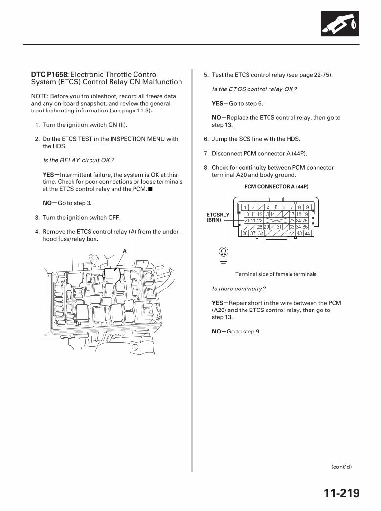
01
02
SJC8A00K77100091658FAAT00
-
-
-
-
-
-
DTC P1658:
YES
NO
YES
NO
YES
NO
11-219
A
PCM CONNECTOR A (44P)
ETCSRLY(BRN)
Electronic Throttle ControlSystem (ETCS) Control Relay ON Malfunction
NOTE: Before you troubleshoot, record all freeze dataand any on-board snapshot, and review the generaltroubleshooting information (see page 11-3).
1. Turn the ignition switch ON (II).
2. Do the ETCS TEST in the INSPECTION MENU withthe HDS.
Intermittent failure, the system is OK at thistime. Check for poor connections or loose terminalsat the ETCS control relay and the PCM.
Go to step 3.
3. Turn the ignition switch OFF.
4. Remove the ETCS control relay (A) from the under-hood fuse/relay box.
5. Test the ETCS control relay (see page 22-75).
Go to step 6.
Replace the ETCS control relay, then go tostep 13.
6. Jump the SCS line with the HDS.
7. Disconnect PCM connector A (44P).
8. Check for continuity between PCM connectorterminal A20 and body ground.
Repair short in the wire between the PCM(A20) and the ETCS control relay, then go tostep 13.
Go to step 9.
(cont’d)
Terminal side of female terminals
Is the RELAY circuit OK ?
Is the ETCS control relay OK ?
Is there continuity?
07/05/09 16:53:10 61SJC020_110_0219

03
-
-
-
-
-
-
YES
NO
YES
NO
YES
NO
11-220
Electronic Throttle Control System
DTC Troubleshooting (cont’d)
PCM CONNECTOR C (44P)
IG1ETCS (YEL/GRN)
9. Disconnect PCM connector C (44P).
10. Turn the ignition switch ON (II).
11. Measure voltage between PCM connector terminalC4 and body ground.
Repair short to power in the wire betweenthe PCM (C4) and the ETCS control relay, then go tostep 12.
Go to step 18.
12. Turn the ignition switch OFF.
13. Reconnect all connectors.
14. Turn the ignition switch ON (II).
15. Reset the PCM with the HDS.
16. Do the PCM idle learn procedure (see page 11-273).
17. Check for Temporary DTCs or DTCs with the HDS.
Check for poor connections or looseterminals at the ETCS control relay and the PCM,then go to step 1.
Troubleshooting is complete. If any otherTemporary DTCs or DTCs are indicated, go to theindicated DTC’s troubleshooting.
18. Reconnect all connectors.
19. Update the PCM if it does not have the latestsoftware (see page 11-7), or substitute a known-good PCM (see page 11-8).
20. Check for Temporary DTCs or DTCs with the HDS.
Check for poor connections or looseterminals at the ETCS control relay and the PCM. Ifthe PCM was updated, substitute a known-goodPCM (see page 11-8), then recheck. If the PCM wassubstituted, go to step 1.
If the PCM was updated, troubleshooting iscomplete. If the PCM was substituted, replace theoriginal PCM (see page 11-205). If any otherTemporary DTCs or DTCs are indicated, go to theindicated DTC’s troubleshooting.
Terminal side of female terminals
Is there battery voltage?
Is DTC P1658 indicated?
Is DTC P1658 indicated?
07/05/09 16:53:10 61SJC020_110_0220
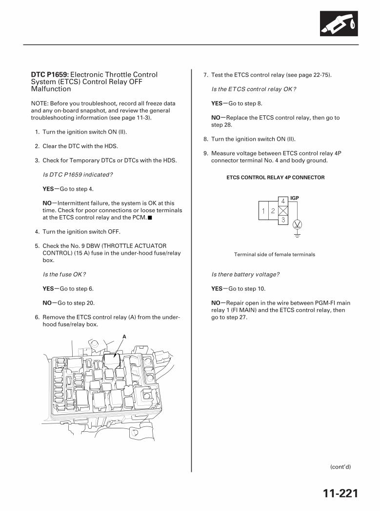
01
02
SJC8A00K77100091659FAAT00
-
-
-
-
-
-
-
-
DTC P1659:
YES
NO
YES
NO
YES
NO
YES
NO
11-221
A
ETCS CONTROL RELAY 4P CONNECTOR
IGP
Electronic Throttle ControlSystem (ETCS) Control Relay OFFMalfunction
NOTE: Before you troubleshoot, record all freeze dataand any on-board snapshot, and review the generaltroubleshooting information (see page 11-3).
1. Turn the ignition switch ON (II).
2. Clear the DTC with the HDS.
3. Check for Temporary DTCs or DTCs with the HDS.
Go to step 4.
Intermittent failure, the system is OK at thistime. Check for poor connections or loose terminalsat the ETCS control relay and the PCM.
4. Turn the ignition switch OFF.
5. Check the No. 9 DBW (THROTTLE ACTUATORCONTROL) (15 A) fuse in the under-hood fuse/relaybox.
Go to step 6.
Go to step 20.
6. Remove the ETCS control relay (A) from the under-hood fuse/relay box.
7. Test the ETCS control relay (see page 22-75).
Go to step 8.
Replace the ETCS control relay, then go tostep 28.
8. Turn the ignition switch ON (II).
9. Measure voltage between ETCS control relay 4Pconnector terminal No. 4 and body ground.
Go to step 10.
Repair open in the wire between PGM-FI mainrelay 1 (FI MAIN) and the ETCS control relay, thengo to step 27.
(cont’d)
Terminal side of female terminals
Is DTC P1659 indicated?
Is the fuse OK ?
Is the ETCS control relay OK ?
Is there battery voltage?
07/05/09 16:53:11 61SJC020_110_0221
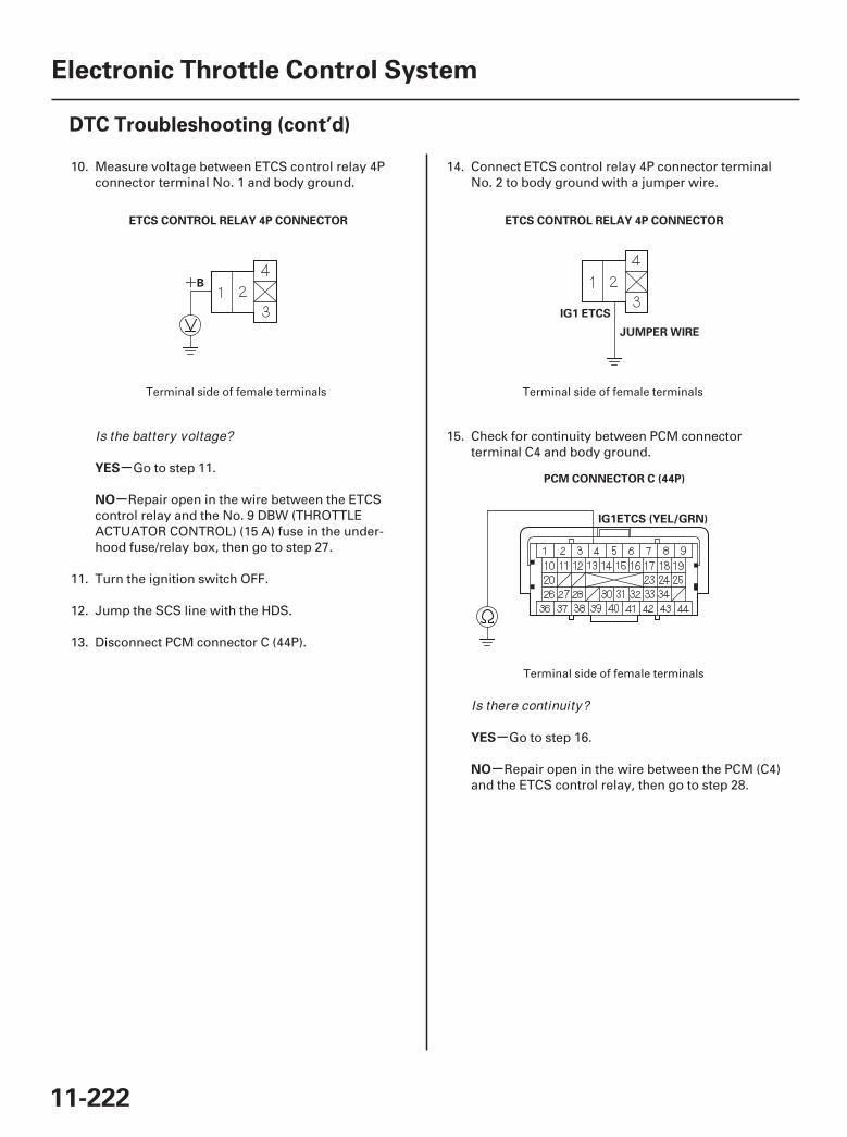
03 04
05
+
-
-
-
-
YES
NO
YES
NO
11-222
Electronic Throttle Control System
DTC Troubleshooting (cont’d)
B
ETCS CONTROL RELAY 4P CONNECTOR
IG1 ETCS
JUMPER WIRE
ETCS CONTROL RELAY 4P CONNECTOR
PCM CONNECTOR C (44P)
IG1ETCS (YEL/GRN)
10. Measure voltage between ETCS control relay 4Pconnector terminal No. 1 and body ground.
Go to step 11.
Repair open in the wire between the ETCScontrol relay and the No. 9 DBW (THROTTLEACTUATOR CONTROL) (15 A) fuse in the under-hood fuse/relay box, then go to step 27.
11. Turn the ignition switch OFF.
12. Jump the SCS line with the HDS.
13. Disconnect PCM connector C (44P).
14. Connect ETCS control relay 4P connector terminalNo. 2 to body ground with a jumper wire.
15. Check for continuity between PCM connectorterminal C4 and body ground.
Go to step 16.
Repair open in the wire between the PCM (C4)and the ETCS control relay, then go to step 28.
Terminal side of female terminals Terminal side of female terminals
Terminal side of female terminals
Is the battery voltage?
Is there continuity?
07/05/09 16:53:11 61SJC020_110_0222
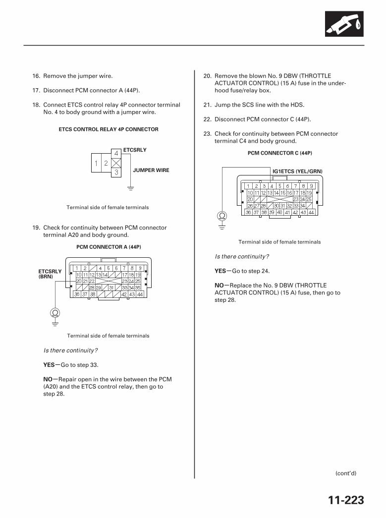
06
07
08
-
-
-
-
YES
NO
YES
NO
11-223
ETCSRLY
JUMPER WIRE
ETCS CONTROL RELAY 4P CONNECTOR
PCM CONNECTOR A (44P)
ETCSRLY(BRN)
PCM CONNECTOR C (44P)
IG1ETCS (YEL/GRN)
16. Remove the jumper wire.
17. Disconnect PCM connector A (44P).
18. Connect ETCS control relay 4P connector terminalNo. 4 to body ground with a jumper wire.
19. Check for continuity between PCM connectorterminal A20 and body ground.
Go to step 33.
Repair open in the wire between the PCM(A20) and the ETCS control relay, then go tostep 28.
20. Remove the blown No. 9 DBW (THROTTLEACTUATOR CONTROL) (15 A) fuse in the under-hood fuse/relay box.
21. Jump the SCS line with the HDS.
22. Disconnect PCM connector C (44P).
23. Check for continuity between PCM connectorterminal C4 and body ground.
Go to step 24.
Replace the No. 9 DBW (THROTTLEACTUATOR CONTROL) (15 A) fuse, then go tostep 28.
(cont’d)
Terminal side of female terminals
Terminal side of female terminals
Terminal side of female terminals
Is there continuity?
Is there continuity?
07/05/09 16:53:12 61SJC020_110_0223
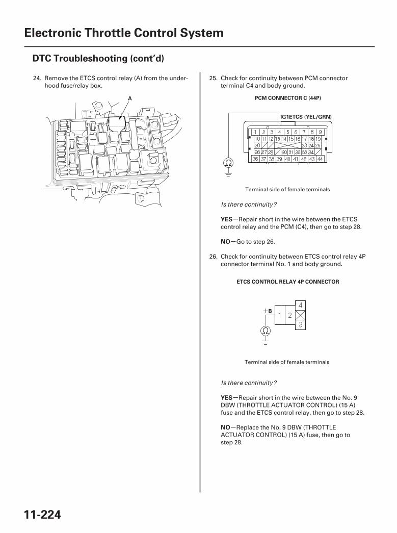
09 10
11
+
-
-
-
-
YES
NO
YES
NO
11-224
Electronic Throttle Control System
DTC Troubleshooting (cont’d)
A PCM CONNECTOR C (44P)
IG1ETCS (YEL/GRN)
B
ETCS CONTROL RELAY 4P CONNECTOR
24. Remove the ETCS control relay (A) from the under-hood fuse/relay box.
25. Check for continuity between PCM connectorterminal C4 and body ground.
Repair short in the wire between the ETCScontrol relay and the PCM (C4), then go to step 28.
Go to step 26.
26. Check for continuity between ETCS control relay 4Pconnector terminal No. 1 and body ground.
Repair short in the wire between the No. 9DBW (THROTTLE ACTUATOR CONTROL) (15 A)fuse and the ETCS control relay, then go to step 28.
Replace the No. 9 DBW (THROTTLEACTUATOR CONTROL) (15 A) fuse, then go tostep 28.
Terminal side of female terminals
Terminal side of female terminals
Is there continuity?
Is there continuity?
07/05/09 16:53:12 61SJC020_110_0224
-
-
-
-
YES
NO
YES
NO
11-225
27. Turn the ignition switch OFF.
28. Reconnect all connectors.
29. Turn the ignition switch ON (II).
30. Reset the PCM with the HDS.
31. Do the PCM idle learn procedure (see page 11-273).
32. Check for Temporary DTCs or DTCs with the HDS.
Check for poor connections or looseterminals at the ETCS control relay and the PCM,then go to step 1.
Troubleshooting is complete. If any otherTemporary DTCs or DTCs are indicated, go to theindicated DTC’s troubleshooting.
33. Reconnect all connectors.
34. Update the PCM if it does not have the latestsoftware (see page 11-7), or substitute a known-good PCM (see page 11-8).
35. Check for Temporary DTCs or DTCs with the HDS.
Check for poor connections or looseterminals at the ETCS control relay and the PCM. Ifthe PCM was updated, substitute a known-goodPCM (see page 11-8), then recheck. If the PCM wassubstituted, go to step 1.
If the PCM was updated, troubleshooting iscomplete. If the PCM was substituted, replace theoriginal PCM (see page 11-205). If any otherTemporary DTCs or DTCs are indicated, go to theindicated DTC’s troubleshooting.
Is DTC P1659 indicated?
Is DTC P1659 indicated?
07/05/09 16:53:12 61SJC020_110_0225
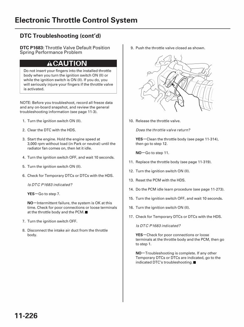
01
SJC8A00K77100091683FAAT30
-
-
-
-
-
-
DTC P1683:
YES
NO
YES
NO
YES
NO
11-226
Electronic Throttle Control System
DTC Troubleshooting (cont’d)
Throttle Valve Default PositionSpring Performance Problem
Do not insert your fingers into the installed throttlebody when you turn the ignition switch ON (II) orwhile the ignition switch is ON (II). If you do, youwill seriously injure your fingers if the throttle valveis activated.
NOTE: Before you troubleshoot, record all freeze dataand any on-board snapshot, and review the generaltroubleshooting information (see page 11-3).
1. Turn the ignition switch ON (II).
2. Clear the DTC with the HDS.
3. Start the engine. Hold the engine speed at3,000 rpm without load (in Park or neutral) until theradiator fan comes on, then let it idle.
4. Turn the ignition switch OFF, and wait 10 seconds.
5. Turn the ignition switch ON (II).
6. Check for Temporary DTCs or DTCs with the HDS.
Go to step 7.
Intermittent failure, the system is OK at thistime. Check for poor connections or loose terminalsat the throttle body and the PCM.
7. Turn the ignition switch OFF.
8. Disconnect the intake air duct from the throttlebody.
9. Push the throttle valve closed as shown.
10. Release the throttle valve.
Clean the throttle body (see page 11-314),then go to step 12.
Go to step 11.
11. Replace the throttle body (see page 11-319).
12. Turn the ignition switch ON (II).
13. Reset the PCM with the HDS.
14. Do the PCM idle learn procedure (see page 11-273).
15. Turn the ignition switch OFF, and wait 10 seconds.
16. Turn the ignition switch ON (II).
17. Check for Temporary DTCs or DTCs with the HDS.
Check for poor connections or looseterminals at the throttle body and the PCM, then goto step 1.
Troubleshooting is complete. If any otherTemporary DTCs or DTCs are indicated, go to theindicated DTC’s troubleshooting.
Is DTC P1683 indicated?
Does the throttle valve return?
Is DTC P1683 indicated?
07/05/09 16:53:13 61SJC020_110_0226

01
SJC8A00K77100091684FAAT30
-
-
-
-
-
-
DTC P1684:
YES
NO
YES
NO
YES
NO
11-227
Throttle Valve Return SpringPerformance Problem
Do not insert your fingers into the installed throttlebody when you turn the ignition switch ON (II) orwhile the ignition switch is ON (II). If you do, youwill seriously injure your fingers if the throttle valveis activated.
NOTE: Before you troubleshoot, record all freeze dataand any on-board snapshot, and review the generaltroubleshooting information (see page 11-3).
1. Turn the ignition switch ON (II).
2. Clear the DTC with the HDS.
3. Start the engine. Hold the engine speed at3,000 rpm without load (in Park or neutral) until theradiator fan comes on, then let it idle.
4. Turn the ignition switch OFF, and wait 10 seconds.
5. Turn the ignition switch ON (II).
6. Check for Temporary DTCs or DTCs with the HDS.
Go to step 7.
Intermittent failure, the system is OK at thistime. Check for poor connections or loose terminalsat the throttle body and the PCM.
7. Turn the ignition switch OFF.
8. Disconnect the intake air duct from the throttlebody.
9. Push the throttle valve open as shown.
10. Release the throttle valve.
Clean the throttle body (see page 11-314),then go to step 12.
Go to step 11.
11. Replace the throttle body (see page 11-319).
12. Turn the ignition switch ON (II).
13. Reset the PCM with the HDS.
14. Do the PCM idle learn procedure (see page 11-273).
15. Turn the ignition switch OFF, and wait 10 seconds.
16. Turn the ignition switch ON (II).
17. Check for Temporary DTCs or DTCs with the HDS.
Check for poor connections or looseterminals at the throttle body and the PCM, then goto step 1.
Troubleshooting is complete. If any otherTemporary DTCs or DTCs are indicated, go to theindicated DTC’s troubleshooting.
Is DTC P1684 indicated?
Does the throttle valve return?
Is DTC P1684 indicated?
07/05/09 16:53:13 61SJC020_110_0227
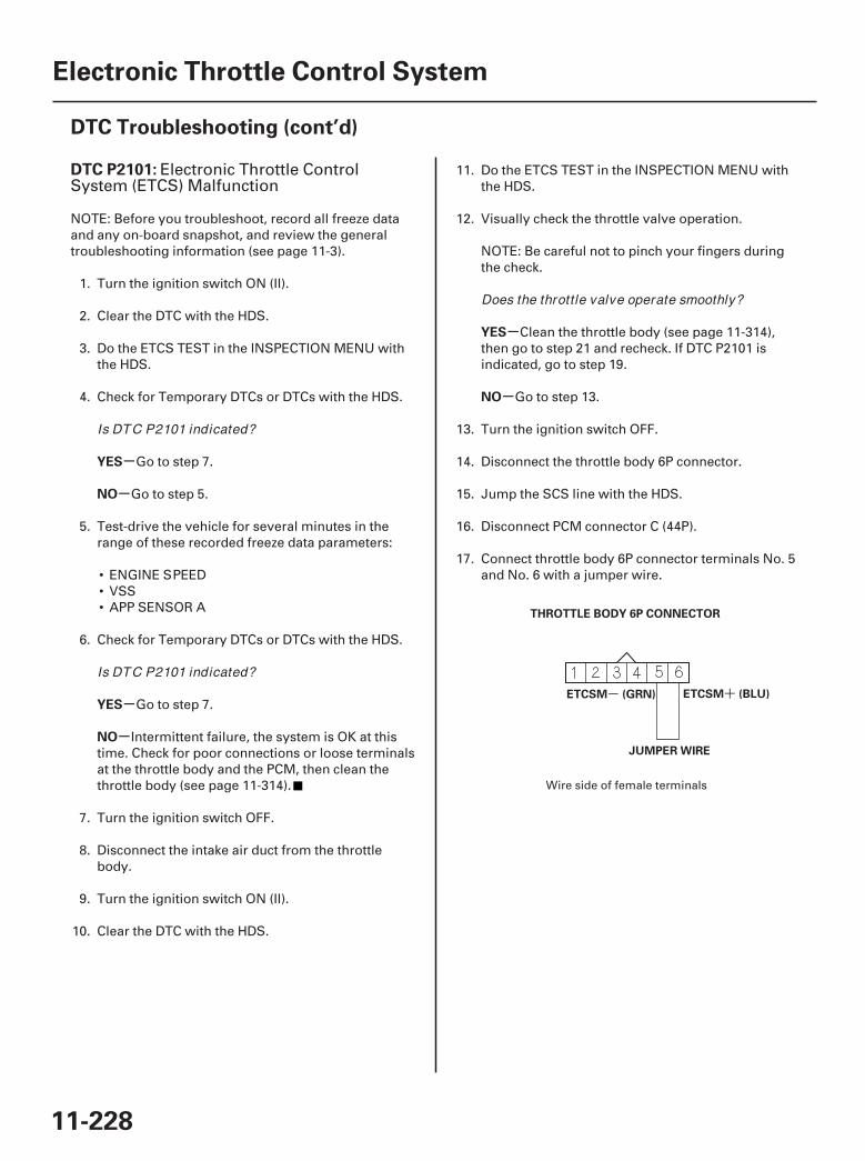
01
SJC8A00K77100092101FAAT30
- +
-
-
-
-
-
-
DTC P2101:
YES
NO
YES
NO
YES
NO
11-228
Electronic Throttle Control System
DTC Troubleshooting (cont’d)
THROTTLE BODY 6P CONNECTOR
ETCSM (GRN) ETCSM (BLU)
JUMPER WIRE
Electronic Throttle ControlSystem (ETCS) Malfunction
NOTE: Before you troubleshoot, record all freeze dataand any on-board snapshot, and review the generaltroubleshooting information (see page 11-3).
1. Turn the ignition switch ON (II).
2. Clear the DTC with the HDS.
3. Do the ETCS TEST in the INSPECTION MENU withthe HDS.
4. Check for Temporary DTCs or DTCs with the HDS.
Go to step 7.
Go to step 5.
5. Test-drive the vehicle for several minutes in therange of these recorded freeze data parameters:
• ENGINE SPEED• VSS• APP SENSOR A
6. Check for Temporary DTCs or DTCs with the HDS.
Go to step 7.
Intermittent failure, the system is OK at thistime. Check for poor connections or loose terminalsat the throttle body and the PCM, then clean thethrottle body (see page 11-314).
7. Turn the ignition switch OFF.
8. Disconnect the intake air duct from the throttlebody.
9. Turn the ignition switch ON (II).
10. Clear the DTC with the HDS.
11. Do the ETCS TEST in the INSPECTION MENU withthe HDS.
12. Visually check the throttle valve operation.
NOTE: Be careful not to pinch your fingers duringthe check.
Clean the throttle body (see page 11-314),then go to step 21 and recheck. If DTC P2101 isindicated, go to step 19.
Go to step 13.
13. Turn the ignition switch OFF.
14. Disconnect the throttle body 6P connector.
15. Jump the SCS line with the HDS.
16. Disconnect PCM connector C (44P).
17. Connect throttle body 6P connector terminals No. 5and No. 6 with a jumper wire.
Wire side of female terminals
Is DTC P2101 indicated?
Is DTC P2101 indicated?
Does the throttle valve operate smoothly?
07/05/09 16:53:13 61SJC020_110_0228
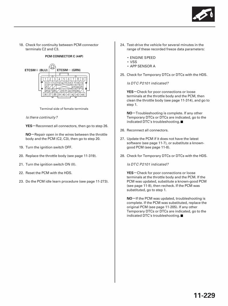
02
-+
-
-
-
-
-
-
YES
NO
YES
NO
YES
NO
11-229
ETCSM (GRN)ETCSM (BLU)
PCM CONNECTOR C (44P)
18. Check for continuity between PCM connectorterminals C2 and C3.
Reconnect all connectors, then go to step 26.
Repair open in the wires between the throttlebody and the PCM (C2, C3), then go to step 20.
19. Turn the ignition switch OFF.
20. Replace the throttle body (see page 11-319).
21. Turn the ignition switch ON (II).
22. Reset the PCM with the HDS.
23. Do the PCM idle learn procedure (see page 11-273).
24. Test-drive the vehicle for several minutes in therange of these recorded freeze data parameters:
• ENGINE SPEED• VSS• APP SENSOR A
25. Check for Temporary DTCs or DTCs with the HDS.
Check for poor connections or looseterminals at the throttle body and the PCM, thenclean the throttle body (see page 11-314), and go tostep 1.
Troubleshooting is complete. If any otherTemporary DTCs or DTCs are indicated, go to theindicated DTC’s troubleshooting.
26. Reconnect all connectors.
27. Update the PCM if it does not have the latestsoftware (see page 11-7), or substitute a known-good PCM (see page 11-8).
28. Check for Temporary DTCs or DTCs with the HDS.
Check for poor connections or looseterminals at the throttle body and the PCM. If thePCM was updated, substitute a known-good PCM(see page 11-8), then recheck. If the PCM wassubstituted, go to step 1.
If the PCM was updated, troubleshooting iscomplete. If the PCM was substituted, replace theoriginal PCM (see page 11-205). If any otherTemporary DTCs or DTCs are indicated, go to theindicated DTC’s troubleshooting.
Terminal side of female terminals
Is there continuity?
Is DTC P2101 indicated?
Is DTC P2101 indicated?
07/05/09 16:53:13 61SJC020_110_0229

01
02
SJC8A00K77100092118FAAT30
-+
- +
-
-
-
-
DTC P2118:
YES
NO
YES
NO
11-230
Electronic Throttle Control System
DTC Troubleshooting (cont’d)
ETCSM (GRN)ETCSM (BLU)
PCM CONNECTOR C (44P)
THROTTLE BODY 6P CONNECTOR
ETCSM ETCSM
Throttle Actuator Current Range/Performance Problem
NOTE: Before you troubleshoot, record all freeze dataand any on-board snapshot, and review the generaltroubleshooting information (see page 11-3).
1. Jump the SCS line with the HDS.
2. Disconnect PCM connector C (44P).
3. Measure resistance between PCM connectorterminals C2 and C3.
Go to step 4.
Go to step 15.
4. Disconnect the throttle body 6P connector.
5. At the throttle body side, measure resistancebetween throttle body 6P connector terminals No. 5and No. 6 with the throttle fully closed.
Go to step 6.
Repair short in the wires between the throttlebody and the PCM (C2, C3), then go to step 7.
6. Replace the throttle body (see page 11-319).
7. Reconnect all connectors.
8. Turn the ignition switch ON (II).
9. Reset the PCM with the HDS.
Terminal side of female terminals
Terminal side of male terminals
Is there about 1.0 or less?
Is there about 1.0 or less?
07/05/09 16:53:14 61SJC020_110_0230
-
-
-
-
YES
NO
YES
NO
11-231
10. Do the PCM idle learn procedure (see page 11-273).
11. Turn the ignition switch OFF.
12. Turn the ignition switch ON (II).
13. Slowly press the accelerator pedal to the floor.
14. Check for Temporary DTCs or DTCs with the HDS.
Check for poor connections or looseterminals at the throttle body and the PCM, then goto step 1.
Troubleshooting is complete. If any otherTemporary DTCs or DTCs are indicated, go to theindicated DTC’s troubleshooting.
15. Reconnect all connectors.
16. Update the PCM if it does not have the latestsoftware (see page 11-7), or substitute a known-good PCM (see page 11-8).
17. Check for Temporary DTCs or DTCs with the HDS.
Check for poor connections or looseterminals at the throttle body and the PCM. If thePCM was updated, substitute a known-good PCM(see page 11-8), then recheck. If the PCM wassubstituted, go to step 1.
If the PCM was updated, troubleshooting iscomplete. If the PCM was substituted, replace theoriginal PCM (see page 11-205). If any otherTemporary DTCs or DTCs are indicated, go to theindicated DTC’s troubleshooting.
Is DTC P2118 indicated?
Is DTC P2118 indicated?
07/05/09 16:53:14 61SJC020_110_0231
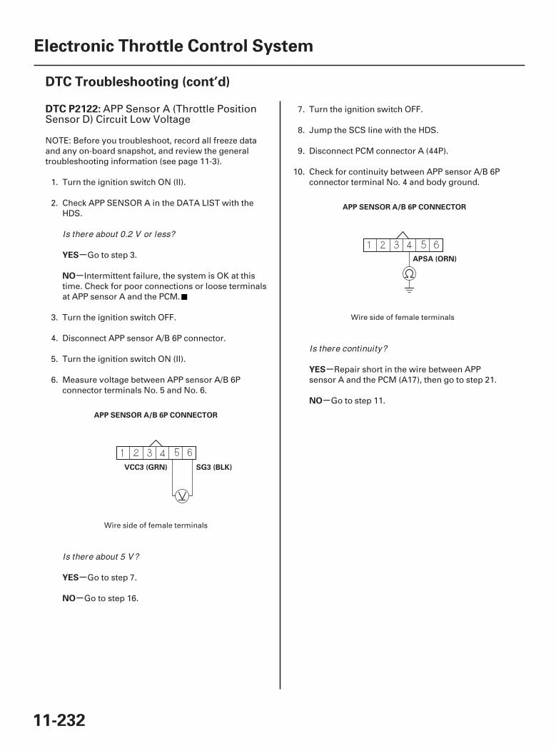
01
02
SJC8A00K77100092122FAAT30
-
-
-
-
-
-
DTC P2122:
YES
NO
YES
NO
YES
NO
11-232
Electronic Throttle Control System
DTC Troubleshooting (cont’d)
APP SENSOR A/B 6P CONNECTOR
SG3 (BLK)VCC3 (GRN)
APP SENSOR A/B 6P CONNECTOR
APSA (ORN)
APP Sensor A (Throttle PositionSensor D) Circuit Low Voltage
NOTE: Before you troubleshoot, record all freeze dataand any on-board snapshot, and review the generaltroubleshooting information (see page 11-3).
1. Turn the ignition switch ON (II).
2. Check APP SENSOR A in the DATA LIST with theHDS.
Go to step 3.
Intermittent failure, the system is OK at thistime. Check for poor connections or loose terminalsat APP sensor A and the PCM.
3. Turn the ignition switch OFF.
4. Disconnect APP sensor A/B 6P connector.
5. Turn the ignition switch ON (II).
6. Measure voltage between APP sensor A/B 6Pconnector terminals No. 5 and No. 6.
Go to step 7.
Go to step 16.
7. Turn the ignition switch OFF.
8. Jump the SCS line with the HDS.
9. Disconnect PCM connector A (44P).
10. Check for continuity between APP sensor A/B 6Pconnector terminal No. 4 and body ground.
Repair short in the wire between APPsensor A and the PCM (A17), then go to step 21.
Go to step 11.
Wire side of female terminals
Wire side of female terminals
Is there about 0.2 V or less?
Is there about 5 V?
Is there continuity?
07/05/09 16:53:14 61SJC020_110_0232
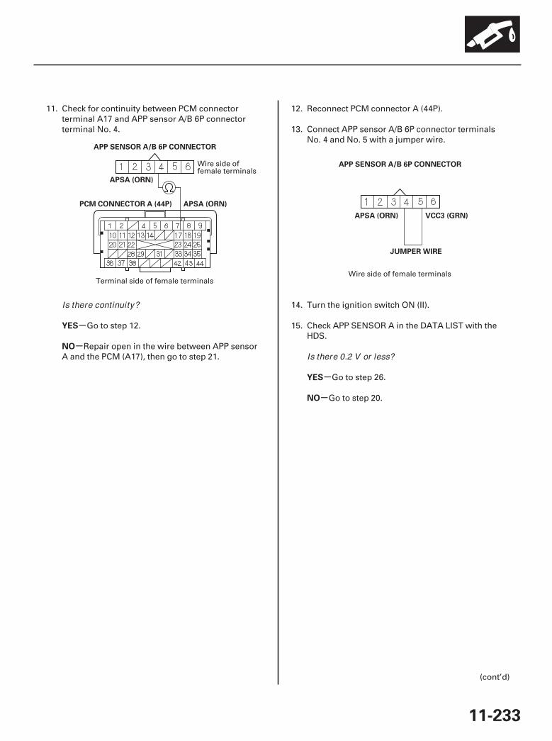
0304
-
-
-
-
YES
NO
YES
NO
11-233
PCM CONNECTOR A (44P)
APP SENSOR A/B 6P CONNECTOR
APSA (ORN)
APSA (ORN)
APSA (ORN) VCC3 (GRN)
JUMPER WIRE
APP SENSOR A/B 6P CONNECTOR
11. Check for continuity between PCM connectorterminal A17 and APP sensor A/B 6P connectorterminal No. 4.
Go to step 12.
Repair open in the wire between APP sensorA and the PCM (A17), then go to step 21.
12. Reconnect PCM connector A (44P).
13. Connect APP sensor A/B 6P connector terminalsNo. 4 and No. 5 with a jumper wire.
14. Turn the ignition switch ON (II).
15. Check APP SENSOR A in the DATA LIST with theHDS.
Go to step 26.
Go to step 20.
(cont’d)
Wire side offemale terminals
Terminal side of female terminalsWire side of female terminals
Is there continuity?
Is there 0.2 V or less?
07/05/09 16:53:14 61SJC020_110_0233
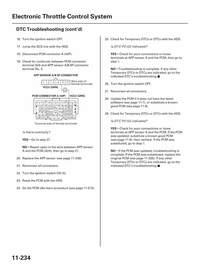
05
-
-
-
-
-
-
YES
NO
YES
NO
YES
NO
11-234
Electronic Throttle Control System
DTC Troubleshooting (cont’d)
PCM CONNECTOR A (44P) VCC3 (GRN)
VCC3 (GRN)
APP SENSOR A/B 6P CONNECTOR
16. Turn the ignition switch OFF.
17. Jump the SCS line with the HDS.
18. Disconnect PCM connector A (44P).
19. Check for continuity between PCM connectorterminal A24 and APP sensor A/B 6P connectorterminal No. 5.
Go to step 27.
Repair open in the wire between APP sensorA and the PCM (A24), then go to step 21.
20. Replace the APP sensor (see page 11-249).
21. Reconnect all connectors.
22. Turn the ignition switch ON (II).
23. Reset the PCM with the HDS.
24. Do the PCM idle learn procedure (see page 11-273).
25. Check for Temporary DTCs or DTCs with the HDS.
Check for poor connections or looseterminals at APP sensor A and the PCM, then go tostep 1.
Troubleshooting is complete. If any otherTemporary DTCs or DTCs are indicated, go to theindicated DTC’s troubleshooting.
26. Turn the ignition switch OFF.
27. Reconnect all connectors.
28. Update the PCM if it does not have the latestsoftware (see page 11-7), or substitute a known-good PCM (see page 11-8).
29. Check for Temporary DTCs or DTCs with the HDS.
Check for poor connections or looseterminals at APP sensor A and the PCM. If the PCMwas updated, substitute a known-good PCM(see page 11-8), then recheck. If the PCM wassubstituted, go to step 1.
If the PCM was updated, troubleshooting iscomplete. If the PCM was substituted, replace theoriginal PCM (see page 11-205). If any otherTemporary DTCs or DTCs are indicated, go to theindicated DTC’s troubleshooting.
Wire side offemale terminals
Terminal side of female terminals
Is there continuity?
Is DTC P2122 indicated?
Is DTC P2122 indicated?
07/05/09 16:53:15 61SJC020_110_0234
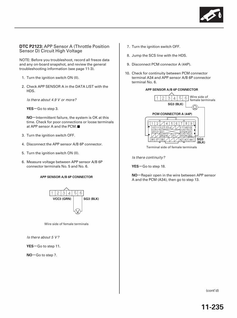
01
02
SJC8A00K77100092123FAAT30
-
-
-
-
-
-
DTC P2123:
YES
NO
YES
NO
YES
NO
11-235
APP SENSOR A/B 6P CONNECTOR
VCC3 (GRN) SG3 (BLK)
PCM CONNECTOR A (44P)
SG3 (BLK)
SG3(BLK)
APP SENSOR A/B 6P CONNECTOR
APP Sensor A (Throttle PositionSensor D) Circuit High Voltage
NOTE: Before you troubleshoot, record all freeze dataand any on-board snapshot, and review the generaltroubleshooting information (see page 11-3).
1. Turn the ignition switch ON (II).
2. Check APP SENSOR A in the DATA LIST with theHDS.
Go to step 3.
Intermittent failure, the system is OK at thistime. Check for poor connections or loose terminalsat APP sensor A and the PCM.
3. Turn the ignition switch OFF.
4. Disconnect the APP sensor A/B 6P connector.
5. Turn the ignition switch ON (II).
6. Measure voltage between APP sensor A/B 6Pconnector terminals No. 5 and No. 6.
Go to step 11.
Go to step 7.
7. Turn the ignition switch OFF.
8. Jump the SCS line with the HDS.
9. Disconnect PCM connector A (44P).
10. Check for continuity between PCM connectorterminal A34 and APP sensor A/B 6P connectorterminal No. 6.
Go to step 18.
Repair open in the wire between APP sensorA and the PCM (A34), then go to step 13.
(cont’d)
Wire side of female terminals
Wire side offemale terminals
Terminal side of female terminals
Is there about 4.9 V or more?
Is there about 5 V?
Is there continuity?
07/05/09 16:53:15 61SJC020_110_0235
-
-
-
-
YES
NO
YES
NO
11-236
Electronic Throttle Control System
DTC Troubleshooting (cont’d)
11. Turn the ignition switch OFF.
12. Replace the APP sensor (see page 11-249).
13. Reconnect all connectors.
14. Turn the ignition switch ON (II).
15. Reset the PCM with the HDS.
16. Do the PCM idle learn procedure (see page 11-273).
17. Check for Temporary DTCs or DTCs with the HDS.
Check for poor connections or looseterminals at APP sensor A and the PCM, then go tostep 1.
Troubleshooting is complete. If any otherTemporary DTCs or DTCs are indicated, go to theindicated DTC’s troubleshooting.
18. Reconnect all connectors.
19. Update the PCM if it does not have the latestsoftware (see page 11-7), or substitute a known-good PCM (see page 11-8).
20. Check for Temporary DTCs or DTCs with the HDS.
Check for poor connections or looseterminals at APP sensor A and the PCM. If the PCMwas updated, substitute a known-good PCM(see page 11-8), then recheck. If the PCM wassubstituted, go to step 1.
If the PCM was updated, troubleshooting iscomplete. If the PCM was substituted, replace theoriginal PCM (see page 11-205). If any otherTemporary DTCs or DTCs are indicated, go to theindicated DTC’s troubleshooting.
Is DTC P2123 indicated?
Is DTC P2123 indicated?
07/05/09 16:53:15 61SJC020_110_0236
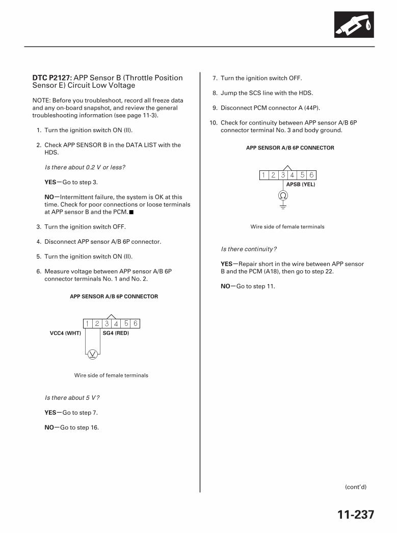
01
02
SJC8A00K77100092127FAAT30
-
-
-
-
-
-
DTC P2127:
YES
NO
YES
NO
YES
NO
11-237
APP SENSOR A/B 6P CONNECTOR
VCC4 (WHT) SG4 (RED)
APP SENSOR A/B 6P CONNECTOR
APSB (YEL)
APP Sensor B (Throttle PositionSensor E) Circuit Low Voltage
NOTE: Before you troubleshoot, record all freeze dataand any on-board snapshot, and review the generaltroubleshooting information (see page 11-3).
1. Turn the ignition switch ON (II).
2. Check APP SENSOR B in the DATA LIST with theHDS.
Go to step 3.
Intermittent failure, the system is OK at thistime. Check for poor connections or loose terminalsat APP sensor B and the PCM.
3. Turn the ignition switch OFF.
4. Disconnect APP sensor A/B 6P connector.
5. Turn the ignition switch ON (II).
6. Measure voltage between APP sensor A/B 6Pconnector terminals No. 1 and No. 2.
Go to step 7.
Go to step 16.
7. Turn the ignition switch OFF.
8. Jump the SCS line with the HDS.
9. Disconnect PCM connector A (44P).
10. Check for continuity between APP sensor A/B 6Pconnector terminal No. 3 and body ground.
Repair short in the wire between APP sensorB and the PCM (A18), then go to step 22.
Go to step 11.
(cont’d)
Wire side of female terminals
Wire side of female terminals
Is there about 0.2 V or less?
Is there about 5 V?
Is there continuity?
07/05/09 16:53:16 61SJC020_110_0237
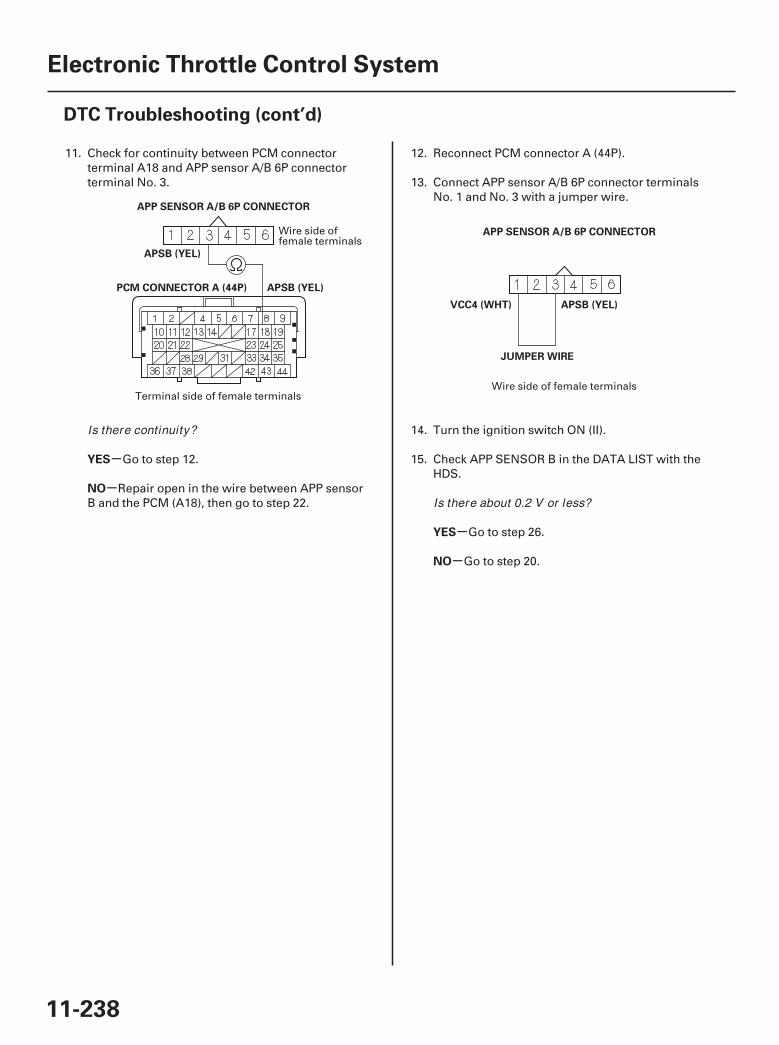
0304
-
-
-
-
YES
NO
YES
NO
11-238
Electronic Throttle Control System
DTC Troubleshooting (cont’d)
PCM CONNECTOR A (44P)
APP SENSOR A/B 6P CONNECTOR
APSB (YEL)
APSB (YEL)
APP SENSOR A/B 6P CONNECTOR
APSB (YEL)VCC4 (WHT)
JUMPER WIRE
11. Check for continuity between PCM connectorterminal A18 and APP sensor A/B 6P connectorterminal No. 3.
Go to step 12.
Repair open in the wire between APP sensorB and the PCM (A18), then go to step 22.
12. Reconnect PCM connector A (44P).
13. Connect APP sensor A/B 6P connector terminalsNo. 1 and No. 3 with a jumper wire.
14. Turn the ignition switch ON (II).
15. Check APP SENSOR B in the DATA LIST with theHDS.
Go to step 26.
Go to step 20.
Wire side offemale terminals
Terminal side of female terminalsWire side of female terminals
Is there continuity?
Is there about 0.2 V or less?
07/05/09 16:53:16 61SJC020_110_0238
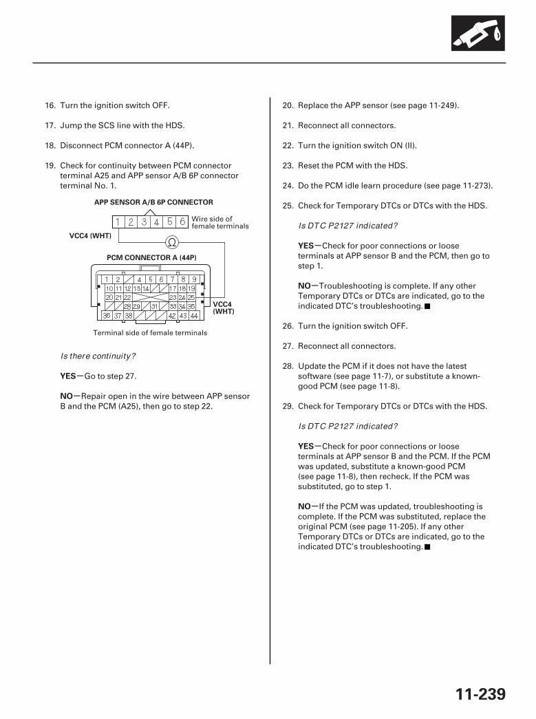
05
-
-
-
-
-
-
YES
NO
YES
NO
YES
NO
11-239
PCM CONNECTOR A (44P)
APP SENSOR A/B 6P CONNECTOR
VCC4(WHT)
VCC4 (WHT)
16. Turn the ignition switch OFF.
17. Jump the SCS line with the HDS.
18. Disconnect PCM connector A (44P).
19. Check for continuity between PCM connectorterminal A25 and APP sensor A/B 6P connectorterminal No. 1.
Go to step 27.
Repair open in the wire between APP sensorB and the PCM (A25), then go to step 22.
20. Replace the APP sensor (see page 11-249).
21. Reconnect all connectors.
22. Turn the ignition switch ON (II).
23. Reset the PCM with the HDS.
24. Do the PCM idle learn procedure (see page 11-273).
25. Check for Temporary DTCs or DTCs with the HDS.
Check for poor connections or looseterminals at APP sensor B and the PCM, then go tostep 1.
Troubleshooting is complete. If any otherTemporary DTCs or DTCs are indicated, go to theindicated DTC’s troubleshooting.
26. Turn the ignition switch OFF.
27. Reconnect all connectors.
28. Update the PCM if it does not have the latestsoftware (see page 11-7), or substitute a known-good PCM (see page 11-8).
29. Check for Temporary DTCs or DTCs with the HDS.
Check for poor connections or looseterminals at APP sensor B and the PCM. If the PCMwas updated, substitute a known-good PCM(see page 11-8), then recheck. If the PCM wassubstituted, go to step 1.
If the PCM was updated, troubleshooting iscomplete. If the PCM was substituted, replace theoriginal PCM (see page 11-205). If any otherTemporary DTCs or DTCs are indicated, go to theindicated DTC’s troubleshooting.
Wire side offemale terminals
Terminal side of female terminals
Is there continuity?
Is DTC P2127 indicated?
Is DTC P2127 indicated?
07/05/09 16:53:16 61SJC020_110_0239
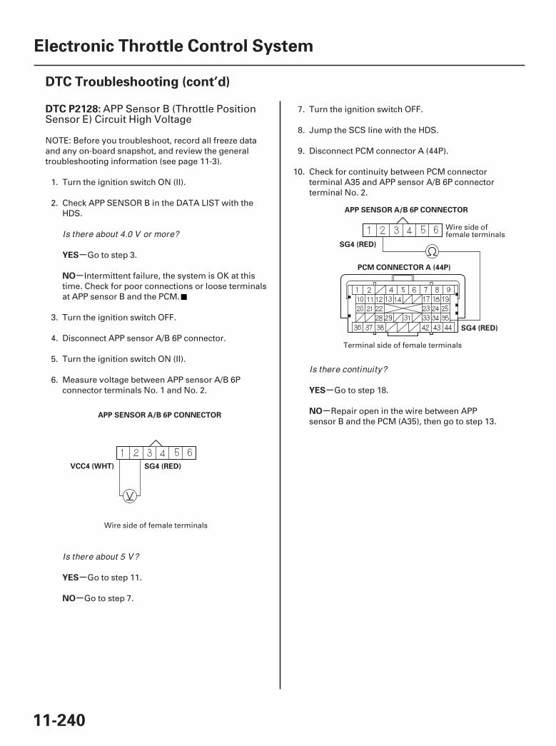
01
02
SJC8A00K77100092128FAAT30
-
-
-
-
-
-
DTC P2128:
YES
NO
YES
NO
YES
NO
11-240
Electronic Throttle Control System
DTC Troubleshooting (cont’d)
APP SENSOR A/B 6P CONNECTOR
VCC4 (WHT) SG4 (RED)
PCM CONNECTOR A (44P)
APP SENSOR A/B 6P CONNECTOR
SG4 (RED)
SG4 (RED)
APP Sensor B (Throttle PositionSensor E) Circuit High Voltage
NOTE: Before you troubleshoot, record all freeze dataand any on-board snapshot, and review the generaltroubleshooting information (see page 11-3).
1. Turn the ignition switch ON (II).
2. Check APP SENSOR B in the DATA LIST with theHDS.
Go to step 3.
Intermittent failure, the system is OK at thistime. Check for poor connections or loose terminalsat APP sensor B and the PCM.
3. Turn the ignition switch OFF.
4. Disconnect APP sensor A/B 6P connector.
5. Turn the ignition switch ON (II).
6. Measure voltage between APP sensor A/B 6Pconnector terminals No. 1 and No. 2.
Go to step 11.
Go to step 7.
7. Turn the ignition switch OFF.
8. Jump the SCS line with the HDS.
9. Disconnect PCM connector A (44P).
10. Check for continuity between PCM connectorterminal A35 and APP sensor A/B 6P connectorterminal No. 2.
Go to step 18.
Repair open in the wire between APPsensor B and the PCM (A35), then go to step 13.
Wire side of female terminals
Wire side offemale terminals
Terminal side of female terminals
Is there about 4.0 V or more?
Is there about 5 V?
Is there continuity?
07/05/09 16:53:16 61SJC020_110_0240
-
-
-
-
YES
NO
YES
NO
11-241
11. Turn the ignition switch OFF.
12. Replace the APP sensor (see page 11-249).
13. Reconnect all connectors.
14. Turn the ignition switch ON (II).
15. Reset the PCM with the HDS.
16. Do the PCM idle learn procedure (see page 11-273).
17. Check for Temporary DTCs or DTCs with the HDS.
Check for poor connections or looseterminals at APP sensor B and the PCM, then go tostep 1.
Troubleshooting is complete. If any otherTemporary DTCs or DTCs are indicated, go to theindicated DTC’s troubleshooting.
18. Reconnect all connectors.
19. Update the PCM if it does not have the latestsoftware (see page 11-7), or substitute a known-good PCM (see page 11-8).
20. Check for Temporary DTCs or DTCs with the HDS.
Check for poor connections or looseterminals at APP sensor B and the PCM. If the PCMwas updated, substitute a known-good PCM(see page 11-8), then recheck. If the PCM wassubstituted, go to step 1.
If the PCM was updated, troubleshooting iscomplete. If the PCM was substituted, replace theoriginal PCM (see page 11-205). If any otherTemporary DTCs or DTCs are indicated, go to theindicated DTC’s troubleshooting.
Is DTC P2128 indicated?
Is DTC P2128 indicated?
07/05/09 16:56:20 61SJC020_110_0241
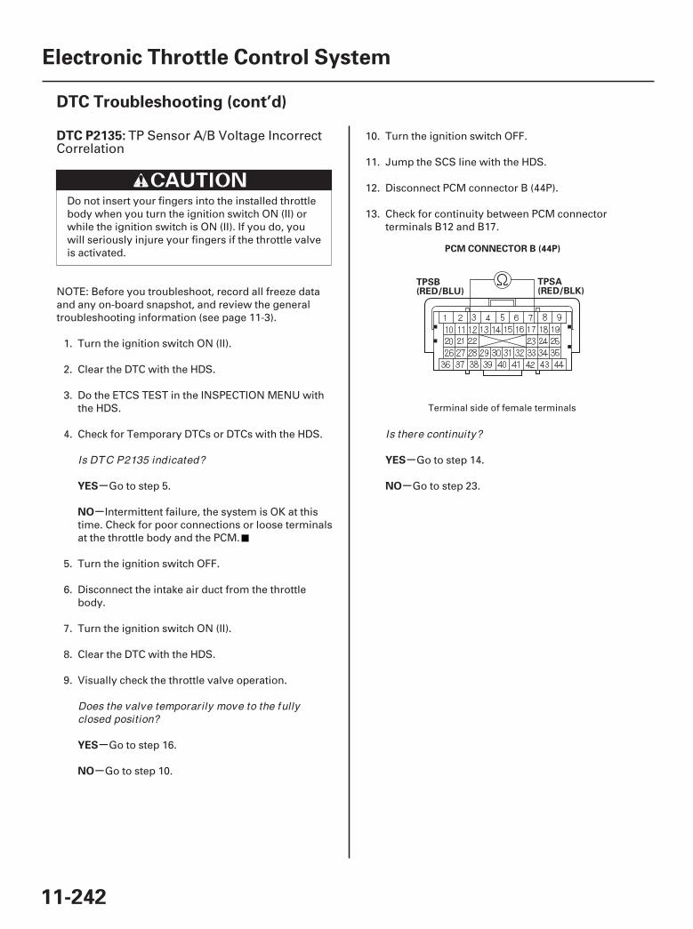
01
SJC8A00K77100092135FAAT30
-
-
-
-
-
-
DTC P2135:
YES
NO
YES
NO
YES
NO
11-242
Electronic Throttle Control System
DTC Troubleshooting (cont’d)
PCM CONNECTOR B (44P)
TPSA(RED/BLK)
TPSB(RED/BLU)
TP Sensor A/B Voltage IncorrectCorrelation
Do not insert your fingers into the installed throttlebody when you turn the ignition switch ON (II) orwhile the ignition switch is ON (II). If you do, youwill seriously injure your fingers if the throttle valveis activated.
NOTE: Before you troubleshoot, record all freeze dataand any on-board snapshot, and review the generaltroubleshooting information (see page 11-3).
1. Turn the ignition switch ON (II).
2. Clear the DTC with the HDS.
3. Do the ETCS TEST in the INSPECTION MENU withthe HDS.
4. Check for Temporary DTCs or DTCs with the HDS.
Go to step 5.
Intermittent failure, the system is OK at thistime. Check for poor connections or loose terminalsat the throttle body and the PCM.
5. Turn the ignition switch OFF.
6. Disconnect the intake air duct from the throttlebody.
7. Turn the ignition switch ON (II).
8. Clear the DTC with the HDS.
9. Visually check the throttle valve operation.
Go to step 16.
Go to step 10.
10. Turn the ignition switch OFF.
11. Jump the SCS line with the HDS.
12. Disconnect PCM connector B (44P).
13. Check for continuity between PCM connectorterminals B12 and B17.
Go to step 14.
Go to step 23.
Terminal side of female terminals
Is DTC P2135 indicated?
Does the valve temporar ily move to the fullyclosed position?
Is there continuity?
07/05/09 16:56:20 61SJC020_110_0242
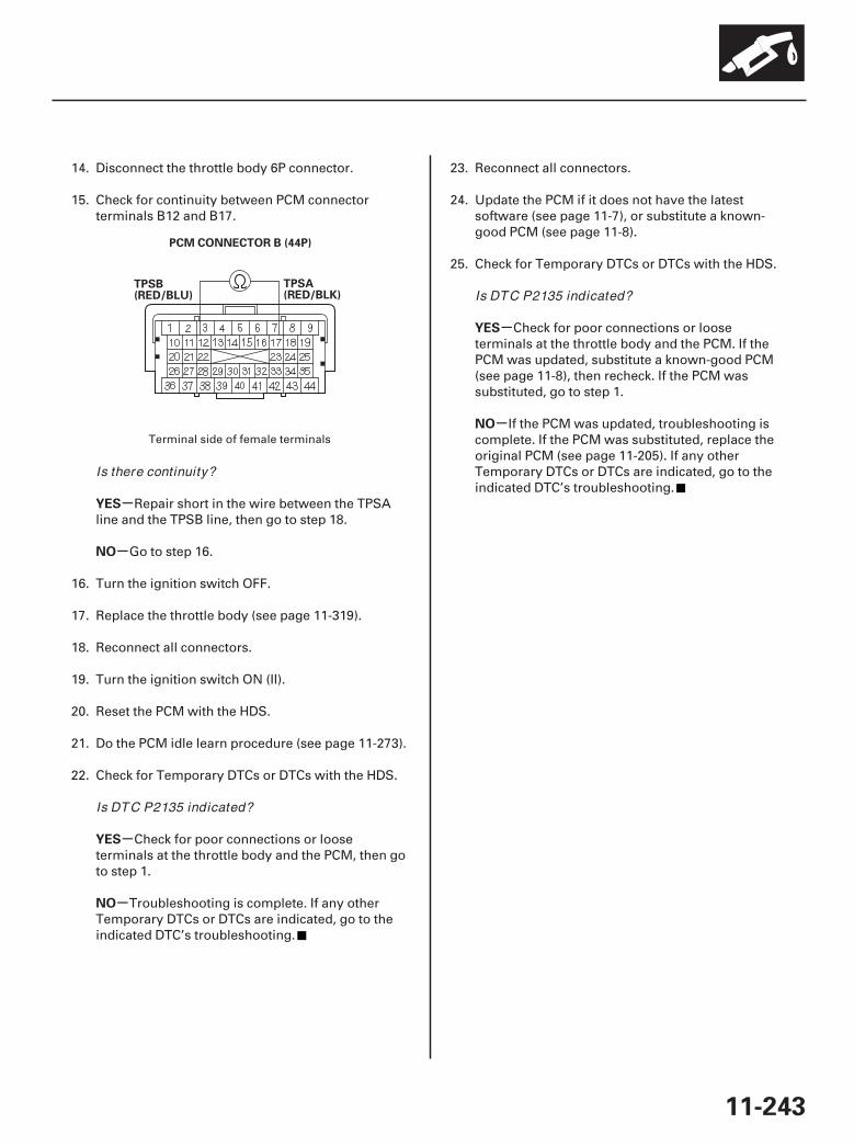
02
-
-
-
-
-
-
YES
NO
YES
NO
YES
NO
11-243
PCM CONNECTOR B (44P)
TPSA(RED/BLK)
TPSB(RED/BLU)
14. Disconnect the throttle body 6P connector.
15. Check for continuity between PCM connectorterminals B12 and B17.
Repair short in the wire between the TPSAline and the TPSB line, then go to step 18.
Go to step 16.
16. Turn the ignition switch OFF.
17. Replace the throttle body (see page 11-319).
18. Reconnect all connectors.
19. Turn the ignition switch ON (II).
20. Reset the PCM with the HDS.
21. Do the PCM idle learn procedure (see page 11-273).
22. Check for Temporary DTCs or DTCs with the HDS.
Check for poor connections or looseterminals at the throttle body and the PCM, then goto step 1.
Troubleshooting is complete. If any otherTemporary DTCs or DTCs are indicated, go to theindicated DTC’s troubleshooting.
23. Reconnect all connectors.
24. Update the PCM if it does not have the latestsoftware (see page 11-7), or substitute a known-good PCM (see page 11-8).
25. Check for Temporary DTCs or DTCs with the HDS.
Check for poor connections or looseterminals at the throttle body and the PCM. If thePCM was updated, substitute a known-good PCM(see page 11-8), then recheck. If the PCM wassubstituted, go to step 1.
If the PCM was updated, troubleshooting iscomplete. If the PCM was substituted, replace theoriginal PCM (see page 11-205). If any otherTemporary DTCs or DTCs are indicated, go to theindicated DTC’s troubleshooting.
Terminal side of female terminals
Is there continuity?
Is DTC P2135 indicated?
Is DTC P2135 indicated?
07/05/09 16:56:21 61SJC020_110_0243
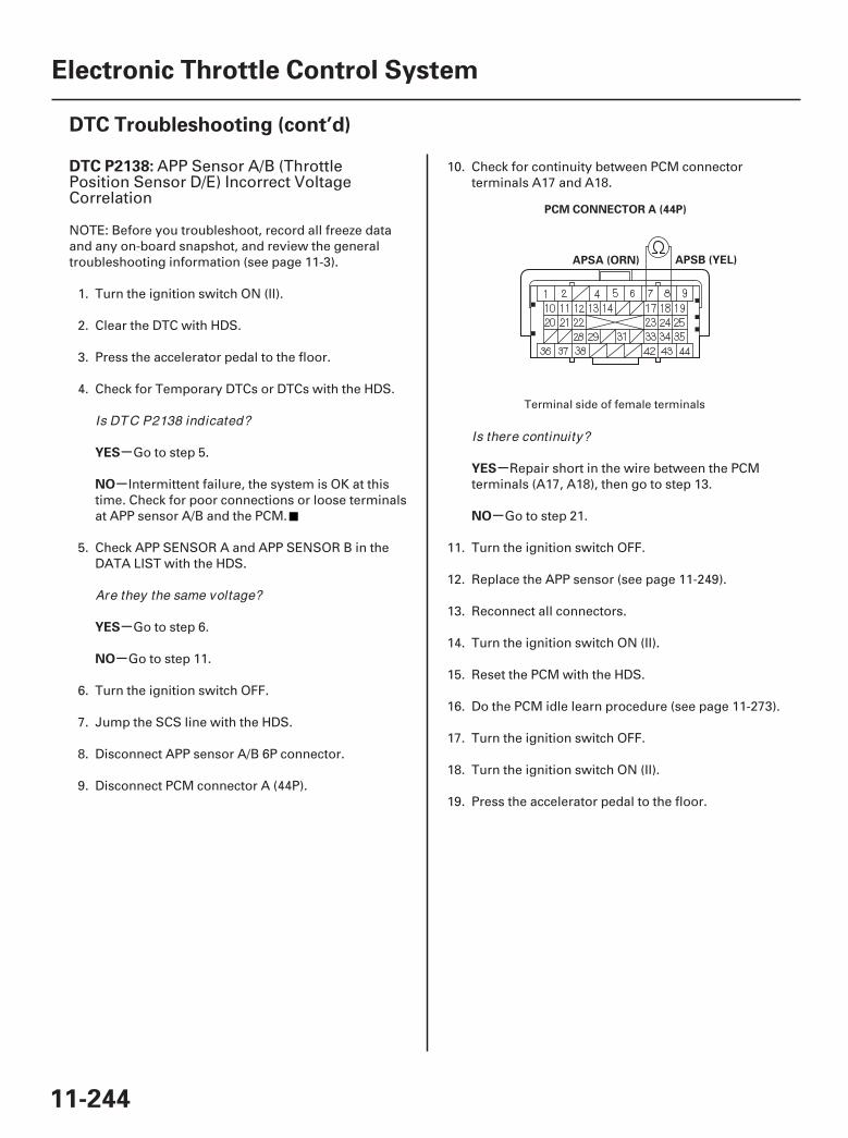
01
SJC8A00K77100092138FAAT30
-
-
-
-
-
-
DTC P2138:
YES
NO
YES
NO
YES
NO
11-244
Electronic Throttle Control System
DTC Troubleshooting (cont’d)
PCM CONNECTOR A (44P)
APSB (YEL)APSA (ORN)
APP Sensor A/B (ThrottlePosition Sensor D/E) Incorrect VoltageCorrelation
NOTE: Before you troubleshoot, record all freeze dataand any on-board snapshot, and review the generaltroubleshooting information (see page 11-3).
1. Turn the ignition switch ON (II).
2. Clear the DTC with HDS.
3. Press the accelerator pedal to the floor.
4. Check for Temporary DTCs or DTCs with the HDS.
Go to step 5.
Intermittent failure, the system is OK at thistime. Check for poor connections or loose terminalsat APP sensor A/B and the PCM.
5. Check APP SENSOR A and APP SENSOR B in theDATA LIST with the HDS.
Go to step 6.
Go to step 11.
6. Turn the ignition switch OFF.
7. Jump the SCS line with the HDS.
8. Disconnect APP sensor A/B 6P connector.
9. Disconnect PCM connector A (44P).
10. Check for continuity between PCM connectorterminals A17 and A18.
Repair short in the wire between the PCMterminals (A17, A18), then go to step 13.
Go to step 21.
11. Turn the ignition switch OFF.
12. Replace the APP sensor (see page 11-249).
13. Reconnect all connectors.
14. Turn the ignition switch ON (II).
15. Reset the PCM with the HDS.
16. Do the PCM idle learn procedure (see page 11-273).
17. Turn the ignition switch OFF.
18. Turn the ignition switch ON (II).
19. Press the accelerator pedal to the floor.
Terminal side of female terminalsIs DTC P2138 indicated?
Are they the same voltage?
Is there continuity?
07/05/09 16:56:21 61SJC020_110_0244

-
-
-
-
YES
NO
YES
NO
11-245
20. Check for Temporary DTCs or DTCs with the HDS.
Check for poor connections or looseterminals at the APP sensor and the PCM, thenclean the throttle body (see page 11-314), and go tostep 1.
Troubleshooting is complete. If any otherTemporary DTCs or DTCs are indicated, go to theindicated DTC’s troubleshooting.
21. Reconnect all connectors.
22. Update the PCM if it does not have the latestsoftware (see page 11-7), or substitute a known-good PCM (see page 11-8).
23. Turn the ignition switch OFF.
24. Turn the ignition switch ON (II).
25. Press the accelerator pedal to the floor.
26. Check for Temporary DTCs or DTCs with the HDS.
Check for poor connections or looseterminals at the APP sensor and the PCM. If thePCM was updated, substitute a known-good PCM(see page 11-8), then recheck. If the PCM wassubstituted, go to step 1.
If the PCM was updated, troubleshooting iscomplete. If the PCM was substituted, replace theoriginal PCM (see page 11-205). If any otherTemporary DTCs or DTCs are indicated, go to theindicated DTC’s troubleshooting.
Is DTC P2138 indicated?
Is DTC P2138 indicated?
07/05/09 16:56:21 61SJC020_110_0245

01
SJC8A00K77100092176FAAT30
- +
-
-
-
-
-
-
DTC P2176:
YES
NO
YES
NO
YES
NO
11-246
Electronic Throttle Control System
DTC Troubleshooting (cont’d)
THROTTLE BODY 6P CONNECTOR
ETCSM (GRN) ETCSM (BLU)
JUMPER WIRE
Throttle Actuator Control SystemIdle Position Not Learned
Do not insert your fingers into the installed throttlebody when you turn the ignition switch ON (II) orwhile the ignition switch is ON (II). If you do, youwill seriously injure your fingers if the throttle valveis activated.
NOTE:• Before you troubleshoot, record all freeze data and
any on-board snapshot, and review the generaltroubleshooting information (see page 11-3).
• If DTC P2135 is stored at the same time as DTC P2176,troubleshoot DTC P2135 first, then recheck for DTCP2176.
1. Turn the ignition switch ON (II).
2. Clear the DTC with the HDS.
3. Turn the ignition switch OFF.
4. Turn the ignition switch ON (II), and wait10 seconds.
5. Check for Temporary DTCs or DTCs with the HDS.
Go to step 6.
Intermittent failure, the system is OK at thistime. Check for poor connections or loose terminalsat the throttle body and the PCM, then clean thethrottle body (see page 11-314).
6. Turn the ignition switch OFF.
7. Disconnect the intake air duct from the throttlebody.
8. Turn the ignition switch ON (II).
9. Clear the DTC with the HDS.
10. Visually check the throttle valve operation whiledoing the ETCS TEST in the INSPECTION MENUwith the HDS.
Go to step 11.
Go to step 12.
11. Check for sludge or carbon on the throttle valve.
Clean the throttle body (see page 11-314),then go to step 21.
Go to step 18.
12. Turn the ignition switch OFF.
13. Disconnect the throttle body 6P connector.
14. Jump the SCS line with the HDS.
15. Disconnect PCM connector C (44P).
16. Connect throttle body 6P connector terminals No. 5and No. 6 with a jumper wire.
Wire side of female terminals
Is DTC P2176 indicated?
Does the throttle valve move to its fully closedposition?
Is there sludge or carbon on the throttle valve?
07/05/09 16:56:21 61SJC020_110_0246
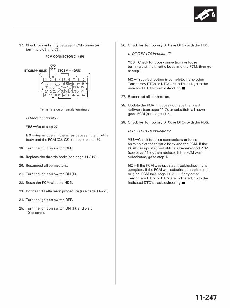
02
-+
-
-
-
-
-
-
YES
NO
YES
NO
YES
NO
11-247
ETCSM (GRN)ETCSM (BLU)
PCM CONNECTOR C (44P)
17. Check for continuity between PCM connectorterminals C2 and C3.
Go to step 27.
Repair open in the wires between the throttlebody and the PCM (C2, C3), then go to step 20.
18. Turn the ignition switch OFF.
19. Replace the throttle body (see page 11-319).
20. Reconnect all connectors.
21. Turn the ignition switch ON (II).
22. Reset the PCM with the HDS.
23. Do the PCM idle learn procedure (see page 11-273).
24. Turn the ignition switch OFF.
25. Turn the ignition switch ON (II), and wait10 seconds.
26. Check for Temporary DTCs or DTCs with the HDS.
Check for poor connections or looseterminals at the throttle body and the PCM, then goto step 1.
Troubleshooting is complete. If any otherTemporary DTCs or DTCs are indicated, go to theindicated DTC’s troubleshooting.
27. Reconnect all connectors.
28. Update the PCM if it does not have the latestsoftware (see page 11-7), or substitute a known-good PCM (see page 11-8).
29. Check for Temporary DTCs or DTCs with the HDS.
Check for poor connections or looseterminals at the throttle body and the PCM. If thePCM was updated, substitute a known-good PCM(see page 11-8), then recheck. If the PCM wassubstituted, go to step 1.
If the PCM was updated, troubleshooting iscomplete. If the PCM was substituted, replace theoriginal PCM (see page 11-205). If any otherTemporary DTCs or DTCs are indicated, go to theindicated DTC’s troubleshooting.
Terminal side of female terminals
Is there continuity?
Is DTC P2176 indicated?
Is DTC P2176 indicated?
07/05/09 16:56:22 61SJC020_110_0247
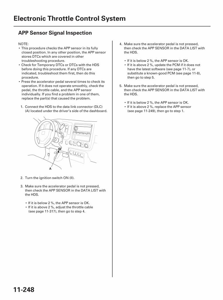
01
SJC8A00A20324112947MAAT00
11-248
Electronic Throttle Control System
APP Sensor Signal Inspection
A
NOTE:• This procedure checks the APP sensor in its fully
closed position. In any other position, the APP sensorstores DTCs which are covered in othertroubleshooting procedure.
• Check for Temporary DTCs or DTCs with the HDSbefore doing this procedure. If any DTCs areindicated, troubleshoot them first, then do thisprocedure.
• Press the accelerator pedal several times to check itsoperation. If it does not operate smoothly, check thepedal, the throttle cable, and the APP sensorindividually. If you find a problem in one of them,replace the part(s) that caused the problem.
1. Connect the HDS to the data link connector (DLC)(A) located under the driver’s side of the dashboard.
2. Turn the ignition switch ON (II).
3. Make sure the accelerator pedal is not pressed,then check the APP SENSOR in the DATA LIST withthe HDS.
• If it is below 2 %, the APP sensor is OK.• If it is above 2 %, adjust the throttle cable
(see page 11-317), then go to step 4.
4. Make sure the accelerator pedal is not pressed,then check the APP SENSOR in the DATA LIST withthe HDS.
• If it is below 2 %, the APP sensor is OK.• If it is above 2 %, update the PCM if it does not
have the latest software (see page 11-7), orsubstitute a known-good PCM (see page 11-8),then go to step 5.
5. Make sure the accelerator pedal is not pressed,then check the APP SENSOR in the DATA LIST withthe HDS.
• If it is below 2 %, the APP sensor is OK.• If it is above 2 %, replace the APP sensor
(see page 11-249), then go to step 1.
07/05/09 16:56:22 61SJC020_110_0248
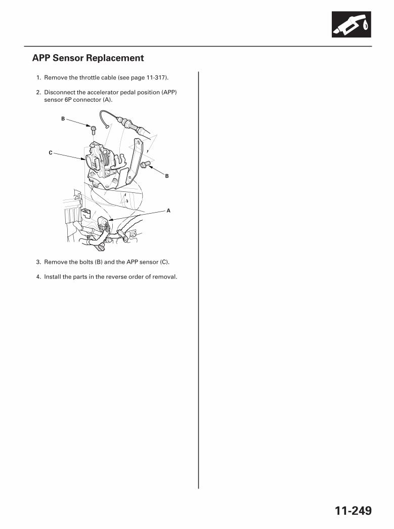
01
SJC8A00A20324112947KBAT01
11-249
APP Sensor Replacement
A
B
C
B
1. Remove the throttle cable (see page 11-317).
2. Disconnect the accelerator pedal position (APP)sensor 6P connector (A).
3. Remove the bolts (B) and the APP sensor (C).
4. Install the parts in the reverse order of removal.
07/05/09 16:56:22 61SJC020_110_0249
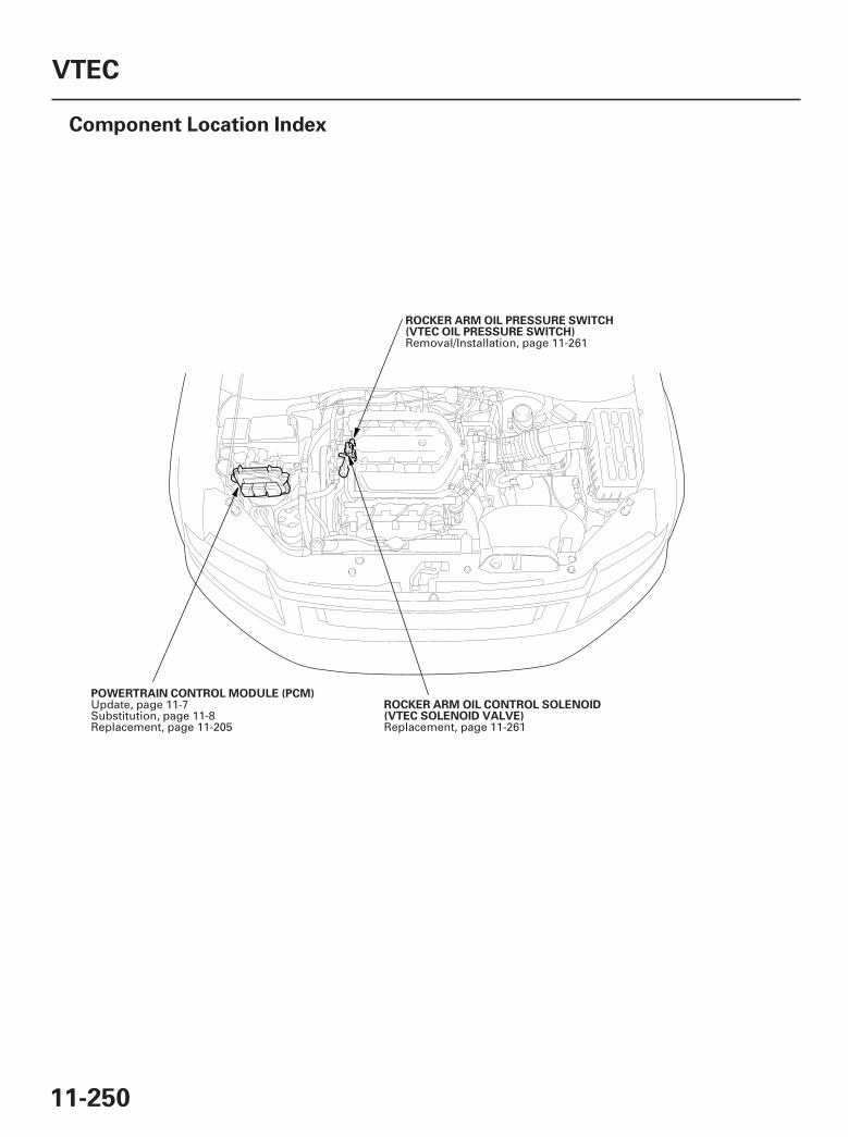
*01
SJC8A00A14680300000DAAT00
11-250
VTEC
Component Location Index
ROCKER ARM OIL PRESSURE SWITCH(VTEC OIL PRESSURE SWITCH)
ROCKER ARM OIL CONTROL SOLENOID(VTEC SOLENOID VALVE)
POWERTRAIN CONTROL MODULE (PCM)
Removal/Installation, page 11-261
Replacement, page 11-261
Update, page 11-7Substitution, page 11-8Replacement, page 11-205
07/05/09 16:56:24 61SJC020_110_0250
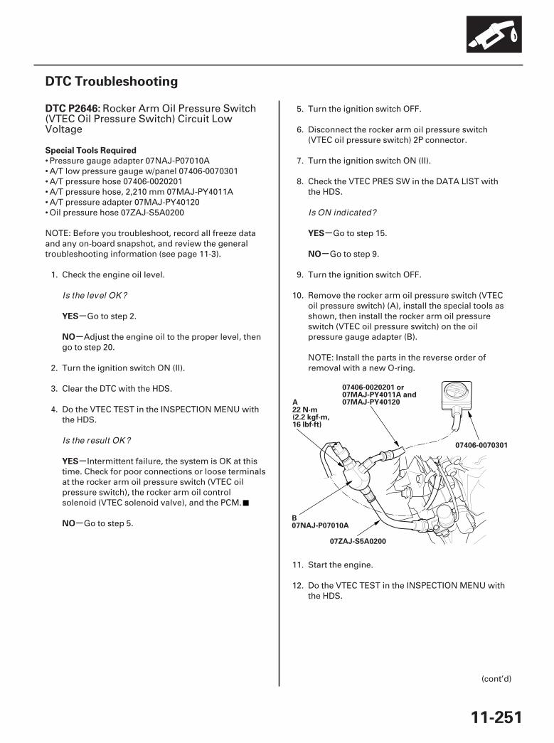
*01
SJC8A00K77100092646FAAT30
-
-
-
-
-
-
DTC P2646:
Special Tools Required
YES
NO
YES
NO
YES
NO
11-251
DTC Troubleshooting
07406-0070301
07ZAJ-S5A0200
07406-0020201 or07MAJ-PY4011A and07MAJ-PY40120A
22 N·m(2.2 kgf·m,16 lbf·ft)
B07NAJ-P07010A
Rocker Arm Oil Pressure Switch(VTEC Oil Pressure Switch) Circuit LowVoltage
• Pressure gauge adapter 07NAJ-P07010A• A/T low pressure gauge w/panel 07406-0070301• A/T pressure hose 07406-0020201• A/T pressure hose, 2,210 mm 07MAJ-PY4011A• A/T pressure adapter 07MAJ-PY40120• Oil pressure hose 07ZAJ-S5A0200
NOTE: Before you troubleshoot, record all freeze dataand any on-board snapshot, and review the generaltroubleshooting information (see page 11-3).
1. Check the engine oil level.
Go to step 2.
Adjust the engine oil to the proper level, thengo to step 20.
2. Turn the ignition switch ON (II).
3. Clear the DTC with the HDS.
4. Do the VTEC TEST in the INSPECTION MENU withthe HDS.
Intermittent failure, the system is OK at thistime. Check for poor connections or loose terminalsat the rocker arm oil pressure switch (VTEC oilpressure switch), the rocker arm oil controlsolenoid (VTEC solenoid valve), and the PCM.
Go to step 5.
5. Turn the ignition switch OFF.
6. Disconnect the rocker arm oil pressure switch(VTEC oil pressure switch) 2P connector.
7. Turn the ignition switch ON (II).
8. Check the VTEC PRES SW in the DATA LIST withthe HDS.
Go to step 15.
Go to step 9.
9. Turn the ignition switch OFF.
10. Remove the rocker arm oil pressure switch (VTECoil pressure switch) (A), install the special tools asshown, then install the rocker arm oil pressureswitch (VTEC oil pressure switch) on the oilpressure gauge adapter (B).
NOTE: Install the parts in the reverse order ofremoval with a new O-ring.
11. Start the engine.
12. Do the VTEC TEST in the INSPECTION MENU withthe HDS.
(cont’d)
Is the level OK ?
Is the result OK ?
Is ON indicated?
07/05/09 16:56:24 61SJC020_110_0251
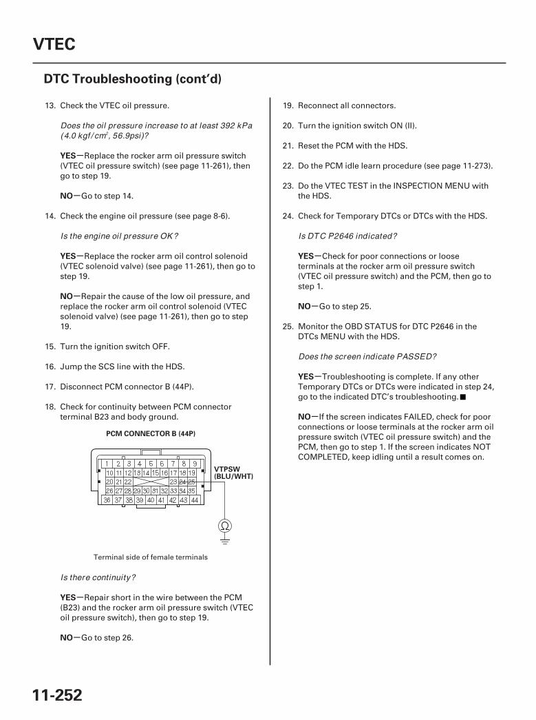
02
-
-
-
-
-
-
-
-
-
-
YES
NO
YES
NO
YES
NO
YES
NO
YES
NO
11-252
VTEC
DTC Troubleshooting (cont’d)
PCM CONNECTOR B (44P)
VTPSW(BLU/WHT)
13. Check the VTEC oil pressure.
Replace the rocker arm oil pressure switch(VTEC oil pressure switch) (see page 11-261), thengo to step 19.
Go to step 14.
14. Check the engine oil pressure (see page 8-6).
Replace the rocker arm oil control solenoid(VTEC solenoid valve) (see page 11-261), then go tostep 19.
Repair the cause of the low oil pressure, andreplace the rocker arm oil control solenoid (VTECsolenoid valve) (see page 11-261), then go to step19.
15. Turn the ignition switch OFF.
16. Jump the SCS line with the HDS.
17. Disconnect PCM connector B (44P).
18. Check for continuity between PCM connectorterminal B23 and body ground.
Repair short in the wire between the PCM(B23) and the rocker arm oil pressure switch (VTECoil pressure switch), then go to step 19.
Go to step 26.
19. Reconnect all connectors.
20. Turn the ignition switch ON (II).
21. Reset the PCM with the HDS.
22. Do the PCM idle learn procedure (see page 11-273).
23. Do the VTEC TEST in the INSPECTION MENU withthe HDS.
24. Check for Temporary DTCs or DTCs with the HDS.
Check for poor connections or looseterminals at the rocker arm oil pressure switch(VTEC oil pressure switch) and the PCM, then go tostep 1.
Go to step 25.
25. Monitor the OBD STATUS for DTC P2646 in theDTCs MENU with the HDS.
Troubleshooting is complete. If any otherTemporary DTCs or DTCs were indicated in step 24,go to the indicated DTC’s troubleshooting.
If the screen indicates FAILED, check for poorconnections or loose terminals at the rocker arm oilpressure switch (VTEC oil pressure switch) and thePCM, then go to step 1. If the screen indicates NOTCOMPLETED, keep idling until a result comes on.
Terminal side of female terminals
Does the oil pressure increase to at least 392 kPa(4.0 kgf / cm , 56.9psi)?
Is the engine oil pressure OK ?
Is there continuity?
Is DTC P2646 indicated?
Does the screen indicate PASSED?
2
07/05/09 16:56:24 61SJC020_110_0252
-
-
-
-
YES
NO
YES
NO
11-253
26. Reconnect all connectors.
27. Update the PCM if it does not have the latestsoftware (see page 11-7), or substitute a known-good PCM (see page 11-8).
28. Do the VTEC TEST in the INSPECTION MENU withthe HDS.
29. Check for Temporary DTCs or DTCs with the HDS.
Check for poor connections or looseterminals at the rocker arm oil pressure switch(VTEC oil pressure switch) and the PCM. If the PCMwas updated, substitute a known-good PCM(see page 11-8), then recheck. If the PCM wassubstituted, go to step 1.
Go to step 30.
30. Monitor the OBD STATUS for DTC P2646 in theDTCs MENU with the HDS.
If the PCM was updated, troubleshooting iscomplete. If the PCM was substituted, replace theoriginal PCM (see page 11-205). If any otherTemporary DTCs or DTCs were indicated in step 29,go to the indicated DTC’s troubleshooting.
If the screen indicates FAILED, check for poorconnections or loose terminals at the rocker arm oilpressure switch (VTEC oil pressure switch) and thePCM. If the PCM was updated, substitute a known-good PCM (see page 11-8), then recheck. If the PCMwas substituted, go to step 1. If the screen indicatesNOT COMPLETED, keep idling until a result comeson.
Is DTC P2646 indicated?
Does the screen indicate PASSED?
07/05/09 16:56:25 61SJC020_110_0253
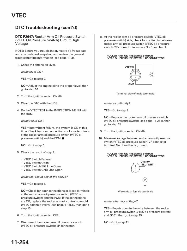
01
02
SJC8A00K77100092647FAAT30
-
-
-
-
-
-
-
-
-
-
DTC P2647:
YES
NO
YES
NO
YES
NO
YES
NO
YES
NO
11-254
VTEC
DTC Troubleshooting (cont’d)
ROCKER ARM OIL PRESSURE SWITCH(VTEC OIL PRESSURE SWITCH) 2P CONNECTOR
VTPSW
GND
VTPSW(BLU/WHT)
ROCKER ARM OIL PRESSURE SWITCH(VTEC OIL PRESSURE SWITCH) 2P CONNECTOR
Rocker Arm Oil Pressure Switch(VTEC Oil Pressure Switch) Circuit HighVoltage
NOTE: Before you troubleshoot, record all freeze dataand any on-board snapshot, and review the generaltroubleshooting information (see page 11-3).
1. Check the engine oil level.
Go to step 2.
Adjust the engine oil to the proper level, thengo to step 16.
2. Turn the ignition switch ON (II).
3. Clear the DTC with the HDS.
4. Do the VTEC TEST in the INSPECTION MENU withthe HDS.
Intermittent failure, the system is OK at thistime. Check for poor connections or loose terminalsat the rocker arm oil pressure switch (VTEC oilpressure switch) and the PCM.
Go to step 5.
5. Check the result of step 4.
• VTEC Switch Failure• VTEC Switch Open• VTEC Switch SIG Line Open• VTEC Switch GND Line Open
Go to step 6.
Check for poor connections or loose terminalsat the rocker arm oil pressure switch (VTEC oilpressure switch) and the PCM. If the connectionsare OK, replace the rocker arm oil control solenoid(VTEC solenoid valve) (see page 11-261), then go tostep 15.
6. Turn the ignition switch OFF.
7. Disconnect the rocker arm oil pressure switch(VTEC oil pressure switch) 2P connector.
8. At the rocker arm oil pressure switch (VTEC oilpressure switch) side, check for continuity betweenrocker arm oil pressure switch (VTEC oil pressureswitch) 2P connector terminals No. 1 and No. 2.
Go to step 9.
Replace the rocker arm oil pressure switch(VTEC oil pressure switch) (see page 11-261), thengo to step 15.
9. Turn the ignition switch ON (II).
10. Measure voltage between rocker arm oil pressureswitch (VTEC oil pressure switch) 2P connectorterminal No. 1 and body ground.
Repair open in the wire between the rockerarm oil pressure switch (VTEC oil pressure switch)and G101, then go to step 15.
Go to step 11.
Terminal side of male terminals
Wire side of female terminals
Is the level OK ?
Is the result OK ?
Is the test result any of the above?
Is there continuity?
Is there battery voltage?
07/05/09 16:56:25 61SJC020_110_0254
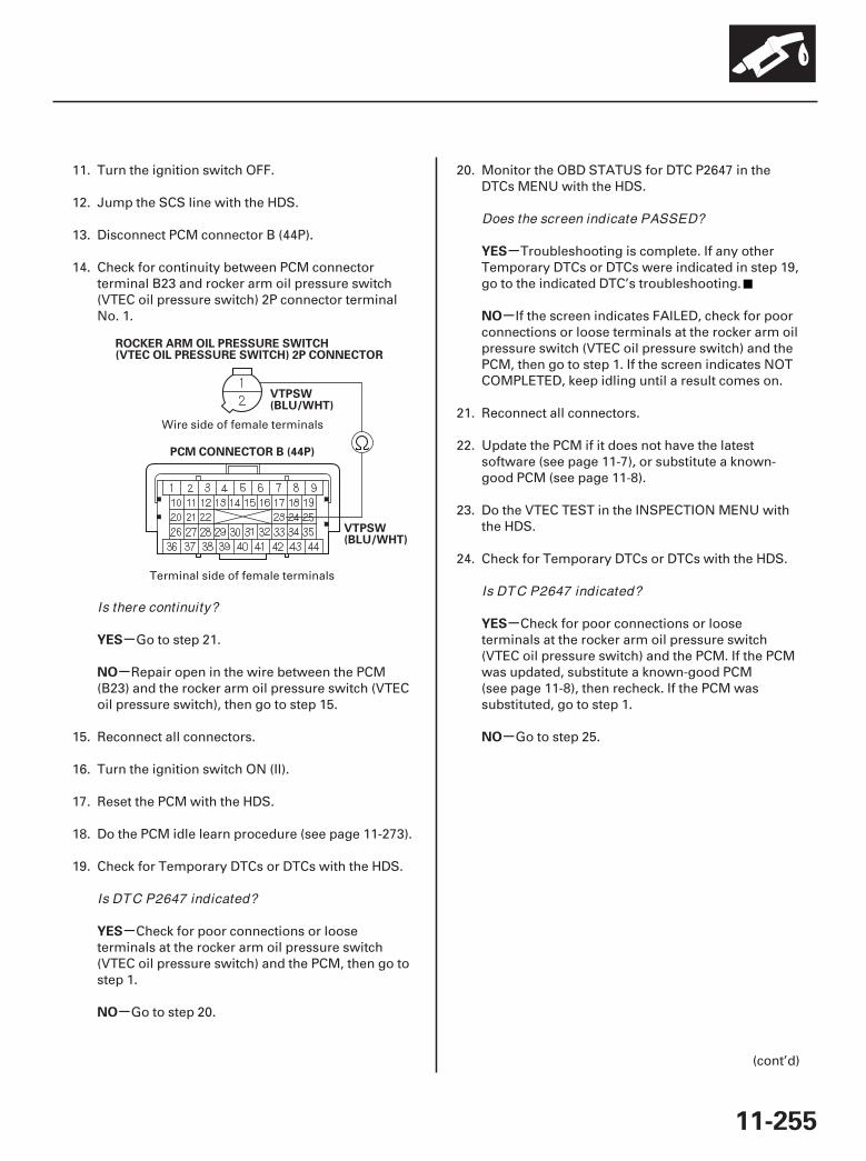
03
-
-
-
-
-
-
-
-
YES
NO
YES
NO
YES
NO
YES
NO
11-255
PCM CONNECTOR B (44P)
VTPSW(BLU/WHT)
ROCKER ARM OIL PRESSURE SWITCH(VTEC OIL PRESSURE SWITCH) 2P CONNECTOR
VTPSW(BLU/WHT)
11. Turn the ignition switch OFF.
12. Jump the SCS line with the HDS.
13. Disconnect PCM connector B (44P).
14. Check for continuity between PCM connectorterminal B23 and rocker arm oil pressure switch(VTEC oil pressure switch) 2P connector terminalNo. 1.
Go to step 21.
Repair open in the wire between the PCM(B23) and the rocker arm oil pressure switch (VTECoil pressure switch), then go to step 15.
15. Reconnect all connectors.
16. Turn the ignition switch ON (II).
17. Reset the PCM with the HDS.
18. Do the PCM idle learn procedure (see page 11-273).
19. Check for Temporary DTCs or DTCs with the HDS.
Check for poor connections or looseterminals at the rocker arm oil pressure switch(VTEC oil pressure switch) and the PCM, then go tostep 1.
Go to step 20.
20. Monitor the OBD STATUS for DTC P2647 in theDTCs MENU with the HDS.
Troubleshooting is complete. If any otherTemporary DTCs or DTCs were indicated in step 19,go to the indicated DTC’s troubleshooting.
If the screen indicates FAILED, check for poorconnections or loose terminals at the rocker arm oilpressure switch (VTEC oil pressure switch) and thePCM, then go to step 1. If the screen indicates NOTCOMPLETED, keep idling until a result comes on.
21. Reconnect all connectors.
22. Update the PCM if it does not have the latestsoftware (see page 11-7), or substitute a known-good PCM (see page 11-8).
23. Do the VTEC TEST in the INSPECTION MENU withthe HDS.
24. Check for Temporary DTCs or DTCs with the HDS.
Check for poor connections or looseterminals at the rocker arm oil pressure switch(VTEC oil pressure switch) and the PCM. If the PCMwas updated, substitute a known-good PCM(see page 11-8), then recheck. If the PCM wassubstituted, go to step 1.
Go to step 25.
(cont’d)
Wire side of female terminals
Terminal side of female terminals
Is there continuity?
Is DTC P2647 indicated?
Does the screen indicate PASSED?
Is DTC P2647 indicated?
07/05/09 16:56:25 61SJC020_110_0255
-
-
YES
NO
11-256
VTEC
DTC Troubleshooting (cont’d)
25. Monitor the OBD STATUS for DTC P2647 in theDTCs MENU with the HDS.
If the PCM was updated, troubleshooting iscomplete. If the PCM was substituted, replace theoriginal PCM (see page 11-205). If any otherTemporary DTCs or DTCs were indicated in step 24,go to the indicated DTC’s troubleshooting.
If the screen indicates FAILED, check for poorconnections or loose terminals at the rocker arm oilpressure switch (VTEC oil pressure switch) and thePCM. If the PCM was updated, substitute a known-good PCM (see page 11-8), then recheck. If the PCMwas substituted, go to step 1. If the screen indicatesNOT COMPLETED, keep idling until a result comeson.
Does the screen indicate PASSED?
07/05/09 16:56:25 61SJC020_110_0256
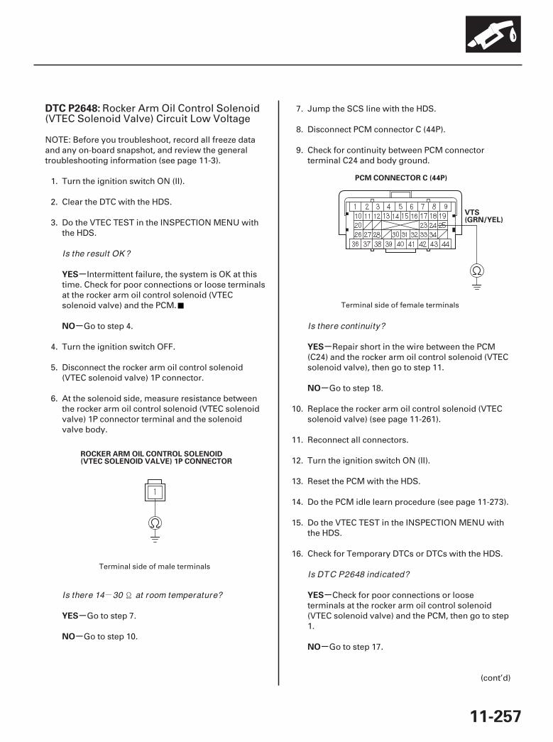
-
01
02
SJC8A00K77100092648FAAT30
-
-
-
-
-
-
-
-
DTC P2648:
YES
NO
YES
NO
YES
NO
YES
NO
11-257
ROCKER ARM OIL CONTROL SOLENOID(VTEC SOLENOID VALVE) 1P CONNECTOR
PCM CONNECTOR C (44P)
VTS(GRN/YEL)
Rocker Arm Oil Control Solenoid(VTEC Solenoid Valve) Circuit Low Voltage
NOTE: Before you troubleshoot, record all freeze dataand any on-board snapshot, and review the generaltroubleshooting information (see page 11-3).
1. Turn the ignition switch ON (II).
2. Clear the DTC with the HDS.
3. Do the VTEC TEST in the INSPECTION MENU withthe HDS.
Intermittent failure, the system is OK at thistime. Check for poor connections or loose terminalsat the rocker arm oil control solenoid (VTECsolenoid valve) and the PCM.
Go to step 4.
4. Turn the ignition switch OFF.
5. Disconnect the rocker arm oil control solenoid(VTEC solenoid valve) 1P connector.
6. At the solenoid side, measure resistance betweenthe rocker arm oil control solenoid (VTEC solenoidvalve) 1P connector terminal and the solenoidvalve body.
Go to step 7.
Go to step 10.
7. Jump the SCS line with the HDS.
8. Disconnect PCM connector C (44P).
9. Check for continuity between PCM connectorterminal C24 and body ground.
Repair short in the wire between the PCM(C24) and the rocker arm oil control solenoid (VTECsolenoid valve), then go to step 11.
Go to step 18.
10. Replace the rocker arm oil control solenoid (VTECsolenoid valve) (see page 11-261).
11. Reconnect all connectors.
12. Turn the ignition switch ON (II).
13. Reset the PCM with the HDS.
14. Do the PCM idle learn procedure (see page 11-273).
15. Do the VTEC TEST in the INSPECTION MENU withthe HDS.
16. Check for Temporary DTCs or DTCs with the HDS.
Check for poor connections or looseterminals at the rocker arm oil control solenoid(VTEC solenoid valve) and the PCM, then go to step1.
Go to step 17.
(cont’d)
Terminal side of male terminals
Terminal side of female terminals
Is the result OK ?
Is there 14 30 at room temperature?
Is there continuity?
Is DTC P2648 indicated?
07/05/09 16:56:26 61SJC020_110_0257
-
-
-
-
-
-
YES
NO
YES
NO
YES
NO
11-258
VTEC
DTC Troubleshooting (cont’d)
17. Monitor the OBD STATUS for DTC P2648 in theDTCs MENU with the HDS.
Troubleshooting is complete. If any otherTemporary DTCs or DTCs were indicated in step 16,go to the indicated DTC’s troubleshooting.
If the screen indicates FAILED, check for poorconnections or loose terminals at the rocker arm oilcontrol solenoid (VTEC solenoid valve) and thePCM, then go to step 1. If the screen indicates NOTCOMPLETED, keep idling until a result comes on.
18. Reconnect all connectors.
19. Update the PCM if it does not have the latestsoftware (see page 11-7), or substitute a known-good PCM (see page 11-8).
20. Do the VTEC TEST in the INSPECTION MENU withthe HDS.
21. Check for Temporary DTCs or DTCs with the HDS.
Check for poor connections or looseterminals at the rocker arm oil control solenoid(VTEC solenoid valve) and the PCM. If the PCM wasupdated, substitute a known-good PCM (see page11-8), then recheck. If the PCM was substituted, goto step 1.
Go to step 22.
22. Monitor the OBD STATUS for DTC P2648 in theDTCs MENU with the HDS.
If the PCM was updated, troubleshooting iscomplete. If the PCM was substituted, replace theoriginal PCM (see page 11-205). If any otherTemporary DTCs or DTCs were indicated in step 21,go to the indicated DTC’s troubleshooting.
If the screen indicates FAILED, check for poorconnections or loose terminals at the rocker arm oilcontrol solenoid (VTEC solenoid valve) and thePCM. If the PCM was updated, substitute a known-good PCM (see page 11-8), then recheck. If the PCMwas substituted, go to step 1. If the screen indicatesNOT COMPLETED, keep idling until a result comeson.
Does the screen indicate PASSED?
Is DTC P2648 indicated?
Does the screen indicate PASSED?
07/05/09 16:56:26 61SJC020_110_0258
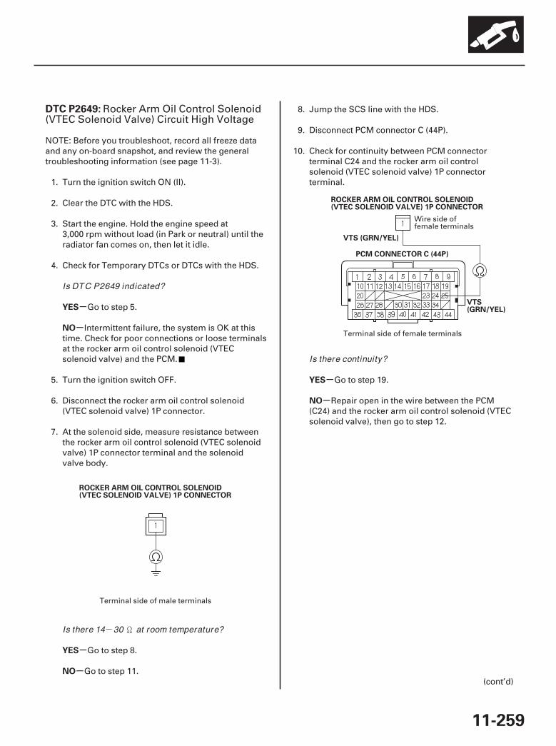
-
01
02
SJC8A00K77100092649FAAT30
-
-
-
-
-
-
DTC P2649:
YES
NO
YES
NO
YES
NO
11-259
ROCKER ARM OIL CONTROL SOLENOID(VTEC SOLENOID VALVE) 1P CONNECTOR
PCM CONNECTOR C (44P)
VTS(GRN/YEL)
ROCKER ARM OIL CONTROL SOLENOID(VTEC SOLENOID VALVE) 1P CONNECTOR
VTS (GRN/YEL)
Rocker Arm Oil Control Solenoid(VTEC Solenoid Valve) Circuit High Voltage
NOTE: Before you troubleshoot, record all freeze dataand any on-board snapshot, and review the generaltroubleshooting information (see page 11-3).
1. Turn the ignition switch ON (II).
2. Clear the DTC with the HDS.
3. Start the engine. Hold the engine speed at3,000 rpm without load (in Park or neutral) until theradiator fan comes on, then let it idle.
4. Check for Temporary DTCs or DTCs with the HDS.
Go to step 5.
Intermittent failure, the system is OK at thistime. Check for poor connections or loose terminalsat the rocker arm oil control solenoid (VTECsolenoid valve) and the PCM.
5. Turn the ignition switch OFF.
6. Disconnect the rocker arm oil control solenoid(VTEC solenoid valve) 1P connector.
7. At the solenoid side, measure resistance betweenthe rocker arm oil control solenoid (VTEC solenoidvalve) 1P connector terminal and the solenoidvalve body.
Go to step 8.
Go to step 11.
8. Jump the SCS line with the HDS.
9. Disconnect PCM connector C (44P).
10. Check for continuity between PCM connectorterminal C24 and the rocker arm oil controlsolenoid (VTEC solenoid valve) 1P connectorterminal.
Go to step 19.
Repair open in the wire between the PCM(C24) and the rocker arm oil control solenoid (VTECsolenoid valve), then go to step 12.
(cont’d)
Terminal side of male terminals
Wire side offemale terminals
Terminal side of female terminals
Is DTC P2649 indicated?
Is there 14 30 at room temperature?
Is there continuity?
07/05/09 16:56:26 61SJC020_110_0259
-
-
-
-
-
-
-
-
YES
NO
YES
NO
YES
NO
YES
NO
11-260
VTEC
DTC Troubleshooting (cont’d)
11. Replace the rocker arm oil control solenoid (VTECsolenoid valve) (see page 11-261).
12. Reconnect all connectors.
13. Turn the ignition switch ON (II).
14. Reset the PCM with the HDS.
15. Do the PCM idle learn procedure (see page 11-273).
16. Start the engine. Hold the engine speed at3,000 rpm without load (in Park or neutral) until theradiator fan comes on, then let it idle.
17. Check for Temporary DTCs or DTCs with the HDS.
Check for poor connections or looseterminals at the rocker arm oil control solenoid(VTEC solenoid valve) and the PCM, then go to step1.
Go to step 18.
18. Monitor the OBD STATUS for DTC P2649 in theDTCs MENU with the HDS.
Troubleshooting is complete. If any otherTemporary DTCs or DTCs were indicated in step 17,go to the indicated DTC’s troubleshooting.
If the screen indicates FAILED, check for poorconnections or loose terminals at the rocker arm oilcontrol solenoid (VTEC solenoid valve) and thePCM, then go to step 1. If the screen indicates NOTCOMPLETED, keep idling until a result comes on.
19. Reconnect all connectors.
20. Update the PCM if it does not have the latestsoftware (see page 11-7), or substitute a known-good PCM (see page 11-8).
21. Check for Temporary DTCs or DTCs with the HDS.
Check for poor connections or looseterminals at the rocker arm oil control solenoid(VTEC solenoid valve) and the PCM. If the PCM wasupdated, substitute a known-good PCM (see page11-8), then recheck. If the PCM was substituted, goto step 1.
Go to step 22.
22. Monitor the OBD STATUS for DTC P2649 in theDTCs MENU with the HDS.
If the PCM was updated, troubleshooting iscomplete. If the PCM was substituted, replace theoriginal PCM (see page 11-205). If any otherTemporary DTCs or DTCs were indicated in step 21,go to the indicated DTC’s troubleshooting.
If the screen indicates FAILED, check for poorconnections or loose terminals at the rocker arm oilcontrol solenoid (VTEC solenoid valve) and thePCM. If the PCM was updated, substitute a known-good PCM (see page 11-8), then recheck. If the PCMwas substituted, go to step 1. If the screen indicatesNOT COMPLETED, keep idling until a result comeson.
Is DTC P2649 indicated?
Does the screen indicate PASSED?
Is DTC P2649 indicated?
Does the screen indicate PASSED?
07/05/09 16:56:26 61SJC020_110_0260

01
SJC8A00A14680351516KBAT20
01
SJC8A00A14680351518KDAT00
11-26111-261
Rocker Arm Oil Control Solenoid(VTEC Solenoid Valve)Replacement
Rocker Arm Oil Pressure Switch(VTEC Oil Pressure Switch)Removal/Installation
B
C
12 N·m(1.2 kgf·m,8.7 lbf·ft)
A
B22 N·m(2.2 kgf·m,16 lbf·ft)
C
A
1. Disconnect the rocker arm oil control solenoid(VTEC solenoid valve) connector (A).
2. Remove the rocker arm oil control solenoid (VTECsolenoid valve) (B).
3. Install the parts in the reverse order of removalwith a new O-ring (C).
1. Disconnect the rocker arm oil pressure switch(VTEC oil pressure switch) connector (A), thenremove the rocker arm oil pressure switch (VTECoil pressure switch) (B).
2. Install the parts in the reverse order of removalwith a new O-ring (C).
07/05/09 16:56:27 61SJC020_110_0261
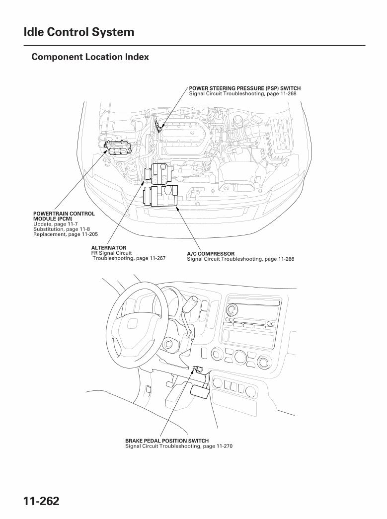
*01
*02
SJC8A00A20336100000DAAT00
11-262
Idle Control System
Component Location Index
ALTERNATOR
A/C COMPRESSOR
POWERTRAIN CONTROLMODULE (PCM)
POWER STEERING PRESSURE (PSP) SWITCH
BRAKE PEDAL POSITION SWITCH
FR Signal CircuitTroubleshooting, page 11-267 Signal Circuit Troubleshooting, page 11-266
Update, page 11-7Substitution, page 11-8Replacement, page 11-205
Signal Circuit Troubleshooting, page 11-268
Signal Circuit Troubleshooting, page 11-270
07/05/09 16:56:29 61SJC020_110_0262
SJC8A00K77100090506FAAT30
-
-
-
-
-
-
-
-
DTC P0506:
YES
NO
YES
NO
YES
NO
YES
NO
11-263
DTC Troubleshooting
Idle Control System RPM LowerThan Expected
NOTE: Before you troubleshoot, record all freeze dataand any on-board snapshot, and review the generaltroubleshooting information (see page 11-3).
1. Turn the ignition switch ON (II).
2. Clear the DTC with the HDS.
3. Start the engine. Hold the engine speed at3,000 rpm without load (in Park or neutral) until theradiator fan comes on, then let it idle.
4. Check for these conditions in the DATA LIST withthe HDS:
• ECT SENSOR 1 above 158 °F (70 °C)• IAT SENSOR above 32 °F (0 °C)• Vehicle speed is 0 mph (0 km/h)• ST FUEL TRIM between 0.73 and 1.47• FSS is CLOSED
5. Monitor the OBD STATUS for DTC P0506 in theDTCs MENU with the HDS.
Go to step 6.
If the screen indicates PASSED, go to step 8. Ifthe screen indicates EXECUTING, let the engineidle until a result comes on. If the screen indicatesOUT OF CONDITION, go to step 4 and recheck.
6. Remove the intake air duct from the throttle body.
7. Check for dirt, carbon, or damage in the throttlebore.
If there is dirt or carbon, clean the throttlebody (see page 11-314). Also check for damage tothe air cleaner element (see page 11-315), then goto step 13. If there is damage in the throttle bore, goto step 12.
Check the A/C system or power steeringsystem, then go to step 10.
8. Remove the intake air duct from the throttle body.
9. Check for dirt, carbon, or damage in the throttlebore.
If there is dirt or carbon, clean the throttlebody (see page 11-314). Also check for damage tothe air cleaner element (see page 11-315), then goto step 13. If there is damage in the throttle bore, goto step 12.
Go to step 10.
10. Recheck with different load conditions (turn on theheadlights, blower motor, or A/C; change the gearposition, etc.).
11. Monitor the OBD STATUS for DTC P0506 in theDTCs MENU with the HDS.
Intermittent failure, the system is OK at thistime.
If the screen indicates FAILED, check the A/Csystem and/or power steering system, then go tostep 1 and recheck. If the screen indicatesEXECUTING, let the engine idle until a result comeson. If the screen indicates OUT OF CONDITION, goto step 10 and recheck.
(cont’d)
Does the screen indicate FAILED?
Is there dir t, carbon, or damage in the throttlebore?
Is there dir t, carbon, or damage in the throttlebore?
Does the screen indicate PASSED?
07/05/09 16:56:29 61SJC020_110_0263
-
-
-
-
YES
NO
YES
NO
11-264
Idle Control System
DTC Troubleshooting (cont’d)
12. Replace the throttle body (see page 11-319).
13. Reset the PCM with the HDS.
14. Do the PCM idle learn procedure (see page 11-273).
15. Start the engine. Hold the engine speed at3,000 rpm without load (in Park or neutral) until theradiator fan comes on, then let it idle.
16. Check for these conditions in the DATA LIST withthe HDS:
• ECT SENSOR 1 above 158 °F (70 °C)• IAT SENSOR above 32 °F (0 °C)• Vehicle speed is 0 mph (0 km/h)• ST FUEL TRIM between 0.73 and 1.47• FSS is CLOSED
17. Check for Temporary DTCs or DTCs with the HDS.
Check for poor connections or looseterminals at the throttle body and the PCM. If thePCM was updated, substitute a known-good PCM(see page 11-8), then recheck. If the PCM wassubstituted, go to step 1.
Go to step 18.
18. Monitor the OBD STATUS for DTC P0506 in theDTCs MENU with the HDS.
If the PCM was updated, troubleshooting iscomplete. If the PCM was substituted, replace theoriginal PCM (see page 11-205). If any otherTemporary DTCs or DTCs were indicated in step 17,go to the indicated DTC’s troubleshooting.
If the screen indicates FAILED, check for poorconnections or loose terminals at the throttle bodyand the PCM. If the PCM was updated, substitute aknown-good PCM (see page 11-8), then recheck. Ifthe PCM was substituted, go to step 1. If the screenindicates EXECUTING or OUT OF CONDITION,keep idling until a result comes on.
Is DTC P0506 indicated?
Does the screen indicate PASSED?
07/05/09 16:56:29 61SJC020_110_0264
SJC8A00K77100090507FAAT30
-
-
-
-
-
-
-
-
DTC P0507:
YES
NO
YES
NO
YES
NO
YES
NO
11-265
Idle Control System RPM HigherThan Expected
NOTE: Before you troubleshoot, record all freeze dataand any on-board snapshot, and review the generaltroubleshooting information (see page 11-3).
1. Turn the ignition switch ON (II).
2. Clear the DTC with the HDS.
3. Start the engine. Hold the engine speed at3,000 rpm without load (in Park or neutral) until theradiator fan comes on, then let it idle.
4. Monitor the OBD STATUS for DTC P0507 in theDTCs MENU with the HDS.
Go to step 5.
If the screen indicates PASSED, intermittentfailure, the system is OK at this time. If the screenindicates EXECUTING, let the engine idle until aresult comes on. If the screen indicates OUT OFCONDITION, recheck with different load conditions(electrical, A/C, gear position, etc.), then go tostep 3.
5. Check for vacuum leaks at these parts:
• PCV valve• PCV hose• EVAP canister purge valve• Throttle body• Intake manifold• Brake booster hose
Repair or replace the leaking part(s), then goto step 6.
Go to step 6.
6. Turn the ignition switch ON (II).
7. Reset the PCM with the HDS.
8. Do the PCM idle learn procedure (see page 11-273).
9. Start the engine. Hold the engine speed at3,000 rpm without load (in Park or neutral) until theradiator fan comes on, then let it idle.
10. Check for Temporary DTCs or DTCs with the HDS.
Check for poor connections or looseterminals at the throttle body and the PCM. If thePCM was updated, substitute a known-good PCM(see page 11-8), then recheck. If the PCM wassubstituted, go to step 1.
Go to step 11.
11. Monitor the OBD STATUS for DTC P0507 in theDTCs MENU with the HDS.
If the PCM was updated, troubleshooting iscomplete. If the PCM was substituted, replace theoriginal PCM (see page 11-205). If any otherTemporary DTCs or DTCs were indicated in step 10,go to the indicated DTC’s troubleshooting.
If the screen indicates FAILED, check for poorconnections or loose terminals at the throttle bodyand the PCM. If the PCM was updated, substitute aknown-good PCM (see page 11-8), then recheck. Ifthe PCM was substituted, go to step 1. If the screenindicates EXECUTING or OUT OF CONDITION,keep idling until a result comes on.
Does the screen indicate FAILED?
Are there any leaks?
Is DTC P0507 indicated?
Does the screen indicate PASSED?
07/05/09 16:56:29 61SJC020_110_0265

01
SJC8A00A20336112101FAAT00
-
-
-
-
-
-
-
-
YES
NO
YES
NO
YES
NO
YES
NO
11-266
Idle Control System
A/C Signal Circuit Troubleshooting
PCM CONNECTOR A (44P)
ACC (RED)
JUMPER WIRE
1. Start the engine.
2. Turn the blower switch on.
3. Turn the A/C switch on.
4. Check the A/C CLUTCH in the DATA LIST with theHDS.
Go to step 5.
Do the A/C pressure switch circuittroubleshooting (see page 21-130).
5. Check the A/C system.
The air conditioning system circuit is OK.
Go to step 6.
6. Turn the ignition switch OFF.
7. Turn the ignition switch ON (II).
8. Activate the A/C CLUTCH in the INSPECTIONMENU with the HDS.
Do the A/C system test (see page 21-77).
Go to step 9.
9. Turn the ignition switch OFF.
10. Jump the SCS line with the HDS.
11. Disconnect PCM connector A (44P).
12. Turn the ignition switch ON (II).
13. Momentarily connect PCM connector terminal A14to body ground with a jumper wire several times.
Update the PCM if it does not have the latestsoftware (see page 11-7), or substitute a known-good PCM (see page 11-8), then recheck. If thesymptom/indication goes away with a known-goodPCM, replace the original PCM (see page 11-205).
Check for poor connections or loose terminalsat the A/C clutch relay and the PCM. If theconnections are OK, check the A/C clutch relay(see page 22-75), repair open in the wire betweenthe PCM (A14) and the A/C clutch relay and theother A/C systems.
Terminal side of female terminals
Does it indicate ON?
Does the A/ C system operate?
Is there a clicking noise f rom the A/ C compressorclutch?
Is there a clicking noise f rom the A/ C compressorclutch?
07/05/09 16:56:30 61SJC020_110_0266
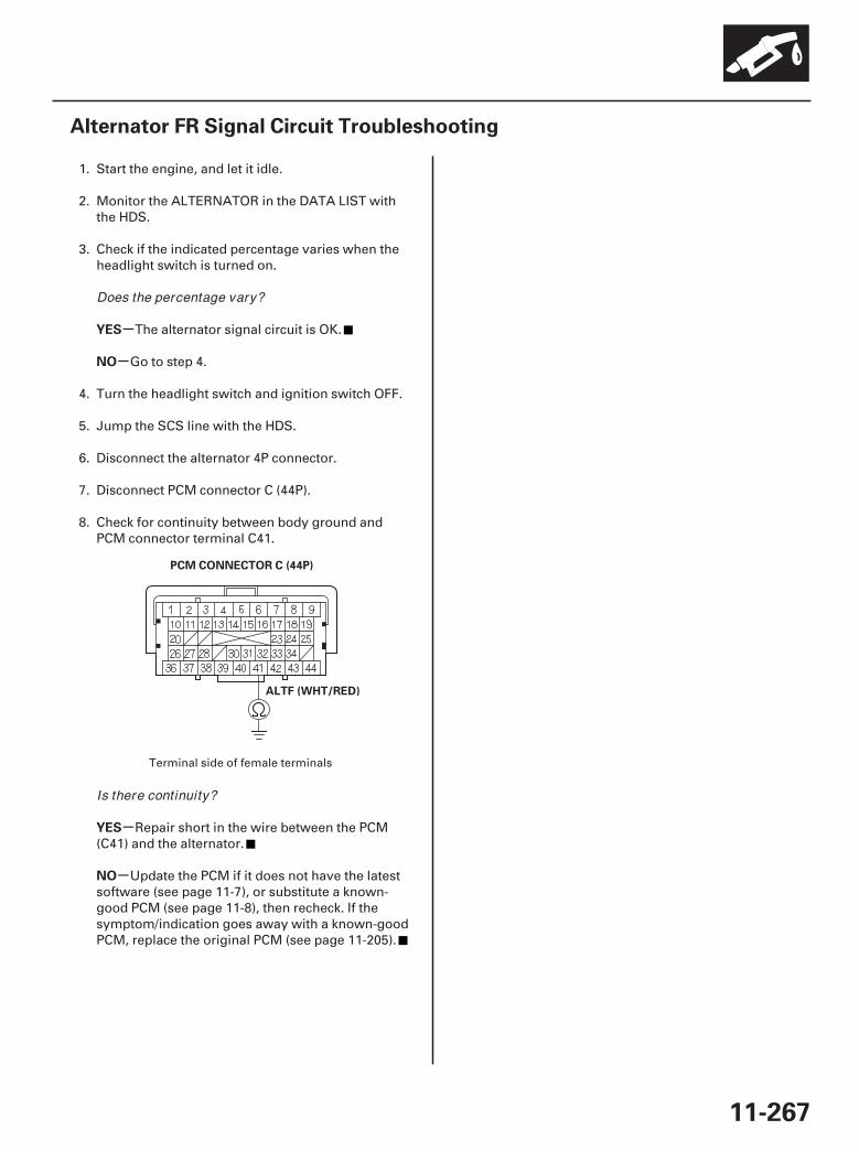
01
SJC8A00A20336112931FAAT00
-
-
-
-
YES
NO
YES
NO
11-267
Alternator FR Signal Circuit Troubleshooting
PCM CONNECTOR C (44P)
ALTF (WHT/RED)
1. Start the engine, and let it idle.
2. Monitor the ALTERNATOR in the DATA LIST withthe HDS.
3. Check if the indicated percentage varies when theheadlight switch is turned on.
The alternator signal circuit is OK.
Go to step 4.
4. Turn the headlight switch and ignition switch OFF.
5. Jump the SCS line with the HDS.
6. Disconnect the alternator 4P connector.
7. Disconnect PCM connector C (44P).
8. Check for continuity between body ground andPCM connector terminal C41.
Repair short in the wire between the PCM(C41) and the alternator.
Update the PCM if it does not have the latestsoftware (see page 11-7), or substitute a known-good PCM (see page 11-8), then recheck. If thesymptom/indication goes away with a known-goodPCM, replace the original PCM (see page 11-205).
Terminal side of female terminals
Does the percentage vary?
Is there continuity?
07/05/09 16:56:30 61SJC020_110_0267
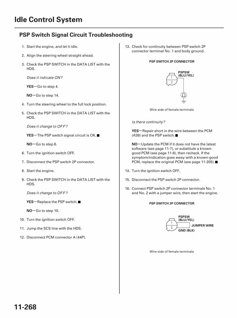
01
02
SJC8A00A20336147022FAAT00
-
-
-
-
-
-
-
-
YES
NO
YES
NO
YES
NO
YES
NO
11-268
Idle Control System
PSP Switch Signal Circuit Troubleshooting
PSPSW(BLU/YEL)
PSP SWITCH 2P CONNECTOR
PSPSW(BLU/YEL)
PSP SWITCH 2P CONNECTOR
GND (BLK)
JUMPER WIRE
1. Start the engine, and let it idle.
2. Align the steering wheel straight ahead.
3. Check the PSP SWITCH in the DATA LIST with theHDS.
Go to step 4.
Go to step 14.
4. Turn the steering wheel to the full lock position.
5. Check the PSP SWITCH in the DATA LIST with theHDS.
The PSP switch signal circuit is OK.
Go to step 6.
6. Turn the ignition switch OFF.
7. Disconnect the PSP switch 2P connector.
8. Start the engine.
9. Check the PSP SWITCH in the DATA LIST with theHDS.
Replace the PSP switch.
Go to step 10.
10. Turn the ignition switch OFF.
11. Jump the SCS line with the HDS.
12. Disconnect PCM connector A (44P).
13. Check for continuity between PSP switch 2Pconnector terminal No. 1 and body ground.
Repair short in the wire between the PCM(A38) and the PSP switch.
Update the PCM if it does not have the latestsoftware (see page 11-7), or substitute a known-good PCM (see page 11-8), then recheck. If thesymptom/indication goes away with a known-goodPCM, replace the original PCM (see page 11-205).
14. Turn the ignition switch OFF.
15. Disconnect the PSP switch 2P connector.
16. Connect PSP switch 2P connector terminals No. 1and No. 2 with a jumper wire, then start the engine.
Wire side of female terminals
Wire side of female terminals
Does it indicate ON?
Does it change to OFF?
Does it change to OFF?
Is there continuity?
07/05/09 16:56:30 61SJC020_110_0268
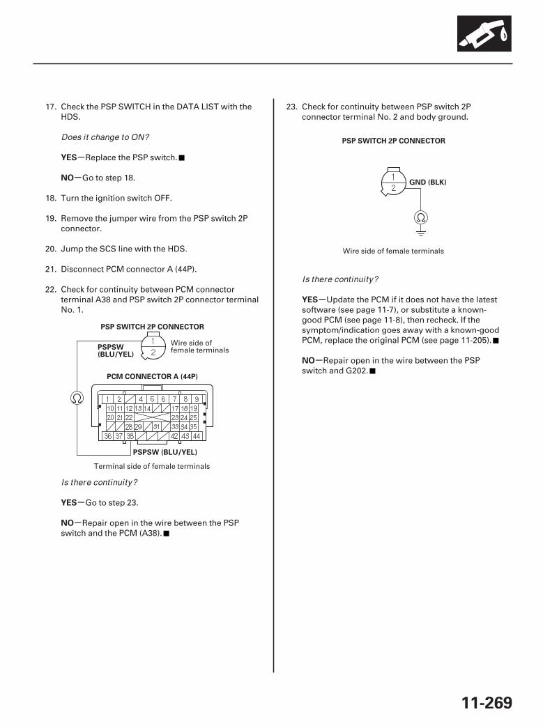
03
04
-
-
-
-
-
-
YES
NO
YES
NO
YES
NO
11-269
PSP SWITCH 2P CONNECTOR
PCM CONNECTOR A (44P)
PSPSW (BLU/YEL)
PSPSW(BLU/YEL)
GND (BLK)
PSP SWITCH 2P CONNECTOR
17. Check the PSP SWITCH in the DATA LIST with theHDS.
Replace the PSP switch.
Go to step 18.
18. Turn the ignition switch OFF.
19. Remove the jumper wire from the PSP switch 2Pconnector.
20. Jump the SCS line with the HDS.
21. Disconnect PCM connector A (44P).
22. Check for continuity between PCM connectorterminal A38 and PSP switch 2P connector terminalNo. 1.
Go to step 23.
Repair open in the wire between the PSPswitch and the PCM (A38).
23. Check for continuity between PSP switch 2Pconnector terminal No. 2 and body ground.
Update the PCM if it does not have the latestsoftware (see page 11-7), or substitute a known-good PCM (see page 11-8), then recheck. If thesymptom/indication goes away with a known-goodPCM, replace the original PCM (see page 11-205).
Repair open in the wire between the PSPswitch and G202.
Wire side offemale terminals
Terminal side of female terminals
Wire side of female terminals
Does it change to ON?
Is there continuity?
Is there continuity?
07/05/09 16:56:31 61SJC020_110_0269
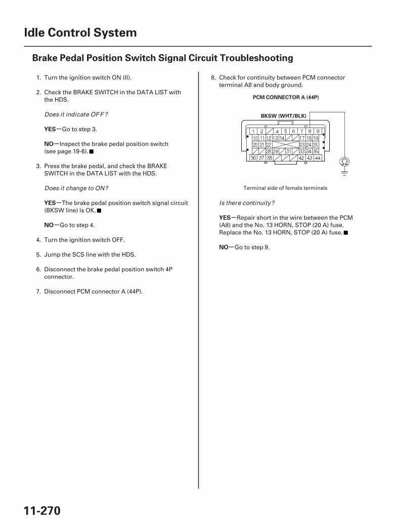
01
SJC8A00A20336114806FAAT00
-
-
-
--
-
YES
NO
YES
NO
YES
NO
11-270
Idle Control System
Brake Pedal Position Switch Signal Circuit Troubleshooting
PCM CONNECTOR A (44P)
BKSW (WHT/BLK)
1. Turn the ignition switch ON (II).
2. Check the BRAKE SWITCH in the DATA LIST withthe HDS.
Go to step 3.
Inspect the brake pedal position switch(see page 19-6).
3. Press the brake pedal, and check the BRAKESWITCH in the DATA LIST with the HDS.
The brake pedal position switch signal circuit(BKSW line) is OK.
Go to step 4.
4. Turn the ignition switch OFF.
5. Jump the SCS line with the HDS.
6. Disconnect the brake pedal position switch 4Pconnector.
7. Disconnect PCM connector A (44P).
8. Check for continuity between PCM connectorterminal A8 and body ground.
Repair short in the wire between the PCM(A8) and the No. 13 HORN, STOP (20 A) fuse.Replace the No. 13 HORN, STOP (20 A) fuse.
Go to step 9.
Terminal side of female terminals
Does it indicate OFF?
Does it change to ON?
Is there continuity?
07/05/09 16:56:31 61SJC020_110_0270
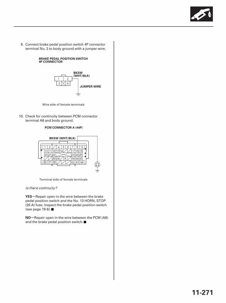
02
03
-
-
YES
NO
11-271
BRAKE PEDAL POSITION SWITCH4P CONNECTOR
BKSW(WHT/BLK)
JUMPER WIRE
PCM CONNECTOR A (44P)
BKSW (WHT/BLK)
9. Connect brake pedal position switch 4P connectorterminal No. 2 to body ground with a jumper wire.
10. Check for continuity between PCM connectorterminal A8 and body ground.
Repair open in the wire between the brakepedal position switch and the No. 13 HORN, STOP(20 A) fuse. Inspect the brake pedal position switch(see page 19-6).
Repair open in the wire between the PCM (A8)and the brake pedal position switch.
Wire side of female terminals
Terminal side of female terminals
Is there continuity?
07/05/09 16:57:12 61SJC020_110_0271
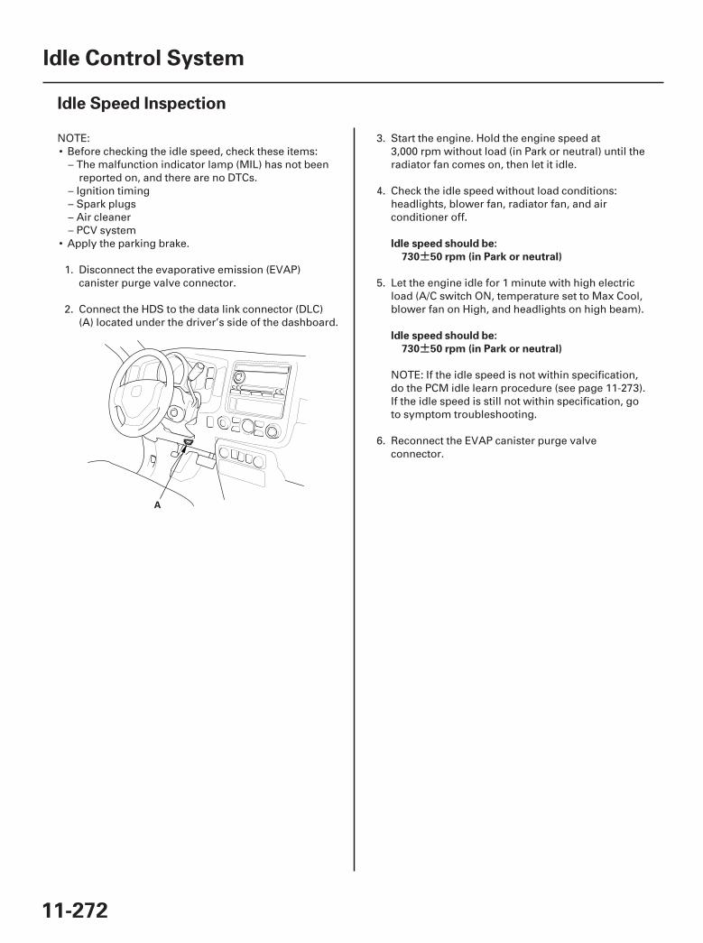
01
SJC8A00A20336100000MAAT00
±
±
Idle speed should be:
730 50 rpm (in Park or neutral)
Idle speed should be:
730 50 rpm (in Park or neutral)
11-272
Idle Control System
Idle Speed Inspection
A
NOTE:• Before checking the idle speed, check these items:
– The malfunction indicator lamp (MIL) has not beenreported on, and there are no DTCs.
– Ignition timing– Spark plugs– Air cleaner– PCV system
• Apply the parking brake.
1. Disconnect the evaporative emission (EVAP)canister purge valve connector.
2. Connect the HDS to the data link connector (DLC)(A) located under the driver’s side of the dashboard.
3. Start the engine. Hold the engine speed at3,000 rpm without load (in Park or neutral) until theradiator fan comes on, then let it idle.
4. Check the idle speed without load conditions:headlights, blower fan, radiator fan, and airconditioner off.
5. Let the engine idle for 1 minute with high electricload (A/C switch ON, temperature set to Max Cool,blower fan on High, and headlights on high beam).
NOTE: If the idle speed is not within specification,do the PCM idle learn procedure (see page 11-273).If the idle speed is still not within specification, goto symptom troubleshooting.
6. Reconnect the EVAP canister purge valveconnector.
07/05/09 16:57:12 61SJC020_110_0272
SJC8A00A20336147201BAAT00
Procedure
11-273
PCM Idle Learn Procedure
The idle learn procedure must be done so the PCM canlearn the engine idle characteristics.
Do the idle learn procedure whenever you do any ofthese actions:
• Replace PCM.• Reset PCM.• Update PCM.• Clean or replace the throttle body.
NOTE: Erasing DTCs with the HDS does not require youto do the idle learn procedure.
1. Make sure all electrical items (A/C, audio, lights, etc.)are off.
2. Reset the PCM with the HDS.
3. Turn the ignition switch ON (II), and wait 2 seconds.
4. Start the engine. Hold the engine speed at3,000 rpm without load (in Park or neutral) until theradiator fan comes on, or until the engine coolanttemperature reaches 194 °F (90 °C).
5. Let the engine idle for about 5 minutes with thethrottle fully closed.
NOTE: If the radiator fan comes on, do not includeits running time in the 5 minutes.
07/05/09 16:57:12 61SJC020_110_0273
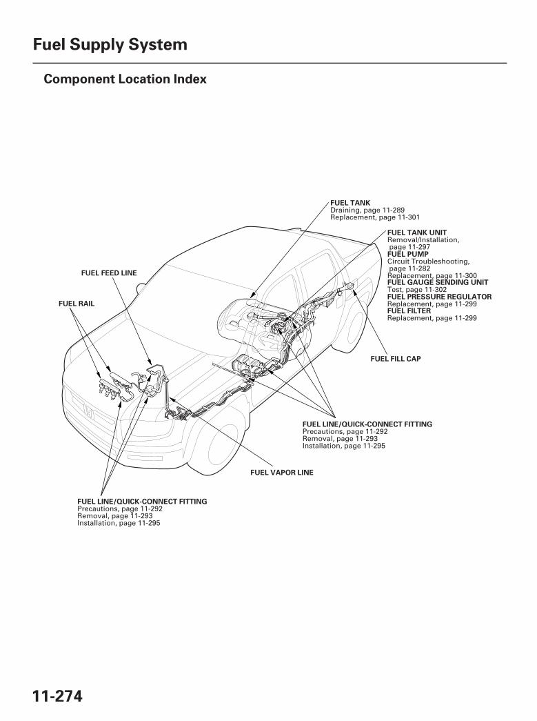
*01
SJC8A00A20326400000DAAT00
11-274
Fuel Supply System
Component Location Index
FUEL LINE/QUICK-CONNECT FITTING
FUEL VAPOR LINE
FUEL FILL CAP
FUEL RAIL
FUEL FEED LINE
FUEL PUMP
FUEL GAUGE SENDING UNIT
FUEL PRESSURE REGULATOR
FUEL FILTER
FUEL LINE/QUICK-CONNECT FITTING
FUEL TANK UNIT
FUEL TANK
Precautions, page 11-292Removal, page 11-293Installation, page 11-295
Circuit Troubleshooting,page 11-282Replacement, page 11-300
Test, page 11-302
Replacement, page 11-299
Replacement, page 11-299
Precautions, page 11-292Removal, page 11-293Installation, page 11-295
Removal/Installation,page 11-297
Draining, page 11-289Replacement, page 11-301
07/05/09 16:57:15 61SJC020_110_0274
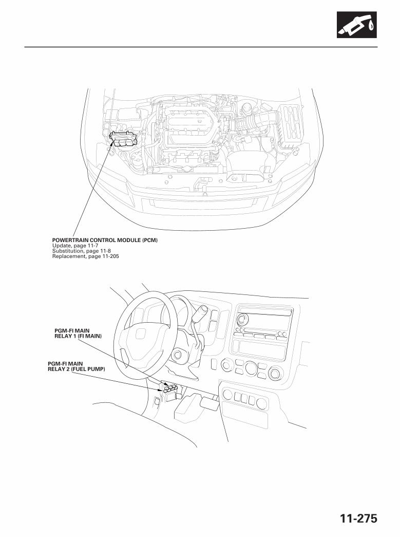
*02
*03
11-275
POWERTRAIN CONTROL MODULE (PCM)
PGM-FI MAINRELAY 2 (FUEL PUMP)
PGM-FI MAINRELAY 1 (FI MAIN)
Update, page 11-7Substitution, page 11-8Replacement, page 11-205
07/05/09 16:57:17 61SJC020_110_0275
SJC8A00K77100090461FAAT30
-
-
-
-
DTC P0461:
YES
NO
YES
NO
11-276
Fuel Supply System
DTC Troubleshooting
Fuel Level Sensor (Fuel GaugeSending Unit) Range/Performance Problem
NOTE:• Before you troubleshoot, record all freeze data and
any on-board snapshot, and review the generaltroubleshooting information (see page 11-3).
• Because it requires 162 miles (260 km) of drivingwithout refueling to complete this diagnosis, this DTCP0461 cannot be duplicated during thistroubleshooting.
1. Test the fuel gauge sending unit (see page 11-302).
Check for poor connections or looseterminals at the fuel gauge sending unit and thegauge control module.
Replace the fuel gauge sending unit (see page11-300), then go to step 2.
2. Turn the ignition switch ON (II).
3. Reset the PCM with the HDS.
4. Do the PCM idle learn procedure (see page 11-273).
5. Check for Temporary DTCs or DTCs with the HDS.
If DTC P0461 is indicated, check for poorconnections or loose terminals at the fuel gaugesending unit and the gauge control module, thengo to step 1. If any other Temporary DTCs or DTCsare indicated, go to the indicated DTC’stroubleshooting.
Troubleshooting is complete.
Is the fuel gauge sending unit OK ?
Are any Temporary DTCs or DTCs indicated?
07/05/09 16:57:17 61SJC020_110_0276
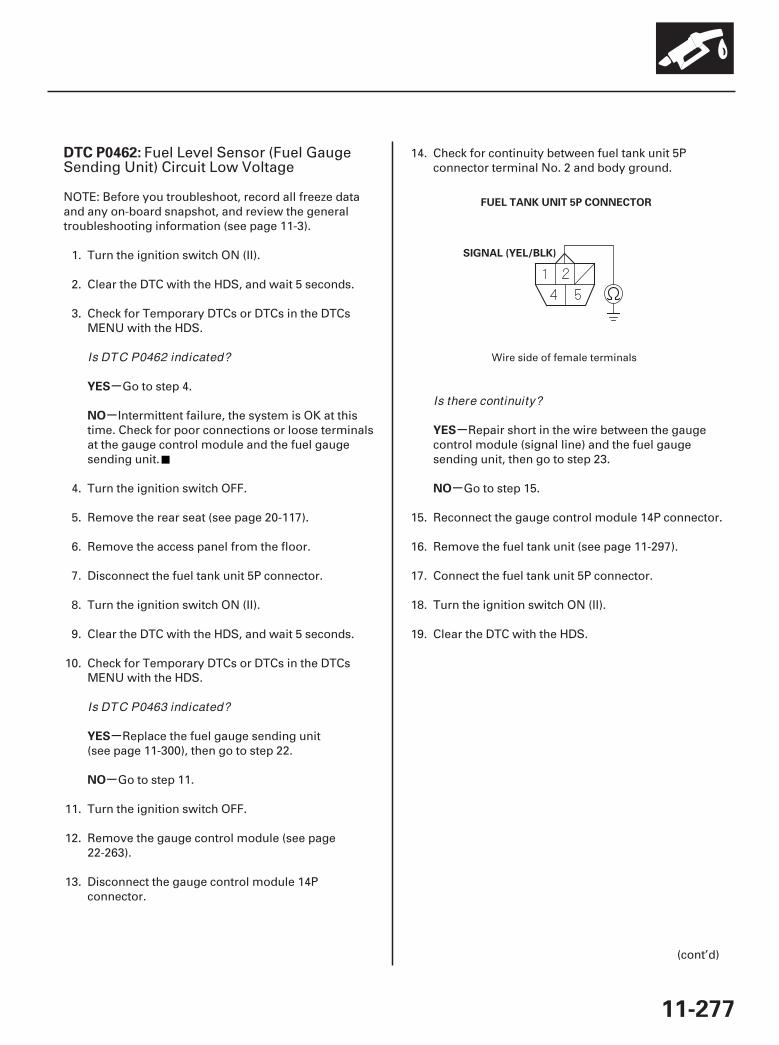
01
SJC8A00K77100090462FAAT30
-
-
-
-
-
-
DTC P0462:
YES
NO
YES
NO
YES
NO
11-277
FUEL TANK UNIT 5P CONNECTOR
SIGNAL (YEL/BLK)
Fuel Level Sensor (Fuel GaugeSending Unit) Circuit Low Voltage
NOTE: Before you troubleshoot, record all freeze dataand any on-board snapshot, and review the generaltroubleshooting information (see page 11-3).
1. Turn the ignition switch ON (II).
2. Clear the DTC with the HDS, and wait 5 seconds.
3. Check for Temporary DTCs or DTCs in the DTCsMENU with the HDS.
Go to step 4.
Intermittent failure, the system is OK at thistime. Check for poor connections or loose terminalsat the gauge control module and the fuel gaugesending unit.
4. Turn the ignition switch OFF.
5. Remove the rear seat (see page 20-117).
6. Remove the access panel from the floor.
7. Disconnect the fuel tank unit 5P connector.
8. Turn the ignition switch ON (II).
9. Clear the DTC with the HDS, and wait 5 seconds.
10. Check for Temporary DTCs or DTCs in the DTCsMENU with the HDS.
Replace the fuel gauge sending unit(see page 11-300), then go to step 22.
Go to step 11.
11. Turn the ignition switch OFF.
12. Remove the gauge control module (see page22-263).
13. Disconnect the gauge control module 14Pconnector.
14. Check for continuity between fuel tank unit 5Pconnector terminal No. 2 and body ground.
Repair short in the wire between the gaugecontrol module (signal line) and the fuel gaugesending unit, then go to step 23.
Go to step 15.
15. Reconnect the gauge control module 14P connector.
16. Remove the fuel tank unit (see page 11-297).
17. Connect the fuel tank unit 5P connector.
18. Turn the ignition switch ON (II).
19. Clear the DTC with the HDS.
(cont’d)
Wire side of female terminalsIs DTC P0462 indicated?
Is DTC P0463 indicated?
Is there continuity?
07/05/09 16:57:17 61SJC020_110_0277
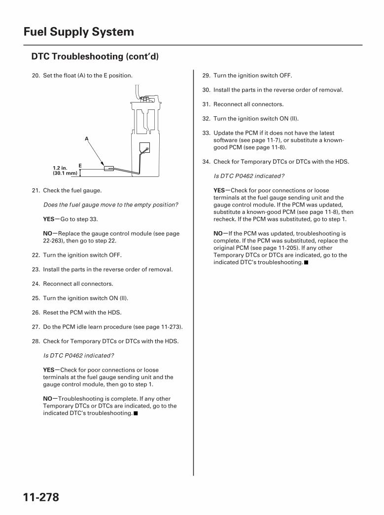
*01
-
-
-
-
-
-
YES
NO
YES
NO
YES
NO
11-278
Fuel Supply System
DTC Troubleshooting (cont’d)
E1.2 in.(30.1 mm)
A
20. Set the float (A) to the E position.
21. Check the fuel gauge.
Go to step 33.
Replace the gauge control module (see page22-263), then go to step 22.
22. Turn the ignition switch OFF.
23. Install the parts in the reverse order of removal.
24. Reconnect all connectors.
25. Turn the ignition switch ON (II).
26. Reset the PCM with the HDS.
27. Do the PCM idle learn procedure (see page 11-273).
28. Check for Temporary DTCs or DTCs with the HDS.
Check for poor connections or looseterminals at the fuel gauge sending unit and thegauge control module, then go to step 1.
Troubleshooting is complete. If any otherTemporary DTCs or DTCs are indicated, go to theindicated DTC’s troubleshooting.
29. Turn the ignition switch OFF.
30. Install the parts in the reverse order of removal.
31. Reconnect all connectors.
32. Turn the ignition switch ON (II).
33. Update the PCM if it does not have the latestsoftware (see page 11-7), or substitute a known-good PCM (see page 11-8).
34. Check for Temporary DTCs or DTCs with the HDS.
Check for poor connections or looseterminals at the fuel gauge sending unit and thegauge control module. If the PCM was updated,substitute a known-good PCM (see page 11-8), thenrecheck. If the PCM was substituted, go to step 1.
If the PCM was updated, troubleshooting iscomplete. If the PCM was substituted, replace theoriginal PCM (see page 11-205). If any otherTemporary DTCs or DTCs are indicated, go to theindicated DTC’s troubleshooting.
Does the fuel gauge move to the empty position?
Is DTC P0462 indicated?
Is DTC P0462 indicated?
07/05/09 16:57:17 61SJC020_110_0278
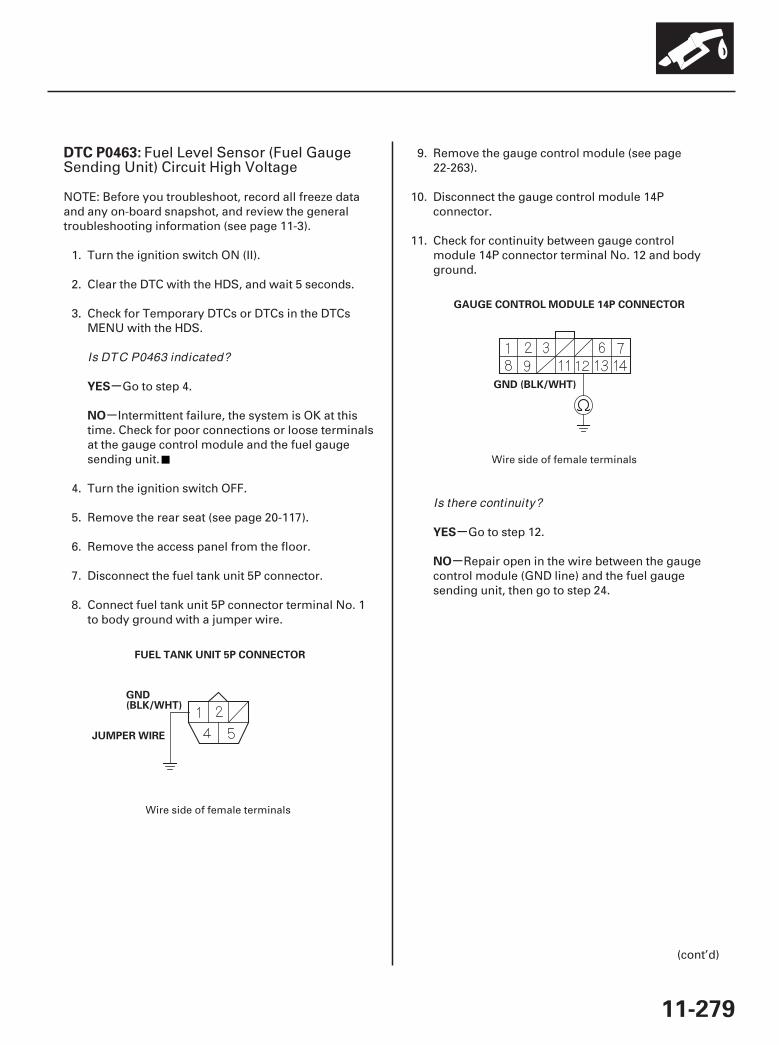
01
02
SJC8A00K77100090463FAAT30
-
-
-
-
DTC P0463:
YES
NO
YES
NO
11-279
FUEL TANK UNIT 5P CONNECTOR
GND(BLK/WHT)
JUMPER WIRE
GAUGE CONTROL MODULE 14P CONNECTOR
GND (BLK/WHT)
Fuel Level Sensor (Fuel GaugeSending Unit) Circuit High Voltage
NOTE: Before you troubleshoot, record all freeze dataand any on-board snapshot, and review the generaltroubleshooting information (see page 11-3).
1. Turn the ignition switch ON (II).
2. Clear the DTC with the HDS, and wait 5 seconds.
3. Check for Temporary DTCs or DTCs in the DTCsMENU with the HDS.
Go to step 4.
Intermittent failure, the system is OK at thistime. Check for poor connections or loose terminalsat the gauge control module and the fuel gaugesending unit.
4. Turn the ignition switch OFF.
5. Remove the rear seat (see page 20-117).
6. Remove the access panel from the floor.
7. Disconnect the fuel tank unit 5P connector.
8. Connect fuel tank unit 5P connector terminal No. 1to body ground with a jumper wire.
9. Remove the gauge control module (see page22-263).
10. Disconnect the gauge control module 14Pconnector.
11. Check for continuity between gauge controlmodule 14P connector terminal No. 12 and bodyground.
Go to step 12.
Repair open in the wire between the gaugecontrol module (GND line) and the fuel gaugesending unit, then go to step 24.
(cont’d)
Wire side of female terminals
Wire side of female terminals
Is DTC P0463 indicated?
Is there continuity?
07/05/09 16:57:18 61SJC020_110_0279
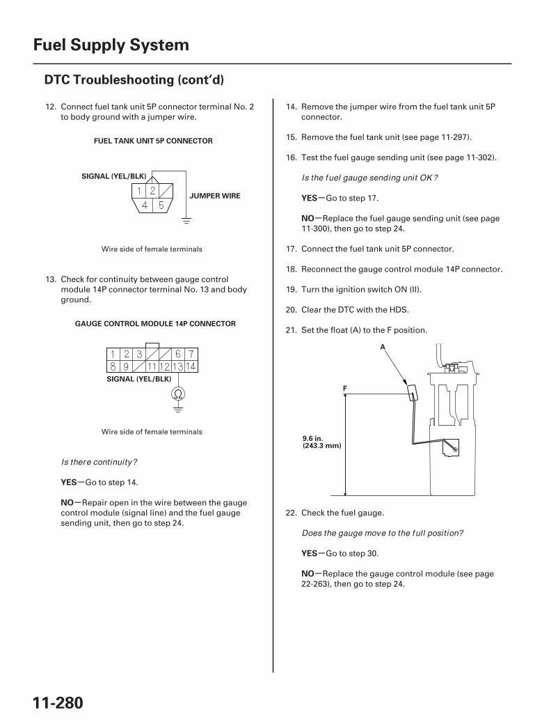
03
04
*01
-
-
-
-
-
-
YES
NO
YES
NO
YES
NO
11-280
Fuel Supply System
DTC Troubleshooting (cont’d)
FUEL TANK UNIT 5P CONNECTOR
SIGNAL (YEL/BLK)
JUMPER WIRE
GAUGE CONTROL MODULE 14P CONNECTOR
SIGNAL (YEL/BLK)
F
9.6 in.(243.3 mm)
A
12. Connect fuel tank unit 5P connector terminal No. 2to body ground with a jumper wire.
13. Check for continuity between gauge controlmodule 14P connector terminal No. 13 and bodyground.
Go to step 14.
Repair open in the wire between the gaugecontrol module (signal line) and the fuel gaugesending unit, then go to step 24.
14. Remove the jumper wire from the fuel tank unit 5Pconnector.
15. Remove the fuel tank unit (see page 11-297).
16. Test the fuel gauge sending unit (see page 11-302).
Go to step 17.
Replace the fuel gauge sending unit (see page11-300), then go to step 24.
17. Connect the fuel tank unit 5P connector.
18. Reconnect the gauge control module 14P connector.
19. Turn the ignition switch ON (II).
20. Clear the DTC with the HDS.
21. Set the float (A) to the F position.
22. Check the fuel gauge.
Go to step 30.
Replace the gauge control module (see page22-263), then go to step 24.
Wire side of female terminals
Wire side of female terminals
Is there continuity?
Is the fuel gauge sending unit OK ?
Does the gauge move to the full position?
07/05/09 16:57:18 61SJC020_110_0280

-
-
-
-
YES
NO
YES
NO
11-281
23. Turn the ignition switch OFF.
24. Install the parts in the reverse order of removal.
25. Reconnect all connectors.
26. Turn the ignition switch ON (II).
27. Reset the PCM with the HDS.
28. Do the PCM idle learn procedure (see page 11-273).
29. Check for Temporary DTCs or DTCs with the HDS.
Check for poor connections or looseterminals at the fuel gauge sending unit and thegauge control module, then go to step 1.
Troubleshooting is complete. If any otherTemporary DTCs or DTCs are indicated, go to theindicated DTC’s troubleshooting.
30. Turn the ignition switch OFF.
31. Install the parts in the reverse order of removal.
32. Reconnect all connectors.
33. Turn the ignition switch ON (II).
34. Update the PCM if it does not have the latestsoftware (see page 11-7), or substitute a known-good PCM (see page 11-8).
35. Check for Temporary DTCs or DTCs with the HDS.
Check for poor connections or looseterminals at the fuel gauge sending unit and thegauge control module. If the PCM was updated,substitute a known-good PCM (see page 11-8), thenrecheck. If the PCM was substituted, go to step 1.
If the PCM was updated, troubleshooting iscomplete. If the PCM was substituted, replace theoriginal PCM (see page 11-205). If any otherTemporary DTCs or DTCs are indicated, go to theindicated DTC’s troubleshooting.
Is DTC P0463 indicated?
Is DTC P0463 indicated?
07/05/09 16:57:18 61SJC020_110_0281
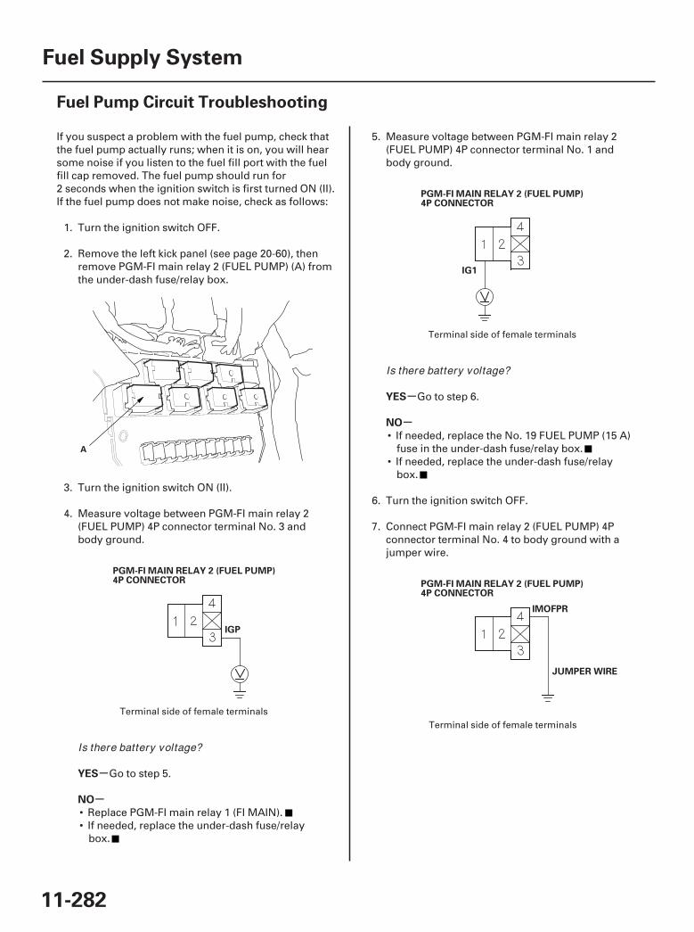
01
02
03
04
SJC8A00A20326428302FAAT10
-
-
-
-
YES
NO
YES
NO
11-282
Fuel Supply System
Fuel Pump Circuit Troubleshooting
A
PGM-FI MAIN RELAY 2 (FUEL PUMP)4P CONNECTOR
IGP
PGM-FI MAIN RELAY 2 (FUEL PUMP)4P CONNECTOR
IG1
PGM-FI MAIN RELAY 2 (FUEL PUMP)4P CONNECTOR
IMOFPR
JUMPER WIRE
If you suspect a problem with the fuel pump, check thatthe fuel pump actually runs; when it is on, you will hearsome noise if you listen to the fuel fill port with the fuelfill cap removed. The fuel pump should run for2 seconds when the ignition switch is first turned ON (II).If the fuel pump does not make noise, check as follows:
1. Turn the ignition switch OFF.
2. Remove the left kick panel (see page 20-60), thenremove PGM-FI main relay 2 (FUEL PUMP) (A) fromthe under-dash fuse/relay box.
3. Turn the ignition switch ON (II).
4. Measure voltage between PGM-FI main relay 2(FUEL PUMP) 4P connector terminal No. 3 andbody ground.
Go to step 5.
• Replace PGM-FI main relay 1 (FI MAIN).• If needed, replace the under-dash fuse/relay
box.
5. Measure voltage between PGM-FI main relay 2(FUEL PUMP) 4P connector terminal No. 1 andbody ground.
Go to step 6.
• If needed, replace the No. 19 FUEL PUMP (15 A)fuse in the under-dash fuse/relay box.
• If needed, replace the under-dash fuse/relaybox.
6. Turn the ignition switch OFF.
7. Connect PGM-FI main relay 2 (FUEL PUMP) 4Pconnector terminal No. 4 to body ground with ajumper wire.
Terminal side of female terminals
Terminal side of female terminals
Terminal side of female terminals
Is there battery voltage?
Is there battery voltage?
07/05/09 16:57:19 61SJC020_110_0282
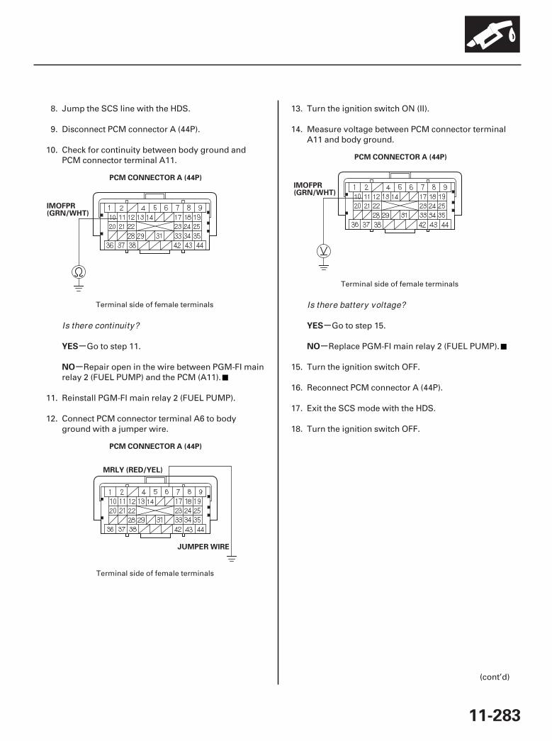
05
06
07
-
-
-
-YES
NO
YES
NO
11-283
PCM CONNECTOR A (44P)
IMOFPR(GRN/WHT)
PCM CONNECTOR A (44P)
MRLY (RED/YEL)
JUMPER WIRE
PCM CONNECTOR A (44P)
IMOFPR(GRN/WHT)
8. Jump the SCS line with the HDS.
9. Disconnect PCM connector A (44P).
10. Check for continuity between body ground andPCM connector terminal A11.
Go to step 11.
Repair open in the wire between PGM-FI mainrelay 2 (FUEL PUMP) and the PCM (A11).
11. Reinstall PGM-FI main relay 2 (FUEL PUMP).
12. Connect PCM connector terminal A6 to bodyground with a jumper wire.
13. Turn the ignition switch ON (II).
14. Measure voltage between PCM connector terminalA11 and body ground.
Go to step 15.
Replace PGM-FI main relay 2 (FUEL PUMP).
15. Turn the ignition switch OFF.
16. Reconnect PCM connector A (44P).
17. Exit the SCS mode with the HDS.
18. Turn the ignition switch OFF.
(cont’d)
Terminal side of female terminals
Terminal side of female terminals
Terminal side of female terminals
Is there continuity?
Is there battery voltage?
07/05/09 16:57:19 61SJC020_110_0283
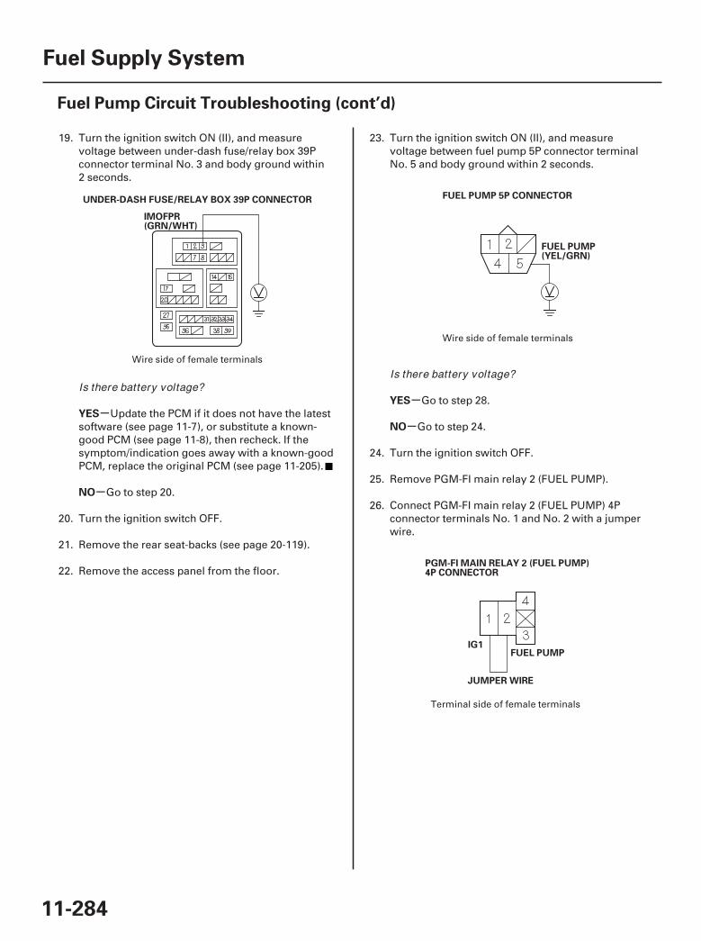
0809
10
-
-
-
-YES
NO
YES
NO
11-284
Fuel Supply System
Fuel Pump Circuit Troubleshooting (cont’d)
UNDER-DASH FUSE/RELAY BOX 39P CONNECTOR
IMOFPR(GRN/WHT)
FUEL PUMP 5P CONNECTOR
FUEL PUMP(YEL/GRN)
PGM-FI MAIN RELAY 2 (FUEL PUMP)4P CONNECTOR
IG1FUEL PUMP
JUMPER WIRE
19. Turn the ignition switch ON (II), and measurevoltage between under-dash fuse/relay box 39Pconnector terminal No. 3 and body ground within2 seconds.
Update the PCM if it does not have the latestsoftware (see page 11-7), or substitute a known-good PCM (see page 11-8), then recheck. If thesymptom/indication goes away with a known-goodPCM, replace the original PCM (see page 11-205).
Go to step 20.
20. Turn the ignition switch OFF.
21. Remove the rear seat-backs (see page 20-119).
22. Remove the access panel from the floor.
23. Turn the ignition switch ON (II), and measurevoltage between fuel pump 5P connector terminalNo. 5 and body ground within 2 seconds.
Go to step 28.
Go to step 24.
24. Turn the ignition switch OFF.
25. Remove PGM-FI main relay 2 (FUEL PUMP).
26. Connect PGM-FI main relay 2 (FUEL PUMP) 4Pconnector terminals No. 1 and No. 2 with a jumperwire.
Wire side of female terminals
Wire side of female terminals
Terminal side of female terminals
Is there battery voltage?Is there battery voltage?
07/05/09 16:57:20 61SJC020_110_0284
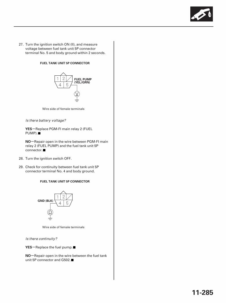
01
02
-
-
-
-
YES
NO
YES
NO
11-285
FUEL TANK UNIT 5P CONNECTOR
FUEL PUMP(YEL/GRN)
GND (BLK)
FUEL TANK UNIT 5P CONNECTOR
27. Turn the ignition switch ON (II), and measurevoltage between fuel tank unit 5P connectorterminal No. 5 and body ground within 2 seconds.
Replace PGM-FI main relay 2 (FUELPUMP).
Repair open in the wire between PGM-FI mainrelay 2 (FUEL PUMP) and the fuel tank unit 5Pconnector.
28. Turn the ignition switch OFF.
29. Check for continuity between fuel tank unit 5Pconnector terminal No. 4 and body ground.
Replace the fuel pump.
Repair open in the wire between the fuel tankunit 5P connector and G502.
Wire side of female terminals
Wire side of female terminals
Is there battery voltage?
Is there continuity?
07/05/09 16:57:20 61SJC020_110_0285
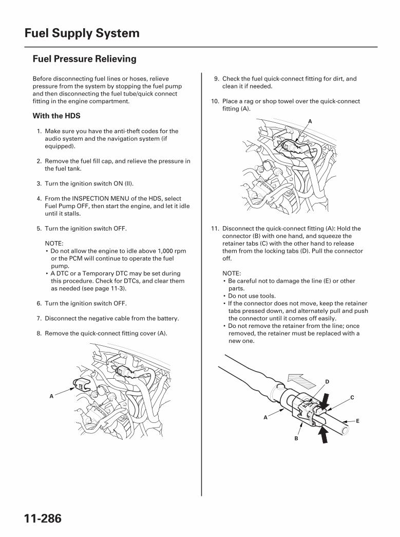
01
02
03
SJC8A00A20326400000MBAT00
With the HDS
11-286
Fuel Supply System
Fuel Pressure Relieving
A
A
A
B
C
E
D
Before disconnecting fuel lines or hoses, relievepressure from the system by stopping the fuel pumpand then disconnecting the fuel tube/quick connectfitting in the engine compartment.
1. Make sure you have the anti-theft codes for theaudio system and the navigation system (ifequipped).
2. Remove the fuel fill cap, and relieve the pressure inthe fuel tank.
3. Turn the ignition switch ON (II).
4. From the INSPECTION MENU of the HDS, selectFuel Pump OFF, then start the engine, and let it idleuntil it stalls.
5. Turn the ignition switch OFF.
NOTE:• Do not allow the engine to idle above 1,000 rpm
or the PCM will continue to operate the fuelpump.
• A DTC or a Temporary DTC may be set duringthis procedure. Check for DTCs, and clear themas needed (see page 11-3).
6. Turn the ignition switch OFF.
7. Disconnect the negative cable from the battery.
8. Remove the quick-connect fitting cover (A).
9. Check the fuel quick-connect fitting for dirt, andclean it if needed.
10. Place a rag or shop towel over the quick-connectfitting (A).
11. Disconnect the quick-connect fitting (A): Hold theconnector (B) with one hand, and squeeze theretainer tabs (C) with the other hand to releasethem from the locking tabs (D). Pull the connectoroff.
NOTE:• Be careful not to damage the line (E) or other
parts.• Do not use tools.• If the connector does not move, keep the retainer
tabs pressed down, and alternately pull and pushthe connector until it comes off easily.
• Do not remove the retainer from the line; onceremoved, the retainer must be replaced with anew one.
07/05/09 16:57:21 61SJC020_110_0286
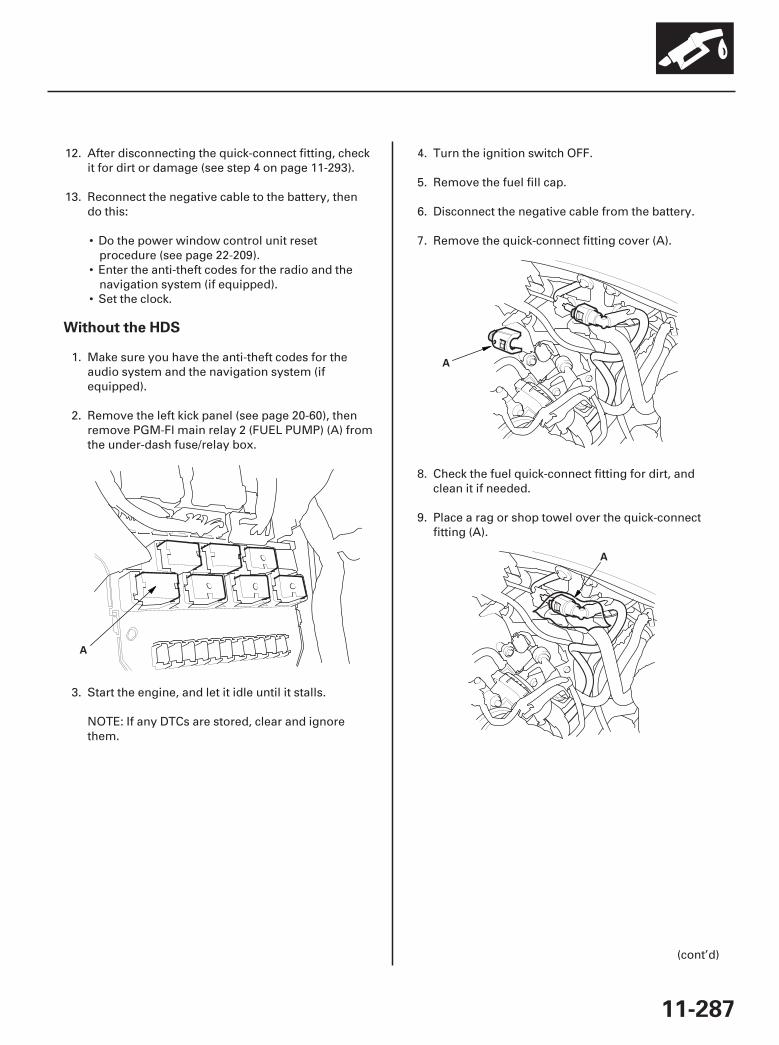
04
05
06
Without the HDS
11-287
A
A
A
12. After disconnecting the quick-connect fitting, checkit for dirt or damage (see step 4 on page 11-293).
13. Reconnect the negative cable to the battery, thendo this:
• Do the power window control unit resetprocedure (see page 22-209).
• Enter the anti-theft codes for the radio and thenavigation system (if equipped).
• Set the clock.
1. Make sure you have the anti-theft codes for theaudio system and the navigation system (ifequipped).
2. Remove the left kick panel (see page 20-60), thenremove PGM-Fl main relay 2 (FUEL PUMP) (A) fromthe under-dash fuse/relay box.
3. Start the engine, and let it idle until it stalls.
NOTE: If any DTCs are stored, clear and ignorethem.
4. Turn the ignition switch OFF.
5. Remove the fuel fill cap.
6. Disconnect the negative cable from the battery.
7. Remove the quick-connect fitting cover (A).
8. Check the fuel quick-connect fitting for dirt, andclean it if needed.
9. Place a rag or shop towel over the quick-connectfitting (A).
(cont’d)
07/05/09 16:57:21 61SJC020_110_0287
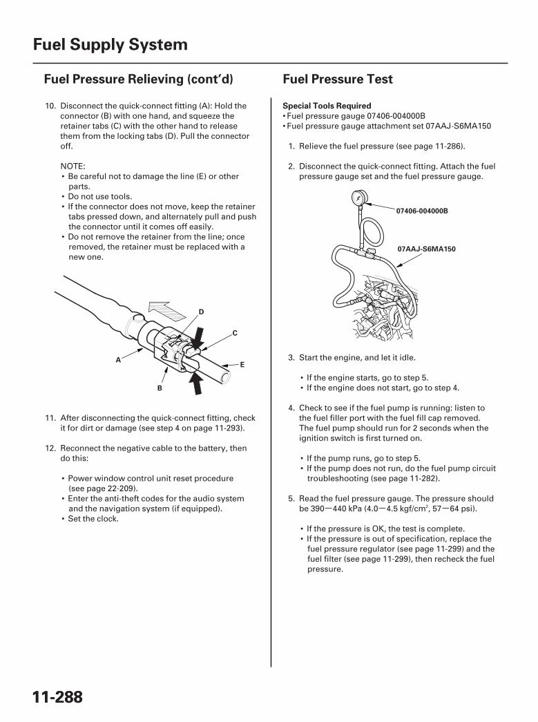
07
- - -
01
SJC8A00A20326400000FEAT00
Special Tools Required
11-28811-288
Fuel Supply System
Fuel Pressure Relieving (cont’d) Fuel Pressure Test
A
B
C
E
D
07AAJ-S6MA150
07406-004000B
10. Disconnect the quick-connect fitting (A): Hold theconnector (B) with one hand, and squeeze theretainer tabs (C) with the other hand to releasethem from the locking tabs (D). Pull the connectoroff.
NOTE:• Be careful not to damage the line (E) or other
parts.• Do not use tools.• If the connector does not move, keep the retainer
tabs pressed down, and alternately pull and pushthe connector until it comes off easily.
• Do not remove the retainer from the line; onceremoved, the retainer must be replaced with anew one.
11. After disconnecting the quick-connect fitting, checkit for dirt or damage (see step 4 on page 11-293).
12. Reconnect the negative cable to the battery, thendo this:
• Power window control unit reset procedure(see page 22-209).
• Enter the anti-theft codes for the audio systemand the navigation system (if equipped).
• Set the clock.
• Fuel pressure gauge 07406-004000B• Fuel pressure gauge attachment set 07AAJ-S6MA150
1. Relieve the fuel pressure (see page 11-286).
2. Disconnect the quick-connect fitting. Attach the fuelpressure gauge set and the fuel pressure gauge.
3. Start the engine, and let it idle.
• If the engine starts, go to step 5.• If the engine does not start, go to step 4.
4. Check to see if the fuel pump is running: listen tothe fuel filler port with the fuel fill cap removed.The fuel pump should run for 2 seconds when theignition switch is first turned on.
• If the pump runs, go to step 5.• If the pump does not run, do the fuel pump circuit
troubleshooting (see page 11-282).
5. Read the fuel pressure gauge. The pressure shouldbe 390 440 kPa (4.0 4.5 kgf/cm , 57 64 psi).
• If the pressure is OK, the test is complete.• If the pressure is out of specification, replace the
fuel pressure regulator (see page 11-299) and thefuel filter (see page 11-299), then recheck the fuelpressure.
2
07/05/09 16:57:22 61SJC020_110_0288
SJC8A00A20326428501LBAT10
11-289
Fuel Tank Draining
1. Remove the fuel tank unit (see page 11-297).
2. Using a hand pump, a hose, and a containersuitable for fuel, draw the fuel from the fuel tank.
3. Reinstall the fuel tank unit (see page 11-298).
07/05/09 16:57:22 61SJC020_110_0289
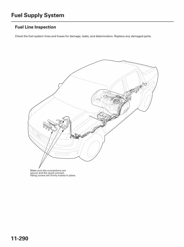
01
SJC8A00A20326428001MAAT00
11-290
Fuel Supply System
Fuel Line Inspection
Check the fuel system lines and hoses for damage, leaks, and deterioration. Replace any damaged parts.
Make sure the connections aresecure and the quick-connectfitting covers are firmly locked in place.
07/05/09 16:57:22 61SJC020_110_0290

02
11-291
To EVAPORATIVEEMISSION (EVAP)CANISTERPURGE VALVE
To FUELRAIL
FUEL TANK UNIT LOCKNUT
BASE GASKET
AB
C
4.76 in. (119 mm)
TOPA: B:
TOP
C:
TOP15 °
150 °
150 °
15 °
Check all clamps, and retighten if necessary.
Replace.
Replace.
Make sure the clamp ispositioned as shown.
Make sure the clamp ispositioned as shown.
07/05/09 16:57:23 61SJC020_110_0291
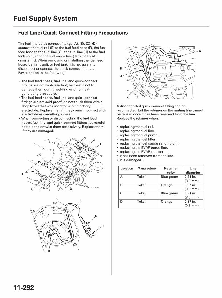
01
02
03
SJC8A00A20326428001BAAT00
Location Manufacturer Retainer
color
Line
diameter
11-292
Fuel Supply System
Fuel Line/Quick-Connect Fitting Precautions
A
F
G
E
A A
B
C
H
I
J
D
D
K
The fuel line/quick-connect fittings (A), (B), (C), (D)connect the fuel rail (E) to the fuel feed hose (F), the fuelfeed hose to the fuel line (G), the fuel line (H) to the fueltank unit (I) and the fuel vapor line (J) to the EVAPcanister (K). When removing or installing the fuel feedhose, fuel tank unit, or fuel tank, it is necessary todisconnect or connect the quick-connect fittings.Pay attention to the following:
• The fuel feed hoses, fuel line, and quick-connectfittings are not heat-resistant; be careful not todamage them during welding or other heat-generating procedures.
• The fuel feed hoses, fuel line, and quick-connectfittings are not acid-proof; do not touch them with ashop towel that was used for wiping batteryelectrolyte. Replace them if they come in contact withelectrolyte or something similar.
• When connecting or disconnecting the fuel feedhoses, fuel line, and quick-connect fittings, be carefulnot to bend or twist them excessively. Replace themif they are damaged.
A disconnected quick-connect fitting can bereconnected, but the retainer on the mating line cannotbe reused once it has been removed from the line.Replace the retainer when:
• replacing the fuel rail.• replacing the fuel line.• replacing the fuel pump.• replacing the fuel filter.• replacing the fuel gauge sending unit.• replacing the EVAP purge line.• replacing the EVAP canister.• it has been removed from the line.• it is damaged.
A Tokai Blue green 0.31 in.(8.0 mm)
B Tokai Orange 0.37 in.(9.5 mm)
C Tokai Blue green 0.31 in.(8.0 mm)
D Tokai Orange 0.37 in.(9.5 mm)
07/05/09 16:57:24 61SJC020_110_0292
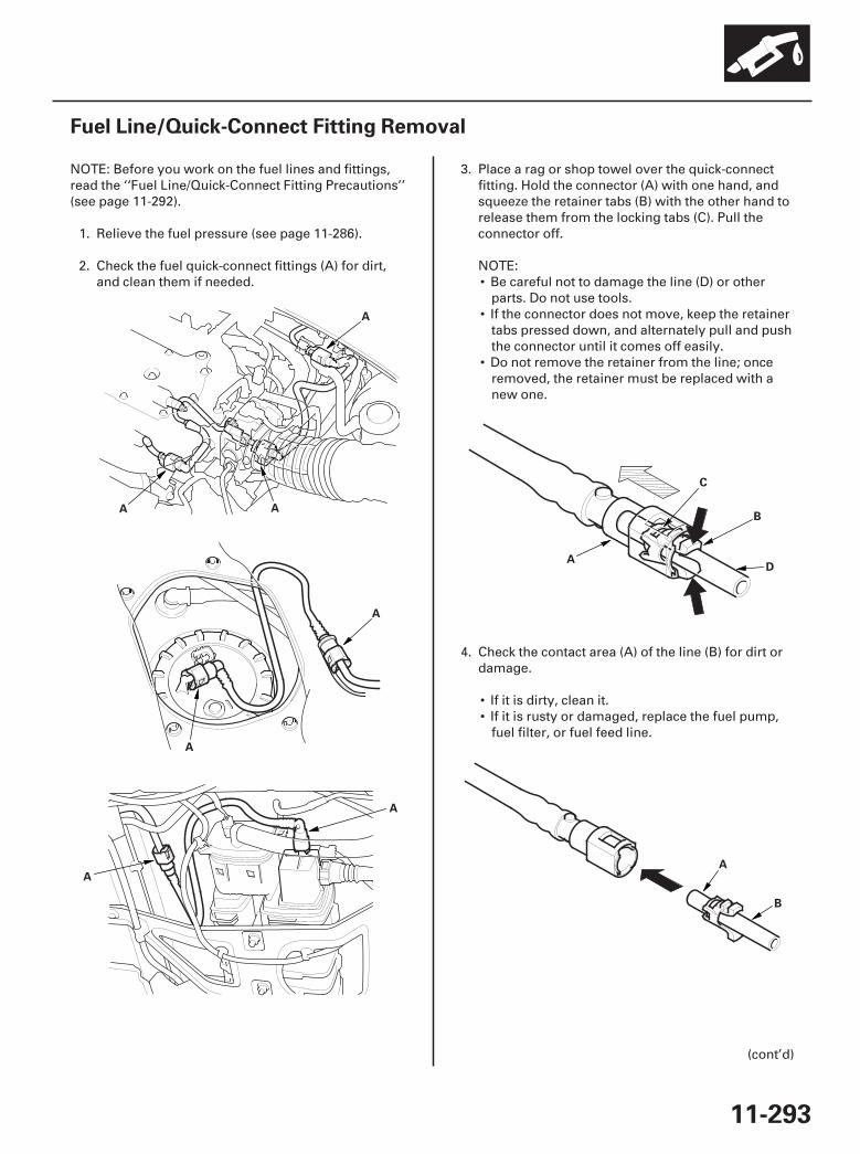
01
02
03
04
05
SJC8A00A20326428001KAAT00
11-293
Fuel Line/Quick-Connect Fitting Removal
A
A A
A
A
A
A
A
B
D
C
A
B
NOTE: Before you work on the fuel lines and fittings,read the ‘‘Fuel Line/Quick-Connect Fitting Precautions’’(see page 11-292).
1. Relieve the fuel pressure (see page 11-286).
2. Check the fuel quick-connect fittings (A) for dirt,and clean them if needed.
3. Place a rag or shop towel over the quick-connectfitting. Hold the connector (A) with one hand, andsqueeze the retainer tabs (B) with the other hand torelease them from the locking tabs (C). Pull theconnector off.
NOTE:• Be careful not to damage the line (D) or other
parts. Do not use tools.• If the connector does not move, keep the retainer
tabs pressed down, and alternately pull and pushthe connector until it comes off easily.
• Do not remove the retainer from the line; onceremoved, the retainer must be replaced with anew one.
4. Check the contact area (A) of the line (B) for dirt ordamage.
• If it is dirty, clean it.• If it is rusty or damaged, replace the fuel pump,
fuel filter, or fuel feed line.
(cont’d)
07/05/09 16:57:25 61SJC020_110_0293
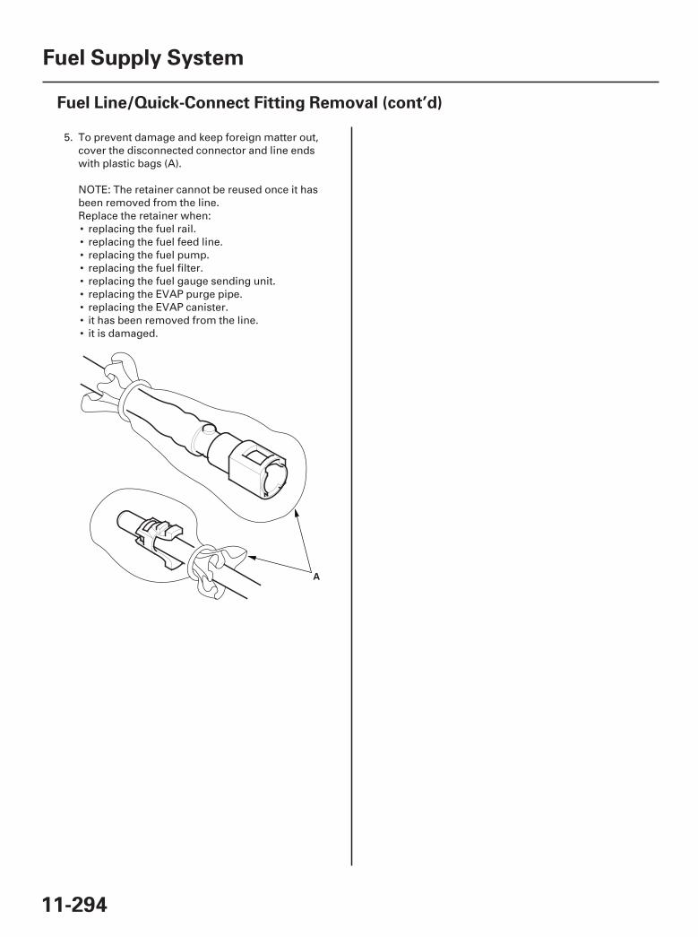
06
11-294
Fuel Supply System
Fuel Line/Quick-Connect Fitting Removal (cont’d)
A
5. To prevent damage and keep foreign matter out,cover the disconnected connector and line endswith plastic bags (A).
NOTE: The retainer cannot be reused once it hasbeen removed from the line.Replace the retainer when:• replacing the fuel rail.• replacing the fuel feed line.• replacing the fuel pump.• replacing the fuel filter.• replacing the fuel gauge sending unit.• replacing the EVAP purge pipe.• replacing the EVAP canister.• it has been removed from the line.• it is damaged.
07/05/09 16:57:25 61SJC020_110_0294
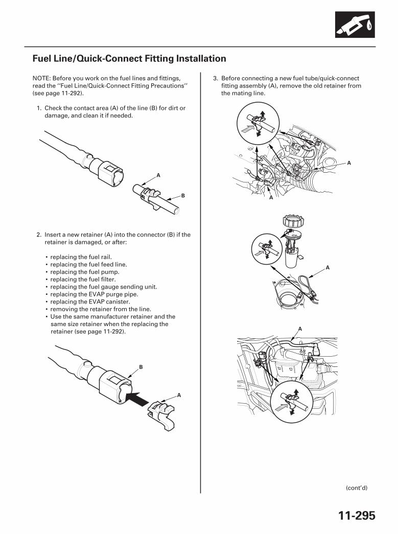
01
02
03
04
05
SJC8A00A20326428001KCAT00
11-295
Fuel Line/Quick-Connect Fitting Installation
A
B
B
A
A
A
A
A
NOTE: Before you work on the fuel lines and fittings,read the ‘‘Fuel Line/Quick-Connect Fitting Precautions’’(see page 11-292).
1. Check the contact area (A) of the line (B) for dirt ordamage, and clean it if needed.
2. Insert a new retainer (A) into the connector (B) if theretainer is damaged, or after:
• replacing the fuel rail.• replacing the fuel feed line.• replacing the fuel pump.• replacing the fuel filter.• replacing the fuel gauge sending unit.• replacing the EVAP purge pipe.• replacing the EVAP canister.• removing the retainer from the line.• Use the same manufacturer retainer and the
same size retainer when the replacing theretainer (see page 11-292).
3. Before connecting a new fuel tube/quick-connectfitting assembly (A), remove the old retainer fromthe mating line.
(cont’d)
07/05/09 16:57:26 61SJC020_110_0295
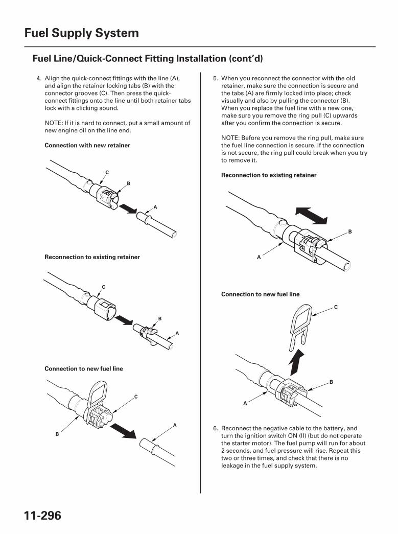
01
02
03
04
05
Connection with new retainer
Reconnection to existing retainer
Connection to new fuel line
Reconnection to existing retainer
Connection to new fuel line
11-296
Fuel Supply System
Fuel Line/Quick-Connect Fitting Installation (cont’d)
C
B
A
C
B
A
A
B
C
A
B
A
B
C
4. Align the quick-connect fittings with the line (A),and align the retainer locking tabs (B) with theconnector grooves (C). Then press the quick-connect fittings onto the line until both retainer tabslock with a clicking sound.
NOTE: If it is hard to connect, put a small amount ofnew engine oil on the line end.
5. When you reconnect the connector with the oldretainer, make sure the connection is secure andthe tabs (A) are firmly locked into place; checkvisually and also by pulling the connector (B).When you replace the fuel line with a new one,make sure you remove the ring pull (C) upwardsafter you confirm the connection is secure.
NOTE: Before you remove the ring pull, make surethe fuel line connection is secure. If the connectionis not secure, the ring pull could break when you tryto remove it.
6. Reconnect the negative cable to the battery, andturn the ignition switch ON (II) (but do not operatethe starter motor). The fuel pump will run for about2 seconds, and fuel pressure will rise. Repeat thistwo or three times, and check that there is noleakage in the fuel supply system.
07/05/09 16:57:27 61SJC020_110_0296
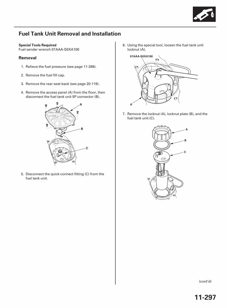
*01
*02
*03
SJC8A00A20326428521KDAT00
Special Tools Required
Removal
11-297
Fuel Tank Unit Removal and Installation
A
B
C
07AAA-S0XA100
A
A
B
C
Fuel sender wrench 07AAA-S0XA100
1. Relieve the fuel pressure (see page 11-286).
2. Remove the fuel fill cap.
3. Remove the rear seat-back (see page 20-119).
4. Remove the access panel (A) from the floor, thendisconnect the fuel tank unit 5P connector (B).
5. Disconnect the quick-connect fitting (C) from thefuel tank unit.
6. Using the special tool, loosen the fuel tank unitlocknut (A).
7. Remove the locknut (A), locknut plate (B), and thefuel tank unit (C).
(cont’d)
07/05/09 16:57:28 61SJC020_110_0297
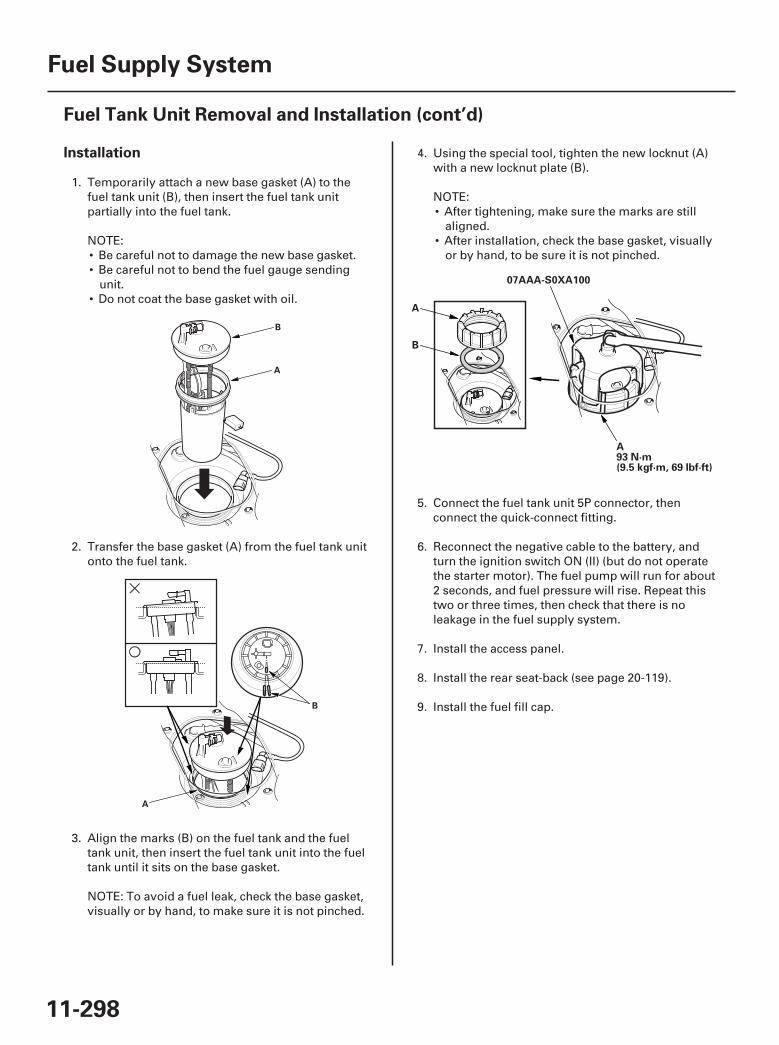
*04
*05
*06
Installation
11-298
Fuel Supply System
Fuel Tank Unit Removal and Installation (cont’d)
A
B
A
B
A
B
07AAA-S0XA100
A93 N·m(9.5 kgf·m, 69 lbf·ft)
1. Temporarily attach a new base gasket (A) to the
NOTE:• Be careful not to damage the new base gasket.• Be careful not to bend the fuel gauge sending
unit.• Do not coat the base gasket with oil.
2.
3. Align the marks (B) on the fuel tank and the fueltank unit, then insert the fuel tank unit into the fueltank until it sits on the base gasket.
NOTE: To avoid a fuel leak, check the base gasket,visually or by hand, to make sure it is not pinched.
4.with a new locknut plate (B).
NOTE:• After tightening, make sure the marks are still
aligned.• After installation, check the base gasket, visually
or by hand, to be sure it is not pinched.
5. Connect the fuel tank unit 5P connector, thenconnect the quick-connect fitting.
6. Reconnect the negative cable to the battery, andturn the ignition switch ON (II) (but do not operatethe starter motor). The fuel pump will run for about2 seconds, and fuel pressure will rise. Repeat thistwo or three times, then check that there is noleakage in the fuel supply system.
7. Install the access panel.
8. Install the rear seat-back (see page 20-119).
9. Install the fuel fill cap.
07/05/09 16:57:28 61SJC020_110_0298
fuel tank unit (B), then insert the fuel tank unitpartially into the fuel tank.
onto the fuel tank.Transfer the base gasket (A) from the fuel tank unit
Using the special tool, tighten the new locknut (A)
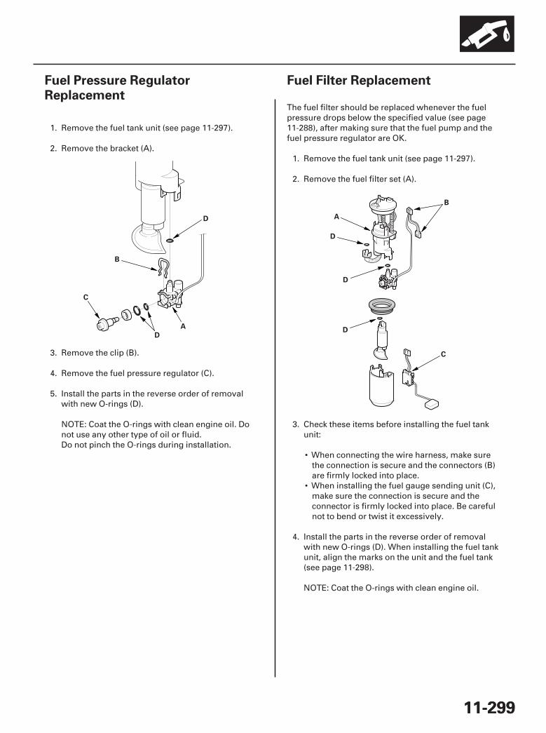
01
SJC8A00A20326428201KBAT00
01
SJC8A00A20326427601KBAT00
11-29911-299
Fuel Pressure RegulatorReplacement
Fuel Filter Replacement
A
B
C
D
D A
B
C
D
D
D
1. Remove the fuel tank unit (see page 11-297).
2. Remove the bracket (A).
3. Remove the clip (B).
4. Remove the fuel pressure regulator (C).
5. Install the parts in the reverse order of removalwith new O-rings (D).
NOTE: Coat the O-rings with clean engine oil. Donot use any other type of oil or fluid.Do not pinch the O-rings during installation.
The fuel filter should be replaced whenever the fuelpressure drops below the specified value (see page11-288), after making sure that the fuel pump and thefuel pressure regulator are OK.
1. Remove the fuel tank unit (see page 11-297).
2. Remove the fuel filter set (A).
3. Check these items before installing the fuel tankunit:
• When connecting the wire harness, make surethe connection is secure and the connectors (B)are firmly locked into place.
• When installing the fuel gauge sending unit (C),make sure the connection is secure and theconnector is firmly locked into place. Be carefulnot to bend or twist it excessively.
4. Install the parts in the reverse order of removalwith new O-rings (D). When installing the fuel tankunit, align the marks on the unit and the fuel tank(see page 11-298).
NOTE: Coat the O-rings with clean engine oil.
07/05/09 16:57:29 61SJC020_110_0299

*01
SJC8A00A20326427702KBAT00
11-300
Fuel Supply System
Fuel Pump/Fuel Gauge Sending Unit Replacement
C
B
A
1. Remove the fuel tank unit (see page 11-297).
2. Remove the fuel level sensor (fuel sending unit) (A)from the fuel tank unit (B).
3. Check these items before installing the fuel tank.
• When connecting the wire harness, make surethe connection is secure and the connectors (C) isfirmly locked into place.
• When installing the fuel gauge sending unit,make sure the connection is secure and theconnector is firmly locked into place. Be carefulnot to bend or twist it excessively.
4. Install the parts in the reverse order of removal.When installing the fuel tank unit, align the markson the unit and the fuel tank (see page 11-298).
07/05/09 16:57:29 61SJC020_110_0300
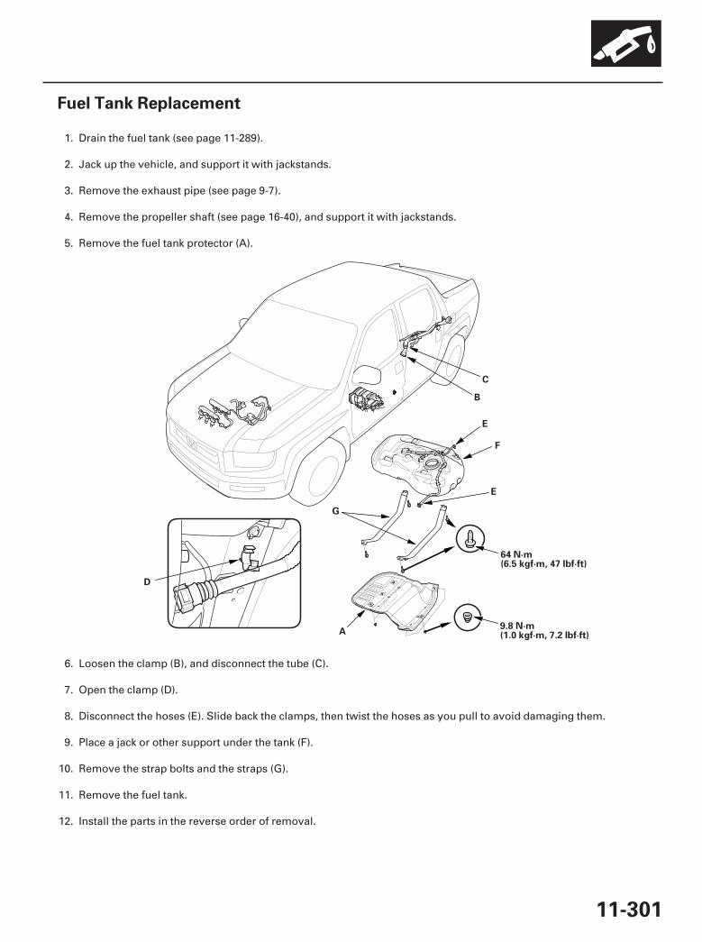
01
SJC8A00A20326428501KBAT00
11-301
Fuel Tank Replacement
A
B
C
D
E
F
G
E
64 N·m(6.5 kgf·m, 47 lbf·ft)
9.8 N·m(1.0 kgf·m, 7.2 lbf·ft)
1. Drain the fuel tank (see page 11-289).
2. Jack up the vehicle, and support it with jackstands.
3. Remove the exhaust pipe (see page 9-7).
4. Remove the propeller shaft (see page 16-40), and support it with jackstands.
5. Remove the fuel tank protector (A).
6. Loosen the clamp (B), and disconnect the tube (C).
7. Open the clamp (D).
8. Disconnect the hoses (E). Slide back the clamps, then twist the hoses as you pull to avoid damaging them.
9. Place a jack or other support under the tank (F).
10. Remove the strap bolts and the straps (G).
11. Remove the fuel tank.
12. Install the parts in the reverse order of removal.
07/05/09 16:58:15 61SJC020_110_0301
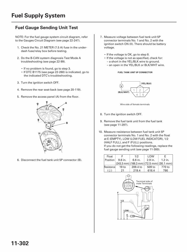
01
02
03
SJC8A00A20326427702FEAT00
11-302
Fuel Supply System
Fuel Gauge Sending Unit Test
A
B
FUEL TANK UNIT 5P CONNECTOR
(YEL/BLK)
(BLK/WHT)
F
E
LOW
1/2
NOTE: For the fuel gauge system circuit diagram, referto the Gauges Circuit Diagram (see page 22-247).
1. Check the No. 21 METER (7.5 A) fuse in the under-dash fuse/relay box before testing.
2. Do the B-CAN system diagnosis Test Mode Atroubleshooting (see page 22-99).
• If no problem is found, go to step 3.• If DTC B1175 (see page 22-260) is indicated, go to
the indicated DTC’s troubleshooting.
3. Turn the ignition switch OFF.
4. Remove the rear seat-back (see page 20-119).
5. Remove the access panel (A) from the floor.
6. Disconnect the fuel tank unit 5P connector (B).
7. Measure voltage between fuel tank unit 5Pconnector terminals No. 1 and No. 2 with theignition switch ON (II). There should be batteryvoltage.
• If the voltage is OK, go to step 8.• If the voltage is not as specified, check for:
– a short in the YEL/BLK wire to ground.– an open in the YEL/BLK or BLK/WHT wire.
8. Turn the ignition switch OFF.
9. Remove the fuel tank unit from the fuel tank(see page 11-297).
10. Measure resistance between fuel tank unit 5Pconnector terminals No. 1 and No. 2 with the floatat E (EMPTY), LOW (LOW FUEL INDICATOR), 1/2(HALF FULL), and F (FULL) positions.If you do not get the following readings, replace thefuel gauge sending unit (see page 11-300).
F9.6 in.
1/26.6 in.
LOW2.9 in.
(72.5 mm)
E1.2 in.
(30.1 mm)
( )19 to
21209.4 to
219.4509 to618.4
770 to790
FloatPosition
(243.3 mm) (166.3 mm)Resistance
Wire side of female terminals
Terminal side ofmale Terminals
07/05/09 16:58:16 61SJC020_110_0302

SJC8A00A20326437601FEAT00
11-30311-303
Low Fuel Indicator Test
11. Reconnect the fuel tank unit 5P connector.
12. Remove the No. 15 BACK UP (40 A) fuse from theunder-hood fuse/relay box for at least 10 seconds,then reinstall it.
13. Turn the ignition switch ON (II).
14. Check that the pointer of the fuel gauge indicates‘‘F’’ with the float at F.
• If the pointer of the fuel gauge does not indicate‘‘F’’ replace the gauge control module.
• If the gauge is OK, the test is complete.
NOTE:• The pointer of the fuel gauge returns to the
bottom of the gauge dial when the ignition switchis OFF, regardless of the fuel level.
• Remove the No. 15 BACK UP (40 A) fuse from theunder-hood fuse/relay box for at least 10 secondsafter completing troubleshooting, otherwise itmay take up to 20 minutes for the fuel gauge toindicate the correct fuel level.
1. Do the gauge control module self-diagnosticfunction procedure (see page 22-244).
• If the low fuel indicator flashes, go to step 2.• If the low fuel indicator does not flash, replace
the gauge control module (see page 22-263).
2. Do the B-CAN system diagnosis Test Mode Atroubleshooting (see page 22-99).
• If any DTCs are indicated, do the indicated DTC’stroubleshooting.
• If no DTCs are indicated, go to step 3.
3. Do the fuel gauge sending unit test (see page11-302).
07/05/09 16:58:16 61SJC020_110_0303
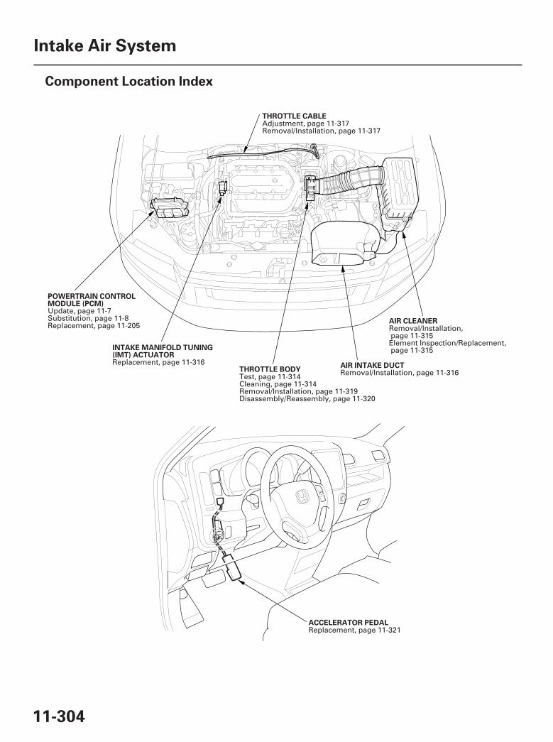
*01
*02
SJC8A00A20336300000DAAT00
11-304
Intake Air System
Component Location Index
POWERTRAIN CONTROLMODULE (PCM)
THROTTLE BODYAIR INTAKE DUCT
AIR CLEANER
THROTTLE CABLE
INTAKE MANIFOLD TUNING(IMT) ACTUATOR
ACCELERATOR PEDAL
Update, page 11-7Substitution, page 11-8Replacement, page 11-205
Test, page 11-314Cleaning, page 11-314Removal/Installation, page 11-319Disassembly/Reassembly, page 11-320
Removal/Installation, page 11-316
Removal/Installation,page 11-315Element Inspection/Replacement,page 11-315
Adjustment, page 11-317Removal/Installation, page 11-317
Replacement, page 11-316
Replacement, page 11-321
07/05/09 16:58:20 61SJC020_110_0304
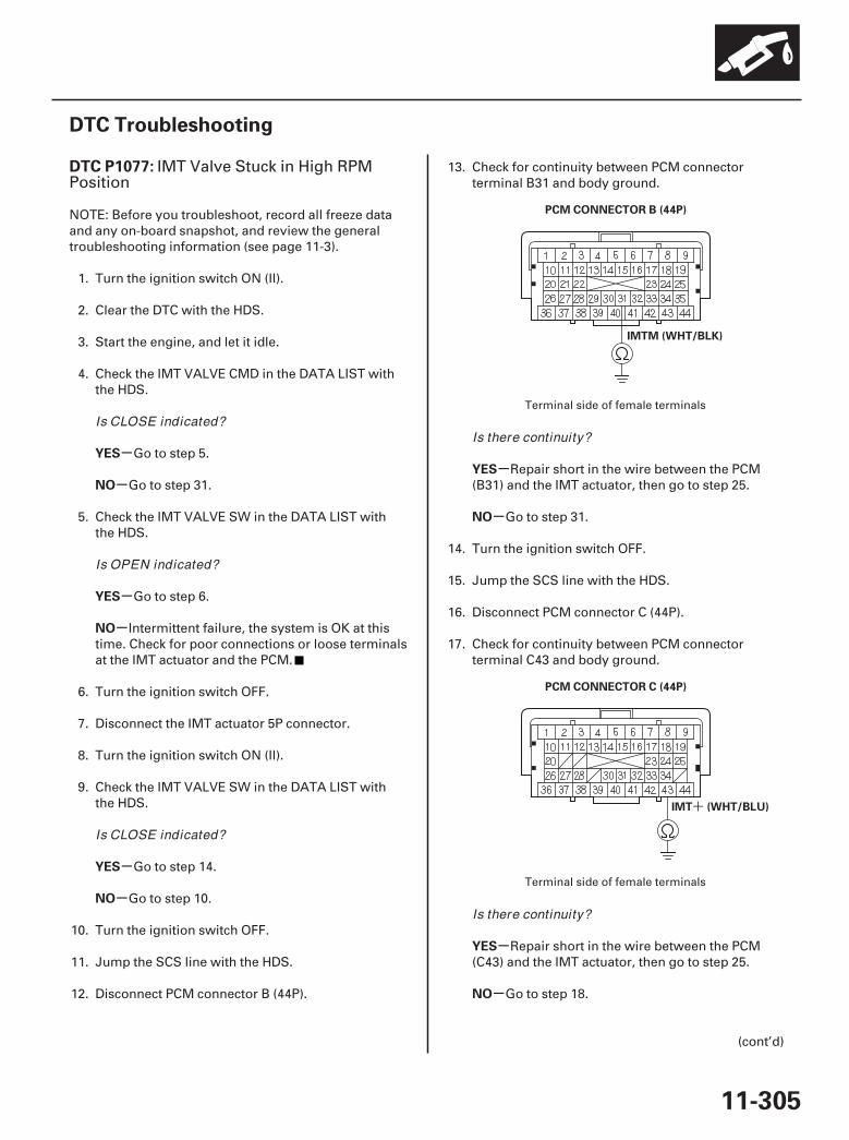
01
02
SJC8A00K77100091077FAAT30
+
-
-
-
-
-
-
-
-
-
-
DTC P1077:
YES
NO
YES
NO
YES
NO
YES
NO
YES
NO
11-305
DTC Troubleshooting
PCM CONNECTOR B (44P)
IMTM (WHT/BLK)
PCM CONNECTOR C (44P)
IMT (WHT/BLU)
IMT Valve Stuck in High RPMPosition
NOTE: Before you troubleshoot, record all freeze dataand any on-board snapshot, and review the generaltroubleshooting information (see page 11-3).
1. Turn the ignition switch ON (II).
2. Clear the DTC with the HDS.
3. Start the engine, and let it idle.
4. Check the IMT VALVE CMD in the DATA LIST withthe HDS.
Go to step 5.
Go to step 31.
5. Check the IMT VALVE SW in the DATA LIST withthe HDS.
Go to step 6.
Intermittent failure, the system is OK at thistime. Check for poor connections or loose terminalsat the IMT actuator and the PCM.
6. Turn the ignition switch OFF.
7. Disconnect the IMT actuator 5P connector.
8. Turn the ignition switch ON (II).
9. Check the IMT VALVE SW in the DATA LIST withthe HDS.
Go to step 14.
Go to step 10.
10. Turn the ignition switch OFF.
11. Jump the SCS line with the HDS.
12. Disconnect PCM connector B (44P).
13. Check for continuity between PCM connectorterminal B31 and body ground.
Repair short in the wire between the PCM(B31) and the IMT actuator, then go to step 25.
Go to step 31.
14. Turn the ignition switch OFF.
15. Jump the SCS line with the HDS.
16. Disconnect PCM connector C (44P).
17. Check for continuity between PCM connectorterminal C43 and body ground.
Repair short in the wire between the PCM(C43) and the IMT actuator, then go to step 25.
Go to step 18.
(cont’d)
Terminal side of female terminals
Terminal side of female terminals
Is CLOSE indicated?
Is OPEN indicated?
Is CLOSE indicated?
Is there continuity?
Is there continuity?
07/05/09 16:58:20 61SJC020_110_0305
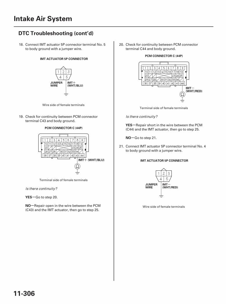
03
04
05
06
+
-
+
-
-
-
-
-
YES
NO
YES
NO
11-306
Intake Air System
DTC Troubleshooting (cont’d)
IMT ACTUATOR 5P CONNECTOR
PCM CONNECTOR C (44P)
IMT (WHT/BLU)
PCM CONNECTOR C (44P)
IMT(WHT/RED)
IMT ACTUATOR 5P CONNECTOR
JUMPERWIRE
IMT(WHT/BLU)
JUMPERWIRE
IMT(WHT/RED)
18. Connect IMT actuator 5P connector terminal No. 5to body ground with a jumper wire.
19. Check for continuity between PCM connectorterminal C43 and body ground.
Go to step 20.
Repair open in the wire between the PCM(C43) and the IMT actuator, then go to step 25.
20. Check for continuity between PCM connectorterminal C44 and body ground.
Repair short in the wire between the PCM(C44) and the IMT actuator, then go to step 25.
Go to step 21.
21. Connect IMT actuator 5P connector terminal No. 4to body ground with a jumper wire.
Wire side of female terminals
Terminal side of female terminals
Terminal side of female terminals
Wire side of female terminals
Is there continuity?
Is there continuity?
07/05/09 16:58:21 61SJC020_110_0306
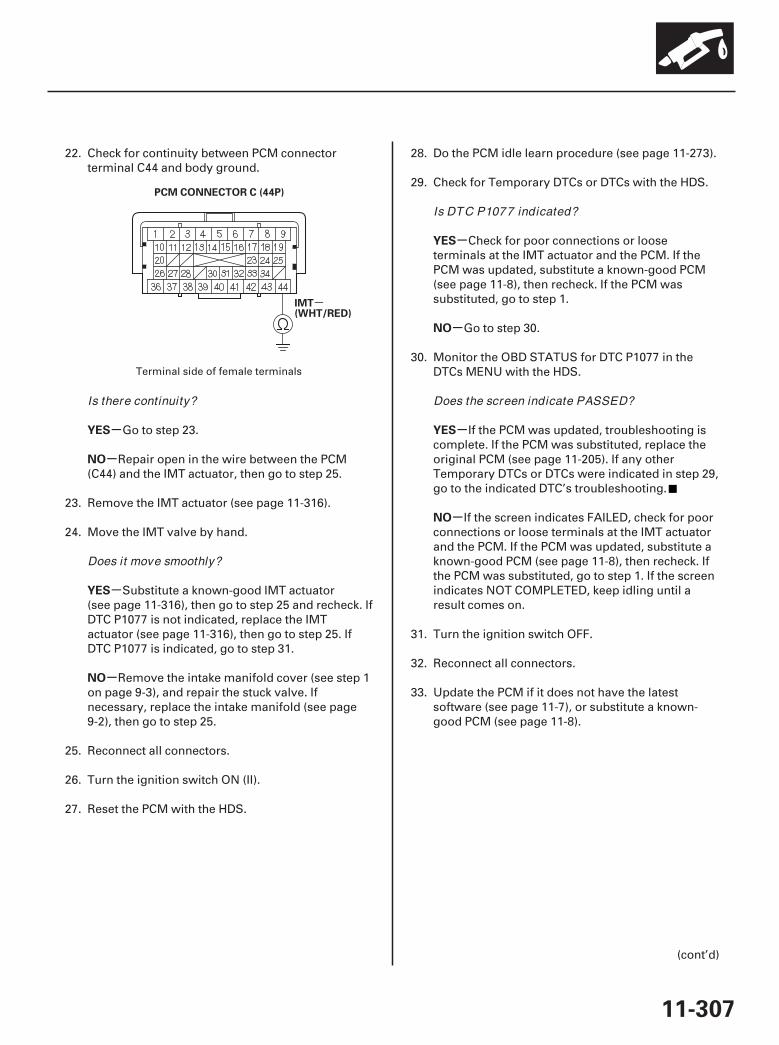
07
-
-
-
-
-
-
-
-
-
YES
NO
YES
NO
YES
NO
YES
NO
11-307
PCM CONNECTOR C (44P)
IMT(WHT/RED)
22. Check for continuity between PCM connectorterminal C44 and body ground.
Go to step 23.
Repair open in the wire between the PCM(C44) and the IMT actuator, then go to step 25.
23. Remove the IMT actuator (see page 11-316).
24. Move the IMT valve by hand.
Substitute a known-good IMT actuator(see page 11-316), then go to step 25 and recheck. IfDTC P1077 is not indicated, replace the IMTactuator (see page 11-316), then go to step 25. IfDTC P1077 is indicated, go to step 31.
Remove the intake manifold cover (see step 1on page 9-3), and repair the stuck valve. Ifnecessary, replace the intake manifold (see page9-2), then go to step 25.
25. Reconnect all connectors.
26. Turn the ignition switch ON (II).
27. Reset the PCM with the HDS.
28. Do the PCM idle learn procedure (see page 11-273).
29. Check for Temporary DTCs or DTCs with the HDS.
Check for poor connections or looseterminals at the IMT actuator and the PCM. If thePCM was updated, substitute a known-good PCM(see page 11-8), then recheck. If the PCM wassubstituted, go to step 1.
Go to step 30.
30. Monitor the OBD STATUS for DTC P1077 in theDTCs MENU with the HDS.
If the PCM was updated, troubleshooting iscomplete. If the PCM was substituted, replace theoriginal PCM (see page 11-205). If any otherTemporary DTCs or DTCs were indicated in step 29,go to the indicated DTC’s troubleshooting.
If the screen indicates FAILED, check for poorconnections or loose terminals at the IMT actuatorand the PCM. If the PCM was updated, substitute aknown-good PCM (see page 11-8), then recheck. Ifthe PCM was substituted, go to step 1. If the screenindicates NOT COMPLETED, keep idling until aresult comes on.
31. Turn the ignition switch OFF.
32. Reconnect all connectors.
33. Update the PCM if it does not have the latestsoftware (see page 11-7), or substitute a known-good PCM (see page 11-8).
(cont’d)
Terminal side of female terminals
Is there continuity?
Does it move smoothly?
Is DTC P1077 indicated?
Does the screen indicate PASSED?
07/05/09 16:58:21 61SJC020_110_0307
-
-
-
-
YES
NO
YES
NO
11-308
Intake Air System
DTC Troubleshooting (cont’d)
34. Check for Temporary DTCs or DTCs with the HDS.
Check for poor connections or looseterminals at the IMT actuator and the PCM. If thePCM was updated, substitute a known-good PCM(see page 11-8), then recheck. If the PCM wassubstituted, go to step 1.
Go to step 35.
35. Monitor the OBD STATUS for DTC P1077 in theDTCs MENU with the HDS.
If the PCM was updated, troubleshooting iscomplete. If the PCM was substituted, replace theoriginal PCM (see page 11-205). If any otherTemporary DTCs or DTCs were indicated in step 34,go to the indicated DTC’s troubleshooting.
If the screen indicates FAILED, check for poorconnections or loose terminals at the IMT actuatorand the PCM. If the PCM was updated, substitute aknown-good PCM (see page 11-8), then recheck. Ifthe PCM was substituted, go to step 1. If the screenindicates NOT COMPLETED, keep idling until aresult comes on.
Is DTC P1077 indicated?
Does the screen indicate PASSED?
07/05/09 16:58:21 61SJC020_110_0308
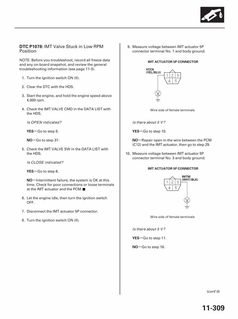
01
02
SJC8A00K77100091078FAAT30
-
-
-
-
-
-
-
-
DTC P1078:
YES
NO
YES
NO
YES
NO
YES
NO
11-309
IMT ACTUATOR 5P CONNECTOR
IMT ACTUATOR 5P CONNECTOR
VCC6(YEL/BLU)
IMTM(WHT/BLK)
IMT Valve Stuck in Low RPMPosition
NOTE: Before you troubleshoot, record all freeze dataand any on-board snapshot, and review the generaltroubleshooting information (see page 11-3).
1. Turn the ignition switch ON (II).
2. Clear the DTC with the HDS.
3. Start the engine, and hold the engine speed above4,000 rpm.
4. Check the IMT VALVE CMD in the DATA LIST withthe HDS.
Go to step 5.
Go to step 37.
5. Check the IMT VALVE SW in the DATA LIST withthe HDS.
Go to step 6.
Intermittent failure, the system is OK at thistime. Check for poor connections or loose terminalsat the IMT actuator and the PCM.
6. Let the engine idle, then turn the ignition switchOFF.
7. Disconnect the IMT actuator 5P connector.
8. Turn the ignition switch ON (II).
9. Measure voltage between IMT actuator 5Pconnector terminal No. 1 and body ground.
Go to step 10.
Repair open in the wire between the PCM(C12) and the IMT actuator, then go to step 29.
10. Measure voltage between IMT actuator 5Pconnector terminal No. 3 and body ground.
Go to step 11.
Go to step 16.
(cont’d)
Wire side of female terminals
Wire side of female terminals
Is OPEN indicated?
Is CLOSE indicated?
Is there about 5 V?
Is there about 5 V?
07/05/09 16:58:22 61SJC020_110_0309
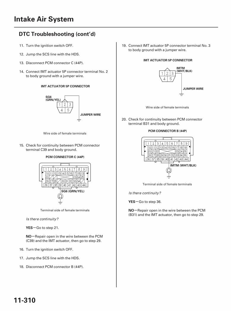
03
04
05
06
-
-
-
-
YES
NO
YES
NO
11-310
Intake Air System
DTC Troubleshooting (cont’d)
IMT ACTUATOR 5P CONNECTOR
PCM CONNECTOR C (44P)
SG6 (GRN/YEL)
IMT ACTUATOR 5P CONNECTOR
PCM CONNECTOR B (44P)
IMTM (WHT/BLK)
SG6(GRN/YEL)
JUMPER WIRE
IMTM(WHT/BLK)
JUMPER WIRE
11. Turn the ignition switch OFF.
12. Jump the SCS line with the HDS.
13. Disconnect PCM connector C (44P).
14. Connect IMT actuator 5P connector terminal No. 2to body ground with a jumper wire.
15. Check for continuity between PCM connectorterminal C39 and body ground.
Go to step 21.
Repair open in the wire between the PCM(C39) and the IMT actuator, then go to step 29.
16. Turn the ignition switch OFF.
17. Jump the SCS line with the HDS.
18. Disconnect PCM connector B (44P).
19. Connect IMT actuator 5P connector terminal No. 3to body ground with a jumper wire.
20. Check for continuity between PCM connectorterminal B31 and body ground.
Go to step 36.
Repair open in the wire between the PCM(B31) and the IMT actuator, then go to step 29.
Wire side of female terminals
Terminal side of female terminals
Wire side of female terminals
Terminal side of female terminals
Is there continuity?
Is there continuity?
07/05/09 16:58:22 61SJC020_110_0310
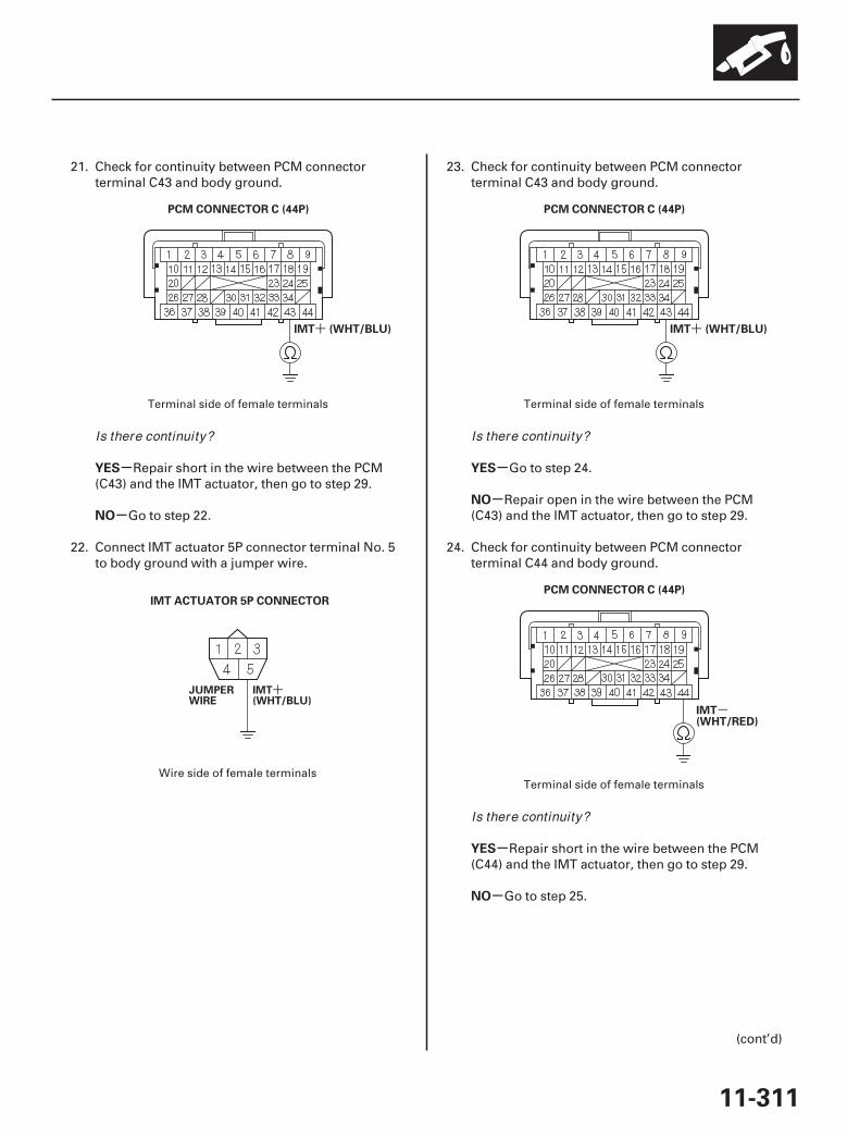
07
08
09
10
+ +
-
+
-
-
-
-
-
-
YES
NO
YES
NO
YES
NO
11-311
PCM CONNECTOR C (44P)
IMT (WHT/BLU)
IMT ACTUATOR 5P CONNECTOR
PCM CONNECTOR C (44P)
IMT (WHT/BLU)
PCM CONNECTOR C (44P)
IMT(WHT/RED)
JUMPERWIRE
IMT(WHT/BLU)
21. Check for continuity between PCM connectorterminal C43 and body ground.
Repair short in the wire between the PCM(C43) and the IMT actuator, then go to step 29.
Go to step 22.
22. Connect IMT actuator 5P connector terminal No. 5to body ground with a jumper wire.
23. Check for continuity between PCM connectorterminal C43 and body ground.
Go to step 24.
Repair open in the wire between the PCM(C43) and the IMT actuator, then go to step 29.
24. Check for continuity between PCM connectorterminal C44 and body ground.
Repair short in the wire between the PCM(C44) and the IMT actuator, then go to step 29.
Go to step 25.
(cont’d)
Terminal side of female terminals
Wire side of female terminals
Terminal side of female terminals
Terminal side of female terminals
Is there continuity? Is there continuity?
Is there continuity?
07/05/09 16:58:23 61SJC020_110_0311
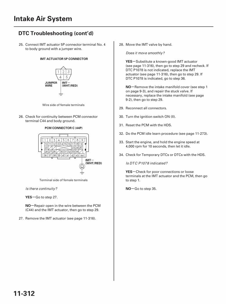
11
12
-
-
-
-
-
-
-
-
YES
NO
YES
NO
YES
NO
11-312
Intake Air System
DTC Troubleshooting (cont’d)
IMT ACTUATOR 5P CONNECTOR
PCM CONNECTOR C (44P)
IMT(WHT/RED)
JUMPERWIRE
IMT(WHT/RED)
25. Connect IMT actuator 5P connector terminal No. 4to body ground with a jumper wire.
26. Check for continuity between PCM connectorterminal C44 and body ground.
Go to step 27.
Repair open in the wire between the PCM(C44) and the IMT actuator, then go to step 29.
27. Remove the IMT actuator (see page 11-316).
28. Move the IMT valve by hand.
Substitute a known-good IMT actuator(see page 11-316), then go to step 29 and recheck. IfDTC P1078 is not indicated, replace the IMTactuator (see page 11-316), then go to step 29. IfDTC P1078 is indicated, go to step 36.
Remove the intake manifold cover (see step 1on page 9-3), and repair the stuck valve. Ifnecessary, replace the intake manifold (see page9-2), then go to step 29.
29. Reconnect all connectors.
30. Turn the ignition switch ON (II).
31. Reset the PCM with the HDS.
32. Do the PCM idle learn procedure (see page 11-273).
33. Start the engine, and hold the engine speed at4,000 rpm for 10 seconds, then let it idle.
34. Check for Temporary DTCs or DTCs with the HDS.
Check for poor connections or looseterminals at the IMT actuator and the PCM, then goto step 1.
Go to step 35.
Wire side of female terminals
Terminal side of female terminals
Is there continuity?
Does it move smoothly?
Is DTC P1078 indicated?
07/05/09 16:58:23 61SJC020_110_0312

-
-
-
-
-
-
YES
NO
YES
NO
YES
NO
11-313
35. Monitor the OBD STATUS for DTC P1078 in theDTCs MENU with the HDS.
Troubleshooting is complete. If any otherTemporary DTCs or DTCs were indicated in step 34,go to the indicated DTC’s troubleshooting.
If the screen indicates FAILED, check for poorconnections or loose terminals at the IMT actuatorand the PCM, then go to step 1. If the screenindicates NOT COMPLETED, keep idling until aresult comes on.
36. Reconnect all connectors.
37. Update the PCM if it does not have the latestsoftware (see page 11-7), or substitute a known-good PCM (see page 11-8).
38. Start the engine, and hold the engine speed at4,000 rpm for 10 seconds, then let it idle.
39. Check for Temporary DTCs or DTCs with the HDS.
Check for poor connections or looseterminals at the IMT actuator and the PCM. If thePCM was updated, substitute a known-good PCM(see page 11-8), then go to step 38. If the PCM wassubstituted, go to step 1.
Go to step 40.
40. Monitor the OBD STATUS for DTC P1078 in theDTCs MENU with the HDS.
If the PCM was updated, troubleshooting iscomplete. If the PCM was substituted, replace theoriginal PCM (see page 11-205). If any otherTemporary DTCs or DTCs were indicated in step 39,go to the indicated DTC’s troubleshooting.
If the screen indicates FAILED, check for poorconnections or loose terminals at the IMT actuatorand the PCM. If the PCM was updated, substitute aknown-good PCM (see page 11-8), then go to step38. If the PCM was substituted, go to step 1. If thescreen indicates NOT COMPLETED, go to step 38.
Does the screen indicate PASSED?
Is DTC P1078 indicated?
Does the screen indicate PASSED?
07/05/09 16:58:23 61SJC020_110_0313
01
02
SJC8A00A20336359401FEAT00
01
SJC8A00A20336359401LBAT00
Carbon Accumulation Check
Throttle Position Learning Check
11-31411-314
Intake Air System
Throttle Body Test Throttle Body Cleaning
A
A
A
A
NOTE: If the malfunction indicator lamp (MIL) has beenreported on, check for diagnostic trouble codes (DTCs).
1. Connect the HDS to the data link connector (DLC)(A) located under the driver’s side of the dashboard.
2. Start the engine. Hold the engine speed at3,000 rpm without load (in Park or neutral) until theradiator fan comes on, then let it idle.
3. Check the REL TP SENSOR in the DATA LIST withthe HDS. The reading should be below 2.54 deg. If itis not, clean the throttle body (see page 11-314).
NOTE: If the malfunction indicator lamp (MIL) has beenreported on, check for diagnostic trouble codes (DTCs).
1. Connect the HDS to the data link connector (DLC)(A) located under the driver’s side of the dashboard.
2. Select the INSPECTION MENU with the HDS.
3. Do the TP POSITION CHECK in the ETCS TEST. Ifneeded, clean the throttle body (see page 11-314).
Do not insert your fingers into the installed throttlebody when you turn the ignition switch ON (II) orwhile the ignition switch is ON (II). If you do, youwill seriously injure your fingers if the throttle valveis activated.
1. Check for damage to the air cleaner. If the aircleaner is damaged, replace it (see page 11-315).
2. Remove the throttle body (see page 11-319).
3. Clean off the carbon from the throttle valve andinside the throttle body with a paper towel soakedin throttle plate and induction cleaner.
NOTE:• Remove the throttle body to clean it.• Be careful not to pinch your fingers.• To avoid removing the molybdenum coating, do
not clean the bearing area of the throttle shaft (A).• Do not spray throttle plate and induction cleaner
directly on the throttle body.• Use Honda genuine throttle plate and induction
cleaner.
4. Install the throttle body (see page 11-319).
5. Reset the PCM with the HDS.
6. Turn the ignition switch ON (II), and wait 2 seconds.
7. Do the PCM idle learn procedure (see page 11-273).
07/05/09 16:58:24 61SJC020_110_0314
01
SJC8A00A20336312601KDAT00
01
SJC8A00A20336312602MDAT00
11-31511-315
Air Cleaner Removal/Installation Air Cleaner Element Inspection/Replacement
B
A12 N·m(1.2 kgf·m,8.7 lbf·ft)
A
B
C3 N·m(0.3 kgf·m, 2 lbf·ft)
1. Remove the bolts (A).
2. Remove the air cleaner (B).
3. Install the parts in the reverse order of removal.
1. Open the air cleaner housing cover (A).
2. Remove the air cleaner element (B) from the aircleaner housing (C).
3. Check the air cleaner element for damage orclogging. If there is damage or clogging, replacethe air cleaner element.
NOTE: Do not use compressed air to clean the aircleaner element.
4. Install the parts in the reverse order of removal.
07/05/09 16:58:24 61SJC020_110_0315
NOTE: If the maintenance minder indicated the air cleaner element required replacement, check for otheritems that may also be displayed in the maintenanceminder main items (see page 3-7) and the sub items (see page 3-8) before resetting the maintenance minder.

01
02
SJC8A00A20336334910KDAT00
01
SJC8A00A20336334791KBAT00
11-31611-316
Intake Air System
Air Intake Duct Removal/Installation
IMT Actuator Replacement
A
A
A
C
D
B9.8 N·m(1.0 kgf·m, 7.2 lbf·ft)
1. Remove the air cleaner (see page 11-315).
2. Remove air intake duct B (A).
3. Remove air intake duct A (A).
4. Install the parts in the reverse order of removal.
1. Remove the intake manifold cover (see step 1 onpage 9-3).
2. Disconnect the IMT actuator 5P connector (A).
3. Remove the bolts (B) and the IMT actuator (C).
4. Install the parts in the reverse order of removalwith a new O-ring (D).
07/05/09 16:58:25 61SJC020_110_0316
- -
--
01
02
SJC8A00A20336359411MBAT02
01
02
SJC8A00A20336359411KDAT00
11-31711-317
Throttle Cable Adjustment Throttle Cable Removal/Installation
A
A BC
A
B
C
D
SILICONE GREASE(P/N 08798-9002)
SILICONE GREASE(P/N 08798-9002)
A
B
B
1. Remove the throttle cable cover (A).
2. Check cable free play at the throttle linkage. Cablefree play (A) should be 10 12 mm (3/8 1/2 in.).
3. If the free play is not within spec (10 12 mm,3/8 1/2 in.), loosen the locknut (B), turn theadjusting nut (C) until the free play is as specified,then retighten the locknut.
4. With the cable properly adjusted, check the throttlelink to be sure it opens fully when you push theaccelerator pedal to the floor. Also check thethrottle link to be sure it returns to the idle positionwhenever you release the accelerator pedal.
1. Remove the throttle cable cover (see page 11-317).
2. Fully open the throttle valve, then remove thethrottle cable (A) from the throttle link (B).
3. Remove the cable housing (C) from the cablebracket (D).
4. Remove the throttle cable (A) from the acceleratorpedal (B).
(cont’d)
07/05/09 16:58:26 61SJC020_110_0317
03
11-318
Intake Air System
Throttle Cable Removal/Installation (cont’d)
C9.8 N·m(1.0 kgf·m,7.2 lbf·ft)
C
B
A
5. Install the parts in the reverse order of removal.
6. Start the engine. Hold the engine speed at3,000 rpm without load (in Park or neutral) until theradiator fan comes on, then let it idle.
7. Hold the cable, removing all slack from it.
8. Set the cable on the bracket (A).Turn the adjusting nut (B) until its free play is 0 mm.
9. Position the adjusting nut on the other side of thebracket, then tighten the locknut (C).
10. Check the throttle cable free play (see step 2 onpage 11-317).
11. With the cable properly adjusted, check the throttlelink to be sure it opens fully when you push theaccelerator pedal to the floor. Also check thethrottle link to be sure it returns whenever yourelease the accelerator pedal.
There should beno clearance.
07/05/09 16:58:26 61SJC020_110_0318
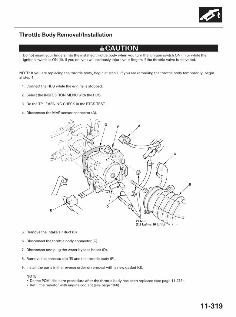
01
SJC8A00A20336359401KDAT00
11-319
Throttle Body Removal/Installation
22 N·m(2.2 kgf·m, 16 lbf·ft)
A
B
C
D
E
FG A
Do not insert your fingers into the installed throttle body when you turn the ignition switch ON (II) or while theignition switch is ON (II). If you do, you will seriously injure your fingers if the throttle valve is activated.
NOTE: If you are replacing the throttle body, begin at step 1. If you are removing the throttle body temporarily, beginat step 4.
1. Connect the HDS while the engine is stopped.
2. Select the INSPECTION MENU with the HDS.
3. Do the TP LEARNING CHECK in the ETCS TEST.
4. Disconnect the MAP sensor connector (A).
5. Remove the intake air duct (B).
6. Disconnect the throttle body connector (C).
7. Disconnect and plug the water bypass hoses (D).
8. Remove the harness clip (E) and the throttle body (F).
9. Install the parts in the reverse order of removal with a new gasket (G).
NOTE:• Do the PCM idle learn procedure after the throttle body has been replaced (see page 11-273).• Refill the radiator with engine coolant (see page 10-6).
07/05/09 16:58:27 61SJC020_110_0319
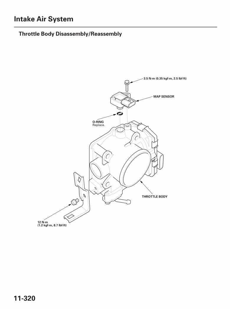
01
SJC8A00A20336359401MFAT00
11-320
Intake Air System
Throttle Body Disassembly/Reassembly
3.5 N·m (0.35 kgf·m, 2.5 lbf·ft)
MAP SENSOR
O-RING
THROTTLE BODY
12 N·m(1.2 kgf·m, 8.7 lbf·ft)
Replace.
07/05/09 16:58:27 61SJC020_110_0320
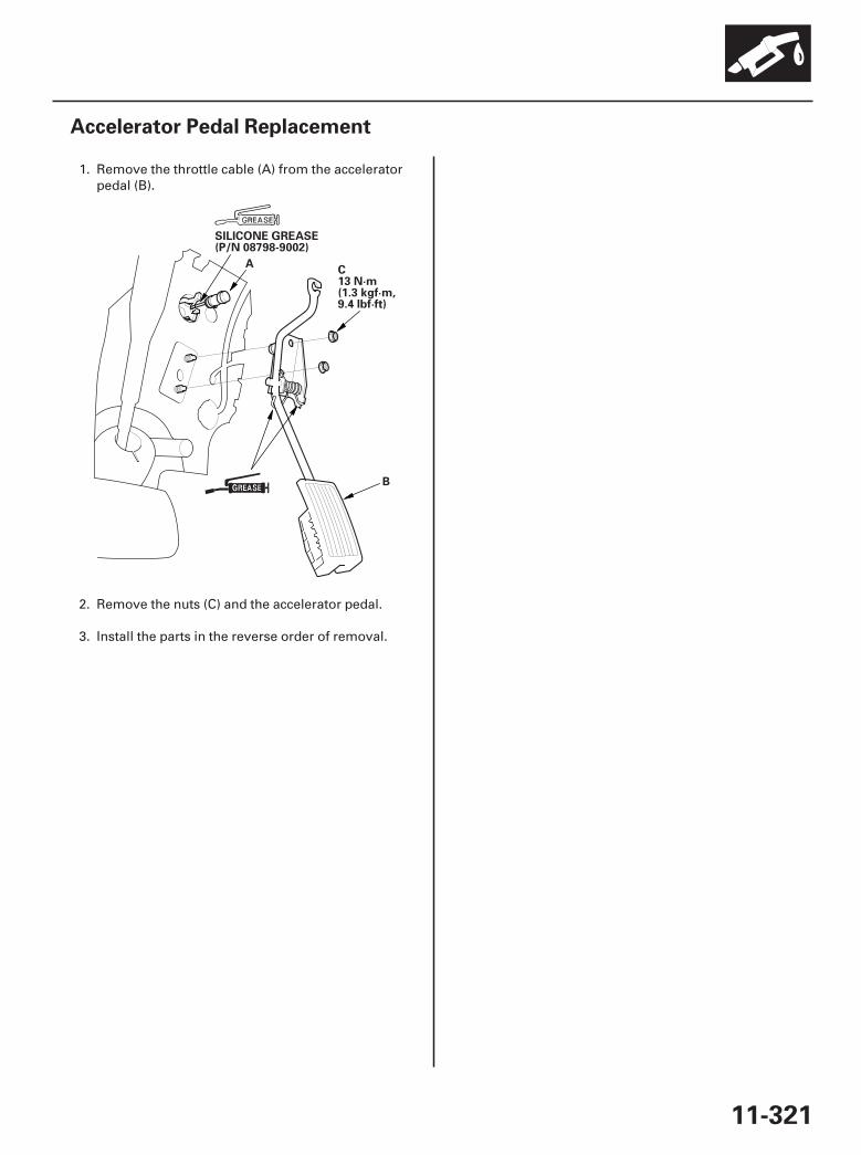
01
SJC8A00A20336312385KBAT00
11-321
Accelerator Pedal Replacement
A
B
SILICONE GREASE(P/N 08798-9002)
C13 N·m(1.3 kgf·m,9.4 lbf·ft)
1. Remove the throttle cable (A) from the acceleratorpedal (B).
2. Remove the nuts (C) and the accelerator pedal.
3. Install the parts in the reverse order of removal.
07/05/09 16:58:27 61SJC020_110_0321
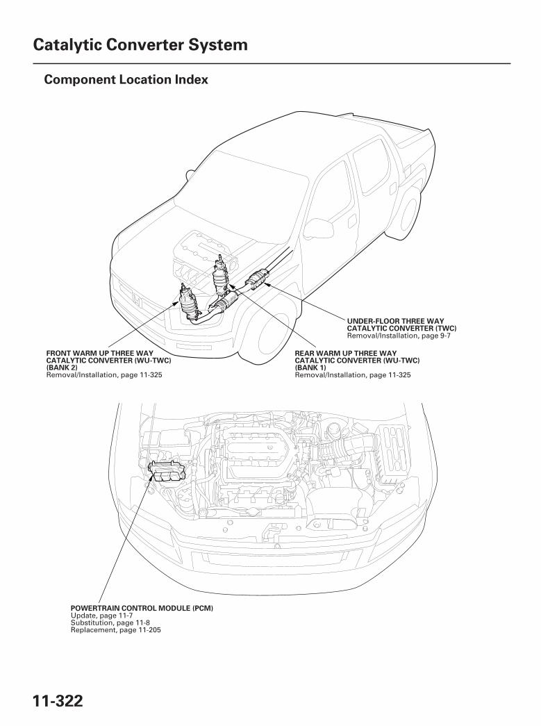
*01
*02
SJC8A00A20316100000DAAT00
11-322
Catalytic Converter System
Component Location Index
FRONT WARM UP THREE WAYCATALYTIC CONVERTER (WU-TWC)(BANK 2)
REAR WARM UP THREE WAYCATALYTIC CONVERTER (WU-TWC)(BANK 1)
UNDER-FLOOR THREE WAYCATALYTIC CONVERTER (TWC)
POWERTRAIN CONTROL MODULE (PCM)
Removal/Installation, page 11-325 Removal/Installation, page 11-325
Removal/Installation, page 9-7
Update, page 11-7Substitution, page 11-8Replacement, page 11-205
07/05/09 16:58:29 61SJC020_110_0322
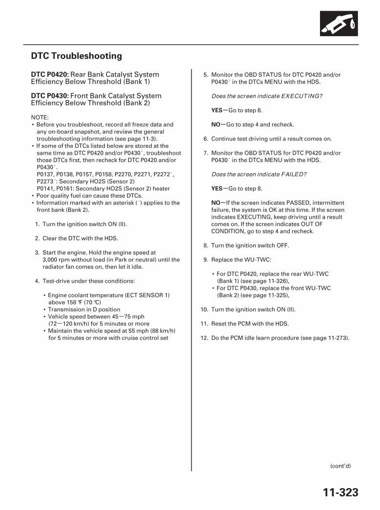
--
SJC8A00K77100090420FAAT30
-
-
-
-
DTC P0420:
DTC P0430:
YES
NO
YES
NO
11-323
DTC Troubleshooting
Rear Bank Catalyst SystemEfficiency Below Threshold (Bank 1)
Front Bank Catalyst SystemEfficiency Below Threshold (Bank 2)
NOTE:• Before you troubleshoot, record all freeze data and
any on-board snapshot, and review the generaltroubleshooting information (see page 11-3).
• If some of the DTCs listed below are stored at thesame time as DTC P0420 and/or P0430 , troubleshootthose DTCs first, then recheck for DTC P0420 and/orP0430 .P0137, P0138, P0157, P0158, P2270, P2271, P2272 ,P2273 : Secondary HO2S (Sensor 2)P0141, P0161: Secondary HO2S (Sensor 2) heater
• Poor quality fuel can cause these DTCs.• Information marked with an asterisk ( ) applies to the
front bank (Bank 2).
1. Turn the ignition switch ON (II).
2. Clear the DTC with the HDS.
3. Start the engine. Hold the engine speed at3,000 rpm without load (in Park or neutral) until theradiator fan comes on, then let it idle.
4. Test-drive under these conditions:
• Engine coolant temperature (ECT SENSOR 1)above 158 °F (70 °C)
• Transmission in D position• Vehicle speed between 45 75 mph
(72 120 km/h) for 5 minutes or more• Maintain the vehicle speed at 55 mph (88 km/h)
for 5 minutes or more with cruise control set
5. Monitor the OBD STATUS for DTC P0420 and/orP0430 in the DTCs MENU with the HDS.
Go to step 6.
Go to step 4 and recheck.
6. Continue test driving until a result comes on.
7. Monitor the OBD STATUS for DTC P0420 and/orP0430 in the DTCs MENU with the HDS.
Go to step 8.
If the screen indicates PASSED, intermittentfailure, the system is OK at this time. If the screenindicates EXECUTING, keep driving until a resultcomes on. If the screen indicates OUT OFCONDITION, go to step 4 and recheck.
8. Turn the ignition switch OFF.
9. Replace the WU-TWC:
• For DTC P0420, replace the rear WU-TWC(Bank 1) (see page 11-326),
• For DTC P0430, replace the front WU-TWC(Bank 2) (see page 11-325),
10. Turn the ignition switch ON (II).
11. Reset the PCM with the HDS.
12. Do the PCM idle learn procedure (see page 11-273).
(cont’d)
Does the screen indicate EXECUTING?
Does the screen indicate FAILED?
07/05/09 16:58:29 61SJC020_110_0323
-
-
-
-
-
-
-
-
YES
NO
YES
NO
YES
NO
YES
NO
11-324
Catalytic Converter System
DTC Troubleshooting (cont’d)
13. Start the engine. Hold the engine speed at3,000 rpm without load (in Park or neutral) until theradiator fan comes on, then let it idle.
14. Test-drive for about 10 minutes, continuallychanging the vehicle speed.
15. Check the CATA MONITOR CONDITION B1 (B2) inthe DATA LIST with the HDS.
Go to step 16.
Go to step 13 and recheck.
16. Test-drive under these conditions:
• Engine coolant temperature (ECT SENSOR 1)above 158 °F (70 °C)
• Transmission in D position• Vehicle speed at 55 mph (88 km/h) for 5 minutes
or more with cruise control set
17. Monitor the OBD STATUS for DTC P0420 and/orP0430 in the DTCs MENU with the HDS.
Go to step 18.
Go to step 16 and recheck.
18. Continue test driving until a result comes on.
19. Check for Temporary DTCs or DTCs with the HDS.
Check for poor connections or looseterminals at the secondary HO2S (sensor 2) and thePCM, then go to step 1.
Go to step 20.
20. Monitor the OBD STATUS for DTC P0420 and/orP0430 in the DTCs MENU with the HDS.
Troubleshooting is complete. If any otherTemporary DTCs or DTCs were indicated in step 19,go to the indicated DTC’s troubleshooting.
If the screen indicates FAILED, check for poorconnections or loose terminals at the secondaryHO2S (Sensor 2) and the PCM, then go to step 1. Ifthe screen indicates EXECUTING, keep driving untila result comes on. If the screen indicates OUT OFCONDITION, go to step 16.
Is the condition OK ?
Does the screen indicate EXECUTING?
Is DTC P0420 and/ or P0430 indicated?
Does the screen indicate PASSED?
07/05/09 16:58:30 61SJC020_110_0324
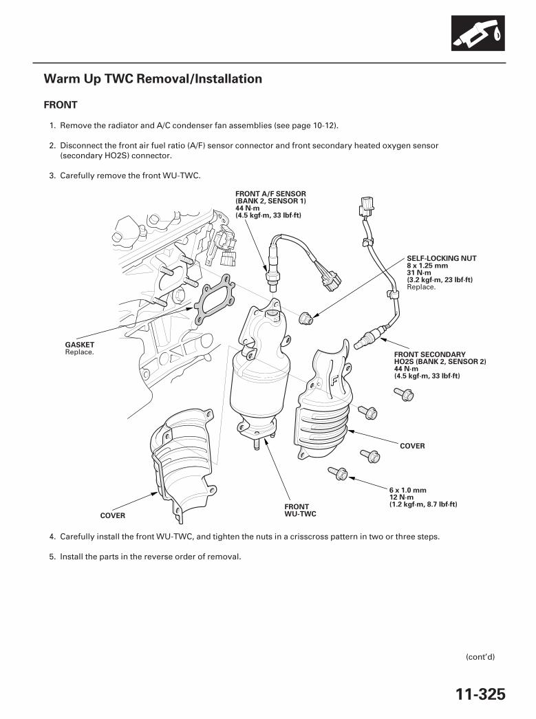
01
SJC8A00A20316116201KDAT10
FRONT
11-325
Warm Up TWC Removal/Installation
GASKET
FRONT A/F SENSOR(BANK 2, SENSOR 1)44 N·m(4.5 kgf·m, 33 lbf·ft)
COVER
FRONT SECONDARYHO2S (BANK 2, SENSOR 2)44 N·m(4.5 kgf·m, 33 lbf·ft)
6 x 1.0 mm12 N·m(1.2 kgf·m, 8.7 lbf·ft)
COVER
FRONTWU-TWC
SELF-LOCKING NUT8 x 1.25 mm31 N·m(3.2 kgf·m, 23 lbf·ft)
1. Remove the radiator and A/C condenser fan assemblies (see page 10-12).
2. Disconnect the front air fuel ratio (A/F) sensor connector and front secondary heated oxygen sensor(secondary HO2S) connector.
3. Carefully remove the front WU-TWC.
4. Carefully install the front WU-TWC, and tighten the nuts in a crisscross pattern in two or three steps.
5. Install the parts in the reverse order of removal.
(cont’d)
Replace.
Replace.
07/05/09 16:58:30 61SJC020_110_0325
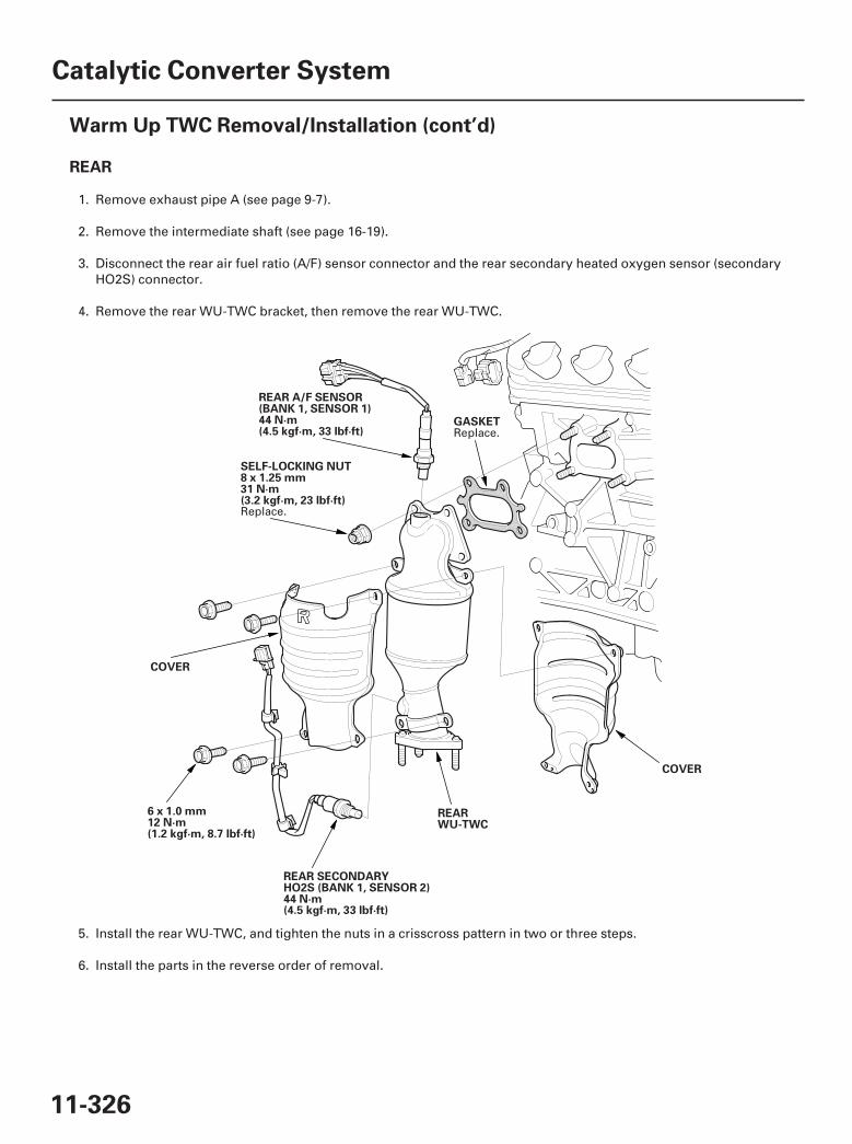
02
REAR
11-326
Catalytic Converter System
Warm Up TWC Removal/Installation (cont’d)
GASKET
REAR A/F SENSOR(BANK 1, SENSOR 1)44 N·m(4.5 kgf·m, 33 lbf·ft)
COVER
REAR SECONDARYHO2S (BANK 1, SENSOR 2)44 N·m(4.5 kgf·m, 33 lbf·ft)
6 x 1.0 mm12 N·m(1.2 kgf·m, 8.7 lbf·ft)
COVER
REARWU-TWC
SELF-LOCKING NUT8 x 1.25 mm31 N·m(3.2 kgf·m, 23 lbf·ft)
1. Remove exhaust pipe A (see page 9-7).
2. Remove the intermediate shaft (see page 16-19).
3. Disconnect the rear air fuel ratio (A/F) sensor connector and the rear secondary heated oxygen sensor (secondaryHO2S) connector.
4. Remove the rear WU-TWC bracket, then remove the rear WU-TWC.
5. Install the rear WU-TWC, and tighten the nuts in a crisscross pattern in two or three steps.
6. Install the parts in the reverse order of removal.
Replace.
Replace.
07/05/09 16:58:30 61SJC020_110_0326
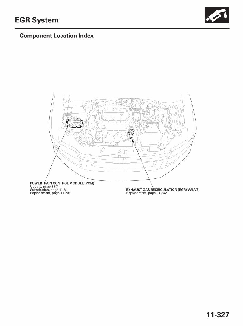
*01
SJC8A00A20323500000DAAT00
11-327
EGR System
Component Location Index
EXHAUST GAS RECIRCULATION (EGR) VALVE
POWERTRAIN CONTROL MODULE (PCM)
Replacement, page 11-342
Update, page 11-7Substitution, page 11-8Replacement, page 11-205
07/05/09 16:58:32 61SJC020_110_0327
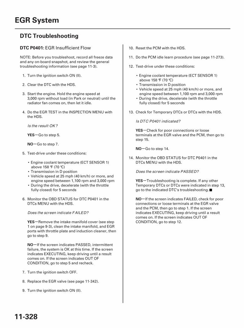
SJC8A00K77100090401FAAT30
-
-
-
-
-
-
-
-
DTC P0401:
YES
NO
YES
NO
YES
NO
YES
NO
11-328
EGR System
DTC Troubleshooting
EGR Insufficient Flow
NOTE: Before you troubleshoot, record all freeze dataand any on-board snapshot, and review the generaltroubleshooting information (see page 11-3).
1. Turn the ignition switch ON (II).
2. Clear the DTC with the HDS.
3. Start the engine. Hold the engine speed at3,000 rpm without load (in Park or neutral) until theradiator fan comes on, then let it idle.
4. Do the EGR TEST in the INSPECTION MENU withthe HDS.
Go to step 5.
Go to step 7.
5. Test-drive under these conditions:
• Engine coolant temperature (ECT SENSOR 1)above 158 °F (70 °C)
• Transmission in D position• Vehicle speed at 25 mph (40 km/h) or more, and
engine speed between 1,100 rpm and 3,000 rpm• During the drive, decelerate (with the throttle
fully closed) for 5 seconds
6. Monitor the OBD STATUS for DTC P0401 in theDTCs MENU with the HDS.
Remove the intake manifold cover (see step1 on page 9-3), clean the intake manifold, and EGRports with throttle plate and induction cleaner, thengo to step 9.
If the screen indicates PASSED, intermittentfailure, the system is OK at this time. If the screenindicates EXECUTING, keep driving until a resultcomes on. If the screen indicates OUT OFCONDITION, go to step 5 and recheck.
7. Turn the ignition switch OFF.
8. Replace the EGR valve (see page 11-342).
9. Turn the ignition switch ON (II).
10. Reset the PCM with the HDS.
11. Do the PCM idle learn procedure (see page 11-273).
12. Test-drive under these conditions:
• Engine coolant temperature (ECT SENSOR 1)above 158 °F (70 °C)
• Transmission in D position• Vehicle speed at 25 mph (40 km/h) or more, and
engine speed between 1,100 rpm and 3,000 rpm• During the drive, decelerate (with the throttle
fully closed) for 5 seconds
13. Check for Temporary DTCs or DTCs with the HDS.
Check for poor connections or looseterminals at the EGR valve and the PCM, then go tostep 15.
Go to step 14.
14. Monitor the OBD STATUS for DTC P0401 in theDTCs MENU with the HDS.
Troubleshooting is complete. If any otherTemporary DTCs or DTCs were indicated in step 13,go to the indicated DTC’s troubleshooting.
If the screen indicates FAILED, check for poorconnections or loose terminals at the EGR valveand the PCM, then go to step 1. If the screenindicates EXECUTING, keep driving until a resultcomes on. If the screen indicates OUT OFCONDITION, go to step 12.
Is the result OK ?
Does the screen indicate FAILED?
Is DTC P0401 indicated?
Does the screen indicate PASSED?
07/05/09 16:58:32 61SJC020_110_0328

-
-
-
-
YES
NO
YES
NO
11-329
15. Update the PCM if it does not have the latestsoftware (see page 11-7), or substitute a known-good PCM (see page 11-8).
16. Test-drive under these conditions:
• Engine coolant temperature (ECT SENSOR 1)above 158 °F (70 °C)
• Transmission in D position• Vehicle speed at 25 mph (40 km/h) or more, and
engine speed between 1,100 rpm and 3,000 rpm• During the drive, decelerate (with the throttle
fully closed) for 5 seconds
17. Check for Temporary DTCs or DTCs with the HDS.
Check for poor connections or looseterminals at the EGR valve and the PCM. If the PCMwas updated, substitute a known-good PCM(see page 11-8), then go to step 16. If the PCM wassubstituted, go to step 1.
Go to step 18.
18. Monitor the OBD STATUS for DTC P0401 in theDTCs MENU with the HDS.
If the PCM was updated, troubleshooting iscomplete. If the PCM was substituted, replace theoriginal PCM (see page 11-205). If any otherTemporary DTCs or DTCs were indicated in step 17,go to the indicated DTC’s troubleshooting.
If the screen indicates FAILED, check for poorconnections or loose terminals at the EGR valveand the PCM. If the PCM was updated, substitute aknown-good PCM (see page 11-8), then go to step16. If the PCM was substituted, go to step 1. If thescreen indicates NOT COMPLETED, go to step 16.
Is DTC P0401 indicated?
Does the screen indicate PASSED?
07/05/09 16:58:32 61SJC020_110_0329
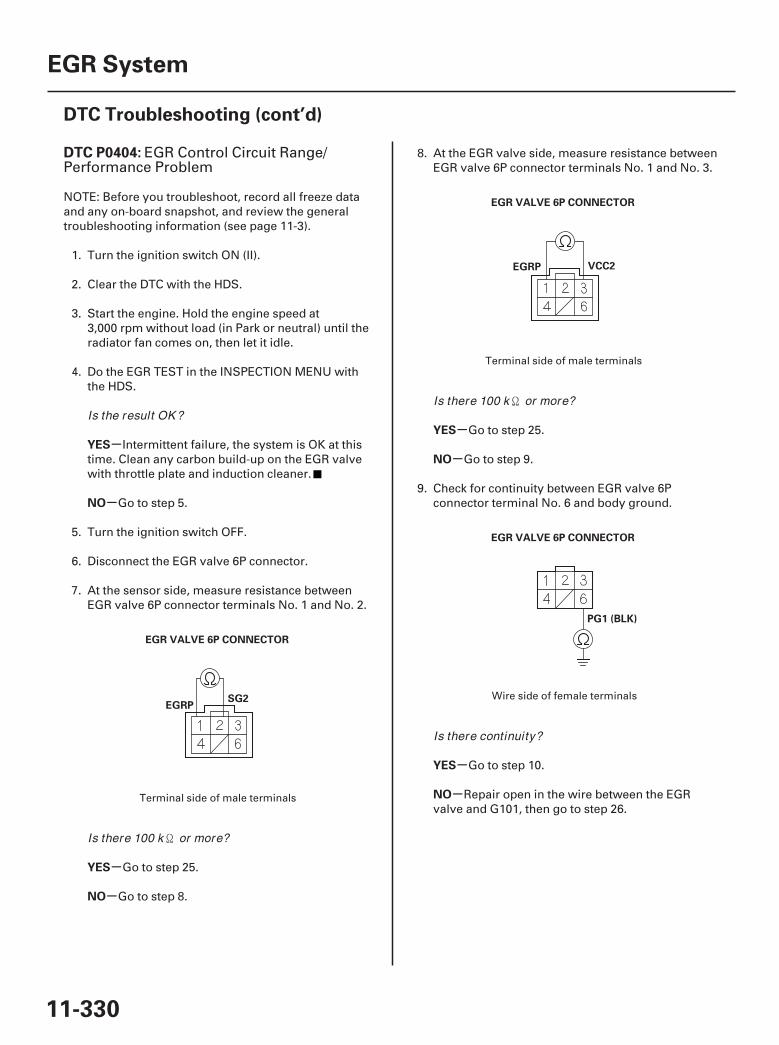
01
02
03
SJC8A00K77100090404FAAT30
-
-
-
-
-
-
-
-
DTC P0404:
YES
NO
YES
NO
YES
NO
YES
NO
11-330
EGR System
DTC Troubleshooting (cont’d)
EGR VALVE 6P CONNECTOR
SG2EGRP
EGR VALVE 6P CONNECTOR
VCC2EGRP
EGR VALVE 6P CONNECTOR
PG1 (BLK)
EGR Control Circuit Range/Performance Problem
NOTE: Before you troubleshoot, record all freeze dataand any on-board snapshot, and review the generaltroubleshooting information (see page 11-3).
1. Turn the ignition switch ON (II).
2. Clear the DTC with the HDS.
3. Start the engine. Hold the engine speed at3,000 rpm without load (in Park or neutral) until theradiator fan comes on, then let it idle.
4. Do the EGR TEST in the INSPECTION MENU withthe HDS.
Intermittent failure, the system is OK at thistime. Clean any carbon build-up on the EGR valvewith throttle plate and induction cleaner.
Go to step 5.
5. Turn the ignition switch OFF.
6. Disconnect the EGR valve 6P connector.
7. At the sensor side, measure resistance betweenEGR valve 6P connector terminals No. 1 and No. 2.
Go to step 25.
Go to step 8.
8. At the EGR valve side, measure resistance betweenEGR valve 6P connector terminals No. 1 and No. 3.
Go to step 25.
Go to step 9.
9. Check for continuity between EGR valve 6Pconnector terminal No. 6 and body ground.
Go to step 10.
Repair open in the wire between the EGRvalve and G101, then go to step 26.
Terminal side of male terminals
Terminal side of male terminals
Wire side of female terminals
Is the result OK ?
Is there 100 k or more?
Is there 100 k or more?
Is there continuity?
07/05/09 16:58:33 61SJC020_110_0330
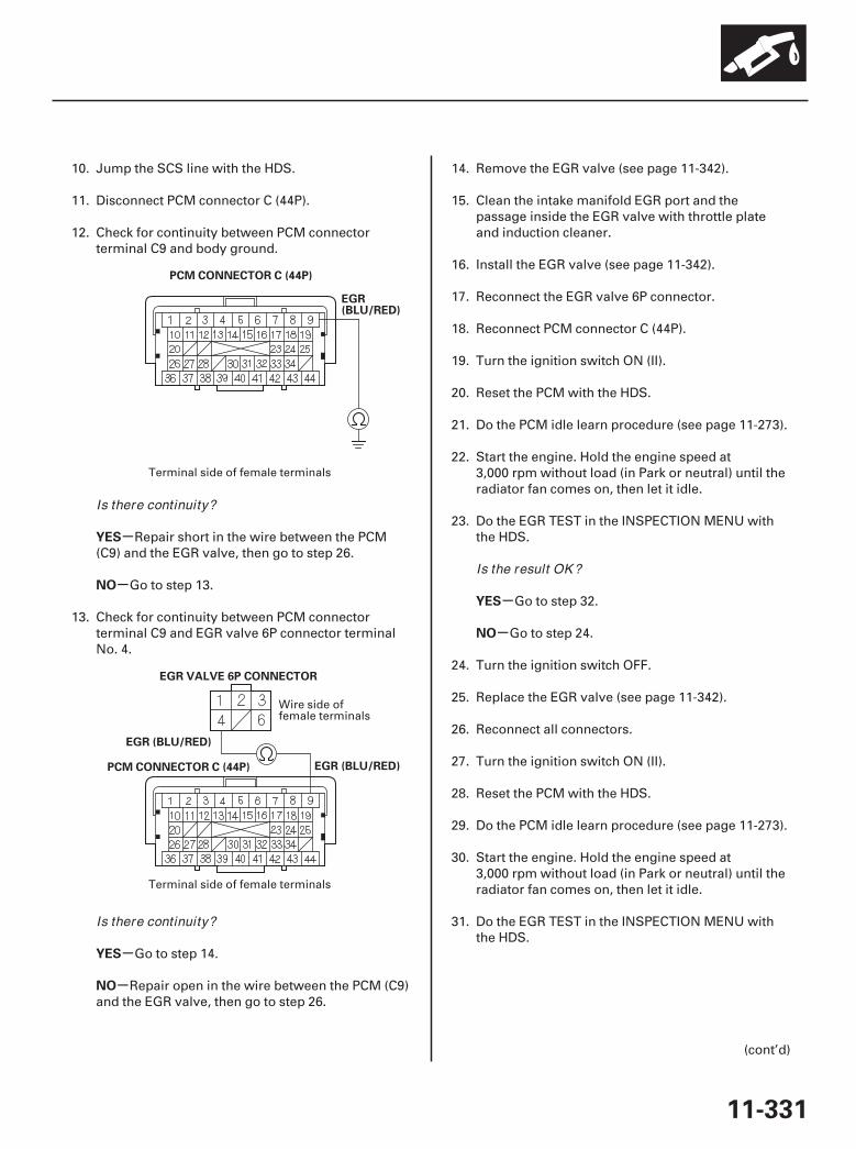
04
05
-
-
-
-
-
-
YES
NO
YES
NO
YES
NO
11-331
PCM CONNECTOR C (44P)
EGR(BLU/RED)
PCM CONNECTOR C (44P)
EGR (BLU/RED)
EGR VALVE 6P CONNECTOR
EGR (BLU/RED)
10. Jump the SCS line with the HDS.
11. Disconnect PCM connector C (44P).
12. Check for continuity between PCM connectorterminal C9 and body ground.
Repair short in the wire between the PCM(C9) and the EGR valve, then go to step 26.
Go to step 13.
13. Check for continuity between PCM connectorterminal C9 and EGR valve 6P connector terminalNo. 4.
Go to step 14.
Repair open in the wire between the PCM (C9)and the EGR valve, then go to step 26.
14. Remove the EGR valve (see page 11-342).
15. Clean the intake manifold EGR port and thepassage inside the EGR valve with throttle plateand induction cleaner.
16. Install the EGR valve (see page 11-342).
17. Reconnect the EGR valve 6P connector.
18. Reconnect PCM connector C (44P).
19. Turn the ignition switch ON (II).
20. Reset the PCM with the HDS.
21. Do the PCM idle learn procedure (see page 11-273).
22. Start the engine. Hold the engine speed at3,000 rpm without load (in Park or neutral) until theradiator fan comes on, then let it idle.
23. Do the EGR TEST in the INSPECTION MENU withthe HDS.
Go to step 32.
Go to step 24.
24. Turn the ignition switch OFF.
25. Replace the EGR valve (see page 11-342).
26. Reconnect all connectors.
27. Turn the ignition switch ON (II).
28. Reset the PCM with the HDS.
29. Do the PCM idle learn procedure (see page 11-273).
30. Start the engine. Hold the engine speed at3,000 rpm without load (in Park or neutral) until theradiator fan comes on, then let it idle.
31. Do the EGR TEST in the INSPECTION MENU withthe HDS.
(cont’d)
Terminal side of female terminals
Wire side offemale terminals
Terminal side of female terminals
Is there continuity?
Is there continuity?
Is the result OK ?
07/05/09 16:59:16 61SJC020_110_0331

-
-
-
-
-
-
-
-
YES
NO
YES
NO
YES
NO
YES
NO
11-332
EGR System
DTC Troubleshooting (cont’d)
32. Check for Temporary DTCs or DTCs with the HDS.
Check for poor connections or looseterminals at the EGR valve and the PCM, then go tostep 34.
Go to step 33.
33. Monitor the OBD STATUS for DTC P0404 in theDTCs MENU with the HDS.
Troubleshooting is complete. If any otherTemporary DTCs or DTCs were indicated in step 32,go to the indicated DTC’s troubleshooting.
If the screen indicates FAILED, check for poorconnections or loose terminals at the EGR valveand the PCM, then go to step 1. If the screenindicates EXECUTING, keep driving until a resultcomes on. If the screen indicates OUT OFCONDITION, go to step 30.
34. Update the PCM if it does not have the latestsoftware (see page 11-7), or substitute a known-good PCM (see page 11-8).
35. Start the engine. Hold the engine speed at3,000 rpm without load (in Park or neutral) until theradiator fan comes on, then let it idle.
36. Do the EGR TEST in the INSPECTION MENU withthe HDS.
37. Check for Temporary DTCs or DTCs with the HDS.
Check for poor connections or looseterminals at the EGR valve and the PCM. If the PCMwas updated, substitute a known-good PCM(see page 11-8), then go to step 35. If the PCM wassubstituted, go to step 1.
Go to step 38.
38. Monitor the OBD STATUS for DTC P0404 in theDTCs MENU with the HDS.
If the PCM was updated, troubleshooting iscomplete. If the PCM was substituted, replace theoriginal PCM (see page 11-205). If any otherTemporary DTCs or DTCs were indicated in step 37,go to the indicated DTC’s troubleshooting.
If the screen indicates FAILED, check for poorconnections or loose terminals at the EGR valveand the PCM. If the PCM was updated, substitute aknown-good PCM (see page 11-8), then go to step35. If the PCM was substituted, go to step 1. If thescreen indicates NOT COMPLETED, go to step 35.
Is DTC P0404 indicated?
Does the screen indicate PASSED?
Is DTC P0404 indicated?
Does the screen indicate PASSED?
07/05/09 16:59:16 61SJC020_110_0332
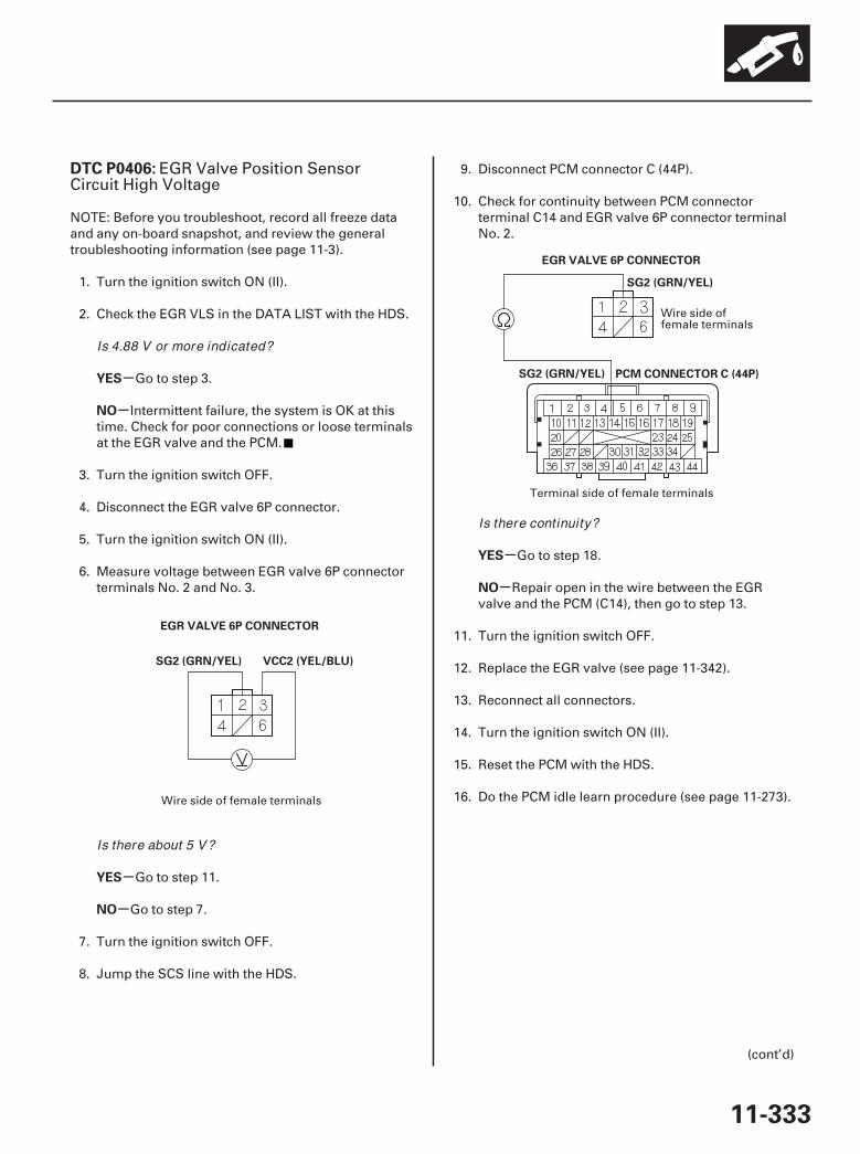
01
02
SJC8A00K77100090406FAAT30
-
-
-
-
-
-
DTC P0406:
YES
NO
YES
NO
YES
NO
11-333
EGR VALVE 6P CONNECTOR
VCC2 (YEL/BLU)SG2 (GRN/YEL)
PCM CONNECTOR C (44P)
EGR VALVE 6P CONNECTOR
SG2 (GRN/YEL)
SG2 (GRN/YEL)
EGR Valve Position SensorCircuit High Voltage
NOTE: Before you troubleshoot, record all freeze dataand any on-board snapshot, and review the generaltroubleshooting information (see page 11-3).
1. Turn the ignition switch ON (II).
2. Check the EGR VLS in the DATA LIST with the HDS.
Go to step 3.
Intermittent failure, the system is OK at thistime. Check for poor connections or loose terminalsat the EGR valve and the PCM.
3. Turn the ignition switch OFF.
4. Disconnect the EGR valve 6P connector.
5. Turn the ignition switch ON (II).
6. Measure voltage between EGR valve 6P connectorterminals No. 2 and No. 3.
Go to step 11.
Go to step 7.
7. Turn the ignition switch OFF.
8. Jump the SCS line with the HDS.
9. Disconnect PCM connector C (44P).
10. Check for continuity between PCM connectorterminal C14 and EGR valve 6P connector terminalNo. 2.
Go to step 18.
Repair open in the wire between the EGRvalve and the PCM (C14), then go to step 13.
11. Turn the ignition switch OFF.
12. Replace the EGR valve (see page 11-342).
13. Reconnect all connectors.
14. Turn the ignition switch ON (II).
15. Reset the PCM with the HDS.
16. Do the PCM idle learn procedure (see page 11-273).
(cont’d)
Wire side of female terminals
Wire side offemale terminals
Terminal side of female terminals
Is 4.88 V or more indicated?
Is there about 5 V?
Is there continuity?
07/05/09 16:59:16 61SJC020_110_0333
-
-
-
-
YES
NO
YES
NO
11-334
EGR System
DTC Troubleshooting (cont’d)
17. Check for Temporary DTCs or DTCs with the HDS.
Check for poor connections or looseterminals at the EGR valve and the PCM, then go tostep 1.
Troubleshooting is complete. If any otherTemporary DTCs or DTCs are indicated, go to theindicated DTC’s troubleshooting.
18. Reconnect all connectors.
19. Update the PCM if it does not have the latestsoftware (see page 11-7), or substitute a known-good PCM (see page 11-8).
20. Check for Temporary DTCs or DTCs with the HDS.
Check for poor connections or looseterminals at the EGR valve and the PCM. If the PCMwas updated, substitute a known-good PCM(see page 11-8), then recheck. If the PCM wassubstituted, go to step 1.
If the PCM was updated, troubleshooting iscomplete. If the PCM was substituted, replace theoriginal PCM (see page 11-205). If any otherTemporary DTCs or DTCs are indicated, go to theindicated DTC’s troubleshooting.
Is DTC P0406 indicated?
Is DTC P0406 indicated?
07/05/09 16:59:17 61SJC020_110_0334

01
SJC8A00K77100092413FAAT30
-
-
-
-
-
-
DTC P2413:
YES
NO
YES
NO
YES
NO
11-335
EGR VALVE 6P CONNECTOR
VCC2 (YEL/BLU)
EGR System Malfunction
NOTE: Before you troubleshoot, record all freeze dataand any on-board snapshot, and review the generaltroubleshooting information (see page 11-3).
1. Turn the ignition switch ON (II).
2. Clear the DTC with the HDS.
3. Start the engine. Hold the engine speed at3,000 rpm without load (in Park or neutral) until theradiator fan comes on, then let it idle.
4. Do the EGR TEST in the INSPECTION MENU withthe HDS.
Intermittent failure, the system is OK at thistime. Check for poor connections or loose terminalsat the EGR valve and the PCM.
Go to step 5.
5. Turn the ignition switch OFF.
6. Turn the ignition switch ON (II).
7. Check the EGR VLS in the DATA LIST with the HDS.
Go to step 8.
Go to step 21.
8. Turn the ignition switch OFF.
9. Disconnect the EGR valve 6P connector.
10. Turn the ignition switch ON (II).
11. Measure voltage between EGR valve 6P connectorterminal No. 3 and body ground.
Go to step 16.
Go to step 12.
(cont’d)
Wire side of female terminals
Is the result OK ?
Is about 0 V indicated?
Is there about 5 V?
07/05/09 16:59:17 61SJC020_110_0335

0203
-
-
-
-YES
NO
YES
NO
11-336
EGR System
DTC Troubleshooting (cont’d)
PCM CONNECTOR C (44P)
EGR VALVE 6P CONNECTOR
VCC2 (YEL/BLU)
VCC2 (YEL/BLU)
PCM CONNECTOR C (44P)
EGRP(WHT/BLK)
12. Turn the ignition switch OFF.
13. Jump the SCS line with the HDS.
14. Disconnect PCM connector C (44P).
15. Check for continuity between PCM connectorterminal C13 and EGR valve 6P connector terminalNo. 3.
Go to step 51.
Repair open in the wire between the EGRvalve and the PCM (C13), then go to step 44.
16. Turn the ignition switch OFF.
17. Jump the SCS line with the HDS.
18. Disconnect PCM connector C (44P).
19. Check for continuity between PCM connectorterminal C20 and body ground.
Repair short in the wire between the PCM(C20) and the EGR valve, then go to step 44.
Go to step 20.
Wire side offemale terminals
Terminal side of female terminals
Terminal side of female terminals
Is there continuity?
Is there continuity?
07/05/09 16:59:17 61SJC020_110_0336
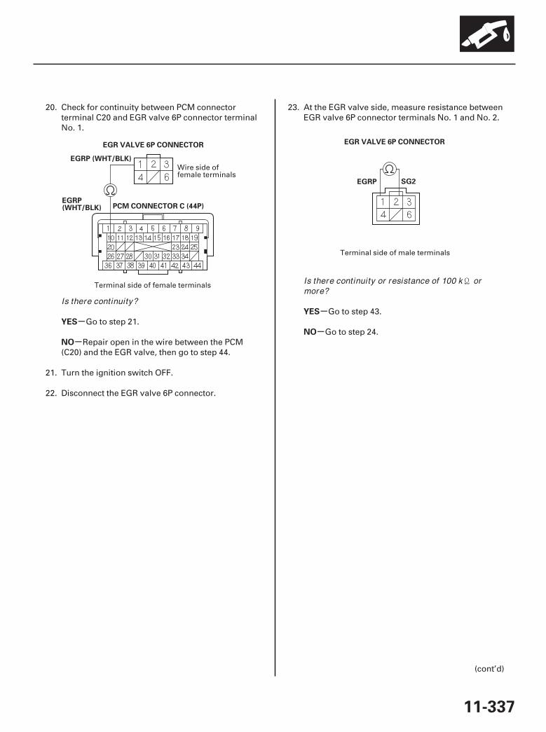
0405
-
-
-
-YES
NO
YES
NO
11-337
PCM CONNECTOR C (44P)
EGR VALVE 6P CONNECTOR
EGRP (WHT/BLK)
EGRP(WHT/BLK)
EGRP SG2
EGR VALVE 6P CONNECTOR
20. Check for continuity between PCM connectorterminal C20 and EGR valve 6P connector terminalNo. 1.
Go to step 21.
Repair open in the wire between the PCM(C20) and the EGR valve, then go to step 44.
21. Turn the ignition switch OFF.
22. Disconnect the EGR valve 6P connector.
23. At the EGR valve side, measure resistance betweenEGR valve 6P connector terminals No. 1 and No. 2.
Go to step 43.
Go to step 24.
(cont’d)
Wire side offemale terminals
Terminal side of female terminals
Terminal side of male terminals
Is there continuity?
Is there continuity or resistance of 100 k ormore?
07/05/09 16:59:18 61SJC020_110_0337
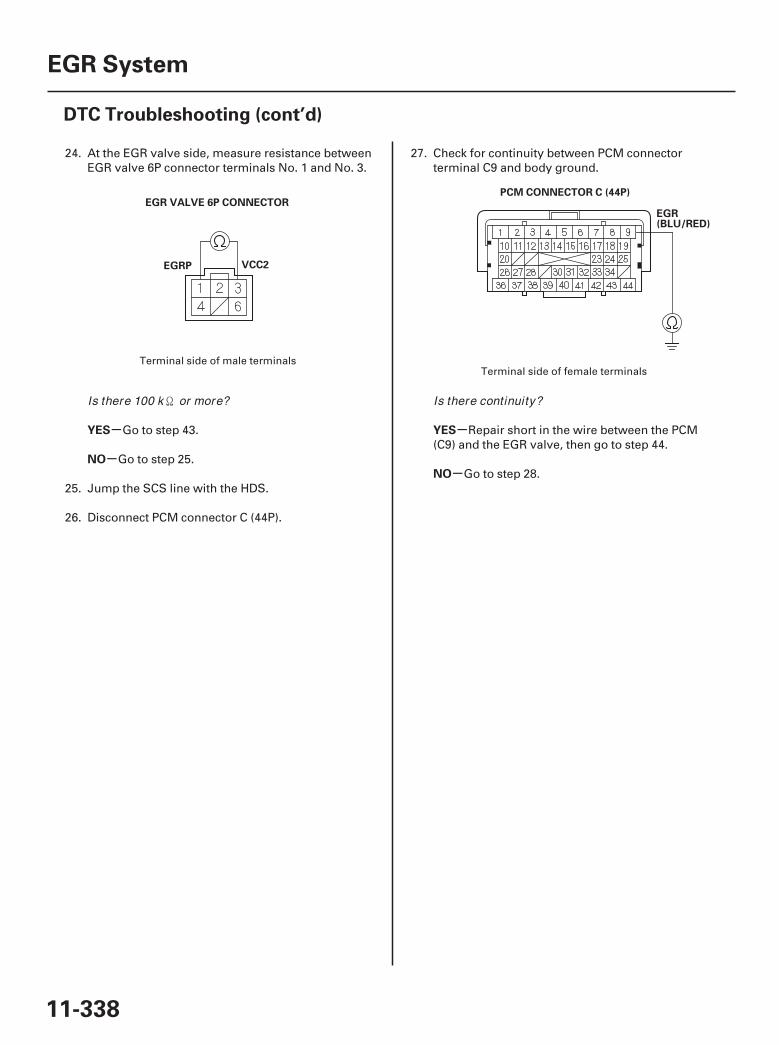
06 07
-
-
-
-
YES
NO
YES
NO
11-338
EGR System
DTC Troubleshooting (cont’d)
EGRP VCC2
EGR VALVE 6P CONNECTORPCM CONNECTOR C (44P)
EGR(BLU/RED)
24. At the EGR valve side, measure resistance betweenEGR valve 6P connector terminals No. 1 and No. 3.
Go to step 43.
Go to step 25.
25. Jump the SCS line with the HDS.
26. Disconnect PCM connector C (44P).
27. Check for continuity between PCM connectorterminal C9 and body ground.
Repair short in the wire between the PCM(C9) and the EGR valve, then go to step 44.
Go to step 28.
Terminal side of male terminalsTerminal side of female terminals
Is there 100 k or more? Is there continuity?
07/05/09 16:59:18 61SJC020_110_0338
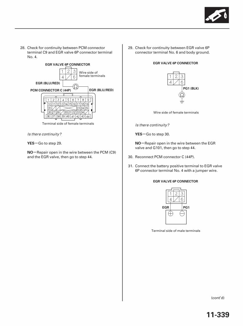
0809
10
-
-
-
-YES
NO
YES
NO
11-339
PCM CONNECTOR C (44P)
EGR (BLU/RED)
EGR VALVE 6P CONNECTOR
EGR (BLU/RED)
EGR VALVE 6P CONNECTOR
PG1 (BLK)
EGR PG1
EGR VALVE 6P CONNECTOR
28. Check for continuity between PCM connectorterminal C9 and EGR valve 6P connector terminalNo. 4.
Go to step 29.
Repair open in the wire between the PCM (C9)and the EGR valve, then go to step 44.
29. Check for continuity between EGR valve 6Pconnector terminal No. 6 and body ground.
Go to step 30.
Repair open in the wire between the EGRvalve and G101, then go to step 44.
30. Reconnect PCM connector C (44P).
31. Connect the battery positive terminal to EGR valve6P connector terminal No. 4 with a jumper wire.
(cont’d)
Wire side offemale terminals
Terminal side of female terminals
Wire side of female terminals
Terminal side of male terminals
Is there continuity?
Is there continuity?
07/05/09 16:59:18 61SJC020_110_0339
-
-
-
-
-
-
-
-
YES
NO
YES
NO
YES
NO
YES
NO
11-340
EGR System
DTC Troubleshooting (cont’d)
32. Start the engine and let it idle, then connect thebattery negative terminal to EGR valve 6Pconnector terminal No. 6 with a jumper wire.
Go to step 51.
Go to step 33.
33. Turn the ignition switch OFF.
34. Remove the EGR valve (see page 11-342).
35. Clean the intake manifold EGR port at the passageinside the EGR valve with throttle plate andinduction cleaner.
36. Install the EGR valve (see page 11-342).
37. Reconnect all connectors.
38. Turn the ignition switch ON (II).
39. Reset the PCM with the HDS.
40. Do the PCM idle learn procedure (see page 11-273).
41. Do the EGR TEST in the INSPECTION MENU withthe HDS.
Go to step 49.
Go to step 42.
42. Turn the ignition switch OFF.
43. Replace the EGR valve (see page 11-342).
44. Reconnect all connectors.
45. Turn the ignition switch ON (II).
46. Reset the PCM with the HDS.
47. Do the PCM idle learn procedure (see page 11-273).
48. Do the EGR TEST in the INSPECTION MENU withthe HDS.
49. Check for Temporary DTCs or DTCs with the HDS.
Check for poor connections or looseterminals at the EGR valve and the PCM, then go tostep 1.
Go to step 50.
50. Monitor the OBD STATUS for DTC P2413 in theDTCs MENU with the HDS.
Troubleshooting is complete. If any otherTemporary DTCs or DTCs were indicated in step 49,go to the indicated DTC’s troubleshooting.
If the screen indicates FAILED, check for poorconnections or loose terminals at the EGR valveand the PCM, then go to step 1. If the screenindicates EXECUTING or OUT OF CONDITION,keep idling until a result comes on.
Does the engine stall or run rough?
Is the result OK ?
Is DTC P2413 indicated?
Does the screen indicate PASSED?
07/05/09 16:59:18 61SJC020_110_0340
-
-
-
-
YES
NO
YES
NO
11-341
51. Turn the ignition switch OFF.
52. Reconnect all connectors.
53. Update the PCM if it does not have the latestsoftware (see page 11-7), or substitute a known-good PCM (see page 11-8).
54. Do the EGR TEST in the INSPECTION MENU withthe HDS.
55. Check for Temporary DTCs or DTCs with the HDS.
Check for poor connections or looseterminals at the EGR valve and the PCM. If the PCMwas updated, substitute a known-good PCM(see page 11-8), then recheck. If the PCM wassubstituted, go to step 1.
Go to step 56.
56. Monitor the OBD STATUS for DTC P2413 in theDTCs MENU with the HDS.
If the PCM was updated, troubleshooting iscomplete. If the PCM was substituted, replace theoriginal PCM (see page 11-205). If any otherTemporary DTCs or DTCs were indicated in step 51,go to the indicated DTC’s troubleshooting.
If the screen indicates FAILED, check for poorconnections or loose terminals at the EGR valveand the PCM. If the PCM was updated, substitute aknown-good PCM (see page 11-8), then recheck. Ifthe PCM was substituted, go to step 1. If the screenindicates EXECUTING or OUT OF CONDITION,keep idling until a result comes on.
Is DTC P2413 indicated?
Does the screen indicate PASSED?
07/05/09 16:59:19 61SJC020_110_0341
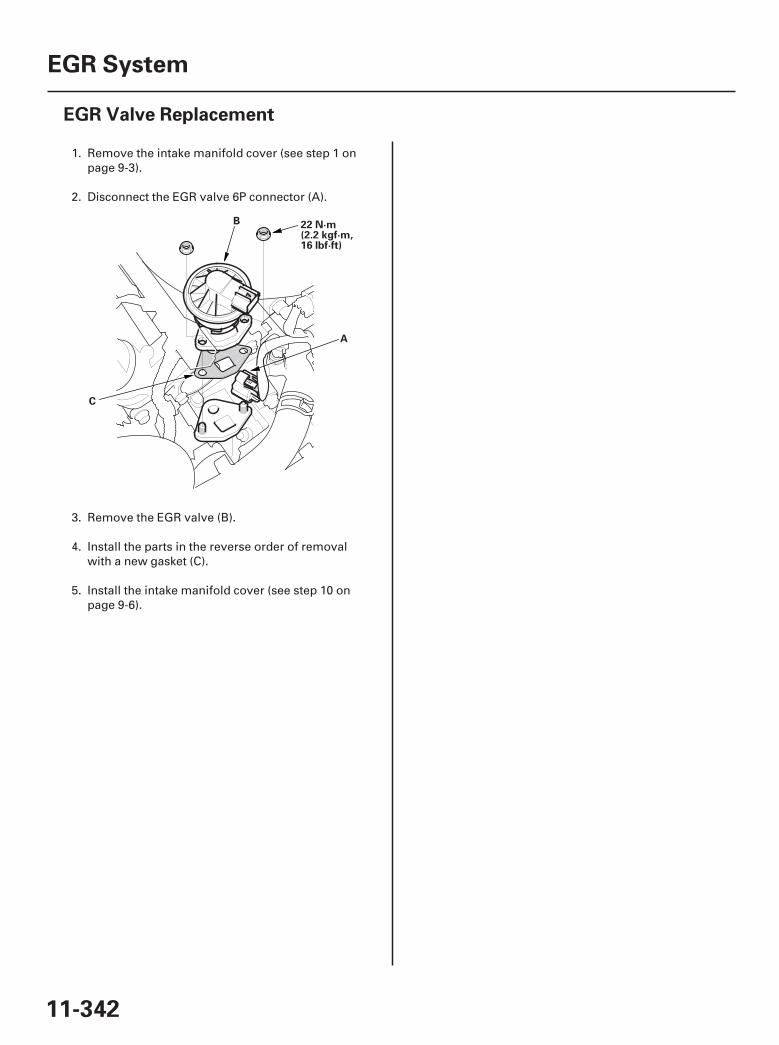
01
SJC8A00A20323525401KBAT00
11-342
EGR System
EGR Valve Replacement
A
B
C
22 N·m(2.2 kgf·m,16 lbf·ft)
1. Remove the intake manifold cover (see step 1 onpage 9-3).
2. Disconnect the EGR valve 6P connector (A).
3. Remove the EGR valve (B).
4. Install the parts in the reverse order of removalwith a new gasket (C).
5. Install the intake manifold cover (see step 10 onpage 9-6).
07/05/09 16:59:19 61SJC020_110_0342

*01
SJC8A00A20360300000DAAT00
11-343
PCV System
Component Location Index
POWERTRAIN CONTROL MODULE (PCM)
PCV VALVEUpdate, page 11-7Substitution, page 11-8Replacement, page 11-205 Inspection, page 11-345
Replacement, page 11-345
07/05/09 16:59:20 61SJC020_110_0343

SJC8A00K77100092279FAAT30
-
-
-
-
-
-
-
-
DTC P2279:
YES
NO
YES
NO
YES
NO
YES
NO
11-344
PCV System
DTC Troubleshooting
Intake Air System Leak
NOTE:• Before you troubleshoot, record all freeze data and
any on-board snapshot, and review the generaltroubleshooting information (see page 11-3).
• If DTC P0443 is stored at the same time as DTC P2279,troubleshoot DTC P0443 first, then recheck for DTCP2279.
1. Check for vacuum leaks at these parts:
• PCV valve• PCV hose• Purge (PCS) line• Throttle body• Intake manifold• Brake booster hose
Go to step 2.
Repair or replace any damaged parts, then goto step 4.
2. Start the engine. Hold the engine speed at3,000 rpm without load (in Park or neutral) until theradiator fan comes on, then let it idle 1 minute.
3. Monitor the OBD STATUS for DTC P2279 in theDTCs MENU with the HDS.
Check the camshaft timing (see page 6-16),then go to step 4.
If the screen indicates PASSED, intermittentfailure, the system is OK at this time. If the screenindicates NOT COMPLETED, go to step 2 andrecheck.
4. Reset the PCM with the HDS.
5. Do the PCM idle learn procedure (see page 11-273).
6. Start the engine. Hold the engine speed at3,000 rpm without load (in Park or neutral) until theradiator fan comes on, then let it idle 1 minute.
7. Check for Temporary DTCs or DTCs with the HDS.
Check for vacuum leaks at the PCV valve, thePCV hose, the purge (PCS) line, the throttle body,the intake manifold, and the brake booster hose,then go to step 1.
Go to step 8.
8. Monitor the OBD STATUS for DTC P2279 in theDTCs MENU with the HDS.
Troubleshooting is complete. If any otherTemporary DTCs or DTCs were indicated in step 7,go to the indicated DTC’s troubleshooting.
If the screen indicates FAILED, go to step 1. Ifthe screen indicates NOT COMPLETED, keep idlinguntil a result comes on.
Are the parts OK ?
Does the screen indicate FAILED?
Is DTC P2279 indicated?
Does the screen indicate PASSED?
07/05/09 16:59:20 61SJC020_110_0344
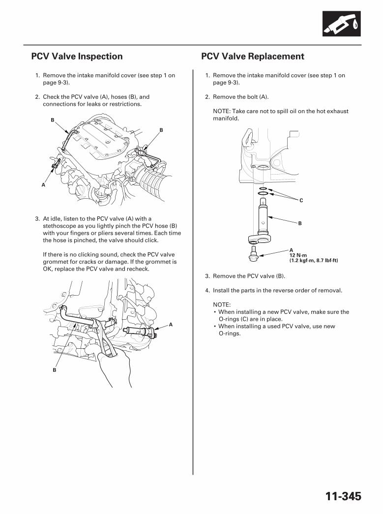
01
02
SJC8A00A20360345801MAAT10
01
SJC8A00A20360345801KBAT00
11-34511-345
PCV Valve Inspection PCV Valve Replacement
A
B
B
A
B
B
C
A12 N·m(1.2 kgf·m, 8.7 lbf·ft)
1. Remove the intake manifold cover (see step 1 onpage 9-3).
2. Check the PCV valve (A), hoses (B), andconnections for leaks or restrictions.
3. At idle, listen to the PCV valve (A) with astethoscope as you lightly pinch the PCV hose (B)with your fingers or pliers several times. Each timethe hose is pinched, the valve should click.
If there is no clicking sound, check the PCV valvegrommet for cracks or damage. If the grommet isOK, replace the PCV valve and recheck.
1. Remove the intake manifold cover (see step 1 onpage 9-3).
2. Remove the bolt (A).
NOTE: Take care not to spill oil on the hot exhaustmanifold.
3. Remove the PCV valve (B).
4. Install the parts in the reverse order of removal.
NOTE:• When installing a new PCV valve, make sure the
O-rings (C) are in place.• When installing a used PCV valve, use new
O-rings.
07/05/09 16:59:21 61SJC020_110_0345
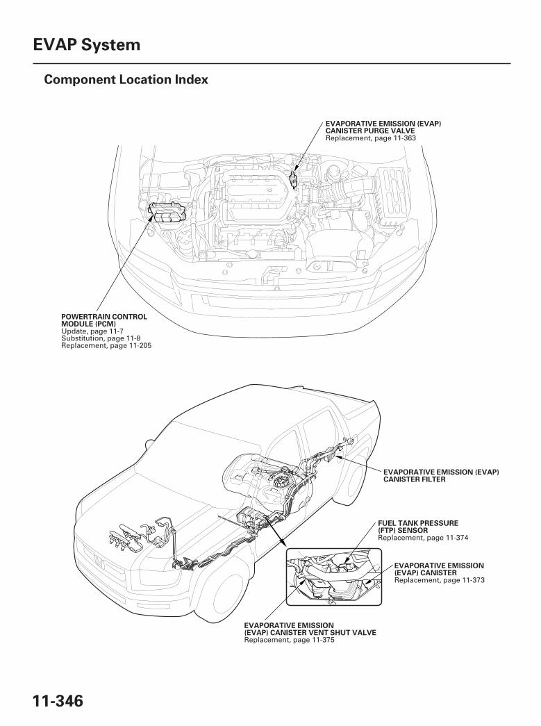
*01
*02
SJC8A00A20323400000DAAT00
11-346
EVAP System
Component Location Index
POWERTRAIN CONTROLMODULE (PCM)
EVAPORATIVE EMISSION (EVAP)CANISTER PURGE VALVE
FUEL TANK PRESSURE(FTP) SENSOR
EVAPORATIVE EMISSION(EVAP) CANISTER
EVAPORATIVE EMISSION(EVAP) CANISTER VENT SHUT VALVE
EVAPORATIVE EMISSION (EVAP)CANISTER FILTER
Update, page 11-7Substitution, page 11-8Replacement, page 11-205
Replacement, page 11-363
Replacement, page 11-374
Replacement, page 11-373
Replacement, page 11-375
07/05/09 16:59:24 61SJC020_110_0346
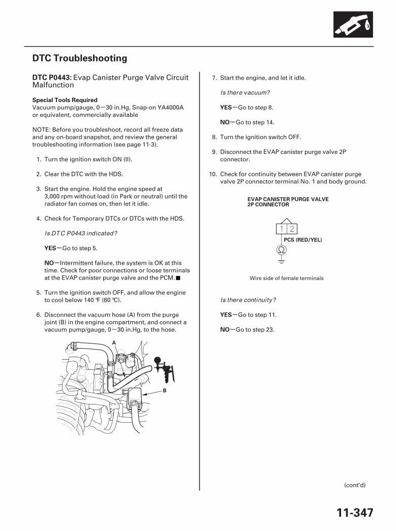
-
-01
02
SJC8A00K77100090443FAAT30
-
-
-
-
-
-
DTC P0443:
Special Tools Required
YES
NO
YES
NO
YES
NO
11-347
DTC Troubleshooting
A
B
EVAP CANISTER PURGE VALVE2P CONNECTOR
PCS (RED/YEL)
Evap Canister Purge Valve CircuitMalfunction
Vacuum pump/gauge, 0 30 in.Hg, Snap-on YA4000Aor equivalent, commercially available
NOTE: Before you troubleshoot, record all freeze dataand any on-board snapshot, and review the generaltroubleshooting information (see page 11-3).
1. Turn the ignition switch ON (II).
2. Clear the DTC with the HDS.
3. Start the engine. Hold the engine speed at3,000 rpm without load (in Park or neutral) until theradiator fan comes on, then let it idle.
4. Check for Temporary DTCs or DTCs with the HDS.
Go to step 5.
Intermittent failure, the system is OK at thistime. Check for poor connections or loose terminalsat the EVAP canister purge valve and the PCM.
5. Turn the ignition switch OFF, and allow the engineto cool below 140 °F (60 °C).
6. Disconnect the vacuum hose (A) from the purgejoint (B) in the engine compartment, and connect avacuum pump/gauge, 0 30 in.Hg, to the hose.
7. Start the engine, and let it idle.
Go to step 8.
Go to step 14.
8. Turn the ignition switch OFF.
9. Disconnect the EVAP canister purge valve 2Pconnector.
10. Check for continuity between EVAP canister purgevalve 2P connector terminal No. 1 and body ground.
Go to step 11.
Go to step 23.
(cont’d)
Wire side of female terminals
Is DTC P0443 indicated?
Is there vacuum?
Is there continuity?
07/05/09 16:59:24 61SJC020_110_0347
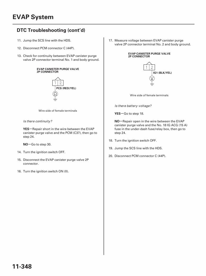
03
04
-
-
-
-
YES
NO
YES
NO
11-348
EVAP System
DTC Troubleshooting (cont’d)
PCS (RED/YEL)
EVAP CANISTER PURGE VALVE2P CONNECTOR IG1 (BLK/YEL)
EVAP CANISTER PURGE VALVE2P CONNECTOR
11. Jump the SCS line with the HDS.
12. Disconnect PCM connector C (44P).
13. Check for continuity between EVAP canister purgevalve 2P connector terminal No. 1 and body ground.
Repair short in the wire between the EVAPcanister purge valve and the PCM (C37), then go tostep 24.
Go to step 30.
14. Turn the ignition switch OFF.
15. Disconnect the EVAP canister purge valve 2Pconnector.
16. Turn the ignition switch ON (II).
17. Measure voltage between EVAP canister purgevalve 2P connector terminal No. 2 and body ground.
Go to step 18.
Repair open in the wire between the EVAPcanister purge valve and the No. 18 IG ACG (15 A)fuse in the under-dash fuse/relay box, then go tostep 24.
18. Turn the ignition switch OFF.
19. Jump the SCS line with the HDS.
20. Disconnect PCM connector C (44P).
Wire side of female terminals
Wire side of female terminals
Is there continuity?
Is there battery voltage?
07/05/09 16:59:24 61SJC020_110_0348

05 06
-
-
-
-
-
-
YES
NO
YES
NO
YES
NO
11-349
PCM CONNECTOR C (44P)
PCS (RED/YEL)
EVAP CANISTER PURGE VALVE2P CONNECTOR
PCS (RED/YEL)
EVAP CANISTER PURGE VALVE2P CONNECTOR
21. Check for continuity between PCM connectorterminal C37 and EVAP canister purge valve 2Pconnector terminal No. 1.
Go to step 22.
Repair open in the wire between the EVAPcanister purge valve and the PCM (C37), then go tostep 24.
22. At the valve side, measure resistance betweenEVAP canister purge valve 2P connector terminalsNo. 1 and No. 2.
Go to step 30.
Go to step 23.
23. Replace the EVAP canister purge valve (see page11-374).
24. Reconnect all connectors.
25. Turn the ignition switch ON (II).
26. Reset the PCM with the HDS.
27. Do the PCM idle learn procedure (see page 11-273).
28. Check for Temporary DTCs or DTCs with the HDS.
Check for poor connections or looseterminals at the EVAP canister purge valve and thePCM, then go to step 1.
Go to step 29.
(cont’d)
Wire side offemale terminals
Terminal side of female terminals
Terminal side of male terminals
Is there continuity?Is there about 33 at room temperature?
Is DTC P0443 indicated?
07/05/09 16:59:25 61SJC020_110_0349
-
-
-
-
-
-
YES
NO
YES
NO
YES
NO
11-350
EVAP System
DTC Troubleshooting (cont’d)
29. Monitor the OBD STATUS for DTC P0443 in theDTCs MENU with the HDS.
Troubleshooting is complete. If any otherTemporary DTCs or DTCs were indicated in step 28,go to the indicated DTC’s troubleshooting.
If the screen indicates FAILED, check for poorconnections or loose terminals at the EVAP canisterpurge valve and the PCM, then go to step 1. If thescreen indicates NOT COMPLETED, keep idlinguntil a result comes on.
30. Reconnect all connectors.
31. Update the PCM if it does not have the latestsoftware (see page 11-7), or substitute a known-good PCM (see page 11-8).
32. Check for Temporary DTCs or DTCs with the HDS.
Check for poor connections or looseterminals at the EVAP canister purge valve and thePCM. If the PCM was updated, substitute a known-good PCM (see page 11-8), then recheck. If the PCMwas substituted, go to step 1.
Go to step 32.
33. Monitor the OBD STATUS for DTC P0443 in theDTCs MENU with the HDS.
If the PCM was updated, troubleshooting iscomplete. If the PCM was substituted, replace theoriginal PCM (see page 11-205). If any otherTemporary DTCs or DTCs were indicated in step 32,go to the indicated DTC’s troubleshooting.
If the screen indicates FAILED, check for poorconnections or loose terminals at the EVAP canisterpurge valve and the PCM. If the PCM was updated,substitute a known-good PCM (see page 11-8), thenrecheck. If the PCM was substituted, go to step 1. Ifthe screen indicates NOT COMPLETED, keep idlinguntil a result comes on.
Does the screen indicate PASSED?
Is DTC P0443 indicated?
Does the screen indicate PASSED?
07/05/09 16:59:25 61SJC020_110_0350
SJC8A00K77100090451FAAT30
-
-
-
-
-
-
DTC P0451:
YES
NO
YES
NO
YES
NO
11-351
FTP Sensor Circuit Range/Performance Problem
NOTE:• Before you troubleshoot, record all freeze data and
any on-board snapshot, and review the generaltroubleshooting information (see page 11-3).
• If DTC P2422 is stored at the same time as DTC P0451,troubleshoot DTC P2422 first, then recheck for DTCP0451.
1. Turn the ignition switch ON (II).
2. Clear the DTC with the HDS.
3. Start the engine, and let it idle 1 minute.
4. Monitor the OBD STATUS for DTC P0451 in theDTCs MENU with the HDS.
Go to step 5.
If the screen indicates PASSED, intermittentfailure, the system is OK at this time. Check forpoor connections or loose terminals at the FTPsensor and the PCM. If the screen indicates NOTCOMPLETED, go to step 3 and recheck.
5. Turn the ignition switch OFF.
6. Replace the FTP sensor (see page 11-374).
7. Turn the ignition switch ON (ll).
8. Reset the PCM with the HDS.
9. Do the PCM idle learn procedure (see page 11-273).
10. Start the engine, and let it idle 1 minute.
11. Check for Temporary DTCs or DTCs with the HDS.
Check for poor connections or looseterminals at the FTP sensor and the PCM, then goto step 1.
Go to step 12.
12. Monitor the OBD STATUS for DTC P0451 in theDTCs MENU with the HDS.
Troubleshooting is complete. If any otherTemporary DTCs or DTCs were indicated in step 11,go to the indicated DTC’s troubleshooting.
If the screen indicates FAILED, check for poorconnections or loose terminals at the FTP sensorand the PCM, then go to step 1. If the screenindicates NOT COMPLETED, go to step 10.
Does the screen indicate FAILED?
Is DTC P0451 indicated?
Does the screen indicate PASSED?
07/05/09 16:59:25 61SJC020_110_0351

- - -01
SJC8A00K77100090452FAAT30
-
-
-
-
-
-
-
-
DTC P0452:
YES
NO
YES
NO
YES
NO
YES
NO
11-352
EVAP System
DTC Troubleshooting (cont’d)
FTP SENSOR 3P CONNECTOR
VCC7 (YEL/BLU)
FTP Sensor Circuit Low Voltage
NOTE: Before you troubleshoot, record all freeze dataand any on-board snapshot, and review the generaltroubleshooting information (see page 11-3).
1. Turn the ignition switch ON (II).
2. Clear the DTC with the HDS.
3. Turn the ignition switch OFF.
4. Remove the fuel fill cap.
5. Turn the ignition switch ON (II).
6. Check the FTP SENSOR in the DATA LIST with theHDS.
Go to step 10.
Go to step 7.
7. Install the fuel fill cap.
8. Start the engine.
9. Monitor the OBD STATUS for DTC P0452 in theDTCs MENU with the HDS.
Go to step 10.
If the screen indicates PASSED, intermittentfailure, the system is OK at this time. Check forpoor connections or loose terminals at the FTPsensor and the PCM. If the screen indicates NOTCOMPLETED, go to step 5 and recheck.
10. Turn the ignition switch OFF.
11. Disconnect the FTP sensor 3P connector.
12. Turn the ignition switch ON (II).
13. Check the FTP SENSOR in the DATA LIST with theHDS.
Go to step 24.
Go to step 14.
14. Measure voltage between FTP sensor 3P connectorterminal No. 1 and body ground.
Go to step 20.
Go to step 15.
Wire side of female terminals
Is about 7.3 kPa ( 2.16 in.Hg, 55 mmHg), or0.3 V or less indicated?
Does the screen indicate FAILED?
Is about 7.3 kPa (2.15 in.Hg, 54.7 mmHg), or4.90 V indicated?
Is there about 5 V?
07/05/09 16:59:25 61SJC020_110_0352
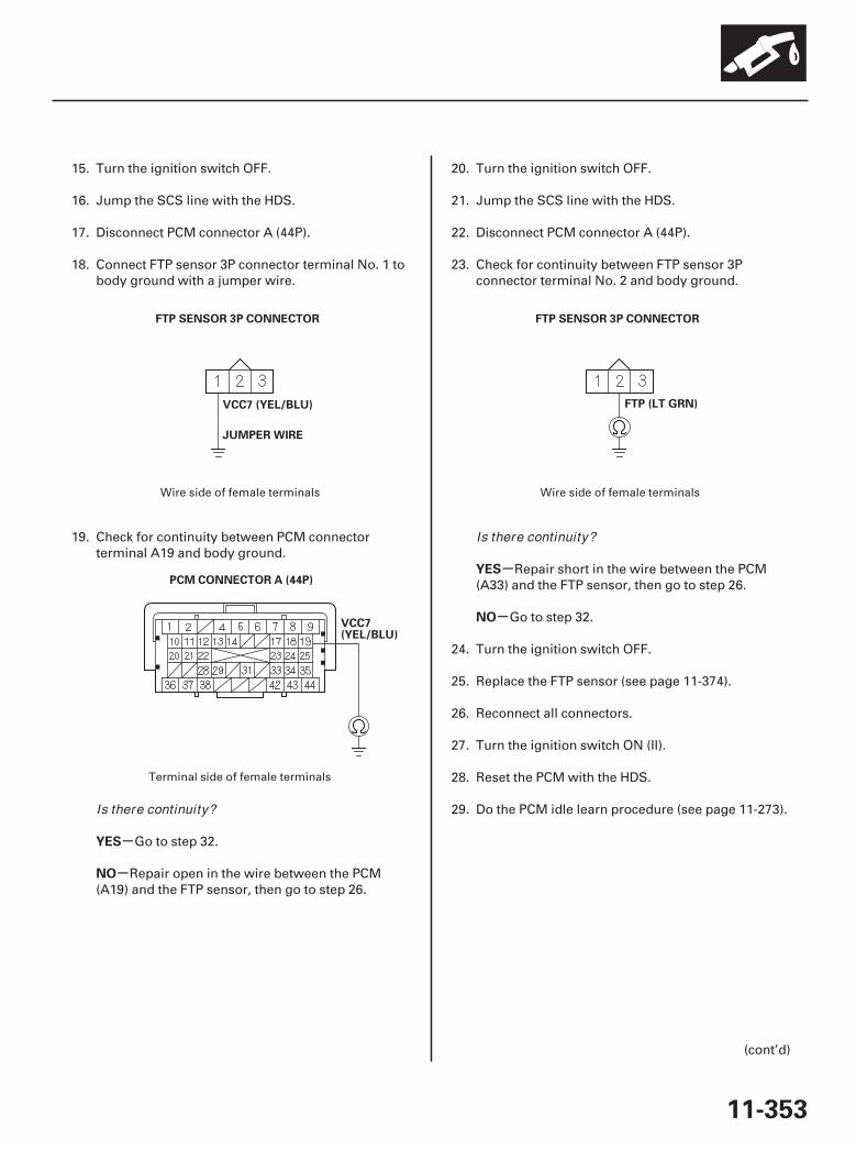
02
03
04
-
-
-
-
YES
NO
YES
NO
11-353
FTP SENSOR 3P CONNECTOR
VCC7 (YEL/BLU)
JUMPER WIRE
PCM CONNECTOR A (44P)
VCC7(YEL/BLU)
FTP SENSOR 3P CONNECTOR
FTP (LT GRN)
15. Turn the ignition switch OFF.
16. Jump the SCS line with the HDS.
17. Disconnect PCM connector A (44P).
18. Connect FTP sensor 3P connector terminal No. 1 tobody ground with a jumper wire.
19. Check for continuity between PCM connectorterminal A19 and body ground.
Go to step 32.
Repair open in the wire between the PCM(A19) and the FTP sensor, then go to step 26.
20. Turn the ignition switch OFF.
21. Jump the SCS line with the HDS.
22. Disconnect PCM connector A (44P).
23. Check for continuity between FTP sensor 3Pconnector terminal No. 2 and body ground.
Repair short in the wire between the PCM(A33) and the FTP sensor, then go to step 26.
Go to step 32.
24. Turn the ignition switch OFF.
25. Replace the FTP sensor (see page 11-374).
26. Reconnect all connectors.
27. Turn the ignition switch ON (II).
28. Reset the PCM with the HDS.
29. Do the PCM idle learn procedure (see page 11-273).
(cont’d)
Wire side of female terminals
Terminal side of female terminals
Wire side of female terminals
Is there continuity?
Is there continuity?
07/05/09 16:59:26 61SJC020_110_0353
-
-
-
-
-
-
-
-
YES
NO
YES
NO
YES
NO
YES
NO
11-354
EVAP System
DTC Troubleshooting (cont’d)
30. Check for Temporary DTCs or DTCs with the HDS.
Check for poor connections or looseterminals at the FTP sensor and the PCM, then goto step 1.
Go to step 31.
31. Monitor the OBD STATUS for DTC P0452 in theDTCs MENU with the HDS.
Troubleshooting is complete. If any otherTemporary DTCs or DTCs were indicated in step 30,go to the indicated DTC’s troubleshooting.
If the screen indicates FAILED, check for poorconnections or loose terminals at the FTP sensorand the PCM, then go to step 1. If the screenindicates NOT COMPLETED, keep idling until aresult comes on.
32. Reconnect all connectors.
33. Update the PCM if it does not have the latestsoftware (see page 11-7), or substitute a known-good PCM (see page 11-8).
34. Check for Temporary DTCs or DTCs with the HDS.
Check for poor connections or looseterminals at the FTP sensor and the PCM. If thePCM was updated, substitute a known-good PCM(see page 11-8), then recheck. If the PCM wassubstituted, go to step 1.
Go to step 34.
35. Monitor the OBD STATUS for DTC P0452 in theDTCs MENU with the HDS.
If the PCM was updated, troubleshooting iscomplete. If the PCM was substituted, replace theoriginal PCM (see page 11-205). If any otherTemporary DTCs or DTCs were indicated in step 34,go to the indicated DTC’s troubleshooting.
If the screen indicates FAILED, check for poorconnections or loose terminals at the FTP sensorand the PCM. If the PCM was updated, substitute aknown-good PCM (see page 11-8), then recheck. Ifthe PCM was substituted, go to step 1. If the screenindicates NOT COMPLETED, keep idling until aresult comes on.
Is DTC P0452 indicated?
Does the screen indicate PASSED?
Is DTC P0452 indicated?
Does the screen indicate PASSED?
07/05/09 16:59:26 61SJC020_110_0354
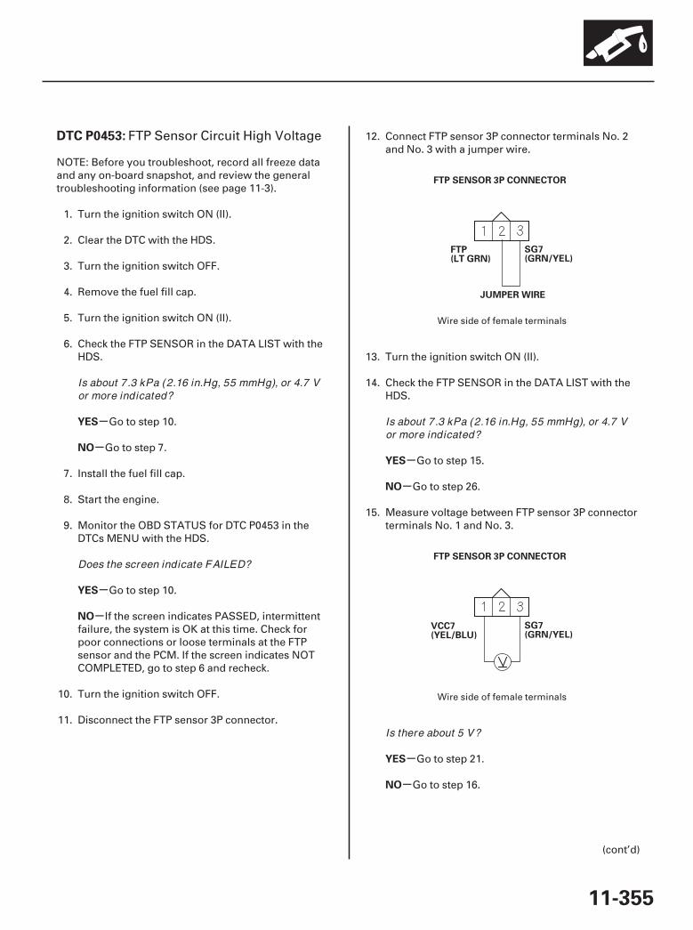
01
02
SJC8A00K77100090453FAAT30
-
-
-
-
-
-
-
-
DTC P0453:
YES
NO
YES
NO
YES
NO
YES
NO
11-355
FTP SENSOR 3P CONNECTOR
SG7(GRN/YEL)
FTP(LT GRN)
JUMPER WIRE
FTP SENSOR 3P CONNECTOR
SG7(GRN/YEL)
VCC7(YEL/BLU)
FTP Sensor Circuit High Voltage
NOTE: Before you troubleshoot, record all freeze dataand any on-board snapshot, and review the generaltroubleshooting information (see page 11-3).
1. Turn the ignition switch ON (II).
2. Clear the DTC with the HDS.
3. Turn the ignition switch OFF.
4. Remove the fuel fill cap.
5. Turn the ignition switch ON (II).
6. Check the FTP SENSOR in the DATA LIST with theHDS.
Go to step 10.
Go to step 7.
7. Install the fuel fill cap.
8. Start the engine.
9. Monitor the OBD STATUS for DTC P0453 in theDTCs MENU with the HDS.
Go to step 10.
If the screen indicates PASSED, intermittentfailure, the system is OK at this time. Check forpoor connections or loose terminals at the FTPsensor and the PCM. If the screen indicates NOTCOMPLETED, go to step 6 and recheck.
10. Turn the ignition switch OFF.
11. Disconnect the FTP sensor 3P connector.
12. Connect FTP sensor 3P connector terminals No. 2and No. 3 with a jumper wire.
13. Turn the ignition switch ON (II).
14. Check the FTP SENSOR in the DATA LIST with theHDS.
Go to step 15.
Go to step 26.
15. Measure voltage between FTP sensor 3P connectorterminals No. 1 and No. 3.
Go to step 21.
Go to step 16.
(cont’d)
Wire side of female terminals
Wire side of female terminals
Is about 7.3 kPa (2.16 in.Hg, 55 mmHg), or 4.7 Vor more indicated?
Does the screen indicate FAILED?
Is about 7.3 kPa (2.16 in.Hg, 55 mmHg), or 4.7 Vor more indicated?
Is there about 5 V?
07/05/09 16:59:26 61SJC020_110_0355

03
04
05
06
-
-
-
-
YES
NO
YES
NO
11-356
EVAP System
DTC Troubleshooting (cont’d)
FTP SENSOR 3P CONNECTOR
SG7(GRN/YEL)
JUMPER WIRE
PCM CONNECTOR A (44P)
SG4(GRN/YEL)
FTP SENSOR 3P CONNECTOR
FTP(LT GRN)
JUMPER WIRE
PCM CONNECTOR A (44P)
FTP (LT GRN)
16. Turn the ignition switch OFF.
17. Jump the SCS line with the HDS.
18. Disconnect PCM connector A (44P).
19. Connect FTP sensor 3P connector terminal No. 3 tobody ground with a jumper wire.
20. Check for continuity between PCM connectorterminal A9 and body ground.
Go to step 34.
Repair open in the wire between the PCM (A9)and the FTP sensor, then go to step 28.
21. Turn the ignition switch OFF.
22. Jump the SCS line with the HDS.
23. Disconnect PCM connector A (44P).
24. Connect FTP sensor 3P connector terminal No. 2 tobody ground with a jumper wire.
25. Check for continuity between PCM connectorterminal A33 and body ground.
Go to step 34.
Repair open in the wire between the PCM(A33) and the FTP sensor, then go to step 28.
Wire side of female terminals
Terminal side of female terminals
Wire side of female terminals
Terminal side of female terminals
Is there continuity? Is there continuity?
07/05/09 16:59:27 61SJC020_110_0356
-
-
-
-
-
-
-
-
YES
NO
YES
NO
YES
NO
YES
NO
11-357
26. Turn the ignition switch OFF.
27. Replace the FTP sensor (see page 11-374).
28. Reconnect all connectors.
29. Turn the ignition switch ON (II).
30. Reset the PCM with the HDS.
31. Do the PCM idle learn procedure (see page 11-273).
32. Check for Temporary DTCs or DTCs with the HDS.
Check for poor connections or looseterminals at the FTP sensor and the PCM, then goto step 1.
Go to step 33.
33. Monitor the OBD STATUS for DTC P0453 in theDTCs MENU with the HDS.
Troubleshooting is complete. If any otherTemporary DTCs or DTCs were indicated in step 32,go to the indicated DTC’s troubleshooting.
If the screen indicates FAILED, check for poorconnections or loose terminals at the FTP sensorand the PCM, then go to step 1. If the screenindicates NOT COMPLETED, keep idling until aresult comes on.
34. Reconnect all connectors.
35. Update the PCM if it does not have the latestsoftware (see page 11-7), or substitute a known-good PCM (see page 11-8).
36. Check for Temporary DTCs or DTCs with the HDS.
Check for poor connections or looseterminals at the FTP sensor and the PCM. If thePCM was updated, substitute a known-good PCM(see page 11-8), then recheck. If the PCM wassubstituted, go to step 1.
Go to step 36.
37. Monitor the OBD STATUS for DTC P0453 in theDTCs MENU with the HDS.
If the PCM was updated, troubleshooting iscomplete. If the PCM was substituted, replace theoriginal PCM (see page 11-205). If any otherTemporary DTCs or DTCs were indicated in step 36,go to the indicated DTC’s troubleshooting.
If the screen indicates FAILED, check for poorconnections or loose terminals at the FTP sensorand the PCM. If the PCM was updated, substitute aknown-good PCM (see page 11-8), then recheck. Ifthe PCM was substituted, go to step 1. If the screenindicates NOT COMPLETED, keep idling until aresult comes on.
Is DTC P0453 indicated?
Does the screen indicate PASSED?
Is DTC P0453 indicated?
Does the screen indicate PASSED?
07/05/09 16:59:27 61SJC020_110_0357
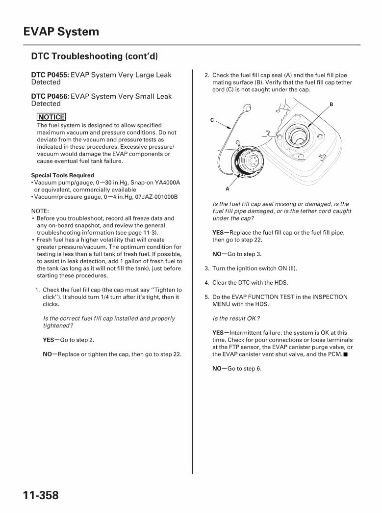
-
-
01
SJC8A00K77100090455FAAT30
-
-
-
-
-
-
DTC P0455:
DTC P0456:
Special Tools Required
YES
NO
YES
NO
YES
NO
11-358
EVAP System
DTC Troubleshooting (cont’d)
A
B
C
EVAP System Very Large LeakDetected
EVAP System Very Small LeakDetected
The fuel system is designed to allow specifiedmaximum vacuum and pressure conditions. Do notdeviate from the vacuum and pressure tests asindicated in these procedures. Excessive pressure/vacuum would damage the EVAP components orcause eventual fuel tank failure.
• Vacuum pump/gauge, 0 30 in.Hg, Snap-on YA4000Aor equivalent, commercially available
• Vacuum/pressure gauge, 0 4 in.Hg, 07JAZ-001000B
NOTE:• Before you troubleshoot, record all freeze data and
any on-board snapshot, and review the generaltroubleshooting information (see page 11-3).
• Fresh fuel has a higher volatility that will creategreater pressure/vacuum. The optimum condition fortesting is less than a full tank of fresh fuel. If possible,to assist in leak detection, add 1 gallon of fresh fuel tothe tank (as long as it will not fill the tank), just beforestarting these procedures.
1. Check the fuel fill cap (the cap must say ‘‘Tighten toclick’’). It should turn 1/4 turn after it’s tight, then itclicks.
Go to step 2.
Replace or tighten the cap, then go to step 22.
2. Check the fuel fill cap seal (A) and the fuel fill pipemating surface (B). Verify that the fuel fill cap tethercord (C) is not caught under the cap.
Replace the fuel fill cap or the fuel fill pipe,then go to step 22.
Go to step 3.
3. Turn the ignition switch ON (II).
4. Clear the DTC with the HDS.
5. Do the EVAP FUNCTION TEST in the INSPECTIONMENU with the HDS.
Intermittent failure, the system is OK at thistime. Check for poor connections or loose terminalsat the FTP sensor, the EVAP canister purge valve, orthe EVAP canister vent shut valve, and the PCM.
Go to step 6.
Is the correct f uel f i l l cap installed and proper lytightened?
Is the fuel f i l l cap seal missing or damaged, is thefuel f i l l pipe damaged, or is the tether cord caughtunder the cap?
Is the result OK ?
07/05/09 16:59:27 61SJC020_110_0358
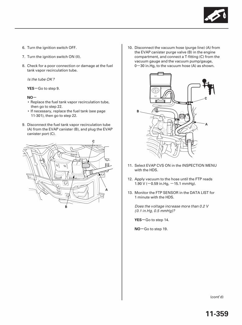
-
- -
02
03
-
-
-
-
YES
NO
YES
NO
11-359
A
B
C
A
B
C
6. Turn the ignition switch OFF.
7. Turn the ignition switch ON (II).
8. Check for a poor connection or damage at the fueltank vapor recirculation tube.
Go to step 9.
• Replace the fuel tank vapor recirculation tube,then go to step 22.
• If necessary, replace the fuel tank (see page11-301), then go to step 22.
9. Disconnect the fuel tank vapor recirculation tube(A) from the EVAP canister (B), and plug the EVAPcanister port (C).
10. Disconnect the vacuum hose (purge line) (A) fromthe EVAP canister purge valve (B) in the enginecompartment, and connect a T-fitting (C) from thevacuum gauge and the vacuum pump/gauge,0 30 in.Hg, to the vacuum hose (A) as shown.
11. Select EVAP CVS ON in the INSPECTION MENUwith the HDS.
12. Apply vacuum to the hose until the FTP reads1.90 V ( 0.59 in.Hg, 15.1 mmHg).
13. Monitor the FTP SENSOR in the DATA LIST for1 minute with the HDS.
Go to step 14.
Go to step 19.
(cont’d)
Is the tube OK ?
Does the voltage increase more than 0.2 V(0.1 in.Hg, 0.5 mmHg)?
07/05/09 16:59:28 61SJC020_110_0359
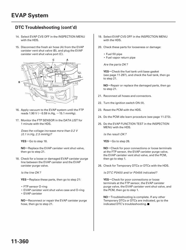
- -
04
-
-
-
-
-
-
-
-
-
-
YES
NO
YES
NO
YES
NO
YES
NO
YES
NO
11-360
EVAP System
DTC Troubleshooting (cont’d)
A
B
C
14. Select EVAP CVS OFF in the INSPECTION MENUwith the HDS.
15. Disconnect the fresh air hose (A) from the EVAPcanister vent shut valve (B), and plug the EVAPcanister vent shut valve port (C).
16. Apply vacuum to the EVAP system until the FTPreads 1.90 V ( 0.59 in.Hg, 15.1 mmHg).
17. Monitor the FTP SENSOR in the DATA LIST for1 minute with the HDS.
Go to step 18.
Replace the EVAP canister vent shut valve,then go to step 21.
18. Check for a loose or damaged EVAP canister purgeline between the EVAP canister and the EVAPcanister purge valve.
Replace these parts, then go to step 21:
• FTP sensor O-ring• EVAP canister vent shut valve case and O-ring• EVAP canister
Reconnect or repair the EVAP canister purgehose, then go to step 21.
19. Select EVAP CVS OFF in the INSPECTION MENUwith the HDS.
20. Check these parts for looseness or damage:
• Fuel fill pipe• Fuel vapor return pipe
Check the fuel tank unit base gasket(see page 11-297), and check the fuel tank, then goto step 21.
Repair or replace the damaged parts, then goto step 21.
21. Reconnect all hoses and connectors.
22. Turn the ignition switch ON (II).
23. Reset the PCM with the HDS.
24. Do the PCM idle learn procedure (see page 11-273).
25. Do the EVAP FUNCTION TEST in the INSPECTIONMENU with the HDS.
Go to step 26.
Check for poor connections or loose terminalsat the FTP sensor, the EVAP canister purge valve,the EVAP canister vent shut valve, and the PCM,then go to step 1.
26. Check for Temporary DTCs or DTCs with the HDS.
Check for poor connections or looseterminals at the FTP sensor, the EVAP canisterpurge valve, the EVAP canister vent shut valve, andthe PCM, then go to step 1.
Troubleshooting is complete. If any otherTemporary DTCs or DTCs are indicated, go to theindicated DTC’s troubleshooting.
Does the voltage increase more than 0.2 V(0.1 in.Hg, 2.5 mmHg)?
Is the line OK ?
Are the parts OK ?
Is the result OK ?
Is DTC P0455 and/ or P0456 indicated?
07/05/09 16:59:28 61SJC020_110_0360

01
02
SJC8A00K77100090457FAAT30
-
-
-
-
-
-
-
-
DTC P0457:
YES
NO
YES
NO
YES
NO
YES
NO
11-361
A
B
C
A
EVAP System Leak Detected/FuelFill Cap Loose or Missing
NOTE: Before you troubleshoot, record all freeze dataand any on-board snapshot, and review the generaltroubleshooting information (see page 11-3).
1. Check the fuel fill cap (the cap must say ‘‘Tighten toclick’’). It should turn 1/4 turn after it’s tight, then itclicks.
Go to step 2.
Replace or tighten the cap, then go to step 19.
2. Check the fuel fill cap seal (A) and the fuel fill pipemating surface (B). Verify that the fuel fill cap tethercord (C) is not caught under the cap.
Replace the fuel fill cap or the fuel fill pipe,then go to step 19.
Go to step 3.
3. Turn the ignition switch ON (II).
4. Clear the DTC with the HDS.
5. Do the EVAP FUNCTION TEST in the INSPECTIONMENU with the HDS.
Intermittent failure, the system is OK at thistime. Check for poor connections or loose terminalsat the FTP sensor, the EVAP canister vent shutvalve, and the PCM.
Go to step 6.
6. Turn the ignition switch OFF.
7. Remove the EVAP canister vent shut valve from theEVAP canister (see page 11-375).
8. Connect the 2P connector to the EVAP canister ventshut valve.
9. Turn the ignition switch ON (II).
10. Select EVAP CVS ON in the INSPECTION MENUwith the HDS.
11. Check the EVAP canister vent shut valve (A)operation.
Check the routing of the EVAP canister venttube, then go to step 18.
Go to step 12.
(cont’d)
Is the correct f uel f i l l cap installed and proper lytightened?
Is the fuel f i l l cap seal missing or damaged, is thefuel f i l l pipe damaged, or is the tether cord caughtunder the cap?
Is the result OK ?
Does the valve operate?
07/05/09 16:59:53 61SJC020_110_0361
-
-
-
-
-
-
YES
NO
YES
NO
YES
NO
11-362
EVAP System
DTC Troubleshooting (cont’d)
12. Turn the ignition switch OFF.
13. Replace the EVAP canister vent shut valve(see page 11-375).
14. Turn the ignition switch ON (II).
15. Reset the PCM with the HDS.
16. Do the PCM idle learn procedure (see page 11-273).
17. Do the EVAP FUNCTION TEST in the INSPECTIONMENU with the HDS.
Go to step 23.
Check for poor connections or loose terminalsat the FTP sensor, the EVAP canister vent shutvalve, and the PCM, then go to step 1.
18. Reinstall the EVAP canister vent shut valve.
19. Turn the ignition switch ON (II).
20. Reset the PCM with the HDS.
21. Do the PCM idle learn procedure (see page 11-273).
22. Do the EVAP FUNCTION TEST in the INSPECTIONMENU with the HDS.
Go to step 23.
Check for poor connections or loose terminalsat the FTP sensor, the EVAP canister vent shutvalve, and the PCM, then go to step 1.
23. Check for Temporary DTCs or DTCs with the HDS.
Check for poor connections or looseterminals at the FTP sensor, the EVAP canister ventshut valve, and the PCM, then go to step 1.
Troubleshooting is complete. If any otherTemporary DTCs or DTCs are indicated, go to theindicated DTC’s troubleshooting.
Is the result OK ?
Is the result OK ?
Is DTC P0457 indicated?
07/05/09 16:59:53 61SJC020_110_0362
SJC8A00K77100090496FAAT30
-
-
-
-
-
-
DTC P0496:
YES
NO
YES
NO
YES
NO
11-363
EVAP System High Purge Flow
NOTE: Before you troubleshoot, record all freeze dataand any on-board snapshot, and review the generaltroubleshooting information (see page 11-3).
1. Turn the ignition switch ON (II).
2. Clear the DTC with the HDS.
3. Do the EVAP FUNCTION TEST in the INSPECTIONMENU with the HDS.
Intermittent failure, the system is OK at thistime. Check for poor connections or loose terminalsat the FTP sensor, the EVAP canister purge valve,the EVAP canister vent shut valve, and the PCM.
Go to step 4.
4. Turn the ignition switch OFF.
5. Replace the EVAP canister purge valve (see page11-374).
6. Turn the ignition switch ON (II).
7. Reset the PCM with the HDS.
8. Do the PCM idle learn procedure (see page 11-273).
9. Do the EVAP FUNCTION TEST in the INSPECTIONMENU with the HDS.
Go to step 10.
Check for poor connections or loose terminalsat the FTP sensor, the EVAP canister purge valve,the EVAP canister vent shut valve, and the PCM,then go to step 1.
10. Check for Temporary DTCs or DTCs with the HDS.
Check for poor connections or looseterminals at the FTP sensor, the EVAP canisterpurge valve, the EVAP canister vent shut valve, andthe PCM, then go to step 1.
Troubleshooting is complete. If any otherTemporary DTCs or DTCs are indicated, go to theindicated DTC’s troubleshooting.
Is the result OK ?
Is the result OK ?
Is DTC P0496 indicated?
07/05/09 16:59:53 61SJC020_110_0363

-- -
01
SJC8A00K77100090497FAAT30
-
-
-
-
-
-
-
-
DTC P0497:
Special Tools Required
YES
NO
YES
NO
YES
NO
YES
NO
11-364
EVAP System
DTC Troubleshooting (cont’d)
A
B
C
EVAP System Low Purge Flow
• Vacuum/pressure gauge, 0 4 in.Hg, 07JAZ-001000B• Vacuum pump/gauge, 0 30 in.Hg, Snap-on YA4000Aor equivalent, commercially available
NOTE: Before you troubleshoot, record all freeze dataand any on-board snapshot, and review the generaltroubleshooting information (see page 11-3).
1. Check the fuel fill cap installation (The cap labelmust say ‘‘Tighten to click’’. The cap should tighten1/4 turn after it is tight.).
Go to step 2.
Properly install the fuel fill cap, then go tostep 24.
2. Turn the ignition switch ON (II).
3. Clear the DTC with the HDS.
4. Do the EVAP FUNCTION TEST in the INSPECTIONMENU with the HDS.
Intermittent failure, the system is OK at thistime. Check for poor connections or loose terminalsat the FTP sensor, the EVAP canister purge valve, orthe EVAP canister vent shut valve, and the PCM.
Go to step 5.
5. Check for a loose or damaged EVAP canister purgeline between the intake manifold and the EVAPcanister purge valve.
Go to step 6.
Reconnect or repair the EVAP canister purgeline, then go to step 24.
6. Disconnect the vacuum hose (A) from the EVAPcanister purge valve joint (B) in the enginecompartment, and connect a T-fitting (C) from thevacuum gauge and the vacuum pump/gauge,0 30 in.Hg, to the vacuum hose as shown.
7. Select EVAP PCS ON in the INSPECTION MENUwith the HDS.
8. Slowly apply about 0.6 in.Hg (15 mmHg) of vacuumto the hose.
Replace the EVAP canister purge valve(see page 11-374), then go to step 23.
Go to step 9.
Is the fuel f i l l cap installed and proper lytightened?
Is the result OK ?
Is the line OK ?
Does it hold vacuum?
07/05/09 16:59:54 61SJC020_110_0364
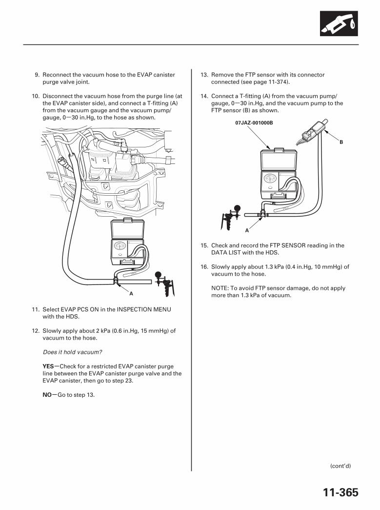
-
-
0203
-
-
YES
NO
11-365
A
07JAZ-001000B
A
B
9. Reconnect the vacuum hose to the EVAP canisterpurge valve joint.
10. Disconnect the vacuum hose from the purge line (atthe EVAP canister side), and connect a T-fitting (A)from the vacuum gauge and the vacuum pump/gauge, 0 30 in.Hg, to the hose as shown.
11. Select EVAP PCS ON in the INSPECTION MENUwith the HDS.
12. Slowly apply about 2 kPa (0.6 in.Hg, 15 mmHg) ofvacuum to the hose.
Check for a restricted EVAP canister purgeline between the EVAP canister purge valve and theEVAP canister, then go to step 23.
Go to step 13.
13. Remove the FTP sensor with its connectorconnected (see page 11-374).
14. Connect a T-fitting (A) from the vacuum pump/gauge, 0 30 in.Hg, and the vacuum pump to theFTP sensor (B) as shown.
15. Check and record the FTP SENSOR reading in theDATA LIST with the HDS.
16. Slowly apply about 1.3 kPa (0.4 in.Hg, 10 mmHg) ofvacuum to the hose.
NOTE: To avoid FTP sensor damage, do not applymore than 1.3 kPa of vacuum.
(cont’d)
Does it hold vacuum?
07/05/09 16:59:54 61SJC020_110_0365
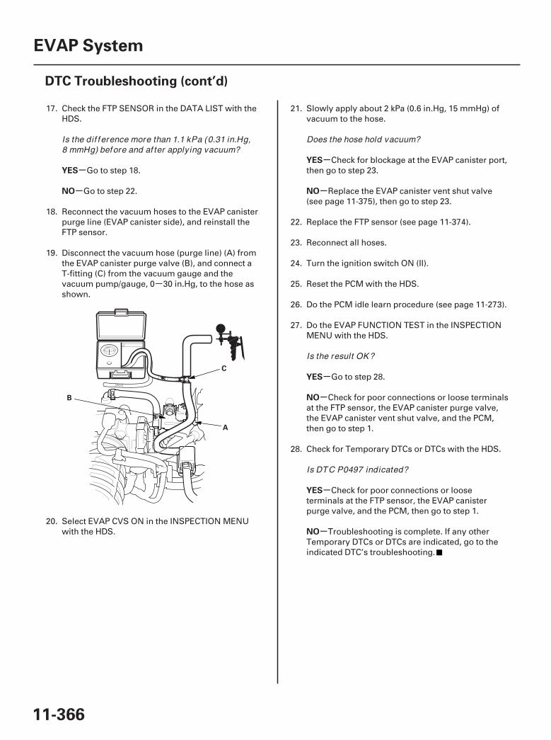
-
04
-
-
-
-
-
-
-
-
YES
NO
YES
NO
YES
NO
YES
NO
11-366
EVAP System
DTC Troubleshooting (cont’d)
A
B
C
17. Check the FTP SENSOR in the DATA LIST with theHDS.
Go to step 18.
Go to step 22.
18. Reconnect the vacuum hoses to the EVAP canisterpurge line (EVAP canister side), and reinstall theFTP sensor.
19. Disconnect the vacuum hose (purge line) (A) fromthe EVAP canister purge valve (B), and connect aT-fitting (C) from the vacuum gauge and thevacuum pump/gauge, 0 30 in.Hg, to the hose asshown.
20. Select EVAP CVS ON in the INSPECTION MENUwith the HDS.
21. Slowly apply about 2 kPa (0.6 in.Hg, 15 mmHg) ofvacuum to the hose.
Check for blockage at the EVAP canister port,then go to step 23.
Replace the EVAP canister vent shut valve(see page 11-375), then go to step 23.
22. Replace the FTP sensor (see page 11-374).
23. Reconnect all hoses.
24. Turn the ignition switch ON (II).
25. Reset the PCM with the HDS.
26. Do the PCM idle learn procedure (see page 11-273).
27. Do the EVAP FUNCTION TEST in the INSPECTIONMENU with the HDS.
Go to step 28.
Check for poor connections or loose terminalsat the FTP sensor, the EVAP canister purge valve,the EVAP canister vent shut valve, and the PCM,then go to step 1.
28. Check for Temporary DTCs or DTCs with the HDS.
Check for poor connections or looseterminals at the FTP sensor, the EVAP canisterpurge valve, and the PCM, then go to step 1.
Troubleshooting is complete. If any otherTemporary DTCs or DTCs are indicated, go to theindicated DTC’s troubleshooting.
Is the dif f erence more than 1.1 kPa (0.31 in.Hg,8 mmHg) before and af ter applying vacuum?
Does the hose hold vacuum?
Is the result OK ?
Is DTC P0497 indicated?
07/05/09 16:59:55 61SJC020_110_0366
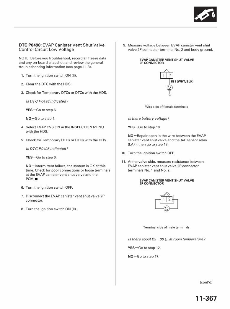
-
01
02
SJC8A00K77100090498FAAT30
-
-
-
-
-
-
-
-
DTC P0498:
YES
NO
YES
NO
YES
NO
YES
NO
11-367
IG1 (WHT/BLK)
EVAP CANISTER VENT SHUT VALVE2P CONNECTOR
EVAP CANISTER VENT SHUT VALVE2P CONNECTOR
EVAP Canister Vent Shut ValveControl Circuit Low Voltage
NOTE: Before you troubleshoot, record all freeze dataand any on-board snapshot, and review the generaltroubleshooting information (see page 11-3).
1. Turn the ignition switch ON (II).
2. Clear the DTC with the HDS.
3. Check for Temporary DTCs or DTCs with the HDS.
Go to step 6.
Go to step 4.
4. Select EVAP CVS ON in the INSPECTION MENUwith the HDS.
5. Check for Temporary DTCs or DTCs with the HDS.
Go to step 6.
Intermittent failure, the system is OK at thistime. Check for poor connections or loose terminalsat the EVAP canister vent shut valve and thePCM.
6. Turn the ignition switch OFF.
7. Disconnect the EVAP canister vent shut valve 2Pconnector.
8. Turn the ignition switch ON (II).
9. Measure voltage between EVAP canister vent shutvalve 2P connector terminal No. 2 and body ground.
Go to step 10.
Repair open in the wire between the EVAPcanister vent shut valve and the A/F sensor relay(LAF), then go to step 18.
10. Turn the ignition switch OFF.
11. At the valve side, measure resistance betweenEVAP canister vent shut valve 2P connectorterminals No. 1 and No. 2.
Go to step 12.
Go to step 17.
(cont’d)
Wire side of female terminals
Terminal side of male terminals
Is DTC P0498 indicated?
Is DTC P0498 indicated?
Is there battery voltage?
Is there about 25 30 at room temperature?
07/05/09 16:59:55 61SJC020_110_0367
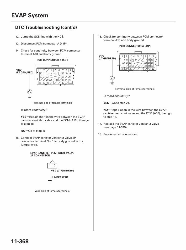
03
04
05
-
-
-
-
YES
NO
YES
NO
11-368
EVAP System
DTC Troubleshooting (cont’d)
PCM CONNECTOR A (44P)
VSV(LT GRN/RED)
VSV (LT GRN/RED)
EVAP CANISTER VENT SHUT VALVE2P CONNECTOR
JUMPER WIRE
PCM CONNECTOR A (44P)
VSV(LT GRN/RED)
12. Jump the SCS line with the HDS.
13. Disconnect PCM connector A (44P).
14. Check for continuity between PCM connectorterminal A10 and body ground.
Repair short in the wire between the EVAPcanister vent shut valve and the PCM (A10), then goto step 18.
Go to step 15.
15. Connect EVAP canister vent shut valve 2Pconnector terminal No. 1 to body ground with ajumper wire.
16. Check for continuity between PCM connectorterminal A10 and body ground.
Go to step 24.
Repair open in the wire between the EVAPcanister vent shut valve and the PCM (A10), then goto step 18.
17. Replace the EVAP canister vent shut valve(see page 11-375).
18. Reconnect all connectors.
Terminal side of female terminals
Wire side of female terminals
Terminal side of female terminals
Is there continuity?
Is there continuity?
07/05/09 16:59:55 61SJC020_110_0368
-
-
-
-
YES
NO
YES
NO
11-369
19. Turn the ignition switch ON (II).
20. Reset the PCM with the HDS.
21. Do the PCM idle learn procedure (see page 11-273).
22. Select EVAP CVS ON in the INSPECTION MENUwith the HDS.
23. Check for Temporary DTCs or DTCs with the HDS.
Check for poor connections or looseterminals at the EVAP canister vent shut valve andthe PCM, then go to step 1.
Troubleshooting is complete. If any otherTemporary DTCs or DTCs are indicated, go to theindicated DTC’s troubleshooting.
24. Reconnect all connectors.
25. Update the PCM if it does not have the latestsoftware (see page 11-7), or substitute a known-good PCM (see page 11-8).
26. Select EVAP CVS ON in the INSPECTION MENUwith the HDS.
27. Check for Temporary DTCs or DTCs with the HDS.
Check for poor connections or looseterminals at the EVAP canister vent shut valve andthe PCM. If the PCM was updated, substitute aknown-good PCM (see page 11-8), then recheck. Ifthe PCM was substituted, go to step 1.
If the PCM was updated, troubleshooting iscomplete. If the PCM was substituted, replace theoriginal PCM (see page 11-205). If any otherTemporary DTCs or DTCs are indicated, go to theindicated DTC’s troubleshooting.
Is DTC P0498 indicated?
Is DTC P0498 indicated?
07/05/09 16:59:56 61SJC020_110_0369
SJC8A00K77100090499FAAT30
-
-
DTC P0499:
YES
NO
11-370
EVAP System
DTC Troubleshooting (cont’d)
EVAP Canister Vent Shut ValveControl Circuit High Voltage
NOTE: Before you troubleshoot, record all freeze dataand any on-board snapshot, and review the generaltroubleshooting information (see page 11-3).
1. Turn the ignition switch ON (II).
2. Clear the DTC with the HDS.
3. Select EVAP CVS ON in the INSPECTION MENUwith the HDS.
4. Check for Temporary DTCs or DTCs with the HDS.
Check for poor connections or looseterminals at the EVAP canister vent shut valve andthe PCM. If the PCM was updated, substitute aknown-good PCM (see page 11-8), then recheck. Ifthe PCM was substituted, go to step 1.
If the PCM was updated, troubleshooting iscomplete. If the PCM was substituted, replace theoriginal PCM (see page 11-205). If any otherTemporary DTCs or DTCs are indicated, go to theindicated DTC’s troubleshooting.
Is DTC P0499 indicated?
07/05/09 16:59:56 61SJC020_110_0370
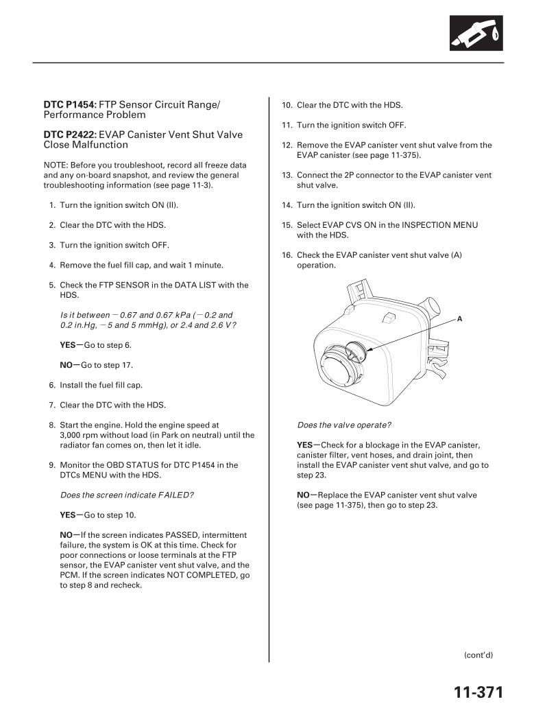
- --
01
SJC8A00K77100091454FAAT30
-
-
-
-
-
-
DTC P1454:
DTC P2422:
YES
NO
YES
NO
YES
NO
11-371
A
FTP Sensor Circuit Range/Performance Problem
EVAP Canister Vent Shut ValveClose Malfunction
NOTE: Before you troubleshoot, record all freeze dataand any on-board snapshot, and review the generaltroubleshooting information (see page 11-3).
1. Turn the ignition switch ON (II).
2. Clear the DTC with the HDS.
3. Turn the ignition switch OFF.
4. Remove the fuel fill cap, and wait 1 minute.
5. Check the FTP SENSOR in the DATA LIST with theHDS.
Go to step 6.
Go to step 17.
6. Install the fuel fill cap.
7. Clear the DTC with the HDS.
8. Start the engine. Hold the engine speed at3,000 rpm without load (in Park on neutral) until theradiator fan comes on, then let it idle.
9. Monitor the OBD STATUS for DTC P1454 in theDTCs MENU with the HDS.
Go to step 10.
If the screen indicates PASSED, intermittentfailure, the system is OK at this time. Check forpoor connections or loose terminals at the FTPsensor, the EVAP canister vent shut valve, and thePCM. If the screen indicates NOT COMPLETED, goto step 8 and recheck.
10. Clear the DTC with the HDS.
11. Turn the ignition switch OFF.
12. Remove the EVAP canister vent shut valve from theEVAP canister (see page 11-375).
13. Connect the 2P connector to the EVAP canister ventshut valve.
14. Turn the ignition switch ON (II).
15. Select EVAP CVS ON in the INSPECTION MENUwith the HDS.
16. Check the EVAP canister vent shut valve (A)operation.
Check for a blockage in the EVAP canister,canister filter, vent hoses, and drain joint, theninstall the EVAP canister vent shut valve, and go tostep 23.
Replace the EVAP canister vent shut valve(see page 11-375), then go to step 23.
(cont’d)
Is it between 0.67 and 0.67 kPa ( 0.2 and0.2 in.Hg, 5 and 5 mmHg), or 2.4 and 2.6 V?
Does the screen indicate FAILED?
Does the valve operate?
07/05/09 16:59:56 61SJC020_110_0371
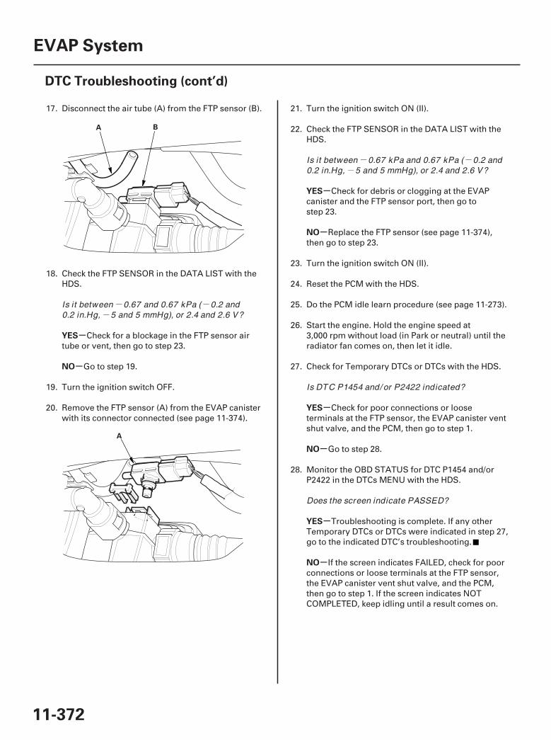
- --
- --
02
03
-
-
-
-
-
-
-
-
YES
NO
YES
NO
YES
NO
YES
NO
11-372
EVAP System
DTC Troubleshooting (cont’d)
A B
A
17. Disconnect the air tube (A) from the FTP sensor (B).
18. Check the FTP SENSOR in the DATA LIST with theHDS.
Check for a blockage in the FTP sensor airtube or vent, then go to step 23.
Go to step 19.
19. Turn the ignition switch OFF.
20. Remove the FTP sensor (A) from the EVAP canisterwith its connector connected (see page 11-374).
21. Turn the ignition switch ON (II).
22. Check the FTP SENSOR in the DATA LIST with theHDS.
Check for debris or clogging at the EVAPcanister and the FTP sensor port, then go tostep 23.
Replace the FTP sensor (see page 11-374),then go to step 23.
23. Turn the ignition switch ON (II).
24. Reset the PCM with the HDS.
25. Do the PCM idle learn procedure (see page 11-273).
26. Start the engine. Hold the engine speed at3,000 rpm without load (in Park or neutral) until theradiator fan comes on, then let it idle.
27. Check for Temporary DTCs or DTCs with the HDS.
Check for poor connections or looseterminals at the FTP sensor, the EVAP canister ventshut valve, and the PCM, then go to step 1.
Go to step 28.
28. Monitor the OBD STATUS for DTC P1454 and/orP2422 in the DTCs MENU with the HDS.
Troubleshooting is complete. If any otherTemporary DTCs or DTCs were indicated in step 27,go to the indicated DTC’s troubleshooting.
If the screen indicates FAILED, check for poorconnections or loose terminals at the FTP sensor,the EVAP canister vent shut valve, and the PCM,then go to step 1. If the screen indicates NOTCOMPLETED, keep idling until a result comes on.
Is it between 0.67 and 0.67 kPa ( 0.2 and0.2 in.Hg, 5 and 5 mmHg), or 2.4 and 2.6 V?
Is it between 0.67 kPa and 0.67 kPa ( 0.2 and0.2 in.Hg, 5 and 5 mmHg), or 2.4 and 2.6 V?
Is DTC P1454 and/ or P2422 indicated?
Does the screen indicate PASSED?
07/05/09 16:59:56 61SJC020_110_0372
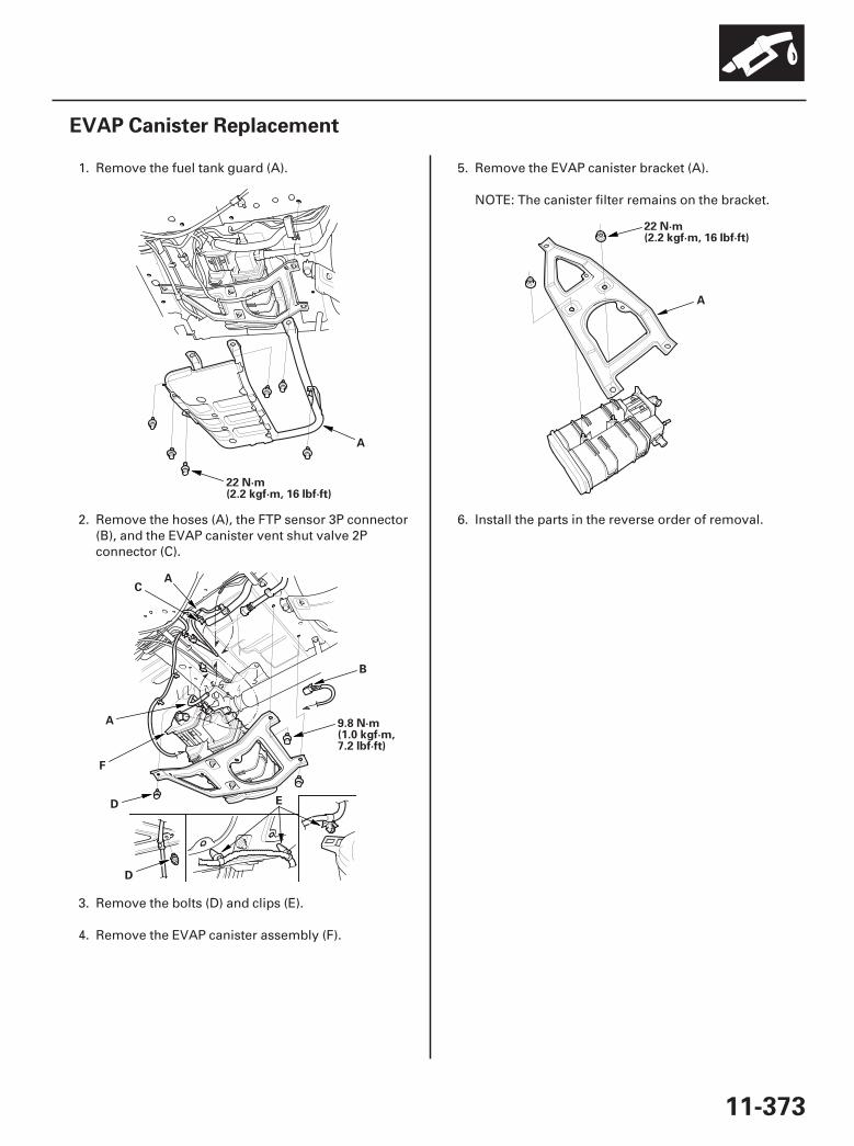
01
01
03
SJC8A00A20323425211KBAT00
11-373
EVAP Canister Replacement
22 N·m(2.2 kgf·m, 16 lbf·ft)
A
A
B
C
D E
A
D
9.8 N·m(1.0 kgf·m,7.2 lbf·ft)
F
22 N·m(2.2 kgf·m, 16 lbf·ft)
A
1. Remove the fuel tank guard (A).
2. Remove the hoses (A), the FTP sensor 3P connector(B), and the EVAP canister vent shut valve 2Pconnector (C).
3. Remove the bolts (D) and clips (E).
4. Remove the EVAP canister assembly (F).
5. Remove the EVAP canister bracket (A).
NOTE: The canister filter remains on the bracket.
6. Install the parts in the reverse order of removal.
07/05/09 16:59:57 61SJC020_110_0373
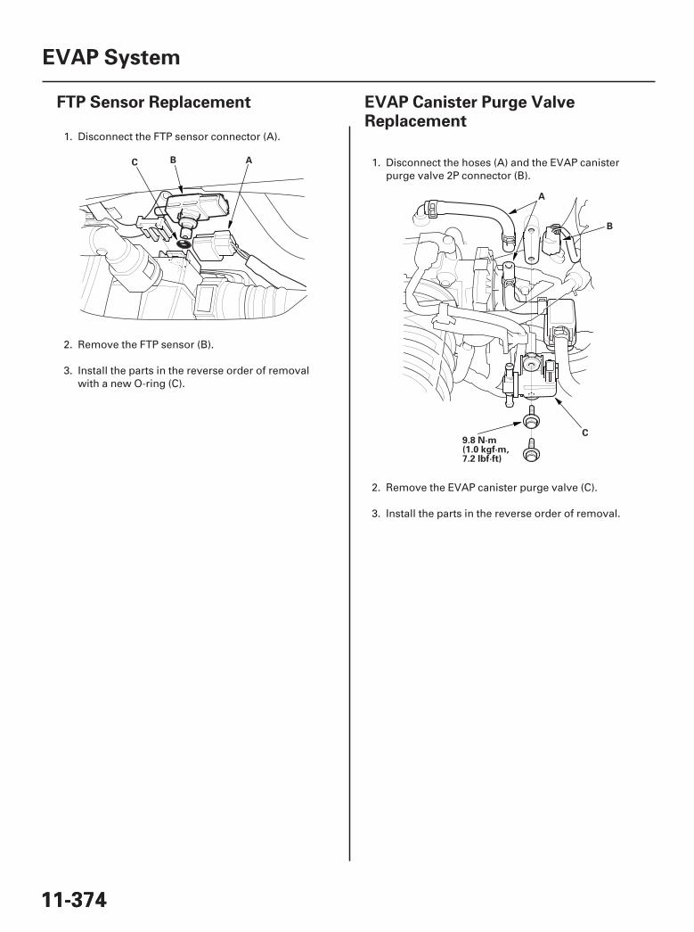
01
SJC8A00A20323428511KBAT00
01
SJC8A00A20323425221KBAT00
11-37411-374
EVAP System
FTP Sensor Replacement EVAP Canister Purge ValveReplacement
ABC
A
B
C9.8 N·m(1.0 kgf·m,7.2 lbf·ft)
1. Disconnect the FTP sensor connector (A).
2. Remove the FTP sensor (B).
3. Install the parts in the reverse order of removalwith a new O-ring (C).
1. Disconnect the hoses (A) and the EVAP canisterpurge valve 2P connector (B).
2. Remove the EVAP canister purge valve (C).
3. Install the parts in the reverse order of removal.
07/05/09 16:59:58 61SJC020_110_0374
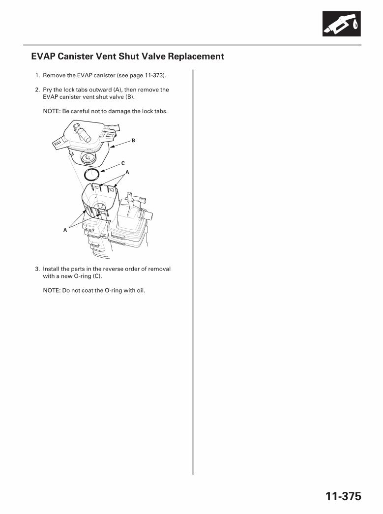
01
SJC8A00A20323425212KBAT00
11-375
EVAP Canister Vent Shut Valve Replacement
A
B
C
A
1. Remove the EVAP canister (see page 11-373).
2. Pry the lock tabs outward (A), then remove theEVAP canister vent shut valve (B).
NOTE: Be careful not to damage the lock tabs.
3. Install the parts in the reverse order of removalwith a new O-ring (C).
NOTE: Do not coat the O-ring with oil.
07/05/09 16:59:58 61SJC020_110_0375