
Nlight Air Operation, Programming and Maintenance Manual
295
Nlight Air Operation, Programming and Maintenance Manual Project Name: Project Location: Acuity Agency: Order #: PO #: Project ID: Date: Controls Tech Support: 1-800-535-2465 - option 1: nLight; option 2: SSI; option 3: Fresco; option 4: Synergy; option 5: LC&D/Bluebox; option 6 ROAM To preschedule a call with tech support (providing a 4 hour business lead time) go to the following link: http://www.acuitybrands.com/resources/schedule-support-request Additional Technical Literature: https://www.acuitybrands.com/products/controls/nlightair 1
-
Upload
khangminh22 -
Category
Documents
-
view
0 -
download
0
Transcript of Nlight Air Operation, Programming and Maintenance Manual

Nlight Air Operation, Programming and
Maintenance Manual
Project Name: Project Location: Acuity Agency: Order #: PO #: Project ID: Date:
Controls Tech Support: 1-800-535-2465 - option 1: nLight; option 2: SSI; option 3: Fresco; option 4: Synergy; option 5: LC&D/Bluebox; option 6 ROAM
To preschedule a call with tech support (providing a 4 hour business lead time) go to the following link:http://www.acuitybrands.com/resources/schedule-support-request
Additional Technical Literature: https://www.acuitybrands.com/products/controls/nlightair
1

Table of Contents
Nlight Air Quick Start Guide ........................................................................................................ 3
Ecylpse User Reference Guide .................................................................................................. 6
SensorView Installation Guide…......................................................................................…….140
2
SensorView User Manual…......................................................................................……........141
CLAIRITY Pro Mobile App User Guide….......................................................................….......264

Acuity Brands | One Lithonia Way Conyers, GA 30012 Phone: 800.535.2465 www.acuitycontrols.com © 2017 Acuity Brands Lighting, Inc. All rights reserved. 03/21/18 912-00058-001
1 of 3
nLight® AIR Quick Start GuideThe 5 C’s of nLight AIR Installation and Startup
Create a login by touching Sign up
Construction
CreateFor new users, use the Clairity™ mobile app to create a User ID (email address) and password. Then, create your Site in Clairity by entering the required information about the Site. This may be completed before installation of the devices. It is recommended that you share the Site with others so they may assist with startup, on-going maintenance, or future re-purposing (see Collaborate on next page).
Zone
Group
Site
An internet connection is required to log in and create a Site within Clairity.
Insert email address & touch
Send verification code
Paste code from email & touch Verify code
Check email
for verification code
Complete enteringsign-up information
Create an account:
Create aSite:
Touch the + to create a Site
Enter Site details& touch Create
Install and energize the nLight AIR devices (fixtures and wall switches). At least one group of nLight AIR devices must be installed prior to starting the Configure step.
Definitions
Zone: One or more devices that have common programming. A device can be in multiple Zones.Group: A set of devices and one or more Zones that are intended to function together. Typically used for room-level programing.Site: A set of groups, zones, and devices that reside in a certain building or address.
3

Acuity Brands | One Lithonia Way Conyers, GA 30012 Phone: 800.535.2465 www.acuitycontrols.com © 2017 Acuity Brands Lighting, Inc. All rights reserved. 03/21/18 912-00058-001
2 of 3
Use the Clairity mobile app to identify a group of devices and place them on the grid.
Configure
Select Devices, then touch the +
First select a Device Type (we selected Sensors). Once the devices populate, touch Identify and the
device will blink to identify itself.
Next, touch the arrow > and place the device on the grid that appears.
Note: To identify a switch, first press any button on the physical switch(s) to wake.Then touch device type Switches, and the list of awake switches will populate.
Use the Clairity mobile app to create zones of control and define behaviors for each. Each device can be in one or more zones
Customize
Select Zones Touch devices to add them to the Zone, then touch Done
Select Behaviors then touch the + Define Behaviors for each Zone & Touch Save Select a Behavior
Touch the + Enter Zone name then touch Create
Create aZone:
Program Zone Behaviors:
4

Acuity Brands | One Lithonia Way Conyers, GA 30012 Phone: 800.535.2465 www.acuitycontrols.com © 2017 Acuity Brands Lighting, Inc. All rights reserved. 03/21/18 912-00058-001
3 of 3
Step 1. Log in to air.acuitynext.com using the email address and password you created to login to the Clairity Mobile App
Step 2. Click “Site Share”
Step 3. Select the site to share by moving through the list or, if you know the site name, using the Search function
Step 4. To share a site with a User, enter the User’s email address into the Search bar.
NOTE: Sharing sites requires that all Users already have created a Clairity account.
Using the login and password you created for the Clairity mobile app, log into air.acuitynext.com to share your site with your customer or colleagues. You may share the site with the end user for their ongoing maintenance or with colleagues so they may assist with support. Choose site share in the header, select the site to share, and add users to receive access.
Collaborate
5

ECLYPSE®User Reference Guide
6

nLight ECLYPSE 2
Table of Contents CHAPTER 1 .................................................................................................................................................. 5
INTRODUCTION ...................................................................................................................................... 5
Overview ............................................................................................................................................. 6
About This User Guide ........................................................................................................................ 7
Acronyms and Abbreviations Used in this Document ........................................................................ 9
CHAPTER 2 ................................................................................................................................................ 11
INTERNET PROTOCOL SUITE FUNDAMENTALS ................................................................................... 11
About the Internet Network ............................................................................................................. 12
Internet Protocol Suite Overview ..................................................................................................... 13
CHAPTER 3 ................................................................................................................................................ 14
IPV4 COMMUNICATION FUNDAMENTALS .......................................................................................... 14
DHCP versus Manual Network Settings ............................................................................................ 15
About Routers, Switches, and Hubs ................................................................................................. 15
CHAPTER 4 ................................................................................................................................................ 18
nLight ECLYPSE CONTROLLER IP NETWORK PROTOCOLS AND PORT NUMBERS .............................. 18
About Port Numbers ......................................................................................................................... 19
nLight ECLYPSE IP Network Port Numbers and Protocols ................................................................ 20
nLight ECLYPSE Services that Require Internet Connectivity ........................................................... 22
CHAPTER 5 ................................................................................................................................................ 23
CONNECTING IP DEVICES TO AN IP NET ............................................................................................ 23
WORK .................................................................................................................................................... 23
Connecting the IP Network ............................................................................................................... 24
Wireless Network Connection .......................................................................................................... 28
Wireless Network Commissioning Architectures ............................................................................. 54
CHAPTER 6 ................................................................................................................................................ 59
FIRST TIME CONNECTION TO AN nLight ECLYPSE CONTROLLER ....................................................... 59
Connecting to the Controller ........................................................................................................... 60
Wi-Fi Network Connection ............................................................................................................... 64
Configuring the Controller ................................................................................................................ 65
Connecting to the Controller’s Configuration Web .......................................................................... 69
7

nLight ECLYPSE 3
Interface ........................................................................................................................................... 69
CHAPTER 7 ................................................................................................................................................ 70
nLight ECLYPSE WEB INTERFACE .......................................................................................................... 70
Overview ........................................................................................................................................... 71
Network Settings ............................................................................................................................... 75
BACnet Settings ................................................................................................................................ 82
User Management ............................................................................................................................ 89
System Settings ......................................................................................................................................... 95
CHAPTER 8 ................................................................................................................................................ 95
CONFIGURING THE nLight ECLYPSE WI-FI ........................................................................................... 95
ADAPTER WIRELESS NETWORKS ......................................................................................................... 95
Setting up a Wi-Fi Client Wireless Network ...................................................................................... 96
Setting up a Wi-Fi Access Point Wireless Network ........................................................................... 97
Setting up a Wi-Fi Hotspot Wireless Network .................................................................................. 99
CHAPTER 9 .............................................................................................................................................. 101
SECURING AN nLight ECLYPSE CONTROLLER ..................................................................................... 101
Introduction .................................................................................................................................... 102
Passwords ....................................................................................................................................... 103
Account Management and Permissions ......................................................................................... 104
HTTPS Certificates ........................................................................................................................... 106
Additional Measures ....................................................................................................................... 107
External Factors .............................................................................................................................. 108
CHAPTER 10 ............................................................................................................................................. 109
BACNET MS/TP COMMUNICATION DATA ........................................................................................... 109
BUS FUNDAMENTALS ......................................................................................................................... 109
BACnet MS/TP Data Transmission Essentials .................................................................................. 110
Maximum Number of BACnet MS/TP Devices on a ........................................................................ 112
Data Bus Segment and Baud Rate .................................................................................................. 112
Data Bus Physical Specifications and Cable Require- ments ........................................................... 115
Data Bus Topology and EOL Terminations ....................................................................................... 117
Data Bus Shield Grounding Requirements ..................................................................................... 121
Using Repeaters to Extend the Data Bus ........................................................................................ 125
Device Addressing ........................................................................................................................... 128
Power Supply Requirements for 24VAC-Powered .......................................................................... 135
8

nLight ECLYPSE 4
Controllers ...................................................................................................................................... 135
CHAPTER 11 ............................................................................................................................................ 138
Resetting or Rebooting the Controller ............................................................................................... 138
Resetting or Rebooting the Controller ........................................................................................... 139
CHAPTER 16 ............................................................................................................................................ 140
NECY CONTROLLER TROUBLESHOOTING .......................................................................................... 140
CHAPTER 18 ............................................................................................................................................ 145
WI-FI NETWORK TROUBLESHOOTING GUIDE .................................................................................. 145
9

nLight ECLYPSE 5
CHAPTER 1 INTRODUCTION
This section provides an overview of the user guide.
Topics Overview About This User Guide Acronyms and Abbreviations Used in this Document
10

nLight ECLYPSE 6
Overview
This document describes best practices, specifications, wiring rules, and application information to implement robust and reliable communications net- works.
About the NECY Series Controller
The NECY Series Controller is a modular and scalable platform that is used to control a wide range of HVAC applications. It uses IP protocol to communicate on wired Ethernet networks and Wi-Fi to communication on wireless net- works.
This user guide also explains how to connect to the nLIGHT ECLYPSE controller’s configuration interfaces.
About the IP Protocol Suite
Distech Controls’ nLight ECLYPSE Series controllers use a widely used IP protocol to communicate with each other and with other applications for control and supervision. What is commonly referred to as IP is actually a multi-layered protocol suite that reliably transmits data over the public Internet and privately firewalled-off intranets. As integral part of our interconnected world, this proto- col is used by applications such as the World Wide Web, email, File Transfer Protocol (FTP), datashares, and so on.
nLight ECLYPSE Series controllers are able to work across geographic boundaries as a unified entity for control and administration purposes.
About BACnet®
The BACnet® ANSI/ASHRAE™ Standard 135-2008 specifies a number of Local Area Network(LAN) transport types. Distech Controls’ controllers sup- port both BACnet/IP and BACnet Master-Slave/Token-Passing (MS/TP) com- munications data bus (based on the EIA-485 medium) as a local network for inter-networking of supervisory controllers and field controllers.
11

nLight ECLYPSE 7
About This User Guide
Purpose of the User Guide
This user guide does not provide and does not intend to provide instructions for safe wiring practices. It is the user’s responsibility to adhere to the safety codes, safe wiring guidelines, and safe work- ing practices to conform to the rules and regulations in effect in the job site jurisdiction. This user guide does not intend to provide all the information and knowledge of an experienced HVAC technician or engineer.
This user guide shows you how to integrate nLight ECLYPSE controllers into your IP network environment while enforcing standard network security practices.
Referenced Documentation
The follow documentation is referenced in this document.
• Controller Hardware Installation Guides: These documents are availableat www.acuitybrands.com
nLIGHT ECLYPSE Introduction
The nLight ECLYPSE series is a modular and scalable platform that is used to control a wide range of HVAC applications. It supports BACnet/IP communication and is a listed BACnet Building Controller (B-BC).
The nECY Series Controller consists of an automation and connectivity server, power supply, and I/O extension modules.
This programmable Connected System Controller provides advanced func- tionality such as customizable control logic, Web-based design and visualiza- tion interface (ENVYSION embedded), logging, alarming, and scheduling.
This user guide also explains how to configure the nLight ECLYPSE controller’s con- figuration interfaces.
Network Security
Maintaining the highest level of network security, especially when IP devices are connected to the Internet requires specially-trained personnel who are aware of the necessary techniques to ensure continued protection. This must
12

nLight ECLYPSE 8
include the implementation of a Virtual Private Network (VPN) to connect with IP controllers over the Internet. It is also important to coordinate with Informa- tion Technology (IT) department personnel the use of shared network resources.
At the first connection to an nLight ECLYPSE Controller you will be forced to change the password to a strong password for the admin account to protect access to the controller.
Intended Audience
This user guide is intended for system designers, integrators, electricians, and field technicians who have experience with control systems, and who want to learn about how to make a successful IP network installation. It is recommended that anyone installing and configuring the devices specified in this user guide have prior training in the usage of these devices.
Conventions Used in this Document
Notes
This is an example of Note text. Wherever the note-paper icon appears, it means the associated text is giving a time-saving tip or a reference to associated information of interest.
Cautions and Warnings
This is an example of Caution or Warning text. Wherever the exclamation icon appears, it means that there may be an important safety concern or that an action taken may have a drastic effect on the device, equipment, and/or network if it is improperly carried out.
13

nLight ECLYPSE 9
Acronyms and Abbreviations Used in this Document
Acronym Definition
ASHRAE American Society of Heating, Refrigeration, and Air- Conditioning Engineers
AP Access Point
APDU Application Protocol Data Units
API Application Programming Interface
ASCII American Standard Code for Information Interchange
BACnet® Building Automation and Control Networking Protocol
BAS Building Automation System
B-BC BACnet Building Controller
BBMD BACnet/IP Broadcast Management Device
CIDR Classless Inter-Domain Routing
DHCP Dynamic Host Configuration Protocol
DNS Domain Name System
EOL End Of Line
FTP File Transfer Protocol
HTML HyperText Markup Language
HTTP Hypertext Transfer Protocol
HTTPS Hypertext Transfer Protocol Secure
HVAC Heating, Ventilating, and Air Conditioning
ID Identifier
IP Internet Protocol
IPv4 Internet Protocol version 4
ISP Internet Service Provider
IT Information Technology
LAN Local Area Network
MAC Media Access Control
MB Megabyte
MHz Megahertz
14

nLight ECLYPSE 10
Acronym Definition
MS/TP Master-Slave/Token-Passing
NAT Network Address Translation
NTP Network Time Protocol
PC Personal Computer
RADIUS Remote Authentication Dial-In User Service
REST Representational State Transfer
RTU Remote Terminal Unit (for Modbus)
SSID Service Set IDentification
TCP Transmission Control Protocol
UDP User Datagram Protocol
URL Uniform Resource Locator
USB Universal Serial Bus
VPN Virtual Private Network
WAN Wide Area Network
WPA Wi-Fi Protected Access
WWW World Wide Web
15

nLight ECLYPSE
11
CHAPTER 2
INTERNET PROTOCOL SUITE FUNDAMENTALS
This chapter describes the Internet protocol operating principles necessary to configure the IP parameters of an IP controller.
Topics
About the Internet Network Internet Protocol Suite Overview
16

nLight ECLYPSE 12
About the Internet Network
The Internet is the world-wide interconnection of networks. At its root how- ever, it is not one big network, but a group of networks that communicate between each other by using standard protocols and by using gateways between these networks called routers.
The structure of the Internet is decentralized and non-hierarchical. On the Internet, all communication uses the Internet Protocol (IP) to communicate and all connected devices are identified by their IP address. An Internet Reg- istry allocates IP addresses to internet service providers to be used by their users.
Data is sent across the network in packets. Each packet has a header that identifies the sender’s and intended receiver’s IP addresses.
17
nLight ECLYPSE 13
Internet Protocol Suite Overview
Internet Protocol (IP) is part of a multi-layered suite that together enables data communication. The following descriptions are an overview of the IP suite protocol layers as used by IP devices:
• Physical layer (bits): This is the physical and device-to-device electricalconnection layer otherwise known as Ethernet. This layer defines:
• The requirements for the physical connection between devices (thesignal medium). For example, RJ-45 connectors (attached per TIA/EIA-568-A,), using Cat 5e data cable. The maximum cable lengthbetween devices is 328 ft. (100 m) at 100 MB/s data rate.
• The electrical signal requirements for data packet transport.
• The data packet structure including data payload and the source anddestination device’s MAC addresses.
In the case of Wi-Fi connected devices, the link layer is the air interface defined by the Wi-Fi standard, such as radio frequencies, data rates, authenti- cation, data channel encryption, and so on.
• Data Link layer: This layer implements the ability for two devices toexchange data with each other.
• Network layer: This layer implements the ability to connect multiple dis- tinct networks with each other. It provides the internetworking methodsthat allow data packets to travel from the source device to a destinationdevice across network boundaries, such as a router through the use of anIP address. See
• Transport Layer (segments): This layer provides end-to-end communica- tion data stream connection between two or more devices through a vari- ety of protocols. However
• , it is the Transmission Control Protocol (TCP), the most commonly usedinternet transport protocol that is used by Distech Controls IP controllersto communicate with each other. TCP creates a connection-orientedchannel between two applications; that is to say the data stream is error- checked, is sorted into the correct sequence (missing data packets are re- transmitted) and this data stream has a port number for addressing a spe- cific application at the destination host computer.
• Session layer (data): This layer implements the protocol to open, close,and manage a session between applications such that a dialog can occur.
• Presentation layer: This layer implements the display of media such asimages and graphics.
• Applications layer: This layer implements the process-to-process commu- nications protocol that includes among other services the BACnet/IP pro- tocol, programming, debugging, WWW, and so on.
All of the above IP suite protocol layers must be fully functional for any two devices or controllers to communicate with each other.
18

nLight ECLYPSE
14
CHAPTER 3
IPV4 COMMUNICATION FUNDAMENTALS
This chapter describes IPv4 Communication operating principles.
Topics
DHCP versus Manual Network Settings Networking Basics About Routers, Switches, and Hubs
19

nLight ECLYPSE
15
DHCP versus Manual Network Settings About Routers, Switches, and Hubs
The differences between a hub, switch, and router are discussed in the table below.
Table 1: Difference between a Hub, Switch, and Router
Device Type Description
Hub Every incoming data packet is repeated on every other port on the device. Due to this, all traffic is made available on all ports which increase data packet col- lisions that affect the entire network, thus limiting its data carrying capacity.
Switch A switch creates a one-to-one virtual circuit that directs IP packets directly to the port that the destination computer is connected to. A switch maintains a lookup table that contains the MAC addresses of all the devices that are connected to the switch ports. The switch always refers to its lookup table before it forwards data packets to the destination devices.
Router Like a switch, a router learns the IP addresses of all devices connected to any of its RJ-45 ports to create a routing table. If a data packet arrives at the router’s port with a destination IP address that is:
• Found in the router’s routing table, the router forwards the data packet tothe appropriate port for the device that has this IP address.
• For a network with a different network ID than the current network ID, therouter forwards the data packet to the uplink port where the next router willagain either recognize the network ID and route the data packet locally oragain forwards the data packet to the uplink port. By being exposed totraffic, a router adds to its routing table the pathways necessary to resolvea data packet's pathway to its final destination, by passing through one ormore routers if necessary.
Connecting a Router
The way a router is connected to other devices changes its function.
Figure 2: The Way a Router is Connected Changes its Function Connection to use ROUTER A as a router Connection to NOT use ROUTER A as a router
ROUTER B
1 2 3 4
UPLINK
ROUTER B
1 2 3 4
UPLINK
To To To To To To To To
Device Device Device WAN Device Device Device WAN
ROUTER A
1 2 3 4
UPLINK
ROUTER A
1 2 3 4
UPLINK
To To To To Device Device Device Device
To To To Device Device Device
UPLINK Function is Not Used
20

nLight ECLYPSE 16
On some routers, the uplink port is marked as WAN (Wide Area Network) and the numbered ports are to be connected to the LAN (Local Area Network) devices.
Network Address Translation / Firewall
A router’s uplink port provides Network Address Translation (NAT) and fire- wall functions.
NAT is a method to hide the private IP addresses of a range of devices (con- nected to LAN ports) behind a single IP address presented at the WAN uplink port. NAT uses a mechanism to track requests to WAN IP addresses and readdresses the outgoing IP packets on exit so they appear to originate from the router itself. In the reverse communications path, NAT again readdresses the IP packet’s destination address back to the original source private IP address.
Due to this tracking mechanism, only requests originating from the LAN side can initiate communications. A request from the WAN to the router cannot be mapped into a private address as there is no outbound mapping for the router to use to properly readdress it to a private IP address. This is why a NAT acts as a firewall that blocks unsolicited access to the router’s LAN side.
Most routers allow you to open a port in the firewall so that WAN traffic received at a specific port number is always forwarded to a specific LAN IP address. The standard port numbers used by nLight ECLYPSE controllers is explained in chapter nLight ECLYPSE Controller IP Network Protocols and Port Numbers.
IP Network Segmentation
For efficient network planning, normally the IP controllers will be assigned to their own network segment of an IP network or subnetwork. This is done as shown in the figure below.
21

nLight ECLYPSE
17
Figure 3: Network Segment for HVAC IP Controllers
To ISP Network
ISP Modem (Fiber, Cable , DSL )
LAN
Network
Company Computer Network
Gateway Router
1 2 3 4
UPLINK
To To To
Device Device Device
Router for HVAC IP
Controllers
1 2 3 4
UPLINK
To IP To IP To IP To IP
Controller Controller Controller Controller
For certain wireless topologies, a wireless router can be used to connect nLight ECLYPSE controller. In this scenario, a wireless operator interface (laptop or tablet) can be used for commissioning as shown in the figure below. If the lap- top has a Supervisor installed, it can be used to program ECB series controlers connected to the RS-485 port of the Connected System Controller.
Figure 4: Network Segment for HVAC IP Controllers with a Wireless Access Point
To ISP Network
ISP Modem (Fiber , Cable, DSL )
LAN
Network
Company Computer Network
Gateway Router
1 2 3 4
UPLINK
Wireless
Tablet HMI To To To
Device Device Device
WiFi Router for HVAC IP
Controllers
1 2 3 4
UPLINK
Wireless
Tablet HMI
To IP To IP
To IP
To IP
Controller Controller Controller Controller
If a wireless router is unavailable or is out-of-range, an nLight ECLYPSE Wi-Fi adapter can be connected to an nLight ECLYPSE controller’s USB port to add wire- less connectivity. See Wireless Network Connection.
22

nLight ECLYPSE 18
CHAPTER 4 nLight ECLYPSE CONTROLLER IP NETWORK
PROTOCOLS AND PORT NUMBERS
This chapter describes the IP Network Protocols and Port Numbers used by the nLight ECLYPSE controller.
Topics About Port Numbers nLight ECLYPSE IP Network Port Numbers and Protocols nLight ECLYPSE Services that Require Internet Connectivity
23

nLight ECLYPSE
19
About Port Numbers
In an IP packet, a port number is an extension of the packet’s IP address and completes the destination address for a communications session. By conven- tion, the packet’s port number is associated with a protocol used between software applications and is used to uniquely identify a communications end- point for a specific application or process running on a computer. This allows a multitude of applications to share a single physical connection to the Inter- net while allowing distinct communication channels between different applica- tions.
For example, your web browser listens to port 80 on your computer to receive HTML web pages sent from a web server on port 80.
The standard port numbers used by nLight ECLYPSE controllers is explained in nLight ECLYPSE IP Network Port Numbers and Protocols.
Sometimes, two applications might use the same port number to communi- cate. To sort out this conflict, the following methods can be used.
• In the configuration of some applications, the port number can be
changed from its default setting. Should you change it, you must also change it on the corresponding application also so that the port numbers will match.
• Routers have features such as port forwarding that can change an incom- ing packet’s port number coming from the Wide Area Network (WAN) to another port number on the Local Area Network or vice versa.
24

nLight ECLYPSE 20
nLight ECLYPSE IP Network Port Numbers and Protocols
nLight ECLYPSE uses the following IP Network Protocols to communicate over IPv4 networks. The corresponding default in-bound port number is also shown.
Service Default Port Number (Protocol)
Description Where can this port number be changed?
SMTP 25 (TCP) Outgoing Email server port number. See the EC-gfx Pro- gram User Guide, Resources Configu- ration.
DNS 53 (TCP, UDP) Domain Name Server URL lookup. –
DHCP 67 (UDP) The router’s DHCP service that allows a device to auto-configure a devices’ IP set- tings.
–
HTTP 80 (TCP) EC-gfx Program Debugging Values (REST service): After the control logic or code has been sent to the controller, a live debugger allows programmers to execute code, view input/output values, and trou- bleshoot errors in real-time.
ENVYSION: The ENVYSION server pres- ents system status, trending visualization, real-time equipment visualization, sched- ule configuration, alarm monitoring, and dashboard functions to a Web browser operator interface.
Web Configuration Interface: This is the network configuration interface for wired and wireless IP network interfaces.
See System Settings. If this is used with EC-Net, this parame- ter can be changed in the RestService and WebService.
25

nLight ECLYPSE 21
Service Default Port Number (Protocol)
Description Where can this port number be changed?
HTTPS 443 (TCP) Secure EC-gfx Program Debugging Val- ues (REST service): After the control logic or code has been sent to the control- ler, a live debugger allows programmers to execute code, view input/output values, and troubleshoot errors in real-time.
Secure ENVYSION: The ENVYSION server presents system status, trending visualization, real-time equipment visual- ization, schedule configuration, alarm monitoring, and dashboard functions to a Web browser operator interface. Secure Web Configuration Interface: This is the network configuration interface for wired and wireless IP network interfaces.
See System Settings. If this is used with EC-Net, this parame- ter can be changed in the RestService and WebService.
Radius Server
1812 (UDP) Authentication Port: This is the port on which authentication requests are made.
Radius Server
1813 (UDP) Accounting Port: This is the port on which accounting requests are made. This is only used to receive accounting requests from other RADIUS servers.
Radius Server
1814 (UDP) Proxy Port: This is an internal port used to proxy requests between a local server and a remote server.
See User Manage- ment. If this is used with EC-Net, these parameters must be set in the RadiusSer- vice.
BACnet/IP 47808 (UDP) The BACnet over IP protocol. See BACnet Settings
MQTT 8883 (TCP) Secure MQ Telemetry Transport. This is an internal port that facilitates communication with the nLight Gateway.
26

nLight ECLYPSE
22
nLight ECLYPSE Services that Require Internet Connectivity
In order to operate, the following out-bound services require:
• A working DNS. See Domain Name System (DNS).
• The default gateway / router to be configured. See Default Gateway.
• Internet connectivity.
The corresponding default out-bound port number is also shown.
Service Default Port Number
(Protocol)
Description
SMTP 25 (TCP) Outgoing Email server port number.
Network Time Protocol (NTP)
123 (UDP) Used to set the controller’s real time clock.
DNS server 53 (UDP, TCP) Used to provide URL name resolution. The controller by default uses an internet DNS. If the local network has a DNS, set its IP address in Network Settings.
27

nLight ECLYPSE 23
CHAPTER 5 CONNECTING IP DEVICES TO AN IP NET WORK
An IP network requires infrastructure such as Ethernet cable, routers, switches, or Wi-Fi hotspots in order to work. The following topics discuss the fundamentals of such a network.
Topics Connecting the IP Network Wireless Network Connection Wireless Network Commissioning Architectures
28

nLight ECLYPSE
24
Connecting the IP Network
There are two methods to connect a device to an IP Network:
• Wired (Ethernet connection with the PRI and SEC ports).
• Wireless (when the nLight ECLYPSE Wi-Fi Adapter is connected to the controller).
Wired Network Cable Requirements
Wired networks use commonly available Cat 5e structural cabling fitted with RJ-45 connectors. If you make your own patch cable, use Category 5e cable and crimp the RJ-45 connectors at both ends of the cable either as T568A or T568B.
Table 2: Wired Network Cable Physical Specifications and Requirements
Parameter Details
Media Cat 5e Cable; four (4) pairs of wires with RJ-45 Connectors (stan- dard straight patch cable)
RJ-45 Pin Configuration Straight-through wiring. Crimp connectors as per T568A or T568B (both cable ends must be crimped the same way).
Characteristic impedance 100-130 Ohms
Distributed capacitance Less than 100 pF per meter (30 pF per foot)
Maximum Cat 5e Cable length between IP devices
328 ft. (100 m) maximum. See About the Integrated Ethernet Switch.
Polarity Polarity sensitive
Multi-drop Daisy-chain (no T-connections) nLight ECLYPSE IP devices have two RJ-45 female RJ-45 connectors that provide IP packet switching to support follow-on devices.
Daisy-chain limit, Con- nected System Controllers
Up to 20 devices can be daisy-chained per network switch port.
Daisy-chain limit, Con- nected VAV Controllers
Up to 50 devices can be daisy-chained per network switch port.
EOL terminations Not applicable
Shield grounding Not applicable
29

nLight ECLYPSE
25
.
Table 3: Distech Controls Recommended Cable Types to use for the Cat 5e Cable Subnetwork Bus
Bus and Cable Types Non-Plenum Applications
(Use in Conduit - FT4)
Plenum Applications (FT6)
Part Number O.D. (Ø)1 Part Number O.D. (Ø)1
300 m (1000 feet), Cat 5e Yellow Jacket Cable - Without Connectors
CB-W244P- 1446YLB
4.6mm (0.18in.)
CB-W244P- 2175YEL
4.6mm (0.18in.)
100 Crimp RJ 45 Connectors
CB-W5506E N/A CB-W5506E N/A
1. Outer cable diameter – This does not take into account the RJ-45 connector.
About the Integrated Ethernet Switch
The 2-port wired interface uses a switch to forward packets addressed to downstream IP devices connected to it. This allows controllers to be daisy- chained together to extend the IP network’s physical range and to reduce the amount of network cable required as each controller no longer has to make a home run to the network switch
Figure 5: Wired Network Connection: Daisy-Chained nLight ECLYPSE Controllers
To Other IP Devices
Wired Router / Switch
Cat 5e Cable Daisy-Chained BACnet/IP Controllers 328ft (100m) Maximum
To Next IP Device
Spanning Tree Protocol
Switches and routers that support Spanning Tree Protocol (are IEEE 802.1D certified) are able to detect and eliminate a loop from being formed on the net- work by disabling any port on the router that is causing a loop. Such switches can be used to enhance network availability by allowing you to create a ring network of controllers that is resistant to a single point network failure (a cut wire for example).
In this scenario, controllers are connected in a loop (or ring) such that the last controller is connected back to the switch / router. Under normal operation, the switch / router disables one of the ports to prevent a packet storm. This is shown below.
30

nLight ECLYPSE
26
X
Figure 7: Wired Network Connection: Spanning Tree Protocol – Normal Operation
To Other IP Devices
Wired Router / Switch
The Router / Switch’s Spanning Tree
Protocol has Blocked this Port
Daisy-Chained BACnet/IP
Controllers
When a network wire is cut, the ring is split into two – the switch / router automatically enables the port to maintain service. This is shown below.
31

nLight ECLYPSE
27
Figure 8: Wired Network Connection: Spanning Tree Protocol – Failover Operation To Other IP Devices
Wired Router / Switch
The Port is Automatically Enabled
Daisy-Chained BACnet/IP
Controllers
Cut Network Wire
The switch / router can be configured to send an email message when port blocking is disabled thus signaling that a network wire has been cut.
Connecting the Network Cable to the nLight ECLYPSE Controller
To connect controllers to an Ethernet network and then discover them, see chapter First Time Connection to an nLight ECLYPSE Controller.
32

nLight ECLYPSE 28
Wireless Network Connection
The nLight ECLYPSE Wi-Fi adapter connects to an nLight ECLYPSE controller’s USB port.
Figure 9: nLight ECLYPSE Wi-Fi Adapter
It adds wireless IP connectivity to nLight ECLYPSE controllers and it can be used in a number of wireless topologies and applications.
Recommendations are provided regarding the radio signal obstructions and factors that should be avoided to obtain the best Wi-Fi radio signal transmis- sion and reception. Walls attenuate radio wave propagation by an amount that varies with the construction materials used. See Radio Signal Transmission Obstructions for more information on wall materials that can reduce range transmission.
About the 2.4 GHz ISM band
The 2.4 GHz ISM (Industrial, Scientific and Medical) band has been allocated worldwide for the use of radio frequency energy by industrial, scientific, and medical purposes as part of the device’s method of internal operation and as such may have powerful emissions that cause interference to radio communi- cations.
For example, microwave ovens operate in the 2.4 GHz ISM band with about 1000W emitted power and a fraction of a percent of that energy does leak from the oven. While this is not a health risk, Wi-Fi networks operate at even lower power levels to communicate and can be overwhelmed by this source of interference.
When setting up a 2.4 GHz band Wi-Fi network, you must take into consider- ation any equipment that operates in the 2.4 GHz ISM band such as medical and laboratory equipment. Other sources of interference are other telecom- munications equipment such as cell phones, GSM/DECT, cordless phones, RFID reader, Bluetooth devices, walkie-talkies, baby monitors, and so on. Note that equipment that transmits in other frequency bands do emit spurious emissions at low levels over a wide spectrum so that a radio transmitter in close proximity to the nLight ECLYPSE Wi-Fi adapter can cause interference, even if its operating frequency is 1.9 GHz for example.
33

nLight ECLYPSE
29
Powe
r (Lo
g)
Figure 10: Typical Radio Transmitter Spurious Emissions
Transmitted power
Center Frequency
Occupied Bandwidth
Spurious Emission Amplitude
Frequency
Desired Signal Spurious Emissions
Distance between nLight ECLYPSE Wi-Fi Adapter and Sources of Interference
Unrelated transmitters should be more than 6.5 feet (2 m) away from the nLight ECLYPSE Wi-Fi Adapter to avoid possible interference.
About Wi-Fi Network Channel Numbers
Wi-Fi communications use a slice of radio spectrum or channel width for data transmission. In general terms, the amount of channel width required is pro- portional to the data transmission rate. Wi-Fi networks operate in a number of different frequency ranges or bands such as the 2.4 GHz band. Each band is divided into a number of industry-standard channels that represent a center frequency for data transmission. In practice, the center frequency is the mid- point between the upper and lower cutoff frequencies of the channel width.
When the channel width is larger than the channel spacing (the space between channels), overlap between the channels can occur, resulting in inter-channel interference that lowers overall network throughput. This is shown in the diagram below. For example, in the 2.4 GHz band using 802.11g, the channel width is 20 MHz while the channel spacing is 5 MHz. If one Wi-Fi network is using channel 1 that is in close proximity to another Wi- Fi network that is using channel 2, there will be significant inter-channel over- lap and interference. Data throughput is reduced as a result.
34

nLight ECLYPSE 30
1 2 3 4 5 6 7 8 9 10 11 12 13 14 Channel 2.412 2.417 2.422 2.427 2.432 2.437 2.442 2.447 2.452 2.457 2.462 2.467 2.472 2.484 Center F
Figure 11: 2.4 GHz Band 802.11g Radio Spectrum Showing Inter-Channel Overlap
(GHz) requency
35

nLight ECLYPSE 31
For a 20 MHz channel width in the 2.4 GHz band using 802.11g, the best channels to use to avoid inter-channel overlap are channels 1, 6, and 11. For a 40 MHz channel width in the 2.4 GHz band using 802.11g, the best chan- nels to use to avoid inter-channel overlap are channels 3 and 11.
For a 20 MHz channel width in the 2.4 GHz band using 802.11n, the best channels to use to avoid inter-channel overlap are channels 1, 6, and 11. For a 40 MHz channel width in the 2.4 GHz band using 802.11g, the best channel to use to avoid inter-channel overlap is channel 3.
For industrial / commercial environments, it is recommended to avoid using a 40 MHz channel width in the 2.4 GHz band as it occupies a large part of the available radio spectrum. This means that it will be difficult to co-exist with other networks while avoiding interference, especially from devices that use mixed mode 802.11 b/g which significantly degrades 802.11n performance. One solution is to disable the 802.11 b/g mode on all hotspots to force all wire- less clients to 802.11n mode, thereby forbidding the use of legacy devices.
Radio Signal Range Radio Signal Transmission Obstructions Where to Locate Wireless Adapters
When installing the wireless adapter, it is important to ensure that distances and obstructions do not impede transmission. Metallic parts, such as steel reinforcement in walls, machinery, office furniture, etc. are major sources of field strength dampening. Furthermore, supply areas and elevator shafts should be considered as complete transmission screens, see following figure.
Figure 12: Screening of Radio Waves
Sheet Metal
Transmission Obstructions and Interference
One way to get around an obstruction, such as a duct, is to place the wireless adapter on the side of the obstruction that is nearer to the coordinating wire- less device, even if the controller is on the opposite side of the obstruction. But always keep in mind that the wireless adapter performs best when it is away from metal objects or surfaces (more than 1" (2.5 cm)).
In addition to obstructions, the angle with which the transmission travels through the obstruction has a major influence on the field strength. The steeper the angle through an obstruction, the radio wave has to travel through
36

nLight ECLYPSE 32
more material resulting in the field strength reduction (See Figure 13.). There- fore, it is preferable that the transmission be arranged so that it travels straight and perpendicularly through the obstruction.
Figure 13: Angle of Radio Waves
High Angle of Incidence
A solution to avoid an obstruction is to add another wireless router located closer to the controller(s).
nLight ECLYPSE Wi-Fi Adapter Mounting Tips
This section provides information and examples on how to properly position the nLight ECLYPSE Wi-Fi Adapter to ensure reliable wireless communication. The most common guidelines to remember when installing the nLight ECLYPSE Wi-Fi Adapter is to keep it at least 1” (2.5 cm) away from metal, and never install the nLight ECLYPSE Wi-Fi Adapter inside a metal enclosure (relay panels, junction box, etc.).
Typical Metal Relay Panel/ Utility Box Installation
The following image shows where to install an nLight ECLYPSE Wi-Fi Adapter on a metal relay panel or utility box with a controller inside the panel/box. To maxi- mize wireless range, the nLight ECLYPSE Wi-Fi Adapter must be installed on the top or side of the panel.
Figure 16: nLight ECLYPSE Wi-Fi Adapter Position with Metal Relay Panel/Utility Box
Wireless Adapter installed on top or
side of panel
37

nLight ECLYPSE
33
Wireless Adapter
NOT to be installed inside the panel
Typical Fan Coil Unit Installation
The following example shows where to install an nLight ECLYPSE Wi-Fi Adapter on a fan coil unit with a controller inside the unit.
38

nLight ECLYPSE 34
must be installed on the top or side of the unit with the antenna straightened out and away from the metal. The nLight ECLYPSE Wi-Fi Adapter and antenna should never be installed inside the metal enclosure.
Figure 17: nLight ECLYPSE Wi-Fi Adapter Position on Fan Coil Unit Antenna & receiver installed
on top or side panel
Antenna & receiver NOT to be installed
inside the metal enclosure
Antenna & receiver installed directly on metal panel should be avoided
Planning a Wireless Network
A wireless network can be installed in many different types of floor spaces, large or small: office space, commercial space, residential space, etc. The fol- lowing provides an example on how to start planning a wireless network such as a large office space. This type of planning can also be used with smaller areas.
1. Retrieve a copy of your floor plans and a compass.
Figure 18: Copy of floor plan and a compass
39

nLight ECLYPSE 35
2. Mark relevant radio shadings into floor plan such as: fire protection walls,lavatories, staircases, elevator shafts and supply areas.
Figure 19: Mark relevant radio shadings
3. Draw circles to locate the ideal positions for your nLight ECLYPSE Wi-FiAdapter as shown below:
40

nLight ECLYPSE
36
Staircase w
ell S
taircase w
ell
Up
Dow
n
Figure 20: Radio nLight ECLYPSE Wi-Fi Adapter Location
Radio Shading Up
Down
Elevator Shaft
Wi-Fi Hotspot
Channel 1
Wi-Fi Hotspot Channel 6
Staircase well
Elevator Shaft
Radio Shading
Wi-Fi Hotspot Channel 11
Radio Shading
Up
Down
Make sure that the nLight ECLYPSE Wi-Fi Adapter is positioned in a way such that no screens block the connection to any corner inside the fire safety section (potential sensor positions).
For reliable range planning, the unfavorable conditions should be detected at the beginning but often come from later changes to the environment (room filled with people, alteration of partition walls, furniture, room plants, etc.).
Even after careful planning, range and signal tests should be done during installation to verify proper reception at the nLight ECLYPSE Wi-Fi Adapter positions. Unfavorable conditions can be improved by changing the antenna position or by adding a router closer to the controller(s).
41

nLight ECLYPSE 37
nLight ECLYPSE Wi-Fi Adapter Connection Modes
nLight ECLYPSE Wi-Fi adapter supports a number of connection modes shown in the table below:
Connection Mode Description
Max Number of Wireless Clients or Nodes
Client This sets the mode of the nLight ECLYPSE Wi-Fi adapter to connect the controller as a client of a Wi-Fi access point. This interface can auto-configure its IP parameters when the connected network that has a DHCP server.
When an nLight ECLYPSE controller is a Wi-Fi client, the Ether- net ports can be used to provide network connectivity to another nLight ECLYPSE controller or to a laptop for example. Each connected device counts towards the “Maximum Number of Wireless Clients or Nodes”. See Wireless Bridge for more information.
16
Access Point This sets the mode of the nLight ECLYPSE Wi-Fi adapter to be a Wi-Fi access point. This access point operates off of the same subnetwork and has the same IP connectivity that the controller has with its wired network connection. For example, if the controller’s wired connection is to a net- work that has an active DHCP server, access point clients can also use this DHCP server to automatically configure their IP connection parameters.
16
Hotspot (default)
This sets the mode of the nLight ECLYPSE Wi-Fi adapter to be a Wi-Fi hotspot with a router. This puts the hotspot into a separate subnetwork with a DHCP server to provide IP addresses to any connected device. Wide area network (WAN) connectivity is through the wired connection.
16
Typical application examples are shown below.
Wi-Fi Client Connection Mode
Cut installation costs by leveraging existing wireless infrastructure and by eliminating the need for Ethernet cables. This architecture is characterized by the point-to-point connection between an access point and a client-controller.
42
nLight ECLYPSE 49
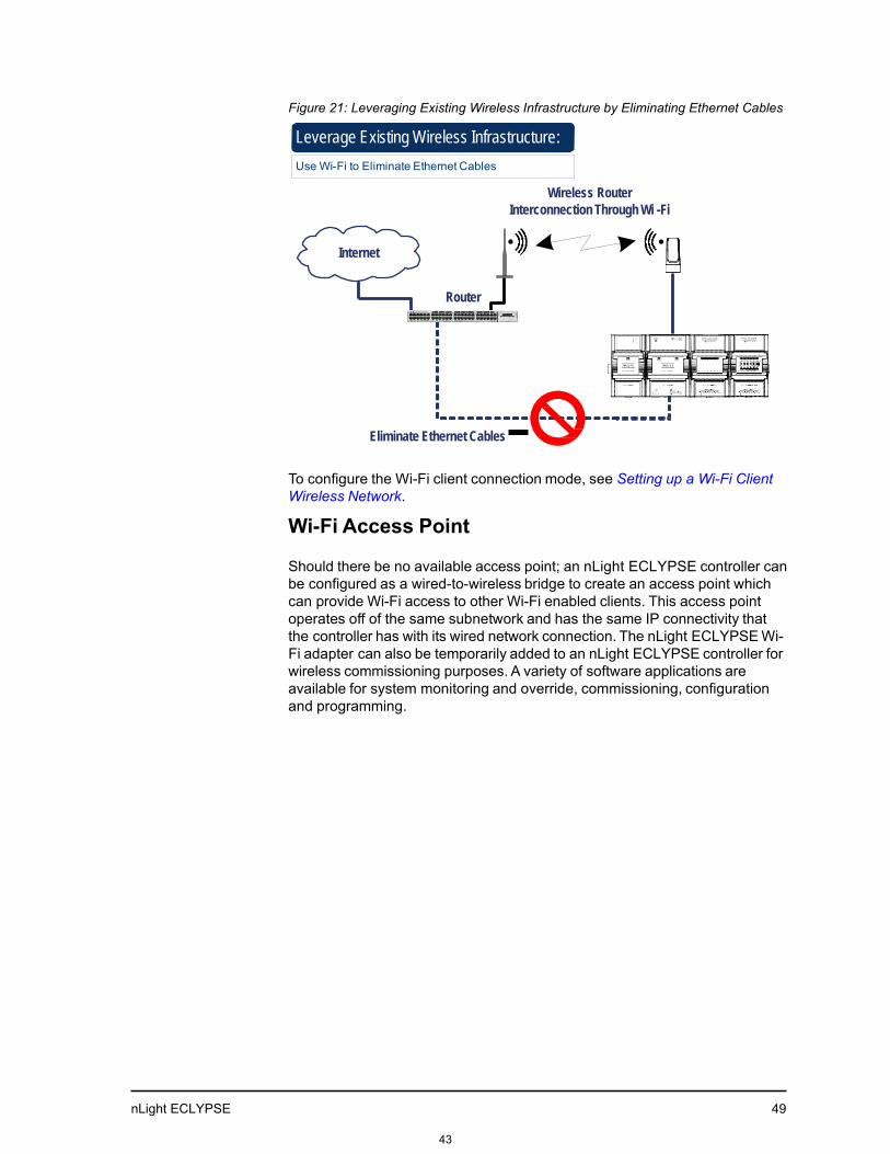
Figure 21: Leveraging Existing Wireless Infrastructure by Eliminating Ethernet Cables
Leverage Existing Wireless Infrastructure:
Use Wi-Fi to Eliminate Ethernet Cables
Wireless Router
Interconnection Through Wi -Fi
Internet
Router
Eliminate Ethernet Cables
To configure the Wi-Fi client connection mode, see Setting up a Wi-Fi Client Wireless Network.
Wi-Fi Access Point
Should there be no available access point; an nLight ECLYPSE controller can be configured as a wired-to-wireless bridge to create an access point which can provide Wi-Fi access to other Wi-Fi enabled clients. This access point operates off of the same subnetwork and has the same IP connectivity that the controller has with its wired network connection. The nLight ECLYPSE Wi-Fi adapter can also be temporarily added to an nLight ECLYPSE controller for wireless commissioning purposes. A variety of software applications are available for system monitoring and override, commissioning, configuration and programming.
43

nLight ECLYPSE
50
Figure 22: Using an nLight ECLYPSE Controller Create an Access Point
Wi-Fi Access Point :
Use the Controller to Provide Wi-Fi Access to other Wireless Devices
Internet
DHCP Server
Router
Wireless Access Point
SiteView Energy
Web Browser
Wired-to-
Wireless Bridge
SensorView
A second nLight ECLYPSE controller can be configured as a wireless client. This can be used as a solution to ‘jump’ architectural features that are not compatible with wires such as glass atrium and the like. To configure the Wi-Fi client connection mode, see Setting up a Wi-Fi Client Wireless Network.
An access point can provide Wi-Fi access to other Wi-Fi enabled clients and controllers.
Figure 23: Using an nLight ECLYPSE Controller as a Wireless Bridge
Controller-to-Controller Interconnection:
Use Wi-Fi to Wirelessly Connect other Controllers
Internet
Router
Wireless Access Point Controller Interconnection
Through Wi -Fi
Wired-to-
Wireless Bridge
Eliminate Ethernet Cables
44

nLight ECLYPSE 51
Wi-Fi Hotspot
Should the wired network not use a DHCP server (uses fixed IP addresses); an nLight ECLYPSE controller can be configured to create a hotspot with a router that creates its own subnet and DHCP server which can provide Wi-Fi access to other Wi-Fi enabled clients. This is the default connection method when an nLight ECLYPSE Wi-Fi adapter is connected to an nLight ECLYPSE controller. The nLight ECLYPSE Wi-Fi adapter can also be temporarily added to an nLight ECLYPSE controller for wireless commissioning purposes. A variety of software applications are available for system monitoring and override, commissioning, configuration and programming.
A hotspot creates a subnetwork. As a result, any connected BAC- net device will not be able to discover BACnet devices on any other LAN subnetwork.
Figure 24: Using an nLight ECLYPSE Controller Create a Hotspot
Wi-Fi Hotspot :
0Use the Controller to Provide Wi-Fi Access to the Controllers’ Configuration Interface
Internet
Router
Wireless Hotspot
SiteView Energy
Wireless Router
and DHCP Server
Wireless Bridge
Web Browser
SensorView
A second nLight ECLYPSE controller can be configured as a wired-to-wireless bridge to allow the connection of wired IP devices to the bridged controller’s Ethernet ports. This can be used as a solution to ‘jump’ architectural features that are not compatible with wires such as glass atrium and the like.
The access point / hotspot can provide Wi-Fi access to other Wi-Fi enabled clients.
45

nLight ECLYPSE
52
Figure 25: Using an nLight ECLYPSE Controller as a Wireless Bridge
Wireless Bridge
Use Wi-Fi to Jump Open spaces
Internet
Router
Wi-Fi Adapter in
Access Point Mode
Wi-Fi Adapter in
Client Mode
Wired IP Wireless to
Wired Bridge
Maximum Number of Wireless Clients or Nodes for an Access Point
A wireless access point can service a maximum of 16 clients or nodes in total. The following examples show what this limit can be composed of:
• One wireless bridged controller is connected to as many as 15 daisy-
chained wired devices.
Figure 26: Using an nLight ECLYPSE Controller as a Wireless Bridge
Wi-Fi Adapter in
Access Point Mode
Wi-Fi Adapter in
Client Mode
Wired IP Wireless to
Wired Bridge
Wired IP – Up to 15 Controllers
• One wireless bridged controller is connected to one wired controller that is wirelessly connected to one wireless bridge that is then connected 13 daisy chained wired devices.
Figure 27: Using an nLight ECLYPSE Controller as a Wireless Bridge
Wi-Fi Adapter in
Access Point Mode
Wi-Fi Adapter in
Client Mode
Wi-Fi Adapter in
Access Point Mode
Wi-Fi Adapter in
Client Mode
Wired IP
Wireless to
Wired Bridge
Wireless to
Wired Bridge
Wired IP – Up to 13
Controllers
46

nLight ECLYPSE 53
If the access point is a Wi-Fi router:
1. The number of devices is limited by the total number of clients the routeris able to support.
2. It can support many controllers acting as wireless to wired bridges.
3. Each wireless to wired bridge controller can support up to 15 controllers.
47

nLight ECLYPSE
54
Wireless Network Commissioning Architectures
Client to Access Point Configuration
A laptop is connected through Wi-Fi, as a Wi-Fi client, to any ECLYPSE Controller that has its wireless settings configured as an Access Point. The other ECLYPSE Controllers are configured as Wi-Fi Clients and are wirelessly connected to the same Access Point.
With this configuration, the laptop and all the nLight ECLYPSE controllers are on the same subnet, so either laptop user has access to all networked nLight ECLYPSE controllers.
Figure 28: Client to Access Point Configuration
Subnet 1
Wired IP Daisy Chain
Wi‐Fi Access Point
Wi‐Fi Client
Wi‐Fi
Client
Wi‐Fi Client
Wi‐Fi Client
Wi‐Fi Client
Wi‐Fi
Access Point
Wi‐Fi Client
Wi‐Fi
Client
Wi‐Fi Client
Wi‐Fi
Client
48

nLight ECLYPSE 55
Client to Hotspot Configuration
Laptop 1 is connected as a Wi-Fi client to a Connected System Controller that has its wireless settings configured as a Hotspot (Subnetwork 2). The ECLYPSE Controllers that are part of the wired network are configured, on their wireless side as a Wi-Fi Access Point (Subnetwork 1).
The remaining ECLYPSE Controllers are configured as a Wi-Fi Client and are wirelessly connected to a VAV controller’s Access Point.
With this configuration, laptop 1 is on the same subnet as the Connected Sys- tem Controller (Subnetwork 2 created by the Hotspot), but all the Connected VAV Controllers are on a different Subnet (Subnetwork 1), so the laptop 1 user only has access to the Connected System Controller. This is because BACnet/IP broadcast discovery messages such as “Who-Is” do not pass through network routers that separate subnetworks. In the example shown below, the Connected System Controller acts as a router between the Wi-Fi hotspot clients and the wired network. This means that BACnet/IP controllers on different subnetworks will not normally communicate with each other. The laptop 2 user has access to both the ECLYPSE controllers and the Connected System Controller. A solution is to use BBMD on both Laptop 1 (using EC-Net for example) and on the Connected System Controller. See BACnet/IP Broadcast Management Device Service (BBMD).
49

nLight ECLYPSE 56
Figure 29: Client to Hotspot Configuration Subnet work 2
Laptop 1 Wi‐Fi Client
Wi‐Fi Hotspot
Subnetwork 1
Wired IP
Connected System Controller Connected Equipment Controller
Wi‐Fi Client
Wi‐Fi
Daisy Chain Wi‐Fi
Access Point
Client
VAV
Wi‐Fi Client
Wi‐Fi
Client
Wi‐Fi
Access Point
Wi‐Fi Client
Wi‐Fi Client
Laptop 2
Wi‐Fi Client
Wi‐Fi
Client
50

nLight ECLYPSE
57
51

nLight ECLYPSE 59
CHAPTER 6 FIRST TIME CONNECTION TO AN nLight ECLYPSE CONTROLLER
This paragraph is here to introduce the topics that will be discussed in the chapter. Following it should be a Topics paragraph.
Topics Connecting to the Controller Ethernet Network Connection Wi-Fi Network Connection Configuring the Controller Connecting to the Controller’s Configuration Web Interface
52

nLight ECLYPSE
60
Connecting to the Controller
When connecting to the controller for the first time, the goal is to gain access to the controller so that you can configure it to work in its future network envi- ronment. To do so, you must connect the controller to form a network.
There are two networking methods to connect to a controller:
• Wired (Ethernet connection) with a PC.
• Wireless (when the nLight ECLYPSE Wi-Fi Adapter is connected to the control- ler) with a PC. See Wi-Fi Network Connection.
Once you have connected the controller(s) to a network, configure the control- ler. See Configuring the Controller.
Controller Identification
Controllers are uniquely identified on the network by their MAC address. This identifier is printed on a label located on the side of the controller and another is on the controller’s box. Get a printed copy of the building’s floor plan. During controller installation, peel the MAC address sticker off of the control- ler’s box and put it on the floor plan where the controller has been installed.
This MAC address is used as part of the controller’s factory-default Wi-Fi access point name and its hostname.
53

nLight ECLYPSE 61
Figure 30: Finding the Controller’s MAC Address
Label Label
ID: MAC Address
Bar Code
MAC: MAC Address
Bar Code
Model: NECY-S1000 / NECY-303
Model: NECY-VAVXXXX
For example, for a MAC Address of : 76:a5:04:cd:4a:d1 The factory-default name for the Wi -Fi access point is nLight ECLYPSE-CD4AD1 The factory-default hostname is nLight ECLYPSE-cd4ad1.local
For example, for a MAC Address of : 76:a5:04:cd:4a:d1 The factory-default name for the Wi -Fi access point is nLight ECLYPSE-CD4AD1 The factory-default hostname is nLight ECLYPSE-cd4ad1.local
54

nLight ECLYPSE
62
Depending on the controller model, the way the controller is connected to the network will change according to whether the controller is a Power over Ether- net (PoE) model or not.
• For non-PoE controller models, see Network Connections for NECY Series
Controllers.
• For the NECY-VAV-PoE controller, see Network Connections for NECY-VAV- PoE Model Controllers..
See also Connecting IP Devices to an IP Network for network wir- ing considerations.
Network Connections for NECY Series Controllers
Connect the controller to the network as follows:
1. Connect your PC’s network card to the controller’s PRI Ethernet port using a Category 5e Ethernet cable.
If you are commissioning more than one controller, connect the controllers and PC to a network switch. Two or more controllers can be connected to the network by daisy-chaining them together by using Cat 5e network Cables to connect the Ethernet Switch Sec(ondary) connector of one controller to the Ethernet Switch Pri(mary) connector of the next controller.
55

nLight ECLYPSE
63
Figure 31: nLight ECLYPSE Wired Network Connection: Cat 5e Cables with RJ- 45 Connectors are used
RJ-45 Connector
To Router /
Next Device
To Next Device
Cat 5e Network Cable
2. Connect power to the controller(s). See the controller’s Hardware Installa- tion Guide for how to do so.
56

nLight ECLYPSE
64
Wi-Fi Network Connection
Once the nLight ECLYPSE Wi-Fi Adapter has been connected to a powered controller, a Wi-Fi hotspot becomes available that allows you to connect to the controller’s configuration Web interface with your PC.
On your PC’s wireless networks, look for an access point named nLight ECLYPSE- XXYYZZ where XXYYZZ are the last 6 hexadecimal characters of the control- ler’s MAC address.
To find the controller’s MAC address, see Controller Identification.
The default password for the wireless network is: ECLYPSE1234
Either of the controller’s two USB HOST ports can be used to connect the wireless adapter.
Figure 34: Connecting the Wireless Adapter to the Controller’s USB HOST Port
To Wireless
Adapter Connected VAV Controller
Cable Assembly USB Plug
Cable Assembly USB Plug
Connected System Controller
To Wireless Adapter
57

nLight ECLYPSE 65
Configuring the Controller
Any of the following methods can be used to connect to the controller’s inter- face in order to configure it:
• Using the controller’s factory-default Hostname in the Web browser
• Using the controller’s IP address in the Web browser
58

nLight ECLYPSE
67
Using the Controller’s Factory-default Hostname in the Web Browser
Controllers have a factory-default hostname that you can use instead of an IP address to connect to it1. The hostname can be used in a Web browser’s address bar. Then install The Bonjour service. The Bonjour service must be installed on your PC to allow your PC to discover controllers by their hostname.
If your PC is unable to resolve the controller’s hostname, you must connect your PC to the controller through Ethernet or Wi-Fi so that your PC only sees the controller network. For example, in this case, your PC must be discon- nected from all other networks such as a corporate network or the Internet. If necessary, temporarily disconnect your PC’s network cable from its Ethernet port.
The controller’s factory-default hostname is ECLYPSE-xxxxxx.local where xxxxxx is the last 6 characters of the MAC address printed on a sticker located on the side of the controller. See Controller Identification.
For example, the sticker on the side of a controller shows that its MAC address is 76:a5:04:cd:4a:d1. Connect to the controller’s Web interface as fol- lows:
1. Open your Web browser.
2. In the Web browser’s address bar, type https://nLight ECLYPSE-cd4ad1.local
and click go.
3. Login to the controller. Then set the controller’s configuration parameters in the controller’s configuration Web interface. See Connecting to the Controller’s Configuration Web Interface.
The Hostname can be changed in the System Settings.
Using the Controller’s IP Address in the Web Browser
Connect to a controller through its IP address as follows:
For a Wi-Fi network connection
1. Open your Web browser.
2. In the Web browser’s address bar, type https://192.168.0.1 (the control- ler’s factory-default wireless hotspot IP address) and click go.
3. Login to the controller. Then set the controller’s configuration parameters in the controller’s configuration Web interface. See Connecting to the Controller’s Configuration Web Interface.
1. Not all smart phones/mobile devices have the Bonjour service installed and thus cannot use the hostname mechanism.
59

nLight ECLYPSE
68
For an Ethernet network connection
You must know the controller’s current IP address (from the DHCP server for example). 1. Open your Web browser.
2. In the Web browser’s address bar enter the controller’s IP address and click go.
3. Login to the controller. Then set the controller’s configuration parameters in the controller’s configuration Web interface. See Connecting to the Controller’s Configuration Web Interface.
60

nLight ECLYPSE
69
Connecting to the Controller’s Configuration Web Interface
The nLight ECLYPSE Series Controller configuration can be made through the controller’s configuration Web interface to set all the controller’s configuration parameters including the controller’s IP address according to your network planning.
At the first connection to an nLight ECLYPSE Controller you will be forced to change the password to a strong password for the admin account to protect access to the controller.
It is important to create new user accounts with strong passwords to protect the controller from unauthorized access. Remove the factory default admin account as this is a commonly known security breech (only the password for this user account needs to be compromised). See User Management, Secur- ing an nLight ECLYPSE Controller, and Supported RADIUS Server Architectures.
Next Steps
In Network Settings, configure the controller’s network parameters so that they are compatible with your network. See nLight ECLYPSE Web Interface.
61
nLight ECLYPSE
70
CHAPTER 7
nLight ECLYPSE WEB INTERFACE
This chapter describes the nLight ECLYPSE controller’s Web interface.
Topics
Overview Network Settings BACnet Settings User Management Radius Server Settings System Settings
62

nLight ECLYPSE
71
Overview
The nLight ECLYPSE controller has a web-based interface that allows you to view system status, configure the controller, update the controller’s firmware, and access different applications associated to your projects.
Note that if you intend on enabling FIPS 140-2 mode, it should be done prior to configuring the controllers. See FIPS 140-2 Mode.
Figure 41: nLight ECLYPSE Controller’s Web Interface Welcome Home Page
Configuration Menu
The sidebar contains the Configuration menus that allow you to view and set the controller’s configuration settings including its IP address, Wi-Fi settings, and to update the controller’s firmware. The menus may vary according to the associated device licenses and the user’s access level. These configuration parameters are password protected.
63

nLight ECLYPSE
72
• IPS Luminaires
• Home Page
• Network Settings
• BACnet Settings
• User Management
• System Settings
Home Page
The main area of the home page consists of the following items:
Item Description
Device Information This section provides basic information on the device such as controller name, device instance, host ID, MAC address, time, and date.
The Copy icon allows you to copy the Host Id and/or the MAC address of the device to that you can quickly paste elsewhere as needed.
Connected to Internet This indicates whether the nLight ECLYPSE controller is connected to the Internet or not.
64

nLight ECLYPSE
73
Item Description
Applications To access different applications associated to your projects and controller license such as the following:
SiteView™ Energy The energy metering edge application gives building owners real-time, actionable data about their facility’s energy consumption and makes it easier to identify usage trends and savings
nLight Explorer An edge application that gives a general system overview and a look at the system health of connected nLight devices
Space Utilization The Space Utilization edge application allows building owners and property managers to analyze where occupants spend their time throughout the day, and make data-driven decisions for renovation, space planning and other expansions
ENVYSION The responsive, web-based design and visualization interface that delivers actionable, graphical data
User Profile and Login Credentials
Click the profile box to change your password and logout. At the first connection to an nLight ECLYPSE Controller you will be forced to change the password to a strong password for the admin account to protect access to the controller. It is important to create new user accounts with strong passwords to protect the controller from unauthorized access.
See User Management, Securing an nLight ECLYPSE Controller, and Supported RADIUS Server Architectures.
To change your password
1. To change your password, click the profile icon and select Change Password.
2. Enter your current password and click Next.
65

nLight ECLYPSE
74
3. Enter the new password twice to confirm and click Next. Your password is changed.
66

nLight ECLYPSE
75
Network Settings
The Network menu is used to configure the nLight ECLYPSE controller’s network interface and set up the wired and wireless network configuration parameters. The available menus are:
• Ethernet
• Wireless
• Diagnostic
Ethernet
The Ethernet screen is used for any wired IP connections that are made through either one of the controller’s Ethernet Switch Pri(mary) connector or Ethernet Switch Sec(ondary) connector. See Figure 31 and Figure 32. The Wired IP parameters can be auto-configured when the connected network has a working DHCP server. The alternative is to manually configure the con- troller’s IP parameters.
67

nLight ECLYPSE
76
Option DHCP Client: Enabled DHCP Client: Disabled
DHCP If the controller is connected to a network that has an active DHCP server, enabling this option will automatically configure the Wired IP connection parameters. The Wired IP parameters shown below are read only (presented for information purposes only).
If you want to manually configure the controller’s network settings (to have a fixed IP address for example) or in the case where the network does not have a DHCP server, disable this option. In this case, you must set the Wired IP connection parameters shown below to establish network connectivity. See also DHCP versus Manual Network Settings
IP Address This is the IP Address provided by the network’s DHCP server.
Set the IP address for this network device. See IPv4 Communication Fun- damentals Ensure that this address is unique from all other device on the LAN including any used for a hot spot’s IP addressing.
Subnet Mask This is the subnet mask provided by the network’s DHCP server.
Set the connected network’s subnet- work mask. See About the Subnetwork Mask
Gateway This is the gateway IP Address pro- vided by the network’s DHCP server.
The IP address of the default gateway to other networks. This is usually the IP address of the connected network router. See Default Gateway
Primary DNS Secondary DNS
This is the primary and secondary DNS IP Address provided by the network’s DHCP server.
The connected network’s primary and secondary IP address of the DNS serv- ers. See Domain Name System (DNS)
When making changes to the network settings, click Apply to apply and save the changes. You can click refresh to refresh the information in the screen.
Wireless Configuration
This configuration interface is for any nLight ECLYPSE Wi-Fi Adapter connected to the HOST connector.
A hotspot creates a subnetwork. As a result, any connected BAC- net device will not be able to discover BACnet devices on any other LAN subnetwork.
68

nLight ECLYPSE
77
Figure 42: The Wi-Fi network operating modes: Hotspot, Access-Point, or Client.
The Wireless connection parameters can be set as follows.
Item Description
On / Off This enables/disables the controller’s wireless features.
Wireless Mode Select the Wi-Fi network operating mode: Hotspot, Access-Point, or Cli- ent.
• Hotspot: This creates a Wi-Fi hot spot with a router. See Setting up a Wi-Fi Hotspot Wireless Network for how to configure this mode.
• Access-Point: This creates a Wi-Fi access point. See Setting up a Wi-Fi Access Point Wireless Network for how to config- ure this mode.
• Client: this connects the controller as a client of a Wi-Fi access point. See Setting up a Wi-Fi Client Wireless Network for how to configure this mode.
See also nLight ECLYPSE Wi-Fi Adapter Connection Modes.
Network Name The network name is the Service Set IDentification (SSID) for a Wi-Fi hotspot. This parameter is case sensitive. When this controller’s active mode is configured as a:
• For Hotspot: set a descriptive network name that other wireless cli- ents will use to find this hotspot.
• For Client: select an available hotspot from the lists of access point connections that are within range. Click the Wi-fi icon to select an available Wi-Fi network from the list of access points that are within range.
69

nLight ECLYPSE
78
Item Description
Encryption Set the encryption method to be used by the Wi-Fi network:
• Open: this option should be avoided as it does not provide any wireless security which allows any wireless client to access the LAN.
• WPA2: select the Wi-Fi Protected Access II option to secure the Wi-Fi network with a password.
Password When encryption is used, set the password to access the Wi-Fi network as a client or the password other clients will use to access this hotspot. Passwords should be a long series of random alphanumeric characters and symbols that are hard to guess. This parameter is case sensitive.
Click to show or hide the password.
IP Address This is the IP address for a Hotspot (or gateway address that wireless cli- ents will connect to). Ensure that this address is:
• Not in the range of IP address set by First Address and Last Address.
• Not the same as the IP address set under IP Configuration for the wired network.
Subnet Mask The hotspot’s subnetwork mask. See About the Subnetwork Mask .
First Address Last Address
This defines the range of IP addresses to be made available for Hotspot clients to use. The narrower the range, the fewer hotspot clients will be able to connect due to the lack of available IP addresses. For example, a range where First Address = 192.168.0.22 and Last Address = 192.168.0.26 will allow a maximum of 5 clients to connect to the hotspot on a first-to-connect basis.
Advanced When a Hotspot or Access-point is configured, this sets the channel width and number the hot spot is to use. The wireless mode can also be set. See below.
Channel Number This sets the center frequency of the transmission. If there are other Wi-Fi networks are nearby, configure each Wi-Fi network to use different channel numbers to reduce interference and network drop-outs. Note: The range of available channels may vary from country to country.
Wi-Fi Mode This sets the wireless mode (wireless G or wireless N). Wireless N mode is backwards compatible with wireless G and B. Wireless G mode is back- wards compatible with wireless . B
SSID Hidden For a Client hot spot, hide or show the Service Set IDentification (SSID).
70
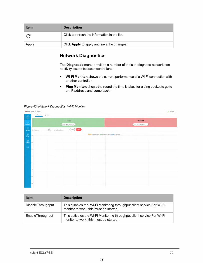
nLight ECLYPSE
79
Item Description
Click to refresh the information in the list.
Apply Click Apply to apply and save the changes
Network Diagnostics
The Diagnostic menu provides a number of tools to diagnose network con- nectivity issues between controllers.
• Wi-Fi Monitor: shows the current performance of a Wi-Fi connection with
another controller.
• Ping Monitor: shows the round trip time it takes for a ping packet to go to an IP address and come back.
Figure 43: Network Diagnostics: Wi-Fi Monitor
Item
Description
Disable Throughput This disables the Wi-Fi Monitoring throughput client service. For Wi-Fi monitor to work, this must be started.
Enable Throughput This activates the Wi-Fi Monitoring throughput client service. For Wi-Fi monitor to work, this must be started.
71

nLight ECLYPSE
80
Item Description
Device Target Select the corresponding controller’s MAC address in the Device Target list.
Ip Address Target Enter the corresponding controller’s IP address for its Wi-Fi interface in Ip Address Target.
Click to refresh the information in the Device Target list.
Start Starts graphing the monitored data.
Clear Clears the graph.
Throughput (Mbps) The transmit datarate to the target.
Signal avg (dBm) The current average receive signal strength. Note: Signal strength is measured in negative units where the stronger the signal, the closer it is to zero. A weaker signal strength will have a more negative number. For example, a receive signal strength of -35 dBm is much stronger than a receive signal strength of -70 dBm.
RX rate (Mbps) The receive datarate from the target.
72

nLight ECLYPSE
81
Figure 44: Network Diagnostics - Ping Monitor
Item Description
Ip Address Target Enter the corresponding controller’s IP address for its Wi-Fi interface in Ip Address Target.
Start Starts graphing the monitored data.
Clear Clears the graph.
73

nLight ECLYPSE
82
BACnet Settings
This is where the BACnet interface parameters are set.
General
This sets the controller’s BACnet network parameters.
Figure 45: General BACnet Settings
Item Description
Controller Name Set a descriptive name by which this controller will be known to other BACnet objects.
Device ID Each controller on a BACnet intra-network (the entire BACnet BAS net- work) must have a unique Device ID. Refer to the Network Guide for more information.
Location The current controller’s physical location. This is exposed on the BACnet network as a device object property.
Description A description of the controller’s function. This is exposed on the BACnet network as a device object property.
APDU Timeout (ms) The maximum amount of time the controller will wait for an acknowledg- ment response following a confirmed request sent to a BACnet device before re-sending the request again or moving onto the next request. This property is exposed on the BACnet network as a device object property.
74

nLight ECLYPSE
83
Item Description
APDU Segment Time- out (ms)
The maximum amount of time the controller will wait for an acknowledg- ment response following a confirmed segmented request sent to a BAC- net device before re-sending the segmented request again or moving onto the next request. This property is exposed on the BACnet network as a device object property.
APDU Retries This sets the number of times to retry a confirmed request when no acknowledgment response has been received. This property is exposed on the BACnet network as a device object property.
Click to refresh the information in the list.
Apply Click Apply to apply and save the changes
Routing
This enables the routing of BACnet packets between BACnet MS/TP control- lers connected to the nLight ECLYPSE Connected System Controller’s RS-485 port and BACnet/IP controllers connected to the nLight ECLYPSE Connected System Controller’s Ethernet Switch ports. For example, routing must be enabled for EC-Net to discover the BACnet MS/TP controllers connected to the nLight ECLYPSE Connected System Controller’s RS-485 port.
Figure 46: BACnet Routing Configuration
Item Description
This enables/disables the routing of BACnet packets between BACnet MS/TP controllers connected to the nLight ECLYPSE Connected System Controller’s RS-485 port and BACnet/IP controllers connected to the nLight ECLYPSE Connected System Controller’s Ethernet Switch ports.
75

nLight ECLYPSE
84
Item Description
Network Number A network number identifies a LAN for routing purposes. All controllers with the same network number are members of the same logical BACnet network. See Device Addressing.
Mac Address The device Mac address.
Click to refresh the information in the list.
Apply Click Apply to apply and save the changes.
Network IP Ports
This sets the IP network configuration parameters (on-board port) as well as the BACnet Broadcast Management Device (BBMD) and Foreign Device for intranetwork connectivity.
Figure 47: BACnet IP Configuration - Network IP Ports
On-Board Port
Item
Description
On / Off This enables/disables the routing of BACnet packets between BACnet MS/TP controllers connected to the nLight ECLYPSE Connected System Controller’s RS-485 port and BACnet/IP controllers connected to the nLight ECLYPSE Connected System Controller’s Ethernet Switch ports.
Network Number A network number identifies a LAN for routing purposes. All controllers with the same network number are members of the same logical BACnet network. See Device Addressing.
BACnet IP UDP Port This is the standard BACnet/IP port number (UDP 47808) used by BAC- net devices to communicate.
76

nLight ECLYPSE
85
Item Description
Enable BBMD BBMD allows broadcast message to pass through a router. See BBMD Settings. To enable this feature, set Enable BBMD on only one device on each subnet.
Enable Foreign Devices
Foreign Device Registration allows a BACnet/IP device to send broadcast messages to a device with BBMD enabled. See Foreign Device Settings. To enable this feature, set Enable Foreign Devices on only one device on each subnet.
Click to refresh the information in the list.
Apply Click Apply to apply and save the changes
BBMD Settings
BACnet/IP devices send broadcast discovery messages such as “Who-Is” as a means to discover other BACnet devices on the network. However, when there are two or more BACnet/IP subnetworks, broadcast messages do not pass through network routers that separate these subnetworks.
BBMD allows broadcast message to pass through a router: on each subnet, a single device has BBMD enabled. Each BBMD device ensures BACnet/IP connectivity between subnets by forwarding broadcast messages found on its subnetwork to each other, and then onto the local subnetwork as a broadcast message.
77

nLight ECLYPSE 86
In the BBMD table, add the BBMD-enabled controllers located on other sub- networks.
Item Description
Add another subnetwork’s BBMD to this controller’s a Broadcast Distribu- tion Table. To add a BBMD:
1. Click .
Figure 48: Adding a BBMD
2. In the IP field, enter IP address of the BBMD located on the othersubnetwork.
3. In the Mask field, enter the subnetwork mask for the other subnet- work.
4. In the Port field, enter the port number for the BACnet service of theBBMD located on the other subnetwork.
5. Click OK.
Edit a BBMD’s information. This icon is displayed only when one or more
BBMD is selected from the list.
Remove a BBMD from this controller’s Broadcast Distribution Table. This
icon is displayed only when one or more BBMD is selected from the list.
Click to refresh the information in the list.
Foreign Device Settings
Some BACnet/IP devices also support a feature called Foreign Device Regis- tration (FDR). FDR allows a BACnet/IP device to send broadcast messages to a device with BBMD enabled. The BBMD-enabled device will then forward these broadcast messages to all other BBMDs and onto all other FDR devices. If a subnet has only FDR supported devices then it does not need a
78
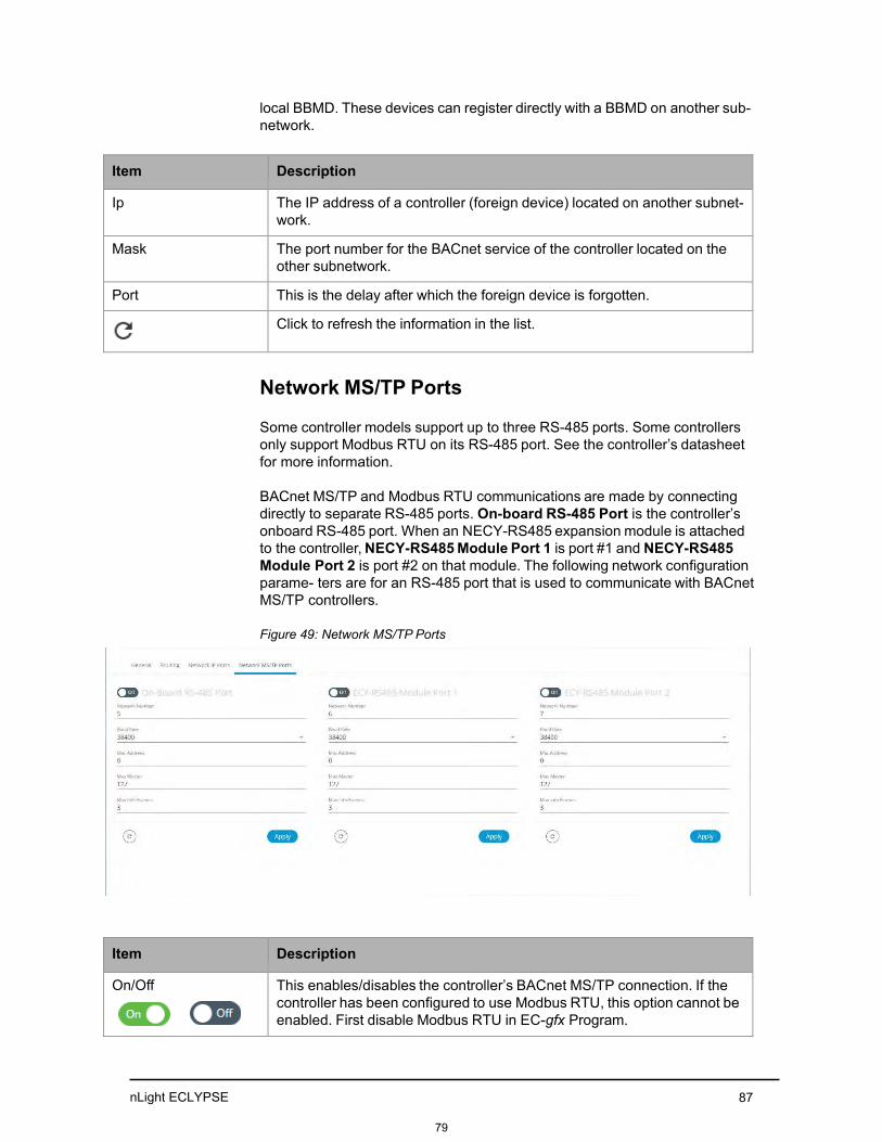
nLight ECLYPSE 87
local BBMD. These devices can register directly with a BBMD on another sub- network.
Item Description
Ip The IP address of a controller (foreign device) located on another subnet- work.
Mask The port number for the BACnet service of the controller located on the other subnetwork.
Port This is the delay after which the foreign device is forgotten.
Click to refresh the information in the list.
Network MS/TP Ports
Some controller models support up to three RS-485 ports. Some controllers only support Modbus RTU on its RS-485 port. See the controller’s datasheet for more information.
BACnet MS/TP and Modbus RTU communications are made by connecting directly to separate RS-485 ports. On-board RS-485 Port is the controller’s onboard RS-485 port. When an NECY-RS485 expansion module is attached to the controller, NECY-RS485 Module Port 1 is port #1 and NECY-RS485 Module Port 2 is port #2 on that module. The following network configuration parame- ters are for an RS-485 port that is used to communicate with BACnet MS/TP controllers.
Figure 49: Network MS/TP Ports
Item Description
On / Off This enables/disables the controller’s BACnet MS/TP connection. If the controller has been configured to use Modbus RTU, this option cannot be enabled. First disable Modbus RTU in EC-gfx Program.
79
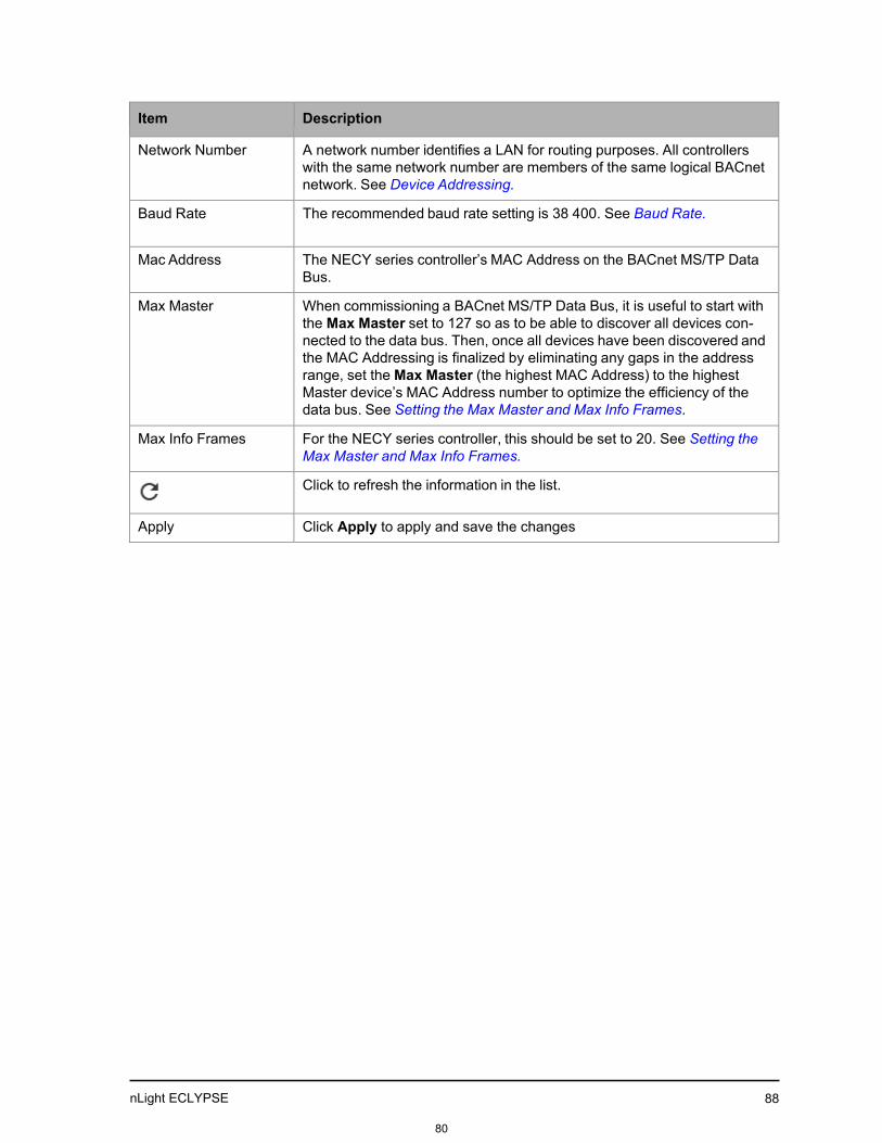
nLight ECLYPSE 88
Item Description
Network Number A network number identifies a LAN for routing purposes. All controllers with the same network number are members of the same logical BACnet network. See Device Addressing.
Baud Rate The recommended baud rate setting is 38 400. See Baud Rate.
Mac Address The NECY series controller’s MAC Address on the BACnet MS/TP Data Bus.
Max Master When commissioning a BACnet MS/TP Data Bus, it is useful to start with the Max Master set to 127 so as to be able to discover all devices con- nected to the data bus. Then, once all devices have been discovered and the MAC Addressing is finalized by eliminating any gaps in the address range, set the Max Master (the highest MAC Address) to the highest Master device’s MAC Address number to optimize the efficiency of the data bus. See Setting the Max Master and Max Info Frames.
Max Info Frames For the NECY series controller, this should be set to 20. See Setting the Max Master and Max Info Frames.
Click to refresh the information in the list.
Apply Click Apply to apply and save the changes
80

nLight ECLYPSE 89
User Management
User management is the control of who can access the controller by enforcing the authentication credentials users need to access the controller. User man- agement can either be locally managed or remotely managed. If there is more than one nLight ECLYPSE controller on the network, it is best to centralize access management .
User management can also set the welcome page a user will land on when they connect to the controller.
Local Configuration
User access to this controller and to other controllers that are using this con- troller as their RADIUS server are managed by adding them to the Local User Management shown below.
Figure 50: Local Configuration User Management
Item Description
Add
Add a new user to user management. See Adding a User. These users will have login access to the controller. It is important to cre- ate new user accounts with strong passwords to protect the controller from unauthorized access. See Securing an nLight ECLYPSE Controller.
81

nLight ECLYPSE 90
Adding a User
Adding a user creates a user profile that allows a person to login to the con- troller with a username / password combination and to have access to certain controller software interfaces. When this controller is used as a RADIUS server by other controllers, users connecting to those controllers will have access to those controllers as defined by their user profile.
Item Description
Edit
Edit a user’s information. When editing user information, the user pass- word is not shown therefore the field appears empty. You can leave the password as is or assign a new one
Remove Remove a user from user management. Remove the factory default admin account as this is a commonly known security breech (only the password for this user account needs to be com- promised). Proceed as follows.
1. Create a new user account with administrative rights for yourself.
2. Logout of the admin account and then login to the user account youhave created.
3. Remove the factory default admin account.
82

nLight ECLYPSE 91
User management can also set the welcome page a user will land on when they connect to the controller with the Welcome Page setting.
1. Click to add a new user or to edit an existing user. The Local User Details windowis displayed.
Figure 51: Adding a User
2. Enter the information as shown below:
3. Clic k Next. The Roles options are displayed.
Item Description
Username The user’s login credential.
Password The user’s password credential.
Show/Hide the user’s password credential.
User must change password at next login
Select to force user to change their password at the next login.
83

nLight ECLYPSE 92
4. Select the access levels the user will be able to use. Set one or moreoptions according to t he user’s role:
Admin Allows user access to the ENVYSION studio and viewer. The user can also view and modify all configuration inter- face parameters and program the controller with EC-gfxPro- gram.
Operator Allows user access to the ENVYSION interface in viewing mode as well as gives partial access to the nLight ECLYPSE Web Configuration Interface. Certain configuration interface screens are unavailable such as User Management, Viewer Information, etc.
Viewer Allows user access to the ENVYSION interface in Viewing mode. The user is not allowed to access the nLight ECLYPSE Web Configuration Interface.
Rest Allows a user to program the controller with EC-gfxProgram. This user does not have access to the nLight ECLYPSE Web Configuration Interface or ENVYSION.
5. Click Next. The Welcome Page screen is displayed where you c an setthe landing page that will be displayed to individual users when theylogin to the controller.
6. Enter the URL of the web page found after the controllers' IP address orhostname. This should be copied from your Web browser’s address barwhen you have navigated to the target page.
For example , the address for the user default web page is HOSTNAME/ nLightECLYPSE/envysion/viewer.html?proj=ENVYSION_PROJECT_NAME or
84
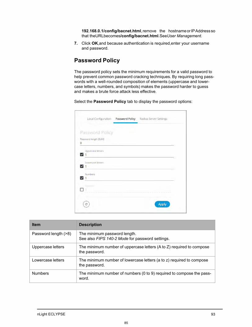
nLight ECLYPSE 93
192.168.0.1/config/bacnet.html, remove the hostname or IP Address so that the URL becomes /config/bacnet.html. See User Management.
7. Click OK, and because authentication is required, enter your usernameand password.
Password Policy
The password policy sets the minimum requirements for a valid password to help prevent common password cracking techniques. By requiring long pass- words with a well-rounded composition of elements (uppercase and lower- case letters, numbers, and symbols) makes the password harder to guess and makes a brute force attack less effective.
Select the Password Policy tab to display the password options:
Item Description
Password length (>8) The minimum password length. See also FIPS 140-2 Mode for password settings.
Uppercase letters The minimum number of uppercase letters (A to Z) required to compose the password.
Lowercase letters The minimum number of lowercase letters (a to z) required to compose the password.
Numbers The minimum number of numbers (0 to 9) required to compose the pass- word.
85

nLight ECLYPSE 94
Item Description
Symbols The minimum number of symbols (for example, =, +, &, , $, etc.) required to compose the password.
Click to refresh the information in the list.
Apply Click Apply to apply and save the changes
86

nLight ECLYPSE 95
System SettingsCHAPTER 8
CONFIGURING THE nLight ECLYPSE WI-FI ADAPTER
WIRELESS NETWORKS
nLight ECLYPSE Wi-Fi Adapter supports a number of wireless network connection modes. This chapter describes how to configure a controller’s wireless net- work. See also nLight ECLYPSE Wi-Fi Adapter Connection Modes.
Topics Setting up a Wi-Fi Client Wireless Network Setting up a Wi-Fi Access Point Wireless Network Setting up a Wi-Fi Hotspot Wireless Network
87

nLight ECLYPSE 96
Setting up a Wi-Fi Client Wireless Network
This connects the controller as a client of a Wi-Fi access point. See Wi-Fi Cli- ent Connection Mode for more information.
Figure 66: Client Wireless Network Settings
Configure the controller’s nLight ECLYPSE Wi-Fi adapter mode as a Wi-Fi client as follows.
1. Set On.
2. Set the Mode to Client.
3. Click for the controller to search for available access points that are within range. The access points are listed on the right.
Figure 67: List of Available Access Points to Pair With
4. Select an access point to pair with from the access point list. The Encryp-tion mode is provided by the access point.
5. Set the access point’s authentication password in
6. Password. This password is set in the access point’s (or wirelessrouter’s) configuration.
7. Click Apply.
88

nLight ECLYPSE 97
Setting up a Wi-Fi Access Point Wireless Network
This turns the controller into a Wi-Fi access point that other wireless clients can use to have network access. This access point operates off of the same subnetwork and has the same IP connectivity that the controller has with its wired network connection. For example, if the controller’s wired connection is to a network that has an active DHCP server, access point clients can also use this DHCP server to automatically configure their IP connection parame- ters. See Wi-Fi Access Point for more information.
Figure 68: Access Point Wireless Network Settings
Configure the controller’s nLight ECLYPSE Wi-Fi adapter mode as a Wi-Fi access point as follows.
1. Under Wireless Configuration, set Enabled.
2. Set the Active mode to Hotspot/AP.
3. Set the name for this access point by which wireless clients will identify itin Network Name.
4. Set the encryption mode to be used by this access point in Encryption:
• None: this option should be avoided as it does not provide anywireless security which allows any wireless client to access the LAN.
• WPA2: select the Wi-Fi Protected Access II option to secure the Wi-Finetwork with a password.
• WPA2 Enterprise: Use this option if you are connecting to an enter-prise network that has a working RADIUS authentication server. ThisRADIUS server provides user authentication.
5. Set the access point’s authentication password in Password. This is thepassword wireless clients will need to know in order to connect to thisaccess point.
6. Under Hotspot Configuration, disable Enabled.
89

nLight ECLYPSE 98
7. Under Advanced, set the Channel Width, Channel Number, and Wi-FiMode. See BACnet Settings for an explanation of these parameters.
8. Click Apply.
90

nLight ECLYPSE 99
Setting up a Wi-Fi Hotspot Wireless Network
This turns the controller into a Wi-Fi hotspot with a router. This puts the hotspot into a separate subnetwork with a DHCP server to provide IP addresses to any connected device. See Wi-Fi Hotspot for more information.
Wide area network (WAN) connectivity is through the wired connection. See Network Address Translation / Firewall. Though BACnet/IP uses IP protocol to communicate, this hotspot acts as an IP router; it does not for- ward broadcast messages which are important in BACnet to identify services that are available within the BACnet internetwork. See BACnet/IP Broadcast Management Device Service (BBMD).
Figure 69: Hotspot Wireless Network Settings
Configure the controller’s nLight ECLYPSE Wi-Fi adapter mode as a Wi-Fi hotspot as follows.
1. Under Wireless Configuration, set Enabled.
2. Set the Active mode to Hotspot/AP.
3. Set the name for this access point by which wireless clients will identify itin Network Name.
4. Set the encryption mode to be used by this hotspot in Encryption:
• None: this option should be avoided as it does not provide anywireless security which allows any wireless client to access the LAN.
• WPA2: select the Wi-Fi Protected Access II option to secure the Wi-Finetwork with a password.
• WPA2 Enterprise: Use this option if you are connecting to an enter- prise network that has a working RADIUS authentication server. ThisRADIUS server provides user authentication.
5. Set the hotspot’s authentication password in Password. This is the pass- word wireless clients will need to know in order to connect to this hotspot.
6. Under Hotspot Configuration, set Enabled.
91

nLight ECLYPSE 100
7. Set the hotspot’s IP address that wireless clients will connect to in IpAddress. Ensure that this address is:
• Not in the range of IP address set by First Address and LastAddress.
• Not the same as the IP address set under IP Configuration for thewired network.
8. Set the hotspot’s subnet mask in Subnet Mask. See About the Subnet- work Mask.
9. Set the hotspot’s addressing range in First Address and Last Address.
This defines the range of IP addresses to be made available for hotspotclients to use. The narrower the range, the fewer hotspot clients will beable to connect due to the lack of available IP addresses. For example, arange where First Address = 192.168.0.22 and Last Address =192.168.0.26 will allow a maximum of 5 clients to connect to the hotspoton a first-to-connect basis.
10. Under Advanced, set the Channel Width, Channel Number, and Wi-FiMode. See BACnet Settings for an explanation of these parameters.
11. Click Apply.
92

nLight ECLYPSE 101
CHAPTER 9 SECURING AN nLight ECLYPSE CONTROLLER
This chapter describes how to harden an nLight ECLYPSE controller from unauthorized access and use.
Topics Introduction Passwords Account Management and Permissions HTTPS Certificates Additional Measures External Factors
93

nLight ECLYPSE
102
Introduction
This chapter describes how to implement best security practices for nLight ECLYPSE controllers. Security is built up layer upon layer to make the system more resistant to attacks. This involves taking simple but effective steps to implement built-in security features.
94

nLight ECLYPSE 103
Passwords
A username / password combination (or credentials) authenticates a user’s access rights to a controller. If an attacker gains access to a user’s password, the attacker has access to carry out any action on the controller that is allowed by that user’s permissions.
Change the Default Platform Credentials
At the first connection to an nLight ECLYPSE Controller you will be forced to change the password to a strong password for the admin account to protect access to the controller.
It is important to create new user accounts with strong passwords to protect the controller from unauthorized access. Remove the factory default admin account as this is a commonly known security breach (only the password for this user account needs to be compromised). The username / password can be changed in User Management and see also Supported RADIUS Server Architectures.
Use Strong Passwords
Passwords should be hard to guess. Avoid birth dates and common keyboard key sequences. A password should be composed of a random combination of 8 or more uppercase and lowercase letters, numbers, and special characters.
If FIPS 140-2 mode is enabled, password must be a random combination of 14 or more uppercase and lowercase letters, numbers, and special charac- ters. The controller will reset to a default username and password when FIPS 140-2 is enabled, and the user will then be prompted to reset both. See FIPS140-2 Mode.
Do not allow a browser to remember a user’s login credentials
When logging into an nLight ECLYPSE controller with certain browsers, the browser asks to remember a user’s login credentials. When this option is set, the next time the user logs in, the credentials will automatically be filled in. While this is convenient, anyone with access to the computer can login using those cre- dentials. Do not set this option for administrator accounts or when accessing an account from an unsecure computer.
95

nLight ECLYPSE 104
Account Management and Permissions User accounts must be properly managed to make it harder for an attacker to compromise security, and to make it easier to detect that an attack has occurred. To set user account parameters, see User Management.
FIPS 140-2 Mode
Enabling FIPS 140-2 mode has an effect on account management and per- missions. Once FIPS 140-2 mode is enabled, several controller settings are reset. Therefore, it is best to enable FIPS 140-2 mode before creating accounts and assigning permissions. See FIPS 140-2 Mode.
Use a Different Account for Each User
Each user account should represent an individual user. Multiple users or user groups should not share an account.
Suspending an account shuts-off a single user’s access to the controller – it does not disrupt many users.
Permissions can be tailored to the needs of each user. A shared account may have more permissions than all users should have.
A shared account has a shared password which is more likely to be leaked.
It is harder to implement password expiration requirements.
Use Unique Service Type Accounts for Each Project
System integrators should use different credentials for each job they do. Should an attacker gain access to one system, they cannot readily access all systems installed by the same system integrator.
Disable Known Accounts When Possible
Create a new user admin account with new credentials then delete the default admin account. It is easier to attack the default admin account when an attacker only has to guess the password.
Assign the Minimum Required Permissions
When creating a new user account, give that account only the minimum rights to access or modify the system needed for that user.
96

nLight ECLYPSE 105
Use Minimum Possible Number of Admin Users
A compromised admin account can be disastrous as it allows complete access to everything. Only give a user admin privileges only when absolutely necessary.
97
nLight ECLYPSE 106
HTTPS Certificates HTTPS is a protocol which encrypts HTTP requests and their responses. This ensures that if someone were able to compromise the network, they would not be able to listen in or tamper with the communications.
Make sure that HTTPS is enabled. For more information on how to enable HTTPS, see Web Server Access.
Certificates
Generate and install a signed SSL certificate. Refer to Web Server Access for information on how to import a custom certificate.
98

nLight ECLYPSE
107
Additional Measures
Update the nLight ECLYPSE Controller’s Firmware to the Latest Release
Always keep the nLight ECLYPSE controller’s firmware up-to-date. The most recent firmware has the latest bug fixes and stability enhancements.
99

nLight ECLYPSE 108
External Factors Install nLight ECLYPSE Controllers in a Secure Location
Ensure that the nLight ECLYPSE Controller is installed in a physically secure loca- tion, under lock and key. Through physical access, an attacker can take over the controller to do with it what they please.
For example, the reset button can be used to reset the controller to its factory default settings. If FIPS 140-2 mode has been enabled on the controller, resetting a controller to its factory default settings will turn FIPS 140-2 mode off.
Make Sure that nLight ECLYPSE Controllers Are Behind a VPN
For off-site connections, ensure that users access the controllers through a Virtual Private Network (VPN). This helps to prevent an attack through eaves- dropping on the communications channel to steal user credentials.
100

nLight ECLYPSE 109
CHAPTER 10 BACNET MS/TP COMMUNICATION DATA BUS
FUNDAMENTALS
This chapter describes the BACnet MS/TP Communications Data Bus operat- ing principles.
Topics BACnet MS/TP Data Transmission Essentials Maximum Number of BACnet MS/TP Devices on a Data Bus Segment and Baud Rate Data Bus Physical Specifications and Cable Requirements Data Bus Topology and EOL Terminations Data Bus Shield Grounding Requirements Using Repeaters to Extend the Data Bus Device Addressing Power Supply Requirements for 24VAC-Powered Controllers
101

nLight ECLYPSE 110
BACnet MS/TP Data Transmission Essentials
Certain nLight ECLYPSE controller models support BACnet MS/TP to BACnet/IP routing according to the controller model purchased. See the Controller’s datasheet for more information. To enable BACnet MS/TP to BACnet/IP rout- ing, see Routing.
The BACnet MS/TP or Modbus RTU network option is selected in the control- ler’s web interface. BACnet MS/TP and Modbus RTU communications are made by connecting directly to separate RS-485 ports. The Connected Sys- tem Controller integrates up to three RS-485 ports when equipped with one NECY-RS485 extension module allowing the controller to support more than one trunk or communication protocol at a time. When the NECY Series Control- ler is configured for BACnet MS/TP, values from the connected BACnet MS/ TP controllers can be used in ENVYSION graphics hosted on the NECY Series Controller. Furthermore, the NECY Series Controller acts as a BACnet/IP to BACnet MS/TP bridge that allows BACnet objects to be shared among BAC- net intra-networks through BBMD. See BACnet/IP Broadcast Management Device Service (BBMD).
The BACnet MS/TP data bus protocol is part of the BACnet® ANSI/ASHRAE™ Standard 135-2008 that uses the EIA-485 (RS-485) physical layerstandard for data transmission (herein called the data bus). Multiple data buses can be logically tied together as each BACnet MS/TP data bus is assigned a unique Network Instance that distinguishes it from other data buses in the BACnet MS/TP Local Area Network (LAN).
EIA-485 is a standard that defines the electrical characteristics of the receiv- ers and drivers to be used to transmit data in a differential (balanced) multi- point data bus that provides high noise immunity with relatively long cable lengths which makes it ideal for use in industrial environments. The transmis- sion medium is inexpensive and readily-available twisted pair shielded cable.
While there are many possible LAN topologies for an EIA-485 data bus, only devices that are daisy-chained together are allowed with BACnet MS/TP (see Figure 74). A spur is only permitted when it is connected to the data bus through a repeater (see Using Repeaters to Extend the Data Bus.)
End-of-line (EOL) terminations are critical to error-free EIA-485 data bus operation. The impedance of the cable used for the data bus should be equal to the value of the EOL termination resistors (typically 120 ohms). Cable impedance is usually specified by the cable manufacturer.
BACnet MS/TP data bus is polarity sensitive
The polarity of all devices that are connected to the two-wire BACnet MS/TP data bus must be respected. The markings to identify the polarity can vary by manufacturer. The following table summarizes the most common identifica- tion labels for BACnet MS/TP data bus polarity.
102

nLight ECLYPSE 111
Table 4: Common Identification Labels for BACnet MS/TP Data Bus Polarity for Distech Controls’ Products
Acuity Controls and Distech Controls Product
Typical Data Bus Connection Terminals
Inverting Non-inverting Reference ECB Series Controllers NET – NET + 24V COM ECB-PTU Series Line-Pow- ered Controllers NET – NET + COM
ECLYPSE Series Controllers NET – NET + S Thermostat – + Ref
Repeater Data– Data1–
Data+ Data1+ N/A
BACnet/IP to MS/TP Adapter RT– RT+ COM BACnet/IP to MS/TP Router – + SC
Except for an ECB-PTU Line-Powered Controllers and NECY Series Controllers, never connect the shield of the BACnet MS/TP data bus to the Reference terminal. See Data Bus Shield Grounding Requirements for more information.
Table 5: Common Identification Labels for BACnet MS/TP Data Bus Polarity for other Manufacturers
Device Manufacturer Typical Data Bus Connection Terminals
Inverting Non-inverting Reference
Common identification labels for BACnet MS/TP data bus polarity by other Manufactur- ers
B A SC – + G TxD–/RxD– TxD+/RxD+ GND U– U+ COM RT– RT+ REF Sig– Sig+ S Data– Data+
When interfacing with BACnet MS/TP devices from other manufacturers, refer to the doc- umentation provided with the device to correctly wire the device.
103

nLight ECLYPSE 112
Maximum Number of BACnet MS/TP Devices on a Data Bus Segment and Baud Rate
The following technical parameters limit the number of devices on a BACnet MS/TP Data Bus Segment.
• The BACnet MS/TP Data Bus Segment has a hard limit on the number ofdevices that can communicate due to the device addressing scheme (theMAC Address Range for BACnet MS/TP Devices). See Data Bus Seg- ment MAC Address Range for BACnet MS/TP Devices.
• Each device presents an electrical load on the BACnet MS/TP Data BusSegment. This is called device loading. The number of devices that canbe connected to a BACnet MS/TP Data Bus Segment is limited by theloading of each device. See Device Loading.
• Choosing a low baud rate can cause BACnet MS/TP Data Bus conges- tion that can limit the amount of data that can be efficiently exchangedbetween devices connected to the BACnet MS/TP Data Bus. For exam- ple, at 9600 baud, the maximum number of devices is reduced to 25 dueto the increased time it takes for token passing between devices. The rec- ommended baud rate is 38 400. See Baud Rate.
• Distech Controls recommends that you connect no more than 50 of our ⅛or ½-load devices on a single BACnet MS/TP Data Bus Segment when abaud rate of 19 200 or higher is used (preferably 38 400 baud). This is toensure that the BACnet MS/TP Data Bus has enough bandwidth to effi- ciently communicate network variables between controllers.
These parameters are described in greater detail below.
Data Bus Segment MAC Address Range for BACnet MS/TP Devices
The BACnet MS/TP data bus supports up 255 devices:
• Up to 128 devices (with device MAC addresses in the range of 0 to 127)that are BACnet MS/TP Masters (that can initiate communication).
• Up to 128 devices (with device MAC addresses in the range of 128 to255) that are BACnet MS/TP Slaves (cannot initiate communication).
However, it is recommended that any given data bus segment have no more than 50 devices, when a baud rate of 19 200 or higher is used for the BACnet MS/TP Data Bus. A repeater counts as a device on each data bus segment to which it is connected.
All Distech Controls’ devices are categorized as BACnet MS/TP Masters, that is, their device MAC address can be set in the range of 0 to 127 only.
104

nLight ECLYPSE 113
Device Loading
Each device presents an electrical load on the BACnet MS/TP Data Bus Seg- ment. This is called device loading. The use of full load devices limits the number of devices connected to a BACnet MS/TP Data Bus Segment to 32 devices. Distech Controls’ BACnet MS/TP devices are ⅛-load devices and ½- load devices, which allows more devices to be connected to the BACnet MS/ TP Data Bus Segment, as compared to full load devices.
Table 6: Device Loading
Manufacturer Device load on the attached BACnet MS/TP Data Bus
Distech Controls’ ECB and ECLYPSE Series controllers Distech Controls’ ECB-PTU Series Line-Powered Controllers
⅛-load devices
Distech Controls’ BACnet MS/TP Thermostats ½-load devices
Other manufacturers Refer to their documentation
However, if a data bus segment is interoperating with devices that are full- load, ½-load, ¼-load, or ⅛-load, then the device that supports the fewest devices on the same data bus is the one that sets the limit for the maximum total number of devices for that data bus segment. For example, you plan to put on one data bus the following devices:
Table 7: Device Loading Example
Manufacturer Quantity of devices (example)
Equivalent full-load devices
Maximum devices supported by the manufacturer
Distech Controls’ devices (⅛-load devices)
8 1 1281
Maximum 50 recommended
Distech Controls’ BAC- net MS/TP Thermostats (½-load devices)
14 7 64 Maximum 50 recommended
Manufacturer Y (full load devices)
26 26 32
Total Full-Load Devices 34 There are too many devices on the data bus. It is limited to a maximum of 32 devices by Manufacturer’s Y devices.
1. This is limited by the maximum number of master devices allowed on aBACnet MS/TP Data Bus.
The solution for the above example is to create two data bus segments con- nected together by a repeater and then split up the devices between the data bus segments, ensuring again that the maximum number of devices on each separate data bus is not exceeded. See Using Repeaters to Extend the Data Bus.
105

nLight ECLYPSE
114
NET-
NET+
NET-
NET+
NET-
NET+
NET-
NET+
NET
+
NET-
S
Baud Rate
Most devices will have a range of baud rate settings and possibly an AUTO setting that detects the baud rate of other devices transmitting on the data bus and adjusts the baud rate of the device accordingly. Typical baud rates are 9600, 19 200, 38 400, and 76 800. The baud rate setting determines the rate at which data is sent on the BACnet MS/TP data bus.
At 9600 baud, the maximum number of devices is reduced to 25 due to the increased time it takes for token passing between devices.
All devices on the data bus must be set to the same baud rate. Therefore, the chosen baud rate must be supported by all devices connected to the data bus.
The recommended baud rate for Distech Controls’ devices is 38 400.
We recommend that you:
• Set the baud rate of two controllers on a BACnet MS/TP Data Bus Seg- ment to the same baud rate to provide failover protection.
• For example, set the baud rate of the NECY Series Controller (ifequipped) and one other controller to 38 400 baud. If the NECY SeriesController becomes unavailable and there is a power cycle, the ECBcontroller will set the baud rate for the BACnet MS/TP Data Bus.
• Set all other devices to automatically detect the baud rate, if this option isavailable.
Figure 70: Setting the Baud rate on two Controllers on a BACnet MS/TP Data Bus Segment for Failover Protection Baud: Auto (Factory Default) Baud: Auto (Factory Default) Baud: Auto (Factory Default) Baud: 38 400 Baud: 38 400
Typical BACnet Device Typical BACnet Device Typical BACnet Device Typical BACnet Device NECY Series
EOL ON EOL OFF EOL OFF EOL OFF EOL ON
Data Bus: Shielded Twisted Pair Cable Electrical System
Ground
To set the baud rate for:
• NECY Series Controllers, see Network Settings.
• ECB Series controllers, see the controller’s hardware installation guide orthe Network Guide.
106

nLight ECLYPSE 115
BACnet MS/TP Communication Data Bus Fundamentals
Data Bus Physical Specifications and Cable Require- ments
Cables composed of stranded conductors are preferred over solid conductors as stranded conductor cable better resist breakage during pulling operations. Distech Controls strongly recommends that the following data bus segment cable specifications be respected.
Table 8: BACnet MS/TP Data Bus Segment Physical Specifications and Cable Requirements
Parameter Details
Media Twisted pair, 24 AWG (see also Metric Conversions for Wire Gauge)
Shielding Foil or braided shield
Shield grounding The shield on each segment is connected to the electrical system ground at one point only; see Data Bus Shield Grounding Require- ments.
Characteristic impedance 100-130 Ohms. The ideal is 100-120 Ohms.
Distributed capacitance between conductors
Less than 100 pF per meter (30 pF per foot). The ideal is less than 60 pF per meter (18 pF per foot).
Distributed capacitance between conductors and shield
Less than 200 pF per meter (60 pF per foot).
Maximum length per seg- ment
1220 meters (4000 feet)
Data Rate 9600, 19 200, 38 400, and 76 800 baud
Polarity Polarity sensitive
Multi-drop Daisy-chain (no T-connections)
EOL terminations 120 ohms at each end of each segment
Data bus bias resistors 510 ohms per wire (max. of two sets per segment)
Shielded cable offers better overall electrical noise immunity than non- shielded cable. Unshielded cable or cable of a different gauge may provide acceptable performance for shorter data bus segments in environments with low ambient noise.
107

nLight ECLYPSE 116
Table 9: Distech Controls Recommended Cable Types for BACnet MS/TP Data Buses
Cable Type Part Number O.D. (Ø)
300 meters (1000 feet), 24 AWG Stranded, Twisted Pair Shielded Cable – FT6, Rated for Plenum Applications
CB-BACN6BL1000 3.75mm (0.148 in.)
Distech Controls BACnet cable offers the best performance over the full range of baud rates, cable lengths, and number of connected devices. This is pri- marily due to lower conductor-to-conductor capacitance of this cable.
108

nLight ECLYPSE 117
NET-
NET
+
NET-
NET
+
NET-
NET
+
NET-
NET
+
NET
+
NET-
S
Data Bus Topology and EOL Terminations
Function of EOL Terminations
The first and last device on the data bus must have End-of-Line (EOL) termi- nation resistors connected across the two data lines/wires of the twisted pair. These resistors serve the following purposes:
• EOL terminations dampen reflections on the data bus that result fromfast-switching (high-speed rising and falling data edges) that otherwisewould cause multiple data edges to be seen on the data bus with theensuing data corruption that may result. The higher the baud rate a databus is operating at, the more important that EOL terminations be properlyimplemented. Electrically, EOL terminations dampen reflections bymatching the impedance to that of a typical twisted pair cable.
• EIA-485 data bus transmitters are tri-state devices. That is they can elec- trically transmit 1, 0, and an idle state. When the transmitter is in the idlestate, it is effectively off-line or disconnected from the data bus. EOL ter- minations serve to bias (pull-down and pull-up) each data line/wire whenthe lines are not being driven by any device. When an un-driven data busis properly biased by the EOL terminations to known voltages, this pro- vides increased noise immunity on the data bus by reducing the likelihoodthat induced electrical noise on the data bus is interpreted as actual data.
When to Use EOL Terminations
EOL terminations should only be enabled / installed on the two devices located at either end of the data bus. All other devices must not have the EOL terminations enabled/installed.
Figure 71: EOL Terminations Must be Enabled at Both the First and Last Device on the Data Bus Typical BACnet Device Typical BACnet Device Typical BACnet Device Typical BACnet Device
EOL ENABLED: When NECY Series
EOL ON EOL OFF EOL OFF EOL OFF the NECY Series controller is the first or
last daisy-chained device : set the EOL
Termination internally
Data Bus: Shielded Twisted Pair Cable ElectricalFirst and last daisy-chained device : - EOL Terminations are ENABLED
OR EOL resistor is installed All other Devices:
- EOL Terminations are DISABLED
System Ground
109

nLight ECLYPSE
118
NET-
NET
+
NET-
NET
+
NET-
NET
+
NET-
NET
+
NET
+
NET
-
S
Devices with built-in EOL terminations are factory-set with the EOL termina- tion disabled by default.
The BACnet/IP to MS/TP Adapter does not have EOL Termination (and BACnet MS/TP Data Bus biasing) capabilities to be used at the end of a BACnet MS/TP data bus. Instead, use the BACnet/IP to MS/TP Router for this application.
When to use EOL Terminations with BACnet MS/TP Thermostats
BACnet MS/TP thermostats support external EOL termination resistors only. When a BACnet MS/TP thermostat is the first or last daisy-chained device, add a 120 Ohm resistor across the – and + BACnet MS/TP data bus connec- tions.
The BACnet MS/TP data bus must be biased. This bias can only be provided by built-in EOL termination resistors (ones set with jumpers or DIP switches – refer to the controller’s Hardware Installation Guide for how to identify and set a controller’s built-in EOL terminations). If a BACnet MS/TP data bus has a BACnet MS/TP thermostat at one end of the BACnet MS/TP data bus and an NECY Series Controller at the other end, you must set the built-in EOL termina- tion in the NECY Series Controller so that proper biasing is provided to the BACnet MS/TP data bus.
Figure 72: Typical EOL Terminations with BACnet MS/TP Thermostats with Biasing Provided by the NECY Series Controller’s Built-in EOL Termination set to ON
Typical BACnet Device
No Built -in EOL Termination
Typical BACnet Device
No Built -in EOL Termination
Typical BACnet Device
No Built -in EOL Termination
Typical BACnet Device
No Built -in EOL Termination
EOL ENABLED: Use the NECY Series controller as a first or last daisy- chained device : The
internal EOL Termination MUST be
set to ON to provide bias to BACnet MS/TP Data
Bus
NECY Series
EOL: Add a 120 Ohm resistor as
shown here
Data Bus: Shielded Twisted Pair Cable
First and last daisy-chained device : - EOL Terminations are ENABLED
at one end, and EOL resistor is installed at other end.
All other Devices: - EOL Terminations are DISABLED.
Electrical System
Ground
About Setting Built-in EOL Terminations
NECY Series Controllers have built-in EOL terminations. These Controllers use jumpers or DIP switches to enable the EOL resistors and biasing circuitry. These controllers have separate bias and EOL termination settings. This is useful in the following scenario: the NECY series controller is located in the middle of the data bus and either one or both controllers at the data bus ends do not have biasing or EOL terminations. In this situation, set the bias on the NECY series controller and set the EOL termination on the controllers at the end of the data bus. If a controller at the end of the data bus does not have a
110

nLight ECLYPSE 119
built-in EOL termination, then add a 120 Ohm resistor across the device’s ter- minals as shown at the left side of Figure 72.
Figure 73: Typical nLight ECLYPSE Controller with Separate EOL Termination and Bias Configuration Settings
ON
1 2 3 OFF
BIAS+ EOL BIAS-
ECB-PTU Series Line-Powered Controllers use DIP switches (found along- side those DIP switches used to set the MAC address) to enable the build-in EOL resistors and biasing circuitry.
ECB Series 24V-Powered Controllers have built-in EOL terminations. These Controllers use jumpers to enable the EOL resistors and biasing cir- cuitry.
Refer to the controller’s Hardware Installation Guide for how to identify and set a controller’s built-in EOL terminations.
Only a Daisy-Chained Data Bus Topology is Accept- able
Use a daisy-chained BACnet MS/TP data bus topology only. No other data bus topology is allowed.
Figure 74: Typical BACnet MS/TP LAN Topology Showing How Devices are Daisy-Chained Together to Form One Data Bus Segment
111

nLight ECLYPSE 120
Only linear, daisy-chained devices provide predictable data bus impedances required for reliable data bus operation. Only a daisy-chained data bus topology should be specified during the planning stages of a project and implemented in the installation phase of the project. A spur is only permitted when it is connected to the data bus through a repeater (see Using Repeaters to Extend the Data Bus).
Figure 75: Unsupported BACnet MS/TP LAN Topologies
112

nLight ECLYPSE 121
Data Bus Shield Grounding Requirements
The EIA-485 data bus standard requires that the data bus must be shielded against interference. A BACnet MS/TP data bus must also be properly grounded.
For ECB Series 24V-Powered Controllers: The data bus’ cable shields must be twisted together and isolated with electrical tape at each device. Note that for ECB 24V-Powered Controllers, the power supply transformer’s sec- ondary that is connected to the 24V COM terminal is grounded. This provides the ground reference for the data bus (see BACnet MS/TP is a Three-Wire Data Bus). If the controller is at the end of the BACnet MS/TP data bus, simply isolate the data bus shield with electrical tape.
For ECB-PTU Series Line-Powered Controllers: The data bus’ cable shields must be twisted together and connected to the COM terminal at each ECB-PTU Line-Powered Controller. Keep the cable shield connections short and take steps at each device to isolate the cable shield from touching any metal surface by wrapping them with electrical tape, for example. Note that for ECB-PTU Line-Powered Controllers, the data bus’ cable shield provides the ground reference for the data bus (see BACnet MS/TP is a Three-Wire Data Bus). If the controller is at the end of the BACnet MS/TP data bus, simply connect the data bus shield to the COM terminal.
ECLYPSE Series Controller: The data bus’ cable shields must be twisted together and connected to the S terminal at each ECLYPSE Series Controller. Keep the cable shield connections short and take steps at each device to isolate the cable shield from touching any metal surface by wrapping them with electrical tape, for example. Note that for ECLYPSE Series Controller, the data bus’ cable shield provides the ground reference for the data bus (see BACnet MS/TP is a Three-Wire Data Bus). If the controller is at the end of the BAC- net MS/TP data bus, simply connect the data bus shield to the S terminal.
Grounding the shield of a data bus segment in more than one place will more than likely reduce shielding effectiveness.
ECB 24V-Powered Controller Data Bus Shield Grounding Requirements
The shield on each data bus segment must be connected to the electrical sys- tem ground at one point only, for example, at the NECY Series Controller, as shown below in Figure 76 and Figure 77.
113

nLight ECLYPSE 122
NET
+
NET
-
S
NET+
NET-
NET+
NET-
NET+
NET-
NET
+
NET
-
S NE
T+
NET-
NET+
NET-
NET+
NET-
NET+
NET-
NET+
NET-
Series Controller located at the End of the Data Bus
NECY Series
Typical BACnet24VAC- Powered Controller
Typical BACnet24VAC- Powered Controller
Typical BACnet24VAC- Powered Controller
Typical BACnet24VAC- Powered Controller
Data Bus Shield: Connect to the ‘S’
terminal
Data Bus Shields: Twist together and Isolate with electrical tape
Data Bus Shields: Twist together and Isolate with electrical tape
Data Bus Shield : Isolate with electrical tape
Electrical System Ground
Data Bus: Shielded Twisted Pair Cable The shield of the data bus must be connected to the electrical system ground at one point only – usually at the Building Controller , when present
Figure 77: Typical Cable-Shield Grounding Requirements for a BACnet MS/TP Data Bus Segment with an NECY Series Controller located in the Middle of the Data Bus
Typical BACnet24VAC- Powered Controller
Typical BACnet24VAC- Powered Controller NECY
Series
Typical BACnet24VAC- Powered Controller
Typical BACnet24VAC- Powered Controller
Data Bus Shield: Isolate with
electrical tape
Data Bus Shields: Connect to the ‘S’
terminal
Data Bus Shields: Twist together and Isolate with
electrical tape
Data Bus Shield: Isolate with electrical tape
Data Bus Shields: Twist together and Isolate
Data Bus: Shielded Twisted Pair Cable
with electrical tape Electrical System Ground
The shield of the data bus must be connected to the electrical system ground at one point only – usually at the Building Controller , when present
ECB-PTU Line-Powered Data Bus Controller Shield Grounding Requirements
The shield on each data bus segment must be connected to the electrical sys- tem ground at one point only, for example, at the NECY Series Controller, as shown below Figure 78 and Figure 79.
114
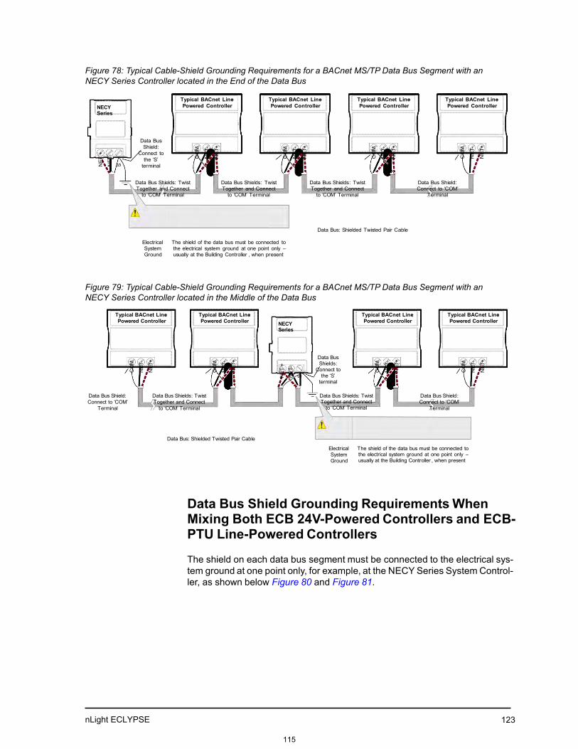
nLight ECLYPSE 123
NET
+
NET
-
S
CO
M
NET
-
NET
+
CO
M
NET
-
NET
+ C
OM
NET
-
NET
+
NET
+
NET
-
S
CO
M
NET
-
NET
+
CO
M
NET
-
NET
+
CO
M
NET
-
NET
+
CO
M
NET
-
NET
+
CO
M
NET
-
NET
+
Figure 78: Typical Cable-Shield Grounding Requirements for a BACnet MS/TP Data Bus Segment with an NECY Series Controller located in the End of the Data Bus
NECY Series
Typical BACnet Line- Powered Controller
Typical BACnet Line- Powered Controller
Typical BACnet Line- Powered Controller
Typical BACnet Line- Powered Controller
Data Bus Shield:
Connect to the ‘S’
terminal
Data Bus Shields: Twist Together and Connect
to ‘COM’ Terminal
Data Bus Shields: Twist Together and Connect
to ‘COM’ Terminal
Data Bus Shields: Twist Together and Connect
to ‘COM’ Terminal
Data Bus Shield: Connect to ‘COM’
Terminal
Data Bus: Shielded Twisted Pair Cable
Electrical System Ground
The shield of the data bus must be connected to the electrical system ground at one point only – usually at the Building Controller , when present
Figure 79: Typical Cable-Shield Grounding Requirements for a BACnet MS/TP Data Bus Segment with an NECY Series Controller located in the Middle of the Data Bus
Typical BACnet Line- Powered Controller
Typical BACnet Line- Powered Controller NECY
Series
Typical BACnet Line- Powered Controller
Typical BACnet Line- Powered Controller
Data Bus Shields:
Connect to the ‘S’
terminal
Data Bus Shield: Connect to ‘COM’
Terminal
Data Bus Shields: Twist Together and Connect
to ‘COM’ Terminal
Data Bus Shields: Twist Together and Connect
to ‘COM’ Terminal
Data Bus Shield : Connect to ‘COM’
Terminal
Data Bus: Shielded Twisted Pair Cable
Electrical System Ground
The shield of the data bus must be connected to the electrical system ground at one point only – usually at the Building Controller , when present
Data Bus Shield Grounding Requirements When Mixing Both ECB 24V-Powered Controllers and ECB-PTU Line-Powered Controllers
The shield on each data bus segment must be connected to the electrical sys- tem ground at one point only, for example, at the NECY Series System Control- ler, as shown below Figure 80 and Figure 81.
115

nLight ECLYPSE 124
NET
+
NET
-
S
NET
+
NET-
NET+
NET-
N
ET+
NET-
NET
+
NET-
S
COM
NET-
NET+
COM
NET-
NET+
NET+
NET-
NET
+
NET-
NET+
NET-
Series Controller located in the End of the Data Bus
NECY Series Data Bus
Shield: Connect to
the ‘S’ terminal
Typical BACnet24VAC- Powered Controller
Typical BACnet Line- Powered Controller
Typical BACnet24VAC- Powered Controller
Typical BACnet24VAC- Powered Controller
Data Bus Shields: Twist Together and Isolate with Electrical Tape
Data Bus Shields: Twist Together and Connect
to ‘COM’ Terminal
Data Bus Shields: Twist Together and Isolate with Electrical Tape
Data Bus Shield : Isolate with
Electrical Tape
Data Bus: Shielded Twisted Pair Cable
Electrical System Ground
The shield of the data bus must be connected to the electrical system ground at one point only – usually at the Building Controller , when present
Figure 81: Typical Cable-Shield Grounding Requirements for a BACnet MS/TP Data Bus Segment with an NECY Series Controller located in the Middle of the Data Bus
Typical BACnet24VAC- Powered Controller
Typical BACnet24VAC- Powered Controller NECY
Series
Typical BACnet Line- Powered Controller
Typical BACnet24VAC- Powered Controller
Data Bus Shields:
Connect to the ‘S’
terminal
Data Bus Shield: Isolate with
Electrical Tape
Data Bus Shields: Twist Together and Connect
to ‘COM’ Terminal
Data Bus Shield : Isolate with
Electrical Tape
Data Bus Shields: Twist Data Bus: Shielded Twisted Pair Cable
together and Isolate with electrical tape
Electrical System Ground
The shield of the data bus must be connected to the electrical system ground at one point only – usually at the Building Controller, when present
116

nLight ECLYPSE 125
Using Repeaters to Extend the Data Bus
A BACnet MS/TP data bus segment can be up to 1220 meters (4000 feet) long with up to a maximum of 50 devices. When a greater length is required, a solution is to use a repeater. A repeater increases the maximum length of the data bus.
Using a Repeater to Extend the Length of the BACnet MS/TP Data Bus
Repeaters can be used to extend a BACnet MS/TP data bus up to 3660 meters maximum total length. Do not use more than two repeaters on a BAC- net MS/TP LAN.
A BACnet MS/TP repeater is a bi-directional device that regenerates and strengthens the electrical signals that pass through it. It creates two electri- cally-isolated BACnet MS/TP data bus segments that transparently enable devices on one side of the repeater to communicate with any device on the other side. The two BACnet MS/TP data bus segments have the same requirements of an ordinary BACnet MS/TP data bus segment; that is, each BACnet MS/TP data bus segment:
• Can be up to 1220 meters (4000 feet) long.
• The first and last device on the data bus must have End-of-Line (EOL) ter-mination resistors connected across the two data lines/wires of thetwisted pair.
• Must respect the maximum limit for Device Loading.
• Will have the same network number as they remain part of the same net-work or LAN.
It is recommended that you connect no more than 50 of our ⅛ or ½-load devices on all BACnet MS/TP Data Bus repeater segments when a baud rate of 19 200 or higher is used (preferably 38 400 baud). This is to ensure that the BACnet MS/TP Data Bus has enough bandwidth to efficiently communicate network variables between controllers.
Do not use more than two repeaters on a BACnet MS/TP data bus. A repeater can only connect two BACnet MS/TP data bus seg- ments even if it has ports to support more than two BACnet MS/TP data bus segments.
A repeater can be added anywhere to a data bus segment including the end of the segment as shown below.
117

nLight ECLYPSE 126
Figure 82: Using a Repeater to Extend the Range of the LAN
A repeater can be used to create a spur as shown below.
Figure 83: Adding a Spur by Using a Repeater
A repeater is counted as a device on each data bus to which it is connected.
When third party devices are connected to a data bus segment, the number of devices that can be connected to that data bus segment may be reduced. See Device Loading.
118

nLight ECLYPSE 127
w
NET
+
NET-
NET+
NET-
NET
+
NET-
Figure 84: Repeater Connections when it is the First or Last Device on its Respective Data Bus Segment
Typical BACnet Device
EOL ON
BACnet MS/TP data bus Bias and EOL termination is provided by this controller’s internal EOL Termination
being set to ON
Typical BACnet Device
No Built -in EOL Termination
BACnet MS/TP data bus Bias and EOL termination is provided by this controller’s internal EOL Termination
being set to ON
Typical BACnet Device
EOL ON
Data Bus Shields: Twist together and Isolate with
electrical tape
Repeater
Data Bus Shields: Twist together and Isolate ith
electrical tape
1 Data Bus: Shielded Twisted Pair Cable
Data + (1)
Data – (2)
Data + (20) 2 Data – (19)
< 7.6 m < 25 ft The data bus shield must be connected to the electrical system ground at
one point only – usually at the Building Controller , when present
The BACnet MS/TP Data Bus must be biased. This bias can only be provided by built-in EOL termination resistors (ones set with a jumper or DIP switch). When a repeater is the first or last device on its respective data bus segment, use the following methods to provide MS/TP Data Bus biasing and EOL termi- nation as applicable to your situation:
1. On the BACnet MS/TP data bus segment shown in Figure 84, bias andEOL termination is provided by a controller’s built-in EOL terminationbeing set to ON. In this case the connection to the repeater cannot bemore than 7.6 meters (25 feet) from this controller.
2. On the BACnet MS/TP data bus segment shown in Figure 84, a 120ΩEOL Termination resistor is added to the repeater’s terminals. Biasing forthis BACnet MS/TP data bus segment is provided by the built-in EOL ter- mination being set to ON at the last controller at the other end of this databus.
See When to Use EOL Terminations for more information. The shield of one data bus must be grounded at one point as specified in Data Bus Shield Grounding Requirements. The shields of the two data buses must be connected together and isolated with electrical tape as shown in Figure 84.
Refer to the controller’s Hardware Installation Guide for how to identify and set a controller’s built-in EOL terminations.
119

nLight ECLYPSE 128
Device Addressing
Device addressing allows the coordinated transfer of messages between the intended devices on the BACnet MS/TP data bus and with devices connected to the internetwork. For this, each device connected to the BACnet MS/TP data bus is identified by a MAC address, a Device Instance number, and a Network Number:
• The MAC Address uniquely identifies a device on a Network (identified bya Network Number). Devices on another Network can have the sameMAC Address as messages are not passed at the internetwork level usingthe MAC Address. The MAC Address also defines the devices on thedata bus that are Masters and Slaves, among other categories (see Table10). The MAC Address is also used to share data bus bandwidth betweendevices through token passing between Master devices.
• The Device Instance uniquely identifies a device across the BACnet inter-network. The Device Instance is any number between 0 and 4 194 303. Itis with the Device Instance that messages are exchanged between BAC-net devices. The Device Instance is also used by routers to forward mes-sages to devices located elsewhere in the internetwork. Unlike a MACAddress, a Device Instance cannot be reused elsewhere in the BACnetinternetwork (it must be unique for the entire network).
• The Network Number is any number between 1 and 65 534. A networknumber identifies a LAN for routing purposes.
Both the MAC Address and the Device Instance must be set for each device and are essential for proper BACnet LAN operation.
For an example of how MAC address, Device Instance number, and Network Number apply to a typical BACnet network, see Figure 86.
About the MAC Address
The MAC Address is a number from 0 to 255; however, we recommend reserving some MAC Addresses for common commissioning and mainte- nance tasks. For example, when a portable adapter is set to use one of these reserved MAC Addresses, it can be temporarily connected with certainty to any BACnet MS/TP data bus of any site without conflicting with other devices already connected to the BACnet MS/TP data bus. We strongly recommend that the MAC address of NECY Series Controller’s MS/TP port be always set to 0.
MAC Addresses should be used as shown in the following table.
120

nLight ECLYPSE 129
Table 10: Recommended BACnet MS/TP Bus MAC Address Values / Ranges for BACnet MS/TP Data Bus Devices
MAC Address Value / Range Usage Devices
0 Data Bus Master (NECY Series Control- ler)
This address is invalid for Distech Con- trols’ ECB series devices
1 Temporary commissioning connection This address is invalid for Distech Con- trols’ ECB series devices
2 Reserved Other
3-127 Master Range Master devices: All Distech Controls’ devices are master devices and should be in this MAC Address range
128-254 Slave Range Slave devices and network sensors
255 Broadcast Do not apply address 255 to any device
BACnet MS/TP Data Bus Token-Passing Overview
The BACnet MS/TP data bus protocol is a peer-to-peer, multiple-master pro- tocol that shares data bus bandwidth by passing a token between Master devices on the data bus that authorizes the device that is holding the token to initiate communications on the data bus. Once the device has completed its request(s), it closes the communications channel, passes the token to the next Master device (making it the current Master), and liberates the data bus.
The token is passed through a short message from device to device on the BACnet MS/TP data bus in consecutive order starting from the lowest MAC address (MAC Address = 0) to the next MAC Address.
Gaps or pockets of unassigned device MAC Addresses should be avoided as this reduces data bus performance. Once a master has finished making its requests, it must poll for the next master that may exist on the Data Bus. It is the timeout for each unassigned MAC Address that slows down the data bus.
The way MAC Addresses are assigned is not a physical requirement: Devices can be daisy-chained on the data bus in any physical order regardless of their MAC Address sequence. The goal is to avoid gaps in the device MAC Address range.
Slave devices cannot accept the token, and therefore can never initiate com- munications. A Slave can only communicate on the data bus to respond to a data request addressed to it from a Master device. Gaps in slave device MAC Addressing have no impact on BACnet MS/TP data bus performance.
121

nLight ECLYPSE 130
Figure 85: Setting the Max Master on the NECY Series Controller to the Highest MAC Address Used on the BACnet MS/TP Data Bus
About Tuning the Max Info Frames Parameter
Once a device has the token, it can make a number of information requests to other devices on the BACnet intranetwork. The maximum number of requests is limited by the Max Info Frames parameter. Once the device has made the maximum number of requests it is permitted to make according to the Max Info Frames parameter, the device passes the token to the following device with the next higher MAC address. This makes the BACnet MS/TP Data Bus more reactive for all devices by preventing a device from hanging on to the token for too long. Ordinary BACnet MS/TP devices should have the Max Info Frames parameter set to between 2 and 4. The Data Bus Master (NECY Series Controller) should have the Max Info Frames parameter set to 20.
About Tuning the Max Master Parameter
To prevent the passing of the token to unused MAC Addresses situated after the final Master device, the Max Master parameter must be set. By default, the Max Master for an NECY Series Controller or a Supervisor is set to 127 which allows for the theoretical maximum of 127 devices besides the Data Bus Master to be connected to the data bus.
In practice, the actual number of devices connected to a data bus is far less, resulting in a gap between the highest MAC Address of any device connected to the data bus and the value set for Max Master. This gap unnecessarily slows-down the data bus with Poll for Master requests.
When commissioning a BACnet MS/TP Data Bus, it is useful to start with the Max Master set to 127 so as to be able to discover all devices connected to
122

nLight ECLYPSE 131
the data bus. Then, once all devices have been discovered and the MAC Addressing is finalized by eliminating any gaps in the address range, set the Max Master (maximum MAC Address) in the NECY Series Controller and in the Supervisor to the highest Master device’s MAC Address number to opti- mize the efficiency of the data bus.
Setting the Max Master and Max Info Frames
The Max Master and Max Info Frames are parameters used to optimize a BACnet MS/TP Data Bus. This is set in the NECY Series Controller and sepa- rately with the Supervisor for each connected BACnet MS/TP device.
For the NECY Series Controller, set the Max Info Frames to 20 in the screen shown in BACnet Settings of the Network MS/TP Ports as this is a device that will make more requests for service from other devices on the network. In general, according to the way a device is programmed, the Max Info Frames may have to be set to a higher value than for other devices. For example, when Roof Top Unit Controllers are used with VAV controllers that use gfxAp- plications code, they should also have their Max Info Frames set to a higher value such as 5, as Roof Top Unit Controllers will poll many VAV controllers for information.
To set the Max Master and Max Info Frames for BACnet MS/TP devices (for example, an ECB series controller), use a Supervisor to do so. See the Net- work User Guide for more information.
Default Device Instance Number Numbering System for Acuity Controls’ controllers
By default, controllers from Distech Controls automatically self-assign a Device Instance number generated from the unique MAC Address assigned to the controller during installation. The Device Instance number is calculated as follows:
Device Instance number = 364 X 1000 + MAC Address
Where 364 is Distech Controls unique BACnet Manufacturer ID.
This Numbering system is sufficient for a BACnet network that has only one NECY Series Controller. For larger BACnet networks that have more than one NECY Series Controller (to form a BACnet intranetwork), set the MAC Addresses, Device Instance Numbers and Network Numbers according to the numbering scheme below.
Adopting a Numbering System for MAC Addresses, Device Instance Numbers, and Network Numbers
Good network planning requires a well-thought-out numbering scheme for device MAC Addresses, Device Instance Numbers (DI), and Network Num- bers. We recommend the following scheme, as it reuses the MAC Address and Network Number in the Device Instance number to make it easier for a
123

nLight ECLYPSE 132
network administrator to know where a device is located in the network. This is shown below.
Table 11: Recommended Numbering Scheme for MAC Addresses, Instance Numbers, and Network Numbers
Description Range Example
BACnet/IP Network Number 0 to 65 534 1
NECY Series Controller BACnet/IP Device Instance Numbers: Multiples of 10 000
10 000 to 4 190 000 10 000 20 000
BACnet MS/TP Network Number: NECY Series Controller BACnet/IP Device Instance Num- ber/1000 + 0,1,2,3,4 (for each LAN)
10 to 4190 10 20 30
BACnet MS/TP Device Instance Number = NECY Series Controller BACnet MS/TP Net- work Number * 1000 + MAC Address
10 000 to 4 190 256 10 006 where MAC = 6
An example of this numbering system is shown below.
Figure 86: BACnet MS/TP Numbering System for MAC Addresses, Device Instance Numbers, and Network Numbers
When discovering devices with EC-Net which has the routing option configured, it will dis- cover all BACnet devices connected to all NECY Series Controllers when routing is enabled (see Routing). Make sure to add only the devices connected to the MS/TP port of the specific NECY Series Controller being configured. Using this numbering system will greatly help to identify those devices that should be added to a given NECY Series Controller.
124

nLight ECLYPSE
133
Setting the NECY Series Controller’s MAC Address
The NECY Series Controller’s MAC address can be set in BACnet Settings of the nLight ECLYPSE Web Interface.
Inter-Building BACnet Connection
BACnet network connections between buildings must be made using BACnet/ IP as shown below.
Figure 87: Typical Inter-Building Connection Using BACnet/IP or FOX
BACnet/IP Broadcast Management Device Service (BBMD)
Though BACnet/IP uses IP protocol to communicate, a standard IP router does not forward broadcast messages which are important in BACnet to iden- tify services that are available within the BACnet internetwork.
When two NECY Series Controllers communicate to each other over a stan- dard IP connection that is separated by an IP router, both NECY Series Control- lers need the BACnet/IP Broadcast Management Device (BBMD) service to be configured and operational.
The BBMD service identifies BACnet messages on the BACnet MS/TP net- work that are intended for a device located on another BACnet network. The BBMD service encapsulates these messages into an IP message to the appropriate BBMD service of the other BACnet MS/TP network(s). The BBMD service on these networks strips out the encapsulation and sends the BACnet message on to the appropriate devices.
125

nLight ECLYPSE 134
When sending BACnet messages across a standard IP connection that has an IP router, there must be one BBMD service running on each BACnet MS/ TP network.
126

nLight ECLYPSE
135
Power Supply Requirements for 24VAC-Powered Controllers
BACnet MS/TP is a Three-Wire Data Bus
Even though data is transmitted over a 2-wire twisted pair, all EIA-485 trans- ceivers interpret the voltage levels of the transmitted differential signals with respect to a third voltage reference common to all devices connected to the data bus (signal reference). In practice, this common signal reference is pro- vided by the building’s electrical system grounding wires that are required by electrical safety codes worldwide. Without this signal reference, transceivers may interpret the voltage levels of the differential data signals incorrectly, and this may result in data transmission errors.
PS100-240 Power Supply is a double-insulated device and therefore is not grounded. The reference for the BACnet MS/TP data bus is made by connecting the shield of the BACnet MS/TP data bus to the ECLYPSE Series Controller’s S terminal to provide a sig- nal reference. This shield is grounded at one point only – see Data Bus Shield Grounding Requirements.
Avoid Ground Lift
24V Power wiring runs should not be too long, nor have too many devices connected to it. Wiring used to supply power to devices has a resistance that is proportional to the length of the wiring run (See Table 12.).
Table 12: Resistance of Common Copper Wire Sizes
AWG Diameter Area Copper wire resistance
Range (mm) (kcmil) (mm2) (Ω/km) (Ω/1000 ft.)
14 0.0641 1.628 4.11 2.08 8.286 2.525
16 0.0508 1.291 2.58 1.31 13.17 4.016
18 0.0403 1.024 1.62 0.823 20.95 6.385
If the power run from the power supply is relatively long and it supplies power to many devices, a voltage will develop over the length of wire. For example, a 1000 ft. of 18 AWG copper wire has a resistance of 6.4 Ohms. If this wire is supplying 1 Ampere of current to connected devices (See Figure 88.), the voltage developed across it will be 6.4 volts. This effect is called ground lift.
127

nLight ECLYPSE 136
Figure 88: Ground Lift from a Long Power Run with a 24VAC Device
AC Power Source
24 / 120 / 208 / 240 / 277 / 347 / 480 VAC, 1Ø, 2-
Power Supply
Fuse: 4A Max. Fast Acting
24 VAC
Electrical Power Run Length
BACnet Device
24V AC/DC
24V COM
Wire plus Ground Reqv I = 1 A
Electrical System
Ground – At Transformer
Only
The equivalent resistance of a run of wire. For example , a 1000 ft of 18 AWG copper wire
has a resistance of 6.4 Ohms. With 1 Ampere of current, the voltage developed along the length of the electrical power run for one
conductor will be 6.4 volts.
Because the 24V COM terminal on ECB series controllers is the signal refer- ence point for the data bus, ground lift offsets the data bus voltage reference that is used to interpret valid data levels sent on the data bus. If the ground lift is more than 7 volts peak, there is a risk of data corruption and offline events due to the device being incapable of correctly reading data signals from the data bus. Thus it is important to keep the power supply (transformer) as close to the controller as possible.
Techniques to Reduce Ground Lift
Reduce the impact of ground lift as follows:
• Use a heavier gauge wire.
• Add more wire runs. Connect these wire runs to the power supply in a starpattern.
• For controllers that accept DC power (that is, models without triac out- puts): Specify a 24VDC power supply. The continuous and even voltageof a DC power supply makes more efficient use of the power handlingcapabilities of a power run. A 24VDC power supply eliminates the 2.5multiplication factor associated with the peak AC current being 2.5 timesthe average RMS AC current. See below.
About External Loads
When calculating a controller’s power consumption to size the 24VAC trans- former, you must also add the external loads the controller is going to supply, including the power consumption of any connected subnet module (for exam- ple, for Allure series communicating sensors). Refer to the respective mod- ule’s datasheet for related power consumption information.
A controller can support a maximum of two Allure series sensor models equipped with a CO2 sensor. See Subnetwork Module Compatibility and Sup- ported Quantity Charts for how many Allure series communicating sensors are supported by a given controller model. The remaining connected Allure series sensor models must be without a CO2 sensor.
128

nLight ECLYPSE 137
24VAC Power Supply Connection
Use an external fuse on the 24VAC side (secondary side) of the transformer, as shown in Figure 89, to protect all controllers against power line spikes.
The ECLYPSE Controller uses the S terminal as the signal reference point for the data bus (see Table 4 for common device terminal labels).
129

nLight ECLYPSE 138
CHAPTER 11 Resetting or Rebooting the Controller
This chapter describes how to recover control over the controller by resetting it to the factory default settings.
Topics Resetting or Rebooting the Controller
130

nLight ECLYPSE 139
Resetting or Rebooting the Controller The reset button is located between the RS-458 and Ethernet connectors on connected system controllers and underneath the cover on connected VAV controllers. Depending on the amount of time the reset button is held down, different actions are taken by the controller.
Hold reset for To
5 seconds Restart / reboot the controller.
10 seconds Reset both Ethernet and Wi-Fi IP addresses back to factory default settings.
20 seconds Reset the controller to its factory default settings. User accounts (user names and passwords) will also be reset to the factory default settings and the controller’s license and HTTPS security certificates will be cleared. If FIPS 140-2 mode has been enabled on the controller, this will turn FIPS 140-2 mode off.
Always backup the controller's license through the controller's Web interface before you hold the controller’s reset button for 20 seconds. Once the controller reboots, you will have to install the license through the controller's Web interface. To backup and install the license, see System Settings. Click Export To PC to backup the controller's license to your PC. Click Import From PC to restore the controller's license file from your PC.
After you hold the controller’s reset button for 20 seconds, the con- troller’s HTTPS security certificates will be regenerated. If you use HTTPS to connect to the controller, you will no longer be able to connect to the controller from any PC that was used in the past to connect to the controller unless you delete the old HTTPS security certificate from these PCs. See Removing a Certificate.
131

nLight ECLYPSE
140
CHAPTER 16
NECY CONTROLLER TROUBLESHOOTING
You can use this Troubleshooting Guide to help detect and correct issues with the nLight ECLYPSE Series controllers.
Table 27: Troubleshooting NECY Controller Symptoms
Symptom Possible Cause Solution
Controller is powered
but does not turn on
Fuse has blown (for
24V controllers)
Disconnect the power. Check the fuse integrity. Reconnect the power.
Power supply polarity Verify that consistent polarity is maintained between all controllers and the trans-
former. Ensure that the COM terminal of each controller is connected to the same
terminal on the secondary side of the transformer. See DHCP versus Manual Net-
work Settings
The device does not
have power / poor-
quality power (for 24V
controllers)
Verify that the transformer used is powerful enough to supply all controllers. See
Transformer Selection and Determining the Maximum Power Run Length
132

nLight ECLYPSE 141
Table 27: Troubleshooting NECY Controller Symptoms
Symptom Possible Cause Solution
Device does not com-
municate on the BAC-
net MS/TP network
Absent or incorrect
supply voltage (for
24V controllers)
1. Check power supply voltage between 24VAC/DC and 24V COM pins and
ensure that it is within acceptable limits (±15% for 24V controllers).
2. Check for tripped fuse or circuit breaker.
Overloaded power
transformer (for 24V
controllers)
Verify that the transformer used is powerful enough to supply all controllers. See
Transformer Selection and Determining the Maximum Power Run Length
Network not wired
properly
Double check that the wire connections are correct.
Absent or incorrect
network termination
Check the network termination(s).
Max Master parameter Configure the Max Master to the highest MAC Address of any device on the MS/
TP data bus. See Setting the Max Master and Max Info Frames
There is another con-
troller with the same
MAC Address on the
BACnet MS/TP data
bus
Each controller on a BACnet MS/TP data bus must have a unique MAC Address.
Look at the MAC Address DIP switch on the faceplate of each controller. If it is set
to 0 (all off), use an Allure EC-Smart-Vue sensor to check the MAC Address.
There is another con-
troller with the same
Device ID on the BAC-
net intranetwork
Each controller on a BACnet intranetwork (the entire BACnet BAS network) must
have a unique Device ID. Use an Allure series communicating sensor to check
the Device ID of each controller. See Adopting a Numbering System for MAC
Addresses, Device Instance Numbers, and Network Numbers
BACnet data bus
polarity is reversed.
Ensure the polarity of the BACnet data bus is always the same on all devices.
See BACnet MS/TP data bus is polarity sensitive
Cut or broken wire. Isolate the location of the break and pull a new cable.
The BACnet data bus
has one or more
devices with the same
MAC Address.
See Adopting a Numbering System for MAC Addresses, Device Instance Num-
bers, and Network Numbers
The baud rate for all
devices are set to
AUTO
At least one device must be set to a baud rate, usually the data bus master. See
Baud Rate
The device is set to a
MAC Address in the
range of 128 to 255.
See if the STATUS LED on the device is showing a fault condition. See Table 28
for a list of fault codes.
This range is for slave devices that cannot initiate communication. All Distech
Controls' devices are master devices and must their MAC Address set accord-
ingly. See Device Addressing
The maximum num-
ber of devices on a
data bus segment has
been exceeded.
Use a repeater to extend the BACnet data bus. See Maximum Number of BACnet
MS/TP Devices on a Data Bus Segment and Baud Rate
The STATUS LED is
blinking
The device has auto-
diagnosed a fault con-
dition
See Table 28 for a list of fault codes.
133

nLight ECLYPSE 142
Table 27: Troubleshooting NECY Controller Symptoms
Symptom Possible Cause Solution
Controller communi-
cates well over a short
network BACnet MS/
TP network, but does
not communicate on
large network
Network length Check that the total wire length does not exceed the specifications of the Network
Guide. See Data Bus Physical Specifications and Cable Requirements
Wire type Check that the wire type agrees with the specification of the Network Guide: See
Data Bus Physical Specifications and Cable Requirements
Network wiring prob-
lem
Double check that the wire connections are correct.
Absent or incorrect
network termination
Check the network termination(s). Incorrect or broken termination(s) will make the
communication integrity dependent upon a controller's position on the network.
Number of controllers
on network segment
exceeded
The number of controllers on a channel should never exceed 50. Use a router or
a repeater: See Data Bus Segment MAC Address Range for BACnet MS/TP
Devices
Max Master parameter Configure the maximum number of master device on the MS/TP network in all
devices to the controller's highest MAC address used on the MS/TP trunk. BAC-
net MS/TP Data Bus Token-Passing Overview.
Hardware input is not
reading the correct
value
Input wiring problem Check that the wiring is correct according to the module's hardware installation
manual and according to the peripheral device's manufacturer recommendations.
Open circuit or short
circuit
Using a voltmeter, check the voltage on the input terminal. For example, for a dig-
ital input, a short circuit shows approximately 0V and an open circuit shows
approximately 5V. Correct wiring if at fault.
Configuration problem Using the controller configuration wizard, check the configuration of the input.
Refer to the controller's user guide for more information.
Over-voltage or over-
current at an input
An over-voltage or over-current at one input can affect the reading of other inputs.
Respect the allowed voltage / current range limits of all inputs. Consult the appro-
priate datasheet for controller input range limits.
Hardware output is not
operating correctly
Fuse has blown (Auto
reset fuse, for 24V
controllers)
Disconnect the power and outputs terminals. Then wait a few seconds to allow
the auto-reset fuse to cool down. Check the power supply and the output wiring.
Reconnect the power.
Output wiring problem Check that the wiring is correct according to the module's hardware installation
manual and according to the peripheral device's manufacturer.
Configuration problem With EC-gfxProgram, check the configuration of the output; for example, is it
enabled? Refer to the EC-gfxProgram User Guide for more information.
0-10V output, 24VAC
powered actuator is
not moving
Check the polarity of the 24VAC power supply connected to the actuator while
connected to the controller. Reverse the 24VAC wire if necessary.
134

nLight ECLYPSE 143
Table 28: LED Fault Condition Interpretation for ECB Devices
ECB Device LED
Interpretation
Description Solution
RX LED not blinking Data is not being
received from the
BACnet MS/TP data
bus.
If there is no communication, see Table 27 - Troubleshooting NECY Controller
Symptoms.
TX LED not blinking Data is not being
transmitted onto the
BACnet MS/TP data
bus.
POWER constant on Power is available at
the device. However
this does not mean
that the quality of sup-
plied power is good.
See Power Supply
Requirements for
24VAC-Powered Con-
trollers.
If not lit, see Power Supply Requirements for 24VAC-Powered Controllers for
the power requirements.
STATUS blinking See following table. -
Table 29: STATUS LED Interpretation for Normal Operation with ECB Devices
Device STATUS LED
blink patterns
Status Description
One fast blink Initialization The device is starting up.
The STATUS LED is
always OFF (Not
applicable to
ECB-PTU Series)
No anomaly Normal operation.
Table 30: Verify that the Following Recommendations have been Carried Out Before Calling Technical Support
Properly terminate the BACnet MS/
TP data bus
EOL terminations must be enabled / installed at either end of the data bus only. See Figure
71.
Avoid duplicate MAC Addresses Verify that no device has a duplicate MAC Address by checking the MAC Address DIP switch
settings on all devices on the data bus, including segments connected by a repeater.
If necessary, isolate devices from the data bus to narrow-down the number of devices that
may be at fault.
135

nLight ECLYPSE 144
Table 30: Verify that the Following Recommendations have been Carried Out Before Calling Technical Support
All devices must be set to the same
baud rate
When all devices are set to AUTO baud rate, at least one device must be set to a baud rate,
usually the data bus master. See Maximum Number of BACnet MS/TP Devices on a Data
Bus Segment and Baud Rate
The data bus is polarity sensitive Ensure that the polarity of all data bus wiring is consistent throughout the network. See BAC-
net MS/TP data bus is polarity sensitive
Do not overload the data bus with
Change of Value (COV) reporting
COV reports create the most traffic on the BACnet MS/TP data bus. Set the COV report rate
to the largest value that provides acceptable performance. Only map COV reports for values
that are necessary. For mapped analog points that are continuously changing, try increasing
the COV increment on these points or set the COV minimum send time flag to true to send
the value at a regular frequency.
Do not leave address holes in the
device’s MAC Address range
Assign MAC Address to device starting at 3, up to 127. Do not skip addresses. Set the maxi-
mum MAC Address in the NECY Series Controller to the final MAC Address number actually
installed.
NOTE: The physical sequence of the MAC Address of the devices on the data bus is unim-
portant: For example, the MAC Address of devices on the data bus can be 5, 7, 3, 4, 6, and 8.
Only daisy-chained devices are
acceptable
Eliminate T-taps and star configurations. Use a router to connect a data bus spur.
Connect no more than five devices to
a power supply transformer (for 24V
controllers)
BACnet MS/TP devices require good power quality. See Power Supply Requirements for
24VAC-Powered Controllers
136

nLight ECLYPSE 145
CHAPTER 18 WI-FI NETWORK TROUBLESHOOTING GUIDE
Any wireless system consists of two or more Wi-Fi transceivers and a radio propagation path (Radio Path). Problems encountered can be any of the fol- lowing.
Symptoms Probable Causes Corrective Actions
Wi-Fi communications are inex-
istent or intermittent
Presence of a low power jammer If the low power jammer is close to the transceiver
antenna, move low power jammer (PC, telephone, etc.)
at least 6.5 feet (2 m) away from transceiver antenna.
Change the Wi-Fi channel on the router. Use a Wi-Fi sur-
veying or Wi-Fi stumbling tool on a laptop computer to
identify unused Wi-Fi channels that may provide a better
interference-free radio path.
Move the nLight ECLYPSE Wi-Fi Adapter’s position
where it has a clear line of sight to the router.
Move the wireless router’s position. Try moving the router
to the center of the room where it has a clear line of site
to each wireless device.
Presence of a high power jammer Remove high power jammer if possible. If not, you will
have to accept strong range reduction or add another
wireless router closer to the controller(s).
Use a wired Ethernet connection to the controller.
Defective nLight ECLYPSE Wi-Fi Adapter
Exchange the wireless dongle with another nLight
ECLYPSE Wi-Fi Adapter. If the dongle is found to be
defective, replace the dongle.
The maximum wireless operating
range has been exceeded
Add another wireless router closer to the controller(s).
The controller has a known technical
issue
Upgrade the controller’s firmware. See User Manage-
ment
The nLight ECLYPSE Wi-Fi
Adapter has been tested
functional and there is no
jammer in the field to interfere
with the signal.
Radio signal path might be obstructed If a new screening or metal separation wall has been
installed since the network was set up, try moving the
receiver to see if the issue is corrected.
Router may have a known technical
issue
Upgrade the router’s firmware. See the manufacturer’s
Website.
137

nLight ECLYPSE 146
Document Revision History 1. Version 0.1 - December 2014 - Beta Release
2. Version 1.0 - January 2015 - Release to Market
3. Version 1.1 - February 2015 - Updated Web Interface Information
4. Version 1.2 - September 2015 - Added the NECY-VAV series controllers, BACnet MS/TP, ModbusRTU, and Modbus TCP network support
5. Version 1.3 - October 2015 - Added Wi-Fi Mesh and Smart Room Control support
6. Version 1.4 - December 2015 - Clarified the number of Allure EC-Smart-Air and Allure EC-Smart- Comfort that are supported by a given controller model.
7. Version 1.5 - May 2016 - Added information for the ECx-Display
8. Version 1.6 - October 2016 - Minor updates
9. Version 1.7 - March 2017:
• New Applications tile in Web Configuration Interface
• Update password information when FIPS 140-2 is enabled.
• XpressNetwork Companion mobile app support
• Updated Foreign Device Settings
10. Version 1.8 - June 2017 - Removed Wi-Fi mesh, added GSA support, new screenshots for thenLight ECLYPSE Web Interface, new backup & restore feature.
138

nLight ECLYPSE 147
139

SensorView Installation Guide
Step 1SENSORVIEW REQUIREMENTSDepending on the intended usage of SensorView, there are two sets of computer hardware/software requirements.
• Single-user / Commissioning Installation: Recommend Windows 7 or Newer• Multi-user Installation: Recommend Windows Server 2012 or Newer
Hardware Minimum Operating Specs:• Ram: 2GB (4GB Recommended)• Hard Drive: 20GB• Browser: Firefox, Chrome, Opera, IE 10+
Versions of Windows supported (both 32 and 64 bit versions supported):• Client Versions: 7, 8.1, 10• Server Versions: 2012 (R2), 2016
Note: Virtual machine operation supported
Step 2PRE-INSTALLATIONThe following Windows software components are required prior to SensorView installation:
• .NET Frameworko Available for download (free) from Windows Updates web page
• IIS (Internet Information Services):o IIS 7.0 Windows
NOTE: If .NET/IIS are not installed prior to running the SensorView installer, user will be automatically prompted to install these items during SensorView installation.
Step 3SENSORVIEW INSTALLATION The SensorView application installer is downloaded from the Acuity Brands website:
• http://www.acuitybrands.com/-/media/Software%20Downloads/nLight/SensorViewInstallerv612%20zip.zip?la=enNOTE: Internet access is required during installation to download latest available version of the SensorView software.
Step 4CONNECTION TO GATEWAYThe Gateway uses its port labeled “LAN” to communicate with the computer running the SensorView software.
• Please reference “SensorView User Manual” for details on methods to connect to a system Gateway.
If assistance is required, please contact our technical support team at 800-535-2465 or [email protected].
140

SensorView Manual
Page 1 of 123
Using SensorView SensorView provides a large variety of configuration options to fine tune the connected nLight network. This section covers common configuration and management tasks that arise when setting up and maintaining the network over time; as well as step by step instructions for accomplishing a given task.
The Device Tree: The Device Tree is the foundation for navigating through SensorView and easily locating a specific device, profile, etc. It is always located in the far left side of the screen, and works in the same fashion as standard collapsing menus do in other programs. Select which feature of the Device Tree you wish to learn more about
Device Tree Overview
Tree Layout
Search / Filter / Locate Device
View Device State
View Device Status
Selecting Multiple Devices
FloorPlan: A feature providing a visual layout of the space for the purposes of device and zone selection and interaction. Contact us to have a layout produced for your nLight installation.
Once a layout is produced and you have received the layout (.mvdb) file, it can be imported into SensorView by going to Admin > Map and clicking the “Import” button, then browsing to and selecting the file.
Software and Firmware Updates
Updating Sensorview: This process walks you through upgrading to the latest version ofSensorView, and ensures you are running on the latest build, including the newest patches,compatibility fixes, and features. This process can only be run by authorized administrators ofSensorView’s host machine, they cannot be performed via the web interface.
Updating Device Firmware: Each nLight device has internal software that can be updated,usually to add new functionality. This process will ensure your devices are all running on up-to-date firmware, and can only be performed by authorized nLight network administrators.
Common Procedures: The menu items on the left are the procedures most commonly asked about using SensorView. If a procedure you are trying to perform is not included in this list, please contact us at [email protected] and we will look into adding it for future revisions.
Logging in
Administrative Taskso Creating Userso Modifying Userso Gateway Pageo Location Page
View Device Properties
Viewing / Editing Device Settingso Normal Deviceso Scene Selectors / nIOs
141

SensorView Manual
Page 2 of 123
Viewing / Editing Zone Settings
Managing Profileso Create a Profileo Edit a Profileo On Demand Profileso Delete a Profile
View Reports
Upgrading Devices
SensorView
Step 1: Requirements
Step 2: Pre-Installation
Step 3: Installation
Step 4: Connecting to Gateway
Virtual Wallpods
Configuring SensorViewo Update SensorViewo Virtual Wallpod Servero Virtual Controlso Virtual WallPod Switcho Control Zone
Virtual WallPod Application
iOS App
GreenScreen
Setting up PostgreSQL
Setting up Database Connection
Setting up GreenScreen
SensorView Page Mapping
Overview
Log[DA1]
Green Screen
Admin: The Admin tabs are for administrators only, and will not be accessed by a day to day end user.
Setup
Updates
Databases
Plugins
Reports
142
SensorView Manual
Page 3 of 123
Navigation Tabs: Across the top of all pages within SensorView are the Navigation Tabs. Depending on a user’s permissions only some of these may be available. To learn more about each tab, click from the list below:
Devices
Control Channelso Local Channelso Global Channels
Group Settings
Profiles
Schedules
Users
Glossaries
SensorView Terms
Status Icons
143

SensorView Manual
Page 4 of 123
Device Tree Overview
The Device Tree Menu, available from the arrow to the right of the search textbox, contains selection features that aid in the location / selection of devices. Three primary types of search features exist: Features, Profiles, and Device States. Features allows for selecting / searching of the tree based on predefined characteristics of the device, such as whether it has a relay or occupancy sensor; available options are: current-sensing, occupancy, daylighting, relay, dimming, switch, dimming-or-relay.
Profiles locates or selects devices that are in a particular profile; this is useful when creating a new profile that operates on all the devices already in an existing profile. As profiles are added or removed from the system the contents of this selections will change. Device States allows for searching or selecting devices depending on their current state.
144

SensorView Manual
Page 5 of 123
145

SensorView Manual
Page 6 of 123
Tree Layout
The layout of the SensorView device tree corresponds closely with the actual wiring of the devices, with a few notable exceptions:
Bridges are not nested within their parents
Zones off a bridge are displayed in ascending alphabetical order
Devices in a zone are displayed in alphabetical order, not wiring
order
146

SensorView Manual
Page 7 of 123
Search / Filter / Locate Device
The SensorView tree allows for the user to select or search for devices based on a variety of parameters. The Device Tree Menu contains numerous options for searching for (“finding”) devices based on predetermined characteristics (such as device state, or features the device has). The text field above the device tree also allows for free text search over the devices. A user can type any value into the field and the tree will automatically begin filtering to display devices with label(s), model(s), or device ID(s) matching the entered value(s).
There are two primary ways to quickly locate a device: use the device Search, or the prebuiltFeatures.
147

SensorView Manual
Page 8 of 123
1. Device search (filter) allows a user to immediately begin typing to search for the device (over device ID, model, or custom label), while
2. Features allows for a user to search for a device based on its o Hardware capabilities:
current-sensing, dimming-or-relay, occupancy, photocell, relay, switch, wireless o Profiles
Select by Profile name o Device state
error, normal, offline, warning
Note that any device matched and displayed will automatically cause the parent zone, bridge, and gateway to be displayed. When operating in MultiSelect (link) mode, clicking on the parent nodes will select all the currently visible child nodes, and will omit the ones that have been filtered out.
148

SensorView Manual
Page 9 of 123
View Device State
For any device selected from the Device Tree (left), SensorView displays data in real time by selecting one of the available tabs: Properties, Current Settings, Default Settings, and Status. This example shows the readings from one of the nLight Ceiling-Mount, Passive Dual-Technology sensors covering approximately an area of 9 meters in diameter (nCM PDT 9) in the Zone called “Mike”, which has been selected from the device tree menu.
There are 6 possible states that an nLight device can be in. These different generally indicate some sort of operational problem with a device.
Note: “Device State” (shown below) is not the same as Device Status. Individual device types can have various “status” conditions, depending on their functions.
Offline – The device is no longer online, check that the device is properly connected
149

SensorView Manual
Page 10 of 123
Out of Range – The device is online, but communication is restricted due to insufficient signal strength. This applies to nWiFi devices only. Signal strength for wireless may vary under certain conditions. Devices downstream from an nWiFi device may also appear Out of Range, if the parent is.
Bootstrap – The device failed a firmware update and is in bootloader. Any relay or dimming output will be toggled on, but the device will not respond to any operational changes. Update the device to resolve this.
Misread – Some properties of the device were not read by the gateway. To resolve state, go to the device and select “Rediscover” or use Group Select->Rediscover
Incompatible – SensorView is not compatible with this device and is unable to configure it. Upgrade the device to resolve this.
Mismatched – SensorView has detected that the devices’ settings do not match what is expected. Synchronize the device (either using SensorView or device’s settings) to resolve.
150

SensorView Manual
Page 11 of 123
View Device Status
The Status Screen displays the present state of any device selected in the left tree menu. Device types have different functions. The status pages display parameters specific to the type of device selected, indicated by icons easily seen at glance.
The current state of the device for each parameter (icon) is also displayed in readable text, which may include additional information on the particular status of the parameter within the selected device.
For a complete guide to Status Icons or possible conditions for a given device parameter, visit the Status Icon Glossary.
151

SensorView Manual
Page 12 of 123
Selecting Multiple Devices
In certain contexts the Device Tree will allow for users to select multiple devices, rather than just one. This mode of selection is available on Group Settings, Profiles, Global Channels, or Users. This mode of selection greatly enhances the ability to quickly create system schedules, permissions, or make wholesale changes to device settings.
To select multiple devices:
Check multiple boxes, each new device will be added to the selection. Checking a selected device a second time will remove it from the grouping.
Check a Zone / Bridge / Gateway to select all of the devices within that group. Check that grouping structure a second time to deselect all devices within that Zone / Bridge / Gateway group.
152

SensorView Manual
Page 13 of 123
Selecting multiple devices is useful when large amounts of devices are to be operated on simultaneously. Profiles, Users, Group Settings and Global Channels all support multiple device selection. All other modes operate in single select, such that selecting any item in the tree displays information specific to that device.
153

SensorView Manual
Page 14 of 123
None Selected (empty Checkboxes)
Bridge Selected (Parent gateway checked in gray)
Zone expanded. All zone devices checked
Specific zone devices unchecked
154

SensorView Manual
Page 15 of 123
Updating SensorView
Please note that the following procedure must be done from the SensorView host computer, and cannot be initiated over the web; administrator credentials on the host are also required.
Note: Always retrieve the latest installer to perform the actual update, on occasion SensorView updates will require subsequent device updates, should this occur the installer will warn you before proceeding with the update.
Depending on the currently installed version of SensorView the steps to update the software may vary, for all versions less than 7.0, follow steps A and B. Otherwise, proceed to step B.
A. Updating to 6.14: 1. Visit Updates page in SensorView & initiate upgrade to 6.12.xx:
2. Return to the Updates page & initiate upgrade to 6.14.xx. 3. Return to Updates page & run all available updates on firmware:
4. Return to Updates page & follow instructions to update to 7.x.x:
B. Updating to the latest version:
155

SensorView Manual
Page 16 of 123
1. Download SensorView installer[DA2] and run Setup.exe 2. Select Modify when offered and follow the prompts.
3. Return to Updates page & run all available firmware
updates.
Downgrading to Version 6.12.x
If you need to return to SensorView Version 6.12 for any reason, run the 6.12.x installer. Note that you will have to uninstall the current version of SensorView beforehand.
156
SensorView Manual
Page 17 of 123
Updating Device Firmware
Select the Admin button at upper left, then select the Updates tab to view all available updates. Devices will be omitted from the listing if they are currently up to date.
SensorView will retrieve the latest firmware for each device from the internet. If you are not going to have internet then download and install the firmware cache (top right), which will allow firmware updates to be performed offline.
The status of the update is displayed in the rightmost column of the blue Status bars, and also at the top center of the screen:
1. Status: Pending while “Preparing to update firmware …“ 2. Status: In Progress while “Updating firmware: X% done“ 3. Status: Completed Fast when “100% Done“
While firmware is being updated by the system, the actual physical device will display a very fast blink of its green status light, as well as closing relays and dimming to full bright, as appropriate. As the process nears completion, the device will display a slow, blinking pattern. After a few minutes, the device status light will return to normal.
157

SensorView Manual
Page 18 of 123
Repeat this process for all devices by selecting any and all (at once) which require firmware updates.
When all devices have been updated, the red Incompatible conditions on the screen will be replaced by Completed Fast.
158

SensorView Manual
Page 19 of 123
Logging in
Navigate to the SensorView login screen via the Start Menu, desktop shortcut, or by directly typing the address into the web browser (note: address requires entering the Host Specific Computer Name, which is installation specific):
http://<Host Computer Name>/SensorView
Enter your case sensitive username and password. Default login is: Username: administrator Password: admin
If you have forgotten or do not have your login information, please contact your network administrator.
159

SensorView Manual
Page 20 of 123
160

SensorView Manual
Page 21 of 123
Administrative Tasks
Only administrative users have authority to perform these tasks, which involve modifying / creating
users, as well as modifying properties on the Gateway & Location pages.
Creating:
1. Click the Users tab
2. Select Add a User from the dropdown
161

SensorView Manual
Page 22 of 123
3. Fill out all fields, making sure to set the appropriate access level.
4. Click Save
Modifying:
162

SensorView Manual
Page 23 of 123
1. Click the Users tab
2. Select user from the dropdown
163

SensorView Manual
Page 24 of 123
3. Change the appropriate information
4. Click Save
164

SensorView Manual
Page 25 of 123
165

SensorView Manual
Page 26 of 123
Gateway Page
The Gateways tab allows operators to manage the nGWY devices that are currently managed by SensorView. nGWY devices running on the same IP Subnet will be discovered automatically by SensorView; any nGWYs that reside on different segments of the IP network can be added by simply entering their IP address on the Gateways tab.
Note: Discovering nGWY devices on different segments of the IP network may require for firewalls and routers to be updated to allow access to the necessary ports.
Including / Excluding Gateways:
1. Click the Admin tab
166
SensorView Manual
Page 27 of 123
2. Click the Gateways section to expand it
167

SensorView Manual
Page 28 of 123
3. Make any changes to the existing list, such as whether or not to include a particular Gateway
4. Add IP addresses of any required Gateways not auto-detected (requires IP address). 5. Click Save to apply your changes
168

SensorView Manual
Page 29 of 123
Location Page
Properly configuring the location for all nGWY devices and the SensorView host is required to ensure that all profiles will run at the proper time. Setting the time zone allows the nGWY devices to properly update their time throughout the course of the year as Daylight Savings Time comes into effect. The location parameters allow the nGWY devices and SensorView to properly compute the correct Sunrise and Sunset times for a given day.
Viewing/Editing Gateway & Server Locations:
1. Click the Admin tab
169

SensorView Manual
Page 30 of 123
2. The Setup tab should automatically load with the Location section expanded
3. Click the Server or Gateway you wish to edit
170

SensorView Manual
Page 31 of 123
4. Uncheck the Edit Coordinates box to edit the Country/State/City fields
5. Click Save to apply your changes
171

SensorView Manual
Page 32 of 123
View Device Properties
1. Click the Devices tab
172

SensorView Manual
Page 33 of 123
2. Using the nLight Network tree to the left, find the device you wish to view
173

SensorView Manual
Page 34 of 123
3. Click the desired device; the properties will populate the Devices area to the right
4. Change the Label, Notes, and other areas to your requirements
174

SensorView Manual
Page 35 of 123
5. Click Save to apply your changes
175
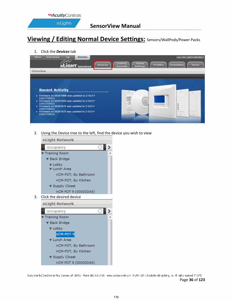
SensorView Manual
Page 36 of 123
Viewing / Editing Normal Device Settings: Sensors/WallPods/Power Packs
1. Click the Devices tab
2. Using the Device tree to the left, find the device you wish to view
3. Click the desired device
176

SensorView Manual
Page 37 of 123
4. Click the Current Settings tab (if it’s grayed out, settings aren’t applicable to the current selection, & you need to pick another device)
5. Your device’s specific settings (varies from device to device) will show 6. Modify the settings in the dropdown/checkbox fields to your specifications (You may also
revert to device defaults by clicking the button at the top)
7. After you’ve made your changes, click the Apply Settings button to save your modifications
Note: hovering over a setting will cause its definition to appear in the information pane at the bottom of the page. The SensorView Terms Glossary also lists these definitions.
177

SensorView Manual
Page 38 of 123
Viewing / Editing Scene Selector / nIO Settings:
1. Click the Devices tab
2. Using the nLight Network tree to the left, find a Scene Selector or nIO
178

SensorView Manual
Page 39 of 123
3. Click the desired device
179

SensorView Manual
Page 40 of 123
4. Click the Current Settings tab (if it’s grayed out, settings aren’t applicable, & you need to pickanother device)
5. For Scene Selectors, the currently assigned action for each of the four control mode buttons isdisplayed. Change settings for each button via the dropdowns. Click Apply Settings to save.
180

SensorView Manual
Page 41 of 123
181
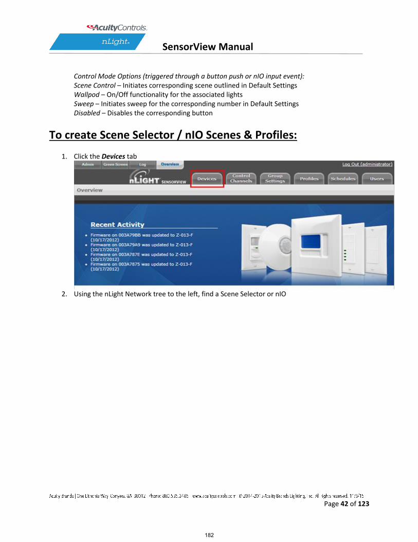
SensorView Manual
Page 42 of 123
Control Mode Options (triggered through a button push or nIO input event): Scene Control – Initiates corresponding scene outlined in Default Settings Wallpod – On/Off functionality for the associated lights Sweep – Initiates sweep for the corresponding number in Default Settings Disabled – Disables the corresponding button
To create Scene Selector / nIO Scenes & Profiles:
1. Click the Devices tab
2. Using the nLight Network tree to the left, find a Scene Selector or nIO
182

SensorView Manual
Page 43 of 123
3. Click the desired device
183

SensorView Manual
Page 44 of 123
4. Click the Default Settings tab (if grayed out, settings aren’t applicable to the current choice, & you need to pick a new device)
5. Select a button, type a name to associate with it, then select which mode you wish to run in:
Wallpod – Assigns on/off control to button Scene – Assigns created scene to button Profile – Assigns an existing profile to button Sweep – Assigns sweep to selected button
184

SensorView Manual
Page 45 of 123
For buttons designated with Scene Mode: Create a scene via the device settings & exceptions dropdowns.
185

SensorView Manual
Page 46 of 123
For buttons designated with Profile Mode: Select an existing profile you wish to attach to the selected button.
For buttons designated with Sweep Control Mode: The Sweep Exit and Sweep Grace Period dropdowns allow you to set a time delay, after which the value of the remaining time delay in all applicable devices will be changed to the input value. This is helpful if you wish to quickly turn all the lights in a zone or building off without affecting any of the device settings.
186

SensorView Manual
Page 47 of 123
6. Click Save Defaults and Apply Now to save, then click another number to change its settings.
187

SensorView Manual
Page 48 of 123
Viewing / Editing Zone Settings
1. Click the Group Settings tab 2. Using the nLight Network tree to the left, click the checkbox next to the desired Zone to select
all devices within the zone. Note: Each port of a Bridge is considered a zone
3. Create the list of settings to be modified by selecting settings one at a time from the provided dropdown field
4. To prevent a device from having a particular setting apply, create an exception 5. After you’ve made your changes, click the Save Defaults button to save your modifications 6. Refer to the Appendix for specific details regarding each setting’s meaning
Managing Profiles
The Profiles page provides the ability to create, edit, and delete all Profiles configured within the system. All Profiles displayed will be grouped with other Profiles sharing the same state: Synchronized, Mismatched, SensorView Only, or Gateway Only.
While creating or editing a profile the Device tree will operate in MultiSelect mode, there is no limit on how many devices can participate in a given Profile. As Devices are added to the Profile more settings may become available on the right, settings are only displayed if there is a Device selected that contains it, settings will be omitted if no Devices selected support it.
The Scheduler, visible at the bottom of the screen, controls the Schedule for the Profile. Profiles can be configured to start/stop at a particular time of day, or based on an offset from Sunrise or Sunset. Recurrences specify how often the Profile should recur in the future, available Recurrences are Daily, Weekly, Monthly, and Yearly.
The Scheduler also contains a tab for Priority, which allows specification of how Scheduling conflicts should be handled. If two, or more, Profiles’ execution times overlap then the Priority determines which Profile will run on each Device. The Schedules section provides a view of exactly how Scheduling conflicts will be resolved by Priority.
Create a Profile
1. Click the Profiles tab 2. Click on New 3. Profile will show up under the SensorView Only header 4. Select all Devices that should be in the Profile using the Device Tree, as Devices are added more
Settings will become available in the Settings area
188

SensorView Manual
Page 49 of 123
5. In the Scheduler/Priority section, create a schedule with any required recurrences, then click Create. For additional schedules select New Schedule in the dropdown and repeat the previous process.
6. Click the Priority tab to modify the priority of the profile using the arrows. Priority will only matter if another Profile is scheduled to execute at the same time, on the same Device.
7. Select desired settings to be added / modified by the profile from the Settings dropdowns; choose values & pick exceptions, if needed.
8. Once all Settings and Schedules have been configured fill in the name for the profile and click Save, the Profile will then move under the Synchronized header.
Edit a Profile
1. Click the Profiles tab 2. Select a Profile Name 3. Edit the schedule & priority, clicking Update to save your changes when finished 4. Remove any existing settings by clicking the – button, modify the current values, or use the Add
a Setting dropdown to add new ones 5. Repeat for each setting you wish to modify, then click Save
On Demand Profiles
SensorView provides the ability to command a Profile to Run or Stop on demand. This is often utilized for standard events that don’t recur according to a specific Schedule, but requires the same lighting configuration.
When a Profile is run on demand it will not stop according to any Schedule, it must be stopped manually; other Profiles that are scheduled to run at the same time, or afterwards, will still execute normally. When a Profile is stopped on demand, and it has a schedule, it will still follow the next Recurrence of the Schedule.
To command a Profile manually: 1. Click the Profiles tab 2. Select a Profile Name 3. Click either Run or Stop to command the Profile
Delete a Profile
1. Click the Profiles tab 2. Select a Profile Name
189

SensorView Manual
Page 50 of 123
3. Click Delete to permanently remove that profile 4. A pop-up will confirm that you wish to do this. Click Ok. 5. Repeat for each profile you wish to delete
**Please note: deleted profiles are permanently removed. Be certain you wish to delete the profile before proceeding.
View Reports
SensorView provides a variety of generated reports detailing all configurable aspects of the nLight network. To view a list of available reports refer to SensorView Reports. To Generate a Report:
1. Click the Admin link 2. Click the Reports tab 3. Select the report you wish to run. Click Generate Report 4. Once run, print a report using the Print Report button, supported browsers all provide the
option to Print to a PDF
Upgrading Devices
1. Click the Admin link in the top right 2. Click the Updates tab (or click the “Updates” link from the Overview page) 3. Check the selected items you wish to update (unchecked items will not update) 4. Click Submit at the bottom of the page
Downloading Firmware Cache: Available when internet connection is present & an updated version of SensorView is available, enabling update downloads that are made available to an offline network.
Note: This process may be lengthy depending on the size of the network.
190

SensorView Manual
Page 51 of 123
SensorView
Installing SensorView is a multi-step process that should only be completed by a qualified computer administrator. Before proceeding, please make the following items available to ensure a successful SensorView Installation:
Windows Installation Disk (Required for Windows XP & Windows Server 2003) Active Internet Connection SensorView Registration Key (provided in each Gateway box) Cross wired CAT-5(e) cable (click here for pinouts)
191

SensorView Manual
Page 52 of 123
Step 1: Requirements There are two types of installations available for SensorView: Single-User / Commissioning For use with any nLight network where a single user operates or commissions the system.
MINIMUM SPECS: SUGGESTED SPECS:
Operating System: Windows 7
Operating System: Windows 7 or 8
Software: IIS 6.0, .NET 4.5.1
Software: IIS 8.0, .NET 4.5.1
Hardware: 1 GB RAM, 2 GB Hard Drive
Hardware: 2 GB RAM, 30 GB Hard Drive
Browser: Firefox, Chrome, Opera, or Internet Explorer 10+
Browser: Firefox, Chrome, Opera, or Internet Explorer 10+
Multi-User For use with any nLight network where multiple concurrent web sessions are desired.
MINIMUM SPECS: SUGGESTED SPECS:
Operating System: Windows Server 2003, Windows Server Web Edition, Windows Small Business Server 2003
Operating System: Windows Server 2008 or 2012
Software: IIS 6.0, .NET 4.5.1
Software: IIS 8.0, .NET 4.5.1
Hardware: 1 GB RAM, 2 GB Hard Drive
Hardware: 2 GB RAM, 30 GB Hard Drive
Browser: Firefox, Chrome, Opera, or Internet Explorer 10+
Browser: Firefox, Chrome, Opera, or Internet Explorer 10+
192

SensorView Manual
Page 53 of 123
Step 2: Pre-Installation
SensorView requires pre-installation of both IIS and the Microsoft .NET Framework.
.NET Framework The .NET Framework 3.0 is automatically installed with Windows Server 2008 & Windows Vista / 7 / 8. If you are NOT running either of these operating systems, click here and follow the .NET installation instructions.
IIS IIS (Internet Information Services) is a Windows component that allows computers to host web applications. This component is required for hosting a SensorView installation, and will allow end users to view and control their SensorView install(s) remotely. To install IIS, please click the link to your corresponding operating system below and follow the specific information for installing this component.
Please Note: Both Win XP & Server 2003 require Windows installation disks and are NOT downloadable from the web. Without Windows discs to install this component, SensorView installation cannot be completed:
Windows XP Pro (32 bit) – IIS 5.0
Windows Small Business Server 2003 (32 bit) – IIS 6.0
Windows Server 2003 (32 bit) – IIS 6.0
Windows Server 2003 (64 bit) – IIS 6.0
Windows Server 2008 – IIS 7.0
Windows Vista / 7 / 8 – IIS 7.0[DA3]
193
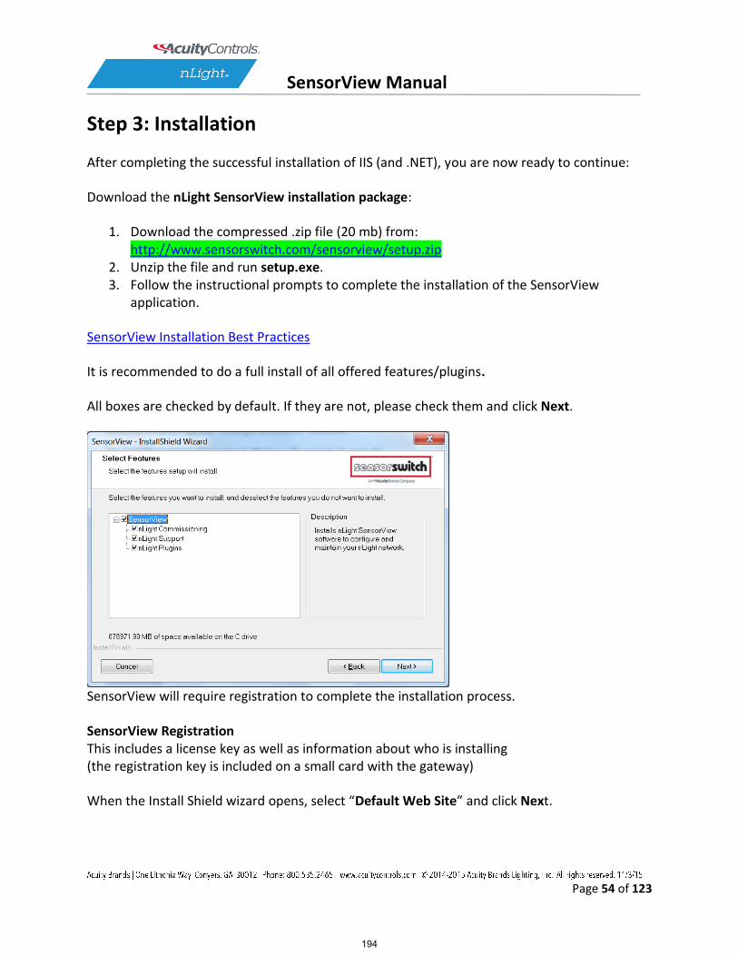
SensorView Manual
Page 54 of 123
Step 3: Installation
After completing the successful installation of IIS (and .NET), you are now ready to continue:
Download the nLight SensorView installation package:
1. Download the compressed .zip file (20 mb) from: http://www.sensorswitch.com/sensorview/setup.zip
2. Unzip the file and run setup.exe. 3. Follow the instructional prompts to complete the installation of the SensorView
application.
SensorView Installation Best Practices
It is recommended to do a full install of all offered features/plugins.
All boxes are checked by default. If they are not, please check them and click Next.
SensorView will require registration to complete the installation process.
SensorView Registration This includes a license key as well as information about who is installing (the registration key is included on a small card with the gateway)
When the Install Shield wizard opens, select “Default Web Site” and click Next.
194

SensorView Manual
Page 55 of 123
Click Install
The install shield wizard takes a few moments to run.
195

SensorView Manual
Page 56 of 123
If you see the following message, click “install this driver software anyway”.
The installation is complete. Click the box to launch SensorView, or
196

SensorView Manual
Page 57 of 123
Click Start, All Programs, Select nLight SensorView
Launch SensorView on the desktop.
197

SensorView Manual
Page 58 of 123
A username and password are required to login to SensorView. When SensorView is freshly installed, use the following:
Default User Name: administrator Default Password: admin
198

SensorView Manual
Page 59 of 123
Step 4: Connecting to Gateway
The Gateway uses the port labeled “Ethernet” to communicate with the computer running the SensorView software. There are several ways to connect to a gateway; please choose the method you wish to use:
Direct Connection
The following procedure will show you how to establish a direct connection between a laptop computer and a Gateway:
NOTE: a cross-wired CAT-5(e) cable is only required to connect this way to an nGWY1, nGWY2 does not require a cross-wired cable
1. If present, disable wireless networking card 2. Connect PC to Gateway’s Ethernet port with cross-wired (cross-over) CAT-5(e) cable
NOTE: a standard patch cable (straight through wired) will not work 3. Turn off/verify DHCP on Gateway
MENU > SETUP OPTIONS > SET [DHCP OFF] NOTE: if pin is required, enter 1234
4. Enter static IP address for Gateway (for example 192.168.1.2) MENU > SETUP OPTIONS > TCP/IP
5. Enter static IP address for Laptop (e.g., 192.168.1.5). The following instructions are for Windows XP. Other operating systems may require different procedures for changing network address.
1. START > CONTROL PANEL > NETWORK CONNECTIONS > LOCAL AREA CONNECTION > PROPERTIES
2. Highlight Internet Protocol (TCP/IP) in box and click Properties 3. Click the radio button for “Use the following IP address” 4. Fill in
IP address: 192.168.1.5 Subnet Mask: 255.255.255.0 Default Gateway: 192.168.1.1
5. Click OK 6. Verify “Link Up” message on Gateway LCD screen. If “Link Up” message does not
appear, reboot gateway MENU > REBOOT
7. Launch SensorView http://localhost/SensorView
8. Login to SensorView Default User Name: administrator Default Password: admin
199

SensorView Manual
Page 60 of 123
9. Once SensorView detects the Gateway it will appear in device tree 10. If Gateway does not appear in the tree, call tech support; 1.800.535.2465
LAN Connection
The following procedure will show you how to connect to a Gateway over an existing Ethernet Local Area Network (LAN).
NOTE: if the computer and Gateway are located on different subnets, use the instructions for connecting over a Wide Area Network (WAN).
1. Connect SensorView’s computer to LAN using a standard patch cable 2. Connect Gateway’s Ethernet port to LAN using a standard patch cable 3. If Link Up message appears on Gateway, go to step e, if not continue to next step 4. The Gateway can either use a dedicated IP address or acquire one from the
network’s DHCP server. 1. To enter a dedicated IP address:
1. Turn off DHCP on Gateway MENU > SETUP OPTIONS > SET [DHCP OFF] NOTE: if pin is required, enter 1234
2. Enter static IP address for Gateway (for example 192.168.1.2) MENU > SETUP OPTIONS > TCP/IP
3. Return to main screen and verify “Link Up” message. If “Link Up” message does not appear, reboot gateway MENU > REBOOT
2. To use a DHCP assigned IP address: 1. Turn On / Verify DHCP on Gateway
MENU > SETUP OPTIONS > SET [DHCP ON] NOTE: if pin is required, enter 1234
2. If DHCP fails, force the Gateway to acquire an address MENU > GET IP ADDRESS
3. Return to main screen. Verify “Link Up” message 5. Launch SensorView
From host computer: http://localhost/SensorView From non-host computer on LAN: http://[enter server name]/SensorView
6. Login to SensorView Default User Name: administrator Default Password: admin
7. Once SensorView discovers the Gateway it will appear in device tree 8. If Gateway does not appear in tree, call Sensor Switch tech support; 1.800.535.2465
200

SensorView Manual
Page 61 of 123
WAN Connection
If you would like to connect to a Gateway over an existing Wide Area Network (WAN), please call tech support at 1.800.535.2465.
Crossover Cable Reference
201

SensorView Manual
Page 62 of 123
Virtual WallPods
With the Virtual WallPod applications, users can control their lighting from their desktop or iOS mobile device. Designed to look like WallPods®, these applications are an excellent alternative to remote controls, which are often lost and require battery replacement. Simple user permissions provide facility managers necessary administrative control.
Configuring SensorView
SensorView is a required component of the Virtual WallPods Plugin. It is used to setup and configure Users and the Virtual WallPods associated with them; as well as authenticate and process commands sent by Virtual WallPods.
Use of Virtual WallPods requires SensorView be online and accessible.
202

SensorView Manual
Page 63 of 123
Update SensorView
Step 1
Before[DA4] starting, log into your SensorView page and click on Admin at the top right of the screen. If you see a Plugins tab, skip Step 1 and proceed to Start the nLight Virtual WallPod Server.
If you do not see a Plugins tab, click the Updates tab and update to the latest version of SensorView. Once the SensorView application update is finished, run the install file for SensorView and select Modify.
203

SensorView Manual
Page 64 of 123
Click Next, and once the proceeding page opens check the nLight Plugins box, followed by Next.
Once the below screen appears the modification is complete, click Finish to close.
Virtual WallPod Server
Step 2
Once at the Admin Dashboard, click Plugins and Start the nLight Virtual WallPod Server.
Notice that stopped will change to running.
204

SensorView Manual
Page 65 of 123
Virtual Controls
Step 3
Now that the nLight Virtual WallPod Server is running, go to the device page by clicking the Devices tab at the top right area of the screen. Once the devices page opens, click on the Virtual Devices tab, located in the same area.
Select a user by clicking on the dropdown arrow
205

SensorView Manual
Page 66 of 123
Virtual WallPod Switch
Step 4
Click the Add a switch button.
Control Zone
Step 5
Select a zone (bridge port) to control, as well as an individual device or switch broadcasting channel. For convenience, only the switch channels that devices are tracking within the zone will appear in the channel dropdown menu.
206

SensorView Manual
Page 67 of 123
This screen shows the nLight Virtual WallPod controlling all devices connected to the zone that are tracking switch via Channel 1 (A).
To control an individual device, select “Individual Device” from the Control Type dropdown (B).
To label the nLight Virtual WallPod, highlight the Switch Label box and enter the preferred Switch Label (C).
If the nLight Virtual WallPod is to control dimming or a 2-Pole device, check the appropriate box (D).
207

SensorView Manual
Page 68 of 123
Virtual WallPod Application
Download the Virtual WallPod application from the Overview page of SensorView. Click the Overview tab at the top right portion of the screen, then Virtual WallPod under the Downloads section (bottom right) to download.
Note: The download link will only be shown if the Virtual WallPod Plugin has been enabled.
It is recommended to save this file to a flash drive so that it can be installed to other machines throughout the network.
Once the files have been downloaded and extracted to a folder, locate it and run setup.exe
208

SensorView Manual
Page 69 of 123
Next, follow the setup file’s installation steps.
209

SensorView Manual
Page 70 of 123
Once the install is complete, follow the path.
Start/All Programs/nLight/nLight Virtual WallPod. (above)
210

SensorView Manual
Page 71 of 123
Once the icon for the nLight Virtual WallPod appears in the Taskbar, right-click it and enter the network configuration.
211

SensorView Manual
Page 72 of 123
If the nLight Virtual WallPod app is installed to the SensorView host machine, the SensorView URL will match the (left) screenshot.
If it is installed to a remote machine (that is on the same LAN or subnet) the SensorView URL will be: http://[host name or IP address]/sensorview Login as a user assigned one or more Virtual WallPods in SensorView.
The nLight Virtual WallPod is now running and will control the assigned relays.
Now that setup for the host machine is complete, the iOS app can be downloaded and installed.
Virtual WallPod iOS App
This section details how to install and setup the Virtual WallPod software for iOS devices.
212

SensorView Manual
Page 73 of 123
Download and Install iOS application
Go to the App Store on the device that will have the nLight Virtual WallPod installed.
Search for nLight Virtual WallPod.
Note that the App is free of charge, as is all nLight software.
Click FREE, followed by the green INSTALL button that appears.
(note: an iTunes account is required)
Once installed, click the WallPod App icon to launch.
213

SensorView Manual
Page 74 of 123
The app will open the WallPod Settings page the first time it’s launched.
Enter the Server Settings URL (replace “yourserver” with host machine’s IP address).
Set Save Password and Auto Logon to desired settings.
Click Done.
214

SensorView Manual
Page 75 of 123
Login with the user credentials for the nLight Virtual WallPod you wish to control. (left)
Select a switch from the devices list. (right)
Installation is now complete.
Notice that the switch is backlit, indicating that the relay controlled by this nLight Virtual WallPod is closed, i.e., “turned on.”
215

SensorView Manual
Page 76 of 123
Green Screen
This SensorView module logs and analyzes system and building performance. A “Savings Scorecard” calculates energy savings in kWH or dollars.
As with SensorView itself, installing the GreenScreen plug-in should be performed by authorized network administrators.
This will entail installing and setting up a database (PostgreSQL), a driver to connect to the database, a DSN for the data source, initializing the database, starting GreenScreen, and configuring GreenScreen options in SensorView.
Setting up PostgresQL
Setting up PostgreSQL on a computer requires downloading and installing the application, configuring the database to accept remote connections, and restarting the database server.
PostgreSQL is a separate product that is maintained and developed entirely separate from SensorView and is in no way affiliated with nLight, SensorSwitch, or Acuity Brands.
For the remainder of this document the phrase “X.Y” will refer to major and minor versions of the version of PostgreSQL being installed; for example: 9.0, 8.4.
GreenScreen is compatible with PostgreSQL versions 8.4 or higher (9.0 recommended).
1.1: Installing PostgreSQL
SensorView can use an existing PostgreSQL database or a dedicated one. Which option is most appropriate is at the discretion of the system owner. Download the most recent version for either Windows x86-64 (64 bit) or x86-32 (32-bit). A few notes on the installer:
Super-User Creation Screen: The screen below configures the default super-user account for PostgreSQL, take note of these
216
SensorView Manual
Page 77 of 123
credentials as those will be the default login account and password for the PostgreSQL database.
Port Configuration Screen: The screen below allows for configuration of the port that PostgreSQL will use for connections. Use whatever value is required by system administrator. Note, SensorView and GreenScreen can be configured to use any port value.
Advanced Options: The screen below allows for configuration of the locale that PostgreSQL is operating in. The default is almost always sufficient. If the installation site has specific requirements then select the most appropriate option from the drop down. The selected option does not seriously affect GreenScreen operations.
On the final screen, push “Next” to finish the installation of PostgreSQL onto the local computer.
1.2: Allowing Remote Connections
This step is only necessary if SensorView and the PostgreSQL database reside on separate computers. By default, PostgreSQL will not allow any remote connections; to change this, administrative access to the host machine for the database is required. To setup PostgreSQL to allow remote connections, go to the directory PostgreSQL was installed at (by default C:\Program Files\PostgreSQL), from that folder open the file at X.Y\data\pg_hba.conf; this file can be opened in notepad or any generic text editor. For how to configure pg_hba.conf, as well as any questions, refer to: 8.4 documentation, 9.0 documentation
For all database versions, adding the following line to the bottom of the file to allow ALL remote connections to the database: host all 0.0.0.0/0 md5 Note, allowing all connections is a potential security risk that should be weighed by system owners.
Save the changes and close the file. PostgreSQL will now accept remote connections from the configured host.
1.3: Tuning PostgreSQL (Optional)
By default PostgreSQL is tuned for systems with low memory sets. By changing a few configuration parameters GreenScreen database queries can be significantly sped up. To
217

SensorView Manual
Page 78 of 123
change configuration options go to the directory in which PostgreSQL was installed (by default C:\Program Files\PostgreSQL). From that folder open the file X.Y\data\postgresql.conf with notepad or any generic text editor. Note that some of the following setting recommendations are based on the total system RAM available. Before entering the new values look up how much total RAM is installed in the computer (right click on My Computer and select Properties) and convert that value to MB (note that 1GB = 1024 MB).
The following changes are suggested to improve performance (note that leaving a # in front of a line denotes a comment and the value will be ignored; remove any leading # for the setting to take effect.
shared_buffers Set to 25% of system RAM (not exceeding 512MB (256MB recommended for most installs) default is 32MB
effective_cache_size 50-75% total RAM (in MB) default is 128MB
After making changes to the configuration the PostgreSQL service must be restarted (1.4) before the new settings will take effect.
Note: Overall system performance may vary. Modifying values may have a result on overall system performance and stability, if problems persist revert modified settings to original values.
Sensor Switch is not responsible for any non-SensorView issues this may cause. Additional tuning considerations.
1.4: Restarting PostgreSQL
PostgreSQL must be restarted before the changes made to pg_hba.conf will take effect. If no changes were made to pg_hba.conf then this step is unnecessary. Go to Start Menu -> Control Panel -> Administrative Tools -> Services (Windows XP / Server 2003) or Start Menu -> Control Panel -> System and Security -> Administrative Tools -> Services (Windows Vista / 7 / Server 2008).
In the services window select the following service:
8.4 PostgreSQL Server 8.4
218

SensorView Manual
Page 79 of 123
9.0 (32 bit) postgresql-9.0-PostgreSQL Server 9.0
9.0 (64 bit) Postgresql-x64-9.0
Right click on the relevant service name and select Restart; this will restart the database server.
1.5: Firewall Setup
If the computer running PostgreSQL is a different from the computer running SensorView, then the firewall on the computer running PostgreSQL may need to be updated to allow for incoming connections on whichever port PostgreSQL was configured to listen on. This will vary depending on the firewall software in use.
219

SensorView Manual
Page 80 of 123
Setting Up Database Connection
A connection to the database that GreenScreen will store data in must be configured. This involves downloading and installing a driver for the database and configuring a system DSN that specifies the connection parameters to SensorView and GreenScreen. Both steps 2.1 and 2.2 must be performed on the computer that is running SensorView.
2.1: Installing a PostgreSQL Driver
For SensorView to connect and control the PostgreSQL database a driver must be installed on the machine hosting SensorView. Download the Windows driver (x32 and x64). After downloading open the zip file, run psqlodbc.msi, and install the driver.
2.2: DSN Configuration
DSNs provide a way to configure a datasource connection in a standard consistent way that can be used throughout the machine. A DSN must be configured to allow SensorView and GreenScreen to connect to the database; this must be done on the machine running SensorView. A DSN consists of a name, database, server, port, user, password, and SSL connection requirements. Locating the correct DSN configuration tool varies depending on the specific version of Windows and whether or not it is 64 bit.
To configure a DSN for Windows XP 32 bit / Server 2003 bit go to: Start Menu -> Control Panel -> Administrative Tools -> Data Sources (ODBC)
To configure a DSN for all 64 bit variants of Windows go to: Start Menu -> Run -> type C:\Windows\SysWOW64\odbcad32.exe and press Enter (Assuming Windows is installed to C:, otherwise substitute correct system path)
To configure a DSN for Windows Vista 32 bit / 7 32 bit / Server 2008 32 bit go to: Start Menu -> Control Panel -> System and Security -> Administrative Tools -> Data Sources (ODBC)
Once the Data Sources (ODBC) popup is open, select the tab System DSN, then press Add. Select a datasource from the list. The name of the driver will vary depending on what was installed, commonly for 32 bit the name will be “PostgreSQL Unicode”, this is the driver that was previously installed during PostgreSQL setup (2.1). Select Finish and a form will appear with additional fields to fill out.
Fill out the form with the following values:
Data Source: A custom name for the DSN that will be put into SensorView
Database: nlight_system_data
220

SensorView Manual
Page 81 of 123
Server: IP Address or hostname of machine running PostgreSQL server. (127.0.0.1 or localhost for local computer)
Port: Port PostgreSQL was configured to run on (by default 5432) User name Account name for the database user
Password: Account password for the database user
SSL Mode: As appropriate for the database (disabled by default)
Select Save. Note, the Data Source name value as this is the field that must be entered into SensorView later. Note that pressing the Test button will fail with “database not found” until step 3.1 has been completed. For testing purposes you can change the datasource name to read ‘postgres’, and then test, if the connection is successful then change the datasource parameter back to nlight_system_data, otherwise check the other parameters that were entered.
221

SensorView Manual
Page 82 of 123
Setting Up GreenScreen
In order to configure and run SensorView the plug-ins component must be installed. For new installs this can be accomplished by making sure that plug-ins is checked during the feature select portion of the SensorView install. For existing installations, run the installer and select Modify, then check plug-ins and push modify. Once the plug-in components have been installed, open SensorView and go to the Admin page and select Plug-ins.
3.1: Administrator Email (Recommended)
GreenScreen will notify the administrator via email if it encounters any issues while attempting to start. To configure email notification the administrator use of SensorView must have an email address entered; additionally the Mail Server section (found at Admin >Setup->Mail Server) must be filled out to allow for email to be sent from SensorView. Notification emails will be sent in two specific instances, if the host Windows service crashes (and the subsequent automatic restart fails); or if, while starting up, GreenScreen is unable to start due to version requirements, improper configuration, or any unexpected error.
3.2: Database Initialization
Once PostgreSQL, the database driver, and the system DSN have been set up and configured, the last step is to build the GreenScreen database and start the service. To build the database, in SensorView, go to Admin -> Databases. At the bottom of the screen is the GreenScreen Database Setup section. Input the name of the custom DSN that was previously configured and SensorView will build the database (upon hitting save). If the credentials supplied in the DSN do not have the create database privilege, then SensorView will prompt for credentials that do. SensorView will use those credentials to create the database and give ownership to the credentials in the DSN. Afterwards the other, higher, set of credentials will be discarded.
3.3: Starting GreenScreen
In order to start GreenScreen, the plug-ins component must have previously been installed (3.0); if this has not been done then there will be no Plug-ins tab. Proceed to the Admin screen in SensorView and select Plug-ins. The host service should already be running; if it is not then the username, password, and domain (optional) must be filled out, then start the nLight Plug-in Host Service. Once this is running GreenScreen can be started and stopped in the top window.
222

SensorView Manual
Page 83 of 123
3.4: GreenScreen Operations
Within the accordion select GreenScreen; on this page options can be set that will configure how GreenScreen will compute savings and what units to display them in. Note that displaying savings in dollars requires electrical generation rate information be entered on the Admin->Plugins->GreenScreen section.
Display Options: SensorView can be configured to show savings in dollars or kWh. For CO2 savings, the generation type for the electricity can be selected that will be used to determine CO2 savings.
Electrical Rates: SensorView can be configured with the building’s electrical rates. Set the rate and time periods in which the rate applies. These settings will only be used if SensorView is set to display savings in dollars.
Baseline Periods: During these periods, SensorView will assume the building is occupied. Energy savings (whether in dollars or kWh) are relative to how much energy would have been spent, with all control points in the system being on for the duration of the baseline periods. Refer to the GreenScreen data sheet for a more detailed explanation of savings analysis.
Hit Save Settings to save the configuration.
Once SensorView has a valid Data Source which can connect to the database, it will display the current size of the database and the state of hosting service in the bottom left corner of the screen (completed in step 3.1).
223

SensorView Manual
Page 84 of 123
SensorView Page Mapping
224

SensorView Manual
Page 85 of 123
Overview
A successful login opens the Overview page, showing:
a list of all recent activity, including Firmware updates (upper left) a Device Network report showing a count of offline and total devices (lower left) a list of all current updates available, with direct links to download and install them. (lower
right) Upper left
o Admin allows authorized administrators to setup and configure SensorView and perform updates.
o Green Screen (upper left) provides a historical and real-time status on energy savings resulting from your installed nLight systems. For in-depth info: Green Screen.
o Log displays troubleshooting data. o Overview returns users to the Overview Screen.
The Overview page features four clickable tabs along the top.
225

SensorView Manual
Page 86 of 123
226

SensorView Manual
Page 87 of 123
Green Screen
This SensorView GreenScreen module logs and analyzes system and building performance. A “Savings Scorecard” calculates energy savings in kWH or dollars.
Detailed graphs show performance over user selected time scales. This data can be used to monitor space and lighting usage, optimize time delays, and better utilize available daylight. Data is also provided to the user in downloadable reports.
Green Screen Admin
227

SensorView Manual
Page 88 of 123
Green Screen requires a configured database (see installation instructions and Databases tab).
The top pull-down allows users to select Savings in kWh, dollars, or CO2.
Generation type indicates a rate of CO2 production to energy consumption and affects CO2 savings.
Electric rates can be specified for time-of-day billing periods (e.g. peak/off-peak). Use the sliders to define time intervals for a specific facility using nLight devices.
Baseline times should be configured for each day of the week, according to normal building occupancy. Calculated savings are relative to the cost of all control points being on for the duration of the baseline.
The bottom line displays basic statistics and status about GreenScreen. It provides indications about the current data aging setting, the size of the database on disk, and the current status of the GreenScreen Plugin.
When configuration or changes are completed, click Save Settings.
See also Green Screen datasheet (PDF).
228

SensorView Manual
Page 89 of 123
Admin
The Admin tabs are for administrators only, and will not be accessed by a day to day end user.
229

SensorView Manual
Page 90 of 123
Setup
The Admin Setup screen displays four setup categories: Location, Gateway Password, Gateways, and Mail Server.
Location
Time zone – Select Time zone from pull-down menu Select Location – Country, State, nearest City
230

SensorView Manual
Page 91 of 123
Location settings allow a gateway to be aware of what time zone and daylight savings rules it should apply. Specifying the location also allows the gateway to determine the proper astronomical time for schedules using sunrise or sunset.
You may edit your location in one of two ways. If the “Edit Coordinates” box is checked, input your location via the latitude and longitude boxes on the right.
If the “Edit Coordinates” box is unchecked, you may edit your location through the dropdowns below.
Gateway Password
This enables authorized users to change current gateway password. Configuring a gateway password ties gateways to your particular SensorView, and prevents unauthorized users from using a different SensorView to modify the system; as well as restricting direct configuration access to the gateways.
Gateways
New gateways can be discovered by IP, and existing gateways can be deleted or excluded.
Mail Server
Update the settings here in order to receive important system notifications.
231

SensorView Manual
Page 92 of 123
Updates
On this screen both software and device firmware updates are performed.
All updates are retrieved automatically from the internet and can be applied at the users’ discretion. Additionally a firmware cache component is available that allows users to perform device updates without an active internet connection. Updates are only shown for components in which an update is actually available.
It is recommended that users run the latest version of SensorView and device firmware to ensure maximum efficiency and utility of nLight devices and networks.
232

SensorView Manual
Page 93 of 123
For step by step information on how to update SensorView please see SensorView Updates.
Databases
The Admin Database page allows you to create and load full system backups.
Database Selection (left side of browser) displays all databases available for your admin user account. There are multiple types of databases from which to select.
Automatic_Backup – Backup of a current or formerly active database. Databases are automatically backed up daily (by default) and receive this label prefix.
233

SensorView Manual
Page 94 of 123
Backup – a backup of a database that has been created on an as-needed or as-desired basis. Administrators may backup the database at any time. To backup a database from the list, select the desired database, enter a name in the “backup name” field, and click Backup.
Import -an imported database Update – a database backup created while updating SensorView.
Backup, Erase, Restore Buttons
Any database selected from the list can be Backed up, Erased or Restored.
Make Backup – When a successful backup is made, an entry, complete with date and time stamp, will be created to verify the process is complete.
Restore/Erase – To restore or erase a backup, click the desired entry followed by the appropriate button.
Import – Choose a database backup with the Browse button, then click Import to upload it and overwrite the current database.
Export – Click to download the current database.
234

SensorView Manual
Page 95 of 123
Plugins
The Admin dashboard for Plugins- Services, BACnet and Green Screen.
Services
At upper left of the Services section each Plugin is listed along with its current status, either Running or Stopped.
Green Screen and BACnet Polling rate Controls the rate at which these plugins are being polled. Increasing the rate may allow for Change of
235

SensorView Manual
Page 96 of 123
Value notifications (BACnet) and GreenScreen reporting points to increase, but will result in additional network traffic. To change the polling rate for these plugins, select a new rate, and click Save & Restart Service.
The nLight Plugin Host Services status (either running or stopped) is indicated in the table below.
Controlling the nLight Plugin Host Service requires system administrator credentials (not SensorView credentials). You may have to contact your local IT department to retrieve the proper set of credentials.
Administrators can enter their credentials (Username, Password, and Domain) for the SensorView host machine, and click Stop or Start.
BACnet Admin Screen
236

SensorView Manual
Page 97 of 123
BACnet administrative settings displayed are:
Local server port – The port (UDP) on which SensorView receives BACnet commands
Network Number – Number nLight devices reside under in BACnet. Default value is the nLight BACnet Vendor ID, 429.
Max APDU Length – maximum packet size BACnet server accepts
ADPU timeout(s) – timeout used for BACnet messages Defined by the ISO 7816 standards, the APDU (Application Protocol Data Unit) is the communication unit between a reader and a card.
Device Instance Base – base address (floor) nLight devices use for BACnet instance numbers
Group Instance Base – base address (floor) nLight groups use for BACnet instance numbers
237

SensorView Manual
Page 98 of 123
Max String Length – (default is 1024) maximum length of BACnet commands sent by SensorView. Allows adjustment of labels if BACnet server can’t accept full strings; drops remainder.
To change these settings enter the desired value in the appropriate field(s) and click Save Settings. Device Instance Base must be smaller than Group Instance Base value.
The nLight Plugin Host Service must be restarted before the modified settings will take effect.
238

SensorView Manual
Page 99 of 123
Reports
Linked directly to the current active SensorView database, authorized administrators can view detailed reports on the following:
Network Device Report: Creates a printable report containing basic information about the devices in the network and their basic properties, such as Label, Device ID, Firmware Version, Zone, and parent Bridge.
Profile & Scene Report: Creates a printable report describing the configuration of all profiles and scenes currently in the system.
Device Settings Report: Creates a printable report describing the default settings for all nLight devices in the system.
Global Channels / Preset Report: Creates a printable report listing all configured Global Channels along with the devices broadcasting and tracking within them. Also listed is all Global Preset configurations saved to any Global Preset capable device.
Discovery Report: Creates a printable report listing basic discovery statistics about all nGWY devices in the system. This is generally used for diagnostic purposes only.
BACnet Inventory Report: Creates a CSV report that lists all BACnet devices available in the system. It lists the Instance Numbers for all BACnet devices, as well as the instance values for all available properties. This is typically provided directly to the BACnet integrator.
239

SensorView Manual
Page 100 of 123
Devices
On the SensorView Overview Device Properties page the user selects from the device tree. By default these devices are listed in hierarchical order: gateways are parents of bridges, which are parents of zones, each of which contain sensors, switches, relays, dimmers, or other devices.
Gateway Properties
Note that some items on Properties pertain only to certain types of devices and do not appear otherwise. Basic Info:
ID: An unique ID assigned to the device.
Firmware Version: Indicates the firmware currently installed and running on the device. If this number does not match information in the Overview screen under “Updates“, it may be time for a firmware update.
Label: This custom label should be used to describe and represent the device.
Notes: (optional) Comments on this device or the area it serves.
Load: (in Watts) Shows and/or sets the load on the selected device or devices within the selected zone; used with Green Screen. Only applicable to devices containing relays or nIO LEDs.
Update Historical Load Data: This indicates whether to change the load for data points previously collected for Green Screen (when checked) or leave old load values unaltered (unchecked). Only applicable to devices containing relays or nIO LEDS.
Advanced detail
240

SensorView Manual
Page 101 of 123
IP: The IP address of the selected gateway. nGWY only.
Device Count: Shows the number of devices beneath this gateway in the network, including its bridges and all devices below them. DB shows the number of database records associated with the selected gateway, which should match the number of devices. Most SensorView users may ignore this data, which is primarily used for network and system diagnostics. Also indicated are the number of devices offline, if any. nGWY only.
Discovery: Indicates the last time the selected Gateway was polled by SensorView. This occurs when an instruction to the device is sent by a SensorView user, or a firmware update. You can perform discovery any time by clicking Rediscover. nGWY only.
Date Code: Indicates the internal lot number for the device.
NTP Server: Network Time Protocol (NTP) is a protocol for synchronizing the clocks of computer systems over a network. This is used to keep times on gateways in sync, and the NTP server’s IP address is listed here. nGWY2 only.
Parent Gateway: The name of the Gateway directly above the selected bridge in the network hierarchy.
Network Depth: The number of steps below a gateway in the network hierarchy.
Associated Profiles: Profiles which include the selected device.
Zone: The name of the Zone in which the selected device resides.
Parent Device: The name of the device above the selected zone in the network hierarchy.
BACnet Instance (Number) A device’s instance number is used to uniquely identify nLight devices connected to BACnet.
The instance number is combined with other parameters in BACnet, such as Object Type or Object Name. Because BACnet services many facilities and many different companies, the instance number compensates for and eliminates any possibility of duplicate identifiers across the BACnet network. It is similar to the WHOIS function for domain names on the Internet. Requesting devices across the network can identify the device, its address information and its relative position in the network hierarchy. More information on BACnet Instance Numbers. Output Controls Provides convenient controls for viewing the current status of the device, as well as modifying the device’s outputs (relays or dimmers as appropriate). Health This section provides diagnostics read-outs for nLight Engineers and Field Techs.
241

SensorView Manual
Page 102 of 123
Control Channels
nLight Devices exchange control information via the use of Local and Global channels. Communication performed within a Zone (single nBRG port) is dictated via Local Channels; while Global Channels allow a device to receive input from any other device on the nLight network.
SensorView allows users to modify both Local and Global Channels to configure the control they need. Local Channels are commonly used to subdivide a single Zone and allow for switches to control individual fixtures or switch legs within a Zone, rather than all of them. Global Channels are more commonly used to provide instantaneous switch control over the entire building with a master switch.
Channels, both Global and Local, can be used to fine tune the control that one devices has over others, for Occupancy, Switching, and Daylighting.
242

SensorView Manual
Page 103 of 123
Local Channels
SensorView’s Local Channels tab allows a user to specify the channeling for all devices in the selected zone. Users can configure Switching, Occupancy, and Photocell channels on a single screen.
Devices tracking a particular channel will respond to commands sent by any device broadcasting on that channel. To configure one device to control another simply set the broadcasting and tracking numbers for the devices to the same number. The column on the far right is a combined view, indicating all devices broadcasting and tracking on the same channel, as changes are made this column will update.
Start by selecting a zone from the tree. Then configure channels (eg. make this switch control only the lights at the back of the room) change the broadcasting channel of one or more devices to a new number, and add that number to the tracking channels of one or more devices the broadcaster(s) should affect. Add or remove tracking channels by expanding a drop-down and checking or unchecking the
243

SensorView Manual
Page 104 of 123
desired channels. Note that as changes to the channels are made the far right column will update to indicate which devices are tracking/broadcasting on each channel.
Global Channels
With traditional wired nLight systems, devices within a zone communicate occupancy, photocell and switch events over local channels.
With global channels, communication of this information is possible between zones as well. This provides enhanced design flexibility for applications requiring master control stations or centralized relays. Global channels are set through SensorView.
Select desired Switches from the Tree menu, and Select Switch on the Global Channels screen, and select the Global Channel on which the desired devices will operate. Click to add desired Switches (devices) to this
If no channel is yet defined, select New Channel. SensorView will display the next available Global Channel.
Devices can be added to more than one channel if desired. Click New Channel to see the next available Global Channel.
nWiFi Global Channel Functionality
Out of the box nWiFi devices communicate with other devices directly connected to them, but when configured can use the WiFi network and global channels to link to other devices wirelessly and communicate switch, occupancy, and/or photocell events.
For example, a common global channel would be tracked by devices within each colored area above. On/Off & Dim Level control of each area is then possible via a standard WallPod. nWiFi devices can be set to track any/all of the 128 global channels – providing the flexibility to assign each device into
244

SensorView Manual
Page 105 of 123
multiple groups based on its location or type (i.e., All Rows, Columns, Alternating, Load Shed eligible, Custom, etc.). Simultaneous On/Off & Dim Level control of multiple global channel groups (referred to as “global preset”) is possible via a Scene Selector WallPod.
nWiFi Global Commands
To create groups of devices that will switch on and off together, click on the Control Channels tab at the top right of the page followed by the Global Channels tab. The tree will expand and display all of the devices that can broadcast and track events over the nWIFI network.
Any Global Channels that have been previously assigned will be displayed. A maximum of 128 Global Channels are available. To view or edit the devices that are part of a global channel expand the channel by clicking the arrow next to the channel name. Click the box under Broadcasting Devices or Tracking Devices to add or remove devices from that group using the device tree.
After setting up the desired channels, click Finish followed by Save Global Channels.
245

SensorView Manual
Page 106 of 123
To create a new Global Channel click the New Channel button, change the default label if desired, and select Broadcasting or Tracking to begin adding devices from the tree.
To select (or deselect) multiple devices at once in the tree click the box next to a top-level device, such as a gateway or nLight Config Tool, to affect everything below it.
Tip: Channels used in a global preset shouldn’t contain the same devices to prevent On/Off conflicts. e.g., a preset where 50% of all lights go on and the other half go off, two global channels are required (one for the On command & the other for Off).
Global Preset: a combination of global channels commands (on/off/dim level) activated simultaneously by a device. Each global preset can feature different commands on different channels. A global preset can contain between 1 and 80 Global Channels.
For example: a Scene Selector can simultaneously send an On command to all devices tracking global channel A and an Off command to all devices tracking global channel B.
To set a Global Preset on a Graphic WallPod (nPOD GFX), find the device in the tree on the Devices page and click the Scenes tab.
246

SensorView Manual
Page 107 of 123
Change the mode to Global Preset and select the desired global channels. Once they have been selected set them to On, Off, or a Dim Level (if dimming hardware is installed) and click Save.
To set a Global Preset for an nPOD(M) device, find device in the tree on the Devices page and select the Default Settings tab near the top right of the page.
Change the mode to Global Preset and select the desired global channels. Once selected set them to On, Off, or a Dim Level (if dimming hardware installed) and click Save.
247

SensorView Manual
Page 108 of 123
Global Presets are resent every time the button on the device is pushed; if any fixture(s) does not respond to the Global Preset, resend by pressing the button again.
248

SensorView Manual
Page 109 of 123
Group Settings
Here default settings can be modified for many devices at once. Start by selecting devices from the tree, which will show a drop-down to add a setting. The list of settings available depends on the devices selected.
Add one or more settings, then select the desired value(s). When finished, click Save Defaults.
Selecting Multiple Devices from the Tree
MultiSelect is a selection mode offered by SensorView’s tree. When operating in this mode, all line items displayed in the tree will be given a checkbox which will allow for selection. Single clicking on a device no longer displays information specific to the device, but rather selects/deselects it.
This mode of selection is used when large amounts of devices are to be operated on simultaneously.
None Selected
(empty Checkboxes)
Bridge Selected
(Parent gateway
checked in gray)
Zone expanded.
All zone devices checked
Specific zone devices
unchecked
Selecting a zone device (a device that exists in a zone) only selects/deselects that device. Selecting a zone, bridge, or gateway selects/deselects children; this allows for a user to quickly select all devices in a zone, bridge, or gateway.
249
SensorView Manual
Page 110 of 123
Profiles
The Profiles tab is where control modes and settings for a particular group are selected. A schedule (complete with a recurrence pattern) and priority are also chosen on this page.
Profiles are stored in the database and the Gateway, which administers profiles according to priorities. The profiles can also be activated on demand via SensorView or the Gateway.
Click New to start creating a new profile, or the name of a profile in the list to edit an existing profile.
Add or remove devices using the checkboxes in the tree on the left. Checked devices can participate in the profile and receive applicable settings while the profile runs.
Scheduler Schedule date/hour/minute for any setting change or control mode Astronomical start/end dates include +/-180 minute deviance from Sunrise/Sunset Set daily/weekly/monthly/yearly recurrences; drilldown options provide more detailed patterns
Priority:
Select the priority of the profile to change, then use the arrows to move to the appropriate position, or down into the disabled area
Unlike other systems which allow scheduling of lights on/off or on-demand dimming scene control, nLight provides users with the ability to schedule changes to almost any operational parameter. This allows for dynamic sequences of operation that can be tailored to a space across different times of day and/or dates.
250

SensorView Manual
Page 111 of 123
Schedules
The Schedules tab shows all scheduled profiles for zones and devices in the nLight network, on a 24-hour schedule for a given date.
Hovering over a profile name displays the profile’s begin and end times. Clicking the profile name is a shortcut to editing that profile on the Profiles tab.
When a zone is expanded, individual schedule bars for the zone’s devices are generated. These bars are colored to denote a specific profile.
Clicking the header with the time markings will bring up a date picker for quick viewing of a future date.
251

SensorView Manual
Page 112 of 123
Users
The Users tab manages users and their permissions to nLight devices and Virtual WallPods.
At the top, under User Accounts, is a drop-down that lists users. Select a user to display and edit the user’s details.
You may assign one or more Virtual Switches to a user by clicking Add Switch. The newly added switch can be labeled using the text field. Select either Zone Channel or an Individual device from the Control Type drop-down.
For zone channel switches Select Zone from the drop-down. Individual devices associated with that zone will be displayed beneath. For individual device Select device to control, and it will be added to your list.
252

SensorView Manual
Page 113 of 123
When finished click Save.
Adding, Modifying, and Deleting Users
To add a user select Add a user from the drop-down. Or select a username to edit that user. Clicking Delete user will delete the user selected in the drop-down.
Users you control, other than yourself, can be one of several user types, which dictates their level of capabilities within SensorView.
Read-only users are only allowed to view status and current settings from the devices they are given permission to; they are not allowed to affect any sort of change to the system.
Basic users are allowed to read and configure the devices within their permissions, including managing profiles for (just) those devices.
Administrators have access to the Admin page. In addition to Basic User tasks for their permission set, Administrators are also allowed to run updates and manage SensorView (location, gateway passwords, mail servers, and users).
253

SensorView Manual
Page 114 of 123
SensorView Terms
100 Hour Burn-In: Overrides relay on and/or dimming output to full bright (typically used for lamp seasoning)
Auto Set-Point: Photocell calibration procedure for detecting optimum lighting control level
Auto to Override On: Special Mode where lights are turned on initially by occupant detection but then left in the Override On state
BACnet Instance (Number) A device’s instance number is used to uniquely identify nLight devices connected to BACnet.
The instance number is combined with other parameters in BACnet, such as Object Type or Object Name. Because BACnet services many facilities and many different companies, the instance number compensates for and eliminates any possibility of duplicate identifiers across the BACnet network. It is similar to the WHOIS function for domain names on the Internet. Requesting devices across the network can identify the device, its address information and its relative position in the network hierarchy. More information on BACnet Instance Numbers.
BMS (Building Management System) A Building Management System (BMS) is a network which monitors and/or controls devices in a building, campus, or in multiple facilities.
When used for monitoring, the BMS polls and displays information from various types of equipment. BMS may monitor alarm conditions for equipment dependent up humidity or temperature. SensorView polls nLight devices, for example, and collect sensor information on occupancy, light levels, microphonic activity, among others.
When used as a control system, the BMS has the ability to change settings on networked devices. This can be done manually by facilities/BMS managers, or by pre-programmed conditions, where settings of devices are modified in response to readings collected by other networked devices. Slave devices pass data from sensors to the master, which processes collected data and issues instructions for any necessary settings changes. Instructions can also be issued to devices based on Profiles which may be scheduled to start at a certain time of day, or triggered by readings and thresholds of other devices. nLight products integrate with BMSs using Internet protocols and open standards such as BACnet.
Broadcast Analog Input: Input mode that senses a 0-10 VDC input Button Mode: Overrides a device and enables its push-button to toggle the device’s
internal relay(s) or dim level Dimming Offset: Fixed voltage difference of dimming output from dimming photocell
254

SensorView Manual
Page 115 of 123
Dimming Rate: The speed at which automatic changes to the light level occur Dual Technology (Microphonics): A second method of occupancy detection that allows
the sensor to hear occupants Dual Zone Fan Mode: Dual Zone photocell mode where Zone 2’s photocell control is
disabled Dual Zone Off-Point: Zone 2’s set-point as a percentage of Zones 1’s set-point (Dual
Zone photocell applications only) Dual Zone Offset: Fixed voltage increase of Zone 2’s dimming output from Zone 1’s
dimming output (Dual Zone photocell applications only) Dual Zone Offset Mode: Dual Zone photocell mode where Zone 2’s set-point is a
selected percentage higher than Zones 1’s set-point DZ Photocell Mode: Indicates a Dual Zone photocell sensor’s method of operation Enabled – Both Positive and Negative: User can increase or decrease lighting level set by
dimming photocell Enabled – Negative Only: User can decrease lighting level set by dimming photocell
Follow Photocell Mode: Instructs how a device’s dimming output reacts relative to a dimming photocell
Idle Time Until Dim: The length of time after last detected occupancy that a sensor will reduce lighting to unoccupied dim level.
Incremental Set-Point Adjust: Alters the target light level that is to be maintained by the device (in footcandles)
Invert Relay Logic: Reverses functionality of relays LED: Indicates the behavior of a device’s LED Local Only Occupancy Tracking: Instructs a device with a relay and/or dimming output
to react to only its internal occupancy information Local Only Photocell Tracking: Instructs a device with a relay and/or dimming output to
react to only its internal photocell information Local Only Switching Tracking: Instructs a device with a relay and/or dimming output to
react to only its own manual switching and/or dimming events Manual On to Full Auto: Special Mode that initially requires the occupant to manually
turn on the lights, after which the sensor assumes full on/off control Manual to Override On: Special Mode that requires the occupant to manually turn on
the lights and then leaves them in the Override On state Microphone Grace Period: The time period after lights are automatically turned off that
they can be reactivated by sound Momentary: Input mode that senses a pulse style switch Night Light Brightness: The percent of full brightness the push-buttons LED illuminates Network Time Protocol (NTP) is a protocol for synchronizing the clocks of computer
systems over a network. nLight gateways are synchronized with an NTP Server. Occupancy Broadcast Channel: The channel on which a sensor transmits its occupancy
information Occupancy Broadcasting: Indicates whether a sensor will transmit its occupancy
information to the rest of its zone
255

SensorView Manual
Page 116 of 123
Occupancy Tracking: Indicates whether a device’s relay and/or dimming output will react to occupancy information
Occupancy Tracking Channel: The channel on which a relay and/or dimming output receives occupancy information
Occupied Bright Level: The output level (0-10 VDC) that a dimming sensor sets the lights when occupancy is detected (not applicable if photocell is enabled).
Override: Indicates whether a device’s relay is forced on/off and/or dimming output is forced to maximum/minimum
Photocell Broadcast Channel: The channel on which a sensor transmits its photocell information
Photocell Broadcasting: Indicates whether a sensor will transmit its photocell information to the rest of its zone
Photocell Dimming Range (High): The maximum output level (0-10 VDC) up to which an automatic dimming photocell will control
Photocell Dimming Range (Low): The minimum output level (0-10 VDC) down to which an automatic dimming photocell will control
Photocell Mode: Indicates a photocell sensor’s method of operation. One mode enables the sensor to turn the lights both on and off while the other mode can only inhibit (prevent) the lights from turning on
Photocell Tracking: Indicates whether a device’s relay and/or dimming output will react to photocell information
Photocell Tracking Channel: The channel on which a relay and/or dimming output receives photocell information
Photocell Transition Off Time: The time period for which a photocell must measure a light level above the set-point before it will turn the lights off
Photocell Transition On Time: The time period for which a photocell must measure a light level below the set-point before it will initiate the lights on
Predictive Exit Time: The time period after manually switching lights off for the occupant to leave the space (Predictive Off mode only)
Predictive Grace Period: The time period after the Predictive Exit Time that the sensor rescans the room for remaining occupants (Predictive Off mode only)
Predictive Off: When lights are switched off, this Special Mode determines whether occupants remain or left the room, so as to leave the lights in either the Override Off or Auto On state.
Profile Mode: Mode that commands a Gateway to run any number of specified profiles Profile Override: Whether profiles selected via a Scene Controller button will cancel out
or run concurrently with other profiles. Reduced Turn-On: Reduces the initial PIR detection strength; for use in areas where
reflections are in sensor’s view Scene Expiration Time: The length of time a selected scene or profile will run before
automatically disengaging and reverting affected devices back to defaults
256
SensorView Manual
Page 117 of 123
Scene Mode: Mode that causes button to initiate pre-programmed settings on devices within a local zone
Scene Mode – Momentary: Mode where pre-programmed settings are run on devices within a local zone when a pulse style switch is sensed from the connected device
Scene Mode – Toggle: Mode where pre-programmed settings are run on devices within a local zone when an open/close style switch is sensed from the connected device
Semi-Auto: Special Mode that requires the occupant to manually turn the lights on, while having them turn off automatically by a sensor
Semi-Auto Grace Period: The time period after lights are automatically turned off that they can be reactivated with movement
Set-Point: The target light level that is to be maintained by the device (in foot-candles) Special Modes: Unique defined behaviors for relays and/or dimming outputs Start-to-High: Lights go to full bright for 20 minutes upon initial power up Stepped Dimming (DUO) Mode: Dual Zone photocell mode where the appropriate
on/off combination of the two associated relays is maintained in order to always meet the photocell set-point requirements
Stepped Dimming (DUO) – Never Off: Dual Zone photocell mode where the appropriate on/off combination of the two associated relays (except both off) is maintained in order to always meet the photocell set-point requirements
Sunlight Discount Factor: Value used to improve the tracking accuracy of a photocell during periods of high daylight; decreasing the value will lower the controlled level of the lights
Sweep Exit Time: The time period before a sweep is executed, setting time delays on affected devices to zero
Sweep Grace Period: The time delay before a sweep is executed, so a user pressing a switch to activate the sweep may exit the room or building before the sweep occurs
Sweep Mode: Mode that causes a Scene Controller button to set the remaining time delay for all devices on a gateway
Sweep Mode – Momentary: Mode that sets the remaining time delay for all devices on a gateway when a pulse style switch is sensed from the connected device
Sweep Mode – Toggle: Mode that sets the remaining time delay for all devices on a gateway when an open/close style switch is sensed from the connected device.
Switch Broadcast Channel: The channel on which a device with a manual switch and/or dimmer transmits
Switch Broadcasting: Indicates whether a device with a manual switch and/or dimmer will transmit events to the rest of its zone
Switch Tracking: Indicates whether a device’s relay and/or dimming output will react to manual switching or dimming events
Switch Tracking Channel: The channel on which a relay and/or dimming output receives manual switching or dimming events
257

SensorView Manual
Page 118 of 123
Timed Override Delay: The length of time an Override On state that is initiated by a Special Mode will remain in effect
Toggle Mode: Input mode of a nIO that senses an open/close style switch Unoccupied Dim Level: The output level (0-10 VDC) a dimming sensor sets the lights
after the idle time until dim timer expires WallPod Dimming Adjustments: Indicates whether user adjustments to dimming levels
are stored to device defaults (Permanent) or not (Temporary) Wallpod Mode – Momentary: Mode that creates an equivalent WallPod signal when a
pulse style switch is sensed from the connected device. Wallpod Mode – Toggle: Mode that creates an equivalent WallPod signal when an
open/close style switch is sensed from the connected device WallPod Mode: Mode that causes a Scene Controller button to function like a WallPod
258

SensorView Manual
Page 119 of 123
Status Icons Voltage Status
Icon Value Description
Bridge / Transceiver PowerState Power Supply Voltage: (VDC)
Device has adequate power (bridge)
Bridge / Transceiver PowerState Power Supply Voltage: (VDC)
Device is close to low power condition (bridge)
Bridge / Transceiver Power State Power Supply Voltage: (VDC)
Device is in low power condition (bridge)
Broadcasting & Tracking Status
Icon Value Description
Occupancy Broadcasting Occupancy status broadcast is active
Occupancy Tracking Occupancy status tracking is active
Photocell Broadcasting Photocell status broadcast is active
Photocell Tracking Photocell status tracking is active
Switch Broadcasting Switch status broadcast is active
Switch Tracking Switch status tracking is active
Scenes & Profiles Status
Icon Value Description
Scene States (per button/nIO) Scene State: Active
Scene associated with button is active
Scene States (per button/nIO) Scene State: Idle
Scene associated with button is not active
259

SensorView Manual
Page 120 of 123
Scene States (per button/nIO) Scene State: Disabled
Button is disabled
Scene Expiration Time Indicates when current running scene/profile will expire
Photocell Not Inhibiting Indicates that photocell is not preventing lights from being on
Photocell Status (per pole) Transition time: (hh:mm:ss)
Indicates when current photocell state will change
Temperature Current temperature at the processor of the device
LightLevel Measured light level: (fc)
Current foot candle level as measured by the photocell
Profile Active Profile is currently active
Profile Inactive Profile is NOT currently active
Photocell Status
Icon Value Description
Photocell Inhibiting Indicates that photocell is preventing the lights from being on
Photocell Not Inhibiting Indicates that photocell is not preventing lights from being on
Photocell Status (per pole) Transition time: (hh:mm:ss)
Indicates when current photocell state will change
LightLevel Measured light level: (fc)
Current foot candle level as measured by the photocell
PIR & PDT Status
Icon Value Description
260

SensorView Manual
Page 121 of 123
Time Delay Remaining: (hh:mm:ss)
Indicates when current occupancy state will expire
Tracked Occupancy Timer Reason why pole is open or closed
PIR Activity PIR Activity detected/detecting occupant motion
PIR Activity No PIR Activity. PIR not currently detecting occupant motion
Microphonic Activity Microphone has detected a triggering noise
Microphonic Activity Microphone is not currently detecting noises
Occupancy, Relay & Dimming Status
Icon Value Description
Occupied Room is occupied
Vacant Room is not occupied
Dimming Output (input) level: (%) Current % of 0-10 VDC scales
Input Dim Level Follow Photocell Level: 4.9% or Input Dim Level: 100%
Pole State Reason Reason why pole is open or closed
Accumulated Hours Accumulated Hours: 1272
Compensated Output Level Compensated Output Level: 0
261
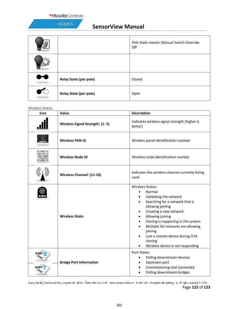
SensorView Manual
Page 122 of 123
Pole State reason: Manual Switch Override Off
Relay State (per pole) Closed
Relay State (per pole) Open
Wireless Status
Icon Value Description
Wireless Signal Strength: (1- 5) Indicates wireless signal strength (higher is better)
Wireless PAN ID Wireless panel identification number
Wireless Node ID Wireless node identification number
Wireless Channel: (11-26) Indicates the wireless channel currently being used
Wireless State:
Wireless States:
Normal
Validating the network
Searching for a network that isallowing joining
Creating a new network
Allowing joining
Cloning is happening in the system
Multiple SSI networks are allowingjoining
Lost a remote device during OTAcloning
Wireless device is not responding
Bridge Port Information
Port States:
Polling downstream devices
Upstream port
Commissioning tool connected
Polling downstream bridges
262

SensorView Manual
Page 123 of 123
Error: Too many adds/deletes (resetbridge)
Error: Local loop
Error: Non-local loop
Error: Devices connected betweenbridges
Number of downstream wireless Bridges and Transceivers
Transceiver Port Status
Port States:
Polling downstream devices
Upstream port
Commissioning tool connected
Polling downstream bridges
Error: Too many adds/deletes (resetbridge)
Error: Local loop
Error: Non-local loop
Error: Devices connected between
bridges
Number of downstream wireless Bridges & Transceivers
263
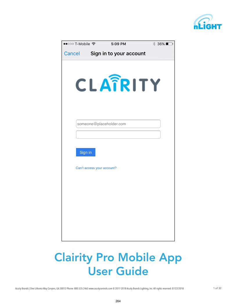
Acuity Brands | One Lithonia Way Conyers, GA 30012 Phone: 800.535.2465 www.acuitycontrols.com © 2017-2018 Acuity Brands Lighting, Inc. All rights reserved. 07/22/2018 1 of 32
Clairity Pro Mobile AppUser Guide
264

Acuity Brands | One Lithonia Way Conyers, GA 30012 Phone: 800.535.2465 www.acuitycontrols.com © 2017-2018 Acuity Brands Lighting, Inc. All rights reserved. 07/22/18 2 of 32
Welcome to the Acuity Controls Clairity Pro mobile app, optimized to quickly and easily startup nLight® AIR lighting control solutions. Clairity Pro is available for both Android™ and iOS devices. This guide explains all the features and functionality within the Clairity Pro mobile app.
Table of Contents
Startup Process Overview.................................................................................................................................................... 4
Out of Box Functionality ...................................................................................................................................................... 4
Download Clairity Pro .......................................................................................................................................................... 5
Enable Bluetooth on Your Mobile Device ............................................................................................................................ 5
Create a User Account ......................................................................................................................................................... 6
Forgot my Password ............................................................................................................................................................ 6
Sign into the App ................................................................................................................................................................. 6
Support ................................................................................................................................................................................ 7
Saving and Retrieving Site Information ............................................................................................................................... 7
Recent Sites Screen ............................................................................................................................................................. 8
Create a New Site ................................................................................................................................................................ 8
Search for an Existing Site ................................................................................................................................................... 8
Edit an Existing Site Name or Address ............................................................................................................................... 9
Create a New Group ............................................................................................................................................................ 9
Search for an Existing Group ............................................................................................................................................. 10
Edit an Existing Group ....................................................................................................................................................... 11
Discovering New nLight AIR Devices & Adding Devices to a Group ............................................................................... 12
Moving Devices on the Grid .............................................................................................................................................. 14
Removing Devices from the Grid ...................................................................................................................................... 14
Commissioning an nLight AIR Adapter ............................................................................................................................. 15
Associate a Group with an nLight AIR Adapter ................................................................................................................ 16
Move a Group from one nLight AIR Adapter to Another ................................................................................................. 16
Making Customer Requests a Reality ................................................................................................................................ 17
Adding Discovered nLight AIR Devices to a Zone ............................................................................................................ 19
Changing which nLight AIR Devices are in an Existing Zone ............................................................................................ 20
Welcome
265

Acuity Brands | One Lithonia Way Conyers, GA 30012 Phone: 800.535.2465 www.acuitycontrols.com © 2017-2018 Acuity Brands Lighting, Inc. All rights reserved. 07/22/18 3 of 32
Table of Contents, cont'd
Selecting a Behavior for a Zone ......................................................................................................................................... 20
Behaviors Explained ........................................................................................................................................................... 21
Calibrating the Daylighting in an Area .............................................................................................................................. 22
Disable a Sensor ................................................................................................................................................................. 22
Setup Dual Zone Offset ..................................................................................................................................................... 23
Adjust Microphonics Sensitivity ......................................................................................................................................... 23
High End and Low End Trim .............................................................................................................................................. 24
Group Firmware Updates .................................................................................................................................................. 25
Individual Device Firmware Updates ................................................................................................................................. 26
Site Access ......................................................................................................................................................................... 27
Sharing Sites ...................................................................................................................................................................... 27
Communication Architecture ............................................................................................................................................. 27
Troubleshooting ................................................................................................................................................................. 28
Who to Call if You Have Questions ................................................................................................................................... 28
Updating Clairity Pro ......................................................................................................................................................... 29
Multiple Users on One Site ................................................................................................................................................ 29
Reprogramming an Area .................................................................................................................................................... 29
Whole Group Decommissioning ........................................................................................................................................ 30
Physically Removing Equipment ........................................................................................................................................ 30
Definition of Terms ............................................................................................................................................................. 31
266

Acuity Brands | One Lithonia Way Conyers, GA 30012 Phone: 800.535.2465 www.acuitycontrols.com © 2017-2018 Acuity Brands Lighting, Inc. All rights reserved. 07/22/18 4 of 32
Startup Process Overview
nLight® AIR consists of fixtures (with and without integrated radios), wall switches, and sensors. There are no communica-tion wires between the devices. Installers and other onsite personnel use the Clairity Pro mobile app to define how these devices interoperate to achieve the result our customers request.
An overview of the startup process we recommend you follow is shown below.
A definition of terms section is located near the end of this guide.
1. Install and energize the equipment. You can proceed to the next step once all nLight® AIR equipment has been
installed in a given functional area of the building.
2. Download the Clairity Pro app (first time users must follow the steps to create a user account)
3. Create the site
4. Create the first group, identify devices, and associate with the grid
5. Create all zones
6. Set behaviors for each zone
7. Return to step 4 when you’re ready to move to the next group
Prior to programming, the devices will operate in their out of box functionality:
• Indoor fixtures with integrated occupancy sensors - All operate independently, and have occupancy enabled. 7.5
minutes after vacancy, the lights will dim to their dim level. After 2.5 more minutes of no activity, the lights will turn off.
• Switches - Do not control any fixtures
• Other indoor fixtures - will turn on when powered.
• Outdoor fixtures - will turn on at night and turn off in the morning.
Out of Box Functionality
NOTE
267

Acuity Brands | One Lithonia Way Conyers, GA 30012 Phone: 800.535.2465 www.acuitycontrols.com © 2017-2018 Acuity Brands Lighting, Inc. All rights reserved. 07/22/18 5 of 32
Download Clairity Pro
Start by downloading the Clairity Pro mobile app from the Apple store (Clairity Pro).
The app is no charge.
Enable Bluetooth on Your Mobile Device
Once the app has downloaded, ensure that Bluetooth® is enabled on mobile device. If you’re unsure, follow the steps
below for either an Android or iOS device.
Disconnect from any existing Bluetooth devices before commissioning.
For Android Devices:
1. Open your device’s Settings menu.
2. Under Wireless & Networks, touch Bluetooth.
3. Touch the switch to turn Bluetooth On or Off.
4. A Bluetooth icon at the top of your screen will indi-
cate when Bluetooth is turned on.
For iOS Devices:
1. On your iOS device, tap Settings > Bluetooth
2. Tap the switch to turn Bluetooth On
3. Once complete, look for the Bluetooth icon
in the status bar of your device
NOTE
268

Acuity Brands | One Lithonia Way Conyers, GA 30012 Phone: 800.535.2465 www.acuitycontrols.com © 2017-2018 Acuity Brands Lighting, Inc. All rights reserved. 07/22/18 6 of 32
If this is your first time using the Clairity Pro app, follow the steps below to create a
new user account.
1. Download the Clairity Pro App
2. Tap on the Sign up link at the bottom of the sign in page
3. Enter your information, including your email address, what you’d like your
password to be, first name, last name, and your display name.
4. Once complete, tap on the Send Verification Code button.
5. Check your email.
6. You will receive an email with a verification code.
7. Go back to the app and enter the verification code you received.
8. Click on the Create Button.
9. Sign into the app with your email and password (Figure 01.)
Create a User Account
Forgot my Password
Sign into the App
If you’ve forgotten your password, tap on the Can’t Access My Account link just below the Sign In button. Follow the
steps to reset your password.
Figure 01: Clairity Pro Sign In
If you already have an account, use your email address and password to sign into
Clairity Pro.
Once you’ve successfully signed in, you’ll see the sync screen (Figure 02). While
this screen is shown, the application is connecting to the cloud to retrieve your
sites.
You must have a connection to the Internet to complete this process.
Users may only log into one mobile device at a time. If you use the same login
on multiple devices simultaneously, the system will not program properly. If
you need to use more than one mobile device, ensure each mobile device is
using a different user name for the login credentials.
NOTE
NOTE
Figure 02: Clairity Sync Screen
269

Acuity Brands | One Lithonia Way Conyers, GA 30012 Phone: 800.535.2465 www.acuitycontrols.com © 2017-2018 Acuity Brands Lighting, Inc. All rights reserved. 07/22/18 7 of 32
Navigate to the support page from the sites screen by tapping on the question
mark on the bottom right portion of the screen. The support page (Figure 03) pro-
vides contact information for Acuity Brands, a link to an instructional video, a link
to a Quick Start Guide, and version information about the Clairity Pro app.
For new users we strongly recommend to view the Quick Start Guide and startup
video to become familiar with the process and the app.
Saving and retrieving previously saved sites in Clairity Pro is very easy. All the data you enter is saved in cloud-based
servers for your future use. If you’re not familiar with the cloud, that’s OK – we take care of all the technical stuff behind
the scenes. Just know that your data is very secure and is ready for your use when you need it. And, best part of the
cloud, you can share the site with others (i.e. – others on your staff and/or the end user when the time comes).
As you make changes and proceed through the screens, information is saved either on your mobile device or in the cloud.
In the event that you do not have a wireless or cellular connection to the Internet while making changes, no problem.
Those changes are held within the app and pushed to the cloud as soon as you have a connection.
All programming changes must be made in the immediate proximity to the area you are programming
Internet connectivity is no longer required after this step.
Support
Saving and Retrieving Site Information
Figure 03: Support Page
NOTE
NOTE
270

Acuity Brands | One Lithonia Way Conyers, GA 30012 Phone: 800.535.2465 www.acuitycontrols.com © 2017-2018 Acuity Brands Lighting, Inc. All rights reserved. 07/22/18 8 of 32
Recent Sites ScreenAfter the app retrieves your sites from the cloud, it will display a list of those available to you. To work on a site, simply tap
it in the list. If you need access to a site that you’re not seeing in your list, please contact Acuity or contact the individual
who has access to the site.
To create a new site, follow the steps below.
If you are adding equipment to an existing installation, you must add the
equipment to the existing site if the design calls for the equipment to work
together.
1. From the mobile app, navigate to the site screen (Figure 04) and click on
the “+” at the bottom of the screen.
2. Enter the information about the site you’re creating. The more informa-
tion you enter, the easier the site will be to search for and find the site in
Clairity Pro in the future. Site Name – the name of the site or project; It
will typically be the name of the building in which you’re working (e.g. –
the White House). We recommend that you do not abbreviate to make it
easier to find the site in the future. Organization / Company – The startup
service provider should select the name of the customer (e.g. – The US
Government)
NOTE
Create a New Site
Search for an Existing SiteThe Sites Screen will display all the sites to which the user can access. For some users who visit numerous sites, we have
made it Select the site you need to access from the list of sites
The search is not case sensitive.
Figure 04: Stes Page - No Available
NOTE
271

Acuity Brands | One Lithonia Way Conyers, GA 30012 Phone: 800.535.2465 www.acuitycontrols.com © 2017-2018 Acuity Brands Lighting, Inc. All rights reserved. 07/22/18 9 of 32
Figure 05: Ste Overview
Edit an Existing Site Name or Address
Site details can be edited from the Site Overview screen (Figure 05) by tapping
on the information that needs to change, making the change, and tapping done
when completed.
Create a New Group
Figure 06: Groups
Typically a group is created for each room. However, a group can not contain more
than 127 devices.
To create a new group, follow these steps:
1. Tap on the “+” icon on the Groups screen (Figure 06).
2. Enter a name for the group. The group name is typically going to be the
name of the room.
3. Tap the Create button
4. The list of groups will load.
5. Tap the group that you just created and the Group overview screen will
load.
272

Acuity Brands | One Lithonia Way Conyers, GA 30012 Phone: 800.535.2465 www.acuitycontrols.com © 2017-2018 Acuity Brands Lighting, Inc. All rights reserved. 07/22/18 10 of 32
Create a New Group, cont'd
Search for an Existing GroupThe Group Screen will display all the existing groups in the site. For large sites with many groups, we have made it easy
to search for the group you need. To access the group search feature:
1. Navigate to the Groups Screen.
2. Enter the name of the group in the search bar at the top of the screen.
3. The list of groups that match your search criteria will update automatically
4. Select the group you need to access from the list of groups
The search is not case sensitive.
The Group Overview screen is used as a main landing point in the Clairity Pro app.
It is the screen that allows for initial device identification, the creation of zones, and
the assignment of behaviors.
To begin identifying devices and adding them to the grid, tap the devices link as
shown in Figure 07..
Figure 07: Group Overview
NOTE
273

Acuity Brands | One Lithonia Way Conyers, GA 30012 Phone: 800.535.2465 www.acuitycontrols.com © 2017-2018 Acuity Brands Lighting, Inc. All rights reserved. 07/22/18 11 of 32
The Groups screen shows all of the groups within a site.
To edit an existing group, select it from the list of available groups (Figure 08).
Edit an Existing Group
Figure 08: Groups Page
Figure 09: Groups Overview
Modify the group details and tap done when completed (Figure 09).
274
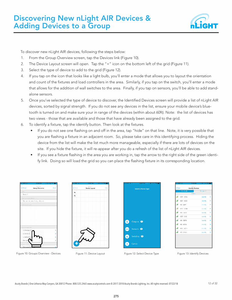
Acuity Brands | One Lithonia Way Conyers, GA 30012 Phone: 800.535.2465 www.acuitycontrols.com © 2017-2018 Acuity Brands Lighting, Inc. All rights reserved. 07/22/18 12 of 32
Discovering New nLight AIR Devices & Adding Devices to a Group
To discover new nLight AIR devices, following the steps below:
1. From the Group Overview screen, tap the Devices link (Figure 10).
2. The Device Layout screen will open. Tap the “+” icon on the bottom left of the grid (Figure 11).
3. Select the type of device to add to the grid (Figure 12).
4. If you tap on the icon that looks like a light bulb, you’ll enter a mode that allows you to layout the orientation
and count of the fixtures and load controllers in the area. Similarly, if you tap on the switch, you’ll enter a mode
that allows for the addition of wall switches to the area. Finally, if you tap on sensors, you'll be able to add stand-
alone sensors.
5. Once you’ve selected the type of device to discover, the Identified Devices screen will provide a list of nLight AIR
devices, sorted by signal strength. If you do not see any devices in the list, ensure your mobile device’s blue-
tooth is turned on and make sure your in range of the devices (within about 60ft). Note: the list of devices has
two views - those that are available and those that have already been assigned to the grid.
6. To identify a fixture, tap the identify button. Then look at the fixtures.
• If you do not see one flashing on and off in the area, tap “hide” on that line. Note, it is very possible that
you are flashing a fixture in an adjacent room. So, please take care in this identifying process. Hiding the
device from the list will make the list much more manageable, especially if there are lots of devices on the
site. If you hide the fixture, it will re-appear after you do a refresh of the list of nLight AIR devices.
• If you see a fixture flashing in the area you are working in, tap the arrow to the right side of the green identi-
fy link. Doing so will load the grid so you can place the flashing fixture in its corresponding location.
Figure 10: Groups Overview - Devices Figure 11: Device Layout Figure 12: Select Device Type Figure 13: Identify Devices
275
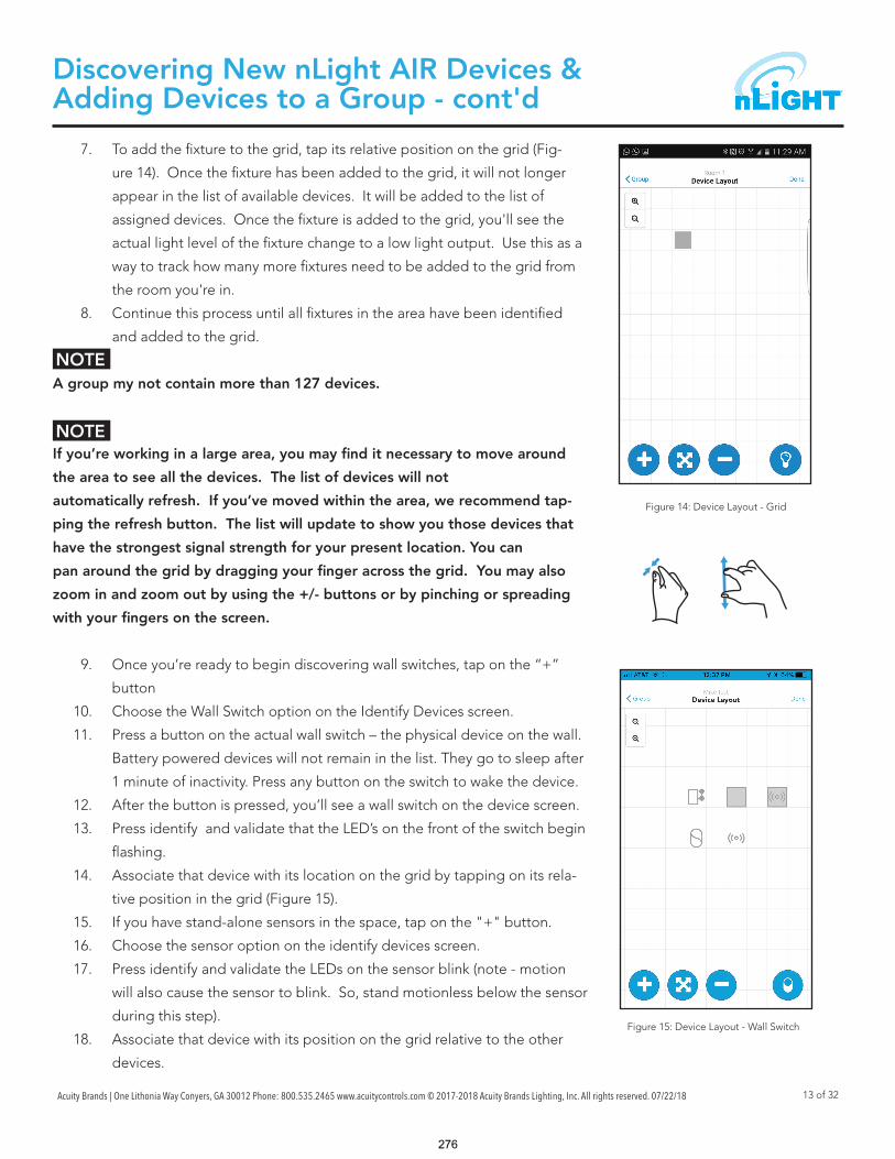
Acuity Brands | One Lithonia Way Conyers, GA 30012 Phone: 800.535.2465 www.acuitycontrols.com © 2017-2018 Acuity Brands Lighting, Inc. All rights reserved. 07/22/18 13 of 32
Discovering New nLight AIR Devices & Adding Devices to a Group - cont'd
NOTE
NOTE
7. To add the fixture to the grid, tap its relative position on the grid (Fig-
ure 14). Once the fixture has been added to the grid, it will not longer
appear in the list of available devices. It will be added to the list of
assigned devices. Once the fixture is added to the grid, you'll see the
actual light level of the fixture change to a low light output. Use this as a
way to track how many more fixtures need to be added to the grid from
the room you're in.
8. Continue this process until all fixtures in the area have been identified
and added to the grid.
A group my not contain more than 127 devices.
If you’re working in a large area, you may find it necessary to move around
the area to see all the devices. The list of devices will not
automatically refresh. If you’ve moved within the area, we recommend tap-
ping the refresh button. The list will update to show you those devices that
have the strongest signal strength for your present location. You can
pan around the grid by dragging your finger across the grid. You may also
zoom in and zoom out by using the +/- buttons or by pinching or spreading
with your fingers on the screen.
9. Once you’re ready to begin discovering wall switches, tap on the “+”
button
10. Choose the Wall Switch option on the Identify Devices screen.
11. Press a button on the actual wall switch – the physical device on the wall.
Battery powered devices will not remain in the list. They go to sleep after
1 minute of inactivity. Press any button on the switch to wake the device.
12. After the button is pressed, you’ll see a wall switch on the device screen.
13. Press identify and validate that the LED’s on the front of the switch begin
flashing.
14. Associate that device with its location on the grid by tapping on its rela-
tive position in the grid (Figure 15).
15. If you have stand-alone sensors in the space, tap on the "+" button.
16. Choose the sensor option on the identify devices screen.
17. Press identify and validate the LEDs on the sensor blink (note - motion
will also cause the sensor to blink. So, stand motionless below the sensor
during this step).
18. Associate that device with its position on the grid relative to the other
devices.
Figure 14: Device Layout - Grid
Figure 15: Device Layout - Wall Switch
276

Acuity Brands | One Lithonia Way Conyers, GA 30012 Phone: 800.535.2465 www.acuitycontrols.com © 2017-2018 Acuity Brands Lighting, Inc. All rights reserved. 07/22/18 14 of 32
Moving Devices on the Grid
1. To move a device on the grid, select the arrow button between the plus and minus buttons.
2. Select the device that needs to move by tapping it on the grid.
3. Select a new location for the device by tapping on the grid.
Removing Devices from the GridIn the event a device needs to be removed from the group (whether it has been fully programmed or not), follow these
steps:
1. Ensure you’re physically located in the group.
2. Navigate to the group in the app
3. Open the Group Overview screen
4. Select “Devices”.
5. From the grid view, select the ‘-‘ button at the bottom of the screen.
6. Tap on the device that needs to be removed.
You must be located in the vicinity of the devices to perform this action.NOTE
277

Acuity Brands | One Lithonia Way Conyers, GA 30012 Phone: 800.535.2465 www.acuitycontrols.com © 2017-2018 Acuity Brands Lighting, Inc. All rights reserved. 07/22/18 15 of 32
Commissioning an nLight Air AdapterTo commission a new nLight AIR adapter, permanently mount the adapter. Do not commission the adapter before it is
permanently mounted. Moving it can result in unstable RF connections to devices you’ve commissioned.
Once the adapter has been mounted and plugged into the Eclypse, allow 2 minutes before adding it to Clairity Pro.
For the first 2 minutes, the Adapter is determining the clearest communication frequency to use. If you try to commis-
sion it to quickly after power on, Clairity Pro will provide you with a warning.
1. Navigate to the Site Overview screen (Figure 16).
2. Select Edge Devices (Figure 17).
3. Walk within about 30 feet of the Adapter you need
to add.
4. Tap on the + to add a new Adapter.
5. Select the adapter from the list of available adapters.
6. Unless otherwise instructed by Technical Support,
keep automatic mode enabled, and tap “Commis-
sion” (Figure 18).
If the project has more than one adapter, it is strongly
recommended that you name the adapters. To do so,
tap on is and rename it in Clairity Pro.
Figure 16: Site Overview Figure 17: Available Edge Devices
Figure 18: Edge Device Overview
278

Acuity Brands | One Lithonia Way Conyers, GA 30012 Phone: 800.535.2465 www.acuitycontrols.com © 2017-2018 Acuity Brands Lighting, Inc. All rights reserved. 07/22/18 16 of 32
Associate a Group with an nLight AIR Adapter
To associate an existing group with the nLight AIR Adapter, navigate to the Group Overview Screen. Walk to the phys-
ical space that correlates with the group. Tap on the “Edge Device Selector” option. Pick the appropriate Adapter
from the list. Tap on the “Assign” button. Clairity Pro will make the appropriate RF Channel changes so the devices can
communicate with the Adapter you’ve chosen.
Clairity Pro will also instruct the devices to attempt to communicate with the Adapter. The app will tell you once this
process is complete. Once complete, the group will show as a networked group on the group screen with an icon next
to the name. It will also be accessible in the Sensorview software.
Clairity Pro will show you any devices that are unable to communicate to the Adapter. You may retry. But, if the devices
are unable to reach the adapter, please choose a different one on the project.
Move a Group from one nLight AIR Adapter to anotherTo move a group from one nLight AIR Adapter to another, navigate to the Group Overview Screen. Walk to the physi-
cal space that correlates with the group. Tap on “Networked Edge Device” and tap on the “Unassign” button. Once
complete, the group will no longer be associated with that Adapter.
Now follow the steps to Associate a Group with the nLight AIR Adapter.
279

Acuity Brands | One Lithonia Way Conyers, GA 30012 Phone: 800.535.2465 www.acuitycontrols.com © 2017-2018 Acuity Brands Lighting, Inc. All rights reserved. 07/22/18 17 of 32
Legend:
- Daylighting Controlled
- Occupancy Controlled
- Switch Controlled
In this section, we’ll review how to take customer requests and create
them in Clairity by creating zones and groups. To illustrate, we’ll
take an open office example that utilizes all the behaviors – on/off by
switch, occupancy, and daylighting.
Consider Figure 19. In this space, there are 16 fixtures and two wall
switches. The design calls for one switch to operate 8 of the fixtures
and the other switch to operate the other 8 fixtures. The entire space
should turn on and off with occupancy. And, the 4 fixtures along the
window should dim with the presence of
natural light.
We have started by identifying all the fixtures and adding them to
the grid in a similar fashion to the physical layout (Figure 20).
Next, we have added the two switches to the grid (Figure 21). Note,
the Clairity app will recognize the type of switch. So, we didn’t need
to indicate the number of buttons on the switches we’ve added.
Next, we’ll start creating zones of control for all the devices that
need to work together. So, first we’ll select the switch and the top 8
fixtures by tapping on them in the grid (Figure 22).
Making Customer Requests a Reality
Figure 19: Layout Example
Figure 20: Layout On Grid Figure 21: Layout with Switches Figure 22: Creating Zones
280

Acuity Brands | One Lithonia Way Conyers, GA 30012 Phone: 800.535.2465 www.acuitycontrols.com © 2017-2018 Acuity Brands Lighting, Inc. All rights reserved. 07/22/18 18 of 32
We’ll follow this process for each collection of devices that need to operate together. We’ve created the other switch
zone (Figure 23), the occupancy zone (Figure 24), and daylighting zone (Figure 25). Note how in these images, the devices
show as a lighter orange, indicating that the devices are already in one zone.
We can assign each zone a behavior from the Group Overview screen. Select a zone to assign a behavior and then select
one or more behavior for each zone (Figure 26). After we select on/off by switch for the first two zones, we apply an
occupancy behavior for the zone with all the fixtures. We can choose the dim level and timeouts as discussed on page 21
(Behaviors Explained).
Finally, we assign a daylighting behavior to our zone of fixtures along the windows.
Once finished, tap save and the programming is pushed to the devices. After it is done, a screen like Figure 27 is dis-
played showing that the push of the settings was successful.
Making Customer Requests a Reality- cont'd
Figure 23: Switch Zone Figure 24: Occupancy Zone Figure 25: Daylighting Zone
Figure 26: Zone Behavior Figure 27: Push Overview
281

Acuity Brands | One Lithonia Way Conyers, GA 30012 Phone: 800.535.2465 www.acuitycontrols.com © 2017-2018 Acuity Brands Lighting, Inc. All rights reserved. 07/22/18 19 of 32
Adding Discovered nLight AIR Devices to a Zone
To add devices to an nLight AIR zone, follow the steps below.
1. Navigate to the Group Overview screen
2. Select the “Zones” from the Group Components section of the screen.
3. If this is the first zone in the group, your screen will appear like Figure 28.
4. Tap the “+” on the bottom of the screen.
5. The grid view will load. To add devices to the zone, tap them on the grid. As devices are added to the zone,
they will turn orange (Figure 29). Those not in the zone will remain blue.
6. Once all devices that will operate together have been selected, tap next.
7. Once you return to the zones screen, your new zone and any others you create will appear in a list (Figure
30).
A zone will not do anything until a behavior has been assigned.
Fixtures and power packs can be in multiple zones. Wall switches and sensors can only be in one zone.
NOTE
NOTE
Figure 28: Zones Figure 29 Create Zones Figure 30: Zones List
282

Acuity Brands | One Lithonia Way Conyers, GA 30012 Phone: 800.535.2465 www.acuitycontrols.com © 2017-2018 Acuity Brands Lighting, Inc. All rights reserved. 07/22/18 20 of 32
To select a behavior for a zone, follow the steps below:
1. Navigate to the Group Overview screen (Figure 32) for the group you’re modifying.
2. Select Behaviors (Figure 33)
3. Choose a behavior for each zone.
4. Once the behavior has been selected, you may fine tune some of the parameters.
The available parameters vary based upon the behavior selected.
5. Once complete, tap on the save icon. This will result in the programming being sent to the devices via Bluetooth
(Figure 34)
NOTE
If you’re modifying an existing zone, navigate to the group that contains the zone.
From the list of existing zones, select the zone you want to modify by tapping on it
in the list (Figure 31).
After you’ve selected it, you can add additional devices to the zone or remove
devices from the zone, all by tapping on the grid.
Changing which nLight AIR Devices are in Modifying an Existing Zone
Figure 31: Modify Zones
Selecting a Behavior for a Zone
Figure 32: Group Overview Figure 33: Behaviors Figure 34: Programming
283

Acuity Brands | One Lithonia Way Conyers, GA 30012 Phone: 800.535.2465 www.acuitycontrols.com © 2017-2018 Acuity Brands Lighting, Inc. All rights reserved. 07/22/18 21 of 32
Behaviors Explained
Below is a summary of all behaviors and how they can be configured. Please note that a zone may have one or more
behaviors.
1. On / Off by switch
• Can be applied to any zone that has at least one fixture and one switch.
• You may select if the light comes on to full bright or if it turns on to the prior dim level when the on button
is pressed.
• If combined with daylighting turning the lights on will make the fixtures go to their day lighting level. If the
switch has raise and lower buttons, the user may raise the light level above the daylighting level.
• If combined with occupancy the switch will override the occupancy behavior for 1 minute
2. Occupancy
• Can be applied to any zone with at least 1 sensor.
• Configurable parameters include
1. On by
• Occupancy (Auto on) - lights will turn on when at least 1 sensor in the zone sees motion. Lights
will dim down after “X” minutes of no activity.
• Vacancy (On by Switch) - Lights must be turned on via a switch. Lights will dim down after “X”
minutes of no activity.
2. Turn on to xx% when occupied
3. Dim to % - The level the lights will dim to after “X” minutes of no activity.
4. After “X” minutes of no activity - The time delay between the sensors no longer sensing motion and
the lights dimming to the dim to %.
5. Turn off time - The time delay between the dim to light level and the lights turning off. Total time be-
tween no motion and the lights turning off is the sum of the turn off time and the dim after time.
• Immediately after sending programming values to the fixtures, the fixtures require a few minutes to synchro-
nize before following the programmed time outs.
After programming, devices must see motion. Then, all devices must NOT see motion for
3 minutes + the device's specified timeout period of no activity.
3. Daylighting
• Can be applied to any zone with at least 1 sensor.
• Must be calibrated after programming has been sent to the fixtures. This can be done by navigating to the
group overview screen, selecting device settings, and selecting photosensor calibration.
Users must select either 'individual' or 'common' photosensor. Individual photosensors can only
be used if every fixture in the zone has a sensor. It will result in an inconsistent lighting look on the
ceiling, but it may be more consistent on the work surface. Common photosensor will result in all the
fixtures following one sensor which the user will select. This option will result in the common look at
the ceiling.
NOTE
NOTE
284

Acuity Brands | One Lithonia Way Conyers, GA 30012 Phone: 800.535.2465 www.acuitycontrols.com © 2017-2018 Acuity Brands Lighting, Inc. All rights reserved. 07/22/18 22 of 32
Calibrating the Daylighting in an Area
To calibrate daylighting, follow the steps below:
1. Navigate to the Group.
2. From device settings choose photosensor calibration (Figure 35).
3. Manually adjust the set-point or choose to auto-calibrate the photo-
sensor.
You need to program a daylighting behavior for the daylighting zone
NOTE
Figure 35: Photocell Calibration
Figure 36: Device Settings Figure 37: Occupancy Sensing
To optimize occupancy performance, sometimes it is necessary to disable sensors in fixtures. It may be necessary to do
this to the fixture close to a doorway so it does not detect hallway traffic or in cases where sensors are very close to HVAC
ducts.
To enable or disable particular sensors, navigate to the Group Overview Screen and choose the Devices Settings option
(Figure 36). Tap on the “Occupancy Sensing” option (Figure 37). Select the sensor on the grid, disable the sensor, and
tap save.
Disable a Sensor
285

Acuity Brands | One Lithonia Way Conyers, GA 30012 Phone: 800.535.2465 www.acuitycontrols.com © 2017-2018 Acuity Brands Lighting, Inc. All rights reserved. 07/22/18 23 of 32
Dual Zone Offset is a feature that allows users to dim a second row of fixtures
differently than the row closest to the windows in cases when only one sensor is
being used. This feature is not needed in cases when each fixture has a sensor
embedded.
To enable this feature, add all the fixtures that need to respond to daylight
to one control zone. From the Group Overview Screen, choose the Devices
Settings option. Tap on the “Dimming Adjustment from Photosensor” option
(Figure 38).
Select the devices that should dim less than the other by tapping on the grid.
Note, you may select more than one device at a time. Tap on the offset % value
to make an adjustment and tap “Save”. Note, a value less than 100% will cause
the fixtures selected to dim less than those not selected.
Setup Dual Zone Offset (Dimming Adjustment From Photosensor)
Figure 38: Dimming Adjust
To optimize occupancy performance, you have the ability to adjust the microphonics sensitivity (for devices that have this
capability).
To adjust Microphonics Sensitivity values, navigate to the Group Overview Screen and choose the Devices Settings option
(Figure 39). Tap on the “Microphonics Sensitivity” option (Figure 40). Select the sensor on the grid, adjust the setting
from the drop down selector, and tap save.
Adjust Microphonics Sensitivity
Figure 39: Device Settings Figure 40: Microphonics Sensitivity
286

Acuity Brands | One Lithonia Way Conyers, GA 30012 Phone: 800.535.2465 www.acuitycontrols.com © 2017-2018 Acuity Brands Lighting, Inc. All rights reserved. 07/22/18 24 of 32
To adjust the maximum or minimum light level an output device can achieve,
you can adjust the Hi/Low End Trim.
To do so, navigate to the Group Overview Screen and choose the Devices
Settings option (Figure 39). For 0-10V devices (such as the rPP20 Power Pack, rS-
DGR, and rSBOR), tap the “Low Voltage High/Low End Trim” option (Figure 41).
Tap on the devices you wish to change, use the sliders to make the adjustment,
and tap save.
Figure 41: Hi/Low Trim Settings
Set Hi/Low End Trim for Power Packs, rSBORs, and rSDGRs
To adjust the maximum or minimum light level an output device can achieve, you can adjust the Hi/Low End Trim.
To do so, navigate to the Group Overview Screen and choose the Devices Settings option. For rES7 and rIO-Based fix-
tures, tap the “Digital High/Low End Trim” option.
Tap on the devices you wish to change, use the sliders to make the adjustment, and tap save.
Set Hi/Low End trim for rES7 and rIO-Based Fixtures
287
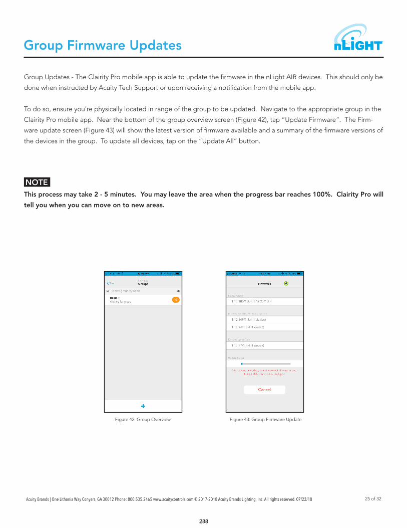
Acuity Brands | One Lithonia Way Conyers, GA 30012 Phone: 800.535.2465 www.acuitycontrols.com © 2017-2018 Acuity Brands Lighting, Inc. All rights reserved. 07/22/18 25 of 32
Group Firmware Updates
Group Updates - The Clairity Pro mobile app is able to update the firmware in the nLight AIR devices. This should only be
done when instructed by Acuity Tech Support or upon receiving a notification from the mobile app.
To do so, ensure you’re physically located in range of the group to be updated. Navigate to the appropriate group in the
Clairity Pro mobile app. Near the bottom of the group overview screen (Figure 42), tap “Update Firmware”. The Firm-
ware update screen (Figure 43) will show the latest version of firmware available and a summary of the firmware versions of
the devices in the group. To update all devices, tap on the “Update All” button.
This process may take 2 - 5 minutes. You may leave the area when the progress bar reaches 100%. Clairity Pro will
tell you when you can move on to new areas.
NOTE
Figure 42: Group Overview Figure 43: Group Firmware Update
288

Acuity Brands | One Lithonia Way Conyers, GA 30012 Phone: 800.535.2465 www.acuitycontrols.com © 2017-2018 Acuity Brands Lighting, Inc. All rights reserved. 07/22/18 26 of 32
Individual Device Firmware Updates
To update an individual device before it is commissioned, navigate to the site overview page (Figure 44) and tap on "Up-
date Device Firmware."
From the list of devices, identify the device you want to update by using the Identify link (Figure 45). Tap update to start
the firmware update process.
You must remain within 60 feet of the device you're updating for the duration of the update, which may be 3-4
minutes.
NOTE
Figure 44: Site Overview Figure 45: Update Firmware
289

Acuity Brands | One Lithonia Way Conyers, GA 30012 Phone: 800.535.2465 www.acuitycontrols.com © 2017-2018 Acuity Brands Lighting, Inc. All rights reserved. 07/22/18 27 of 32
Site Access
For any site you create, you will have access to that site upon subsequent logins. However, you will not be able to see
sites you did not create until access is granted to you. Please contact the original site creator to request access or reach
out to Acuity. If you're not sure who created the site for the equipment you need to program, please reach out to Acuity
Technical Support.
Sites may be shared with colleagues or customers. To do
so, follow these steps:
1. In your browser, go to air.acuitynext.com (Figure 46)
2. When you log in, you'll see your sites.
3. Click on the particular site you wish to share.
4. Add the user with whom you'd like to share the site.
5. Once complete, that user will be able to access the
site in Clairity Pro.
The communication between the app and the devices behaves differently before and after the initial grouping process.
Prior to devices being added to a group:
• Before devices are added to a group, the app communicates directly to each device via Bluetooth.
After devices have been added to a group:
• After a devices have been added to a group, the app communicates with only one device (called the group moni-
tor) within the group. That device then communicates to all the others on a different frequency.
• While the Bluetooth communication distance is approximately 100ft, it is possible the group monitor is out of range
of the Bluetooth communication based on where you are standing within the area (especially for very large areas). If
the Clairity app fails to connect to the Group Monitor, the application will display a grid representation of the group
and indicate which device to move toward to facilitate communications.
Sharing Sites
NOTE
Communication Architecture
You’ll be unable to share a site with someone who has
not gone through the process of creating a Clairity
account.Figure 46: nLight AIR Website
290
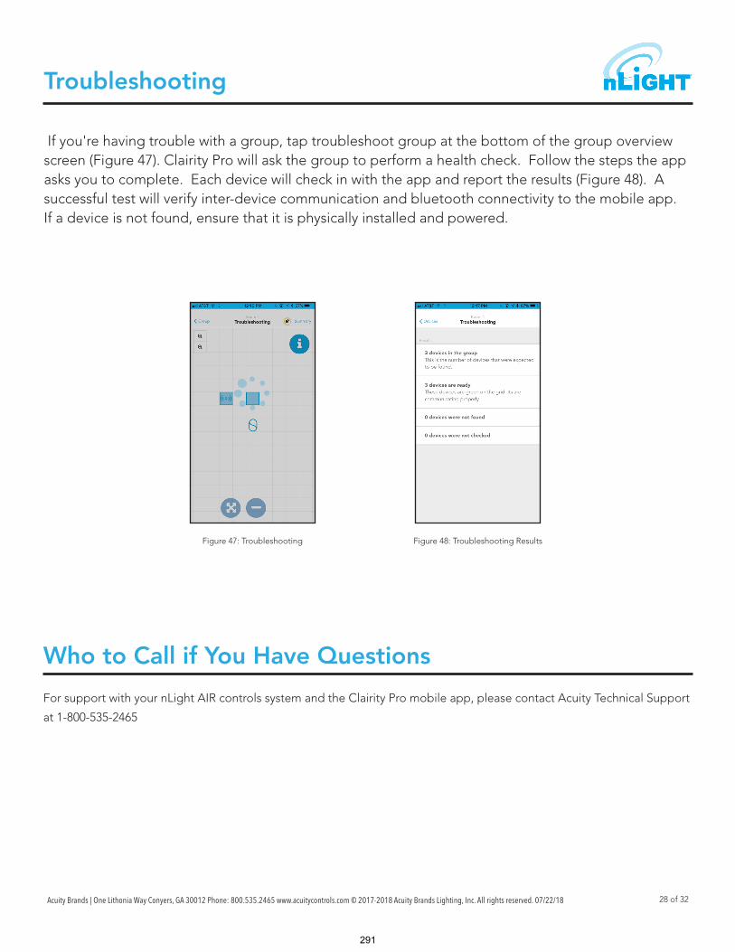
Acuity Brands | One Lithonia Way Conyers, GA 30012 Phone: 800.535.2465 www.acuitycontrols.com © 2017-2018 Acuity Brands Lighting, Inc. All rights reserved. 07/22/18 28 of 32
Troubleshooting
For support with your nLight AIR controls system and the Clairity Pro mobile app, please contact Acuity Technical Support
at 1-800-535-2465
If you're having trouble with a group, tap troubleshoot group at the bottom of the group overview screen (Figure 47). Clairity Pro will ask the group to perform a health check. Follow the steps the app asks you to complete. Each device will check in with the app and report the results (Figure 48). A successful test will verify inter-device communication and bluetooth connectivity to the mobile app. If a device is not found, ensure that it is physically installed and powered.
Who to Call if You Have Questions
Figure 47: Troubleshooting Figure 48: Troubleshooting Results
291

Acuity Brands | One Lithonia Way Conyers, GA 30012 Phone: 800.535.2465 www.acuitycontrols.com © 2017-2018 Acuity Brands Lighting, Inc. All rights reserved. 07/22/18 29 of 32
In the event that a new version of Clairity Pro is developed, you’ll receive a notification through the app store that a new
version has been made available. We recommend reading through the release notes associated with the new version so
you can learn of the new features and capabilities of the new version prior to downloading it.
More than one service provider may use the Clairity app at one time. This is most common in the case of large sites with
relatively short construction cycles. Each user can run through the startup process (create groups, create zones, set be-
haviors). We have a few recommendations for how to maximize their efficiency.
• Any user who has access to the site can grant access to others.
• We suggest each resource work in a different portion of the building. The distance between resources minimizes
the likelihood that devices will be flashed in someone else’s area. Resources cannot perform startup activities within
the same group.
• In the event that simultaneous users are in a building that has poor cellular coverage, we recommend regular com-
munication with your colleagues to ensure each knows who is starting up which portion of the building, as changes
they make on their mobile device will not show on your mobile device until those changes can be pushed to the
cloud through a cellular or wireless connection.
Updating Clairity Pro
Multiple Users on One Site
Reprogramming an Area
If changes need to be made to a given area, navigate to the group that corresponds with that area. The same process is
followed for button reprogramming, occupancy sensor adjustments, and photosensor recalibration.
• On the Group Overview screen, tap on "Behaviors"
• Adjust the behavior accordingly. The behavior screen allows for the adjustment of occupancy parameters and
switch settings.
• Tap save and the programming will be pushed to the nLight AIR devices.
292

Acuity Brands | One Lithonia Way Conyers, GA 30012 Phone: 800.535.2465 www.acuitycontrols.com © 2017-2018 Acuity Brands Lighting, Inc. All rights reserved. 07/22/18 30 of 32
Whole group decommissioning is a process that will destroy all programming, zoning, and grouping. Essentially the fixtures will return to their out of box default state. Whole group decommissioning should NOT be used to modify zoning or programming parameters.
Whole group decommissioning should rarely be used. However, there are some circumstances where it makes sense. These include renovation of a previously commissioned nLight AIR space.
To decommission a group:
1. Navigate to the group overview screen.2. Click on the commissioned devices link. The commissioned devices screen will load. 3. To proceed with decommissioning, tap the decommission all link.
In the event that equipment needs to be physically removed from an area, you must first follow the “Removing Devices
from the Grid” process described earlier in this document. Failing to do so will result in the inability to reprogram the
device that has been removed.
Whole Group Decommissioning
NOTE
Physically Removing Equipment
You must be located in the vicinity of the devices to perform this action.
Figure 49: Group Overview Figure 50: Commissioned Devices
293

Acuity Brands | One Lithonia Way Conyers, GA 30012 Phone: 800.535.2465 www.acuitycontrols.com © 2017-2018 Acuity Brands Lighting, Inc. All rights reserved. 07/22/18 31 of 32
Definition of Terms
Site An installation of lighting control equipment for one customer at one location
Account One or more sites that are all affiliated with one end user.
Area A descriptor for a physical geographical area, within a customer site, that has some common use or purpose
Group All the devices within one area
Switch A piece of equipment that, is typically mounted on a wall, that a user may interact with to control lights in their vicinity
Identify A process by which a device provides some visual feedback (e.g. - the flashing of a fixture) so it’s location can be determined.
Zone A collection of lighting fixtures expected to work together - re-sulting from a logical grouping
Photosensor A device that detects the presence of light.
Fixture A piece of equipment that outputs light
Behavior The manner in which a collection of devices (zone) operate. Some people refer to this as the sequence of operation.
Startup The act of troubleshooting and programming a new installation of equipment
Mobile Device A personal handheld communication device that provides con-nectivity to wifi, cellular, or bluetooth
Daylighting A lighting control strategy that accounts for the presence of nat-ural light and changes the artificial light to achieve a desired light level
Occupancy Sensor A control device that detects motion
Device A generic term used to describe the individual units that com-prise a system.
294

Acuity Brands | One Lithonia Way Conyers, GA 30012 Phone: 800.535.2465 www.acuitycontrols.com © 2017-2018 Acuity Brands Lighting, Inc. All rights reserved. 07/22/2018 32 of 32
Audit Log
Initial Release 08-08-16
Updated to include features supported in version 1.2.1.62 of the Clairity mobile app 11-22-16
Updated to include features supported in version 1.3.0 of the Clairity mobile app 02-21-17
Updated to include features supported in version 1.4.0 of the Clairity mobile app 03/22/17
Updated to include features supported in version 1.4.0 of the Clairity mobile app 06/12/17
Updated to include features supported in version 1.5.2.5 of the Clairity Pro mobile app 03/14/18
Updated to include additional programming options 07/22/18
295