Initials BBauman OPERATION AND MAINTENANCE MANUAL
550
-
Upload
khangminh22 -
Category
Documents
-
view
0 -
download
0
Transcript of Initials BBauman OPERATION AND MAINTENANCE MANUAL


OTAB
VOLUME1
PORTANGELESWATERTREATMENTPLANTOPERATION MAINTENANCEMANUALINDEX
1 Section8710 DoorHardware
EquipmentDataSheetsAbbreviationsandSchedules
ProductData
ElectricalSystemDescription
SpecialWarranties
2 Section9651ResilientTileFlooring
EquipmentDataSheetsProductData
MaintenanceData
3 Section9680Carpet
EquipmentDataSheetsProductData
MaintenanceData
SpecialWarranties
4 Section10505MetalLockers
ProductData
MaintenanceData
5 Section10655AccordianFoldingPartition
EquipmentDataSheetsProductData
MaintenanceData
SpecialWarranties
InstallationInstructions
AsBuiltDrawings
6 Section10801Toilet BathAccessories
EquipmentDataSheetsProductData
MaintenanceData
SpecialWarranties
7 11160LoadingDockEquipment
EquipmentDataSheetsOwnersManual
PlannedMaintenanceProgram
SpecialWarranties
TAB
8
VOLUME1CONTINUED
11210VerticalTurbinePumpsRanneyWell
PumpsP201202 203
EquipmentDataSheets
WarrantyandStorageIntroduction
Installation
OperationMaintenance
RepairParts
PumpSubmittalVendorSubmittal
StartupTestsandReports
VOLUME2
1 11210VerticalTurbinePumpsHighService
PumpsP621622 623
EquipmentDataSheets
WarrantyandStorageIntroduction
Installation
OperationMaintenance
RepairParts
PumpSubmittalVendorSubmittal
StartupTestsandReports
2 11210VerticalTurbinePumpsSmallBackwash
PumpsP611612
EquipmentDataSheets
WarrantyandStorageIntroduction
Installation
OperationMaintenance
RepairParts
PumpSubmittalVendorSubmittal
StartupTestsandReports
bEYd

TAB
VOLUME2
3 11210VerticalTurbinePumpsLargeBackwash
PumpsP613 614
EquipmentDataSheets
WarrantyandStorageIntroduction
Installation
OperationMaintenance
RepairParts
PumpSubmittalVendorSubmittal
StartupTestsandReports
4 11210VerticalTurbinePumpsBackwash
TransferPumpsP811 812
EquipmentDataSheets
WarrantyandStorageIntroduction
Installation
OperationMaintenance
RepairParts
PumpSubmittalVendorSubmittal
StartupTestsandReports
VOLUME3
1 11210VerticalTurbinePumpsRecycleStorage
ReturnPumpsP831 832
EquipmentDataSheets
WarrantyandStorageIntroduction
Installation
OperationMaintenance
RepairParts
PumpSubmittalVendorSubmittal
StartupTestsandReports
StartupTestsandReports
TAB
VOLUME3CONTINUED
2 Section11220CoagFlocSedimProcessMechanical0 M
EquipmentDataSheetsContactList
Process0 M
CoaglnjectionandMaturationMixers
SandRecirculationSlurryPumpsSettlingTankScraper
VOLUME4
1 Section11220CoagFlocSedimProcessMechanical0 MContinued
2 Section11220CoagFlocSedimProcessInsturmentation Controls
ActiflowControlPanelDrawings
LoopDrawings
1
Hydrocyclones
GuagesandSwithcesValves
LamellaTubes
Microsand
BillofMaterialsandDrawings
VOLUME5
Section11220CoagFlocSedimProcessInsturmentation ControlsContinuedBillofMaterials
VenderProductDataSheets
pHMeters
RawWaterTurbidityMeter
EffluentTurbidityMeter
MagneticFlowMeter
57300SystemManual
0

TAB
VOLUME6
1 Section11220CoagFlocSedimProcessInsturmentation ControlsContinued
S7300SystemManualContinued
MP277OperationInterfaceManual
StartUpReports
2 Section11235FilterEquipment
EquipmentDataSheets
PrefacePagesIntroduction
SafetyPrecautions
StartupandOperation
ShutdownandStorage
SamplingandTestingMaintenance
PartsInformation
Appendix
VOLUME7
O1 Section11240ChemicalFeedEquipment
EquipmentDataSheets
GeneralArrangementInformation
MeteringPumps
MeteringPumpMotors
VOLUME8
1 Section11240ChemicalFeedEquipmentContinued
PumpLocalControlPanelsPressureReliefValves
PulsationDampenersCalibrationColumns
PressureInstrumentation
VOLUME9
1 Section11240ChemicalFeedEquipment
ContinuedTanks
StaticMixerInjectionQuillsGeneralInformation
TestReports
TAB
VOLUME9CONTINUED
2 Section11240ChemicalFeedSystemPolymer
FeedSystem
EquipmentDataSheetsIntroduction
PolyBlendProductWarranty
OperationandMaintenanceData
Drawings
VOLUME10
1 Section11260SodiumHypochloriteOnSiteGenerator
EquipmentDataSheetsOnSiteGeneration
WaterFiltrations SofteningWaterHeater
WaterPressureBoost
BrineGenerationandFiltration
BrineBoost
SolutionStorageandLevelMeasurement
HydrogenSafety
MioxWarranty
ProjectDrawings
2 Section11500AirCompressor
EquipmentDataSheets
2StageCompressorManual
VOLUME11
1 Section11500AirCompressorContinued
CompressorPartsListControlPanelManual
HighTemperatureDryerManual
2 Section11510PositiveDisplacementBlowers
EquipmentDataSheetsBlowerManual
ElectricMotorManual
VBeltDriveManual
StartUpandTestReports

TAB TAB
VOLUME11Continued
3 Section12491LouverBlinds
ProductDataandSchedule
CleaningInstructions
4 Section15205ValvesWeirsandAccessories
EquipmentDataSheets
BrayPneumaticActuators
BrayLugWaferButterflyValve
12CLAValPumpControlValve
16CLAValPumpControlValve
10CLAValPumpControlValve
8CLAValSurgeAnticipator
WilkinsDoubleCheckValveAssemblyM HGateValve
ValMaticSwingFlexCheckValve
ValMaticButterflyValves
ValMaticCamCentricPlugValvesValMaticAirReleaseValves
TycoFlowControlMorinActuator
VOLUME12
1 Section15250MechanicalInsulation
ProductDataandSchedule
InspectionandMaintenanceProcedures
2 Section15300FireProtectionSystem
AsBuiltDrawings
3 Sections1541015450PlumbingFixturesPlumbingEquipment
EquipmentDataSheets
WC1WaterClosetWallHung
UR1UrinalWallHungADA
Lay1LavatoryCountertopADA
DF1DrinkingFountainSHWRShowerADA
KS1KitchenSink
LS1andLS2LabSinks
ESStation
EWEyewashUnitWH1WaterHeater
WH2WaterHeater
SpecialWarranties
VOLUME12CONTINUED
4 Section15190MechanicalIdentification
MaintenanceData
ProductData
5 Section17736ElectricRadiantHeaters
EquipmentDataSheetsProductDataandPartsList
6 Section15900HVACControland
Instrumentation
EquipmentDataSheets
UniversalCircuitBreakerTransformers
AirTemperatureSensors
SolidStateEconomizerSystemAirDuctSmokeDetector
ProgrammableVAVUnitaryControllers
TemperatureControllersElectronicStand AloneControllers
WallModules
CommercialProgrammableThermostat
EconomizerLogicModulesWebAXControlModule
Relays
VOLUME13
1 Section1645016440164251605016455
16140
BillofMaterials
2 Section16450LowVoltageBuswayBillofMaterials
ShopDrawings
SpectraSeriesBuswayInstructions
CertificateofSeismicCompliance
3 Section16440MotorControlCenter
BillofMaterials
CertifiedTestReport
ShopDrawings
SparePartsListInstallationandInstructions
VFDDrives
Starters
TAB TAB
VOLUME11Continued
3 Section12491LouverBlinds
ProductDataandSchedule
CleaningInstructions
4 Section15205ValvesWeirsandAccessories
EquipmentDataSheets
BrayPneumaticActuators
BrayLugWaferButterflyValve
12CLAValPumpControlValve
16CLAValPumpControlValve
10CLAValPumpControlValve
8CLAValSurgeAnticipator
WilkinsDoubleCheckValveAssemblyM HGateValve
ValMaticSwingFlexCheckValve
ValMaticButterflyValves
ValMaticCamCentricPlugValvesValMaticAirReleaseValves
TycoFlowControlMorinActuator
VOLUME12
1 Section15250MechanicalInsulation
ProductDataandSchedule
InspectionandMaintenanceProcedures
2 Section15300FireProtectionSystem
AsBuiltDrawings
3 Sections1541015450Plumbing
FixturesPlumbingEquipment
EquipmentDataSheets
WC1WaterClosetWallHung
UR1UrinalWallHungADA
Lav1LavatoryCountertopADA
DF1DrinkingFountainSHWRShowerADA
KS1KitchenSink
LS1andLS2LabSinks
ESStation
EWEyewashUnitWH1WaterHeater
WH2WaterHeater
SpecialWarranties
VOLUME12CONTINUED
4 Section15190MechanicalIdentification
MaintenanceData
ProductData
5 Section17736ElectricRadiantHeaters
EquipmentDataSheetsProductDataandPartsList
6 Section15900HVACControland
Instrumentation
EquipmentDataSheetsUniversalCircuitBreakerTransformers
AirTemperatureSensors
SolidStateEconomizerSystemAirDuctSmokeDetector
ProgrammableVAVUnitaryControllersTemperatureControllersElectronicStand AloneControllers
WallModules
CommercialProgrammableThermostat
EconomizerLogicModulesWebAXControlModule
Relays
VOLUME13
1 Section1645016440164251605016455
16140
BillofMaterials
2 Section16450LowVoltageBuswayBillofMaterials
ShopDrawings
SpectraSeriesBuswayInstructions
CertificateofSeismicCompliance
3 Section16440MotorControlCenter
BillofMaterials
CertifiedTestReport
ShopDrawingsSparePartsListInstallationandInstructions
VFDDrives
Starters
TAB
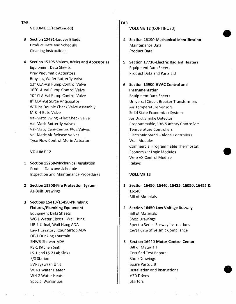
VOLUME13Continued
3 Section16440MotorControlCenter
Continued
TVSS
CertificateofSeismicCompliance
4 Section16425Switchboards
BillofMaterials
CertifiedTestReports
ShopDrawings
SpectraSwitchboardsPowerBreakIICircuitBreakers
MicroVersaTripPortableTestSet
SKFrameBreakers
VOLUME14
1 Section16425SwitchboardsContinuedMoldedCaseCircuitBreakers
SGFrameBreakers
PQMIIElectronicMetering
OTypeHEIntegratedTVSS
CertificateofSeismicCompliance
2 Section16050Panelboards
BillofMaterials
AEPanelboards
AQPanelboards
ULConnectedRatingsNEMASafeInstructions
CertificateofSeismicCompliance
3 Section16455Transformers
BillofMaterials
Specification DataSheet
ShopDrawingsInstallationandMaintenance
ULCompliance
CertificateofSeismicCompliance
4 Section16440Starters
BillofMaterials
ShopDrawings300LineStarters
InstallationNEMASize0
TAB
VOLUME14CONTINUED
4 Section16440StartersContinuedInstallationNEMASize2
ACPowerCapacitors
GEWarrantyInformation
5 Section16500Lighting
LightingSchedule
LightingProductData
Warranty
VOLUME15IndexbeginsonNextPage

TAB
VOLUME15
Section1690016910InstrumentationandControlProgrammableControllerFieldEquipment1 TSIQuickReferenceItemIndex
2 ChemquipProductsConbracoIndustries
DwyerInstruments
HachCompany
HachCompany
HachCompany
HachCompany
HachCompany
HachCompany
OnyxValveCompany
ReotempInstruments
Siemens
TAB
VOLUME16
50SEPulsationSnubber
7610301AApollo FullPortIsolationValve
RHTLWWallMountAirTemperatureHumidityTransmitter
1720ELowRangeTurbidimeter
sc100ControllerforTurbidityAnalyzerandpH
MonitoringFormazinCalibrationKii
TenSettePipet
DPD1P1scDigitalDifferentialpHSensor
CL17FreeChlorineResidualAnalyzer
FreeChlorineReagentSet
MaterialSafetyDataSheets
2316SSTreeAssembly100OHM3WireRTDwithThermowell
ModelTCXT4IntelligentEconomy2WireTransmitter
MAG5000MagneticFlowmeterTransmitters
MAG5100WMagneticFlowMeters
Section1690016910InstrumentationandControlProgrammableControllerFieldEquipment
Continued
1 TSIQuickReferenceItemIndex
Siemens Hydrorranger200UltrasonicLevelTransmitterand2 HandHeldProgrammer
Siemens STHUltrasonicLevelTransducer
UnitedElectricControls
WikaInstrumentCorp
H100701H100702 H100703PressureSwitches
233344WPressureGauges
L99010DiaphragmSeals

TAB
VOLUME16Continued
0
3
4
Section1690016910InstrumentationandControlProgrammableControllerProcessorEquipment
SIMATICS7300GettingStartedCPU31xCommisioningSiemens 6ES73172EK130AB0317PNDPProcessor
Siemens
VOLUME17
1 TSQuickReferenceItemIndex
2 Siemens
3 Siemens
SIMATIC57300CPU71XSystemInstallation
OperatingInstructionManual
6ES73172EK13OABO3172PNDPCPUProcessor
6ES79538LL200AA02MBMMCMemoryCard
6ES73071EA000AA05AmpPLCPowerSupply6ES73901AF300AA0530mmDINRail
6ES73901AJ300AA0830mmDINRail
6ES73211BH020AA016PointDigitalInputModule
6ES73221BH01OAAO16PointDigitalOutputModule
6ES73317KF02OABO8PointAnalogInputModule
6ES73325HD010AB04PointAnalogOutputModule6ES73921AJ000AA020PinFrontConnector
6ES7972OBB51OXAOProfibusConnectorwithPGPort
6ES71531AA03OXBOIM1531ProfibusDPInterface
6ES79720BA51OXAOProfibusConnector
6ES79720AA01OXAOProfibusRS485Repeater6ES73211BL00OAAO32PointDigitalInputModule
6ES73221BL00OAAO32PointOutputModule6ES73921AM000AA040PinFrontConnector
6ES73700AA010AA0DummyModule
SIMATICSY300CPU31XTechnicalSpecificationsManual
6ES73172EK13OABO3172PNDPCPUProcessor
6ES79538LL20OAAO2MBMMCMemoryCard
SIMATICPROFINETCPU317PNDPConficuringthePRODINETInterfaceGettingStartedManual

TAB
VOLUME17Continued
Section1690016910InstrumentationandControlProgrammableControllerProcessorEquipment
4 Siemens
VOLUME18
1 Siemens
2 TSI ASBuiltDrawings
SIMATICNETS7CPsforPROFIBUSCofiguring
CommisioningManualPartAGereralApplication6ES73172EK13OABO3172PNDPCPUProcessor
6ES79538LL200AA02MBMMCMemoryCard6ES73901AF300AA0530mmDINRail
6ES73901AJ300AA0f30mmDINRail
6ES73921AJ000AA020PinFrontConnector
6ES73921AM000AA040PinFrontConnector
6ES73700AA010AA0DummyModule
6ES79720B351OXAOProfibusConnectorwithPGPort
6ES79720BA510XAOProfibusConnector
6ES79720AA01OXAOProfibusRS485Repeate
SIMATICS7300AutomationSystemModuleDataManual
6ES73071EA00OAAO5AmpPLCPowerSupply
6ES73211BH02OAAO16PtDigitalInputModule
6ES73221BHO1OAAO16PtDigitalOutputModule
6ES73317KF02OABO3PtAnalogInputModule
6ES73325HDO1OABO4PtAnalogOutputModule
6ES79720AAO1OXAOProfibusRS485Repeater
6ES73211BLOOOAAO32PtDigitalInputModule
6ES73221BL00OAAO332PtDigitalOutputModule

0
s
0
LT
CardinalOneS12pindexs stem
Section164501644016425160501645516140
Section16450LowVoltageBusway
Section16440MotorControlCenter
Section16425Switchboards

0
BillofMaterials

0 DSS
43QuailCourtSuite210WalnutCreekCA94596
Item QtyDescription
1 1SpectraBusway126SBUS
1RunofCopper3P3W3000AHousingGround43FtofFeederIndoor
2EachGESwitchboardStubGESWBSWG2Each90DegreeElbow1EachWallFloorFlange4FtofFeederOutdoorIP6566
BillofMaterial
PORTANGELESWTP
2 1EvolutionSeriesMCCGO100MCC1
LinetypeE9000ULlabelingrequiredNEMAWiringClassIBTNEMAEnclosureNEMA1G
12TopMountedWirewayMCCisFrontMountingOnly480Volts3Phase3Wire60Hz
MainHorzBus800AmpsRating65000AICMinVerticalBus300Amps
EnclosureandBus6VerticalSections6NEMAEnclosure1G20wide
EnclosureModifications
6 SeismicBracingZone4BusSystem6 800AmpCUMainBus6 300AmpCUGroundBus2 600AmpCUFrontVerticalBus6 VerticalUnitGroundBus
6 VerticalUnitGroundLug4 300AmpCUFrontVerticalBusBusModifications
6 65000AICSCBusBracing6 DoubleBoltedConstructionforMainBus
IncomingPower1600AmpTerminalBoardWith22AWG600MCMLugsPer
PhaseTOPFeedCuAILugFeeders
1FeederCBSELTType150AmpsFrame100AmpsTrip4FeederCBSELTType150AmpsFrame20AmpsTrip4FeederCBSELTType150AmpsFrame30AmpsTrip
CombinationStarterDevices
4Size1FVNRStarter3Hp7AmpsTripSELCBDiscAccessories
1 AmbientcompensatedOLrelay1 CPT300VA
1 Intlk 1NoCharge2Total3Size1FVNRStarter10Hp30AmpsTripTECLCBDisc
Accessories
1 AmbientcompensatedOLrelay1 CPT300VA
1 Intlk 1NoCharge2Total2Size4FVNRStarter100Hp150AmpsTripSELCBDisc
Accessories
1 AmbientcompensatedOLrelay
GEConsumer IndustrialDate 6112009
Telephone 9259451140
WINProposal 6N2PORTWTP
SpeediVersion V870

1 CPT300VA
1 Intlk 1NoCharge2Total2Size1FVNRStarter5Hp15AmpsTripSELCBDisc
Accessories
1 CPT150VA
1 InterlockNoCharge1 StandardOLrelay
1Size4FVNRStarter100Hp150AmpsTripSELCBDiscAccessories
1 CPT300VA
1 InterlockNoCharge1 StandardOLrelay
1Size1FVNRStarter10Hp30AmpsTripTECLCBDiscAccessories
1 CPT150VA
1 InterlockNoCharge1 StandardOLrelay
VariableFrequencyDrives2AF300P115HpVariableFrequencyDriveVariableTorque
CircuitBreaker
Accessories
1 BuiltinElectronicOLRelay1 C2000AUXControl4polecontrolrelay1 CPT300VAwinterposingrelay1 StandardVFDBypassselectorswitch1 VFD3Linereactor
1 VFDLOADFILTER
2AF300P1112HpVariableFrequencyDriveVariableTorqueCircuitBreaker
Accessories
1 BuiltinElectronicOLRelay1 C2000AUXControl4polecontrolrelay1 CPT300VAwinterposingrelay1 VFD3Linereactor
Miscellaneous
512SectionofFuturespaceavailableUnitssuppliedwiththefollowingoptions
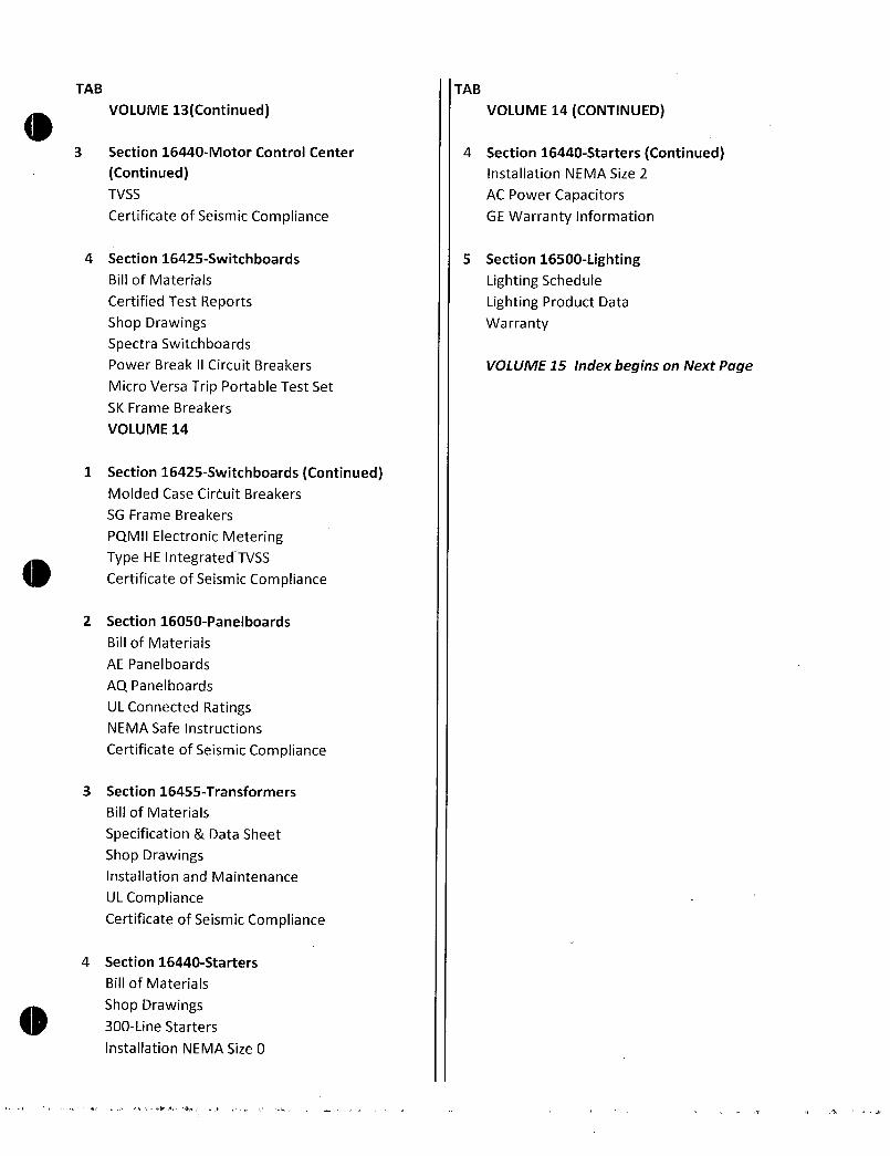
17MTWVW1STDcontrolwire17ControlwiremarkersNONE
17ControlwireterminalsStrippedSTD17Highdensitycontrolterminalboard17MTWVW1STDpowertype17Nonepowerwiremakers17StrippedWireSTDpowerwireterminal14NONESTDpowerterminalboard
WiringClass1NEMAWiringClassIB1AdderforBTWiring
3 1EvolutionSeriesMCCGO100MCC2
LinetypeE9000NEMAWiringClassIBDNEMAEnclosureNEMA1G
12TopMountedWirewayMCCisFrontMountingOnly480Volts3Phase3Wire60Hz
MainHorzBus2000AmpsRating42000AICMinVerticalBus300Amps
Miscellaneous
EnclosureandBus8VerticalSections3NEMAEnclosure1G20wide3NEMAEnclosure1G36wide2NEMAEnclosure1G24wide
EnclosureModifications
GEConsumer Industrial

8 Steelbottomplates8 SeismicBracingZone4BusSystem8 2000AmpCUMainBus8 300AmpCUGroundBus1 850AmpCUFrontVerticalBus8 VerticalUnitGroundBus
8 VerticalUnitGroundLug7 300AmpCUFrontVerticalBusBusModifications
8 65000AICSCBusBracing8 DoubleBoltedConstructionforMainBus
IncomingPower1600AmpTerminalBoardWith22AWG600MCMLugsPer
PhaseTOPFeedCuAILugCombinationStarterDevices
3Size2FVNRStarter25Hp50AmpsTripSELCBDiscAccessories
1 AmbientcompensatedOLrelay1 CPT300VA
3 Intlks 1NoCharge4TotalMiscellaneous
1 FB4803FuseBlock Fuses10A33Size4FVNRStarter100Hp150AmpsTripSELCBDisc
Accessories
1 AmbientcompensatedOLrelay1 CPT300VA
3 Intlks 1NoCharge4TotalMiscellaneous
1 FB4803FuseBlock Fuses10A3VariableFrequencyDrives
3AF300P11450HpVariableFrequencyDriveVariableTorqueCircuitBreaker
Accessories
1 1kOhmpotentiometer1 BuiltinElectronicOLRelay1 C2000AUXControl4polecontrolrelay1 CPT300VAwinterposingrelay2 InterlocksNoCharge1 VFD3Linereactor
1 VFDCOMCDPROFIDP
1 VFDLOADFILTERMiscellaneous
2 CR120BLRelayLatchingMiscellaneous
712SectionofFuturespaceavailable16SectionofFuturespaceavailable
Unitssuppliedwiththefollowingoptions9MTWVW1STDcontrolwire9ControlwiremarkersNONE
9ControlwireterminalsStrippedSTD9Highdensitycontrolterminalboard6MTWVW1STDpowertype6Nonepowerwiremakers6StrippedWireSTDpowerwireterminal3NONESTDpowerterminalboard
WiringClass1NEMAWiringClassIB
4 1EvolutionSeriesMCCGO100MCC3
LinetypeE9000NEMAWiringClassIBDNEMAEnclosureNEMA3RTYPEA
12TopMountedWireway
GEConsumer Industrial

0 MCCisFrontMountingOnly480Volts3Phase3Wire60Hz
MainHorzBus600AmpsRating65000AICMinVerticalBus300Amps
Miscellaneous
EnclosureandBus4VerticalSections3NEMAEnclosure3RAOutdoor20wide1NEMAEnclosure3RAOutdoor30wide
NEMA3RCYCLENOTICETotalmanufacturingcyclewillbeincreasedbyanadditionalweekfiveworkingdaystothestandardcycleindicatedbySpeediWinEnclosureModifications
4 SeismicBracingZone4BusSystem4 600AmpCUMainBus4 300AmpCUGroundBus1 600AmpCUFrontVerticalBus4 VerticalUnitGroundBus
4 VerticalUnitGroundLug3 300AmpCUFrontVerticalBusBusModifications
4 65000AICSCBusBracing4 DoubleBoltedConstructionforMainBus
Maindevice
1SGL4TType400AmpsFrame300AmpsTripMainCBWith16AWG600MCMCablesPerPhaseTOPFeed
Feeders
1FeederCBSELTType100AmpsFrame20AmpsTrip1FeederCBSELTType100AmpsFrame100AmpsTrip
CombinationStarterDevices
2Size1FVNRStarter5Hp15AmpsTripSELCBDiscAccessories
1 CPT300VA
3 Intlks 1NoCharge4Total1 Standard3posselectorswitch1 StandardOLrelay
2Size2FVNRStarter15Hp25AmpsTripSELCBDiscAccessories
1 CPT300VA
3 Intlks 1NoCharge4Total1 Standard3posselectorswitch1 StandardOLrelay
1Size2FVNRStarter25Hp50AmpsTripSELCBDiscAccessories
1 CPT300VA
3 Intlks 1NoCharge4Total1 StandardOLrelay
1Size4FVNRStarter100Hp150AmpsTripSELCBDiscAccessories
1 CPT300VA
3 Intlks 1NoCharge4Total1 StandardOLrelay
LightingPanelBoards124CktsAQPanelboardwith225AMAINCBTypeAQ1Pole20
AmpsTripBranchBreakerLightingandPowerTransformers
130KVA3PHwithCBwPrimaryTapsTVSS
1TVSS100kASCCRMiscellaneous
16SectionofFuturespaceavailable412SectionofFuturespaceavailable
Unitssuppliedwiththefollowingoptions6MTWVW1STDcontrolwire
GEConsumer Industrial
O 6ControlwiremarkersNONE
6ControlwireterminalsStrippedSTD6Highdensitycontrolterminalboard6MTWVW1STDpowertype6Nonepowerwiremakers6StrippedWireSTDpowerwireterminal5NONESTDpowerterminalboard
WiringClass1NEMAWiringClassIB
5 1MCCSparePartsMCCRenewalSpareParts
6 1SpectraBoltOnAV1Swb108AMDP
3SectionsServiceEntranceM
3P4W480277603000AMainLugs65KAICIncomingFeedBottomFeedtoright2125Amp3PoleSELA2PadlockSE150
1400Amp3PoleSGLA41PadlockSG600
1300Amp3PoleSGLA41PadlockSG600
1800Amp3PoleSKLA81PadlockSK1200
12000Amp3PoleSSIndivMtd1PadlockPBII
2FullyRatedCUBus1BussedPullSection
2CUBusHeatRated
1TVSSHE100200kA200kAIC
2FullHeightBusOption2SideBarriers4CurrentTransformer
1PQMIIBasePQMII3PotentialTransformer
MiscellaneousAddOns
1Busway3Ph4WStandard3000A
7 1SpectraBoltOnAV2Swb108ASED
4SectionsServiceEntranceS3P4W48027760
3000AMainLugs65KAICIncomingFeedBottomFeedtoright
12000Amp3PoleSSIndivMtd1ShuntTrip1ProgrammerLSIG1AuxContacts11BellAlarm
1KirkKeyLock1EUSERCPadlockPBII
13000Amp3PoleSSDIndivMtdDrawoutMounting
1ShuntTrip1ProgrammerLSIG1AuxContacts11BellAlarm
1KirkKeyLock1EUSERCPadlockPBII
2FrontRearlineup1ServiceEntranceLabel
GEConsumer Industrial

0
0
0
4TYPE3RNonWalkIn2FullyRatedCUBus1UtilityCompartment4W
SEATTLECITYOFWALGHTDEPT
2MeterSockets4W1BussedPullSection
3CUBusHeatRated
4SeismicUBCCBCZone34orIBC2003MiscellaneousAddOns
1Busway3Ph4WStandard3000A
8 1PanelboardTypeAQ101L1
SingleSectionPanelBottomFeedSurfaceMnt42Ckts3P4W208Y120V10KAIC
225AMainLugs4220A1PoleTHQB
1CopperBusHeatRated1Groundmainlug TGL20
4GroundBoxbonded TGL2
1AB43BBox
1AF43SFront
1AQF3422MBXInteriorAXB7
9 1PanelboardTypeAE101P1
SingleSectionPanelBottomFeedSurfaceMnt42Ckts3P4W480Y277V42KAICSeriesRated
400AMainLugs320A1PoleTEY
920A1PoleTEYSpace115A3PoleTEY
520A3PoleTEY
230A3PoleTEY
140A3PoleTEY
1100A3PoleTEY
1CopperBusHeatRated1Groundmainlug TGL20
4GroundBoxbonded TGL2
1AB55BBox
1AF55SFront
1AEF3424MBXInteriorAXB7
THISPANELWASSERIESRATEDAT42KAICWITHA400ASGLUPSTREAMBREAKERULSERIESCONNECTEDRATINGSAREINPUBLICATIONDET008A
10 1PanelboardTypeAQ101L2
SingleSectionPanelBottomFeedSurfaceMnt42Ckts3P4W208Y120V10KAIC
225AMainLugs3820A1PoleTHQB
140A2PoleTHQB
160A2PoleTHQB
1CopperBusHeatRated1Groundmainlug TGL20
4GroundBoxbonded TGL2
1AB43BBox
1AF43SFront
1AQF3422MBXInteriorAXB7
GEConsumer Industrial

11 1PanelboardTypeAQ101L4
SingleSectionPanelBottomFeedSurfaceMnt12Ckts3P4W208Y120V10KAIC
125AMainLugs820A1PoleTHQB
420A1PoleTHQBSpace1CopperBusHeatRated1GroundBoxbonded TGL2
1AB25BBox
1AF25SFront
1AQF3121MBXInteriorAXB7
12 2Transformer67D
T2T39T83B3464G03
75kVA3PhKFACTORK4Aluminum
60Hz150CRiseTypeQLTP1Impedance7Pri4802424 Sec208Y120
ElecShieldYes
13 2LVCapacitor410PFC
65L815TE1
PWRFACTCORRECT100KVAR
14 1EvolutionSeriesMCCGO100RANNEYMCC
LinetypeE9000NEMAWiringClassIBDNEMAEnclosureNEMA1G
12TopMountedWirewayMCCisFrontMountingOnly480Volts3Phase3Wire60Hz
MainHorzBus2500AmpsRating 65000AIC
MinVerticalBus300AmpsMiscellaneous
EnclosureandBus6VerticalSections2NEMAEnclosure1G24wide2NEMAEnclosure1G36wide1NEMAEnclosure1G30wide1NEMAEnclosure1G20wide
EnclosureModifications
6 SeismicBracingZone4BusSystem6 2500AmpCUMainBus6 300AmpCUGroundBus5 300AmpCUFrontVerticalBus6 VerticalUnitGroundBus
6 VerticalUnitGroundLug1 600AmpCUFrontVerticalBusBusModifications
6 65000AICSCBusBracing6 DoubleBoltedConstructionforMainBus
Maindevice
1BusSpliceToSwitchboard1 2500AmpsCopperMainBusSplice1 300AmpsCopperGroundBusSplice
SolidStateStarters
1Size6SolidStateCircuitBreaker350HpSTDDUTYAccessories
GEConsumer Industrial

1 BuiltinElectronicOLRelay1 CPT300VAwinterposingrelay
VariableFrequencyDrives2AF300P11350HpVariableFrequencyDriveVariableTorque
CircuitBreaker
Accessories
1 1kOhmpotentiometer1 BuiltinElectronicOLRelay1 C2000AUXControl4polecontrolrelay1 CPT300VAwinterposingrelay1 Shunttrip1 VFD3Linereactor
1 VFDCOMCDPROFIDP
1 VFDLOADFILTER
SpecialUnitManualEntries1PriceofSpecialUnitManualEntries
Miscellaneous
1 37GA100FCFILTERACTIVEHARMONIC100AMPMiscellaneous
412SectionofFuturespaceavailable16SectionofFuturespaceavailable
Unitssuppliedwiththefollowingoptions3MTWVW1STDcontrolwire3ControlwiremarkersNONE
3ControlwireterminalsStrippedSTD3Highdensitycontrolterminalboard3MTWVW1STDpowertype3Nonepowerwiremakers3StrippedWireSTDpowerwireterminal
WiringClass1NEMAWiringClassIB
OrderInformation
3 StandardInstructionBooks
3 StandardCatalogRenewalParisBooks3 812by11PrintCustomerPrints
15 1SpectraBoltOnAV2Swb108ARANNEYSWB
4SectionsServiceEntranceR3P4W48027760
2500ASS2500ATripGroundFault
ManuallyOperatedMain65KAIC
IncomingFeedBottomFeedtoright
1ProgrammerPower LIT2
1KirkKeyLock1EUSERCPadlockPBII
5100Amp3PoleFBH612500Amp3PoleSSIndivMtd1KirkKeyLock1EUSERCPadlockPBII
2FrontRearlineup1ServiceEntranceLabel
7Nameplate2FullyRatedCUBus1UtilityCompartment4W
SEATTLECITYOFWALGHTDEPT
2MeterSockets4W1BussedPullSection
3CUBusHeatRated1TVSSHE100200kA200kAIC
GEConsumer Industrial

1E9000TransitionSecCu1MicroVersaTripPortableTestSetTVRMS24SeismicUBCCBCZone34orIBC20034CurrentTransformer
1PQMIIBasePQMII3PotentialTransformer
MiscellaneousAddOns
1VoltMeterPhaseselectorswitch
GEConsumer Industrial
16 1PanelboardTypeAE101RANNEYP1
SingleSectionPanelBottomFeedSurfaceMnt24Ckts3P4W480Y277V42KAICSeriesRated125A3PoleSFLAMain
815A3PoleTEY
1CopperBusHeatRated2GroundBoxbonded TGL2
1AB49BBox
1AF49SFront
1AEF3242DBXInteriorAXB7
THISPANELWASSERIESRATEDAT42KAICWITHA125ASFLAMAINBREAKERULSERIESCONNECTEDRATINGSAREINPUBLICATIONDET008A
17 1PanelboardTypeAE101RANNEYL1
SingleSectionPanelBottomFeedSurfaceMnt30Ckts3P4W208Y120V10KAIC
100A3PoleTEYMain
215A1PoleTEY
2520A1PoleTEYSpace330A1PoleTEY
1CopperBusHeatRated3GroundBoxbonded TGL2
1AB31BBox
1AF31SFront
1AEF3301BBXInteriorAXB7
18 1PanelboardTypeAE101RANNEYL3
SingleSectionPanelBottomFeedSurfaceMnt30Ckts3P4W208Y120V10KAIC100A3PoleTEYMain
2420A1PoleTEY
620A1PoleTEYSpace1CopperBusHeatRated3GroundBoxbonded TGL2
1AB31BBox
1AF31SFront
1AEF3301BBXInteriorAXB7
19 1Transformer66KC
30KVAT3XFMR
9T83C9872
30kVA3PhVENTEDCopper60Hz150CRiseTypeQLTP1Impedance509999990463257Pri4802425 Sec208Y120Gem
ElecShieldNo

0
0
0
20 1EnclsdNEMAStarter10G1STARTER2
CR487D594MH4AALAE
CombinationStarterwithMagBreakCircuitBreakerHP20
LineVolt460480V60Hz3Phase
NormalStartingdutyNEMAType1EnclosureandOversizedNEMAsize2
MagneticCircuitBreakerofrating50AwithoutCurrentLimiterControlCircuitVoltage 120V
CPTVA100VA
CCF CPTwpri secfuses
ControlOptions12ptTerminalStripunwiredThermalBiMetallicAmbientCompensated1NO1NCoverload
HandOffAutoHOASelectorSwitchStandardLightGOClass10G1
StandardLeadTime10daysFastracItem1Day
21 4EnclsdNEMAStarter10G1FANSTARTERS
CR487B594MA4AALAE
CombinationStarterwithMagBreakCircuitBreakerHP15
LineVolt460480V60Hz3Phase
NormalStartingdutyNEMAType1EnclosureandOversizedNEMAsize0
MagneticCircuitBreakerofrating3AwithoutCurrentLimiterControlCircuitVoltage 120V
CPTVA50VA
CCF CPTwpri secfuses
ControlOptions12ptTerminalStripunwiredThermalBiMetallicAmbientCompensated1NO1NCoverload
HandOffAutoHOASelectorSwitchStandardLightGOClass10G1
StandardLeadTime10daysFastracItem1Day
GEConsumer Industrial

BillofMaterials
ShopDrawings
SpectraSeriesBuswayInstructions
CertificateofSeismic
Compliance

0
e
TableofContents
OrderReq51001404
PORTANGELESWATERTREATMENTPLANT
Tab2 SpecificationSectionBuswayBillofMaterial
ShopDrawingsSupportingInformationSpectraSeriesBuswayCertificateofSeismicCompliance
GEH5876
Operation MaintenanceManual

O
0
PWO004
1
111406
32009SHOPORDER02616805 RUN 1 RELEASEAPl SHOPORDER
02616805
ITEM
SEQQTY
FOLLMATLIS3000AMPRATINGYA3PH4WFNHSGPATHGNSPECTRAINDOORSBFEEDERWITHTWOSTACK
4000COPPERBARPERPHASE
FINISHANSI61
STOREINDOORSINACLEANDRYAREAPREFERABLYCLOSETOTHEINSTALLATIONPOINTS FAILURETOSTOREANDPROTECTTHEBUSWAYPROPERLYCANCAUSESERIOUSDAMAGEANDWILLVOIDTHEWARRANTY
1 1 TYPEAAVJOINTSTUB
1 ISSLOTAVSWBA
EYIBAAVOADEZZZZ 8000
2 1 STRAIGHTLENGTH
1 ISBOLTISSLOT
EYIBAAAZACDZZZZ 58250
3 1 ELBOWUP
1 ISBOLTISSLOT
EYIBAABZBCDZZZZ 10000 27500
4 1 STRAIGHTLENGTH
1 ISBOLTISSLOT
EYIBAAAZACDZZZZ120000
5 2 212C1194G1067 FLATELBOW400CU2STK4W8X81
6 1 ELBOWRIGHT
1 ISSLOTISSLOT
EYIBAABZEDDZZZZ 21000 21000
7 1 STRAIGHTLENGTH
1 ISBOLTISSLOT
EYIBAAAZACDZZZZ101000
8 1 ELBOWRIGHT
1 ISBOLTISSLOT
EYIBAABZECDZZZZ 21000
9 1 STRAIGHTLENGTH
1 ISBOLTISSLOT
EYIBAAAZACDZZZZ 18000
GENERAL ELECTRIC 30609 PAGE
CUSTOMERBILLOFMATERIAL
DESCRIPTION
21000
125631
PROM
PRIORITY 5000

0
O
PWO004 GENERAL ELECTRIC 30609 PAGE
2
111406
CUSTOMERBILLOFMATERIAL
32009SHOPORDER02616805 RUN 1 RELEASEAPl SHOPORDER
02616805
ITEM PRIORITY 5000
SEQQTY DESCRIPTION
FOLLMATLIS3000AMPRATINGYA3PH4WFNHSGPATHGNSPECTRAOUTDOORSTYLE2SBFEEDERWITHTWOSTACK4000COPPERBARPERPHASE
FINISHANSI61
10 1 ELBOWUP
1 ISBOLTISSLOT
EYIBADBZBCDZZFU 34000 10000
11 1 STRAIGHTLENGTH
1 ISSLOTISSLOT
EYIBADAZADDZZDV 47125
OMITJOINTASYEPI
12 1 TYPEASWBDSTUB
1 ISBOLTAVSWBA
EYIBADMOACEZZDV 8000
13 1 LD LAYOUTDWG CUSTBILLOFMATL1
14 1 OH OUTDOORHARDWARE
1
15 2 212C3002P101 GASKETENDCAP1
16 10 212C1041G719 TRAPEZEHANGSBTG2BP4451
17 2 212C1052Q617 WALLFLRFLANGE40002BP1
125631
PROM
026E16805 GECI ULa16tlUnt
1442
04jPAD
63
64 FIELDCHECK
FRONT
r
AO
MDP
12
ABC
140
1424
178
A
B
C
ELEVATIONVIEW
361z
PLANVIEW
111r
GEUSACONFIDENTIALANDPROPRIETARYTMsGEdocumentcontainsconfidentialanderoonetaymformaecnorGE
DoctrinalDlstraeutlon anControlEDCInsloanedoncandoonthatItandtheinformationmerleshallnotbeusedUrecpenlnorbe
disclosed10othersexceptasexpresslyapwedbyEDCAnycementcenlainingsuchinformationshallbereamedcorepest
INDOC OUTDOOR
12
l2I355091RELEASEDAP1GC
1I1124501REVISED rwraxruunmmONT119PRINT
APPROVAL
EDoa xLPCt50
AO
CIBA
558
SED 898
FRONT
CONTRACTOR PROJECT
NO
1ALA07110VIVincNano c56ioaaa
ORDERNO
1
2
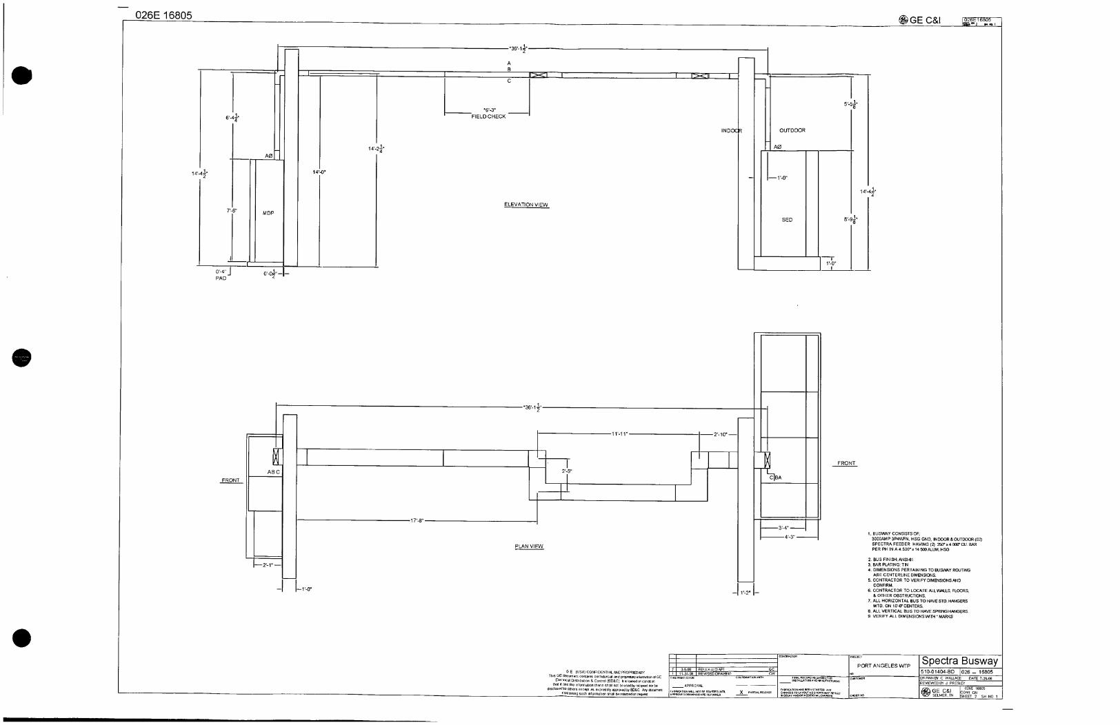
1BUSWAYCONSISTSOF
3000AMP3P4WFNHSGGNDINDOOROUTDOORS2SPECTRAFEEDERHAVING22504000CUBARPERPHINA4500x14500ALUMHSG
2BUSFINISHANSI61
3BARPLATINGTIN
4DIMENSIONSPERTAININGTOBUSYWYROUTING
ARECENTERLINEDIMENSIONS
5CONTRACTORTOVERIFYDIMENSIONSANDCONFIRM
6CONTRACTORTOLOCATEALLWALLSFLOORSOTHEROBSTRUCTIONS
7ALLHORIZONTALBUSTOHAVESTDHANGERS
MTDON100CENTERS
8ALLVERTICALBUSTOHAVESPRINGHANGERS
9VERIFYALLDIMENSIONSIMTHMARKS
PORTANGELESWTP SpectraBusway51001404BD102616805nAWNOTCWALLACEDATE72908
REVIEWEDIBAJPRESLEY
GEC81026Eseas
ONTON
SELMERTNSHEEP2SH001

026E16805
31000x2747
2582
1800
FIELDCHECK
580x800
5800x800
71010
412000
6210x2100
GEUSACONFIDENTIALANCP2OF41E1ARYThisGEdocumentcontainsconfidentialandprop1005infamah0nofCE
Electn06lDIsmb0060001EDSClluslmnedmcan0001matitandtheinformationthermshellnotbeusedDyrecpemnorto
disclosedtoOthers30031asexpresslymordacityED8CAnydocumentcontainingsuchintonationshallbereturnedorrelest
91800
2I3609uRELEASEDAP1I1112405IREVISEDDRAVANG
NSPRINTISVON
APPROVAL
i7Vse7s
32100x2100
103400x1000
114713
12800
XPANNALSCLGSE
G1ON1ooNN0101i
PaoA
PORTANGELESWTP
AIV1roN0xoiuturCrUaxJ
reFlumxyxerAare3xrlofuriooaIniriorrcur
NO
CUSTOmER
OMENNO
GECI likt1N 2
SpectraBusway151001404BDJ02616805RAWUOYCWALLACEDATE12309
PeTWEEBYJPRESLEY
6GECI026E16805
0CNSELMER HEETNSTFINSHNO2
0
0
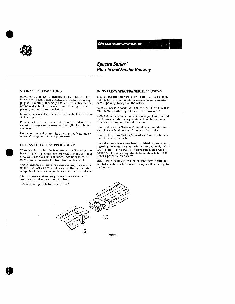
STORAGEPRECAUTIONS
BeforestoringunpacksufficientlytomakeacheckorthebuswayfurpossibleconcealeddamageresultingfromshippingandhandlingIfdamagehasoccurrednotifytheshipperimmediatelyifthcbuswayisfreeofdamagerestorepackinguntilreadyforinstallation
Storeindoorsinacleandryat preferablyclosetotheinstillationpoints
Protectthebuswayfrommechanicaldamageandanycontactwithorexposuretocorrosivefumesliquidssaltsorconcrete
Failuretostoreandprotectthebuswayproperlycancauseseriousdamageandwillvoidthewarranty
PREINSTALLATIONPROCEDURE
MlacnpossibledeliverthebuswaytoitsinstallationlocationbeforeunpackingLargelabelsoneachshippingcartonorcratedesignatetheitemscontainedAdditionallyeachbuswaypieceisidentifiedwithanhemnumberlabel
InspecteachbuswaypieceforpossibledamageorcontaminationContactsurfacesmustbecleanHowevernoattemptshouldbemadetopolishtarnishedcontactsurfaces
Checktomakecertainthatjointinsulatorsarenotdamagedorcrackedandarefirmlyinplace
Nleggereachpiecebeforeinstallation
BAR
END
GEH5876InstallationInstructions
SpectraSeriesPlugnandFeederBusway
INSTALLINGSPECTRASERIESBUSWAY
Establishbusbarphasesequence0sideislabeledtodeterminehowthebuswayistobeinstilledsoastomaintaincorrectphasingthroughoutthesystem
Notethatphasetranspositionlengthswhenfurnishedmayrelocatethe0totheoppositesideofthebuswayrun
EachbuswaypiecehasabarendandajointendseeFigure1Normallythebuswayisorientedendforendwith
buendspointingawayfrontthesourer
Inverticalrisersthebarendsshouldheupandthe0sideshouldhe00therightwhenfacingthcplugoutlet
Inverticalriserinstallationsitiseasiertolowerthebuswayintoplacethantoraiseit
1finstallationdrawingshavebeenfurnishedinformationregardingtheorientationofthebuswayendforendandlocationoftheNsideaswellasotherpertinentdatawillbefurnishedThesedrawingsshouldbecarefullyfollowedtoinsureaproperbuswaysystem
Whenliftingthebuswaybyforkliftorbycranedistributeandbalancetheweighttoavoidflexingorotherdamagetothehousing
jtlEND
Figure1

InstallingSpectraSeriesBuswaycont
WHERETOSTART
Starttheinstallationifatallpossibleatthemostcriticalpointsuchasamainfeedboxswitchboardorswitchgearanelboworothercriticalfittingortermination
OBSTRUCTIONS
WhereabuswayrunmustpassthruawallorflooranopeningoneinchlargerthanthebuswaycrosssectionshouldbeprovidedJointsmaynotoccurinsidewallsorfloorsperNECAflangeisavailabletomasktheopeningafterthebuswayisinstalled
MINIMUMCLEARANCES
3 11
CEILING
WALL
6T
1
3FORRISER
IFLANGEORSPRING1 HANGERCLEARANCE
T
CEILING
1OO
SEE
TABLE
2
1
Figure2
4minimumprovidesclearancefor30100ampfusibleplugs7minimumfor200ampfusibleplugs8minimumforallotherplugsSeeTable1
HORIZONTALMOUNTING
OverheadSupport12droprodsarerecommendedMax10footspacingDroprodsandotherhardwaremustbefurnishedbytheinstaller
Maintaingoodalignmentofthedroprodsalongthebuswayrun
Avoidhangingdroprodsatabuswayjoint
Afterthebuswayissecuredinthehangersadjustthehangersontherodsforcorrectelevation
Swaybracesmayberequiredtokeeptherunstraightortopreventrotationfurnishedbytheinstaller
WallorColumnSupportSinglerodhangersFigure45maybeusedformountingbuswayonwallsorcolumnsbytheadditionofananglesupportbytheinstaller
2
TABLE1PLUGSIZESINCHES
Device
ELine
TBI
FJFK
JJJKTB4
KM
TB6TB8
30A60A
100A
200A
400A
600A
Doorhingesattopforallplugs400ampandover
Othershingeatcnd
Figure4OneStackStandardFlatwise
PlugDimensions
A IB IC IDCircuitBreakers
6 8 23
168 9
71 9 24
35 14334I
FusibleSwitche
114 169 994118
185 1235
16741 11521I
171918723623
Foroveralldimension
includinghangersadd1inchestoA
DROPROD
SEETABLE2
Figure6
SWAYBRACING
ANCHORPOINTS
WHENREQD
PlugOverhangs
BuswayEachE I Side
2
23
29101278152678 5
2
52
7
Figure5OneStackEdgewise
1014gFigure7

e VERTICALMOUNTING
Supportbuswayonmaximum16centersUseTable3todeterminethenumberofspringsrequiredbasedonbuswayweightasshowninTables4and5ToassemblehangerstobuswayFigure68 9afterplacingthelengthinpositionthatthefloor1 LoosenhangerboltsA
2Assemblehangertoeachsideofbusway
3 PositionthehangersonthebuswaysothatthebasechannelBrestsonthefloororothersupportFloorflangeCmaybeplacedunderhangerbutwillnotsupportbuswayweight
4 HandtightenhangerboltsA
5AnchorbasechannelsBtotheirsupport
6TightenhangerboltsA
Installthenextlengthandmakethejointassemblysecinstructionsonnextpage
7 Checktoensurehangerhas8initialfloorclearance
AdjustmentofspringsiffurnishedFigure98 DeterminerequiredHdimensionofhangersprings
foundonlayoutdrawingorusingformulabelowUsingfinaladjustingnutsEsetspringsonhangerstoHdimensionAfterspringisadjustedtightenjamnutFsospringwillnotmove
HDimensionFormula
H5 W Buswaywtftxftfloordevicesonfloor150 Totalnoofspringsfloor
9 LoosenhangerboltsA
10PositionhangeragainstbuswayandresthangerbasechannelsBontheirsupportsinstallerfurnished
11FithangerclampsGtobuswayhousinganhandtightenhangerboltA
12AnchorbasechannelBtoitssupport
13TightenhangerboltsA
14AfterbuswayrunisinstalledstartingatthetophangerraisetheinitialadjustingnutsDofallhangerstothetopofthespringstudsThestudsarecrimpedtoholdthenutintheuppermostposition
HANGER
BOLT
A
TABLE2HANGERDIMENSIONSINCHES
BarsperPhase
2
Figure8RigidRiserHanger
AmpereRating
TABLE3BUSWAY
SPRINGS
BuswayHeightNoSpringsLbs Reqd0600 I 1
6011200
Over1200
HANGAR
CLAMP
G
Busway HangerCopper Alum A B
225800 225600 4
1000 5
1200 800 558 1074
1350 1000 6
1600 1200 7
2000 1350 8
1600 9 14
2500 2000 11
3000 15
2500 152
4000 3000 18
5000 4000 23
2
3
594MINCLNC
TABLE4WEIGHT
LBSQMRFUSIBLESWITCHES
Ampere30
60
100
200
400
600
HANGER
BOLTA
A
Figure9SpringRiserHanger
26
Weight24
25
28
46
135
160
INITIAL
ADJUSTINGNUTD
8
SEEINITIAL
TABLF2HEIGHTBASE
CHANNEL
B
8zFINAL
JAMADJNUTNUT E
F
3
InstallingSpectraSeriesBuswaycons
VERTICALMOUNTINGCONT JOINTSWITH 2INCHADJUSTABILITY
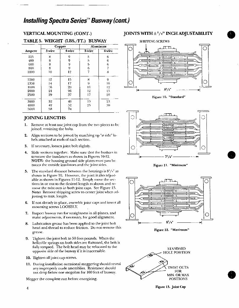
TABLE5WEIGHTLBSFTBUSWAY SHIPPINGSCREWS
Copper 1 Aluminum
OJ
ri
AmpereI 3wire I 4wire I 3wire 4wire
JOININGIFNGTHS1 Removeatleastonejointcapfromthetwopiecestobe
joinedretainingthebolts
2 Alignsectionstobejoinedbymatchingupvssidelabelsattachedatendsofeachsection
3 Ifnecessaryloosenjointboltslightly
4 SlidesectionstogetherMakesurethatthebusbarsinterweavetheinsulatorsasshowninFigures1012NOTEthehousinggroundsideplatesmustpasshetweentheoutsideinsulatorsandthejointsides
5 Thestandarddistancebetweenthehousingsis88asshowninFigure10HoweverthejointisalsoadjustableasshowninFigures1112SimplymovethesectionsinorouttothedesiredlengthasshownandremovethetwistoutsinbothjointcapsSeeFigure13NoteRemoveshippingscrewtocenterjointwhenadjustingtomaxlength
6 IfnotalreadyinplaceassemblejointcapsandinsertallmountingscrewsLOOSELY
7 Inspectbuswayrunforstraightnessinallplanesandmakeadjustmentsifnecessaryforgoodalignment
8 LubricationgreasehasbeenappliedtothejointboltheadandthreadtoreducefrictionDonotremovethis
grease
9 Tightenthejointboltto50footpoundsWhenthebellevillespringsonbothsidesarcflattenedtheboltisfullytorquedTheboltheadmayberelocatedtotheoppositesideofthebuswayifitisinaccessible
10Tightenalljointcapscrews
11DuringinstallationoccasionalmeggeringshouldrevealanyimproperlymadeassembliesResistanceshouldnotdropbelowonemegohmfor100feetofbusway
Meggerthecompleterunbeforeenergizing
4
225 8 9 5 6
400 8 9 5 6
600 8 9 5 6
800 8 9 6 7
1000 10 12 7 8
1200 12 15 8 9
1350 14 17 9 10
1600 16 20 10 12
2000 21 26 12 15
2500 29 37 17 20
3000 32 40 19 23
4000 42 52 25 30
5000 58 74
O
0
0
l
8e
7
Figure10Standard
I1fTI
yI
Figure11Minimum
S
87e
Figure12Maximum
STANDARD
HOLEPOSITION
TWISTOUTS
FOR
MINORMAX
POSITIONS
Figure13JointCap
0
O
ny
O
0

InstallingandRemovingSpectraSeriesTMBuswayPlugs
OPERATING
HANDLEWRENCH
PLUGASSISTINDICATOR
ALIGNMENTWHENEQUIPPEDiT PIN
HANGERHOOKS
Itisagoodsafetypracticetodeenergizethebuswaybeforeinsertingorremovingplugs
Inspectplugbeforeinstallingonbusway
Stabfingershavebeenlubricatedwithgreasewhichshouldnotberemoved
Buswaypluginoutletsaremadeaccessiblebyhingingtheoutletcover180toaretainingfrictionlatch
Analignmentpinpolarizesandlocatesthepluginthecorrectpositiononly
PlugsareinterlockedpermittingengagementanddisengagementwiththebuswaywhenintheOFFpositiononly
Placetheoperatinghandleatthedesiredpositionontheplugandsecureitwiththescrewprovided
Ifplugassisthasbeenfurnishedontheplugtheoperatinghandlemaybeusedasawrenchtooperatethemechanism
ToinstallaplugwheretherearplughangerinterfereswithajointcapitisnecessarytoremovethebreakofftabsseeFigure14
Onlargeplugsdroprodbracketsareprovidedforauxiliarysupportoftheplugonhorizontalrung
ripf as
PINTERLOCK
SLIDE
IPro STAB
FINGERS
BREAKOFF
TABS
Figure14PlugMounting
INTERLOCK
SLOT
CAPTIVE
COVERSCREW
GROUNDSTAB
ALIGNMENT
PIN
HOUSING
HOLE
PHASE
STABS
OOCautionMakecertainplugassistpointerislinedupwithinpositionpriortoturningplugon
ToInstallPlugNotEquippedwithPlugAssistFigure14
1 MakesuredeviceisinOFFposition2 Loosenthefourboltsonthehangerhooks3 Insertalignmentpinintohousinghole4 Pushstabsintofullcontactwiththebusway5 Engagethefourhangerhookswiththebuswayrails
andtightenbolts
ToInstallPlugEquippedwithPlugAssistFigure14
1 MakesuredeviceisinOFFpositionandplugassistindicatorisrotatedfullytowardstabsoutposition
2 Loosenthefourboltsonthehangerhooks3 Insertalignmentpinintohousinghole4 Engagethefourhangerhookswiththebuswayrails
Tightenboltsandwiredevice
5 Rotateplugassistindicatorfullytowardthestabsinposition
ToremoveplugsfirstturndeviceOFFThenreversetheactionsintheappropriateprocedureabove
5

stallingSpectraSeriesOutdoor FeederBusway
nstallthehusvayusingtheinstructionsforindoorhuswavwiththefollowingexceptionsforoutdoorbusvavjoint
JohnCapJointCrapsarepackagedinthehardwarepackageRemovethefourshippingjointgasketprotectorspaintedyellowandretainthejointcapmounting l3x
holesInstallthejointcapsandtightencompletelySomepressuremayberequiredtodeflectgasketinorder to
startscrews
NotethatforhuswaymountededgewisethebottomjointcapwillbemarkedBOTTOMCAPThiscapwill have
weepholes
6
OUTDOOR
JOINTCAP
JointCoversThesecoversspanthejointonthe wideside
ofthebuswayAttachthecoversspanthejointonthe wide
sideofthehusayAttachthecoverswiththe 120x
screwsPiercethegasketwithasharptoolsuchasanawlNuICthatforbusvavmountedflatthebottomcoverwillbemarkedBOTTOMtvOVERThiscoverwillhaveweepholesinthedimples
WaterBarriersTheseare7shapedbracketsthataretaitornassembledwiththesameboltsthatholdthejointsidestothehuswayForverticalriserinstallationsthewaterbarriersonthebottomsidewillhaveweepholesfactoryinstalled
JOINTOVER
Figure15
WATERBARRIER

SeriSpectrjog
tri
ciett
Ntl
C
tuckoCtc
aiEtPttdt
f
t eQitntsitAVlocaSknPttQ
a
1o tat
cBt
2lxtistc ttt O
riotof
1e
1c
Ct
ltttt p eihltd
elsu
titttha
tbttsij
4 C noo tstitiP ttcdi
11
4it ltt20AA
cOtttrr et sbt4P eitttthtcit coStt tstiets
v
tote tateCe4vstca
3tthtwtutlGa4 tha fettckcttt ed 1 t sc gat
Grt
ke
vlatccttttto
i
ce
et
s
c
n
ws Vt1TikC tttte etas S
y eissP yl ost
ePcs
cotC cttett1to
otGoverlljegketwitftftc 49scjevs
cete bcef ibtsOM ewcc
i
a
ti
f 8usyvavA Indoor
DripProp
firtt5aaclse
matte tp CVace
rk tlettP ttcoyei
tiP ties t booi5tifoi ay
lockCCte
ttZe A20 IS
cet tYjele ItCON
fatoicest t10k
Oleloft aie e
emsIn 0tYtevv0 Cshe
11ee iWA
c0tcke
t6
s1aPhatotoo NWtS stal Voles
factoeeP

BuswayMaintenanceProcedures
PROTECTINGTHEBUSWAY
Particularcaremustbeexercisedduringinstallationtoprotectthebuswayfromcontaminants
ShouldthebuswayinadvertentlybecomecontaminatedwithwateritshouldbebakeddryorreplacedContactthecompanyforinstructions
INSPECTINGTHEBUSWAY
Periodicinspectionsshouldbemadetospottroubleareasorchangesinoperatingcondition
Accumulationsofdustdirtorforeignmattershouldberemoved
Moisturefromleaksorcondensationdrippingfrompipesshouldbeeliminated
Checkforanyequipmentsinstallednearthebuswaythatmaycausedamagebecauseofundueexternalheating
VisuallyinspectthebellevillespringsatthejointtoensurethatthespringsareflatFlatspringsindicatethatproperjointpressureisbeingmaintainedItisnotnecessarytorechecktorqueonjointboltasslongasvisualcheckissatisfactory
TheseinstructionsdonotpurporttocoveralldetailsorvariationsinequipmentnortoprovideforeverypossiblecontingencytobemetinconnectionwithinstallationoperationormaintenanceShouldfurtherinformationbedesiredorshouldparticularproblemsarisewhicharenotcoveredsufficientlyforthepurchaserspurposesthemattershouldbereferredtotheGECompany
GEH58761091BLA
GeneralElectricCompany41WoodfordAvePlainvilleCT06062
1991GeneralElectricCompany
WARNINGDeenergizethebuswaybeforeperforminganyofthefollowingoperations
Carefullyinspectallvisibleelectricaljointsandterminationsfortightnessofboltsnutsetc
Checkforsignsofoverheatingatjointsterminationsfuseclipsetcordeteriorationininsulatingmaterialormeltingofsealingcompound
Besuretheconditionwhichcausedanyoverheatinghasbeeneliminated
CheckformissingorbrokenpartsproperspringtensionfreemovementnestingorcorrosiondirtexcessiveweararcspattersootydepositstrackingCleanorreplacepartsasrequired
AleggerthesystembeforereenergizingTheresistanceshouldnotbebelowonemegohrnfor100feetofbusway
Forgeneralinstructionsregardinghandlinginstallationoperationandmaintenanceofbuswaysystemsrated600voltsorlessseeNEMAPublicationBU11
GEElectricalDistribution Control

CERFCAEOFSESVCCOvP ACE
GEConsumer Industrial
ElectricalDistribution
ForSpectraSeriesBusway
QualifiedtoIEEE6931997 HIGHLevelwith13AmplificationFactorQualifiedtoIBC2003
10
CertificationReportPreparedby
WEGundy AssociatesInc
POBox2900HalleyID83333
Sd 10gS 150 I 15forzh 0
Sd 16gS 240 Ip 15forzh 0
inaccordancewithICCESAC156
10
FrequencyHertz
SeeGEdocument10095806P1forCertificationReportinterpretationoftestdataandPEstamp
i ia
1ZPA064a1I
THISISTOCERTIFYTHATTHEABOVENAMEDEQUIPMENTMEETSOREXCEEDSALLOFTHEABOVEREQUIREMENTSACCORDINGTOIEEE6931997ANDIBC2003
100
RRS
Lowestequipmentnaturalfrequency37Hz QualifiedbyshaketabletestingWyleLaboratoriesAug1992
eDET47610706PrintedinUSA

BillofMaterials
CertifiedTestReport
ShopDrawings
SparePartsList
Installation Instructions
VFDDrives
Starters

Tab3 SpecificationSection16440MotorControlCentersCertifiedTestReportsShopDrawingsSparePartsListSupportingDocumentsInstallation InstructionofMCC DEH40472
VFDAF330P11Drives OPCG11SDEV
Starters DEH41021
TVSS C2020004801
CertificateofSeismicCompliance
PORTANGELESWATERTREATMENTPLANT
TableofContents
OrderReg51001404
Operation MaintenanceManualkL

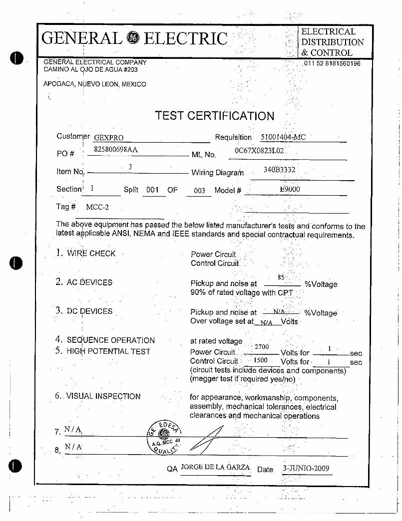
GENERAL0ELECTRIC
0 GENERALELECTRICALCOMPANYCAMINOALOJODEAGUA203
APODACANUEVOLEONMEXICO
CustomerGEXPRO
PO825800698AA
ItemNo
Section 12
Tag MCC
TheaboveequipmenthaspassedlatestapplicableANSINEMAand
1WIRECHECK
2ACDEVICES
3DCDEVICES
4SEQUENCEOPERATION
5HIGHPOTENTIALTEST
6VISUALINSPECTION
7NA
8NA
2
Split 001 OF
TESTCERTIFICATION
Requisition 51001404MC
MLNo0067X0823L01
WiringDiagram
003 Model
atratedvoltage
PowerCircuit
ControlCircuit
340B3332
E9000
85
Pickupandnoiseat90ofratedvoltagewithCPT
ELECTRICAL
DISTRIBUTIONCONTROL
011528181560196
thebelowlistedmanufacturerstestsandconformstotheIEEEstandardsandspecialcontractualrequirements
Voltage
Pickupandnoiseat NSA VoltageOvervoltagesetat NIA Volts
2700 1PowerCircuit Voltsfor
ControlCircuit lsoo Voltsfor 1
circuittestsincludedevicesandcomponentsmeggertestifrequiredyesno
forappearanceworkmanshipcomponentsassemblymechanicaltoleranceselectricalclearancesandMechanicaloperations
QAJORGEDELAGARZA Date 3JUNIO2009
sec
sec

GENERALOELEGENERALELECTRICALCOMPANYCAMINOALOJODEAGUA203
APODACANUEVOLEONMEXICO
CustomerGEXPRO
825800698AAPO
ItemNo
Section 34
Tag MCC1
TheaboveequipmenthaspassedthebelowlistedmanufacturerstestsandconforrnstothelatestapplicableANSINEMAandIEEEstandardsandspecialcontractualrequirements
1WIRECHECK
2ACDEVICES
3DCDEVICES
4SEQUENCEOPERATION
5HIGHPOTENTIALTEST
6VISUALINSPECTION
7NA
8NA
2
TESTCERTIFICATION
WiringDiagram
Split 002 OF 003 Model
Requisition 51001404MC
MLNo0067X0823L01
PowerCircuit
ControlCircuit
340B3332
E9000
85
Pickupandnoiseat90ofratedvoltagewithCPT
ELECTRICAL
DISTRIBUTION
CONTROL011528181560196
Voltage
Pickupandnoiseat NSA VoltageOvervoltagesetat1441 Wits
atratedvoltage2700
PowerCircuit VoltsforI
sec
ControlCircuit 1500 Voltsfor 1 sec
circuittestsincludedevicesandcomponentsmeggertestifrequiredyesno
forappearanceworkmanshipcomponentsassemblymechanicaltoleranceselectricalclearancesandmechanical
QAJORGEDELAGARZA Date

GENERAL ELECTRIC
GENERALELECTRICALCOMPANYCAMINOALOJODEAGUA203
APODACANUEVOLEONMEXICO
CustomerGEXPRO
825800698AAPO
7NA
TESTCERTIFICATION
Requisition 51001404MC
0067X0823L01MLNo
ItemNo2
WiringDiagram
Section 5 Split 003 OF 003 Model
Tag MCC
Theaboveequipmenthaspassedthebelowlistedmanufacturerstestsandconforms tothe
latestapplicableANSINEMAandIEEEstandardsandscontractualrequirements
1WIRECHECK PowerCircuit
411 ControlCircuit
s
85
2ACDEVICES Pickupandnoiseat Voltage90ofratedVoltagewithCPT
3DCDEVICES Pickupandnoiseat N Voltage
OvervoltagesetatNA VCAS
4SEQUENCEOPERATION atratedvoltage2700
HIGHPOTENTIALTEST PowerCircuit r Voltsfor sec
ControlCircuit 15 V61tsfor 1 sec
circuittestsIncludedevicesandcomponentsmeggertesttrequiredyesno
6VISUALINSPECTION forappearanceWorkmanshipcomponentsassemblymechanicaltoleranceselectrical
0Eandmechanicaloperations
occ 491
9
340B3332
E9000
ELECTRICAL
DISTRIBUTION
CONTROL
011528181560196
QAJORGEDELAGARZADate 3JVNI02009
a
GENERAL0ELECTRICGENERALELECTRICALCOMPANYCAMINOALOJODEAGUA203
APODACANUEVOLEONMEXICO
CustomerGEXPRO
PO
ItemNoy
Section 1 Split 001 OF 003 Model
Tag MCC2
Theaboveequipmenthaspassedthebelowlistedmanufacturers testsandconformstothelateapplicableANSINEMAandIEEE standardsandspecialcontractualrequirements
1WIRECHECK
2ACDEVICES
3DCDEVICES
4SEQUENCEOPERATION
5HIGHPOTENTIALTEST
6VISUALINSPECTION
7NA1
8NA
Requisition 51001404MC
825800698AAMLNo
0067X0823L02
3
TESTCERTIFICATION
WiringDiagram
PowerCircuit
ControlCircuit
85
Pickupandnoiseat90ofratedvoltagewithCPT
Pickupandnoiseat NSA VoltageOvervoltagesetat NA Volts
atratedvoltage2700
PowerCircuit Voltsfor1
sec
ControlCircuit 1500 Voltsfor 1 sec
circuittestsincludedevicesandcomponentsmeggertestifrequiredyesno
forappearanceworkmanshipcomponentsassemblymechanicaltoleranceselectricalclearancesandrmechanicaloperations
QAJORGEDELAGARZA
340B3332
Date
E9000
ELECTRICAL
DISTRIBUTIONCONTROL
011528181560196
Voltage
3JUNIO2009
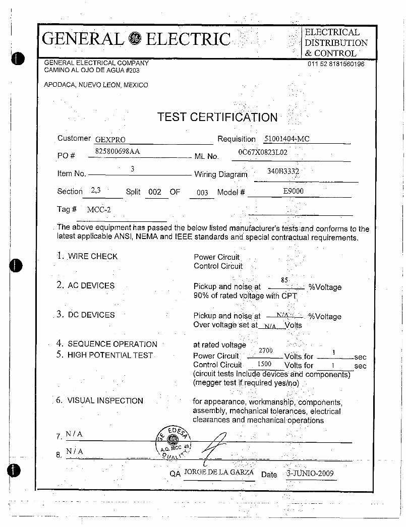
GENERAL0ELECTRICGENERALELECTRICALCOMPANYCAMINOALOJODEAGUA203
APODACANUEVOLEONMEXICO
CustomerGEXPRO
PO825800698AA
ItemNo
Section 23
Tag MCC2
3
1WIRECHECK
2ACDEVICES
3DCDEVICES
4SEQUENCEOPERATION5HIGHPOTENTIALTEST
6VISUALINSPECTION
NA
8NA
TESTCERTIFICATION
Requisition 51001404MC
MLNo0067X0823L02
WiringDiagram
Split 002 OF 003 Model
TheaboveequipmenthaspassedthebelowlistedmanufacturerstestsandconformstothelatestapplicableANSINEMAandIEEEstandardsandspecialcontractualrequirements
PowerCircuit
ControlCircuit
85
Pickupandnoise Voltage90ofratedvoltagewithCPT
Pickupandnoiseat NIA VoltageOvervoltagesetatNI Volts
atratedvoltage270
PowerCircuit Vo1
sec
ControlCircuit 1500 Voltsfor 1 sec
circuittestsincludedevicesandcomponentsmeggertestifrequiredyesno
appearanceworkmanshipcomponentsassemblymechanicaltoleranceselectricalclearancesandmechanicaloperations
QAJORGEDELAGARZA
340B3332
E9000
ELECTRICAL
DISTRIBUTIONCONTROL
011528181560196

GENERAL0ELECTRIC
GENERALELECTRICALCOMPANY
CAMINOALOJODEAGUA203
APODACANUEVOLEONMEXICO
CustomerGEXPRO
PO825800698AA
ItemNo3
WiringDiagram
Section 45 Split 003 OF 003 Model
Tag MCC2
TheaboveequipmenthaspassedthebelowlistedmanufacturerstestsandconformstothelatestapplicableANSINEMAandIEEEstandardsandspecialcontractualrequirements
LWIRECHECK
2ACDEVICES
1DCDEVICES
4SEQUENCEOPERATION
5HIGHPOTENTIALTEST
6VISUALINSPECTION
7NA
NA
TESTCERTIFICATION
aa
QUALC
Requisition 51001404MC
MLNo0067X0823L02
PowerCircuit
ControlCircuit
340B3332
E9000
85Pickupandnoiseat90ofratedvoltagewithCPT
ELECTRICAL
DISTRIBUTION
CONTROL
011528181560196
Voltage
Pickupandnoiseat NIA VoltageOvervoltagesetat NSA Volts
atratedvoltage2700
PowerCircuit Voltsfor1
sec
ControlCircuiit 1500 Voltsfor 1 sec
circuittestsincludedevicesandcomponentsmeggertestifrequiredyesno
forappearanceworkmanshipcomponentsassemblymechanicaltoleranceselectricalclearancesandmechanicaloperations
QAJORGEDELAGARZADate 3JUNIO2009
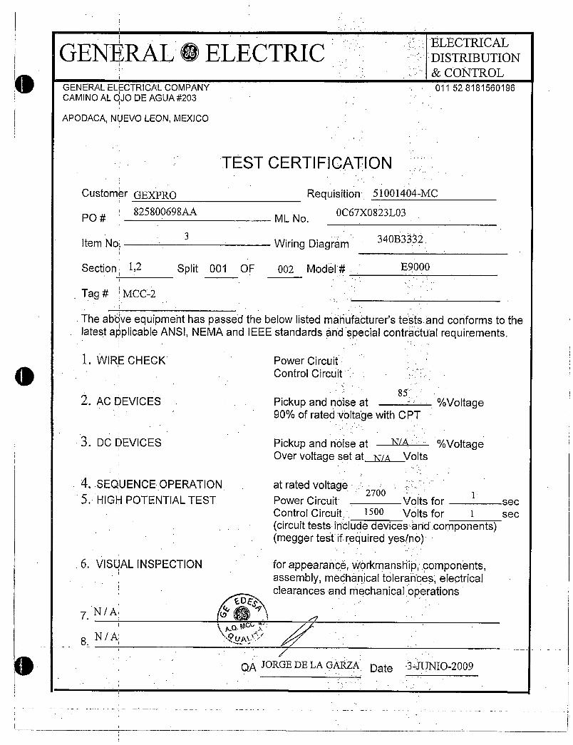
GENERAL0ELECTRIC
GENERALELECTRICALCOMPANYCAMINOALOJODEAGUA203
APODACANUEVOLEONMEXICO
CustomerGEXPRO
825800698AAPO
1WIRECHECK
2ACDEVICES
3DCDEVICES
6VISUALINSPECTION
7NA
8NA
TESTCERTIFICATION
3ItemNo WiringDiagram
Requisition 51001404MC
MLNo0067X0823L03
Section 12 Split 001 OF 002 Model
Tag MCC2
TheaboveequipmenthaspassedthebelowlistedmanufacturerstestsandconformstothelatestapplicableANSINEMAandIEEEstandardsandspecialcontractualrequirements
4SEQUENCEOPERATION atratedvoltage5HIGHPOTENTIALTEST
PowerCircuit
ControlCircuit
85
Pickupandnoiseat90ofratedvoltagewithCPT
Pickupandnoiseat NA VoltageOvervoltagesetatNA Volts
2700PowerCircuit Voltsfor
1sec
ControlCircuit 1500 Voltsfor 1 sec
circuittestsincludedevicesandcomponentsmeggertestifrequiredyesno
forappearanceworkmanshipcomponentsassemblymechanicaltoleranceselectricalclearancesandmechanicaloperations
tJLfq
QAJORGEDELAGARZ
340B333
Date
E9000
ELECTRICAL
DISTRIBUTIONCONTROL
011528181560196
Voltage
34JUNIO2009

GENERAL0ELECTRIC
e GENERALELECTRICALCOMPANYCAMINOALOJODEAGUA203
APODACANUEVOLEONMEXICO
CustomerGEXPRO Requisition 51001404MC
PO825800698AA
MLNo0067X0823L03
ItemNo
Section 34
Tag MCC2
1WIRECHECK
02ACDEVICES
3DCDEVICES
4SEQUENCEOPERATION
5HIGHPOTENTIALTEST
6VISUALINSPECTION
NA
NA
3
TESTCERTIFICATION
WiringDiagram
Split 002 OF 002 Model
TheaboveequipmenthaspassedthebelowlistedmanufacturerstestsandconformstothelatestapplicableANSINEMAandIEEEstandardsandspecialcontractualrequirements
PowerCircuitControlCircuit
85Pickupandnoiseat Voltage90ofratedwithCPT
Pickupandnoiseat NA VoltageOvervoltagesetatNA Volts
atratedvoltage2700
PowerCircuit Voltsfor1
sec
ControlCircuit 1500 Voltsfor 1 sec
circuittestsincludedevicesandcomponentsmeggertestrequiredyesno
forappearanceworkmanshipcomponentsassemblymechanicaltoleranceselectricalclearancesandrechanicaloperations
340B3332
E9000
ELECTRICAL
DISTRIBUTION
CONTROL
011528181560196
QAJORGEDELAGARZA Date 34UNIO2009

GENERAL0ELECTRIC
GENERALELECTRICALCOMPANY
CAMINOALOJODEAGUA203
APODACANUEVOLEONMEXICO
CustomerGEXPRO825800698AA
PO
ItemNo
Section 12
Tag MCC
1WIRECHECK
4112ACDEVICES
3DCDEVICES
7NA
8 NA
4
4SEQUENCEOPERATION
5HIGHPOTENTIALTEST
6VISUALINSPECTION
TESTCERTIFICATION
Split 001 OF 002 Model
Requisition 51001404MC
MLNo 067k0823104
WiringDiagram
Theaboveequipmenthaspassedthebelowlistedmanufacturerstestsandconformstothelatest applicableANSINEMAandIEEEstandardsandspecialcontractualrequirements
PowerCircuit
ControlCircuit
QAJORGEDE LAGARZADate 3JTJN02009
340B332
E9000
ELECTRICAL
DISTRIBUTIONCONTROL
011528181560196
85
Pickupandnoiseat Voltage90ofratedvoltagewithCPT
Pickupandnoiseat NSA VoltageOvervoltagesetatNIA Volts
atratedvoltage2700
PowerCircuit Voltsfor1
Qec
ControlCircuit 1500 Wiltsfor 1 sec
circuittestsincludedevicesandcomponentsmeggertestifrequiredyesno
forappearanceWorkmanshicomponentsassemblymechanicaltoleranceselectricalclearancesandmechanicaloperations
J

1iGENERAL0ELECTRI
GENERALELECTRICALCOMPANY
CAMINOALOJODEAGUA203
APODACANUEVOLEONMEXICO
CustomerGEXPRO825800698AA
PO
ItemNo
Section 34
Tag MCC3
TheaboveequipmenthaspassedthebelowlistedmanufacturerstestsandconformstothelatestapplicableANSINEMAandIEEEstandardsandspecialcontractualrequirements
1WIRECHECK PowerCircuit
ControlCircuit
2ACDEVICES
3DCDEVICES
4
6VISUALINSPECTION
7NA
8NA
TESTCERTIFICATION
Split 002 OF 002 Model
4SEQUENCEOPERATION atratedvoltage5HIGHPOTENTIALTEST
Requisition51001404MC
MLNo0067X0823L04
WiringDiagram340B3332
E9000
ELECTRICALDISTRIBUTION
CONTROL
011528181560196
85
Pickupandnoiseat Voltage90ofratedvoltagewithCPT
Pickupandnoiseat N1A VoltageOvervoltagesetat Nth Volts
2700PowerCircuit Voltsfor
1sec
ControlCircuit 1500 Voltsfor 1 sec
circuittestsincludedevicesandtcomponentsmeggertestifrequiredyeslno
forappearanceworkmanshipcomponentsassemblymechanicaltoleranceselectricalclearancesandmechanicaloperations
QAJORGEDELAGARZA Date 3JUNIO2009

0
GENERAL0ELECTRIC
GENERALELECTRICALCOMPANYCAMINOAL0J0DEAGUA203
APODACANUEVOLEONMEXICO
CustomerGEXPRO Requisiion 51001404MC825800698AA 0067X0823L05
PO MLNo
lternNo
Section 1 Split 001 OF 004 Model
ELECTRICAL
DISTRIBUTION
CONTROL
011528181560196
2ACDEVICES
3DCDEVICES
13
411 ControlCircuit
4SEQUENCEOPERATION
5HIGHPOTENTIALTEST
6VISUALINSPECTION
NA8NA
TESTCERTIFICATION
WiringDiagram 340B3332
E9000
Tag RANNEYMCC
TheabdveequipmenthaspassedthebelowlistedManufacturerstestsandconforms tothe
latestapplicableANSINEMAandIEEEstandardsandspecialcontractualrequirements
1WIRECHECK PowerCircuit
85
Pickupandnoiseat Voltage90ofratedVoltagewithCPT
PickupandnoiSeat VoltageOvervoltagesetatNiA Volts
atratedvoltagePowerCircuit VoltSfor
1sec
1500 VoltsforControlCircuit 1 sec
circuittestsincludedevicesandcomponentsmeggertestifrequiredyesno
forappearanceworkmanshipComponentsassemblymechanicaltoleranceselectrical
fc n clearancesandmechanicaloperationsr
QAJORGEDELAGARZADate

GENERALCDELECTRICGENERALELECTRICALCOMPANYCAMINOALOJODEAGUA203
APODACANUEVOLEONMEXICO
CustomerGEXPRO
PO 825800698AA
ItemNo
Section 23 Split
Tag RANNEYMCC
1WIRECHECK
2ACDEVICES
3DCDEVICES
13
4SEQUENCEOPERATION5HIGHPOTENTIALTEST
6VISUALINSPECTION
7NA
8NA
TESTCERTIFICATION
Requisition 51001404MC
MLNo0C67X0823L05
WiringDiagram
002 OF 004 Model
TheaboUeequipmenthaspassedthebelowlistedmanufacturers testsandconformstothelatestapplicableANSINEMAandIEEEstandardsandspecialcontractualrequirements
PowerCircuitControlCircuit
1
ELECTRICAL
DISTRIBUTION
CONTROL
011528181560196
atratedvoltage
340133332
E
Pickupandnoiseat Voltage90ofratedyoltagewithCPT
Pickupandnoiseat NA VoltageOvervoltagesetatNIA Volts
2700 1PowerCircuit VoltsforControlCircuit 1500 Voltsfor 1
circuittestsincludedevicesandcomponentsmeggertestifrequiredyesno
forappearanceworkmanshipcornponentsassemblymechanicaltoleranceselectricalclearancesandmechanicaloperationsco
ftD1c A 7
NttutY
QAJORGEDELAGARZADate 3JUNI02009
sec
sec

GENERALCDELECTRICGENERALELECTRICALCOMPANYCAMINOALOJODEAGUA203
APODACANUEVOLEONMEXICO
CustomerGEXPRO Requisition51001404MC
825800698AA 0067X0823L05PO I MLNo
ItemNo
2ACDEVICES
3DCDEVICES
13
TESTCERTIFICATION
WiringDiagram
E9000
ELECTRICAL
DISTRIBUTIONCONTROL
011528181560196
340B3332
Sectionj45 Split 003 OF 004 Model
Tag RANNEYMCC
The aboieequipmenthaspassedthebelowlistedmanufacturerstestsandconformstothelatestapplicableANSI NEMAandIEEEstandardsandspecialcontractualrequirements
LWIRECHECK PowerCircuitControlCircuit
85
Pickupandnoiseat Voltage90ofratedvoltagewithCPT
Pickupandnoiseat NI VoltageOvervoltagesetat NA Volts
4SEQUENCEOPERATION atratedvoltageI 2700 1
5HIGHPOTENTIALTEST PowerCircuit Voltsfor sec
ControlCircuit 1500 Voltsfor 1 sec
circuittestsincludedevicesandcomponentsmeggertestifrequiredyesno
6VISUALINSPECTION forappearanceworkmanshipcomponentsassemblymechanicaltoleranceselectrical
DESg1clearancesandmechanicaloperationsD
7NA 941tacc
8NIA
QAJORGEDELAGAZA Date JUNIO2009

GENERALELECTRICALCOMPANYCAMINOALOJODEAGUA203
APODACANUEVOLEONMEXICO
GENERALCDELECTRIC
CustomerGEXPRO825800698AA
PO
ItemNo
1WIRECHECK
2ACDEVICES
3DCDEVICES
13
TESTCERTIFICATION
7 ACC
uAAA8N o
Requisition 51001404MC
MLNo0067X0823L05
WiringDiagram
PowerCircuit
ControlCircuit
340B3332
85
Pickupandnoiseat90ofratedvoltagewithCPT
E9000
atratedvoltage2700
PowerCircuit Voltsfor
QAJORGEDELAGARZA Date 3JUNIO2009
ELECTRICAL
DISTRIBUTION
CONTROL
011528181560196
Section 6 Split 004 OF 004 Model
Tag RANNEYMCC
Theaboveequipmenthaspassedthebelowlistedmanufacturerstestsand conformstothelatest applicable ANSINEMAandIEEEstandardsandspecialcontractualrequirements
Voltage
Pickupandnoiseat NLA VoltageOvervoltagesetatNSA Volts
4SEQUENCEOPERATION5HIGHPOTENTIALTEST sec
ControlCircuit 1500 Voltsfor 1 sec
circuittestsincludedevicesandcomponentsmeggertestifrequiredyesno
6VISUALINSPECTION forappearanceworkmanshipcomponentsassemblymechanicaltoleranceselectricalclearancesandmechanicaloperations
1
0
A ACCELERATINGi
RC ALTERNATINGCURRENT
RM AMMETER
AR ALARMRELAY
AMP AMPERE
RMS AMMETERTRRNSFERiSWITCHANN ANNUNCIATOR
ASW AUXILIARYSWITCHAT AUTOTRANSFORMER
RTS AUTOMATICTRANSFERSWITCH
B BRAKE
C CLOSE
CAP CAPACITOR
CB CIRCUITBREAKER
CLF CURRENTLIMITINGFUSE
CLLT CURRENTLIMITINGrERCTORCR CONTROLRELAY i
CT CURRENTTRANSFORMER
D DOWN
DB DYNAMICBRAKING
DC DIRECTCURRENT
D5W DOORSWITCH
ES EMERGENCYSTOP
ETA ELAPSEDTIMEMETER
F FORWARD
FC FIELDCONTACTOR
FOR
FLS
FS
FU
FEEDER
FLOATSWITCH
FASTSPEED
FUSE
FLOWSWITCri
FVNRFULLVOLTAGENONIREVERSINGFINNYFULLVOLTAGE
NONIREVERSINGVACUUM
FVR FULLVOLTAGEREVERSING
GND GROUND
HOAHANDOFFAUTOMATIC
HP HORSEPOWER
HTR HEATER
Mt gDIASURGESUPPRESSOREXAMPLEACROSSTHEMCOIL
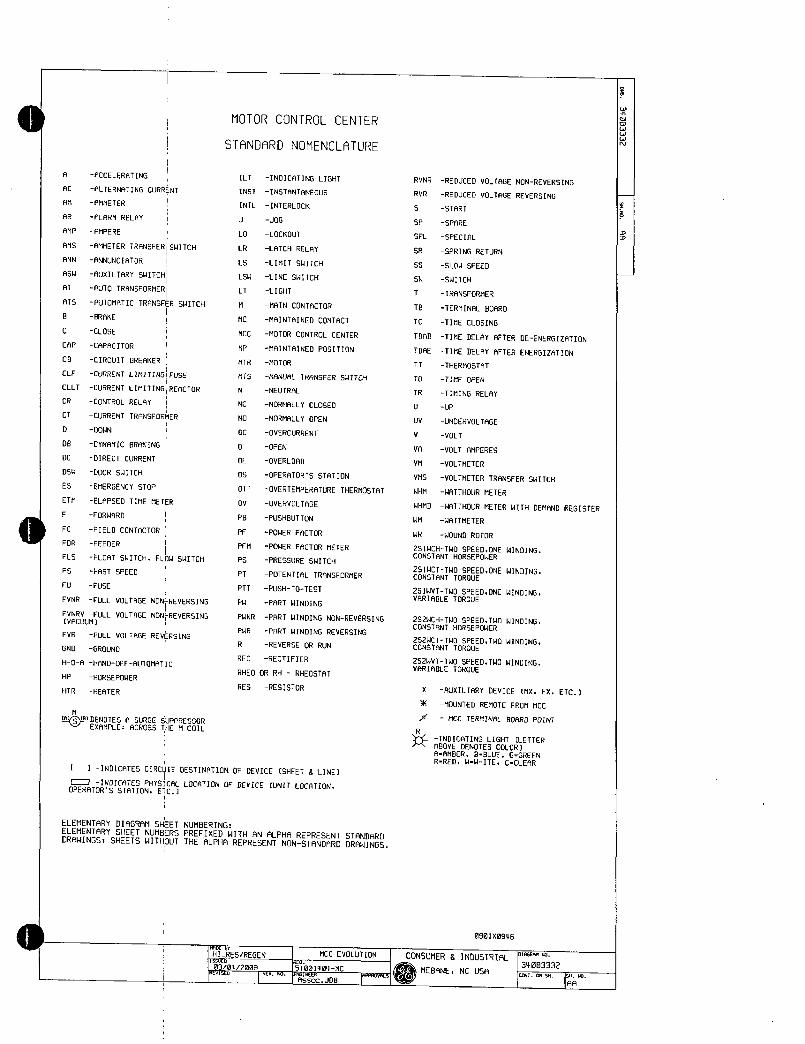
MOTORCONTROLCENTER
STANDARDNOMENCLATURE
ILT INDICATINGLIGHT
INST INSTANTANEOUS
INTL INTERLOCK
J JOG
LO LOCKOUT
LR LATCHRELAY
LS LIMITSWITCH
LSW LINESWITCH
LT LIGHT
M MAINCONTACTOR
MC MAINTAINEDCONTACT
MCC MOTORCONTROLCENTER
MP MAINTAINEDPOSITION
MTR MOTOR
HTS MANUALTRANSFERSNITCH
N NEUTRAL
NC NORMALLYCLOSED
NO NORMALLYOPEN
DC OVERCURRENT
O OPEN
OL OVERLOAD
OS OPERATORSSTATION
OTT OVERTEMPERATURETHERMOSTAT
OV OVERVOLTAGE
PB PUSHBUTTON
PF POWERFACTOR
PFM POWERFACTORMETER
PS PRESSURESWITCH
PT POTENTIALTRANSFORMER
PTT PUSHT0TEST
PW PARTWINDING
PWNRPARTWINDINGNONREVERSING
PWR PARTWINDINGREVERSING
R REVERSEORRUN
REC RECTIFIER
RHEOORRHRHEOSTAT
RES RESISTOR
1INDICATESCIRCUITDESTINATIONOFDEVICESHEET8LINE
C773INDICATESPHYSICALLOCATIONOFDEVICEUNITLOCATIONOPERATORSSTATIONETC
ELEMENTARYDIAGRAMSHEETNUMBERINGELEMENTARYSHEETNUMBERSPREFIXEDWITHANALPHAREPRESENTSTANDARDDRAWINGSSHEETSWITHOUTTHEALPHAREPRESENTNONSTANDARDDRAWINGS
bi
IHIRESREGENassuu03042000rrtVlbt IK
MCCEVOLUTION
151001404MC
RVNR
RVR
5
SP
SAL
SR
SS
SW
T
TB
IC
TT
TO
TR
U
UV
V
VA
VM
VMS
WHM
REDUCEDVOLTAGENONREVERSING
REDUCEDVOLTAGEREVERSING
START
SPARE
SPECIAL
SPRINGRETURN
SLOWSPEED
SWITCH
TRANSFORMER
TERMINALBOARD
TIMECLOSING
TDRDTIMEDELAYAFTERDEENERGIZRTION
TDAETIMEDELAYAFTERENERGIZATION
THERMOSTAT
TIMEOPEN
TIMINGRELAY
UP
UNDERVOLTAGE
VOLT
VOLTAMPERES
VOLTMETER
VOLTMETERTRANSFERSWITCH
WATTHOURMETER
WHMD WATTHOURMETERWITHDEMANDREGISTER
WM WATTMETER
WR WOUNDROTOR
2S1WCHTWOSPEEDONEWINDINGCONSTANTHORSEPOWER
2SIWCTTWOSPEEDONEWINDINGCONSTANTTORQUE
2SIWVTTWOSPEEDONEWINDINGVARIABLETORQUE
2S2WCHTWOSPEEDTWOWINDINGCONSTANTHORSEPOWER
2S2WCTTWOSPEEDTWOWINDINGCONSTANTTORQUE
2S2WVTTWOSPEEDTWOWINDINGVARIABLETORQUE
X AUXILIARYDEVICEMXFXETC
K MOUNTEDREMOTEFROMMCC
e MCCTERMINALBOARDPOINT
RINDICATINGLIGHTLETTER
ABOVEDENOTESCOLORAAMBERBBLUEGGREENRREDWWHITECCLEAR
0901X0906
1 CONSUMER8INDUSTRIAL
MEBANENCUSA1wOIAGMO
34003332CWTOM51SM10
IAA
0
2

SPLICE INCLINEUL800 UL UL UL UL UL OUTLINESUMMARY MCCEVOLUTION
OWGFORPRINTAPPROVAL
AF3VT FVNR AF3VT IFDRCI20I FyNROUSTITEMNRMEMCC15 3 05 AEC 10
RRD RCD IIF030320I RFDTOTALSECTIONS6
FED
FyNR FVNR FDRC630 FDRCB30GERON51001404MC
3
ACF RDF IFDD363 I FDAFF30I PANELNCCATALOG N0090166506L61
1ITEM
ARF
FRONTFVNR FVNR AF3VT FVNR SPACE CUSTOMER
3 100 05 10 GEXPRO7130
RAH 084 AEH RFH USER
FVNR AF3VT FVNR SPACE PORTANGELESWTPORDER10 5 10
NEMRCLASSI TYPEBD ENCL1636 RCJ ADJ RE PFJ
POWERSUPPLY480VOLTS60HZ3003 FVNR F0R0611032 FVNR SPACE 3PHASE3WIRE
10 100 600 100
FDR00100 CONTROLI20VACSINGWINDINGCPTSECTHEIGHT RRL I ADL AFL
90INCHES FVNR
I FDRCB20
I SPACEAMPS iMRTL IPLATING
10 ROM MAIN8US600 COPPER STDTINSPACE
VERTBUS COPPERSTDTINRAN ABN ACN EDN I REN RFN
GNUBUS300 COPPERSTDTIN
1SHIPPING 0010 I 0020 NEUTBUSLENGTH
BUSBRACING65000SYMMETRICALULSECTN0 2 3 4 5 6
MCCSHORTOCTRATING65000SYM
ESTWEIGHT3000LBS
MODSHEET DRAWINGSRNDSHEETSSTANDARDDRAWING34063332
SECTWoD FRONT20020FRONT20x20FRONT20020FRONT20020FRONT20020FRONT20020 SPECIALDRAWING60 60 SPEC5HTS
UNITIC54PLUGTCSH
VERTBUSR 300STUBVERTBUS3 300
VERTBUSSULENGTH 60
STUBVERTBUSSULENGTH50
VERTSTABONOSULENGTH50 60
VER1LOAD6M0SULENGTH
CUSTOMERINCLINEPERPHASE32RW6600MCMTOPSECTRR
300 300 300 300
60 60 60 60
60 60 60 60
LIGHTING8INRUSTRIRL
358056NCUSA
ONON034003332
CONTON5HL013 SHL01
ENGINE63AssocJ66
ISSUED03042008
REVNO9 RE407242006

UNITSUMMARY MCCEVOLUTION ENGINEER REV10292009
REONO 51001404MC ISSUED03042008 REVN015
PANELCATNO0067X0823L01
UNITNPCRTx D IXNOTLABELED27397916113E3523 R
TOTALWHITEFACEBLACKCORE WUNITUNITCU5T NAMEPLATE ELEM CONN SFUNCTIONI HP FLA RPM SF OL OL CB TRIP FUSESRUX UL CUL SC CPTVACATALOGNUMBER
LOCMODUNIT I Z KW HEATER RELAY SW FUSEBY INTLKLABELLABELMARKERSH NO Z E KKW CR123 TYPE CLIP
OICE
AAD
AAF
AAH
RRJ
II
AAL
RRN
RBJ 109
ABN
ACJ 109
9CN
ADD
BLANKNP
M411
COAGULATIONMIXER
1M412140010NMIXER
P425
SLUDGEPUMP
P415SLUDGEPUMP
P416SLUDGEPUMP
M413MATURATIONMIXER
SC414SLUDGESCRAPER
TM423
MATURATIONMIXER
SC424SLUDGESCRAPER
M422COAGULATIONMIXER
102 202A FVNR 1 5000 66 1750 11500778A AMBIENTSELI 15
1102 1202A FVNR
1102202A FVNR
102 12029 FVNR
FVNR102 202A
1099
1089
1299
102
2099
2089
2099
108
1208A2029
C
C
C
INCLINE
AF3VT
II
AF3VT
AF3VT
CiAF3VT
FVNR
5000
1
1
1
10000
10000
10000
7500
7500
0500
5000
800
119
6611800
11911800
119 1800
941750
05001 11800
94
1
66
1750
1750
15010778A
150
150
150
150
150
150
150
0I37B
01378
None
C137B AMBIENT
None
None
AMBIENT
AMBIENT
1SELI
AMBIENT
None
None
None
1800 1150None None
C7789 AMBIENT
SELL
SELI
SELL
SELI
SELL
SELI
SELI
15
20
20
20
13
20
SELI 20
i15
CONSUMERSINDUSTRIAL
MEBRNENCUSRDWGNO31083332
OWGFORINSTALLATION CONTONSHLOIBSHLOIA
UL 01X4485200
2 3UL 142 300 1852485201
23UL 142 300 1952485201
2 3UL 142 300 IAS2485204
2 3UL 142 30011952485204
2 31UL 142 1300 1952485204
00UL 177 300
0 0UL 177 300
0 0UL 177 300
1w58485202
IWS4485210
1WS8485202
00UL 177 300 114S4485210
2 3UL 142 300 19S2485201
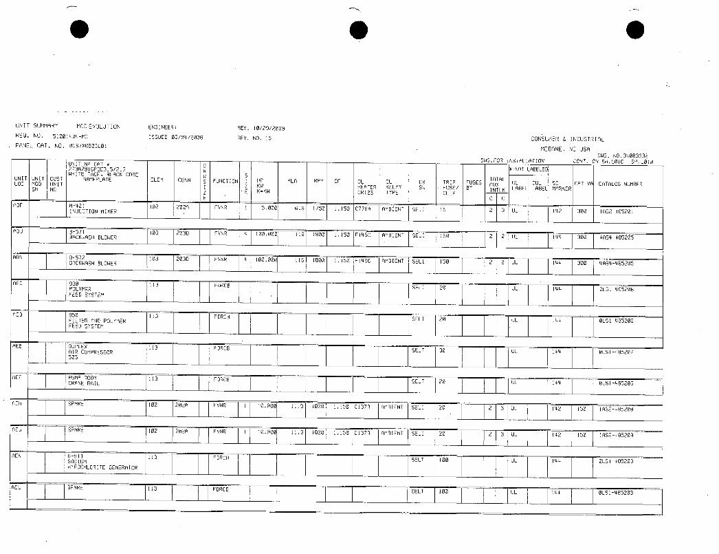
UNITSUMMARY MCCEVOLUTION ENGINEER
REON0 51001404MC ISSUED03042008
PANELCATNO006700823L01
UNITUNITCUSTLOCMODUNIT
SH NO
ADF
ADJ
ADN
REC
PEE
REF
REH
AEJ
REK
AEL r
UNITNPCATx273A7916P3E3523WHITEFACEBLACKCORE
NAMEPLATE
SPARE
M421INJECTIONMIXER
B571BACKWASHBLOWER
8572BACKWASHBLOWER
PUMPROOMCRANERAIL
SPARE
ELEM CONN
102
103
103
930 113 FDRCB
POLYMERFEEDSYSTEM
RED 950 113
FILTERANDPOLYMERFEEDSYSTEM
DUPLEX 113 FDRCB
AIRCOMPRESSOR505
113
SPARE
1102102
G911 113SODIUMHYPOCHLORITEGENERATOR
113
202A FVNR 1 5000
2030
203D
202A
202A
FVNR
FVNR 4
FDRCB
FDRCB
FVNR
FVNR
FDRCB
FDRCB
REV10292009
REVN015
1
1
HP FLR RPM SF OL OL CB TRIP
KW HEATER RELAY SW FUSE
KKW CR123 TYPE CLIP
100000
10000
10000
66
116
100000 116
119
119
1750 1150C778A AMBIENTSELL
1800 1150F1490
180011150
1800
1800 1150
F149C
1150C137B
C137B
AMBIENTSELI
AMBIENT
AMBIENT
SELL
SELT 20
SELT 20
SELT 30
SELT
AMBIENT1SELI
SELI
15
150
150
20
20
20
SELT 100
SELT 100
CONSUMER8INDUSTRIAL
MEBANENCUSADWGN034083332
DWGFORINSTALLATION CONTONSHL01CSHL018
XNOTLABELED
FUSESTAOTALuxBY INTLK
0C
2 3
2
2
2
2
2
UL CUL SC CPTVACATALOGNUMBERLABELLABELMARKER
UL 142 300 1652485201
UL 144 300 4694485205
UL 144 300 4694485205
UL 144 0L91485208
UL 144 0L51485206
UL 144 0LS1485207
UL 144 0LS1485206
3
1UL 142 150 IAS2485208
3
I
UL 142 150 1852485208
UL 144 0LS1485203
UL 144 OLS1485203

UNITSUMMARY MCCEVOLUTION ENGINEER REV02272009
REQND 51001404MC ISSUED03042008 REVNO14
PANELCATNO0067X0823L01
UNITLOC
REM
REN
APO
RFE
AFF
AFG
RFH
AFJ
AFN
UNITNPCRTa273R7916P3E3523WHITEFACEBLACKCORE
UNITCUST NAMEPLATEMODUNITSH NO
SPARE
BLANKNP
SPARE
PROCESSAREAHEATERSNORTH
PROCESSAREAHEATERSSOUTH
REDUNDANT 113
SODIUMHYPOCHLORITEGENERATOR
SODIUMHYPOCHLORITEWATERHEATER
BLANKNP
SPARE
ELEA
113
102
113
113
113
102
2020
2020
FDRCB
SPACE
FVNR
FDRCB
FDRCB
FDRCB
FDRCB
SPACE
FVNR
10000
4120000
1191800
1151800
0
RS
CONNWSFUNCTIONI HP FLR RPM SF OL OL CB TRIP FUSES
I Z KW HEATER RELAY SW FUSEBY
Z E KKW CR123 TYPE CCLIP
E
1150
1150
C137B
F149C
AMBIENT
AMBIENT
SECT 20
SELI 20
SELT 30
SELT 30
SELT100
SELT 40
SELI 150
1110BCONSUMER8INDUSTRIAL
MEBANENCUSADWGNO34003332
DWGFORINSTALLATION CONTONSHL02 SHLOIC
IXNOTLABELEDUL CUL 5C CPTVACATALOGNUMBER
LABELLABELMARKER
TOTALRUXINTLK
0 C
2
2
3
3
UL
UL
UL
UL
UL
UL
144 OLS1405205
142
144
144
144
UL 144
144
150
300
0XX1485212
16S2485208
0LS1405207
0LS1485207
0LS1485203
0LS14853E5
OXX2405205
4RS4485211
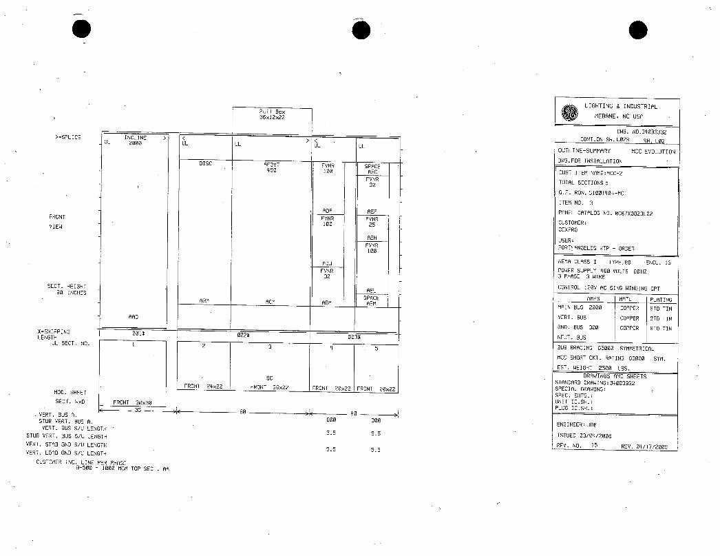
SPLICE
FRONT
VIEW
SECTHEIGHT
90INCHES
0SHIPPING
LENGTHULSECTN0
MODSHEET
SECTWxD
INCLINEUL 2000
ARO
0010
FRONT30x30
35
VERTBUSR
STUBVERTBUSR
VERTBUSSULENGTH
STUBVERTBUSSULENGTH
VERTSTABGNDSULENGTH
VERTLORDGNDSULENGTH
CUSTOMERINCLINEPERPHASEG500 1000MCMTOPSECTRA
UL
DISC
ABM
2
FRONT24x22
UL
0020
60
PullBox36x12x22
RF3VT450
RCM
3
SC
FRONT36x22
UL
FVNR100
ADP
FVNR100
ADJ
FVNR30
ADM
4
600
55
55
0030
UL
SPACEAEC
FVNR30
REF
FVNR25
AEH
FVNR100
40
5
300
55
55
AEL
SPACE
REM
FRONT20x22FRONT20x22
DWGFORINSTALLATION
CUSTOMER
GEXPRO
USER
PORTANGELESWTP ORDER
LIGHTING8INDUSTRIAL
MEBANENCUSA
DWGNO340B3332
CONTONSHL02B SHL02
OUTLINESUMMARY MCCEVOLUTION
CUSTITEMNAMEMCC2
TOTALSECTIONS5
GERON51001404MC
ITEMN03
PANELCATALOGN00067X0823L02
NEMACLASSI TYPEBD ENCL1G
POWERSUPPLY480VOLTS60HZ3PHASE3WIRE
CONTROL120VACSINGWINDINGCPT
AMPS IMIL
MAINBUS2000 COPPER
VERTBUS COPPER
GNDBUS300 COPPER
NEUTBUS
BUSBRACING65000SYMMETRICAL
MCCSHORTCKTRATING65000 SYM
ESTWEIGHT2500LBS
DRAWINGSANDSHEETS
STANDARDDRAWING34083332
SPECIALDRAWING
SPECSHTS
UNITICSH
PLUGICSH
IPLATING
STDTIN
STDTIN
STDTIN
ENGINEERJDB
ISSUED03042000
REVN0 15 REV04172009

UNITSUMMARY MCCEVOLUTION
REONO 51001404MC
PANELCRTNO0067X0823L02
UNITUNITLOCMOD
SH
RAO
ABMYR
RCMPRO
ADP
RDJ
ADM
AEC
REF
AEH
REL
REM
CUSTUNITNO
UNITNPCRTx27397916F303523WHITEFACEBLACKCORE
NAMEPLATE
MAINLUGS
8622 1119 2110ACDISCHIGHSERVICEPUMPDISCONNECT
8622
111A
HIGHSERVICEPUMP
P613BACKWASHPUMP
8614BACKWASHPUMP
8611BACKWASHPUMP
BLANKNP
8612BACKWASHPUMP
SPARE
SPARE
BLANKNP
ENGINEERJDB
ISSUED03042008
DR
S
ELEM CONN SFUNCTIONII Z
Z E
E
102 202D
102
102
102
21109
ICAF3VT 7450000
FVNR 4
202D
202C
102 202C
202B
102 202D
r 1
INCLINE
FVNR
FVNR
SPACE
FVNR
FVNR
SPACE
REV10292009
REVN016
FVNR 4
HPKW
KKW
100000
100000
30000
30000
25000
100000
FLA RPM SF OL OL CB TRIP
HERTER RELAY SW FUSE
CR123 TYPE CLIP
2000
507
116
116
383
1800
1800
1800
3831200
28
116
1800
1800
1150
NoneNone
1150
1150
1150
F149C
1150F149C
AMBIENT
AMBIENT1SELI
1200 11508487B AMBIENT
F487B
C3030
1150F149C
AMBIENT
AMBIENT
AMBIENT
SKLI2I 1000
SELI 150
SELI
SELI
5E0I
150
SELI 70
70
50
150
CONSUMER8INDUSTRIAL
MEBRNENCUSADWGN034083332
DWGFORINSTALLATION CONTON5HL03 SHL0213
11NOTLABELEDIFUSESTOTALUL CUL SC CPTVACATALOGNUMBERBY INTLKLABELLABELMARKER
IO C
1UL0159485217
0UX9485218
0 0UL 10 300 71JS9485218
2 3UL 144 300 4954485211
2 3UL 144 300 4954485211
2 3UL 144 300 3953485216
0XX1485212
2 3UL 144 300 3953485216
2 3UL 143 300 2952485215
3UL 144 300 4954485211
0XXI485212

SPLICE
FRONT
VIEW
SECTHEIGHT
90INCHES
M00SHEET
SECTWx0
CUL UL UL
DISC
FRONT24x22
VERTBUSA
STUBVERTBUSA
VERTBUSSULENGTH
STUBVERTBUSSULENGTH
VERTSTPBGNDSULENGTH
VERTLORDGNDSULENGTH
CUSTOMERINCLINEPERPHASE
PullBox36x12x22
UL
0 DISC AF3V7450 450
SSHIPPING 0010
LENGTHULSECTN0 2 3
FRONT36x22
0023
FRONT20x22 FRONT36x22
60 60
0LIGHTING INDUSTRIAL
MEBANENCUSA
DWGN034003332
CONTONSHL03A 5H103
OUTLINESUMMARY MCCEVOLUTION
OWGFORPRINTAPPROVAL
CUSTITEMNAMEMCC2
TOTALSECTIONS4
GERON51001404MC
ITEMNO3
PANELCATALOGN00901X0946L03
CUSTOMER
GEXPRO
USER
PORTANGELESWTPORDER
NOMACLASSI TYPEBD ENCLIG
POWERSUPPLY450VOLTS60503PHASE3WIRE
CONTROL120VACSINGWINDINGCPT
AMPS 1MATL IPLATINGAFM AGM PHM AIM MAINBUS2000 COPPER STDTIN
VERTBUS COPPER STDTIN
GNDBUS300 COPPERSTDTIN
NEUTBUS
BUSBRACING65000SYMMETRICAL
MCCSHORTCKTRATING42000SYN
ESTWEIGHT2000LBS
DRAWINGSANDSHEETSSTANDARDDRAWING34083332SPECIALDRAWING
SPECSHTSUNITIC56
PLUGICSH
ENGINEERAssocJDB
ISSUED07242000
REVN02 REV07252000
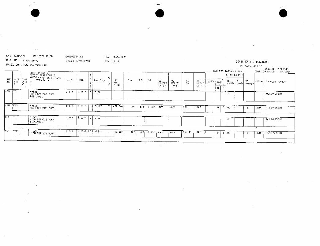
UNITSUMMPRY MCCEVOLUTION
REONO 51001404MC
PANELCATNO0067X0823L03
AFMY9 P623 111A 211G9C DISC
HIGHSERVICEPUMPDISCONNECT
AGM
9HMY9
AIMPRO
PRO P623HIGHSERVICEPUMP
P621HIGHSERVICEPUMPDISCONNECT
P621HIGHSERVICEPUMP
ENGINEERJDB
ISSUED07242088
111
111A
211GA
211GA
C
1119 211GACDISC
C
F3VTf7
AF3VT
REV10292009
REVN09
7
450000
450000
507 1800
507 1800
UNITNPCATa D
273A7916P3E3523 R
WHITEFACEBLACKCORE W S
UNITUNITCUST NAMEPLATE ELEM CONN sFUNCTIONI HP FLA RPM SF OL OL CB TRIP FUSES
LOCMODUNIT I Z KW HEATER RELAY SW FUSEBY
SH NO Z E KKW CR123 TYPE CLIP
E
1150Non
1150 None
None
None
SKL12I
SKL12I
1000
1000
CONSUMER8INDUSTRIAL
MEBANENCUSADWGN034083332
DWGFORINSTALLATION CONTONSHL04 SHL039
NOTLABELEDITOTALAUXINTLK
0C
0
0
0
0
UL CUL SC CPTVACATALOGNUMBERLABELLABELMARKER
UL
UL
10
10
300
300
OUX9485218
71159485218
OUX9485218
7WS9485218

SPLICEUL UL UL UL
FVNR FVNR LTGPNL SPACE
5 5 3
RRD RBD ADD
I SPACE FVNR15
SPACE
RAE
TVSSRBF ADF
FRONTFVNR
15 RCG I SPACEADG
VIEW TRANCB MTG
ABH 30
API IFDRCB 100ABI
MRINCB FDRCB 20 I300 RBJ
FVNR10
SECTHEIGHT RBL
90INCHES FVNR25
RRORBN RCN ADN
1SHIPPING 0011 0021
LENGTHULSECTN0 1 2 3 4
MODSHEET
SECTWxD FRONT20x20FRONT20x20 FRONT30x20 FRONT20x20
40 1 I 50 1
x25 50 25I
VERTBUSR 600 300 300 300
STUBVERTBUSR
VERTBUSSULENGTH 55 60 30 25
STUBVERTBUSSULENGTH
VERTSTABGNDSULENGTH 55 60 30 25
VERTLORDGNDSULENGTH
CUSTOMERINCLINEPERPHRSE2020AWG 400MCMBOTTOMSECTAR
01LIGHTING INDUSTRIAL
MEBANENCUSA
DWGN0340B3332
CONTONSHL04R SHL04
OUTLINESUMMARY MCCEVOLUTION
DWGFORINSTALLATION
OUSTITEMNAMEMCC3
TOTALSECTIONS4
GERON51001404MC
ITEMN04
PANELCATALOGND0067X0023L04
CUSTOMER
GEXPRO
USER
PORTANGELESWTP ORDER
NEMRCLASSI TYPEBD ENCL3R
POWERSUPPLY400VOLTS60HZ
3PHASE3WIRE
CONTROL120VRCSINGWINDINGCPT
AMPS IMATL PLATING
MAINBUS600 COPPER STDTIN
VERTBUS COPPER STDTIN
GNDBUS300 COPPER STDTIN
NEUTBUS
BUSBRACING65000SYMMETRICAL
MCCSHORTCKTRATING65000 SM
ESTWEIGHT2000LBS
DRAWINGSANDSHEETSSTANDARDDRAWING34093332
SPECIALDRAWING
SPECSHTS
UNITI0SHI91
PLUGICSH
ENGINEER
ISSUED03042000
REVN0 14 REV02272009
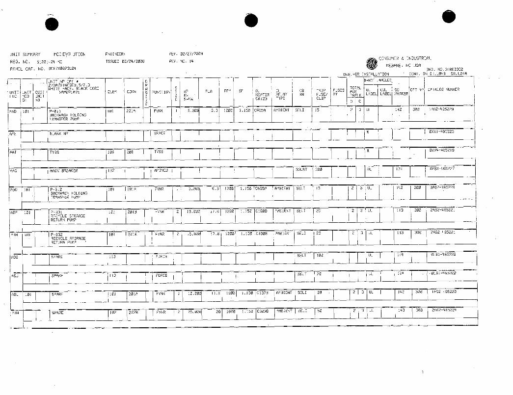
UNITSUMMARY MCCEVOLUTION ENGINEER REV02272009
REONO 51001404MC ISSUED03042008 REVNO14
PANELCRTNO006700823L04
UNITNPCPTa D2730791603E3523 RWHITEFACEBLACKCORE W 6
UNITUNITOUST NAMEPLATE ELEA CONN sFUNCTION1 HP FLR RPM SF OL OL CB TRIP FUSES
LOCMOD UNIT I Z KW HEATER RELAY SW FUSEBY
SH NO 2 E KKW CR123 TYPE CLIP
E
RRD 101 P611 101 201A FVNR 1 5001 631200 115006958 AMBIENTSELI 15
BACKWASHHOLDINGTRANSFERPUMP
ARE
ARI
RAD
ABN
ABH 101
RBI
A8J
RBL 101
BLANKNP
TVSS
SPARE
SPARE
SPARE
1SPARE
106
MAINBREAKER
1112
113
113
1101
1102
206
201A
202B
SPACE
TVSS
MAINCB
ROD 101 P812 101 201A FVNR 1 5022 631200 1150069511 AMBIENTSELI 15
BACKWASHHOLDINGTRANSFERPUMP
RBF 1101 P631 101 2019 JFVNR 2 15000 1761200 115001803 AMBIENTSELI 25
RECYCLESTORAGERETURNPUMP
P832 101 2018 FVNR 2 15000 1761200 115001828 AMBIENTSELI 25 2 3UL 143
RECYCLESTORAGERETURNPUMP
FDRCB
FDRCB
FVNR
FVNR
1
110000119
2 25000 28
1800
1800
1150
1150C3038 AMBIENT
SGL4T
SELT
SELT
SELI
300
100
20
0137B1AMBIENT1SELI 20
50
DWGFORINSTALLATION
TOTALRUXINTLK
0I23
23UL
2 3UL
2
2
3
3
O9
1XNOTLABELEDUL CUL SC CPTVACATALOGNUMBERLABELLABELMARKER
UL
UL
UL
UL
UL
UL
CONSUMER8INDUSTRIAL
MEBANENCUSADWGN0340B3332
CONTONSHL048SHL04A
142 300 1052485229
174
142 300 11162495229
143 300 21152485221
144
144
142 300
143
300 21152485221
0L61495228
0LS1485222
1882485220
300 21152485224
OXX1485225
OXX4495219
0M66485227
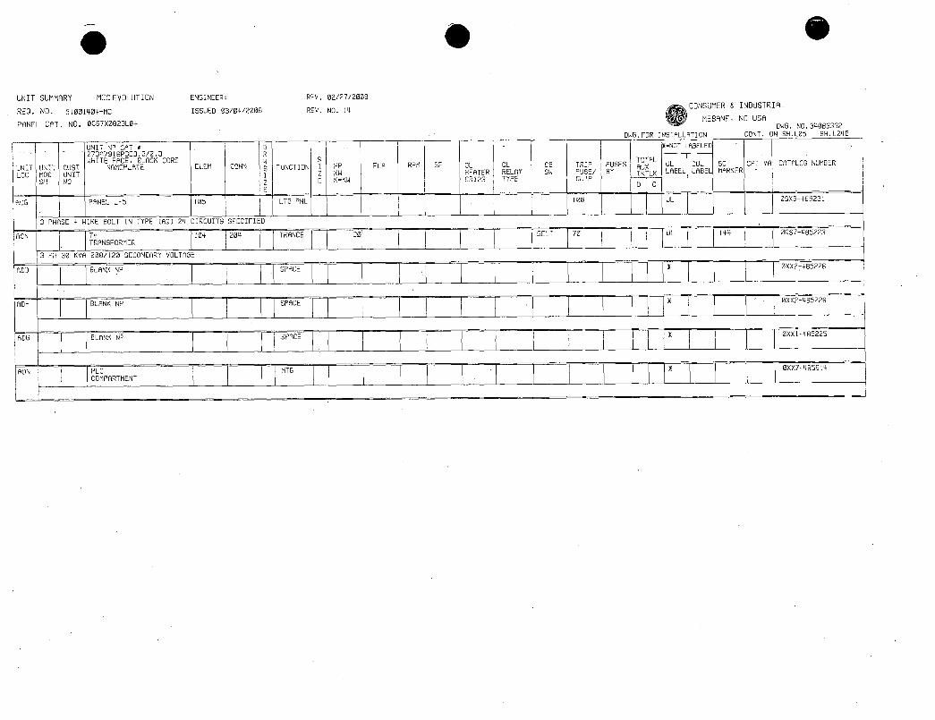
ADD
RDF
RDG
FON
UNITSUMMARY MCCEVOLUTION ENGINEER REV02272009
REONO 51001404MC ISSUED03042008 REVNO14
PANELCATNO0067X0823L04
UNITNPCAT2738791683E3523WHITEFACEBLACKCORE
UNITUNITCOST NAMEPLATELOCMOD UNIT
SH NO
RCS PANELL5
BLANKNP
BLANKNP
BLANKNP
PLCCOMPARTMENT
ELEM CONN
105
3PHASE4WIREBOLTINTYPECAD24CIRCUITSSPECIFIED
RCN 104 204
TRANSFORMER1
3PH30KVA208120SECONDARYVOLTAGE
SFUNCTIONI
LTGPNL
TRANCE
SPACE
SPACE
SPACE
MTG
J
T
HP FLA RPM SF OL OL CB TRIP FUSESTOTALRUXKW HEATER RELAY SW FUSEBY INTLKKKW CRI23 TYPE CLIP
30
100
SELT 70
DWGFORINSTALLATION
IXNOTLRBELEDIUL CUL SC CPTVACATALOGNUMBERLABELLABELMARKER
01C
UL
UL 144
CONSUMER8INDUSTRIAL
MEBANENCUSADWGN034083332
CONTONSHL05 SHL048
05X5485231
0087485223
0XX2485226
0XX2485226
0XX1485225
0XX7485614

o o
SPLICE 2
UL UL
FRONT
VIEW
SECTHEIGHT90INCHES
XSHIPPING
LENGTH81SECTN0
M00SHEET
SECTWxD
SPCC SPACE AF3VT SPACE AF3VT SSS
350 350 350
SAN
0010
SAH
FRONT24x22
24
AHD ADD
SPACE SPACE
ABF RDF
DISC DISC
ABM
2
FRONT24x22
UL UL UL
LIGHTING8INDUSTRIAL
MEBANENCUSA
DWGN034003332
CONTONSHL05A SHL05
UL OUTLINESUMMARY MCCEVOLUTION
DWGFORPRINTAPPROVAL
CUSTITEMNAMERANNEYMCC
TOTALSECTIONS6
GERON51001404MC
ITEMN013
PANELCATALOGN00901X0946L05
CUSTOMER
GEXPRO
USER
PORTANGELESNTPORDER
NEMRCLASSI TYPEBD ENCLIG
POWERSUPPLY480VOLTS60HZ3PHASE3WIRE
CONTROL120VACSINGWINDINGCPT
AMPS IMRTL IPLATING
ACM ADM REM AFM MAINBUS2500 COPPERSTDTIN
VERTBUS COPPERSTDTIN
ONOBUS300 COPPERSTDTIN
NEUTBUS
002X 1 0031 0041 IBUSBRACING65000SYMMETRICAL
FRONT36x22 FRONT24x22
60
4 5 6
FRONT36x22 FRONT30x22
60 30
MCCSHORTCSTRATING65000SYM
ESTWEIGHT3000LBS
DRAWINGSANDSHEETSSTANDARDDRAWING34003332SPECIALDRAWING
SPECSHTSUNITICSHPLUGICSH
VERTBUSA 300 600 600 600 ENGINEERAssocJOB
STUBVERTBUSAVERTBUSSULENGTH 10 40 40 15
ISSUED03042008
STUBVERTBUSSULENGTHREVN08 REV07242000
VERTSTABGNDSULENGTH 10 40 40 15
VERTLORD00SULENGTH
CUSTOMERINCLINEPERPHASE

O Q
UNITSUMMARY MCCEVOLUTION
REGN051001404MC
PANELCATN00901X0946L05
UNITNPCAT273A7916P3E30I5WHITEFACEBLOCKCORE
UNITUNITCUST NAMEPLATELOCM0DUNIT
SH NO
RAN 1E1001RBD
1ABF
1ABM
Il
ACM
ADD
1ADF
ADM
AEA
AEA
ACTIVEFILTER
BLANKNP
1BLANKNP
P201VERTICALTURBINEDISCONNECT
P201VERTICALTURBINE
1BLANKNP
1BLANKNP
12202VERTICALTURBINEDISCONNECT
1P202VERTICALTURBINE
P203VERTICALTURBINE
ENGINEERAssoc358
ISSUED03042008
ELEA CONN
1 100 1 200
1108
11108
12102
1102 210F
0
W5
E
FUNCTION
SPCL
1SPACE
11SPACE
210F C
IDISC
ICIAF3VT
1SPACE
1SPACE
1CDISC
REV07242008
REVN08
IHP
2KWEKKW
FLA RPM5f OL OL CB TRIPFUSESTOTALAuxHEATERRELAY SW FUSEBY INTLKCR123 TYPE CLIP
INTLK
10C
6
13500001 3961180011150 None
1 1 1 1 111 I I
1 1 1 1 1 111 1 1
I I
1None 1soL61 600
LIGHTING8INDUSTRIAL
MEBANENCUSADWGN034003332
DWGFORPRINTAPPROVAL CONTONSHE100SHL05R
13FNOTLABELE01UL CUL
11
SC CPTVPCATALOGNUMBERLABELLABELMARKER
1 1010
1UL
1 143
1 I I 1 I I I 111 1 1
1 l 1 1 11 1 i 1 1 111 1 1
11102
1210F1CAf3YT 6350000
3961160011150 INOne1
None
159661 600 1 1
0
10
1UL
1 143
1107 1207F1C5SS 6
13500001 3961180011150
None None I SGP6T 600
I0
10
1UL
1 155 300
300
300

0 0 0
ow34083332 I snxoN3L0314
r
FRONTVIEW
4500
25k
2000 2000 3000
FLOORPLAN
5500
AA AB AC AD
25
2000
10543WITHFAN
FLOORLINt
10483W0FAN
500 2000
SIDEVIEW
526
10105

o m e
NOTES MCC
REQNO51001404MC
PANELCATNO0901X0946L01
NOTEMATRIXKEY
C CUSTOMER N NAMEPLATE
CA CASE U UNIT
F FINAL T TEST
NOTEAPPLIESTO GeneralNotesForEntireJob
C T A ULLABELEDSECTIONCANBEDETERMINEDBYULINTOPWIREWAYOFOUTLINESHEET ULLABELEDUNITCANBEDETERMINEDFROMCOLUMNMARKEDULLABELONSUMMARYSHEET
C T B WARNINGUSEONLYFUSESOFTYPEFURNISHEDORINDICATEDINNOTESORELECTRICALEQUIVALENTC CA T C ALLUNUSEDSTABHOLESINVERTICALBUSWILLBEPLUGGED
C CA T D MCCUNITINTERIORSTOBEPAINTEDWHITEC N U CA T 68 HIDENSITYPULLAPARTCONTROLTERMINALBOARDSWILLBESUPPLIEDUNLESSOTHERWISENOTEDINTHESHIPPINGITEMC N U CA T 77 POWERTERMINALBOARDSWILLBEPULLAPARTFORSIZE182UNLESSOTHERWISENOTEDONTHESHIPPINGITEMC CAF T 100 Pleaserefertosheet300forbocktobackcrossoverbusloaoutofMCC2
NotesForL01Onl
ENGINEERAssocJDB
ISSUED 03042008
REV07252008
REVNO 9
C CA T 311 INTERMEDIATETYPESIDESCANNOTBEUSEDINTHISLINEUPC CA T 314 BRACINGWILLBEPROVIDEDONTHISLINEUPFORUB0SEISMICZONE4C F T 361 SECTIONABDOESNOTMEETNEMA12ORNEMA2REQUIREMENTSC F T 361 SECTIONADDOESNOTMEETNEMA12ORNEMA2REQUIREMENTS
NotesForL02Onla
C CA T 311 INTERMEDIATETYPESIDESCANNOTBEUSEDINTHISLINEUPC CA T 314 BRACINGWILLBEPROVIDEDONTHISLINEUPFORUB0SEISMICZONE4C CA T 332 FLOORPLATESWILLBEFURNISHEDINALLSECTIONSC F T 361 SECTIONACDOESNOTMEETNEMA12ORNEMA2REQUIREMENTS
CAF T 368 DRIVEFANASSEMBLYREQUIREDONTOPOFSECTIONAC
NotesForL03Onl
LIGHTING8INDUSTRIAL
MEBANENCUSA
DWGNO340B3332
SHEET00
CONTONSH
DWGS FORPRINTAPPROVAL
C CA T 311 INTERMEDIATETYPESIDESCANNOTBEUSEDINTHISLINEUPC CA T 314 BRACINGWILLBEPROVIDEDONTHISLINEUPFORUB0SEISMICZONE4C CA T 332 FLOORPLATESWILLBEFURNISHEDINALLSECTIONSC F T 361 SECTIONAGDOESNOTMEETNEMA12ORNEMA2REQUIREMENTS
C F T 361 SECTIONAIDOESNOTMEETNEMA12ORNEMA2REQUIREMENTSCAF T 368 DRIVEFANASSEMBLYREQUIREDONTOPOFSECTIONAGCAF T 368 DRIVEFANASSEMBLYREQUIREDONTOPOFSECTIONAI
NotesForL04Oni
C CA T 305 MCCENCLOSUREISMODIFIEDFORNEMA3RTYPEANONWALKINOUTDOORUSEALLGASKETINGTOBECLOSEDCELLNEOPRENESPECIALFLOORSILLSREARCOVERSTOPANDBOTTOMWIREWAYCOVERSANDSPLICEBARS REFERTONEMA3RLAYOUTFORDIMENSIONS
C CA T 311 INTERMEDIATETYPESIDESCANNOTBEUSEDINTHISLINEUP

et O O
NOTES MCC
REQNO51001404MC
PANELCATNO0901X0946L01
NOTEMATRIXKEY
C CUSTOMER N NAMEPLATE
CA CASE U UNIT
F FINAL T TEST
ENGINEERAssocJDB
ISSUED 03042008
REV07252008
REVNO 9
NOTEAPPLIESTO NotesForL04Only CONTINUED
C CA T 314 BRACINGWILLBEPROVIDEDONTHISLINEUPFORUB0SEISMICZONE4C CA T 332 FLOORPLATESWILLBEFURNISHEDINALLSECTIONSC CA F T 372 SEEDRAWINGN3RFANSHEET1FORTYPICALNEMA3RFANCIRCUITWHENFANISREQUIRED
NotesForL05Only
C CA T 311 INTERMEDIATETYPESIDESCANNOTBEUSEDINTHISLINEUPC CA T 314 BRACINGWILLBEPROVIDEDONTHISLINEUPFORUB0SEISMICZONE4C CA T 330 BUSSPLICEMATLWILLBEFURNISHEDFORSPLICINGTOEXISTINGLINEUPONLEFTANDRIGHTC F T 361 SECTIONACDOESNOTMEETNEMA12ORNEMA2REQUIREMENTS
C F T 361 SECTIONAEDOESNOTMEETNEMA12ORNEMA2REQUIREMENTSCA F T 368 DRIVEFANASSEMBLYREQUIREDONTOPOFSECTIONACCA F T 368 DRIVEFANASSEMBLYREQUIREDONTOPOFSECTIONAECAF T 369 FANASSEMBLYREQUIREDONTOPOFSECTIONAF
C CAF T 371 SEEDRAWINGGSFANSHEETS12FORTYPICALFANASSEBBLYCIRCUIT
LIGHTING8INDUSTRIAL
MEBANENCUSA
DWGNO340B3332
SHEET00A
CONTONSH L01
DWGS FORPRINTAPPROVAL

ar
CONdITENTRYYITNREIUYABLECOYERPLATE
N
13lYEIcRpIT
15
111PLN323117V738966 797999SECTYIOiN
TYPICALFRONT
VIEWSEE
OUTLINE8SUMMARYFRONTVIEW
AREAFORGROUNDANDNEUTRALBUS
IFSPECIFIED
CONDUITOPENING
1i
AVERTICALTROUGHPAEA
ISTB661CIGOE851599
CSECTWIDTHWI
TWO963116t911
MTG1cLESONE
F
11300228 330661
eo
7B7999
144 i1SECTWIDTH
BHTBT MCCEVOLUTIONHIRESREGEN
0xu03042008 151001404nCiztvlscu ncvwENIAssocJDB
RT5912370It12092191
61REI16OPENINGTYPICAL
DSMAXIMUMODORSWINGEQUALSSECTIONWON
03752BUSBAR
3LBTOC 1AiNJN
699ONGROUNDBUS41s
7fi2rN23Am
Tr6299 1130 E301W1
338299
26041409676613
101
250911
NEC
39762991REmHBLELIFTINGANGLE
39B
318816299
909988133
0901X0946
CONSUMER8INDUSTRIAL
MEBANENCUSA
011GRAN100
34063332
CONTON915NNo
NAB

521301
RE1vABLES31
60NDIJ11EMTRT IJNA
COVERPLATES f
52I1301
FRONT
12 30 1F myBlSECT111069
TYPICALFRONTVIEWSEE
OUTLINE8SUMMARYFRONTVIEW
AREAFORWINOANDNEUTRALBLS 7Y063MtnIFSPECIFIED
JIG065MjI
4
569133eSM IFj0771y
22A
96111e NTn559088
218IMCONDUIT
22
rSE NIDTNr
COMMITOPENING
AVERTICALTROUGHAREAIS1066xC410E
270767076
CKTNI0TH ISA13kfTB9mJ
591
3f7xmnalenn
NIRENA1OPENING
767167L20316007793PH
BUS
noutreHIHIRESREGEN 1 MCCEVOLUTION
9xcu3042009 51001404MC IxvSED
I N11 B Iv99065I
D5S11971x1 DSNIIY
1307ToGROUNDBUS
ACC301762111 REA0060ELIFTING
208088MGLE
17620 220559891
VIESRIGHT510E
5112511IFFINB00ISSPECIFIEDWANREOUIRCOONVF0
GREATERTHAN30111MDON25001f11INBUSSPLICE0675
16AN
17275I3B791
9009003
0
375x2BUSB117111100
25791 7e2m
0901X0946
ACO8INDUSTRIAL
A MEBANENCUSA
09Ax1U0REMEOMSUINGSECTION61018
1room790
34083332CONTM5H679N0
AC AC

REBOvABLEONQUIIENTRY 1B021
FRONT3335M
I R IMII JuMI1L3N
SECTWIDTH I
TYPICALFRONTVIEWSEEOUTLINE8SUMMARYFRONTVIEW
MENFORCROWDAWDNEUTRALEUSAO863116M13IFSPECIFIED NTGHOESON4
1524 CONDUIT133NN TOPEING
19756431t1 Jc6B399NNSWAN
69I CDsmuTTMI6730
WENTNi
7B11N 1 M
r122I WITSECTNIDTH
RVERTICALTRORiAREAIS1066XCWIDEMSNN
CSECTWIDTH 301M
4070X47QIZIRONX1ef6M1
tREIWYOPENING
TrPICAL
6607RN3PHBUS
IDLBT
MCCEVOLUTIONHIRESREGEN
0303042008 151001404MC1kEYTrR 1 IJOB
TO39762M1 4511125n0RENOvABLELIFTINGIFFANI5SPECIFIEDANGLE FANREQUIREDONVFD
GREATERTNV13B11PANDON2586F7PMAINBUS
SPLICE5313151tFRI300fs2nh3BB1
DSNAX1M1WtliSNING 3209
EQUALSSECTIONNIDTH 22203
9uw7D rGROUNDBUS
I
30
36Mf
RIGHTSIDE
BIMxIMR1REARDOORSWINGSECTIONWIDTH
2375X2BUSBARrAxlmn
0901X0946
CONSUMER8INDUSTRIAL
MEBANENCUSA1DIPGRA0
ND
34083332
1Cow ON91isNDN3L03A 1AD
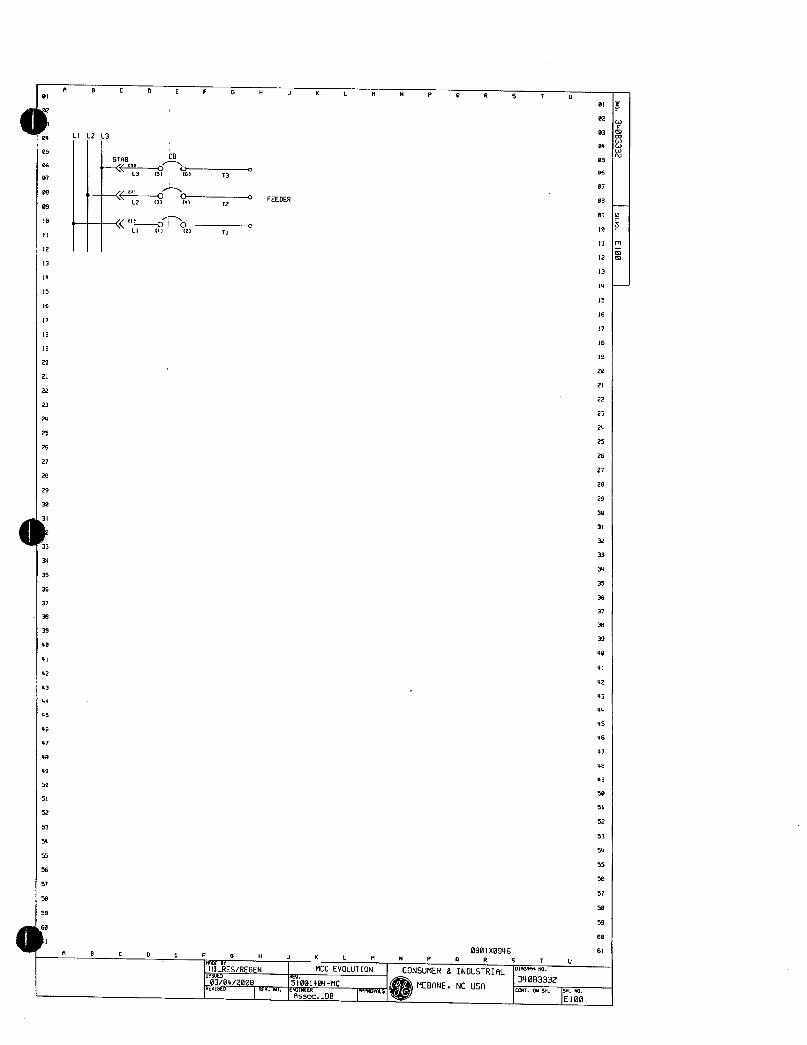
A 0 C D E F 6 H J K L N P 0 0 9 T U
01
02
03O
04wCav105 CB 05
STAB06 3G 06
L3 951 16 13
07 07
1208 0 C FEEDER00
09L2 131 1 72
09
10
11
111 C 18
LI 111 2 TI11I
m
2 12m
13 13
11
15 15
16 16
I7 17
18 18
19 19
22 20
21 21
22 22
23 23
24 24
25 25
26 26
27 27
28 28
29 29
30 30
31 31
32
33 33
31 34
35 35
36 36
37 37
38 30
39 39
40 40
41 VI
42 V2
43 43
44 V4
45 45
46 46
47 4
68 46
49 49
50 50
51 51
52 52
53 53
54 56
55 55
56 56
57 57
50 58
59 59
60
61110 0901x0946
A L E F G H J R L X N P 0 R 9 T U
70E0
HIRESREGEN 1 MCCEVOLUTION1
CONSUMER8INDUSTRIAL I0483332
01V3042008 1510014FA MEBANENCUSAtlu hcc CONTONHISNNO1E102I I 1E100
423
6
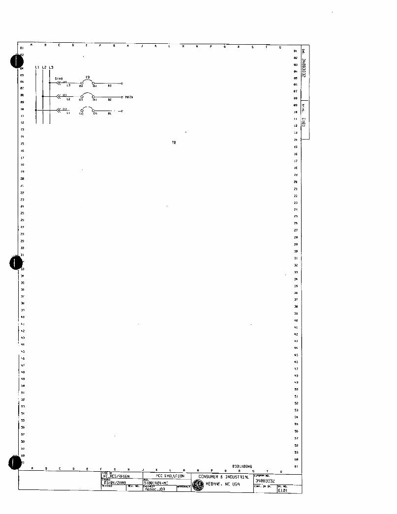
01
005
06
07
08
09
10
12
13
14
I6
17
IB
0 0 C
LIL2L3
STAB
L3
L2
u1
L1
E F 6 X J K L
CB
15 161 03
131 1 02
11 21 01
11616
90
1919
2020
2121
2222
2323
2626
2525
2826
2727
2820
2929
30 30
31
32
33
34 34
3535
3636
3737
3839
3939
4040
4141
42 42
4343
4444
45VS
46 46
4747
4848
49 49
50 50
51 51
52 52
53 53
54 54
55 55
56 56
57 57
58 50
59 59
611 0901X0946 61
fl B C D E F G X J K L N N P 0 17 S T
NIRESREGEN I MCCEVOLUTION
03042008 1551001404MCnvibeu
0 5 T 0
CONSUMERgINDUSTRIAL
MEBANENCUSAI01610
IA
340B3332
ICGXr0454
1E101
01
82
03
04
05
06
07
08
09
10
I1m
C5712
13
14
15
16
17

01
2
04
05
07
0s
09
10
11
12
13
1a
15
16
17
18
19
20
21
22
23
24
zs
26
27
20
29
30
4112
33
34
35
36
37
39
39
40
4
42
43
44
45
46
47
48
49
50
51
52
53
54
55
56
57
58
59
e6061
A 0 C D E 6 H J K L K N P
TRANSITIONTOSWITCHBOARD
01 32
3411 1413
SS x11 41
ICT T
1321 1121
4
2
STABCB
i13oc
L3153 IWK3
12
L2 CIK2
KI
ICTAND2CTARELOCATEDINTHESWITCHBOARD
30005
5
I O03
VVV
TH15166PAIR 2
11415120PAIR 4
I31
A2FU
7
B
4
I1QJH2
FAN2
Dt32J2
GND
52
DRCNNGR3IREfLR1t1 IIYA42 KEIfFel
CR2101
FAULT
tA7142
DOT A
LEDTYPE
THESEWIRESMUSTBERUNINTHEFIELDI
123
3
Ial
ASF
2l
131P6C061NE
GND
GNDBUS
a
to
MI
MI
R T
01
02
03
04
85
06
07
08
09
10
1
12
13
14
15
16
17
18
19
20
21
22
23
24
25
26
27
28
29
30
31
32
33
34
35
36
37
38
39
40
41
42
43
44
45
46
47
48
49
50
51
52
53
5
55
100AACTIVEFILTER56
UNITAHN 57
58
591 2
MAINBUS60
090150946 61
B C D E F G H J K L N N P 8 R 5 T U
IHRFSREGEN MCCEVOLUTION CONSUMER8INDUSTRIAL430463332
13R520 Y IS1001404 nC C2MEBRNENCUSAIrk w caraL1IDb
RSSOCJ1313 1100
5
M

01
04
05
06
07
08
09
10
II
12
13
14
15
16
17
16
19
28
21
22
23
24
25
26
27
28
29
30
31
40
41
42
43
44
45
46
47
48
49
50
51
52
53
54
55
56
57
50
59
60 A
fl C
LILL3
STABf3L3
34
JPRE1R35
36
37
38
39
2IiTFUn1
D
CBI
5 16K3
3 1947K2
R K1
E G H J K L 1 N P R 5 T U
XI an
1
cN HZJH2T
421x2
GNO
HINDOFFf4JT01113Iiit1tH2
I1
11 111X31 I
I
Ilzz0HLOSnICCL
04
3
630
620
61
600
51
50
50
40
30
20
9
M OL le
K1el211Aef4rX21
13
T2
71
MOTOR
090x0946
8 G N K 1 N NP OR S T U
UIR 1 MCCEVOLUTION CONSUMER INDUSTRIAL01NO
RESREGENIseuc4
1001u34083332
03042086 11VO4MC
PiQMD2006 nLNW tntN
1Yre Qt H HK
IAsOC
MEBANENCUSA CONN5
1
0lF
02W
03mB4
N05
06
07
08
09
10
11
12
13
14
15
16
17
18
19
Z0
21
22
23
24
25
26
27
28
29
30
31
32
33
34
35
36
37
38
39
40
41
42
43
44
45
46
47
48
49
50
51
52
53
54
55
56
57
58
59
60
61

05
06
07
80
89
l0
43
44
46
47
48
49
50
51
5Z
53
A 8
LILL3
II CBSTAB
2 31
L357 sK313
14
L23 14K215
16 O
LI11 C217
18
19
20HI
21
22 1TTn O1
23
24
25
26
27
28
29
30
33
34 r
35
36
37
38
39
40
41
42 le4
D E F H J K 11 H P R T U
11
M
5116 51 1211 K6
13
41 q 14
15
111I2 16
60 28
3e 31
1Ao 32
lo
OLTB
T30
34
T2035
110 35
0N 38
f212250151 39
M 40
3111L1u1266I 41
M 42115116
X62I63 43
44
45 45
46
47
46
49
50
51
52
53
54 5
55 55
56 56
S7 57
50 50
59 59
06060
61 09010946 61
4 8 D E 6 G 8 J K M H P 0 R 9 T U
lit81 MCCEVOLUTIOND1fGtN
IHIRFSREGEN I CONSUMER INDUSTRIALssuEO Feu
Q34003332
030412008 151001404MCt
MEERNENCUSAcomtMsis40111x
csso1lrrx Cl7 l 1102RssxJD6
KI
112
5l au 222
5
M1211111211
31
K5
T3
T2
T1
MOTOR
01
02
03
04
05
86
07
08
09
I8
mN

BS
00
07
06
R B C E F 6 N J K L
09
0 L1L13
N 0 R 5 T U
3cl
70C2PFCC3
11CB
STABN
12
L35 683f5116 Z61
13T3
14 21 C 39 13lV
T2
6
a 61Inl121 u MOTOR
17
III37
1fK4
T1
22U
01
02
03
04
05
06
07
08
09
10
11
12
13
14
15
6
7
12DI19
1920
21 1Loin tn2dH220
22 t2F
Ilira21
21 an agX2 I 2223
2423ON24
25
2526
63e 2627 62s
2861e 27
60020
29 51e
50e 2930
S
ue 3031
2
30
2e31
10e 3233 le
H OL 82 3334
I R wlIBnIAe TB34
35 IR 3 4p
3536
37 M 36
Rr r721111115 2 37
N 39
HIt251R39
39V0
M 4041 f13ItY
42 4
60 61 41
N V243
4344
4445
4546
4647
4748
4049
V950
5051
5152
5253
5354
5455
5556
5657
5758
5859
59
606160
q 0901183946 6C 0 E F G N J K L N N P 0 R S T U
4916BTRFS BIB6RNNN0HTRFFEN 1 MCCEVOLUTION CONSUMER INDUSTRIRLIs6uEB 103042008 15 34083332001604MC MEBANENCUSAncvtxu
1 rATCJOB r41 ICw304sNs4No
1103
8
m

04
05
B6
07
08
09
10
11
12
13
14
15
16
7
18
19
20
21
22
23
24
25
26
27
28
29
30
1132
33
34
35
36
37
38
39
40
41
42
43
44
45
46
47
49
49
50
51
52
53
54
55
56
57
58
59
so61
Ft
A
LIL2L3
C D
STABCB
L35 61
Vz
L23 tat
IC
LIm z
E F 6
30KKOA
K1
TAPPEDTRANSFORMERC62127TAPSC2ABOVEC4BELOWNORM
3PHASE480208Y120V
R J K
K2
X2
X0
13
X3
C D E F G H J K Ln1
HIRESREGEN 1 MCCEVOLUTION
TA 51001404MCIIUD 17ssocJDB
XI
KS
83
H
H
GND
CONSUMER8INDUSTRIAL
9 T 9
090IX09460 R 5 T D
D1AGRIl0
34083332MEBANENCUSA
201045H5H0
1104
01
02
03
04
05
06
07
08
09
10
11
12
6
7

A D D E F N J K M N P R T
01
02
03
04
05 05
0606
MAINCB100A07 07
08L1 L2 L3 j6
0
09 609
10 I p o2 PanelDescription 10
20AIP 1 20141P11 O O O
BOLTINTYPEIRO12
cmA12 3
13 r20141P 2017IP 100AMP120206v 13
O G 3 O
14 i4
5 63PHASE4WIRE
13 120A1P 2081P110KRICSCFullerRated 15
0 J O COPPERBUS1e 16
8 Nemo1Enclosure
17
OC2081P 208IPc1FrontFIuSh
17
18 1 TOPFeed 18
199 10 19
20 O C20AIP 20AIP MainDescription20
21 11 12 Amps100 21
22 OC20101P 2081POQ jyPEMRINCB 22
23 13 1423
N 20141P z0RIPo Accessories 24
25 25
15 16
26
OC2001P 20IP0026
27
17 18Options 27
ze20161P 2014IP j InterorOnly
28
O C O O29
t9 202 GroundBoxbondedTGL2
30
212081P 2081P
1 O G 0 BranchDevices 31
222
aC20A1P 2081POr0tyRnwsPCoto
33
32
24 2081 THOS33
39 23 2434
O35 1
O20141P 20AIPO 35
36 Remarks 36
37BoxandfrontnotsuPPl1ed 37
38 38
39 39
40 40
41 41
42 42
43 43
44 48
45 45
46 46
47 47
48 48
49 49
50 50
51 S
52 52
53 53
54 54
55 55
56 56
57 57
58 58
59 59
41160 60
sl 0901X0946 61
A 8 D1 E F 6 H J K L M NMD R T U
HIRESREGEN I MCCEVOLUTION1 CONSUMER8INDUSTRIAL0110N0iswc4 4c4 3408333203042008 51001404MC MEBANENCUSR TONy 44
4cnmu
I444IR9s Iw6v65IjOVrj l 1105

L1L2L3
9 B 0 E F R K M P R S T U
TVSS
66TRANOUELL 05
fONDOOR 06es
07LINE1LINE2LINE3 07
ee w
1ESI08
LUZ ENABLE40509 o DISABLEALARM 89
10 10
11 11mO 0
12 041 12
13 13
ILL I 11 i4
IS 6 GN4131 121 f111
15
I6 MCCGND8115 t T 16
17 17
18 9928 18
131
19 13 9
20 20
212L2 21
2222
1
23 11 23
24 24
25 25
26 26
27 27
28 1 20
29 29
30 30
3
32
33 33
34 34
35 35
36 36
37 37
38 38
33 39
40 40
al 41
42 42
43 43
44 44
45 45
46 46
47 47
48 48
49 49
50 50
51 51
52 52
53 53
54 54
55 55
56 56
57 57
50 58
59 59
60
0 090160946 61
D E F 9 K L M
MIXIRFSRFm
MCCEVOLUTIONMiFN
w03042008 51001404MCNcrme4
1tavN1nN
N P 9 R S T
CONSUMER6INDUSTRIAL
MEBANENCUSR1M
N
0GN322B3332CONT94511150ND
105
el
02wT
03m94l
N

8 8 D E F 6 H K N N P 8 R 5 T U
01 BI
02
03
04 04
05 05
86 06
07 07
08 esLILL3
09 09
10 5TACB
10555 10
3
11 L 51 coK3 5131 DL6731 T3 II
12 12Q1
3 v 1ul3
r
L2431 4K2 3127 @127 T2 13
14
11 C 3 rlr
IS 111 23K OM l2TU
16
17 K1 K2 17
18 18
19 19
20 20112FU ru 5412FU
HIR H2R11
MOTOR1
15
6
2111FUru T
2
22 9I1111 X2152ix 22
23 Gib 821 23
24 18CONTROL 24
25 VOLTAGE 25n
26 M11 264
27 R 7 3 27
RUN 2e
28 J7 CIA2 Pe 28
291F1
l
COMMONC le571 29
x2
30 RUN xz 30
RUN 66071441 TB DTB
L1311114 21 I 31
2 I
OVERRIDE0 32137
33 33
34 JOGGING3 34
41
35r3
35
36 INPUT7 36
37 10 37
OUTPUT38 0107
39
0
39
40 0 40
THERNISTOR751T5
I 41410
4x61
2 42
43 0 43111
44 44
0YS RUN DRCNN FRN DRCNN COMMANt 45
133111311 1tE7fl1FM11 VOLTAGE46
FAN2 1331
97 weal 47
048 341 48
49 49
50 ENDOFRAMP2 50
INTERVAL
51 RELRY 0 51OUTPUT 241
52 52
53 53
54 54
TDRD5655 55O
56 85232 56
COMMLNICR7ION57 57
58 5B
59 59
60
dlei 0901X0946 61
A C D E F 5 H J K 1 M N P 0 R 5 T U
IHIRESREGEN 1 MCCEVOLUTION I CONSUMER6INDUSTRIAL011swEO 464 3403333203002008 51091404MC 1 MEBANENCUSA EaTp15XSX
4b
1 Assoe I Il07Ho
E
4v
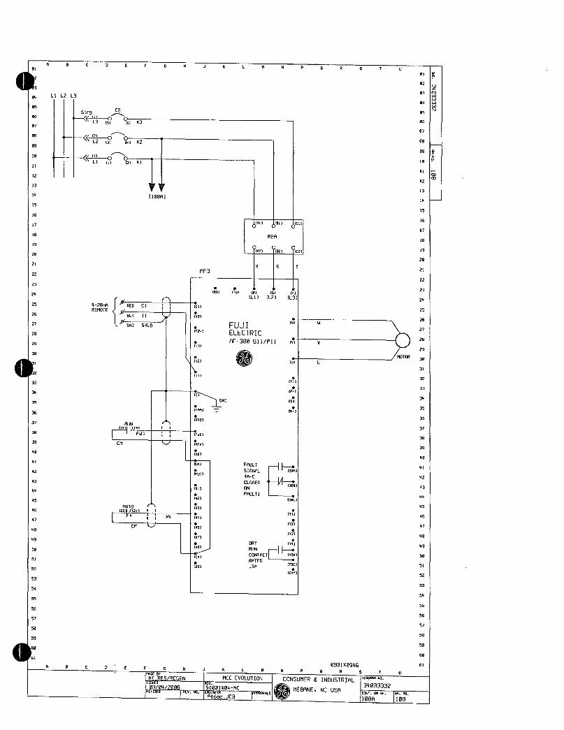
81
2
3
04
05
D6
07
08
09
10
11
12
3
14
15
16
17
8
19
20
21
22
23
24
33
34
35
36
37
38
39
40
41
42
43
44
45
46
47
48
49
50
51
52
53
54
55
56
57
58
59
A C D E F 6 J K L 1 N P R T 6
LIL2L
5766CB
13Iv s63
171
L2c3 CK2
u
LIn a161
25
420vAREMOTE26
27
20
29
30
2
REDC1
BLK11
5496415
RUN1113FWO
CM
VV110881
MT 1221121111
1 11
CM U
I
2i
24
CI
cvzl
IP247
13
111
1
AF3
PM
812
1401
580
15
16
8101 10
17
REA 18
YA2YB21102 19
20
R S T 21
22
23
1L3 24
25
26
27
20
29
30
31
32
33
34
35
36
37
39
39
40
41
42
3081 43
44
45
46
47
48
49
50
51
52
53
54
55
56
57
58
59
60
61
170 R 5
LIL2
FUJIELECTRIC
AF300611Pll
FAULT5I21
AC
CLOSED
ON
FAULT
4 W
411
4
03
4
301
301
111
fY1
1131
CRT Y4
RUN HeCONTACT 5
RATEDTX
3A
Cm
0901X0946R 8 D E F H K M N P 0 R 5 7
HIRFSREGEN 1 MCCEVOLUTION1 CONSUMER INDUSTRIAL14ssueo 3403333203042008 15001404MCQMEBANENCUSA
fMcnxu 03 MecM
RSSOJ06 108A 1100
01
02
03
04
05
06
07
08
13
14

05
06
07
08
09
10
1
12
13
14
15
16
17
10
19
20
21
22
23
24
25
26
27
28
29
30
101133
34
35
36
37
38
39
40
41
42
43
44
45
46
47
48
49
50
51
32
53
54
55
56
57
59
41
A B D F H K M P R T
KIK211113
2FU
171141
51 H2
H11 151J1231
7
51 au 16232L
AF3FAULT3303141308
14 JPR 18
RUN13371I1311II
RUN
610
5flr
2
20
21fr
6
210
RUN20e
FyY3 C14a60
Se I6
317
10
02
C18
2eTB DTB19
20
AUTO 21
81Yu 22
23
24
25
26
27
29
FAN1112 29PJ
30
58 50
D E F 11 K L K
HInESREGEN MCCEVOLUTIONHIRISSUED mu
03042000 151001408MCkcvlsco cvnu
090120946N P 0 R S F U
CONSUMERSINDUSTRIAL0350M0
134083332MEBANENCUSA rteIM916HH4
I108R
01
02
03
04
85
06
07
00
09
10
11m12313
15
31
32
33
34
35
36
37
38
39
40
41
42
43
44
45
46
47
48
49
50
51
52
53
54
55
56
57
59
60
61

04
05
06
07
05
09
10
1
14
15
16
17
19
19
20
21
22
23
24
25
27
28
29
30
4
A BC D E F 9 R J K L N 0 R 5 T U
01
02
O3
LIL2L3 au
05
as
O7
08
09
le
11B12
vy13
1109131 i4
15
16
dm dmCC1 7
RER 18
16 Q2i82 j1C219
20
R S 21
11F22
1 b 23
00 01 101 51 171
L1L2 L3 24
4 C1 rc11LFTR 25
REMOTE Iulcz1BUS11 172
W W 1326
560SHLD FUJI 27
P241 ELECTRIC inn02f 129
REG11P11 iv N T229113
TyJyp1611821 HOTOR
30
1121 fUl U I 11
STABCB
131 CL35 5K3
L231 c92
111
nL1 921K1
111 32
71
3333
P0
3 E 34
ttinl 7
650 001
151
3535
36 36
821N 37
37 1011141 11
38 I liFWDI ii EU0 3B
39 CM J 1861 39
40 0161 40
4t cnl FAULT II141
SIONRL 13081
42 PLC IC42
43CLOSED y01 43
ki ON
44 FRULT 44
62 30
4545
03RUTO46 2214121111 7l 46
ii X4 14147 f 11 47
CM U 051
49 T3 49
X7
49 DRY Rol 49
50RUN
CONTACT
RATED
1159 50
Cn1
51 05131
tics 3A
52 ILm 52
53 53
54 54
55 55
56 56
57 57
58 56
59 59
606B
61 0901X0946 61
A 6 D E F X K L 01 NP OR 5 T
WmUT 01868x1EVOLUTION
01868x1N0
HIRESREGEN I I CONSUMER INDUSTRIAL55050 8X4 34053332037042009 1510014046C IMEBANENCUSA cp055X5p
Laosso 1109X
IRssocJDB 1096
31
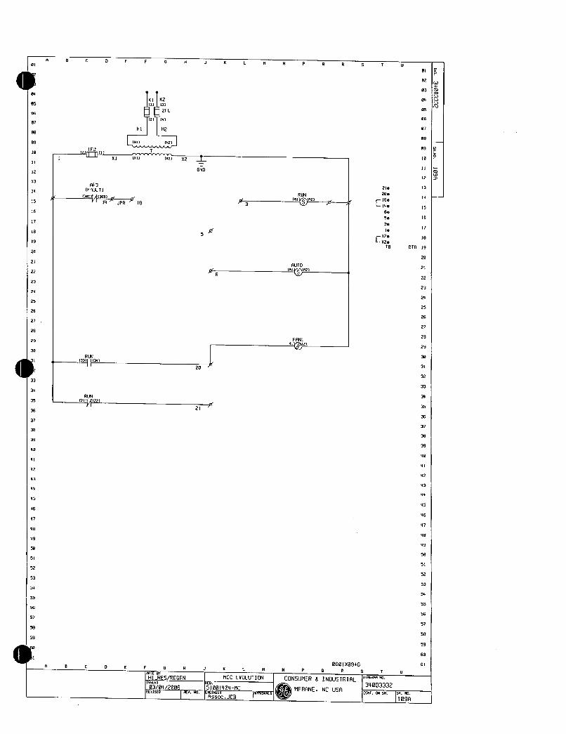
05
06
07
08
09
le
1
12
13
14
15
16
17
18
19
20
21
22
Z3
24
25
26
27
20
29
R 8 D E F G H J K L M N P 0 R 5 U
30
RUN13311I1341I1
33
34
RUN35 1211141221
36
37
38
39
40
41
42
43
44
45
46
47
40
49
50
51
52
53
54
55
56
57
58
59
OF
11111 fN2ja1 f
81 1x1 1x21
RF3IFRULTI130C11f383
1U JPR 18
0
K1K211113
t2F612141
111 H2
X2
GND
5
21
6
3
F 6 N K L M
Hl MCCEVOLUTION55664
REGEN155ucu
r403042008 51001404MCerlseu
13641NIFRo
RUN1011r
RUT101n2
FRN1
11114211
N P
MEBANENCUSA
210
20e
C18014e
6e
5e
3e
Ie
xx202eTB
0901X0946
0 R T
CONSUMER8INDUSTRIAL018 MO
340B3332
CONTCOI54is1101109A
03
04
05
06
07
08
l4
15
16
17
le
DTB19
20
21
22
23
24
25
26
27
28
29
30
31
32
33
34
35
36
37
39
39
40
41
42
43
44
45
46
47
48
49
50
51
52
53
54
55
56
57
58
39
60
61
09
IB
11
127
13

05
06
07
es
09
10
11
12
13
14
15
16
17
18
19
20
21
22
23
24
25
26
27
29
29
30
1111233
34
35
36
37
36
39
40
41
42
43
44
45
46
47
9B
V9
50
51
52
53
54
55
56
57
58
59
5061
LILL3
CB
151 GK3
01 4K2
0 C1 21KI
t
4201A REDCI 1
REMOTEBLK11 V
SHOSNLO623
FREO lAO 33REDPOT
PAP 1
121WHT11
ma 11 11
59MIN BLK
13
12
J
13
D12
1
E
AF3
RUNIlul1133 1I
FWDI ii END
CM REV
Flgl
021
IX6
M FAULT
SIGNALPLC AC
CLOSEDON
FAULTX1
x2
x3
1
35
1x71
xs1cm
191
U1111wallC11RER
in10211m0
D E F 6 N K N
HIRnESREGEN 1 MCCEVOLUTION
155AL0304l79f0R 51 MCaFKTSEo INcluIRuEccJDB IarKUr6La
60 1 R 51
CL13LZ L31
R S T
FILOFUJIELECTRICAF611P11 O
NI
0P
61
GN0 01
1N
301
Ir2
t
DRY PAO
RUN
CONTACT Y591
RATEDr5c
3A
Km
V
1
LFTR
1UCZ1f
1111132
D
16111621
U
CONSUMER8INDUSTRIAL
MEBANENCUSA
T3
T2
T1
L111P1 DCREA
Pt I2
100HPONLY
MOTOR
0901x0946
N P O R 5 7 U
010GRKAN0
340B3332
CONTON54ismK0110A 1110
01
02
03
04
05
06
07
013
09
12
13
4
15
16
17
18
19
20
21
22
23
24
25
26
27
28
29
30
31
32
33
34
35
36
37
30
39
40
41
42
43
44
45
46
87
48
49
50
51
52
53
54
55
56
57
58
59
60
61

3
01
05
e6
07
00
09
IB
1
2
15
15
16
17
18
19
20
21
22
23
24
25
26
27
29
29
30
do33
38
35
36
37
39
39
40
41
42
43
44
45
46
47
49
49
50
51
5Z
53
54
55
56
57
58
59
0
61
A 0
K1 K2
1111171121 11IKl2FUr1
HlRIHIL J0215
121111111x1 1111
AP3FAULTt30trf130Be
114 JPR 18
RUN13311341
RUNP111122111
DOORSWITCHSHOWNINCLOSEDPOSITION
521 1826ND
5
20
21
J K L
le
3
D5 ASW1 ST
10145
MOP14
0DLKAl9LKl45F 1146
F 6 N K L 5
IHIRESREGEN 1 MCCEVOLUTION
EUea4ae0e Isiee14e4MCIKenxu 116 1AssocJOB 1wrm
N 0
AUTOfllTA2
JPRX2
J7
FAN2UYT121
DRCNN FAN1 DRCNNRE1lFlll Ii 21 E11E1TIF11L1
5 7 D
18
RUN 19
UIvlDvL 20
21
22
23
24
25
26
27
29
29
30
31
32
33
34
35
36
37
38
39
40
41
42
43
44
45
46
47
48
49
5e
51
52
53
54
55
56
57
58
59
60
0901X0946 61
N P 0 R S T 0
CONSUMER8INDUSTRIAL01Nl
MEBANENCUSA134083332m4101454
9H1x1
11108
210
200
180C 14e
60
50
3
1e e
X2e 450
C97 x20
TB DTB
01F02J
03B
w0411
N05
06
07
08
09
10
11
12
13
14
15
16
17
0i
S

R C E f N J K M N P R T
B1
z
3
11LL3
05
06
07
00
09
10
II
12
13
14
15
16
17
10
19
29
21
22
23
24
25
26
27
28
29
30
434
35
36
37
38
39
40
41
42
43
44
45
46
47
48
49
50
51
52
53
54
55
56
57
58
59
06061
CB
L3s iK3
L2 K2
LIU C2K1
4 REDC1REMOTE
61411
AH0SHLO
FRED
POT13RFC I13
FRP 1121RHTjj12
1817 1 11ISW814 818W
RUN14113I1FWD
CM
n
AUTO221A21I1X4
CM U
111V2
01226
8F3
13
14
15
16
ell d01CI 17
PER 18
902 11021 902119
20
FUJIELECTRIC
RF300611P11
MOTOR
0
02
03
04
05
06
07
08
09
IB
R S 21
22
O 0 1 1 1 23
80 1101 R1 5 CO
LIL2 L3 24
LFTR 25
1C111211 26
11 0 T3
1011021De 26
Iv V 72131 Y 29
I942130
4121 411 3 1e1 1131
1111 32
2u P1 DCREA
7 PI 141233
34
660 1 100HPONLY1 35
12411 R
36
92
37
DFWD 38
k20 39
e661 40
01 FAULT A 41
SIGNAL D1
PLC AC42
1CLOSED AVia 43
ON
FAULT 44
3DC5
all 46
0 47
4131 48
DRY 81 49
RUN
CONTACT 914 50
RATED950 51
3R
WW1 52
53
54
55
56
57
58
39
60
0901X0946 61
F G N J K 1 M N P R 5 T
IRFSREGFN I MCCEVOLUTION I CONSUMER8INDUSTRIAL i 34013332103042008 191001404MC I MEBANENCUSA
01 ND
Whctn wviglvrt5CONToN5659xo
1x4
118ssacEB I I 1111R 1111

33
34
35
36
37
38
39
40
41
42
93
4
45
46
47
48
49
50
51
5Z
53
54
55
56
57
58
59
A 8 C E F H J K M N P 0 R T U
05
06
07
08
09
10
1
12
13
14
15
16
17
8AF3
19FAULT
KI KZ
I2j2HIR IHIJIIAhMtiI Fu01131
21li rI1T
X X11 X21
307113001
20 14 JPR 18F
21
22
23
24
25
26
27 6
28
29 DS A5N1 STIKON14H1981 010
30 45 1146DOORSWITCHSHOWNINCLOSEDPOSITION
0
R 8
RUN3311134
RUN1211122
5
X2
6ND
20
21
0 E F 6 H J K L M
HIRESRFGENR MCCEVOLUTION
1wGu03042000 51001404MC65I XM4
IMtCHIR95oJOB
AUTO07NNO2
JPRX2
FAN2
1102DRCNN FAN DRCNN
IHLEf1FMl1 114jpj2 AE1141
09@1x0946N
1 0 R CONSUMER
8INDUSTRIALMEBANE
NCUSRI
y21
20
C
14RUN6e A1
St0215e u3e
0
0 02e
450 C
XZe62e TBDTD 5
T U DIAGRAM
MD340B3332
CONT
OH541Isma111R01
02
03
04
05
06
07
08
09
10
11
12
513
14
15
16
17
18
19
20
21
22
23
24
25
26
27
28
29
30
31
32
33
34
35
36
37
38
39
40
41
42
43
44
45
46
47
48
49
50
51
52
53
54
55
56
57
50
59
60
61

uail CourtSuite210
WalnutCreekCA94596
Proposal 6N232354A
ThefollowingSparePartsarerecommendedbasedontheproposedBillOfMaterialquotedhereinThequantitiesrecommendedarebasedonGEexperienceforthetypeofpartandtheperiodoftimetheSparePartsaremeanttosupporttheinstalledequipmentActualBillofMaterialmaychangeafterEngineeringReview
Cat
15D2
15D2
302A
302A
546A
546A
551
555
CR12
CR30
0CR30
CR30
CR32
CR32
CR32
CSC
CSC
CSC
CSC
SELA
SRPE
TECL
v
SparePartQuotation
PORTANGELESWTP ORDER
GEConsumer Industrial
Date 5272009
Time 20528PM
Telephone 9259451140
Fax 9259451144
UnitPricesExtended
Description Startup Operating List NetNet
M NEMASize2110VStarterCoil 1 1 6900 4830 9660M NEMASize1110VStarterCoil 1 1 5500 3850 7700
M CPT480120VAC300VA 1 3 39300 27510 110040M CPT480120VAC150VA 1 1 31000 21700 43400
M NEMASize2ContactKit 1 1 19100 13370 26740M NEMASize1ContactKit 1 1 12500 8750 17500
M NEMASize4ContactKit 1 1 68800 48160 96320M NEMASize4110VStarterCoil 1 1 18400 12880 25760
M HeaterOverloadRelay 2 6 900 630 5040M NEMASize34BaseInterlockBlock 1 1 5000 3500 7000
M NEMASize2BaseInterlockBlock 1 1 5000 3500 7000M NEMASize1BaseInterlockBlock 1 1 5000 3500 7000M NCAdderBlock 1 2 3800 2660 7980
M NOAdderBlock 1 2 3800 2660 7980M NEMASize4OverloadRelay 1 1 22500 15750 31500
M NEMASize2OverloadRelay 1 1 13300 9310 18620M NEMASize1OverloadRelay 1 1 8200 5740 11480
M FuseCPTSecondary 3 5 1600 1120 8960M FuseCPTSecondary 1 1 1600 1120 2240M FuseCPTPrimary 1 1 1100 770 1540M FuseCPTPrimary 2 3 1100 770 3850M SpectraMagBreakMCP65KAIC 480V 1 1 53000 37100 74200
M SpectraCBRatingPlugEFrame 1 1 10600 7420 14840
M LimiterAttachmenttoTEC100KAIC 1 1 84800 59360 118720

Name PORTANGELESWTPORDER
Prop 6N232354A
O
Notes
1AllBookpricesarebasedontheGO11GMdiscountschedule
2ThisSparePartRecommendationmustbeattachedtotheequipmentorderorsubsequentsparepartorderforpricingtobevalid
3ThissparepartquotationissubjecttotheTerms Conditionsineffectfortheequipmentforwhichtheyarerecommended
4ThequantitiesquotedhereinarebasedonthequotedBillofMaterialSubsequentchangestothequotedbillmayrequireanewsparepartrecommendation
5WhenthetotalrecommendedlistofStartupInitialorOperationsparesispurchasedforshipmentwiththeequipmenttheMebanediscountedpricewillbeofferedonindividualitemsuntiltheexpirationofthewarranty
PeacockTowersRo
0
TotalListPrice
TotalNetPrice
Totals
Startup Operating
428000 522100299600 365470
Date 5272009
Time 20528PM
Page 2
ThescopeofdifferentrecommendedSparePartcategoriesaredefinedasfollows
StartupThesecomponentsshouldbeconsideredtosupportrepairandorreplacementneedsthatoccurduringinstallationinordertobeginCommercialoperationinasbuiltconditiontocommencementoftheManufacturersWarrantyobligation
InitialThisperiodisdefinedtobethe1styearofoperationtocoincidewiththestandardWarrantylengthTheserecommendedsparesaretobekeptonhandbytheOwnertoeffectrepairstoMCCequipmentoutsideofManufacturersWarrantyclaimsandtoensurebackupofcriticalcontinuousprocessneeds
OperationThisperiodisdefinedtobethefirst3yearsofoperationoftheequipmentTheserecommendedpartsaredeemedtobeabletocovernormalMCCequipmentslongtermneeds
0hwill individuallylabeleachcomponentorderedandprovideamanifestofthetotalpartsorderedalongwithidentifiermentationsufficientfortheOwnertolocatewherethesepartsareusedwithintheMCCequipmentGEwillunitshipthesespares
hejobsiteorsuchlocationasprovidedwiththeorder

0
0
0
43QuailCourtSuite210
WalnutCreekCA94596
StarterCircuitBreaker
Quantity Function NemaSize12 FVNR 1
7 FVNR 4
6 FVNR 2
VFDVTStarterCircuitBreaker
Quantity HP2 5
2 05
3 450
2 350
SolidStateStarterCircuitBreakerQuantity HP
1 350
SelectorSwitches
Quantity Type6 STANDARD
ControlRelayQuantity Type
9 C2000
SummaryofMCCItems
PORTANGELESWTP ORDER
WiringQuantity Type VARating
32 CPT 300
3 CPT 150
GEConsumer Industrial
Date 5272009
Time 20529PM
Telephone 9259451140
Fax 9259451144
Proposal 6N232354A

ovo uteon Ser E9000
Motor Contro Centers
O
Installation MaintenanceGuideDEH40472Rev04
imaginationatwork

EvolutionSeriesE9000Installation MaintenanceGuide
Contents
WarningsCautions Notes 21 Introduction 3
GeneralDescription VerticalSectionEnclosures 3
GeneralDescription MotorControlCenterBuses 4
GeneralDescription MotorControlCenterUnits 42 ReceivingHandling Storage 5
Receiving 5
Handling 5
Storage 53 Installation 6
InstallationofBottomEntryConduits 6
PreparationofFlooring 7
PositioningandJoiningSections 7
BusSplicing 8
BusSpliceKits g
NECWorkSpace 9
InstallationofTopEntryConduits 9
EquipmentWiring 10
MainIncomingPowerCables 10
IndividualUnitWiring 10
WiringNEMATypeAMotorControlCenters 11
WiringNEMATypeBMotorControlCenters 11
WiringNEMATypeCMotorControlCenters 11
WiringBetweenSections 12
TerminalBlocks 12
InstallationofMotorControlCenterUnits 12
RemovalofDrawoutMotorControlCenterUnits 14
OperatingHandlesDoorInterlocksandPadlockingProvisions 14
OperatingHandle 15PilotBracketandDoor 16NEMA3ROutdoorEnclosureInstallation 16
4 Operation 18
PreparingforinitialOperation 18
InitialOperationoftheMotorControlCenter 18
DoorClosingProcedure 195 Maintenance 20
EquipmentMaintenance 20
ControlPowerFusing 20
SuggestedMaintenanceTook 20
ReplacingorAddingBreakerAccessoriestoPluginEorFFrameCircuitBreaker 21
ReplacingaControlPowerTransformerMountedUnderDisconnect 21
ReplaceaCompactStarter12X 21
SuggestedLifts 21
PublicationsAvailablefromGE 22
RenewalParts 22
OrderingAdditionalorReplacementParts 23OtherInformation 23
6 OverloadHeaters 24
HeatersforTherMagCircuitBreakerControllers 24
HeatersforMagBreakControllers 25
HeatersforFusedControllers 30
HeatersforSize6and7FusedControllers 33
ElectronicOverloadforCircuitBreakerandFusedControllers 33
0
m
DEH40472
WarningsCautions Notes
AsUsedInThisPublication
WARNINGS
Warningnoticesareusedinthispublicationtoemphasizethathazardousvoltagescurrentsorotherconditionsthatcouldcausepersonalinjuryarepresentinthisequipmentormaybeassociatedwithitsuse
Warningnoticesarealsousedforsituationsinwhichinattentionorlackofequipmentknowledgecouldcauseeitherpersonalinjuryordamagetoequipment
CAUTIONS
NOTES
Cautionnoticesareusedforsituationsin
whichequipmentmightbedamagedifcareisnottaken
Notescallattentiontoinformationthatis
especiallysignificanttounderstandingandoperatingtheequipment
ThisdocumentisbasedoninformationavailableatthetimeofitspublicationWhileeffortshavebeenmadetoensureaccuracytheinformationcontainedhereindoesnotcoveratdetailsorvariationsinhardwareandsoftwarenordoesitprovideforeverypossiblecontingencyinconnectionwithinstallationoperationandmaintenanceFeaturesmaybedescribedhereinthatarenotpresentinallhardwareandsoftwaresystemsGEIndustrialSystemsassumesnoobligationofnoticetoholdersofthisdocumentwithrespecttochangessubsequentlymade
GEIndustrialSystemsmakesnorepresentationorwarrantyexpressedimpliedorstatutorywithrespecttoandassumesnoresponsibilityfortheaccuracycompletenesssufficiencyorusefulnessoftheinformationcontainedhereinNowarranteesofmerchantabilityorfitnessforpurposeshallapply
OCopyright2009GeneralElectricCompanyAllRightsReserved
2

EvolutionSeriesE9000Installation MaintenanceGuide
Chapter1Introduction
ThispublicationprovidesguidelinesforinstallationandmaintenanceofEvolutionMotorControlCentersasshowninFigure1TheinformationprovideddoesnotcoveralldetailsorvariationsinthisproductofferingnordoesitaddressallpossiblecontingenciestobemetinconnectionwithinstallationoperationormaintenanceShouldfurtherinformationbedesiredcontactGEFieldServiceAdministrationCallGERESOLve
18884373765
RefertotheGErequisitionnumberfoundonthefrontoftheequipmentwhencallingforassistance
3
Disconnectequipmentfromallelectricalservicesbeforeperforminganyinstallationormaintenancework
ForadditionalinformationincludingsafetyconsiderationsforpersonnelworkingonthisproductseeNEMAStandardPublicationNoICS23InstructionsontheHandlingInstallationOperationandMaintenanceofMotorControlCenters
Figure1EvolutionSeriesthreesectionlineup
GeneralDescriptionVerticalSectionEnclosures
EachEvolutionMCCverticalsectionisassembledwith
twofullsidesheetshavingopeningsnearthetopandbottomforlateralbusingandwiringbetweensectionsMultiplesectionsarejoinedtogetheratthefactoryinthreesectionmaximumshippingsplitsEachshippingsplitisprovidedwithcontinuousfloorsillsandaliftingangleFloorsillsandliftinganglesarefieldremovableEachshippingsplitincludesacontinuousnonremovablemainhorizontalbusMainbussplicebarsareprovidedwithineachshippingsplitforfieldconnectingmainbussesRefertomotorcontrolcenteroutlinedrawingsfurnishedbytheGeneralElectricCompanyforlocationofshippingsplitswithineachmotorcontrolcenterlineup
Verticalsectionsarenormallyprovidedwithatop12highhorizontalwirewayandabottom6highhorizontalwirewayEachverticalsectionisalsoprovidedwithavertical4widewirewayHingeddoorsareprovidedoverhorizontalandverticalwirewaysThesedoorscanberemovedbyextractingthehingepinsinsidethedoors
SectionHeightSectionWidth
SectionDepth
Toopentheexternaldoorsrotatethelatches90counterclockwiseuntilthescrewdriverslotsarevertical
Secure Open
Becauseofthegreatvarietyofmotorcontrollerassembliesandcomponentsprovidedwithinindustrialmotorcontrolcentersandtosatisfyfloorspacelimitationsatinstallationsitesalargevarietyofverticalsectiondimensionsareprovidedasfollows
907866etc
202430etc
132022ordeeperforlargeassemblies
RefertomotorcontrolcenterdrawingsfurnishedbyGEbeforeperforminganyfieldinstallationwork

EvolutionSeriesE9000Installation MaintenanceGuide
GeneralDescriptionMotorControlCenterBuses
ThemainhorizontalpowerbusislocatedatthetopoftheverticalsectionThebusboltedjointsareaccessiblefromthefrontbylooseningthebarriermountingscrewsandslidingtheLexanbusbarrierupandforwardfromthemainbusFigure2showsahorizontalpowerbuswithitsLexanbarrierFigure3showsthebusbarriermountingslotsandscrew
Theverticalbuseither300Aor600850AisconnectedwithtwoboltsperphasetothemainbusThephaserelationshipisABCfromtoptobottomandlefttorightasviewedfromthefront
AcontinuoushorizontalgroundbussizedinaccordancewiththeNationalElectricalCodeisprovidednearthebottomofallmotorcontrolcenters
AoptionalverticalgroundbuscanbeprovidedineachsectionprovidingadditionalgroundingAneutralbusisprovidedwhenspecifiedinthebottomoftheincomingsectionorinthebottomofallenclosuresasspecified
Figure2HorizontalbuswithLexanbarrier
Figure3Horizontalbusbarriermountingslotandscrew
GeneralDescriptionControlCenterUnits
ConsultPublicationDET291fordetailedlistingsofEvolutionMCCunits
Pluginunitsaresuppliedwithstabsratedateither250Aor600AUnitsabove600Amaybefixedboltedinplaceandareeitherbusorcableconnected
Installationandoperationofunitsaredescribedelsewhereinthisguide
4

EvolutionSeriesE9000Installation MaintenanceGuide
Chapter2 ReceivingHandling Storage
Receiving
Beforeleavingthefactorythemotorcontrolcenterisgivenafinalmechanicalandelectricalinspectionandispackedinaccordancewiththebestpracticesforelectricalequipment
OnreceiptofanyapparatusmakeanimmediateinspectionforanydamageorlossofequipmentintransitShoulddamageormissingmaterialbenotedfileaclaimimmediatelywiththecarrierandnotifythenearestofficeoftheGeneralElectricCompanyInformationsuchasadescriptionofthedamagetheshippingcratenumberstherequisitionnumbersandthepanelcatalognumbershouldaccompanytheclaim
Handling
ControlcentersectionsarealwaysshippedinanuprightpositioninsingleorgroupsectionsSectionsmustbemaintainedinanuprightpositionduringallhandling
NeverattempttojackliftormovetheequipmentatpointsotherthantheliftingangleorfloorsillsUsetwoormorechainsorcablestodistributetheweightevenlyPinchbarspiperollersorslingsareusefulimplementsforhandlingequipmentbutbecarefultomaintaindistributedloadingandtoalwaysapplyleverageatthefloorsillsandorliftingangleFigures4and5illustratetypicalhandlingtechniques
5
91
Figure4UsingstandardliftinganglestohoisttheMCC
Figure5PositioningtheMCCwithrollers
Storage
Ifitisnecessarytostoretheequipmentforanylengthoftimebesuretoobservethefollowingprecautions
UncratetheequipmentStoretheequipmentinacleandryhumiditycontrolledareaatmoderatetemperatureCoverwithasuitablecanvasorheavydutyplasticcovertoprevententranceofforeignmaterialIfequipmentmustbestoredincoolorhighhumidityareasinadditiontocompletelycoveringtheequipmentprovideaheatsourcetopreventcondensationofmoistureintheequipmentEnergizespaceheatersiffurnishedintheequipmentorplaceastandard120voltlampratedat75wattsinsidethebottomofeachverticalsection

0
0
EvolutionSeriesE9000Installation MaintenanceGuide
Chapter3 Installation
InstallationofBottomEntryConduitsConduitscanbestubbedinafterthelocationofthe
motorcontrolcenterlineuphasbeenestablishedConduitshouldbestubbedapproximately2inches151mmabovethefinishedfloorlineFigure6andFigure7showtheconduitentrancespaceavailableatthebottomofstandardsectionsExceptionstothisavailablespaceruleareindicatedondrawingsfurnishedbyGEforspecificinstallationsCentertheconduitbeneaththesection
verticalwirewaytofacilitatedirectcableentryNoteBottomrearentranceshouldonlybeusedwithfullrearaccessibility
Figure6ABottomconduitentrancedetailsforstandard13inchdeepsectionlowbusposition
APE falb
NiITtiAa11lsLt1QrpioIilSol
466X191
BeforeanyinstallationworkisbegunconsultalldrawingsfurnishedbytheGeneralElectricCompanyaswellasallapplicablecontractdrawingsfortheparticularinstallationPayparticularattentiontothelocdtionofunitsinthemotorcontrolcenterandtheir
relationstoexistingorplannedconduitsandbusways
yr blulbiNMir
17r 1rm
Figure6BBottomconduitentrancedetailsforstandard13inchdeepsectionbusupperposition
GfIG
4Fr3
fGysySty4r1 616
201rTI1
6uS
Ira r041I
i7t
fJ5
1F1
rl
Figure6CBottomconduitentranceforstandard20inchdeepsectionlowbusposition6inchbottomcover
iEE
FtJd t 4iiIIe51IYII14
IOrfYE
Figure6DBottomconduitentrancedetailsforstandard20inchdeepsectionbusupperposition
1Fi1111G
1115alir646a412 LINP
4
fr
I36r
Figure7ALowbuspositionofgroundandneutralbusminimumavailablespaceforconduitentryin13inchdeepsection6inchcover
19I46
Figure7BStandardpositionofgroundandneutralbuswith12inchcovercompartmentatthebottomofMCC
6

EvolutionSeriesE9000Installation MaintenanceGuide
rYnrbl154
4103n1Ia
rt tvlr34Lk
7
5
tr
Figure7CLowbuspositionofgroundandneutralbusminimumavailablespaceforconduitentryin13inchdeepsection6inchcover
Figure7DUpperpositionofgroundandneutralbusmaximumspaceavailableforconduitentry6inchbottomcover
PreparationofFlooring
FormostinstallationstheMCCfloorsillscanrestonthe
finishedfloorThefoundationfortheequipmentshouldbelevelandevenAlthoughnotnormallyrequiredthepurchasermayelecttoinstalllevelandgroutthesteelmembersorMCCfloorsillsinthefloorasillustratedinFigure8andFigure9Ifthefloorsillsareremovedliftingandmovingtheshippingsectionsmustbedonecarefully
Figure8ControlcenterfloorsillsgroutedtothefloorbeforeinstallationtoprovidealevelfoundationNoteCannotberolledasinFigure5withoutfloorsills
Surfaceundermotorcontrolcenterbasemustbeofnoncombustiblematerialunlessbottomcoversareinstalledineachverticalsection
Theoverallheightoftheequipmentshouldbeconsideredwithrespecttoheadroomtopconduitentryspaceandalignmentwithotherequipment
IfanchorboltsaretobeimbeddedinthefoundationtheymustbelocatedaccordingtothedrawingsfurnishedbyGEforthespecificequipmentFor13inch3302mmdeepverticalsectionsanchorboltsorsomeformofexternalbracingisrequiredAnchorboltsshouldbe12inchdiameterofGrade2steelminimum
Ifthereareverticalsectionsofvaryingdepthssuchas1320or22inchesinasinglelineupthefrontsofthesectionsmustbelinedupforproperalignmentofthemainbusbarsFigure9illustratesthispoint
Figure9Installingsteelfloormembers
Notethefrontalignmentofthe13inchdeepsection
PositioningandJoiningSections
IfgroupsofsectionsaretobejoinedtogetherinafinallineupremovetheendcoverplatesandtheplugbuttonsfromthesidesofthesectionstobejoinedFigure10showsthesideviewswiththeendcoverplatesremovedfor20inchdeepsectionswith2inch508mmand4inch1016mmbusbars
CarefullycheckandremovedirtdustorbitsofpackingmaterialfromtheinteriorofallsectionsUseabrushsoftclothorvacuumcleaner

O
4
EvolutionSeriesE9000Installation MaintenanceGuide
AllcablesenteringthebottomsofsectionsshouldbepulledthroughconduitstoapointwheretheywillbeaccessibleaftertheequipmentisinplaceSectionscanbemovedtotheirfinalpositionandproperlyleveled
GnrILnvrIUtllalUivvwPlar V1r1 r44syI
Trtzs
PhreBus
PIuaButton
DonotusecompressedairtocleantheequipmentifitcontainsmoistureRemoveallhardwarepackagesdrawingsandotheritemsshippedwiththeequipmentCheckallnutsboltsandelectricaljointsfortightness
1Wilie GvvlrelWsyt SNLrtLJ
Figure10Sideviewofa20inchdeepsectionshowingthecoverplatesplugbottomsandjoiningpoints
BusSplicing
MainneutralandgroundbussplicebarswithallassociatedhardwarearefurnishedasnecessarytojoinsectionstogetherTheyarelocatedinthefirstsectiontotherightofthejointSeeFigures1314and15forapproximatedimensionsformainneutralandgroundbus
RemovethetopLexanbarrierasshowninFigure11andFigure12toaccessthemainbusRefertoinstructiondrawingsinsplicekitSeeTable2
Figure11HorizontalbuswithLexanbarrier
crew
rw
Figure12Horizontalbusbarriermountingslotandscrew
Table1Torquevaluesforvariousboltsizesandjointtypes
BoltSize
51618
3816
1213
5811
3410
CopperJointslbft Nm
59 712
1216 1622
3039 4153
6580 88108
125150 169203
AluminumJoints
lbft Nm
659 912
1015 1420
2535 3447
3545 4761
5075 68102
NoteWhenassemblingorconnectingtoaluminumbusapplyasuitablejointcompoundbetweenthecontactingsurfaces
8

EvolutionSeriesE9000Installation MaintenanceGuide
BusSpliceKitsTable2BusSpliceKitsSplicingFromToE9000E9000
11113sMainBusSpliceAssemblyKit
StandardSplicing
16001110C1735G1SM1800 1110C1735G4SM112001110C1735G7SM
2000
1600110C1735G12SM
125001110C1735G13SM1N3RandSpacerShells1600 1110C1735G14SM800 1110C1735G15SM12001110C1735G16SM
9
BarsSize SCRatingSplicein 600VMax
Phasethick xsymInstruction
CopperwidthImps Drawing
11111
1
14x2165K38x2165K12x21100K
2 12x2100K
12x21100K
114x2165K138x2165K112x21100K
1600110C1735G17SM 2 12x2100K2000
125001110C1735G13SM12 112x21100KIncludedinkits
NoteStandardplatingistinRefertofactoryforalternateplaten
111111
9
1110C1258TG111110C1256TG111110C1253TG11110C1263TG1
1110C1785TG11
1110C1258TG111110C1256TG111110C1253TG11110C1263TG1
1110C1263TG11
NECWorkSpace
NECWorkSpaceisdefinedinTable11026aWorkingSpacesIncludedintheseclearancerequirementsisthestepbackdistancefromthefaceoftheequipmentTable11026aprovidesrequirementsforclearancesawayfromtheequipmentbasedonthecircuitvoltagetogroundandwhethertherearegroundedorungroundedobjectsinthestepbackspaceorifthereareexposedlivepartsacrossfromeachotherThevoltagestogroundconsistoftwogroups0to150and151to600inclusiveRememberwhereanungroundedsystemisutilizedthevoltagetogroundwillbethegreatestvoltagebetweenthegivenconductorandanyotherconductorofthecircuitForexamplethevoltagetogroundfora480voltungroundeddeltasystemis480volts
SeeFigure14forgeneralworkingclearancerequirementsDistancesaremeasuredfromthelivepartsifthelivepartsareexposedorfromtheenclosurefrontiflivepartsareenclosedIfanyassembliessuchasswitchboardsormotorcontrolcentersareaccessiblefromthe
backandexposelivepartstheworkingclearancedimensionswouldberequiredattherearoftheequipment
asillustratedNotethatforCondition3wherethereisanenclosureonoppositesidesoftheworkingspacetheclearanceforonlyoneworkingspaceisrequired
L9152
Figure14GeneralWorkingClearanceRequirements
InstallationofTopEntryConduits
AfterthemotorcontrolcenterisinplaceandleveledandthesectionsarejoinedtogetherconduitscanbebroughtintothetopsofsectionsasrequiredFigure15andFigure16showtheconduitentryspaceavailableatthetopsofstandardsectionsRefertodrawingsfurnishedbyGEfordeviationsonspecificinstallationsNoteToprearentranceshouldonlybeusedwithfullrearaccessibility
AlwaysremovetopcoverplateswhendrillingholesThispreventssmallmetalchipsfromfallingintothepanelandcauseseriousdamage
FROM
Figure15Topconduitentryspacefor13inchsections

EvolutionSeriesE9000Installation MaintenanceGuide
Width
20
24
30
Figure16Topconduitentryspacefor20inchand22inchsections
Table3DimensionsforFigures15and16
DimensionA
20
24
30
DimensionB
1756
2156
2756
EquipmentWiring
O g Whenpullingbendingandterminatingfieldwiringavoidscrapingcuttingorotherwisedamagingcableinsulationorstrands
MainIncomingPowerCables
RefertothemotorcontrolcenterdrawingsprovidedbyGEforthelocationofthemaindisconnectorincominglineterminalsandthedirectiontoporbottomofcableentryCablebendingroomprovidedwithintheverticalsectionwillmeetorexceedNationalElectricalCode
requirements
IncominglinesectionsareprovidedwithcablesupportsIncomingcablesmustbefirmlysecuredtowithstandthesignificantforcesthatmaybegeneratedduringashortcircuit
CablessecuredateachsupportasillustratedinFigure17andFigure18600Aexamplewilladequatelybracecablesforfaultsof100KRMSsymmetricalamperesbasedonhorizontalbusbracingHowevercablesshouldalwaysbesecuredatthefirstsupportinsidetheenclosureandatthesupportnearesttotheincomingterminalsInsulatedbushingsarealsorecommendedatconduitterminations
1112
18124
Figure17Typicaltopentryofmaincablestotheincominglinelugcompartment600Ashown
Figure18Typicalbottomentryormaincablestotheincominglinelugcompartment600Ashown
AligntheconduitlinearlydirectlyoverorascloseaspossibletothesupportsRunthecableinaconvenientorientationmakingsurethecableislocatedagainstthesupportsbeforeitconnectstothecableterminalsLashthecableusingthefollowingprocedure
Wrapthelinecablestogetherandifprovidedtiecablestogetherwithnominal38inch95mmnylonropeorropehavingaminimumtensilestrengthof2000pounds8896Nat6inches152mmand12inches305mm
fromthelineterminalsUsefivewrapsandcompleteeveryadditional6incheswithfivewrapsorevery1inch25mmwithonewrapUsesuppliedcablesupportsasdesiredRefertoUL891
IndividualUnitWiring
OpentheverticalwirewaydoorsandthetopandorbottomhorizontalwirewayhingedcoversAlldoorscanberemovedifdesiredbyextractinghingepinsorremovingthehinge
10

EvolutionSeriesE90O0Installation MaintenanceGuide
Wheninstallingcablesbesuretonotdamagethecableinsulationonanysharpedgessuchassteelworkorscrews
Whereaccesstotherearofthesectionisavailable
cablescanbebroughtintothespacebehindtheverticalbusandbroughtforwardintothefrontwiretroughareathroughanyofthemodularopeningsintherighthandsteelsupportplate
WiringNEMATypeAMotorControlCenters
UsethefollowingproceduretowireNEMATypeAMCCs
1Removeblackplasticbarrierclosesttounitconnectionpointsandremoveknockoutsasrequired
2PullloadcablesneartheunittobewiredMeasure
allowingforcablebendscutandstripthecablesandfeedthemcarefullythroughbarrierknockoutintotheunitTerminatethecablesonthefeederor
starterlugsprovidedintheunitIfaluminumwireisusedcoatthewirestrandswithanoxideinhibitinggreasespecificallydesignatedforusewithaluminumcableInstallplasticsidebarrier
3Pullthecontrolwiringthenmeasurecutstripandterminateitonindividualdeviceterminalsintheunit
4Whenspecifiedanoptionalgroundlugisprovidedineachdrawoutcombinationstarterunitfortermi
natingamotorframegroundingwireForlargerstartersthelugismountedonthehorizontalgroundbus
5UsecordorplastictiestosecureallwiringRoutethewiringtoavoidinterferencewithmovingpartsandtokeepitawayfromheatproducingcomponentssuchasresistorsandfuses
6Verifythattheconnectionsonalldevicesandterminalblocksaretightenedtotheirpropertorquevaluesaslistedonthelabelontheverticalwirewaydoor
WiringNEMAType6MotorControlCenters
UsethefollowingproceduretowireNEMATypeBMCCs1Removeblackplasticbarrierclosesttounitconnection
pointsandremoveknockoutsasrequired2PullloadcablesneartheunittobewiredMeasure
allowingforcablebendscutandstripthecablesandfeedthemcarefullythroughbarrierknockoutintotheunitTerminatefeedercablesdirectlyonthe
11
lugsonthedisconnectConnectthemotorleadsatthestarterterminalsifeitheroftheseconditionsismet
aThemotorcontrolcenterisfurnishedas
NEMABDwiringwhereDDeviceorbThestarterisNEMAsize6orsmaller
ConnectthemotorleadstothestarterattheT1T2andT3terminalsiftheseconditionsaremet
aTheequipmentisfurnishedasNEMABTwiringand
bThestarterisNEMAsize2orsmaller
InstallplasticsidebarrierafterpowerandcontrolwiringinStep4iscompleteAluminumwireisnotrecommendedforthisproduct
3PullthecontrolwiringthenmeasurecutstripandterminateitattheterminalblocksprovidedwithintheunitOptionallycontrolterminalblocksmaybepulledapartandtheplasticknockoutsremovedtoallowwiringoutsidethebucketTheterminalblockscanthenbeplacedbackthroughtheplasticknockoutopeningsandreinstalledThismethodallowswiringtoterminalblocksoutsidetheconfinesofthestarterunit
4WhenspecifiedanoptionalgroundlugisprovidedineachdrawoutcombinationstarterunitforterminatingamotorframegroundingwireForlargerstartersthelugismountedonthehorizontalgroundbus
5UsecordorplastictiestosecureallwiringRoutethewiringtoavoidinterferencewithmovingpartsandtokeepitawayfromheatproducingcomponentssuchasresistorsandfuses
6Verifythattheconnectionsonalldevicesandterminalblocksaretightenedtotheirpropertorquevaluesaslistedonthelabelontheverticalwirewaydoor
WiringNEMATypeCMotorControlCenters
MasterterminalboardsinNEMATypeCmotorcontrolcentersareprovidedinthelargertoporbottomhorizontalwirewayofeachverticalsectionRefertothedrawingsprovidedbyGEforthelocationsofmasterterminalboardsFigure19andFigure20showtypicalTypeCterminalboardarrangements
TheseterminalboardsareconnectedatthefactorytocontrolterminalblocksofpluginunitsineachverticalsectionWiringdiagramsprovidedbyGEshowtheseterminalpointsTheseterminalblocksarealsofactorywiredtotheT1T2andT3motorleadterminalsforeachNEMAsize12starterunitineachverticalsection

EvolutionSeriesE9000Installation MaintenanceGuide
Fieldconnectionstothesecontrolandloadterminals
shouldbemadeatthemasterterminalboards
Makefieldconnectionstoallfeedersandmotorloads
forstarterslargerthanNEMAsize2asdescribedforNEMATypeBmotorcontrolcenters
OptionalgroundinglugcanbeprovidedineachPluginuniteifverticalgroundbusisspecified
It
Figure19TypicalTypeCterminalboardatthetopofasection
t
I
Figure20TypicalTypeCterminalboardsinmultiplesections
WiringBetweenSections
Figure21showsthedimensionsofsidecutoutsineachverticalsectionforwiringbetweensectionsCrosswiringcanbeaccomplishedatboththetopandbottomofsections20or22deepverticalsectionsaccessiblefromtherearcanbecrosswiredintheopenrearareawiththewiringbroughtforwardthroughovalopeningsintherearoftheverticalwireway
Figure22Mountingtheterminalblock
Figure21Sidecutoutdimensionson132022and25
Ifrearaccessisusedarearmainbusbarrierisarequiredoption
TerminalBlocks
Thenewstyleterminalblocksaremountedonametalraillocatedatthebottomoftheunitasshownin
Figure22Theterminalblockeasilyslidesintopositionfromeithersideofthemountingrail
InstallationofMotorControlCenterUnits
AnyunitorderedseparatelyisshippedcompletewiththedoorandassociatedhardwareIfthespaceavailableintheverticalsectionisgreaterthanthenewunit
12

EvolutionSeriesE9000Installation MaintenanceGuide
heightorderablankfillerdoorwithhingehardwareandasnapshelfSeetherenewalpartsbulletinfororderingblankdoorsandgasketmaterialsThegasketmateriallinestheinnerperimeterofthesectionFigure23showsthegasketmaterialmountedtotheoutsideofthedoor
Gasket
Figure23NEMA12GasketmaterialinstalledinaMCCsection
Usethefollowingproceduretoinstallamotorcontrolcenterunit
1AttachthedoorhingestotheleftsideofthesectionlineupthedoorwiththehingestheninsertthehingepinstosecurethedoorInstallaholddownbracketwiththelowerdoorhingebutdonottightenthemountingscrewatthistime
2 Placethetwotabsontheleftsideoftheshelfinto
theappropriateopeningsinthesectionstructure3Lowertherightsideoftheshelfandsnapthetwo
detentsintherightsideflangeintothetwoholesinthesideoftheverticalwiringtroughbarrierasshowninFigure24Swiveltheshelfholddownbracketandgroundingspringintoplaceandtightenthelowercasehinge
4 Examinethenewunitcarefullyfrontandreartoensurethatallscrewterminalsaretightallforeignmaterialandpackingareremovedandtheinsulatingbarriersaresecure
5TheunitdisconnectmustbeintheOFFpositionbeforetheunitcanbeinsertedintothevertical
section
6 Ifnecessaryrotatethelatchesatthetopandbottomoftheunitsothattheyarehorizontal
7Removethesnapincoverovertheverticalbusstabinopeningsattheappropriateinstallationlocationfortheunittobeinstalled
8 Lifttheunitandplaceitsbaseonthefronthorizontalsurfaceofthesnapinshelf
13
9Slidetheunitintotheverticalsectionthenpushatthetopandbottomuntilthestabsarefullyengagedwiththeverticalbus
10RotatethelatchesatthetopandbottomoftheunitclockwisetoengagethelatcheswiththehorizontalshelvesaboveandbelowtheunitSeeFigures25and26
11Verifytheoperationofthedisconnecthandleandsafetyinterlocksasdescribedlaterinthismanual
Figure24Frontviewofthesnapinshelfasinstalled
Figure25UnitdisconnectintheOFFpositionTwoquarterturndoorlatchesarelocatedatthetop

0
0
EvolutionSeriesE9000Installation MaintenanceGuide
Figure26Quarterturnlatchlocatedatthebottomoftheunit
RemovalofDrawOutMotorControlCenterUnits
Someunitsmaystillhavecontrolpowerappliedfromanexternalsourceaftertheunitdisconnect
hasbeenswitchedtotheOFFpositionBeextremelycarefulwhenremovingunitsfromanymotorcontrolcenterFailuretoobservethisprecautioncanresultinseriousinjuryordeath
Theprocedureforremovingamotorcontrolcenterunitisgenerallythereverseoftheprocedureforinstallingaunit1EnsurethattheunitdisconnectisintheOFFposition
asshowninFigure252Turnthedoorlatchesaquarterturnopentheunit
doorandtheverticalwiringtroughdoor3Disconnectallfieldconnectedwiringbyseparating
thepullapartterminalblocksintheunitPasstheterminalblocksandwiresintotheverticalwiringtroughNotethattheplasticknockoutsintheverticalwirewaybarriercanberemovedandleftwithintheverticalwirewaywiththefieldwiringratherthanthreadingthewiringandterminalsbackthroughtheknockout
4DisconnectanyotherfieldinstalledwiresthatareterminatedintheunitRemovethesewiresfromthe
unittagthemifdesiredandleavethemintheverticalwirewayadjacenttotheunit
BecarefulwithanyfieldwiringremovedfromaunitthatmaybecomeenergizedSuchwiringmustbeadequatelyinsulatedtoavoidinadvertentcontactFailuretoobservethisprecautioncanresultinseriousinjuryordeath
5TurnthelatchesatthetopandbottomoftheunitaquarterturncounterclockwisetoreleasetheunitTheselatchesareshowninFigure25andFigure26
6Pullunitouttoremoveitbeingextremelycarefultosupportitsweightasitisfullywithdrawn
7Thedooroverthewithdrawnunitcanbelatchedclosed
8Ifdesiredablankdoorcanbeorderedtocoverthe
unusedopeningForlargeunitspacestwoblankdoorsandahorizontalunitshelfmayberequired
OperatingHandlesDoorInterlocksandPadlockingProvisionsAllEvolutionmotorcontrolcenterunitsarefurnished
withdisconnectoperatinghandlesthatareintegraltotheunitstructureThepositionofthedisconnectONOFFforswitchesorONOFFTRIPforcircuitbreakers
isindicatedbythepositionoftheoperatinghandleTheoperatinghandleisinterlockedwithacatchontheinsideoftheunitdoortopreventinadvertentopeningofthedoorwhenthedisconnectisintheONpositionasshowninFigure27SwitchingthehandletoOFFallowsaccesstotheinterioroftheunit
EachdisconnectoperatinghandleisequippedwithaninterlockthatpreventsopeningthedoorwhenthedisconnectisON
Aconcealedscrewcanbeturnedcounterclockwise
witha532Allenwrenchtodefeatthedoorinterlock
andaccessthebreakerdisconnectwhenONasshown
inFigure28Onlyqualifiedpersonnelshouldbeallowedtodefeattheinterlock
Figure27DoorinterlockfeaturethatpreventsaccesstothedisconnectwhenthepowerisON
14

EvolutionSeriesE9000Installation MaintenanceGuide
Figure28Concealedscrewusedtodefeatthedoorinterlock
Figure29ThedoorcannotbeopenedwhenthedisconnectisON
ThedisconnectisalsoequippedwithapadlockingprovisionsothattheoperatinghandlecanbelockedintheOFFpositionwithasmanyasthreepadlocksasshowninFigure30ThehandlecanalsobedrilledtoaccommodateonepadlocktosecureitintheONpositionIneithercasetheunitcannotbewithdrawnbecauseof
interferencebetweenthepadlocksanddoor
FinalcommissioningVerifythatalldoorsareproperlylatchedandinterlockedpriortoenergizing
t
Figure30Operatinghandlealsoshowingthesafetylockouthasp15
Table3WeightandheightsofCBbasicwithCPT
Pluginunits Estimatedweight Minimumheightnodoor I Ibs inches
NEMASize1FVNR135 112NEMASize2FVNR137 112
1NEMASize3FVNR153 118NEMASize4FVNR162 I24
1NEMASize5FVNR1125 I36
CAUTIONshouldbeusedwhenremovingorinstallingunitsconsidertheweightintableaboveTwopersonsmayberequiredortheassistanceofaliftingdevicesSeepage21forsuggestedlifts
OperatingHandle
TheoperatinghandlemustbemovedoutofthewaytoaccesstothebreakerdisconnectMakesurethatthe
disconnectoperatinghandleisintheOFFpositionasshowninFigure30OpenthedoorthenremovethemountingscrewsecuringthebaseofthehandletothesideoftheunitasshowninFigure31ThehandlecanthenberotatedupandoutofthewayasshowninFigure32allowingaccesstothebreaker
Figure31Removingtheoperatinghandlemountingscrew

EvolutionSeriesE9000Installation MaintenanceGuide
Figure32Rotatingtheoperatinghandletoaccessthebreaker
PilotBracketandDoor
ThepilotdevicedoorcanberemovedbyliftingstraightoffperFigure33Alsothemetalbracketcanberemovedbylooseningmountingscrewsandremovingbracket
Figure33Graspthecenterofthedoor
Figure34PilotDeviceBracketlockingbracketindoor
ThepilotdevicebracketinislockedinplaceusingthedoormountedlockingbracketshowninFigure34
NEMA3ROutdoorEnclosureInstallation
FASTENWITH1420THDFORMINGSCREWSTYPONTOPANDREARCAP
LEFTNODULE
JOININGI2HARDWAREFASTEN4PLCS
NEMA3RInstallationInstructions
FIGURE1
LEFT
REARCOYER
RIGHTNODULE
1RemoveleftrearcoveronrightshippingmoduleFigure1SavethescrewsforlaterreassemblyofthecoverNotethattheleftmodulerightrearcoverhasaflangethatwillbeunderneaththeremovedcoveredwithitisreplacedThisprovidesanoverlappingconnectionintherearofthetwosplicedmodulesDetailC
2Slideadjoiningshippingmodulesasclosetogetheraspossiblewhilecarefullyaligningthemodulesfronttoback
3Joinshippingmodulestogetherusing4sets12hardwarefrontonlyHardwarekitsshippingwithmodules
4Assemblebussplicesperspliceinstructionsincludedinsplicekit
5Installwirewaytransitionchannelbarrierbyslidingitthoughthe5x5wirewaycutoutandattachingitusing11428x38threadrollingFigure3
6Reattachrightrearcoverbyreattaching1420x58sealingscrewDetailCI
7Attachedcentercapusing81420x58threadrollingscrewsFigure1
Notes
13inchfloormemberscanbeinstalledsimilarlytostandardMCCflormembers
2Moduledoorscanberemovedbyremoving1420x38threadrollingscrewsfromdoorhingebracketDetailDI
16

EvolutionSeriesE9000Installation MaintenanceGuide
17
FRONTLEFTPOST
1420X58THREADROLLIN6
WASHERSCREW
RIGHTREARCOVER
r
PIANO HINGE HINGEBRACKETDETAILD SEEDETAILC
DETAILC
1
LEFTREARCOVER
ICE
REFERTOSPECIFICJOBDRAWINGSFORQUANTITYOFSHIPPINGMODULESANDTOTALLENGTH
1420X98THREADROLLINGSCREW
10543WITHROFFAN
10534W0RtOFFAN
FRAMEEXT11CCOEPTHIISECTIONI5B
A
1111 iii 111 11 71111 1111
IST MODULE 2NDMODULE 3RDMODULE
TOTALLENGTHOFNEMA
FIE2ASSEMBLYMODULELINEUP
3520FOR20DPORMCCDEPTH
41 1520rSPACE
BETSHIPPINGSPLITS
CHANNELBARRIERMOUNTINGSCREW1428X38
THREADROLLING
ROSE3
FIGURE4
WIRECHANNELBARRIER
9INCHDEEPFLOORPLATES
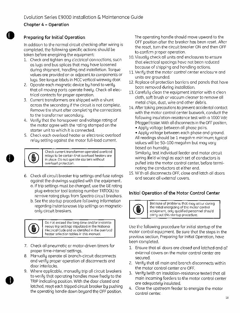
EvolutionSeriesE9000Installation MaintenanceGuide
Chapter4 Operation
PreparingforInitialOperation
Inadditiontothenormalcircuitcheckingafterwiringiscompletedthefollowingspecificactionsshouldbetakenbeforeenergizingtheequipment1Checkandtightenanyelectricalconnectionssuch
aslugsandbussplicesthatmayhaveloosenedduringshipmenthandlingandinstallationTorquevaluesareprovidedonoradjacenttocomponentsorlugsSeetorquelabelsinMCCverticalwirewaydoor
2OperateeachmagneticdevicebyhandtoverifythatallmovingpartsoperatefreelyCheckallelectricalcontactsforproperoperation
3CurrenttransformersareshippedwithashuntacrossthesecondaryifthecircuitisnotcompleteRemovetheshuntaftercompletingtheconnectionstothetransformersecondary
4Verifythatthehorsepowerandvoltageratingofthemotoragreewiththeratingstampedonthestarterunittowhichitisconnected
5Checkeachoverloadheaterorelectronicoverload
relaysettingagainstthemotorfullloadcurrent
6CheckallcircuitbreakertripsettingsandfuseratingsagainstthedrawingssuppliedwiththeequipmentaIftripsettingsmustbechangedusetheGErating
plugextractortoolcatalognumberTRTOOLtoremoveratingplugsfromSpectracircuitbreakers
bSeethestartupprocedurefollowinginformationregardinginstantaneoustripsettingsonmagneticonlycircuitbreakers
CheckcurrenttransformeroperatedoverloadrelaystobecertainthatoverloadheatersareinplaceDonotoperatestarterswithoutoverloadprotection
DonotexceedthelongtimeandorinstantaneoustripsettingsstipulatedintheNationalElectricalCodeandasidentifiedintheoverloadheaterselectiontablesinthismanual
7Checkallpneumaticormotordriventimersforpropertimeintervalsettings
8Manuallyoperateallbranchcircuitdisconnectsandverifyproperoperationofdisconnectsanddoorinterlocks
9WhereapplicablemanuallytripallcircuitbreakerstoverifythatoperatinghandlesmovefreelytotheTRIPindicatingpositionWiththedoorclosedandlatchedreseteachtrippedcircuitbreakerbypushingtheoperatinghandledownbeyondtheOFFposition
TheoperatinghandleshouldmoveupwardtotheOFFpositionafterthebreakerhasbeenresetAftertheresetturnthecircuitbreakerONandthenOFF
toconfirmproperoperation10Visuallycheckallunitsandenclosurestoensure
thatelectricalspacingshavenotbeenreducedbecauseofshippingandhandlingactions
11Verifythatthemotorcontrolcenterenclosureandunitsaregrounded
12Replaceallprotectionbarriersandpanelsthathavebeenremovedduringinstallation
13Carefullycleantheequipmentinteriorwithacleanclothsoftbrushorvacuumcleanertoremoveall
metalchipsdustwireandotherdebris14Aftertakingprecautionstopreventaccidentalcontact
withthemotorcontrolcenterbusworkconductthe
followinginsulationresistancetestwitha1000VdcMeggertesterWithalldisconnectsintheOFFposition
ApplyvoltagebetweenallphasepairsApplyvoltagebetweeneachphaseandground
Allreadingsshouldbe1megohmminimumtypicalvalueswillbe50100megohmbutmayvarybasedonhumiditySimilarlytestindividualfeederandmotorcircuitwiringfieldwiringaseachsetofconductorsispulledintothemotorcontrolcenterbeforeterminatingtheconductorsateitherend
15WithalldisconnectsOFFcloseandlatchalldoorsandsecureallexternalcovers
InitialOperationoftheMotorControlCenter
Becauseofproblemsthatmayoccurduringtheinitialenergizingofthemotorcontrolequipmentonlyqualifiedpersonnelshouldcarryoutthisstartupprocedure
UsethefollowingprocedureforinitialstartupofthemotorcontrolequipmentBesurethatthestepsintheprevioussectionPreparingforInitialOperationhavebeencompleted1Ensurethatalldoorsareclosedandlatchedandall
externalcoversonthemotorcontrolcenteraresecured
2VerifythatallmainandbranchdisconnectswithinthemotorcontrolcenterareOFF
3Verifywithaninsulationresistancetesterthatallmainincomingfeederstothemotorcontrolcenterareadequatelyinsulated
4Closetheupstreamfeedertoenergizethemotorcontrolcenter
18
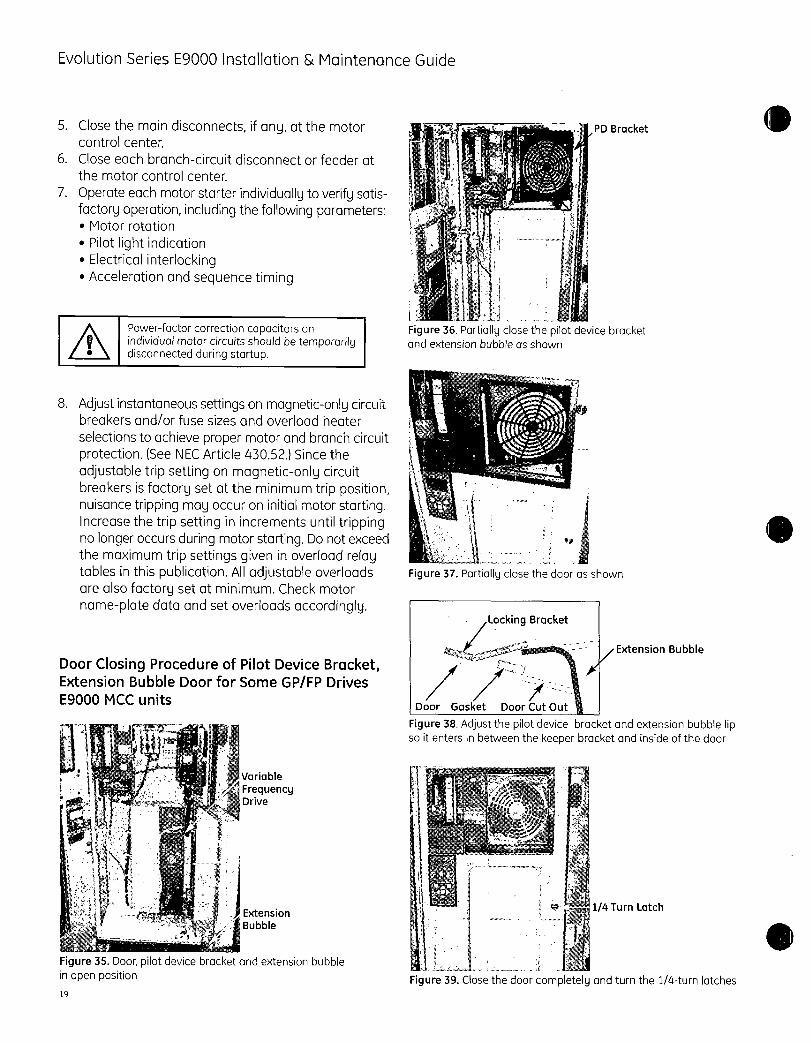
EvolutionSeriesE9000Installation MaintenanceGuide
5Closethemaindisconnectsifanyatthemotorcontrolcenter
6Closeeachbranchcircuitdisconnectorfeederatthemotorcontrolcenter
7Operateeachmotorstarterindividuallytoverifysatisfactoryoperationincludingthefollowingparameters
Motorrotation
PilotlightindicationElectricalinterlockingAccelerationandsequencetiming
19
Powerfactorcorrectioncapacitorsonindividualmotorcircuitsshouldbetemporarilydisconnectedduringstartup
8Adjustinstantaneoussettingsonmagneticonlycircuitbreakersandorfusesizesandoverloadheater
selectionstoachievepropermotorandbranchcircuitprotectionSeeNECArticle43052SincetheadjustabletripsettingonmagneticonlycircuitbreakersisfactorysetattheminimumtrippositionnuisancetrippingmayoccuroninitialmotorstartingIncreasethetripsettinginincrementsuntiltrippingnolongeroccursduringmotorstartingDonotexceedthemaximumtripsettingsgiveninoverloadrelaytablesinthispublicationAlladjustableoverloadsarealsofactorysetatminimumCheckmotornameplatedataandsetoverloadsaccordingly
DoorClosingProcedureofPilotDeviceBracketExtensionBubbleDoorforSomeGPFPDrivesE9000MCCunits
Variable
FrequencyDrive
ExtensionBubble
Figure35Doorpilotdevicebracketandextensionbubbleinopenposition
PDBracket
Figure36Partiallyclosethepilotdevicebracketandextensionbubbleasshown
Figure37Partiallyclosethedoorasshown
LockingBracket
DoorGasket DoorCutOut
Figure38Adjustthepilotdevicebracketandextensionbubblelipsoitentersinbetweenthekeeperbracketandinsideofthedoor
ExtensionBubble
14TurnLatch
Figure39Closethedoorcompletelyandturnthe14turnlatches

O
EvolutionSeriesE9000Installation MaintenanceGuide
Chapter5 Maintenance
EquipmentMaintenance
DeenergizeallequipmentbeforeperforminganymaintenanceoperationTheremaybevoltagepresentwithintheequipmentfromremotesourceseventhoughallmainandbranchcircuitdisconnectshavebeenopenedattheequipmentFailuretoobservethisprecautioncanresultinseriousinjuryordeath
ThecustomershouldprepareamaintenanceprogramconsistingofascheduleandchecklistmatrixlistingitemstobeperiodicallyexaminedontheinstalledequipmentThefrequencyandextentofthemaintenanceactivitieswillvarydependingonsuchfactorsasequipmentusageandenvironmentalconditionsIn anymaintenanceprogramthefollowingactionsshouldbeincluded1 Removea dustanddirtwithasoft
clothbrush orvacuumcleaner
2 Wipecleanallmainbusinsulatorsandverticalbusbarriers
3 InspectmainandverticalbusjointsandmainbussupportsandtightenifnecessaryRefertoTable1fortorquespecifications
4 Inspectallwiringfromunitsfordeteriorationofinsulation
5 RemovedrawoutunitsandcheckstabsandallunitwiringsRemoveaccumulateddustfromhorizontalshelvesandthe areasaroundstabs
6 CheckallstartercontactsTheyneedonlybereplacedwhennearlyallthesilvertipisgoneandthecontacttipsupportisexposedDonotfilethecontactsFilingorotherwisedressingthecontactsonlyresultinlosttipmaterialandreducesstarterlifeSeeGEipublicationGET6915Aforquestionablecontactappearance
7 Checkallunitwiringfordeteriorationofinsulationandtightenallconnections
8VisuallycheckmetersandinstrumentsCheckcriticalinstrumentcalibrations
9 Checkallunitdoorinterlocksfor properoperation10Checkallindicatinglightsandreplace asrequired11Iffusereplacementis necessaryalwaysinstallthe
sametypeandratingasthefusesfurnishedwiththemotorcontrolcenterFusedesignsmaybemechanicallyequivalentbutnotelectricallyequivalentTheymaynothavethesameshortcircuitwithstandandcurrentlimitingability
ControlPowerFusing
Controlfusesarefrontaccessibleexceptinthe6inchcompactstarterRemove6inchFVNRstarterformaintenanceFusesarelocatedonthesideasshown
inFigure40
Figure40Fuselocation
SuggestedMaintenanceTools
Thefollowingtoolsarerecommendedforperformingmaintenanceoperations
GESpectracircuitbreakerratingplugremovaltoolcatalognumberTRTOOLseeFigure41GEpilotlightandpushbuttonremovaltoolcatalognumberGEN1684AseeFigure42EntelliGuardTUDigitalTestKitcatalognumberGTUK20seeFigure43TheTestKitmayalsobeusedtotemporarilydefeatthegroundfaultfunctionduringprimaryinjectionhighcurrenttestsetAllenwrenchinsize532inchor4metricfor
defeatingthedoorinterlock
Figure41RatingplugremovaltoolcatalognumberTRTOOL
20

EvolutionSeriesE900OInstallation MaintenanceGuide
Figure42PilotlightandpushbuttonremovaltoolcatalognumberGEN1684A
Figure43EntelliGuardTripUnitDigitalTestKitcatalognumberGTUK20
Rearrangementofunitsmustfollowthefollowingloadingrules80ofthefeedertriporfuseclipratingplus100ofthestartersfullloadcurrentplus25ofthelargestmotorfullloadcurrentDonotexceedtheverticalbusratinglabeloneachsection
ReplacingorAddingBreakerAccessoriestoPluginEorFframeCircuitBreaker
Usethefollowingproceduretoreplaceacircuitbreakerinamotorcontrolcenter
1Turnthepoweroff2Removetheunitfromthemotorcontrolcenter
3Removelineandloadcablesnotrequiredforaccessoriesonly
4RemovethetoggleholdingplatetoggleneedstobeintheONpositionUP
5Removethetopfourscrewsintopplateholdingthebreakerassemblynotrequiredforaccessoriesonly
6Removethreefrontbreakerscrewsfromassembly
21
7Slidethebreakerdownandout
8InstallthenewbreakerbyfollowingthisprocedureinthereverseorderTorqueallelectricalconnections
ReplacingaControlPowerTransformerMountedUnderDisconnect
Usethefollowingproceduretoreplaceacontrolpowertransformermountedunderadisconnect
1Turnthepoweroff2 Removethesaddleunitfromthemotorcontrolcenter3 Removethetopplatefromthesaddleunit4 Removethehandleassemblyasdescribedon
page155 Removelineandloadcables
6Loosenthescrewssecuringthedisconnectassemblytothebackplateandslidetheassemblyout
7 Disconnectthetransformerpowerandcontrolleads8 Removethetransformermountingscrewsandlift
outthetransformer
9 InstallthenewtransformerbyfollowingthisprocedureinthereverseorderTorqueallelectricalconnections
ReplacingaCompactStarter12X
Usethefollowingproceduretoreplacethestarter1Turnthepoweroff2Removethesaddleunitforthemotorcontrolcenter3 Removethepilotdevicebracketitisnotrequired
toremovecontrolwiring4 Removeoverloadrelay5 UseDINrailreleasetogainaccesstolineside
wiringofcontactorremovelinewires6Reversetoinstallnewstarter
SuggestedLifts
ExampleGEModelNo55B534913P1Allweldedconstruction
Positivelockwinchsystem500IbcapacityRaisedheight58Loweredheight31820X20decksize
10loadcenter2X6moldedonrubbercasters

EvolutionSeriesE900OInstallation MaintenanceGuide
PublicationslAvailablefromGE
OrderanyofthefollowingpublicationsfromyournearestGEIndustrialSystemsrepresentativeauthorizeddistributororfromthefollowingaddress
GEConsumer Industrial
DistributionServicesPOBox2913
BloomingtonIL617022913Phone30966141513Fax3096626990
Thefollowinginstructionsareavailable
300LineStarterGEH5190 NEMASize1FVNRGEH4774 NEMASize2FVNR
GEH4806 NEMASize3FVNR
GEH4807 NEMASize4FVNRGEH4839 NEMASize5FVNRGEH5198 NEMASize6FVNRGEH5190 NEMASize1FVR 2SpeedGEH4775 NEMASize2FVR 2SpeedGEH4806 NEMASize3FVR 2Speed
O GEH4807 NEMASize4FVR 2SpeedGEH4839 NEMASize5FVR 2SpeedGET6915ATechInfoContactAppearanceC2000Contactors
GEH6263 CL02CL025GEH6264 CLGEH6265 CLGEH6266 CL10
GEH6350 CK08GEH6227 CK095GEH6228 CK10BCK11BCK12BSolidStateStarters
DEH40396 ASTATIBPPlus
DEH40397 ASTATCDPlusRelaysGEH4115 CR120BGEH6435 ECMAF600Drives
DET609 AF600FPOperatingInstallationDET620 AF600FPProgrammingGuideDET623 AF600FPAF650GPDET624 AF600FPAF650GPProfibusDPDET633 AF600FPAnalogIOInstructionsDET635 AF600FPAF650GPExternalDCSupplyDET607 AF650GPOperatingInstallationDET618 AF650GPProgrammingGuide
SmartRelaysLM10
GEK106642
MM300
GEK113022 InstructionManual
GEK113336 QuickStartGuideGEK113392 CommunicationGuide
MM200
GEK113400 InstructionManualGEK113401 QuickStartGuideGEK113402 CommunicationGuide
SpectraCircuitBreakersDET244 SpecialLugsGET7002 ApplicationandSelectionDET060 MicroVersaTripPMTMDET061 MicroVersaTripPIusTMGEZ7754 SpectraTimeCurrentCurves
PowerBreakIIInsulatedCaseCircuitBreakers
DEH4568 GTUTestKit
GEH6270 PBIIInstructionManual
DEH4567 EntelliGuardInstructionManualDES101 EntelliGuardTripCurves
RenewalParts
BecauseofthevarietyofcomponentsfurnishedintheE9000motorcontrolcenterthesuggestedsparepartswillvaryYoushouldconsidermaintaininganadequatesupplyofthefollowingcomponentsasspares
Overloadheaters
Powerandcontrolcircuitfuses
ReplacementstartercontactkitsStartercoils
PilotlightsPushbuttons
CircuitbreakersandfusibleswitchesExtradrawoutterminalblocks
Completestartersandorspareunitsaswarrantedbyinstallationneeds
YourGEaccountmanagerwillbegladtoassistyouinpreparingarecommendedpartslistforyourinstallation
22

EvolutionSeriesE9000Installation MaintenanceGuide
OrderingAdditionalorReplacementParts
Thefollowinginformationisneededforsupplyingtheproperequipment1 Alldataonthemotorcontrolcentermasternameplate2 Iftheunitistobeaduplicateofanexistingunitall
dataonthatunitsnameplatelocatedontherightsideoftheunit
3 NEMAcontrolcenterclassIorII4 NEMAwiringtypeABorC5 NEMAenclosuretype11Gasketed23Ror126 Powersupplycharacteristics
VoltageNumberofphasesFrequencyinHz
7 ControlpowervoltageandfrequencyinHz8 Nameplatedesignationandtitle9 Motorcharacteristics
HorsepowerratingSpeedinRPMTemperatureriseinCFullloadcurrentinamperesAcceleratingtimeinsecondsServicefactor
10Disconnectcharacteristics
FusibleswitchratingAfusetypeandclipsCircuitbreakerframesizeandcurrentratingA
11NEMAstartersize123456or712StartertypeFVNRFVRRVNR2speedwinding
andaccessories
PushbuttonsstartstopforwardreverseupdownTransferswitchHOA
PilotlightsquantitycolorandtypeInterlocksquantityofNOandNCControlpowertransformer
13UnitXheightorspaceavailable14Arehorizontalshelvesorotherpartsrequired15Circuitry16Allothermodifications
23
OtherInformation
ForotherinformationrefertothenearestGEsales
officeandgivefulldetailsincludingequipmentnameplatedataNameplatesareprominentlydisplayedonthemotorcontrolcenterlineupandcontainsuchdetailsasservicevoltagefrequencyfactoryordernumberSimilarnameplatesaremountedoneachmotorcontrolcenterunit
wwwaeelectricalcom

0
EvolutionSeriesE9000Installation MaintenanceGuide
Chapter6 OverloadHeaters
HeatersforTherMagCircuitBreakerControllersForcontinuousratedmotorswithaservicefactorof
115to125selecttheappropriateheatersforthemotorfullloadcurrentForcontinuousratedmotorswithaservicefactorof10multiplythemotorfullloadcurrentby09and usethisvaluetoselectheaters
Overloadrelaytrippingcurrentin40Cambientistheminimumvalueoffullloadcurrentmultipliedby125
ProvideshortcircuitprotectioninaccordancewiththeNationalElectricalCode
OverloadrelayswithautomaticresetmayautomaticallystartamotorconnectedtoatwowirecontrolcircuitWhenautomaticrestartingisnotdesireduseathreewirecontrolcircuit
CircuitbreakertrippingmaybeanindicationthatafaultcurrenthasbeeninterruptedToprovidecontinuedprotectionagainstfireorshockhazardexamineallcurrentcarryingpartsandothercomponentsofthemotorcontrollerandreplaceanycomponentsIfheaterburnoutoccurstheCompleteoverloadrelaymustbereplaced
Size0and1StandardandAmbientCompMotorFull
LoadAmps3Ph3Heater
4145
4649
5053
5459
6065
6676
7784
8593
94104
105115
116127
128139
140155
156173
174189
190205
206228
229247
248279
280331
332370
371406
407447
448495
Heater
Number
CR123
CO54A
C060A
C066A
C071A
C078A
C087A
C097A
C109A
C118A
C131A
C148A
C163A
C184A
C196A
C220A
C239A
C268A
C301A
C326A
C356A
C379A
C419A
C466A
C526A
MotorFull
LoadAmps3Ph3Heater496549
550591
592647
648720
721822
823872
873967
968104
105110
111124
125132
133154
155171
172180
Size
172181
182200
201215
216225
226239
240263
264270
1
Heater
Number
CR123
C592A
C630A
C695A
C778A
C867A
C955A
C104B
C113B
C125B
C137B
C151B
C163B
C1806
C198B
C198B
C214B
C228B
C250B
C273B
C303B
C330B
Size2StandardandAmbientCompMotorFull Heater MotorFull
LoadAmps Number LoadAmps3Ph3Heater CR123 3Ph3Heater548585 C630A 168179
585647 C695A 180187
648735 C778A 188204
736806 C867A 205227
807903 C955A 228247
904961 C104B 248263
962105 C113B 264295
106116 C125B 296325
117125 C137B 326367
126136 C151B 368419
137167 C163B 420432
11 433450
Size3StandardandAmbientCompMotorFull
LoadAmps3Ph3Heater
190193
194221
222234
235270
271291
292318
319339
340376
377419
420477
478521
522558
559597
598681
682715
716782
783875
876900
MotorFull
LoadAmps3Ph3Heater
271322
323340
341368
369446
447484
485539
540574
575600
601695
696717
718799
800923
924970
971108
109118
119131
132135
Heater
Number
CR123
F233B
F243B
F270B
F300B
F327B
F357B
F395B
F430B
F487B
F567B
F614B
F658B
F719B
F7728
F848B
F914B
F104C
F114C
Size4StandardandAmbientCompHeater
Number
CR123
F357B
F395B
F430B
F487B
F567B
F614B
F658B
F719B
F772B
F848B
F914B
F104C
F114C
F118C
F133C
F149C
F161C
I 11
11
MotorFull
LoadAmps3Ph3Heater
178184
185211
212221
222261
262280
281313
314333
334343
344409
410447
448510
511520
521554
555633
634661
662735
736822
823900
MotorFull
LoadAmps3Ph3Heater
288320
321342
343367
368439
440466
467526
527556
557587
588671
672706
707763
764887
888934
935105
106114
115128
129131
132135
Heater
Number
CR123
C180B
C198B
C214B
C228B
C250B
C273B
C303B
C330B
C366B
C400B
C440B
C460B
Heater
Number
CR123
F233B
F243B
F270B
F300B
F327B
F357B
F395B
F430B
F487B
F567B
F614B
F658B
F719B
F772B
F848B
F914B
F104C
F114C
Heater
Number
CR123
F357B
F395B
F430B
F487B
FS67B
F614B
F658B
F719B
F772B
F848B
F914B
F104C
F114C
F118C
F133C
F149C
F161C
F174C
24

EvolutionSeriesE9000Installation MaintenanceGuide
Size5StandardandAmbientCompMotorFull Heater MotorFull Heater
LoadAmps Number LoadAmps Number
3Ph3Heater CR123 3Ph3Heater CR123
109118 C592A11 185200 1 C104B
119128 C630A11 201221 C113B 1129138 C695A11 222237 C125B
139155 C778A11 238262 C137B
156168 C867A11 263270 C151B
169184 C955A11
HeatersforMagBreakControllers
TheMagBreakprotectorisfactoryadjustedtotheminimumtripsetting
TomaintainoverloadshortcircuitandgroundfaultprotectionusethefollowinginstructionstoselectheatersandtoadjusttheMagBreaktripsetting
Forcontinuousratedmotorswithaservicefactorof
115to125selecttheappropriateheatersforthemotorfullloadcurrentForcontinuousratedmotors
withaservicefactorof10multiplythemotorfullloadcurrentby09andusethisvaluetoselectheaters
UsetheheatertabletoverifythattheMagBreakandcurrentlimiterratingiscorrectforthemotorfullloadcurrentThensettheMagBreaktripsettingtotherecommendedvalue
IftheMagBreaktripsduringmotorstartupincreasethetripsettingbyonestepatatimeuntilthemotorcanbeconsistentlystartedDonotexceedthemaximumtripsettingshownintheheatertable
Overloadrelaytrippingcurrentin40Cambientistheminimumvalueofheaterfullloadcurrentmultipliedby125
25
Size0and1StandardI
CircuitbreakertrippingmaybeanindicationthatafaultcurrenthasbeeninterruptedToprovidecontinuedprotectionagainstfireorshockhazardexamineallcurrentcarryingpartsandothercomponentsofthemotorcontrollerandreplaceanydamagedcomponentsIfheaterburnoutoccursthecompleteoverloadrelaymustbereplaced
MotorFull Heater TEC MagBreakLoadAmps Number TECL TripSetting
3Ph3Heater CR123 Rating Rec Max
6574 C087A 3 LO LO7584 C097A 3 LO LO
8592 C109A 3 LO 1
93102 C118A 3 LO 1
103110 C131A 3 LO 2
111123 C148A 3 LO 2
124138 C163A 3 LO 3
139149 C184A 3 LO 4
150167 C196A 3 1 4
168179 C220A 3 1 5
180198 C239A 3 1 6
199224 C268A 3 2 7
225243 C301A 3 3 8225243 C301A 7 Lo 1
244275 C326A 7 LO 2
276325 C356A 7 LO 3
326343 C379A 7 LO 4
344403 C419A 7 1 4
404443 C466A 7 1 5
444494 C526A 7 2 6
495536 C592A 7 2 7
537577 C630A 7 3 6
537577 C630A 15 LO 2
578635 C695A 15 Lo 2
636692 C778A 15 LO 3
693799 C867A 15 LO 3
800847 C955A 15 1 4
848919 C104B 15 1 5
920100 C113B 15 1 6
101107 C125B 15 2 6
108120 C137B 15 2 7
108120 C137B 30 LO 2
121129 C151B 15 3 8
121129 C151B 30 LO 2
130151 C163B 30 LO 3
152163 C180B 30 LO 4
164179 C198B 30 1 4
Size1180197 C214B 30 1 5
198212 C2288 30 1 6
213223 C250B 30 2 7
224235 C273B 30 2 8
236255 C3036 30 3 1 8
236255 C303B 50 LO 1 3
256270 C3306 1 50 1 LO 1 3

EvolutionSeriesE9000Installation MaintenanceGuide
Size0and1AmbientCompMotorFull Heater TEC MagBreakLoadAmps Number TECL TripSetting
3Ph3Heater CR123 Rating Rec Max
6676 C087A 3 LO LO
7784 C097A 3 LO LO
8593 C109A 3 LO 1
94104 C118A 3 LO 1
105115 C131A 3 LO 2
116127 C148A 3 LO 2
128139 C163A 3 LO 3
140155 C184A 3 LO 4
156173 C196A 3 1 4
174189 C220A 3 1 5
190205 C239A 3 2 6
206228 C268A 3 2 7
229247 C301A 3 3 8
229247 C301A 7 LO 1
248279 C326A 7 LO 2
280331 C356A 7 LO 3
332370 C379A 7 LO 4
371406 C419A 7 1 5
407447 C466A 7 1 5
448495 C526A 7 2 6
496549 C592A 7 2 7
496549 C592A 15 LO 1
550591 C630A 7 3 8
550591 C630A 15 LO 2
592647 C695A 15 LO 2
648720 C778A 15 LO 3
721822 C867A 15 LO 3
823872 C955A 15 1 4
873967 C104B 15 1 5
968104 C113B 15 1 6
105110 C125B 15 2 7
111124 C137B 15 2 7
111124 C137B 30 LO 2
125132 C151B 30 LO 2
133154 C163B 30 LO 3
155171 C180B 30 LO 4
Size1172181 C198B 30 1 5
182200 C214B 30 1 5
201215 C228B 30 2 6
216225 C250B 30 2 7
226239 C273B 30 2 8
226239 C273B 50 LO 2
240260 C303B 30 3 8
240260 C303B 50 LO 3
261270 C330B 50 LO I 4
Size2Standard
MotorFull
LoadAmps3Ph3Heater881927
928999
100111
112121
112121
122130
122130
131155
156168
169180
181197198216
217239
217239
240255
240255
256260
256282
283316
317347348378
379406
407434
Heater TEC
Number TECL
CR123 RatingC104B 15
C113B 15
C125B 15
C137B 15
C137B 30
C151B 15
C151B 30
C163B 30
C180B 30
C198B 30
C214B 30
C228B 30
C250B 30
C250B 50
C273B 30
C273B 50C303B 30
C303B 50
C330B 50
C366B 50
C400B 50
C440B 50
C460B 50
Size2AmbientCompMotorFull Heater TEC
LoadAmps Number TECL
3Ph3Heater CR123 Rating904961 C104B 15
962105 C113B 15106116 C125B 15
117125 C137B 15117125 C137B 30
126130 C151B 15
126136 C151B 30
137167 C163B 30
168179 C180B 30
180187 C198B 30
188204 C214B 30
205227 C228B 30
228247 C250B 30
228247 C250B 50248260 C273B 30248263 C273B 50264295 C303B 50
296325 C330B 50
326367 C366B 50
368419 C400B 50
420432 C440B 50
433434 C460B 1 50
Size3StandardandAmbientCompMotorFull Heater TEC
LoadAmps Number TECL
3Ph3Heater CR123 Rating178184 lF233B 30185211 IF243B 30212221 F270B 30222260 F300B 30261280 F327B 50
281313 F357B 50314333 F395B 50
334343 F430B 50
344409 F487B 50
410434 F567B 50
435447 F567B 100
448510 F614B 100511520 F658B 100521554 F719B 1 100
MagBreakTripSetting
Rec Max2
2
3
3
LO
4
LO
1
1
2
2
2
3
LO
3
LO
3
LO
1
2
2
3
3
MagBreakTripSetting
Rec Max
2
2
3
3
LO
4
LO
1
1
2
2
2
3
LO
4
LO
LO1
2
2
3
3
5
6
6
7
2
8
2
3
4
5
5
6
7
2
8
3
9
3
4
5
6
7
8
5
6
7
8
2
9
3
3
5
5
6
7
8
2
9
4
4
4
6
7
9
9
MagBreakTripSetting
Rec Max
1 5
1 6
2 7
3 7
LO 4
LO 4
1 51 61 62 8
LO 3
LO 3
1 4
1 4
26

EvolutionSeriesE9000Installation MaintenanceGuide
Size3StandardandAmbientCompcontMotorFull
LoadAmps3Ph3Heater
555633
634661
662735
736822
823869
Size4StandardMotorFull
LoadAmps3Ph3Heater
288320
321342
343367
368434
435439
440466
467526
527556
557587
588671
672706
707763
707763
764869
764887
888934
935102
103110
111122
123131
MotorFull
LoadAmps3Ph3Heater
288320
321342
343367
368434
368438
439466
467526
527556
557587
588671
672706
707763
764869
764887
888934
935105
106114
115128
129130
Heater
Number
CR123
F772B
F848B
F914B
F104C
F114C
Heater
NumberCR123
F357B
F395B
F430B
F487B
F487B
F567B
F614B
F658B
F719B
F772B
F848B
F914B
F914B
F104C
F104C
F114C
F118C
F133C
F149CF161C
Size4AmbientCompHeater
Number
CR123
F357B
F395B
F430B
F487B
F487B
F567B
F614B
F658B
F719B
F772B
F848B
F914B
F104C
F104C
F114C
F118C
F133C
F149C
F161C
TEC
TECL
Rating100
100
100
100
100
TEC
TECL
Rating50
50
50
50
100
100
100
100
100
100
100
100
150
100
150
150
150
150
150
150
TEC
TECL
Rating50
50
50
50
100100
100
100
100100
100
100
100
150
150
150
150
150
150
Size5StandardandAmbientComp
27
MotorFull
LoadAmps3Ph3Heater
106115
116125
126135126135
136151
152164
165179
180195
196215
216231
232255
256270
Heater
Number
CR123
C592A
C630A
C695AC695A
C778A
C867A
C955A
C104B
C113B
C125B
C137B
C151B
TEC
TECL
Rating55016705501670
550167010003300
10003300
10003300
10003300
110003300110003300110003300
110003300
110003300
MagBreakTripSetting
Rec Max
1 5
2 6
2 6
2 7
3 9
MagBreakTripSetting
Rec
1
2
2
3
1
1
1
1
2
2
3
3
LO
4
LO
1
1
1
1
2
Rec
2
2
2
3
LO2
1
1
2
2
3
3
4
LO
1
1
1
2
2
Max
4
56
7
3
3
3
4
5
5
6
7
1
8
2
3
3
4
4
5
MagBreakTripSetting
Max
4
5
6
7
2
3
3
4
55
6
7
8
2
3
3
4
5
6
MagBreakTripSetting
Rec Max
2 6
3 7
3 7
LO 3
LO 3
LO 4
1 5
2 5
2 6
3 6
4 7
4 HI
Size0and1Standard
MotorFull Heater
LoadAmps Number
3Ph3Heater CR123
6574
7584
8592
93102
103110 1C131A111123 1C148A124138
139149
150167
168179
180198
199224
225243
244275
276325
326343
344403
404443
444494
495536
537577
537577
578635
636692
693799
800847
848919
920100
101107
108120
121129
130151
152163
164179
Size1Standard
MotorFull
LoadAmps3Ph3Heater
180197 1198212
213223 1224235 1236255 1256270 1
SE MagBreakRating TripSettina
Plug Rec Max
C087A 3 LO LO
C097A 3 LO LO
C109A 3 LO LO
C118A 3 LO 2
3 LO 2
3 LO 2
C163A 3 LO 3
C184A 3 LO 4
C196A 3 LO 4
C220A 3 LO 5
C239A 3 2 5
C268A 3 3 5
C301A 3 3 6
C326A 7 LO 3
C356A 7 LO 4
C379A 7 LO 4
C419A 7 2 4
C466A 7 2 5
C526A 7 3 5
C592A 7 3 6
C630A 7 4 6
C630A 15 LO 3
C695A 15 LO 3
C778A 15 LO 4
C867A 15 2 4
C955A 15 2 5
C104B 15 3 5
C113B 20 2 4
C125B 20 2 5
C137B 20 2 5
C151B 20 3 5
C163B 20 4 6
C180B 25 3 5
C198B 25 3 6
Heater SE MagBreakNumber Rating TripSettina
CR123 Plug Rec Max
C214B 30 3 5
C228B 30 3 5
C250B 30 3 6
C273B 40 2 5
C303B 40 3 5
C330B 40 3 5

EvolutionSeriesE9000Installation MaintenanceGuide
Size0and1AmbientCompMotorFull Heater
LoadAmps Number
3Ph3Heater CR123
6676
7784
8593
94104
105115
116127
128139
140155
156173
174189
190205
206228
229247
248279
280331
332370
371406
407447
448495
496549
550591
550591
592647
648720
721822
823872
873967
968104
105110
111124
125132
133154
155171
C087A
C097A
C109A
C118A
C131A
C148A
C163A
C184A
C196A
C220A
C239A
C268A
C301A
C326A
C356A
C379A
C419A
C466A
C526A
C592A
C630A
C630A
C695A
C778A
C867A
C955A
C104B
IC113BC125B
C137B
C151B
C163B
1C180B
SE
RatingPlug
3
3
3
3
3
3
3
3
3
3
3
3
3
7
7
7
7
7
7
7
7
15
15
15
15
15
15
20
20
20
20
20
25
MagBreakTrioSettina
Rec Max
LO LO
LO LO
LO LO
LO 2
LO 2
LO 3
LO 3
LO 4
2 4
2 5
2 5
3 5
3 6
LO 3
LO 4
2 4
2 4
2 5
3 5
3 6
4 6
LO 3
LO 3
2 4
2 4
2 5
3 5
2 4
2 4
2 5
3 5
4 6
3 1 5
Size1AmbientCompMotorFull Heater SE MagBreakLoadAmps Number Rating TripSetting
3Ph3Heater 1CR123 Plug Rec 1 Max
172181 1C198B 25 3 6
182200 1C214B 30 3 5
201215 1C228B 30 3 5
216225 11C250B 30 3 6
226239 1C273B 40 2 5
240260 1C303B 40 3 5
261270 1C330B 40 3 5
Size2Standard
MotorFull Heater
LoadAmps Number
3Ph3Heater CR123
881927
928999
100111
112121
122130
131155
156168
169180
181197
198216
217239
240255
256282
283316
317347
348378
379406
407434
C104B
C113B
C125B
C137B
C151B
C163B
C180B
C198B
C214B
C228B
C250B
C273B
C303B
C330B
C366B
C400B
C440B
C460B
Size2AmbientCompMotorFull Heater
LoadAmps Number
3Ph3Heater CR123
288320 F357B
321342 F395B
343367 F430B
368438 F487B
439466 F567B
467526 F614B
527556 F658B
557587 F719B
588671 F772B
672706 F848B
707763 F914B
764887 F104C
888934 F114C
9351050 F118C
10601140 F133C
11501280 F149C
12901300 F161C
Size3StandardandAmbientCompMotorFull
LoadAmps3Ph3Heater
178184
185211
212221
222260
261280
281313
314333
334343
344409
410447
448510
511520
521554
555633
634661
662735
736822
823869
Heater
Number
CR123
F233B
F243B
F207B
F300B
F327B
F357B
F395B
F430B
F487B
F567B
F614B
F658B
F719B
F772B
F848B
F914B
F104C
F114C
SE
Rating
Plug15
20
20
20
20
20
25
25
30
30
40
40
50
50
50
50
60
60
SE
RatingPlug50
50
70
70
70
100
100
100
100
100
150
150
150
150
150
150
150
SE
RatingPlug30
30
30
40
40
50
50
50
70
70
100
100
100
100
100
100
150
150
Rec
3
2
2
3
3
4
3
3
3
3
2
2
2
3
3
3
3
3
MagBreakTripSetting
Rec 1 Max
3 1 5
3 1 5
2 5
3 5
3 5
2 4
2 5
2 5
3 5
3 6
2 4
2 5
3 5
3 5
3 5
4 6
4 6
Rec
2
3
3
3
3
3
3
3
2
3
LO
LO
2
3
3
3
2
2
MagBreakTripSetting
MagBreakTripSetting
Max
5
4
5
5
5
6
5
6
5
5
5
5
5
5
6
6
5
6
1 Max
1 5
1 5
1 5
1 5
1 5
5
5
5
5
5
4
4
5
5
5
6
4
5
28

EvolutionSeriesE9000Installation MaintenanceGuide
Size4StandardMotorFull
LoadAmps3Ph3Heater
288320
321342
343367
368439
440466
467526
527556
557587
588671
672706
707763
764887
888934
9351020
10301100
11101220
12301310
Size4AmbientComp
29
MotorFull
LoadAmps3Ph3Heater
288320
321342
343367
368438
439466
467526
527556
557587
588671
672706
707763
764887
888934
9351050
10601140
11501280
12901300
Heater
Number
CR123
F357B
F395B
F430B
F487B
F567B
F614B
F658B
F719B
F772B
F848B
F914B
F104C
F114C
F118C
F133C
F149C
F161C
Heater
Number
CR123
F357B
F395B
F4306
F487B
F567B
F614B
F658B
F719B
F772B
F848B
F914B
F104C
F114C
F118C
F133C
F149C
F161C
SE
RatingPlug50
50
70
70
70
100
100
100
100
100
150
150
150
150
150
150
150
SE
RatingPlug50
50
70
70
70
100
100
100
100
100
150
150
150
150
150
150
150
MagBreakTripSetting
Rec
3
3
2
3
3
2
2
2
3
3
2
2
3
3
3
4
4
Max
5
5
5
5
5
4
5
5
5
6
4
5
5
5
5
6
6
MagBreakTripSetting
Rec Max I3 5
3 5
2 5
3 5
3 5
2 4
2 5
2 5
3 5
3 6
2 4
2 5
3 5
3 5
3 5
4 6
4 1 6
Size4StandardMotorFull
LoadAmps3Ph3Heater
288320
321342
343367
368439
440466
467526
527556
557587
588671
672706
707763
764887
888934
9351020
10301100
11101220
12301310
Size4AmbientComp
MotorFull Heater
LoadAmps Number
3Ph3Heater CR123
288320 F357B
321342
343367
368438
439466
467526
527556
557587
588671
672706
707763
764887
888934
9351050
10601140
11501280
12901300
Heater SF MagBreakNumber Rating TripSettingCR123 Plug Rec
F357B 70 2
F395B 70 2
F430B 70 2
F487B 70 2
F567B 70 3 5
F614B 100 2 4
F658B 100 2 4
F719B 100 2 5
F772B 150 LO 4
F848B 150 LO 4
F914B 150 2 4
F104C 200 LO 4
F114C 200 LO 4
F118C 200 LO 5
F133C 200 2 6
F149C 200 2 6
F161C 200 2 6
SF MagBreakRating TripSetting
Plug Rec
70 2
F395B 70 3
F430B 70 3
F487B 70 3
F567B 70 3
F614B 100 2
F658B 100 2
F719B 100 2
F772B 150 LO
F848B 150 LO
F914B 150 2
F104C 200 LO
F114C 200 LO
F118C 200 LO
F133C 200 2
F149C 200 2
F161C 200 2
Max
4
4
5
5
Max
4
4
5
5
5
4
4
5
4
4
4
4
4
5
6
6
6

Size530015CTStandardandAmbientComp
0
0
EvolutionSeries E9000Installation MaintenanceGuide
MotorFull
LoadAmps3Ph3Heater
106115
116125
126135
136151
152164
165179
180195
196215
216231
232255
256270
Size66005CTStandardandAmbientCompMotorFull Heater SG
LoadAmps Number Rating3Ph3Heater CR123 Plug
181197 IC220A 400 MIN
198214 IC239A 400 2
215238 IC268A 500 MIN
239258 IC301A 500 MIN
259290 1C326A 500 2
291346 IC356A 600 MIN
347387 IC379A 600 2
388424 IC419A 600 3
Size66005CTStandardandAmbientCompInstantaneous
TripSetting
MotorFull
LoadAmps3Ph3Heater
181197
198214
215238
239258
259290
291346
347387
388423
424467
468516
517540
1Heater SG Instantaneous
Number Rating TripSettingICR123 Plug Rec 1 Max
IC592A 250 LO 3
C630A 250 LO 4
IC695A 250 2 4
IC778A 250 2 5
IC867A 300 2 4
IC955A 300 2 5
IC104B 350 2 4
C113B 350 2 5
IC125B 400 2 4
IC137B 400 2 5
IC151B 400 3 5
Heater
Number
CR123
C220A
C239A
C268A
C301A
IC326AC356A
C379A
C419A
C466A
IC526AC592A
SK
RatingPlug400
400
400
500
500
800
800
800
1000
1000
1000
Instantaneous
TripSetting
Rec Max4
5
4
4
5
5
5
MAX
Rec
LO
2
3
LO
2
LO
LO
2
LO
2
2
Max
4
4
5
4
5
4
5
5
4
4
5
OverloadHeatersforFusedControllers
Forcontinuousratedmotorswithaservicefactorof
115to125selecttheappropriateheatersforthemotorfullloadcurrentForcontinuousratedmotors
withaservicefactorof10multiplythemotorfullloadcurrentby09andusethisvaluetoselectheaters
Overloadrelaytrippingcurrentin40Cambientistheminimumvalueoffullloadcurrentmultipliedby125
ProvideshortcircuitprotectioninaccordancewiththeNationalElectricalCodeexceptthatfusesarenottoexceedthevalueshowninthetable
SuitableforuseinacircuitcapableofdeliveringnotmorethanthemaximumRMSsymmetricalamperesindicatedintheMaximumFuseandShortCircuit
Ratingtablebelow600Vmaximumwhenprotectedbyanappropriatefusehavinganinterruptingratingnotlessthantheavailableshortcircuitcurrent
MaximumFuseandShortCircuitRating
NEMAClassRKFuse IClassJFuse
Max
I MaxRMS Max
IMaxRMS
Clip SymAmpsClipSumAmps1 130A1100000160A11000002 1601100000110011000003 110011000001200I1000004 12001100000140011000005 1400I10000016001100000
Size
OverloadrelayswithautomaticresetmayautomaticallystartamotorconnectedtoatwowirecontrolcircuitWhenautomaticrestartingisnotdesireduseathreewirecontrolcircuit
OpeningofthefusesmaybeanindicationthatafaultcurrenthasbeeninterruptedToprovidecontinuedprotectionagainstfireorshockhazardexamineallcurrentcarryingpartsandothercomponentsofthemotorcontrollerandreplaceanydamagedcomponentsIfheaterburnoutoccursthecompleteoverloadrelaymustbereplaced
IClassK1K5FuseMax MaxRMS
Clip SymAmpsFuse 5000
per 5000Overload 5000
Heater 10000Table 10000
30

EvolutionSeriesE9000Installation MaintenanceGuide
Size0and1StandardandAmbientComp
Size1StandardandAmbientComp
31
MotorFull
LoadAmps3Ph3Heater
4145
4649
5053
5459
6065
6676
7784
8593
94104
105115
116127
128139
140155
156173
174189
190205
206228
229247
248279
280331
332370
371406
407447
448495
496549
550591
592647
648720
721822
823872
873967
968104
105110
111124
125132
133154
15511
172180
MotorFull
LoadAmps3Ph3Heater
172181
182200
201215
216225
226239
240263
264270
Heater
Number
CR123
CO54A
C060A
C066A
C071A
C078A
C087A
C097A
C109A
C118A
C131A
C148A
C163A
C184A
C196A
C220A
C239A
C268A
C301A
C326A
C356A
C379A
C419A
C466A
C526A
C592A
C630A
C695A
C778A
C867A
C955A
C104B
C113B
01255
C137B
01515
C163B
C180B
C198B
Heater
Number
CR123
C198B
C214B
C228B
C250B
C273B
C303B
C330B
Maximum
Fuse
Rating3
3
3
3
3
3
3
3
3
3
3
3
6
6
6
6
6
6
10
10
12
15
15
15
20
20
25
25
30
30
35
350
400
459
500
600
600
600
Maximum
Fuse
Rating600
600
600
600
6000
6000
6000
00Seemaximumfuseandshortcircuitratingtableonpage29
Size2StandardandAmbientCompMotorFull Heater Maximum
LoadAmps Number Fuse
3Ph3Heater CR123 Rating548585 C630A 20
586647 C695A 20
648735 C778A 25
736806 C867A 30
807903 C955A 30
904961 C104B 35
962105 C113B 35
106116 C125B 40
117125 C137B 45
126136 C151B 50
137167 C163B 60
168179 C180B 60
180187 C198B 70D
188204 02148 800
205227 C228B 800
228247 C250B 909
248263 0235 900
264295 C303B 1000
296325 C330B 1000
326367 C3665 1000
368419 C4005 1000
420432 C440B 1000
433450 I C4605 I 1000
Size3Standard
MotorFull
LoadAmps3Ph3Heater
190193
194221
222234
235270
271291
292318
319339
340376
37419
420477
478521
522558
55959
598681
b8215
716782
83875
876900
Heater
Number
CR123
F233B
F243B
F270B
F300B
F327B
F357B
F395B
F430B
F48B
F567B
F6145
F658B
F195
F772B
F848B
F914B
F104C
F114C
Maximum
Fuse
Rating70
80
80
90
100
1100
1250
1250
1500
1750
1750
2000
2000
2000
2000
2000
2000
2000
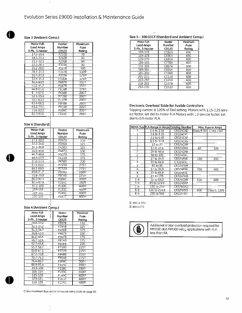
EvolutionSeriesE9000Installation MaintenanceGuide
Size3AmbientCompMotorFull
LoadAmps3Ph3Heater
178184
185211
212221
222261
262280
281313
314333
334343
344409
410447
448510
511520
521554
555633
634661
66235
36822
823900
Size4Standard
MotorFull
LoadAmps3Ph3Heater
271322
323340
341368
369446
447484
485539
540574
575600
601695
696717
18799
800923
924970
91108
109118
119131
132135
MotorFull
LoadAmps3Ph3Heater
288320
321342
343367
368439
440466
467526
527556
557587
588671
672706
701763
6488
888934
935105
106114
115128
129131
132135
Size4AmbientComp
Heater Maximum
Number Fuse
CR123 RatingF233B 70
F2438 80
F270B 80
F300B 90
F327B 100
F357B 1100
F395B 1250
F430B 1250
F488 1500
F567B 150W
F6148 1750
F658B 200
1 200W
F772B 200W
F848B 2000
F914B 2000
F104C 2000
I114C I 2000
Heater Maximum
Number Fuse
CR123 RatingF357B 110
F395B 125
F430B 125
F487B 150
F567B 175
F614B 175
F658B 200
f719B 2250
F728 2250
F848B 2500
F9146 2750
I 3000
F114C 3500
F118C 4000
F133C 4000
F149C 4000
F161C 4000
Heater Maximum
Number Fuse
CR123 RatingF357B 110
F395B 125
F430B 125
F487B 150
F567B 175
F614B 175
F658B 200
F719B 2250
F72B 2250
F8488 2500
F9148 2750
F104C 3000
F114C 3500
F118C 3500
F133C 4000
F149C 4000
F161C 4000
F174C I 4000
CDSeemaximumfuseandshortcircuitratingtableonpage29
Size530015CTStandardandAmbientCompMotorFull Heater Maximum
LoadAmps Number Fuse
3Ph3Heater CR123 Rating109118 C592A 600
119128 C630A 600
129138 C695A 600
139155 C778A 600
156168 C867A 600
169184 C955A 600
185200 C104B 600
201221 C113B 600
222237 C125B 600
238262 C137B 600
263270 I C151B 600
ElectronicOverloadTableforFusibleControllers
Trippingcurrentis120ofDialsettingMotorswith115125servicefactorsetdialtomotorFLAMotorswith10servicefactorsetdialto09motorFLA
NEMASizerLARangeinAmpslCataloqNumber1 MaxFuseinAmps1 08to159 1CR324CXD ClassR30ClassJ601 16to319 1 CR324CXE
1 32to649 CR324CXF
1 65to128 CR324CXG
1 13to27 CR324CXH
2 13to256 CR324DXG 60 100
2 26to499 CR324DXH
2 SOto100 CR324DXJ
3 17to349 CR324FXK 100 200
3 35to649 CR324FXL
3 65to90 CR324FXM
4 17to349 CR324FXK 200 400
4 35to649 CR324FXL
4 65to135 CR324FXM
50 32to640 CR324GXN 400 1 600
50 65to1299 CR324GXP
5O 130to270 CR324GXQ60 130to2599 CR324HXS 6006CO 260to540 CR324HXT
T30015CTs
CO8005CTs
ClassL1200
AdditionalmotoroverloadprotectionrequiredforMM200abdMM300relayapplicationswithFLAlessthan6A
32

EvolutionSeriesE9000Installation MaintenanceGuide
HeatersforNEMASize6and7FusedControllers
Forcontinuousratedmotorswithaservicefactorof
115to125selecttheappropriateheatersforthemotorfullloadcurrentForcontinuousratedmotors
withaservicefactorof10multiplythemotorfullloadcurrentby09andusethisvaluetoselectheaters
Overloadrelaytrippingcurrentin40Cambientistheminimumvalueoffullloadcurrentmultipliedby125ProvideshortcircuitprotectioninaccordancewiththeNationalElectricalCode
33
OverloadheatersforcontrollerswithNEMASize6startersfor
standardandambientcompensatedratingsCTratio6005
MaximumMotorFullLoadCurrent
181197
198214
215238
239258
259290
291346
347387
388423
424467
468516
517540
OverloadheatersforcontrollerswithNEMASize7startersfor
standardandambientcompensatedratingsCTratio8005
MaximumMotor
FullLoadCurrent
346387
388461
462515
516565
566622
623688
689763
764810
Openingofthecircuitbreakerorpowerfusemaybeanindicationthatafaultcurrenthasbeen
interruptedToprovidecontinuedprotectionagainstfireorshockhazardexamineallcurrentcarryingpartsandothercomponentsofthemotorcontrollerandreplaceanydamagedcomponentsIfheaterburnoutoccursthecompleteoverloadrelaymustbereplaced
CurrentTransformer
SecondaryAmps151164
165178
179198
199215
216242
243288
289322
323353
354389
390430
431450
CurrentTransformer
SecondaryAmps216242
243288
289322
323353
354389
390430
431477
478506
HeaterNumber
CR123
C220A
C239A
C268A
C301A
C326A
C356A
C379A
C419A
C466A
C526A
C592A
HeaterNumberCR123
C326A
C356A
C379A
C419A
C466A
C526A
C592A
C630A
ElectronicOverloadforCircuitBreakerandFusedControllers
Thetrippingcurrentis120ofthedialsettingForcontinuousratedmotorswithaservicefactorof115to125setthedialtothemotorfullloadcurrentFor
continuousratedmotorswithaservicefactorof10setthedialto09ofthemotorfullloadcurrentRefer
toGEH6430or6431beforeenergizing
OpeningofthebranchcircuitprotectivedevicemaybeanindicationthatafaultcurrenthasbeeninterruptedToprovidecontinuedprotectionagainstfireorshockhazardexamineallcurrentcarryingpartsandothercomponentsofthemotorcontrollerandreplaceanydamagedcomponentsIfheaterburnoutoccursthecompleteoverloadrelaymustbereplaced
ProvideshortcircuitprotectioninaccordancewithNECArticle430orCECodePart1
Trippingcurrentis120ofDialsettingMotorswith115125servicefactorsetdialtomotorFLAMotorswith10servicefactorsetdialto09motorFLA
CatalognumbersofelectronicoverloadsforvarioussizesofNEMAstartersandcurrentranges
NEMAFLARangeICatalogSize inAmps INumber
11 108to159 CR324CXD
11 116to319 CR324CXE
11 132to649 CR324CXF
1 165to128 CR324CXG
1 113to27 CR324CXH
2 113to256 CR324DXG
2 126to499 CR324DXH
2 150to100 CR324DXJ
3 117to349 CR324FXK
3 135to649 CR324FXL
3 165to90 CR324FXM
4 117to349 CR324FXK
4 35to649 CR324FXL
4 65to135 CR324FXM
50 132to640 CR324GXN
50 165to1299 CR324GXP
50 1130to270 CR324GXQ
160 1130to2599CR324HXS60 1260to540 CR324HXT
030015CTs
08005CTs
BreakerFrame Type
EMag ThermalMagEMag ThermalMagEMag ThermalMag
EMag ThermalMagEMag ThermalMagEMagThermalMagEMagThermalMag
EMag ThermalMagEMag ThermalMagEMag ThermalMag
EMagThermalMagEFGMag ThermalMagEFGMag ThermalMag
EFGMag ThermalMag
GMagThermalMag
GMag ThermalMagGMag ThermalMag
GKMagThermalMagKMagThermalMag

0
CatalognumbersofelectronicoverloadsforvarioussizesofNEMAstartersandcurrentranges
NEMAFLARange CatalogSize inAmps Number
1 08to159 CR324CXD
1 16to319 CR324CXE
1 32to649 CR324CXF
1 65to128 CR324CXG
1 13to27 CR324CXH
2 13to256 CR324DXG
2 26to499 CR324DXH 60 100
2 50to100 CR324DXJ
3 17to349 CR324FXK
3 35to649 CR324FXL 100 200
3 65to90 CR324FXM
4 17to349 CR324FXK
4 35to649 CR324FXL 200 400
4 65to1351 CR324FXM
5 32to640 CR324GXN
5 65to129 CR324GXP 400 600
50 130to270 CR324GXQ1
60 130to2599CR324HXS
O30015CTs
O8005CTs
IECStyleOverloadRelaysC2000ContactorCLNCJType
CurrentMax I
Range ICg CatNoClass
0465115 RTN1D 10
0651115 RTN1F 10
115 15 RTN1G 10
131915 RTN1H 10
182715 RTN1J 10
254115 RTNIK 10
406315 RTNIL 10
558515 RTNIM 10
8012 30 RTNIN 10
1001635 RTNIP 10
1451840 RTNIS 10
1752250 RTNIT 10
Cat Nol Class
RT12D
RT12F
RT12G
RT12H
RT12J
RT12K
RT12L
RT12M
RT12N
RT12P
RT12S
RT12T
MaxFuseinAmps
TimeDelay TimeDelayClassRJ30ClassJ60
600 ClassL1200
RTOverloadRelayfor12XStarter
20
20
20
20
20
20
20
20
20
20
20
20
Lugwiresize
148
148
148
148
148
148
148
148
148
148
148
148
TorqueinIbs
1420
1420
1420
1420
1420
1420
1420
1420
1420
1420
1420
1420
AF600FPAF650GPDrivesE9000
PanelmountusewithRTXPbaseadapter
CatNo
Class10
LARO2AJ RTN1B
LAR25AJ RTN1C
RTN1D
RTN1F
RTN1G
RTN1H
RTN1J
RTN1K
RTN1L
LAR45AJ RTN1M
IRTN1N1RTN1PRTN1S
RTN1T
RTN1U
RTN1V
RTN1W
LARO8AJ IRTN2A
Contactor
Mountdirecttocontactor
CatNo
Class10
ILAR08AJ RTN2B
RTN2C
RTN2D
RTN2E
RTN2G
RTN2H
RTN2J
RTN2L
RTN2M
RTN3B
RTN3C
KARO8CJ RTN3D
RTN3E
RTN3F
RTN4N
KAR95BYWZRTN4P
RTN4R
RTN4N
KAR95BJWZRTN4P
RTN4R
IKAR1OBYWZRTN5AIKAR11BYWZRTN5BIKAR1IBJWZRTN5BIKAR12BJWZRTN5C
RTN5C
KAR12BYWZRTN5D
RTNSE
Class30isavailable
WZSpecialforMebane
Contactor
LAR10AJ
Class20
NA
NA
RT12D
RT12F
RT12G
RT12H
RT12J
RT12K
RT12L
RT12M
RT12N
RT12P
RT12S
RT12T
RT12U
RT12V
RT12W
NA
Class20
NA
NA
RT22D
RT22E
RT22G
RT22H
RT22H
RT22L
RT22M
NA
RT32C
RT32D
RT32E
RT32F
NA
NA
NA
NA
NA
NA
NA
NA
NA
NA
NA
NA
NA
FLA
range
016026148AWG 1420
027041148AWG 1420
042065148AWG 1420
066110148AWG 1420
111150148AWG 1420
151190148AWG 1420
19125 148AWG 1420
251410148AWG 1420
41163 148AWG 1420
63185 148AWG 1420
851120148AWG 1420
12116 148AWG 1420
16118 148AWG 1420
18122 148AWG 1420
22126 148AWG 1420
26132 148AWG 1420
32140 148AWG 1420
11515 103AWG 50
LugwiresizeT
iorquenIbs
FLArangeLugwiresizeTorqueinIbs
15119 103AWG 50
19125 103AWG 50
25132 103AWG 50
32143 103AWG 50
43155 103AWG 50
55165 103AWG 50
65182 103AWG 50
82197 101AWG 50
971110101AWG 50
5580 6250MCM275
80190 6250MCM275
9011206250MCM275
12011406250MCM275
14011906250MCM275
120190 6350MCM200
19012806350MCM200
28013104t6350MCM200
120190 6350MCM200
19012806350MCM200
28013106350MCM200
120190 6350MCM375
19012806350MCM375
19012806350MCM375
28014006350MCM375
28014008500MCM375
40015008500MCM375
50016508500MCM375
34

TheseinstructionsdonotcoveralldetailsorvariationsinequipmentnordotheyprovideforeverypossiblecontingencythatmaybemetinconnectionwithinstallationoperationormaintenanceShouldfurtherinformationbedesiredorshouldparticularproblemsarisethatarenotcoveredsufficientlyforthepurchaserspurposesthemattershouldbereferredtotheGECompany
GEConsumerIndustrial
41WoodfordAvenuePlainvilleCT06062
wwwgeelectricalcom
2009GeneralElectricCompany
imaginationatworkDEH40472R040109
USERMANUAL
PROFIBUSDPOPTIONOPCG 11SPDP
for Fuji FREiVIC5000G11SP11S
GE Fuji AF300011P11
DOCNOSDM7526011
HMSFIELDBUSSYSTEMSABPILEFELTSGATAN9395S30250HALMSTADSWEDEN
PHONE4635172900
FAX4635172909
emailInfo@hmsse
webwwwhmsse

RevisionNotes
000124
000130
000803
Preface
Revision100 Created
Revison101 84Monitoringdatadataformatcorrection
1 Revison102 I ExtendedSystemconfigurationchapter10
ThedataandillustrationsfoundinthisdocumentarenotbindingWereservetherighttomodifyourproductsinlinewithourpolicyofcontinuousproductdevelopmentTheinformationinthisappendixissubjecttochangewithoutnoticeandshouldnotbeconsideredasacommitmentbyHMSFIELDBUSSYSTEMSAB
HMSFIELDBUSSYSTEMSABassumesnoresponsibilityforanyerrorsthatmayappearinthisdocument
Theproductandtechnologydescribedinthisdocumentispatentpendinginthefollowingcountries
USACanadaJapanBelgiumDenmarkFinlandFranceGreeceIrelandItalyLuxemburgMonacoNetherlandsPortugalSwitzerlandLichtensteinSpainUnitedKingdomSwedenGermanyandAustria
ANYBUSisaregisteredtrademarkofHMSFIELDBUSSYSTEMSAB
Allothertrademarksarethepropertyoftheirrespectiveholders
Relateddocuments
or
PROFIBUSProfileforvariablespeeddrivesPROFIDRIVEPNOOrderNo3072
FRENIC5000G11SP11SINSTRUCTIONMANUALINRSi470554E
PROFIDR1VEworkinggroupofProfibusNutzerorganisation
FujiElectric
USERMANUALRevision102
20001010
HMSFIELDBUSSYSTEMSAB 2
USERMANUALRevision102
20001010
TableofContents
1 Applicable inverters 5
2 ReceivingInspection 6
3 Installation 7
31 InstallationMethod 7
32 InstallationChecklist 8
4 ProfibusoptioncardOPCG11SPDP 9
5 IntroductiontoProfibusDP 9
51 TechnicalfeaturesofProfibusDP 9
6 OPCG11SPDPOverview 11
61 Physicalinterface 11
62 Configuration 12
621 Baudrate 12
622 Termination 12
623 NodeAddress 12
624 PPOtypeselection 13
625 Changeoverofcommunications 14
626 Faststop 15
627 ConfigurationofPCDword14 16
63 Actionatcommunicationerror 17
64 IndicationLEDs 20
7 OperatingthedriveviaProfidriveprofile 21
71 PPGdescription 21
72 PCDpart 22
721 Controlstatusword 22
722 FrequencysetpointActualfrequency 27
723 PCDword14 27
73 PCVpart 27
74 Example 30
75 Profidrivespecificparameters 31
76 Malfunctioncodes 33
8 Parametersspecificfor communication 35
81 Commanddata 35
82 Operationcommanddata 35
HMSFIELDBUSSYSTEMSAB 3

USERMANUALRevision102
20001010
83 Functiondata 37
84 Monitoringdata 38
9 Parameterdataformat 40
91 Listofparameterdataformat 40
92 Dataformatspecification 46
10 Systemconfiguration 51
101 Hardwareconfiguration 52
102 Softwareconfiguration 55
11 GSDfile 57
HMSFIELDBUSSYSTEMSAB 4

1Applicableinverters
Item
Inverte
CompatibleInverter
ModelInumber
GEFujiversionMinimuminverter
ROMversion
number
type
Description
FRENIC5000G11SPi1SAF300G11Pi1
ThelasttwodigitsofthemodelnumbershouldbeB1orlater
Example6KG1123X1B1
USERMANUALRevision102
20001010
upto22kW30HP ENversion S08000andafter
ItisimpossibletouseversionpriortoS08000inverter
JapanesestandardJE Cannotbeused
andCNversion
UXandGEFujiversion S08000andafter
ItisimpossibletouseversionpriortoS08000inverter
30kW40HPand ENJapanesestandard H07602andafter
above JNJEANCNUX Itisimpossibletouseversionsof
andGEFujiversionH00000toH07601
NOTE
ThisproductcanonlybeusedforInverterswithROMversionnumbersgreaterthanorequaltotheversionsshownabove
AndinthecaseofinstallingthisoptionintheG11P11inverterthatisaJapanesestandardJNJEorCNversionpleasecontactFujiElectricoritsdistributors
ChecktheROMnumberofyourInverterasfollowsusingtheinverterkeypad
aCheckthattheInverterOperationmonitorOperationmodescreenisdisplayed
bPressthePRGkeyoftheInverteronce
cSelectthe5MAINTENANCwiththecursorandpresstheFUNCDATAkey
dPressthedowncursorkeytoincrementthedisplayattheMAINTENANCscreen
FinallytheROMnumberisshowninthemaintenanceinformationasindicatedbythedisplayINVHxxxxxorSiemer
ThemaintenanceandinspectionitemsaresimilartotheInverterunitfordetailrefertotheInverterInstructionManual
HMSFIELDBUSSYSTEMSAB 5I

2ReceivingInspection
Confirmthefollowingitemsuponareceipt
1 Themodelnumbermatchesyourpurchaseorder
Checkthemodelnumberprintedonthecircuitboard
Model OPC G11SPDP
OPTIONTYPE
PDP ProfibusDPINTERFACEOPTION
INVERTERTYPE
G11S FRENIC5000G11SP11SSERIES
AF300G11P11SERIES
2InspectionfordamageduringtransportationReportdamagetotransportationcarrier
USERMANUALRevision102
20001010
HMSFIELDBUSSYSTEMSAB 6
0
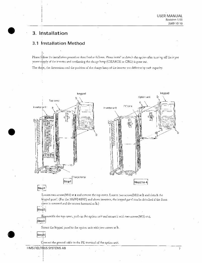
3Installation
31InstallationMethod
PleasefollowtheinstallationproceduredescribedasfollowsPleaseinstallordetachtheoptionafterturningofftheinputpowersupplyoftheinverterandconfirmingthechargelampCHARGEorCRGisgoneout
Theshapethedimensionsandthepositionofthechargelampoftheinverteraredifferentbyeachcapacity
Inverter
init a
r
M0
IStep1I
Topcover
I
keypad
b
Chargelamp
IStepl
b
Inverterunit
IStep2to41
USERMANUALRevision102
20001010
LoosentwoscrewsM4ataandremovethetopcoverLoosentwoscrewsM3atbanddetachthekeypadpanelForthe30kW40HPandaboveinvertersthekeypadpanelcanbedetachedifthefrontcoverisremovedandthescrewsloosenedatb
IStep2
Reassemblethetopcoverpushintheoptionunitand secureitwithtwoscrewsM3atc
IStep3Securethekeypadpaneltotheoptionunitwithtwoscrewsatb
IStepk
ConnectthegroundcabletothePEterminaloftheoptionunitHMSFIELDBUSSYSTEMSAB 7

32InstallationChecklist
Afterinstallationandwiringcheckthefollowingitems
1Thewiringiscorrect
2NoloosewiresorscrewsremaininsidetheInverter
3Thescrewsandterminalsarealltight
4Therearenoloosethreadsofwiresatterminalsthatmaycontactotherterminals
5TheswitchpositionsontheAnybusSmoduleJP6ontheconversionboardaresuitablefortheusepurposeDonotchangetheJP4ontheconversionboard
6InverterparameterssuchasH30E15E30toE32o27o28o30too38aresetcorrectlyH30LinkActiveInactiveE15effecttoOFF3E30effecttoBit8ofStatuswordE31andE32effecttoBit10ofStatuswordo27ando28forRASo30PPOtypeo31too38PCDsetting
USERMANUALRevision102
20001010
HMSFIELDBUSSYSTEMSAB 8
0
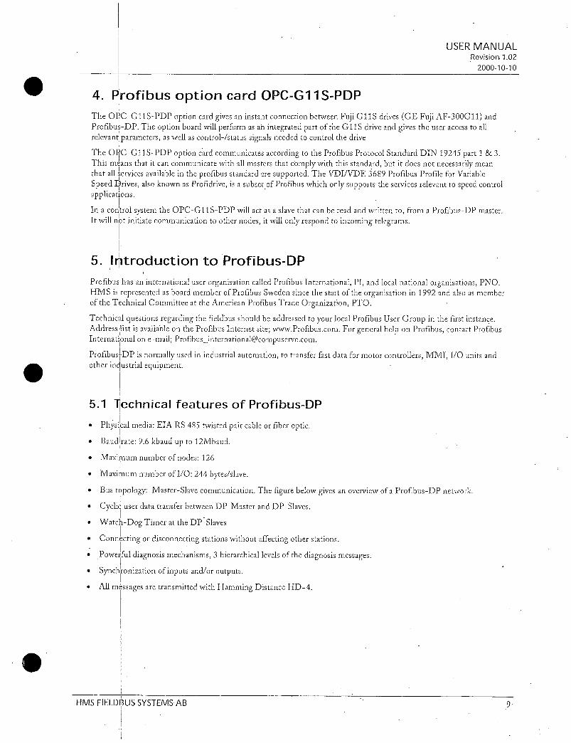
4ProfibusoptioncardOPCG11SPDPThe OPC G11SPDPoptioncardgivesaninstantconnectionbetweenFujiG11SdrivesGEFujiAF300G11andProfibusDPTheoptionboardwillperformasanintegratedpartoftheG11Sdriveandgivestheuseraccesstoall
relevant parametersaswellascontrolstatussignalsneededtocontrolthedriveThe OPC G11SPDPoptioncardcommunicatesaccordingtotheProfibusProtocolStandardDIN19245part13Thismeansthatitcancommunicatewithallmastersthatcomplywiththisstandardbutitdoesnotnecessarilymeanthatallservicesavailableintheprofibusstandard aresupportedTheVDIVDE3689ProfibusProfileforVariableSpeedDrivesalsoknown asProfidriveisasubsetofProfibuswhichonlysupportstheservicesrelevanttospeedcontrol
applicationsInacontrolsystemtheOPCG11SPDPwillactasaslavethatcanbereadandwrittentofromaProfibusDPmasterItwillnotinitiatecommunication toothernodesitwillonlyrespondtoincomingtelegrams
5IntroductiontoProfibusDP
USERMANUALRevision102
20001010
ProfibushasaninternationaluserorganisationcalledProfibusInternationalPIandlocalnationalorganisationsPNOHMSisrepresentedasboardmemberofProfibusSwedensincethestartoftheorganisationin1992andalsoasmemberoftheTechnicalCommitteeattheAmericanProfibusTradeOrganizationPTO
TechnicalquestionsregardingthefieldbusshouldbeaddressedtoyourlocalProfibusUserGroupinthefirstinstanceAddresslistisavailableontheProfibusInternetsitewwwProfibuscomForgeneralhelponProfibuscontactProfibusInternationalonemailProfibusinternational@compuservecomProfibus
DPisnormallyusedinindustrialautomationtotransferfastdataformotorcontrollersMMIIOunitsandotherindustrialequipment5
1TechnicalfeaturesofProfibusDPPhysical
mediaEIARS485ttivistedpaircableorfiberopticBaud
Irate96kbaudupto12MbaudMaximumnumberofnodes126Maxi
Ium numberofIO244bytesslaveBus
topologyMasterSlavecommunicationThefigurebelowgivesanoverviewofaProfibusDPnetworkCyclic
userdatatransferbetweenDPMasterandDPSlavesWatch
DogTimerattheDPSlavesConnecting
ordisconnectingstationswithoutaffectingotherstationsPowerful
diagnosis mechanisms3hierarchicallevelsofthediagnosismessagesSynchronization
ofinputsandoroutputsAll
messagesaretransmittedwithHammingDistanceHD4HMS
FIELDBUSSYSTEMSAB

PROFIBUSDP
Master
RS232
PersonalComputerwithConfigurationSoftware
DP
4
ProfibusDPSlavenode1 ProfibusDP
Slavenoden
ProfibusDPSlavenode2
Figure1BustopologyofProfibusDP
Figure2BuscycletimeofaProfibusDPMonoMastersystem2bytesIOdataslave
USERMANUALRevision102
20001010
HMSFIELDBUSSYSTEMSAB 10

6OPCG11SPDPOverviewThissectioncontainsallnecessaryinformationtostartupandconfiguretheOPCG11SPDP
61Physicalinterface
IsolationThebusisgalvanicallyseparatedfromtheotherelectronicswith anonboardDCDCconverterBussignalsAlinelandBline areisolatedviaoptocouplers
ProfibuDPcommunicationASICSPC3chipfromSiemens
BusconnectionTheOPCG11SPDP connectstotheprofibusnetworkwitha9pinfemaleDSUBconnectorForthepinlayoutrefertoTable1
2
3
4
5
6
7
8
9
Table1PinLayout
HMSFIELDBUSSYSTEMSAB
Shield ConnectedtoPE
NotConnected
NotConnected
BLine PositiveRxDTxDaccordingtoRS485specification
RTS RequestToSend
GNDBUS IsolatedGNDfromRS485side
5VBUS Isolated5VfromRS485side
NotConnected
ALine NegativeRxDTxDaccordingtoRS485specification
NotConnected
USERMANUALRevision102
20001010
5U BUSandGNDBUSareusedforbusterminationSomedeviceslikeopticaltransceiversRS485tofibreopticsmightrequireexternalpowersupplyfromthesepinsRTSisusedinsomeequipmenttodeterminethedirectionoftransmissionInstandardapplicationsonlyALineBLineandShieldareused
11

62Configuration
621Baudrate
ThebaudrateOnaProfibusDPnetworkissetduringconfigurationofthemasterandonlyonebaudrateispossibleinaProfibusDPinstallationTheOPCG11SPDPhasanautobaudratedetectionfunctionandtheuserdoesnothaveto
configurethebaudrateonthemoduleRefertoTable2forthebaudratessupported
622Termination
623NodeAddress
96kbits
192kbits
9375kbits
1875kbits
500kbits
15Mbits
3Mbits
6Mbits
12Mbits
Table2Supportedbaudrates
TheendnodesinaProfibusDPnetworkhastobeterminatedtoavoidreflectionsonthebuslineTheOPCG11S
PDPisequippedwithaterminationswitchtoaccomplishthisinaneasywayIfthemoduleisusedasthefirstorlastmoduleinanetworktheterminationswitchhastobeinONpositionOtherwisetheswitchhastobeinOFFposition
PleaseNoteIfanexternalterminationconnectorisusedtheswitchmustbeinOFFposition
TerminationswitchON Busterminationenabled
Ifthemoduleisthelastorfirstmodule
thebusterminationhastobesetonoranexternalterminationconnectorhastobe
used
TerminationswitchOFF Busterminationdisabled
USERMANUALRevision102
20001010
BeforepowerontheOPCG11SPDPthenodeaddresshastobesetThisisdonewithtworotaryswitchesonthemodulethisenablesaddresssettingsfrom199indecimalformatLookingatthefrontofthemoduletheleftmostswitchisusedforthetensettingandtherightmostswitchisusedforthesettingoftheintegers
Example
AddressLeftSwitchSettingx10RightSwitchSettingx1
PleaseNoteThenodeaddresscannotbechangedduringoperation
HMSFIELDBUSSYSTEMSAB 12

624PPOtypeselection
OPCG11SPDPsupportsPPOtype14Refertochapter71forPPOdescription
ThesamePPOtypemustbesetfromboththekeypadandthemasterconfigurationIfthesettingsdonotcomplytheOPCGPDPwill notstartexchangingdatawiththemaster
SettingthePPO tvocfromkeypad
TheinverterotypeparametersareusedtoconfiguretheProfibusDPinterfaceTheotypeparametersareonlyaccessiblefromtheinverterkeypadaftertheProfibusinterfacehasbeeninstalled
PPOtypeselectionismadeinparametero30Afterchangingthisparameterthedrivehastoberepoweredforthechangetotakeaffect
o30data
016255
2
3
4
5
Table3PPOtypeselection
SettingthePPOtunefrommaster
IdentificationbytesarctransmittedintheconfigurationframeoftheProfibusDPmasterThesebytesdefinethePPOtypeofthe userdataframeTheidentificationbytesareincludedintheGSDfilerefertochapter8thatisusedduringconfigurationofthe masterForhowtoconfiguretheProfibusDPmasterpleaserefertothemanualfortheactualmaster
HMSFIELDBUSSYSTEMSAB
PPOtypeselection
PPO1
PPO2
PPO3
PPO4
PPO2
USERMANUALRevision102
20001010
13

625Changeoverofcommunications
InordertoenabletheinvertercontrolthroughthecommunicationbycommanddataandoperationdatatheinverterfunctioncodeH30SeriallinkFunctionselectionshouldbeconfiguredforavalueof13ThereadingandwritingoffunctiondataandfunctionsarepossibleatanytimeregardlessofthesettingofFunctioncodeH30
Host
Frequencysetting
0
Forward
command
Communication
0C
Changeoverofcommunication
validinvalid
C
Inputterminals
OFF
ON
Frequencycommand
Forward
command
Frequencycommand
Forwardcommand
Valid SW1
Invalido
Valid
oSW2
InvalidJ
Frequency
H30Seriallinik
Switchingcircuitofcommunication
validinvalid
orwardtmmr2rl
IE01 E09MultifunctionterminalssettingI
Changeoversignalofcommunicationvalidinvalid
4
USERMANUALRevision102
20001010
6251Changeovermethodforcommunicationcontrol
ThechangeoverofthecommunicationcontrolcanbeperformedbythemultifunctioncommandterminalsterminalsXlX9ontheinverterHoweveritisnecessarytoconfiguretheinvertersmultifunctioncommandinputterminalsE01E09XlX9terminalsfunctiontothelinkoperationselectionData24Ifthemultifunctioncommandterminalshavenotbeensettothelinkoperationselectionthecommunicationbecomesvalidautomatically
State
Communicationinvalidmode
CommunicationvalidmodeH30setting
Note
1Sinceallmemoriesareinitializedatswitchingpowersupplyonthecommanddataandoperationdatamustbewriteagainfromtheupstreamunits
2EvenwhenthecommunicationisinvalidthewritingofcommanddataandoperationdataisvalidbutitisnotreflectedbySW1SW2Thechangeoverwithoutshockispossiblebythewaythedataissetpriortothetransition
HMSFIELDBUSSYSTEMSAB 14
e
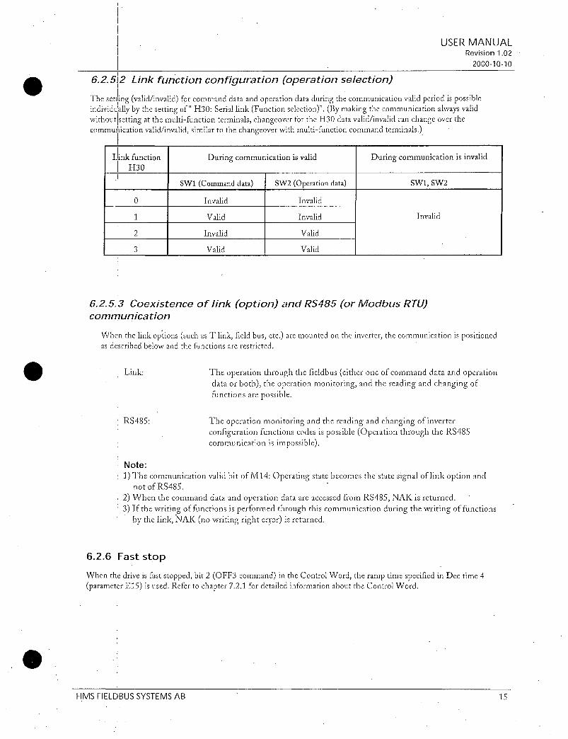
6252Linkfunctionconfigurationoperationselection
ThesettingvalidinvalidforcommanddataandoperationdataduringthecommunicationvalidperiodispossibleindividuallybythesettingofH30SeriallinkFunctionselectionBymakingthecommunicationalwaysvalidwithoutsettingatthemultifunctionterminalschangeoverfortheH30datavalidinvalidcanchangeoverthecommunicationvalidinvalidsimilartothechangeoverwithmultifunctioncommandterminals
Linkfunction
H30
Link
Duringcommunicationisvalid Duringcommunicationisinvalid
1 SW1Commanddata SW2Operationdata
0 I Invalid Invalid
1 I Valid Invalid
2 1 Invalid Valid
3 1 Valid Valid
625 CoexistenceoflinkoptionandRS485orModbusRTUcommunication
RS485
SW1SW2
Invalid
TheoperationmonitoringandthereadingandchangingofinverterconfigurationfunctionscodesispossibleOperationthroughtheRS485communicationisimpossible
USERMANUALRevision102
20001010
WhenthelinkoptionssuchasTlinkfieldbusetcaremountedontheinverterthecommunicationispositionedasdescribedbelowandthefunctionsarerestricted
Theoperationthroughthefieldbuseitheroneofcommanddataandoperationdataorboththeoperationmonitoringandthereadingandchangingoffunctionsarepossible
Note
1ThecommunicationvalidbitofM14OperatingstatebecomesthestatesignaloflinkoptionandnotofRS485
2WhenthecommanddataandoperationdataareaccessedfromRS485NAKisreturned3Ifthewritingoffunctionsisperformedthroughthiscommunicationduringthewritingoffunctions
bythelinkNAKnowritingrighterrorisreturned
626Faststop
Whenthedriveisfaststoppedbit2OFF3commandintheControlWordtheramptimespecifiedinDectime4parameterE15isusedRefertochapter721fordetailedinformationabouttheControlWord
HMSFIELDBUSSYSTEMSAB 15

627ConfigurationofPCDword14
AssigningparameterstoPCDword14refertochapter723canbeperformedintwoways
1Fromkeypado31o38
2FromnetworkPNU915916
Afterchangingtheseparametersthedrivehastoberepoweredforthechangetotakeaffect
Assignmentfromkevnad
AssignmentofPCDwriteword14PLC Drive
o31 CommunicationnumberforparametertransferredinPCD1
o32CommunicationnumberforparametertransferredinPCD2
033CommunicationnumberforparametertransferredinPCD3
o34CommunicationnumberforparametertransferredinPCD4
AssignmentofPCDreadword14DrivePLC
o35CommunicationnumberforparametertransferredinPCD1
o36 CommunicationnumberforparametertransferredinPCD2
o37CommunicationnumberforparametertransferredinPCD3
o38 CommunicationnumberforparametertransferredinPCD4
Assignmentfromorofibusnetwork
AssignmentofPCDwriteword14PLC Drivewithparameter915
915index1 CommunicationnumberforparametertransferredinPCD1
915index2CommunicationnumberforparametertransferredinPCD2
915index3 CommunicationnumberforparametertransferredinPCD3
915index4CommunicationnumberforparametertransferredinPCD4
AssignmentofPCDreadword14DrivePLCwithparameter916
916index1 CommunicationnumberforparametertransferredinPCD1
916index2CommunicationnumberforparametertransferredinPCD2
916index3 CommunicationnumberforparametertransferredinPCD3
916index4CommunicationnumberforparametertransferredinPCD4
PleaseNote
1PCDwords14areonlyenabledifPPO2or4isselected
2Communicationnumbersarewithintherange1255SeeSection9foranindexofinvertercommunicationnumbersIfacommunicationnumberissetto0theactualPCDwordwillbeignored
USERMANUALRevision102
20001010
HMSFIELDBUSSYSTEMSAB 16

63Actionatcommunication error
Incaseofoccurrtransmissionerrorscommunicationcutoffwiththemasterthefollowingactionscanbeselected
1Selectactionwhenerrorisdetectedo27
o27
0
1
2 Continueoperationaccordingtothelastcommand Er5
receiveduntilrestorationofthecommunicationIfthe
communicationisnotrestoredbeforetheo28time
expiresthenimmediateforcedstop
3
Actionaterrordetection
Immediateforcedstop
Continueoperationwithino28timeandstop
Continueoperationtillrestorationofthe Automaticrestoration
communicationandaftertherestorationfollowto afterrestoringdesignationofcommunication communication
2Settingtimeoftimeraterroro28
00600s
Inacaseofo270Modeofimmediateforcedstopatcommunicationerrordetection
CommandfromMaster
Internal
operationofinverter
Communicationstate
Display Normal
FWD
Settingfrequency
Operationcommand
Settingfrequency
Outputfrequency
Error
Normal 1 1 Normal
ON
Operation
Coasttostop
Er5
Er5
Er5
Communicationfailure
ON
Remarks
Stop Operation
USERMANUALRevision102
20001010
Continueoperationusingthecommandjustbeforetheerrorwithino28timebut
whenrestoringoperatefollowingtothedesignationofcommunication
Alarmreset
HMS FIELDBUS SYSTEMSAB 17

Inacaseofo271o2850sModeofimmediateforcedstopafter5satoccurringcommunicationerror
Command
fromMaster
Internal
operationofinverter
Command
fromMaster
Internal
operationofinverter
Communicationstate
Display
FWD
Settingfrequency
Operationcommand 1 Operation
Settingfrequency
Outputfrequency
Communication
state
Display
FWD
Settingfrequency
rOperationcommand
Settingfrequency
Outputfrequency
Normal
ON
Normal
ON
Normal
Operation
Error
1
Error
50s
Normal
OFF
Coasttostop
Normal
Normal Er5
50s
ON
Er5
Coasttostop
Alarmreset
ON
Stop Operation
Inaccelerationevenifoccurringtransmissionerroracceleratedtothesettingfrequency
1Inaperioduntilrestoringthecommunicationthelastcommandscommanddataandoperationdatareceivedbeforetheerrorarekept
Inacaseofo272o2850sThecommunicationisnotrestoredfor50secaftererrordetectionandinvertertripsEr5
Alarmreset
Stop 1 Operation
Inaccelerationevenifoccurringtransmissionerroracceleratedtothesettingfrequency
USERMANUALRevision102
20001010
HMSFIELDBUSSYSTEMSAB 18

Inacaseofo272o2850sAcommunicationerroroccursbutrestoredwithin 5s
Error
CommandfromMaster
frequency
internaloperationofinverter
CommandfromMaster
Internaloperationofinverter
Communicationstate
Display
FWD
Setting
rOperationcommand
Settingfrequency
Outputfrequency
Display
FWD
Settingfrequency
rOperationcommand
Settingfrequency
Outputfrequency
HMSFIELDBUSSYSTEMSAB
Normal
ON
Operation Stop
ON
Operation
Normal
Normal
50s
Inaccelerationevenifoccurringerroracceleratedtothesetting
1Inaperioduntilrestoringthecommunicationthecommandscommand dataandoperationdatajustbeforetheerror darekept
Inacseofo273WhenacommunicationerroroccurstheoperationcontinuesError
Communicationstate Normal 1Normal
Normal
1
OFF
ON
n n
F n
Continueoperationkeepingthesettingatoccurringtransmissionerror
USERMANUALRevision102
20001010
19

64IndicationLEDs
TheOPCG11SPDPisequippedwithfourLEDsThefunctionoftheLEDsaredescribedinFigure3andTable4
1Notused
2OnLine
3OffLine
4Fieldbusdiagnostics
Fieldbusdiagnostics Red FlashingRed1HzErrorinconfigurationPPOtypesetinparametero30doesnotmatchPPOtypesetduringconfigurationofthenetwork
FlashingRed4HzErrorininitialisationoftheProfibuscommunicationASIC
TurnedOffNodiagnosticspresent
OnLine Green IndicatesthatthemoduleisOnLineonthefieldbus
GreenModuleisOnLineanddataexchangeispossibleTurnedOffModuleisnotOnLine
OffLine Red IndicatesthatthemoduleisOffLineonthefieldbus
Table4LEDfunctionality
HMSFIELDBUSSYSTEMSAB
Figure3LEDs
USERMANUALRevision102
20001010
RedModuleisOffLineandnodataexchangeispossibleTurnedOffModuleisnotOffLine
20

7OperatingthedriveviaProfidriveprofileThissectiondescribeshowtocontroldriveviacontrolwordstatuswordandhowtoaccessdriveparameters
71PPOdescriptionThestructureoftheuserdataisdesignatedasparameterprocessdataobjectsPPOintheProfidriveprofileTheprofiledefinesfivePPO typeswhereOPCG11SPDPsupportsPP01PPO4
TherearePPOswithaparameterareaPCVandaprocessdataareaPCDThereisalsoPPOsthatconsistexclusivelyof processdataPCD
1PP O1 consistsofthePCVareaand2wordsPCD
2 PPO2 consistsofthePCVareaand6wordsPCD
3PPO3consistsonlyof2wordsPCD4PPO4consistsonlyof6wordsPCD
ThePPOtypeisdefinedintheProfibusDPmasterparametersettingsandmustcomplywiththesettinginparametero30 refer tochapter624
Word 1 2 3 4 5 6
I I 1 I 1
PPO1
1 11 1 1 I
Word 1 2 3 4 5 6 7 8 9 10
I I I I I I I I I
PPO21 1 1 1 1 1 1 1 1
Word 5 6
1
PP03
Word
PPO4I
PCV PCD
HMS FIELD BUSSYSTEMSAB
PCA IND PVA C3WMRVPCD PCD PCD PCD 1CD PCD PCD PCD
STWMAV 2 3 4 5 6 7
5 6 7 8 9 10
I I I I I
1 I I 1 I
PleaseNotePPOtypeisselectedatpowerupandcannotbechangedinruntime
USERMANUALRevision102
20001010
21

72PCDpart
InthischaptertheprocessdatapartPCDofaPPOisdiscussed
ThePCDpartconsistsofafixedpartallPPOsandaparameterablepartonlyPPO2 4
Inthefixedpartcontrolwordandspeedreferencearetransferredtothedrivewhilestatuswordandactualoutputfrequencyaretransferredfromthedrive
IntheparameterablepartPCDword14theusercanconfigurewhatparametersthatshouldbetransferredtofromthedriveeverybuscycle
721Control statusword
ThissectiondescribeshowtooperatethedrivewiththecontrolstatuswordTextwritteninitalicreferstotheactualstateintheprofidrivestatediagramrefertoFigure4
ProfidriveControlWord
ThecontrolwordisusedtosendcontrolcommandstotheinverterPLCDrive
Bitofcontrolword Bit0 Bit1
0 OFF1normalstop ON1
1 OFF2coaststop ON2
2 OFF3faststop ON3
3 Operationdisabled Operationenabled
4 Rampgeneratordisabled Conditionforoperation
5 Stoprampgenerator Rampgeneratorenabled
6 Setpointdisabled Setpointenabled
7 Nofunction Faultacknowledge
8 Notused Notused
9 Notused Notused
10 Datanotvalid Datavalid
11 Nofunction Reversing
1215 Notused Notused
Bit0OFF1ON1
Bit0NormalstopthatusesdecelerationtimespecifiedinDECTIME1EnterOFF1activestateWhenoutputfrequency0thedriveoutputisdisabled
Bit1Drivecanbestartedifallotherstartconditionsarefulfilled
Bit1OFF20N2
Bit0DrivecoasttostopEnterOFF2activestateReturnstoSwitchoninhibitstateBit1Drivecanbestartedifallotherstartconditionsarefulfilled
USERMANUALRevision102
20001010
HMSFIELDBUSSYSTEMSAB 22

Bit2OFF3ON3
Bit0 laststop thatusesdecelerationtimespecifiedinDECTIME4EnterOFFSactivestateWhenoutputfrequency0thedriveoutputisdisabled
Bit1Drive canbestartedifallotherstartconditionsarefulfilled
Bit3Operationdisabledenabled
Bit0DrivecoasttostopEnterInhibitoperationstate
Bit1Drive canbestartedifallotherstartconditionsarefulfilled
Bit4RamoveneratordisabledConditionforoperation
Bit0Outputfrequencyissetto0InverterremainsinRunningstate
Bit1Drivecanbestartedifallotherstartconditionsarefulfilled
IBit5StoprampveneratorRampveneratorenabled
I
Bit0ActualoutputfrequencyisfrozenChangestofrequencysetpointhasnoaffectBit1Drive canbestartedifallotherstartconditionsarefulfilled
Bit6Stpointdisabledenabled
Bit0NormalstopthatusesdecelerationtimespecifiedinDECTIME1
Bit1 Drive canbestartedifallotherstartconditionsarefulfilled
Bit7NofunctionFaultacknowledge
Bit0Nofaultacknowledge
Bit1 Fault isacknowledgedonpositiveedgeiebit0then1EnterSwitchoninhibitstate
Bit10DatainvalidDatavalid
Bit0ThecontrolwordandfrequencysetpointfromPROFIBUSarenotactivated
Bit1ThecontrolwordandfrequencysetpointfromPROFIBUSareactivated
Bit11NofunctionReversing
Bit0 Drive isnotreversing
Bit1Driveisreversing
HMSFIELDBUSSYSTEMSAB
USERMANUALRevision102
20001010
23

ThestatuswordindicatesthestatusoftheinverterDrive PLC
Bitofstatusword
0
1
2
3
4
5
6
7
8
ProfrdriveStatusWord
Bit0
Notreadyforswitchon
Notreadyforoperation
Operationinhibited
Nofault
OFF2
OFF3
Startdisable
Noalarm
Frequencynotequaltosetpoint
Localcontrol
Frequencyoutofrange
Notused
Bit0NotreadyforswitchonReadytoswitchon
Bit0Controlwordbit01or2OFF1OFF2OFF3issetto0orthedrivehastripped
Bit1Controlwordbit00andbits1210aresetto1Readytoswitchonstate
Bit1NotreadyforoperationReadyforoperation
Bit0Controlwordbit01or2OFF1OFF2OFF3issetto0orthedrivehastripped
Bit1Controlwordbit01and2aresetto1andthedrivehasnottrippedReadystate
Bit2OperationinhibitedOperationenabled
Bit0Controlwordbit012or3OFF1OFF2OFF3orOperationdisabledissetto0orthedrivehastripped
Bit1Controlwordbit012and3aresetto1andthedrivehasnottrippedEnableoperationstate
Bit3NoFaultFaultTrip
Bit0Drivehasnottripped
Bit1DriveistrippedFaultresetfromkeypadorbit7inControlWordisneededtoresetthedriveafterthefaultiscleared
Bit4OFF2ON2
Bit0OFF2commandactiveControlwordbit10OFF2activestate
Bit1Controlwordbit1 1
Bit 1
Readytoswitchon
Readyforoperation
Operationenabled
Trip
ON2
ON3
Startenable
Alarm
Frequencyequaltosetpoint
Buscontrol
Frequencywithinrange
Notused
USERMANUALRevision102
20001010
HMSFIELDBUSSYSTEMSAB 24

Bit5OFF3ON3
Bit06FF3commandactiveControlwordbit20OFF3activestate
Bit1 Control wordbit21
Bit6StartdisableStartenable
Bit0Controlwordbit00andbit10 1NotReadytoswitchonstate
Bit1Controlwordbit1or2OFF2OFF3issetto0orfaulttriphasbeenacknowledgedSwitch oninhibiti
Bit8FreauencvnoteoualtosetpointFreouencveaualtosetpoint
Bit0Actualoutputfrequencydoesnotequalfrequencysetpointiemotor isacceleratingdecelerating
Bit1ActualoutputfrequencydoesequalfrequencysetpointPleaseNoteThefrequencytolerancewidthisconfiguredinparameterE30
Bit9LocalcontrolBuscontrol
Bit0RuncommandandFrequencysettingareinvalidviaProfibus
Bit1RuncommandorFrequencysettingarevalidviaProfibus
Bit10FreuuencvoutofrangeFreauenvvrvithinranee
Bit0Actualoutputfrequencyislowerthanthelimitspecified inparameterE31andE32
Bit1Actualoutputfrequencyisaboveorequaltothelimitspecifiedinparameter E31andE32
HMSFIELDBUSSYSTEMSAB25
USERMANUALRevision102
20001010

VoltageON
Inhibitoperationbit30
Drivestopped
activ
Fromeverystate
A B CD
B C D
I I IRFGoutputdisabledbit40
OFFIbit00
Normal rostop
Drivestopped
Bit10
Openloadcontactor
Loadcontactoropen
StopRFGbit50
C D
D B
Inhibit
setpoinlibit60
SwitehLonviintijbit
OFF1bit0o
NOreadyforswitchon
Bit20
Coaststop
D
A
c1
ReadytIswitchpn
IBit61
4 ControlwordbitpatternXXXXX1XXXXXXX110
ON1bit01
Bit0 1
IBit1 1i
iEnableoperationbit3 1
giIBit21
RFGoutputenabledbit4 1
ggepcra
4RFGAccelerationenabled
bit5 1
Rampfunctiongenerator14cce1elifionenabled
Enablesetpointbit61
1 state
OFF3bit20fQuickstopBit50
Drivestopped
Openloadcontactor
Loadcontactoropen
Faultacknowledge 4Bit70to1
Fromeverystate
111F Cth
Fromeverystate
1StopdriveBit3 1
OFF2bit10
Coaststop13it40
Loadcontactor
open
USERMANUALRevision101
20001010
Figure4Profidrivestatediagram
HMSFIELDBUSSYSTEMSAB 26

Bit
Byte1
Byte2
722FrequencysetpointActualfrequency
ThedataformatisStandardizedvaluewhere0hex0 and4000hexis100ofMaxfrequencyspecifiedinparameterF03orA01
Standardizedvalue
Alineailvalue
00Oh100is24000h
Data type N2
Range 2002002
Resolution 200061
Lengthl 2bytes
Notation1 2scomplementnotation
MSBis1bitaftersignbitin1byte
Signbit0positivenumber
Signbit1negativenumber
S 7 6 5 4 3 2 1
SIGN 2 21 22 2 2 25 26
27 28 29 2in 211 212 213 214
723PCDword14
USERMANUALRevision102
20001010
InPCDword14theusercandeterminewhichdriveparametersthatshouldbetransferredtofromthedriveeverybuscycleRefertochapter627forconfigurationofPCDword14
73PCVpart
TheparameterpartPCVisfixedto4wordsandcanbeusedforreadingandorupdatingtheparametersinthedriveonebyoneRequestsandresponsesisahandshakeprocedureandcannotbebatchedmeaningthatifthemastersendsoutareadwriterequestithastowaitfortheresponsebeforeitsendsanewrequest
ThePCVisfurtherdividedintothreepartsPCAParameterCharacteristics1wordIND Subindex1wordandPVAParametervalue2words
PCAhandling
bisb14b13b12 b11 b10 Ds b b b bs b4 b3 b2 b1 bo1 it 1 1 1
r
1 1 I I 1 1 I 1
RC SPM PNU
1 1 1 1 1 I 1 1 1 1 1 1 1
Figure5PAword
RCRequestresponsecharacteristicsRange015
SPMTogglebitforSpontaneousMessagesnotusedbyOPCG11SPDP
PNUParameternumberRange1255forG11Sspecificparametersand900999forprofidrivespecificparametersPleaserefertochapter75forwhichprofidrivespecificparametersthataresupported
HMSFIELDBUSSYSTEMSAB 27

RCcontent
Request Function
0 Norequest
1 Requestparametervalue
2 Changeparametervalueword
3 Changeparametervaluelongword
4 Requestdescriptionelement
5 Changedescriptionelement
6 Requestparametervaluearray
7 Changeparametervaluearrayword
8 Changeparametervaluearraylongword9 Requestnumberofarrayelements
1015 Notused
Response Function
0 Noresponse
1 Transferparametervalueword
2 Transferparametervaluelongword
3 Transferdescriptionelement
4 Transferparametervaluearrayword
5 Transferparametervaluearraylongword
6 Requestnumberofarrayelements7 Requestrejectedincludingfaultnumberseebelow8 NotparameterchangerightsbyPCVinterface
915 Notused
NotsupportedbyOPCGI1SPDP
USERMANUALRevision102
20001010
ReauestResponsehandline
TheRCportionofthePCAworddefinestherequestresponsethatmaybeissued
SinceallparametersinG11Sarewordtype16bitsthePVApartwilltransmitparametervaluesinbytes7and8Byte5and6arereservedforparametersthatarelongwordtype32bits
IftheRequestResponsecontainsarrayelementsthehighbytebyte3oftheINDwordwillcarrythearraysubindex
IfthedriverejectsarequestfromthemastertheRCwordinthePPOreadwillindicatethisbyassumingvalue7ThedescribingfaultnumberrefertoTable5willbefoundinthePVApart
HMSFIELDBUSSYSTEMSAB 28

Faultnumber
0
1
2
3
4
5
7
9
11
17
101
102
103
104
105
106
Table5Faultnumber
Interpretation
Nonadmissibleparameternumber
Parametervaluecannotbechanged
Upperorlowerlimitexceeded
Erroneoussubindex
Noarray
Incorrectdatatype
Descriptiveelementcannotbechanged
Descriptivedatanotavailable
Noparameterchangerights
Taskcannotbeexecutedduetooperatingstatus
Priorityoflinkerror
Drivecommunicationerror
Busycommunicatingwithanotherunit
Errorduringwriting
Flashsegmentoverflow
Illegaltaskrequested
USERMANUALRevision102
20001010
HMSFIELDBUSSYSTEMSAB 29

USERMANUALRevision102
20001010
74Example
InthisexamplePPO1isusedtosetparameterS08Accelerationtime1to40secondsAlsoaStartcommandandafrequencysetpoint50 isgiven
Request 1 20 08 100 00 00 00 100 1 28 104 1 067F 20 100Response 110 08 1 00 00 00 00 1 00 1 28 1 03 1 37 20 1 00
IntherequestmessagethefirsttwobytesareusedforparameteridentificationThefirstdigit2denotesthefunctionChangeparametervaluerefertochapter73Theseconddigitalongwiththesecondbyte0and08indicatesparameternr8Bytes7and80028DEC40istheparametervalue40meaning40secondsThelastfourbytesaretheControlWordandFrequencysetpointControlWordvalue0406 047Fstartsthemotorwhile2000refer
to722signifies50 ofthemaximumfrequencyspecifiedinparameterF03orA01
Intheresponsemessagethefirstdigit1indicatesthefunctionTransferparametervalueThelastfourbytesareStatusWordandActualfrequency
TostartthedrivetheprofibusstatemachinemustbeshiftedinacorrectwayThismaybedoneintwostepsFirstthecontrolwordshouldbesetto0406EnterReadytoswitchonstateandthento047FEnterOperatingstateRefertothestatediagraminFigure4
HMSFIELDBUSSYSTEMSAB 30

75Profidrivespecificparameters
ThetablebelowshowswhichprofidrivespecificparametersthataresupportedbyOPCGI1SPDP
915
IndexedassignmentofPCDwritewoid14
916
IndexedassignmentofPCDreadword14
918
ProfibusDPslaveaddress
927
Parametereditrights
947
IndexedFaultmemory
963
PROFIBUSDPbaudrate
HMSFIELDBUSSYSTEMSAB
1
Refertochapter627forhowtoassign 1255
PCDwords
Refertochapter627forhowtoassign 1255
PCDwords
Returnsaddressswitchsetting
0Parametereditrightsfromnetwork 01
notpossible
1Parametereditrightsfromnetworkpossible
Index1Faultmemory0 Refertochapter76forthe R
Index2to8Fixedto0
Index9Faultmemory1priorIndex10to16Fixedto0
Index17Faultmemory2prior
Index18to24Fixedto0
Index25Faultmemory3rprior
RefertodriveparameterM16M19
ShowsthebaudrateoftheProfibusDP
network
0Baudratenotfound
196Kbaud
2192Kbaud
3 4545Kbaud
49375Kbaud
51875Kbaud
6500Kbaud
715Mbaud
830Mbaud
960Mbaud
10120Mbaud
199
malfunctioncodes
012
USERMANUALRevision102
20001010
RW
RW
R
RW
R
31
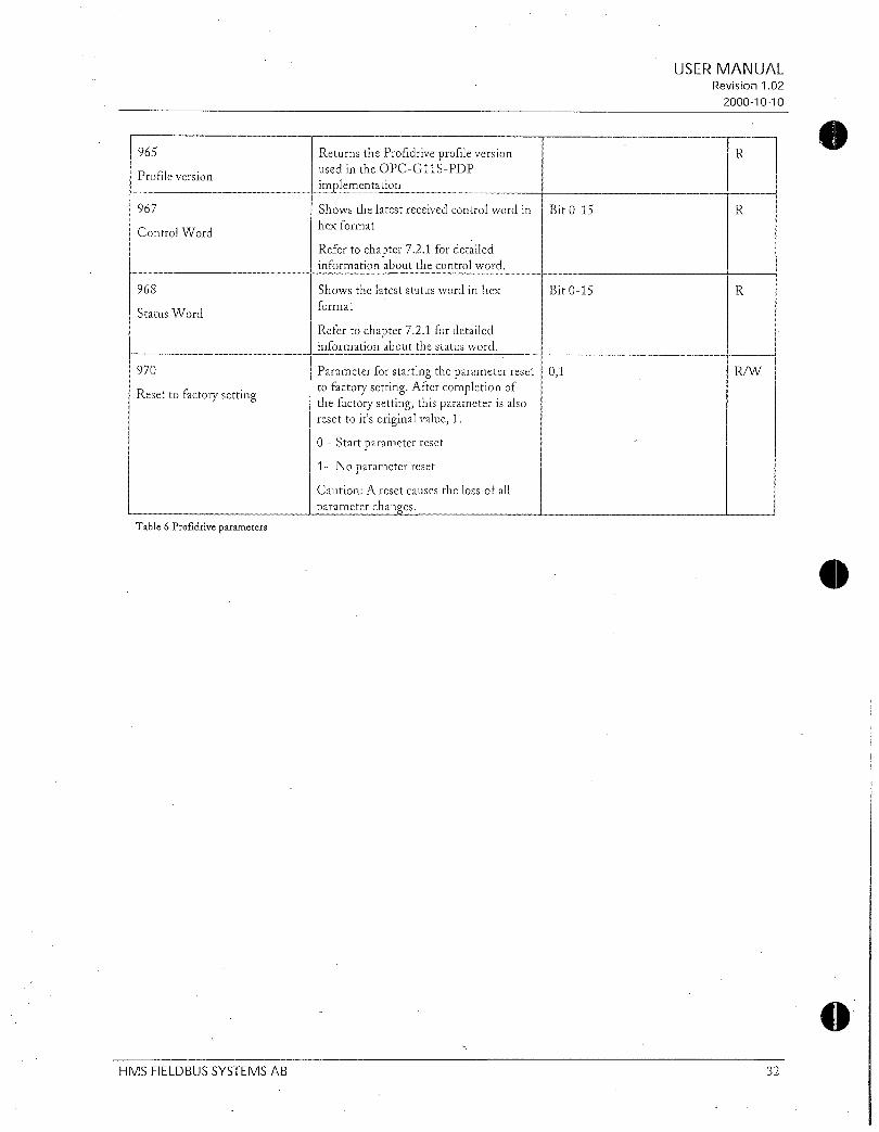
965
Profileversion
967
ControlWord
StatusWord
970
Resettofactorysetting
Table6Profidriveparameters
ReturnstheProfidriveprofileversionusedintheOPCG11SPDP
implementation
Showsthelatestreceivedcontrolwordin
hexformat
Refertochapter721fordetailedinformationaboutthecontrolword
Refertochapter721fordetailedinformationaboutthestatusword
CautionAresetcausesthelossofall
parameterchanges
Bit015
USERMANUALRevision102
20001010
R
R
968 Showsthelateststatuswordinhex Bit015 R
format
Parameterforstartingtheparameterreset 01 RW
tofactorysettingAftercompletionofthefactorysettingthisparameterisalsoresettoitsoriginalvalue1
0Startparameterreset
1Noparameterreset
HMSFIELDBUSSYSTEMSAB 32

76 Malfunctioncodes
0
1
2
3
4
5
Noalarm
OvercurrentDuringacceleration
OvercurrentDuringdeceleration
OvercurrentWhilerunningatconstantspeed
OvercurrentInput
Groundfault
6 OvervoltageDuringacceleration
7 OvervoltageDuringdeceleration
8 OvervoltageWhilerunningatconstantspeed
10 Undervoltage
11 Inputphaselose
12 Powersupplyfrequencyabnormal
13 ACFuseblown
14 DCFuseblown
16 DClinkchargecircuitabnormal
17 Overheatofheatsinkininverter
18 Externalalarminput
19 Overheatofunitinternaltemp
20 Overheatofmotor
22 OverheatofDBresistance
23 ElectronicthermaloverloadrelayMotor1
24 ElectronicthermaloverloadrelayMotor2
25 ElectronicthermaloverloadrelayInverter
27 Overspeed
28 PGerror
29 Thermistorcircuitdisconnection
31 Memoryerror
32 KEYPADpanelcommunicationerror
0000
OC1 2301
0C2 2302
0C3 2303
OC 2100
EF 2330
OUl 3211
OU2 3212
OU3 3213
LU 3220
Lin 3130
FrE 3140
ACF 5453
FUS 5450
PbF 5120
OH1 4310
0112 9000
OH3 4110
OH4 4300
dbH 4210
OL1 2211
OL2 2212
OLU 2200
OS 7310
Pg 7301
nrb 5000
Erl 5500
Erg 7520
USERMANUALRevision102
20001010
HMSFJELDBUSSYSTEMSAB 33

33 CPUerror Er3 5220
34 Optioncommunicationerror Er4 7510
35 Optionerror Er5 7511
36 Operatingprocerror Er6 F004
37 Outputphaselosserror Er7 7200
38 RS485communicationerror Er8 B100
39 ADconverterdefective Er9 7000
USERMANUALRevision102
20001010
HMSFIELDBUSSYSTEMSAB 34

8ParametersspecificforcommunicationTooperatetheinvertersortomonitorthestateviacommunicationthefollowingparametersareavailableforcommunicationinaddition totheconfigurationfunctionsoftheinvertersTheseparametersareacommondataformatapplicabletoinvertertypesonandafterG11P11seriessothatitispossibletoaccessdifferentinvertertypesbythesame program onthehostside
81Commanddata
Code
SOl Settingfrequencypu
SO5 ISetting frequency
Note
1Thedatawritingexceedingthesetting rangeispossiblebuttheactualactionwillberestrictedwithintheinverter
2Whenthecommanddataisreaditisnotthecommanddataofactualactionbutthecommanddatacommunicatedbeforethefinalcommanddatacanbeobtainedbyreadingofthemonitoringdatadescribedlater
Name Unit
Hz
I
82Operationcommanddata
Variablerange
2000020000
Maximumfrequencyat20000
1 00040000P11S00012000
Minunit
1
001 1 RW
RReading
WWriting
USERMANUALRevision102
20001010
IReadwriteRW
Code 1i Name 1 Unit 1 Variablerange Minunit 1 Readwrite
SO6IOperationcommand I Refertothedataformat11 1 RW
S07 I UniversalDo I Refertothedataformat12 1 RW
S12 UniversalAo 2000020000 1 RW
j 100outputat20000I
1
Note
1SinceXlX9aremultifunctioninputsitisnecessarytosetthefunctionswithE01E092ThealarmresetisexecutedwhenRSTsignalchangesfromONtoOFFeventherearenoalarmingfactors3UniversalDois afunctionutilizinginvertersDoviatransmission
IndetailrefertothedetaildescriptionsE20E24inFunctionExplanationintheinstructionmanualofinverter
4Thedatawritingexceedingthesetting rangeispossiblebuttheactualactionwillberestrictedwithintheinverter
HMSFIELEBUSSYSTEMSAB 35

5Whentheoperationcommandsareinstructedthroughthecommunicationtherelationtotheinverterterminalcommandsbecomesasfollows
Classification
Operation FWDREV FWDREVcommand
command
03 I SS1248
45 RT1RT2
6 HLD
7 BX
8 RST Alarmreset
9 THR
10 JOG
11 Hz2Hzl
12 M2M1 Motor2Motor1
13 DCBRK DCbrakecommand
14 TL2TL1 Torquelimiter2Torquelimiter1
SW50SW60 Switchingoperationbetweenlineandinverter5060Hz
UPDOWN UPDOWNcommand
WEKP WriteenableforKEYPAD
HzPID PIDcontrolcancel
1516C
6
01718V
019V
20
21
22
23
24
25
26
27
28
29
30
31
32
IVS
Symbol
IL
HzTRQ
LE
UDI
STM
PGHz
SYC
ZERO
STOP1
STOP2
EXITE
Function
Name
Multistepfreqselection
ACCDECtimeselection
3wireoperationstopcommand
Coasttostopcommand
TripcommandExternalfault
Joggingoperation
Freqset2Freqset1
Inversemodechangeoverterminals12andC1
Interlocksignalfor522
TRQcontrolcancel
LinkenableBusRS485
UniversalDI
Pickupstartmode
SYPGenable
Invalid
USERMANUALRevision102
20001010
Command
1 Transmission Terminalblock
Valid Invalid
Invalid
Valid
Valid
Invalid
Valid Invalid
Invalid 1 Valid
Valid Invalid
Invalid Valid
Valid Invalid
Invalid Valid
Valid
Synchronizationcommand Valid Invalid
Zerospeedcommand
Forcedstopcommand
ForcedstopcommandwithDecelerationtime4
1 Preexcitingcommand
Invalid Valid
Valid
HMSFIELDBUSSYSTEMSAB 36

83FunctiondataCode Name Uni Variablerange
t
S08 IAcceleration time F07 I s 0136000
S09 1Deceleration time F08 1 s 0136000
S10 Torque limitlevel1DrivingF40 200020000
P11S200015000999
Sil Torquelimitlevel2BrakingF41 000200020000
Note1Thewritingtooutoftherangeistreatedasoutofrangecrror2TheaccelerationanddecelerationtimeSO8andS09areassignedtoF07AccelerationtimePand
F08DecelerationtimeIrespectively3Thetorquelimitlevel1and2ofS10andS11areassignedtoF40Torquelimit1Driving and
F41Torquelimit1Braking respectively
HMSFIELDBUSSYSTEMSAB
P11S200015000999
USERMANUALRevision102
20001010
Minunit ReadWrite
01 RW
01 RW
100 RW
100 RW
37
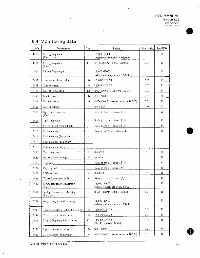
84MonitoringdataCode I Description
MOl SettingfrequencyFinaldata
M05 SettingfrequencyFinaldata
M06 Outputfrequency1
M07
MO8
M09
M10
M11
M12
M13
M14
M15
M16
M17
M18
M19
M20
M21
M23
M24
M25
M26
M27
M31 SettingFrequencyatalarmingFinaldata
M32 Outputfrequencyatalarming
M33
M34
M35
Torquecalculationvalue
Torquecurrent
Outputfrequency1
Inputpower
Outputcurrent
Outputvoltage
OperationcommandFinaldata
Operatingstate
YlY5outputterminaldata
Faultmemory0
Faultmemory1stprior
Faultinernory2ndprior
Faultmemory3rdprior
Operatingtime
DClinkcircuitvoltage
Typecode
Capacitycode
ROMversion
Transmissionerrorcode
SettingfrequencyatalarmingFinaldata
M36 1 Inputpoweratalarming
M37 1 Outputcurrentatalarming
HMSFIELDBUSSYSTEMSAB
Unit I Range
Hz 040000P11S00012000
Hz
V
h
V
Hz
ITorque calculationvalueatalarming
Torquecurrentatalarming
Outputfrequency1atalarming Hz
II
2000020000
MaximumfrequencyatX0000
2000020000
Maximumfrequencyat20000
2000020000
2000020000
00040000P11S00012000
00020000
00020000Inverterratingat10000
006000
Refertothedataformat11
Refertothedataformat13
Refertothedataformat12
Referto76Malfunctioncodes
065535
01000
Refertothedataformat14
Refertothedataformat9
064999
Refertothedataformat1
2000020000
Maximumfrequencyat20000
040000P11S00012000
2000020000
Maximumfrequencyat20000
1 2000020000
1 2000020000
4000040000
P11S1200012000
1 00020000
1 00020000Inverterratingat10000
USERMANUALRevision102
20001010
1 MinunitReadWrite
1 R
001 R
1 R
001 R
001 R
001 R
001 R
001 R
10 R
R
R
R
R
1 R
1 R
R
R
1 R
R
1 R
001 R
1 R
001 1 R
001 1 R
001 R
001 R
001 1 R
38
0

eM38 Outputvoltageatalarming
M39 Operationcommandatalarming
M40 Operatingstateatalarming
M41 YlY5outputterminaldataatalarming
M42 Operationtimeatalarming
M43 DClinkcircuitvoltageatalarming
M44 Inverterinternalairtempatalarming
1V145 Coolingfintempatalarming
M46 IIi Lifeofmaincircuitcapacitor
M47 LifeofprintedcircuitboardIcapacitor
M48 Lifeofcoolingfan
Note
2
HMSFIELDBUSSYSTEMSAB
1006000
Refertothedataformat11
Refertothedataformat13
Refertothedataformat12
h 1 065535
01000
C 0120
C I 0120
1 001000
h 065535
h 065535
1Theoutputfrequency1isbeforeslipcompensation
1
1
01
1
USERMANUALRevision102
20001010
R
R
R
R
R
R
R
R
R
R
R
Theoutputfrequency1withspeedregulatorusingoptionOPCG11SPGistreatedasthesynchronousfrequency
39
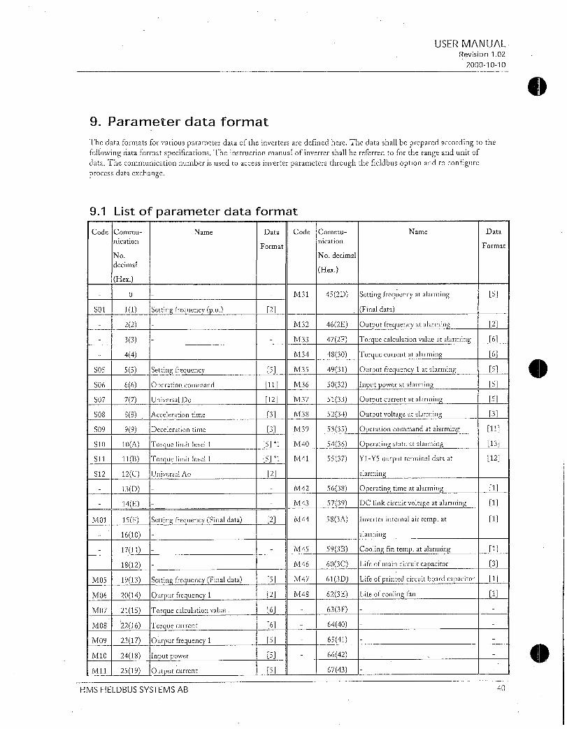
9Parameterdataformat
ThedataformatsforvariousparameterdataoftheinvertersaredefinedhereThedatashallbepreparedaccordingtothefollowingdataformatspecificationsTheinstructionmanualofinvertershallbereferredtofortherangeandunitofdataThecommunicationnumberisusedtoaccessinverterparametersthroughtheficldbusoptionandtoconfigureprocessdataexchange
91Listofparameterdataformat
Name Data
Format Format
No Nodecimal
decimal
CodeCommu
nication
S01
S05
S06
S07
S08
S09
S10
S11
S12
MOl
M05
M06
M07
M08
M09
M10
M11
Hex
0
11
22
33
44
55
66
77
88
99
10A
11B
12C
13D
14E
15F
1610
1711
1812
1913
2014
2115
2216
2317
2418
2519
Settingfrequencypu
Settingfrequency
Operationcommand
UniversalDo
Accelerationtime
Decelerationtime
Torquelimitlevel1
Torquelimitlevel1
UniversalAo
HMSFIELDBUSSYSTEMSAB
Name Data CodeCommu
nication
SettingfrequencyFinaldata
1Setting frequencyFinaldata
Outputfrequency1
Torquecalculationvalue
Torquecurrent
Outputfrequency1
Inputpower
Outputcurrent
Hex
M31 452D
2
M32 462E
M33 472F
M34 4830
5 M35 4931
11 M36 5032
12 M37 5133
3 M38 5234
3 M39 5335
51 M40 5436
51 M41 5537
2
M42 5638
II M43 5739
2 M44 583A
M45 593B
M46 603C
5 M47 613D
2 M48 I 623E
6 633F
6 6440
5 I 6541
5 6642
5 6743
Settingfrequencyatalarming
Finaldata
Outputfrequencyatalarming
Torquecalculationvalueatalarming
Torquecurrentatalarming
Outputfrequency1atalarming
Inputpoweratalarming
Outputcurrentatalarming
Outputvoltageatalarming
Operationcommandatalarming
Operatingstateatalarming
Y1Y5outputterminaldataat
alarming
1Operating timeatalarming
1DC linkcircuitvoltageatalarming
Inverterinternalairtempat
alarming
Coolingfintempatalarming
Lifeofmaincircuitcapacitor
Lifeofprintedcircuitboardcapacitor
Lifeofcoolingfan
USERMANUALRevision102
20001010
40

M12
M13
M14
M15
NI16
M17
M18
M19
M20
M21
M23
M24
1V125
M26 4028
M27 141291
4122A432B442C
261A Outputvoltage
271B OperationcommandFinaldata
1281C Operatingstate
291D Y1Y5outputterminaldata
1301E Faultmemory0
1311F Faultmemory1stprior
13220 Faultmemory2ndprior
3321 Faultmemory3rdprior
13422 Operatingtime
13523 DClinkcircuitvoltage
362413725 Typecode
13826 Capacitycode
3927 ROMversion
Transmissionerrorprocessing
code
Settingfrequencyatalarming
Finaldata
II
1999istreatedas7FFF
F00
FO1
F02
F03
F04
F05
F06
F07
F08
F09
F10
Fil
F12
F13
F14
USERMANUALRevision102
20001010
6844
6945
7046 Dataprotection
7147 Frequencycommand1
7248 Operationmethod
7349 Maximumoutputfrequency1
744A Basefrequency1
754B Ratedvoltage1
764C Maximumoutputvoltage1
774D Accelerationtime1
784E Decelerationtime1
794F Torqueboost1
8050 Electronicsthermaloverloadrelay1
Selection
8151 Electronicsthermaloverloadrelay1
Level
8252 Electronics thermaloverloadrelay1
8353 Electronicsthermaloverloadrelay
Brakingresistor
8454 Restartaftermomentarypowerfailure
Selection
HMSFIELDBUSSYSTEMSAB 41

CodeCommu
nication
No
decimal
Hex
F15 8555
F16 8656
F17 8757
F18 8858
F20 8959
F21 905A
F22 915B
F23 925C
F24 935D
F25 945E
F26 955F
F27 9660
F30 9761
F31 9862
F33 9963
F34 10064
F35 10165
F36 10266
F40 10367
F41 10468
F42 10569
E01 1066A
E02 1076B
E03 1086C
E04 1096D
E05 1106E
E06 1116F
E07 11270
E08 11371
E09 11472
El0 11573
Ell 11674
E12 11775
Torquelimit1Driving
Torquelimit1Braking
Torquevectorcontrol1
X1terminalfunction
X2terminalfunction
X3terminalfunction
X4terminalfunction
X5terminalfunction
X6terminalfunction
X7terminalfunction
X8terminalfunction
X9terminalfunction
Accelerationtime2
Decelerationtime2
Accelerationtime3
HMSFIELDBUSSYSTEMSAB
Name
1Frequency limiterHigh
FrequencylimiterLow
Gainforfrequencysettingsignal
Biasfrequency
DCbrakeStartingfrequency
DCbrakeBrakinglevel
DCbrakeBrakingtime
Startingfrequency
StartingfrequencyHoldingtime
Stopfrequency
MotorsoundCarrierfrequency
MotorsoundSoundtone
FMAterminalVoltageadjust
FMAterminalFunctionselection
FMPterminalPulseratemultiplier
FMPterminalVoltageadjust
FMPterminalFunctionselection
30Ryoperationmode
Data
Format
CodeCommu
nication
No
decimal
Hex
E37 13587
E40 13688
E41 13789
E43 1388A
E44 1398B
E45 1408C
C01 1418D
CO2 1428E
CO3 1438F
C04 14490
COS 14591
C06 14692
C07 14793
C08 14894
C09 14995
C10 15096
C11 15197
C20 15298
C30 15399
C31 1549A
C32 1559B
C33 1569C
P01 1579D
P02 1589E
P03 1599F
PO4 160A0
P05 161A1
P06 162A2
P07 163A3
P08 164A4
P09 165A5
H03 166A6
Name Data
Overloadearlywarning2level
Display coefficientA
DisplaycoefficientB
LEDmonitorDisplayselection
LEDmonitorDisplayatSTPmode
LCDmonitorDisplayselection
Jumpfrequency1
Jumpfrequency2
Jumpfrequency3
Jump frequencyWidth
Multi stepfrequency1
Multistepfrequency2
Multistepfrequency3
Multistepfrequency4
Multistepfrequency5
Multistepfrequency6
Multistepfrequency7
Joggingfrequency
Frequencysetting2
Analoginputoffsetterminal12
Analoginputbiasterminal12
AnaloginputoffsetterminalC1
Analoginputgainterminal12
Analogfilter
Motor 1Numberofpoles
Motor1Capacity
Motor1Ratedcurrent
1Motor 1Autotuning
Motor1Onlinetuning
Motor1Noloadcurrent
IMotor 1R1
Motor1X
1Motor 1Slipcompensationcontrol
1Data initializing
USERMANUALRevision102
20001010
Format
1
5
10
4
1
10
5
5
5
12
42

E13 1111876E14 111977
I
E15 12078
E16 I42179E17 1227A
E20 1237BE21 11247CE22 1257DE23 11267EE24 1277F
E30 12880FrequencyarrivalFAR
Detectingwidth
E31 12981Frequencydetection1FDT
level
E32 13082FrequencydetectionFDT
Hysteresiswidth
E33 13183Overloadearlywarning
E34
E35
E36
1Overload earlywarning1level
13385OverloadearlywarningTimertime
13486Frequencydetection2FDTlevel
1075kHzistreatedas0000H
2ThecImmunicationmightnotbeabletobecontinuedbywritingdata1
3999isHeatedas03E7H9994Itis irnpossibletoexecutetheAutotuningviaProfibusDP
Decelerationtime3
Accelerationtime4
Decelerationtime4
Torquelimiter1Driving
Torquelimiter1Braking
Y1terminalfunction
Y2terminalfunction
Y3terminalfunction
Y4terminalfunction
Y5AYSCterminalfunctions
Modeselection
3
IT04
H05
H06
H07
H08
1I09
IT10
II11
H12
1
H14
H15
f116
1118
3 I H19
I H2O
1 I121
1122
10 I H23
3 I124
1 1
167A7
168A8
169A9
170AA
171AB
172AC
173AD
174AE
175AF
176B0
177B1
178B2
17933
180B4
181B5
182B6
183B7
184B8
185B9
186BA
187BB
AutoresetTimes
AutoresetResetinterval
Fanstopoperation
ACCDCCpatternModeselection
Reversephasesequencelock
StartmodePickupmode
Energysavingoperation
Decelerationmode
Instantaneousovercurrentlimiting
AutorestartRestarttime
AutorestartFrequencyfallrate
AutorestartHoldingDCvoltage
Autorestart
OPRcommandselfholdtime
TorquecontrolModeselection
Activedrive
PIDcontrolModeselection
PIDcontrolFeedbacksignal
PIDcontrolPGain
PIDcontrolItime
PIDcontrolDtime
PIDcontrolFeedbackfilter
USERMANUALRevision102
20001010
HMSFIELDBUSSYSTEMSAB 43

CodeCommu
nication
No
decimal
Hex
H26 188BC
H27 189BD
H28 190BE
H30 191BF
H31 192C0
1 193C1
H33 194C2
1134 195C3
H35 196C4
H36 1 197C5
1137 198C6
H38 1 199C7
1139 200C8
A01 201C9
A02 202CA
A03 1 203CB
A04 I 204CC
A05 205CD
A06 206CE
A07 207CF
A08 208D0
A09 209D1
A10 210D2
All 211D3
Al2 212D4
A13 213D5
A14 214D6
A15 215D7
Alb 216D8
A17 217D9
A18 218DA
Name
PTCthermistorModeselection
PTCthermistorLevel
Droopoperation
SeriallinkFunctionselection
RS485Address
RS485Modeselectiononerror
RS485Timertime
RS485Baudrate
RS485Datalength
1RS485 Paritycheck
RS485Stopbits
1RS485 Noresponsedetectiontime
RS485Responseinterval
Maximumfrequency2
Basefrequency2
Ratedvoltage2atbasespeed
Maximumoutputvoltage2
Torqueboost2
Electronicsthermal2Selection
Electronicsthermal2Level
Electronicsthermal2
Thermaltimeconstant
Torquevectorcontrol2
Motor2Numberofmotor2poles
Motor2Capacity
Motor2Ratedcurrent
Motor2Autotuning
Motor2Onlinetuning
Motor2Noloadcurrent
Motor2R1setting
Motor2Xsetting
Motor2Slipcompensationcontrol2
Data CodeCommu
nicationFormat
11
11
11
51
110361037110381111040
Hex
235EB 1Bus ConfigurationParameter07
236EC 1Bus ConfigurationParameter08
237EDBusConfigurationParameter09
238EEBusConfigurationParameter10
239EFBusConfigurationParameter11
o41 2401BusConfigurationParameter12
o09 Basesidenumberofencoderpulses
o42 241F1BusConfigurationParameter13
o10 Timeconstantofpulsetraininputfilter
o43 242F2BusConfigurationPar14
Commandpulsecompensationcoefficient1
044 2431BusConfigurationParameter15
o12 Commandpulsecompensationcoefficient2
045 244174BusConfigurationParameter16
o13 Mainspeedregulatorgain
o46 245175BusConfigurationParameter17
o14 APRPgain
o47 246176BusConfigurationParameter18
o15 Zphasematchinggain
048 247177BusConfigurationParameter19
o16 Offsetangle
o49 248F8BusConfigurationParameter20
o17 Detectinganglewidthforcompletion
ofsynchronizing
o50 249F9BusConfigurationParameter21
o18 Toomachdeviation
250FABusConfigurationParameter22
251FBBusConfigurationParameter23
252FCBusConfigurationParameter24
253FDBusConfigurationParameter25
254FEBusConfigurationParameter26
255FF
oil
10511o52o53
10541055
No
decimal
Name
USERMANUALRevision102
20001010
Data
Format
HMSFIELDBUSSYSTEMSAB 44
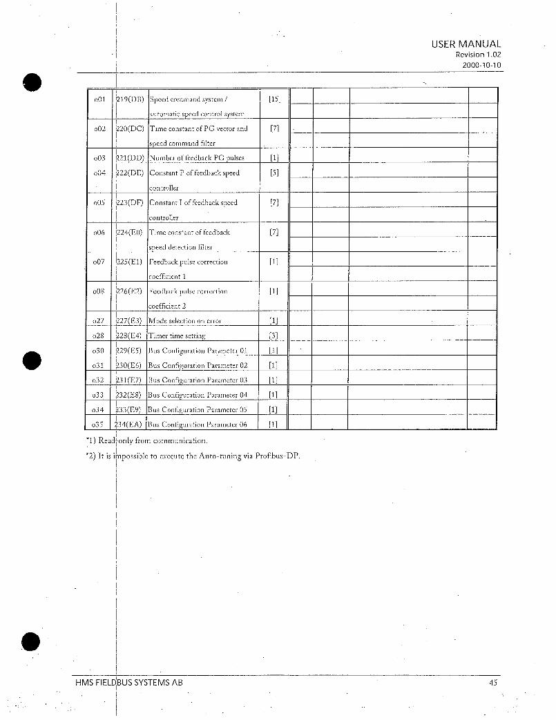
Speedcommandsystem
automaticspeedcontrolsystem
TimeconstantofPGvectorand
speedcommandfilter
NumberoffeedbackPGpulses
ConstantPoffeedbackspeed
controller
ConstantIoffeedbackspeed
controller
Timeconstantoffeedback
speeddetectionfilter
o07 225E1Feedbackpulsecorrection 1
coefficient1
o08 226E2Feedbackpulsecorrection 1
coefficient2
o27 227E3Modeselectiononerror 1
o28 1 228E4Timertimesetting 3
030 229E5BusConfigurationParameter01 1
o31 230E6BusConfigurationParameter02 1
o32 231E7BusConfigurationParameter03 1
o33 232E8BusConfigurationParameter04 1
034 233E9BusConfigurationParameter05 1
o35 234EABusConfigurationParameter06 1
1Readonlyfromcommunication
2ItisimpossibletoexecutetheAutotuningviaProfibusDP
o01 I219DB
o02 220DC
o03 1221DDo04 222DE
o05 223DF
o06 1224E0
7
1
5
7
7
USERMANUALRevision102
20001010
HMSFIELDBUSSYSTEMSAB 45

92Dataformatspecification
Alldatawithinthedatafieldofthecommunicationframeconsistof16bitsbinarydata
MSB
atmorriiatiI
ExampleIfF15Frequencylimiterhighlimit60Hz
601 60003C
ataormat IntegerdataPositivenegativeMinunit1
ExampleIfF18Biasfrequency 20Hz
201 20FFECtwoscomplement
ataoimatl3
LSB
15 14 13 12 11 10 9 8 7 6 5 4 3 2 1 0
Negativedataistreatedwithtwoscomplement
Dataformat4
IntegerdataPositiveMinunit1
DecimaldataPositiveMinunit01
ExampleIfF17Gainforfrequencysettingsignal1000
100010 100003E8
DecimaldataPositivenegativeMinunit01
ExampleIfH28Droopoperation
5010 50FFCEtwoscomplement
tagimat
16bitsbinarydata
ataomat61
DecimaldataPositiveMinunit001
ExampleIfCO5Multistepfrequency15025Hz
5025100 5025 13A1
ataomati7
DecimaldataPositivenegativeMinunit001
DecimaldataPositiveMinunit0001
ExampleIfMO7Actualtorquevalue 8538
85381008538DEA6twoscomplement
ExampleIfo05ConstantIoffeedbackspeedcontroller0105s01051000 105 0069
0
0
F
1
D
0
0
F
3
F
3
E
0
USERMANUALRevision102
20001010
3
E
E
C
A
A
6
c
C
8
E
1
HMSFIELDBUSSYSTEMSAB 46

10ataformatraDecimaldataPositivenegativeMinunit0001
ExampleIfbeing1234123410001234FB2Etwoscomplement
eataormat9
5
10
20
40
75
150
220
370
550
750
Code
Capacitycode
CapacitykW Code CapacitykW
005 1100 11
01 1500 15
02 1850 185
04 2200 22
075 3000 30
15 3700 37
22 4500 45
37 5500 55
55 7500 75
75 9000 90
Example If30kW
Since301003000OBB8
ExponentialdataACCDECtimecurrentvaluedisplaycoefficient
MSB LSB
15 14 13 12 11 10 9 8 7 6 5 4 3 2 1 0
Polarity 0 0 0Index
Dataportionpotion
Notused
HMSFIELDBUSSYSTEMSAB
0001 001999 000999
101 100999 100999
21 100999 100999
310 100999 10003600
0Positive 1Negative
ExampleF07Accelerationtime1200s
20001200
Code
11000
13200
16000
20000
22000
25000
28000
31500
35500
40000
F
0
B
USERMANUALRevision102
20001010
2
CapacitykW
110
132
160
200
220
250
280
315
355
400
47

iatormat11Operationcommand
15 14 13 12 11 10 9 8 7 6 5 4 3 2 1 0
0 0 0 0 X9 X8 X7 X6 X5 X4 X3 X2 X1
crrA c1
Alarmreset
command
ataormtrl2
Notused
ExampleIfM13OperationcommandFinalcommandFWDX1X5ON
00000000010001010045
Universaloutputterminal
Multifunctioncommand
ExampleIfM15UniversaloutputterminalY1Y5 ON
00000000000100010011
i
0
USERMANUALRevision102
20001010
FWDForwardrotation
command
REVReverserotation
command
AllbitsareONby1
0
15 14 13 12 11 10 9 8 7 6 5 4 3 2 1 0
0 0 0 0 0 0 0 0 0 0 0 Y5 Y4 Y3 Y2 Y1
Notused Universalcommand
AllbitsareONby1
0
4
1
5
1
HMSFIELDBUSSYSTEMSAB 48

ataormat13
ExampleOmittedMonitoringmethodissimilarasintheformats11and12
FWD Inforwardoperation IL Incurrentlimiting
REV Inreverseoperation ACC Inacceleration
EXT InDCbrakingorinpreexcitation DEC Indeceleration
ALM Alarm
INT Invertertrip RL Transmissionvalid
BRK Inbraking WR Functionwritingright
NUV DClinkvoltageisestablishment 0KeypadpanelUndervoltageconditionat0
1RS485
TL Intorquelimiting 2Linkoption
VL Involtagelimiting
1
2
3
4
5
6
15 14 13 12 11 10 9 8 7 6 5 4 3 2 1 0
Code
Operatingstatus
15 14 13 12 11 10 9 8 7 6 5 4 3 2 1 0
Typecode
Unittype
VG
G
P
E
C
S
HMSFIELDBUSSYSTEMSAB
WR RLALMDECACC IL VL TLNUVBRKINTEXTREVFWD
Type
Generation Series
Generation Series
1 11thseries ForJapan
ForAsia
ForChina
ForEurope
ForUSA
AllbitareONoractiveby1
USERMANUALRevision102
20001010
Voltageseries
Voltageseries
100Vsinglephase
200Vsinglephase
200Vthreephase
400Vthreephase
575Vthreephase
49

Dataformat15Codesetting1 4figures
USERMANUALRevision102
20001010
15 14 13 12 11 10 9 8 7 6 5 4 3 2 1 0
Data4 Data3
ExampleIfo22Aifunctionselection 123
Since1230124
Data2 Data1
3
HMSFIELDBUSSYSTEMSAB 50

10 SystemconfigurationThisisanexample onhowtoconfiguretheOPCG11SPDPintheSiemensStep7programInordertoenabledataexchangebetweentheStep7andtheFujidrive twoimportantstepshastobemadethehardwareconfigurationandthecorrectPLCprogramming
II
USERMANUALRevision102
20001010
HMSFIELdBUSSYSTEMSAB 51
I

101Hardwareconfiguration
StartuptheHWConfigprogramandinstalltheGSDfilefortheOPCG11SPDPThisisdoneunderOptionsInstallNewDDBfiles
ChoosetheGSDfileHMS1011andpressopen
H115DDBFiea19x
tta Gsd Ys
Hms1000 r7 Wagob750
HMS1001 QPDPF0162 1WaHMS1002 PSFT0882 015000
HMS1003 s1en906a
HMS1009 Ilncart
Hmv1010 DUndP
HMSFIELDBUSSYSTEMSAB
USERMANUALRevision102
20001010
52

5
ThenstartupanewprojectandconfigurethePLCandProfibus masterSetuptheProfibusmasterwithbaudrateandparameters
51111194 1
SfafionEdeWei037 Apr84OWrdeerNap
CslaIfI aferdiemrpiriijRr
1131
SIRfMNub IGM1N144
1P520754 16573071E
2131711U314 6E97314184
3
56I
8910I11
Peale
gliSteeti
ZfI0f081IPS30754
23jCPU31CPU314
56
P13314
3I4MCP3425131
67
HMSFIEL6St1SSYSTEMSAB
I
ggFl8g5Node4CP3425p0 870
te47onooeeon
PPO1
boPPOTyp3PPGTyp4
934r363113 AISIFIC188lPl4IIHW744119141 I
PROFIBUS11IDPMas185yalers11801
0366nn16anrrJ0Bre0
15E303043A0043I6ES731410E013A00I6GK73425DA0003
58IkISPded
47PROMOU1OP
IMAM300C7CP300CP310231A2SYMOOR
CP34005232CMODULE
C1R5232CMODULE
CP34085422148510002
CP3422A51
CP3425C73425jCPU301IM7430
Prepard811 1433047EXTENSIONpete1505303
P13071041P5307SA
RACKS0Radj31
l1454010831000170I
7S6000praoco6CODAECEtJE450141eandS7
ir0Wx
USERMANUALRevision102
20001010
CreateanetworkfortheProfibussystembychoosinginsertDPMasterSystemClickonlOPCG11SPDPintheHardwarecatalogueProfibusDPAdditionalFieldDevicesAntriebeanddrag the
foldertotheProfibusnetworklineThenchoosethePPOtypeandpressOK
9S01Ed61LcY5o5451615483
P844IStandardPROFIBUSDP
911AddlxwlP4d0evIenJIO0GATEWAY1JANIRIEBE
1JOPCG00013PUneadiModuleJ0ConfiguredSration3174484804C360342001481111DPAS1DDPPALv4c
1CENCODERET200B
JQET200C0ET2003jE1200410ET20W37JET200r470IDENT
EgIPC0 NC
41
53

TheconfigurationprogramwillnowautomaticallysetupthemodulewithINandOUTaddresses
ToseehowthemoduleisconfiguredortochangeaddressesdoubleclickonUniversalModule
diinsetacViewQoa41402815v
olD01081141I I Jk
1
PveposslAe
sta11wr
DicA41F2i
3
456
1314151617191920
x
1 PS3075AI
CPU31
dillCP3425156I7I
JTaYGlll0NEl0GiliTMNIEIll
StationEditinsectaYewOptions47adowHt
Asiio5ROE18MSAddess
II
J2I05740834teduk4ID0OiMaillurrERN flaaaessAd0oss17mtri
71lh4c0MSlati14010084u1fYol
1ASIekIlt lltlwetoxdIE
PROFIBUSNIDPMasteSystem11801
j81
FI8us0DPMatterSystem11801
r10FtG1
OPIIOMA
lxwcdnrl
Standard J
14ePROFIBUSDPtO0AdditionalheldDevices
00
8rGATEWAY
1JANTRIEBE71DPWtSPOP
UnnersaiModAeDLCongued61a0onsJL3Controkr1jCP3425asDPMasteralGDPAS
DPPAtank
1CENCODEREt0ET2028
ET2000
1UET200L5l0ET200MFJET2002
CE12011tz1C1DENTt0IPC150NC
e1 t
Ie1fii101
ErC14sludad 1FivPROFIBUSDP
21AddtieralFieldDevices
0110i8L1GATEWAY
7UANTRIE880OPC7115PDPAUniversalModuie
OCodguadStations1JComallei1JCP3425asDPMast1aJDPAS
1JDPPAEnk10ENCODER00ET20013jET200C
7JET2028j0ET200481JET2000
720ET2002110DENTJIPC
150NC
1100Pa71131
USERMANUALRevision102
20001010
WhenthemoduleisconfiguredtheconfigurationcanbedownloadedtothemasterthisisdoneunderPLCDownload
819 019
TICMena laloc11135
HMSFIELDBUSSYSTEMSAB 54
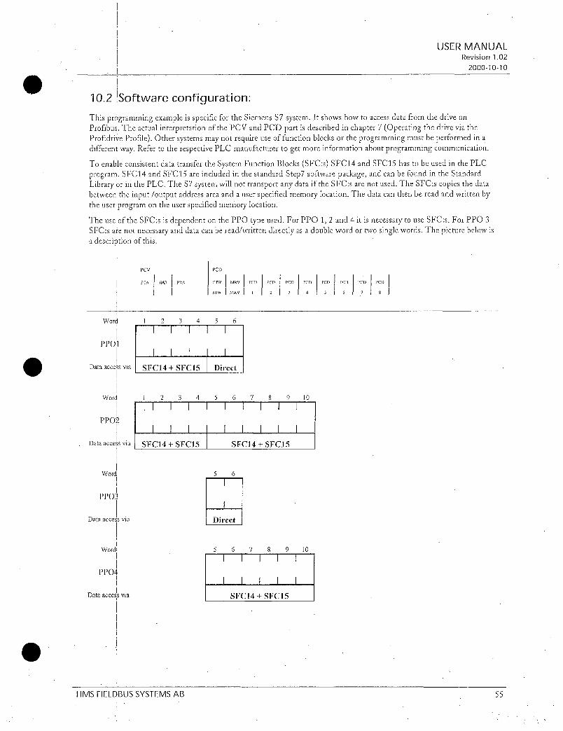
I
1021SoftwareconfigurationThisprogrammingexampleisspecificfortheSiemensS7systemItshowshowto accessdatafromthedriveon
ProfibusTheactualinterpretationofthePCVandPCDpartisdescribedinchapter7OperatingthedriveviatheProfrdriveProfileOther systemsmaynotrequireuseoffunctionblocksortheprogrammingmustbeperformedinadifferen i wayRefertotherespectivePLCmanufacturertogetmoreinformationaboutprogrammingcommunication
ToenableconsistentdatatransfertheSystemFunctionBlocksSFCsSFC14andSFC15hastobeusedinthePLCprogramSFC14andSFC15areincludedinthestandardStep7softwarepackageandcanbefoundintheStandardLibraryorinthePLCTheS7systemwillnottransportanydataiftheSFCsarenotusedTheSFCscopiesthedatabetweentheinputoutputaddressareaandauserspecifiedmemorylocationThedatacanthenbereadandwrittenbytheuserprogramontheuserspecifiedmemorylocation
TheusetheSFCsisdependentonthePPOtypeusedForPPO12and4itisnecessarytouseSFCsForPPO3SFCsarenotnecessaryanddatacanbereadwrittendirectlyasadoublewordortwosinglewordsThepicturebelowisa descriptionofthis
Word
PPO1
Dataaccessvia
Word
PPO21
Dataaccessvia
Word
PPO3
Dataaccessvia
PCV
PCA IND PVA
1 2 3 4 5 6
1 1 1 1 1
I I 1 1 I
SFC14SFC15
1 2 3 4 5 6 7 8 9 10
1 1 1 1 1 1 1 1 1
I I I
SFC14 SFC15
PCD
CTWMRVPCD PCD PCD PCD PCD PCD PCD PCD
STWMAV 1 2 3 4 5 6 7 8
Direct
1 1 1 1 1 1
SFC14 SFC15
5 6
1
1 Direct
Word 5 6 7 8 9 10
1 1 1 1 1
PPO41 1 1 1 1
Dataaccessv SFC14 SFC15
HMSFIELDBUSSYSTEMSAB1
USERMANUALRevision102
20001010
55

IntheexamplebelowitisshownhowtoprogramthecommunicationifPPO2isusedTheINOparametertellsthestartaddressoftheinputoutputareaexampleW160ThevalueshouldbeenteredinhexTheRETVALisastoragelocationwordforerrormessagesfromtheSFCexampleIVIW50TheOUT1andIN1parametersspecifiestheuserspecifiedstoragelocationandthesizeofthememoryareaexamplePM00BYTE8ThestartaddressesandsizesisaccordingtothevaluesspecifiedinthehardwareconfigurationprogramHWConfig
IntheexamplebelowtheinputPCVdatacanbereadinMWO MW6andinputPCDdatacanbereadinMW8MW18TheoutputPCVdatacanbewrittentoMW20 MW26andoutputPCDdatacanbewrittentoMW28MW38ThePCVandPCDparthastobetransferredseparatelybecausetheyareconfiguredasseparatemodulesinthehardwareconfigurationprogram
iB1htesInupG1t5IMATIG301Stttun0FileEditPastePLCDebugViewrptionaWindosHelp
OBI Title
r
RtetworkLReadPCVfromdrive
CALLSFC 14
INO W160
RETVALM8150OUT1 PH00BYTE8
tJetvoek2ReadPCDfromdrive
FileBlocksaved
CALLSFC 14
I810 81168
PETVAL188154
OUT PM80BYTE12
ttetrrork3WritePCVtodrive
CALLSFC 15
I810 ZJ160
IN1 PM200BYTE8
RETVAL188152
ttetsmrk4WritePCDtodrive
CALLSFC 15
INO tJ168
IN1 PM280BYTE12
RETVAL188156
IAbs 1Irt1
USERMANUALRevision102
20001010
HMSFIELDBUSSYSTEMSAB 56

11GSDfile
EachdeviceonaProfibusDPnetworkisassociatedwithaGSDfilecontainingallnecessaryinformationaboutthedeviceThistextfileisusedbythenetworkconfigurationprogramduringconfigurationofthenetwork
TheGSDfileforOPCG11SPDPHMS1011GSDisshownbelow
ProfibusDeviceDatabaseofHMSFieldbusSystemsDPslave
ModelOPCG11SPDP
DescriptionProfidriveProfibusDPoptionboardforFUJIC11inverter
LanguageEnglish
Date20October1999
AuthorHMSFieldbusSystemsAB
ProfrbusDP
GSDRevision 1
Deviceidentification
VendorName HMSFieldbusSystemsAB
ModclName OPCGI1SPDP
Revision Version100I
IdentNumber 0x1011
Protocollldcnt 0 DPprotocolI
StationType 0 Slavedevice
FMSsupp 0 FMSnotsupported
HardwareRelease Version130
SoftwareRelease Version100
I
Supportedbaudrates
96supp 1
192supp 1
9375supp 1
1875supp 1
I
500supp 1
15Msupp 1I
3Msupp 1
6Msup p 1
12Msupp 1
1HMSFIELDBUSSYSTEMSAB
I
USERMANUALRevision102
20001010
57
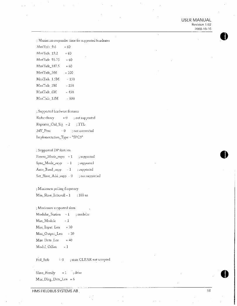
Maximumrespondertimeforsupportedbaudrates
MaxTsdr96
MaxTsdr192
MaxTsdr9375
MaxTsdr1875
MaxTsdr500
MaxTsdr15M
MaxTsdr3M
MaxTsdr6M
lVlaxTsdr12M
Supportedhardwarefeatures
Redundancy
RepeaterCtrlSig 2
24VPins 0
ImplementationType
SupportedDPfeatures
FreezeModesupp 1
SyncModesupp 1
AutoBaudsupp 1
SctSlaveAddsupp 0
FailSafe
60
60
60
60
100
150
250
450
800
0 notsupported
SlaveFamily 1 drive
MaxDiagDataLen 6
TTL
notconnected
SPC3
Maximumpollingfrequency
MinSlaveIntervall1 100us
supported
supported
supported
notsupported
Maximumsupportedsizes
ModularStation 1 modular
MaxModule 1
MaxInputLen 20
MaxOutputLen 20
MaxDataLen 40
ModulOffset 1
0 stateCLEARnotaccepted
USERMANUALRevision102
20001010
HMSFIELDBUSSYSTEMSAB 58

Definitionofmodules
ModulePPOTyp1OxF3OxF1
EndModuleModulePPOTyp2OxF3OxF5
EndModule
ModulePPOTyp3OxF1EndModuleModuleIPPOTyp4OxF5
EndModule
USERMANUALRevision102
20001010
HMSFIELDBUSSYSTEMSAB 59

U
0s
GE 3esAmr
ThisaddendumisforthefollowingdriveROMversions
AF300G11P11 30HPandbelow S09000orlater40HPandabove H10036orlater
ChecktheROMversioninthemaintenanceinformationonthekeypadPleaserefertosection439Maintenanceinformationin
theUsersGuide

ThefollowingfunctionsarechangedoraddedEExtensionTerminalFunctionsFunc
No
E01
E02
E03
E04
E05
E06
E07
E08
E09
E20
E21
F22
E23
E24
U UserFunctionsFunc NAME
No
U01Maximumcompensationfrequencyduringbrakingtorquelimit
1stSshapelevelatacceleration
2ndSshapelevelatacceleration
1stSshapelevelatdeceleration
2ndSshapelevelatdeceleration
MainDClink Initialvalue
capacitorMeasuredvalue
PCboardcapacitorpoweredontime
UO2
UO3
U04
U05
U08
U09
U10
U11
U13
U15
U23
U24
U48
U49
U56
U57
U58
U59
U59
U60
U61
U89
Speedagreement
PGerror
NAME
X1terminalfunction
X2terminalfunction
X3terminalfunction
X4terminalfunction
X5terminalfunction
X6terminalfunction
X7terminalfunction
X8terminalfunction
X9terminalfunction
Y1terminalfunction
Y2terminalfunction
Y3terminalfunction
Y4terminalfunction
Y5AandY5Cterminalfunc
PGerrorselection
Brakingresistorfunctionselect
DCfantripselect
EAX1FUNCX2FUNC
X3FUNC
X4FUNC
X5FUNC
X6FUNC
X7FUNC
X8FUNC
X9FUNC
Y1FUNC
Y2FUNC
Y3FUNC
Y4FUNC
VTRY5FUNC
E02
E03
E04
E05
E06
E07
E08
E09
E20
UO2
UO3
U04
U05
U08
U09
U10
Coolingfanoperatingtime USER11
Magnetizecurrentvibration USER13
dampinggain
FirlSlipcompensationfilter USER15
timeconstant
Integralgainofcontinuous USER23Foperationatpowerfailure
Proportionalgainofcontinuousoperationatpowerfailure
Inputphaselossprotection
U49PS485protocolselection USER49
Detectionwidth USER56
Detectiontimer USER57
U56
U58USER58
nalUSER59USER59U59
LCDDisplay
LCDDisplay
USER01
USER02
USER03
USER04
USER05
USER08
USER09
USER10
USER24
USER48
Regenerationavoidance
11M111USER60
atdeceleration
Voltagedetectoffsetand Fall USER61
gainadjustment
Motoroverloadmemoryretention EmilUSER89
10to35
0to37
Settingrange UnitMin
Unit
Settingrange Unit
0to65535
1to50
1to50
1to50
1to50
0to65535
0to65535
0to65535h
0to65535h
0to32767
0to32767
0to65535
0to65535
012
01
0to50
00to100s
01
00toA8HEX00to01
01
30HPFixed40HP 012
01
1
Min
Unit
1
1
1
1
1
1
1
h 1
h 1
s 01
FactorySetting30HP140HP
0
1
2
3
4
5
6
7
8
0
1
2
7
10
FactorySetting 1Change30HP140HP duringop
75 A
819
556
1738
1024
10
10
10
10
xxxx
0
0
0
75HP 100HP
0 1
0
10
05
1
00 1 NA
NA 1 00
0
0
1
410
546
1000
1000
Changeduringop
NA
NA
NA
NA
NA
NA
NA
NA
NA
NA
NA
NA
NA
NA
NA
NA
NA
NA
A
A
A
A
A
A
A
A
NA
NA
A
A
NA
NA
NA
NA
A
A
User
SetValue
User
SetValue
Remark
Remark
NoteUfunctionsaredisplayedonthekeypadpanelofkeypadpanelROMversionK08000orlater

52FunctionExplanation
F13 J ElectronicthermalOILrelayforbrakingresistor
irivecapacity
10HPandbelow
15HPandabove
Whenselectingavalueof2setthetypeofabrakincresistorandconnectioncircuitbyfunctioncodeU59PleaserefertoU59fordetails
F141 RestartmodeaftermomentarypowerfailureoperationselectionWhenselectingavalueof2or3 bothintegrationconstantandprportionalconstantduringridethoughoperationcareadjustedbyfunctioncodeU23andU24PleaserefertofunctioncodesU23andU24fordetails
RelatedFunctions
U23
U24
F25 Stopfrequency
Setvalues01to600Hz
TheupperlimitofincreasefrequencyduringtorquelimitoperationissetbythefunctioncodeU01Whenthesetvalue0RegenerationavoidanceisselectedtheoperationmodeissetbythefunctioncodeU60
PleaserefertothefunctioncodeU01andU60fordetails
RelatedFunction
U01
U60
E01
E09
Set
value
33
34
35
inactive
1Activebuiltinbrakingresistor2Active 10dutyexternal
brakingresistor0Inactive
Torquelimitlbraking
TorqueIimit2braking
X1Terminalfunction
X9Terminalfunction
Function
Operation
RelatedFunctions
U59
LinespeedcontrolcancellationHzLSC
LinespeedfrequencymemoryLSCHLD
Linespeedcontrolcancellation HzLSC
Linespeedfrequencymemory LSCHLD
FrequencysettingFrequencysettingHz1Hz2
OThesefunctionsbecomeeffectivetheoptioncardOPCG11SPGPG2isinstalledRefertoeachmanual
fordetailTheseareforAF300G11only
2
Frequencysetting1Frequencysetting2Hz1Hz2jThisfunctionswitchesthefrequencysettingmethodselectedinfunctioncodesF01andC30Thelogicisreservedifthevalueissetto11 frequencyset2frequencyset1Hz2Hz1
Setvalue
Inputsignal35
Off 1C30FREQCMD2F01FREQCMD1On
NoteThissetvaluecannotbeusedwithsetvalue11onand
theXinputWhenthesetvalue11and35areselectedontwoXinputsimultaneouslyanEr6isgenerated
E20
E24
Set
value
30 LifeexpectancydetectionsignalLIFELifeofcoolingfanInternalDCfanfailure
35 SpeedagreementsignalDSAG36 IPGerrorsignalPGABN37 ITorqueIimitingSignalwithdelayTL2
WARNING
Function
code
U09 CapacitorinDCbus
U10
U11
Frequencysettingmethodselected
Y1Terminalfunction
Y5AandY5CTerminalfunction
Function
Outputsignalregardinginternal
DCfansfailureisonlyapplicablefordrivesrated40HPandabove
LifeexpectancydetectionsignalLIFEWhenanyoftheLifeexpectancyfunctioncodesU09toU11reachesdetectionlevelONsignalisoutputThedrivedoesnotalarmandthealarmoutput30A30b30Cdoesnotoperate
Partsmonitored
ElectrolyticcapacitorPCboard
Coolinofan
on
Lifeexpectancyjudgmentlevel
85orlessofthe
initialvalue
61000hours
125000hours
InthefollowingcasesnormallifejudgmentofthecapacitorintheDCbusmaynotbeachievedWhenpoweristurnedoffduringdriveoperation0WhencoolingfanONOFFcontrolisusedfunction
codeH061WhenanpowerissuppliedthroughtheauxiliaryinputterminalsR0T0Whentheoptioncardisused

WhenRS485communicationisused
WhenthepowersupplyisturnedoffwithdigitalinputsFWDREVX1X9beingON
Inthecaseof and capacitorlifecalculationmaybeadjustedbyU08andU09
eedlagreementsignnalDSAGerPAB
RelatedFunctions
U08toU11
9Thesefunctions areeffective fortheoption card
OPCG11SPGPG2RefertoeachmanualfordetailThesearefoAF300G11only
tTorquelrnitingrSrgnW4ithdelayfLL2Thisoutputsignalisgenerated byTorquelimit
operation regeneration avoidance operation and
overcurrentlimitingoperationof20msormore
H07 ACCDECpatternmodeselect
ThisfunctionselectstheaccelerationanddecelerationpatternSetvalue
0 Inactivelinearaccelerationanddeceleration1 Sshapeaccelerationanddecelerationmild2 Sshapeaccelerationand
decelerationvariable3 Curvilinearaccelerationanddeceleration
PleasereferfunctioncodeUO2toU05tosetoftherangeoftheSshape
Thesetvalue15becomes1HzThesetvalue1becomes115Hz
RelatedFunctions
UO2toU05
0menUfunctionsthataredisplayedonK08000orlaterofkeypadROMversionThesecannotbereadwritethrouahcommunicationexceptRS485
U01 MaximumcompensationfrequencyduringbrakingtorquelimitThisfunctionbecomeseffectivewhenthetorquelimitbrakeisusedThedriveincreasestheoutputfrequencysothattorquecalculationsdonotexceedthetorquelimitbrakesetting F41orE17WhenF41orE17issetto999ThefunctionisturnedoffThisfunctionsetstheincrementalofupperlimitofoutputsetfrequencyWhentheregenerationavoidanceisselectedtheregenerationabilitycanbeimprovedbyraisingmaximumcompensationfrequencyHowevertheoutputfrequencyofthedriveislimitedatthefrequencylimithighF15
0 USER 01
Settingrange0to65535
UO2 1stSshapelevelofaccelerationstartj
3
UO3J 2ndSshapelevelofaccelerationstop
U04 1stSshapelevelofdecelerationstart
U05 2ndSshapelevelofdecelerationstop9When2issetinthefunctioncodeH07bothcurvilinear
accelerationanddecelerationrangesofSshapecanbesetupwithcompleteflexibilityTherangeisbasedonthemaximumoutputfrequency1F03or2A01
SER
U USER
ITH0 USER
0uS R
Settingrange1to50
Outputfrequency
fHz
f0
UO3
UO2
0
tacc
Atdeceleration
Acceleration
0
0
0
0
2
3
4
5
UO2 UO3
If1f0Ifmaxi100
tdec
U04
O100valueofthisfunctionmeansmaximumfrequencyfmaxAccelerationtimetaccanddecelerationtimetdec of
upperfigureisalwayslongerthanthelinearaccelerationtimeanddecelerationtimeWhenthesetacceleration
timeF07E10E12E14isassumedtobeTaanddecelerationtimeF08 EllE13 E15isassumedtoTdtaccandtdeccanbecalculatedbythefollowingexpressions
Acceleration
or
If1f01fmamxU04 U05
100
tact f1f0 UO2 UO3 XTafmax 100
tdec f1f0 U04U05 xTd
Linearaccelerationand Sshapetermdecelerationterm
If1fOIfmaxiUO2 UO3
100
U05
or
ts

Deceleration
f1f0JfinaxxU04 U05
100
f1f0 100 UO2UO3tact 2X x x xTa
fmax UO2 UO3 100
tdec 2x
Ir
U08 InitialvalueofDClinkcapacitor
U09 MeasuredvalueofDClinkcapacitor
DataforthelifeexpectancyofthecapacitorintheDClinkisstoredinthisfunctionTheelectricaldischargetimeofthrcapacitorcanbemeasuredautomaticallyandthetimeforreplacementcanbedeterminedbythechangeindischargerate
08SER 08
USER 09
Settingran0to65535
f1f0 100xU04U xTd
frnca 1104 U05 100
TheelectricaldischargetimewhichismeasuredwhentheunitisnewissetintofunctioncodeU08asainitialvalueThisvalueisdifferentineachdrive
TheelectricaldischargetimeofthecapacitorismeasuredautomaticallywhenthepowersupplyisturnedoffTheresultisstoredinfunctioncodeU09
Whenthepowersupplyisturnedoffundertheconditionsdescribedthedecrementrate comparedtothenewunitratecanbemeasured
ConditionswhichhasbeendescribedasEstimationof
lifeexpectancybasedonmaintenanceinformationintheinstructionmanualpage82asperiodicalinspection
TheresultofU09
x100isdisplayedinCAPxxxxinU08
maintenanceinformation85isthestandardforpartreplacementIfthecapacityandlifeexpectancyofthecapacitorsistobemadeunderactualoperatingconditionssetthevalue30intothefunctioncodesE20toE24 Recordthe
measurementresultU09tothefunctioncodeU08astheinitialvalueThisshouldbedonewhendriveisnewand
beforeoperatingstartsHoweverthismeasurementresultcannotbeperformedincaseofCIand
iLDuringdriveoperationandthepowersupplyisturnedoff
CoolingfanONOFFcontrolisusedfunctioncodeH061ForcorrectmeasurementperformthetestwithpowerthedrivestoppedandthecoolingfanshavebeeninoperationItisnotnecessarytoremoveoptioncardsorthecontrolterminalconnections
Thismeasurementshouldbeperformedabout10timestominimizeerroraverageusedastheinitialvalueMoreoverwhenthereis10ormoreofchangefromthelastmeasuredvaluedisregardthismeasurementIfthechangeismorethan10thismeasurementisnotdisplayedonthekeypad
SetmeasuredvalueU09intotheinitialvalueU08after
4
changingcapacitorsRelatedFunctions
E20toE24
Setvalue30
010 PCboardcapacitorpoweredontime
TheaccumulationtimeofthecapacitorsonPCboardisdisplayedTheaccumulationtimeofthecontrolpowersupplymultipliedbythelifeexpectancycoefficientdefinedbythetemperatureinsidethedrivearedisplayedHencethehoursdisplayedmaynotagreewiththeactualoperatinghoursSincetheaccumulationtimeiscountedbyunitofhourspowerinputforlessthanonehourwillbedisregardedTheaccumulationtimeisdisplayedinTCAPxxxxxhofmaintenanceinformationThestandardreplacementtimeis61000hRefertothemanualsection82regularcheckforthecheck
0USER 10
Settingrange 0to65535hours
SCleartheaccumulationtimeto0hourafterreplacingthePCboardonwhichcapacitorsarelocatedTherearealsoPCBoardswithoutcapacitorsexControlcircuitboardDonotcleartheaccumulationtimewhenreplacingthesecardsFordetailscontactGEFuji
RelatedFunctions
E20toE24
Setvalue30
1111 Coolingfanoperatingtime
RelatedFunctionsE20toE24
Setvalue30
TheintegratedoperatinghoursofthecoolingfansaredisplayedSincetheintegratedhoursarecountedbyunitshourspowerinputforlessthanonehourwillbedisregardedTheintegrated hoursaredisplayedinTFANxxxxxhofthemaintenanceinformation
Thestandardreplacementtimeis40000hinadriveof5HPorlessThestandardatthereplacementtimeis25000hinadriveof75HPormoreTheseareestimatedlifeexpectancies ofa coolingfan atadrive ambient
temperatureof40CThedisplayedvalueshouldbeconsideredasaroughestimatebecausetheactuallifeofacoolingfanisinfluencedsignificantlybytemperatureRefertothemanual82regularcheckforthischeck
USER 11
Settingrange0to65535hours
Clearintegratedoperatingtimeto0hourafterreplacingthecoolingfans
013 Magnetizecurrentvibrationdampinggain
AdjustifMagnetizecurrentvibrationoccursinthedriveoutputcurrent
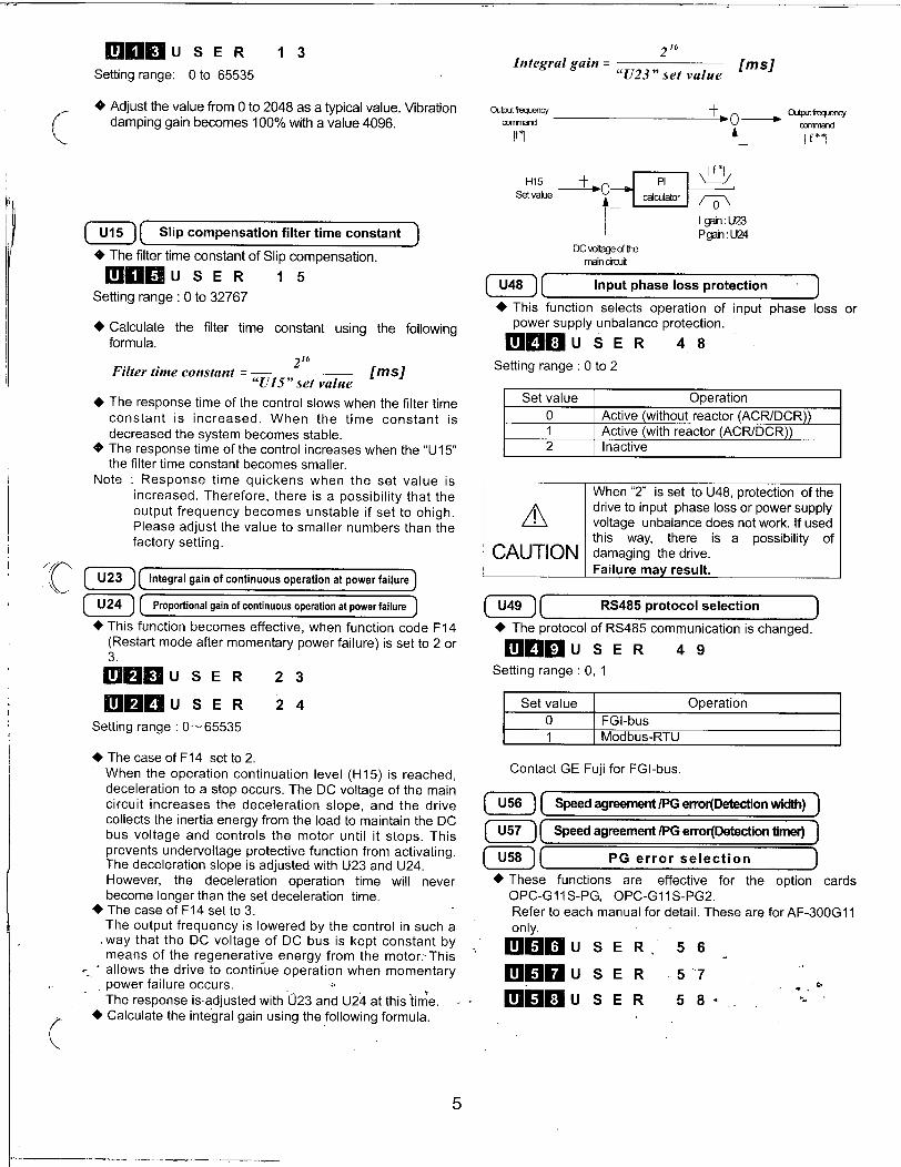
USER 1 3 216Integralgain fins
U23setvalueSettingrange0to65535
Adjustthevaluefrom0to2048asatypicalvalueVibrationdampinggainbecomes100withavalue4096
U15 Slipcompensationfiltertimeconstant
ThefiltertimeconstantofSlipcompensationUSER 1 5
Settingrange0to32767
Calculatethefiltertimeconstantusingthefollowingformula
216Filtertimeconstant ms
U15setvalue
TheresponsetimeofthecontrolslowswhenthefiltertimeconstantisincreasedWhenthetimeconstantis
decreasedthesystembecomesstableTheresponsetimeofthecontrolincreaseswhentheU15thefiltertimeconstantbecomessmaller
Note ResponsetimequickenswhenthesetvalueisincreasedThereforethereisapossibilitythattheoutputfrequencybecomesunstableifsettoohighPleaseadjustthevaluetosmallernumbersthanthefactorysetting
U23 Integralgainofcontinuousoperationatpowerfailure
U24 Proportionalgainofcontinuousoperationatpowerfailure
ThisfunctionbecomeseffectivewhenfunctioncodeF14Restartmodeaftermomentarypowerfailureissetto2or3
USER 23
OUSER 24
Settingrange065535
ThecaseofF14setto2
WhentheoperationcontinuationlevelH15isreacheddecelerationtoastopoccursTheDCvoltageofthemaincircuitincreasesthedecelerationslopeandthedrivecollectstheinertiaenergyfromtheloadtomaintaintheDCbusvoltageandcontrolsthemotoruntilitstopsThispreventsundervoltageprotectivefunctionfromactivatingThedecelerationslopeisadjustedwithU23andU24HoweverthedecelerationoperationtimewillneverbecomelongerthanthesetdecelerationtimeThecaseofF14setto3
TheoutputfrequencyisloweredbythecontrolinsuchawaythattheDCvoltageofDCbusiskeptconstantbymeansoftheregenerativeenergyfromthemotorThisallowsthedrivetocontinueoperationwhenmomentarypowerfailureoccursTheresponseisadjustedwith023andU24atthistimeCalculatetheintegralgainusingthefollowingformula
5
Outputfrequencycommand
H15
Setvalue
U48 lThisfunctionselectsoperationofinputphasepowersupplyunbalanceprotection
0E8USER 48
Settingrange0to2
t
U49l
Setvalue
0
1
2
CAUTION
Setvalue
0
1
A
DCvoltageofthemaincircuit
Inputphaselossprotection
PI
calculator
1ActivewithoutreactorACRDCR1ActivewithreactorACRDCR1Inactive
When2issettoU48protectionofthedrivetoinputphaselossorpowersupplyvoltageunbalancedoesnotworkIfusedthisway thereisa possibilityofdamagingthedriveFailuremayresult
RS485protocolselection
TheprotocolofRS485communicationischanged
M09USER 49
Settingrange01
1FGIbusIModbusRTU
ContactGEFujiforFGIbus
0
A
lf10
IgainU23PgainU24
Operation
Operation
U58 PGerrorselection
Outputfrequencycommand
lossor
U56 SpeedagreementPGerrorDetectionwidth
U57 SpeedagreementPGerrorDetectiontimer
Thesefunctionsare effectivefortheoptioncardsOPCG11SPGOPCG11SPG2RefertoeachmanualfordetailTheseareforAF300G11
only
m6USER 56
MOB SER 57
USER 58

1
USER 59
Settingrange0toA8HEX
Settingoftensdigittoeselection
Set Typebrakingvalue resistor
p 1Standardappliedresistor1 1230V1HP2 I230V3Hr3 1230V5iP4 123CA75HP5 230V10HP
6 460V1HP
7 460V3HP
8 460V5HP
9 1460V75HPA 1460V10HP
Resistance
100
40
33
20
15
200
160
130
80
60
200
400
400
800
900
200
400
400
800
900
IU59 Brakingresistorfunctionselect
For10HPandbelow
WhenfunctioncodeF13electronicthermalissetto2boththetypeofthebrakingresistorandtheconnectioncircuitaresetFactorysettingissettostandardbrakingresistorandthenumberofresistorsisoneWhentheload
capacityofresistorsareincreasedresettheparameterperthefollowingtables
DutyCapacityce
W ED10
Settinaofunitsdigitconnectioncircuitselection
Brakingresistor 1Synthetic
Power
cti Duty Y consumptionofUse
resistance resistance
numberConnectioncircuitED comparatively0 1 10
PC DB00
1 2PJ p11VcDB
20 2R
2 2 20 12RlLiir
cDB
3 4 ri N 40 RPo 0oB
LAvvvas
4 3PCJVfJ DB
30 3R 33
5 6
V
tiv 50 32RP DDB
6 9 LviA v50 R
pC AVVV DB
7 4
PtJVhhh1Jrjih40 4R 25l0
8 8 PWAW1AN ADS50 2R 125
IONMNvV1
1ItislimitedbytheEDvalueofthebrakingtransistorinsidethedrive
6
Setthefunctioncodes F13andU59 before
operatingthedriveanddontchangethefunctionsduringoperationTheintegratedthermaldataisclearedimmediatelywhenfunctioncode F13or
U59 arechanged Theoverheatprotectionofresistorbecomesinvalid
Asthereisapossibilityofdamagingthedrivetheresistorvaluelessthanstandardappliedvalueshouldnotbeavailable
UseequalvalueresistorsincombinationsforabrakingresistorandconnectthemsothattheelectricpowerisconsumedequallyineachresistorWhenanexternalbrakingresistorisusedinsteadof10dutyfunctioncodeF13shouldbesetto0
OWhenresistorvalueslessthanthestandardresistor
valueissetintothefunctioncoderegenerativeoperationisinvalidOUalarmwilloccurIfconnectionofresistorandthevalueofresistordoes
notcorrespondedthereisapossibilityofdamagingtheresistorandthedrive
Failuremayresult
U59 DCfantripselect
For40HPandabove
ThisfunctionselectsoperationofDrivetripOH1incaseofDCfanfailure
9SER 59
Settingrange00to01Setvalue Operation
00
01
100 Q WARNING
50 IfyouleavethedrivefanstoppedthedrivemayhaveoverheatingalarmOH1OH3ormaydecreasethelifeofelectrolyticcapacitorsontheprintedcircuitboardinthe
50 driveIfDCfanfailsexchangetheDCfanandsetthisfunctionactiveassoonaspossibleContactfactory
25 aboutDCfanexchangeprocedureFailuremayresult
17 U60 Regenerationavoidanceatdeceleration
Thisfunctionisavailablewhentorquelimitbrakeof11 F41orE17issetto0
60USER 60
Settingrange01
Setvalue
0
1
0 CAUTION
Active
DrivetripOH1whenDCfanfailsInactive
DrivedoesnottripwhenDCfanfails
Operation
Regenerativetorquelimitoperationforhighresponseuse
OUalarmavoidanceoperationforonlydecelerationorLargeinertiause
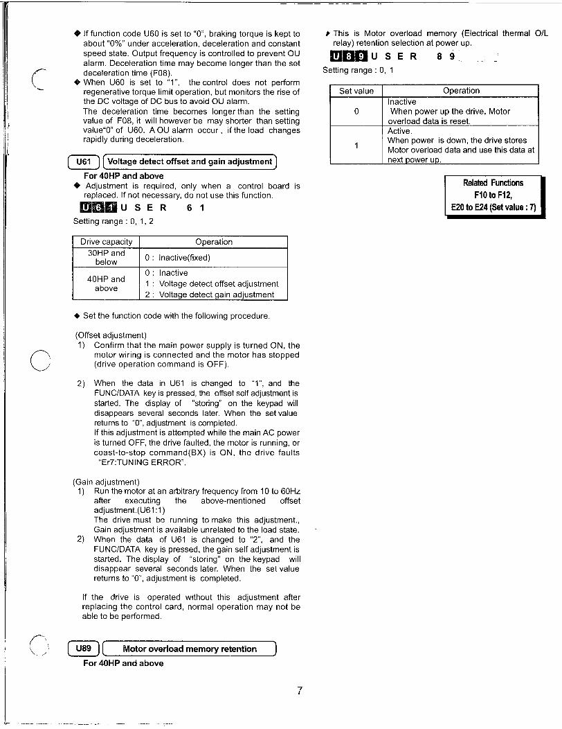
1
OIffunctioncodeU60issetto0brakingtorqueiskepttoabout0 underaccelerationdecelerationandconstant
speedstateOutputfrequencyiscontrolledtopreventOUalarmDecelerationtimemaybecomelongerthanthesetdecelerationtimeF08WhenU60issetto1 thecontroldoesnotperformregenerativetorquelimitoperationbutmonitorstheriseoftheDCvoltageofDCbustoavoidOUalarmThedecelerationtimebecomeslongerthanthesettingvalueofF08itwillhoweverbemayshorterthansettingvalue0ofU60AOUalarmoccur iftheloadchangesrapidlyduringdeceleration
U61 Voltagedetectoffsetandgainadjustment
For40HPandabove
AdjustmentisrequiredonlywhenacontrolboardisreplacedIfnotnecessarydonotusethisfunction
6 USER 61
Settingrange012
Drivecapacity30HPand
below
40HPand
above
Operation
0 Inactivefixed
0 Inactive
1 Voltagedetectoffsetadjustment2 Voltagedetectgainadjustment
Setthefunctioncodewiththefollowingprocedure
Offsetadjustment1 ConfirmthatthemainpowersupplyisturnedONthe
motorwiringisconnectedandthemotorhasstoppeddriveoperationcommandisOFF
2 WhenthedatainU61ischangedto1 andthe
FUNCDATAkeyispressedtheoffsetselfadjustmentisstartedThedisplayof storingonthekeypadwilldisappearsseveralsecondslaterWhenthesetvaluereturnsto0adjustmentiscompletedIfthisadjustmentisattemptedwhilethemainACpoweristurnedOFFthedrivefaultedthemotorisrunningorcoasttostopcommandBXisONthedrivefaultsEr7TUNINGERROR
Gainadjustment1 Runthemotoratanarbitraryfrequencyfrom10to60Hz
after executing the abovementioned offset
adjustmentU611ThedrivemustberunningtomakethisadjustmentGainadjustmentisavailableunrelatedtotheloadstate
2 WhenthedataofU61ischangedto2 andthe
FUNCDATAkeyispressedthegainselfadjustmentisstartedThedisplayofstoringonthekeypad will
disappearseveralsecondslaterWhenthesetvaluereturnsto0adjustmentiscompleted
Ifthedriveisoperatedwithoutthisadjustmentafterreplacingthecontrolcardnormaloperationmaynotbeabletobeperformed
U89 Motoroverloadmemoryretention
For40HPandabove
7
ThisisMotoroverloadmemoryElectricalthermalOLrelayretentionselectionatpowerup
mfl9USER 89
Settingrange01
Setvalue
0
1
OperationInactive
WhenpowerupthedriveMotoroverloaddataisreset
Active
WhenpowerisdownthedrivestoresMotoroverloaddataandusethisdataat
nextpowerup
RelatedFunctions
F10toF12
E20toE24Setvalue7

GEConsumer Industrial
Users Guide
imaginationatwork

2007byGEDrivesIncAllrightsreserved
TheseinstructionsdonotpurporttocoveralldetailsorvariationsinequipmentnortoprovideeverypossiblecontingencytobemetduringinstallationoperationandmaintenanceIffurtherinformationisdesiredorifparticularproblemsarisethatarenotcoveredsufficientlyforthepurchaserspurposethemattershouldbereferredtoGEDrivesPlainvilleCTUSA
ThisdocumentcontainsproprietaryinformationofGEDrivesandisfurnishedtoitscustomersolelytoassistthatcustomerintheinstallationtestingoperationandormaintenanceoftheequipmentdescribedThisdocumentshallnotbereproducedinwholeorinpartnorshallitscontentsbedisclosedtoanythirdpartywithoutthewrittenapprovalofGEDrives
AF300P11isatrademarkofGEDrives
EnergyaverisaregisteredtrademarkofGeneralElectricCompanyUSAGeniusisaregisteredtrademarkofGEFanucAutomationNorthAmericaIncProfibusisatrademarkofProfibusInternational
XDisatrademarkofGeneraFElectricCompanyUSA
Datasubjecttochangewithoutnotice70702007GEDrives
F
VVF 4 77k
Wafr
37 c

WARNING
ThisequipmentcontainsapotentialhazardofelectricshockorburnOnlypersonnelwhoareadequatelytrainedandthoroughlyfamiliarwiththeequipmentandtheinstructionsshouldinstalloperateormaintainthisequipmentIsolationoftestequipmentfromtheequipmentundertestpresentspotentialelectricalhazardsIfthetestequipmentcannotbegroundedtotheequipmentundertestthetestequipmentscasemustbeshieldedtopreventcontactbypersonnel
Tominimizehazardofelectricalshockorburnapprovedgroundingpracticesandproceduresmustbestrictlyfollowed
WARNING
Topreventpersonalinjuryorequipmentdamagecausedbyequipmentmalfunctiononlyadequatelytrainedpersonnelshouldmodifyanyprogrammablemachine
Datasubjecttochangewithoutnotice707tt2007GEDrives

TableofContents
i Preface
SafetyInstructions
ModelNumberingSystemDiagram vii
Dimensions Weights viii
1BeforeUsingThisProduct 11
ReceivingInstructions 11
Appearance 11
HandlingtheProduct 12
Carrying 13
Storage 13
RatingsEfficiencyandWattsLoss 14
2InstallationEnvironmentandConnection 21
OperatingEnvironment 21
InstallationMethod 21
Connection 23
BasicConnectionDiagrams 24
ConnectingtheMainCircuitandGroundTerminals 28
ConnectingtheControlTerminals 211
TerminalConfiguration 215
CableSizeTighteningTorqueCircuitProtectionRating 216
DCLinkReactor 217
3Operation 31
InspectionandPreparationBeforeOperation 31
OperationMethod 31
TrialRun 31
4KeypadPanel 41
AppearanceofKeypadPanel 41
OperationFromtheKeypadPanel 42
NormalOperation 42
AlarmModes 42
EnteringDataontheKeypadPanel 44
OperationMode 44
SettingDigitalFrequency 44
SwitchingtoLEDDigitalMonitor 45
ProgramMenuScreen 45
Datasubjecttochangewithoutnotice70702007GEDrives
SettingFunctionData 45
CheckingFunctionData 47
MonitoringOperatingStatus 47
IOCheck 48
MaintenanceInformation 49
LoadRateMeasurement 410
AlarmInformation 411
AlarmHistoryandFactors 412
DataCopy 413
AlarmMode 415
5FunctionSelection 51
FunctionSelectionList 51
AlphabeticalFunctionList 55
FunctionExplanation 57
FFundamentalFunctions 57
EExtensionsTerminalFunctions 518
CControlFunctionsofFrequency 528
6ProtectiveOperations 61
ListofProtectiveFunctions 61
AlarmReset 62
7Troubleshooting 71
ActivationofProtectiveFunction 71
AbnormalMotorRotation 75
8MaintenanceandInspection 81
DailyInspections 81
PeriodicInspections 81
MainCircuitMeasurements 84
InsulationTest 85
ReplacementParts 85
9WarrantyPartsandService 91
InWarrantyFailureChecklist 92

10ReplacementParts 101
11Specifications 111
StandardSpecifications 111
CommonSpecifications 113
OutlineDimensions 115
KeypadMountingHole 1112
12RS485ModbusRTUSerialCommunications121
TransmissionSpecification 121
Connection 121
SerialInterfaceConfiguration 121
ModbusRTUFunctions 121
DriveFunctionCodeAccess 122
CommandandMonitorDataRegisters 122
DataFormatSpecification 124
CommunicationErrors 128
13Options 131
BuiltinOptions 131
14ElectromagneticCompatibilityEMC 141
General 141
RecommendedInstallationInstructions 141
Datasubjecttochangewithoutnotice7072007GEDrives

SafetyInstructions
Readthismanualcarefullybeforeinstallingconnectingwiringoperatingservicingorinspectingthedrive
Familiarizeyourselfwithallsafetyfeaturesbeforeusingthedrive
Inthismanualsafetymessagesareclassifiedasfollows
WARNING
CAUTION
SituationsmoreseriousthanthosecoveredbyCAUTIONwilldependonprevailingcircumstancesAlwaysfollowinstructions
InstructionsonUse
Improperoperationmayresultinseriouspersonalinjuryordeath
Improperoperationmayresultinslighttomediumpersonalinjuryorpropertydamage
WARNING
Thisdriveisdesignedtodrivea3phaseinductionmotorandisnotsuitableforasinglephaseorothertypesofmotors
Thisdrivemaynotbeusedasacomponentofalifesupportsystemorothermedicaldevicedirectlyaffectingthepersonalwelfareoftheuser
ThisdriveismanufacturedunderstrictqualitycontrolstandardsHoweversafetyequipmentmustbeinstalledorthefailureofthisdevicemayresultinpersonalinjurypropertydamageorriskanaccident
InstructionsonInstallation
WARNING
Mountthisdriveonanincombustiblematerialsuchasmetalotherwiseariskoffiremayresult
Donotplacecombustibleorflammablematerialnearthisdriveasfiremayresult
CAUTION
DonotholdorcarrythisdrivebyitscoverDonotdroptheconverterasinjurymayresult
Ensurethatthedriveandheatsinksurfacesarekeptfreeofforeignmatterlintpaperdustsmallchipsofwoodormetalanddustasfireoraccidentmayresult
Donotinstalloroperateadamageddriveoradrivewithmissingpartsaselectricshockorinjurymayoccur
Datasubjecttochangewithoutnotice70702007GEDrives III

iv
InstructionsonWiring
WARNING
ConnectthedrivetopowerviaalineprotectionmoldedcasecircuitbreakerorfuseasfiremayresultAlwaysconnectagroundwireaselectricshockorfiremayresult
Alicensedspecialistmustperformallwiringworkaselectricshockmayresult
Turnoffthepowerbeforewiringaselectricshockmayresult
Wirethedriveaftermechanicalinstallationiscompleteaselectricshockorinjurymayoccur
CAUTION
ConfirmthatthenumberofphasesandratedvoltageofthisproductmatchthoseoftheACpowersupplyotherwiseinjurymayresult
DonotconnecttheACpowersupplytotheoutputterminalsUVandWasinjurymayresult
DonotdirectlyconnectabrakingresistortotheDCterminalsP andN asfiremayresult
Ensurethatthenoisegeneratedbythedrivemotororwiringdoesnotadverselyaffectperipheralsensorsandequipmentasanaccidentmayresult
InstructionsonOperation
WARNING
BesuretoinstallthecoverbeforeturningonthepowerDonotremovethecoverwhilepowertothedriveisturnedonElectricshockmayoccur
DonotoperateswitcheswithwethandsaselectricshockmayresultWhentheretryfunctionisselectedthedrivemayrestartautomaticallyaftertrippingDesignthemachinetoensurepersonalsafetyintheeventofrestartAccidentmayresultWhenthetorquelimitingfunctionisselectedoperatingconditionsmaydifferfrompresetparametersaccelerationdecelerationtimeorspeedInthiscasepersonalsafetymustbeassuredAnaccidentmayresult
TheSTOPkeyisonlyeffectivewhenafunctionsettinghasbeenestablishedInstallanindependentemergencyswitchtodisabletheSTOPkeyonthekeypadpanelwhenanoperationisselectedviatheexternalsignalterminalotherwiseanaccidentmayresult
OperationscanstartupsuddenlyafteranalarmisresetifthereisarunsignalpresentConfirmthattherunsignalinputisnotpresentbeforeresettingthealarmAccidentmayresult
DonottouchdriveterminalswhenenergizedevenifthedrivehasstoppedElectricshockmayresult
CAUTION
DonotstartorstopthedriveusingthemaincircuitpowerFailuremayresult
DonottouchtheheatsinkorbrakingresistorbecausetheybecomeveryhotI3urnsmayresult
SincethedrivecanreachhighspeedoperationeasilycarefullychecktheperformanceofmotorormachinebeforechangingarspeedsettingsInjurymayresult
DonotusethedrivebrakingfunctionformechanicalholdingInjurymayresult
Datasubjecttochagewithoutnotice70702007GEDrives

InstructionsonMaintenanceInspectionandReplacement
WARNINGWaitaminimumoffiveminutes30HPorlessortenminutes40HPormoreafterpowerhasbeenturnedoffopenbeforestartinginspectionAlsoconfirmthatthechargelampisoffandthatDCvoltagebetweenterminalsP andNdoesnotexceed25VElectricalshockmayresult
OnlyauthorizedpersonnelshouldperformmaintenanceinspectionandreplacementoperationsRemoveallmetaljewelrysuchaswatchesandringsUseinsulatedtoolsonlyElectricshockorinjurymayresult
InstructionsonDisposal
CAUTION
TreatasindustrialwastewhendisposingofdriveInjurymayresult
InstructionsforULcULRequirements
CAUTION
HazardofelectricalshockDisconnectincomingpowerbeforeworkingonthiscontrol
Dangerousvoltageexistuntilchargelightisoff
Type1indooruseonly
Tighteningtorqueandwiresizeforfieldwiringterminalaremarkedadjacenttotheterminaloronthewiringdiagram
ThedriveshallbeconnectedwithListedClassJFuseorCircuitBreakerrated600Vasshowninthe
Table23530HPorless
Incaseofusingauxiliarycontrolpowerinputconnectitbyreferringtothebasicconnectiondiagram231
Suitableforuseonacircuitcapableofdeliveringnotmorethan100000rmssymmetricalamperesfor230V460V
Use6075CCUwireonly
AClass2circuitwiredwithClass1wire30HPorlessUseClass1wireonly40HPormore
FieldwiringconnectionmustbemadebyaULListedandCSACertifiedclosedloopterminalconnectorsizedforthewiregaugeinvolvedConnectormustbefixedusingthecrimptoolspecifiedbytheconnectormanufacturer
Solidstatemotoroverloadprotectionisprovidedineachmodel
OtherInstructions
WARNING
NevermodifytheproductElectricshockorinjurymayresult
Datasubjecttochangewithoutnotice7072007GEDrives

ConformitytoLowVoltageDirectiveinEurope
GeneralInstructions
vi
CAUTION
Thecontactcapacityofalarmoutputforanyfault30ABCandrelaysignaloutputY5AY5Cis05Aat48VDC03A 250VAC
ThegroundterminalGshouldbeconnectedtogroundUseacrimpterminaltoconnectacabletothemaincircuitterminalordrivegroundterminal
WherearesidualcurrentprotectivedeviceRCDisusedforprotectionincaseofdirectorindirectcontactonlyatypeBdeviceisallowedonthesupplysideofthiselectricalequipmentOtherwiseanotherprotectivemeasureshallbeappliedsuchasseparationoftheelectricalequipmentfromtheenvironmentbydoubleorreinforcedinsulationorisolationoftheelectricalequipmentandsupplysystembythetransformer
UseasinglecabletoconnecttheGdrivegroundterminalDonotusetwoormoredrivegroundterminals
UseonlyamoldedcasecircuitbreakerMCCBormagneticcontactorMCthatconformtoENorIECstandards
OperatethedriveunderovervoltageCategoryIIIconditionsandmaintainPollutionDegree2orbetterasspecifiedinIEC664TomaintainPollutionDegree2orbetterinstallthdriveinacontrolpanelstructurelevelNEMA3orhigherwhichisfreefromwateroilcarbondustetc
FortheinputoutputwiringofthedriveusecablediameterandtypeasspecifiedinAppendixCinEN60204
ToensuresafetyinstallanoptionalACreactorDCreactororexternalbrakingresistorasfollows
1InstallinsideanIP4Xcabinetorbarrierifelectricalpartsareexposed
2InstallinsideanIP2Xcabinetorbarrierifelectricalpartsarenotexposed
Incaseofexternalcoolingsystemcoverthedriverearsideinordernottotouchthemaincapacitorandbrakingresistor
ForclaritysomefiguresinthismanualmayshowthedrivewithcoversandsafetyscreensremovedforexplanationpurposesDonotoperatethedeviceuntilallsuchcoversandscreenshavebeenreplaced
Datasubjecttochargewithoutnotice70702007GEDrives

AF300P11TMModelNumberingSystemDiagram
Description
GEProductCode
AF300DriveFamily
InputVoltage
2 230V5060Hz
4 460V5060Hz
InputPhases
3 3Phase
Horsepower
F50 12Hp010 10Hp
100 100Hp
6K
FactoryInstalledOptions
N None
X KeypadB tobedetermined
P11
EnclosureType
1 NEMA1ULType12 NEMA12ULType124 NEMA4ULType48 IP00withNEMA12heatsink
9 IP00
ProductRevision
A 1stRevision
B 2ndRevision
MinorProductRevision
1 1stMinorRevision
2 2ndMinorRevision
Datasubjecttochangewithoutnotice70702007GEDrives
N XNNN X N

AF300P11Dimensions Weights
AF300P11
HP NEMA RatedOutput Overload AF300P11
Rating Enclosure CurrentA 1101min ModelNo
230VAC3phase5060HzInput025 1 15
05 1 3
1 1 5
2 1 8
3 1 11
5 1 17
75 1 22
10 1 29
15 1 42
20 1 55
25 1 67
30 1 78
40 1 115
50 1 145
60 1 180
75 1 215
100 1 283
125 1 346
150 1 415
viii
NEMA117
33
55
88
12
19
24
32
46
61
74
86
127
160
198
237
311
381
457
230VAC3phase5060HzInputNEMA4025 4 15 17 6KP1123F25X4
05 4 3 33 6KP1123F50X4
1 4 5 55 6KP1123001X4
2 4 8 88 6KP1123002X4
3 4 11 12 6KP1123003X4
5 4 17 19 6KP1123005X4
75 4 22 24 6KP1123007X4
10 4 29 32 6KP1123010X4
15 4 42 46 6KP1123015X4
230VAC3phase5060HzInputNEMA1220 12 55 61
25 12 67 74
30 12 78 86
6KP1123F25X1
6KP1123F50X1
6KP1123001X1
6KP1123002X1
6KP1123003X1
6KP1123005X1
6KP1123007X1
6KP1123010X1
6KP1123015X1
6KP1123020X1
6KP1123025X1
6KP1123030X1
6KP1123040X1
6KP1123050X1
6KP1123060X1
6KP1123075X1
6KP1123100X1
6KP1123125X1
6KP1123150X1
Catalog Dimensions WeightNo HxWxDinches lbs
D6600
D6601
D6602
D6603
D6604
D6605
D6606
D6607
D6608
D6609
D6610
D6611
D6612
D6613
D6614
D6615
D6616
D6617
D6618
D6650
D6651
D6652
D6653
D6654
D6655
D6656
D6657
D6658
6KP1123020X2 D6659
6KP1123025X2 D6660
6KP1123030X2 D6661
230VAC3phase5060HzInputOpen40 Open 115 127 6KP1123040X9
50 Open 145 160 6KP1123050X91
60 Open 180 198 6KP1123060X9
75 Open 215 237 6KP1123075X9
100 Open 283 311 6KP1123100X9
125 Open 346 381 6KP1123125X9
150 Open 415 457 6KP1123150X9
IndicatesproductrevisionNoteHpratingisshownfor230Vand460VnominalsystemsWhenapplyingatlowervoltageselectthedrivebyratedcurrentandnotHprating
1024x433x512
1024x433x512
1024x433x571
1024x591x571
1024x591x571
1024x591x571
1024x866x768
1024x866x768
1024x866x768
1575x984x768
1575x984x768
1575x984x768
297x135x100
297x135x100
331x149x106
380x149x106
380x149x106
413x210x112
504x269x142
1024x433x512
1024x433x512
1024x433x571
1024x591x571
1024x591x571
1024x591x571
1024x866x768
1024x866x768
1024x866x768
1575x984x768
1575x984x768
1575x984x768
217x134x100
217x134x100
242x148x106
291x148x106
291x148x106
295x209x112
346x268x142
48
48
55
84
84
84
126
126
126
220
220
231
70
70
86
106
110
172
282
48
48
55
84
84
84
126
126
126
220
220
231
64
64
79
97
101
154
253
DatasubjecttochangEwithoutnotice70702007GEDrives

AF300P11Dimensions Weights
AF300P11
HP NEMA RatedOutput Overload AF300P11
Rating Enclosure CurrentA 1101min ModelNo
230VAC3phase5060HzInputOpenwithNEMA12Heatsink6KP1123040X8
6KP1123050X8
6KP1123060X8
6KP1123075X8
6KP1123100X8
6KP1123125X8
6KP1123150X8
40 Open 115 127
50 Open 145 160
60 Open 180 198
75 Open 215 237
100 Open 283 311
125 Open 346 381
150 Open 415 457
460VAC3phase5060HzInputNEMA105 1 15 17 6KP1143F50X1 D6649
1 1 25 28 6KP1143001X1 D6619
2 1 37 41 6KP1143002X1 D6620
3 1 55 61 6KP1143003X1 D6621
5 1 9 99 6KP1143005X1 D6622
75 1 125 14 6KP1143007X1 D6623
10 1 165 18 6KP1143010X1 D6624
15 1 23 25 6KP1143015X1 D6625
20 1 30 33 6KP1143020X1 D6626
25 1 37 41 6KP1143025X1 D6627
30 1 44 48 6KP1143030X1 D6628
40 1 60 66 6KP1143040X1 D6630
50 1 75 83 6KP1143050X1 D6631
60 1 91 100 6KP1143060X1 D6632
75 1 112 123 6KP1143075X1 D6633
100 1 150 165 6KP1143100X1 D6634
125 1 176 194 6KP1143125X1 D6635
150 1 210 231 6KP1143150X1 D6636
200 1 253 278 6KP1143200X1 D6637
250 1 304 334 6KP1143250X1 D6638
300 1 377 415 6KP1143300X1 D6639
350 1 415 457 6KP1143350X1 D6640
400 1 485 534 6KP1143400X1 D6641
450 1 520 572 6KP1143450X1 D6642
500 1 650 715 6KP1143500X1 06643
600 1 740 814 6KP1143600X1 D6644
700 1 840 924 6KP1143700X1 D6645
800 1 960 1056 6KP1143800X1 D6646
460VAC3phase5060HzInputNEMA405 4 15 17 6KP1143F50X4 D6699
1 4 25 28 6KP1143001X4 D6669
2 4 37 41 6KP1143002X4 D6670
3 4 55 61 6KP1143003X4 D6671
5 4 9 99 6KP1143005X4 D6672
75 4 125 14 6KP1143007X4 D6673
10 4 165 18 6KP1143010X4 D6674
15 4 23 25 6KP1143015X4 D6675
IndicatesproductrevisionNoteHpratingisshownfor230Vand460VnominalsystemsWhenapplyingatlowervoltageselectthedrivebyratedcurrentandnotHprating
Datasubjecttochangewithoutnotice70702007GEDrives
Catalog Dimensions WeightNo HxWxDinches lbs
217x134x100
217x134x100
242x148x106
291x148x106
291x148x106
295x209x112
346x268x142
1024x433x512
1024x433x571
1024x591x571
1024x591x571
1024x591x571
1024x866x768
1024x866x768
1024x866x768
1575x984x768
1575x984x768
1575x984x768
297x135x100
297x135x100
297x149x106346x149x106
346x149x106
380x149x106
380x21Ox124
380x210x124
531x210x142
531x21Ox142
551x269x142
551x269x142
551x269x142
571x268x177
571x268x177
571x346x177
571x346x177
1024x433x512
1024x433x571
1024x591x571
1024x591x571
1024x591x571
1024x866x768
1024x866x768
1024x866x768
64
64
79
97
101
154
253
48
55
84
84
84
134
134
134
220
220
231
70
70
82
95
97
115
174
174
245
245
337
337
337
562
562
804
804
48
55
84
84
84
134
134
134

AF300P11Dimensions Weights
AF300P11
HP NEMA RatedOutput Overload AF300P11Rating Enclosure CurrentA 1101min ModelNo
460VAC3phase5060HzInputNEMA1220 12 30 3325 12 37 41
30 12 44 48
460VAC3phase5060HzInputOpen40 Open 60 66
50 Open 75 8360 Open 91 10075 Open 112 123100 Open 150 165
125 Open 176 194
150 Open 210 231
200 Open 253 278
250 Open 304 334
300 Open 377 415
350 Open 415 457
400 Open 485 534
450 Open 520 572
500 Open 650 715
600 Open 740 814
700 Open 840 924
800 Open 960 1056
x
6KP1143020X2
6KP1143025X2
6KP1143030X2
6KP1143040X9
6KP1143050X9
6KP1143060X9
6KP1143075X9
6KP1143100X9
6KP1143125X9
6KP1143150X9
6KP1143200X9
6KP1143250X9
6KP1143300X9
6KP1143350X9
6KP1143400X9
6KP1143450X9
6KP1143500X9
6KP1143600X9
6KP1143700X9
6KP1143800X9
460VAC3phase5060HzInputOpenwithNEMA12Heatsink40 Open 60 66 6KP1143040X850 Open 75 83 6KP1143050X860 Open 91 100 6KP1143060X875 Open 112 123 6KP1143075X8100 Open 150 165 6KP1143100X8125 Open 176 194 6KP1143125X8150 Open 210 231 6KP1143150X8200 Open 253 278 6KP1143200X8250 Open 304 334 6KP1143250X8300 Open 377 415 6KP1143300X8350 Open 415 457 6KP1143350X8400 Open 485 534 6KP1143400X8450 Open 520 572 6KP1143450X8
500 Open 650 715 6KP1143500X8
600 Open 740 814 6KP1143600X8
700 Open 840 924 6KP1143700X8
800 Open 960 1056 6KP1143800X8
IndicatesproductrevisionNoteHpratingisshownfor230Vid460VnominalsystemsWhenapplyingatlowervoltageselectthedrivebyratedcurrentandnotHprating
Catalog Dimensions WeightNo HxWx111inches Ibs
D6676 1575x984x768D6677 1575x984x768
D6678 1575x984x768
220
220
231
217x134x100 64
217x134x100 64
217x148x106 75
266x148x106 86
266x148x106 88
291x148x106 106
291x209x124 154
291x209x124 154
394x209x142 220
394x209x142 220
394x268x142 308
394x268x142 308
394x268x142 308
551x268x177 551
551x268x177 551
551x356x177 793
551x356x177 793
217x134x100 64
217x134x100 64
217x148x106 75
266x148x106 86
266x148x106 88
291x148x106 106
291x209x124 154
291x209x124 154
394x209x142 220
394x209x142 220
394x268x142 308
394x268x142 308
394x268is142 308
551x268x177 551
551x268x177 551
551x356x177 793
551x356x177 793
Datasubjecttochangewithoutnotice707C2007GEDrives
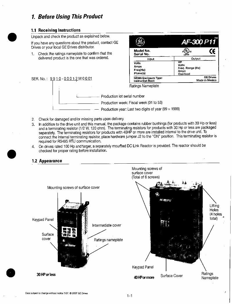
1BeforeUsingThisProduct
11ReceivingInstructionsUnpackandchecktheproductasexplainedbelow
IfyouhaveanyquestionsabouttheproductcontactGEDrivesoryourlocalGEDrivesdistributor1 Checktheratingsnameplatetoconfirmthatthe
deliveredproductistheonethatwasordered
SERNo991 00012M0001
12Appearance
KeypadPanel
Mountingscrewsofsurfacecover
Surfacecover
30HPorTess
Datasubjecttochangewithoutnotice70702007GEDrives
Intermediatecover
Ratingsnameplate
AF309 P1iF 09P11
11
ModelNoSerialNo
Input
Volts
AmpsFreqHzPhases
NEMAEnclosureTypeInstructionBook
RatingsNameplate
Productionlotserialnumber
ProductionweekFiscalweek01to53
ProductionyearLasttwodigitsofyear99 1999
2 Checkfordamagedandormissingpartsupondelivery3 Inadditiontothedriveunitandthismanualthepackagecontainsrubberbushingsforproductswith30Hporless
andaterminatingresistor12W120ohmTheterminatingresistorsforproductswith30HporlessarepackagedseparatelyTheterminatingresistorsforproductswith40HPormoreareinstalledinternaltothedriveunitToconnecttheinternalterminatingresistorplacehardwarejumperJ2totheONpositionThisterminatingresistorisrequiredforRS485RTUcommunication
4 Ondrivesrated100HpandlargeraseparatelymournedDCLinkReactorisprovidedThereactorshouldbecheckedforproperratingbeforeinstallation
Mountingscrewsofsurfacecover
Totalof6screws
KeypadPanel
40HPormore SurfaceCover
COUSLISTED
OutputHP
Volts
FreqRangeHzAmpsOverload
CE
GEDrivesMadeinMexico
LiftingHoles
4holestotal
RatingsNameplate

13HandlingtheProduct
1RemovingtheCover
Fordrives30HPorlessloosenthecovermountingscrewsthenremovethecoverbypullingfromthetopseeFigure131
Fig131RemovingtheCoverfordrivesof30HPorless
Fordrives40HPormorefirstremovethesixcovermountingscrewsthenremovethecover
Mountingscrewsofservicecover6positionstotal
2RemovingtheKeypadPane
Afterremovingthecoverasexplainedin1loosenthekeypadpanelmountingscrewsandremoveasshowninFigure133fordrives30HPorTess
Fig132RemovingtheCoverfordrivesof40HPormore
Fig133RemovingtheKeypadPanelfordrivesof30HPorless
Fordrives40HPormoreloosenthekeypadpanelmountingscrewsandremoveusingthefingerholdsonthekeypadpanelcase
Keypadpanelca
Fig134RemovingtheKeypadPanelfordrives40HPormore
12
MountingscrewsofKeypadpane
izic313
MI
aINN
i
a
Datasubjecttochargewithoutnotice70702007GEDrives

14Carrying
CarrytheproductbythemainunitDonotcarrytheproductbyitscoverorpartsotherthanthemainunitUseacrane or
hoisttocarryaproductequippedwithhangingholes
15Storage
TemporaryStorage
TemporarystorageofthisproductmustmeettheconditionslistedinTable151Table151StorageEnvironment
Item
AmbientTemperature
StorageTemperature
RelativeHumidity
Atmosphere
Note1ThestoragetemperatureappliesonlytoshortperiodsoftimesuchasduringtransportRefertocommentsonextendedstorageguidelines
Note2Sincealargechangeintemperaturewithinthishumidityrangemayresultincondensationorfreezingdonotstorewheresuchtemperaturechangesmayoccur
1 Donotplacethisproductdirectlyonthefloor2 Tostoretheproductinanextremeenvironmentpackinvinylsheetingetc3 Iftheproductisstoredinahighhumidityenvironmentinsertadryingagentegsilicagelandpacktheproductin
vinylsheeting
LongtermStorage
Iftheproductistobestoredforanextendedperiodoftimeafterpurchasethemethodofstoragedependsprimarilyonthestoragelocation
Thegenerallongtermstoragemethodisasfollows1 Theaboveconditionsfortemporarystoragemustbesatisfiedlfthestorageperiodexceedsthreemonthstheupper
limitofambienttemperaturemustbereducedto30C86Ftopreventthedeteriorationoftheelectrolyticcapacitors
2 Packtheproductthoroughlytoeliminateexposuretomoistureandincludeadryingagenttoensurearelativehumidityofabout70orless
3 DonotleavetheproductmountedinacontrolpanelandexposedtotheelementslikemoistureordustparticularlyonaconstructionsiteInthiscaseremovetheproductandstoreinasuitableenvironment
4 ElectrolyticcapacitorswilldeteriorateifnotprovidedwithpowerforanextendedperiodoftimeDonotstoreelectrolyticcapacitorsforoneyearorlongerwithoutprovidingpower
Datasubjecttochangewithoutnotice70702007GEDrives
Specifications10to50C Condensationorfreezingasaresultofsuddentemperature14to122Fchangesmustnotoccur
25to65C4to149F
15to95ThestandardproductmustnotbeexposedtodustdirectsunlightcorrosivegasflammablegasoilmistvaporwaterdropsorvibrationThesaltcontentintheatmosphereshouldbeminimized
13

16AF300P11DriveRatingsEfficiencyandWattsLoss
RatedOutput RatedOutput Efficiencyat2KHz Efficiencyat WattsLossat WattLossat
HPRating CurrentA PowerKVA 15KHz 2KHzW 15KHzW InternalDBW
230VAC
025 15 059 920 905 25 30 NA
05 3 11 935 917 35 45 NA
1 5 19 949 940 50 60 NA
2 8 31 957 941 80 110 NA
3 11 43 959 949 110 140 NA
5 17 67 962 954 170 210 NA
75 22 87 962 952 210 280 NA
10 29 11 965 953 290 370 NA
15 42 16 964 952 410 550 NA
20 55 21 969 959 500 670 NA
25 67 26 968 958 630 840 NA
30 78 31 965 955 770 1030 NA
1 2KHz I 10KHz I 2KHzW I 10KHzW I
40 115 45 972 968 950 1100 NA
50 145 57 970 967 1250 1400 NA
60 180 71 971 966 1500 1750 NA
75 215 85 973 966 1700 1950 NA
100 283 112 974 970 2200 2500 NA
I 2KHz 1 6KHz 1 2KHzW I 6KHzW2800 NA125 346 137 974
I 973 320000 I 3350 NA150 415 165 974
460VAC05 15 11 935 893 35 60 NA
1 25 19 954 917 45 85 NA
2 37 29 967 941 60 110 NA
3 55 43 970 945 80 150 NA
5 9 71 971 950 130 230 NA
75 125 99 973 953 160 290 NA
10 165 131 973 954 210 370 NA
15 23 183 976 959 300 520 NA
20 30 239 979 965 360 610 NA
25 37 294 978 964 460 770 NA
30 44 35 978 964 530 870 NA
2KHz 10KHz I 2KHzW 10KHzW I
40 60 47 978 969 750 1050 NA
50 75 59 977 969 950 1300 NA
60 91 72 978 970 1100 1550 NA
75 112 89 978 970 1350 1900 NA
100 150 119 978 971 1800 2450 NA
2KHz 6KHz I 2KHzW 6KHzW I
125 176 140 981 978 1850 2200 NA
150 210 167 980 978 2400 2750 NA
200 253 202 980 977 2900 3350 NA
250 304 242 981 978 3250 3800 NA
300 377 300 981 978 4250 4900 NA
350 415 330 982 979 4350 5100 NA
400 485 386 981 978 5100 5900 NA
450 520 414 981 978 5700 6650 NA
500 650 518 982 979 6900 8050 NA
600 740 590 981 978 8050 9350 NA
700 840 669 982 979 8900 10400 NA
800 960 765 981 978 10300 12100 NA
14 Datasubjecttochangewithoutnotice7072007GEDrives
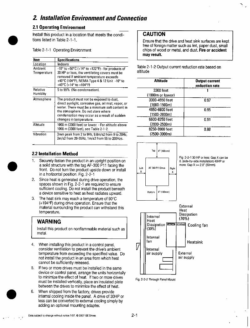
2InstallationEnvironmentandConnection
21OperatingEnvironment
InstallthisproductinalocationthatmeetstheconditionslistedinTable211
Table211OperatingEnvironment
Item 1SpecificationsLocation 1IndoorsAmbient 10to50C14to122FforproductsofTemperature 30HPorlesstheventilatingcoversmustbe
removedifambienttemperatureexceeds40C104FNEMAType4 12Unit10to
40C14to104FRelative 5to95NocondensationHumidity
Atmosphere TheproductmustnotbeexposedtodustdirectsunlightcorrosivegasoilmistvapororwaterTheremustbeaminimumsaltcontentin
theatmosphereDonotstorewherecondensationmayoccurasaresultofsuddenchangesintemperature
Altitude 1000m3300feetorlowerForaltitudeabove1000m3300feetseeTable212
Vibration 3mmpeakfrom2to9Hz98ms2from9to20Hz2ms2from2055Hz1ms2from55to200Hzs
22InstallationMethod
1 SecurelyfastentheproductinanuprightpositiononasolidstructurewiththetagAF300P11facingthefrontDonotturntheproductupsidedownorinstallinahorizontalpositionFig221
2 SinceheatisgeneratedduringdriveoperationthespacesshowninFig221arerequiredtoensuresufficientcoolingDonotinstalltheproductbeneathadevicesensitivetoheatasheatradiatesupward
3 Theheatsinkmayreachatemperatureof90C194FduringdriveoperationEnsurethatthematerialsurroundingtheproductcanwithstandthistemperature
WARNING
Installthisproductonnonflammablematerialsuchasmetal
4 WheninstallingthisproductinacontrolpanelconsiderventilationtopreventthedrivesambienttemperaturefromexceedingthespecifiedvalueDonotinstalltheproductinanareafromwhichheatcannotbesufficientlyreleased
5 Iftwoormoredrivesmustbeinstalledinthesame
deviceorcontrolpanelarrangetheunitshorizontallytominimizetheeffectofheatIftwoormoredrives
mustbeinstalledverticallyplaceaninsulatedplatebetweenthedrivestominimizetheeffectofheat
6 WhenshippedfromthefactorydrivesprovideinternalcoolinginsidethepanelAdriveof30HPorlesscanbeconvertedtoexternalcoolingsimplybyaddinganoptionalmountingadapter
Datasubjecttochangewithoutnotice707a2007GEDrives 21
Table212Outputcurrentreductionratebasedonaltitude
Left
x
G
CAUTION
EnsurethatthedriveandheatsinksurfacesarekeptfreeofforeignmattersuchaslintpaperdustsmallchipsofwoodormetalanddustFireoraccidentmayresult
Altitude
3300feet
1000morlower33004950feet
10001500m49506600feet
15002000m66008250feet
20002500m82509900feet
25003000m
Top4100mm
AF300P11Drive
Bottom4100mm
InternalHeat
Dissipation30
Internalfan
Rightx
ExternalHeat
Dissipation70
Coolingfan
Internal
airsupply External
airsupply
Fig222ThroughPanelMount
Fig22130HPorlessGapXcanbe0sidebysideinstallation40HPormoreGapX 2050mm
Heatsink
Outputcurrentreductionrate
1
097
095
091
088

Adriveof40HPormorecanbeconvertedtoexternal
coolingsimplybymovingtheupperandlowermountingbracketsasshowninFig223RemovetheM6bracketscrewsmovethebracketsthensecurethebracketsusingtheM5casemountingscrewsThebracketscrewsarenolongerrequiredafterchangingthebracketmountingposition
BracketScrewsM6
CasemountingscrewsM510screwstotal
Fig223
Mounting
Mountingbracket
Inanexternalcoolingsystemaheatsinkradiatingabout70oftotaldriveheattotallosscanbeplacedoutsidethedeviceorcontrolpanelasshowninFig222
7Fordrivesof30HPorlessremovetheventilatingcoversifambienttemperatureexceeds40C104F
1RemovingtheVentilatingCoversOneventilatingcoverismountedontopofthedriveandtwoorthreearemountedatthebottomRemovethe
maincoverandthenremoveventilatingcoversbypoppingoutthecoverinsertsasshowninFig224
Fig224Removingtheventilatingcover
22
InstallationofOpenTypewithNEMA12HeatsinkDrive40Hpandabove
Panel
Fig225
a
e
Adhesive
urfaceside
Gasket
Nut
Silicon
glue
SpringwasherPanel
Fig226
1 Removeadhesiveprotectionstripfromgasketandthenmountgaskettopanelenclosurecarefullyaligningcutoutandmountingholes
2 InstallthedriveunitandtightenthemountingboltandnutTighteningtorque119IbsinchM8425IbsinchM12 Mountinghardwaretobesuppliedbycustomerrefertofigure225
3 AfterpropertorquehasbeenappliedtoallmountinghardwaresealtheoutsideendofthehardwarewithsiliconglueSilicongluetobesuppliedbythecustomerRefertoFig226
Datasubjecttochangawithoutnotice7072007GEDrives

23Connection
Removethemaincoverbeforeconnectingtheterminalblocksasfollows
231BasicConnection
1 AlwaysconnectpowertotheLiRL2SandL3TmaincircuitpowerterminalsonthedriveConnectingpowertoanotherterminalwilldamagethedriveCheckthattheinputvoltageiswithinthemaximumallowablevoltagemarkedonthenameplateetc
2 Alwayswirethegroundterminaltogroundtopreventproblemssuchasfireorelectricshockandtominimizenoise3 Useareliablecrimpterminalforconnectionbetweenapowerterminalandapowerwire4 Afterterminatingthewiringconnectionconfirmthefollowing
aConfirmthattheconnectioniscorrect
bConfirmthatallnecessaryconnectionshavebeenmadecConfirmthatthereisnoshortcircuitorgroundfaultbetweentheterminalsandwire
5 ConnectionmodificationafterpoweronThesmoothingcapacitorinthedirectcurrentportionofthemaincircuitcannotbedischargedimmediatelyafterthepoweristurnedoffToinsuresafetyuseamultimetertocheckthatthedirectcurrentDCvoltageisloweredtothesafetyrange25VDCorlessafterthechargelampgoesoffAlsoconfirmthatthevoltageiszerobeforeshortcircuitingTheresidualvoltageelectricchargemaycausesparks
WARNING
AlwaysconnectagroundwireElectricshockorfiremayresultEnsurethatatrainedspecialistperformsallwiringConfirmthatthepoweristumedoffopenbeforebeginninganywiringoperationsElectricalshockmayresult
Datasubjecttochangewithoutnotice70702007GEDrives 23
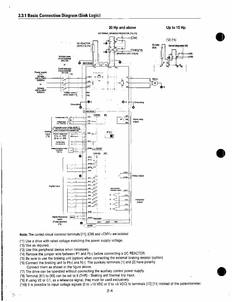
231BasicConnectionDiagramSinkLogic
Powersupply
3phase200to230V
50I80H2
Or
3phase400to480V
50J60Hz
Digitalinput
Moldedcasecircuitbreaker
MCCB
or bMaddrpf1kit
Earthleakagecircuitbreaker
ELCBP71
Mengfrequencymeter
0to001rFM2l
AyoontrdPow00 C
Potentiometer2
V0gvaOrotwDC
1
I
Digitalfrequency180K1meter
PulsecounterC
DCREACTOR
DCR2C4
0
rl
fro
G
Grounding
sR
12
nsfMCtroaeo0plpnYoImfovoCe0to5vOCtoinMnY
Analog112111xtdeltheinputSecondvotepener1g Oto10V ov
Oto5V
CurareInput aai
4to200AOC
1210totuvDC
24DC
CD
20HpandaboveEXTERNALBRAKINGRESISTOR25
2iCM
THR8BRAKINGUNITC26
PTC
I
DX SD
24
G
iGrounding
0030030C
y5O
52
WMweanusmrswathcAye
y
m
4Iti 2
9 0
Alarmrelayoutput
Relayoutput
Transistor
output
Upto15Hp
4
blendblablgresiftpe
NoteThecontrolcircuitcommonterminals11CMandCMYareisolated
1Useadrivewithratedvoltagematchingthepowersupplyvoltage2Useasrequired3Usethisperipheraldevicewhennecessary4RemovethejumperwirebetweenP1andP beforeconnectingaDCREACTOR5Besuretousethebrakingunitoptionwhenconnectingtheextemalbrakingresistoroption6ConnectthebrakingunittoPansN Theauxiliaryterminals1and2havepolarity
Connectthemasshowninthefigureabove7Thedrivecanbeoperatedwithoutconnectingtheauxiliarycontrolpowersupply8TerminalX1toX9canbesetto9THRBrakingunitthermaltripinput9IfusingV2orC1asareferencesignaltheymustbeusedexclusively10Itispossibletoinputvoltagesignals0to10VDCor0to5VDCtoterminals1211insteadofthepotentiometer

BasicConnectionDiagramtoPLCSinkLogic
Powersupplyr1
3phase200to230V
5060Hz
or
3phase400to480V
5060Hz
Moldedcasecircuitbreaker
MCCB
or
Earthleakagecircuitbreaker
ELCBC3
Potentiometer
VoltageInputr0to410VDC
Auxiliarycontrolpowersupply7
Itispassibletoinputvosignals0to410VDCor0to5VDctotemhnals
Analog121111insteadofthepotentiometerinputSecondvoltageInput9 0to 10V o
0to 5V
DCREACTOR
DCR24
RO
GroundingriG
Controlcircuit1
1131
I 12
111
INOVDt7
Currentinput4to20mADC
Analogfrequencymeter0t0OOHz
FM2
Digitalfrequencymeter
Pulsecounter
Datasubjecttochangewithoutnotice70702007GEDrives
1
f
Lj R5485j
20Hpandabove
EXTERNALBRAKINGRESISTOR25
PTC
I
DX
25
SD
G
30A
3030B30C
Y5C
1vsw
Dualdirection
transistorswitchCMY
Yb
Y3
Y2
Y1
CM
11Grounding
Alarmrelayoutput
Relayoutput
Transistor
output
Upto15Hp
2
DCreactor
OCR
Seepage24fornotes

BasicConnectionDiagramSourceLogicTypicallyusedinEurope
Powerguppy
3phase200to230V5013012
Or
400toV50OOHz
Moldedwe
circuitbreakerMCCBor
Earthleakagecircuitbreaker
ELCBs RFIFilter
L2
L3
PE
L1 L1
L3
PaWecmMSC2
Arabnoquorey
DDOWnIFM2
Digitalinput
Digitalfrequencymeter
Pulsecounter
AindltyconbolrL
poweoppy7l
Grounding
VampDC
re ao mntilAnalogl12141111MadontoInputswardwhoaInputI
90to 10VIa1
0to 5VlCrawlWagI11
20aADCIl
CCREACTOR
DCR
6
MHz1
R0
TO
G
lControldramI
I71it2
IN
i
fP2y
EXTERNALBRAKINGRESISTOR25
THRXe
20Hpandabove Upto15Hp
i
0x
R5405
OA
ia P24
IBRAKINGUNIT26
PTO
26
l
G 7Greunding
30A
D00
Alarmrelayoutput
Raleyoutput
Transistor
output
ENCLOSJRE
24DCready
nOCRExternalInkingresistorDB
2
p LI
01Pj G
Pfd
Motor
AmwurIdor
sceenerruble
G
tHR
P24
NoteThecontrolcircuitcommonterminals11CMandCMYareisolated
1Useadrivewithratedvoltagematchingthepowersupplyvoltage2Useasrequired3Usethisperipheraldevicewhennecessary4RemovethejumperwirebetweenP1andP beforeconnectingaDCREACTOR5Besuretousethebrakingunitoptionwhenconnectingtheextemalbrakingresistoroption6ConnectthebrakingunittoPansN Theauxiliaryterminals1and2havepolarity
Connectthemasshowninthefigureabove7Thedrivecanbeoperatedwithoutconnectingtheauxiliarycontrolpowersupply8TerminalX1toX9canbesetto9THRBrakingunitthermaltripinput9IfusingV2orC1asareferencesignaltheymustbeusedexclusively10Itispossibletoinputvoltagesignals0to10VDCor0to5VDCtoterminals1211insteadofthepotentiometer

BasicConnectionDiagramtoPLCSourcelogicTypicallyusedinEurope
owersupply
el3phase200to230V5060Hz
Or
3phase
400to480V50601z
Moldedcase
circuitbreakerMCCBor
Earthleakagecircuitbreaker
ELCB3 RFIFilter
L1
1L2 L2
9L3
rPE
L3
Potentiometer2
VwyWPWOlatOV0CDC
Auxiliarynontrtpowersupply
Grounding
to0100DCnob004wAUyAnalog112H11insteadcrowinputsecondsoilageinputg0to 10VIc
Dto 5V111CurranWAXIl
4to20mADCIAnalogfrequencytr
oloeat IFMco
PLC
Digitalfrequencymeter
Pulsecounter2
Datasubjecttochangewithoutnotice707m2007GEDrives
DCREACTOR4XSCC
RO
T
ontrolcrew1 10VDoi
RS485
24V
P24 iPLC
Z24VDC
IREVHCM
A fox 0x SD
20Hpandabove
EXTERNALBRAKINGRESISTOR2C5
THRXR
Go G Grounting
PTC
1
27
P24
BRAKINGUNITC248
ao3013SSC
PalaredlnParoleeswelchCan
034
032
03
Alarmrelayoutput
Relayoutput
en Transistor
output
ENCLOSURE
DCreactor
OCR
P1
Upto15Hp
Motor
Armouredor G
screenedcable
Seepage26fornotes

232ConnectingtheMainCircuitandGroundTerminals
Table231Functionsofmaincircuitterminalsandgroundtermnals
Symbol ITerminalName
L1RL2SL3TIMaincircuitpowerterminalsUVW IInverteroutputterminalsROTO Inputterminalsforauxiliarycontrolpower
G
1MaincircuitpowerterminalsL1RL2SL3T1 Connecttheseterminalstothepowersupplyviaamoldedcasecircuitbreakerorgroundleakagecircuitbreakerfor
circuitprotectionPhasesequencematchingisunnecessary2 Toinsuresafetyamagneticcontactorshouldbeusedtodisconnectthedrivefromthepowersupplywhenthedrive
protectivefunctionactivates3 UsecontrolcircuitterminalFWDREVortheRUNSTOPkeyonthekeypadpaneltostartorstopthedriveThemain
circuitpowershouldbeusedtostartorstopthedriveonlyifabsolutelynecessaryandthenshouldnotbeusedmorethanonceeveryhour
4 Ifyouneedtoconnecttheseterminalstoasinglephasepowersupplypleasecontactthefactory
2DriveoutputterminalsUVW1 Connecttheseterminalstoa3phasemotorinthecorrectphasesequenceIfthedirectionofmotorrotationis
incorrectexchangeanytwooftheUVandWphases2 Donotconnectapowerfactorcorrectioncapacitororsurgeabsorbertothedriveoutput3 Ifthecablefromthedrivetothemotorisverylongahighfrequencycurrentmaybegeneratedbystraycapacitance
betweenthecablesandresultinanovercurrenttripofthedriveanincreaseinleakagecurrentorareductionincurrentindicationprecision
WhenamotorisdrivenbyaPWMtypedrivethemotorterminalsmaybesubjecttosurgevoltagegeneratedbydriveelementswitchingIfthemotorcablewith460VseriesmotorsinparticularisparticularlylongsurgevoltagewilldeterioratemotorinsulationTopreventthisusethefollowingguidelines
Drives75HPandlargerMotorInsulationLevel 11000V 11300V 11600V460VACInputVoltage 166ft20m 1328ft100m 11312ft400m230VACInputVoltage 11312ft400m 11312ft400m 11312ft400m
Drives5HPandsmaller
MotorInsulationLevel I1000V 11300V 11600V460VACInputVoltage 166ft20m 1165ft50m 1165ft50m230VACInputVoltage 1328ft100m 1328ft100m 1328ft100m
Forthiscasethecablelengthisdeterminedbysecondaryeffectsandnotvoltagespiking
NoteWhenamotorprotectivethermalOILrelayisinsertedbetweenthedriveandthemotorthethermal0Lrelaymaymalfunctionparticularlyinthe460Vseriesevenwhenthecablelengthis165feet50morlessTocorrectinsertafilterorreducethecarrierfrequencyUsefunctioncodeF26Motorsound
DCreactorterminals
Terminalsforexternalbrakingresistor
TerminalsforDClinkcircuit
Groundterminal
28
Description
Connectsa3phasepowersupplyConnectsa3phasemotor
ConnectsabackupACpowersupplytothecontrolcircuitnotsupportedfordIvesof1Hporless
ConnectstheoptionalpowercorrectingDCreactor
Connectstheoptionalexternalbrakingresistorfordrivesof15Hporless
SuppliesDClinkcircuitvolt3getotheexternalbrakingunitoptionorpowerregenerationunitoption
IConnectsthedrivechassiscasetoground
Datasubjecttochangewithoutnotice7072007GEDrives

3InputterminalsforauxiliarycontrolpowerROandTO
ThedriveoperatesevenifpowerisnotprovidedtotheseterminalsIfaprotectivecircuitoperatesandthemagneticcontactoronthedrivespowerisopenedofftheinvertercontrolcircuitpowerthealarmoutput30ABandCandthekeypadpaneldisplaygoesoffTopreventthisthemaincircuitACpowermustalsobesuppliedasauxiliarycontrolpowertotheauxiliarycontrolpowerinputterminalsROandTO1 ToensureeffectivenoisereductionwhenusingaradionoisefiltertheoutputpowerfromthefiltermustgototheauxiliarycontrolpowerinputterminalsIftheseterminalsareconnectedtotheinputsideofthefilterthenoisereductioneffectdeteriorates
4DCreactorterminalsP1andP
1 BeforeconnectingapowerfactorcorrectingDCreactoroptionaltotheseterminalsremovethefactoryinstalledjumper
2 IfaDCreactorisnotuseddonotremovethejumperNoteFordrivesof100HpormoretheDCreactorisprovidedasaseparatestandardcomponentandshouldalwaysbeconnectedtotheterminalsDCreactorisprovidedasopentypeenclosuretobeprovidedbyother
CAUTION
ADCreactordoesnotcomewithdrivesratedless
than100HphoweveruseaDCreactororACreactorunderthefollowingconditionsotherwisethedrivemaybedamagedormalfunction
1 Usedwhenthecapacityofthepowersupplytransformerexceeds500kVAandexceedstherated
capacityofthedrivetenfold2 Usedwhenathyristerconverterisconnectedasa
commonloadonthesametransformer
3 UsedtopreventadriveOVtripfromoccuringwhenthepowerfactorcapacitorinthepowerlineisswitchedonandoff
4 Usedwhenthevoltageimbalanceexceds3
Imbalancerate MaxvoltageVMinvoltageVbetweenphase x100
3phaseaveragevoltageV
5TerminalsforexternalbrakingreP and
DB15HporTess
TheP11drive15HporlessdoesnotcontainabrakingresistorToimprovebrakingperformanceanexternalbrakingresistormustbeinstalled
1 ConnectterminalsP andDBontheexternal
brakingresistortoterminalsP andDBonthedrive
2 Thewiringlengthtwistedpaircablesetcshouldnotexceed165feet5m
Datasubjecttochangewithoutnotice7072007GEDrives 29
MCCB
Power
supply
Fig232Connectiontheauxiliarycontrolpowerinputterminals
6TerminalsforDClinkcircuitP andN
TheP11driveof20HpormoredoesnotcontainadrivecircuitforthebrakingresistorToimprovebrakingperformanceanexternalbrakingunitoptionandanexternalbrakingresistoroptionmustbeinstalled
1 ConnectterminalsPandNonthebrakingunittoterminalsPandNonthedriveThewiringlengthtwistedpaircablesetcshouldnotexceed165feet5m
2 ConnectterminalsPandDBonthebrakingresistortoterminalsP andDBonthebrakingunitThewiringlengthtwistedpaircablesetcshouldnotexceed33feet1OmIfterminalsP andNonthedrivearenotusedleavetheterminalsopenIfP isconnectedtoN orthebrakingresistorisconnecteddirectlytheresistorwillburnup
3 Auxiliarycontacts1and2ofthebrakingunithavepolarity
4 RefertoDBunitinstructionbookforparalleledresistors
NoteBrakingunitsandresistorsareratedondegreeofbrakingdurationandsystemfrequencyofbrakingcycleVerifyunitsmeetapplicationrequirements
Fig233
DCreactor
DCR
Noise
filterMagneticcontactor
LI
DCR
P1 P
IrDCDC
DRIVE
P1 P
ExternalbrakingresistorDB
0
laP1 p JDBN
Fig234Connection15Hporless
sCM
THR

DCreactor
DCR
FrequencyHz
50
60
ExternalbrakingresistorDB
CM
DB
P1 P N
THR
BrakingunitBU
Fig235Connection20Hpormore100Hpormoreparallelresistors200Hpormoreparallelbrakingunits
7Groundterminal
ThegroundingconnectorshouldbesizedinaccordancewiththeNECorCanadianElectricalCodeTheconnec
tionshouldbemadebyaULlistedorCSAcertifiedclosedloopterminalconnectorsizedforthewiregaugeinvolvedTheconnectoristobefixedusingthecrimptoolspecifiedbytheconnectormanufacturer
8AuxiliarypowerswitchingconnectorCNUXfordrivesof40Hpormore
Whenadriveof40HpormorerequiresmaincircuitpowervoltageaslistedbelowdisconnecttheauxiliarypowerswitchingconnectorCNUXfromU1andconnecttoU2FortheswitchingmethodseeFig236
Table233MainVoltageRequiringAuxiliaryPowerSwitchingConnector
PowerVoltageRangeVAC380398
380430
CAUTION
CheckthatthenumberofphasesandratedvoltagematchthoseoftheACpowersupplyDonotconnecttheACpowersupplytotheoutputterminalsUVWInjurymayresultDonotdirectlyconnectabrakingresistortotheDCterminalsPandN Firemayresult
TheswitchingconnectorsaremountedonthepowerPCBabovethecontrolPCBasshownontheright
NoteToremoveaconnectorunlocktheconnectorusingthelockingmechanismandpullToinstallfirmlypushtheconnectoruntilitclicksintoplace
CNUX
210
EnlargedviewofpartA
EIU1I
00
IROT011RL3T1
1 0 0l 000
10 0
3DviewofpartA
FactoryShipmentStatusConnectorCNUXU1
WhenshippedfromthefactoryCNUXisconnectedtotheU1side
I
riIQiex
IOR AuxiliarypowerswitchingonnectorCNUX
1
II
e
o
Auxiilarycontrolpoweinputterminal
00
1714
Datasubjecttochangewithoutnotice70702007GEDrives
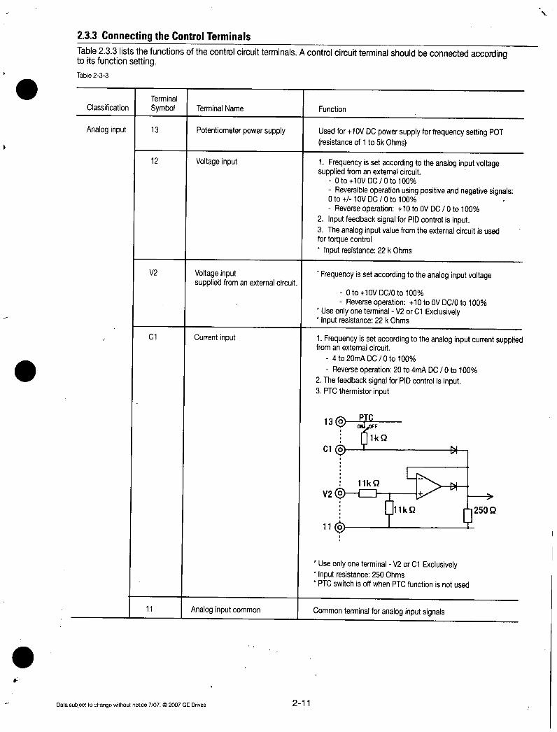
233ConnectingtheControlTerminalsTable233liststhefunctionsofthecontrolcircuitterminalsAcontrolcircuitterminalshouldbeconnectedaccordingtoitsfunctionsetting
Table233
Terminal
Classification Symbol TerminalName Function
Analoginput 13 Potentiometerpowersupply Usedfor10VDCpowersupplyforfrequencysettingPOTresistanceof1to5kOhms
12 Voltageinput 1Frequencyissetaccordingtotheanaloginputvoltagesuppliedfromanexternalcircuit
0to10VDC0to100
Reversibleoperationusingpositiveandnegativesignals0to 10VDC0to100
Reverseoperation10toOVDC0to1002InputfeedbacksignalforPIDcontrolisinput3Theanaloginputvaluefromtheexternalcircuitisusedfortorquecontrol
Inputresistance22kOhms
V2 Voltageinputsuppliedfromanexternalcircuit
C1 Currentinput 1Frequencyissetaccordingtotheanaloginputcurrentsuppliedfromanexternalcircuit
4to20mADC0to100
Reverseoperation20to4mADC0to1002ThefeedbacksignalforPIDcontrolisinput3PTCthermistorinput
11
Datasubjecttochangewithoutnotice7072007GEDrives211
Frequencyissetaccordingtotheanaloginputvoltage
0to10VDC0to100
Reverseoperation10toOVDC0to100UseonlyoneterminalV2orC1ExclusivelyInputresistance22kOhms
13r
V2
110
PTCOFF
I1kS2
11kS2
0
UseonlyoneterminalV2orC1ExclusivelyInputresistance250OhmsPTCswitchisoffwhenPTCfunctionisnotused
Analoginputcommon Commonterminalforanaloginputsignals

Digitalinput FWD
REV
X1
X2
X3
X4
X5
X6
X7
X8
X9
P24
PLC
CM
Analogoutput FMA
11commonterminal
ForwardoperationStopcommand
Reverseoperation
Stopcommand
Digitalinputt
1Digitalinput21Digitalinput31Digitalinput41Digitalinput51Digitalinput6
Digitalinput7Digitalinput8
Digitalinput9
ControlUnitpowerSupply
PLCsignalpower
Digitalinputcommon
Analogmonitor
Pulseoutput FMP FrequencymonitorCMcommon pulsewaveformoutputterminal
212
UsedforforwardoperationwhenFWDCMisonordecelerationandstopwhenFWDCMisopened
UsedforreverseoperationwhenRECMisonordecelerationandstopwhenREVCMisopened
ThecoasttostopcommandexternalalarmalarmresetmultistepfrequencyselectionandotherfunctionsfromanexternalcircuitcanbeassignedtoterminalsX1toX9FordetailsseeSettingtheTerminalFunctionsE01toE09inSection52FunctionExplanationSpecificationsofdigitalinputcircuit
Item
Operatingvoltage
Maximumloadcurrent
Leakagecurrent
PLCC8BkQ
FWDREVCX1X9
CMg
ON
OFF
ON
OFF
ovl
min
OV
22V
24VDCpowersupplyforcontrolinputMaximumoutputcurrent100mA
UsedtoconnectPLCpowersupplyforoutputsignalsratednominalvoltage24VDC22to27VDCrangeatsinklogicoperation
CommonterminalfordigitalinputsignalsandP24
OutputsmonitorsignalusinganalogDCvoltage0to10VDCThesignalindicatesoneofthefollowing
OutputfrequencybeforeslipcompensationLoadfactor
OutputfrequencyafterslipcompensationPowerconsumptionOutputcurrentPIDfeedbackvalue
OutputvoltagePGfeedbackvalue
OutputtorqueDClinkcircuitvoltageConnectableimpedancemin5kohms
OutputsamonitorsignalusingthepulsewaveformThissignalhasthesamefunctionastheFMAsignal
typ max
12V24V 127V32mAj45mA
105mA
Datasubjecttochangewithoutnotice70702007GEDrives

Transistor Y1 Transistoroutput1
Y2 Transistoroutput2Y3 iransistoroutputt
Y4 Transistoroutput4
ArunningsignalfrequencyequivalencesignaloverloadearlywarningoutputsignalandothersignalsfromthedriveareoutputastransistoroutputtoarbitraryportsFordetailsseeSettingtheTerminalFunctionsE20toE23inSection52FunctionExplanation
Specificationsoftransistoroutputcircuit
Item 1 mintyp1 max
Operatingvoltage I ON 1V 12VI OFF 124V127V
Maximumbadcurrent ON 50mA
Leakagecurrent I OFF 01mA
CME Transistoroutputcommon CommonterminalfortransistoroutputsignalsThisterminalisinsulatedfromterminalsCMand11
Relayoutput30A30B30C Alarmoutputsforanyfault Ifthedriveisstoppedbyanalarmprotectivefunctionthealarmsignalisoutputfromtherelaycontactoutputterminal1SPDTContactrating250VAC03Acos00348VDC05AforCEMarking
Anexcitationmodeexcitationatalarmoccurrenceoratnormaloperationcanbeselected
Y5AY5C Multipurposesignal ThesesignalscanbeoutputsimilartotheY1toY4signalsaboveThecontactratingisthesameasthatofthealarmoutputabove
Communic DXDX RTUcommunication InputoutputsignalterminalsforRTUcommunicationinputoutputation Upto31inverterscanbeconnectedusingthedaisychainmethod
SD Communicationcable TerminalforconnectingthecableshieldTheterminaliselectricallyshieldconnectionterminal floating
1Analoginputterminals1312C1and111 Theseterminalsreceivelowlevelanalogsignalsthat
maybeaffectedbyexternalnoiseThecablesmustbeasshortaspossible20metersorlessmustbeshieldedandtheshieldsmustbegroundedIfthecablesareaffectedbyexternalinductionnoisetheshieldingeffectmaybeimprovedbyconnectingtheshieldtoterminal11
2 Ifcontactsmustbeconnectedtothesecircuitstwin
bifurcatedcontactsforhandlinglowlevelsignalsmustbeusedAcontactmustnotbeconnectedtoterminal11
3 IfanexternalanalogsignaloutputdeviceisconnectedtotheseterminalsitmaymalfunctionasaresultofdrivenoiseTopreventmalfunctionconnectaferritecoreorcapacitortotheexternalanalogsignaloutputdevice
Datasubjecttochangewithoutnotice707C2007GEDrives
Shieldedwires
VR
1kto
5Kohms
213
Y1Y4Q
2830VCITY
Fig239
U1312
Samephasethroughconnectionormultiplewinding2or3times
50V
Fig2310ExampleofNoisePrevention
Drive
11
12C
11Drive
0022uFFerritecore

2DigitalinputterminalsFWDREVX1toX9PLCandCM
1 DigitalinputterminalsegFWDREVX1toX9aregenerallyturnedonoroffbyconnectingordisconnectingthelinetoorfromtheCMterminal
IfdigitalinputterminalsareturnedonoroffbyswitchingthePLCsopencollectoroutputusinganexternalpowersupplyaresultingbypasscircuitmaycausethedrivetomalfunctionTopreventamalfunctionconnectthePLCterminalasshowninFig2311
Programmable Drive
controller 1logicPLC
0 0
FWD0
TDC24V
Fig2311PreventionofBypassCurrentbyExternalPower
2 Whenusingacontactinputahighqualityrelaywithreliablecontactsmustbeused
3TransistoroutputterminalsY1toY4CMY1 Theseterminalshaveacircuitconfigurationasshown
inTable233TransistorOutput Confirmthe
polarityoftheexternalpowersupply2 Toconnectacontrolrelayconnectasurgeabsorbing
diodetobothendsofitsexcitingcoil4SinkorSourceLogicSelection1 SetSWIforSinkorSourceConnectiontothePLC
ThefactorydefaultsettingisSinkandthisinstructionmanualexplainsSinklogicfunctiononly
2 WhenyouneedtoconnectsourcetypelogicrefertoBasicConnectionDiagramFig233andFig234andTechnicalInformationManualSinkLogiciscommonlyusedintheUSAandSourceLogiciscommonlyusedinEurope
5Others1 Topreventamalfunctionasaresultofnoisecontrol
terminalcablesmustbeplacedasfaraspossiblefromthemaincircuitcables
2 Thecontrolcablesinsidetheinvertermustbesecuredtopreventdirectcontactwiththemaincircuitegmaincircuitterminalblock
WAFWVG
ControllinesgenerallydonothaveenhancedinsulationIftheinsulationofacontrollineis
damagedthecontrolsignalsm exposedto
highvoltageinthemaincircuitIneLowVoltageDirectiveinEuropealsorestrictstheexposuretohighvoltageElectricshockmayresult
CAUTION
TheinvertermotorandcablesgeneratenoiseCheckthattheambientsensorsanddevicesdo
notmalfunctionAccidentmayresult
214
6Wiringofcontrolcircuitinverterof40Hpormore1 Pulloutthecontrolcircuitwiringalongtheleftpanel
asshowninFig23122 SecurethecabletocablebindingholeAontheleft
wallofthemaincircuitterminalblockusingacabletie
eglnsulockThecabletiemustnotexceed01435mminwidthand00615mminthickness
3 WhentheoptionalPCboardismountedthesignallinesmustbesecuredtocablebindingholeB
Fig2312TheControlWiringRoute
CablebindingHoleB
Cableties
Wiringofcontrolcircuit
Leftpanel
Controlterminal
wiring
Cable
bindingHoleA
Fig2313SecuringPositionsforInverterControlCircuitWiring40HPormore
Datasubjecttochangewithoutnotice70702007GEDrives

234TerminalConfiguration
1Maincircuitterminals
14to1Hp230VAC12to1Hp460VAC
L1RL2SL3TDB P1 P N U V W
OG
G
IGI
2to5Hp230VAC2to5Hp460VAC
IGI
ScrewsizeM35
L1RL2SL3TDB P1 P N U V W
ScrewsizeM4
75to15Hp230VAC I ROITO75to15Hp460VAC ScrewsizeM35
L1RL2SL3TDB P1P N U V W
ScrewsizeM5
20to30Hp230VAC20to30Hp460VAC
NGI0GI ScrewsizeM6
40to50Hp230VAC40to100Hp460VACScrewsizeM4
ROTO
G G
00
U V W
ScrewsizeM8
Datasubjecttochangewithoutnotice7072007GEDrives
RO ITO IScrewsizeM35
RO ITOScrewsizeM35
I0GI
215
60To100Hp230VAC125to200Hp460VAC
ROTO U V W
L1RL2SL3TDB P1 P N
ScrewsizeGM8G G
00 OtherterminalsM10
125Hp230VAC
ROTO ScrewsizeM4
L1RL2SL3TTP1P N U V W
G G ScrewsizeGM10
00 OtherterminalsM12
150Hp230VAC250to450Hp460VAC
IL1R
ROTO
IL2S
G G ScrewsizeGM10
00OtherterminalsM12
500600Hp460VAC
ROTO ScrewsizeM4
700800Hp460VAC
ROTO
L1R L2S L3T
L1RL2S L3T P1
ScrewsizeM4
IL3T IUP1
P
P
111R1IL2S1IL3111P1IIUIIV11WIL1RL2SL3TDB P1 P N U V W 1L1RIIL2SIIL3T P1IIU IrVIIWI
G G IP P0
INI N
ScrewsizeG M10OtherterminalsM12
1111110
L1RL2SL3TDB P1 P N G G
V
ScrewsizeROTOM4G M10OtherterminalsM12
N

2Controlcircuitterminals
HP
30AY5ACMYY3 Y1 C1 FMAFMPPLCX1 X2 X3 X4 X5 X6 X7 X8 X9
30C30BY5CY4 Y2 11 12 13 V2 CM CMFWDREVP24P24DXDXSD
235AF300P11DriveCableSizeTighteningTorqueandCircuitProtectionRating
L1RL2SL3TNominal
230VACInput025 3 3
05 5 6
1 10 15
2 15 20
3 20 30
5 35 50
75 60 80
10 70 125
15 100 150
20 125 200
25 150 225
30 175 250
40 200
50 225
60 300
75 350
100 300
125 400
150 450
IncomingDevice I TighteningTorquelbInchNm
InputFuse
AuxiliaryInputCircuitL1R
UV EGL2S13TInput
BreakerWP1P
MaximumCIR0TO
3
3
3
3
3
3
3
3
3
3
3
3
5
5
5
5
5
5
5
15 1 10612 I10615 1 1220 1
30 I 208236 208
40 1 23660 1
100 31035 310
125 I 35175 1 51358225 1250 1300
200 1 119135225 1
300 123927119135 119
350 1 135300 1400 I42548 I
23927
450 1
216
DBcircuit
121P ROTONDB
I CablesizeAWG
L1RL2S DCReactorDBcircuitROControl L UVW
PlP2P TOControl
NI1DB
62107 16 16 22
10612 I1414 14
10
8
6
4
3
2
1
40 10 1 20 I10Uty21 30 1 40 10
Uty220 40 IUty21IUty230uty210IQty220 8 1
IIlly220Uty2301Uty240 6 1IUty240Ilry2401Uty2250 4
Uty2250Uty2300Uty2350
460VACInput05 1 3 3 3 I 15 10612 106 6207
1 5 6 3 1 15 I 12 I2 10 10 3 15 208236 208 106121
3 1 15 15 3 20 236
5 1 20 25 3 35 1 14
75 1 30 45 3 50 310351 310 1 12
10 40 60 3 70 35 10
15 50 90 3 90 5135820 70 110 3 110 8
25 80 125 3 150 6
30 100 125 3 I 175 4
40 100 10 100 119135 2 3 3
50 125 10 125 I 1 2 2
60 175 10 175 513 20 2 1
75 150 10 150 58 30 10 20
100 175 10 175 20 30 40
125 200 10 200 2392711911351 30 40 130921
150 225 10 225 23927 119 Qry210Ury210 Qty210
200 300 10 300 I I 135 I Ilea10Uty220 Qry230
250 400 10 400 42548 239 Qty230Ury230 11W240
300 450 10 450 27 Uty240Ity2250 Utv2300
350 500 10 500 Qty22501Cry2300 Qty2350
400 600 10 600 13 Qty23501Cry2350 Qry2500
450 700 10 700 Qty23501Cry2400 Qty2500
500 700 101 700 IQty5001Cty3300 Qty3300
600 1000 10I 1000 IQty3001Cry3350 Qty3500
700 1000 10I 1000 Icay34001Cty3500 Qty3600
800 1200 10I 1200 1Qty3500ILty3600 Uty3600
11ClassJFuseorCircuitBreakerreted600Vwiththemaximumcurrentratingasshownintheabovetableshallbeconnectedtothedrivefor30Handless2BasedonGEFujistandardDBunitandDBresistordesignsOtherratingrequirecarefulreview3ConsultfactoryDeviceratingssuchassystemcoordinationshortcircuitratingandtypemustbecarefullyreviewedbytheuserWiresizefromNECtables31016Copperwirerated60DegCfor100ampsorless75DegCforover100ampsin30DegCambientand125timesDriveratedampsTheseareminimumwiresizesconsultandconformtolocalandnationalcodes
16 16
14
10
8
6
4
31
1a
10
Datasubjecttochangewithoutnotice7072007GEDrives
22

236DCLinkReactor
Dimensionsininches
Hp I ModelNo Width
230VP11
100 DCR275B 787
125 DCR290B 709
150 DCR2110B 748
460VP11
100 DCR475B 748
125 DCR490B 748
150 DCR4110B 748
200 DCR4132B 787
250 DCR4160B 827
300 DCR4200B 827
350 DCR4220B 866
400 DCR4280B 866
450 DCR4280B 866
500 DCR4355B 984
600 DCR4400B 984
700 DCR4450B 1063
800 DCR4500B 111
Datasubjecttochangewithoutnotice7072007GEDnves
Width
Terminal
rti
Depth
1063
1102
1299
1063
1102
1102
1102
126
1299
1378
1457
1457
1299
1378
1378
1417
r
217j
7
Depth
Height Weight LossWJ
709 37 55
846 37 57
905 46 67
689 35
787 44
787 46
807 55
807 68
906 75
906 81
965 95
965 95
878 99
917 106
1035 121
1035 143
58
64
73
84
90
126
131
133
150
205
215
272
292
Note
AF300P11Drivesrated100HpandabovearefurnishedwithaDClinkreactorThisreactormustbeinstalledbetweenterminalP1andPpriortocommissioningoftheDrive
TheweightoftheDCLinkReactorisnotincludedwiththatoftheDrive
DCLinkReactorisprovidedasopentypeandisseparatelymountedEnclosuretobeprovidedbyothers

31InspectionandPreparationBeforeOperationCheckthefollowingbeforeoperation1 Checkthattheconnectionsarecorrect
InparticularcheckthatthepowersupplyisnotconnectedtoanyoftheUVorWoutputterminalsandthatthegroundterminalissecurelygrounded
2 Checkforshortcircuitsandgroundfaultsbetweentheterminalsandsectionsunderpower
3 Checkforlooseterminalsconnectorsorscrews4 Checkthatthemotorisdisconnectedfromthemechanical
equipment5 Turnoffswitchesbeforeturningonpowertoensurethatthedrive
willnotstartoroperateabnormallyatpoweron6 Checkthefollowingafterpoweron
aNoalarmmessageisdisplayedonthekeypadpanelseeFigure312
bThefaninsidethedriveisrotatingFordriveswith2Hpormore
32OperationMethodTherearevariousmethodsofoperationSelectamethodofoperationaccordingtotheoperatingrequirementsandspecificationsrefertoSection42OperatingtheKeypadPanelandChapter5FunctionSelectionTable321listsgeneralmethodsofoperation
33TrialRun
OnceinspectioniscompletedseeSection31proceedwithatrialrunThemotorisinitiallydisconnectedandthedriveisoperatedfactorysettingusingthekeypadpanel
TurnpoweronandconfirmthattheLEDmonitordisplay000Hzisblinking
2 Setthefrequencytoabout5Hzusing0key3 Tostarttherunpress keyforforwardrotationorCI
keyforreverserotationTostoppress keyVerifyfrequencyincreasesforzerotothesetpoint
Connectmotorandrepeatsteps134 Checkthefollowingitems
a Isthedirectionofrotationcorrectb Istherotationsmoothnobuzzingorabnormalvibrationc Areaccelerationanddecelerationsmooth
5 IfnoabnormalityisdetectedincreasethefrequencyandchecktheaboveitemsagainIftheresultsofthetrialrunarenormalstartaformalrun
1
3Operation
WARNING
BesuretohavethedrivecoverinplacebeforeturningonthepowerclosedNeverremovethecoverwhilepowerisappliedtothedriveToensuresafetydonotoperateswitcheswithwethandsElectricshockmayresult
FWD
Datasubjecttochangewithoutnotice7072007GEDrives
STOP
31
OperationCommand
Operation
usingkeypad
panel
Operation
usingexternal
terminal
signals
Drive
L1RL2SL3T U V WO o0 0
power
Fig311Driveconnection
motor
HzAVdrHnMmmkWXIOX100
NC
DATAEMOTELOCAL
JOGlNORMAL
Fig312Displayonkeypadpanelatpoweron
FrequencySetting
Keysonkeypadpanel
FrequencySettingPOTVR
analogvoltageanalogcurrent
OperationCommand
FWD
STOP
Inputfrom
Terminals
FWDCMand
REVCM
NotesIfanerrorisdetectedinthedriveor
motorsoperationimmediatelystopandattempttodeterminethecauseoferrorbyreferringtoChapter7Troubleshooting
SincevoltageisstillpresentatthemaincircuitterminalsL1RL2SL31andauxiliarycontrolpowerterminalsROTOevenwhentheoutputfromthedriveisterminateddonottouchtheterminalsThesmoothingcapacitorinthedriveischargedafterthepoweristurnedoffanditisnotdischargedimmediatelyBeforetouchinganelectriccircuitconfirmthatthechargelampisofforuseamultimetertocheckthatthevolatgehasdecreasedbelow25VDCforlowvoltageattheDCPNterminals

Notes
32
Datasubjecttochangewithoutnotice70702007GEDrives

4KeypadPanelThekeypadpanelhasvariousfunctionsforspecifyingoperationssuchasfrequencysettingrunstopcomrnandconfirmingandchangingfunctiondataconfirmingstatusandcopyingfunctioncodesettingsReviewtheuseofeachfunctionbeforeattemptingtooperatethedrivefromthekeypadpanelThekeypadpanelcanalsoberemovedorinsertedduringinverteroperationHoweverifthekeypadpanelisremovedduringkeypadpaneloperationegrunstopfrequencysettingthedrivestopsandoutputsanalarm
41AppearanceofKeypadPanel
r@In1Q
HzAVrminMminkWXI0X100
MEM
RUN FWD
PRGIIPRGMENUFDLEDSHIFT
FWDREVSTOPREMLOCCOMMJOG
HUNGDATA
REMOTELOCAL
JOGNORMAL
Controlkeysvalidduringkeypadpaneloperation
Usedfordriverunandstop
ForwardoperationcommandFWD
CIReverseoperationStopcommandSTOP
Operationkeys
Usedforswitchingscreensdatachangefrequencysettingetc
OperationKeys
DFUNCDATA
0SHIFT
0STOP
STOP
Datasubjecttochangewithoutnotice70702007GEDrives
LEDmonitor
4digitdisplayUsedtodisplaydatasuchassettingfrequencyoutputfrequencyandalarmcode
AuxiliaryInformationRelatedtoLEDMonitor
IndicatesselectedunitsormultipleofthedatashownontheLEDmonitorandisdisplayedonthetoplineoftheLCDmonitorThe symbolindicatesselectedunitsormultiplenumberThesymbolAindicatesthatthereisanupperscreennotcurrentlydisplayedLCDMonitor
UsedtodisplayvariousitemsofinformationsuchasoperationstatusandfunctiondataAnoperatingguidemessageisscrolledanddisplayedatthebottomoftheLCDmonitorThisLCDmonitorhasabacklightfeaturewhichturnsonwhenthecontrolpowerisappliedoranykeypadkeyispressedandstaysonapproximately5minutesafterthelastkeystrokeStatusIndicatorsonLCDMonitor
Displayscurrentoperatingstatus
FWDForwardoperationREVReverseoperationSTOPStop
DisplaystheselectedoperatingmodeREMterminalblock
LOCkeypadpanelCOMMcommunicationterminal
JOGjoggingmode
ThesymbolVindicatesthatthereisalowerscreennotcurrentlydisplayedRUNLEDvalidduringoperationfromkeypadpanel
IndicatesthatanoperationcommandwasinputbypressingtheFWDorREVkey
41
PrimaryFunction
Usedtoswitchthecurrentscreentothemenuscreenorswitchtotheinitialscreeninoperationtripmode
UsedtoswitchtheLEDmonitorortodeterminetheenteredfrequencyfunctioncodeordata
Usedtochangedatamovethecursorupordownorscrollthescreen
UsedtomovethecursorhorizontallyatdatachangeWhenthiskeyispressedwiththeupordownkeythecursormovestothenextfunctionblock
UsedtocancelcurrentinputdataandswitchthedisplayedscreenIfanalarmoccursthiskeyisusedtoresetthetripstatusvalidonlywhentheinitialalarmmodescreenisdisplayed
UsedtoswitchnormaloperationmodetojoggingoperationmodeorviceversaTheselectedmodeisdisplayedontheLCDmonitor
SwitchesoperationmodefromkeypadpaneloperationmodetoterminalblockoperationmodeorreverseWhenthesekeysareoperatedfunctionF01dataisalsoswitchedfrom0to3orfrom14to0TheselectedmodeisdisplayedontheLCDindicator

42OperationFromtheKeypadPanelLCDScreenLevelStructure421NormalOperation
Thekeypadpaneloperatingsystemscreentransitionlevelstructureisstructuredasfollows
16000IOperationMode
AA A
IAlarmAlarmmode
A A A
PRG
1ProgramMenu
RESET
PRG
160001
422AlarmModes
IfalarmisactivatedoperationischangedfromnormalkeypadpaneloperationtoanalarmmodeoperationThealarmmodescreenappearsandalarminformationisdisplayed
Theprogrammenufunctionscreensandsuppleme yscreensremainunchangedasluringnormaloperationthoughtheswitchingmethodfromprogrammenutoalarmmotislimitedtoPRG
160001OperationMode I Keypadpaneloperatingsystemduringnormaloperation
AlarmisAactivated
Alarmmodeprocessingincluding
PRG
PRG
IAlarmIProgramMenu
FUNCDATA
RESET
RESET
FUNCDATA
RESET
16000I
42
i
Screenforeach
Function
IAlarmI
1
Screenforeach
Function
FUNCDATA
FUNCDATA
6000ISupplementaryScreen
RESET
IAlarmISupplementaryScreen
Datasubjecttochangewithoutnotice7072007GEDrives

Table421OverviewofContentsDisplayedforeachLevel
No LevelnameI1 OperationMode
2 ProgramMenu
3 ScreenforeachFunction
4 Supplementaryindividual
Content
ThisscreenisfornormaloperationFrequencysettingfromthekeypadpanelandLEDmonitorswitchingarepossibleonlywhenthisscreenisdisplayed
EachfunctionofthekeypadpanelisdisplayedinmenuformandcanbeselectedByselectingthedesiredfunctionfromthelistandpressingDATAthecorrespondingfunctionscreenisdisplayedThefollowingfunctionsareavailableaskeypadpanelfunctionsmenus
No 1 MenuNamel1 DATASET
2 DATACHECK
PurposeThecodeandnameofthefunctionaredisplayedSelectingafunctiondisplaysadatasettingscreenforcheckingormodifyingdataThecodeandnameofthefunctionaredisplayedSelectafunctiontodisplayascreenforcheckingdataModifyingdataispossibleasdescribedabovebygoingtothedatasettingscreen
3 Cancheckvariousdataontheoperatingstatus4 Cancheckthestatusofanaloganddigitalinputoutputsfortheinverterand
optionsasanIOchecker
5 CancheckinverterstatuslifeexpectancycommunicationerrorstatusandROMversioninformationasmaintenanceinformation
6 Canmeasuremaximumandaveragecurrentandaveragebreakingforceinloadratemeasurement
7 Canchecktheoperatingstatusandinputoutputstatusatthelatestalarmoccurrence
8 CancheckthelatestalarmorsimultaneousloccurringalarmsandalarmhistorySelectingthealarmandpressing displaysalarmcontentsfortroubleshooting
9 I DATACOPY1PlacesthefunctionofoneinverterinmemoryforcopyingtoanotherdriveThefunctionscreenselectedontheprogrammenuappearshencecompletingthefunction
OPR
IOCHECK
MAINTENANCE
LOADFCTR
ALMINF
ALMCAUSE
Datasubjecttochangewithoutnotice70702007GEDrives 43
UNDATA
FunctionsnotcompletedegmodifyingfunctiondatadisplayingalarmfactorsonScreenfunctionscreensaredisplayedonthesupplementaryscreen

43EnteringDataontheKeypadPanel431OperationMode
ThescreenfornormalinverteroperationincludesascreenfordisplayingdriveoperatingstatusandascreenforgraphicallydisplayingthestatusintheformofabargraphTheoperatorcanswitchbetweenbothscreensbyusingthefunctionE45
1OperatingStatusE450
6000
STOPPRG PRG
MENU
FDLEDSHIFT
2BarGraphE451
6000 I111MILIHzMt II I 1FoutloutTRQ
frequencysettingspress
432SettingDigitalFrequency
Ontheoperationmodescreenpress or0todisplaythesetfrequencyontheLEIData isincreasedor
decreasedinthesmallestpossibleunitdependingonwhichkeyispressedTheadjustmentsindatawilloccurrapidlyiftheoperatorholdsdown or0Toselectadigituse andthendatacanbesetdirectlyTosavethe
FUNC
DATA
PressmaandErgtotoreturntotheoperation modeIfkeypadpanelsettingsarenotelectedthepresentfrequencysettingmodeappearsontheLCDWhenselectingthePIDfunctionthePIDcommandcanbesetwithaprocess value
refertotechnicaldocumentationfordetails
1DigitalkeypadpanelsettingsF010orC300
1 6000 I 6000
DIGSETHz
0 LOCAL
PRG PRG 50400
MENU FDDATASETFDLEDSHIFT
RUNFw
2Nondigitalsetting
6000
RUN oPRGPRGMENUFDLEDSHIFT
6000
RUNFwPRG PRG
MENU
FDLEDSHIFT
DirectionofrotationblanknocomrrandorFWDREVOperatingstatusSTOPnocommandorRUN
OutputfrequencymaximumfrequencyatfullscaleOutputcurrent200ofinverterratingatfullscaleTorquecalculation200ofmotorratingatfullscale
44
r
5689
DIGSETHzLOCAL
0 50400
FDDATASET
STORING
1 6000 11 Frequencysettingvalue
REMOTEREFScreenexplanation12V1 Presentfrequencysettingmode
FDDATASET Operationsguide
Frequencysettingvalue
ScreenexplanationPresentfrequencysettingmodeFrequencysettingrange
Operationsguide
WhenAqpressedandwriting
Datasubjecttochangewithoutnotice7072007GEDrives

433SwitchingtoLEDDigitalMonitor
Duringnormaloperationpress FUNCtoswitchtoLEDmonitordisplayWhenmonitoreddataisswitchedtheLEDmonitorcontentsaredisplayedWhenpoweristumedonthemonitorcontentssetbythefunctionE43aredisplayedontheLED
E43 E4400 Settingfrequency1 Settingfrequency2 Settingfrequency3 1 Outputcurrent4 Outputvoltage
specifiedvalue5 Synchronous
speedsettingvalue
6 Linespeedsettingvalue
7 Loadrotation
speedsettingvalue
8 Torquecalculationvalue
9 Power
consumption10 PIDsettingvalue11 PIDremote
settingvalue12 PIDfeedbackvalue
I 6000 L
RUNPRG
FD
PRGMENU
LEDSHIFT
WhenstoppingE441
with0or toselectanitemthenpress
1DATASETTING
2DATACHECK3OPRMNTR4IOCHECK5MAINTENANCE6LOADFCTR7ALMINF8ALMCAUSE9DATACOPY
Datasubjecttochangewithoutnotice70702007GEDrives
WhenrunningE4401
Outputfrequency1beforeslipcompensationOutputfrquency2afterslipcompensation
SettingfrequencyOutputcurrent
Outputvoltagespecifiedvalue
1DATASETTING2DATACHECK
3OPRMNTR
4IOCHECK
Synchronousspeed
Linespeed
Loadrotationspeed
Torquecalculationvalue
Powerconsumption
PIDsettingvalue
PIDremotesettingvalue
PIDfeedbackvalue
FUNC
DATA
DISPLAY
4IOCHECK45MAINTENANCE
6LOADFCTR7ALMINF
FUNC
DATA
45
todisplaythenextscreen
Unit
Hz
A
V
rmin
mmin
rmin
kW
indication
Remarks
For4digitsormorethelasrdigitsarecutwithx10x100markedontheindicator
DisplayedonlywhenPIDiseffectiveinPIDoperationselection
434ProgramMenuScreen
TheProgramMenuscreenisshownbelowOnlyfouritemscanbedisplayedsimultaneouslyMovethecursor
435SettingFunctionData
OntheProgramMenuscreenselect1DataSettingTheFunctionSelectscreenappearswithfunctioncodesandnamesonitSelectthedesiredfunction
j 6000 L 6000 LF00DATAPRTC
F01FREQCOM1
F02OPRMETHODF03MAXHz1
NFunctionCode FunctionName
FUNC
DMA
j 6000
F01FREQCOM1
011
DataSettingRange Data
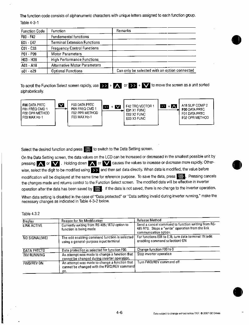
ThefunctioncodeconsistsofalphanumericcharacterswithuniquelettersassignedtoeachfunctiongroupTable431
FunctionCode
F00F42
E01E47
CO1C33
P01P09
H03H39
A01A18
o01o29
Function
Fundamentalfunctions
TerminalExtensionFunctions
FrequencyControlFunctionsMotorParameters
HighPerformanceFunctionsAlternativeMotorParameters
OptionalFunctions
ToscrolltheFunctionSelectscreenrapidlyusem Kaor Qtomovethescreenasaunitsortedalphabetically
F00DATAPRTC
F01FREQCMD1F02OPRMETHOD
F03MAXHz1
Table432
DATAPRTCTD
INVRUNNING
FWDREVON
F00DATAPRTC0 F01FREQCMD1
F02PPRMETHOD
F03MAXHz1
SelectthedesiredfunctionandpressFUNC
switchtotheDataSettingscreen
OntheDataSettingscreenthedatavaluesontheLCDcanbeincreasedordecreasedinthesmallestpossibleunitby
pressing121or Holdingdown0orQcausesthevaluestoincrease ordecreasemorerapidlyOther
wiseselectthedigittobemodifiedusing andthensetdatadirectlyWhendataismodifiedthevaluebefore
modificationwillbedisplayedatthesametimeforreferencepurposeTosavethedatapressFUNC
Pressingcancels
thechangesmadeandreturnscontroltotheFunctionSelectscreenThemodifieddatawillbeeffectiveininverteroperationafterthedatahasbeensavedbyFUNC
Remarks
Display IReasonforNoModificationLINKACTIVE CurrentlywritingfromRS485RTUoptionto
functionisbeingmade
NOSIGNALWE
F42TRQVECTOR1E01X1FUNCE02X2FUNC
E03X3FUNC
WhendatasettingisdisabledinthecaseofDataprotectedorDatasettinginvalidduringinverterrunningmakethenecessarychangesasindicatedinTable432below
Theeditenablingcommandfunctionisselectedusingageneralpurposeinputterminal
DataprotectionisselectedforfunctionF00 I
AnattemptwasmadetochangeafunctionthatcannotbechanaedduringinverteroperationAnattemptwasmadetochangeafunctionthatcannotbechangedwiththeFWDREVcommandon
Canonlybeselectedwithanoptionconnected
Ifthedataisnotsavedthereisnochargetotheinverteroperation
46
0 A18SLIPCOMP2
F00DATAPRTC
F01DATAPRTC
F02OPRMETHOD
ReleaseMethod
SendacancelcommandtofunctionwritingfromRS485RTUStopsawriteoperationfromthelinkcommunicationoptionForfunctionsE01toE19turndataterminal19editenablingcommandselectionON
ChangefunctionFOOto0Stopinverteroperation
TurnFWDREVcommandoff
Datasubjecttochangewithoutnotice70702007GEDrives

436CheckingFunctionData
Select2DATACHECKontheProgramMenuscreenTheFunctionSelectscreenthenappearswithfunctioncodesandnames
6000 6000
1DATA
RUN FWD 2DATAC
SETTING
PRGPRGMENU 3OPRMNTR
FDLEDSHIFT 410CHECK
Functioncode
UNEDATA
Datachangedfrominitialvalue Data
SelectthedesiredfunctionandpressFUNCDATAtocheckthefunctiondataBypressingFUNCDATAthescreenswitchestotheDataSettingscreenwheredatacanbemodified
437MonitoringOperatingStatus
Select3OPRMNTRontheProgramMenuscreentodisplaythecurrentinverteroperatingstatusUse0andtoswitchbetweenthefouroperationmonitorscreens
6000 6000 6000
RUNFWDPRGPRGMENU
FDLEDSHIFT
1DATASETTING
2DATACHECK
3OPRMNTR
410CHECK
Datasubjecttochangewithoutnotice7072007GEDrives
UNDAA
6000
FOO 0
F01 1
F021
iF03 60Hz
47
FoutxxxxxHz
loutxxxA
VoutxxxV
TRQxxx
FU
6000
FOO DATAPRTC
3
010
Outputfrequency
OutputcurrentOutputvoltageTorquecalculationmethod
6000 6000
SYNxxxxxx Synchronousrotation laFrefxxxxxHz Settingfrequency
speedrminxxxxxxxxx Operationstatus
LODxxxxxx Loadspeedrmin FWDREVRotatingdirectionLINxxxxxx Linespeedmmin ILCurrentlimiting
VLVoltagelimiting
1 laLUUndervoltageTLTorquelimiting
6000
SVxxxxx PIDsettingvaluePVxxxxx PIDfeedbackvalue
TLDxxx DrivingtorquelimitingsettingTLBxxx Brakingtorquelimitingsetting

438IOCheck
Select4IOontheProgramMenuscreenChecktodisplayanaloganddigitalinputoutputsignalstatusforthedriveandoptionsUse and toswitchbetweenthesevenscreensofdata
6000
RUN FWD
1DATASETTING REMX2 0X6
2DATACHECK FWDDX3 0X7PRGPRGMENU 3 3OPRMNTR REVcX4 DX8FDLEDSHIFT 410CHECK iDX1 DX5 nX9
6000
01 uY5
cY2
oY3
LY4
6000
t
12xxxV Terminal12input22xxxV Terminal22inputvoltageA10option32xxxV Terminal32inputvoltageAlooptionV2xxxV TerminalV2input
6000
A0xxxxV
CSxxxmA
DIxxxxH
DOxxH
16000
P1xxxx0ps
Z1xxxpsP2xxxxx0ps
Z2xxxps
Outputterminalstatus
SignalOFFSignalON
Analoginputsignal
DIOoptionIOstatus
PGSYoptioninputstatus
6000 6000
1
c MastersideABphase4xfrequency
MastersideZphase4xfrequency
SlavesideNBphase4xfrequency
QlavesideZphase4xfrequency
AnalogoutputvoltageAIOoption
AnalogoutputcurrentAIOoption
DigitalinputterminalHEXindication
DigitalouputterminalHEXindication
48
0
1LA
6000
C1xxxmA
C2xxxmA
6000
FMAxxxH
FMPxxxV
FMPxxxxps
Inputterminalstatusterminals
SignalOFFSignalON
60 Inputterminalstatus
viacommunication
COMuX2 DX6
oFWDoX3 oX7
DREVoX4 nX8 SignalOFFSignalON
oX1 oX5 oX9
Analoginputsignal
4TerminalC1inputcurrent4 TerminalC2inputcurrentAIOoption
Outputformeter
FMAoutputvoltageFMPoutputvoltage
4 FMPoutputfrequency
Datasubjecttoctangewithoutnotice70702007GEDrives

439MaintenanceInformation
Select5ontheProgramMenuscreenMaintenancetodisplayinformationnecessaryformaintenanceandinspectionUse0and toswitchbetweenthefivescreensofdata
6000
RUNPRGPRGMENU
FDLEDSHIFT
6000
TCAPXXXXXH
61000H
TFANXXXXXH
25000H
6000
NRKxxxxx
NRRxxxxx
NROxxxxx
t
6000
1DATASETTING
2DATACHECK
3OPRMNTR
4IOCHECK
Datasubjecttochangewithoutnotice70702007GEDrives
5MAINTENANCE
CapacitoronPCBoardaccumulationtime
JudgementlevelCoolingfanoperating0Judgementleveltime
Noofcommunication
errorskeypadpanelNoofcommunication
errorsRS485
Noofcommunication
errorsoption
6000
TIMExxxxxH
EDCxxxV
TMPIxxxxC
TMPFxxxxC
16000
ImaxxxxA
CAPxxxx
INVHxxxxx
KEYPADKxxxxx
OPTIONPxxxxx
49
6000
L Cumulativepoweredontime
DClinkcircuitvoltageMaximumtemperatureofinsidedrive
MaximumvalueinhourunitsMaximumtemperatureofheatsinkMaximumvalueinhourunits
MaximumcurrentrmMaximimvalueinhourunits
Maincapacitorcapacity
ROMversiondrive40HPormoreHxxxxx
30HPorlessSxxxxxROMversionkeypadpanelROMversionoption

4310LoadRateMeasurement
Select6LoadRateMeasurementLOADFCTRontheProgramMenuscreenThemaximumcurrentaveragecurrentandaveragebrakingpowerduringthesetmeasuringtimearemeasuredanddisplayed
6000
RUINFWDPRGPRGMENU
FDLEDSHIFT
6000
1DATASETTING
2DATACHECK
3OPRMNTR
4IOCHECK
6LOADFCTR
UNCOAA
6000
T3600s 1 DisplayreturnstoinitialvalueImax564A Maximumcurrent
lave235A Averagecurrent
BPave104 Averagebrakingpower
Motorratedoutput100
6000 LT3600s MeasuringtimeImax000A
lave000A
BPave00
5MAINTENANCE Changemeasuringusing1311and
6000 I Startmeasuring 6000
T150s Displaystheremaining T600s
Imax000A measuringtimwhen o Imax000A
lave000A reacheszeroendsthe lave000A
BPave00 measurement BPave00
410
Ellandla
Setmeasuringtime
Measuresmaximumcurrentaveragecurrentandaveragebrakingpowerin600sintervals
Datasubjecttochangewithoutnotice7072007GEDrives

4311AlarmInformation
Select7AlarmInformationALMINFontheProgramMenuscreenAvarietyofoperatingdataatthetimethelatestalarmoccurredisdisplayedUseUPandDOWNtoswitchbetweentheninescreensofalarminformationdata
6000 L 6000
RUNFWD 1DATASETTING
D 2DATACHECKPRGPRGMENU 3OPRMNTRFDLEDSHIFT 4IOCHECK
001
TIMExxxxxh
EDCxxxV
TMPIxxxxC
TMPFxxxxC
REM
FWD
REV
X1
0C1
X2
X3
X4
X5
0C1
Y1 Y5
Y2
Y3
Y4
0C1
5xxx
4xxx
3xxx
2xxx
X6
X7
X8
X9
SIGNALOFFSIGNALON
5MAINTENANCE
6LOADFCTR
7ALMINF
SIGNALOFFSIGNALON
Outputterminalstatusataalarmoccurence
Uptofouralarmcodescanbedosplayedsimultaneously
Datasubjecttochangewithoutnotice70702007GEOnves
CumulativeoperatinghoursatalarmoccurenceDClinkcircuitvoltageatalarmoccurenceTemperatureinsidedriveatalarmoccurence
Heatsinktemperatureatalarmoccurence
El
Inputterminalstatusataalarm
occurenceterminals
01
Previousalarm 71
Beforepreviousalarms2
Twotimesbeforepreviousob3
Multiplealarms QSimultaneouslyoccuringalarms
Alarmcode
Codeoflatestalarm
0C1 Highspeedblinkingduringalarmmodeonly
FoutxxxxxHz 4Outputfrequencyatalarm4Outputcurrentatalarmoccurence
Outputvoltageatalarmoccurence4Torquecalculationvalueatalarm
occurence
411
loutxxxAVoutxxxV
TRQxxx
L 0C1
COMX2
FWD X3
REV X4
X1 X5
0C1
FrefxxxxxHz
xxxxxxxxx
i
OC1
NRKxxxxx
NRRxxxxx
NROxxxxx
p OC1
xxx xxx
XXX
xxx xxx
xxx xxx
4Noofcommunicationerrorsat
alarmoccurenceKeypadpanelNoofcommunicationerrorsat
alarmoccurenceRS485
Noofcommunicationerrorsat
alarmoccurenceOptions
TC Settingfrequencyatalarmoccurence1FOperatingstatusatalarm occurence
FWDREVRotatingIL CurrentlimitingVL VoltagelimitingLU UndervoltageTL Torquelimiting
InputFterminal statusataalarm
t
X6
X7
X8
X9
SIGNALOFFSIGNALON
Lastestalarm
Noofoccurences
AlarmhistoryNoofoccurences
UpdatedatalarmoccurenceIfthe
causeofanalarmisthesameasthe
previousoneonlythenumberogoccurencesisincremented
1

4312AlarmHistoryandFactors
Select8AlarmCauseontheProgramMenuscreentodisplaythealarmhistory
PressFUNCDATAtodisplaytroubleshootinginformationforthealarmselected
6000
RUNFWDPRGPRGMENU
FDLEDSHIFT
oc1
6000
1DATASETTING2DATACHECK
3OPRMNTR
4IOCHECK
5MAINTENANCE
6LOADFCTR
7ALMINF
8ALMCAUSE
Alarmcodeofthe
selectedalarm
xxxxxxxxxxxxx
xxxxxxxxxxxxx Alarmoccurencefactor
xxxxxxxxxxxxx oftheselectedalarm
xxxxxxxxxxxxx
MCDAA01xxxxxx Lastestalarm
1xxxxxx
2xxxxxx Alarmhistory3xxxxxx
412
6000
16000 L
5xxx
4xxx
3xxx
2xxx
Multiplealarmssimultaneouslyoccuringalarms
MovethecursorusingMIand toselectoneofthe
alarmoccured
Datasubjecttochangewithoutnotice7072007GEDrives

4313DataCopy
Select9DataCopytodisplaytheDataCopyontheProgramMenuscreenReadscreenAcopyoperationisthenperformedinthefollowingorderfunctiondataisreadfromthefirstinverterthekeypadpanelisremovedandattachedtoasecondinverterthedatafromthefirstinverteriswrittentoandstoredinthesecondinverter
Theverifyfeaturealsomakesitpossibletocompareandcheckdifferencesinthedatastoredinthekeypadpanelandthedatastoredintheinverter
ReaddataWritedata
6000r AttachkeypadpanelTurnpowerON
RUNFWD DPIRGPRGMENU
FDLEDSHIFT 1 6000
RUNFWDPRGPRGMENU
6000 FDLEDSHIFT
1DATASETTING
2DATACHECK
3OPRMNTR
4IOCHECK
5MAINTENANCE
6LOADFCTR
7ALMINF
8ALMCAUSE
9DATACOPY
Y
DATACOPY Datacopyscreen
i
READ
UNCDAA
DATACOPY
READ
Modereadmode
rReading
1DATACOPY
30HP2 DataofdrivetypereadREAD bykeypadpanel
COMPLETE
Read complete
Removekeypadpananel
Datasubjecttochangewithoutnotice7072007GEDnves
6000
1DATASETTING
2DATACHECK
3OPRMNTR
4IOCHECK
5MAINTENANCE
6LOADFCTR
7ALMINF
8ALMCAUSE
9DATACOPY
I
1
0TA
DATACOPY
30HP2
READ
0
DATACOPY
30HP2
UNCDAA
DATACOPY
30HP2
WRITE
413
Drivetypeofdatastoredbykeypadpanel
WRITE4 Modewritemode
DATACOPY
30HP2
WRITE
COMPLETE
rWriting immuummigt Writecomplete

Data checkverify6000
RUNFWDPRGPRGMENU
FDLEDSHIFT
16000
1DATASETTING
2DATACHECK
3OPRMNTR
4IOCHECK
5MAINTENANCE
6LOADFCTR
7ALMINF
8ALMCAUSE
9DATACOPY
DATACOPY
30HP2
READ
I
DATA
DATACOPY
30HP2
WRITE
1DATACOPY
30HP2
VERIFY
DATA
DATACOPY
30HP2
VERIFY
O
DATACOPY
30HP2
1Changedisabledduringoperation
givetypeofdatastoredinthekeypadpanel
Datacheckin
progress
Modedatacheck
VERIFY
COMPLETEDatacheckcomplete
414
Errorprocessing
IfawriteoperationisattemptedduringadriveoperationorviceversatheerrormessagebelowwillappearAfterstoppingthedriveandpressing
aigretrythewriteoperation
DATACOPY
30HP2
WRITE
INVRUNNINGS
2Memoryerror
IfawriteoperationisattemptedwhiledatahasnotbeensavedLenodatainthekeypadpaneldatamemoryduringthereadmodeorwhenthedrivetypeofdatareadbykeypadpanelisdifferentfromthedrivetypetowhichdataistobewrittenthefollowingerrormessagewillappear
DATACOP
WRITE
MEMORYERROR
3Verifyerror
DuringadatacheckverifyoperationifdatastoredinthekeypadpaneldiffersfromdatastoredinthedrivethefollowingerrormessageisdisplayedtoindicatethefunctionnurnberThedataissus
pendedTocontinuethedatacheckandcheckforothermismatchingdatapressoTATostopthedatacheckandswitchtoanotheroperationpress
DATACOPY
50HP2WRITE
ERRF25
e
Datasubjecttochangewithoutnotice7072007GEDrives

4314AlarmMode
IfanalarmoccurstheAlarmScreenindicatingthealarmcontentsisdisplayedUseInland to
displayalarmhistoryandmultiplealarmsifmorethantwoalarmsoccursimultaneouslyAlarmdetectiononorder
too
Alarmdetectionorder
LED
Operationmethod display5
la 4
3
2
1 1
Blank
Blank
Blank
Blank
AlarmcodeSeeTable611
Datasubjecttochangewithoutnotice7072007GEDrives
Alarmcode
1xxxxxx Noofconsecutiveoccurences
xxxxxxxxxxxxx Alarmname
PRGPRG
MENU OperationguideRESETRESET
LCD
display5
4
3
2
1
0
1
2
3
DescriptionNo5alarm
No4alarm
No3alarm
No2alarm
No1alarmmorethantwoalarmsoccurred
LatestalarmonlyonealarmoccurredalarmreleasedPreviousalarmhistory
AlarmhistorybeforepreviousalarmAlarmhistorytwotimesbeforepreviousalarm
415
Notes
416Datasubjecttochangewithoutnotice7072007GEDrives
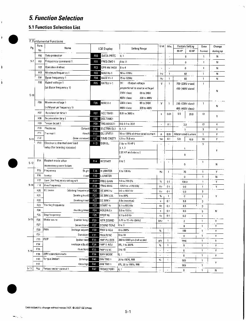
5FunctionSelection
51FunctionSelectionList
FFundamentalFunctions
FuncPg
No
571
510
F00DataprotectionF01Frequencycommand1F02IOperationmethodF03Maximumfrequency1F04Basefrequency1F05Ratedvoltage1
atBasefrequency1
F06Maximumvoltage1
atMaximumfrequency1
F07IAccelerationtime1F081Decelerationtime1F09Torqueboost1F10IElectronicF11Thermall
5 111F121F13Electronicthermaloverload
relayforbrakingresistor
512
514
515
5
16
5171
F14
F15
F16
F17
F18
F20
F21
F22
F23
F24
F25
F26
F27
F30
F31
F33
F34
F35
F36
F40
F41
F42
Restartmodeafter
momentarypowerfailure
Frequency
Limiter
Gainforfrequencysetsignal
Biasfrequency
DCbrake
Startingfrequency
Name
Select
level
timeconstant
high
low
startingfrequency
brakinglevel
brakingtime
holdingtime
Stopfrequency
Motorsound carrierfreq
soundtone
FMA voltageadjust
function
FMP pulserate
voltageadjust
function
3ORYoperationmode
Torquelimiterl driving
braking
Torquevectorcontrol1
Datasubjecttochangewithoutnotice7072007GEDrives
F00
F01
F02
F03
F04
F05
F07
F08
F09
F10
F11
F12
F13
F14
F15
F16
F17
F18
F20
F21
F22
F23
F24
F25
F26
F27
F30
F31
F33
F34
F35
F36
F40
F41
F42
LCDDisplay
101
SettingRange
DATAPRTC
FREQCMD1 10to11OPRMETHODIOto4MAXHz1 150to120HzBASEHz1 125to120HzRATEDV1 OV Outputvoltage
proportionaltosourcevoltage
230Vclass 80to240V
460Vclass 320to480V
MAXV1 230Vclass 80to240V
460Vclass 320to480V
ACCTIME1 1001to3600sDECTIMEI
TRQBOOST110001to200ELCTRNOL11012OLLEVEL1 120to135ofdriveratedcurrentTIMECNST1105to750minDBROL Upto15HP1
012
20HPandabovej
0
RESTART Oto5
51
Unit
L1
Min1FactorySetting
10
0
30HP 40HP
0
60
60
V 1 230230Vclass
460460Vclass
1 1011 20 1I 11 1
1A10011Motorratedcurrent11min1011 50 1 1001
0
0
HLIMITER 10to120Hz Hz 11 70 1
LLIMITER I 0 1
FREQGAIN 00to2000 01 1000 1
FREQBIAS 1200to1200Hz 1Hz 01 00 1
DCBRKHz 10Oto600Hz 1Hz101 00 3
DCBRKLVL 10to80 1 11 0 1
DCBRKt 100sinactive L101 00 3
STARTHz 101to600Hz 1Hz101 05 3
HOLDINGt 100to100s 1s101 00 3
STOPHz 101to60Hz 1Hz 01 02 1
MTRSOUND1075to15kHz6kHz 1kHz 1 2 1
SOUNDTONE10to3 1 1 0 1
FMAVADJ 10to200 1 11 100 1
FMAFUNC 10to10 0 1
FMPPULSES1300to6000psfullscale 1ps 1 1440 1
FMPVADJ 101to200 1 1 0 1
FMPFUNC 101010 0 1
3ORYMODE 101 1 0 1
DRVTRQ1 120to150999 1 1 999 1
BRKTRQ1 1020to150999 999 1
TRQVECTOR1101 1 0 1
Data
Formst
1
1
1
1
1
1
V 1 230230Vclass 1
460460Vclass
s 001 60 200 12
12
3
1
19
3
Change
duringop
N
N
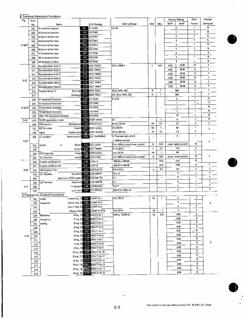
ETerminalExtensionsFunctions
Pg Func
No Name
E01X1terminalfunction
E02X2terminalfunction
E03X3terminalfunction
E04X4terminalfunction
51821E05X5terminalfunction
E06X6terminalfunction
E07X7terminalfunction
E08X8terminalfunction
522
52224
524
525
526
527
CFrequencyControlFunctions
528
E09
E10
Ell
E12
613
E14
E15
E16
E17
E20
E21
E22
E23
E24
E25
E30
E31
E32
E33
E34
E35
E36
E37
E40
E41
E42
E43
E44
E45
E46
E47
C01
CO2
CO3
C04
CO5
CO6
C07
C08
C09
C10
C11
C12
C13
C14
C15
C16
C17
C18
C19
X9terminalfunction
Accelerationtime2
Decelerationtime2
Accelerationtime3
Decelerationtime3
Accelerationtime4
Decelerationtime4
Torquelimiter2
Y1terminalfunction
Y2terminalfunction
Y3terminalfunction
Y4terminalfunction
Y5AY5Cterminalfunction
Y5RYoperationmodeFARfunction
EDTfunction
signal
01function
signal I
FDT2function
0L2function
DisplaycoefficientA
Displaycoefficient8
LEDDisplayfilter
LEDMonitor
LCDMonitor
Jump
frequency
Multistep
frequency
setting
PLCD DisplayXIFUNC
X2FUNC
X3FUNC
X4FUNC
X5FUNC
X6FUNC
X7FUNC
X8FUNC
X9FUNC
ACCTIME2
iggiDECTIME2EaACCTIME3mgDECTIME3
ACCTIME4
KmDECTIME4drivingE16DRVTRQ2
function
602
E03
E04
E05
606
E07
608
E09
ElO
El4
brakinglirallBRKTRU2alY1FUNCEnY2FUNCginvFUNCEsY4FUNC
Y5FUNC
azgY5RYMODEHysteresisE30FARHYSTR
IevellENIFDT1LEVELHysteresis11191FDT1HYSTR
E24
modeselect633OL1WARNING
levelE34011LEVEL
timerOL1TIMERlevelE36FDT2LEVEL
levelE37
E40
E41
E42
E43
displayinSTOPmodeE44LEDMNTR2
Ifuncttonl LCDMNTR
languageE46LANGUAGE
contrastE47CONTRAST
Jumpfreq1IJUMPHz1Jumpfreq2CO2JUMPHz2
Jumpfreq3CO3JUMPHz3
HysteresisC04JUMPHYSTR
Freq1CO5MULTIHz1
Freq2C06MULTIHz2
Freq3C07MULTIHz3
Freq4CO8MULTIHz4
Freq5C09MULTIHz5
Freq6C10MULTIHz6
Freq71111111MULTIHz7Freq81111131MULTIHz8Freq91E3MULTIHz9
Freq10C1F4MULTIHz10
Freq11 MULTIHz11
Freq12C16MULTIHz12
Freq13 MULTIHz13
Freq14FMULTIHz14
Freq15C19MULTIHz15
0L2LEVEL
COEFA
COEFB
DISPLAYFL
LEDMNTR
0to32
001to3600s
120to150999120to150999
10to33
101100to100Hz0to120Hz
00to300Hz
0Thermalcalculation
1Outputcurrent
15to150ofrateddrivecurrent101to600s10to120Hz15to150ofrateddrivecurrent
199900to99900
199900to99900100to50sOto12
01
01
0to5
0sottto10hard
Oto120Hz
Oto30
000to12000Hz
52
SettingRange Unit Min
s 001
I 1 1
I I1
L I11Hz101
Hz 1
Hz 01
1A 001
1S 01
Hz 1
A 001
001
001
s 01
L
Hz 1
Hz 1
Hz 001
FactorySetting
30HPI40HP0
1
2
3
4
5
6
7
8
600
600
600
600
600
600
999
999
0
2
7
10
0
25
60
10
0
0
0
0
3
000
000
000
000
000
000
000
000
000
000
000
000
000
000
000
2000
2000
2000
2000
2000
2000
motorratedcurrent
100
60
motorratedcurrent
001
000
05
0
0
0
1
5
Data
Format
1
1
1
1
1
1
1
1
1
12
12
12
12
12
12
1
1
1
11
1
1
3
1
3
1
19
3
1
19
12
12
3
1
1
1
1
1
1
1
1
1
5
5
5
5
5
5
5
5
5
5
5
5
5
5
Datasubjecttochnngewithoutnotice7072007GEDrives
Change
Duringop
N
N
N
N
N
N
N
N
N
Y
Y
Y
Y
Y
Y
Y
Y
N
N
N
N
N
N
Y
Y
Y
Y
Y
Y
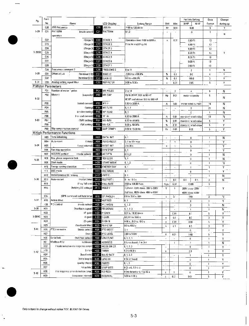
Func
No Name
C20JOGfrequency529 C21PATTERN
operation
Pg
52930C25
C26
C27
C28
C30Frequencycommand2 C30FREDCMD2
530 C31IOffsetadjust terminal12111M1BIAS12C32I terminalC1j1GAIN12
531 C33Analogsettingsignalfilter gmREFFILTERPMotorParameters
IP01INumberofmotor1poles P01MIPOLES
P02Motor1 capacityP02M1CAP532
PO4
P05
P06
533 P07
P08
P09Slipcompensationcontrol
HHighPerformanceFunctions
534
535
536
537
538
53940
541
542
543
C22
C23
C24
P03
H03
H04
H05
H06
H07
H08
H09
H10
H11
H12
H13
H14
H15
H16
H19
H2O
H21
H22
H23
H24
H25
H26
H27
H30
H31
H32
H33
H34
H35
H36
H37
H38
H39
Datainitializing
Autoreset
modeselect
ratedcurrent
tuning
onlinetuning
noloadcurrent
R1setting
Xsetting
times
resetinterval
Fanstopoperation
ACCDECpattern modeselect
Revphasesequencelock
Startmode
OPRcommandselfholdtime
Activedrive
PIDcontrol
Datasubjecttochangewithoutnotice7072007GEDrives
C20
C21
StageHIMSTAGE1Stage2STAGE2Stage3C24STAGE3
Stage4STAGE4Stage5C26STAGE5
Stage611511STAGE6Stage7C28STAGE7
P03
PO4
P05
P06
P07
P08
P09
H03
H04
H05
H06
H07
H08
H09
Energysavingoperation H10ENERGYSAV
DECmode DECMODE
InstantaneousOClimiting INSTCL
Autorestart restarttimerRESTARTtfreqfallrateH14FALLRATE
holdingDCvoltageH15HOLDV
H16
H19
H20modeselect
feedbacksignalFBSIGNALPgainPGAINIgainIGAIN
DgainH24DGAIN
feedbackfilterMIFBFILTERPTCthermistor modeselectH26PTCMODE
levelM1PTCLEVELSeriallink functionselectH30LINKFUNC
ModbusRTU addressADDRESSmodeselectonnoresponseerrorMODEONER
timerTIMERbaudrateH34BAUDRATE
datalengthLENGTHparitycheckH36PARITY
stopbitsSTOPBITSnoresponseerrordetectiontimeH38NORESt
responseintervalH39INTERVAL
LCDDisplay
JOGHz
PATTERN
M1Ir
MITUN1
MITUN2
M1lo
M1R1
M1X
SLIPCOMP1
DATAINIT
AUTORESET
RESETINT
FANSTOP
ACCPTN
REVLOCK
STARTMODE
SELFHOLD1
AUTRED
PIDMODE
SettingRange
I000to12000Hz012
Operationtime000to6000s
F1toF4and81toR4
0to11
1000to1000
00to2000
000to500s
2to14
Upto30HP001to60HP
40HPandabove001to600HP
000to2000A
012
01
000to2000A
000to5000
000to5000
000to1500Hz
01
01to10times
2to20s
01
0123
01
012
01
01
01
01to100s
000to10000Hzs
3phase230Vclass200to300V
3phase460Vclass400to600V
00to300s999
01
012
0123
001to1000times
0001to3600s
000s001to100s
00to600s
01
000to500V
0123
0broadcast1to247
0123
00to600s
0123
08bitfixed
012
02bit111bit
0nodetection1to60s
000to100s
53
FactorySettingI Data Change
Unit MinI30HPI40HPIFormat duringop
HzI001I 500 I 5 Y
0 1
2
Hp 001
A 001 motorratedcurrent
0
0
A 0011standardratedvalue001Istandardratedvalue0011standardratedvalue
Hz 001 000
Hzs
V
V
s 001
sI1
1
1
01
001
1
01
001
01
001
01
001
s1001
000Fl
000Ft
000F1
000Fl
000F1
000F1
000Fl
2
00
1000
005
4
motorcapacity
0
0
5
0
0
0
0
1
0
I 0501
1000
200Vclass235V
400Vclass470V
999
0
0
01
00
000
05
0
160
0
0
20
1
0
0
0
0
001
13
13
13
13
13
13
13
1
4
3
5
9
5
19
21
1
19
5
5
5
1
1
1
1
t
3
5
1
3
1
1
1
5
3
5
3
5
1
1
3
1
1
5
Y
N
Y
N
N
Y
Y
Y
Y
Y
Y
Y
N
Y
Y
Y
Y
Y
Y
Y
Y
N
Y
N
Y
Y
Y
N
N
N
N
N
N
Y
Y
Y
N
Y
Y
Y
N
N
N
Y
Y
N
N
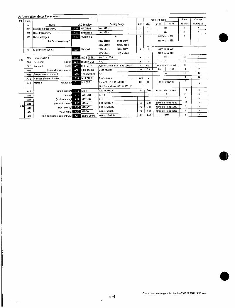
AAlternativeMotorParameters
Pg
544
545
Func
No Name
A01Maximumfrequency2A02Basefrequency2A03Ratedvoltage2
A01
A02
A03
atBasefrequency2 230Vclass 80to240V
460Vclass 320to480V
A04Maximumvoltage2 A04MAXV2 230Vclass 80to240V
460Vclass 320to480V
A05Torqueboost2 A05TRQBOOST210001to200A06Electronic selectA06ELCTRNOL2 1012A07thermal2 levelA07OLLEVEL2 120to135ifINVratedcurrentA08 thermaltimeconstantA08TIMECNST2105to750min
A09Torquevectorcontrol2 A09TROVECTOR2101
Al0Numberofmotor2poles A10M2POLES 12to14polesAllMotor2 capacityAl1M2CAP Upto30HP001to60HP
40HPandabove001to600HP
Alt ratedcurrentAltM2Ir 1000to2000AA13 tuning M2TUN1 1012A14 onlinetuning M2TUN2 101A15 noloadcurrent M2lo 1000to2000AA16 R1setting M2R1 1000to5000All Xsetting M2X 1000to5000A18 slipcompensationcontrol2 SLIPCOMP21000to1500Hz
Al3
A14
Al5
Alb
All
A18
LCDDisplay SettingRange
MAXHz2 150to120HzBASEHz2 125to120HzRATEDV2 0
54
FactorySetting 1Data Change
UnitMin130HPI 40HPIFormat Duringop
Hz111 60 1 1 1 N
Hz 11 60 1 1 Ii
N
V 1 230Vclass230 1
460Vclass460 N
V 1 230Vclass230 1
460Vclass460
20
001Imtorratedcurrent011 i0 1 100
I 0
21 4
001 motorcapacity
001motorratedcurrent0
0
001standardratedvalue001 standardratedvalue
001 standardratedvalue
001 000
3
1
19
3
1
9
5
19
21
1
19
5
5
5
N
Y
Y
Y
Y
N
N
N
N
N
N
N
Y
Y
Y
Datasubjecttochangewithoutnotice7072007GEDrives

52AlphabeticalFunctionList
PGINAME51613ORYoperationmode510Accelerationtime1522Accelerationtime2522Accelerationtime3522Accelerationtime4534ACCDECPattern537ActiveDrive531Analogsettingsignalfilter5101Basefrequency1544IBasefrequency25141Biasfrequency534Datainitializing57IDataprotection514IDCbrakeBrakinglevel514IDCbrakeBrakingtime514DCbrakeStartingfreq536DECmode
510Decelerationtime1522IDecelerationtime2522IDecelerationtime3522Decelerationtime4
526DisplaycoefficientA526DisplaycoefficientB5 ElectronicThermal1Level511ElectronicThermal1Select511ElectronicThermal1Thermal
timeconstant
544IElectronicthermal2Level544Electronicthermal2Select544Electronicthermal2Thermal
timeconstant511Electronicthermaloverload
relavforDBresistor
536Energysavingoperation534Fanstopoperation525IFARfunctionHysteresis525IFDTfunctionLevel525IFDTsignal Hysteresis5251FDT2functionLevel515IFMA Voltageadjust515IFMAFunction5161FMPFunction516IFMPPulserate516FMPVoltageadjust57Frequencycommand1530Frequencycommand2514FrequencylimiterHigh514FrequencylimiterLow514Gainforfreqsetsignal5361InstantaneousOClimiting529IJOGfrequency528JumpfrequencyHysteresis528JumpfrequencyJumpfreq1528JumpfrequencyJumpfreq2528JumpfrequencyJumpfreq3527ILCDMonitorContrast527LCDMonitorFunction527ILCDMonitorLanguage526LEDDisplayfilter526ILEDMonitor Function
F36
F07
E10
E12
E14
H07
H19
F04
A02
F18
H03
F00
F21
F22
F20
H11
F08
El1
E13
E15
E40
E41
F11
F10
F12
A07
A06
A08
F13
H10
H06
E30
E31
E32
E36
F30
F31
F35
F33
F34
F01
C30
F15
F16
F17
H12
C20
C04
C01
CO2
CO3
E47
E45
E46
E42
E43
Datasubjecttochangewithoutnotice7072007GEDrives
LCDDisplay3ORYMODE
ACCTIME1
ACCTIME2
ACCTIME3
ACCTIME4
ACCPTN
AUTRED
REFFILTER
BASEHz1
BASEHz2
FREQBIAS
DATAINIT
DATAPRTC
DCBRKLVL
DCBRKt
DCBRKHz
DECMODE
DECTIME1
DECTIME2
DECTIME3
DECTIME4
COEFA
COEFB
OLLEVEL1
ELCTRNOL1
TIMECNST1
OLLEVEL2
ELCTRNOL2
TIMECNST2
DBROL
ENERGYSAV
FANSTOP
FARHYSTR
FDT1LEVEL
FDT1HYSTR
FDT2LEVEL
FMAVADJ
FMAFUNC
FMPFUNC
FMPPULSES
FMPVADJ
FREDCMD1
FREDCMD2
HLIMITER
LLIMITER
FREQGAIN
INSTCL
JOGHz
JUMPHYSTR
JUMPHz1
JUMPHz2
JUMPHz3
CONTRAST
LCDMNTR
LANGUAGE
DISPLAYFL
LEDMNTR
55
PGINAME526
I LEDMonitorDisplay40STOPmode
510Maximumfrequency1544Maximumfrequency2510IMaximumvoltage1544IMaximumvoltage2542IModbusRTUAddress542IModbusRTUBaudrate542IModbusRTUDatalength542
I ModbusRTUModeselectonnoresponseerror
543ModbusRTUNoresponseerrordetectiontime
542IModbusRTUParitycheck543IModbusRTUResponse
interval
542IModbusRTUStopbits542IModbusRTUTimer533Motor1 R1setting533IMotor1 Xsetting532Motor1Capacity533Motor1Noloadcurrent533Motor1OnlineTuning532Motor1Ratedcurrent532Motor1Tuning545IMotor2 R1setting5451Motor2 Xsetting544Motor2Capacity545IMotor2Noloadcurrent5451Motor2OnlineTuning544Motor2Ratedcurrent545Motor2Slipcompensation
control2
545Motor2Tuning515MotorsoundCarrierfreq515MotorsoundSoundtone528Multistepfrequencysetting
Frea1528IMultistepfrequencysetting
Frea2528MultistepfrequencysettingI Frea3528IMultistepfrequencysetting
Frea4
528MultistepfrequencysettingI Frea5528MultistepfrequencysettingI Frea6528IMultistepfrequencysetting
Freq7528MultistepfrequencysettingIFreq 8
528MultistepfrequencysettingI Freq9528Multistepfrequencysetting528IMultistep
528MultistepfrequencysettingFreq11
528MultistepfrequencysettingIFrea12528MultistepfrequencysettingIFrea13528MultistepfrequencysettingFreq 14
528IMultistepfrequencysettingFrea15
E44
F03
A01
F06
A04
H31
H34
H35
H32
H38
H36
H39
H37
H33
P07
P08
P02
P06
P05
P03
PO4
Al6
A17
411
415
414
412
A18
A13
F26
F27
CO5
CO6
C07
C10
C11
C15
C16
C17
LCDDisplayLEDMNTR2
MAXHz1
MAXHz2
MAXV1
MAXV2
ADDRESS
BAUDRATE
LENGTH
MODEONER
NORESt
PARITY
INTERVAL
STOPBITS
TIMER
M1R1
M1X
M1CAP
M1lo
M1TUN2
M1Ir
M1TUN1
M2R1
M2X
M2CAP
M2lo
M2TUN2
M2Ir
SLIPCOMP2
M2TUN1
MTRSOUND
SOUNDTONE
MULTIHz1
MULTIHz2
MULTIHz3
MULTIHz4
MULTIHz5
MULTIHz6
MULTIHz7
MULTIHz8
MULTIHz9
MULTIHz10
MULTIHz11
MULTIHz12
MULTIHz13
MULTIHz14
MULTIHz15

1
52AlphabeticalFunctionListcontinuedPGINAME532INmberofmotor1poles544 nberofmotor2poles
530Offsetadjustterminal12530OffsetadjustterminalC1525IOLfunctionModeselect525IOLfunctionsiganlTimer525IOLfunctionsignalLevel52510L2functionLevel57Operationmethod529IPattern529Pattern5291Pattern529IPattern529Pattern
529Pattern
Stage1Stage2Stage3Stage4Stage5Stage6
529Pattern Stage75291PATTERNoperationMode
select
539IPIDcontrol Dgain541IPIDcontrol Feedbackfilter538IPIDcontrol Feedbacksignal539IPIDcontrol Igain537IPIDcontrol Modeselect539IPIDcontrol Pgain5411PTCthermistorLevel541IPTCthermistorModeselect510Ratedvoltage1544Ratedvoltage2atBase
frequency2512Restartmodeaftermomentary
powerfailure
535Revphasesequencelock542SeriallinkFunctionselect533ISncompensationcontrol535Startmode
515StartingfrequencyFreq515StartingfrequencyHolding
time
515Stopfrequency511Torqueboost1544Torqueboost2516Torquelimiter1braking516Torquelimiter1Driving522Torquelimiter2braking522Torquelimiter2Driving5177Torquevectorcontrol1544Torquevectorcontrol2518IX1terminalfunction518IX2terminalfunction
518X3terminalfunction5181X4terminalfunction518IX5terminalfunction
518IX6terminalfunction518IX7terminalfunction522IY1terminalfunction5221Y2terminalfunction522IY3terminalfunction522IY4terminalfunction524IY5RYoperationmode522IY5AY5Cterminalfunc
P01
A10
C31
C32
E33
E35
E34
E37
F02
C22
C23
C24
C25
C26
C27
C28
C21
H24
H25
H21
H23
H2O
H22
H27
H26
F05
A03
F14
H08
H30
P09
H09
F23
F24
F25
F09
A05
qF41F40
E17
E16
F42
A09
E01
E02
E03
E04
E05
E06
E07
E20
E21
E22
E23
E25
E24
LCDDisplayM1POLES
M2POLES
BIAS12
GAIN12
OL1WARNING
OL1TIMER
OL1LEVEL
OL2LEVEL
OPRMETHOD
STAGE1
STAGE2
STAGE3
STAGE4
STAGE5
STAGE6
STAGE7
PATTERN
DGAIN
FBFILTER
FBSIGNAL
IGAIN
PIDMODE
PGAIN
PTCLEVEL
PTCMODE
RATEDV1
RATEDV2
RESTART
REVLOCK
LINKFUNC
SLIPCOMP1
STARTMODE
STARTHz
HOLDINGt
STOPHz
TRQBOOST1
TRQBOOST2
BRKTRQ1
DRVTRQ1
BRKTRQ2
DRVTRQ2TRQVECTOR1
TRQVECTOR2
X1FUNC
X2FUNC
X3FUNC
X4FUNC
X5FUNC
X6FUNC
X7FUNC
Y1FUNC
Y2FUNC
Y3FUNC
Y4FUNC
Y5RYMODE
Y5FUNC
56
Datasubjecttochangowithoutnotice7072007GEDrives

53FunctionExplanation
FFundamentalFunctions
F00 Dataprotection
o0DIAITIAIIPIRITICISettingrange 0datacanbechanged
1datacannotbechanged
Thisfunctionprotectsthesystembyblockinganydatachangesfromthekeypadpanel
Settingprocedure
0to1 PresstheSTOPand keyssimultaneouslytochangethevaluefrom to1thenpress
FUNC
theDATAtovalidatethechange
1to0 PresstheSTOPand0keyssimultaneouslytochangethevaluefrom1to0thenpress
theDFUNCMA keytovalidatethechange
F01 Frequencysetting1
F01 RE0 CMD
Thisfunctiondeterminesthemethodtobeusedforsettingfrequency
NOTEUseonlyoneterminalV2or01exclusively
0 KeypadoperationInor key
1 Voltageinputterminal12andV20to10VDC0to5VDC
2 CurrentinputterminalC14to20mADC3 Voltageandcurrentinputterminals12and014 Reversibleoperationwithpolarityterminal12
Oto10VDC5 Reversibleoperationwithpolarityterminal12andV1
option0to 10VDC
RelatedfunctionsE01toE09Setvalues21
6 Inversemodeoperationterminal12andV210to0VDC
7 InversemodeoperationterminalC120to4mADC8 UPDOWNcontrol1initialfreq 0Hz
9 UPDOWNcontrol2initialfreq lastvalue
RelatedfunctionsE01toE09Setvalues1718
10PATTERNoperation
RelatedfunctionsC21toC28
11DIoptionorPulsetraininputFordetailsseeinstructionmanualonoptions
Datasubjecttochangewithoutnotice7072007GEDrives 57
Frequencysettingvalue
Maximum frequency
Setvalue13
1
Setvalue45
Maximumfrequency
Frequencysettingvalue
Maximumfrequency
0
0 4 20m
AnaloginputterminalC1
F02 Operationmethod
software
4 Terminaloperationsoftware
10v
Analoginputterminal12
F012 PR ME H0D
Thisfunctiondeterminestheinputmethodforoperationcommands
0 Keypadoperation orCOIorSTOPkey1 Terminaloperation keyactive
2 Terminaloperation keyinactive
3 Terminaloperation keyactivewithGEstart
FWD
STOP
STOP
STOP
STOP
Normaloperationsetvalue1345
inverseoperationsetvalue6
Normaloperationsetvalue2
Inverseoperationsetvalue7
keyinactivewithGEstart
NoteGEstartsoftwarepreventsdrivefromrestartingwhenpowerisapplied
Thisfunctioncanonlybechangedwhenterminals
andENareopenREMOTELOCALswitchingfromthekeypadpanelautomaticallychangesthesetvaluefrom0to3ofthisfunction
FWD

GEStartSoftwareSelectionDuringTerminalOperation
POWERON
RESET
STOPKEYTERMINAL
MODE
STOPKEYNETWORK
MODE
POWER
FWD 1
OUTPUT
ALARM
NETWORK NETWORKMODE LECM 1
FWDTERMINAL
FWDNETWORK
OUTPUT
ALARM
FWD
STOP
OUTPUT
ALARM
NETWORKLECM
FWDTERMINAL
STOP
OUTPUT
ALARM
InactiveSettina1or2 ActiveSetting3or4
1
RESET I
FWD 1
OUTPUT 1 7ALARM 1
I
n
n
1
X
1
58
POWER
FWD 1
OUTPUT
ALARM
RESET
FWD I
OUTPUT
ALARM
1
I ER6
n n
MultiAlarmsI
NETWORKLECM I IFWDTERMINAL
FWDNETWORK IOUTPUT
ALARM 1 ER6 1 1 ER6
RESET
SeeAlarmModepage415
NoteStartSoftwaredoesnotworkatAUTORESETmodeandPROGRAMMINGmode
StopKeyModeSelectionDuringTerminalOperation
InactiveSetting2or4 I ActiveSetting1or3
FWD 1
STOP
OUTPUT7
ALARM
NETWORKLECM
FWDTERMINAL
STOP
OUTPUT
ALARM
ER6
1
n
1 ER6
Datasubjecttoflangewithoutnotice7072007GEDrives

FrequencySettingBlockDiagram
Hz2Hz1004
ISS1
SS2
SS4I
ISS8
JOG
Hz2P1D1
Frequencysetting
Frequencysettingbykeypad
IM
switching
command
Datasubjecttochangewithoutnotice707t2007GEDrives
0C
Oborpulsetrainoptional65110
00
ForwatdrReverseoperation
Gain Bias
frequencyfrequency
MultoapFrequencyswitching
0
51
i
3
D
0
59
Negativepolaritypreventiona
Wt23457
Feedbackseleolion
H20
P113control
Feedbackfilter
OperatqnSelect
11111ProportionalIrregular
Differenital
trial
Limitsignal
Upperhrtutfrequency
LimiterPfOCESSulg
FO3
SetIrequenCyvalue

F03 Maximumoutputfrequency1
F013 AX Hz 1
Settingr Tie50to120Hz
ThisfunctionsetsthemaximumoutputfrequencyforMotor1
SettingavaluehigherthantheratedvalueofthedevicetobedrivenmaydamagethemotorormachineMatchthedeviceratingwhensettingthisfunction
F04 Basefrequency1
F104 ASE Hz 1
Settingrange25to120Hz
ThisfunctionsetsthemaximumoutputfrequencyintheconstanttorquerangeofMotor1ortheoutputfrequencyattheratedoutputvoltageMatchthemotorrating
NoteIfthevalueofBasefrequency1issethigherthanthatofMaximumoutputfrequency1theoutputvoltagedoesnotincreasetotheratedvoltageThemaximumfrequencylimitstheoutputfrequency
Outputvoltage
ConstanttorquerangeF06
Maximum
outputvoltage1
F05Rated
voltage1
F05 Ratedvoltage1
0 F04Bas F03
trequenc1Maximumoutput
F ATED V 1
Settingrange 230VACseries080to240V460Vseries0320to480V
ThisfunctionsetstheratedvalueofthevoltageoutputtoMotor1Notethatavoltagegreaterthanthesupplyinputvoltagecannotbeoutput
Value0terminatesoperationofthevoiugeregulatorfunctiontherebyresultingintheoutputofavoltageproportionaltothesupplyvoltage
NoteIfthevalueofRatedvoltage1issethigherthanMaximumoutputvoltage1theoutputvoltagedoesnotincreasetotheratedvoltageThemaximumoutputvoltagelimitstheoutputvoltage
F06Maximumoutputvoltage1F06 AX V11
Outputfrequency
Settingrange 230VACseries80to240VAC460VACseries320to480VAC
ThisfunctionsetsthemaximumvalueofthevoltageoutputforMotor1Notethatavoltagehigherthanthesupplyinputvoltagecannotbeoutput
F07Accelerationtime1
F08 Decelerationtime1
0
0
q
cp
5
0
7
81
U
aa
0
Acceleratilen
operationtime
ACC TIME1
DEC TIME1
Settingrange ACCTIME1001to3600secondsDECTIIME1001to3600seconds
Thesefunctionssettheaccelerationtimefortheoutputfrequencyfromstartuptomaximumfrequencyaswellasthedecelerationtimefrommaximumfrequencytooperationstop
Accelerationanddecelerationtimesarerepresentedbythethreemostsignificanthighorderdigits
SetaccelerationanddecelerationtimeswithrespecttomaximumfrequencyTherelationshipbetweenthesetfrequencyvalueandaccelerationdecelerationtimesisasfollows
Setfreauencv maximumfreauencv
TheactualoperationtimematchesthesetvalueT
c
Accelerationtime
FWD
STOP
MaximumfrequencySet
frequency
Time
1Decelerationtime
Setfreauencv maximurnfreauencv
Theactualoperationtimediffersfromthesetvalue
Accelerationdeceleratioloperationtime setvaluex
setfrequencymaximumfrequency
STOP
Maximumfrequency
Setfrequency
TimeDeceleration
operationtime4
Acceleratilime Decelerationtime
NoteIfthesetaccelerationanddecelerationtimesare
settooloweventhoughtheresistancetorqueandmomentofinertiaoftheloadaregreatifthetorquelimitingfunctionsorstallPreventionfunctionareactivateditprolongstheoperationtimebeyondthesetvalue
510 Datasubjecttocrangewithoutnotice7072007GEDrives

F09 TorqueBoost1
F109 R0 B00sT1
ThisisaMotor1functionThefollowingcanbeselected
Selectionofloadcharacteristicssuchasautomatic
torqueboostsquarelawreductiontorqueloadproportionaltorqueloadconstanttorqueload
EnhancementoftorqueVfcharacteristicswhichisloweredduringlowspeedoperationInsufficientmagneticfluxofthemotorduetoavoltagedropinthelowfrequencyrangecanbecompensated
SettingRange00
01to09 Squarelawreductiontorqueforfanandpumploads
10to19 Proportionaltorqueformiddleclassloadsbetweensquarelawreductiontorqueandconstanttorquelinearchange
20to200 1Constanttorouelinearchange
TorquecharacteristicsSquarelawreductiontorque Proportionaltorque
OutputvoltageV OutputvoltageV
100 Ratedvoltage1100go
Ratedvoltage1
09 Base
frequency110G 01 10
0 0Outputfrequencyf
SincealargetorqueboostvaluecreatesoverexcitationinthelowspeedrangecontinuedoperationmaycausethemotortooverheatCheckthecharacteristicsofthedrivenmotor
OutputvoltageV
100 Ratedvoltage1
1CharacteristicsSelectedAutomatictorqueboostwherethetorqueboostvalueofaconstanttorqueloadalinearchangeisautomaticallyadjusted
0
Constanttorque
19Basfrequency1
10
Outputfrequencyf
200
0
10 20Basefrequency9Outputfrequencyf
F10 Electricthermal01relayoperationselection
F11 Electricthermal0Lrelaylevel
F12 Electricthermal0LrelaythermaltimeTheelectronicthermal0Lrelaymanagestheoutputfrequencyoutputcurrentandoperationtimeoftheinvertertopreventthemotorfromoverheatingwhen150ofthesetcurrentvalueflowsforthetimesetbyF12thermaltimeconstantDatasubjecttochangewithoutnotice772007GEDrives
FI110ELcTRN 0L1
Settingrange 0Inactive
1Activeforgeneralpurposemotor2Activeforforcedairmotor
ThisfunctionspecifieswhethertooperatetheelectronicthermalOILrelayandselectsthetargetmotorWhenageneralpurposemotorisselectedtheoperationlevelisloweredinthelowspeedrangeaccordingtothecoolingcharacteristicsofthemotor
DOL IEVEL1Thesettingrangeis20to135oftherateddrivecurrent
Thisfunctionsetstheoperationlevelcurrentfortheelectronicthermal0LrelayEnteravaluefrom1to11timestheratedmotorcurrentvalue
511
100
6a
54 14to30HP
WhenF101
20
15
05
Fex033
UYf1 1I1ME
Current0peratontime
WhenF102
c
40to60HP
WhenF101
fefbfb60Hz
60Hzfb60HzfbBasefrequency
Fe083re
OutputfrequencyfHz
Operationlevelcurrentandoutput
NsT1
Thesettingrangeis05to750minutesin01minuteincrements
Thetimefromwhen150oftheoperationlevelcurrentflowscontinuouslytowhentheelectronicthermal0Lrelayactivatescanbesetwiththisfunction
11111111111IMO
OM 11111MINIMEN1111I 111111111111
iiiiiuuiauiiif1inuIfaeffmiuaurr
uaaoNtMilmu an
NNEMOHUM
M 11uuM fir OMB
hang
0 50 100 150
outputcurrentoperationlevelcurentx100
b
F121
Ft2
200F1203
F13 Electricthermal0Lrelayforbraking
DBR OL
Thisfunctioncontrolsthefrequentuseandcontinuousoperatingtimeofthebrakingresistortopreventtheresistorfromoverheating
DriveCapacity1 Operation
15Hporless 0Inactive
1Inactive
2Activeexternalbrakingresistor
20Hpormore 10Inactive
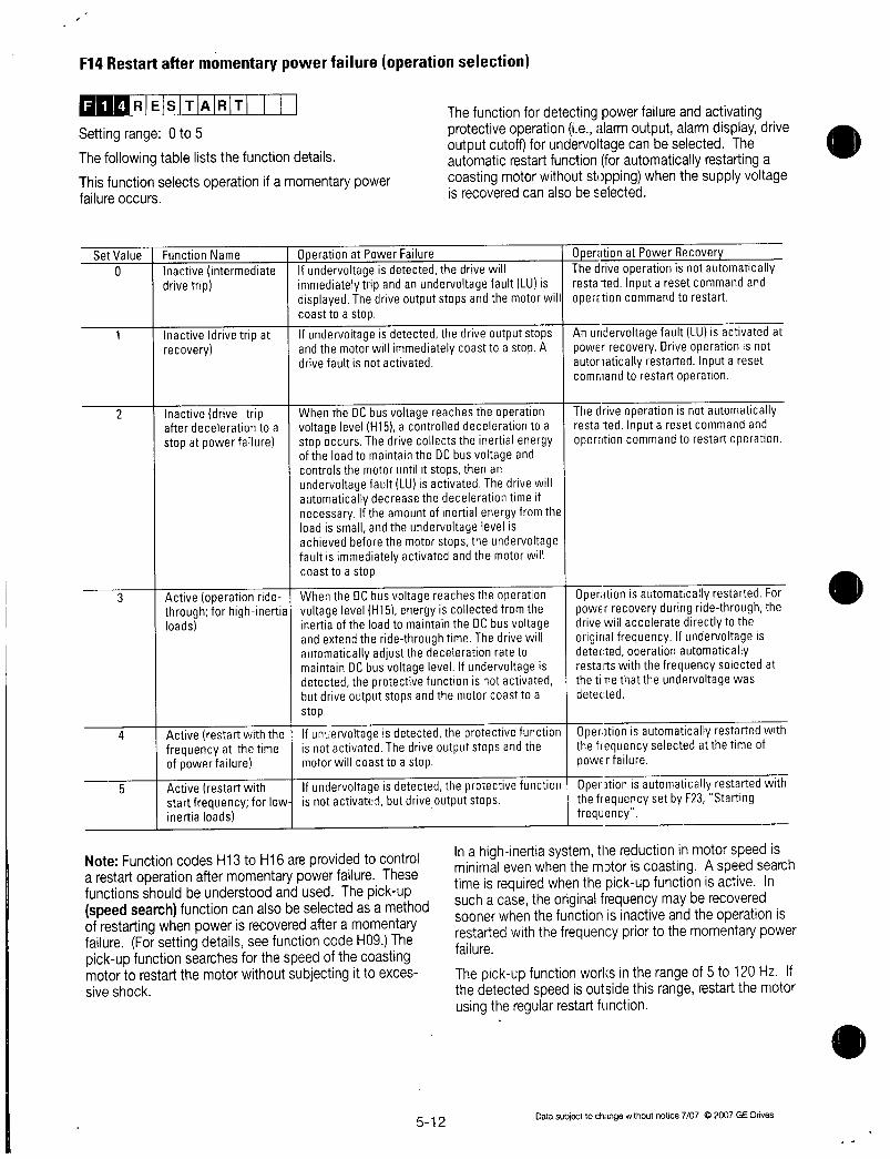
F14Restartaftermomentarypowerfailureoperationselection
F REsTART
Settingrange0to5
Thefollowingtableliststhefunctiondetails
Thisfunctionselectsoperationifamomentarypowerfailureoccurs
SetValue
0
1FunctionName
Inactiveintermediatedrivetrip
1 Inactivedrivetripatrecovery
2 Inactivedrivetripafterdecelerationtoa
stopatpowerfailure
3 Activeoperationride1throughforhighinertialoads
4 Activerestartwiththefrequencyatthetimeofpowerfailure
5 Activerestartwithstartfrequencyforlowinertialoads
NoteFunctioncodesH13toH16areprovidedtocontrolarestartoperationaftermomentarypowerfailureThesefunctionsshouldbeunderstoodandusedThepickupspeedsearchfunctioncanalsobeselectedasamethodofrestartingwhenpowerisrecoveredafteramomentaryfailureForsettingdetailsseefunctioncodeH09Thepickupfunctionsearchesforthespeedofthecoastingmotortorestartthemotorwithoutsubjectingittoexcessiveshock
OperationatPowerFailureIfundervoltageisdetectedthedrivewillimmediatelytripandanundervoltagefaultLUisdisplayedThedriveoutputstopsandthemotorwillcoasttoastop
IfundervoltageisdetectedthedriveoutputstopsandthemotorwillimmediatelycoasttoastopAdrivefaultisnotactivated
WhentheDCbusvoltagereachestheoperationvoltagelevelH15acontrolleddecelerationtoastopoccursThedrivecollectstheinertialenergyoftheloadtomaintaintheDCbusvoltageandcontrolsthemotoruntilitstopsthenanundervoltagefaultLUisactivatedThedrivewillautomaticallydecreasethedecelerationtimeifnecessaryIftheamountofinertialenergyfromtheloadissmallandtheundervoltagelevelisachievedbeforethemotorstopstheundervoltagefaultisimmediatelyactivatedandthemotorwillcoasttoastop
WhentheDCbusvoltagereachestheoperationvoltagelevelH15energyiscollectedfromtheinertiaoftheloadtomaintaintheDCbusvoltageandextendtheridethroughtimeThedrivewillautomaticallyadjustthedecelerationratetomaintainDCbusvoltagelevelIfundervoltageisdetectedtheprotectivefunctionisnotactivatedbutdriveoutputstopsandthemotorcoasttoastop
IfunervoitageisdetectedtheprotectivefunctionisnotactivatedThedriveoutputstopsandthemotorwillcoasttoastop
Ifundervoltageisdetectedtheprotectivefunctionisnotactivatedbutdriveoutputstops
512
ThefunctionfordetectingpowerfailureandactivatingprotectiveoperationLealarmoutputalarmdisplaydriveoutputcutoffforundervoltagecanbeselectedTheautomaticrestartfunctionforautomaticallyrestartingacoastingmotorwithoutstoppingwhenthesupplyvoltageisrecoveredcanalsobeselected
OperationatPowerRecoveryThedriveoperationisnotautomaticallyrestatedInputaresetcommandandopertioncommandtorestart
AnundervoltagefaultLUisactivatedatpowerrecoveryDriveoperationisnotautomaticallyrestartedInputaresetcommandtorestartoperation
ThedriveoperationisnotautomaticallyrestatedInputaresetcommandandoperationcommandtorestartoperation
OperationisautomaticallyrestartedForpowerrecoveryduringridethroughthedrivewillacceleratedirectlytotheoriginalfrequencyIfundervoltageisdetectedoperationautomaticallyrestartswiththefrequencyselectedatthetinethattheundervoltagewasdetected
OperationisautomaticallyrestartedwiththefrequencyselectedatthetimeofpOWErfailure
OperationisautomaticallyrestartedwiththefrequencysetbyF23Startingfrequency
InahighinertiasystemthereductioninmotorspeedisminimalevenwhenthemotoriscoastingAspeedsearchtimeisrequiredwhenthepickupfunctionisactiveInsuchacasetheoriginalfrequencymayberecoveredsoonerwhenthefunctionisinactiveandtheoperationisrestartedwiththefrequencypriortothemomentarypowerfailure
Thepickupfunctionworksintherangeof5to120HzIfthedetectedspeedisoutsidethisrangerestartthemotorusingtheregularrestartfunction
Datasubjecttochangewithoutnotice7072007GEDrives

Setvalue0A
Maincircuit
DCvoltage
Outputfrequency
LUtrip
Setvalue1
Maincircuit
DCvoltage
Outputfrequency
LUtrip
Setvalue2
Maincircuit
DCvoltage
LUtrip
Powerfailure Powerrecovery
Outputfrequency
V
Undervoltag
ON
Undervoltag
ON
H15
Operationcontinuationlevel
I ON
Datasubjecttochangewithoutnotice707C2007GEDrives
Time
Time
Time
513
Setvalue3
Maincircuit
DCvoltage
Output tfrequency
motorspeed
LUtrip
OutputterminalsY1toY5
Setvalue4
Maincircuit
DCvoltage
Output ffrequency
motorspeed
LUtrip
OutputterminalsY1toY5
Setvalue5
Maincircuit
DCvoltage
Output tfrequency
motorspeed
LUtrip
Output tterminalsY1toY5
Powerfailure Powerrecovery
VH15 7Operationcontinuationlevel
Undervoltage
4H13Waitingtime
ON
Undervoltage
H13Waitingtime
I ON
NoteDotteddashedlinesindicatemotorspeed
a
dSynchronization
cceleration

F15FrequencylimiterHigh
F16FrequencylimiterLow
e8 LLIM T R
Settingrange0to120Hz
Thesefunctionsareusedtodefinetheupperandlowerlimitsofthesetfrequency
Maximum
frequency
Maximum
frequency
Maximumfrequency
pperlimitvalue
Per
LowerlimitValue
Lowerlimitvalue
limitvalue100
100
Thedriveoutputstartswiththestartfrequencywhenoperationbeginsandstopswiththestopfrequencywhenoperationends
Iftheupperlimitvalueislessthanthelowerlimitvaluetheupperlimitvalueoverridesthelowerlimitvalue
F17Gain
E RE0 GA N
Settingrange 00to2000
Thisfunctionassignstherateofthesetfrequencyvaluetoanaloginput
Operationfollowsthefigurebelow
Setfrequencyvalue
Setfrequency
Setfrequency
Maximumfrequency
200
100
50
10VAnaloginput10Vterminal12
20mAI20mAterminalC1
514
F18Biasfrequency
12E113 RE0 B
Settingrange
As
1200to1200Hz
Thisfunctionaddsabiasfrequencytothesetfrequencyvaluefromanaloginput
TheoperationfollowsthefigurebelowIfthebiasfrequencyishigherthantheMaximumfrequencyorlowerthantheMaximumfrequencyitislimitedtotheMaximumorMaximumfrequency
Setfrequencyvalue
Maximum
frequency
10
frequefrequency
F20DCinjectionBrakestarting
F21DCinjectionbrakeoperationlevel
F22DCinjectionbraketimeHF120 C BRK
Settingrange0to60Hz
StartingfrequencyThisfunctionsetsthefrequencywithwhichtostartaDCinjectionbrakeinordertodeceleratethemotortoastop
OEMDC BRK
DC BRK
Biasfrequencywhenpositive
10V
20mA
Bigsfrequencywhennegative
VLL
Settingrange0to80
OperationlevelThisfunctionsetstheoutputcurrentlevelwhenaDCinjectionbrakeisappliedasapercentageoftheratedoutputcurrentin1increments
t
Analoginput10Vterminal12
20mAterminalC1
Settingrange 00Inactive
01to300seconds
TimeThisfunctionsetsthetimeforaDCinjectionbrakeoperation
CAUTION
DonotusethedrivebrakefunctionformechanicalholdingInjurymayresult
Datasubjecttochangewithoutnotice7072007GEDrives

F23Startingfrequencyfrequency
F24StartfrequencyHoldingtimeF25StopfrequencyF1213sTART Hz
Settingrange01to60HzFrequencyThisfunctionsetsthefrequencyatstartup
Thestartingfrequencycanbesettoreservethetorqueatstartupandcanbesustaineduntilthemagneticfluxofthemotorisestablished
F12I4HOILIDIIINIGI ISettingrange01to100seconds
HoldingtimeThisfunctionsetstheholdingtimeduringwhichthestartfrequencyissustainedatstartup
Theholdingtimedoesnotapplyduringswitchingbetweenforwardandreverse
Theholdingtimeisnotincludedintheaccelerationtime
TheholdingtimealsoapplieswhenpattemoperationC21isselectedTheholdingtimeisincludedinthetimervalue
FI2I5SIIzl II ISettingrange01to60Hz
Thisfunctionsetsthefrequencyatstop
Outputfrequency
Holdingtime
Startingfrequency
Stoppingfrequency
Time
Theoperationwillnotstartifthestartingfrequencyislessthanthestoppingfrequencyorifthesetfrequencyislessthanthestoppingfrequency
F26Motorsoundcarrierfrequency
FI2I6
DriveCapacity
30Hporless
40to100Hp
100Hpormore
MITIRI ISIOIVIN I
CarrierfrequencyMotornoise
OutputcurrentwaveformLeakagecurrentNoiseoccurrenceRFI
Forwardrotation 1
Thisfunctionadjuststhecarrierfrequencytopreventresonancewiththemachinesystemreducemotoranddrivenoiseandalsoreduceleakagecurrentfromoutputcircuitwiring
SettingRange
1075to15kHzI075tolOkHz1075to6kHz
Datasubjecttochangewithoutnotice7072007GEDrives
Low HighHign Low
Bad Good
SmallamountLaigeamount
ExtremelylowHigh
1 ReducingthesetvalueadverselyaffectstheoutputcurrentwaveformiehigherharmonicsincreasesmotorlossandraisesmotortemperatureForexampleat075kHzreducethemotortorquebyabout15
2 Increasingthesetvalueincreasesdrivelossesandraisesdrivetemperature
F27Motorsoundsoundtone
CODTR TON
Settingrange0123
Thetoneofmotornoisecanbealteredifthecarrier
frequencyis7kHzorlowerUsethisfunctionasrequired
F30FMAterminalvoltageadjustment
F31FMAterminalfunctionselection
F1310
FI311
F
e
MA V
Settingrange0to200
MonitordataegoutputfrequencyoutputcurrentcanbeoutputtoterminalFMAasaDCvoltageTheamplitudeoftheoutputcanalsobeadjusted
ThisfunctionadjuststhevoltagevalueofthemonitoritemselectedinF31whenthemonitoramountis100 A
valuefrom0to200canbesetin1increments
Higherthan10VFMA10V
termin
al
outputvoltag
FIMIAI IFIuINICIII
ThisfunctionselectsthemonitoritemtobeoutputtoTerminalFMA
Value1MonitorItem0 Outputfrequency1
beforeslipcompensation
1 Outputfrequency2afterslipcompensation
2 Outputcurrent3 Outputvoltage
515
4 Outputtorque5 Loadrate
6 Output7 PIDfeedbackamount
8 PGfeedbackamount
onlywhenoptionisinstalled
9 DClinkcircuitvoltage
10 1UniversalAO
AD
srF300
50 100
J
100MonitorAmount
Maximumoutputfrequency
Maximumoutputfrequency
F30200
F30100
F305090
2xratedoutputcurrentofdrive230Vseries250V
460Vseries500V
2xratedmotortorque2xratedloadofmotor
2xrateddriveoutputFeedbackamountat100
Synchronousspeedatmaximumfrequency
230Vseries500V
460Vseries1000V
OutputfromRS485orBusoption

F33FMPterminalpulserate
F34FMPterminalvoltageadjustmentF35FMPterminalfunctionselection
MonitordataiegoutputfrequencyoutputcurrentcanbeoutputtoterminalFMPaspulsevoltageMonitordatacanalsobesenttoananalogmeterasaveragevoltageWhensendingdatatoadigitalcounterorotherinstrumentaspulseoutputsetthepulserateinF33toanyvalueandthevoltageinF34to0WhendataissenttoananalogmeterorotherinstrumentasaveragevoltagethevoltagevaluesetinF34determinestheaveragevoltageandF33isfixedat2670ps
MP PLusEs
Settingrange300to6000psin1psincrements
TheF33functionsetsthepulsefrequencyofthemonitoritemselectedinF35
T1
T
Pulsecycletime
Pulsefrequencyps 1T
Duty TiTx100
AveragevoltageV 156xT1T
MP V A J
rte
About156V
Setvalue0 ThepulsefrequencyvariesdependingontheamountofthemonitoritemselectedinF35maxvalueisthevaluesetinF33
TheF34functionsetstheaveragevoltageofpulseoutputtoterminalFMP
1to200 Pulsefrequencyisfixedat2670psTheaveragevoltageofthemonitoritemselectedinF35whenthemonitoramountis100 isadjustedintherange1 200 in1incrementspulsedutyvaries
FIMIPI IFIUINICI 1
TheF35functionselectsthemonitoritemtobeoutputtoterminalFMP
ThesetvalueandmonitoritemsarethesameasthoseusedforF31refertotable
516
F3630Ryoperationmode
ODIETF316 0RY M
Thisfunctionspecifieswhethertoactivateexcitethealarmoutputrelay30Ryforanyfaultatnormaloralarmstatus
Ifthesetvalueis1contacts30Aand30Careconnectedwhenthedrivecontrolvoltageisestablishedaboutonesecondafterpoweron
F40Torquelimit1driveF41Torquelimit1brake
Value10 Drivenopower
Atnormal
Atalarm
1 DrivenopowerAtnormal
Atalarm
Function
Torquelimit
driving
Torquelimit
braking
DRV TRQI
BRK TRQI
ThetorquelimitoperationcalculatesmotortorquefromtheoutputvoltagecurrentandtheprimaryresistancevalueofthemotorandcontrolsthefrequencysothecalculatedvaluedoesnotexceedthelimitThisoperationenablesthedrivetocontinueoperationunderthelimitevenifasuddenchangeinloadtorqueoccurs
Limitsaresetfordrivingtorqueandbrakingtorque
Whenthisfunctionisactivatedaccelerationanddecelerationoperationtimesarelongerthanthesetvalues
I SetValue 120to150
1 999 120to150
Operation30A30COFF30B30CON
30A30COFF30B30CON30A30CON30B30COFF30A30COFF30B30CON
30A30CON30B30COFF30A30COFF30B30CON
OperationThetorqueislimitedtothesetvalue
TorquelimitinginactiveThetorqueislimitedtothesetvalue
0 Automaticallyprevents
OU2tripduetopowerregenerationeffect
999 1Torquelimitinginactive
WARNING
WhenthetorquelimitfunctionisselectedanoperationmaynotmatchthesetaccelerationanddecelerationtimeorsetspeedThemachineshouldbesodesignedthatsafetyisensuredevenwhenoperationdoesnotmatchthesetvalues
Datasubjecttochangewithoutnotice7072007GEDrives

F42Torquevectorcontrol1
F412 R0 EcT0 1
Toobtainthemostefficientmotortorquethetorquevectorcontrolcalculatestorqueaccordingtoloadtoadjustthevoltageandcurrentvectorstooptimumvaluesbasedonthecalculatedvalue
Value Operation
0 inactive
1 active
RelatedFunctionsP01toP09
IfF421activethefollowingfunctionsareaffected
1 F09Torqueboost1isautomaticallysetto00automatictorqueboosting
2 P09SlipcompensationcontrolisautomaticallyactivatedIfsetto00theamountofslipcompensationforastandard3phaseFujimotorisappliedOtherwisethesetvalueisapplied
Usethetorquevectorcontrolfunctionunderthefollowingconditions
1TherecanonlybeonemotorConnectionoftwoormoremotorsmakesaccurate
controldifficult
2 ThefunctiondataratedcurrentP03noloadcurrentP06R1P07andXP08forMotor1mustbecorrect
Ifastandard3phaseGEmotorisusedsettingthecapacityFunctionP02ensuresentryoftheabovedataAnautotuningoperationshouldbeperformedforothermotors
3 TheratedcurrentofthemotormustnotbesignificantlylessthantheratedcurrentofthedriveAmotortwosizeslowerincapacitythanthenominalmotorindicatedforthedriveisthesmallestthatshouldbeused
4 Topreventleakagecurrentandensureaccuratecontrolthelengthofthecablebetweenthedriveandmotorshouldnotexceed50m
5 IfareactorisconnectedbetweenthedriveandthemotorandwiringimpedancecannotbedisregardedusePO4Autotuningtoresetdata
IftheseconditionsarenotsatisfiedsetF42 0Inactive
Datasubjecttochangewithoutnotice707C2007GEDrives517

EExtensionTerminalFunctions
E01TerminalX1
E09TerminalX9
0
0
0
0
0
0
0
0
0
X1 FUNCX2 FUNCX3 FUNC
X4 FUNCX5 FUNC
X6 FUNC
X7 FUNC
X8 FUNC
X9 FUNC
FunctionscanbeindividuallysetfromeachofthedigitalinputterminalsX1toX9
Value Function
0123Multistepfrequencyselection1to15steps45 Accelerationanddecelerationtimeselection3steps
6 SelfholdselectionHLD
7 CoasttostopcommandBX
8 AlarmresetRST
9 ExternalalarmTHR
10 JoggingJOG
11 Frequencysetting2Frequencysetting1Hz2Hzl12 Motor2Motor1M2M1
13 DCinjectionbrakecommandDCBRK
14 Torquelimit2Torquelimit1TL2TL1
15 Switchingoperationfromlinetodrive50HzSW5016 Switchingoperationfromlinetodrive60HzSW60
17 UPcommandUP
18 DOWNcommandDOWN
19 EditpermissioncommandWEKP
20 PIDcontrolcancellationHzPID
21 INormalInverseswitchingTerminals12andC1IVS22 IInterlock522IL23 ITorquecontrolcancellationHzTRQ24 ILinkcommunicationselectionLE25 IUniversalDIUDI26 1PickupstartmodeSTM30 ITimedalarmstopcommandSTOP131 Timedalarmstopcommandwith
Decelerationtime4STOP2
NoteValueswhicharenotsetinthefunctionsfromE01toE09areassumedtobeinactive
518
MultistepfrequencyselectionValue0123ThefrequencycanbeswitchedtoapresetfrequencyinfunctiorcodesCO5toC19byswitchingtheexternaldigitalinputsignalAssignvalues0to3tothetargetdigitalinputterminalThecombinationofinputsignalsdeterminesthefrequency
3
SS8
off1off1off1off
off
off
off
Combination
ofInputSignals5 1 4
RT2 1 RT1off off
Combinationof
InputSignals2 1
SS4 I SS2off1 off
off
off
0
SS1
on
on
ononon
brion
on
on
on
onon on
onon
on
on
on
on
on
on
on
on
on
on
off off
off1 off
off
off
on1 off
off1
off
off off
off
0
0
on
on
on
on
1CO5MULTIHz111C06MULTIHz2I
C07MULTIHz311C08MULTIHz41
C09MULTIHz51010MULTIHz61C11MULTIHz71C12MULTIHz8IC13MULTIHz91
off1C14MULTIHz101IC15MULTIHz11
off1C16MULTIHz12on1C17MULTIHz13off1C18MULTIHz14IC19MULTIHz15
SelectedFrequency
1
Related
Functions
CO5C19
SettingSetting000to
40000Hz
AccelerationandDecelerationtimeselection
Value45TheacceleratioranddecelerationtimecanbeswitchedtoapresettimeinfunctioncodesEl0toE15byswitchingtheexternaldigitalinputsignalAssignvalues4and5tothetargetdigitalinputterminalThecombinationofinputsignalsdeterminestheaccelerationanddecelerationtimes
SelectedAcceleration
DecelerationTimes
1
F07ACCTIME1
F08DECTIME1 Related
E10ACCTIME2 Functions
EllDECTIME2 El0El5
El2ACCTIME3 SettingRangeE13DECTIME3 001to3600s
E14ACCTIME4
El5DECTIME4
Datasubjecttochangewithoutnotice7072007GEDrives

SelfholdselectionHLD
Value6Thisselectionisusedfor3wireoperationTheFWDorREVsignalisselfheldwhenHLDCMisonandthisselfholdisclearedwhenHLDCMisturnedoffTo
usethisHLDterminalfunctionassign6tothetargetdigitalinputterminal
Forward
rotation
REVCM
Forward
Outputrotation
Frequency
FWDCMJON
REVCM
BXCM
FWD
REV
HLD
CM
HLDCM oNN
Reverse
rotation
CoasttostopcommandBXValue7WhenBXandCMareconnecteddriveoutputiscutoffimmediatelyandthemotorstartstocoasttoastopAnalarmsignalisneitheroutputnorselfheldIfBXandCMaredisconnectedwhentheoperationcommandFWDorREVisonoperationbeginsatthestartfrequencyTousethisBXterminalfunctionassignvalue7tothetargetdigitalinputterminal
Forward Forwardrotation rotation
Ignored
I ON
1
ONOA1 F0671
AlarmresetRST
Value8IfadrivetripoccursconnectingRSTtoCMclearsthealarmoutputforanyfaultDisconnectingthemclearsthetripindicationandrestartsoperationTousethisRSTterminalfunctionassignvalue8tothetargetdigitalinputterminal
ExternalalarmTHR
Value9DisconnectingTHRandCMduringoperationcutsoffdriveoutputiemotorstartstocoasttoastopandoutputsalarmOH2whichisselfheldinternallyandclearedbyRSTinputThisfunctionisusedtoprotectanexternalbrakeresistorandothercomponentsfromoverheatingTousethisTHRterminalfunctionassignvalue9tothetargetdigitalinputterminalONinputisassumedifthisterminalfunctionisnotset
JoggingJOG
Value10ThisfunctionisusedforjoggingoperationtopositionaworkpieceWhenJOGandCMareconnectedthe
Datasubjecttochangewithoutnotice7072007GEDrives 519
operationisperformedwiththejoggingfrequencysetinfunctioncodeC20whiletheoperationcommandFWDCMorREVCMisonTousethisJOGterminalfunctionassign10tothetargetdigitalinputterminal
Frequencysetting2frequencysetting1Value11ThisfunctionswitchesthefrequencysettingmethoddefinedbyfunctioncodesF01andC30usinganexternaldigitalinputsignal
InputSignal1SelectedFrequencySetting11
off
on
Motor2Motor1
Value12Thisfunctionswitchesmotorconstantsusinganexternaldigitalinputsignal
ThisinputiseffectiveonlywhentheoperationcommandtothedriveisoffandoperationhasstoppedanddoesnotapplytotheoperationatOHz
InputSignal1SelectedMotor12 1off 1Motor1
Motor2
1RelatedFunctionsA01A18
on
13
off
on
OutputFrequency
DCBrake
Frequency
DCBrake
FWDCM 1
DCBRKCM
11F01FREDCMD1
C30FREQCMD2
DCinjectionbrakecommandDCBRKValue13ThisfunctionisusedforDCBraketimecontrol
bydigitalinputincludingextendingbrakingoperationduringstoppingaswellasduringstartupintoarotatingloadWhentheexternaldigitalinputsignalisonDCinjectionbrakingstartswhenthedrivesoutputfrequencydropsbelowthefrequencypresetinfunctioncodeF20aftertheoperationcommandgoesoffTheoperationcommandgoesoffwhentheSTOPkeyispressedduringkeypadpaneloperationorwhenbothterminalsFWDandREVgooffduringterminalblockoperationTheDCinjectionbrakingcontinueswhilethedigitalinputsignalisonInthiscasethelongerofthefollowingtimesisselected
ThetimesetwithfunctioncodeF22
ThetimeduringwhichtheinputsignalissetON
InputSignal1SelectedOperation11DCinjectionbrakecommandnotgiven
DCinjectionbrakecommandgiven
ON 1
ON 1
1 ON 1
ON 1
1ON1
ON 1

Torquelimit2torquelimit1Value14Frequencysetting2frequencysetting1ThisfunctionswitchesthetorquelimitvaluesetwithfunctioncodesF40F41E16andE17usinganextemaldigitalinputsignal
InputSignal114 1off F40DRVTRQ1
F41BRKTRQ1
SelectedTorqueLimitValue
E16DRVTRQ2
E17DRVTRQ2
RelatedFunctions
F40F41E16E17
SettingRangeDRV20to200999BRKO20to200 999
Switchingoperationfromlinedrive60HzSW6050HzSW50
Value1516Motoroperationcanbeswitchedfrom60Hz50Hzcommercialpowertodriveoperationwithoutstoppingthemotorbyswitchingtheexternaldigitalinputsignal
InputSignalI
Function
10
off on 1Driveoperationtolineoperation60Hz50Hzcn off 1Lineoperationtodriveoperation60Hz50Hz
Followingamomentarypowerfailureifthedigitalinputsignalgoesoff50or60HzaccordingtotheinputsignalisoutputaftertherestartwaitingtimefunctioncodeH13Themotoristhendirectedtodriveoperation
UPcommandUPDOWNcommandDOWN
Value1718Whenanoperationcommandisinputontheoutputfrequencycanbeincreasedordecreasedusinganexternaldigitalinputsignal
Thechangerangesfrom0tomaximumfrequencyOperationintheoppositedirectionoftheoperationcommandisnotallowed
Combination SelectedFunction
ofInputSignals whenoperationcommandison18 1 17
off 1 off
offHoldstheoutputfrequencyIncreasestheoutputfrequencyaccordingtotheaccelerationtimeDecreasestheoutputfrequencyaccordingtothedecelerationtimeHoldstheoutputfrequency
TherearethetwotypesofUPDOWNoperationsasshownbelowSelectthedesiredtypebysettingthefrequencyF01or030
Frequencysetting
FO1orC30
8
UPDOWN1
9
UPDOWN2
EditpermissioncommanddatachangepermissionWEKPdataprotectionValue19Thisfunctionallowsthedatatobechangedonlywheninputisreceivedfromanexternalsignaltherebypreventingfunctioncodedatachanges
19 1SelectedFunctionoff 1Prohibitdatachanges
Allowdatachangeson
NoteIfaterminalisassignedthevalue19thedatacannotbechangedTochangedataturntheterminalonandchangeitssettingtoanothernumber
PIDcontrolcancellationHzPID
Value20ThePIDcontrolcanbedisabledbyanexternaldigitalinputsignal
InputSignal1SelectedFunction20
off
on
WhenthePIDcontrolisdisabledthefrequencyissetfromkeypadpanel
Normaloperationinverse
Value21AnaloginputTerminals12and01canbeswitchedbetweennormalandinverseoperationsusinganexternaldigitalinputsignal
InputSignal1SelectedFunction21 1RelatedFunctionF01off NormaloperEtionnnormaloperationis
setandviceversa
Inverseoperationitnormaloperationissetandviceversa
Initialvalue Operationcommandreentryatpower duringdecelerationinputon
OHz Operatesatthefrequencyatreentry
Previous
frequency
Frequency
Frequency
FlVDON
REV
RelatedFunctionsH2OH25EnablePIDcontrol
DisablePIDcontrol
FVVDON
REV 1OFFI
Returnstothefrequencybeforedeceleration
OFF1
Interlock522
Value22WhenacontactorisinstalledontheoutputsideofthedrivethecontactoropensatthetimeofamomentarypowerfailureThispreventsthereductionoftheDCcircuitvoltageandmaypreventthedetectionofapowerfailureandacorrectrestaroperationafterpowerisrecoveredTherestartoperationintheeventofamomentarypowerfailurecanbeperformedeffectivelywithpowerfailureinformationprovidedbyanexternaldigitalinputsignal
520 Datasubjecttochaigewithoutnotice707C2007GEDrives

InputSignal1Function22
off
on
on
NOmomentarypoweralluredetectionoydigitalinput
Tviomentarypowerfailuredetectionoydigitalinput
TorquecontrolcancellationHzTRQValue23IffunctioncodeH18Torquecontrolissettoactivevalue1or2thisoperationcanbecancelledexternallybyassigning23tothetargetdigitalinputterminalandswitchingbetweenactiveandinactiveforthisinputsignal
InputSignal1SelectedFunction23 1RelatedFunctionH18off Torquecontrolfunctionactivetheinputvoltageto
Terminal12isthetorquecommandvalue
TorquecontrolfunctioninactivetheinputvoltagetoTerminal12isthefrequencycommandvaluePIDfeedbackamountwhenPIDcontroloperationisselectedH201or2
LinkOperationselectionLEValue24FrequencyandoperationcommandsfromthedatacommunicationslinkcanbeenabledordisabledbyswitchingtheexternaldigitalinputsignalSelectthecommandsourceinH30Linkfunctionandassign24tothetargetdigitalinputterminaltoenableordisablecommandsinthisinputsignalstate
InputSignal SelectedFunction
24 1RelatedFunctionH30off 1Linkcommanddisabled
Linkcommandenabledon
UniversalDIUDI
Value25Assigning25toadigitalinputterminalrenderstheterminalauniversalDIterminalTheONOFFstateof
signalinputtothisterminalcanbecheckedthroughtheRS485andBUSoption
Thisinputterminalisonlyusedtocheckforanincominginputsignalthroughcommunicationanddoesnotaffectdriveoperation
PickupstartmodeSTMValue26ThepickupstartmodeinfunctioncodeH09canbeenabledordisabledbyswitchingtheextemaldigitalinputsignalAssign26tothetargetdigitalinputterminaltoenableordisablethefunctioninthisinputsignalstate
InputSignal1SelectedFunction26 1RelatedFunctionH09off 1Startcharacteristicfunctiondisabled
Startcharacteristicfunctionenabledon
Datasubjecttochangewithoutnotice7072007GEDrives
521
TimedalarmstopcommandSTOP1
Timedalarmstopcommandwithdecelerationtime4STOP2
Value3031DisconnectingSTOP1andCMduringoperationthedrivedeceleratesandstopsbyapresentdecelerationtimeSTOP1decelerationtime4STOP2settingandthenoutputsalarmEr6whichislatchedinternallyandclearedbyRSTinputONinputisassumedwhenthisterminalfunctionisnotset
DigitalInput
TerminalX1
TerminalX2
TerminalX3
TerminalX4
TerminalX5
TerminalX6
TerminalX7
TerminalX8
TerminalX9
Value
0
1
2
3
4
5
6
7
8
FactorySettingsatShipmentDescription
MultistepfrequencyselectionSS1MultistepfrequencyselectionSS2MultistepfrequencyselectionSS4MultistepfrequencyselectionSS8AccelerationanddecelerationselectionRTllAccelerationanddecelerationselectionR12SelfholdselectionHLDCoasttostopcommandBXAlarmresetRST

E10Accelerationtime2
EllDecelerationtime2
E12Accelerationtime3
E13Decelerationtime3
E14Accelerationtime4
E15Decelerationtime4
OperationFWD
REWr
X2i
X31
CM
Outputfrequency
CC TIME2
EC TIME2
ACC TIME3DEC TIME3ACC TIME4
DEC TIME4
AccelerationtimelF07andDecelerationtimelF08aswellasthreeotheraccelerationanddecelerationtimescanbeselected
TheoperationandsettingrangesarethesameasthoseforAccelerationtimelandDecelerationtimelSee
explanationsforF07andF08
ForswitchingaccelerationanddecelerationtimesselectanytwoterminalsfromTerminalX1inE01toTerminalX9inE09asswitchingsignalinputterminalsSettheselectedterminalsto4accelerationanddecelerationtimeland5accelerationanddecelerationtime2andinputasignaltoeachterminaltoswitchaccelerationanddecelerationtimesSwitchingispossibleduringaccelerationdecelerationorconstantspeedoperation
ExampleWhenTerminalsX2andX3aresetto4and5
ON n n n
ON
ON
AccelecelAccelDecelAccelLecelAccel
timetimetimetimetimetimetme1 1 2 2 3 3 4
Time
Maximum
frequency
ecel
time
a
E16Torquelimit2driveE17Torquelimit2brake
Be BRK TRQ 2
ThisfunctionisusedtoswitchthetorquelimitlevelsetbyF40andF41usinganexternalcontrolsignalInputanexternalsignalbysettinganyofthedigitalinputterminalsX1toX9to14forTorquelimit2Torquelimit1inE01toE09
522
E20TerminalY1functionselection
E24TerminalsY5AandY5Cfuntionselection
SomecontrolandmonitorsignalscanbeselectedandoutputfromterminalsY1toY5TerminalsY1toY4usetransistoroutputterminalsY5AandY5Cuserelaycontacts
Value
0
1
2
3
4
5
6
7
8
9
10
11
12
13
14
15
16
17
18
19
20
21
22
23
24
25
26
27
28
31
32
33
Y1 FUNC
Y2 FUNC
Y3 FUNCY4 FUNC
Y5 FUNC
OutputSignalDriveRunningRUNFrequencyarrivalFARFrequencydetectionFDT1StoppingduetoundelvoltageLVTorquepolaritydetectionBDTorquelimitingTLRestartaftermomentarypowerfailureIPFOverloadearlywarningOLIKeypadpaneloperationKPDrivestoppingSTPReadyforoperationfiDYSwitchingbetweenlineanddriveSW88SwitchingbetweenlineanddriveSW522SwitchingbetweenlineanddriveSW521Motor2switchingSWM2TerminalAXfunctionAX
PatternoperationstagechangeTUPatternoperationcycleoperationcompletedTOPatternoperationstagenumberSTG1PatternoperationstagenumberSTG2PatternoperationstagenumberSTG4AlarmdetailAL1AlarmdetailAL2AlarmdetailAL4AlarmdetailAL8
CoolingfanoperatingFANRetryfunctionoperatingTRYUniversalDOUD0HeatsinkoverheatearlywarningOH2ndFreqleveldetectionFDT22ndOLlevelearlywarning0L2TerminalC1offsignalC1OFF
NoteForoutputsignalsmarked refertoinstruction
manualsforRTUcommunicationandthesynchronousoperationcard
Datasubjecttochangewithoutnotice707C2007GEDrives

DriverunningRUN
Value0TheRUNsignalisoutputwhenthereisoutputspeeddriveisoutputtingafrequencyWhentheDCinjectionbrakefunctionisactivetheRUNsignalisoff
FrequencyarrivalFARValue1SeetheexplanationforfunctioncodeE30frequencyarrivaldetectionwidth
FrequencydetectionFDT1Value2SeetheexplanationforfunctioncodesE31andE32frequencydetection
StoppingduetoundervoltageLVValue3IftheundervoltageprotectivefunctionactivatesieifthemaincircuitDCvoltagefallsbelowtheundervoltagedetectionlevelanONsignalisoutputThesignalgoesoffwhenthevoltagerecoversandincreasesabovethedetectionlevelTheONsignalisretainedaslongastheundervoltageprotectivefunctionisactive
Undervoltagedetectionlevel 230Vseries200V460Vseries400V
TorquepolaritydetectionBDValue4ThisfunctiondeterminesthetorquepolaritycalculatedinthedriveandoutputsasignalindicatingdrivingorbrakingtorqueAnOFFsignalisoutputfordrivingtorqueanONsignalisoutputforbrakingtorque
TorquelimitingTLValue5WhentorquelimitingisactivethestallpreventionfunctionisautomaticallyactivatedtochangetheoutputfrequencyThetorquelimitingsignalisoutputtolightentheloadandalsousedtodisplayoverloadconditionsonthemonitordeviceThisONsignalisoutputwhilethecurrentortorqueislimitedorpowerregenerationisprevented
RestartaftermomentarypowerfailureIPFValue6Followingamomentarypowerfailurethisfunctionreportsthestartofrestartmodetheoccurrenceofanautomaticpullinandthecompletionoftherecoveryoperation
FollowingamomentarypowerfailureanONsignalisoutputwhenpowerisrecoveredandasynchronizationpullinoperationisperformedThesignalgoesoffafterafrequencylevelequaltothatpriortopowerfailurehasbeenrecovered
For0HzrestartatpowerrecoverynosignalisoutputbecausesynchronizationendswhenpowerisrecoveredThefrequencyisnotrecoveredtothelevelbeforethepowerfailureoccurred
OverloadearlywarningOWValue7Beforethemotorisstoppedbyatripoperationofanelectronicthermal01relaythisfunctionoutputsanONsignalwhentheloadreachestheoverloadearlywarninglevel
EithertheelectronicthermalOILrelayearlywarningoroutputcurrentoverloadearlywarningcanbeselected
Datasubjecttochangewithoutnotice7072007GEDrives
ForsettingprocedureseeE33OverloadearlywamingoperationselectionandE34Overloadearlywarningoperationlevel
NoteThisfunctionisonlyeffectiveforMotor1
KeypadpaneloperationValue8AnONsignalisoutputwhentheoperationcommandkeysFWDREVandSTOPonthekeypadpanelcanbeusedieF02Operation 0toissueoperationandstopcommands
DrivestoppingSTOPValue9ThisfunctionoutputsaninvertedsignaltoRUNtoindicatezerospeedAnONsignalisoutputwhentheDCinjectionbrakefunctionisoperating
ReadyforoperationRDYValue10ThisfunctionoutputsanONsignalwhenthedriveisreadytooperateThedriveisreadytooperateafterthemaincircuitandcontrolcircuitpowerhavebeenestablishedwherethedriveprotectivefunctionisnotactivated
Aboutonesecondisrequiredfrompowerontoreadyforoperationundernormalconditions
SwitchingbetweentheAClineandthedrive
SW88SW522SW521Value111213Toperformatransferbetweenthelineandthedrivetherelaysequencecanbeaccomplishedusingvalues1112and13ontheYoutputsThesevalueswillprovideoutputsthatcanbeusedforopeningandclosingcontactorsinthetransfersequenceForadetailedexplanationoftheseoutputspleaserefertothefactory
Motor2switchingSWM2Value14WhenasignalforswitchingtoMotor2isinputfromtheterminalselectedbyTerminalsX1toX9thisfunctionselectsandoutputsthesignaltoswitchthemagneticcontactorforthemotorSincethisswitchingsignalisnotoutputduringrunningincludingwhentheDCinjectionbrakingfunctionisoperatingasignalmustbereinputafteroutputstops
TerminalAXfunctionAX
Value15WhenanoperationcommandFWDorREVisenteredthisfunctionoutputsanONsignalWhenastopcommandisenteredthesignalgoesoffafterdriveoutputstopsWhenacoasttostopcommandisenteredandthedriveprotectivefunctionisoperatingthesignalgoesoffimmediately
PatternoperationstagechangeTU
Value16Whenthepatternoperationstagechangesthisfunctionoutputsaoneshot100msONsignaltoreportastagechange
523

PatternoperationcycleoperationcompletedTO
Value17Afterthesevenstagesofapatternoperationhavebeencompletedthisfunctionoutputsaoneshot100msONsignaltoreportthecompletionofallstages
PatternoperationstagenumberSTG1STG2STG4
Value181920Duringpatternoperationthisfunctionreportsthestageoperationprocessbeingoperated
Pattern
OperationStageNoStage1Stage2Stage3Stage4Stage5Stage6Stage7
STG1
on
off
on
off
on
off
on
AlarmDetail
DriveProtectiveFunction
OutputTerminal
STG2
off
on
on
off
off
on
on
1 OutputTerminal
IAL1IAL21AL4AL8
dvercurrentgroundfaultblownfuse on off off off
Overvoitaae 1off onIoffIoffUndervoltageshortageinputphase
on on off offfailure
Motor1andMotor2overload off1off1on1offdriveoverload onIoff1onIoffHeatsinkoverheatingdrive off on I on offoverheatinainternallyExternalalarminputbrakingresistor j I Ionoverheating 1on on off
MemoryerrorCPUerror offjoff off0onKeypadpanelcommunicationerror
on off offIonooinncommunicatjnnerror
Optionerror off1on1off1onOutputwirinuerror off1off1on1onRTUcommunicationerror on1off1on1onOverspeedPGdisconnection off1on1on1on
STG4
off
off
off
on
on
on
on
Whenpatternoperationisnotactivatedienostagehasbeenselectedtheterminalsdonotoutputasignal
AlarmdetailAL1AL2AL4AL8
Value21222324Thisfunctionreportstheoperatingstatusofthedriveprotectivefunction
Undernormaloperationterminalsdonotoutputasigna
CoolingfanoperatingFANValue25WhenusedwithH06CoolingfanONOFFcontrolthisfunctionoutputsasignalwhilethecoolingfanisoperating
RetryfunctionoperatingTRYValue26WhenH04Retryoperatingissetto1orhigherthesignalisoutputduringtheretryoperationifthedriveprotectivefunctionhasbeenactivated
UniversalD0UD0
Value27Assigningavalueof27toatransistoroutputterminalrenderstheterminalauniversalDOterminal
ThisfunctionenablesONOFFthroughtheRS485andBUSoption
Thisfunctionservesonlytcturnthetransistoroutputonoroffthroughcommunicationandisnotrelatedtodriveoperation
HeatsinkoverheatearlywarningOHValue28Thisfunctionoutputsanearlywarningsignalwhentheheatsinktemperatureoverheatdetectionleveliswithin10Coftheovertemptrippoint
2ndFreqleveldetectionFDT2Vallue31Thisfunctionsetsthe2ndFreqleveldetectionSeetheexplanationofFunctionCodeE36andE37HysteresiswidthissameasFDT1E32
2nd01levelearlywarning012Value32Thisfunctionsetsthe2ndoverloadearlywarningSeetheexplanationofoverloadearlywamingOLE37
TerminalC1offsignalC1OFF
Value33ThisfunctionoutputsanONsignalwhenthe01currentinputissmallerthan2mA
Y1Y5SETTINGSWHENSHIPPEDFROMTHEFACTORY
DigitalOutput
Value
TerminalY1 0
TerminalY2 1
TerminalY3 2
TerminalY4 7
TerminalY5 15
E25Y5Ryoperationmode
x2 15IRIYIrp
FactorySettingatShipment
Description
OperatingRUN
FrequencyarrivalFAR
FrequencydetectionFDT
OverloadearlywarningOL
TerminalAXfunctionAX
E
ThisfunctionspecifieswhethertoexcitetheY5relayatONsignalmodeorOFFsignalmode
SetValue 1Operation0 AtOFFsignalmodeY5AY5COFF
AtONsignalmodeY5AY5CON1 AtOFFsignalmodeY5AY5CON
AtONsignalmodeY5AY5COFF
524 Datasubjecttoch3ngewithoutnotice70702007GEDrives

Weltthesevailieis1contactsY5AandY5Careconnectedwhenthedrivecontrolvoltageisestablishedaboutonesecondafterpoweron
E30Frequencyarrivaldetectionwidth
ISITFRSettingrange00to100Hz
he w1 v
tcyisihusameasthesetoperatingIrequencyIhedetectionwidthcanbeadjustedfrom0to10Hzofthesettingfrequency
AJhenthe oncviswithinthedetectionwidthanON
signalcanbeselectedandoutputfromterminalsY1toly51
0Outliequency
requencydetalction
sgnz
terminalsY1toY5
ictenoti
Detcctionwidth
ON
iHr 00to300Hz
33U3rnoenc
A Setirequency
Setfrequency
Detectionwidtt
tI
Detecvcan
ON
Datasublecttochnnijemthoutnotice70702007GEDrives
SetfrecGency
1ime
31Frequencydetectionoperationlevel
E32Frequencydetectionhysteresiswidth
111FlDITI LEVELF HYSTE1
SettingaagerOperationlevel0to120Hz
Thesefdeterminetheoperationleveloftheoutput1cyanahysteresiswidthteroperationreleaseIftheoutputfrequencyexceedsthesetoperationlevelartONsiTiaicanbeoutputfromtem toY5
E33Overloadearlywarningoperation
DotLLJfvEILIF1Settingrange0ElectronicthermalOILrelay
oleofthefollowingtwotypesofoverloadearlyvvFrriirrrearlywarningbyelectronicthermal0Lrelayrr1rorearlywarningbyoutputcurrentorrrIH10131311
t1yirNrc
11w116i
itrtititurfrit
15J011um
Overrruriearlyw11111nghyelectronicthermal011relaywithinversetimecharacteristicstooutputUriuntTheoperationselectionandthermaltimeconstantfortheinversetimecharacteristicsarethesameasthoseoftheelectronicthermal0LrelayformotorprotectionF10andF12
Anoverleadearlywarningisissuedwhenoutputcurrentexceedsthesetcurrentvalueforthesettime
34Overloadearlywarningoperationlevel
ODLLJ1i ILikryTEILISettingrangeDriveratedoutputcurrentx5to150TIn1flciion linestheoperationlevelforthe
IlierviiOitrelayoroutputcurrentTheoperationreleaselevelis90ofthesetvalue
E35Overloadearlywarningoperationtime
LI T1111E031jiSettingrange00to600seconds
ThisfunctionisusedwhenE33Overloadearlywarningoperationselectionissetto1
Setsthetimefromwhentheoperationlevelisattainedurltrltheoverloadearlywarningfunctionisactivated
E36Frequencydetection2operationlevel
Thisfunctiondeterminestheoperationdetectionlevel2oftheoutputfrequencyforoperationreleaseThisfunctionoperatesthesameasE31Frequencydetection1operationlevelFordetailsseetheexplanationfor031
E37 Overloadearlywarning2
E
functronoeterminestheoperationlevel2oftheputryicurrentThisfunctionoperatessameasE33outputcurrentandE35setting
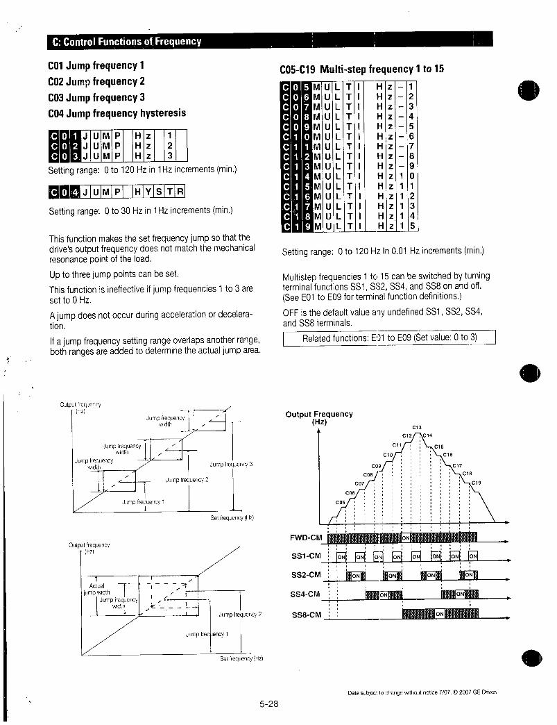
CControlFunctionsofFrequency
CO1Jumpfrequency1
CO2Jumpfrequency2
CO3Jumpfrequency3
C04Jumpfrequencyhysteresis
OutputfrequencyHz
Jumpfrequency11
1
2
3
Settingrange0to120Hzin1Hzincrementsmin
JUMp HYSTR
Settingrange0to30Hzin1Hzincrementsmin
Thisfunctionmakesthesetfrequencyjumpsothatthedrivesoutputfrequencydoesnotmatchthemechanicalresonancepointoftheload
Uptothreejumppointscanbeset
Thisfunctionisineffectiveifjumpfrequencies1to3aresetto0Hz
Ajumpdoesnotoccurduringaccelerationordeceleration
Ifajumpfrequencysettingrangeoverlapsanotherrangebothrangesareaddedtodeterminetheactualjumparea
OutputfrequencyHz
Jumpfrequencywidth
Jumpfrequency
1width
Jumpfrequencywidth Jumpfrequency3
Jumpfrequency2
1Actual T i f
jumpwidthJumpfrequency
t t
width k1 i
i
SetfrequencyHz
JumpfreqJency1
Jumpfrequency2
SetfrequencyHz
528
CO5C19Multistepfrequency1to150
0
0
0
01
1
1
1
11
1
1
11
Settingrange0to120HzIn001Hzincrementsmin
Multistepfrequencies1to15canbeswitchedbytumingterminalfunctionsSS1SS2SS4andSS8onandoffSeeE01toE09forterminalfunctiondefinitions
OFFisthedefaultvalueanyundefinedSS1SS2SS4andSS8terminals
RelatedfunctionsE01toE09Setvalue0to3
OutputFrequencyHz
FWDCM
SS1CM
SS2CM
SS4CM
SS8CM
ULT
ULT
MULT
MULT
MULT
MULT
MULTMULT
MULT
MULT
MULTMULT
MULTMULT
MULT
Cos
CO6
CO9
C08
Col
H
H
H
H
H
H
H
H
H
H
H
H
H
H
H
cio
z
z
z
z
z
z
z
z
z
z
z
z
z
z
z
011
1
1
1
1
1
1
C12
1
2
3
4
5
6
7
8
9
0
1
2
3
4
5
C13
C14
C15
C16
017
C18
C19
Datasubjecttochangewithoutnotice7072007GEDrives

C20Jogfrequency
poSettingrange000to12000Hz
Thisfunctionsetsafrequencyforthemotorjoggingoperationwhichisdifferentfromthenormaloperation
ThejoggingfrequencyisusedforoperationwhenthejoggingmodesignalisreceivedfromthekeypadpanelorcontrolterminalFordetailsseetheexplanationsofE01TerminalX1toE09TerminalX9
C21 Patternoperationoperationselection
Patternoperationisanautomaticoperationaccordingtoapresetoperationtimedirectionofrotationaccelerationanddecelerationtimeandfrequency
WhenusingthisfunctionsetFO1Frequencysettingto
10patternoperation
Thefollowingoperationpatternscanbeselected
Value1OperationPattern0 Performapatternoperationcyclethenstop
operation1 Performpatternoperationrepeatedly
OperationisstoppedbytheSTOPoperation2 Performapatternoperationcyclethen
continueoperationatthelastsetfrequency
Setvalue0
Forward
Output
frequency0
Reversev
Setvalue1
Forward
Output
frequency0
Reverse
Setvalue2
Forwardr
Output
frequency0
Reverse
O
A
G
T
HIZI1
TIEIRN
RelatedFunctionsF01C30 10
Endofacycle
7
EndofacycleFWD
Datasubjecttochangewithoutnotice707C2007GEDrives
Endofacycle
0
Time
Time
Time
529
C22C28 Patternoperationstage1to7
STAGESTAGE
STAGESTAGESTAGE
STAGE
STAGE
1
2
3
4
5
67
SevenstagesareoperatedinorderoffunctioncodesaccordingtothevaluessetinC22Pattemoperationstage1toC28Patternoperationstage7Eachfunctionsetstheoperationtimeandthedirectionofrotationforeachstageandassignsvaluestoaccelerationanddecelerationtime
SetorassignitemOperationtimeRotation
direction
Accelerationand
decelerationtime
Settingexample
100 F
T
StageNo
Stage1
Stage2
Stage3
Stage4
Stage5
Stage6
Stage7
Valuerange00to6000s
ForwardcounterclockwiseReverseclockwiseAccelerationtime1F07Decelerationtime1F08
2Accelerationtime2El0Decelerationtime2Ell
3Accelerationtime3E12Decelerationtime3E13
4Accelerationtime4E14Decelerationtime4E15
NoteTheoperationtimeisrepresentedbythethreemostsignificantdigitshencecanbesetwithonlythreehighorderdigits
0
F
R
1
Accelerationanddeceleration
timecode3
MotorrotatingdirectionForwardcounterclockwise
Operationtime100s
Settheoperationtimeto000foranyunusedstageswhichareskippedduringoperation
InregardtothesetfrequencyvaluethemultistepfrequencyfunctionisassignedaccordingtothetablebelowSevenfrequenciescanbesetforCO5Multistepfrequency1to011Multistepfrequency7
OperationFrequency
Multistepfrequency1CO5
Multistepfrequency2C06
Multistepfrequency3C07
Multistepfrequency4C08
Multistepfrequency5C09
Multistepfrequency6C10
Multistepfrequency7C11

Patternoperationexample Notes
FunctionValueOperationFrequency
C21 1
C22stage1 600F2
C23stage2 100F1
C24stage3 655R4
C25stage4 550R3
C26stage5 500F2
C27stage6 720F4
C28stage7 350F2
Thefollowingdiagramshowsthisoperation
Forward
direction
1
Reverse
direction
A
Setvalue17
MultistepMultistep Multistep frequency
frequency1frequency2 6
Stage1 MultAC4
frequencyn 4
ACC1
ACC2ACC4
ASet
value 4191s16
1
Multistepfrequency3
ACC2
ACC3
Selectsfunction
Multistepfrequency1CO5
Multistepfrequency2C06
Multistepfrequency3C07
Multistepfrequency4C08
Multistepfrequency5C09
Multistepfrequency6C10
Multistepfrequency7C11
Multistepfrequency4
DEC2
DEC2
Multistepfrequency7
Stake7
600S100S655S550S500S720S35051141 04 4i4RG YF
OutputsignalsfromterminalsY1toY5
DEC1
Time
RunningandstoppingarecontrolledbypressingtheSTOPorFWDkeysorbyopeningandclosingthecontrolterminals
WhenusingthekeypadpaneltheFWDkeystartsoperationTheSTOPkeypausesstageadvancePressingtheFWDkeyagainwillrestartoperationfromthestoppointaccordingtothestagesIfanalarmstopoccurspresstheRESETkeytoreleasethedriveprotectivefunctionthenpresstheFWDkeytorestartstageadvance
IfoperationistorestartfromthefirststageC22Patternoperationstage1enteraSTOPcommandandpresstheRESETkey
IfanalarmstopoccurspresstheRESETkeytoreleasetheprotectivefunctionthenpresstheRESETkeyagain
530
1 ThedirectionofrotationcannotbereversedbyacommandissuedfromtheREVkeyonthekeypadpanelorTerminalREVAnyreverserotationcommandsenteredwillbecanceledSelectforwardorreverserotationbythedataineachstageIfthecontrolterminalsareusedforoperationtheselfholdfunctionwillnotworkSelectanaltematetypeswitchwhenusingcontrolterrninals
2 AttheendofacyclethemotordeceleratestostopaccordingtothevaluesetinF08Decelerationtime1
C30Frequencysetting2
EioFIRIEIQIICIMIDII2ForthesettingmethodseetheexplanationforF01NotesSetting23and7areinactiveC1signals
Thisfunctiondeterminesthefrequencysettingmethod
C31AnaloginputbiasadjustmentThesettingrangeis1000to1000in01incrementsofthemaximumoutputfrequency
C32AnaloginputgainadjustmentThegainadjustmentrangeis00to200
MirAAThesefunctionssetthegainandbiasforanaloginputTerminals12inconjunctionwithfunctionsF17freqgainandF18freqbias
FordetailsseetheexplanationforF17andF18
C33Analogsettingsignal
REIFI IFII ElRI
Settingrange000to500seconds
AnalogsignalsinputfromTerminals12V2orC1maycontainnoisewhichrendersthecontrolunstableThisfunctionadjuststhetimeconstantoftheinputfiltertoremovetheeffectsofnoise
AvaluethatissettoolargedelayscontrolresponsealthoughstabilizingthecontrolAvaluethatissettoosmallspeedsupcontrolresponsebutrendersthecontrolunstable
IftheoptimumvalueisnotknownadjustthesettingifthecontrolisunstableorresponseisdelayedNote
ThesetvalueiscommonlyappliedtoTerminals12V2andC1ForinputofPIDfeedbackthePIDcontrolfeedbackfilterH25isused
Datasubjecttochangewithoutnotice70702007GEDrives
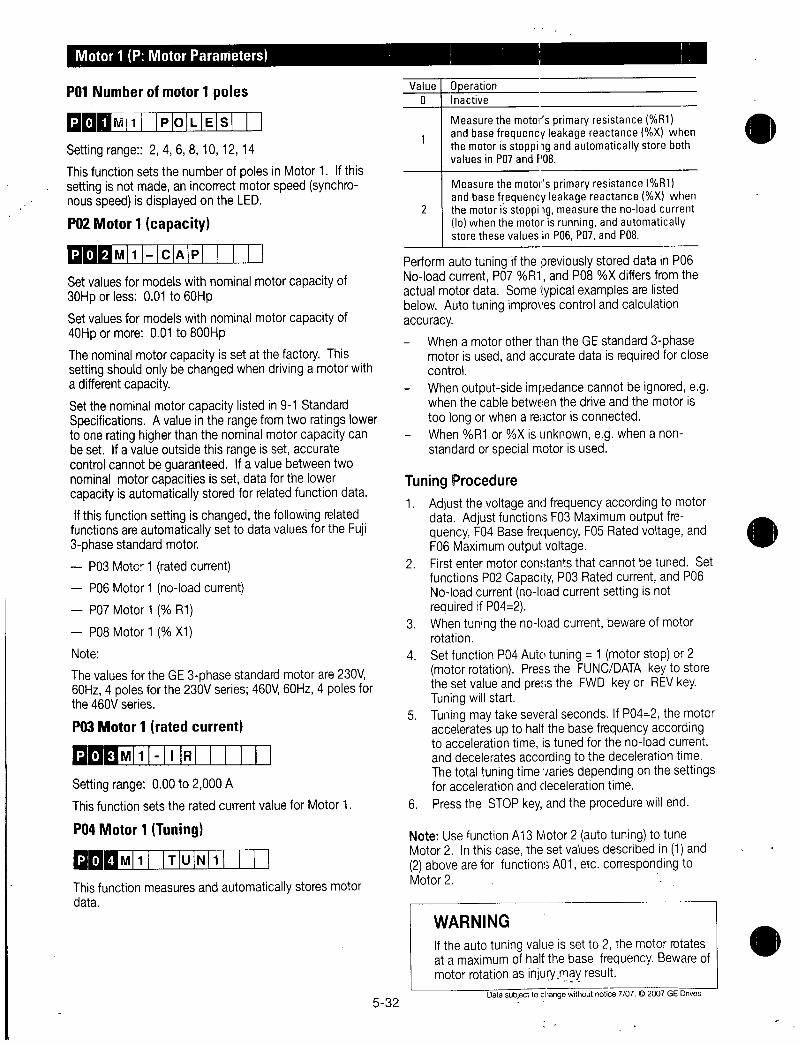
Motor1PMotorParameters
P01Numberofmotor1poles
a
0
0
lirF411 P0LEs
Settingrange2468101214
ThisfunctionsetsthenumberofpolesinMotor1IfthissettingisnotmadeanincorrectmotorspeedsynchronousspeedisdisplayedontheLED
P02Motor1capacity
M1 cAP
Setvaluesformodelswithnominalmotorcapacityof30Hporless001to60Hp
Setvaluesformodelswithnominalmotorcapacityof40Hpormore001to800Hp
ThenominalmotorcapacityissetatthefactoryThissettingshouldonlybechangedwhendrivingamotorwithadifferentcapacity
Setthenominalmotorcapacitylistedin91StandardSpecificationsAvalueintherangefromtworatingslowertooneratinghigherthanthenominalmotorcapacitycanbesetIfavalueoutsidethisrangeissetaccuratecontrolcannotbeguaranteedIfavaluebetweentwonominalmotorcapacitiesissetdataforthelowercapacityisautomaticallystoredforrelatedfunctiondata
IfthisfunctionsettingischangedthefollowingrelatedfunctionsareautomaticallysettodatavaluesfortheFuji3phasestandardmotor
P03Motor1ratedcurrent
P06Motor1noloadcurrent
P07Motor1 R1
P08Motor1 X1
Note
ThevaluesfortheGE3phasestandardmotorare230V60Hz4polesforthe230Vseries460V60Hz4polesforthe460Vseries
P03Motor1ratedcurrent
P03 1 R
Settingrange000to2000AThisfunctionsetstheratedcurrentvalueforMotor1
PO4Motor1Tuning
04M1 TuN1
Thisfunctionmeasuresandautomaticallystoresmotordata
532
ValueIOperation0 1Inactive
MeasurethemotorsprimaryresistanceR1andbasefrequencyleakagereactanceXwhenthemotorisstoppiigandautomaticallystorebothvaluesinP07andf08
MeasurethemotorsprimaryresistanceR1andbasefrequencyleakagereactanceXwhen
2 themotorisstoppiigmeasurethenoloadcurrentlowhenthemotorisrunningandautomaticallystorethesevaluesinP06P07andP08
PerformautotuningifthepreviouslystoreddatainP06NoloadcurrentP07R1andP08XdiffersfromtheactualmotordataSometypicalexamplesarelistedbelowAutotuningimprovescontrolandcalculationaccuracy
WhenamotorotherthantheGEstandard3phasemotorisusedandaccuratedataisrequiredforclosecontrol
Whenoutputsideimpedancecannotbeignoredegwhenthecablebetweenthedriveandthemotoris
toolongorwhenareactorisconnectedWhenR1orXisunknownegwhenanonstandardorspecialmotorisused
TuningProcedure1 Adjustthevoltageandfrequencyaccordingtomotor
dataAdjustfunctionsF03MaximumoutputfrequencyF04BasefrequencyF05RatedvoltageandF06Maximumoutputvoltage
2 FirstentermotorconstantsthatcannotbetunedSetfunctionsP02CapacityP03RatedcurrentandP06NoloadcurrentnoloadcurrentsettingisnotrequiredifPO42
3 Whentuningthenoloadcurrentbewareofmotorrotation
4 SetfunctionPO4Autotuning1motorstopor2motorrotationPresstheFUNCDATAkeytostorethesetvalueandpresstheFWDkeyorREVkeyTuningwillstart
5 TuningmaytakeseveralsecondsIfPO42themotoracceleratesuptohalfthebasefrequencyaccordingtoaccelerationtimeistunedforthenoloadcurrentanddeceleratesaccordingtothedecelerationtimeThetotaltuningtimevariesdependingonthesettingsforaccelerationanddecelerationtime
6 PresstheSTOPkeyandtheprocedurewillend
NoteUsefunctionA13Motor2autotuningtotuneMotor2Inthiscasethesetvaluesdescribedin1and2aboveareforfunctionsA01etccorrespondingtoMotor2
WARNING
Iftheautotuningvalueissetto2themotorrotatesatamaximumofhalfthebasefrequencyBewareofmotorrotationasinjurymayresult
Datasubjecttochangewithoutnotice7072007GEDnves
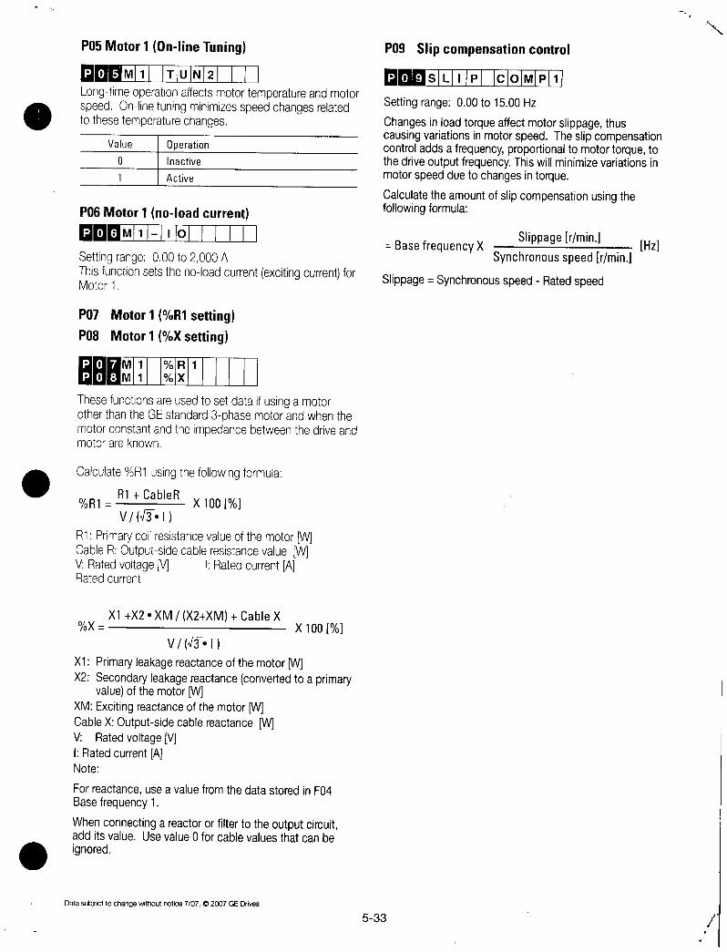
P05Motor1OnlineTuning
M0 M1 ITIU I fLongtimeoperationaffectsmotortemperatureandmotorspeedOnlinetuningminimizesspeedchangesrelatedtothesetemperaturechanges
0
0
0
Value
0
1
1Operation1Inactive1Active
P06Motor1noloadcurrent
Q 6m111111OIII 1II
Settingrange000to2000AThisfunctionsetsthenoloadcurrentexcitingcurrentforMotor1
P07 Motor1R1settingP08 Motor1Xsetting
HTR1
X
ThesefunctionsareusedtosetdataifusingamotorotherthantheGEstandard3phasemotorandwhenthemotorconstantandtheimpedancebetweenthedriveandmotorareknown
CalculateR1usingthefollowingformula
R1R1 CableR
X100
VNIY1
R1PrimarycoilresistancevalueofthemotorWCableROutputsidecableresistancevalueWVRatedvoltageM IRatedcurrentARatedcurrent
X1X2XMX2XM CableXX X100
Vf1
X1PrimaryleakagereactanceofthemotorpiX2Secondaryleakagereactanceconvertedtoaprimary
valueofthemotorWXMExcitingreactanceofthemotorWCableXOutputsidecablereactanceWV RatedvoltageVIRatedcurrentANote
ForreactanceuseavaluefromthedatastoredinF04Basefrequency1
WhenconnectingareactororfiltertotheoutputcircuitadditsvalueUsevalue0forcablevaluesthatcanbe
ignored
Datasubjecttochangewithoutnotice7072007GEDrives
P09Slipcompensationcontrol
533
09SL P c0MP1
Settingrange000to1500Hz
ChangesinloadtorqueaffectmotorslippagethuscausingvariationsinmotorspeedTheslipcompensationcontroladdsafrequencyproportionaltomotortorquetothedriveoutputfrequencyThiswillminimizevariationsinmotorspeedduetochangesintorque
Calculatetheamountofslipcompensationusingthefollowingformula
SlippagerminBasefrequencyX Hz
Synchronousspeedrmin
Slippage SynchronousspeedRatedspeed

HHighPerformancefunction
H03Datainitializing
11DATA N T
Settingrnage 0Disabled1Initializesdata
Thisfunctionreturnsallfunctiondatachangedbythecustomertotheoriainalfactorysettinasinitialization
ToperforminitializationpresstheSTOPandAkeystogethertosetH031thenpresstheFUNCDATAkeyThevaluesforallfunctionsareinitializedThesetvalue
inH03automaticallyreturnsto0followingtheendofinitialization
H04AutoresetTimes
H05AutoresetResetinterval
0
4AuT0 REsIEIT
R SET NT
Settheprotectivefunctionreleasecountandwaitingtimefromitsstartuptorelease
SettingrangeCount01to10Waitingtime2to20seconds
WhenadriveproteQtivefunctionwhichinvokestheretryoperationisactivatedthesefunctionsreleaseoperationoftheprotectivefunctionandrestartsoperationwithoutissuinganalarmorterminatingoutput
TodisabletheretryfunctionsetH04Retrycount 0
Driveprotectivefunctionsthatcaninvoketheretryfunction
dBH
brakingresistoroverheatingOL1
Motor1overload
OL2
Motor2overload
OLU
Driveoverload
0C10C20C3
Overcurrent
OV1OV2OV3
Overvoltage
OH1
Heatsinkoverheating
OH3
Driveoverheating
internally
IfthevalueofH04Retrycountissetfrom1to10adriveruncommandisimmediatelyenteredfollowingthewaittimesetinH05RetrywaittimeandthestartupoftheretryoperationIfthecauseofthealarmhasbeenremovedatthistimethedrivestartswithoutswitchingtoalarmmodeIfthecauseofthealarmstillremainstheprotectivefunctionisreactivatedaccordingtothewaittimesetinH05RetrywaitingtimeThisoperationisrepeateduntilthecauseofthealarmisremovedTherestartoperationswitchestoalarmmodewhentheretrycountexceedsthevaluesetinH04RetrycountTheoperationoftheretryfunctioncanbemonitoredfromterminalsY1toY5
534
WARNING
WhentheretryfunctionisselectedoperationwillautomaticallyrestartdependingonthecauseofthestopThemachineshouldbedesignedtoensuresafetyduringarestartWhentheretryfunctionisselectedGEstartsoftwareF02set3or4doesnotwork
Alarm
ProtectivefunctionAutomatic
release
command
of
protectivefunctionOutputfrequency
Output
signals
terminalsY1toY5
Occurrence
Alarm
Protectivef OperatingOperating Operating Operating
functtonIAutomatic 0101 0i0yf 01Sy
rwlearseaIaH05 H05yrll
Rntrycommand Wan Watted
of
m
me dmcCountsetin
protectivefunctiont First Second 04count
Outputfrequency
Outputsignals
terminalsY1toY5J 11 ON
H06Fanstopoperation
0
Settingrange 0ONOFFcontroldisabled1ONOFFcontrolenabled
ThisfunctionspecifieswhetherONOFFcontrolforthecoolingfanisautomaticVVhilepowerisappliedtothedrivetheautomaticfancontroldetectsthetemperatureoftheheatsinkandturnsthefanonoroffWhenthiscontrol
isnotselectedthecoolingfanrotatescontinuously
ThecoolingfanoperatingstatuscanbemonitoredfromterminalsY1toY5
H07ACCDECModeselectpattern
Whenretrysucceeded
OccurrenceExtinction
ViOperating
Waitingtime1105 n
retryfailed Alarm
reset
1 AN
0
SIT10
Restart
P
ip7kIcIc1 IPITINI 11
Time
Extinction
Settingrange 0Inactivelinearaccelerationanddeceleration
1Sshapeaccelerationanddecelerationmiid2Sshapeaccelerationanddecelerationsharp3Curvilinearaccelerationanddeceleration
Thisfunctionselectstheaccelerationanddecelerationpattern
Datasubjecttociangewithoutnotice7072007GEDrives

SshapeAccelerationandDeceleration
Thispatternreducesshockbymitigatingoutputfrequencychangesatthebeginningandendofaccelerationanddeceleration
Outputfrequency
tIHzjA
tact Dacc
Patternconstants
When1isselctedinH07
midSshapepattern
RangeofSshaped
Timefor
SshapedataccelerationTimefor
Sshapedatdeceleration
005xmaximum
outputfrequencyHz010x
acceleration
times010x
decelerations
OO1EfLIOICIKII1
Settingrange 0Inactive1Active
Datasubjecttochangewithoutnotice707C2007GEDrives
When2isselctedin
H07midSshapepattern
010xmaximumoutputfrequencyHz
020xaccelerationtimes
020xdecelerations
Whenaccelerationanddecelerationtimesareverylongorshortaccelerationanddecelerationarealmostlinear
CurvilinearAccelerationandDeceleration
Thisfunctionisusedtominimizemotoraccelerationand
decelerationtimesintherangethatincludesaconstantoutputrange
Outputfrequency
acceleration deceleration
olMaximumk s
output
Set
frequency
Base
frequency
0 tsec
H08Revphasesequencelock
Ifaccidentalreversingcouldresultinamalfunctionthisfunctioncanbesettopreventreversal
ThisfunctionpreventsareversingoperationresultingfromaconnectionbetweentheREVandCMterminalsinadvertentactivationoftheREVkeyornegativeanaloginputfromTerminals12orV1
H09Startmode
09SITIAIRITIIMIOIDIEI
Settingrange012
Thisfunctionsmoothlycatchesaspinningmotorwhichiscoastingafteramomentarypowerfailureorafterthemotorhasbeensubjecttoexternalforcewithoutstoppingthemotoriewindmillingfan
AtstartupthisfunctiondetectsthemotorspeedandoutputsthecorrespondingfrequencytherebyenablingashockfreemotorstartupThenormalstartupmethodisusedifthecoastingspeedofthemotoris120HzormoreasadrivefrequencyandifthevalueofF03MaximumfrequencyexceedsthevalueofF15Frequencylimiterupperlimit
535
Value
0 11 I2
Restartaftera
Normal momentary Linetodrive
startup power switchingfailure
Inactive1 Inactive 1 Inactive
Inactive1 Active 1 Active
Active I Active 1 Active
Explanation
1 ThisfunctioniseffectiveifF14Restartaftermomen
tarypowerfailureoperationselectionissetto34or5ThisfunctionisalsoeffectivewhenoperationisswitchedfromthelinetothedriveThemotoris
startedwiththesamefrequencyasthecurrentcoastingspeedspeedsearch
2 InadditiontorestartingfollowingamomentarypowerfailureandswitchingbetweenthelineandthedrivethisfunctiondetectsthecoastingspeedofthemotorandstartsthemotoratthesamefrequencyasallstartupsincludingwhenanONoperationcommandisentered
Byassigning26startcharacteristicsselectiontoterminalsX1toX9thisfunctioncanbeexternallyselectedasthenormalstartupmethodwheneveranONoperationcommandisentered
01sor 02sor
CM1 longer longer
LSTM
Outputfrequencymotorspeed
Speedsearch
HHON
ON
L
Acceleration
Time
Time
NoteThedotteddashedlineindicatesmotorspeed

H10Energysavingoperation
MU EN RGY sAV
Settingran 0Inactive 1Active
Withconstantspeedoperationatlightloadsfixedoutputfrequencythisfunctionautomaticallyreducestheoutputvoltagewhileminimizingtheproductofvoltageandcurrentpower
ExceptionIfF09Torqueboost1 00
Notes
UsethisfunctionforvariabletorqueloadsegfanspumpsIfusedforaconstanttorqueloadorrapidlychangingloadthisfunctioncausesadelayincontrolresponse
Theenergysavingoperationautomaticallystopsduringaccelerationanddecelerationorwhenthetorquelimitingfunctionisactivated
H11DECmode
DEC M0DE
Settingrange 0DecelerationtostopbasedondatasetwithH07Nonlinearaccelerationanddeceleration
1CoastingtostopThisfunctiondeterminesthedrivestoppingmethodwhenaSTOPcommandisentered
Note
ThisfunctioniseffectiveonlywhenaSTOPcommandisenteredandthereforeisineffectiveifthemotorisstoppedbyloweringthesetfrequency
H12Instantaneousovercurrentlimiting
hiINISlTIIcILI I
Settingrange0Inactive 1Active
AnovercurrenttripgenerallyoccurswhencurrentflowsabovethedriveprotectivelevelfollowingarapidchangeinmotorloadTheinstantaneousovercurrentlimitingfunctioncontrolsdriveoutputandprohibitstheflowofacurrentexceedingtheprotectiveleveleveniftheloadchanges
Sincetheoperationleveloftheinstantaneousovercurrentlimitingfunctioncannotbeadustedthetorquelimitingfunctionmustbeused
MotorgenerationtorquemaybereducedwheninstantaneousovercurrentlimitingisappliedSetthisfunctiontobeinactiveforequipmentsuchaselevatorswhichareadverselyaffectedbyreducedmotorgenerationtorqueinwhichcaseanovercurrenttripoccurswhenthecurrentflowexceedsthedriveprotectivelevelAmechanicalbrakeshouldbeusedtoensuresafety
536
H13AutorestartRestarttime
RIEISITIAIRII ITI
Settingrange01to1003econds
InstantaneousswitchingtoanotherpowerlinewhenthepowerofanoperatingmotoriscutofforpowerfailureoccurscreatesalargephasedifferencebetweenthelinevoltageandthevoltageremaininginthemotorwhichmaycauseelectricalormechanicalfailureTorapidlyswitchpowerlinesstoretheremainingvoltageattenuationtimetowaitforthevoltageremaininginthemotortoattenuateThisfunctionoperatesatrestartafteramomentarypowerfailure
IfthemomentarypowerfailuretimeisshorterthanthewaittimevaluearestartoccursfollowingthewaittimeIfthepowerfailuretimeislongerthanthewaittimevaluearestartoccurswhenthedriveisreadytooperateafterabout02to05seconds
H14Autorestartfreqfallrate
hill AILILIIRIAITE
Settingrange000001to10000HzsIfH14 000thefrequencyisreducedaccordingtothesetdecelerationtime
ThisfunctiondeterminesthereductionrateoftheoutputfrequencyforsynchronizingthedriveoutputfrequencywiththemotorspeedThi3functionisalsousedtoreducethefrequencyandtherebypreventstallingunderaheavyloadduringnormaloperationNote
AfrequencyreductionratethatissettoolargemaytemporarilyincreasetheregenerationenergyfromtheloadandinvoketheovervoltageprotectivefunctionConverselyaratethatistoosmallextendstheoperationtimeofthecurrentlimitingfunctionandmayinvokethedriveoverloadprotectivefunction
H15AutorestartholdingDCvoltage
roll HoILIDIIII
Settingrange 230Vseries200to300V
460Vseries400to600V
ThisfunctionisusedwhenF14Restartaftermomentary
powerfailureoperationselectionissetto2decelerationtostopatpowerfailureor3operationcontinuationEitherfunctionstartsacontroloperationifthemaincircuitDCvoltagedropsbelowthesetoperationcontinuationlevel
Ifpowersupplyvoltagetothedriveishigh controlcanbe
stabilizedevenunderanexcessiveloadbyraising the
operationcontinuationlevelHowever ifthelevelistoo
highthisfunctionactivatesduring normaloperationandcausesunexpectedmotionPleasecontactGE Drives
beforechangingthefactorydefaultvalue
Datasubjecttochangewithoutnotice7072007GEDrives

H16AutorestartOPRcommandselfholdtime
116SELFHOLD ITSettingrange00to300seconds999
SincethepowertoanexternaloperationcircuitrelaysequenceandthemainpowertothedriveisgenerallycutoffatapowerfailuretheoperationcommandissuedtothedriveisalsocutoffThisfunctionsetsthetimean
operationcommandistobeheldinthedriveIfapowerfailurelastsbeyondtheselfholdtimepoweroffisassumedautomaticrestartmodeisreleasedandthedrivestartsoperationatnormalmodewhenpowerisappliedagainThistimecanbeconsideredtobetheallowablepowerfailuretime
IfH16 999anoperationcommandwillbehelduntilcontrolpowerinthedriveisestablishedoruntilthemaincircuitDCvoltageisabout0
H19Activedrive
09AuT RED
Settingrange 0Inactive1Active
Thisfunctionautomaticallyextendsacceleratingtimeby60secondsorlongertopreventaninvertertripresultingfromatemperatureriseintheinverterduetoovercurrent
Iftheactivedrivefunctionisactivatedtheaccelerationtimewillbethreetimestheselectedtime
H2OPIDcontrolmodeselect
0P D M0DE
Settingrange 0Nooperation1Normaloperation2Inverseoperation
PIDcontroldetectstheamountoffeedbackfromasensorandcomparesitwiththetargetvalueegreferencetemperatureIfthevaluesdifferthisfunctionproducesanoutputtoeliminatethedeviationInotherwordsthiscontrolmatchesthefeedbackamountwiththetargetvalue
Thisfunctioncanbeusedforflowcontrolpressurecontroltemperaturecontrolandotherprocesscontrols
Targetvalue
J DriveI Gontroi
sectionI I tartet
HI
Feedbackamount
ForwardorreverseoperationscanbeselectedforPID
controller outputThisenablesmotorrevolutionstobefasterorsloweraccordingtoPIDcontrolleroutput
Datasubjecttochangewithoutnotice7072007GEDrives 537

Inverteroutputfrequency
Maximum
frequncy
0
0 PIDoutput
Normalopreration
iInverseopreration
100
ThetargetvaluecanbeenteredusingF01Frequencysetting1ordirectlyfromthekeypadpanel
ForentryfromF01Frequencysetting1inputasignaltotheselectedterminalFordirectentryfromthekeypadpanelturnonkeypadoperationSelectanyofthedigitalTerminalsX1E01toX9E09andassignavalueof11frequencysettingswitching
NOTEForthetargetvalueandfeedbackamounttheprocessamountcanbedisplayedaccordingtothevaluessetinE40DisplaycoefficientAandE41DisplaycoefficientB
Display
DisplaycoefficientA
DisplaycoefficientB
Target value or
0 100feedbackamount
H21PIDcGntrolfeedbacksignal
FB CSIII0
ThisfunctionselectstheterminaldirectionofoperationandfeedbackinputSelectavaluefromthetablebelowaccordingtosensorspecifications
Value Description0 Terminal12forwardoperation0to10Vvoltageinput1 TerminalC1forwardoperation4to20mAcurrentinput2 Terminal12reverseoperation10toOVvoltageinput3 1TerminalC1reverseoperation20to4mAcurrentinput
538
Feedbackamount
100
0
OV
4mA Input
Normal
operation
Inverse
operation10V
20mA
OnlypositivevaluescanbeinputforthisfeedbackamountofPIDcontrolNegativevalueseg0to10V10toOVcannotbeinputherebythefunctioncannotbeusedforareverseoperationbyananalogsignal
FeedbacksignalsettingIH21mustbedifferentfromthetypeofsetpointvalue
Datasubjecttochangewithoutnotice7072007GEDrives

Directfrequencysettingfromkeypadpanel
Processamountsetting11fromkeypadpanel
SettingselectedinF01frequencysetting1
Deviation
Operationamount
13EPIIGIAIIIN11 1 11
Datasubjecttochangewithoutnotice7072007GEDrives
E01toE09functionfrequencysettingswitchingbetween1and2
PID
calculator
H22PIDcontrolPgain
H23PIDcontrolIgain
H24PIDcontrolDgainThesefunctionsarenotgenerallyusedalonebutarecombinedlikePcontrolPIcontrolPDcontrolandPIDcontrol
Pgainoperation
AnoperationusinganoutputfrequencyproportionaltodeviationiscalledPoperationwhichoutputsanoperationamountproportionaltodeviationthoughitcannoteliminatedeviationalone
Time
Settingrange001to100times
PgainistheparameterthatdeterminestheresponselevelforthedeviationofPoperationAlthoughanincreaseingainspeedsupresponseanexcessivegaincausesvibrationandadecreaseingaindelaysresponse
Normal
operation
Inverse
operation I2
H2O
operationselection
Response
E01toE09functionPIDcontrolcancellation
Igainoperation
AnoperationwherethechangespeedoftheoutputfrequencyisproportionaltothedeviationiscalledanoperationAnIoperationoutputsanoperationamountastheintegralofdeviationandthereforehastheeffectofmatchingthefeedbackcontrolamounttothetargetvalueegsetfrequencythoughitdeterioratesresponseforsignificantchangesindeviation
539
c0
u0
0E
0
E
Frequencycommand
40
1
Signalreversal
Signalreversal
H21settingsignalswitching
Drive
section
Control
target
getTerminal12
1
Terminal
Clror
Time
Time

BEEFIGAINSettingrange00Inactive01to3600seconds
H23IgainisusedasaparametertodeterminetheeffectofIoperationAlongerintegrationtimedelaysresponseandweakensresistancetoexternalelementsAshorterintegrationtimespeedsupresponsebutanintegrationtimethatistooshortcausesvibration
Dgainoperation
AnoperationwheretheoutputfrequencyisproportionaltothedeviationdifferentialiscalledaDoperationItoutputsanoperationamountasthedeviationdifferentialandthereforeiscapableofrespondingtosuddenchanges
0
0
o
D GA N
Time
Settingrange000Inactive001to100seconds
H24DgainisusedasaparametertodeterminetheeffectofaDoperationAlongerdifferentiationtimecausesvibrationbyPoperationquicklyattenuatingattheoccurrenceofdeviationExcessivedifferentiationtimecouldcausevibrationShorteningthedifferentiationtimereducesattenuationattheoccurrenceofdeviation
PIcontrol
PoperationalonedoesnotremovedeviationcompletelyP IcontrolwhereIoperationisaddedtoPoperationisnormallyusedtoremovetheremainingdeviationPIcontrolalwaysoperatestoeliminatedeviationevenwhenthetargetvalueischangedorthereisaconstantdisturbanceWhenIoperationisstrengthenedhowevertheresponseforrapidlychangingdeviationdeterioratesPoperationcanalsobeusedindividuallyforloadscontaininganintegralelement
PDcontrol
IfdeviationoccursunderPDcontrolanoutputfrequencylargerthanthatofDoperationaloneoccursrapidlyandpreventsthedeviationfromexpandingForasmalldeviationPoperationisrestrictedWhentheloadcontainsanintegralelementPoperationalonemayallowresponsestovibrateduetotheeffectoftheintegralelementinwhichcasePDcontrolisusedtoattenuatethevibrationofPoperationandstabilizeresponsesInotherwordsthiscontrolisappliedtoloadsinprocesseswithoutabrakingfunction
540
PIDcontrol
PIDcontrolcombinestePoperationtheIoperationwhichremovesdeviatiDnandtheDoperationwhichsuppressesvibrationThiscontrolachievesdeviationfreeaccurateandstableresponses
AdjustingPIDvalueAdjustthePIDvaluewhilemonitoringtheresponsewaveformonanoscilloscopeorotherinstrumentifpossibleProceedasfollows
IncreasethevalueofFI22Pgainwithoutgeneratingvibration
DecreasethevalueofH23Igainwithoutgeneratingvibration
IncreasethevalueofH24Dgainwithoutgeneratingvibration
Adjusttheresponsewaveformasfollows
ToremovetheovershootincreasethevalueofH23IgainthendecreasethevalueofH24Dgain
After
adjustment
00n
aBeforeadjustment
TostabilizeresponsequicklyallowingforminovershootdecreasethevalueofH23IgainorincreasethevalueofH24Dgain
0a
CC
Q0
00a
1
Before
adjustment
After
adjustment
Before
adjustment
Time
Time
TosuppressvibrationwithaperiodlongerthanthevalueofH23IgainincreasethevalueofH23
After
adjustment
Time
TosuppressvibrationwithafrequencyroughlyequivalenttothevalueH24DgaindecreasethevalueofH24Ifthereisresidualvibrationwith00decreasethevalueofH22Pgain
Before
adjustment
After
adjustment
Time
Datasubjecttochangewithoutnotice7072007GEDrives

H25PIDcontrolFeedbackfilter
111130FIBI IFIITIEIRI1Settingrange00to600seconds
ThisfilterisforfeedbacksignalinputfromTerminals12or01ThisfilterstabilizesoperationofthePIDcontrolsystemAsetvaluethatistoolargehoweverdeterioratesresponse
H26PTCthermistormodeselect
Settingrange 0Inactive1Active
SetthisfunctionactivewhenthemotorhasaPTCthermistorforoverheatprotection
ConnectthePTCthermistorasshowninthefigurebelowTurnonswitchPTConthecontrolPCBThetripmodeisactivatedbyOH2Externalthermalrelaytripped
PTC
thermistor
PTc M0DE
13
C
Resistor
250Ohm
11
PTC
IONOFF
1kOhmT
ov
H27
Level
DC1OV
I
ComparatorOH2
NoteMustbe0settingwhenusing420mAreferenceorfeedbacksignalandthePTCswitchmustbeoff
H27PTCthermistorlevelselect
QPTIc ILIEI
Settingrange000to500V
ThevoltageinputtoTerminal01iscomparedtothesetvoltagelevelIftheinputvoltageisequaltoorgreaterthanthesetvoltageH26PTCthermistorModeselectstarts
ThePTCthermistorhasitsownalarmtemperatureTheinternalresistancevalueofthethermistorlargelychangesatthealarmtemperatureTheoperationvoltagelevelissetusingthischangeintheresistancevalue
Internalresistanceof
PTCthermistor
Rp2
Rpl
Alarm
temperature
Datasubjecttochangewithoutnotice707Cr2007GEDrives
Temperature
ThefigureaboveforH26PTCthermistorModeselectshowsthata250WresistorandthethermistorresistancevalueRpareconnectedinparallelHencevoltageVc1atTerminal01canbecalculatedusingthefollowingforrnula
250Rp
Vci 250Rp X10V
1000250Rp250 Rp
TheoperationlevelcanbesetbybringingRpintheVc1calculationformulaintothefollowingrange
Rp1 Rp Rp2
TocalculateRpusethefollowingformula
H28Droopoperation
ODIR00PII I I II
Settingrange99Hzto00Hz
WhentwoormoredrivemotorsoperateasinglemachineahigherloadisplacedonthemotorthatisrotatingthefastestDroopoperationachievesagoodloadbalancebyapplyingdroopingcharacteristicstospeedagainstloadvariations
541
Calculatethedroopamountusingthefollowingformula
Droopamount BasefrequencyX
SpeeddroopatratedtorquerminHz
Synchronousspeedrmin
Characteristicsofthemotor
Whendroop Whendroopoperationisactive operationisinactive
Torque
Ratedtorque
0
Rp Rp1 Rp2Ohm
SpeedSynchronous
speed

H30SeriallinkFunctionselect
L NK FUNC
Settingrange0to3
ThelinkfunctioncommunicationprovidesastandardRS485serialinterfaceandoptionalfieldbusconnections
Theseriallinkfunctionincludes
1 Monitoringdatamonitoringfunctiondatacheck2 Frequencysetting3 OperationcommandFWDREVandothercom
mandsfordigitalinput4 Writefunctiondata
CommunicationcanbeenabledanddisabledbyadigitalinputThisfunctionsetstheseriallinkfunctionwhencommunicationisenabled
Value
0
1
2
3
FrequencyCommand
Disabled
Enabled
Disabled
Enabled
OperationCommand
Disabled
Disabled
Enabled
Enabled
ThedatamonitoringandwritefunctionsarealwaysenabledDisablingcommunicationbyadigitalinputproducesthesameresultsasifthisfunctionweresetto0IfthebusoptionisinstalledthissettingselectsthebusfunctionandtheRS485interfaceisrestrictedtomonitoringandwritingfunctiondataIfthebusoptionisnotinstalledthissettingselectstheRS485function
H31RS485Address
H39RS485ResponseintervalThesefunctionssettheconditionsforRS485RTUserialcommunicationSettheconditionsaccordingtothehostdevice
DIDIRESS JSettingrange1to247ThisfunctionsetsthestationaddressofRTUMaximumconnecteddevicesis31foranRS485network
B0D 0N ER
Settingrange0to3
Thesefunctionsconfigurethedrivebehaviorintheeventofacommunicationerror
542
2
MTIIIMIEIRI1 1 111
Settingrange0to600sec
Thisfunctionsetstheerrorprocessingtimervalue
Settingrange0to3
Thisfunctionsetsthebaudrate
Value IProcessingatCommunicationError0 1ImmediateEr8tripforcedstop
ContinueoperationwithintimertimeEr8tripafter1 timeexpires
3 IContinueoperation
BAUD
Value
0
1
2
3
LENGT
Thisfunctionsetsdataleigth
Value IDataLength0 I8bit
61PIAIITIYI1 I11
Thisfunctionsetstheparitybit
Value IParityEit0 1None1 1Even2 IOdd
MasiT
Thisfunctionsetsthestcpbit
Value
0
ContinueopetationandretrywithintimertimetheninvokeanEr8tripifacommunicationerroroccursIfanerrordoesnotoccurcontinueoperation
P
R
BaudRate
19200bitss
9600bits
4800bits
2400bits
H
6
StopBi
2bits
1bit
ATE
Ts
ThestopbitisautomaticallyconfiguredbythevalueoftheparitybitForparityNONEthestopbitis2bitsForparityEVENorODDThestopbitis1bit
Datasubjecttocrangewithoutnotice7072007GEDrives

BIERIRE
D
s T
Settingrange 0nodetection1to60seconds
InasystemwherethedriveiscontinuouslypolledwithinaspecifictimethisfunctiondetectsthataccesswasstoppedduetoanopencircuitorothernetworkfaultandresultsinanEr8trip
NTIE VAL
Settingrange000to100second
Thisfunctionsetsthetimefromwhenarequestisissuedfromthehostdevicetowhenaresponseisreturned
Datasubjecttochangewithoutnotice7072007GEDrives

AAlternativeMotorParametersMotor2
A01Maximumfrequency2
A
A
ThisfunctionsetsthemaximumfrequencyforMotor2outputbythedriveItoperatesthesameasF03Maximumfrequency1FordetailsseetheexplanationforF03
A02Basefrequency2
0
ThisfunctionsetsthemaximumoutputfrequencyintheconstanttorqueareaforMotor2ieoutputfrequencyatratedoutputvoltageItoperatesthesameasF04Basefrequency1FordetailsseetheexplanationforF04
A03RatedVoltage2
ThisfunctionsetstheratedvoltageoutputtoMotor2ItoperatesthesameasF05Ratedvoltage1FordetailsseetheexplanationforF05
A04MaximumVoltage2
OMAIXl
ElSE Hz 2
RATED 2
MAIX V
2
21111
ThisfunctionsetsthemaximumdriveoutputvoltageforMotor2ItoperatesthesameasF06Maximumvoltage1FordetailsseetheexplanationforF06
A05Torqueboost2
0TR B00S 2
ThisfunctionsetsthetorqueboostfunctionforMotor2ItoperatesthesameasF09Torqueboost1FordetailsseetheexplanationforF09
544
A06Electronicthermalrelay2select
A07Electronicthermalrelay2level
A08Electronicthermalrelay2Thermaltimeconstant
A
A
A
Thesefunctionssetthefunctionoftheelectronicthermal
overloadrelayforMotor2TheyoperatethesameasF10toF12Electronicthermaloverloadrelay1FordetailsseetheexplanationsforF10toF12
0
0
0
A09Torquevectorcontrol2
OTIR0VECT
1ELCTRN 0L2OL LEVEL2TIME CNST2
0R2
ThisfunctionsetsthetorquevectorfunctionforMotor2ItoperatesthesameasF42Torquevectorcontrol1FordetailsseetheexplanationforF42
A10Numberofmotor2poles
A00M2 P0LES
ThisfunctionsetsthenumberofpolestobedrivenbyMotor2ItoperatestheameasP01NumberofMotor1polesFordetailsseetheexplanationforP01
AllMotor2capacity
12111111301IcIAIPThisfunctionsetsthecapacityofMotor2ItoperatesthesameasP02Motor1CapacityFordetailsseetheexplanationforP02HowevertherelatedmotordatafunctionschangetoAl2Motor2RatedcurrentA15Motor2NoloadcurrentA16Motor2R1settingandAl7Motor2Xsetting
Al2Motor2Ratedcurrent
Ei0IMI2IILITI 1
functionsetstheratedcurrentforMotor2It
operatesthesameasP03Motor1RatedcurrentFordetailsseetheexplanationforP03
Datasubjectochangewithoutnotice7072007GEDrives

A13Motor2Tuning
A
A0
2 TuN1nemThisfunctionsetsonlinetuningforMotor2ItoperatesthesameasforPO4Motor1TuningFordetailsseetheexplanationforPO4
A14Motor2Onlinetuning
4M2 N2
ThisfunctionsetsonlinetuningforMotor2ItoperatesthesameasP05Motor1OnlinetuningFordetailsseetheexplanationforP05
A15Motor2Noloadcurrent
A
ThisfunctionsetsthenoloadcurrentforMotor2It
operatesthesameasP06Motor1NoloadcurrentFordetailsseetheexplanationforP06
A16Motor2R1setting
AllMotor2Xsetting
B6M2R1
7M2 X
ThesefunctionssetR1andXforMotor2ItoperatesthesameasP07Motor1R1settingandP08Motor1XsettingFordetailsseetheexplanationsforP07andP08
A
A
A18Slipcompensationcontrol2
A
Elam2 0
aSL p c0Mp2
ThisfunctionsetstheamountofslipcompensationforMotor2ItoperatesthesameasP09SlipcompensationcontrolFordetailsseetheexplanationforP09
Datasubjecttochangewithoutnotice70702007GEDrives 545

Notes
546Datasubjecttochangewithoutnotice7072007GEDrives

6ProtectiveOperations
61ListofProtectiveFunctions
IntheeventofanabnormalityintheinvertersoperationtheprotectivefunctionwillactivateimmediatelytotriptheinverteranddisplaythealarmnameontheLEDmonitorwhilethemotorcoaststoastopAlistofthealarmswiththeirexplanationsisincludedinthetablebelowandtroubleshootingchartsinSection7Table611ListofAlarmsandCauses
1 KeypadPanelDisplayILED1 LCD
OC1IOCDURINGACC0C2IOCDURINGDEC
0C3I OCATSETSPD
AlarmName
Overcurrent
Groundfault EF
Overvoltage
Undervoltage
Inputphaseloss Lin
OverheatingofheatOH1sink
Externalalarm OH2
Overheatinginternally
Overheatingofbrakingresistor
OH3
dbH
Motor1overload OL1
Motor2overload OL2
Driveoverload OLU
Memoryerror Er1
Keypadpanelcommunication Erg
error
CPUerror 1Er3Optionerror IEr4
1Er5
Blownfuse FUS
Operatingerror Erb
Outputwiring error Er7
ModbusRTUerrorIEr8
GROUNDFAULT
OU1 OVDURINGACC
OU2 OVDURINGDEC
OU3 OVATSETSPD
LU UNDERVOLTAGE
PHASELOSS
FINOVERHEAT
EXTALARM
HIGHAMBTEMP
DBROVERHEAT
MOTOR1OL
MOTOR2OL
INVERTEROL
DCFUSEOPEN
MEMORYERROR
KEYPDCOMERR
CPUERROR
OPTNCOMERR
OPTIONERROR
OPRPROCDERR
TUNINGERROR
1RS485COMERRI
Duringacceleration
Duringdeceleration
Runningatconstantspeed
NoteNumberinfronofAlarmCodeindicatesmultiplealarmsSeepage415Datasubjecttochangewithoutnotice7072007GEDrives
61
CauseofActivation
Iftheinverteroutputcurrentmomentarilyexceedstheovercurrentdetectionlevelduetoanovercurrentinthemotororashortcircuitorgroundfaultintheoutputcircuittheprotectivefunctionisactivatedduringheavyload
Ifagroundfaultintheinverteroutputcircuitisdetectedtheprotectivefunctionisactivatedfor40HpormoreonlyIfagroundfaultoccursinaninverterratedat30HporlesstheinverterisprotectedbytheovercurrentprotectionIfprotectionagainstpersonalinjuryorpropertydamageisrequiredinstallaseparategroundfaultprotectiverelayorgroundleakagecircuitbreaker
Duringacceleration
Duringdeceleration
1Runningatconstantspeed
IftheDClinkvoltageinthemaincircuitexceedstheovervoltagedetectionlevel230Vseries400VDC460Vseries800VDCduetoanincreaseintheregeneratingcurrentfromthemotortheoutputisshutdownHoweverprotectionagainstinadvertentovervoltageeghighvoltagelinemaynotbeprovided
IftheDClinkvoltageinthemaincircuitfallsbelowtheundervoltagedetectionlevel230Vseries400VDC460Vseries800VDCduetoaloweredpowersupplytheoutputisshutdownIffunctionF14RestartaftermomentarypowerfailurewasselectedanalarmisnotdisplayedInadditionifthesupplyvoltagefallstoalevelunabletomaintaincontrolpoweranalarmmaynotbedisplayed
IfinputpowerL1RL2SandL3Thasanyphaseofthe3phasepowerOPENorifthereisasignificantdisparitybetweenthephasestheretifyingdiodesorsmoothingcapacitorsmaybedamagedAnAlarmisdisplayedandtheprotectivefunctionisactivatedduringheavyload
Ifthetemperatureoftheheatsinkrisesduetoacoolingfanfailureorthetemperatureoftheheatsinkistoolowtheprotectivefunctionisactivatedduringheavyload
Iftheexternalalarmcontactsonthebrakingunitbrakingresistororexternalthermal0LrelayareconnectedtothecontrolcircuitterminalsTHRthecontactswillbeactuatedaccordingtocontactsignals
Ifthetemperatureinsidetheinverterrisesduetopoorventilationetctheprotectivefunctionisactivated
IfelectronicthermalOLrelayforbrakingresistorfunctionF13isselectedtheprotectivefunctionisactivatedtopreventtheresistorfromburningduetooverheatingcausedbyfrequentuseofthebrakingresistor
Theprotectivefunctionisactivatedifthemotorcurrentexceedsthepresetlevelprovidedthatelectronicthermal0Lrelay1functionF10hasbeenselected
Ifthesecondmotorcurrentexceedsthepresetlevelwhentheoperationisswitchedtodrivethesecondmotortheprotectivefunctionisactivatedprovidedthatelectronicthermal0Lrelay2offunctionA04wasselected
Iftheoutputcurrentexceedstheratedoverloadcurrenttheprotectivefunctionisactivatedtoprovidethermalprotectionagainstoverheatingofthesemiconductorelementsintheinvertersmaincircuit
IfthefuseintheinverterisblownoutfollowingashortcircuitordamagetotheinternalcircuittheProtectivefunctionisactivatedfor40Hoormoreonly
Ifamemoryerroroccurssuchasmissingorinvaliddatatheprotectivefunctionisactivated
Ifacommunicationerrororinterruptbetweenthekeypadpanelandcontrolcircuitisdetectedtheprotectivefunctionisactivated
IfaCPUerroroccursduetonoiseetctheprotectivefunctionisactivated
Erroroccurredwhileusinganoptionalunit
DetectsdriveoperatingprocedureerrorduringdrivestartupFWDorREVconnectedtoterminalCMwhenMainpowerisappliedtodriveF02setting3or4StopkeyonkeypadispressedinterminaloperationF02setting1or3Detectedtimedalarmstopcommand
Ifthereisanopencircuitorconnectionerrorintheinverteroutputwiringduringanautotuningproceduretheprotectivefunctionisactivated
IfanerroroccurswhileusingModbusRTUtheprotectivefunctionisactivated

62AlarmReset
ToreleasethetripstatusentertheresetcommandbypressingtheRESETkeyonthekeypadpanelorsendingtheappropriatesignaltotheRSTterminalafterremovingthecauseofthetripSincetheresetcommandisanedgeoperationinputacommandsequencesuchasOFFONOFFasshowninFig621
WhenreleasingthetripstatussettheoperationcommandtoOFFIftheoperationcommandissettoONinverterwillstartoperationafterresetting
62
10msormore
i 1Resetcommand OFF1ON1OFFKeypadpaneldisplay
Alarmoutput
Fig621
NormaldisplayIAlarmdisplayIOperable
OFF ON OFF
I
tTrip
WARNING
IfthealarmresetisactivatedwiththeoperationsignalONtheinverterwillrestartsuddenlywhichmaybedangerousToensuresafetydisabletheoperatingsignalwhenreleasingthetripstatusasaccidentmayresult
Datasubjecttochangewithoutnotice7072007GEDnves
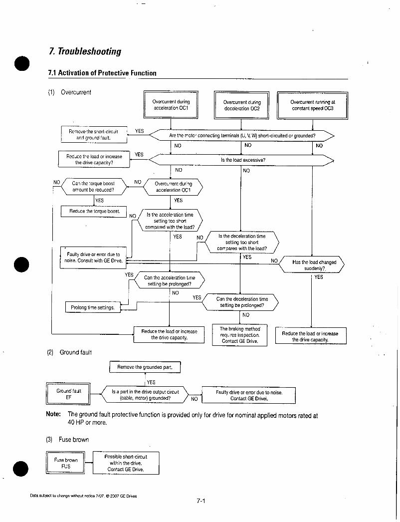
7Troubleshooting
71ActivationofProtectiveFunction
1 Overcurrent
NO
Removetheshortcircuit
andgroundfault
Canthetorqueboostamountbereduced
1YESReducethetorqueboost
Faultydriveorerrordueto InoiseConsultwithGEDrive
2 Groundfault
3 Fusebrown
Fusebrown
FUS
1 YES
Reducetheloadorincrease 1YESthedrivecapacity
NO
Nix
YES
Prolongtimesettings1 1
1
Possibleshortcircuit
withinthedrive
ContactGEDrive
Datasubjecttochangewithoutnotice7072007GEDrives
Overcurrentduringacceleration0C1
ArethemotorconnectingterminalsUVWshortcircuitedorgrounded
1 1 1
1
Removethegroundedpart
NO
Overcurrentduringacceleration0C1
NO NO
1 YES
Cantheaccelerationtime
settingbeprolonged
NO
Istheaccelerationtime
settingtooshortcomparedwiththeload
YES NO
1 Reducetheloadorincrease
thedrivecapacity
YES
71
Overcurrentduringdeceleration0C2
NO
Istheloadexcessive
Isthedecelerationtime
settingtooshortcomparedwiththeload
YES
Canthedecelerationtime
settingbeprolonged
NO
ThebrakingmethodrequiresinspectionContactGEDrive
NO
YES
Groundfault Isapartinthedriveoutputcircuit FaultydriveorerrorduetonoiseEF cablemotorgrounded NO1 ContactGEDrivei
Overcurrentrunningatconstantspeed0C3
NO
Hastheloadchangedsuddenly
YES
Reducetheloadorincrease
thedrivecapacity
Note Thegroundfaultprotectivefunctionisprovidedonlyfordrivefornominalappliedmotorsratedat40HPormore

4Overvoltage
Reducethesupplyvoltagetolessthanthespecifiedupperlimit
FaultydriveorerrorduetonoiseContact
GEDrive
5Lowvoltage
LowvoltageLU
C
CIsthepowersupply
voltagewithinthespecifiedvalue
OvervoltageduringaccelerationOU1
NO
NO
YES
1 NO
1 YES
DoesOUalarmactivatewhenaccelerationis
completed
1 YES
Canthedecelerationtimebeprolonged
YES
Reducel
INO
Isthepowersupplyvoltagewithinthespecifiedvalue
NO
YES
DoesOUactivatewhentheloadissuddenlyremoved
Hasamomentarypowerfailureoccurred
Faultypartsorlooseconnectioninthepower
circuit
OvervoltageduringdecelerationOU2
1 NO
DoesthemaincircuitDClinkvoltage
exceedtheprotectionlevel
YES
Cantheamountofloadinertiabereduced
IsthebrakingdeviceorDCbrakefunctioninuse
InspectthebrakingmethodContactGEDrive
Istherealoadrequiringalargestartingcurrentwithinthesamepower
distributiongroup
Modifypowerdistributionsystemtosatisfythespecifiedvalue
72
IYES
NO
YES
NO
YES
Cantheacceleration
YEStimebeprolonged
NO
Resetandrestart
operation
Replacethefaultypartandrepairtheconnection
DoesLUactivatewhen
thecircuitbreakeror
magneticcontactorisswitchedon
OvervoltacerunningatconstantspeedOU3
Ispowertransformercapacityadequate
YES
YESINO
YES
Prolong
NO
YES
ConsiderusingabrakingsystemorDC
brakefunction
Faultydrivecontrolcircuitorerrorduetonoiseetc
ContactGEDrive
IsthemaincircuitDCvoltagebetweenPNhigherthanthe
detectionlevelspecifiedinSection611
1Thedrivemaybefaulty
ContactGEDrive
Datasubjecttochangewithoutnotice7072007GEDrives

6Overheatinginternallyandoverheating 7 Externalthermalrelaytrippedofheatsink
OvertemperatureatinsideairOH3
Checkthetemperatureoftheheatsinkusingthealarm
informationdisplayedonthekeypadpanel
Doestheheatsink
temperatureindicate50Corlower
1
1NO
OverheatingatheatsinkOH1
1
YES
IstheloadexcessiveYES
1 NO
Isthecoolingfanrotating
1YESIsthecoolingair
passageblocked
1NOfstheambient YES
temperaturewithinthespecification
1NOArrangeperipheral
conditionstomeetthe
specification
NO
Datasubjecttochangewithoutnotice7072007GEDrives
YESi1
8 Driveoverloadandmotoroverload
Driveoverload Motoroverload
OLU OL1OL2
Dothecharacteristicsofthe
electronicthermal0Lrelayandmotoroverloadmatch
IVESIstheelectronicthermal0L NO
relaysettingcorrect
IYEsIstheloadexcessive
NO
1YESReducetheloador
increasedrivecapacity
Ilncreaseambient
temperature
YES
Istheambient NO
temperature10Corlower
ReducetheloadI
Replacethecoolingfan
Removeobstacles
FaultydriveorerrorduetonoiseetcContactGEDrive
Connectathermal0L
relayexternally
Settothecorrectlevel
FaultydriveorerrorduetonoiseetcContactGEDrive
73
ExternalthermalrelaytrippedOH2
NO IsPTCMODE
H26enabled
YES
IsPTCoperatingYES 1
NO
IsPTClevelH27set
correctly
1YESIstheexternalcircuit
includingconstantsregular
YES
FaultydriveorerrorduetonoiseetcContactGEDrive
1
NO 1
NO
IsdatainputtothecontrolterminalsTHRX1toX9 NOArealarmsignalsfrom
externalequipmentinputtotheterminalsandtheCM
1YES
Isthealarmfunctionof NOtheexternalequipment
operatingcorrectly
IYESFaultydriveorerrorduetonoiseetcContactGEDrive
Incorrectmotorloador
inadequatecoolingCheckthemotorside
Settocorrectvalue
Changetoregularexternalcircuit
Connectthealarm
Isignalcontact
Removethecause
ofalarmfunction
activation

9 MemoryerrorEr1KeypadpanelcommunicationerrorEr2CPUerrorEr3
Eri23indicatedAbnormal
displayorindicationgoesout
TurnthepoweroffthenonagainaftertheCHARGElamp
CRGgoesoff
Isdatadisplayedonthe N
LEDmonitorcorrectly
IYESDriveisnormal
Continueoperation
11InputPhaseLoss
InputphaselossLin
NO
FaultydriveorerrorduetonoiseetcContactGEDrive
Areallmaincircuitpowersupply NOterminalsL1RL2SandL3fT
connectedtothepowersupply
YES
Arethereloosescrewson YES
theterminalblock
1NOIsthereasignificantimbalancevoltagebetweenphases
YS
Remedyfaultyparts
NO
AretheconnectorsplugsandICsinsertedcorrectlyIstherenoisegenerating
sourcenearby
YES
DrivemaybefaultyContactGEDrive
Connectallthree
phases
Tightenthescrewsontheterminalblock
FaultydriveorerrorduetonoiseetcContactGEDrive
74
YES
l
10Outputwiringerror
OutputwiringerrorEr7
Didtheerroroccur
duringtuning
Arethebrakingunitand YES
brakingresistorconnectedincorrectly
1
NO
NO
1 NO
NO
Faultydriveorerrorduetonoiseetc
ContactGEDrive
IstheUVWterminalwiringnotYESconnectedoristhereanopen
circuit
1 NO
Thekeypadpanelconnectorisloose
Isconnectionbetween
controlterminalsFWDREVCMenabled
FaultydriveorerrorduetonoiseetcContactGEDrive
YES
YES
Connect
correctlyorreplacethe
cable
Connect
correctlyorreplacethe
cable
Securethe
connector
Disablethe
connection
Datasubjecttochangewithoutnotice7072007GEDrives

72AbnormalMotorRotation
1 Ifmotordoesnotrotate
Removethecauseofalarm
functionactivationandreset
thealarmthenrunthemotor
Ifnoerrorisdetectedcontinueoperation
IYES
Doesthemotorrunif IFWDorREVispressed I
Motordoesnotrotate
1N
PresstheUP
keyandsetthefrequency
IYESDoesthemotorstart
whenthekeyUPispressed
1N
Setthefrequencycorrectly
Faultymotor
JNOExcessiveload
IYES
jIsthetorqueboost YES
setcorrectly
1 NO
IRaisethetorqueboost
YES
Datasubjecttochangewithoutnotice7072007GEDrives
ChargelampCRGlightsandLCDmonioor
lightsup
IYES
IstheLCDmonitor
displayinganalarmmodescreen
INO
Keyadpanel
NO
Isinputmethodfromkeypadpanelorcontrol
terminal
Wastheforwardor
reverseoperationcommandgiven
YESYES
I YES
1
Control
terminals
NO Hasthefrequency NObeenset
YES YES
NO
ArethefrequencylimiterHighandthefrequency
YESsettinglowerthanthe
startingfrequency
1NO
CArethedriveoutput NO
terminalsUVWprovidedwiththepropervoltage
YES Arethecablestothe NOmotorconnected
correctly
ITheloadisexcessiveresultinginmotorlockReducetheloadandcheckthatthebrakeisreleased
ifamechanicalbrakeisused
NO Is externalwiringbetweencontrolcircuitterminalsFWD
REV CMconnectedcorrectly
Istheexternalwiringbetween Icontrolterminals131211
andC1orbetweenX1X9and NO
CMforthemultistepfrequencyselectionconnected
correctly
Arethecircuitbreakerand NOmagneticcontactoronthepower
supplysideswitchedonYES
ArethevoltagesatthepowerterminalsRL1
S12TL3normal
IYES
IsajumperorDCreactor NOconnectedbetweenterminals
P1andP4
IYES
75
1NO
YES
DrivemaybefaultyContactGEFuji
Correctthewiringerror
ReplacethefaultyfrequencysettingPOTVRsignalconverter
I switchorrelaycontactsasrequired
YES
Turnon
Checkforproblemslow
NOvoltageanopenphasealooseconnectionpoor
contactandremedyaccordingly
Connect
DrivemaybefaultyContactGEDrive
Replacethefaultyswitchorrelay
Correctthewiringerror
NoteMonitortheoperationcommandorfrequencysettingvaluesetcontheLEDorLCDmonitorafter
selectingtherespectivefunctions
ThemotordoesnotrotateifthefollowingcommandsareissuedAnoperationcommandisissuedwhilethecoasttostoporDCbrakingcommandisoutputAreverseoperationcommandisissuedwiththeH08Revphasesequencelockvaluesetof1

i
Ifthemotorrotatesbutthespeeddoesnotchange
Changethesetting
YES
Themotorrotatesbutthe
speeddoesnotchange
Pattern
operationIsthetimertiming
YES
toolong
1 NO
Isthepatternoperationcompeted
NO
YESAreallaccelerationanddecelerationtimes
identical
NO
FaultydriveorerrorduetonoiseetcContactGEDrive
Isthemaximum
frequencysetting
toolow
NO
YES Isthehigherorlowerfrequencylimiter
activating
NO
NO Istheaccelerationor
decelerationtimeset
toolong
Whichfrequencysettingmethodsusedkeypadpanel
analogsignalmultistepfrequencyorUPDOWNcontrolIsthepatternoperationactivated
MultistepfrequencyUPDOWN
YES
Increasethesetting
Keypadpaneloperation
Analogsignal
Aretheexternalconnections NOICorrecttheconnectionbetweenX1X9andCM
correct
YES
Arethefrequenciesforeachmultistep
frequencydifferent
YES
YES
Changethetimesettingtoconformtoloadvalues
76
error
NO1ChangethefrequencyI setting
Setthefrequency
iYES
Doesthespeedchangewhen NO
theOForDOWNispressed
Ganthefrequencyflingsignal0to10V
NO
1
se YES
to20mAbechanged
AretheexternalNO connectionsbetween
controlterminals1312
11andC1correct
YES
ReplacethefaultyfrequencysettingPOTVRorsignal
converterasrequired
InthefollowingcaseschangingthemotorspeedisalsorestrictedSignalsareinputfromcontrolterminalsboth12andC1whenF01Frequencycommand1and030
Frequencycommand2aresetto3andthereisnosignificantchangeintheaddedvalueTheloadisexcessiveandthetorquelimitingandcurrentlimitingfunctionsareactivated
Datasubjecttochangewithoutnotice7072007GEDrives
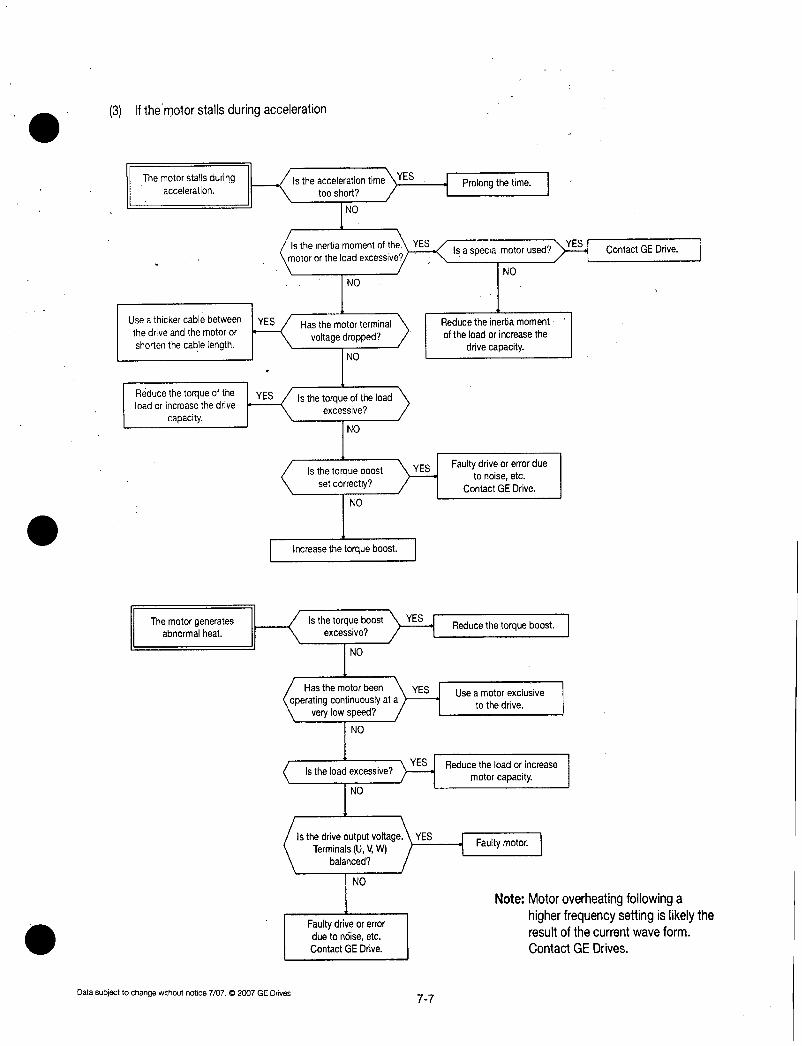
3 Ifthemotorstallsduringacceleration
Themotorstallsduringacceleration
Useathickercablebetween
thedriveandthemotoror
shortenthecablelength
Reducethetorqueoftheloadorincreasethedrive
capacity I
Themotorgenerates Isthetorqueboost YES
abnormalheat excessive
NO
Datasubjecttochangewithoutnotice7072007GEDrives
IstheaccelerationtimeYEStooshort
NO
Istheinertiamomentof the YES
Motorortheload excessiveNO
YES Hasthemotorterminal
voltagedropped
NO
YES Isthetorqueoftheloadexcessive
NO
Isthetorqueboostsetcorrectly
NO
Increasethetorqueboost
NO
Istheloadexcessive
NO
YES
Hasthemotorbeen YES
operatingcontinuouslyataverylowspeed
Isthedriveoutput voltage YES
TerminalsUVWbalanced
NO
FaultydriveorerrorduetonoiseetcContactGEDrive
77
Prolongthetime
IsaspecialmotorusedYESNO
Reducetheinertiamoment
oftheloadorincreasethe
drivecapacity
Faultydriveorerrorduetonoiseetc
ContactGEDrive
Reducethetorqueboost
Useamotorexclusive
tothedrive
YESIReducetheloadorincreasemotorcapacity
Faultymotor
ContactGEDrive
NoteMotoroverheatingfollowingahigherfrequencysettingislikelytheresultofthecurrentwaveform
ContactGEDrives

Notes
78 Datasubjecttochangewithoutnotice7072007GEDrives
8MaintenanceandInspection
ProceedwithdailyinspectionandperiodicinspectiontopreventmalfunctionandensurelongtermreliabilitySometipsregardingthingstolookforduringtheseinspectionsarelistedbelow
81DailyInspectionsDuringoperationavisualinspectionforabnormaloperationcantakeplaceextemallywithoutremovingthecovers
Theinspectionshouldcoverthefollowingareas
1Theperformanceaccordingtostandardspecificationsisasexpected
2Theenvironmentconformstostandardspecifications3Thekeypadpaneldisplayisnormal4Therearenoabnormalsoundsvibrationsorodors5Therearenoindicationsofoverheatingordiscoloration
82PeriodicInspections
Periodicinspectionsshouldbemadeafterstoppingoperationscuttingoffthepowersourceandremovingthesurfacecover
NotethatafterturningoffthepowerthesmoothingcapacitorsintheDCsectionofthemaincircuittaketimetodischargeTopreventelectricshockconfirmwithamultimeterthatthevoltagehasdroppedbelowthesafetyvalue25VDCorbelowafterthechargelampCRGgoesoff
WARNING
Starttheinspectionatleastfiveminutesaftertumingoffthepowersupplyforinvertersratedat30HporlessWaitatleasttenminutesforinvertersratedat40HpormoreCheckthatthechargelampCRGwentoffandthatthevoltageis25VDCorlessbetweenterminalsPandN Electric
shockmayresultOnlyauthorizedpersonnelshouldperformmaintenanceandcomponentreplacementoperationsRemovemetaljewelrysuchaswatchesandringsandalwaysuseinsulatedtoolsNevermodifythedriveElectricshockorinjurymayresult
Datasubjecttochangewithoutnotice7072007GEDrives81

AreatoCheckI ItemstoCheck
Environment 1Checktheambienttemperaturehumidityvibrationatmospheredustgasoilmistwaterdrops
2Istheareasurroundingtheequipmentfreeofforeignobjects
Voltage
Keypadpanel
Structure
frameorcover
UC
Resistor
ControlPC
Eboardand5connector0
00
Coolingfan
E
u
a
c0
0Ventilation
Arethevoltagesinthemaincircuitandthecontrolcircuitnormal
1Isthedisplayhardtoread2Arethecharacterscomplete
1Isthereabnormalsoundorvibration2Arenutsorboltsloose3Istheredeformationordamage4Istherediscolorationasaresultofoverheat
ing5Aretherestainsordust
Common 1Aretherelooseormissingnutsorbolts2Aretheredeformationscracksdamageor
discolorationduetooverheatingordeteriorationintheequipmentandinsulation
3Aretherestainsanddust
Conductors 1Istherediscolorationordistortionofaandwiring conductorduetooverheating
2Aretherecrackscrazingordiscolorationofthecablesheath
Terminalblock I Istheredamage
Smoothing 1Isthereelectrolyteleakagediscolorationcapacitor crazingorswellinginthecase
2Isthesafetyvalvenotprotrudingorarevalvesprotrudingtoofar
3Measurethecapacitanceifnecessary
1Isthereanyunusualodorordamagetotheinsulationbyoverheating
2Isthereanopencircuit
Transformer Isthereabnormalbuzzingoranunpleasantandreactor smell
Magnetic 1Istherearattlingnoiseduringoperationconductor 2Arethecontactsroughandrelay
1Arethereanyloosescrewsorconnectors2Isthereanunusualodorordiscoloration3Aretherecracksdamagedeformationor
excessiverust
4Isthereelectrolyteleakageordamagetothecapacitor
1Isthereabnormalsoundorvibration2Arenutsorboltsloose3Istherediscolorationduetooverheating
Seeadditionalnotesonfollowingpage
Howtoinspect
1Conductavisualinspectionanduseappropriatemeters
2Visualinspection
Measurewithamultimeter
1Visualinspection2Visualinspection
1Visualandauralinspection2Tighten345Visualinspection
1Tighten23Visualinspection
12Visualinspection
IVisualinspection12Visualinspection3Estimatelifeexpectancyfrom
maintenanceinformationandfrorn
measurementsusingcapacitancemeasuringequipment
82
1Visualandolfactoryinspection2Conductavisualinspectionorusea
multimeterbyremovingtheconnectionononeside
Auralolfactoryandvisualinspection
1Auralinspection2Visualandolfactoryinspection3Visualinspection4Estimatelifeexpectancybyvisual
inspectionandmaintenaceinformation
I EvaluationCriteria
1Resultscomplywithallstandardspecifications
2Theareaisclear
Resultscomplywithallstandardspecifications
12Thedisplaycanbeeasilyreadandcharactersarenormal
12345Noabnormalities
123NoabnormalitiesNoteDiscolorationofthe
busbardoesnot
indicateaproblem
12Noabnormalities
INoabnormalities12Noabnormalities3Capacitanceiswithin
85ofinitialvalue
12
Noabnormalities
Lessthanabout10
oftheindicatedresistancevalue
Noabnormalities
1Auralinspection 12Noabnormalities2Visualinpection
1234Noabnormalities
1AuralandvisualinspectionTurr 1Thefanmustrotatemanuallyconfirmthepoewrisoff smoothly
2Tighten 23Noabnormalities3Visualinspection4Estimatelifeexpectancybymainte
nanceinformation
Isthereforeignmatterontheheatsinkorintake Visualinspection Noabnormalities
andexhaustports
Datasubjecttochangewithoutnotice7072007GEDrives

NoteIfequipmentisstainedwipewithacleanclothUseavacuumtoremovedustEstimateoflifeexpectancybasedonmaintenanceinformation
ThemaintenanceinformationisstoredinthedrivekeypadpanelItindicatestheelectrostaticcapacitanceofthemaincircuitcapacitorsandthelifeexpectancyoftheelectrolyticcapacitorsonthecontrolPCboardandthecoolingfansUsethisdataasthebasistoestimatethelifeexpectancyofparts
1Determiningthecapacitanceofthemaincircuitcapacitors
ThisdriveisequippedwithafunctiontoautomaticallyindicatethecapacitanceofthecapacitorsinstalledinthemaincircuitwhenpoweringupthedriveafterdisconnectingthepoweraccordingtotheprescribedconditionsTheinitialcapacitancevaluesaresetinthedrivewhenshippedfromthefactoryandthedecreaseratio tothose
valuescanbedisplayedUsethisfunctionasfollows
1RemoveanyoptionboardsfromtheinverterDisconnecttheDCbusconnectionstothemaincircuitTerminalsPandNfromthebrakingunitorotherinvertersifconnectedThepowerfactorcorrectingreactorDCreactordoesnotneedbedisconnectedApowersupplyintroducedtotheauxiliaryinputTerminalsROTOthatprovidescontrolpowershouldbeisolated
2DisableallthedigitalinputsFWDREVX1X9onthecontrolterminalsAlsodisconnectRS485serialcommunicationifused
TurnonthemainpowersupplyConfirmthatthecoolingfanisrotatingandthattheinverterisnotoperatingThereisnoproblemiftheOH2Externalthermalrelaytrippedfunctionisactivatedbythedigitalinputterminal
3Turnthemainpoweroff4Turnonthemainpoweragainafterverifyingthatthechargelampiscompletelyoff5Openthemaintenanceinformationonthekeypadpanelandconfirmthecapacitancevaluesofthe
builtincapacitors
2 LifeexpectancyofthePCcontrolboardTheactualcapacitanceofacapacitorisnotmeasuredinthiscaseHowevertheintegratedoperatinghoursforthecontrolpowersupplymultipliedbythelifeexpectancycoefficientasdefinedbythetemperatureinsidetheinverterwillbedisplayedHencethehoursdisplayedmaynotagreewiththeactualoperatinghoursdependingontheoperationalenvironmentSincetheintegratedhoursarecountedinunithourspowerinputforlessthanonehourwillbedisregarded
3 LifeexpectancyofcoolingfanTheintegratedoperatinghoursofthecoolingfanaredisplayedSincetheintegratedhoursarecountedinunithourspowerinputforlessthanonehourwillbedisregardedThedisplayedvalueshouldbeconsideredaroughestimatebecausetheactuallifeofacoolingfanisinfluencedsignificantlybythetemperature
Table82Roughestimateoflifeexpectancyusingmaintenanceinformation
Parts 1 RecommendedLevel
Capacitorinmaincircuit 185orlessoftheinitialvalue
ElectrolyticcapacitoroncontrolPCboard 161000hours
Coolingfan 140000hours5Hporless25000hoursOver75Hp
Estimatedlifeexpectancyofaventilationfanatinverterambienttemperatureof40C
Datasubjecttochangewithoutnotice707C2007GEDnves 83

83MainCircuitMeasurements
TheindicatedvaluesdependonthetypeofmeterbecausetheharmoniccomponentisincludedinthevoltageandcurrentofthemaincircuitpowerinputandtheoutputmotorsideoftheinverterIfmeasuringwithameterforcommercialpowerfrequencyuseusethemetersshowninTable831
ThepowerfactorcannotbemeasuredusingpowerfactormeterscurrentlyavailableonthemarketwhichmeasurethephasedifferencebetweenvoltageandcurrentIfpowerfactorsmustbemeasuredmeasurethepowervoltageandcurrentontheinputsideandoutputsidethencalculatethepowerfactorusingthefollowingformula
Table83 MetersforMeasuringMainCircuit
Item
Symbol
Power
supply
PowerWPowerfactor x100
3xVoltageVxCurrentA
InputpowersupplySide OutputmotorSide DCLinkCircuit
VoltageP N
Voltage nCurrentnnn
Metername Ammeter Voltmeter Powermeter Ammeter Voltmeter Powermeter DCVoltmeter
ARST VRST WRST AUVW VUVW WUVW V
Metertype Movingiron Rectifieror Digital Movingiron Rectifier Digitalpower Movingcoiltype
type movingironpowermeter type type meter
tvoe
NoteIftheoutputvoltageismeasuredwitharectifiertypemeteranerrormayoccurUSEadigitalACpowermetertoensureaccuracy
84
Voltage Current
Motor
Datasubjecttochangewithoutnotice7072007GEDrives

84InsulationTest
AvoidmeggertestingonandrivesinceaninsulationtestwascompletedatthefactoryIfameggertest mustbecom
pletedproceedasdescribedbelowIncorrecttestingmethodsmayresultinproductdamageIfthespecificationsforthedielectricstrengthtestarenotfollowedthedrivemaybedamagedIfadielectricstrength test
mustbecompletedcontactyourlocaldistributorornearestFujiElectricsalesoffice
1Meggertestforthemaincircuit1 Usea500VDCmeggerandisolatethemainpowerbeforestartingmeasurement2 Ifthetestvoltageisconnectedtothecontrolcircuitremoveallconnectioncablestothecontrolcircuit3 ConnectthemaincircuitterminalsusingcommoncablesasshowninFig8414 Performthemeggertestonlybetweenthecommoncablesconnectedtothemaincircuitandground
Terminal05 Ameggerindicating5MOhmormoreisnormalThisisthevaluemeasuredwithonlythedriveconnected
Megger
G
L1RL2SL3TDB P1P4N U
Fig841Meggertest
2Insulationtestinthecontrolcircuit
MeggeranddielectricstrengthtestsarenotperformedonthecontrolcircuitUsearesistancemultimeter withahighresistancerangetocheckthecontrolcircuit
1 Removeallexternalcablesfromthecontrolcircuitterminals2 ConductacontinuitytestbetweengroundsAresultof1MOhmormoreisnormal
3ExteriormaincircuitandsequencecontrolcircuitRemoveallcablesfromdriveterminalstoensurethattestvoltageisnotappliedtothedrive
85ReplacementPartsThelifeexpectancyofapartdependsonthetypeofparttheenvironmentandoperatingconditionsPartsshouldbereplacedasshowninTable851
Table851Partreplacement
Partname
Coolingfan
Smoothingcapacitor
ElectrlyticcapacitoronthePCboard
Fuse
Otherparts
Datasubjecttochangewithoutnotice7072007GEDrives
Standardperiodforreplacement
3years
5years
7years
10years
Comments
Exchangeforanewpart
ExchangeforanewpartdetermineaftercheckingExchangeforanewPCboarddetermineafterchecking
Exchangeforanewpart
Determineafterchecking
85

Notes
86Datasubjecttochangewithoutnotice70702007GEDrives

9WarrantyPartsandService
Thepurposeofthissectionistoprovidespecificinstructionstotheuserofthestandarddrivereferenced
inthisbookregardingwarrantyadministrationandhowtoobtainassistanceonbothinwarrantyandoutofwarrantyequipment
Forallwarrantyproceduresrefertosection10ofthisinstructionmanualtoidentifythepartorassembly
Ifassistanceisrequiredtodeterminewarrantystatusidentifydefectivepartsorobtainthenameofyourlocaldistributorcall
GEIndustrialSystemsProductServiceEngineering1501RoanokeBlvd
SalemVA241536492USAPhone18005335885UnitedStates
15403783280InternationalFax 15403878606All
indicatestheinternationalaccesscoderequiredwhencallingfromoutsideoftheUSA
Datasubjecttochangewithoutnotice7072007GEDrives 91
WARRANTYCOVERAGE
ThewarrantycoversallmajorpartsofthedrivesuchasthemainprintedcircuitboardstransistormodulesetcThewarrantydoesnotcoverreplacementoffusesoroftheentiredrive
Warrantyperiodis12monthsafterinstallationor18monthsaftershipmentfromtheCompanywhicheveroccursfirst
Howevertheguaranteewillnotapplyinfollowingcaseseveniftheguaranteetermhasnotexpired
1 Damagewascausedbyincorrectuseorinappropriaterepairormodification
2 Theproductwasusedinanenvironmentoutsidethestandardspecifiedrange
3 Damagewascausedbydroppingtheproductafterpurchaseoroccurredduringtransportation
4 Damagewascausedbyanearthquakefirefloodinglightningabnormalvoltageorothernaturalcalamitiesandsecondarydisasters
BeforecallingthenumberatlefttodeterminewarrantystatusthedriveserialnumberwillberequiredThisislocatedonthedrivenameplateIfthedriveisstillunderwarrantyfurtherinformationwillberequiredpertheInWarrantyFailureChecklistshownonpage92ofthisinstructionmanual
OUTOFWARRANTYPROCEDURES
WhenthedefectiveparthasbeenidentifiedcontactyourlocalauthorizedGEstandarddrivesdistributortoorder
replacementparts
MOTORS
MotorrepairsonGeneralElectricmotorsaregenerallyhandledbyGEAuthorizedElectricMotorServicentersorGEApparatusServiceShopsForspecificinstructionsonyourmotorcallthedistributorfromwhichitwaspurchasedandbepreparedtofurnishcompletenameplatedata

INWARRANTYFAILURECHECKLIST
ToassistwithwarrantytroubleshootingthefollowinginformationisrequiredThisdataisneededtoevaluatethecauseinanefforttoeliminateanyfurtherfailures
ModelNo
SerialNo
StartUpDateFailureDate
StatusWhenFailureOccurredcheckonePowerUp Running Accel Decel
ExplanationofFailure
ApplicationInformationcheckYesorNoInputTransformer Yes No
IfYes KVA
L1Volts L2Volts L3Volts
PowerFactorCorrectionCapacitors Yes No
IfYesMicrofarrad
OtherEquipmentonSamePower Yes No
IfYeswhat
LineReactoronInput Yes No
InputStarter Yes No
OutputStarter Yes No
MotorOverloads Yes No
ControlTerminalsUsedcircleifused
co
co U
CO
0 CO
M
UCC C
U M X X X X X X X XLL
r N
U Uu
W
FunctionCodesDifferentFromFactorySettingsFunctionCode Setting FunctionCode Setting
FailureMessageseeSection4LatestFault PreviousFaults
Hz 1
A 2
V 3
AfteralloftheChecklistinformationisacquiredcontactthefollowingnumberforassistance8005335885WhenreturningfailedpartsreferencetheC ontheshippingdocumentsthatcamewiththereplacementpartsandshipfailedpartstoGEDrives
MarkedC
92
NoMessag
Cl CL c c CO
Datasubjecttochangewithoutnotice7072007GEDrives

10AF300P11ReplacementParts
CatalogNo Rating DriveHP Quantityperdrive141121 112131
AF300P11230VAC30HPandBelowMainControlCard
G11CPCBB1 1 1 1 1 1
GateDriver PowerSupplyCardG11PPCBG2002 1
G11PPCBG2004 1
G11PPCBG2008 1
G11PPCBG2015 1
G11PPCBG2022 1
G11PPCBG2037 1
G11PPCBG2055
G11PPCBG2075
G11PPCBG2110
611PPCBG2150
611PPCBG2185
KEYPADPANELOnlyonetypeperdriveTPAG11S NEMATyoe1 1 1 1 1 1 1
TPAG11S4 NEMAType4 1 1 1 1 1 1
CAPACITORUNIT
G11CAP01 PCB 1
G11CAP02 PCB 1
G11CAP03 PCB 1
G11CAP09 2700uFx1G11CAP10 3900uFx1G11CAP11 4700jFx2
LocatedonGatedrive PowersupplyCardFAN
G11FANO1
611FAN202
POWERMODULE
PS11046
PS11047
6MBP75RS060
6MBP100RS060
6MBP15ORS060
6MBP200RS060
RECTIFIERMODU
PVC758
CLK120AA80
CLK180AA80
FRONTCOVER
G11UPCG008P
G11UPCGO4OP
611UPCG075P
GIIUPCG220P
E
75A800V
120A800V
180A800V
Datasubjecttochangewithoutnotice7072007GEDrives
1
30A600V 1 1
50A600V
75A600V
100A600V
150A600V
200A600V
LocatedonGatedrive PowersupplyCardi
LocatedonGatedrive PowersupplyCardCHARGERESISTOR I30W66 I30W66WJ I I80W25 I80W25WJ 1
LocatedonGatedrive PowersupplyCard
1 11 11 11 1 II 1 1 111 111 1 1 1 1 11 1 1 1 1 1
101
5175110I15120125130
1 1 1 1 1 1 1
1
1
11
1
1
1
1
1
1
1
1
1
1
1
1
1
1
I1
1
1
1
1
1
2
2
1
1
1
1
1
1 1
1 1
2
2
1
1
1
11I I
11111
2
2
1
1
1

10AF300P11ReplacementPartscontinuedCatalogNo
AF300P11230VAC40HPandAboveMainControlCard
EP4113B1
GateDriver PowerSupplyCardEP3956C1
EP3956C2
EP3956C3
EP3957C1
EP3957C2
KEYPADPANEL
TPAG11S4
DCCAPACITOR
LNT2G302MSMAFF
HCGHA2G362N3K
HCGHA2G452NE3K
HCGHA2G592N3K
FAN
FBA09A24H1B0
Standard4715PS22TB30
2750MTP15
6250MG1
ForNEMAl2HeatsinkUHS4556MLOT1
2750MTP15OT1
U6250MKG1LTPOT1
IGBTMODULE
2MBi300NB060
CM400OU12H206
2MBi300NB06001
RECTIFIERMODULE
P01008AC
CHARGERESISTOR
HF5C5504
DCCONTACTOR
FC3UL
FC1UL
FC4UL
SC7NUL
DCFUSE
CR2L260UL
CR2L400UL
A50P6004
INPUTMODULECARD
EP3985C1
EP3985C3
Rating
400V3000uF400V3600uF
400V4500iF
400V5900uf
80W75ohm
AC220VAUX2B
AC220VAUX2B
AC220VAUX2B
AC200240V
DriveHP Quantityperdrive
40150160175110011251150
102
4 4
2 2
2
3
1
1
2
3
1
1
1
1
1
4
1
2
2
3
6
1
2
1
1
1
1
1
4
2
2
2
6
6
1
1
1
1
4
2
2
2
6
9
1
2 2
5 6
2 4
3 4
3
9
9
2
2
4
12
9
2
1
DatasubjecttoFlangewithoutnotice7072007GEDrives

10AF300P11ReplacementPartscontinuedCatalogNo Rating DriveHP Quantityperdrive
1121 1121315175110115120125130
AF300P11460VAC30HPandBelowMainControlCard
G11CPCBB1 I 1
GateDriver PowerSupplyCardG11PPCBG4004 1
G11PPCBG4008
611PPCBG4015
G11PPCBG4022
611PPCBG4037
611PPCBG4055
G11PPCBG4075
G11PPCBG4110
611PPCBG4150
611PPCBG4185
KEYPADPANELOnlyonetypeperdriveTPAG11S NEMATvpe1 1
TPAG11S4 NEMATvpe4 1
CAPACITORUNIT
G11CAPO4
G11CAP05
G11CAP06
G11CAP07
G11CAP08
G11CAP09
G11CAP10
G11CAP11
FAN
G11FANO1
GIIFANO2
POWERMODULE
PS12046
PS12047
6MBP5ORS120
6MBP75RS120
6MBP100RS120
RECTIFIERMODULE
PVC7516
CLK7OAA160
CLK100AA160
CHARGERESISTOR
30W200
80W100
FRONTCOVER
611UPCG008P
611UPCGO4OP
611UPCG075P
G11UPCG220P
datasubjecttochangewithoutnotice7072007GEDrives
PCB 1
PCB 1
PCB 1
1500uFx22000uFx2
2700pFx23900uFx2
4700uFx2
LocatedonGatedrive PowersuoplyCard
t
1
1
1
1
1
1
1
15A1200V 1
25A1200V
50A1200V
75A1200V
100A1200V
LocatedonGatedrive PowersupplyCardi
75A1600V 1 I
70A1600V I I100A1600V 1 I
LocatedonGatedrive PowersupplyCard1 1 1
30W20WJ I 1 I80W10WJ I 1 1
LocatedonGatedrive PowersuoplyCard
11111 1 1 I1 1 1 11 1 11
1 I I I I
103
1
2
1
1
1
1
111
1
2
1
1
1
1
11
1
2
1
1
1
1
111
2
2
1
1
1
2
2
1
1
1
2
2
1
1
1
I II I1 1
11111

AFP11ReplacementPartscontinuedCatalogNo Rating DriveHP Quantityperdrive
1401501601751100112511501200125013001350140014501500160017001800
AF300P11460VAC40HPandAboveMainControlCard
EP4113B1 1 111111111111111111111111111111111
GateDriver PowerSupplyCardEP3959C1 1 11 1EP3959C2 11 1 1EP3959C3 1 1 1 1 IEP3959C4 1 1
EP3959C5 111EP3957C3 1 1 1 1
EP3957C4 1 I 1 1 1 1
EP3957C5 1 1 1 1 1 1 1
GATEDRIVEAMPLIFIERCARD
EP4142 1 1 1 1 1 1 1 1 1 I I 1 1 1 13131313
KEYPADPANEL
TPAG11S4 1111111111111111111111111111111111
DCCAPACITOR
LNT2G302MSMAFF
HCGHA2G362N3K
HCGHA2G452NE3K
HCGHA2G592N3K
HCGHA2G742N3K
HCGHA2G932N3KG
400V3000uF
400V3600uF400V4500uF
400V59000f
400V74000F
400V9300uF
4 4114
4
4
104
4
6
6 8
8
12
12 12
20 20 26 26
FANUNIT
FBA09A24H1B0 111111111112I212131314I4I414141 1MRS18OUL 1 1 1 I I I I I I I I 1 I 13131414THB1UHS4556M I I I I I I I I I 1 I I I I 1 1414Standard4715PS22TB30 12121 1 1 1 1 1 1 1 1 1 I 1 12750MTP15 1 1 12121 1 13131 1 1 1 1 1 1 16250MG1 1 I 1 1 12121 1 13131414141 1orNEMAl2HeatsinkUHS4556MLOT1 1 12121 I 1 1 1 1 1 1 I 1 I 1 1 12750MTP150T1 1 1 I 12121 1 13131 1 1 1 I I 1 1U6250MKG1LTPOT1I I I I I 1212I 1 13131414141 1 1
IGBTMODULE
2MBi150PC14002 13131 I 1 1 I 1 I I 1 1 1 1 1 1CM200DU24H2O3 1 I 131 1 1 I 1 1 I 1 1 I 1 1 12MBi300P14002 1 I I 13131 1 1 1 1 1 1 1 1 1 1CM200DU24H2O2 1 1 1 I 1 16 I 1 1 1 1 1 1 1 12MBi300P14003 1 I I 1 I 1 16161919112112112118118124124
REC7 MODULE
PD6016A 1 31313I 1 1 1 1 1121121 1 1 1 1 1PD10016A I I 1 1 13131616161 1 112112112124124130130
Datasubjecttohangewithoutnotice70702007GEOnves

10AF300P11ReplacementPartscontinued
CatalogNo
AF300P11460VAC40HPandAbove
DCCONTACTOR
FC1UL
FC4UL
SC7NUL
SC8NUL
SCN8
DCFUSE
CR6L15OUL
CR6L2000L
CR6L3000L
A70Q4004
A70Q5004
A7006004
A70QS8004
A70P16004TA
A70P20004
Datasubjecttochangewithoutnotice7072007GEDrives
Rating DriveHP Quantityperdrive401501601751100112511501200125013001350140014501500160017001800
IGBTMODULE
2MBi150PC14002 1 13131 1 1 1 1 1 1 1 1 1 1 1 I 1CM200DU24H203 1 I 1 131 1 1 I 1 1 I I I I 1 1 12MBi300p14002 1 1 1 13131 1 1 1 1 1 1 1 I 1CM200DU24H202 1 1 1 1 1 16 1 1 1 1 I 1 1 I 12MBi300P14003 1 1 1 1 1 16161919112112112118118124124
RECTIFIERMODULE
PD6016A 1 1313131 1 1 1 1 1121121 1 1 1 1 1PD10016A 1 1 1 1 13131616161 1 112112112124124130130
CHARGERESISTOR
HF5C5504 180W75ohm11 11111111112121213131GRZG400 1 1 1 1 1 1 1 I 1 1 1 1
AC220VAUX2B1111111111121212AC220VAUX2B 1 1 I 1 I 1 I
AC200240V1 1 1 1 1 1 1 1AC200240V1 1 1 1 1 1 1 1AC200240V
600V150A
600V200A
600V300A
1 1 1
1
1
105
1
1 1
212
1
1
1
1
4141 1 11 121212 2
111
1 1
2121212
1
1
TRANSFORMER
HF5C55025512VA 11111 1 1 1 1 1 1 1 1 1 1 1 I 1HF5C550312524VA 1 1 1111I1111 1 1 1 1 1 1 1 1 1HF5B661330016VA 1 1 I 1 1 I 111111111111 11 1 1HF5B395170020VA I 1 1 1 I I 1 1 1 1 1 1 1 11111111
INPUTMODULECARD
EP3985C2 1 1 1111111 1 1 1 1 1 1 I 1 1 1EP3985C4 1 1 1 1 1 1 1 1 1 1111111111I1111111

Notes
106Datasubjecttochangewithoutnotice70702007GEDrives

Threephase230VseriesTypedesignation
6KP1123X1NEMAType16KP1123 X2NEMAType126KP1123 X4NEMAType4 F25 F50 001 002 003 005 007 010 015 020 025 030 040 050 060 075 100 125 150
6KP1123 X8OpenType12Heatsink6KP1123 X9Open
IndicatesproductrevisionNominal230Vsystemappliedmotor HP114112 2 3 5 75 10 15I20I25 301140 50 60 75 100 125 150
Output RatedCapacity11 kVA1059I11I19 31 43 67 87I 11 16I21I26 31II45 57171I85 112 137 165ratings RatedVoltage2 V13phase200V50Hz 200V2z0V230V60Hz
RatedCurrent3 A115I30150180I11 I17I 221291 42I 55I67I 78111151145I180I215I283I346I415OverloadCapability 110ofratedcurrentforlmin IIRatedFrequency Hzj 5060Hz
Input PhasesVoltageFrequency phase200to230V5060Hz II3phase200to220V50Hz200to230V60Hzrating Voltagefrequencyvariations IVoltage10to15Voltageunbalance52orless Frequency5to5
Momentaryvoltagedip Whentheinputvoltageis165Vormoretheinvertercanbeoperatedcontinuouslycapability6 IftheACLinevoltageisbelowratedthedrivewillnotprovidethe15msridethru
ThesmoothrecoverymethodisselectableOutput 1MaximumFreq 150to120Hzfrequency IBaseFreq f25to120Hz
SettingI
StartingFreq 1to60HzContinuoustime00to100sCarrierFreq8 1075to15kHz Theminimumcarrierfrequencychancesdependonmaximumoutputfrequency 1075tolokHz 1075to6kHz
AccuracyStability Analogsetting 02ofMaximumfrequencylet25x10degreesCDigitalsetting m001ofMaximumfrequencyat10to50degreesC
Settingresolution Analogsetting 13000ofMaximumfrequencyex002Hzat60Hz004Hzat120HzDigitalsetting 0O1HzatMaximumfrequencyofupto9999Hz01HzatMaximumfrequencyof100Hzandabove
Linksetting Twomethodsareselectable
120000ofMaximumfrequencyex0003Hzat60Hz001Hzat400Hz001HzFixed
Control VoltFreqCharacteristic 180to240VwithAVRcontrolatbaseandmaximumfrequencyadjustableTorqueboost Constanttorqueload Variabletorqueload
Automaticsettingcode 00
Manualsettingcode 20to200 01to19
NEMATypelType4 INEMATypelTypel2 II OpenOpenwithNEMAType12HeatsmkNEMA11 Natural I Fancooling
UUcUL LOWVOLTAGEdirective EMCdirective
IEC618002RatingspecificationsforlowvoltageadjustablefrequencyacpowerdrivesystemsIEC6180031EMCproductstandardincludingspecifictestmethodsI
Enclosure
Coolingmethodr
Standards
NOTES
1InverteroutputcapacitykVAat230V
21Outputvoltageisproportionaltothepowersupplyvoltageandcantexceedthepowersupplyvoltage3Currentderatingmayberequiredincaseoflowimpedanceloadsuchashighfrequencymotor5ReferencetotheIEC6180035231
UnbalanceinpowersupplyvoltageII
185load
811carrierfrequencyissetatmorethan10kHzandanoverheatconditiondetectedbyInternalthermalsensoroccursdrivewillautomaticallyreducecarrierfrequencyto8kHzinordertoavoidtripAvailableupto30HPunit
MaximumvohagelvlMinimumvoltageVII3phaseaveragingvoltageVI
X67II
Cl
mie

Threephase460Vseries
Typedesignation6KP1143X4NEMATypal6KPt143X2NEMAType126KP1143 X4NEMAType46KP1143X8OpenType12Heatsink6KP1143 X9Open
Nominal460VsystemappliedmotorRatedCapacity1RatedVoltage21RatedCurrent3
OvedoadCapability
RatedFrequencyPhasesVoltageFrequency
Inputratings
Outputfrequency
Enclosure
CoolingmethodStandards
Voltagefrequencvvariations
Momentaryvoltagedipcapability6
IMaximumFreq
BaseFreq
SettingIStartingFreqCarrierReg8
AccuracyStability
Settingresolution
Control V06FreqChamctenstic
Torqueboost
e51ReferencetotheIEC616063523
Inputvoltane
400to4400511110440to480060Hz380V50Ha3980orsmeller
380to41506004300orsmeller
U1enosNweersupplyvogege
F50 002 003 005 007 010 015 020 025 030
HP12I1I2 3 5I75 10I15kVA111119129143 711991131 183
V13phase360040004150500z380040064400460060HzAl15125137155190I1251165123
1110orratedcurrentforlminHz150007Iz
I3phase360004800506040
1Voltage410to15IVoltageunbalance512orlessWhenMeinputvoltageis310VormoretheinvertercanbeoperatedcontinuouslyIftheACtinevoltageisbelowratedthedrivewillnotprovidethe15msridethru
Thesmoothrecoverymethodisselectable150to1209z125to120X0101to60HzContinuoustime00tol00s
NOTES
IInverteroutputcapacityIHVAIat460V2Outputvoltageisproportionaltothepowersupplyvoltageandcantexceedthepowersupplyvoltage31Currentderatingmayberequiredincaseoflowimpedanceleadsuchashighfrequencymotor4Changethetapofauxiliarytransformer
380V50Hzand380to410060HzChangeoverCNUXconnectorfromU1parttoU2pertReferencetotheInstructionmanual
20 25 301140 501601751239 I 294 350IL47 I 59L721891
301 1441160 751ul1112111110ofratedcurrentfor1min
I075to15kHz 075to10kHz
Theminimumcarrierfrequencychangesdependonmaximumoutputfrequency IIAnalog setting o02ofMaximumfrequencyfat25010degreesC
Digitalsetting x001ofMaximumfrequency4010to050degreesCAnalogsetting 13000ofMaxfrequency00100211zat60Hz004Hzat120HzDigitalsetting 00100atMaximumfrequencyofupto9999H10140atMaximumfrequencyof10000andaboveLinksetting Twomethodsareselectable
120000ofMaximumfrequencyex0003Hzat60Hz001Hzat40011z00111Fixed
1320to4600IwdhAVRcontrolatbaseandmaximumfrequencyadjustableConstanttoruqueload Variabletorqueload
Automaticsettingcode 00
Manualsettingcode 20to200
1 NEMATypelType1 Natural1
UIlcUL LOWVOLTAGEdirective EMCdirective
IEC618002Ratingspecificationsforlowvoltageadjustablefrequencye0powerdrivesystemsIIEC6180031EMCproductstandardincludingspecifictestmethods1
llCNUXconnector
UlFectarysemng
U2
MaximumvohageIV1MinimrevoltWW13phasemeragin4vottage0
Otto19
NEMATypalType1211 OpenOpenwithNEMAType12HeatsinkNEMAType1Fancooling
X671141
85load
111carrierfrequency030031morethan10kHzandanoverheatconditiondetectedbyinternalthermalsensor1occursdrivewilleutomaticallyto86HzinordertoavoidtripAvailableupto3011Punttl
040 950 060 075 100 125 150 200 250 300 350 400 450 500 600 700 800
3phase380to44005007380to48006000380050Hzand380t0415V60Hz4
10011251150 200 2501300i35014001450150016001700 800
1191140 167 24212421300133013961414157815901669 765
150I176j2101304j30413771415I48515201656L7401840I960
075to6kH0
Frequency45to5
0
s

112CommonSpecifications
0L
0
Outputfrequency
Item
ControlMethod
Maximum
freauencvBase
freauencv
StartingfreauencvCarrier
freauencv
Accuracystability
Settingresolution
VoltagefrequencyCharacteristics
TorqueBoost
Acceleratingdeceleratingtime
DCinjectionbraking
Functionequipped
Operationmethod
Frequencysetting
Operationstatussignal
Datasubjecttochangewithoutnotice7072007GEDrives
Exolanation
SinusoidalwavePWMcontrolwithVFcontroltorquevectorcontrolPGfeedbackvectorcontroloption50to120Hzvariablesetting
25to120Hzvariablesetting
01to60HzvariablesettingHoldingtime00to100s
075to15kHz30HPorTess075to10kHz40100HP075to6kHz125HPormore
Analogsetting 02orlessofthemaxfrequencyat25 10C
DigitalSetting 001 orlessofthemaxfrequency10to50C
Analogsetting13000ofmaxfrequencyeg002Hz60Hz005Hz150HzDigitalsetting001Hz9999Hzorless01Hz1000Hzormore
Outputvoltageatbasefrequencycanbeadjustedseparatelysuchas80to240V200Vseriesor320to480V400Vseries
AutoOptimumcontrolcorrespondingtotheloadtorqueManual01to200codesettingenergysavingsreducedtorauetoconstanttorquestrongetc001to3600s
Fouracceleratinganddeceleratingtimesettingsarepossibleindependentofeachotherbyselectingdigitalinputsignals
InadditiontolinearaccelerationanddecelerationeitherSshapedaccelerationdecelerationweakstrongorcurvilinearaccelerationdecelerationcanbeselected
Startingfrequency00to60Hzbrakingtime00to300sBrakinglevels0to80Frequencyupperandlowerlimiterbiasfrequencyfrequencygainjumpfrequencypickupoperationrestartaftermomentarypowerfailureswitchingoperationfromlinetodriveslipcompensationcontrolautomaticenergysavingoperationregenerationavoidingcontroldroopcontroltorquelimiting2strptorquecontrolPIDcontrolsecondmotorswitchingcoolingfanONOFFcontrol
KeypadpanelRunbyFWDREVkeysstopbySTOPkeyTerminalinputForwardStopcommandReverseStopcommandCoasttoStopcommandAlarmresetaccelerationdecelerationselectionmultistepfrequencyselectionetc
KeypadpanelsettingbyUPandDOWNkeysExternalpotentiometerExternalfreqSettingPOTVR1to5kohmAnaloginput0to10V0to5V4to20mAoto10VFWDREVoperation10to0reverseoperation20to4mAreverseoperationUPDOWNcontrolFrequencyincreasesordecreasesaslongasthedigitalinputsignalsareturnedon
MultistepfrequencyselectionUpto15stepsareselectablebyacombinationofdigitalinputsignalsfourkindsLinkoperationOperationbyRS485standardProgramoperationPatternoperationbyprogramJoggingoperationJoggingoperationbyFWDREVkeyordigitalinputsignals
Transistoroutput4signalsRunningfrequencyarrivalfrequencydetectionoverloadearlywarningetcRelayoutput2signalsAlarmoutputforanyfaultmultipurposeoutputsignalsAnalogoutput1signalOutputfrequencyoutputcurrentoutputvoltageoutputtorquepowerconsumptionetcPulseoutput1signalOutputfrequencyoutputcurrentoutputpoweroutputtorquepowerconsumptionetc
113

112CommonSpecificationscontinued
0
m
U
AmbienttemperatureE
0
cStorageLU
Item
DigitaldisplayLED
Liquidcrystaldisplay
Language
Lampdisplay
Protectivefunction
Installationlocation
Vibration
Ambient
temperature
Ambient
humidity
Explanation
OutputfrequencysettingfrequencyoutputcurrentoutputvoltagemotorsynchronousspeedlinespeedloadrotationspeedcalculatedPIDvaluePIDcommandvaluePIDfeedbackvaluealarmcode
OperationinformationoperationalguidefunctionalcodenamesettingdataalarminformationtesterfunctionmotorloadratemeasuringfunctionMaximumaveragecurrentrmsduringmeasuringperiodmaintenanceinformationintegratedoperationhourscapacitancemeasurementformaincircuitcapacitorsheatsinktemperaturetc
SixlanguagesJapaneseEnglishGermanFrenchSpanishItalianChargingvoltageresidualoperation indication
OvercurrentshortcircuitgroundfaultovervoltageundervoltageoverloadoverheatingblownfusemotoroverloadexternalalarminputopenphaseoutputopenOphasewhentuningbrakingresistorprotectionCPUandmemoryerrorkeypadpanelcommunicationserrorPTCthermistorprotectionsurgeprotectionstallpreventionetc
Indooraltitudelessthan3300feet1000mfreefromcorrosivegasdustanddirectsunlight
10to50C14to122Fventilatingcovermustberemovedunderconditionsexceeding40C104Fformodelsratedat30HPorless
I3mm peakfrom29Hz98msfrom920Hz2msfrom2055Hz1msfrom55200Hz
25to65C13to149F
15 to95nocondensation
114 Datasubjecttcchangewithoutnotice7072007GEDrives

113OutlineDimensions
ControlcircuitterminalsM3
02
Controlcircuitterminals
M3
Auxiliarycontrolpowersupplyterminals
M35
Maincircuitannals
M5
228581
106e27Wireinletknockouthole
434110 0287
0287 37896
2e02406
Maincircuitterminals
M35
tOMMIWaMmmOMOMOMMPOMMM
MEMOOMMV
n
021061155
15613051 0611155
J1 Wireinlet
1111IyI knockoutiilt hole
ii71Type D 1 01 1 D2 1 D3 1 D4
1412Hp 512 144 315 37 281
130 265 80 94 7151Hp 571 203 374 429 341
145 515 95 I 109 865
1811461
8662201
7721191
240391001
047121
C
2071525
24114W341Wireinletknockouthole
75to15Hp
Datasubjecttochangewithoutnotice7072007GEDrives
031101
7681195
409104
039101
N
J491395
567144
115
047121
14
Wireinletknockouthole
0287
2002406
Controlcircuitterminals
M3
Auxiliarycontrolpowersupplyterminals
M35
Maincircuitterminals
M4
Controlcircuitterminals
M3
Auxiliarycontrolpowersupplyterminals
M35
Maincircuitterminals
M5
1221311
591150
5351136 Y
984250
8901226
2403910101
0391101
2171551
254645 242615
0287 571145
32426ID246
I F
cc
30187021WireinletKnockouthole
2to5Hp
047121
6
2e16510421Wireinletknockouthole
29109
76811951
417106
0391101E
031181
061285
5121306261591
031181
20to30Hp

1131OutlineDimensionsNEMA1
W4 ID1z D4 D2
111111111111IT Pli7
4g PLei14MIMEW4 1 I D3 I W1
O0 00
1
116
00
4or6
FixdngBolts
230VSeriesNEMA1
Hp I DIMENSIONSinchesmm Mtg Wt
1W11W31W411411112IH31H61H71H91H101 D D2 D31D4 Bolts Lbkg40 94 135 209 197 202 04 71 3 297 10 02 57 41 M8 70
50 I 240 I I 342 I 530 I 500 512 9 180 75 I 755 255 4 145 105 3260 1108 149 234 222 227 79 331 106 86
275 1377 1595 565 577 200 840 270 3975 283 272 276 38 106
720 690 702 965 48100 110
50125 1169 21
127 274 05 111 33 413 112 36 M12 172
430 533 685 I 695 I 13 I 283 83 I 1050 I 285 91 I I 78
150
I228
I114 269 335
I321
I325
I I151
I504
I142 87
I6I580 290 683 850 815 825 383 1280 220 166 128
460VSeriesNEMA1
Hp I DIMENSIONSinchesmm Mtg Wt
1WI
360
W3 W4IH1IH2IH31H61H71H9 H10 D 1D2 D31D4 Bolts Lbkg40 94 135 209 197 202 04 71 3 297 10 02 57 41 M8 70
50 I 240 I 342 530 1500 512 9 180 75 7551 255 I 4 145 105 3260 108 149 106 82
275 377 I 270 37
75 258 246 251 346 95
655 625 1637 880 43100 97
44
125 283 272 276 79 38 115
720 I 690 I 702 I 200 965 52
150 169 21 28 266 27 05 82 33 124 69 47 M12 174
200 430 533 I 710 I 675 I 685 I 13 208 I 83 315 1751 121 79
250 38 37 37 13 531 142 87 7 245
300 970 935 945 333 1350 360 220 166 111350 228 114 269 151 551 337
400 580 290 683 383 1400 153
450
Datasubjecttochangewithoutnotice70702007GEDrives
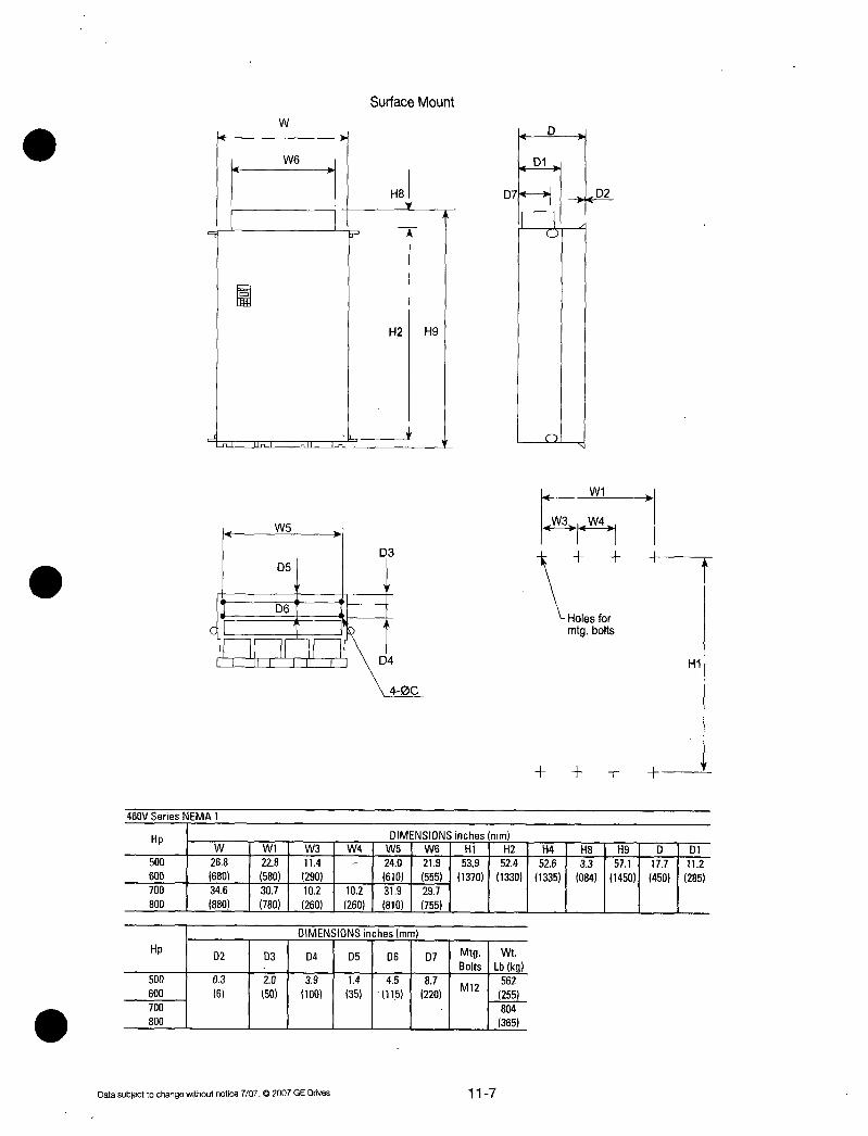
5
cI
460VSeriesNEMA1
HpW
500 268
600 680700 346
800 880
W6
w
W5
D5
V
D6i
T
W11 W3
228
I114
580 290
307I 102
780I260
Datasubjecttochangewithoutnotice7072007GEDrives
SurfaceMount
D3
D4
H8
r 1
H2 H9
40C
DIMENSIONSinchesmm
Hp02 D3 D4 D5 D6 D7 Mtg Wt
BoltsLbkg500 03 20 39 14 45 87 562
600 6 50 100 35 115 220M12
255700 804
800 365
117
01
D74 D2
5
W1
Holesfor
mtgbolts
W3 rttW4
H1
DIMENSIONSinchesImm
W41W5IW61H11H21H41H81H91 D1D1
240I219 539 524 526 33 571 177 112
610 555 I 137013301335 0841450450285102 319 297
260 I 810I755

1132OutlineDimensionsOpenType
OWLraw
SurfaceMount
W 2or30C D
W1 D1 02vr
c
N
SS
W1
4or6ois
118
ThroughPanelMount
W
W1
Ors
T
2or30C 01
02too
N
W2
W1
H3 H4
230VSeries
HP 1 DIMENSIONInchmm MtgWeight230V 1 W1 W1 1W21W31 H H11 H21 H31H41H51H6 D1D1 D2I C I Bolts I Lbkg
40 134 94 128 217 209 197 202 05 1 04 10 57 02 04 M8 6450 340 240 1 326 I 550 530 500 512 I 12 25 9 2551 145 4 10 I 2960 148 108 142 242 234 222 227 106 79
375 275 361 1 615 595 565 577 1 270 I 3675 291 283 272 276 97
740 720 690 702 44100
I101
46125 I209 169 201 295 27 274 06 13 05 112 06 M12 154
530 I 430 510 750 I 685 I 695 I 16 33 13 2851 15 70150 I268 228 26 346 335 321 325 142 87 253
680 I 580 660 880 I 850 i 815 I 825 I 360 I 220 115460VSeries 1 1
Hp DIMENSIONInchmm 1MtgWeight460V W1 W1 W2 W3 H 1H11H21 H31H4 H5 H6 0101 D2 C1Bolts I Lbkg
40 134 94 128 217 209 197 202 05 1 04 10 57 02 04 MB 6450 I 340 I 240 326 550 530 500 512 12 25 9 255 1 145 4 10 2960 148 108 142 106 75
375 275 361 2701 3475 266 258 246 251 86
675 655 625 637 39100 88
140125 I 291 283 272 276 106
740 I 720 1 690 I 702 I 48150 209 169 201 I 28 266I 27 06 13 05 124 69 06 M12 154200 530 430 510 1710 I 675 682 16 133 13 315 1 17515 I 70250 394 382 368 372 142 87 220
300 1000 970 935 945 360 220 I 100350 268 228 26 114 308400 680 1580 660 290 140450
Datasubjecttochangewithoutnotice7072007GEDrives

cW
W1
W3W4F 41
11 nut inn
460VSeriesOpenType
3or4aC
H6
it
C
H2H1 H
SurfaceMount ThroughPanelMount
4D1
D2
C1
1W2
W1 W1
kW3W4l1
A
Holesfor
Holesfor mtgboltsmtgbolts
H1
H7
H3H1
AlternativeThroughPanelMountbottombracketsupportbycustomersupply
D1
1D2
W2
W
1W3I W41
Holesfor
mtgboltsH4
4dia1435Liftingbolts
Hp DIMENSIONSinchesmmW 1W11 W21W3IW4lW5 HIH1IH2IH3IH41H5I H6IH7IDI01
500 268 228 260I114 240 551 539 524 528 526 06 14 06 177 112600 680 1 1580 I 66012901 610 14001370133013401335016 035 015450285700 I 346 307 338 102 102 319
800 880 I 780 I 860 I 260 I 260 I 810
Hp I DIMENSIONSinchesmmMtg Wt
1 D2 1D3I D4 1D51D61 C BoltsLbkq500 03 2 39 14 45 06 551
600 6 50 100 35 115 015M12
250700 793
800 360

1133OutlineDimensionsOpenTypewithNEMA12Heatsink
w
wI
W2
W4
IW5
71016160ARNOW
eon
a
2or30c
WI
W2
W4
W5 W3 WS
3or40
a
el
l l L11f
9
1
EMI
tiMI
neOnIMO
0
Fiq3N2M6
tFii
9
DI
1111111111111111111111111111111
m
1110
Iw5
WI 10Frrinq8911s WI
W3 W3
W4 w4
W6W6n oI
W6W6
r2
2M6
Fig1
WI
W3
W4
W5
W7
Fig4
WI
W3
W9
W5 115
WBW7W6W6W7W8
22FIXINGBOLTS
M2
Fig6
14FiringBolls
4M6
12FIXINGBOLTS
MB
mx
InS
Fig2 2M6
WI
W3
W4
IW5 W5
W7IW7
FiqS 4M6
WI
W3
W4
W5 W5 W5
W9WBW7W6WTW8W9
24FIXIN6BOLTS
1112
Fig7
12FBONS
16F0699
12FIXINGBOLTS
UA8
Datasubjectt3changewithoutnotice7071D2007GEDrives
Bolls

AF300P11230VACSeries
HPIWIW1IW2IW3IW4IW5IW6W7W8W9401504144113391283945 472
5013821366340326240 120
60
16421579147614211083 541
75417401375361275 1375
100
AF300P11460VACSeries
100
125
200
DIMENSIONSInchmm
H1H1 H21H31H4 H5 H611712165208719692016
550530500512
2421234322242272047098035167
61559556557712259425
2913 27172764 413
7402835690702 105
720
2913283527172764
7401720169017021
2913279526572697
740710675685
374
951
112523232228208720081693 846 2953 26972736 175827
5905661530510 14301 215 750 1685695061128049445210 051
291328192677259822831142 295 3465334632093248 402846334613
I150
740716680660 15801 290 75 880850815825 I 1553251251
102215850
DIMENSIONSInchlmm
HPW1W1IW2IW31W4IW5IW61W71W8W9HIH11H2IH31H4H5 H61H71H81H911110401504144113391283945 472
50382366340326240 120 2165208719692016 374 2087
60 550530500512 95 530
047098035 669 043
7516421579147614211083 541 2657257924612508122592851170257911
4174013751361275 1375 675655625637 725 655
H81H91H10H11H12C D 011BoltsILbkgI2087 886 66 1
5301 1 225 130
6692343043 04 571M6 81
170595 I 11 101063145and37
270 M8
199
2835 452
720 104
413 2835
105 I 1720
1568272795
395210710
FixingWtFig
47
1122571M6 161
06285145and 73
1151417866M122604
360220 118
FixingWtFigH11H12C D DIBoltsLbko
886 66
225 3011
M6 77
04 571and 35
101063145M8 88
270 40
90 2
41
108
149
124689 161
3151175 73
23232228208720081693 846 061128049 051 06 M6
2501 590566530510430 215 155325125 13 15 and
I229
13
1300 3937381936813720 2158463819 1417866M12104
350291328192677259822831142 295 10009709351945 5452151970 3601220 317
400740716680660580290 75 1445
450
5002913281926772598
228311142295455260 M8 551 6
65074071668066058029075115566 5512539452365276061138057018699846571543708105917721122and250
1700370136063465338630711024472276256433140013701330134015535145451775215145138120515450285M127937
8009409168808607802601207065110 360
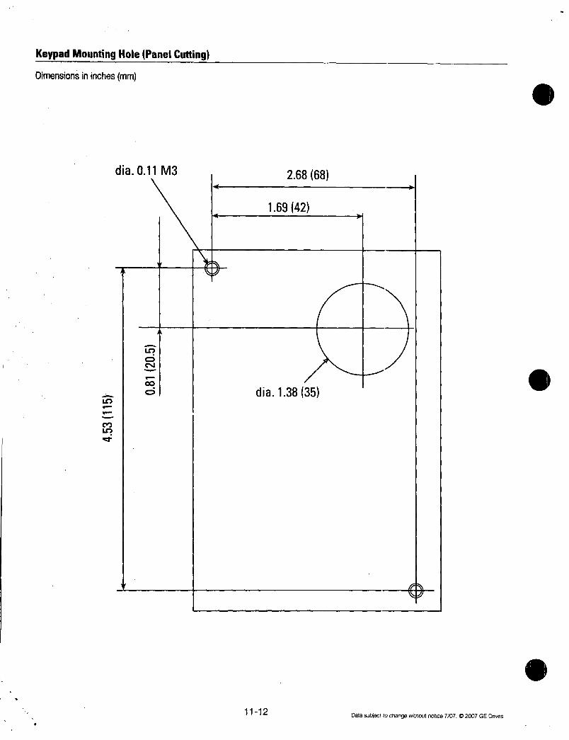
KeypadMountingHolePanelCutting
Dimensionsininchesmm
MLt
dia011M3
1112
26868
16942
dia13835
Datasubjecttochangewithoutnotice707C2007GEDrives
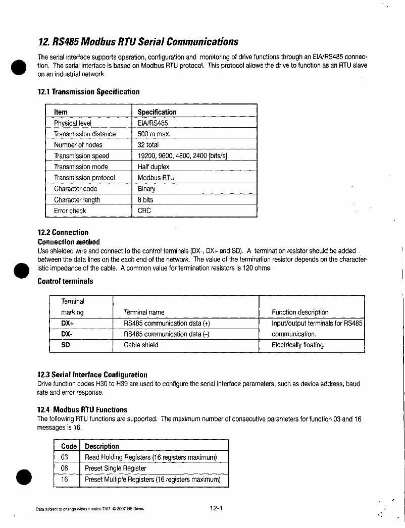
12RS485ModbusRTUSerialCommunications
TheserialinterfacesupportsoperationconfigurationandmonitoringofdrivefunctionsthroughanEIARS485connectionTheserialinterfaceisbasedonModbusRTUprotocolThisprotocolallowsthedrivetofunctionasanRTUslaveonanindustrialnetwork
121TransmissionSpecification
Item Specification
Physicallevel EIARS485
Transmissiondistance 500mmax
Numberofnodes 32total
Transmissionspeed 19200960048002400bitssTransmissionmode Halfduplex
Transmissionprotocol ModbusRTU
Charactercode Binary
Characterlength 8bits
Errorcheck CRC
122Connection
Connectionmethod
UseshieldedwireandconnecttothecontrolterminalsDXDXandSDAterminationresistorshouldbeaddedbetweenthedatalinesontheeachendofthenetworkThevalueoftheterminationresistordependsonthecharacteristicimpedanceofthecableAcommonvalueforterminationresistorsis120ohms
Controlterminals
Terminal
marking Terminalname
DX RS485communicationdata
DX RS485communicationdata
SD Cableshield
Functiondescription
InputoutputterminalsforRS485communication
Electricallyfloating
123SerialInterfaceConfigurationDrivefunctioncodesH30toH39areusedtoconfiguretheserialinterfaceparameterssuchasdeviceaddressbaudrateanderrorresponse
124ModbusRTUFunctions
ThefollowingRTUfunctionsaresupportedThemaximumnumberofconsecutiveparametersforfunction03and16messagesis16
Code1Description03 IReadHoldingRegisters16registersmaximum06 IPresetSingleRegister16 I PresetMultipleRegisters16registersmaximum
Datasubjecttochangewithoutnotice7072007GEDrives 121

125DriveFunctionCodeAccess
AllofthedrivefunctioncodesareaccessiblethroughtheRS485serialinterfaceDrivefunctioncodesaremappedtoRTUholdingregistersAdrivefunctioncodeRTUaddressis2bytesinlengthThehighbytecorrespondstoacodethatrepresentsthedriveparametersortFMThelowbytecorrespondstothedriveparameternumberwithinthesort099
Code Sort
0 F
1 E
2 C
3 P
4 H
Name
Basicfunction
Terminalfunction
Controlfunction
Motor1function
Highlevelfunction
ForexampledrivefunctioncodeM11outputcurrentisaddressedasRTUparameternumber080Bhexadecimalor2059decimal
highbyte 1 lowbytedriveparametersortcode driveparameternumber126CommandandMonitorDataRegisters
ThecommandandmonitorfunctioncodesareusedtocontroltheoperationofthedriveandmonitorthestatusvariablesthroughtheserialinterfaceThecommandandmonitorfunctioncodesarenotaccessblefromthedrivekeypadinterfaceDriveparameterH30anddigitalinputsignalLEmustbeenabledtooperatethedrivefromtheModbusinterfaceIfLEisnotassignedtoadigitalinputX1X9thesignalwilldefaulttoONFrequencySettingRegisters
Address Code Name
1793 SO1 Frequencycommand
11797 1S05JFrequencycommand
Note
1IfbothSO1andS05aresetthedrivewillignorethesettingofS052Adatasettingthatexceedsthesettingrangeispossiblebuttheactualactionwillbelimitedbythedriveconfiguration
OperationcommanddataRegisters
AddressCodeName
1798 IS061Operationcommand1799 IS071UniversalDo1804 S12 UniversalAo
1800 IS08JAccelerationtimeF071801 1S091DecelerationtimeF081802 S10
I Torquelimitlevel1drivingF40
1803 S11
I Torquelimitlevel2brakingF41
Note
1
2
Code Sort
5 A
6 0
7 S
Unit VariableRange
Thewritingofdataoutofrangeistreatedasoutofrangeerror
Useavalueof7FFFtoenter999fortorquelimitfunctions122
Name
Motor2function
Optionfunction
Commandfunctiondata
8 M Monitordata
Unit VariableRange2000020000
maxfrequencyat 20000JHz100040000
IRefertothedataformat14IRefertothedataformat15
2000020000
100outputat 20000
UnitVariablerange
s10136000s10136000
I2000 20000999
000200020000999
Read Data
Minunit Write Format
Note
1SinceX1X9areconfigurableinputcommandsitisnecessarytosetthefunctionsbyE01E092ThealarmresetisexecutedwhenRSTsignalchangesfromONtoOFFeveniftherearenoalarms3UniversalDoisafunctionthatutilizesthedrivesdigitaloutputsviacommunication
FunctiondataRegistersAddressCodeName
1 RW 2
1 001 1RW1 5
Minunit Read
Write
IRNVIIRWI
1 RW
Data
Format
14
15
2
Minunit Read Data
Write Format
01 IRW1 3
01 IRW1 3
1
IRW
I5
1 RW
I5
Datasubjecttochangewithoutnotice70702007GEDrives

Monitoringparameterregisters
Address
2049
2053
2054 1
12055 IM0712056 1M08I2057 1M092058 1M10
2059 1M11
12060 IM122061 M13
2062 1M142063 M15 12064 1M16I
12065 IM1712066 IM18
2067 1M192068 M20
2069 IM21 DClinkvoltage2071 1M23 Typecode2072 1M241Drivecapacitycode2073 1M25 ROMversion
2074 M26 Transmissionerrorprocessingcode
2075 M27 Frequencycommandatalarmfinalcommand
2079 M31 Frequencycommandatalarmfinalcommand
2080 M32 Actualfrequencyatalarm
2081
2082
2083
2084
2085
2086
2087
2088
2089
2090
2091
2092
2093
2094
2095
2096
CodeMO1
M05
M06
M33IM34IM35
M36
M37
M38
M39
M40
M41
M42
M43
M44
M45
M46
M47
M48
Description
Frequencycommandfinalcommand
Frequencycommandfinal IHz
command
Actualfrequency
ActualtorquevalueTorquecurrentOutputfrequencyMotoroutputinputelectricpower
Outputcurrentrms
Outputvoltagerms
Operationcommandfinalcommand
OperatingstateUniversaloutputterminaldata
Faultmemory0Faultmemory1Faultmemory2Faultmemory3Integratedoperatingtime
ActualtorqueatalarmTorquecurrentatalarm
Outputfrequencyatalarm
MotoroutputatalarminputpowerOutputcurrentrmsatalarm
Outputvoltageeffectivevalueatalarm
Operationcommandatalarm
Operatingstateatalarm
Universaloutputterminaldataatalarm
Integratedoperationtimeatalarm
DClinkvoltageatalarm
Inverterinternalairtempatalarm
Coolingfintempatalarm
Lifeofmaincircuit
capacitor
Lifeofprintedcircuitboardcapacitor
Lifeofcoolingfan
Datasubjecttochangewithoutnotice7072007GEDrives
Unit
Hz
h
V
Hz
IHz
V
h
V
C
C
h
Range
2000020000max frequencyat 200001
040000
2000020000
maxfrequencyat2000020000200002000020000
00040000
00020000
00020000inverterratingat10000
V 006000Refertodataformat14
Refertodataformat16Refertodataformat15
Refertodataformat10
065535
01000
Refertodataformat17Refertodataformat11064999
Refertodataformat20
2000020000maxfrequencyat20000040000
2000020000
maxfrequencyat200002000020000
2000020000
000400
00020000
00020000inverterratingat10000006000
Refertodataformat14
Refertodataformat16
Refertodataformat15
065535
01000
0120
0120
001000
065535
h1065535
123
Minunit Read Data
Write Format
1
IR
I2
001 1 R 1 5
001
001
001
001
1
001
001
001
001
001
1
1
1
01
1
1
R
R
R
R
R
001
IR
1 I R
R
R
R
R
R
R
R
R
R
R
2
6
6
5
5
5
3
14
15
1
17
11
1
20
2
R
I5
R 2
R
R
R
R
R
R
R
R
R
R
R
R
R
R
R
R
16 I
10
10
10
I10
1
6
6
5
5
3
14
16
15
1
1
1
3
1
1

127DataFormatSpecificationAlldatainthedatafieldofcommunicationframeshallberepresentedbya16bitlengthword
15 14 13 12 11 10 9 8 7 6 5 4 3 2 1 0
16bitsbinarydata
Dataformat1 UnsignedIntegerdataPositiveMinunit1ExampleIfF15Frequencylimitupper60Hz60 003C
Dataformat2Exampledata 20
20 FFEC
IntegerdataPositivenegativeMinunit1
Dataformat3 UnsignedDecimaldataPositiveMinunit01ExampleIfF17frequencygainsettingsignal 1000
1000X10 1000 03E8
Dataformat4 DecimaldataPositivenegativeMinunit01ExampleIfC31Analoginputoffsetadjustterminall2 50
50X1050 FFCE
Dataformat5 UnsignedDecimaldataPositiveMinunit001ExampleIfCO5multistepfrequency1 5025Hz
5025X100 5025 13A1H
Dataformat6 DecimaldataPositivenegativeMinunit001ExampleIfM07actualtorquevalue85388538X1008538DEA6
Dataformat7 UnsignedDecimaldataPositiveMinunit0001ExampleIfo05followupsideASR1constant 0105s
0105X1000 105 0069
Dataformat8 DecimaldataPositivenegativeMinunit0001ExampleData 1234
1234X1000 1234 FB2E
Dataformat9 UnsignedIntegerdataPositiveMinunit2ExampleIfP01Motor1numberofpoles2pole2 0002
Dataformat10 AlarmCode
124 Datasubjectochangewithoutnotice70702007GEDrives

Code
0
1
2
3
5
6
7
8
10
11
14
16
17
18
19
Dataformat11
Code
7
15
25
50
100
200
300
500
750
1000
1500
Dataformat12
15 14
Polarity 0
1Negative
0Positive
Description
Noalarm
OvercurrentduringaccelerationINVoutputIOvercurrentduringdecelerationINVoutput1OvercurrentduringsteadystateoperationINVoutputGroundfault
OvervoltageduringaccelerationOvervoltageduringdecelerationOvervoltageduringsteadystateoperationDCundervoltagePowersupplyopenphaseBlownDCfuse
OutputwiringerrorOverheatheatsinkinverterOverheatoutsidethermalOverheatunitinsidetemp
Capacitycode
CapacityHP
007spare015spare025
05
1
2
3
5
75
10
15
IndexdataACCDECtimedisplaycoefficient
13 12 11 10
0 0 Indexportion
0001X
101 X
21 X
310 X
Datasubjecttochangewithoutnotice71072007GEDrives
Code
2000
2500
3000
4000
5000
6000
7500
10000
12500
15000
ExampleIfF07accelerationtime1 200s
100 20999 index1
200 01X200404000008 04C8
Code
22
001 23
002 24
003 25
EF 27
OU1 28
OU2 31
OU3 32
LU 33
Lin 34
FUS 35
Er7 36
OH1 37
OH2 38
OH3
CapacityHP20
25
30
40
50
60
75
100
125
150
9 8 7 6 5 4 3 2 1 01 i 1 1 1 1 1 1 1
Dataportion
125
001999
00999
100999
100999
DescriptionOverheatDBresistorOverloadmotor1Overloadmotor2Overloaddrive
OverspeedPGwirebreak
MemoryerrorKeypaderrorCPUerror
Optioncommerror
OptionerrorPLerror
OutputwiringerrorRS485commerror
Code CapacityHP17500 175
20000 200
25000 250
30000 300
35000 350
40000 400
45000 450
50000 500
60600 600
60700 700
60800 800
00099910099910099910009990
dbH
OL1
OL2
OLU
OS
PcEr1
Er2
Er3
Er4
Er5
Er6
Er7
Er8

Dataformat13 Patternoperation
15 14 13 12 11 10 9 8 7 6 5 4 3 2 1 0
Direction1 1 1 1 I 1 I I I I
ofrotation 0 Time Indexportion Dataportion
0FWD
1REV
01stACCDECtime 0001X 001999 00099912ndACCDECtime 101 X 100999 10099923rdACCDECtime 21 X 100999 10099934thACCDECtime 310 X 100999 10009990
ExampleIfC22Stagel 100sR210sreverserotationaccelerationtime2decelerationtime2Since100 01X100 9000 0400 0064 9464
Dataformat14 Operationcommand15 14 13 12 11 10 9 8 7 6 5 4 3 2 1 0
RST 0 0 0 0 X9 X8 X7 X6 X5 X4 X3 X2 X1 REVFWD
AllbitareONby1ExampleIfS06operationcommand FWDX1andX5 ON
0000000001000101b 0045
Dataformat15 Universaloutputterminal
15 14 13 12 11 10 9 8 7 6 5 4 3 2 1 0
0 0 0 0 0 0 0 0 0 0 0 Y5 Y4 Y3 Y2 Y1
AllbitareONbylExampleIfM15UniversaloutputterminalY1andY5 ON
0000000000010001b
0011H
Dataformat16 Operatingstate15 14 13 12 11 10 9 8 7 6 5 4 3 2 1 0
BUSY WR RL ALM DEC ACC IL VL TL NUV BIRKINT EXT REVFWD
126 Datasubjecttochangewithoutnotice7072007GEDrives

AllbitareONoractiveby1FWD ForwardoperationREV0ReverseoperationEXT DCbrakingactiveorpreexcitation
INT NoOutputBRK BrakingactiveNUV DClinkvoltageisestablished
undervoltageat0TL TorquelimitingVL Voltagelimiting
Dataformat17
15 14 13 12 11 10 9
Code
1
2
3
4
5
6
Type Generation
Type
G
P
Typecode
Dataformat18 Codesetting14figures
15 14 13 12 11 10 9 8 7 6 5 4
Data4 Data3 Data2
Dataformat19 AmperagevalueDecimaldatapositiveMinunit001invertercapacityisnotmorethan30HPMinunit001fornotTessthan40HP
ExampleIfF11electronicsthermaloverloadrelay1level1070A40HP1070X101070042EIfF11electronicsthermaloverloadrelay1level360A1HP
Since360X1003600168
Dataformat20 Transmissionerrorcode
Code1 Description1 1FCfunctioncodeerror2 1Illegaladdress3 IllegaladdressDatarangeerror
7 NAK
PriorityforcommNoprivilegeforwritingerrorForbiddenwritingerror
Datasubjecttochangewithoutnotice7072007GEDrives
Generation
11
Series
USA
IL
ACC
DEC
ALM
RL
WR
CurrentlimitingUnderacceleration
Underdeceleration
Drivefault
Transmissionvalid
Functionwritingprivlege0Keypadpanel1RS485
2FieldbusoptionBUSYProcessingdatawrite
8 7 6 5 4
Series
Code1 Description71 1CRCerror noresponse72 1Parityerror noresponse73 Othererrors noresponse
FramingerrorOverrunerror
Bufferfullerror
127
Voltageseries
230Vthreephase460Vthreephase
3 2 1 0
Voltageseries
3 2 1
Data1

Dataformat21 Autotuning
15 14 13 12 11 10 9 8 7 6 5 4 3
I I I I
0 0 0 0 0 0 REVFWD Dataportion
ExampleIfPO4motor1autotuning1Forwardrotation0000000100000001
b0101
H
2 1 0
I
0Withoutforwardrotationcommand
1Withforwardrotationcommand
0Withoutreverserotationcommand
1Withreverserotationcommand
127CommunicationErrors
ExceptionResponseWhenthedrivereceivesamessagethatdoesnotcontaincommunicationerrorsbutthemessagecannotbeprocessedthedrivewillreturnanexceptionresponseTheexceptionresponsecontainsanerrorubcodeinthedatafieldthatrepresentstheproblem
ExceptionResponseErrorsSubCode1Name
1 IIllegalFunction2 IllegalDataAddress
3 1IllegalDataValue7 NegativeAcknowledge
1 Causes
IReceivedRTUFunctionotherthan0306or16Thestartingparameteraddressisanunuseddriveparameter
ThestartingparameteraddressplustheoffsetreferstodriveparametergreaterthanthelastparameterinaFunctionCodesortThenumberofregistersisgreaterthan16
IDatacontainsanoutofrangevalueforadriveparameterRequesteddatacannotbechangedwhilethedriveisrunningThedriveparameterfunctionisownedbythenetworkinterfaceoptioncardandcannotbechanged
1
Communicationerrors
CommunicationerrorsoccurwhenthedrivereceivesaninvalidmessageThedrivewillnotreturnaresponsetoacommunicationerrorAcodethatrepresentsthelastcommunicationerrorisstoredindriveparameterM26TypicalcommunicationmessageerrorsincludeparityframingandCRCerrors
128Datasubjecttochangewithoutnotice70702007GEDrives

13Options131BuiltinOptions
ThedrivesupportstwointernallymountedcardsOneoptioncardismountedunderthemaincoverLocationAandtheotheroptioncardismountedinaspecialadapterunderthekeypadLocationBOnlyonecardcanbemountedintheselocationsTherearetwodifferenttypesofoptioncardsType1andType2YoucannotusetwoType1orTwoType2cardsbutyoucanmixanycombinationofType1andType2providedyouonlyhaveoneoptionpermountinglocationEachoptioncardmustbemountedinthedesignatedlocationThechartbelowliststheoptioncardtheirtypesandtheirmountinglocations
Name
OPCG11SRY
Relayoutputcard
OPCG11SDI0
Digitalinterfacecard
OPCG11SAI0
Analoginterfacecard
OPCG11SCI0
InterfacecardOPCG11SLON
CommunicationcardOPCG11SPDP
CommunicationcardOPCG11SDEV
Communicationcard
OPCG11SCOP
Communicationcard
OPCG11SMBP
Communicationcard
OPCG11SIBS
Communcationcard
HE300GEN150
Communicationcard
Datasubjecttochangewithoutnotice7072007GEDrives
Type Loc
1 A
2 A None
2 A None
1 A 2B
2 B 1A
2 B 1A
2 B 1A
2 B 1A
2 B 1A
2 B 1A
2 B 1A
2ndOption Function
TypeLoc2B Relayoutputcard
ThetransistoroutputfromthedrivecontroloutputterminalsY1andY4areconvertedtotherelayoutput1SPDTFrequencysettingbybinarycodemax16bits
Monitoring8bitsoffrequencyoutputcurrentandoutputvoltage
Auxiliaryinputforanalogfrequencysetting0to 10V
Monitoringofdriveoutputfrequencycurrentandtorqueinanalogvoltageanalogoutput010VDCabd420mA
115VACControlinputanisolationamplifierrelayoutputPGencoderanalogoutput420mASerialcommunicationcardforLonWorks
SerialcommunicationcardforProfibusDP
SerialcommunicationcardforDeviceNet
SerialcommunicationcardforCAN
SerialcommnicationcardforModbusplus
SerialcommuncationcardforInterbusS
SerialcommunicationcardforGenius
131

Name DigitalIOinterfacecardType OPCG11SDI0
Function 4digitalinputsIBinarycodeinputofmax16bitsorBCDinputSinkSourcechangeable3digitaloutputsBinarycodeoutputofmax8bits
Specifications Input Digitalsignalinput4pointsbyshortcircuitingterminalsL1L16andM1Sink
ONoperationcurrent 45mAmax
OFFoperationvoltage 27Vmax
Source
ONoperationcurrent 45mAmax
OFFoperationvoltage 27Vmax
Relatedfunctioncode 019020
Output Digitalsignaloutput3pointsbyshortcircuitingterminalsbetween01to06andM2Sink
ONoperationcurrent 5OmAmax
OFFoperationvoltage 27Vmax
Source
ONoperationcurrent 5OmAmax
OFFoperationvoltage 27Vmax
Relatedfunctioncode 021
PowerSource 24UDC32mAx4 128mAConnection
diagram
Remarks
0
132
L1R
L2S
L3T
116
115
114
113
112
111
110
19
18
17
16
15
14 02
13
12Sink
01LSBi
U
V
wc
08MSB
07
06
05
04
03
11LSB
M1 M2
CM
G t
CD
T
Datasubjecttochangewithoutnotice707C2007GEDrives

Name AnalogIOInterfaceCardType OPCG11SAIO
3analoginputs2voltageinputsand1currentinputTorquelimitingvaluedrivingbrakingfrquencysettingratiosettingFunction canbeinputrespectively
2analogoutputs1voltageoutputand1currentoutput11typesofdatacanbeoutputSpecifications Input Analogsignalinput3points32and3122and21C2and21
Terminal32Voltageinputbothsides 0to10VDC0to100 inputimpedance22kohmTerminal22Voltageinputbothsides 0to10VDC0to100 inputimpedance22kohmTerminalC2Currentinput 4to 20mADC0to100 inputimpedance250kohm
ForvoltageinputpowersupplyterminalforvariableresistorP10shouldbeconnectedRelatedfunctioncodeo22
Output Analogsignalinput2pointsbetweenA0andAOCSandCSTerminalA0Voltageoutput0to10VDCformax2voltmetersinputimpedance10kohmTerminalA0VoltageoutputcommonTerminalCS Currentoutput4to20mAdcmax500ohmTerminalCSCurrentoutputcommon
TerminalCSisisloatedfromterminal2131andADRelatedfunctioncodeo23
Connection
diagram
Remarks
MCCB
or
ELCB
O
RUNcommand
input r
Datasubjecttochangewithoutnotice7072007GEDrives
L1R
L2S
L3T
RO
T0
13
12
11
01
Y5A
Y5C
Y4
Y3
Y2
Y1
CM
PLC
FW
REV
CM
X1
X2
X3
X4
X5
X6
X7
X8
X9
CM
FM
FM
DX
DXSD
EG
AF303P11
u
V
w
30A
30B
30C
32
31
22
21
C2
AO
AO
CS
CS
133
ryVR
VRVoltageinput
1kohm Bothpolarity
VoltageinputY1kohmSinglepolarity
Currentinput
fAnalogvoltmeter
Anammeter
TerminalsIROandTOarenotprovidedfor10HPorsmaller

Name IRelayOutputCardType Cardtype OPCG1ISRY
UnittypeFunction Includes4relayoutputcircuits
ConvertstransistoroutputsignalsfromdrivecontroloutputterminalsY1toY4torelay1SPDToutputsignalsSpecifications Input INone
Output 1Fourchannelcontact12terminalsfromY1AtoY4C250VAC03Aocdia 03
PowersourceIThepowersourcetodrivetherelaycardissuppliedfromthedriveConnection
diagram
Remarks
0
5G
5G
5G
13Vdc 24Vdc
ofI
134
CD
OND
13Vdc 24Vdc
13Vdc
C
n1
r
C5CDi
Y2A
0Y2B
0Y2C
0
Y1Ai
Y1
B
Y1CO
Y3A
Y3B0
Y3C0
r Y4A
Y4B
Y4C0
Datasubjecttochangewithoutnotice7072007GEDrives
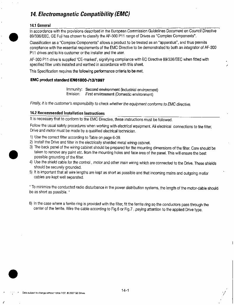
14ElectromagneticCompatibilityEMC
141General
InaccordancewiththeprovisionsdescribedintheEuropeanCommissionGuidelinesDocumentonCouncilDirective89336EECGEFujihaschosentoclassifytheAF300P11rangeofDrivesasComplexComponents
ClassificationasaComplexComponentsallowsaproducttobetreatedasanapparatusandthuspermitscompliancewiththeessentialrequirementsoftheEMCDirectivetobedemonstratedtobothanintegratorofAF300P11drivesandtohiscustomerortheinstallerandtheuser
AF300P11driveissuppliedCEmarkedsignifyingcompliancewithECDirective89336EECwhenfittedwithspecifiedfilterunitsinstalledandearthedinaccordancewiththissheet
ThisSpecificationrequiresthefollowingperformancecriteriatobemet
EMCproductstandardEN61800131997
ImmunitySecondenvironmentIndustrialenvironmentEmision FirstenvironmentDomesticenvironment
FinallyitisthecustomersresponsibilitytocheckwhethertheequipmentconformstoEMCdirective
142RecommendedInstallationInstructions
ItisnecessarythattoconformtotheEMCDirectivetheseinstructionsmustbefollowed
FollowtheusualsafetyprocedureswhenworkingwithelectricalequipmentAllelectricalconnectionstothefilterDriveandmotormustbemadebyaqualifiedelectricaltechnician
1UsethecorrectfilteraccordingtoTableonpage6392InstalltheDriveandfilterintheelectricallyshieldedmetalwiringcabinet3ThebackpanelofthewiringcabinetshouldbepreparedforthemountingdimensionsofthefilterCareshouldbe
takentoremoveanypaintetcfromthemountingholesandfaceareaofthepanelThiswillensurethebestpossiblegroundingofthefilter
4UsetheshieldcableforthecontrolmotorandothermainwiringwhichareconnectedtotheDriveTheseshieldsshouldbesecurelygrounded
5Itisimportantthatallwirelengthsarekeptasshortaspossibleandthatincomingmainsandoutgoingmotorcablesarekeptwellseparated
Tominimizetheconductedradiodisturbanceinthepowerdistributionsystemsthelengthofthemotorcableshouldbeasshortaspossible
6InthecasewhereaferriteringisprovidedwiththefilterfittheferriteringsotheconductorspassthroughthecenteroftheferriteWirethecableaccordingtoFig6orFig7payingattentiontotheappliedDrivetype
fDatasubjecttochangewithoutnotice70702007GEDrives141

AppliedDriveAF300P11HpMaxratedvoltage3
FilterTypeP11 Fujimodel
025
05
1
2
3
5
75
10
15
20
25
30
RF3180F11
RF3180F11
50 RF3280F11
60 RF3280F11
40
75
100
EFL150G114
EFL15G11425 EFL220G114
30 EFL22G114
RF3100F11
4RF3100F11
20
40
50
60
75
100
125
150
200
250
300
350
400
500
500
600
700
800
EFL075SP2
EFL075SP2
EFL370SP2
EFL37SP2
EFL750SP2
EFL75SP2
EFL150SP2
EFL15SP2
EFL220SP2
EFL22SP2
EFL075G114
EFL075G114
RF3180F11
RF3180F11
RF3280F11
RF3280F11
RF3400F11
RF3400F11
RF3880F11
RF3880F11
Phase230VAC
TestedMotor
CableLength
Rated EN55011 EN55011
Current ClassB ClassA
6A
25A
504
1004
150A
180A
2804
400A
RF3400F11
125 RF3400F11150
HPMaxratedvoltage3Phase480VAC05
1
2
3EFL400G114
124
5EFL40G114
75
10EFL750G114
354
15EFL75G114
5A
504
72A
1804
280A
4b0A
800A
164ft
50m
328ft
100m
Dimensions
LxWxHmm
957x335x366
243x85x93
917x413x535
233x105x136
1075x472x622
273x120x158
1949x787x63
495x200x160
142
MountDim Ferrite Total Watt Note
YxXmm RingQtyWtlb lossW04
OF11 33 14
51
39
OF21 55 82
21
OF21 11024
254x95 40
42
898x232
228x59
846x315
215x80
10x374
202x807x76 1917x630OF31
513x205x193 487x160
1949x787x63 184x653
495x200x160 468x166
328Ft 2311x984x807 2205x335
100m 587x250x205 560x85
126x456x165 1154x354
320x116x42 293x90
126x61x177 1154x413
320x155x45 293x105
33ft 164ft
10m 50m1343x886x187 1224x657
341x225x475 311x167
1969x984x276 1768x728
500x250x70 449x185
10041713x787x519 1606x654
435x200x130 408x166
RFIFilterData
184x653
468x166
2205x3352311x984x807
587x250x205 560x85
2709x1433x709 2551x591
688x364x180 648x150 F200
160
31
44168
74
99
Fig1
SeparateType
Fig3487 60 Separate
Type487 120
110 220 Fig4Separate
Type
08
31
31
26 69
18
10
40 17
24
29
49
47
62
20
79
88
28621
848 120
130 180
Fig2
Separate
IntegralType
Fig3Separate
487 60 Type
Fig4Separate
110 220 Type
142 180 I Fig5
Separate
Type
Datasubjecttochangewithoutnotice7072007GEDnves

L1L2L3 PE
LINE
LOAD
L1L2L3
P i01o
44
o 1010101PEL1L2L3
UNE
Y
A
V
L
Y
Datasubjecttochangewithoutnotice7072007GEDrives
H
L
LOAD
L1RL2SL3T
1
wto
Figure1
Figure2
JH S
143
FerriteRingDimensionsInchesmmPartNoI D I HI T
OF1 09825 20151 06717OF2 16141 28071 07118OF3 28372 394100 10627
3powercables1groundingcable
T

GroundTerminal
RF3100F11M8
RF3180F11M10
MountingScrewM6x6
StudTerminal
RF3280F11M12x8
RF3400F11M16x8
MountingScrewM6x4
FilterType
RF3100F11
RF3180F11
DimensionsInchesmm
W W1 H H1
787200 654166 171435 I 161408
787200 654166 I 195495 I 184468
807205
Figure3OutlineDimensionsRF3100F11RF3180F11
y
0
0
33585
33585
15740
144
231587
220560
H
H1
Figure4OutlineDimensionsRF3280F11 i
D
512130
630160
Imo
0
0
111111
III
Datasubjecttochangewithoutnotice7072007GEDrives

MountingScrewM6x6
143364
TerminalM16clearhole
3Phase
PowerSupply
709160
RCDor
MCCB
Figure5OutlineDimensionsRF3880F11
L1L1
L2L2
L3L3
Datasubjecttochangewithoutnotice70702007GEDrives
271688
255648
Metalwiringcabinet
RFI
Filter
PE
L1RU
L2SV
L3TW
Figure6 230VallHp460VTessthan450Hp
145
F2OO16O
r
1
614 803
r156 204
138
351
230VSeries30HPandlessonlyFitaferriteringtothecablewiththe3phaseconductorsonlypassing
Drive throughthecenteroftheferrite
P1 P ShieldedMotorCable
Shieldingmustbeelectricallycontinuousandgroundedatthecabinetandthemotor

RCDor
MCCB
Metalwiringcabinet
Drive
PE
RFI
Filter
L1121
L2L2
L3L3
P1 P
L1RU
L2SV
L3TW
146
Fitaferriteringtothecablewithconductorspassingthroughthecenterdtheferrite
Figure7 AF300P11460V500Hpandhigher
Fitaferriteringtothecablewithconductorspassingthroughthecenteroftheferrite
ShieldedMotorCable
Shieldingmustbeelectricallycontinuousandgroundedatthecabinetandthemotor
Datasubjecttochargewithoutnotice7072007GEDrives

GEConsumer Industrial
41WoodfordAvenuePlainvilleCT06062
wwwgeelectricalcom
imaginationatwork GEI100364D
SupersedesGEI100364C070730
FERGADV

0
MediumVoltageSolidStateOEMSoftStarter
INSTALLATION OPERATION
MANUAL
DEH41021

MediumVoltageSolidStateSoftStarters
2372KV
Installation
OperationManual
Chapter1Introduction 111 Overview
12 Specifications13 DesignFeatures14 TheoryofOperation15 GeneralProtection
16 ThermalOverloadProtection
17 FiringCircuit18 Electronics
Chapter2Connections21 Warnings22 ControlConnections23 ReferenceSectionwithRTDPowerCommunicationsandCPUboarddrawings
Chapter3StartUp 1731 Introduction
32 AccelerationAdjustments33 DecelerationAdjustments34 SequenceofNormalOperation35 EmergencyBypassOperation
Chapter4UserInterfaceandMenuNavigation 2141 KeypadOperatorInterface42 MenuNavigation
Chapter5SetpointProgramming 2451 SetpointsPageList52 SetpointMenu
SP1BasicConfiguration 34
SP2StarterConfiguration 35
SP3PhaseGroundSettings 38
SP4RelayAssignment 41
SP5RelayConfiguration 43
SP6IOConfiguration 44
SP7CustomAccelerationCurve 47
SP8OverloadCurveConfiguration 50
SP9RTDOptionConfiguration 51
SP10SetPassword 53
SP11Communications 54
SP12SystemSetpoints 55
SP13Calibration Service 57
Chapter6MeteringPages 5861 MeteringPageListMenu
Chapter7MaintenanceandTroubleshooting 6871 FailureAnalysis72 TypicalBlockDiagram73 OverloadCurveDefinition74 TCBDiagram75 TypicalWiringDiagram76 SparePartsList77 InstructionsforStackReplacement78 InstructionsforLowVoltageTest
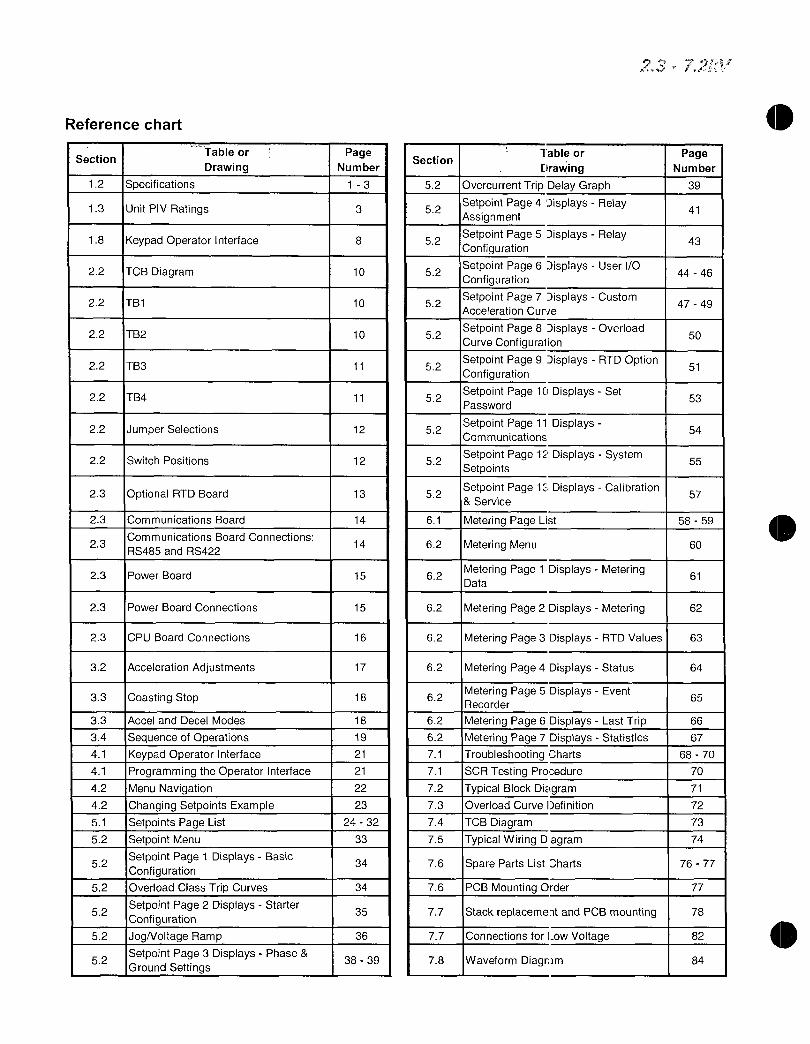
Referencechart
SectionTableor
12 Specifications
Drawing
13 UnitPIVRatings
18 KeypadOperatorInterface
22 TCBDiagram
22 TB1
22 TB2
22 TB3
22 TB4
22 JumperSelections
22 SwitchPositions
23 OptionalRTDBoard
23 CommunicationsBoard
23
52
52
52
52
52
CommunicationsBoardConnections
RS485andRS422
23 PowerBoard
23 PowerBoardConnections
23 CPUBoardConnections
32 AccelerationAdjustments
33 CoastingStop
33 AccelandDecelModes
34 SequenceofOperations41 KeypadOperatorInterface41 ProgrammingtheOperatorInterface42 MenuNavigation42 ChangingSetpointsExample51 SetpointsPageList52 SetpointMenu
SetpointPage1DisplaysBasicConfiguration
OverloadClassTripCurvesSetpointPage2DisplaysStarterConfiguration
IJogNoltageRampSetpointPage3DisplaysPhaseGroundSettings
PageNumber
13
3
Section
52
52
8 52
10 52
10 52
10 52
11 52
11 52
12 52
12 52
13 52
14 61
14 62
15 62
15 62
16 62
17 62
18 62
18 62
19 62
21 71
21 71
22 72
23 73
2432 74
33 75
34 76
34 76
35 77
36 77
3839 78
Tableor
revving
IOvercurrentTripDelayGraphSetpointPage4DisplaysRelayAssignment
SetpointPage5DisplaysRelayConfiguration
SetpointPage6DisplaysUserIOConfiguration
SetpointPage7DisplaysCustomAccelerationCurie
SetpointPage8DisplaysOverloadCurveConfiguration
SetpointPage9DisplaysRTDOptionConfiguration
SetpointPage10DisplaysSetPassword
SetpointPage11DisplaysCommunications
SetpointPage12DisplaysSystemSetpoints
SetpointPage13DisplaysCalibrationService
MeteringPageList
MeteringMenu
MeteringPage1DisplaysMeteringData
MeteringPage2DisplaysMetering 62
MeteringPage3DisplaysRTDValues 63
MeteringPage4DisplaysStatus 64
MeteringPage5DisplaysEventRecorder
MeteringPage6DisplaysLastTrip
MeteringPage7DisplaysStatistics
TroubleshootingCharts
SCRTestingProcedure
TypicalBlockDiagramOverloadCurveDefinition
TCBDiagram
TypicalWiringDagram
SparePartsListCharts
PCBMountingOrder
StackreplacementandPCBmounting
1ConnectionsforLowVoltage
WaveformDiagram
50
51
53
54
55
61
PageNumber
39
41
43
4446
4749
57
5859
60
65
66
67
6870
70
71
72
73
74
7677
77
78
82
84
0

Chapter1 Introduction
0 ThischapterisanintroductiontothereducedvoltagesolidstatestarterformediumvoltageACmotorsItdescribesthebasicconfigurationoperationandunitfeaturesItishighlyrecommendedthatnewusersreadthissectionthoroughlytogainabasicunderstandingofthestartersystembeforeattemptingtostartupaunit
ao
11Overview
ThestandardsoftstarterpanelisanSCRbasedmotorcontrollerdesignedforthestartingprotectionandcontrolofACmediumvoltagemotorsItcontainstheSCRstackassembliesfiberopticconnectionsandlowvoltagecontrolcircuitryreadytobeinterfacedwithanenclosureandthenecessaryequipmenttocreateacompleteClassE2mediumvoltagemotorsoftstarter
12Specifications
125Continuous
50060seconds
60030seconds
1Cycleupto14xFLAinternallyprotectedbytheprogrammableshortcircuit
50or60Hz2Hzhardwareselectable
6SCRs12SCRsor18SCRsmodeldependent
6500V21000VmodeldependentseeTable1
Userselectablephasesequencedetection
RCsnubberdvdtnetworksoneperSCRmodule
Enclosedunits0to40C32to104Foptional20to50Cwithheaters595relativehumidity03300ft1000mabovesealevelwithoutderatingRatingsforambientconditionsexternaltounit
2or3wire120VACcustomersupplied
MultipleFormCcontactsrated4Amps250VACmax
8Relays4programmable FormCcontact
FaultIndicatorFormCcontact
2300V7200V 60kV
ULRecognizedCanadianULRecognized
1

12Specificationscontinued
StartingProgrammableforClass5through30RunProgrammableforClass5through30whenAiSpeedisdetected
Manualdefaultorautomatic
OverloadcircuitretainsthermalconditionofthemotorregardlessofcontrolpowerstatusUnitusesrealtimeclocktoadjustforofftime
OverloadwillnotresetuntilthermalcapacityavailableinthemotorisenoughforasuccessfulrestartStarterlearnsandretainsthisinformationbymonitoringprevioussuccessfulstarts
ImbalanceTripLevel530currentdifferencebetweenanytwophasesImbalanceTripDelay120seconds
TripLevel100300ofmotorFLATripDelay120seconds
UnderCurrentTripLevel1090 ofmotorFLA
UnderCurrentTripDelay160seconds
CoastDownTimeRange160minutes
Range16successfulstartsperhourTimebetween
ystarts160minutesbetweenstartattempts
FormCDPDTRated4amps240VACmax960VA
Programmable
Programmable
ProgrammableRampTypesVoltageorCurrentRampVRorCRStartingTorque0100oflinevoltageVRor0000ofmotorFLACRRampTime1to120secondsCurrentLimit200600VRorCR
4OptionsVR1VR2VR1CR2CR1CR2CR1VR2DualRampControlRamp1 Default
Ramp2 selectableviadrycontactinput
BeginDecelLevel0100oflinevoltageStopLevel0to1lessthanBeginDecelLevelDecelTime160seconds
VoltageJog575
KickVoltage10100KickTime012seconds
ShortedSCRPhaseLossShuntTripPhaseImbalanceTripOverloadOvertempOvercurrentShortCircuitLoadLossUndervoltageorAnyTrip
CoastDownTimeStartsPerHourTimeBetweenStartsandAnyLockout
Dataincludescauseofeventtimedatevoltagepowerfactorandcurrentforeachphaseandgroundfaultcurrentattimeofevent
2
23 72V

12Specificationscontinued
13DesignFeaturesThestandardsoftstartpanelhasthefollowingfeatures
RCSnubberNetworksprovideTransientVoltageProtectionforSCRPowerModulesineachphasetoavoiddvdtdamage
FiringCircuitTheSCRsaregatedturnedonusingaSustainedPulseFiringCircuitThiscircuitryisamplifiedandisolatedfromthecontrolvoltagebymeansoffiberopticsandringtransformers
PercentofFLA
ABCPhaseCurrentAvgCurrentGroundFaultoption
Remainingthermalregisterthermalcapacitytostart
AvgStartTimeAvgStartCurrentMeasuredCapacitytostarttimesincelaststart
Temperaturereadingsfromupto12RTDsupto6statorRTDskWkVARPFkWH
ModbusRTU
RS485RS422orRS232
Upto247devicespermode
Fulloperationstatusviewandprogrammingviacommunicationsport
AlphanumericLCDdisplay
8functionkeyswithtactilefeedback
12LEDsincludePowerRunAlarmTripAuxRelays
Upto1000circuitfeetfromchassisusetwistedshieldedwirepowersource
SRAMloadedfromEEPROMatinitialization
IFlashEPROMfieldreplaceableINonvolatileEEPROMnobatterybackupnecessary
Lithiumionbatteryforclockmemoryonly
SCRPowerModulesForeachphasetheSCRsare Voltage
matcheddevicesarrangedininverseparallelpairsandinseriesstringsasindicatedinthecharttofacilitatesufficient 2300V
PeakInverseVoltageratingsfortheapplicablesupply 33004160V
voltage 60007200V
Voltage
2300V 133004160V160007200V
14TheoryofOperationThepowerofthesoftstarterisintheCPUamicroprocessorbasedprotectionandcontrolsystemforthemotorandstarterassemblyTheCPUusesPhaseAngleFiringoftheSCRstoapplyareducedvoltagetothemotorandthenslowlyandgentlyincreasestorquethroughcontrolofthevoltageandcurrentuntilthemotoracceleratestofullspeedThisstartingmethodlowersthestartingcurrentofthemotorreducingelectricalstressesonthepowersystemandmotorItalsoreducespeakstartingtorquestressesonboththemotorandloadmechanicalcomponentspromotinglongerservicelifeandlessdowntime
3
SeriesTotal
PairsNumber PIVRatingofSCRs
0 1 6 1 6500V
2 l 12 I 13000V
3 1 18 1 19500V
Series
Pairs
2
4
6
UnitP1VRatingsTable1
Total
Number PIVRatingofSCRs
12 1 7000V
24 1 14000V
36 1 21000V

AccelerationThesoftstartercomesstandardwithseveralmethodsof
acceleratingthemotorsothatitcanbeprogrammedtomatchalmostanyindustrialACmotorapplication
ThefactorydefaultsettingappliesaVoltageRampwithCurrentLimitasthishasbeenproventhemostreliablestartingmethodforthevastmajorityofapplicationsUsingthisstartingmethodtheInitialTorquesettingappliesjustenoughvoltagetothemotortocausethemotorshafttobeginturningThisvoltageisthengraduallyincreasedovertimeaspertheRampTimesettinguntiloneofthreethingsoccurthemotoracceleratestofullspeedtheRampTimeexpiresoraCurrentLimitsettingisreached
IfthemotoracceleratestofullspeedbeforetheramptimesettinghasexpiredanautomaticAntiOscillationfeaturewilloverridetheremainingramptimeandfullvoltagewillbeappliedThiswillpreventanysurgingorpulsationinthemotortorquewhichmightotherwiseoccurduetotheloadnotbeingfullycoupledtothemotorwhenoperatingatreducedvoltageandtorquelevels
IfthemotorhasnotreachedfullspeedattheendoftheramptimesettingthecurrentlimitsettingwillproportionallycontrolthemaximumoutputtorqueFeedbacksensorsinthesoftstarterprovideprotectionfromastallconditionanoverloadconditionorexcessiveaccelerationtime
TheCurrentLimitfeatureisprovidedtoaccommodateinstallationswherethereislimitedpoweravailableforexampleonsitegeneratorpowerorutilitylineswithlimitedcapacityThetorqueisincreaseduntilthemotorcurrentreachesthepresetCurrentLimitpointanditisthenheldatthatlevelCurrentLimitoverridestheramptimesettingsoifthemotorhasnotacceleratedtofullspeedundertheCurrentLimitsettingthecurrentremainslimitedforaslongasittakesthemotortoacceleratetofullspeed
WhenthemotorreachesfullspeedandthecurrentdropstorunninglevelsthesoftstarterdetectsanAtSpeedconditionandclosestheBypassContactorTheBypassContactorservestoshuntpoweraroundtheSCRstackassembliestopreventheatbuildupinthestarterenclosureduetotheslightvoltagedropacrosstheSCRsAtthispointthesoftstarterhasthemotoroperatingatfullvoltagejustasanyotherstarterwould
Otherstartingmethodsavailabletothesoftstarterare
CurrentRampusesaclosedcurrentfeedbackPIDlooptoprovidealineartorqueincreaseuptoaMaximumCurrentlevel
ConstantCurrentcurrentisimmediatelyincreasedtotheCurrentLimitpointandheldthereuntilthemotorreachesfullspeed
CustomCurvegivestheusertheabilitytoplottorqueandtimepointsonagraphThesoftstarterwillthenacceleratethemotorfollowingthesepoints
TachometerInputuses420mAmonitoringsignalfromthemotororloadshaft
DecelerationthesoftstarterprovidestheuserwiththeoptionofhavingtheloadcoasttoastoporofcontrollingthedecelerationbyslowlyreducingthevoltagetothemotoruponinitiatingastopcommandTheDecelfeatureistheoppositeofDCinjectionbrakinginthatthemotorwillactuallytakelongertocometoastopthanifallowedtocoasttoastopThemostcommonapplicationfortheDecelfeatureispumpingapplicationswhereacontrolledstoppreventswaterhammerandmechanicaldamagetothesystem
4

15GeneralProtection
Operationofthesoftstartercanbedividedinto4modesReadyStartRunandStopTheCPUprovidesmotorandloadprotectioninallfourmodesAdditionaldetailsoneachprotectionfeaturecanbefoundinlaterchapters
ReadyModeInthismodecontrolandlinepowerareappliedandthestarterisreadyforastartcommandProtectionduringthismodeincludesthemonitoringofcurrentforleakagethroughmultipleshortedSCRsorweldedcontactsontheBypassContactorOtherprotectionfeaturesineffectare
StarterSCRTemperatureShortedSCR
BlownFuseIndication
PhaseReversalifenabledLineFrequencyTripWindowExternalInputFaults
NoteTheProgrammingModecanonlybeenteredfromtheReadyModeDuringprogrammingallprotectionfeaturesandstartcommandaredisabled
StartModeTheseadditionalprotectionfunctionsareenabledwhenthesoftstarterreceivesavalidStartcommand
PhaseReversalifenabledStartCurve
AccelerationTimer
PhaseImbalance
ShortCircuit LoadPrecheck
GroundFaultOptionalExternalInputFaultsAccumulatedStartingFLAUnitsOverloadProtection
ThermalCapacity
NoteShortedSCRandShuntTripprotectionarenotineffectoncethesoftstartergoesintotheStartMode
RunModeThesoftstarterenterstheRunModewhenitreachesfulloutputvoltageandthemotorcurrentdropsbelowtheFLAsettingmotornameplateFLAtimestheservicefactorforapredeterminedperiodoftimeDuringtheRunModetheseadditionalprotectionfeaturesareenabled
RunningOverloadCurvePhaseLoss
UnderCurrentLoadLoss
OverCurrentElectronicShearPinJamExternalInputFaults
protection
StopModeOnceaStopcommandhasbeengiventheunitprotectionfeatureschangedependingonwhichStopModeisselected
DecelModeretainsallprotectionfeaturesoftheRunModeAttheendofDecelthemotorwillbestoppedandtheprotectionfeatureschangeasindicatedbelow
CoastToStopModepowerisimmediatelyremovedfromthemotorandthesoftstarterreturnstotheReadyModeCoastDown BackSpinTimerStartsperHourTimeBetweenStarts
ExternalInputFaults5
23 72o

16ThermalOverloadProtection
ThesoftstarterplaysanimportantroleintheprotectionofyourmotorinthatitmonitorsthemotorforexcessivethermalconditionsduetostartingrunningorevenambientconditionsThesoftstarterhasaDynamicThermalRegistersystemintheCPUthatprovidesamathematicalrepresentationofthethermalstateofthemotorThisthermalstateinformationiskeptinmemoryandismonitoredforexcessesinbothvalueandrateofchangeInputisderivedfromcurrentimbalancesandoptionalRTDmeasurementsmakingitdynamictoallprocessesinvolvingthemotorThesoftstartermonitorstheseconditionsseparatelyduringStartandRunmodestoprovideproperthermaloverloadprotectionatalltimes
StartModeoverloadprotectionisselectableusingoneofthreemethods
BasicProtection1dataisaccumulatedandplottedbasedonanOverloadCurveselectedinprogrammingThisisprogrammedperNEMAClass530standardcurvesandisbasedontheLockedRotorCurrentfromthemotornameplateasprogrammedintothesoftstarter
MeasuredStartCapacitytheuserentersameasuredamountofthermalcapacityfromapreselectedsuccessfulstartasasetpointtotheThermalRegisterforthesoftstartertofollow
LearnedCurveProtectiontheusersetsthesoftstartertotheLEARNmode
andstartsthemotorundernormalstartingconditionsTheCPUthensamplesandrecords100datapointsduringthestartcurveanalyzesthemandcreatesagraphicalrepresentationinmemoryThesoftstarteristhenswitchedtoCurveFollowprotectionmodeandmonitorsmotorperformanceagainstthiscurveThisfeatureisespeciallyusefulininitialcommissioningteststorecordabaselineperformancesampleinthiscaseitisnotnecessarilyusedformotorprotection
RunModeoverloadprotectionisinitiatedwhenthesoftstarterdeterminesthatthemotorisAtSpeedOverloadProtectionisinitiatedwhenthemotorRMScurrentrisesaboveapickuppointasdeterminedbythemotornameplateFLAandservicefactorRunmodeprotectionisprovidedbytheCPUmonitoringtheDynamicThermalRegisterDatafortheDynamicThermalRegisterisaccumulatedfrom1calculationsandmotorcoolingratesAtripoccurswhentheregisterreaches100asdeterminedbytheselectedOverloadProtectionCurveNEMAClass530standardcurvesandisbasedontheprogrammedLockedRotorCurrentindicatedonthemotornameplateTheDynamicThermalRegisterisalteredorbiasedbythefollowingconditions
CurrentImbalancewillbiastheregisterhighertoaccountforadditionalmotorheatingduringacurrentimbalancecondition
NormalCoolingprovidedwhenthemotorcurrentdropsbelowthepickuppointorthemotorisofflineThecoolingrateislowerformotorsthatareofflinesuchasafteratripsincecoolingfansarealsoinoperative
RTDInputrequirestheoptionalRTDmonitorcardwillbiastheregisterineitherdirectionbasedonrealtimeinputofthemotorbearingandevenambienttemperatureconditions
DynamicResetisanotherfeaturethataddsreliabilityandconsistencytotheperformanceofthesoftstarterIfamotoroverloadconditionoccursandthesoftstartertripsitcannotberesetuntilsufficientcooldowntimehaselapsedThecooldowntimeisbiasedbyRTDmeasurementswhentheyareusedOtherwisethecooldowntimeisdeterminedbythethermalstateofthemotorwhenthestartertripped
6

A
RetentiveMemoryprovidescontinuousoverloadprotectionandrealtimeresetevenifpowerislostUponrestorationofpowerthesoftstarterwillreadtheRealTimeClockandadjustthethermalregistertodisplaywhatwouldbethetrueorrealelapsedtime
LearnedResetCapacityisafeaturethatisuniquetothesoftstarterBysamplingtheamountofthermalcapacityusedinthepreviousthreestartsthesoftstarterwillnotallowaresetuntilasufficientamountofthermal
capacityhasbeenregainedinthemotorThispreventsnuisancetrippingandinsuresthatunsuccessfulstartattemptswherecurrentisnotpresentwhichwouldotherwiseuseupthestartsperhourcapacityofthemotorarenotcounted
17FiringCircuitTheSCRgatefiringcircuitiscriticaltoperformanceandstabilityofthesystemThesoftstarterfiringcircuitincludesseveraluniquefeatureswhichenhancetheruggednessnoiseimmunityandflexibilityformaximizedperformanceThisperformanceisattainedwithouttheneedforreactorsorfieldinstalleddevicesused
inothersystemsregardlessofconditionslineimpedanceshortcircuitcapacityorswitchingtransientsThesefeaturesinclude
AutoSynchronizingofthegatetimingpulsesmatcheseachphasefiringangletotheirrespectivephasesThesoftstarteractivelytracksminorshiftsinthelinefrequencyavoidingnuisancetrippingthatmayhappenwithconventionalgatefiringsystemsThisisespeciallyusefulonportableorbackupgeneratorsuppliesallowingthesoftstartertobeusedconfidentlyinapplicationsthathaveunstablepower
SustainedPulsefiringkeepsthefiringsignalactivefor270electricaldegreesensuringthattheDCgatepulsecausestheSCRtofireeveniflinenoiseispresentatacriticalmomentThisprovidesthesoftstarterwithsuperiornoiseimmunityandprotectsagainstmisfiringenhancingthesystemreliability
ClosedLoopFiringControlisamethodofbalancingtheSCRfiringpatternbasedonthedesiredoutputTheCPUusesfeedbacksignalsfromboththeoutputcurrentandvoltageprovidingsmoothoutputandpreventingimbalancesduringrampingwhichpreventsunnecessarymotorheating
TransformerIsolationofthefiringsignalspreventsinterferencefromlinenoiseandEMIRFIsignalsthatmaybepresentSpeciallydesigned120V3phaseisolationtransformersprovidepotentialmeasurementfiringboardpowerandgatepowersystemswhilebeingisolatedfromthelinevoltageHighisolationRingTransformersareusedtostepthisdownto28VACfortheSustainedPulsefiringcircuitprovidingfurtherisolationfortheSCRgates
FiberOpticIsolationisprovidedforallsignalinterfacesbetweentheMediumVoltageandLowVoltagesystemsEventhecurrentsignalsfromCTsareconvertedtofiberopticsignalsformaximumisolationandsafety
18Electronics
ThesoftstarterelectronicssystemsaredividedintotwocategoriesLowVoltageandMediumVoltagebasedsolelyonwheretheyarelocatedinthestarterstructure
LowVoltageelectronicsincludetheKeypadOperatorInterfacetheCPUandMainPowerPCboardsarelocatedinanisolatedLowVoltageCompartmentoftheenclosure
7

KeypadOperatorInterfacea2linex20characterLCDdisplaywithbacklightingforlowambientconditionsThedisplayreadoutisintruncatedEnglishandcanshowmultipledatapointsineachscreenAlsoincludedare12LEDindicatorswhichincludePowerRunAlarmTripandthestatusofthe8AuxRelaysItcommunicatestotheCPUviaaseriallinkandifnecessarycanberemotelymounteduptoacircuitdistanceof1000fromthesoftstarter
CPUBoardwherethemicroprocessorandcommunicationscoprocessorresideItisattachedtothemainpowerboardandcommunicatestoitandtheKeypadOperatorInterfaceviaseriallinksTheCPUdeterminesoperatingfunctionsstoresuserprogrammingandactsuponfeedbacksignalsforfaultsmeteringandhistoricaldataThisboardalsocontainstheflashEEPROMandSRAMmemoryaswellastheAnalogIOandterminations
MainPowerBoardisalsoreferredtoastheFiringBoardItcontainstheDigitalIOrelaysandinterfacestotheTCBboardseebelowforuserinterfaceItalsocontrolsthesequencingoftheIsolationandBypasscontactorswiththeSCRfiringThisboardgeneratesallfiringsignalsfortheSCRstacksandreceivesfeedbacksignalsfromfiberoptictransmittersItconvertsanaloglevelstodigitalsignalsfortheCPUThesefiringpulsesareviafiberopticsignalstoisolatethemfromtheMediumVoltageenvironment
ControlElectronicsarelocatedinthemediumvoltageandlowvoltagesectionsofthesoftstarterThemainlinepowermustbedisconnectedbeforetheseelectronicscanbeaccessed
TCBTerminalandControlBoardistheuserconnectioninterfaceboardItislocatedintheMediumVoltagesectioninordertosatisfyULterminationrequirementsbutdoesnotactuallyconnectdirectlytothemediumvoltagecomponentsotherthanthecontactorcoilsThisboardcontainstheuserterminalblocksoutputrelaysduplicatedinputsandcontrolpowerconnectionsItalsocontainsadditionaltimedrelaysforinterfacingwithPowerFactorCorrectioncontactorsifusedandotherexternaldevicesPleasenotePowerFactorCapacitorwarningsinSection21
GateDriveBoardslocateddirectlyontheSCRstacksTheseboardscommunicatetotheMainPowerboardviafiberopticcablesTheyamplifythegatepulsesignalswithpowerfromtheRingTransformerstocreatetheSustainedPulseFiringoftheSCRsThereisoneGateDriveboardforeachpairofSCRsineachstack
TempCTBoardsareattachedtotheGateDriveboardsontheSCRstacksandprovidetheheatsinktemperatureandcurrentsignalsbacktotheMainPowerBoardviafiberopticcables
MOVBoardsareattachedtostandoffsmountedontheSCRheatsinksand
aremounteddirectlybelowtheGateDriveboardsTheMOVboardsareusedtoprotectthegatecathodesectionoftheSCRs
DVDTBoardsarealsoattachedtostandoffsmountedontheSCRheat
sinksandaremountedbelowtheMOVboardsTheDVDTboardsareused
toreducevoltagetransientsacrossthestackassemblies
8
KeypadOperatorInterface

Chapter2 Connections
21Warnings
0
ANGEHAZARDOUSVOLTAGE
Disconnectallpowersupplyingthisequipmentpriortoworkingonit
Failuretofollowthisinstructionwillresultindeath
orseriousinjury
OWARNINGSAFETYHAZARD
Donotbypasselectricalormechanicalinterlocks
Failuretofollowthisinstructionwillcausesevere
equipmentdamageseriousinjuryordeath
NotePowerFactorCapacitorsDonotinstallPFcapacitorsontheloadsideofthesoftstarter
IfPFcapacitorsareinstalledonthelinesideofthesoftstartereitherlocatethecapacitorsasfaraspossiblefromthemaincontactororuseaseparatecontactortoswitchthecapacitors
ACAUTIONSCRDAMAGE
DonotconnectPFCcapacitorstotheloadsideoftheunit
DoingsowillcauseDIDTdamagetotheSCRswhenenergized
9
72i
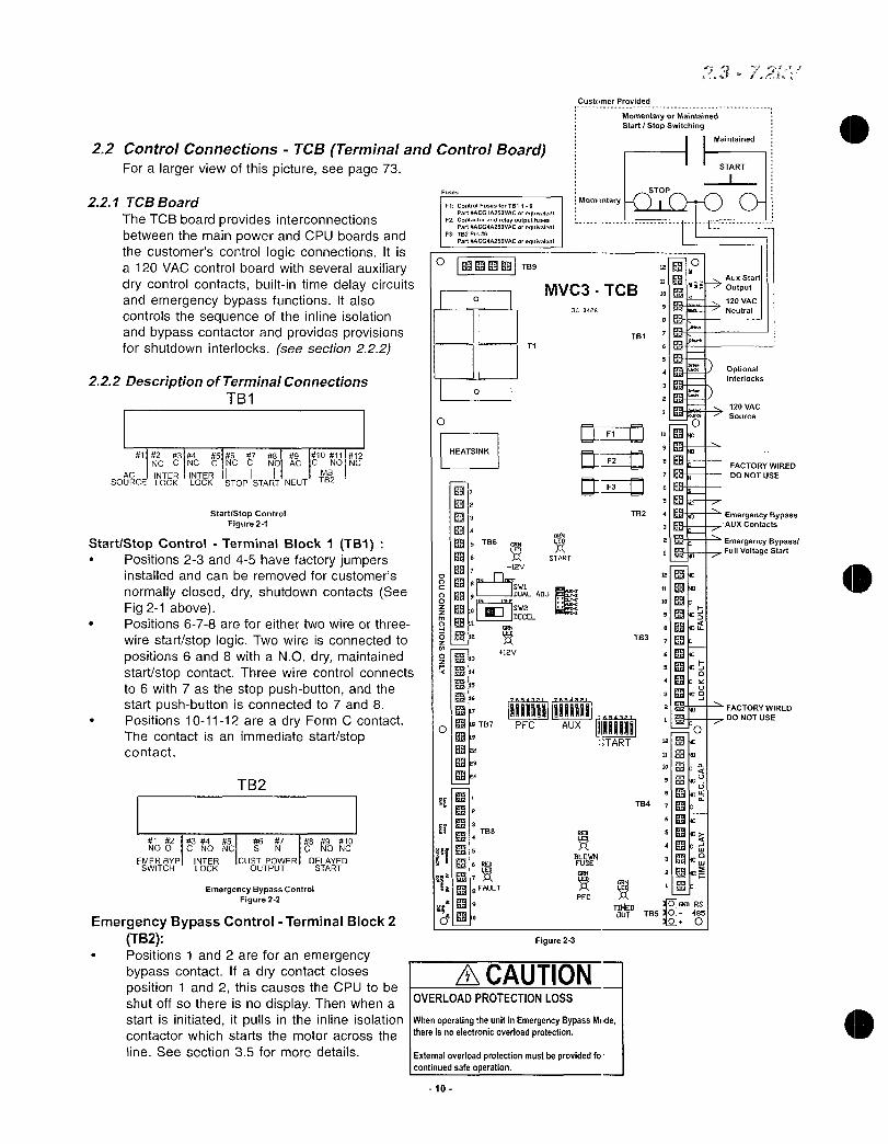
22ControlConnections TCBTerminalandControlBoardForalargerviewofthispictureseepage73
221TCBBoard
TheTCBboardprovidesinterconnectionsbetweenthemainpowerandCPUboardsandthecustomerscontrollogicconnectionsItisa120VACcontrolboardwithseveralauxiliarydrycontrolcontactsbuiltintimedelaycircuitsandemergencybypassfunctionsItalsocontrolsthesequenceoftheinlineisolationandbypasscontactorandprovidesprovisionsforshutdowninterlocksseesection222
222DescriptionofTerminalConnectionsTB1
1234 56789101112NCCNCCNCC NOACCNONC
AC INTERINTER1 1 MB
SOURCELOCKLOCKSTOPSTARTNEUTTB2
StartStopControlFigure21
StartStopControl TerminalBlock1TB1Positions23and45havefactoryjumpersinstalledandcanberemovedforcustomers
normallycloseddryshutdowncontactsSeeFig21abovePositions678areforeithertwowireorthree
wirestartstoplogicTwowireisconnectedtopositions6and8withaNOdrymaintainedstartstopcontactThreewirecontrolconnectsto6with7asthestoppushbuttonandthestartpushbuttonisconnectedto7and8Positions101112areadryFormCcontactThecontactisanimmediatestartstopcontact
TB2
NOO 33NONC 6 7N CNONCEMERBYPINTER CUSTPOWERDELAYED
SWITCH LOCK OUTPUT START
EmergencyBypassControlFigure22
EmergencyBypassControlTerminalBlock2TB2Positions1and2areforanemergencybypasscontactIfadrycontactclosesposition1and2thiscausestheCPUtobeshutoffsothereisnodisplayThenwhenastartisinitiateditpullsintheinlineisolationcontactorwhichstartsthemotoracrossthe
lineSeesection35formoredetails
O
Fuses
2902
t14
15
16
17
sTB70
19
22
23
24
gi
10
F1ControlFusesforTB119
PartACG1A25OVACorequivalentF2Contactorandrelayoutputfuses
PartACG4A25OVACorequivalentF3TB2Pin6
PartACG4A2S0VACorequivalent
HEATSINK
T
t
T
T
0
4909
5TB6
712V
91 ISW1DUALADJop rum
I ISW2DECELl
le
690
17112V
IF 3TBB4
5
6RED
8FAULT
0
440TB9
T1
MVC3TCB
START
531
I1011111111AiPFC AUX 111111111
TART
FigureFigure23
OVERLOADPROTECTIONLOSS
CustomerProvided
STOP
Momentaryentary
360426
ACAUTION
RED
l1
BLOWNFUSErak
PFC
WhenoperatingtheunitinEmergencyBypassModethereisnoelectronicoverloadprotection
Extemaloverloadprotectionmustbeprovidedfocontinuedsafeoperation
MomentaryorMaintained
StartStopSwitching
TB1
F1 laF2IF3IId
TB2 4
3
TB3
TB4
12 oAuxStart
640 Output
10
120VAC
Neutral9
10
4
9
e
7
2
12
11
10
B
7
6
5
4
3
2
11
10
9
e
TIMEDOUTTB5
7
5
4
2
I
O
O
T
0T
12
O
4E
4
1
YUK
pIFACTORYWIREDDONOTUSE
6410RS
485
0
23
Maintained
START
OptionalInterlocks
120VAC
Source
FACTORYWIRED
DONOTUSE
EmergencyBypassAUXContacts
EmergencyBypassFullVoltageStart

Positions345areaFormCcontactThisisadrycontactthatisinitiatedbytheemergencycontactbeingclosedItprovidesindicationoftheemergencybypassmodePositions6and7areacustomerconnectionforcontrolpowerPosition6isthe120VACsupply400VAandposition7isthereturnPositions8910areaFormCcontactThedrycontactisadelayedstartstopcontactTheamountofdelayisdeterminedbyX1X2andSW3seeSwitchPositionsandJumperSelectiononthenextpageNoteAdditionalTimeDelaytoSP2oftheCPUprogramming
Fault TerminalBlock3TB3Positions123and456aresetsofFormCcontactsTheseare
drycontactsthatoperatewhenablownfuseindicationisgivenordisconnectisopenPositions789and101112aresetsofFormCcontactsTheseare
faultcontactsthatchangestateifanyfaultconditionoccurs
OptionalRelay Terminal4TB4Positions123and456aresetsofFormCcontactsTheseare
auxiliarytimedelaycontactsthatwillchangestateafteradelaywhentheStartcontactisinitiatedX3X4andSW4determinetheamountofdelaySeeswitchpositionandJumperselectiononthefollowingpagePositions789and101112aresetsofFormCcontactsTheseare
powerfactorcorrectioncapacitorPFCcontactstopullinanisolationcontactorforthepowerfactorcorrectioncapacitorsifrequiredbytheapplicationThesewillchangestatewhentheAtSpeedcontactisinitiatedX5X6andSW5determinetheamountofdelaySeeSwitchPositionsandJumperSelectiononthefollowingpageNoteThisdelayisinadditiontoSP2oftheCPUprogramming
Terminal5BlockTB5RS485connectionssoftwarerequiredifwiringdistanceis25ftthenmakeuseofterminationresistorsasneededMinimum22gaugetwistedpairwiring
TerminalBlock6TB6FactorywiredMainpowerboardconnections112
TerminalBlock7TB7FactorywiredMainpowerboardconnections1324
TerminalBlock8TB8Positions1and2acceptdrynormallyclosedcontactsfromblownfuseindicatorsandordisconnectinterlockcontact
Positions3and4acceptdrynormallyclosedcontactsfromanexternaloverloadprotectiondevicerequiredifemergencybypassisusedPositions5and6acceptdrynormallyclosedcontactfromthebypasscontactorforanAtSpeedindicationFactorywiredPositions7and8arewiredtothecoilofthebypasscontactorandenergizesanddeenergizesthecontactorFactorywiredPositions9and10arewiredtothecoiloftheinlineisolationcontactorandenergizesanddeenergizesthecontactor
NoteAllcustomercontactsare960VA120VACMaxrateddrycontacts
TB3
123456789101112CNONCCNONCCNONCCNONC
LockoutFaultContacts
Figure24
TB4
t123456576811101112CNONCCNONCGNONCCNONC
TIMEDELAY PFCCAP
TimeDelayPFCCapContactsFigure25

LEDsprovidedontheTCBboard12VDCpowersupply12VDCpowersupplyStart startisinitiatedtoTCBboard
Fault anyfaulthasoccurredFuseBlown disconnectopenorblownfusehasactivatedPFCOn PowerFactorCorrectionCapacitorcontactshaveenergizedTimedOut Auxiliarytimedelaycontactshaveenergized
JumperSelectionForthefollowingpleaserefertoFigure26
StartDelayThisisaselectabledelayperiodbetweentheinitiationofthestartcommandandwhentheCPUactuallyreceivesthestartsignalSelectingJumperX1orX2determinesthemethodbywhichthisdelayincyclesorsecondsiscalculatedSeebelowforinstructionsonsettingdelaytime
X1 DLYCStarttimedelayincyclesX2 DLYSStarttimedelayinsecondsFactorysetting
AuxiliaryStartDelayfromthetimethestartisinitiatedtowhencontactschangestateSelectingjumperX3orX4determinesthemethodbywhichthisdelayiscalculatedcyclesorsecondsSeebelowforinstructionsonsettingdelaytime
X3 AUXCAuxiliarytimedelayincyclesX4 AUXSAuxiliarytimedelayinsecondsFactorysetting
PowerFactorCorrectionPFCCapacitorContactorDelayFromthetimethebypassclosestowhencontactschangestateJumperselectiondeterminesthemethodbywhichthisdelayiscalculatedSeebelowforinstructiononsettingdelaytime
X5 PFCCTimedelayincyclesX6 PFCSTimedelayinsecondsFactorysetting
SwitchPositions
PleaserefertoFigure27SW1 On DualAdjustment
OFF Disabled
SW2 Notused
SwitchesSW3SW4andSW5are7positiondipswitchesthatusebinarycodetocountupto127secondscyclesseeJumperSelectionaboveSW3 StartDelay7positiondipswitchusesbinarycountupto127secondscyclesSeejumperselectionaboveFactorysetting1secondSW4 AuxiliaryStartDelay7positiondipswitchusesbinarycountupto127secondscyclesSeejumperselectionaboveFactorysetting1second
SW5 PFCtimedelay7positiondipswitchusesbinarycountupto127secondscyclesSeejumperselectionaboveFactorysetting1second
NoteThisswitchinteractswiththeCPUprogrammingwhentheDecelfunctionisenabled
NoteThesetimesareinadditiontoSP2intheCPUsetpoints
12
PFCSrX6PFCC X5AUXC X3DLYC X1DLYS X2AUXS X4
Figure27
JuniperSelectiononTCBBoardFigure26
SwitchPositions
On
1 2 3 4 5 6 7
Tme 1 2 4 8163264
secondscycles
lxampleSwitchsettingsarecumulativeSettingdipswitchpositions12and3toon 124 7seconds
totaltimeNoteThisexampleappliestoSW3SW4 SW5

23ReferenceSectionTHISSECTIONISFORREFERENCEONLYNOFIELDWIRINGCONNECTIONSAREREQUIRED
23aOptionalRTDBoard
0
IJ7
27ZS EciUa
rz0ccr
7
RTD
TypicalRTDInstallation
U1P1
EC111R23 ECiR2
C4
1R7 U
C6 C7
R110 U20RIO
R9
C9 Ej0n
11ER15
C12
R16U5
1iU7 11F07
L1C17 C19
C18
U10
U11
DR49
RTD1 RTD2 RTD3 RTD4
1
TB1 12113
031 U12
COr1 c rz3
RTD5 RTp6
TB2 24125
13
RTD7
R5E102IQ4CI
TB3 36137
U4 CB
X1
U9
C37 L1
E10 gDEIN C43
E1UL2
TB4
23
U6
116
C45
0
RTD8 RTp9 RTD10 RTD11 Rip12
48

Z3ReferenceSectionTHISSECTIONISFORREFERENCEONLY
NOFIELDWIRINGCONNECTIONSAREREQUIRED
23bCommunicationsBoard
0 O
TB1
TB1RS485
NoteRemoveforlastunitinmodbusstring
23cCommunicationsBoardConnections
1 2 3 4 IIN U UZ Z
m
RS485Connections
CustomerConnections
REAR
VIEW
TB2RS422X2X3
11
14
X4 J1
TB2 1 2 3 4 5 reI N N
Q ma KOD
RECEIVETRANSMIT
RS422Connections
FactoryOnly

0
23ReferenceSectionTHISSECTIONISFORREFERENCEONLYNOFIELDWIRINGCONNECTIONSAREREQUIRED
23dPowerBoard
CI
TwoWire
Connection
0i
CT
GF
J8
AUX1
TRIPRelay
BoardGroup TestPoints
HHH
0
0082 B1
oe
20
0 0
23ePowerBoardConnections
TB3
1 2 3 4 5 6
InterlocktartControl
ContactControl
Power Power
J5
TB1
2 34 56T 89
TB1
FactoryuseonlyDonotreprogram
I1 2 3 I 4 I 5 6 7
C NONCC NON0C
AUX2
ALARMRelay
TB2
RefertoSetpointPage5forprogramminginformation
8 1 9 10 11 L 13 14 I15116I17 18 19 20 21 122F3 24
NONCC NONCC NONCC NON0C NONCC NONC
AUX3
RUNRelay
J3
0
2 4
AUX4
ATSPEEDRelay
J420 J6
TB2
567 89 1011
ThreeWire
Connection
AUX5
Relay
TB3
MaxRelayContactRatingis240VAC4A960VA
15
J L
F1
1 2 1 3 4 5 6
11InterlockStop wt
Control Control
Power Power
TJJ1
7PPhase
48Phase
1CPhase
J2
IJ7
0
T63
0
J2
AUX6 AUX7 AUX8
Relay Relay Relay
4msi021cL

23ReferenceSectionTHISSECTIONISFORREFERENCEONLYNOFIELDWIRINGCONNECTIONSAREREQUIRED
23fCPUBoardConnections
TB1
1
a2654321
r
J7
1920
J4
7
cc
12
1920J5
1 1 121 3 4 151 6 7 1819
TB4
TB1
1 8CGND4
TB2
4
Contactfactoryforremoteresetconnections
0
Cw
E
02
7
NoteInstallprogramjumpertoenablesetpointprogrammingJumpermustberemovedafterprogrammingorforprolongedstoragetopreservesettings
16
1TB2 8TB3
8
J2
od
O Nm
cco
cn
LL
a
T63 0 0 0
4039
J32 1
CGND3
0
FactorywiredDonotchange
EN
1 12 31 4 5 6 7 8
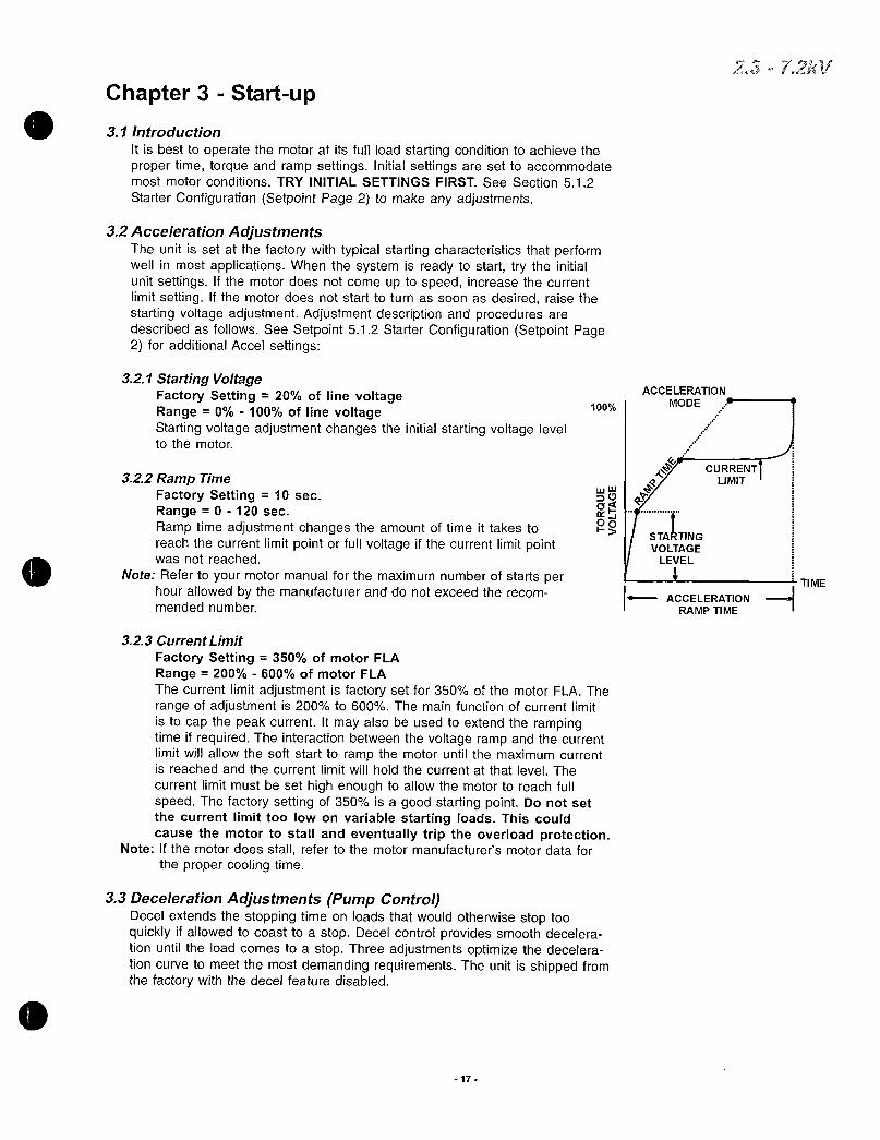
0Chapter3 Startup
31Introduction
ItisbesttooperatethemotoratitsfullloadstartingconditiontoachievethepropertimetorqueandrampsettingsInitialsettingsaresettoaccommodatemostmotorconditionsTRYINITIALSETTINGSFIRSTSeeSection512
StarterConfigurationSetpointPage2tomakeanyadjustments
32AccelerationAdjustmentsTheunitissetatthefactorywithtypicalstartingcharacteristicsthatperformwellinmostapplicationsWhenthesystemisreadytostarttrytheinitialunitsettingsIfthemotordoesnotcomeuptospeedincreasethecurrentlimitsettingIfthemotordoesnotstarttoturnassoonasdesiredraisethestartingvoltageadjustmentAdjustmentdescriptionandproceduresaredescribedasfollowsSeeSetpoint512StarterConfigurationSetpointPage2foradditionalAccelsettings
321StartingVoltageFactorySetting 20oflinevoltageRange 0 100oflinevoltageStartingvoltageadjustmentchangestheinitialstartingvoltageleveltothemotor
322RampTimeFactorySetting 10sec
Range 0 120sec
Ramptimeadjustmentchangestheamountoftimeittakestoreachthecurrentlimitpointorfullvoltageifthecurrentlimitpointwasnotreached
NoteRefertoyourmotormanualforthemaximumnumberofstartsperhourallowedbythemanufactureranddonotexceedtherecommendednumber
17
100
323CurrentLimit
FactorySetting 350ofmotorFLA
Range 200 600ofmotorFLA
Thecurrentlimitadjustmentisfactorysetfor350ofthemotorFLATherangeofadjustmentis200to600 Themainfunctionofcurrentlimit
istocapthepeakcurrentItmayalsobeusedtoextendtherampingtimeifrequiredTheinteractionbetweenthevoltagerampandthecurrentlimitwillallowthesoftstarttorampthemotoruntilthemaximumcurrentisreachedandthecurrentlimitwillholdthecurrentatthatlevelThe
currentlimitmustbesethighenoughtoallowthemotortoreachfullspeedThefactorysettingof350isagoodstartingpointDonotsetthecurrentlimittoolowonvariablestartingToadsThiscouldcausethemotortostallandeventuallytriptheoverloadprotection
NoteIfthemotordoesstallrefertothemotormanufacturersmotordataforthepropercoolingtime
33DecelerationAdjustmentsPumpControlDecelextendsthestoppingtimeonloadsthatwouldotherwisestoptooquicklyifallowedtocoasttoastopDecelcontrolprovidessmoothdecelerationuntiltheloadcomestoastopThreeadjustmentsoptimizethedecelerationcurvetomeetthemostdemandingrequirementsTheunitisshippedfromthefactorywiththedecelfeaturedisabled
ACCELERATION
MODE A
1
wW
saY
OoSTARTING
VOLTAGE
LEVEL
ACCELERATION
RAMPTIME
CURRENTLIMIT
J
TIME
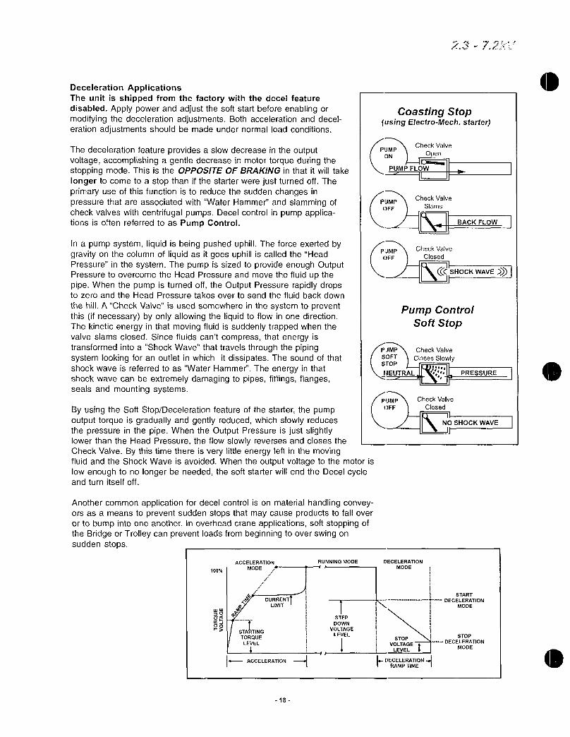
DecelerationApplicationsTheunitisshippedfromthefactorywiththedecelfeaturedisabledApplypowerandadjustthesoftstartbeforeenablingormodifyingthedecelerationadjustmentsBothaccelerationanddecelerationadjustmentsshouldbemadeundernormalloadconditions
ThedecelerationfeatureprovidesaslowdecreaseintheoutputvoltageaccomplishingagentledecreaseinmotortorqueduringthestoppingmodeThisistheOPPOSITEOFBRAKINGinthatitwilltakelongertocometoastopthanifthestarterwerejustturnedoffTheprimaryuseofthisfunctionistoreducethesuddenchangesinpressurethatareassociatedwithWaterHammerandslammingofcheckvalveswithcentrifugalpumpsDecelcontrolinpumpapplicationsisoftenreferredtoasPumpControl
InapumpsystemliquidisbeingpusheduphillTheforceexertedbygravityonthecolumnofliquidasitgoesuphilliscalledtheHeadPressureinthesystemThepumpissizedtoprovideenoughOutputPressuretoovercometheHeadPressureandmovethefluidupthepipeWhenthepumpisturnedofftheOutputPressurerapidlydropstozeroandtheHeadPressuretakesovertosendthefluidbackdown
thehillACheckValveisusedsomewhereinthesystemtopreventthisifnecessarybyonlyallowingtheliquidtoflowinonedirectionThekineticenergyinthatmovingfluidissuddenlytrappedwhenthevalveslamsclosedSincefluidscantcompressthatenergyistransformedintoaShockWavethattravelsthroughthepipingsystemlookingforanoutletinwhichitdissipatesThesoundofthatshockwaveisreferredtoasWaterHammerTheenergyinthatshockwavecanbeextremelydamagingtopipesfittingsflangessealsandmountingsystems
ByusingtheSoftStopDecelerationfeatureofthestarterthepumpoutputtorqueisgraduallyandgentlyreducedwhichslowlyreducesthepressureinthepipeWhentheOutputPressureisjustslightlylowerthantheHeadPressuretheflowslowlyreversesandclosestheCheckValveBythistimethereisverylittleenergyleftinthemovingfluidandtheShockWaveisavoidedWhentheoutputvoltagetothemotorislowenoughtonolongerbeneededthesoftstarterwillendtheDecelcycleandturnitselfoff
AnothercommonapplicationfordecelcontrolisonmaterialhandlingconveyorsasameanstopreventsuddenstopsthatmaycauseproductstofalloverortobumpintooneanotherInoverheadcraneapplicationssoftstoppingoftheBridgeorTrolleycanpreventloadsfrombeginningtooverswingonsuddenstops
100
ACCELERATIONMODE
CURRENTLIMIT
0a
43OQ 1
STARTING
TORQUE
LEVEL
ACCELERATION
18
9
H
STEP
DOWN
VOLTAGE
LEVEL
CoastingStopusingElectroMechstarter
CheckValve
Open
PUMPFLOW
it I
PUMPON
OFF
RUNNINGMODE DECELERATION
MODE
PJMP CheckValveSOFT ClosesSlowlySTOP
IJEUTRAL
STOP
VOLTAGELEVEL
ffDECELERATIONIRAMPTIME I
CheckValve
Slams
II BACKFLOW
I II
CheckValve
Closed
diSHOCKWAVE
I
PumpControlSoftStop
CheckValve
Closed
INOSHOCKWAVE
li
START
DECELERATIONMODE
STOP
DECELERATION
MODE

0
0
0
331StartDecelerationVoltageFactorySetting 60oflinevoltageRange 0 100oflinevoltageThestepdownvoltageadjustmenteliminatesthedeadbandinthedecelerationmodethatisexperiencedwhilethevoltagedropstoalevelwherethemotordecelerationisresponsivetodecreasedvoltageThisfeatureallowsforaninstantaneousdropinvoltagewhendecelerationisinitiated
332StopDecelerationVoltageFactorySetting 20oflinevoltageRange 0 100oflinevoltageThestopvoltagelevelsetpointiswherethedecelerationvoltagedropstozero
333DecelerationTime
FactorySetting 5sec
Range 0 60sec
ThedecelerationramptimeadjuststhetimeittakestoreachthestopvoltagelevelsetpointTheunitshouldberestartedandstoppedtoverifythatthedesireddecelerationtimehasbeenachieved
NoteDonotexceedthemotormanufacturersrecommendednumberofstartsperhourWhencalculatingthenumberofstartsperhouradecelcurveshouldbecountedasastartcurveForexamplerecommendednumberofstartsperhour 6allowablestartswithdecelcycleperhour 3
34SequenceofNormalOperationApplycontrolpowerandcheckthatthePowerLEDcomesonDisplay1ApplythreephasepowertotheunitThemotorshouldrunonlywhenthestartcommandisappliedApplythestartcommandDisplay2TheRUNLEDwillbelitDisplay3TheAUX3LEDswillbelitIfthemotordoesnotenterrunmodeinthesettimeAccelerationtimelimitseeSP82atripwilloccurWhenthemotorreachesfullspeedtheAUX4LEDAtSpeedwillbelitThePOWERRUNAUX3LEDswillbelitindicatingthatthecontacthasenergizedIAIBICwilldisplaythecurrentsettingforPhaseAPhaseBandPhaseCandtheGFindicatesgroundfaultDisplay4IfthemotordeceleratesorstopsduringtheaccelerationperiodhitthestopbuttonimmediatelyandopenthedisconnectlineIftheunitdoesnotfollowthisoperationalsequencepleaserefertotheTroubleshootingChapter
ItisbesttooperatethemotoratitsfullloadstartingconditiontoachievethepropertimetorqueandrampsettingsInitialsettingsaresettoaccommodatemostmotorconditionsTRYINITIALSETTINGSFIRSTSeeSection511SetpointPage2tomakeanyadjustments
InitialVoltageSoftStartCurve
CurrentLimit
AccelerationTime
IfdecelisenabledthefollowingparametersforDecelerationTimeStartDecelVoltageseeSP2page35andStopDecelVoltagemustalsobeprogrammed
19
Display1
Display2
Display3
Display4
MOTORSTOPPEDREADYTOSTART
MOTORSTARTING00XFLA
IAIBIC GF
Pf
OVERLOADALARMTIMETOTRIPXXXSECS

35EmergencyBypassOperation
HAZARDOUSOPERATION
DonotoperatetheBypassContactorwithmediumvoltagepowerappliedtotheunit
Failuretofollowthisinstructionwillcausethemotor
tostartunexpectedly
RemoveinputpowerusinglinestartsectionandlockoutdisconnectClosetheemergencybypasscontactReclosedisconnectonlinestartpanelBimetallicoverloadprotectionisrequiredcustomersuppliediffactoryemergencyoverloadprotectionoptionhasnotbeenincluded
NoteIntheemergencybypassmodethereisnooverloadprotectionunlessaseparateoptionalorcustomersupplierthermaloverloadrelayisinstalled
ThelinestartpanelisoperableasanormalacrossthelinestarterWhenpowerisappliedthebypasscontactorisenergizedtyingtheinputterminalsdirectlytoitsoutputterminalsWhentheONOFFcontactisclosedthemaincontactorisenergizedandthemotorlinestartsWhentheONOFFcontactisopenedthemotorisdisconnectedfromthelineviathemaininlinevacuumcontactor
20
72V
O

Chapter4 UserInterface MenuNavigationThischapterexplainsthekeypadoperatorinterfacetheLCDdescriptionsandtheprogrammingfeatures
s
41KeypadOperatorInterfaceTheuserkeypadkeypadoperatorinterfaceconsistsof
2rowby20charactersLiquidCrystalDisplayLCD12LEDs
8pushbuttons
NoteThecontrollerismenudrivenandtherearethreelevelsofprogrammingTheprogrammingfortwooftheselevelsispasswordprotectedLeveltworequiresathreedigitpasswordandlevelthreerequiresafourdigitpassword
MENU Togglebetweenthemenuselectionformeteringandsetpointpages
RESET Willclearthetripindicatorandreleasethetriprelay
IntheeditmodepresstheENTERpushbuttonsotheunitwillacceptthenewprogramminginformation
ENTER WhennotintheeditmodetheENTERpushbuttonwilltogglethroughtheeventindicatorlistsuchasalarmsortrips
HELP Providesgeneralhelpinformationaboutaspecificsetpointoraction
WillscrollupthroughthesetpointandmeteringmenupageItwillscrolltothetopofthesetpointpageora
UPARROW sectionIneditmodeitwillincreaseasetpointinanincrementalsteportogglethroughtheavailableoptionsinthesetpoint
InthemainmenutheRIGHTARROWbuttonprovidesaccesstothesetpointpageForsetpointpageswith
RIGHTARROWmultiplecolumnstheRIGHTARROWwillscrollthesetpointpagetotherightWhenineditmodeitwillshiftonecharactertotheright
Willscrolldownthroughthesetpointpagesanddown
DOWNARROWthroughthesetpointsIneditmodeitwilldecrementthroughvaluesandtoggleavailableoptionsinthesetpoint
WillmovetotheleftthroughsetpointpageswithLEFTARROWmultiplecolumnsWhenineditmodeitwillbecomethe
backspacekeyandwillshiftonecharactertotheleft
Power IndicatescontrolpowerispresentRun Indicatesunitmotorisrunning
Alarm Lights inconjunctionwithAUX2toindicateeventorwarnofpossiblecriticalcondition
Trip Lights inconjunctionwithAUX1toindicateacriticalconditionhasoccurred
AUX18 lAuxilaryrelays
NoteThedirectionalarrowbuttonsrequirecarefuloperationIneditmodeifthebuttonsareheldforalongperiodthescrollingspeedwillincrease
21
KeypadOperatorInterface

42MenuNavigation
A IPAGE 1 BASICCONFIGURATION
LEVEL1
PAGE2STARTER
CONFIGURATION
LEVEL2
APAGE7 CUSTOM
ACCELERATIONCURVE
LEVEL3
IPAGE 6 USERIOCONFIGURATION
V
PAGE3 PHASE
GROUNDSETTINGS
PAGE4RELAY
ASSIGNMENT
PAGE5RELAYCONFIGURATION
PAGE9 RTD
CONFIGURATION
PAGE10SECURITYSETPASSWORD
PAGE11
COMMUNICATIONS
PAGE12 SYSTEM
V SETPOINTS
MENU
I
PAGESOVERLOAD
CURVECONFIGURATION
IFACTORY
I PAGE13CALIBRATION
LEVEL SERVICE
Notes
1TheMENUkeysallowyoutotogglethescrefnsbetweentheSetpointMenuandtheMeteringMenuSimplyusethearrowkeystogettothedifferentscreenswithineachmenu
ExampleToaccessSetpointPage3PHASE GROUNDSETTINGSpresstheMENUkeyonceandtheDOWNARROWtwotimes
2Levels12and3indicatepasswordprotectionlevelsforthesesetpointpages
22

A421PasswordAccess
ScreensinLevel1ofthesetpointmenucanbechangedwithoutpasswordaccessbecausetheylistbasicmotorinformationScreensinLevels2and3requirepasswordsbecausetheyprovidemoreindepthprotectionandcontrolofthesoftstarterunitThepasswordinLevels2and3canbechangedbytheuser
Note SetpointscanonlybechangedwhenthemotorisinStopReadyModeTheunitwillnotallowastartifitisstillintheEditModeWhentheunitisintheEditModeanasteriskisdisplayedinthetoprightcornerofthedisplay
422ChangingSetpointsExample1ChangingMotorFLA
APressMENUbuttontodisplaySetpointPage1BasicConfigurationBPresstheRIGHTARROWyouwillviewthescreenMotorFullLoad
AmpsCPresstheENTERbuttonforeditmodeNotetheasterisk inthetop
rightcorneroftheLCDscreenthatindicatesEditModeDTochangethevalueselecttheUPARROWorDOWNARROWEToacceptthenewvaluepresstheENTERbuttonTheunitwillaccept
thechangesandwillleavetheeditmodeNotetheisnolongerinthetoprightcorneroftheLCDDisplay
MENU
PAGE1BASICCONFIGURATION
MOTORFULLLOADAMPS
140AMPS
ENTER
ENTER
2x
MOTORFULLLOADAMP
142AMPS
MOTORFULLLOADAMP142AMPS
23

Chapter5 SetpointProgrammingThecontrollerhasthirteenprogrammablesetpointpageswhichdefinethemotordatarampcurvesprotectionIOconfigurationandcommunicationsInSection51thesetpointpagesareoutlinedinchartformInSection52thesetpointpagesareillustratedanddefinedforeasynavigationandprogrammingNoteSetpointscanonlybechangedwhenthestarterisintheReadyModeAlsothesoftstartwillnotstartwhenitisinprogrammingmode
51SetpointsPageListThesechartslisttheSetpointPagetheprogrammablefunctionsandthesection
511BasicConfigurationSetpointPagel
0
o0cc
C15m
c 205
E 00Nm rLL
0aU 0N
chasm a
CO oZ
MotorFullLoadAmpsFLA
ServiceFactor
TmOverloadClass
To12
Jo NEMADesign
InsulationClassa
o LineVoltage
LineFrequency
512StarterConfigurationSetpointPage2
StartControlMode
JogVoltage
StartRamp1Type
InitialVoltage1
RampTime1
CurrentLimit1
InitialCurrent1
RampTime1
MaximumCurrent1
StartRamp2Type
InitialVoltage2
RampTime2
CurrentLimit2
InitialCurrent2
RampTime2
MaximumCurrent2
KickStartType
KickStartVoltage
KickStartTime
Deceleration
StartDecelerationVoltage
StopDecelerationVoltage
DecelerationTime
TimedOutputTime
RunDelayTime
AtSpeedDelayTime
Modeldependent
115
10
B
B
4160
60
StartRamp1
Off
Voltage
20
10sec
350FLA
200FLA
10sec
350FLA
Off
60
10sec
350 FLA
200FLA
10sec
350FLA
Off
65
050sec
Disabled
60
30
5sec
Off
1Sec
1Sec
24
50100ofUritMaxCurrentRatingModelandServiceFactordependent10013
OLClass530
AF
ABCEFHKNS
100to7200V
50or60HZ
JogStartRamp1StartRamp2CustomAccelCurveStartDisabledDualRamp
575Off
CurrentVoltageOff
0100
0120sec
200600
0300
0120sec
200600
CurrentVoltageOff
0100
0120sec
200600
0600
0120sec
200600
VoltageorOff
10100
010200
EnabledorDisabled
0100
059
160sec
11000secOff
130secOff
130secOff
SP11
SP12
SP13
SP14
SP15
SP16
SP17
SP21
1 SP22
SP23
SP24
SP25
SP26
SP27
SP28
SP29

t 513PhaseandGroundSettingsSetpointPage3
0
Groundfaultoptionmustbeinstalled
ImbalanceAlarmLevel
ImbalanceAlarmDelay
ImbalanceTripLevel
ImbalanceTripDelay
UndercurrentAlarmLevel
UndercurrentAlarmDelay
OvercurrentAlarmLevel
OvercurrentAlarmDelay
OvercurrentTripLevel
OvercurrentTripDelay
PhaseLossTrip
PhaseLossTripDelay
PhaseRotationDetection
PhaseRotation
GroundFaultAlarmLevel
GroundFaultAlarmDelay
GroundFaultLosetTripLevel
GroundFaultLosetTripDelay
GroundFaultHisetTripLevel
GroundFaultHisetTripDelay
OvervoltageAlarmLevel
OvervoltageAlarmDelay
OvervoltageTripLevel
OvervoltageTripDelay
UndervoltageAlarmLevel
UndervoltageAlarmDelay
UndervoltageTripLevel
UndervoltageTripDelay
LineFrequencyTripWindow
LineFrequencyTripDelay
PFLeadPFAlarm
PFLeadAlarmDelay
PFLeadPFTrip
PFLeadTripDelay
PFLagPFAlarm
PFLagAlarmDelay
PFLagPFTrip
PFLagTripDelay
PowerDemandPeriod
KWDemandAlarmPickup
KVADemandAlarmPickup
KVARDemandAlarmPickup
AmpsDemandAlarmPickup
15FLA
15sec
20
20sec
Off
20sec
Off
20sec
Off
20sec
Disabled
01sec
Enabled
ABC
Off
01sec
Off
05sec
Off
0008sec
Off
10sec
Off
20sec
Off
10sec
Off
20sec
Disabled
10sec
Off
10sec
Off
10sec
Off
10sec
Off
10sec
10min
OffKW
OffKVA
OffKVAR
OffAmps
25
530 Off
10200sec
530 Off
10200sec
1090 Off
10600sec
100300 Off
10200sec
100300 Off
10200sec
EnabledorDisabled
0200sec
EnabledOnly
ABC
590 Off
01200sec
590 Off
0120sec
590 Off
00080250sec
530 Off
10300sec
530 Off
10300sec
530 Off
10300sec
530 Off
10300sec
06HzDisabled
10200sec
01100Off
1120sec
01100Off
1120sec
01100Off
1120sec
01100Off
1120sec
160min
Off1100000
Off1100000
Off1100000
Off1100000
r112kV
SP31
SP32
SP33
SP34
SP35
SP36
SP37
SP38
SP39
SP310
5P311
SP312
SP313
SP314
SP315
SP316
SP317
SP318
SP319
SP320

514RelayAssignmentsSetpointPage4
mCt
OLTripIBTrip
SCTrip
OvercurrentTripStatorRTDTrip
BearingRTDTrip
GFHiSetTrip
GFLoSetTrip
PhaseLossTrip
AccelTimeTrip
StartCurveTrip
OverFrequencyTrip
UnderFrequencyTripI1TStartCurve
LearnedStartCurve
PhaseReversal
OvervoltageTrip
UndervoltageTrip
PowerFactorTrip
TachAccelTrip
InhibitsTripTCBFault
ExternalInput2
DualRampThermostat
OLWarningOvercurrentAlarm
SCRFailShuntAlarm
GroundFaultAlarm
UnderCurrentAlarm
MotorRunningIBAlarm
StatorRTDAlarm
NonStatorRTDAlarm
RTDFailureAlarm
SelfTestFail
ThermalRegisterUVAlarm
OVAlarm
PowerFactorAlarm
KWDemandAlarm
KVADemandAlarm
KVARDemandAlarm
AmpsDemandAlarm
TimedOutput
RunDelayTime
AtSpeed
Groundfaultoptionmustbeinstalled
TripOnly None None
Trip None None
TripOnly None None
Trip None None
Trip None None
Trip None None
Trip None None
Trip None None
Trip None None
TripOnly None None
TripOnly None None
Trip None None
Trip None None
Trip None None
Trip None None
Trip None None
Trip None None
Trip None None
Trip None None
None None None
Trip None None
Trip None None
None None None
None None None
Trip None None
Alarm None None
Alarm None None
None None None
Alarm None None
None None None
AUX3 None None
Alarm None None
None None None
None None None
None None None
Trip None None
Alarm None None
Alarm None None
Alarm None None
None None None
None None None
None None None
None None None
None None None
None None None
None None None
AUX4 None None
26
None
TripAUX1AlamAUX2AUX3
AU4
AUX58
OnlyAvailablein8RelaySystemNotes
AUK1toAUX4areforFactory
UseonlyDonotchange
OnlyAUX58areusedinthe2nd 3rdrelayassignments
s

515RelayConfigurationSetpointPage5
L
0
LO CVErn
CllL a
0ccci0 aCLC I
cr Al
TripAUX1FailSafe
TripAUX1RelayLatched
AlarmAUX2FailSafe
AlarmAUX2RelayLatched
AUX3RelayFailSafe
AUX3RelayLatched
AUX4RelayFailSafe
AUX4RelayLatched
AUX5RelayFailSafe
AUX5RelayLatched
AUX6RelayFailSafe
AUX6RelayLatched
AUX7RelayFailSafe
AUX7RelayLatched
AUX8RelayFailSafe
AUX8RelayLatched
No
Yes
No
No
No
No
No
No
No
No
No
No
No
No
No
No
27
YesorNo
YesorNo
YesorNo
YesorNo
YesorNo
YesorNo
YesorNo
YesorNo
YesorNo
YesorNo
YesorNo
YesorNo
YesorNo
YesorNo
YesorNo
YesorNo
23 72kV
SP51
SP52
SP51
SP52
SP51
SP52
SP51
SP52
SP51
SP52
SP51
SP52
SP51
SP52
SP51
SP52

516UserIOConfigurationSetpointPage6
TachometerScaleSelection
ManualTachScale40mA
ManualTachScale200mA
TachAccelTripModeSelect
TachRampTime
TachUnderspeedTripPT
TachOverspeedTripPT
TachAccelTripDelay
AnalogOutput1
AnalogOutput14mA
AnalogOutput120mA
AnalogOutput2
AnalogOutput24mA
AnalogOutput220mA
UserProgrammableExternalInputs
TCBFault
NameExtInput1
ExternalInput1Type
ExternalInput1TimeDelay
ExternalInput2
NameExtInput2
ExternalInput2Type
ExternalInput2TimeDelay
SecondRamp
NameExtInput3
SecondRampType
SecondRampTimeDelay
Thermostat
NameExtInput4
ThermostatType
ThermostatTimeDelay
Disabled
0RPM
2000RPM
Disabled
20sec
1650RPM
1850RPM
1sec
RMSCurrent
0
250
MotorLoad
0
1000
Enabled
TCBFault
NO
1sec
Disabled
NO
0sec
DualRamp
SecondRamp
NO
0sec
Enabled
Thermostat
NC
1sec
28
EnabledorDisabled
03600
03600
UnderspeedOverspeedorDisabled
1120
03600
03600
160
OffRPM03600HottestNonStatorRTD0200CHottestStatorRTD
0200CRMSCurrent07500AMotorLoad0000
065535
065535
SameAsAnalogInput1
01000
01000
EnabledorDisabled
UserDefinedupto15Characters
NormallyOpenorClosed
060sec
EnabledorDisabled
UserDefinedupto15Characters
NormallyOpenorClosed
060sec
EnabledorDisabledorDualRamp
UserDefinedupto15Characters
NormallyOpenorClosed
060sec
EnabledorDisabled
UserDefinedupto15Characters
NormallyOpenorClosed
060sec
23a72kV
SP61
SP62
SP63
SP64
SP65
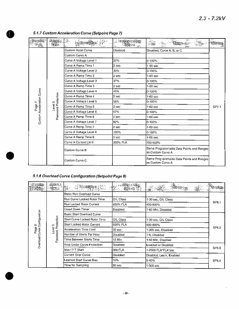
517CustomAccelerationCurveSetpointPage7
crot
CustomAccelCurve Disabled
CustomCurveA
CurveAVoltageLevel1
CurveARampTime1
CurveAVoltageLevel2
CurveARampTime2
CurveAVoltageLevel3
CurveARampTime3a
CurveAVoltageLevel40 0 CurveARampTime4
a
t CurveAVoltageLevel5NIli
CurveARampTime5a
CurveAVoltageLevel6
ct CurveARampTime6
CurveAVoltageLevel7
CurveARampTime7
CurveAVoltageLevel8
CurveARampTime8
CurveACurrentLimit
CustomCurveB
CustomCurveC
25
2sec
30
2sec
37
2sec
45
2sec
55
2sec
67
2sec
82
2sec
100
2sec
350FLA
518OverloadCurveConfigurationSetpointPage8
eliNL
BasicRunOverloadCurve
RunCurveLockedRotorTime
RunLockedRotorCurrent
CoastDownTimerC0ri c
BasicStartOverloadCurve
0t StartCurveLockedRotorTime110
co2 StartLockedRotorCurrent
aa AccelerationTimeLimitci J
c NumberofStartsPerHouro
fca ro TimeBetweenStartsTimeo
rai5 AreaUnderCurveProtection0
MaxITTStart
CurrentOverCurve
LearnedStartCurveBias
TimeforSampling
OLClass
600FLA
Disabled
OLClass
600FLA
30sec
Disabled
15Min
Disabled
368FLA
Disabled
10
30sec
29
DisabledCurveABorC
0100
160sec
0100
160sec
0100
160sec
0100
160sec
0100
160sec
0100
160sec
0100
160sec
0100
160sec
200600
SameProgrammableDataPointsandRangesasCustomCurveA
SameProgrammableDataPointsandRangesasCustomCurveA
130sec0LClass
400800
160MinDisabled
130sec0LClass
400800
1300secDisabled
16Disabled
160MinDisabled
EnabledorDisabled
12500FLAFLAsec
DisabledLearnEnabled
540
1300sec
23 72kV
SP71
SP81
SP82
SP83
SP84

519RTDOptionConfigurationSetpointPage9
co
m
J
UseNEMATempforRTDValues DisabledofRTDUsedforStator
RTDVoting
StatorPhaseAlType
Disabled
Off
RTD1Description StatorAl
StatorPhaseAlAlarmLevel Off
StatorPhaseAlTripLevel Off
StatorPhaseA2Type Off
RTD2Description StatorA2
StatorPhaseA2Alarm Off
StatorPhaseA2TripLevel Off
StatorPhaseB1Type Off
RTD3Description StatorB1
StatorPhaseB1AlarmLevel Off
StatorPhaseB1TripLevel Off
StatorPhaseB2Type Off
RTD4Description StatorB2
StatorPhaseB2AlarmLevel Off
StatorPhaseB2TripLevel Off
StatorPhase01Type Off
RTD5Description Stator01
StatorPhase01AlarmLevel Off
StatorPhase01TripLevel Off
StatorPhaseC2Type Off
RTD6Description StatorC2
StatorPhaseC2AlarmLevel Off
StatorPhaseC2TripLevel Off
EndBearingType Off
RTD7Description EndBearing
EndBearingAlarmLevel Off
EndBearingTripLevel Off
ShaftBearingType Off
RTD8Description ShaftBearing
ShaftBearingAlarmLevel Off
ShaftBearingTripLevel Off
RTD9Type Off
RTD9Description Userdefined
RTD9AlarmLevel Off
RTD9TripLevel Off
30
Enabled orDisabled
106EnabledorDisabled120OHMNI100OHMNI100OHMPT10OHMCU
UserdefinedUp1015Characters
0240C32464FOff
0240C32464FOff
SameasStatorPhaseAl
UserdefinedUp1015Characters
0240C32464FOff
0240C32464FOff
SameasStatorPiaseAl
UserdefinedUpto15Characters
0240C32464FOff
0240C32464FOff
SameasStatorPiaseAl
UserdefinedUp1015Characters
0240C32464FOff
0240C32464FOff
SameasStatorPiaseAl
UserdefinedUpto15Characters
0240C32464FOff
0240C32464FOff
SameasStatorPiaseAl
UserdefinedUpto15Characters
0240C32464FOff
0240C32464FOff
SameasStatorAl
UserdefinedUpto15Characters
0240C32464FOff
0240C32464FOff
SameasStatorPhaseAl
UserdefinedUpto15Characters
0240C32464FOff
0240C32464FOff
SameasStatorPhaseAl
UserdefinedUpto15Characters
0240C32464FOff
0240C32464FOff
23m72kV1
SP91
SP92
SP93
SP94

519RTDOptionConfigurationPage9Contd
1RTD10Type Off
RTD10Description
RTD10AlarmLevel
RTD10TripLevel0
772 RTD11Typean co
RTD11DescriptionCDEas o 1RTD11AlarmLevelCL0
RTD11TripLevel
RTD12Type
5110SecuritySetPasswordPage10
00
0
5111CommunicationsPage11
cr SetLevel2PasswordcU
SetLevel3Password
RTD12Description
RTD12AlarmLevel
1RTD12TripLevel
SetFrontBaudRate
SetModbusBaudRate
1ModbusAddressNumberSetAccessCode
SetLinkBaudRate
RemoteStartStop
Userdefined
Off
Off
Off
Userdefined
Off
Off
Off
Userdefined
Off
Off
110011000
196KBsec196KBsec12471
1384KBsecDisabled
31
000999ThreeDigits
100009999FourDigits
1244896192384KBsec1244896192384KBsec1124711999
1244896192384KBsecEnabled orDisabled
SameasStatorPhaseAl
UserdefinedUpto15Characters
0240C32464FOff
0240C32464FOff
SameasStatorPhaseAl
UserdefinedUpto15Characters
0240C32464FOff
0240C32464FOff
SameasStatorPhaseAl
UserdefinedUpto15Characters
0240C32464FOff
0240C32464FOff
23 72kV
SP94
SP111
SP112
SP113
SP114
SP115
SP116
1SP1011SP102

5112SystemSetpointPage12
N0
aCOCO
c
m0atiTcsU
DefaultDisplayScreen
MeteringDataPage
MeteringDataScreen
Alarms
RTDFailureAlarm
ThermalRegisterAlarm
ThermalAlarmDelay
ThermalRegisterSetupInfo
ColdStallTime
HotStallTime
StoppedCoolDownTime
RuningCoolDownTime
RelayMeasuredCoolRates
ThermalRegisterMinimum
MotorDesignAmbientTemp
MotorDesignRunTemperature
MotorStatorMaxTemp
IBInputtoThermalRegister
UseCalculatedKorAssign
PressEntertoClrThermalRegister
5113CalibrationandServiceSetpointPage13
SetDateandTime
DDMMYYHHMM
EnterDateDDMMYYYY
EnterTimeHHMM
Model
FirmwareREV
PressEntertoAccessFactory
Settings
Disabled
90
10sec
OLClass
hOLClass
30Min
15Min
Disabled
15
40C
80Max
INSCLS
Enabled
FACTORYSET
FACTORYSET
FACTORYSET
FACTORYSET
32
EnterMeteringPage14EnterMeteringScreenPage1110Page2111Page3129Page416
EnabledorDisabled
Off4095
120sec
OLClass530or440secondtimedelay
zOLClass440sec
10300Min
10300Min
EnabledorDisabled
1050
1090C
50100ofMotorStatorMaxTemp
INSCLS102403EnabledOnly
1150On
D131M112 19702069
H0023M059
DisplayOnlyCannotbechanged
AvailabletoQualifiedFactoryPersonnel
2372kV
SP121
SP122
SP123
SP124
SP131
SP132
SP133

52SetpointMenu
Y
A PAGE1 BASICCONFIGURATION
LEVEL1
Y
LEVEL2
LEVEL3
PAGE2STARTERCONFIGURATION
PAGE3 PHASEGROUNDSETTINGS
PAGE4RELAY
ASSIGNMENT
PAGE5RELAY
CONFIGURATION
PAGE6 USERIO
CONFIGURATION
PAGE7 CUSTOM
ACCELERATIONCURVE
PAGE8OVERLOADCURVECONFIGURATION
PAGE9RTD
CONFIGURATION
PAGE10SECURITYSETPASSWORD
PAGE11
COMMUNICATIONS
PAGE12 SYSTEM
SETPOINTS
MENU
I1
I
I
I
FACTORY
I PAGE13CALIBRATION
LEVEL SERVICE
Note
1PushMENUkeytotogglethescreensbetweenSetpointMenuandMeteringMenu
2FollowthearrowkeystogettodifferentscreensExampleForPage3PHASE GROUNDSETTINGSpresstheMENUkeyandtheDOWNARROWtwotimes
33
23 72
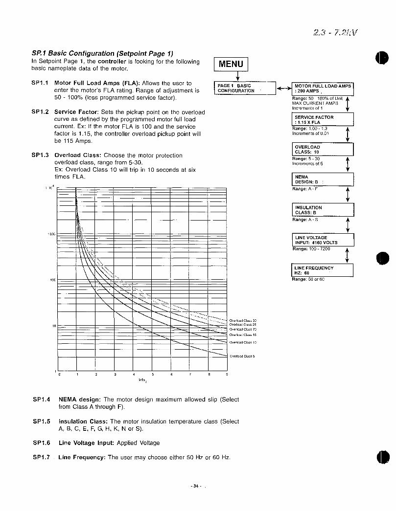
SP1BasicConfigurationSetpointPage1InSetpointPage1thecontrollerislookingforthefollowingbasicnameplatedataofthemotor
SP11 MotorFullLoadAmpsFLAAllowstheusertoenterthemotorsFLAratingRangeofadjustmentis50 100lessprogrammedservicefactor
SP12ServiceFactorSetsthepickuppointontheoverloadcurveasdefinedbytheprogrammedmotorfullloadcurrentExIfthemotorFLAis100andtheservice
factoris115thecontrolleroverloadpickuppointwillbe115Amps
SP13OverloadClassChoosethemotorprotectionoverloadclassrangefrom530ExOverloadClass10willtripin10secondsatsixtimesFLA
100
1000
10
Mfla
NI r 1 I
I
SP14 NEMAdesignThemotordesignmaximumallowedslipSelectfromClassAthroughF
SP15 InsulationClassThemotorinsulationtemperatureclassSelectABCEFGHKNorS
SP16 LineVoltageInputAppliedVoltage
Nl 1
OvedoadClass25
1 j OvedoadClass30ti
OverloadClass20
1 I
V
OverloadClass15I I 4i I
I I JOverloadClass10
I 1 i I III I OverloadClass5
3 4 5 6 7 8 9
SP17 LineFrequencyTheusermaychooseeither50Hzor60Hz
34
I I
MENU
PAGE1BASICCONFIGURATION
MOTORFULLLOADAMPS
200AMPS IRange50100ofUnitMAXCURRENTAMPS
Incrementsof1
SERVICEFACTOR
115XFLA
Range10013Incrementsof001
OVERLOADCLASS10
Range530Incrementsof5
NEMA
DESIGNB
RangeAF
INSULATION
CLASSB
RangeAS
LINEVOLTAGE
INPUT4160VOLTS
Range1007200
LINEFREQUENCYHZ60
Range50or60
237 a
I
I
1
I s

SP2StarterConfigurationSetpointPage2
MENU
PAGE2STARTERCONFIGURATION
HitDOWNARROWonetime
STARTCONTROLMODE
STARTRAMP1
JOGSTARTRAMP1 ASTARTRAMP2DUALRAMPCUSTOMACCELCURVESTARTDISABLED
JOGVOLTAGE
OFF
Range575orOffIncrements5
V
STARTRAMP1TYPE
VOLTAGE
OptionsVoltageCurrentorOff
STARTRAMP2TYPEOFF
OptionsVoltageCurrentAorOff
KICKSTART
TYPEOFF
RangeVoltageorOff
DECELERATION
RangeEnabledor
DisableTIMEDOUTPUT
TIMEOFF
Range11000secOFFIncrementsof1
RUNDELAY
TIME1SEC
Range030secOFFIncrementsof1
ATSPEEDDELAY
TIME1SEC
Range030secOFFIncrementsof1
V
IDISABLED
z
If
VOLTAGE
selected
these
screens
willappear
t
35
If
VOLTAGE
selected
these
screens
willappear
INITIALVOLTAGE
120
Range0100Incrementsof1
RAMPTIME
110SEC
Range0120SECIncrementsof1
CURRENTLIMIT
1350FLA
Range200600Incrementsof10
INITIALVOLTAGE
260
Range0100Incrementsof1
RAMPTIME
210SEC
Range0120SECIncrementsof1
CURRENTLIMIT
2350FLA
Range200600Incrementsof10
KICKSTARTVOLTAGE65
Range10100Incrementsof5
KICKSTARTTIME
050SEC
Range010200Incrementsof010
STARTDECELERATIONVOLTAGE60
Range0100Incrementsof1
STOPDECELERATIONVOLTAGE30
Range059Incrementsof1
DECELERATION
TIME5SEC
Range160Incrementsof1
IfCURRENT
selectedthese
screens
willappear
1
Range0300Incrementsof1
RAMPTIME
110SEC
Range0120SECIncrementsof1
INITIALCURRENT1200FLA
MAXIMUMCURRENT
1350FLA
Range200600Incrementsof10
If ifCURRENT
selected INITIALCURRENT
2200FLAscreens
will
these
appearRange0300Incrementsof1
RAMPTIME
210SEC
Range0120SECIncrementsof1
MAXIMUMCURRENT2350FLA
Range200600Incrementsof10
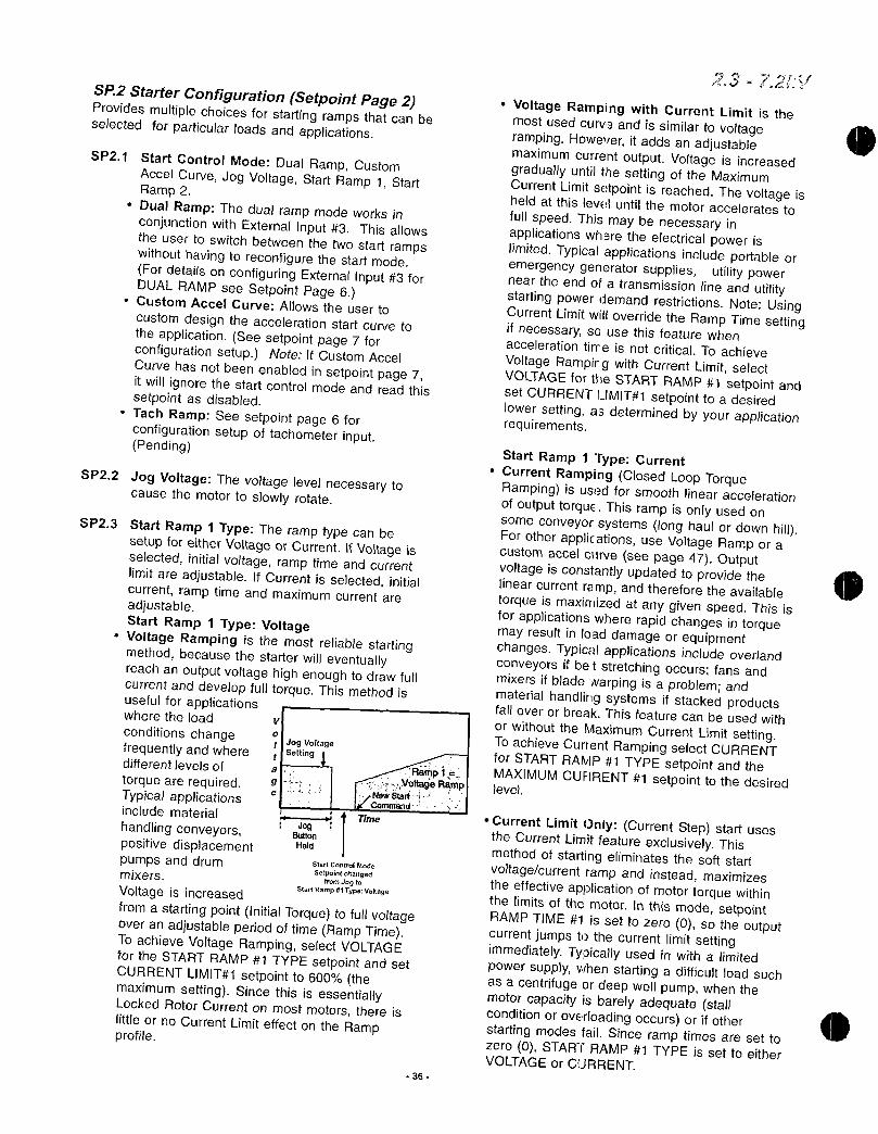
SP2StarterConfigurationSetpointPage2Providesmultiplechoicesforstartingrampsthatcanbeselectedforparticularloadsandapplications
SP21 StartControlModeDualRampCustomAccelCurveJogVoltageStartRamp1StartRamp2DualRampThedualrampmodeworksinconjunctionwithExternalInput3ThisallowstheusertoswitchbetweenthetwostartrampswithouthavingtoreconfigurethestartmodeFordetailsonconfiguringExternalInput3forDUALRAMPseeSetpointPage6CustomAccelCurveAllowstheuserto
customdesigntheaccelerationstartcurvetotheapplicationSeesetpointpage7forconfigurationsetupNoteIfCustomAccelCurvehasnotbeenenabledinsetpointpage7itwillignorethestartcontrolmodeandreadthissetpointasdisabledTachRampSeesetpointpage6forconfigurationsetupoftachometerinputPending
SP22JogVoltageThevoltagelevelnecessarytocausethemotortoslowlyrotate
SP23StartRamp1TypeTheramptypecanbesetupforeitherVoltageorCurrentIfVoltageisselectedinitialvoltageramptimeandcurrentlimitareadjustableIfCurrentisselectedinitialcurrentramptimeandmaximumcurrentareadjustableStartRamp1TypeVoltageVoltageRampingisthemostreliablestartingmethodbecausethestarterwilleventuallyreachanoutputvoltagehighenoughtodrawfullcurrentanddevelopfulltorqueThismethodisusefulforapplicationswheretheload
conditionschangefrequentlyandwheredifferentlevelsof
torquearerequiredTypicalapplicationsincludematerial
handlingconveyorspositivedisplacementpumpsanddrummixers
VoltageisincreasedfromastartingpointInitialTorquetofullvoltageoveranadjustableperiodoftimeRampTimeToachieveVoltageRampingselectVOLTAGEfortheSTARTRAMP1TYPEsetpointandsetCURRENTLIMIT1setpointto600themaximumsettingSincethisisessentiallyLockedRotorCurrentonmostmotorsthereis
littleornoCurrentLimiteffectontheRampprofile
v
O
JogVoltagesetting
e
JogButtonHeld
StartContraMode
SetpointchangedfromJogto
StartRamp1TypeVoltage
RampiOtagoRamp
NVWSferftCommand
Time
36
72trr
VoltageRampingwithCurrentLimitisthemostusedcurv3andissimilartovoltagerampingHoweveritaddsanadjustablemaximumcurrentoutputVoltageisincreasedgraduallyuntilthesettingoftheMaximumCurrentLimitsetpointisreachedThevoltageisheldatthisleveluntilthemotoracceleratesto
fullspeedThismaybenecessaryinapplicationswheretheelectricalpowerislimitedTypicalapplicationsincludeportableoremergencygeneratorsupplies utilitypowerneartheendofatransmissionlineandutilitystartingpowerdemandrestrictionsNoteUsingCurrentLimitwilloverridetheRampTimesettingifnecessarysousethisfeaturewhenaccelerationtirreisnotcriticalToachieve
VoltageRampirgwithCurrentLimitselectVOLTAGEfortheSTARTRAMP1setpointandsetCURRENTLIMIT1setpointtoadesiredlowersettingasdeterminedbyyourapplicationrequirements
StartRamp1TypeCurrentCurrentRampingClosedLoopTorqueRampingisusedforsmoothlinearaccelerationofoutputtorqueThisrampisonlyusedonsomeconveyorsystemslonghaulordownhillForotherapplicationsuseVoltageRamporacustomaccelcurveseepage47OutputvoltageisconstantlyupdatedtoprovidethelinearcurrentrampandthereforetheavailabletorqueismaximizedatanygivenspeedThisisforapplicationswhererapidchangesintorquemayresultinloaddamageorequipmentchangesTypicalapplicationsincludeoverlandconveyorsifbetstretchingoccursfansandmixersifbladewarpingisaproblemandmaterialhandlingsystemsifstackedproductsfalloverorbreakThisfeaturecanbeusedwith
orwithouttheMaximumCurrentLimitsettingToachieveCurrentRampingselectCURRENTforSTARTRAMP1TYPEsetpointandtheMAXIMUMCURRENT1setpointtothedesiredlevel
CurrentLimitOnlyCurrentStepstartusestheCurrentLimitfeatureexclusivelyThismethodofstartingeliminatesthesoftstartvoltagecurrentrampandinsteadmaximizestheeffectiveapplicationofmotortorquewithinthelimitsofthemotorinthismodesetpointRAMPTIME1issettozero0sotheoutputcurrentjumpstothecurrentlimitsettingimmediatelyTypicallyusedinwithalimitedpowersupplywhenstartingadifficultloadsuchasacentrifugeordeepwellpumpwhenthemotorcapacityisbarelyadequatestallconditionoroverloadingoccursorifotherstartingmodesfailSinceramptimesaresettozero0STARTRAMP1TYPEissettoeitherVOLTAGEorCURRENT
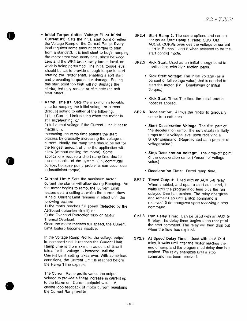
InitialTorqueInitialVoltage1orInitialCurrent1SetstheinitialstartpointofeithertheVoltageRamportheCurrentRampEveryloadrequiressomeamountoftorquetostartfromastandstillItisinefficienttobeginrampingthemotorfromzeroeverytimesincebetweenzeroandtheWK2breakawaytorquelevelnoworkisbeingperformedTheinitialtorquelevelshouldbesettoprovideenoughtorquetostartrotatingthemotorshaftenablingasoftstartandpreventingtorqueshockdamageSettingthisstartpointtoohighwillnotdamagethestarterbutmayreduceoreliminatethesoftstarteffect
RampTime1Setsthemaximumallowable
timeforrampingtheinitialvoltageorcurrenttorquesettingtoeitherofthefollowing1theCurrentLimitsettingwhenthemotorisstillacceleratingor2fulloutputvoltageiftheCurrentLimitissettomaximum
IncreasingtheramptimesoftensthestartprocessbygraduallyincreasingthevoltageorcurrentIdeallytheramptimeshouldbesetforthelongestamountoftimetheapplicationwillallowwithoutstallingthemotorSomeapplicationsrequireashortramptimeduetothemechanicsofthesystemiecentrifugalpumpsbecausepumpproblemscanoccurduetoinsufficienttorque
CurrentLimitSetsthemaximummotor
currentthestarterwillallowduringRampingAsthemotorbeginstoramptheCurrentLimitfeaturesetsaceilingatwhichthecurrentdrawisheldCurrentLimitremainsineffectuntilthe
followingoccurs1themotorreachesfullspeeddetectedbytheAtSpeeddetectioncircuitor2theOverloadProtectiontripsonMotorThermalOverload
OncethemotorreachesfullspeedtheCurrentLimitfeaturebecomesinactive
IntheVoltageRampProfilethevoltageoutputisincreaseduntilitreachestheCurrentLimit
RamptimeisthemaximumamountoftimeittakesforthevoltagetoincreaseuntiltheCurrentLimitsettingtakesoverWithsomeloadconditionstheCurrentLimitisreachedbeforetheRampTimeexpires
TheCurrentRampprofilevariestheoutputvoltagetoprovidealinearincreaseincurrentuptotheMaximumCurrentsetpointvalueAclosedloopfeedbackofmotorcurrentmaintainstheCurrentRampprofile
37
KickStartTimeThetimetheinitialtorqueboostisapplied
72V
SP24StartRamp2ThesameoptionsandscreensetupsasStartRamp1NoteCUSTOMACCELCURVEoverridesthevoltageorcurrentstartinRamps1and2whenselectedtobethestartcontrolmode
SP25KickStartUsedasaninitialenergyburstinapplicationswithhighfrictionloads
KickStartVoltageTheinitialvoltageasapercentoffullvoltagevaluethatisneededtostartthemotorieBreakawayorInitialTorque
SP26DecelerationAllowsthemotortograduallycometoasoftstop
StartDecelerationVoltageThefirstpartofthedecelerationrampThesoftstarterinitiallydropstothisvoltageleveluponreceivingaSTOPcommandRepresentedasapercentofvoltagevalue
StopDecelerationVoltageThedropoffpointofthedecelerationrampPercentofvoltagevalue
DecelerationTimeDecelramptime
SP27TimedOutputUsedwithanAUX58relayWhenenabledanduponastartcommanditwaitsuntiltheprogrammedtimeplustherundelayedtimehasexpiredTherelayenergizesandremainssountilastopcommandisreceivedItdeenergizesuponreceivingastopcommand
SP28RunDelayTimeCanbeusedwithanAUX58relayThedelaytimerbeginsuponreceiptofthestartcommandTherelaywillthendropoutwhenthetimehasexpired
SP29AtSpeedDelayTimeUsedwithanAUX4relayitwaitsuntilafterthemotorreachestheendoframpandtheprogrammeddelaytimehasexpiredTherelayenergizesuntilastopcommandhasbeenreceived

SP3Phase GroundSettingsSetpointPage3 MENU
SecurityLevel2
PAGE3PHASE
GROUNDSETTINGS
Note ProperphasesequencemustbeobservedwhenconnectingtheinputpowerForexamplephaseAmustleadphaseBwhichinturnmustleadphaseCby120respectivelyIfthephaserotationisnotcorrectafaultlightandtheLCDdisplaywillindicatetheproblem
SP31 ImbalanceAlarmLevelThisisanadvance
warningofaphaseimbalanceproblemTheproblemmaynotbeafaultinthemotorbutmerelycausedbyimbalancedvoltages
ImbalanceAlarmDelayTheamountoftimetheimbalanceconditionmustexistbeforean
alarmoccurs
HitDOWNARROWtwotimes
SP32ImbalanceTripLevelThiswilltripthemotoronexcessivephaseimbalanceThetriplevelshouldbeprogrammedtoahighervaluethanthealarmlevel
ImbalanceTripDelayTheamountoftimetheimbalanceconditionmustexistbeforeatripwilloccur
SP33UndercurrentAlarmLevelTypicallyusedtowarnofpossibleToadlossacouplingbreakingorothermechanicalproblems
UndercurrentAlarmDelayTheamountoftimetheundercurrentconditionmustexistbeforean
alarmwilloccur
SP34OvercurrentAlarmLevelTypicallyusedtoindicatewhenthemotorisoverloadedThis
featurecanbeusedtoeitherstopthefeedtotheequipmentorwarnoperatorsofanoverloadcondition
OvercurrentAlarmDelayTheamountoftimetheovercurrentconditionmustexistbeforean
alarmwilloccur
38
IIMBALANCEALARM
LEVEL15FLA
Range530OFFIncrementsof1
IMBALANCETRIP
LEVEL20FLA
Range530 OFFIncrementsof1
OVERCURRENTALARNILEVELOFF
Range100300OFFIncrementsof1
OVERCURRENTTRIP
LEVELOFF
Range100300 OFFIncrementsof1
PHASEROTATION
DETECTIONENABLED
IGROUND FAULTALARM
LEVELOFF
Range590OFFIncrementsof1
GROUNDFAULTLOSET
TRIPLEVELOFF
Range590 OFFIncrementsof1
GROUNDFAULTHISETTRIPLEVELOFF
Range590 OFFIncrementsof1
OVERVOLTAGEALARMLEVEL OFF
Range530 OFFIncrementsof1
OVERVOLTAGETRIP
LEVELOFF
Range530 OFFIncrementsof1
UNDERVOLTAGETRIP
LEVELOFF
Range530 OFF
tIncrementsof1
UNDERCURRENTALARMLEVEL OFF
Range1090OFFIncrementsof1
PHASELOSSTRIPDISABLED
OptionsEnabledorDisabled
UNDERVOLTAGEALARM
LEVELOFF
Range530 OFFIncrementsof1
LINEFREQUENCYTRIPWINDOW DISABLED
Range06DisabledIncrementsof1
m7
IMBALANCEALARMDELAY 15SEC
Range10200SECIncrementsof01
IMBALANCETRIP
DELAY20SEC
Range10200SECIncrementsof01
UNDERCURRENTALARMDELAY20SEC
Range10600SECIncrementsof01
1
I
IOVERCURRENT ALARM
DELAY20SEC
Range10200SECOFFIncrementsof01
L DOVERCURRENTTRIPDELAY20SEC
Range10200SECIncrementsof01
PHASELOSSTRIPDELAY 01SEC
Range0200SECIncrementsof01
Q I PHASEROTATION
ABC
1 GROUNDFAULTALARM
DELAY01SEC
Range01200SECIncrementsof01
GROUNDFAULTLOSETTRIPDELAY05SEC
Range01200SECOFFIncrementsof01
GROUNDFAULTHISET
TRIPDELAY0008SEC
Range00080250SECIncrementsof0002
OVERVOLTAGEALARM
DELAY 10SEC
Range10300SECIncrementsof01
OVERVOLTAGETRIP
DELAY20SEC
Range10300SECIncrementsof01
EUNDERVOLTAGEALARMDELAY 10SEC
Range10300SECIncrementsof01
I4 UNDERVOLTAGETRIP
DELAY20SEC
Range10300SECIncrementsof01
ELINEFREQUENCYTRIPDELAY 10SEC
Range10200SECIncrementsof01

OSP3Phase GroundSettingsSetpointPage3
MENU
Overcurrent
TripDelayTheamountoftime
theovercurrent
conditionmust
existbeforeatripwilloccur
r
eCurrentlevel
nrunningundertnormalload
GroundFaultOptionmustbeinstalled
PAGE3PHASE
GROUNDSETTINGS
SP35OvercurrentTripLevelTypicallyusedtoindicatethemotorisseverelyoverloadedandatwhichpointatripoccurs
OverCurrentTripU Setting 250FLA
LoadJams
HitDOWNARROWtwotimes
Time
SP36PhaseLossTripWhenenabledthesoftstarterwilltripthemotorofflineuponalossofphasepower
PhaseLossTripDelayTheamountoftimethephaselossconditionmustexistbeforeatripwilloccu
SP37PhaseRotationDetectionThesoftstarteris
continuouslymonitoringthephaserotationUponastartcommandatripwilloccurifitdetectsachangeinthephaserotation
PhaseRotationMustbeABConlyThissetpointmonitorsthewiringtoensurethatthephaserotationiscorrectToviewthepresentphaserotationgotoMeteringPagelscreennumber4onpage61
SP38 GroundFaultAlarmTypicallyusedtowarnoflowlevelgroundcurrentleakage
GroundFaultAlarmDelayTheamountoftimethatthegroundfaultconditionmustexistbeforeanalarmwilloccur
SP39 GroundFaultLosetTripLevelTypicallyusedtotripthemotoronalowlevelofgroundcurrentleakageThissetpointisintendedtodetecthighimpedancefaults
GroundFaultLosetTripDelayTheamountoftimethatthegroundfaultconditionmustexistbeforeatripwilloccur
39
SP3
SP3
POWERFACTORLEADPFALARMOFF
Range01100OFFIncrementsof01
POWERFACTORLEADPFTRIPOFF
Range01100OFFIncrementsof01
POWERFACTORLAGPFALARM OFF
Range01100OFFIncrementsof01
POWERFACTORLAGPFTRIP OFF
Range01100OFFIncrementsof01
POWERDEMAND
PERIOD10MINUTES
Range160Minutes
tIncrementsof1
KWDEMANDALARM
PICKUPOFFKW
RangeOFF1100000Incrementsof1
KVADEMANDALARMPICKUPOFFKVA
RangeOFF1100000Incrementsof1
KVARDEMANDALARMPICKUPOFFKVAR
RangeOFF1100000Incrementsof1
AMPSDEMANDALARMPICKUPOFFAMPS
RangeOFF1100000Incrementsof1
IPF LAGALARM
DELAY10SEC
Range1120SECIncrementsof1
1
PFLEADALARMDELAY 1SEC
Range1120SECIncrementsof1
PFLEADTRIP
DELAY10SEC
Range1120SECIncrementsof1
1 PFLAGTRIP
DELAY10SEC
Range1120SECIncrementsof1
10 GroundFaultHisetTripLevelUsedtotripthemotorwithinmillisecondsupondetectingahighlevelofgroundcurrentleakageThissetpointisintendedtodetectlowimpedancefaults
GroundFaultHisetTripDelayTheamountoftimethatthegroundfaultconditionmustexistbeforeatripwilloccur
11OvervoltageAlarmLevelTypicallyusedtoindicatewhenthelinevoltageistoohighThisisanalarmlevel
OvervoltageAlarmDelayTheamountoftimethattheovervoltageconditionmustexistbeforeatripwilloccur

SP312OvervoltageTripLevelTypicallyusedtoindicatethatthelinevoltageistoohighandatwhichpointatripoccurs
OvervoltageTripDelayTheamountoftimethattheovervoltageconditionmustexistbeforeatripwilloccur
SP313UndervoltageAlarmLevelTypicallyusedtoindicatewhenthelinevoltageistoolowThisisanalarmlevel
UndervoltageAlarmDelayTheamountoftimethattheovervoltageconditionmustexistbeforeatripwilloccur
SP314UndervoltageTripLevelTypicallyusedtoindicatethatthelinevoltageistoolowandatwhichpointatripoccurs
UndervoltageTripDelayTheamountoftimethattheundervoltageconditionmustexistbeforeatripwilloccur
SP315LineFrequencyTripWindowTheacceptableamountofdriftaboveorbelowthelinefrequencyinHzbeforeatripisgenerated
LineFrequencyTripDelayTheamountoftimethatthefrequencydriftconditionmustexistbeyondthewindowbeforeatripwilloccur
SP316PowerFactorLeadAlarmTypicallyusedtoindicatealeadingpowerfactor
PowerFactorLeadAlarmDelayTheamountoftimethatthepowerfactorleadconditionmustexistbeyondthewindowbeforeatripwilloccur
SP317PowerFactorLeadTripTheacceptableamountofpowerfactorleadbeforeatripisgenerated
PowerFactorLeadDelayTheamountoftimethatthepowerfactorleadconditionmustexistbeyondthewindowbeforeatripwilloccur
40
SP318PowerFactorLagAlarmTypicallyusedtoindicatealaggingpowerfactor
PowerFactorLagAlarmDelayTheamountoftimethatthepowerfactorlaggingconditionmustexistbeyordthewindowbeforeatripwilloccur
SP319PowerFactorLagTripTheacceptableamountofpowerfactorlagbeforeatripisgenerated
PowerFactorLagDelayTheamountoftimethatthepowerfactorlagconditionmustexistbeyondthewindowbeforeatripwilloccur
SP320PowerDemandPeriodThecontroller
measuresthedemandofthemotorforseveral
parameterscurrentkWkVARkVAThedemandvaluesofmotorsassistsinenergymanagementprogramswhereprocessesmaybealteredorscheduledtoreduceoverall
demandDemandiscalculatedbyaprogrammedamountoftimewherecurrentkWkVARandkVAsamplesaretakenandthenaveragedandstoredtoassessdemand

SP4RelayAssignmentSetpointPage4
4110 MENU
PAGE4RELAY
ASSIGNMENT
lHit DOWNARROWthreetimes
IOILTRIP1STTRIPONLY
RangeTRIPAUX1ALARMAUX2AUX3AUX4
IBTRIP1STTRIP
ISCTRIP
1STTRIPONLY
OVERCURRENTTRIP1STTRIP
STATORRTDTRIP
1STTRIP
IGF LOSETTRIP1STTRIP
PHASELOSSTRIP1STTRIP
ACCELTIMETRIP1STTRIPONLY
STARTCURVETRIP
1STTRIPONLY
OVERFREQUENCYTRIP1STTRIP
1 1STTRIP
IITSTARTCURVE1STTRIP
NONSTATORRTDTRIP1STTRIP
GFHISETTRIP
11101STTRIP
UNDERFREQUENCYTRIP
ILEARNEDSTARTCURVE
1STTRIP
41
PHASEREVERSAL1STTRIP
OVERVOLTAGETRIP1STTRIP
IUNDERVOLTAGE TRIP
1STTRIP
POWERFACTORTRIP1STTRIP
ITACH ACCELTRIP
1STNONE
INHIBITSTRIP1STTRIP
TCBFAULT
1STTRIP
EXTERNALINPUT21STNONE
DUALRAMP1STNONE
THERMOSTAT1STTRIP
OLWARNING1STALARM
OVERCURRENTALARM
1STALARM
tISCR
FAIL
NONE
SHUNTALARM
1ST
GROUNDFAULTALARM
I1STALARM
IUNDERCURRENTALARM
lI1STNONE
IMOTOR RUNNING
1STAUX3
4
1
IBALARM
1STALARM
STATORRTDALARM1STNONE
INONSTATORRTDALARM
1STNONE
RTDFAILUREALARM
1STNONE
SELFTESTFAIL1STTRIP
ITHERMAL REGISTER
1STALARM
IUNALARM
1STALARM
ONALARM1STALARM
POWERFACTORALARM1STNONE
TIMEDOUTPUT1STNONE
RUNDELAYTIME1STNONE
ATSPEED
1STAUX4
23A7210
t
IKW DEMANDALARM
1STNONE
IKVA DEMANDALARM
1STNONE
KVARDEMANDALARM1STNONE
AMPSDEMANDALARM1STNONE

SP4RelayAssignmentSetpointPage4SecurityLevel2
AlloftheprotectionfunctionsoftheMVCPlusareuserprogrammabletoanoutputrelayThefactorywillshipwithalltrippingfunctionsassignedtoTRIPAUX1relayandallalarmfunctionstoALARMAUX2relayNoteAUX1 4areFactorySetandshouldnotbechanged
SP41 Thefollowingisalistofalltheuserprogrammablefunctions
NoteThe1stRelayAssignmentsarefactorydefaultsandshouldnotbechanged
FUNCTIONS RELAYASSIGNMENTS
1st 2nd 3rd
IMBALANCETRIP TRIPAUX1 NONE NONE
SHORTCIRCUITTRIP TRIPAUX1 NONE NONE
OVERCURRENTTRIP TRIPAUX1 NONE NONE
STATORRTDTRIP TRIPAUX1 NONE NONE
NONSTATORRTDTRIP TRIPAUX1 NONE NONE
GROUNDFAULTHISETTRIP TRIPAUX1 NONE NONE
GROUNDFAULTLOSETTRIP TRIPAUX1 NONE NONE
PHASELOSSTRIP TRIPAUX1 NONE NONE
OVERFREQUENCYTRIP TRIPAUX1 NONE NONE
UNDERFREQUENCYTRIP TRIPAUX1 NONE NONE
IITSTARTCURVE TRIPAUX1 NONE NONE
LEARNEDSTARTCURVE TRIPAUX1 NONE NONE
PHASEREVERSAL TRIPAUX1 NONE NONE
OVERVOLTAGETRIP TRIPAUX1 NONE NONE
UNDERVOLTAGETRIP TRIPAUX1 NONE NONE
POWERFACTORTRIP TRIPAUX1 NONE NONE
TACHACCELTRIP NONE NONE NONE
INHIBITSTRIP TRIPAUX1 NONE NONE
TCBFAULT TRIPAUX1 NONE NONE
EXTERNALINPUT2 NONE NONE NONE
DUALRAMP NONE NONE NONE
THERMOSTAT TRIPAUX1 NONE NONE
OVERLOADWARNING ALARMAUX2 NONE NONE
OVERCURRENTALARM ALARMAUX2 NONE NONE
SCRFAILSHUNTALARM ALARMAUX2 NONE NONE
GROUNDFAULTALARM ALARMAUX2 NONE NONE
UNDERCURRENTALARM NONE NONE NONE
MOTORRUNNING AUX3 NONE NONE
IMBALANCEALARM ALARMAUX2 NONE NONE
STATORRTDALARM NONE NONE NONE
NONSTATORRTDALARM NONE NONE NONE
RTDFAILUREALARM NONE NONE NONE
SELFTESTFAIL TRIPAUX1 NONE NONE
THERMALREGISTER ALARMAUX2 NONE NONE
UVALARM ALARMAUX2 NONE NONE
OVALARM ALARMAUX2 NONE NONE
POWERFACTORALARM NONE NONE NONE
KWDEMANDALARM NONE NONE NONE
KVADEMANDALARM NONE NONE NONE
KVARDEMANDALARM NONE NONE NONE
AMPSDEMANDALARM NONE NONE NONE
TIMEDOUTPUT NONE NONE NONE
RUNDELAYTIME NONE NONE NONE
ATSPEED AUX4 NONE NONE
Groundfaultoptionmustbeinstalled42

SP5RelayConfigurationSetpointPage5SecurityLevel2
0
InSetpointPage5theusercanconfigurethefouroutputrelaysaseitherfailsafeornonfailsafeandlatchingornonlatching
MENU
PAGE5RELAY
CONFIGURATION
SP51 WhenarelayhasbeenconfiguredasfailsafeandpowerisappliedtherelaywillbeenergizedTherelaywillthendeenergizewhenaneventoccursorifthepowerfailsNoteTherelaysinthecontrollerwillnotpreventastartsequenceunlesstheyarewiredinasinterlocksIfpowerislostthemotorpowerisalsolost
SP52Arelayconfiguredasnonlatchingwillresetitselfwhenthecauseof
thetripeventisnotcontinuousTheTRIPAUX1relayshouldalwaysbeprogrammedforlatchingbecausethistripshouldrequireavisualinspectionofthemotorandstarterbeforeissuingamanualresettoreleasetherelayafteratriphasbeenstored
HitDOWNARROWfourtimes
31FAILSAFEAUX1RELAY
FAILSAFE NO
43
OptionsYesorNo
ALARMAUX2RELAYFAILSAFE NO
AUX3RELAY
FAILSAFENO
AUX4RELAY
FAILSAFENO
AUX5RELAY
FAILSAFE NO
AUX6RELAY
FAILSAFE NO
AUX7RELAY
FAILSAFE NO
AUX8RELAY
FAILSAFE NO
TRIPAUX1RELAYLATCHED YES
ALARMAUX2RELAYLATCHED NO
AUX3RELAYLATCHED NO
AUX4RELAY
LATCHED NO
AUX5RELAY
LATCHED NO
AUX6RELAYLATCHED NO
AUX7RELAY
LATCHED NO
14 I AUX8RELAYLATCHED NO
ik

SP6UserIOConfigurationSetpointPage6SecurityLevel2
MENU
PAGE6USER110
CONFIGURATION
tHit DOWNARROWfivetimes
TACHOMETERSCALESELECTIONDISABLED F
OptionsENABLEDor ADISABLED
V
TACHACCELTRIPMODE
SELECTDISABLED
OptionsUNDERSPEEDOVERSPEEDorDISABLED
ANALOGOUTPUT1
RMSCURRENT
Range AAnalogOutput RangeRPM 03600
HottestBearing 0200CHottestStatorRTD0200CRMSCurrent 06500A
MotorLoad 01000KW 030000KW
OFF
Incrementsof1V
ANALOGOUTPUT2
MOTORLOAD
RangeSeeAnalogOutput
11Incrementsof1
USERPROGRAMMABLEEXTERNALINPUTS
Continued
ENABLED
MANUALTACHSCALE
40mA0RPM
Range03600Incrementsof5
1MANUALTACHSCALE200mA2000RPM
Range03600Incrementsof5
TACHRAMPTIME
20SEC
Range1120SECDisabled
Incrementsof1
TACHUNDERSPEEDTRIP
PT1650RPM
Range03600Incrementsof5
TACHOVERSPEEDTRIPPT1850RPM
Range03600Incrementsof5
TACHACCELTRIP
DELAY1SEC
ANALOGOUTPUT14ma0
44
Range160Incrementsof1
Range065535Incrementsof1
ANALOGOUTPUT2
4mA0
Range01000Incrementsof1
23ID 1V
ANALOGOUTPUT1
20mA250
Range065535Incrementsof1
ANALOGOUTPUT2
20mA1000
Range01000Incrementsof1

SP6UserIOConfigurationSetpointPage6SecurityLevel2Thecontrollercanbeconfiguredtoacceptatachometerfeedbacksignalthroughthe420mAinputandhastwooptionsavailableforscalingthetachometerinput
SP61Thefirstscreenofsetpointpage6isTACHOMETERSCALESELECTIONWhenthis
issettoENABLEDtheuserwillneedtoinputthetachometerscaleofthe420mAinputrange
ManualTachScale40mATheunitis
lookingforanRPMvaluetoassigntothelowestpointonthescaleThisvalueshouldrepresentthemotoratzerospeed
ManualTachScale200mATheunitis
lookingforanRPMvaluetoassigntothehighestpointonthescaleThisvalueshouldrepresentthemotoratfullspeed
SP62TachAccelTripModeSelectWhenenabledtheunderspeedoroverspeedmustbeselectedfortheTachAccelTripIfunderspeedisselectedonlytheTachUnderspeedTripPointwillbeusedIfoverspeedisselectedonlytheTachOverspeedTripPointwillbeused
TachRampTimeThisisthedurationoftime
beforethetachometerbeginstosample
TachUnderspeedTripTheminimumvalueofmotorRPMwhichmustbeachievedbeforethe
TachRampTimesampleistaken
TachOverspeedTripThemaximummotorRPMallowedwhentheTachRampTimesampleistaken
TachAccelTripDelayThedurationoftimethattheTachAcceltripconditionmustpersistbeforeatripisgenerated
45
SP63Thecontrollerprovidestwo420mAanalogoutputsEachanalogoutputisindependentoftheotherandcanbeassignedtomonitordifferentfunctionsTheavailableoutputrangesareRPMHottestNonStatorBearingRTDHottestStatorRTDRMScurrentor Motor
Load
AnalogOutput1 Selectafunctionfromthe
availablefiveoptionstobetransmittedfromthe420mAoutputNoteIfselectingRPMtheTachometerfeedbackinputsignalmustbepresentinorderforthecontrollertogiveproperoutputIfselectingRTDtheRTDoptionmustbeinstalledandanRTDinputsignalmustbepresentforaproperoutputtobegivenfromtheanalogoutputAnalogOutput14mAEnteravaluethatthe4mAlevelwillrepresentfortheselectedfunctiontypicallythisvalueshouldbe0AnalogOutput120mAEnteravaluethatthe20mAlevelwillrepresentfortheselectedfunction
SP64AnalogOutput2 AllofthesetpointsandsetupscreensforAnalogOutput2arethesameasthoseforAnalogOutput1
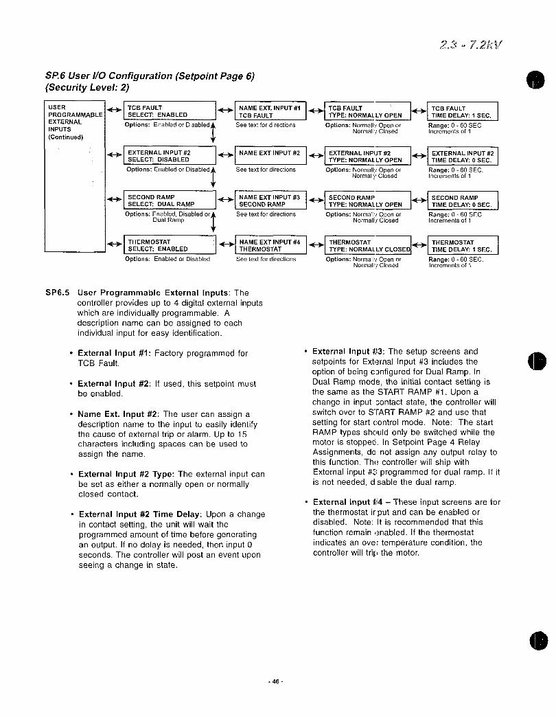
SP6UserIOConfigurationSetpointPage6SecurityLevel2
USER
PROGRAMMABLE
EXTERNAL
INPUTS
Continued
4TCBFAULTSELECTENABLED
OptionsEnabledor
Disabled
E3SECONDRAMPSELECTDUALRAMP
OptionsEnabledDisabledorDualRamp
ExternalInput1FactoryprogrammedforTCBFault
ExternalInput2Ifusedthissetpointmustbeenabled
NameExtInput2TheusercanassignadescriptionnametotheinputtoeasilyidentifythecauseofexternaltriporalarmUpto15charactersincludingspacescanbeusedtoassignthename
IH NAMEEXTINPUT1
TCBFAULT
Seetextfordirections
444EXTERNALINPUT2 FBI NAMEEXTINPUT2
SELECTDISABLED
OptionsEnabledor
DisabledSeetextfordirections
4NAMEEXTINPUT3SECONDRAMP
Seetextfordirections
THERMOSTAT NAMEEXTINPUT4
SELECTENABLED THERMOSTAT
OptionsEnabledorDisabled Seetextfordirections
SP65UserProgrammableExternalInputsThecontrollerprovidesupto4digitalexternalinputswhichareindividuallyprogrammableAdescriptionnamecanbeassignedtoeachindividualinputforeasyidentification
ExternalInput2TypeTheexternalinputcanbesetaseitheranormallyopenornormallyclosedcontact
ExternalInput2TimeDelayUponachangeincontactsettingtheunitwillwaittheprogrammedamountoftimebeforegeneratinganoutputIfnodelayisneededtheninput0secondsThecontrollerwillpostaneventuponseeingachangeinstate
46
11 TCBFAULTTYPENORMALLYOPEN
OptionsNormallyOpenorNormallyClosed
1
FEXTERNALINPUT2TYPENORMALLYOPEN
OptionsNormallyOpenorNormallyClosed
1 SECONDRAMP
TYPENORMALLYOPEN
OptionsNormallyOpenorNormallyClosed
OptionsNormallyOpenorNormallyClosed
I
23m72hV
TCBFAULTTIMEDELAY1SEC
Range060SECIncrementsof1
EXTERNALINPUT2
TIMEDELAY0SEC
Range060SECIncrementsof1
40ISECOND RAMP
TIMEDELAY0SEC
Range060SECIncrementsof1
THERMOSTAT THERMOSTAT
TYPENORMALLYCLOSED TIMEDELAY1SEC
Range060SECIncrementsof1
ExternalInput3ThesetupscreensandsetpointsforExternalInput3includestheoptionofbeingcDnfiguredforDualRampInDualRampmodetheinitialcontactsettingisthesameastheSTARTRAMP1UponachangeininputDontactstatethecontrollerwillswitchovertoSTARTRAMP2andusethat
settingforstartcontrolmodeNoteThestartRAMPtypesshouldonlybeswitchedwhilethemotorisstoppedInSetpointPage4RelayAssignmentsdonotassignanyoutputrelaytothisfunctionThecontrollerwillshipwithExternalinput IprogrammedfordualrampIfitisnotneededdsablethedualramp
ExternalInput14 TheseinputscreensareforthethermostatitputandcanbeenabledordisabledNoteItisrecommendedthatthis
functionremainenabledIfthethermostat
indicatesanovertemperatureconditionthecontrollerwilltripthemotor
0

SecurityLevel3
0
SP7CustomAccelerationCurveSetpointPage7
MENU
HitDOWNARROWsixtimes
PAGE7CUSTOMACCELERATIONCURVE
SP71 SetpointPage7allowstheusertocustomdesigntheaccelerationcurvestartcurvetothespecificapplicationTheusercancustomdesignuptothreedifferentcurvesinthecontrollerOnlyonecurvecanbeactiveenabledatatimeEachofthethreecurvesallowforeightvoltageplottingpointswithcorrespondingramptimesandacurrentlimitsettingNoteEachsuccessivevoltagelevelmustbeprogrammedtoavoltagelevelequaltoorgreaterthanthepreviouslevelAlleightlevelsofvoltagesmustbeprogrammedandtheeighthlevelhasbeenpresetat100
IfCustomAccelCurvehasbeensettocurveABorConthispagethecontrollerwilloverridetheStartControlModeselectedinSetpointPage2evenifStartControlModeinSetpointPage2hasnotbeensettoCustomAccelCurveNoteSetpointPage7hasasecuritylevel3requirement
HCUSTOMACCELCURVEDISABLED
RangeDISABLEDCURVEABorC
47
A
CUSTOMCURVEA
CURVEAVOLTAGE
LEVEL125
Range0100Incrementsof1
CURVEARAMP
TIME12SEC
Range160SECIncrementsof1
ICURVE AVOLTAGE
LEVEL230
Range0100Incrementsof1
CURVEARAMP
TIME22SEC
Range160SECIncrementsof1
ICURVE AVOLTAGE
LEVEL337
Range0100Incrementsof1
CURVEARAMP
TIME32SEC
Range160SECIncrementsof1
CURVEAVOLTAGE
LEVEL445
Range0100Incrementsof1
CURVEARAMP
TIME42SEC
Range160SECIncrementsof1
CURVEAVOLTAGE
LEVEL555
Range0100Incrementsof1
CURVEARAMP
TIME52SEC
Range160SECIncrementsof1
CURVEAVOLTAGELEVEL667
Range0100Incrementsof1
CURVEARAMPTIME62SEC
Range160SECIncrementsof1
CURVEAVOLTAGE
LEVEL782
Range0100Incrementsof1
CURVEARAMP
TIME72SEC
Range160SECIncrementsof1
2372kc

SP7CustomAccelerationCurveSetpointPage7SecurityLevel3
CUSTOMCURVEA
CUSTOMCURVEB
A
F
CURVEAVOLTAGE
LEVEL8100
Range0100Incrementsof1
CURVEARAMPTIME82SEC
Range160SECIncrementsof1
CURVEACURRENTLIMIT350FLA
Range200600Incrementsof10
CURVEBVOLTAGELEVEL125
Range0100Incrementsof1
CURVEBRAMP
TIME12SEC
Range160SECIncrementsof1
CURVEBVOLTAGELEVEL230
Range0100Incrementsof1
CURVEBRAMP
TIME22SEC
Range160SECIncrementsof1
CURVEBVOLTAGE
LEVEL337
Range0100Incrementsof1
CURVEBRAMP
TIME32SEC
Range160SECIncrementsof1
CURVEBVOLTAGE
LEVEL445
Range0100Incrementsof1
CURVEBRAMP
TIME42SEC
Range160SECIncrementsof1
CURVEBVOLTAGE
LEVEL555
Range0100Incrementsof1
CURVEBRAMP
TIME52SEC
Range160SECIncrementsof1
CURVEBVOLTAGELEVEL667
Range0100Incrementsof1
CURVEBRAMP
TIME62SEC
Range160SECIncrementsof1
48
CUSTOMCURVEB
CUSTOMCURVEC
CURVEBVOLTAGE
LEVEL782
Range0100Incrementsof1
CURVEBRAMP
TIME72SEC
Range160SECIncrementsof1
CURVEBVOLTAGELEVEL8100
Range0100Incrementsof1
CURVEBRAMP
TIME82SEC
Range160SECIncrementsof1
CURVEBCURRENT
LIMIT350FLA
Range200600Incrementsof10
CURVECVOLTAGE
LEVEL125
Range0100Incrementsof1
CURVECRAMPTIME12SEC
Range160SECIncrementsof1
CURVECVOLTAGE
LEVEL230
Range0100Incrementsof1
CURVECRAMP
TIME22SEC
Range160SECIncrementsof1
CURVECVOLTAGE
LEVEL337
Range0100Incrementsof1
CURVECRAMP
TIME32SEC
Range160SECIncrementsof1
CURVECVOLTAGELEVEL445
Range0100Incrementsof1
CURVECRAMPTIME42SEC
Range160SECIncrementsof1
CURVECVOLTAGE
LEVEL555
Range0100Incrementsof1
CURVECRAMP
TIME52SEC
Range160SECIncrementsof1
23 721W

SP7CustomAccelerationCurveSetpointPage7SecurityLevel3
SP71 SetpointPage7allowstheusertocustomdesigntheaccelerationcurvestartcurvetothespecificapplicationTheusercancustomdesignuptothreedifferentcurvesinthecontrollerOnlyonecurvecanbeactiveenabledatatimeEachofthethreecurveshaseightvoltagelevelswithcorrespondingramptimesandacurrentlimitsettingNoteEachsuccessivevoltagelevelmustbeprogrammedtoavoltagelevelequaltoorgreaterthanthepreviouslevelAlleightlevelsofvoltagesmustbeprogrammedandtheeighthlevelhasbeenpresetat100
IfCustomAccelCurvehasbeensettocurveABorConthispagethecontrollerwilloverridetheStartControlModeselectedinSetpointPage2evenifStartControlModeinSetpointPage2hasnotbeensettoCustomAccelCurveNoteSetpointPage7hasasecuritylevel3requirement
49
CUSTOMCURVEC CURVECVOLTAGELEVEL667
Range0100Incrementsof1
d CURVECRAMP
TIME62SEC
Range160SECIncrementsof1
CURVECVOLTAGE
LEVEL782
Range0100Incrementsof1
CURVECRAMP
TIME72SEC
Range160SECIncrementsof1
si CURVECVOLTAGELEVEL8100
Range0100Incrementsof1
CURVECRAMP
TIME82SEC
Range160SECIncrementsof1
CURVECCURRENT
LIMIT350FLA
Range200600Incrementsof10
kV

SP8OverloadCurveConfigurationSetpointPage8SecurityLevel3
MENU
HitDOWNARROWseventimes
PAGE8OVERLOAD BASICRUN
CURVECONFIGURATION OVERLOADCURVE
ConfigurestheunitsstartandrunprotectionmodeTheunithasindependentstartandruncurveprotectionandthesettingscanbebasedontheOLClassorsetbythemotorslockedrotorcurrentandtime
SP81 BasicRunOverloadCurve
RunCurveLockedRotor
TimeSetthelockedrotor
timetotheOLClassdefault
choseninSetpointPage1orsetthetimeinsecondsThis
isthetimethelockedrotor
conditionexistsbeforeatripoccurs
RunLockedRotorCurrent
Thecurrentthemotordraws
withfullvoltageonthewindingsandnorotormovementasapercentofmotorFLARefertothenameplatedataorcontactthemotormanufacturer
CoastDownTimerIf
enabledthispreventsthemotorfromrestartingfortheprogrammedamountoftimeafterastopcommandisgiven
BASICSTARTOVERLOADCURVE
SP82BasicStartOverloadCurve
StartCurveLockedRotorTimeThelocked
rotortimecanbesettotheOLClassdefault
choseninSetpointPage1ortoaspecifictimeTheoverloadconditionmustexistforthe
programmedamountoftimebeforeatripoccurs
StartLockedRotorCurrentThecurrentthe
motordrawswithfullvoltageonthewindingsandnomotormovementasapercentofmotorFLARefertothemotornameplatedataorcontactthemotormanufacturer
AccelerationTimeLimitIfthemotordoesnot
enterrunmodereachatspeedwithinthepresettimetheunittripsonaccelerationtimelimit
AREAUNDERCURVE
PROTECTIONDISABLED
RangeENABLEDorDISABLED
50
RUNCURVELOCKE
IRUNLOCKEDROTOR
FROTORTIMEOILCIASSdCURRENT600FLA
Range130SECO1
CLASSCOASTDOWNTIMERTIMEDISABLED
Range160MINDISABLEDIncrementsof1
STARTCURVELOCKED IESTARTLOCKEDROTOR
ROTORTIMEOILCLASS CURRENT600FLA
Range130SECOILCLASSIncrementsof1
Incrementsof1
ACCELERATIONTIME
LIMIT30SEC
Range1300SECDISABLEDIncrementsof1
NUMBEROFSTARTPER
HOURDISABLED
Range16DISABLED
tIncrementsof1
4 TIMEBETWEENSTARTSTIME15MIN
Range160MINDISABLEDIncrementsof1
MAXIITSTART368FLAFLASEC
Range12500FLAlimeSec
23 7o
Range400800Incrementsof1
Range400800Incrementsof10
CURRENTOVER HI LEARNEDSTARTCURVE TIMEFORSAMPLING
CURVEDISABLED BIAS10 30SEC
OptionsDISABLEDLEARN Range540 Range1300SECorENABLED Incrementsof1 Incrementsof1
NumberofStartsperhourIfenabledthislimitsthemaximumnumberofstartspermittedperhourThissetpointallowsamaximumof6startsperhourContactmotormanufacturerTimeBetweenStartsIfenabledthecontroller
preventsanotherstartattemptuntiltheprogrammedtimehasexpired

ASP9RTDOptionConfigurationSetpointPage9SecurityLevel3
MENU
HitDOWNARROWeighttimes
PAGE9RTD FUSENEMATEMPFORCONFIGURATION RTDVALUESDISABLED
OptionsENABLEDOR
tDISABLED
OFRTDSUSEDFORSTATOR 4
Range06Incrementsof1
RTDVOTING
DISABLED
OptionsENABLEDorDISABLED
STATORPHASEAlTYPE I43 RTD1DESCRIPTION
OFF STATORPHASEAl
Range Range
STATORPHASEA2TYPE41
RTD2DESCRIPTIONOFF STATORPHASEA2
Range
STATORPHASEB1TYPE I RTD3DESCRIPTION
OFF STATORPHASEB1
Range
STATORPHASEB2TYPE RTD4DESCRIPTION STATORPHASEB2ALARMI STATORPHASEB2TRIPOFF STATORPHASEB2 FB LEVELOFF FLEVELOFF
Range Range Range Range
STATORPHASEC1TYPE RTD5DESCRIPTIONOFF STATORPHASEC1
Range
STATORPHASEC2TYPE RTD6DESCRIPTION STATORPHASEC2ALARM STATORPHASEC2TRIPOFF 1STATORPHASEC2 FLEVELOFF If LEVELOFF
Range
tRange Range Range
E BEARINGTYPE IH END
7DESCRIPTION eIEND BEARINGALARM ENDBEARINGTRIP
Range
tRange Range Range
SHAFTBEARINGTYPEOFF
Range
RTD9TYPEOFF
Range
RTD10TYPEOFF
Range
RTD11TYPE
OFF
Range
Z
IH
Range
Range
Range
PleasenotethisissuppliedasanoptionContactfactoryformoreinformation
Optional
Ranges120OHMNICKELNI100OHMNICKEL I10OHMCOPPERCU100OHMPLATINUMPTOFF
OFFor0240C32464FExample C F
Incrementsof1
STATORA1STATORA2STATORB1STATOR82STATORC1STATORC2FRONTBEARINGBACKBEARINGBEARINGBOXAMBIENTNONE
RTD8DESCRIPTION
SHAFTBEARING
Range
RTD9DESCRIPTION
RTD9
Range
RTD10DESCRIPTION
RTD10
Range
FyRTD11DESCRIPTIONRTD11
Range
51
IH
IH
IFY
J
FSTATORPHASEAlALARM
1STATORPHASEAlTRIP
LEVELOFF LEVELOFF
Range Range
STATORPHASEA2ALARM
1 FDSTATORPHASEA2TRIPLEVELOFF LEVELOFF
Range Range
I4STAEOROP EASE B1
ALARMPHASEB1TRIP
Range Range
STATORPHASEC1 ALARMI1311 STATORPHASEClTRIPLEVELOFF LEVELOFF
Range Range
SHAFTBEARINGALARM IAD SHAFTBEARINGTRIPLEVELOFF LEVELOFF
Range Range
RTD9ALARM
LEVELOFF
Range
RTD10ALARM
LEVELOFF
Range
RTD11ALARM
LEVELOFF
Range
RTD9TRIP
LEVELOFF
Range
RTD10TRIP
LEVELOFF
Range
RTD11TRIP
LEVELOFF
Range
RTD12TYPE FRTD12DESCRIPTION I RTD12ALARM
I RTD12TRIPOFF RTD12 LEVELOFF LEVELOFF
Range Range Range Range

SP9RTDOptionConfigurationSetpointPage9SecurityLevel3ThecontrollerisavailablewithanoptionalRTDcardthatprovides12programmableRTDswhichareindividuallyprogrammablefortypeTheavailabletypesare100ohmplatinum100ohmnickel120ohmnickeland10ohmcopperEachRTDcanbeidentifiedwithadescriptionnameofupto15charactersincludingspacingAlsoeachindividualRTDhasitownalarmandtriplevel
SP91 UseNEMATempforRTDValueWhenthissetpointisenabledthecontrollerwillusetheNEMAdesigninsulationclasstolimitthemaximumallowedrangeofthealarmandtriplevelThemaximumallowedtemperaturerangeis240Cor464F
SP92 OfRTDSUsedforStatorUptosixRTDscanbeassignedtomonitorthestatorofthemotor
SP93RTDVotingWhenthisisenabledthecontrollerwillnotpostatripuntil2RTDshaveexceededthetriplevelThispreventsnuisanceRTDtripping
SP94Eachofthe12RTDsisconfiguredinthefollowingmannerThefirstcolumnistheRTDtypethesecondcolumnistheRTDdescriptionthethirdcolumnisthealarmlevelandthefourthcolumnisthetriplevelThefirstsixRTDshavebeenpreprogrammedwithadescriptionnamefortheSTATORwithtwoRTDsperphaseRTDs1 2havebeennamedSTATOR
PHASEAlandA2respectivelyRTDs34arenamedSTATORPHASEB1andB2RTDs56arenamedSTATORPHASEC1andC2Ifother
descriptionnamesarerequiredpresstherightarrowbuttonfromtheRTDTypescreentogotheRTDdescriptionscreenIfnoalarmortriplevelisrequiredthesesetpointscanbeturnedoff
52
23m
0

SP10SetPasswordSetpointPage10SecurityLevel3ThecontrollerhasthreelevelsofuserprogrammablesetpointscreensLevelonesetpointsdonotrequireapasswordbecausethedatacontainedinleveloneisbasicnameplatedataandstartercontrolLeveltwosetpointscreensrequireathreedigitpasswordtoconfiguretheprotectionschemesLevelthreesetpointscreensrequireafourdigitpasswordtoaccessthefullrangeofprotectionandstarterschemes
SP101SetLevel2PasswordThislevelusesa3digitpasswordThedefaultlevel2passwordis100
SP102SetLevel3PasswordLevelthreeusesa4
digitpasswordThedefaultlevel3passwordis1000
53
MENU
PAGE10SECURITY
SETPASSWORD
HitDOWNARROWninetimes
Range00009999
7IV
Range000999
SETLEVEL2
14PASSWORD100
SETLEVEL3
PASSWORD1000

SP11CommunicationsSetpointPage11SecurityLevel3SP111SetFrontBaudRateConfigurestheRS232
communicationsbaudrate
SP112SetModbusBaudRateConfiguresthemodbuscommunicationsbaudrate
SP113ModbusAddressNumberAssignsaModbusaddresstothecontrollerrelay
SP114SetAccessCodeAssignsanaccesscodetotheModbusaddressingTypicallynotused
SP115SetLinkBaudRateConfigurestheRS422communicationsbaudratebetweenthekeypadoperatorandtheCPUboardForapplicationswithremotekeypadonly
SP116RemoteStartStopAllowstheRS485ModbuscommunicationstostartandstopthemotorContactfactoryfordetails
54
MENU
PAGE11
COMMUNICATIONS
HitDOWNARROWtentimes
SETFRONTBAUD
RATE96KBSEC
Range244896192
t384KBSEC
SETMODBUSBAUDRATE96KBSEC
Range244896192
t384KBSEC
MODBUSADDRESSNUMBER247
Range1247Incrementsof1
SETACCESSCODECODE1
Range1999Incrementsof1
SETLINKBAUD
RATE384KBSEC
Range244896192
t384KBSEC
REMOTESTARTSTOP
DISABLED
OptionEnabledorDisabled
O
s

SP12SystemSetpointsSetpointPage12SecurityLevel3
MENU
HitDOWNARROWeleventimes
PAGE12SYSTEMSETPOINTS
DEFAULTDISPLAY4 3SCREEN
ALARMS RTDFAILUREALARM
THERMALREGISTER
SETUPINFORMATION
PRESSENTERTOCLR
THERMALREGISTER
t
155
METERINGDATA
IMETERINGDATA
PAGE1 41SCREEN 1
EnterMeteringPage14 EnterMeteringNumberfordisplay ScreenNumberfordisplay
ALARMDISABLED
EnabledorDisabled
THERMALREGISTER
ALARM90
RangeOff4095Incrementsof1
COLDSTALLTIME
OLCLASS
RangeOLCLASS440SEC
Incrementsof1
HOTSTALLTIME
12OLCLASS
Range12OLCLASS440SEC
Incrementsof1
STOPPEDCOOLDOWNTIME30MIN
Range10300MINIncrementsof1
RUNNINGCOOLDOWNTIME15MIN
Range10300MINIncrementsof1
I RELAYMEASUREDCOOL IRATESDISABLED
RangeENABLEDorDISABLED
THERMALREGISTER
MINIMUM15
Range1050 OFFIncrementsof1
MOTORSTATORMAX
ITEMPERATUREINSCLS
RangeInsulationClass10240C
Incrementsof1
IIIB INPUTTOTHERMAL IREGISTERENABLED
OptionsENABLEDor
tDISABLED
USECALCULATEDKORASSIGN7
Range150ON
MOTORDESIGNAMBIENTTEMPERATURE40C
Range1090CIncrementsof1
t
IMOTORDESIGNRUNTEMPERATURE80MAX
Range50100ofMotorStatorMaxTemp
Incrementsof1
THERMALALARM
DELAY10SEC
Range120SECIncrementsof1

SP12SystemSetpointsSetpointPage12SecurityLevel3SP121DefaultDisplayScreenThissetpointgroup
allowstheusertochoosethedefaultscreenthe
controllerdisplayswhilethemotorisrunningSelectthemeteringpagenumber13thenselectthemeteringscreennumberTherangevariesdependingontheselectedpageTodisplayadefaultscreenprogramthefollowingtwosetpointsMeteringDataPage RangeisPage1 3
MeteringDataScreen IfPage1isselectedasthedefaultpagethenScreens110areavailableIfPage2Screens129areavailableIfPage3isselectedthenScreens16areavailableSeeMeteringMenuMP1forscreennumberassignment
SP122AlarmsConfigurestheRTDfailurealarmwhenRTDoptionisincludedandthethermalregisteralarm
RTDFailureAlarmIfenabledandanRTD
shortsoropenanalarmoccursOnlyifRTDoptionisinstalledThermalRegisterAlarmSetsalevelinthethermalregistertogenerateanalarmwhentheThermalRegisterCapacityUsedhasexceededthislevel
ThermalAlarmDelayTheamountoftimethattheThermalRegisterUsedmustexceedthesetpointbeforeanalarmconditionwilloccur
SP123ThermalRegisterSetupInformationThissetpointgroupwillconfigurethethermalregisterandindicatetothecontrollerwhichinputstousewhenthermalmodelingColdStallTimeEnterthetimefromthemotor
manufacturersspecificationsheetorusethetimedefinedbytheOLClassThissetpointisusedtodefinethethermalcapacityofthemotorHotStallTimeEntertheamountoftime
specifiedbythemotormanufacturerorusehalfofthetimedefinedbytheOLClassStoppedCoolDownTimeThetimethemotorrequirestocooldownafterithasstoppedUseonlythedataprovidedbythemotormanufacturerThissetpointisusedtoconfigurethecoolingrateofthethermalregisterRunningCoolDownTimeTheamountoftimethemotorrequiresforcoolingdownwhilerunningUseonlythedataprovidedbythemotormanufacturer
RelayMeasuredCoolRatesWhentheRTDoptionissuppliedthecontrollercanbeconfiguredtousethemeasuredcoolratesfromtheRTDsinsteadoftheprogrammedsettingsThissetpointshouldonlybeenabledwhentheRTDoptionispresent
56
23 72 V
ThermalRegisterMinimumSetsthevalueinthethermalregisterwhichrepresentsamotorrunningatthenameplatecurrentwithnooverheatingornegativesequencecurrentspresentMotorDesignAmbientTemperatureUsethedatafromthemotormanufacturers
specificationsWhenRTDoptionissuppliedthissetpointwillbethebasepointfortheRTDbiasingoftheThermalRegisterMotorDesignRunTemperatureUsethedatafromthemotormanufacturersspecificationsThissetpointdefinestheoperatingtemperatureriseofthemotoratfullloadampsor100loadMotorStatorMaxTemperatureThisrepresentsthemaximumtemperaturethestatorinsulationwillwithstandTheusermaychoosetousethetemperaturesettingoftheinsulationclassselecteditSetpointPage1orenteraspecificmaximunitemperatureThisvalueshouldnotexceedthestatorsinsulation
temperatureThismaximumtemperaturerepresents100thermalcapacityUBInputtoThermalRegisterWhenenableditallowsthecontrollertousethelinecurrent
imbalanceinformationtobiastheThermal
RegisterUserCalculatedKorAssignWhenthesetpointissettoONthecontrollerwillcalculatethekconstantfactorforbiasingthethermalregisterortheusermaychoosetoassignthekvalue
SP124PressEntertoCLRThermalRegisterAllowsthelevelthreepasswordusertoclearthethermalregisterforemergencyrestarts

SP13Calibration ServiceSetpointPage13SecurityLevelFactoryUseOnly
MENU
HitDOWNARROWtwelvetimes
PAGE13CALIBRATION
SERVICE 1SETDATEANDTIME
MODELFIRMWAREREV
PRESSENTERTO ACCESSFACTORYSETTINGS
SP13 Calibration ServiceSetpointPage13CertainscreensaredisplayedforuserinformationonlysuchasCurrentdateandtimeModelnumberand
FirmwarerevisionnumberSetpointchangesinthispagewillonlybeaccessibletofactorypersonnelSP131SetDateandTimeDisplaysthedateandtime
EnterDateDDMMYYYYAllowsthefactorypersonneltoprogramthedateforthecontrollerintheformatshown
EnterTimehhmmAllowsthefactorypersonneltoprogramthetimeforthecontroller
SP132Model Firmware Displaysthemodelnumberandfirmwarerevisioninthecontroller
SP133PressEntertoAccessFactorySettingsAvailabletoqualifiedpersonnel
23 721flf
ENTERDATEDDMMYYYYI ENTERTIMEhhmm4
11RangeD131M112 RangeH0023M059
Y19702069 Incrementsof1Incrementsof1
57

Chapter6 MeteringPagesTheunitoffersperformancemeteringwhichgivestheusertheabilitytoviewinformationaboutthemotorandthesoftstarter
61MeteringPageListThefollowingchartslisteachMeteringPageandthefunctionswithinthatpageTheapplicablesectionofthemanualisalsoreferenced
611MeteringMenu DataMeteringPage1
I
612MeteringMeteringPage2
PhaseABCandGroundFaultOption
Averagecurrentofthe ofimbalanceandthemotorsRPM
MotorloadasapercentageofmotorFLA
Linefrequencyandpresentphasesequence
PercentageofremainingThermalRegister
Thermalcapacityrequiredtostartthemotor
Averagetimerequiredtostart
Averagecurrentduringstart
Measuredlrequiredtostartthemotor
Amountoftimerequiredtostartthemotorduringthelastsuccessfulstart
613RTDOptionValuesMeteringPage3
PJFirid
PhaseABCcurrentsandPowerFactor
PhaseABCcurrentsandGroundFaultOption
DisplayskWandkVA
DisplayskVARandPowerFactor
DisplaysPeakONandkWDemand
DisplaysPeakONandkVADemand
DisplaysPeakONandkVARDemand
DisplaysPeakONandAmpsDemand
ClearsDemandvalues
DisplaysMegawatthoursused
PressentertoclearstatisticsonMWHvalues
HotteststatorRTD16
HottestnonstatorRTD712
TemperatureofstartphaseAlinCandF
MaximumtemperatureforRTD1
SameasScreens34forRTDs212
ClearthemaximumtemperatureregisterLevel3passwordrequired
Measuredrunningthermalstabilizationtimeofmotorinminutes
Measuredstoppedcoolingtimetoambientofmotorinminutes
58
1
2
3
4
5
6
7
8
9
10
1
2
3
4
5
6
7
8
9
10
11
1
2
3
4
526
27
28
29
23m J rn4

0
614StatusMeteringPage4
Currentstatus
Amountoftimeremainingbeforeanoverloadtripoccurs
Amountoftimeremainingfromathermalinhibitsignal
Coastdowntimeremaining
Amountoftimeremainingbeforeastartcommandcanbegiven
Excessivenumberofstartsperhour
615EventRecorderMeteringPage5
a5IDisplaystheeventwithdateandtimeUpto60events
aoDisplaysPhaseABCcurrentvaluesGroundFaultOptionattimeoftrip
DisplaysVabVbcVcaandPowerFactorattimeoftrip
acaa0
616LastTrip
con
aIca
canJ
MeteringPage6
617StatisticsMeteringPage7VONIj r
Causeoflasttrip
Measuredphasecurrent
Measuredvoltageandpowerfactor
ImbalancepercentagethefrequencyandthekW
HotteststatorRTDtemperature
HottestnonstatorRTDtemperature
59
Accumulatedtotalrunninghours
Clearthetotalrunninghourcount
Totalnumberoftrips
Numberofstartandrunoverloadtripssincethelaststatisticaldataclearing
Numberoffrequencytripsandimbalancetrips
Overcurrenttrips
StatorandnonstatorRTDtrips
Groundfaulthisetandlosettrips
Accelerationtimetrips
Startundercurvetrips
cn Startovercurvetrips
asm IstartcurvetripsCL
Learnedstartcurvetrips
Failshunttriptrips
Phaselosstriptrips
Tachacceltriptrips
UndervoltageandOvervoltagetrips
PowerFactortrips
Phasereversaltrips
ExpInp1
ExpInp2
ExpInp3
ExpInp4
Pressentertoclearstatistics
1
2
3
4
5
6
1
1A
1B
1
2
3
4
5
6
1
2
3
4
5
6
7
8
9
10
11
12
13
14
15
16
17
18
19
20
21
22
23
24
23 72V

62MeteringMenuPushMENUkeytotogglethescreensbetweenSetpointMenuandMeteringMenuandfollowthearrowkeystogettodifferentscreens
MENU
v YMETERINGPAGE1CURRENTMETEREDDATA
METERINGPAGE2
VOLTAGEPOWERDATA
METERINGPAGE3
RTDVALUES
METERINGPAGE4
STATUS
METERINGPAGE5
EVENTRECORDER
METERINGPAGE6
LASTTRIP
METERINGPAGE7
STATISTICS
I
I
t
I
60
23
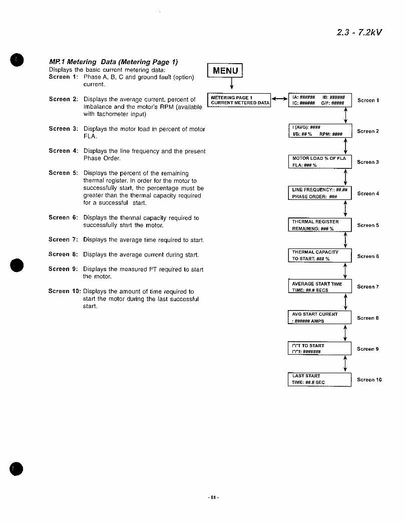
0 MP1MeteringDataMeteringPage1Displaysthebasiccurrentmeteringdata MENUScreen1PhaseABCandgroundfaultoption
current
Screen2DisplaystheaveragecurrentpercentofimbalanceandthemotorsRPMavailablewithtachometerinput
PhaseOrder
Screen5DisplaysthepercentoftheremainingthermalregisterInorderforthemotortosuccessfullystartthepercentagemustbegreaterthanthethermalcapacityrequiredforasuccessfulstart
Screen6Displaysthethermalcapacityrequiredtosuccessfullystartthemotor
Screen7Displaystheaveragetimerequiredtostart
Screen8Displaystheaveragecurrentduringstart
Screen9DisplaysthemeasuredIrequiredtostartthemotor
Screen10Displaystheamountoftimerequiredtostartthemotorduringthelastsuccessfulstart
61
METERINGPAGE1
CURRENTMETEREDDATA
IA
IC
IB
GF
IAVG
IB RPMScreen3Displaysthemotorloadinpercentofmotor
FLA
Screen4DisplaysthelinefrequencyandthepresentMOTORLOAD OFFLA
FLA
LINEFREQUENCY
PHASEORDER
THERMALREGISTER
REMAINING
THERMALCAPACITY
TOSTART
AVERAGESTARTTIME
TIME SECS
AVGSTARTCURENT
AMPS
IITTOSTART
IITq
LASTSTART
TIME SEC
23 72kV
Screen1
Screen2
Screen3
Screen4
Screen5
Screen6
Screen7
Screen8
Screen9
Screen10

MP2 MeteringMeteringPage2
Displaysthestatisticalvoltagemeteringinformation
Screen1DisplaysPhaseABCandPowerFactorNotePFNAMotorstopped
PFLG LaggingPFLD Leading
Screen2DisplaysPhaseABCandGroundFaultCurrent
Screen3DisplayskWandkVA
Screen4DisplayskVARandPowerFactor
Screen5DisplaysPeakOnandkWdemand
Screen6DisplaysPeakOnandkVAdemand
Screen7DisplaysPeakOnandkVARdemandNotePFNAMotorstopped
PFLG LaggingPFLD Leading
Screen8DisplaysPeakOnandAmpsdemand
Screen9ClearsDemandValues
Screen10DisplaystheMegawatthoursused
Screen11PressEntertoclearstatisticsonMWH
values
62
MENU
METERINGPAGE2
VOLTAGEPOWERDATAH
Screen1
Vab Vbc
Vca PF
Screen2
IAIB
IC GIF
Screen3
kW
kVA
Screen4
kVAR
PF
Screen5
PEAKON
kW
Screen6
PEAKONI
kVA
Screen7
PEAKONI
kVAR
Screen8
PEAKON
AMPS
Screen9
PRESSENTERTOCLEAR
DEMANDVALUES
Screen10
MWHUSED
Screen11
23 72kV
PRESSENTERTOCLEARMWHVALUES
1 0

0
r
MP3RTDValuesMeteringPage3DisplaystheRTDinformationwhenRTDoptionissupplied
METERINGPAGE3
RTDVALUES
Screen1DisplaysthehotteststatorRTD1 6
dependinguponnumberofRTDsusedforstator
Screen2DisplaysthehottestnonstatorRTD712if16isusedforstator
Screen3DisplaysthetemperatureofstatorphaseAlinCandF
Screen4DisplaysthemaximumtemperatureforRTD1sincethelastcommandtoclearthe
thermalregister
Screen526SameasScreens34forRTDs2
12
Screen27Allowstheusertoclearthemaximum
temperatureregisteruponenteringthesetpointlevel3password
Screen28Displaysthemeasuredruncooltimeinminutes
Screen29Displaysthemeasuredstoppedcooltimeinminutes
63
H HOTTESTSTATOR
RTD C
Screen2 Y
HOTTESTNONSTATORRTD C
Screen3
STATORPHASEAl
RTD1 C F
Screen5
STATORPHASEA2
RTD2F
Screen7
STATORPHASEB1
RID3
FScreen9
STATORPHASEB2
RTD4 C F
Screen11 Y
STATORPHASEC1
RTD5 C F
Screen13
STATORPHASEC2RTD6
FScreen15
ENDBEARING
RTD7 C F
Screen17
SHAFTBEARING
RTD8
FScreen19
RTD9
RTD9
Screen21
RTD10RTD10 C F
Screen23
RTD11
RTD11 C F
Screen25
RTD12
RTD12 C F
Screen27 Y
PRESSENTERTO
CLEARMAXTEMPREGS
Screen2RMEASUREDRUNCOOLTIME MIN
SSteen29
MEASUREDSTOPPED
COOLTIME MIN
2372V
Screen4
F MAXTEMPSINCE
CLEARRTD1 C
Screen6
H MAXTEMPSINCE
CLEARRTD2 C
Screen8
4MAXTEMPSINCE
CLEARRTD3 C
Screen10
FMAXTEMPSINCECLEARRTD4 C
H
Screen12
MAXTEMPSINCE
CLEARRTD5 C
Screen14
MAXTEMPSINCE
CLEARRTD6 C
Screen16
MAXTEMPSINCE
CLEARRTD7 C
Screen18
HMAX TEMPSINCE
CLEARRTD8 C
Screen20
MAXTEMPSINCE
CLEARRTD9 C
Screen22
HMAX TEMPSINCE
CLEARRTD10 C
Screen24
HMAX TEMPSINCE
CLEARRTD11 C
Screen26
IMAXTEMPSINCECLEARRTD12 C
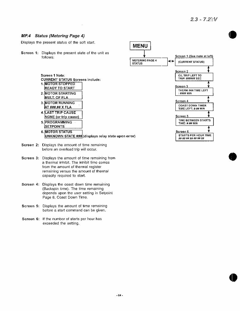
MP4 StatusMeteringPage4
Displaysthepresentstatusofthesoftstart
Screen1Displaysthepresentstateoftheunitasfollows
Screen2
Screen3
Screen1Note
CURRENTSTATUSScreensinclude
1IMOTORSTOPPED
READYTOSTART
2IMOTOR STARTING
MULTOFFLA
3IMOTORRUNNINGT XFLA
4LASTTRIPCAUSE
NONEortripcause
5PROGRAMMING
SETPOINTS
6MOTORSTATUS
UNKNOWNSTATE displaysrelaystateuponerror
Displaystheamountoftimeremainingbeforeanoverloadtripwilloccur
DisplaystheamountoftimeremainingfromathermalinhibitTheinhibittimecomes
fromtheamountofthermalregisterremainingversustheamountofthermalcapacityrequiredtostart
Screen4DisplaysthecoastdowntimeremainingBackspintimeThetimeremainingdependsupontheusersettinginSetpointPage8CoastDownTime
Screen5Displaystheamountoftimeremainingbeforeastartcommandcanbegiven
Screen6Ifthenumberofstartsperhourhasexceededthesetting
64
MENU
METERINGPAGE4
STATUS
23721
Screen1Seenoteatleft
FI CURRENTSTATUS
Screen2
OLTRIPLEFTTOTRIP SEC
Screen3 Y
THERMINHTIMELEFT
MIN
Screen4
COASTDOWNTIMER
TIMELEFT MIN
Screen5
TIMEBETWEENSTARTS
TIME MIN
Screen6
STARTSPERHOURTIME

MP5 EventRecorder60EventsMeteringPage5
to
MENU
METERINGPAGE5
EventRecorder60event 1st
Event
2nd
Event
59th
Event
60th
Event
Screen1
causeofevent
I
causeofevent
II
causeofevent
causeofevent
A
V
Screenla
IA
IC
IA
IC
IB
GF
IB
GF
A
V
IB
GF
IB
GF
Alleventswillbeviewedfromoldesteventinbuffertomostrecentevent
Theeventsarelistedfromoldesttomostrecent
Screen1DisplaystheeventieImbalanceTripwiththedateandtimeitoccurred
ScreenlaDisplaysthecurrentatPhaseABCandthegroundfaultatthetimeofthetrip
ScreenlbDisplaystheVabVbcVcaandpowerfactoratthetimeoftrip
65
Screen1b
HVabVca
H
H
Vab
Vca
Vab
Vca
Vab
Vca
23m72kV
Vbc
PF
Vbc
PF
Vbc
PF
Vbc
PF

MP6 LastTripMeteringPage6
Displaystheinformationregardingthelasttrip
Screen1Displaysthecauseofthelasttrip
Screen2Displaysthemeasuredphasecurrentatthetimeofthetrip
Screen3DisplaystheVabVbcVcaandpowerfactoratthetimeoftrip
Screen4DisplaystheimbalancepercentagethefrequencyandthekWatthetimeofthetrip
Screen5DisplaysthehotteststatorRTDtemperaturewhenRTDoptionpresentattimeofthetrip
Screen6DisplaysthehottestnonstatorRTDtemperaturewhenRTDoptionpresentatthetimeofthetrip
66
MENU
METERINGPAGE6
LASTTRIP
Screen1
causeoftripvalueattimeoftrip
Screen2
la
lc
Screen4
IB Hz
KW
Screen5
HOTTESTSTATORRTD
Screen6
23720
lb
GF
Screen3
Vab Vca
Vca PF
t
HOTTESTNONSTATOR
IRTD
tis

s
MENU
METERINGPAGE7
STATISTICS
MP7 StatisticsMeteringPage7
DisplaysthestatisticaltripinformationScreen1DisplaysthetotalofmegawatthoursScreen2Displaystheaccumulatedtotalrunning
hours
Screen3ClearsthetotalrunninghourcountScreen4Displaysthetotalnumberoftripssincethe
lastclearingthestatisticaldataandthetotalnumberofshortcircuittrips
Screen5Displaysthenumbersofstartoverloadandrunoverloadtripssincethelastclearingofthestatisticaldata
Screen6DisplaysthenumberoffrequencytripsandImbalancetrips
Screen7DisplaysthenumberofovercurrenttripsScreen8DisplaysthenumberofStatorandnonStator
RTDTripsScreen9DisplaysthenumberofGroundFaultHiand
LoSettripsScreen10Displaysthenumberofaccelerationtime
tripsScreen11Displaysthenumberofstartundercurve
tripsScreen12Displaysthenumberstartovercurvetrips
Screen13Displaysthenumberof1startcurvetripsScreen14Displaysthenumberoflearnedstartcurve
tripsScreen15DisplaysthenumberoffailshunttripsScreen16DisplaysthenumberofphaselosstripsScreen17Displaysthenumberoftachometer
accelerationtripsScreen18Displaysthenumberofundervoltageand
Screen1
MWHTOTAL
67
Screen2 Screen3
RUNNINGHOURSTOTALE PRESSENTERTO
TIME HOURS CLEARRUNHOURS
Screen4
TOTALTRIPS
SCTRIPS
Screen5
STARTOLTRIPS
RUNOLTRIPS
Screen6
FREQUENCYTRIPS
IBTRIPS
Screen7
OVERCURRENT
TRIPS
Screen8
STATORTRIPS
NONSTATORTRIPS
Screen9
GFHISETTRIPS
GFLOSETTRIPS
Screen10
ACCELERATIONTIME
TRIPS
Screen11
STARTUNDERCURVE
TRIPS
Screen12
STARTOVERCURVE
TRIPS
Screen13
overvoltagetrips I1TSTARTCURVE
Screen19DisplaysthenumberofpowerfactortripsTRIPS
Screen20Displaysthenumberofphasereversaltrips Screen14 tScreen21Displaysthenumberofexternalinput1 LEARNEDSTARTCURVE
ItripsTRIPS
Screen22Displaysthenumberofexternalinput2 Screen15 ttrips FAILSHUNTTRIP
Screen23Displaysthenumberofexternalinput3 TRIPS
tripsScreen24Displaysthenumberofexternalinput4
Screen16
PHASELOSSTRIP
trips TRIPS
Screen25RequiresaSecurityLevel2passwordtoclearthestatistics Screen17
ITACH ACCELTRIP
TRIPS
t
Screen18
UNTRIPS
ONTRIPS
Screen19
POWERFACTOR
TRIPS
Screen20
PHASEREVERSAL
TRIPS
Screen21
EXPINP1
Screen22
EXPINP2
Screen23
EXPINP3
Screen24
2372kV
EXPINP4
Screen25
PRESSENTERTOCLEARSTATISTICS
rUDD1TEInILFTTI111ITlim

Chapter7 MaintenanceandTroubleshootingThesoftstarterisdesignedtobeamaintenancefreeproductHoweveraswithallelectronicequipmenttheunitshouldbecheckedperiodicallyfordirtmoistureorindustrialcontaminantsThesecancausehighvoltagearcovercarbontrackingorpreventpropercoolingoftheSCRheatsinksAllboltsshouldbecheckedannuallyforpropertightnessusinganaccuratetorquewrenchAccordingtothemanufacturersmanualcheckthecontactorforairgapspacingofthevacuumbottles
NoteIftheunitisinstalledinacontaminatedenvironmentandforcedaircoolingisuedblowerfiltersmustbecheckedandcleanedregularlytoinsureproperairflowandcoolingoftheenclosure
71FailureAnalysisWhenafaultoccurstheLCDwilldisplaythefaulterrorandthelistedLEDandAU RelaywillbelitPleaseclearallfaultsbeforeattemptingtorestarttheunitNoteIftheproblempersistsafterthereqairedprogrammingchangeshavebeenmadeandallcorrectiveactionshavebeentakenpleasecontactthefactoryforassistance
Oneofthemain
fusesblowsor
circuitbreaker
openswhenthepowerisappliedorisconnectis
open
TCBFAULTTRIP Trip AUX1
ShortCircuitTrip SHORTTRIP Trip AUX1
SINGLEPHASETRIP
SinglePhaseTrip CheckLCDdisplayfor Trip AUX1
possiblefaultindicators
Thermostattrips EXTERNALTRIPON
duringrun THERMOSTAT Trip AUX1
68
ShortcircuitbetweentheLocateand removeshortinputs
FaultySCRs
Shortcircuitorgroundfaulinmotorcabling
PhaseLoss
Branchcircuitprotectionnotcorrectlysized
Faultymaincircuitboard
FaultySCRs
2372kV
FemovepowerandtestSCRsRefertoSection711fortheSCRtestingprocedure
Locateandremoveshortorground
Repaircauseofphaseloss
Verifycorrectsizingofbranchcircuitprotection
RemovepowerandreplacemaincircuitbDard
RemovepowerandtestSCRsRefertoSection711fortheSCRtesting
ocedureSinglephaseincoming
powerCorrectproblemwithincomingpower
FaultySCRs
FansnotfunctioningIfsupplied
Heatsinkcoatedwithdirt
Overcurrentonunit
Environmenttemperatureover122Fambient
temperatureforchassis
unitsorover104Fambienttemperaturefor
enclosedversion
RemovepowerandtestSCRsRefertoSection711fortheSCRtestingprocedure
IffanshavepowerremovepowerandreplacefansIffansdonothavepowerfindcauseofpowerlossandrepair
Removepowerandcleanheatsinkwithhighpressureair80100psimaxcleananddryair
Verifythatrunningcurrentdoesnotexceedunitrating
Placeunitinenvironmenttemperature
Tessthan122Fforpanelversionorlesstan104Fforenclosedversion
Bypassfailedtoclose Checkbypasscontactorandwiring

0
0
PhaseLoss
Overload
Stallprevention ACCELTIMETRIP Trip AUX1
Trip
LineFrequencyTrip
Controlcircuit
fusesblowafter
controlpoweris
applied
PHASELOSS
OVERLOADTRIP Trip AUX1
UnderVoltage UNDERVOLTAGETRIP
OVERORUNDER
FREQUENCYTRIP
None
Trip AUX1
Trip AUX1
UnderCurrent
TripUNDERCURRENTTRIP Trip AUX1
SelftestFailure SELFTESTFAILURE Trip AUX1
Trip AUX1
AnyGroundFaultGROUNDFAULT
TripSETop LHSET Trip AUX1
4
MotorstoppedCheckforfaultindication Trip AUX1
duringrun
69
Lossof1ormorephases
ofpowerfromutilityorgeneratedpower
Checkpowersource
Blownpowerfuses Checkforshortcircuits
ImproperprogrammingCheckmotornameplateversusprogrammedparameters
PossibleloaddamageorCheck motorcurrentsjammedload
ImpropersettingformotorVerifycurrentlimitsettingloadcondition
23 72kV
Damagedload Checkforloadfailure
Improperprogramming Checksetpointsettings
WrongpositionofCheckdisconnectoropenbreakerdisconnectedbreaker
MaincontactorfailedtoCheckinternalconnections
close
Transformertoosmall Reducecurrentlimitsettingsaturationorsaggingpowersupplytransformer
Improperprogramming Checksetpointsettings
Unloadedmotor Checkload
FailedCPUorMainFiringContactfactoryBoard
Vibration CheckinternalwiringconnectionsTroubleshootandrepairgenerator
ContactutilitiescompanyGeneratorPowerProblem
Mainboardfailureorgridchange
ThreephasepowerremovedfromMainBoard
ImproperprogrammingCheckprogramsetpoints
AnywiregoingtogroundCheckwith meggarorHipotmotorleadsIestatorgroundmotorandmotor
groundsoftstartground
Highvibrationorlooseconnections
Checkinternalconnections
WarningThisisaseriousfaultconditionEnsurethatthefault
conditionisclearedontheloadbeforeattemptingtorestartthemotor
Loadshortedgroundedfaulted Removepowerandrepair
FaultymaincircuitboardReplacethemaincircuitboard
Shortincontrolcircuit Removepowerlocateandremovethisshort
None None
Wrongcontrolvoltage Applythecorrectvoltagetothecontrolcircuit

Motorwillnotstart
GateDrive
Board
KG GK
WHITEWIRES
KCATHODEGGATE
Anyfaultindicationmessage
Motorvibrates
Motorgrowls
whilestartingorextremely IMBALANCEALARM
unbalancedmotor
currentsrunmode
IMBALANCETRIP
Trip AUX1
Trip AUX1
Alarm AUX2
711SCRTestingProcedurePerformtheSCRHeatSinkOhmtestoneachStackAssembly
FromPositionAto
PositionB
c FromPositionBto
PositionC
GatetoCathodefor
eachSCR
NoteAllow15minutesaftershutdownforDVDTnetworktodischargeDCvoltage
70
NocontrolvoltageappliedApplycontrolvoltagetoTB1pins1and6tocontrolboard onthepowerboard
ControlpowertransformerRemovepowerandreplacethepowerfailureorCPTfusefailuretransformerortheCPTfuse
Startcircuitwired
incorrectly
Nostartcommand
No3phaselinevoltage
ShortedSCRinstarter
Faultycontrollogic
Failureofmaincircuit
board
Faultymotor
FaultySCRs
FaultygatecathodeonSCRs
Faultymaincircuitboard
Faultymotorwiring
Faultymaincircuitboard
8to100Ohms
Lessthan10orgreaterthan100Ohms
23 72kV
Removepowerandcorrectthestart
circuitwiring
ApplythestartcommandApply3phaselinevoltagetotheunit
FtemovepowerandtestSCRsRefertoSection711fortheSCRtestingprocedure
Ftemovepowerandrepairthecontrollogic
Replacethemaincircuitboard
Checkthemotorandthemotor
connections
FtemovepowerandperformtheSCRcevicechecks
FtemovepowerandtestSCRsRefertoSection711fortheSCRtestingprocedure
Replacethemaincircuitboard
Troubleshootandrepairreplacewiring
Replacethemaincircuitboard
Greaterthan10KOhm IPassLessthan10KOhm FailGreaterthan10KOhm IPassLessthan10KOhm IFail
PassTypical8to20Ohms
Fail

0 72TypicalBlockDiagram
CPU
DigitalController
ControlBoard
CustomerConnections
Main
FiringBoard
FiberOptics III 1
4
III II
RingTransformer
FiberOptics
71
VoltageTransformer
1flOCTIyC1f
ECO I LC
A B
1I
L1 L2 L3
I I
SCRAssembly
L4CT
C
T1 T2 T3
72kV

73 OverloadCurveDefinition
110
1000
100
10
10 1 2 3 4
Mfla
5
72
6 7
11
8 9
OverloadClass30
OverloadClass25
OverloadClass20
OverloadClass15
OverloadClass10
OverloadClass5
23b72kV

4 74 TCBDiagram
0
OI
O
O
HEATSINK
SW1
O 9 DUALADJ
1oJIJ DCn IDECELZ it
GRDNTZT1 12
t12VO F13Zrn
14
OZ 15
16 764
TIIiN1IIIHIIo
LeTB7 PFC AUX iiliuui19
6
z
3
TB84
6REDEDt 7
b aFAULT
10
O
1
2
3
4
5
6
22
03
24
ITB9
TB6 GRN
12V
12
13
MVC3 TCB 1U
GRN
JSTART
360426
s
WFUSEGRIM
PFC
START
TB1
TIMEDDUT
TB3
TB4
12
11
10
9
e
7
6
5
4
3
2
11
10
9
6
7
6
5
4
3
2
1
fi
10
O12 1C
71
IC
SID
1c10LL
OGNnRS
TB50485O O
73
AuxStart
Output
120VAC
Neutral
OptionalInterlocks
120VACSource
FACTORYWIRED
DONOTUSE
i
EmergencyBypassAUXContacts
i
EmergencyBypassFullVoltageStart
Fuses
FACTORYWIRED
DONOTUSE
CustomerProvided
MomentaryorMaintainedStartStopSwitching
Momentary
STOP
START
F1ControlFusesforTBI19PartACG1A250VACorequivalent
F2ContactorandrelayoutputfusesPartACG4A250VACorequivalent
F3TB2Pin6
PartACG4A250VACorequivalent1c
10OXU
ICO
23T
Maintained

75TypicalWiringDiagram
CPINERoew
0o00o040s0
rl
MAIN
BOARD
ZEROSEQUENCE
CT 05A
CTSecondaryTwistedPairs
GROUNDFAULT
BOARD
OPTIONAL
ElEl
MVC3GFCT
LlLJ
COMMBOARD
DSS1000COMM
NoteThlsIs
TheRearVie
OfThisBoard
MVC3MB
RS485Customer
0Connect
TRANSFORMER
Part4100044
WOtInput
1HTTM
Fr IJ
DSS1000CPU
CPU Alff
BOARD
2
RTDBOARD
OPTIONAL
m Oaoo00000000000000000
3PhaseMedium MediumVoltageVoltageSupply CPT i
OPTIONALt
11
I
J
I
74
Imoemon
IMVC3TCB
o
I
Note1SeeManufacturersMnwnlForConnectionBeWls
FlberOpticHarness
Customerustomer3PhaseMediumVoltageProritletlSupplyAfterCircuit
BreakerInllneContactor
NOTEMustChangeStateDuringStartLStop
PHASEA
PHASEB
PHASEC
T
Located
InMedium
VoltageSection
MOMENTARYOR
MAINTAINED
STARTSTOP
SWITCHING
MOMENTARY
CustomerProvided
MAINTAINEDSTARTSTOP
k11
11
11

CTSecondoryTWlstedPak
CTSecondarysB5A
WeI
4
Ten IIINVC3OprielTEMPCT
olitro
VC3G0
Mb II0EMPCT
111rVC3G0
NOTETypical2300VoltAssemblyShoWn
ForHigherVoltagesIncreaseAmountOfSCRsGateDriveNOVOVOTBoardAndRingTransformers
taringIsSimilar
3Phase
120VAC
111
IMVC3I
IV
0VDTI1MVC3NOVII 11
MEDIUMVOLTAGESUBPANEL
1
RingTransformer
NVC31
1D I
V lv
i II
75
II
uBYPASS
CONTACTOR
RingTransformer
yMaybemountedelsewhere
MVC3M0
i
DVDTBoard
IMVE3
IIi
jigT 1nvari IMVC3MO
MOVBoard
1 1
23m72kV
TertpCTBoard
GateDriveBoard

76 SpareParisList
Description
Current
Transformer
Heatsink
AssemblywithBoards
1Phase
SCRsClampedinHeatSink
Alone
GateDrive
Transfomer
VoltageTransfomers
ControlPower
Transfomers
TemperatureCurrentBoard
PartNumber
CallFactory
MVC3STK23200
MVC3STK23400
MVC3STK23600
MVC3STK41200
MVC3STK41400
MVC3STK41600
MVC3STK72200
MVC3STK72400
MVC3STK72600
250200650023
250400650023
250600350023
250200650041
250400650041
250600350041
250200650072
250400650072
250600350072
100090
100090
100090
100090
100090
100090
ContactFactory
ContactFactory
MVC3TempCTPS
Specifymodelnumber
2300V200A
2300V400A
2300V600A
33004160V200A
33004160V400A
33004160V600A
60007200V200A
60007200V400A
60007200V600A
2300V200A
2300V400A
2300V600A
33004160V200A
33004160V400A
33004160V600A
60007200V200A
60007200V400A
60007200V600A
2300V200A400A
2300V600A
33004160V200A400A
33004160V600A
60007200V200A400A
60007200V600A
ContactFactory
ContactFactory
Allmodels
76
UnitVoltage QuantityandAmpRating ReqUnit
3
3
3
3
3
3
3
3
3
3
3
3
3
3
3
3
3
3
3
3
6
6
12
9
12
Contact
Factory
Contact
Factory
3
23 72kV
0

0
Descriptionx PartNumber
1 MVC3GD
MVC3GD
GateDrive I MVC3GD
Boards MVC3GD
MVC3GD
MVC3GD
MVC2MOV
MVC2MOV
MOVBoardMVC2MOV
MVC2MOV
MVC2MOV
MVC2MOV
MVC2DvDt
MVC2DvDt
DvDtBoardMVC2DvDt
MVC2DvDt
MVC2DvDt
MVC2DvDt
MainFiringMVC3MBMTR Allmodels 1
Board
DigitalController MVC3CPUMTR Atmodels 1
ControlBoard MVC3TCB Allmodels 1
MediumVoltageContactFactory Specifymodelnumber
ContactFuses Factory
CommunicationsDSS1000COM Allmodels 1
Board
RTDBoard DSS1000RTD Option 1
GroundFaultBoard MVC3GFCT Option 1
GroundFaultCT 110029B Option 1
PCBMountingOrder
DVDT
Board
UnitVoltage QuantityandAmpRating ReqUnit
2300V200A400A 3
2300V600A 6
33004160V200A 400A 6
33004160V600A 12
60007200V200A 400A 15
60007200V600A 18
2300V200A400A 3
2300V600A 6
33004160V200A400A 6
33004160V600A 12
60007200V200A400A 15
60007200V600A 18
2300V200A400A 3
2300V600A 6
33004160V200A400A 6
33004160V600A 12
60007200V200A 400A 15
60007200V600A 18
77
MOV
Board
GateDrive
Board
WHITEWIRESKG GK
KG GK
WHITEWIRES
KCATHODEGGATE
TempCTBoard
23 72k1

77 InstructionsforStackReplacementForReferenceOnly
PCBMountingOrder
78
DVDT
Board
MOV
Board
2372kV
TEMP CTBoard
GateDriveBoard
MOVBoard
GateDrive
Board
WHITEWIRES
KG GK
KGGKWHITEWIRES
KCATHODEGGATE
TempCTBoard

77 InstructionsforStackReplacement
DANGERHAZARDOUSVOLTAGE
Disconnectallpowersupplyingthisequipmentpriortoworkingonit
Failuretofollowthisinstructionwillresultindeath
orseriousinjury
NoteAllpowersourcesmustberemovedandawaitingperiodofatleast15minutesmustbeobservedbeforeinitiatinganyrepairstotheunitsbecauseDCvoltagemaystillbepresentimmediatelyafterturningoffpowertotheunit
NoteItisgoodpracticetodisassembleandreassembleonestackatatimesoyoucanhaveanassembledandwiredstackintheunitasareference
NoteItisrecommendedthattheorderincludetheSCRwiththeheatsink
assemblyataminimumOnlyanexperiencedtechnicianshouldattempttoreplacetheSCRs
Tools
Phillipsscrewdriver3812pointsocketset2916wrenches
12wrench
ACDCMultimeter
Manualrefertodrawingsinthissection
Procedure
1VerifythatnoDCorACvoltageispresentonanyofthepowercomponents
2DisconnectallfourwiresconnectedtoTB1positions13onthetemperatureCTboard
3Disconnectthe4redtransformerwiresoneachofthegatedriveboardsThesewouldbeTB1positions3and5foreachgatedriveboardTypicallythe2300Vunitwillhaveonly4wiresperphasetodisconnecta4160Vunitwillhave8wiresperphaseanda60007200Vunitwillhave12wiresperphaseNotethe7200V600ampunitwillalsohave24wires
4Usethe916wrenchandcarefullyunboltallofthelineandloadpowerconnectionsattachedtotheheatsinksNoteIftheunitisa6000
7200Vremovethepowerstrapconnectingonesideofthestacktothestackdirectlybelowit
5BeforeremovingthefiberopticwiringmakeanoteofthelabelonthefibercabletoensuretheyareplacedexactlyinthesamesockettheywereremovedfromNowremoveallfiberopticconnectorsonthestackGentlypushontheconnectortabandpullwithagentlelefttorightmotionontheconnectorinthedirectionawayfromthefiberopticdeviceTwoconnectorswillbefoundpergatedriveboardandoneduplexconnectorwillbefoundonthesmallTempCTboardontopCautionDonottouchthetipoftheconnectorsorcontaminatetheconnectionsocketswithanydustorforeignmaterial
6RemovethewiresfromtheTempCTboardterminalblock3screws7Usea916socketwitha6extensiontoremovethelowerboltthat
routesthroughthefrontfaceoftheheatsinkandintotheisolationstandoffmountedtothewhitepanelThencarefullyholdtheheatsinkinplacewithonehandandremovethetopboltfromtheheatsink
8Ensurethefiberopticconnectorsandallwiresarepositionedoutofthewayandthentheheatsinkcanbegentlyremovedfromtheunit
79
23d72kV

SCRReplacement1 Removewhitejumperwiresonthegatedriveboardandmakeanoteof
theirplacement2 Removeboth716boltsandsingle1032screwatthetopofgate
driveboardandliftofftheboard
3ToremovetheMOVboardremovetheSCRgatecathodeleadsthinredandwhitewiresandthewhitejumperwiresattachedtothemMakeanoteastohowtheywereconnectedUnboltthe fasteners
aswell
4 Atthispointallboardsshouldnowberemovedfromthealuminumheatsinkassembly
5 MakeanoteordrawingofhoweachoftheSCRsareorientedwithintheheatsinkIffactorysuppliedreplacementSCRsandheatsinksareusedthefollowingstepsarenotrequired
6 Loosenandcarefullyremovethe12feedthroughboltandtwoblackspringsthatholdtheassemblytogetherandturnitonitsside
7 Removethetwo2SCRSinthetoplayermakingcertaintonotethattheSCRsarenotfacingthesamedirection
8 Removethetwo2SCRsinthebottomlayeralsomakingcertaintonotethattheSCRsarenotfacingthesamedirection
9 CleantheheatsinksurfaceareathoroughlyandreapplysomethermalheatsinkgreasesparinglytotheSCRsmatingsurfaces
10PleasenotethatreplacementSCRsareinmatchedsetsoffourandassuchpleasetrytokeepthematchedsetswithinthesamephase
11NowtakeanytwoSCRsfromasetandplacethemontheheatsinkinthesamedirectionastheoldSCRswereensuringthatthedimpleinthecenteroftheSCRisproperlyplacedontothecenterpinoftheheatsinkassemblyPlacethenextlevelofheatsinkbaronthemountedSCRsNoteThereisadifferenceintheheatsinkbarsThecenterbarhas
moreholesdrilledinitformountingthecircuitboardsonit12Nowreplacetheothertwo2SCRsbyrepeatingsteps10and1113NextcarefullysandwichtheSCRsandturnthestackoversotheheat
sinkbarsareverticalandrunthecenterboltthroughthespringsandhandtightenthenutonthecenterboltassembly
14Thenmakeapproximately3and12fullrevolutionsonthenuttocreatetheappropriateamountofcompressionforceYoucantellifthereisenoughcompressionforceappliedtotheheatsinkbythefactthattheforceneededtoturnthenutwillsuddenlyincrease
15Finallyreinstallallboardsinthesamemarinerinwhichtheywereremoved
16RefertodrawingPCBmountingorderdrawingsfordisassemblingandreassemblingthestackassembly
Reinstallation
1HoldtherebuiltornewstackassemblyintheverticalpositionwiththeTempCTboardontoponlythetopstackassemblywillhavethisboardinamultistackphaseandplacethestackonthepositioningstudsthatprotrudefromtheisolationstandoffs
2WhilepressingonthestacktoholditonthepositioningstudsplacethefeedthroughboltthroughtheheatsinkandfingertightenthetopboltThenrepeattheprocesswiththebottomfeedthroughbolttoensurethestackisheldagainsttheisolationstandoffs
3AfterverifyingnowiresorfibershavebeenpinchedbetweenthestackassemblyandisolationstandoffstightenthetopboltcompletelythenrepeattheprocessforthebottomboltNowthestackassemblyshouldbeheldfirmlyinplace
4Usingthe916wrenchreinstallthelineandloadpowercablesandtighten
80
23 72kV
s 5IfneededrefertotheappropriatedrawingtoreconnectredtransformerwiresoneachgatedriveboardAsanexampleforthe4160VstackreattachTB41toX3TB43toX4TB13toX2andTB11toX1VerifyallX wiresarereconnectedtotheiroriginalpositiononthegatedriveboardsOtherwisetheSCRswillmisfire
6ReconnectthermostatwiresonTB1positions2and3oftheTempCTboard
7ReconnectthemainCTblackwiretoTB11Thenfeedthewhitewire
throughtheboardmountedCTandconnecttoTB11ontheTempCTboardPleasenotethatoneeachofthethickwhitewiresfromtheencapsulatedCTmustbeconnectedwiththeMainCTswiring
8EnsurethesamefiberopticroutingisusedasbeforeIfthefiberopticwiringispositionedclosetoaheatsourcesuchasthe25wattresistorsonthegatedriveboardmeltingordistortionoftheplasticfibermayoccurMinimumdistanceisahinchwithaminimumbendradiusof2
inchesAllgatedriveboardsrequire2singleconnectorsperboardandtheTempCTconnectorisaduplexpiecewithamatingtabthatfacesawayfromthestackIfthetabisbrokenoffrefertoanadjacentstackslabelstoseehowthelabelsshouldbepositionedwheninstallingaduplexconnectorwithabrokentabAgaincautionshouldbetakennottotouchthefiberconnectorendorforceitinwiththetabfacingdown
81
2372kV
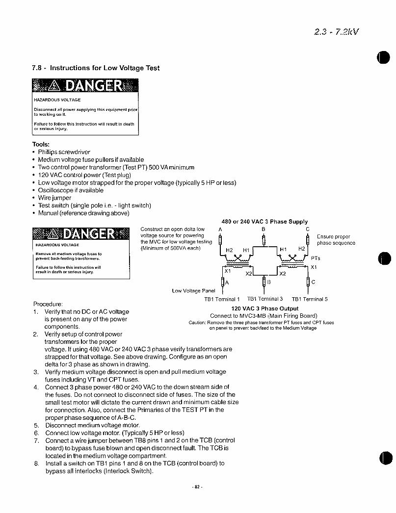
78 InstructionsforLowVoltageTest
DHAZARDOUSVOLTAGE
Disconnectallpowersupplyingthisequipmentpriortoworkingonit
Failuretofollowthisinstructionwillresultindeath
orseriousinjury
Tools
PhillipsscrewdriverMediumvoltagefusepullersifavailableTwocontrolpowertransformerTestPT500VAminimum120VACcontrolpowerTestplugLowvoltagemotorstrappedforthepropervoltagetypically5HPorlessOscilloscopeifavailableWirejumperTestswitchsinglepoleielightswitchManualreferencedrawingabove
ADANGERHAZARDOUSVOLTAGE
Removeallmediumvoltagefusestopreventbackfeedingtransformers
Failuretofollowthisinstructionwill
resultindeathorseriousinjury
480or240VAC3PhaseSupplyConstructanopendeltalow A B C
voltagesourceforpoweringtheMVCforlowvoltagetestingMinimumof500VAeach
82
A
LowVoltagePanel
TB1Terminal1Procedure
1VerifythatnoDCorACvoltageispresentonanyofthepowercomponents
2 VerifysetupofcontrolpowertransformersforthepropervoltageIfusing480VACor240VAC3phaseverifytransformersarestrappedforthatvoltageSeeabovedrawingConfigureasanopendeltafor3phaseasshownindrawing
3VerifymediumvoltagedisconnectisopenandpullmediumvoltagefusesincludingVTandCPTfuses
4 Connect3phasepower480or240VACtothedownstreamsideofthefusesDonotconnecttodisconnectsideoffusesThesizeofthe
smalltestmotorwilldictatethecurrentdrawnandminimumcablesize
forconnectionAlsoconnectthePrimariesoftheTESTPTintheproperphasesequenceofABC
5 Disconnectmediumvoltagemotor6 ConnectlowvoltagemotorTypically5HPorless7 ConnectawirejumperbetweenTB8pins1and2ontheTCBcontrol
boardtobypassfuseblownandopendisconnectfaultTheTCBislocatedinthemediumvoltagecompartment
8 InstallaswitchonTB1pins1and8ontheTCBcontrolboardtobypassallinterlocksInterlockSwitch
X1
PTs
X1
C
721 1 X2
13
TB1Terminal3 TB1Terminal5
120VAC3PhaseOutput
ConnecttoMVC3MBMainFiringBoardCautionRemovethethreephasetransformerPTfusesandCPTfuses
onpaneltopreventbackfeedtotheMediumVoltage
23 72kV
Ensureproperphasesequence
9 Verifyorwirea120VACplugtotheTESTplugsuppliedbythefactoryLinestartpackagesonly
10RemovebothcontrolpowerfusesonthemediumvoltageCPTsinglephasecontrolpowertransformer
11Remove3fusesfromthemediumvoltagepotentialtransformerPT12Verifythe120volttestswitchisintheNORMALpositionLine
startpackageonly13Connecttestpowertotestplugconnectorandplacethe120volttest
switchtotheTESTposition14ThekeypadshouldbeenergizedwiththePowerLEDStopLED15ClosethetemporaryStartswitchwhichisconnectedtothecontrol
board
16TheMainVacuumcontactorshouldcloseandthekeypadshouldtriponUnderVoltageOpentemporaryInterlockswitchandresetCPUfault
17ConnecttheSecondaryoftheTESTPTtoPanelTB1positions1phaseAposition3phaseBandposition5phaseConthemainfiringboardMVC3MBItisphysicallylocatedbehindthelowvoltagecompartmentdoorScrewterminalblock
18Verifyallconnectionsaregoodandthenenergizethelowvoltageofeither480or240voltthreephases
19UsethemultimeterontheACscaleandverify3phase120VACphasetophaseatTB1pins13and5ofthemainfiringboard
20Ifall120VAC3phaseispresentthendeenergizelowvoltageof480or240VAC
21Reenergizethelowvoltageof480or240VAC22Nowalltestvoltagesshouldbepresent480or240VACandthree
phase120VACTESTPTand120VACsinglephaseforcontrolpower
23ClosethetemporaryStartswitchandthetestmotorshouldspinupsmoothly
24UsetheMultimeterontheACscaleandcheckphasetophasevoltagesonT1T2andT3motorleadsThevoltagesshouldbebalanced
25IfthemotordoesntspinupsmoothlythesoftstarterismalfunctioningProceedtostep27fortroubleshooting
26Ifthemotorstartsandrunssmoothlythenrepeatthisprocedureinreversetoremovealltestconnectionsandreinstallallfuses
83
2372kV
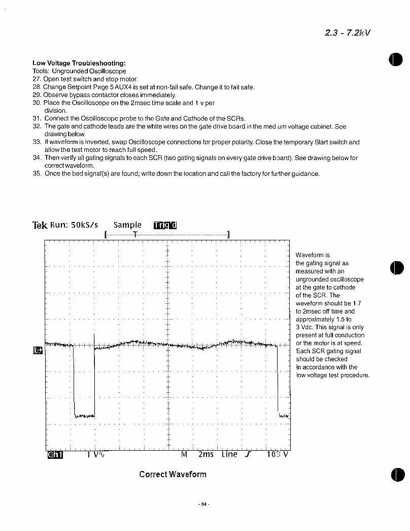
LowVoltageTroubleshootingToolsUngroundedOscilloscope27Opentestswitchandstopmotor28ChangeSetpointPage5AUX4issetatnonfailsafeChangeittofailsafe29Observebypasscontactorclosesimmediately30PlacetheOscilloscopeonthe2msectimescaleand1vper
division
31ConnecttheOscilloscopeprobetotheGateandCathodeoftheSCRs32ThegateandcathodeleadsarethewhitewiresonthegatedriveboardinthemedumvoltagecabinetSee
drawingbelow33IfwaveformisinvertedswapOscilloscopeconnectionsforproperpolarityClosethetemporaryStartswitchand
allowthetestmotortoreachfullspeed34ThenverifyallgatingsignalstoeachSCRtwogatingsignalsoneverygatedrivebaardSeedrawingbelowfor
correctwaveform
35Oncethebadsignalsarefoundwritedownthelocationandcallthefactoryforfurtherguidance
TekRunSOkSs Sample UDE11 T
LIN
CorrectWaveform
M 2ms Line T 103V
84
23 72kV
Waveformis
thegatingsignalasmeasuredwithan
ungroundedoscilloscopeatthegatetocathodeoftheSCRThe
waveformshouldbe17
to2msecofftimeand
approximately15to3VdcThissignalisonlypresentatfullconductionorthemotorisatspeedEachSCRgatingsignalshouldbechecked
inaccordancewiththe
lowvoltagetestprocedure

o
is
GEConsumer Industrial
PowerQualityEquipment
INSTALLATIONOPERATIONANDMAINTENANCEMANUAL
GETRANQUELLEnhancedThermalProtectionSeriesIntegrallyMountedMediumandHighExposureTVSS
ForGESpectraandOEMapplications
2020004801 0707 Page1of13

GEETPSERIESTVSSforINTEGRALELECTRICALEQUIPMENTINSTALLATIONOPERATIONANDMAINTENANCEMANUAL
TABLEOFCONTENTS
IMPORTANTNOTICE 3
TransformerXOBondWarningStatement 3
PRODUCTDESCRIPTION 4
APPLICATIONGUIDELINES 4
MaximumContinuousOperatingVoltage 4
ElectricalSystemConfiguration 5
PeakImpulseRating 5
ShortCircuitCurrentRating 5
EnvironmentalRatings 5
PREINSTALLATIONREQUIREMENTS 6
SystemConfigurationandVoltage 6
SystemGroundingandBonding 6
PrimaryOvercurrentDisconnect 6
VOLTAGERATINGSANDPOWERSOURCECONFIGURATIONS 7
NECCOMPLIANTGROUNDINGANDBONDINGEXAMPLE 8
INSTALLATION 9
MountingConsiderationsOEM 9
PowerConnectionsOEM 9
WireRoutingOEM 9
CircuitBreakerOEM 9
RemoteAlarmContacts 9
TVSSDisconnectSwitch 10
PreEnergizationCheck 10
TVSSWIRINGTERMINALSREMOTEALARMANDULLABELLOCATIONDIAGRAM 10
DIMENSIONS 11
OPERATION 12
LineStatusIndicators 12
AlarmStatusIndicators 12
RemoteAlarmContacts 12
TestEnableDisableSwitch 12
SurgeCounterLCD 12
MAINTENANCE 13
SERVICINGTROUBLESHOOTING 13
2020004801 0707 Page2of13
0IMPORTANTNOTICE
THEENTIRECONTENTOFTHISMANUALMUSTBEREADANDFULLYUNDERSTOOD
BEFOREATTEMPTINGANYINSTALLATIONORENERGIZATIONOFTHETRANOUELLSERIESTVSS
IfthereareanyquestionsabouttheoperationalstatusorintegrityoftheelectricalsystempriortoinstallationoftheTVSSpleaseconsultaqualifiedtrainedelectricianbeforeattemptingtocontinue
IftheminimumrequirementsofthismanualarenotfollowedtheTVSScouldbecomeirreversiblydamagedandortheelectricalsystemcouldbeleftunprotected
ChoosingtherightproductfortheapplicationalongwithcorrectinstallationmethodsasdefinedwithinthismanualwillallowtheTranquellTVSStoprovidethebestpossibleprotectionformanyyears
FailuretocomplywiththeapplicablerequirementsofthismanualcanvoidtheTVSSwarranty
a A WARNINGSPECIALATTENTIONMUSTBEGIVENTOVERIFYTHATAPROPERNEUTRALGROUNDXOBONDHASBEENMADEWHENPOWERISSUPPLIEDFROMANUPSTREAMTRANSFORMERORANYOTHERTYPEOFSEPARATELYDERIVEDPOWERSOURCE
FAILURETOPROVIDETHISBONDASREQUIREDPERARTICLE25030OFTHENATIONALELECTRICALCODECANRESULTINELEVATEDPHASETOGROUNDSOURCEVOLTAGE
POTENTIALSTHESEVOLTAGESCANCAUSEDAMAGETOELECTRICALEQUIPMENTASWELLASSAFETYHAZARDSINCLUDINGFIREELECTRICALSHOCKSERIOUSINJURYORDEATH
2020004801 0707 Page3of13

PRODUCTDESCRIPTION
GETRANQUELLSeriesTVSSareSurgeProtectiveDevicesSPDdesignedforinstallationonlowvoltageelectricaldistributionsystemsGETVSSaredesignedtoprotectelectricalequipmentloadsagainstthedamagingeffectsoftransientvoltagesthatcanbeinducedorgeneratedasaresultofremotelightningpowerequipmentswitchingorhighfrequencydisturbances
TheTRANQUELLETPSeriesTVSSincorporatesMetalOxideVaristorNOVtechnologytoachievesuperiortransientsuppressionperformance IntegraltotheMOVisapatentedThermalProtectionsystemthatoffersbestinclassTVSScircuitinterruptionittheeventofanabnormalovervoltageconditionOtherstandardfeaturesincludeprotectionstatusindicatinglightsanaudiblealarmwithtestanddisablefeaturesformCalarmcontactsforremotemonitoringasurgeeventcounterandbuiltinEMIfiltering Asurgerateddisconnectisoptionalonsomemodels
TheTranquellTVSSunitdescribedinthismanualisintendedtobefcctoryinstalledinelectricalequipmentbytheequipmentmanufacturerGEapplicationsincludeSpectraSeriesPanelsMCCandSwitchgearforlowvoltageelectricaldistributionsystems ForotherspecialOEMapplicationspleasecontactaGEfactoryrepresentativeTheintegrallymountedTVSSisULcULrecognizedunderfileE108159conformingtoUL1283and1449SecondEditionFeb92007TheelectricalpanelorgearwithinstalledTVSSwillbeaULListedassemblyconformingtoallapplicableULstandardsfortheequipmenttypeinadditiontoUt1449AllratingsareinaccordancewithANSI IEEEC624112002C624122002andNEMALS11992R2000
recommendedpractices
APPLICATIONGUIDELINES
Determiningthesurgeprotectiontobeprovidedinafacilityorforaparticularsystemorequipmentcanbeacomplexproblemthatshouldbeaddressedasearlyaspossible Thisis
typicallywhenanewfacilityisconstructedorsensitiveelectronicequipmenthasbeeninstalledThefollowingguidelinesareofferedforapplicationassistance
PriortoinstallinganyTVSSensurethatyourfacilityelectricsupplysystemisproperlyinstalledandconnectedinaccordancewithallapplicablenationalandlocalcodesandsafetyproceduresAllequipmentandsystemsshouldbeinstalledinaccordancewithmanufacturersinstructions
UtilizethepersonnelfromyourlocalutilityyourengineeringdepartmentGEapplicationorserviceengineeringoracompetentconsultingengineeringfirmfortechnicalguidanceortroubleshooting
UnderstandyoursystemandthecapabilitiesandlimitationsofTVSSandotherpowerconditioningequipment
SelecttheproperTRANQUELLSeriesunitforyoursystemvoltageconfigurationandtheanticipatedsurgeenvironmentSomeofthekeyparametersforselectionaredefinedas
MAXIMUMCONTINUOUSOPERATINGVOLTAGEMCOV
ThisvaluedefinesthemaximumlinetolineorlinetoneutralcontinuousACvoltagethatcanbesafelyappliedtotheprotectorMCOVlevelsforTranquellSeriesTVSSaresetat115ofnominalsystemvoltageFor120voltACsystemstheMCOVis125 Ifthereisariskthattheelectrical
systemvoltagecouldexceedMCOVorifanyunusuallyhighpowerfrequenciesTemporaryOverVoltagesTOOorphaseswellsareanticipatedcontactyourGESalesEngineerforfurtherassistance
2020004801 0707 Page4of13

0APPLICATIONGUIDELINESCONT
SYSTEMCONFIGURATION
ProtectorsareavailableforsinglesplitphasewithneutralandgroundthreephasegroundedWYEthreephaseungroundedWYEthreephasehighlegdeltaandforthreephaseungroundeddeltasystemsSeepage7fortransformerwiringschemes
PEAKIMPULSERATING
PeaksurgecurrentcapabilityisanimportantcharacteristicforaTVSSTheratingpermodeshouldequalorexceedthemaximumsurgeexpectedinserviceGETVSSdescribedinthismanualareavailableinmaximumsurgeratingsof65kA80kA100kA150kA200kAand300kA
SHORTCIRCUITCURRENTRATING
TheTranquellTVSSdescribedinthismanualareULcertifiedforuseonelectricalsystemswithratedampacitiesupto200000symmetricalamperesmaximum
ENVIRONMENTALRATINGS
IntegrallymountedTVSSdeviceswillmaintainthesameNEMAEnclosureratingastheElectricalPaneltheyareinstalledinTheTVSSisdesignedtooperatewithinanambienttemperaturerangeof40C40Fto60C140Fwitharelativehumiditylevelbetween095noncondensing
NoprotectorcansurviveadirectlightningstrikeAstrikeclosetoanyprotectorwhichsubjectsthedevicetosurgecurrentorenergydutyinexcessofitscapabilitycanfailtheprotectorElectricalSystemSupplyvoltagesinexcessoftheMCOVcapabilitycanalsofailtheunit
ShouldaconditionoccurthatresultsinprematurefailureoftheTVSSthesuppressioncircuitrywillshortallowingtheintegralfusingtointerruptcurrentflowthroughtheTVSSwithoutdisruptingpowertotheprotectedequipment
IncreasedrateofriseandhighersurgecurrentmagnitudesbothresultinsomeincreaseindischargevoltageConditionscanoccurwherethewithstandcapabilityoftheprotectedequipmentisexceededeventhoughthesurgeprotectorisdoingitsjobandclampingthesurgeInthesecasesadditionallowvoltageprotectionmayberequiredlocatedascloseaspossibletothesensitiveequipment
TRANQUELLSeriesWYEconnectedunitshavebothnormalmodeLNLLandcommonmodeLGNGprotectionProtectionbetweenneutralandgroundisprovidedonunitsdesignedforWYEconnectedapplicationsOngroundedneutralsystemscommonmodeprotectionisneedediftheneutraltogroundbondismademorethan10feetfromthesurgeprotectorThiswillminimizeneutraltogroundpotentialduringatransientavoidinghightransientvoltageswhichcouldreduceprotectionandcausepossibledamagetothesystemortotheequipmentCommonmodeprotectionmayalsobeusedwhentheneutraltogroundbondiswithin10feetTRANQUELLSeriesdeltaconnectedunitshavecommonmodelinetogroundprotection
2020004801 0707 Page5of13

THEEQUIPMENTCOVEREDBYTHESEINSTRUCTIONSSHOULDBEINSTALLEDANDSERVICEDONLYBYCOMPETENTQUALIFIEDPERSONNELUTILIZINGPROPERSAFETYPRACTICESANDPROCEDURES
THESEINSTRUCTIONSAREWRITTENFORSUCHPERSONNELANDARENOTINTENDEDASA
SUBSTITUTEFORADEQUATETRAININGANDEXPERIENCEINSAFEPROCEDURESFORTHISTYPEOFEQUIPMENT
PREINSTALLATIONREQUIREMENTS
PriortoenergizationoftheTranquellintegrallymountedTVSSitiscritialthatthefollowingitemshavebeenaddressed
DONOTATTEMPTTOENERGIZETHETVSSORCONTINUEWITHTHEINSTALLATIONIF
ALLOFTHESECONDITIONSHAVENOTBEENMETORAREUNKNOWN
1SYSTEMCONFIGURATIONANDVOLTAGE
ChecktheconfigurationandvoltagesupplyratingsthatwillbefeedingthepaneltoensurethattheproperTVSSmodelnumberhasbeenselectedforyoursystem TheTVSSmodel
numbercanbefoundontheULlabelaffixedtothebodyoftheTVSSseepage10TheTVSSselectioncanbeverifiedbycomparingtheModelNumbertothecorrectelectricalsystemdescribedintheVOLTAGERATINGS POWERSOURCECONFIGURATIONSchart
shownonpage7ThiseffortmightrequireremovalofthepanelboardcoverandordeadfrontshieldRefertotheelectricalequipmentIOMmanualfordetailsonthepanelassembly
2SYSTEMGROUNDINGANDBONDING
VerifythataNECNationalElectricalCodecompliantXObondhasbeenmadeattheupstreamtransformerorotherseparatelyderivedsystemthatfeedstheTVSSPerNEC25030thisbondmustbeinplaceonall3PhaseWYE3PhaseHiLegDeltaandSinglePhaseSplitSystemsRefertopage8foranexampleofaninstallationthatcomplieswithNECrecommendations
AWARNINIGFAILURETOPROVIDETHEXOBONDWILLDAMAGETHETVSSANDVOID
THEPRODUCTWARRANTY
VerifythattherehavenotbeenmultipleinstancesofNeutraltoGroundbondsontheelectricalsystemThesebondswhileeitherintentionaloraccidentalresultinGroundcurrentsthatcancreatedifferentialvoltagepotentialsbetweenNeutralandGroundRedundantNeutraltoGroundconnectionscanresultindamagetotheTVSSandareinviolationofNEC
3PRIMARYOVERCURRENTDISCONNECT
ConfirmthattheTVSSwillbeinstalledonanelectricalpowersystemthathasanupstreamservicedisconnectbreakerorfusePerNEC285installationofaTVSSonthelineservicesideofthemainbreakerisnotallowed
2020004801 0707 Page6of13

0
0
VOLTAGERATINGS POWERSOURCECONFIGURATIONS
TRANQUELL
MODEL
TPMETPHE120S
NOMINAL
VOLTAGE
5060hZ
120208
240V
MAXIMUM
CONTINOUSRMS
OPERATING
VOLTAGE
150VLNLG
TPMETPHE120Y 120208V 150VLNLG
TPMETPHE220Y 220380V 320VLNLG
ThreePhase
TPMETPHE240Y 240415V 320VLNLG WYE
4Wire Ground
TPMETPHE277Y 277480V 320VLNLG
TPMETPHE347Y 347600V 420VLNLG
TPMETPHE240D 240V 270VLG
TPMETPHE480D 480V 550VLG
TPMETPHE240H 120240V
2020004801 0707
150VLNLGPhaseA C
270VLNLGPhaseB
SYSTEM
TYPE
SinglePhase3Wire Ground
DualPhase
3Wire Ground
ThreePhase
Delta
3Wire
ThreePhase
WYE
3Wir3
ThreePhase
DeltaHiLeg4Wire Ground
SOURCE
CONFIGURATION
Page7of13
LI
N
L2
LI
N
L2
LI
L
L3
LI
L2
L3
LI
L2
L3
L3
LI
L2
ForothervoltagesorconfigurationspleaseconsultwithaGEFactoryRepresentativebeforespecifyingorattemptingtoinstallTVSS

I
X3
EquipmentGroundingConductorRefNEC
25032B1
X2
BondingJumperRefNEC25030a1
X00
Q
O
O
PHASEC
PHASEB
PWAQFA
NEUTRAL
GROUND
GroundingElectrodeConductorRefNEC
250622506425066
GroundingElectrodeRefNEC25030a4
0rr
GO
4
PrimaryDistPanelwOvercurrent
orServiceDisconnect
Means
ExampleofanNECCompliantGroundingArrangementforaSeparatelyDerivedPowerSystem
Note
Primarytransformerwindingsnotshownforsimplicity
2020004801 0707 Page8of13
0

AL WARNINGPOWERMUSTBEPROVENDISCONNECTEDBEFORESTARTINGINSTALLATIONINSPECTIONORMAINTENANCE FAILURETODOSOMAYCAUSESERIOUSINJURYDEATHANDORPROPERTYDAMAGE
INSTALLATION
TheGETranquellTVSSwillcomefromthefactorypreinstalledandwiredintotheElectricalEquipmentCabinetorPanelForallotherOriginalEquipmentManufacturersOEMsandcustomapplicationsrefertotheOEMstepsbelowforadditionalinstallationrequirements
BeforeattemptinginstallationmakesurethatthepreinstallationrequirementsofthismanualhavebeensatisfiedIfthestatusofthepreinstallationrequirementsarenotknowndonotattempttocontinue
1 MOUNTINGCONSIDERATIONSOEM
TheTVSSisconfiguredwithamountingbasetoallowforsecureattachmenttotheequipmentframe TheTVSScanbeinstalledinanyorientationhoweverspecialconsiderationshouldbegiventoallowforperiodicinspectionofthediagnosticdisplaypanelTheTVSSshouldbeinstalledasclosetothepowersourceaspossibletoprovidethebestTVSSperformanceTheTVSSmountingbaseshouldalwaysbesecuredtoastructurethatisintendedtobegroundedSeepage11fordimensionalrequirements
2 POWERCONNECTIONSOEM
CompressionterminalsareprovidedontheTVSSforconnectiontotheelectricalpowersystemTheseterminalswillaccommodateuptosize20strandedcopperconductorsTheminimumrequiredwiresizeforGETVSSis 6AWGSeepaae10forterminallocationandidentification
3 WIREROUTINGOEM
ThelengthofwiringtotheTVSSmustbekeptataminimumforthebestperformanceWirelengthsshouldbeshortstraitrunsbetweentheTVSSandpowersourceWiringimpedancecanbefurtherreducedbytwistingthephaseneutralandgroundconductorstogetherandroutedinthesameracewayorchannelAlwaysavoidsharpbendswhenroutingTVSSconductors
4 CIRCUITBREAKEROEM
AdedicatedcircuitbreakerisnotrequiredaslongastheTVSSisinstalledontheloadsideoftheprimaryovercurrentdisconnectmainbreakerorfuseHoweverifadedicatedbreakerisdesiredGErecommendsa60AbreakerfortheTVSS
5 REMOTEALARMCONTACTS
RemoteAlarmMonitoringContactsareprovidedonallTranquellTVSSmodelsIfthistypeofmonitoringisdesiredrefertopaae10forthelocationandpinconfigurationofthesecontactsThecontactsaredry1formCtyperated125VAC2AmpsmaximumOncetheTVSShasbeenenergizedandisfoundtobeoperatingnormallythealarmcontactswillonlychangeifthereisafailurewithintheTVSSsuppressioncircuitryorifpowerhasbeendisconnectedfromtheTVSSLeavingtheRemoteAlarmContactsunconnectedwillnotaffecttheperformanceoftheTVSS
2020004801 0707 Page9of13

PHASEA
PHASEB
6 TVSSDISCONNECTSWITCH
AmanuallyoperateddisconnectswitchisprovidedasastandardfeatureonsomemodelsItcanbeusedtodisconnecttheTVSSintheeventoffailureorservicingFormodelswithoutanintegraldisconnectadedicatedcircuitbreakershouldbeconsideredasameansofdisconnect
7 PREENERGIZATIONCHECK
OnceallofthepreinstallationconditionshavebeenmetandtheTranquellTVSShasbeeninstalledtheTVSScannowbeenergizedForTVSSOperationalStatusrefertoOperationandMaintenanceSectionspages12 13
PHASEC 00
161 0NEUTRAL
GROUND72IoIoI
TVSSModelNumber
ULRatingsLabel
RemoteAlarm
MonitoringTerminals
NormalStatusIndicationNOCOM Closed
NCCOMOpen
AlarmStatusIndication
NOCOM OpenNCCOMClosed
ThisillustrationrepresentstheorientationofaTVSSasinstalledinaSpectraSeriesPowerPanelOtherorientationsarepossibledependingonthetypeofequipmenttheTVSSisinstalledinTheTVSSfeatureswill
bethesameregardlessofapplicationFormodelswithoutadisconnectswitchthephaseneutralandgroundorientationswillbethesameas
shownintheillustrationabove
2020004801 0707 Page10of13

0
0
5C
71
4I0
k
e
e
I353
711
41141
380 I450
PPSERIESTVSSASSEMBLY
C13011 HOLES1HCS1
4
1589
1EC4
Ev1WINS
E
SLE
1FOEtJe171001RFOzEiEM1 SICNTS1Ei 1rTE1461 h
I41if 1 1 1SWSystemsI k ET IIIILL
NTE
GENERALELECTRICCOMPANY

OPERATION
UPONENERGIZATIONOFTHETVSSIFANYOFTHELAMPSORALARMSINDICATESANABNORMALCONDITIONPOWERSHOULDPROMPTLYBEDISCONNECTEDFROMTHETVSS
THEELECTRICALSYSTEMSHOULDBEINSPECTEDANDTHEPREINSTALLATION
REQUIREMENTSSHOULDBEVALIDATEDDONOTATTEMPTTOLEAVEPOWERAPPLIEDTO
THETVSSORREENERGIZETHETVSSINTHEEVENTOFANALARMCONDITIONPLEASE
CONTACTYOURLOCALGEREPRESENTATIVEFORFURTHERASSISTANCE
AfterapplyingpowertotheTVSSverifythattheprotectionmonitoringcircuitsarefunctioningcorrectlyIfallstatusalarmsindicatenormaltheTVSShasbeensuccessfullyinstalledandisoperational
1 LINESTATUSINDICATORS
ThegreenlinestatusLEDsprovidevisualindicationofTVSShealthstatusAslongastheTVSSisconnectedtotheelectricalsystemsupplyvoltageandtheTVSSsuppressioncircuitryisfunctionalthegreenindicatorswillbeilluminatedThereisoregreenindicatorpereachprotectedphase
2 ALARMSTATUSINDICATOR
WhenilluminatedtheredAlarmStatusIndicatorLEDwillprovidenotificationofaTVSSfailureconditionVerifytheAlarmStatusIndicatorisnotilluminateduponstartup
3 REMOTEALARMCONTACTS
RemoteAlarmContactsareavailabletoremotelymonitorthehealthstatusoftheTVSSAnalarmconditionwillresultinastatuschangeofthecontactsThesecontactsdonotaffecttheperformanceoftheTVSSandarenotrequiredtobeconnectedfortheTVSStofunctionasintended
4 TEST ENABLEDISABLESWITCH
EnablePosition ThisisthenormalpositionforthetripositionswitchIntheenablepositiontheAudibleAlarmwillsoundintheeventofaTVSSfoiluremode
DisablePosition ThispositionwillsilencetheAudibleAlarmifdesiredThedisableswitchwillnotdisableordisconnecttheTVSSfromtheelectricalpowersystem
TestPosition TheTestswitchprovidesaquickdiagnosticstatusoftheAudibleAlarmAlarmStatusIndicatorandRemoteAlarmContactsWhenpressedtheAudibleAlarmwillsoundtheAlarmLampwillilluminateandtheRemoteContactswillchangestateTheTestpositionismomentaryOncepressedtheswitchwillautomaticallyresettotheEnablePositionuponrelease
5 SURGECOUNTERLCD
TheSurgeCounterwillsenseandrecordtransientsurgeeventsthathavebeenmitigatedbytheTVSSThecounterhasbeendesignedtodetecttransientsthatexceedthepeaksinewavebymorethan70 IfdesiredtheSurgeCounterDisplaycanberesettozeroatanytimebypressingtheresetbuttonlocatedontheLCDdisplay
TVSSDisplayPanel
SurgeCounterReset
SurgeCounterLCDDisplay
ut LINE
0 0
EAURA
3T
0aENABLE
DISABLE
0a
CD
LineStatusIndicators
TestEnableDisableSwitch
AlarmIndicator
2020004801 0707 Page12of13
0
A
MAINTENANCE
NOTICE
GEdoesnotprovideaspecificscheduleforpreventativemaintenanceasconditionswillvarybasedonlocationandtheenvironmentalfactorspresentedateachinstallationsiteHoweverperiodicinspectionsshouldbescheduledtoverifythattheTVSSdoesnotindicateafailuremode
InspectionsshouldalsobemadetochecktheintegrityoftheelectricalsupplyconnectionstotheTVSStoensurecontinuedreliableperformance
SERVICING TROUBLESHOOTING
TheTranquellETPSeriesTVSScontainsnouserserviceablepartsandrequiresnocalibrationTheruggeddesignoftheTVSSshouldprovidemanyyearsofservice
ShouldaconditionoccurthatresultsinprematurefailureoftheTranquellTVSStheintegralTVSSsuppressionthermalfusingwillsafelyinterruptcurrentflowthroughtheTVSSwithoutdisruptingpowertotheprotectedequipment
IfachangeinoperationalstatusalarmindicationoccursaqualifiedlicensedelectricianshouldinspecttheelectricalsystemtoverifyelectricalsystemintegrityIftheTVSSremainsinalarmaftersysteminspectioncorrectionshavebeenmadetheTVSSshouldbereplacedForfurtherassistancecontactyourlocalsalesrepresentativeorcallGEResolveat18884373765
WARNINGSINTHEEVENTOFATVSSFAILUREDONOTATTEMPTTODISASSEMBLETHETVSSTOREPLACEFUSINGOROTHERCOMPONENTSTHETVSSCONTAINSTHERMALLY
PROTECTEDMOVSTHATWILLONLYOPENWHENTHETVSSHASFAILEDINANON
SERVICEABLECONDITIONTHEENTIRETVSSMUSTBEREPLACED
CONTACTGERESOLVEAT18884373765
TRANQUELLANDSPECTRAAREREGISTEREDTRADEMARKSOFGENERALELECTRICCOMPANY
TheseinstructionsdonotpurporttocoveralldetailsorvariationsinequipmentnortoprovideforeverypossiblecontingencytobemetinconnectionwithinstallationoperationormaintenanceShouldfurtherinformationbedesiredorshouldparticularproblemsarisewhicharenotcoveredsufficientlyforthepurchaserspurposesthemattershouldbereferredtotheGECompany
GECONSUMER INDUSTRIAL
GEZENITHCONTROLS
2501PECANSTREET
BONHAMTEXAS75418USA
2020004801 0707 Page13of13

GEConsumer Industrial
ElectricalDistribution
CERT OF SESV CCOMP ACEEvolutionMotorControlCenters
QualifiedtoIEEE6931997 HIGHLevelwith13AmplificationFactor
QualifiedtoIBC2003
10
CertificationReportPreparedby
WEGundy AssociatesIncPOBox2900HaileyID83333
Sd 10gS 150 I 15forzh 0
Sd 16gS 240 Ip 15forzh 0
inaccordancewithICCESAC156
1 1 11 1 1 111
1 1 11 1 1 1 1 11
I I1 I 1 1 1 11
I I II I I I I II
I I II I I I I I I1
L I 1TRS
I IPeak16q
10
FrequencyHertz
I I
THISISTOCERTIFYTHATTHEABOVENAMEDEQUIPMENTMEETSOREXCEEDSALLOFTHEABOVEREQUIREMENTSACCORDINGTOIEEE6931997ANDIBC2003
SeeGEdocument10095801P1forCertificationReportinterpretationoftestdataandPEstamp
1 1 II1
IRRS1 Ii
I1PA064g
I
1 1 111111
100
Lowestequipmentnaturalfrequency41Hz QualifiedbyshaketabletestingWyleLaboratoriesDec2005
eDET67107061PrintedinUSA

BillofMaterials
CertifiedTestReport
ShopDrawings
SpectraSwitchboards
PowerBreakIICircuit
Breakers
MicroVersaTripPortableTestSet
SKFrameBreakers
Starters

TableofContents
OrderReq51001404
PORTANGELESWATERTREATMENTPLANT
Tab4 SpecificationSection16425SwitchboardsCertifiedTestReportsShopDrawingSupportingDocumentsSpectraSwitchboards GEH5875
PowerBreakIICircuitBreakers GEH6271
MicroVersaTripPortableTestSet GEI86158
SKFrameBreakers GEH5960
MoldedCaseCircuitBreakers GET7002D
SGFrameBreakers GEH5663
PQMIIElectronicMetering GEK106435L
TypeHEIntegratedTVSS DEH223
CertificateofSeismicCompliance
Operation MaintenanceManual

GENERAL ELECTRIC
SWITCHBOARDTESTCERTIFICATIONREPORT
Customer GESupply
JobName PortAngelesWTPOrder
Reg 51001404SB
Item 5
CustomermarkMDP
WiringDiagrams 750143500sheet147
THEEQUIPMENTLISTEDABOVEHASBEENINSPECTEDANDSUBJECTEDTOTHEAPPLICABLEPRODUCTIONTESTSPECIFIEDINUL891ANDNEMAPB2ANDHASBEENFOUNDTOBEACCEPTABLE
1WIRECHECK
2ACDEVICES
3DCDEVICES
4SEQUENCEOPERATION
5HIGHPOTENTIALTEST
6VISUALINSPECTION
7GROUNDFAULT
PerformanceTestingperGEI48907
8na
QATechnician
ML
Sections1thru3
PowerCircuit
ControlCircuit
Pickupandnoiseat 90 voltage90ofratedvoltagewithCPT
na
atratedvoltage
IndustrialSystems
MEB9010759D
GENERALELECTRICALCOMPANY6801INDUSTRIALDRPOBOX489
MEBANENORTHCAROLINA27302
9195635561
HIPOT2Xrated 26kvfor1second000GND
forappearanceworkmanshipcomponentsassemblymechanicaltoleranceselectricalClearancesmechanicaloperations
na
na
na
ComponentGroundFaulttesting4wireIntegral3wirenotestingatassemblyplant
ekOAqt date kc0
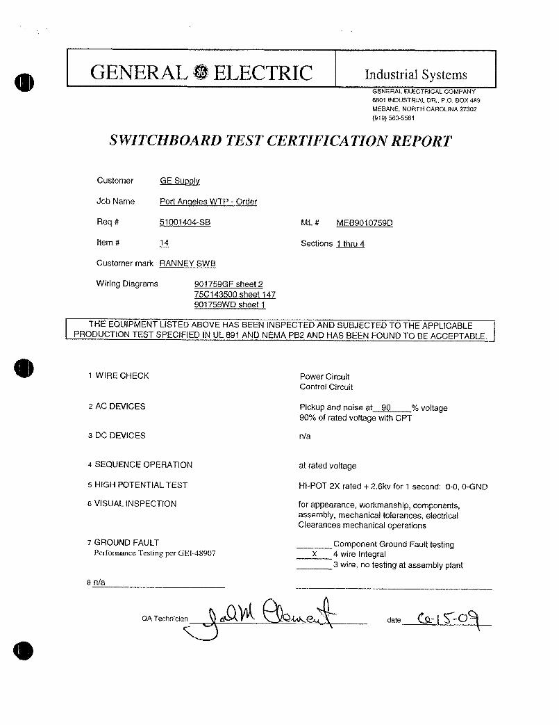
GENERAL fELECTRIC
8na
SWITCHBOARDTESTCERTIFICATIONREPORT
Customer GESupply
JobName PortAnoelesWTPOrder
Req 51001404SB ML MEB9010759D
Item 14 Sections1thru4
CustomermarkRANNEYSWB
WiringDiagrams 901759GFsheet2
75C143500sheet147
901759WDsheet1
1WIRECHECK
2ACDEVICES
3DCDEVICES
4SEQUENCEOPERATION
6VISUALINSPECTION
7GROUNDFAULT
PerformanceTestingperGEI48907
PowerCircuit
ControlCircuit
na
atratedvoltage
IndustrialSystemsGENERALELECTRICALCOMPANY
6801INDUSTRIALDRPOBOX489
MEBANENORTHCAROLINA27302
9195635561
THEEQUIPMENTLISTEDABOVEHASBEENINSPECTEDANDSUBJECTEDTOTHEAPPLICABLEPRODUCTIONTESTSPECIFIEDINUL891ANDNEMAPB2ANDHASBEENFOUNDTOBEACCEPTABLE
Pickupandnoiseat90 voltage90ofratedvoltagewithCPT
5HIGHPOTENTIALTEST HIPOT2krated 26kvfor1second000GND
forappearanceworkmanshipcomponentsassemblymechanicaltoleranceselectricalClearancesmechanicaloperations
ComponentGroundFaulttestingX 4wireIntegral
3wirenotestingatassemblyplant
QATechnician 3600 Qfir date

0
CircuitNoTVSS
1
2
3
4
5
6
NOTES
SpectraSeriesSwitchboard
Device
TVSS100KSS2o
SFLA
SFLA
SKLA8
SGLA4
SGLA4
1ACCESSTOFrontOnly1PHASE3P4W1CLASS2 1AMPERE3000
1LABELUL 1BUSMILCU1000AIn
1VOLTAGE480Y277V1PLATESilverPlateISTYLEBoltOn IRATINGFOIIy
BUSBRACINGMSSYMI 65000A
DEVMININTRATINGIRMSSYM1 65000A
1TotalLineUpWAUth105
SwitchboardDeviceInformation
AmpsPoles0 1 0 1
2000I 3 1MCC2125 3 IPLANTPANELL11251 3 IPANELL2OFFICESHOP8001 3 IMCC1400I 31POWERPANELP13001 3 1MCC3
1Coppergroundbusfurnished
2Equipmentgroundbusfurnished
3Devicefurnishedwithpadlockingprovisions
4DevicefurnishedwithPowerLIT1PrgrmrwfrargetsModule
5LIT1programmerfurnishedasLSIT1withshorttimesetatmaxsetting90c6PQM2MeterinstalledinSwitchboardWirepersheet75C143500SH147
7Shippingsplitsbetweeneachsectionshipeachsectionseparately8SwitchboardfurnishedwithCertifiedTestReports
9SwitchboardfurnishedwithTVSSHE100kApermode200kAperphase200kAICTVSSfurnishedwithIndicatingLightsAlarmFormCContactsSurgeCounter DisconnectSwitch
10IMPORTANTIfaccesstobusstubconnectionislimitedstubshouldbeinstalledbeforeboardisplacedinfinallocationSupportbuswayexternallyfromswitchboard
11SwitchboardfurnishedwithSeismicZone34
JOBNAMEPORTANGELESWTPORDERWILLADVISEWILLADVISEW
MADEBYLoweryISSUED031202008
RELBYiL
HiRas70994
CUSTOMERGESUPPLY31285SANCLEMENTESTHAYWARD94544
ICUSTORDERNO
1REQNNO51001404SBORDERNOMEB9010759D
Nameplates Luas
IPLANTMEBANElMARKMDP
13453
3
31313
I1
902124091 CHANGFSPERIS1 DtMEB9010759D1R1071809RETOMANUFACTURINpL1NODATEREVISIONS INITIALS1SHEET05DS1
Notes
ITEM05

0
12HIC
28
I 01
G
16
28
RELBYDL
SpectraSeriesSwitchboard
35 30
FrontView
ULI
1201POM21 11
SS
I2000A
3000ATFR
3PH4WCU
3012TFR15ON
GPHN
J
Poe4
3000A 3000A
C20 C20
BussingDiagram
20
1 24
20
3000A3000A
Load500MCMMe1HoleALPERP5N
Y
JOBNAMEPORTANGELESWTPORDER1MLLADVISEWILLADVISEWAIJ00XXXXXXX
MADEBYLoweryDIISSUED03202008
HiRes70989
ACCESSTQFrontOnlyIPHASE3P4W 1
CLASS2 1AMPERE3000LABELOIL 1BUSMTLCu1000Aini
VOLTAGE480Y277VIPLATESilverPrate 1STYLEBotOn IRATINGFully IBUSBRACINGRMSSYMI 65000A1DEVMININTRATINGRMSSYMI 65000AI
TotalLineUpWidth105 1
UL
17
7
11
40
171
1
631
3000A
3000A
C20
VENTED
NSS
5XFILLER
2 1 3
4
5 6
02FILLER
6XFILLER
6XFILLER
VENTED
III
I1I1
TVrsl
3000A
MOM
UL1
SB43X
ICUSTOMERGESUPPLY
31285SANCLEMENTESTHAYWARD94544
CUSTORDERNO
IREQNNO510014041ORDERNOMEB9010759D
PLANTMEBANE
1I I
R10218091RELTOMANUFACTURINGDL1
MARKMDP
MEB9010759D
CONDUITSPACErvPL0ILSWOONS
INOIDATEREVISIONS INITIALS1SHEET05 ITEM05
1ITL
x625DIATYPI

m
TotalLinoUpWidth105
TopConduitAreaSection01 Section02
35 30
0 6116 6
HiRes70994
0
02
SpectraSeriesSwitchboard
3
C249W24Hx27W
BottomConduitArea
35
CmrArea2Hx24W 411
FrontPlanView
3
FrontPlanView
RELBY6L
Section03
41
Co6Aea66x34W
40
CurialRip9Hx34W
JOBNAMEPORTANGELESWTPORDERWILLADVISEWILLADVISEW
MADEBYLoweryD1ISSUED03202008
ConduitDetail
CUSTOMERGESUPPLY31285SANCLEMENTESTHAYWARD94544
CUSTORDERNO
rREQNNO51001404SB
OI2DERNOMEB9010759D
25
CONDUITSPACEMEALALLSECTIONS
PLANTront MARKJrY
II I IMEB9010759DIR40211810RELTQIANUACVEING OLINDIDATEREVISIONS INITIALSSHEET05CD1 REM05

CircuitNoGen
Main
1ACCESSTOFrontOnlyIPHASE3P4WICLASS2 IAMPERE3000
TM
SpectraSeries VOLTAGE480Y277VIPLATESilverPlaenSwitchboard
JOBNAMEPORTANGELESWTPORDERWILLADVISEWILLADVISEWXXXXXXXX1w
MADEBYLoweryD1ISSUED03202008RELBYDL
HiRes70996
STYLEBolt 1RATINGFully
BUSBRACINGRMSSYM 65000A
IDEVMNINTRATINGRMSSYM 65000A
TotalLineUpWidth150
SwitchboardDeviceInformation
AmpsPoles Nameplates2000 3 GENMAINBREAKER
Device
SSD20
SSD30
13000 3 MAINBREAKER
Lugs
NOTES
1Coppergroundbusfurnished
2Equipmentgroundbusfurnished
3SwitchboardfurnishedwithSeismicZone34
4Devicefumishedwithkirklock
5DevicefurnishedwithLSIGprogrammer
6Devicefumishedwithdrawoutmounting
7Devicefumishedwithpadlockingprovisions
8Devicefumishedwith120VAC125VDCshunttrip
9Devicefurnishedwithbellalarmswitchandlockout
10Deviceisfurnishedwithintegralgroundfaultprotectionwiredper901759GFSH1
11Devicefurnishedwith4240VAC125250DCauxiliaryswitchesSPDT
12Shippingsplitsbetweeneachsectionshipeachsectionseparately
13SwitchboardfurnishedwithCertifiedTestReports
14SwitchboardfurnishedMainGenkirklockschemeprovide2lockswith1key
15SwitchboardfumishedwitharainproofTYPE3RnonwalkinenclosureNOTESeeplanviewfordetailsNeedadditonal514inchspaceclearanceontopoftheswbd
16IMPORTANTIfaccesstobusstubconnectionislimitedstubshouldbeinstalledbeforeboardisplacedinfinallocationSupportbuswayextemallyfromswitchboard
CUSTOMERGESUPPLY31285SANCLEMENTESTHAYWARD94544
ICUSTORDERNO1REQNNO510014041ORDERNOMEB9010759D
PLANTMEBANE
1MARKSED
1 11MEB9010759D
IIjlopmaglRFLTOMANUFACTURING111INO1DATEREVISIONS INITIALSSHEET06DS1 ITEM06
CONDUITSPACEFK1rALALL 620A
Notes
4567891011
14567891011I

90
20
22
RELBYDL
HR70994
SpectraSeries ISEULSE IBUSMILCu1000AinI CTTYPEwand
IVOLTAGE480Y277VIPLATESilverPlate 1p7TYPFSwitchboard STYLEBoltOn IRATINGFully
65000APERGEDWG750143613PV101101A10113
DEVMININTRATINGRMSSYM1 65000APERPWRCOSPEC75r47H5fITotalLineUpWidth150
30 40 40
U4 ULSE
16
SSD
24
18
SSD
2000A
3000A
3000A
C30
Gen
01
FrontView
Gen
G a 1N 3 3000A
GenLire8500MC
ch1HoleALPERPHN
BussingDiagram
JOBNAMEPORTANGELESWEPORDER
WILLWILLADYVISEW
MADEBYLoweryD
1BUSBRACINGRMSSYM
128
32
28 I
3000A
C30
3000ATFR3PH4WCU3002TFR150N
NPHG
1 L
ISSUED03202008
IACCESSTOFrontOnlylPHASE3P4W POWERCOGErsRIOUULGX42SINCtqCODE2Z
ICLASS2 IAMPERE3000 10CTFACE8MTGONLY
30000
Main
116
28 12002 a1
illUL
II
I 1 28
II
28
ZZ
3000A
I28
l
30000 3000A
T30 T30
30000 Main
C30
30000 30000
ICUSTOMERGESUPPLY
31285SANCLEMENTESTHAYWARD94544
1CUSTORDERNO
REONNO51001404SBORDERNOMEB9010759D
40
U
u
01
ULine850010011Ned1HoloALPER0148
I
UL
IPLANTMEBANEMARKSED
II I IMEB9010759D
CONDUITSPACEpeeouSECTIONS
1R10218091RELTQMANUFACTURINGDLIINOIDATEIREVISIONS INITIALSISHEET06FV1 ITEM06

TotalUnaUpWidth150
TapConduitArea
Section01 Section02
30 40
116
HiRes70994
40
10
SpectraSeriesSwitchboard
BottomConduitArea
30 4
6i0504Area31HEiw
FrontPlanView
FrontPlanView
RELBYOL
Section03
40
40
1
6L
JOBNAMEPORTANGELESWTPORDERWILLADVISEWILLADVISEW
MADEBYtowerD ISSUED03202008
ConduitDetai
Section04
40
40
OverhangI 5Overhang 15Overhang I5Overhang
Cmo3Area3iH23iW
OverhangI 5Overhang 5Overhang15Overhang I
1SLOPE
CUSTOMERGESUPPLY31285SANCLEMENTESTHAYWARD94544
ICUSTORDERNO
R NO5D Io51
1404
ORDE NO
94114
5 10 40
SCREENVENT
SIDEVIEW
5OVERHANG
9 9514
25
PLANTMtbANt
IMARKStu
1 IMEB9010759D
CONDUITSPACE
TYPALALLSECTp1D
42181019RELTOMANUPACIURUIG DI IDATE REVISIONS INITIALSISHEET06 ITEM
S625DIA
aTYPI

CircuitNo Device
Gen 1 SSD25Main 1 SSD25
TVSS 1TVSS100K1 1 FBH62 FBH63
4
5
6
7
NOTES
1ACCESSTOFrontOnly1PHASE3P4W 1
TMICLASS2 1AMPERE2500 1
PlateSpectraSe I CEom77 1 7ESU
Cu
e0Switchboard ISTYLEBoltOn IRATINGFully 1
IBUSBRACINGRMSSYMI 65000A
1DEVMINNTRATINGRMSSYM 65000A
TotalLineUpWidth135 1
FBH6FBH6
FBH6
FBH6FBH6
JOBNAMEPORTANGELESWTPORDERWILLADOVISEW
MADEBYLoweryDISSUED03202008
RELBYDL
HiRes70994
SwitchboardDeviceInformation
AmpsPoles Nameplates1600 3 GENERATORBREAKER2000 3 MAINBREAKER
0 I 0 1
10013 1PANELL110013IPANELP11001 3 IPANELP21001 3 1FANSTARTERS1001 3 1XFMRT350 1 3 1AIRCOMPRESSOR150 13 IAIRCOMPRESSOR2
Lugs
25
1Coppergroundbusfurnished
2Equipmentgroundbusfurnished
3SwitchboardfurnishedwithNameplates
4SwitchboardfurnishedwithSeismicZone34
5Devicefumishedwithkirklock
6Devicefumishedwithdrawoutmounting
7Devicefurnishedwithpadlockingprovisions
8DevicefumishedwithPowerLIT2PrgrmrwTargetsModule
9LIT2programmerfurnishedasLSIT2withshorttimesetatmaxsetting90c
10Devicefurnishedwith4240VAC125250DCauxiliaryswitchesSPDT
11Deviceisfurnishedwithintegralgroundfaultprotectionwiredper901759GFSH2
12Shippingsplitsbetweeneachsectionshipeachsectionseparately
13VoltMeterPhaseselectorswitchwiredper75C143500SH23
14PQM2MeterinstalledinSwitchboardWirepersheet75C143500SH147
15CTs30005onA Bphaseinsection4areforcustomerusewiredper901759WDSH1
16SwitchboardfumishedMainGenkirklockschemeprovide2lockswith1key
17SwitchboardfurnishedwithCertifiedTestReports
18SwitchboardfumishedwithTVSSHE100kApermode200kAperphase200kAICTVSSfurnishedwithIndicatingLightsAlarmFormCContactsSurgeCounter DisconnectSwitch
ICUSTOMER 31SUPPLYCL9LEM NTEST IPLANTMEDANEMARKRANNEYSWB
IOUSTORDERNO I I IMEB9010759DIREONNO510014045B 1R10218091RELTOMANUFACTURINGDL1
IORDERNOMEB9010759D 1NOiDATEIREVISIONS INITIALS1SHEET14
CONDUITSPACEnrtrxALLtECo
Notes
156789115678911
ITEM14
gyp525ou
otYP1

28
ZZ
2500A
J0
28
MAULSE
SpectraSeries VOLTAGE480Y277V IPLATESin
Switchboard YLEST BoltOn 1RATINGFully
BUSBRACINGRMSSYMI 65000A
DEVMININTRATINGIRMSSYMI 65000A
1TotalLineUpWidth135
25006
T30
RELBYOL
HiRes70989
40
U
G K i
250UA
1261ueeMelNdIALPEASN
BussingDiagram
TM
SSD
I2500A
32
16
2500A
JOBNAMEPORTANGELESWTPORDERWILLADOVISEW
MADEBYLoweryDISSUED03202008
30
25006
T30
pON4
25006C35
Li
ACCEssTOFrontOnly1PHASE3P4WCLASS2 IAMPERE2500
Main
0401
2
30
uLSE ULt
4 I41
POMJ I BWC
112HIC 11SSD
GenI
TI
32
25006GenC35
UL
25006 21
42
25006
C30
250061 e
6
25006 2500A
161350LoadALMechPERP568N
35
6FILLER 11 BLANK
213415
1617
800A
ICUSTOMERGESUPPLY
31285SANCLEMENTESTHAYWARD94544
ICUSTORDERNO1REQNNO51001404SBIORDERNOMEB9010759D
TVSS
1POWERCOGESI6unt50trt7281PnI CITSPACEMTGONLY
onTYPEWtock
PITTYPF
ERGEDWGM1438131101A1015
PERPWRCOSPEC74417TAISASit1
ui
58028X
MCC
XTION
28 20 20 21
01 1 02 05 04
vxrYVxk4xYxcxrYxxxxvvr vxvvyvvvvvvvryvY
T1112FloorSillsIFront
rBPHONLY
16r MCC
MCC
CODEQ25 I 111
CONDUITSPACEALL
623
I IMEB9010759D
1R102118091RELTOMANUFACTURINGDLINOIDATEREVISIONS INITIALSSHEET14FV1
IPLANTMEBANE
lMARKRANNEYSWB
ITEM14

TotalLinoUpWidth135
TopConduitAreaSection01
40
HiRes70994
T
6
SpectraSeriesSwitchboard
BottomConduitArea
40
Cm1iNw7GHM11W
2
30
Section02 Section03 Section04
30 30 35
FrontPlanView
1
RELBY17L
30
CortiArea3eh24tV
FrontPlanView
1
4
3
Cont4A3411225W
JOBNAMEPORTANGELESWTPORDERWILLADVISEWILLADVISEW
IMADEBYioweryD ISSUED03202008
ConduitDetai
2
CUSTOMERGESUPPLY31285SANCLEMENTEHAYWARD94544
CUSTORDERNO
REQNNO51001404SBORDERNOMEB9010759D
25
I
AIEBARt MARKRANNEYSST
IR 02180 RETOMANUFACTURING DLMEB9010759DINDIDATEIREVISIONS INITIALS I SHEET14
CONDUITSPACEnwrxu3lecTIO6
REM14
1112
J25DA
0CIwi

CTI
8
A
C
LINE48012716003413PH4W
A B C N
Tw100MLL2nnOACTAO1
ethtJ
XICI
XI I 1 IcCT2E
E3I
14
ICI Li
CT3
CT4 XCE
OPT1OHAL
II2A12
31210
1E11
C3
3PTS
3FU2ri
XI
0XI
5 6 OFU6 XI
CNI
C62
CN3
C4
CN4
SWBDGROUND
BUS
13 C7 12 1E 75C143500 15I141
SWBDGROUND
GUS SWBDGROUND
BUS
5A IA CON 5A IA COU 5A IA
PHASEA PHASES PHASEC HLUIHAL
CON 15A IA COuN118 1 10 I 12 13 14 15 16 17 I2 19 20
0
s1
eENAMrTtA13T6eL1T1 I10L10Y00l10011Ml
14 1 13 Q 12
142
143
M417
GNO5
GND6
412AWG
412AIMS
VI
I011051000Alt10IX0A51HIHLUNLESSOTHERWISEKW
SPECIALIRDRAWWORSRc0ltRAOCLON
w0K10111101I
2n00110230003 WALGI1PC0rCAltf0005
MOLESA05 1111601000T1ONE
CONTROLPOWER
w AI w
V V3 VII N Lr2 3 4 5 6 7 g
y MM1116
4 43
I LLII 1 I 1f I
II I
1I I
1 11 1
rocA00ITIGUAlIMO01011T01 SGHATUPES 1DATEI
NcR 110101 Iex1 o88I
r111125 JIPAPilc010111Ci11503311lI
CEixtstrifSystem
911E
CIYnL11OuIZALC0020100KMI
PQM
METER
NOTEIALLWIRINGTO
BE114AWGUNLESSOTHERWISENOTED
GSMELCCIItcCOMPANY
ROMWO600347 4802773PH4WWTS
75C143500 100713REET121

m
c
B
A
A
CT
CT2E
TxAxLEPaOi2rTex
14
LINE480Y2776003473PH4W
D A B C N
Ix1 11CT3
CT4 XI
EOPTIONAL
14
3PTSI 2 OFU2
rXI
C018
32h4 OFUd XI 10
N2
111156 0FU6Ir
XI
1M3
N47
NMI
cN1
C82
CN3
u
CN4
SWBDGROUND
BUS
13
SWBD
GROUNDBUS SKID
GROUNDBUS
1
13
12OEF30111EA11330COMFIDE
LTINFO00A1IO1
ir tk1
100403289
GND5
0006
10612404IJWE
5EV1
119800657210200308
131302011811A100300524
DESCA1PT1011
I VOLTAGEINPUTS CONTROLPOWER
mF 1I WJO10zc
VI V2 V3 VNI 2 3 4
10
I I312AWG
112AWG I 1
12
N5 6 7
38151082
I6
L8
PHASEA PHASE9 PHASEC
58IA CON 5A IA COY I 5A IA
LJ I 12 14 IS
O
75C143500 I1141
0400 18380000
1826981MAL13181021BWN
BGFI108021I 10227031EGB
PQMMETER
NEUTRAL
CON I SA IA Cou
17 ElIC 20
NOTEIALLWIRINGTO
BE114AWGUNLESSOTHERWISENOTED
CETIELEGIPoCCCOPANTi0A10011105411000Ri1301 SIGNATUPES 1DA1I
J 1a 10182989101001011APIII1x81001N1411 I
UNLESSIN 1
CW0I i111
LLPOMWO 600347 480277saPOqSED o4EwuvcLGFGTOLSARI001
IYfo00DECIRALSAIIPL0210411k002 05111111FL8121000003
A00110005 11100yIEOxxoW
RALPIONS
0HISN JIP0140rOOl131111017111
eCIARACILR100 100100w 1ICAL1IPLUM101111
Systems
3PH4WWPTS
75C143500150100111

4559
70VOURC1
7N
4
1 4RVi1
s311
t040A0
37144740H2711441OISUENCL1Z3M
2F
5 ifrviVIti1Y7t7J
lPI 12 P3
WHENCROMPTONMODEL077INSTRUMENTSARESUPPLIEDTERMINALNUMBERSARESHOWNINPARENTHESIS
um5511
1s0li
GEUSACONFIDENTIALANDPROPRIETARYTwaEawnnetwul1m1411Melpn1nrwhlwwln
OSTJNNldbautlen1Cams1E814lIAnnnonmamboCrlandtrlonWlanthwNnnxEwdDdrtnlclOdoeWonAwnsenpnienAopenOrWAG 00444nA
AAtrecnAnocA monA4444
C0N11KTS
HRIHREM0
12
124331073
V71100wtP3V1211 14157101 4200t142
13
al017241E
2440CY1aC1MfT I87TCAis77 IEHi0 IRPYP10Ew0 1
1INSZR S4r1 nwort045177144moreISt17734144 10107 SRl1SRURtMC
MnvTu
OENERnLJELECTRIC
DIAGRAMt3slob
METERINGDIAGRAM
FROn TO 1 TO
BLOCK BERNDEY NOWHENROO1 NO
RH II FU t
3t
JI 3
VS 12I Pt 2
2 P2 4
16 P3 I6
11141 PN R111H
1511 1
1 1 1 lc
I 1 1 I
1 1 1
1
1 1
1 I
I 1
NO
POI1T10N
1 1
4OEN0T12108741TSLOSE0
ua
27i
7501435004x223
111011QU EI
s111M11s111111111EI
111M11111111111
31
3
32

CT1
CT2
DRAWNBY
ISSUED
GEEDC
2CTCIRCUITDIAGRAM
FORUSEWITHEB27B06S
SHORTINGTERMINALBOARD
A@ B0 00
0
X1
7X2
X1
X2
c
DLOWERY
01
CN
C2
CN
SHORTINGSCREWS
CAUTION
CURRENTTRANSFORMERSARE
OSHORTEDBYGROUDNGSCREWS
90159WDCONTONSH
REMOVEGROUNDINGSCREWS
AFTERMETERHASBEENNSTAUED
Yellow
75A662443P4
SHNO 1
REVISIONS
JUMPERSMAYBEREMOVEDIF
SEPARATECIRCUITSAREREQUIRED PRINTSTO
APPROVAL
GDL
021909 MEBANENC CONTONSH SHNO 1
EDC 90159WD
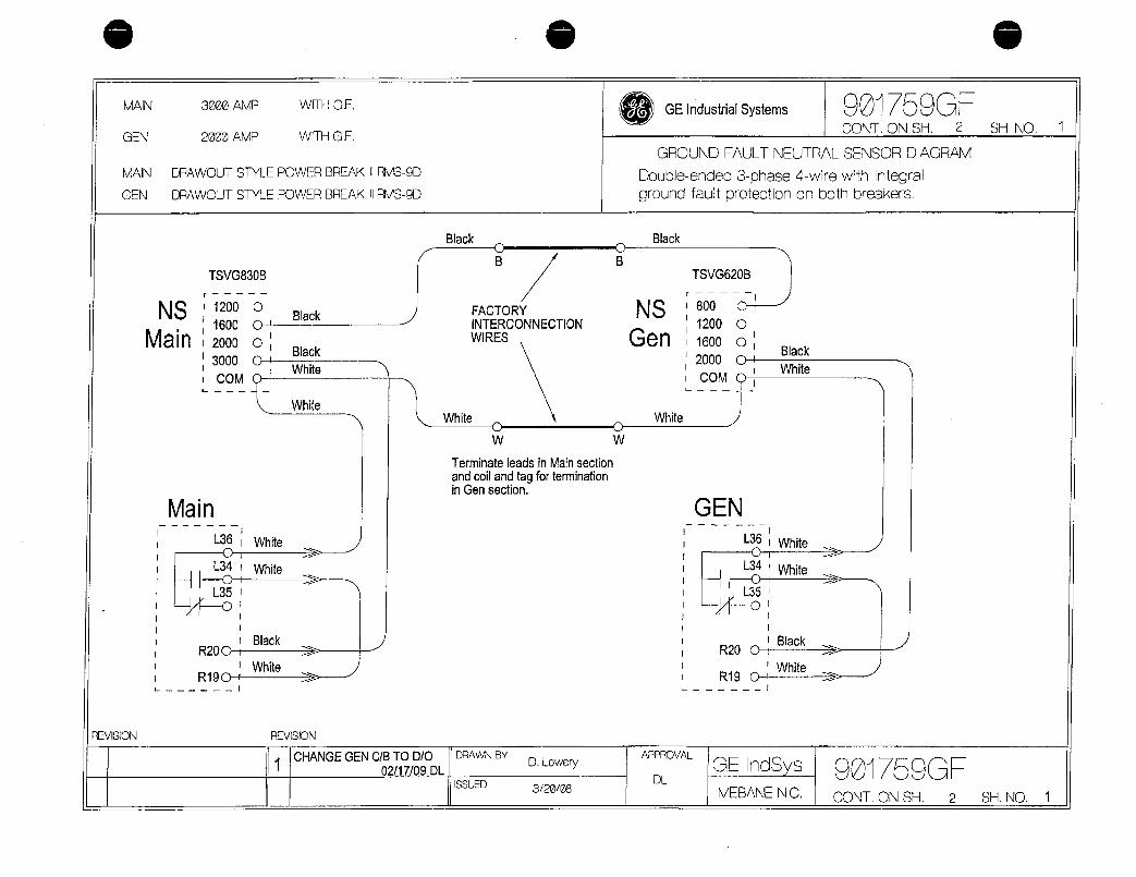
o
MAIN 3000AMP WITHGF
GEN 2000AMP WITHGF
MAIN DRAWOUTSTYLEPOWERBREAKIIRMS9D
GEN DRAWOUTSTYLEPOWERBREAKIIRMS9D
NS 1200 OBlack
1600 0
Main 2000 0Black
3000CWhite
COMC
WhiteWhite
W
TerminateleadsinMainsection
andcoilandtagforterminationinGensection
Main
L36
L34C
L35O
R20C
R190
TSVG830B
White
White
Black
White
Black
B
FACTORYINTERCONNECTIONWIRES
REVISION REVISION
1CHANGEGENCBTODO DRAWNBY
021709DLISSUED
DLowery
32008
B
W
L J L
GEIndustrialSystems 901759GHCONTONSH 2
GROUNDFAULTNEUTRALSENSORDIAGRAM
Doubleended3phase4wirewithintegralgroundfaultprotectiononbothbreakers
Black
NS
Gen
White
APPROVAL
DL
TSVG620B
800 C
12000
1600 0
2000C
COMC
J
GEN
Black
White
L36 White
H LG Whitef
L35Ci
R20Black
R19CWhite
SHNO 1
GEIndSys 9017590EMEBANENC CONTONSH 2 SHNO 1
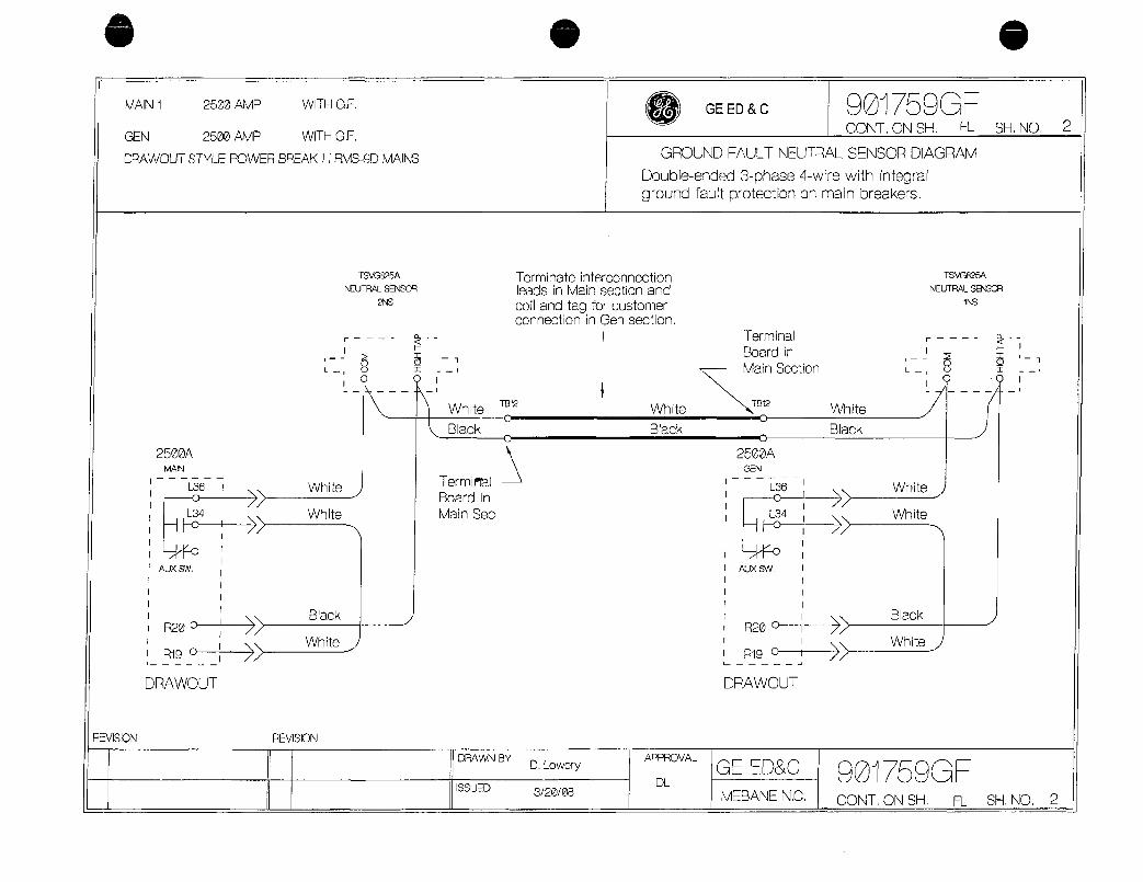
MAIN1 2500AMP WITHGF
GEN 2500AMP WITHGF
DRAWOUTSTYLEPOWERBREAKIIRMS9DMAINS
2500AMAN
L36
c
L34 1
Hc
AUXSW
R20
Rigc
REVISION REVISION
White
White
Black
White
TSVG825A
NEUTRALSENSOR
2NS
TermiPIal
Boardin
MainSec
ISSUED 32008
TerminateinterconnectionleadsinMainsectionand
coilandtagforcustomerconnectioninGensection
WhiteTB12
White
Black Black
DRAWNBYDLowery
APPROVAL
CONTONSH FL SHNO 2
GROUNDFAULTNEUTRALSENSORDIAGRAM
Doubleended3phase4wirewithintegralgroundfaultprotectiononmainbreakers
DL
GEEDC
Terminal
Boardin
MainSection
TB12
3
2500AGEN
L36
124ylir
AUXSw
I I
I I
I I
R20cI I
R19c
DRAWOUT DRAWOUT
GEEDC
MEBANENC
White
Black
901759tH
TSVG825A
NEUTRALSENSOR
1NS
II
L U S
n n 1
White
White
Black
White
901759G1
i
CONTONSH FL SHNO 2


s
WARNINGS
CAUTIONS
NOTES
GEH5875
WARNINGSCAUTIONSANDNOTESASUSEDINTHISPUBLICATION
Warningnoticesareusedinthispublicationtoemphasizethathazardousvoltagescurrentsorotherconditionsthatcouldcausepersonalinjuryarepresentinthisequipmentormaybeassociatedwithitsuse
Warningnoticesarealsousedforsituationsinwhichinattentionorlackofequipmentknowledgecouldcauseeitherpersonalinjuryordamagetoequipment
Cautionnoticesareusedforsituationsinwhichequipmentmightbedamagedifcareisnottaken
Notescallattentiontoinformationthatisespeciallysignificanttounderstandingandoperatingtheequipment
ThisdocumentisbasedoninformationavailableatthetimeofitspublicationWhileeffortshavebeenmadetoensureaccuracytheinformationcontainedhereindoesnotcoveralldetailsorvariationsinhardwareandsoftwarenordoesitprovideforeverypossiblecontingencyinconnectionwithinstallationoperationandmaintenanceFeaturesmaybedescribedhereinthatarenotpresentinallhardwareandsoftwaresystemsGEIndustrialSystemsassumesnoobligationofnoticetoholdersofthisdocumentwithrespecttochangessubsequentlymade
GEIndustrialSystemsmakesnorepresentationorwarrantyexpressedimpliedorstatutorywithrespecttoandassumesnoresponsibilityfortheaccuracycompletenesssufficiencyorusefulnessoftheinformationcontainedhereinNowarranteesofmerchantabilityorfitnessforpurposeshallapply
IhefollowingaretrademarksoftheGeneralElectricCompanySpectraSeries
OCopTight2002GECompanyAllRightsReserved

AVERTISSEMENT
ATTENTION
NOTES
GEH5875
AVERTISSEMENTATTENTIONETNOTETELSQUUTILISESDANSCETTEPUBLICATION
LesavisportantslamentionAvertissementsontutilisesdanscettepublicationpourmettreenevidencequedestensionsoucourantsdangereuxouquedautresconditionsquipourraientcauserdesblessuressontpresentesdanscetequipernentoupourraientetreassocieesausagedecetequipement
LesavisportantlamentionAvertissementsontaussiutilisesaucasoildessituationsdanslesquellesdelinattentionoulemanquedeconnaissancede16quipementpourraitresulteroubienendesblessuresouendesbrisde1equipement
LesavisportantslamentionAttentionsontutilisespourlescasoii1equipementpourraitetreendommagesilonnenArendpassoin
LesavisportantslamentionNoteattirentattentionsuruneinformationquiestparticulierementsignificativealacomprehensionetaoperationde1equipement
CedocumentestbasesurinformationdisponibleanmomentdecettepublicationBienqueleseffortsaienteteapportespourassurerlaprecisioninformationcicontenuenecouvrepastouslesdetailsouvariationsdequincaillerienidelogicielninecouvrepourtoutproblemeretiealinstallationloperationoulentretienDesoptionspeuventetredecritesciinclusquinesontpaspresentesdanstouslessystemesdequincaillerieoudelogicielGEIndustrialSystemsnesengageaucunementaaviserlesdetenteursdecedocumentenregarddeschangementsapportessubsequemment
GEIndustrialSystemsnefaitenegardaucunerepresentationougarantieexprimeesousentendueoustatutaireninassumeaucuneresponsabilitepourlaprecisionlacompletionlasuffisanceou1utilitedelinformationcicontenueAucunegarantiepourfinsdemarchandisageoudutilitedesireenesapplique
LessymbolesquisuiventsontdesmarquesdecommercedeGeneralElectricCompanySpectraSeries
Copyright2002GECompanyTousdroitsreserves
ii
e

SpectraSeries TMSwitchboards
TableofContents
Chapter1ReceivingHandlingandStorageReceiving 1
Handling 1
Storage 1
LiftingInstructions 2
Chapter2 InstallingtheSwitchboardBeforeInstallation 3
Location 3
Clearance 3
RearAccess 3
FoundationRequirements 3
IndoorEquipment 3
OutdoorEquipment 4
Conduits 4
SeismicallyCertifiedEquipment 5
FieldConnectionandTestingofGroundFaultProtectionSystems 6
FuseSelection 8
TestingandInspection 8
GroundFaultProtection 8
Bolts 9
ElectricalClearances 9
Grounding 10
SwitchboardsUsingCordforShortCircuitProtection 10
BeforeInstallation 10
InstallationProceduresforMainCableswhenCableBraceisProvided 11
InspectionafterMainCableInstallation 11
Chapter3
Chapter4
Chapter5
SplicingtheSwitchboardSectionsGroupASpliceDiagrams 12
Group13SpliceDiagrams 25
ConnectingtheSectionFrames 36
SwitchboardMaintenanceGeneralMaintenanceProcedures 37
AmbientTemperaturesandCircuitLoading 38
ShortCircuits 38
ArcingDamagetoInsulation 38
WaterSoakedEquipment 38
SpareParts 39
iii
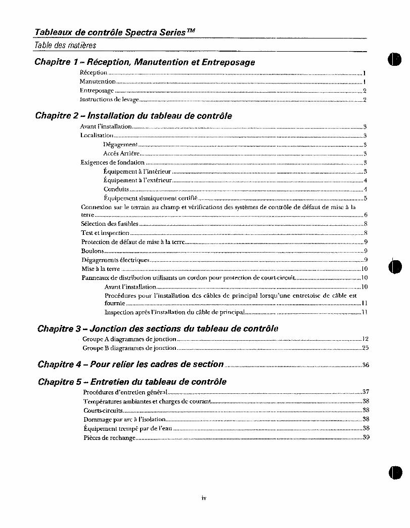
TableauxdecontroleSpectraSeries TM
Tabledesmatieres
Chapitre1ReceptionManutentionetEntreposage 0Reception 1
Manutention 1
Entreposage 2
Instructionsdelevage 2
Chapitre2 InstallationdutableaudecontroleAvantlinstallation 3
Localisation 3
Degagement 3
AccesArriere 3
Exigencesdefondation 3
Equipementa1interieur 3
Equipementalexterieur 4
Conduits 4
Equipementsismiquementcertifie 5
Connexionsurleterrainauchampetverificationsdessystemesdecontrolededefautdemisealaterre 6
Selectiondesfusibles 8
Testetinspection 8
Protectiondedefautdemisealaterre 9
Boulons 9
Degagementselectriques 9
Misealaterre 10
Panneauxdedistributionutilisantsuncordonpourprotectiondecourtcircuit 10
Avantinstallation 10
ProcedurespourIinstallationdescablesdeprincipallorsquuneentretoisedecableestfournie 11
Inspectionapresinstallationducabledeprincipal 11
Chapitre3 Jonctiondessectionsdutableaudecontrole
GroupeAdiagrammesdejonction 12
GroupeBdiagrammesdejonction 25
Chapitre4 Pourrelierlescadresdesection 36
Chapitre5 Entretiendutableaudecontrole
Proceduresdentretiengeneral 37
Temperaturesambiantesetchargesdecourant 38
Courtscircuits 38
Dommagepararcalisolation 38
Equipementtrempepardeleau 38
Piecesderechange 39
iv
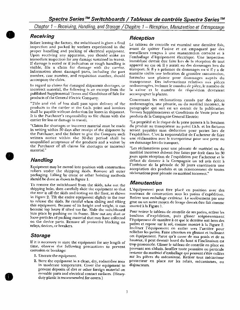
SpectraSeries TMSwitchboards TableauxdecontroleSpectraSeries
Chapter1ReceivingHandlingandStorageChapitre1ReceptionManutentionetEntreposage
ReceivingBeforeleavingthefactorytheswitchboardisgivenafinalinspectionandpackedbyworkersexperiencedintheproperhandlingandpackingofelectricalequipmentUponreceivinganyapparatusyoushouldmakeanimmediateinspectionforanydamagesustainedintransitIfdamageisnotedorifindicationorroughhandlingisvisiblefileaclaimfordamagewiththecarrierInformationaboutdamagedpartsincludingthepartnumbercasenumberandrequisitionnumbershouldaccompanytheclaim
InregardtoclaimsfordamagedshipmentsshortagesorincorrectmaterialthefollowingisanexcerptfromthepublishedSupplementalTermsandConditionsofSaleforproductsoftheGeneralElectricCompany
TitleandriskoflossshallpassupondeliveryoftheproductstothecarrieratthefobpointandinvoicesshallbepayablewithoutdeductionforlossesinshipmentItisthePurchasersresponsibilitytofileclaimswiththecarrierforlossordamageintransitClaimsforshortagesorincorrectmaterialmustbemadeinwritingwithin30daysafterreceiptoftheshipmentbythePurchaserandthefailuretogivetheCompanysuchwrittennoticewithinthe30dayperiodshallbeunqualifiedacceptanceoftheproductsandawaiverbythePurchaserofallclaimsforshortagesorincorrectmaterial
HandlingEquipmentmay movedintopositionwithconstructionrollersundertheshippingskidsRemoveallouterpackagingLiftingbycraneorotherhoistingmethodsshouldbedoneasshowninFigure1ToremovetheswitchboardfromtheskidstakeouttheshippingboltsthencarefullyslidetheequipmentsothattherearisofftheskidsandrestingonthefloorasshowninFigure2TilttheentireequipmentslightlytothereartoreleasetheskidsBecarefulwhenslidingandtiltingthisequipmentBecauseofitsheightandweightitcanbecometopheavyiftiltedtoofarSlidetheswitchboardintoplacebypushingonitsframeBlowoutanydustorlooseparticlesofpackingmaterialthatmayhavecollectedonthedevicepartsRemoveallprotectiveblockingonrelaysdevicesorbreakers
StorageIfitisnecessarytostoretheequipmentforanylengthoftimeobservethefollowingprecautionstopreventcorrosionorbreakage
1Uncratetheequipment2Storetheequipmentinacleandryrodentfreearea
inmoderatetemperatureCovertheequipmenttopreventdepositsofdirtorotherforeignmaterialonmovablepartsandelectricalcontactsurfacesHeavydutyplasticisrecommendedforcovers
ReceptionLetableaudecontroleestexamineunedernierefoisavantdequitterlusineetestempaquetepardestravailleursrompusaunemanutentioncorrecteeta1emballagedequipementelectriqueUneinspectionimmediatedevraitetrefaitelorsdelareceptiondetoutappareilaucasoilityauraiteudesdornmageslorsdutransportSiityapresencededornmagesousiiiyademanierevisibleuneindicationdegrossieremanutentionformulezuneplaintepourdommagesaupresdutransporteurDesinformationsrelativesauxpiecesendommageesincluantlenurnerodepiecelenumbeodelacaisseetlenumeroderequisitiondevraientaccompagnerlaplainte
ConcernantlesreclamationscausespardespiecesendommageesuncpenurieoudumaterielincorrectleparagraphequisuitestunextraitdelapublicationIermesSupplementairesetConditionsdeVentepourlesproduitsdelaCompagnieGeneralElectric
LaproprieteetlerisquedelapertepasseraalalivraisonduproduitautransporteuraupointfhbetlesfacturesserontpayablessansdeductionpourperteslorsdelexpeditionCestlaresponsabilitedelacheteurdefaireunereclamationavecletransporteurpouruneperteouundommagelorsdutransportLesreclamationspourunepenuriedematerieloudumaterielincorrectdoiventetrefaitesparecritdansles30joursapresreceptiondelcxpeditionparlacheteuretledefautdedonneralaCompagnieuntelavisecritIinterieurdelaperiodede30joursconstituerauneacceptationdesproduitsetunrenoncementdetouterreclamationspourpenurieoumaterielincorrect
Manutention
LequipementpeutetreplaceenpositionavecdesrouleauxdeconstructionsouslespatinsdexpeditionRetirertoutemballageexterieurLesoulevementparunegrueouunautremoyendelevagedevraitetrefaitcommemontrealaFigure1
Pourretirerletableaudecontroledesespatinsretirerlesboulonsdexpeditionpuffsglissersoigneusement1equipementdemaniereacequelederrieresoithorsdespatinsetreposesurlesolcommemontrealaFigure2InclinerIequipementenentiervers1arrierepourrelacherlespatinsFaireattentionenglissantetinclinantcetequipementParcequacausedesonpoidsetdesahauteuritpeutdevenirlourdduhautsiIinclinaisonesttropprononceeGlisserIetableaudecontroleenplaceenpoussantsonchassisSoufflertoutepoussiereouparticulerestantedumaterieldemballagequipeuventsetrecolleessurlespiecesdumecanismeRetirertoutmecanismeprotecteurenplacesurlesrelaismecanismesoudisjoncteurs

SpectraSeries TMSwitchboards TableauxdecontroleSpectraSeries rm
Chapter1ReceivingHandlingandStorageChapitre1 ReceptionM9nutentionetEntreposage
3IftheequipmentisstoredincoolordampareasapplyheattokeepitdryOnindoorswitchboardstwostandard100W120Vaclampscanbeinstalledineachswitchboardsection
CAUTIONRemoveallcartonsandother
miscellaneouspackingmaterialsfrominsidetheunitsbeforeenergizinganyheatersorlamps
LiftingInstructionsObservethefollowingpointswhenliftingtheequipment
DonotpasscablesorropesthroughsupportholesAlwaysuseloadratedshacklesorsafetyhooksinsupportholesRigslingssothatthelegsarenolessthan45fromhorizontalasshowninFigure1
LiftingSlingsSpreaderand LiftingPlatesAnglesorBlockingNotFurnishedwith BeamsFurnishedwith
Equipment Equipment1linguesdelevageextenseur PlaquesdelevageanglesouetappareldeblocageNon poutresIndusavecinclusavecIequipement Iequipement
Figure1LiftingtheequipmentwithacraneorotherliftingmeansFigure1Levagedefequipementavecunegrueoudautresmoyens
delevage
2
EntreposageSiitestnecessairedentreposerlequipementpourtouteperiodedetempsobserverlesprecautionssuivantespourenprevenirlacorrosionoulebris
1Sortir1equipementdesaboite
2EntreposerlequipementdansunendroitpropresecexemptderorgeursatemperaturemodereeCouvrirlequipementpourprevenirlesdepotsdepoussicreoudautresmateriauxstrangerssurlespartiesmobilesetlescontactselectriquesdesurfaceOnrecommandeunplastiquerobustepourcouvrir
3SilequipementestentreposedansunendroitfroidouhumidechaufferlequipementpourlegardersecPourlestableauxa1interieuronpeutinstallerdeuxlampesstandards100W120Vcadanschaquesectionlestableauxdecontrole
AIINTIONRetirertouslescartonsetautres
diversobjetsdesmateriauxdemballagedelinterieurdeelementavantdutilisertout
appareildechauffageoularnpes
InstructionsdeImageObserverlespointssuivantslorsquevouslevezlequipement
Nepaspasserdecablesoudecordesparlesouverturesdosoutien
Utilisertoujoursdesmanillesoudescrochetsdesoutiendontlachargeestcalibresdanslesouverturesdesoutien
Greerleselinguespourquelescotesnesoientpasamoinsde45de1horizontalcomrnemontrealaFigure1
RemoveRetirer
Remove
Retirer
Figure2Removingtheshippingboltsandslidingtheunitofftheskid
Figure2Retraitdesboulonsdexpeditionetdesfourniturespourleselinguesetstraitdespatins

SpectraSeriesTMSwitchboards TableauxdecontroleSpectraSeriesTM
Chapter2 InstallingtheSwitchboardChapitre2 Installationdutableaudecontrole
BeforeInstallation
BeforeanyinstallationworkisperformedstudyalldrawingsfurnishedbythesupplierfortheparticularinstallationTheseincludearrangementdrawingsfrontendandplanviewsconnectionsdiagramsandscheduleofequipmentAnymaterialexternaltotheequipmentthatmayberequiredtomeetanylocalcodessuchasmatsscreensorrailingsisnotfurnished
Location
WhenlocatingtheswitchboardcheckallapplicablecodesforaisleworkingspaceandplacementrequirementsThespaceatthefrontmustbesufficienttoallowthedoorstobeopenedandremovablebreakerstoberemoved
Clearance
WerecommendaclearanceofoneinchbetweenthebackoftheswitchboardandthewallorobstructionHoweverthisclearanceisnotrequiredunlessa30kVAorlargertransformerisintegraltotheswitchboard
RearAccess
SomeswitchboardsmayrequireaccesstofieldwiringterminalsfromtherearDonotinstalltheseswitchboards
againstabackwall
FoundationRequirements
IndoorEquipment
ThefloororfoundationmustbestrongenoughtopreventsaggingfromtheweightoftheswitchboardstructureIfthefoundationissubjecttovibrationstheequipmentmustbespeciallymountedtopreventtransmittingvibrationstotheequipment
TheswitchboardmustbebolteddirectlytothefloorasshowninFigure3ThefloormustbelevelwithoutanyhighspotsthatmightcausemisalignmentIfthefloorisnotlevelusefloorchannels
ANOTE Forseismicallycertifiedequipmentrefertotheinstallationinstructionsonpage5
IfsteelfloorchannelsareusedembedtheminalevelconcreteslabwiththetopsurfaceofthechannelsflushwiththefinishedfloorToavoiddistortionofthe
structurethesteelchannelsmustbelevelandalignedwitheachotherbeforetheequipmentisanchoredTherecommendedfoundationconstructionandmethodof
mountingtheswitchboardtothefoundationareshowninFigure4Channelsshouldbegroutedafterinstallation
3
Avantinstallation
AvantdeprocederatouttravaildinstallationetudiertauslesdessinsfournisparlefournisseurpourlinstallationspecifiqueCelainclutlesdessinsdeladispositionfaceextremiteetlesvuesdesplanslesdiagrammesdeconnexionsetlalistedelequipementToutmateriauexterneaIequipementpourlequelitpeutetrerequisderencontrerdescodeslocauxcommedestapisecransourampesnestpasfourni
Localisation
LorsdelalocalisationdutableaudecontroleverifiersouslescodesapplicablespourlesrequisreliesauxcouloirsespacedetravailetlesraisesenplacenecessairesLespacealavantdoitetresuffisantpourpermettreauxportesdetreouvertesetquonpuisseenleverlesdisjoncteursamovibles
egagement
Onrecommandeundegagementdeunpouceentre1arrieredutableaudecontroleetlemuroucequiobstrueToutefoiscedegagementnestpasrequisamoinsquuntransformateurde30kVaouplusgrosnesoitintegrantautableaudecontrole
AccesArriere
CertainspanneauxdedistributionpeuventdemanderunaccespourlaconnexiondebornessurleterrainparlarriereNepasinstallercespanneauxdedistributioncontreunmur
Exigencesdefondation
EquipementalinterieurLeplancheroulafondationdoiventetresuffisammentsolidespourprevenirlaffaissementcauseparlepoidsdelastructuredutableaudecontroleSilafondationestsujetteauxvibrationsIequipementdoitetrespecialementmontepourprevenirlatransmissiondevibrationsitlequipementLetableaudecontroledoitetreboulonnedirectementauplanchercommemontrealaFigure3LeplancherdoitetreaniveausansendroitsurelevequipuissecauserunmesalignementSileplanchernestpasaniveauutiliserdesprofilespourplanchers
NOTE Pouriequipementsismiquementcertifievousreferer aux instructions
dinstallationalapage5

SpectraSeries TMSwitchboards TableauxdecontroleSpectraSeries TM
Chapter2 InstallingtheSwitchboardChapitre2 Installationdutableaudecontrole
OutdoorEquipmentOutdoorequipmentisusuallyinstalledonalevelsmoothconcretepadWhenoptionalchannelsillsaresuppliedwiththeswitchboardsetthemonthepadandfillthemwithgroutasshowninFigure5
Conduits
WhenthefoundationchannelsarebeinginstalledanyconduitsorsleevesrequiredforpowerandcontrolcablesthataretoentertheequipmentfromunderneathshouldbelocatedandinstalledwithintheavailablespaceshownonthefloorplandrawingsConsiderinstallingconduitsorsleevesthatmightrerequiredforfutureconnectionsConduitstubsshouldextendabovethefloorenoughtopreventwaterenteringAlsoconsiderthelocationsofcomponentsintheswitchboardandallowspaceforswingingcablesaftertheyleavetheconduitThelowestlivemetalpartintheswitchboardwillbeapproximately8inchesabovethebottomoftheswitchboardnotincludingfloorsillsNotethattheswitchboardmustbeliftedovertheconduitstubsTerminatetheconduitsat
theswitchboardwiththeappropriateconduitconnectorsConduitsmayrequiregroundingorelectricalconnectiontotheswitchboardenclosure
J EI
Figure3SwitchboardboltedtothefloorindoorconstructionFigure3Tableaudecontroleboulonneauplancherconstruction
finterieur
FrontDevant
1nm
Figure4Switchboardmountedonfloorchannelsindoorconstruction
Figure4Tableaudecontrolemontesurdesprofilespourplanchersconstructionpourfinterieur
SidesprofilespourplanchersenaciersontutiliseslesencastrerdansuneplaquedebetonaveclapartiesuperieureduprofileaegaliteavecleplancherfiniPoureviterladistorsiondeisstructurelacierdesprofilesdoltetreaniveauetalignlesunslesautresavantquelequipementnesoitancreLaconstructiondelafondationrecommandeeetlamethodedemontagedutableaudecontrolealafondationsontmontreesala
Figure4Lesprofilesdoiventetrerecouvertsdemortierapreslinstallation
EquipementaIextifrieurLequipementtlexterieuresthabituellementinstallesurunsocledehetonlisseLorsquelesseuilsoptionnelsdeprofilessontfournisavecletableaudecontrolelesdisposersurlesocleetlesrempliravecdumortiercornmemontrealaFigure5
Conduits
LorsquePoninstallelcprofilesdelafondationtoutconduitoumanchonrequispourIenergieetlescablesdecontrolequientrentdans1equipementparledessousdevraientetreLocalisesetinstallesalinterieurdeIespacedisponiblemontresurleadessinsdesplansduplancherPenserainstallationdeconduitsoudemanchonsquipourraientetrerequispourdesconnexionsfuturesLestronconscleconduitsdevraientseprolongersuffisammentaudessusduplancherpourprevenirlesinfiltrationsdeauPrendreaussienconsiderationlalocalisationdes
composantesdansletableaudecontroleetallouerdelespacepourdisposerItscablesapresquilsquittentleconduitLaplusbassepiicedemetalsoustensiondansletableaudecontroleseraapproximativement8poucesaudessusdufonddutableaudecontrolesansinclurelesseuilsdeplancherPrendrenotequeletableaudecontroledoltetreleveaudessusdestronconsdestuyauxRelierlesconduitsautableaudecontroleaveclesraccords
detuyauxappropriesI1sepeutquelesconduitsrequiereutuneraisealaterreouuneconnexioneleciriqueauhoitierdutableaudecontrole
4
PadwithoutSillsFront Soclesansseuils
Devent
L
PadwithSillsSocleavecseuils
Figure5NonwalkinswitchboardoutdoorconstructionFigure5Tableaudecontrolesansaccesdeboutconstructionpour
1exterieur

SeismicallyCertifiedEquipmentForseismicallycertifiedswitchboardsofCBC UBC
Zones34followthepreviousinstructionswiththefollowingmodificationsLocatetheseismickitshippedwitheachsectionbeforeinstallationThekitforeach
sectionislocatedintherearoftheswitchboardsectionattachedtothehorizontalbusThekitshouldcontain
four1inchspacerspersectionThesespacersshouldbeinstalledasshowninFigure6orFigure7WhenfloorchannelsareusedthesespacersshouldbeinstalledasshowninFigure8
Spacer1InchLon
213ThreadedRodSpacer L MinimumLength1InchLong 175Inch 5Q ti
Figure6Installationofseismicallycertifiedswitchboardswithoutfloorsills
1213BoltMinimumLength
to 150Inch
0
oo012LockWasher
floorLine
4213SleeveAnchorSetinConcreteSlab13SleeveAnchorSpacer
1InchLongSetinConcreteSlab
Spacer1InchLong
SpectraSeries TMSwitchboards TableauxdecontroleSpectraSeries TM
Chapter2 InstallingtheSwitchboardChapitre2 Installationdutableaudecontrole
z13NutV2LockWasher
R1213Bolt
MinimumLength150Inch
LockWasher
Spacer1InchLong
213BoltMinimumLength150Inch
12LockWasher
1213ThreadedRodMinimumExposedThread175Inch
Ii o z
LockWasher
z13Bolt
FloorLine
Figure7Alternateinstallationofseismicallycertifiedswitchboardswithoutfloorsills
FloorSillTopMinimumLengthPlacedEven
wrthConcreteSlab 01Inch0
i ry2LockWasher
FloorLine
1
Spacer11nchLong
kFloorSill
213PressedNut
Figure8Installationofseismicallycertifiedswitchboardswithfloorsills
5
EquipementsismiquementcertifiePourlestableauxsismiquementcertifiesdezones34CBC
UBCsuivrelesinstructionscidessusavecles
modificationsquisuiventLocaliserlekitsismiqueenvoyeavecchaquesectionavantlinstallationPourchaquesectionlekitestlocalisealarrieredelasectiondutableaudecontriteattachealabarreomnibushorizontaleLekit
devraitcontenir4espaceursde1pouceparsectionCesespaceursdevraientetreinstallescommemontrealaFigure6oulaFigure7LorsquedesprofilesdeplancherssontutilisescesespaceursdevraientetreinstallescommemontrealaFigure8
Espaceur1poucedelong
Fcrou
12Rondelle
deblocage
Espaceur1poucedeIon
1213TigeMeleeLongueurminimumde175pouces
213BoulonLongueurminimum
de150pouces
zRondelle
deblocage
Espaceu1poucedelong
1213Tigefileteefiletageexposeminimum175po
zRondelle0 rdeblocage0
1 Niveaudu
1 plancherrn
Figure6Installationdetableauxdecontrolesismiquementcertifiesavecdesseuilsdeplanchers
1213BoutonLongueurminimum
de150pouces
zRondelledeblocage
Blancher
2213AncrageAmanchoninstatledansunedalle
AncrageamoochondebetEspaceur instatledansunedelta1poucedelongdebeton
Figure7Installationoptionnelledetableauxdecontralesismiquementcertifieessansseuilspourplanchers

SpectraSeries TMSwitchboards TableauxdecontroleSpectraSeries TM
Chapter2 InstallingtheSwitchboard Chapitre2 Installationdutableaudecontrole
FieldConnectionandTestingofGroundFaultProtectionSystemsObservethefollowingpointswhenconnectingandtestinggroundfaultsystemsasillustratedinFigures9and10
IntheserviceentrancesectionbondtheneutralconductortotheswitchboardgroundbuswithamainbondingjumpergroundstrapLocatethisgroundingpointontheneutralconductoronthesupplysideofanygroundfaultsensorsinvolvingtheneutralconductorDonotmakegroundingconnectionstotheneutralconductorontheloadside
oftheservicedisconnect
Onloadfeedersrunallphaseconductorsandneutralifusedthroughthesensorwindowswithallinthesamedirectionwithrespecttosensorpolarity
DonotrunequipmentgroundconductorsthroughgroundfaultsensorsConnectthemdirectlytotheswitchboardgroundbusnottotheneutralbusConnecttheservicegroundingelectrodewaterpipeetctothelugprovidedontheswitchboardgroundbusforthispurposeWheneveraserviceisderivedfromagroundedneutralsupplythegroundedneutralconductormustbebroughtintotheserviceentranceequipmentevenifthegroundedconductorisnotneededfortheloadsuppliedbytheserviceThisisrequiredtoprovidealowimpedancegroundfaultcurrentreturnpathtotheneutraltoassureoperationoftheovercurrentdeviceforsafetytopersonnelandpropertyRefertoGEpublicationGEI48907forinstructionsonconductingperformancetestofnewinstallationsofgroundfaultprotectionsystems
ServiceEntrance
MainBreake
3Phase4WireSupply
123NG
AlternateSensorsforO MainBreakerGFP
GFR
GroundReturnSensor
ZeroSequenceorResidualSensor
N NeutralBusN
123NrS1
r
723N11111
1
3Phase4WireLoad
123
I I
3Phase3WireLoad
AlternateSensor
Arrangements
123N
ZeroSequence
123N
Residual
123N
0000
Residual
GFRGroundFault
Relay
GRDBus
Figure9Typicalsinglesourcegroundfaultprotectionusinggroundfaultrelays
6
Espaceur1poucedelong
Ir13BoulonLongueur
1minimumde150pouces
Rondelle
dublocage
Scullpour BoulonLongueurWencherlehaut minimumde150poucesplaceaegaiiteayeladalledebeton
Espaceur1pcucedelong
sRondelle
D rdeblocage
Niveau
tduplancher
213Ecroupressedonsleseuilduplancher
Figure8installationdetableuxdecontrolesismiquementcertifiesavecdesseuilspourplanchers
Connexionsurleterrainauchampetverificationsdessystemesdecontrolededefautdemisealaterre
ObserverlespointssuivantslorsdeisconnexiondelaverificationdessystemesdedefautdemisealaterrecommeillustreauxFigure9et10
Danslasectionentreedeserviceraccorderleconducteurduneutrealaharreomnibusdemisealaterredutableaudecontroleavecuncablederaccord
pourprincipalcourroiedemisealaterreLocalisercepointdemisealaterresurleconducteurduneutresurlecotealimentationdenimportelequeldesdetecteursdedefautdemisealaterreimpliquantleconducteurduneutrcNepasfairedeconnexionsdemilesalaterreauconducteurduneutresurlecote
chargedudebranchenrdeserviceSurlesalimenteursdechargefairepassertouslesconducteursdephaseetleneutresiutiliseparlaoulesfenetresdudetecteuravectouslesalimenteurs
danslamemodirecticnenrespectantlapolariteNepasfairepasserlesconducteursdemisealaterrede1equipementparlesdetecteursdedefautdemiselaterreLesrelierdirectementauxbarresomnibusde
misealaterredutableaudecontroleetnonauxbarresomnibusduneutre
RelierlelectrodedemisealaterredeservicetuyauxdeauetcalacossefournieaceteffetsurlabaneomnibusdemisealaTerredutableau
Lorsquunbranchementestderivedunealimentationavecneutremisalaterreleconducteurduneutremis
alaterredoitareamenedansiequipementdentreedeservicememesileconducteurmisalaterrenestpasnecesssairepourlachargefournieparlebranchementCeciestnecessairealasecuritedu
personneletdesproprietesdefournirunetrajectoiredecourantdedefautdemisealaterrepourleneuter

s
3Phase4WireSupply123 NG
Service l1 01Entrance 0
MainBreaker
N
SpectraSeries TMSwitchboards TableauxdecontroleSpectraSeries TM
Chapter2 InstallingtheSwitchboardChapitre2 Installationdutableaudecontrole
3Phase4WireLoad
1
FDR2li
T
4WireIGF
Neutral
BusN
23y3Phase3WireLoad
Figure10Typicalsinglesourcegroundfaultprotectionusingintegralgroundfaulttrips
faibleimpedancepourassurerIoperationdesmecanismesdesurintensitedecourant
VousrefereralapublicationdeGEGEI98907pour1esinstructionssurlaconduitedutestdeperformancedenouvellesinstallationsdesysteinesdeprotectiondedefautdemisealaterre
FDR1
N
Alimentation3Phases4cables123NG
GF
IntegralGround
FaultProtection Disjoncteur rDetecteur
duprincipal deretour
deentree GFRdemise
3Wire
deservice Cf1j 8laterre
IGF SequencezeroouGroundDetecteurresidueT I vlc
Bus
O Barreomnibusduneutre
123N
it i
123123N 23G1
Charge3phases4cablesCharge3phases3cables
Figure9Protectiontypiquededefautderaisealaterredesourcesimpleutilisantdesrelaisdedefautdemisealaterre
FORtrr
DisjoncteurduprincipaldeIentreedeservice
13
123 r
Detecteursoptionnelspour0ledisjnncteurduprincipal0r1
nDR2GFR
Alimentation3Phases4cables123 NG
0
4cables
IGF
0
4cables10F
Barreomnibus
duneutre N
FDR2 I
0
3cablesIGF
Arrangementsoptionnelsdesdetecteurs
123N
0
Sequencezero
123N
Residue
123N
00V
Residue
GFRRelaisdedefautdemise8Isterre
Barreomnibusdemicealaterre
IGFProtection
integratededefautde
miseaIsterra
Barreomnibusdemisealeterre
12
l r I
Charge3phases4cablesCharge3phases3cables
Figure1aProtectiontypiquededefautdemisealaterredesourcesimpleutilisantdesdeciencheursintegrauxdedefautdemiseala
terre

SpectraSeriesTMSwitchboards TableauxdecontreSpectraSeries
Chapter2 InstallingtheSwitchboardChapitre2 Installationdutableaudecontrole
FuseSelection
SelecttheproperfusesforeachcircuitbasedonloadcharacteristicsandavailableshortcircuitcurrentatthefineterminalsoftheswitchboardSelectafuseforwhich
theratingofthecombinationfuseandswitchequalsorexceedstheavailableshortcircuitcurrentRemovable
linktypefusesarenotrecommended
TestingandInspectionAftertheequipmenthasbeeninstalledandallconnectionsmadetestandinspecttheswitchboardbeforeeneigizingAlthoughtheequipmentanddeviceshavebeeninspectedatthefactoryperformafinalfieldtesttobecertainthattheequipmenthasbeenproperlyinstalledandthatallconnectionsarecorrectandhavenot
loosenedduringtransportationCompletelycheckthewiresandallboltsandterminalsfortightnessCheckallKirkkeyinterlockingschemestoinsuredesiredperformanceMakesurethattheincominglineisdeenergizedwhilealltestsareinprogressInadditiontothesemechanicalchecksusea
megohmmetertotesttheswitchboardOpenallswitchboarddevicesandremoveallinstrumentationand
controlfusesUseamegohmmeterdeveloping500voltsSwitchboardstestedwhenleavingthefactoryshowtypicalminimumvaluesof100rnegohmsIfanyswitchboardtestedundertheaboveconditionsshowsresistancevalues
considerablybelowthisinspectitforpossibletrackingoninsulationorinsulationbreakdown
AllscrapsofwireplasterdustandotherforeignmaterialmustberemovedVacuumcleaningisrecommendedforcleaning
AfterthoroughcleaningandinspectionifthemegohmreadingisstilllowitmaystillbesafetoenergizetheequipmentWhenrestoringfloodedorwetequipmenttoserviceforexampletheacceptedpracticeistorequireaminimumof1megohmbeforeenergizingUnderdamporhumidconditionsitisconsideredgoodpracticetooperatetheequipmentatlowerthanratedvoltageforashorttimeifpossibletoimprovethelowreadingInstructionsforinspectionandtestingoflowvoltagepowercircuitbreakersaregivenintheapplicableindividualinstructionmanualsDirectionsfortestingdevicessuchasrelaysinstrumentsandmetersarefoundintheinstructionmanualfurnishedwitheachdevice
ProtectiverelaysmustbecoordinatedwithotherrelaysinthesystemthereforetheserelaysaresetbythepurchaserGeneralinstructionsonsettingrelaysareprovidedintherelayinstructionmanuals
GroundFautProtection
WhengroundfaultprotectionisprovidedallfieldconnectionsmustbemadecorrectlytoinsureproperfunctioningofthegroundfaultprotectionsystemObservetherulesdescribedinthefollowingsectionsasillustratedinFigures9and10
Selectiondesfusibles
SelectionnerlesfusiblescorrectspourchaquecircuitbasesurlescaracteristiquesdechargeetlescourantsdecourtcircuitsdisponiblesauxterminauxdureseaudutableaudecontroleSelectionnerunfusiblepourlequcilavalcurnominaledelacombinaisonfusibleetinterrupteurgaleouexcedelecourantdecourtcircuitdisponibleLesEllsfusiblesnesontpasrecomrnandes
TestetinspectionApresque1equipementaitereinstalletquetouteslesconnexionsaientetefairetesteretinspecterletableaudecontroleavantdemettresoustensionBienque1equipementetlesmecanismesaientteeinspectesalusinefaitesunderniertestsurlechamppourvousassurerque1equipementaereinstallcorrecternentetquetouteslesconnexionssontcorrectesetnontpasererelacheesdurantletransportVerifiezcornpletementleserragedescahlagesettouslesboulorssetlesbornesVerifiezsouslesarrangementsdeverrouillagepourvousassurerdelaperformancedesireeAssurervousquelalignedentreenestpassoustensionpendantquetouslestestssontentraindetrefaits
EnplusdecesverificationsmecaniquesutiliserunmegohrnmetrepourtesterletableaudecontroleOuvrirtouslesmecanismesdutableaudecontroleetretirerroute
linstrumentationetlesfusiblesdecontroleUtiliserun
megohrnmetrequideveloppe500voltsLestableauxdccontrolequisonttestesislasortiedelusinemontrentdesvaleursminimumtypiqaesde100megohmsSitouttableaudecontroletestsouslesconditionscidessus
dernontredesvaleursderesistanceconsiderablement
moindresquecelleci1inspecterpourdecelerundefautpossibledeisolationouenbrisdecelleci
TouslesresidusdecableplaneettoutautremateriaustrangerdoiventetreenlevesUnnettoyagealaspirateurestrecornmande
Apresunnettoyageetuneinspectioncompletesilalecturemegohmesttoujoursbasseilsepeutquilsoittoujourssecuritairedemettre1equipementsoustensionLorsqueIonrestaureleservicedunequipementinondeoumouilleparexempelapratiqueaccepteeestdenecessiterunminimumde1megohmavantdemettresoustensionLorsdeconditionsmoitesouhumidesilestconsiderscommeunebonnepratiquedopererlequipementaunetensionmoindrequecellecalibreepourunecourteperiodedetempssipossiblepourenameliorerlabasselecture
LesinstructionspourinspectionetletestagededisjoncteursisfaiblepouvoirdetensionsontdonneesdanslesmanualsdinstructionsspecifrquesapplicablesLesdirectionspourletestagedemecanismescommelesrelaisinstrumentsetcompteurssetrouventdanslemanueldinstructionfourniaveechaquemecanisrneLesrelaisprotecteursdoiventetrecoordonnesaveclesautresrelaisdanslesystemeToutefoiscesrelaissontajustespar

SpectraSeriesTMSwitchboards TableauxdecontroleSpectraSeriesTM
Chapter2 InstallingtheSwitchboardChapitre2 Installationdutableaudecontrole
lacheteurDesinstructionsdordregeneralsurIajustagedesrelaissontfourniesdanslesmanuelsdinstructiondurelais
Bolts
SwitchboardsarefurnishedwithmediumcarbonsteelhardwarewiththetensilestrengthslistedinTable1SimilarhardwaremustbeusedforanyadditionalboltingUseatorquewrenchwhentighteningtothenominalvaluesgivenforeithercopperoraluminumconnectionsUseflatandlockwashersforallconnectionsDonotplacewashersundertheheadsofcarriagebolts
BoltSize
Grosseurduboulon
420
57s18
31816V213
1213withavec2Belleville 60000 70
washerrondellea
5816 60000 I 80
EUSERCUtilities
Table1TighteningtorquesforsuppliedhardwareTable1Couplesdeserragepourlaquincailleriefournie
Tensile
StrengthpsiResistancede
tractionpsi
120000
120000
120000
60000
ElectricalClearances
MaintaintheminimumclearanceslistedinTable2UL
andTable3CSAexceptatterminalsofcircuitbreakersandswitches
Condition 0125V
Betweenuninsulated
livepartsofoppositepolarity
ThroughairOversurface
Betweenuninsulated
livepartsandgroundedmetalthroughairoroversurface
Torquelbft
Couplelbpi4
9
16
39
VoltageDifferenceDifferencedetension
Protectiondedefautdemiseala
terre
LorsquuneprotectiondedefautdemisealaterreestfourniemuteslesconnexionsfaitessurleterraindoiventetrefaitescorrectementpourassurerlefonctionnementcorrectdusystemedeprotectiondedefautdemisealaterreObservezlesreglesdecritesdanslessectionssuivantescomrneillustreesauxFigures9et10
Table2MinimumclearancesforlivepartsULTable2DegagementsminimumspourdespartiessoustensionUL
Boulons
Lestableauxdecontrolesontfournisavecune
quincailleriedacieraCarbonemoyenaveclesresistancesalatractioniisteesalaTable1UnequincailleriesimilairedoitetreutiliseepourtoutboulonnageadditionnelUtiliserunecledecoupledetorsionlorsqueIonresserreauxvaleursnominatesdonneesaussibien
pourlesconnexionsdecuivrequedaluminiumUtiliserdesrondellesplatesetdeblocagepourtouteslesconnexionsNepasplacerlesrondellessouslestetesdesboulonsdecarrosserie
DegagementselectriquesMaintenirlesdegagementsminimumslistesislaTable2ULetTable3CSAsaufauxbornesdedisjoncteursetdinterrupteurs
126250V251600V Condition
Entredespartiessoustensiondepotaritesopposees
1213 3419 125 Atraverslair
3419 131I 2351 Pardessuslasurface
Entredespartiessoustensionetdumetalmis
12131 121131 11251 alaterreatraverslair
oupardessusunesurface
Athroughairspacingofnotlessthan12inchisacceptableatacircuitbreakeroraswitchotherthanasnapswitchandbetweengroundeddeadmetalandinsulatedneutralofa277480VacthreephasefourwirepanelboardorswitchboardUnespacementdairdepasmoinsde12poestacceptablepourundisjoncteurouuninterrupteurautrequunirtterrrupteurcoupurebrusqueetentrelemetalmislaterrehorstensionetleneutreisoledunpanneauouduntableaudecontrole277480Vcatroisphasesquetrecables

SpectraSeries TMSwitchboards TableauxdecontroleSpectraSeriesTM
Chapter2 InstallingtheSwitchboardChapitre2 Installationdutableaudecontrole
Condition
Betweenuninsulated
livepartsofoppositepolarity
ThroughairOversurface
Betweenlivepartsandground
ThroughairOversurface
GroundingThegroundbusisboltedtotheuprightsoftherearframestructureItisarrangedsothatconnectionstothestationgroundcanbemadeinanyunitAgroundlugisincludedineachcompleteequipmentfortyingtheswitchboardtothe station ground Groundsense relays are
recommendedforprotectionoftheswitchboard
A WARNINGTheequipmentmustbeadequatelygroundedtoinsurethatallpartsoftheequipmentotherthanlivepartsareatgroundpotentialFailuretoobservethisprecautioncanresultinseriousinjuryordeath
SwitchboardsUsingCordforShortCircuitProtection
VoltageDifferenceDifferencedetension
0120V 121240Vj241480V 481600V
WhereneutraltophaseisinvolvedspacingmaybebasedonthenormalvoltagebetweenthemNeutraltogroundspacingsshouldbebasedonthesamespacingsrequiredfortheotherconductorsEntreunneutreetunephaseIespacementpeutetrebasesurIatensionnormateentreeuxLesespacementsneutreamisealaterredevraientetrebasessurlesmemesespacementsrequispourleautresconducteurs
Table3MinimumclearancesforlivepartsCSA
Table3DegagernentsminimumspourdespartiessoustensionCSA
BeforeInstallation
BeforeanyinstallationworkisperformedstudyalldrawingsfurnishedbythesupplierfortheparticularinstallationTheseincludearrangementdrawingsfrontendandplanviewconnectiondiagramsandscheduleofequipmentAnymaterialexteriortotheequipmentthatmayberequiredtomeetanylocalcodessuchasrailingsisnotfurnished
1213 3419 78221 125 Atraverslair
3419 131 144 251 Pardessuslasurface
Entredespartiessoustensionetmisalaterre
1213 3419 78221 125 Atraversfair
3419 125 134 138 Pardessuslasurface
Misealaterre
LabarreomnibusdemisealaterreestboulonneeaumontantdelastructureducadrearriereDecettefacon
lesconnexionsdelamisealatersedelastationpeuventetrefaitesdansnimportequelleunitetinecossedemisealaterreestincludedanschaqueequipementcompletpourattacherletableaudecontrolealamisealaterredeIastationPourlaprotectiondutableaudecontroledesrelaisdedetectiondemisealaterresontrecommandes
10
Entredespartiessoustensiondepolaritesopposees
Condition
AVERTISSEMEA LequipementdoltetreadequatementmisalaterrepourassurerquetouteslespiecesdetequipementautresquelespartiessoustensionsontaleurpotentieldemisealaterreLedefautdobservercettc
precautionpeutresulterenblessureserieuscoulamost
Panneauxdedistributionutilisantsun
cordonpourprotectiondecourtcircuit
Avantinstallation
AvantquetouttravaildinstallationnesoitrealiseetudiertouslesdessinsfournisparlefournisseurpourinstallationspecifiqueGelainclutlesdessinsdelarrangementdeviantboutetlavueenplandiagrammedesconnexionsetlalistede1equipementToutmaterielexternea1equipementquipeutetrerequisclerencontrertoutcodelocalcommelesrampesWestpasfourni

A
SpectraSeries TMSwitchboards TableauxdecontroleSpectraSeries TM
Chapter2 InstallingtheSwitchboardChapitre2 Installationdutableaudecontrole
InstallationProceduresforMainCabeswhenCableBraceisProvided
AligntheconduitholeslinearlydirectlyoverorascloseaspossibletothebracesConsiderinstallinganyconduitsorsleevesthatmayberequiredforfutureconnectionsRunandbendthemaincableinthemostconvenient
orientationinsuringthatthemaincablehasbeenlocateddirectlyupagainstthecablebracesbeforeitconnectstothemaincableterminalsLashthemaincableasshownin
Figure11usinga38inchnylonropeorapolyesterbraidedropehavingaminimumtensilestrengthof2000IbMakesixrevolutionsaroundtheAand13phasemaincablesandsixrevolutionsaroundtheBandCphasemaincablescontinuewrappingthecordaroundthemaincablelashingandaroundthecablebracesifapplicablebetweenthephasesTieaknottothecablebraceorcableasvotecompletethelastrevolutionAllrevolutionsmustheastightaspossibletopreventwhippingduringshortcircuitsTheropeisnotprovided
MainCableTerminals
Barnesducabledeprincipal
CableBraceLentretoiseducable
6
Maximum
1
Figure11TyingthemaincablestothecablebraceFigure11PourattacherlescablesdeprincipalaCentretoisedu
cable
InspectionafterMainCableInstallation
ObservethefollowingrulesaboutcableinstallationTopreventheatingtheremustbenoclosedloopsofsteelaroundasingleconductororgroupofconductorsthatdoesnotincludealltheconductorsofthecircuitincludingtheneutralIftheconductorsmustpassthroughseparateholesinapieceofsteelcutslotsbetweentheholes
Donotallowcablescarryinghighcurrentstocomenearinstrumentsormetersasthismayaffecttheiraccuracy
UsetheminimumlengthofcablenecessarytomaketheconnectionsTheincreasedresistanceoflongercablesgeneratesunnecessaryheatCheckmaincablelashingannually
11
Procedurespourinstallationdescablesdeprincipallorsquuneentretoisedecableestfournie
AlignerlineairementlesouverturesdesconduitsdirectenrentpardessusouaussipresquepossibledesentretoisesPenseralinstallationdetoutconduitou
manchonquipeuventetrenecessairespourdesconnexionsfutures
FairepasserlecabledeprincipaletleplierdansorientationlapluspratiqueenvousassurantquelccabledeprincipalaetesituedirectenrentcontrelesentretoisesdecableavantdeleconnecterauxbornesdecabledeprincipaltierlecabledeprincipalconrmernontrealaFigure11enutilisanttinecordedenylonde38poouunecordedepolyestertresseeavantuneresistancedetractionminimumde2000lbFairesixtoursautourdescablesdeprincipalaphaseAet13etsixtoursautourdescablesdcprincipalclephase11etCContinuerdenvelopperlacordeautourduliendecableIeprincipalenliantetautourdesentretoiscsdecablesiapplicableentrelesphasesAttachertinmendalentretoisedecableouaucableeommevouscompleterlederniertourTouslestoursdoiventetreaussitendusquepossibleafindeprevenirlefoucttementdurantlescourtscircuitsLacordenestpasfournie
Inspectionapresinstallationducabledeprincipal
Observerlesreglessuivantesconcernantlinstallationducable
fourprevenirIechauffeinentitnedoitpasyavoirdebouclesfenenacierautourdunconducteursimpleoudogrotipesdeconducteursquinincluentpastouslesconducteursducircuitincluantletenure
Silesconducteursdoiventpasserpardesouverturessepareesdansunepiecedaciertallierdesencochesentrclesouvertures
Nepaslaisserlescablestransportantdeschargeseleveesdecourantsapprocherprosdesinstrumentsoucompteurscarleurprecisionpourraitenetreaffectee
UtiliserlalongueurminimumdecablenecessairepourfairelesconnexionsLaresistanceaccruedepluslongscablesgenereunechaleurinutile
Verifierannuellementlelienducabledeprincipal

SpectraSeriesSwitchboards TableauxdecontroleSpectraSeriesrm
Chapter3 SplicingtheSwitchboardSectionsChapitre3 Jonctiondessectionsdutableaudecontrole
Jonctiondessectionsdutableaude
controle
Alignerlessectionsscionlesdessinsfournisparlefournisseurpour1instalationspecifiqueConnecterlesjonctionscommemonIreauxFigures1255SilaquincailleriefournieestsuffisantepourremplirrouteslesouverturesdanslesconnexionsdejonctionsfaitesleIaquincaillerieadditionnelleestnecessaireacausedesexigencesderenfortlorsdecourtcircuitPourdessectionsmonteesindividuellementprovenantduprincipalderivationdeserviceouvenantdecossesconnecteesadessectionsmonteesindividuellementde
principalderivationoudeservicevoirlesdiagrammesduGroupeAFigures1235
Pourdessectionsdeprincipalderivationoudentreemonteesindividuellementconnecteesisdessectionsde
distributionmonteesencoupevoirlesdiagrammesduGroupeBFigures3655
SplicingtheSwitchboardSectionsAlignthesectionsaccordingtothedrawingsfurnishedbythesupplierfortheparticularinstallationConnectthesplicesasshowninFigures1255IfenoughhardwareisprovidedtofillalltheholesinthespliceconnectionsdosoTheadditionalhardwareisnecessarybecauseofshortcircuitbracingrequirements
ForindividuallymountedmainfeederutilityorincominglugpullsectionstoindividuallymountedmainfeederorutilitysectionsseethediagramsofGroupAFigures1235
ForindividuallymountedmainfeederorutilitysectionstogroupmounteddistributionsectionsseethediagramsofGroup13Figures3655
GroupASpliceDiagramsUsethediagramsofFigures932forindividuallymountedmainfeederutilityorincominglugpullsectionstoindividuallymountedmainfeederorutilitysectionsThediagramsaredividedintothefollowingtypes
Figures1214Figures1517Figures1822Figures2325Figures2628Figures2931Figures3234Figure35
Mainbussplice
OffsetmainbusspliceTaperedmainbusspliceTaperedoffsetmainbusspliceNeutraldisconnectspliceNeutralbussplice
TaperedneutralbusspliceGroundbussplice
GroupeAdiagrammesdeJonctionUtiliserlesdiagrammesdesFigures932pourdessectionsmonteesindividuellementdeprincipalderivationdeserviceoudentreeprovenantdecossesconnecteesadessectionsmonteesindividuellementprincipalderivationoudeserviceLesdiagrammessontdivisesparlestypessuivants
Figures1214JonctiondelabarreomnibusdeprincipalJonctiordecaleedelabarreomnibusdeprincipalJonctionaminciedelabarreomnibusdeprincipalJonctionamincieetdecaleedelabarreomnibusdeprincipalJonctiondusectionneurdeneutreJonctiondelabargeomnibusduneutre
Jonctionaminciedelabarreomnibusduneutre
Jonctiondelabarreomnibusdemisealaterre
12
Figures1517
Figures1822
Figures2325
Figures2628Figgire9QS1Figures3234
Figure35

SpectraSeries TMSwitchboards TableauxdecontroleSpectraSeriesrMChapter3 SplicingtheSwitchboardSectionsChapitre3 Jonctiondessectionsdutableaudecontrole
MainBus
Barreomnibus
deprincipal
IndividuallymountedmainfeederutilityorincominglugsectionSectionsdeprincipal
derivationdeserviceouvenantdecossemontees
individuellement
MainBus
Barreomnibus
deprincipal
1 Cie l
x61QVo
elgtes
individuallymountedmainfeederorutilitysection
Sectionsdeprincipalderivationouvenantdecosse
monteesindividuellement
MainBus
Barreomnibus
deprincipalMainBusSplice
JonctiondeIsbarre
omnibusdeprincipalMainBus
rBarreomnibus
J deprincipal
krnl ef00
oocp l
1cDCo
Figure12Splicingdiagramforindividuallymountedmainfieederutilityorincominglugpullsectionstoindividuallymounted
mainfeederutilitysectionswith8001200Aaluminumorcoppermainbus
Figure12Diagrammedejonctionpourdessectionsmonteesindividuellementdeprincipalderivationdeserviceouvenantde
cosseentreeconnecteesadessectionsdeprincipalderivationoudeservicemonteesindividuellementavecbarreomnibusdaluminium
oudecuivre8001200A
13
MainBus
Barreomnibus
deprincipal
IndividuallymountedmainfeederutilityorincominglugsectionSectionsdeprincipal
derivationdeserviceouvenantdecossemontees
individuellement
Individuallymountedmainfeederorutilitysection
Sectionsdeprincipalderivationouvenantdecosse
monteesindividuellement
MainBus
Barreomnibus
MainBusSplice deprincipal
Jonctiondelabarre
MainBus omnibusdeprincipal
BarreomnibusMainBus
deprincipal Bd omnibus
deprincipal
cij 10 Oj A0
14oJ
g
1Iof 10oCx01 1CfjCO
Figure13Splicingdiagramforindividuallymountedmainfeederutilityorincominglugpullsectionstoindividuallymounted
mainfeederutilitysectionswith16002500Aaluminumorcoppermainbus
Figure13Diagrammedejonctionpourdessectionsmonteesindividuellemerndeprincipalderivationdeserviceouvenantde
cosseentreeconnecteesadessectionsdeprincipalderivationoudeservicemonteesindividuellementavecbarreomnibusdaluminium
oudecuivre16002500A
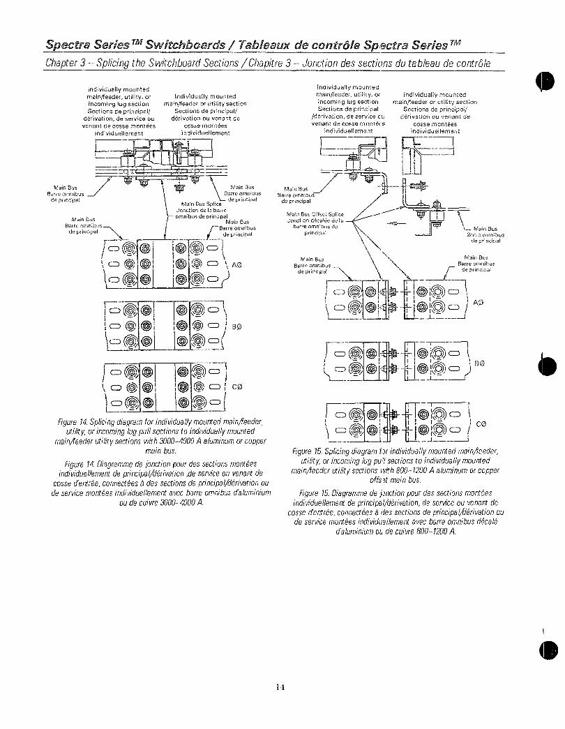
SpectraSeries TMSwitchboards TableauxdecontrleSpectraSeries T
Chapter3 SplicingtheSwitchboardSectionsChapitre3 Jonctiondessectionsdutableaudecontrle
MainBus
Barreomnibus
deprincipal
IndividuallymountedmainfeederutilityorincominglugsectionSectionsdeprincipal
derivationdeserviceouvenantdecossemontees
individuellement
MainBus
Barreomnibus
deprincipal
cDa0
o 0ICD 0
1c 50i
Individuallymountedmainfeederorutilitysection
Sectionsdeprincipalderivationouvenantde
cossemontees
individuellement
MainBus
Barreomnibus
deprincipalMainBusSplice
JonctiondeIsbarre
omnibusdeprincipalMainBus
I
Barre
prieoncip alJ deprincipal
BO
cp
Figure14Splicingdiagramforindividuallymountedmainfeederutilityorincominglugpullsectionstoindividuallymounted
mainfeederutilitysectionswith30004000Aaluminumorcoppermainbus
Figure14DiagrammedeJonctionpourdessectionsmonteesindividuellementdeprincipalderivationdeserviceouvenantde
cossedentreeconnectees3dessectionsdeprincipalderivationoudeservicemonteesindividuellementavecbarreomnibusdaluminium
oudecuivre30004000A
MainBus
Barreomnibus
deprincipal
11
Individuallymountedmainfeederutilityor
incominglugsectionSectionsdeprincipal
derivationdeservicecuvenantdecossemontees
individuellement
MainBus
Barreomnibus
deprincipal
MainBusOffsetSpliceJonctiondecelgedeIs
barreomnibusde
principal
cpiD iiir001E
1BO
1740oOA@
Individuallymountedmainfeederorutilitysection
Sectionsdeprincipaiderivationouvenantde
cossemontees
individueilernent
MainBus
Barreornnibus
deprincipal
MainBus
Barreomnibus
deprincipal
AO
tonc1I
Figure15Splicingdiagramfirindivrduallymountedmainfeederutilityorincominglugpu1sectionstoindividuallymounted
mainfeederutilitysectionsivith8001200Aaluminumorcopperoffsetmainbus
Figure15Diagrammedeunctionpourdessectionsmonteesindividuellementdeprincipalderivationdeserviceouvenantde
cossedentreeconnectees8dessectionsdeprincipalderivationoudeservicemonteesindividullementavecbarreomnibusdecale
daluminiumatdecuivre8001200A

0
O
SpectraSeriesTMSwitchboards TableauxdecontroleSpectraSeriesTMChapter3 SplicingtheSwitchboardSectionsChapitre3 Jonctiondessectionsdutableaudecontrole
MainBus
Barreomnibus
deprincipal
MainBus
Barreomnibus
deprincipal
IndividuallymountedmainfeederutilityorincominglugsectionSectionsdeprincipal
derivationdeserviceouvenantdecossemontees
individuellement
Individuallymountedmainfeederorutilitysection
Sectionsdeprincipalderivationouvenantdecosse
monteesindividuellement
MainBusOffsetSpliceJonctiondecaleedelabarre
omnibusdeprincipalLMain Bus
Barreomnibus
deprincipal
MainBus
jdeBeomnibus
deprincipal
a o
AQ
Figure16Splicingdiagramforindividuallymountedmainfeederutilityorincominglugpullsectionstoindividuallymounted
mainfeederutilitysectionswith16002500Aaluminumorcopperoffsetmainbus
Figure16Diagrammedejonctionpourdessectionsmonteesindividuellementdeprincipalderivationdeserviceouvenantde
cossedentreeconnecteesadessectionsdeprincipalderivationoudeservicemonteesindividuellementavecbarreomnibusdecale
daluminiumoudecuivre16002500A
15
IndividuallymountedmainfeederutilityorincominglugsectionSectionsdeprincipal
derivationdeserviceouvenantdecossemontees
individuellement
MainBus
Barreomnibus
deprincipal
MainBus
Beomnibus
dedeprincipal
o
Individuallymountedmainfeederorutilitysection
Sectionsdeprincipalderivationouvenantdecosse
monteesindividuellement
MainBusOffsetSpliceJonctiondecaleedelabarre
omnibusdeprincipal
MainBus
Barreomnibus
deprincipal
MainBus
Barmnibus
de
re
prioncipalo rp o
II
toAO
oOo
CDcr4t1
i1 CDio BO
oof
Figure17Splicingdiagramforindividuallymountedmainfeederutilityorincominglugpullsectionstoindividuallymounted
mainfeederutilitysectionswith30004000Aaluminumorcopperoffsetmainbus
Figure17Diagrammedejonctionpourdessectionsmonteesindividuellementdeprincipalderivationdeserviceouvenantde
cossedentreeconnecteesbdessectionsdeprincipalderivationoudeservicemonteesindividuellementavecbarreomnibusdecale
daluminiumoudecuivre30004000A

SpectraSeresTMSwitchboards TableauxdecanticleSpectraSeries
Chapter3 SplicingtheSwitchboardSections Chapitre3 Jonctiondessectionsdutableaudecontrole
MainBus
Barreomnibus
deprincipal
Individuallymountedmainfeederutilityor
incominglugsectionSectionsdeprincipal
derivationdeserviceouvenantdecossemontees
individuellement
MainBus
Barreomnibus
deprincipal
Individuallymountedmainfeederorutilitysection
Sectionsdeprincipalderivationouvenantde
cossemontees
individuellement
MainBusBarreomnibus
deprincipal
MainBusTaperedSpliceJonctionaminciedelabarre
omnibusdeprincipalMainBus
Barreomnibus
deprincipal
ABC0
LowCurrentBascourant
1000A800A
HighCurrentCouranteleve
1200A
1200A
1000A 800A
Figure18Splicingdiagramforindividuallymountedmainfeederutilityorincominglugpullsectionstoindividuallymounted
mainfeederutilitysectionswithaluminumorcoppertaperedmainbus
Figure18Diagrammedejonctionpourdessectionsmonteesindividuellementdeprincipalderivationdeserviceouvenantde
cossedentreeconnecteesadessectionsdeprincipalderivationoudeservicemonteesindividuellementavecbarreomnibusamincie
caluminiumoudecuivre
MainBus
Barreomnibus
deprincipal
16
IndividuallymountedmsinjfeaderutilityrincominglugsectionSectionsdeprincipal
derivationdeservicenuvenantdecossemontE
individuellement
Individuallymountedmainjfeederorutilitysection
Sectionsdeprincipalderivationouvenantde
cossemontees
individuallenient
MainBus
Barreomnibus
deprincipal
MainBusTaperedSpliceJunctionaminciedelabarre
omnibusdeprincipalMainBus MainBus
l
Barreomnibus BarreomnibusdePrincipal
E
deprincipal
Tc ail leAQ ABCO
HighCurrent LowCurrent
Couranteieve Bascourant
2000A 800A
1600A 1200A
1600A 1000A
Figure19Splicingdiagramforindividuallymountedmainfeederutilityorincominglugpullsectionstoindividuallymounted
mainfeederutilitysectionswithaluminumorcoppertaperedmainbus
Figure19Diagrammedejunctionpourdessectionsmonteesindividuellementdeprincipalderivationdeserviceouvenantde
cossedentreeconnecteesadessectionsdeprincipalderivationoudeservicemonteesindividuellementavecbarreomnibusamincie
daluminirlmoudecuivre

0
0
SpectraSeries TMSwitchboards TableauxdecontroleSpectraSeries TM
Chapter3 SplicingtheSwitchboardSectionsChapitre3 Jonctiondessectionsdutableaudecontrole
MainBus
Barreomnibus
deprincipal
IndividuallymountedmainfeederutilityorincominglugsectionSectionsdeprincipal
derivationdeserviceouvenantdecossemontees
individuellement
a0
HIgh rentCouranteleve
2500A
2500A
2000A
2000A
MainBus1600A
Barreomnibus
deprincipal
CICThcii
individuallymountedmainfeederorutilitysection
Sectionsdeprincipalderivationouvenantde
cossemontees
individuellement
MainBus
Barreomnibus
deprincipal
MainBusTaperedSpliceJonctionaminciedela
barreomnibusdeprincipalMainBus
MainBusBarreomnibus
deprincipal Bdepinprincipaldeprincipal
mel 00cD110 j
TowCurrentBascourant
1200A
1000A
1200A
1000A
800A
MainBus
Barreomnibus
deprincipal
I ABCO
4 Lcro
ABCQ
HighCurrent LowCurrentCouranteleve Bascourant
3000A 1200A
3000A 1000A
Figure20Splicingdiagramforindividuallymountedrnaineederutilityorincominglugpullsectionstoindividuallymounted
mainreederutilitysectionswithaluminumorcoppertaperedmainbus
Figure20Diagrammedejonctionpourdessectionsmonteesindividuellementdeprincipalderivationdeserviceouvenantde
cossedentreeconnecteesadessectionsdeprincipaderivationoudeservicemonteesindividuellementavecbarreomnibusamincie
Aluminiumoudecuivre
17
MainBusBarreomnibus
deprincipal
Individuallymountedmainfeederutilityorincominglugsection
Sectionsde
principalderivationdeserviceouvenantdecossemonteesindividuellement
MainBus
Barreomnibus
deprincipal
icpca0cJ
a0HighCurrentCouranteleve
3000A
3000A
MainBus
Barreomnibus
deprincipal
o
o
whi 1
Individuallymountedmainfeederorutilitysection
Sectionsdeprincipalderivationouvenantde
cossemontees
individuellement
It MainBus
Barreomnibus
deprincipalMainBusTaperedSpbce
Jonctionaminciedelabarre
omnibusdeprincipalMainBus
r TBarreomnibus
deprincipal
0o ABCO
LwCurrentBascourant
2500A2000A
MainBus
Barreomnibus
deprincipal
tI O C
tACO
HighCurrent LowCurrentCouranteleve Bascourant
2500A 2000A
Figure21Splicingdiagramforindividuallymountedmainfeederutilityorincominglugpullsectionstoindividuallymounted
mainfeederutilitysectionswithaluminumorcoppertaperedmainbus
Figure21Diagrammedejunctionpourdessectionsmonteesindividuellementdeprincipalderivationdeserviceouvenantde
cossedentreeconnecteesadessectionsdeprincipalderivationoudeservicemonteesindividuellementavecbarreomnibusamincie
daluminiumoudecuivre

SpectraSeries TMSwitchboards TableauxdecontroleSpectraSeries TM
Chapter3 SplicingtheSwitchboardSectionsChapitre3 Jonctiondessectionsdutableaudecontrble
IndividuallymountedmainfeederutilityorincominglugsectionSectionsdeprincipal
derivationdeserviceouvenantdecossemontees
individueliement
MainBusJBarreomnibus
deprincipal
MainBusBarreomnibusmnibus
de D ag
de 1
individuallymountedmainfeederorutilitysection
Sectionsdeprincipalderivationouvenantde
cossemontees
individueilement
MainBusBarreomnibus
ripnrinrina
MainBusTaperenSpliceJonctionaminciedelabarre
omnibusdeprincipalt MainBus
Jrarseomnibus
ripnnnrrnal
ABCO
HighCurrentCouranteieve
4000A 3000A
MainBusBarreomnibus
deprincipal
HighCurrentCouranteleve
2500A
2000A
LowCurrentBascourant
MainBus
Barreomnibusripnranrrnal
L
HighCurrent LowCurrent
Couranteleve Bascourant
4000A 2500A
4000A 2000A
3000A 1600A
MainBusBarreomnibus
ripnrinrinal
AB CO
MainBus
Sarreomnibusripnrinrinal
A fiBCif
ICCjjLowCurrent
Bascourant1600A
1600A
Figure22Splicingdiagramforindividuallymountedmainfeederutilityorincominglugpullsectionstoindividuallymounted
maineederutilitysectionswithaluminumorcoppertaperedmainbus
Figure22DiagrammedeJonctionpourdessectionsmonteesindividueliementdeprincipalderivationdeserviceouvenantde
cossedentreeconnecteesadessectionsdeprincipalderivationoudeservicemonteesindividueliementavecbarreomnibusamincie
daluminiumoudecuivre
18
MainBusBarreomnibus
deprincipal
MainBusTaperedOffsetSpliceJonctionamincieetdecaeede
isbarreomnibusdeprincipal
individuallymountedmainteederutilityorincominglugsectionSectionsdeprincipal
derivationdeserviceou
venantdecossemontees
individueliement
MainBus
Barreomnibusao
C
HighCurrentCourantdove
1200A
1200A1000A
individuallymountedmainfeederorutilitysection
Sectionsdeprincipalderivationouvenantde
cossemontees
individueilement
@F0 Ai
elPi
0lnILowCurrent
Bascourant
1000A
800A
800A
MainBus
Barreomnibus
MainBus
BarreomnibuspHeineiral
lCO
Figure23Splicingdiagramforindividuallymountedmainreederutilityorincominglugpulsectionstoindividuallymounted
meinfeederutilitysectionswithaluminumorcoppertaperedoffsetmainbus
Figure23DiagrammedeJonctionpourdessectionsmonteesindividueliementdeprincipalderivationdeserviceouvenantde
cossedertreeconnecteesadessectionsdeprincipalderivationoudeservicemonteesindividuellementavecbarreomnibusdecalee
aminciedalLminiumoudecuivre

0
SpectraSeries TMSwitchboards TableauxdecntrleSpectraSeries T
Chapter3 SplicingtheSwitchboardSectionsChapitre3 Junctiondessectionsdutableaudecontr5le
MainBus
Barreorrebusdeprincipal
individuallymountedmainfreederutilityorincominglugsectionSectionsdeprincipal
derivationdeserviceouvenantdecossemontees
individuellement
L
MainBusTaperedOffsetSpliceJenctionamincieetdecaleedeIs
barreomnibusdeprincipal
MainBus
Barreomnibus
deprincipal
o
CDriHighCurrentCourantCleve
1600A1600A
1600A
2000A2000A
2000A
2500A2500A
3000A
Individuallymountedmeinfeederorutilitysection
Sectionsdeprincipalderivationouvenantde
cossemontees
individuellement
MainBus
Barreomnibus
deprincipal
o0DACD AO
B0
MainBus
Barreomnibusde
principal
LowCurrentBascourant
1200A
1000A
800A
1200A1000A800A
1200A
1000A
1200A1000A
Figure24Splicingdiagramforindividuallymountedmainfeederutilityorincominglugpullsectionstoindividuallymounted
mainfeederutilitysectionswithaluminumorcoppertaperedoffsetmainbus
Figure24Diagrammedejonctionpourdessectionsmonteesindividuellementdeprincipalderivationdeserviceouvenantde
cossedentreeconnecteesadessectionsdeprincipalderivationoudeservicemonteesindividuellementavecbarreomnibusdecalee
aminciedaluminiumoudecuivre
19
MainBus
BareomnibusponrinrIn
IndividuallymountedmainfteederutilityorincominglugsectionSectionsdeprincipal
derivationdeserviceouvenantdecossemontees
individuellement
MainBusTaperedOffsetSpliceJonctionamincieetddcaieedela
barreomnibusdeprincipal
MainBus
Barreomnibus
deprincipal
II
F
Czm 1lII
HighCurrentCourantCleve
2000A
2500A
2500A
3000A
3000A3000A
4000A
4000A4000A
4000A
Individuallymountedmainfeederorutilitysection
Sectionsdeprincipalderivationouvenantde
cossemontees
individuellement
MainBusBarreomnibus
deprincipal
MainBus
rBarreomnibusI deprincipal
Icz c AO
CD 11oAolBO
o of
ogipCD1oDo CO
0Ca0ILowCurrent
Bascourant
1600A2000A
1600A
2500A
2000A
1600A3000A
2500A2000A
1600A
Figure25Splicingdiagramforindividuallymountedmain4eederutilityorincominglugpullsectionstoindividuallymounted
mainfeederutilitysectionswithaluminumorcoppertaperedoffsetmainbus
Figure25Diagrammedejonctionpourdessectionsmonteesindividuellementdeprincipalderivationdeserviceouvenantde
cossedentreeconnecteesadessectionsdeprincipalderivationoudeservicemonteesindividuellementavecbarreomnibusdecalee
aminciedaluminiumoudecuivre

SpectraSeries MISwitchboards TableauxdecontroleSpectraSeriesTM
Chapter3 SplicingtheSwitchboardSectionsChapitre3 Jonctiondessectionsdutableaudecontrole
IndividuallymountedmainfeederutilityorincominglugsectionSectionsdeprincipal
derivationdeserviceouvenantdecossemontees
individuellement
NeutralBus
Barreomnibusdeneutre
NeutralBusSpliceJonctiondeBarre
omnibusdeneutre
NeutralBus
Barreomnibusde
neutre
Di
Individuallymountedmainfeederorutilitysection
Sectionsdeprincipalderivationouvenantde
cossemontees
individuellement
OrNeutral Bus
Barreomnibusdeneutre
NeutralBusSpliceJonctiondebarreomnibusdeneutre
NeutralBus
Barreomnibus
rLideneutre
Figure26SplicingdiagramforindividuallymountedmainAfeederutilityorincominglugpullsectionstoindividuallymounted
rnainfleederutilitysectionswith8001200Aaluminumorcopperneutraldisconnect
Figure26Diagrammedejonctionpourdessectionsmonteesindividuellementdeprincipalderivationdeserviceouvenantde
cosseentreeconnecteesadessectionsdeprincipalderivationoudeservicemonteesindividuellementavecsectionneurdeneutre
aluminiumoudecuivre8007200A
20
IndividuallymountedmainfeederutilityorincominglugsectionSectionsdeprincipal
derivationdeserviceouvenantdecossemontees
individuellement
Individuallymountedmainfeederorutilitysection
Sectionsdeprincipalderivationouvenantde
cossemontees
individuellement
NeutralBus
Barreomnibusdeneutre
NeutralBusSpliceJonctiondebarreomnibusdeneutre
NeutralBus
Barreomnibusdeneutre
NeutralBus
rBarreomnibus1 deneutre
NeutralBus
Barreomnibus
deneutre
NeutralBusSpliceJonctiondebarre
omnibusdeneutre
Figure27Splicingdiagramforindividuallymountedmainfeederutilityorincominglugpullsectionstoindividuallymounted
mainifeederutilitysectionswith16002500Aaluminumorcopperneutraldisconnect
Figure27Diagrammede1onctionpourdessectionsmonteesindividuellementdeprincipalderivationdeserviceouvenantde
cossedentreeconnecteesadessectionsdeprincipalderivationoudeservicemonteesindividuellementavecsectionneurdeneutre
aluminiumoudecuivre16002500A

SpectraSeriesTMSwitchboards TableauxdecontroleSpectraSeriesTMChapter3 SplicingtheSwitchboardSectionsChapitre3 Jonctiondessectionsdutableaudecontrole
IndividuallymountedmainfeederutilityorincominglugsectionSectionsdeprincipal
derivationdeserviceouvenantdecossemontees
individuellement
NeutralBus pBarreomnibus
deneutre
NeutralBusSpliceJonctiondebarre
omnibusdeneutre
NeutralBusBarreomnibus
deneutre
Individuallymountedmaineederorutilitysection
Sectionsdeprincipalderivationouvenantde
cossemontees
individuellement
NeutralBusSpliceJonctiondebarre
omnibusdeneutre
NeutralBus
rBarreomnibusfl deneutre
NeutralBus
Barreomnibusdeneutre
Figure28Splicingdiagramforindividuallymountedmainfeederutilityorincominglugpullsectionstoindividuallymounted
mainfeederutilitysectionswith30004000Aaluminumorcopperneutraldisconnect
Figure28Diagrammedejonctionpourdessectionsmonteesindividuellementdeprincipalderivationdeserviceouvenantde
cossedentreeconnecteesadessectionsdeprincipalderivationoudeservicemonteesindividuellementavecsectionneurdeneutre
daluminiumoudecuivre30004000A
21
NeutralBusBarreomnibus
deneutre
NeutralBus
Barreomnibusdeneutre
IndividuallymountedmeinfeederutilityorincominglugsectionSectionsdeprincipal
derivationdeserviceouvenantdecossemontees
individuellement
IndividuallymountedmainfeederorutilitysectionSectionsdeprincipal
derivationouvenantde
cossemontees
individuellement
NeutralBus
Barreomnibusdeneutre
NeutralBusSpliceJonctiondebarre
omnibusdeneutre
0 kI
IT
NeutralBus
Barreomnibusdeneutre
Figure29Splicingdiagramforindividuallymountedmainfeederutilityorincominglugpullsectionstoindividuallymounted
mainJeederutilitysectionswith8001200Aaluminumorcopperneutralbus
Figure29Diagrammedejonctionpourdessectionsmonteesindividuellementdeprincipalderivationdeserviceouvenantde
cossedentreeconnecteesedessectionsdeprincipalderivationoudeservicemonteesindividuellementavecbarreomnibusdeneutre
daluminiumoudecuivre8001200A

SpectraSeries rvrSwitchboards TableauxdecontrailSpectraSeries
Chapter3 SplicingtheSwitchboardSectionsChapitre3 Jonctiondessectionsdutableaudecontrole
NeutralBus
Barreomnibus
deneutre
NeutralBus
Barreornnbusdeneutre
IndividuallymountedmainfeederutilityorincominglugsectionSectionsdeprincipal
derivationdeserviceouvenantdecossemontees
individuellement
IndividuallymountedmainfeederorutilitysectionSectionsdeprincipal
derivationouvenantde
cossemontees
individuellement
NeutralBusSpliceJonctiondebarreomnibusdeneutre
NeutralBusBarreomnibus
deneutre
NeutralBus
Barreomnibusdeneutre
Figure30Splicingdiagramforindividuallymountedmainfeederutilityorincominglugpullsectionstoindividuallymounted
mainfeederutilitysectionswith16002500Aaluminumorcopperneutralbus
Figure30Diagrammedejonctionpourdessectionsmonteesindividuellementdeprincipalderivationdeserviceouvenantde
cossedentreeconnecteesadessectionsdeprincipalderivationoudeservicemonteesindividuellementavecbarreomnibusdeneutre
daluminiumoudecuivre16002500A
22
NeutralBus
Barreomnibus
deneulre
NeutralBusBarreomnibus
deneutre
IndividuallymountedmainfeedeiutilityorincominglugsectionSectionsdoprincipal
derivationdeserviceouvenantdecosemontees
individuellement
1t
IndividuallymountedmainfeederorutilitysectionSectionsdeprincipal
derivationouvenantde
cossemonteesindividuellement
NeutralBus
Barreomnibus
deneutre
NeutralBusSpliceJonctiondebarreomnibusdeneutre
NeutralBus
Barreomnibus
deneutre
00
00r
LFigure31Splicingdiagramforindividuallymountedmainfeeder
utilityorincominglugpullsectionstoindividuallymountedmainfeederutilitysectionswith30004000Aaluminumorcopper
neutralbus
Figure31Diagrammedejonctionpourdessectionsmonteesindividuellementdeprincipalderivationdeserviceouvenantde
cossedentreeconnecteesadessectionsdeprincipalderivationoudeservicemonteesindviduellementavecbarreomnibusdeneutre
daluminiumoudecuivre30004000A
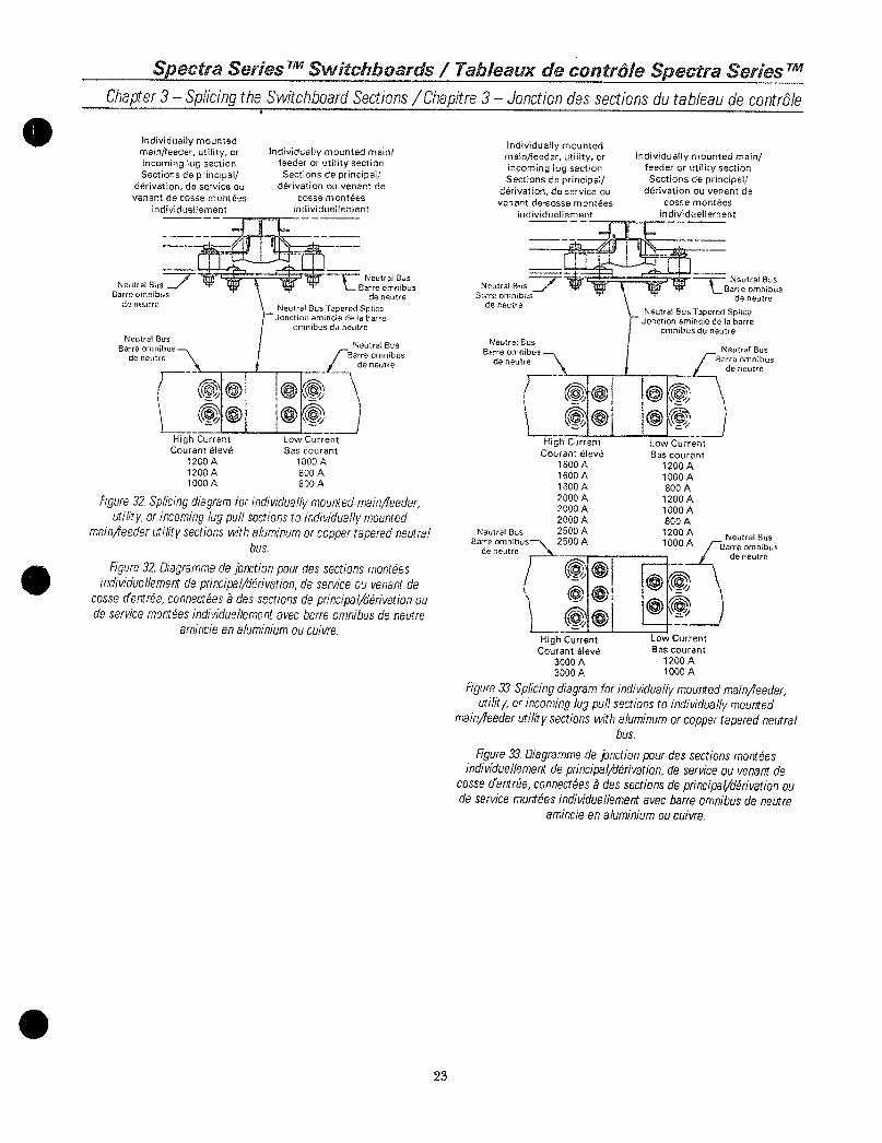
SpectraSeries TMSwitchboards TableauxdecontroleSpectraSeriesChapter3 SplicingtheSwitchboardSectionsChapitre3 Jonctiondessectionsdutableaudecontrale
IndividuallymountedmainfeederutilityorincominglugsectionSectionsdeprincipal
derivationdeserviceouvenantdecossemontees
individuellement
NeutralBusiBarreomnibus
deneutre
NeutralBus
Barreomnibusdeneutre
HighCurrent LowCurrentCouranteleve
1200A
1200A
1000A
individuallymountedmainfeederorutilitysectionSectionsdeprincipal
derivationouvenantdecossemontees
individuellement
NeutralBus
Barreomnibusdeneutre
NeutralBusTaperedSpliceJonctionaminciedeIsbarre
omnibusduneutre
NeutralBus
Barreomnibus
deneutre
Bascourant1000A
800A800A
Figure32Splicingdiagramforindividuallymountedmainfieederutilityorincominglugpullsectionstoindividuallymounted
rnainfeederutilitysectionswithaluminumorcoppertaperedneutralbus
Figure32Diagrammedejonctionpourdessectionsmonteesindividuellementdeprincipalderivationdeserviceouvenantde
cossedentreeconnecteesbdessectionsdeprincipalderivationoudeservicemonteesindividuellementavecbarreomnibusdeneutre
amincieenaluminiumoucuivre
23
IndividuallymountedmainfeederutilityorincominglugsectionSectionsdeprincipal
derivationdeserviceouvenantdeeossemontees
individuellement
NeutralBus
Barreomnibus
deneutre
NeutralBus
Badeeneutrede
I 01Q
HighCurrentCouranteleve
1600A1600A
1800A
2000A
2000A
2000A
NeutralBus 2500ABarre
omnibus2500A
deneutre
HighCurrentCouranteleve
3000A
3000A
IndividuallymountedmainfeederorutilitysectionSectionsdeprincipal
derivationouvenantdecossemontees
individuellement
NeutralBus
IBarreomnibusdeneutre
NeutralBusTaperedSpliceJonctionaminciedelabarre
omnibusduneutre
NeutralBus
Barreomnibus
deneutre
LowCurrent
Bascourant
1200A
1000A
800A
1200A
1000A
800A
1200A1000A
kI
LowCurrent
Bascourant
1200A
1000A
NeutralBus
Barreomnibus
deneutre
Figure33Splicingdiagramforindividuallymountedmainfeederutilityorincominglugpullsectionstoindividuallymounted
mainFeederutilitysectionswithaluminumorcoppertaperedneutralbus
Figure33Diagrammedejonctionpourdessectionsmonteesindividuellementdeprincipalderivationdeserviceouvenantde
cossedentreeconnecteesbdessectionsdeprincipalderivationoudeservicemonteesindividuellementavecbarreomnibusdeneutre
amincieenaluminiumoucuivre

SpectraSeries TMSwitchboards TableauxdecontroleSpectraSeriesTMChapter3 SplicingtheSwitchboardSectionsChapitre3 Jonctiondessectionsdutableaudecontrole
IndividuallymountedmainfeederutilityorincominglugsectionSectionsdeprincipal
derivationdeserviceouvenantdecossemontees
individuellement
NeutralBus
Barreomnibusdeneutre
NeutralBus
Barre
omnibusdeneutre
NeutralBus
Barreomnibusdeneutre
r 000of
1 00
HighCurrent LowCurrent
Couranteleve Bascourant
3000A 2500A
3000A 2000A
3000A 1600A4000A 2500A
NeutralBus 4000A 2000ABarreomnibus 4000A 1600A
deneutre
HighCurrentCouranteleve
2000A
2500A2500A
0
IndividuallymountedmainfeederorutilitysectionSectionsdeprincipal
derivationouvenantdecossemontees
individuellement
NeutralBus
Barreomnibus
deneutre
NeutralBusTaperedSpliceJonctionaminciedelabarre
omnibusduneutre
NeutralBus
Barreomnibus
r deneutre
LowCurrent
Bascourant
1600A
2000A
1600A
1 CC 00al 100
NeutralBus
Barreomnibus
deneutre
NeutralBus
Barreomnibusdeneutre
HighCurrent LowCurrent
Couranteleve Bascourant
4000A 3000A
Figure34Splicingdiagramforindividuallymountedmainfeederutilityorincominglugpullsectionstoindividuallymounted
mainfeederutilitysectionswithaluminumorcoppertaperedneutralbus
Figure34DiagrammedeJonctionpourdessectionsmonteesindividuellementdeprincipalderivationdeserviceouvenantde
cossedentreeconnecteesadessectionsdeprincipalderivationoudeservicemonteesindividuellementavecbarreomnibusdeneutre
amincieenaluminiumoucuivre
24
IndividuallymountedmainfeederutilityorincominglugsectionSectionsdeprincipal
derivationdeserviceouvenantdecossemontees
individuellement
GroundBus
arreomnibuscemiseaIsterre
10 3GroundBus
Barreomnibusdertmiseatoterre
IndividuallymountedmainfeederorutilitysectionSectionsdeprincipal
derivationouvenantde
cossemontees
individuellement
GroundBusSpliceunctiondeIsbarreomnibus
demisealaterre
ii
GroundBus
arreomnibusde
mise8laterre
GroundBus
Barreomnibusdemisealaterre
Figure35Spicingdiagramforindividuallymountedmainfeederutilityorincominghppullsectionstoindividuallymounted
mainfeederutilitysectionswith8004000Aaluminumorcoppergroundbus
Figure35DiagrammhdeJonctionpourdessectionsmonteesindividuellementdeprincipalderivationdeserviceouvenantde
cossedentreeconnecteesaddssectionsdeprincipalderivationoudeservicemonteesindidduellementavecbarreomnibusdemise
laterrerlaluminiumoudecuivre8004000A

GroupBSpliceDiagrams
Chapter3 SplicingtheSwitchboardSectionsCha
UsethediagramsofFigures3655forindividuallymountedmainfeederutilityorincominglugsectionstogroupmounteddistributionsectionsThediagramsaredividedintothefollowingtypesFigures3645Figures4649Figures5053Figure54Figure55
MainBusBarreomnibus
deprincipal
IndividuallymountedmainfeederutilityorincomingiugsectionSectionsdeprincipal
derivationdeserviceouvenantdecossemontees
individuellement
MainBusSpliceJonctiondeIsbarre
omnibusdeprincipal
MainBusBarreomnibus
deprincipal
SpectraSeriesSwitchboards
MainbusspliceNeutralbusspliceOffsetneutralbusspliceGroundbusspliceOffsetgroundsplice
dcD41C7O
Groupmounteddistributionsection
Sectiondedistribution
monteeengroupe
iVO
MainBus
Barreomnibus
deprincipal
MainBusSpliceJonctiondelabarre
omnibusdeprincipal
MainBus
rBarreomnibus
deprincipal
AO0
BO
CO
Figure36Splicingdiagramforndividuallymountedmainfeederutilityorincominglugpullsectonstogroupmounteddistribution
sectionswith8001200Aaluminumorcoppermainbus
Figure36Diagrammedejonctionpourdessectionsmonteesindividuellemeattdeprincipalderivationdeserviceouprovenantdecossesdentreeconnecteesadessectionsdedistributionmonteesengroupeavecbarresomnibusenaluminiumoucuivrede8001200
4
25
TableauxdecontroleSpectraSeriespitre3 Jonctiondessectionsdutableaudecontrole
GroupeBdiagrammesdejonctionUtiliserlesdiagrammesdesFigures3655pourdessectionsmonteesindividuellementdeprincipalderivationdeserviceousectionsprovenantdccossesdenueeconnecteesadessectionsdedistributionmontees
engroupeLesdiagrammessontdivisesscionlestypessuivants
Figures3645Figures4649Figures5053
Figure54
Figure55
MainBus
Barreomnibus
deprincipal
MainBusSpliceJonctiondelebarre
omnibusdeprincipal
MainBusBarreomnibus
deprincipal
JonctiondebarreomnibusdeprincipalJonctiondcbarreomnibusdeneutreJonctiondecaleedebarreomnibusdeneutre
JonctiondeBarreomnibusdemisealaterre
Jonctiondecaleedemisealaterre
IndividuallymountedmainfeederutilityorincominglugsectionSectionsdeprincipal
derivationdeserviceouvenantdecossemontees
individuellement
Groupmounteddistributionsection
Sectiondedistribution
monteeengroupe
MainBusSpliceJonctiondelebarre
omnibusdeprincipal
MainBus
rBarreomnibus
deprincipal
MainBus
7Barreomnibus
deprincipal
Figure37Splicingdiagramforindividuallymountedmainfeederutilityorincominglugpullsectionstogroupmounteddistribution
sectionswith1600Aaluminumorcoppermainbus
Figure37Diagrammedejonctionpourdessectionsmonteesindividuellementdeprincipalderivationdeserviceouprovenantdecossesdentreeconnecteesedessectionsdedistributionmoatesengroupeavecbarresomnibusenaluminiumoucuivrede1600A

SpectraSeriesTMSwitchboards TableauxdecontroleSpectraSeriesr
Chapter3 SplicingtheSwitchboardSectionsChapitre3 Jonctiondessectionsdutableaudecontrole
MainBus
Barreomnibus
deprincipal
Individuallymountedmainfeederutiiityor
incominglugsectionSectionsdeprincipal
derivationdeserviceouvenantdecossemontees
individuellement
MainBusSpliceJonctiondeIsbarre
omnibusdeprincipal
MainBus
Barre omnibudeprincipal t
CD00tcJCD i
O0
O0
Coco
Groupmounteddistributionsection
Sectiondedistribution
monteeengroupe
Tamevaneomnibus
deprincipal
MainBusSpliceJonctiondelabarreomnibusdeBrincip
MainBus
de
omnibusa us
dea
principal
HQ
CO
0
Figure38Splicingdiagramforindividuallymountedmainfeederutilityorincominglugpullsectionstogroupmounteddistribution
sectionswith2000Aaluminummainbus
Figure38Diagrammedejenctionpourdessectionsmonteesindividuellementdeprincipalderivationdeserviceouprovenantde
groupeavecbarresomnibusenaluminiumde2000A
26
Individuallyrrounted
mainfeederutilityorincominglugsectionSectionsdepiincipal
derivationdeserviceou
venantdecossemonteesindividuellement
MainGus
Barreurnnibusdeprincipal
MainBusSpliceJunctiondelabarre
omnibusdeprncipal
MainBus
Barreomnibus
deprincipal
0C
0
Groupmounteddistributionsection
Sectiondedistribution
monteeengroupe
JL
00
0O
C U
o
Oa
MainBusSpliceJonctiondelabarre
omnibusdeprincipal
0AO
CJa
DOB
OOO
MainBus
arreomnibus
deprincipal
MainBus
de3arraomnibus
principal
CO
Figure39Splicingdiagramforindividuallymountedmainfeederutilityorincominglugpullsectionstogroupmounteddistribution
sectionsrrth2000Acoppermainbus
Figure39DiagramrredeJonctionpourdessectionsmonteesindividuellementdeprincipalderivationdeserviceouprovenantdecossescfentreeconnecteesadessectionsdedistributionmontees
engroupeavecbanesomnibusencuivrede2000A
s
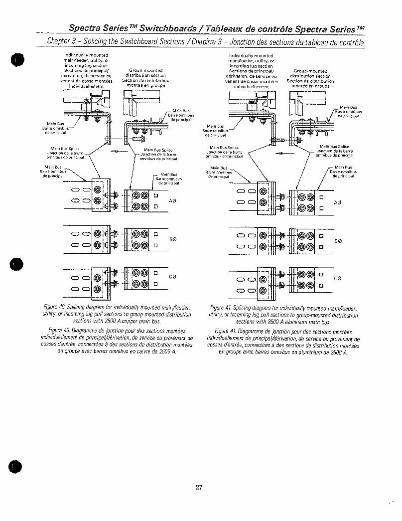
SpectraSeries TMSwitchboards TableauxdecontroleSpectraSeries TM
Chapter3 SplicingtheSwitchboardSectionsChapitre3 Jonctiondessectionsdutableaudecontrole
IndividuallymountedmainfeederutilityorincominglugsectionSectionsdeprincipal
derivationdeserviceouvenantdecossemontees
individuellement
MainBus
Barreomnibus
deprincipal
MainBusSpliceJonctiondelabarre
omnibusdeprincipal
MainBusBarreomnibus
deprincipal
00OI
cD0Or
Olc c
OOQ
0OOjJ
Groupmounteddistributionsection
Sectiondedistribution
monteeengroupe
MainBus
Barreomnibus
deprincipal
u u
MainBusSpliceJonctiondelabarre
omnibusdeprincipal
MainBus
Barreomnibus
deprincipal
AO
BO
CO
Figure40Splicingdiagramforindividuallymountedmainfeederutilityorincominglugpullsectionstogroupmounteddistribution
sectionswith2500Acoppermainbus
Figure40Diagrammedejonctionpourdessectionsmonteesindividuellementdeprincipalderivationdeserviceouprovenantdecossesdentreeconnecteesadessectionsdedistributionmontees
engroupeavecbarresomnibusencuivrede2500A
27
MainBus
Barreomnibus
deprincipal
MainBusSpliceJonctiondelabarre
omnibusdeprincipal
MainBus
Barreomnibus
deprincipal
IndividuallymountedmainfeederutilityorincominglugsectionSectionsdeprincipal
derivationdeserviceouvenantdecossemontees
individuellement
Groupmounteddistributionsection
Sectiondedistributionmonteeengroupe
MainBus
Barreomnibus
deprincipal
r
MainBusSpliceJonctiondelabarre
omnibusdeprincipal
MainBus
Barreornnibus
deprincipal
BO
CO
Figure41Splicingdiagramforindividuallymountedmainfeederutilityorincominglugpullsectionstogroupmounteddistribution
sectionswith2500Aaluminummainbus
Figure41Diagrammedejunctionpourdessectionsmonteesindividuellementdeprincipalderivationdeserviceouprovenantdecossesdentreeconnecteesadessectionsdedistributionmontees
engroupeavecbarresomnibusenaluminiumde2500A
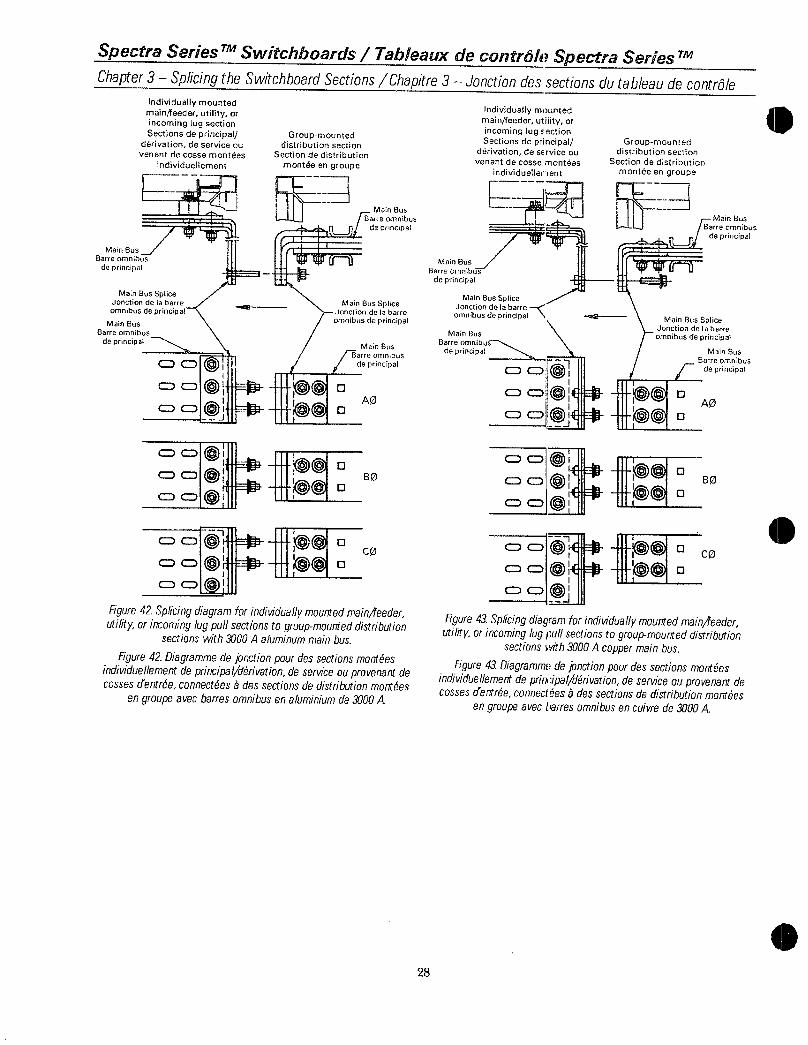
SpectraSeriesTMSwitchboards TableauxdecontroleSpectraSeriesTM
Chapter3 SplicingtheSwitchboardSectionsChapitre3 Jonctiondessectionsdutableaudecontrole
MainBus
Barreomnibus
deprincipal
Individuallymounted
mainfeederutilityorincominglugsectionSectionsdeprincipal
derivationdeserviceouvenantdecossemontees
individuellement
MainBusSpliceJonctiondelabarre
omnibusdeprincipal
MainBus
Barreomnibus
deprincipal
CDO
CDCD
0
CDO
Groupmounteddistributionsection
Sectiondedistribution
monteeengroupe
MainBus
Sarreomnibus
fl tt deprincipalltJ
MainBusSpliceJonctiondelabarre
omnibusdeprincipal
0
0
0
MeinBus
Barreomnibus
PPPPPP deprincipal
0
AO0
B0
oco
Figure42Splicingdiagramforindividuallymountedmainfeederutilityorincominglugpullsectionstogroupmounteddistribution
sectionswith3000Aaluminummainbus
Figure42Diagrammedejonctionpourdessectionsmonteesindividuellementdeprincipalderivationdeserviceouprovenantdecossesdentreeconnecteesbdessectionsdedistributionmontees
engroupeavecbarresomnibusenaluminiumde3000A
MainBus
Barreomnibus
deprincipal
28
IndividuallymountedmainfeederutilityorincominglugsectionSectionsdeprincipal
derivationdeserviceouvenantdecossemontees
individuellement
MainBusSpliceJonctiondelabarre
omnibusdeprincipal
MainBus
Barreomnibus
deprincipal
O C30CDaoOCa
CDCD
0c o
CDCD0j
Groupmounteddistributionsection
Sectiondedistributionmonteeengroupe
U
MainBusSpliceJonctiondelabarre
omnibusdeprincipal
MainBusBarreomnibus
deprincipal
00 0
MainBus
Barreomnibus
deprincipal
AO
BO
Figure43Splicingdiagramforindividuallymountedmainfeederutilityorincominglugpullsectionstogroupmounteddistribution
sectionsw3000Acoppermainbus
Figure43Diagrammedejonctionpourdessectionsmonteesindividuellementdeprincipalderivationdeserviceouprovenantdecossesderitreeconnecteesadessectionsdedistributionmontees
engroupeavecbarresomnibusencuivrede3000A

SpectraSeries TMSwitchboards TableauxdecntroleSpectraSeries TM
Chapter3 SplicingtheSwitchboardSectionsChapitre3 Jonctiondessectionsdutableaudecontrole
MainBus
Barreomnibus
deprincipal
ManBus
Barreomnibus
deprincipal
IndividuallymountedmainfeederutilityorincominglugsectionSectionsdeprincipal
derivationdeserviceouversantdecossemontees
individueliement
MainBusSpliceJonctiondelabarre
omnibusdeprincipal
Groupmounteddistributionsection
Sectiondedistribution
monteeengroupe
MainBus
i Barreomnibus
deprincipal
MainBusSpliceJonctiondelabarre
omnibusdeprincipal
MainBus
omnibus
deprincipal
60
CO
Figure44Splicingdiagramforindividuallymountedmainfeederutilityorincominglugpullsectionstogroupmounteddistribution
sectionswith4000Aaluminummainbus
Figure44Diagrammedejonctionpourdessectionsmonteesindividuellementdeprincipalderivationdeserviceouprovenantdecossesdentreeconnecteesadessectionsdedistributionmontees
engroupeavecbarresomnibusenaluminiumde4000A
29
MainBusBarreomnibus
deprincipal
MainBusSpliceJonctiondelebarre
omnibusdeprincipal
MainBus
Barreomnibus
deprincipal
individuallymountedmainfeederutilityorincominglugsectionSectionsdeprincipal
derivationdeserviceou
venantdecossemontees
individuellement
Groupmounteddistributionsection
Sectiondedistribution
monteeengroupe
IfE
MainBus
arreomnibus
c edeprincipal
MainBusSpliceJonctiondetobarreomnibusdeprincipal
rrrMainBus
Barreomnibus
deprincipal
AO
Figure45Splicingdiagramforindividuallymountedmainfeederutilityorincominglugpullsectionstogroupmounteddistribution
sectionswith4000Acoppermainbus
Figure45Diagrammedejonctionpourdessectionsmonteesindividueliementdeprincipalderivationdeserviceouprovenantdecossesdentreeconnecteesadessectionsdedistributionmontees
engroupeavecbarresomnibusencuivrede4000A

SpectraSeries TMSwitchboards TableauxdecontrailSpectraSeries TM
Chapter3 SplicingtheSwitchboardSectionsChapitre3 Jonctiondessectionsdutableaudecontrole
IndividuallymountedmainfeederutilityorincominglugsectionSectionsdeprincipal
de3rivationdeserviceouvenantdecossemontees
individuellement
NeutralBus
Barreomnibusdeneutre
NeutralBusSpliceJonctiondebarreomnibusdeneutre
NeutralBus
Barreomnibus
deneutre
C
Groupmounteddistributionsection
Sectiondedistribution
monteeengroupe
NeutralBusBarreomnibus
deneutre
NeutralBusSpliceJonctiondebarreomnibusdeneutre
NeutralBus
Barreomnibusdeneutre
Figure46Splicingdiagramforindividuallymountedmainfeederutilityorincominglugpullsectionstogroupmounteddistribution
sectionswith8001200Aaluminumorcopperneutralbus
Figure46Diagrammedejonctionpourdessectionsmonteesindividuellementdeprincipalderivationdeserviceouprovenantdecossescfentreeconnectees8dessectionsdedistributionmontees
engroupeavecbarresomnibusdeneutreenaluminiumoucuivrede8001200A
30
IndividuallymountedmainfeederuilityorincominglugsectionSectionsdeprincipal
derivationdeserviceouvenantdecossemontees
individuellement
NeutralBus
Barreomnibusdeneutre
NeutralBusSpliceJonctiondebarre
omnibusdeneutre
NeutralBusBarreomnibus
deneutre
Groupmounteddistributionsection
Sectiondedistribution
monteeengroupe
NeutralBusBarreomnibus
deneutreNeutralBusSpliceJonctiondebarreomnibusdeneutre
NeutralBusBarreomnibus
deneutre
Figure47Splicingdiagramforindividuallymountedmainfeederutilityorincominglugpullsectionstogroupmounteddistribution
sectionswith16002000Aaluminumorcopperneutralbus
Figure47DiagrammedeJonctionpourdessectionsmonteesindividuellementdepri7cipalderivationdeserviceouprovenantdecossestfentreeconnetxeesedessectionsdedistributionmontees
engroupeavecbarresomnibusdeneutreenaluminiumoucuivrede16002000A

NeutralBus
3arreomnibusdeneutre
SpectraSeriesTMSwitchboards TableauxdecontroleSpectraSeriesTM
Chapter3 SplicingtheSwitchboardSectionsChapitre3 Jonctiondessectionsdutableaudecontrole
NeutralBusSpliceJonctiondebarre
omnibusdeneutre
NeutralBus
Barreomnibusdeneutre
IndividuallymountedmainfeederutilityorincominglugsectionSectionsdeprincipal
derivationdeserviceouvenantdecossemontees
individuellement
Groupmounteddistributionsection
Sectiondedistribution
monteeengroupe
NeutralBus
Ba
deomnibus
deneutre
NeutralBusSpliceJonctiondebarre
omnibusdeneutre
BarrNeutralBus
omnibus
deneutre
Figure48Splicingdiagramforindividuallymountedmainfeederutilityorincominglugpullsectionstogroupmounteddistribution
sectionswith2500Aaluminumorcopperneutralbus
Figure48DiagrammedeJonctionpourdessectionsmonteesindividuellementdeprincipalderivationdeserviceouprovenantdecossesdentreeconnectees3dessectionsdedistributionmontees
engroupeavecbarresomnibusdeneutreenaluminiumoucuivrede2500A
NeutralBusBarreomnibus
deneutre
31
Individuallymounted
mainfeederutilityorincominglugsection
Sectionsdeprincipalderivationdeserviceouvenantdecossemontees
individuellement
NeutralBusSpliceJonctiondebarre
omnibusdeneutre
NeutralBus
Barre omnibusdeneutre
Groupmounteddistributionsection
Sectiondedistribution
monteeengroupe
NeutralBusBarreomnibus
deneutre
Jeutrat BusSpliceJonctiondebarreomnibusdeneutre
NeutralBus
Barreomnibus
I1deneutre
11 I
i
It
Figure49Splicingdiagramforindividuallymountedmain4eederutilityorincominglugpullsectionstogroupmounteddistribution
sectionswith30004000Aaluminumorcopperneutralbus
Figure49Diagrammedejunctionpourdessectionsmonteesindividuellementdeprincipalderivationdeserviceouprovenantdecossesdernreeconnectees3dessectionsdedistributionmontees
engroupeavecbarresomnibusdeneutreenaluminiumoucuivrede30004000A

SpectraSeriesTMSwitchboards TableauxdecontroieSpectraSeriesTMChapter3 SplicingtheSwitchboardSectionsChapitre3 Jonctiondesectionsdutableaudecontrole
NeutralBus
BarreOmnibusdeneutre
IndividuallymountedmainfeederutilityorincominglugsectionSectionsdeprincipal
derivationdeserviceouvenantdecossemontees
individuellement
NeutralBusSpliceJonctiondebarreomnibusdeneutre
NeutralBus
Barre
omnibusdeneutre
0
O
Groupmounteddistributionsection
Sectiondedistribution
monteeengroupe
Nee
omnibusBarreomnibusdeneutre
NeutralBusSpliceJonctiondebarre
omnibusdeneutre
NeutralBusBarreomnibus
deneutre
Figure50Splicingdiagramforindividuallymountedmainfeederutilityorincominglugpullsectionstogroupmounteddistributionsectionswith8001200Aaluminumorcopperoffsetneutralbus
Figure50Diagrammedejonctionpourdessectionsmonteesindividuellementdeprincipalderivationdeserviceouprovenantdecossesdentreeconnecteesbdessectionsdedistributionmonteesengroupeavecbarresomnibusdecaleedeneutreenaluminiumou
cuivrede8001200A
NeutralBusiBarreomnibus
deneutre
32
IndividuallymountedmainfeederutilityorincominglugectionSectionsdeprincipal
derivationdeserviceouvenantdecossemontees
individuellemen
NeutralBusSpliceJonctiondebarre
omnibusde neutreNeutralBus
Barreomnibusdeneutre
t
Groupmounteddistributionsection
Sectiondedistribution
monteeengroupe
NeutralBusBarreomnibus
deneutre
NeutralBusSpliceJonctiondebarreomnibusdeneutre
NeutralBusBarreomnibus
deneutre
Figure51Splicingdiagramforindividuallymountedmainfeederutilityorincominglugpullsectionstogroupmounteddistributionsectionswith16002000Aaluminumor copperoffsetneutralbus
Figure51Diagrammedejonctionpourdessectionsmonteesindividuellementdeprincipalderivationdeserviceouprovenantdecossescfentreeconnecteesedessectionsdedistributionmonteesengroupeavecbarresomnibusdecaleedeneutreenaluminiumou
cuivrede16002000A

v
NeutralBuserreomnibusdeneutre
SpectraSeries TMSwitchboards TableauxdecontroleSpectraSeries TM
Chapter3 SplicingtheSwitchboardSectionsChapitre3 Jonctiondessectionsdutableaudecontrole
IndividuallymountedmainfeederutilityorincomingtugsectionSectionsdeprincipal
derivationdeserviceouvenantdecossemontees
individuellement
NeutralBusSpliceJonctiondebarre
omnibusdeneutre
NeutralBus
Barreomnibusdeneutre
Groupmounteddistributionsection
Sectiondedistribution
monteeengroupe
I I
I
OtlBarreBus NeutralBus
I
es
BarreomnibusBarreomnibus
415neutre deneutre
t
I I
I
NeutralBusSpliceJonctiondebarreomnibusdeneutre
Figure52Splicingdiagramforindividuallymountedmainfeederutilityorincominglugpullsectionstogroupmounteddistribution
sectionswith2500Aaluminumorcopperoffsetneutralbus
Figure52Oiagrammedejonctionpourdessectionsmonteesindividuellementdeprincipalderivationdeserviceouprovenantdecossesdentreeconnecteesadessectionsdedistributionmontees
engroupeavecbarresomnibusdecaleedeneutreenaluminiumoucuivrede2500A
NeutralBus
BarreomnibusNeutralBusdeneutreBarreomnibus
deneutre
33
IndividuallymountedmainfeederutilityorincominglugsectionSectionsdeprincipal
derivationdeserviceouvenantdecossemontees
individuellement
NeutralBusSpliceJonctidebarre
omnibusdeneutre
Groupmounteddistributionsection
Sectiondedistribution
monteeengroupe
0
NeutralBusSpliceJonctiondebarreomnibusdeneutre
NeutralBus
Barreomnibus
deneutre
NeutralBus
Barre omnibusdeneutre
Figure53Splicingdiagramforindividuallymountedmainj7eederutilityorincominglugpullsectionstogroupmounteddistributionsectionswith30004000Aaluminumorcopperoffsetneutralbus
Figure53Diagrammedejonctionpourdessectionsmonteesindividuellementdeprincipalderivationdeserviceouprovenantdecossesdentreeconnecteesadessectionsdedistributionmonteesengroupeavecbarresomnibusdecaleedeneutreenaluminiumou
cuivrede30004000A

SpectraSeriesTMSwitchboards TableauxdecontroleSpectraSeriesTM
Chapter3 SplicingtheSwitchboardSectionsChapitre3 Jonctiondessectionsdutableaudecontrole
GroundBus
BarreomnibusdemiseaIsterre
GroundBusSpliceJonctiondelabarre
omnibusdemiseIaterre
GroundBus
Barreomnibusdemiselaterra
individuallymountedmainfeederutilityorincominglugsectionSectionsdeprincipal
derivationdeserviceouvenantdecossemontees
individuetiement
Groupmounteddistributionsuction
Sectiondedistribution
monteeengroupe
GroundBusSpliceJonctiondelabarre
omnibusdemiseaIsterre
GroundBus
BarreomnibusdemiseAlaterre
GroundBus
Barreomnibusdemise5Interre
Figure54Splicingdiagramforindividuallymountedmainfeederutilityorincominglugpullsectionstogroupmounteddistributionsectionswith8004000Acopperandaluminumgroundbus
Figure54Diagrammedejonctionpourdessectionsmonteesindividuetiementdeprincipalderivationdeserviceouprovenantdecussesdentreeconnecteesadessectionsdedistributionmonteesencrroupeavecbarresomnibusdemise
8laterreenaluminiumoucuivrede8004000A
34

SpectraSeriesrSwitchboards TableauxdecontroleSpectraSeries TM
Chapter3 SplicingtheSwitchboardSectionsChapitre3 Jonctiondessectionsdutableaudecontrole
GroundBus
Barreomnibusde
mise3laTerre
GroundBusOffsetSpliceJonctiondecaleedelabarreomnibusdemiseilaterre
GroundBus
Barreomnibusdemiseaterre
IndividuallymountedmainfeederutilityorincominglugsectionSectionsdeprincipal
derivationdeserviceouvenantdecossemontees
individuellement
35
Groupmounteddistributionsection
Sectiondedistribution
monteeengroupe
L
GroundBus
Barreomnibusdemisealaterre
GroundBusOffsetSpliceJonctiondecaleedelabarreomnibusdemiseAlaterre
GroundBus
Barreomnibusde
miseAlaTerre
Figure55Splicingdiagramforindividuallymountedmainfeederutilityorincominglugpullsectionstogroupmounteddistributionsectionswith8004000Aaluminumorcopperoffsetgroundbus
Figure55DiagrammedeJonctionpourdessectionsmonteesindividuellementdeprincipalderivationdeserviceouprovenantdecossesdentreeconnecteesadessectionsdedistributionmonteesengroupeavecbarresomnibusdecalee
demisealaterreenaluminiumoucuivrede8004000A

SpectraSeries TMSwitchboards TableauxdecontroleSpectraSeries 7M
Chapter4 ConnectingtheSectionFramesChapitre4 Jonctiondessectionsdutableaudecontrole
ThesectionframesareconnectedasshowninFigure56ThejoiningofthesectionscontainstwoboltedconnectionsonthetopandbottomdepthframemembersInadditiontwoboltedconnectionsaremadeoneachverticalframememberTheverticalconnections
arelocatedonethirdandtwothirdsupfromthebottomoftheswitchboardfora90inchswitchboardtheconnectionsaremadeat30inchesand60inchesoffthe
ground
Section1
Figure56Connectingthesectionframes
Figure56Pourrelierlescadresdesection
Section2
Lescadresdelasectionsontconnectescommemontrea IIIlaFigure56Lwsemblagedessectionscontientdeuxconnexionsboulonneesauhauletaubasdelamembrure
deprofondeurducadreDeplusdeuxconnexionsboulonneessontfaitessurchaquemembrureverticaleducadreLesconnexionsverticalessontsitueesuntierset
deuxtiersapartirdubasdutableaupourunpanneaudecontrolede90polesconnexionssontfaitesa30poet60podusol
36

A
1
SpectraSeries TtMSwitchboards TableauxdecontroleSpectraSeries TM
Chapter5 SwitchboardMaintenanceChapitre5 Entretiendutableaudecontrole
AWARNING Deenergizethisequipmentbeforeperforminganywork
GeneralMaintenanceProcedures
ToobtainthebestservicefromthisswitchboardestablishaperiodicmaintenancescheduleAtaminimumperformanannualcheckandoverallmaintenanceprocedurefortheswitchboarddevicesandallconnectionsEquipmentsubjecttohighlyrepetitiveoperationmayrequiremorefrequentmaintenance
KeepapermanentrecordofallmaintenanceworkIncludealistofperiodicchecksandteststhedatetheyweremadetheconditionoftheequipmentandanyrepairsoradjustmentsperformedMaintenanceemployeesshouldfollowallrecognizedsafetypracticessuchasthoseintheNationalElectricalCodetheCanadianElectricalCodeandincompanyandothersafetyregulationsForspecificinformationaboutthemaintenanceofdevicessuchascircuitbreakersrelaysandmetersrefertotheseparatemanualsprovidedwitheachdevice
ObservethefollowingimportantpointsPeriodicallyinspecttheswitchboardwhileunderloadtodetermineifthereisanyindicationofoverheatingIfoverheatingoranyotherunsatisfactoryconditionisfoundcompletelydeenergizetheswitchboardandinvestigateLookparticularlyforlooseboltsandconnections or overloading Remove any
accumulationofdirtorotherforeignmatterintheenclosureDonottouchlivepartswhiletheswitchboardisenergizedPlatedpartsmaybecomedarkoveraperiodoftimebecause ofoxidation Donotremove this
discolorationasthatwillreducethethicknessoftheplating
RetightenlugsandjointstoeliminatepossibleheatingpointsTransmissionofvibrationsthroughthebuildingstructureandconduitstotheswitchboardmayloosenlugsandjointsTurningtheloadoffandoncausesexpansionandcontractionbetweenlugsandcableswhichtendstoloosenthelugsDonotopensealedbreakersortripunitsasthismaydisturbthecalibrationReturnsuchunitstothe
factoryforanyreplacementrequired
37
A AVERTISSEMENTEnleverlecourantdecet
equipementavantderealisertouttravail
ProceduresdentretiengeneralPourobtenirunmeilleurservicedecetableaudecontroleetabliruncalendrierdentretienperiodiqueFaitesauminimumuneverificationannuelleetuneproceduredentretiengeneralpourlesmecanismesdutableaudecontroleettouteslesconnexionsLequipementquiestsujetauneoperationhautementrepetitivepeutdemanderunentretienplusfrequent
GardezunregistrepermanentdetouttravaildentretienInclureaceregistreunelistedesverificationsperiodiquesetdestestsladateoilcelaaetefaitlaconditiondeIequipementettoutereparationouajustementeffectueLesemployesdentretiendevraientsuivretouteslespratiquesreconnuesdesecuritetellesgluecellesduNationalElectricalCodedu Codecanadiende
1electriciteetcellesdelacompagnieetdautresreglementsdesecurite
Pouruneinformationspecifiqueconcernantentretiendesmecanismestelsquelesdisjoncteurslesrelaisetlescompteursvousrefererauxmanuelsseparesfournisavecchaquemecanisme
ObserverlesimportantspointssuivantsInspectorperiodiquementletableaudecontrolelorsquilestsouslachargepourdeterminersiityaaucuneindicationdesurchauffeSiunesurchauffeesttrouveeoutoutautreconditioninsatisfaisanteenlevercompletementtoutcourantdutableaudecontroleetenchercherlacauseAyezlceilparticulierementsurdesboulonsetdesconnexionsrelacheesouune
surchargeRetirertouteaccumulationdepoussiereouautrematiereetrangeredanslebolderNetouchezpasauxpartiessoustensionlorsqueletableaudecontroleestbranche
LespartiesplaqueespeuventnoirciravecletempsacausedeloxydationNepasenlevercettecolorationcarcelareduiralepaisseurduplacageResserrerlescossesetlesjointspoureliminerdespointspossibledechauffageLatransmissiondevibrationsatraverslastucturede1imrneubleetdes
conduitsautableaudecontrolepeutrelacherlescossesetlesjointsBrancheretdebranchersouventlachargecauselexpansionetlacontractionentrelescossesetlescablescequitendarelacherlescossesNepasouvrirlesdisjoncteursscellesoulesdeclencheurscarcelapeutderangerlacalibrationRetournerdetellesunitesalusinepourtoutremplacementrequis

SpectraSeries TMSwitchboards TableauxdecontroleSpectraSeries TM
Chapter5 SwitchboardMaintenanceChapitre5 Entretiendutableaudecontrole
AmbientTemperaturesandCircuitLoadingSwitchboardsaredesignedforinstallationwheretheaverageambienttemperaturedoesnotexceed25C77FForhighertemperaturesderatingisrequiredTheconductortemperatureswithintheenclosuremaybeashighas80C176FSomepartsofthebreakersswitchesandfusesmayrunevenhotterItisrecommendedthatthermalmagneticmoldedcasebreakersinswitchboardsnotbeloadedinexcessof80of
theratingwhentheloadwillcontinueforthreehoursormoreevenwithambientcompensatedbreakers
ShortCircuits
NormallytheovercurrentprotectivedeviceonthecircuitwillpreventanyelectricaldamageexceptattheactualpointoftheshortcircuitMakeathoroughinspectionoftheentiresystemafteranylargefaultcurrenttoinsurethattherehasbeennomechanicaldamagetoconductorsinsulationorequipment
InadditiontheindividualovercurrentprotectivedeviceordevicesthatperformedtheshortcircuitinterruptionmustbeinspectedforpossiblearcingdamagetothecontactsarcchutesandinsulationDonotopensealeddevicessuchasbreakertripunitsIfthereisanypossibilitythatsealedunitsmayhavebeendamagedtheyshouldbereplacedForadditionaldetailsontheparticulardevicerefertotheapplicableinstructionmanualprovidedwiththedevice
ArcingDamagetoInsulationSomeorganicinsulatingmaterialscarbonizewhensubjectedtotheheatofanelectricalarcandlosetheirinsulatingpropertiesAnyinsulationfoundtobecarbontrackedmustbereplacedbeforeapplyingpower
WaterSoakedEquipmentWhenequipmenthasbecomewatersoakedobservethefollowingpointsduringmaintenance
CompletelydeenergizetheswitchboardCarefullycleananddryallpartsoftheswitchboardWhenusingheatersmakesurethetemperaturedoesnotexceed180F
Replaceallfuses
38
Temperaturesambiantesetchargesdecou7antLestableauxdecontrolesontconcuspouruneinstallationoulatemperatureambiantemoyennenexcedepas25C77QFPourdestemperaturespluseleveesundeclassementestnecessaireLestemperaturesduconducteura1interieurduboitierpeuventetreaussieleveesque80C176FCertainespiecesdedisjoncteursinteetfusiblespeuventdevenirencorepluschaudesI1estrecommandequelesdisjoncteursabalersmoulesthermoinagnetiquesdanslestableauxdecontrolenesoientpaschargesenexcesde80delavaleurassigneelorsqueIachargeseraactiveepourtroisheuresouplusmemeavecdesdisjoncteurscompensespourtemperatureambiante
Courtscircuits
NormalementleraecanismeprotecteurdesurchargedecourantsurlecircuitpreviendratoutdommageelectriquesaufaupointreeldecourtcircuitFaireuneinspectioncompletedetoutlesystemeaprestoutcourantdedefautpoursassurerquilnyapasdedommagesmecaniquesauxconducteursa1isolationoua1equipement
DepluslemecanismedeprotectiondesurchargeoulesmecanismesquifontlinterruptiondecourtcircuitdoiventetreinspectespourdesdommagesdarcsurlescontactsdeschutesdarcetisolationNepasouvrirlesmecanismesscetlescomtnelesdeclencheursde
disjoncteursSilexisteunepossibilitequedespiecesscelleesaienteteendommageesellesdevraientetreremplaceesPourdesdetailsadditionnelsconcernantunmecanismeparliculiervousrefereraumanueldinstructionapplicablefourniaveclemecanisme
DommagepararcaisolationQuelquesmateriauxdisolationorganiquesdisolationcarbonisentlorsdueassujettisalachaleurdunarcelectriqueetperdentleursproprietesisolantesrouteisolationdemontrantunctracedecarbonedoitetre
remplaceeavantderemettrelecourant
EquipementtrempepardeeauLorsque1equipementestdevenutrempepardeleauobserverlespointssuivantsdurantIentretien
Enlevercompletementtoutcourantdutableaudeconmole
NettoyersoigneusementetsechertouteslespiecesdutableaudecontroleLorsquevousutilisezdesappareilsde chauffageassurezvousquelatemperaturenexcedepas180F
Replacertouslnfusibles

v
SpectraSeriesSwitchboards TableauxdecontroleSpectraSeriesT
Chapter5 SwitchboardMaintenanceChapitre5 Entretiendutableaudecontrole
InspectallindividualdevicesfortheentranceofwaterdirtorforeignmatterDonotopensealeddevicessuchasbreakertripunitsReplacethem
BeforereenergizingtheswitchboardperformamegohmresistancetestasdescribedinTestingandInspectioninChapter2IfassistanceorguidanceisrequiredcontactyourlocalserviceengineerYoursuppliersserviceshophasfacilitiesforreconditioningequipmentanddevices
SparePartsAsparepartsstockforthecomponentsoftheswitchboardsuchasbusandinsulatorsisnotrecommendedWhencomponentsmustbeorderedpleaserefertothenameplatemarkingandshopdrawingnumberandorderbydescriptionAsparepartsstockofdevicessuchascircuitbreakersmetersandswitcheswillvaryduetothevarietyofinstallationsYoursuppliersalesengineerwillbehappytoassistyouintheproperselectionofadevicestocklist
39
InspectertouslesmecanismesindividuelspourlentreedeaudesaleteoudematiereetrangereNepasouvrirlesmecanismesscenescommelesdeclencheursdedisjoncteursLesremplacerAvantderemettrelecourantautableaudecontrolefaitesuntestderesistancemegohmcommedecritdansTestetInspectionauchapitre2SiityabesoindassistanceoudeconseilscontactervotreingenieurdeservicelocalLedepartementdeservicedevotrefournisseuralesmoyenspourreconditionnerIequipementetlesmecanismes
PiecesderechangeUnapprovisionnementdepiecesderechangepourlescomposantesdutableaudecontroletellesquelesbarresomnibusetlesisolateursnestpasrecommandeLorsquelondoltcommanderdescomposantesvousreferersilvousplaitainscriptiondelaplaquesignaletiqueetlenumerodedessindelusineetcommanderparladescription
UnapprovisionnementdemecanismesderechangetelsquelesdisjoncteurslescornpteursetlesinterrupteursvarieradualavarietedesinstallationsLingenieurdesventesdevotrefournisseurseraheureuxdevousaiderpourlechoixappropriedunelistedapprovisionnementdemecanismes

TheseinstructionsdonotcoveralldetailsorvariationsinequipmentnordotheyprovideforeverypossiblecontingencythatmaybemetinconnectionwithinstallationoperationormaintenanceShouldfurtherinformationbedesiredorshouldparticularproblemsarisethatarenotcoveredsufficientlyforthepurchaserspurposesthemattershouldbereferredtotheGECompany
CesinstructionsnontpaspourproposdecouvrirtonslesdetailsouvariationsdeleqiipementnidefournirdessolutionspourtauslesimprevusreliesaveclesoperationscauseesparlinstallationoulentretienSidesinformationssupplementairesetaientrequisesousilsurvenaitunproblemeparticulierlesquelsnesontpassuffisarnmentconvertsselonlacheteurcecidevraitetrerefereaGECompany
GEH5875R050302
GeneralElectricCompany41WoodfordAvePlainvilleCT06062
2002GeneralElectricCompany
GEIndustrialSystems

to
Power Break 0 Devices
Draw 80000 Ampere Frames

0
WARNINGS
CAUTIONS
NOTES
GEH6271
WARNINGSCAUTIONSANDNOTESASUSEDINTHISPUBLICATION
Warningnoticesareusedinthispublicationtoemphasizethathazardousvoltagescurrentsorotherconditionsthatcouldcausepersonalinjuryarepresentinthisequipmentormaybeassociatedwithitsuse
Warningnoticesarealsousedforsituationsinwhichinattentionorlackofequipmentknowledgecouldcauseeitherpersonalinjuryordamagetoequipment
Cautionnoticesareusedforsituationsinwhichequipmentmightbedamagedifcareisnottaken
Notescallattentiontoinformationthatisespeciallysignificanttounderstandingandoperatingtheequipment
ThisdocumentisbasedoninformationavailableatthetimeofitspublicationWhileeffortshavebeenmadetoensureaccuracytheinformationcontainedhereindoesnotcoveralldetailsorvariationsinhardwareandsoftwarenordoesitprovideforeverypossiblecontingencyinconnectionwithinstallationoperationandmaintenanceFeaturesmaybedescribedhereinthatarenotpresentinallhardwareandsoftwaresystemsGEIndustrialSystemsassumesnoobligationofnoticetoholdersofthisdocumentwithrespecttochangessubsequentlymade
GEIndustrialSystemsmakesnorepresentationorwarrantyexpressedimpliedorstatutorywithrespecttoandassumesnoresponsibilityfortheaccuracycompletenesssufficiencyorusefulnessoftheinformationcontainedhereinNowarranteesofmerchantabilityorfitnessforpurposeshallapply
ThefollowingaretrademarksofGECompany
PowerBreakMicroVersaTripPMMicroVersaTripPlusPower POWERLEADER
2001GECompanyAllRightsReserved

PowerBreak Devices
DrawOutDeviceInstallation
TableofContents
Description 1
Features 1
InstallingtheDevice 3
RemovingtheDevice 5
MaintenanceProcedures 6
Lubrication 6
ListofFigures1RearviewofthePowerBreakIIdrawoutdevice 1
2Leftsideofdevicesliowingpadlockaccessoryandrackingshaftlockoutplate 1
3Rightsideofthedeviceshowingtherejectionfeatureclrawoutpositionindicatorandelectricoperatorcutoffswitch 2
4LiftingBarattachedtoadrawoutdeviceformanuallifting 3
5LiftingBarattachedtoadrawoutdeviceforliftingwithahoist
6Deviceinstalledonrailsreadytobepushedintothesubstructure 4
7Wrenchattachedtothedevicerackingshaft 4
8Compartmentpositionindicatoronthefrontofthedevice 4
9Withdrawingthesubstructurerails 5
10Rotatingthedeviceforwardforinspection 5
ListofTabes
1Catalognumbersofdrawoutcircuitbreakersandcorrespondingsubstructures 1
2Catalognumbersofdrawoutswitchesandcorrespondingsubstructures 1
3Illustrationoftherejectionschemelogicshowingwhichcircuitbreakersmaybeinstalledinwhichsubstructures 2
4Illustrationoftherejectionschemelogicshowingwhichswitchesmaybeinstalledinwhichsubstructures 2
ii
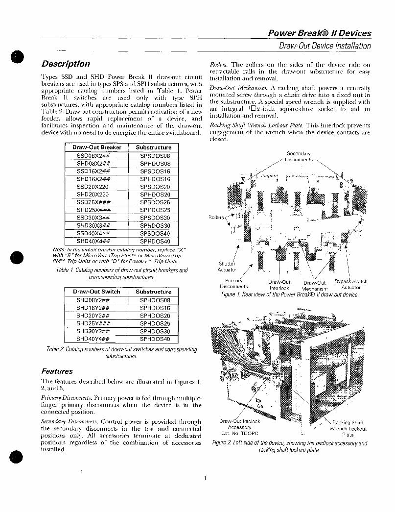
0Description
TypesSSDandSHDPowerBreak11drawoutcircuitbreakersareusedintypesSPSandSPHsubstructureswithappropriatecatalognumberslistedinTable1PowerBreakIIswitchesareusedonlywithtype SPH
substructureswithappropriatecatalognumberslistedinTable2Drawoutconstructionpermitsactivationofanewfeederallowsrapidreplacementofadeviceandfacilitatesinspectionandmaintenanceofthedrawoutdevicewithnoneedtodeenergizetheentireswitchboard
DrawOutBreaker
SSDO8X2
SHDO8X2
SSD16X2
SHD16X2
SSD20X220
SHD20X220
SSD25X
SHD25X
SSD30X3
SHD30X3
SSD40X4
SHD40X4
DrawOutSwitch
SHDO8Y2
SHD16Y2
SHD20Y2
SHD25Y
SHD30Y3
SHD40Y4
Substructure
SPSDOS08
SPHDOS08
SPSDOS16
SPHDOS16
SPSDOS20
SPHDOS20
SPSDOS25
SPHDOS25
SPSDOS30
SPHDOS30
SPSDOS40
SPHDOS40
Substructure
SPHDOS08
SPHDOS16
SPHDOS20
SPHDOS25
SPHDOS30
SPHDOS40
NoteInthecircuitbreakercatalognumberreplaceXwithBforMicroVersaTripPlusorMicroVersaTripPMTTripUnitsorwith0forPowerkTripUnits
Table1Catalognumbersofdrawoutcircuitbreakersandcorrespondingsubstructures
Table2Catalognumbersofdrawoutswitchesandcorrespondingsubstructures
Features
ThefeaturesdescribedbelowareillustratedinFiguresI2and3
PrimaryDisconnectsPrimacypowerisfedthroughmultiplefingerprimarydisconnectswhenthedeviceisintheconnectedposition
SecondaryDisconnectsControlpowerisprovidedthroughthesecondarydisconnectsinthetestandconnectedpositionsonlyAllaccessoriesterminateatdedicatedpositionsregardlessofthecombinationofaccessoriesinstalled
RollersTherollersonthesidesofthedevicerideon
retractablerailsinthedrawoutsubstructureforeasyinstallationandremoval
DrawOutMechanismArackingshaftpowersacentrallymountedscrewthroughachaindriveintoafixednutinthesubstructureAspecialspeedwrenchissuppliedwithanintegralt2inchsquaredrivesockettoaidininstallationandremoval
RackingShaftWrenchLockoutPlateThisinterlockpreventsengagementofthewrenchwhenthedevicecontactsareclosed
Rollers
ShutterActuator
PowerBreak Devices
DrawOutDeviceInstallation
SecondaryDisconnects
Primary DrawOut DrawOut BypassSwitchDisconnects Interlock Mechanism Actuator
Figure1RearviewofthePowerBreak11drawoutdevice
DrawOutPadlock
AccessoryCatNoTDOPC
RackingShaftWrenchLockout
Plate
Figure2Leftsideofthedeviceshowingthepadlockaccessoryandrackingshaftlockoutplate

PowerBreak Devices
DrawOutDeviceInstallation
DrawOut
Position
Indicator
RejectionFeature
Figure3Rightsideofthedeviceshowingtherejectionfeaturedrawoutpositionindicatorandelectricoperatorcutoffswitch
DrauiOutPositionIndicatorIndicateswhetherthedeviceis
intheconnectedtestordisconnectpositionElectricOperatorCutoffSwitchPreventscyclingofthespringchargingmotorduringinstallationorremovalofadevice
DrawOutInterlockThisfeaturetripsacloseddeviceifthewrenchinterlockisdeliberatelydefeatedThedeviceistrippedbeforetheprimarydisconnectspartasthedeviceisrackedoutandbeforetheprimaldisconnectsengageasthedeviceisrackedin
RejectionFeatureThisfeaturepreventsinsertionofadeviceintoasubstructureoflowerampereratingorhighershortcircuitratingItdoesnotrejectadevicewithincompatiblecontrolwiringSeethelabelonthedeviceorTableslor2forthepropersubstructurecatalognumberAlsoshowninFigure8
Tables3and4illustratetherejectionschemelogicNotethatdevicesmaybesafelyused in higherratedsubstructuresHoweverlocalandindustrycodesandstandardsrequirethatconductorsbesizedtothesubstructureThereforeinstallingdevicesinsubstructureswithhigherratingsispossiblebutnoteconomicalDrawOutPadlockAccessoryWhenapadlockisinstalledthisfeatureworkswiththerackingshaftlockoutplatetopreventengagementoftherackingshaftwrenchShutterActuatorAstudactuatestheoptionalshutteraccessory
ByPassSwitchActuatorOperatestheoptionalbypassswitchaccessory
LiftingBarTheLiftingBarcatalognumberTDOLBisavailableforsafehandlingofthedrawoutdeviceasillustratedinFigures4and5
2
BreakerSSDO8X202X204X208SHDO8X202X204X208
SSD16X210X216SHD16X210X216
SSD20X220SHD20X220
SSD25X210X220X325SHD25X210X220X325
SSD30X330
SHD30X330
SSD40X440SHD40X440
Switch
SHDO8Y202Y204Y208
SHD16Y210Y210
SHD20Y22C
SHD25Y210Y220Y325
SHD30Y330
SHD40Y440
SubstructureSPSDOS08SPHDOS08
SPSDOS16
SPHDOS16
SPSDOS20SPHDOS20
sSPSDOS25SPHDOS25
SPSDOS30SPHDOS30
1SPHDOS40
NoteInthedevicecatalognumberreplaceXwithBforMicroVersaTripPIusTMorMicroVersaTripPMTTripUnitsorwithDforPowerTMTripUnits
Table3Illustrationoftherejectionschemelogicshowingwhichcircuitbreakersmaybinstalledinwhichsubstructures
Substructure
SPHDOS08
SPHDOS16
sSPHDOS20
SPHDOS25
SPHDOS30
SPHDOS40
Table4Illustrationoftherejectionschemelogicshowingwhichswitchesmaybeinstalledinwhichsubstructures

ATTENTIONLemecanismecloitetreaOFFavantquilnesoitembrocheSileressortdefermeturecle
mecanismeestchargefernierlescontactsdemecanismeparactionsurleboutonONpuisappuyersurleboutonOFFpourouvrirlescontacts
4Engagethe1L2inchsquareendoftherackingshaftwiththesuppliedwrenchcatalognumberTDORTandrotatetheshaftclockwisetodrawthedeviceinto
theTESTorCONNECTEDpositionasillustratedinFigure7ThecompartmentpositionindicatorisshowninFigure8
NOTEIfthedevicedoesnotfitthestructurechecktherejectionrelationshipillustratedinFigure8toverifythatacorrectlyratedcleviceisbeinginstalledTable1liststhecorrectdrawoutsubstructureforeachdeviceframe
NOTESilemecanismenerentrepasclansleberceauverifierlecletrompeurillustredanslesfigure8quientpecheinsertiondimauvaiscalibreclemecanismeLaTable1definisleberceauconvenableachaquetailledemecanisme
3
PowerBreakIIDevices
DrawOutDeviceInstallation
InstallingtheDevice
Usethefollowingproceduretoinstallthedrawoutdeviceintothesubstructure r
1AttachtheLiftingBarcatalognumberTDOLBby s LiftingBarlocatingthehooksonthebarbeneaththeshoulderstudsofthedeviceasillustratedinFigures4and5
2PulloutthesubstructurerailsuntiltheydropintothehorizontallockedpositionLowerthedevicesothatthegroovesintherollersdropovertherails
3MakesurethegroovesinallrollersstraddletherailsasillustratedinFigure6thenremovetheLiftingBarandpushthedeviceintothesubstructureuntilitstopsintheDISCONNECTEDpositionThenlifttherailsandpushthemintothestoredposition
CAUTIONThedevicemustbeOFFbeforeitis
connectedIfthecleviceischargedpresstheONbuttontoclosetheclevicecontactsthenpresstheOFFbuttontoopenthecontacts
Shoulder
Stud
Figure4LiftingBarattachedtoadrawoutdeviceformanuallifting
Figure5LiftingBarattachedtoadrawoutdeviceforliftingwithahoist

PowerBreakIIDevices
DrawOutDeviceInstallation
Figure6Deviceinstalledonrailsreadytobepushedintothesubstructure
RackingTool
Figure7Wrenchattachedtothedevicerackingshaft
4
Substructure
RejectionFeature
v 06in
lkminimum
Device
RejectionFeature
CompartmentPositionIndicator
Figure8Compartmentpositionindicatoronthefrontofthedevice
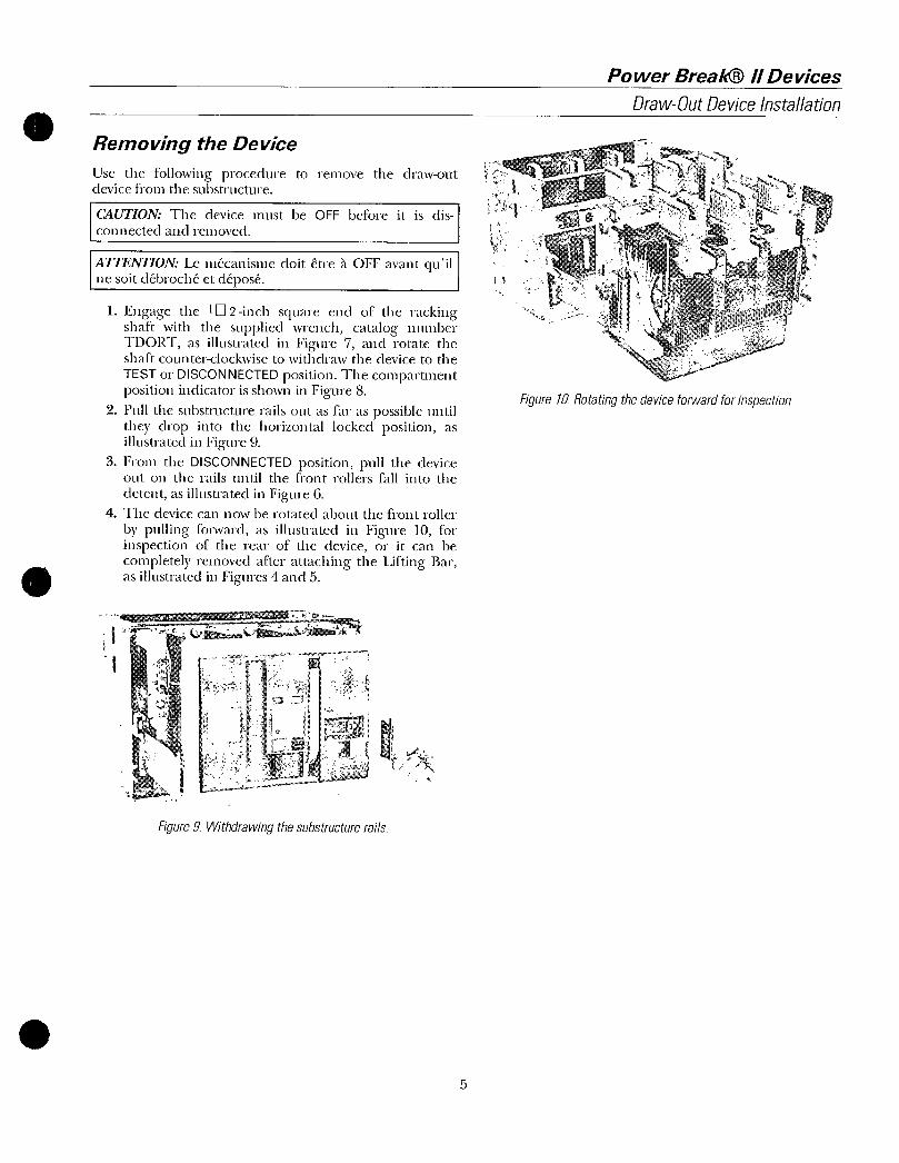
RemovingtheDevice
Usethefollowingproceduretoremovethedrawoutdevicefromthesubstructure
CAUTIONThedevicemustbeOFFbeforeitisdis
connectedandremoved
ATTENTIONLemecanismedoitetreaOFFavantquilnesoitdebrocheetdepose
1Engagethe1 2inchsquareencloftherackingshaftwiththesuppliedwrenchcatalognumberTDORTasillustratedinFigure7androtatetheshaftcounterclockwisetowithdrawthedevicetothe
TESTorDISCONNECTEDpositionThecompartmentpositionindicatorisshowninFigure8
2PullthesubstructurerailsoutasfaraspossibleuntiltheydropintothehorizontallockedpositionasillustratedinFigure9
3FromtheDISCONNECTEDpositionpullthedeviceoutontherailsuntilthefrontrollersfallintothe
detentasillustratedinFigure64Thedevicecannowberotatedaboutthefrontroller
bypullingforwardasillustratedinFigure10forinspectionoftherearofthedeviceoritcanbecompletelyremovedafterattachingtheLiftingBarasillustratedinFigures4and5
Figure9Withdrawingthesubstructurerails
5
PowerBreakDevices
DrawOutDeviceInstallation
Figure10Rotatingthedeviceforwardforinspection
PowerBreak Devices
DrawOutDeviceInstallation
MaintenanceProcedures
AregularmaintenancescheduleshouldbeestablishedtoobtainthebestserviceandreliabilityPlantoperatingandlocalconditionsdictatethefrequencyofinspectionsrequired
ApermanentrecordshouldbekeptofallmaintenanceworkItwillbeavaluablereferenceforsubsequentmaintenanceworkandstationoperationRecordsshouldinclude reports oftests performed condition of
equipmentandrepairsandadjustments
MaintenanceemployeesmastfollowallrecognizedsafetypracticessuchasthosecontainedintheNationalElectricalSafetyCodeandincompanyorothersafetyregulationsSolidinsulationsurroundinganenergizedconductorinpowerapparatusmustneverbereliedupontoprovideprotectiontopersonnel
Drawoutstructureandconnectionsshouldbegiventhefollowing overall maintenance at least annuallyMaintenancefrequencydependsontheseverityofserviceandatmosphericconditionsEquipmentsubjecttohighlyrepetitive operation may require more frequentmaintenance
Whilesomeofthesestepscanbedonewiththedeviceinthetiltoutpositionacompletecheckcanonlybeniacleafterremovingthedevicefromtherails
WARNINGBeforeattemptinganyworkondrawoutdevicesensurethatallsourcesofpower primaryandsecondaryhavebeendeenergized
AVERTISSEMENT Avant cle commencer toute
interventionstirdesmecanismesdebrochableverifier
quetouteslesalimentationsdepuissancealafoisprimaireetsecondairesonttoupees
1ThoroughlycleantheequipmentbyremovingalldustandotheraccumulationsWipeorvacuumcleanthebusesandsupportsDonotusecompressedairforblowingoutequipment
2InspectbusesandorterminallugconnectionsforsignsofoverheatingorweakeningofinsulatingsupportsCheckindicatingdevicesandmechanicalandkeyinterlocksforproperfunctioningLubricateallmovingandrubbingpartswithasuitablelubricantsuchasMobil28redgrease
3CheckprimaryandsecondarydisconnectingsurfacesforsignsofabnormalwearoroverheatingIfrequiredcleancontactswithasuitablesolventDiscolorationofsilveredsurfacesisnotharmful
unlessatmosphericconditionscausedepositssuchassulfidesonthecontactsurfaces
4Checktoseethatallanchorboltsandstructurebolts
aretightInspectallcableorbusconnectionsforsigns of overheating and tighten all loose
6
connectionsCheckthatallsecondaryconnectionsaresecureandallcontrolwiringisintact
5AftercleaningwiththedeviceremovedmeasureandrecordresistancestogroundandbetweenphasesofinsulationonbusesandconnectionsSincedefinite
limitscannotbegivenforsatisfactoryresistancevalueskeeparecordofresistancereadingssothatweakeningofinsulationfromonemaintenanceperiodtothenextcanberecognizedbycomparingreadingsReadingshouldbetakentindersimilarconditionseachtimeifpossibleandtherecordshouldincludetemperatureandhumidityIlighpotentialtestsarenotrequiredbutifitseemsadvisablebasedoninsulationresistancetestsorafter
repairstestvoltageshouldnotexceed75ofthefactorytestvoltagewhichistwotimestheratingplus1000volts
6OperateeachdeviceintheTESTpositiontoensureproperfunctioningThisisparticularlyimportantfordevicesthatnormallyremainineithertheopenedorclosedpositionsforlongperiods
7When the equipment is subject to unusual
conditionssuchascontaminatingfumesandexcessivemoistureschedulemaintenanceatmore
frequentintervalsInthiscasethisproceduremaynotbesufficientandadditionalprecautionsmaybenecessarytoprotecttheequipment
Lubrication
AlltheareassubjecttofrictionareliberallycoatedatthefactorywithMobil28redgreaseIfthecontactsurfacesthedevicepowerscrewandtheinterlockpinarecleanedduringmaintenancecoattheprimarydisconnectcontactsurfacesthethreadsofthenutorscrewandtheinterlock
pinwithMobil28

GeneralElectricCompany41WoodfordAvePlainvilleCT06062
GEH6271R040501 2001GeneralElectricCompany
GEIndustrialSystems

riomimam
5WM3F UftVCIICIUI
CircuitProtectiveDevicesDepartmentPlainvilleConnecticut06062
iga
TGsiilyVGIjd1IICJn IVIVULIeirr1111
TestSetCatNn TAKTCat V M IVI
Lt
trAIWlu 00 4
CORNYYonKe r
ei1 0 a 7 i l11 lil
55000f50050SitCONO0x115 ONtrN51uCiL1F5Ofx100
rna0000000000
9aic
k
1505lSOP
CAr0F0
VIC
0110000PAULT
I
WORTCM00rt
ig FAULT1000ATNIP u1rvn
mT
SE
1T1rvruytz
Theseinstructionsdonotpurporttocoveralldetailsorvariationsinequipment nortoprovideforeverypossiblecontingencytobemetinconnectionwithinstallationoperationormaintenanceShouldfurtherinformationbedesired orshouldparticularproblemsarisewhicharenotcoveredsufficientlyforthepurchaserspurposesthemattershouldbereferredtotheGeneralElectricCompany

CONTENTS
Page
INTRODUCTION 3
SolidstateProgrammerUnitOnly ModeA 3
CompleteTripDeviceSystem ModeB 3
SPECIFICATIONS 3
APPLICABLETIMECURRENTCURVES 3
OPERATINGCONTROLS 3
ONOFFSwitch 4
TripBreaker ProgrammerOnlySwitch 4
TestSelector 4
ProgrammerLongtimePickupSettingSelector 4
CurrentAdjustKnob 4
PresetCurrentButton 4
StartButton 4
TestIndicator 5
TripIndicator 5
ResetButton 5
PhaseSensorContinuityTest 5
TestcurrentMeter 5
ElapsedTimeMeter 5
TestSetLockoutIndicator 5
ExternalMonitorJacksTestSetAccuracy 5
2
CONNECTINGTHETESTSET 6
SafetyPrecautions 6
Connections 6
ProgrammerOnlyTest ModeA 6
CompleteSystemTest Mode8 7
PRELIMINARYTESTPROCEDURE 7
FUNCTIONALTESTS
LongtimePickupTest 8
LongtimeDelayTest 9
ShorttimePickupTest 10
ShorttimeDelayTest 11
InstantaneousPickupTest 12
GroundFaultPickupTest 13
GroundFaultTimedelayTest 14
PhaseSensorContinuityTest 14
FaultTripIndicators 15
IFTESTRESULTSDONOTCONFORM 15
COMPLETIONOFTESTS 15
SCHEMATICPARTSLIST 1617
SIMPLIFIEDSCHEMATICCIRCUITDESCRIPTION 18

ThepurposeoftheseinstructionsistoextendtheusefulnessoftheTAKTS1TestSetsothatit
mayalsobeusedtotestVersaTripMode2solidstatetripdevicesItmaynotbeusedtotestearlierVersaTripmodeltypes
TESTINGVERSATRIPMODEL2WITHTESTSETCATNOTAKTS1GEI86158
INTRODUCTION
TestSetTAKTS1 isaportableinstrumentdesignedforfieldtestingtheperformanceofTypesSSTandECSsolidstateovercurrenttripdevices
Followingarealistofcomponentswhichcomprisethecompletetripdevicesystem
1SolidstateProgrammerUnit
2PhaseCurrentSensors
3FluxShiftMagneticTripDevice
4FourthwireNeutralSensorforunitscon
tainingaGroundFaulttripelementforuseonthreephasefourwireToadcircuits
AllcomponentsexcepttheNeutralSensoraremountedintegraltothecircuitbreakerWhenusedtheNeutralSensorisseparatelymountedinthebusorcablecompartmentoftheswitchgearIndrawoutconstructionitisautomaticallyconnectedtothetripdeviceonthebreakerviaadrawoutsecondarydisconnectblock
TheTAKTS1TestSetisusedtoperformthevarioustripdevicetestsintwobasicmodes
A SolidStateProgrammerUnitOnlyB CompleteTripDeviceSystem
WARNING THESE TESTSCANBECONDUCTED ONLY ON A DEENERGIZEIBREAKER ONEWHICHIS
COMPLETELYDISCONNECTEDFROMITSPRIMARYANDCONTROLPOWERSOURCES
AlltestsareconductedwiththeprogrammerplugdisconnectedfromthebreakerItmaybenecessarytoremovetheprogrammerfromthebreakertogainaccesstoitstestplug
SOLIDSTATEPROGRAMMERUNITONLYMODEA
TestScope
1VerifythetimecurrentcharacteristicsandpickupcalibrationofthevarioustripelementsDesignationsforthetripelementsareabbreviatedasfollows
LT LongTimeST ShortTime
INST Instantaneous
GF GroundFault
2VerifyoperationofthefaulttripindicatorsonProgrammerunitssoequipped
COMPLETETRIPDEVICESYSTEMMODEB
TestScope
1PerformallprogrammertestspreviouslydescribedplustheprovisiontoactivatetheFluxShiftMagneticTripDevicetoverifyitsoperationbyphysicallytrippingthebreaker
2CheckcontinuityofthePhaseSensors
SPECIFICATIONS
Input105125Vac5060Hz
PowerConsumption150wattsmaximum
Weight20pounds
Dimensions15inLx9inHx934inD
APPLICABLETIMECURRENTCURVES
VersaTrip MOD2LTST INST GES618461866187and6188
VersaTrip MOD2 GroundFault GES618561896190and6191
OPERATINGCONTROLS
TheTestSetindicatorsandoperatingcontrolsareidentifiedonthefrontpanelarrangementshowninFig1anddescribedonpages4and5
3

GE86158TESTINGVERSATRIPMODEL2WITHTESTSETCATNOTAKTS1
ONOFFSWITCH
ELAPSEDTIMEMETER
1
0000QImSECONDS
PRESETCURRENT START
CIRCUITPROICfREOVICISOLPTPLINVILLECONKUCO1
GENERAL
SSTECSTESTSETCATNOTAKTS1
INSTRUCTIONSGEN64354
TESTSELECTOR
B
L GROUNDOA EAULT
TRIPBREAKER
ELECTRIC errPROGRAMMER
ONLY
PROGRAMMERLONGTIME
PICKUPSETTING
Applies115VacinputpowertothetestsetAredcompanionLEDindicatorlocateddirectlyaboveilluminateswhentheswitchisintheONpositionProtectionisprovidedbyaoneamperefuselocatedabovetheindicatorlight
TRIPBREAKER PROGRAMMERONLY
SWITCH
Providesachoiceoftwotestmodes
ProgrammerOnlyPosition ModeA
Theprogrammerstripsignaloutputisconfinedtothetestsetcircuitryandcannottripthebreaker
TripBreakerPosition ModeB
TheprogrammerstripsignaloutputisdirectedtothecircuitbreakersmagnetictripdevicetophysicallytripthebreakerThismodeestablishestheintegrityofthemagnetictripdeviceandtheprogrammerscapabilitytoactuateit
TESTSELECTOR
PositionedaccordingtothetypeoftestdesiredPhaseCurrentABCorGROUNDFAULT
4
TESTCURRENTMETER
Fig1FrontpanelofTestSetTAKTS1
PROGRAMMERLONGTIMEPICKUP
SETTINGSELECTOR
EstablishesatestcurrentmagnitudeconsistentwithandspecificallyforeachcontinuousamperesetpointontheprogrammerForallphasecurrenttestingLTSTandINSTelementsthepositionofthiscontrolmustmatchthecontinuousamperesettingontheprogrammer
CURRENTADJUSTKNOB
Avariabletransformerforestablishingthedesiredleveloftestcurrenttobeappliedtotheprogrammer
PRESETCURRENTBUTTON
EnablestheoperaortopreestablishviatheCURRENTADJUSTcontrolthedesiredtestcurrentpriortoinitialingatestForthiscontroltofunctiontheprograrrmerunitmustbeconnectedtothetestset
STARTBUTTON
OR
4POSH
TEST
PHASESENSORCONTINUITYTEST
OA OC
InitiatesthetestrunbyapplyingcurrenttotheprogrammerThecurrentpersistsuntiltheunittripsortheRESETbuttonisactuated

TESTINDICATOR
TESTINGVERSATRIPMODEL2WITHTESTSETCATNOTAKTS1GE186158
ThisLEDlightswheneverthePRESETCURRENTorSTARTcontrolsareactivated
TRIPINDICATOR
AnLEDwhichwhenlitindicatesthatanacceptabletripsignalhasbeendeliveredbytheprogrammerConverselyatripnotaccompaniedbythelightsignifiesthatthetripsignalamplitudeistoolowUponcompletionofatesttheTRIPindicatorstayslituntiltheRESETbuttonisdepressed
RESETBUTTON
ResetstheTestSetlogicsothatanewtestsequencecanbeinitiatedItalsostopsatestinprogress
PHASESENSORCONTINUITYTEST
ThissectionofthepanelcontainscontrolsforcheckingelectricalcontinuityofeachphasesensorcircuitTheselectordeterminesthephasetobetestedPropercontinuityexistswhentheOKLEDindicatorlightsupwhenthePUSHTOTESTbuttonisdepressedNolightsignifiesthatahighresistanceoropencircuitexistsintheCToritswiringharnessseeNote3page14
TESTCURRENTMETER
ProvidesdigitalreadoutofthenormalizedtestcurrentlevelbeingappliedtotheProgrammerUnitItisnevernecessarytocalculateatestcurrentvalue
ELAPSEDTIMEMETER
AmechanicalcounterwhichrecordstheprogrammerstrippingtimeinsecondsandtenthsItmustbemanuallyresetaftercompletionofeachtest
NOTEWhenoperatingtheTestSetfroma50HzsupplyreadingsoftheElapsedTimelvetermustbemultipliedbya12factor
TESTSETLOCKOUTINDICATOR
TopreventpossibledamagetotheProgrammerUnitwhensubjectedtoabnormallyprolongedorcontinuoustestingathighcurrentlevelsalockout
circuitisprovidedThiscircuitmonitorsthecurrenttimeinputtotheprogrammersuchthatwhenapredeterminedlimitisexceededtheTestSetbecomesinoperativeforaperiodofapproximately70secondsItthenautomaticallyresetstoitsnormaloperatingstateAlockoutconditionexistswhenevertheTESTSETLOCKOUTindicatorislit
EXTCRNALMONITORJACKSTESTSETACCURACY
ThetestcurrentvaluesdisplayedontheTestCurrentMeterareaccuratetowithin 3percentofthemeterreadingTheselimitsarecontingentuponacleansinewaveinputvoltagetotheTestSetWavedistortioncancauseadditionalerror
ShouldgreateraccuracybedesiredprovisionismadeforconnectingexternalinstrumentsviatheEXTERNALMONITORjacksonthefrontpanelThesejacksareconnectedacrossanisolatedprecision02ohmresistorinserieswiththetestcurrentcircuitOutputatthesejacksisshowninTable1
TheEXTERNALMONITORjacksmayalsobeemployedinconjunctionwithastorageoscilloscopeformoreaccuratemeasurementoftriptimesFortriptimesintherangeoflessthanonesecondtheTestSetstimemetercanprovideonlyasingledigitapproximationnearest01second
AOBorq5C
GROUND
FAULT
TABLEI
EXTERNALMONITOROUTPUT
TESTSET
CONTROLPOSITIONSPROGRAMMER
TEST LONGTIMESELECTOR PICKUP
SETTING
06X
07X
08X
09X
10x
11x
NotApplicable
AC
MILLIVOLTS
PERTEST
CURRENTUNIT1
60
70
8090
100
110
100
EXAMPLE Theexternalmonitoroutputwithaprogrammerlongtimepickupsettingof07XandaTestCurrentMeterreadingof600 70x600420my 1percent
5

GEI86158TESTINGVERSATRIPMODEL2WITHTESTSETCATNOTAKTS1
R
MALE
PRnaRAMMFRUNITSIDEVIEW
vvNM OrIIV1I1L1OTJIGCr
SAFETYPRECAUTIONS
WARNING BEFORE CONNECTING
THETESTSETTOTHEBREAKERTRIP11r1CEcYSTMcnielIOCTLJATTLICUCVIVJIJlC1vl lvvurlalrlznr Iris
CIRCUITBREAKERISCOMPLETELYDISCONNECTED FROM ITSPOWER
SOURCEONDRAWOUTEQUIPMENTRACKTHEBREAKERTOITSDISCONNECTEDPOSITIONVERIFYTHATTHEBREAKERISTRIPPED
CAUTIONIONIVEVER DISiEVGA THE
HARNFSS CONNECTOR FROM THE
PROGRAMMERUNITONABREAKERTHATISENERGIZEDANDCARRYINGLOADCURRENT THISWILLOPEN
CIRCUIT THE CURRENTSENSORSALLOWINGDAivGERVuSAvDDAMALIAIrVOLT TnEVFnPCFFMV1VJVV1IPIVLv
FIG2
FEMALE BREAKERHARNESSTOIUIPNTSENSORS
n ANDMAGNETICTRIPDEVICE
r
NOTETHEPROGAMMERPLUGLOCATIONMI1VARYIIEPFNfINCf1NRRFASFR
FRAMESIZEITISLOCATED
EITHERONTHEBACKORTHESIDE
YAIVELOr INCrnuunAivimtnBOA
Fig2Normalinservicebreakerconnection
srINNrsTIIflI
TAKTSTESTSET
PROGRAMMERONLYTEST
MODEASEEFIG3
Fig3ConnectionforProgrammerOnlytest
NOTEBeforeproceedingwiththefollowingconnectionworkensurethattheTestSetpowersupplycordisnotconnected
1RemovebreakercoverandProgrammerUnit
breakerharnessfrom hLDisconnectthe5realcernaflleaafromthe
ProgrammerUnit
3PlugtheTestSetfemaleconnectorleadtothereceptacleontherearoftheprogrammer
4TheTestSetmaleconnectorleadneednotbeJ
theLharness ProgrammerPconnectedtouIeufeclclharnessforIlvgraliOnlytestingHotheFig4connectionvin
shouldheusedifCompleteSystemtestsaretoberunalso
TESTSET
MALECONNECTOR
NTLlccn

0
s
TESTINGVERSATRIPMODEL2WITHTESTSETCATNOTAKTS1GEI86158
TESTSET
LEADS
1RemovebreakercoverandProgrammerUnit
2DisconnectthebreakerharnessfromtheProgrammerUnitandreconnectitsfemaleconnectortothemaleconnectorleadfromtheTestSet
3PlugtheTestSetfemaleconnectorleadintothereceptacleontheprogrammer
4BreakerswithVersaTripMOD2areprovidedwithprogrammerpositioninterlocksThesemustbebypassedandthebreakercoverreplacedtoalsotesttheFluxShiftDevice
PRELIMINARYTESTPROCEDURE
Thefollowingstepsshouldbeconductedbeforestartingfunctionaltests
1PositiontheTestSetcontrolsasfollows
CURRENTADJUSTRotatetozero
TESTSELECTORA
TAK
TESTSET
Fig4ConnectionforCompleteSystemtest
BREAKERHARNESS
4TurnpowerON
AC
SOURCE
NOTE THEPROGAMMERPLUGLOCATIONWILLVARY
DEPENDINGONBREAKERFRAMESIZEITISLOCATEDEITHERONTHEBACKORTHESIDEPANELOFTHEPROGRAMMERBOX
COMPLETESYSTEMTEST TRIPBREAKER PROGRAMMERONLYMODEBSEEFIG4 Asdesired
PROGRAMMERLONGTIMEPICKUPSETTINGPositionthisknobidenticaltothe
programmerscontinuousamperesetting
2RecordtheInServicesettingsoftheprogrammersothatitssetpointscanberestoreduponcompletionoftesting
3ConnecttheTestSetpowercordtothe105125Vacpowersource
5PushtheSTARTbuttonTheElapsedTimeMeterwillstarttorunandtheTESTindicator
shouldlightandremainlit
6PushtheRESETbuttonTheElapsedTimeMeterwillstopandtheTESTindicatorlightwillgoout
7MechanicallyresettheElapsedTimeMeterFunctionaltestingdescribedindividuallyforeachtripelementinsubsequentpagesmaynowbegin
7

GEI86158TESTINGVERSATRIPMODEL2WITHTESTSETCATNOTAKTS1
PURPOSE
dviiiurired
that within ForVerifytnatpickupoccurswithintoleranceForanygivenpickupsettingthisisachievedintwosteps
1TestforNOPICKUPatacurrentvalue
slightlybelowthepublishedlowertolerancelimitSeeNote1
nTest PICKUP tvalueLIeStforPltwratacurrentvalueS lli
abovepublisheduppertolerancelimit SabllIcpiaII1Irp ee
Note2
PROCEUDREIVV
NOPICKUP
1Programmersettings
LONGT1MEDELAY setonMINband
ThINTorMAXbandsmayheusedifdesired
2PositionTestSetcontrols
PICKUP
8
PROGRAMMERLONGTIMEPICKUPSETMust LtheTINGInvu Pvlusimatchtheprograricon
tinuousamperesetting
TESTSELECTOR ABorC
TESTCURRENT PresettheNOTRIPtest
currentshowninTable2
JneaetUhlerandRESETbutton
4PushSTART Allowtesttorununtiltime
delayofTable2hasexpiredUnitshouldNOTtripFor50Hzoperationmultiplytimerreadingsby12
1PositionTestSetcontrols SameasNO
PICKUPStep2except
PresetCURRENTLEVELtothetripcurrentshowninTable2
2ResettimerandRESETbutton
3PushSTARTAllowtesttorununtilunit
tripsThetimemeterreadingshouldconformtoTable2limits For50Hzoperationmultiplytimerreadingsby12
IfunitdoesnottripwithinthespecifiedtimerepeatthetestcarefullymonitoringandreadjustingthetestcurrentasnecessaryTransientdipsinthesupplyvoltagecouldlowerthetestsignalcurrentbeowitspickupvaluecausingtheprogrammertimingcircuittoreset
RepeatPICKUPandNOPICKUPtestsontheotherphases
MODE
NOTRIP
TRIP
TABLE2
LONGTIMEPICKUPVERSATRIPMODEL2PROGRAMMERS
TESTCURRENT
SENSORAMP
RATING
TEST1IMITSTIMEINSECONDS
1600A 2000A MIN INT MAX
ORLESSORMOREBANDBANDBAND
050 100 250 I500 1000
065 130 200 400 800
Thesensorampratingisshownonthefaceoftheprogrammerbeingtesta1
NOTE1Lowertestlimitsareextended
belowthepublishedpickuptolerancetoallowforTestSetaccuracy
NOTE2UppertestlimitsexceedthepublishedpickuptolerancetoallowforTestSetaccuracyplusnominaldipsinTestSetsupplyvoltage Duringtestingthetestcurrentshouldbemonitoredandadjustedifnecessary
Iftestresultsdonotconformseepage15

0
a
PURPOSE
PROCEDURE
iPositionTestSetcontrols
X
VALUE
TESTINGVERSATRIPMODEL2WITHTESTSETCATNOTAKTS1GE186158
LONGDELAYTEST
theVerifythathe
TcharacteristicVerify lduIeLIcnarderlStiCconformstoits
upperandlowerbandlimitsThistestrequiresmeasurementofdelaytimesatthreedifferentvaluesoftestcurrent
PROGRAMMERLONGTIMEPICKUPSETTING Mustmatchtheprogrammerscon
tinuousamperesetting
TESTSELECTOR OABorC
TESTCURRENT FromTable3selectthreetestcurrentvaluesPresetthefirstvalue
15X
2OX
30X40X
50X
60X
70X
8OX
TESTCURRENT
SENSORAMPRATING
1600A 2000A
ORLESS ORMORE
075
100
150200
250
300
350
400
150
200
300400
500
600
700
800
ThesensorampratingisshownonthefaceoftheprogrammerbeingtestedtReflectingthe 3percentTestSetaccuracyalltestlimitsareextendedbeyondthepublished
bandlimitsofthetimecurrentcurvesDuringtestingthetestcurrentshouldbemonitoredandreadjustedifnecessary
Iftestresultsdonotconformseepage15
TABLE3
LONGTIMEDELAY
VERSATRIPMODEL2PROGRAMMERS
NOTEThesevaluesmustbebelowthe
shorttimeandinstantaneouspickupsettingsontheprogrammerotherwiseaprematuretripsignalwillbereceivedfromthosefunctions
9ResettimerandRESETbutton
3PushSTARTAllowtesttorununtiltripoccursTIMEmeterreadingshouldconformtoTable3limitsFor50Hzoperationmultiplytimerreadingsby12
4RepeattheabovetestattheothertwotestvaluesThisstepverifiesthelinearityoftheTCcharacteristic
5Repeatthetestontheotherphasesatonetestvalue
Repeattheabovetestseriesontheotherdelaybands
TESTLIMITSt
TIMEINSECONDS
MIN 1NT MAX
BAND BAND BAND
6021018
338573
15025584143
5492
3764
2747
2136
12002037
6771146
301509169286
10818375127
5593
4272
2408407413542292
6021018338573
216367150255
110187
84143
9

GE86158TESTINGVERSATRIPMODEL2WITHTESTSETCATNOTAKTS1
PURPOSE
SHORTTIMEPICKUPTEST
VerifythatpickupoccurswithintoleranceThisrequirestwotestsatanydesiredpickupsettingoneforpickupattheuppertolerancelimitthesecondfornopickupatthelowertolerancelimit
PvCLVUDE
PICKUP
1Programmersettings
10
STDELAYBAND Asdesired
INSTIPICKUP MustbesethigherthantheSTpickup otherwisetheunit illtiSpicnipsettingvcivvlacuicLunitvditripufirstonINSTmovie
2PositionTestSetcontrols
PROGRAMMERLONGTIMEPICKUPSETTING Mustmatchtheprogrammerscontinuousamperesetting
TESTSELECTOR OABorC
TESTCURRENT PresetanuppertestcurrentlimitfromTable4
3ResettimerandRESETbutton
PRO
GRAMMER
PICKUP
SETTING LOWER
LIMIT
NOTRIP
15 065
2 087
25 109
3 130
4 174
5 218
6 261
7 305
8 349
SENSORAMPERERATING
1600AORLESS
60HZ 50HZ
UPPER
LIMIT
TRIP
085
113
142
170
227
283
340
397
453
TABLE4
SHORTTIMEPICKUP
VERSATRIPMODEL2PROGRAMMERS
TESTCURRENT
LOWER
LIMIT
NOTRIP
063
084
105
127
169
211
254
296
338
ACTUALPICKUPVALUEifdesired
NOPICKUP
Thesensorampereratingisshownonthefaceoftheprogrammerbeingtested
Iftestresultsdonotconformseepage15
4PushSTARTTheunitmusttripinTessthanonesecondasindicatedbythetimerFor50Hzoperationmultiplytinierreadingsby12
StartingattheTowertolerancelimitTable4testincrementalincreasesintestcurrentuntila
tripoccursinlessthanonesecondasindicatedbythetimerPushthePRESETCURRENTbuttonreadtheactualpickupvalue
1Programmersettings SameasPICKUPStep1
2PositionTestSetcontrols SameasPICKUPStep2except
TESTCURRENT Presetthelowertestcurrent
limitfromTable4
3PushSTARTTheunitmustnottripinTessthanonesecondHoweveratripmayoccurafteronesecondduetoasignalfromom LTelementtheLTeciiicit
F50Hoperationmultiplytimerreadingsby12
RepeatPICKUPandNOPICKUPtestsforatleastonesettingoneachoftheotherphases
SENSORAMPERERATING
2000AORMORE
60HZ 50HZ
UPPER LOWER UPPER LOWER UPPER
LIMIT LIMIT LIMIT LIMIT LIMIT
TRIP NOTRIPTRIP NOTRIPTRIP
082 130 170 127 165
110 175 227 169 220
137 218 283 211 275
165 261 340 254 330
220 349 454 339 440
275 436 567 424 550
330 523 680 508 659
385 611 793 592 769
440 698 907 678 879

PURPOSE
ProvideanapproximateindicationthattimedelayoccurswithinthetirnefursvJiutteUfneDandSelectedDuetothesmalltimemagnitudesinvolved05secondsorlessthetimersrightdigitprovidesonlyaroughapproximationoftheactualtriptimeIfamoreaccurate reading is desired theEXTERNAL
MONITORORjacksmaybeemployedasdescribedpreviouslyinOPERATINGCONTROLS
SHORTTIME PICKUP Use minimum
setting
TESTINGVERSATRPMODEL2WITHTESTSETCATNOTAKTS1GEI86158
HARTTIMEDELAYTEST
PROCEDURE
1Programmersettings
INSTPICKUP Usemaximumsetting
7PositionTSTestSetcontrols
PROGRAMMERLONGTIMEPICKUPSETTING Mustmatchtheprogrammerscon
tinuousamperesetting
TESTSELECTOR OABorC
TESTCURRENT Presetatestcurrent
valuetwostepshigherthantheprogrammersSTpickupsettingegpreset50fora3XpickupsettingThisavoidsmeasurementatthekneeofthetimecurrecurvewherethetimedelaymaybelongerthanthebandlimitsgiveninTable5
3ResettimerandRESETbutton
4PushSTARTObservetriptime
Repeattheabovetestontheothertimebandsthencheckatleastonebandoneachoftheother
phases
BAND
MIN
INT
MAX
TABLE5
SHORTTIMEDELAY
PUBLISHEDBANDLIMITS
TIMEINSECONDS
LOWER I UPPER
0095
021
035
017
030
048
Iftestresultsdonotconformceepage15
11

GEI86158TESTINGVERSATRIPMODEL2WITHTESTSETCATNOTAKTS1
INSTANTANEOUSPICKUPTEST
PURPOSE
ifthatpickup toleranceThistlldlplcKllpoccurswithintwciaiwe iiS
e0twotests agivenpickupsettingrequirestvstsat ynrwr tin nne
forpickupattheuppertolerancelimitthesecondfornopickupatthelowertolerancelimit
PROCEDURE
PICKUP
1PositionTestSetcontrols
12
PROGRAMMERLONGTIMEPICKUPSETTING Must htheIiv IvluamatchtiicprogramiiicrScontinuousamperesetting
TESTSELECTOR OABorC
TESTCURRENT PresetanuppertestcurrentlimitfromTable6
2ResettimerandRESETbutton
3PushSTARTTheunitmusttripimmediatelyasindicatedbylittleornodiscernibletimermovement
PRO
GRAMMER
PICKUP
SETTING LOWERLIMIT
NOTRIP
2X 087
25X 109
3X 130
4X 174
5X 218
6X 261
7X 305
8X 349
10X 436
113
142
170
227
283340
397
453
567
Iftestresultsdonotconformseepage15
TABLE
ACTUALPICKUPVALUEifdesired
StartingatthelowertolerancelimitTable6testincrementalincreasesintestcurrentuntilan
INSTtripoccursnodiscernibletimermovementPushthePRESETCURRENTbuttonreadtheactualpickupvalue
INSTANTANEOUSPICKUPVERSATRIPMODEL2PROGRAMMERS
084 110
105 137
NOPICKUP
1PositionTestSeptcontrols SameasPICKUPStep1except
TESTCURRENT Presetthelowertest
currentlimitfromTable6
2PushSTARTTheUnlitmustnottripinstantaneouslyasinPICKUPSt3 thINST
elementisnotactivatedattheselowerlimitvalues
HowevertheunitissubjecttoandwillrespondtoatimedelayedtripsignalfromtheLTelementAlsoifsoequippeditrespondstoanySTelementwhosepickupissetbelowtheINSTsettingineither delayed producesdefiniteeventthedeldyCUtrippro nuueauenite
movementofthetimerapositiveindicationthatpositiveunitdidnottripviatheINSTmode
RepeatPICKUPandNOPICKUPtestsforateastonesettingoneachoftheotherphases
TESTCURRENT
SENSORAMPERERATING SENSORAMPERERATING
1600AORLESS 2000AORMORE
60HZ 5OH 60HZ 50HZ
UPPER LOWER UPPER LOWER UPPER LOWER UPPER
LIMIT LIMIT LIMIT LIMIT LIMIT LIMIT LIMIT
TRIP NOTRIPTRIP NOTRIPTRIP NOTRIPTRIP
174
218
227 169
211
127 165 260 34C 254
169 220 349 454 339
211 275 436 567 424
254 330 523 68C 508
296 385 611 7K 592
338 440 698 907 678
423 550 873 113 847
Thesensorampereratingisshownonthefaceoftheprogrammerbeingtested
220
275
330
440
550
659
769
879
1099

O
TESTINGVERSATRIPMODEL2WITHTESTSETCATNOTAKTS1GEI86158
GROUNDFAULTPICKUPTEST
PURPOSE
VerifythatpickupoccurswithintoleranceTwotestsarerequiredatagivenpickupsetting one
forpickupattheuppertolerancelimitthesecondfornopickupatthelowertolerancelimit
PROCEDURE
PICKUP
1PositionTestSetcontrols
TESTSELECTOR GroundFault
TESTCURRENT PresetanuppertestcurrentlimitfromTable7
2ResettimerandRESETbutton
3PushSTARTTheunitmusttriptimerwillindicateTessthanonesecondFor50Hzoperationmultiplytimerreadingsby12
FRO
GRAMMERPICKUP
SETTING
018X
02X
022X
025X
03X
035X
04X045X
048X
050X
060X
070X
075X
LOWER UPPER
LIMIT LIMIT
NOTRIPTRIP
00780087
0096
0109
0130
0152
0174
0196
02090218
0261
0305
0327
SENSORAMPERERATING1600AORLESS
01020113
0125
0142
0170
0198
02270255
02720283
0340
0397
OIf resultsdonotconformseepage15
0076
0085
00930106
0127
0148
01690191
0203
0212
0254
0296
TABLE7
GROUNDFAULTPICKUP
VERSATRIPMODEL2PROGRAMMERS
60HZ 50HZ 1 60HZ 50HZ
LOWER UPPERLIMIT LIMIT
NOTRIPTRIP
0099
0110
0121
0137
0165
0192
0220
0247
02640275
0330
0385
0425 0318 0412
ACTUALPICKUPVALUEifdesired
StartingatthelowerlimitTable7testincrementalincreasesinTestCurrentuntilatripoccursinlessthanonesecondasindicatedbythetimerPushthePRESETCURRENTbuttonreadtheactualpickupvalue
NOPICKUP
1PositionTestSetControls SameasPICK
UPStep1except
TESTCURRENT PresetthelowertestcurrentlimitfromTable7
2ResettimerandRESETbutton
3PushSTARTTheunitshouldnottriptimerwillreadgreaterthanoneseconddelayDiscontinuethetestafteronesecondIfthetestisallowedtorunlongerthan30secondsatripsignalcanbereceivedfromtheLTelementforsome
programmersettingcombinationsFor50Hzoperationmultiplytimerreadingsby12
TESTCURRENT
LOWER UPPER
LIMIT LIMIT
NOTRIPTRIP
01570174
0192
0218
0260
0305
0348
0392
0419
0436
0523
0611
0654
SENSORAMPERERATING
2000AORMORE
0204
0227
02490283
0340
0397
0453
0510
05440567
0680
0793
0850
Thesensorampereratingisshownonthefaceoftheprogrammerbeingtested
LOWER
LIMIT
NOTRIP
0152
0169
0186
0212
0254
0296
03390381
04070424
0508
0593
0635
UPPER
LIMIT
TRIP
01980220
02420275
0330
0385
0440
0495
05280550
0659
0769
0824
13
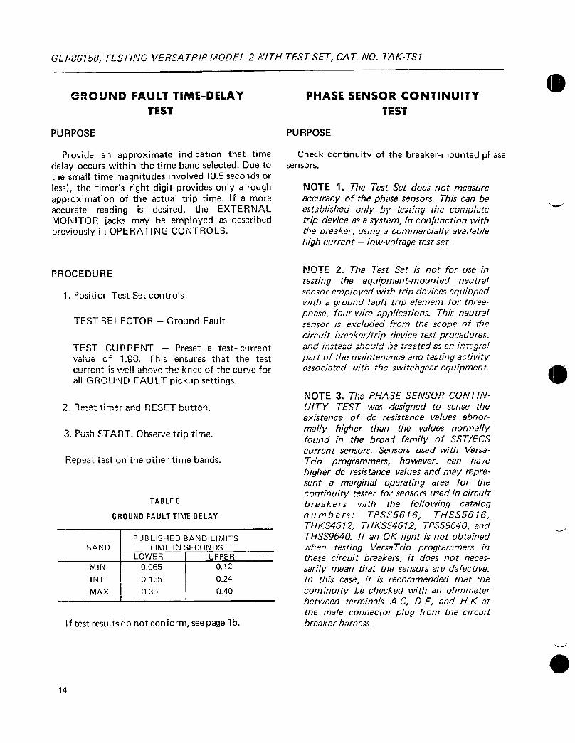
GE186158TESTINGVERSATRIPMODEL2WITHTESTSETCATNO7AKTS1
14
GROUNDFAULTTIIUICDELAVVAVVYFAULTTIMEDELAY
TEST1C1
PURPOSE
ProvideanapproximateindicationthattimedelayoccurswithinthetimebandselectedDuetothesmalltimemagnitudesinvolved05secondsorlessthetimersrightdigitprovidesonlyaroughapproximationoftheactualtriptimeIfamoreaccurate reading is desired theEXTERNAL
MONITORjacksmaybeemployedasdescribedpreviouslyinOPERATINGCONTROLS
PROCEDURE
1PositionTestSetcontrols
TESTSELECTOR GroundFault
TESTCURRENT Presetatestcurrent
valueof190Thisensuresthatthetest
currentiswellabovethekneeofthecurvefor
allGROUNDFAULTpickupsettings
2ResettimerandRESETbutton
3PushSTARTObservetriptime
Repeattestontheothertimebands
BAND
MIN
INT
MAX
TABLE8
GROUNDFAULTTIMEDELAY
PUBLISHEDBANDLIMITSTIMEINSECONDS
1 LOWER 1 UPPER
0065
0165
030
012
024
040
Iftestresultsdonotconformseepage15
PHASESENSORCONTINUITY
TEST
PURPOSE
Checkcontinuityofthebreakermountedphasesensors
NOTE1TheTestSetdoesnotmeasure
accuracyofthephasesensorsThiscanbeestablishedonlybytestingthecompletetripdeviceasasysteminconjunctionwiththebreakerusingacommerciallyavailablehighcurrent lowvoltagetestset
NOTE2TheTestSetisnotforuseintesting theequipmentmountedneutral
sensoremployedwithtripdevicesequippedwithagroundfaulttripelementforthreephasefourwireapplicationsThisneutralsensorisexcludedfromthescopeofthecircuitbreakertripdevicetestproceduresandinsteadshould152treatedasanintegralpartofthemaintenanceandtestingactivityassociatedwiththeswitchgearequipment
NOTE3ThePHASESENSORCONTIN
UITYTESTwasdesignedtosensetheexistenceofdcresistancevaluesabnor
mallyhigherthanthevaluesnormallyfoundinthebroadfamilyofSSTECScurrentsensorsSensorsusedwithVersa
Trip programmershowevercanhavehigherdcresistancevaluesandmayrepresentamarginaloperatingareaforthecontinuitytesterforsensorsusedincircuitbreakers with the following catalognumbers TPSS5616 THSS5616THKS4612THKSS4612TPSS9640andTHSS9640IfanOKlightisnotobtainedwhentestingVersaTripprogrammersinthesecircuitbreakersitdoesnotnecessarilymeanthatthesensorsaredefectiveInthiscaseitisrecommendedthatthecontinuitybecheckedwithanohmmeterbetweenterminalsACDFandHKatthemaleconnectorplugfromthecircuitbreakerharness

TESTINGVERSATRIPMODEL2WITHTESTSETCATNOTAKTS1GE186158
PROCEDURE
1EnsureallpowerisremovedfromthecircuitbreakerandthatthemaleconnectorfromtheTestSetisconnectedtothefemaleconnectorofthecircuitbreakerharness
2Selectthephasetobetested
3PushthePUSHTOTESTbuttonTheOKlightmustlightwhilethePUSHTOTESTbuttonisdepressedAbsenceoftheOKlightindicatesahighresistanceoropencircuitintheCTorwiringharness
Iftestresultsdonotconformseepage15
FAULTTRIPINDICATORS
Asanoptionalaccessoryprogrammersmaybeequippedwithpopouttypefaulttripindicatorslocatedalongthetopofthefaceplate
InoperationtheseplungerspopouteachtimetheirrespectivetripelementdeliversatripsignalIfaprogrammertripsonLToverloadonlythatindicatorisactivatedForshortcircuitsasingleindicatorservesboththeSTandINSTelementsandisactivatedbyeitherTheGFindicatorrespondsonlytoagroundfaulttrip
Whentestingprogrammerssoequippedthetripindicatorsarefunctioningproperlyiftheyareactivatedeachtimetheirrespectivetripelementtrips
IFTESTRESULTSDONOTCONFORM
Reviewtheinstructionstoseethatthepropertestprocedureisbeingfollowed
CheckallsettingsontheProgrammerUnit
IstheTESTSELECTORswitchintheGROUNDFAULTpositionforgroundfaulttestingIntheOAOBorPCpositionforallothertests
Does the PROGRAMMER LONGTIME
PICKUPSETTINGcontrolontheTestSet
matchtheprogrammerscontinuousamperesetting
IstheTRIPBREAKER PROGRAMMER
ONLYswitchinthepropermode
Areallcableconnectorsfullyengaged
IftheSTelementtripstoosoonorattoolowaleveltheINSTpickupsettingisprobablytoolowTheINSTpickupmustbesetatahigherXvaluethantheSTelementPickupbandtolerancesmustalsobeconsidered
TimermakesnoisebutdoesnotoperatePushRESETbuttonManuallyresettimer
Whenusing50Hzpowerthetimerreadingmustbemultipliedby12
SeeSectionOPERATINGCONTROLSre
gardingtestsetaccuracy
UsetheEXTERNALMONITORjacksasdescribedinOPERATINGCONTROLSto
checkthecurrentlevelthatisbeingappliedtotheProgrammerUnitThesejacksmaybeusedalsotomonitortriptime
IfthePHASESENSORCONTINUITYTEST
OKTightdoesnotTightrefertoNote3oftheinstructionsforthattest
Ifafterrepeatingthetestsresultsdonotconformdonotreconnectthecircuitbreakeruntilthedefectivecomponentisreplaced
COMPLETIONOFTESTS
Afterthetripdevicetestinghasbeencompleteddiligentproceduresmustbe exercised preparatory
torestoringthecircuitbreakertoservice
Ensurethatthebreakerisfullydisconnectedfromanypowersource
DisengagetheTestSetconnectorsfromtheprogrammerandthefemalecircuitbreakerharnessconnector
Reconnectthefemaleharnessconnectorto
theProgrammerUnitFailuretodothisvoidsthebreakersautomatictripsystem
Resetallfaulttripindicatorsontheprogrammer
Iftheprogrammersadjustmentknobsweremovedtodifferentsettingsduringtestingrestorethemtotheiroriginalasreceivedsettings
15
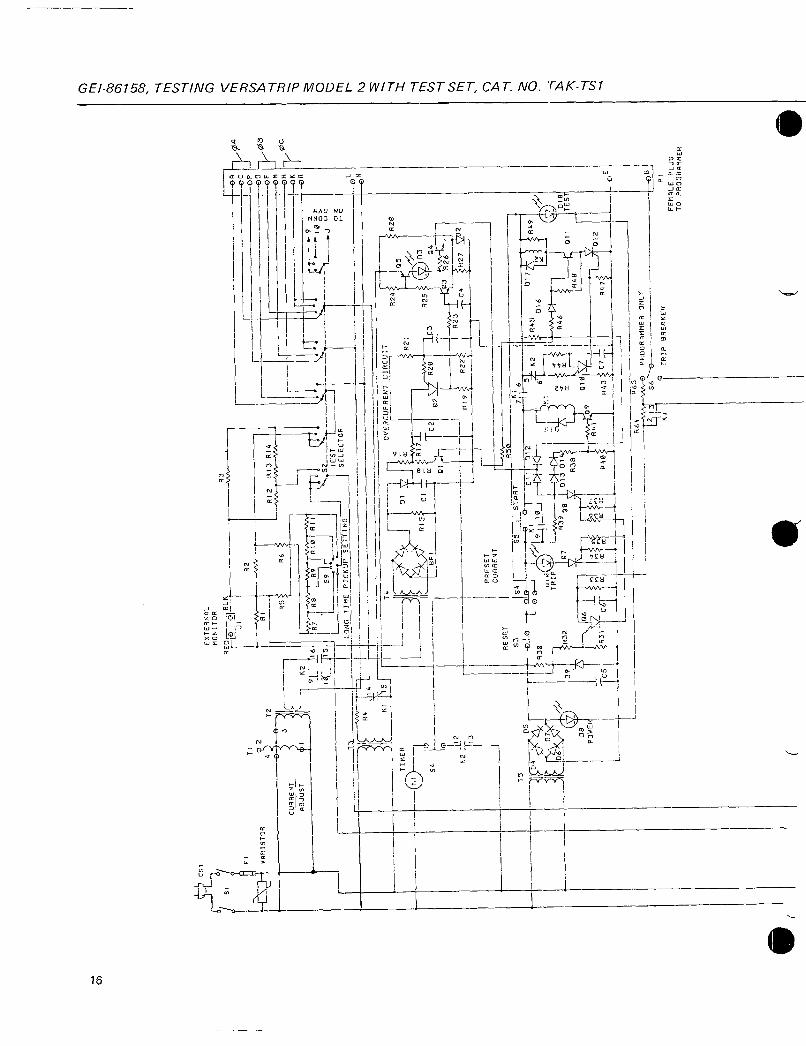
Ccs
51
8PRISTOR
CURRENT ADJUST
T1
2
TIMERYi1
fJ
Ic
12
62
I
9i16
R7
R8
R9
RIO
R
I
10
115
1
s9
r
PICKUPS
T
1SELECTOR
LONGTIME
PICKUPSETTING
11LK2
13
15
ADS
IC14
y 08 PO4ER
6
XTERNRL
MONITOR REDr
8L6JI
R2
R
812
813R1
4
R1
R6
r
5
R30991
R32
106
L
5R31C
RESET
010403
L0o
PRESET CURRENT
R3VrNVr
9
z
J
v
OVERCURRENICIRCUIT
R24
05
R28
01
Q
R21
J
R152
Ci
I
mR17
t
RZG
IC7D
C2
G2
R28
1L3
04
R23
yy
1197
R22
TC4
F27
S
S
958
SSTART
6
012
S1Fie
CJ
TRIP
inN
7
R3908
11
2
845I016
8466
9
0101 Ft43
7
0R
OA
OC
Y
CPOF
014
II
OR
R64
T613MP6068088ER
ONLY
11
O
TRIPSRERKER
K1
ozC
D172Y
t
R49
I
SJ
L
011
TES1
Ft
4tyyt8
R47
P1
FEMRLEPLUG
TO
PROGRAMMER

T6
019
RESISTORS
R1
R2
R3
R4
R5812
R13R58
R6
R7
R8
R9
R10
R11
1114
R15
R161117
R18832
R19820
R44R52
R62
1121
R22
R23824R28
R25
1126834
R37840
R48860
R27
R30R39R45
R31
R33
R35R36R41
R38R46
020
III r022
021
R63
Ci24
R51
Fig5Schematicdiagram SSTECSTestSetCatNoTAKTS1DrawingNo139C4370
DESCRIPTIONOhms
020125W
05150W
100125VV
30005101N
1K114W
9091 14W
2611 114W
1961 14W
154114W
1211 14W
1001 14W
28K114W
806112W
1008114W
1MEG101418
33281 141N
68181 14W
51K5 14W
22K514W
18514W
1220151i4W
22K5 12W
34K1 14W
1013W
228514W
47K5 114W
R53
1
1023 v
n52
RESISTORS
Contd
11421143
R47
1140
851R63
R5
R54R50R55
R56
R57
R59
R61
1164
R65
C1
C2
C3C4C6
C9010
0508
C7
BR1
6102
011012
013014
D16025
D26027
D28030
MCTERCIRCUIT
854
0
DIODES DESCRIPTION
VaroVE18
1N4148
026
02028455
L
PARTSLISTFORFILE5
DESCRIPTIONOhms
110K1514W
2700514W
27K512W
1K512W
14060I 18NI
100K5 14W
15000118W
100K31012W
365K114W
100152W
39052W
56015 12W
6851i2W
1010 250VDC
2701015VDC
Tantalum
0110100VDC
15075VDC
Aluminum
0331050VDC
DIODES
Contd
456 029J8
D4D5
D6D7
015D17
D19D20
D21D22
D31D33
D34D35
03D8
010D18
D32
D9
D23D24
D29
Q1Q304
09011
0206
010013
Q5
10708012014Al
T1
1T2T3
PUSHTOTEST
f0157
DESCRIPTION
185060
LED28V20ma
115V11 1W
IN474010V1W
IN5352B1545W
CAPACITORSDESCRIPTIONMMdTRANSISTORS
ANDSCRS DESCRIPTION
GET930
a
L9
2N6028
2N5087
C103B
OPAmpMC1741CP
TRANS
FORMEF1S DESCRIPTION
VariableTransformer
GE9T92A1
1StancorP86411TriadN48X
PHASESENSOR
CONTINUIIYCIRCUIT Y
rr033
R61
030 S8
R57 4032OK
013Rt2i
TRANS
FORMERS
Contd DESCRIPTION
T4
T5TG
GE5678743G4
StancorP8601
SWITCHES DESCRIPTION
S1 JBTST22K
S2 Centralah
SA20214C000
S3 Grayhd14002
S4 Grayhill4605081 5020101
1S5S7 Gravh1114001
S6 JSTST12D
S8S9 Cen1ralab
SA20014C000
RELAYS DESCRIPTION
K1K2 AlliedT1544C28VDC
CONNEC
TORS DESCRIPTION
lP1 Amp2012981
IP2 Amp2012971
VARSTOR
TIMER
EXTERNAL
MONITOR
JACK
IDVPA
V15CILA20A
Cramer636S10084
HHSmith26986
Dlyrtec277002
034
1 F
0
035
P2MALEPLUG70
CIRCUITBREAKERHARNESS
0
m

GEI86158TESTINGVERSATRIPMODEL2WITHTESTSETCATNOTAKTS1
105125
18
VAC
4 SETTING
s9
TI
CURRENT
ADJUST
PRESETK2
T3
T5
T6
EXTERNALMONITOR
T2
0M2TIMER
DVMCIRCUIT
DVM
LTPICKUP
RFEEDTOPROGRAMMERPOWERSUPPLY
CIRCUITDESCRIPTION
AbriefdescriptionoftheTestSetcircuitryisgivenbelowRefertothesimplifiedschematicofFig6
S2
PRESETRESETSTARTPROGRAMBKR
LOGICCIRCUITS
1InputvoltageisappliedtotheTestSetthroughathreewirepowercordvithagroundconductor The chassis and metal parts are
groundedtoprotecttheoperator
2Outputvoltagesareisolatedfromtheinputvoltagebymeansofmultiplewindingironcoretransformers
3AllpowertotheTestSetissuppliedthroughtheONOFFswitchandaoneamperesloblofuse
K2 T4 S2IFuti
S2 cryOVERCURRENT
LOCKOUTCIRCUITS
KI
PHASE
SENSOR
CONTINUITY
CIRCUIT
Fig6TestSetsimplifiedschematic
T1
bA
0
H
1CDDoFoHoL
FEMALEPLUGTO
PROGRAMMER
MALEPLUGTO
BREAKER
4T2isa126voltfilamenttransformerthat
providesthelowvoltagesimulatedfaultsignalcurrentstotheprogrammerviatheTESTSELECTORswitchS2whenrelaycontactK2isclosedThetestcurrentisadjustedbyvariabletransformer
SwitchesS2andS9providetheappropriateresistorselectionforthedigitalmeter
TheEXTERNALMONITORisaprecisionshuntresistorwhichprovidesanoutputthatisanaccuraterepresentationofthetestcurrent
5TheovercurrentlockoutcircuitprotectstheprogrammerfromprolongedorcontinuoustestingathighcurrentlevelsOnceenergizedthecircuitwilllockouttheTestSetforapproximately70secondsandthenautomaticallyreset

TESTINGVERSATRIPMODEL2WITHTESTSETCATNOTAKTS1GE186158
6T3isanisolationtransformerthatfeedsthe
powersupplyoftheprogrammerPoweristransferredwhenrelayK1isenergizednormallyclosedcontactopensK1isenergizedslightlybeforeK2inordertoensurethatpowersupplyvoltageisavailablebeforetestcurrentisapplied
7PowerisappliedtothetimerbyrelaycontactK2
STransformerT5powerstheTestSetlogiccircuitry
9TransformerT6powersthePHASESENSORCONTINUITYTESTcircuitandthedrivecircuitryforthedigitalvoltmeter
ForcompleteschematicdiagramseeFig5
19

GENERALELECTRICCOMPANY
CIRCUITPROTECTIVEDEVICESDEPARTMENT
PLAINVILLECONNECTICUT06062
GENERAL ELECTR C

11111VUULIVII
SpectraRMSTMmoldedcasecircuitbreakerswith
MicroVersaTripPlusorMicroVersaTripPMtripunitsprovideadjustableoverloadandshortcircuitprotectionforelectricalequipmentFrametypesSKHBSKLBSKPBSKHHSKLLandSKPPare
availablewithaselectionofratingplugstoamaximumof1200amperesdependingonthesensorrating
SKframecircuitbreakersarelistedperUnderwritersLaboratoriesstandardUL489andCanadian
StandardsAssociationstandardCSA222No5and
meettherequirementsoftheInternationalElectrotechnicalCommissionstandardIEC9472
WARIviNGmangerofelectricalshockorinjuryTurnOFFthepoweraheadofequipmentbeforeinstallingthisdeviceorremovinganyotherdevice
iiriihangercieieclrolutioiiiiuper
lalimentationavantdinstallercetappareilouavantderetirestmitreannarvii
CAUTIONThisproductisNOTsuitableforuseinequipmentnotspecificallydesignedtoacceptitContacttheequipmentmanufacturerforpossibleequipmentmodifications
IMPORTANTCetappareilnedoitpasetreemployedansunequipernentnonspeciaieiuentadapteaceteffctContdtteLlcLonStrULtcurCviiictI1alltICS
11modifications talnJijJVSS11JnCSmodificationsaapNUrLtLayu1J1111iL
r
SpectraRMS TMSKFrame11II tirniriRri bareJrVIvoavLoisaIJlt JJW1
A441Mic 0roVcrsaTrintaPinenrMcroVersaTrinPMTrimUnituWriWNWNOIre fr o1
4
4
d y
rVim
SK1200AFramePMbreakerwitharatingpluginstalled

Opulit at17VIA aria vienueCasetArGLDrwat
InstallationInstructions
AenrvhimoowoInuy
1UnpackthecircuitbreakerandinspectitforanyshippingdamageEnsurethatthebreakerhastheproperampererangesensorratingvoltageratingandinterruptionratingfortheapplication
BB
16A2Q4 Code
SK
HB
LB
PB
HH
LL
PP
Description
5x1200
50kAat480Vac
65kAat480Vac
100kAat480Vac
50kAat480Vac
65kAat480Vac
100kAat480Vac
SKFramebreakerSK
50kAat480VacstandardULratingHB
3poles600VacmaximumULvoltage36
36 3poles600Vac
B MicroVersaTripPlustripunitC MicroVersaTripPMtripunitwith
MeteringandPOWERLEADERTMCommunicationBusTripsystem
D MicroVersaTripPMtripunitwithMeteringandPONERLEADERCounicationBus
andProtectiverelays
A LI
B LSI
C LIG
D LSIG
E LICPMicroVersaTripPlustripunitonly
F LSICPMicroVersaTripPlustripunitonly
0800 800amperes
1200 1200amperes
Table1CatalognumberingsystemforSpectraRMSSKFramebreakerswithMicroVersaTripPlusorMicroVersaTripPMtripunits
ExampleabreakerwithcatalognumberSKHB36BA0800hasthefollowingfeatures
2
Sithibreakerisavailablewithawidevari
etyofconfigurationscomparethecatalognumberofyourpurchasedbreakerwiththecatalognumberkeyinTable1Installationofanincorrectbreakercouldresultinmisapplicationlackofsystemcoordinationorreductioninsystemfunctionality
StandardUL
rating
100continuous
ULrating
Function
1Framedesignation
Interruptionrating
PolesMaximumULvoltage
Ovrcurrentprotectivefunctions
L longtimestandardSshorttime
Iinstantaneousstandard
Ggroundfault
CF24Vdccontrolpower
Sensorratings
MicroVersaTripPlustripunitB
LongtimeandinstantaneousovercurrentprotectivefunctionsA800amperesensorrating0800

0
aauaavgNumber
SRPK800B300
SRPK800B400
SRPK800B500
SRPK800B600
SRPK80013700
SRPK800B800
SRPK1200B600
SRPK1200B700
SRPK1200B800
SRPK1200B1000
SRPK1200B1200
CatalogNumber
TCAL81
TCAL121
TC081A
TCO121
TCAL124
SpectraRMSSKFrameMoldedCaseCircuitBreakerInstallationinstructions
2FollowingtheinstructionssuppliedwiththeratingpluginstalltheplugintothebreakerbodyAvailableratingplugswiththeircatalognumbersarelistedinTable2
Sensor
RatingAmps
800
1200
WireRange
30500kcmil
250500kcmil1250350kcmil
30500kcmil
250400kcmil
350750kcmil
PIrrTotnn
1 300
400
500
600
700
800
1 600
700
800
1000
1 1200
Table2SKFrameratingplugs
3InstallanyinternalaccessoriesfollowingtheinstructionssuppliedwitheachaccessoryAvailableaccessoriesandtheirmountinglocationsarelistedinTable3Checkallaccessories
forproperinstallationandwireroutingVerifybreakeroperationwiththeinstalledaccessories
3
Internal
AccessoryInstallation
AuxiliarySwitchesSPDTorDPDT
ShuntTrip
BellAlarmS
UndervoltageRelease
0ULlistingpendingeSuitablefor500kcmilforvoltagedropconsiderations
Table4Terminallugcatalognumbersandspecifications
AccessoryCompartmentLocationand
ExitSide
LeftIRight
4
1
Maximum
Numberof
Accessories
1BellAlarmplus
1AuxSwitch
pluseither
1ShuntTripor1UndervoltageRelease
OLeadsmayberoutedunderbreakertoppositesideAnauxiliaryswitchisrequiredforMicroVersaTripPM
breakerstatussignal
Table3Availableaccessories
4AttachtheterminallugslistedinTable4followingtheinstructionssuppliedwiththekitUseonekitforeachwiretermination
maximumofsixlugkits
5EnsurethatallterminalsaretorquedtothepropervalueaslistedinTable4Reinstalltheterminalcoversensuringthattheyarefirmlyseated
NOTEAluminumwiremustbeusedwithajointcompoundrecommendedbythewiremanufacturer
IMFORTAVTDlescasdemploidecablealuminumutilizezlelubricantrecommandeparlefabricant
Torqueinlb Strip Numberof
WireType i 9St T L
WireHoles Materialrvrretype WireLugLugStrap ixrigw Wurcnole3 Lugiviari
Copperor 375 400 112 3 Aluminum
Aluminum
Aluminum1 375 400 112 4 Aluminum
Copper
Copper 1 375 1 400 112 1 3 Copper
Copper 1 375 1 400 112 1 4 Copper
Copperor 500 400 112 3 Aluminum
Aluminum
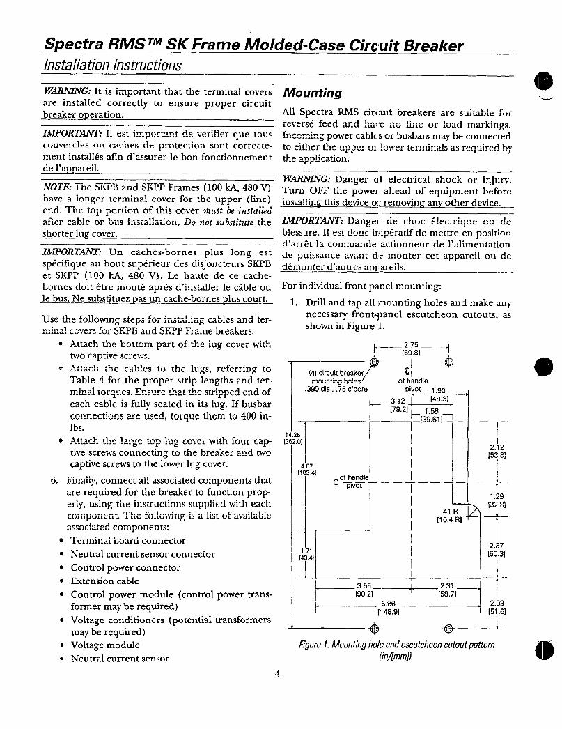
SpectraRMS TMSKFrameMoldedCaseCircuitBreakerinstallationinstructions
WARNINGItisimportantthattheterminalcoversareinstalledcorrectlytoensurepropercircuitbreakeroperation
IMPORTANTT1estidverifierTieto
cnuyercleso11cachesdeprotectionsontcorrectementinstallesafindassurerlebonfonctionnement
delappareil
NOTETheSKPBandSKPPFrames100kA480VhavealongerterminalcoverfortheupperlineendThetopportionofthiscovermustbeinsiaiiedaftercable Linstallation substituteheaIICrcaU1CorbusinstallationLVnotsubstitutetI1C
shortertuffcover
IMPORTANTUncachesbornespluslongestspecifiqueauboutsuperieurdesdisjoncteursSKPBetSKPP100kA480VLehautedececache
bornesdoitetremonteapresdinstallerlecableoulebusNesubstituezpasuncachebornespluscourt
USe111C1VlloW111Jtc1J111L3L111eaJLe3andterminalcoversforSKPBandSKPPFramebreakers
Attach bottom Cthe1 1fLL1L11theUVLL1111partoft11GlugcoverwithtwocaptivescrewsAttachthecablestothelugsreferringtoTable4fortheproperstriplengthsandterminaltorquesEnthatthestrippeendofeachcableifullyseatinitslilyIfhusharJ
connectioareusedtorquethemto400inlhs
Attachthelargetopiugcoverwithfourcapconnectingtothebrandtwo
captivescrewstothelowerlugcover
6 FinallyconnectallassociatedcomponentsthatarerequiredforthebreakertofunctionproperlyusingtheinstructionssuppliedwitheachcomponentThefollowingisalistofavailableassociatedcomponentsTerrillnalboardconnector
Neutralcurrentsensorconnector
ControlpowerconnectorExtensioncable
ControlpowermodulecontrolpowertransformermayberequiredVoltageconditionerspotentialtransformers
LiveScrews
mayberequired
VoltagemoduleNeutralcurrentsensor
4
Mounting
AllSpectraRMScircuitbreakersareSuitableforreversefeedandhavenolineorloadmarkingsincomingpowercablesorbusbarsmaybeconnectedtoeitherthupperorlowtasrequiredbyl J
theapplication
WARNINGDangerofelectricalshockorinjuryTurnOFFthepoweraheadofequipmentbeforeinsallinethisdeviceorremovinzanyotherdevice
IMPORTANTDdechocp ulectriqemdeb h
bless11estdoneirnperatifdemettreenpositiondarretlacommandeactionneurdelalimentation
depuissanceavantdemontercetappareiloudedemonterdautresappareils
Forindividualfrontpanelmounting
1DrillandtapallmountingholesandmakeanynecessaryfrontpanelescutcheoncutoutsasshowninFigure1
1425
13e20
4circuitbreakermountinghoes
390dia75cbore
407
1C341
171
4341
275
6981
ofhpivot 190
312I 14831
179211
156
3961
355
902586
14891
J
aa
41R I2104R1T
231
587
Figure1Mountingholeandescutcheoncutoutpatterninmm
212
1538
ofhandy
pivot i129
3281
237
16031
203
516
l
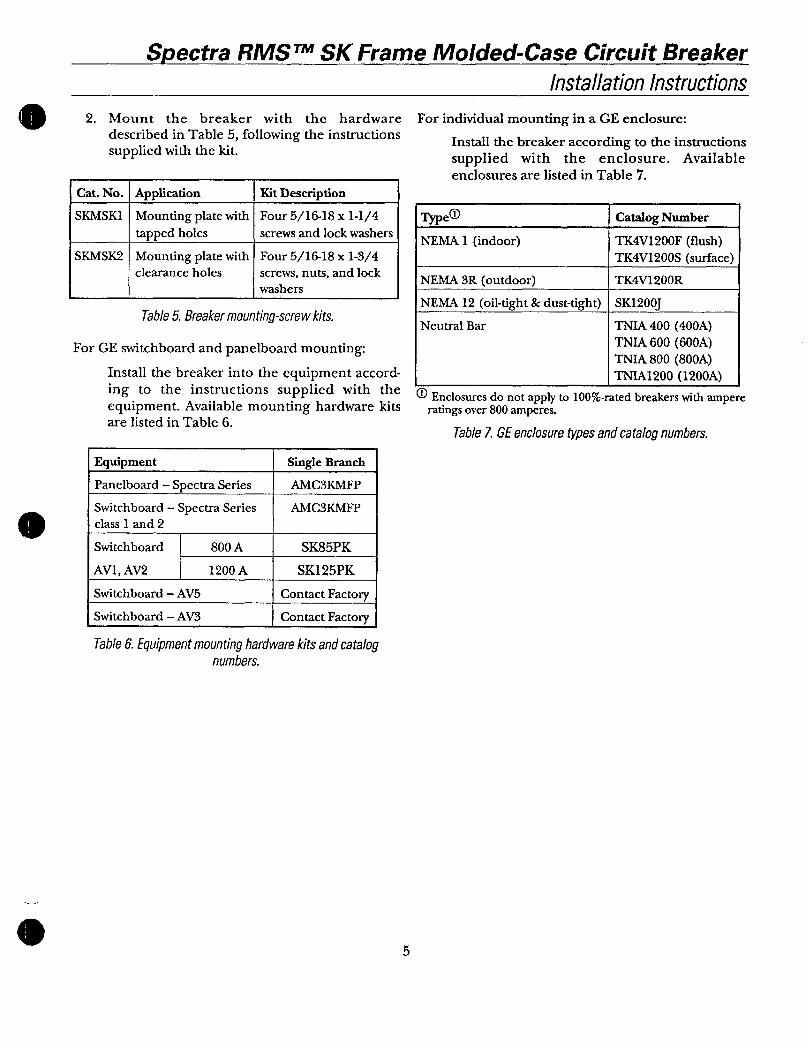
o
0
SpectraRMSTMSKFrameMoldedCaseCircuitBreakerInstallationInstructions
2 Mountthebreakerwiththehardware
describedinTable5followingtheinstructionssuppliedwiththekit
CatNoIApplication IKitDescriptionSKMSK1MountingplatewithFour51618x114
tappedholes screwsandlockwashers
SKMSK2MountingplatewithFour51618x134clearanceholes screwsnutsandlock
washers
Table5Breakermountingscrewkits
ForGEswitchboardandpanelboardmounting
InstallthebreakerintotheequipmentaccordingtotheinstructionssuppliedwiththeequipmentAvailablemountinghardwarekitsarelistedinTable6
Equipment
Panelboard SpectraSeries
Switchboard SpectraSeriesclass1and2
Switchboard 1 800A
AV1AV2 1200A
Switchboard AV5
Switchboard AV3
SingleBranch
AMC3KMFP
AMC3KMFP
SK85PK
SK125PK
ContactFactory
ContactFactory
Table6Equipmentmountinghardwarekitsandcatalognumbers
5
ForindividualmountinginaGEenclosure
Installthebreakeraccordingtotheinstructionssuppliedwith the enclosureAvailable
enclosuresarelistedinTable7
Typed ICatalogNumberNEMA1indoor TK4V1200Fflush
TK4V1200Ssurface
NEMA3Routdoor 1 TK4V1200R
NEMA12oiltight dusttight 1 SK1200J
NeutralBar TNIA400400ATNIA600600A
TNIA800800ATNIAl2001200A
Enclosuresdonotapplyto100ratedbreakerswithampereratingsover800amperes
TableZGEenclosuretypesandcatalognumbers
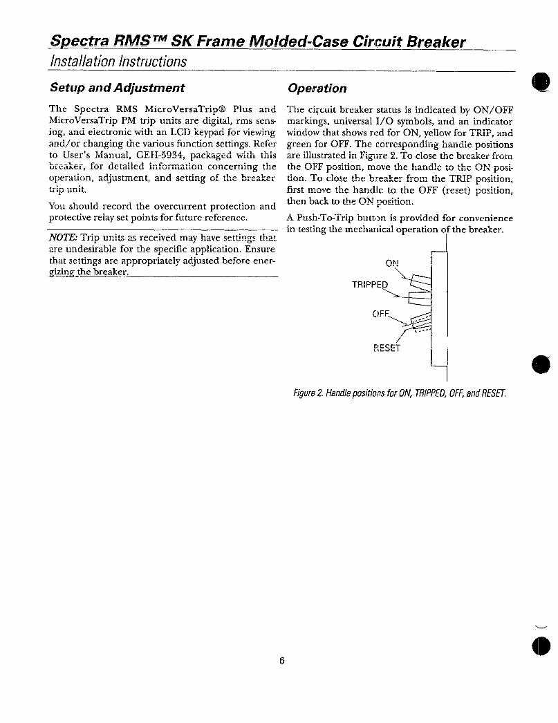
SpectraITS TMSKFrameMoldedCaseCircuitBreaker
Installationinstructions
SetupandAdjustment
TheSpectraRMSMicroVersaTripPlusandMicroVersaTripPMtripunitsaredigitalrmssensingandelectronicwithanLCDkeypadforviewingandorchangingthevariousfunctionsettingsRefertoUsersManualGEH5934packagedwiththisbreaker detailedinformationfor ctaiicuii
t
uviuiaonConcerningtheoperationadjustmentandsettingofthebreakertripunit
Youshouldrecordtheovercurrentprotectionandprotectiverelaysetpointsforfuturereference
NOTETripunitsasreceivedmayhavesettingsthatareundesirableforthespecificapplicationEnsurethatsettingsareappropriatelyadjustedbeforeenergizingthebreaker
6
Operation
ThecircuitbreakerstatusisindicatedbyONOFFmarkingsuniversalIOsymbolsandanindicatorwindowthatshowsredforONyellowforTRIPandgreenforOFFThecorrespondinghandlepositionsareillustratedinFigure2ToclosethebreakerfromtheOFFpositionmovethehandletotheOrpositionToclosethebeakerfromtheTRIPpositionfirstmovethehandletothOFFresetpthebacktotheONposition
APushToTripbuttonisprovidedforconvenienceintestingthemechanicaloperationofthebreaker
ON
TRIPPED
i
OFF
RESET
Figure2HandlepositionsforONTRIPPEDOFFandRESET

Maintenance
Spect7AfATiAl AIJl115SL
Breakerapecrraruvra SKFrameIVIUIaeafuseCircuitvreaKer
InstallationInstructions
Itisrecommendedthatthefollowingoperationsbenerfnrmedannually
WARNINGDangerofelectricalshockorinjuryTurnoffpoweraheadofequipmentbeforeattemptingtoservice
IMPORTANTDangerdelectrocutionCouperlalimentationavantdaffectuertouteaction
dentretien
1Turnoffthepowertotheequipmentbeingserviced
2Cleanthesurfacesofthebreakerandsur
roundingareaofanydirtsootorotherdebris
gTncnertthehreakerfnranvsioncofrlarnage
4Operatethepushtotripbuttonandtogglehandleseveraltimetoexercisethemechanism
7 1 1 1 r
andlestti1Cmechanicaloperationofthe1J1CQACL
5 Checkallovercurrentprotectionandprotectiverelaysettingsforcorrectvaluesasestablishedforthesystem
6 IfanysignofdamageisfoundorthemechanismhasasluggishorstickyoperationorthetripunitdisplayflashesERRreplacethecircuitbreaker
Thecircuitbreakerissealedandcontainsnouser
serviceablepartsOpeningthebreakerwillvoidanyandallwarranties
7
AGAm1MVCVIIC
ThefollowingexternalaccessoriesareavailableforSpectraRMSSKFramebreakersCatalognumbersandotherorderinginformationfortheseexternal
accessoriesmaybeobtainedfromyourauthorizedGEdistributorAccessoriesidentifiedwithanasterisk requireremovalofthehandleextension
Mountingkits
PluginbaseboltonbaseBackconnectedstuds
rauiocluugucvlccs
Externalhandleoperators
MotoroperatorsMechanicalinterlock
TheseinstructionsdonotcoveralldetailsorvariationsinequipmentnordotheyprovideforeverypossiblecontingencythatmaybemetinconnectionwithinstallationoperationormaintenanceShouldfurtherinformationbedesiredorshouldparticularproblemsarisethatarenotcoveredsufficientlyforthepurchaserspurposesthemattershouldbereferredtotheGECompany
41
GEH59500194PSA
GeneralElectricCompany41WoodfordAvePlainvilleCT06062
1994GeneralElectricCompany
GEElectricalDistribution Control