Operation and Maintenance Manual Water Supply - UNICEF
63
Table 1: Borehole information 5 0 Operation and Maintenance Manual Water Supply Azraq Refugee Camp - Jordan Draft March 2019
-
Upload
khangminh22 -
Category
Documents
-
view
1 -
download
0
Transcript of Operation and Maintenance Manual Water Supply - UNICEF

Table 1: Borehole information 5
0
Operation and Maintenance Manual Water Supply
Azraq Refugee Camp - Jordan
Draft
March 2019
Unicef Jordan O & M Manual Water Supply Azraq Refugee Camp WASH Section
Azraq Refugee Camp Page 1 / 62 PG / 03.04.2019
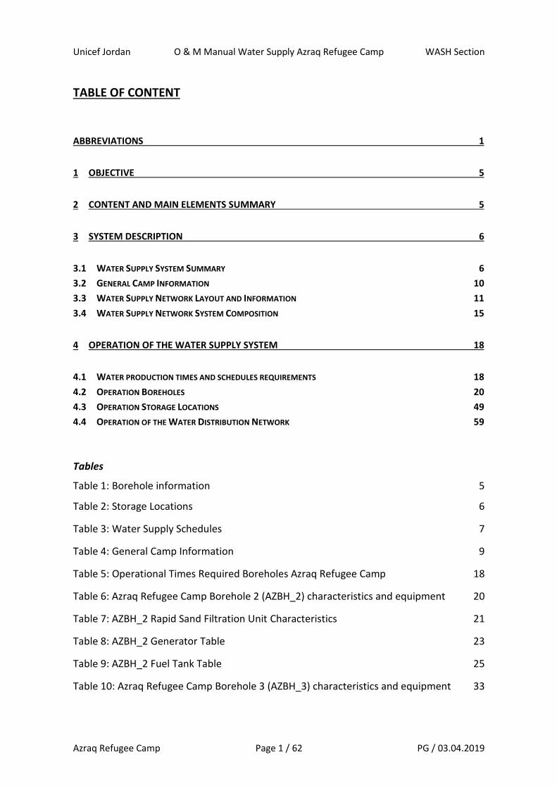
TABLE OF CONTENT
ABBREVIATIONS 1
1 OBJECTIVE 5
2 CONTENT AND MAIN ELEMENTS SUMMARY 5
3 SYSTEM DESCRIPTION 6
3.1 WATER SUPPLY SYSTEM SUMMARY 6
3.2 GENERAL CAMP INFORMATION 10
3.3 WATER SUPPLY NETWORK LAYOUT AND INFORMATION 11
3.4 WATER SUPPLY NETWORK SYSTEM COMPOSITION 15
4 OPERATION OF THE WATER SUPPLY SYSTEM 18
4.1 WATER PRODUCTION TIMES AND SCHEDULES REQUIREMENTS 18
4.2 OPERATION BOREHOLES 20
4.3 OPERATION STORAGE LOCATIONS 49
4.4 OPERATION OF THE WATER DISTRIBUTION NETWORK 59
Tables
Table 1: Borehole information 5
Table 2: Storage Locations 6
Table 3: Water Supply Schedules 7
Table 4: General Camp Information 9
Table 5: Operational Times Required Boreholes Azraq Refugee Camp 18
Table 6: Azraq Refugee Camp Borehole 2 (AZBH_2) characteristics and equipment 20
Table 7: AZBH_2 Rapid Sand Filtration Unit Characteristics 21
Table 8: AZBH_2 Generator Table 23
Table 9: AZBH_2 Fuel Tank Table 25
Table 10: Azraq Refugee Camp Borehole 3 (AZBH_3) characteristics and equipment 33
Unicef Jordan O & M Manual Water Supply Azraq Refugee Camp WASH Section
Azraq Refugee Camp Page 2 / 62 PG / 03.04.2019
Table 11: Aeration Tower Characteristics (at AZBH_3 for H2S elimination) 36
Table 12: Rapid Sand Filtration Unit at AZBH_3 37
Table 13: AZBH_3 Generator Table 39
Table 14: AZBH_3 Fuel Tank Table 42
Table 15: Table of Gate Valve Chambers Distribution Network Azraq Refugee Camp 60
Pictures
Picture 1: Conceptual Map of Azraq Refugee Camp 10
Picture 2: Water Supply Network Azraq Refugee Camp – Main Level 11
Picture 3: Water Supply Network Azraq Refugee Camp – Village 2 12
Picture 4: Water Supply Network Azraq Refugee Camp – Village 3 12
Picture 5: Water Supply Network Azraq Refugee Camp – Village 5 13
Picture 6: Water Supply Network Azraq Refugee Camp – Village 6 13
Picture 7: Conceptual System of the Water Supply at Block 7 Plot Level 14
Picture 8: Systemic flow chart of Azraq Water Supply Network System 17
Picture 9: Operational Timetables Boreholes and Storage Locations 19
Picture 10: Sand Filtration Unit 22
Picture 11: Sand Filter Composition 22
Picture 12: AZBH_2: Generators and Fuel Tank 24
Picture 13: AZBH_2: Schematic Site Layout Borehole 2 25
Picture 14: Storage Location J2 for Tanker Filling Station at AZBH_2 26
Picture 15: Tanker Filling Station at AZBH_2 26
Picture 16: Location of the valley chamber 28
Picture 17: Pumping from AZBH_2 to Storage Location J4 (Gate Valves Configuration) 29
Picture 18: Pumping from AZBH_2 to Storage Location J8 (Gate Valves Configuration) 29
Picture 19: Pumping from AZBH_2 to Sand filtration Unit (Gate Valves Configuration) 30
Picture 20: Pumping from AZBH_2 to Storage Location J2 (Gate Valves Configuration) 30
Picture 21: Pumping from AZBH_2 to the Cleanout 31
Unicef Jordan O & M Manual Water Supply Azraq Refugee Camp WASH Section
Azraq Refugee Camp Page 3 / 62 PG / 03.04.2019
Picture 22: Chlorination Unit and Chlorination Injection Point at AZBH_3 35
Picture 23: Aeration Tower at AZBH_3 for H2S elimination 36
Picture 24: Rapid Sand Filtration Unit at AZBH_3 37
Picture 25: Layer Composition Rapid Sand Filtration Unit AZBH_3 38
Picture 26: AZBH_3: Generators and Fuel Tanks 41
Picture 27: AZBH_3: Schematic Site Layout Borehole 3 42
Picture 28: AZBH_3: Photo of borehole and operation building 43
Picture 29: AZBH_3: Photo of water treatment systems (Aeration tower, sand filter) 43
Picture 30: Pumping from AZBH_3 to Storage Location J4 (Gate Valves Configuration) 44
Picture 31: Pumping from AZBH_3 to Storage Location J8 (Gate Valves Configuration) 45
Picture 32: Pumping from AZBH_3 to Water Treatment (Gate Valves Configuration) 45
Picture 33: Pumping from AZBH_3 to the Cleanout (Gate Valves Configuration) 46
Picture 34: Pumping from AZBH_3 bypassing the Aeration Tower and Sand Filtration 46
Picture 35: Location of Storage Location J4 49
Picture 36: Schematic System Layout Storage Location J4 50
Picture 37: Photos Storage Location J4 52
Picture 38: Location of Storage Location J8 53
Picture 39: Schematic System Layout Storage Location J8 53
Picture 40: Photos Storage Location J8 54
Picture 41: Chlorination Unit at Storage Location J8 56
Picture 42: Location of Tanker Filling Station and Storage Location J2 56
Picture 43: Schematic System Layout of Tanker Filling Station and Storage Location J2 57
Picture 44: Photos Tanker Filling Station and Storage Location 58
Picture 45: Location of Gate-Valve Chambers Distribution Network 60
Picture 46: Example of Gate-Valve Chamber 61
Unicef Jordan O & M Manual Water Supply Azraq Refugee Camp WASH Section
Azraq Refugee Camp Page 4 / 62 PG / 03.04.2019
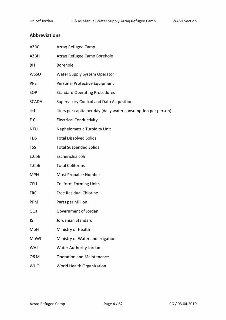
Abbreviations
AZRC Azraq Refugee Camp
AZBH Azraq Refugee Camp Borehole
BH Borehole
WSSO Water Supply System Operator
PPE Personal Protective Equipment
SOP Standard Operating Procedures
SCADA Supervisory Control and Data Acquisition
lcd liters per capita per day (daily water consumption per person)
E.C Electrical Conductivity
NTU Nephelometric Turbidity Unit
TDS Total Dissolved Solids
TSS Total Suspended Solids
E.Coli Escherichia coli
T.Coli Total Coliforms
MPN Most Probable Number
CFU Coliform Forming Units
FRC Free Residual Chlorine
PPM Parts per Million
GOJ Government of Jordan
JS Jordanian Standard
MoH Ministry of Health
MoWI Ministry of Water and Irrigation
WAJ Water Authority Jordan
O&M Operation and Maintenance
WHO World Health Organization
Unicef Jordan O & M Manual Water Supply Azraq Refugee Camp WASH Section
Azraq Refugee Camp Page 5 / 62 PG / 03.04.2019
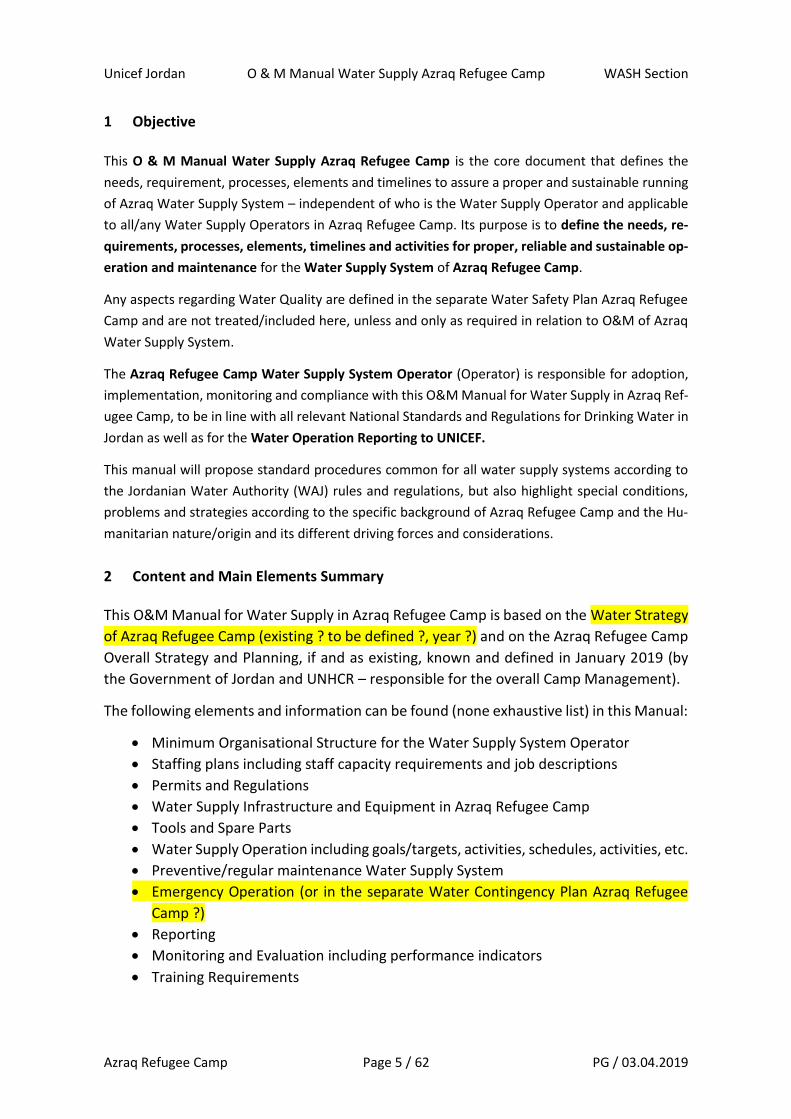
1 Objective
This O & M Manual Water Supply Azraq Refugee Camp is the core document that defines the
needs, requirement, processes, elements and timelines to assure a proper and sustainable running
of Azraq Water Supply System – independent of who is the Water Supply Operator and applicable
to all/any Water Supply Operators in Azraq Refugee Camp. Its purpose is to define the needs, re-
quirements, processes, elements, timelines and activities for proper, reliable and sustainable op-
eration and maintenance for the Water Supply System of Azraq Refugee Camp.
Any aspects regarding Water Quality are defined in the separate Water Safety Plan Azraq Refugee
Camp and are not treated/included here, unless and only as required in relation to O&M of Azraq
Water Supply System.
The Azraq Refugee Camp Water Supply System Operator (Operator) is responsible for adoption,
implementation, monitoring and compliance with this O&M Manual for Water Supply in Azraq Ref-
ugee Camp, to be in line with all relevant National Standards and Regulations for Drinking Water in
Jordan as well as for the Water Operation Reporting to UNICEF.
This manual will propose standard procedures common for all water supply systems according to
the Jordanian Water Authority (WAJ) rules and regulations, but also highlight special conditions,
problems and strategies according to the specific background of Azraq Refugee Camp and the Hu-
manitarian nature/origin and its different driving forces and considerations.
2 Content and Main Elements Summary
This O&M Manual for Water Supply in Azraq Refugee Camp is based on the Water Strategy
of Azraq Refugee Camp (existing ? to be defined ?, year ?) and on the Azraq Refugee Camp
Overall Strategy and Planning, if and as existing, known and defined in January 2019 (by
the Government of Jordan and UNHCR – responsible for the overall Camp Management).
The following elements and information can be found (none exhaustive list) in this Manual:
• Minimum Organisational Structure for the Water Supply System Operator
• Staffing plans including staff capacity requirements and job descriptions
• Permits and Regulations
• Water Supply Infrastructure and Equipment in Azraq Refugee Camp
• Tools and Spare Parts
• Water Supply Operation including goals/targets, activities, schedules, activities, etc.
• Preventive/regular maintenance Water Supply System
• Emergency Operation (or in the separate Water Contingency Plan Azraq Refugee
Camp ?)
• Reporting
• Monitoring and Evaluation including performance indicators
• Training Requirements
Unicef Jordan O & M Manual Water Supply Azraq Refugee Camp WASH Section
Azraq Refugee Camp Page 6 / 62 PG / 03.04.2019
The elaboration of this O&M Manual for Water Supply in Azraq Refugee Camp is based on:
• Camp layout (January 2019)
• Water Supply System – boreholes and network (January 2019)
• Technical drawings of the water supply network (January 2016)
• Hydraulic Models of Azraq Refugee Camp Water Supply Network (February 2016)
• Borehole reports (drilling and pumping tests) of existing boreholes
• Actual Pump specifications and settings (April 2019)
• Documentation for equipment, such as pumps, valves, flowmeters etc.
• Documentation for the operation and process control (SCADA)
• Population/Users: Actual Camp Occupation and Maximum Camp Design Capacity
• Locations, state and use of institutions and services (January 2019)
• Site visits on the ground by UNICEF WASH Section and Azraq Camp Water Supply
Systems Operator
3 System Description
3.1 Water Supply System Summary
Maximum Camp Design Capacity: 55’000 persons in 10’608 shelters
Current Camp Population: 38’000 persons in xxxx shelters
Average Daily Water Production: 1’820 m3/day (2018)
Minimum and Maximum
Daily Water Production: 1’354 to 2’138 m3/day (2018)
Water sources/origin: 2 boreholes of the camp (only for the camp)
Current pumping schedule: flexible hours, not regularised yet, as per water
operator’s team work choice on the ground.
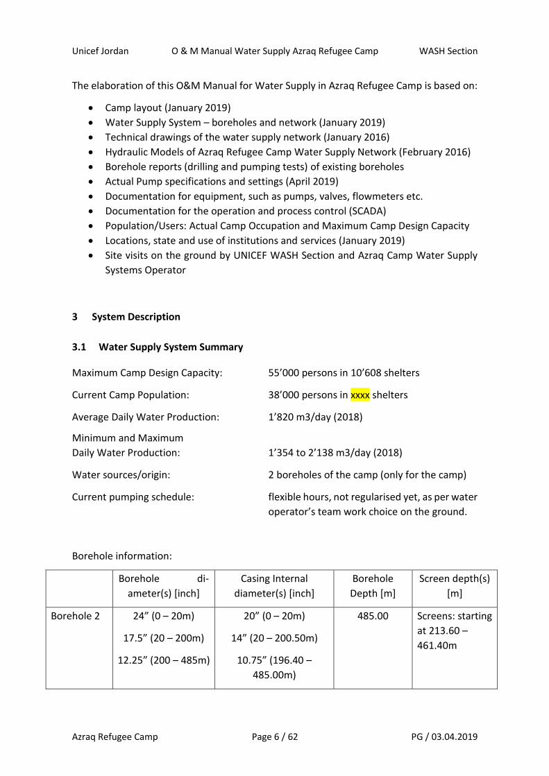
Borehole information:
Borehole di-
ameter(s) [inch]
Casing Internal
diameter(s) [inch]
Borehole
Depth [m]
Screen depth(s)
[m]
Borehole 2 24” (0 – 20m)
17.5” (20 – 200m)
12.25” (200 – 485m)
20” (0 – 20m)
14” (20 – 200.50m)
10.75” (196.40 –
485.00m)
485.00
Screens: starting
at 213.60 –
461.40m
Unicef Jordan O & M Manual Water Supply Azraq Refugee Camp WASH Section
Azraq Refugee Camp Page 7 / 62 PG / 03.04.2019
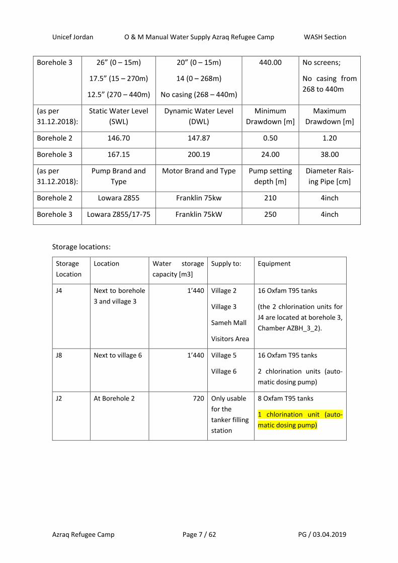
Borehole 3 26” (0 – 15m)
17.5” (15 – 270m)
12.5” (270 – 440m)
20” (0 – 15m)
14 (0 – 268m)
No casing (268 – 440m)
440.00 No screens;
No casing from
268 to 440m
(as per
31.12.2018):
Static Water Level
(SWL)
Dynamic Water Level
(DWL)
Minimum
Drawdown [m]
Maximum
Drawdown [m]
Borehole 2 146.70 147.87 0.50 1.20
Borehole 3 167.15 200.19 24.00 38.00
(as per
31.12.2018):
Pump Brand and
Type
Motor Brand and Type Pump setting
depth [m]
Diameter Rais-
ing Pipe [cm]
Borehole 2 Lowara Z855 Franklin 75kw 210 4inch
Borehole 3 Lowara Z855/17-75 Franklin 75kW 250 4inch
Storage locations:
Storage
Location
Location Water storage
capacity [m3]
Supply to: Equipment
J4 Next to borehole
3 and village 3
1’440 Village 2
Village 3
Sameh Mall
Visitors Area
16 Oxfam T95 tanks
(the 2 chlorination units for
J4 are located at borehole 3,
Chamber AZBH_3_2).
J8 Next to village 6 1’440 Village 5
Village 6
16 Oxfam T95 tanks
2 chlorination units (auto-
matic dosing pump)
J2 At Borehole 2 720 Only usable
for the
tanker filling
station
8 Oxfam T95 tanks
1 chlorination unit (auto-
matic dosing pump)

Unicef Jordan O & M Manual Water Supply Azraq Refugee Camp WASH Section
Azraq Refugee Camp Page 8 / 62 PG / 03.04.2019
Designed/Target daily water provision: 35 lcd (litres per capita per day)
Current water supply schedule:
Summer (from …… to ………. )
Supply Time 1 Supply Time 2 From Storage Total time
Village 2 7.00 – 9.00 14.00 – 16.00 J4 4h
Village 3 9.00 – 11.00 16.00 – 18.00 J4 4h
Village 5 7.00 – 9.00 14.00 – 16.00 J8 4h
Village 6 9.00 – 11.00 16.00 – 18.00 J8 4h
Winter (from …… to ………. )
Supply Time 1 Supply Time 2 From Storage Total time
Village 2 7.00 – 9.00 14.00 – 16.00 J4 4h
Village 3 7.00 – 9.00 14.00 – 16.00 J4 4h
Village 5 7.00 – 9.00 14.00 – 16.00 J8 4h
Village 6 7.00 – 9.00 14.00 – 16.00 J8 4h
Remarks on the water supply schedules:
• The water operator is on the ground at village level during the supply hours – and checks
if the needs have been covered or not. Therefore, the times are sometimes a bit longer
or shorter – than the standard ones indicated.
• Distribution schedule is only partly flexible – as water production from the 2 boreholes
is limited and water is blended before distribution (due to higher, but still acceptable
TDS concentrations (as per JS 286:2015) from borehole 3; this is mainly done because of
complaints from consumers and to increase the water taste (quality) provided to con-
sumers.
Water Quality (details see Water Quality Safety Plan Azraq Refugee Camp):
At borehole 2 (AZBH_2):
• Rapid sand filtration
• By the operator: Hourly monitoring of turbidity (NTU), and daily monitoring for pH, FRC,
and E.C. (for TDS by calculation) and Ammonium (not done yet); Monthly testing of TDS
(by gravimetric method) by the operator (not done yet)

Unicef Jordan O & M Manual Water Supply Azraq Refugee Camp WASH Section
Azraq Refugee Camp Page 9 / 62 PG / 03.04.2019
• By an external certified laboratory (Yarmouk) for the operator: Monthly testing of:
E. coli and Total coliforms + list of standard physical and chemical parameters (details
see Water Quality Safety Plan Azraq Refugee Camp).
• By monitoring body (MoH) through external certified laboratory (RSS): Every 6 months,
testing of: E. coli and Total coliforms + comprehensive list of all physical, chemical and
radiological parameters.
At borehole 3 (AZBH_3):
• Aeration tower for H2S elimination
• Rapid sand filtration
• Chlorination by automatic dosing pumps
• By the operator: Hourly monitoring of turbidity (NTU) and daily monitoring for pH, FRC,
and E.C. (for TDS by calculation) and Ammonium (not done yet); Monthly testing of TDS
(by gravimetric method) by the operator (not done yet)
• By an external certified laboratory (Yarmouk) for the operator: Monthly testing of:
E. coli and Total coliforms + list of standard physical and chemical parameters (details
see Water Quality Safety Plan Azraq Refugee Camp).
• By monitoring body (MoH) through external certified laboratory (RSS): Every 6 months,
testing of: E. coli and Total coliforms + comprehensive list of all physical, chemical and
radiological parameters.
At water storage station J4 (next to AZBH_3):
• No water treatment, as all done directly at borehole 3.
• FRC levels monitoring at T95 storage tanks and outlet level on a daily basis
• Turbidity monitoring on a daily basis
At water storage station J8 (next to Village 6):
• Chlorination by automatic dosing pumps solar powered (no network connection exist-
ing, but possible as network next to it close)
• FRC levels monitoring at T95 storage tanks and outlet level on a daily basis
• Turbidity monitoring on a daily basis
At water distribution network level:
• Water quality monitoring frequencies, monitoring parameters and monitoring locations,
please refer to/see in the Water Quality Safety Plan Azraq Refugee Camp.
• So far, the water operator does only FRC and E.C testing on a daily basis with a certain
amount of random samples at tapstands and chambers. Plan to do FRC, E.C, pH and
turbidity analysis on a daily basis at strategic tapstand locations (see Water Quality
Safety Plan Azraq Refugee Camp) plus monthly sampling for total coliforms and E. coli
at network level – which is not done until now.
Unicef Jordan O & M Manual Water Supply Azraq Refugee Camp WASH Section
Azraq Refugee Camp Page 10 / 62 PG / 03.04.2019
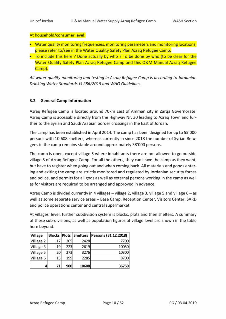
Village Blocks Plots Shelters Persons (31.12.2018)
Village 2 17 205 2428 7700
Village 3 19 223 2619 10050
Village 5 20 273 3276 10300
Village 6 15 199 2285 8700
4 71 900 10608 36750
At household/consumer level:
• Water quality monitoring frequencies, monitoring parameters and monitoring locations,
please refer to/see in the Water Quality Safety Plan Azraq Refugee Camp.
• To include this here ? Done actually by who ? To be done by who (to be clear for the
Water Quality Safety Plan Azraq Refugee Camp and this O&M Manual Azraq Refugee
Camp).
All water quality monitoring and testing in Azraq Refugee Camp is according to Jordanian
Drinking Water Standards JS 286/2015 and WHO Guidelines.
3.2 General Camp Information
Azraq Refugee Camp is located around 70km East of Amman city in Zarqa Governorate.
Azraq Camp is accessible directly from the Highway Nr. 30 leading to Azraq Town and fur-
ther to the Syrian and Saudi Arabian border crossings in the East of Jordan.
The camp has been established in April 2014. The camp has been designed for up to 55’000
persons with 10’608 shelters, whereas currently in since 2018 the number of Syrian Refu-
gees in the camp remains stable around approximately 38’000 persons.
The camp is open, except village 5 where inhabitants there are not allowed to go outside
village 5 of Azraq Refugee Camp. For all the others, they can leave the camp as they want,
but have to register when going out and when coming back. All materials and goods enter-
ing and exiting the camp are strictly monitored and regulated by Jordanian security forces
and police, and permits for all gods as well as external persons working in the camp as well
as for visitors are required to be arranged and approved in advance.
Azraq Camp is divided currently in 4 villages – village 2, village 3, village 5 and village 6 – as
well as some separate service areas – Base Camp, Reception Center, Visitors Center, SARD
and police operations center and central supermarket.
At villages’ level, further subdivision system is blocks, plots and then shelters. A summary
of these sub-divisions, as well as population figures at village level are shown in the table
here beyond:
Unicef Jordan O & M Manual Water Supply Azraq Refugee Camp WASH Section
Azraq Refugee Camp Page 11 / 62 PG / 03.04.2019
For the water supply in Azraq Refugee Camp, the division into villages is relevant, and the
lowest level to which the water supply network can be regulated for operation (see Section
3.3.).
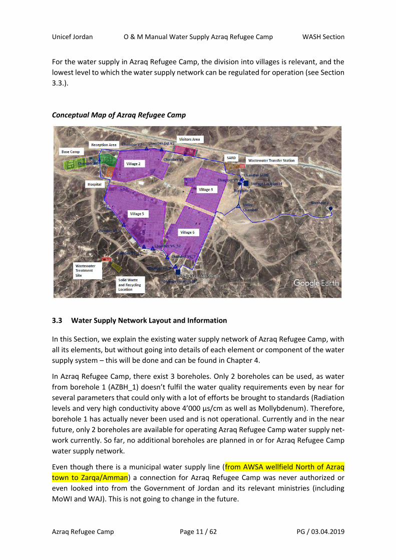
Conceptual Map of Azraq Refugee Camp
3.3 Water Supply Network Layout and Information
In this Section, we explain the existing water supply network of Azraq Refugee Camp, with
all its elements, but without going into details of each element or component of the water
supply system – this will be done and can be found in Chapter 4.
In Azraq Refugee Camp, there exist 3 boreholes. Only 2 boreholes can be used, as water
from borehole 1 (AZBH_1) doesn’t fulfil the water quality requirements even by near for
several parameters that could only with a lot of efforts be brought to standards (Radiation
levels and very high conductivity above 4’000 µs/cm as well as Mollybdenum). Therefore,
borehole 1 has actually never been used and is not operational. Currently and in the near
future, only 2 boreholes are available for operating Azraq Refugee Camp water supply net-
work currently. So far, no additional boreholes are planned in or for Azraq Refugee Camp
water supply network.
Even though there is a municipal water supply line (from AWSA wellfield North of Azraq
town to Zarqa/Amman) a connection for Azraq Refugee Camp was never authorized or
even looked into from the Government of Jordan and its relevant ministries (including
MoWI and WAJ). This is not going to change in the future.

Unicef Jordan O & M Manual Water Supply Azraq Refugee Camp WASH Section
Azraq Refugee Camp Page 12 / 62 PG / 03.04.2019
Water from the 2 boreholes are pumped to two storage locations – J4 station located at
borehole 3, and J8 station located next to village 6. From this two storage locations, the
water is distributed by gravity over a ring main pipeline around the camp to the 4 villages
and the service areas. The village level distribution systems are connected to the ring main
pipeline the following:
• For village 2: two connection lines; chamber J2 and chamber Ext V2
• For village 3: one connection line; chamber J4
• For village 5: three connection lines; chamber J6, chamber J5.1 and J5.2
• For village 6: two connection lines; chamber J7 and chamber J8
The locations of the boreholes, the storage locations, the ring main pipeline and the con-
nection chambers to the village levels are shown in the map beyond here.
Water Supply Network Azraq Refugee Camp – Main Level:
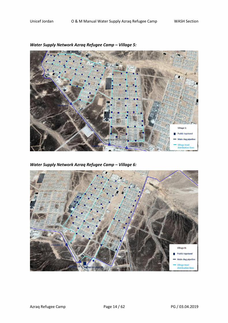
From each of the chambers on the ring main pipeline, a distribution line continues at village
level, with further branching to cover the whole area of the village. The distribution lines
at village level lead then to several public tapstands, where refugees collect their water.
There are no household connections in Azraq Refugee Camp for the water supply.
The following maps show the distribution networks and tapstands for each of the villages.

Unicef Jordan O & M Manual Water Supply Azraq Refugee Camp WASH Section
Azraq Refugee Camp Page 13 / 62 PG / 03.04.2019
Water Supply Network Azraq Refugee Camp – Village 2:
Water Supply Network Azraq Refugee Camp – Village 3:
Unicef Jordan O & M Manual Water Supply Azraq Refugee Camp WASH Section
Azraq Refugee Camp Page 14 / 62 PG / 03.04.2019
Water Supply Network Azraq Refugee Camp – Village 5:
Water Supply Network Azraq Refugee Camp – Village 6:
Unicef Jordan O & M Manual Water Supply Azraq Refugee Camp WASH Section
Azraq Refugee Camp Page 15 / 62 PG / 03.04.2019
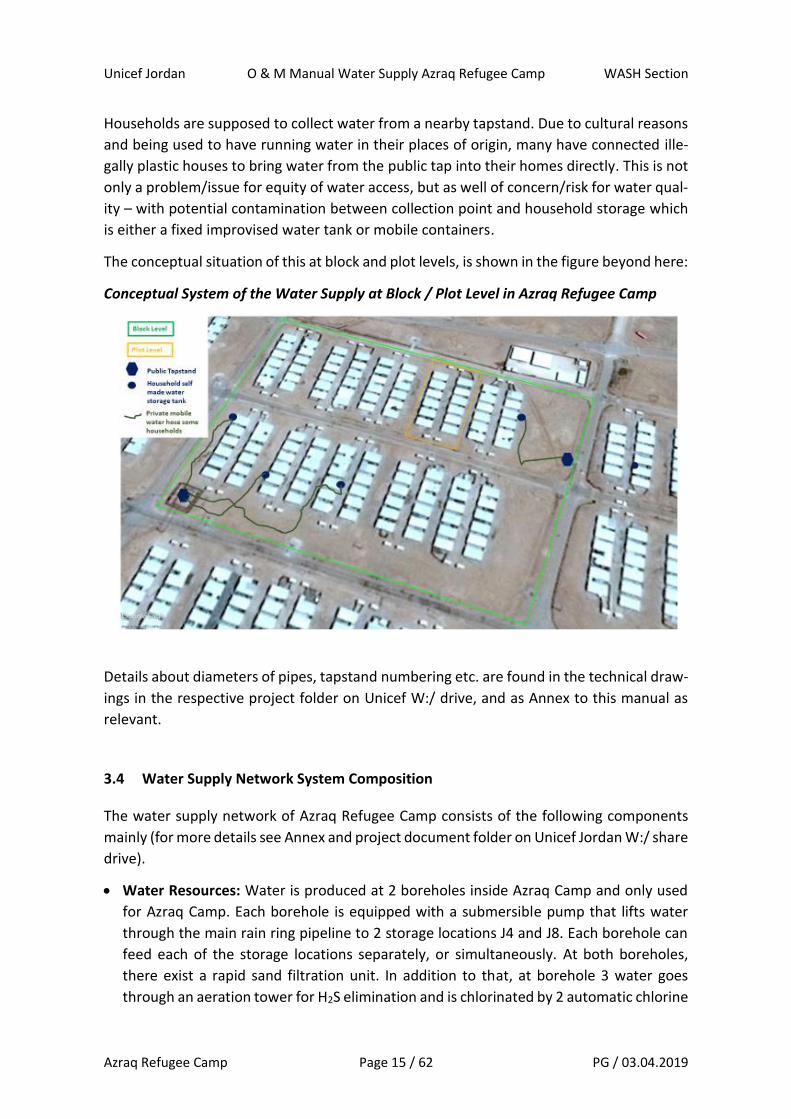
Households are supposed to collect water from a nearby tapstand. Due to cultural reasons
and being used to have running water in their places of origin, many have connected ille-
gally plastic houses to bring water from the public tap into their homes directly. This is not
only a problem/issue for equity of water access, but as well of concern/risk for water qual-
ity – with potential contamination between collection point and household storage which
is either a fixed improvised water tank or mobile containers.
The conceptual situation of this at block and plot levels, is shown in the figure beyond here:
Conceptual System of the Water Supply at Block / Plot Level in Azraq Refugee Camp
Details about diameters of pipes, tapstand numbering etc. are found in the technical draw-
ings in the respective project folder on Unicef W:/ drive, and as Annex to this manual as
relevant.
3.4 Water Supply Network System Composition
The water supply network of Azraq Refugee Camp consists of the following components
mainly (for more details see Annex and project document folder on Unicef Jordan W:/ share
drive).
• Water Resources: Water is produced at 2 boreholes inside Azraq Camp and only used
for Azraq Camp. Each borehole is equipped with a submersible pump that lifts water
through the main rain ring pipeline to 2 storage locations J4 and J8. Each borehole can
feed each of the storage locations separately, or simultaneously. At both boreholes,
there exist a rapid sand filtration unit. In addition to that, at borehole 3 water goes
through an aeration tower for H2S elimination and is chlorinated by 2 automatic chlorine
Unicef Jordan O & M Manual Water Supply Azraq Refugee Camp WASH Section
Azraq Refugee Camp Page 16 / 62 PG / 03.04.2019
dosing pumps, before sent to storage location J4 and J8. At borehole 2, no chlorination
is done.
• Storage: Two separate storage locations exist in Azraq Refugee Camp. At each location,
16 Oxfam Water Storage Tanks are installed, operational and used. Both locations have
a capacity of 1’440 m3 (around 90m3 usable of the T95 Oxfam tank – between outlet
and inlet levels). Storage Location J4 is feeding village 2 and village 3, as well as the camp
central supermarket, the reception area and SARD base. Storage location J8 is feeding
village 5 and village 6 mainly. Base Camp, Reception Area and the camp Hospital are at
the far point of the ring main pipeline, and therefore can and are fed by both storage
locations (depending on available flow rates and pressures situations in the overall sys-
tem). Storage location J8 is equipped with 2 automatic chlorination dosing pumps – used
to chlorinate water arriving from borehole 2.
At borehole 2, there is an additional storage location with 8 Oxfam Water Storage tanks
installed with a capacity of 720 m3 (around 90m3 usable of the T95 Oxfam tank – be-
tween outlet and inlet levels) which serve the tanker filling station – which is normally
no longer used. There is no possibility currently to pump water from this storage location
to the ring main pipeline or any of the villages, as no pump available/installed and no
network connection to the ring main pipeline. We call this storage location J2 (situated
at Borehole 2).
• Main ring pipeline: A main ring pipeline goes all around Azraq Refugee Camp, and with
connection to both boreholes. It is used on one hand for pumping water from the bore-
holes to the storage locations, as well as for the distribution to the villages by gravity.
Though, the eastern part of the ring main pipeline is exclusively used for the pumping
from the boreholes to the 2 storage locations, and can be isolated by gate-valves from
the western part, which is mainly used for the distribution of water to villages and ser-
vice areas by gravity. The ring main pipeline is HDPE, has a length of 13km and diameters
from 180 and 250mm in different sections.
• Village level flow control chambers: Village level flow control chambers are connected
to the ring main pipeline to regulate and control water distribution to villages and ser-
vice areas. All village level supply lines are connected to one of these flow control cham-
bers. Each flow control chamber is equipped with a manual gate-valve, a flow meter and
a tap for water sampling or/and air release if and as needed. The villages are supplied
through the following flow control chambers:
o Village 2: Chamber V2 ; Chamber Ext_V2
o Village 3: Chamber V3
o Village 5: Chamber V5_6; Chamber V5_51; Chamber V5_52
o Village 6: Chamber V6_7; Chamber V6_8
Village level flow meters reading are collected every day before and after each rotation
to know the quantities of water provided to each village (since March 2019).
• Village level distribution lines: The distribution system at village level is different in each
village. Some do have a separation into several individual lines after the village level flow

Unicef Jordan O & M Manual Water Supply Azraq Refugee Camp WASH Section
Azraq Refugee Camp Page 17 / 62 PG / 03.04.2019
chamber – such as for village 2, whereas for other villages only one line departs from
the village level flow control chamber, and then further branches out, without any fur-
ther flow regulation chambers inside the villages – such as village 3. Parts of the village
level distribution lines are sometimes single lines with end points, sometimes ring pipe-
lines (see detailed maps at village levels in the Annex and the project folder on Unicef
shared drive W:/). The same applies to service areas level distribution lines.
• Public tapstands: All public tapstands are supplied by the village level distribution lines.
There are no household level water connections in Azraq Refugee Camp. Though, some
refugees connect flexible plastic water houses (green garden houses) to public tapstands
to bring water to their self-made storage tanks and tap or mobile storage containers in
their homes (which is illegal basically as well as a risk for water quality, but tolerated and
difficult to control/enforce). In Azraq Refugee camp, there are the following number of
public tapstands per village:
o Village 2: 71 public tapstands
o Village 3: 82 public tapstands
o Village 5: 88 public tapstands
o Village 6: 59 public tapstands
o Total Azraq Camp: 300 tapstands
Each public tapstand is equipped with 4 taps (nozzles), and with a simple concrete plat-
form with simple surface drainage (no gravel packs for spill over and runoff infiltration)
leading to natural ground/drainage channels. Each tapstand can be isolated and cut off
from the village level distribution lines by a manually operated gate-valve at tapstand
level. No all tapstands are currently used, as not all areas in the camp are actually occu-
pied by refugees and some shelters empty and not used.
At service area and centres level, such as schools, makanis, health facilities, and NGO/in-
stitutions compounds, tapstands within buildings as well as, the village level distribution
lines are connected to water tanks, which are feeding then tapstands and toilet flushing
of the compounds and buildings in separate sub-networks.

Unicef Jordan O & M Manual Water Supply Azraq Refugee Camp WASH Section
Azraq Refugee Camp Page 18 / 62 PG / 03.04.2019
Systemic flow chart of Azraq Water Supply Network System:
The main components of the water supply system, as well as the main flow control gate
valves are shown in this systemic flow chart for Azraq Camp Water Supply Network.
4 Operation of the Water Supply System
4.1 Water production times and schedules requirements
The goal of the operation of Azraq Refugee Camp Water Supply System is to provide suffi-
cient safe drinking water for all refugees and services in the camp every day. The minimum
target value is to assure provision of 35 liters per person per day (35 lcd). This means a
minimum water production of 1’330 m3/day for 38’000 persons.
In 2018, the average daily water production in Azraq Camp was 1’820 m3/day – with a
minimum of 1’354 m3/day to a maximum of 2’138 m3/day. This means that in average 49
lcd were produced in 2018. From this, consumption for WASH outs, backwashing of sand-
filters, consumption of institutions, service areas and working personnel in the camp, as
well as water losses in the network still need to be deducted.
Based on the average borehole production rates in 2018, with 72.1 m3/h for borehole 2
and 43.2 m3/h for borehole 3, this means that both boreholes need to be operated for at
least 11.5 hours per day to assure the minimum water production of 1’330 m3/day. In order
to reach the average production of 2018, the minimum operation time of both boreholes
in Azraq Refugee Camp needs to be 15.8 hours per day.
Unicef Jordan O & M Manual Water Supply Azraq Refugee Camp WASH Section
Azraq Refugee Camp Page 19 / 62 PG / 03.04.2019
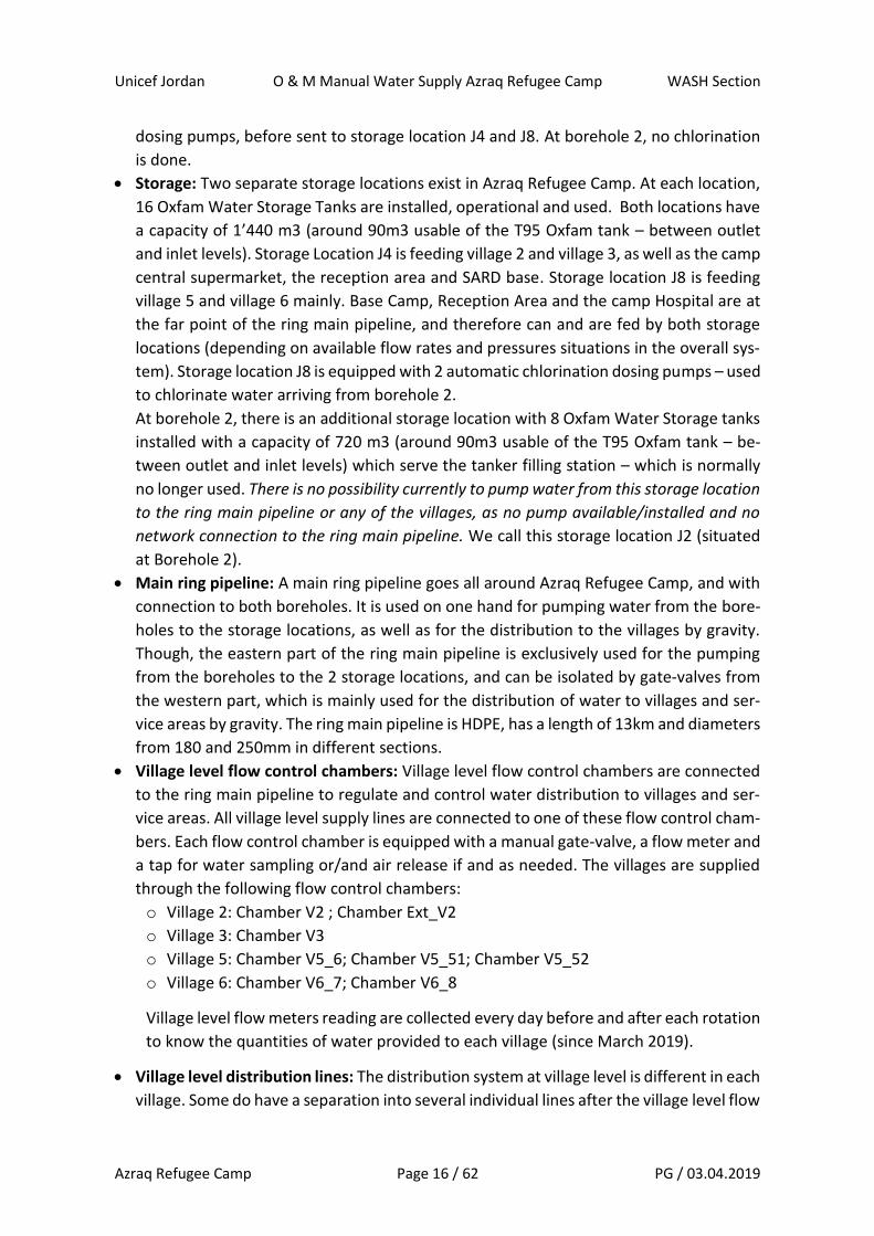
Operation times
required for wa-
ter production at
Azraq Refugee
Camp at average
production rates
of boreholes
For 38’000
persons at 35
lcd (Absolute
Minimum)
= 1’330
m3/day
For 38’000 per-
sons at 49 lcd
(Average 2018
– including
losses, institu-
tions, etc.)
= 1’820 m3/day
For 38’000 per-
sons at maxi-
mum demand in
2018
= 2’138 m3/day
For 55’000 per-
sons (camp
maximum ca-
pacity) at 35 lcd
= 1’925 m3/day
Borehole 2 11.5 h / day 15.8 h / day 18.6 h / day 16.7 h / day
Borehole 3 11.5 h / day 15.8 h / day 18.6 h / day 16.7 h / day
Both pumps / boreholes need to run for at least 12 hours per day, to assure production of
the minimum water quantity required in Azraq Refugee Camp. At peak demand in summer,
both boreholes need to be run for up to 18 hours per day.
In 2018, water was pumped from borehole 2 in average 16.3 hours per day, and from bore-
hole 3 in average 10.8 hours per day. If possible, it is reasonable to maximize the pumping
time at borehole 2, as the hourly production rate is 40% higher than at borehole 3 and as
the static water level remains much more stable with a decrease of 1.40m in 2018 com-
pared to 4.50 (3 times as much) in borehole 3.
Though, in terms of efficiency, one m3 of water produced from borehole 2 consumed in
average 0.361 lt of fuel, whereas for borehole 3 one m3 of water produced required only
0.293 lt of fuel – which is 20% less.
As water quality in borehole 3 is just within national standards for Total Dissolved Solids
(TDS), water from borehole 3 is blended with water from borehole 2 to reduce TDS content
level before distribution. As refugees have complained in the past about a smell and taste
level of the water provided.
That blending requires therefore a harmonized pumping schedule between borehole 2 and
borehole 3, which is generally the following:
1st step: pump from borehole 2 and borehole 3 to water storage station J8 station in the
morning for minimum 3 hours. Often, pumping time is around 4 hours.
2nd step: pump from borehole 2 and borehole 3 to water storage station J4 during mid-day
for minimum 5 hours. Often, pumping time is around 7 hours.
3rd step: pump from borehole 2 and boreholes 3 again to water storage station J8 in the
after-noon to evening for minimum 4 hours. Often, pumping time is around 5 hours.

Unicef Jordan O & M Manual Water Supply Azraq Refugee Camp WASH Section
Azraq Refugee Camp Page 20 / 62 PG / 03.04.2019
Therefore, both boreholes are pumping to the same water storage location simultaneously
at the same time. This is not only required due to blending, but as well the ring main pipe-
line of the camp would allow to pump water from borehole 3 to storage location J4 and
from borehole 2 to storage location J8 at the same time, but not the other way round.
Though, it is possible, from any borehole to pump to any storage location – if only one
borehole is operated – which sometimes happens in the morning for a bit, and again at the
end of the day for a bit.
The timetables indicated are based on the operation as carried out in 2018. For the Maxi-
mum Timetable, it would be possible to start 1 to 2 hours earlier with pumping, in order to
avoid spillover pumping time to the next morning early hours.
Pumping timetable during Ramadan is special – and different, as mainly going on during
night.
4.2 Operation Boreholes
Operation of the 2 boreholes of Azraq Refugee Camp is indicated here. The explanations
and indications given here refer to the regular operation mode. Emergency operation mode
and considerations, are explained in chapter xxxx.
Borehole 2 (AZBH_2) and equipment at borehole 2:
Borehole 2 is located about 2km east of village 6 and village 3 (GPS coordinates: 36.624178
/ 31.901361). AZBH_2 has the following characteristics:
Unicef Jordan O & M Manual Water Supply Azraq Refugee Camp WASH Section
Azraq Refugee Camp Page 21 / 62 PG / 03.04.2019
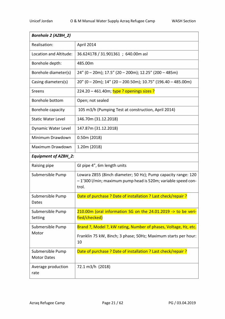
Borehole 2 (AZBH_2)
Realisation: April 2014
Location and Altitude: 36.624178 / 31.901361 ; 640.00m asl
Borehole depth: 485.00m
Borehole diameter(s) 24” (0 – 20m); 17.5” (20 – 200m); 12.25” (200 – 485m)
Casing diameters(s) 20” (0 – 20m); 14” (20 – 200.50m); 10.75” (196.40 – 485.00m)
Sreens 224.20 – 461.40m; type ? openings sizes ?
Borehole bottom Open; not sealed
Borehole capacity 105 m3/h (Pumping Test at construction, April 2014)
Static Water Level 146.70m (31.12.2018)
Dynamic Water Level 147.87m (31.12.2018)
Minimum Drawdown 0.50m (2018)
Maximum Drawdown 1.20m (2018)
Equipment of AZBH_2:
Raising pipe GI pipe 4”, 6m length units
Submersible Pump Lowara Z855 (8inch diameter; 50 Hz); Pump capacity range: 120
– 1’300 l/min; maximum pump head is 520m; variable speed con-
trol.
Submersible Pump
Dates
Date of purchase ? Date of installation ? Last check/repair ?
Submersible Pump
Setting
210.00m (oral information SG on the 24.01.2019 -> to be veri-
fied/checked)
Submersible Pump
Motor
Brand ?, Model ?, kW rating, Number of phases, Voltage, Hz, etc.
Franklin 75 kW, 8inch; 3 phase; 50Hz; Maximum starts per hour:
10
Submersible Pump
Motor Dates
Date of purchase ? Date of installation ? Last check/repair ?
Average production
rate
72.1 m3/h (2018)
Unicef Jordan O & M Manual Water Supply Azraq Refugee Camp WASH Section
Azraq Refugee Camp Page 22 / 62 PG / 03.04.2019
Average production
time
978 Minutes per day = 16h and 18 minutes (2018)
Average water pro-
duction
1’175 m3/day (2018)
Borehole monitoring
probe
Brand, Type, Parameters monitored
Senator Plus, Temperature, Pressure, Water Level, E.C.
Borehole monitoring
probe depth setting
Depth ? (and Date at which the depth information is from)
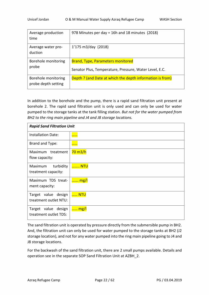
In addition to the borehole and the pump, there is a rapid sand filtration unit present at
borehole 2. The rapid sand filtration unit is only used and can only be used for water
pumped to the storage tanks at the tank filling station. But not for the water pumped from
BH2 to the ring main pipeline and J4 and J8 storage locations.
Rapid Sand Filtration Unit
Installation Date: ……
Brand and Type: ……
Maximum treatment
flow capacity:
70 m3/h
Maximum turbidity
treatment capacity:
…….. NTU
Maximum TDS treat-
ment capacity:
……. mg/l
Target value design
treatment outlet NTU:
…… NTU
Target value design
treatment outlet TDS:
…… mg/l
The sand filtration unit is operated by pressure directly from the submersible pump in BH2.
And, the filtration unit can only be used for water pumped to the storage tanks at BH2 (J2
storage location), and not for any water pumped into the ring main pipeline going to J4 and
J8 storage locations.
For the backwash of the sand filtration unit, there are 2 small pumps available. Details and
operation see in the separate SOP Sand Filtration Unit at AZBH_2.
Unicef Jordan O & M Manual Water Supply Azraq Refugee Camp WASH Section
Azraq Refugee Camp Page 23 / 62 PG / 03.04.2019
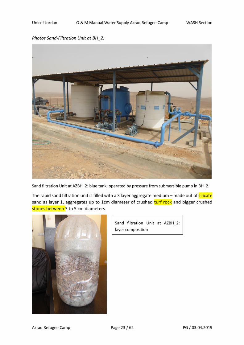
Photos Sand-Filtration Unit at BH_2:
Sand filtration Unit at AZBH_2: blue tank; operated by pressure from submersible pump in BH_2.
The rapid sand filtration unit is filled with a 3 layer aggregate medium – made out of silicate
sand as layer 1, aggregates up to 1cm diameter of crushed turf rock and bigger crushed
stones between 3 to 5 cm diameters.
Sand filtration Unit at AZBH_2:
layer composition
Unicef Jordan O & M Manual Water Supply Azraq Refugee Camp WASH Section
Azraq Refugee Camp Page 24 / 62 PG / 03.04.2019
The details of pumps, connections, valves, operation of the sand filtration unit at AZBH_2
are indicated in the specific SOP Sand filtration Unit AZBH_2 – separately from this docu-
ment.
Borehole 2 equipment is powered by generator – as no grid connection was allowed to be
established. The national grid is passing next to the camp, so a connection would be possi-
ble, if given permission from the relevant ministry and the grid operator (which so far has
not been given).
There are two big generators present at borehole 2 to power the submersible pump, which
are used by alternation – meaning generator 1 one day, then generator 2 the next day, then
again generator 1, and so on.
In addition to this, there is a smaller service generator to be used outside pump operating
hours for the office and staff accommodation caravans at BH2.
The characteristics of the generators at Borehole 2 are indicated here:
Generator 1:
Asset Number: ……
Installation Date: ……
Brand and Type: Perkins….
Power Rating (kVA): 250 kVA
Number of Phases: ……..
Motor information: …….
Alternator
information:
……
Control Panel
Information:
……
Fuel Tank
Information:
Integrated fuel tank, but used currently supplied from the sepa-
rate 7’000 lt fuel tank.
Generator 2:
Asset Number: ……
Installation Date: ……
Brand and Type: Cumins…

Unicef Jordan O & M Manual Water Supply Azraq Refugee Camp WASH Section
Azraq Refugee Camp Page 25 / 62 PG / 03.04.2019
Power Rating (kVA): 220 kVA
Number of Phases: ……..
Motor information: …….
Alternator
information:
……
Control Panel
Information:
……
Fuel Tank
Information:
Integrated fuel tank, but used currently supplied from the sepa-
rate 7’000 lt fuel tank.
Generator 3:
Asset Number: ……
Installation Date: ……
Brand and Type: Perkins….
Power Rating (kVA): 55 kVA
Number of Phases: ……..
Motor information: …….
Alternator
information:
……
Control Panel
Information:
……
Fuel Tank
Information:
Integrated fuel tank, but used currently supplied from the sepa-
rate 7’000 lt fuel tank.
Photo of generators and
fuel tank at AZBH_2
Unicef Jordan O & M Manual Water Supply Azraq Refugee Camp WASH Section
Azraq Refugee Camp Page 26 / 62 PG / 03.04.2019
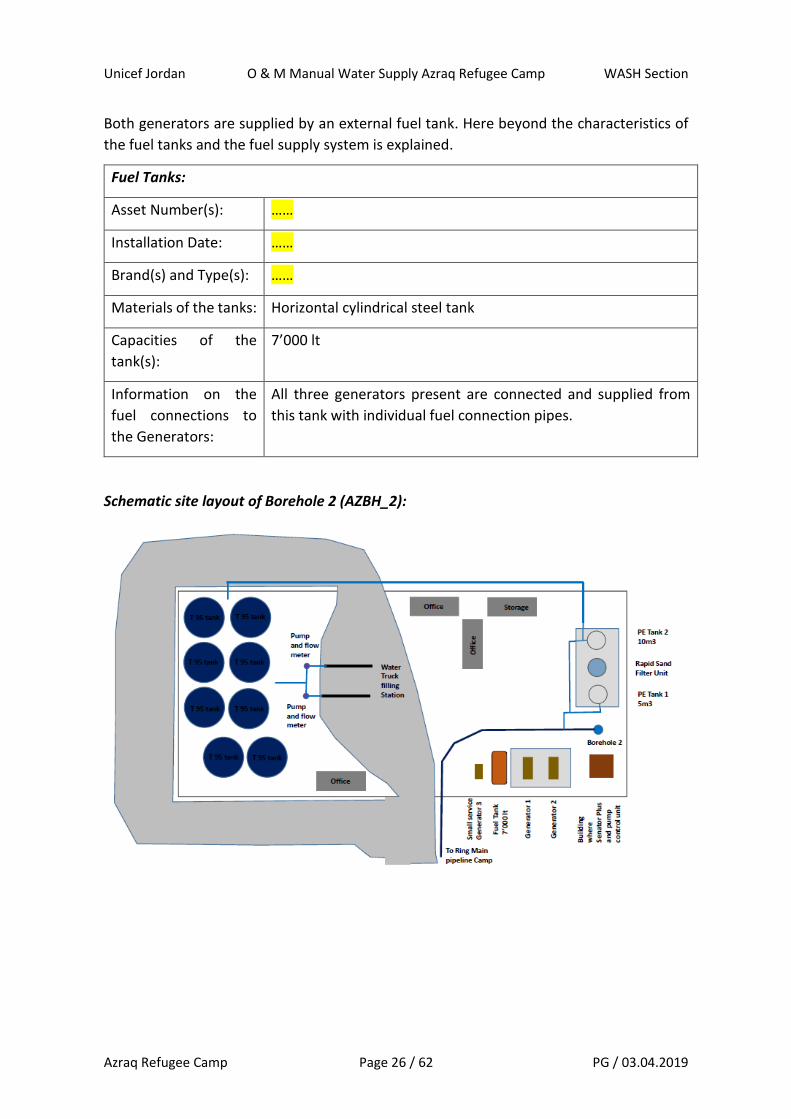
Both generators are supplied by an external fuel tank. Here beyond the characteristics of
the fuel tanks and the fuel supply system is explained.
Fuel Tanks:
Asset Number(s): ……
Installation Date: ……
Brand(s) and Type(s): ……
Materials of the tanks: Horizontal cylindrical steel tank
Capacities of the
tank(s):
7’000 lt
Information on the
fuel connections to
the Generators:
All three generators present are connected and supplied from
this tank with individual fuel connection pipes.
Schematic site layout of Borehole 2 (AZBH_2):
Unicef Jordan O & M Manual Water Supply Azraq Refugee Camp WASH Section
Azraq Refugee Camp Page 27 / 62 PG / 03.04.2019
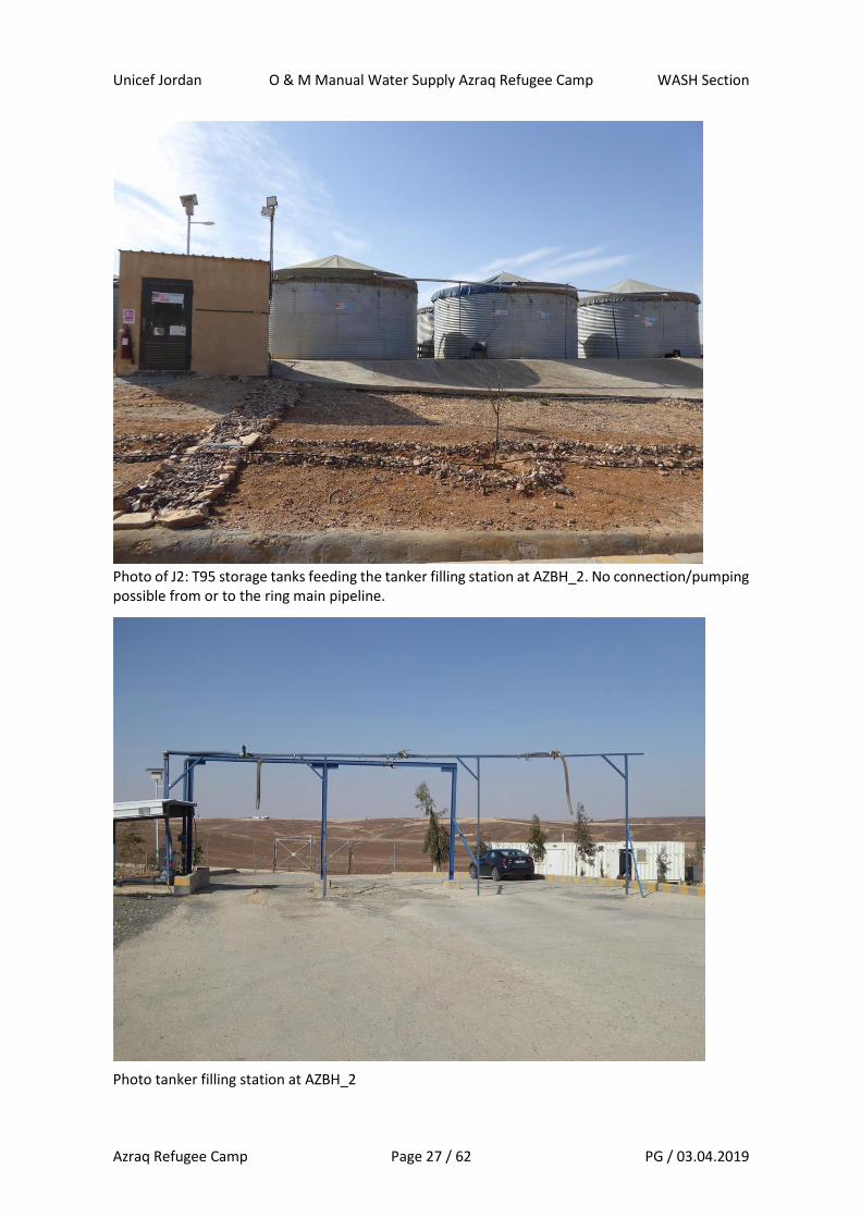
Photo of J2: T95 storage tanks feeding the tanker filling station at AZBH_2. No connection/pumping possible from or to the ring main pipeline.
Photo tanker filling station at AZBH_2

Unicef Jordan O & M Manual Water Supply Azraq Refugee Camp WASH Section
Azraq Refugee Camp Page 28 / 62 PG / 03.04.2019
Borehole 2 (AZBH_2) operation:
Azraq Borehole 2 is equipped with a submersible pump (details given before). The submers-
ible pump is powered by one of the 2 generators at a time available and in use at AZBH_2.
From the borehole water can be pumped to 4 locations, by opening/closing respective
gate-valves:
1) To storage location J4 at AZBH_3 via the ring-main pipeline – and the chamber in
the valley
2) To storage location J8 next to village 6 via the ring main pipeline – and the chamber
in the valley
3) To the sand-filtration unit at AZBH_2, and then to the storage location of the tanker
filling station at AZBH_2 (J2)
4) Directly to the storage location of the tanker filling station at AZBH_2 (J2)
5) Pumping to the Wash-out at AZBH_2 (Cleanout)
The valley chamber (VACB) is the one on the ring-main pipeline that allows to choose/direct
if water from BH_2 is pumped to storage location J4 (at AZBH_3) or to storage location J8
(next to village 6). Currently, in this camber in the valley (VACB) – all gate valves are open,
and none are operated in usual operation mode chosen by the current operator. The flow
to storage locations J4 and J8 are controlled by closing the respective gate valve at the entry
of either of the stations, in order to supply the other one.
But, the VACB gives the possibility, to close gate valves there to choose/block the line to
storage locations J4 and J8, depending on which one wants to be supplied and when. But,
this needs that one person physically goes there to operate the gate valves at each time,

Unicef Jordan O & M Manual Water Supply Azraq Refugee Camp WASH Section
Azraq Refugee Camp Page 29 / 62 PG / 03.04.2019
as the gate valves are not connected to a remote controlled operation system (SCADA for
example).
Beyond here, the layout plan and gate valve configuration at AZBH_2 and at VCAB as well
as storage location J4 and J8 are given, for each of the 4 situations/pumping destinations
to be served/pumped water to.
1) Pumping from AZBH_2 to storage location J4 (at AZBH_3):
2) Pumping from AZBH_2 to storage location J8 (next to village 6):

Unicef Jordan O & M Manual Water Supply Azraq Refugee Camp WASH Section
Azraq Refugee Camp Page 30 / 62 PG / 03.04.2019
3) Pumping from AZBH_2 to the sand filtration unit at AZBH_2:
4) Pumping from AZBH_2 to storage tanks T95 at AZBH2 (called storage location J2):
Unicef Jordan O & M Manual Water Supply Azraq Refugee Camp WASH Section
Azraq Refugee Camp Page 31 / 62 PG / 03.04.2019
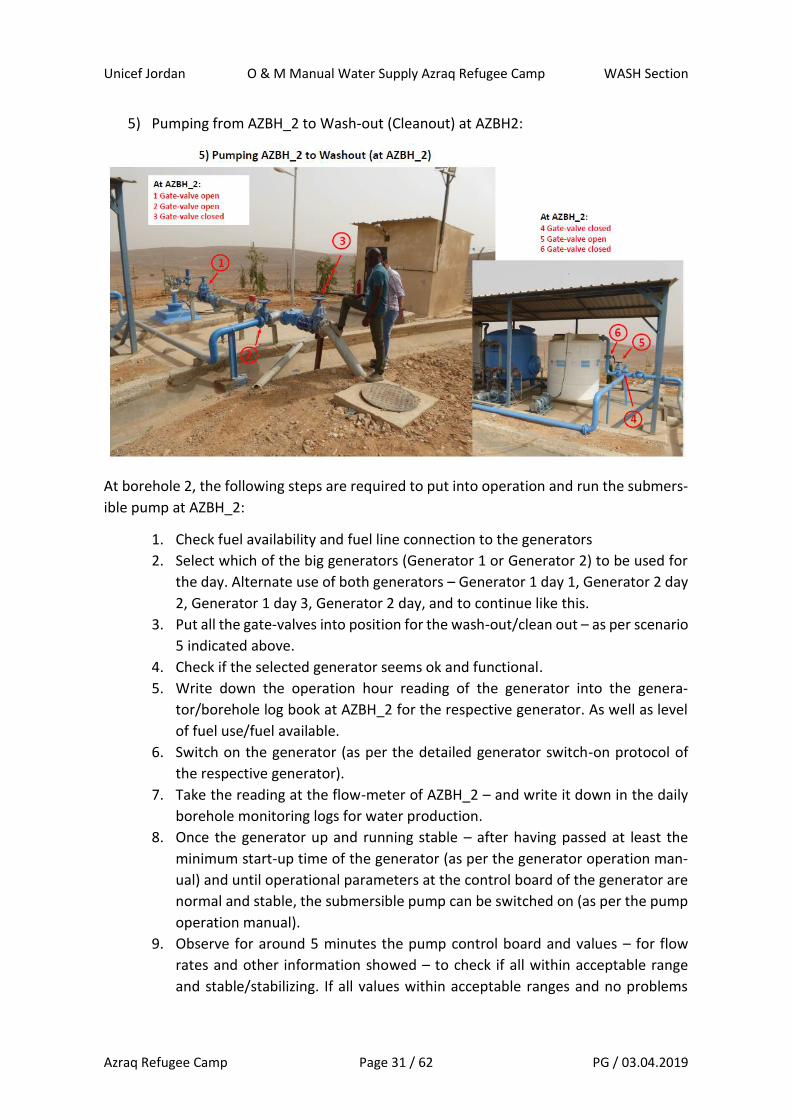
5) Pumping from AZBH_2 to Wash-out (Cleanout) at AZBH2:
At borehole 2, the following steps are required to put into operation and run the submers-
ible pump at AZBH_2:
1. Check fuel availability and fuel line connection to the generators
2. Select which of the big generators (Generator 1 or Generator 2) to be used for
the day. Alternate use of both generators – Generator 1 day 1, Generator 2 day
2, Generator 1 day 3, Generator 2 day, and to continue like this.
3. Put all the gate-valves into position for the wash-out/clean out – as per scenario
5 indicated above.
4. Check if the selected generator seems ok and functional.
5. Write down the operation hour reading of the generator into the genera-
tor/borehole log book at AZBH_2 for the respective generator. As well as level
of fuel use/fuel available.
6. Switch on the generator (as per the detailed generator switch-on protocol of
the respective generator).
7. Take the reading at the flow-meter of AZBH_2 – and write it down in the daily
borehole monitoring logs for water production.
8. Once the generator up and running stable – after having passed at least the
minimum start-up time of the generator (as per the generator operation man-
ual) and until operational parameters at the control board of the generator are
normal and stable, the submersible pump can be switched on (as per the pump
operation manual).
9. Observe for around 5 minutes the pump control board and values – for flow
rates and other information showed – to check if all within acceptable range
and stable/stabilizing. If all values within acceptable ranges and no problems
Unicef Jordan O & M Manual Water Supply Azraq Refugee Camp WASH Section
Azraq Refugee Camp Page 32 / 62 PG / 03.04.2019
indicated/seen, pumping to continue. If doubts and values not stabilizing, con-
tinue to observe for further time, until values stabilize, or until pump shuts
down by own protection mechanisms. Do not switch off the pump unless really
big concerns – as number of restarts of the pump per time are limited and can
cause damage to the pump.
10. After pump running stable, check on values for the water quality parameters
measured by the senator-pro probe at their indication panels in the service
building next to AZBH_2. And, take water sample at the sampling tap at AZBH_2
and do the relevant tests for additional parameters- such as turbidity (NTU),
ammonium (N-NH4), and pH. Once all parameters ok as required for drinking
water, continue with next step (step Nr. 9). Write down all parameters tested
for with time and testing results in the borehole log of AZBH_2.
11. Change all the gate-valves into the required position – as per the destination
location where you want to pump the water to (see scenarios 1 to 4 explained
above). And, inform the respective team at storage location J4 or J8, that you
will be starting to pump water their way (so they’re aware and can check on the
flow arriving in terms of quantities and qualities).
12. Write down time when you started pumping with indication to what destina-
tion, into the AZBH_2 logbook and water production templates.
13. During pumping, every hour, write down water quality parameters E.C, pH, tem-
perature in the borehole/water production log book of AZBH_2. Take samples
and analyse turbidity each hour and write down the testing time and results in
the borehole/water production log book of AZBH_2 as well.
14. Write down flow-meter reading each time, a change in the gate-valve setting is
done, and indicate to which direction water is pumped now, and the end of
pumping to the location set/served before.
15. Once the required quantities pumped for the day, switch off the pump (as per
the pump operation manual procedure). And, read flow-meter and write into
the logbook together with the time of pumping end.
16. Switch off the generator used (as per the generator operation manual switch-
off procedure), once the pump has been switched off and stopped. Write down
operation switch off time of the generator, operation hours and fuel use into
the generator and borehole log book of AZBH_2.
17. Before any restart of the pump, respect the minimum rest time required for the
pump as per the pump operation manual. Otherwise, you will damage the
pump/pump motor.
Any other operations/instructions for borehole 2 activities ? Make SOP for sand filtration
unit and SOP for water tanker filling station separately in separate documents. For genera-
tor start up and switch-off, as well as for submersible pump start and switch-off, see user
Unicef Jordan O & M Manual Water Supply Azraq Refugee Camp WASH Section
Azraq Refugee Camp Page 33 / 62 PG / 03.04.2019
manuals/procedure done by contractor – and see if user manual ok, or if need to make a
laminated card that will be put at the generators and at the pump.
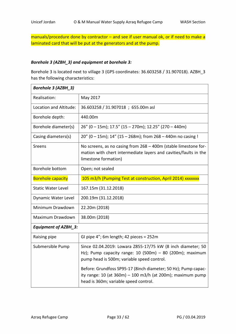
Borehole 3 (AZBH_3) and equipment at borehole 3:
Borehole 3 is located next to village 3 (GPS coordinates: 36.603258 / 31.907018). AZBH_3
has the following characteristics:
Borehole 3 (AZBH_3)
Realisation: May 2017
Location and Altitude: 36.603258 / 31.907018 ; 655.00m asl
Borehole depth: 440.00m
Borehole diameter(s) 26” (0 – 15m); 17.5” (15 – 270m); 12.25” (270 – 440m)
Casing diameters(s) 20” (0 – 15m); 14” (15 – 268m); from 268 – 440m no casing !
Sreens No screens, as no casing from 268 – 400m (stable limestone for-
mation with chert intermediate layers and cavities/faults in the
limestone formation)
Borehole bottom Open; not sealed
Borehole capacity 105 m3/h (Pumping Test at construction, April 2014) xxxxxxx
Static Water Level 167.15m (31.12.2018)
Dynamic Water Level 200.19m (31.12.2018)
Minimum Drawdown 22.20m (2018)
Maximum Drawdown 38.00m (2018)
Equipment of AZBH_3:
Raising pipe GI pipe 4”; 6m length; 42 pieces = 252m
Submersible Pump Since 02.04.2019: Lowara Z855-17/75 kW (8 inch diameter; 50
Hz); Pump capacity range: 10 (500m) – 80 (200m); maximum
pump head is 500m; variable speed control.
Before: Grundfoss SP95-17 (8inch diameter; 50 Hz); Pump capac-
ity range: 10 (at 360m) – 100 m3/h (at 200m); maximum pump
head is 360m; variable speed control.
Unicef Jordan O & M Manual Water Supply Azraq Refugee Camp WASH Section
Azraq Refugee Camp Page 34 / 62 PG / 03.04.2019
Submersible Pump
Dates
Installation on the 02.04.2019; Used pump from Rhukban
Submersible Pump
Setting
252.00m (42 main raising pipes 6m each = 252m)
Submersible Pump
Motor
Now: Franklin 75kW rewindable (Model Nr. 2636145311 – DOL;
304; PE2/PA windings) 3 phase; 50Hz at 380-415 V (and 60Hz at
460 V); Maximum starts per hour: 10; VFD approved (30 to 50 Hz
resp. 30 to 60 Hz (at 460V)).
Before: Franklin 75kW (Model Nr. 2396047043); 3 phase; 50 Hz;
Maximum starts per hour: 10; VFD approved.
Submersible Pump
Motor Dates
New motor installed on the 02.04.2019; not used before
Average production
rate
43.2 m3/h (2018)
Average production
time
918 Minutes per day = 15h and 18 minutes (2018)
Average water pro-
duction
645 m3/day (2018)
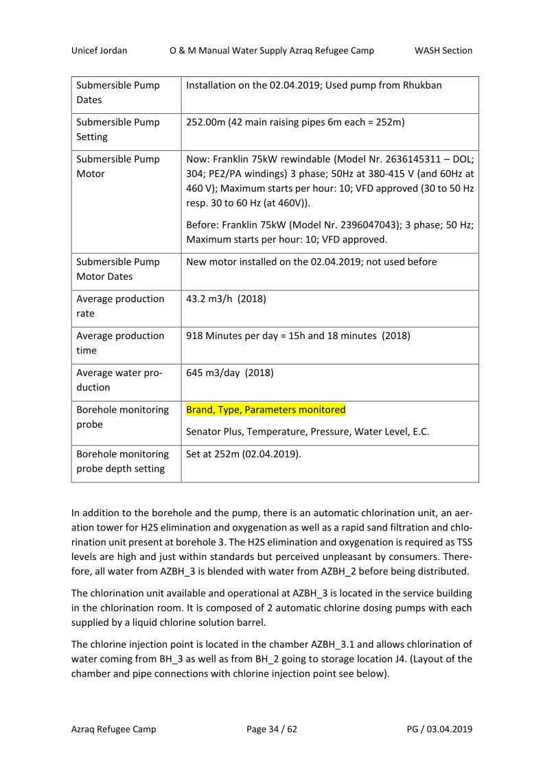
Borehole monitoring
probe
Brand, Type, Parameters monitored
Senator Plus, Temperature, Pressure, Water Level, E.C.
Borehole monitoring
probe depth setting
Set at 252m (02.04.2019).
In addition to the borehole and the pump, there is an automatic chlorination unit, an aer-
ation tower for H2S elimination and oxygenation as well as a rapid sand filtration and chlo-
rination unit present at borehole 3. The H2S elimination and oxygenation is required as TSS
levels are high and just within standards but perceived unpleasant by consumers. There-
fore, all water from AZBH_3 is blended with water from AZBH_2 before being distributed.
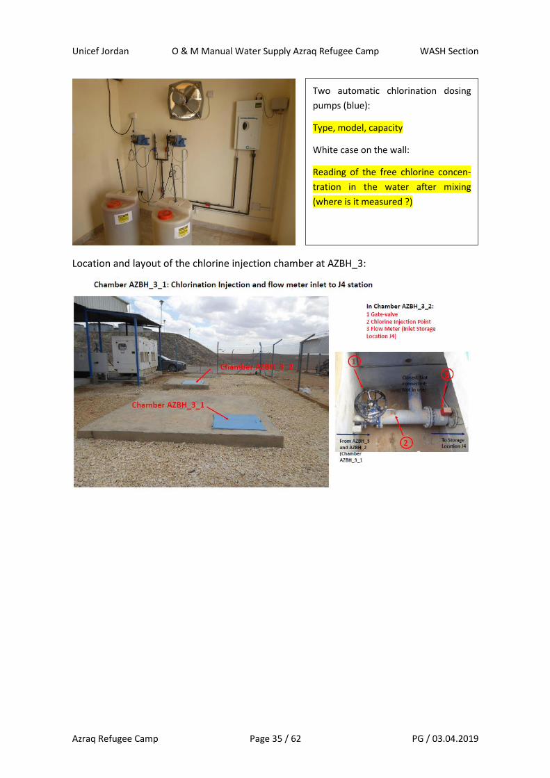
The chlorination unit available and operational at AZBH_3 is located in the service building
in the chlorination room. It is composed of 2 automatic chlorine dosing pumps with each
supplied by a liquid chlorine solution barrel.
The chlorine injection point is located in the chamber AZBH_3.1 and allows chlorination of
water coming from BH_3 as well as from BH_2 going to storage location J4. (Layout of the
chamber and pipe connections with chlorine injection point see below).
Unicef Jordan O & M Manual Water Supply Azraq Refugee Camp WASH Section
Azraq Refugee Camp Page 35 / 62 PG / 03.04.2019
Location and layout of the chlorine injection chamber at AZBH_3:
Two automatic chlorination dosing
pumps (blue):
Type, model, capacity
White case on the wall:
Reading of the free chlorine concen-
tration in the water after mixing
(where is it measured ?)
Unicef Jordan O & M Manual Water Supply Azraq Refugee Camp WASH Section
Azraq Refugee Camp Page 36 / 62 PG / 03.04.2019
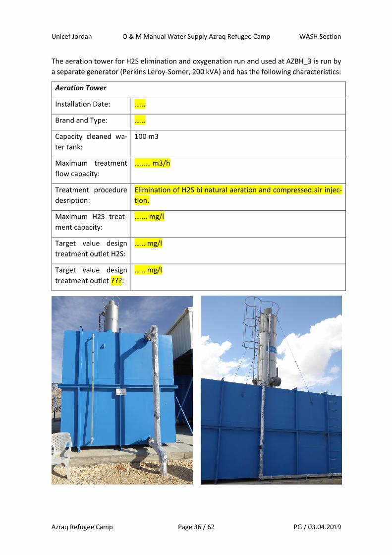
The aeration tower for H2S elimination and oxygenation run and used at AZBH_3 is run by
a separate generator (Perkins Leroy-Somer, 200 kVA) and has the following characteristics:
Aeration Tower
Installation Date: ……
Brand and Type: ……
Capacity cleaned wa-
ter tank:
100 m3
Maximum treatment
flow capacity:
……… m3/h
Treatment procedure
desription:
Elimination of H2S bi natural aeration and compressed air injec-
tion.
Maximum H2S treat-
ment capacity:
……. mg/l
Target value design
treatment outlet H2S:
…… mg/l
Target value design
treatment outlet ???:
…… mg/l
Unicef Jordan O & M Manual Water Supply Azraq Refugee Camp WASH Section
Azraq Refugee Camp Page 37 / 62 PG / 03.04.2019
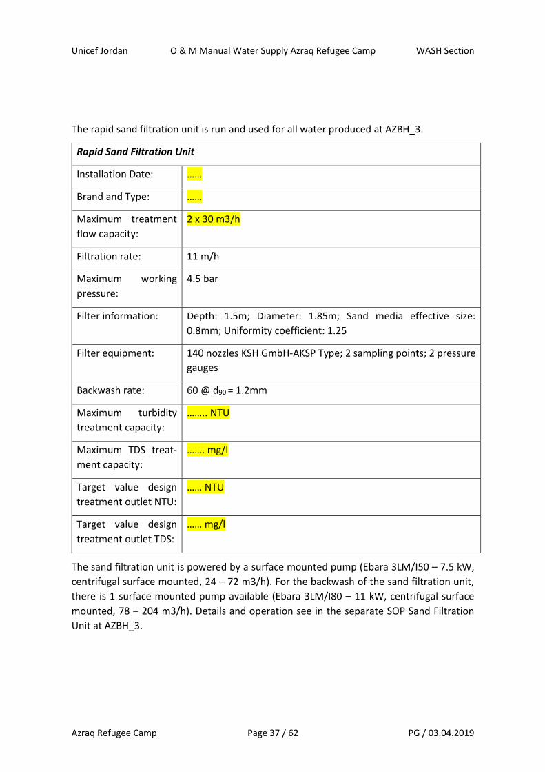
The rapid sand filtration unit is run and used for all water produced at AZBH_3.
Rapid Sand Filtration Unit
Installation Date: ……
Brand and Type: ……
Maximum treatment
flow capacity:
2 x 30 m3/h
Filtration rate: 11 m/h
Maximum working
pressure:
4.5 bar
Filter information: Depth: 1.5m; Diameter: 1.85m; Sand media effective size:
0.8mm; Uniformity coefficient: 1.25
Filter equipment: 140 nozzles KSH GmbH-AKSP Type; 2 sampling points; 2 pressure
gauges
Backwash rate: 60 @ d90 = 1.2mm
Maximum turbidity
treatment capacity:
…….. NTU
Maximum TDS treat-
ment capacity:
……. mg/l
Target value design
treatment outlet NTU:
…… NTU
Target value design
treatment outlet TDS:
…… mg/l
The sand filtration unit is powered by a surface mounted pump (Ebara 3LM/I50 – 7.5 kW,
centrifugal surface mounted, 24 – 72 m3/h). For the backwash of the sand filtration unit,
there is 1 surface mounted pump available (Ebara 3LM/I80 – 11 kW, centrifugal surface
mounted, 78 – 204 m3/h). Details and operation see in the separate SOP Sand Filtration
Unit at AZBH_3.

Unicef Jordan O & M Manual Water Supply Azraq Refugee Camp WASH Section
Azraq Refugee Camp Page 38 / 62 PG / 03.04.2019
Photos Sand-Filtration Unit at AZBH_3:
The rapid sand filtration unit is filled with a 3 layer aggregate medium – made out of silicate
sand as layer 1, aggregates up to 1cm diameter of crushed turf rock and bigger crushed
stones between 3 to 5 cm diameters.
Sand filtration Unit at AZBH_3: layer composition
Sand filtration Unit
at AZBH_3: 2 blue
tanks; operated by
pressure from sur-
face mounted
pumps for inlet (up)
and backwash
(down).

Unicef Jordan O & M Manual Water Supply Azraq Refugee Camp WASH Section
Azraq Refugee Camp Page 39 / 62 PG / 03.04.2019
The details of pumps, connections, valves, operation of the sand filtration unit at AZBH_3
are indicated in the specific SOP Sand filtration Unit AZBH_3 – separately from this docu-
ment.
Borehole 3 equipment is powered by generator – as no grid connection was allowed to be
established. The national grid is passing next to the camp, so a connection would be possi-
ble, if given permission from the relevant ministry and the grid operator (which so far has
not been given).
There are two big generators present at borehole 2 to power the submersible pump, which
are used by alternation – meaning generator 1 one day, then generator 2 the next day, then
again generator 1, and so on.
A third big generator (200 kVA) is present and used to run the aeration tower for H2S elim-
ination and oxygenation.
In addition to this, there is a smaller service generator to be used outside pump operating
hours for the office/service building at BH3.
The characteristics of the generators at Borehole 3 are indicated here:
Generator 1:
Asset Number: ……
Installation Date: ……
Brand and Type: Perkins….
Power Rating (kVA): 250 kVA
Number of Phases: ……..
Motor information: …….
Alternator
information:
……
Control Panel
Information:
……
Fuel Tank
Information:
Integrated fuel tank, but used currently supplied from the 3 sep-
arate 2’000 lt fuel tanks.
Unicef Jordan O & M Manual Water Supply Azraq Refugee Camp WASH Section
Azraq Refugee Camp Page 40 / 62 PG / 03.04.2019
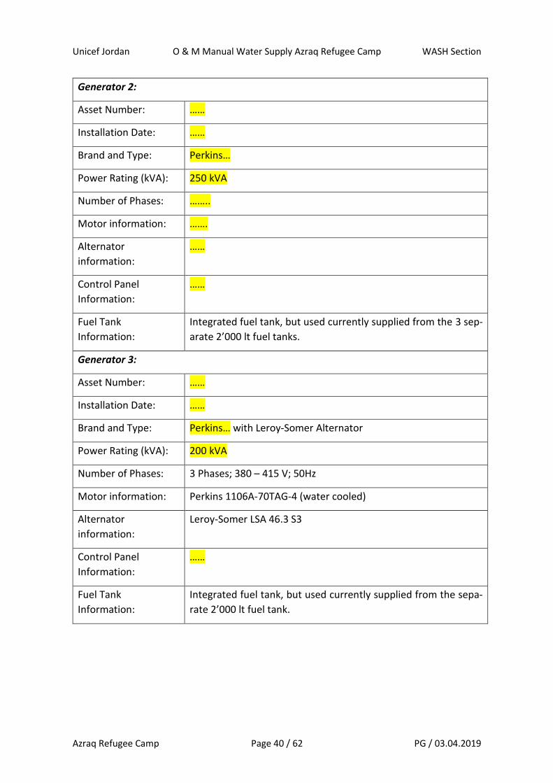
Generator 2:
Asset Number: ……
Installation Date: ……
Brand and Type: Perkins…
Power Rating (kVA): 250 kVA
Number of Phases: ……..
Motor information: …….
Alternator
information:
……
Control Panel
Information:
……
Fuel Tank
Information:
Integrated fuel tank, but used currently supplied from the 3 sep-
arate 2’000 lt fuel tanks.
Generator 3:
Asset Number: ……
Installation Date: ……
Brand and Type: Perkins… with Leroy-Somer Alternator
Power Rating (kVA): 200 kVA
Number of Phases: 3 Phases; 380 – 415 V; 50Hz
Motor information: Perkins 1106A-70TAG-4 (water cooled)
Alternator
information:
Leroy-Somer LSA 46.3 S3
Control Panel
Information:
……
Fuel Tank
Information:
Integrated fuel tank, but used currently supplied from the sepa-
rate 2’000 lt fuel tank.

Unicef Jordan O & M Manual Water Supply Azraq Refugee Camp WASH Section
Azraq Refugee Camp Page 41 / 62 PG / 03.04.2019
Generator 4:
Asset Number: ……
Installation Date: ……
Brand and Type: Hyundai….
Power Rating (kVA): 16 kVA
Number of Phases: ……..
Motor information: …….
Alternator
information:
……
Control Panel
Information:
……
Fuel Tank
Information:
Integrated fuel tank, but used currently supplied from the sepa-
rate 2’000 lt fuel tank.
Photo of generators and fuel tanks at AZBH_3
Unicef Jordan O & M Manual Water Supply Azraq Refugee Camp WASH Section
Azraq Refugee Camp Page 42 / 62 PG / 03.04.2019
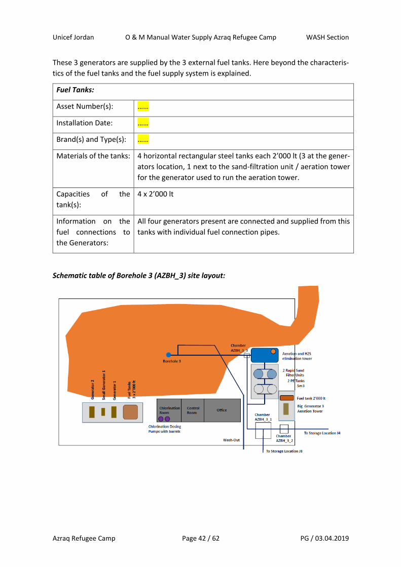
These 3 generators are supplied by the 3 external fuel tanks. Here beyond the characteris-
tics of the fuel tanks and the fuel supply system is explained.
Fuel Tanks:
Asset Number(s): ……
Installation Date: ……
Brand(s) and Type(s): ……
Materials of the tanks: 4 horizontal rectangular steel tanks each 2’000 lt (3 at the gener-
ators location, 1 next to the sand-filtration unit / aeration tower
for the generator used to run the aeration tower.
Capacities of the
tank(s):
4 x 2’000 lt
Information on the
fuel connections to
the Generators:
All four generators present are connected and supplied from this
tanks with individual fuel connection pipes.
Schematic table of Borehole 3 (AZBH_3) site layout:
Unicef Jordan O & M Manual Water Supply Azraq Refugee Camp WASH Section
Azraq Refugee Camp Page 43 / 62 PG / 03.04.2019
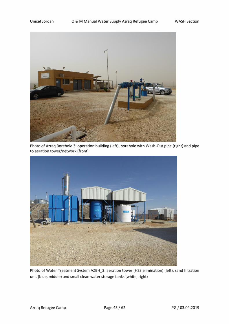
Photo of Azraq Borehole 3: operation building (left), borehole with Wash-Out pipe (right) and pipe to aeration tower/network (front)
Photo of Water Treatment System AZBH_3: aeration tower (H2S elimination) (left), sand filtration
unit (blue, middle) and small clean water storage tanks (white, right)
Unicef Jordan O & M Manual Water Supply Azraq Refugee Camp WASH Section
Azraq Refugee Camp Page 44 / 62 PG / 03.04.2019
Borehole 3 (AZBH_3) operation:
Azraq Borehole 3 is equipped with a submersible pump (details given before). The submers-
ible pump is powered by one of the 2 big generators at a time available and in use at
AZBH_3.
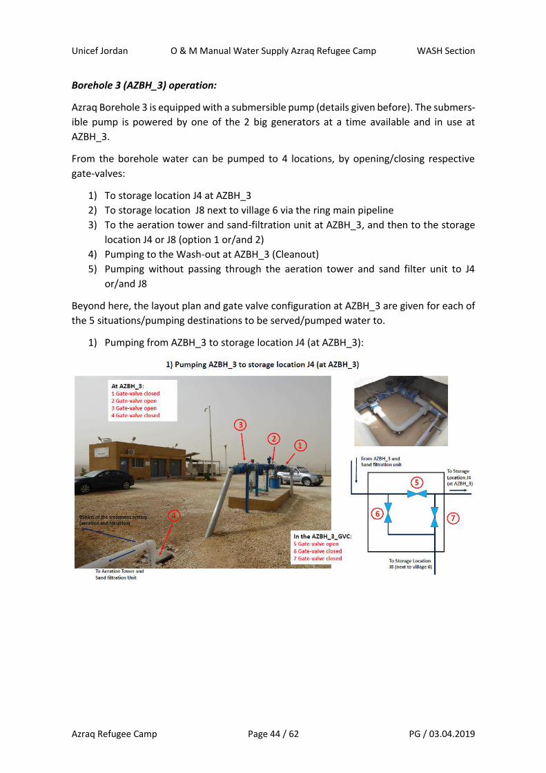
From the borehole water can be pumped to 4 locations, by opening/closing respective
gate-valves:
1) To storage location J4 at AZBH_3
2) To storage location J8 next to village 6 via the ring main pipeline
3) To the aeration tower and sand-filtration unit at AZBH_3, and then to the storage
location J4 or J8 (option 1 or/and 2)
4) Pumping to the Wash-out at AZBH_3 (Cleanout)
5) Pumping without passing through the aeration tower and sand filter unit to J4
or/and J8
Beyond here, the layout plan and gate valve configuration at AZBH_3 are given for each of
the 5 situations/pumping destinations to be served/pumped water to.
1) Pumping from AZBH_3 to storage location J4 (at AZBH_3):
Unicef Jordan O & M Manual Water Supply Azraq Refugee Camp WASH Section
Azraq Refugee Camp Page 45 / 62 PG / 03.04.2019
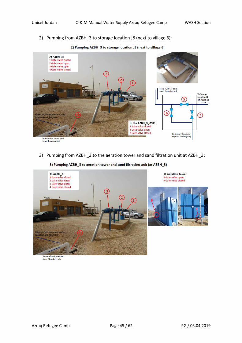
2) Pumping from AZBH_3 to storage location J8 (next to village 6):
3) Pumping from AZBH_3 to the aeration tower and sand filtration unit at AZBH_3:
Unicef Jordan O & M Manual Water Supply Azraq Refugee Camp WASH Section
Azraq Refugee Camp Page 46 / 62 PG / 03.04.2019
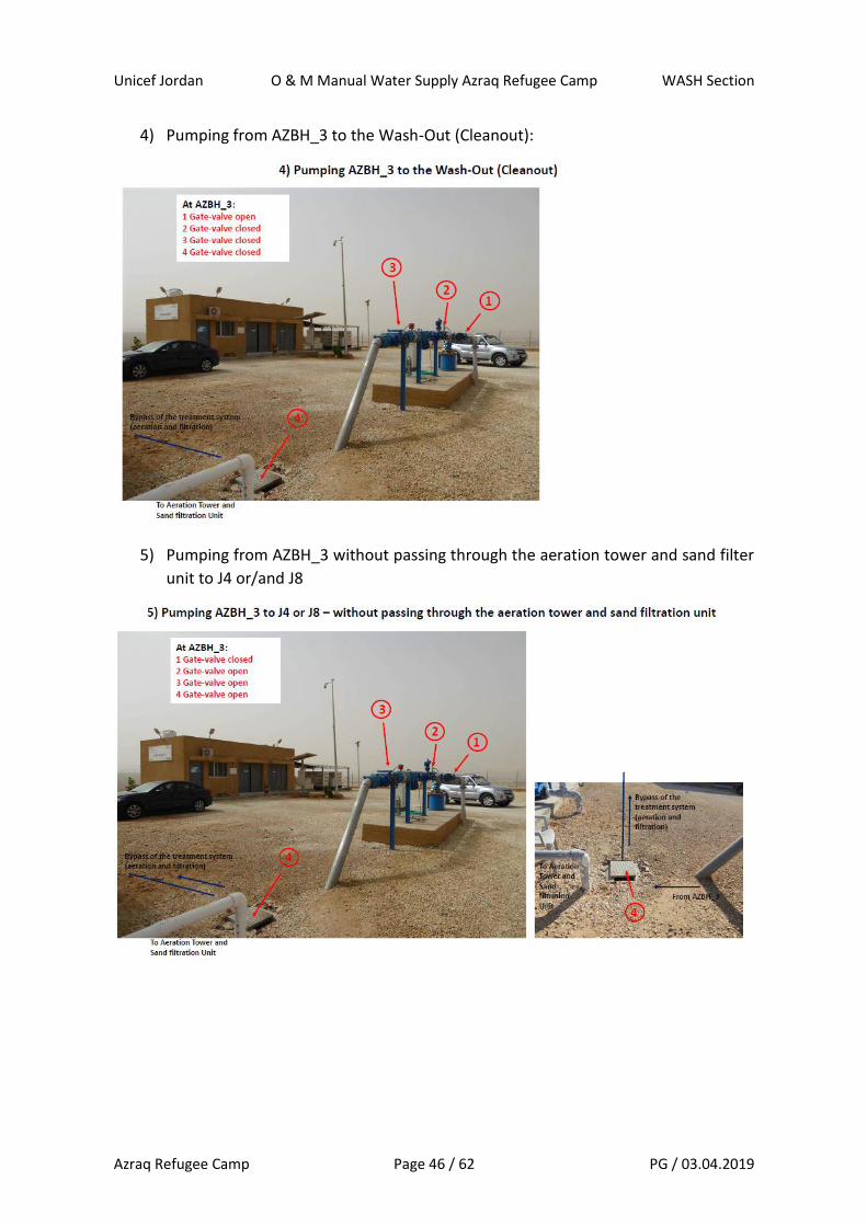
4) Pumping from AZBH_3 to the Wash-Out (Cleanout):
5) Pumping from AZBH_3 without passing through the aeration tower and sand filter
unit to J4 or/and J8

Unicef Jordan O & M Manual Water Supply Azraq Refugee Camp WASH Section
Azraq Refugee Camp Page 47 / 62 PG / 03.04.2019
At borehole 3, the following steps are required to put into operation and run the submers-
ible pump at AZBH_3:
1. Check fuel availability and fuel line connection to the generators
2. Select which of the big generators (Generator 1 or Generator 2) to be used for
the day. Alternate use of both generators – Generator 1 day 1, Generator 2 day
2, Generator 1 day 3, Generator 2 day, and to continue like this.
3. Put all the gate-valves into position for the wash-out/clean out – as per scenario
4 indicated above.
4. Check if the selected generator seems ok and functional.
5. Write down the operation hour reading of the generator into the genera-
tor/borehole log book at AZBH_3 for the respective generator. As well as level
of fuel use/fuel available.
6. Switch on the generator (as per the detailed generator switch-on protocol of
the respective generator).
7. Take the reading at the flow-meter of AZBH_3 – and write it down in the daily
borehole monitoring logs for water production.
8. Check the automatic chlorination units that liquid chlorine is available, that con-
nections are ok and chlorine dosing pumps ready to be switched on.
9. Once the generator up and running stable – after having passed at least the
minimum start-up time of the generator (as per the generator operation man-
ual) and until operational parameters at the control board of the generator are
normal and stable, the submersible pump can be switched on (as per the pump
operation manual).
10. Observe for around 5 minutes the pump control board and values – for flow
rates and other information showed – to check if all within acceptable range
and stable/stabilizing. If all values within acceptable ranges and no problems
indicated/seen, pumping to continue. If doubts and values not stabilizing, con-
tinue to observe for further time, until values stabilize, or until pump shuts
down by own protection mechanisms. Do not switch off the pump unless really
big concerns – as number of restarts of the pump per time are limited and can
cause damage to the pump.
11. After pump running stable, check on values for the water quality parameters
measured by the senator-pro probe at their indication panels in the control
room of the service building of AZBH_3. And, take water sample at the sampling
tap at AZBH_3 and do the relevant tests for additional parameters- such as tur-
bidity (NTU), ammonium (N-NH4), and pH. Once all parameters ok as required
for drinking water, continue with next step (step Nr. 11). Write down all param-
eters tested for with time and testing results in the borehole log of AZBH_3.
12. Change all the gate-valves into the required position – as per the destination
location where you want to pump the water to (see scenarios 1 to 5 explained
above). And, inform the respective team at storage location J4 or J8, that you
Unicef Jordan O & M Manual Water Supply Azraq Refugee Camp WASH Section
Azraq Refugee Camp Page 48 / 62 PG / 03.04.2019
will be starting to pump water their way (so they’re aware and can check on the
flow arriving in terms of quantities and qualities).
13. Write down time when you started pumping with indication to what destina-
tion, into the AZBH_3 logbook and water production templates.
14. Switch on the automatic chlorine dosing pump that you’re using this day (alter-
native use of the 2 automatic chlorine dosing pumps one day 1, next day the
other one, etc.)
15. When using the aeration tower and sand filtration unit – which is the usual op-
eration – you have to follow the following steps beyond here to put these units
in operation:
a. Write down in the generator 3 log book (the one for the aeration tower)
the reading of the operation hours as well as the time of starting the
generator. Check fuel availability in the fuel tank and fuel connection line
status. Start the generator as per the generator handbook procedure.
b. Only switch on the aeration tower unit, if the water flow from the bore-
hole is stable and sufficient. If this is the case, switch of the aeration
tower unit.
c. Switch on the small pump after the aeration tower to start feeding the
sand filtration units.
d. Once there is sufficient water in the white PE tanks after the sand filtra-
tion unit, switch on the small surface mounted pumps after these tanks,
to pump the water to J4 or/and J8 station – as per the destination
needed.
16. During pumping, every hour, write down water quality parameters E.C, pH, tem-
perature in the borehole/water production log book of AZBH_3. Take samples
and analyse turbidity each hour and write down the testing time and results in
the borehole/water production log book of AZBH_3 as well. And, check on the
operation of the automatic chlorination dosing pumps and the reading of the
free residual chlorine level indicated in the chlorination room white box on the
wall. Should always be within 0.5 to 1.0 mg/l under normal operation condi-
tions. If value read outside this range, make manual FRC test to check/verify
proper function of the equipment, and if value read confirmed, then adjust
quantity of chlorine injected by the automatic dosing pumps until you reach/can
read the required value (this will need time to adjust – so observe and give time
for the system to react).
17. Write down flow-meter reading each time, a change in the gate-valve setting is
done, and indicate to which direction water is pumped now, and the end of
pumping to the location set/served before.
18. Once the required quantities pumped for the day, switch off the pump (as per
the pump operation manual procedure). And, read flow-meter and write into
the logbook together with the time of pumping end.
19. Switch off the automatic chlorine dosing pump.

Unicef Jordan O & M Manual Water Supply Azraq Refugee Camp WASH Section
Azraq Refugee Camp Page 49 / 62 PG / 03.04.2019
20. Switch of the aeration tower (first the unit itself, then its generator), and then
the sand filtration unit and its pumps. If the pumping for the day is finished, then
the sand-filter backwash should be initiated and operated (as per the specific
sand filtration unit SOP).
21. Switch off the generator used (as per the generator operation manual switch-
off procedure), once the pump has been switched off and stopped. Write down
operation switch off time of the generator, operation hours and fuel use into
the generator and borehole log book of AZBH_3.
22. Before any restart of the pump, respect the minimum rest time required for the
pump as per the pump operation manual. Otherwise, you will damage the
pump/pump motor.
Any other operations/instructions for borehole 3 activities ? Make SOP for aeration tower
and SOP for sand filtration unit.
4.3 Operation Storage Locations
Operation of the 2 storage locations and the tanker filling station (and storage location at
AZBH_2) of Azraq Refugee Camp is indicated here. The explanations and indications given
here refer to the regular operation mode. Emergency operation mode and considerations,
are explained in chapter xxxx.
Storage Location J4 (at AZBH_3):
The location of the storage Location J4 is indicated in the map beyond here:
Unicef Jordan O & M Manual Water Supply Azraq Refugee Camp WASH Section
Azraq Refugee Camp Page 50 / 62 PG / 03.04.2019
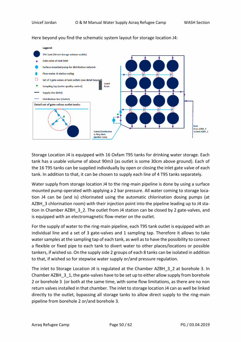
Here beyond you find the schematic system layout for storage location J4:
Storage Location J4 is equipped with 16 Oxfam T95 tanks for drinking water storage. Each
tank has a usable volume of about 90m3 (as outlet is some 30cm above ground). Each of
the 16 T95 tanks can be supplied individually by open or closing the inlet gate valve of each
tank. In addition to that, it can be chosen to supply each line of 4 T95 tanks separately.
Water supply from storage location J4 to the ring-main pipeline is done by using a surface
mounted pump operated with applying a 2 bar pressure. All water coming to storage loca-
tion J4 can be (and is) chlorinated using the automatic chlorination dosing pumps (at
AZBH_3 chlorination room) with their injection point into the pipeline leading up to J4 sta-
tion in Chamber AZBH_3_2. The outlet from J4 station can be closed by 2 gate-valves, and
is equipped with an electromagnetic flow-meter on the outlet.
For the supply of water to the ring-main pipeline, each T95 tank outlet is equipped with an
individual line and a set of 3 gate-valves and 1 sampling tap. Therefore it allows to take
water samples at the sampling tap of each tank, as well as to have the possibility to connect
a flexible or fixed pipe to each tank to divert water to other places/locations or possible
tankers, if wished so. On the supply side 2 groups of each 8 tanks can be isolated in addition
to that, if wished so for stepwise water supply or/and pressure regulation.
The inlet to Storage Location J4 is regulated at the Chamber AZBH_3_2 at borehole 3. In
Chamber AZBH_3_1, the gate-valves have to be set up to either allow supply from borehole
2 or borehole 3 (or both at the same time, with some flow limitations, as there are no non
return valves installed in that chamber. The inlet to storage location J4 can as well be linked
directly to the outlet, bypassing all storage tanks to allow direct supply to the ring-main
pipeline from borehole 2 or/and borehole 3.
Unicef Jordan O & M Manual Water Supply Azraq Refugee Camp WASH Section
Azraq Refugee Camp Page 51 / 62 PG / 03.04.2019
The operator of storage location J4 has to be informed when supply to his location is
started, so he can open/close the respective gate valves of the T95 tanks that he wants to
be filled/used, in what order, up to what levels/quantities, etc. In addition to that, the op-
erator takes FRC (free residual chlorine) samples at some T95 tanks to check FRC levels of
water supplied to the storage location at each rotation. In addition to that, FRC levels are
checked and reported on at outlet of J4 station before water reaches the ring-main pipeline
at the J4 station outlet sampling point. The operator of storage location J4 has as well to
assure that the automatic chlorination pumps located at AZBH_3 are switched-on, for all
water coming to storage location J4 from borehole 2 and borehole 3.
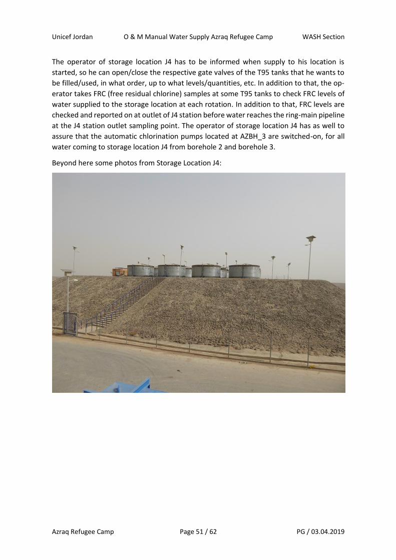
Beyond here some photos from Storage Location J4:
Unicef Jordan O & M Manual Water Supply Azraq Refugee Camp WASH Section
Azraq Refugee Camp Page 52 / 62 PG / 03.04.2019
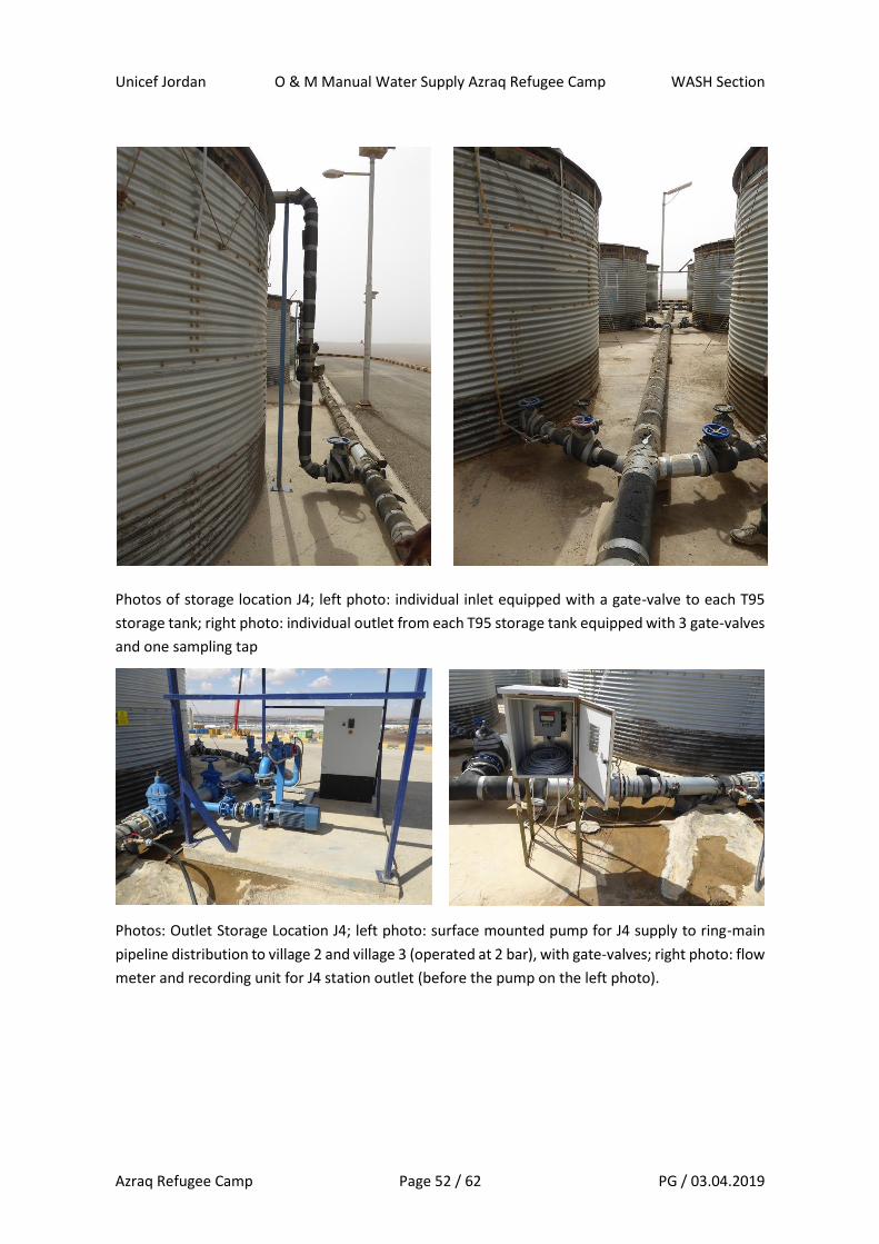
Photos of storage location J4; left photo: individual inlet equipped with a gate-valve to each T95
storage tank; right photo: individual outlet from each T95 storage tank equipped with 3 gate-valves
and one sampling tap
Photos: Outlet Storage Location J4; left photo: surface mounted pump for J4 supply to ring-main
pipeline distribution to village 2 and village 3 (operated at 2 bar), with gate-valves; right photo: flow
meter and recording unit for J4 station outlet (before the pump on the left photo).

Unicef Jordan O & M Manual Water Supply Azraq Refugee Camp WASH Section
Azraq Refugee Camp Page 53 / 62 PG / 03.04.2019
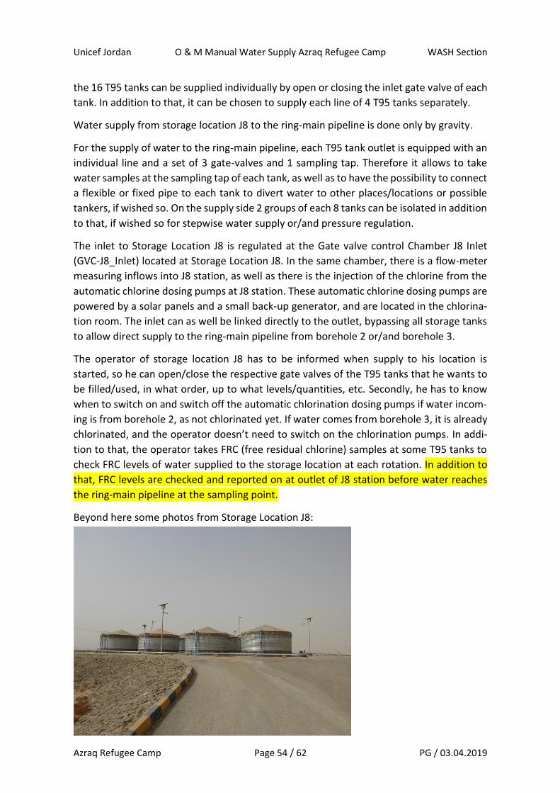
Storage Location J8 (next to village 6):
The location of the storage Location J8 is indicated in the map beyond here:
Here beyond you find the schematic system layout for storage location J8:
Storage Location J8 is equipped with 16 Oxfam T95 tanks for drinking water storage. Each
tank has a usable volume of about 90m3 (as outlet is some 30cm above ground). Each of
Unicef Jordan O & M Manual Water Supply Azraq Refugee Camp WASH Section
Azraq Refugee Camp Page 54 / 62 PG / 03.04.2019
the 16 T95 tanks can be supplied individually by open or closing the inlet gate valve of each
tank. In addition to that, it can be chosen to supply each line of 4 T95 tanks separately.
Water supply from storage location J8 to the ring-main pipeline is done only by gravity.
For the supply of water to the ring-main pipeline, each T95 tank outlet is equipped with an
individual line and a set of 3 gate-valves and 1 sampling tap. Therefore it allows to take
water samples at the sampling tap of each tank, as well as to have the possibility to connect
a flexible or fixed pipe to each tank to divert water to other places/locations or possible
tankers, if wished so. On the supply side 2 groups of each 8 tanks can be isolated in addition
to that, if wished so for stepwise water supply or/and pressure regulation.
The inlet to Storage Location J8 is regulated at the Gate valve control Chamber J8 Inlet
(GVC-J8_Inlet) located at Storage Location J8. In the same chamber, there is a flow-meter
measuring inflows into J8 station, as well as there is the injection of the chlorine from the
automatic chlorine dosing pumps at J8 station. These automatic chlorine dosing pumps are
powered by a solar panels and a small back-up generator, and are located in the chlorina-
tion room. The inlet can as well be linked directly to the outlet, bypassing all storage tanks
to allow direct supply to the ring-main pipeline from borehole 2 or/and borehole 3.
The operator of storage location J8 has to be informed when supply to his location is
started, so he can open/close the respective gate valves of the T95 tanks that he wants to
be filled/used, in what order, up to what levels/quantities, etc. Secondly, he has to know
when to switch on and switch off the automatic chlorination dosing pumps if water incom-
ing is from borehole 2, as not chlorinated yet. If water comes from borehole 3, it is already
chlorinated, and the operator doesn’t need to switch on the chlorination pumps. In addi-
tion to that, the operator takes FRC (free residual chlorine) samples at some T95 tanks to
check FRC levels of water supplied to the storage location at each rotation. In addition to
that, FRC levels are checked and reported on at outlet of J8 station before water reaches
the ring-main pipeline at the sampling point.
Beyond here some photos from Storage Location J8:
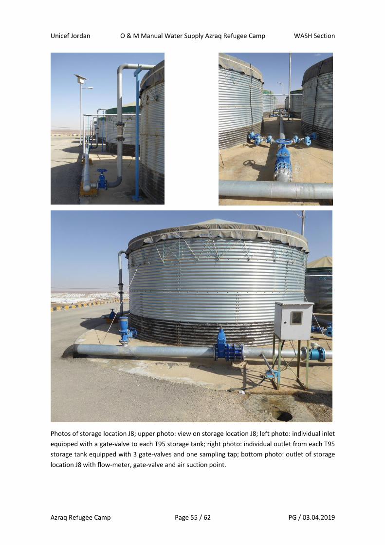
Unicef Jordan O & M Manual Water Supply Azraq Refugee Camp WASH Section
Azraq Refugee Camp Page 55 / 62 PG / 03.04.2019
Photos of storage location J8; upper photo: view on storage location J8; left photo: individual inlet
equipped with a gate-valve to each T95 storage tank; right photo: individual outlet from each T95
storage tank equipped with 3 gate-valves and one sampling tap; bottom photo: outlet of storage
location J8 with flow-meter, gate-valve and air suction point.

Unicef Jordan O & M Manual Water Supply Azraq Refugee Camp WASH Section
Azraq Refugee Camp Page 56 / 62 PG / 03.04.2019
Photos of storage location J8: chlorination station with left: chlorination station building with solar
panels, small generator and power grid line (not connected); right: automatic chlorine dosing
pumps and liquid chlorine drums.
Tanker filling station and storage location J2 (at AZBH_2):
The location of the tanker filling station and storage Location J2 is indicated in the map
beyond here:

Unicef Jordan O & M Manual Water Supply Azraq Refugee Camp WASH Section
Azraq Refugee Camp Page 57 / 62 PG / 03.04.2019
Here beyond you find the schematic system layout for the tanker filling station and storage
location J2:
Tanker Filling Station and Storage Location J2 is equipped with 6 Oxfam T95 tanks for drink-
ing water storage (usable volume: 540 m3). Each tank has a usable volume of about 90m3
(as outlet is some 30cm above ground). Each of the 6 T95 tanks can be supplied individually
by open or closing the inlet gate valve of each tank. Water to the tanker filling station can
only be supplied from borehole.
Supply from borehole 3 possible -> enough pressure from the pumps there ?
Water supply from storage location J2 to the tanker filling station is done first part by grav-
ity, and then using surface mounted pumps. The tanker filling station is equipped with 2
filling lines with one line having 2 filling hoses, and 1 line having 3 filling hoses. Each filling
line can be supplied independently, and is equipped with a gate-valve, a pump and a flow
meter.
Water flowing form the storage location J2 to the tanker filling station is chlorinated by
automatic chlorine dosing pumps. Yes ? no ? If yes, where is the chlorination point ? And,
why chlorination not used/possible for water from BH_2 sent to J4 ?
The operator of storage location J2 and the tanker filling station has to be informed when
supply to his location is started, so he can open/close the respective gate valves of the T95
tanks that he wants to be filled/used, in what order, up to what levels/quantities, etc.
For operating the tanker filling station, the operator has to check the two surface mounted
pumps, put the gate-valves in positions for which tanker filling line(s) he want to use, and
to check that the tanker filling hoses are closed (not to spill/loose water). Secondly, he has
then to go and open the gate-valves from each T95 tank he wants water to flow to the
tanker filling station pumps and to switch on and switch off the automatic chlorination dos-
ing pumps as needed.

Unicef Jordan O & M Manual Water Supply Azraq Refugee Camp WASH Section
Azraq Refugee Camp Page 58 / 62 PG / 03.04.2019
In addition to that, the operator takes FRC (free residual chlorine) samples from the tanker
filling hoses when the tanker filling station is used.
Beyond here some photos from the Tanker Filling Station and Storage Location J2:

Unicef Jordan O & M Manual Water Supply Azraq Refugee Camp WASH Section
Azraq Refugee Camp Page 59 / 62 PG / 03.04.2019
Photos of storage location J2 and tanker filling station; photo 1: T95 tanks and chlorination room of
storage location J2; photo 2: tanker filling station; photo left: tanker filling station 2 pump and flow
meter; photo right: tanker filling station 2 pump, flow meter and gate valve.
4.4 Operation of the Water Distribution Network
In this chapter, all activities linked to the operation of the water distribution part of Azraq
Refugee Camp water supply system are explained. The explanations and indications given
here refer to the regular operation mode. Emergency operation mode and considerations,
are explained in chapter xxxx.
To assure water supply to the 4 villages and all service areas of Azraq Refugee Camp, 11
gate-valve chambers are located on the ring-main pipeline. 8 of them are used to control
water supply to the 4 villages, and 3 of them are used to control water supply to 5 service
areas. Whereas the gate-valves in the chambers controlling water supply of the villages
are only open during the distribution times, the gate-valves in the 3 chambers controlling
water supply to service areas are generally open permanently, but still can be closed based
on operational requirements. All gate-valves in the network of Azraq Refugee Camp are
operated manually and no remote control system is installed/available.
Each of the chambers is equipped with a gate-valve as well as a flow-meter. Since March
2019, flow-meter readings are taken every time when gate-valves to villages are opened
and closed. This allows to monitor and know, how much water has been distributed to
which village and to which service area(s). All gate-valve chambers have a solid cover with
a lock, so that access to them is only possible for the water operator of Azraq Refugee
Camp.
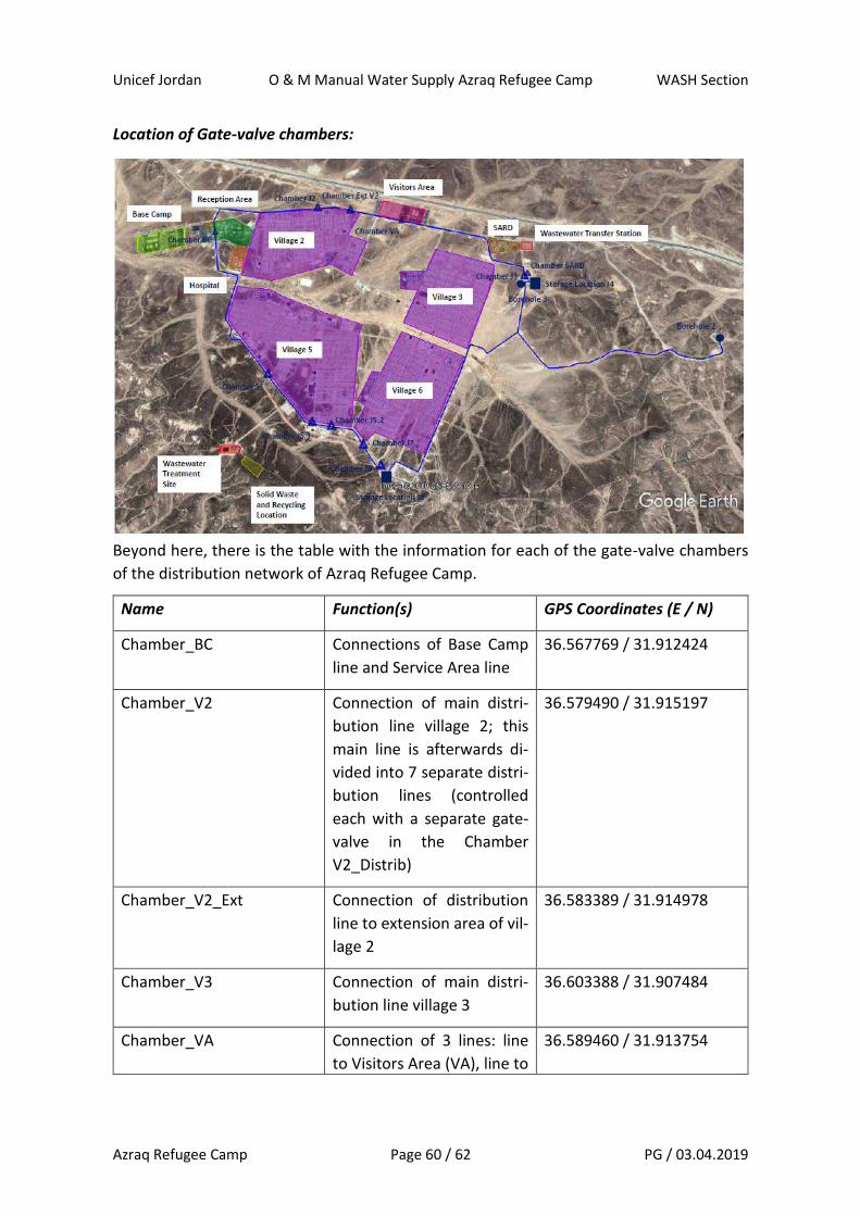
Unicef Jordan O & M Manual Water Supply Azraq Refugee Camp WASH Section
Azraq Refugee Camp Page 60 / 62 PG / 03.04.2019
Location of Gate-valve chambers:
Beyond here, there is the table with the information for each of the gate-valve chambers
of the distribution network of Azraq Refugee Camp.
Name Function(s) GPS Coordinates (E / N)
Chamber_BC Connections of Base Camp
line and Service Area line
36.567769 / 31.912424
Chamber_V2 Connection of main distri-
bution line village 2; this
main line is afterwards di-
vided into 7 separate distri-
bution lines (controlled
each with a separate gate-
valve in the Chamber
V2_Distrib)
36.579490 / 31.915197
Chamber_V2_Ext Connection of distribution
line to extension area of vil-
lage 2
36.583389 / 31.914978
Chamber_V3 Connection of main distri-
bution line village 3
36.603388 / 31.907484
Chamber_VA Connection of 3 lines: line
to Visitors Area (VA), line to
36.589460 / 31.913754
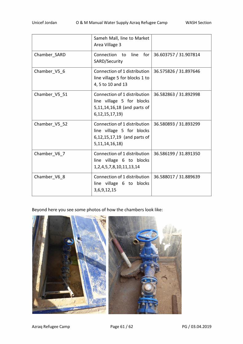
Unicef Jordan O & M Manual Water Supply Azraq Refugee Camp WASH Section
Azraq Refugee Camp Page 61 / 62 PG / 03.04.2019
Sameh Mall, line to Market
Area Village 3
Chamber_SARD Connection to line for
SARD/Security
36.603757 / 31.907814
Chamber_V5_6 Connection of 1 distribution
line village 5 for blocks 1 to
4, 5 to 10 and 13
36.575826 / 31.897646
Chamber_V5_51 Connection of 1 distribution
line village 5 for blocks
5,11,14,16,18 (and parts of
6,12,15,17,19)
36.582863 / 31.892998
Chamber_V5_52 Connection of 1 distribution
line village 5 for blocks
6,12,15,17,19 (and parts of
5,11,14,16,18)
36.580893 / 31.893299
Chamber_V6_7 Connection of 1 distribution
line village 6 to blocks
1,2,4,5,7,8,10,11,13,14
36.586199 / 31.891350
Chamber_V6_8 Connection of 1 distribution
line village 6 to blocks
3,6,9,12,15
36.588017 / 31.889639
Beyond here you see some photos of how the chambers look like:
Unicef Jordan O & M Manual Water Supply Azraq Refugee Camp WASH Section
Azraq Refugee Camp Page 62 / 62 PG / 03.04.2019
Beyond the level of the chambers located on the ring-main pipeline and controlling the
water supply into the villages, there are no further control or access gate-valves or possi-
bilities to regulate the flows inside the village levels.
But, each tapstand has its own gate-valve on the distribution line, and can be opened and
closed off as per the operational requirements and/or consumer demand or not. This gate-
valves are located in the ground next to each tapstand, with no real gate-valve chamber.
All chambers and gate-valves are operated by the water supply operator of Azraq Refugee
Camp.