
SWE20F Hydraulic Excavator - Operation & Maintenance ...
104
Operation & Maintenance Manual SWE20F Hydraulic Excavator SUNWARD INTELLIGENT EQUIPMENT CO., LTD. Sunward Intelligent Industrial Park, Xingsha, Changsha, China Sept.2019
-
Upload
khangminh22 -
Category
Documents
-
view
1 -
download
0
Transcript of SWE20F Hydraulic Excavator - Operation & Maintenance ...

Operation & Maintenance
Manual SWE20F
Hydraulic Excavator
SUNWARD INTELLIGENT EQUIPMENT CO., LTD. Sunward Intelligent Industrial Park, Xingsha, Changsha, China
Sept.2019

I
FOREWORD
This manual provides rules and guidelines which will help you use this machine safely and effectively. The precautions in this manual must be followed at all times when performing operation and maintenance. Most accidents are caused by the failure to follow fundamental safety rules for the operation and maintenance of machines. Accidents can be prevented by knowing beforehand conditions that may cause hazard when performing operation and maintenance.
Operators and maintenance personnel must always do as follows before beginning operation or maintenance. Always be sure to read and understand this manual thoroughly before performing operation
and maintenance.
Read the safety message given in this manual and the safety labels affixed to the machine thoroughly and be sure that you understand them fully.
This manual should be considered as a permanent part of your machine. If you sell the machine, be sure to give this manual to the new owners together with the machine.
Only original spare parts procured from Sunward are to be used. To use parts of poor quality will be detrimental to machine’s overall performance.
All operation described in this instruction manual should be carried out exclusively by trained and qualified staff.
This machine is designed in metric system and the sizes provided in this manual are metric, therefore, please only use parts and tools in metric system.
Sunward guarantees maintenance to our customers. Please refer to guarantee certificate which you have obtained from our distributors for maintenance concerns. With a guarantee certificate, you are entitled to get maintenance from Sunward. In some cases even beyond maintenance period, Sunward provides maintenance on the spot, which is usually free of charge. However, if machine is abused or kept in overloading operations or its performance is changed beyond our original regulations, compensations for maintenance will be unavailable and service on the spot will probably be refused. All the information including charts and specifications in this manual is the latest that we can get. We reserve the right to make without prior notice any modification or amendment to machine component.
Sunward Intelligent Equipment Co., Ltd
II
TABLE OF CONTENTS
1. SAFETY RULES ........................................................................................................................ 1
1.1 SAFETY MARK ................................................................................................................... 11.2 SAFETY LABEL .................................................................................................................. 11.3 GENERAL SAFETY INSTRUCTION ................................................................................. 11.4 PREPARE FOR EMERGENCIES ........................................................................................ 21.5 WEAR SAFETY PROTECTIVE ARTICLES ...................................................................... 21.6 CHECK MACHINE BEFORE START-UP .......................................................................... 21.7 ADJUST OPERATOR SEAT ............................................................................................... 21.8 ENTER OR LEAVE MACHINE CORRECTLY ................................................................. 21.9 START ENGINE CORRECTLY .......................................................................................... 21.10 FORBID HITCHING OTHER PEOPLE ............................................................................ 31.11 KEEP MACHINE AWAY FROM ELECTRICITY TRANSMISSION LINE ................... 31.12 MOVE MACHINE SAFELY .............................................................................................. 31.13 PREVENT ACCIDENT WHILE BACKING OR SWINGING ......................................... 31.14 OPERATE DIGGING WORK SAFELY ............................................................................ 41.15 AVOID ACCIDENT BY CONTROL FAILURE ............................................................... 51.16 PARK MACHINE SAFELY ............................................................................................... 51.17 SAFE MAINTENANCE ..................................................................................................... 51.18 SUPPORT MACHINE CORRECTLY ............................................................................... 61.19 CLEAN TRASH ON THE MACHINE ............................................................................... 61.20 PREVENT BATTERY FROM EXPLODING .................................................................... 61.21 STORE PARTS SAFELY ................................................................................................... 71.22 PREVENT SPLASHING OBJECTS .................................................................................. 71.23 PREVENT PARTS FROM FLYING OFF .......................................................................... 71.24 KEEP AWAY FROM TRANSMISSION PARTS .............................................................. 71.25 AVOID INHALING ASBESTOS DUST ........................................................................... 71.26 BEWARE OF INHALING FOG OR EXHAUST GAS ...................................................... 81.27 BEWARE OF SCALD ........................................................................................................ 81.28 BE CAUTIOUS OF PRESSURE LIQUIDS ....................................................................... 81.29 AVOID HEATING UP NEAR PRESSURE OIL PIPE ...................................................... 81.30 AVOID HEATING UP INFLAMMABLE LIQUID PIPE ................................................. 81.31 REMOVE PAINT BEFORE WELDING OR HEATING .................................................. 91.32 DISPOSE OF LIQUID SAFELY ........................................................................................ 91.33 DISPOSE OF CHEMICAL SAFELY ................................................................................. 91.34 AVOID FIRE ....................................................................................................................... 91.35 EMERGENCY EXIT ........................................................................................................ 101.36 NOISE AND VIBRATION ........................................................................................................ 101.37 OTHER SAFETY MARKS ............................................................................................... 11
2. MACHINE FAMILIARIZATION ............................................................................................ 13
2.1 POSITION OF THE VARIOUS MACHINE COMPONENTS .......................................... 14

III
2.2 CABIN ................................................................................................................................. 182.3 MONITOR PANEL ............................................................................................................. 192.4 WANE CONTROL PANEL ................................................................................................ 222.5 START-UP SWITCH .......................................................................................................... 222.6 HEATER .............................................................................................................................. 23
2.6.1 WORK THEORY ......................................................................................................... 232.6.2 INSTALLATION .......................................................................................................... 232.6.3 OPERATION ................................................................................................................ 23
2.7 RADIO ................................................................................................................................. 232.8 SEAT ADJUSTMENT ........................................................................................................ 242.9 PILOT SAFETY LEVER .................................................................................................... 252.10 ENGINE ACCELEROGRAPH SPEED CONTROL LEVER .......................................... 252.11 PILOT OPERATION ........................................................................................................ 262.12 OPEN AND CLOSE FRONT WINDOW ......................................................................... 282.13 AIR DUCTING HOOD AND UPPER-COVER ............................................................... 282.14ACCESSORY AND TOOL LIST ...................................................................................... 292.15 IDENTIFIER ..................................................................................................................... 31
3. MACHINE OPERATION ......................................................................................................... 31
3.1 MACHINE WORKING ENVIRONMENT ........................................................................ 313.2 RUNNING AND OPERATION .......................................................................................... 313.3 OPERATE ENGINE ........................................................................................................... 323.4 TRAVEL CONTROL .......................................................................................................... 36
3.4.1 CONTROL TRAVEL WITH PEDAL .......................................................................... 363.4.2 TRAVEL WITH HANDLE CONTROL ...................................................................... 373.4.3 TRAVEL SPEED .......................................................................................................... 383.4.4 TRAVEL BRAKE ......................................................................................................... 383.4.5 OUTLINE OF TRAVEL ............................................................................................... 38
3.5 EXCAVATION ................................................................................................................... 403.6 LIFT WORK ........................................................................................................................ 483.7 HYDRAULIC BREAKING OPERATION ........................................................................ 493.8 BOOM SWING ................................................................................................................... 51
4 MAINTENANCE ....................................................................................................................... 52
4.1 CORRECT MAINTENANCE AND INSPECTION PROCEDURE .................................. 524.2 MAINTENANCE GUIDE ................................................................................................... 56
4.2.1 ADD LUBRICANT GREASE ...................................................................................... 564.2.2 ENGINE OIL ................................................................................................................ 564.2.3 GEAR OIL .................................................................................................................... 594.2.4 FUEL SYSTEM ............................................................................................................ 614.2.5 HYDRAULIC SYSTEM ............................................................................................... 644.2.6 AIR FILTER ................................................................................................................. 704.2.7 COOLING SYSTEM .................................................................................................... 724.2.8 OTHERS ....................................................................................................................... 754.2.9 MAINTENANCE IN SPECIAL SITUATION ............................................................. 824.2.10 PROTECTION FOR LONG TERM STORE ............................................................. 83

IV
4.2.11 HEATER MAINTENANCE ....................................................................................... 83
5. TRANSPORTATION AND STORAGE .................................................................................. 84
6. TROUBLE SHOOTING ........................................................................................................... 87
7. SPECIFICATIONS ................................................................................................................... 91
7.1 TECHNICAL PARAMETER ............................................................. 错误!未定义书签。
7.2 TECHNICAL INTRODUCTION ....................................................................................... 937.3 OPERATION PARAMETER ............................................................................................. 96
8. ATTACHMENT ....................................................................................................................... 99
8.1 ELECTRIC DRAWING ...................................................................................................... 998.2 HYDRAULIC DRAWING ................................................................. 错误!未定义书签。
8.3 HYDRAULIC COMPONENT LIST ................................................................................ 101
9. ABOUT MANUFACTURER ................................................................................................. 102

1
The safety instructions in this chapter
only include the general safety rules
of machine. They can’t cover all the
possible dangers. If there is any
problem, please report to your superior
before operation and maintenance.
1. SAFETY RULES
1.1 SAFETY MARK Fig 1-1 is the mark to remind of safety, when you see this mark on the machine or in the manual book; it indicates that the human body is in danger of injury.
1.2 SAFETY LABEL There are various labels at various points of machine, in these labels, various words indicate various hurt risks, such as “DANGER”, “WARNIGN”, “CAUTION” etc (as right figure), they mean as follows: 1) DANGER—indicates an imminently hazardous
situation which, if not avoided, could result in death or serious injury.
2) WARNING—indicates a potentially hazardous situation which, if not avoided, could result in death or serious injury.
3) CAUTION—indicates potentially hazardous situation which, if not avoided, may result in minor or moderate injury.
“DANGER”, “WARNING” safety labels are stuck at given points of machine within the range of possible danger. General attentions listed on the “CAUTION” safety label. In this manual book, “CAUTION” also reminds of safety instruction.
1.3 GENERAL SAFETY INSTRUCTION Study the manual carefully and follow the safety instructions in the labels and manual before operating the machine. 1) Always keep the safety labels clean. Change
any lost or damaged label with a new one. If the labels or manual book are lost, you can contact dealer and indicate the model of machine to purchase a new one.
2) Only qualified operator is permitted to operate this machine. Keep the machine in good condition as per this manual.
2
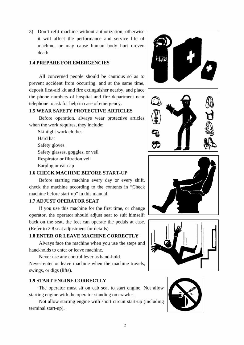
3) Don’t refit machine without authorization, otherwise it will affect the performance and service life of machine, or may cause human body hurt oreven death.
1.4 PREPARE FOR EMERGENCIES
All concerned people should be cautious so as to prevent accident from occurring, and at the same time, deposit first-aid kit and fire extinguisher nearby, and place the phone numbers of hospital and fire department near telephone to ask for help in case of emergency. 1.5 WEAR SAFETY PROTECTIVE ARTICLES
Before operation, always wear protective articles when the work requires, they include:
Skintight work clothes Hard hat Safety gloves Safety glasses, goggles, or veil Respirator or filtration veil Earplug or ear cap
1.6 CHECK MACHINE BEFORE START-UP Before starting machine every day or every shift,
check the machine according to the contents in “Check machine before start-up” in this manual. 1.7 ADJUST OPERATOR SEAT
If you use this machine for the first time, or change operator, the operator should adjust seat to suit himself: back on the seat, the feet can operate the pedals at ease. (Refer to 2.8 seat adjustment for details) 1.8 ENTER OR LEAVE MACHINE CORRECTLY
Always face the machine when you use the steps and hand-holds to enter or leave machine.
Never use any control lever as hand-hold. Never enter or leave machine when the machine travels, swings, or digs (lifts).
1.9 START ENGINE CORRECTLY The operator must sit on cab seat to start engine. Not allow
starting engine with the operator standing on crawler. Not allow starting engine with short circuit start-up (including
terminal start-up).

3
1.10 FORBID HITCHING OTHER PEOPLE When the machine is in operation or traveling,
prohibit other people except operator staying on the machine. 1.11 KEEP MACHINE AWAY FROM ELECTRICITY TRANSMISSION LINE
Any part or load of machine touching electricity transmission line will cause human death or GBH. Prohibit machine or its load being close to electricity transmission line, the machine should be 3 meters away from line.
1.12 MOVE MACHINE SAFELY Before the machine travels and swings, operator
should know the position of other people. When machine travels or before it swings, operator
should warn other people by ringing the horn. Operation at confined area should use signal in
swinging, and harmonize the hand signal before machine start-up.
Before operating the machine traveling, confirm that the operation of traveling pedal/control lever is corresponding with the traveling direction.
Treadle the foreside of traveling pedal or push traveling lever forward, and the machine will travel along tension wheel. By contraries, the machine will travel along sprocket wheel.
When machine travel on slope, place bucket as figures show, keep bucket 200-300mm up the slope ground, if the machine slides or becomes unstable, set the bucket down at once.
1.13 PREVENT ACCIDENT WHILE BACKING OR SWINGING
In order to prevent accident while backing or swinging, the operator must follow: Before back or swing the machine, look round and confirm nobody is around. Ensure that other people stand out of the boom swing range. Pay attention to that whether other people stay in work range or not. Ring horn or use other
signals to warn before moving the machine. If the operator’s vision is blocked when the machine backs, a signalman is needed and the
signalman should always be seen.

4
If signalman is needed, he or she should use hand signal. Only when both signalman and operator understand the meaning of signal, the operator can operate the machine traveling and swinging.
Understand all the meanings of flag, mark, and signal, and determine the person who is in charge of signaling.
Keep the cleanness of window, mirror, and lamp. When the visibility is weakened by dust, rain, and fog,
etc, lamplight should be used. Please read carefully and understand well the
contents of this manual book. 1.14 OPERATE DIGGING WORK SAFELY Before digging, operator should be aware of the
position of the embedded lines, such as cable, gas pipe, water supply pipe, and operate the machine carefully to prevent accident.
All the non-working people should be away from the working range of machine.
Make sure the ground of working site is hard enough to support machine.
When the machine works at pithead, the tension wheel end should be outward pithead, keeping the traveling orientation vertical with pit cliff. In this way, the machine can move away easily when the cliff collapses.
When the machine works in deep spot, you should prevent the boom bottom and cylinder from colliding with high objects.
Turn over prevention When the machine works on slope, the track should be parked along the slope, retract the bucket as much as possible, keep the bucket close to ground and machine to avoid turning over. When swinging with load, decrease swing speed to avoid turning over. When work on frozen ground, you should prevent the ascending temperature from causing the ground to soften, otherwise it will affect the stability of machine.
During operation, prevent boom or arm from colliding with high objects. The bucket is only for digging work, do not allow using bucket to work as pneumatic pick or
hydraulic breaker does.

5
1.15 AVOID ACCIDENT BY CONTROL FAILURE When the machine loses control, if someone tries
to mount on or stop machine, it will cause GBH or death.
To avoid the machine losing control, pay attention to the following proceedings: Place the machine on horizontal ground, try your best
not to stay on slope, and stop machine as following procedures: Lower the bucket to the ground. Run engine at low revs for 3 minutes to cool down
machine. Stop engine, take out key from key switch. Switch off pilot control.
If the machine has to stay on slope, use chocks to block crawler, lower bucket, and plug bucket teeth into ground.
Fix the machine well to avoid accidental movement. Park the machine away from other machines at proper
distance. 1.16 PARK MACHINE SAFELY Stop machine as following schedule: Place machine on horizontal ground. Lower the bucket to the ground. Run engine at low rev for 3 minutes. Place the timing handle at stop position, screw the
ignition key to “OFF” position. Switch off pilot control. Close window, top window, and cabin. 1.17 SAFE MAINTENANCE Attention of maintenance:
Before working, be aware of maintenance rules. Keep the working area clean and dry. Don’t allow injecting lubricant or maintaining to the moving machine. Avoid body and clothing touching with transmission parts.
Preparation for maintenance Place the machine on horizontal ground. Lower the bucket to the ground. Run engine at low rev for 5 minutes. Pull stop handle forward, stop engine, take out key from the switch. Hang “DO NOT OPERATE” label at control lever. Switch off pilot control.

6
Safety in maintenance If maintenance must be made during engine operation,
there must be somebody in cabin. If the machine must be lifted, then the angle between
boom and arm must be kept between 90-110° to support the lifted parts stably in maintenance work.
Never work under the machine being lifted by boom. Check some parts at regular intervals, repair or replace,
if necessary. (refer to chapter “maintenance” in this manual)
Make sure all parts are in good condition and fitted correctly. Replace worn or damaged parts. Clean any accumulative lubricant or scraps.
When adjust electric system or weld on machine, disconnect earthing cable (negative pole) of battery.
1.18 SUPPORT MACHINE CORRECTLY Prohibit repairing or maintaining machine before the
machine is well supported. Before maintenance, lower the working device to the
ground. If the machine or work device have to be lifted for
maintenance purpose, the machine or work device should be well supported.
Don’t support the machine on slag, hollow brick, or other fragile objects.
Don’t work under machine when it is only supported by a jack.
1.19 CLEAN TRASH ON THE MACHINE Keep the engine, radiator, battery, hydraulic line, fuel
tank, and cabin clean. After stopping engine, the surrounding temperature
may rise immediately. Open overhaul gate to cool engine as soon as possible and clean engine apartment.
Clean machine at regular interval, eliminate accumulative lubricant and other trash. Make sure not to spray water or vapour into cabin.
1.20 PREVENT BATTERY FROM EXPLODING Prohibit fire or flame being close to the battery top, otherwise the battery gas will explode. Check the electricity deposit with voltage meter or gravimeter. Don’t place metal bestriding
connection rod to check electricity deposit. Never electricize the frozen battery, otherwise it will explode. The battery should be warmed
up to 16°C (60°F).

7
1.21 STORE PARTS SAFELY The stored parts, such as bucket, hydraulic breaker, etc, are likely to fall down, causing GBH
or death. By all effective means, store parts and machine safely to avoid falling down. Don’t permit
unauthorized people, especially children being closed to the parts storage area.
1.22 PREVENT SPLASHING OBJECTS Prevent splashing metal or grits hurt, wear blinkers
or safety glass. Before knocking on object, check whether somebody
else is in the working area or not, and stop other people from entering the working area to avoid hurt.
1.23 PREVENT PARTS FROM FLYING OFF In operation or maintenance, take care of the parts
that may fly off, avoid possible flying off parts to human body and face. 1.24 KEEP AWAY FROM TRANSMISSION PARTS Touching transmission parts may cause GBH. When work around the transmission parts, in order to
avoid accident, prevent hand, foot, hair and clothes from entangling in the machine.
1.25 AVOID INHALING ASBESTOS DUST Prevent inhaling possible asbestos dust, for the
asbestos fibre may cause lung cancer. Some washers contain asbestos fibre, in these
components, normally, the asbestos is in the resin or enveloped in some way. If the asbestos-contained parts don’t bring dust, there isn’t danger in normal disposal.
To avoid causing dust, don’t clean with compressed air, and avoid brushing and grinding asbestos-contained materials. In maintenance work, please wear regulated respirator, use special dust collector to clean asbestos. If you can’t get this dust collector, use little oil or water to be moistened asbestos-contained material. Comply with working area rules and concerned asbestos disposal rules, stop other people from entering working area.

8
1.26 BEWARE OF INHALING FOG OR EXHAUST GAS Inhaling engine exhaust gas will cause disease, so
much as, or death. If it is necessary to operate machine in the building,
open door and window to ensure well ventilation, or use long exhaust pipe to discharge smoke.
1.27 BEWARE OF SCALD During operation, engine oil, gear oil, hydraulic oil
will become hot. Meanwhile, engine, hose, pipeline, and other parts will also become hot. Beware of scalding.
Carry out inspection and maintenance after oil and parts are cooled to prevent scalding. The hydraulic oil tank and pipeline are high pressured, before maintenance or replacement, release the pressure to avoid hot oil erupting.
1.28 BE CAUTIOUS OF PRESSURE LIQUIDS Effluent liquids in high pressure can penetrate through
skin, causing GBH. Release pressure before disjoining liquids or other
pipeline to avoid this danger. Operate control lever many times to release pressure.
Before supercharging, tighten all the connections. Inspect leakage with cardboard, make sure to protect
your hand and body against touching high pressure liquids
If accident occurs, see the doctor at once. Any liquid penetrated in skin must be cleaned within a
few hours. Otherwise it will cause necrosis. 1.29 AVOID HEATING UP NEAR PRESSURE OIL PIPE If heating up near pressure oil pipe, the inflammable
spray will cause severe burn to the nearby people. Don’t carry out welding, gas protection welding, or gas cutting near pressured oil pipe or other flammable goods.
If it is a must to carry out welding, gas protection welding, or gas cutting near pressure oil pipe, mount temporary fireproof jacket to protect hose or other materials.
1.30 AVOID HEATING UP INFLAMMABLE LIQUID PIPE Not permit welding inflammable liquid steel pipe or hose. Before welding this kind of pipe
or hose, clean this pipe or hose completely with incombustible solvent.

9
1.31 REMOVE PAINT BEFORE WELDING OR HEATING Prevent bringing potential poisonous gas and dust. When paint is heated up by welding or by other
methods, it will cause poisonous gas. Remove paint as following methods before welding
or heating up. Rub out paint with abrasive paper or wheel, during
this work, remember to wear regulated respirator to avoid inhaling dust.
Rub out paint with solvent or paint remover. After rubbing out, clean paint remover with soap and water before welding. Before welding or heating up, volatilize the paint remover gas at least 15 minutes. The paint removing work should be operated outdoor
or at well ventilation sites. 1.32 DISPOSE OF LIQUID SAFELY All fuels, the majority of lubricants, and some
coolants are inflammable. These inflammable liquids should be stored away from fire, do not permit stabbing or setting storage case on fire.
Dispose of fuel carefully, stop engine before adding fuel, prohibit smoking while adding fuel or using flame near the machine being added fuel. Add fuel at outdoor site.
Don’t put oil-containing rags on machine to ensure machine is clean. 1.33 DISPOSE OF CHEMICAL SAFELY
Touching deleterious chemical directly will cause serious injury to human body. The chemical used in excavator, such as lubricant, coolant, dope, and adhesive, may be deleterious.
Before using deleterious chemical, you should check and understand its danger, know how to operate safely, and use recommended implement to work. 1.34 AVOID FIRE
In order to avoid fire, following methods are necessary. Check leakage, the leakage of fuel, hydraulic oil and lubricant may cause fire.
Inspect clamps whether lost, damaged or loosened or not, hose twisted or not, attrition between hose and hard pipe or not, oil cooler damaged or not, and oil cooler connection loosened or not. Use a piece of cardboard to check leakage, never check leakage with nude hand to prevent pressured oil from shooting up causing injury.
Tighten, repair, or replace any clamps, pipe, hose, oil cooler, and flange bolt of oil cooler. Don’t twist or knock on high-pressured pipe. Don’t assemble twisted or damaged pipeline or hose.
Inspect short circuit. The short circuit of electric system can cause fire.

10
Before every shift or 8-hour operation, check loosened, twisted, hardened, or cracked cable and wire.
Before every shift or 8-hour operation, check lost or damaged connectors. Before operation, tighten, repair, or replace any loosened or damaged cable, wire and
connector. If the cable or wire is loosened or twisted, don’t operate the machine. Repair switch
Before everyday operation, check the function of key switch and engine emergency stop switch. If there is any unusuality, repair at once. In case of fire, if you can’t stop engine, it will aggravate firepower, and may cause GBH. Clean out inflammable materials
Spilled fuel, stored breeze, and other inflammable materials may cause fire. Keep the machine clean every day to prevent fire. 1.35 EMERGENCY EXIT
Emergency exit mark is shown in right figure: When there is an emergency and the operator can not get out of the cabin, take the small hammer hung on the wall in cabin to break the window with emergency exit mark to leave the machine. The cabin safety structure can not be repaired after damage but it can be replaced with other qualified safety protective structures.
1.36 Noise and vibration
The emission sound pressure level at the operator's and the sound power level of machine are measured according to ISO 6396:2008 considering the method of ISO 3744:2009 under the operation condition required in EU Directive 2000/14/EC and 2005/88/EC, the test results as below: The A-weighted emission sound pressure level at the operator's position is: LpA= 80 dB, which is less than 80 dB required in EN 474-1:2006+A1:2009. The sound power level of the machine is:LWA= 93 dB, which complied with the limit of 2000/14/EC and 2005/88/EC
1. Pay attention not to be hurt by the splashing objects while
breaking the window with a certain distance to the breaking hole
for safety.
2. The breaking hole should be big enough for operator to get out
(according to operator’s own condition) and the hole should have
no sharp spines for safety.

11
Note:
it is suggest to wear ear shields for long time operation.
The exposure to the vibrations can be considerably reduced observing the following recommendations: -- the correct equipment for the machine and for the work to do; --select the suitable seat, which can reduce the vibration to the operator sufficiently. (remark: the seat provided in the machine has complied with spectral class EM 6 of EN ISO 7096:2008); -- Adjust and set the operator seat in the correct position; -- check regularly the operator seat’s adjusting and do not forget its properly maintenance; -- Operate correctly with the machine equipment using it uniformly and avoid, as much as possible, abrupt movement and excessive shakes; -- Adjust the speed and choose the best journey during the machine travelling, avoid as much as possible uneven journey or the impact with possible obstacles so to minimize the vibrations level The following result is measured for sitting operator in accordance with EN 12096:1997 under the normal operation condition, refer to ISO/TR25398. The mean square weighted value of the acceleration to whom the upper limbs of the operator is subjected, which is less than 0.5 m/s2; The mean square weighted value of the acceleration to whom the body of the operator is subjected, is less than 0.5 m/s2
1.37 OTHER SAFETY MARKS
.
warning:Please do not get near to the machine when it is being operated.
Warning:Please do not get near to the machine when machine working equipment is being operated.
Warning:Please do not stop engine before opening engine hood.

12
Warning: Please stay away from the loader arm clearance area.
Warning:Please near away from the rotating area.
Warning:Pay attention to machine’s lifting capacity in operation.
The lifting capacity is based on the criteria of the machine being level on a firm supporting ground. When the machine is operated in conditions that deviate from these criteria (e.g. on soft or uneven ground, on a slope or when subject to slide loads), these conditions shall be taken into account by the operator and need contract manufacture for safety operation.

13
2. MACHINE FAMILIARIZATION Name of excavators
Model Development code No. Swing Crawler
allocation Cabin allocation
Weight(Kg)
SWE20F 722
With swing
Rubber crawler Closed cab 1940
With swing
Rubber crawler Open cab 1840
Note: The above weight figures are measured with the following five requirements: 1. Diesel oil tank is full (diesel oil instrument displays full); 2. Hydraulic oil is enough ; 3. Water tank antifreeze fluid is enough; 4. Sealing plate is assembled; 5. Driver’s weight is not included

14
2.1 POSITION OF THE VARIOUS MACHINE COMPONENTS
1. Cabin
2. Seat
3. Rear hood
4. Middle hood
5. Cab operation platform
6. Traveling motor
7. Support wheel
8. Carrier board
9. Rubber crawler
10. Guide wheel
11. Dozer blade
12. Dozer cylinder
13. Bucket
14. Link rod
15. Swing arm
16. Bucket cylinder
17. Arm
18. Arm cylinder
19. Boom
21. Boom cylinder
22. Swing head
FIG. 2-1

18
2.2 CABIN 1 Monitor 2 Heating/defrost alternation switch 3 Right operating handle 4 Bulldozer control rod 5 Cigar lightener 6 Engine accelerograph speed control 7 Starting switch 8 Wane control switch 9 Left operating handle 10 Pilot safety rod 11 Assisting control pedal 12 Right-traveling control rod 13 Arm swing control pedal SIMPLE CABIN 1 Monitor 2 Heating/defrost alternation switch 3 Right operating handle 4 Bulldozer control rod 5 Engine accelerograph speed 6 control 7 Starting switch 8 Wane control switch 9 Left operating handle 10 Pilot safety rod 11 Assisting control pedal 12 Right-traveling control rod 13 Arm swing control pedal
FIG. 2-3
FIG 2-2

19
2.3 MONITOR PANEL
FIG.2-5
1 — Automatic idling indicator 2 — Working Light indicator
3 — Engine oil pressure warning indicator 4 — Work hour meter
5 — Engine speed meter 6 — Electric charging indicator
7 — High speed traveling indicator 8 — Warm-up indicator
FIG. 2-4

20
9 — Air filter clogged indicator lamp 10— Flameout control indicator
11— Cooling Water temperature indicator 12— Sound cancel button
13— High speed traveling control button 14— Working Light control button
15— Screen switch button 16— Fuel level indicator
17— Excavator monitor 18— Fuel level warning indicator
19
When the start switch is on position 3 (refer to start switch), auto-check start, all the indicators come on for about 2 seconds. 1 —Automatic idling indicator This symbol light comes on when the system is in automatic idling. SWE17B-3 has no the function of automatic idling 2 —Working Light indicator This symbol light comes on when the working light is on work. 3 — Engine oil pressure warning indicator This indicator indicates the engine oil pressure. When the pressure is normal, there’s no indication; it lights on when the pressure is low and meanwhile, buzzer will warn.
4 —Work hour meter The number on this device is the work time of this machine. 5 —Engine speed meter The speed of the working engine. 6 — Electric charging indicator This symbol light comes on when the generator working condition is abnormal; and it turns off when generator becomes normal.
7 — High speed traveling indicator This indicator lights up when machine is traveling at high speed; and it will not light up when the machine is traveling at low speed. 8 — Warm-up indicator If the machine has to start in cold weather, put the key at warm-up position and this signal will light up; at the same time, the screen shows “warming up”, after 15second, it shows “warming up finish”.
9 — Air filter clogged indicator lamp
When the air filter core is clogged, red indicator light comes on. Please clean or replace outer core.
10 —Flameout control indicator
— Cooling water temperature warning indicator
Check operation control
This symbol light comes on when the engine working condition is abnormal(the engine oil

21
pressure is low or coiling water temperature is high); and the buzzer warning ; after 30seconds engine stops working.
11 — Cooling Water temperature indicator This indicates the engine cooling water temperature. The pointer is within green range when the water temperature is normal; if it goes into the red range, it means water temperature is too high; the LCD will flicker with buzzer alarming.
12 — Sound cancel button
When the monitor warning up, pressing this button can stop the sound of buzzer alarming.
13 — High speed traveling control button
Press this button, the machine will travel at high speed; press the button again, it will travel at low speed.
14 —Working Light control button
Press this button, the working light comes up.
15 — Screen switch button
Press this button, the screen will show the working hour and speed; press the button again, it will show the time.
16 —Fuel level indicator This indicates the fuel level. The pointer is within green range when the fuel level is normal; if it goes into the red range, it means fuel in tank is lower than 10%; the LCD will flicker with buzzer alarming.
17 — Excavator monitor
Other parts of this monitor.
18 — Fuel level warning indicator
If the fuel level is normal, green lamp comes on; if red lamp comes on and LCD flicker, that means only litter fuel in tank, it should check and fill fuel.
19—Cooling water temperature warning indicator When the water temperature is normal, there’s no display, the signal lights up when the temperature is high(about 105 degree), the buzzer warns and the screen shows “Cooling water temperature is too high” at the same time.

22
2.4 WANE CONTROL PANEL 1-windshield wiper switch This switch turns on and off the cabin windshield wiper. When press this button, wiper starts working, and the green lamp turns on, press the button again, green light turns off, which means the wiper has stopped. This is a two-gear switch, first half is the first gear (low speed), the second half is the second gear (high speed).
2-Washer switch This switch turns on and off the water bottle in cabin. When press this button, green lamp turns on, the burner cap on glazing works; press the button again, the burner stops working. 3-heater switch When press this button, green lamp turns on, heater works, the whole cabin starts to be heated. 4—transfer switch Up and down switches are used to control dozer blade and the extension and retraction of chassis separately.
5-Caution light switch
When press this button, red lamp turns on, caution light works and start flickering. 6-Wane panel Figure 2-7 is the wane control panel of closed cabin, the simple cabin only applies to 4. 2.5 START-UP SWITCH ① -OFF(stop the engine) ② -ON(connect electric power ) ③ -PREHEAT(warm-up) ④ -START(start engine)start the engine, The switch will turn back to “ON” position when
Do not turn the switch from “off”
to “on” or from “on ” to “off”
in a short time, or it may cause
damage to the engine.
FIG. 2-7
The wiper is likely to freeze up on
the glass, any operation of the
wiper before it is thawed may cause
damage to it.

23
let go of the key. 2.6 HEATER
2.6.1 WORK THEORY
High and low port of engine circulating water is connected with inlet and outlet of heater core separately by hose. Open hot water valve when heating, circulating water (about 90 °C) will flow into the heater core, open airflow switch, warm air will blow continuously, thus obtaining heating effect.
2.6.2 INSTALLATION
Heater unit must be firm and not loose after installation. Wire harness and hot water tube circuit must be connected reliably.
2.6.3 OPERATION
Ensure enough space for ventilation. Do not store flammable or explosive stuff near the air exit. Heater work switch I-heater fan rotates at low speed II-heater fan rotates at high speed 2.7 RADIO Well-known brand radio with strong aseismatic and dustproof capability is beautiful and durable. (Refer to the radio user manual)
For the heating system adopts engine cooling water as heat source, it is connected
with water tank, when ambient temperature is lower than 0°C and engine stops
working, empty water tank or add antifreeze to water tank in order to prevent heater
core crack.
Be cautious to the operation of heater in warm weather, because the coolant will
circulate in the heater even after the switch
is turned off.
When the heater is not needed, do as the follows to stop the circulation of coolant:
Park the machine on a level ground, shut down
the engine, open engine cover, shut down valve
①.
It is recommanded that this system
should be applicated before engine
start-up, otherwise, there may be a
shortage of battery power.
图.2-8

24
2.8 SEAT ADJUSTMENT SC29-32 seat (As figure 2.9) is a specially designed deluxe driver seat for construction machineries. The backrest and cushion are both designed according to the body engineering ergonomics, which offers the driver the most comfort. The seat is assembled with a suspension device, which can help to reduce harmful vibration effectively and ease the fatigue of the driver. Technical Features (1) The Forward and afterward travel of the seat is180mm (For:90mm, Aft:90mm) (2) The stepless adjustable angle scope of the backrest: 38 degrees –75 degrees. (3) Headrest adjustable height scope:60mm Operation Instruction (1) For & Aft adjustment
Put up the adjustment knob by your hand, then pull or push knob C forward or backward to the proper position you want, and then release the knob, the slider will lock automatically.
(2) Backrest adjustment Put up recliner knob B, then rotate the backrest to the proper position you want, release the knob to lock the backrest.
(3) Armrest adjustment While adjusting the armrest angle, put up the armrest to the proper angle, then rotate the adjustment knob until it is on locking position, by which adjustment is done.
FIG. 2-9
(1) Only adjust the seat when the driver is in safety status. (2) For slider and recliner adjustment, please make sure the knob in the proper
position; only when the adjustment mechanism parts are separate can you do the adjustment.
(3) After all the adjustment, please make sure every knob stays in proper position and every part is locked.

25
Before leaving the operator’s seat, set the safety lever securely to lock position.
If any controls should be touched accidentally when the safety lever has not been
locked, it may cause serious accident.
Make sure the engine is stopped and safety lever is set to lock position before leaving
the operator’s seat.
Carefully push or pull the safety lever, do not touch other levers.
The safety lever can lock the work lever of front device (left & right operation
joystick). Therefore, there will be no impact when the left & right operation lever
is touched by accident; but you should know that the safety lock lever is not used
for the operation of dozer (undercarriage extension) lever, left & right travel control
lever, boom swing control pedal, assistant control pedal.
The seat of the machine meets the requirements of EN ISO 7096:2000.
2.9 PILOT SAFETY LEVER
When pull the safety lever up to lock position, the whole front work device will not be able
to work. Push the safety lever to release position.
2.10 ENGINE ACCELEROGRAPH SPEED CONTROL LEVER
Engine accelerograph lever adjusts engine revs. When accelerograph handle is lifted to the upmost, engine runs at full load; lower handle to bottommost, engine runs at minimum load; adjust accelerograph between upmost and bottommost to adjust engine revs, and also you can screw handle to adjust accelerograph imperceptibly.
Lower bucket (front work device) to ground and put all the control levers on, stop the machine.
If the front work device can still work when the safety lever is on “Release” position,
and all the control levers are at “Neutral”,that means there are some malfunctions
of the system. Push the safety valve to “Lock” position, turn off the engine switch
at once and contact the nearest sunward dealer.

26
2.11 PILOT OPERATION
Operation marks:
You should clearly understand the corresponding part of each control lever.
The instruction of this manual is established under the international standard.
These control levers are used for the operation of boom、arm、bucket、swing、boom swing and dozer (undercarriage extending).
A. Right joystick This joystick can make the following operations:
a- Lift boom b- Lower boom c- Load backhoe, or bucket close d- Unload backhoe, or bucket open
B. Left joystick
This joystick can do the following operations:
e- slew the superstructure widdershins f- slew the superstructure clockwise g- extend the arm h- retract the arm Composite operation can be achieved by the assorted
FIG.2-11
FIG.2-12
FIG.2-13

27
operations of the two joysticks.
The horn button is equipped on the joystick.
C. Dozer (undercarriage extension) control pedal This control lever can control the dozer or
undercarriage extension by composite operation with the dozer & undercarriage transform switch.
(A)-lift the dozer/track becomes narrow
(B)-lower the dozer/track becomes wide
D. Traveling control lever Make sure that the dozer is at the foreside of the operator’s seat before operating the traveling control lever. Reverse the control lever when the dozer is at the heel of operator’s seat.
The traveling control lever can operate the machine go forward or backward or change the direction of traveling. Refer to the page of “traveling joystick operation”.
E. Boom swing control pedal
This pedal is used to control the boom swing.
(A) Boom swings to the right (B) Boom swings to the left
F. Assistant control pedal This pedal is used to control the hydraulic oil of assistant hydraulic circuit
(A) Hydraulic oil flows to the assistant pipe
(B) Hydraulic oil flows to the assistant pipe.
FIG.2-14
FIG.2-15
FIG.2-17
FIG.2-16

28
When close the front window, hold the
handles tightly and lower the window
slowly so as not to break the glass or
hurt your head and hands.
Set the pedal to lock position when it is not being used, if any controls should be touched
accidentally when the pedal has not been
locked, it may cause serious accident!
These devices are used to lock the boom swing and assistant pedal. You can lock the pedal
by putting the lock pedal on the pedals.
2.12 OPEN AND CLOSE FRONT WINDOW
Front window of the cabin can easily be opened for maintenance and emergency leave. Open the fastening of front window, push the glass window upwards and backwards to the scheduled position, then the front window is fastened. Before closing the front window, firstly, loosen the lock pin, grasp the 2 handles with your hands, lower the front window slowly to the bottom, then lock the lock pin tightly.
2.13 AIR DUCTING HOOD AND UPPER-COVER
Air ducting hood: The engine should be equipped with air ducting hood to prevent foreign materials from being reeled into fan which disturbs the normal work of fan. On the other hand, the assembly of air ducting hood can prevent accident caused by carelessly putting hand into the fan. It is equipped with mounting plate on both left and right and is connected with the water tank. Upper-cover The upper-cover can protect the hydraulic components, electric circuit in the interior of the excavator and ensures the beautiful appearance. It is fixed on the platform and also protects engine.
FIG.2-18
FIG.2-19

29
2.14ACCESSORY AND TOOL LIST
Random accessory list
N0. COD. Name Quantity
1 703101008002 GREASE CUP 8
2 703101010001 GREASE CUP 10
3 720211000008 FUSE PLATE 1
4 720211000009 FUSE PLATE 5
5 720211000010 FUSE PLATE 1
6 720211000011 FUSE PLATE 1
7 720211000018 FUSE PLATE 2
8 750401000009 GREASE GUN 1
9 750401000039 GREASE GUN 1
10 790010000001 WORK CLOTHES 2
11 720245010004 Lgnition Key 2

30
Tool list
N0. COD. Name Quantity
1 740505000119 TOOL BOX 1
2 815299010001 TOOL PACKAGE 1
3 740104000019 HEX WRENCH 1
4 740104000003 HEX WRENCH 1
5 740104000004 HEX WRENCH 1
6 740104000005 HEX WRENCH 1
7 740104000006 HEX WRENCH 1
8 740104000007 HEX WRENCH 1
9 740115000001 DOUBLE OPEN END WRENCH 1
10 740115000022 DOUBLE HEAD WRENCH 1
11 740115000002 DOUBLE OPEN END WRENCH 1
12 740115000003 DOUBLE OPEN END WRENCH 1
13 740115000004 DOUBLE OPEN END WRENCH 1
14 740115000024 DOUBLE OPEN END WRENCH 1
15 740115000007 DOUBLE HEAD WRENCH 1
16 740106000014 SPLINE END WRENCHES 1
17 740106000016 SPLINE END WRENCHES 1
18 740106000038 DOUBLE END SPANNER 1
19 740106000006 SPLINE END WRENCHES 1
20 740106000005 SPLINE END WRENCHES 1
21 740106000009 SPLINE END WRENCHES 1
22 740103000001 MONKEY WRENCH 1
23 740103000004 MONKEY WRENCH 1
24 740121000011 CROSS SCREWDRIVER 1
25 740121000029 A WORD SCREWDRIVER 1
26 740131000062 CARP PLIERS 1
27 740131000022 LONG FLAT NOSE PLIERS 1
28 740119000023 ENGINE OIL FILTER WRENCHES 1
29 740210000026 BALL HAMMER 1

31
2.15 IDENTIFIER
Gravity center mark:
Pull hook mark: 750610020148 Foot pedal dropping mark:
3. MACHINE OPERATION 3.1 MACHINE WORKING ENVIRONMENT
Machine adjustment is not needed below the altitude of 2300m. The machine should work at a temperature above -30 ℃ and you should fully preheat machine before starting it. You can run it all day even on rainy or snowy days but have to obey corresponding safe operation instructions.
3.2 RUNNING AND OPERATION
1) Watch engine running carefully
Pay special attention to the first 50 hours’ running until you are familiar
with the sound and feelings of new machine.
Operate the machine with the engine power limited in the range of 80% of the full load
Avoid excessive engine idle. Check the indicators and indicate lamps frequently during operating.
The manual only applies to normal working conditions, when the machine works in other potentially dangerous conditions, such as conditions with
inflammable, explosive materials, dust and poisonous chemical materials,
you should obey corresponding safe operation instructions and regulations.
When the machine is used with other purposes not in this manual, you have to get the consent of Sunward or its agents and obey relative regulations
in the place where the machine is used.

32
2) Every 8-hour operation or everyday
Carry out the 8-hour operation or everyday maintenance.
Pay attention to liquid leakage.
In the first 100-hour or when work in mud, lubricate the pivot of working instrument every other 8 hours’ operation.
3) After first 50-hour operation
Carry out 50-hour operation maintenance.
Check the torque of detectable fastener.
4) After first 100-hour operation
Carry out 50-hour and 100-hour maintenance.
3.3 OPERATE ENGINE
Daily inspection 1) Electric system Check whether there are abraded or cracked wire and slack connector or not, and check whether the light can be turned on or off normally.
2) Boom, arm, bucket, dozer blade, sheet metal, track shoe
Check whether there are curving, damaged and lost parts or not.
3) Fastener
Check whether there are slack or lost parts or not.
4) Fuel system
Drain water and sediment from the fuel tank.
5) Hydraulic system
Check leakage, hose twist, abrasion between pipe and hose or other parts.
6) Lubrication
Check the appointed lubrication points listed in the periodic maintenance table.
7) Protection device
Check shield and mud shield.
8) Safety
FIG. 3-1

33
FIG. 3-2
Keep all people away from machine and remove barrier. Check diesel engine
Place the machine on a horizontal ground, check the engine oil level (stop engine, the engine oil will return to the tank 15 minutes later)
The oil dipstick should be in the range of “MIN” and “MAX” mark.
Electric device
Check all switches, light indicators, safety warning devices, battery electrolyte acidity and fuses.
Air filter When indicator light comes on, it means that you should maintain or replace filter core.
Oil level in hydraulic oil tank
Hydraulic oil filling mark: 750610020201
Please pay attention to the followings when fill oil to hydraulic oil tank:
1) Place machine on a horizontal ground and retract all hydraulic cylinders, the oil level is not allowed to exceed MAX mark.
2) Similarly, when all hydraulic cylinders extend, the oil level should be above the MIN mark.
3) Choose the recommended oil according to the Lubricant List.
4) All filled hydraulic oil must pass through returning oil filter.
FIG.3-3
FIG 3-4

34
Engine staring and stopping mark:
Before starting engine
1) Keep pilot valve control lever locked and pilot handle & travel pole neutral. Operator sits on seat.
2) Turn key switch to ON position, all indicator lights come on except engine hour meter and LCD module, buzzer tweets, self inspection is finished after 2 seconds and the monitor system is on normal working condition.
Start engine
1)Keep pilot valve control lever locked. 2)Turn key switch to ON position.
3)Beep horn to warn surrounding people.
4)Start engine by turning key switch clockwise to START position. Release key, the switch will return to ON position.
In order to avoid damage of starter, never operate motor starter for 10 seconds or
more every time. If the engine can’t start, turn the key switch to OFF position and
wait at least 2 minutes, then try again. After the wrong start, the engine should be
stopped completely, then you can turn key switch, otherwise it may damage starter.
If there is a flicker in monitor, stop engine at once and check the reason.
FIG. 3-5

35
When battery is used or charged, it will produce explosive gas. Avoid flame or spark
being close to battery. Electricize battery
in a well-ventilated area. Place the machine
on dry & hard ground, not on steel plate,
otherwise it may produce spark accidentally.
Never connect anode and cathode directly,
otherwise it will cause short circuit.
When start engine, the operator must sit on the operation seat to control machine.
Start engine in cold weather
1) Keep pilot valve control cut off pole to the lock position, pilot joystick and travel pole at the neutral position.
2) Turn key switch to "ON" position.
3) Right-turn key switch to "HEAT" position, about 30 seconds later, indicator light comes on,
it means the preheating work is finished.
4) Key switch continue to right-turn to "START" position to start engine, switch will automatically return to "ON" position when release key.
Adjust engine rev
When accelerograph handle is lifted to upmost and engine runs at full load; lower handle to bottommost, engine runs at minimum load; adjust accelerograph between upmost and bottommost to control engine rev, and also you can screw handle to adjust accelerograph imperceptibly.
Stop engine
1) Lower the bucket to ground.
2) Place the accelerograph handle to minimum load position for about 5 minutes.
3) Screw key switch to “OFF” position to stop engine, and take out key.
4) Pull pilot control lever to LOCK position.
Use assistant battery
FIG. 3-6
Don’t stop engine directly when it is fully loaded,
stop engine after 5 minutes minimum load operation
to unload the heat load and avoid possible damage
to engine. If engine stops with load, remove load
and start engine at once. Operate engine for 1
minute at half speed before loading.

36
Earth the 12V cathode (-), and only use 12V assistant battery.
When the battery exhausts, start engine with assistant battery.
1) Connect assistant battery
Stop engine which is equipped with assistant battery.
Connect one end of red wire ① with battery
anode (+), and connect the other end with assistant battery anode (+).
Connect one end of black wire ② with cathode
of assistant battery, and connect the other end with excavator framework as earthing connection. When connecting with excavator framework, keep as far as possible away from the battery connection wire end.
Start engine.
2) Separate assistant battery
First, break black cathode (-) wire ② away from framework.
Disjoin the other end of black cathode (-) wire ② from assistant battery.
Disjoin red anode (+) wire ① from assistant battery.
Disjoin red anode (+) wire ① from machine battery.
3.4 TRAVEL CONTROL
3.4.1 CONTROL TRAVEL WITH PEDAL
1) Straight travel: Treadle two pedals forward at the same time. (pedal 1 and 2) 2) Straight back: Treadle two pedals backward at the same time. (pedal 3 and 4)
Connect assistant battery
(Red)
(Black)
Assistant battery Machine battery
②
①
FIG.3-7
FIG 3-8
37
FIG.3-11
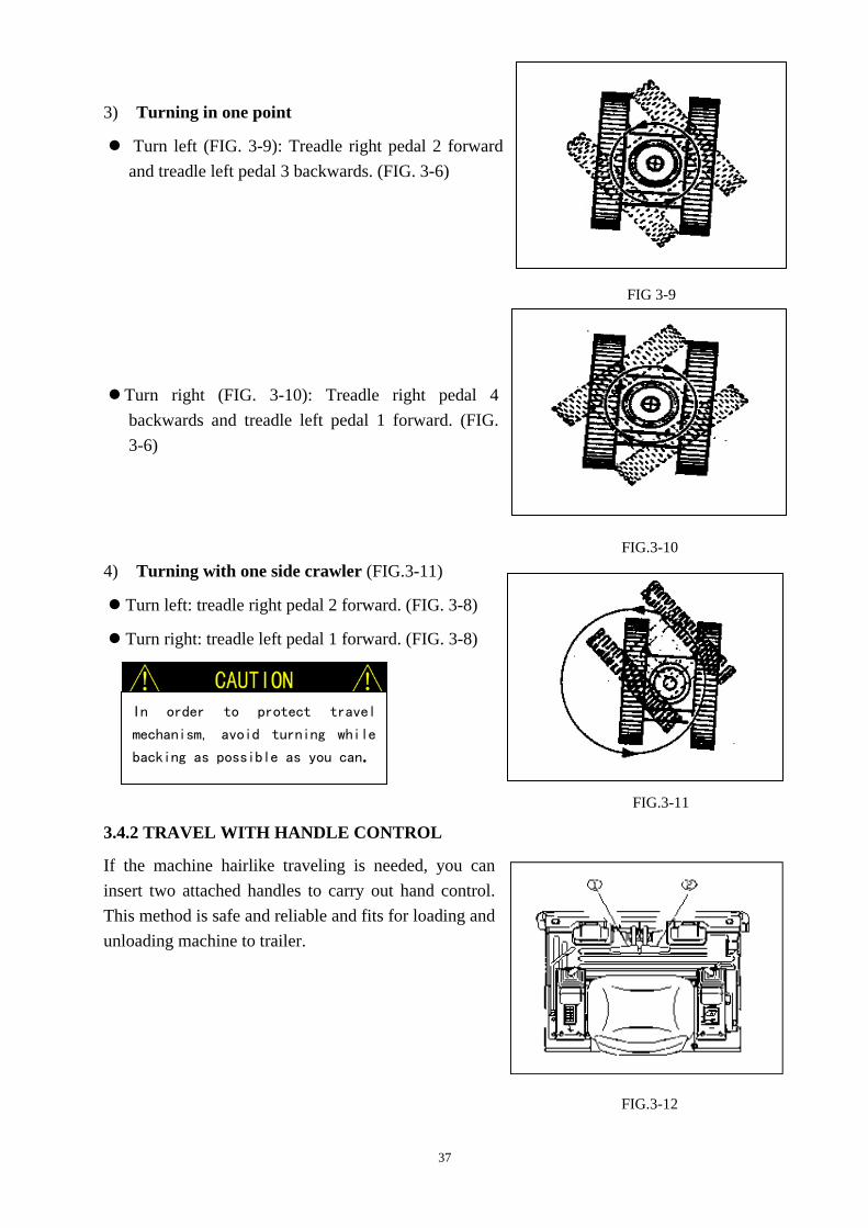
In order to protect travel
mechanism, avoid turning while
backing as possible as you can.
3) Turning in one point
Turn left (FIG. 3-9): Treadle right pedal 2 forward and treadle left pedal 3 backwards. (FIG. 3-6)
Turn right (FIG. 3-10): Treadle right pedal 4
backwards and treadle left pedal 1 forward. (FIG. 3-6)
4) Turning with one side crawler (FIG.3-11)
Turn left: treadle right pedal 2 forward. (FIG. 3-8)
Turn right: treadle left pedal 1 forward. (FIG. 3-8)
3.4.2 TRAVEL WITH HANDLE CONTROL
If the machine hairlike traveling is needed, you can insert two attached handles to carry out hand control. This method is safe and reliable and fits for loading and unloading machine to trailer.
FIG.3-10
FIG 3-9
FIG.3-12
38
FIG.3-13
FIG.3-14
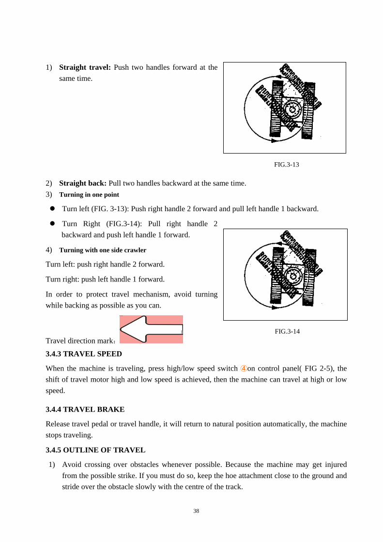
1) Straight travel: Push two handles forward at the same time.
2) Straight back: Pull two handles backward at the same time. 3) Turning in one point
Turn left (FIG. 3-13): Push right handle 2 forward and pull left handle 1 backward.
Turn Right (FIG.3-14): Pull right handle 2 backward and push left handle 1 forward.
4) Turning with one side crawler
Turn left: push right handle 2 forward.
Turn right: push left handle 1 forward.
In order to protect travel mechanism, avoid turning while backing as possible as you can.
Travel direction mark:
3.4.3 TRAVEL SPEED
When the machine is traveling, press high/low speed switch ④on control panel( FIG 2-5), the shift of travel motor high and low speed is achieved, then the machine can travel at high or low speed.
3.4.4 TRAVEL BRAKE
Release travel pedal or travel handle, it will return to natural position automatically, the machine stops traveling.
3.4.5 OUTLINE OF TRAVEL
1) Avoid crossing over obstacles whenever possible. Because the machine may get injured from the possible strike. If you must do so, keep the hoe attachment close to the ground and stride over the obstacle slowly with the centre of the track.

39
2) On uneven ground, travel at low speed and avoid accelerating, stopping or changing directions abruptly.
3) When working in water, check the depth of the water, make sure that the water’s depth is not higher than the half of the track roller. Never dip the rear end of the machine into water.
If the lubricant parts need to work in water for a long time, add enough lubricant oil until the old oil is replaced.
Never imerge the slew bearing in water or sand, if you have to do so, contact the dealer or technician to confirm if this is allowed.
4) Pay special attention to the balance when traveling on a slope (the maximum grade ability is 20°, maximum lateral tipping angle is 10°). And you should note that when actual working area conditions are poor, the machine’s stability might be lower.
When traveling on slopes or grades, lower the bucket to a height of 20 to 30cm. In emergencies, lower the bucket to the ground and stop the machine.
When traveling on slopes or grades, move slowly in first gear (low speed).
Do not travel down slopes in reverse.
Do not change the directions or cross slopes sideways. First return to a flat surface, then redirect the machine.
5) If the excavator can’t travel for getting into miriness, you can extend arm and place bucket to ground to lift one side of crawler, then turn the lifted crawler to clean out the bedload. In order to reduce the force enduring of boom and arm, the angle between boom and arm should be in the range of 90°--110°
6) When the machine gets into wallow or passes raceway, you can use arm and boom to help the machine pass.
FIG.3-15
900~1100
FIG3-16
FIG 3-17
900~1100
20~30cm

40
If the control lever comes back to the neutral position while it is
traveling down the slope, the machine will automatically stop.
If the machine slides while traveling up on the slope, use the pulling
power of the boom to help the machine clime up the slope.
If engine stops accidentally while traveling down the slope, set the
control lever back to the neutral position to stop the machine, lower the
bucket to the ground to block the machine and then restart the machine.
7) The machine must travel in the pose shown in fig 3-17 when traveling up on a slope of 15°
or more.
8) The machine should travel at low speed and in a
pose shown in FIG. 3-18 when it is traveling down on a slope of 15° or more.
3.5 EXCAVATION
Working condition When dig lengthways with backhoe, make the drive wheel backward and guide wheel forward. (as figure)
In order to guarantee safety in quarry working, make the drive wheel backward and guide wheel forward.
Pilot handles control
1 — Left pilot handle
2 — Right pilot handle
1
2
FIG. 3-20
FIG. 3-18
20~30cm
900 ~
FIG. 3-19

41
Control with right pilot handle
Right figure is the obverse view of right pilot handle (when operator sits on the seat). The four movements of handle can make the excavator move as follows.
a —— Raise boom
b —— Lower boom
c —— backhoe load, or bucket close
d —— backhoe dump, or bucket open
Control with left pilot handle
Right figure is the obverse view of left pilot handle (when operator sits on the seat). The four movements of handle can make the excavator move as follows.
e ——Make the superstructure slew widdershins.
f ——Make the superstructure slew clockwise.
g —— Extend arm
h —— Retract arm
Composite movement of excavator
1) When the machine slews, you can operate the composite movement of boom and bucket.
2) It can operate as follows: bucket digs while arm is flexing; arm digs while lowering boom, etc.
3) Besides the co-operation between right and left handle, pull either of the handles to any diagonal orientation (45° direction), can achieve the adjacent two composite movements.
Slewing platform brake
Release slewing control handle, return it to neutral position, it will bring sufficient brake power to brake platform. While reverse handle operation can bring more brake torque.
FIG. 3-21
FIG.3-22
gh
f
e
FIG.3-23
42
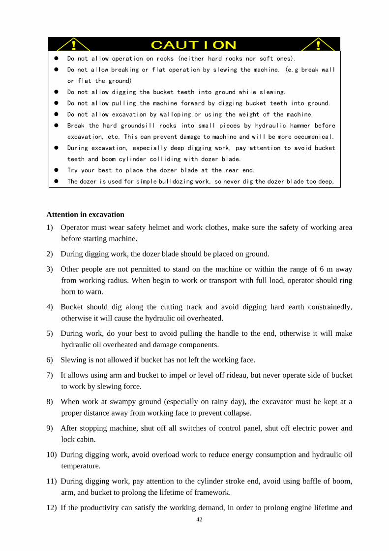
Do not allow operation on rocks (neither hard rocks nor soft ones).
Do not allow breaking or flat operation by slewing the machine. (e.g break wall
or flat the ground)
Do not allow digging the bucket teeth into ground while slewing.
Do not allow pulling the machine forward by digging bucket teeth into ground.
Do not allow excavation by walloping or using the weight of the machine.
Break the hard groundsill rocks into small pieces by hydraulic hammer before
excavation, etc. This can prevent damage to machine and will be more oecumenical.
During excavation, especially deep digging work, pay attention to avoid bucket
teeth and boom cylinder colliding with dozer blade.
Try your best to place the dozer blade at the rear end.
The dozer is used for simple bulldozing work, so never dig the dozer blade too deep,
Attention in excavation 1) Operator must wear safety helmet and work clothes, make sure the safety of working area
before starting machine.
2) During digging work, the dozer blade should be placed on ground.
3) Other people are not permitted to stand on the machine or within the range of 6 m away from working radius. When begin to work or transport with full load, operator should ring horn to warn.
4) Bucket should dig along the cutting track and avoid digging hard earth constrainedly, otherwise it will cause the hydraulic oil overheated.
5) During work, do your best to avoid pulling the handle to the end, otherwise it will make hydraulic oil overheated and damage components.
6) Slewing is not allowed if bucket has not left the working face.
7) It allows using arm and bucket to impel or level off rideau, but never operate side of bucket to work by slewing force.
8) When work at swampy ground (especially on rainy day), the excavator must be kept at a proper distance away from working face to prevent collapse.
9) After stopping machine, shut off all switches of control panel, shut off electric power and lock cabin.
10) During digging work, avoid overload work to reduce energy consumption and hydraulic oil temperature.
11) During digging work, pay attention to the cylinder stroke end, avoid using baffle of boom, arm, and bucket to prolong the lifetime of framework.
12) If the productivity can satisfy the working demand, in order to prolong engine lifetime and

43
In order to protect the electric parts in
cabin, close top window and cabin door when
you park the excavator.
In cold weather, the excavator should be
parked on hard ground to avoid crawler and
ground congealing together. If congealment
happens accidentally, please lift crawler
by using boom, move excavator carefully to
avoid damaging drive wheels.
keep low noise running, try your best not to run at maximum accelerograph, the best revs of engine should be 1600-1800 r/min.
13) Before every shift, according to the rules, inject grease to all reaming connections through grease nozzles until the grease overflows. Otherwise it will cause axle and sleeves damage.
Park excavator 1) Place excavator on a horizontal ground.
2) Lower the bucket to ground.
3) Place accelerograph handle on minimum load position for 5 minutes.
4) Turn ignition key to “OFF” position, and take out key.
5) Pull pilot control lever to lock position.
6) Lock all doors and compartments.
7) Inspection after the engine is stop. Check the oil tank and water tank, work
device, superstructure and infrastructure, repair all the abnormal parts;
Fill all the oil tank, this can refer to chapter “check the oil level”, and clean all the paper scrapes and dirt from engine.
Remove any dirt from
8) Lock all the doors and boxes. 9) If you have to park the machine on the slope, use other method to prevent machine from
sliding.
Operate on swampy ground 1) Try your best to avoid traveling on swampy ground.
2) Clean crawler frame if the machine works on very soft ground or is stuck.
3) Slew superstructure 90° and lower bucket to lift one side of crawler off ground, keep the angle between boom and arm within a range of 90°--110°, and place the bucket arc on the ground.
4) Turn the lifted crawler to eliminate dirt.
Lift one side of crawler by using boom and arm.

44
Don’t slew on slope.
Avoid tilting Avoid transverse traveling on slope. When the machine travels on slope, the traveling direction should be accordant with the gradient. When upgrade and downgrade, keep the bucket pointing to the traveling direction and lifted 20-30cm to the ground. Lower bucket at once if the machine is skidding or instable.
When the machine slews with heavy load, operate carefully with low slewing speed.
Operate in water or mud
You should note following information when operate in water or mud:
1) The working area should be hard enough to prevent excavator from going down.
2) The water flow should be slow.
3) Undercarriage immerged height should not exceed chain support wheel.
4) Avoid immerging slewing support, inner gear ring, and slewing connector.
5) The rear end of machine is not allowed to be immersed into water.
When operate in these conditions, please check the
FIG. 3-26
900~1100
20~30cm
FIG. 3-27
Keep the angle between boom and armwithin a range of 90°--110°, and place the
bucket arc on ground.
Slew superstructure 90° and lower bucket to lift one side of crawler off ground.
Don’t dig into the ground with bucket
teeth when the machine is in backhoe
condition.
Place chock under the framework to
support machine.
FIG.3-24
FIG.3-25

45
excavator position often.
Backhoe operation
1) Place the bucket teeth on ground while the angle between bucket bottom and ground is 45°.
2) Apply arm to be the main digging force, pull bucket to the machine direction.
3) When dirt adheres to the bucket, remove arm and (or) bucket quickly to throw dirt.
4) When dig straight trench, place crawler parallel to the trench. After digging to required depth, remove machine to continue digging.
Leveling operation
Don’t push or pull earth with bucket when the machine travels.
1) Push dozer blade backward to fill and level road.
2) Apply boom, arm, and bucket generally. As the figure shows, place bucket and arm on a line basically. Operate arm in while lifting boom slowly. Once arm passes the vertical position, lower boom slowly and keep the movement of bucket plane. Operating boom, arm, and bucket at
FIG. 3-28
FIG. 3-29
FIG.3-30
Don’t apply bucket overmuch to
level road surface, otherwise
excavator will be damaged.
When lower boom, you should avoid stopping it suddenly. Otherwise the impact load may damage excavator.
When operate arm, in order to prevent damaging hydraulic cylinder, you should avoid lowering hydraulic cylinder to the bottom.
Prevent bucket from colliding with crawler. When digging deep trench, you should prevent boom or arm cylinder hose
from impacting with ground.
46
the same time enables the leveling operation more accurate.
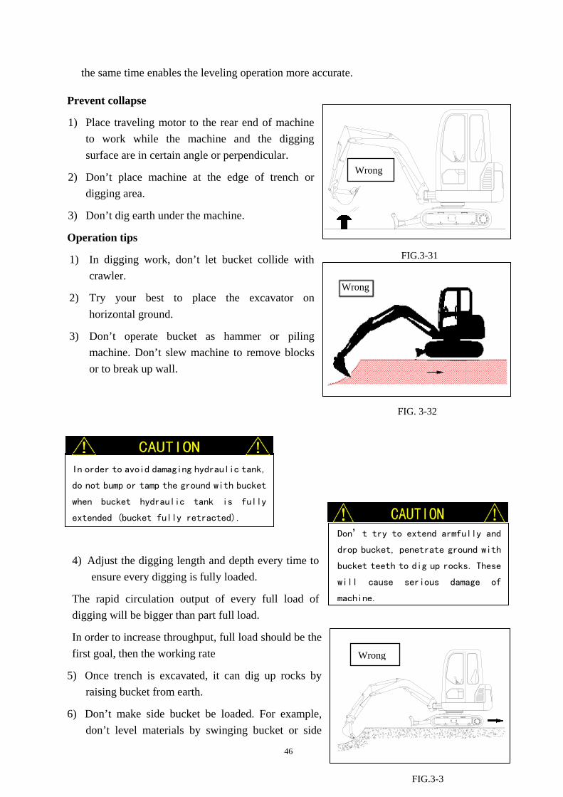
Prevent collapse
1) Place traveling motor to the rear end of machine to work while the machine and the digging surface are in certain angle or perpendicular.
2) Don’t place machine at the edge of trench or digging area.
3) Don’t dig earth under the machine.
Operation tips
1) In digging work, don’t let bucket collide with crawler.
2) Try your best to place the excavator on horizontal ground.
3) Don’t operate bucket as hammer or piling machine. Don’t slew machine to remove blocks or to break up wall.
4) Adjust the digging length and depth every time to
ensure every digging is fully loaded.
The rapid circulation output of every full load of digging will be bigger than part full load.
In order to increase throughput, full load should be the first goal, then the working rate
5) Once trench is excavated, it can dig up rocks by raising bucket from earth.
6) Don’t make side bucket be loaded. For example, don’t level materials by swinging bucket or side
Wrong
FIG.3-31
In order to avoid damaging hydraulic tank,
do not bump or tamp the ground with bucket
when bucket hydraulic tank is fully
extended (bucket fully retracted).
Don’t try to extend armfully and
drop bucket, penetrate ground with
bucket teeth to dig up rocks. These
will cause serious damage of
machine.
Wrong
FIG. 3-32
FIG.3-3
Wrong

47
impact objects with bucket.
Prevent misuse of machine
1) Don’t treat traveling movement as accessional digging force. Otherwise it will damage the machine.
2) Don’t raise the front and rear of machine and treat the weight of machine as accessional digging force. Otherwise it will damage the machine.
Dozer blade operation mark:
Pay attention to the dozer blade position
1) When extend dozer blade, it may collide with boom cylinder or bucket, please pay attention to it.
2) When carries out deep digging work, place dozer blade at rear to guarantee safety.
Prevention measurement for dozer blade 1) Don’t use dozer blade to dig, otherwise it will damage
dozer blade or crawler system.
2) Dozer blade can’t support large or unstable barycenter
Note
FIG.3-36
Note
FIG.3-35
FIG.3-34
Wrong

48
Follow all safety regulations when the
machine lifts objects.
Don’t use damaged chain, wire rope, or
cord in lifting work.
Don’t move the load suddenly, don’t move
load on the top of human beings, and never
permit anybody to be adjacent to the load.
Ensure everybody is away from the lifted
objects until the chocks support the load
or the load has been stably placed on the
ground.
Fix superstructure and place the
traveling motor at the rear.
Don’t connect sling/chain to the bucket
teeth.
objects, otherwise it will damage dozer blade or crawler system.
3) When the machine is traveling, dozer blade can’t hook any object, otherwise it will damage dozer blade or crawler system.
4) When prop up machine with dozer blade, the ground should be plane to ensure dozer blade touch ground stably.
Be careful when retract foreside working device
Don’t allow the bucket to collide with dozer blade.
Don’t allow dozer blade to touch roadblock
Don’t allow dozer blade to touch roadblock, otherwise dozer blade, cylinder or other components will be damaged
3.6 LIFT WORK
Lifting hook mark: 750610020152
FIG.3-38
FIG.3-37

49
1) Sling/chain should tightly bind the load, the workman should glove when bind sling/chain.
2) Connect sling/chain with bucket lifting ring, curled bucket and retracted arm.
3) Before start, uniform the hand signal with signalman.
4) Acquaint with the positions of all workmen in the range of work area.
5) Mark hand rigging on the load to ensure the people pulling hand rigging is away from load.
6) Try to lift the load before normal operation.
Park the machine beside the load.
Load the machine.
Lift load to the height of 50mm (2in) off the ground.
While keeping the load close to ground, move the load from the machine.
If there is any evidence of stability reduction, lower load to the ground.
7) Just lift the load to required height.
3.7 HYDRAULIC BREAKING OPERATION
Hydraulic breaking operation tips…if equipped
Choose hydraulic breaker with correct dimension and weight. Consult with your dealer.
Pump / Main valve section assignment
The hydraulic pressure of section AUX (the hydraulic pressure of the breaker section) supplied by P2 is 21 M Pa.
Attention to hydraulic breaker tubing
1) When the hydraulic breaker is out of use, cover the pipe end of arm and fit a plug at the end of hydraulic breaker hose to avoid dirt entering into system.
2) Ensure stocking cover and plug in tool compartment for maintenance purpose.
3) Avoid dirt entering into system when change bucket with breaker.
4) After connection, check the oil leakage and bolts slack condition.
Before fitting hydraulic breaker on the arm, read machine and hydraulic breaker manuals carefully, and carry out the required confirmation or inspection.
Carry out required inspection before daily operation.

50
Excavator with hydraulic hammer breaker
Excavator with normal bucket
Hydraulic oil 600★ 1000 Filter core 100★ 250
Wrong
1) Operate machine slowly, the stability of machine will be decreased because the hydraulic breaker is heavier than the bucket. Therefore, use dozer blade to support and work in front of dozer blade.
2) Avoid hammering work with hydraulic breaker. Never use boom or arm to break objects, otherwise it will damage machine.
3) Don’t move objects with hydraulic breaker,
otherwise it will damage machine.
4) Don’t operate hydraulic breaker when hydraulic
cylinder piston retracts or extends fully, avoid damaging hydraulic cylinder or machine.
5) If hydraulic breaker hose jumps abnormally, stop
operation immediately. The pressure change of breaker accumulator or damaged accumulator will cause unusual hose jump, and damage hydraulic breaker or machine.
6) When retract foreside attachment, don’t allow the chisel of breaker to touch boom.
7) Don’t operate hydraulic breaker in water.
8) Don’t lift objects with hydraulic breaker, otherwise it will cause machine upset and (or) breaker damage.
9) Don’t swing superstructure to the side of machine to operate hydraulic breaker, or the machine will be instable and thus shorten the lifetime of undercarriage.
Replacement of hydraulic oil and filter core Hydraulic breaker operation will pollute hydraulic system and accelerate aging. You should replace hydraulic oil filter core and hydraulic oil more frequently to avoid damaging hydraulic pump and other hydraulic parts. The recommended replacement interval is shown as follows.
Replacement interval (hours)
FIG.3-3
Wrong
FIG.3-41
FIG.3-40
Note

51
The figures with mark ★ apply for excavators whose
hydraulic breaker operation time is more than 100%. For the
hydraulic breaker operation time ratio is less than 100%,
the replacement interval should be as the diagram shows.
When the machine operates hydraulic breaker continuously
more than 100 hours, replace hydraulic oil filter core.
Set the pedal to the lock position when
it is not used. If not, if any controls
should be touched accidentally when the
pedal has not been locked, it may cause
serious accident.
Hydraulic breaker
operation time percentage (%)
3.8 BOOM SWING
The boom swing pedal locates at the position of operator’s right foot, it is used to swing boom, but the superstructure (cabin, engine, etc) won’t slew when operating this pedal.
A. Treadle lower side of pedal, swing boom to right side.
B. Treadle higher side of pedal, swing boom to left side.
FIG.3-4
FIG.3-41 Replacement interval (hours)
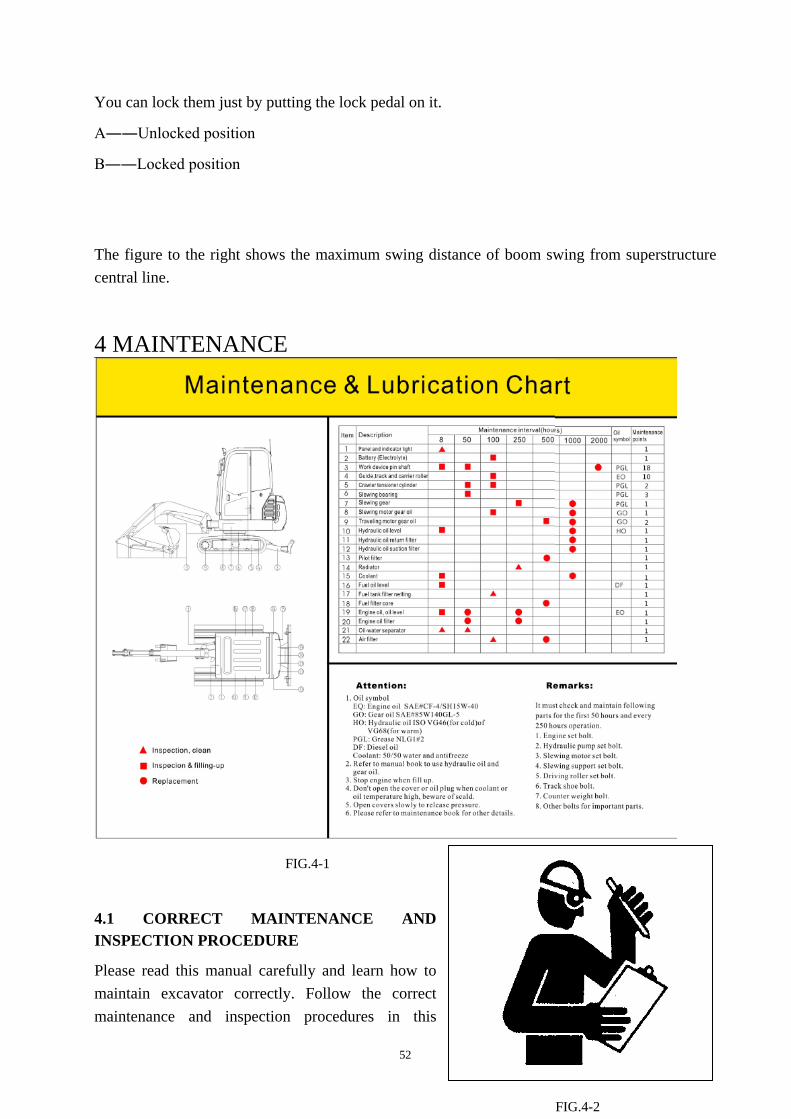
52
You can lock them just by putting the lock pedal on it.
A――Unlocked position
B――Locked position
The figure to the right shows the maximum swing distance of boom swing from superstructure central line.
4 MAINTENANCE
4.1 CORRECT MAINTENANCE AND INSPECTION PROCEDURE
Please read this manual carefully and learn how to maintain excavator correctly. Follow the correct maintenance and inspection procedures in this
FIG.4-2
FIG.4-1

53
manual. Check excavator before daily operation.
1) Check monitor.
2) Check all liquid level.
3) Check leakage, distortion, abrasion, and damage of hoses and pipes.
4) Check noise and temperature around excavator.
5) Check slack or loss of parts.
Repair the excavator before operation if the machine has problems, or consult your dealer.
Periodic maintenance
Carry out all recommended maintenance in this manual.
Check work calculagraph (hour meter) usually
Determine when the machine needs periodic maintenance according to calculagraph ①.
Use recommended fuel, hydraulic oil and lubricant. Only use original SUNWARD parts. If user doesn’t use recommended fuel, hydraulic oil, lubricant and original SUNWARD
parts, the warranty will automatically be invalid.
Never adjust engine rev limiter or hydraulic system safety valve. Avoid electric parts touching water and vapor. Never disassemble engine pump controller, sensor, etc.

54
The intervals in the periodic maintenance list are based on the normal condition. If operate excavator in bad conditions, the intervals should be shorten.
Use fuel and lubricant correctly
Preparation for maintenance 1) Place the machine on a hard horizontal ground.
2) Lower the bucket to the ground.
3) Operate engine at low rev for 5 minutes.
4) Stop engine, and take out the key from switch. (If it is necessary to maintain the machine as the engine runs, operator can’t leave cabin)
5) Pull the pilot control lever to “LOCK” position.
6) Before maintenance, please hang the label “DO NOT OPERATE” on left joystick.
Always use recommended fuel and
lubricant, otherwise it will damage
the machine and lose the warranty of
Sunward.

55
Engine maintenance Please carry out periodic maintenance in the engine manual.
Periodic replacement of hydraulic hose 1) Make sure to carry out periodic inspection of machine to guarantee safe operation. If listed
parts are damaged, it may cause serious fire. Because it is difficult to judge the aging situation of these parts by vision, you should replace them at listed intervals. However, if any part is found bad in the inspection, it should be replaced before operation without consideration of intervals. Also check the hose couplers, if they are distorted, cracked or aged, replace them if necessary.
2) Make sure to check all hoses periodically, and replace them if necessary.
3) Consult your dealer about how to replace hose correctly.
Recommended periodic hose placement list
Periodic replaced parts Replacement
Interval
Engine Fuel hose (from fuel tank to precipitator, from precipitator to oil feeding pump)
1.5 years
Machine
Body
Pump inhaling hose (from oil tank to main pump) 2 years Pump output hose (from pump outlet to multipurpose valve) 2 years Multipurpose valve hose (from multipurpose valve to working device, slewing coupler, slewing motor)
2 years
Low pressure hose (pilot hose, oil-returning hose) 2 years
Working Device
Boom cylinder hose 2 years Arm cylinder hose 2 years Bucket cylinder hose 2 years
Note: Make sure to replace seals (such as O ring) when replace hoses.

56
4.2 MAINTENANCE GUIDE
4.2.1 ADD LUBRICANT GREASE
★★ Means that these parts need maintaining when work in water or mud.
Recommended lubricant grease brand and specification
Position: bucket, arm, boom, slewing gear, slewing bearing, etc. From —20 to 40°C(from —4 to 104F)
BP petroleum BP Energrease Ls—EP2 Caltex petroleum Multifax EP2 Esso Beacon EP2 Japan Daphne Coronex Grease EP2 Mobil petroleum Mobilux EP2 Germany 2# lithium grease ★ Shell Shell Alvania EP Grease 2 Remark Heavy duty lithium grease
Note:The excavator departed from factory has been filled with “★” marked engine
oil.
4.2.2 ENGINE OIL
Parts name Qty Interval (hours)
8 50 100 250 500 1000 2000
1. Engine oil Check
oil level
―― △
2. Engine oil Replace
1.6~2.8L △★ △
3.Engine oil filter Replace ―― △★ △
Note:★ means that the engine oil and engine oil filter must be replaced after
the first 50 hours’ operation of machine.
Please maintain as per the requirement in diesel engine manual book.

57
In order to make the correct choice of a commercial oil, please refer to the “YANMAR operation and maintenance manual.”
Recommended engine oil
Position: bucket, arm, boom, slewing gear, slewing bearing, etc. From —20 to 40°C(from —4 to 104F)
BP petroleum BP Energrease Ls—EP2 Caltex petroleum Multifax EP2 Esso Beacon EP2 Japan Daphne Coronex Grease EP2 Mobil petroleum Mobilux EP2 Germany 2# lithium grease Shell Shell Alvania EP Grease 2 Remark Heavy duty lithium grease
Note: The excavator departed from factory has been filled with “★” marked engine
oil.
Engine oil specification: Be sure engine oil being used must meet following criterion or classification. API classification CD (or higher)…. ACEA classification E3, E4, E5. JASO classification DH-1 The other technical requirement for engine. Replace engine oil, when value TBN drops to 1.0(mgKOH/g), Engine oil viscosity : Refer to viscosity fig below for proper engine oil of SAE during different ambient temperature.
The performance of engine oil is very
different, commonly the engine oil adopts
API or CCMC standard.
YANMAR engine company recommends to use engine oil .of 3TNV70-SSU(API
classification CD)

58
The reading will be imprecise if
check oil level immediately after
stopping machine. Make sure to cool
down the engine oil at least 15
minutes before inspection.
Check engine oil level 1) Park the excavator on a level ground.
2) Take out dipstick, wipe the oil with clean cloth, and insert dipstick into engine again.
3) Take out dipstick again, the oil level must lie between MAX and MIN marks.
4) Fill engine oil through filler filter if necessary. Make sure to use recommended oil.
Replace engine oil
The engine oil and oil filter must be replaced after the first 50 hours’ operation.
After first replacement, please carry out replacement as per <YANMAR operation and maintenance manual>.
Replace engine oil filter…every 500 hours
Steps of replacing engine oil and filter
1) Warm up engine oil before start, but don’t overheat.
2) Park the excavator on a level ground.
3) Lower the bucket to ground.
4) Run engine idle for 5 minutes.
5) Shut off engine, and take out key switch.
6) Pull the pilot control lever to lock position.
In order to get correct value, check
oil level before starting engine
everyday and make sure to park the
excavator on level ground.

59
7) Take off the outlet plug, pour the oil into a 10L container through a clean cloth.
8) After oil is vented, check whether there is metallic chipping on cloth.
9) Fit and screw down outlet plug.
10) Clean surrounding area of engine oil filter seat. Turn the filter cartridge anti-clockwise to remove old seals.
11) Clean sealed washer surface of filter seat.
12) Wipe clean oil on the seals of new filter.
13) Fit new filter, turn filter clockwise until the washer touch interface. Ensure not to damage washer when fitting filter.
14) Screw down engine oil filter. Remember not to make it too tight to prevent screw thread distortion or filter core seals damaging.
15) Open oil filter cover, and fill recommended oil in engine 15 minutes later, check whether the oil level lies within the marking range or not.
16) Fit filler cap.
17) Start engine. Run at low revs for 5 minutes.
18) Check whether the engine oil pressure indicator light goes out at once, if not, stop engine and check for the reason.
19) Stop engine, take out key from key switch.
20) Check whether there is any leakage at outlet plug.
21) Check oil level on dipstick
4.2.3 GEAR OIL
Parts name Qty Interval (hours)
8 50 100 250 500 1000 2000
1、Slewing reducer Check oil level — △
Replace 2L △
2、Traveling reducer Check oil level — △
Replace 2x2 L △
The engine oil may be very hot,
please be cautious of scalding.

60
Recommend gear oil Brand Manufacturer
Gear oil -20℃--40℃
Esso Esso Gear Oil GP80-90,GP85W-90 Nippon Petroleum Gear Lube Sp90
Mobil Mobilube Gx90 Fina GL-580W-90
GREAT WALL brand of China Petrochemical 85W/90
Shanghai oil refining factory API-GL-4 85W/90
Traveling reducer Check oil level…every 500 hours operation
1) Park the excavator on a level ground.
2) Lower bucket to the ground.
3) Run engine idle for 5 minutes.
4) Shut off engine, and take out key switch.
5) Pull the pilot control lever to lock position.
6) Open oil level check plug, check oil level.
7) If necessary, fill the filler through oil ② fil ler hole
to the level as the right figure shows.(refer to “gear oil blank”)
In the figure: ② is the reducer oil fil ler hole, ③ is the
oil drainage port.
Replace gear oil…every 1000 hours operation
1) Park the excavator on a level ground.
2) Lower bucket to the ground.
3) Run engine at low revs for 5 minutes.
4) Shut off engine, and take out key switch.
5) Pull the pilot control lever to lock position.
6) Take out oil drainage port plug ③, and empty gear
FIG.4-4
FIG 4-5
The gear oil may be very hot,
please start working until the
gear oil cools down.
The first replacement should be
applied after 250 hours ’
operation of the new machine,
after this time, replace it every
1000 hours.
FIG.4-4

61
oil.
7) Re-fit on oil drainage port plug.
8) Take out filler cap. Fill in gear oil until the oil level is equal to the oil filler hole.
4.2.4 FUEL SYSTEM
Parts name Qty
Interval (hrs)
8 50 100
200 400 1000 2000
1. Vent fuel tank sediment 1 △ 2. Check and vent sundries in precipitator 1 △★ △
3. Vent water and sediment in water segregator 1 △
4. Replace fuel filter 1 △
5.Check fuel hose
Leakage, crack, etc. —— △ Crack, distortion, etc. —— △
Recommended fuel:
Please use high quality diesel fuel (GB2520 in normal condition; 10 for the winter) only, do not use kerosene.
Fueling
1) Refer to “stop engine” chapter, park the
excavator properly and turn off the engine correctly.
2) Check fuel indicator on monitor, do fueling work if necessary.
3) Prevent any dirt, dust, water or other impurity from getting into fuel tank or fuel system.
4) Make sure that there is no fuel sparked onto the ground in the fueling work every day after the work in order to prevent coagulation of fuel.
5) Put on cap after fueling.
Check and vent the precipitator every
50 hours, and replace it every 1000
hours.
Be caution about the fuel. Turn
off engine before fueling. Do not
smoke while fueling the fuel tank
or work near the fuel system.
FIG. 4-6

62
Vent the sediment in fuel tank 1) Rotate the superstructure flat roof 90°, and park
the excavator on level ground.
2) Lower the bucket to ground.
3) Run engine at low revs for 5 minutes.
4) Shut off engine, and take out key switch.
5) Pull the pilot control lever to lock position
6) Open the vent valve on the bottom of fuel tank for several seconds, vent water and sediment. Then close the vent valve.
Check and vent the impurities…every 50 hours
Vent water and sediment of the segregator…
everyday Vent water and sediment of the segregator…everyday. Shut off engine in a correct manner. Open the vent valve on the bottom of the segregator. Screw the valve anticlockwise for circles, until the valve goes down for 25mm. Vent the water in the catch basin of the filter until pure fuel flows out.
Replace the fuel filter…every 400 hours. 1) Use proper container when venting the fuel to protect environment and secure safety. Do not
pour the fuel on ground、into slot or river、pool and lake. Properly dispose of the scrap fuel.
Fuel precipitator, which is generally
called fuel coarse strainer. The fuel,
which comes from fuel tank, should be
filled into fuel pump after being
percolated through it, this can protect
fuel pump.
Exhaust the air in fuel system after
venting the water.
FIG.4-8
FIG.4-7

63
2) Clean the surrounding area of filter. Disassemble the filter, clean the surface of the sealed washer.
3) Replace O ring.
4) Fill clean fuel into the new fuel filter and lubricate the O ring with clean oil.
5) Screw down the filter by your hands, but make sure not over do it.
6) Exhaust the air from fuel system after replacement of the filter.
Check the fuel hose…every day…every 200 hours
In order to prevent such danger: 1) Park the excavator on firm level ground. Lower the bucket to ground, stop the engine in a
correct manner, and take off the key from key switch.
2) Check the twist wear and leakage of fuel hose. Replace or fasten the hose if any abnormality is found.(refer to the table below)
Inspection of hoses interval(hour) Check point abnormality Solution
Everyday Hose end Hoses with knitted cover
leakage wear crack
Fasten or replace replace replace
Every 200 hours
Hose end Hoses with knitted cover
hose hose
hose end and connector
crack crack
brushfire protrusion bending
distortion & eroding
replace replace replace
replace(adopt proper bending semidiameter)
replace
Over screwing will have the screw
thread distorted and damage the
sealed ring of filter core or filter
More operation details are on
chapter “ engine operation &
maintenance instruction book”
Leakage of fuel will result in fire,
and human accident.
Please use the original components of
sunward only.

64
Exhaust air from fuel system.
Exhaust air from fuel system by pushing down the joystick on fuel filter seat.
4.2.5 HYDRAULIC SYSTEM
Recommended hydraulic oil brand and specification
Parts name Qty Interval (hours)
8 50 100 200 500 1000 1500 2000 1. Check hydraulic oil level —— △ 2. Vent sundries of hydraulic oil tank ——
△ ★
3. Replace hydraulic oil 30L △
4. Clean oil inhaling filter ——
5. Replace oil inhaling filter —— When replacing hydraulic oil
6. Clean oil returning filter △
7. Replace oil returning filter core. —— △
8. Replace pilot oil filter —— △ △
9. Check hose and pipeline
Leakage —— △
Crack and distortion —— △
More details are on “ engine
maintenance instruction book”.
Air in the fuel system will cause
stat-up difficulties and abnormal
operation of engine. After venting
water and sediment from precipitator,
make sure to exhaust air from fuel
system after replacing the fuel filter
or venting over the fuel tank.

65
Inspection and maintenance of hydraulic system
1) Make sure to park the machine on a firm level ground when maintaining hydraulic system.
2) Lower bucket to ground, and stop engine.
3) Begin hydraulic system maintenance after parts, hydraulic oil, and lubricant have cooled down completely. The hot parts or oil are likely to fly out or spark out and cause serious damage. When remove screw plug or bolts, keep your body and face away from them.
4) Before maintaining hydraulic system, exhaust air of hydraulic oil tank to release pressure.
5) Make sure to operate control lever several times to release inner pressure.
6) Avoid checking and maintaining the traveling and slewing circuit at slope.
7) When connecting hydraulic hoses and pipes, pay special attention to keep seals surface clean and avoid damaging them. Please remember following items:
Wash the interior of hoses, pipes, and oil tank with cleanser; and wipe up them before
connection.
Use scatheless or non-defective O rings. Don’t damage them in the assembly.
Never distort high pressure hose, the lifetime of distorted hose will be shortened greatly.
Oil species Hydraulic oil Parts Hydraulic system Replacement interval 1000 hours
Temperature
Engine oil Manufacturer
-30℃-30℃ -5℃-40℃
Fina HM46
Esso Standard
Mobil AW32 AW46
Shell
German
Caltex HD46
Note Abrasion-resisted hydraulic oil
The hydraulic parts will be very hot
during operation. Please remember to
cool down excavator before inspection
or maintenance.

66
FIG.4-9
8) Fill same brand & spec. hydraulic oil, never use different brands of oil at the same time. When you want to use “recommended hydraulic oil brand and specification” listed oil, make sure to replace all hydraulic oil in the system at the same time.
Check hydraulic oil level…everyday
1) Park machine on a level ground.
2) Arm cylinder extracts and bucket cylinder extends completely to fix excavator.
3) Lower bucket to ground.
4) Run engine idle for 5 minutes.
5) Stop engine, and take out key switch.
6) Pull pilot control lever to lock position.
7) Open right side door, check oil level meter. The oil level must lie between marks. Otherwise you should fill oil.
Fill oil: 1) Screw anticlockwise and open screw cover on the top.
2) Fill oil through filter netting, and check oil lever meter again.
3) Screw down cover.
Vent hydraulic oil tank impurities…every 200 hours
1) For easy access, rotate superstructure 90°,and park the machine on level ground.
Never use other hydraulic oils not
included in the list.
Don ’ t start engine when the
hydraulic oil tank is empty.
Never start engine when the
hydraulic oil tank is empty.
Never start engine when the
hydraulic oil tank is empty.
FIG.4-10

67
2) Lower bucket to the ground.
3) Run engine idle for 5 minutes.
4) Stop engine, and take out key switch.
5) Pull pilot control lever to lock position.
6) Keep your body and face far away from oil outlet plug.
7) Loosen vent plug at the bottom of hydraulic oil tank after oil cools down, vent water and sediments.
8) Screw down vent plug after water and sediments have been vented.
Replace hydraulic oil…every 1000 or 1500 hours
Clean oil inhaling filter …when replace hydraulic
oil
1) For easy access, rotate superstructure 90o
2) Arm cylinder extracts and bucket cylinder extends completely to fix excavator.
,and park the machine on level ground.
3) Lower the bucket to ground.
4) Run engine at low revs for 5 minutes.
5) Stop engine, and take out key.
6) Pull pilot control lever to lock position.
7) Screw the screw plug ① of vent hole, release the inner pressure of fuel tank.
Don’t loosen vent plug before oil
cools down, the hydraulic oil may
be hot enough to cause scald.
The replacement interval of
hydraulic oil is different with
its specification. (Refer to the
recommended oil table of this
part)
Before screwing the screw plug, or
separating the oil pipe, stand at the
side of the part, screw it slowly to
release pressure, and keep your face
and body away from the screw plug.
The hydraulic oil may be hot,
cool it down before
FIG. 4-11

68
1) Release oil vent plug ③ at the bottom of
hydraulic oil tank by spanner to vent the oil. And fill the scrap oil into some kind of container.
2) Release the rubber hose connecting oil return hole flange ② and oil sucking hole flange ④.
3) Remove the oil return hole flange ② and oil sucking hole flange ④.
4) Remove the oil sucking filter core and oil returning filter core.
5) Clean the interior of oil sucking filter core and oil tank, if change filter, fit new filter on the flange.
6) Connect the clean filter core (or new filter core ) with their connect flange, fasten the fuel tank, then connect the rubber hose.
7) Clean, fit on, and screw down oil outlet plug.
8) Fill the new clean hydraulic oil from point A to the oil tank. Keep the oil level reach the position between the marks of oil level meter.
9) Screw down screw plug ① of air vent hole.
Exhaust air
1) Release exhaust plug of hydraulic pump.
2) Once hydraulic oil overflows from the exhaust plug plug, screw the plug down immediately.
3) Start engine and run it idle for 10 mins.
4) Run engine idle, do 4-5 times incomplete journey extending & contracting operation all the hydraulic cylinders.
5) Run engine at high speed, do 4-5 times incomplete journey extending & contracting operation with all the hydraulic cylinders.
6) Run engine idle again, do 4-5 times complete journey extending & contracting operation with all the hydraulic cylinders.
After the replacement of hydraulic
oil, exhaust the air from hydraulic
circuit and hydraulic device. If this
work has not been properly done, it may
cause damage to the hydraulic devices.
FIG.4-12

69
Check the hoses and pipes…everyday…every 200 hours
1) Inspect leakage with cardboard, pay attention to protect your hand and body not touching high pressure liquids
2) If accident occurs, see the doctor at once.
3) Any liquid penetrated in skin must be cleaned within a few hours. Otherwise it will cause necrosis.
Hose inspection Interval hour Check point Abnormality manner
Everyday Hose surface
Hose end Connector
leakage leakage leakage
replace replace
fasten or replace hose or O ring
Every 200 hours
hose surface hose end
hose surface hose surface
hose hose
hose end and connector
crack crack
out coming of enhanced material
parts protrusion bending
distortion and eroding
replace replace replace replace replace
replace(adopt proper bending semidiameter)
replace
FIG.4-13
The jets of high pressure liquid
can penetrate skin and cause
serous damage.
The leakage of hydraulic oil and lubricant can cause fire and damage of human
body, in order to prevent this danger:
Park the excavator on a firm level ground.
Lower the bucket to ground.
Run engine idle for 5 minutes.
Stop the engine in a correct manner and take out the key from key switch.
Put pilot control split level to LOCK position.
Check the twist, the wear between other parts, leakage of fuel hoses. Replace
or fasten them immediately if there is any abnormality. (Refer to the table
below)

70
4.2.6 AIR FILTER
Parts name qty interval(hour)
8 50 100 250 500 1000 2000
1.Air filter core Clean 1 △ Or when the indicator light
replace 1 After 5 times clean or 1 year operation 2.Air filter and
connecting pipes between engines
Check the seal
condition △
Replace Replace immediately when crack or leakage is detected
Clean air filter core…every 100 hours or clogging indicator light comes on.
Replace outer and inner filter core…every 5 times clean or 1 year operation.
1) Park excavator on level ground.
2) Lower bucket to ground
3) Run engine idle for 5 minutes.
4) Stop engine, and take out key switch.
5) Pull pilot control lever to lock position.
6) Open engine cover. Remove pothook of
Please use the original
components of sunward only
Only clean air filter at scheduled time to prevent dust entering engine.
Also check airproof and fixation termly of elastic joint between engine and
air filter. Because the engine, muffler, radiator, hydraulic oil pipe, glide
components and many other parts of the machine may still hot, touching may cause
scald.
Shut off engine and cool the machine down before inspection and maintenance.
Wear proper protective equipments when operating compressed air, such as
blinkers and light filter mask, metal scraps or other objects may cause damage
to human body.
FIG.4-14

71
rubber ring ④ and release shell (8).
7) Release the lock catch and take out the dust collection cup ⑥.
8) Clean the interior of the dust collection cup ⑥
9) Take out the filter core ⑦.
10) Cover the back of the shell of the air filter with cloth or adhesive tape to avoid the entering of dust.
11) Clean the interior of the shell.
12) Use dry compress air whose pressure is lower than 686kPa to clean air filter core ②, first, blow
along the flute of interior of the filter core, than blow from outside, finally blow from the interior.
13) Light a lamp in the filter core, check the filter core, replace it immediately whether any hole or spot is detected.
14) Remove the cloth or adhesive tape of step 10.
15) Install filter core.
16) Install dust collection cup ⑥, keep the “TOP”
mark up, then lock the lock catch ⑤.
17) Use rubber ring ④ to fasten shell ⑧.
18) Press button ③ on dust indicator ① to press the
red piston into filter core shell.
Connection pipeline between air filter and engine
Check airproof…everyday
Replace…When pipeline
has crack and air leakage
Decrease pressure of compressed air,
keep other people away from operation
site, beware of flying debris and wear
personal safety implements.
FIG.4-15
If bad airproof or crack occurs
on connection pipeline, dirty
air will enter and damage engine.
FIG.4-17
FIG.4-16

72
4.2.7 COOLING SYSTEM
Parts name Qty Interval (hours)
8 50 100 250 500 1000 2000
1. Check cooling water level 1 △ 2. Check and adjust fan belt tension 1 ※1 △
3. Replace cooling water 10L △ 4. Clean radiator and hydraulic oil cooler core
interior 1 △※3
exterior 1 When replace cooling water
Fill soft and pure tap water or bottled water.
Antifreeze: If the air temperature is below 0℃(32℉ ), add antifreeze and soft water to the cooling system.
In general, the ratio of antifreeze should be between 30% and 60%.
If the ratio is less than 30%, the cooling system will be rusted; if the ratio is more than 60%, the engine will be overheated. Use 50% water and 50% glycol antifreeze, the engine can operate at the -37℃ perennially.
Only maintain in the first inspection.
When the machine is delivered, 30% of antifreezing fluid has been filled in the
cooling system.
Operate the machine at dusty areas, maintenance interval should be shortened.
Antifreeze is poisonous, if ingested, will cause serious injury or
death. In case of drinking it by accident, you should lead vomiting
and go to hospital at once.
Ensure storing the antifreeze with container, which has been sealed
with cover or has obvious mark, the antifreeze should be stored at
the place that children can’t get.
If the antifreeze splashes into eyes by accident, wash eyes 10 to 15
minutes with water, and then go to hospital at once.
Obey all the regulations when store or throw away antifreeze.

73
Check cooling water level…everyday
When engine is running, the cooling water level should reach the lower surface of flume neck. If the water level is lower than the lower surface, add cooling water to water tank.
Check and adjust fan belt tension
Every 100 hours (the first check should be
after 50- hour operation)
Press the belt with thumb at the middle point between strap wheels and crank, if the press is 58.8N (6kg), the maximum flexibility should be 10mm.
Visually check the damage, crack, and abrasion of belt. If there is any ill evidence, change the belt.
Clean radiator and oil cooler core
Exterior……every 250 hours
Interior……once per half year
Open radiator repairing door and hood cover.
Use compressed air (less than 0.2MP) or water to clean or wash the radiator of oil cooler.
Lax fan belt may cause insufficient
power of battery, engine overheat, and
quick & abnormal belt abrasion. On the
other hand, over tighten the belt will
damage bearing and belt.
Before the system cools down, don’t
loosen water filler cover ① of
radiator. Screw off the cover slowly,
release all the pressure before
Don’t check, test, and replace belt
when engine is running.
Mount new belt, run engine at low revs for 3-5 minutes, adjust tension
again to ensure the new belt is
perched correctly.
Use low pressure compress air (less than 0.2MP) to do clean work, be aware
of flying claps, wear individual
protect equipments, including eye
protection items.
When working in the dusty
environment, check the sundries and
blocking of radiator, oil cooler and
condenser core.
FIG. 4-18
①

74
Replacement of coolant every 1000 hours
1) Open the engine back cover.
2) Loosen the radiator box cover, release the press in radiator.
3) Loosen the water venting plug ① to vent the coolant into some kind of container.
4) Screw down the water venting screw plug and add some cleanser and water, fill the radiator water tank with water. This job may take some time. Please use the cleanser under the instruction on this manual.
5) Start engine, run idle for about 30 mins. Pay attention to the cleanser level and add water if the level goes down.
6) Shut off engine and vent all the cleanser.
7) Screw down the water venting plug ①, add water, start engine and run idle for 10 mins, then shut off the engine and vent all the water.
8) Repeat the hereinbefore cleaning work until the water is clean.
9) Screw down the water venting plug ①and add new coolant till the appointed height after clean job.
10) Start engine and run it idly, exhaust air, shut off
Shut off engine and cool down the machine before operation. The body、muffler、radiator and other parts of the machine will be very hot when
the engine is just stopped, touching these parts may cause serious scald.
The cooling water of engine is also very hot, be careful when loosen radiator box cover and venting plug to avoid serious scald by the injection of high temperature
and high pressure cooling water.
If it is needed to maintain the machine while engine is running, the cooperated work of 2 men is necessary, one should sit on the operator’s seat while another
one do maintenance work.
Keep your body and clothes away from the transmission parts. When the engine is running, it is very dangerous to stand behind the machine, as
the machine is likely to move suddenly.
Do not move the radiator box cover or the water venting plug before the engine coolant has cooled down. Shut off engine, slowly loosen the radiator box cover
and water venting plug after the engine and radiator cover have cooled down.
① FIG. 4-19

75
engine after the coolant level is stable and stay at the appointed height.
11) Check the coolant height, then screw down the water tank cover.
4.2.8 OTHERS
Parts name Qty Interval (hours)
8 50 100 250 500 1000 2000 1 . Check abrasion and laxation of bucket teeth —— △
2.Replace bucket 1 When necessary 3.Control lever lubricant When necessary 4.Check track tag 2 △
5.Replacement of rubber track 2 When necessary
6.Clean track mechanism ―― When necessary 7 . Bolt & nut fasten moment When necessary
Check bucket teeth 1) Check the abrasion and laxation of bucket
teeth everyday.
2) Replace the seriously abraded teeth.
3) The replacement procedure :
Take out lock pin ① with hammer and punch.
When disassembling the lock pin, be careful, do not damage elastic steel ring ②.
Dismantle teeth, check the damage of lock pin ① and elastic steel ring ②, replace them if
necessary.
Clean the protruding seat surface.
To prevent injury caused by flying
off metal scrap, wear goggles or
safety glasses.
FIG.4-21
(2)
(1)
FIG. 4-20
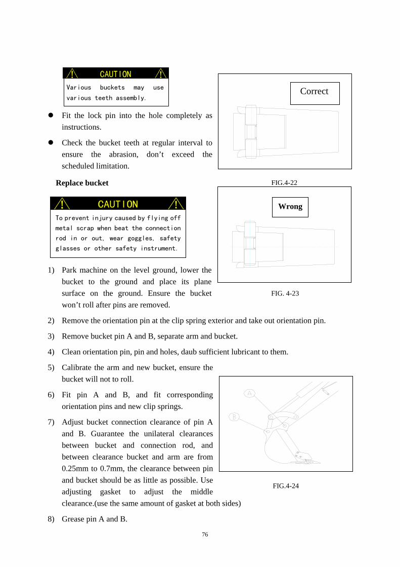
76
Fit the lock pin into the hole completely as
instructions.
Check the bucket teeth at regular interval to ensure the abrasion, don’t exceed the scheduled limitation.
Replace bucket
1) Park machine on the level ground, lower the
bucket to the ground and place its plane surface on the ground. Ensure the bucket won’t roll after pins are removed.
2) Remove the orientation pin at the clip spring exterior and take out orientation pin.
3) Remove bucket pin A and B, separate arm and bucket.
4) Clean orientation pin, pin and holes, daub sufficient lubricant to them.
5) Calibrate the arm and new bucket, ensure the bucket will not to roll.
6) Fit pin A and B, and fit corresponding orientation pins and new clip springs.
7) Adjust bucket connection clearance of pin A and B. Guarantee the unilateral clearances between bucket and connection rod, and between clearance bucket and arm are from 0.25mm to 0.7mm, the clearance between pin and bucket should be as little as possible. Use adjusting gasket to adjust the middle clearance.(use the same amount of gasket at both sides)
8) Grease pin A and B.
Various buckets may use
various teeth assembly.
To prevent injury caused by flying off
metal scrap when beat the connection
rod in or out, wear goggles, safety
glasses or other safety instrument.
FIG.4-24
Correct
FIG.4-22
Wrong
FIG. 4-23

77
Lubrication of control lever
Add some lubricant to the control lever and pedal if they can not move smoothly.
A. Control lever
1) Disassemble the low part of the rubber dustproof cover of the operation lever, turn over it upward.
2) Clean the aging lubricant and add new lubricant.
3) Reposit the rubber dustproof of control lever.
B. Link bar mechanism 1) Remove rubber mat ①.
2) Loosen the bolt, disassemble cover ②.
3) Disassemble rubber dustproof ③.
4) Use doper to add lubricant to lubricant nozzle ④.
5) Clean the overflowed lubricant. 6) Fit the cover and rubber mat in the
reversed order of disassembly operation.
Park the excavator with engine off,
takes out the key, set pilot safety
control lever to lock position. If
not, the sudden movement of excavator
may cause serous damage.
FIG.4-25
FIG.4-26
FIG.4-27

78
Check track lag …every 50 hours (or when necessary)
A. Inspection 1). Slowly operate the control valve, use the
operation device and dozer blade to lift the machine.
2). Check the center under surface of the track frame and the clearance of the up surface (A), the clearance should be within following range: A 65~70mm.
Please use wood block, jack or other firm and stable supporter to lift the machine.
Never work while there is not enough support of the machine, especially when the
hydraulic cylinder is working.
There is pressure grease in the track tightening mechanism, the grease pressure relief
valve may fly out and cause damage if you do not operate as the follow procedures.
Slowly screw off the grease pressure relief valve.
Never let your body, face, legs or arms be exposed in front of the grease pressure
relief valve.
Two men are needed when checking the track tensity, one operate the excavator to lift
the track of one side, the other one measure the dimension, you must pay more attention
to prevent the sudden movement of the machine. Warn up the engine before the checking
work and park the machine on a level ground, and use stoppers if necessary.
FIG.4-28
If there is too much dirt, dust or other
things on the undercarriage assembly, you
may get an incorrect measure result, so you
must clean the undercarriage before the
measuring work.
FIG.4-2

79
B. Adjustment
Increase tension power 1) Take off cover ①. 2) Use grease gun to inject grease into grease
pressure relief valve ② through grease nozzle. 3) Check the track tensity.
Decrease tension power
1) Take off cover ①.
2) Slowly screw off grease pressure relief valve ② to
release grease. If there are any difficulties when adding the grease, move the machine forward or backward.
3) Screw down grease pressure valve ②.
4) Check the track tensity.
Replace rubber track Check the rubber track and repair or replace them immediately when following conditions appear. And contact the SUNWARD dealer for repair or replacement.
1) If the track has been pulled longer and can not recover, it should be replaced immediately.
2) If the dummy club ①is lower than 5mm, replace
track. 3) If more than 2 of the steel wire core ②have
exposure, replace track.
4) If half of the steel wire core ② has broken, replace
the track.
5) Replace the track if only one of the iron core has desquamated.
6) Replace track when rubber track has a more than 60mm long gap.
A. Disassemble 1) Completely loosen the tightened track. (Refer to page 83 and 84 “inspection of track”) 2) Slowly operate the control lever, use the operation device and dozer blade to lift the machine,
and use other firm and stable objects to support the machine.
3) Insert a steel pipe into the gap between rubber track and the track frame, slowly reverse the
FIG.4-30
FIG.4-31
FIG.4-32

80
sprocket wheel until the steel pipe is near the guild wheel and rubber track leaves the guild wheel to a certain height.
4) Slide the rubber track to the side of machine to disassemble it. Both of the two tracks can be disassembled following this schedule.
B. Installation 1) Slowly operate the control lever to lift the machine with control device and the dozer blade,
then use some wood block、jack or other firm subjects to support the machine.
2) Install the rubber track on the sprocket wheel.
3) Insert a steel pipe into the gap between the rubber track and the track frame, slowly reverse the sprocket wheel until the steel pipe is near the guild wheel and rubber track has left the guild wheel for a certain height.
4) Slide the rubber track to the inboard of the machine, get the track、sprocket wheel and guild wheel in mesh and take out the steel pipe.
5) Check the rubber track and ensure that it is in mesh with sprocket wheel and guild wheel.
6) Tighten the rubber track with tightening mechanism until it reaches the standard tensity.
7) Install the other track in the same manner.
Clean the track
1) Lift the track on one side of the machine and firmly support it before cleaning the machine.
2) Clean all the sand grains and dirt in the guild wheel slide way.
Bolt & nut tighten moment
(Iso10.9 intensity standard certificated) 1) If no special request, considering the screw down moment of the bolt and nut refers to the
following table.
2) Don’t use the moment in the following table when assembling plastic caps, or the cap may be broken. Contact the SUNWARD dealer or after service department for help when doing this.
3) Use standard pieces of bolts and nuts in the same specification for replacement.
4) Alternately screw down the bolts and nuts (up、down、left and right), or screw it 2-3 times to ensure enough tensity.
Stop machine and clean it immediately when it is very dirty.
Any dry and firm dirt or freezing dirt will cause damage to the track mechanism and
shorten its service life.

81
Screw thread Spanner
specification(mm)
Screw thread specification
Screw moment(N.m)
Thick screw thread
10 M6×1.0 9.8±0.5 12,13 M8×1.25 22.6±1.1 14,17 M10×1.5 47.1±2.4 17,19 M12×1.75 83.4±4.1 19,22 M14×2.0 134.4±6.7 22,24 M16×2.0 207.9±10.4 27,30 M20×2.5 410.9±20.5
Thin screw thread
12,13 M8×1.0 24.5±1.2 14,17 M10×1.25 50±2.5 17,19 M12×1.5 87.3±4.3 19,22 M14×1.5 135.3±6.8 22,24 M16×1.5 220.6±11 27,30 M20×1.5 452.1±22.6

82
4.2.9 MAINTENANCE IN SPECIAL SITUATION
Operation condition Maintenance
Work in mud、water or rain
1. Inspect the loose and lost of connector、bolts and nuts, obvious damage and leakage.
2. Clean mud、stone、sand grain on the machine, check the damage、crack and loose of jointing after work.
3. Carry out everyday lubrication and maintenance. 4. Clean concerned parts with water after working in acid
rain or corrosive chemical materials.
Work beside the sea
1. Inspect all the screw plugs and make sure that all of them have been screwed down.
2. Clean the machine carefully to remove all the salt on machine and maintain the wiring frequently to prevent possible cauterization.
In dusty or hot condition
1. More frequently clean the air filter core.
2. Wash the radiator and oil cooler cooling fin to remove dust and dirt.
3. More frequently clean the fuel sucking filter and its core.
4. Termly carry out clean maintenance, especially the surface of the engine and generator.
Work in the stony ground condition
1. Carefully operate the machine. Check if the undercarriage and track assembly are over damaged or worn.
2. Check for the loosen、damaged and lost connector、bolts and nuts.
3. More frequently check the over damaged and worn bucket and breaker.
4. Install a top frame and front frame if necessary to prevent damage caused by fallen subjects.
In cold weather
1. Use high quality, low glutinosity oil, which fit the environment temperature.
2. Make sure to use the antifreeze, which fit the temperature.
3. Charge the battery a little bit before the usual time. If the battery is not completely charged, the electrolyte may be frozen.
4. Clean all the dirt on machine to prevent possible damage caused by frozen dirt.

83
“Lubricant operation” means to warm up the
machine and repeat the operation of a series
of traveling, rotation and digging for 2-3
times.
The lubricant oil and grease will become aging. Therefore, carry out inspection
before operating the machine every time.
4.2.10 PROTECTION FOR LONG TERM STORE
If the excavator needs to be stored for over 1 month, the following protection should be adopted to maintain its function during the store period.
Protection for long term store
Maintenance Details
Clean machine Completely clean the machine, fix any malfunction.
Add lubricant oil and grease
Check the lubricant to find if it is dirty or insufficient. Add lubricant to the parts, which need this. And smear a layer of oil.
Battery Take off the battery and charge it then restore it.
Coolant Add antirust. Add antifreeze if it is possible to be frozen; or vent out all the coolant, and hang a label:“No water in radiator” in the cabin.
Dustproof and moistureproof measure Store the machine in a dry garage and cover it.
Tools Inspect and repair it after stored.
Lubricant operation If the oil layer is damaged, the part is likely to rust, and cause some abnormal wear. Start the machine once per month at least to prevent this situation and check the liquid level of coolant and lubricant.
4.2.11 HEATER MAINTENANCE
(1) Use compressed air to wash heating core surface termly(half a year~one year) according to work environment.
(2) Inspect hot water tube circuit and wire harness termly to prevent abrasion, scald, over bend and connector loose.

84
5. TRANSPORTATION AND STORAGE
5.1 General transportation rules Before transporting the machine with trailer, obey the related local regulations of freeway governing the length, width, height, and weight.
If any measurement exceeds the regulation of local freeway, you must apply for special permission, or separate the machine to smaller parts for transportation purpose.
5.2 Transportation measurement
SWE17B
A. total height:2378 mm C. chassis lwidth:980 mm
B. total length:3820 mm D. chassis width:(track frame extended):1310 mm
E. superstructure width(cabin):1170 mm
There is a possibility that the machine will roll, tip over, or fall while loading or
unloading it. Therefore, you need to take the following precautions:
Select a firm, level surface and keep sufficient distance from the roadside.
Use a loading ramp of adequate strength and size. Maintain the slope of loading ramps
within 15°.
Keep the truck bed and loading ramps free of oil, clay, ice, snow, and other materials,
which can become slippery.
Never change courses on the ramps.
Do not slew on the ramps. The machine may tip over.
If you must swing on the truck bed, do so slowly as the footing can be unstable.
Because the fulcrum on the trail is not stable, when swinging or rotating on a trail,
you need to do it very slow.
FIG.5-1

85
SWE20B
A. total height:2370 mm C. chassis lwidth:990 mm
B. total length:3820 mm D. chassis width:(track frame extended):1360 mm
E. superstructure width(cabin):1210 mm
Notice:
Specific dimension in transport parameter and outline drawing are
shown in section 7(technical specification)
5.3 Loading & unloading Make sure that the ramps are strong enough before loading the machine and follow these procedures:
1) Apply the truck’s parking brake and place stoppers against its tires.
2) Fasten the ramps securely to the truck bed so that they will not come off. Set the ramps to an angle of 15°or less.
3) Direction of the excavator: The work device should be placed at the foreside and directs forward while loading (as the right figure); and while unloading, place the work device backward at the rear, and travel backward.
4) Line up the center of the truck bed with the center of the machine and the center of the ramps with the center of the crawlers.
5) Use the engine accelerograph control lever to reduce the revs of engine, drive the machine slowly to the slope, and lower the hoe attachment as much as possible, making sure it will not hit the truck.
6) Close the windows and doors of cabin, cover the vent, prevent rain from entering.
The machine should travel at lowest speed on ramps.
Turning while traveling on ramps is very dangerous, and it is forbidden. If you must
do so, turn the machine back to the ground or truck bed, modify the traveling direction,
and then pass the ramps.
The intersection of the top of ramps and truck bed is protuberant, pass it carefully.
Prevent the possible tip over and injury while the superstructure of excavator is
swinging. Retract, lower arm and swing superstructure slowly to achieve best stability.
FIG.5-2
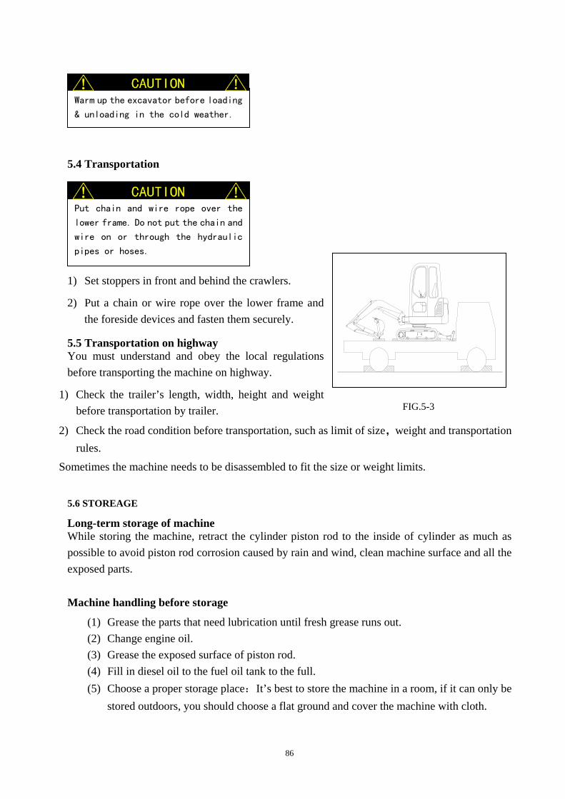
86
5.4 Transportation 1) Set stoppers in front and behind the crawlers.
2) Put a chain or wire rope over the lower frame and the foreside devices and fasten them securely.
5.5 Transportation on highway You must understand and obey the local regulations before transporting the machine on highway.
1) Check the trailer’s length, width, height and weight before transportation by trailer.
2) Check the road condition before transportation, such as limit of size,weight and transportation rules.
Sometimes the machine needs to be disassembled to fit the size or weight limits.
5.6 STOREAGE
Long-term storage of machine While storing the machine, retract the cylinder piston rod to the inside of cylinder as much as possible to avoid piston rod corrosion caused by rain and wind, clean machine surface and all the exposed parts.
Machine handling before storage
(1) Grease the parts that need lubrication until fresh grease runs out. (2) Change engine oil. (3) Grease the exposed surface of piston rod. (4) Fill in diesel oil to the fuel oil tank to the full. (5) Choose a proper storage place:It’s best to store the machine in a room, if it can only be
stored outdoors, you should choose a flat ground and cover the machine with cloth.
Warm up the excavator before loading
& unloading in the cold weather.
FIG.5-3
Put chain and wire rope over the
lower frame. Do not put the chain and
wire on or through the hydraulic
pipes or hoses.

87
As to malfunction reason and repair
manner of the engine, please refer to
the 《YANMAR 403C-11 engine malfunction
estimation and maintenance manual 》.
Only authorized people can disassemble and repair the hydraulic parts, please
consult with manufacturer if mentioned works is necessary.
Lower the work equipment or dozer blade to the ground when servicing them and
release the residual pressure of hydraulic system:
Park the machine on level ground, stop the engine, put the pilot control rod
on open position
and shake the pilot operation handle for several circles.
Machine storage period
(1) Run the machine once a month during storage period. (2) Run the air-conditioner system once a month.
Machine handling after storage
(1) Wipe the grease off on piston rod surface. (2) Grease all the places that need lubrication. (3) Check engine oil level to make sure it is in a stipulated position, otherwise you should
fill oil. If there is any water in oil, change oil (4) Turn the key to “ON” position, switch accelerograph button from low to high speed and
last for 3 seconds, then switch to low speed and start engine. 6. TROUBLE SHOOTING If malfunction occurs, stop machine immediately, analyze the reason and maintain adjust or repair the machine as following methods, objects and order.

88
Malfunctions and solutions
Malfunction Reasons Solutions
Noisy hydraulic pump and vibratory pipeline
1. Hydraulic malfunction. 2. Air bubble in hydraulic
system. 3. Aging hydraulic oil,
degenerative oil mixed with moisture, wrong brand and specification produce bubble.
4. Low hydraulic oil temperature and high viscidity of hydraulic oil.
1. Consult with your dealer.
2. Check whether air leakage at oil pump inlet pipeline.
3. Replace oil. 4. Run engine in low revs
and then warm up the engine.
Control levers don’t work or work slowly.
1. The machine is out of use for a long time, air separates from oil and floats in pilot control pipeline and hydraulic cylinder,etc.
2. No pressure or exceeding pressure in pilot system.
3. Low hydraulic oil temperature and high viscidity of hydraulic oil
4. Hydraulic pump malfunction.
5. Main safety relief valve malfunction
1. Operate control levers for several times.
2. Check hydraulic control system, low-pressure relief valve, and gear pump.
3. Warm up machine.
4. Consult with your dealer.
5. Consult with your dealer.
A cylinder doesn’t work or work slowly.
1. Corresponding pilot valve malfunction
2. Corresponding commutator valve malfunction
3. Corresponding overload valve malfunction
4. Hydraulic cylinder pole damaged
5. Hydraulic cylinder interior seals damaged
1. Repair
2. Consult with your dealer
3. Consult with your dealer
4. Consult with your dealer
5. Replace oil seals

89
Slewing platform don’t
slew, slew slowly, or slew
not smoothly.
1.Corresponding pilot valve malfunction
2.Hydraulic motor malfunction
3.Slewing retarder malfunction
4.Slewing bearing malfunction
5.Need to add lubricant grease into the slewing bearing.
1.Repair
2.Consult with your dealer
3.Consult with your dealer
4.Repair
5.Add lubricant grease

90
Heater Malfunctions and solutions
Malfunction
feature Reason Resolution
Track of one side
doesn’t work or
move very slowly
(serious deflexion
of traveling)
1. Control pilot valve malfunction
2. Corresponding commutator valve and stop valve malfunction
3. Center connector seal damage
4. Hydraulic motor malfunction
5. Travel redactor fault
6. The displacement of two-gang hydraulic
pump is not equal
1. Repair
2. Consult with the dealer
3. Consult with the dealer
4. Consult with the dealer
5. Consult with the dealer
6. Consult with the dealer
The hydraulic oil
temperature rises
too fast or becomes
too high
1. There is dirt on the surface of oil cooler.
2. Wear of hydraulic parts and reduction of the cubage efficiency.
3. Overfall valve and over load valve opens too frequently
1. Clean
2. Contact the dealer。
3. Over digging , over loading, change the digging method.
Some unexpected
actions occur
without operating
1.Multitandem valve lever block.
2.Pilot valve core block.
1. Contact the dealer
2. Contact the dealer
Mandril leak at the
top of pilot valve Seal ring of the pilot valve mandril piston trepan boring aging or damage
Inspect and replace
Work device
malfunction Usually caused by the block of multitandem valve lever’s one way valve
Inspect and replace
Malfunction Description Check Solution Heater unit stops working.
Air blower stops running.
A. Circuit break. B. Bad grounding.
Check and repair Check and repair
Heating effect is not good.
Air blower works normally.
A. Hot water tube circuit block. B. Heavy dust on heater core surface.
Check tube circuit. Clean core surface.

91
7. SPECIFICATIONS
7.1-1 20FTECHNICAL PARAMETER
Engine…………………………………………………………………YANMAR diesel engine Model………………………………………………………………YANMAR 3TNV80F-SSU Displacement………………………………………………………………………………1.267L Number of cylinder………………………………………………………………………………3 Power………………………………………………………………………… 13.4 kW/2200rpm Fuel assumption…………………………………………………………………………250g/kw.h Coupling ………………………………………………………MONOLASTIC 32 Flansch kupp lung Radiator…………………………………………………………………………4842.077.0000V1
Hydraulic device Hydraulic pump…………………………………………………………………… plunger pump Model…………………………………………………………………PVD-0B-19P-6AG3-5807A F l o w … … … … … … … … … … … … … … … … … … … … … … … … 2 x 2 1 + 1 5 L / m i n W o r k p r e s s u r e … … … … … … … … … … … … … … … … … … … … … 2 2 . 5 / 1 8 M P a Multitandem valve……………………………………………………………………EV310160 Hydraulic pilot valve………………………………………………………carry out the hydraulic proportion control of the boom, arm, bucket and flat swing through 2 “+”control joysticks
Left operate handle model……………………………………………..…….…HC-RCX 47585 Right operate handle model………………………………………………………HC-RCX 47586
Pilot system pressure……………………………………………………………………3.5Mpa Hydraulic cylinder (standard backhoe) ………….double action combined sealed hydraulic tank Boom cylinder………………………………………………………………………φ60Xφ35mm Arm cylinder………………………………………………………………………φ60Xφ35mm Bucket cylinder……………………………………………………………………φ60Xφ35mm Dozer cylinder……………………………………………………………………φ75Xφ40mm Swing cylinder…………………………………………………………………… φ60Xφ35mm Undercarriage cylinder…………………………………………………………… φ55Xφ30mm Swing hydraulic motor……………………………………………………plunger variable motor Model…………………………………………………………………PCR-1B-05A-P-9189A Travel hydraulic motor…………………………………..…… plunger two polar variable motor Model……………………………………………………………………PHV-2B-20A-PT-9775A
Hydraulic oil tank capacity………………………………………………………………35L
Hydraulic cooling device Oil cooling device model……………………………………………………B7793A.000 Fan drive……………………………………………………………………… engine drive
Hydraulic oil filter

92
Oil return filter core model………………………………………………………………EF-133
Swing mechanism
Maximum output screw moment…………………………………………………………3016N.m
Flat rotate speed………………………………………………………………………10rpm
Slewing bearing……………………………………………Single volleyball slewing bearing
traveling brake…………………………………………………hydraulic brake “+”spring pressure
multiple brake (normally closed)
Electric device
Battery………………………………………………………………………………1X12V,60Ah
Starter…………………………………………………………………………………12V,1.4KW
Generator…………………………………………………………………………………12V,40A
Fuel device
Fuel tank capacity………………………………………………………………………………23L
Travel mechanism
Speed ratio …………………………………………………………………………………31
Maximum output torque moment
High speed…………………………………………………………………………...898 N.m
Low speed……………………………………………………………………………1589Nm
Travel speed High speed…………………………………………………………………………3.6 km/h Low speed…………………………………………………………………………2.1 km/h
Gradeability……………………………………………………………………………………30°
Travel brake…………………………………………………hydraulic brake“+” spring pressure
multiple brake (normally closed)
Track tensity……………………………………………………………………………hydraulic
Optional items:
Standard bucket: ……………………………………………………………………………384mm, 0.04 m 3 Optional bucket: ……………………………………………………………(260mm, 0.027 m 3),
(300mm, 0.03 m 3 ), (600mm, 0.06 m 3 ), (1000mm, 0.1 m 3 ) Standard arm: …………………………………………………………………………… 1150 mm
Customers can choose simple cabin and quick coupler as an option according to different requirements.

93
7.2 TECHNICAL INTRODUCTION
SWE20F is an all hydraulic track excavator with beautiful appearance, 360° rotatable flat roof, 1080mm long small rear end, all of these ensure the work in limited place. The engine is YANMAR 3 cylinder water-cooling diesel engine which has a normal rated power of 13.4kW/2200rpm. Use flexible supporting breadthwise,install the engine at the rear end of machine. Air filter is a fixed equipment of SK119540-12510; safety device (optional) on engine inlet pipe ensures more safety and stability of the engine. Large capacity water tank with air exhaust device for the engine cooling system can effectively protect engine and ensure normal work in high temperature and prevent overheating. The main pump and engine directly connected with flange, maximum work pressure is 21 Mpa. Use flexible shaft coupling installed in the diesel motor flywheel to drive the main pump, perfectly avoid the influence on main pump, which is caused by the vibration of diesel motor.
Hydraulic system and pilot system Hydraulic pump, main valve, drive motor and swing motor from Italy Nachi、HC with perfect quality and stable work condition can ensure the stable work of the whole system. Full power qualified system can make full use of the engine power. Aboratively matched drive control element can ensure the good control of the whole
machine. The system can appropriately distribute and make use of flow to improve and promote
the machine performance. High pressure double speed travel motor provides high traction and travel speed. Adopt a 33L oil tank to supply the oil pump. Oil pump supply oil to the entire working device through multitandem valve, and the
oil comes back to oil tank through oil cooler and magnetism papery filter. The pilot control mechanism in cabin can ensure the multitandem valve action. The gear pump connected with main pump can supply hydraulic oil to pilot oil passage. The high precision high-pressure filter in pilot oil passage can avoid interferer from
outside. Hydraulic oil cooling
We adopt aluminium oil air exchanging cooler. Hydraulic oil can be perfectly cooled.
Fuel device Diesel tank can be supplied from a 23L fuel tank, the compact and appropriate design makes it very easy to add fuel and clean.

94
Swing drive Hydraulic swing motor drives the swing supporting of inner joggle through a planetary reducer. The normally engaged brake in drive system can ensure the safety of the machine.
Boom swing The design of ultra-large angle boom swing mechanism makes the machine be applied at side ditch, side channel, foot of wall and cliff. It better meets the current demand of both home and foreign markets and broadens the use range of machine. Undercarriage The excavator undercarriage is a high tortuosity rigid steel structure part. The large dimension pilot wheel and drive wheel provide best travel ability on severe road condition and self-clean ability. Undercarriage with the function of left and right track frame flexing has greatly improved the stability of machine in operation. The wheels and track are Shan Tui products with high stability and quality. The single element of track device, such as oriented wheel, carrier roller, track wheel, have a long lubricant cycle and don’t need to be maintained frequently. Hydraulic track tension device can conveniently tension and loosen track. The helix spring provides huge tension power for oriented wheel and ensures the track orientation, avoid track digression. High alloy steel track has good adhesion, stability and long service life.
Travel drive Travel drive adopts axial piston double speed oil motor for power supply, providing high travel speed and more traction. Novel travel mechanism is a build-in structure with compact structure and high universality. The viarable system make the travel speed change from 0~2.06km/h to 0~3.53km/h. Travel brake Italian COMER piston motor and well-assorted brake drive adopt hydraulic brake“+”multiple spring pressure brake (normally closed) to provide stable brake ability while working, especially when working on the slope. Compensation valve connected with travel motor can avoid overdrive when machine traveling on slope. Cabin The cabin has two types, the common one & the brief one. The common cabin and flexibly installed cabin tally with international standard on width、height and structure. In addition, the test result according to the ISO10262 and ISO12117 standard of cabin protection structures by the engineering equipment lab center of Ji Lin University shows that the prototype meets the lowest performance requirements.

95
Wide front door can extend to the front and ensure convenient passage. Glass around the cabin and turnover front window provides best view for operator. Cabin seat is designed according to the ergonomics and can provide more comfort. The surface, backrest and rigidity are adjustable and can suit different kinds of requirement from different operator. Seat with safety belt and pillow is optional. Control lever is appropriately integrated with left & right control box, the light handle of the lever can prevent fatigue caused by long time work. Double action pedal switch control the travel drive. Also it can be controlled manually. Monitor is within operator’s sight and it is very easy to recognize the indicators on it, such as engine、electronic device and hydraulic system. All the indicator’s sketch maps comply with SAE certification. There is radio installed in cabin. Also, there is heater in cabin (optional). The heater we adopt is world famous Bergstrom product with perfect performance. Machine canopy and sound insulation The whole canopy is composed of firm middle machine canopy and back cover. It can protect the engine and pumps, the high quality sound insulation materials reduce noise to comply with European standard. Arm teeth We adopt knockdown tooth, which has a tooth cover and tooth holder made by wearable alloy steel. The cover and holder are connected with lateral pin, which allows easy replacement. Though there is no special bucket tooth on the side of the bucket, there are side blades with clearance angle to help digging.

96
7.3 OPERATION PARAMETER
(1)Outline dimension
(2)Working range dimension
model parameter
SWE20F
Outline dimension(length×width×height) mm 3820X990X2370
Dimension parameter
A Distance between wheel mm
1210
B Length of track mm
1555
C Turret distance to ground mm
482
D Gyration radius of turret mm
1122
E Chassis width mm
990/1360
F Track width mm
230
G Ground clearance of chassis mm
160
H Track height mm
385
I Overall length mm
3820
J Overall height(to cab top) mm
2370
K Upper structure width mm
990
Dozer dimension(length × width) mm 1310×267
SUNWARD

97
model parameter
SWE20F
Working range
A Max. digging height mm
3770
B Max. unloading height mm
2720
C Max. digging depth mm
2380
D Max. vertical digging depth mm
1870
E Max. digging radius mm
4040
F Max. reach at ground level mm
3945
G Max. lifting height of dozer mm
295
H Max. digging depth of dozer mm
360
R Min. swing radius mm
1565
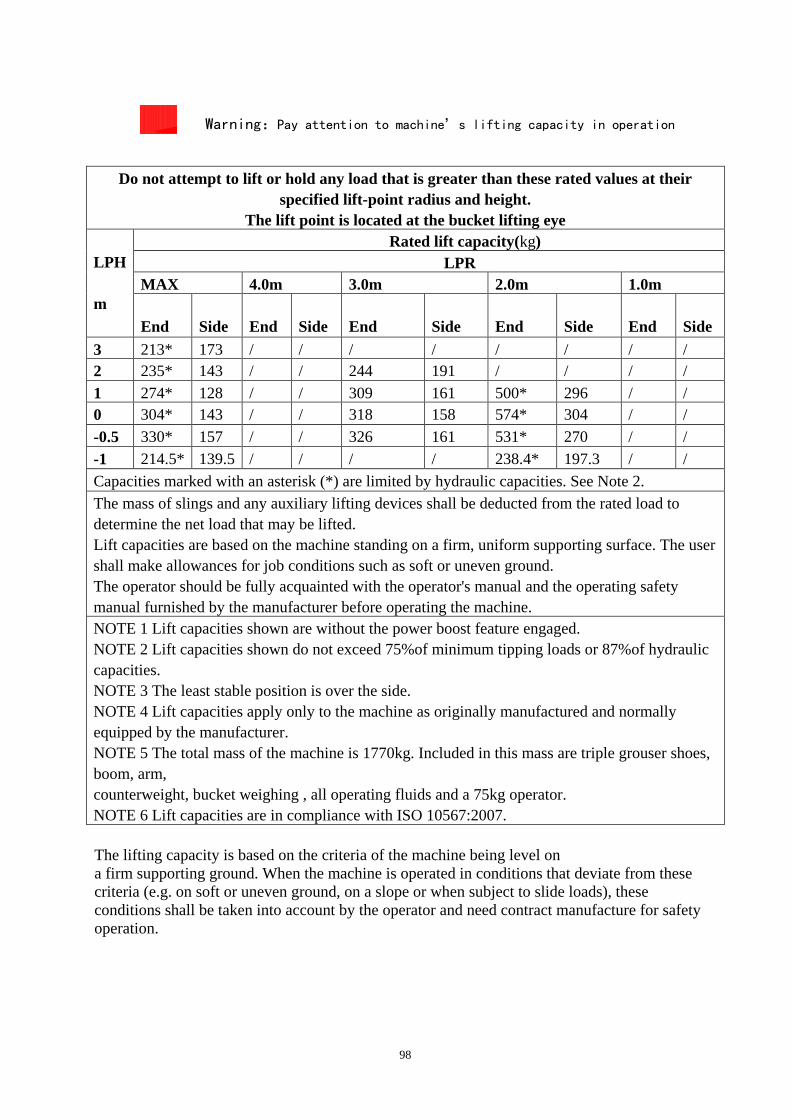
98
Warning:Pay attention to machine’s lifting capacity in operation
Do not attempt to lift or hold any load that is greater than these rated values at their
specified lift-point radius and height. The lift point is located at the bucket lifting eye
LPH m
Rated lift capacity(kg) LPR MAX 4.0m 3.0m 2.0m 1.0m End
Side
End
Side
End
Side
End
Side
End
Side
3 213* 173 / / / / / / / / 2 235* 143 / / 244 191 / / / / 1 274* 128 / / 309 161 500* 296 / / 0 304* 143 / / 318 158 574* 304 / / -0.5 330* 157 / / 326 161 531* 270 / / -1 214.5* 139.5 / / / / 238.4* 197.3 / / Capacities marked with an asterisk (*) are limited by hydraulic capacities. See Note 2. The mass of slings and any auxiliary lifting devices shall be deducted from the rated load to determine the net load that may be lifted. Lift capacities are based on the machine standing on a firm, uniform supporting surface. The user shall make allowances for job conditions such as soft or uneven ground. The operator should be fully acquainted with the operator's manual and the operating safety manual furnished by the manufacturer before operating the machine. NOTE 1 Lift capacities shown are without the power boost feature engaged. NOTE 2 Lift capacities shown do not exceed 75%of minimum tipping loads or 87%of hydraulic capacities. NOTE 3 The least stable position is over the side. NOTE 4 Lift capacities apply only to the machine as originally manufactured and normally equipped by the manufacturer. NOTE 5 The total mass of the machine is 1770kg. Included in this mass are triple grouser shoes, boom, arm, counterweight, bucket weighing , all operating fluids and a 75kg operator. NOTE 6 Lift capacities are in compliance with ISO 10567:2007. The lifting capacity is based on the criteria of the machine being level on a firm supporting ground. When the machine is operated in conditions that deviate from these criteria (e.g. on soft or uneven ground, on a slope or when subject to slide loads), these conditions shall be taken into account by the operator and need contract manufacture for safety operation.

99
8. ATTACHMENT
8.1 20FNELECTRIC DRAWING

100
8.2 20FHYDRAULIC DRAWING

101
8.3 HYDRAULIC COMPONENT LIST
No. Name No. Name
1 diesel engine 11 hydraulic oil tank
2 plunger pump 12 main valve
3 pilot oil source block 13 center rotation joint
4 swing motor 14 arm cylinder
5 left joystick (pilot control valve)——arm+swing
15 boom cylinder
6 right joystick (pilot control valve)——boom+bucket
16 bucket cylinder
7 selector valve——blade+crawler extends and retracts
17 travel motor
8 oil suction filter core 18 dozer blade cylinder
9 oil cooler 19 boom swing cylinder
10 oil return filter core 20 chassis extends and
retracts

102
9. ABOUT MANUFACTURER Company: SUNWARD intelligent equipment Co., LTD.
Trade mark:
Address: 16 LiXiang Road, Xingsha economic and technologic development district, Changsha,
Hunan.
Tel: 0086-0731-83572739 83572783
Maintenance point: our office in some provinces and cities of China
About distributor
About distributor
Distributor name:
Address:
Tel:
Fax:
Email:
Service personnel:
Note