THE LARGEST HYDRAULIC EXCAVATOR IN NEW ZEALAND
112
Bulletin of the New Zealand Geotechnical Society Inc. ISSN 0111–6851 NZ GEOMECHANICS NEWS JUNE 2018 issue 95 THE LARGEST HYDRAULIC EXCAVATOR IN NEW ZEALAND BLUFF ROAD COROMANDEL: ROCKFALL RISK MANAGEMENT RECLAMATION ON SOFT GROUND – LYTTELTON MARLBOROUGH DAM CONSTRUCTION CHALLENGES
-
Upload
khangminh22 -
Category
Documents
-
view
0 -
download
0
Transcript of THE LARGEST HYDRAULIC EXCAVATOR IN NEW ZEALAND

Bulletin of the New Zealand Geotechnical Society Inc. ISSN 0111–6851NZ GEOMECHANICS NE
WSJUNE 2018 issue 95
NZ GEOMECHANICS NEWS
THE LARGEST
HYDRAULIC EXCAVATOR
IN NEW ZEALAND
BLUFF ROAD COROMANDEL:
ROCKFALL RISK MANAGEMENT
RECLAMATION
ON SOFT GROUND
– LYTTELTON
MARLBOROUGH DAM
CONSTRUCTION CHALLENGES

09 837 2150 www.groutingservices.co.nz
For over more than 40 years, Grouting Services has delivered some of New Zealand’s most significant Ground Anchoring, Soil Nailing, Micro-Piling and Post-Tensioning contracts.
If you’re interested in working with us or finding out more about the results we’ve achieved for our clients call 09 837 2510 or visit our website.
With ground anchor technology advancing all the
time, our association with Samwoo means our
New Zealand clients will continue to have access
to world-leading technology including:
· Removable compressive distributive anchors
(SW-RCD)
· Removable distributive tension anchors
(SW-SMART)
· Permanent compressive distributive anchors
(SW-PCD)
· Permanent tensile frictional anchors
(SW-PTF)
We have successfully completed some 5000m
of removable anchors and the level of enquiry
continues to rise as the sustainable benefits of
this technology are realised - once a construction
project is completed, there is nothing left in the
ground that will obstruct future developments on
adjoining properties.
Samwoo’s anchor technology is economical,
efficient and another way for Grouting Services
to remain at the forefront of our industry.
Design PerformConstruct Improve
We’re proud to be the sole distributor in New Zealand for Samwoo Anchor Technology, BluGeo GRP60 Bar,
OVM Prestressing Systems, Tighter (Kite) Earth Anchors and Grout Grippa Grout Sock (Australasia).
RETAININGYOUR BUSINESS
IS OUR BUSINESS
Our multidisciplinary operation specialises in the fields of ground anchoring, soil nailing, drilling,
post-tensioning and grouting. The combination of capability and depth of technical expertise makes
us a market leader and supports our reputation for providing value engineered solutions to our customers.
GROUND ANCHORING
POST-TENSIONING
SOIL NAILING
SEISMIC UPGRADE
GROUTING
DRILLING

SCHOLARSHIPThe NZGS Management Committee provides funding for a scholarship
that would enable a member of the Society to undertake postgraduate
research in New Zealand that would advance the objectives of the
Society. Through this scholarship, the Society hopes to encourage
members to enrol for post-graduate research (e.g., PhD, Masters
by research) or undertake independent research (e.g., post-doctoral
research) which would not otherwise be possible for them.
SCHOLARSHIP VALUE IS UP TO NZ$20K
SUBMISSIONS IN BY 31 OCTOBER 2018
FULL DETAILS PAGE 90 >
5
XXXXXXXXXXXXXXXX
June 2018 • NZ Geomechanics News
CONTENTS
04 Chair's corner06 Editorial
News07 YGP 12th Austalian and New Zealand08 News in Brief; NHSM update, MBIE Module downloads update, NZGD survey, Opus course, static plate load test, NZGS or ENZ Fellows Awards CONFERENCE18 13th Australian New Zealand Conference on Geomechanics
PROJECT NEWS20 Waikato Expressway visit24 Kaikoura Update
PHOTO COMPETITION31 Call for entries
COVER IMAGE: Waikato Expressway Huntly Section, photo: Kade Croft, Account Manager, Geotechnics
Technical32 Lyttelton Port of Christchurch44 Haldon Dam 56 Coromandel Road - lessons64 Stage 2 Bridge on Liquefiable
Material68 ICOLD paper
Society80 Mercer Lecturer83 CPP Geo84 Upcoming Events86 Student posters90 Scholarship submission details91 NZGS Awards and deadlines
OBITUARIES92 David Burns, 94 Don U Deere, 95 Richard Z T Bieniawski
96 International society reports - ISSMGE, IAEG, ISRM101 Branch Reports103 Branch Coordinators106 Management Commitee List, Editorial Policy, Subscriptions, Membership 107 Advertisors listing, Advertising 108 National and International Events
24 84
56 20
Introduction and BackgroundLiquefaction and associated lateral-spreading have resulted in significant modes of ground damage in more than 13 historic New Zealand earthquakes. Themost recent being the 2016 MW 7.8 Kaikoura earthquake which triggered localised manifestations of liquefaction on the Lower Wairau Plains (LWP),Marlborough. Over this region peak ground accelerations were measured between 0.15 to 0.26 g. The effects from liquefaction were particularly pronouncedalong the inner banks of the meandering Ōpaoa River, Blenheim. Various datasets have been collated by researchers and practising engineers which offerinsights into the geomorphological, topographic, and spatial settings in which these manifestations have occurred. These datasets have been examined indetail through the course of this research.
Insights from Liquefaction Manifestations and Associated Lateral-spreading from the
2016 Kaikoura EarthquakeM. Ogden and L. Wotherspoon
Department of Civil and Environmental Engineering, The University of Auckland, Auckland, New Zealand
Key Findings and Future WorkShallow groundwater combined with loose, fine-grained soils deposited on innerbends by the action of active and paleo-river channels largely explains thedistribution of liquefaction manifestations caused by the 2016 Kaikouraearthquake. Further investigation of these manifestations, specifically areas oflateral-spreading, is underway with support from Marlborough District Council.
Local Movement ModelsLocal vertical difference and horizontal movement modelswere derived from high quality pre- and post-event LiDARand aerial imagery. Both models clearly identify themagnitude and orientation of land movements, withtectonic components removed, as a result of liquefactionand associated lateral-spreading. The maximum extent oflateral-spreading has been estimated to be approximately80 m for this event, however, varies considerably alongthe length of the Õpaoa River. There is an evident spatialcorrelation between the size and turn of the river bendsand the severity of lateral-spreading, with the mostsevere spreads occurring where the river has changeddirection through more than 180 degrees.
Simplified Liquefaction AssessmentsThe simplified liquefaction assessment procedure requiring analysis ofsusceptibility, triggering, and consequence has been applied to the availableCPTs on the LWP through the New Zealand Geotechnical Database (NZGD). TheBoulanger and Idriss 2014[1] triggering methodology with default finescorrection correlation, soil behaviour type cut-off of 2.6, 50th percentiletriggering curve, and 10 m depth of analysis were used. Generally, there isagreement between prediction and observation when computed liquefactionvulnerability parameters are compared with threshold values designed toestimate manifestation. Erroneous predictions largely arise through miss-calculation of depth to groundwater, highlighting the importance of developingaccurate groundwater models when applying the simplified methods.
The system response and the spatial context of soil profiles containingliquefiable elements must be considered when assessing the potential forliquefaction manifestation. This is currently not captured and is one of the keylimitations of the simplified methods. False predictions arise in highly stratifiedsoils which have discontinuous profiles, complex groundwater regimes withzones of partial saturation, or have crustal layers which can either facilitate orinhibit the migration of pore water pressures to the surface. An example of thelater is shown in the adjacent figure, in which soil profiles inferred from CPTtraces, located at sites which liquefied during the 2016 Kaikoura earthquake,comprise very soft upper layers having IC > 2.6, underlain by loose to mediumdense sands and silts. The flow of liquefied material under elevated pore waterpressures was able to permeate the very soft non-liquefiable upper layers andmanifest as surficial sand boils.
Timeline of historic New Zealand earthquakes that have triggered liquefaction manifestations represented by moment magnitude
1:8,000
A
A’
A A’
References[1]. Boulanger, R.W. & Idriss, I.M., 2014. CPT and SPT based liquefaction triggering
procedures. Centre for Geotechnical Modelling.
Soil BehaviourType
Cone Penetration Test(CPT)
CPT qc profile and inferred soil behaviour type along with factor of safety against liquefaction triggering at locations where liquefaction manifested during the 2016 Kaikoura earthquake.
Assu
med
satu
ratio
n
GWD
Factor of Safety against liquefaction triggering
Õpaoa River
86
6 NZ Geomechanics News • June 2017
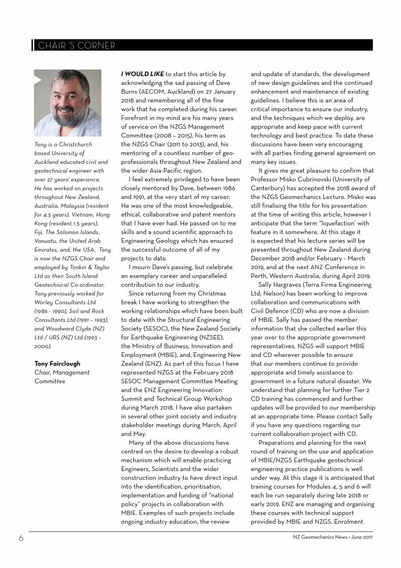
I WOULD LIKE to start this article by acknowledging the sad passing of Dave Burns (AECOM, Auckland) on 27 January 2018 and remembering all of the fine work that he completed during his career. Forefront in my mind are his many years of service on the NZGS Management Committee (2008 – 2015), his term as the NZGS Chair (2011 to 2013), and, his mentoring of a countless number of geo-professionals throughout New Zealand and the wider Asia-Pacific region.
I feel extremely privileged to have been closely mentored by Dave, between 1986 and 1991, at the very start of my career. He was one of the most knowledgeable, ethical, collaborative and patent mentors that I have ever had. He passed on to me skills and a sound scientific approach to Engineering Geology which has ensured the successful outcome of all of my projects to date.
I mourn Dave’s passing, but celebrate an exemplary career and unparalleled contribution to our industry.
Since returning from my Christmas break I have working to strengthen the working relationships which have been built to date with the Structural Engineering Society (SESOC), the New Zealand Society for Earthquake Engineering (NZSEE), the Ministry of Business, Innovation and Employment (MBIE), and, Engineering New Zealand (ENZ). As part of this focus I have represented NZGS at the February 2018 SESOC Management Committee Meeting and the ENZ Engineering Innovation Summit and Technical Group Workshop during March 2018. I have also partaken in several other joint society and industry stakeholder meetings during March, April and May.
Many of the above discussions have centred on the desire to develop a robust mechanism which will enable practicing Engineers, Scientists and the wider construction industry to have direct input into the identification, prioritisation, implementation and funding of “national policy” projects in collaboration with MBIE. Examples of such projects include ongoing industry education, the review
and update of standards, the development of new design guidelines and the continued enhancement and maintenance of existing guidelines. I believe this is an area of critical importance to ensure our industry, and the techniques which we deploy, are appropriate and keep pace with current technology and best practice. To date these discussions have been very encouraging with all parties finding general agreement on many key issues.
It gives me great pleasure to confirm that Professor Misko Cubrinovski (University of Canterbury) has accepted the 2018 award of the NZGS Geomechanics Lecture. Misko was still finalising the title for his presentation at the time of writing this article, however I anticipate that the term “liquefaction’ with feature in it somewhere. At this stage it is expected that his lecture series will be presented throughout New Zealand during December 2018 and/or February - March 2019, and at the next ANZ Conference in Perth, Western Australia, during April 2019.
Sally Hargraves (Terra Firma Engineering Ltd; Nelson) has been working to improve collaboration and communications with Civil Defence (CD) who are now a division of MBIE. Sally has passed the member information that she collected earlier this year over to the appropriate government representatives. NZGS will support MBIE and CD wherever possible to ensure that our members continue to provide appropriate and timely assistance to government in a future natural disaster. We understand that planning for further Tier 2 CD training has commenced and further updates will be provided to our membership at an appropriate time. Please contact Sally if you have any questions regarding our current collaboration project with CD.
Preparations and planning for the next round of training on the use and application of MBIE/NZGS Earthquake geotechnical engineering practice publications is well under way. At this stage it is anticipated that training courses for Modules 4, 5 and 6 will each be run separately during late 2018 or early 2019. ENZ are managing and organising these courses with technical support provided by MBIE and NZGS. Enrolment
CHAIR ’S CORNER
Tony is a Christchurch based University of Auckland educated civil and geotechnical engineer with over 27 years’ experience. He has worked on projects throughout New Zealand, Australia, Malaysia (resident for 4.5 years), Vietnam, Hong Kong (resident 1.5 years), Fiji, The Solomon Islands, Vanuatu, the United Arab Emirates, and, the USA. Tony is now the NZGS Chair and employed by Tonkin & Taylor Ltd as their South Island Geotechnical Co-ordinator. Tony previously worked for Worley Consultants Ltd (1986 - 1990), Soil and Rock Consultants Ltd (1991 – 1993), and Woodward Clyde (NZ) Ltd / URS (NZ) Ltd (1993 – 2000).
Tony FaircloughChair, Management Committee

details will be issued to our members via the fortnightly email notices and posted onto the NZGS website in due course. ENZ will also issue enrolment notices separately to their membership, at the appropriate time, for these “must do” training courses.
Eleni Gkeli (WSP-Opus, Wellington) has continued to ensure that NZGS continues to provide high-value training courses to our members through 2018. The NZGS training courses and workshops which have been held during the first half of 2018 comprise:
• Jet Grouting – Technology, Design and Control – Presented by Professor Giuseppe Modoni. – Was held in Auckland, Wellington and
Christchurch. – Total of 30 attendees.
• Principles and Practice of Engineering Geology – Presented by Fred Baynes, Stuart Read
and Ann Williams. – Was held in Auckland and Wellington. – Total of 47 attendees.
• Quantitative Risk Assessment in Geotechnical Engineering
– Presented by Professor Vaughan Griffiths. – Was held in Wellington and Christchurch. – Total of 41 attendees.The feedback received on all of the above courses and
workshops has been extremely positive. It is worth noting that improvements to the advertising, management and registration processes over the past 12 months has led to an overall increase in the level of attendee satisfaction.
Planning is currently in progress for the additional NZGS training courses which are expected to be held during the second half of 2018. Details are provided elsewhere in this issue. Enrolment details for these courses will be issued to our members via the fortnightly email notices and posted onto the NZGS website in due course.
In addition, travel arrangements are currently being finalised to bring the following internationally recognised speakers and presentations to the New Zealand circuit:
• Rankine Lecture 2017: Professor Eduardo Alonso, “Triggering and Motion of Landslides”.
• Terzaghi Lecture 2017: Professor R Kerry Rowe, “Protecting the Environment with Geosynthetics”.
• Terzaghi Lecture 2014: Professor Carlos Santamarina, “Energy Geotechnology: Enabling New Insights into Soil Behaviours”.
Further information is provided elsewhere in this issue. Members who are located outside the main centres who would like to see an international speaker in their home town should contact their branch co-ordinator and work with them to petition the national management committee. The committee will endeavour to add provincial towns
to the circuit of any international speaker where it is demonstrated that an appropriate minimum level of interest and attendee numbers is present.
Marlene Villeneuve (University of Canterbury) and Kevin Anderson (AECOM, Auckland) continue their good work as the NZGS representatives and primary points of contact for the PEngGeol and CPEng registers and Body of Knowledge and Skills (BoKS) discussions with ENZ. Development and finalisation of the “Geotechnical” BoKS documentation is well advanced, and collaboration with ENZ is underway to ensure alignment and consistency with the other engineering disciplines such as structural and coastal. I strongly encourage all members to visit the NZGS website and familiarise themselves with the current versions of the BoKS documents. All questions and clarifications should be directed, in the first instance, to Teresa Roetman the NZGS Secretary ([email protected]).
Finally, I wish to remind you all of the following upcoming conferences:
• The 13th Australia New Zealand Conference on Geomechanics, Perth; Western Australia, 01 to 03 April 2019,
• The 21st New Zealand Geotechnical Society Symposium, Dunedin; New Zealand, provisionally scheduled for the third week of October 2020, and,
• The 20th International Conference on Soil Mechanics and Geotechnical Engineering, Darling Harbour; New South Wales, 12 to 16 September 2021.
Further details are provided within this issue of the Geomechanics News, on the Australian Geomechanics Society website (http://www.australiangeomechanics.org/) and/or on the New Zealand Geotechnical Society website (http://www.nzgs.org/). I strongly encourage all members to consider attending at least one of these noteworthy events.
Please do not hesitate to contact me via email on [email protected] if you wish to discuss any issue which you believe is of direct relevance to our membership.
Tony FaircloughNZGS Chair, 2017-2019
June 2017 • NZ Geomechanics News 7

NZ Geomechanics News • June 20188
EDITORIAL
Don Macfarlane has worked as an applied engineering geologist for nearly 40 years and has accumulated some knowledge, a fair bit of wisdom and a few brickbats along the way. His real interest is dams and associated issues (seismic hazard, slope instability) but any good geohazard affecting an engineering structure will do. These days he is a Technical Director with AECOM in Christchurch.NZ Geomechanics News co-editor
Gabriele is a Senior Lecturer in Geotechnical Engineering at the University of Canterbury. Gabriele’s research interests include earthquake geotechnical engineering and related problems; constitutive modelling for geomaterials; development of advanced laboratory and field testing devices; geo-hazard reconnaissance and mitigation; reuse and recycling of industrial granular wastes as sustainable geomaterials.NZ Geomechanics News co-editor
THE FIRST HALF of 2018 has been a busy one in our industry. There are quite a few updates from MBIE and NZGD in the briefs section that are worth paying attention to. The technical part of this issue is a combination of conference papers from the NZGS Symposium and from international conferences, as well as individual technical reports. Lots of great projects out there that we can learn from.
We present the NZGS student poster award winners this issue showing the quality of the work students in our industry are doing. We also have an ad for upcoming NZGS short course on soft soil, offered in Auckland, Wellington and Christchurch. Be sure to check it out. Don’t forget to check out all of the education and training opportunities on the NZGS calendar at NZGS.org.
This is my sixth and last issue and I am transitioning out of this role. It has been a great three years getting to know how the society works and working alongside some amazing professionals to provide support for and to champion our industry.
I am passing on the lead co-editor position to Don Macfarlane and welcoming Gabriele Chiaro to the team. Gabriele joined the University of Canterbury as a Lecturer in Geotechnical Engineering in 2015. He is originally from Italy and comes to us via his PhD and several research fellowships in Japan and Australia. I am sure that Don and Gabriele will do a fine job!
Finally I would like to thank all of the contributors to Geomechanics News, and to probably the most important member of our team: our layout and design expert, Karryn Muschamp, who does all of the hard work putting each issue together.Marlene
IN MY FIRST contribution to the editor’s page, I firstly want to thank Marlene for her tremendous contribution to Geomechanics News since taking on the role of Editor, and for her help in making this transition. She has left us with a high standard to maintain! And we welcome the new Chair (Tony) as we bid farewell to Charlie Price, a friend and colleague since the days of Project Aqua.
In my career I have had the pleasure of working with many outstanding individuals so it is with great sadness that I have found myself including obituaries for two of them in this issue.
Don Deere was my first experience of being subjected to external, independent review (at Clyde) – we didn’t want or need this! We thought. We were wrong – the experience that he brought added value beyond anything we could ever have anticipated. And then he went on the form the Review Panels for the Clyde Landslides and Manapouri Second Tunnel projects (we had seen the value and wanted those ones!). One of my abiding memories of Don as a reviewer is that he never criticised us – to give us a message he would push his chair back and tell a story to explain why something had (or hadn’t) worked on some other project somewhere in the world. Then it was up to us…
David Burns left a huge professional legacy both in his excellent project work, and in his contributions as a teacher and mentor. He became a colleague at AECOM when the merger with URS occurred. I had worked with David on a couple of projects (I was the reviewer!) before that time. His commitment to the best possible outcome, no matter what it took, was hard to rein in! He was indeed a perfectionist, who liked to ‘discuss’ every point of difference in great detail.
My contribution to this issue is a photo of the Clyde Power Project site geologists in the summer of 1992/93 (I think). See how many of those youthful faces you recognise!Don

June 2016 • NZ Geomechanics News
12TH AUSTRALIA & NEW ZEALAND YOUNG GEOTECHNICAL
PROFESSIONALS CONFERENCE 7-9 NOVEMBER 2018 HOBART
Held every 2 years, the Young Geotechnical Professional Conference (YGPC) events are unique 3 day conferences facilitated by a joint initiative of the Australian Geomechanics Society (AGS) and New Zealand Geotechnical Society (NZGS).
The aim of the 12YGPC conference is to provide younger professionals within the ANZ geomechanics industry experience in technical paper preparation and conference presentation. Each delegate prepares a technical paper and then presents their peer-reviewed paper to both their conference colleagues and senior industry professionals that are invited to attend in a mentoring capacity.
YGPC events also include a field trip into the surrounding regions, where delegates visit current projects or sites of geotechnical / geological interest. Along with a number of social events to encourage interaction between the delegates, the 12YGPC will provide an enjoyable and informative event aimed at the development of future leaders in the geotechnical profession.
The conference attracts delegates from across Australia and New Zealand from consulting and contracting firms, industry bodies and research institutions, showcasing the diverse range of projects and products in the geomechanics field.
SPONSORSHIP PROSPECTUSThe Australian Geomechanics Society and the New Zealand Geotechnical Society
invite you to sponsor the 12th Young Geotechnical Professionals Conference (12YGPC Hobart)
The aims of the YGPC conferences are to:
• Promote the professional development of delegates through sharing experience and ideas, and by all delegates presenting a paper to both senior professionals and peers;
• Expand and strengthen the lines of communications across Australia and New Zealand between young professionals within the field of geomechanics;
• Promote an enhanced perspective of the varied roles, responsibilities and opportunities encompassed by the geotechnical profession; and
• Encourage the exchange of knowledge between consultants, research institutions, contractors and industry associated with the geotechnical industry.
12YGPC offers you a range of sponsorship opportunities to suit your budget which are detailed in the table below.
The 12YGPC is committed to providing optimum exposure for all sponsors. Additional opportunities may be available and we are willing to tailor a package to meet your specific business goals. We encourage organisations to contact the Conference Committee to discuss opportunities that are not included in this brochure.
••••••••
•••••
•••••
••••••
••••••
••
•••
••••••
••
•••
•••••••
•••
••
SPONSORSHIP PACKAGES PLATINUM GOLD SILVER BRONZE
Sponsored
Cost AUD(inc. GST) $3,300.00 $1,100.00 $550.00
Number Available - 1 more available 5 more available Unlimited
Benefits • Recognition as the sole Platinum Sponsor during opening and closing sessions
• Host conference dinner, opportunity to address delegates
• Largest logo on conference handbook/ proceedings and satchel
• 2x Satchel insert
• Recognition as a Gold Sponsor during opening and closing sessions
• Co-host welcome drinks
• Logo on conference handbook / proceedings and satchel
• 2x Satchel insert
• Co-host morning/ afternoon tea breaks
• Logo on conference handbook / proceedings
• 1x Satchel insert
• Logo on conference handbook / proceedings
• 1x Satchel insert

NZ Geomechanics News • June 201710
NEWS
News – In Brief
FOR MORE THAN 70 years the static plate load test has been well known in international geotechnical practice. This test assesses two important stiffness parameters of the soil: the static soil modulus Es and the subgrade reaction modulus K. Additionally, by unloading and reloading the soil, it can assess the level of compaction achieved, similarly to the approach followed with nuclear density measurements.
The plate load test is extensively used in many countries (for example, Germany, UK, United States) for a range of different applications. Some of them are:
• Pavements and airfields: Assessment of compaction for base and subbase layers; assessment of compressibility of subgrade
• Ground treatment: Assessment of soil treatment effectiveness; for example lime stabilized soils or reinforced soils with geogrid
• Railways: Assessment of track ballast performance
• Landfills, abandoned mines or quarries, site re-developments: Assessment of the existing compaction level and expected future performance
However, for a number of reasons up until now, the static plate load test has not been well established in New Zealand practice. Such reasons potentially include:
• The required reaction mass; a heavy plant such as an excavator is required
• A relatively long test time • The mobilization of relatively heavy equipment for performing the test (plates, jacks, strain gages) and issues around their compatibility, calibration, accuracy and sensitivity
• Practical issues around monitoring three strain gages and the required level of expertise required in the field by technicians
• The time required for the interpretation of results and the disparity among different standards and available methods. The choice of method for estimating E and K is often at the discretion of the engineer. The resulting E and K can be quite variable when using different methods with the same data.
• Health and safety issues arising from the presence of the technician under the heavy plant recording during the test.
The development in recent years of the integrated static plate load tester has eliminated all of these issues listed above. This equipment uses the international standard DIN 18134:2012-04 which provides a robust mathematical algorithm with which E and K are both estimated in a consistent manner.
The advantages of the integrated plate load tester are:
• Direct estimation while on site of modulus Ev1 and reload modulus Ev2 with digital printout of results
THE USE OF THE STATIC PLATE LOAD TEST in New Zealand

June 2018 • NZ Geomechanics News 11
NEWS
based on the DIN 18134:2012-04 mathematical algorithm; this saves a lot of interpretation time for the geotechnical engineer
• Fast and robust estimation for K based on the same DIN standard as above
• Assessment of soil compaction based on the ratio of Ev2/Ev1
• 20 minutes assembling time and 40 minutes typical testing time per point
• The testing equipment has a robust and compact design
• Elimination of three strain gages by using digital data acquisition through a measuring bridge with 300, 600 and 762mm plates
• By using 600 and 762mm plate sizes, coarser soil materials can be assessed
• Elimination of health and safety issues: after equipment assembly, no operator is located under the counterweight during the test
• Data transfer through USB interface to an analysis software, Bluetooth technology and GPS for accurate mapping of the measuring point
• Fully calibrated digital and mechanical equipment
• Interpretation software that supports results reporting in a straightforward manner
• Another advantage the test offers is that the plate sizes available have closely similar dimensions to the typical foundation geometries encountered in residential buildings described in NZS
3604. By applying proper stress levels under the plate, the test can successfully simulate the behavior of the actual foundation under design or assessment.
A sufficiently heavy plant is still required to provide the counter weight on site and this is selected based on the estimated level of applied stress.
The new integrated static plate load tester will now allow the engineer to choose an efficient option to measure the two important stiffness parameters discussed above.
Reported by:Nick Van Warmerdam and Darcy Krissansen, Geocivil Ltd., Christchurch and Whangarei
NZ Geomechanics News • June 201812
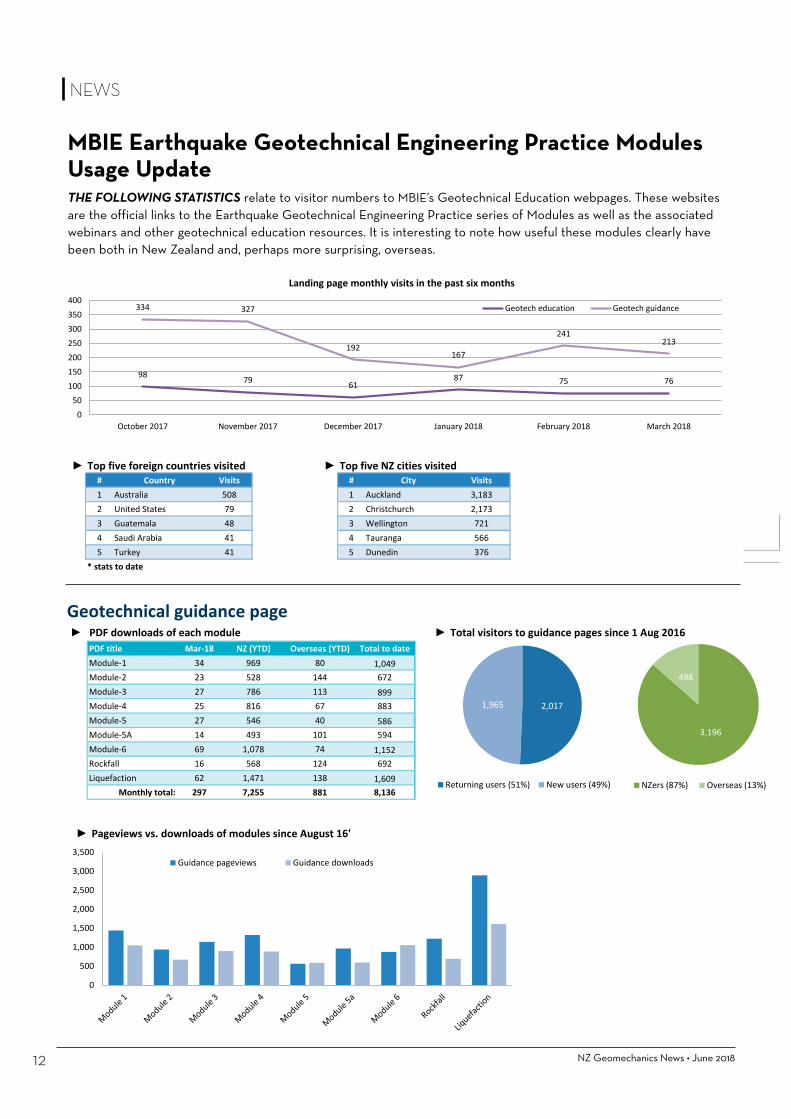
Geotechnical information on building.govt.nz web statsMarch 2018
► Top five foreign countries visited ► Top five NZ cities visited# Country Visits # City Visits1 Australia 508 1 Auckland 3,1832 United States 79 2 Christchurch 2,1733 Guatemala 48 3 Wellington 7214 Saudi Arabia 41 4 Tauranga 5665 Turkey 41 5 Dunedin 376
* stats to date
Geotechnical guidance page► PDF downloads of each module ► Total visitors to guidance pages since 1 Aug 2016 ► Pageviews vs. downloads of modules since August 16'
PDF title Mar-18 NZ (YTD) Overseas (YTD) Total to dateModule-1 34 969 80 1,049Module-2 23 528 144 672Module-3 27 786 113 899Module-4 25 816 67 883Module-5 27 546 40 586Module-5A 14 493 101 594Module-6 69 1,078 74 1,152Rockfall 16 568 124 692Liquefaction 62 1,471 138 1,609
Monthly total: 297 7,255 881 8,136
Geotechnical education page► Top 5 pages visited this month ► Total visitors to Education page since 1 Aug 2016 ► Top five foreign countries visited ► Top five NZ cities visited
Page title Column1 Column2 Mar-18 Total to date # Country Visits # City VisitsModule-1 18 573 1 Australia 228 1 Auckland 1,174Module-3 17 445 2 India 109 2 Christchurch 546Module-5A 11 273 3 United States 61 3 Wellington 236Learn about rockfall 6 88 4 Guatemala 57 4 Hamilton 210Why we are creating a geotechnical resource 4 207 5 United Arab Emirates 22 5 Tauranga 109
Monthly total: 65 2,054 * stats to date
1,187 1,065
Returning users (53%) New users (47%)
1,690
471
NZers (78%) Overseas (22%)
2,017 1,965
Returning users (51%) New users (49%)
3,196
498
NZers (87%) Overseas (13%)
98 79 61 87 75 76
334 327
192 167
241 213
050
100150200250300350400
October 2017 November 2017 December 2017 January 2018 February 2018 March 2018
Landing page monthly visits in the past six months
Geotech education Geotech guidance
0
500
1,000
1,500
2,000
2,500
3,000
3,500Guidance pageviews Guidance downloads
Drill Force New Zealand Ltd is a multi-disciplined drilling company which delivers unparalleled quality and service throughout New Zealand. Drill Force has over 30 drilling rigs to service the Environmental, Water Well, Geotechnical,
Seismic, Mineral Resource, Construction and Energy markets.
• 1.0m wide for narrow access, expandable track base for stability
• 55% gradeability • Suitable for wireline coring,
auger, DHH and rotary mud drilling methods
• 250m HQ and 160m PQ capacity • Infinite mast angle capability • Suitable for low and high entry
mast angle positions
Website: www.drillforce.co.nz
Ryan | 027 837 2030 | [email protected] Zane | 021 842 475 | [email protected]
NEWS
MBIE Earthquake Geotechnical Engineering Practice Modules Usage UpdateTHE FOLLOWING STATISTICS relate to visitor numbers to MBIE’s Geotechnical Education webpages. These websites are the official links to the Earthquake Geotechnical Engineering Practice series of Modules as well as the associated webinars and other geotechnical education resources. It is interesting to note how useful these modules clearly have been both in New Zealand and, perhaps more surprising, overseas.

NEWS
Geotechnical information on building.govt.nz web statsMarch 2018
► Top five foreign countries visited ► Top five NZ cities visited# Country Visits # City Visits1 Australia 508 1 Auckland 3,1832 United States 79 2 Christchurch 2,1733 Guatemala 48 3 Wellington 7214 Saudi Arabia 41 4 Tauranga 5665 Turkey 41 5 Dunedin 376
* stats to date
Geotechnical guidance page► PDF downloads of each module ► Total visitors to guidance pages since 1 Aug 2016 ► Pageviews vs. downloads of modules since August 16'
PDF title Mar-18 NZ (YTD) Overseas (YTD) Total to dateModule-1 34 969 80 1,049Module-2 23 528 144 672Module-3 27 786 113 899Module-4 25 816 67 883Module-5 27 546 40 586Module-5A 14 493 101 594Module-6 69 1,078 74 1,152Rockfall 16 568 124 692Liquefaction 62 1,471 138 1,609
Monthly total: 297 7,255 881 8,136
Geotechnical education page► Top 5 pages visited this month ► Total visitors to Education page since 1 Aug 2016 ► Top five foreign countries visited ► Top five NZ cities visited
Page title Column1 Column2 Mar-18 Total to date # Country Visits # City VisitsModule-1 18 573 1 Australia 228 1 Auckland 1,174Module-3 17 445 2 India 109 2 Christchurch 546Module-5A 11 273 3 United States 61 3 Wellington 236Learn about rockfall 6 88 4 Guatemala 57 4 Hamilton 210Why we are creating a geotechnical resource 4 207 5 United Arab Emirates 22 5 Tauranga 109
Monthly total: 65 2,054 * stats to date
1,187 1,065
Returning users (53%) New users (47%)
1,690
471
NZers (78%) Overseas (22%)
2,017 1,965
Returning users (51%) New users (49%)
3,196
498
NZers (87%) Overseas (13%)
98 79 61 87 75 76
334 327
192 167
241 213
050
100150200250300350400
October 2017 November 2017 December 2017 January 2018 February 2018 March 2018
Landing page monthly visits in the past six months
Geotech education Geotech guidance
0
500
1,000
1,500
2,000
2,500
3,000
3,500Guidance pageviews Guidance downloads
Drill Force New Zealand Ltd is a multi-disciplined drilling company which delivers unparalleled quality and service throughout New Zealand. Drill Force has over 30 drilling rigs to service the Environmental, Water Well, Geotechnical,
Seismic, Mineral Resource, Construction and Energy markets.
• 1.0m wide for narrow access, expandable track base for stability
• 55% gradeability • Suitable for wireline coring,
auger, DHH and rotary mud drilling methods
• 250m HQ and 160m PQ capacity • Infinite mast angle capability • Suitable for low and high entry
mast angle positions
Website: www.drillforce.co.nz
Ryan | 027 837 2030 | [email protected] Zane | 021 842 475 | [email protected]

NZ Geomechanics News • June 201814
NEWS
NZGS RECENTLY RAN a survey on behalf of the funders (MBIE and EQC) of the New Zealand Geotechnical Database (NZGD). The purpose of the survey was to get a better understanding of the spread of the users of the database, potential barriers to uploading data and other possible datasets that are stored separately and could be uploaded to be incorporated in the NZGD.
Of the 67 respondents, just over 60% confirmed they are a regular user of the NZGD. Of the users who do not regularly use the NZGD, we found that this is generally due to a lack of existing data presented in their geographical area of work. This indicates to achieve an increased user base, more seed funding of the NZGD is required to increase data uploading from public agencies (i.e. councils and other government agencies) and private consultants to increase the geographical coverage of data.
Of the regular users of the NZGD, half of these do not regularly upload new data, with data generation, no client approval, difficulty of data uploading or having someone else in the organisation to upload the data being the key reasons for not proactively uploading data. The feedback provided an insight into the challenges of consistent data uploading, and provided recommendations for improvement. Furthermore, almost half of the users of the
NZGD do not routinely include a clause in their contracts confirming agreement with their clients to upload geotechnical data to the NZGD.
To encourage increased uploading of geotechnical data some standard wording that some consultants are adding in the “Variation” section of the Standard IPENZ/ ACENZ Short Form Model Conditions of Engagement or other standard consultancy contracts follows:
In accordance with the New Zealand Geotechnical Database (NZGD) Terms of Use, approval is given by the client to allow the consultant to upload factual geotechnical data to the NZGD that may be collected during any geotechnical site investigation works performed as part of the commissioning of the works proposed.
One third of the respondents provided further detail on additional datasets that currently aren’t presented in the NZGD, which may add more value to the NZGD. If you would like to assist further with the discussion on additional datasets please contact either Nathan [email protected] or John [email protected]. Otherwise MBIE and EQC intends to contact the respondents that suggested these additional datasets with the intent to gain approval to upload to the NZGD. The results of the survey can be found on the NZGD website.
In summary, the feedback received was valuable in aiding MBIE and EQC in prioritising work to increase user uptake and engagement of the NZGD. The NZGD is an internationally unique data sharing resource that has economic, business efficiency and carbon reducing benefits. That being said, while use is on the way up it is apparent there is still a long way to go to make use of the NZGD a routine part of business practice and MBIE, EQC and NZGD users all have a role to play in this regard to safeguard the future of this invaluable resource.
The survey also highlighted a number of common questions are arising from users and shortly a FAQ section will be placed in the NZGD Help section to answer these questions. In addition, a list of client approvals from various agencies will be placed in the Help section and this will be regularly updated as more approvals are obtained.
With regard to other related news, a business case for the NZGD is near completion and will be socialised around government and key stakeholders in the near future. This business case will also likely include a strategy outlining the future direction for the NZGD.
Reported by: Nathan Schumacher, senior geotechnical engineer, Ministry of Business, Innovation and Employment
NZGD USE SURVEY RESULTS

0800 879 879ph: 03 230 3000 www.mcneillnz.com
Cnr SH1 & Clapham Rd, Kennington, Invercargille: [email protected]
PIL
ING
SON
IC
OUTSTANDING gear, service & results
DRILLING DISTRIBUTION
CP
T
Sonic DrillingDiamond CoringAircoreCPT Core Penetration TestingSPT SamplingCast In-Situ PilesDriven PilesFranki PilesRock Anchors

NEWS
NZ Geomechanics News • June 201716
REVIEW of NATIONAL SEISMIC HAZARD MODELIn 2015 MBIE commissioned an independent international panel of experts to review the New Zealand National Seismic Hazard Model (NSHM). The panel issued their final report to MBIE in April 2017 which looked at:
• The governance and resourcing, of the NSHM. • Hazard estimate stability of the NSHM. • The application of probabilistic seismic assessment analysis (PSHA), its robustness and transparency for incorporation in the NSHM.
• Seismic hazard approach used in the NSHM. • Site specific hazard study guidelines and reporting requirements.
The report presented a list of activities to be considered, including
the development of an appropriate governance structure and a new funding model for improving and maintaining the NSHM.
In response to the reports finings MBIE and EQC are co-funding a business case that will present options for consideration for the future governance and funding of the NSHM. A number of stakeholders will be consulted with to support the development of the business case.
After consideration of the options MBIE, potentially working with other agencies, will then seek to implement a preferred option to allow the activities recommended in the April 2017 expert panel report to be completed. These are summarised in priority order below:
• Form a NSHM team. • Adequately document the processes used to develop the current NSHM models (both the 2002 model used in the current maps and the 2010 model that updates the seismic source characterisation).
• Move the existing software to an open-source hazard programme and make the model publically available, readily accessible and user friendly.
• Review and update the period-dependant spectral shapes used in NZS1170.5.
• Develop guidelines for undertaking site-specific hazard studies. • Work through the other technical recommendations made in the expert panel report to update and improve the NSHM.
If you would like to discuss the content of this article further, please email [email protected].
• technical papers • technical notes of any length
• feedback on papers and articles• news or technical descriptions of
geotechnical projects• letters to the NZ Geotechnical Society
or the Editor• reports of events and personalities
• industry news• opinion pieces
TELL US ABOUT YOUR PROJECT, NEWS, OPINIONS,
OR SUBMIT A TECHNICAL ARTICLE. WE WELCOME
ALL SUBMISSIONS, INCLUDING:
Geoengineer.org is part of an interconnected network of Centers with the Mission to be a catalyst for innovation & excellence in practice, research and education of the geotechnical industry by creating unique resources, applications & communication tools, and by promoting cutting edge information that impacts the industry and its image on a global and local scale.
Founded in 2000, Geoengineer.org has grown to be one of the most popular geotechnical engineering websites with thousands of monthly visitors and members. It is managed by a team of geotechnical engineers, geotechnical engineering data miners, information technology professionals, and marketing specialists, working together to provide professionals and academia in the geotechnical engineering industry with relevant information and communication services.
Check it out.
Please contact the editors ([email protected])
if you need any advice about the format or suitability of your material.

NZ Geomechanics News • June 201818
COURSE OBJECTIVES AND OUTCOMESThis one-day course, developed and organised by NZGS, will provide an introduction to the essential components of soft soil engineering. The course will include an overview of the theory of the behaviour of soft soils and design criteria. Attendees will develop good understanding of the issues arising when building on such soils and of the importance of specific strategy and planning for such projects. The course will also provide methodologies for ground investigation and sampling and techniques for building the ground model. The techniques for soft soil treatment will be discussed, including construction staging and monitoring.
The course will comprise classroom teaching and a short design exercise. At the completion of the course, attendees should be able to consider options to deliver the project, scope a geotechnical investigation to support the design, perform simple calculations to estimate the performance of options including consolidation, stone columns and soil mixing. Attendees will be introduced to implementation of instrumentation and monitoring regime and use of the Observational Method and back analysis. Development of specifications for ground improvement for soft soils will be briefly addressed.
WHO SHOULD ATTEND?The course is targeted at geotechnical engineers with minimum 2 years’ experience, and ideally at those with 5 to 10 years’ experience. More senior engineers may benefit from a refresher. It is assumed that the attendees have a university level understanding of soil mechanics.
PRESENTERSThe course will be presented by Dr. Richard Kelly, based in Australia and Nick Wharmby based in New Zealand.
UPCOMING NZGS COURSE IN DESIGN AND CONSTRUCTION TECHNIQUES IN SOFT GROUND
NZ Geomechanics News • June 201818
NEWS
Nick WharmbyNick is a Civil Engineer specialised in Geotechnology. Nick has been working in New Zealand since 2004, and has been involved in major infrastructure projects playing a key role in bringing new construction methodologies to the country, including ground improvement techniques. Nick has contributed in his area of expertise to many international organisations and committees (Federation of Piling Specialists Technical Committee, ICE, Ground Engineering Advisory Panel, CIRIA). Nick is currently Technical Manager with March Construction.
Dr. Richard KellyRichard is a Chartered Professional Engineer and fellow of the Institution of Engineers, Australia (CPEng). He is currently the Chief Technical Principal – Geotechnical with SMEC Australia - New Zealand, a Conjoint Professor of Practice at the University of Newcastle and an Honorary Professorial Fellow at the University of Wollongong. Richard has extensive expertise in site characterisation, soft soil engineering, ground improvement, materials use, earthworks and foundation design.
COSTThe cost for the course per attendee is$350 plus GST, for NZGS members$650 plus GST, for non-NZGS membersThis covers full attendance, course notes and teaching material, and full catering for the day. COURSE LOCATIONS AND DATES AUCKLAND - Monday 3 September 2018**(the course will be repeated tentatively on Tuesday 4 September, depending on the level of interest). WELLINGTON – Wednesday 5 September 2018. CHRISTCHURCH – Friday 7 September 2018.
REGISTRATIONS
ARE EXPECTED TO
OPEN IN MID-JULY 2018.
Details of the course structure
and content, exact times and venues
will be announced then. The number
of attendees will be limited
to 25 - 30 per course.
FOR FURTHER INFORMATION contact the organiser Eleni Gkeli ([email protected]).

Specialising in :
• Piling
• Slip Stabilisation
• Retaining walls
• Rope Access
• Contaminated Site Remediation
• Ground Improvement
• Wick Drains
• Excavations
• Seismic Strengthening
• Foundations & Concrete Work
• Civil Structures
• Ground Anchors
• Rammed Aggregate Piers (RAP)
• Subdivisions
• Stone Columns
[email protected] 09 412 7048 www.cll.net.nz

Professor Fumio Tatsuoka, Professor Emeritus, University of Tokyo and Tokyo University of Science
Dr Oskar Sigl, Managing Director, Geoconsult Asia, Singapore
Marc Woodward, Senior Principal Geotechnical Engineer, CMW Geosciences
Rob Day, Associate Principal - Geotechnical, Arup (AGS 2016 Practitioner Award, Sir John Holland Civil Engineer of the Year 2018)
Dr Doug Stewart, Principal Geotechnical Engineer, Golder
13th Australia New Zealand Conference on Geomechanics
Perth Convention & Exhibition Centre
Perth, Western Australia • 1-3 April, 2019
Are you interested in sponsoring and securing your exhibition space?
Contact us on +61 2 9265 0700
Conference Managers: Arinex Pty Ltd - 3/110 Mounts Bay Road, Perth, Western Australia 6000
Tel: 08 9486 2000
Invited Keynote Speakers:
Key Dates:
Sponsorship Opportunities:
Abstract Submissions:
CLOSED
Notification July 2018
Registration:
NOW OPEN
Early bird closes 19 November 2018
Full Papers:
Open July 2018
Close 26 September 2018
Registration
NOW OPEN
www.anzgeomechanics2019.org
Special Lecture:
2018 NZGS Geomechanics Award Lecture: Professor Misko Cubrinovski University of Canterbury
ANZGEO19-JournalSpreadA4-v5.indd 2-3 15/5/18 8:40 pm

PROJECT NEWS
Waikato Branch Site Visit to the Waikato Expressway Huntly Section
THE FIRST COUPLE of attempts at a branch event site visit were delayed due to poor weather (not that it ever rains in the Waikato) but we finally got there on Thursday 19th April with a bunch of lucky lads and ladies.
We were graced with an all-star cast of tour guides including FH/HEB Project Director Tony Dickens and Construction Manager Tony Adams. Project Geotechnical Engineer Natasha Jokhan provided technical input on various design and construction aspects. Thanks also to Tom Glenn and Shane Wilton for their technical inputs. The event was well attended by a good cross section of the Waikato geotechnical community. The tour started with a site induction and virtual flyover with commentary on this 15 km long, $409M construction project with ground conditions ranging from soft compressible alluvial soils to strong Greywacke. Some interesting project statistics include:
• Approximately 3.5M m3 of fill • Geogrid reinforced Engineered fills up to 21m deep
• Fill batter gradients of 1V to 1.5H • A 57m deep summit cut through Greywacke rock and clay (1.3 million m3 in this one cut)
Kori LentferKori is a Engineering Geologist. He graduated in 1998 with a BSc(Tech) in Geology, followed by Masters study at Waikato University and an MSc thesis in Engineering Geology from Auckland University in 2007. [email protected]
Above: Looking north towards the 57m deep Summit Cut in the distance.
Above: Tony Adams describing the structural fill process.
NZ Geomechanics News • June 201822
FPHILLIP ALCONER0274 304 554
JOSH KENDRICK0272 855 004

FPHILLIP ALCONER0274 304 554
JOSH KENDRICK0272 855 004

NZ Geomechanics News • June 201824
• 450,000 linear metres of wick drain installed in historic mine waste materials with 2m of settlement occurring under surcharge loading (to date)
• Four bridges utilising friction and end bearing piles up to 45m deep
• Timber piles were used under bridge abutments (four bridges) for stability under seismic / lateral spread conditions
• Cut to waste volumes of 900,000m3
Above: The largest hydraulic
excavator in New Zealand.
The site tour included a series of stops including the Taupiri Summit cut and several bridges along the new highway alignment with Q and A session at each stop with project engineers.
Thanks again to the project team for their time to lead the site tour and for their honest and open discussions on the challenges they have faced and the solutions employed to make the project fly. Construction is due to be complete in December 2019 of what will be a stunningly scenic section of New Zealand’s highway network.
Photos by Kade Croft
PROJECT NEWS
In March an Abseil Access team of five drilled and blasted over 300m3 of rock using two cliff face drill rigs and sequentially timed explosives in Northern Coromandel. Check out the shocking video on our facebook page.
Earlier this year our geotechnical crew installed rock bolts and shotcrete to unstable areas behind the
Latter Day Saints Church in Dunedin. Using long reach EWP’s and cranes the work was
completed in record time.
rock anchorsslope stabilisationrockfall netting & catch fencesdesign & build
nationwide wellington 15 bute street, 04 801 5336
christchurch 26 thackers Quay, 03 384 0336
www.abseilaccess.co.nz
A steep boulder bank threatened the hydro pipes and new valves at Cobb Powerstation in Takaka. In April the geoteam set to work with three weeks of boulder destruction with explosives followed by building twin rockfall catch fences.

Assessment of landslide hazard in the road/rail corridor on the Kaikoura Coast NCTIR Slopes Geotechnical Team
INTRODUCTIONThe M7.8 Kaikoura earthquake of 14 November 2016 generated very large peak ground accelerations (PGA’s) that resulted in the closure of the coastal sections of both State Highway 1 and the Main North Railway Line due to slope failures originating from above the road and rail corridor at more than 50 locations north and south of Kaikoura (Figure 1).
NZ Geomechanics News • December 201726
The North Canterbury Transport Infrastructure Recovery (NCTIR) was set up by the government under the Hurunui/Kaikoura Earthquakes Recovery Act 2016 to repair and re-open the earthquake-damaged road and rail networks between Christchurch and Picton by the end of 2017. NCTIR is an alliance partnership between the NZ Transport Agency, KiwiRail, Fulton Hogan, Downer, HEB Construction and Higgins.
The Main North rail line was reopened in September 2017 for limited services. The State Highway was re-opened (with restrictions) in December 2017 and fully re-opened on 30 April 2018.
A large number of engineering geologists, geotechnical engineers and (some) geomorphologists drawn from many different organisations are working on the recovery project. This short summary, which reflects the work of the whole team, outlines our approach to assessing the landslide hazard to the road/rail corridor and the key understandings that have developed from this work.
EARTHQUAKE EFFECTSThe 2016 Kaikoura earthquake caused significant damage over a very large area, with large debris slides on the coastal slopes closing both State Highway 1 (SH1) and the Main North Rail Line (MNL) between Picton and Christchurch (eg. see Figure 1).
Once post-earthquake LiDAR information was available it did not take long to realise that many old landslides and creeping slopes are concealed in the bush and scrub-covered slopes above the transportation corridor (Figure 2).
Helicopter inspections immediately after the earthquake showed that many of the ridge crests were intensely shattered and dilated due to topographic amplification effects from this and previous earthquakes. Many of the earthquake-induced landslides
Figure 1: Location of coastal areas affected by landslides and slope failures burying SH1,
Ohau Point
PROJECT NEWS

PROJECT NEWS
December 2017 • NZ Geomechanics News 27
had originated in these areas. DEM’s based on LiDAR data identified
that most of the large failures occurred in accumulations of debris from large old (ancient) paleo-landslides and/or thick accumulations of landslide-derived colluvium, or as failures of parts of the adjacent ridges (eg. Figure 3). Some of the paleo-landslide features (or parts of them) have been highlighted by tension cracks that developed along their margins as a result of the Kaikoura Earthquake; others show little sign of response to the earthquake (eg. see Figure 2).
In addition, many of the debris/colluvium slopes have localised earthquake-induced tension cracks, scarps and/or shallow failures, in some cases reaching to the top of the ridge above the transportation corridor.
CURRENT SITUATIONThe landslide materials have been cleared from the road and rail formations, structures have been repaired or replaced, protective works have been designed and constructed at many locations, and sections of the road and rail have been, or are being, realigned to increase resilience of these important transportation links (for examples, see Figures 4 and 5).
Figure 2: Site SR30A is an old landslide at Tunnel 8 portal (Kaikoura South) that did not react to the
earthquake. The hillshade model shows geomorphic detail and clear indications of on-going creep movement.
Figure 3: Slip area P3, Okiwi Bay (top) has secondary features that did not reach the
highway. Site SR14 at (above) is an example of localised failure of an old landslide

NZ Geomechanics News • June 201828
Since the earthquake quite small rainfall events have initiated debris flows from the secondary failures and erosion on the primary landslide slopes. The debris flows have deposited new debris on the road and rail links and discharged via culverts onto the foreshore. The rainfall associated with ex-Cyclones Cook and Debbie (April 2017) emphasised that debris flows will continue to be a problem until source areas revegetate. This concern was reinforced by ex-Cyclone Gita in February 2018 (see above).
HAZARD AND RISK ASSESSMENTSField mapping following the earthquake revealed extensive ground cracking, tension cracks and scarps within, around and in some cases well beyond these features (for example, see Figure 3). The mapping also highlighted that despite extensive damage, only a small proportion (~5% by area) of the slopes had actually failed.
Figure 4: Site P8, December 2016 and in September 2017 after clearing debris and realigning rail. Temporary road alignment shown.
Figure 5: Site P2, December 2016 and in October 2017 after clearance. Road realignment underway. Old road is used
for temporary access, protected by barrier.
1 NCTIR has also undertaken an assessment of risk to road users using the NSW Guide to Slope Risk Analysis which yields an Assessed Risk Level (ARL) for each slope or section of slope. This assessment, which has been updated to reflect remedial works undertaken, is not described here.
PROJECT NEWS
The focus of the original mapping programme was on the large landslides that blocked the road and rail corridor. This mapping identified additional pre-existing (paleo) landslides that had not failed, and a number of ‘secondary’ failures that had not reached the transport corridor but potentially threatened the road and rail corridor in the event of future movement. It was decided that these features should also be assessed as the risk to rail and road users could be significant1. By reviewing a number of hillshade models, we identified over 50 geomorphic features that have the appearance of paleo-landslides that could affect the road and rail corridor. These features range from 10,000 m2 to 100,000 m2 in area and are distributed throughout the project corridor between Oaro and Clarence.
Landslide classificationThe geological mapping undertaken by

June 2018 • NZ Geomechanics News 29
PROJECT NEWS
Age of landslidingRapid coastal erosion was likely occurring as sea level was rising until about 6,000 years before present. This toe erosion is inferred to have had a major destabilising effect on the coastal slopes, initiating the landslides and keeping them active. Relative uplift of the coastline in the last 6,000 years is estimated to be about 18 m. Hence, within the last 6,000 years, tectonic uplift (associated with earthquakes similar to the Kaikoura earthquake) has stranded the landslides above the eroding effect of the sea and removed the destabilising effect. Consequently, the landslides are now much less active than they have been in the past, and their behaviour is driven by climatic and tectonic events rather than coastal erosion.
Identification of landslide activity from LiDAR dataLiDAR datasets were collected by NCTIR in December 2016 and May 2017. These have been used to assist with evaluation of slope instability hazards and in re-design of the road and rail corridors. Digital terrain models and various hillshade models developed by the NCTIR GIS and mapping teams have allowed the identification or improved understanding of areas of previously hidden rock outcrop or colluvium, possible headscarps, tension cracks, alluvial terraces and debris flow channels.
An initial screening assessment of the identified landslide features was undertaken using the simple matrix presented as Figure 6. The objective of this screening assessment was to prioritise field mapping efforts and ensure that any slope that is likely to present high hazard to the road and rail corridor is inspected by a mapping team. In particular, a LiDAR difference model developed using the December 2016 and May 2017 LiDAR data sets has been used to identify any significant changes in the slope morphology that could indicate on-going, post-earthquake landslide movement.
NCTIR since the 2016 Kaikoura Earthquake has faced many challenges. Access to many of the sites is extremely difficult because the slopes are steep, heavily vegetated and often mantled with loose rock. Helicopters were used to transfer teams to and between sites to improve the efficiency of mapping excursions. Efforts were concentrated on headscarp and toe areas because many of the landslides are too steep to safely traverse on foot.
Field mapping utilised the mobile phone or tablet based ArcGIS Collector App to collect geological data. The system allows users to find their position on aerial models stored on their mobile device. The device does not require mobile phone coverage and relies on the GPS satellite network to calculate user location. This technique was particularly useful for mapping the shape and distribution of tension cracks and scarps beneath heavy bush cover and for recording structural geological data.
The combination of DEM analysis and field mapping recognised extensive areas of past landsliding and mass movement as well as the recent earthquake effects. This has led to the development of a landslide classification scheme in which the pre-existing landslides have been classified as follows:
• Ancient landslide: The slope had previously failed and has a debris pile at the base, or
• Mass movement: The slope shows evidence of long term creep or repeated minor movements rather than obvious discrete slope failures (eg. Figure 2).
The earthquake-induced slope failures affecting the road/rail transportation corridor along the north coast section have been classified as:
• Primary landslide: Landslide debris reached and covered the road and/or rail corridor (eg. Figures 1, 4 and 5).
• Secondary landslide: Landslide debris did not reach the road and/or rail corridor in significant volumes, but has potential to significantly affect the corridor (eg. see Figure 3).

This approach also allowed a cross-check of the risks posed by the slopes in the ARL and/or KiwRail Slope Hazard Rating assessment as areas of erosion and debris accumulation clearly showed up on those slopes sensitive to rainfall effects (Figure 7) and the LiDAR difference models also have the potential to identify any areas with significant ongoing mass movement.
Hillshade category
Difference map categoryD1 D2 D3
H1 A B CH2 B C DH3 C D D
Figure 6: Likelihood and
priority assessment matrix for
slopes based on hillshade maps
and LiDAR differences.
Assessment A Highest risk/ priorityB Moderate risk/priorityC Low risk/priorityD Very low risk/priority
Hillshade categoriesH1 Sharp morphology and/
or activeH2 Moderately sharp
morphology and/or minor recent activity
H3 Subdued morphology and/or not recently active
Difference map categoriesD1 Evidence of widespread
surface changeD2 Evidence of localised
surface changeD3 No clear evidence
of surface change
PROJECT NEWS
0800 820 8070MINGHA BLUFF SH73 – ARTHURS PASS
www.stonestrong.co.nz
SS-2018-210x148mm horiz_Geotech_june.indd 1 30/05/18 5:35 AM

June 2018 • NZ Geomechanics News 31
PROJECT NEWS
approximately 18,000 m3 requiring removal to expose the road and rail. The road was closed for 10 days and the rail for 15 days. The nearby Black Miller Stream was similarly affected by Cyclone Alison in 1975, at which time a train was partially buried in the debris (David Bell, pers. comm, March 2018; see Figure 9).
CONCLUSIONSMost of the old landslides identified along the coastal corridor were probably creeping before the earthquake. As a result of the earthquake they have been subjected to shallow failures affecting parts of them (or the adjacent ridges). Although damaged, they are not thought to be moving significantly faster than before, which is consistent with international experience.
The hillshade DEM models have allowed good geomorphological mapping of the landslides and other slopes along the Kaikoura coast, and we have a level of engineering geological mapping that is sufficient to allow an assessment of hazard and risk for most slopes.
Despite extensive engineering works including debris removal, stabilisation and protection works and/or realignments to improve resilience, on-going instability of the slopes above the Kaikoura Coast transportation corridor is expected due to the damage caused by the earthquake. The ongoing instability is most likely to consist of rockfalls, soil falls and debris flows triggered by rainfall events. It is expected that for frequent events these can largely be contained by the protective
The slope shown in Figure 7 is classified as H1/D2 (B – moderate) in terms of the criteria outlined in Figure 7. However, because the road/rail corridor is over 50m from the toe of the slope, the site is assessed to pose a low risk to users of the transportation corridor.
EFFECTS OF CYCLONE GITAEx-tropical Cyclone Gita struck the Kaikoura Coast on 20-21 February 2018 and rainfalls ranging from 100 to almost 250mm were recorded over a 24 hour period. At Rakautara, 215 mm of rain was recorded over an 18 hour period, which is considered to have a return period on the order of 1 in 30 to 1 in 50 years based on NIWA’s High Intensity Rainfall Design System (HIRDS). There was a 3 to 4 hour period of intense rainfall (with a peak intensity of 45 mm/hr) and the 6 hour rainfall accumulation was considered to be on the order of a 1 in 80 to 1 in 100 year event.
Most of the slopes where cleanup and stabilisation works had been undertaken survived the event with remarkably little damage but large debris flows originated from remote sources in streams crossing the transport corridor at a number of locations, particularly north of Kaikoura. The most dramatic of these was at Jacobs Ladder where a very large granular debris flow inundated both the rail and road and buried them with debris (ranging from silt and fine sand to boulders >1 m diameter) that was many metres thick in places, and the MNL was pushed out across the road (Figure 8). The deposit is estimated to have been around 100,000 m3 with
Figure 7: Example of aerial
photo and hillshade map showing
LiDAR differences, Okiwi Bay.
The dark blue in the difference
map represents erosion, the
yellow and orange areas indicate
deposition.

works undertaken, but it is recognised that there will be larger, less frequent events (including future earthquakes) that will result in road and/or rail closures for varying lengths of time.
Assessment of the mapping and LiDAR information, supported by rockfall modelling for engineering design, has enabled the slopes to be classified
Figure 8: Debris flow covering
road and rail at Jacobs Ladder,
Cyclone Gita, Feb 2018.
Figure 9: Debris flow at Black
Miller Stream, Cyclone Alison,
March 1975.
according to their relative activity and risk to the road and rail links. The asset owners, KiwiRail and NZTA, have specified acceptable outage levels and NCTIR will develop observational monitoring and maintenance strategies to manage such events.
PROJECT NEWS
Your civil engineering testing professionals.Solving your civil engineering testing problems with accurate data, reliable products and innovative solutions.
For more information, call our friendly team on 0508 223 444 or visit www.geotechnics.co.nz

NZ Geotechnical Society 2018PHOTO COMPETITION
CONDITIONS OF ENTRY
1. Only amateur photographers may enter.2. Photos must be taken by the entrant.3. No computer generated pictures.4. Any photographs received may be
published in subsequent NZ Geotechnical Society publications and material.
5. Winning entries will be final and no correspondence will be entered into.
6. NZ Geotechnical Society members only may enter.
The 2018 theme is
• Email to: [email protected] (send as jpgs)
• Entries close 30 September 2018
• Clearly mark your entry with your name and provide a caption for your photo
SEND YOUR ENTRY TO$250win
The winning photo and the top runners-up will be printed in the December 2018 issue of NZ Geomechanics News
Anything Geotechnical
ENTRIES CLOSE
September 30
Your civil engineering testing professionals.Solving your civil engineering testing problems with accurate data, reliable products and innovative solutions.
For more information, call our friendly team on 0508 223 444 or visit www.geotechnics.co.nz

NZ Geomechanics News • June 201834
Detailed Design of Land Reclamation over soft ground in a seismically active environment at Lyttelton Port of Christchurch
TECHNICAL
Ching DaiDr Ching Dai is a Chartered Principal at Coffey, with more than 30 years professional experience specialising in geotechnical and tunnelling design. He plays a leading role in design, analysis and project delivery of road, tunnelling, rail, maritime, mining, land development, building and transport infrastructure design projects both locally and internationally.
Andrew HutchinsonAndrew Hutchinson MSc, Project Engineering Geologist, he has 11 years consulting experience based in New Zealand, Australia and the U.K. His work spans a broad spectrum of engineering from land development, transport infrastructure, slope stabilisation and building seismic assessments. He specialises in seismic engineering and has particular interest in site specific response assessment and soil/ structure interaction.
Ioannis AntonopoulosIoannis is a Chartered Geotechnical Engineer with a focus on large infrastructure and development projects. He has extended experience in large projects and working within interdisciplinary teams in both design and construction including geotechnical earthquake engineering design, water reservoirs, road, surface & deep foundations, cut & cover, tunnelling, slope stability, hydrogeology and water resource management.
Chris ThompsonChris is a Senior Engineering Geologist with Coffey, based in Christchurch. He works on a variety of projects, from residential through to large infrastructure. He is currently working on several subdivision projects along with helping Lyttelton Port with its land reclamation project.
ABSTRACTIn fulfilling its vision and purpose Lyttelton Port of Christchurch (LPC) intends to create new land in Te Awaparahi Bay through a land development programme. The programme involves reclamation of approximately 34ha of new land and the construction of a new 700m wharf, to be built in two stages. The proposed approximate 100m deep piled wharf structure will be subject to both residual land consolidation movement and seismic loading. As the required consolidation completion depends on the acceptance of the proposed wharf structure capacity, the key challenge is how can we accelerate the expected consolidation settlement and achieve a cost-effective wharf structure in the proposed development timeframe? The major component of the detailed design comprised the land reclamation including 60m soft ground treatment, its seismic response and to ensure the proposed wharf is feasible following land reclamation development under seismic and static condition. The ground model and material parameters have been further explored. Sophisticated numerical analyses were carried out to assess stability, consolidation deformations, seismic time history analysis and soil/structure interaction under static and dynamic seismic loading, and a surcharge program was designed to achieve settlement requirements prior to wharf construction.
Specifically: the consolidation settlement back analysis was carried out to compare with the ongoing monitoring to develop the surcharge design. The liquefaction analysis, one-dimensional and two-dimensional seismic time history response analyses have been undertaken to assess the response of the reclamation and the wharf structure to likely dynamic seismic loading. A dynamic soil-structure interaction analyses between the wharf pile structure and ground has been carried out to determine the proposed wharf reaction. This paper summaries the key steps in the analysis development and outlines the innovation of the land reclamation design at LPC.
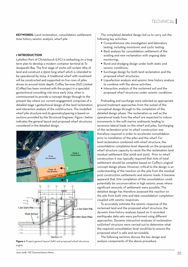
June 2018 • NZ Geomechanics News 35
TECHNICAL
1 INTRODUCTIONLyttelton Port of Christchurch (LPC) is embarking on a long-term plan to develop a modern container terminal at Te Awaparahi Bay. The first stage of works will reclaim 16ha of land and construct a 350m long wharf which is intended to be operational by 2024. A traditional wharf with revetment will be constructed and supported on five rows of piles driven to around 100m depth. Coffey Services (NZ) Limited (Coffey) has been involved with the project in a specialist geotechnical consulting role since early 2014, when is commissioned to provide a concept design through to the present day where our current engagement comprises of a detailed stage 1 geotechnical design of the land reclamation, and interaction analysis of the soil/structure. The modelled wharf pile structure and its geometry/spacing is based on sections provided by the Structural Engineer. Figure 1 below indicates the general layout and proposed wharf structures considered in the detailed design.
KEYWORDS: Land reclamation, consolidation settlement, time history seismic analysis, wharf pile
The completed detailed design led us to carry out the following key activities:
• Comprehensive site investigation and laboratory testing, including monotonic and cyclic testing;
• Back analysis for consolidation settlement of the existing and new reclamation with ongoing data monitoring;
• Bund and dredging design under both static and seismic conditions;
• Surcharge design for both land reclamation and the proposed wharf structures;
• Liquefaction analysis and seismic time history analysis to combine with the above activities
• Interaction analysis of the reclaimed soil and the proposed wharf structures under seismic conditions
Preloading and surcharge were selected as appropriate
ground treatment approaches from the outset of the conceptual design through to the completion of the detailed design phase. The reclamation as well as the operational loads from the wharf are expected to induce movements in the soft marine sediments leading to excessive lateral loads on the wharf and piles. Surcharging of the reclamation prior to wharf construction was therefore required in order to accelerate consolidation prior to installation of the piles and the wharf. For land reclamation combined with wharf structure, the consolidation completion level depends on the proposed wharf structure capacity to resist the the reclamation land residual settlement (Dai 2008 and 2012). Prior to wharf construction it was typically required that 70% of total settlement should be complete based on Coffey’s original concept design phase. However, critical to the design is an understanding of the reaction on the pile from the residual post construction settlements and seismic loads. It became apparent that 70% completion of the consolidation could potentially be unconservative in high seismic areas where significant amounts of settlement were possible. The detailed design has therefore assessed the reaction on the pile from both 70% and 95% consolidation completion coupled with seismic responses.
To accurately estimate the seismic response of the reclaimed land and the proposed wharf structure, the dynamic time history analyses based on 11 recorded earthquake data sets were performed using different approaches. Dynamic interaction analyses of reclamation soil/wharf structure were carried out to determine what the required consolidation level would be to ensure the proposed wharf is safe and serviceable.
The following sections discuss the key design and analysis components of the above procedure.Figure 1: Project general layout (left) and proposed wharf structure
(right)
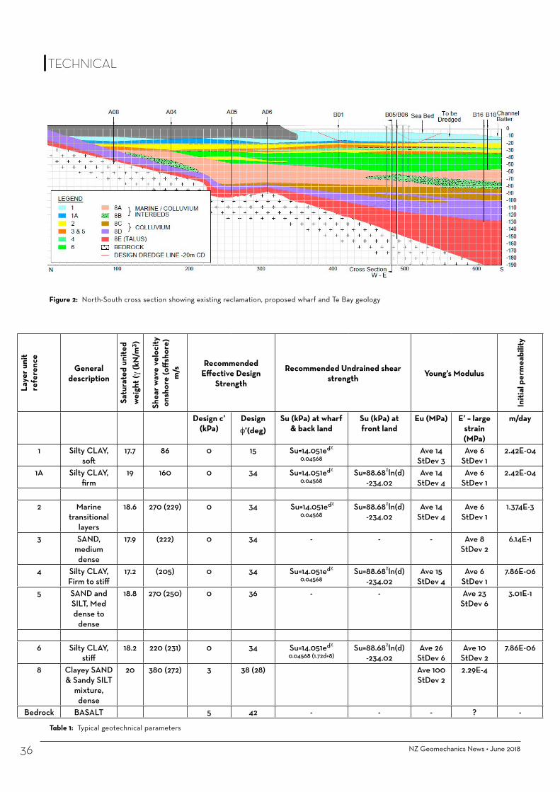
NZ Geomechanics News • June 201836
Table 1: Typical geotechnical parameters
Figure 2: North-South cross section showing existing reclamation, proposed wharf and Te Bay geology
Laye
r uni
t re
fere
nce
General description
Satu
rate
d un
ited
wei
ght (
γ (k
N/m
3 )
Shea
r wav
e ve
loci
ty
onsh
ore
(off
shor
e)
m/s
Recommended Effective Design
Strength
Recommended Undrained shear strength Young’s Modulus
Initi
al p
erm
eabi
lity
Design c’ (kPa)
Design φ’(deg)
Su (kPa) at wharf & back land
Su (kPa) at front land
Eu (MPa) E’ – large strain (MPa)
m/day
1 Silty CLAY, soft
17.7 86 0 15 Su=14.051edχ 0.04568
Ave 14 StDev 3
Ave 6 StDev 1
2.42E-04
1A Silty CLAY, firm
19 160 0 34 Su=14.051edχ 0.04568
Su=88.68χln(d) -234.02
Ave 14 StDev 4
Ave 6 StDev 1
2.42E-04
2 Marine transitional
layers
18.6 270 (229) 0 34 Su=14.051edχ 0.04568
Su=88.68χln(d) -234.02
Ave 14 StDev 4
Ave 6 StDev 1
1.374E-3
3 SAND, medium dense
17.9 (222) 0 34 - - - Ave 8 StDev 2
6.14E-1
4 Silty CLAY, Firm to stiff
17.2 (205) 0 34 Su=14.051edχ 0.04568
Su=88.68χln(d) -234.02
Ave 15 StDev 4
Ave 6 StDev 1
7.86E-06
5 SAND and SILT, Med dense to
dense
18.8 270 (250) 0 36 - - Ave 23 StDev 6
3.01E-1
6 Silty CLAY, stiff
18.2 220 (231) 0 34 Su=14.051edχ 0.04568 (1.72d+8)
Su=88.68χln(d) -234.02
Ave 26 StDev 6
Ave 10 StDev 2
7.86E-06
8 Clayey SAND & Sandy SILT
mixture, dense
20 380 (272) 3 38 (28) Ave 100 StDev 2
2.29E-4
Bedrock BASALT 5 42 - - - ? -
TECHNICAL

June 2018 • NZ Geomechanics News 37
TECHNICAL
2 GEOLOGICAL SETTING AND DESIGN PARAMETERSThe project has benefited from a relatively comprehensive on-shore and offshore site investigation and laboratory testing programme. This was carried out between 2015 and 2017. The investigation included on-shore and off-shore boreholes drilled to a maximum depth -170m CD, Cone Penetration Tests to -58m, CPTu tests, Dilatometer testing, downhole shear wave velocity testing, settlement monitoring at the existing reclamation and laboratory testing (soil indices, triaxial tests, direst shear, unconfined compression tests, monotonic loading tests).
The upper ground profile in the bay area generally consists of fine grained relatively young marine sediments (silt, clay and interbedded fine sand layers). The deposits are dominated by normally consolidated fine grained materials (silt and clay) with units designated 1,1a, 4 and 6 being compressible. Interbedded layers of sand are encountered through the ground profile and are associated with a gradual change in environment from a deeper marine to a near shore environment where wave action has higher energy and hence sandier soils are observed. Below the marine deposits lie volcanic derived colluvium overlying weathered volcanic rock (typically basalt). The geological N-S cross section is presented in Figure 2.
The deriving of design parameters is included in the unpublished report (Coffey 2017). The major outputs are summarised in the table 1 below:
3 CONSOLIDATION SETTLEMENT BACK-ANALYSIS AND SURCHARGE DESIGN
3.1 AnalysisThe surcharge design was first analysed using Coffey’s in house program CONFED which is a 1D based method to provide a benchmark for the more detailed 2D analysis using Plaxis 2D. Each method used back analyses of material parameters to match the observed settlement at a monitoring plate on the existing reclamation. Measured monitoring results at a monitoring plates were available from their installation in March 2016 to August 2017 (the detailed design phase). The previous existing reclamation is assumed to have reached the monitoring station location in October 2013 therefore fill placement and settlement had been under way for around 2.5years prior to the start of monitoring. Back-analysis of settlement rates and material parameters indicated that around 550mm of settlement had already occurred prior to plate installation.
Total settlements after 100years were predicted to be approximately 1.77m at the existing reclamation and 1.85m at the bund. A surcharge loading programme was then
designed to achieve the design criteria of 70% of total consolidation by stage 1 wharf completion in 2024. Figure 3 shows a typical example of how time vs settlement and pore water pressure increases with each application of surcharge load, followed by dissipation of excess pore water pressures and corresponding increases in effective stress.
The results indicate that a surcharge of 0.7m of fill would be required to meet the design criteria of 70% consolidation settlement completion at the existing reclamation. However, at the bund and new reclamation even a surcharge of 9.0m of fill would only achieve 55% completion of the consolidation by 2024. Plaxis 2D was used to analyse this problem in more detail.
Figure 3: Typical plot of time vs settlement and excess pore water
pressure, effective and total stress at bund following additional
surcharging.
3.2 2D CONSOLIDATION ANALYSIS USING PLAXIS 2D
3.2.1 2D Analysis methodsThe settlements associated with reclamation construction and operational loads have been assessed in Plaxis 2D v.2017. The construction sequence is illustrated in Figure 4 and the analysis model is shown in Figure 5. It includes the following steps:

NZ Geomechanics News • June 201838
• Initialization of stresses across virgin seabed prior to reclamation.
• Emulation of the existing reclamation by construction in 4 stages over 6.5years (2011 to the present day).
• Back-analysis of material stiffness and permeability to match settlement monitoring at the edge of the existing reclamation (outputs see Figure 6).
• Emulation of the new reclamation with dredging to -18.0m CD and bund construction in 3 stages over 2.5 years to design level RL +5m CD.
• Application of working loads; 12kPa 9.0m back from bund crest, and 55kPa across the backland.
• Post construction consolidation to achieve >99% degree of consolidation across the model.
3.2.2. 2D Analysis ResultsSettlements following application of operational loads but with no additional surcharge are predicted to be in the order 1.64m at the existing reclamation and 1.88m immediately behind the bund which is in good agreement with the 1D results.
The analysis shows that consolidation at the existing reclamation is likely to be 70% complete by 2024 (Table 2
and 7 left). However, the bund and new reclamation with no surcharge is less than half complete, and therefore requires additional surcharging prior to wharf construction.
3.3 Bund and New Reclamation Surcharge DesignA surcharge loading programme was designed in Plaxis 2D by adding a series of distributed loads above the design level of 5m CD, to simulate placement of fill. Settlement was calculated between each load application and the loads and hold times were iterated to achieve 70% and 95% consolidation by 2024.
The surcharge design which achieves 95% consolidation is shown in Table 3 and must be left in place until January 2022 as a minimum, and can be removed any-time after this date to suit the wharf construction program.
Figure 7 (right) shows settlement behind the bund with and without the surcharge illustrating how the extra surcharge accelerates the consolidation settlement and achieves the design criteria. Figure 8 presents Plaxis output showing vertical settlement at 95% completion in 2024.
Figure 4: Designed construction
sequences.
Figure 5: Plaxis model used in settlement analysis.
Figure 6: Settlement near crest of existing reclamation with model
parameters back-analysed to match observed settlements.
TECHNICAL

June 2018 • NZ Geomechanics News 39
TECHNICAL
Figure 7: (Top) Settlements under operational loads with no additional
surcharge; (Above) Comparison of Consolidation Settlement with and
without Extra Surcharge Behind Bund.
Figure 8: Plaxis output of vertical settlement at 95% complete at 2024.
4 REACTION ON PROPOSED WHARF STRUCTURE UNDER STATIC CONDITIONSLateral soil movements will continue to occur at the bund as the soils continue to settle following the completion of wharf construction. These further lateral ground movements will induce a lateral reaction on the wharf piles in addition to any seismic load. The static bending moments and shear forces induced in the piles (following construction of the wharf) due to on-going consolidation have been modelled in Plaxis 2D.
Figure 9 shows that the maximum reaction on the piles due to consolidation movement is between Unit 6 and Unit 8 (about -60m CD). This is due to the significant differential movement contrast in this area with the major consolidation movement occurring in Unit 6 (silt/clay), compared with the very minor movement that takes place in Unit 8 (very stiff colluvium).
Stage from to Days per stageDredge (to RL18m CD) April 2018 July 2018 90Construct Bund (5.0m CD) July 2018 January 2019 180Backfill - New Reclamation (5.0m CD) January 2019 January 2020 365
Surcharge 1: 7.2m CD January 2020 February 2020 30Surcharge 2: 9.2m CD February 2020 March 2020 30Surcharge 3: 11.2m CD March 2020 January 2022 670Remove Surcharge & Construct Wharf January 2022 January 2024 -
δ 2022 (mm)
δ 2024 (mm)
δ 2027 (mm)
δ 2044 (mm)
δ 100 (mm)
2024 Operational design criteria δ
completed in 2024
Comment<200/3y
(mm)<500/20y
(mm)Behind Bund 450 770 1170 1540 1880 400 770 41% Criteria
Not MetExisting
Reclamation 1050 1130 1350 1520 1640 51 390 69% Criteria likely Met
Table 2: Settlements with no additional surcharge (operational loads only)
Table 3: Surcharge design at bund at new reclamation.

NZ Geomechanics News • June 201840
Table 4: Liquefaction analysis assessment Parameters.
The analysis indicates that liquefaction potential is low. Liquefaction induced free-field vertical settlement within the sandier layers are also low with settlements in the range of 15-50mm over the depth of the CPTs (typically 45 to 60m depth) across most design events.
Seismic design Following on from the concept design phase
(Antonopoulos I.K. & B.H. Cheah, 2017), the detailed seismic design was carried out using Performance Based Design and full soil-foundation-structure-interaction methods. The design follows a series of steps to capture the performance under a suite of eleven (11) critical earthquake time histories (deconvoluted as necessary) selected to represent near field, regional and Alpine Fault events.
A one-dimensional soil amplification analysis has been undertaken to assess the new stratigraphy’s response
Two cases were analysed assuming the bund will have completed 70% and 90% of the total expected settlement by 2024 leaving a further 30% and 10% of settlement to occur respectively. The analyses show that the static reaction induced in the piles from the 10% remaining consolidation (Figure 10 right) is only about one third of the reaction if 30% of the consolidation movement were still occur (Figure 10 left). The reaction moment induced in the piles from installation of the wharf deck and any seismic loads will therefore govern the pile design.
5 REACTION ON PROPOSED WHARF STRUCTURE UNDER SEISMIC CONDITIONAn important aspect of the pile design is to consider the induced reaction in the piles from the seismic soil movement.
5.1 Liquefaction analysisA liquefaction assessment of soils within the Te Awaparahi Bay has been undertaken based on the methods of Bray and Sancio (2006), Boulanger and Idriss (2014) and Andrus & Stokoe (1997) for the four average exceedance probabilities presented in Table 4 below.
Return Period PGA Effective Magnitude (Meff)1/25 0.15g 5.981/75 0.29g 6.031/475 0.59g 6.151/2500 0.73g 6.20
TECHNICAL
Figure 9: Consolidation movement along the boundary of Unit 6 and Unit 8 superimposed with static pile bending moment – max.
moment was near the interface of Unit 6 and Unit 8.

w
NORTH ISLAND• Auckland• Tauranga
SOUTH ISLAND• Christchurch• Dunedin
0800 DMT CPT (368 278)[email protected]
SMALL TRACKED RIGS
MAN-PORTABLE RIG
12 + 22 TON TRUCK RIGS
22 TON MOROOKA
I N S I T U T E S T I N G : C P T - S e i s m i c - D M T
Specialists in high quality in situ testing• CPT, SCPT • DMT, SDMT• DPSH • SWS - SDS
Large range of versatile rigs that can access almost any site• steep sites• soft ground• basements and narrow access• tidal estuaries• over water• helicopter or crane access
Expert advice on• which in situ test to use for a particular site or application• interpreting soil paramaters from in situ tests
Let us assist you to get the information you need for your geotechnical project
Our Mission:
BEST POSSIBLE DATA

NZ Geomechanics News • June 201842
under the selected time histories and to be used as a benchmark for calibration and comparison of the 2D analyses. Both Equivalent-linear (EL) and non-linear (NL) methods were used. The EL analyses were performed using software Shake2000 (Ordóñez, 2012), and the NL analyses were performed using software D-Mod2000 (Matasović and Ordóñez, 2011). Details regarding earthquake record time histories, deconvolution, and motion scaling are referred to in the report (Coffey 2017).
Based on the results of the 1D soil amplification analysis, the most critical records were:
Lixouri 2014, which exhibits a significant forward directivity component, and
Kaikōura 2016, recorded within the Wellington Port basin, which exhibits both long duration and basin reflection effects.
These were selected as input motions for the 2D time history analyses that were carried out to assess the performance of the concept design wharf structure against the new reclamation.
Performance of proposed wharf structure under both residual settlement and seismic loading
Time history analyses and soil-foundation-structure-interaction of the proposed wharf has been undertaken using the 2D finite difference software FLAC. The model is setup around a representative north-south section through the proposed reclamation and the wharf. The modelled wharf structure geometry and spacing is based on a typical wharf section in Figure 1.
The 2D analyses have been carried out with both the Lixouri (2014) and the Kaikōura (2016) input motions and have been compared with the 1D benchmark. Both resulted in very similar and comparable results albeit the Kaikōura motion takes considerable computation time due to its duration. Therefore, the Lixouri (2014) time history was selected as the final input motion for the design.
The time history and soil-foundation-structure-interaction analyses results include bending moments, shear forces and displacements for the wharf piles. Combined with reactions from the residual consolidation settlement in section 4, and the time history analysis in this section, Figure 9 below illustrates the distribution of bending moments along the landward pile, which is the worst case when compared to both seaward and internal piles across the wharf structure.
As can be seen in Figure 10, at the interface level between Units 6 and 8, the cumulative bending moment (static + seismic) was about 4MNm/pile for 70% consolidation movement completion. Considering the proposed pile dimension of 1.5m diameter with a 25mm thick steel tube pile, the reaction in the pile may have overstressed the section when compared to its capacity.
However, the cumulative moment at this elevation for 90% consolidation was approximately 2MNm/pile, which should be less than the proposed pile capacity. Accordingly, to minimise the reaction on the pile, it has been recommended that 90% completion of consolidation should be achieved before wharf construction commences.
6 CONCLUSIONThe current land reclamation design faces challenges from deep soft ground consolidation settlement, a seismically active environment and client operation timeframe requirements. These items are also relevant to the interaction analysis with the proposed wharf structures. The land reclamation design included a comprehensive suite of analysis. A back analysis was carried out to determine the consolidation timeframe and residual deformation. Plaxis 2D analysis was also performed to identify the reaction on the proposed wharf structure under residual reclamation land deformation. Full time history analyses were carried out, and the selected Lixouri (2014) event was used as input motion to the 2D finite difference software FLAC to determine the performance on the wharf piles and reclamation under seismic loading. The reactions along the proposed piles combined the results of both residual static deformation and seismic loading.
Based on the detailed analyses with the proposed wharf structure capacity, a consolidation completion of 90% is required. A rational and detailed schedule of fill heights
Figure 10: (left) – Moment for 70% consolidation completion;
(right) – Moment for 90% consolidation completion.
TECHNICAL

TECHNICAL
with staying times was also designed as in Figure 4.The completed detailed design can be directly
extrapolated into the Stage 2 land reclamation and proposed wharf structure design for Lyttelton Port of Christchurch. It is believed that the design and analysis experience can be applied to similar infrastructure design in New Zealand.
7 ACKNOWLEDGEMENTThe writers wish to thank Lyttelton Port of Christchurch for their approval to publish this paper.
REFERENCEDai, C., 2008, Bulkhead wall design on very soft clay ground, Continuum
and Distinct Element Numerical Modelling in Geo-Engineering - Hart, Detournay & Cundall (eds.) Paper: 11-01 ©2008 Itasca Consulting Group, Inc., Minneapolis, ISBN 978-0-9767577-1-9
Dai, C., 2012, Wharf Bulkhead Wall Geotechnical and Structural Capacity Assessment, Journal of Australian Geomechanics Society.
Coffey (2017), Design Report on LLPC Te Awaparahi Bay Stage 1 Land reclamation, 773-CHCGE208087AA, Christchurch, NZ
Plaxis v2017, Delft, The NetherlandsAntonopoulos I.K. & B.H. Cheah, 2017. Seismic design of the Te Bay
Reclamation of the Lyttelton Port of Christchurch. PBD-III Vancouver 2017
In and On the ground, we go Beyond withexceptional Geotechnical Delivery!
As a specialist geotechnical consultancy, we prideourselves on becoming immersed with our clients’
projects, taking ownership of geotechnical issues
Come advance your career with us!
cmwgeosciences.com
Bray, J.D. and Sancio, R.B., 2006, Assessment of the Liquefaction Susceptibility of Fine-GrainedSoils, J. Geotech. Geoenvironment. Eng., 132(9): 1165-1177
Boulanger, R. W. and Idriss, I. M., 2014, CPT and SPT Based Liquefaction Triggering Procedures, Center for Geotechnical Modeling Department of Civil and Environmental Engineering University of California Davis, California
Andrus, R.D., and Stokoe, K.H., 1997., Liquefaction Resistance Based on Shear Wave velocity, NCEER Workshop on Evaluation of Liquefaciton Resistance of Soils, Technical Report NCEER-97-0022. T.L. Youd and I.M. Idriss, Eds., 4-5 Jan 1996, Nat. Ctr. For Earthquake Engrg. Res., Buffalo, NY, pp. 89-128
Geomotions LLC 2016. SHAKE2000D-Mod2000 Matasović and Ordóñez, 2011Itasca Consulting Group, Inc. (2016) FLAC — Fast Lagrangian Analysis
of Continua, Ver. 8.0. Minneapolis: Itasca
Originally published: Antonopoulos I.K. & B.H. Cheah, 2017. Seismic design of the Te Bay Reclamation of the Lyttelton Port of Christchurch. PBD-III Vancouver 2017.Awad A. & I.K. Antonopoulos, 2017. Kawarau Bridge Development in Queenstown. Piling & Deep Foundations New Zealand 2017.McDermott C., I.K. Antonopoulos, B. Cheah, 2017. Overcoming Soft Ground Conditions at the Lyttelton Port of Christchurch. Australian Coasts & Ports 2017.

Your Complete Wall Solution—Each block in the Redi-Rock system is available in any texture
Gravity Walls MSE Walls Freestanding Walls
See redi-rock.com for additional products and accessories.
Redi-Rock® is a complete engineered retaining wall solution that uses giant concrete blocks that stack up like Lego to create strong, great-looking wall solutions for• Gravity Walls• MSE Reinforced WallsApplications• Gabionbasketalternative• Sliprepairs• Roadsandbridges• Retainingwallsforsubdivisons,seawalls,waterwaysandmuch,muchmore
DesignSoftwareRedi-Rock®retainingwallsystemisdesignedforengineers,byengineers.Designingcriticalwallstructuresisimportantwork-andyouneedthebestresourcesavailabletohelpyoudoyourjob.AllthedesigntoolsandsoftwareareFREEandcanbedownloadedatredi-rock.com
Tolearnmorevisitwww.redi-rock.comEmail:[email protected]:David021951057
AVAILABLEIN3LOCATIONSTHROUGHOUTNORTHISLANDNORTHLAND&AUCKLAND•WAIKATO
NEWPLYMOUTH&WELLINGTON
Massivewavesdeterioratedtheshorelineandaportionoftheroad.Aquickrepairwasimperativetogettingthisroadbacktoasafecondition.
ThesmallcrewneededonthisNZTAjobinGisbornewereabletocompletetheentireprojectin10days.
Thankstothejointeffortofallinvolved,theprojectwascompletedquicklyandwithouttotalroadclosure!
Redi-Rock®Gravitywallactsasarmourforwashedoutshorelineslope
SafeandQuickInstallationRedi-Rock®wallsprovidemanybenefitsandadvantageswhencomparedtotraditionalretainingsolutions.• Thelarge,1tonneblockscanbeinstalledquicklyusingamachine.
• Quickinstallationsreducetrafficholdupsanddisruptiontocommunities.
• Projectscanbecompletedefficientlyandaheadofschedule.
• Redi-Rock®blocksaresafetoinstallandreducetheriskofinjurytocontractors.ThereisnoneedforexpensivescaffoldingwheninstallingRedi-Rock®atheights.

NZ Geomechanics News • June 201846
Haldon Dam is a 15 m high zoned earth-fill embankment irrigation dam, located approximately 10 km south-west of Seddon, in the Awatere Valley, New Zealand. The crest and upstream shoulder of the embankment suffered serious damage during the 2013 Cook Strait earthquakes, and the Regulator enforced emergency lowering of the reservoir by 5.5 m to reduce the risk of flooding to Seddon Township from a potential dam failure. AECOM was engaged by the owner to carry out a forensic analysis of the damaged dam and subsequently the design of the 2-Stage remedial works. The remedial works addressed the existing dam deficiencies and earthquake damage in order to restore the dam to full operational capacity and gain code compliance certification. Key features of the approach included holding a design workshop with the owner prior to undertaking detailed design, careful rationalisation of the upstream shoulder to optimise the competing interests of strength and permeability, contractor and regulator involvement in the design and construction process, and balancing risk and constructability with the chimney filter retrofit. This paper presents a description of, and approach to, remedial works solution undertaken to remediate a substandard and earthquake-damaged dam to fully operational status in an area of high seismicity. Applying this approach, the objective of achieving a robust, safe, economical design that was acceptable to the regulators and the owner was achieved.
Keywords: Haldon, earthquake, seismic, remediation, case-study.
1 INTRODUCTIONHaldon Dam is a 15 m high, Medium Potential Impact Category (PIC) (potential for loss of life, moderate socio-economic, financial or environmental damage) irrigation dam located on Starborough Creek approximately 10 km south-west of Seddon, in the Awatere Valley, New Zealand. A site location map is presented in Figure 1.
Between 2003 and 2008, investigations, design and construction of the original dam was completed. The original design comprised an approximately 15m high by 170m long crest embankment with conditioned mudstone core, alluvial gravel shoulders, and downstream chimney filter/drainage zone, with a storage volume of approximately 250,000 m3, and design flood event of 1 in 1000 Annual Exceedance Probability (AEP). It is founded
Haldon Dam Remediation: A Case Study of Earthquake Damage and Restoration – Originally presented at ANCOLD (2017) Conference, Hobart
John Harris John is a Geotechnical Engineer with AECOM in Christchurch. He holds a BSc in Geology, and a MEngSc in Engineering Geology/Geotechnical Engineering. John has worked on a variety of projects from residential and commercial developments, earth retaining structures, embankment dams and canals, highways, and tunnels.
Ron Fleming Ron Fleming has over 44 years’ experience in the planning, feasibility assessment, design management, implementation and construction management of large infrastructure projects. His experience includes irrigation projects, hydro-electric projects, dams and tunnels.
James Robinson James has over twenty years’ dams consulting design expertise. His experience includes site investigation, design and construction monitoring of earth embankment water dams and tailings facilities on various mining and water projects in New Zealand, Australia, South America, Asia and Africa.
TECHNICAL

June 2018 • NZ Geomechanics News 47
on in-situ mudstone. The dam has a separate spillway on the left abutment and an environmental flow release pipeline on the right abutment, with an intake at the head of the reservoir. The spillway consisted of an 18.5m long, 5m wide broad crested weir with an armoured energy dissipation zone, and 120 m long riprap lined channel with a second energy dissipation basin at the outlet. A typical section of the original design is shown in Figure 2.
Initial construction was completed in February 2008. During construction there were a number of non-compliant issues with the design and construction which were not closed out at the time. These, and a number of other issues in combination, resulted in poor performance of the dam on first filling, including a longitudinal crack on the downstream side of the crest, and minor slumping of the upstream shoulder. The construction contractor subsequently went into liquidation with the result that no
as-built construction records were available.The dam filled during a single rainstorm event in July
2008 and came close to overtopping when it was found that the spillway had been constructed too high and narrower than the design. Following this, remedial work on the spillway was carried out but the dam was not put into service due to ongoing concerns over its performance.
After damage to the dam by the Cook Strait Earthquakes, the Regulator (Marlborough District Council (MDC)) and its dam consultant (MWH Limited) enforced emergency lowering of the reservoir by 5.5 m to reduce the risk of flooding to Seddon Township from a potential dam failure. This involved excavation through the spillway and spillway channel, and excavation of a second lower level outlet trench through the left abutment.
Following these events, AECOM were engaged to perform an independent forensic analysis of the dam. This
Figure 1: Site Location Map
TECHNICAL
Figure 2: Typical Section of Original Dam Design

NZ Geomechanics News • June 201848
involved investigating and defining the deficiencies and advising on remedial solutions, and whether repair was practicable, given the extent of the damage. A remediation solution was identified, and the estimated cost of this was compared to the estimated cost of a full dam demolition and reconstruction. This analysis concluded that remedial works were an economically viable approach.
This paper presents an overview of the remedial works undertaken to restore the dam to full operational capacity, and the rationalisation process followed for each design feature. Specific challenges associated with the dam site such as regional seismicity and sensitive foundation geology will also be presented, and methods employed to overcome these challenges.2. GEOLOGICAL SETTINGThe QMAP Geology of the Kaikoura Area (Rattenbury et al., 2006) indicates that the area around the dam site is underlain by Late Pleistocene-age alluvial deposits consisting of ‘weathered, poorly sorted to moderately sorted gravel underlying loess-covered; commonly eroded aggradational surfaces’. This is underlain by the Miocene-Pliocene age Starborough Formation, consisting of ‘poorly bedded sandstone and sandy siltstone in the Awatere Valley; and siltstone near White Bluffs’. Also on site is the Late Miocene age Upton Formation Siltstone, consisting of ‘Poorly sorted and poorly bedded channelised greywacke conglomerate with lenses of sandstone and sandy siltstone’.
The site is located in the Australian and Pacific plate boundary transition region with the Hikurangi subduction zone to the north-east and continental collision to the southwest. Movement along the plate boundary is dominantly accommodated by the oblique strike-slip, north-east – south-west trending faults in the region. The regional faults that provide the greatest contribution to the seismic hazard at the site include the Alpine, Hope, Clarence, Awatere, and Wairau Faults; all of which generate earthquakes with magnitudes greater than Moment Magnitude (Mw) 7.0, with recurrence intervals of 300 to 2,000 years. No faults are known to intersect the site.
3. RECENT SEISMICITY3.1 2013 Cook Strait EarthquakesThe Cook Strait Earthquake sequence of 2013 consisted of two major earthquakes. The main Mw6.5 shock of 21 July 2013, and the secondary Mw 6.6 shock of 16th August 2013. Seismographs in the region indicated that July 2013 event was likely to have induced peak ground acceleration (PGA) at the dam site of approximately 0.21g, while the August 2013 event is thought have induced slightly higher PGA at the dam site. Several significant fore- and after-shocks occurred in association with the main events, ranging from Mw 4.7 to Mw 5.9. Figure 3 shows the locations and focal mechanisms for the Cook Strait earthquakes of 2013.
Figure 3:
Locations and
Focal Mechanisms
for Cook Strait
Earthquakes of 2013
TECHNICAL

June 2018 • NZ Geomechanics News 49
Following the main earthquake of 21 July 2013, the dam experienced cracking along the crest. These longitudinal cracks were most evident on the upstream side of the crest, with smaller cracks down the centre of the crest. The longitudinal cracks varied in width up to approximately 100 mm with the widest cracking located where the embankment is at its highest.
Following the 16 August 2013 event, the longitudinal cracks had opened further and the crack towards the middle of the dam where the embankment is at its highest had increased up to 500 mm wide. The upstream shoulder appeared to have separated laterally from the core and slumped vertically. This cracking was in the same location as the cracking observed following first filling, indicating that the post-earthquake cracking could have been a continuation of deformation of the upstream shoulder which had initiated prior to the earthquakes. Figures 4 and 5 show the damage to the crest and upstream face of the embankment following the August 2013 event.
Monitoring on 2 October 2012 indicated that post-construction embankment settlement had almost stopped. However, the monitoring results of 19 August 2013 indicated that the embankment settled further (up to 130 mm) due to the main and aftershock sequences. This settlement was concentrated at settlement monitoring point Pin 2 which is located approximately at the highest section of the embankment on the downstream edge of the crest road.
The damage experienced by the dam as a result of the Mw6.5 main shock, is categorised as “major” and the damage following the Mw6.6 aftershock is categorised as
“severe” using the system of Pells and Fell (2003). Following the August 2013 event, the Regulator
(Marlborough District Council (MDC)) and its dam consultant (MWH Limited) enforced emergency lowering of the reservoir by 5.5m to reduce the risk of flooding to Seddon Township from a potential dam failure. Seddon is some 12 km downstream, where a peak flow of 120 m3/s were expected (higher but comparable to the 100 AEP flood discharge of 90 m3/s). The lowering involved demolition of the spillway weir and stilling basin and excavation through the spillway channel, and excavation of a second lower level outlet trench through the left abutment.
3.2 2016 Kaikoura EarthquakeAn Mw7.8 earthquake occurred on 14 November 2016, initiating approximately 15 km north-east of Culverden, and rupturing in a north-east direction on a number of different faults over a distance of approximately 200 km. The largest energy release was near the township of Seddon, approximately 15 km north-east of the dam site. Peak ground accelerations associated with the Kaikoura earthquake were recorded at 0.75 g (at the Seddon Fire Station) and 1.27 g (at the Ward Fire Station). A significant amount of aftershocks occurred following this event, as shown in Figure 6.
Figure 4: Vertical Settlement of Upstream Shoulder Following the
August 2013 Event
Figure 5: Right: Longitudinal Crack Following the August 2013 Event
TECHNICAL
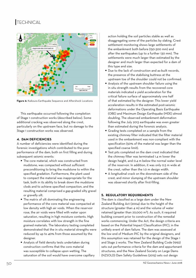
NZ Geomechanics News • June 201850
action holding the soil particles stable as well as disaggregating some of the particles by slaking. Crest settlement monitoring shows large settlements of the embankment both before (150-300 mm) and after the earthquakes (up to a further 130 mm). The settlements were much larger than estimated by the designer and much larger than expected for a dam of this type and size.
• Due to the lack of construction and as-built records, the presence of the stabilising buttress at the upstream toe of the shoulder could not be confirmed.
• Analysis of the upstream shoulder failure using the in situ strength results from the recovered core materials indicated a yield acceleration for the critical failure surface of approximately one half of that estimated by the designer. This lower yield acceleration results in the estimated post-seismic deformations under the Operating Basis Earthquake (OBE) and Maximum Design Earthquake (MDE) almost doubling. The observed embankment deformation following the July 2013 earthquake was even greater than estimated during the forensic analysis.
• Grading tests completed on a sample from the existing chimney filter indicated that the filter material used in the embankment was non-compliant with the specification (50% of the material was larger than the specified coarse limit).
• Test pits completed on the dam crest indicated that the chimney filter was terminated 1.4 m lower the design height, and 0.4 m below the normal water level of the reservoir. In addition, it was only 0.5 m wide at the crest, rather than the 1.0 m design width.
• A longitudinal crack on the downstream side of the crest, and minor slumping of the upstream shoulder was observed shortly after first-filling.
5. REGULATORY REQUIREMENTS The dam is classified as a large dam under the New Zealand Building Act (2004) due to the height of the structure (greater than 4 m) and the volume of water retained (greater than 20,000 m3). As such, it required building consent prior to construction of the remedial works commencing. Under the Act, the design criteria are based on the Potential Impact Classification (PIC), in the unlikely event of dam failure. The dam was assessed at the low end of Medium PIC by the original designers, and this assumption was retained for the design of the Stage 1 and Stage 2 works. The New Zealand Building Code (1992) sets out performance criteria for the dam and appurtenant structures, and the New Zealand Society on Large Dams (NZSOLD) Dam Safety Guidelines (2015) sets out design
Figure 6: Kaikoura Earthquake Sequence and Aftershock Locations
This earthquake occurred following the completion of Stage 1 construction works (described below). Some additional cracking was observed along the crest, particularly on the upstream face, but no damage to the Stage 1 construction works was observed.
4. DAM DEFICIENCIESA number of deficiencies were identified during the forensic investigations which contributed to the poor performance of the dam, both on first filling and during subsequent seismic events:
• The core material, which was constructed from mudstone, was compacted without sufficient preconditioning to bring the mudstone to within the specified gradation. Furthermore, the plant used to compact the material was inappropriate for the task, both in its ability to break down the mudstone clods and to achieve specified compaction, and the resulting material comprised a gap-graded silty gravel or gravelly silt.
• The matrix of silt dominating the engineering performance of the core material was compacted at low density with high air voids. When the reservoir rose, the air voids were filled with water upon saturation, resulting in high moisture contents. High moisture correlates with low strength in the fine grained materials. The laboratory testing completed demonstrated that the in situ material strengths were reduced by up to 40% from those assumed by the designer.
• Analysis of field density tests undertaken during construction confirms that the core material was susceptible to collapse upon wetting. The saturation of the soil would have overcome capillary
TECHNICALTECHNICAL

June 2018 • NZ Geomechanics News 51
criteria for large dams. Design and construction of the remedial works were completed in accordance with the relevant sections of these overarching documents.
6. STAGE 1 REMEDIATION 6.1 RationaleThe remedial works to restore the dam to full operational capacity was completed in two stages. Stage 1 comprised a “Make Safe” solution, with the intent of enabling the dam to continue to operate at the lowered reservoir level (244.35 m RL) indefinitely. The objective of the Stage 1 “Make Safe” design was to design an interim solution to satisfy the relevant dam safety requirements with the reservoir maintained at the lower level, while also allowing the works to be incorporated into the Stage 2 permanent remediation. For practical purposes the solution allowed the spillway to pass a 1 in 1000 year flood as required for a lower end Medium PIC dam.
6.2 Stage 1 WorksThe key elements of the Stage 1 works are summarised as follows:
• Low-Level Outlet Pipe Installation: Conversion of the existing emergency low level outlet trench into a permanent Low-Level Outlet (LLO) using a DN560 mm Polyethylene (PE) pipe. The pipe was fully encased in concrete upstream of the chimney filter. The upstream end included a flanged connection for the future addition of a control valve during Stage 2. Following installation of the LLO, the trench was backfilled using the embankment cross section to the existing ground level with zoned fill incorporating an impervious central core, alluvial shoulders, and internal drainage (in the form of a chimney filter and downstream blanket drain) to reduce seepage, control pore pressures within the downstream shoulder, and mitigate the risk of piping though the fill. The dam
embankment was founded on in-situ Tertiary-age mudstone, with the core keyed into in-situ mudstone. The core consisted of mudstone won from a borrow area upstream from the dam, conditioned to a clay in the borrow area, and compacted to 98% relative compaction within -1% to + 2% of optimum moisture content. The LLO has sufficient capacity to pass the average annual flow in the stream without surcharging and can pass flows up to the 2 year AEP event before the water level in the reservoir exceeds the spillway channel invert level.
• Spillway Upgrade: The existing spillway channel was enlarged slightly to accommodate the 1 in 1000 year flood event (AECOM’s reassessment of this event resulted in a larger design flow for this event than the flow adopted for the original design). The new channel profile comprised a two stage trapezoidal section with the lower section accommodating all but the extreme flood, which will rise into the upper section but remain within the formed channel. Riprap erosion protection was reinstated along the channel, and at the upstream end in the location of the demolished weir and stilling basin.
• Ford Crossing: A ford was constructed across the spillway 50 m downstream from the spillway mouth. It consisted of 4 round culverts encased in concrete. The height of the ford was approximately 1.2 m above the invert of the spillway channel and the culverts are capable of passing up to a 1 in 5 year AEP event with higher flows passing over the ford.
A typical section through the LLO pipe trench backfill is shown in Figure 7, and some photographs showing the installation of the LLO pipe are shown in Figure 8. Stage 1 remedial works were completed over the course of approximately 5 months from March to August 2016. Code Compliance Certification for the Stage 1 works was issued for the works by the regulator, MDC, on 8 November 2016.
Figure 7: LLO Pipe Backfill Typical Section
TECHNICALTECHNICAL

NZ Geomechanics News • June 201852
design reviewer. Discussion at the workshop focussed on remediation objectives, design constraints, design options, and the relative construction costs associated with the options. The central aim of the workshop was to identify a preferred conceptual design solution for the Stage 2 remedial works that was robust, safe, economical, and acceptable to the regulators and the owner.
The workshop identified five remediation options, with one identified as the preferred. This preferred solution was summarised in a technical memorandum and concept drawings, which was issued to the regulator (MDC) and their peer reviewer (MWH) for comment before proceeding to detailed design. The aim of this technical summary was to engage with the regulators early in order to streamline the approval process, allowing an early start to the construction. Following in-principle agreement from the parties concerned, the preferred concept was advanced to detailed design.
7.3 Stage 2 WorksBuilding consent has been granted for the Stage 2 remedial works, with construction scheduled to commence in November 2017. The key elements of the Stage 2 works are summarised as follows:
• Removal of slumped material from the upstream shoulder: As this was the location of the worst earthquake-induced damage, the observational method will be employed during construction to ensure that sufficient material is removed. This will include the excavation of a number of trial pits, full time observation by the design team, and inspections by the regulator and the regulator’s peer reviewer. This approach is intended to ensure satisfaction from all parties that sufficient material has been removed. This will be followed by rolling of the cut surface to ensure adequate compaction of the remaining in-situ material.
• Construction of an upstream buttress: The buttress is to be constructed from high-strength alluvial gravel material to stabilise the upstream shoulder, with a minimum horizontal width of 4 m. The buttress will reinstate the upstream slope to the original design line, or be 4 m wide, whichever is larger. The material will have a fines content of 10-15%, which will give it the added benefit of acting as a supplementary seepage barrier to augment the existing core. The riprap protection will be reconstructed on the upstream face.
• Reconstruction of the dam crest: Removal and reconstruction of the upper portion of the dam crest. The depth of removed material is subject to inspection and review by the design engineer during
Figure 8: Construction of LLO Pipe
7. STAGE 2 REMEDIATION7.1 Design IntentThe intent of the Stage 2 remedial works was to return to dam to full operational capacity with the reservoir at the design Full Supply Level (FSL) of RL 249.5 m, in accordance with relevant dam safety requirements. In order to achieve this, four key remaining deficiencies had to be addressed, namely:
• Dam Crest: Insufficient compaction at the dam crest, and inadequate filter height;
• Upstream Shoulder: Slumping and instability of the upstream shoulder;
• Core: Likely inadequate conditioning of the existing mudstone core;
• Chimney Filter: Non-compliance of the existing chimney filter.
7.2 Design ProcessPrior to undertaking detailed design, an optioneering workshop was held. This workshop included the dam owner, the owner’s engineer, the design team, and
TECHNICAL

June 2018 • NZ Geomechanics News
THE SMART ENGINEER!
and some other new faces
on our brand new website
www.rdcl.co.nz
excavation, but will be a minimum of 2.3 m deep. To avoid overtopping during the construction works, an adequate freeboard will be maintained above the current spillway invert level. Emergency actions are included in the contract to backfill the crest should an extreme flood event be forecast. Following completion of the upstream shoulder works, the cut surface of the core and shoulders will be proof rolled, and the crest reconstructed, with mudstone core, gravel shoulders and vertical chimney drain, to the design crest level.
• Construction of secondary downstream chimney filter: A portion of the downstream shoulder will be excavated with a 4 m wide bench at approximately RL 239 m, which is about 4 m above the base of the existing downstream central finger drains. The temporary upslope excavation batter will be 1.4H:1V. This temporary slope batter has been defined to ensure a minimum Factor of Safety of 1.3, to ensure that the works can be completed without compromising safety, which ensures maximum cover for the retro-fitted chimney drain within the downstream shoulder. A 4 m deep, 1 m wide vertical chimney drain from the centre of the bench will be constructed and connected to the existing base finger drains in the downstream shoulder. An inclined chimney filter (1 m wide horizontally) will be constructed within the reconstructed downstream shoulder wedge, and a 1 m wide vertical chimney filter will be constructed within the new dam crest. This will provide a continuous chimney filter from the dam crest to the existing finger drains.
• Reconstruction of the spillway weir and road crossing: The spillway weir and road crossing will be re-constructed at the full supply level. This will entail a small embankment with a concrete cut-off, and reinforced concrete ford crossing. The existing stilling basin for the weir will be reinstated immediately downstream of the weir. The weir and stilling basin will be protected by riprap embedded in concrete (stone pitching).
• Upstream inlet valve: A knife valve will be installed on the existing LLO, with a vertical spindle actuator to allow reservoir drawdown in the event of an emergency.
• Construction of a jetty: A jetty will be constructed to provide access to a vertical spindle actuator which in turn is connected to the LLO pipe valve. The jetty fulfils the important role of allowing access to the LLO valve actuator if the reservoir level needs to be lowered urgently following a future large earthquake event.
TECHNICAL
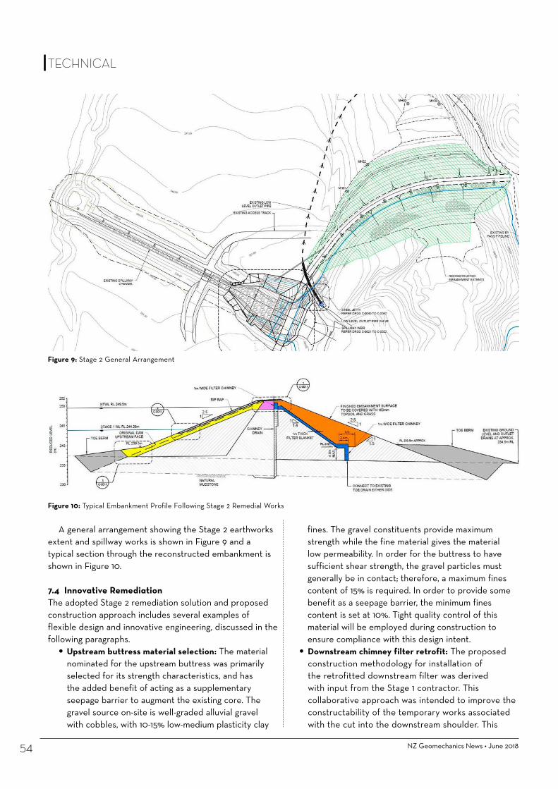
NZ Geomechanics News • June 201854
fines. The gravel constituents provide maximum strength while the fine material gives the material low permeability. In order for the buttress to have sufficient shear strength, the gravel particles must generally be in contact; therefore, a maximum fines content of 15% is required. In order to provide some benefit as a seepage barrier, the minimum fines content is set at 10%. Tight quality control of this material will be employed during construction to ensure compliance with this design intent.
• Downstream chimney filter retrofit: The proposed construction methodology for installation of the retrofitted downstream filter was derived with input from the Stage 1 contractor. This collaborative approach was intended to improve the constructability of the temporary works associated with the cut into the downstream shoulder. This
A general arrangement showing the Stage 2 earthworks extent and spillway works is shown in Figure 9 and a typical section through the reconstructed embankment is shown in Figure 10.
7.4 Innovative RemediationThe adopted Stage 2 remediation solution and proposed construction approach includes several examples of flexible design and innovative engineering, discussed in the following paragraphs.
• Upstream buttress material selection: The material nominated for the upstream buttress was primarily selected for its strength characteristics, and has the added benefit of acting as a supplementary seepage barrier to augment the existing core. The gravel source on-site is well-graded alluvial gravel with cobbles, with 10-15% low-medium plasticity clay
Figure 9: Stage 2 General Arrangement
Figure 10: Typical Embankment Profile Following Stage 2 Remedial Works
TECHNICAL

proved to be a worthwhile exercise, with the contractor suggesting several adjustments to the proposed design. A 4 m deep trial trench was excavated in the downstream shoulder during the design phase to confirm that the proposed trench depth could be achieved. This depth needed to be shallow enough to be safe and constructable, yet deep enough to keep earthworks volumes to a minimum. The retrofitted chimney filter, was relatively standard in design, providing filter protection and also mitigating the risks of development of excess pore pressures to the most susceptible parts of the embankment.
• Involvement of the regulator and peer reviewer in the design and construction process: Given the history of non-compliance and earthquake damage at Haldon Dam, it was considered prudent to involve both the regulator and their peer reviewer during both the design and construction phases.
This approach was unconventional, but given the uncertainties around the extent of earthquake-induced damage to the existing dam (particularly the upstream shoulder), was seen as the best approach to provide confidence in the design and construction of the works.
8. CONCLUSIONThe Haldon Dam has had a troubled history, with a number of non-compliant issues during the initial construction, which led directly to poor performance and emergency works to lower the reservoir following the Cook Strait Earthquake sequence in 2013, despite experiencing reasonably modest peak ground accelerations. The adopted two-stage remediation process was intended to give maximum flexibility to the dam owner. The Stage 1 “make-safe” works resulted in a fully compliant dam, albeit with a lowered reservoir, while also forming part of the
210mm wide x 148mm high
MCMILLANDrillingGROUP
Established since 1947, McMillan’s have steadily grown to become one of New Zealand’s largest and leading multifaceted drilling companies.
www.drilling.co.nz
South IslandPhone: +64 3 324 2571 Fax: +64 3 324 2431 email : [email protected]
North Island Phone: +64 9 238 5138 Fax: +64 9 238 5132 email : [email protected]
16HMDG20161110
Creating tailored innovative foundation solutions
explore, strengthen, sustain
Ensuring the accurate assessment of complex ground conditions
including ultra-sensitive 7.5MPa range and high capacity 15cm2 CPT cones
sCPTu + sDMT
TECHNICAL

10. REFERENCESFell, R.; MacGregor, P.; Stapledon, D.; Bell, G.; Foster, M. (2015).
Geotechnical Engineering of Dams. Second Edition. CRC Press/Balkema.
GNS Science (2013): Report on the seismicity associated with the 21st July (Cook Strait) and 16 August (Lake Grassmere) 2013 earthquakes, prepared as an Affidavit by Neil Alexander Morris of MDC, dated 18 September 2013.
Holden, C. et al (2013). Sources, ground motion and structural response characteristics in Wellington of the 2013 Cook Strait earthquakes. Bulletin NZ Society for Earthquake Engineering 48(4): 188-195.
New Zealand Building Act (2004), including Building Act Amendments (2013).
New Zealand Building Code (1992).NZ Geotechnical Society (2005). Field Description of Soil and Rock;
Guideline for the field classification and description of soil and rock for engineering purposes. NZ Geotechnical Society, December 2005.
NZSOLD (2015). New Zealand Dam Safety Guidelines.Raeside, J.D. (1964). Loess deposits of the South Island, New Zealand,
and soils formed on them. NZ Journal of Geology and Geophysics 7: 811-838.
Rattenbury, M., Townsend, D., & Johnston, M. (2006). Geology of the Kaikoura Area. Institute of Geological & Nuclear Sciences 1:250,000 geological map. Lower Hutt, New Zealand: GNS Science.
URS (April 2014). Haldon Range Dam Remedial Options Report.USSR (2011). Materials for Embankment Dams.
Stage 2 permanent remediation works. Key features of the design approach included holding a design workshop with the owner and stakeholders prior to undertaking detailed design, careful rationalisation of the upstream shoulder to optimise the competing interests of strength and permeability, contractor and regulator involvement in the design and construction process, and balancing risk and constructability with the chimney filter retrofit. Applying this approach, the objective of achieving a robust, safe, economical design that was acceptable to the regulators and the owner was achieved.
9. ACKNOWLEDGEMENTSThe authors wish to acknowledge the dam owner, Richard Bell of Starborough Creek Holdings Limited, for permission to publish this paper. The AECOM design and construction support team, including Colin Newton, Lewis Thomas, Sally Hayward and Richard Harkness. The regulator, MDC, including Jeff Atkinson, Graham Allum and Guy Boddington. The regulators peer review panel, MWH, including Peter Foster and Matthew Shore. The Stage 1 contractor, Crafar Crouch Limited, including Norm Crafar and Luke Eden.
TECHNICAL
Leading up to Drill Force New Zealand’s 10th Anniversary, we purchased of the specialist geotechnical da-ta acquisition company CPTit. The acquisition of CPTit further cements Drill Force as a leading provider of
geotechnical drilling and testing in New Zealand.
Phone: 09 267 9100
Website: www.drillforce.co.nz
• The newest addition to the Drill Force drilling fleet is a track mount-ed 19 tonne Geomil Panther 170
• The rig is set up to undertake: • CPT/CPT(U) using Geomil electrical
probes and CPTest acquisition soft-ware
• DMT/sDMT using the Marchetti flat Dilatometer
Ryan | Project Manager | 027 837 2030 | [email protected] Zane | Operations Manager | 021 842 475 | [email protected]
Bespoke Innovation with Leveloggers
Liquefaction Monitoring
Seismic Activity Monitoring
Monitoring liquefiable material in the Waikato River during vibration piling
Response of material to earthquake events in the Port Hills, Christchurch
• The Solinst Levelogger is a water level and temperature recording device.
• Uses include ground water monitoring from pumping and slug tests; stream gauging; level monitoring to tidal fluctuation; and long term water level monitoring.
• High accuracy at 0.05% net full scale.
• 10 years battery life based on one reading/min.
• Construction of a new railway bridge.• Leveloggers installed in sand pockets in the Waikato
River and adjacent railway embankment.• Preferred to vibrating wire piezometers because of
required frequency of 0.5 second readings.• Involved live, continuous monitoring of pore pressure
during vibration piling embankment and train events, with software plotting every 0.5 seconds.
Interpretation of data:• Results from monitoring showed a small amount of
energy from the piling technique and a large amount of energy in the embankment from the coal train!
• Located in a small estuarine area at the foot of the Port Hills, with a geology of coarse sands and gravels.
• Leveloggers installed at a depth of 6m below ground level, in a sand cell with bentonite seal in column.
• Ground water level at 2-4m below ground level.
• Leveloggers measured the effects of seismic activity on pore water pressure.
• Data points collected every 0.5 seconds.
Interpretation of data:
• The higher the magnitude of the aftershock, the higher the spike on the plot.
• Tidal and rainfall effects were also observed due to pressure increase.
For more information, contact our friendly team on 0508 223 444 or visit www.geotechnics.co.nz
Seismic Activity
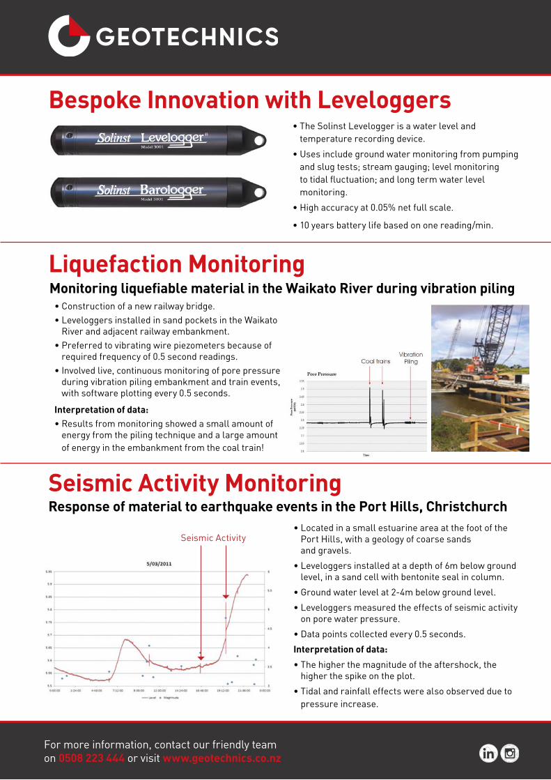

NZ Geomechanics News • June 201858
KEYWORDS: risk management, rockfall, public perception, public influence.
ABSTRACTBluff road is a low use, single lane, coastal road linking two beach resorts on the north east coast of the Coromandel Peninsula. It is a popular pedestrian short cut between the two beaches, is the access way to attractive fishing marks and provides important options for access to a number of properties.
At one location, close to the western end of the road, the road is overhung by a steep rock bluff at a point where it is partly formed on reclaimed land and supported by retaining structures. Following significant rockfalls and erosion damage in the years since Cyclone Wilma in 2011 a detailed assessment of possible remedial works to improve the safety and resilience was instigated.
Remedial works comprising blasting, scaling, bolting and a passive netting scheme commenced in late 2015. During this work further significant rockfalls occurred, promoted by previously unseen fractures. Following further risk and cost benefit assessment the decision was made to close the affected section of the road. This meant the popular recreational route for pedestrians and cyclists was no longer available and that the Matarangi fire service had a potential additional 11km route to reach the east end of Rings Beach.
Throughout 2016 the public repeatedly removed fences, barriers and warning signs erected to warn of the high risk of rockfalls and prevent access.
In this paper we describe the history of the site, the works carried out and discuss issues around rockfall risks, road closure and public perception of risk.
1 INTRODUCTIONBluff road is a low use, single lane, coastal road linking two beach resorts on the northeast coast of the Coromandel Peninsula, Figure 1. It is a popular pedestrian short cut between the two beaches, is the access way to attractive fishing marks and provides important options for private and emergency access to several properties.
At one location close to the western end of the road, the road is overhung by a near vertical 20m high bluff of variably weathered and hydrothermally altered andesite, that is also locally sheared and closely fractured, Figure 2. Three major discontinuity sets are present. Two of them, dipping out of the face at angles of between 30 and 50° and a second dipping out of the face at 70 to 80° promoted planar and toppling failure respectively. The third, near vertical set, has a strike at almost 90° to the face and act as release planes for block failures. Weathering and hydrothermal alteration has particularly picked out the vertical discontinuities trending into the face, which are locally concentrated and may be localised
Bluff Road Coromandel: Rockfall Risk Management, Public Perception and Influence
TECHNICAL
Chris Hughes Christopher Hughes is the WSP-Opus Geotechnical and Contaminated Land Team Leader for the Auckland office. He’s a Senior Engineering Geologist, Contaminated Land Specialist (SQEP) and Chartered Geologist with over 16yrs work experience. His experience is wide ranging; including slope stability (soil and rock) and design of rockfall mesh and anchors.
Ken Read Ken is Principal Geotechnical Engineer with CMW Geosciences in Hamilton. He is both a Chartered Engineer (NZ) and Chartered Geologist (UK) with 32 years’ experience in Engineering Consultancy. He has extensive experience rock and soil slope stability, and risk assessment associated with roading and infrastructure development.

June 2018 • NZ Geomechanics News 59
TECHNICAL
Figure 2: Views of Bluff Road section of concern showing overhang, fracturing and weathering/alteration
Figure 1: Site location
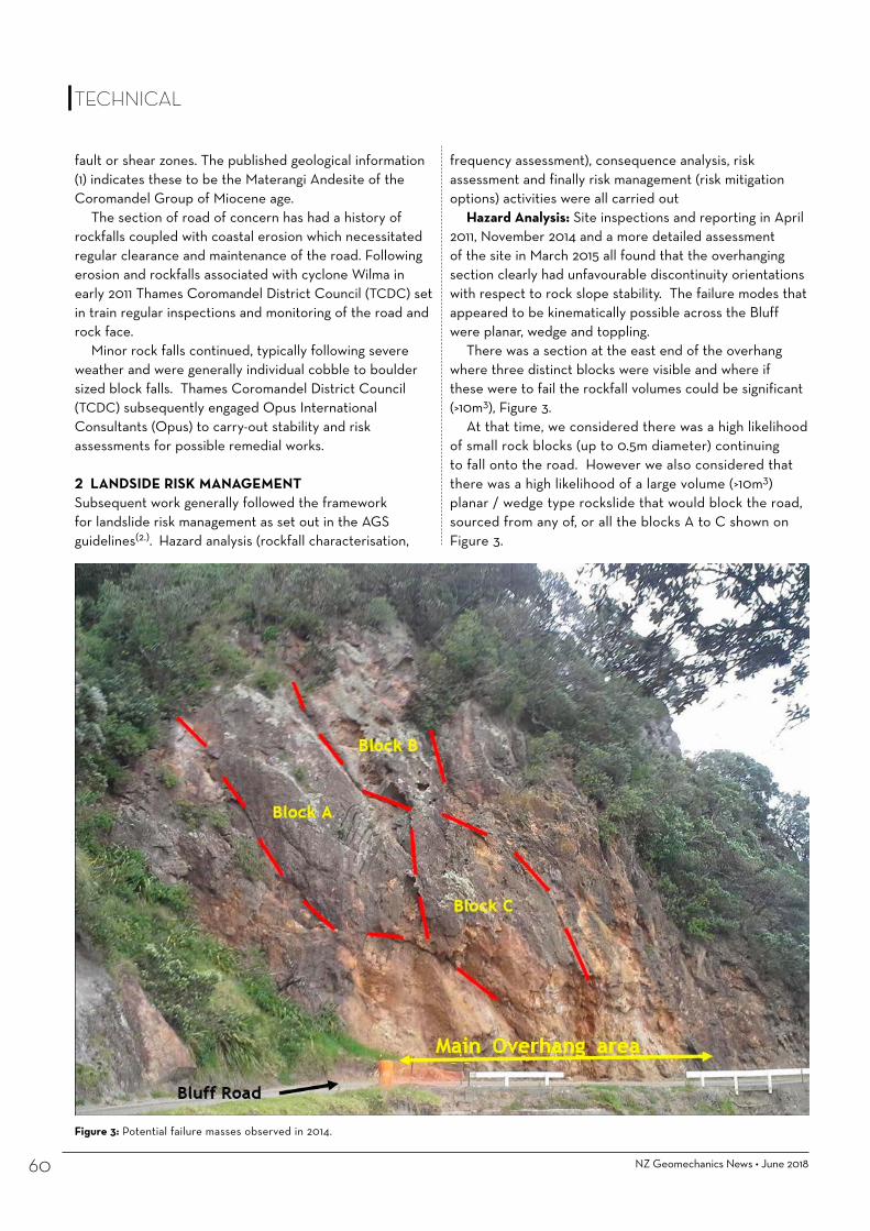
NZ Geomechanics News • June 201860
frequency assessment), consequence analysis, risk assessment and finally risk management (risk mitigation options) activities were all carried out
Hazard Analysis: Site inspections and reporting in April 2011, November 2014 and a more detailed assessment of the site in March 2015 all found that the overhanging section clearly had unfavourable discontinuity orientations with respect to rock slope stability. The failure modes that appeared to be kinematically possible across the Bluff were planar, wedge and toppling.
There was a section at the east end of the overhang where three distinct blocks were visible and where if these were to fail the rockfall volumes could be significant (>10m3), Figure 3.
At that time, we considered there was a high likelihood of small rock blocks (up to 0.5m diameter) continuing to fall onto the road. However we also considered that there was a high likelihood of a large volume (>10m3) planar / wedge type rockslide that would block the road, sourced from any of, or all the blocks A to C shown on Figure 3.
fault or shear zones. The published geological information (1) indicates these to be the Materangi Andesite of the Coromandel Group of Miocene age.
The section of road of concern has had a history of rockfalls coupled with coastal erosion which necessitated regular clearance and maintenance of the road. Following erosion and rockfalls associated with cyclone Wilma in early 2011 Thames Coromandel District Council (TCDC) set in train regular inspections and monitoring of the road and rock face.
Minor rock falls continued, typically following severe weather and were generally individual cobble to boulder sized block falls. Thames Coromandel District Council (TCDC) subsequently engaged Opus International Consultants (Opus) to carry-out stability and risk assessments for possible remedial works.
2 LANDSIDE RISK MANAGEMENT Subsequent work generally followed the framework for landslide risk management as set out in the AGS guidelines(2.). Hazard analysis (rockfall characterisation,
Figure 3: Potential failure masses observed in 2014.
TECHNICAL

June 2018 • NZ Geomechanics News 61
TECHNICAL
Risk Assessment: The road was used by as little as five vehicles a day and a small number of pedestrians. With the greatest likelihood of failure occurring during or shortly after extreme weather events, the risk to life and limb was therefore considered low. However the road has a strategic importance of enabling emergency access to adjacent properties from two different directions, and this played a relatively greater role in the risk assessment by Thames Coromandel District Council.
Risk Management: An assessment was carried out for 4 treatment options and a ‘do nothing’ option, using the NZTA “Risk Management Process Manual” as a basis(3). The criteria used and outcomes are given on Tables 1 and Table 2 below. Table 1 was generated for the bolt and mesh option (treated risk), similar tables were generated for the other options considered.
Table 2: Summary of outcomes
The scoring reflected that whilst remedial work reduced the likelihood of key threats being realised the consequences of these were still very serious. It also reflected the responsibility felt by all parties to protect
the public, and the client and consultant reputation risks around this.
Closing the road was considered by the client and the public to be a move of last resort. Other options such as a retreat of the cliff face, a rock block bolting and active mesh system and a rockfall protection structure were ruled out on environmental, cost or cultural grounds. Work was subsequently commenced to remove the overhang and improve safety by a combination of a passive mesh system secured to the rock face by bolt anchors.
2 SITE WORKWork commenced in November 2015 to remove blocks B and C plus a section of material to the right of these blocks (Figure 3). This work was to consist of scaling and blasting to remove approximately 350m3 of rock and the installation of 350 m2 of passive mesh held in place by bolt anchors at the top and bottom of the slope. Scaling and blasting was completed prior to the Christmas holiday shutdown after which the placement of mesh was to be carried out. As works were not complete the road was temporarily closed over his period with signage and fencing erected.
A significant rock-fall occurred after heavy rain on the 25th of December (Figure 4). It is unclear if this was also related in part to the effects of the work, such as blasting and stress relief opening fractures.
Option Very high threats
High threats
Weighted Score
“Do nothing” 1 4 18Close the Road 0 1 5Move Road Over Seaward 0 5 17Scaling Works 0 5 17Rock bolting / mesh works 0 4 15
Table 1: Risk matrix for mesh and bolt option

NZ Geomechanics News • June 201862
and behind the scoring system point to meshing and bolting as the preferred option.
The technical risk of finding more unknown and unfavourable discontinuities together with deeper weathering and alteration forced a rethink and change of policy to close the road. This was a decision that should have eliminated the risk, and elimination is always seen as the preferred option over mitigation.
As engineering geologists and geotechnical engineers, we make almost daily assessments of risk, assessing hazards, likelihoods and consequences. We are used to the concept and application of ‘Factors of Safety’ and basing our engineering and policy decisions on these.
However in this case, it is clear that certain members of the public did not agree to the ‘no risk’ option as evidenced
3 POST SITE WORK RISK AND RISK TAKINGA review of the discontinuity and weathering profile exposed after the December 2015 rockfall concluded that previously unknown discontinuities and deeper weathering and alteration of the rock mass indicated there was a greater risk of ongoing and potentially large volume rockfalls than previously understood.
Significant additional costs would be incurred to continue and the decision was made to discontinue work and close the road. The community was informed and barriers and signs erected to prevent pedestrian access. Rockfall debris was left in place to deter vehicle access. There is a footpath over the bluff that allows alternative pedestrian access.
However, over the next year the fences and barriers were repeatedly cut and broken down by members of the public seeking to use the road as a short cut between the two communities and to popular fishing and diving marks (Figure 5 and 6).
This was despite clearly hazardous conditions, as exhibited by wide open fractures, isolated fallen blocks (Figure 7 and 8), signage / barriers and warnings in the press.
During site inspections by Opus and Council staff, members of the public would typically linger by the fences and barriers until they thought they could pass through unobserved.
4 DISCUSSION AND UPDATEWe used a well tried procedure to weigh factors in our decision making which, though still appearing to give a significant risk, did after consideration of factors beyond
Figure 4: Rockfall of 25 December
2015.
Figure 5: Vandalised fencing
TECHNICAL

June 2018 • NZ Geomechanics News 63
TECHNICAL
through their actions at the site. Threats of prosecution, publicity (Figure 9) and signs warning of the danger (Figure 10) were ineffective and ignored, as was the actual occurrence of further rockfalls following road closure.
Despite the continued rockfalls and clear evidence of danger, even families with young children are willing to take a risk if it will save them a 10-minute detour over the hill instead of around it. Ignoring the signage and barriers infers that the public made their own assessment of risk every time they use the road.
At the time of preparing this paper work was starting for a second phase of scaling and removal of the remaining hazardous block(s) and to install a passive mesh retention system so the road can be re-opened as a public footpath. It will remain closed to all but emergency vehicles.
5 CONCLUSIONSWe consider that two lessons can be drawn from this project.
The first is that there is always a risk that conditions exposed in a rock face do not fully reflect those behind it. In this case deeper weathering and alteration of the rock together with the presence of significant unfavourable discontinuities not exposed on the rock face meant that the scope of work to achieve an acceptable degree of safety increased to a point where it was concluded that it was no longer cost effective to continue mitigation works.
Figure 6: Footpath past debris
Figure 7: Open fractures above path
Reliance on engineering geological mapping of the exposed rock, with acknowledgement of possible variation, led to the bolt and mesh solution adopted. However unknown and unfavourable discontinuities together with more pervasive alteration than anticipated forced a reconsideration and change in risk management policy.
The second was confirmation that the perception of an acceptable level of risk is very dependent on the view of the beholder and what they stand to lose or gain. In this case the rockfall assessment procedure identified the mechanisms of rockfall, likelihood and threat, and concluded that these were significant. The management of those risks, threats and consequences fell to the Council who are responsible for the protection of the public and ensuring their safety as far as possible on the Council
Figure 8: Fallen blocks on footpath

NZ Geomechanics News • June 2018
roads. Councils and Engineers have to act in what they consider to be the best interests of the public, and seek cost effective ways of achieving those aims. In this case road closure was adopted but not accepted by the public that it was intended to protect.
What the authors have taken from this is that you cannot underestimate the willingness of people to put themselves at risk if they consider the advantage gained (even minor) outweighs the likelihood of an adverse and unacceptable outcome.
6 ACKNOWLEDGEMENTSThe authors wish to thank Thames Coromandel District Council for their permission to prepare this paper.
REFERENCES1 New Zealand Geological Survey Geological Map Sheet N40, Northern
Coromandel, 1:63,360 scale.2 Australian Geomechanics Society (2007) “Practice note Guideline
for Landslide Susceptibility, Hazard and Risk Zoning for Land Use Planning”, Vol42 No1 March 2007.
3 Transit New Zealand “Risk Management Process Manual, AC/Man/1, September 2004, version 3.
4 Waikato Times, 30th December 2016.
Figure 9: Regional Newspaper Article3
Figure 10: Signage during site work
TECHNICALGeosolve
London
www.geosolve.co.uk
SLOPE
Slope Stability Analysis &
Reinforced Soil Design
Key features
Multiple water tables or piezometric surfaces
Slip surfaces: Circular, 2 and 3 part wedges,
general non-circular slips
Seismic forces
Interactive graphical input
Reinforced soil options:
- Designs optimum reinforcement
- Choice of reinforcement material
Grids, strips, fabric, soil nails
WALLAP version 6
Retaining Wall Analysis
Sheet piles, Diaphragm walls
Combi walls, Soldier pile walls
Key features
Factor of Safety calculation
Bending moment and displacement analysis
with 2-D quasi FE option and soil arching
Change from undrained to drained conditions
Thermal loading in struts
Variable wall section
Seismic loading
Context sensitive help
Customized report generation.
Limit State analysis
Soil Properties archive
Comprehensive advice in
accordance with Eurocode 7
New features
• Integral Bridge design to PD 6694
• Single Pile analysis with loads
applied at various orientations
GWALL
Gravity Wall Analysis
Key features
Limit equilibrium analysis for calculating factors of
safety against sliding and overturning.
Calculation of bending moments and shear forces
in the stem and base (including the effect of
earth pressures due to compaction).
Contacts: Daniel Borin & Duncan Noble
support@ geosolve.co.uk
Proposed half page advert for
2 issues of NZ Geo News
Originally published in:20th NZGS Geotechnical Symposium (2017)
GEOVERTwww.geovert.com
Ground Anchors
Soil Nails
Micro Piling
Tunnel Remediation & Strengthening
Retaining Walls
Confined Space & Low Overhead Drilling
Slope Stabilisation
Rockfall Protection
Debris Flow Systems
Providing innovative & economic solutions, Geovert will add value on a variety of EQC remediation works and projects requiring ground improvements, slope stabilisation or rockfall protection work throughout Asia Pacific.
YOUR PARTNER FOR ALL GROUND ENGINEERING PROJECTS IN ANY ENVIRONMENT
AUCKLANDP +64 9 837 7808F +64 9 837 780915 Kaimahi RdWairau ValleyNorth Shore 0627
CHRISTCHURCHP +64 3 962 5840F +64 3 962 58415/18 Taurus PlaceBromleyChristchurch 8062
New Zealand || Australia || Indonesia || Singapore
NZ Geomechanics News • June 201866
INTRODUCTIONEarly this year, New Zealand Transport Agency (NZTA) has published the NZTA Stage 2 Research Report titled “Analysis of piled bridges at sites prone to liquefaction and lateral spreading in New Zealand”. The report is available on NZTA’s website at the following address:
http://www.nzta.govt.nz/resources/analysis-of-piled-bridges-at-sites-prone-to-liquefaction-and-lateral-spreading-in-new-zealand/
It follows the first stage of the project summarised in the Stage 1 Research Report titled “The development of design guidance for bridges in New Zealand for liquefaction and lateral spreading effects”, NZTA Report 553, which is also available on NZTA’s website:
http://www.nzta.govt.nz/resources/research/reports/553
The NZTA research project included a review of seismic behaviour of bridges on sites prone to liquefaction and lateral spreading in New Zealand and overseas, and reviewing available design methods for bridges against liquefaction and lateral spreading effects. The latter involved detailed consideration of the bridge design framework in New Zealand and developing an appropriate design methodology for New Zealand conditions.
The overall purpose of the project was to identify a clear set of available procedures for analysis and design that are based on observed seismic behaviour of bridges (reviewed case studies) and the most recent research findings from across the world. The outcomes of the NZTA project were presented in two reports:
• Stage 1 Research Report that summarises these methods and provides references to supporting materials (where such references are available). • Stage 2 Research Report that presents a summary of an example application of pseudo-static analysis in the design of bridges on sites prone to liquefaction. The report gives detailed procedures for geotechnical field and laboratory testing, liquefaction evaluation methods and examples for two bridge sites, detailed description of recommended procedures for pseudo-static analysis (including flow charts for the design process), an overview of dynamic analysis methods, and presents detailed design examples for two bridges.
The design requirements and guidelines given in the Stage 2 Research Report are to be incorporated in the NZTA Bridge Manual and disseminated to the wider New Zealand engineering community.
The project team was led by WSP Opus and comprised WSP Opus researchers (Dr Alexei Murashev, Messrs Campbell Keepa, Gopal Adhikari, Dejan Novakov and Donald Kirkcaldie), the University of Canterbury (Prof Misko Cubrinovski and Dr Jennifer Haskell) and the University of Auckland (Prof Rolando Orense).
A brief summary of the Stage 2 report is given below.
STAGE 2 RESEARCH REPORTIn the Stage 2 of the NZTA research project, methods for the evaluation of bridges on liquefiable sites were assessed and a detailed pseudo-static procedure was developed
Analysis of piled bridges at sites prone to liquefaction and lateral spreading in New Zealand – NZ Transport Agency Report
TECHNICAL
Alexei Murashev would like to see layout
Alexei Murashev Alexei graduated with a Master’s degree in Civil Engineering from the South Ural State University and PhD degree from the Perm National Research Polytechnic University in Russia. He came back to the South Ural State University as a lecturer and later became an Associate Professor in soil mechanics and foundation engineering, strength of materials, structural mechanics and numerical methods. In New Zealand, Alexei worked as a senior geotechnical consultant with Beca (1993 – 2003). He joined Opus in 2003 and is currently a Technical Principal, Manager of the Geotechnical & Risk Group and Opus Partner. Alexei has led a large number of research, building, bridge, roading and other infrastructure projects as well as earthquake risk studies. He has been involved in the preparation of many Eastern European and New Zealand design standards including the 3rd edition of the NZTA Bridge Manual, National Ground Improvement Guidelines (MBIE/NZGS Module 5) and published more than 50 technical papers on various aspects of geotechnical engineering. In 2011, Alexei was elected a Fellow of IPENZ (currently Engineering NZ).

June 2018 • NZ Geomechanics News 67
Alexei Murashev would like to see layout
for the analysis and seismic assessment of piled bridges in New Zealand. The Stage 2 report summarises this procedure and presents two examples of its application (Tauherenikau Bridge and Belfast Road Underpass). Also included in the Stage 2 report are two examples of the evaluation of liquefaction and lateral spreading, where guidance on the scoping of site investigations at bridge sites with liquefaction susceptible geologies is presented (Anzac Bridge and Belfast Road Underpass).
Liquefaction evaluation examplesExample 1: Tauherenikau BridgeThe first liquefaction site evaluation example is for the Tauherenikau River Bridge near Featherston. The 127 m long eight-span concrete bridge is located on deep gravelly alluvium located about 10 km from both the Wellington Fault and the Wairarapa Fault that have recurrence intervals of 715 to 1,575 years and 1,200 years, respectively. These faults are capable of producing Mw7.5 and Mw8.2 earthquakes. A simple deterministic assessment of ground motions proved useful in the assessment of seismicity at this site where there are known active faults nearby. Comparison of the Bridge manual’s 1,000-year return ground motions (peak ground acceleration (PGA) = 0.45
g, Mw7.0) to ground motion predictions from rupture of the Wairarapa and Wellington Faults suggests the seismic hazard could be under-represented by the Bridge manual at this location.
The importance of understanding a) whether the gravels are clast supported and b) the characteristics of the supporting soil matrix in the liquefaction evaluation of gravelly soils is emphasised in the Tauherenikau Bridge example. Challenges with assessing the density of gravelly soils, and therefore their liquefaction potential using penetration testing techniques, are addressed with the supplementation of a triggering evaluation using shear wave velocities and the adjustment of standard penetration tests using blow counts measured in 25 mm increments.
Example 2: Belfast Road UnderpassThe second example of a liquefaction site evaluation is for a site just north of Christchurch where a new underpass is to be constructed. The two-lane, two-span reinforced concrete bridge will take Belfast Road over the new at grade Christchurch Northern Motorway. The bridge has approach embankments approximately 8 m high at the abutments with spill through slopes and a central pier.
TECHNICAL
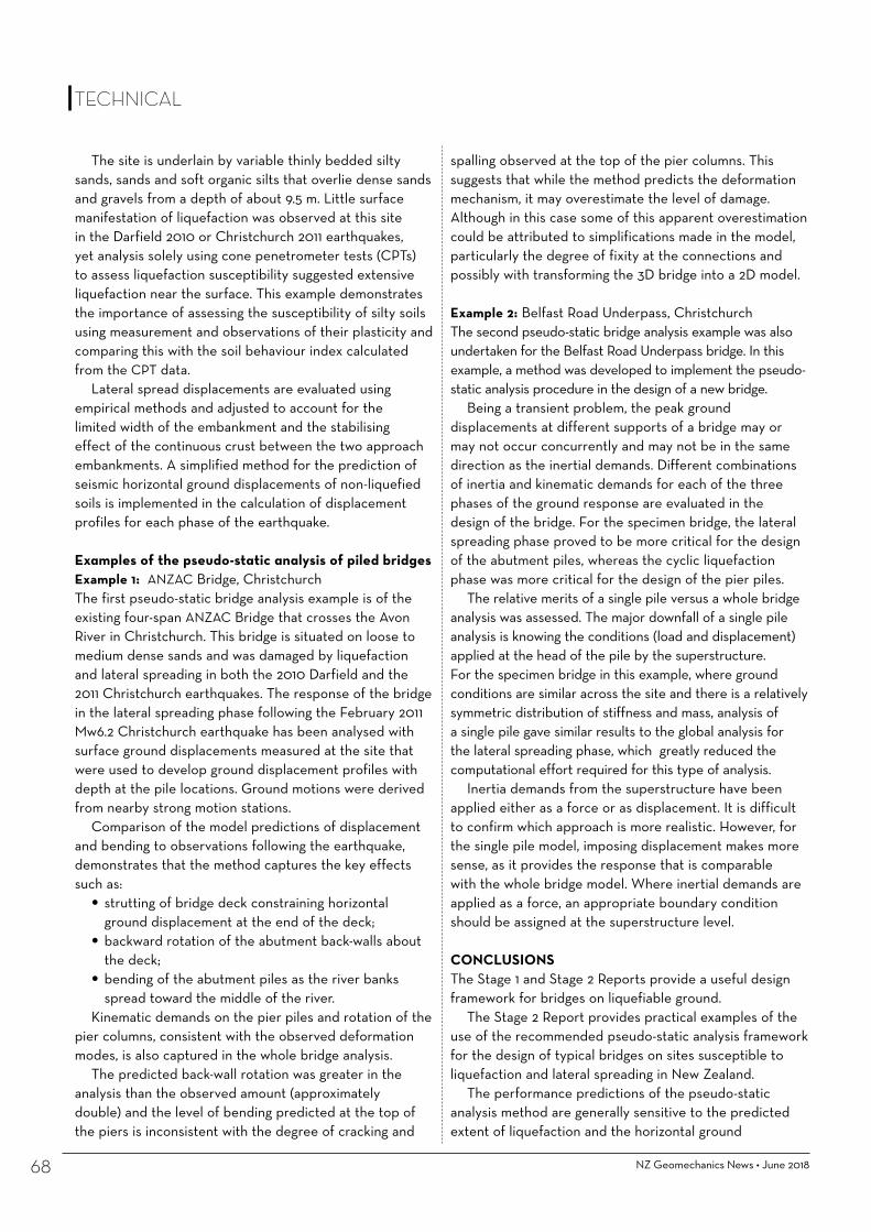
NZ Geomechanics News • June 201868
spalling observed at the top of the pier columns. This suggests that while the method predicts the deformation mechanism, it may overestimate the level of damage. Although in this case some of this apparent overestimation could be attributed to simplifications made in the model, particularly the degree of fixity at the connections and possibly with transforming the 3D bridge into a 2D model.
Example 2: Belfast Road Underpass, ChristchurchThe second pseudo-static bridge analysis example was also undertaken for the Belfast Road Underpass bridge. In this example, a method was developed to implement the pseudo-static analysis procedure in the design of a new bridge.
Being a transient problem, the peak ground displacements at different supports of a bridge may or may not occur concurrently and may not be in the same direction as the inertial demands. Different combinations of inertia and kinematic demands for each of the three phases of the ground response are evaluated in the design of the bridge. For the specimen bridge, the lateral spreading phase proved to be more critical for the design of the abutment piles, whereas the cyclic liquefaction phase was more critical for the design of the pier piles.
The relative merits of a single pile versus a whole bridge analysis was assessed. The major downfall of a single pile analysis is knowing the conditions (load and displacement) applied at the head of the pile by the superstructure. For the specimen bridge in this example, where ground conditions are similar across the site and there is a relatively symmetric distribution of stiffness and mass, analysis of a single pile gave similar results to the global analysis for the lateral spreading phase, which greatly reduced the computational effort required for this type of analysis.
Inertia demands from the superstructure have been applied either as a force or as displacement. It is difficult to confirm which approach is more realistic. However, for the single pile model, imposing displacement makes more sense, as it provides the response that is comparable with the whole bridge model. Where inertial demands are applied as a force, an appropriate boundary condition should be assigned at the superstructure level.
CONCLUSIONSThe Stage 1 and Stage 2 Reports provide a useful design framework for bridges on liquefiable ground.
The Stage 2 Report provides practical examples of the use of the recommended pseudo-static analysis framework for the design of typical bridges on sites susceptible to liquefaction and lateral spreading in New Zealand.
The performance predictions of the pseudo-static analysis method are generally sensitive to the predicted extent of liquefaction and the horizontal ground
The site is underlain by variable thinly bedded silty sands, sands and soft organic silts that overlie dense sands and gravels from a depth of about 9.5 m. Little surface manifestation of liquefaction was observed at this site in the Darfield 2010 or Christchurch 2011 earthquakes, yet analysis solely using cone penetrometer tests (CPTs) to assess liquefaction susceptibility suggested extensive liquefaction near the surface. This example demonstrates the importance of assessing the susceptibility of silty soils using measurement and observations of their plasticity and comparing this with the soil behaviour index calculated from the CPT data.
Lateral spread displacements are evaluated using empirical methods and adjusted to account for the limited width of the embankment and the stabilising effect of the continuous crust between the two approach embankments. A simplified method for the prediction of seismic horizontal ground displacements of non-liquefied soils is implemented in the calculation of displacement profiles for each phase of the earthquake.
Examples of the pseudo-static analysis of piled bridgesExample 1: ANZAC Bridge, ChristchurchThe first pseudo-static bridge analysis example is of the existing four-span ANZAC Bridge that crosses the Avon River in Christchurch. This bridge is situated on loose to medium dense sands and was damaged by liquefaction and lateral spreading in both the 2010 Darfield and the 2011 Christchurch earthquakes. The response of the bridge in the lateral spreading phase following the February 2011 Mw6.2 Christchurch earthquake has been analysed with surface ground displacements measured at the site that were used to develop ground displacement profiles with depth at the pile locations. Ground motions were derived from nearby strong motion stations.
Comparison of the model predictions of displacement and bending to observations following the earthquake, demonstrates that the method captures the key effects such as:
• strutting of bridge deck constraining horizontal ground displacement at the end of the deck;
• backward rotation of the abutment back-walls about the deck;
• bending of the abutment piles as the river banks spread toward the middle of the river.
Kinematic demands on the pier piles and rotation of the pier columns, consistent with the observed deformation modes, is also captured in the whole bridge analysis.
The predicted back-wall rotation was greater in the analysis than the observed amount (approximately double) and the level of bending predicted at the top of the piers is inconsistent with the degree of cracking and
TECHNICAL

displacements applied to the soil springs in the analysis. As shown in the examples, ground displacement predictions have a high degree of uncertainty. This is one area where further research is needed to improve the accuracy of the performance predictions using the pseudo-static method. Other aspects of the analysis procedure requiring further refinement are:
• the evaluation of liquefaction resistance of pumice soils, gravelly soils and sites with thinly interbedded layers;
• the assessment of ground displacement profiles at bridge piles for sites with improved ground
• whether the pinning effect of the piles is sufficiently accounted for within the pseudo-static method;
• for bridges with approach embankments, how the stiffness of the bridge affects the direction of spreading;
• assessing bridge response with kinematic and inertia loading in the transverse and longitudinal directions together.
The examples highlight some of the challenges when applying the recommended methods. There is a high degree of uncertainty associated with the assessment
of liquefaction hazards and the response of bridges to lateral spreading. Built-in conservatism at each step of the analysis can be applied to manage this uncertainty, but this is not always transparent. Furthermore, the compounding effect of such conservatism can result in overly conservative assessments and designs.
One key item emphasised in this study is the need for parametric studies and sound engineering judgement to envelope the response and gain a good understanding of the likely seismic performance of the bridge from which to make appropriate design decisions.
ACKNOWLEDGEMENTSThe funding for the project was provided by the New Zealand Transport Agency (NZTA). Dr John Wood of John Wood Consulting is thanked for his detailed review of the Stage 2 Research Report. Messrs Nigel Lloyd, John Reynolds and Barry Wright of NZTA are gratefully acknowledged for their valuable comments, advice and support provided to the research team through the course of the project.
Drill Force New Zealand Ltd is a multi-disciplined drilling company which delivers unparalleled quality and service throughout New Zealand. Drill Force has over 30 drilling rigs to service the Environmental, Water
Well, Geotechnical, Seismic, Mineral Resource, Construction and Energy markets.
Phone: 09 267 9100
Website: www.drillforce.co.nz
• Truck, tracked, tractor, trailer and helicopter portable mounted rigs
• In-situ testing: SPT, shear vane, permeability testing, CPT testing, DMT and sDMT testing
• Instrumentation installation: piezometers, vibrating wire piezometers, inclinometers
• We specialise in difficult access sites, man portable, barge and helicopter. Including project specific
Ryan | Project Manager | 027 837 2030 | [email protected] Zane | Operations Manager | 021 842 475 | [email protected]
TECHNICAL

NZ Geomechanics News • June 201870
Marlborough dam construction challenges – Polly Guan, Ron Fleming and James Robinson, ICOLD 2017 Meeting, Prague
TECHNICAL
ABSTRACTThe New Zealand Building Act 2004 requires dams above 4m high, holding more than 20,000 cum, be engineer designed with construction supervision, whilst complying with best practice under the NZSOLD Dam Safety Guidelines. The design challenge with these dams for small agricultural enterprises is achieving an economic solution as funding is usually constrained.
A case study of a typical Marlborough earth dam, one of two 20m high earth dams commissioned by Yealands Wine Group, is presented herein. Natural materials used in embankment construction included mudstone, alluvial gravel, and loess. The technical challenges during construction included dealing with ubiquitous loess soils, and availability of locally-sourced, suitable filter material.
Limited availability of gravel required use of loess within the embankment shoulder. Prior to construction a field trial was conducted and a method specification was developed to determine the performance of the loess and the extent of conditioning required to achieve an acceptable embankment fill material.
Another challenge was economically producing suitable filter material. The common practice of washing to remove fines was not practicable, so an innovative “winnowing” technique was adopted. The high seismicity of the region also presented some interesting design challenges.
1 INTRODUCTIONYealands Dodson’s Dam #1 (Dam#1) is the first of two earth embankment dams designed by AECOM and constructed between late 2015 and 2017 by Yealands Wine Group, who operate a privately owned vineyard in the Marlborough Region (north east of the South Island) of New Zealand (see Figure 1). The Marlborough summer climate is characteristically warm and dry with typical summer daytime temperatures ranging from 20°C to 26°C and an average summer rainfall of 105mm (Marlborough Research Centre, 2016). Security of irrigation water supply to meet demand during dry periods is essential for wine production in the region as well as being important to business risk mitigation. The Dodson’s dams were developed primarily to improve water security when abstraction from the river is restricted and will be operated as pumped storages due to the low catchment inflows.
Dam #1 is a zoned earth embankment dam approximately 20m high with a 130m crest length, and a storage volume of approximately 190,000m3. Irrigation water is abstracted from the Awatere River via a dedicated pipeline.
The dam wall comprises a low permeability central core with internal drainage (in the form of chimney filter and downstream finger drains) to reduce seepage and control pore pressures within the downstream shoulder. The dam embankment is founded on Tertiary-age mudstone with the core (Zone 1) keyed into in-situ weathered mudstone, as shown on Figure 2. To minimise construction cost due to limited budget, it was essential to maximise the use of on-site materials and minimise processing of filter materials.
The core consists of compacted mudstone won from the reservoir, and the upstream and downstream shoulders are a combination of loess and alluvial gravel (Zone 3A) and silty to sandy gravel (Zone 3B), also won from the reservoir. Filter sand and drainage gravel materials (Zone
Polly GuanPolly Guan is a Chartered Geotechnical Engineer and has worked for AECOM for the past six years specialising in the geotechnical investigation and design of earth dams and canals. The projects that she has worked on include Hunter Downs Irrigation Scheme, Tekapo Canal Remediation Project, North Otago Irrigation Expansion Scheme, Central Plains Water Irrigation Project, and Yealands Dodson Dams. She is currently based in AECOM's Brisbane office.
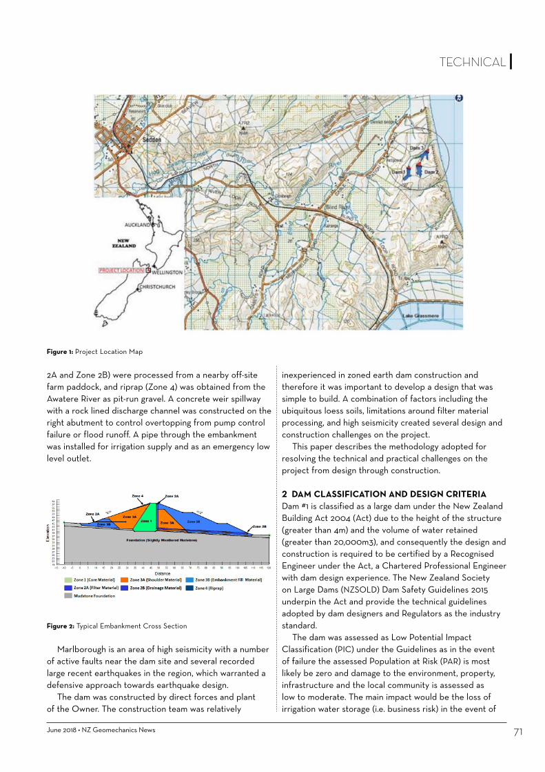
June 2018 • NZ Geomechanics News 71
TECHNICAL
2A and Zone 2B) were processed from a nearby off-site farm paddock, and riprap (Zone 4) was obtained from the Awatere River as pit-run gravel. A concrete weir spillway with a rock lined discharge channel was constructed on the right abutment to control overtopping from pump control failure or flood runoff. A pipe through the embankment was installed for irrigation supply and as an emergency low level outlet.
Figure 2: Typical Embankment Cross Section
Marlborough is an area of high seismicity with a number of active faults near the dam site and several recorded large recent earthquakes in the region, which warranted a defensive approach towards earthquake design.
The dam was constructed by direct forces and plant of the Owner. The construction team was relatively
inexperienced in zoned earth dam construction and therefore it was important to develop a design that was simple to build. A combination of factors including the ubiquitous loess soils, limitations around filter material processing, and high seismicity created several design and construction challenges on the project.
This paper describes the methodology adopted for resolving the technical and practical challenges on the project from design through construction.
2 DAM CLASSIFICATION AND DESIGN CRITERIADam #1 is classified as a large dam under the New Zealand Building Act 2004 (Act) due to the height of the structure (greater than 4m) and the volume of water retained (greater than 20,000m3), and consequently the design and construction is required to be certified by a Recognised Engineer under the Act, a Chartered Professional Engineer with dam design experience. The New Zealand Society on Large Dams (NZSOLD) Dam Safety Guidelines 2015 underpin the Act and provide the technical guidelines adopted by dam designers and Regulators as the industry standard.
The dam was assessed as Low Potential Impact Classification (PIC) under the Guidelines as in the event of failure the assessed Population at Risk (PAR) is most likely be zero and damage to the environment, property, infrastructure and the local community is assessed as low to moderate. The main impact would be the loss of irrigation water storage (i.e. business risk) in the event of
Figure 1: Project Location Map

NZ Geomechanics News • June 201872
although recognised as being problematic as a dam construction material due to its moisture sensitivity, could not be overlooked due to the limited availability gravel and the cost prohibitive alternative of importing embankment fill material.
The characteristics of the adopted construction materials are set out in Table 1 below:
4 CHALLENGES IN GEOLOGY AND LOCAL CONSTRUCTION MATERIALThe most interesting design and construction challenges described herein involve the use of the dispersive loess material, and the innovative approach to processing of complying filter material that were successfully used in the development of a cost constrained dam, in an area of high seismicity. These are discussed in Sections 4.1 and 4.2 below:
4.1 Loess Challenges4.1.1 Loess Characteristics Due to the natural process of wind-blown deposition, loess has an open (honeycomb) structure with a very high void ratio, but is typically low permeability. Loess can stand at near vertical slopes for long periods provided its moisture content remains low. However, upon wetting, it is highly prone to slumping, dispersion, erosion and piping. Laboratory test results showed the loess to be low to medium plasticity (8 ≤ PI ≥ 12), and results from pinhole dispersion tests (Dispersive D1 with Method A) and crumb tests (Grade 4, Strong Reaction) confirmed its dispersive character. Experience has shown that dispersive soils can be used as construction materials, provided that they are properly designed and well compacted. The main concerns around the use of loess as embankment fill included:
•Piping through embankment foundation •Seismic liquefaction • Achieving adequate compaction density due to its moisture content and shear strength sensitivity.
a dam breach. In consultation with the client the PIC was determined to be at the low end of Low PIC. The key risks to dam safety were assessed as the local seismicity and the potential for internal erosion of the dispersive loess material used in the shoulders.
The NZSOLD Guidelines for a Low PIC dam stipulate the following design criteria:
• Inflow Design Flood (IDF): annual exceedance probability (AEP) 1 in 100 years.
• Wind and Waves Hazard: Freeboard at IDF Level superimposed with a 1 in 100 year wind AEP (with allowance for wind setup and wave run up).
• Earthquake Hazard: Operating Basis Earthquake (OBE) AEP 1 in 150 years, and Safety Evaluation Earthquake (SEE) AEP f 1 in 500 years to 1 in 1,000 years. Due to high seismicity of the area a design SEE of 1 in 1,000 AEP was adopted.
Probabilistic estimates of seismic hazard using published data (e.g. NZS 1170.5 (2004) and NZTA Bridge Manual (2013)) estimated a horizontal peak ground acceleration (HPGA) of 0.31g for an OBE event and 0.69g for the SEE event.
3 CHARACTERISATION OF THE CONSTRUCTION MATERIALSThe local geology comprises Tertiary aged sandstone and siltstone (Starborough Formation), overlain by Quaternary-age alluvium (Rattenbury et al. 2006), and mantles of loess with thickness of up to several meters. The Quaternary-age alluvium deposits generally consist of poorly to well graded gravel with sand and silt. Loess commonly comprises silt with clay and fine sand.
The dam construction materials were selected from the materials available on site, which were characterised by pre-design site investigations. These investigations confirmed the typical soil profile to include topsoil overlying loess with gravel lenses of variable thickness. The bedrock was found to be mudstone with an upper weathered zone. The mudstone and gravel are accepted locally as suitable dam construction materials. The loess,
Material Description
Engineering Properties
Unit Weight γ (kN/m3)
Friction Angle, φ (0) Cohesion, c (kPa) Permeability kv (m/s)Total Effective Total Effective
Foundation Weathered mudstone 19 25 33 0 0 1.00E-09Zone 1 Compacted Mudstone 18 20 30 6 0 1.00E-08
Zone 2A Filter Sand 19 - 40 - 0 8.00E-03Zone 2B Drainage Sandy Gravel 19 - 40 - 0 7.00E-03Zone 3A Mixture of Loess with
alluvial gravel18 16 30 6 4 5.00E-09
Zone 3B Sandy Gravel 21 - 35 - 0 3.00E-05
Table 1: Summary of Dam Construction Material Engineering Properties
TECHNICAL

June 2018 • NZ Geomechanics News 73
TECHNICAL
4.1.2 Dam FoundationIn situ loess and compacted loess fill when saturated and exposed to sufficient seismic load can be susceptible to liquefaction and hence the loess beneath the upstream shoulder, the core and the lower areas within the bottom of the valley beneath the downstream shoulder was removed to expose the mudstone basement rock. The mudstone core and vertical chimney filter were keyed into the mudstone foundation along the entire length of the crest. The chimney filter was connected to a series of downstream finger drains with a width and spacing that reduced the extent of saturation within the downstream foundation. This included the loess beneath the u/s shoulder, the core, and the lower areas within the bottom of the valley beneath the d/s shoulder. This reduced the potential for liquefaction as well as piping within the downstream foundation.
4.1.3 Shoulder DesignThe concerns around the use of loess in embankment fill construction were primarily around piping risk. To mitigate this risk the use of loess was restricted to those zones of the embankment considered less susceptible to piping. These included the upstream shoulder and an internal zone within the downstream shoulder, immediately downstream from the chimney filter and above the finger drains. Another factor considered in the shoulder design was the stability under the design earthquake loads. In the course of the stability assessment an earthworks optimisation process was applied. This involved balancing total embankment earthworks volumes against gravel fill availability. Use of gravel in embankment shoulder construction allowed steeper embankment batter slopes to be adopted which reduced earthworks volumes but limitations on gravel construction material availability meant that the gravel had to be used judiciously.
During analysis it was also found that due to the low permeability of the loess (5E-09 m/s), rapid drawdown could pose upstream shoulder stability issues, so a 200mm thick horizontal filter layer was included in the lower part of the upstream shoulder to dissipate pore pressures.
4.1.4 Loess CompactionLoess is well-known as a challenging material to construct fill from due to its sensitivity to moisture changes and blocky characteristics. Prior to construction, a field compaction trial was conducted on Zone 1, Zone 3A and Zone 3B materials to develop a method specification to simplify construction and reduce the need for engineering construction monitoring. The trial determined the compaction density performance of the loess, the best disaggregation method for loess clods, and the extent of conditioning required to achieve an acceptable product
without over-wetting (and loss of shear strength). In-situ loess had a moisture content approximately 2%-5% drier than the optimum moisture content (OMC) of 14.5% to 15%, and soil clods contained even lower moisture. The standard compaction tests conducted in a soil laboratory on disaggregated loess material showed a tight compaction curve with a sharp slope on the wetter side of OMC, as shown on Figure 3. Over-conditioned loess material results in loss of shear strength, causing heaving (due to excess pore pressures) at which point the target density cannot be met and the material becomes unworkable.
Figure 3: Loess Compaction Curves
The first step in construction was to mechanically breakdown the loess clods by adding moisture to the fill material. The second step was to compact to required density and void ratio. The construction procedures are summarised as follows:
• The loess was transported by dump truck from the borrow area to the embankment.
• A bulldozer spread the material across the fill area to a layer thickness of 200mm. During placement, water was spread on the loose fill surface or on the pile in the front of the ‘dozer.
• A 30 tonne Caterpillar 825 tamping foot static compactor made 4 passes, at which point the soil clods appeared to be effectively crushed and broken into small fragments. Throughout this procedure, water was only added to the material observed as dry. It was important not to over-condition the fill as it normally took 2 to 3 hours to air dry the material back to OMC. Some experience and judgement, especially during early stages of compaction, was required to avoid over-conditioning of loess fill. To assist with this, simple microwave moisture content tests were conducted on site during the compaction trial and early stage of the construction.


June 2018 • NZ Geomechanics News
• The conditioned fill material was then compacted with a 26 tonne padfoot vibrating compactor to further break down soil clods and to achieve the required density. Compaction of each layer was performed in increments of 2 or more passes.
• The minimum required density of Zone 3A material was 1.76 t/m3, which was 98% of maximum dry density. This was achieved during the trial and throughout the dam embankment construction. Nuclear Density Meters (NDM) testing was used as record testing to confirm specification compliance.
The construction and quality testing procedures established from the construction trial were effective and simple for the constructor to apply.
4.2 Filter Material ChallengesThe design gradation for Zone 2A material was to have a fines content of no more than 5% following placement and compaction. In New Zealand, typical alluvial sand contains more than 5% fines, so buying a commercially produced washed sand product would have been very expensive. The owner had access to relatively clean beach sand and gravel from an adjacent property, hence there was a strong commercial motivation to try to produce an unwashed natural product that was fit for purpose. Preliminary PSD testing of representative samples of the beach sediments indicated that it was relatively clean (3-6% fines) and that depending on the specific location within the borrow pit either a coarse to medium sand or a fine gravel, run of pit product could be derived. The sand was identified as a potential Zone 2A material for the chimney filter with the gravel as a Zone 2B material for finger drains. The challenge was establishing a methodology for economically manufacturing a compliant filter material on-site.
Upon completion of the site investigation, the unprocessed Zone 2A and Zone 2B beach sediment materials were confirmed to lack fine sand and so not comply with the design grading limits. The solution was to blend the beach sand with a fine grained sand and remove the excessive fines to produce a complying product.
4.2.1 Filter Material Blending TrialAn alluvial (Wairau) sand source comprising fine sand and silt was found within economic haul distance. A series of blending trials were conducted to produce a product within the Zone 2A filter design envelope. Blending of beach sand and Wairau sand with ratio of 4:1 was found to be the best product. The blended material satisfied the non-erosion filter criteria, but resulted in a product with a fines (<0.075mm sieve) content above 5%.
The Zone 2B material was a pit run beach deposit of well-graded sandy gravel material that contained a high
TECHNICAL

NZ Geomechanics News • June 201876
percentage of fines, which had to be removed to meet the filter design criteria.
4.2.2 Fines Removal OptionWashing the filter material on site to remove fines was not practicable therefore the innovative alternative of ‘winnowing’ out the fines was trialled and then adopted. The dam site is located adjacent to Cook Strait, an area notorious for its strong winds.
To manufacture Zone 2A filter, beach sand was blended with Wairau sand at a ratio of 4:1 using a loader to create a stockpile on a windy day. After this, the material was put through a screen and conveyer to remove oversize, then allowed to gravity fall to the processed stockpile. To improve the effectiveness of the winnowing, the material had to be dry, processed during strong wind, and with adequate falling distance. The same process was adopted for processing Zone 2B material to remove fines from the beach gravel.
Grading of unprocessed and processed of Zone 2A material is shown on Figure 4.
The winnowing technique proved to be effective for processing Zone 2A sand, but not so effective for coarser Zone 2B gravel material. This is thought to be due to the Zone 2B fines being more plastic than the Zone 2A material and/or the dryness of the material as any residual moisture in the stockpiled materials caused the fines to adhere to the granular sand/gravel. 4.2.3 Adjustment of Filter Material in Construction
Source Location: Yealands Dodson Dam 1
0
10
20
30
40
50
60
70
80
90
100
0.001 0.01 0.1 1 10 100 1000
Perc
entP
assin
g(%
)
Particle Size (mm)
Zone 2A GradationZone 2A envelop amendedZone 2A envelop - initial designWairau SiltBlending Trial (4:1) without winnowingBeach Sand
SILT GRAVELSANDCLAY COBBLES
fine coarsemedium finefine mediummedium coarsecoarseBOULDERS
0.002 2006020.060.020.006 2060.60.2
Particle Size DistributionZone 2A Chimney Filter Material
Zone 2A envelopeWairau Sand Gradation
Beach Sand
Date: 10/02/2017 Page 1 of 1Path: C:\Users\polly.guan\Desktop\ICOLD conference\Filter Plots\
File: Zone 2A PSD Figure_modified.xls
Variation in grading and fines content for the Zone 2B material meant that despite the best efforts of winnowing described above it was difficult to consistently produce a filter material with fines content below 5%.
Grading limits for the Zone 2B material were adjusted to suit, with an amended grading having a maximum fines content of 6%, as shown on Figure 5. In general, a maximum of 5% (in place) fines was targeted to ensure the material was cohesionless, low plasticity and hence unable to support a crack, and free draining. To allay any concerns over the plasticity, sand castle tests were performed, which confirmed that the material (collapse time under 2 minutes) as very unlikely to be able to support a crack (Fell et al., 2015). Constant head permeability testing on a representative sample confirmed that the permeability of the Zone 2B drainage material (average of 1.3 x 10⁻³ m/s) was more than adequate for the estimated seepage design flow and finger drain design widths.
The blended material produced was therefore accepted by the designers as adequate.
5 SEISMIC PERFORMANCE OF THE DAMThe dam site is located in the Australian and Pacific plate boundary transition region with the Hikurangi subduction zone to the northeast and continental collision to the southwest. Movement along the plate boundary is dominantly accommodated by the oblique strike-slip, northeast-southwest trending faults in the region.
Figure 4: Zone 2A Chimney Filter Material Particle Size Distribution
TECHNICAL

June 2018 • NZ Geomechanics News 77
TECHNICAL
The regional faults that provide the greatest contribution to the seismic hazard at the site include the Alpine, Hope, Clarence, Awatere, and Wairau Faults; all of which generate earthquakes with magnitudes greater than Mw7 every 300 to 2,000 years. Four active faults are known within 10km of the site: Hog Swamp Fault, a newly discovered un-named fault in Cook Strait, London Hill Fault, and the Awatere Fault. No faults are known to intersect the site.
5.1 Historical SeismicityThe dam site is located in an area of known high seismic activity, and a number of large historical earthquakes have been recorded in the region as summarised below:
• Mw7.4 on the Awatere Fault on 16 October 1848. • Mw8.2 Wairarapa earthquake on 23 January 1855. • Mw7.3 on the Hope Fault (a key component of the Marlborough Fault Zone) on 01 September 1888.
• Mw 7.3 (Ms 7.8) Murchison Earthquake on 17 June 1929 • Mw6.5 Cook Strait Earthquake on 21 July 2013, and Mw6.6 Lake Grassmere Earthquake on 16 August 2013.
• Mw7.8 Kaikoura Earthquake on 14 November 2016.In the Lake Grassmere Earthquake, a horizontal PGA
of up to 0.7g was recorded in Ward, approximately 17km south east of the dam site (Van Dissen et al. 2013); see Figure 6. Both of the 2013 earthquakes caused damage to buildings on both sides of Cook Strait. However, no surface ruptures were observed.
Source Location: Yealands Dodson Dam 1
0
10
20
30
40
50
60
70
80
90
100
0.001 0.01 0.1 1 10 100 1000
Perc
ent P
assin
g (%
)
Particle Size (mm)
Zone 2B envelope - initial designZone 2B envelope amendedZone 2B Gradation
SILT GRAVELSANDCLAY COBBLES
fine coarsemedium finefine mediummedium coarsecoarseBOULDERS
0.002 2006020.060.020.006 2060.60.2
Particle Size DistributionZone 2B Drainage Material
Zone 2B envelope
Date: 5/9/2018 Page 1 of 2Path: D:\Conference\ICOLD 2017\Filter Plots\
File: Figure PSD Zone 2B.xls
5.2 Kaikoura EarthquakeThe epicentre of the Mw7.8 Kaikoura Earthquake on 14 November 2016, was approximately 150km south-west of the dam site, and movement occurred on or near the interface between the Pacific Plate and the Australian Plate involving a combination of strike-slip faulting and dip-slip faulting on multiple faults. Aftershocks occurred as far north as Wellington, about 150 km to the northeast of the main shock (GNS, 2016).
A GPS site at Cape Campbell (approximately 15km from the dam site) recorded the land shifted to the north-northeast by more than 2m, and up vertically by almost 1m (GNS, 2016). HPGAs recorded were up to 0.67g in Seddon and 1.07g in Ward (GNS, 2016), comparable to those recorded in the 2013 Lake Grassmere and Cook Strait earthquakes (see Figure 7).
Since the earthquake, the site area has been continuously affected by aftershocks with earthquake magnitudes from Mw3 to Mw5.
5.3 Dam Performance after Kaikoura EarthquakeThe dam embankment was approaching practical completion and the spillway mouth and chute were being constructed when the Kaikoura Earthquake occurred. In addition, a rainfall event of approximately 35mm over approximately 24 hours followed the day after the main earthquake event.
The HPGA of 0.67g recorded at Seddon (GNS, 2016) is
Figure 5: Zone 2B Drainage Material Particle Size Distribution

NZ Geomechanics News • June 201878
included a foundation inspection before placement of fill, inlet/outlet pipe installation, spillway construction, and instrumentation installation. Quality control on dam compaction was tested with a Nuclear Densometer. The control testing was carried out and documented by site personnel with periodic checks by the design engineer.
7 CONCLUSIONSThe Act requires that large dams be engineer-designed with QC construction supervision, whilst complying with best practice under the NZSOLD Dam Safety Guidelines. The design challenge with Dodson’s Dam was to achieve an economic solution as funding was constrained for this small agricultural enterprise. The technical challenges associated with construction included overcoming the adverse characteristics of loess soils, and the availability of locally-sourced, suitable filter material.
Loess is particularly problematic for earth dams as it is dispersive, and hence prone to internal erosion, and difficult to work with and compact due to moisture sensitivity. Limited availability of suitable gravels required the use of loess as the embankment shoulder material. Compaction trials with loess were conducted to determine the degree of breakdown and moisture conditioning required to provide an acceptable fill material from the loess.
Another challenge was producing suitable filter material from available local sources in an economic manner. The blending and “winnowing” technique used proved successful in achieving an acceptable product.
An additional challenge in the design of the dam was associated with the high seismicity of the region. The dam itself withstood the earthquake and performed well given the recorded HPGA is close to the designed SEE event.
close to the SEE design seismic PGA of 0.69g adopted for the dam. A dam safety inspection was undertaken on 17 November 2016 and observed:
Cracks up to about 20mm wide across the downstream face and along the edge of the filter chimney contact. Settlement appeared to be caused by the earthquake shaking. Most cracks showed an orientation aligned parallel to the crest.
A small amount of clean water flowing from the toe drains (the dam had been partially filled prior to the earthquake).
Rip rap placed in the mid-section of spillway channel was dislodged and the downstream spillway channel was eroded by surface run-off in places.
The earthquake damage appeared to be superficial, and the dam did not show any significant signs of distress. Overall, the dam itself withstood the earthquake and performed well given the level of ground shaking experienced during the Kaikoura earthquake and initial aftershocks.
6 CONSTRUCTION MONITORINGAs the dam is categorised as a large dam, one of the requirements under the Act is for the designer to conduct surveillance and monitoring of construction quality at specified Hold Points throughout the duration of the construction period, with continued surveillance monitoring once the dam is in service.
A construction quality management plan was drafted by the site engineer to assist the constructor. Pre-construction inspections included borrow pit development, compaction trials, and earthfill, filter and drain material production testing. Construction hold point inspections
Figure 6: Two Maps Comparing Peak Ground Acceleration Measured for the Cook Strait (left) and Lake Grassmere (right) Earthquakes (GNS, 2013)
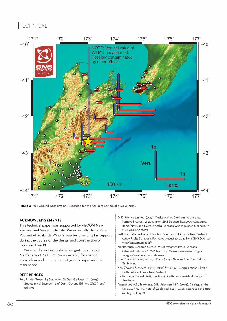
NZ Geomechanics News • June 201880
ACKNOWLEDGEMENTSThis technical paper was supported by AECOM New Zealand and Yealands Estate. We especially thank Peter Yealand of Yealands Wine Group for providing his support during the course of the design and construction of Dodson’s Dam #1.
We would also like to show our gratitude to Don Macfarlane of AECOM (New Zealand) for sharing his wisdom and comments that greatly improved the manuscript.
REFERENCESFell, R.; MacGregor, P.; Stapledon, D.; Bell, G.; Foster, M. (2015).
Geotechnical Engineering of Dams. Second Edition. CRC Press/Balkema.
Figure 7: Peak Ground Accelerations Recorded for the Kaikoura Earthquake (GNS, 2016).
GNS Science Limited. (2013). Quake pushes Blenheim to the east. Retrieved August 12, 2015, from GNS Science: http://www.gns.cri.nz/Home/News-and-Events/Media-Releases/Quake-pushes-Blenheim-to-the-east-24-07-20133
Institute of Geological and Nuclear Sciences Ltd. (2004). New Zealand Active Faults Database. Retrieved August 10, 2015, from GNS Science: http://data.gns.cri.nz/af/
Marlborough Research Centre. (2016). Weather Press Releases. Retrieved February 1, 2017, from http://www.wineresearch.org.nz/category/weather-press-releases/
New Zealand Society of Large Dams (2015). New Zealand Dam Safety Guidelines.
New Zealand Standard 1170.5: (2004) Structural Design Actions – Part 5: Earthquake actions – New Zealand
NZTA Bridge Manual (2013). Section 5: Earthquake resistant design of structures
Rattenbury, M.S.; Townsend, D.B.; Johnston, M.R. (2006). Geology of the Kaikoura Area. Institute of Geological and Nuclear Sciences 1:250 000 Geological Map 13
TECHNICAL


NZ Geomechanics News • June 201882
Dr Kerry Rowe to present the 2018/19 Mercer Lecture
SOCIETY
Dr Kerry Rowe
The 2018/19 Mercer Lecturer will be Dr Kerry Rowe from Queen’s University, Kingston, Ontario, who will discuss the use of geosynthetics in construction on soft soils.
Dr Rowe, who holds the Canada Research Chair in Geotechnical and Geoenvironmental Engineering at Queen’s University, is a past president of the International Geosynthetics Society, a Fellow of the Royal Society and a world-renowned expert in geosynthetics and geonvironmental engineering.
He has given some of geotechnics’ most prestigious lectures, including the Rankine Lecture in 2005, the Casagrande lecture in 2011 and the Karl Terzaghi Lecture in 2017. In 2018, Rowe was appointed Officer of the Order of Canada, the country’s highest civilian honour.
“We are delighted Kerry has agreed to be the next Mercer Lecturer,” said Tensar’s Vice President Global Applications Technology Tim Oliver, who represents the lecture’s sponsor, Tensar, on the Mercer Lecture advisory committee.
“Kerry has built an unrivalled global reputation for his work in both research and engineering practice in a wide range of disciplines, including geosynthetics. He is therefore an ideal person to deliver the Mercer Lecture, which aims to promote co-operation and information exchange between the geotechnical engineering profession and the geosynthetics industry,” Oliver said.
“The Mercer lecture series aims to reach out beyond the world of geosynthetics and engage with geotechnical engineers at large –some of whom may not yet be fully familiar with the potential for geosynthetics in their area of interest.”
The biennial Mercer Lecture was established in 1992 in memory of the inventor of geogrids, Dr Brian Mercer, who was an advocate of innovation, research and development.
Endorsed by the International Society for Soil Mechanics and Geotechnical Engineering (ISSMGE) and the IGS, the lecture tour gives individuals who have made a significant technical contribution to the advancement of geosynthetics the opportunity to present their work at three major conferences in three continents.
The Mercer Lecturer is chosen by an advisory committee of representatives from IGS, ISSMGE and Tensar. Chaired by Professor Jorge Zornberg (the 2015/16 Mercer Lecturer), the members are Jose Luis Machado from Portugal, Professor Junichi Koseki from Japan, Professor Ennio Palmeira from Brazil and Tim Oliver from Tensar.
Reported by Tensar Internationalwww.tensar.co.uk


12TH AUSTRALIA & NEW ZEALAND YOUNG GEOTECHNICAL
PROFESSIONALS CONFERENCE 7-9 NOVEMBER 2018 HOBART
Held every 2 years, the Young Geotechnical Professional Conference (YGPC) events are unique 3 day conferences facilitated by a joint initiative of the Australian Geomechanics Society (AGS) and New Zealand Geotechnical Society (NZGS).
The aim of the 12YGPC conference is to provide younger professionals within the ANZ geomechanics industry experience in technical paper preparation and conference presentation. Each delegate prepares a technical paper and then presents their peer-reviewed paper to both their conference colleagues and senior industry professionals that are invited to attend in a mentoring capacity.
YGPC events also include a field trip into the surrounding regions, where delegates visit current projects or sites of geotechnical / geological interest. Along with a number of social events to encourage interaction between the delegates, the 12YGPC will provide an enjoyable and informative event aimed at the development of future leaders in the geotechnical profession.
The conference attracts delegates from across Australia and New Zealand from consulting and contracting firms, industry bodies and research institutions, showcasing the diverse range of projects and products in the geomechanics field.
SPONSORSHIP PROSPECTUSThe Australian Geomechanics Society and the New Zealand Geotechnical Society
invite you to sponsor the 12th Young Geotechnical Professionals Conference (12YGPC Hobart)
The aims of the YGPC conferences are to:
• Promote the professional development of delegates through sharing experience and ideas, and by all delegates presenting a paper to both senior professionals and peers;
• Expand and strengthen the lines of communications across Australia and New Zealand between young professionals within the field of geomechanics;
• Promote an enhanced perspective of the varied roles, responsibilities and opportunities encompassed by the geotechnical profession; and
• Encourage the exchange of knowledge between consultants, research institutions, contractors and industry associated with the geotechnical industry.
12YGPC offers you a range of sponsorship opportunities to suit your budget which are detailed in the table below.
The 12YGPC is committed to providing optimum exposure for all sponsors. Additional opportunities may be available and we are willing to tailor a package to meet your specific business goals. We encourage organisations to contact the Conference Committee to discuss opportunities that are not included in this brochure.
••••••••
•••••
•••••
••••••
••••••
••
•••
••••••
••
•••
•••••••
•••
••
SPONSORSHIP PACKAGES PLATINUM GOLD SILVER BRONZE
Sponsored
Cost AUD(inc. GST) $3,300.00 $1,100.00 $550.00
Number Available - 1 more available 5 more available Unlimited
Benefits • Recognition as the sole Platinum Sponsor during opening and closing sessions
• Host conference dinner, opportunity to address delegates
• Largest logo on conference handbook/ proceedings and satchel
• 2x Satchel insert
• Recognition as a Gold Sponsor during opening and closing sessions
• Co-host welcome drinks
• Logo on conference handbook / proceedings and satchel
• 2x Satchel insert
• Co-host morning/ afternoon tea breaks
• Logo on conference handbook / proceedings
• 1x Satchel insert
• Logo on conference handbook / proceedings
• 1x Satchel insert

June 2018 • NZ Geomechanics News 85
Know your GEO – a challenge
A FEW ISSUES back, this photo of most of the team of engineering geologists working on Clyde Power Project in the summer of 1991/92 was published in Geomechanics News, with the challenge for readers to identify as many of them as possible. Answers were to be provided in the following issue.
Almost no-one took up the challenge. And so we didn’t provide the answers...
Recently Leah King was searching the back issues, found the photo and asked who they all were. So we decided to give you another crack at identifying as many as possible of those in the photo.
We can tell you that some of the CPP team (for example Paul Horrey, Barry McDowell and Linda Price) are not in the photo – maybe they were the ones working that day! Or maybe they were just shy?
Please email your answers to [email protected]
This time we WILL publish the names in the next issue!
And we will publicly name those of you who manage to correctly identify everyone in the photo!
SOCIETY

NZ Geomechanics News • June 201886
PLANNING IS CURRENTLY in progress for the following additional NZGS training courses which are expected to be held during the second half of 2018:
• Soft Soil Engineering – To be presented by Dr Richard
Kelly and Nick Wharmby. – Provisionally scheduled to be
held in held in Auckland on 03 September, Wellington on 05 September and Christchurch on 06 September.
– 60 places will be available in the Auckland session with 30 places available in each of the Wellington and Christchurch sessions.
• Course title to be confirmed – The NZGS Management
Committee intends to run a total of five workshops or training courses during 2018.
– Preliminary discussions are currently in progress to finalise the topic, dates and locations for this fifth training course.
Enrolment details will be issued to our members via the fortnightly email notices and posted onto the NZGS website in due course.
Upcoming Events
Travel arrangements are currently being finalised to bring the following internationally recognised speakers and presentations to the New Zealand circuit:
TERZAGHI LECTURE 2017: Professor R Kerry Rowe, “Protecting the Environment with Geosynthetics”, 01 to 05 October 2018, Auckland, Wellington and Christchurch venues TBC.
TERZAGHI LECTURE 2017: Professor Carlos Santamarina, “Energy Geotechnology: Enabling New Insights into Soil Behaviours”, 01 to 05 October 2018, Auckland, Wellington and Christchurch venues TBC.
RANKINE LECTURE 2017:Professor Eduardo Alonso, “Triggering and Motion of Landslides”, Auckland 11 September, 12 Wellington September and 13 Christchurch September.
Karl von Terzaghi
William John Macquorn Rankine
SOCIETY

SCHOLARSHIPThe NZGS Management Committee provides funding for a scholarship
that would enable a member of the Society to undertake postgraduate
research in New Zealand that would advance the objectives of the
Society. Through this scholarship, the Society hopes to encourage
members to enrol for post-graduate research (e.g., PhD, Masters
by research) or undertake independent research (e.g., post-doctoral
research) which would not otherwise be possible for them.
SCHOLARSHIP VALUE IS UP TO NZ$20K
SUBMISSIONS IN BY 31 OCTOBER 2018
FULL DETAILS PAGE 90 >

NZ Geomechanics News • June 201888
NZGS Student Poster Awards
THE NEW ZEALAND Geotechnical Society Student Awards are presented to recognise and encourage student participation in the fields of geotechnical engineering and engineering geology, and to introduce our best student talent to potential employers. This year we extended the deadline for the posters through to end January 2018 to capture all students in geotechnical engineering and engineering geology in New Zealand, which saw an increase in Masters and PhD poster submissions.
For these awards, students of a recognised tertiary institution in New Zealand prepare an A1 size poster that clearly and concisely presents their work on any aspect or topic in the fields of geotechnical engineering or engineering geology. The posters are judged on technical content, layout, and overall poster appeal and ranked by a panel nominated by the management committee of the NZGS.
This year the posters were displayed during the Auckland Branch meeting on Tuesday 22nd May at the University of Auckland alongside the mega 1.8m by 0.9m poster prepared by Charlie Price and Mike Stannard for the 19th International Conference in Soil Mechanics and Geotechnical Engineering, held in Seoul. The high quality of the submissions made for excellent viewing and discussion prior to a presentation by Charlie Price, who also presented the winner with his certificate on behalf of the NZGS committee at the end of the evening.
First prize went to Matt Ogden from University of Auckland for his poster entitled “Insights from liquefaction manifestation and associated lateral-spreading from the 2016 Kaikoura earthquake”. Second and third places went to Claudio Capellaro for his poster entitled “Cyclic undrained direct shear testing of Christchurch sands”; and Remus Marchis for his poster entitled “The evolution of coastal gullies in the Ashburton Gravel”, both from the University of Canterbury. The posters have been sent to Christchurch, where the second and third place winners will be presented their awards by Tony Fairclough.
Reported by Christopher Wright, Geotechnical Engineer, Riley Consultants
SOCIETY
Christopher Wright Chris is a geotechnical engineer at Riley Consultants Ltd. He has bachelor degrees in civil engineering (University of Southern Queensland) and finance (Massey University) and is currently undertaking post-graduate studies in geotechnical engineering at the University of Auckland. Chris’ career began in civil engineering and infrastructure asset management, and progressed to geotechnical engineering.
Opposite: First place Matt Ogden

Introduction and BackgroundLiquefaction and associated lateral-spreading have resulted in significant modes of ground damage in more than 13 historic New Zealand earthquakes. Themost recent being the 2016 MW 7.8 Kaikoura earthquake which triggered localised manifestations of liquefaction on the Lower Wairau Plains (LWP),Marlborough. Over this region peak ground accelerations were measured between 0.15 to 0.26 g. The effects from liquefaction were particularly pronouncedalong the inner banks of the meandering Ōpaoa River, Blenheim. Various datasets have been collated by researchers and practising engineers which offerinsights into the geomorphological, topographic, and spatial settings in which these manifestations have occurred. These datasets have been examined indetail through the course of this research.
Insights from Liquefaction Manifestations and Associated Lateral-spreading from the
2016 Kaikoura EarthquakeM. Ogden and L. Wotherspoon
Department of Civil and Environmental Engineering, The University of Auckland, Auckland, New Zealand
Key Findings and Future WorkShallow groundwater combined with loose, fine-grained soils deposited on innerbends by the action of active and paleo-river channels largely explains thedistribution of liquefaction manifestations caused by the 2016 Kaikouraearthquake. Further investigation of these manifestations, specifically areas oflateral-spreading, is underway with support from Marlborough District Council.
Local Movement ModelsLocal vertical difference and horizontal movement modelswere derived from high quality pre- and post-event LiDARand aerial imagery. Both models clearly identify themagnitude and orientation of land movements, withtectonic components removed, as a result of liquefactionand associated lateral-spreading. The maximum extent oflateral-spreading has been estimated to be approximately80 m for this event, however, varies considerably alongthe length of the Õpaoa River. There is an evident spatialcorrelation between the size and turn of the river bendsand the severity of lateral-spreading, with the mostsevere spreads occurring where the river has changeddirection through more than 180 degrees.
Simplified Liquefaction AssessmentsThe simplified liquefaction assessment procedure requiring analysis ofsusceptibility, triggering, and consequence has been applied to the availableCPTs on the LWP through the New Zealand Geotechnical Database (NZGD). TheBoulanger and Idriss 2014[1] triggering methodology with default finescorrection correlation, soil behaviour type cut-off of 2.6, 50th percentiletriggering curve, and 10 m depth of analysis were used. Generally, there isagreement between prediction and observation when computed liquefactionvulnerability parameters are compared with threshold values designed toestimate manifestation. Erroneous predictions largely arise through miss-calculation of depth to groundwater, highlighting the importance of developingaccurate groundwater models when applying the simplified methods.
The system response and the spatial context of soil profiles containingliquefiable elements must be considered when assessing the potential forliquefaction manifestation. This is currently not captured and is one of the keylimitations of the simplified methods. False predictions arise in highly stratifiedsoils which have discontinuous profiles, complex groundwater regimes withzones of partial saturation, or have crustal layers which can either facilitate orinhibit the migration of pore water pressures to the surface. An example of thelater is shown in the adjacent figure, in which soil profiles inferred from CPTtraces, located at sites which liquefied during the 2016 Kaikoura earthquake,comprise very soft upper layers having IC > 2.6, underlain by loose to mediumdense sands and silts. The flow of liquefied material under elevated pore waterpressures was able to permeate the very soft non-liquefiable upper layers andmanifest as surficial sand boils.
Timeline of historic New Zealand earthquakes that have triggered liquefaction manifestations represented by moment magnitude
1:8,000
A
A’
A A’
References[1]. Boulanger, R.W. & Idriss, I.M., 2014. CPT and SPT based liquefaction triggering
procedures. Centre for Geotechnical Modelling.
Soil BehaviourType
Cone Penetration Test(CPT)
CPT qc profile and inferred soil behaviour type along with factor of safety against liquefaction triggering at locations where liquefaction manifested during the 2016 Kaikoura earthquake.
Assu
med
satu
ratio
n
GWD
Factor of Safety against liquefaction triggering
Õpaoa River

NZ Geomechanics News • June 201890
Cyclic Undrained DSS Testing of Christchurch SandsClaudio CappellaroPhD Candidate – University of Canterbury – Christchurch, New Zealand
I am grateful to my supervisory team, Prof Misko Cubrinovski, Prof J.D. Bray (UC Berkeley) and Dr Gabriele Chiaro, for their support and guidance. I wish to thank also Prof M.F. Riemer (UCBerkeley) and Dr M.E. Stringer for their collaboration and contribution, and the lab technicians at the University of Canterbury, Mr S. Faitotonu, Ms N. van de Veerd and Mr M. Weavers, for theirassistance and help. The DSS testing device employed in this study was designed and manufactured at the University of California, Berkeley, which kindly allowed permission for its use. I finallywish to acknowledge the financial support provided by EQC, NHRP, the UC Doctoral Scholarship and QuakeCoRE.
ACKNOWLEDGEMENTS
INTRODUCTIONEarthquake-triggered soil liquefaction caused extensive damage and heavy economic lossesin Christchurch during the 2010-2011 Canterbury earthquakes. The most severemanifestations of liquefaction were associated with the presence of natural deposits ofclean sands and silty sands of fluvial origin. However:• Liquefaction resistance of fines-containing sands is commonly inferred from empirical
relationships based on clean sands (i.e. sands with less than 5% fines). Hence, existingevaluation methods have poor accuracy when applied to silty sands!
• Existing methods do not quantify appropriately the influence on liquefaction resistanceof soil fabric and structure, which are unique to a specific depositional environment.
WATER SEDIMENTATION
In order to obtain soil specimens with fabric and structure resembling those typical offluvial soil deposits, which are common in Christchurch, specimens are prepared in thelaboratory using the water sedimentation technique (Figure 3):(1) Soil is poured in a water filled mould using a funnel.(2) After sedimentation, water in excess is drained through the specimen and removed
from the mould. The top surface of the specimen is levelled before the top cap ispositioned on the specimen.
(3) Higher densities (>50% for Sand A, >65% for Sand B) can be achieved by usingadditional weights and the application of gentle vibrations on the table using a mallet.
(4) The procedure yields specimens of approximately 61 mm in diameter and 15 mm inheight.
Soil
Water
Funnel
Mould
1 Spatula 2250 g
Top cap 3 61 mm
15 mm
4
Figure 3. Water sedimentation technique for specimen preparation.
Segregated
Coarse sand
Fine sand
Fines
Layered
Incr
easin
g Fi
nes C
onte
nt
Figure 4. Examples of different soil structures.
DIRECT SIMPLE SHEAR (DSS) TESTFree-field response of level ground deposits under earthquake excitation is usuallyassociated with simple shear mode of deformation of a soil element (Figure 1). The DirectSimple Shear (DSS) test was introduced in order to better approximate these loadingconditions with respect to the triaxial test commonly used in geotechnical applications.
Laboratory tests are performed with a custom-built DSS device (Figure 2) with the followingdetails:• Specimen with circular cross-section wrapped within plain latex membrane (similarly to
conventional triaxial testing devices).• Lateral (cell) pressure applied through a confining chamber by means of compressed air.• Back Pressure can be used for specimen saturation.
Figure 1. Propagation of SH seismic wavesthrough level ground, free-field soil deposit.
Figure 2. Cross-section of DSS device.(modified after Boulanger, 1990)
To investigate and quantify the influence of fines content, soil fabric (i.e. arrangement of soilparticles) and structure (e.g. layering, segregation) on the undrained cyclic behaviour andliquefaction resistance of fines-containing sandy soils from Christchurch using:• A series of Direct Simple Shear (DSS) tests on soil specimens reconstituted in the
laboratory with the water sedimentation technique.• Comparison of DSS results against Triaxial tests already performed at the University of
Canterbury on undisturbed (Gel-Push, Dames & Moore) and reconstituted (moisttamping) specimens of similar soils.
SCOPE OF RESEARCH
BENCHMARK TESTS ON CLEAN SANDS
TESTING PROCEDURE:• Preparation of specimen at target relative density by water sedimentation.• Saturation: percolate CO2 (30 mins) percolate de-aired water (x5 volume of specimen)
apply Back Pressure (≥ 200 kPa).• Anisotropic consolidation with K ⁄ 0.5 and 100 kPa. Post-consolidation
B-values for this test series ranged between 0.92 and 0.98.• Closure of drainage valves (= undrained conditions).• Stress-controlled cyclic shearing with uniform shear load of pre-defined amplitude and
f = 0.05 Hz. Cyclic shearing takes place at constant .
The pluviation can be performed either in asingle stage or in multiple stages, so as toenforce either a segregated or a layeredstructure (Figure 4).
TEST MATERIALS:Tests on two clean sands fromChristchurch (Figure 5) are presentedherein (Cappellaro et al., 2018). Thesetests will provide the reference sandbehaviour for the interpretation ofsubsequent tests on fines-containingsands:• Sand A: Uniform marine sand with
sub-angular to sub-rounded grains andrelatively clean surfaces, sampled at5.7 m depth in the suburb of Avonside.
• Sand B: Fraction >75 μm of a fluvialsilty sand with sub-angular to sub-rounded grains, sampled at 1.7 mdepth in the suburb of Bexley.
Sand B Sand A
Figure 5. Particle size distribution curves from dry sieve analysis and index properties of test sands.
TEST RESULTS:At similar relative densities and under similar levels of cyclic shearing demand, the twosands show remarkably different liquefaction resistance (Figure 6). Possible explanations:• Different grain size compositions and particle characteristics (shape, angularity) of the
two sands.• Prolonged time of vibration for Sand A specimens required to obtain similar density as
Sand B specimens, which may have resulted in a more stable fabric in Sand A.FUTURE RESEARCH STEPS:• Completion of testing series on Sand B.• Performance of DSS tests on reconstituted specimens of sand with fines content of 25%
and 50% for both segregated and layered structures.• Comparison of test results against triaxial tests on similar soils, and also against field
performance of sandy soil deposits observed during Canterbury Earthquakes.
Figure 6. (A) Stress paths and stress-strain curves observed in cyclic DSS tests with similar CSR for two Christchurch sands at 65% relative density.
(B) Number of cycles against CSR for ϒ = 7.5% DA (double-amplitude, i.e. peak-to-peak) for cyclic DSS tests on Christchurch marine Sand A and fluvial Sand B.
Sand ADR = 66%CSR = 0.20Nc = 23.5
Sand BDR = 64%CSR = 0.19Nc = 2.5
BA
Sand Gs emin emaxD50
(mm)
A (Marine) 2.68 0.606 1.007 0.269
B (Fluvial) 2.68 0.708 1.205 0.132
1 2
3
4
5
REFERENCES:Boulanger R.W. (1990). Liquefaction Behavior of Saturated Cohesionless Soils Subjected to Uni-Directional and Bi-Directional Static and Cyclic Simple Shear Stresses. PhD Thesis, University of California, Berkeley.Cappellaro C., Cubrinovski M., Bray J.D., Chiaro G., Riemer M.F., & Stringer M.E. (2018). “Comparisons in the Cyclic Direct Simple Shear Response of Two Sands from Christchurch, New Zealand”, Proc. GEESD V, Austin, Texas (Submitted).
Above: Second place Claudio Cappellaro
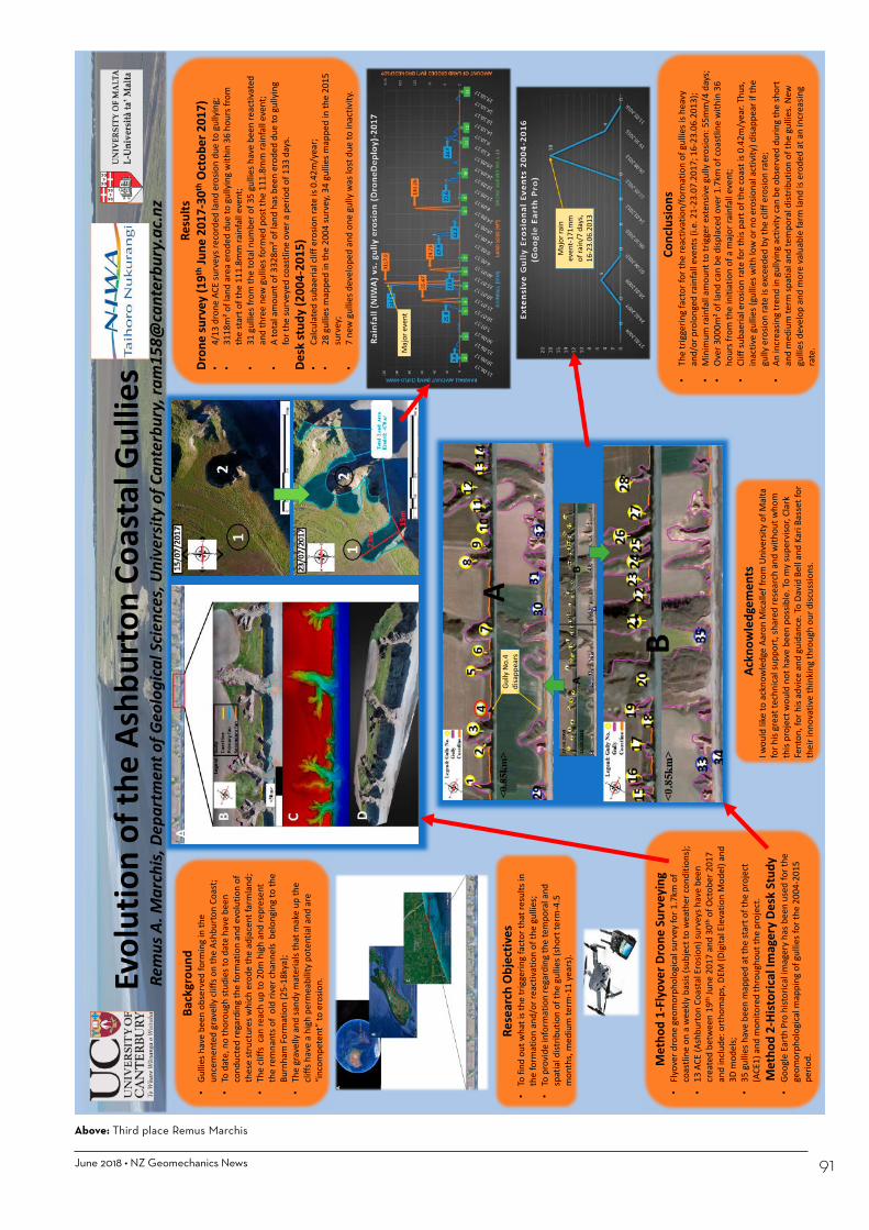
June 2018 • NZ Geomechanics News 91
Evol
utio
n of
the
Ashb
urto
n Co
asta
l Gul
lies
Rem
us A
. Mar
chis,
Dep
artm
ent o
f Geo
logi
cal S
cienc
es, U
nive
rsity
of C
ante
rbur
y, ra
m15
8@ca
nter
bury
.ac.
nz
Rese
arch
Obj
ectiv
es•
To fi
nd o
ut w
hat i
s the
trig
gerin
g fa
ctor
that
resu
lts in
th
e fo
rmat
ion
and/
or re
activ
atio
n of
the
gulli
es;
•To
pro
vide
info
rmat
ion
rega
rdin
g th
e te
mpo
ral a
nd
spat
ial d
istrib
utio
n of
the
gulli
es (s
hort
term
-4.5
m
onth
s, m
ediu
m te
rm-1
1 ye
ars)
.
Back
grou
nd•
Gulli
es h
ave
been
obs
erve
d fo
rmin
g in
the
unce
men
ted
grav
elly
cliff
s on
the
Ashb
urto
n Co
ast;
•To
dat
e, n
o th
orou
gh st
udie
s to
date
hav
e be
en
cond
ucte
d re
gard
ing
the
form
atio
n an
d ev
olut
ion
of
thes
e st
ruct
ures
whi
ch e
rode
the
adja
cent
farm
land
;•
The
cliffs
can
reac
h up
to 2
0m h
igh
and
repr
esen
t th
e re
mna
nts o
f ol
d riv
er ch
anne
ls b
elon
ging
to th
e Bu
rnha
m F
orm
atio
n (2
5-18
kya)
;•
The
grav
elly
and
sand
y m
ater
ials
that
mak
e up
the
cliffs
hav
e a
high
per
mea
bilit
y po
tent
ial a
nd a
re
“inco
mpe
tent
” to
eros
ion.
Resu
ltsDr
one
surv
ey (1
9thJu
ne 2
017-
30th
Oct
ober
201
7)•
4/13
dro
ne A
CE su
rvey
s rec
orde
d la
nd e
rosio
n du
e to
gul
lyin
g;•
3118
m² o
f lan
d ar
ea e
rode
d du
e to
gul
lyin
g w
ithin
36
hour
s fro
m
the
star
t of t
he 1
11.8
mm
rain
fall
even
t;•
31 g
ullie
s fro
m th
e to
tal n
umbe
r of 3
5 gu
llies
hav
e be
en re
activ
ated
an
d th
ree
new
gul
lies f
orm
ed p
ost t
he 1
11.8
mm
rain
fall
even
t;•
A to
tal a
mou
nt o
f 332
8m² o
f lan
d ha
s bee
n er
oded
due
to g
ully
ing
for t
he su
rvey
ed co
astli
ne o
ver a
per
iod
of 1
33 d
ays.
Desk
stud
y (2
004-
2015
)•
Calcu
late
d su
baer
ial c
liff e
rosio
n ra
te is
0.4
2m/y
ear;
•28
gul
lies m
appe
d in
the
2004
surv
ey, 3
4 gu
llies
map
ped
in th
e 20
15
surv
ey;
•7
new
gul
lies d
evel
oped
and
one
gul
ly w
as lo
st d
ue to
inac
tivity
.
Met
hod
1-Fl
yove
r Dro
ne S
urve
ying
•Fl
yove
r dro
ne g
eom
orph
olog
ical s
urve
y fo
r 1.7
km o
f co
astli
ne o
n a
wee
kly
basis
(sub
ject
to w
eath
er co
nditi
ons)
; •
13 A
CE (A
shbu
rton
Coa
stal
Ero
sion)
surv
eys h
ave
been
cr
eate
d be
twee
n 19
thJu
ne 2
017
and
30th
of O
ctob
er 2
017
and
inclu
de: o
rtho
map
s, DE
M (D
igita
l Ele
vatio
n M
odel
) and
3D
mod
els;
•35
gul
lies h
ave
been
map
ped
at th
e st
art o
f the
pro
ject
(A
CE1)
and
mon
itore
d th
roug
hout
the
proj
ect.
Met
hod
2-Hi
stor
ical I
mag
ery
Desk
Stu
dy•
Goog
le E
arth
Pro
hist
orica
l im
ager
y ha
s bee
n us
ed fo
r the
ge
omor
phol
ogica
l map
ping
of g
ullie
s for
the
2004
-201
5 pe
riod.
Conc
lusio
ns•
The
trig
gerin
g fa
ctor
for t
he re
activ
atio
n/fo
rmat
ion
of g
ullie
s is h
eavy
an
d/or
pro
long
ed ra
infa
ll ev
ents
(i.e
. 21-
23.0
7.20
17; 1
6-23
.06.
2013
);•
Min
imum
rain
fall
amou
nt to
trig
ger e
xten
sive
gully
ero
sion:
55m
m/4
day
s;•
Over
300
0m² o
f lan
d ca
n be
disp
lace
d ov
er 1
.7km
of c
oast
line
with
in 3
6 ho
urs f
rom
the
initi
atio
n of
a m
ajor
rain
fall
even
t;•
Cliff
suba
eria
l ero
sion
rate
for t
his p
art o
f the
coas
t is 0
.42m
/yea
r. Th
us,
inac
tive
gulli
es (g
ullie
s with
low
or n
o er
osio
nal a
ctiv
ity) d
isapp
ear i
f the
gu
lly e
rosio
n ra
te is
exc
eede
d by
the
cliff
eros
ion
rate
;•
An in
crea
sing
tren
d in
gul
lyin
g ac
tivity
can
be o
bser
ved
durin
g th
e sh
ort
and
med
ium
term
spat
ial a
nd te
mpo
ral d
istrib
utio
n of
the
gulli
es. N
ew
gulli
es d
evel
op a
nd m
ore
valu
able
farm
land
is e
rode
d at
an
incr
easin
g ra
te.
Ackn
owle
dgem
ents
I wou
ld li
ke to
ack
now
ledg
e Aa
ron
Mica
llef f
rom
Uni
vers
ity o
f Mal
ta
for h
is gr
eat t
echn
ical s
uppo
rt, s
hare
d re
sear
ch a
nd w
ithou
t who
m
this
proj
ect w
ould
not
hav
e be
en p
ossib
le. T
o m
y su
perv
isor,
Clar
k Fe
nton
, for
his
advi
ce a
nd g
uida
nce.
To D
avid
Bel
l and
Kar
i Bas
set f
or
thei
r inn
ovat
ive
thin
king
thro
ugh
our d
iscus
sions
.
Maj
or e
vent
Gully
No.
4 di
sapp
ears
Maj
or ra
in
even
t-171
mm
of
rain
/7 d
ays,
16-2
3.06
.201
3
Above: Third place Remus Marchis

The NZGS Management Committee provides funding for a scholarship that would enable a member of the Society to undertake postgraduate research in New Zealand that would advance the objectives of the Society. Through this scholarship, the Society hopes to encourage members to enrol for post-graduate research (e.g., PhD, Masters by research) or undertake independent research (e.g., post-doctoral research) which would not otherwise be possible for them.
www.nzgs.org
Please go to the NZGS website [www.nzgs.org] for an application form or send any queries to [email protected]
– 2018 –VALUE OF THE SCHOLARSHIP
IS UP TO
NZ$20k
SCHOLARSHIP
Examples of suitable applications would be: (a) applicant is in full time work and the research
relates to a project they are currently working on. It would be funded partly by their employer and/or client and partly by NZGS;
(b) applicant is in full time work and would like to take a year or two years out to complete a full time or part-time masters.
The fields of research would be in Engineering Geology and/or Geotechnical Engineering. The topic or field of study should be of wide interest to geopractitioners in New Zealand. The award of such a scholarship would include agreed milestones. Deliverables would include a publication and/or a thesis. A nominated representative from the NZGS will act as a liaison with the scholar and the supervisor (where applicable).
The NZGS Management Committee has agreed on the following Terms of Reference for the NZGS Scholarship:
1. A scholarship termed the “New Zealand Geotechnical Society Scholarship” wholly funded by the New Zealand Geotechnical Society (NZGS) and administered by the NZGS Management Committee is available for members (defined to be either a Student Member or Normal Member) of the NZGS.
2. The scholarship is provided to enable the member to undertake postgraduate research
work in the fields of Engineering Geology and/or Geotechnical Engineering in New Zealand.
3. This research work can lead to the award of a post-graduate degree but is not necessarily restricted to such an award. It is expected that the study or research work will be undertaken at a post-graduate level and not at an undergraduate level
4. A publication at the end of the study or research work in the form of a report or thesis is a requirement of the award of the scholarship.
5. The scholarship is awarded on an ad-hoc basis at the sole discretion of the NZGS Management Committee. This is dependent on proposals submitted for consideration by the Committee.
6. Applications for consideration by the Committee should be submitted to the Management Secretary by 31st October of each year.
7. The period of research work is to be agreed with the NZGS Management Committee.
8. The value of the scholarship is a sum of up to NZ$20,000. This amount may be awarded in its entirety, split between several applicants or not awarded at all depending on the applications received.
SUBMISSIONS IN BY 31 OCTOBER 2018

June 2018 • NZ Geomechanics News 93
SOCIETY
NZGS SCHOLARSHIPS (ANNUAL)Important dates are:Sept 2018 Call for applicationsEnd Oct 2018 Closing date for applicationsEnd Nov 2018 Closing date for full submissionFeb 2019 Successful applicants announced (if any)
See advertisement in this issue for details
NZGS STUDENT AWARDS POSTER COMPETITION (ANNUAL)Important dates are:June 2018 Call for applicationsMid Nov 2018 Closing date for applicationsEnd Jan 2019 Closing date for receipt of poster
Feb 2019 Judging and announcement of winners at local NZGS evening event
The 2017-2018 winners are: Matt Ogden (doing a Masters in Geotech Engineering at Auckland with Liam Wotherspoon)Claudio Cappellaro (doing a PhD (Engineering) at Canterbury with Misko Cubrinovski)Remus Marchis (completed a Professional Masters of Engineering Geology at Canterbury with Clark Fenton)See 2017-18 winning posters in this issue
YOUNG GEOTECHNICAL PROFESSIONAL (YGP) CONFERENCE AWARDSTen Young Professionals are the recipients of conference awards to attend the 12th ANZ Young Geotechnical Professionals Conference (12YGPC) to be held in Hobart, Tasmania on 7-9 November 2018:
Jawad Arefi, Gislaine Pardo Tobar, Aimee Rhodes, Francesca Spinardi, Kylie Johnson, Kieran Foote, Zeb Paterson, Andrew Gordon, Alec Wild and Sam Glue.
These awards are sponsored by the Earthquake Commission (EQC) and NZGS.
NZGS GEOMECHANICS LECTUREThe 2018 recipient of the award is Prof Misko Cubrinovski (University of Canterbury). He will deliver his lecture in various parts of the country from late 2018 to early 2019. He will also give the lecture during the 2019 ANZ Geomechanics Conference in Perth in April 2019.
NZGS GEOMECHANICS AWARDSeven (7) papers were received for consideration. A panel of judges (Mick Pender, CY Chin, Kevin McManus) is currently assessing the submissions.
The 2018 winner(s) will be announced during the Society’s AGM scheduled in September 2018.
NZGS Awards Calendar
IAEG Awards 2018 (Richard Wolters Prize, Hans Cloos Medal, Marcel Arnould Medal): no nominee this year.
ISSMGE Awards (various): next round of nominations likely to be in July 2019.
ISRM Rocha Medal 2020: nomination must reach the ISRM Secretary-General by 31 December 2018. For submittal through NZGS, nominations should be received by the Secretary by end October 2018.
OTHER AWARDS
Rolando Orense Rolando is the Geomechanics Group Leader at the Department of Civil & Environmental Engineering, University of Auckland. His research interest is earthquake geotechnical engineering, and he has extensive experience in doing research, teaching and consulting works related to soil liquefaction, ground response analyses and seismic soil-structure [email protected]

NZ Geomechanics News • June 201894
SOCIETY – OBITUARIES
DAVID BURNS, a life member of the New Zealand Geotechnical Society, died in Auckland on 27 January 2018 at the age of 64. David was chair of the society from 2011 to 2013 and immediate past-chair from 2013 to 2015. Earlier he was an elected committee member, treasurer, and vice-chair from 2008 to 2011, serving eight years in all. One thing that stands out in his work for the society is his role in championing and formulating the registration system for engineering geologists which put engineering geologists on a par with Chartered Professional Engineers. Our Australian colleagues drool when they talk about what NZ has achieved. Professional Engineering Geologists are now Chartered Members of Engineering New Zealand. He was part of the first group to be registered as PEngGeol became a practice area assessor for subsequent applications. He also helped to revise the society’s rules in 2014, was a reviewer on numerous occasions for NZGS symposia and ANZ conference papers, and was a regular participant in Auckland Branch activities. He helped revise a core document for the society, the Guidelines for field description of rocks and soils for engineering purposes (Williams et al. 2005).
David was a graduate of Waikato University’s Department of Earth Sciences, beginning in 1972, and finishing in 1980 when he completed an MSc with Cam Nelson on carbon and oxygen stable isotope geochemistry of Cenozoic calcareous sedimentary rocks (Burns and Nelson 1981; Nelson and Burns 1982; Nelson et al. 1983). David was a foundation member of the Waikato Branch of the Geological (now Geoscience) Society
David Andrew Burns BSc MSc CMEng(PEngGeol) Life member NZGS (1953-2018)
of New Zealand that was formed in 1975, and a member of the local organising committee for the society’s annual conference held in Hamilton in 1976.
David embarked on his career in engineering geology, initially in Tauranga (Fig. 1) and then in Auckland, finishing as a highly-respected, experienced Technical Director in Ground Engineering at AECOM (Auckland), despite having no formal training in the discipline other than his Waikato degrees in earth sciences. David started a job as a soil technician with a forerunner company of AECOM. He only ever worked for one company. He was an example of a geologist with core geological skills who learned engineering geology on the job. David spent considerable time overseas including in Belize, Indonesia, Bangladesh, Lao PDR and Vietnam as well as throughout New Zealand, working on a wide range of projects in engineering geology.
David wasn’t always conventional in his personal life and he railed against certain conventions. In contrast, in his professional life he was more conventional. He set the benchmark and exhibited best practice. David’s standing in the profession was attested to by the attendees at his funeral and messages received about David’s standing in the engineering community. He was also well known in the Australian engineering geological community.
David and geology were inseparable. He was the nightmare driver, constantly looking at cut batters, especially where new construction work was occurring or where the earth was bare. He could see geological strata. David would focus on these through the
windscreen, then swivel his head sideways while passing the batter and intensely view it in the rear view mirror.
When it came to writing reports David was a perfectionist. For David a report that was 99.5% there, was not good enough. He just kept writing and editing, and striving for 100%. While writing was his forte his ability to interpret geology and solve problems was more important. David had a rigorous way of working, getting data, interpreting it and making a judgement. To say he was thorough is an understatement. There was no quick conversation with David – he would want to chew it over and discuss the problem from every angle. The outcome was always well considered judgement which his colleagues and clients relied on.
Towards the end of his career, as ill-health slowed him down, David undertook a lot of editing, helping colleagues with less experience to knock their reports into shape.
David’s professional legacy is seen not so much in his excellent project work, but rather in those whom he
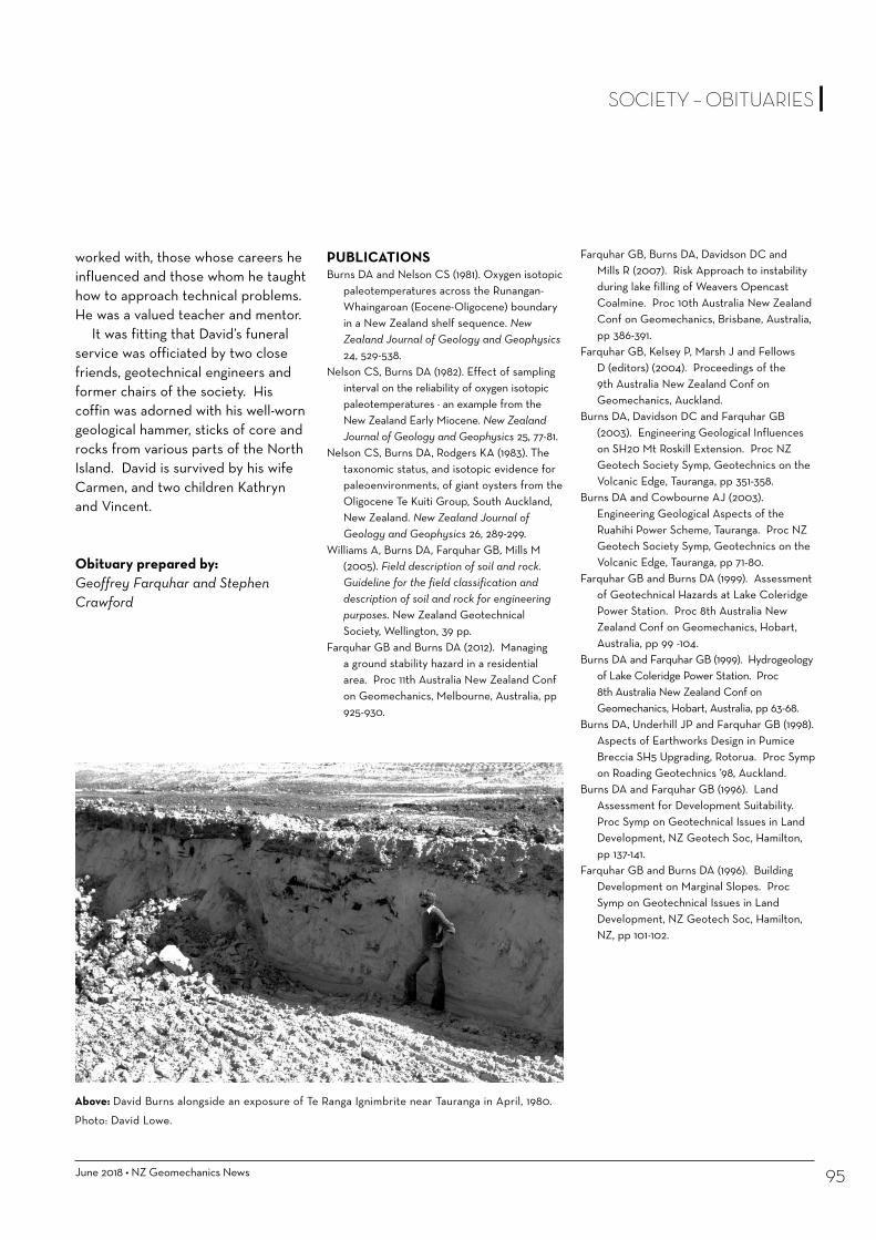
June 2018 • NZ Geomechanics News 95
SOCIETY – OBITUARIES
worked with, those whose careers he influenced and those whom he taught how to approach technical problems. He was a valued teacher and mentor.
It was fitting that David’s funeral service was officiated by two close friends, geotechnical engineers and former chairs of the society. His coffin was adorned with his well-worn geological hammer, sticks of core and rocks from various parts of the North Island. David is survived by his wife Carmen, and two children Kathryn and Vincent.
PUBLICATIONS Burns DA and Nelson CS (1981). Oxygen isotopic
paleotemperatures across the Runangan-Whaingaroan (Eocene-Oligocene) boundary in a New Zealand shelf sequence. New Zealand Journal of Geology and Geophysics 24, 529-538.
Nelson CS, Burns DA (1982). Effect of sampling interval on the reliability of oxygen isotopic paleotemperatures − an example from the New Zealand Early Miocene. New Zealand Journal of Geology and Geophysics 25, 77-81.
Nelson CS, Burns DA, Rodgers KA (1983). The taxonomic status, and isotopic evidence for paleoenvironments, of giant oysters from the Oligocene Te Kuiti Group, South Auckland, New Zealand. New Zealand Journal of Geology and Geophysics 26, 289-299.
Williams A, Burns DA, Farquhar GB, Mills M (2005). Field description of soil and rock. Guideline for the field classification and description of soil and rock for engineering purposes. New Zealand Geotechnical Society, Wellington, 39 pp.
Farquhar GB and Burns DA (2012). Managing a ground stability hazard in a residential area. Proc 11th Australia New Zealand Conf on Geomechanics, Melbourne, Australia, pp 925-930.
Above: David Burns alongside an exposure of Te Ranga Ignimbrite near Tauranga in April, 1980.
Photo: David Lowe.
Obituary prepared by:Geoffrey Farquhar and Stephen Crawford
Farquhar GB, Burns DA, Davidson DC and Mills R (2007). Risk Approach to instability during lake filling of Weavers Opencast Coalmine. Proc 10th Australia New Zealand Conf on Geomechanics, Brisbane, Australia, pp 386-391.
Farquhar GB, Kelsey P, Marsh J and Fellows D (editors) (2004). Proceedings of the 9th Australia New Zealand Conf on Geomechanics, Auckland.
Burns DA, Davidson DC and Farquhar GB (2003). Engineering Geological Influences on SH20 Mt Roskill Extension. Proc NZ Geotech Society Symp, Geotechnics on the Volcanic Edge, Tauranga, pp 351-358.
Burns DA and Cowbourne AJ (2003). Engineering Geological Aspects of the Ruahihi Power Scheme, Tauranga. Proc NZ Geotech Society Symp, Geotechnics on the Volcanic Edge, Tauranga, pp 71-80.
Farquhar GB and Burns DA (1999). Assessment of Geotechnical Hazards at Lake Coleridge Power Station. Proc 8th Australia New Zealand Conf on Geomechanics, Hobart, Australia, pp 99 -104.
Burns DA and Farquhar GB (1999). Hydrogeology of Lake Coleridge Power Station. Proc 8th Australia New Zealand Conf on Geomechanics, Hobart, Australia, pp 63-68.
Burns DA, Underhill JP and Farquhar GB (1998). Aspects of Earthworks Design in Pumice Breccia SH5 Upgrading, Rotorua. Proc Symp on Roading Geotechnics ’98, Auckland.
Burns DA and Farquhar GB (1996). Land Assessment for Development Suitability. Proc Symp on Geotechnical Issues in Land Development, NZ Geotech Soc, Hamilton, pp 137-141.
Farquhar GB and Burns DA (1996). Building Development on Marginal Slopes. Proc Symp on Geotechnical Issues in Land Development, NZ Geotech Soc, Hamilton, NZ, pp 101-102.

NZ Geomechanics News • June 201896
A tribute to Prof. Don Deere (1922-2018)
REGRETTABLY PROF. DON UEL DEERE left us on January 14th at the age of 95. He had hardly recovered from a fall a few months earlier. His passing, however, leaves very good memories for his former students, assistants, colleagues and clients. Five years ago, when he was celebrating his 90th birthday, we were invited by his son Don W. Deere and daughter to Gainesville, Florida, to a memorable ceremony, while Prof. Deere was still very active. His last years after he recovered almost totally from a stroke were spent golfing, dancing, etc. at his glamourous retirement resort.
He represented a very important milestone for Engineering Geology and Rock Mechanics in his activities at the University of Illinois, Champaign-Urbana Campus, in the 60s and 70s. Together with Prof. Ralph Peck, they led and pioneered Geotechnics and Rock Mechanics in the USA. His area of expertise covered Civil Engineering (Ph.D), Mining (B.S.) and Geology (M.Sc.). My own impression is that Prof. Deere was a man who was very kind and respectful of his students and colleagues whom he encouraged the most. Moreover, he was a man who knew how to utilize the potential of his assistants to make them grow together with him. This resulted in a formation of a group of very talented colleagues, such as Ron Heuer, Alfred J. Hendron, Ed Cording, Frank Patton, and later Gabriel Fernandez, among others who were not of my time. Among his former students, you can find many engineers and geologists who reached senior and influential positions, like Andy Merritt (his consulting partner), Ray Miller, Harvey Parker (President of ITA), Jim Coulson (Chief Engineer at TVA), Ray Benson and Bob Conlon (Both
Geotechnical Department Heads at Acres), Brian Sinclair, Sergio Brito, Alan Smallwood, Jim Gamble, Alberto Nieto, Jim Mahar and many others including the author of these lines. After many years at the University of Illinois, he moved to the University of Florida where he could devote more time to his consulting practice.
He was a recognized expert in Engineering Geology and Rock Mechanics and has the great merit of integrating Geology in Geotechnical and Geomechanical projects. He consulted on numerous dams, mining, tunnels and other underground projects for the US government, contractors and design engineering companies all over the world. Many of these projects involved precedent structures such as the Churchill Falls hydroelectric project in Labrador, Canada and the World Trade Centre in New York city. He also acted as a member of the Board of Consultants in many other large projects around the world. In Brazil he made very important contributions as a member of Board of Consultants for the following hydroelectric projects: Itaipu, Água Vermelha, Sobradinho, Itaparica, Paulo Afonso, Itumbiara, Sao Felix, Altamira and others. His first mission in Brazil was to help me on the design of the final slopes of the Cauê Open Pit Mine, in 1972.
His experiences in the field became teaching material for his classes. He wrote and co-authored numerous papers and was, of course, the inventor of the rock mass assessment tool, the RQD. Together with Giovanni Lombardi, he invented the GIN method of grouting. He was Chairman of the US Nuclear Waste Technical Review Board. He
was the President of the Commission on Standardization of Laboratory and Field Tests of the ISRM from 1968 to 1973. He received numerous distinctions throughout his career, including being elected to both the National Academy of Engineering and the National Academy of Sciences. He was also a consummate joke teller.
Milton KanjiReproduced from ISRM Newsletter No. 41 - March 2018
OBITUARIES

June 2018 • NZ Geomechanics News 97
OBITUARIES
PROF. RICHARD Z.T. BIENIAWSKI, died on 11 December 2017 at his home. He was born in 1936, in Krakow, Poland. He was one of the most prominent and influential rock engineering personalities of the 20th century.
Prof. Bieniawski was trained as a naval architect and marine engineer in Poland, graduated in South Africa as mechanical engineer and obtained a doctorate in mining and tunnel engineering. He taught for 20 years at the Pennsylvania State University and retired on his 60th birthday to Prescott, having become Visiting Professor of Design Engineering at the University of Cambridge, England.
In the ISRM, he was chairman of the Commission on Testing Methods from 1972 to 1979 and Vice President for Africa from 1974 to 1979.
As two who have been to ISRM conferences for a long time, and therefore have known Dick Bieniawski for more than half his life, and during a bigger proportion of our own, it was with sadness we recently heard the news of his death on December 11, 2017.
His enthusiasm for life and work - seemingly at all times - was a foolproof camouflage of the fact that he had a long life, and was truly a senior and respected colleague. Starting in South Africa as a mechanical engineer, where he obtained a PhD in mining and tunnel engineering, he has been through his life a teacher and an engineer.
It is true perhaps, but misleading of his multi-faceted contributions to education, to rock mechanics and to rock engineering, that he is best known for his own RMR rock mass rating, which was a prime member of the 1972, 1973 and 1974 independently developed rock mass classification methods.
It is of interest to underline here that these classification methods miraculously
In memory of Richard Z.T. Bieniawski (1936-2017)
developed almost simultaneously, if we look at the longer time-scale. RMR has of course provided healthy competition for Q, and gave a flying start for GSI.
Dick’s book on rock mass classification methods of 1989, Engineering Rock Mass Classifications - A Complete Manual for Engineers and Geologists in Mining, Civil, and Petroleum Engineering, is one of the most cited texts in rock engineering.
However, how could Dick’s contributions to rock mechanics and rock engineering, during his first steps in the discipline, be neglected? The invaluable PhD thesis on the Mechanism of the Brittle Fracture of Rock in compression and tension is a remarkable sign of Dick’s ability to couple theory and practice.
The precious contributions of Dick Bieniawski to rock engineering in mining and tunneling are also to be reminded, as well demonstrated with his books on Strata Control in Mineral Engineering of 1987 and on Rock Mechanics Design in Mining and Tunneling of 1989.
The use of consistent design methods in rock engineering has always been Dick’s concern. This is well demonstrated in the books on Tunnel Design by Rock Mass Classifications of 1990 and on Design Methodology in Rock Engineering of 1992, always complemented with important case histories.
Giovanni Barla and Nick BartonReproduced from ISRM Newsletter No. 41 - March 2018

NZ Geomechanics News • June 201898
SOCIETY – INTERNATIONAL REPORTS
13TH IAEG CONGRESS 2018
The 13th IAEG Congress will be held in San Francisco, California during the week of 17-21 September 2018. For this event the IAEG is partnering with the US Association of Environmental & Engineering Geologists. This will be the first time the IAEG Congress has been held in the USA.
Registration for the Congress is open and information on events planned, field courses and guest tour options can be found on this webpage: https://www.aegannualmeeting.org/registration
IAEG EXECUTIVE COMMITTEE AND COUNCIL MEETINGS NOVEMBER 2017The IAEG Executive Committee met in Kathmandu, Nepal 24 to 26 November 2017. This was followed by the annual IAEG Council meeting. These meetings were held in conjunction with the 11th Asian Regional Conference of IAEG. Key discussion points from the Kathmandu meetings included membership, strategy and fees as summarised here.
MEMBERSHIP AND NEW NATIONAL GROUPSIn 2017 there were 4369 members of the IAEG from 58 National Groups. This is a 9% increase in membership from 2016. New Zealand is the third largest National Group with 311 members affiliated via the New Zealand Geotechnical Society.
Three new National Groups were approved - Bangladesh, Iraq and Chinese Taipei (the latter as a Regional Group).
International Association for Engineering Geology and the Environment
NEW MEMBERSHIP FEE STRUCTURECouncil approved a new fee structure in line with the Bulletin being published digital-only from 2019. The new fees, which will take effect from 2019, for NZ IAEG members, will be:
•No Bulletin 20 € •With Bulletin 32 €
The smaller differential in fees between no bulletin and receiving the bulletin from 2019 reflects the lower cost in publishing digital-only compared with the existing hard copy. This is the first change in IAEG fees since 2008.
The next IAEG Executive Committee meeting is May 2018 in Paris, and the next annual Executive and Council meetings will be in San Francisco as part of the Congress in September 2018. These will be reported on in future bulletins.
IAEG EXECUTIVE COMMITTEE FROM 2019 TO 2022Nominations for positons on the IAEG Executive for the period 2019 to 2022 closed 15 May 2018. This includes the President, Vice-Presidents for geographical areas, Secretary-General and Treasurer. Elections will held at the council meeting in September.
The next IAEG Vice President for Australasia will come from New Zealand based on the 1:1 agreement between the AGS and NZGS. NZGS has nominated Doug Johnson for the role of Australasian VP. An Australian Liaison for the IAEG over the term 2019 to 2022 to coordinate with the new VP from NZ will be nominated by the AGS.
IAEG WEBSITE Just a reminder – the IAEG website contains a number of recorded lectures and webinars that can be watched online. Keep checking the website as new items are added periodically.
Doug Johnson NZ IAEG Representative
Doug JohnsonDoug has a Master’s degree in Engineering Geology from the University of Canterbury NZ (1984). He has worked on many mining, quarrying and civil engineering projects across a range of complex geological terrains, geographies and on both green and brown field site developments. Doug is currently Managing Director of Tonkin + Taylor and is passionate about people, the client experience, and technical solutions providing long term benefits to the community and the environment.
Mark EggersMark is is a Principal and Director at Pells Sullivan Meynink where he consults on large civil and mining projects across Australia, New Zealand and SE Asia. Mark has a keen interest in education and research through close associations with University of New South Wales and University of Canterbury. He also co-teaches field courses in engineering geology for the Australian Geomechanics Society.

June 2018 • NZ Geomechanics News 99
SOCIETY – INTERNATIONAL REPORTS
International Society for Rock Mechanics and Rock Engineering
REGIONAL REPORT FOR AUSTRALASIA – JUNE 2018The period since December 2017 has been a relatively quiet period, ahead of preparations for the next ISRM Board and Council meetings in Singapore on 28 – 30 October 2018 in association with ARMS10 - the ISRM 10th Asian Rock Mechanics Symposium (http://www.arms10.org - 31 October – 03 November).
MULLER AWARD (2019)Nominations for the Muller award, a recognition of distinguished contributions to the profession of rock mechanics and rock engineering closed on 30 April 2018. This is the prestigious ISRM technical award, and based on nominations received voting at the Council meeting on 30 October 2018 will decide the 2019 recipient. The lecture will be given during the ISRM 14th International Congress on Rock Mechanics in Foz do Iguaçu, Brasil in September 2019.
ROCHA MEDAL (2018, 2019 & 2020):Nominations for the 2019 award closed on 31 December 2017. The award recognises the most meritorious PhD thesis in rock mechanics, and 21 theses were submitted. Evaluation is underway and the winner will be announced at the ISRM Council meeting in Singapore on 30 October 2018.
The 2018 winner Michael du Plessis (South Africa) with the thesis “Design and Performance of Crush Pillars” (University of Pretoria) will do his presentation at the ARMS 10 Symposium in Singapore (29 October – 03 November).
Stuart Read Stuart Read is an engineering geologist with GNS Science. He obtained his degree, in engineering geology from the University of Canterbury, in 1971. His 43 years of engineering geological consulting and research experience has been in the evaluation, investigation, construction and refurbishment of engineering and mining projects. He has taken a leading role in the development of the rock and soil mechanics laboratory for GNS Science and has research interests in the strength and deformation properties of rock and soil masses.
Nominations for the 2020 award are open and need to be with the ISRM Secretary General by 31 December 2018.
ISRM ON-LINE LECTURES Two on-line lectures have been given over the last months:
• 20th by Professor Milton Kanji (Brazil) on 12 December 2017 with the title “Dam foundations affected by geological aspects”
• 21st by Prof Laura Pyrak-Nolte (USA) on 15 March with the title “Geophysical Characterization of Fractures”.
The lectures are available on the ISRM website (ISRM online lectures e.g. https://www.isrm.net/gca/index.php?id=1325 for Prof Kanji).
MEMBERSHIP:ISRM individual membership worldwide remains at 7,800, collected from with 62 National Groups (countries). Europe and Asia have the greatest individual membership (>25%), with other regions including Africa and Australasia having ~5%. – currently 320 in Australia and 170 from New Zealand). There are 150 Corporate memberships, with four from Australia and none from New Zealand.
YOUNG PROFESSIONALS:Fostering of younger members (under 35) is a recognised need, but current feeling in the Board is that promotion of young professionals group is better as a bottom driven activity. This is through National Groups (as is in Australia and New Zealand) and supported at conferences, in particular at ISRM Congresses and regional conferences (e.g. ARMS10 in
2018 in Singapore will have several activities – Rockbowl quizz, drilling competition, social. There will also be another Early Career Forum for young professionals sponsored by the ISRM Education Fund).
COMMUNICATION: The ISRM website (www.isrm.net) has information on the society’s intent, structure and activities, including conferences, commissions, awards, products and publications. For those AGS members affiliated to ISRM as individual members there is a members area with access to further
continued >
NZ Geomechanics News • June 2018100
products. There is also Linked in, Twitter or RSS access.
Regular means of communication (under ISRM information on the website) are:
• ISRM Newsletter, which has been published quarterly since March 2008. LAST ISSUE No 40 in December 2017
• ISRM News Journal, now under the editorship of Dr José Muralha (Portugal) LAST ISSUE No 20 (Dec 2017) issued in March 2018.
The ISRM Digital Library, which was launched in October 2010. (https://www.isrm.net/gca/?id=992), is intended to make rock mechanics material available to the rock mechanics community, in particular papers published from ISRM Congresses and sponsored Symposia. It is part of OnePetro (https://www.onepetro.org), a large online library managed by the Society of Petroleum Engineers. ISRM individual members are allowed to download, at no cost, up to 100 papers per year from the ISRM conferences.
COMMISSIONSThere are 17 ISRM Commissions in the 2015 – 2019 term (not listed here but included in a previous Geomechanics News). Commission purposes and anticipated products, along with membership, are included on the ISRM website (links on https://www.isrm.net/gca/?id=153).
Commissions run on a voluntary basis and several are very active, with associated publications (e.g. blue and orange books for testing methods). A reduced price for the orange book is
available for ISRM members through the members page (see also https://www.isrm.net/gca/?id=177).
FedIGS (Federation of International Geo-Engineering Societies www.geoengineeringfederation.org/):
FedIGS is a grouping under which the three international societies that NZ Geotechnical Society affiliates to operates. Three Technical Commissions operate under the FedIGS umbrella –
• JCT1 (Natural slopes and landslides) co-ordinated under IAEG
• JCT2 (representation of geo-engineering data) co-ordinated under ISRM
• JTC3 (Education and training) co-ordinated under ISSMGE
The JCT2 committee is in a changeover period, with election of new members. Dr Ian Brown, as a New Zealand representative, has joined the committee. If you have a strong interest in storage and manipulation of data, and wish to know more, get in touch with Ian.
IN MEMORIAMTwo of the leading lights in the development of rock mechanics, in particular in the 1960s and 1970s, have passed away – Prof Don Deere and Prof Dick Bieniawski. Obituaries are published elsewhere in this issue.
Stuart Read
SOCIETY – INTERNATIONAL REPORTS
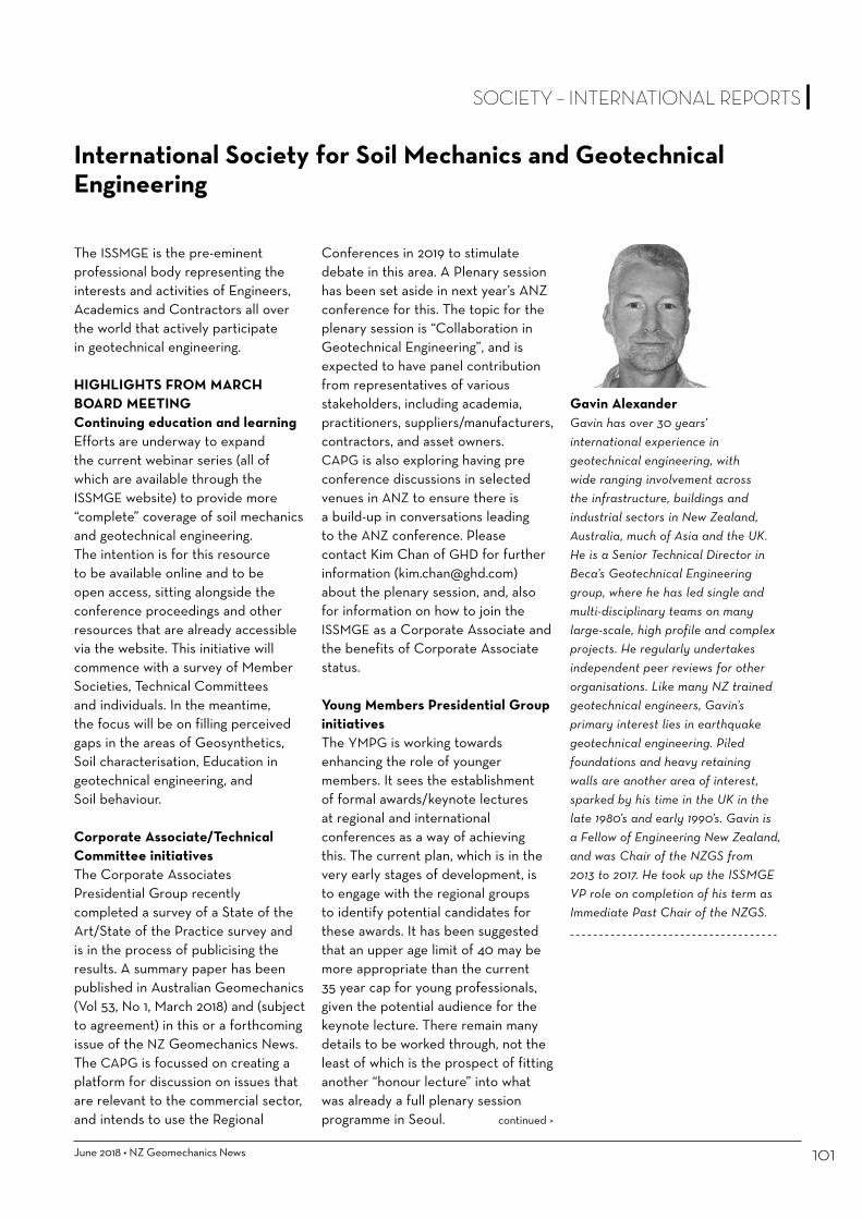
June 2018 • NZ Geomechanics News 101
SOCIETY – INTERNATIONAL REPORTS
The ISSMGE is the pre-eminent professional body representing the interests and activities of Engineers, Academics and Contractors all over the world that actively participate in geotechnical engineering.
HIGHLIGHTS FROM MARCH BOARD MEETINGContinuing education and learningEfforts are underway to expand the current webinar series (all of which are available through the ISSMGE website) to provide more “complete” coverage of soil mechanics and geotechnical engineering. The intention is for this resource to be available online and to be open access, sitting alongside the conference proceedings and other resources that are already accessible via the website. This initiative will commence with a survey of Member Societies, Technical Committees and individuals. In the meantime, the focus will be on filling perceived gaps in the areas of Geosynthetics, Soil characterisation, Education in geotechnical engineering, and Soil behaviour.
Corporate Associate/Technical Committee initiativesThe Corporate Associates Presidential Group recently completed a survey of a State of the Art/State of the Practice survey and is in the process of publicising the results. A summary paper has been published in Australian Geomechanics (Vol 53, No 1, March 2018) and (subject to agreement) in this or a forthcoming issue of the NZ Geomechanics News. The CAPG is focussed on creating a platform for discussion on issues that are relevant to the commercial sector, and intends to use the Regional
Conferences in 2019 to stimulate debate in this area. A Plenary session has been set aside in next year’s ANZ conference for this. The topic for the plenary session is “Collaboration in Geotechnical Engineering”, and is expected to have panel contribution from representatives of various stakeholders, including academia, practitioners, suppliers/manufacturers, contractors, and asset owners. CAPG is also exploring having pre conference discussions in selected venues in ANZ to ensure there is a build-up in conversations leading to the ANZ conference. Please contact Kim Chan of GHD for further information ([email protected]) about the plenary session, and, also for information on how to join the ISSMGE as a Corporate Associate and the benefits of Corporate Associate status.
Young Members Presidential Group initiativesThe YMPG is working towards enhancing the role of younger members. It sees the establishment of formal awards/keynote lectures at regional and international conferences as a way of achieving this. The current plan, which is in the very early stages of development, is to engage with the regional groups to identify potential candidates for these awards. It has been suggested that an upper age limit of 40 may be more appropriate than the current 35 year cap for young professionals, given the potential audience for the keynote lecture. There remain many details to be worked through, not the least of which is the prospect of fitting another “honour lecture” into what was already a full plenary session programme in Seoul.
International Society for Soil Mechanics and Geotechnical Engineering
continued >
Gavin AlexanderGavin has over 30 years’ international experience in geotechnical engineering, with wide ranging involvement across the infrastructure, buildings and industrial sectors in New Zealand, Australia, much of Asia and the UK. He is a Senior Technical Director in Beca’s Geotechnical Engineering group, where he has led single and multi-disciplinary teams on many large-scale, high profile and complex projects. He regularly undertakes independent peer reviews for other organisations. Like many NZ trained geotechnical engineers, Gavin’s primary interest lies in earthquake geotechnical engineering. Piled foundations and heavy retaining walls are another area of interest, sparked by his time in the UK in the late 1980’s and early 1990’s. Gavin is a Fellow of Engineering New Zealand, and was Chair of the NZGS from 2013 to 2017. He took up the ISSMGE VP role on completion of his term as Immediate Past Chair of the NZGS.

NZ Geomechanics News • June 2018102
SOCIETY – INTERNATIONAL REPORTS
The YMPG is also investigating open online course platforms, with these courses being aimed at a slightly higher level than the webinars.
Professional Image CommitteeThe new PIC, under the leadership of Prof Towhata, has finalised its goals for the current term, and these are available on the ISSMGE website. The focus will be on publicising the value of an appropriate level of geotechnical investigation. This will, I’m sure, strike a chord with most of us!
TECHNICAL COMMITTEESThe state of the current technical committees covers a wide range, from very active (like TC203, Earthquake) to essentially defunct (like TC210, Dams). It has, in fact, been suggested that TC210 be disestablished because of the lack of activity and because its aims are duplicated by ICOLD. This suggestion has spurred action from some quarters. A new TC309, Machine Learning, is about to be established.
It is timely that representation on the TC’s is refreshed, and I have prepared a list of the current recorded members across Australia and NZ. The level of apparent participation in the current 33 TC’s from the AGS is impressive – two Chairs, one Vice Chair, three Secretaries and 44 nominated or corresponding members. The NZGS, on the other hand, is comparatively light, with only five nominated members.
Each of our Societies need to revitalise our involvement in the Technical Committees – firstly by confirming the ongoing and real interest of the current members, and secondly by opening up opportunities for new nominees and corresponding members. Graham Scholey and I are leading this, and have been impressed with the initial response from current members. There will shortly be an opportunity for new members to be nominated.
SELECTION OF NEW SECRETARY GENERALProfessor Neil Taylor’s current term as Secretary General finishes at the mid-term Council meeting in September 2019. Nominations being called for a new Secretary General, though I understand that Neil is prepared to stand again. The rules allow him to continue for a further four years. Neil and his support team have done a great job, and it is my view that there is little value to be gained by replacing him any sooner than necessary. Consequently, the NZGS and the AGS will be supporting Neil’s re-appointment as Secretary General.
CONFERENCESAbstract submission for the next ANZ conference, to be held in Perth in early April 2019, will have closed by the time you read this. This is the first of the next round of ISSMGE Regional Conferences, which are traditionally held between the four yearly international conferences.
Preparations for Sydney 2021 are underway, with the venue confirmed and PCO expected to be appointed by the time this goes to print.
FORTHCOMING BOARD MEETINGSThe next Board meetings are scheduled for 6 June (face to face, Skopje, Macedonia).
For more information about the ISSMGE, please visit www.issmge.org
Gavin AlexanderISSMGE Vice President for Australasia
Graham ScholeyAGS Liaison with the ISSMGE VP for [email protected]
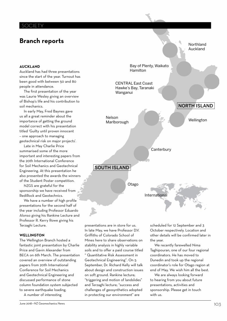
June 2018 • NZ Geomechanics News 103
XXXXXXXXXXXXXXXX
NORTH ISLAND
SOUTH ISLAND
NorthlandAuckland
Bay of Plenty, Waikato Hamilton
CENTRAL East Coast Hawke’s Bay, Taranaki Wanganui
Wellington
Otago
International
Canterbury
NelsonMarlborough
Branch reports
SOCIETY
AUCKLANDAuckland has had three presentations since the start of the year. Turnout has been good with between 50 and 80 people in attendance.
The first presentation of the year was Laurie Wesley giving an overview of Bishop's life and his contribution to soil mechanics.
In early May, Fred Baynes gave us all a great reminder about the importance of getting the ground model correct with his presentation titled ‘Guilty until proven innocent – one approach to managing geotechnical risk on major projects’.
Late in May Charlie Price summarised some of the more important and interesting papers from the 20th International Conference for Soil Mechanics and Geotechnical Engineering. At this presentation he also presented the awards the winners of the Student Poster competition.
NZGS are grateful for the sponsorship we have received from RediRock and Geotechnics.
We have a number of high profile presentations for the second half of the year including Professor Eduardo Alonso giving his Rankine Lecture and Professor R. Kerry Rowe giving his Terzaghi Lecture.
WELLINGTONThe Wellington Branch hosted a fantastic joint presentation by Charlie Price and Gavin Alexander from BECA on 6th March. The presentation covered an overview of outstanding papers from 20th International Conference for Soil Mechanics and Geotechnical Engineering and discussed performance of stone column foundation system subjected to severe earthquake loading.
A number of interesting
presentations are in store for us. In late May, we have Professor D.V. Griffiths of Colorado School of Mines here to share observations on stability analysis in highly variable soils and to offer a paid course titled “ Quantitative Risk Assessment in Geotechnical Engineering”. On 5 September, Dr. Richard Kelly will talk about design and construction issues on soft ground. Rankine lecture; “triggering and motion of landslides” and Terzaghi lecture; “success and challenges of geosynthetics adopted in protecting our environment” are
scheduled for 12 September and 3 October respectively. Location and other details will be confirmed later in the year.
We recently farewelled Nima Taghipouran, one of our four regional coordinators. He has moved to Dunedin and took up the regional coordinator’s role for Otago region at end of May. We wish him all the best.
We are always looking forward to hearing from you about future presentations, activities and sponsorship. Please get in touch with us.

NZ Geomechanics News • June 2018104
NELSONWe have had 2 presentations so far this year.
On 15 March Charlie Price gave an interesting presentation to a small audience on key papers from the 20th International Conference for Soil Mechanics and Geotechnical Engineering that was held in Seoul in Sept. 2017. Thanks to Stantec for providing the venue.
On 15 May Dr. Liam Wotherspoon provided another interesting presentation on Site Characterisation in New Zealand including results of recent research including the Nelson-Tasman urban area. The meeting invite was extended out to ENZ members and we had a good turnout of 25 people. Thanks to WSP-Opus for providing the venue and sponsoring this meeting.
If local members have ideas for future presentation topics please contact [email protected]
H GEO-NEWS WEEKLY E-NEWSLETTER HOur new weekly email lists all notices and Branch announcements normally sent to members, but in one email. Please send items to include to [email protected]
SOCIETY
SEE THE
EVENTS DIARY OR
WWW.NZGS.ORG
FOR FUTURE
EVENTS
WAIKATO The Waikato Branch went on tour of the SH1 Waikato Expressway Huntly Section on 19 April with an all-star cast of tour guides including FH/HEB Project Director Tony Dickens and Construction Manager Tony Adams. Project Geotechnical Engineer Natasha Jokhan provided technical input on various design and construction aspects. Thanks also to Tom Glenn and Shane Wilton for their technical inputs. The event was well attended by a good cross section of the Waikato geotechnical community. See the full page article for further details.
UPCOMING EVENTS for the Waikato group include Liquefaction studies from several Waikato projects, short-presentation night, civil engineering laboratory visit TBC.
NZ Geotechnical Society 2018PHOTO
$250
COMPETITION
ENTRIES CLOSESeptember 302018
THE BEST OF NEW ZEALANDThis years theme
Anything Geotechnical
Tell us about your project, news, opinions, or submit a technical article. We welcome all submissions, including:
Please contact the editors ([email protected]) if you need any advice about the format or suitability of your material.
• technical papers • technical notes of any length• feedback on papers and articles• news or technical descriptions of
geotechnical projects
• letters to the NZ Geotechnical Society or the Editor
• reports of events and personalities• industry news• opinion pieces

June 2018 • NZ Geomechanics News 105
SOCIETY
Eric TorvelainenEric is passionate about soil stiffness, SSI and liquefaction. A Canterbury graduate, he works in T&T using numerical methods to solve complex problems, such as wind turbine foundations, bridges, multi-storey and in-ground [email protected]
James JohnsonJames is a Senior Geotechnical Engineer with Beca Ltd in Auckland. He has a BSc (Hons) (2009) in geophysics and mathematics and a MEngSt (Hons) (2012) in geotechnical engineering from the University of Auckland. He has worked on variety of large infrastructure projects around New Zealand, Europe, and North Africa where he has gained significant experience in soil-structure [email protected]
Christopher WrightChris is a geotechnical engineer at Riley Consultants Ltd. He has bachelor degrees in civil engineering (University of Southern Queensland) and finance (Massey University) and is currently undertaking post-graduate studies in geotechnical engineering at the University of Auckland. He began in civil engineering and infrastructure asset management, and progressed to geotechnical [email protected]
AUCKLANDNORTHLAND
Philip CookI am a Chartered Professional Engineer. I have an interest in risk assessment, landslides, Northland Allochthon geology, liquefaction, and seismic assessment for earthquake resistant foundations, foundation settlement.Look forward to improving the geotechnical features of soils in Northland. Enjoy the coastal lifestyle of [email protected]
Kim de GraafKim is a Geotechnical Engineer with Beca Ltd. She completed a BSc(Hons) in Mathematics and Statistics at the University of Canterbury before working in accountancy for several years. Kim then returned to UC to complete a PhD in Geotechnical Engineering and has been working at Beca on various small projects over the last year while completing her [email protected]
James GriffithsJames is an Engineering Geologist with Beca in Tauranga. After a previous life working in outdoor education and guiding on the Fox Glacier for 7 years, James studied Geology at Otago University, graduating in 2014 with a BSc (Hons). James has worked on site hazard assessments, geotechnical site investigations and ground modeling for a broad range of clients and market [email protected]
WAIKATO BAY OF PLENTY
Kori LentferKori is a Engineering Geologist. He graduated in 1998 with a BSc(Tech) in Geology, followed by Masters study at Waikato University and an MSc thesis in Engineering Geology from Auckland University in 2007. Kori has worked for consultants based in the UK, Europe and the Middle East. [email protected]
Andrew HollandAndrew is a Director of HD Geotechnical. He studied engineering at the University of Auckland, graduating in 2002. Andrew's experience includes geotechnical investigation, assessment and design for infrastructure, buildings and development. Andrew is a Chartered Professional Engineer (CPEng)[email protected]

NZ Geomechanics News • June 2018106
SOCIETY
Sam GlueSam is a Geotechnical Engineer working for Tonkin & Taylor in Christchurch with 9 years experience working throughout New Zealand and Australia. Sam graduated from Canterbury with a BE (Civil) in 2006 and is passionate about being involved in the construction of major infrastructure projects that will withstand the test of time and earthquakes. [email protected]
Paul WopereisPaul is Principal Engineering Geologist with MWH, part of Stantec based in Nelson.Paul has worked at MWH since 2001 and is currently involved in projects in New Zealand and Fiji. Previously Paul was a senior exploration geologist with L & M Mining Ltd and has worked on mining and exploration projects in New Zealand and South [email protected]
Jennifer KellyJen is a Senior Engineering Geologist working for Riley Consultants in Christchurch. She has a BSc (Hons) geoscience from St Andrews (2004) and an MSc in geotechnical engineering and management from Birmingham University (2011). She worked in the UK for 8 years on large infrastructure projects before moving to NZ in 2013 and gaining great experience here and in the Pacific [email protected]
WELLINGTON
CANTERBURYNELSON
Tom GraceTom is a geologist who has worked for consulting companies on a large range of projects - predominately mineral exploration, mining feasibility & development and geotechnical projects in Southeast Asia, Canada, Australia and New Zealand. Tom has a strong interest in ground testing (CPT, surface and downhole geophysics, downhole testing)[email protected]
HAWKE'S BAY
Aimee RhodesAimee is a graduate geotechnical engineer with Opus. She recently completed her Masters degree in Earthquake Engineering with the University of Canterbury. Aimee has experience with liquefaction analysis and soil characterisation having worked on modelling liquefaction in stratified soils for her Masters [email protected]
Tom BunnyTom is a Senior Engineering Geologist with MWH, part of Stantec and is the geotechnical discipline in New Zealand. His specialities include geotechnical investigation, site hazard assessment, ground modelling, risk management, earthworks and stability assessments for central and local government, SOE’s, CCO’s, commercial and panel partners throughout NZ, Pacific Region, and New [email protected]
Jerry SpinksJerry is a chartered professional engineer who has worked in New Zealand and the UK. Returning to New Zealand in 2011, he has worked on a variety of building projects. Jerry recently joined Jacobs Engineering, where he has been undertaking a number of landslide assessments and is working on the Pinehaven Flood Protection [email protected]
Shirley WangShirley is a Geotechnical Engineer with 8 years of experience working at Tonkin & Taylor Wellington Office. She graduated from Canterbury University with a BE(Hons) in 2009. She has experience in seismic assessment, geotechnical and environmental investigation, slope stability, foundation design and construction [email protected]

June 2018 • NZ Geomechanics News 107
The New Zealand Geotechnical Society (NZGS) is the affiliated organization in New Zealand of the International Societies representing practitioners in Soil mechanics, Rock mechanics and Engineering geology. NZGS is also affiliated to the Institution of Professional Engineers NZ as one of its collaborating technical societies.
The aims of the Society are:a) To advance the education and
application of soil mechanics, rock mechanics and engineering geology among engineers and scientists.
b) To advance the practice and application of these disciplines in engineering.
c) To implement the statutes of the respective international societies in so far as they are applicable in New Zealand.
d) To ensure that the learning achieved through the above objectives is passed on to the public as is appropriate.
All society correspondence should be addressed to the Management Secretary (email: [email protected]). The postal address is NZ Geotechnical Society Inc, P O Box 12 241, WELLINGTON 6144.
SOCIETY
Nima Taghipouran Nima is a chartered professional engineer based in the WSP-Opus office in Dunedin. Nima graduated from the University of Auckland in 2012. He has been involved in a wide range of medium to large scale projects throughout the lower North Island. His areas of interest include foundation and retaining wall design, slope stabilisation and earthquake engineering. [email protected]
Eli Maynard Eli is a Geotechnical and Water Resources Engineer at GeoSolve in Dunedin. He has 6 years’ of post-graduate experience gained from a wide range of projects involving water storage dams, flood protection schemes, deep foundations with piling and ground improvement, landslide remediation, irrigation schemes and groundwater [email protected]
Charles McDermottCharles is a Senior Geotechnical Engineer with Miyamoto in Christchurch. He is originally from the UK where he graduated with a BEng (hons) in Civil Engineering from Kingston University (2007). Charles moved to Christchurch in 2013 where he has been involved in earthquake recovery and the design of a number of large infrastructure projects.
OTAGO
SEE THE
EVENTS DIARY OR
WWW.NZGS.ORG
FOR FUTURE
EVENTS
Letters or articles for NZ Geomechanics News
should be sent to [email protected].
Letters or articles for NZ Geomechanics News
should be sent to [email protected].
MEMBERSHIPEngineers, scientists, technicians, contractors, students and others who are interested in the practice and application of soil mechanics, rock mechanics and engineering geology are encouraged to join.
Full details of how to join are provided on the NZGS website http://www.nzgs.org/about/
CANTERBURY

NZ Geomechanics News • June 2018108
SOCIETY
Teresa RoetmanAs Secretary, I spend a lot of time talking to members, especially our new members who join. Since the last issue of NZ Geomechanics news our membership has continued to grow, in the last 3 months we have signed up more than 35 new members. Some of these are due to the new courses we have this year. We encourage any non members to join and enjoy the membership savings for any upcoming courses. Also we have free membership to students! If you are a student, feel free to fill out a membership form and email it to [email protected]
I also list upcoming events on Linkedin. You can find me as “Management Secretary New Zealand Geotechnical Society”
Please remember to contact the Management
Secretary (Teresa) if you wish to update any
membership, address or contact details. If you
would like to assist your Branch, as a presenter
or sponsor, or to provide a venue, refreshments, or an idea, please drop a line to your Branch
Co-ordinator or Teresa. If you require any
information about other events or conferences, the NZGS Committee
and NZGS projects, or the International
Societies (IAEG, ISRM and ISSMGE) please contact the Secretary on [email protected] You may also check the
Society’s website for Branch and Conference
listings, and other Society news: www.nzgs.org
Management Committee 2018
EDITORIAL POLICYNZ Geomechanics News is a biannual bulletin issued to members of the NZ Geotechnical Society Inc. Readers are encouraged to submit articles for future editions of NZ Geomechanics News. Contributions typically comprise any of the following:� technical papers which may, but need not
necessarily be, of a standard which would be required by international journals and conferences
� technical notes of any length
� feedback on papers and articles published in NZ Geomechanics News
� news or technical descriptions of geotechnical projects
� letters to the NZ Geotechnical Society or the Editor
� reports of events and personalities
� industry news
� opinion pieces
Please contact the editors ([email protected]) if you need any advice about the format or suitability of your material.
Articles and papers are not normally refereed, although constructive post-publication feedback is welcomed. Authors and other contributors must be responsible for the integrity of their material and for permission to publish. Letters to the Editor about articles and papers will be forwarded to the author for a right of reply. The editors reserve the right to amend or abridge articles as required.
The statements made or opinions expressed do not necessarily reflect the views of the New Zealand Geotechnical Society Inc.
www.nzgs.org
NZGS Membership SUBSCRIPTIONSAnnual subscriptions cost $105 per member. First time members will receive a 50% discount for their first year of membership; and student membership is free. Membership application forms can be found on the website http://www.nzgs.org/membership.htm or contact the NZGS Secretary on [email protected] for more information.
POSITION NAME EMAIL
Chair Tony Fairclough [email protected]
Immediate Past Chair Charlie Price [email protected]
Vice-Chair and Treasurer Ross Roberts [email protected]
Elected Member Kevin Anderson [email protected]
Elected Member Eleni Gkeli [email protected]
Elected member Sally Hargraves [email protected]
Elected Member Rolando Orense [email protected]
Management Secretary Teresa Roetman [email protected]
Co-opted NZ Geomechanics Co-editor
Marlene Villeneuve [email protected]
NZ Geomechanics Co-editor Don Macfarlane [email protected]
YGP representative (co-opted)
Pip Mills [email protected]
IAEG Australasian Vice President
Mark Eggers [email protected]
IAEG NZ Representative Doug Johnson [email protected]
ISSMGE Australasian Vice President
Gavin Alexander [email protected]
ISRM Australian Vice President
Stuart Read [email protected]

June 2018 • NZ Geomechanics News 109
TYPEBLACK AND WHITE COLOUR
SPECIAL PLACEMENTS
SIZEINSIDE FRONT OR
BACK COVEROPPOSITE
CONTENTS PAGE
Double A3 - $1400 $1600 (front A3) 420mm wide x 297mm high
Full page A4 $600 $700 $1000 $1000 210mm wide x 297mm high
Half page $300 $350 - 90mm wide x 265mm high 210mm wide x 148mm high
Quarter page $150 $175 - 90mm wide x 130mm high
Flyers/inserts From $700 for an A4 page, contact us for an exact quote to suit your requirements as price depends on weight and size.
ADVERTISINGNZ Geomechanics News is published twice a year and distributed to the Society’s 1000 plus members throughout New Zealand and overseas. The magazine is issued to society members who comprise professional geotechnical and civil engineers and engineering geologists from a wide range of consulting, contracting and university organisations, as well as those involved in laboratory and instrumentation services. NZGS aims to break even on publication, and is grateful for the support of advertisers in making the publication possible.
Notes1. All rates given per issue and exclude GST2. Space is subject to availability3. A 3mm bleed is required on all ads that bleed off the page.4. Advertiser to provide all flyers
5. Advertisers are responsible for ensuring they have all appropriate permissions to publish. This includes the text, images, logos etc. Use of the NZGS logo in advertising material is not allowed without pre-approval of the NZGS committee.
SOCIETY
Abseil Access ................................................................................................................23Avalon ..............................................................................................................................15,81Contract Landscapes Ltd ........................................................17CMW Geoscience ..................................................................... 41Drill Force NZ Ltd ..........................................................11,54,67Duracrete ...............................................................................42-43Geocivil Ltd ..................................................................................65Geosolve UK ................................................................................62Geotechnics ................................. 30,55,outside back coverGeovert Ltd .................................................................................63Griffiths Drilling ....................................................................72,73Ground Investigation............................................................... 39Grouting Services NZ Ltd ..................... inside front cover
Hiway Geotechnical .................................................................77McMillan Specialist Drilling Services .................................53New Zealand Geotechnical Society ...opposite contentsPensolve .........................................................................................12Perry Geotech .............................................................................21Prodrill (Auck) Ltd .....................................................................79RDCL .............................................................................................. 51Strongstone ..................................................................................28
Advertisers’ Directory

110
National and International Events
SOCIETY
NZ Geomechanics News • June 2018
2018
17-20 JULY 2018London, UKISSMGE TC104 (Physical Modelling in Geotechnics)
13-16 AUGUST 2018Vienna, AustraiaThe China-Europe Conference on Geotechnical Engineering
3-5 AUGUST 2018Hong Kong7th International Conference on Unsaturated Soils (UNSAT2018)
13-14 AUGUST 2018Amsterdam, HollandInternational Conference on Earth Science and Geo Science
18-19 AUGUST 2018Shanghai, ChinaInternational Symposium on Seismic Performance and Design of Slopes
16-21 SEPTEMBER 2018San Francisco USAEngineering Geology for a Sustainable World
17-21 SEPTEMBER 2018California, USAThe 13th IAEG Congress
19-21 SEPTEMBER 2018St Petersburg, RussiaISSMGE Soil-Structure Interaction and Retaining Walls Urban Planning Below the Ground Level
Triggering and Propagation of Rapid Flow-like Landslides
2019
1-3 APRIL 2019Perth Australia13th ANZ conference on Geomechanics (ANZ2019)
7-11 MAY 2019Okinawa, Japan2019 Rock Dynamics Summit
17-20 JUNE 2019Rome, Italy7ICEGE International Conference of Earthquake Geotechnical Engineering
10-13 JUNE 2019Colorado, USA7th International Conference on DebrisFlow Hazards Mitigation
1 JULY 2019Rykjavik, IcelandECSMGE 2019 – XVIIEuropean Conference of Soil Mechanics and Geotechnical Engineering
7-11 SEPTEMBER 2019Budapest, Hungary6th International Conference on Geotechnical and Geophysical Site Characterization
13-18 SEPTEMBER 2019Iguassu Falls – Brazil ISRM 14th International congress of Rock Mechanics
24-27 SEPTEMBER 2018Anaheim, Ca, USA43rd Annual Conference on Deep Foundations
3-5 OCTOBER 2018Trabzon, Turkey12th Regional Rock Mechanics Symposium
18-19 OCTOBER 2018Neum, Bosina and HerzegovinaGEO-EXPO 2018
7-9 NOVEMBER 2018Hobart, Australia12th ANZ Young Geotechnical Professionals Conference
19-21 NOVEMBER 2018Santiago, Chile3rd South American Symposium on Rock Excavations SASORE2018)
28-1ST NOVEMBER 2018Hangzhou, ChinaThe 8th International Congress on Environmental Geotechnics
29-3RD NOVEMBER 2018SingaporeARMS 10 Rock Mechanics in Infrastructure and Resource Development
24-29 NOVEMBER 2018Cairo, EgyptGeoMEast 2018International Conference.
3-5 DECEMBER 2018Hong KongSecond JTC1 Workshop on
7-10 OCTOBER 2019Cape Town, SA17th African Regional Conference on Soil Mechanics and Geotechnical Engineering
14-18 OCTOBER 2019Chicago USA44th Annual Conference on Deep Foundations
14-17 OCTOBER 2019Taipei, Taiwan16ARC Asian Regional Conference on Soil Mechanics and Geotechnical Engineering
17-20 NOVEMBER 2019Cancun, MexicoXV1 Panamerican Conference on Soil Mechanics and Geotechnical Engineering
2020
1-3 APRIL 2020Perth, AustraliaSlope Stability 2020 Symposium
JUNE 2020Trondheim, NorwayEUROCK2020
JULY 14-16, 2020Greater Noida, India7th International Conference on Recent Advances In Geotechnical Earthquake Engineering and Soil Dynamics (Icragee)
LINKS ARE
AVAILABLE FROM
THE NZ
GEOTECHNICAL
SOCIETY WEBSITE
WWW.NZGS.ORG

The Earthquake geotechnical engineering guidelines
www.nzgs.org
Module 1: Overview of the Guidelines Released March 2016
Module 2: Geotechnical Investigations for Earthquake Engineering Released November 2016
Module 3: Liquefaction Hazards Released July 2010 as Module 1, updated May 2016 as Module 3
Module 4: Earthquake Resistant Foundation Design Released November 2016
Module 5: Ground Improvement of Soils Prone to Liquefaction Released May 2017
Module 5a: Specification for Ground Improvement Released November 2015
Module 6: Earthquake Resistant Retaining Wall Design Released May 2017
Module 7: Earthquake Slope Stability Development to commence in 2017
FEEDBACK is requested to [email protected]
NZGS_ec2016 BC.indd 1 14/06/17 8:00 PM

Smarter and Safer - The Reliable Service Clearance SolutionAvoiding a service strike is a high priority for all of us in the field. The personal injuries, let alone potential loss of life, delays and expensive repairs are simply not worth the risk.
That’s why here at Geotechnics, we utilise the latest Ground Penetrating Radar technology and Electromagnetic tools. This allows us to locate cables, pipes and all utilities; gathering subsurface data through images without destroying the surroundings.
Ground Penetrating Radar (GPR) • A fast and non-destructive geophysical
tool that sends electromagnetic pulses into the ground to obtain data about sub-surface features
• Able to locate concrete, plastic, metal and asbestos pipes, cables, voids, man-made objects, and other buried structures
Electromagnetic Tools• Used in conjunction with a GPR, these tools
are able to locate gas pipes, power cables, communication conduits, and steel water pipes by inducing a current onto the tracer wire or pipe
Hydro-excavation to Expose Services• Where exact service depths are crucial,
potholing and service-trenching by hydro-excavation is the safest method we can use
Because this comes second nature to us, our specialist, NULCA-accredited team can take all of the hassle out of determining what needs to be done to comprehensively locate utilities on your site.
For more information, call our friendly team on 0508 223 444 or visit www.geotechnics.co.nz