
85D Excavator - Moffat Pipe
202
85D Excavator *OMT239670* OPERATOR'S MANUAL 85D Excavator OMT239670 ISSUE E3 (ENGLISH) CALIFORNIA Proposition 65 Warning Diesel engine exhaust and some of its constituents are known to the State of California to cause cancer, birth defects, and other reproductive harm. If this product contains a gasoline engine: WARNING The engine exhaust from this product contains chemicals known to the State of California to cause cancer, birth defects or other reproductive harm. The State of California requires the above two warnings. Additional Proposition 65 Warnings can be found in this manual. Worldwide Construction And Forestry Division LITHO IN U.S.A.
-
Upload
khangminh22 -
Category
Documents
-
view
2 -
download
0
Transcript of 85D Excavator - Moffat Pipe
85DExcavator
*OMT239670*
OPERATOR'S MANUAL85D Excavator
OMT239670 ISSUE E3 (ENGLISH)
CALIFORNIAProposition 65 Warning
Diesel engine exhaust and some of its constituentsare known to the State of California to cause cancer,
birth defects, and other reproductive harm.
If this product contains a gasoline engine:
WARNING
The engine exhaust from this product containschemicals known to the State of California to causecancer, birth defects or other reproductive harm.
The State of California requires the above two warnings.
Additional Proposition 65 Warnings can be found in this manual.
Worldwide ConstructionAnd Forestry Division
LITHO IN U.S.A.

Introduction
VD76477,00004EB -19-11JUN12-1/1
Foreword
READ THIS MANUAL carefully to learn how to operateand service your machine correctly. Failure to do socould result in personal injury or equipment damage.This manual and safety signs on your machine may alsobe available in other languages. (See your John Deeredealer to order.)
THIS MANUAL SHOULD BE CONSIDERED a permanentpart of your machine and should remain with the machinewhen you sell it.
MEASUREMENTS in this manual are given in bothmetric and customary U.S. unit equivalents. Use onlycorrect replacement parts and fasteners. Metric and inchfasteners may require a specific metric or inch wrench.
RIGHT-HAND AND LEFT-HAND sides are determined byfacing in the direction of forward travel.
WRITE PRODUCT IDENTIFICATION NUMBERS (P.I.N.)in the Machine Numbers section. Accurately record allthe numbers to help in tracing the machine should it bestolen. Your dealer also needs these numbers when youorder parts. File the identification numbers in a secureplace off the machine.
WARRANTY is provided as part of John Deere's supportprogram for customers who operate and maintain theirequipment as described in this manual. The warranty isexplained on the warranty certificate or statement whichyou should have received from your dealer.
This warranty provides you the assurance that JohnDeere will back its products where defects appear withinthe warranty period. In some circumstances, John Deerealso provides field improvements, often without chargeto the customer, even if the product is out of warranty.Should the equipment be abused, or modified to changeits performance beyond the original factory specifications,the warranty will become void and field improvementsmay be denied. Setting fuel delivery above specificationsor otherwise overpowering machines will result in suchaction.
If you are not the original owner of this machine, it is inyour interest to contact your local John Deere dealer toinform them of this unit's serial number. This will help JohnDeere notify you of any issues or product improvements.
053113
PN=2
Introduction
Continued on next page VD76477,0000582 -19-11APR11-1/2
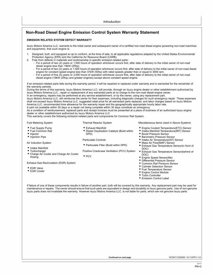
Non-Road Diesel Engine Emission Control System Warranty Statement
EMISSION RELATED SYSTEM DEFECT WARRANTY
Isuzu Motors America LLC. warrants to the initial owner and subsequent owner of a certified non-road diesel engine (powering non-road machinesand equipment), that such engine is:
1. Designed, built, and equipped so as to conform, at the time of sale, to all applicable regulations adapted by the United States EnvironmentalProtection Agency (EPA) and the California Air Resource Board (CARB).
2. Free from defects in materials and workmanship in specific emission-related parts:- For a period of two (2) years or 1,500 hours of operation whichever occurs first, after date of delivery to the initial owner of non-roaddiesel engine less than 19kW (25hp).
- For a period of two (2) years or 1,500 hours of operation whichever occurs first, after date of delivery to the initial owner of non-road dieselengine for constant speed engine less than 37kW (50hp) with rated speeds greater than or equal to 3000 rpm.
- For a period of five (5) years or 3,000 hours of operation whichever occurs first, after date of delivery to the initial owner of non-roaddiesel engine (19kW (25hp) and greater engines) except above constant speed engine.
If an emission-related parts fails during the warranty period, it will be repaired or replaced under warranty and is warranted for the remainder ofthe warranty periods.During the terms of this warranty, Isuzu Motors America LLC. will provide, through an Isuzu engine dealer or other establishment authorized byIsuzu Motors America LLC., repair or replacement of any warranted parts at no charge to the non-road diesel engine owner.In an emergency, repairs may be performed at any service establishment, or by the owner, using any replacement part.Isuzu Motors America LLC. will reimburse the owner for their expenses, including diagnostic charges for such emergency repair. These expensesshall not exceed Isuzu Motors America LLC. suggested retail price for all warranted parts replaced, and labor charges based on Isuzu MotorsAmerica LLC. recommended time allowance for the warranty repair and the geographically appropriate hourly labor rate.A part not available within 30 days or a repair not being complete within 30 days constitute an emergency.As a condition of reimbursement, replaced parts and receipt invoices must be presented at a place of business of an authorized Isuzu enginedealer or other establishment authorized by Isuzu Motors America LLC.This warranty covers the following emission-related parts and components for Common Rail System.
Fuel Metering System
• Fuel Supply Pump• Fuel Common Rail• Injector• Injection Pipe
Air Induction System
• Intake Manifold• Turbocharger• Charge Air Cooler and Charge Air CoolerHosing
Exhasut Gas Recirculation (EGR) System
• EGR Valve• EGR Cooler
Thermal Reactor System
• Exhaust Manifold• Diesel Oxydization Catalyst (Build withinDPD)
Particulate Controls
• Particulate Filter (Build within DPD)
Positive Crankcase Ventilation (PCV) System
• PCV
Miscellaneous items Used in Above Systems
• Engine Coolant Temperature(ETC) Sensor• Intake Manifold Temperature(IMT) Sensor• Boost Pressure Sensor• Barometric Pressure Sensor• Intake Air Temperature(IAT) Sensor• Mass Air Flow(MAF) Sensor• Exhaust Gas Temperature Sensor(in front ofDOC)• Exhaust Gas Temperature Sensor(behind ofDOC)• Engine Speed Sensor(Ne)• Differential Pressure Sensor• Common Rail Pressure Sensor• Cylinder Detection Sensor• Fuel Temperature Sensor• Engine Control Module• Turbo Controller• Emission Control Label
If failure of one of these components results in failure of another part, both will be covered by this warranty. Any replacement part may be used formaintenance or repairs. The owner should ensure that such parts are equivalent in design and durability to Isuzu genuine parts. Use of non-genuineIsuzu parts does not invalidate the warranty. However Isuzu Motors America LLC. is not liable for parts, which are not genuine Isuzu parts.
053113
PN=3

Introduction
VD76477,0000582 -19-11APR11-2/2
LIMITATIONS AND RESPONSIBILITIES
These warranties are subject to the following:
ISUZU MOTORS AMERICA LLC. RESPONSIBILITIESDuring the emission warranty period, if a defect in material or workmanship of a warranted part or component is found, Isuzu Motors AmericaLLC. will provide;
• New, remanufactured, or repaired parts and/or components required to correct the defect. Note: Items replaced under this warranty become theproperty of Isuzu Motors America LLC.• Labor, during normal working hours, required to make the warranty repair. This includes diagnosis and labor to remove and install theengine, if necessary.
OWNER RESPONSIBILITIESDuring the emission warranty period, the owner is responsible for:
• The performance of all required maintenance. A warranty claim will not be denied because the scheduled maintenance was not performed.However, if the lack of required maintenance was the reason for the repair, then the claim will be denied.• Premium of overtime costs.• Costs to investigate complaints, which are not caused by a defect in Isuzu Motors America LLC. materialor workmanship.• Providing timely notice of a warrantable failure and promptly making the product available for repair.
LIMITATIONSIsuzu Motors America LLC. is not responsible for resultant damages to an emission-related part or component resulting from:
• Any application or installation Isuzu Motors America LLC. deems improper as explained in the Instruction Manual.• Attachments, accessory items, or parts not authorized for use by Isuzu Motors America LLC.• Improper non-road diesel engine maintenance, repair, or abuse.• Owner’s unreasonable delay in making the product available after being notified of a potential product problem. This warranty is in addition toIsuzu Motors America LLC. standard warranty, applicable to the non-road diesel engine product involved.
Remedies under this warranty are limited to the provision of material and services as specified herein. Isuzu Motors America LLC. is notresponsible for incidental or consequential damages such as downtime or lossuse of engine powered equipment.
053113
PN=4
Introduction
Continued on next page VD76477,0000584 -19-20APR11-1/2
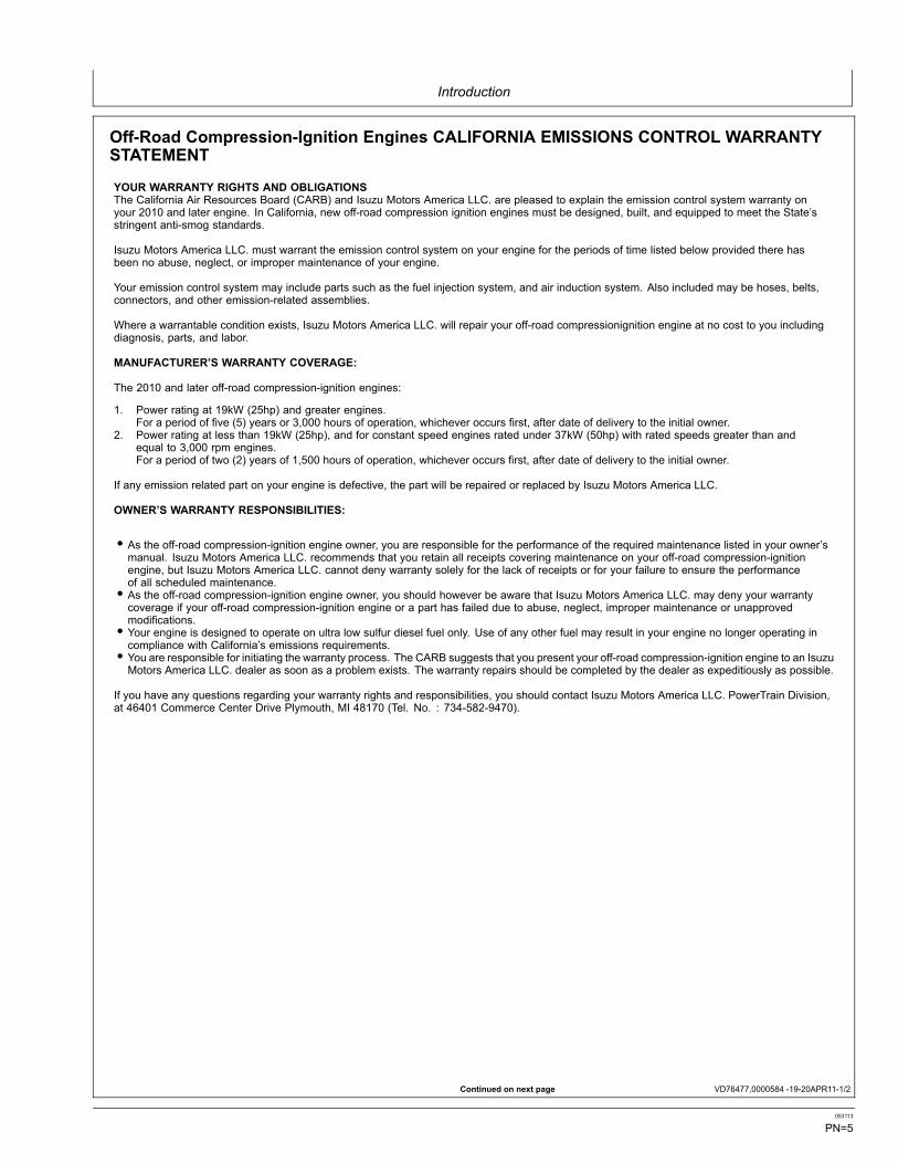
Off-Road Compression-Ignition Engines CALIFORNIA EMISSIONS CONTROL WARRANTYSTATEMENT
YOUR WARRANTY RIGHTS AND OBLIGATIONSThe California Air Resources Board (CARB) and Isuzu Motors America LLC. are pleased to explain the emission control system warranty onyour 2010 and later engine. In California, new off-road compression ignition engines must be designed, built, and equipped to meet the State’sstringent anti-smog standards.
Isuzu Motors America LLC. must warrant the emission control system on your engine for the periods of time listed below provided there hasbeen no abuse, neglect, or improper maintenance of your engine.
Your emission control system may include parts such as the fuel injection system, and air induction system. Also included may be hoses, belts,connectors, and other emission-related assemblies.
Where a warrantable condition exists, Isuzu Motors America LLC. will repair your off-road compressionignition engine at no cost to you includingdiagnosis, parts, and labor.
MANUFACTURER’S WARRANTY COVERAGE:
The 2010 and later off-road compression-ignition engines:
1. Power rating at 19kW (25hp) and greater engines.For a period of five (5) years or 3,000 hours of operation, whichever occurs first, after date of delivery to the initial owner.
2. Power rating at less than 19kW (25hp), and for constant speed engines rated under 37kW (50hp) with rated speeds greater than andequal to 3,000 rpm engines.For a period of two (2) years of 1,500 hours of operation, whichever occurs first, after date of delivery to the initial owner.
If any emission related part on your engine is defective, the part will be repaired or replaced by Isuzu Motors America LLC.
OWNER’S WARRANTY RESPONSIBILITIES:
• As the off-road compression-ignition engine owner, you are responsible for the performance of the required maintenance listed in your owner’smanual. Isuzu Motors America LLC. recommends that you retain all receipts covering maintenance on your off-road compression-ignitionengine, but Isuzu Motors America LLC. cannot deny warranty solely for the lack of receipts or for your failure to ensure the performanceof all scheduled maintenance.• As the off-road compression-ignition engine owner, you should however be aware that Isuzu Motors America LLC. may deny your warrantycoverage if your off-road compression-ignition engine or a part has failed due to abuse, neglect, improper maintenance or unapprovedmodifications.• Your engine is designed to operate on ultra low sulfur diesel fuel only. Use of any other fuel may result in your engine no longer operating incompliance with California’s emissions requirements.• You are responsible for initiating the warranty process. The CARB suggests that you present your off-road compression-ignition engine to an IsuzuMotors America LLC. dealer as soon as a problem exists. The warranty repairs should be completed by the dealer as expeditiously as possible.
If you have any questions regarding your warranty rights and responsibilities, you should contact Isuzu Motors America LLC. PowerTrain Division,at 46401 Commerce Center Drive Plymouth, MI 48170 (Tel. No. : 734-582-9470).
053113
PN=5
Introduction
VD76477,0000584 -19-20APR11-2/2
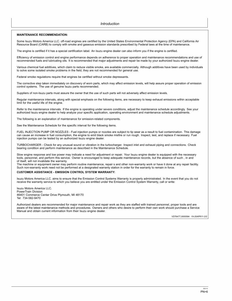
MAINTENANCE RECOMMENDATION:
Some Isuzu Motors America LLC. off-road engines are certified by the United States Environmental Protection Agency (EPA) and California AirResource Board (CARB) to comply with smoke and gaseous emission standards prescribed by Federal laws at the time of maintenance.
The engine is certified if it has a special certification label. An Isuzu engine dealer can also inform you if the engine is certified.
Efficiency of emission control and engine performance depends on adherence to proper operation and maintenance recommendations and use ofrecommended fuels and lubricating oils. It is recommended that major adjustments and repair be made by your authorized Isuzu engine dealer.
Various chemical fuel additives, which claim to reduce visible smoke, are available commercially. Although additives have been used by individualsto solve some isolated smoke problems in the field, they are not recommended for general use.
Federal smoke regulations require that engines be certified without smoke depressants.
The corrective step taken immediately on discovery of worn parts, which may affect emission levels, will help assure proper operation of emissioncontrol systems. The use of genuine Isuzu parts recommended.
Suppliers of non-Isuzu parts must assure the owner that the use of such parts will not adversely affect emission levels.
Regular maintenance intervals, along with special emphasis on the following items, are necessary to keep exhaust emissions within acceptablelimit for the useful life of the engine.
Refer to the maintenance intervals. If the engine is operating under severe conditions, adjust the maintenance schedule accordingly. See yourauthorized Isuzu engine dealer to help analyze your specific application, operating environment and maintenance schedule adjustments.
The following is an explanation of maintenance for emission-related components.
See the Maintenance Schedule for the specific interval for the following items.
FUEL INJECTION PUMP OR NOZZLES - Fuel injection pumps or nozzles are subject to tip wear as a result to fuel contamination. This damagecan cause an increase in fuel consumption, the engine to emit black smoke misfire or run rough. Inspect, test, and replace if necessary. Fuelinjection pumps can be tested by an authorized Isuzu engine dealer.
TURBOCHARGER - Check for any unusual sound or vibration in the turbocharger. Inspect inlet and exhaust piping and connections. Checkbearing condition and perform maintenance as described in the Maintenance Schedule.
Slow engine response and low power may indicate a need for adjustment or repair. Your Isuzu engine dealer is equipped with the necessarytools, personnel, and perform this service. Owner is encouraged to keep adequate maintenance records, but the absence of such , in andof itself, will not invalidate the warranty.The machine or equipment owner may perform routine maintenance, repair s and other non-warranty work or have it done at any repair facility.Such non-warranty work need not be performed at a designated warranty station in order for the warranty to remain in force.CUSTOMER ASSISTANCE - EMISSION CONTROL SYSTEM WARRANTY:
Isuzu Motors America LLC. aims to ensure that the Emission Control Systems Warranty is properly administrated. In the event that you do notreceive the warranty service to which you believe you are entitled under the Emission Control System Warranty, call or write:
Isuzu Motors America LLC.PowerTrain Division46401 Commerce Center Drive Plymouth, MI 48170Tel: 734-582-9470
Authorized dealers are recommended for major maintenance and repair work as they are staffed with trained personnel, proper tools and areaware of the latest maintenance methods and procedures. Owners and others who desire to perform their own work should purchase a ServiceManual and obtain current information from their Isuzu engine dealer.
053113
PN=6

Introduction
TX,TM,FAX -19-03JUL01-1/1
Technical Information Feedback FormWe need your help to continually improve our technicalpublications. Please copy this page and FAX or mail yourcomments, ideas and improvements.SEND TO: John Deere Dubuque Works
18600 South John Deere RoadAttn: Publications, Dept. 324Dubuque, IA 52004-0538USA
FAX NUMBER: 1-563-589-5800 (USA)
Publication Number:
Page Number:
Ideas, Comments:
Name:
Phone:
Email Address:
THANK YOU!
053113
PN=7

Introduction
053113
PN=8
Contents
Page
Safety—Safety and Operator ConveniencesSafety and Operator Convenience Features .....1-1-1
Safety—General PrecautionsRecognize Safety Information ...........................1-2-1Follow Safety Instructions..................................1-2-1Operate Only If Qualified ...................................1-2-1Wear Protective Equipment...............................1-2-2Avoid Unauthorized Machine Modifications.......1-2-2Add Cab Guarding for Special Uses..................1-2-2Inspect Machine ................................................1-2-2Stay Clear of Moving Parts................................1-2-3Avoid High-Pressure Fluids ...............................1-2-3Avoid High-Pressure Oils ..................................1-2-3Work In Ventilated Area.....................................1-2-4Prevent Fires .....................................................1-2-4Prevent Battery Explosions ...............................1-2-5Handle Chemical Products Safely .....................1-2-5Dispose of Waste Properly ................................1-2-5Prepare for Emergencies...................................1-2-6Clean Debris from Machine...............................1-2-6
Safety—Operating PrecautionsUse Steps and Handholds Correctly .................1-3-1Start Only From Operator's Seat .......................1-3-1Use and Maintain Seat Belt ...............................1-3-1Prevent Unintended Machine Movement ..........1-3-1Avoid Work Site Hazards...................................1-3-2Keep Riders Off Machine ..................................1-3-2Avoid Backover Accidents .................................1-3-3Avoid Machine Tip Over ....................................1-3-3Use Special Care When Lifting Objects ............1-3-4Add and Operate Attachments Safely ...............1-3-4Prevent Unintended Detonation of
Explosive Devices .........................................1-3-4
Safety—Maintenance PrecautionsPark and Prepare for Service Safely .................1-4-1Service Cooling System Safely .........................1-4-1Remove Paint Before Welding or Heating.........1-4-2Make Welding Repairs Safely ...........................1-4-2Drive Metal Pins Safely .....................................1-4-2
Safety—Safety SignsSafety Signs ......................................................1-5-1
Page
Operation—Operator's StationPedals, Levers, and Panels...............................2-1-1Switch Panel......................................................2-1-2Switch Panel Functions .....................................2-1-3Horn...................................................................2-1-3Pilot Shutoff Lever .............................................2-1-4Travel Alarm and Travel Alarm Cancel Switch ..2-1-5Right Enable Switch ..........................................2-1-5Engine Stop Knob..............................................2-1-6Cab Heater and Air Conditioner ........................2-1-7Selecting Display Between Celsius and
Fahrenheit .....................................................2-1-8Operating the AM/FM Radio..............................2-1-8Secondary Exit Tool...........................................2-1-9Opening Upper Front (Secondary Exit)
Window .......................................................2-1-10Removing and Storing the Lower Front
Window .......................................................2-1-11Opening Cab Window......................................2-1-11Adjusting the Seat ...........................................2-1-12
Operation—Monitor OperationMonitor...............................................................2-2-1Monitor Functions..............................................2-2-2Monitor Start-Up ................................................2-2-3Main Menu.........................................................2-2-4Time Set Menu ..................................................2-2-4Displaying Operating Conditions .......................2-2-5Maintenance Settings........................................2-2-6Screen Display When Scheduled
Maintenance is Due ......................................2-2-8Fuel Rate Display/No Display..........................2-2-10Language Settings...........................................2-2-11Alarm Occurrence Screen ...............................2-2-12
Operation—Operating the MachineBefore Starting Work .........................................2-3-1Operator's Daily Machine Check
Before Starting ..............................................2-3-1Starting Engine..................................................2-3-2Cold Weather Warm-Up ....................................2-3-4Travel Pedals and Levers..................................2-3-5Control Lever Pattern Operation........................2-3-6Mechanical Control Lever Pattern
Selector—If Equipped ...................................2-3-7
Continued on next page
Original Instructions. All information, illustrations and specifications in thismanual are based on the latest information available at the time of publication.
The right is reserved to make changes at any time without notice.COPYRIGHT © 2013DEERE & COMPANY
Moline, IllinoisAll rights reserved.
A John Deere ILLUSTRUCTION ® ManualPrevious Editions
Copyright © 2008, 2009, 2010, 2011
i 053113
PN=1
Contents
Page
Operating Blade.................................................2-3-7Operating In Water and Mud .............................2-3-8Driving Up a Steep or Slippery Slope................2-3-8Lifting.................................................................2-3-8Lower Boom With Engine Stopped....................2-3-9Parking Machine..............................................2-3-10Loading and Unloading for Transport ..............2-3-11Towing Machine...............................................2-3-12Lifting Machine ................................................2-3-12
Maintenance—MachineDiesel Fuel.........................................................3-1-1Lubricity of Diesel Fuel ......................................3-1-1Handling and Storing Diesel Fuel ......................3-1-2Biodiesel Fuel ....................................................3-1-3Testing Diesel Fuel ............................................3-1-4Minimizing the Effect of Cold Weather
on Diesel Engines .........................................3-1-5Alternative and Synthetic Lubricants .................3-1-6Diesel Engine Break-In™ Oil.............................3-1-6Diesel Engine Oil ...............................................3-1-7Diesel Engine Oil and Filter Service Intervals ...3-1-8Hydraulic Oil ......................................................3-1-9Travel Gear Case Oil .......................................3-1-10Track Adjuster, Working Tool Pivot,
Swing Bearing, and Swing BearingGear Grease ...............................................3-1-10
Heavy Duty Diesel Engine Coolant .................3-1-11Drain Intervals for Diesel Engine Coolant........3-1-11John Deere COOL-GARD™ II Coolant
Extender......................................................3-1-12Supplemental Coolant Additives......................3-1-12Operating in Warm Temperature Climates ......3-1-13Additional Information About Diesel
Engine Coolants and John DeereCOOL-GARD™ II Coolant Extender ...........3-1-14
Testing Diesel Engine Coolant.........................3-1-15
Maintenance—Periodic MaintenanceService Machine at Specified Intervals..............3-2-1Check the Hour Meter Regularly .......................3-2-1Prepare Machine for Maintenance ....................3-2-2Open Access Doors for Service ........................3-2-3Open Engine Hood for Service..........................3-2-3Fuel Tank...........................................................3-2-3Hydraulic Breaker and Crusher Attachments ....3-2-4Fluid Analysis Program Test Kits and
3-Way Coolant Test Kit..................................3-2-4Periodic Maintenance Record Keeping
System ..........................................................3-2-5
Maintenance—As RequiredCheck and Adjust Track Sag .............................3-3-1Clean Fuel Tank Inlet Screen ............................3-3-3Drain Fuel Tank Sump.......................................3-3-4Drain Water Separator.......................................3-3-4Check and Adjust A/C Belt ................................3-3-5
Page
Clean Radiator Air Inlet Screen.........................3-3-5Check Windshield Washer Fluid Level ..............3-3-6Clean Air Cleaner Dust Valve ............................3-3-6Check Coolant ...................................................3-3-7
Maintenance—Every 10 Hours or DailyCheck Hydraulic Tank Oil Level.........................3-4-1Check Engine Oil Level .....................................3-4-3Check Recovery Tank Coolant Level.................3-4-4
Maintenance—Initial Service—50 HoursInspect and Re-Torque Track Hardware............3-5-1
Maintenance—Every 100 HoursGrease Bucket Pivot Pins..................................3-6-1Grease Working Tool Pivots ..............................3-6-2
Maintenance—Every 250 HoursGrease Blade.....................................................3-7-1Drain Hydraulic Tank Sump...............................3-7-1Check Travel Gear Case Oil Level ....................3-7-2Check Battery Electrolyte Level and Terminals ..3-7-3Clean or Replace Primary Air Cleaner
Element .........................................................3-7-5Inspect and Re-Torque Track Hardware............3-7-6Take Engine Oil Sample ....................................3-7-6
Maintenance—Every 500 HoursReplace Fuel Filter ............................................3-8-1Replace Water Separator Element....................3-8-1Clean Fuel Pump Strainer .................................3-8-2Change Engine Oil and Replace Filter ..............3-8-2Check Air Intake Hoses.....................................3-8-3Grease Swing Bearing.......................................3-8-4Check Cab Fresh Air Filter ................................3-8-4Check Cab Recirculating Air Filter.....................3-8-5Grease Swing Bearing Gear..............................3-8-6Take Fluid Samples ...........................................3-8-6
Maintenance—Every 1000 HoursReplace Hydraulic Oil Tank Filter ......................3-9-1Replace Pilot System Oil Filter ..........................3-9-2Adjust Engine Valve Clearance .........................3-9-2Check and Adjust Fan Belt Tension...................3-9-3Replace Air Cleaner Elements and
Dust Valve .....................................................3-9-4Check Coolant ...................................................3-9-5
Maintenance—Every 2000 HoursClean the Engine Crankcase
Ventilation Tube...........................................3-10-1Change Travel Gear Case Oil .........................3-10-1
Maintenance—Every 5000 HoursReplace Swing Motor and Gear Case Filter ....3-11-1
Continued on next page
ii 053113
PN=2

Contents
Page
Change Hydraulic Tank Oil, CleanSuction Screen............................................3-11-2
Maintenance—Every 6000 HoursDrain Cooling System......................................3-12-1Cooling System Fill and Deaeration
Procedure....................................................3-12-3
Miscellaneous—MachineBleed Fuel System - Electric Fuel Pump...........4-1-1Do Not Service or Adjust Injection
Nozzles or High Pressure Fuel Pump ...........4-1-1Do Not Service Control Valves,
Cylinders, Pumps, or Motors.........................4-1-1Precautions for Alternator and Regulator ..........4-1-2Handling, Checking, and Servicing
Batteries Carefully.........................................4-1-3Using Booster Batteries—24-Volt System.........4-1-4Using Battery Charger .......................................4-1-5Replacing Batteries ...........................................4-1-5Fluid Sampling Test Ports—If Equipped............4-1-6Welding On Machine .........................................4-1-6Welding Near Electronic Control Units ..............4-1-6Keep Electronic Control Unit
Connectors Clean .........................................4-1-7Clean the Machine Regularly ............................4-1-7Adding 12-Volt Accessories...............................4-1-7JDLink™ Machine Monitoring System
(MMS)—If Equipped......................................4-1-7Replacing Fuses................................................4-1-8Replacing Bucket Teeth...................................4-1-12Replacing Bucket Tooth
Tip—Heavy-Duty Bucket .............................4-1-12Removing Bucket ............................................4-1-13Track Sag General Information .......................4-1-13Hardware Torque Specifications......................4-1-13Unified Inch Bolt and Screw Torque Values.....4-1-14Metric Bolt and Screw Torque Values..............4-1-15
Miscellaneous—Operational CheckoutOperational Checkout........................................4-2-1
Miscellaneous—TroubleshootingTroubleshooting Procedure ...............................4-3-1Engine ...............................................................4-3-2Electrical System...............................................4-3-6Hydraulic System...............................................4-3-8
Miscellaneous—StoragePrepare Machine for Storage ............................4-4-1Monthly Storage Procedure...............................4-4-2
Miscellaneous—Machine NumbersRecord Product Identification Number (PIN) .....4-5-1Record Engine Serial Number...........................4-5-1Record Travel Motor Serial Numbers ................4-5-1Record Swing Motor Serial Number ..................4-5-2Record Hydraulic Pump Serial Number.............4-5-2
Page
Keep Proof of Ownership ..................................4-5-2Keep Machines Secure .....................................4-5-3
Miscellaneous—Specifications85D Engine Specifications.................................4-6-185D Drain and Refill Capacities.........................4-6-185D Machine Specifications ..............................4-6-285D Working Ranges ........................................4-6-4Lift Capacity—85D, Arm: 1.62 m (5 ft 4
in.), 450 mm (18 in.) Rubber Pads................4-6-5Lift Capacity—85D, Arm: 1.62 m (5 ft 4
in.), Shoe: 600 mm (24 in.) ...........................4-6-6Lift Capacity—85D, Arm: 1.62 m (5 ft
4 in.), 450 mm (18 in.) ContinuousRubber Belt ...................................................4-6-7
Lift Capacity—85D, Arm: 2.12 m (6 ft11 in.), 450 mm (18 in.) Rubber Pads ...........4-6-8
Lift Capacity—85D, Arm: 2.12 m (6 ft11 in.), Shoe: 600 mm (24 in.).......................4-6-9
Lift Capacity—85D, Arm: 2.12 m (6 ft11 in.), 450 mm (18 in.) ContinuousRubber Belt .................................................4-6-10
iii 053113
PN=3

Contents
iv 053113
PN=4
Safety—Safety and Operator Conveniences
OUT4001,0000003 -19-07MAR08-1/1
Safety and Operator Convenience Features
TX1037498—UN—26FE
B08
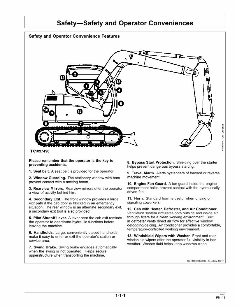
Please remember that the operator is the key topreventing accidents.
1. Seat belt. A seat belt is provided for the operator.
2. Window Guarding. The stationary window with barsprevent contact with a moving boom.
3. Rearview Mirrors. Rearview mirrors offer the operatora view of activity behind him.
4. Secondary Exit. The front window provides a largeexit path if the cab door is blocked in an emergencysituation. The rear window is an alternate secondary exit,a secondary exit tool is also provided.
5. Pilot Shutoff Lever. A lever near the cab exit remindsthe operator to deactivate hydraulic functions beforeleaving the machine.
6. Handholds. Large, conveniently placed handholdsmake it easy to enter or exit the operator's station orservice area.
7. Swing Brake. Swing brake engages automaticallywhen the swing is not operated. Helps secureupperstructure when transporting the machine.
8. Bypass Start Protection. Shielding over the starterhelps prevent dangerous bypass starting.
9. Travel Alarm. Alerts bystanders of forward or reversemachine movement.
10. Engine Fan Guard. A fan guard inside the enginecompartment helps prevent contact with the hydraulicallydriven fan.
11. Horn. Standard horn is useful when driving orsignaling coworkers.
12. Cab with Heater, Defroster, and Air Conditioner.Ventilation system circulates both outside and inside airthrough filters for a clean working environment. Builtin defroster vents direct air flow for effective windowdefogging/deicing. Air conditioner provides a comfortable,temperature-controlled working environment.
13. Windshield Wipers with Washer. Front and rearwindshield wipers offer the operator full visibility in badweather. Washer fluid helps keep windows clean.
1-1-1 053113
PN=13
Safety—General Precautions
TX,RECOGNIZE -19-28JUN10-1/1
TX,FOLLOW -19-20JAN11-1/1
TX,QUALIFIED -19-18JAN11-1/1
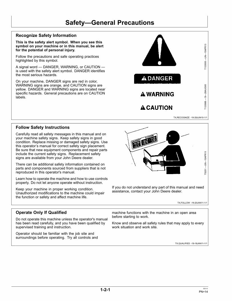
Recognize Safety InformationThis is the safety alert symbol. When you see thissymbol on your machine or in this manual, be alertfor the potential of personal injury.
Follow the precautions and safe operating practiceshighlighted by this symbol.
A signal word — DANGER, WARNING, or CAUTION —is used with the safety alert symbol. DANGER identifiesthe most serious hazards.
On your machine, DANGER signs are red in color,WARNING signs are orange, and CAUTION signs areyellow. DANGER and WARNING signs are located nearspecific hazards. General precautions are on CAUTIONlabels.
T133555—UN—15APR13
T133588—19—28AUG00
Follow Safety InstructionsCarefully read all safety messages in this manual and onyour machine safety signs. Keep safety signs in goodcondition. Replace missing or damaged safety signs. Usethis operator’s manual for correct safety sign placement.Be sure that new equipment components and repair partsinclude the current safety signs. Replacement safetysigns are available from your John Deere dealer.
There can be additional safety information contained onparts and components sourced from suppliers that is notreproduced in this operator's manual.
Learn how to operate the machine and how to use controlsproperly. Do not let anyone operate without instruction.
Keep your machine in proper working condition.Unauthorized modifications to the machine could impairthe function or safety and affect machine life.
TS201—UN—15APR13
If you do not understand any part of this manual and needassistance, contact your John Deere dealer.
Operate Only If QualifiedDo not operate this machine unless the operator's manualhas been read carefully, and you have been qualified bysupervised training and instruction.
Operator should be familiar with the job site andsurroundings before operating. Try all controls and
machine functions with the machine in an open areabefore starting to work.
Know and observe all safety rules that may apply to everywork situation and work site.
1-2-1 053113
PN=14
Safety—General Precautions
TX,WEAR,PE -19-22SEP10-1/1
AM40430,00000A9 -19-20AUG09-1/1
TX,CABGUARD -19-12FEB13-1/1
TX,INSPECT -19-08SEP10-1/1
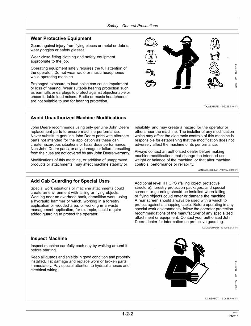
Wear Protective EquipmentGuard against injury from flying pieces or metal or debris;wear goggles or safety glasses.
Wear close fitting clothing and safety equipmentappropriate to the job.
Operating equipment safely requires the full attention ofthe operator. Do not wear radio or music headphoneswhile operating machine.
Prolonged exposure to loud noise can cause impairmentor loss of hearing. Wear suitable hearing protection suchas earmuffs or earplugs to protect against objectionable oruncomfortable loud noises. Radio or music headphonesare not suitable to use for hearing protection.
TS206—UN—15APR13
Avoid Unauthorized Machine Modifications
John Deere recommends using only genuine John Deerereplacement parts to ensure machine performance.Never substitute genuine John Deere parts with alternateparts not intended for the application as these cancreate hazardous situations or hazardous performance.Non-John Deere parts, or any damage or failures resultingfrom their use are not covered by any John Deere warranty.
Modifications of this machine, or addition of unapprovedproducts or attachments, may affect machine stability or
reliability, and may create a hazard for the operator orothers near the machine. The installer of any modificationwhich may affect the electronic controls of this machine isresponsible for establishing that the modification does notadversely affect the machine or its performance.
Always contact an authorized dealer before makingmachine modifications that change the intended use,weight or balance of the machine, or that alter machinecontrols, performance or reliability.
Add Cab Guarding for Special UsesSpecial work situations or machine attachments couldcreate an environment with falling or flying objects.Working near an overhead bank, demolition work, usinga hydraulic hammer or winch, working in a forestryapplication or wooded area, or working in a wastemanagement application, for example, could requireadded guarding to protect the operator.
Additional level II FOPS (falling object protectivestructure), forestry protection packages, and specialscreens or guarding should be installed when fallingor flying objects could enter or damage the machine.A rear screen should always be used with a winch toprotect against a snapping cable. Before operating in anyspecial work environments, follow the operator protectionrecommendations of the manufacturer of any specializedattachment or equipment. Contact your authorized JohnDeere dealer for information on protective guarding.
Inspect MachineInspect machine carefully each day by walking around itbefore starting.
Keep all guards and shields in good condition and properlyinstalled. Fix damage and replace worn or broken partsimmediately. Pay special attention to hydraulic hoses andelectrical wiring.
T6607A
Q—UN—15APR13
1-2-2 053113
PN=15

Safety—General Precautions
TX,MOVING,PARTS -19-20JAN11-1/1
DX,FLUID -19-12OCT11-1/1
TX,HPOILS -19-20JAN11-1/1
Stay Clear of Moving PartsEntanglements in moving parts can cause serious injury.
Stop engine before examining, adjusting, or maintainingany part of machine with moving parts.
Keep guards and shields in place. Replace any guardor shield that has been removed for access as soon asservice or repair is complete. T1
33592—UN—15APR13
Avoid High-Pressure FluidsInspect hydraulic hoses periodically – at least onceper year – for leakage, kinking, cuts, cracks, abrasion,blisters, corrosion, exposed wire braid or any other signsof wear or damage.
Replace worn or damaged hose assemblies immediatelywith John Deere approved replacement parts.
Escaping fluid under pressure can penetrate the skincausing serious injury.
Avoid the hazard by relieving pressure beforedisconnecting hydraulic or other lines. Tighten allconnections before applying pressure.
Search for leaks with a piece of cardboard. Protect handsand body from high-pressure fluids.
If an accident occurs, see a doctor immediately. Any fluidinjected into the skin must be surgically removed withina few hours or gangrene may result. Doctors unfamiliar
X9811
—UN—23AUG88
with this type of injury should reference a knowledgeablemedical source. Such information is available inEnglish from Deere & Company Medical Department inMoline, Illinois, U.S.A., by calling 1-800-822-8262 or +1309-748-5636.
Avoid High-Pressure OilsThis machine uses a high-pressure hydraulic system.Escaping oil under pressure can penetrate the skincausing serious injury.
Never search for leaks with your hands. Protect hands.Use a piece of cardboard to find location of escaping oil.Stop engine and relieve pressure before disconnectinglines or working on hydraulic system.
If hydraulic oil penetrates your skin, see a doctorimmediately. Injected oil must be removed surgicallywithin hours or gangrene could result. Contact aknowledgeable medical source or the Deere & CompanyMedical Department in Moline, Illinois, U.S.A.
T133509—UN—15APR13
T133840—UN—20SEP00
1-2-3 053113
PN=16
Safety—General Precautions
DX,AIR -19-17FEB99-1/1
TX,PREVENT,FIRE -19-20JAN11-1/1
Work In Ventilated AreaEngine exhaust fumes can cause sickness or death. Ifit is necessary to run an engine in an enclosed area,remove the exhaust fumes from the area with an exhaustpipe extension.
If you do not have an exhaust pipe extension, open thedoors and get outside air into the area.
TS220—UN—15APR13
Prevent FiresHandle Fuel Safely: Store flammable fluids away fromfire hazards. Never refuel machine while smoking or whennear sparks or flame.
Clean Machine Regularly: Keep trash, debris, greaseand oil from accumulating in engine compartment, aroundfuel lines, hydraulic lines, exhaust components, andelectrical wiring. Never store oily rags or flammablematerials inside a machine compartment.
Maintain Hoses and Wiring: Replace hydraulic hosesimmediately if they begin to leak, and clean up any oilspills. Examine electrical wiring and connectors frequentlyfor damage.
Keep A Fire Extinguisher Available: Always keep amultipurpose fire extinguisher on or near the machine.Know how to use extinguisher properly.
T133552—UN—15APR13
T133553 —UN—07SEP00
T133554 —UN—07SEP00
1-2-4 053113
PN=17
Safety—General Precautions
DX,SPARKS -19-03MAR93-1/1
DX,MSDS,NA -19-03MAR93-1/1
DX,DRAIN -19-03MAR93-1/1
Prevent Battery ExplosionsKeep sparks, lighted matches, and open flame away fromthe top of battery. Battery gas can explode.
Never check battery charge by placing a metal objectacross the posts. Use a volt-meter or hydrometer.
Do not charge a frozen battery; it may explode. Warmbattery to 16°C (60°F).
TS204—UN—15APR13
Handle Chemical Products SafelyDirect exposure to hazardous chemicals can causeserious injury. Potentially hazardous chemicals used withJohn Deere equipment include such items as lubricants,coolants, paints, and adhesives.
A Material Safety Data Sheet (MSDS) provides specificdetails on chemical products: physical and health hazards,safety procedures, and emergency response techniques.
Check the MSDS before you start any job using ahazardous chemical. That way you will know exactly whatthe risks are and how to do the job safely. Then followprocedures and recommended equipment.
(See your John Deere dealer for MSDS’s on chemicalproducts used with John Deere equipment.)
TS1132
—UN—15APR13
Dispose of Waste ProperlyImproperly disposing of waste can threaten theenvironment and ecology. Potentially harmful waste usedwith John Deere equipment include such items as oil, fuel,coolant, brake fluid, filters, and batteries.
Use leakproof containers when draining fluids. Do not usefood or beverage containers that may mislead someoneinto drinking from them.
Do not pour waste onto the ground, down a drain, or intoany water source.
Air conditioning refrigerants escaping into the air candamage the Earth’s atmosphere. Government regulationsmay require a certified air conditioning service center torecover and recycle used air conditioning refrigerants.
Inquire on the proper way to recycle or dispose of wastefrom your local environmental or recycling center, or fromyour John Deere dealer.
TS1133
—UN—15APR13
1-2-5 053113
PN=18
Safety—General Precautions
DX,FIRE2 -19-03MAR93-1/1
TX,DEBRIS -19-20JAN11-1/1
Prepare for EmergenciesBe prepared if a fire starts.
Keep a first aid kit and fire extinguisher handy.
Keep emergency numbers for doctors, ambulance service,hospital, and fire department near your telephone.
TS291—UN—15APR13
Clean Debris from MachineKeep engine compartment, radiator, batteries, hydrauliclines, exhaust components, fuel tank, and operator'sstation clean and free of debris.
Clean any oil spills or fuel spills on machine surfaces.
Temperature in engine compartment could go upimmediately after engine is stopped. BE ON GUARDFOR FIRES DURING THIS PERIOD.
Open access door(s) to cool the engine faster, and cleanengine compartment. T6
669A
G—UN—15APR13
1-2-6 053113
PN=19
Safety—Operating Precautions
TX,STEPS -19-09FEB11-1/1
TX,SOFOS -19-20JAN11-1/1
TX,SEAT,BELT -19-20JAN11-1/1
DW90712,00002C1 -19-07MAR08-1/1
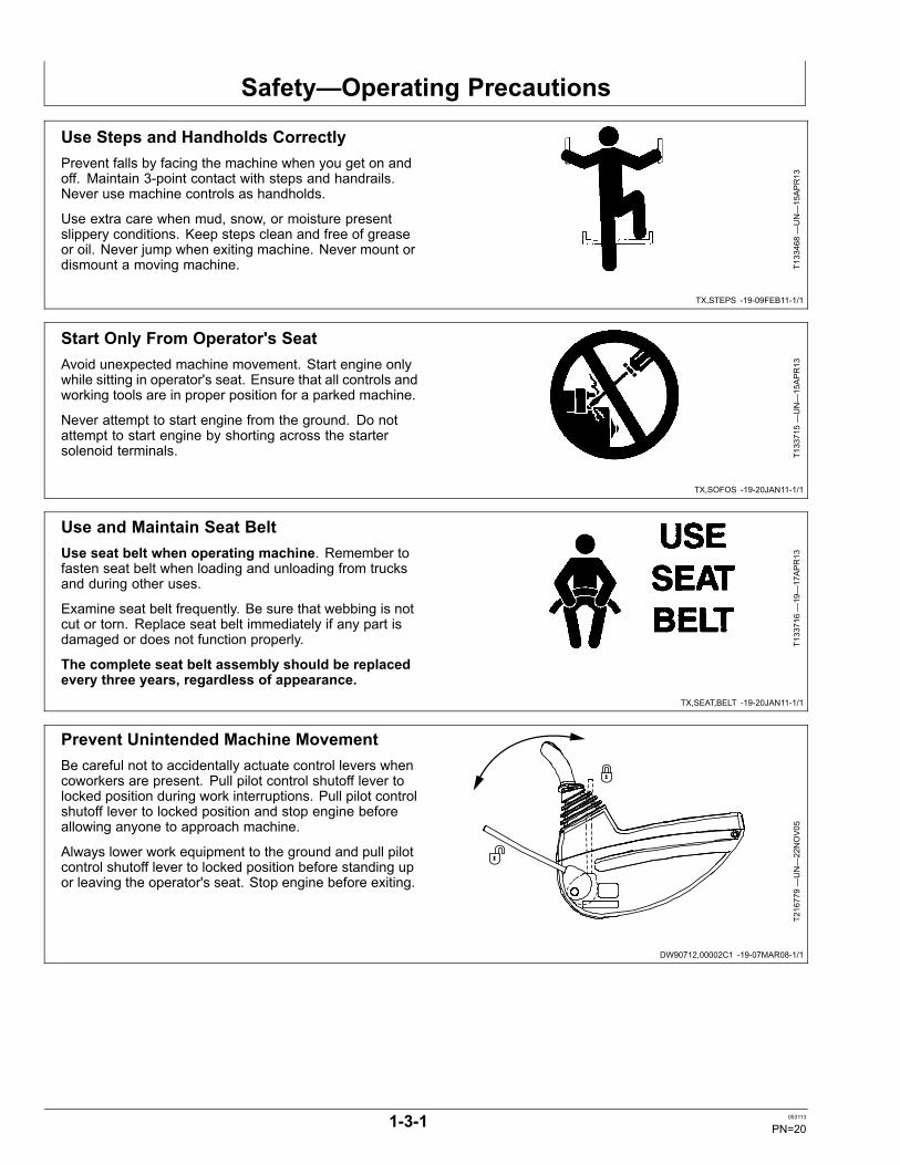
Use Steps and Handholds CorrectlyPrevent falls by facing the machine when you get on andoff. Maintain 3-point contact with steps and handrails.Never use machine controls as handholds.
Use extra care when mud, snow, or moisture presentslippery conditions. Keep steps clean and free of greaseor oil. Never jump when exiting machine. Never mount ordismount a moving machine. T1
33468—UN—15APR13
Start Only From Operator's SeatAvoid unexpected machine movement. Start engine onlywhile sitting in operator's seat. Ensure that all controls andworking tools are in proper position for a parked machine.
Never attempt to start engine from the ground. Do notattempt to start engine by shorting across the startersolenoid terminals. T1
33715—UN—15APR13
Use and Maintain Seat BeltUse seat belt when operating machine. Remember tofasten seat belt when loading and unloading from trucksand during other uses.
Examine seat belt frequently. Be sure that webbing is notcut or torn. Replace seat belt immediately if any part isdamaged or does not function properly.
The complete seat belt assembly should be replacedevery three years, regardless of appearance.
T133716—19—17APR13
Prevent Unintended Machine MovementBe careful not to accidentally actuate control levers whencoworkers are present. Pull pilot control shutoff lever tolocked position during work interruptions. Pull pilot controlshutoff lever to locked position and stop engine beforeallowing anyone to approach machine.
Always lower work equipment to the ground and pull pilotcontrol shutoff lever to locked position before standing upor leaving the operator's seat. Stop engine before exiting.
T216779—UN—22NOV05
1-3-1 053113
PN=20
Safety—Operating Precautions
TX03679,0001748 -19-09JUL12-1/1
TX03679,0001726 -19-03JAN07-1/1
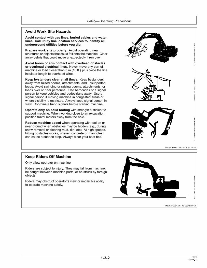
Avoid Work Site HazardsAvoid contact with gas lines, buried cables and waterlines. Call utility line location services to identify allunderground utilities before you dig.
Prepare work site properly. Avoid operating nearstructures or objects that could fall onto the machine. Clearaway debris that could move unexpectedly if run over.
Avoid boom or arm contact with overhead obstaclesor overhead electrical lines. Never move any part ofmachine or load closer than 3 m (10 ft.) plus twice the lineinsulator length to overhead wires.
Keep bystanders clear at all times. Keep bystandersaway from raised booms, attachments, and unsupportedloads. Avoid swinging or raising booms, attachments, orloads over or near personnel. Use barricades or a signalperson to keep vehicles and pedestrians away. Use asignal person if moving machine in congested areas orwhere visibility is restricted. Always keep signal person inview. Coordinate hand signals before starting machine.
Operate only on solid footing with strength sufficient tosupport machine. When working close to an excavation,position travel motors away from the hole.
Reduce machine speed when operating with tool on ornear ground when obstacles may be hidden (e.g., duringsnow removal or clearing mud, dirt, etc). At high speeds,hitting obstacles (rocks, uneven concrete or manholes)can cause a sudden stop. Always wear your seat belt.
T134986—UN—31OCT00
T133650—UN—27SEP00
T133549—UN—24AUG00
Keep Riders Off MachineOnly allow operator on machine.
Riders are subject to injury. They may fall from machine,be caught between machine parts, or be struck by foreignobjects.
Riders may obstruct operator’s view or impair his abilityto operate machine safely.
T7273A
H—UN—08JU
N90
1-3-2 053113
PN=21
Safety—Operating Precautions
TX,AVOID,BACKOVER -19-25OCT10-1/1
TX03679,00016DF -19-03JAN07-1/1
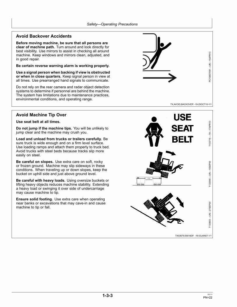
Avoid Backover AccidentsBefore moving machine, be sure that all persons areclear of machine path. Turn around and look directly forbest visibility. Use mirrors to assist in checking all aroundmachine. Keep windows and mirrors clean, adjusted, andin good repair.
Be certain reverse warning alarm is working properly.
Use a signal person when backing if view is obstructedor when in close quarters. Keep signal person in view atall times. Use prearranged hand signals to communicate.
Do not rely on the rear camera and radar object detectionsystems to determine if personnel are behind the machine.The system has limitations due to maintenance practices,environmental conditions, and operating range.
PC10857X
W—UN—15APR13
Avoid Machine Tip OverUse seat belt at all times.
Do not jump if the machine tips. You will be unlikely tojump clear and the machine may crush you.
Load and unload from trucks or trailers carefully. Besure truck is wide enough and on a firm level surface.Use loading ramps and attach them properly to truck bed.Avoid trucks with steel beds because tracks slip moreeasily on steel.
Be careful on slopes. Use extra care on soft, rockyor frozen ground. Machine may slip sideways in theseconditions. When traveling up or down slopes, keep thebucket on uphill side and just above ground level.
Be careful with heavy loads. Using oversize buckets orlifting heavy objects reduces machine stability. Extendinga heavy load or swinging it over side of undercarriagemay cause machine to tip.
Ensure solid footing. Use extra care when operatingnear banks or excavations that may cave-in and causemachine to tip or fall.
T133716—19—17APR13
T133545—UN—15SEP00
T133803—UN—27SEP00
1-3-3 053113
PN=22

Safety—Operating Precautions
TX03679,00016E1 -19-03JAN07-1/1
TX,ATTACH -19-20JAN11-1/1
VD76477,0001543 -19-08JAN08-1/1
Use Special Care When Lifting ObjectsNever use this machine to lift people.
Never lift a load above another person. Keep bystandersclear of all areas where a load might fall if it breaks free.Do not leave the seat when there is a raised load.
Do not exceed lift capacity limits posted on machine andin this manual. Extending heavy loads too far or swingingover undercarriage side may cause machine to tip over.
Use proper rigging to attach and stabilize loads. Be sureslings or chains have adequate capacity and are in goodcondition. Use tether lines to guide loads and prearrangedhand signals to communicate with co-workers.
T133839—UN—27SEP00
Add and Operate Attachments SafelyAlways verify compatibility of attachments by contactingyour authorized dealer. Adding unapproved attachmentscould affect machine stability or reliability and could createa hazard for others near the machine.
Ensure that a qualified person is involved in attachmentinstallation. Add guards to machine if operator protection
is required or recommended. Verify that all connectionsare secure and attachment responds properly to controls.
Carefully read attachment manual and follow allinstructions and warnings. In an area free of bystandersand obstructions, carefully operate attachment to learn itscharacteristics and range of motion.
Prevent Unintended Detonation of ExplosiveDevicesAvoid serious injury or death from an explosion hazard.Deactivate all cellular or radio frequency devices onequipment stored or operating in an area, such as ablasting zone, where the use of radio transmitting devicesare prohibited.
TX1023216—UN—07MAY
07
1-3-4 053113
PN=23
Safety—Maintenance Precautions
TX,PARK,EXC -19-30JUN10-1/1
DX,RCAP -19-04JUN90-1/1
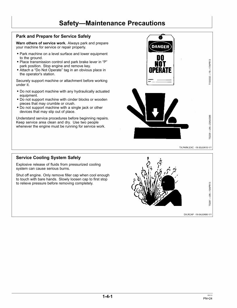
Park and Prepare for Service SafelyWarn others of service work. Always park and prepareyour machine for service or repair properly.
• Park machine on a level surface and lower equipmentto the ground.• Place transmission control and park brake lever in “P”park position. Stop engine and remove key.• Attach a “Do Not Operate” tag in an obvious place inthe operator's station.
Securely support machine or attachment before workingunder it.
• Do not support machine with any hydraulically actuatedequipment.• Do not support machine with cinder blocks or woodenpieces that may crumble or crush.• Do not support machine with a single jack or otherdevices that may slip out of place.
Understand service procedures before beginning repairs.Keep service area clean and dry. Use two peoplewhenever the engine must be running for service work.
T133332—19—17APR13
TS229—UN—23AUG88
Service Cooling System SafelyExplosive release of fluids from pressurized coolingsystem can cause serious burns.
Shut off engine. Only remove filler cap when cool enoughto touch with bare hands. Slowly loosen cap to first stopto relieve pressure before removing completely.
TS281—UN—15APR13
1-4-1 053113
PN=24
Safety—Maintenance Precautions
DX,PAINT -19-24JUL02-1/1
MB60223,0000212 -19-31MAY12-1/1
TX,PINS -19-20JAN11-1/1
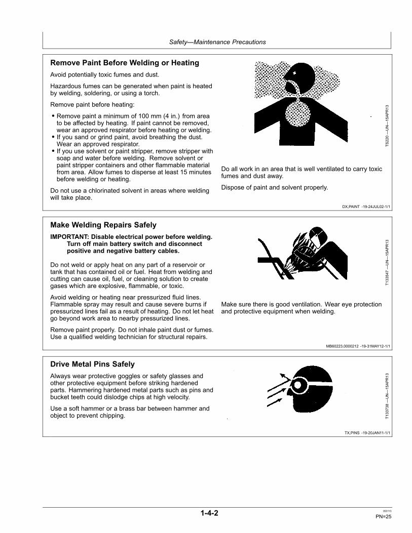
Remove Paint Before Welding or HeatingAvoid potentially toxic fumes and dust.
Hazardous fumes can be generated when paint is heatedby welding, soldering, or using a torch.
Remove paint before heating:
• Remove paint a minimum of 100 mm (4 in.) from areato be affected by heating. If paint cannot be removed,wear an approved respirator before heating or welding.• If you sand or grind paint, avoid breathing the dust.Wear an approved respirator.• If you use solvent or paint stripper, remove stripper withsoap and water before welding. Remove solvent orpaint stripper containers and other flammable materialfrom area. Allow fumes to disperse at least 15 minutesbefore welding or heating.
Do not use a chlorinated solvent in areas where weldingwill take place.
TS220—UN—15APR13
Do all work in an area that is well ventilated to carry toxicfumes and dust away.
Dispose of paint and solvent properly.
Make Welding Repairs SafelyIMPORTANT: Disable electrical power before welding.
Turn off main battery switch and disconnectpositive and negative battery cables.
Do not weld or apply heat on any part of a reservoir ortank that has contained oil or fuel. Heat from welding andcutting can cause oil, fuel, or cleaning solution to creategases which are explosive, flammable, or toxic.
Avoid welding or heating near pressurized fluid lines.Flammable spray may result and cause severe burns ifpressurized lines fail as a result of heating. Do not let heatgo beyond work area to nearby pressurized lines.
Remove paint properly. Do not inhale paint dust or fumes.Use a qualified welding technician for structural repairs.
T133547—UN—15APR13
Make sure there is good ventilation. Wear eye protectionand protective equipment when welding.
Drive Metal Pins SafelyAlways wear protective goggles or safety glasses andother protective equipment before striking hardenedparts. Hammering hardened metal parts such as pins andbucket teeth could dislodge chips at high velocity.
Use a soft hammer or a brass bar between hammer andobject to prevent chipping. T1
33738—UN—15APR13
1-4-2 053113
PN=25

Safety—Safety Signs
Continued on next page OUT4001,000004D -19-28FEB08-1/2
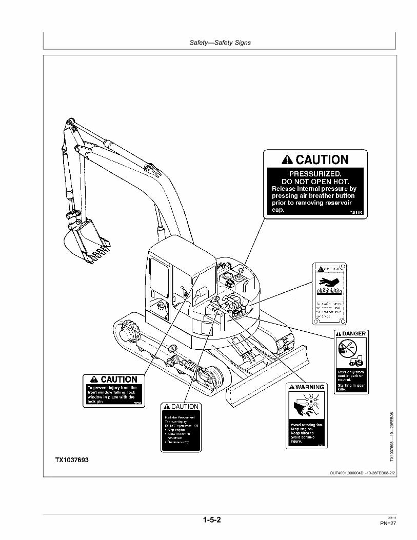
Safety Signs
TX1037692—19—29FE
B08
1-5-1 053113
PN=26
Safety—Safety Signs
OUT4001,000004D -19-28FEB08-2/2
TX1037693—19—29FE
B08
1-5-2 053113
PN=27
Operation—Operator's Station
OUT4001,0000008 -19-07MAR08-1/1
Pedals, Levers, and Panels
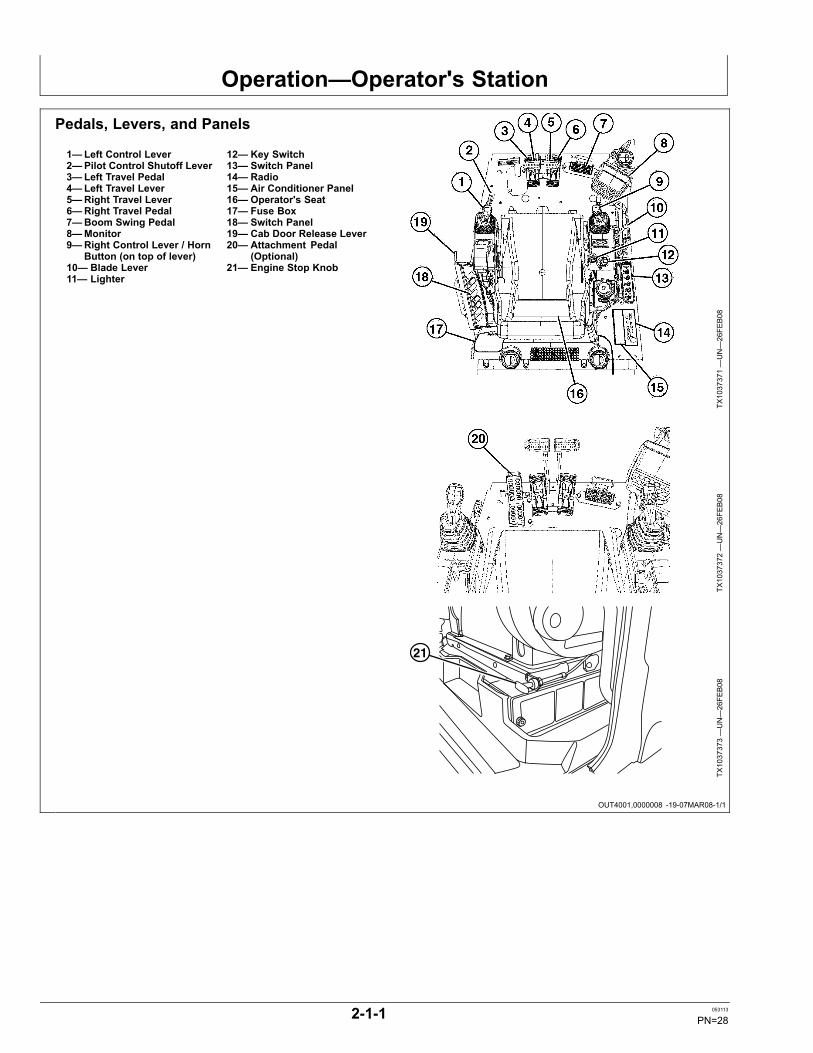
1—Left Control Lever2—Pilot Control Shutoff Lever3—Left Travel Pedal4—Left Travel Lever5—Right Travel Lever6—Right Travel Pedal7—Boom Swing Pedal8—Monitor9—Right Control Lever / Horn
Button (on top of lever)10— Blade Lever11— Lighter
12— Key Switch13— Switch Panel14— Radio15— Air Conditioner Panel16— Operator's Seat17— Fuse Box18— Switch Panel19— Cab Door Release Lever20— Attachment Pedal
(Optional)21— Engine Stop Knob
TX1037371—UN—26FE
B08
TX1037372—UN—26FE
B08
21
TX1037373—UN—26FE
B08
2-1-1 053113
PN=28

Operation—Operator's Station
OUT4001,000006A -19-04MAR08-1/1
Switch Panel
TX1037996A
—UN—04MAR08
TX1038002A
—UN—04MAR08
1—Engine Speed Dial2—Auto-Idle Switch3—Power Mode Switch4—Travel Speed Switch5—Work Lights Switch
6—Windshield Wiper andWasher Switch
7—Key Switch8—Lighter9—Power Outlet
TX1038004A
—UN—04MAR08
2-1-2 053113
PN=29
Operation—Operator's Station
OUT4001,000006B -19-14SEP12-1/1
OUT4001,000006C -19-04MAR08-1/1
Switch Panel Functions
1. Engine Speed Dial: Turn dial clockwise to increaseengine speed or counterclockwise to decrease enginespeed.
2. Auto-Idle Switch: With engine on, move auto-idleswitch to A/I ON and the engine speed dial to above theauto-idle speed. Auto-idle indicator will appear on monitordefault screen when auto-idle is on.
The engine will run at the engine speed dial setting for 4seconds after turning key switch ON. The auto-idle systemwill then slow the engine to auto-idle engine speed.
The auto-idle circuit automatically reduces engine speedafter 4 seconds when control levers are placed in neutralposition.
Engine speed increases to engine speed dial setting whenany control lever is operated.
Engine speed will change depending on engine speeddial setting and position of control levers.
Turn auto-idle switch OFF, and set engine speed dial toimprove machine control in difficult work areas, loading,and unloading.
3. Power Mode Switch: Move switch to select enginespeed mode.
P Mode
Use P mode when general digging work is needed.
E (Economy) Mode (S.N. —9333643)
Use E mode to improve fuel efficiency and reduce noiselevel with a small difference in engine speed.
E (Economy) Mode (S.N. 9333644—)
Not used.
4. Travel Speed Switch: Turn switch to select fast orslow speed travel.
5. Work Light Switch: Turn switch to first position to turnon drive light. Switch panel will also light.
Turn light switch to second position to turn on boom worklight and drive light. If default screen is displayed onmonitor, the background goes from white to black.
NOTE: The wiper does not operate unless the upperfront window is completely closed.
6. Wiper Switch: Wiper switch has several positions:
OFF ... Wiper stops operating and is retracted.
INT ... Wiper operates intermittently at the intervalselected by the switch position.
ON ... Wiper operates continuously.
Washer Switch: Push and hold switch to squirt fluid onwindshield. Do not hold down switch for more than 20seconds.
7. Key Switch:The key switch has 4 positions: OFF,ACC, ON, and START.
8. Lighter: For operator convenience. Can also be usedas a electrical port for service and maintenance for 24-voltappliances.
9. Power Outlet (5 amp maximum): For 12-volt electricalservice.
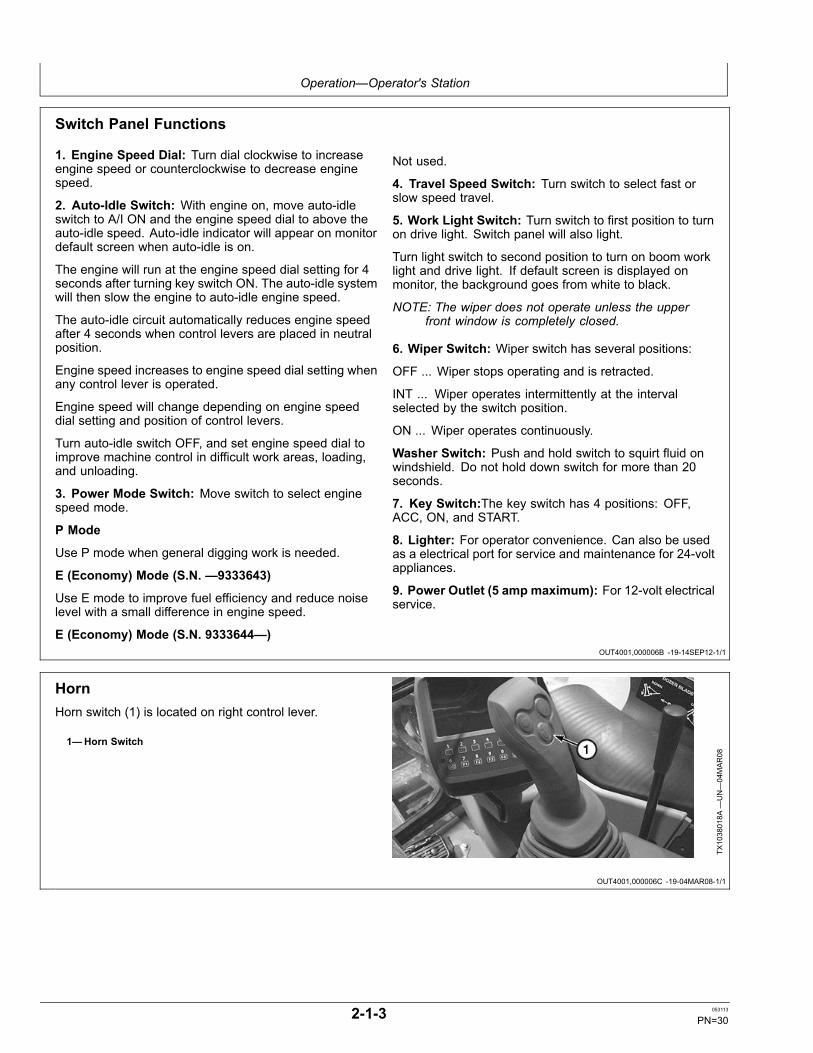
HornHorn switch (1) is located on right control lever.
1—Horn Switch
TX1038018A
—UN—04MAR08
2-1-3 053113
PN=30

Operation—Operator's Station
OUT4001,000006D -19-04MAR08-1/1
Pilot Shutoff LeverThe pilot shutoff lever (1) shuts off hydraulic pilot pressureto all pilot control valves. When pilot shutoff lever is inlocked (UP) position, the machine will not move if a leveror pedal is accidentally moved. Engine will not start withpilot shutoff lever in the unlocked (DOWN) position.
Always pull pilot shutoff lever to locked (UP) position whenyou stop the engine or leave the operator’s station.
Push pilot shutoff lever forward to unlocked (DOWN)position to operate machine.
1—Pilot Shutoff Lever
TX1038019A
—UN—04MAR08
Locked (UP) Position
TX1038021A
—UN—04MAR08
Unlocked (DOWN) Position
2-1-4 053113
PN=31
Operation—Operator's Station
OUT4001,000006E -19-04MAR08-1/1
OUT4001,000006F -19-04MAR08-1/1
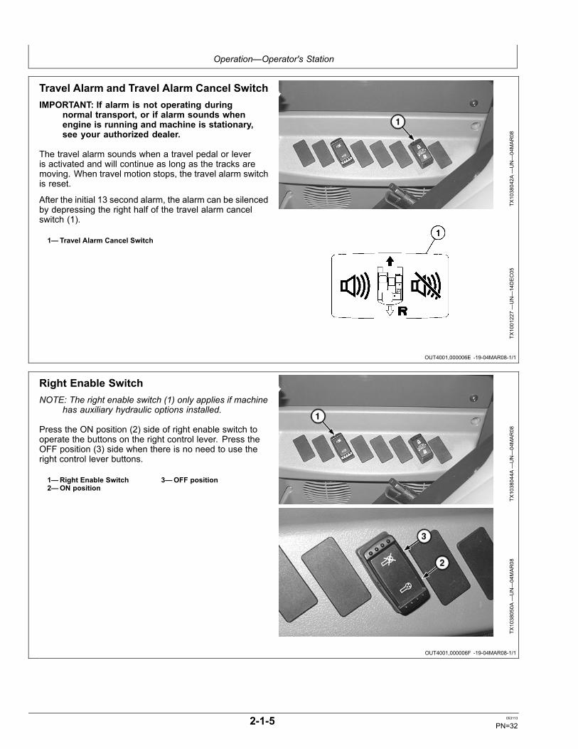
Travel Alarm and Travel Alarm Cancel SwitchIMPORTANT: If alarm is not operating during
normal transport, or if alarm sounds whenengine is running and machine is stationary,see your authorized dealer.
The travel alarm sounds when a travel pedal or leveris activated and will continue as long as the tracks aremoving. When travel motion stops, the travel alarm switchis reset.
After the initial 13 second alarm, the alarm can be silencedby depressing the right half of the travel alarm cancelswitch (1).
1—Travel Alarm Cancel Switch
TX1038042A
—UN—04MAR08
TX1001227—UN—14DEC05
Right Enable SwitchNOTE: The right enable switch (1) only applies if machine
has auxiliary hydraulic options installed.
Press the ON position (2) side of right enable switch tooperate the buttons on the right control lever. Press theOFF position (3) side when there is no need to use theright control lever buttons.
1—Right Enable Switch2—ON position
3—OFF position
TX1038044A
—UN—04MAR08
TX1038050A
—UN—04MAR08
2-1-5 053113
PN=32
Operation—Operator's Station
OUT4001,000007F -19-07MAR08-1/1
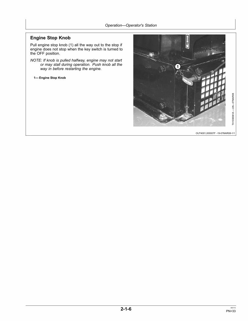
Engine Stop KnobPull engine stop knob (1) all the way out to the stop ifengine does not stop when the key switch is turned tothe OFF position.
NOTE: If knob is pulled halfway, engine may not startor may stall during operation. Push knob all theway in before restarting the engine.
1—Engine Stop Knob
TX1038361A
—UN—07MAR08
2-1-6 053113
PN=33
Operation—Operator's Station
DW90712,000043E -19-08JAN07-1/1
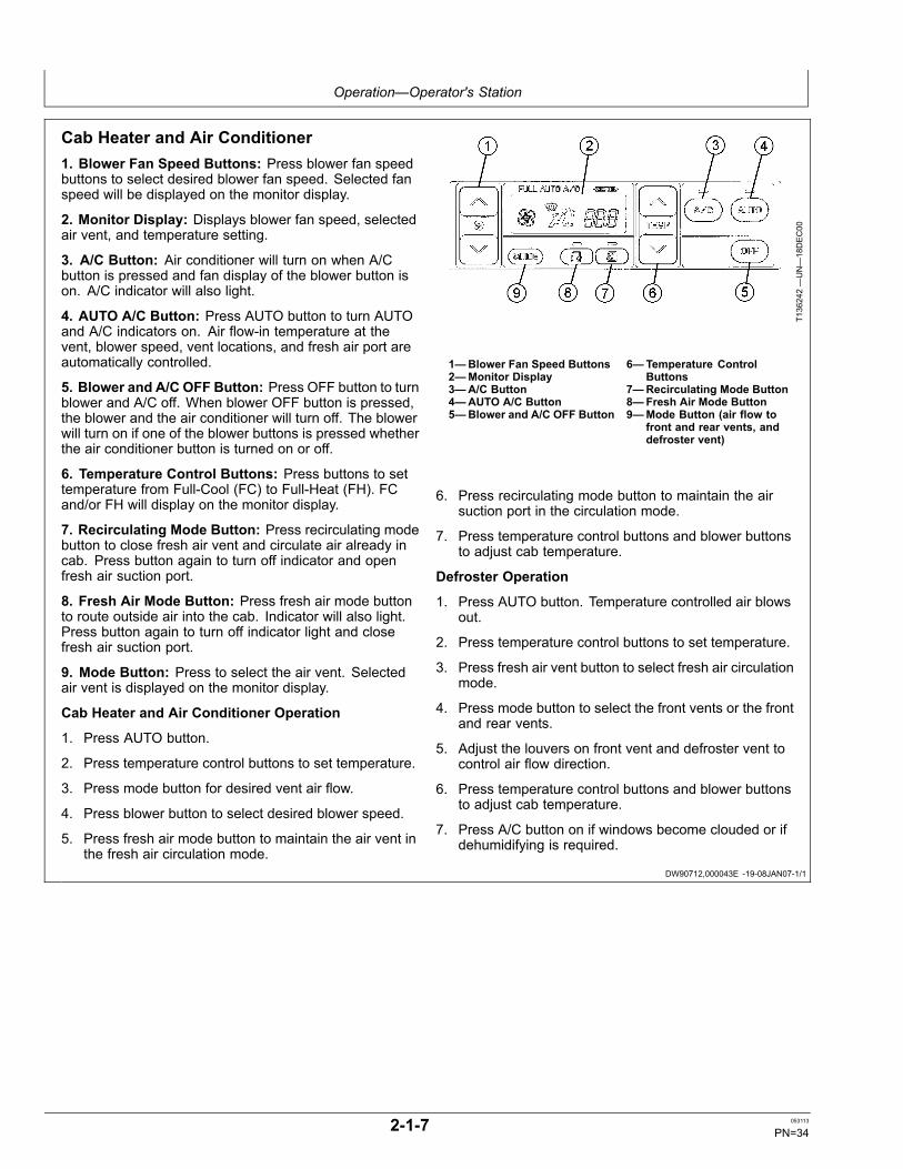
Cab Heater and Air Conditioner1. Blower Fan Speed Buttons: Press blower fan speedbuttons to select desired blower fan speed. Selected fanspeed will be displayed on the monitor display.
2. Monitor Display: Displays blower fan speed, selectedair vent, and temperature setting.
3. A/C Button: Air conditioner will turn on when A/Cbutton is pressed and fan display of the blower button ison. A/C indicator will also light.
4. AUTO A/C Button: Press AUTO button to turn AUTOand A/C indicators on. Air flow-in temperature at thevent, blower speed, vent locations, and fresh air port areautomatically controlled.
5. Blower and A/C OFF Button: Press OFF button to turnblower and A/C off. When blower OFF button is pressed,the blower and the air conditioner will turn off. The blowerwill turn on if one of the blower buttons is pressed whetherthe air conditioner button is turned on or off.
6. Temperature Control Buttons: Press buttons to settemperature from Full-Cool (FC) to Full-Heat (FH). FCand/or FH will display on the monitor display.
7. Recirculating Mode Button: Press recirculating modebutton to close fresh air vent and circulate air already incab. Press button again to turn off indicator and openfresh air suction port.
8. Fresh Air Mode Button: Press fresh air mode buttonto route outside air into the cab. Indicator will also light.Press button again to turn off indicator light and closefresh air suction port.
9. Mode Button: Press to select the air vent. Selectedair vent is displayed on the monitor display.
Cab Heater and Air Conditioner Operation
1. Press AUTO button.
2. Press temperature control buttons to set temperature.
3. Press mode button for desired vent air flow.
4. Press blower button to select desired blower speed.
5. Press fresh air mode button to maintain the air vent inthe fresh air circulation mode.
T136242—UN—18DEC00
1—Blower Fan Speed Buttons2—Monitor Display3—A/C Button4—AUTO A/C Button5—Blower and A/C OFF Button
6—Temperature ControlButtons
7—Recirculating Mode Button8—Fresh Air Mode Button9—Mode Button (air flow to
front and rear vents, anddefroster vent)
6. Press recirculating mode button to maintain the airsuction port in the circulation mode.
7. Press temperature control buttons and blower buttonsto adjust cab temperature.
Defroster Operation
1. Press AUTO button. Temperature controlled air blowsout.
2. Press temperature control buttons to set temperature.
3. Press fresh air vent button to select fresh air circulationmode.
4. Press mode button to select the front vents or the frontand rear vents.
5. Adjust the louvers on front vent and defroster vent tocontrol air flow direction.
6. Press temperature control buttons and blower buttonsto adjust cab temperature.
7. Press A/C button on if windows become clouded or ifdehumidifying is required.
2-1-7 053113
PN=34

Operation—Operator's Station
OUT4001,000007C -19-05MAR08-1/1
DW90712,0000385 -19-08JAN07-1/1
Selecting Display Between Celsius andFahrenheit1. While depressing both A/C button (3) and mode button
(9), turn the key switch ON.2. The LCD will display “Sd” for approximately 5 seconds.3. After display “Sd” is deleted, all LEDs will come on.4. After all LEDs come ON, continue to press the blower
button (1) four times.5. Then, press and hold the A/C button (3) and then
press blower button (1) at the same time.6. The selection mode between Celsius and Fahrenheit
starts.Each time the fresh air mode button (8) is pressed,the display is shifted between Celsius and Fahrenheit.When Celsius is displayed, the LCD displays “C.”When Fahrenheit is displayed, the LCD displays “F.”Select preferred setting.
7. After selection is complete, end by turning the keyswitch OFF.The LCD will display in the selected mode when themachine is operated the next time.
T136242—UN—18DEC00
1—Blower Fan Speed Buttons2—Monitor Display3—A/C Button4—AUTO A/C Button5—Blower and A/C OFF Button
6—Temperature ControlButtons
7—Recirculating Mode Button8—Fresh Air Mode Button9—Mode Button (air flow to
front and rear vents, anddefroster vent)
Display on LCDCelsius (°C) 18.0 to 32.0Fahrenheit (°F) 63 to 91
Operating the AM/FM RadioPress power switch (1) to turn radio on, and repeatedlypress one of tuning buttons (5) until desired station isreached. To preset a station, select the desired stationusing tuning buttons. Press and hold one of the stationpreset buttons (4) for more than 2 seconds until anelectronic tone is heard. The frequency of the presetstation will be indicated on digital display (7).
Setting the Clock
NOTE: In order to set the clock, the power switchmust be on, and the digital display (7) mustbe in the time display mode.
Press and hold the reset button labeled RST (8) until thetime is flashing.
Press the time set button labeled M (8) to set the correctminute.
Press the time set button labeled H (8) to set the correcthour.
Press and hold the reset button to set time.
T214911—UN—17NOV05
1—Power Switch/VolumeControl Knob
2—Tone Adjustment Ring3—AM/FM Button4—Station Preset Buttons
5—Tuning Buttons6—Display Mode Change
Button7—Digital Display8—Time Set / Reset Buttons
2-1-8 053113
PN=35
Operation—Operator's Station
OUT4001,0000071 -19-04MAR08-1/1
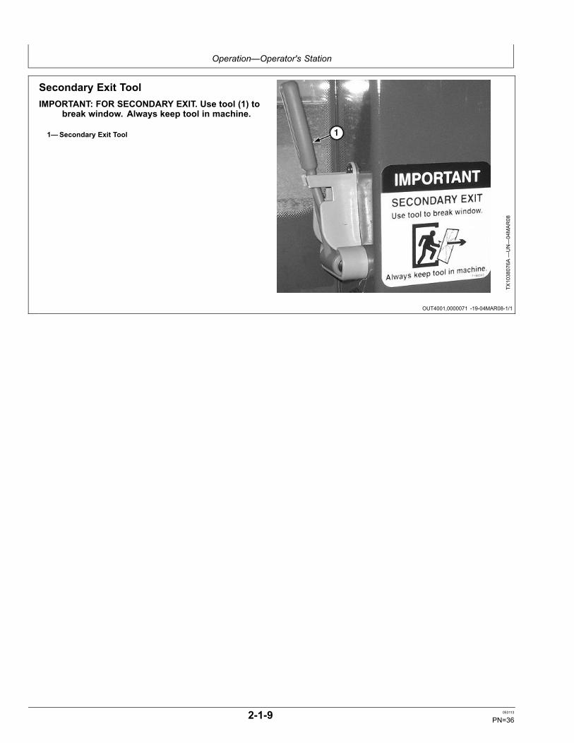
Secondary Exit ToolIMPORTANT: FOR SECONDARY EXIT. Use tool (1) to
break window. Always keep tool in machine.
1—Secondary Exit Tool
TX1038076A
—UN—04MAR08
2-1-9 053113
PN=36
Operation—Operator's Station
OUT4001,0000072 -19-07MAR08-1/1
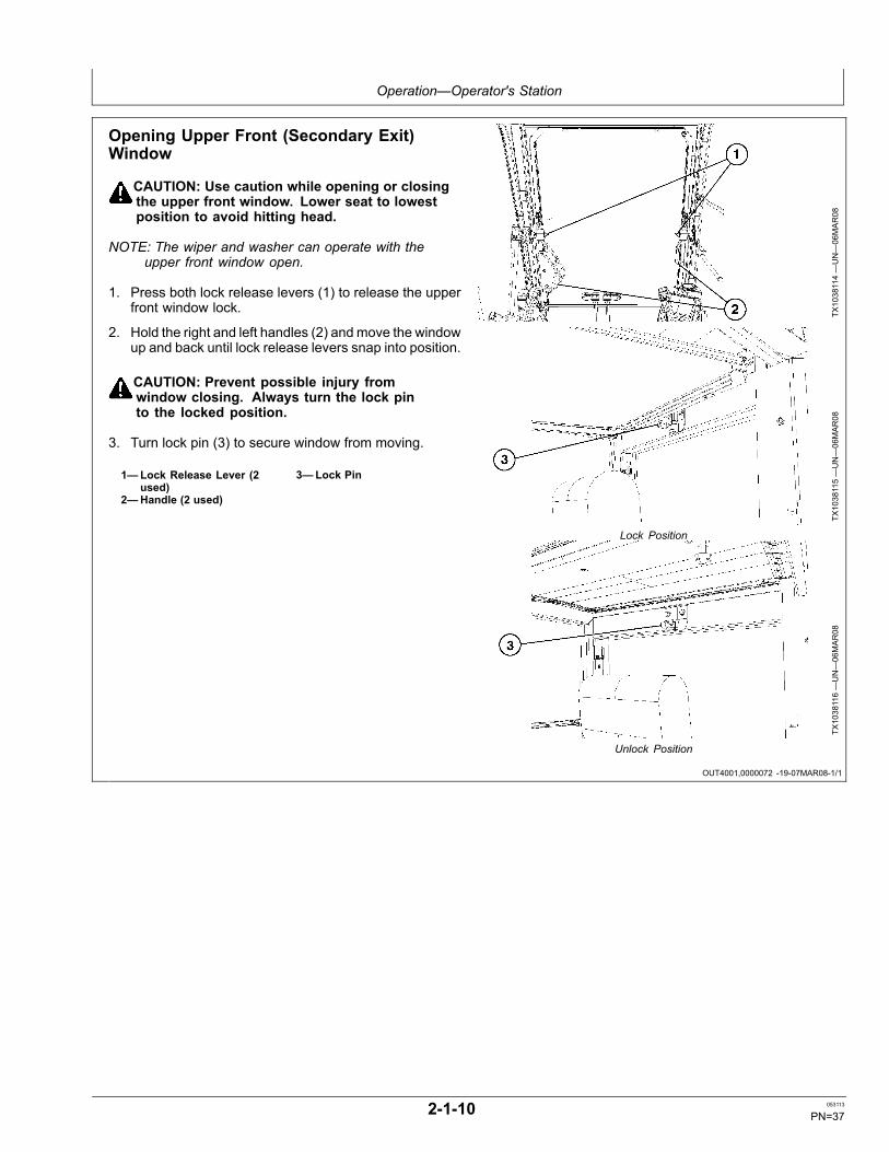
Opening Upper Front (Secondary Exit)Window
CAUTION: Use caution while opening or closingthe upper front window. Lower seat to lowestposition to avoid hitting head.
NOTE: The wiper and washer can operate with theupper front window open.
1. Press both lock release levers (1) to release the upperfront window lock.
2. Hold the right and left handles (2) andmove the windowup and back until lock release levers snap into position.
CAUTION: Prevent possible injury fromwindow closing. Always turn the lock pinto the locked position.
3. Turn lock pin (3) to secure window from moving.
1—Lock Release Lever (2used)
2—Handle (2 used)
3—Lock Pin
TX1038114—UN—06MAR08
TX1038115—UN—06MAR08
Lock Position
TX1038116—UN—06MAR08
Unlock Position
2-1-10 053113
PN=37
Operation—Operator's Station
OUT4001,0000073 -19-05MAR08-1/1
OUT4001,0000074 -19-05MAR08-1/1
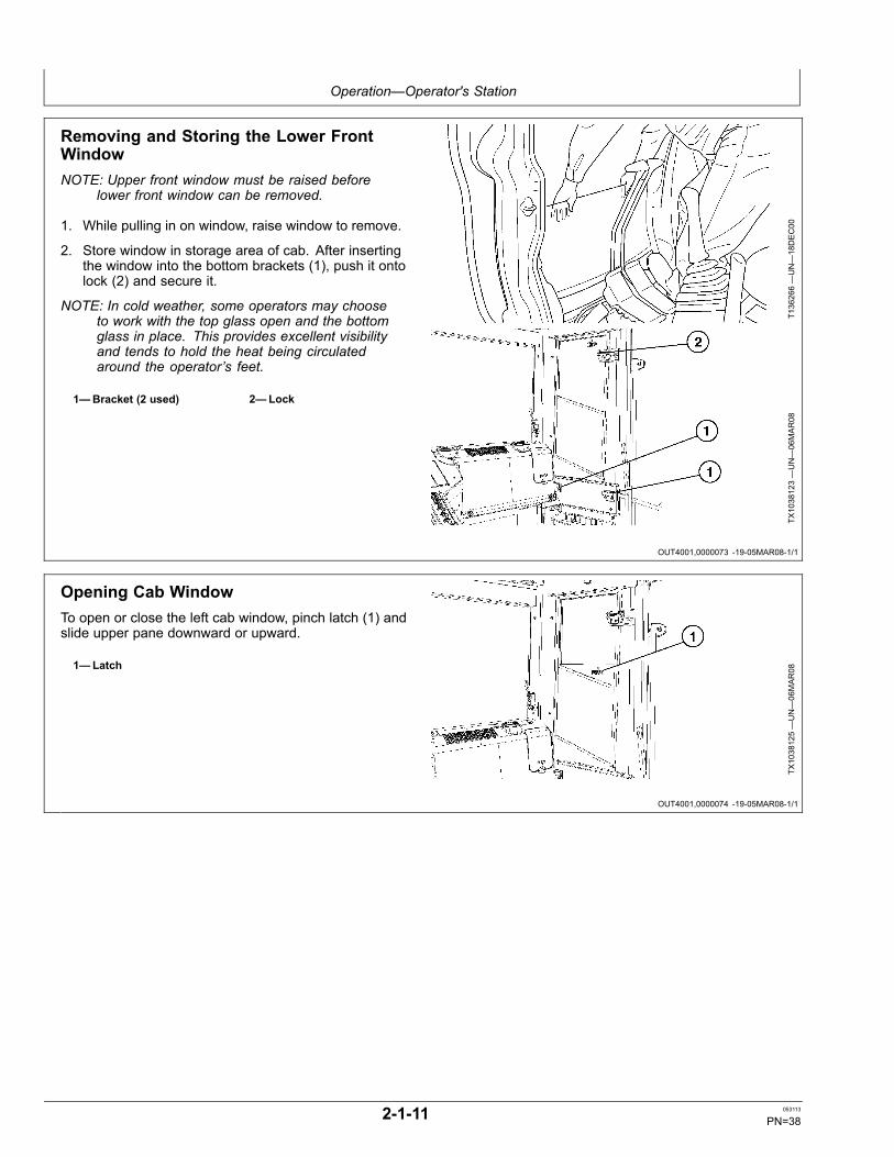
Removing and Storing the Lower FrontWindowNOTE: Upper front window must be raised before
lower front window can be removed.
1. While pulling in on window, raise window to remove.
2. Store window in storage area of cab. After insertingthe window into the bottom brackets (1), push it ontolock (2) and secure it.
NOTE: In cold weather, some operators may chooseto work with the top glass open and the bottomglass in place. This provides excellent visibilityand tends to hold the heat being circulatedaround the operator’s feet.
1—Bracket (2 used) 2—Lock
T136266—UN—18DEC00
TX1038123—UN—06MAR08
Opening Cab WindowTo open or close the left cab window, pinch latch (1) andslide upper pane downward or upward.
1—Latch
TX1038125—UN—06MAR08
2-1-11 053113
PN=38
Operation—Operator's Station
OUT4001,0000075 -19-06MAR08-1/1
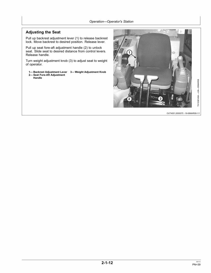
Adjusting the SeatPull up backrest adjustment lever (1) to release backrestlock. Move backrest to desired position. Release lever.
Pull up seat fore-aft adjustment handle (2) to unlockseat. Slide seat to desired distance from control levers.Release handle.
Turn weight adjustment knob (3) to adjust seat to weightof operator.
1—Backrest Adjustment Lever2—Seat Fore-Aft Adjustment
Handle
3—Weight Adjustment Knob
TX1038149A
—UN—05MAR08
2-1-12 053113
PN=39
Operation—Monitor Operation
MD04263,00003D3 -19-04MAY09-1/1
Monitor
7777.7h
8:01
F1
F2
F3
F4
H
C
F
E
L/h17.3
A.I.
F1 F2 F3 F4
1 2 3 4 5
6 7 8 9 0
17
16
15
6 7 98 10 13
14
12
1154321 30
29
28
27
26
25
18 19 20 21 22 2423
TX1001230 TX1001230—UN—04JAN06
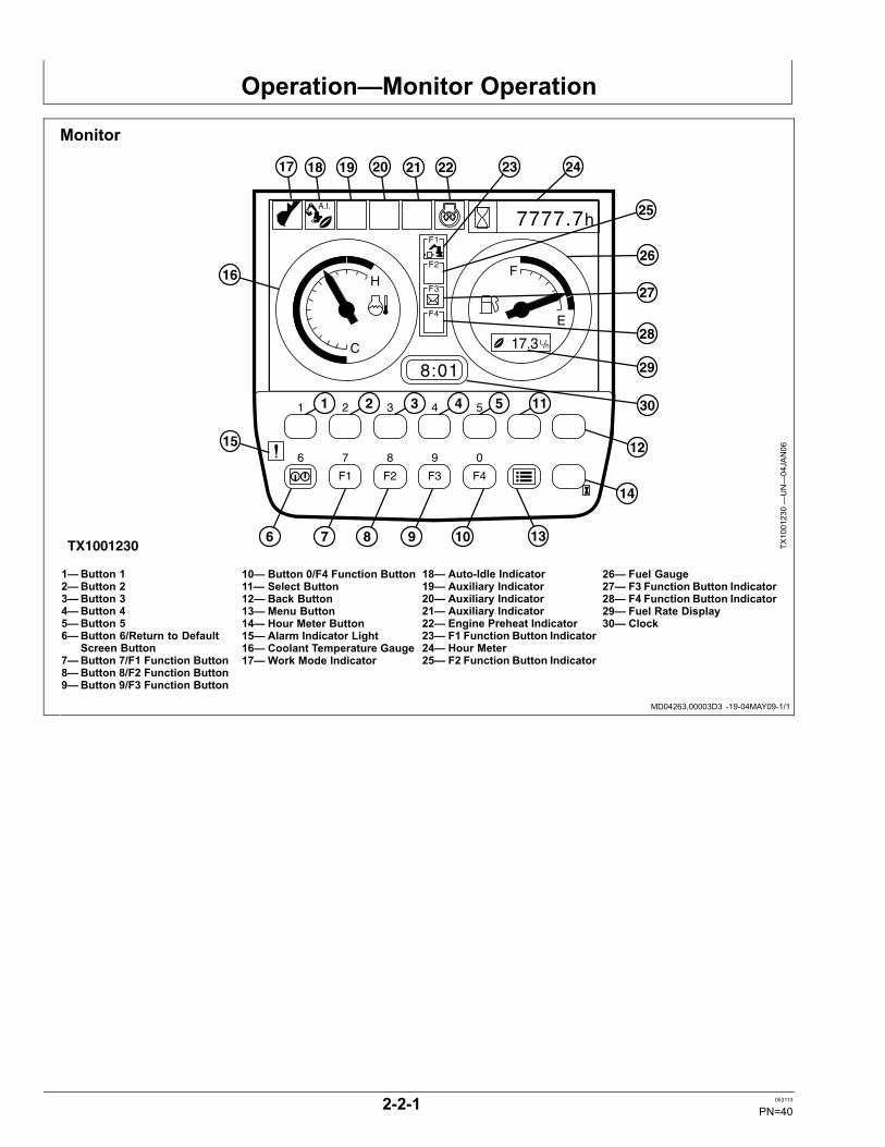
1—Button 12—Button 23—Button 34—Button 45—Button 56—Button 6/Return to Default
Screen Button7—Button 7/F1 Function Button8—Button 8/F2 Function Button9—Button 9/F3 Function Button
10— Button 0/F4 Function Button11— Select Button12— Back Button13— Menu Button14— Hour Meter Button15— Alarm Indicator Light16— Coolant Temperature Gauge17— Work Mode Indicator
18— Auto-Idle Indicator19— Auxiliary Indicator20— Auxiliary Indicator21— Auxiliary Indicator22— Engine Preheat Indicator23— F1 Function Button Indicator24— Hour Meter25— F2 Function Button Indicator
26— Fuel Gauge27— F3 Function Button Indicator28— F4 Function Button Indicator29— Fuel Rate Display30— Clock
2-2-1 053113
PN=40
Operation—Monitor Operation
MD04263,00003D4 -19-04MAY09-1/1
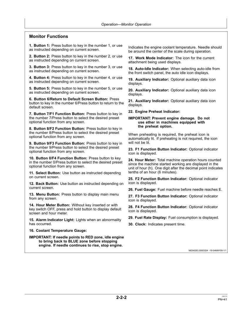
Monitor Functions
1. Button 1: Press button to key in the number 1, or useas instructed depending on current screen.
2. Button 2: Press button to key in the number 2, or useas instructed depending on current screen.
3. Button 3: Press button to key in the number 3, or useas instructed depending on current screen.
4. Button 4: Press button to key in the number 4, or useas instructed depending on current screen.
5. Button 5: Press button to key in the number 5, or useas instructed depending on current screen.
6. Button 6/Return to Default Screen Button: Pressbutton to key in the number 6/Press button to return to thedefault screen.
7. Button 7/F1 Function Button: Press button to key inthe number 7/Press button to select the desired presetoptional function from any screen.
8. Button 8/F2 Function Button: Press button to key inthe number 8/Press button to select the desired presetoptional function from any screen.
9. Button 9/F3 Function Button: Press button to key inthe number 9/Press button to select the desired presetoptional function from any screen.
10. Button 0/F4 Function Button: Press button to keyin the number 0/Press button to select the desired presetoptional function from any screen.
11. Select Button: Use button as instructed dependingon current screen.
12. Back Button: Use button as instructed depending oncurrent screen.
13. Menu Button: Press button to display main menufrom any screen.
14. Hour Meter Button: Without key inserted or withkey switch OFF, press and hold button to display defaultscreen and hour meter.
15. Alarm Indicator Light: Lights when an abnormalityhas occurred.
16. Coolant Temperature Gauge:
IMPORTANT: If needle points to RED zone, idle engineto bring back to BLUE zone before stoppingengine. If needle continues to rise, stop engine.
Indicates the engine coolant temperature. Needle shouldbe around the center of the scale during operation.
17. Work Mode Indicator: The icon for the currentattachment being used displays.
18. Auto-Idle Indicator: When selecting auto-idle fromthe front switch panel, the auto idle icon displays.
19. Auxiliary Indicator: Optional auxiliary data icondisplays.
20. Auxiliary Indicator: Optional auxiliary data icondisplays.
21. Auxiliary Indicator: Optional auxiliary data icondisplays.
22. Engine Preheat Indicator:
IMPORTANT: Prevent engine damage. Do notuse ether in machines equipped withthe preheat option.
When preheating is required, the preheat icon isautomatically lit. If preheating is not required, the iconwill not be lit.
23. F1 Function Button Indicator: Optional indicatoricon is displayed.
24. Hour Meter: Total machine operation hours countedsince the machine started working are displayed in theunit of hour (h). One digit after the decimal point indicatestenths of an hour (6 minutes).
25. F2 Function Button Indicator: Optional indicatoricon is displayed.
26. Fuel Gauge: Fuel machine before needle reaches E.
27. F3 Function Button Indicator: Optional indicatoricon is displayed.
28. F4 Function Button Indicator: Optional indicatoricon is displayed.
29. Fuel Rate Display: Fuel consumption is displayed.
30. Clock: Indicates present time.
2-2-2 053113
PN=41
Operation—Monitor Operation
DW90712,000047C -19-29JAN07-1/1
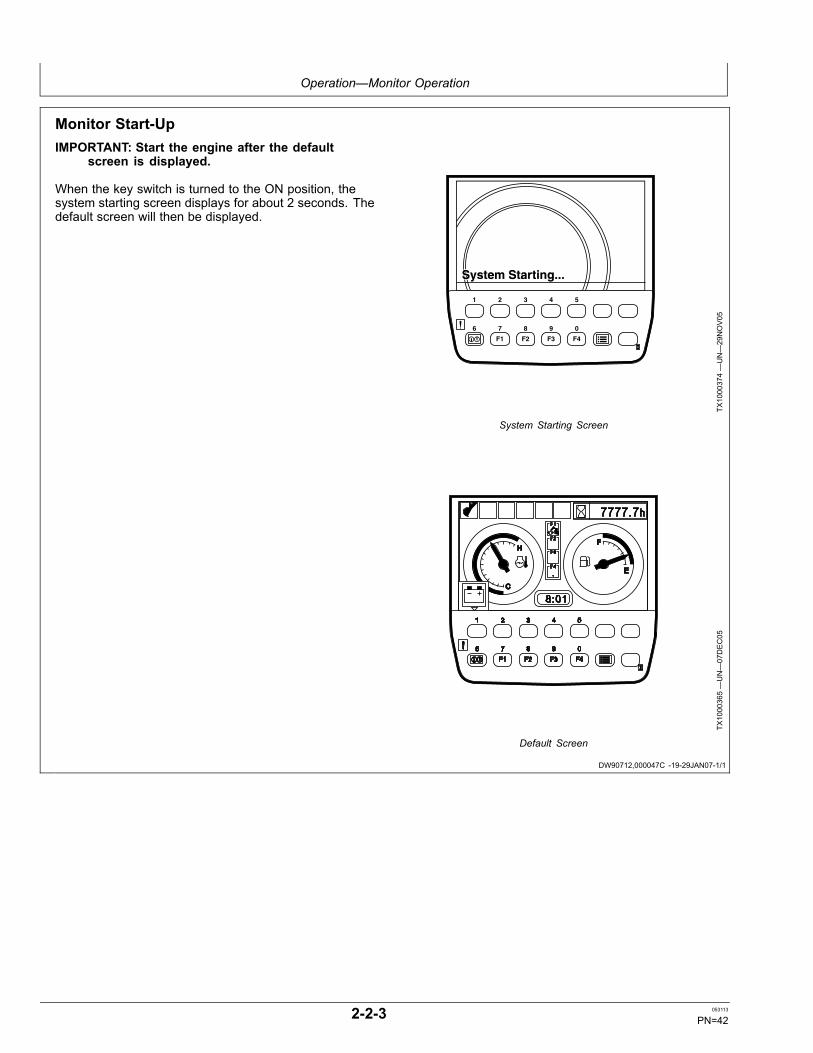
Monitor Start-UpIMPORTANT: Start the engine after the default
screen is displayed.
When the key switch is turned to the ON position, thesystem starting screen displays for about 2 seconds. Thedefault screen will then be displayed.
System Starting...System Starting...
F1 F2 F3 F4
1 2 3 4 5
6 7 8 9 0
TX1000374—UN—29NOV05
System Starting Screen
TX1000365—UN—07DEC05
Default Screen
2-2-3 053113
PN=42
Operation—Monitor Operation
MD04263,00003C1 -19-04MAY09-1/1
MD04263,00003C2 -19-30APR09-1/1
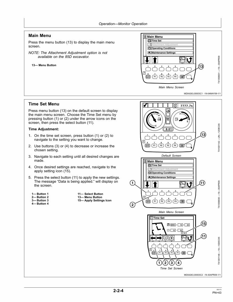
Main MenuPress the menu button (13) to display the main menuscreen.
NOTE: The Attachment Adjustment option is notavailable on the 85D excavator.
13— Menu Button
Main MenuTime Set
Attachment Adjustment
Operating Conditions
Maintenance Settings
F1 F2 F3 F4
1 2 3 4 5
6 7 8 9 0
13
TX1058931—19—30APR09
Main Menu Screen
Time Set MenuPress menu button (13) on the default screen to displaythe main menu screen. Choose the Time Set menu bypressing button (1) or (2) under the arrow icons on thescreen, then press the select button (11).
Time Adjustment:
1. On the time set screen, press button (1) or (2) tonavigate to the setting you want to change.
2. Use buttons (3) or (4) to decrease or increase thechosen setting.
3. Navigate to each setting until all desired changes aremade.
4. Once desired settings are reached, navigate to theapply setting icon (15).
5. Press the select button (11) to apply the new settings.The message “Data is being applied.” will display onthe screen.
1—Button 12—Button 23—Button 34—Button 4
11— Select Button13— Menu Button15— Apply Settings Icon
7777.7h
8:01
F1
F2
F3
F4
H
C
F
E
A.I.
F1 F2 F3 F4
1 2 3 4 5
6 7 8 9 0
13
TX1001142—UN—12DEC05
Default Screen
Main MenuTime Set
Attachment Adjustment
Operating Conditions
Maintenance Settings
F1 F2 F3 F4
1 2 3 4 5
6 7 8 9 0
111
2
TX1058930—19—30APR09
Main Menu Screen
Time Set
/2005 /12 23
12 23
F1 F2 F3 F4
1 2 3 4 5
6 7 8 9 0
:
11
15
21 43 TX1001146—19—13DEC05
Time Set Screen
2-2-4 053113
PN=43
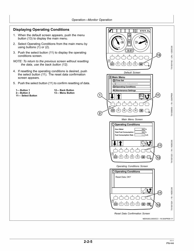
Operation—Monitor Operation
MD04263,00003C3 -19-30APR09-1/1
Displaying Operating Conditions1. When the default screen appears, push the menu
button (13) to display the main menu.
2. Select Operating Conditions from the main menu byusing buttons (1) or (2).
3. Push the select button (11) to display the operatingconditions screen.
NOTE: To return to the previous screen without resettingthe data, use the back button (12).
4. If resetting the operating conditions is desired, pushthe select button (11). The reset data confirmationscreen appears.
5. Push the select button (11) to confirm resetting of data.
1—Button 12—Button 211— Select Button
12— Back Button13— Menu Button
7777.7h
8:01
F1
F2
F3
F4
H
C
F
E
A.I.
F1 F2 F3 F4
1 2 3 4 5
6 7 8 9 0
13
TX1001142—UN—12DEC05
Default Screen
Main MenuTime Set
Attachment Adjustment
Operating Conditions
Maintenance Settings
F1 F2 F3 F4
1 2 3 4 5
6 7 8 9 0
111
2
TX1058930—19—30APR09
Main Menu Screen
Operating Conditions
0.0Hour Meter
Total Fuel Consumption
Fuel Consumption Rate
0.0
---.-
h
L
L/h
F1 F2 F3 F4
1 2 3 4 5
6 7 8 9 0
11
12
TX1001323—19—16DEC05
Operating Conditions Screen
Operating Conditions
Reset Data. OK?
F1 F2 F3 F4
1 2 3 4 5
6 7 8 9 0
11
12
TX1001324—19—16DEC05
Reset Data Confirmation Screen
2-2-5 053113
PN=44
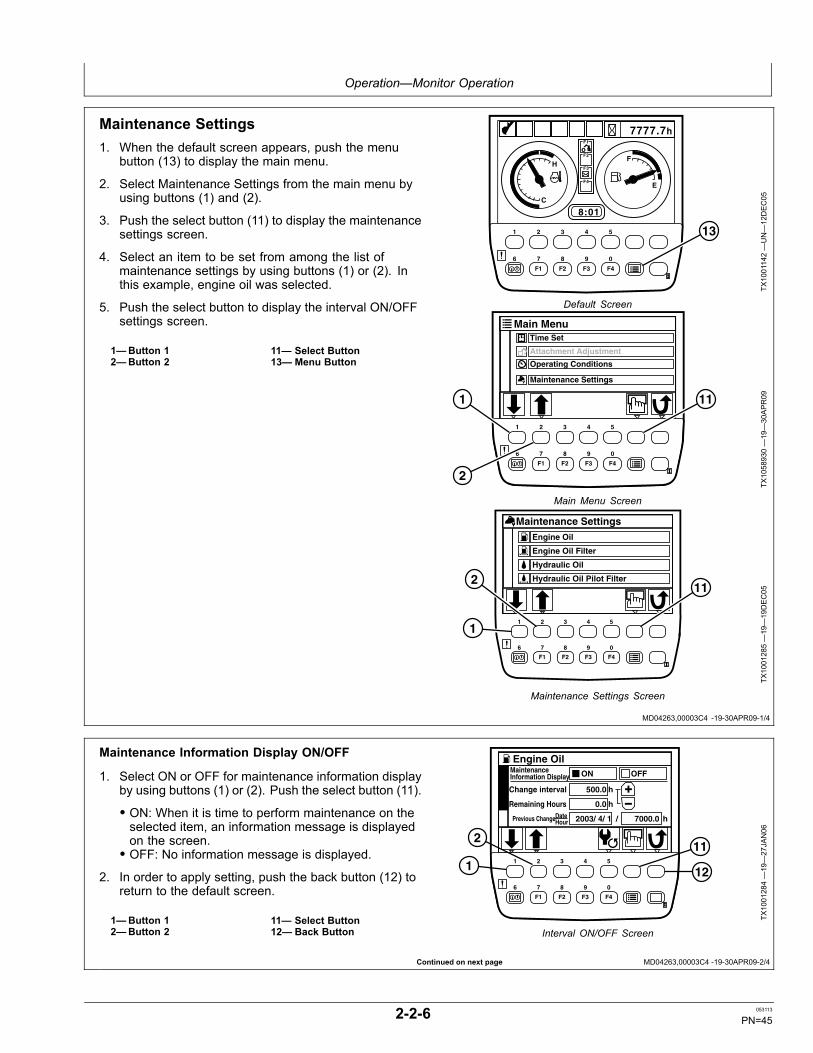
Operation—Monitor Operation
MD04263,00003C4 -19-30APR09-1/4
Continued on next page MD04263,00003C4 -19-30APR09-2/4
Maintenance Settings1. When the default screen appears, push the menu
button (13) to display the main menu.
2. Select Maintenance Settings from the main menu byusing buttons (1) and (2).
3. Push the select button (11) to display the maintenancesettings screen.
4. Select an item to be set from among the list ofmaintenance settings by using buttons (1) or (2). Inthis example, engine oil was selected.
5. Push the select button to display the interval ON/OFFsettings screen.
1—Button 12—Button 2
11— Select Button13— Menu Button
7777.7h
8:01
F1
F2
F3
F4
H
C
F
E
A.I.
F1 F2 F3 F4
1 2 3 4 5
6 7 8 9 0
13
TX1001142—UN—12DEC05
Default Screen
Main MenuTime Set
Attachment Adjustment
Operating Conditions
Maintenance Settings
F1 F2 F3 F4
1 2 3 4 5
6 7 8 9 0
111
2
TX1058930—19—30APR09
Main Menu Screen
Maintenance Settings
Engine Oil Filter
Engine Oil
Hydraulic Oil
Hydraulic Oil Pilot Filter
F1 F2 F3 F4
1 2 3 4 5
6 7 8 9 0
1
112
TX1001285—19—19DEC05
Maintenance Settings Screen
Maintenance Information Display ON/OFF
1. Select ON or OFF for maintenance information displayby using buttons (1) or (2). Push the select button (11).
• ON: When it is time to perform maintenance on theselected item, an information message is displayedon the screen.• OFF: No information message is displayed.
2. In order to apply setting, push the back button (12) toreturn to the default screen.
1—Button 12—Button 2
11— Select Button12— Back Button
Change interval 500.0
ON OFF
Previous ChangeDateHour 2003/ 4/ 1 7000.0
Remaining Hours 0.0
h
/ h
h
Engine OilMaintenance Information Display
F1 F2 F3 F4
1 2 3 4 5
6 7 8 9 0
1
211
12
TX1001284—19—27JAN06
Interval ON/OFF Screen
2-2-6 053113
PN=45
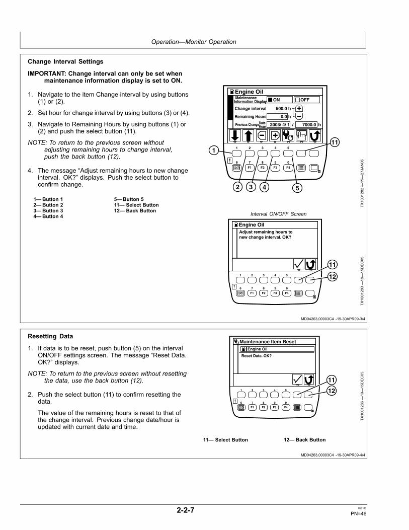
Operation—Monitor Operation
MD04263,00003C4 -19-30APR09-3/4
MD04263,00003C4 -19-30APR09-4/4
Change Interval Settings
IMPORTANT: Change interval can only be set whenmaintenance information display is set to ON.
1. Navigate to the item Change interval by using buttons(1) or (2).
2. Set hour for change interval by using buttons (3) or (4).
3. Navigate to Remaining Hours by using buttons (1) or(2) and push the select button (11).
NOTE: To return to the previous screen withoutadjusting remaining hours to change interval,push the back button (12).
4. The message “Adjust remaining hours to new changeinterval. OK?” displays. Push the select button toconfirm change.
1—Button 12—Button 23—Button 34—Button 4
5—Button 511— Select Button12— Back Button
Change interval 500.0
Maintenance Information Display ON OFF
Previous Change 2003/ 4/ 1 7000.0
Remaining Hours 0.0
h
/ h
h
Engine Oil
DateHour
F1 F2 F3 F4
1 2 3 4 5
6 7 8 9 0
1
2 3 4 5
11
TX1001282—19—27JAN06
Interval ON/OFF Screen
Adjust remaining hours to �new change interval. OK?
Engine Oil
F1 F2 F3 F4
1 2 3 4 5
6 7 8 9 0
11
12
TX1001283—19—15DEC05
Resetting Data
1. If data is to be reset, push button (5) on the intervalON/OFF settings screen. The message “Reset Data.OK?” displays.
NOTE: To return to the previous screen without resettingthe data, use the back button (12).
2. Push the select button (11) to confirm resetting thedata.
The value of the remaining hours is reset to that ofthe change interval. Previous change date/hour isupdated with current date and time.
Maintenance Item Reset
Reset Data. OK?
Engine Oil
F1 F2 F3 F4
1 2 3 4 5
6 7 8 9 0
11
12
TX1001286—19—15DEC05
11— Select Button 12— Back Button
2-2-7 053113
PN=46
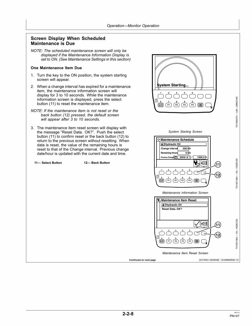
Operation—Monitor Operation
Continued on next page OUT4001,00000AE -19-06MAR08-1/2
Screen Display When ScheduledMaintenance is DueNOTE: The scheduled maintenance screen will only be
displayed if the Maintenance Information Display isset to ON. (See Maintenance Settings in this section)
One Maintenance Item Due
1. Turn the key to the ON position, the system startingscreen will appear.
2. When a change interval has expired for a maintenanceitem, the maintenance information screen willdisplay for 3 to 10 seconds. While the maintenanceinformation screen is displayed, press the selectbutton (11) to reset the maintenance item.
NOTE: If the maintenance item is not reset or theback button (12) pressed, the default screenwill appear after 3 to 10 seconds.
3. The maintenance item reset screen will display withthe message “Reset Data. OK?”. Push the selectbutton (11) to confirm reset or the back button (12) toreturn to the previous screen without resetting. Whendata is reset, the value of the remaining hours isreset to that of the Change interval. Previous changedate/hour is updated with the current date and time.
11— Select Button 12— Back Button
System Starting...System Starting...
F1 F2 F3 F4
1 2 3 4 5
6 7 8 9 0
TX1000374—UN—29NOV05
System Starting Screen
Change interval 500.0
Previous Change 2003/ 4/ 1 1000.0
Remaining Hours 0.0
h
/ h
h
Hydraulic Oil
Maintenance Schedule
Date Hour
F1 F2 F3 F4
1 2 3 4 5
6 7 8 9 0
11
12
TX1001364—19—15DEC05
Maintenance Information Screen
Maintenance Item Reset
Reset Data. OK?
Hydraulic Oil
F1 F2 F3 F4
1 2 3 4 5
6 7 8 9 0
11
12TX
1001363—19—15DEC05
Maintenance Item Reset Screen
2-2-8 053113
PN=47
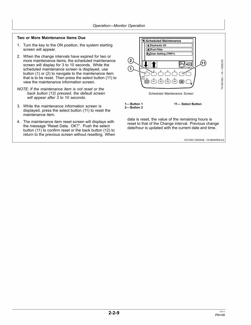
Operation—Monitor Operation
OUT4001,00000AE -19-06MAR08-2/2
Two or More Maintenance Items Due
1. Turn the key to the ON position, the system startingscreen will appear.
2. When the change intervals have expired for two ormore maintenance items, the scheduled maintenancescreen will display for 3 to 10 seconds. While thescheduled maintenance screen is displayed, usebutton (1) or (2) to navigate to the maintenance itemthat is to be reset. Then press the select button (11) toview the maintenance information screen.
NOTE: If the maintenance item is not reset or theback button (12) pressed, the default screenwill appear after 3 to 10 seconds.
3. While the maintenance information screen isdisplayed, press the select button (11) to reset themaintenance item.
4. The maintenance item reset screen will displays withthe message “Reset Data. OK?”. Push the selectbutton (11) to confirm reset or the back button (12) toreturn to the previous screen without resetting. When
Fuel Filter
User Setting (TRIP1)
Hydraulic Oil
Scheduled Maintenance
1
F1 F2 F3 F4
1 2 3 4 5
6 7 8 9 0
2
111
TX1001362—19—15DEC05
Scheduled Maintenance Screen
1—Button 12—Button 2
11— Select Button
data is reset, the value of the remaining hours isreset to that of the Change interval. Previous changedate/hour is updated with the current date and time.
2-2-9 053113
PN=48
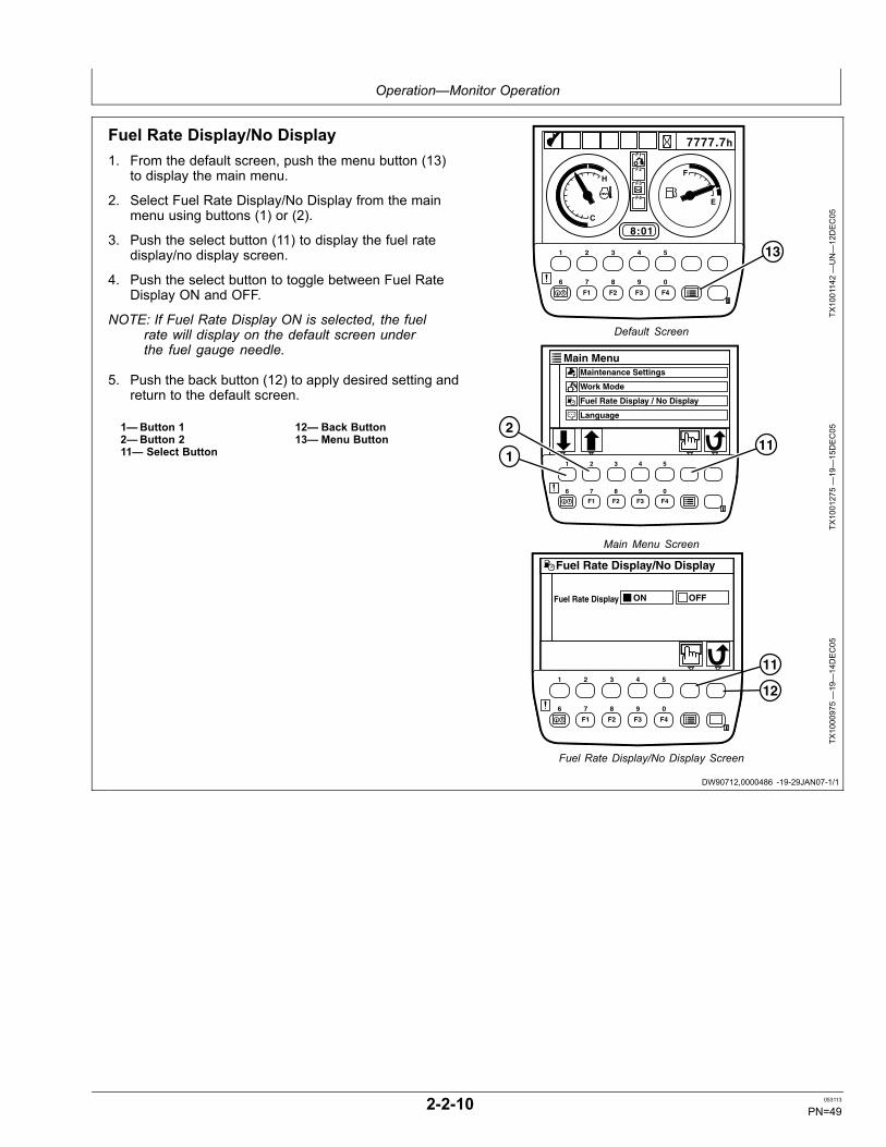
Operation—Monitor Operation
DW90712,0000486 -19-29JAN07-1/1
Fuel Rate Display/No Display1. From the default screen, push the menu button (13)
to display the main menu.
2. Select Fuel Rate Display/No Display from the mainmenu using buttons (1) or (2).
3. Push the select button (11) to display the fuel ratedisplay/no display screen.
4. Push the select button to toggle between Fuel RateDisplay ON and OFF.
NOTE: If Fuel Rate Display ON is selected, the fuelrate will display on the default screen underthe fuel gauge needle.
5. Push the back button (12) to apply desired setting andreturn to the default screen.
1—Button 12—Button 211— Select Button
12— Back Button13— Menu Button
7777.7h
8:01
F1
F2
F3
F4
H
C
F
E
A.I.
F1 F2 F3 F4
1 2 3 4 5
6 7 8 9 0
13
TX1001142—UN—12DEC05
Default Screen
Main Menu
Language
Fuel Rate Display / No Display
Work Mode
Maintenance Settings
F1 F2 F3 F4
1 2 3 4 5
6 7 8 9 0
2
111
TX1001275—19—15DEC05
Main Menu Screen
Fuel Rate Display/No Display
Fuel Rate Display ON OFF
F1 F2 F3 F4
1 2 3 4 5
6 7 8 9 0
12
11
TX1000975—19—14DEC05
Fuel Rate Display/No Display Screen
2-2-10 053113
PN=49
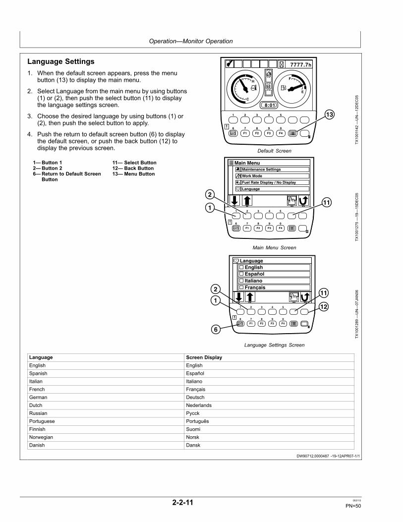
Operation—Monitor Operation
DW90712,0000487 -19-12APR07-1/1
Language Settings1. When the default screen appears, press the menu
button (13) to display the main menu.
2. Select Language from the main menu by using buttons(1) or (2), then push the select button (11) to displaythe language settings screen.
3. Choose the desired language by using buttons (1) or(2), then push the select button to apply.
4. Push the return to default screen button (6) to displaythe default screen, or push the back button (12) todisplay the previous screen.
1—Button 12—Button 26—Return to Default Screen
Button
11— Select Button12— Back Button13— Menu Button
7777.7h
8:01
F1
F2
F3
F4
H
C
F
E
A.I.
F1 F2 F3 F4
1 2 3 4 5
6 7 8 9 0
13
TX1001142—UN—12DEC05
Default Screen
Main Menu
Language
Fuel Rate Display / No Display
Work Mode
Maintenance Settings
F1 F2 F3 F4
1 2 3 4 5
6 7 8 9 0
2
111
TX1001275—19—15DEC05
Main Menu Screen
EnglishEspañolItalianoFrançais
Language
F1 F2 F3 F4
1 2 3 4 5
6 7 8 9 0
. . .
11
12
2
1
6
TX1001289—UN—07JAN06
Language Settings Screen
Language Screen DisplayEnglish EnglishSpanish EspañolItalian ItalianoFrench FrançaisGerman DeutschDutch NederlandsRussian PycckPortuguese PortuguêsFinnish SuomiNorwegian NorskDanish Dansk
2-2-11 053113
PN=50

Operation—Monitor Operation
DW90712,0000488 -19-12AUG10-1/11
DW90712,0000488 -19-12AUG10-2/11
Continued on next page DW90712,0000488 -19-12AUG10-3/11
Alarm Occurrence ScreenIn case any abnormality occurs, the alarm indicators (1)are displayed on the default screen.
Push the button on the monitor located under an alarmindicator to view the alarm indication screen and thecorrective action necessary.
1—Alarm Indicators
F1
F2
F3
F4
H
C
F
E
t
7777.7h
8:01
F1 F2 F3 F4
1 2 3 4 5
6 7 8 9 0
1
TX1000871—UN—01DEC05
Default Screen
Engine Overheat Alarm
Engine coolant temperature has abnormally increased.Stop operation. Run the engine at slow idle speed orlower the coolant temperature.
TX1000882 —UN—01DEC05
Engine Overheat Alarm
Engine Warning Alarm
Engine or engine related parts are abnormal. Consultyour authorized dealer.
TX1000883 —UN—01DEC05
Engine Warning Alarm
2-2-12 053113
PN=51
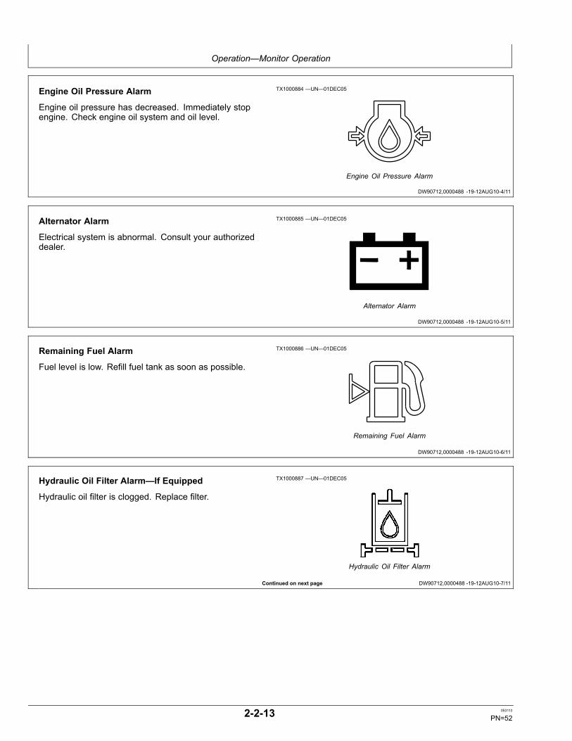
Operation—Monitor Operation
DW90712,0000488 -19-12AUG10-4/11
DW90712,0000488 -19-12AUG10-5/11
DW90712,0000488 -19-12AUG10-6/11
Continued on next page DW90712,0000488 -19-12AUG10-7/11
Engine Oil Pressure Alarm
Engine oil pressure has decreased. Immediately stopengine. Check engine oil system and oil level.
TX1000884 —UN—01DEC05
Engine Oil Pressure Alarm
Alternator Alarm
Electrical system is abnormal. Consult your authorizeddealer.
TX1000885 —UN—01DEC05
Alternator Alarm
Remaining Fuel Alarm
Fuel level is low. Refill fuel tank as soon as possible.
TX1000886 —UN—01DEC05
Remaining Fuel Alarm
Hydraulic Oil Filter Alarm—If Equipped
Hydraulic oil filter is clogged. Replace filter.
TX1000887 —UN—01DEC05
Hydraulic Oil Filter Alarm
2-2-13 053113
PN=52

Operation—Monitor Operation
DW90712,0000488 -19-12AUG10-8/11
DW90712,0000488 -19-12AUG10-9/11
Continued on next page DW90712,0000488 -19-12AUG10-10/11
Air Filter Clogged Alarm
Air filter elements are clogged. Clean or replace air filterelements.
TX1000888 —UN—01DEC05
Air Filter Clogged Alarm
Work Mode Alarm
Work Mode system is abnormal. Consult your authorizeddealer.
TX1000889 —UN—01DEC05
Work Mode Alarm
Pilot Shutoff Lever Alarm
Pilot shutoff lever system is abnormal. Consult yourauthorized dealer.
TX1000890 —UN—01DEC05
Pilot Shutoff Lever Alarm
2-2-14 053113
PN=53
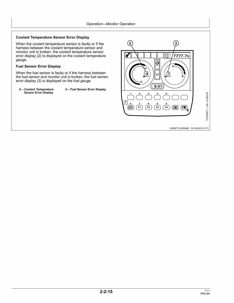
Operation—Monitor Operation
DW90712,0000488 -19-12AUG10-11/11
Coolant Temperature Sensor Error Display
When the coolant temperature sensor is faulty or if theharness between the coolant temperature sensor andmonitor unit is broken, the coolant temperature sensorerror display (2) is displayed on the coolant temperaturegauge.
Fuel Sensor Error Display
When the fuel sensor is faulty or if the harness betweenthe fuel sensor and monitor unit is broken, the fuel sensorerror display (3) is displayed on the fuel gauge.
2—Coolant TemperatureSensor Error Display
3—Fuel Sensor Error Display
7777.7h
8:01
H
C
F
E
A.I.
t
F1
F2
F3
F4 ERROR ERROR
F1 F2 F3 F4
1 2 3 4 5
6 7 8 9 0
2 3
TX1000877—UN—01DEC05
2-2-15 053113
PN=54
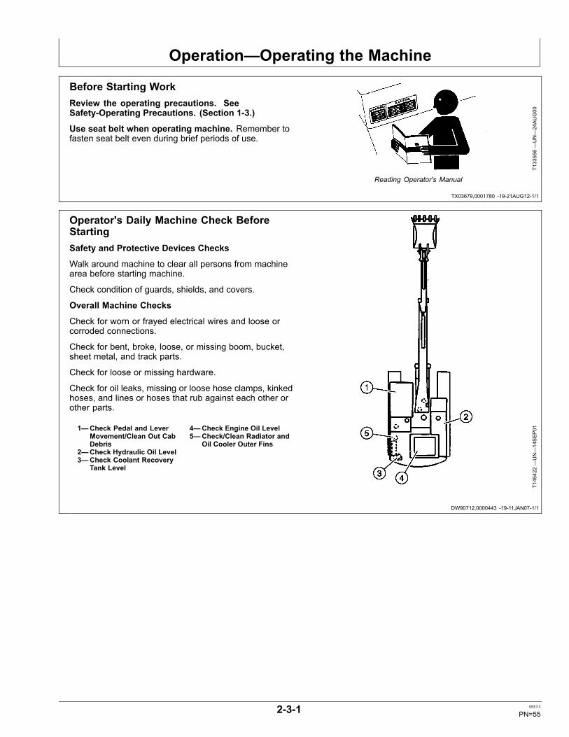
Operation—Operating the Machine
TX03679,0001780 -19-21AUG12-1/1
DW90712,0000443 -19-11JAN07-1/1
Before Starting WorkReview the operating precautions. SeeSafety-Operating Precautions. (Section 1-3.)
Use seat belt when operating machine. Remember tofasten seat belt even during brief periods of use.
T133556—UN—24AUG00
Reading Operator's Manual
Operator's Daily Machine Check BeforeStartingSafety and Protective Devices Checks
Walk around machine to clear all persons from machinearea before starting machine.
Check condition of guards, shields, and covers.
Overall Machine Checks
Check for worn or frayed electrical wires and loose orcorroded connections.
Check for bent, broke, loose, or missing boom, bucket,sheet metal, and track parts.
Check for loose or missing hardware.
Check for oil leaks, missing or loose hose clamps, kinkedhoses, and lines or hoses that rub against each other orother parts.
1—Check Pedal and LeverMovement/Clean Out CabDebris
2—Check Hydraulic Oil Level3—Check Coolant Recovery
Tank Level
4—Check Engine Oil Level5—Check/Clean Radiator and
Oil Cooler Outer Fins
T145422—UN—14SEP01
2-3-1 053113
PN=55
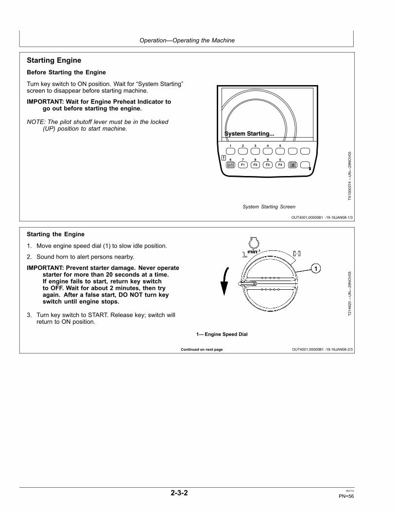
Operation—Operating the Machine
OUT4001,00000B1 -19-16JAN08-1/3
Continued on next page OUT4001,00000B1 -19-16JAN08-2/3
Starting EngineBefore Starting the Engine
Turn key switch to ON position. Wait for “System Starting”screen to disappear before starting machine.
IMPORTANT: Wait for Engine Preheat Indicator togo out before starting the engine.
NOTE: The pilot shutoff lever must be in the locked(UP) position to start machine.
System Starting...System Starting...
F1 F2 F3 F4
1 2 3 4 5
6 7 8 9 0
TX1000374—UN—29NOV05
System Starting Screen
Starting the Engine
1. Move engine speed dial (1) to slow idle position.
2. Sound horn to alert persons nearby.
IMPORTANT: Prevent starter damage. Never operatestarter for more than 20 seconds at a time.If engine fails to start, return key switchto OFF. Wait for about 2 minutes, then tryagain. After a false start, DO NOT turn keyswitch until engine stops.
3. Turn key switch to START. Release key; switch willreturn to ON position.
T214920—UN—29NOV05
1—Engine Speed Dial
2-3-2 053113
PN=56
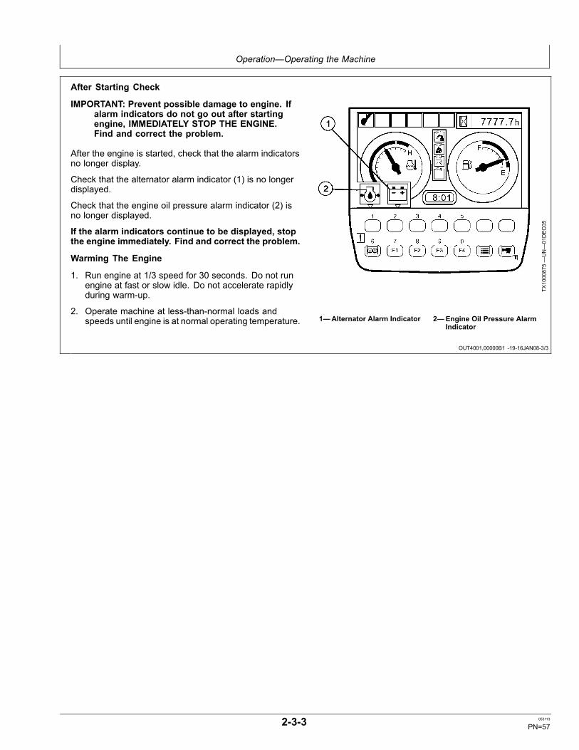
Operation—Operating the Machine
OUT4001,00000B1 -19-16JAN08-3/3
After Starting Check
IMPORTANT: Prevent possible damage to engine. Ifalarm indicators do not go out after startingengine, IMMEDIATELY STOP THE ENGINE.Find and correct the problem.
After the engine is started, check that the alarm indicatorsno longer display.
Check that the alternator alarm indicator (1) is no longerdisplayed.
Check that the engine oil pressure alarm indicator (2) isno longer displayed.
If the alarm indicators continue to be displayed, stopthe engine immediately. Find and correct the problem.
Warming The Engine
1. Run engine at 1/3 speed for 30 seconds. Do not runengine at fast or slow idle. Do not accelerate rapidlyduring warm-up.
2. Operate machine at less-than-normal loads andspeeds until engine is at normal operating temperature.
TX1000875—UN—01DEC05
1—Alternator Alarm Indicator 2—Engine Oil Pressure AlarmIndicator
2-3-3 053113
PN=57

Operation—Operating the Machine
DW90712,00002D3 -19-06MAR08-1/1
Cold Weather Warm-Up
CAUTION: Prevent possible injury fromunexpected machine movement. If hydraulic oilis cold, hydraulic functions move slowly. DO NOTattempt normal machine operation until hydraulicfunctions move at close-to-normal cycle times.
In extremely cold conditions, an extended warm-up periodwill be necessary.
Avoid sudden operation of all functions until the engineand hydraulic oil are thoroughly warm.
1. If temperature is below 0° Celsius (32° Fahrenheit),engine will start at 1400 rpm. Engine will maintain 1400rpm until hydraulic temperature reaches 2° Celsius(36° Fahrenheit) or 15 minutes, whichever comes first.
2. Run engine at 1/2 speed for 5 minutes. Do not runat fast or slow idle.
CAUTION: Prevent possible injury fromunexpected machine movement. Clear the area ofall persons before running your machine throughthe warm-up procedure. If machine is inside abuilding, warm the travel circuit first and movethe machine to a clear area outside. Cold oil willcause machine functions to respond slowly.
3. Actuate travel and swing functions slowly, initiallymoving only short distances.
4. Operate boom, arm, and bucket functions by movingcylinders a short distance each direction for the firsttime.
5. Continue cycling cylinders by increasing the traveleach cycle until full stroke is obtained.
6. Swing upperstructure so boom is perpendicular totracks.
CAUTION: Prevent possible injury from machinesliding backwards. Keep angle betweenboom and arm 90—110°.
7. Keeping the angle between boom and arm 90—110°,fully actuate bucket close function (cylinder extend)and lower bucket to raise track off ground.
IMPORTANT: Holding function actuated for morethan 10 seconds can cause damage fromhot spots in the control valve.
8. While rotating raised track in forward direction, actuatebucket curl function (cylinder extend) for 10 secondsand release for 5 seconds for a period of 2-1/2 minutes.
9. Repeat procedure with track rotating in reversedirection.
10. Lower machine to ground.
11. Repeat steps 6—10 on opposite track.
12. Operate all hydraulic functions to distribute warm oilin all cylinders, motors, and lines.
13. If hydraulic functions still move slowly, repeat steps7 and 8.
2-3-4 053113
PN=58

Operation—Operating the Machine
OUT4001,000009D -19-06MAR08-1/1
Travel Pedals and Levers
CAUTION: Keep bystanders clear of machinewhen traveling.
Keep bystanders clear of machine when traveling.
The instructions below apply when the travel motors (4)are to the rear of the machine. If the travel motors are tothe front of the machine, the machine moves OPPOSITEto the direction described.
FORWARD TRAVEL (1): Push down on front of bothpedals or push both levers forward.
REVERSE TRAVEL (2): Push down on rear of bothpedals or pull both levers rearward.
NEUTRAL POSITION (3): Travel brakes will automaticallystop and hold the machine.
RIGHT TURN: Push down on front of left pedal or pushleft lever forward.
LEFT TURN: Push down on front of right pedal or pushright lever forward.
SHORT TURN (COUNTER-ROTATE): Push down thefront of one pedal and the rear of the other or push onelever forward and pull the other rearward.
CAUTION: Prevent possible injury from machinetipping. Operate control pedals or levers slowlywhen traveling down a slope.
TRAVELING DOWN A SLOPE: Operate control pedals orlevers slowly when traveling down a slope.
T137492—UN—25JAN01
1—Forward Travel2—Reverse Travel
3—Neutral Position4—Travel Motor
COLD WEATHER OPERATION: Travel pedal and leverdampers are provided for smooth control. In extremelycold weather, pedal or lever effort will increase. Operatepedals or levers several times with pilot shutoff lever inlocked position.
2-3-5 053113
PN=59
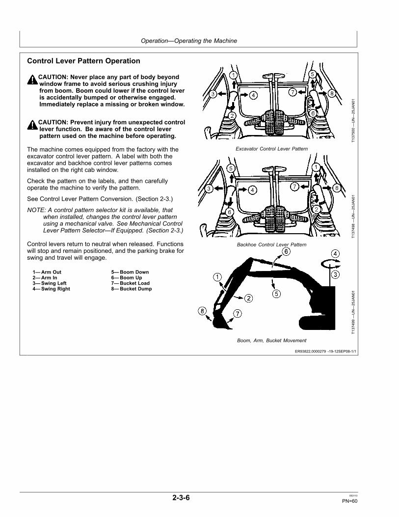
Operation—Operating the Machine
ER93822,0000279 -19-12SEP08-1/1
Control Lever Pattern Operation
CAUTION: Never place any part of body beyondwindow frame to avoid serious crushing injuryfrom boom. Boom could lower if the control leveris accidentally bumped or otherwise engaged.Immediately replace a missing or broken window.
CAUTION: Prevent injury from unexpected controllever function. Be aware of the control leverpattern used on the machine before operating.
The machine comes equipped from the factory with theexcavator control lever pattern. A label with both theexcavator and backhoe control lever patterns comesinstalled on the right cab window.
Check the pattern on the labels, and then carefullyoperate the machine to verify the pattern.
See Control Lever Pattern Conversion. (Section 2-3.)
NOTE: A control pattern selector kit is available, thatwhen installed, changes the control lever patternusing a mechanical valve. See Mechanical ControlLever Pattern Selector—If Equipped. (Section 2-3.)
Control levers return to neutral when released. Functionswill stop and remain positioned, and the parking brake forswing and travel will engage.
1—Arm Out2—Arm In3—Swing Left4—Swing Right
5—Boom Down6—Boom Up7—Bucket Load8—Bucket Dump
T137500—UN—25JAN01
Excavator Control Lever Pattern
T137498—UN—25JAN01
Backhoe Control Lever Pattern
T137499—UN—25JAN01
Boom, Arm, Bucket Movement
2-3-6 053113
PN=60
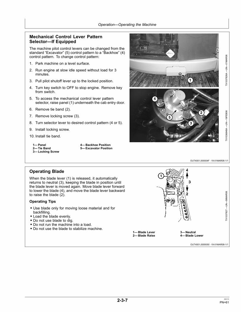
Operation—Operating the Machine
OUT4001,000004F -19-01MAR08-1/1
OUT4001,0000050 -19-01MAR08-1/1
Mechanical Control Lever PatternSelector—If EquippedThe machine pilot control levers can be changed from thestandard “Excavator” (5) control pattern to a “Backhoe” (4)control pattern. To change control pattern:
1. Park machine on a level surface.
2. Run engine at slow idle speed without load for 3minutes.
3. Pull pilot shutoff lever up to the locked position.
4. Turn key switch to OFF to stop engine. Remove keyfrom switch.
5. To access the mechanical control lever patternselector, raise panel (1) underneath the cab entry door.
6. Remove tie band (2).
7. Remove locking screw (3).
8. Turn selector lever to desired control pattern (4 or 5).
9. Install locking screw.
10. Install tie band.
1—Panel2—Tie Band3—Locking Screw
4—Backhoe Position5—Excavator Position
TX1037826A
—UN—01MAR08
TX1036848A
—UN—19FE
B08
Operating BladeWhen the blade lever (1) is released, it automaticallyreturns to neutral (3), keeping the blade in position untilthe blade lever is moved again. Move blade lever forwardto lower the blade (4), and move the blade lever backwardto raise the blade (2).
Operating Tips
• Use blade only for moving loose material and forbackfilling.• Load the blade evenly.• Do not use blade to dig.• Do not run the machine into a load.• Do not use the blade to stabilize machine.
TX1037827—UN—06MAR08
1—Blade Lever2—Blade Raise
3—Neutral4—Blade Lower
2-3-7 053113
PN=61
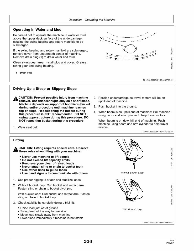
Operation—Operating the Machine
TX14740,0001CAF -19-05SEP06-1/1
DW90712,00002D6 -19-07SEP06-1/1
DW90712,00002D7 -19-07SEP06-1/1
Operating In Water and MudBe careful not to operate the machine in water or mudabove the upper deck surface of the undercarriage,causing the swing bearing and rotary manifold to besubmerged.
If the swing bearing and rotary manifold are submerged,remove cover from underneath center of machine.Remove drain plug (1) to drain water and mud.
Clean swing gear area. Install plug and cover. Greaseswing gear and swing bearing.
1—Drain Plug
T136459—UN—18DEC00
Driving Up a Steep or Slippery Slope
CAUTION: Prevent possible injury from machinerollover. Use this technique only on a short slope.Machine depends on support of boom/arm/bucketduring entire procedure until machine reachestop of slope. Repositioning the bucket duringthis procedure is NOT recommended. DO NOTswing upperstructure during this procedure. DONOT reposition bucket during this procedure.
1. Wear seat belt.
2. Position undercarriage so travel motors will be onuphill end of machine.
3. Push bucket into the ground.
4. When boom is on uphill end of machine: Pull machineusing boom and arm cylinder to help travel motors.
When boom is on downhill end of machine: Pushmachine using boom and arm cylinder to help travelmotors.
Lifting
CAUTION: Lifting requires special care. Observethese rules when lifting with your machine:
• Never use machine to lift people• Do not exceed lift capacity limits• Keep everyone clear of raised loads• Never attach sling or chain to bucket teeth• Use tether lines to guide loads• Use hand signals to communicate with others
1. Use proper rigging to attach and stabilize loads.
2. Without bucket loop: Curl bucket and retract arm.Fasten sling or chain to bucket pivot pin.
With bucket loop: Curl bucket and retract arm. Fastensling or chain to bucket loop.
3. Check stability by carefully doing a trial lift:
• Raise load just off of ground• Swing load all the way to one side• Move load slowly away from machine• Lower load immediately if machine is not stable
T133649—UN—02NOV00
Without Bucket LoopT135070—UN—02NOV00
With Bucket Loop
2-3-8 053113
PN=62
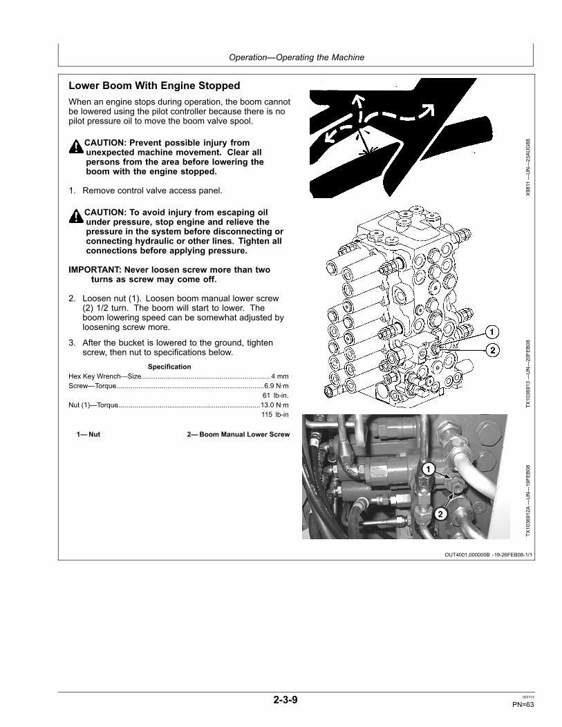
Operation—Operating the Machine
OUT4001,000000B -19-26FEB08-1/1
Lower Boom With Engine StoppedWhen an engine stops during operation, the boom cannotbe lowered using the pilot controller because there is nopilot pressure oil to move the boom valve spool.
CAUTION: Prevent possible injury fromunexpected machine movement. Clear allpersons from the area before lowering theboom with the engine stopped.
1. Remove control valve access panel.
CAUTION: To avoid injury from escaping oilunder pressure, stop engine and relieve thepressure in the system before disconnecting orconnecting hydraulic or other lines. Tighten allconnections before applying pressure.
IMPORTANT: Never loosen screw more than twoturns as screw may come off.
2. Loosen nut (1). Loosen boom manual lower screw(2) 1/2 turn. The boom will start to lower. Theboom lowering speed can be somewhat adjusted byloosening screw more.
3. After the bucket is lowered to the ground, tightenscrew, then nut to specifications below.
SpecificationHex Key Wrench—Size................................................................... 4 mmScrew—Torque.............................................................................6.9 N·m
61 lb-in.Nut (1)—Torque..........................................................................13.0 N·m
115 lb-in
1—Nut 2—Boom Manual Lower Screw
X9811
—UN—23AUG88
TX1036913—UN—20FE
B08
TX1036912A
—UN—19FE
B08
2-3-9 053113
PN=63

Operation—Operating the Machine
OUT4001,000009F -19-15JAN08-1/1
Parking Machine
IMPORTANT: During freezing weather, preventdamage to undercarriage components fromfrozen mud and dirt. Machine must beparked on a solid level surface to preventtracks freezing in the ground.
1. Park machine on a solid level surface.
During freezing weather, clean mud and dirt fromtracks, rollers, and track frames. Clean the steps andwalkways after parking the machine.
If tracks are frozen in the ground, slowly raise themachine using boom to free the tracks. Move machinecarefully.
2. Lower equipment to the ground.
3. Turn auto-idle switch OFF.
IMPORTANT: Turbocharger can be damagedif procedure to shut down engine isnot done properly.
4. Run engine with engine rpm dial at 1/3 position withoutload for 2 minutes.
5. Turn engine rpm dial to slow idle position.
6. Turn key switch to OFF. Remove key from switch.
7. Pull pilot shutoff lever to locked position.
IMPORTANT: Prevent cab electrical componentdamage from bad weather. Windows, roofvent, and cab door must be closed to preventrain from entering the cab.
8. Close windows, roof vent, and cab door.
9. Lock all access doors and compartments.
2-3-10 053113
PN=64
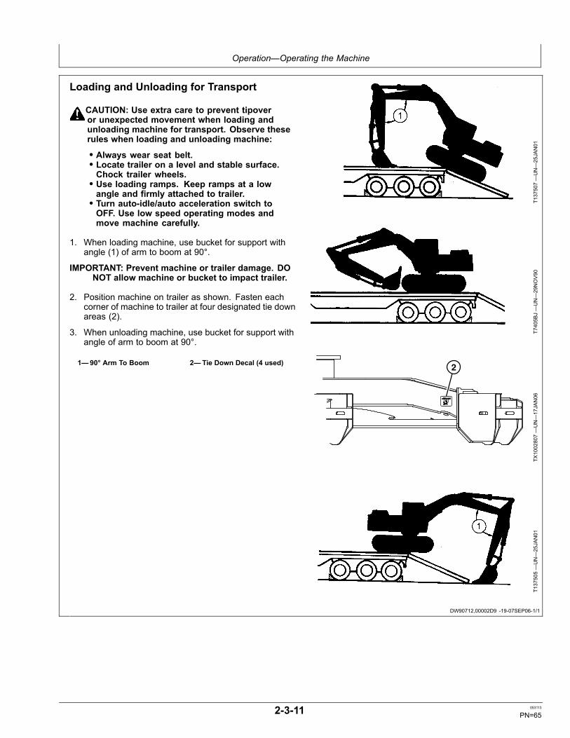
Operation—Operating the Machine
DW90712,00002D9 -19-07SEP06-1/1
Loading and Unloading for Transport
CAUTION: Use extra care to prevent tipoveror unexpected movement when loading andunloading machine for transport. Observe theserules when loading and unloading machine:
• Always wear seat belt.• Locate trailer on a level and stable surface.Chock trailer wheels.• Use loading ramps. Keep ramps at a lowangle and firmly attached to trailer.• Turn auto-idle/auto acceleration switch toOFF. Use low speed operating modes andmove machine carefully.
1. When loading machine, use bucket for support withangle (1) of arm to boom at 90°.
IMPORTANT: Prevent machine or trailer damage. DONOT allow machine or bucket to impact trailer.
2. Position machine on trailer as shown. Fasten eachcorner of machine to trailer at four designated tie downareas (2).
3. When unloading machine, use bucket for support withangle of arm to boom at 90°.
1—90° Arm To Boom 2—Tie Down Decal (4 used)
T137507—UN—25JAN01
T7405B
J—UN—29NOV90
2
TX1002807—UN—17JAN06
T137505—UN—25JAN01
2-3-11 053113
PN=65
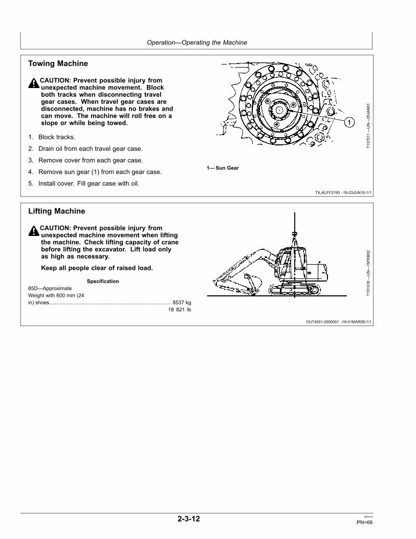
Operation—Operating the Machine
TX,40,FF2193 -19-23JUN10-1/1
OUT4001,0000051 -19-01MAR08-1/1
Towing Machine
CAUTION: Prevent possible injury fromunexpected machine movement. Blockboth tracks when disconnecting travelgear cases. When travel gear cases aredisconnected, machine has no brakes andcan move. The machine will roll free on aslope or while being towed.
1. Block tracks.
2. Drain oil from each travel gear case.
3. Remove cover from each gear case.
4. Remove sun gear (1) from each gear case.
5. Install cover. Fill gear case with oil.
T137511—UN—25JAN01
1—Sun Gear
Lifting Machine
CAUTION: Prevent possible injury fromunexpected machine movement when liftingthe machine. Check lifting capacity of cranebefore lifting the excavator. Lift load onlyas high as necessary.
Keep all people clear of raised load.
Specification85D—ApproximateWeight with 600 mm (24in) shoes...................................................................................... 8537 kg
18 821 lb
T151518—UN—15FE
B02
2-3-12 053113
PN=66
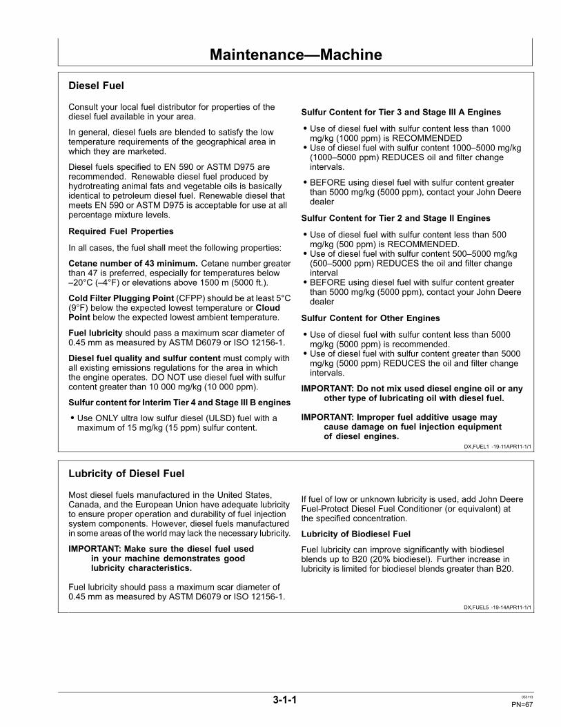
Maintenance—Machine
DX,FUEL1 -19-11APR11-1/1
DX,FUEL5 -19-14APR11-1/1
Diesel Fuel
Consult your local fuel distributor for properties of thediesel fuel available in your area.
In general, diesel fuels are blended to satisfy the lowtemperature requirements of the geographical area inwhich they are marketed.
Diesel fuels specified to EN 590 or ASTM D975 arerecommended. Renewable diesel fuel produced byhydrotreating animal fats and vegetable oils is basicallyidentical to petroleum diesel fuel. Renewable diesel thatmeets EN 590 or ASTM D975 is acceptable for use at allpercentage mixture levels.
Required Fuel Properties
In all cases, the fuel shall meet the following properties:
Cetane number of 43 minimum. Cetane number greaterthan 47 is preferred, especially for temperatures below–20°C (–4°F) or elevations above 1500 m (5000 ft.).
Cold Filter Plugging Point (CFPP) should be at least 5°C(9°F) below the expected lowest temperature or CloudPoint below the expected lowest ambient temperature.
Fuel lubricity should pass a maximum scar diameter of0.45 mm as measured by ASTM D6079 or ISO 12156-1.
Diesel fuel quality and sulfur content must comply withall existing emissions regulations for the area in whichthe engine operates. DO NOT use diesel fuel with sulfurcontent greater than 10 000 mg/kg (10 000 ppm).
Sulfur content for Interim Tier 4 and Stage III B engines
• Use ONLY ultra low sulfur diesel (ULSD) fuel with amaximum of 15 mg/kg (15 ppm) sulfur content.
Sulfur Content for Tier 3 and Stage III A Engines
• Use of diesel fuel with sulfur content less than 1000mg/kg (1000 ppm) is RECOMMENDED• Use of diesel fuel with sulfur content 1000–5000 mg/kg(1000–5000 ppm) REDUCES oil and filter changeintervals.
• BEFORE using diesel fuel with sulfur content greaterthan 5000 mg/kg (5000 ppm), contact your John Deeredealer
Sulfur Content for Tier 2 and Stage II Engines
• Use of diesel fuel with sulfur content less than 500mg/kg (500 ppm) is RECOMMENDED.• Use of diesel fuel with sulfur content 500–5000 mg/kg(500–5000 ppm) REDUCES the oil and filter changeinterval• BEFORE using diesel fuel with sulfur content greaterthan 5000 mg/kg (5000 ppm), contact your John Deeredealer
Sulfur Content for Other Engines
• Use of diesel fuel with sulfur content less than 5000mg/kg (5000 ppm) is recommended.• Use of diesel fuel with sulfur content greater than 5000mg/kg (5000 ppm) REDUCES the oil and filter changeintervals.
IMPORTANT: Do not mix used diesel engine oil or anyother type of lubricating oil with diesel fuel.
IMPORTANT: Improper fuel additive usage maycause damage on fuel injection equipmentof diesel engines.
Lubricity of Diesel Fuel
Most diesel fuels manufactured in the United States,Canada, and the European Union have adequate lubricityto ensure proper operation and durability of fuel injectionsystem components. However, diesel fuels manufacturedin some areas of the world may lack the necessary lubricity.
IMPORTANT: Make sure the diesel fuel usedin your machine demonstrates goodlubricity characteristics.
Fuel lubricity should pass a maximum scar diameter of0.45 mm as measured by ASTM D6079 or ISO 12156-1.
If fuel of low or unknown lubricity is used, add John DeereFuel-Protect Diesel Fuel Conditioner (or equivalent) atthe specified concentration.
Lubricity of Biodiesel Fuel
Fuel lubricity can improve significantly with biodieselblends up to B20 (20% biodiesel). Further increase inlubricity is limited for biodiesel blends greater than B20.
3-1-1 053113
PN=67

Maintenance—Machine
DX,FUEL4 -19-14APR11-1/1
Handling and Storing Diesel Fuel
CAUTION: Reduce the risk of fire. Handle fuelcarefully. DO NOT fill the fuel tank when engineis running. DO NOT smoke while you fill thefuel tank or service the fuel system.
Fill the fuel tank at the end of each day's operation toprevent water condensation and freezing during coldweather.
Keep all storage tanks as full as practicable to minimizecondensation.
Ensure that all fuel tank caps and covers are installedproperly to prevent moisture from entering. Monitor watercontent of the fuel regularly.
When using biodiesel fuel, the fuel filter may require morefrequent replacement due to premature plugging.
Check engine oil level daily prior to starting engine. Arising oil level may indicate fuel dilution of the engine oil.
IMPORTANT: The fuel tank is vented through thefiller cap. If a new filler cap is required, alwaysreplace it with an original vented cap.
When fuel is stored for an extended period or if there is aslow turnover of fuel, add a fuel conditioner to stabilize thefuel and prevent water condensation. Contact your fuelsupplier for recommendations.
3-1-2 053113
PN=68

Maintenance—Machine
Continued on next page DX,FUEL7 -19-29AUG12-1/2
Biodiesel Fuel
Biodiesel fuel is comprised of mono-alkyl esters of longchain fatty acids derived from vegetable oils or animalfats. Biodiesel blends are biodiesel mixed with petroleumdiesel fuel on a volume basis.
Before using fuel containing biodiesel, review theBiodiesel Use Requirements and Recommendations inthis Operator’s Manual.
Environmental laws and regulations can encourage orprohibit the use of biofuels. Operators should consultwith appropriate governmental authorities prior to usingbiofuels.
All John Deere Engines with Exhaust Filter (Released2011 and After)
While 5% blends (B5) are preferred, biodieselconcentrations up to a 20% blend (B20) in petroleumdiesel fuel can be used. Biodiesel blends up to B20can be used ONLY if the biodiesel (100% biodiesel orB100) meets ASTM D6751, EN 14214, or equivalentspecification. Expect a 2% reduction in power and a 3%reduction in fuel economy when using B20.
Biodiesel concentrations above B20 can harm theengine’s emission control systems and should not beused. Risks include, but are not limited to, more frequentstationary regeneration, soot accumulation, and increasedintervals for ash removal.
John Deere approved fuel conditioners, which containdetergent and dispersant additives, are required whenusing B20, and are recommended when using lowerbiodiesel blends.
All John Deere Engines Excluding Exhaust Filter(Primarily Released Prior to 2012)
While 5% blends (B5) are preferred, biodieselconcentrations up to a 20% blend (B20) in petroleumdiesel fuel can be used. Biodiesel blends up to B20can be used ONLY if the biodiesel (100% biodiesel orB100) meets ASTM D6751, EN 14214, or equivalentspecification. Expect a 2% reduction in power and a 3%reduction in fuel economy when using B20.
These John Deere engines can operate on biodieselblends above B20 (up to 100% biodiesel). Operate atlevels above B20 ONLY if the biodiesel is permitted by lawand meets the EN 14214 specification (primarily availablein Europe). Engines operating on biodiesel blends aboveB20 might not fully comply with or be permitted by allapplicable emissions regulations. Expect up to a 12%reduction in power and an 18% reduction in fuel economywhen using 100% biodiesel.
John Deere approved fuel conditioners, which containdetergent and dispersant additives, are required whenusing B20, and are recommended when using lowerbiodiesel blends.
Biodiesel Use Requirements and Recommendations
The petroleum diesel portion of all biodiesel blends mustmeet the requirements of ASTM D975 (US) or EN 590(EU) commercial standards.
Biodiesel users in the U.S. are strongly encouraged topurchase biodiesel blends from a BQ-9000 CertifiedMarketer and sourced from a BQ-9000 AccreditedProducer (as certified by the National Biodiesel Board).Certified Marketers and Accredited Producers can befound at the following website: http://www.bq9000.org.
Biodiesel contains residual ash. Ash levels exceeding themaximums allowed in either ASTM D6751 or EN14214can result in more rapid ash loading and require morefrequent cleaning of the Exhaust Filter (if present).
The fuel filter can require more frequent replacement,when using biodiesel fuel, particularly if switching fromdiesel. Check engine oil level daily prior to starting engine.A rising oil level can indicate fuel dilution of the engine oil.Biodiesel blends up to B20 must be used within 90 daysof the date of biodiesel manufacture. If used, biodieselblends above B20 must be used within 45 days from thedate of biodiesel manufacture.
When using biodiesel blends up to B20, the followingmust be considered:
• Cold weather flow degradation• Stability and storage issues (moisture absorption,microbial growth)• Possible filter restriction and plugging (usually a problemwhen first switching to biodiesel on used engines.)• Possible fuel leakage through seals and hoses(primarily an issue with older engines)• Possible reduction of service life of engine componentsRequest a certificate of analysis from your fuel distributorto ensure that the fuel is compliant with the specificationsprovided in this Operator’s Manual.
Consult your John Deere dealer for approved fuelconditioners to improve storage and performance withbiodiesel fuels.
The following must also be considered if using biodieselblends above B20:
• Possible coking or blocked injector nozzles, resulting inpower loss and engine misfire if John Deere approvedfuel conditioners are not used• Possible crankcase oil dilution (requiring more frequentoil changes)• Possible lacquering or seizure of internal components• Possible formation of sludge and sediments• Possible thermal oxidation of fuel at elevatedtemperatures• Possible compatibility issues with other materials(including copper, lead, zinc, tin, brass, and bronze)used in fuel handling equipment• Possible reduction in water separator efficiency• Possible damage to paint if exposed to biodiesel
3-1-3 053113
PN=69
Maintenance—Machine
DX,FUEL7 -19-29AUG12-2/2
DX,FUEL6 -19-14APR11-1/1
• Possible corrosion of fuel injection equipment• Possible elastomeric seal and gasket materialdegradation (primarily an issue with older engines)• Possible high acid levels within fuel system• Because biodiesel blends above B20 contain moreash, using blends above B20 can result in more rapidash loading and require more frequent cleaning of theExhaust Filter (if present)
IMPORTANT: Raw pressed vegetable oils areNOT acceptable for use as fuel in anyconcentration in John Deere engines. Theiruse could cause engine failure.
Testing Diesel FuelA fuel analysis program can help to monitor the qualityof diesel fuel. The fuel analysis can provide criticaldata such as cetane number, fuel type, sulfur content,water content, appearance, suitability for cold weather
operations, bacteria, cloud point, acid number, particulatecontamination, and whether the fuel meets specification.
Contact your John Deere dealer for more information ondiesel fuel analysis.
3-1-4 053113
PN=70

Maintenance—Machine
DX,FUEL10 -19-20APR11-1/1
Minimizing the Effect of Cold Weather on Diesel Engines
John Deere diesel engines are designed to operateeffectively in cold weather.
However, for effective starting and cold weather operation,a little extra care is necessary. The information belowoutlines steps that can minimize the effect that coldweather may have on starting and operation of yourengine. See your John Deere dealer for additionalinformation and local availability of cold weather aids.
Use Winter Grade Fuel
When temperatures fall below 0°C (32°F), winter gradefuel (No. 1-D in North America) is best suited for coldweather operation. Winter grade fuel has a lower cloudpoint and a lower pour point.
Cloud point is the temperature at which wax will begin toform in the fuel and this wax causes fuel filters to plug.Pour point is the lowest temperature at which movementof the fuel is observed.
NOTE: On average, winter grade diesel fuel has a lowerBtu (heat content) rating. Using winter grade fuelmay reduce power and fuel efficiency, but should notcause any other engine performance effects. Checkthe grade of fuel being used before troubleshootingfor low power complaints in cold weather operation.
Air Intake Heater
An air intake heater is an available option for someengines to aid cold weather starting.
Ether
An ether port on the intake is available to aid cold weatherstarting.
CAUTION: Ether is highly flammable. Do notuse ether when starting an engine equippedwith glow plugs or an air intake heater.
Coolant Heater
An engine block heater (coolant heater) is an availableoption to aid cold weather starting.
Seasonal Viscosity Oil and Proper CoolantConcentration
Use seasonal grade viscosity engine oil based on theexpected air temperature range between oil changesand a proper concentration of low silicate antifreeze asrecommended. (See DIESEL ENGINE OIL and ENGINECOOLANT requirements in this section.)
Diesel Fuel Flow Additive
Use John Deere Fuel-Protect Diesel Fuel Conditioner(winter formula), which contains anti-gel chemistry, orequivalent fuel conditioner to treat non-winter grade fuel(No. 2-D in North America) during the cold weatherseason. This generally extends operability to about 10°C(18°F) below the fuel cloud point. For operability at evenlower temperatures, use winter grade fuel.
IMPORTANT: Treat fuel when outside temperaturedrops below 0°C (32°F). For best results, usewith untreated fuel. Follow all recommendedinstructions on label.
BioDiesel
When operating with biodiesel blends, wax formation canoccur at warmer temperatures. Begin using John DeereFuel-Protect Diesel Fuel Conditioner (winter formula) at5°C (41°F) to treat biodiesel fuels during the cold weatherseason. Use B5 or lower blends at temperatures below0°C (32°F). Use only winter grade petroleum diesel fuelat temperatures below -10°C (14°F).
Winterfronts
Use of fabric, cardboard, or solid winterfronts is notrecommended with any John Deere engine. Their usecan result in excessive engine coolant, oil, and chargeair temperatures. This can lead to reduced engine life,loss of power and poor fuel economy. Winterfronts mayalso put abnormal stress on fan and fan drive componentspotentially causing premature failures.
If winterfronts are used, they should never totally closeoff the grill frontal area. Approximately 25% area in thecenter of the grill should remain open at all times. At notime should the air blockage device be applied directlyto the radiator core.
Radiator Shutters
If equipped with a thermostatically controlled radiatorshutter system, this system should be regulated in such away that the shutters are completely open by the time thecoolant reaches 93°C (200°F) to prevent excessive intakemanifold temperatures. Manually controlled systems arenot recommended.
If air-to-air aftercooling is used, the shutters must becompletely open by the time the intake manifold airtemperature reaches the maximum allowable temperatureout of the charge air cooler.
For more information, see your John Deere dealer.
3-1-5 053113
PN=71

Maintenance—Machine
DX,ALTER -19-11APR11-1/1
VD76477,0001322 -19-08FEB13-1/1
Alternative and Synthetic Lubricants
Conditions in certain geographical areas may requirelubricant recommendations different from those printed inthis manual.
Some John Deere brand coolants and lubricants may notbe available in your location.
Consult your John Deere dealer to obtain information andrecommendations.
Synthetic lubricants may be used if they meet theperformance requirements as shown in this manual.
The temperature limits and service intervals shown inthis manual apply to both conventional and syntheticlubricants.
Re-refined base stock products may be used if thefinished lubricant meets the performance requirements.
Diesel Engine Break-In™ Oil
New engines are filled at the factory with either JohnDeere Break-In™ or Break-In Plus™ Engine Oil. Duringthe break-in period, add John Deere Break-In or Break-InPlus Engine Oil, respectively, as needed to maintain thespecified oil level.
Operate the engine under various conditions, particularlyheavy loads with minimal idling, to help seat enginecomponents properly.
Change the oil and filter at 250 hours maximum forBreak-In Oil or 500 hours maximum for Break-In Plus Oilduring the initial operation of a new or rebuilt engine.
After engine overhaul, fill the engine with either JohnDeere Break-In or Break-In Plus Engine Oil.
If John Deere Break-In or Break-In Plus Engine Oil is notavailable, use a 10W-30 diesel engine oil meeting one ofthe following during the first 250 hours of operation:
• API Service Classification CE• API Service Classification CD• API Service Classification CC• ACEA Oil Sequence E2• ACEA Oil Sequence E1
IMPORTANT: Do not use Plus-50™ II, Plus-50, orengine oils meeting any of the following for theinitial break-in of a new or rebuilt engine:
API CJ-4 ACEA E9API CI-4 PLUS ACEA E7API CI-4 ACEA E6API CH-4 ACEA E5API CG-4 ACEA E4API CF-4 ACEA E3API CF-2API CF
These oils will not allow the engine tobreak in properly.
John Deere Break-In Plus Engine Oil can be used for allJohn Deere diesel engines at all emission certificationlevels.
After the break-in period, use John Deere Plus-50 II, JohnDeere Plus-50, or other diesel engine oil as recommendedin this manual.
Break-In is a trademark of Deere & Company.Break-In Plus is a trademark of Deere & CompanyPlus-50 is a trademark of Deere & Company.
3-1-6 053113
PN=72
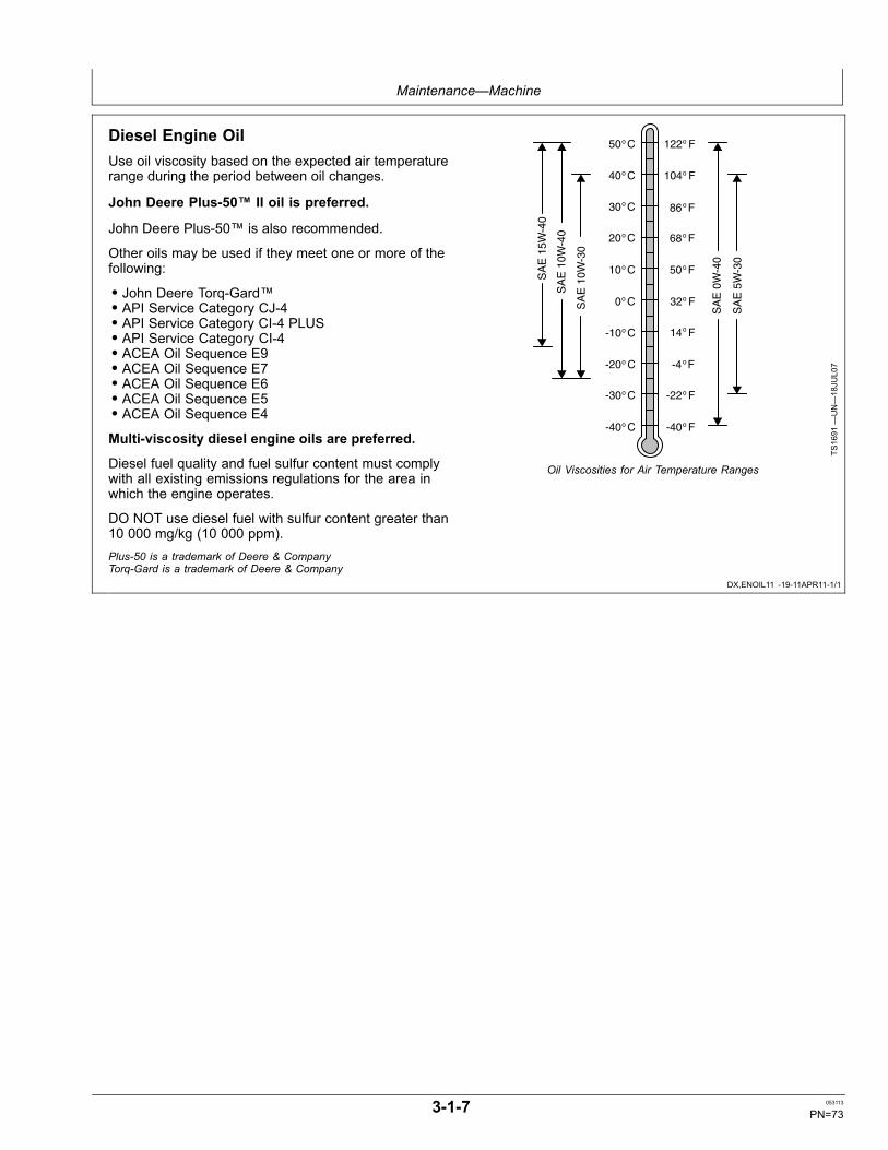
Maintenance—Machine
DX,ENOIL11 -19-11APR11-1/1
Diesel Engine OilUse oil viscosity based on the expected air temperaturerange during the period between oil changes.
John Deere Plus-50™ II oil is preferred.
John Deere Plus-50™ is also recommended.
Other oils may be used if they meet one or more of thefollowing:
• John Deere Torq-Gard™• API Service Category CJ-4• API Service Category CI-4 PLUS• API Service Category CI-4• ACEA Oil Sequence E9• ACEA Oil Sequence E7• ACEA Oil Sequence E6• ACEA Oil Sequence E5• ACEA Oil Sequence E4
Multi-viscosity diesel engine oils are preferred.
Diesel fuel quality and fuel sulfur content must complywith all existing emissions regulations for the area inwhich the engine operates.
DO NOT use diesel fuel with sulfur content greater than10 000 mg/kg (10 000 ppm).
SA
E 1
5W-4
0
SA
E 1
0W-4
0
SA
E 1
0W-3
0
SA
E 0
W-4
0
SA
E 5
W-3
0
50 Co
40 Co
30 Co
20 Co
10 Co
0 C o
-10 Co
-20 Co
-30 Co
-40 Co
122 Fo
50 Fo
32 Fo
14 Fo
-4 Fo
-22 Fo
-40 Fo
104 Fo
68 Fo
86 Fo
TS1691
—UN—18JU
L07
Oil Viscosities for Air Temperature Ranges
Plus-50 is a trademark of Deere & CompanyTorq-Gard is a trademark of Deere & Company
3-1-7 053113
PN=73

Maintenance—Machine
DX,ENOIL13 -19-03AUG09-1/1
Diesel Engine Oil and Filter Service Intervals
The oil and filter service intervals in the following tableshould be used as guidelines. Actual service intervalsalso depend on operation and maintenance practices. Itis suggested to use oil analysis to determine the actualuseful life of the oil and to aid in selection of the properoil and filter service interval.
Oil and filter service intervals are based on a combinationof oil pan capacity, type of engine oil and filter used, andsulfur content of the diesel fuel.
Diesel fuel sulfur level will affect engine oil and filterservice intervals. Higher fuel sulfur levels reduce oil andfilter service intervals as shown in the table.
• Use of diesel fuel with sulfur content less than 0.10%(1000 mg/kg) is strongly recommended.• Use of diesel fuel with sulfur content 0.10% (1000mg/kg) to 0.50% (5000 mg/kg) may result in REDUCEDoil and filter change intervals as shown in the table.• BEFORE using diesel fuel with sulfur content greaterthan 0.50% (5000 mg/kg), contact your John Deeredealer.• DO NOT use diesel fuel with sulfur content greater than1.00% (10 000 mg/kg).
IMPORTANT: When using biodiesel blends greaterthan B20, reduce the oil and filter serviceinterval by 50% or monitor engine oil basedon test results from Oilscan.
Oil types in the table include:
• John Deere Plus-50™ II and John Deere Plus-50• “Other Oils” include John Deere Torq-Gard Supreme™,API CJ-4, API CI-4 PLUS, API CI-4, ACEA E9, ACEAE7, ACEA E6, ACEA E5, or ACEA E4 oils.
Use of lower specification oils in Tier 3 engines may resultin premature engine failure.
NOTE: The 500 hour extended oil and filter change intervalis only allowed if all the following conditions are met:
• Engine equipped with an extended draininterval oil pan• Use of diesel fuel with sulfur content lessthan 0.50% (5000 mg/kg)• Use of John Deere Plus-50™ II or JohnDeere Plus-50 oil• Use of an approved John Deere oil filter
U.S. Tier 3 and EU Stage III A - PowerTech Plus™ U.S. Tier 3 and EU Stage III A - PowerTech™Oil Pan Size (L/kW) Oil Pan Size (L/kW)
Oil pan capacity Greater than orequal to 0.10
Greater than orequal to 0.12
Greater than orequal to 0.14
Greater than orequal to 0.22
Greater than orequal to 0.10
Greater than orequal to 0.12
Greater than orequal to 0.14
Fuel Sulfur Less than 0.10% (1000 mg/kg) Less than 0.10% (1000 mg/kg)Plus-50 375 hours 500 hours 500 hours 500 hours 375 hours 500 hours 500 hours
Other Oils 250 hours 250 hours 250 hours 250 hours 250 hours 250 hours 250 hoursFuel Sulfur 0.10 - 0.20% (1000 - 2000 mg/kg) 0.10 - 0.20% (1000 - 2000 mg/kg)Plus-50 300 hours 300 hours 500 hours 500 hours 300 hours 400 hours 500 hours
Other Oils 200 hours 200 hours 250 hours 250 hours 200 hours 200 hours 250 hoursFuel Sulfur 0.20 - 0.50% (2000 - 5000 mg/kg) 0.20 - 0.50% (2000 - 5000 mg/kg)Plus-50 250 hours 250 hours 300 hours 500 hours 275 hours 350 hours 500 hours
Other Oils 150 hours 150 hours 200 hours 250 hours 150 hours 175 hours 250 hoursFuel Sulfur 0.50 - 1.00% (5000 - 10 000 mg/kg) 0.50 - 1.00% (5000 - 10 000 mg/kg)Plus-50 Contact John Deere Dealer (dealer refers to DTAC solutions) 187 hours 250 hours 250 hours
Other Oils Contact John Deere Dealer (dealer refers to DTAC solutions) 125 hours 125 hours 125 hoursThe service interval of “Other Oils” may be extended only if oil analysis is performed to determine the actual service life, to a maximum not toexceed that of Plus-50.
Plus-50 is a trademark of Deere & CompanyTorq-Gard Supreme is a trademark of Deere & CompanyPowerTech Plus is a trademark of Deere & CompanyPowerTech is a trademark of Deere & Company
3-1-8 053113
PN=74
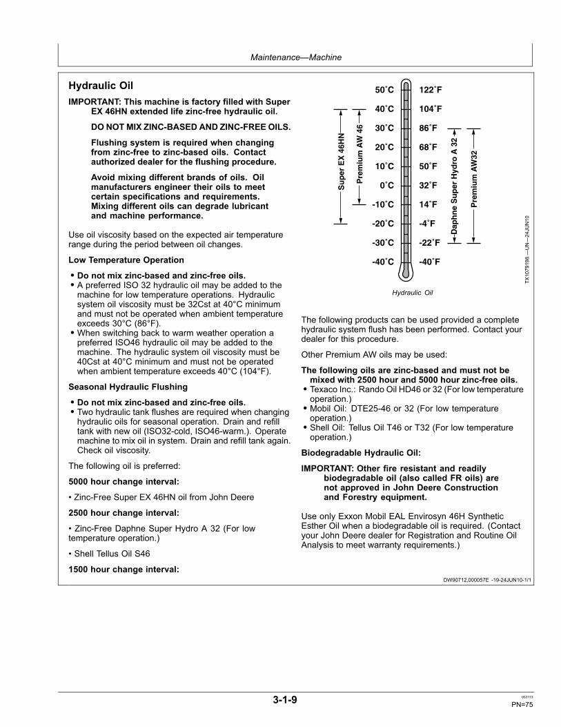
Maintenance—Machine
DW90712,000057E -19-24JUN10-1/1
Hydraulic OilIMPORTANT: This machine is factory filled with Super
EX 46HN extended life zinc-free hydraulic oil.
DO NOTMIX ZINC-BASED AND ZINC-FREE OILS.
Flushing system is required when changingfrom zinc-free to zinc-based oils. Contactauthorized dealer for the flushing procedure.
Avoid mixing different brands of oils. Oilmanufacturers engineer their oils to meetcertain specifications and requirements.Mixing different oils can degrade lubricantand machine performance.
Use oil viscosity based on the expected air temperaturerange during the period between oil changes.
Low Temperature Operation
• Do not mix zinc-based and zinc-free oils.• A preferred ISO 32 hydraulic oil may be added to themachine for low temperature operations. Hydraulicsystem oil viscosity must be 32Cst at 40°C minimumand must not be operated when ambient temperatureexceeds 30°C (86°F).• When switching back to warm weather operation apreferred ISO46 hydraulic oil may be added to themachine. The hydraulic system oil viscosity must be40Cst at 40°C minimum and must not be operatedwhen ambient temperature exceeds 40°C (104°F).
Seasonal Hydraulic Flushing
• Do not mix zinc-based and zinc-free oils.• Two hydraulic tank flushes are required when changinghydraulic oils for seasonal operation. Drain and refilltank with new oil (ISO32-cold, ISO46-warm.). Operatemachine to mix oil in system. Drain and refill tank again.Check oil viscosity.
The following oil is preferred:
5000 hour change interval:
• Zinc-Free Super EX 46HN oil from John Deere
2500 hour change interval:
• Zinc-Free Daphne Super Hydro A 32 (For lowtemperature operation.)
• Shell Tellus Oil S46
1500 hour change interval:
-40˚C
-30˚C
-20˚C
-10˚C
0˚C
10˚C
20˚C
30˚C
40˚C
50˚C
-40˚F
-22˚F
-4˚F
14˚F
32˚F
50˚F
68˚F
86˚F
104˚F
122˚F
Pre
miu
m A
W 4
6
Dap
hn
e S
up
er H
ydro
A 3
2
Pre
miu
m A
W32
Su
per
EX
46H
N
TX1079198—UN—24JU
N10
Hydraulic Oil
The following products can be used provided a completehydraulic system flush has been performed. Contact yourdealer for this procedure.
Other Premium AW oils may be used:
The following oils are zinc-based and must not bemixed with 2500 hour and 5000 hour zinc-free oils.• Texaco Inc.: Rando Oil HD46 or 32 (For low temperatureoperation.)• Mobil Oil: DTE25-46 or 32 (For low temperatureoperation.)• Shell Oil: Tellus Oil T46 or T32 (For low temperatureoperation.)
Biodegradable Hydraulic Oil:
IMPORTANT: Other fire resistant and readilybiodegradable oil (also called FR oils) arenot approved in John Deere Constructionand Forestry equipment.
Use only Exxon Mobil EAL Envirosyn 46H SyntheticEsther Oil when a biodegradable oil is required. (Contactyour John Deere dealer for Registration and Routine OilAnalysis to meet warranty requirements.)
3-1-9 053113
PN=75
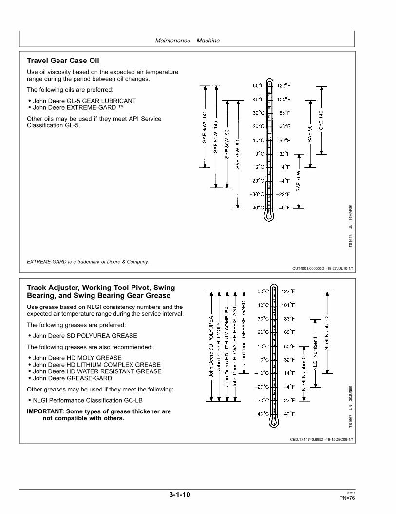
Maintenance—Machine
OUT4001,000000D -19-27JUL10-1/1
CED,TX14740,6952 -19-15DEC09-1/1
Travel Gear Case OilUse oil viscosity based on the expected air temperaturerange during the period between oil changes.
The following oils are preferred:
• John Deere GL-5 GEAR LUBRICANT• John Deere EXTREME-GARD ™
Other oils may be used if they meet API ServiceClassification GL-5.
TS1653
—UN—14MAR96
EXTREME-GARD is a trademark of Deere & Company.
Track Adjuster, Working Tool Pivot, SwingBearing, and Swing Bearing Gear GreaseUse grease based on NLGI consistency numbers and theexpected air temperature range during the service interval.
The following greases are preferred:
• John Deere SD POLYUREA GREASE
The following greases are also recommended:
• John Deere HD MOLY GREASE• John Deere HD LITHIUM COMPLEX GREASE• John Deere HD WATER RESISTANT GREASE• John Deere GREASE-GARDOther greases may be used if they meet the following:
• NLGI Performance Classification GC-LBIMPORTANT: Some types of grease thickener are
not compatible with others.
TS1667
—UN—30JU
N99
3-1-10 053113
PN=76
Maintenance—Machine
DX,COOL3 -19-14APR11-1/1
DX,COOL11 -19-14APR11-1/1
Heavy Duty Diesel Engine Coolant
The engine cooling system is filled to provide year-roundprotection against corrosion and cylinder liner pitting, andwinter freeze protection to -37°C (-34°F). If protection atlower temperatures is required, consult your John Deeredealer for recommendations.
The following engine coolants are preferred:
• John Deere COOL-GARD™ II Premix• John Deere COOL-GARD II PG Premix
Use John Deere COOL-GARD II PG Premix when anon-toxic coolant formulation is required.
Additional Recommended Coolants
The following engine coolant is also recommended:
• John Deere COOL-GARD II Concentrate in a 40–60%mixture of concentrate with quality water.
John Deere COOL-GARD II Premix, COOL-GARD II PGPremix, and COOL-GARD II Concentrate coolants do notrequire use of supplemental coolant additives.
Other Coolants
John Deere COOL-GARD II and COOL-GARD II PGcoolants might not be available in the geographical areawhere service is performed.
If these coolants are unavailable, use a coolantconcentrate or prediluted coolant intended for use withheavy duty diesel engines and with a minimum of thefollowing chemical and physical properties:
• Is formulated with a quality nitrite-free additive package.• Provides cylinder liner cavitation protection according toeither the John Deere Cavitation Test Method or a fleetstudy run at or above 60% load capacity• Protects the cooling system metals (cast iron, aluminumalloys, and copper alloys such as brass) from corrosion
The additive package must be part of one of the followingcoolant mixtures:
• ethylene glycol or propylene glycol base prediluted(40—60%) heavy duty coolant• ethylene glycol or propylene glycol base heavyduty coolant concentrate in a 40—60% mixture ofconcentrate with quality water
Water Quality
Water quality is important to the performance of thecooling system. Distilled, deionized, or demineralizedwater is recommended for mixing with ethylene glycol andpropylene glycol base engine coolant concentrate.
IMPORTANT: Do not use cooling system sealingadditives or antifreeze that containssealing additives.
Do not mix ethylene glycol and propyleneglycol base coolants.
Do not use coolants that contain nitrites.
COOL-GARD is a trademark of Deere & Company
Drain Intervals for Diesel Engine Coolant
Drain and flush the cooling system and refill with freshcoolant at the indicated interval, which varies with thecoolant used.
John Deere COOL-GARD™ II Premix, COOL-GARDII PG Premix and COOL-GARD II Concentrate aremaintenance free coolants for up to six years or 6000hours of operation, provided that the cooling system istopped off using only John Deere COOL-GARD II Premixor COOL-GARD II PG Premix.
Test the coolant condition annually with Coolant TestStrips designed for use with John Deere COOL-GARDII coolants. If the test strip chart indicates that additiveis required, add John Deere COOL-GARD II CoolantExtender as directed.
If John Deere COOL-GARD™ II Premix, COOL-GARD IIPG Premix, or COOL-GARD II Concentrate is used, butthe coolant is not tested OR additives are not replenishedby adding John Deere COOL-GARD II Coolant Extender,the drain interval is four years or 4000 hours of operation.This drain interval only applies to COOL-GARD II coolantsthat have been maintained within a 40—60% mixture ofconcentrate with quality water.
If a coolant other than COOL-GARD II, or COOL-GARDII PG is used, reduce the drain interval to two years or2000 hours of operation.
COOL-GARD is a trademark of Deere & Company
3-1-11 053113
PN=77
Maintenance—Machine
DX,COOL16 -19-20APR11-1/1
DX,COOL4 -19-14APR11-1/1
John Deere COOL-GARD™ II Coolant Extender
Some coolant additives will gradually deplete duringengine operation. For John Deere COOL-GARD™ IIPremix, COOL-GARD II PG Premix, and COOL-GARD IIConcentrate, replenish coolant additives between drainintervals by adding John Deere COOL-GARD II CoolantExtender.
John Deere COOL-GARD II Coolant Extender should notbe added unless indicated by coolant testing.
John Deere COOL-GARD II Coolant Extender is achemically matched additive system for use with allJohn Deere COOL-GARD II coolants. John DeereCOOL-GARD II Coolant Extender is not intended for usewith nitrite-containing coolants.
IMPORTANT: Do not add a supplemental coolantadditive when the cooling system is drainedand refilled with any of the following:
• John Deere COOL-GARD II• John Deere COOL-GARD II PG
The use of non-recommended supplemental coolantadditives may result in additive drop-out, gelation of thecoolant, or corrosion of cooling system components.
Add the recommended concentration of John DeereCOOL-GARD II Coolant Extender. DO NOT add morethan the recommended amount.
COOL-GARD is a trademark of Deere & Company
Supplemental Coolant Additives
Some coolant additives will gradually deplete duringengine operation. For nitrite-containing coolants,replenish coolant additives between drain intervals byadding a supplemental coolant additive as determinednecessary by coolant testing.
John Deere Liquid Coolant Conditioner is recommendedas a supplemental coolant additive for nitrite-containingcoolants.
John Deere Liquid Coolant Conditioner is not designedfor use with John Deere COOL-GARD™ II Premix,COOL-GARD II PG Premix, or COOL-GARD IIConcentrate.
IMPORTANT: Do not add a supplemental coolantadditive when the cooling system is drainedand refilled with any of the following:
• John Deere COOL-GARD II• John Deere COOL-GARD II PG
If other coolants are used, consult the coolant supplierand follow the manufacturer's recommendation for use ofsupplemental coolant additives.
The use of non-recommended supplemental coolantadditives may result in additive drop-out and gelation ofthe coolant.
Add the manufacturer's recommended concentration ofsupplemental coolant additive. DO NOT add more thanthe recommended amount.
COOL-GARD is a trademark of Deere & Company
3-1-12 053113
PN=78
Maintenance—Machine
DX,COOL6 -19-03NOV08-1/1
Operating in Warm Temperature Climates
John Deere engines are designed to operate using glycolbase engine coolants.
Always use a recommended glycol base engine coolant,even when operating in geographical areas where freezeprotection is not required.
John Deere COOL-GARD™ II Premix is available in aconcentration of 50% ethylene glycol. However, thereare situations in warm temperature climates where acoolant with lower glycol concentration (approximately20% ethylene glycol) has been approved. In these cases,the low glycol formulation has been modified to providethe same level of corrosion inhibitor as John DeereCOOL-GARD II Premix (50/50).
IMPORTANT: Water may be used as coolant inemergency situations only.
Foaming, hot surface aluminum and ironcorrosion, scaling, and cavitation will occurwhen water is used as the coolant, even whencoolant conditioners are added.
Drain cooling system and refill withrecommended glycol base engine coolantas soon as possible.
COOL-GARD is a trademark of Deere & Company
3-1-13 053113
PN=79
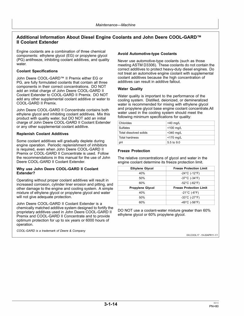
Maintenance—Machine
DX,COOL17 -19-20APR11-1/1
Additional Information About Diesel Engine Coolants and John Deere COOL-GARD™II Coolant Extender
Engine coolants are a combination of three chemicalcomponents: ethylene glycol (EG) or propylene glycol(PG) antifreeze, inhibiting coolant additives, and qualitywater.
Coolant Specifications
John Deere COOL-GARD™ II Premix either EG orPG, are fully formulated coolants that contain all threecomponents in their correct concentrations. DO NOTadd an initial charge of John Deere COOL-GARD IICoolant Extender to COOL-GARD II Premix. DO NOTadd any other supplemental coolant additive or water toCOOL-GARD II Premix.
John Deere COOL-GARD II Concentrate contains bothethylene glycol and inhibiting coolant additives. Mix thisproduct with quality water, but DO NOT add an initialcharge of John Deere COOL-GARD II Coolant Extenderor any other supplemental coolant additive.
Replenish Coolant Additives
Some coolant additives will gradually deplete duringengine operation. Periodic replenishment of inhibitorsis required, even when John Deere COOL-GARD IIPremix or COOL-GARD II Concentrate is used. Followthe recommendations in this manual for the use of JohnDeere COOL-GARD II Coolant Extender.
Why use John Deere COOL-GARD II CoolantExtender?
Operating without proper coolant additives will result inincreased corrosion, cylinder liner erosion and pitting, andother damage to the engine and cooling system. A simplemixture of ethylene glycol or propylene glycol and waterwill not give adequate protection.
John Deere COOL-GARD II Coolant Extender is achemically matched additive system designed to fortify theproprietary additives used in John Deere COOL-GARD IIPremix and COOL-GARD II Concentrate and to provideoptimum protection for up to six years or 6000 hours ofoperation.
Avoid Automotive-type Coolants
Never use automotive-type coolants (such as thosemeeting ASTM D3306). These coolants do not contain thecorrect additives to protect heavy-duty diesel engines. Donot treat an automotive engine coolant with supplementalcoolant additives because the high concentration ofadditives can result in additive fallout.
Water Quality
Water quality is important to the performance of thecooling system. Distilled, deionized, or demineralizedwater is recommended for mixing with ethylene glycoland propylene glycol base engine coolant concentrate.Allwater used in the cooling system should meet thefollowing minimum specifications for quality:Chlorides <40 mg/LSulfates <100 mg/LTotal dissolved solids <340 mg/LTotal hardness <170 mg/LpH 5.5 to 9.0
Freeze Protection
The relative concentrations of glycol and water in theengine coolant determine its freeze protection limit.
Ethylene Glycol Freeze Protection Limit40% -24°C (-12°F)50% -37°C (-34°F)60% -52°C (-62°F)
Propylene Glycol Freeze Protection Limit40% -21°C (-6°F)50% -33°C (-27°F)60% -49°C (-56°F)
DO NOT use a coolant-water mixture greater than 60%ethylene glycol or 60% propylene glycol.
COOL-GARD is a trademark of Deere & Company
3-1-14 053113
PN=80
Maintenance—Machine
DX,COOL9 -19-11APR11-1/1
Testing Diesel Engine Coolant
Maintaining adequate concentrations of glycol andinhibiting additives in the coolant is critical to protect theengine and cooling system against freezing, corrosion,and cylinder liner erosion and pitting.
Test the coolant solution at intervals of 12 months or lessand whenever excessive coolant is lost through leaks oroverheating.
Coolant Test Strips
Coolant test strips are available from your John Deeredealer. These test strips provide a simple, effectivemethod to check the freeze point and additive levels ofyour engine coolant.
When Using John Deere COOL-GARD II
John Deere COOL-GARD II Premix™ , COOL-GARDII PG Premix and COOL-GARD II Concentrate aremaintenance free coolants for up to six years or 6000hours of operation, provided that the cooling system istopped off using only John Deere COOL-GARD II Premixor COOL-GARD II PG premix. Test the coolant conditionannually with coolant test strips designed for use withJohn Deere COOL-GARD II coolants. If the test stripchart indicates that additive is required, add John DeereCOOL-GARD II Coolant Extender as directed.
Add only the recommended concentration of John DeereCOOL-GARD II Coolant Extender. DO NOT add morethan the recommended amount.
When Using Nitrite-Containing Coolants
Compare the test strip results to the supplemental coolantadditive (SCA) chart to determine the amount of inhibitingadditives in your coolant and whether more John DeereLiquid Coolant Conditioner should be added.
Add only the recommended concentration of John DeereLiquid Coolant Conditioner. DO NOT add more than therecommended amount.
Coolant Analysis
For a more thorough evaluation of your coolant, perform acoolant analysis. The coolant analysis can provide criticaldata such as freezing point, antifreeze level, pH, alkalinity,nitrite content (cavitation control additive), molybdatecontent (rust inhibitor additive), silicate content, corrosionmetals, and visual assessment.
Contact your John Deere dealer for more information oncoolant analysis.
COOL-GARD is a trademark of Deere & Company
3-1-15 053113
PN=81
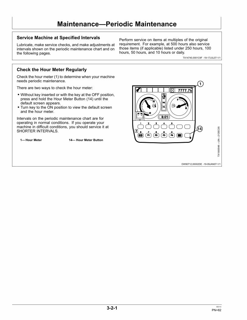
Maintenance—Periodic Maintenance
TX14740,0001C9F -19-17JUL07-1/1
DW90712,00002DE -19-09JAN07-1/1
Service Machine at Specified IntervalsLubricate, make service checks, and make adjustments atintervals shown on the periodic maintenance chart and onthe following pages.
Perform service on items at multiples of the originalrequirement. For example, at 500 hours also servicethose items (if applicable) listed under 250 hours, 100hours, 50 hours, and 10 hours or daily.
Check the Hour Meter RegularlyCheck the hour meter (1) to determine when your machineneeds periodic maintenance.
There are two ways to check the hour meter:
• Without key inserted or with the key at the OFF position,press and hold the Hour Meter Button (14) until thedefault screen appears.• Turn key to the ON position to view the default screenand the hour meter.
Intervals on the periodic maintenance chart are foroperating in normal conditions. If you operate yourmachine in difficult conditions, you should service it atSHORTER INTERVALS.
1—Hour Meter 14— Hour Meter Button
1
14
TX1000548—UN—21DEC05
3-2-1 053113
PN=82
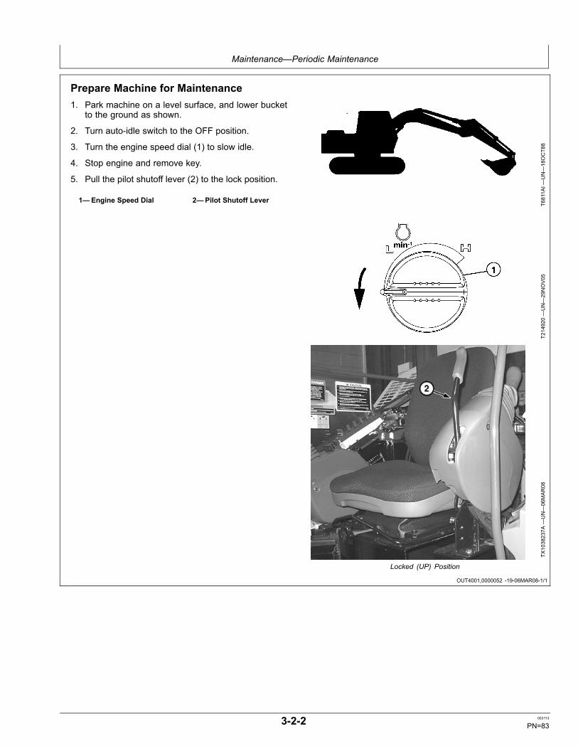
Maintenance—Periodic Maintenance
OUT4001,0000052 -19-06MAR08-1/1
Prepare Machine for Maintenance1. Park machine on a level surface, and lower bucket
to the ground as shown.
2. Turn auto-idle switch to the OFF position.
3. Turn the engine speed dial (1) to slow idle.
4. Stop engine and remove key.
5. Pull the pilot shutoff lever (2) to the lock position.
1—Engine Speed Dial 2—Pilot Shutoff Lever
T6811A
I—UN—18OCT88
T214920—UN—29NOV05
TX1038237A
—UN—06MAR08
Locked (UP) Position
3-2-2 053113
PN=83
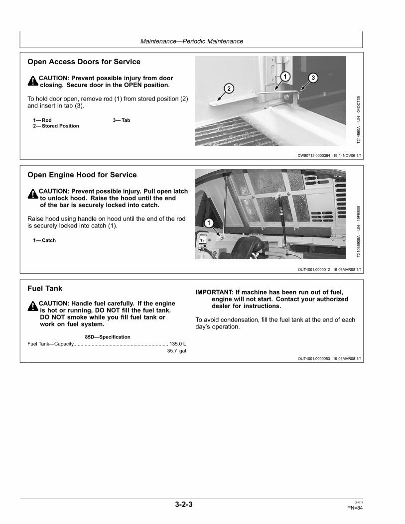
Maintenance—Periodic Maintenance
DW90712,0000394 -19-14NOV06-1/1
OUT4001,0000012 -19-06MAR08-1/1
OUT4001,0000053 -19-01MAR08-1/1
Open Access Doors for Service
CAUTION: Prevent possible injury from doorclosing. Secure door in the OPEN position.
To hold door open, remove rod (1) from stored position (2)and insert in tab (3).
1—Rod2—Stored Position
3—Tab
T214860A
—UN—04OCT05
Open Engine Hood for Service
CAUTION: Prevent possible injury. Pull open latchto unlock hood. Raise the hood until the endof the bar is securely locked into catch.
Raise hood using handle on hood until the end of the rodis securely locked into catch (1).
1—Catch
TX1036908A
—UN—19FE
B08
Fuel Tank
CAUTION: Handle fuel carefully. If the engineis hot or running, DO NOT fill the fuel tank.DO NOT smoke while you fill fuel tank orwork on fuel system.
85D—SpecificationFuel Tank—Capacity.................................................................... 135.0 L
35.7 gal
IMPORTANT: If machine has been run out of fuel,engine will not start. Contact your authorizeddealer for instructions.
To avoid condensation, fill the fuel tank at the end of eachday’s operation.
3-2-3 053113
PN=84
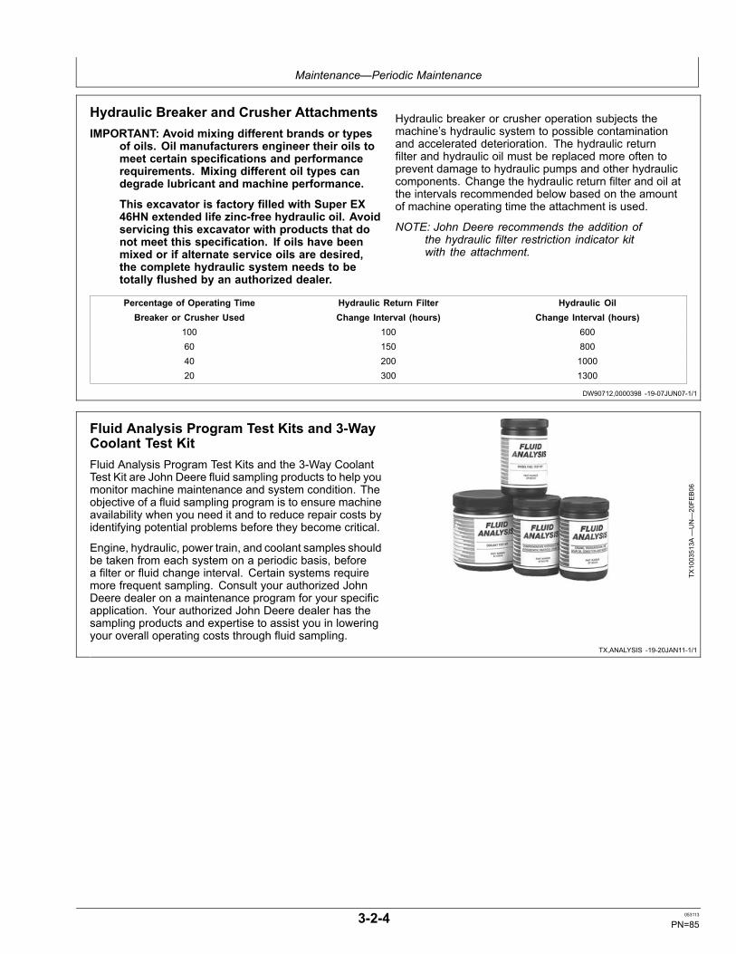
Maintenance—Periodic Maintenance
DW90712,0000398 -19-07JUN07-1/1
TX,ANALYSIS -19-20JAN11-1/1
Hydraulic Breaker and Crusher AttachmentsIMPORTANT: Avoid mixing different brands or types
of oils. Oil manufacturers engineer their oils tomeet certain specifications and performancerequirements. Mixing different oil types candegrade lubricant and machine performance.
This excavator is factory filled with Super EX46HN extended life zinc-free hydraulic oil. Avoidservicing this excavator with products that donot meet this specification. If oils have beenmixed or if alternate service oils are desired,the complete hydraulic system needs to betotally flushed by an authorized dealer.
Hydraulic breaker or crusher operation subjects themachine’s hydraulic system to possible contaminationand accelerated deterioration. The hydraulic returnfilter and hydraulic oil must be replaced more often toprevent damage to hydraulic pumps and other hydrauliccomponents. Change the hydraulic return filter and oil atthe intervals recommended below based on the amountof machine operating time the attachment is used.
NOTE: John Deere recommends the addition ofthe hydraulic filter restriction indicator kitwith the attachment.
Percentage of Operating Time Hydraulic Return Filter Hydraulic OilBreaker or Crusher Used Change Interval (hours) Change Interval (hours)
100 100 60060 150 80040 200 100020 300 1300
Fluid Analysis Program Test Kits and 3-WayCoolant Test KitFluid Analysis Program Test Kits and the 3-Way CoolantTest Kit are John Deere fluid sampling products to help youmonitor machine maintenance and system condition. Theobjective of a fluid sampling program is to ensure machineavailability when you need it and to reduce repair costs byidentifying potential problems before they become critical.
Engine, hydraulic, power train, and coolant samples shouldbe taken from each system on a periodic basis, beforea filter or fluid change interval. Certain systems requiremore frequent sampling. Consult your authorized JohnDeere dealer on a maintenance program for your specificapplication. Your authorized John Deere dealer has thesampling products and expertise to assist you in loweringyour overall operating costs through fluid sampling.
TX1003513A
—UN—20FE
B06
3-2-4 053113
PN=85
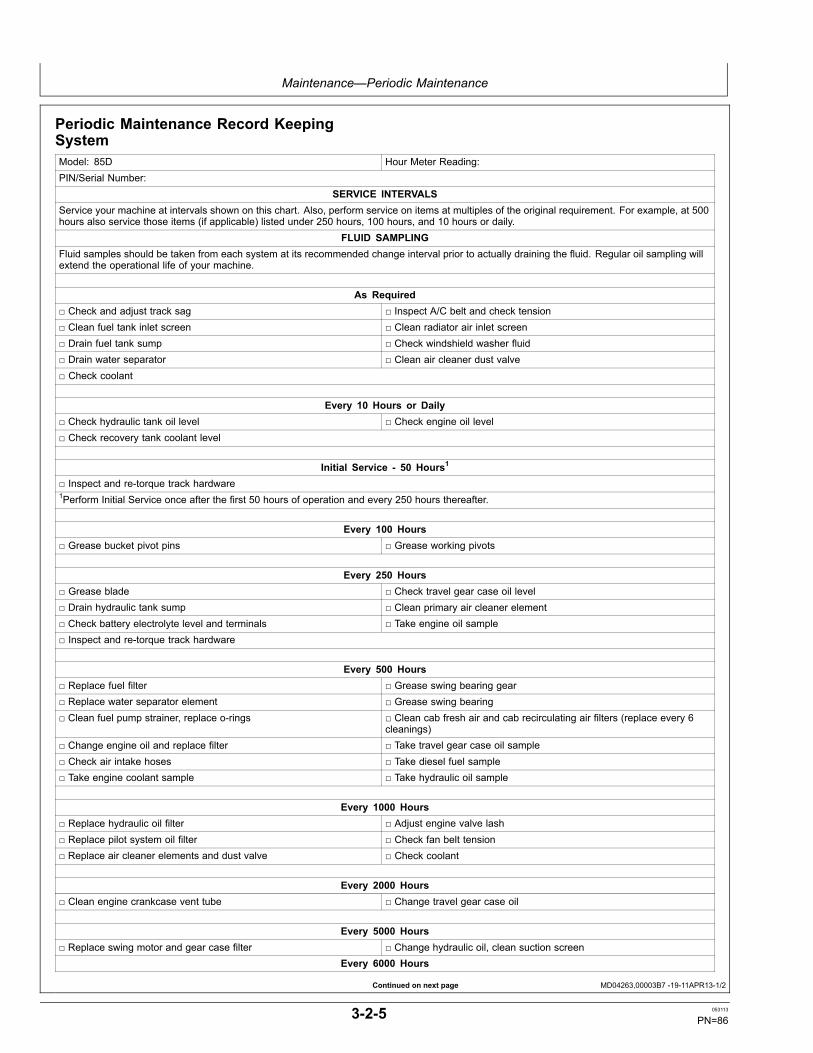
Maintenance—Periodic Maintenance
Continued on next page MD04263,00003B7 -19-11APR13-1/2
Periodic Maintenance Record KeepingSystemModel: 85D Hour Meter Reading:PIN/Serial Number:
SERVICE INTERVALSService your machine at intervals shown on this chart. Also, perform service on items at multiples of the original requirement. For example, at 500hours also service those items (if applicable) listed under 250 hours, 100 hours, and 10 hours or daily.
FLUID SAMPLINGFluid samples should be taken from each system at its recommended change interval prior to actually draining the fluid. Regular oil sampling willextend the operational life of your machine.
As Required□ Check and adjust track sag □ Inspect A/C belt and check tension□ Clean fuel tank inlet screen □ Clean radiator air inlet screen□ Drain fuel tank sump □ Check windshield washer fluid□ Drain water separator □ Clean air cleaner dust valve□ Check coolant
Every 10 Hours or Daily□ Check hydraulic tank oil level □ Check engine oil level□ Check recovery tank coolant level
Initial Service - 50 Hours1
□ Inspect and re-torque track hardware1Perform Initial Service once after the first 50 hours of operation and every 250 hours thereafter.
Every 100 Hours□ Grease bucket pivot pins □ Grease working pivots
Every 250 Hours□ Grease blade □ Check travel gear case oil level□ Drain hydraulic tank sump □ Clean primary air cleaner element□ Check battery electrolyte level and terminals □ Take engine oil sample□ Inspect and re-torque track hardware
Every 500 Hours□ Replace fuel filter □ Grease swing bearing gear□ Replace water separator element □ Grease swing bearing□ Clean fuel pump strainer, replace o-rings □ Clean cab fresh air and cab recirculating air filters (replace every 6
cleanings)□ Change engine oil and replace filter □ Take travel gear case oil sample□ Check air intake hoses □ Take diesel fuel sample□ Take engine coolant sample □ Take hydraulic oil sample
Every 1000 Hours□ Replace hydraulic oil filter □ Adjust engine valve lash□ Replace pilot system oil filter □ Check fan belt tension□ Replace air cleaner elements and dust valve □ Check coolant
Every 2000 Hours□ Clean engine crankcase vent tube □ Change travel gear case oil
Every 5000 Hours□ Replace swing motor and gear case filter □ Change hydraulic oil, clean suction screen
Every 6000 Hours
3-2-5 053113
PN=86
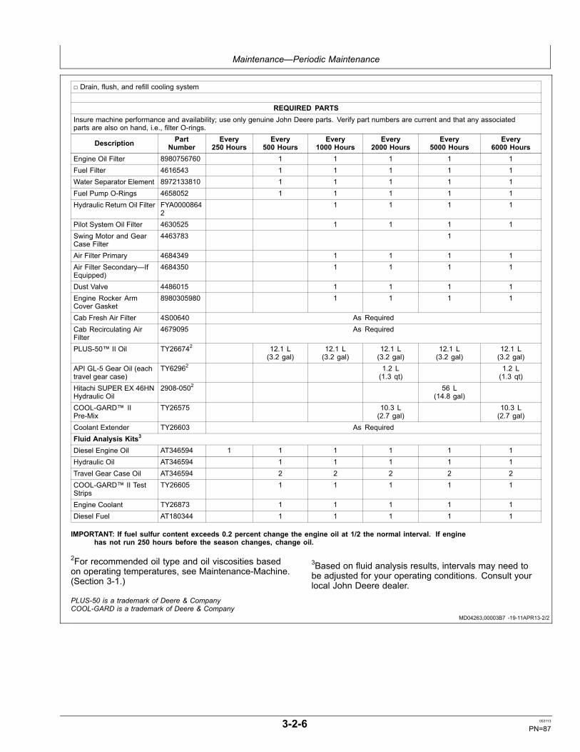
Maintenance—Periodic Maintenance
MD04263,00003B7 -19-11APR13-2/2
□ Drain, flush, and refill cooling system
REQUIRED PARTSInsure machine performance and availability; use only genuine John Deere parts. Verify part numbers are current and that any associatedparts are also on hand, i.e., filter O-rings.
Description PartNumber
Every250 Hours
Every500 Hours
Every1000 Hours
Every2000 Hours
Every5000 Hours
Every6000 Hours
Engine Oil Filter 8980756760 1 1 1 1 1Fuel Filter 4616543 1 1 1 1 1Water Separator Element 8972133810 1 1 1 1 1Fuel Pump O-Rings 4658052 1 1 1 1 1Hydraulic Return Oil Filter FYA0000864
21 1 1 1
Pilot System Oil Filter 4630525 1 1 1 1Swing Motor and GearCase Filter
4463783 1
Air Filter Primary 4684349 1 1 1 1Air Filter Secondary—IfEquipped)
4684350 1 1 1 1
Dust Valve 4486015 1 1 1 1Engine Rocker ArmCover Gasket
8980305980 1 1 1 1
Cab Fresh Air Filter 4S00640 As RequiredCab Recirculating AirFilter
4679095 As Required
PLUS-50™ II Oil TY266742 12.1 L(3.2 gal)
12.1 L(3.2 gal)
12.1 L(3.2 gal)
12.1 L(3.2 gal)
12.1 L(3.2 gal)
API GL-5 Gear Oil (eachtravel gear case)
TY62962 1.2 L(1.3 qt)
1.2 L(1.3 qt)
Hitachi SUPER EX 46HNHydraulic Oil
2908-0502 56 L(14.8 gal)
COOL-GARD™ IIPre-Mix
TY26575 10.3 L(2.7 gal)
10.3 L(2.7 gal)
Coolant Extender TY26603 As RequiredFluid Analysis Kits3
Diesel Engine Oil AT346594 1 1 1 1 1 1Hydraulic Oil AT346594 1 1 1 1 1Travel Gear Case Oil AT346594 2 2 2 2 2COOL-GARD™ II TestStrips
TY26605 1 1 1 1 1
Engine Coolant TY26873 1 1 1 1 1Diesel Fuel AT180344 1 1 1 1 1
IMPORTANT: If fuel sulfur content exceeds 0.2 percent change the engine oil at 1/2 the normal interval. If enginehas not run 250 hours before the season changes, change oil.
2For recommended oil type and oil viscosities basedon operating temperatures, see Maintenance-Machine.(Section 3-1.)
3Based on fluid analysis results, intervals may need tobe adjusted for your operating conditions. Consult yourlocal John Deere dealer.
PLUS-50 is a trademark of Deere & CompanyCOOL-GARD is a trademark of Deere & Company
3-2-6 053113
PN=87

Maintenance—As Required
ER79617,0000C4E -19-07SEP10-1/4
Continued on next page ER79617,0000C4E -19-07SEP10-2/4
Check and Adjust Track SagCheck Track Sag—Rubber Tracks
1. Rotate upperstructure so front of upperstructure isover travel motors (180°).
2. Lower the bucket and blade to raise both tracks offground.
3. Raise pilot control shutoff lever to locked position.
CAUTION: Prevent possible injury fromunexpected machine movement. Place blocksunder machine frame to support machinewhile measuring track sag.
4. Place blocks under machine frame to support machine.
5. Lower pilot control shutoff lever to unlocked position.
6. Rotate track so track joint is positioned at the uppercenter of the track.
TX1081420—UN—09SEP10
Machine Position
7. Operate track forward and backward to equallydistribute tension to the left and right.
8. Stop engine.
9. Measure distance (1) from bottom of center roller toinner ridge of rubber track.
SpecificationTrack—Sag.............................................................................15—20 mm
0.6—0.8 in.
10. If not to specification, adjust track sag. See AdjustingTrack Sag.
11. Repeat check on other side of machine.
1—Track Sag Distance2—Track
3—Roller
T121709—UN—10JU
N99
TX1081452—UN—31AUG10
Track Sag Distance
3-3-1 053113
PN=88
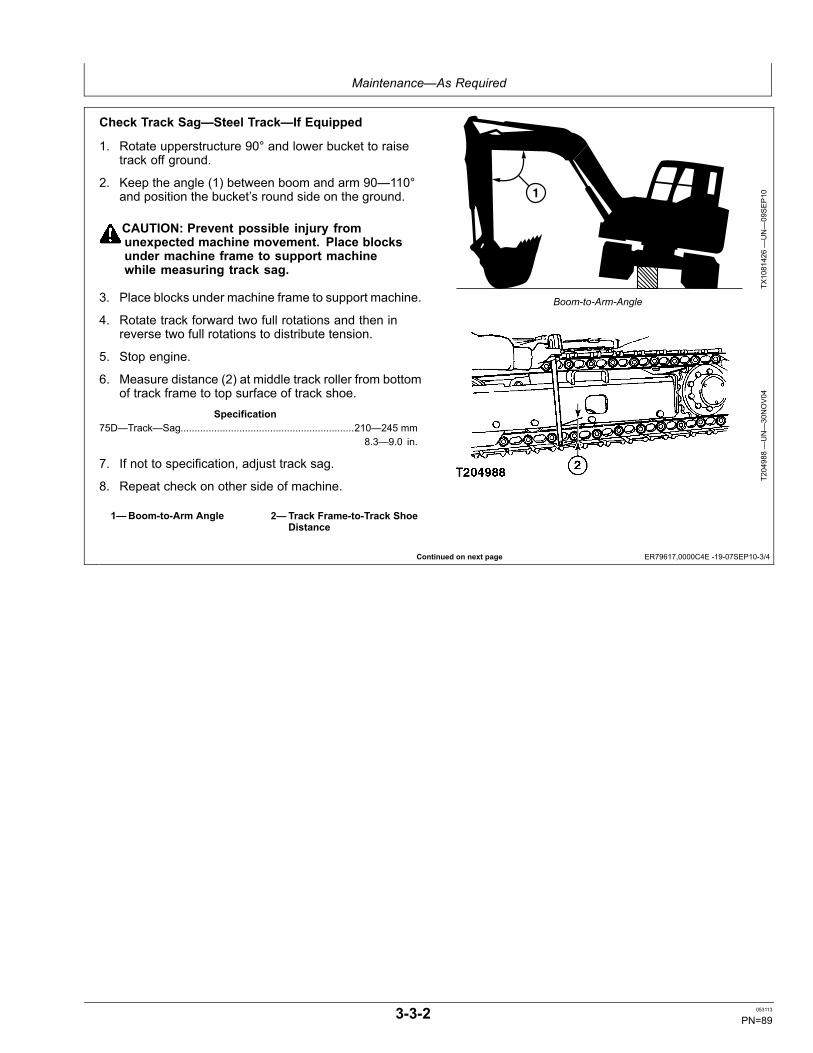
Maintenance—As Required
Continued on next page ER79617,0000C4E -19-07SEP10-3/4
Check Track Sag—Steel Track—If Equipped
1. Rotate upperstructure 90° and lower bucket to raisetrack off ground.
2. Keep the angle (1) between boom and arm 90—110°and position the bucket’s round side on the ground.
CAUTION: Prevent possible injury fromunexpected machine movement. Place blocksunder machine frame to support machinewhile measuring track sag.
3. Place blocks under machine frame to support machine.
4. Rotate track forward two full rotations and then inreverse two full rotations to distribute tension.
5. Stop engine.
6. Measure distance (2) at middle track roller from bottomof track frame to top surface of track shoe.
Specification75D—Track—Sag..............................................................210—245 mm
8.3—9.0 in.
7. If not to specification, adjust track sag.
8. Repeat check on other side of machine.
1—Boom-to-Arm Angle 2—Track Frame-to-Track ShoeDistance
1
TX1081426—UN—09SEP10
Boom-to-Arm-Angle
T204988—UN—30NOV04
3-3-2 053113
PN=89
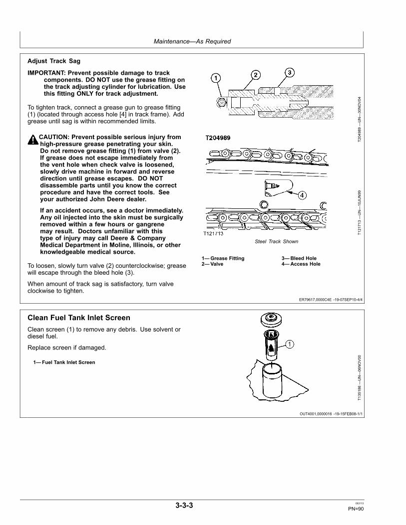
Maintenance—As Required
ER79617,0000C4E -19-07SEP10-4/4
OUT4001,0000016 -19-15FEB08-1/1
Adjust Track Sag
IMPORTANT: Prevent possible damage to trackcomponents. DO NOT use the grease fitting onthe track adjusting cylinder for lubrication. Usethis fitting ONLY for track adjustment.
To tighten track, connect a grease gun to grease fitting(1) (located through access hole [4] in track frame). Addgrease until sag is within recommended limits.
CAUTION: Prevent possible serious injury fromhigh-pressure grease penetrating your skin.Do not remove grease fitting (1) from valve (2).If grease does not escape immediately fromthe vent hole when check valve is loosened,slowly drive machine in forward and reversedirection until grease escapes. DO NOTdisassemble parts until you know the correctprocedure and have the correct tools. Seeyour authorized John Deere dealer.
If an accident occurs, see a doctor immediately.Any oil injected into the skin must be surgicallyremoved within a few hours or gangrenemay result. Doctors unfamiliar with thistype of injury may call Deere & CompanyMedical Department in Moline, Illinois, or otherknowledgeable medical source.
To loosen, slowly turn valve (2) counterclockwise; greasewill escape through the bleed hole (3).
When amount of track sag is satisfactory, turn valveclockwise to tighten.
T204989—UN—30NOV04
T121713—UN—10JU
N99
Steel Track Shown
1—Grease Fitting2—Valve
3—Bleed Hole4—Access Hole
Clean Fuel Tank Inlet ScreenClean screen (1) to remove any debris. Use solvent ordiesel fuel.
Replace screen if damaged.
1—Fuel Tank Inlet ScreenT135186—UN—06NOV00
3-3-3 053113
PN=90

Maintenance—As Required
OUT4001,0000057 -19-03JAN08-1/1
OUT4001,0000017 -19-26FEB08-1/1
Drain Fuel Tank Sump1. Park machine on a level surface. Rotate
upperstructure 90° for easier access.
2. Stop engine.
3. Remove fuel tank fill cap.
4. Open drain valve (1) for several seconds to drainwater and sediment into a container. Dispose of wasteproperly. Close drain valve.
5. Install fill cap.
1—Drain Valve
T6811A
J—UN—18OCT88
T162168—UN—10DEC02
Drain Water Separator1. Open right rear access cover to access water
separator.
2. Loosen bleed plug (1) on top of water separator (2).
3. Open drain valve (3) to extract water from fuel system.Collect waste in a container and dispose of it properly.
4. Close drain valve.
5. Tighten bleed plug.
6. Bleed fuel system, if necessary. See Bleed FuelSystem in Miscellaneous-Machine. (Section 4-1.)
TX1036932A
—UN—19FE
B08
1—Bleed Plug2—Water Separator
3—Drain Valve
3-3-4 053113
PN=91

Maintenance—As Required
OUT4001,0000039 -19-01MAR08-1/1
OUT4001,0000019 -19-07MAR08-1/1
Check and Adjust A/C BeltVisually check the A/C belt for wear. Replace if necessary.
NOTE: When a new belt is installed, be sure to re-adjustthe tension after operating the engine for 3 to5 minutes at slow idle speed to be sure thatthe new belt is seated correctly.
Use the following steps to adjust A/C belt tension:
1. Check A/C belt tension by depressing the midpointbetween compressor pulley (1) and tension pulley (2)with thumb.
SpecificationCompressorBelt—Deflection........................................................................8—12 mm
0.32—0.47 in.—Depressing Force..........................................................................98 N
22 lb (force)
2. If tension is not within specifications, loosen bolt (4).
3. Move the tension pulley until tension is correct.Tighten bolt.
TX1037256—UN—27FE
B08
1—Compressor Pulley2—Tension Pulley3—Crank Pulley
4—Bolt5—Fan Pulley6—Alternator
Clean Radiator Air Inlet Screen
CAUTION: Prevent possible injury from flyingchips. Reduce compressed air to less than196 kPa (1.96 bar) (28.4 psi) when using forcleaning purposes. Clear area of bystanders,guard against flying chips, and wear personalprotection equipment including eye protection.
1. Open left access door.
2. Unscrew wing nuts (1).
3. Remove and clean oil cooler front screen (2) andradiator screen (3).
4. Use compressed air opposite to the normal air flowfor cleaning.
5. Clean the air conditioner condenser (4) (if equipped).
6. Install oil cooler front screen and radiator screen.
7. Install wing nuts to secure oil cooler front screen andradiator screen.
8. Close left access door.
If machine is equipped with a hydraulic reverse fanfunction, use the reverse cooling fan switch to clean thecooling system.
The reversing cooling fan switch has three positions:
TX1036952A
—UN—19FE
B08
1—Wing Nut (2 used)2—Oil Cooler Front Screen
3—Radiator Screen4—Air Conditioner Condenser
• AUTO: Every 60 minutes the radiator cooling fan willautomatically reverse direction for 15 seconds withoutintervention from the operator.• OFF: Fan resumes normal operation.• MANUAL: Fan will reverse direction for 15 secondswhen right portion of switch is pressed.
NOTE: The reversing fan function shall not be reactivatedwithin 1 minute of its last completion (this timeincludes “Automatic” cycle).
3-3-5 053113
PN=92
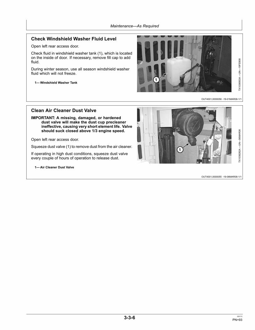
Maintenance—As Required
OUT4001,0000056 -19-01MAR08-1/1
OUT4001,0000055 -19-06MAR08-1/1
Check Windshield Washer Fluid LevelOpen left rear access door.
Check fluid in windshield washer tank (1), which is locatedon the inside of door. If necessary, remove fill cap to addfluid.
During winter season, use all season windshield washerfluid which will not freeze.
1—Windshield Washer Tank
TX1036953A
—UN—19FE
B08
Clean Air Cleaner Dust ValveIMPORTANT: A missing, damaged, or hardened
dust valve will make the dust cup precleanerineffective, causing very short element life. Valveshould suck closed above 1/3 engine speed.
Open left rear access door.
Squeeze dust valve (1) to remove dust from the air cleaner.
If operating in high dust conditions, squeeze dust valveevery couple of hours of operation to release dust.
1—Air Cleaner Dust Valve
TX1038282A
—UN—06MAR08
3-3-6 053113
PN=93
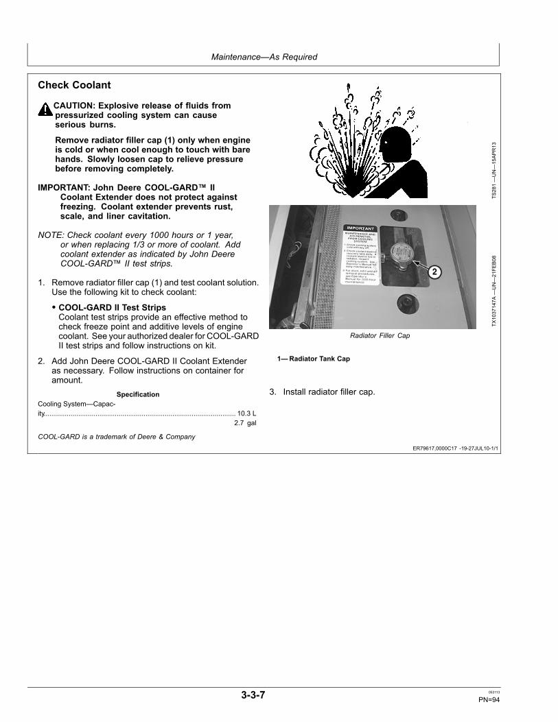
Maintenance—As Required
ER79617,0000C17 -19-27JUL10-1/1
Check Coolant
CAUTION: Explosive release of fluids frompressurized cooling system can causeserious burns.
Remove radiator filler cap (1) only when engineis cold or when cool enough to touch with barehands. Slowly loosen cap to relieve pressurebefore removing completely.
IMPORTANT: John Deere COOL-GARD™ IICoolant Extender does not protect againstfreezing. Coolant extender prevents rust,scale, and liner cavitation.
NOTE: Check coolant every 1000 hours or 1 year,or when replacing 1/3 or more of coolant. Addcoolant extender as indicated by John DeereCOOL-GARD™ II test strips.
1. Remove radiator filler cap (1) and test coolant solution.Use the following kit to check coolant:
• COOL-GARD II Test StripsCoolant test strips provide an effective method tocheck freeze point and additive levels of enginecoolant. See your authorized dealer for COOL-GARDII test strips and follow instructions on kit.
2. Add John Deere COOL-GARD II Coolant Extenderas necessary. Follow instructions on container foramount.
SpecificationCooling System—Capac-ity.................................................................................................... 10.3 L
2.7 gal
TS281—UN—15APR13
TX1037147A
—UN—21FE
B08
Radiator Filler Cap
1—Radiator Tank Cap
3. Install radiator filler cap.
COOL-GARD is a trademark of Deere & Company
3-3-7 053113
PN=94
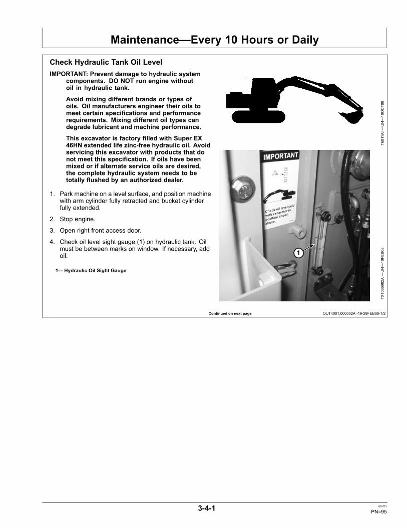
Maintenance—Every 10 Hours or Daily
Continued on next page OUT4001,000002A -19-29FEB08-1/2
Check Hydraulic Tank Oil LevelIMPORTANT: Prevent damage to hydraulic system
components. DO NOT run engine withoutoil in hydraulic tank.
Avoid mixing different brands or types ofoils. Oil manufacturers engineer their oils tomeet certain specifications and performancerequirements. Mixing different oil types candegrade lubricant and machine performance.
This excavator is factory filled with Super EX46HN extended life zinc-free hydraulic oil. Avoidservicing this excavator with products that donot meet this specification. If oils have beenmixed or if alternate service oils are desired,the complete hydraulic system needs to betotally flushed by an authorized dealer.
1. Park machine on a level surface, and position machinewith arm cylinder fully retracted and bucket cylinderfully extended.
2. Stop engine.
3. Open right front access door.
4. Check oil level sight gauge (1) on hydraulic tank. Oilmust be between marks on window. If necessary, addoil.
1—Hydraulic Oil Sight Gauge
T6811A
I—UN—18OCT88
TX1036982A
—UN—19FE
B08
3-4-1 053113
PN=95
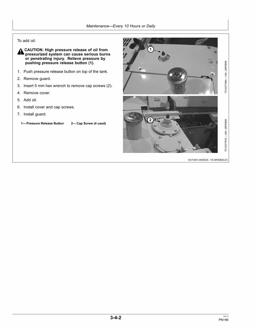
Maintenance—Every 10 Hours or Daily
OUT4001,000002A -19-29FEB08-2/2
To add oil:
CAUTION: High pressure release of oil frompressurized system can cause serious burnsor penetrating injury. Relieve pressure bypushing pressure release button (1).
1. Push pressure release button on top of the tank.
2. Remove guard.
3. Insert 5 mm hex wrench to remove cap screws (2).
4. Remove cover.
5. Add oil.
6. Install cover and cap screws.
7. Install guard.
1—Pressure Release Button 2—Cap Screw (4 used)
TX1037796A
—UN—29FE
B08
TX1037797A
—UN—29FE
B08
3-4-2 053113
PN=96
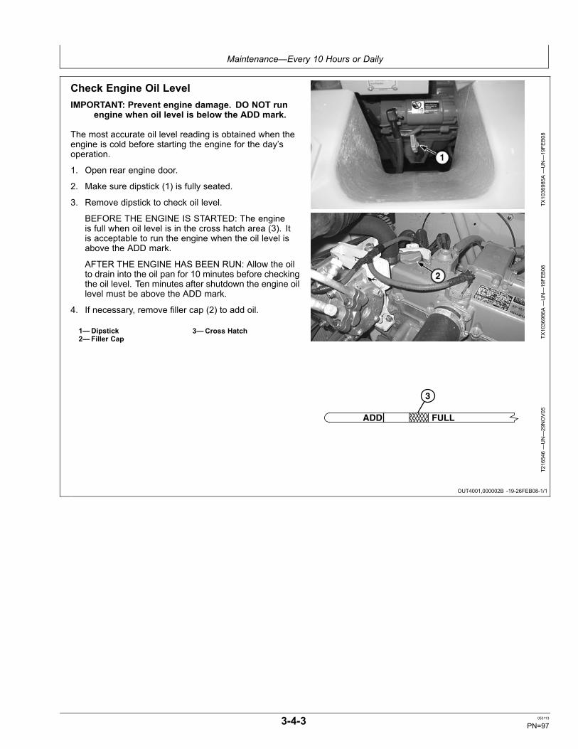
Maintenance—Every 10 Hours or Daily
OUT4001,000002B -19-26FEB08-1/1
Check Engine Oil LevelIMPORTANT: Prevent engine damage. DO NOT run
engine when oil level is below the ADD mark.
The most accurate oil level reading is obtained when theengine is cold before starting the engine for the day’soperation.
1. Open rear engine door.
2. Make sure dipstick (1) is fully seated.
3. Remove dipstick to check oil level.
BEFORE THE ENGINE IS STARTED: The engineis full when oil level is in the cross hatch area (3). Itis acceptable to run the engine when the oil level isabove the ADD mark.
AFTER THE ENGINE HAS BEEN RUN: Allow the oilto drain into the oil pan for 10 minutes before checkingthe oil level. Ten minutes after shutdown the engine oillevel must be above the ADD mark.
4. If necessary, remove filler cap (2) to add oil.
1—Dipstick2—Filler Cap
3—Cross Hatch
TX1036985A
—UN—19FE
B08
TX1036986A
—UN—19FE
B08
FULL
3
ADD
T216546—UN—29NOV05
3-4-3 053113
PN=97
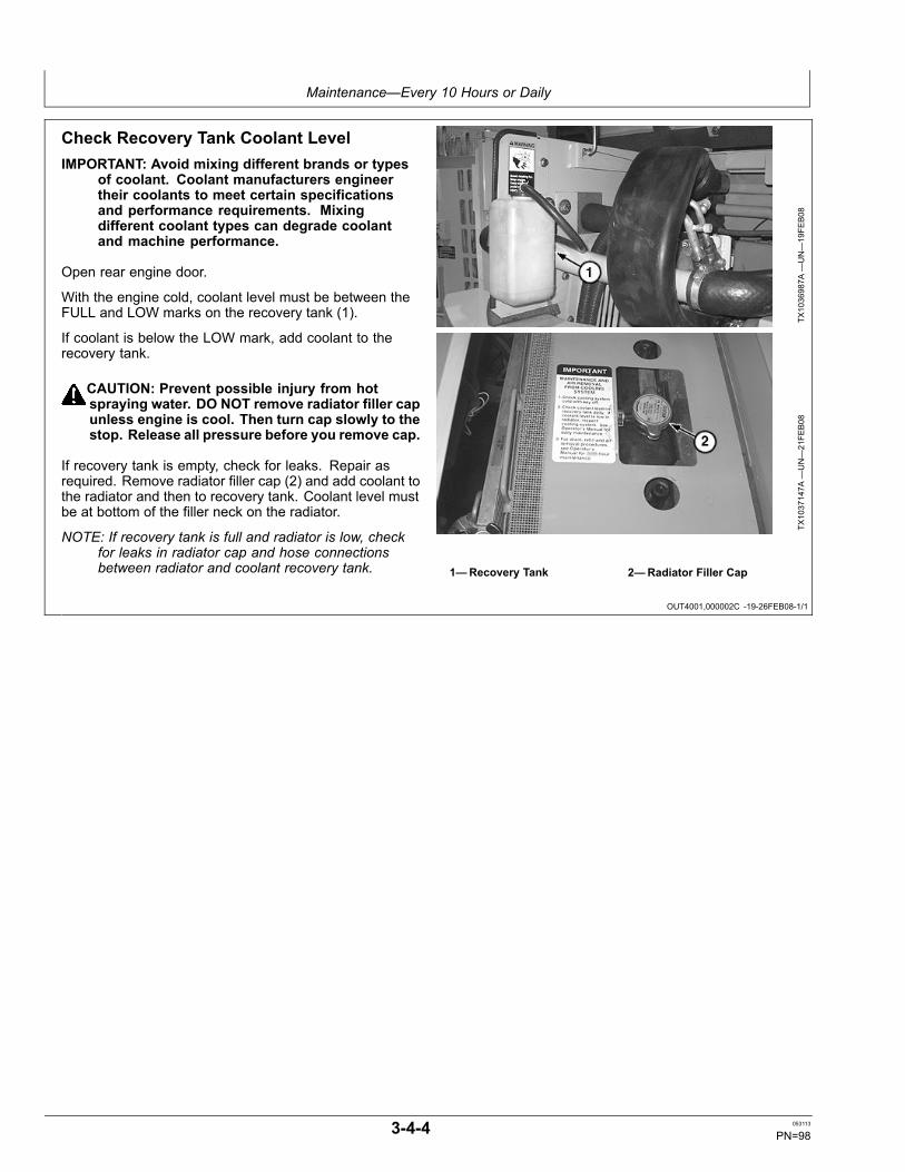
Maintenance—Every 10 Hours or Daily
OUT4001,000002C -19-26FEB08-1/1
Check Recovery Tank Coolant LevelIMPORTANT: Avoid mixing different brands or types
of coolant. Coolant manufacturers engineertheir coolants to meet certain specificationsand performance requirements. Mixingdifferent coolant types can degrade coolantand machine performance.
Open rear engine door.
With the engine cold, coolant level must be between theFULL and LOW marks on the recovery tank (1).
If coolant is below the LOW mark, add coolant to therecovery tank.
CAUTION: Prevent possible injury from hotspraying water. DO NOT remove radiator filler capunless engine is cool. Then turn cap slowly to thestop. Release all pressure before you remove cap.
If recovery tank is empty, check for leaks. Repair asrequired. Remove radiator filler cap (2) and add coolant tothe radiator and then to recovery tank. Coolant level mustbe at bottom of the filler neck on the radiator.
NOTE: If recovery tank is full and radiator is low, checkfor leaks in radiator cap and hose connectionsbetween radiator and coolant recovery tank.
TX1036987A
—UN—19FE
B08
TX1037147A
—UN—21FE
B08
1—Recovery Tank 2—Radiator Filler Cap
3-4-4 053113
PN=98

Maintenance—Initial Service—50 Hours
CC28724,00001AA -19-13NOV09-1/1
Inspect and Re-Torque Track HardwareTracks shoes should be inspected and re-torqued at first50 hours and 250 hour intervals thereafter. See Inspectand Re-Torque Track Hardware. (Section 3-7.)
3-5-1 053113
PN=99
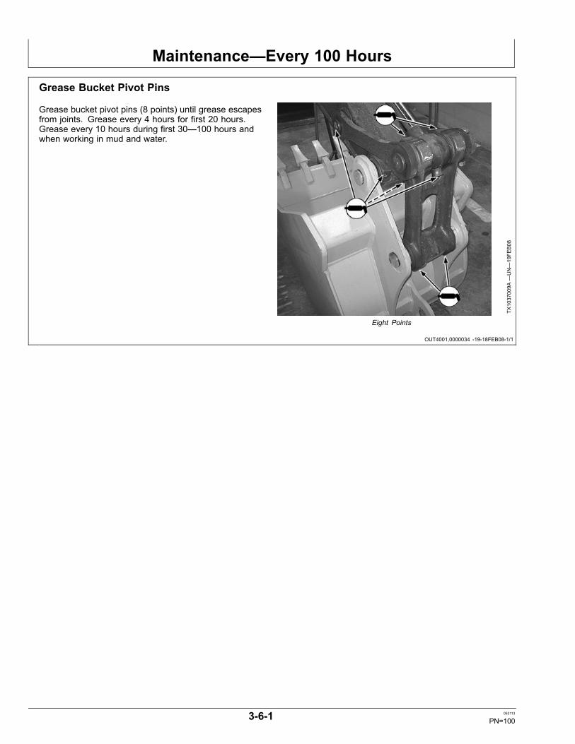
Maintenance—Every 100 Hours
OUT4001,0000034 -19-18FEB08-1/1
Grease Bucket Pivot Pins
Grease bucket pivot pins (8 points) until grease escapesfrom joints. Grease every 4 hours for first 20 hours.Grease every 10 hours during first 30—100 hours andwhen working in mud and water.
TX1037009A
—UN—19FE
B08
Eight Points
3-6-1 053113
PN=100
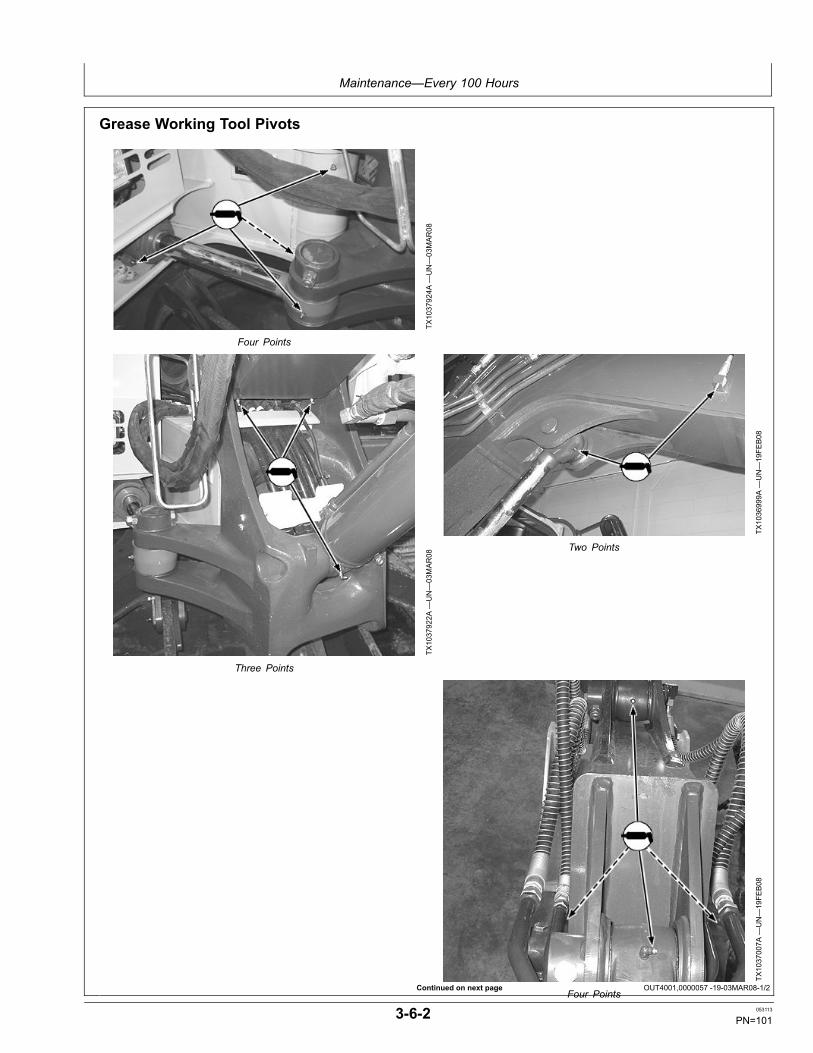
Maintenance—Every 100 Hours
Continued on next page OUT4001,0000057 -19-03MAR08-1/2
Grease Working Tool Pivots
TX1037924A
—UN—03MAR08
Four Points
TX1037922A
—UN—03MAR08
Three Points
TX1036999A
—UN—19FE
B08
Two Points
TX1037007A
—UN—19FE
B08
Four Points
3-6-2 053113
PN=101

Maintenance—Every 100 Hours
OUT4001,0000057 -19-03MAR08-2/2
Grease boom (13 points) until grease escapes from joints.Grease every 4 hours for the first 20 hours. Grease every
10 hours during the first 30—100 hours and when workingin mud and water.
3-6-3 053113
PN=102

Maintenance—Every 250 Hours
OUT4001,000001B -19-03MAR08-1/1
Continued on next page OUT4001,000001C -19-05MAR08-1/2
Grease BladeGrease blade until grease escapes from joints. Greaseevery 4 hours for first 20 hours. Grease every 10 hoursduring first 30—100 hours and when working in mud andwater.
TX1037015A
—UN—03MAR08
Four Points
Drain Hydraulic Tank Sump
CAUTION: High pressure release of oil frompressurized system can cause serious burnsor penetrating injury. The hydraulic tank ispressurized. Relieve pressure by pushingpressure release button (1).
1. To relieve pressure, push the pressure release button(1).
2. Remove guard.
3. Insert 5 mm hex wrench to remove cap screws (2).
4. Remove cover.
1—Pressure Release Button 2—Cap Screw (4 used)
TX1037796A
—UN—29FE
B08
TX1037797A
—UN—29FE
B08
3-7-1 053113
PN=103

Maintenance—Every 250 Hours
OUT4001,000001C -19-05MAR08-2/2
OUT4001,0000037 -19-27JUL10-1/1
5. After oil is cool, remove plug (4) for several seconds todrain water and sediment into a container. Dispose ofwaste properly.
6. Install plug.
7. Install hydraulic oil tank cover and cap screws.
8. Install guard.
4—Plug
TX1015678A
—UN—27NOV06
Check Travel Gear Case Oil Level1. Park the machine on level ground rotating travel gear
case until positioned as shown.
2. Stop engine.
CAUTION: High pressure release of oils frompressurized system can cause serious burns.Wait for travel gear case oil to cool. Keep body andface away from check plug (2). Gradually loosencheck plug to release air to relieve pressure.
3. After travel gear case has cooled, slowly loosen checkplug (2) to release air to relieve pressure.
4. Remove check plug. Oil level (4) must be even withbottom of check plug hole.
5. If necessary, remove fill plug (1), and add oil until oilflows out of oil level check plug hole.
6. Wrap threads of plugs with sealing-type tape. Installplug. Tighten plugs to specification.
SpecificationPlug—Torque.................................................................................49 N·m
36 lb-ftT134964—UN—01NOV00
1—Fill Plug2—Check Plug
3—Drain Plug4—Oil Level
7. Repeat procedure for other side.
3-7-2 053113
PN=104
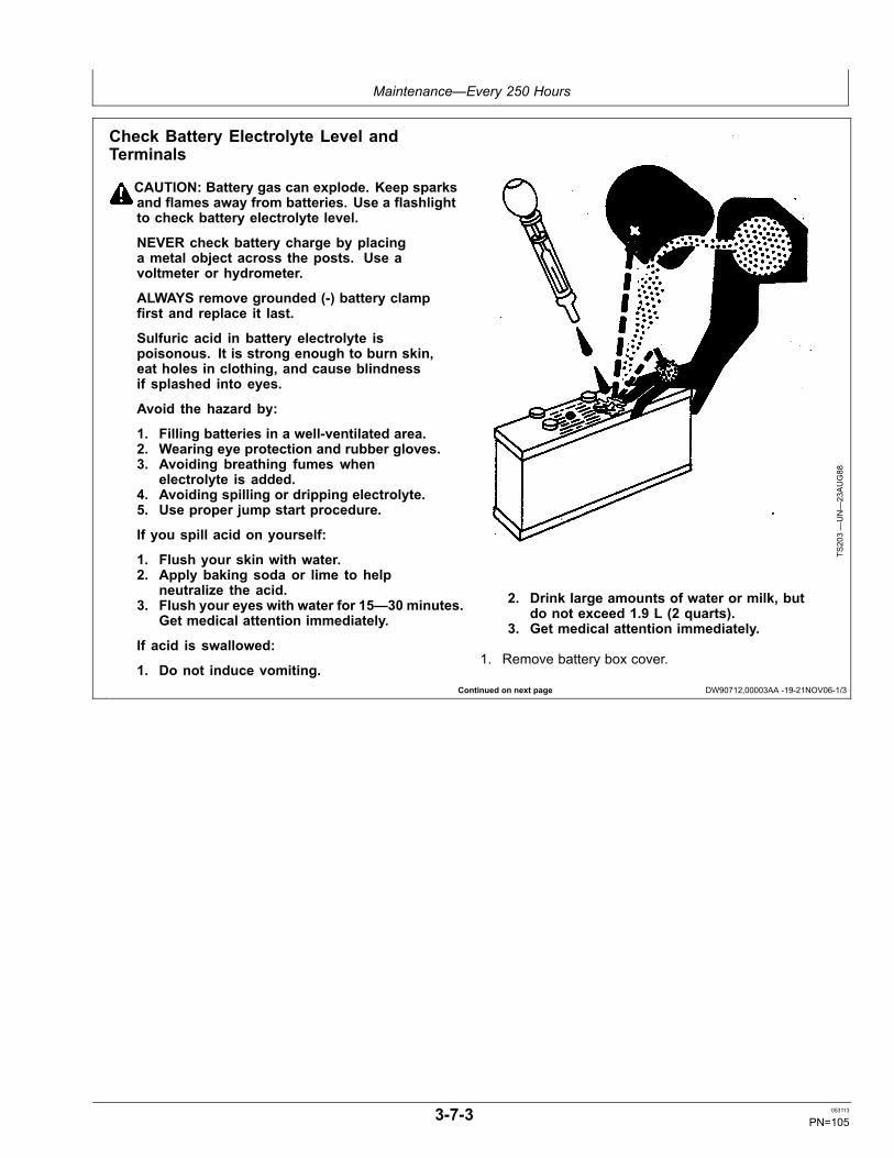
Maintenance—Every 250 Hours
Continued on next page DW90712,00003AA -19-21NOV06-1/3
Check Battery Electrolyte Level andTerminals
CAUTION: Battery gas can explode. Keep sparksand flames away from batteries. Use a flashlightto check battery electrolyte level.
NEVER check battery charge by placinga metal object across the posts. Use avoltmeter or hydrometer.
ALWAYS remove grounded (-) battery clampfirst and replace it last.
Sulfuric acid in battery electrolyte ispoisonous. It is strong enough to burn skin,eat holes in clothing, and cause blindnessif splashed into eyes.
Avoid the hazard by:
1. Filling batteries in a well-ventilated area.2. Wearing eye protection and rubber gloves.3. Avoiding breathing fumes when
electrolyte is added.4. Avoiding spilling or dripping electrolyte.5. Use proper jump start procedure.
If you spill acid on yourself:
1. Flush your skin with water.2. Apply baking soda or lime to help
neutralize the acid.3. Flush your eyes with water for 15—30 minutes.
Get medical attention immediately.
If acid is swallowed:
1. Do not induce vomiting.
TS203—UN—23AUG88
2. Drink large amounts of water or milk, butdo not exceed 1.9 L (2 quarts).
3. Get medical attention immediately.
1. Remove battery box cover.
3-7-3 053113
PN=105
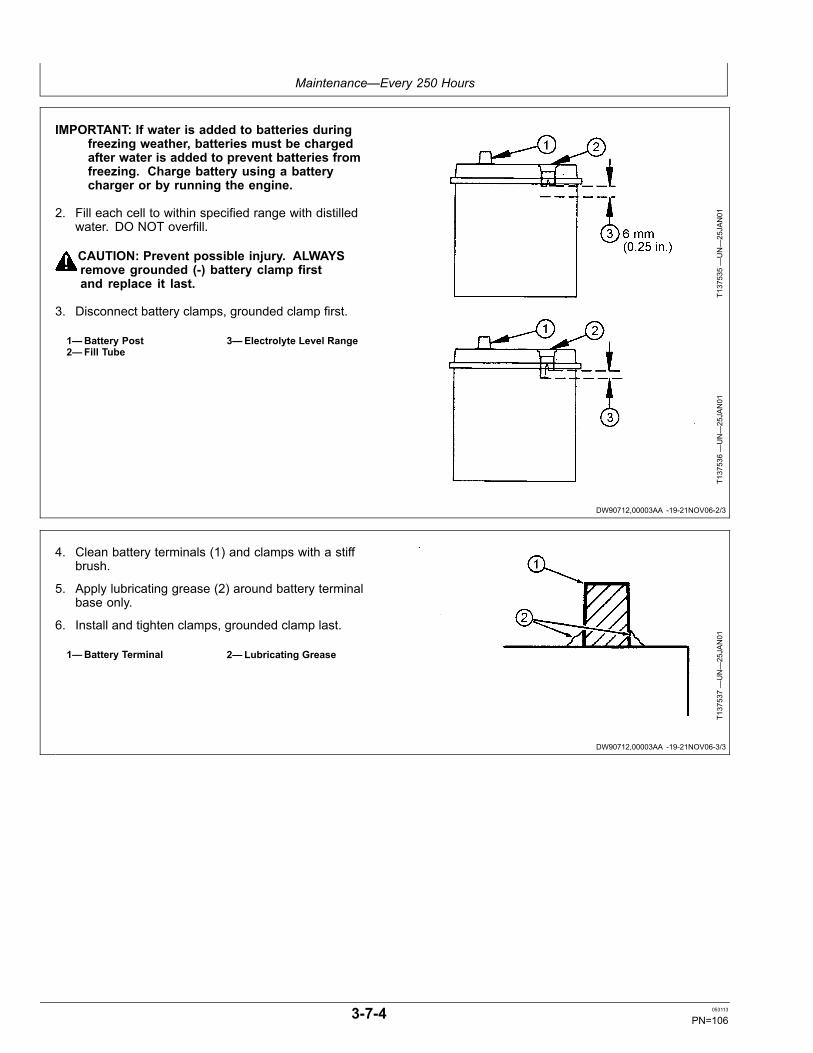
Maintenance—Every 250 Hours
DW90712,00003AA -19-21NOV06-2/3
DW90712,00003AA -19-21NOV06-3/3
IMPORTANT: If water is added to batteries duringfreezing weather, batteries must be chargedafter water is added to prevent batteries fromfreezing. Charge battery using a batterycharger or by running the engine.
2. Fill each cell to within specified range with distilledwater. DO NOT overfill.
CAUTION: Prevent possible injury. ALWAYSremove grounded (-) battery clamp firstand replace it last.
3. Disconnect battery clamps, grounded clamp first.
1—Battery Post2—Fill Tube
3—Electrolyte Level Range
T137535—UN—25JAN01
T137536—UN—25JAN01
4. Clean battery terminals (1) and clamps with a stiffbrush.
5. Apply lubricating grease (2) around battery terminalbase only.
6. Install and tighten clamps, grounded clamp last.
1—Battery Terminal 2—Lubricating Grease
T137537—UN—25JAN01
3-7-4 053113
PN=106
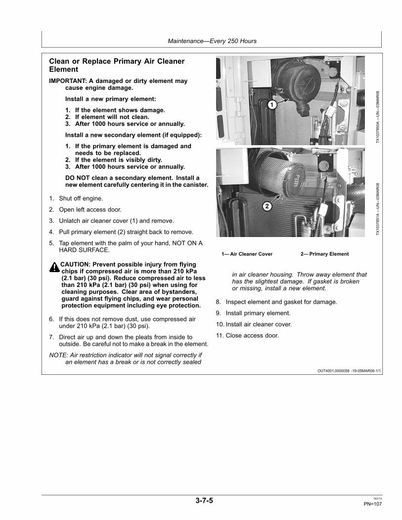
Maintenance—Every 250 Hours
OUT4001,0000058 -19-05MAR08-1/1
Clean or Replace Primary Air CleanerElementIMPORTANT: A damaged or dirty element may
cause engine damage.
Install a new primary element:
1. If the element shows damage.2. If element will not clean.3. After 1000 hours service or annually.
Install a new secondary element (if equipped):
1. If the primary element is damaged andneeds to be replaced.
2. If the element is visibly dirty.3. After 1000 hours service or annually.
DO NOT clean a secondary element. Install anew element carefully centering it in the canister.
1. Shut off engine.
2. Open left access door.
3. Unlatch air cleaner cover (1) and remove.
4. Pull primary element (2) straight back to remove.
5. Tap element with the palm of your hand, NOT ON AHARD SURFACE.
CAUTION: Prevent possible injury from flyingchips if compressed air is more than 210 kPa(2.1 bar) (30 psi). Reduce compressed air to lessthan 210 kPa (2.1 bar) (30 psi) when using forcleaning purposes. Clear area of bystanders,guard against flying chips, and wear personalprotection equipment including eye protection.
6. If this does not remove dust, use compressed airunder 210 kPa (2.1 bar) (30 psi).
7. Direct air up and down the pleats from inside tooutside. Be careful not to make a break in the element.
NOTE: Air restriction indicator will not signal correctly ifan element has a break or is not correctly sealed
TX1037850A
—UN—03MAR08
TX1037851A
—UN—03MAR08
1—Air Cleaner Cover 2—Primary Element
in air cleaner housing. Throw away element thathas the slightest damage. If gasket is brokenor missing, install a new element.
8. Inspect element and gasket for damage.
9. Install primary element.
10. Install air cleaner cover.
11. Close access door.
3-7-5 053113
PN=107
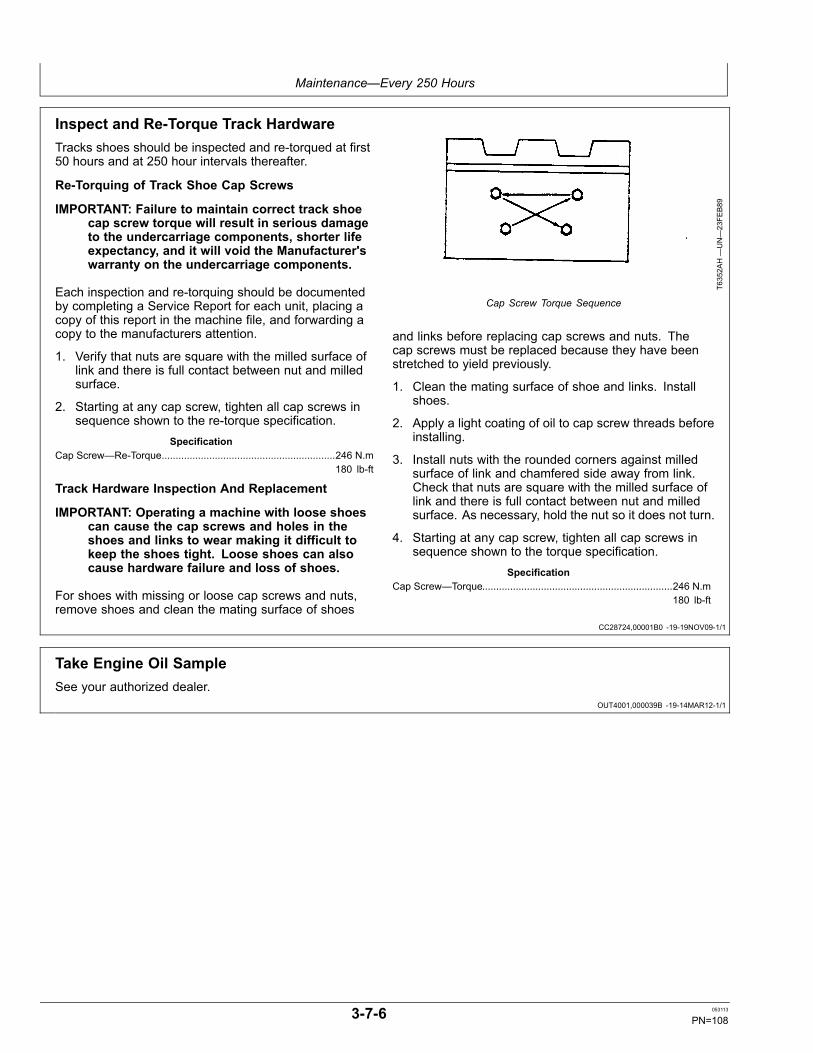
Maintenance—Every 250 Hours
CC28724,00001B0 -19-19NOV09-1/1
OUT4001,000039B -19-14MAR12-1/1
Inspect and Re-Torque Track HardwareTracks shoes should be inspected and re-torqued at first50 hours and at 250 hour intervals thereafter.
Re-Torquing of Track Shoe Cap Screws
IMPORTANT: Failure to maintain correct track shoecap screw torque will result in serious damageto the undercarriage components, shorter lifeexpectancy, and it will void the Manufacturer'swarranty on the undercarriage components.
Each inspection and re-torquing should be documentedby completing a Service Report for each unit, placing acopy of this report in the machine file, and forwarding acopy to the manufacturers attention.
1. Verify that nuts are square with the milled surface oflink and there is full contact between nut and milledsurface.
2. Starting at any cap screw, tighten all cap screws insequence shown to the re-torque specification.
SpecificationCap Screw—Re-Torque..............................................................246 N.m
180 lb-ft
Track Hardware Inspection And Replacement
IMPORTANT: Operating a machine with loose shoescan cause the cap screws and holes in theshoes and links to wear making it difficult tokeep the shoes tight. Loose shoes can alsocause hardware failure and loss of shoes.
For shoes with missing or loose cap screws and nuts,remove shoes and clean the mating surface of shoes
T6352A
H—UN—23FE
B89
Cap Screw Torque Sequence
and links before replacing cap screws and nuts. Thecap screws must be replaced because they have beenstretched to yield previously.
1. Clean the mating surface of shoe and links. Installshoes.
2. Apply a light coating of oil to cap screw threads beforeinstalling.
3. Install nuts with the rounded corners against milledsurface of link and chamfered side away from link.Check that nuts are square with the milled surface oflink and there is full contact between nut and milledsurface. As necessary, hold the nut so it does not turn.
4. Starting at any cap screw, tighten all cap screws insequence shown to the torque specification.
SpecificationCap Screw—Torque....................................................................246 N.m
180 lb-ft
Take Engine Oil SampleSee your authorized dealer.
3-7-6 053113
PN=108
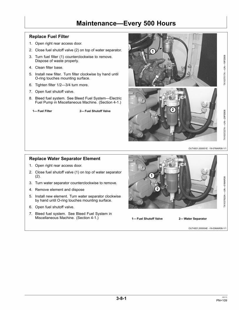
Maintenance—Every 500 Hours
OUT4001,000001E -19-07MAR08-1/1
OUT4001,000004E -19-03MAR08-1/1
Replace Fuel Filter1. Open right rear access door.
2. Close fuel shutoff valve (2) on top of water separator.
3. Turn fuel filter (1) counterclockwise to remove.Dispose of waste properly.
4. Clean filter base.
5. Install new filter. Turn filter clockwise by hand untilO-ring touches mounting surface.
6. Tighten filter 1/2—3/4 turn more.
7. Open fuel shutoff valve.
8. Bleed fuel system. See Bleed Fuel System—ElectricFuel Pump in Miscellaneous Machine. (Section 4-1.)
1—Fuel Filter 2—Fuel Shutoff Valve
TX1037017A
—UN—19FE
B08
TX1037227A
—UN—29FE
B08
Replace Water Separator Element1. Open right rear access door.
2. Close fuel shutoff valve (1) on top of water separator(2).
3. Turn water separator counterclockwise to remove.
4. Remove element and dispose
5. Install new element. Turn water separator clockwiseby hand until O-ring touches mounting surface.
6. Open fuel shutoff valve.
7. Bleed fuel system. See Bleed Fuel System inMiscellaneous Machine. (Section 4-1.)
TX1037825A
—UN—01MAR08
1—Fuel Shutoff Valve 2—Water Separator
3-8-1 053113
PN=109
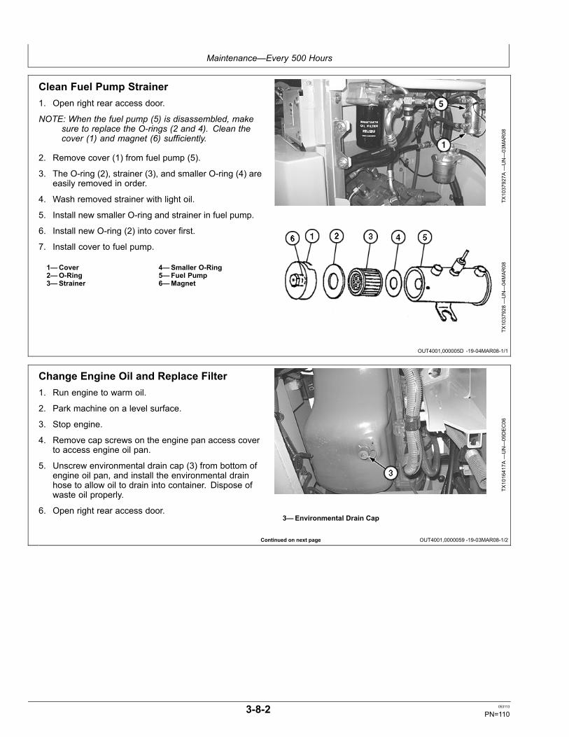
Maintenance—Every 500 Hours
OUT4001,000005D -19-04MAR08-1/1
Continued on next page OUT4001,0000059 -19-03MAR08-1/2
Clean Fuel Pump Strainer1. Open right rear access door.
NOTE: When the fuel pump (5) is disassembled, makesure to replace the O-rings (2 and 4). Clean thecover (1) and magnet (6) sufficiently.
2. Remove cover (1) from fuel pump (5).
3. The O-ring (2), strainer (3), and smaller O-ring (4) areeasily removed in order.
4. Wash removed strainer with light oil.
5. Install new smaller O-ring and strainer in fuel pump.
6. Install new O-ring (2) into cover first.
7. Install cover to fuel pump.
1—Cover2—O-Ring3—Strainer
4—Smaller O-Ring5—Fuel Pump6—Magnet
TX1037927A
—UN—03MAR08
TX1037928—UN—04MAR08
Change Engine Oil and Replace Filter1. Run engine to warm oil.
2. Park machine on a level surface.
3. Stop engine.
4. Remove cap screws on the engine pan access coverto access engine oil pan.
5. Unscrew environmental drain cap (3) from bottom ofengine oil pan, and install the environmental drainhose to allow oil to drain into container. Dispose ofwaste oil properly.
6. Open right rear access door.TX
1016417A
—UN—09DEC06
3—Environmental Drain Cap
3-8-2 053113
PN=110
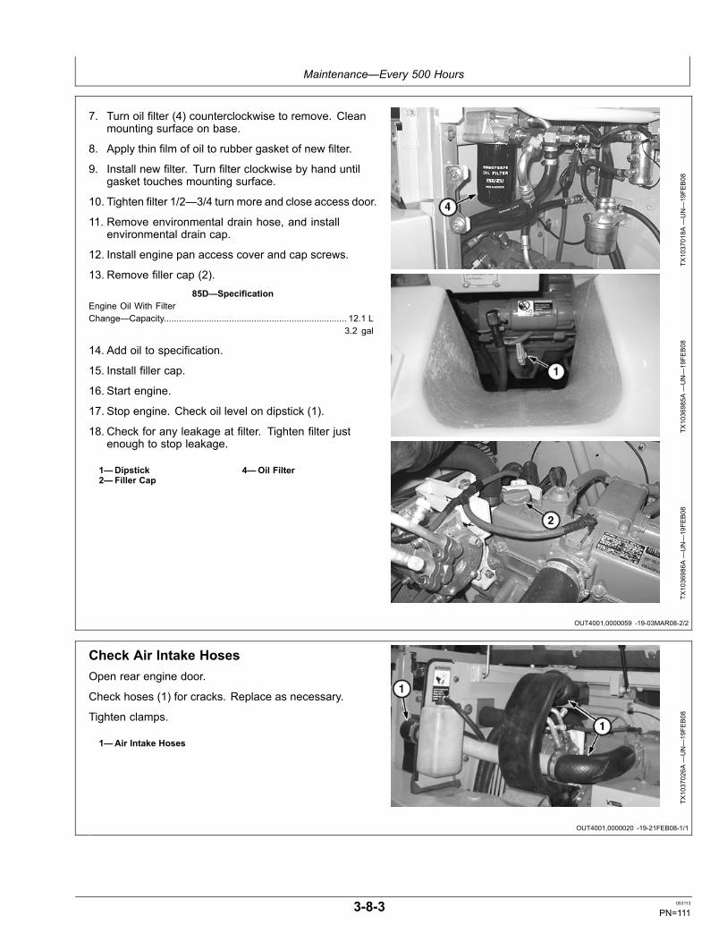
Maintenance—Every 500 Hours
OUT4001,0000059 -19-03MAR08-2/2
OUT4001,0000020 -19-21FEB08-1/1
7. Turn oil filter (4) counterclockwise to remove. Cleanmounting surface on base.
8. Apply thin film of oil to rubber gasket of new filter.
9. Install new filter. Turn filter clockwise by hand untilgasket touches mounting surface.
10. Tighten filter 1/2—3/4 turn more and close access door.
11. Remove environmental drain hose, and installenvironmental drain cap.
12. Install engine pan access cover and cap screws.
13. Remove filler cap (2).85D—Specification
Engine Oil With FilterChange—Capacity......................................................................... 12.1 L
3.2 gal
14. Add oil to specification.
15. Install filler cap.
16. Start engine.
17. Stop engine. Check oil level on dipstick (1).
18. Check for any leakage at filter. Tighten filter justenough to stop leakage.
1—Dipstick2—Filler Cap
4—Oil Filter
TX1037018A
—UN—19FE
B08
TX1036985A
—UN—19FE
B08
TX1036986A
—UN—19FE
B08
Check Air Intake HosesOpen rear engine door.
Check hoses (1) for cracks. Replace as necessary.
Tighten clamps.
1—Air Intake Hoses
TX1037026A
—UN—19FE
B08
3-8-3 053113
PN=111
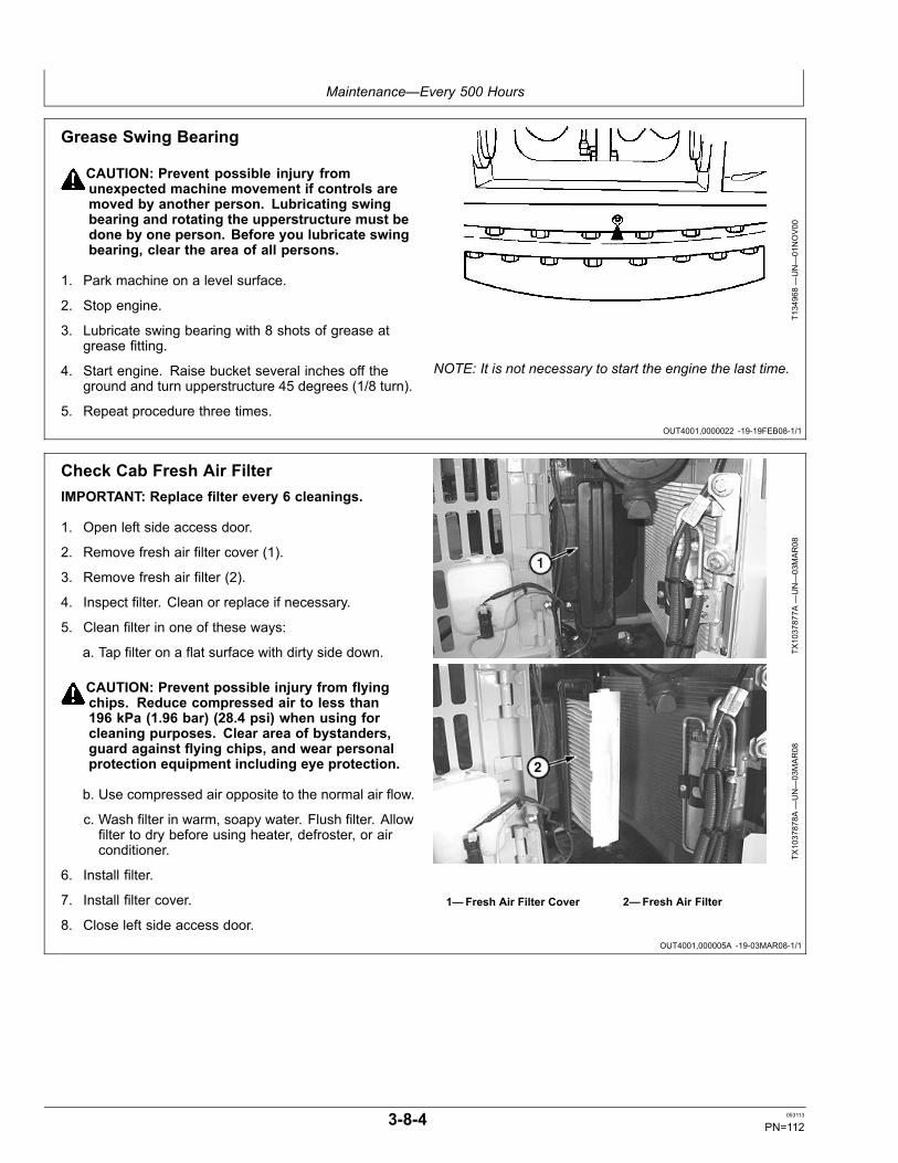
Maintenance—Every 500 Hours
OUT4001,0000022 -19-19FEB08-1/1
OUT4001,000005A -19-03MAR08-1/1
Grease Swing Bearing
CAUTION: Prevent possible injury fromunexpected machine movement if controls aremoved by another person. Lubricating swingbearing and rotating the upperstructure must bedone by one person. Before you lubricate swingbearing, clear the area of all persons.
1. Park machine on a level surface.
2. Stop engine.
3. Lubricate swing bearing with 8 shots of grease atgrease fitting.
4. Start engine. Raise bucket several inches off theground and turn upperstructure 45 degrees (1/8 turn).
5. Repeat procedure three times.
T134968—UN—01NOV00
NOTE: It is not necessary to start the engine the last time.
Check Cab Fresh Air FilterIMPORTANT: Replace filter every 6 cleanings.
1. Open left side access door.
2. Remove fresh air filter cover (1).
3. Remove fresh air filter (2).
4. Inspect filter. Clean or replace if necessary.
5. Clean filter in one of these ways:
a. Tap filter on a flat surface with dirty side down.
CAUTION: Prevent possible injury from flyingchips. Reduce compressed air to less than196 kPa (1.96 bar) (28.4 psi) when using forcleaning purposes. Clear area of bystanders,guard against flying chips, and wear personalprotection equipment including eye protection.
b. Use compressed air opposite to the normal air flow.
c. Wash filter in warm, soapy water. Flush filter. Allowfilter to dry before using heater, defroster, or airconditioner.
6. Install filter.
7. Install filter cover.
8. Close left side access door.
TX1037877A
—UN—03MAR08
TX1037878A
—UN—03MAR08
1—Fresh Air Filter Cover 2—Fresh Air Filter
3-8-4 053113
PN=112
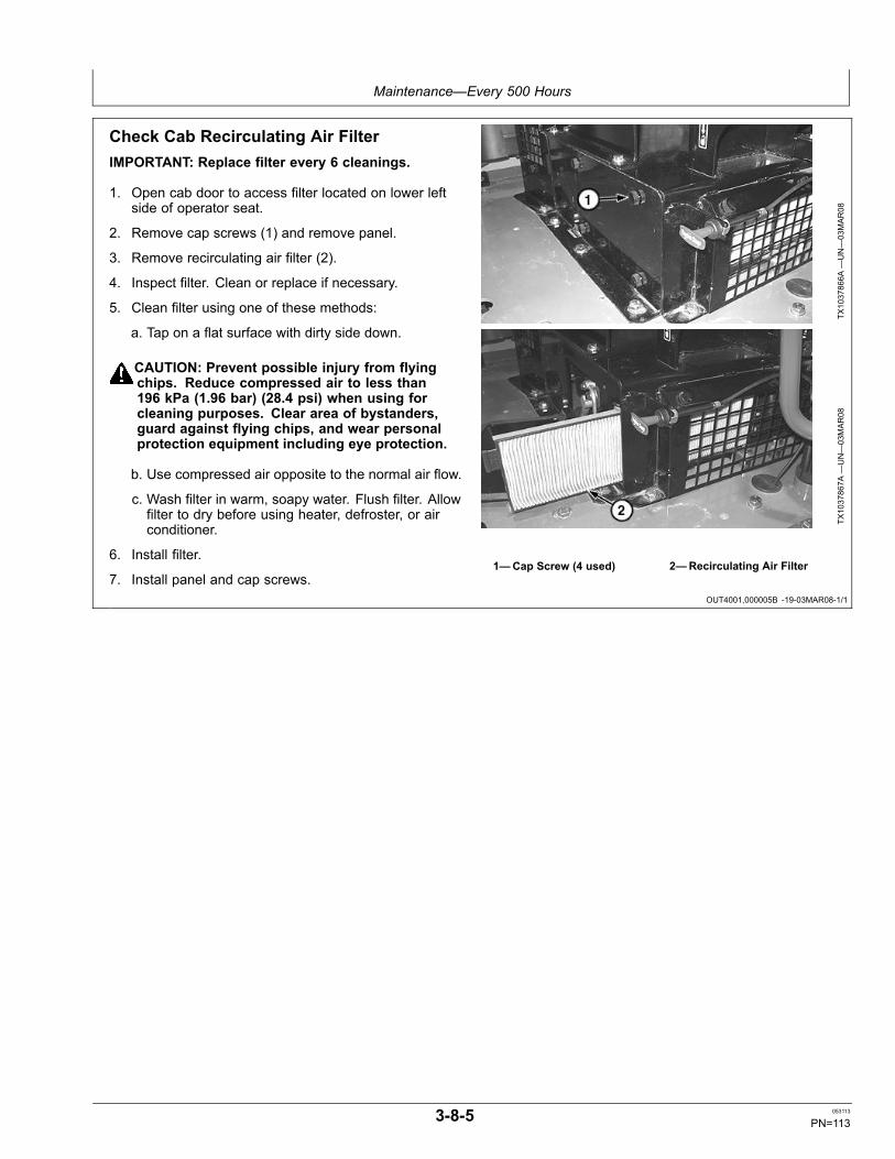
Maintenance—Every 500 Hours
OUT4001,000005B -19-03MAR08-1/1
Check Cab Recirculating Air FilterIMPORTANT: Replace filter every 6 cleanings.
1. Open cab door to access filter located on lower leftside of operator seat.
2. Remove cap screws (1) and remove panel.
3. Remove recirculating air filter (2).
4. Inspect filter. Clean or replace if necessary.
5. Clean filter using one of these methods:
a. Tap on a flat surface with dirty side down.
CAUTION: Prevent possible injury from flyingchips. Reduce compressed air to less than196 kPa (1.96 bar) (28.4 psi) when using forcleaning purposes. Clear area of bystanders,guard against flying chips, and wear personalprotection equipment including eye protection.
b. Use compressed air opposite to the normal air flow.
c. Wash filter in warm, soapy water. Flush filter. Allowfilter to dry before using heater, defroster, or airconditioner.
6. Install filter.
7. Install panel and cap screws.
TX1037866A
—UN—03MAR08
TX1037867A
—UN—03MAR08
1—Cap Screw (4 used) 2—Recirculating Air Filter
3-8-5 053113
PN=113

Maintenance—Every 500 Hours
OUT4001,000005C -19-27JUL10-1/1
ER79617,0000C16 -19-27JUL10-1/1
Grease Swing Bearing Gear
CAUTION: Prevent possible injury fromunexpected machine movement if controls aremoved by another person. Lubricating swingbearing gear and rotating the upperstructuremust be done by one person.
1. Remove cover over the swing motor. Swing bearinggear (1) is located at the base on the front side of theswing motor.
2. Remove cap screws from swing bearing gear accesscover (2).
3. Grease must be to the top of all internal gear teethof the swing bearing. Grease must be free ofcontamination. Add approximately 0.5 kg (1.1 lb) ofgrease, if required. If the grease is contaminated,remove grease and replace with clean grease.
IMPORTANT: If water or mud is found in swinggear area, see Operating in Water andMud. (Section 2-3.)
4. If grease shows any sign of water or mud, replace allthe grease on the internal gear.
SpecificationGrease—Capacity............................................................................ 4.4 L
1.2 gal
IMPORTANT: Excessive grease can damage theswing gear case seal.
5. Remove any excess grease from over the top of theswing drive pinion.
6. Install access cover and cap screws.
7. Install cover.
TX1037892A
—UN—03MAR08
TX1037907—UN—04MAR08
1—Swing Bearing GearLocation
2—Access Cover
Take Fluid SamplesSee your authorized dealer for taking the following fluidsamples:
• Hydraulic Oil
• Travel Gear Case Oil• Coolant• Diesel Fuel
3-8-6 053113
PN=114
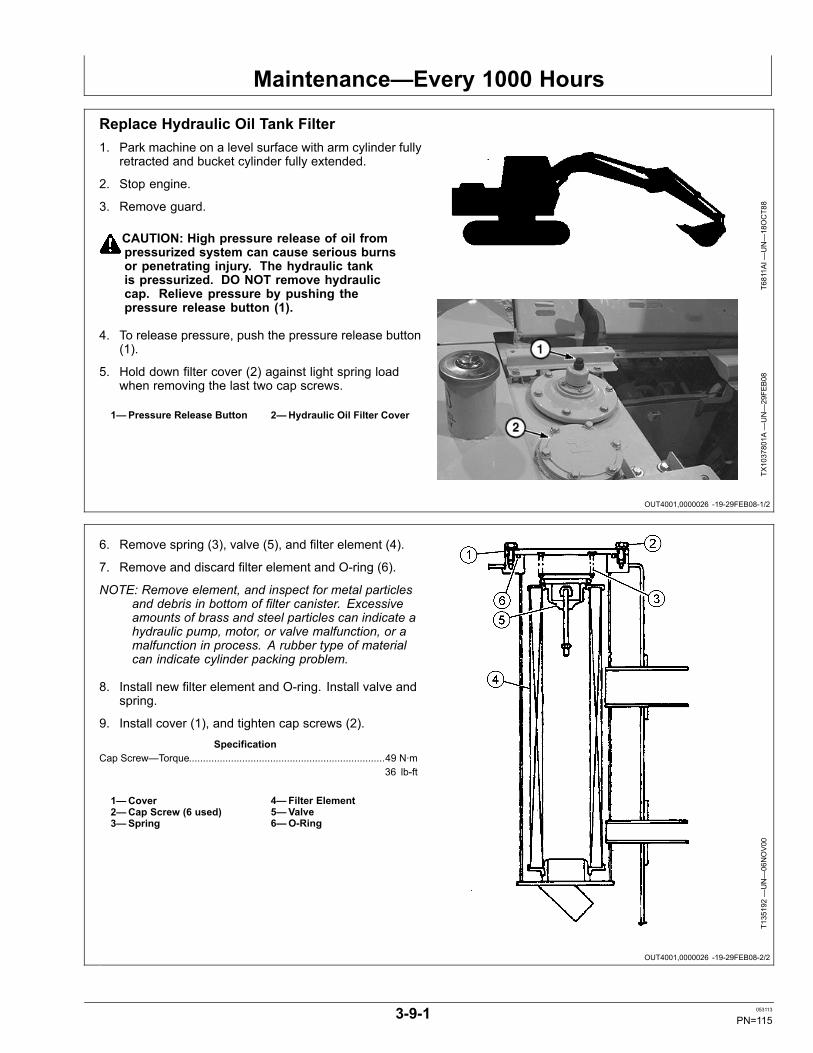
Maintenance—Every 1000 Hours
OUT4001,0000026 -19-29FEB08-1/2
OUT4001,0000026 -19-29FEB08-2/2
Replace Hydraulic Oil Tank Filter1. Park machine on a level surface with arm cylinder fully
retracted and bucket cylinder fully extended.
2. Stop engine.
3. Remove guard.
CAUTION: High pressure release of oil frompressurized system can cause serious burnsor penetrating injury. The hydraulic tankis pressurized. DO NOT remove hydrauliccap. Relieve pressure by pushing thepressure release button (1).
4. To release pressure, push the pressure release button(1).
5. Hold down filter cover (2) against light spring loadwhen removing the last two cap screws.
1—Pressure Release Button 2—Hydraulic Oil Filter Cover
T6811A
I—UN—18OCT88
TX1037801A
—UN—29FE
B08
6. Remove spring (3), valve (5), and filter element (4).
7. Remove and discard filter element and O-ring (6).
NOTE: Remove element, and inspect for metal particlesand debris in bottom of filter canister. Excessiveamounts of brass and steel particles can indicate ahydraulic pump, motor, or valve malfunction, or amalfunction in process. A rubber type of materialcan indicate cylinder packing problem.
8. Install new filter element and O-ring. Install valve andspring.
9. Install cover (1), and tighten cap screws (2).Specification
Cap Screw—Torque......................................................................49 N·m36 lb-ft
1—Cover2—Cap Screw (6 used)3—Spring
4—Filter Element5—Valve6—O-Ring
T135192—UN—06NOV00
3-9-1 053113
PN=115

Maintenance—Every 1000 Hours
OUT4001,0000027 -19-06MAR08-1/1
OUT4001,0000028 -19-15FEB08-1/1
Replace Pilot System Oil Filter
CAUTION: High pressure release of oil frompressurized system can cause serious burnsor penetrating injury. The hydraulic tank ispressurized. Relieve pressure by pushingthe pressure release button (1).
1. To relieve hydraulic pressure, push the pressurerelease button (1).
2. Open right front access door.
3. Remove cap screws (3) and access panel (4) belowpilot system oil filter (2).
4. Remove filter by turning it counterclockwise anddispose .
5. Clean the filter O-ring contact area on the filter head.
6. Apply a thin film of clean oil to the O-ring of the newfilter.
7. Install new filter. Turn the filter clockwise by hand untilthe O-ring touches the contact area. Be sure not todamage the O-ring when installing the filter.
8. Install access panel and cap screws.
9. Close right front access door.
1—Pressure Release Button2—Pilot System Oil Filter
3—Cap Screw (4 used)4—Access Panel
TX1037796A
—UN—29FE
B08
TX1037050A
—UN—19FE
B08
Pilot Filter Not Visible From This View
TX1037080A
—UN—19FE
B08
Adjust Engine Valve ClearanceSee your authorized dealer for engine valve clearanceadjustment.
3-9-2 053113
PN=116
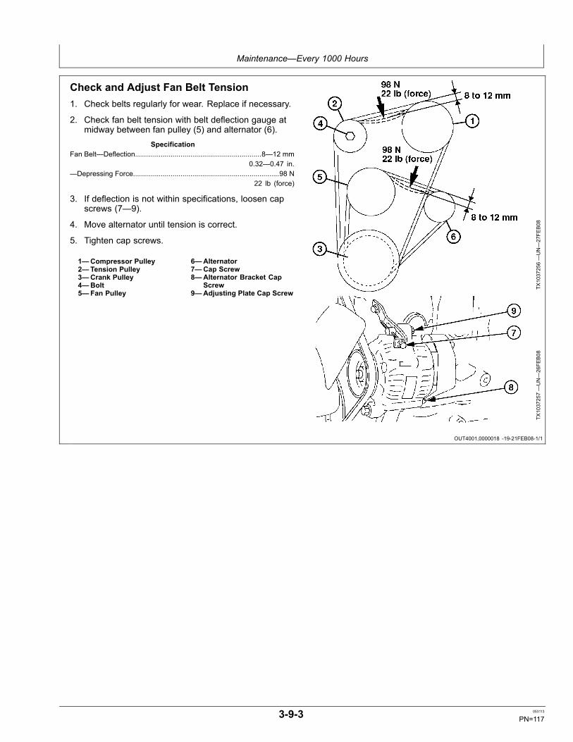
Maintenance—Every 1000 Hours
OUT4001,0000018 -19-21FEB08-1/1
Check and Adjust Fan Belt Tension1. Check belts regularly for wear. Replace if necessary.
2. Check fan belt tension with belt deflection gauge atmidway between fan pulley (5) and alternator (6).
SpecificationFan Belt—Deflection................................................................8—12 mm
0.32—0.47 in.—Depressing Force..........................................................................98 N
22 lb (force)
3. If deflection is not within specifications, loosen capscrews (7—9).
4. Move alternator until tension is correct.
5. Tighten cap screws.
1—Compressor Pulley2—Tension Pulley3—Crank Pulley4—Bolt5—Fan Pulley
6—Alternator7—Cap Screw8—Alternator Bracket Cap
Screw9—Adjusting Plate Cap Screw
TX1037256—UN—27FE
B08
TX1037257—UN—26FE
B08
3-9-3 053113
PN=117
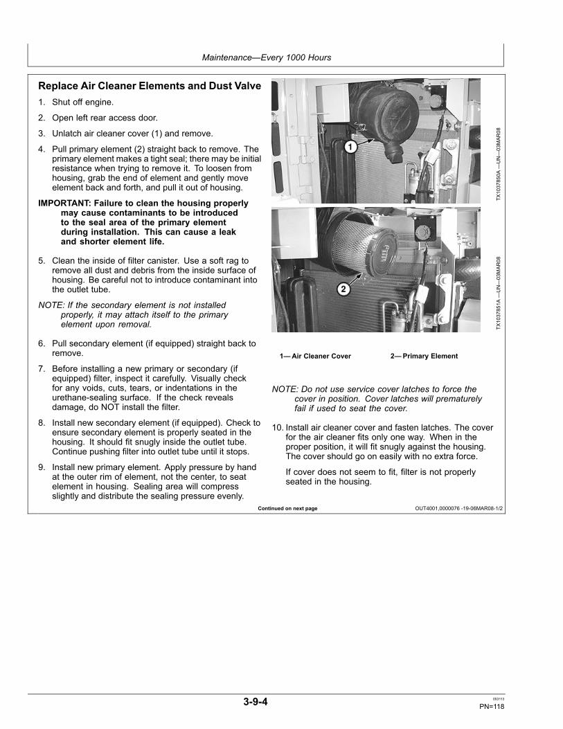
Maintenance—Every 1000 Hours
Continued on next page OUT4001,0000076 -19-06MAR08-1/2
Replace Air Cleaner Elements and Dust Valve1. Shut off engine.
2. Open left rear access door.
3. Unlatch air cleaner cover (1) and remove.
4. Pull primary element (2) straight back to remove. Theprimary element makes a tight seal; there may be initialresistance when trying to remove it. To loosen fromhousing, grab the end of element and gently moveelement back and forth, and pull it out of housing.
IMPORTANT: Failure to clean the housing properlymay cause contaminants to be introducedto the seal area of the primary elementduring installation. This can cause a leakand shorter element life.
5. Clean the inside of filter canister. Use a soft rag toremove all dust and debris from the inside surface ofhousing. Be careful not to introduce contaminant intothe outlet tube.
NOTE: If the secondary element is not installedproperly, it may attach itself to the primaryelement upon removal.
6. Pull secondary element (if equipped) straight back toremove.
7. Before installing a new primary or secondary (ifequipped) filter, inspect it carefully. Visually checkfor any voids, cuts, tears, or indentations in theurethane-sealing surface. If the check revealsdamage, do NOT install the filter.
8. Install new secondary element (if equipped). Check toensure secondary element is properly seated in thehousing. It should fit snugly inside the outlet tube.Continue pushing filter into outlet tube until it stops.
9. Install new primary element. Apply pressure by handat the outer rim of element, not the center, to seatelement in housing. Sealing area will compressslightly and distribute the sealing pressure evenly.
TX1037850A
—UN—03MAR08
TX1037851A
—UN—03MAR08
1—Air Cleaner Cover 2—Primary Element
NOTE: Do not use service cover latches to force thecover in position. Cover latches will prematurelyfail if used to seat the cover.
10. Install air cleaner cover and fasten latches. The coverfor the air cleaner fits only one way. When in theproper position, it will fit snugly against the housing.The cover should go on easily with no extra force.
If cover does not seem to fit, filter is not properlyseated in the housing.
3-9-4 053113
PN=118
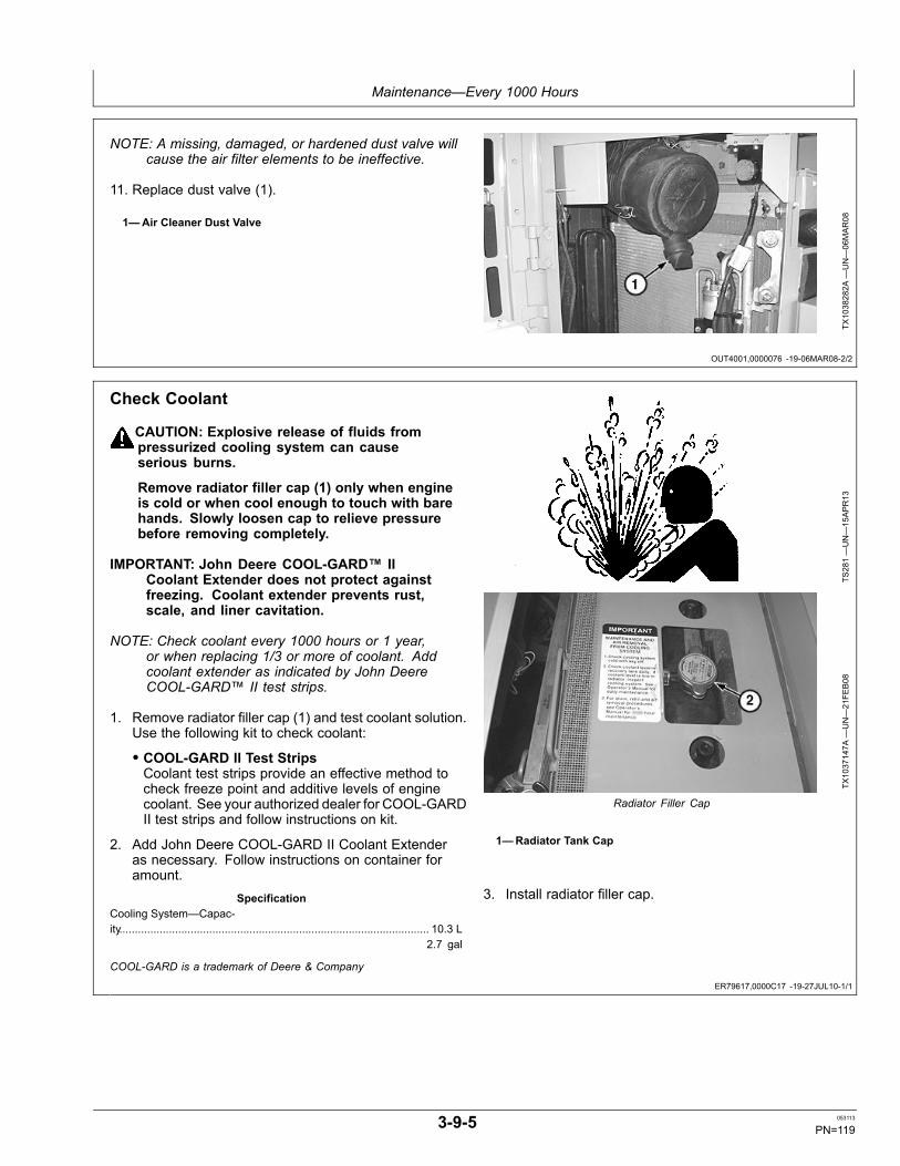
Maintenance—Every 1000 Hours
OUT4001,0000076 -19-06MAR08-2/2
ER79617,0000C17 -19-27JUL10-1/1
NOTE: A missing, damaged, or hardened dust valve willcause the air filter elements to be ineffective.
11. Replace dust valve (1).
1—Air Cleaner Dust Valve
TX1038282A
—UN—06MAR08
Check Coolant
CAUTION: Explosive release of fluids frompressurized cooling system can causeserious burns.
Remove radiator filler cap (1) only when engineis cold or when cool enough to touch with barehands. Slowly loosen cap to relieve pressurebefore removing completely.
IMPORTANT: John Deere COOL-GARD™ IICoolant Extender does not protect againstfreezing. Coolant extender prevents rust,scale, and liner cavitation.
NOTE: Check coolant every 1000 hours or 1 year,or when replacing 1/3 or more of coolant. Addcoolant extender as indicated by John DeereCOOL-GARD™ II test strips.
1. Remove radiator filler cap (1) and test coolant solution.Use the following kit to check coolant:
• COOL-GARD II Test StripsCoolant test strips provide an effective method tocheck freeze point and additive levels of enginecoolant. See your authorized dealer for COOL-GARDII test strips and follow instructions on kit.
2. Add John Deere COOL-GARD II Coolant Extenderas necessary. Follow instructions on container foramount.
SpecificationCooling System—Capac-ity.................................................................................................... 10.3 L
2.7 gal
TS281—UN—15APR13
TX1037147A
—UN—21FE
B08
Radiator Filler Cap
1—Radiator Tank Cap
3. Install radiator filler cap.
COOL-GARD is a trademark of Deere & Company
3-9-5 053113
PN=119
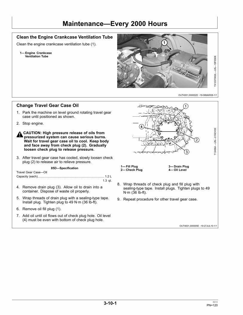
Maintenance—Every 2000 Hours
OUT4001,000002D -19-06MAR08-1/1
OUT4001,000005E -19-27JUL10-1/1
Clean the Engine Crankcase Ventilation TubeClean the engine crankcase ventilation tube (1).
1—Engine CrankcaseVentilation Tube
TX1037065A
—UN—19FE
B08
Change Travel Gear Case Oil1. Park the machine on level ground rotating travel gear
case until positioned as shown.
2. Stop engine.
CAUTION: High pressure release of oils frompressurized system can cause serious burns.Wait for travel gear case oil to cool. Keep bodyand face away from check plug (2). Graduallyloosen check plug to release pressure.
3. After travel gear case has cooled, slowly loosen checkplug (2) to release air to relieve pressure.
85D—SpecificationTravel Gear Case—OilCapacity (each)................................................................................ 1.2 L
1.3 qt.
4. Remove drain plug (3). Allow oil to drain into acontainer. Dispose of waste oil properly.
5. Wrap threads of drain plug with a sealing-type tape.Install plug. Tighten plug to 49 N·m (36 lb-ft).
6. Remove oil fill plug (1).
7. Add oil until oil flows out of check plug hole. Oil level(4) must be even with bottom of check plug hole.
T134964—UN—01NOV00
1—Fill Plug2—Check Plug
3—Drain Plug4—Oil Level
8. Wrap threads of check plug and fill plug withsealing-type tape. Install plugs. Tighten plugs to 49N·m (36 lb-ft).
9. Repeat procedure for other travel gear case.
3-10-1 053113
PN=120
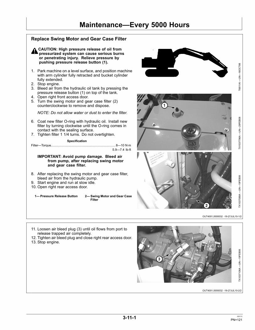
Maintenance—Every 5000 Hours
OUT4001,0000032 -19-27JUL10-1/2
OUT4001,0000032 -19-27JUL10-2/2
Replace Swing Motor and Gear Case Filter
CAUTION: High pressure release of oil frompressurized system can cause serious burnsor penetrating injury. Relieve pressure bypushing pressure release button (1).
1. Park machine on a level surface, and position machinewith arm cylinder fully retracted and bucket cylinderfully extended.
2. Stop engine.3. Bleed air from the hydraulic oil tank by pressing the
pressure release button (1) on top of the tank.4. Open right front access door.5. Turn the swing motor and gear case filter (2)
counterclockwise to remove and dispose.
NOTE: Do not allow water or dust to enter the filter.
6. Coat new filter O-ring with hydraulic oil. Install newfilter by turning clockwise until the O-ring comes incontact with the sealing surface.
7. Tighten filter 1 1/4 turns. Do not overtighten.Specification
Filter—Torque.......................................................................... 8—10 N·m5.9—7.4 lb-ft
IMPORTANT: Avoid pump damage. Bleed airfrom pump, after replacing swing motorand gear case filter.
8. After replacing the swing motor and gear case filter,bleed air from the hydraulic pump.
9. Start engine and run at slow idle.10. Open right rear access door.
1—Pressure Release Button 2—Swing Motor and Gear CaseFilter
T6811A
I—UN—18OCT88
TX1037796A
—UN—29FE
B08
TX1037088A
—UN—19FE
B08
11. Loosen air bleed plug (3) until oil flows from port torelease trapped air completely.
12. Tighten air bleed plug and close right rear access door.13. Stop engine.
TX1037106A
—UN—19FE
B08
3-11-1 053113
PN=121
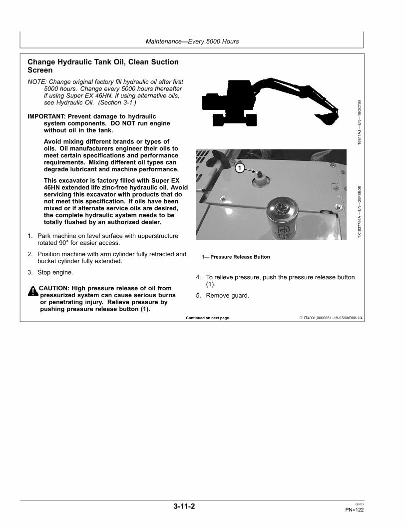
Maintenance—Every 5000 Hours
Continued on next page OUT4001,0000061 -19-03MAR08-1/4
Change Hydraulic Tank Oil, Clean SuctionScreenNOTE: Change original factory fill hydraulic oil after first
5000 hours. Change every 5000 hours thereafterif using Super EX 46HN. If using alternative oils,see Hydraulic Oil. (Section 3-1.)
IMPORTANT: Prevent damage to hydraulicsystem components. DO NOT run enginewithout oil in the tank.
Avoid mixing different brands or types ofoils. Oil manufacturers engineer their oils tomeet certain specifications and performancerequirements. Mixing different oil types candegrade lubricant and machine performance.
This excavator is factory filled with Super EX46HN extended life zinc-free hydraulic oil. Avoidservicing this excavator with products that donot meet this specification. If oils have beenmixed or if alternate service oils are desired,the complete hydraulic system needs to betotally flushed by an authorized dealer.
1. Park machine on level surface with upperstructurerotated 90° for easier access.
2. Position machine with arm cylinder fully retracted andbucket cylinder fully extended.
3. Stop engine.
CAUTION: High pressure release of oil frompressurized system can cause serious burnsor penetrating injury. Relieve pressure bypushing pressure release button (1).
T6811A
J—UN—18OCT88
TX1037796A
—UN—29FE
B08
1—Pressure Release Button
4. To relieve pressure, push the pressure release button(1).
5. Remove guard.
3-11-2 053113
PN=122
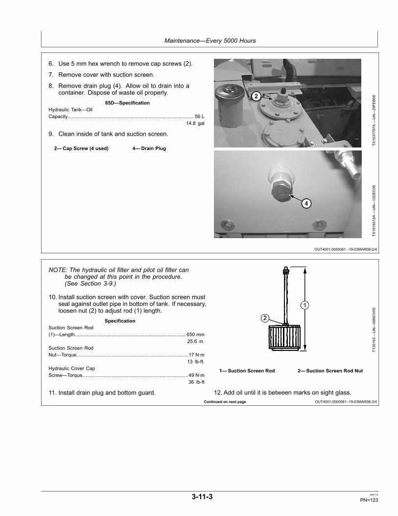
Maintenance—Every 5000 Hours
OUT4001,0000061 -19-03MAR08-2/4
Continued on next page OUT4001,0000061 -19-03MAR08-3/4
6. Use 5 mm hex wrench to remove cap screws (2).
7. Remove cover with suction screen.
8. Remove drain plug (4). Allow oil to drain into acontainer. Dispose of waste oil properly.
85D—SpecificationHydraulic Tank—OilCapacity............................................................................................ 56 L
14.8 gal
9. Clean inside of tank and suction screen.
2—Cap Screw (4 used) 4—Drain Plug
TX1037797A
—UN—29FE
B08
TX1016515A
—UN—12DEC06
NOTE: The hydraulic oil filter and pilot oil filter canbe changed at this point in the procedure.(See Section 3-9.)
10. Install suction screen with cover. Suction screen mustseal against outlet pipe in bottom of tank. If necessary,loosen nut (2) to adjust rod (1) length.
SpecificationSuction Screen Rod(1)—Length................................................................................. 650 mm
25.6 in.Suction Screen RodNut—Torque..................................................................................17 N·m
13 lb-ft.Hydraulic Cover CapScrew—Torque..............................................................................49 N·m
36 lb-ft
11. Install drain plug and bottom guard.
T135193—UN—06NOV00
1—Suction Screen Rod 2—Suction Screen Rod Nut
12. Add oil until it is between marks on sight glass.
3-11-3 053113
PN=123

Maintenance—Every 5000 Hours
OUT4001,0000061 -19-03MAR08-4/4
IMPORTANT: If the hydraulic pump is not filled withoil, it will be damaged when the engine is started.
13. Open right rear access door.
14. Remove air bleed plug (3).
15. Fill pump with oil through air bleed plug port until oilflows out of hole.
16. Temporarily tighten air bleed plug. Start the engineand run at slow idle.
17. Loosen air bleed plug slightly until oil flows from plugport to release trapped air completely.
18. Tighten air bleed plug and close right rear access door.
19. Purge air from cylinders and swing motor by cyclinghydraulic functions.
20. Position machine with arm cylinder fully retracted andbucket cylinder fully extended.
21. Check oil level in sight glass. Add oil, if necessary.Install and tighten tank cover.
TX1037106A
—UN—19FE
B08
3—Air Bleed Plug
22. Install guard on top of cover.
3-11-4 053113
PN=124
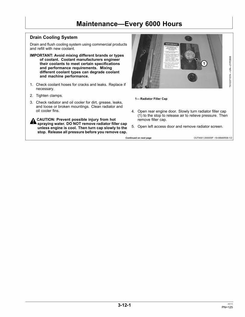
Maintenance—Every 6000 Hours
Continued on next page OUT4001,000005F -19-06MAR08-1/2
Drain Cooling SystemDrain and flush cooling system using commercial productsand refill with new coolant.
IMPORTANT: Avoid mixing different brands or typesof coolant. Coolant manufacturers engineertheir coolants to meet certain specificationsand performance requirements. Mixingdifferent coolant types can degrade coolantand machine performance.
1. Check coolant hoses for cracks and leaks. Replace ifnecessary.
2. Tighten clamps.
3. Check radiator and oil cooler for dirt, grease, leaks,and loose or broken mountings. Clean radiator andoil cooler fins.
CAUTION: Prevent possible injury from hotspraying water. DO NOT remove radiator filler capunless engine is cool. Then turn cap slowly to thestop. Release all pressure before you remove cap.
TX1037157A
—UN—21FE
B08
1—Radiator Filler Cap
4. Open rear engine door. Slowly turn radiator filler cap(1) to the stop to release air to relieve pressure. Thenremove filler cap.
5. Open left access door and remove radiator screen.
3-12-1 053113
PN=125
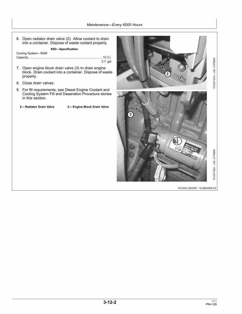
Maintenance—Every 6000 Hours
OUT4001,000005F -19-06MAR08-2/2
6. Open radiator drain valve (2). Allow coolant to draininto a container. Dispose of waste coolant properly.
85D—SpecificationCooling System—RefillCapacity......................................................................................... 10.3 L
2.7 gal
7. Open engine block drain valve (3) to drain engineblock. Drain coolant into a container. Dispose of wasteproperly.
8. Close drain valves.
9. For fill requirements, see Diesel Engine Coolant andCooling System Fill and Deaeration Procedure storiesin this section.
2—Radiator Drain Valve 3—Engine Block Drain Valve
TX1037161A
—UN—21FE
B08
TX1037162A
—UN—21FE
B08
3-12-2 053113
PN=126
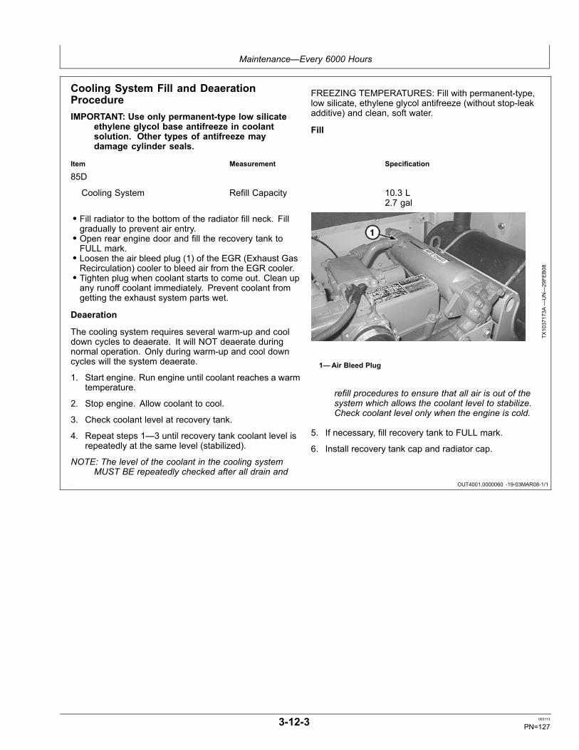
Maintenance—Every 6000 Hours
OUT4001,0000060 -19-03MAR08-1/1
Cooling System Fill and DeaerationProcedureIMPORTANT: Use only permanent-type low silicate
ethylene glycol base antifreeze in coolantsolution. Other types of antifreeze maydamage cylinder seals.
FREEZING TEMPERATURES: Fill with permanent-type,low silicate, ethylene glycol antifreeze (without stop-leakadditive) and clean, soft water.
Fill
Item Measurement Specification
85D
Cooling System Refill Capacity 10.3 L2.7 gal
• Fill radiator to the bottom of the radiator fill neck. Fillgradually to prevent air entry.• Open rear engine door and fill the recovery tank toFULL mark.• Loosen the air bleed plug (1) of the EGR (Exhaust GasRecirculation) cooler to bleed air from the EGR cooler.• Tighten plug when coolant starts to come out. Clean upany runoff coolant immediately. Prevent coolant fromgetting the exhaust system parts wet.
Deaeration
The cooling system requires several warm-up and cooldown cycles to deaerate. It will NOT deaerate duringnormal operation. Only during warm-up and cool downcycles will the system deaerate.
1. Start engine. Run engine until coolant reaches a warmtemperature.
2. Stop engine. Allow coolant to cool.
3. Check coolant level at recovery tank.
4. Repeat steps 1—3 until recovery tank coolant level isrepeatedly at the same level (stabilized).
NOTE: The level of the coolant in the cooling systemMUST BE repeatedly checked after all drain and
TX1037173A
—UN—29FE
B08
1—Air Bleed Plug
refill procedures to ensure that all air is out of thesystem which allows the coolant level to stabilize.Check coolant level only when the engine is cold.
5. If necessary, fill recovery tank to FULL mark.
6. Install recovery tank cap and radiator cap.
3-12-3 053113
PN=127
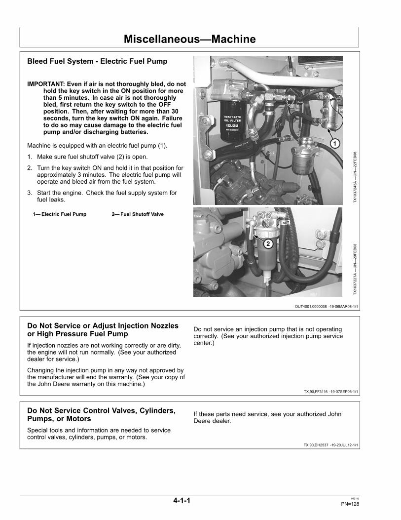
Miscellaneous—Machine
OUT4001,0000038 -19-06MAR08-1/1
TX,90,FF3116 -19-07SEP06-1/1
TX,90,DH2537 -19-20JUL12-1/1
Bleed Fuel System - Electric Fuel Pump
IMPORTANT: Even if air is not thoroughly bled, do nothold the key switch in the ON position for morethan 5 minutes. In case air is not thoroughlybled, first return the key switch to the OFFposition. Then, after waiting for more than 30seconds, turn the key switch ON again. Failureto do so may cause damage to the electric fuelpump and/or discharging batteries.
Machine is equipped with an electric fuel pump (1).
1. Make sure fuel shutoff valve (2) is open.
2. Turn the key switch ON and hold it in that position forapproximately 3 minutes. The electric fuel pump willoperate and bleed air from the fuel system.
3. Start the engine. Check the fuel supply system forfuel leaks.
1—Electric Fuel Pump 2—Fuel Shutoff Valve
TX1037243A
—UN—22FE
B08
TX1037227A
—UN—29FE
B08
Do Not Service or Adjust Injection Nozzlesor High Pressure Fuel PumpIf injection nozzles are not working correctly or are dirty,the engine will not run normally. (See your authorizeddealer for service.)
Changing the injection pump in any way not approved bythe manufacturer will end the warranty. (See your copy ofthe John Deere warranty on this machine.)
Do not service an injection pump that is not operatingcorrectly. (See your authorized injection pump servicecenter.)
Do Not Service Control Valves, Cylinders,Pumps, or MotorsSpecial tools and information are needed to servicecontrol valves, cylinders, pumps, or motors.
If these parts need service, see your authorized JohnDeere dealer.
4-1-1 053113
PN=128
Miscellaneous—Machine
CED,OUO1021,185 -19-05NOV08-1/1
Precautions for Alternator and Regulator
When batteries are connected, follow these rules:
1. Disconnect negative (-) battery cable when you workon or near alternator or regulator.
2. DO NOT TRY TO POLARIZE ALTERNATOR ORREGULATOR.
3. Be sure alternator wires are correctly connectedBEFORE you connect batteries.
4. Do not ground alternator output terminal.
5. Do not disconnect or connect any alternator orregulator wires while batteries are connected or whilealternator is operating.
6. Connect batteries or a booster battery in the correctpolarity (positive [+] to positive [+] and negative [-] tonegative [-]).
7. Do not disconnect the batteries when engine isrunning and alternator is charging.
8. Disconnect battery cables before you connect batterycharger to the batteries. If machine has more than onebattery, each battery must be charged separately.
4-1-2 053113
PN=129
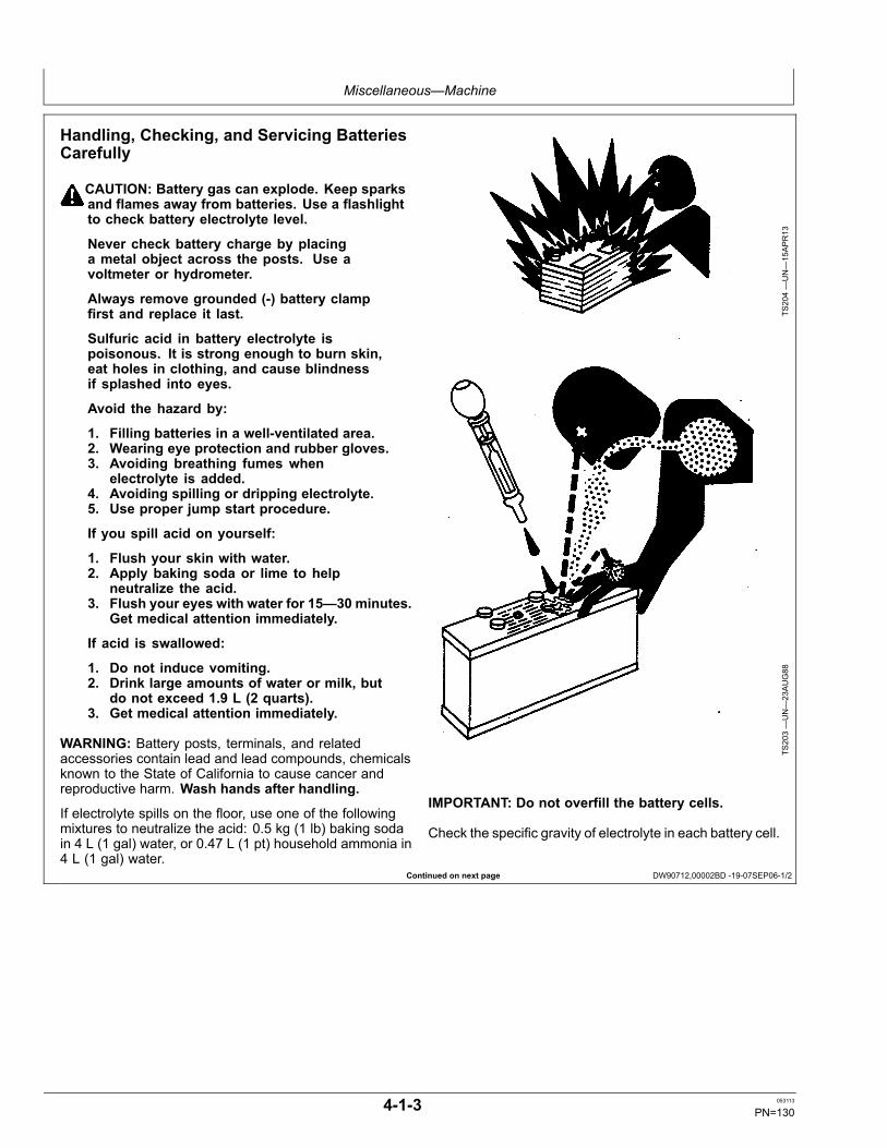
Miscellaneous—Machine
Continued on next page DW90712,00002BD -19-07SEP06-1/2
Handling, Checking, and Servicing BatteriesCarefully
CAUTION: Battery gas can explode. Keep sparksand flames away from batteries. Use a flashlightto check battery electrolyte level.
Never check battery charge by placinga metal object across the posts. Use avoltmeter or hydrometer.
Always remove grounded (-) battery clampfirst and replace it last.
Sulfuric acid in battery electrolyte ispoisonous. It is strong enough to burn skin,eat holes in clothing, and cause blindnessif splashed into eyes.
Avoid the hazard by:
1. Filling batteries in a well-ventilated area.2. Wearing eye protection and rubber gloves.3. Avoiding breathing fumes when
electrolyte is added.4. Avoiding spilling or dripping electrolyte.5. Use proper jump start procedure.
If you spill acid on yourself:
1. Flush your skin with water.2. Apply baking soda or lime to help
neutralize the acid.3. Flush your eyes with water for 15—30 minutes.
Get medical attention immediately.
If acid is swallowed:
1. Do not induce vomiting.2. Drink large amounts of water or milk, but
do not exceed 1.9 L (2 quarts).3. Get medical attention immediately.
WARNING: Battery posts, terminals, and relatedaccessories contain lead and lead compounds, chemicalsknown to the State of California to cause cancer andreproductive harm. Wash hands after handling.
If electrolyte spills on the floor, use one of the followingmixtures to neutralize the acid: 0.5 kg (1 lb) baking sodain 4 L (1 gal) water, or 0.47 L (1 pt) household ammonia in4 L (1 gal) water.
TS204—UN—15APR13
TS203—UN—23AUG88
IMPORTANT: Do not overfill the battery cells.
Check the specific gravity of electrolyte in each battery cell.
4-1-3 053113
PN=130

Miscellaneous—Machine
DW90712,00002BD -19-07SEP06-2/2
OUT4001,0000238 -19-12MAR12-1/1
See your authorized dealer for JT05460SERVICEGARD™ battery and coolant tester. Followdirections included with the tester.
A fully charged battery will have a corrected specificgravity reading of 1.260. If the reading is below 1.200,charge the battery.
T85402
—UN—10NOV88
SERVICEGARD is a trademark of Deere & Company
Using Booster Batteries—24-Volt SystemBefore boost starting, machine must be properly shutdownto prevent unexpected machine movement when enginestarts.
CAUTION: An explosive gas is produced whilebatteries are in use or being charged. Keep flamesor sparks away from the battery area. Make surethe batteries are charged in a well ventilated area.
IMPORTANT: The machine electrical system is a24-volt negative (-) ground. Connect two 12-voltbooster batteries together as shown for 24-volts.
1. Connect one end of the positive cable to the positiveterminal of the machine batteries (A) and the other endto the positive terminal of the booster batteries (B).
2. Connect one end of the negative cable to the negativeterminal of the booster batteries. Connect the otherend of the negative cable to the machine frame as faraway from the machine batteries as possible.
3. Start engine.
4. Immediately after starting engine disconnect the endof the negative cable from the machine frame. Then
T7233JN—UN—21MAY
90
Booster Batteries, 2-Battery Application
A—Machine Battery (2 used) B—Booster Battery (2 used)
disconnect the other end of the negative cable fromthe negative terminal of the booster batteries.
5. Disconnect positive cable from booster batteries andmachine batteries.
4-1-4 053113
PN=131

Miscellaneous—Machine
OUT4001,0000239 -19-03JAN12-1/1
OUT4001,0000080 -19-07MAR08-1/1
Using Battery Charger
CAUTION: Prevent possible injury from explodingbattery. Do not charge a battery if the batteryis frozen or it may explode. Warm battery to16°C (60°F) before charging.
Turn off charger before connecting ordisconnecting it.
IMPORTANT: Do not use battery charger as abooster if a battery has a 1.150 specificgravity reading or lower.
Disconnect battery ground (-) clamp beforeyou charge batteries in the machine to preventdamage to electrical components.
A battery charger may be used as a booster to start engine.
Ventilate the area where batteries are being charged.
Stop or cut back charging rate if battery case feels hot,or is venting electrolyte. Battery temperature must notexceed 52°C (125°F).
TS204—UN—15APR13
Prevent Battery Explosions
N36890—UN—07OCT88
Charger
Replacing Batteries
Your machine has two 12-volt batteries with negative (-)ground. Batteries must meet one of the specificationsbelow.
SpecificationBattery—Cold CrankingAmps At -18°C (0°F)........................................................................... 550Battery—MinutesReserve Capacity At 25Amps.................................................................................................. 100
If one battery in a 24-volt system has failed but the other isstill good, replace the failed battery with one of the sametype. For example, replace a failed maintenance-freebattery with a new maintenance-free battery. Differenttypes of batteries may have different rates of charge. Thisdifference could overload one of the batteries and cause itto fail.
4-1-5 053113
PN=132

Miscellaneous—Machine
OUT4001,000003A -19-26FEB08-1/1
TX,WOM -19-20JAN11-1/1
DX,WW,ECU02 -19-14AUG09-1/1
Fluid Sampling Test Ports—If EquippedTo access the engine fluid sampling test port (1), openthe right rear access door.
To access the hydraulic fluid sampling test port (2), openthe right front access door.
1—Engine Sample Port 2—Hydraulic Sample Port
TX1037276A
—UN—25FE
B08
TX1037274A
—UN—22FE
B08
Welding On MachineIMPORTANT: Disconnect both negative and
positive battery cables and microprocessorunit (if applicable).
Have only a qualified welder do this job.Connect welder ground clamp close to each
weld area so electrical current does notpass through any bearings.
Remove or protect all parts that can bedamaged by heat or weld splatter.
Welding Near Electronic Control UnitsIMPORTANT: Do not jump-start engines with arc
welding equipment. Currents and voltages aretoo high and may cause permanent damage.
1. Disconnect the negative (-) battery cable(s).
2. Disconnect the positive (+) battery cable(s).
3. Connect the positive and negative cables together. Donot attach to vehicle frame.
4. Clear or move any wiring harness sections away fromwelding area.
5. Connect welder ground close to welding point andaway from control units.
TS953—UN—15MAY
90
6. After welding, reverse Steps 1—5.
4-1-6 053113
PN=133
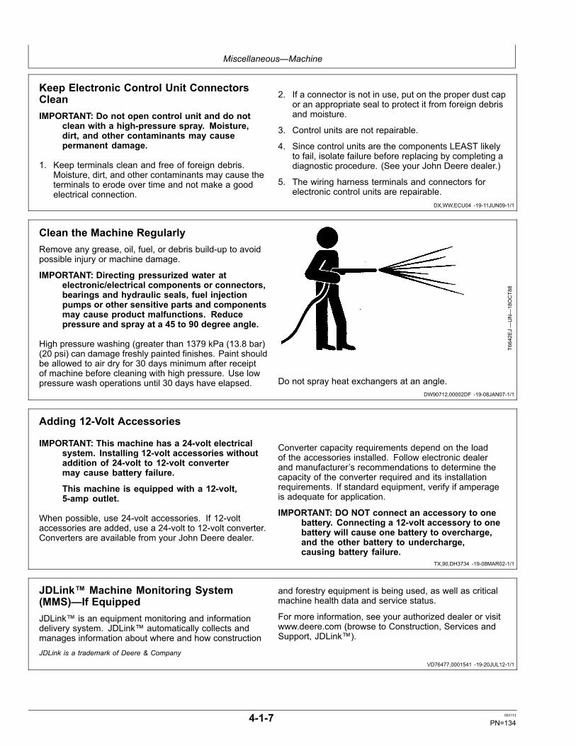
Miscellaneous—Machine
DX,WW,ECU04 -19-11JUN09-1/1
DW90712,00002DF -19-08JAN07-1/1
TX,90,DH3734 -19-08MAR02-1/1
VD76477,0001541 -19-20JUL12-1/1
Keep Electronic Control Unit ConnectorsCleanIMPORTANT: Do not open control unit and do not
clean with a high-pressure spray. Moisture,dirt, and other contaminants may causepermanent damage.
1. Keep terminals clean and free of foreign debris.Moisture, dirt, and other contaminants may cause theterminals to erode over time and not make a goodelectrical connection.
2. If a connector is not in use, put on the proper dust capor an appropriate seal to protect it from foreign debrisand moisture.
3. Control units are not repairable.
4. Since control units are the components LEAST likelyto fail, isolate failure before replacing by completing adiagnostic procedure. (See your John Deere dealer.)
5. The wiring harness terminals and connectors forelectronic control units are repairable.
Clean the Machine RegularlyRemove any grease, oil, fuel, or debris build-up to avoidpossible injury or machine damage.
IMPORTANT: Directing pressurized water atelectronic/electrical components or connectors,bearings and hydraulic seals, fuel injectionpumps or other sensitive parts and componentsmay cause product malfunctions. Reducepressure and spray at a 45 to 90 degree angle.
High pressure washing (greater than 1379 kPa (13.8 bar)(20 psi) can damage freshly painted finishes. Paint shouldbe allowed to air dry for 30 days minimum after receiptof machine before cleaning with high pressure. Use lowpressure wash operations until 30 days have elapsed.
T6642E
J—UN—18OCT88
Do not spray heat exchangers at an angle.
Adding 12-Volt Accessories
IMPORTANT: This machine has a 24-volt electricalsystem. Installing 12-volt accessories withoutaddition of 24-volt to 12-volt convertermay cause battery failure.
This machine is equipped with a 12-volt,5-amp outlet.
When possible, use 24-volt accessories. If 12-voltaccessories are added, use a 24-volt to 12-volt converter.Converters are available from your John Deere dealer.
Converter capacity requirements depend on the loadof the accessories installed. Follow electronic dealerand manufacturer’s recommendations to determine thecapacity of the converter required and its installationrequirements. If standard equipment, verify if amperageis adequate for application.
IMPORTANT: DO NOT connect an accessory to onebattery. Connecting a 12-volt accessory to onebattery will cause one battery to overcharge,and the other battery to undercharge,causing battery failure.
JDLink™ Machine Monitoring System(MMS)—If EquippedJDLink™ is an equipment monitoring and informationdelivery system. JDLink™ automatically collects andmanages information about where and how construction
and forestry equipment is being used, as well as criticalmachine health data and service status.
For more information, see your authorized dealer or visitwww.deere.com (browse to Construction, Services andSupport, JDLink™).
JDLink is a trademark of Deere & Company
4-1-7 053113
PN=134
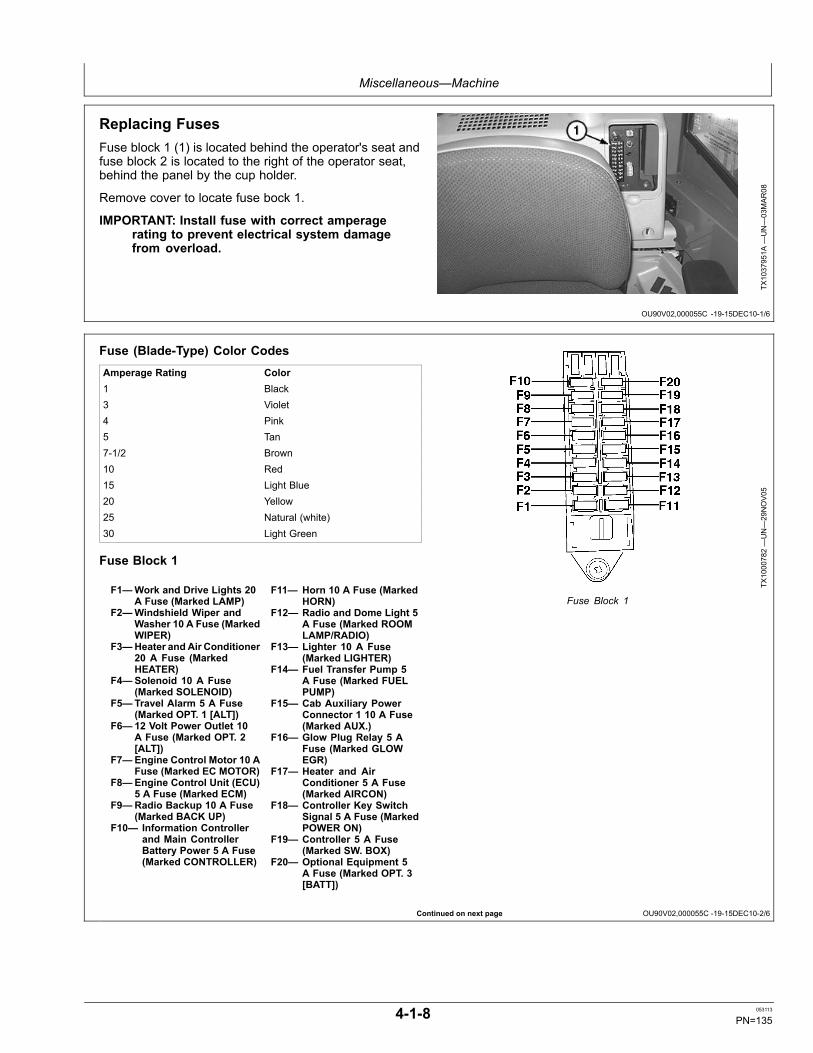
Miscellaneous—Machine
OU90V02,000055C -19-15DEC10-1/6
Continued on next page OU90V02,000055C -19-15DEC10-2/6
Replacing FusesFuse block 1 (1) is located behind the operator's seat andfuse block 2 is located to the right of the operator seat,behind the panel by the cup holder.
Remove cover to locate fuse bock 1.
IMPORTANT: Install fuse with correct amperagerating to prevent electrical system damagefrom overload.
TX1037951A
—UN—03MAR08
Fuse (Blade-Type) Color CodesAmperage Rating Color1 Black3 Violet4 Pink5 Tan7-1/2 Brown10 Red15 Light Blue20 Yellow25 Natural (white)30 Light Green
Fuse Block 1
F1—Work and Drive Lights 20A Fuse (Marked LAMP)
F2—Windshield Wiper andWasher 10 A Fuse (MarkedWIPER)
F3—Heater andAir Conditioner20 A Fuse (MarkedHEATER)
F4—Solenoid 10 A Fuse(Marked SOLENOID)
F5— Travel Alarm 5 A Fuse(Marked OPT. 1 [ALT])
F6— 12 Volt Power Outlet 10A Fuse (Marked OPT. 2[ALT])
F7—Engine Control Motor 10 AFuse (Marked EC MOTOR)
F8—Engine Control Unit (ECU)5 A Fuse (Marked ECM)
F9—Radio Backup 10 A Fuse(Marked BACK UP)
F10— Information Controllerand Main ControllerBattery Power 5 A Fuse(Marked CONTROLLER)
F11— Horn 10 A Fuse (MarkedHORN)
F12— Radio and Dome Light 5A Fuse (Marked ROOMLAMP/RADIO)
F13— Lighter 10 A Fuse(Marked LIGHTER)
F14— Fuel Transfer Pump 5A Fuse (Marked FUELPUMP)
F15— Cab Auxiliary PowerConnector 1 10 A Fuse(Marked AUX.)
F16— Glow Plug Relay 5 AFuse (Marked GLOWEGR)
F17— Heater and AirConditioner 5 A Fuse(Marked AIRCON)
F18— Controller Key SwitchSignal 5 A Fuse (MarkedPOWER ON)
F19— Controller 5 A Fuse(Marked SW. BOX)
F20— Optional Equipment 5A Fuse (Marked OPT. 3[BATT])
TX1000782—UN—29NOV05
Fuse Block 1
4-1-8 053113
PN=135
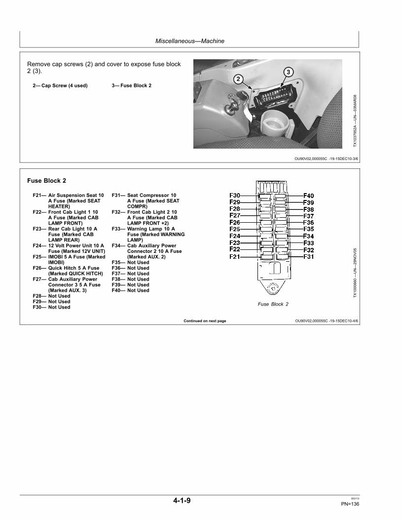
Miscellaneous—Machine
OU90V02,000055C -19-15DEC10-3/6
Continued on next page OU90V02,000055C -19-15DEC10-4/6
Remove cap screws (2) and cover to expose fuse block2 (3).
2—Cap Screw (4 used) 3—Fuse Block 2
TX1037952A
—UN—03MAR08
Fuse Block 2
F21— Air Suspension Seat 10A Fuse (Marked SEATHEATER)
F22— Front Cab Light 1 10A Fuse (Marked CABLAMP FRONT)
F23— Rear Cab Light 10 AFuse (Marked CABLAMP REAR)
F24— 12 Volt Power Unit 10 AFuse (Marked 12V UNIT)
F25— IMOBI 5 A Fuse (MarkedIMOBI)
F26— Quick Hitch 5 A Fuse(Marked QUICK HITCH)
F27— Cab Auxiliary PowerConnector 3 5 A Fuse(Marked AUX. 3)
F28— Not UsedF29— Not UsedF30— Not Used
F31— Seat Compressor 10A Fuse (Marked SEATCOMPR)
F32— Front Cab Light 2 10A Fuse (Marked CABLAMP FRONT +2)
F33— Warning Lamp 10 AFuse (Marked WARNINGLAMP)
F34— Cab Auxiliary PowerConnector 2 10 A Fuse(Marked AUX. 2)
F35— Not UsedF36— Not UsedF37— Not UsedF38— Not UsedF39— Not UsedF40— Not Used
TX1000660—UN—29NOV05
Fuse Block 2
4-1-9 053113
PN=136
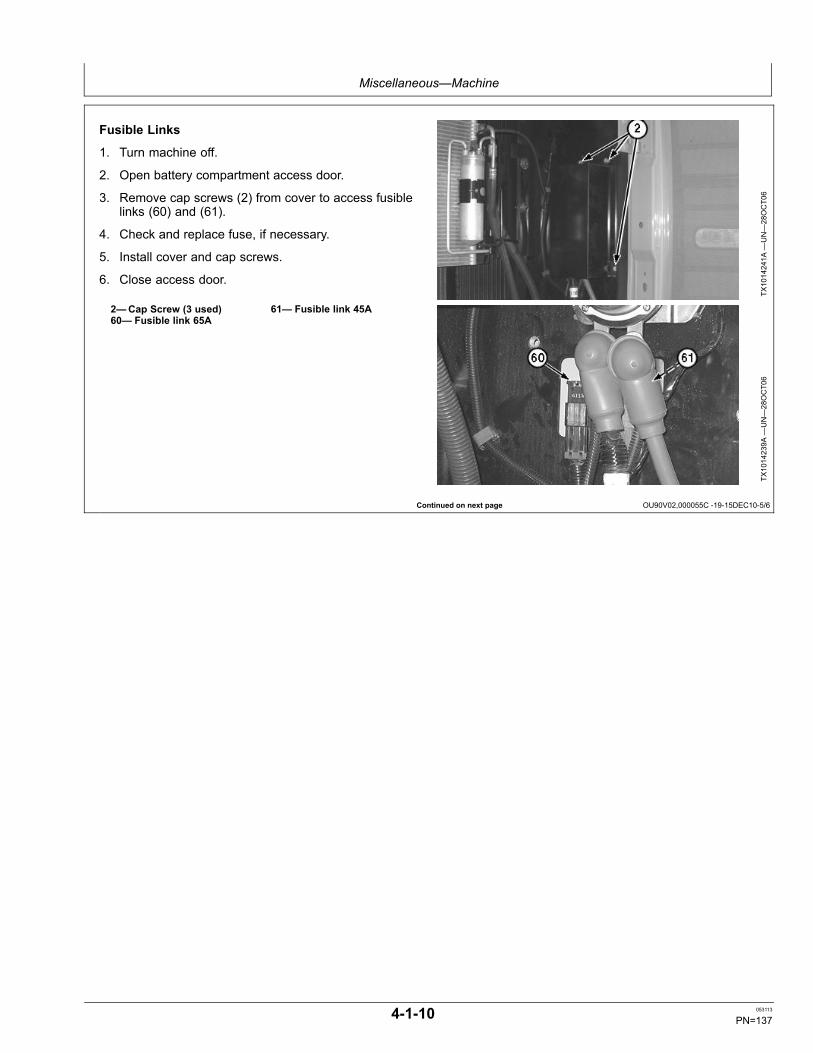
Miscellaneous—Machine
Continued on next page OU90V02,000055C -19-15DEC10-5/6
Fusible Links
1. Turn machine off.
2. Open battery compartment access door.
3. Remove cap screws (2) from cover to access fusiblelinks (60) and (61).
4. Check and replace fuse, if necessary.
5. Install cover and cap screws.
6. Close access door.
2—Cap Screw (3 used)60— Fusible link 65A
61— Fusible link 45A
TX1014241A
—UN—28OCT06
TX1014239A
—UN—28OCT06
4-1-10 053113
PN=137
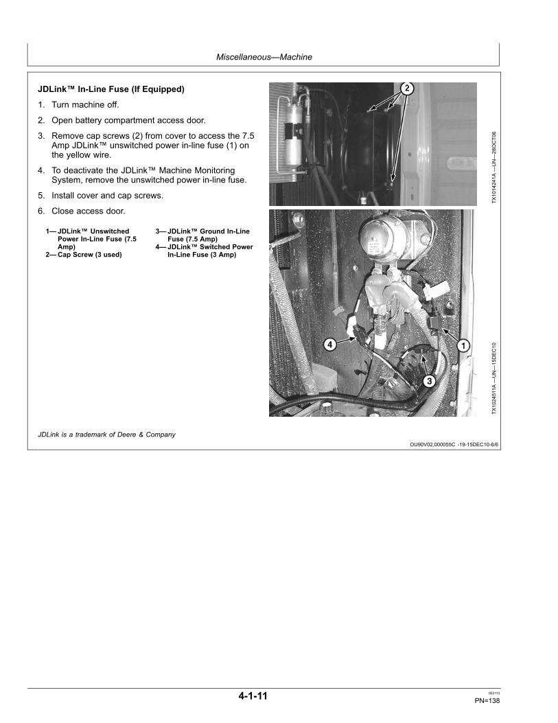
Miscellaneous—Machine
OU90V02,000055C -19-15DEC10-6/6
JDLink™ In-Line Fuse (If Equipped)
1. Turn machine off.
2. Open battery compartment access door.
3. Remove cap screws (2) from cover to access the 7.5Amp JDLink™ unswitched power in-line fuse (1) onthe yellow wire.
4. To deactivate the JDLink™ Machine MonitoringSystem, remove the unswitched power in-line fuse.
5. Install cover and cap screws.
6. Close access door.
1—JDLink™ UnswitchedPower In-Line Fuse (7.5Amp)
2—Cap Screw (3 used)
3—JDLink™ Ground In-LineFuse (7.5 Amp)
4—JDLink™ Switched PowerIn-Line Fuse (3 Amp)
TX1014241A
—UN—28OCT06
TX1024511A
—UN—15DEC10
JDLink is a trademark of Deere & Company
4-1-11 053113
PN=138
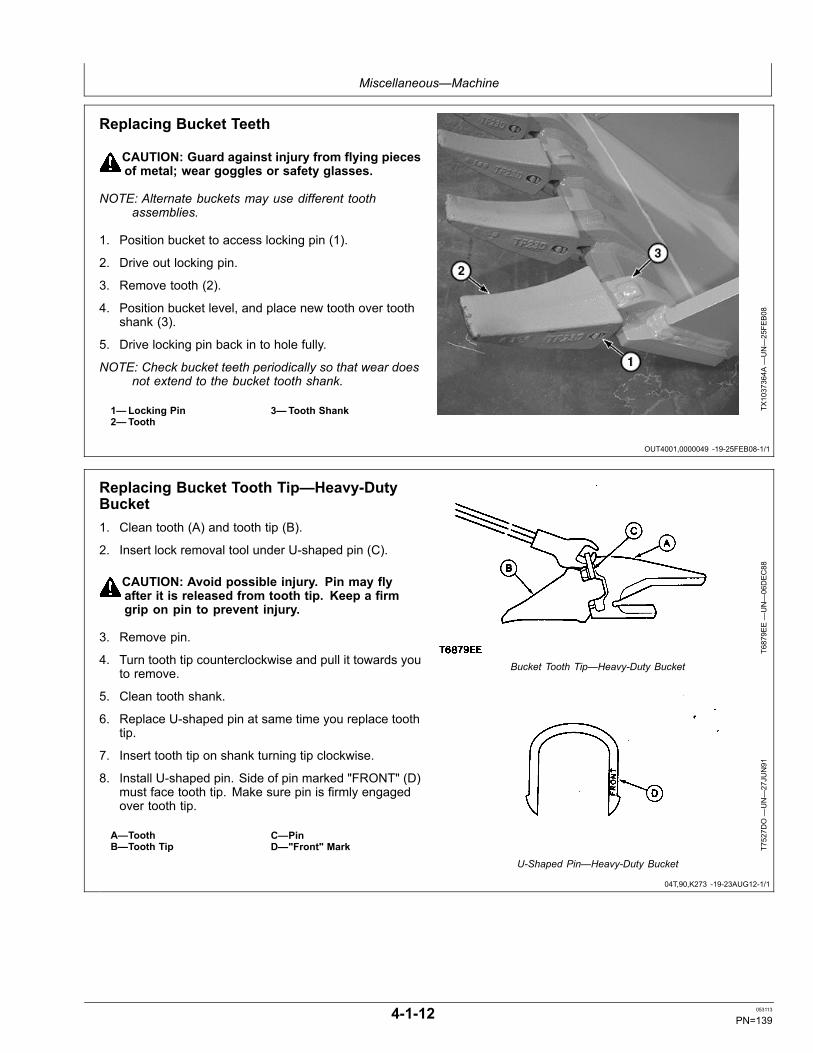
Miscellaneous—Machine
OUT4001,0000049 -19-25FEB08-1/1
04T,90,K273 -19-23AUG12-1/1
Replacing Bucket Teeth
CAUTION: Guard against injury from flying piecesof metal; wear goggles or safety glasses.
NOTE: Alternate buckets may use different toothassemblies.
1. Position bucket to access locking pin (1).
2. Drive out locking pin.
3. Remove tooth (2).
4. Position bucket level, and place new tooth over toothshank (3).
5. Drive locking pin back in to hole fully.
NOTE: Check bucket teeth periodically so that wear doesnot extend to the bucket tooth shank.
1—Locking Pin2—Tooth
3—Tooth Shank TX1037364A
—UN—25FE
B08
Replacing Bucket Tooth Tip—Heavy-DutyBucket1. Clean tooth (A) and tooth tip (B).
2. Insert lock removal tool under U-shaped pin (C).
CAUTION: Avoid possible injury. Pin may flyafter it is released from tooth tip. Keep a firmgrip on pin to prevent injury.
3. Remove pin.
4. Turn tooth tip counterclockwise and pull it towards youto remove.
5. Clean tooth shank.
6. Replace U-shaped pin at same time you replace toothtip.
7. Insert tooth tip on shank turning tip clockwise.
8. Install U-shaped pin. Side of pin marked "FRONT" (D)must face tooth tip. Make sure pin is firmly engagedover tooth tip.
A—ToothB—Tooth Tip
C—PinD—"Front" Mark
T6879E
E—UN—06DEC88
Bucket Tooth Tip—Heavy-Duty Bucket
T7527D
O—UN—27JU
N91
U-Shaped Pin—Heavy-Duty Bucket
4-1-12 053113
PN=139

Miscellaneous—Machine
OUT4001,000003C -19-22FEB08-1/1
DW90712,00002E0 -19-07SEP06-1/1
TX,90,FF1225 -19-15MAR93-1/1
Removing Bucket1. Lower bucket to the ground.
2. Remove cap screws (1).
3. Slide O-ring seals out of way. Remove bucket pins.
1—Cap Screw (2 used)
TX1037290A
—UN—25FE
B08
Track Sag General Information
To maximize undercarriage life, keep track sag withinspecification. Tracks may require adjustment severaltimes during a working day due to changing soil type andmoisture content.
Adjust tracks in the actual operating conditions.
TIGHT TRACK: Packing causes a tight track. If materialpacks in the undercarriage, adjust tracks with the materialpacked in the components.
While the track spring will recoil and the machine cancontinue to operate with a tight track, continued operationwill result in excessive pin and bushing wear, sprocket
popping, tooth tip wear, and excessive loads on the entireundercarriage and travel drive system.
Machine productivity and fuel consumption are alsoadversely affected because increased horsepower isneeded to move the machine.
LOOSE TRACK: A loose track has more side to sidemotion, increasing side wear on the links, rollers, and frontidler. An excessively loose track will slap at high groundspeeds, resulting in high impact loads on the sprocketteeth, bushings, and carrier rollers.
Hardware Torque SpecificationsCheck cap screws and nuts to be sure they are tight.If hardware is loose, tighten to torque shown on thefollowing charts unless a special torque is specified.
4-1-13 053113
PN=140
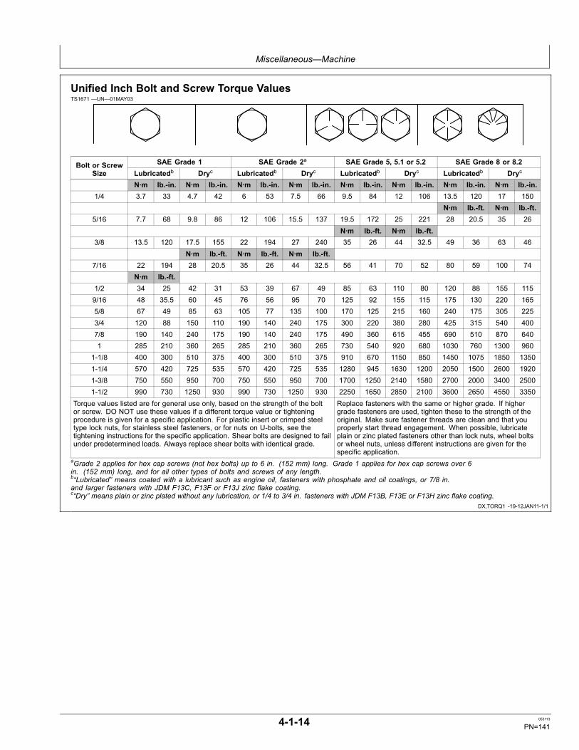
Miscellaneous—Machine
DX,TORQ1 -19-12JAN11-1/1
Unified Inch Bolt and Screw Torque ValuesTS1671 —UN—01MAY03
SAE Grade 1 SAE Grade 2a SAE Grade 5, 5.1 or 5.2 SAE Grade 8 or 8.2Bolt or ScrewSize Lubricatedb Dryc Lubricatedb Dryc Lubricatedb Dryc Lubricatedb Dryc
N·m lb.-in. N·m lb.-in. N·m lb.-in. N·m lb.-in. N·m lb.-in. N·m lb.-in. N·m lb.-in. N·m lb.-in.1/4 3.7 33 4.7 42 6 53 7.5 66 9.5 84 12 106 13.5 120 17 150
N·m lb.-ft. N·m lb.-ft.5/16 7.7 68 9.8 86 12 106 15.5 137 19.5 172 25 221 28 20.5 35 26
N·m lb.-ft. N·m lb.-ft.3/8 13.5 120 17.5 155 22 194 27 240 35 26 44 32.5 49 36 63 46
N·m lb.-ft. N·m lb.-ft. N·m lb.-ft.7/16 22 194 28 20.5 35 26 44 32.5 56 41 70 52 80 59 100 74
N·m lb.-ft.1/2 34 25 42 31 53 39 67 49 85 63 110 80 120 88 155 1159/16 48 35.5 60 45 76 56 95 70 125 92 155 115 175 130 220 1655/8 67 49 85 63 105 77 135 100 170 125 215 160 240 175 305 2253/4 120 88 150 110 190 140 240 175 300 220 380 280 425 315 540 4007/8 190 140 240 175 190 140 240 175 490 360 615 455 690 510 870 6401 285 210 360 265 285 210 360 265 730 540 920 680 1030 760 1300 960
1-1/8 400 300 510 375 400 300 510 375 910 670 1150 850 1450 1075 1850 13501-1/4 570 420 725 535 570 420 725 535 1280 945 1630 1200 2050 1500 2600 19201-3/8 750 550 950 700 750 550 950 700 1700 1250 2140 1580 2700 2000 3400 25001-1/2 990 730 1250 930 990 730 1250 930 2250 1650 2850 2100 3600 2650 4550 3350
Torque values listed are for general use only, based on the strength of the boltor screw. DO NOT use these values if a different torque value or tighteningprocedure is given for a specific application. For plastic insert or crimped steeltype lock nuts, for stainless steel fasteners, or for nuts on U-bolts, see thetightening instructions for the specific application. Shear bolts are designed to failunder predetermined loads. Always replace shear bolts with identical grade.
Replace fasteners with the same or higher grade. If highergrade fasteners are used, tighten these to the strength of theoriginal. Make sure fastener threads are clean and that youproperly start thread engagement. When possible, lubricateplain or zinc plated fasteners other than lock nuts, wheel boltsor wheel nuts, unless different instructions are given for thespecific application.
aGrade 2 applies for hex cap screws (not hex bolts) up to 6 in. (152 mm) long. Grade 1 applies for hex cap screws over 6in. (152 mm) long, and for all other types of bolts and screws of any length.b“Lubricated” means coated with a lubricant such as engine oil, fasteners with phosphate and oil coatings, or 7/8 in.and larger fasteners with JDM F13C, F13F or F13J zinc flake coating.c“Dry” means plain or zinc plated without any lubrication, or 1/4 to 3/4 in. fasteners with JDM F13B, F13E or F13H zinc flake coating.
4-1-14 053113
PN=141
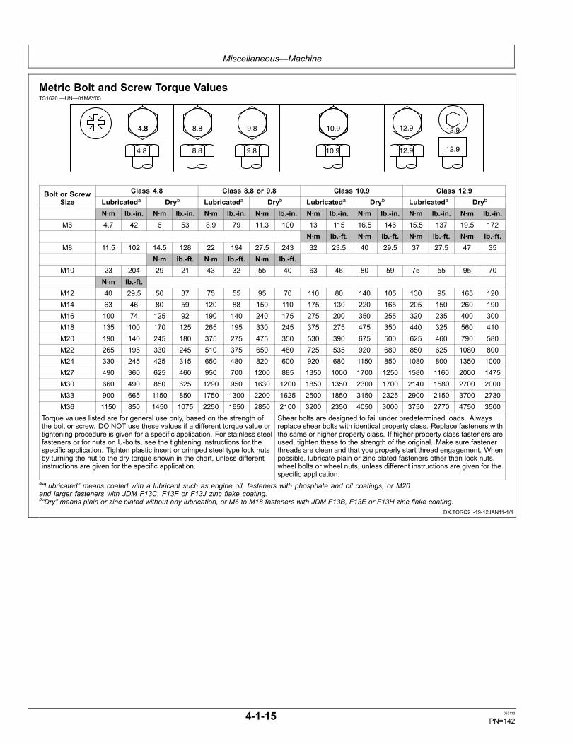
Miscellaneous—Machine
DX,TORQ2 -19-12JAN11-1/1
Metric Bolt and Screw Torque ValuesTS1670 —UN—01MAY03
4.84.8 8.8 9.8 10.9 12.9 12.9
12.912.910.99.88.84.8
Class 4.8 Class 8.8 or 9.8 Class 10.9 Class 12.9Bolt or ScrewSize Lubricateda Dryb Lubricateda Dryb Lubricateda Dryb Lubricateda Dryb
N·m lb.-in. N·m lb.-in. N·m lb.-in. N·m lb.-in. N·m lb.-in. N·m lb.-in. N·m lb.-in. N·m lb.-in.M6 4.7 42 6 53 8.9 79 11.3 100 13 115 16.5 146 15.5 137 19.5 172
N·m lb.-ft. N·m lb.-ft. N·m lb.-ft. N·m lb.-ft.M8 11.5 102 14.5 128 22 194 27.5 243 32 23.5 40 29.5 37 27.5 47 35
N·m lb.-ft. N·m lb.-ft. N·m lb.-ft.M10 23 204 29 21 43 32 55 40 63 46 80 59 75 55 95 70
N·m lb.-ft.M12 40 29.5 50 37 75 55 95 70 110 80 140 105 130 95 165 120M14 63 46 80 59 120 88 150 110 175 130 220 165 205 150 260 190M16 100 74 125 92 190 140 240 175 275 200 350 255 320 235 400 300M18 135 100 170 125 265 195 330 245 375 275 475 350 440 325 560 410M20 190 140 245 180 375 275 475 350 530 390 675 500 625 460 790 580M22 265 195 330 245 510 375 650 480 725 535 920 680 850 625 1080 800M24 330 245 425 315 650 480 820 600 920 680 1150 850 1080 800 1350 1000M27 490 360 625 460 950 700 1200 885 1350 1000 1700 1250 1580 1160 2000 1475M30 660 490 850 625 1290 950 1630 1200 1850 1350 2300 1700 2140 1580 2700 2000M33 900 665 1150 850 1750 1300 2200 1625 2500 1850 3150 2325 2900 2150 3700 2730M36 1150 850 1450 1075 2250 1650 2850 2100 3200 2350 4050 3000 3750 2770 4750 3500
Torque values listed are for general use only, based on the strength ofthe bolt or screw. DO NOT use these values if a different torque value ortightening procedure is given for a specific application. For stainless steelfasteners or for nuts on U-bolts, see the tightening instructions for thespecific application. Tighten plastic insert or crimped steel type lock nutsby turning the nut to the dry torque shown in the chart, unless differentinstructions are given for the specific application.
Shear bolts are designed to fail under predetermined loads. Alwaysreplace shear bolts with identical property class. Replace fasteners withthe same or higher property class. If higher property class fasteners areused, tighten these to the strength of the original. Make sure fastenerthreads are clean and that you properly start thread engagement. Whenpossible, lubricate plain or zinc plated fasteners other than lock nuts,wheel bolts or wheel nuts, unless different instructions are given for thespecific application.
a“Lubricated” means coated with a lubricant such as engine oil, fasteners with phosphate and oil coatings, or M20and larger fasteners with JDM F13C, F13F or F13J zinc flake coating.b“Dry” means plain or zinc plated without any lubrication, or M6 to M18 fasteners with JDM F13B, F13E or F13H zinc flake coating.
4-1-15 053113
PN=142
Miscellaneous—Operational Checkout
ER93822,0000278 -19-14SEP12-1/38
ER93822,0000278 -19-14SEP12-2/38
ER93822,0000278 -19-14SEP12-3/38
Continued on next page ER93822,0000278 -19-14SEP12-4/38
Operational Checkout
This procedure is used to check operation of the machine.It is designed so you can do a walk around inspection,check machine operation, and perform specific checksfrom the operator's seat.
If there is a problem with the machine, diagnosticinformation in this checkout will help determine theprobable cause. This information may allow you toperform a simple adjustment to correct the problem. Usethe table of contents to help find adjustment procedures.
A location will be required which is level and has adequatespace to complete the checks. No tools are needed toperform the checkout.
Complete the usual necessary visual checks (oil levels, oilcondition, external leaks, loose hardware, linkage, wiring)prior to doing the checkout. The machine must be atoperating temperature for many of the checks.
Read each check completely before performing. If noproblem is found, you will be instructed to go to the nextcheck. If a problem is indicated, you will be referred to aprocedure for adjustment, repair, or replacement.
The monitor can be used to perform diagnostic andoperational checks. The monitor can display enginespeed, pressures, and Diagnostic Trouble Codes (DTCs).
Diagnostic Trouble Codes Check
Display and ClearDiagnostic Trouble Codes
Always check for diagnostic trouble codes and correct them before performing theoperational checkout.Diagnostic trouble codes can be displayed by using several methods:
• Monitor Controller• With Service Advisor YES: See your authorized
dealer.LOOK: Are diagnostic trouble codes present? NO: Proceed with
operational checkout.
Operational Checks—Key Switch Off, Engine Off Checks
4-2-1 053113
PN=143

Miscellaneous—Operational Checkout
ER93822,0000278 -19-14SEP12-5/38
ER93822,0000278 -19-14SEP12-6/38
Continued on next page ER93822,0000278 -19-14SEP12-7/38
Horn Circuit Check
TX1037291 —UN—03MAR08Horn Button
1—Horn Button
Key switch Off.Push horn button (1) on top of right pilot control lever. YES: Go to next check.LISTEN: Does horn sound? NO: Check horn 10 A fuse
(F11) (marked HORN). Seeyour authorized dealer.
Hour Meter and FuelGauge Check 1
14
TX1005661 —UN—31MAR06Monitor, Hour Meter and Fuel Gauge
1—Hour Meter14— Hour Meter Button
Press and hold hour meter button (14) until default screen appears.LOOK: Does hour meter (1) display machine hours? YES: Go to next check.LOOK: Does fuel gauge display a fuel level? NO: Check controller key
signal switch 5 A fuse (F18)(marked POWER ON). Seeyour authorized dealer.
Operational Checks—Key Switch On, Engine Off Checks
4-2-2 053113
PN=144
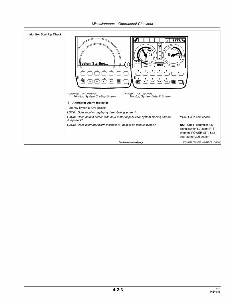
Miscellaneous—Operational Checkout
Continued on next page ER93822,0000278 -19-14SEP12-8/38
Monitor Start Up Check
System Starting...System Starting...
F1 F2 F3 F4
1 2 3 4 5
6 7 8 9 0
TX1005660 —UN—06APR06Monitor, System Starting Screen
1
TX1005657 —UN—03APR06Monitor, System Default Screen
1—Alternator Alarm Indicator
Turn key switch to ON position.LOOK: Does monitor display system starting screen?LOOK: Does default screen with hour meter appear after system starting screendisappears?
YES: Go to next check.
LOOK: Does alternator alarm indicator (1) appear on default screen? NO: Check controller keysignal switch 5 A fuse (F18)(marked POWER ON). Seeyour authorized dealer.
4-2-3 053113
PN=145
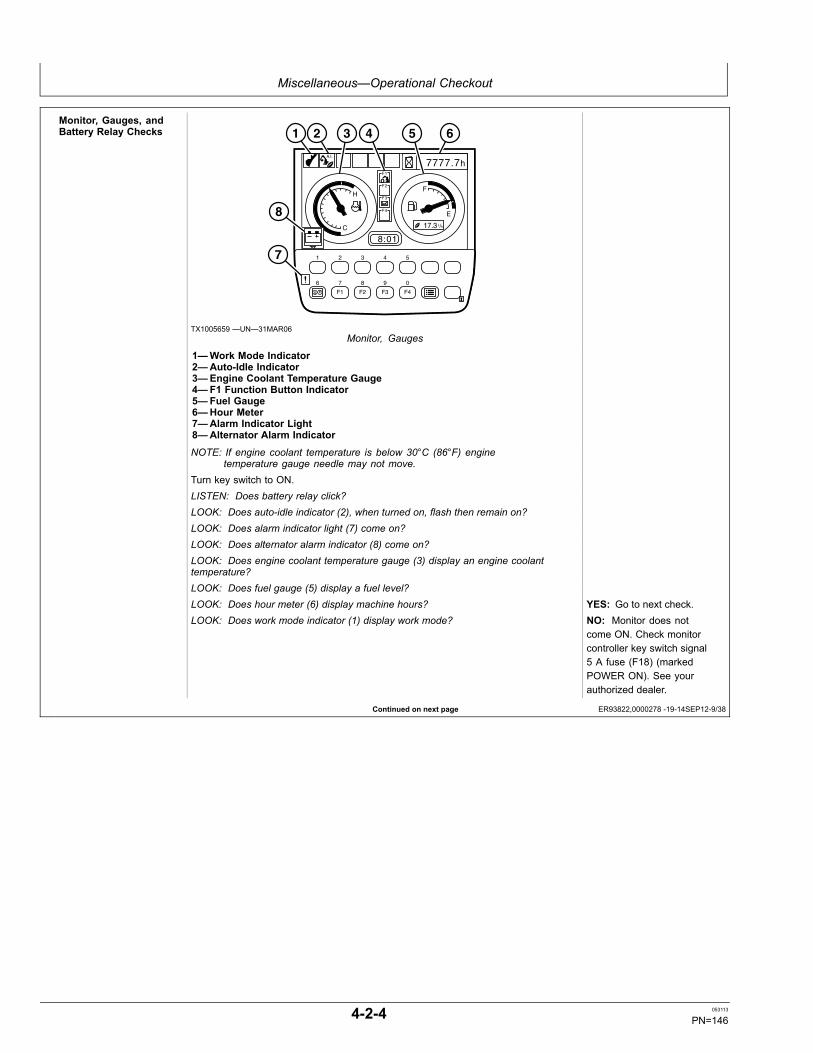
Miscellaneous—Operational Checkout
Continued on next page ER93822,0000278 -19-14SEP12-9/38
Monitor, Gauges, andBattery Relay Checks
7777.7h
8:01
F1
F2
F3
F4
H
C
F
E
L/h17.3
A.I.
F1 F2 F3 F4
1 2 3 4 5
6 7 8 9 0
1 2 3 4 5 6
8
7
TX1005659 —UN—31MAR06Monitor, Gauges
1—Work Mode Indicator2—Auto-Idle Indicator3—Engine Coolant Temperature Gauge4—F1 Function Button Indicator5—Fuel Gauge6—Hour Meter7—Alarm Indicator Light8—Alternator Alarm Indicator
NOTE: If engine coolant temperature is below 30°C (86°F) enginetemperature gauge needle may not move.
Turn key switch to ON.LISTEN: Does battery relay click?LOOK: Does auto-idle indicator (2), when turned on, flash then remain on?LOOK: Does alarm indicator light (7) come on?LOOK: Does alternator alarm indicator (8) come on?LOOK: Does engine coolant temperature gauge (3) display an engine coolanttemperature?LOOK: Does fuel gauge (5) display a fuel level?LOOK: Does hour meter (6) display machine hours? YES: Go to next check.LOOK: Does work mode indicator (1) display work mode? NO: Monitor does not
come ON. Check monitorcontroller key switch signal5 A fuse (F18) (markedPOWER ON). See yourauthorized dealer.
4-2-4 053113
PN=146

Miscellaneous—Operational Checkout
ER93822,0000278 -19-14SEP12-10/38
Continued on next page ER93822,0000278 -19-14SEP12-11/38
Travel Lever and PedalNeutral Checks
TX1037303 —UN—26FEB08Travel Levers and Pedals
1—Forward2—Rearward
Push both travel levers and pedals forward (1), then release.Pull both travel levers and pedals rearward (2), then release.FEEL: Do levers and pedals require equal effort to operate in forward and reverse? YES: Go to next check.LOOK: Do levers and pedals return to neutral at the same time when released? NO: See your authorized
dealer.
Light Circuit Checks1 2
TX1037310 —UN—26FEB08Lights and Windshield Wiper Switches
1—Work Light Switch2—Windshield Wiper and Washer Switch
Turn work light switch (1) to first position.LOOK: Are monitor panel back lights and drive lights on?Turn light switch to second position. YES: Go to next check.LOOK: Do monitor panel back lights and drive lights remain on and boom work lightscome on?
NO: Check work anddrive lights 20 A fuse(F1) (marked LAMP) andcontroller key switch signal5 A fuse (F18) (markedPOWER ON). See yourauthorized dealer.
4-2-5 053113
PN=147
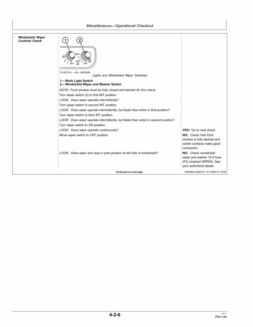
Miscellaneous—Operational Checkout
Continued on next page ER93822,0000278 -19-14SEP12-12/38
Windshield WiperControls Check 1 2
TX1037310 —UN—26FEB08Lights and Windshield Wiper Switches
1—Work Light Switch2—Windshield Wiper and Washer Switch
NOTE: Front window must be fully closed and latched for this check.Turn wiper switch (2) to first INT position.LOOK: Does wiper operate intermittently?Turn wiper switch to second INT position.LOOK: Does wiper operate intermittently, but faster than when in first position?Turn wiper switch to third INT position.LOOK: Does wiper operate intermittently, but faster than when in second position?Turn wiper switch to ON position.LOOK: Does wiper operate continuously? YES: Go to next check.Move wiper switch to OFF position. NO: Check that front
window is fully latched andswitch contacts make goodconnection.
LOOK: Does wiper arm stop in park position at left side of windshield? NO: Check windshieldwiper and washer 10 A fuse(F2) (marked WIPER). Seeyour authorized dealer.
4-2-6 053113
PN=148
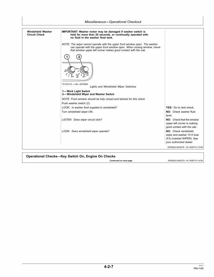
Miscellaneous—Operational Checkout
ER93822,0000278 -19-14SEP12-13/38
Continued on next page ER93822,0000278 -19-14SEP12-14/38
Windshield WasherCircuit Check
IMPORTANT: Washer motor may be damaged if washer switch isheld for more than 20 seconds, or continually operated withno fluid in the washer fluid tank.
NOTE: The wiper cannot operate with the upper front window open. The washercan operate with the upper front window open. When closing window, checkthat window upper left corner makes good contact with the cab.
1 2
TX1037310 —UN—26FEB08Lights and Windshield Wiper Switches
1—Work Light Switch2—Windshield Wiper and Washer Switch
NOTE: Front window should be fully closed and latched for this check.Push washer switch (2).LOOK: Is washer fluid supplied to windshield? YES: Go to next check.Turn windshield wiper ON. NO: Check washer fluid
level.LISTEN: Does wiper circuit click? NO: Check that the window
upper left corner is makinggood contact with the cab.
LOOK: Does windshield wiper operate? NO: Check windshieldwiper and washer 10 A fuse(F2) (marked WIPER). Seeyour authorized dealer.
Operational Checks—Key Switch On, Engine On Checks
4-2-7 053113
PN=149
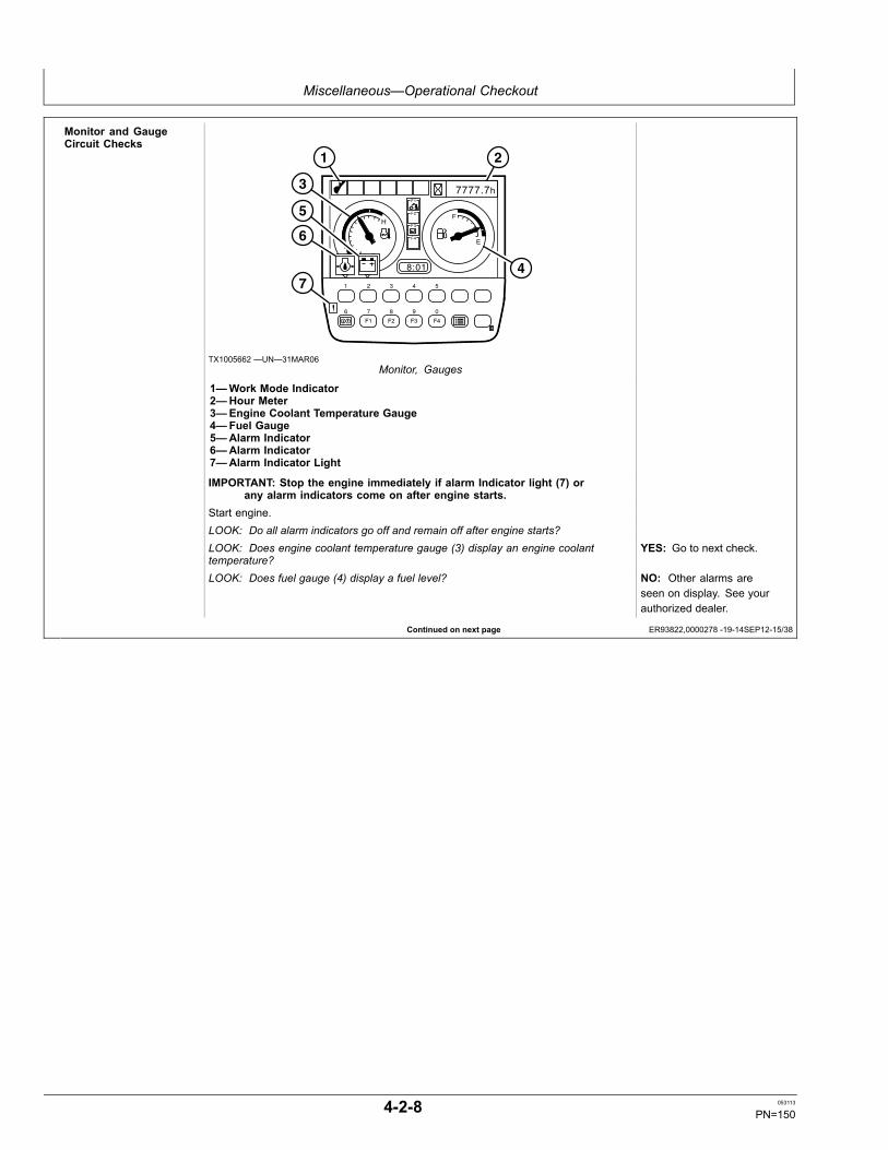
Miscellaneous—Operational Checkout
Continued on next page ER93822,0000278 -19-14SEP12-15/38
Monitor and GaugeCircuit Checks
7777.7h
8:01
F1
F2
F3
F4
H
C
F
E
F1 F2 F3 F4
1 2 3 4 5
6 7 8 9 0
6
7
5
3
1 2
4
TX1005662 —UN—31MAR06Monitor, Gauges
1—Work Mode Indicator2—Hour Meter3—Engine Coolant Temperature Gauge4—Fuel Gauge5—Alarm Indicator6—Alarm Indicator7—Alarm Indicator Light
IMPORTANT: Stop the engine immediately if alarm Indicator light (7) orany alarm indicators come on after engine starts.
Start engine.LOOK: Do all alarm indicators go off and remain off after engine starts?LOOK: Does engine coolant temperature gauge (3) display an engine coolanttemperature?
YES: Go to next check.
LOOK: Does fuel gauge (4) display a fuel level? NO: Other alarms areseen on display. See yourauthorized dealer.
4-2-8 053113
PN=150

Miscellaneous—Operational Checkout
Continued on next page ER93822,0000278 -19-14SEP12-16/38
Pilot Control ShutoffCircuit Check
1
TX1037315 —UN—28FEB08Engine Speed Dial
TX1037246 —UN—04MAR08Pilot Shutoff Lever Locked
1—Engine Speed Dial2—Pilot Shutoff Lever
CAUTION: Machine may move during this check. Make sure area isclear and large enough to operate all machine functions.
Turn engine speed dial (1) to L (slow idle) position.Pull pilot shutoff lever into LOCKED (rearward) position.Slowly actuate dig and travel functions. YES: See your authorized
dealer.LOOK: Do dig and travel functions operate? NO: Continue check.
TX1037247 —UN—03MAR08Pilot Shutoff Lever Unlocked
Push pilot shutoff lever into UNLOCKED (forward) position.Slowly actuate dig and travel functions. YES: Go to next check.LOOK: Do dig and travel functions operate? NO: See your authorized
dealer.
4-2-9 053113
PN=151
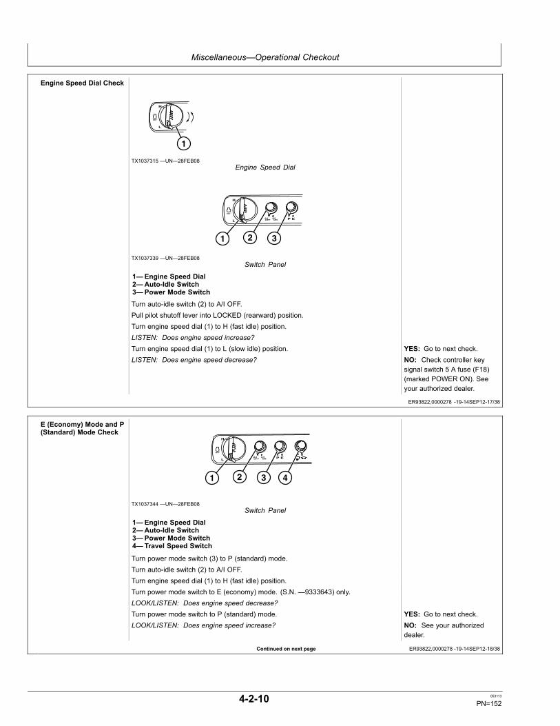
Miscellaneous—Operational Checkout
ER93822,0000278 -19-14SEP12-17/38
Continued on next page ER93822,0000278 -19-14SEP12-18/38
Engine Speed Dial Check
1
TX1037315 —UN—28FEB08Engine Speed Dial
1 2 3
TX1037339 —UN—28FEB08Switch Panel
1—Engine Speed Dial2—Auto-Idle Switch3—Power Mode Switch
Turn auto-idle switch (2) to A/I OFF.Pull pilot shutoff lever into LOCKED (rearward) position.Turn engine speed dial (1) to H (fast idle) position.LISTEN: Does engine speed increase?Turn engine speed dial (1) to L (slow idle) position. YES: Go to next check.LISTEN: Does engine speed decrease? NO: Check controller key
signal switch 5 A fuse (F18)(marked POWER ON). Seeyour authorized dealer.
E (Economy) Mode and P(Standard) Mode Check
1 2 3 4
TX1037344 —UN—28FEB08Switch Panel
1—Engine Speed Dial2—Auto-Idle Switch3—Power Mode Switch4—Travel Speed Switch
Turn power mode switch (3) to P (standard) mode.Turn auto-idle switch (2) to A/I OFF.Turn engine speed dial (1) to H (fast idle) position.Turn power mode switch to E (economy) mode. (S.N. —9333643) only.LOOK/LISTEN: Does engine speed decrease?Turn power mode switch to P (standard) mode. YES: Go to next check.LOOK/LISTEN: Does engine speed increase? NO: See your authorized
dealer.
4-2-10 053113
PN=152
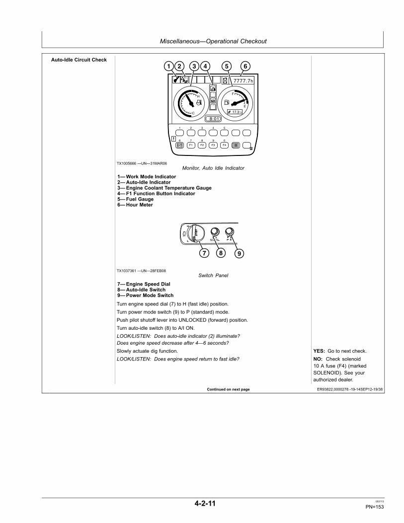
Miscellaneous—Operational Checkout
Continued on next page ER93822,0000278 -19-14SEP12-19/38
Auto-Idle Circuit Check
7777.7 h
8:01
F1
F2
F3
F4
H
C
F
E
L / h 17.3
A.I.
F1 F2 F3 F4
1 2 3 4 5
6 7 8 9 0
1 2 3 4 5 6
TX1005666 —UN—31MAR06Monitor, Auto Idle Indicator
1—Work Mode Indicator2—Auto-Idle Indicator3—Engine Coolant Temperature Gauge4—F1 Function Button Indicator5—Fuel Gauge6—Hour Meter
7 8 9
TX1037361 —UN—28FEB08Switch Panel
7—Engine Speed Dial8—Auto-Idle Switch9—Power Mode Switch
Turn engine speed dial (7) to H (fast idle) position.Turn power mode switch (9) to P (standard) mode.Push pilot shutoff lever into UNLOCKED (forward) position.Turn auto-idle switch (8) to A/I ON.LOOK/LISTEN: Does auto-idle indicator (2) illuminate?Does engine speed decrease after 4—6 seconds?Slowly actuate dig function. YES: Go to next check.LOOK/LISTEN: Does engine speed return to fast idle? NO: Check solenoid
10 A fuse (F4) (markedSOLENOID). See yourauthorized dealer.
4-2-11 053113
PN=153
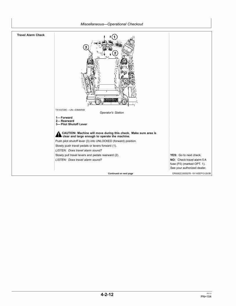
Miscellaneous—Operational Checkout
Continued on next page ER93822,0000278 -19-14SEP12-20/38
Travel Alarm Check
TX1037395 —UN—03MAR08Operator's Station
1—Forward2—Rearward3—Pilot Shutoff Lever
CAUTION: Machine will move during this check. Make sure area isclear and large enough to operate the machine.
Push pilot shutoff lever (3) into UNLOCKED (forward) position.Slowly push travel pedals or levers forward (1).LISTEN: Does travel alarm sound?Slowly pull travel levers and pedals rearward (2). YES: Go to next check.LISTEN: Does travel alarm sound? NO: Check travel alarm 5 A
fuse (F5) (marked OPT. 1).See your authorized dealer.
4-2-12 053113
PN=154
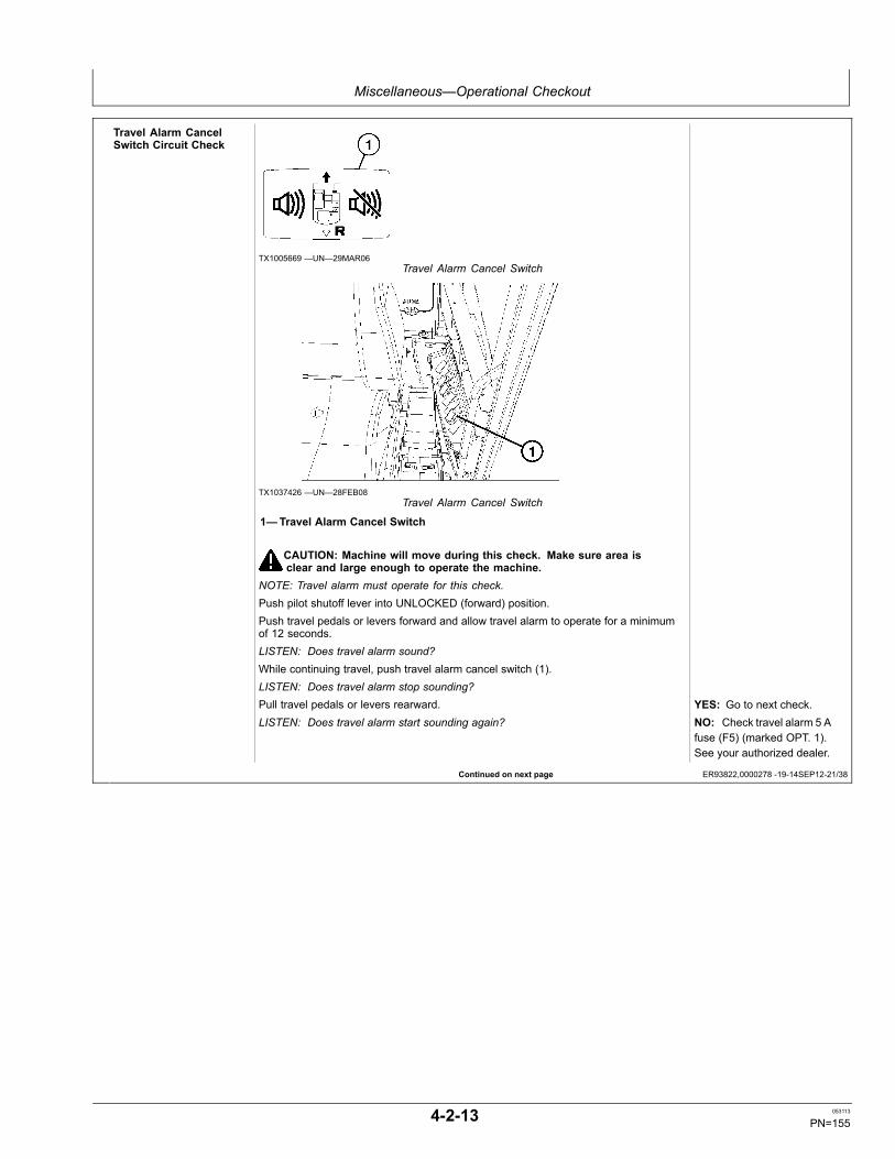
Miscellaneous—Operational Checkout
Continued on next page ER93822,0000278 -19-14SEP12-21/38
Travel Alarm CancelSwitch Circuit Check
TX1005669 —UN—29MAR06Travel Alarm Cancel Switch
TX1037426 —UN—28FEB08Travel Alarm Cancel Switch
1—Travel Alarm Cancel Switch
CAUTION: Machine will move during this check. Make sure area isclear and large enough to operate the machine.
NOTE: Travel alarm must operate for this check.Push pilot shutoff lever into UNLOCKED (forward) position.Push travel pedals or levers forward and allow travel alarm to operate for a minimumof 12 seconds.LISTEN: Does travel alarm sound?While continuing travel, push travel alarm cancel switch (1).LISTEN: Does travel alarm stop sounding?Pull travel pedals or levers rearward. YES: Go to next check.LISTEN: Does travel alarm start sounding again? NO: Check travel alarm 5 A
fuse (F5) (marked OPT. 1).See your authorized dealer.
4-2-13 053113
PN=155
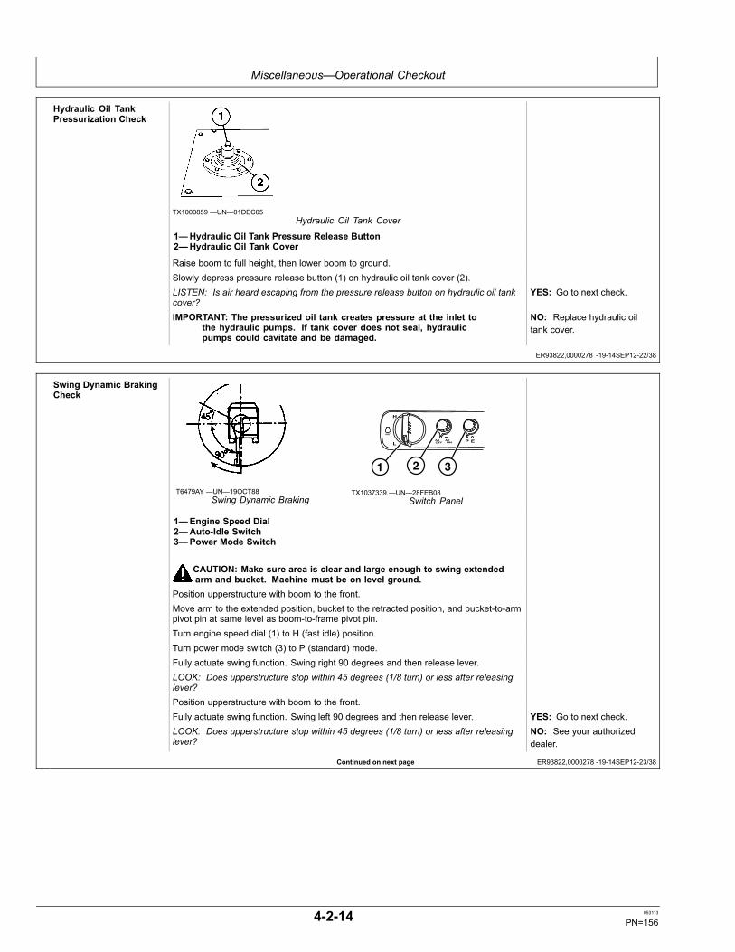
Miscellaneous—Operational Checkout
ER93822,0000278 -19-14SEP12-22/38
Continued on next page ER93822,0000278 -19-14SEP12-23/38
Hydraulic Oil TankPressurization Check
TX1000859 —UN—01DEC05Hydraulic Oil Tank Cover
1—Hydraulic Oil Tank Pressure Release Button2—Hydraulic Oil Tank Cover
Raise boom to full height, then lower boom to ground.Slowly depress pressure release button (1) on hydraulic oil tank cover (2).LISTEN: Is air heard escaping from the pressure release button on hydraulic oil tankcover?
YES: Go to next check.
IMPORTANT: The pressurized oil tank creates pressure at the inlet tothe hydraulic pumps. If tank cover does not seal, hydraulicpumps could cavitate and be damaged.
NO: Replace hydraulic oiltank cover.
Swing Dynamic BrakingCheck
T6479AY —UN—19OCT88Swing Dynamic Braking
1 2 3
TX1037339 —UN—28FEB08Switch Panel
1—Engine Speed Dial2—Auto-Idle Switch3—Power Mode Switch
CAUTION: Make sure area is clear and large enough to swing extendedarm and bucket. Machine must be on level ground.
Position upperstructure with boom to the front.Move arm to the extended position, bucket to the retracted position, and bucket-to-armpivot pin at same level as boom-to-frame pivot pin.Turn engine speed dial (1) to H (fast idle) position.Turn power mode switch (3) to P (standard) mode.Fully actuate swing function. Swing right 90 degrees and then release lever.LOOK: Does upperstructure stop within 45 degrees (1/8 turn) or less after releasinglever?Position upperstructure with boom to the front.Fully actuate swing function. Swing left 90 degrees and then release lever. YES: Go to next check.LOOK: Does upperstructure stop within 45 degrees (1/8 turn) or less after releasinglever?
NO: See your authorizeddealer.
4-2-14 053113
PN=156

Miscellaneous—Operational Checkout
Continued on next page ER93822,0000278 -19-14SEP12-24/38
Swing Park Brake andCircuit Drift Check
T140540 —UN—17MAY01Machine Position
1
TX1037315 —UN—28FEB08Engine Speed Dial
1—Engine Speed Dial
Fill the bucket with dirt.Position machine on a hillside with a slope of approximately 25%. If a hill is notavailable, raise one side of machine approximately 300 mm (1 ft) with the boom andthen put a block under the track.Move arm to the fully extended position.Raise boom so arm-to-bucket pivot pin are the same height as boom-to-frame pivot pin.Position upperstructure with cab over travel motors, perpendicular to tracks.Turn engine speed dial (1) to L (slow idle) position.Wait approximately 5 minutes with all functions in neutral.NOTE: Function does not need to be fully actuated to disengage the swing park brake.Slowly actuate bucket load function to disengage the swing park brake. Do not hold thefunction over relief for more than 10 seconds.LOOK: Does upperstructure hold position when swing park brake is engaged?LOOK: Does upperstructure move only slightly when swing park brake is disengaged?Swing upperstructure 180 degrees left and repeat procedure.Turn engine speed dial to L (slow idle) position.Wait approximately 5 minutes with all functions in neutral.Slowly actuate bucket load function to disengage the swing park brake. Do not hold thefunction over relief for more than 10 seconds.LOOK: Does upperstructure hold position when swing park brake is engaged? YES: Go to next check.LOOK: Does upperstructure move only slightly when swing park brake is disengaged? NO: Upperstructure moves
when all functions are inneutral and park brake isengaged. Check for pilotoil pressure to swing parkbrake. See your authorizeddealer.
4-2-15 053113
PN=157
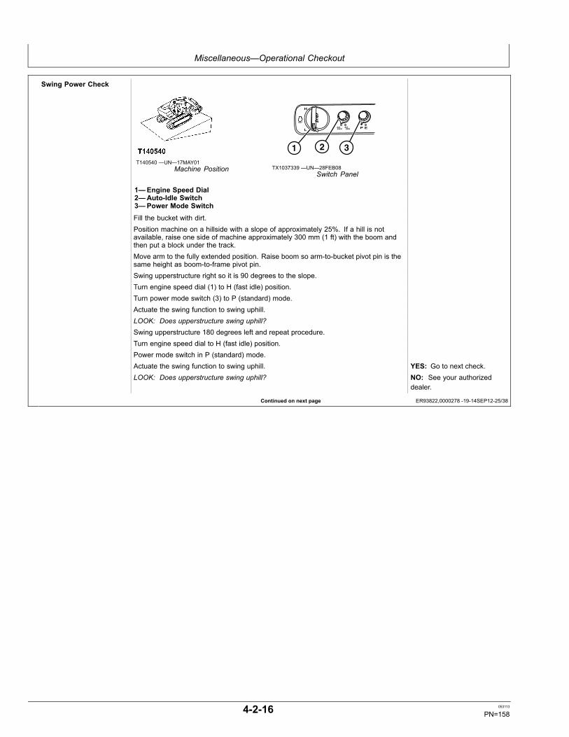
Miscellaneous—Operational Checkout
Continued on next page ER93822,0000278 -19-14SEP12-25/38
Swing Power Check
T140540 —UN—17MAY01Machine Position
1 2 3
TX1037339 —UN—28FEB08Switch Panel
1—Engine Speed Dial2—Auto-Idle Switch3—Power Mode Switch
Fill the bucket with dirt.Position machine on a hillside with a slope of approximately 25%. If a hill is notavailable, raise one side of machine approximately 300 mm (1 ft) with the boom andthen put a block under the track.Move arm to the fully extended position. Raise boom so arm-to-bucket pivot pin is thesame height as boom-to-frame pivot pin.Swing upperstructure right so it is 90 degrees to the slope.Turn engine speed dial (1) to H (fast idle) position.Turn power mode switch (3) to P (standard) mode.Actuate the swing function to swing uphill.LOOK: Does upperstructure swing uphill?Swing upperstructure 180 degrees left and repeat procedure.Turn engine speed dial to H (fast idle) position.Power mode switch in P (standard) mode.Actuate the swing function to swing uphill. YES: Go to next check.LOOK: Does upperstructure swing uphill? NO: See your authorized
dealer.
4-2-16 053113
PN=158
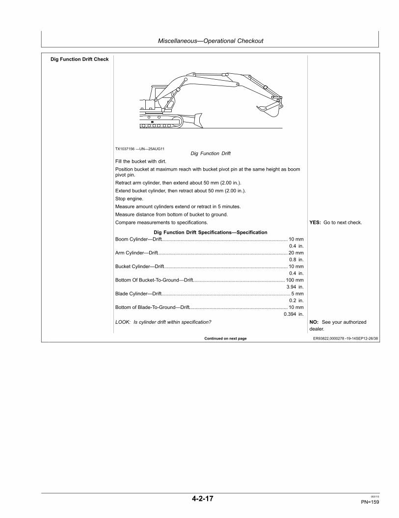
Miscellaneous—Operational Checkout
Continued on next page ER93822,0000278 -19-14SEP12-26/38
Dig Function Drift Check
TX1037156 —UN—25AUG11Dig Function Drift
Fill the bucket with dirt.Position bucket at maximum reach with bucket pivot pin at the same height as boompivot pin.Retract arm cylinder, then extend about 50 mm (2.00 in.).Extend bucket cylinder, then retract about 50 mm (2.00 in.).Stop engine.Measure amount cylinders extend or retract in 5 minutes.Measure distance from bottom of bucket to ground.Compare measurements to specifications.
Dig Function Drift Specifications—SpecificationBoom Cylinder—Drift............................................................................................ 10 mm
0.4 in.Arm Cylinder—Drift............................................................................................... 20 mm
0.8 in.Bucket Cylinder—Drift........................................................................................... 10 mm
0.4 in.Bottom Of Bucket-To-Ground—Drift................................................................... 100 mm
3.94 in.Blade Cylinder—Drift.............................................................................................. 5 mm
0.2 in.Bottom of Blade-To-Ground—Drift........................................................................ 10 mm
0.394 in.
YES: Go to next check.
LOOK: Is cylinder drift within specification? NO: See your authorizeddealer.
4-2-17 053113
PN=159
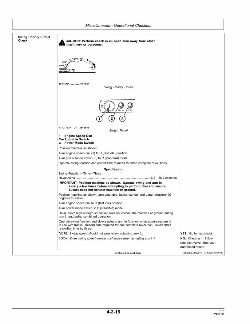
Miscellaneous—Operational Checkout
Continued on next page ER93822,0000278 -19-14SEP12-27/38
Swing Priority CircuitCheck CAUTION: Perform check in an open area away from other
machinery or personnel.
TX1037131 —UN—21FEB08Swing Priority Check
1 2 3
TX1037339 —UN—28FEB08Switch Panel
1—Engine Speed Dial2—Auto-Idle Switch3—Power Mode Switch
Position machine as shown.Turn engine speed dial (1) to H (fast idle) position.Turn power mode switch (3) to P (standard) mode.Operate swing function and record time required for three complete revolutions.
SpecificationSwing Function—Time—ThreeRevolutions...................................................................................... 16.2—18.2 secondsIMPORTANT: Position machine as shown. Operate swing and arm in
slowly a few times before attempting to perform check to ensurebucket does not contact machine or ground.
Position machine as shown, arm extended, bucket curled, and upper structure 90degrees to tracks.Turn engine speed dial to H (fast idle) position.Turn power mode switch to P (standard) mode.Raise boom high enough so bucket does not contact the machine or ground duringarm in and swing combined operation.Operate swing function and slowly actuate arm in function when upperstructure isin line with tracks. Record time required for one complete revolution. Divide threerevolution time by three.NOTE: Swing speed should not slow when actuating arm in. YES: Go to next check.LOOK: Does swing speed remain unchanged when actuating arm in? NO: Check arm 1 flow
rate pilot valve. See yourauthorized dealer.
4-2-18 053113
PN=160
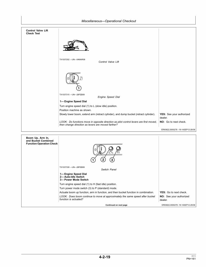
Miscellaneous—Operational Checkout
ER93822,0000278 -19-14SEP12-28/38
Continued on next page ER93822,0000278 -19-14SEP12-29/38
Control Valve LiftCheck Test
TX1037202 —UN—04MAR08Control Valve Lift
1
TX1037315 —UN—28FEB08Engine Speed Dial
1—Engine Speed Dial
Turn engine speed dial (1) to L (slow idle) position.Position machine as shown.Slowly lower boom, extend arm (retract cylinder), and dump bucket (retract cylinder). YES: See your authorized
dealer.LOOK: Do functions move in opposite direction as pilot control levers are first moved,then change direction as levers are moved farther?
NO: Go to next check.
Boom Up, Arm In,and Bucket CombinedFunction Operation Check
1 2 3
TX1037339 —UN—28FEB08Switch Panel
1—Engine Speed Dial2—Auto-Idle Switch3—Power Mode Switch
Turn engine speed dial (1) to H (fast idle) position.Turn power mode switch (3) to P (standard) mode.Actuate boom up function, arm in function, and then bucket function in combination. YES: Go to next check.LOOK: Does boom continue to move at approximately the same speed after bucketfunction is actuated?
NO: See your authorizeddealer.
4-2-19 053113
PN=161
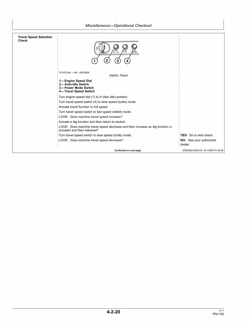
Miscellaneous—Operational Checkout
Continued on next page ER93822,0000278 -19-14SEP12-30/38
Travel Speed SelectionCheck
1 2 3 4
TX1037344 —UN—28FEB08Switch Panel
1—Engine Speed Dial2—Auto-Idle Switch3—Power Mode Switch4—Travel Speed Switch
Turn engine speed dial (1) to H (fast idle) position.Turn travel speed switch (4) to slow speed (turtle) mode.Actuate travel function to full speed.Turn travel speed switch to fast speed (rabbit) mode.LOOK: Does machine travel speed increase?Actuate a dig function and then return to neutral.LOOK: Does machine travel speed decrease and then increase as dig function isactuated and then released?Turn travel speed switch to slow speed (turtle) mode. YES: Go to next check.LOOK: Does machine travel speed decrease? NO: See your authorized
dealer.
4-2-20 053113
PN=162
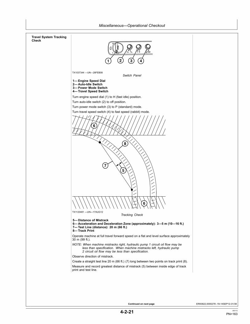
Miscellaneous—Operational Checkout
Continued on next page ER93822,0000278 -19-14SEP12-31/38
Travel System TrackingCheck
1 2 3 4
TX1037344 —UN—28FEB08Switch Panel
1—Engine Speed Dial2—Auto-Idle Switch3—Power Mode Switch4—Travel Speed Switch
Turn engine speed dial (1) to H (fast idle) position.Turn auto-idle switch (2) to off position.Turn power mode switch (3) to P (standard) mode.Turn travel speed switch (4) to fast speed (rabbit) mode.
6
6
7
8
5
TX1120481 —UN—17AUG12Tracking Check
5—Distance of Mistrack6—Acceleration and Deceleration Zone (approximately): 3—5 m (10—16 ft.)7—Test Line (distance): 20 m (66 ft.)8—Track Print
Operate machine at full travel forward speed on a flat and level surface approximately30 m (99 ft.).NOTE: When machine mistracks right, hydraulic pump 1 circuit oil flow may be
less than specification. When machine mistracks left, hydraulic pump2 circuit oil flow may be less than specification.
Observe direction of mistrack.Create a straight test line 20 m (66 ft.) (7) long between two points on track print (8).Measure and record greatest distance of mistrack (5) between inside edge of trackprint and test line.
4-2-21 053113
PN=163
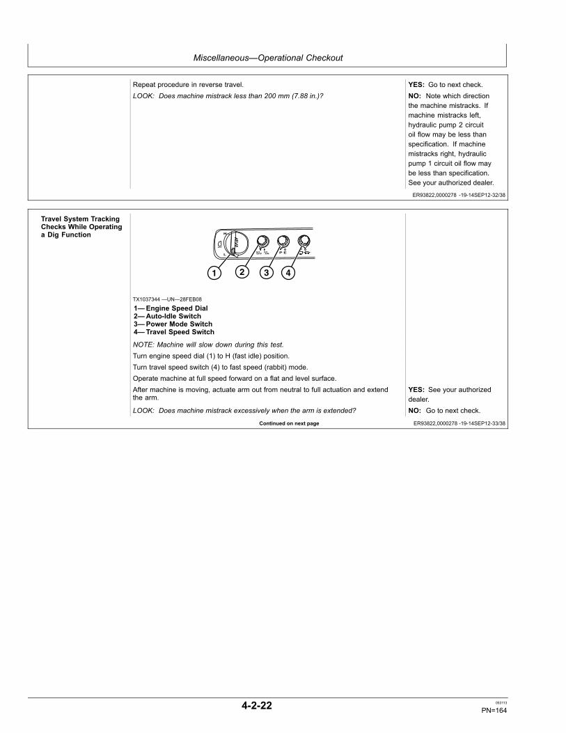
Miscellaneous—Operational Checkout
ER93822,0000278 -19-14SEP12-32/38
Continued on next page ER93822,0000278 -19-14SEP12-33/38
Repeat procedure in reverse travel. YES: Go to next check.LOOK: Does machine mistrack less than 200 mm (7.88 in.)? NO: Note which direction
the machine mistracks. Ifmachine mistracks left,hydraulic pump 2 circuitoil flow may be less thanspecification. If machinemistracks right, hydraulicpump 1 circuit oil flow maybe less than specification.See your authorized dealer.
Travel System TrackingChecks While Operatinga Dig Function
1 2 3 4
TX1037344 —UN—28FEB08
1—Engine Speed Dial2—Auto-Idle Switch3—Power Mode Switch4—Travel Speed Switch
NOTE: Machine will slow down during this test.Turn engine speed dial (1) to H (fast idle) position.Turn travel speed switch (4) to fast speed (rabbit) mode.Operate machine at full speed forward on a flat and level surface.After machine is moving, actuate arm out from neutral to full actuation and extendthe arm.
YES: See your authorizeddealer.
LOOK: Does machine mistrack excessively when the arm is extended? NO: Go to next check.
4-2-22 053113
PN=164

Miscellaneous—Operational Checkout
Continued on next page ER93822,0000278 -19-14SEP12-34/38
Travel SystemManeuverability Check
1 2 3 4
TX1037344 —UN—28FEB08Switch Panel
1—Engine Speed Dial2—Auto-Idle Switch3—Power Mode Switch4—Travel Speed Switch
Turn engine speed dial (1) to H (fast idle) position.Turn travel speed switch (4) to fast speed (rabbit) mode.Drive machine at full speed forward down a slope.Turn in each direction.LOOK: Does each track slow down in response to pedal or lever movement in order toturn?Repeat the procedure in reverse travel.Drive machine at full speed in reverse down a slope.Turn in each direction. YES: Go to next check.LOOK: Does each track slow down in response to pedal or lever movement in order toturn?
NO: See your authorizeddealer.
4-2-23 053113
PN=165
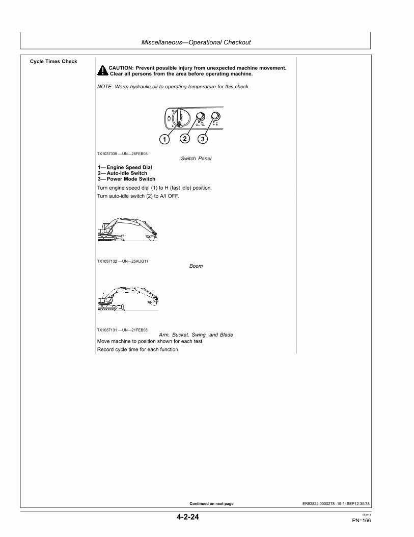
Miscellaneous—Operational Checkout
Continued on next page ER93822,0000278 -19-14SEP12-35/38
Cycle Times CheckCAUTION: Prevent possible injury from unexpected machine movement.Clear all persons from the area before operating machine.
NOTE: Warm hydraulic oil to operating temperature for this check.
1 2 3
TX1037339 —UN—28FEB08Switch Panel
1—Engine Speed Dial2—Auto-Idle Switch3—Power Mode Switch
Turn engine speed dial (1) to H (fast idle) position.Turn auto-idle switch (2) to A/I OFF.
TX1037132 —UN—25AUG11Boom
TX1037131 —UN—21FEB08Arm, Bucket, Swing, and Blade
Move machine to position shown for each test.Record cycle time for each function.
4-2-24 053113
PN=166
Miscellaneous—Operational Checkout
Continued on next page ER93822,0000278 -19-14SEP12-36/38
SpecificationBoom Raise (Cylinder Extend)—CycleTime (Seconds)...................................................................................................2.9—3.5Boom Lower (Cylinder Retract)—CycleTime (Seconds)...................................................................................................2.6—3.2Arm In (Cylinder Extend)—Cycle Time(Seconds)............................................................................................................2.4—3.0Arm Out (Cylinder Retract)—Cycle Time(Seconds)............................................................................................................2.2—2.8Bucket Load (Cylinder Extend)—CycleTime (Seconds)...................................................................................................3.3—3.9Bucket Dump (Cylinder Retract)—CycleTime (Seconds)...................................................................................................2.0—2.6Blade Raise (Cylinder Retract)—CycleTime (Seconds)...................................................................................................1.1—1.9Blade Lower (Cylinder Extend)—CycleTime (Seconds)...................................................................................................1.2—2.0Boom Swing Right or Left—Cycle Time(Seconds)............................................................................................................5.9—6.9Swing Left or Right, 3 Revolutions From aRunning Start—Cycle Time (Seconds)...........................................................16.2—18.2Drive 20 m (65 ft) From A RunningStart (Check In Forward And ReverseWith Travel Speed Switch In FASTPosition)—Cycle Time (Seconds)...................................................................13.4—15.4Drive 20 m (65 ft) From A RunningStart (Check In Forward And ReverseWith Travel Speed Switch In SLOWPosition)—Cycle Time (Seconds)...................................................................21.2—25.2Track Raised For 3 Revolutions From ARunning Start (Check In Forward AndReverse With Travel Mode Switch InFAST Position)—Cycle Time (Seconds).........................................................12.3—14.3Track Raised For 3 Revolutions FromA Running Start (Check In ForwardAnd Reverse With Travel Mode SwitchIn SLOW Position)—Cycle Time(Seconds)........................................................................................................18.5—22.5
YES: Go to next check.
LOOK: Does machine perform within specifications? NO: See your authorizeddealer.
4-2-25 053113
PN=167
Miscellaneous—Operational Checkout
Continued on next page ER93822,0000278 -19-14SEP12-37/38
Heater And AirConditioner Circuit CheckAnd Controls Check(Automatic TemperatureControl)
T136242 —UN—18DEC00Heater and Air Conditioner Controls
1—Fan Speed Switches2—Monitor Display3—Air Conditioner ON and OFF Switch (A/C)4—Automatic Operation Switch (AUTO)5—Heater and Air Conditioner OFF Switch (OFF)6—Temperature Control Switches (TEMP)7—Recirculating Air Switch8—Fresh Air Switch9—Front, Rear, and Defroster Vent Control Switch (Mode)
NOTE: The air conditioner and heater controller automatically adjusts vent position, fanspeed, and intake air source to achieve any temperature set by the operator.
Key ON, press OFF switch (5).Start engine.Run engine until normal operating temperature is reached.Press temperature control switch (6) to maximum heat position.FEEL: Does warm air come from the vents?Press temperature control switch to maximum cold position.LISTEN: Does air conditioner compressor clutch solenoid “click”?FEEL: Does cool air come from the vents?Press AUTO switch (4).LISTEN: Does air conditioner compressor clutch solenoid “click”?LOOK: Does indicator light above A/C (3) and AUTO switches illuminate?LOOK: Does monitor display illuminate and display vent position, fan speed, andtemperature setting?Press temperature control switch to maximum heat position.FEEL/LISTEN: Does vent position change?LOOK: Does fan speed change to maximum and temperature setting increase?LOOK: Does full heat (FH) appear in the temperature setting area?FEEL: Does warm air come from the vents?Press temperature control switch to maximum cold position.FEEL/LISTEN: Does vent position change?LOOK: Does fan speed change to maximum and temperature setting decrease?LOOK: Does full cool (FC) appear in the temperature setting area?FEEL: Does cool air come from the vents?Press A/C switch.LISTEN: Does air conditioner compressor clutch solenoid “click”? (Heater is ON inmanual mode.)LOOK: Do indicator lights above A/C and AUTO switches go OFF?Press temperature control switch to maximum heat position.FEEL/LISTEN: Does vent position change?LOOK: Does fan speed change to maximum and temperature setting increase?LOOK: Does full heat (FH) appear in the temperature setting area?FEEL: Does warm air come from the vents?
4-2-26 053113
PN=168
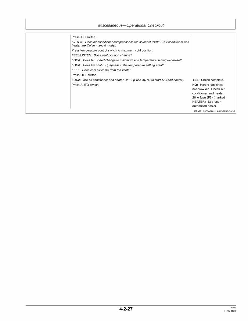
Miscellaneous—Operational Checkout
ER93822,0000278 -19-14SEP12-38/38
Press A/C switch.LISTEN: Does air conditioner compressor clutch solenoid “click”? (Air conditioner andheater are ON in manual mode.)Press temperature control switch to maximum cold position.FEEL/LISTEN: Does vent position change?LOOK: Does fan speed change to maximum and temperature setting decrease?LOOK: Does full cool (FC) appear in the temperature setting area?FEEL: Does cool air come from the vents?Press OFF switch.LOOK: Are air conditioner and heater OFF? (Push AUTO to start A/C and heater). YES: Check complete.Press AUTO switch. NO: Heater fan does
not blow air. Check airconditioner and heater20 A fuse (F3) (markedHEATER). See yourauthorized dealer.
4-2-27 053113
PN=169

Miscellaneous—Troubleshooting
TX,TROUBLESHOOT -19-20JAN11-1/1
Troubleshooting ProcedureNOTE: Troubleshooting charts are arranged from the
simplest to verify, to least likely, more difficultto verify. When diagnosing a problem, useall possible means to isolate the problem to asingle component or system. Use the followingsteps to diagnose problems:
Step 1. Operational Checkout Procedure
Step 2. Troubleshooting Charts
Step 3. Adjustments
Step 4. See your authorized John Deere dealer.
4-3-1 053113
PN=170

Miscellaneous—Troubleshooting
Continued on next page OUT4001,0000078 -19-07MAR08-1/4
EngineSymptom Problem Solution
Engine Cranks But Will Not Start OrHard To Start
Engine learn switch Turn to OFF position.
Engine stop knob Push knob in to retracted position.
No fuel Add fuel. Bleed air.
Fuse Inspect glow plug relay 5 A fuse(marked GLOW EGR), and replace, ifnecessary.
Incorrect fuel Use correct fuel.
Fuel filters restricted Replace filter. Clean fuel tank inletscreen. Bleed air.
Water separator restricted or notprimed
Inspect water separator. Bleed air.
Water in fuel Inspect, drain, and refill.
Leaks in fuel system Inspect fuel system connections. Seeyour authorized dealer.
Contaminated fuel Drain tank. Add clean fuel. Checkwater separator.
Air in fuel system Bleed air.
Low battery power Charge or install new batteries.
Slow cranking speed (poor electricalconnection)
Clean and tighten battery and starterconnections.
Incorrect engine oil Use correct oil.
Air filter restricted Clean or replace elements.
Starter Repair or replace starter.
Engine Knocks, Runs Irregularly,Or Stops
Air filter restricted Clean or replace elements. Cleansystem.
Fuel filter restricted Replace filter. Bleed air. Clean fueltank inlet screen.
Water separator restricted Inspect water separator.
Air in water separator Bleed air from fuel system.
Engine oil level low Add correct oil to proper level.
4-3-2 053113
PN=171
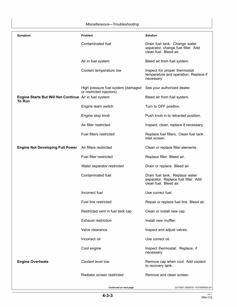
Miscellaneous—Troubleshooting
Continued on next page OUT4001,0000078 -19-07MAR08-2/4
Symptom Problem Solution
Contaminated fuel Drain fuel tank. Change waterseparator, change fuel filter. Addclean fuel. Bleed air.
Air in fuel system Bleed air from fuel system.
Coolant temperature low Inspect for proper thermostattemperature and operation. Replace ifnecessary.
High pressure fuel system (damagedor restricted injectors)
See your authorized dealer.
Engine Starts But Will Not ContinueTo Run
Air in fuel system Bleed air from fuel system.
Engine learn switch Turn to OFF position.
Engine stop knob Push knob in to retracted position.
Air filter restricted Inspect, clean, replace if necessary.
Fuel filters restricted Replace fuel filters. Clean fuel tankinlet screen.
Engine Not Developing Full Power Air filters restricted Clean or replace filter elements.
Fuel filter restricted Replace filter. Bleed air.
Water separator restricted Drain or replace. Bleed air.
Contaminated fuel Drain fuel tank. Replace waterseparator. Replace fuel filter. Addclean fuel. Bleed air.
Incorrect fuel Use correct fuel.
Fuel line restricted Repair or replace fuel line. Bleed air.
Restricted vent in fuel tank cap Clean or install new cap.
Exhaust restriction Install new muffler.
Valve clearance Inspect and adjust valves.
Incorrect oil Use correct oil.
Cool engine Inspect thermostat. Replace, ifnecessary.
Engine Overheats Coolant level low Remove cap when cool. Add coolantto recovery tank.
Radiator screen restricted Remove and clean screen.
4-3-3 053113
PN=172
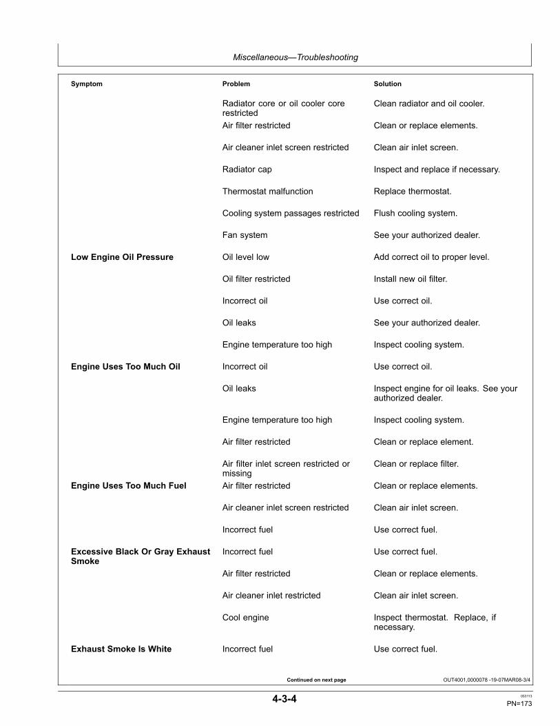
Miscellaneous—Troubleshooting
Continued on next page OUT4001,0000078 -19-07MAR08-3/4
Symptom Problem Solution
Radiator core or oil cooler corerestricted
Clean radiator and oil cooler.
Air filter restricted Clean or replace elements.
Air cleaner inlet screen restricted Clean air inlet screen.
Radiator cap Inspect and replace if necessary.
Thermostat malfunction Replace thermostat.
Cooling system passages restricted Flush cooling system.
Fan system See your authorized dealer.
Low Engine Oil Pressure Oil level low Add correct oil to proper level.
Oil filter restricted Install new oil filter.
Incorrect oil Use correct oil.
Oil leaks See your authorized dealer.
Engine temperature too high Inspect cooling system.
Engine Uses Too Much Oil Incorrect oil Use correct oil.
Oil leaks Inspect engine for oil leaks. See yourauthorized dealer.
Engine temperature too high Inspect cooling system.
Air filter restricted Clean or replace element.
Air filter inlet screen restricted ormissing
Clean or replace filter.
Engine Uses Too Much Fuel Air filter restricted Clean or replace elements.
Air cleaner inlet screen restricted Clean air inlet screen.
Incorrect fuel Use correct fuel.
Excessive Black Or Gray ExhaustSmoke
Incorrect fuel Use correct fuel.
Air filter restricted Clean or replace elements.
Air cleaner inlet restricted Clean air inlet screen.
Cool engine Inspect thermostat. Replace, ifnecessary.
Exhaust Smoke Is White Incorrect fuel Use correct fuel.
4-3-4 053113
PN=173
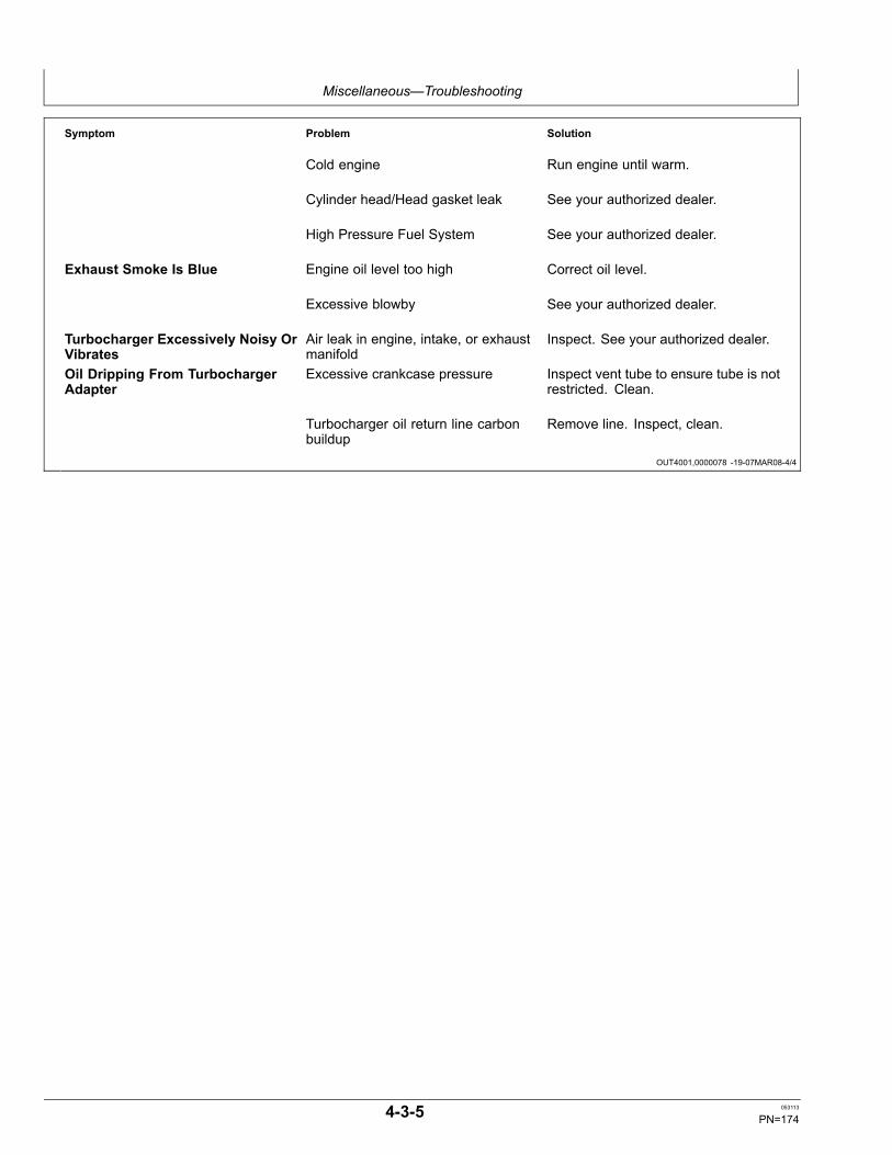
Miscellaneous—Troubleshooting
OUT4001,0000078 -19-07MAR08-4/4
Symptom Problem Solution
Cold engine Run engine until warm.
Cylinder head/Head gasket leak See your authorized dealer.
High Pressure Fuel System See your authorized dealer.
Exhaust Smoke Is Blue Engine oil level too high Correct oil level.
Excessive blowby See your authorized dealer.
Turbocharger Excessively Noisy OrVibrates
Air leak in engine, intake, or exhaustmanifold
Inspect. See your authorized dealer.
Oil Dripping From TurbochargerAdapter
Excessive crankcase pressure Inspect vent tube to ensure tube is notrestricted. Clean.
Turbocharger oil return line carbonbuildup
Remove line. Inspect, clean.
4-3-5 053113
PN=174
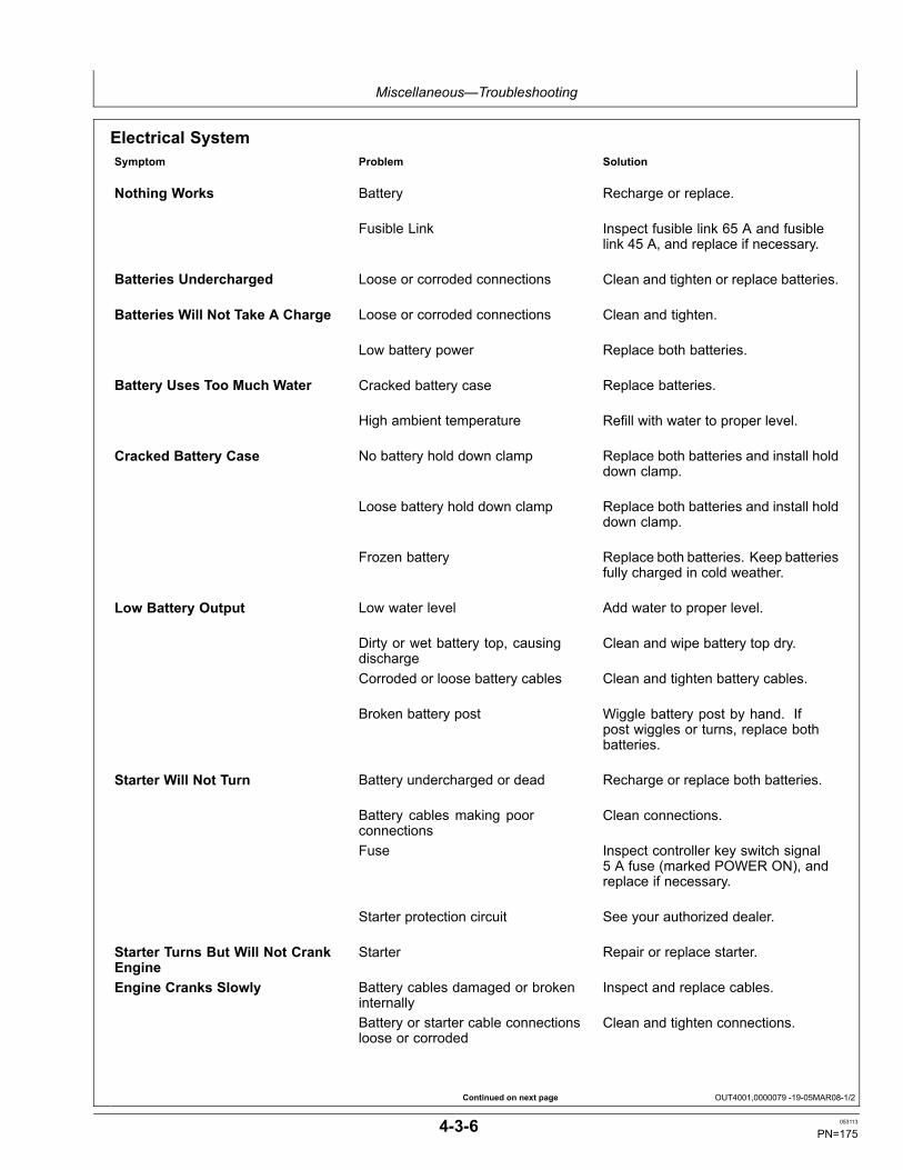
Miscellaneous—Troubleshooting
Continued on next page OUT4001,0000079 -19-05MAR08-1/2
Electrical SystemSymptom Problem Solution
Nothing Works Battery Recharge or replace.
Fusible Link Inspect fusible link 65 A and fusiblelink 45 A, and replace if necessary.
Batteries Undercharged Loose or corroded connections Clean and tighten or replace batteries.
Batteries Will Not Take A Charge Loose or corroded connections Clean and tighten.
Low battery power Replace both batteries.
Battery Uses Too Much Water Cracked battery case Replace batteries.
High ambient temperature Refill with water to proper level.
Cracked Battery Case No battery hold down clamp Replace both batteries and install holddown clamp.
Loose battery hold down clamp Replace both batteries and install holddown clamp.
Frozen battery Replace both batteries. Keep batteriesfully charged in cold weather.
Low Battery Output Low water level Add water to proper level.
Dirty or wet battery top, causingdischarge
Clean and wipe battery top dry.
Corroded or loose battery cables Clean and tighten battery cables.
Broken battery post Wiggle battery post by hand. Ifpost wiggles or turns, replace bothbatteries.
Starter Will Not Turn Battery undercharged or dead Recharge or replace both batteries.
Battery cables making poorconnections
Clean connections.
Fuse Inspect controller key switch signal5 A fuse (marked POWER ON), andreplace if necessary.
Starter protection circuit See your authorized dealer.
Starter Turns But Will Not CrankEngine
Starter Repair or replace starter.
Engine Cranks Slowly Battery cables damaged or brokeninternally
Inspect and replace cables.
Battery or starter cable connectionsloose or corroded
Clean and tighten connections.
4-3-6 053113
PN=175
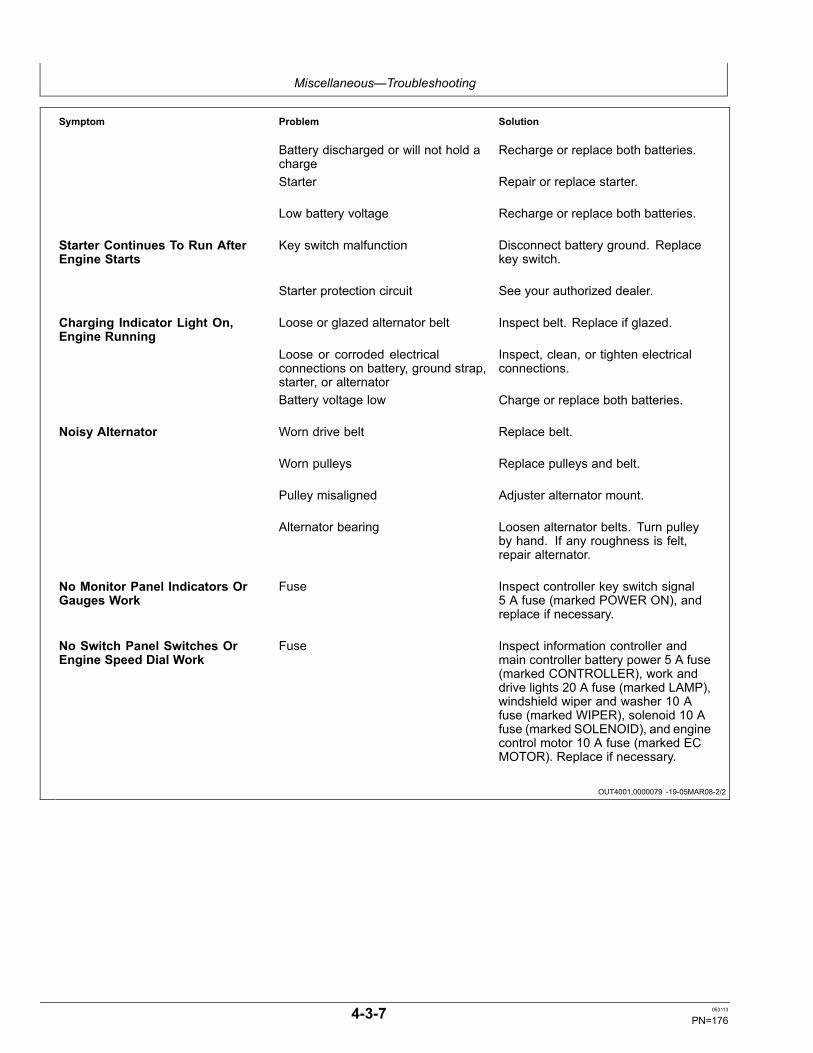
Miscellaneous—Troubleshooting
OUT4001,0000079 -19-05MAR08-2/2
Symptom Problem Solution
Battery discharged or will not hold acharge
Recharge or replace both batteries.
Starter Repair or replace starter.
Low battery voltage Recharge or replace both batteries.
Starter Continues To Run AfterEngine Starts
Key switch malfunction Disconnect battery ground. Replacekey switch.
Starter protection circuit See your authorized dealer.
Charging Indicator Light On,Engine Running
Loose or glazed alternator belt Inspect belt. Replace if glazed.
Loose or corroded electricalconnections on battery, ground strap,starter, or alternator
Inspect, clean, or tighten electricalconnections.
Battery voltage low Charge or replace both batteries.
Noisy Alternator Worn drive belt Replace belt.
Worn pulleys Replace pulleys and belt.
Pulley misaligned Adjuster alternator mount.
Alternator bearing Loosen alternator belts. Turn pulleyby hand. If any roughness is felt,repair alternator.
No Monitor Panel Indicators OrGauges Work
Fuse Inspect controller key switch signal5 A fuse (marked POWER ON), andreplace if necessary.
No Switch Panel Switches OrEngine Speed Dial Work
Fuse Inspect information controller andmain controller battery power 5 A fuse(marked CONTROLLER), work anddrive lights 20 A fuse (marked LAMP),windshield wiper and washer 10 Afuse (marked WIPER), solenoid 10 Afuse (marked SOLENOID), and enginecontrol motor 10 A fuse (marked ECMOTOR). Replace if necessary.
4-3-7 053113
PN=176
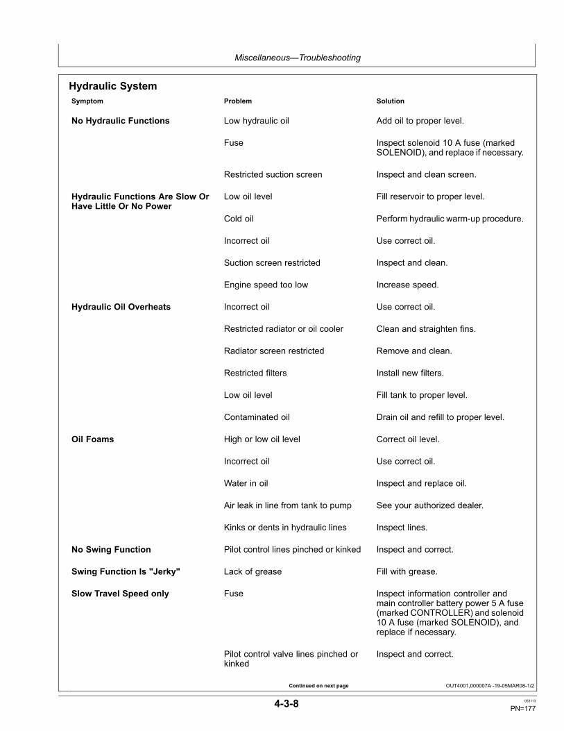
Miscellaneous—Troubleshooting
Continued on next page OUT4001,000007A -19-05MAR08-1/2
Hydraulic SystemSymptom Problem Solution
No Hydraulic Functions Low hydraulic oil Add oil to proper level.
Fuse Inspect solenoid 10 A fuse (markedSOLENOID), and replace if necessary.
Restricted suction screen Inspect and clean screen.
Hydraulic Functions Are Slow OrHave Little Or No Power
Low oil level Fill reservoir to proper level.
Cold oil Perform hydraulic warm-up procedure.
Incorrect oil Use correct oil.
Suction screen restricted Inspect and clean.
Engine speed too low Increase speed.
Hydraulic Oil Overheats Incorrect oil Use correct oil.
Restricted radiator or oil cooler Clean and straighten fins.
Radiator screen restricted Remove and clean.
Restricted filters Install new filters.
Low oil level Fill tank to proper level.
Contaminated oil Drain oil and refill to proper level.
Oil Foams High or low oil level Correct oil level.
Incorrect oil Use correct oil.
Water in oil Inspect and replace oil.
Air leak in line from tank to pump See your authorized dealer.
Kinks or dents in hydraulic lines Inspect lines.
No Swing Function Pilot control lines pinched or kinked Inspect and correct.
Swing Function Is "Jerky" Lack of grease Fill with grease.
Slow Travel Speed only Fuse Inspect information controller andmain controller battery power 5 A fuse(marked CONTROLLER) and solenoid10 A fuse (marked SOLENOID), andreplace if necessary.
Pilot control valve lines pinched orkinked
Inspect and correct.
4-3-8 053113
PN=177

Miscellaneous—Troubleshooting
OUT4001,000007A -19-05MAR08-2/2
Symptom Problem Solution
Travel Is "Jerky" Track sag adjustment Adjust tension.
Rocks or mud lodged in track frame Remove and repair.
Engine Stops When Travel OrControl Lever Moved
Water separator restricted Drain. Change filter element.
NOTE: If any other problems are encountered whichrequire special tools or machine knowledge tocorrect, see your authorized dealer.
4-3-9 053113
PN=178

Miscellaneous—Storage
OUT4001,00000A1 -19-27JUL10-1/1
Prepare Machine for Storage1. Before storage, operate engine on at least one
complete tank of petroleum diesel fuel to purge thefuel system. Ensure that the fuel tank is full duringstorage to prevent water build up due to condensation.
NOTE: For up to and including B20, it is recommendedthat biodiesel be used within 3 months of itsmanufacture. For blends greater than B20, it isrecommended that the biodiesel be used within 45days. The poor oxidation stability characteristic ofbiodiesel can result in longterm storage problems.John Deere does not recommend using biodiesel inengines powering standby applications or vehiclesoperating on a seasonal basis. Consult your JohnDeere dealer or fuel supplier for additives to improvefuel storage and performance of biodiesel fuels.These additives must be added to the biodiesel closeto its time of production for them to be effective.
2. Repair worn or damaged parts. Install new parts, ifnecessary, to avoid needless delays later.
3. Replace air cleaner elements.
IMPORTANT: High pressure washing greater than1379 kPa (13.8 bar) (200 psi) can damage freshlypainted finishes. Paint should be allowed toair dry for 30 days minimum after receipt ofmachine before cleaning parts or machineswith high pressure. Use low pressure washoperations until 30 days have elapsed.
4. Wash the machine. Use low pressure wash operations(less than 1379 kPa (13.8 bar) (200 psi) until 30 daysafter receipt of machine have elapsed. Paint areas toprevent rust. Replace decals, where needed.
5. Apply oil to track chains. Run machine back and forthseveral times. Park machine on a hard surface toprevent tracks from freezing to ground.
6. Store machine in a dry, protected place. If storedoutside, cover with a waterproof material.
T5813A
M—UN—09FE
B89
IMPORTANT: LPS 3 Rust Inhibitor can destroypainted finish. DO NOT spray LPS 3 RustInhibitor on painted areas.
7. Retract all hydraulic cylinders, if possible. If not, coatexposed cylinder rods with LPS ® 3 Rust Inhibitor.
8. Place a DO NOT OPERATE tag on the right controllever.
9. Lubricate all grease points.
NOTE: If the batteries are kept disconnected for more thanone month or when the batteries are reconnected,contact your nearest Hitachi dealer. Resetting of theinformation controller (ICX) may be required.
10. Remove the batteries and store in a dry, protectedplace after charging fully. If not removed, disconnectthe negative battery cable from the (—) terminal.
11. Add a fuel stabilizer additive and top off fuel tank withfuel to prevent condensation.
12. Drain water separator.
13. Remove keys and lock all covers and doors.
LPS is a trademark of the Holt Lloyd Corporation.
4-4-1 053113
PN=179

Miscellaneous—Storage
TX,STORAGE,KEY -19-20JAN11-1/2
TX,STORAGE,KEY -19-20JAN11-2/2
Monthly Storage Procedure
CAUTION: Prevent possible injury or deathfrom asphyxiation. Engine exhaust fumescan cause sickness or death. Start engineONLY in a well-ventilated area.
1. Drain water and sediment from fuel tank when airtemperature is above freezing.
2. Remove LPS 3® Rust Inhibitor from cylinder rods witha cleaning solvent.
T6191A
A—UN—18OCT88
LPS 3 Rust Inhibitor is manufactured by Holt Lloyd Corporation.
IMPORTANT: Prevent possible engine damage.During cold temperatures, check fluidity ofengine oil on dipstick. If the oil appears waxy orjelly-like rather than liquid, DO NOT attempt tostart engine. Use external heat source to warmthe crankcase until oil appears fluid.
3. Check all fluid levels. If low, check for leaks and addoil as required.
4. Check belts.
5. Check condition of all hoses and connections.
6. Check battery electrolyte level. Charge and installbattery.
7. For machines with tires, check condition of tires andtire pressure.
For machines with tracks, check condition of tracksand track sag.
On crawler machines with non-sealed andnon-lubricated track chains, apply oil to thepin-to-bushing joints. Run machine back and forthseveral times.
8. Park machine on a hard surface to prevent tracks fromfreezing to ground.
9. Fill fuel tank.
10. Pre-lubricate turbocharger bearings, if equipped:
a. Disconnect fuel shutoff fuse.
b. Crank engine for 10 seconds.
c. Connect fuel shutoff fuse.
11. Inspect engine compartment, and remove any foreignmaterial that could have accumulated. Start engine
T6181A
U—UN—18OCT88
and run until it reaches operating temperature. Run at1/2 speed for 5 minutes. Do not run at fast or slow idle.
• If engine fails to start or runs poorly after starting,change fuel filter(s). Bleed fuel system.
12. Operate all controls, levers, seat adjustments, andothers.
CAUTION: Prevent possible injury fromunexpected machine movement. Clear thearea of all persons before running machinethrough the operation procedure.
13. Make sure that the area is clear to allow for movement.Cycle all hydraulic functions several times. Checkcondition of all hoses and connections.
14. Park the machine with cylinder rods retracted, ifpossible. Turn key switch to OFF.
15. Apply LPS 3 Rust Inhibitor to exposed cylinder rodareas.
4-4-2 053113
PN=180
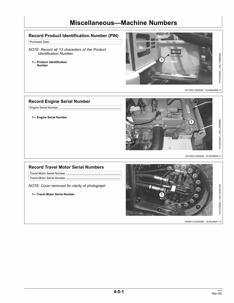
Miscellaneous—Machine Numbers
OUT4001,0000063 -19-04MAR08-1/1
OUT4001,0000046 -19-25FEB08-1/1
DW90712,00003BE -19-09JAN07-1/1
Record Product Identification Number (PIN)Purchase Date
NOTE: Record all 13 characters of the ProductIdentification Number.
1—Product IdentificationNumber
TX1037994A
—UN—04MAR08
Record Engine Serial NumberEngine Serial Number
1—Engine Serial Number
TX1037350A
—UN—25FE
B08
Record Travel Motor Serial NumbersTravel Motor Serial NumberTravel Motor Serial Number
NOTE: Cover removed for clarity of photograph
1—Travel Motor Serial Number
TX1012828A
—UN—05OCT06
4-5-1 053113
PN=181
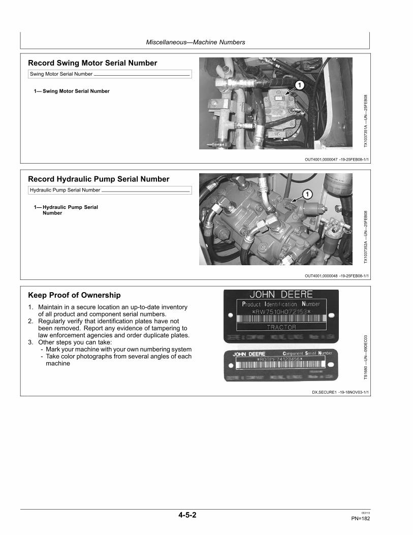
Miscellaneous—Machine Numbers
OUT4001,0000047 -19-25FEB08-1/1
OUT4001,0000048 -19-25FEB08-1/1
DX,SECURE1 -19-18NOV03-1/1
Record Swing Motor Serial NumberSwing Motor Serial Number
1—Swing Motor Serial Number
TX1037351A
—UN—25FE
B08
Record Hydraulic Pump Serial NumberHydraulic Pump Serial Number
1—Hydraulic Pump SerialNumber
TX1037352A
—UN—25FE
B08
Keep Proof of Ownership1. Maintain in a secure location an up-to-date inventory
of all product and component serial numbers.2. Regularly verify that identification plates have not
been removed. Report any evidence of tampering tolaw enforcement agencies and order duplicate plates.
3. Other steps you can take:- Mark your machine with your own numbering system- Take color photographs from several angles of eachmachine
TS1680
—UN—09DEC03
4-5-2 053113
PN=182
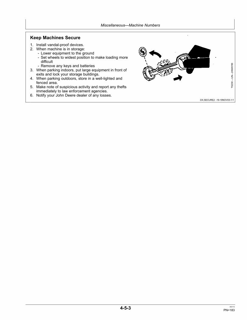
Miscellaneous—Machine Numbers
DX,SECURE2 -19-18NOV03-1/1
Keep Machines Secure1. Install vandal-proof devices.2. When machine is in storage:
- Lower equipment to the ground- Set wheels to widest position to make loading moredifficult
- Remove any keys and batteries3. When parking indoors, put large equipment in front of
exits and lock your storage buildings.4. When parking outdoors, store in a well-lighted and
fenced area.5. Make note of suspicious activity and report any thefts
immediately to law enforcement agencies.6. Notify your John Deere dealer of any losses.
TS230—UN—24MAY
89
4-5-3 053113
PN=183
Miscellaneous—Specifications
OUT4001,0000064 -19-07MAR08-1/1
OUT4001,0000065 -19-27JUL10-1/1
85D Engine SpecificationsItem Measurement Specification
ISUZU—4LE2X Type 4-Stroke Cycle, Turbocharged, DirectInjection, Certified with EPA Tier 3Emissions
Bore and Stroke 85 x 96 mm3.35 x 3.78 in.
Cylinders 4Displacement 2.2 L
133 cu in.Maximum Net Torque 215 N·m
159 lb-ftPower @ 2000 rpm 40.5 kW
54.3 hp Net SAECooling Fan SuctionElectrical system 24 VoltBatteries (2) 12 volt 100 Minutes Reserve Capacity
85D Drain and Refill CapacitiesItem Measurement Specification
Fuel Tank Capacity 135.0 L35.7 gal
Cooling System Refill Capacity 10.3 L2.7 gal
Engine Oil Capacity, Including Filter Change 12.1 L3.2 gal
Hydraulic Tank Oil Capacity 56 L14.8 gal
Hydraulic System Oil Capacity 103 L27.2 gal
Travel Gear Case (each) Oil Capacity 1.2 L1.3 qt.
4-6-1 053113
PN=184

Miscellaneous—Specifications
Continued on next page OUT4001,000004A -19-06MAR08-1/2
85D Machine Specifications
TX1037311
1
7
13
4
912
2
16
14
3
10
8
5
6
1115
TX1037311—UN—26FE
B08
1—Overall Width (excludingrearview mirrors)
2—Cab Height3—Rear End Swing Radius4—Minimum Ground Clearance
5—Counterweight Clearance6—Engine Cover Height7—Overall Width Of
Upperstructure8—Undercarriage Length
9—Undercarriage Width10— Sprocket Center To Idler
Center11— Track Shoe Width12— Blade Width13— Blade Height
14— Blade Bottom HighestPosition
15— Blade Bottom LowestPosition
16— Maximum Approach Angle
NOTE: Specifications and design subject to changewithout notice. Wherever applicable, specificationsare in accordance with PCSA and SAE standards.Except where otherwise noted these specificationsare based on a machine equipped with 2,470
mm (8 ft 1 in.) blade, 600 mm (24 in.) shoes,1383 kg (3,049 lb ) counterweight, 1.62 m (5 ft4 in.) arm, 0.41 m3 (.53 yd3),762 mm (30 in.),333 kg (735 lb) bucket, full fuel tank, 79 kg (175lb) operator and standard equipment.
Item Measurement Specification
1—Overall Width (excludingrearview mirrors)
Distance 2320 mm7 ft 7 in.
2—Cab Height 2690 mm8 ft 10 in.
3—Rear End Swing Radius Distance 1490 mm4 ft 11 in.
4—Minimum Ground Clearance Distance 360 mm1 ft 2 in.
5—Counterweight Clearance Distance 760 mm2 ft 6 in.
6—Machine Engine Cover Height 1750 mm5 ft 9 in.
7—Upperstructure Overall Width 2320 mm7 ft 7 in.
4-6-2 053113
PN=185
Miscellaneous—Specifications
OUT4001,000004A -19-06MAR08-2/2
Item Measurement Specification
8—Undercarriage Length 2920 mm9 ft 7 in.
9—Undercarriage Width 2320 mm7 ft 7 in.
10—Sprocket Center To Idler Center Distance 2290 mm7 ft 6 in.
11—Track Shoes Width 450 mm (18 in.)600 mm (24 in.)
12—Blade Width 2470 mm8 ft 1 in.
13—Blade Height 460 mm1 ft 6 in.
14—Blade Bottom Highest Position 380 mm1 ft 3 in.
15—Blade Bottom Lowest Position 280 mm11 in.
16—Blade Maximum Approach Angle 26.2°
Machine Operating Weight 8537 kg18,821 lb
4-6-3 053113
PN=186
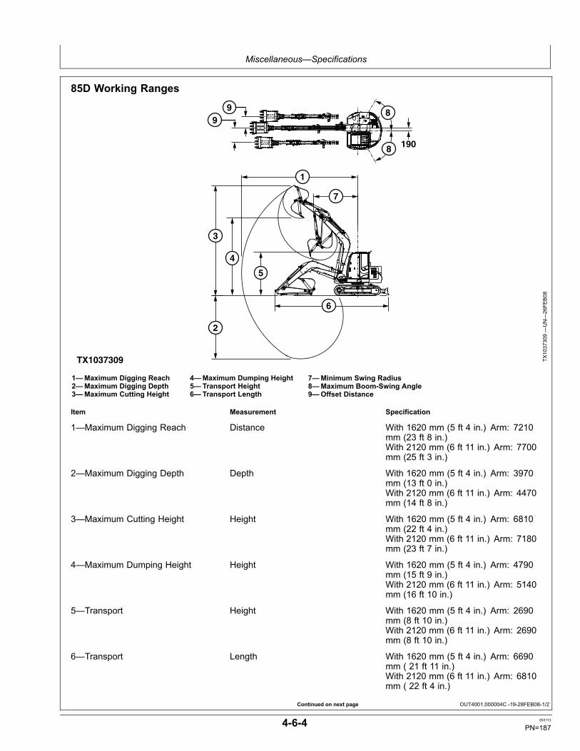
Miscellaneous—Specifications
Continued on next page OUT4001,000004C -19-28FEB08-1/2
85D Working Ranges
TX1037309
99
1
3
2
4
5
7
6
8
8 190
TX1037309—UN—26FE
B08
1—Maximum Digging Reach2—Maximum Digging Depth3—Maximum Cutting Height
4—Maximum Dumping Height5—Transport Height6—Transport Length
7—Minimum Swing Radius8—Maximum Boom-Swing Angle9—Offset Distance
Item Measurement Specification
1—Maximum Digging Reach Distance With 1620 mm (5 ft 4 in.) Arm: 7210mm (23 ft 8 in.)With 2120 mm (6 ft 11 in.) Arm: 7700mm (25 ft 3 in.)
2—Maximum Digging Depth Depth With 1620 mm (5 ft 4 in.) Arm: 3970mm (13 ft 0 in.)With 2120 mm (6 ft 11 in.) Arm: 4470mm (14 ft 8 in.)
3—Maximum Cutting Height Height With 1620 mm (5 ft 4 in.) Arm: 6810mm (22 ft 4 in.)With 2120 mm (6 ft 11 in.) Arm: 7180mm (23 ft 7 in.)
4—Maximum Dumping Height Height With 1620 mm (5 ft 4 in.) Arm: 4790mm (15 ft 9 in.)With 2120 mm (6 ft 11 in.) Arm: 5140mm (16 ft 10 in.)
5—Transport Height With 1620 mm (5 ft 4 in.) Arm: 2690mm (8 ft 10 in.)With 2120 mm (6 ft 11 in.) Arm: 2690mm (8 ft 10 in.)
6—Transport Length With 1620 mm (5 ft 4 in.) Arm: 6690mm ( 21 ft 11 in.)With 2120 mm (6 ft 11 in.) Arm: 6810mm ( 22 ft 4 in.)
4-6-4 053113
PN=187
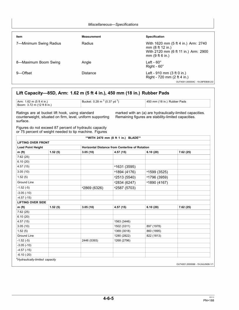
Miscellaneous—Specifications
OUT4001,000004C -19-28FEB08-2/2
OUT4001,0000066 -19-24JUN08-1/1
Item Measurement Specification
7—Minimum Swing Radius Radius With 1620 mm (5 ft 4 in.) Arm: 2740mm (8 ft 12 in.)With 2120 mm (6 ft 11 in.) Arm: 2900mm (9 ft 6 in.)
8—Maximum Boom Swing Angle Left - 60°Right - 60°
9—Offset Distance Left - 910 mm (3 ft 0 in.)Right - 720 mm (2 ft 4 in.)
Lift Capacity—85D, Arm: 1.62 m (5 ft 4 in.), 450 mm (18 in.) Rubber Pads
Arm: 1.62 m (5 ft 4 in.)Boom: 3.72 m (12 ft 8 in.)
Bucket: 0.28 m 3 (0.37 yd 3) 450 mm (18 in.) Rubber Pads
Ratings are at bucket lift hook, using standardcounterweight, situated on firm, level, uniform supportingsurface.
Figures do not exceed 87 percent of hydraulic capacityor 75 percent of weight needed to tip machine. Figures
marked with an (a) are hydraulically-limited capacities.Remaining figures are stability-limited capacities.
**WITH 2470 mm (8 ft 1 in.) BLADE**LIFTING OVER FRONTLoad Point Height Horizontal Distance from Centerline of Rotationm (ft) 1.52 (5) 3.05 (10) 4.57 (15) 6.10 (20) 7.62 (25)7.62 (25)6.10 (20)4.57 (15) a1631 (3595)3.05 (10) a1894 (4176) a1599 (3525)1.52 (5) a2513 (5540) a1796 (3959)Ground Line a2834 (6247) a1890 (4167)-1.52 (-5) a2869 (6326) a2587 (5703)-3.05 (-10)-4.57 (-15)LIFTING OVER SIDEm (ft) 1.52 (5) 3.05 (10) 4.57 (15) 6.10 (20) 7.62 (25)7.62 (25)6.10 (20)4.57 (15) 1563 (3446)3.05 (10) 1502 (3311) 897 (1978)1.52 (5) 1369 (3018) 860 (1895)Ground Line 1280 (2822) 822 (1813)-1.52 (-5) 2446 (5393) 1268 (2796)-3.05 (-10)-4.57 (-15)-6.10 (-20)aHydraulically-limited capacity
4-6-5 053113
PN=188
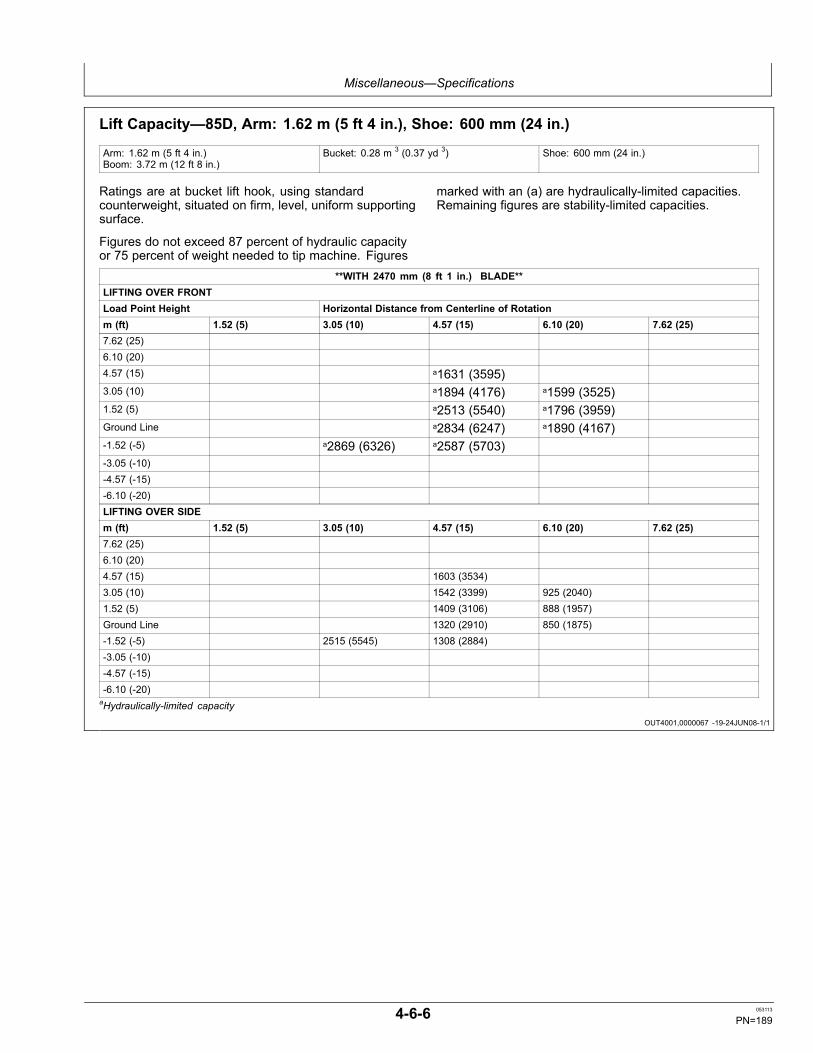
Miscellaneous—Specifications
OUT4001,0000067 -19-24JUN08-1/1
Lift Capacity—85D, Arm: 1.62 m (5 ft 4 in.), Shoe: 600 mm (24 in.)
Arm: 1.62 m (5 ft 4 in.)Boom: 3.72 m (12 ft 8 in.)
Bucket: 0.28 m 3 (0.37 yd 3) Shoe: 600 mm (24 in.)
Ratings are at bucket lift hook, using standardcounterweight, situated on firm, level, uniform supportingsurface.
Figures do not exceed 87 percent of hydraulic capacityor 75 percent of weight needed to tip machine. Figures
marked with an (a) are hydraulically-limited capacities.Remaining figures are stability-limited capacities.
**WITH 2470 mm (8 ft 1 in.) BLADE**LIFTING OVER FRONTLoad Point Height Horizontal Distance from Centerline of Rotationm (ft) 1.52 (5) 3.05 (10) 4.57 (15) 6.10 (20) 7.62 (25)7.62 (25)6.10 (20)4.57 (15) a1631 (3595)3.05 (10) a1894 (4176) a1599 (3525)1.52 (5) a2513 (5540) a1796 (3959)Ground Line a2834 (6247) a1890 (4167)-1.52 (-5) a2869 (6326) a2587 (5703)-3.05 (-10)-4.57 (-15)-6.10 (-20)LIFTING OVER SIDEm (ft) 1.52 (5) 3.05 (10) 4.57 (15) 6.10 (20) 7.62 (25)7.62 (25)6.10 (20)4.57 (15) 1603 (3534)3.05 (10) 1542 (3399) 925 (2040)1.52 (5) 1409 (3106) 888 (1957)Ground Line 1320 (2910) 850 (1875)-1.52 (-5) 2515 (5545) 1308 (2884)-3.05 (-10)-4.57 (-15)-6.10 (-20)aHydraulically-limited capacity
4-6-6 053113
PN=189
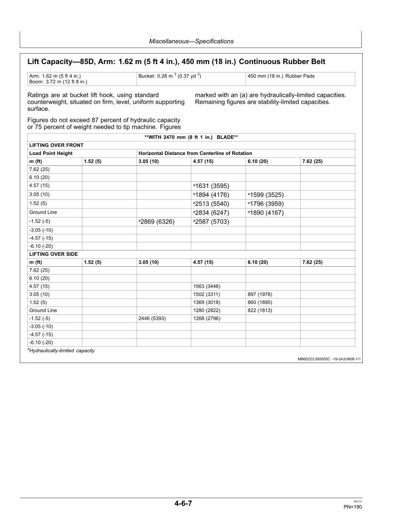
Miscellaneous—Specifications
MB60223,000005C -19-24JUN08-1/1
Lift Capacity—85D, Arm: 1.62 m (5 ft 4 in.), 450 mm (18 in.) Continuous Rubber Belt
Arm: 1.62 m (5 ft 4 in.)Boom: 3.72 m (12 ft 8 in.)
Bucket: 0.28 m 3 (0.37 yd 3) 450 mm (18 in.) Rubber Pads
Ratings are at bucket lift hook, using standardcounterweight, situated on firm, level, uniform supportingsurface.
Figures do not exceed 87 percent of hydraulic capacityor 75 percent of weight needed to tip machine. Figures
marked with an (a) are hydraulically-limited capacities.Remaining figures are stability-limited capacities.
**WITH 2470 mm (8 ft 1 in.) BLADE**LIFTING OVER FRONTLoad Point Height Horizontal Distance from Centerline of Rotationm (ft) 1.52 (5) 3.05 (10) 4.57 (15) 6.10 (20) 7.62 (25)7.62 (25)6.10 (20)4.57 (15) a1631 (3595)3.05 (10) a1894 (4176) a1599 (3525)1.52 (5) a2513 (5540) a1796 (3959)Ground Line a2834 (6247) a1890 (4167)-1.52 (-5) a2869 (6326) a2587 (5703)-3.05 (-10)-4.57 (-15)-6.10 (-20)LIFTING OVER SIDEm (ft) 1.52 (5) 3.05 (10) 4.57 (15) 6.10 (20) 7.62 (25)7.62 (25)6.10 (20)4.57 (15) 1563 (3446)3.05 (10) 1502 (3311) 897 (1978)1.52 (5) 1369 (3018) 860 (1895)Ground Line 1280 (2822) 822 (1813)-1.52 (-5) 2446 (5393) 1268 (2796)-3.05 (-10)-4.57 (-15)-6.10 (-20)aHydraulically-limited capacity
4-6-7 053113
PN=190
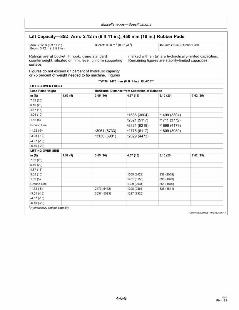
Miscellaneous—Specifications
OUT4001,0000068 -19-24JUN08-1/1
Lift Capacity—85D, Arm: 2.12 m (6 ft 11 in.), 450 mm (18 in.) Rubber Pads
Arm: 2.12 m (6 ft 11 in.)Boom: 3.72 m (12 ft 8 in.)
Bucket: 0.28 m 3 (0.37 yd 3) 450 mm (18 in.) Rubber Pads
Ratings are at bucket lift hook, using standardcounterweight, situated on firm, level, uniform supportingsurface.
Figures do not exceed 87 percent of hydraulic capacityor 75 percent of weight needed to tip machine. Figures
marked with an (a) are hydraulically-limited capacities.Remaining figures are stability-limited capacities.
**WITH 2470 mm (8 ft 1 in.) BLADE**LIFTING OVER FRONTLoad Point Height Horizontal Distance from Centerline of Rotationm (ft) 1.52 (5) 3.05 (10) 4.57 (15) 6.10 (20) 7.62 (25)7.62 (25)6.10 (20)4.57 (15)3.05 (10) a1635 (3604) a1499 (3304)1.52 (5) a2321 (5117) a1711 (3772)Ground Line a2821 (6219) a1896 (4179)-1.52 (-5) a3961 (8733) a2775 (6117) a1809 (3989)-3.05 (-10) a3130 (6901) a2029 (4473)-4.57 (-15)-6.10 (-20)LIFTING OVER SIDEm (ft) 1.52 (5) 3.05 (10) 4.57 (15) 6.10 (20) 7.62 (25)7.62 (25)6.10 (20)4.57 (15)3.05 (10) 1555 (3429) 938 (2069)1.52 (5) 1431 (3155) 895 (1973)Ground Line 1329 (2931) 851 (1876)-1.52 (-5) 2473 (5452) 1298 (2861) 835 (1841)-3.05 (-10) 2537 (5593) 1327 (2926)-4.57 (-15)-6.10 (-20)aHydraulically-limited capacity
4-6-8 053113
PN=191

Miscellaneous—Specifications
OUT4001,0000069 -19-24JUN08-1/1
Lift Capacity—85D, Arm: 2.12 m (6 ft 11 in.), Shoe: 600 mm (24 in.)
Arm: 2.12 m (6 ft 11 in.)Boom: 3.72 m (12 ft 8 in.)
Bucket: 0.28 m 3 (0.37 yd 3) Shoe: 600 mm (24 in.)
Ratings are at bucket lift hook, using standardcounterweight, situated on firm, level, uniform supportingsurface.
Figures do not exceed 87 percent of hydraulic capacityor 75 percent of weight needed to tip machine. Figures
marked with an (a) are hydraulically-limited capacities.Remaining figures are stability-limited capacities.
**WITH 2470 mm (8 ft 1 in.) BLADE**LIFTING OVER FRONTLoad Point Height Horizontal Distance from Centerline of Rotationm (ft) 1.52 (5) 3.05 (10) 4.57 (15) 6.10 (20) 7.62 (25)7.62 (25)6.10 (20)4.57 (15)3.05 (10) a1635 (3604) a1499 (3304)1.52 (5) a2321 (5117) a1711 (3772)Ground Line a2821 (6219) a1896 (4179)-1.52 (-5) a3961 (8733) a2775 (6117) a1809 (3989)-3.05 (-10) a3130 (6901) a2029 (4473)-4.57 (-15)-6.10 (-20)LIFTING OVER SIDEm (ft) 1.52 (5) 3.05 (10) 4.57 (15) 6.10 (20) 7.62 (25)7.62 (25)6.10 (20)4.57 (15)3.05 (10) 1561 (3441) 942 (2077)1.52 (5) 1437 (3167) 899 (1981)Ground Line 1334 (2942) 855 (1885)-1.52 (-5) 2482 (5472) 1303 (2873) 839 (1849)-3.05 (-10) 2546 (5613) 1333 (2938)-4.57 (-15)-6.10 (-20)aHydraulically-limited capacity
4-6-9 053113
PN=192
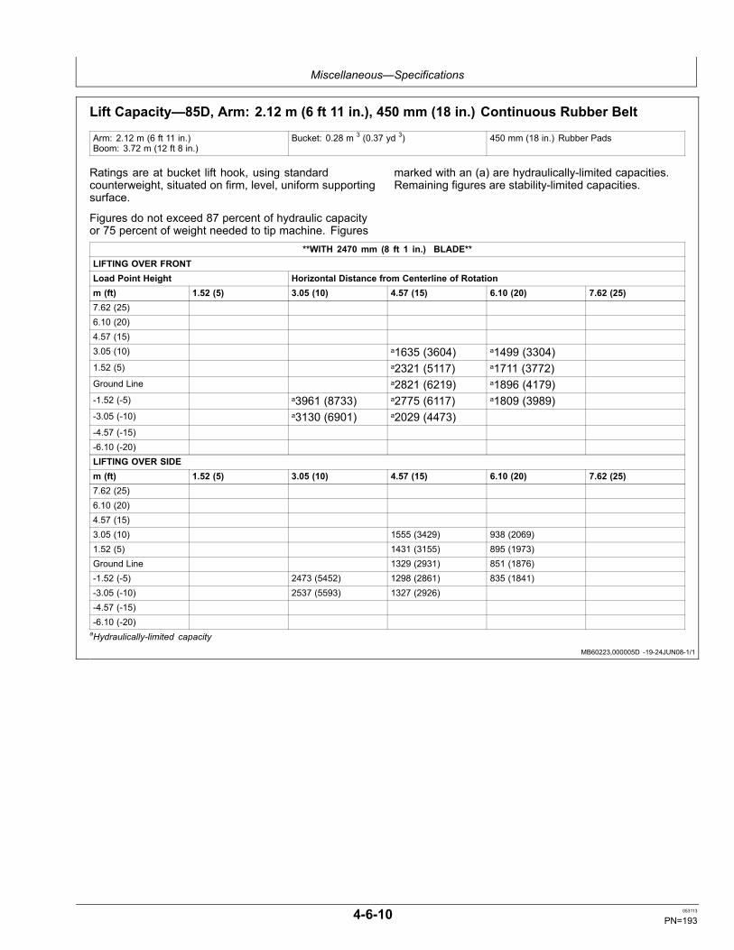
Miscellaneous—Specifications
MB60223,000005D -19-24JUN08-1/1
Lift Capacity—85D, Arm: 2.12 m (6 ft 11 in.), 450 mm (18 in.) Continuous Rubber Belt
Arm: 2.12 m (6 ft 11 in.)Boom: 3.72 m (12 ft 8 in.)
Bucket: 0.28 m 3 (0.37 yd 3) 450 mm (18 in.) Rubber Pads
Ratings are at bucket lift hook, using standardcounterweight, situated on firm, level, uniform supportingsurface.
Figures do not exceed 87 percent of hydraulic capacityor 75 percent of weight needed to tip machine. Figures
marked with an (a) are hydraulically-limited capacities.Remaining figures are stability-limited capacities.
**WITH 2470 mm (8 ft 1 in.) BLADE**LIFTING OVER FRONTLoad Point Height Horizontal Distance from Centerline of Rotationm (ft) 1.52 (5) 3.05 (10) 4.57 (15) 6.10 (20) 7.62 (25)7.62 (25)6.10 (20)4.57 (15)3.05 (10) a1635 (3604) a1499 (3304)1.52 (5) a2321 (5117) a1711 (3772)Ground Line a2821 (6219) a1896 (4179)-1.52 (-5) a3961 (8733) a2775 (6117) a1809 (3989)-3.05 (-10) a3130 (6901) a2029 (4473)-4.57 (-15)-6.10 (-20)LIFTING OVER SIDEm (ft) 1.52 (5) 3.05 (10) 4.57 (15) 6.10 (20) 7.62 (25)7.62 (25)6.10 (20)4.57 (15)3.05 (10) 1555 (3429) 938 (2069)1.52 (5) 1431 (3155) 895 (1973)Ground Line 1329 (2931) 851 (1876)-1.52 (-5) 2473 (5452) 1298 (2861) 835 (1841)-3.05 (-10) 2537 (5593) 1327 (2926)-4.57 (-15)-6.10 (-20)aHydraulically-limited capacity
4-6-10 053113
PN=193

Miscellaneous—Specifications
4-6-11 053113
PN=194
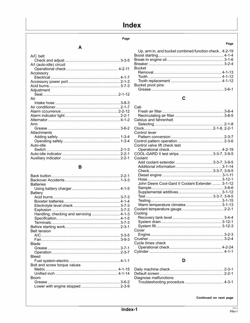
Index
Page
A
A/C beltCheck and adjust ................................................... 3-3-5
A/I (auto-idle) circuitOperational check................................................ 4-2-11
AccessoryElectrical ................................................................ 4-1-7
Accessory power port ................................................ 2-1-3Acid burns.................................................................. 3-7-3AdjustmentSeat...................................................................... 2-1-12
AirIntake hose ............................................................ 3-8-3
Air conditioner............................................................ 2-1-7Alarm cccurrence..................................................... 2-2-12Alarm indicator light ................................................... 2-2-1Alternator ................................................................... 4-1-2ArmGrease ................................................................... 3-6-2
AttachmentsAdding safely ......................................................... 1-3-4Operating safely..................................................... 1-3-4
Auto-idleSwitch .................................................................... 2-1-3
Auto-idle indicator...................................................... 2-2-1Auxiliary indicator ...................................................... 2-2-1
B
Back button................................................................ 2-2-1Backover Accidents ................................................... 1-3-3BatteriesUsing battery charger............................................. 4-1-5
BatteryAcid burns.............................................................. 3-7-3Booster batteries.................................................... 4-1-4Electrolyte level check ........................................... 3-7-3Explosion ............................................................... 3-7-3Handling, checking and servicing .......................... 4-1-3Specification........................................................... 4-1-5Terminals................................................................ 3-7-3
Before starting work................................................... 2-3-1Belt tensionA/C......................................................................... 3-3-5Fan......................................................................... 3-9-3
BladeGrease ................................................................... 3-7-1Operation ............................................................... 2-3-7
BleedFuel system-electric ............................................... 4-1-1
Bolt and screw torque valuesMetric ................................................................... 4-1-15Unified inch .......................................................... 4-1-14
BoomGrease ................................................................... 3-6-2Lower with engine stopped .................................... 2-3-9
Page
Up, arm in, and bucket combined function check.. 4-2-19Boost starting............................................................. 4-1-4Break-In engine oil..................................................... 3-1-6Breaker ...................................................................... 3-2-4BucketRemoval............................................................... 4-1-13Tooth .................................................................... 4-1-12Tooth replacement ............................................... 4-1-12
Bucket pivot pinsGrease ................................................................... 3-6-1
C
CabFresh air filter ......................................................... 3-8-4Recirculating air filter ............................................. 3-8-5
Celsius and fahrenheitSelecting ................................................................ 2-1-8
Clock................................................................2-1-8, 2-2-1Control leverPattern conversion................................................. 2-3-7
Control pattern operation........................................... 2-3-6Control valve lift check testOperational check................................................ 4-2-19
COOL-GARD II test strips ...............................3-3-7, 3-9-5CoolantAdd coolant extender ...................................3-3-7, 3-9-5Additional information .......................................... 3-1-14Check...........................................................3-3-7, 3-9-5Diesel engine ....................................................... 3-1-11Hose..................................................................... 3-12-1John Deere Cool-Gard II Coolant Extender ......... 3-1-12Sample................................................................... 3-8-6Supplemental additives........................................ 3-1-12Test ..............................................................3-3-7, 3-9-5Testing.................................................................. 3-1-15Warm temperature climates................................. 3-1-13
Coolant temperature gauge....................................... 2-2-1CoolingRecovery tank level................................................ 3-4-4System drain ........................................................ 3-12-1System fill............................................................. 3-12-3
CoverEngine.................................................................... 3-2-3
Crusher...................................................................... 3-2-4Cycle times checkOperational check................................................ 4-2-24
Cylinder ..................................................................... 4-1-1
D
Daily machine check.................................................. 2-3-1Default screen ........................................................... 2-2-1Diagnose malfunctionsTroubleshooting procedure .................................... 4-3-1
Continued on next page
Index-1 053113
PN=1
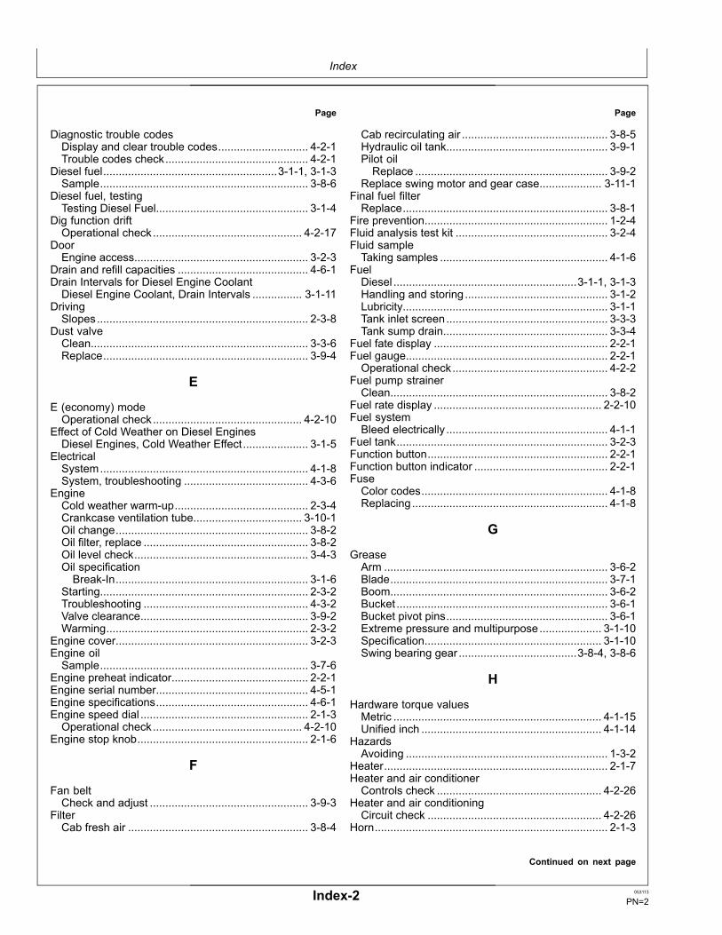
Index
Page
Diagnostic trouble codesDisplay and clear trouble codes............................. 4-2-1Trouble codes check.............................................. 4-2-1
Diesel fuel........................................................3-1-1, 3-1-3Sample................................................................... 3-8-6
Diesel fuel, testingTesting Diesel Fuel................................................. 3-1-4
Dig function driftOperational check................................................ 4-2-17
DoorEngine access........................................................ 3-2-3
Drain and refill capacities .......................................... 4-6-1Drain Intervals for Diesel Engine CoolantDiesel Engine Coolant, Drain Intervals ................ 3-1-11
DrivingSlopes.................................................................... 2-3-8
Dust valveClean...................................................................... 3-3-6Replace.................................................................. 3-9-4
E
E (economy) modeOperational check................................................ 4-2-10
Effect of Cold Weather on Diesel EnginesDiesel Engines, Cold Weather Effect..................... 3-1-5
ElectricalSystem................................................................... 4-1-8System, troubleshooting ........................................ 4-3-6
EngineCold weather warm-up........................................... 2-3-4Crankcase ventilation tube................................... 3-10-1Oil change.............................................................. 3-8-2Oil filter, replace ..................................................... 3-8-2Oil level check........................................................ 3-4-3Oil specificationBreak-In.............................................................. 3-1-6
Starting................................................................... 2-3-2Troubleshooting ..................................................... 4-3-2Valve clearance...................................................... 3-9-2Warming................................................................. 2-3-2
Engine cover.............................................................. 3-2-3Engine oilSample................................................................... 3-7-6
Engine preheat indicator............................................ 2-2-1Engine serial number................................................. 4-5-1Engine specifications................................................. 4-6-1Engine speed dial ...................................................... 2-1-3Operational check................................................ 4-2-10
Engine stop knob....................................................... 2-1-6
F
Fan beltCheck and adjust ................................................... 3-9-3
FilterCab fresh air .......................................................... 3-8-4
Page
Cab recirculating air ............................................... 3-8-5Hydraulic oil tank.................................................... 3-9-1Pilot oilReplace .............................................................. 3-9-2
Replace swing motor and gear case.................... 3-11-1Final fuel filterReplace.................................................................. 3-8-1
Fire prevention........................................................... 1-2-4Fluid analysis test kit ................................................. 3-2-4Fluid sampleTaking samples ...................................................... 4-1-6
FuelDiesel ...........................................................3-1-1, 3-1-3Handling and storing.............................................. 3-1-2Lubricity.................................................................. 3-1-1Tank inlet screen.................................................... 3-3-3Tank sump drain..................................................... 3-3-4
Fuel fate display ........................................................ 2-2-1Fuel gauge................................................................. 2-2-1Operational check.................................................. 4-2-2
Fuel pump strainerClean...................................................................... 3-8-2
Fuel rate display ...................................................... 2-2-10Fuel systemBleed electrically .................................................... 4-1-1
Fuel tank.................................................................... 3-2-3Function button.......................................................... 2-2-1Function button indicator ........................................... 2-2-1FuseColor codes............................................................ 4-1-8Replacing............................................................... 4-1-8
G
GreaseArm ........................................................................ 3-6-2Blade...................................................................... 3-7-1Boom...................................................................... 3-6-2Bucket .................................................................... 3-6-1Bucket pivot pins.................................................... 3-6-1Extreme pressure and multipurpose.................... 3-1-10Specification......................................................... 3-1-10Swing bearing gear ......................................3-8-4, 3-8-6
H
Hardware torque valuesMetric ................................................................... 4-1-15Unified inch .......................................................... 4-1-14
HazardsAvoiding ................................................................. 1-3-2
Heater........................................................................ 2-1-7Heater and air conditionerControls check ..................................................... 4-2-26
Heater and air conditioningCircuit check ........................................................ 4-2-26
Horn........................................................................... 2-1-3
Continued on next page
Index-2 053113
PN=2

Index
Page
Horn circuitOperational check.................................................. 4-2-2
HoseCoolant................................................................. 3-12-1
Hour meter.......................................................2-2-1, 3-2-1Operational check.................................................. 4-2-2
Hour meter button...................................................... 2-2-1HydraulicBreaker .................................................................. 3-2-4Oil level check........................................................ 3-4-1Oil specification...................................................... 3-1-9Replace filter .......................................................... 3-9-1Shutoff lever........................................................... 2-1-4Suction screen clean............................................ 3-11-2Sump drain............................................................. 3-7-1System troubleshooting ......................................... 4-3-8
Hydraulic oil tank pressurizationOperational check................................................ 4-2-14
Hydraulic pump serial number................................... 4-5-2Hydraulic tankOil change............................................................ 3-11-2
I
InjectionNozzle .................................................................... 4-1-1Pump...................................................................... 4-1-1
J
JDLink........................................................................ 4-1-7Jump starting............................................................. 4-1-4
K
Key switchSwitch off, engine off, checks ................................ 4-2-1Switch on, engine off, check .................................. 4-2-2Switch on, engine on, checks ................................ 4-2-7
Key Switch................................................................. 2-1-3
L
Language settings ................................................... 2-2-11LeverLeft control ............................................................. 2-3-6Pilot shutoff ............................................................ 2-1-4Right control........................................................... 2-3-6Steering.................................................................. 2-3-5
LeversLocation ................................................................. 2-1-1
Lift capacity....................................................4-6-5, 4-6-10Lifting......................................................................... 2-3-8Machine ............................................................... 2-3-12
Lifting objectsSpecial care ........................................................... 1-3-4
Page
Light circuitOperational check.................................................. 4-2-5
Lighter........................................................................ 2-1-3Lower boomWith engine stopped .............................................. 2-3-9
Lubricants, SafetySafety, Lubricants .................................................. 3-1-6
Lubricity of diesel fuel ................................................ 3-1-1
M
MachineClean regularly....................................................... 4-1-7Lifting ................................................................... 2-3-12Towing.................................................................. 2-3-12
Machine modificationsAvoid ...................................................................... 1-2-2
Machine movementUnintended............................................................. 1-3-1
Machine specifications .............................................. 4-6-2Machine tip overAvoiding ................................................................. 1-3-3
Machine working ranges............................................ 4-6-4Machine,inspect......................................................... 1-2-2Main menu................................................................. 2-2-4MaintenanceMachine position .................................................... 3-2-2Schedule and record.............................................. 3-2-5
Maintenance settings................................................. 2-2-6Menu button............................................................... 2-2-1Metric bolt and screw torque values ........................ 4-1-15Monitor....................................................................... 2-2-1Alarm indicator light ............................................... 2-2-1Alarm occurrence................................................. 2-2-12Auto-idle indicator .................................................. 2-2-1Auxililary indicator .................................................. 2-2-1Back button............................................................ 2-2-1Clock...................................................................... 2-2-1Coolant temperature gauge ................................... 2-2-1Default screen........................................................ 2-2-1Engine preheat indicator ........................................ 2-2-1Fuel gauge............................................................. 2-2-1Fuel rate display.........................................2-2-1, 2-2-10Function button ...................................................... 2-2-1Function button indicator........................................ 2-2-1Functions ............................................................... 2-2-2Gauges and battery disconnect relay checks ........ 4-2-4Hour meter ............................................................. 2-2-1Hour meter button.................................................. 2-2-1Language settings................................................ 2-2-11Main menu ............................................................. 2-2-4Maintenance settings............................................. 2-2-6Menu button........................................................... 2-2-1Monitor and gauge circuit checks .......................... 4-2-8Operating conditions.............................................. 2-2-5Return to default screen button.............................. 2-2-1Scheduled maintenance ........................................ 2-2-8Select button.......................................................... 2-2-1
Continued on next page
Index-3 053113
PN=3
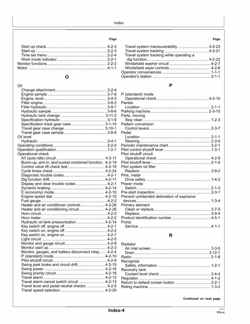
Index
Page
Start up check........................................................ 4-2-3Start-up .................................................................. 2-2-3Time set menu ....................................................... 2-2-4Work mode indicator .............................................. 2-2-1
Monitor functions ....................................................... 2-2-2Motor ......................................................................... 4-1-1
O
OilChange attachment................................................ 3-2-4Engine sample ....................................................... 3-7-6Engine, level .......................................................... 3-4-3Filter engine ........................................................... 3-8-2Filter hydraulic........................................................ 3-9-1Hydraulic sample ................................................... 3-8-6Hydraulic tank change ......................................... 3-11-2Specification hydraulic ........................................... 3-1-9Specification track gear case............................... 3-1-10Travel gear case change ..................................... 3-10-1Travel gear case sample........................................ 3-8-6
Oil levelHydraulic ................................................................ 3-4-1
Operating conditions.................................................. 2-2-5Operation qualification............................................... 1-2-1Operational checkA/I (auto-idle) circuit ............................................. 4-2-11Boom up, arm in, and bucket combined function.. 4-2-19Control valve lift check test .................................. 4-2-19Cycle times check................................................ 4-2-24Diagnostic trouble codes........................................ 4-2-1Dig function drift ................................................... 4-2-17Display and clear trouble codes............................. 4-2-1Dynamic braking .................................................. 4-2-14E (economy) mode............................................... 4-2-10Engine speed dial ................................................ 4-2-10Fuel gauge............................................................. 4-2-2Heater and air conditioner controls ...................... 4-2-26Heater and air conditioning circuit........................ 4-2-26Horn circuit............................................................. 4-2-2Hour meter ............................................................. 4-2-2Hydraulic oil tank pressurization .......................... 4-2-14Key switch off, engine off ....................................... 4-2-1Key switch on, engine off ....................................... 4-2-2Key switch on, engine on....................................... 4-2-7Light circuit............................................................. 4-2-5Monitor and gauge circuit....................................... 4-2-8Monitor start up...................................................... 4-2-3Monitor, gauges, and battery disconnect relay ...... 4-2-4P (standard) mode ............................................... 4-2-10Pilot shutoff circuit.................................................. 4-2-9Swing park brake and circuit drift......................... 4-2-15Swing power ........................................................ 4-2-16Swing priority circuit ............................................. 4-2-18Travel alarm ......................................................... 4-2-12Travel alarm cancel switch circuit ........................ 4-2-13Travel lever and pedal neutral checks ................... 4-2-5Travel speed selection ......................................... 4-2-20
Page
Travel system maneuverability ............................ 4-2-23Travel system tracking ......................................... 4-2-21Travel system tracking while operating adig function......................................................... 4-2-22Windshield washer circuit ...................................... 4-2-7Windshield wiper controls ...................................... 4-2-6
Operator conveniences ............................................. 1-1-1Operator's station ...................................................... 2-1-1
P
P (standard) modeOperational check................................................ 4-2-10
PanelsLocation ................................................................. 2-1-1
Parking machine...................................................... 2-3-10Parts, movingStay clear ............................................................... 1-2-3
Pattern conversionControl levers......................................................... 2-3-7
PedalLocation ................................................................. 2-1-1Steering.................................................................. 2-3-5
Periodic maintenance chart ....................................... 3-2-1Pilot control shutoff lever ........................................... 1-3-1Pilot shutoff circuitOperational check.................................................. 4-2-9
Pilot shutoff lever ....................................................... 2-1-4Pilot system oil filterReplace.................................................................. 3-9-2
Pins, metalDrive safely ............................................................ 1-4-2
Power modeSwitch .................................................................... 2-1-3
Pre-start inspection.................................................... 2-3-1Prevent unintended detonation of explosivedevices..................................................................... 1-3-4Primary elementClean or replace..................................................... 3-7-5Replace.................................................................. 3-9-4
Product identification number .................................... 4-5-1PumpService................................................................... 4-1-1
R
RadiatorAir inlet screen ....................................................... 3-3-5Drain .................................................................... 3-12-1
Radio ......................................................................... 2-1-8RecognizeSafety, information ................................................. 1-2-1
Recovery tankCoolant level check................................................ 3-4-4
Regulator ................................................................... 4-1-2Return to default screen button ................................. 2-2-1Riding machine.......................................................... 1-3-2
Continued on next page
Index-4 053113
PN=4
Index
Page
Right enableSwitch .................................................................... 2-1-5
Rubber trackCheck sag.............................................................. 3-3-1
S
SafetyAdd cab guarding for special uses...............1-2-1, 1-2-2Clean debris from machine.................................... 1-2-6Operator's seat ...................................................... 1-3-1Protective equipment ............................................. 1-2-2
Safety features .......................................................... 1-1-1Safety signs............................................................... 1-5-1Safety, Avoid High-Pressure FluidsAvoid High-Pressure Fluids ................................... 1-2-3
Safety, informationRecognize.............................................................. 1-2-1
Sample portsFluid sample........................................................... 4-1-6
Scheduled maintenance............................................ 2-2-8ScreenRadiator air inlet..................................................... 3-3-5
SeatAdjustment ........................................................... 2-1-12
Secondary element (if equipped)Replace.................................................................. 3-9-4
Secondary exitWindow ................................................................ 2-1-10
Secondary exit tool .................................................... 2-1-9Select button.............................................................. 2-2-1Selecting displayCelius and fahrenheit ............................................. 2-1-8
Serial numberEngine.................................................................... 4-5-1Hydraulic pump...................................................... 4-5-2Swing motor ........................................................... 4-5-2Travel motor........................................................... 4-5-1
Set time ..................................................................... 2-2-4ShoeCap screw inspection...................................3-5-1, 3-7-6
SignsSafety..................................................................... 1-5-1
SlopesDriving up............................................................... 2-3-8
SpecificationEngine.................................................................... 4-6-1Fuel tank ................................................................ 3-2-3Grease ................................................................. 3-1-10Hardware torque .................................................. 4-1-13Hydraulic oil ........................................................... 3-1-9Travel gear case oil.............................................. 3-1-10
Starting engine .......................................................... 2-3-2SteeringMachine ................................................................. 2-3-5
StepsUse correctlyHandholds .......................................................... 1-3-1
Page
StorageMachine ................................................................. 4-4-1Monthly .................................................................. 4-4-2
Storing fuel ................................................................ 3-1-2Suction screenClean.................................................................... 3-11-2
SwingArea cleaning......................................................... 2-3-8Dynamic braking check........................................ 4-2-14Park brake and circuit drift check......................... 4-2-15Power check ........................................................ 4-2-16Priority circuit check ............................................. 4-2-18
Swing bearing gearGrease .........................................................3-8-4, 3-8-6
Swing motor and gear case filterReplace................................................................ 3-11-1
Swing motor serial number........................................ 4-5-2SwitchAuto-idle................................................................. 2-1-3E (economy) mode................................................. 2-1-3Horn ....................................................................... 2-1-3Key......................................................................... 2-1-3P (standard) mode ................................................. 2-1-3Power mode........................................................... 2-1-3Right enable........................................................... 2-1-5Travel alarm cancel................................................ 2-1-5Travel mode ........................................................... 2-1-3Windshield washer................................................. 2-1-3Windshield wiper.................................................... 2-1-3Work light ............................................................... 2-1-3
Switch panel .............................................................. 2-1-2Functions ............................................................... 2-1-3
T
Time set menu........................................................... 2-2-4Tip overAvoiding ................................................................. 1-3-3
ToolSecondary exit ....................................................... 2-1-9
Torque chartsMetric ................................................................... 4-1-15Unified inch .......................................................... 4-1-14
Towing machine....................................................... 2-3-12TrackSag....................................................................... 4-1-13Sag check .............................................................. 3-3-1Shoe, cap screw torque ...............................3-5-1, 3-7-6
TransportLoading machine.................................................. 2-3-11Unloading machine .............................................. 2-3-11
TravelAlarm cancel switch circuit check ........................ 4-2-13Alarm check ......................................................... 4-2-12Gear case oil specification ................................... 3-1-10Lever and pedal neutral checks............................. 4-2-5Speed selection check......................................... 4-2-20System maneuverability check ............................ 4-2-23
Continued on next page
Index-5 053113
PN=5
Index
Page
System tracking check......................................... 4-2-21System tracking checks while operating adig function......................................................... 4-2-22
Travel alarm............................................................... 2-1-5Cancel switch......................................................... 2-1-5
Travel gear caseOil change............................................................ 3-10-1Oil level .................................................................. 3-7-2
Travel modeSwitch .................................................................... 2-1-3
Travel motor serial numbers...................................... 4-5-1TroubleshootingElectrical system.................................................... 4-3-6Engine.................................................................... 4-3-2Hydraulic system.................................................... 4-3-8
Troubleshooting procedure........................................ 4-3-1
U
Unified inch bolt and screw torque values ............... 4-1-14
V
ValveControl ................................................................... 4-1-1
Page
W
WarrantyNon-road emission control warranty statement .......... -3Off-road emissions control warranty statement .......... -5
Water separatorDrain ...................................................................... 3-3-4
Water separator elementReplace.................................................................. 3-8-1
Welding...................................................................... 4-1-6Welding repairs.......................................................... 1-4-2WindowCab ...................................................................... 2-1-11Lower front ........................................................... 2-1-11Secondary exit ..................................................... 2-1-10
WindshieldWasher circuit check.............................................. 4-2-7Washer fluid ........................................................... 3-3-6Washer switch........................................................ 2-1-3Wiper controls check.............................................. 4-2-6Wiper switch........................................................... 2-1-3
Work lightSwitch .................................................................... 2-1-3
Work mode indicator.................................................. 2-2-1Work site hazardsAvoid ...................................................................... 1-3-2
Index-6 053113
PN=6

Index
Index-7 053113
PN=7

Index
Index-8 053113
PN=8