
Service Guide 55V4 MINI EXCAVATOR - Kattrak
277
Service Guide for 55V4 MINI EXCAVATOR
-
Upload
khangminh22 -
Category
Documents
-
view
0 -
download
0
Transcript of Service Guide 55V4 MINI EXCAVATOR - Kattrak

ServiceGuide
for
55V4
MINI EXCAVATOR

Introduction
● This service guide covers check, adjustment, and maintenance of main parts on this machine.
● Chapter A describes the necessary numeric values and information for maintenance covered throughout the manual.
● Chapter B describes measurement, maintenance, adjustment required for troubleshooting and check.
● Chapter C describes installation of optional features and other items.
● For engine check, adjustment, and maintenance, please refer to the separate “Engine Maintenance Man-ual”.
○ Audience of this manual is those who have basic skills and knowledge on hydraulic shovels. Other people without such skills and knowledge may not be able to achieve maintenance according to this manual.
○ It is prohibited to transfer or sell this manual to any third party or prepare copies.

How to Use This Manual
This document uses a form of loose-leaf to support machine improvements and maintenance techniques that evolve day by day. Sequential issue of revisions and additional items allows for always providing the latest maintenance information.
Page Organization
1
A1-01 Precautions on Check and Maintenance 55V4Note:
Note column
Item name
Page No.Management No.
Model nameItem No.
027A1010-00/
Item No.: A 1 - 0 1 *Chapter Sequential No. Variation of the item (None for the first, then A, B, C...)Section
Management No.: 0 2 7 A 1 0 1 0 - 0 0Chapter Section Variation of the item (0 for the first, then A, B, C...)Item no.
Revision number of the itemModel
Page No.: Page for each item
Note column: The applicable machine number, specifications, and other precautions are entered.It is provided on the first page only as required.

How to Use This Manual
How to Issue Revisions/Additions
For this manual, additions/revisions are issued for each item.
Revisions are limited to the cases below.• Correction of incorrect characters, sentences, contents, etc.• Addition to description, etc.
If description or instructions do not match the work contents as a result of design changes, new items are ad-ditionally issued.In this case, the original item is followed by A, B, C… as a sequential code for easy understanding.The target machine number, specifications, etc. are entered in the Note column.
For items in and after Contents, a revision of Contents will be issued for both revision and addition. As a re-sult, you can check the latest manual by viewing Contents.For whether Contents are the latest version, advise with Customer Support Department, Documents Group about the revision number of the Contents management number.
Contents management number 0 2 7 0 0 0 0 0 - 0 0
Revision No.

02700000−00 /1
55V4Contents
Item No. Revision No.
A Maintenance Information
1 General Information
Precautions on Check and Maintenance · · · · · · · · · · · · · · · · · · A1 - 01 0Precautions on Cold Season · · · · · · · · · · · · · · · · · · · · · · · · · · · A1 - 02 0Precautions on Long-time Storage · · · · · · · · · · · · · · · · · · · · · · · A1 - 03 0Unit Symbols · · · · · · · · · · · · · · · · · · · · · · · · · · · · · · · · · · · · · · · A1 - 04 0
2 Machine Body Information
Serial Number (Machine and Engine) · · · · · · · · · · · · · · · · · · · · · A2 - 01 0Part Names · · · · · · · · · · · · · · · · · · · · · · · · · · · · · · · · · · · · · · · · · A2 - 02 0Specifications · · · · · · · · · · · · · · · · · · · · · · · · · · · · · · · · · · · · · · · A2 - 03 0Main Dimensions · · · · · · · · · · · · · · · · · · · · · · · · · · · · · · · · · · · · A2 - 04 0Work Range · · · · · · · · · · · · · · · · · · · · · · · · · · · · · · · · · · · · · · · · A2 - 05 0Weight Breakdown · · · · · · · · · · · · · · · · · · · · · · · · · · · · · · · · · · · A2 - 06 0Oil/Grease, Fuel, Coolant · · · · · · · · · · · · · · · · · · · · · · · · · · · · · · A2 - 07 0Tightening Torque · · · · · · · · · · · · · · · · · · · · · · · · · · · · · · · · · · · · A2 - 08 0Paint Data · · · · · · · · · · · · · · · · · · · · · · · · · · · · · · · · · · · · · · · · · · A2 - 09 0Attachment Data · · · · · · · · · · · · · · · · · · · · · · · · · · · · · · · · · · · · · A2 - 10 0Lifting Capacity · · · · · · · · · · · · · · · · · · · · · · · · · · · · · · · · · · · · · · A2 - 11 0
Note:
55V4
02600000−00 /2
Contents Item No. Revision No.
3 Component Information (Hydraulic Components)
Hydraulic Pump · · · · · · · · · · · · · · · · · · · · · · · · · · · · · · · · · · · · · A3 - 01 0Control Valve · · · · · · · · · · · · · · · · · · · · · · · · · · · · · · · · · · · · · · · A3 - 02 0Swing Motor · · · · · · · · · · · · · · · · · · · · · · · · · · · · · · · · · · · · · · · · A3 - 03 0Travel Motor · · · · · · · · · · · · · · · · · · · · · · · · · · · · · · · · · · · · · · · · A3 - 04 0Cylinder · · · · · · · · · · · · · · · · · · · · · · · · · · · · · · · · · · · · · · · · · · · ·A3 - 05 0Rotary Joint · · · · · · · · · · · · · · · · · · · · · · · · · · · · · · · · · · · · · · · · A3 - 06 0Remote Control Valve · · · · · · · · · · · · · · · · · · · · · · · · · · · · · · · · · ·A3 - 07 0
4 Equipment Information (Other Than Hydraulic Equipment)
Crawler · · · · · · · · · · · · · · · · · · · · · · · · · · · · · · · · · · · · · · · · · · · · A4 - 01 0Idler · · · · · · · · · · · · · · · · · · · · · · · · · · · · · · · · · · · · · · · · · · · · · · · A4 - 02 0Lower Roller · · · · · · · · · · · · · · · · · · · · · · · · · · · · · · · · · · · · · · · · A4 - 03 0Upper Roller · · · · · · · · · · · · · · · · · · · · · · · · · · · · · · · · · · · · · · · · A4 - 04 0Crawler Shoe Tension Adjusting Device · · · · · · · · · · · · · · · · · · · A4 - 05 0OK Monitor · · · · · · · · · · · · · · · · · · · · · · · · · · · · · · · · · · · · · · · · · A4 - 06 0
5 Circuit Diagram
Hydraulic Circuit Diagram · · · · · · · · · · · · · · · · · · · · · · · · · · · · · · A5 - 01 0Electrical Wiring Diagram/Wire Harness · · · · · · · · · · · · · · · · · · A5 - 02 0

02700000−00 /3
55V4Contents Item No. Revision No.
B Check and Maintenance
1 General Maintenance
List of Check/Maintenance Parts · · · · · · · · · · · · · · · · · · · · · · · · B1 - 01 0Periodic Check Table · · · · · · · · · · · · · · · · · · · · · · · · · · · · · · · · · B1 - 02 0Periodically Replaceable Parts · · · · · · · · · · · · · · · · · · · · · · · · · · B1 - 03 0Performance Measurement · · · · · · · · · · · · · · · · · · · · · · · · · · · · B1 - 04 0Performance Check Criteria/Permissible Value · · · · · · · · · · · · · B1 - 05 0Hydraulic Measurement and Adjustment · · · · · · · · · · · · · · · · · · B1 - 06 0Consumable Parts and Use Limitation · · · · · · · · · · · · · · · · · · · · B1 - 07 0
2 Maintenance Method
Crawler Check/Adjustment · · · · · · · · · · · · · · · · · · · · · · · · · · · · · B2 - 01 0Bucket Tooth Check and Replacement · · · · · · · · · · · · · · · · · · · · B2 - 02 0Bucket Mounting Clearance Check and Adjustment · · · · · · · · · · B2 - 03 0Greasing · · · · · · · · · · · · · · · · · · · · · · · · · · · · · · · · · · · · · · · · · · · B2 - 04 0Hydraulic Oil Check, Refilling, Replacement, and Strainer Washing · · · · · · · · · · · · · · · · · · · · · · · · · · · · · · · · · B2 - 05 0Return Filter Cartridge Replacement · · · · · · · · · · · · · · · · · · · · · B2 - 06 0Travel Reduction Gear Oil Check, Refilling, and Replacement · · B2 - 07 0Battery Check, Electrolyte Refilling and Replacement · · · · · · · · B2 - 08 0Fuel Circuit Check, Cleaning, and Filter Replacement · · · · · · · · B2 - 09 0Coolant Check, Refilling, and Replacement · · · · · · · · · · · · · · · · B2 - 10 0Engine Oil Check, Refilling, Replacement, and Filter Replacement · · · · · · · · · · · · · · · · · · · · · · · · · · · · · · · · B2 - 11 0Air Cleaner Check, Cleaning, and Element Replacement · · · · · · B2 - 12 0Fan Belt Check, Adjustment, and Replacement · · · · · · · · · · · · · B2 - 13 0Fuse Replacement · · · · · · · · · · · · · · · · · · · · · · · · · · · · · · · · · · · B2 - 14 0Radiator Fin and Oil Cooler Fin Check and Adjustment · · · · · · · B2 - 15 0Lever Pattern Change · · · · · · · · · · · · · · · · · · · · · · · · · · · · · · · · · · B2 - 16 0
3 Disassembly/Assembly
Swing Motor Disassembly/Assembly · · · · · · · · · · · · · · · · · · · · · B3 - 01 0Travel Remote Control Valve Disassembly/Assembly · · · · · · · · · B3 - 02 0
C OptionAuxiliary Piping · · · · · · · · · · · · · · · · · · · · · · · · · · · · · · · · · · · · · · C1 - 01 0

A1 General Information

027A1010−00 /1
55V4A1-01 Precautions on Check and Maintenance
■ Understand the check/maintenance method!Before starting check/maintenance, read and understand “Check/Maintenance Section” care-fully. Paying attention to safety, perform check/maintenance.
■ Do not perform maintenance for the moving machine.To prevent from being crushed or caught, lower the bucket on the ground and stop the engine. If the work is required inevitably, keep full contact with the operator.
■ Perform check/maintenance on a flat ground.If the machine is operated on a slope, turn and running may be activated by the dead weight and personnel may be caught. On a rigid and flat ground, lower the working devices such as bucket on the ground.
■ Maintenance under the machineSimple jack-up of the working machine may cause the main body to catch personal body. Use supports and blocks under the crawler to secure the space.
DangerOperation
ban
■ Indication of check/maintenancePost a “Check/maintenance” warning plate on a visible position of the door or operating lever so that other people will not touch the machine in-advertently.
During
the i
nspe
ction
and m
ainten
ance
Opera
tion
ban
■ Holding the working machineRemoval of the hydraulic hose or pin removal for repair while the working machine is up may result in a dangerous state such as oil jetting out or fall of the working machine. Be sure to lower the working machine on the ground or support the machine with safety supports or blocks.

55V4
027A1010−00 /2
A1-01 Precautions on Check and Maintenance
■ Do not perform maintenance while the en-gine is running.Touching the rotating or moving part such as the fan belt may catch or cut personal body. Be sure to stop the engine.
■ Relieve the internal pressure from the hy-draulic system before maintenance.If the pipe or hose is removed without removing the internal pressure from the hydraulic system, the pressurized oil may jet out. Before starting the work, relieve the internal pressure.
■ The engine is hot after the machine stops.Do not touch the engine or muffler immediately after the machine stops. Each part is hot and therefore a burn may be caused. After each part is cooled down, start check/maintenance.
■ Precautions on shoe tension adjustment• Since a high pressure is provided in the shoe
adjusting device, grease or valve may jet out of the supply port and this is dangerous unless the maintenance procedure is followed.
• When loosening the shoe tension, do not put your face, hand, leg, or body in front of the valve.
■ Do not open the radiator cap when it is hot.If the cap is removed when the radiator water temperature is high, hot steam may jet out and a burn may be caused. Therefore, do not open the cap. After the water temperature drops, loosen the radiator cap slowly to reduce the pressure.
■ Handling of battery, etc.• Before maintenance of the electrical system or
welding, remove the (-) terminal of the battery.
• The battery generates combustible gas and ig-nition/explosion may be caused. Since diluted sulfuric acid is used as the battery liquid, spe-cial care must be taken to handling.

027A1010−00 /3
55V4A1-01 Precautions on Check and Maintenance
■ Precautions on high-pressure oilHigh-pressure jetted out oil sticking on your skin or coming in your eyes is dangerous.
If the oil sticks to your skin, medical treatment is required immediately.
■ Precautions on fire• Do not put fire close upon fuel refilling.• Stop the engine before fuel refilling.• Do not put fire close when you are using light
oil for washing parts.
■ Use of protectorsDuring the grinding work or pin or tooth removal work, chips may come in your eyes and injury may be caused. Wear the protection glasses and protection helmet for the work.
■ Precautions on maintenance at a high place• Do not climb on the boom of the working ma-
chine because the step position is bad and you may fall.
• Use the stepladder, stool, etc. for the work.
55V4
027A1010−00 /4
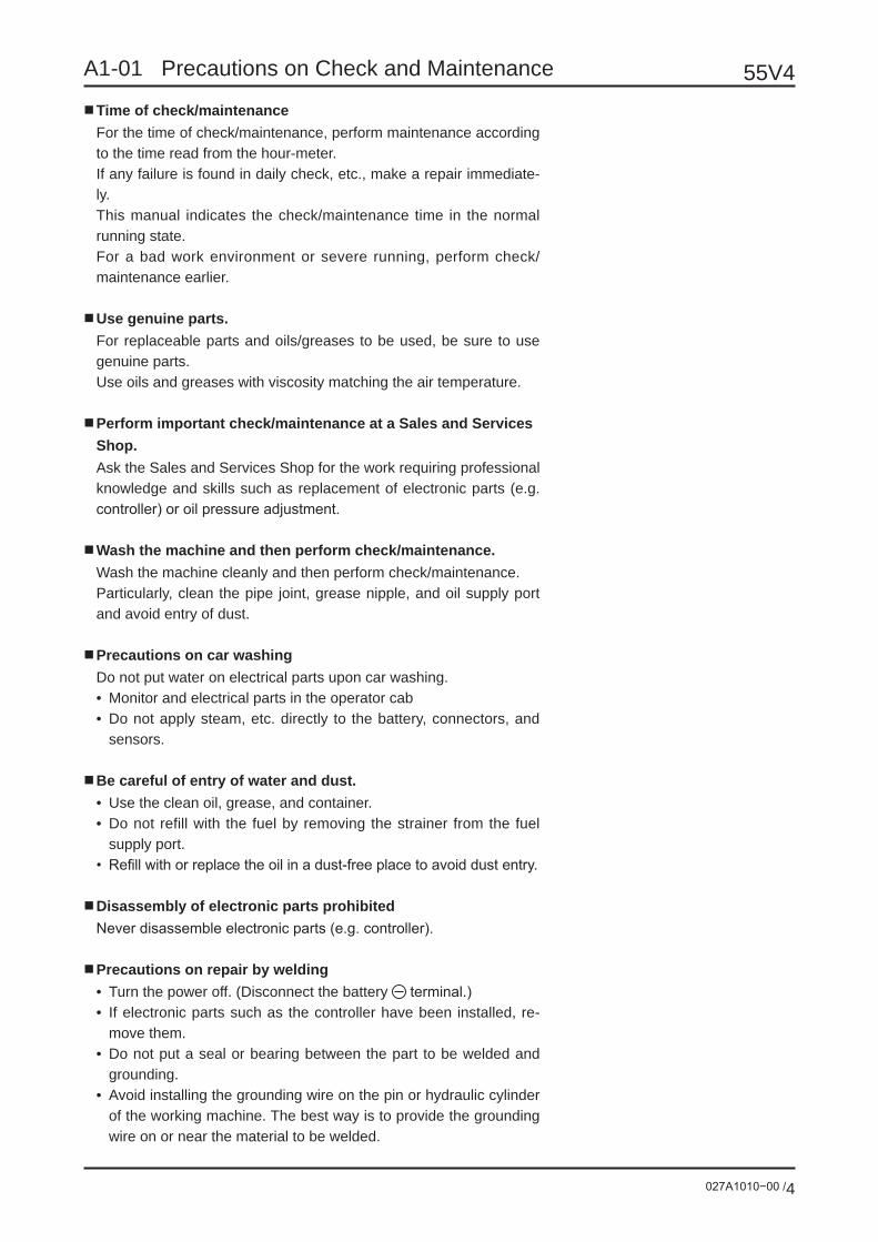
A1-01 Precautions on Check and Maintenance
■ Time of check/maintenanceFor the time of check/maintenance, perform maintenance according to the time read from the hour-meter.If any failure is found in daily check, etc., make a repair immediate-ly.This manual indicates the check/maintenance time in the normal running state.For a bad work environment or severe running, perform check/maintenance earlier.
■ Use genuine parts.For replaceable parts and oils/greases to be used, be sure to use genuine parts.Use oils and greases with viscosity matching the air temperature.
■ Perform important check/maintenance at a Sales and Services Shop.Ask the Sales and Services Shop for the work requiring professional knowledge and skills such as replacement of electronic parts (e.g. controller) or oil pressure adjustment.
■ Wash the machine and then perform check/maintenance.Wash the machine cleanly and then perform check/maintenance.Particularly, clean the pipe joint, grease nipple, and oil supply port and avoid entry of dust.
■ Precautions on car washingDo not put water on electrical parts upon car washing.• Monitor and electrical parts in the operator cab• Do not apply steam, etc. directly to the battery, connectors, and
sensors.
■ Be careful of entry of water and dust.• Use the clean oil, grease, and container.• Do not refill with the fuel by removing the strainer from the fuel
supply port.• Refill with or replace the oil in a dust-free place to avoid dust entry.
■ Disassembly of electronic parts prohibitedNever disassemble electronic parts (e.g. controller).
■ Precautions on repair by welding• Turn the power off. (Disconnect the battery terminal.)• If electronic parts such as the controller have been installed, re-
move them.• Do not put a seal or bearing between the part to be welded and
grounding.• Avoid installing the grounding wire on the pin or hydraulic cylinder
of the working machine. The best way is to provide the grounding wire on or near the material to be welded.

027A1020−00 /1
55V4A1-02 Precautions on Cold Season
If the air temperature drops, a starting trouble or freezing of the cool-ant may occur. Prepare for the cold season as described below.
■ FuelIn winter season, the fuel may be frozen and starting the engine may be difficult in cold districts. Use the fuel (light oil) matching the air temperature.Light oil freezing temperature (according to JIS K2204)
Type of light oil Freezing temperature RemarksNo.1 -5°C or lower
General useNo.2 -10°C or lowerNo.3 -20°C or lower
Cold districtsSpecial No.3 -30°C or lower
■ CoolantThis machine is shipped from the factory by mixing the long-life coolant (LLC) upon shipping (Density: 50%). The freczing tempera-ture is -35°C.Replace the long-life coolant every 2 years (in autumn of the sec-ond year).
■ Lubrication oils/greasesReplace the engine oil and hydraulic oil with the ones with viscosity matching the outer air temperature. For the specified viscosity, see “A2-07 Oil/Grease, Fuel, Coolant”.
■ BatteryIn the cold season, the current discharged at the start is high and the battery capability is degraded. In the state close to discharge, the battery liquid may be frozen. Set the state close to fully charged and pay attention to heat insulation for starting in the next morning. Refill with the distilled water immediately before starting to avoid freezing.
■ Post-work precautions• To prevent the hydraulic cylinder rod seal from being damaged,
remove mud and water from the cylinder rod.• To prevent chassis parts from being frozen, park the vehicle on a
dry, rigid ground or on plates put on the ground.• To prevent the fuel from being frozen, drain away water from the
water sedimentor.

027A1030−00 /1
55V4A1-03 Precautions on Long-time Storage
During long-time storage, keep the position as shown at right to prevent rust from being generated on the cylinder rod.
■ Before storage• Wash/clean each part.• Supply oil/grease or replace oil for each part.• Coat grease on the exposed part of the hydraulic cylinder piston
rod.• Store the machine indoors. If the machine is inevitably being left
outdoors, select a well-draining, well-ventilated place with less moisture. Put plates on the ground and cover the machine with vinyl sheet, etc.
• Remove the battery, charge it fully, and store it or remove the mi-nus terminal.
■ During storage
If rust-preventive operation is inevitably being performed indoors, open windows and entrances for ventilation to prevent gas poisoning.
• While the machine stops for a long time, run a series of opera-tions including traveling, swing, and working machine motions at a low speed after warming up once a month for rust prevention and lubrication.
• Before running the working machine, wipe off the grease coated on the hydraulic cylinder rod.
■ After storage• Supply oil/grease to each part. Check the coolant volume and re-
fill with the coolant if necessary.• Wipe off the grease coated on the hydraulic cylinder rod.• After the engine is started, repeat operations of traveling, swing,
and working machine operation several times after warming up for idling of each part.
Position for long-time storage
027A1040−00 /1
55V4A1-04 Unit Symbols
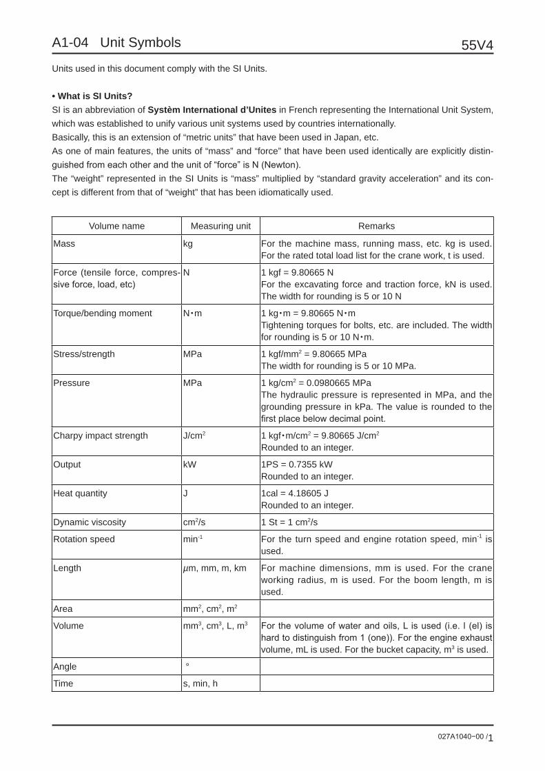
Volume name Measuring unit Remarks
Mass kg For the machine mass, running mass, etc. kg is used. For the rated total load list for the crane work, t is used.
Force (tensile force, compres-sive force, load, etc)
N 1 kgf = 9.80665 NFor the excavating force and traction force, kN is used. The width for rounding is 5 or 10 N
Torque/bending moment N・m 1 kg・m = 9.80665 N・mTightening torques for bolts, etc. are included. The width for rounding is 5 or 10 N・m.
Stress/strength MPa 1 kgf/mm2 = 9.80665 MPaThe width for rounding is 5 or 10 MPa.
Pressure MPa 1 kg/cm2 = 0.0980665 MPaThe hydraulic pressure is represented in MPa, and the grounding pressure in kPa. The value is rounded to the first place below decimal point.
Charpy impact strength J/cm2 1 kgf・m/cm2 = 9.80665 J/cm2
Rounded to an integer.
Output kW 1PS = 0.7355 kWRounded to an integer.
Heat quantity J 1cal = 4.18605 JRounded to an integer.
Dynamic viscosity cm2/s 1 St = 1 cm2/s
Rotation speed min-1 For the turn speed and engine rotation speed, min-1 is used.
Length µm, mm, m, km For machine dimensions, mm is used. For the crane working radius, m is used. For the boom length, m is used.
Area mm2, cm2, m2
Volume mm3, cm3, L, m3 For the volume of water and oils, L is used (i.e. l (el) is hard to distinguish from 1 (one)). For the engine exhaust volume, mL is used. For the bucket capacity, m3 is used.
Angle °
Time s, min, h
Units used in this document comply with the SI Units.
• What is SI Units?SI is an abbreviation of Systèm International d’Unites in French representing the International Unit System, which was established to unify various unit systems used by countries internationally.Basically, this is an extension of “metric units” that have been used in Japan, etc.As one of main features, the units of “mass” and “force” that have been used identically are explicitly distin-guished from each other and the unit of “force” is N (Newton).The “weight” represented in the SI Units is “mass” multiplied by “standard gravity acceleration” and its con-cept is different from that of “weight” that has been idiomatically used.

A2 Machine Body Information

027A2010−00 /1
55V4A2-01 Serial Number
• The check/maintenance method and parts may vary depending on the time of manufacture.• Before the start of maintenance or order placement of parts, be sure to confirm the serial number.• Serial numbers of this machine and the engine are marked on the positions shown below.
This machine
On “Complete machine marking plate”, the model and serial number are punched.
Engine
On “Engine nameplate”, the model and engine serial number are punched.
Engine nameplate
Complete machine marking plate

027A2020−00 /1
55V4A2-02 Part Names
Contents Page
1 Frame P2
2 Engine P3
3 Hydraulic Parts P4
4 Operation Equipment P6
5 Electrical Parts P7
6 Travel Equipment P10
55V4
027A2020−00 /2
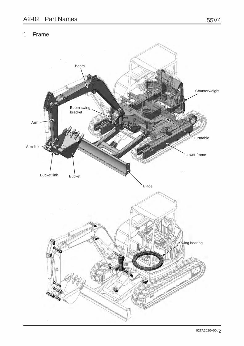
A2-02 Part Names
1 Frame
Boom
Counterweight
Turntable
Lower frame
Blade
BucketBucket link
Arm link
Arm
Boom swing bracket
Swing bearing

027A2020−00 /3
55V4A2-02 Part Names
2 Engine
Radiator
Fuel tank
Pump flange
Muffler
Air cleaner
Dust indicator
Fuel cooler
Fuel filter
Oil filter
Fuel pump
Water sedimentor
Reservoir tank

55V4
027A2020−00 /4
A2-02 Part Names
3 Hydraulic parts
Arm cylinder
Boom swing cylinderTravel motor (Right)
Swing motor
Travel motor (Left)
Rotary joint
Blade cylinder
Boom cylinder
Bucket cylinder
Hydraulic oil tank
Return filter
Oil cooler
Hydraulic pump
Control valve

027A2020−00 /5
55V4A2-02 Part Names
Remote control valve (Right)
Remote control valve (Left)
Remote control valve (Boom swing)
Remote control valve (Travel)
Remote control valve (Blade)

55V4
027A2020−00 /6
A2-02 Part Names
4 Operation equipment
OK monitor
Water temperature gauge
Fuel gauge
Hour meter
No use No use No use No use
Travel two-speed lamp
Engine alarm lamp
Glow lamp
Battery charge alarm lamp
Engine oil pressure alarm lamp
Coolant temperature alarm lamp
Auto-idling lamp
Water sedimentor alarm lamp
Gate lock alarm lamp
Operator’s Seat
Light Switch
Blade Lever
Remote controllever (Right)
OK moniter
Offset pedal Travel Lever (Right) Travel Lever (Left) Foot rest
Gate lock lever
Remote controllever (Left)
Eco mode lamp

027A2020−00 /7
55V4A2-02 Part Names
5 Electrical parts
General layout
Work lamp harness
Work lamp
Battery
Battery cable (minus)
Earth
Battery cable (plus)

55V4
027A2020−00 /8
A2-02 Part Names
Oil pressure switch
Throttle controller
Starter relay
Glow relayGlow timer relay Throttle motor
Fuel sensor
Controller self-hold relay
Engine earth cable
Starter
Alternator
Glow plug
Engine stop solenoid
Water temperature switch
Water temperatuer sensor
Horn
Travel two-speed solenoid
Lever lock solenoid
Main harness
Light harness connecting section
Console harnessconnecting section
Fusible linkWater sedimentor switch
Potentiometer
Flip-flop relay
Fuel pump
027A2020−00 /9
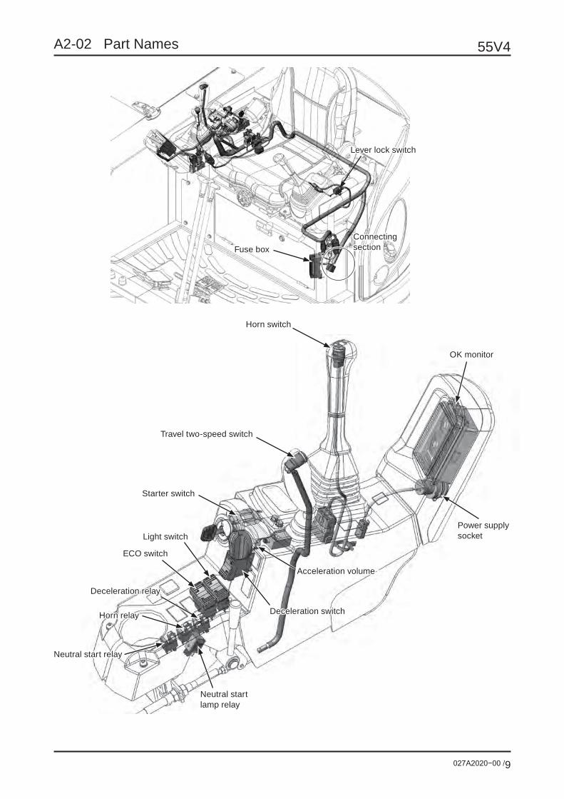
55V4A2-02 Part Names
Fuse box
OK monitor
Horn switch
Power supply socket
Travel two-speed switch
Starter switch
Light switch
Deceleration switch
Deceleration relay
Horn relay
Neutral start lamp relay
Neutral start relay
Lever lock switch
Connecting section
Acceleration volume
ECO switch

55V4
027A2020−00 /10
A2-02 Part Names
6 Travel equipment
Rubber crawler
Sprocket
Upper roller
Lower roller
Spring
Grease cylinder
Idler

027A2030−00 /1
55V4A2-03 Specifications
■ Speed and hil l-climbing abilitySwing speed 9.3 min-1
Travel speed (low/high) 2.9 / 4.6 km/hrHill-climbing ability 58% (30°)
■ EngineMaker KUBOTAName V2403-DI-EDM
Type Vertical water-cooled 4-cycle direct-injection type
Number of cylinders - diameter × stroke 4 –φ87mm × 102.4 mm Total exhaust volume 2.434 L
Rated output 32.4 kW / 2400 min-1
(44.1ps / 2400 rpm)DIN6271B
(31.2 kW / 2400 min-1)
Maximum torque 152 N•m / 1400 min-1
(15.5 kgf•m / 1400 rpm)
Fuel consumption (rated) 252 g / kW•h(185 g / psh)
Fuel tank capacity 66 LStarter 12 V – 2.0 kWBattery 12 V – 92 AH 95D31LAlternator 12 V – 40ALubricating oil quantity Max. 9.7 L Min. 3.0 L
Coolant capacity 10.1 L (only for engine itself 3.7 L)
■ MassTwo-post canopy
Four-post canopy Cab
Machine mass kg400mm Rubber shoe 4960 4990 5140400mm Steel shoe 5000 5030 5180
Machine body mass kg400mm Rubber shoe 3810 3840 3990400mm Steel shoe 3850 3880 4030
Average grounding pressure kPa
400mm Rubber shoe 29 29 30400mm Steel shoe 29 29 30
027A2040−00 /1
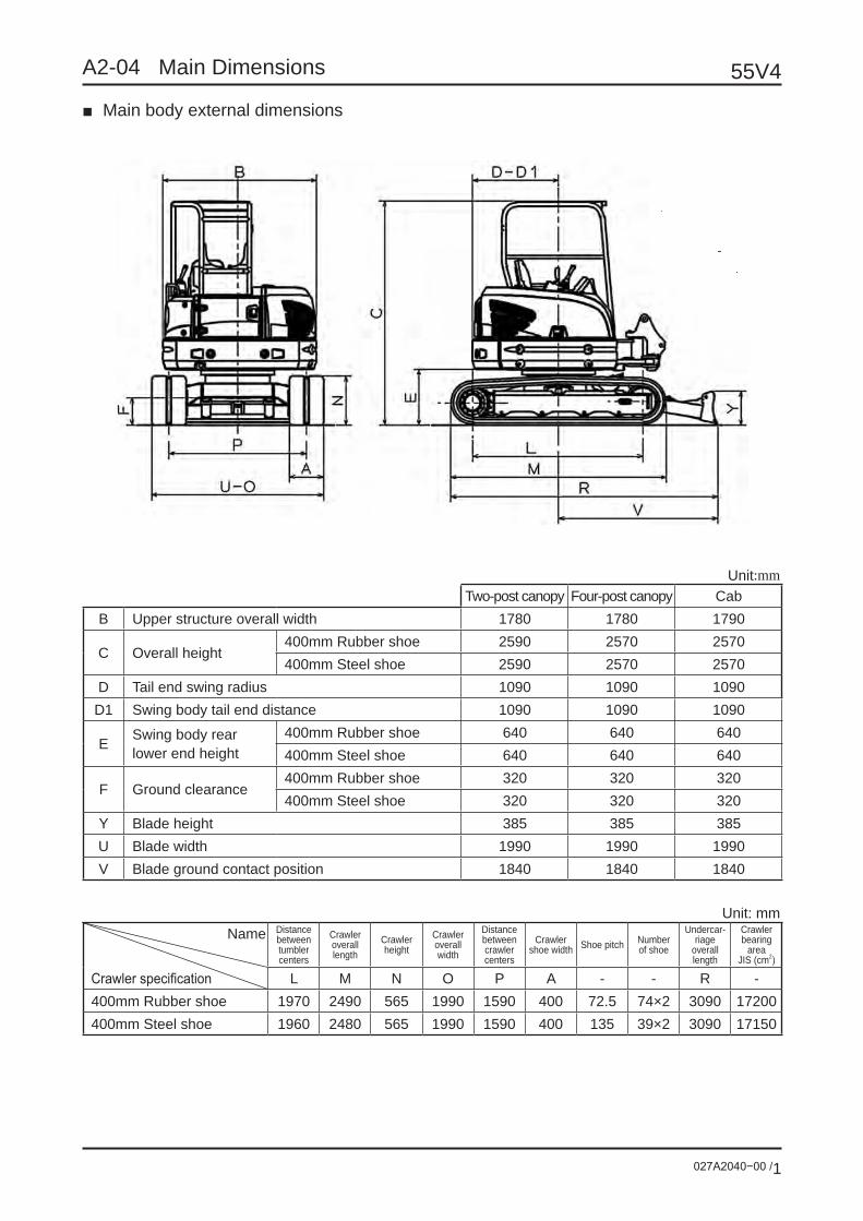
55V4A2-04 Main Dimensions
■ Main body external dimensions
Unit:mmTwo-post canopy Four-post canopy Cab
B Upper structure overall width 1780 1780 1790
C Overall height400mm Rubber shoe 2590 2570 2570400mm Steel shoe 2590 2570 2570
D Tail end swing radius 1090 1090 1090D1 Swing body tail end distance 1090 1090 1090
E Swing body rear lower end height
400mm Rubber shoe 640 640 640400mm Steel shoe 640 640 640
F Ground clearance400mm Rubber shoe 320 320 320400mm Steel shoe 320 320 320
Y Blade height 385 385 385U Blade width 1990 1990 1990V Blade ground contact position 1840 1840 1840
Unit: mmName Distance
between tumbler centers
Crawler overall length
Crawler height
Crawler overall width
Distance between crawler centers
Crawler shoe width Shoe pitch Number
of shoe
Undercar-riage
overall length
Crawler bearing
areaJIS (cm2)
Crawler specification L M N O P A - - R -400mm Rubber shoe 1970 2490 565 1990 1590 400 72.5 74×2 3090 17200400mm Steel shoe 1960 2480 565 1990 1590 400 135 39×2 3090 17150

55V4
027A2040−00 /2
A2-04 Main Dimensions
■ Dimensions upon transportation
Unit: mmTwo-post canopy
Four-post canopy Cab
Attachment specification Standard Standard StandardBucket capacity (m3) New JIS 0.16 0.16 0.16S1 Overall length (Blade in front) 5370 5370 5370S2 Overall length (Blade in rear) 5970 5970 5970
C Overall height400mm Rubber shoe 2590 2570 2570400mm Steel shoe 2590 2570 2570
W Overall width 1990 1990 1990

027A2050−00 /1
55V4A2-05 Work Range
(1) Standard/Long arm
When digging deep at the blade side, the boom cylinder sometimes interferes with the blade.
Unit: mmNo. Name Standard arm Long arm
Standard mounted bucket capacity (m3) New JIS 0.16 0.14A Maximum digging radius 5970 6200B Maximum floor level digging radius 5810 6050C Maximum digging depth (without blade) 3590 3830D Radius against maximum digging depth 2140 2120E Maximum digging height 5470 5610F Radius against maximum digging height 3560 3760G Maximum dump height 3820 3960H Radius against maximum dump height 3260 3460I Minimum dump height 1330 1080J Radius against minimum dump height 2210 2250K Maximum vertical digging depth 2690 2930L Radius against maximum vertical digging depth 4020 4080M Minimum floor level digging radius 1880 1770N Maximum digging distance with floor 4520 4760
OMinimum front swing radius 2420 2460
(Swing in right) 2100 2130(Swing in left) 2190 2230
P Height against minimum front swing radius 4200 4200Arm length 1600 1850
Boom length 2700 2700
Long arm
Standard arm

55V4
027A2050−00 /2
A2-05 Work Range
(2) Side groove digging work range
(Rig
ht s
win
g)
(Lef
t sw
ing)

027A2060−00 /1
55V4A2-06 Weight Breakdown
1. Mass upon transportationShoe/cab type Mass (kg)
Rubber shoe, four-post canopy 4990Steel shoe, four-post canopy 5030Rubber shoe, two-post canopy 4960Steel shoe, two-post canopy 5000Rubber shoe, cab 5140Steel shoe, cab 5180
2. Base machineShoe/cab type Mass (kg)
Rubber shoe, four-post canopy 4380Steel shoe, four-post canopy 4420Rubber shoe, two-post canopy 4350Steel shoe, two-post canopy 4390Rubber shoe, cab 4530Steel shoe, cab 4570
This mass is not the machine body mass but includes water, fuel, blade, etc.
3. Upper machineType Mass (kg)
Four-post canopy 2500Two-post canopy 2470Cab 2650
4. Lower machineType Mass (kg)
Rubber shoe 1880Steel shoe 1920
5. Hoe attachmentType Mass (kg)
Standard 610Long 630

027A2070−00 /1
55V4A2-07 Oil/Grease, Fuel, Coolant
1 List of oil, fuel, and coolant
* Depending on air temperature, follow the table.
Location Type GradeUse depending on air temperature
Required volume-30 -20 -10 0 10 20 30 40
1 Engine oil pan Engine oil API-CF Maximum : 9.7 LMinimum : 6.7 L
SAE10W-30
SAE15W-40
2 Hydraulic oil tank
Hydraulic
oilWear-
resistant
*Note 1Full system : 75 LTank level : 56 L
ISO-VG46
ISO-VG32
3 Travel reduction gear Gear oil API GL-4 0.9 L × 2SAE90
4 Front idler Engine oil API-CD 0.08 L × 2SAE30
5 Upper roller Engine oil API-CD 0.045 L × 2SAE30
6 Lower roller Engine oil API-CD 0.18 L × 8SAE30
7 Fuel tank Light oil JIS 66 L
JIS No.2
JIS No.3
JIS Special No.3
8 Cooling system Water LLC Long life coolant (LLC) added* Note 2
Engine : 3.7 LFull volume : 10.1 L
2 positions on right and left
8 positions on right and left 2 positions on
right and left
2 positions on right and left
2
7
3
56
4
8
1

55V4
027A2070−00 /2
A2-07 Oil/Grease, Fuel, Coolant
Note 1: The full system oil volume means that the hydraulic oil is supplied to the standard position on the hydraulic tank oil level gauge with the position shown in the figure.
Note 2: The mixed quantity should be 50%.
Lowest outer air temperature (°C) -35Mixing percentage (%) 50
Mixed volume (L)
Coolant (L) 5.0Water (L) 5.1
Coolant,Full volume: 10.1L
Engine body : 3.7L,Radiator, etc. : 5.6L,Tank : 0.8L
2 List of check/replacement cycle for oil, fuel, and coolant
1 Engine oil pan Engine oil Check and refill every day. Replace 50 hours after the initial use and then replace every 250 hours.
2 Hydraulic oil tank Hydraulic oil Check and refill every day. Replace every 1,000 hours.
3 Travel reduction gear Gear oil Replace 50 hours after the initial use. Check and refill every 500 hours. Replace every 1,000 hours.
4 Front idler Engine oil Replace upon disassembly/repair.
5 Upper roller Engine oil Unreplaceable (Replace the assembly of upper roller.)
6 Lower roller Engine oil Replace upon disassembly/repair.
7 Fuel tank Light oil Drain water from the water sedimentor every day.
8 Cooling system Water Check and refill every day. Replace every 2 years.

027A2070−00 /3
55V4A2-07 Oil/Grease, Fuel, Coolant
1 Swing bracket pin
Lubricate every 50 hours.
2 Bucket pin3 Bucket pin4 Bucket cylinder head pin5 Arm link pin6 Boom foot pin7 Boom top pin8 Boom cylinder foot pin9 Boom cylinder head pin10 Arm cylinder foot pin11 Arm cylinder head pin12 Bucket cylinder foot pin13 Boom swing cylinder foot pin14 Boom swing cylinder head pin15 Blade cylinder foot pin16 Blade cylinder head pin17 Blade pin (left)18 Blade pin (right)19 Swing bearing20 Swing gear Lubricate every 500 hours.21 Grease cylinder (left) For crawler tension adjustment. Lubricate upon adjust-
ment/replacement of the crawler tension.22 Grease cylinder (right)
Use Extreme-Pressure Grease (EP) No.2.
3 List of lubricated positions
21
1
2
3
4
5
6
7
8
9
10
11
12
1315
16
1718
19
20
22
14

027A2080−00 /1
55V4A2-08 Tightening Torque
1 General tightening torqueUnless torque is specified for screws, tighten them according to the table below.
1-1 Tightening torque of metric screw (10T)
Bolt size
Wrenchsize (mm)
Tightening torque
Metric coarse heat-treated bolt
(N•m)
Metric fine heat-treated bolt
(N•m)
M8 13 23 25
M10 17 47 50
M12 19 83 91
M14 22 134 135
M16 24 206 220
M20 30 412 450
M24 36 715 813
1-2 Tightening torque of piping taper screw
Pipe thread nominal diameter
Tightening torque(N•m)
1/4 19.6 – 39.2
3/8 29.4 – 58.8
1/2 58.8 – 98.0
3/4 117.6 – 166.6
1 137.2 – 205.8
1-1/4 166.6 – 254.8
1-1/2 205.8 – 294.0
2 245.0 – 343.0
1-3 Tightening torque of rubber hose union nut
Hose size (inch) Tightening torque(N•m)
1/4" 25
3/8" 49
1/2" 59
3/4" 118
1" 137
1-1/4" 167

55V4
027A2080−00 /2
A2-08 Tightening Torque
2 Position to be tightened by the specified torqueWhen removing and retightening the bolts shown in the figure, follow the specified torque and conditions.
Total 2 pcs. at right and left
Total 24 pcs. at right and left
Total 24 pcs. at right and left
Total 16 pcs. at right and left
3 pcs.
20 pcs.
10 pcs.
20 pcs.
2 pcs.
12
3
4
5
6
7
10 11

027A2080−00 /3
55V4A2-08 Tightening Torque
Code Position Bolt nominal diameter
Wrench to be used (mm)
Tightening torque (N·m) Other conditions
1 Travel motor M14 22 156.8 Apply the screw lock.2 Drive sprocket M14 19 156.8 Apply the screw lock.
3 Lower roller M20 32 490 Apply molybdenum disulfide grease.
4 Upper roller M16 24 241 ↑5 Swing bearing (Inner) M16 24 245 ↑6 Swing bearing (Outer) M16 24 245 ↑7 Swing motor M16 24 245 ↑
8 Engine vibration-proof rubber bracket (Fan side) M12 19 106 ↑
9 Engine vibration-proof rubber bracket (Flywheel side) M12 17 106 Apply the screw lock.
10 Counterweight M24 36 826 Apply molybdenum disulfide grease.
11 Coupling M14 Hexagonal wrench(width across flat: 12)
137 Accessory of coupling
Total 14 pcs. at four places
6 pcs.
4 pcs.
8
9
11

027A2090−00 /1
55V4A2-09 Paint Data
Two-post canopy specificationSwing CYL
Blade CYL
Gray
A B
Name Light-green Dark-gray
Munsell No. 2.5BG 6/10 N-3.0
Notes: Do not coat the following parts: rubber parts, sponge parts, catch metal fixtures, hydraulic hose, cyl inder rod, rod packing, ATT plating pin, air cleaner, muffler and exhaust pipes.
55V4
027A2090−00 /2
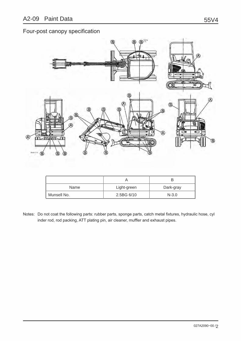
A2-09 Paint Data
Four-post canopy specificationSwing CYL
Blade CYL
A B
Name Light-green Dark-gray
Munsell No. 2.5BG 6/10 N-3.0
Notes: Do not coat the following parts: rubber parts, sponge parts, catch metal fixtures, hydraulic hose, cyl inder rod, rod packing, ATT plating pin, air cleaner, muffler and exhaust pipes.

027A2090−00 /3
55V4A2-09 Paint Data
Cab specificationSwing CYL
Blade CYL
Inside of cab
Dark gray
A B
Name Light-green Dark-gray
Munsell No. 2.5BG 6/10 N-3.0
Notes: Do not coat the following parts: rubber parts, sponge parts, catch metal fixtures, hydraulic hose, cyl inder rod, rod packing, ATT plating pin, air cleaner, muffler and exhaust pipes.

027A2100−00 /1
55V4A2-10 Attachment Data
Code A (hole) B (hole) C D E F G H IDimension (mm) φ45 φ45 200 56 335 300 218 φ90 φ90
Code J K L M1(hole) M2(hole) N O P QDimension (mm) 150 150 263 φ45 φ45 10 φ13 φ45 φ55
Code R S T U V W X1 X2 YDimension (mm) 249 319 1600 356 175 647 150 160 60
Code Z α βDimension (mm) φ45 φ45 208
1 Dimensions relating to mounting of breaker, etc.
Bucket
Bucket pin
Bucket link
Arm link pin
Shortest length: 875mm
Stroke: 565mm
Arm point boss
Bucket cylinder rod

55V4
027A2100−00 /2
A2-10 Attachment Data
2 Ear plate dimensions
Heat-treated bolt lock washer
Flange
Standard number of shims attachment: 6Adjust the number of shims so that the clearance with the arm boss will be 0.1 to 0.8mm.
Boss
Boss
Boss Boss
Boss
Section A-A Gap adjusting device
Detail B Arm attached part
Detail C Bucket link attached part
Ear plate details
View D
O-ring seal surface
O-ring seal surfaceO-ring seal surface
14 mm dia. Drilling through
14 mm dia. Drill
4-M10 (P1.5) Tapping through as a single part
(Sha
ft)
(Hole
)(S
haft)
(Hole
)
Shim
Drill hole 8.5mm (equal distribution)

027A2110−00 /1
55V4A2-11 Lifting Capacity
Lifting capacity by boom cylinder (SAE type)Forward lifting, blade fulcrum, with standard arm
(Note) The lifting load in this table is 75% of the tipping load or 87% of the load upon relief, whichever is smaller.
Unit : tons Lifting position height Maximum lifting radius Maximum lifting radius position
radius positionMaximum lifting
Normal lifting
Work radius
Hoi
stin
g po
sitio
n he
ight
(H)

55V4
027A2110−00 /2
A2-11 Lifting Capacity
Lifting capacity by boom cylinder (SAE type)Side lifting, with standard arm
(Note) The lifting load in this table is 75% of the tipping load or 87% of the load upon relief, whichever is smaller.
position
radius positionMaximum lifting
Normal lifting
Work radius
Hoi
stin
g po
sitio
n he
ight
(H)
Unit : tonsLifting position height Maximum lifting radius

A3 Component Information (Hydraulic Components)

027A3010−00 /1
55V4A3-01 Hydraulic Pump
1 External view
Adjustment is strictly prohibited.
Adjustment is strictly prohibited.
Adjustment is strictly prohibited.
Suction port S1
(Suction port S3)
4-M12 Depth 18
YAZAKI SWP connector (2P: Female) for locking “SOL B: PPC”
YAZAKI SWP connector (2P: Male) for changing “SOL A: travel two-speed”
Discharge port P2G1/2
(Discharge port P4)(G3/8)Discharge port P1
G1/2
Discharge port P3G1/2
Discharge port G1/4
Adjustment is strictly prohibited.(For setting the P4 pressure)
Mass: 29 kg

55V4
027A3010−00 /2
A3-01 Hydraulic Pump
2 Hydraulic symbols
3 P-Q chart
Discharge pressure P1 + P2 MPa(P1=P2)
P1、P2≤24.5 MPa
Pum
p di
scha
rge
quan
tity
q 1, q
2 cm
3 /rev
(q1=
q 2)
① P3=1.5 MPa
② P3=20.6 MPa
4 SpecificationsPump capacitycm3/rev
25 + 25 + 18.4 + 4.5(P1 + P2 + P3 + P4)
Rotation direction Clockwise rotation (as viewed from the shaft edge)
25

027A3020−00 /1
55V4A3-02 Control Valve
1 External view
Mass: 45 kg
Tightening torque (4 places)26.5 ~ 29.4 N•m
Connecting valve
Boom swing
Blade
Swing
Service
Arm
Travel (left)
Travel (right)
Boom
Bucket
port

55V4
027A3020−00 /2
A3-02 Control Valve
Main relief valve
7/8-14 UNFTightening torque: 69 – 78 N•mWidth across flat: 17
Width across flat: 24
Stamp position for identification O-ring
Overload relief valve
7/8-14 UNFTightening torque: 69 – 78 N•mWidth across flat: 17
Width across flat: 24Stamp position
O-ring

027A3020−00 /3
55V4A3-02 Control Valve
2 Hydraulic symbols
Connecting valve
Boom swing
Blade
Swing
Servise
Arm
Travel left
Travel right
Boom
Bucket

55V4
027A3020−00 /4
A3-02 Control Valve
3 Characteristic chartSpool pressure reception characteristics
4 Specifications• Relief valve setting pressure
P1 : 24.5 ±0.3 MPa, at 60L/minP2 : 24.5 ±0.3 MPa, at 60L/minP3 : 20.6 ±0.3 MPa, at 44L/min
• Overload relief valve setting pressureB1 : 27.4 ±0.3 MPa, at 10L/minA2 : 27.4 ±0.3 MPa, at 10L/minB2 : 27.4 ±0.3 MPa, at 10L/minA5 : 27.4 ±0.3 MPa, at 10L/minB5 : 27.4 ±0.3 MPa, at 10L/minB8 : 24.5 ±0.3 MPa, at 10L/min
Spool stroke (mm)
Pilo
t pre
ssur
e (M
Pa)
Others
Connecting valve

027A3020−00 /5
55V4A3-02 Control Valve
5 Cross-sectional view5-1 Bucket section
5-2 Boom section
Identification seat “O-ring” is not mounted on the mating surface.
There is not a passage on this surface.
Tightening torque (2 places)Two identification grooves
Tightening torque (4 places)8.8~10.8N.m
Identification groove in the spool assembling direction
No. Name Q’ty1 Valve housing 12 Spool 13 Cap 24 Spring seat 25 Spring seat 26 Spring 27 Poppet 18 Poppet 19 Spring 2
10 Plug 211 O-ring 212 O-ring 213 Socket head bolt 4
Tightening torque (1 place)
Tightening torque (2 places)
Tightening torque (2 places)SECTION A-A
Identification groove in the spool assembling direction
Tightening torque (5 places)
SECTION B-B
SECTION X-X
SECTION Y-Y
No. Name Q’ty1 Valve housing 12 Spool 13 Cap 14 Spring seat 25 Spring seat 26 Spring 27 Anti-drift V ASSY 18 Poppet 19 Spring 1
10 Plug 111 O-ring 112 O-ring 113 O-ring 214 Socket head bolt 215 Poppet 116 Spring 117 Spacer 218 O-ring 119 Backup ring 120 Socket head bolt 521 Plug ASSY 2

55V4
027A3020−00 /6
A3-02 Control Valve
5-3 Travel (right) section
5-4 Travel (left) section
Without poppet and spring
Tightening torque
Tightening torque (4 places)
No. Name Q’ty1 Valve housing 12 Spool 13 Cap 24 Spring seat 25 Spring seat 26 Spring 27 Plug 18 O-ring 19 O-ring 2
10 Socket head bolt 411 O-ring 112 Poppet 113 Spring 1
Without poppet and spring
Tightening torque
Tightening torque (4 places)
No. Name Q’ty1 Valve housing 12 Spool 13 Cap 24 Spring seat 25 Spring seat 26 Spring 27 Plug 18 O-ring 19 O-ring 2
10 Socket head bolt 411 O-ring 112 Poppet 113 Spring 1

027A3020−00 /7
55V4A3-02 Control Valve
5-5 Arm section
5-6 Service section
Tightening torque
Tightening torque
Tightening torque (4 places)
Tightening torque: 2N•m(Orifice diameter ø2.4)
SECTION A-A
Identification groove in the spool assembling direction
SECTION X-X
“O-ring” is not mounted on the mating surface.Tightening torque (1 place)
Tightening torque (4 places)
No. Name Q’ty1 Valve housing 12 Spool 13 Cap 24 Spring seat 25 Spring seat 26 Spring 27 Poppet 189 Spring 1
10 Plug 111 O-ring 112 O-ring 213 Socket head bolt 414 O-ring 115 Poppet 116 Spring 117 O-ring 118 Plug 119 O-ring 120 Orifice plug 121 O-ring 122 Plug 1
No. Name Q’ty1 Valve housing 12 Spool 23 Cap 24 Spring seat 25 Spring seat 26 Spring 27 Poppet 189 Spring 1
10 Plug 111 O-ring 112 O-ring 213 Socket head bolt 4

55V4
027A3020−00 /8
A3-02 Control Valve
5-7 Blade section
5-8 Boom swing section
Tightening torque (1 place)
Tightening torque (4 places)Identification groove in the spool assembling direction
Identification
Tightening torque (1 place)
Tightening torque (4 places)Identification groove in the spool assembling direction
No. Name Q’ty1 Valve housing 12 Spool 13 Cap 24 Spring seat 25 Spring seat 26 Spring 27 Poppet 189 Spring 1
10 Plug 111 O-ring 112 O-ring 213 Socket head bolt 414 O-ring 1
No. Name Q’ty1 Valve housing 12 Spool 13 Cap 24 Spring seat 25 Spring seat 26 Spring 27 Poppet 189 Spring 1
10 Plug 111 O-ring 112 O-ring 213 Socket head bolt 414 O-ring 1

027A3020−00 /9
55V4A3-02 Control Valve
5-9 Swing section
5-10 P3 Supply/Connecting valve section
Identification
Tightening torque (1 place)
Tightening torque (4 places)
Three identification grooves
Tightening torque
Tightening torque (4 places)
No. Name Q’ty1 Valve housing 12 Spool 13 Cap 24 Spring seat 25 Spring seat 26 Spring 27 Poppet 189 Spring 1
10 Plug 111 O-ring 112 O-ring 213 Socket head bolt 414 O-ring 1
No. Name Q’ty1 Valve housing 12 Spool 13 Cap 14 Spring seat 15 Spring seat 16 Spring 17 O-ring 28 Cap kit 19
1011 Plug 112 O-ring 113 Socket head bolt 41415 O-ring 1

027A3030−00 /1
55V4A3-03 Swing Motor
1 External view
2 Hydraulic symbols
3 SpecificationsEquivalent capacity 475 cm3/revReduction gear Speed reduction ratio 1/21.5Hydraulic motor Capacity 22.1 cm3/rev
Parking brake Releasing pressure
Minimum value 2.5 MPaMaximum value 4.9 MPa
Relief valve (single unit)
Set pressure 16.7 MPa at 44L/minCracking pressure 12.7 (or more) MPa at 1L/min
Mass Approx. 37kg
.PORT)
.PORT)
.PORT)
.PORT)
Rotation direction(As viewed from the output shaft)Rotation direction Oil inlet Oil outlet
Clockwise B ACounterclockwise A B

55V4
027A3030−00 /2
A3-03 Swing Motor
4 Disassembly drawing

027A3030−00 /3
55V4A3-03 Swing Motor

55V4
027A3030−00 /4
A3-03 Swing Motor
5 Parts listNo. Name Q’ty
REDUCTION GEAR 1set101 BODY 1102 CARRIER 1 1103 CARRIER 2 1104 PINION SHAFT 1105 A INTERNAL GEAR 1106 B1 GEAR 4107 B2 GEAR 3108 S1 GEAR 1109 S2 GEAR 1111 NEEDLE 92112 NEEDLE 72113 RING SEAL 1114 O RING 1115 THRUST PLATE 1 1116 THRUST PLATE 2 1117 THRUST WASHER 1 4118 THRUST WASHER 2 3119 PRE-ROAD COLLAR 2120 SNAP RING 4121 BEARING 1122 BEARING 1123 OIL SEAL 1124 SCREW 6126 PIN 2128 RING 1129 RING 1 4130 RING 2 3
No. Name Q’tyHYDRAULIC MOTOR 1set
201 BODY H 1202 PLATE S 1203 SHAFT 1204 CYLINDER BARREL 1205 VALVE PLATE 1206 PISTON 9207 SHOE 9208 SHOE HOLDER 1209 BARREL HOLDER 1210 SWASH PLATE 1212 RETAINER 2213 PIN 3214 FILTER 1215 SPRING C 1216 BEARING 1217 BEARING 1218 METAL PLUG 1221 SNAP RING 1223 SCREW 8224 SPRING PIN 1225 PIN 3226 PIN 1231 BRAKE PISTON 1232 SPRING ASSY 1233 DISK PLATE 1235 O RING 1236 O RING 1245 SCREW 4246 CHECK VALVE 2247 PLUG 2248 SPRING 2249 O RING 2
No. Name Q’tyRELIEF VALVE ASSY 2set
301 SEAT 1302 RETAINER 1303 POPPET 1304 PISTON 1305 CAP 1306 SPRING 1307 SPACER *308 O RING 1309 O RING 1310 O RING 1311 O RING 1312 BACK UP RING 2
No. Name Q’ty401 BODY 1402 SPOOL 1403 CHECK VALVE 2404 SPRING GUIDE 2405 PLUG 2406 SPRING 2407 SPRING 2408 CHOKE 2409 RING 2410 O RING 2411 O RING 2412 O RING 2

027A3040−00 /1
55V4A3-04 Travel Motor
1 External view
PF1/4 Ps port with cap
2-PF1/8 Pressure etection port with plug
2-PF3/8 ø19 Drain port (T1/T2) with plugDIS B2351 0 type
2-PF1/2 ø14 P port with shipping plugDIS B2351 0 type
Oil supply/drain • level port position
Lubricant supply/drain portPF 3/8-A
Lubricant supply/drain portPF 3/8-A
Lubricant level
Lubricant detection portPF 3/8-A
Oil quantity: 0.9LOil type: Gear oilGL-4 SAE 90

55V4
027A3040−00 /2
A3-04 Travel Motor
2 Hydraulic symbols
3 Specifications
Reduction gear
Maximum output torque 1st/2nd speed 6780/4160 N•mMaximum output rotary speed 1st/2nd speed 34.5 / 56.2 min-1
Speed reduction ratio 1 / 58.943
Hydraulic motor
Capacity 1st/2nd speed 29.5 / 18.1 cm3/revMaximum use pressure 24.5 MPaMaximum output rotary speed 1st/2nd speed 2033 / 3313 min-1
Maximum flow rate 60 L/minTwo-speed change pressure 3.40 MPa
Parking brakeStatic friction torque 75.6 N•mRelease pressure 1.2 MPa
Mass : 58 kg

027A3040−00 /3
55V4A3-04 Travel Motor
4 Cross-sectional view
Tigh
teni
ng to
rque
Tigh
teni
ng to
rque
Tigh
teni
ng to
rque
Tigh
teni
ng to
rque
Tigh
teni
ng to
rque
Tigh
teni
ng to
rque
Tigh
teni
ng to
rque
Tigh
teni
ng to
rque
Tigh
teni
ng to
rque
Tigh
teni
ng to
rque
Tigh
teni
ng to
rque
Tigh
teni
ng to
rque
Tigh
teni
ng to
rque
Tigh
teni
ng to
rque
Tigh
teni
ng to
rque
Tigh
teni
ng to
rque
Tigh
teni
ng to
rque
Tigh
teni
ng to
rque
Tigh
teni
ng to
rque
Tigh
teni
ng to
rque
Two-
spee
d ro
tatio
n un
it

55V4
027A3040−00 /4
A3-04 Travel Motor
No. Name Q’ty1 Reduction gear 1
1-1 Flange holder 11-2 Floating seal 21-3 Angular bearing 11-4 Ring nut 11-5 Plug 21-6 Housing 11-7 Steel ball 991-8 Plug 21-9 Planetary gear B 4
1-10 Needle bearing 41-11 Inner race 41-12 Thrust washer 41-13 Thrust plate 11-14 Screw 41-15 Sun gear 11-16 Thrust washer 31-17 Holder 11-18 Planetary gear A 31-19 Cage & Roller 31-20 Inner race 31-22 Drive gear 11-23 Thrust plate 11-23 Thrust plate 11-23 Thrust plate 11-24 Cover 11-25 O-ring 11-26 Wire 11-27 Plug 31-29 O-ring 3
2 Shaft 13 Ball bearing 14 Oil seal 15 Swash plate 16 Steel ball 27 Cylinder block 18 Spring seat 19 Spring 110 Washer 111 Snap ring 112 Pin 313 Retainer holder 114 Retainer plate 115 Piston ASSY 919 Two-speed piston 220 Spring 225 Valve plate 126 Pin 127 Ball bearing 128 O-ring 129 O-ring 430 Base plate 1
No. Name Q’ty30 Base plate 131 Plunger ASSY 1
31-1 Spool 131-2 Check valve 231-3 Spring 231-4 Plug 231-5 O-ring 236 Spring seat 237 Spring 238 Cap 239 O-ring 240 Orifice 441 Spool ASSY 1
41-1 Spool A 141-2 Spool C 142 Spring 143 Plug 144 O-ring 245 Plug ASSY 3
45-1 Plug 145-2 O-ring 146 Plug 147 Orifice 448 Socket head bolt 649 Pin 450 Valve ASSY 1
50-1 Valve body 150-2 Spool 150-3 Spring 250-4 Spring seat 250-5 Plug 250-6 O-ring 250-7 O-ring 350-8 Socket head bolt 351 Nameplate 152 Drive screw 253 Shipping plug 254 Shipping plug 155 Plug 157 O-ring 258 Plug 259 Plug 260 Brake piston 161 Disk plate 162 Spring 863 Spring 465 O-ring 166 O-ring 171 Orifice 272 Spring seat 173 Plug 274 O-ring 2
027A3050−00 /1
55V4A3-05 Cylinder
Contents Page
1 Boom Cylinder P2
2 Arm Cylinder P4
3 Bucket Cylinder P6
4 Boom Swing Cylinder P8
5 Blade Cylinder P10

55V4
027A3050−00 /2
A3-05 Cylinder
1 Boom cylinder1-1 External view
Detail of retraction side piping mounting unit
Plug COMP2-A type
Cushion stroke 43
Shortest length 1029 ±2.0Stroke 671 ±2.0
Tightening torque 17.2 ±0.9 N•m(M8×1.25)
Detail of piping support unit
Tightening torque 160 ±7.8 N•m(M20×1.5) Width across flat 36
Grease nipple plug
Tightening torque 160 ±7.8 N•m(M20×1.5) Width across flat 36
Detail of extension side piping mounting unit
1-2 Cross-sectional view
Calk two positions.
End face identification groove
Tightening torque 2172 N•mTightening torque 32.6 N•m(M42×3.0) Width across flat 65
Piston COMP Holder COMP Cylinder head COMP
Tightening torque 647 N•m (M102×2)(Upon tightening, coat Three-Bond #1901 on the thread.)
Mass : 55 kg

027A3050−00 /3
55V4A3-05 Cylinder
1-3 Parts list
No. Name Q’ty No. Name Q’ty1 CYL tube ASSY 1 5 Piston COMP 11-1 Cylinder tube 1 5-1 Piston 11-2 Cylinder bottom 1 5-2 Seal ring ASSY 11-3 Elbow 1 5-3 Slide ring 21-4 Boss 1 5-4 Setscrew 11-5 Boss 1 5-5 Steel ball 11-6 Boss 11-7 Plate 1 6 Cushion bearing 11-8 Nipple cover 1 7 Joint 11-9 Pin bush 1
8 Pipe ASSY 12 Piston rod ASSY 1 8-1 Pipe 12-1 Rod FC 1 8-2 Joint 12-2 Rod head 1 8-3 Elbow 12-3 Boss 12-4 Pin bush 1 9 Plug 1
10 O-ring 23 Cylinder head COMP 13-1 Cylinder head 1 11 Plug COMP 13-2 Bush 1 11-1 Plug 13-3 U-ring 1 11-2 O-ring 23-4 Wiper ring 1 11-3 Upset bolt 13-5 O-ring 1 11-4 Pipe holder 13-6 Backup ring 13-7 O-ring 1 12 Dust seal 2
13 Grease nipple 24 Holder COMP 1 14 Plug 24-1 Holder 1 15 Plug 24-2 Spacer 1 16 Cap 14-3 Cushion seal 14-4 Collar 14-5 O-ring 14-6 Backup ring 1
55V4
027A3050−00 /4
A3-05 Cylinder
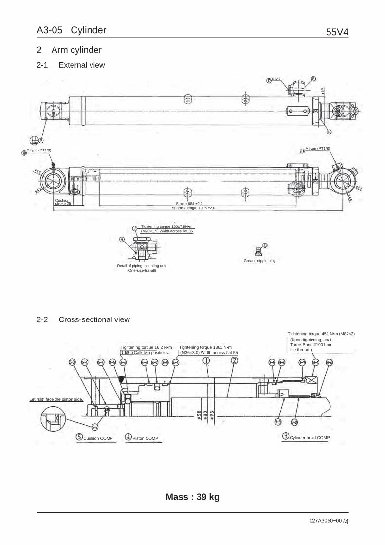
2 Arm cylinder2-1 External view
Tightening torque 160±7.8N•m(M20×1.5) Width across flat 36
Detail of piping mounting unit(One-size-fits-all)
C type (PT1/8) A type (PT1/8)
Stroke 684 ±2.0Shortest length 1005 ±2.0
Cushion stroke 25
Grease nipple plug
2-2 Cross-sectional view
Tightening torque 16.2 N•m
Cylinder head COMPPiston COMPCushion COMP
Let “slit” face the piston side.
Calk two positions.Tightening torque 1361 N•m(M36×3.0) Width across flat 55
Tightening torque 451 N•m(Upon tightening, coat Three-Bond #1901 on the thread.)
(M87×2)
Mass : 39 kg

027A3050−00 /5
55V4A3-05 Cylinder
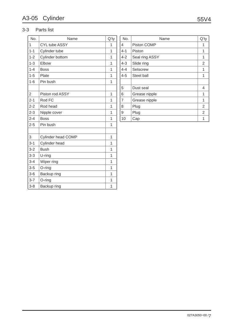
2-3 Parts list
No. Name Q’ty No. Name Q’ty1 CYL tube ASSY 1 4 Piston COMP 11-1 Cylinder tube 1 4-1 Piston 11-2 Cylinder bottom 1 4-2 Seal ring ASSY 11-3 Elbow 1 4-3 Slide ring 21-4 Boss 1 4-4 Setscrew 11-5 Plate 1 4-5 Steel ball 11-6 Pin bush 1
5 Cushion COMP 12 Piston rod ASSY 1 5-1 Cushion bearing 12-1 Rod FC 1 5-2 Cushion seal 12-2 Rod head 1 5-3 Stopper 22-3 Nipple cover 1 5-4 Snap ring 12-4 Boss 12-5 Pin bush 1 6 Joint 1
3 Cylinder head COMP 1 7 Plug 13-1 Cylinder head 1 8 O-ring 23-2 Bush 1 9 Dust seal 43-3 U-ring 1 10 Grease nipple 13-4 Wiper ring 1 11 Grease nipple 13-5 O-ring 1 12 Plug 23-6 Backup ring 1 13 Plug 23-7 O-ring 1 14 Cap 1

55V4
027A3050−00 /6
A3-05 Cylinder
3 Bucket cylinder3-1 External view
Grease nipple plug
A type
C type
Stroke 565 ±2.0Shortest length 875 ±2.0
3-2 Cross-sectional view
Detail of piston unit
Tightening torque 16.2 N•m(M8×1.25)(After tightening, calk two positions on the circumference with a punch.)
Tightening torque 750 N•mM33×2 (Width across flat) 55
Tightening torque 422 N•m(M77×2)(Upon tightening, coat Three-Bond #1901 on the thread.)
Detail of cylinder head unit
Mass : 28.5 kg
027A3050−00 /7
55V4A3-05 Cylinder
3-3 Parts list
No. Name Q’ty No. Name Q’ty1 CYL tube ASSY 1 4 Piston COMP 11-1 Cylinder tube 1 4-1 Piston 11-2 Cylinder bottom 1 4-2 Seal ring ASSY 11-3 Elbow 1 4-3 Slide ring 21-4 Boss 1 4-4 Setscrew 11-5 Plate 1 4-5 Steel ball 11-6 Pin bush 1
5 Dust seal 42 Piston rod ASSY 1 6 Grease nipple 12-1 Rod FC 1 7 Grease nipple 12-2 Rod head 1 8 Plug 22-3 Nipple cover 1 9 Plug 22-4 Boss 1 10 Cap 12-5 Pin bush 1
3 Cylinder head COMP 13-1 Cylinder head 13-2 Bush 13-3 U-ring 13-4 Wiper ring 13-5 O-ring 13-6 Backup ring 13-7 O-ring 13-8 Backup ring 1

55V4
027A3050−00 /8
A3-05 Cylinder
4 Boom swing cylinder4-1 External view
Grease nipple plug
C type(PT1/8) Stroke 552 ±2.0
Shortest length 862 ±2.0
4-2 Cross-sectional view
Tightening torque 16.7 N•m
Detail of piston unit Detail of cylinder head unit
(M8×1.25)(After tightening, calk two positions on the circumference with a punch.)
Tightening torque 530 N•m(M97×2)(Upon tightening, coat Three-Bond #1901 on the thread.)Tightening torque 1220 N•m
M39×3 (Width across flat) 60
Mass : 36 kg

027A3050−00 /9
55V4A3-05 Cylinder
4-3 Parts list
No. Name Q’ty No. Name Q’ty1 CYL tube ASSY 1 5 Dust seal 41-1 Cylinder tube 1 6 Grease nipple 11-2 Cylinder bottom 1 7 Plug 21-3 Elbow 2 8 Plug 21-4 Pin bush 1 9 Cap 1
2 Piston rod ASSY 12-1 Rod FC 12-2 Rod head 12-3 Pin bush 1
3 Cylinder head COMP 13-1 Cylinder head 13-2 Bush 13-3 U-ring 13-4 Wiper ring 13-5 O-ring 13-6 Backup ring 13-7 O-ring 1
4 Piston COMP 14-1 Piston 14-2 Seal ring ASSY 14-3 Slide ring 24-4 Setscrew 14-5 Steel ball 1

55V4
027A3050−00 /10
A3-05 Cylinder
5 Blade cylinder5-1 External view
A type (PT1/8)B type (PT1/8)
Shortest length 519±2.0Stroke 178 ±2.0
Grease nipple plug
Plug COMP
Tightening torque 76.4±3.8N•m(M16×1.5) Width across flat 32
Detail of piping mounting unitDetail of piping support unit
Tightening torque 17.2±0.9N•m(M8×1.25)
5-2 Cross-sectional view
Tightening torque 31.5 N•m
Detail of piston unit Detail of cylinder head unit
(M10×1.5)(After tightening, calk two positions on the circumference with a punch.)
Tightening torque 735 N•m(M112×2)(Upon tightening, coat Three-Bond #1901 on the thread.)Tightening torque 2003 N•m
M45×3 (Width across flat) 70
Mass : 34.5 kg
027A3050−00 /11
55V4A3-05 Cylinder
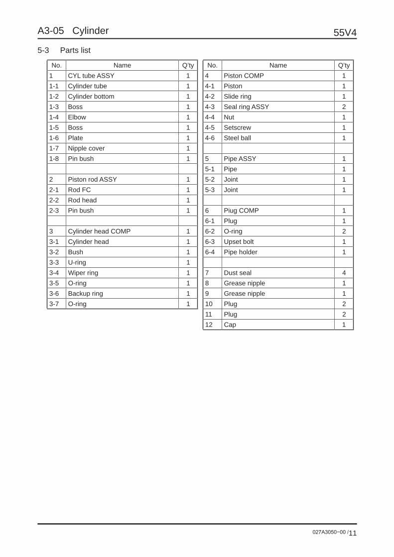
5-3 Parts list
No. Name Q’ty No. Name Q’ty1 CYL tube ASSY 1 4 Piston COMP 11-1 Cylinder tube 1 4-1 Piston 11-2 Cylinder bottom 1 4-2 Slide ring 11-3 Boss 1 4-3 Seal ring ASSY 21-4 Elbow 1 4-4 Nut 11-5 Boss 1 4-5 Setscrew 11-6 Plate 1 4-6 Steel ball 11-7 Nipple cover 11-8 Pin bush 1 5 Pipe ASSY 1
5-1 Pipe 12 Piston rod ASSY 1 5-2 Joint 12-1 Rod FC 1 5-3 Joint 12-2 Rod head 12-3 Pin bush 1 6 Piug COMP 1
6-1 Plug 13 Cylinder head COMP 1 6-2 O-ring 23-1 Cylinder head 1 6-3 Upset bolt 13-2 Bush 1 6-4 Pipe holder 13-3 U-ring 13-4 Wiper ring 1 7 Dust seal 43-5 O-ring 1 8 Grease nipple 13-6 Backup ring 1 9 Grease nipple 13-7 O-ring 1 10 Plug 2
11 Plug 212 Cap 1

027A3060−00 /1
55V4A3-06 Rotary Joint
1 External view/Cross-sectional view
Tightening torque table
10 Hexagonal bolt (M8×1.25) 10.8 ±1.08 N•m
16 Socket head plug (PT1/4) 19.6 ±1.96 N•m
17 Socket head plug (PT3/8) 39.2 ±39.2 N•m
Port thread size (for hub/shaft)
A - D : PF1/2 (JIS B2351 O-ring seal)E, F : PF3/8 (JIS B2351 O-ring seal)G, T : PF1/4 (JIS B2351 O-ring seal)
Mass : 17.6 kg

55V4
027A3060−00 /2
A3-06 Rotary Joint
2 Parts listNo. Name Q'ty1 Axle ASSY 12 Rotor 13 Dust seal 14 O-ring 15 Backup ring 16 Packing ring 77 Thrust ring 18 O-ring 19 C type snap ring for shaft 110 Cover 111 Hexagonal upper bolt 412 Spring washer 413 Plug 414 Plug 315 Nameplate 116 Parker rivet 2
3 Hydraulic symbols

027A3070−00 /1
55V4A3-07 Remote Control Valve
Contents Page
1 Joystick remote control valve P2
2 Remote control valve for boom swing/blade P6
3 Remote control valve for travel P9

55V4
027A3070−00 /2
A3-07 Remote Control Valve
Push rod 1
Push rod 2
Port 2
T Port
Port 1Port 4
Port 3
P Port
6-G1/4: Screw depth 12(JIS B 2351 O-type seal)
Spot facing diameter: ø24, depth: 1Tightening torque: 29.4±2.0N ·m.
Adjusting nut (width across flat: 22)
4-ø7 Through
Push rod 4
Push rod 3
When mounting the lever, fix the adjusting nut (width across flat: 22) with a wrench or the like and tighten the mating lock nut by 41.2±2.9N ·m.
When tightening the casing flange with the M6 bolt, insert a plain washer (outer diameter: ø12 or more) or
use a flange socket.
Model and serialnumber arepunched.
1 Joystick remote control valveNote:One valve can be used for the right and left. The figure below shows “When used at the right side”. To use this at the left side, turn the bellows in 180°.
1-1 External view
Mass : 1.6 kg

027A3070−00 /3
55V4A3-07 Remote Control Valve
1-2 Hydraulic symbols
1-3 Control diagram
Port 1, 3
Port 2, 4
Seco
ndar
y pr
essu
re (M
Pa)
Seco
ndar
y pr
essu
re (M
Pa)
Ope
ratin
g to
rque
(N•m
)O
pera
ting
torq
ue (N
•m)
Push rod stroke (mm)
Push rod stroke (mm)
Operating angle (deg.)
Operating angle (deg.)
Secondary pressure
Secondary pressure
Independent operating torque
Independent operating torque

55V4
027A3070−00 /4
A3-07 Remote Control Valve
1-4 Internal structure
Apply grease to therotating/sliding units.
Apply grease to the top
Shim for adjustingsecondary pressure 217
Port 2, 4 Port 1, 3
Center value for design: t = 0.4, 1 pc.
Be careful for theassembling direction.
9 (Lever (323) Screw depth) 0-2

027A3070−00 /5
55V4A3-07 Remote Control Valve
No. Name Q'ty101 Casing 1151 Plate 1201 Spool 4211 Plug 4212 Push rod 4213 Seal 4214 O-ring 4216 Spring seat 4217 Washer 2 4
221-1 Spring 2221-2 Spring 2241 Spring 4301 Joint 1302 Disk 1312 Adjusting nut 1501 Bellows 1
Tightening torque table
301 M14 47.1 ±2.9 N•m302, 312 M14 68.6 ±4.9 N•m
55V4
027A3070−00 /6
A3-07 Remote Control Valve
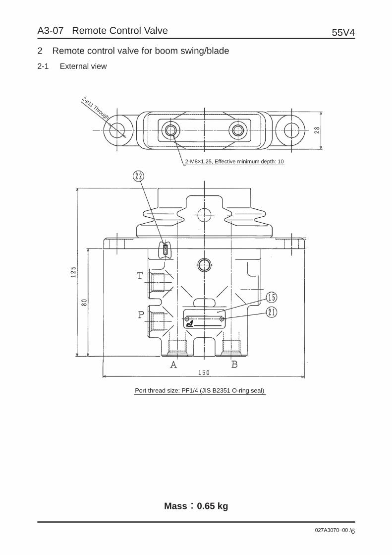
2 Remote control valve for boom swing/blade2-1 External view
2-ø11 Through
2-M8×1.25, Effective minimum depth: 10
Port thread size: PF1/4 (JIS B2351 O-ring seal)
Mass : 0.65 kg

027A3070−00 /7
55V4A3-07 Remote Control Valve
2-2 Hydraulic symbols
2-3 Control diagram
(solid line)Secondary pressure (Dashed line)
Operating torque
MPa
Primarypressure
Operating torque
Secondary
pressure
Operating angle (Deg)
55V4
027A3070−00 /8
A3-07 Remote Control Valve
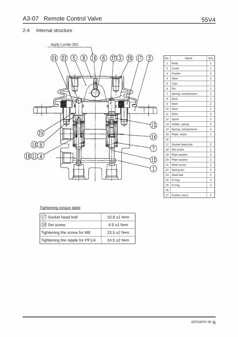
2-4 Internal structure
No. Name Q'ty
1 Body 1
2 Cover 1
3 Pusher 2
4 Shim 2
5 Cam 1
6 Pin 1
7 Spring, compression 2
8 Boot 1
9 Shim 2
10 Shim 2
11 Shim 2
12 Spool 2
13 Holder, spring 2
14 Spring, compression 2
15 Plate, name 1
16
17 Socket head bolt 2
18 Set screw 1
19 Plain washer 2
20 Plain washer 2
21 Rivet screw 2
22 Spring pin 2
23 Steel ball 2
24 O-ring 2
25 O-ring 2
26
27 Pusher, ass’y 2
Tightening torque table
17 Socket head bolt 10.8 ±1 N•m
18 Set screw 4.9 ±1 N•m
Tightening the screw for M8 23.5 ±2 N•m
Tightening the nipple for PF1/4 24.5 ±2 N•m
Apply Loctite 262.

027A3070−00 /9
55V4A3-07 Remote Control Valve
3 Remote control valve for travel3-1 External view
Mass : 3.9 kg

55V4
027A3070−00 /10
A3-07 Remote Control Valve
3-2 Hydraulic symbols
3-3 Control diagram
Sec
onda
ry p
ress
ure
(MPa
)
Ope
ratin
g to
rque
(N•m
)
Push rod stroke (mm)
Pedal operating angle (deg.)
Secondary pressure
Operating torque

027A3070−00 /11
55V4A3-07 Remote Control Valve
3-4 Internal structure
SECTION C-C

55V4
027A3070−00 /12
A3-07 Remote Control Valve
No. Name Q'ty101 Casing 1102 Casing (damper) 1191 Seat 1 2192 Seat 2 2193 Pusher 2194 Steel ball 2201 Cover 2202 Plug 4203 Grease cup 4210 Packing 4211 O-ring 4212 O-ring 4213 O-ring 2214 Push rod 4217 Shim 4218 Spring seat 4224 Piston 2D055 4225 Steel ball 12251 RO plug 3252 Plug 6253 RO plug 2261 O-ring 3263 O-ring 2271 Socket head bolt 4301 Spool 4311 Spring seat 4313 Washer 4324 Spring 4335 Spring 4336 Spring 4413 Cam shaft 2414 Pusher 4420 Cam 2471 Steel ball 4472 Socket head setscrew 2501 Bellows 2
Tightening torque table
271 M6 8.8 ±0.8 N•m251 G1/4 29.4 ±2.0 N•m252 NPTF1/16 6.9 ±1 N•m253 G1/8 11.8 ±1.0 N•m
472 M6 6.9 ±1.0 N•m(Apply Loctite #241.)

A4 Equipment Information (Other Than Hydraulic Equipment)

A4-01 Crawler
027A4010−00 /1
55V4
Contents Page
1 Rubber Crawler P2
2 Steel Crawler P3

A4-01 Crawler 55V4
027A4010−00 /2
1 Rubber crawler1-1 External dimensions
(1 p
itch)
1-2 Specifications
1. Circumferential length at rubber crawler center 5365 mm(72.5P × 74)2. Mass 264 kg/pc.

A4-01 Crawler
027A4010−00 /3
55V4
2 Steel crawler2-1 External dimensions

A4-01 Crawler 55V4
027A4010−00 /4
2-2 Parts list
No. Name Q'ty1TR Track link 381TL Track link 381MR Master link 11ML Master link 1
2 Track bushing 383 Track pin 384 Master bushing 15 Master pin 16 Collar 27 Set pin 18 Shoe bolt 1569 Shoe nut 15610 Shoe L=400 39
The tightening torque of shoe bolt should be 216±20N ·m.“Q’ty” means “quantity for one steel crawler”.
Mass : 279.9 kg / pc

A4-02 Idler
027A4020−00 /1
55V4
Notes:1. Before mounting the bearing block in the front idler assembly, coat grease on the slide surface with the
frame.2. When mounting the front idler assembly to the frame, the oil supply plug side must be outside.
M12×60Tightening torque 83N•m
Spacer

A4-02 Idler 55V4
027A4020−00 /2
No. Name Q'ty1 Idler tumbler 12 Shaft 13 Bearing block 24 Bushing 25 Floating seal 26 O-ring 27 Spring pin 28 Plug 2
Mass : 53.8 kg
Notes:1. Before mounting, clean the parts well to prevent for-
eign matters from entering the units.2. Apply oil to the inner and outer diameters of the seal
and then press-fit it. Fill the gap between the lips of seal with grease.
3. After assembling, supply the lubricant.
Type of lubricant CapacityAPI-CDSAE#30 80 cc
4. Oil leak test: Apply an air pressure of 98kPa through the (8) plug
hole.5. Wind the seal tape around the plug (8) and mount it to
the roller.
10652
φ36
3φ
411

A4-03 Lower Roller
027A4030−00 /1
55V4
Tighten the bolt under the condition that the lower roller mounting surface is tightly in contact with the crawler frame.Tightening torque: 490 N•m
In the case of steel shoe, put a shim (thickness: 9mm) into the gap between frame and shaft. Under the condition that the mounting surfaces are tightly in contact with each other, tighten the bolt.
Rubber shoe
Steel shoe
M20×30Tightening torque 490N•m
Shim

A4-03 Lower Roller 55V4
027A4030−00 /2
Notes:1. Before mounting, clean the parts well to prevent
foreign matters from entering the units.2. Apply oil to the inner and outer diameters of the
seal and then press-fit it. Fill the gap between the lips of seal with grease.
3. After assembling, supply the lubricant.
Type of lubricant CapacityAPI-CDSAE#30 180 cc
4. Oil leak test: Apply an air pressure of 98kPa through the (9)
plug hole.5. Wind the seal tape around the plug (9) and mount
it to the roller.
No. Name Q'ty1 Roller 12 Shaft 13 Collar 14 Collar 15 Floating seal 26 Pin 27 Bushing 28 O-ring 29 Plug 1
Mass : 10.9 kg

A4-04 Upper Roller
027A4040−00 /1
55V4
M16×65Tightening torque 241N•m

A4-04 Upper Roller 55V4
027A4040−00 /2
Notes:1. Before mounting, clean the parts well to prevent
foreign matters from entering the units.2. Apply oil to the inner and outer diameters of the
seal and then press-fit it. Fill the gap between the lips of seal with grease.
3. After assembling, supply the lubricant.
Type of lubricant CapacityAPI-CDSAE#30 45 cc
No. Name Q’ty1 Roller 12 Shaft 13 Oil seal 14 Cap 15 Snap ring 16 Bearing 2
Mass : 5.0 kg

A4-05 Crawler Shoe Tension Adjusting Device
027A4050−00 /1
55V4
Notes:1. For the grease cylinder, the oil supply port side must be outside.2. When loosening the shoe, be sure to loosen the check valve to discharge the grease from the inside. Do not loosen the grease nipple because the high-pressure grease jets out to cause a dangerous status.

A4-05 Crawler Shoe Tension Adjusting Device 55V4
027A4050−00 /2
Check valve tightening torque: 55.8 - 68.6 N•mThis must be strictly observed to prevent the check valve from breakage.
Insert the 15° chamfered side of piston into the cylinder.
Detail of check valve
295Stroke: 32.5

A4-06 OK Monitor
027A4060−00 /1
55V4
1 External view/Cross-sectional view
Detailed specification of pilot lens unitSignal name Symbol LED color
Warning for engine Red
Two-speed Yellow
Oil temperature Red
Battery charge Red
Oil pressure Red
Water temperature Red
Auto-idling Green
Check Yellow
Separation Red
Eco (ecology) mode Green
Warning for DPF Yellow
DPF-1 Yellow
DPF-2 Yellow
DPF-3 Yellow

A4-06 OK Monitor 55V4
027A4060−00 /2
2 Connection diagramMain board
Power circuit
Crystal Hour meter LCD
Hour meter
Hour meter start
No. Signal name No. Signal name1 Warning for engine 13 GND (illumination)2 Two-speed 14 GND (power)3 Oil temperature 15 GND (circuit)4 Battery charge 16 Temperature5 Oil pressure 17 Warning for DPF6 Fuel 18 Light switch7 Hour meter start 19 Battery8 Water temperature 20 IGN9 Auto-idling 21 IGN (Engine ECU)10 Check 22 DPF-111 Separation 23 DPF-212 Eco (ecology) mode 24 DPF-3

A4-06 OK Monitor
027A4060−00 /3
55V4
3 Meter reference values3-1 Hour meter3-1-1 Hour meter LCD
Operation indication
3-1-2 Check voltage: DC12.0V ±0.3V
Check temperature: 20 ±0.5°C
3-1-3 LCD specification
1) IGN is turned on/off. The indication is always ON.
2) When IGN is turned on and the hour meter signal is received, the LCD counts time.
3) The indication range is 0 to 999999 (1/10H). When the value exceeds this range, “999999
(1/10H)” is indicated.
4) The accuracy about time is ±0.1%.
5) Resolution: 0.1H
6) The LCD consists of 7 sections and time is indicated with a 6-digit number. (The indication shifts
to the rightmost end.)
7) When the battery is consumed, the data is saved in the memory for at least 25 years.
3-1-4 Indicator LED for hour meter operation
1) When the hour meter begins to count, the LED is lit.
2) The LED color is green and the operation cycle is 2 seconds (0.5Hz).
3) When the hour meter is OFF, the LED is turned off.
3-2 Water temperature meter3-2-1 Tolerance of indication
Indication (°C) 50 67 105 135 Indication scale
Unit resistance (Ω) 153.9 51.9 ‒ 27.4 23.9 10.8 Red zone
Display (°) 0 38 62 76
Tolerance (°) ±8.0 ±3.5 ±3.5 ‒
3-2-2 Check voltage: DC12.0V ±0.3V
Check temperature: 20 ±0.5°C
3-2-3 Braking characteristics of water temperature meter
When the machine is left at Point C for 1 minute and then the load resistance is instantaneously
moved from Point C to H, it takes 2 ±0.8 seconds to pass Point OH.

A4-06 OK Monitor 55V4
027A4060−00 /4
3-3 Fuel meter3-3-1 Tolerance of indication
Indication F 1/2 E Indication scale
Unit resistance (Ω) 10 38 80
Red zone
Display (°) 76 36 0
Tolerance (°) 5±2 ±3.0 -2±1
3-3-2 Check voltage: DC12.0V ±0.3V
Check temperature: 20 ±0.5°C
3-3-3 Characteristics of fuel meter
1) When the load resistance is moved from Point E (80Ω) to Point F (10Ω) while IGN is OFF, it
takes maximum 4 seconds to move from Point E to Point F.
2) When 32 ±1 seconds have passed since IGN was ON and the load resistance is instantaneously
moved from Point E (80Ω) to Point F (10Ω), it takes 79±10 seconds to pass Point 3/4.

A5 Circuit Diagram

A5-01 Hydraulic Circuit Diagram
027A5010−00 /1
55V4
Bucket cylinder Boom cylinder
Remote control valve (left)
Blade cylinder
Travel motor (left)
Arm cylinder Boom swing cylinder
Swing motor
Remote control valve (boom swing)
Remote control valve (blade)
Remote control valve
(right)
Remote control valve (travel)
Rotary joint
Control valve
Oil cooler
Return filter
Engine
Option
Accumulator
Pump
Suctionfilter
Travel motor (right)
R L REAR F
DU
MP
BU
CK
ET
Bucket
DIG
GIN
G Boom
DO
WN
UP
FOR
WA
RD
FOR
WA
RD
BA
CK
WA
RD
BA
CK
WA
RD
Left travelRight travel
Arm
PUSH
PULL
DOWN L L
UP R R
BladeBoom swing Swing
R L FREAR
Φ70×Φ45×565 Φ95×Φ55×671 Φ80×Φ50×684
29.5/18.1cc/rev i = 58.94329.5/18.1cc/rev i = 58.943 22.1cc/rev i = 21.5
Φ105×Φ55×178
Φ90×Φ50×552
2×25+18.4+4.5cc/rev150Mesh 10μ

A5-01 Hydraulic Circuit Diagram
027A5010−00 /2
55V4
Bucket cylinder Boom cylinder
Remote control valve (left)
Blade cylinder
Travel motor (left)
Arm cylinder Boom swing cylinder
Right Left
Swing motor
Remote control valve (boom swing)
Remote control valve (blade)
Remote control valve
(right)
Remote control valve (travel)
Rotary joint
Control valve
Oil cooler
Return filter
Engine
Option
Accumulator
Pump
Suctionfilter
Travel motor (right)
R L REAR F
DU
MP
BU
CK
ET
Bucket
DIG
GIN
G Boom
DO
WN
UP
FOR
WA
RD
FOR
WA
RD
BA
CK
WA
RD
BA
CK
WA
RD
Left travelRight travel
Arm
PUSH
PULL
DOWN L L
UP R R
BladeBoom swing Swing
R L FREAR
Φ70×Φ45×565 Φ95×Φ55×671 Φ80×Φ50×684
29.5/18.1cc/rev i = 58.94329.5/18.1cc/rev i = 58.943 22.1cc/rev i = 21.5
Φ105×Φ55×178
Φ90×Φ50×552
2×25+18.4+4.5cc/rev150Mesh 10μ
No.1 AUX
Right Left
Right Left
No.3 AUXsolenoid valve
No.1 AUXsolenoid valve

A5-01 Hydraulic Circuit Diagram
027A5010−00 /3
55V4
Bucket cylinder
Boom cylinder Travel motor (right)
Solenoid valve
Blade cylinder
Travel motor (left)
Arm cylinder
Holding valve
Boom swing cylinder
Swing motor
Remote control valve (boom swing)
Remote control valve
(right)
Remote control valve (travel)Pressure
sensor
Pressure sensor
Remote control valve (left)
Holding valve
Remote control valve
(blade)
Crane specification
Control valve
Suctionfilter
Oil cooler
Returnfilter
Engine
Option
Accumulator
Pump
Rotary joint
DU
MP
BU
CK
ET
Bucket
DIG
GIN
G
Boom
DO
WN
(UP
)
FOR
WA
RD
FOR
WA
RD
BA
CK
WA
RD
BA
CK
WA
RD
Left travelRight travel
Arm
PUSH
PULL
DOWN L L
UP R R
BladeBoom swing Swing
R L REAR F R L REAR F
Φ70×Φ45×565
Φ95×Φ55×671
Φ80×Φ50×684
29.5/18.1cc/rev i = 58.943 29.5/18.1cc/rev i = 58.943 22.1cc/rev i = 21.5
Φ105×Φ55×178 Φ90×Φ50×552
2×25+18.4+4.5cc/rev 150Mesh 10μ

A5-02 Electrical Wiring Diagram/Wire Harness
027A5020−00 /1
55V4
HORN
3RD CHANGE SOLENOID
QUICK HITCH(FOR GOVERNOR LEVER)
(FOR THROTTLE DIAL)
SHIBAURA
Note:1. The harness size is 0.75sq if it is not specified.
B BR ACC R1 R2 C Preheat
OFFON
Start
Key switch connection diagram

A5-02 Electrical Wiring Diagram/Wire Harness
027A5020−00 /2
55V4
Proportional control
(Protection coupler)
(Protection coupler)
(Left operation)
(Right operation)
Insulate this wire with tape and bind it with the portion ø7 (420mm) of the corrugate tube.
Glow relay
Glow timer relay
Starter relay
Battery
Controller self-hold relay
Earth
White tape
Insulate this wire with tape and bind it with the portion ø13 (200mm) of the corrugate tube.
Detail HDetail G
Joint F processing position
Water temperature lamp
Constant power supply
Water temperature meter
Monitor + (Monitor side)
Seat stand harnessMale
No. 2 SOLGlow lamp Sedimentor
Fuel pump Key switch
Starter relay
Oil pressure
Throttle controller power supply
Flip-flop Flip-flop Flip-flop Alternator Eng SOL
Charge Monitor + (Fuse side)
Deceleration sensor
Joint D processing position
(Black)Seat stand harness
CR modeInsulate this wire with tape and bind it with the portion ø19 (400mm) of the corrugate tube.
Potentiometer (Engine governor lever)
Glow plug
Water temperature sensor (for water temperature meter)
Seat stand harness(Light gray)
Engine stop SOL
Sedimentor Fuel pumpSeat stand harness
Female
Deceleration
Fuel gaugeLever lock SOL
Potentiometer
Potentiometer Potentiometer
ECO mode (Rotation selection SW)
Horn Work lamp
Lever lock SOL
SWP connector
SWP connector
SWP connector
SWP connector
SWP connector
SWP connector
Travel 2-speed SOL
Earth
Joint E processing position
Flip-flop relay for travel 2-speed
2-speed SOL
Rubber cap
Water temperature switch (for overheat lamp)
Waterproof plug
Fuel gauge
(Gray)
Oil pressure SW
Rubber cap
Throttle motor
Throttle controller
Insulate this wire with tape and bind it with the portion ø10 (300mm) of the corrugate tube.
Horn
(Black)
Starter S
No. 2 AUX SOL(Gray)
Insulate this wire with tape and bind it with the portion ø10 (300mm) of the corrugate tube.
Fusible link
(Fuse)
Notes:1. See the connector from the mating direction.2. The connector made by YAZAKI should be used if it is not specified.3. Fit the corrugate tube for the portion.4. Tape the portion.5. AVS wire should be used for 3.0sq or more and, AVSS wire for less than 3.0sq, if it is not specified.6. Fix the diverging and end portions of corrugate tube with tape.7. The numeral in ○ shows the wiring of connectors.8. Be sure to use the connector with lock.9. Put the plug for the free pin of the waterproof connector into the housing.10. (Bullet terminal/Female) (Sleeve) (Bullet terminal/Male) (Sleeve) (Sleeve) (Flat terminal/Female/U-cut)
11. ø* of corrugate tube shows the normal designation diameter.12. The claw (AUX fuse space) of the fuse box must be at the top side.13. YAZAKI SWP connector Attach a rubber plug applicable to the wire size. Use a plug for the free pin.(7157-3755-50) Attach a rear holder applicable to the housing.
Main harness 1/2

A5-02 Electrical Wiring Diagram/Wire Harness
027A5020−00 /3
55V4
Perform joint processing for the following wires.(Perform insulation/waterproof processing.)
Joint
Perform joint processing for the following wires.(Perform insulation/waterproof processing.)
Joint
Perform joint processing for the following wires.(Perform insulation/waterproof processing.)
Joint
Perform joint processing for the following wires.(Perform insulation/waterproof processing.)
Joint
Perform joint processing for the following wires.(Perform insulation/waterproof processing.)
Joint
Perform joint processing for the following wires.(Perform insulation/waterproof processing.)
Joint
Tape the two wires and then fix them on harness with tape.
Tape the two wires and then fix them on harness with tape.
Tape the wires and then fix them on harness with tape.
Insulate this wire with tape and bind it with the portion ø13 (200mm) of the corrugate tube.
Insulate this wire with tape and bind it with the portion ø13 (200mm) of the corrugate tube.
Insulate this wire with tape and bind it with the portion ø13 (200mm) of the corrugate tube.
“A” connector
“A” connector
Detail G Oil pressure SW
Fuel pump
Travel alarm
Throttle controller
“A” connector power supply
Engine stop SOL
Alternator
Detail of joint “E”
Detail of joint “F”
Detail of joint “D”
Fusible link
Alternator “B” joint
Glow relay
Seat stand harness
Seat stand harness
Detail H
Detail G
Main harness 2/2
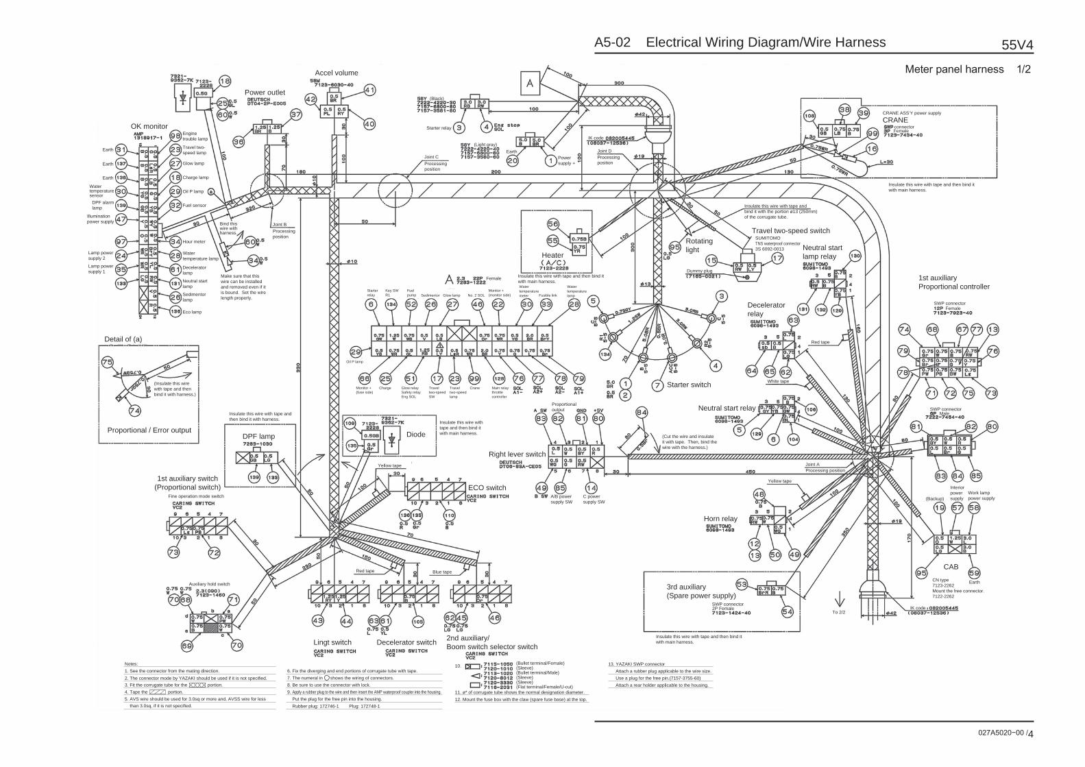
A5-02 Electrical Wiring Diagram/Wire Harness
027A5020−00 /4
55V4
Engine trouble lamp
Earth
OK monitor
Power outlet
Accel volume
Earth
Earth
Water temperature sensor
DPF alarm lamp
Illumination power supply
Lamp power supply 2
Lamp power supply 1
Travel two-speed lamp
Glow lamp
Charge lamp
Oil P lamp
Fuel sensor
Hour meter
Processing position
Bind this wire with harness.
Joint B
(Black)
Starter relay
(Light gray)Earth
Power supply +
IK code
Processing position
connector
Insulate this wire with tape and then bind it with main harness.
Insulate this wire with tape and then bind it with main harness.
Insulate this wire with tape and then bind it with harness.
(Insulate this wire with tape and then bind it with harness.)
Insulate this wire with tape and then bind it with main harness.
Insulate this wire with tape and then bind it with main harness.
CRANE ASS’Y power supply
CRANE
Travel two-speed switchRotating light
HeaterNeutral startlamp relay
1st auxiliaryProportional controller
3rd auxiliary(Spare power supply)
CAB
Horn relay
Deceleratorrelay
Starter switch
Right lever switch
ECO switch
DiodeDPF lamp
1st auxiliary switch(Proportional switch)
Lingt switch Decelerator switch 2nd auxiliary/Boom switch selector switch
Neutral start relay
Female
SWP connector
SWP connector
Joint A
Yellow tape
Processing position
Male
(Backup)
To 2/2
SWP connector2P Female
EarthCN type7123-2262Mount the free connector.7122-2262
IK code
Interior power supply
Work lamp power supply
Female
(Cut the wire and insulate it with tape. Then, bind the wire with the harness.)
SUMITOMOTNS waterproof connector3S 6092-0013
Water temperature lamp
Decelerator lamp
Neutral start lamp
Make sure that this wire can be installed and removed even if it is bound. Set the wire length properly.
Sedimentor lamp
Eco lamp
Detail of (a)
Proportional / Error output
Starter relay
Oil P lamp
Monitor + (fuse side)
Charge Glow relay Safety relayEng SOL
Travel two-speed SW
Travel two-speed lamp
Crane
Proportional output
A/B power supply SW
C power supply SW
Main relay throttle controller
Key SW R1
Fuel pump
Monitor + (monitor side)
Water temperature meter Fusible link
Water temperature lampNo. 2 SOL
Female
Glow lampSedimentor
Notes:1. See the connector from the mating direction.2. The connector mode by YAZAKI should be used if it is not specified.3. Fit the corrugate tube for the portion.4. Tape the portion.5. AVS wire should be used for 3.0sq or more and, AVSS wire for less than 3.0sq, if it is not specified.
(Bullet terminal/Female)(Sleeve)(Bullet terminal/Male)(Sleeve)(Sleeve)(Flat terminal/Female/U-cut)
10. 6. Fix the diverging and end portions of corrugate tube with tape.7. The numeral in shows the wiring of connectors.8. Be sure to use the connector with lock.9. Apply a rubber plug to the wire and then insert the AMP waterproof coupler into the housing. Put the plug for the free pin into the housing. Rubber plug: 172746-1 Plug: 172748-1
11. ø* of corrugate tube shows the normal designation diameter.12. Mount the fuse box with the claw (spare fuse base) at the top.
13. YAZAKI SWP connectorAttach a rubber plug applicable to the wire size.Use a plug for the free pin.(7157-3755-60)Attach a rear holder applicable to the housing.
Processing position
Joint C
Dummy plug
Insulate this wire with tape and bind it with the portion ø13 (250mm) of the corrugate tube.
Red tape
White tape
Blue tape
Yellow tape
Red tape
Fine operation mode switch
Auxiliary hold switch
Joint D
Meter panel harness 1/2

A5-02 Electrical Wiring Diagram/Wire Harness
027A5020−00 /5
55V4
Joint (Horn/Two-speed/No. 1 AUX)
Joint (Monitor)
(Block)(Cover)
Aux. fuseCab (Work lamp)
Male
Lever lock SOL
Lever lock SOL
Lever lock
After crimping the wires with splice.Insulating process using tape.
Eco SWMonitor
MonitorMonitorN start relay
Power supply socket
HoldDeceleratorDeceleration relay
HeaterNo. 3 AUX
HornCrane
Air conditioner
Air conditioner
Fuel pump
Cab (Work lamp)
Joint (Monitor)
Joint (Monitor)
Glow relaySafety relay
Glow relaySafety relay
No. 2 AUX
No. 2 AUX
Air conditioner
Heater(A/C)
Heater(A/C)
No. 3 AUX
No. 3 AUX
Cab (Interior)
Cab (Interior)
Light
Light
Backup
Backup
Power supply socketCrane
Cab (Work lamp)Lever
lock
Power supply socket
Crane Lever lock
Joint(Horn/Two-speed/No. 1 AUX)
Joint(Horn/Two-speed/No. 1 AUX)
Fuel pump
MaleMale
MaleFemale Female
Female
SWP connector
SWP connector
SWP connector
SWP connector
N start lamp
N start lamp
ProportionCab
Main earth
N start relay
Fuel gauge
Horn PotentialPotential
Potential
Light
Engine check lamp
Decelerator(ECU)
Engine rotary speed selection
SWP connector
Fuse box
Horn relay
Right lever switch
Two-speed switch
Two-speed flip-floprelay
Fuse box
Monitor power supply 2
Monitor power supply 1
Monitor illumination power supply
Perform joint processing for the following wires. (Perform insulation/waterproof processing.)
Perform joint processing for the following wires. (Perform insulation/waterproof processing.)
Perform joint processing for the following wires. (Perform insulation/waterproof processing.)
Perform joint processing for the following wires. (Perform insulation/waterproof processing.)
Perform joint processing for the following wires. (Perform insulation/waterproof processing.)
Perform joint processing for the following wires. (Perform insulation/waterproof processing.)
Perform joint processing for the following wires. (Perform insulation/waterproof processing.)
Perform joint processing for the following wires. (Perform insulation/waterproof processing.)
Perform joint processing for the following wires. (Perform insulation/waterproof processing.)
Perform joint processing for the following wires. (Perform insulation/waterproof processing.)
Tape the wires and then fix them on harness with tape.
Tape the wires and then fix them on harness with tape.
Tape the wires and then fix them on harness with tape.
Tape the wires and then fixthem on harness with tape.
Tape the two wires and then fix tem on harness with tape.
Tape the three wires and then fix them on harness with tape.
Joint
Joint
Joint(JC-CB)
Joint
Joint
Joint
(JC-DC)
(JC-DB)
Joint
Joint
To 1/2
Joint
Joint
Cab (Interior)
No. 3 AUX
Heater(A/C)
Light
Backup
Main relay throttle controller
Processing position
Joint E
Mini fuse box IK code number
Fuse box
No. 2 AUX
(As viewed from the box top surface.)
F: Detail of mini fuse box
Detail of Joint “A”
Detail of Joint “B”
Detail of Joint “G”
Detail of Joint “G”
Detail of Joint “E”
Detail of Joint “C”Detail of Joint “D”
Lever lock switch
Crane
Power supply socket
Lever lock
Fuel pump
Fuel clip
Air conditioner
To each fuse
Glow relaySafety relay Processing position
Joint G
Insulate this wire with tape and then bind it with main harness.
Meter panel harness 2/2

B1 General Maintenance

027B1010−00 /1
55V4B1-01 List of Check/Maintenance Parts
Parts shown in the figure require periodic check/replacement.For work details, please see each item in section 2.For the check cycle, see B1-02
Codes in the lower row are maintenance method item numbers
Air cleanerB2-10
BatteryB2-08
Fuel tankB2-09
Hydraulic oil tankB2-05
Grease cylinderB2-01
CrawlerB2-01
Line filterB2-06 Strainer
B2-05
Reservoir tankB2-10
Travel motorB2-07
RadiatorB2-10
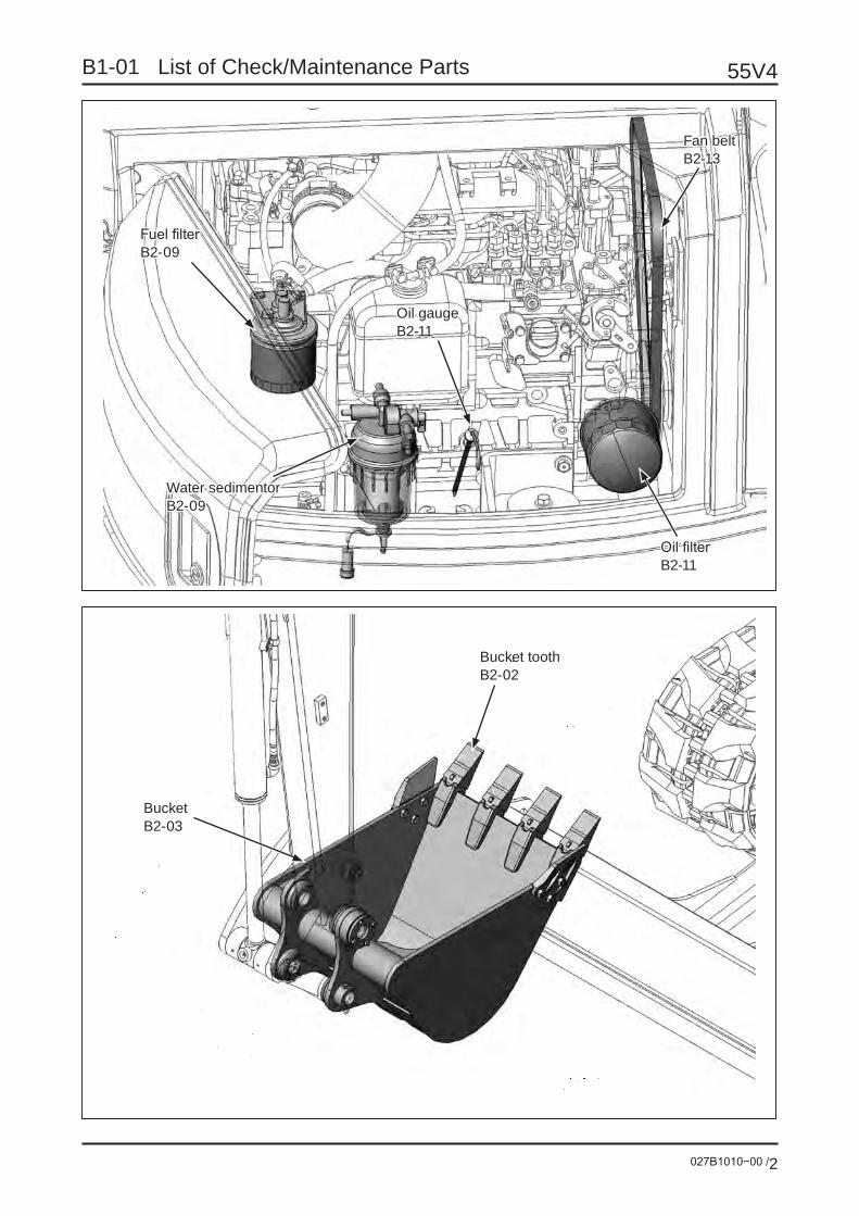
55V4
027B1010−00 /2
B1-01 List of Check/Maintenance Parts
Oil gaugeB2-11
Oil filterB2-11
Fan beltB2-13
Water sedimentorB2-09
Fuel filterB2-09
Bucket toothB2-02
BucketB2-03

027B1020−00 /1
55V4B1-02 Periodic Check Table
: Inspection/Adjustment : Replacement
Class Check/mainte-nance part
Contents of check/maintenance
Interval of check/maintenance
Every day 50h 100h 250h 500h 800h 1000h 1500h 2000h 3000h As required
Lubr
icat
ion
Attachment
Greasing
Boom swing
Blade
Swing bearing
Swing ring gear
Buc
ket
Bucket tooth Replace
Bucket Replace
Clearance Adjust
Cra
wle
r Rubber shoeCheck wear and deterioration
Shoe tension Check and adjust
Red
uctio
n ge
ar
Travel reduction gear
Check oil leak
Check oil qty & refill
Change oilFirst
Hyd
raul
ic s
yste
m
Hydraulic oil tankCheck oil qty & refill
Change hydraulic oil/Clean the tank
*1
Suction strainer Clean
Return filter Replace cartridgeFirst
*2
Hydraulic equipment Check oil leak
Hydraulic devices Check oil leak
*1: When breaker is used: 600 hours*2: When breaker is used: 100 hours

55V4
027B1020−00 /2
B1-02 Periodic Check Table
Class Check/mainte-nance part
Contents of check/maintenance
Interval of check/maintenance
Every day 50h 100h 250h 500h 800h 1000h 1500h 2000h 3000h As required
Lubr
icat
ion
syst
em
Engine oilCheck oil qty & refill
Change First
Oil filter Replace First
Fuel
sys
tem
Fuel tank Check oil qty & refill
Water sedimentorCheck
Clean/Replace element
Fuel filter Replace
Coo
ling
syst
em
Sub tank Check coolant qty & refill
RadiatorClean
Change coolant or one year
Radiator fins/Oil cooler fins Check & Clean
Fan beltAdjust tension First
Check cracks First
Suc
tion
syst
em
Air cleaner
Check dust indicator
Check element/Clean First
Replace element
Hos
es
Fuel hose/Radiator hose/Hydraulic hose Check leak & replace. or two
years
Eng
ine
sys-
tem
Intake valve & exhaust valve head Adjust clearance
Fuel injection system Check/Clean/Check functioning

027B1020−00 /3
55V4B1-02 Periodic Check Table
Class Check/mainte-nance part
Contents of check/maintenance
Interval of check/maintenance
Every day 50h 100h 250h 500h 800h 1000h 1500h 2000h 3000h As required
Ele
ctric
al s
yste
m
Fuse Replace
Fusible link Replace
Battery
Check battery liquid qty & refill
Clean terminal
Bolt tightening point Retightening First

027B1030−00 /1
55V4B1-03 Periodically Replaceable Parts
The important parts shown below that are especially related to safety and fire disasters should be re-placed every 2 years.
For these parts, the material may be changed due to aging or degradation, wear, or fatigue may be caused as a result of repeated use. Then, serious accidents may occur.
For these parts, it is hard to judge the remaining life from the appearance inspection or the feeling of driv-ing.
These parts should be replaced with new ones on a regular basis to maintain the full function even though any particular abnormality is not found.
Even before the replacement time, these parts should be repaired or replaced immediately after any ab-normality is found.
If any abnormality is found on the hydraulic hose or joint other than the periodically replaced parts, re-tightening or replacement should be performed.
Periodically replaced parts
Pump - Control valve hose

55V4
027B1030−00 /2
B1-03 Periodically Replaceable Parts
Boom cylinder hose
Arm cylinder hose

027B1030−00 /3
55V4B1-03 Periodically Replaceable Parts
Bucket cylinder hose
Boom swing cylinder hose

55V4
027B1030−00 /4
B1-03 Periodically Replaceable Parts
Swing motor hose
Blade cylinder hose

027B1030−00 /5
55V4B1-03 Periodically Replaceable Parts
Travel motor hose
Fuel hose

55V4
027B1030−00 /6
B1-03 Periodically Replaceable Parts
Radiator hose

027B1040−00 /1
55V4B1-04 Performance Measurement/Check criteria/Permissible value
1. Cautions for measuring
(1) Measurement Location1 Set the machine on the flat and solid ground.2 For natural lowering amount during traveling and swinging, the place should be sloped in 15°.3 Clearing space for the attachment to swing with maximum reach.4 Clearing flat and solid ground where the machine can run 10 m straight.5 Safety measures such as “Keep Off” should be in place for the measurement.
(2) Measuring Instruments1 Stop watch2 Scale3 Thermometer4 Inclination gauge5 Pen, notebook, chalk and felt pen6 Pressure gauge7 Engine tachometer
(3) Measurement condition
The hydraulic oil temperature must be 50 ± 5°C for measuring.
(4) Measurement result
Compare the measurement result with the function data. If the result is out of the tolerance, repair the machine.

55V4
027B1040−00 /2
B1-04 Performance Measurement/Check criteria/Permissible value
2 Measuring methodMeasurement should be performed three times for each time. If a measured value is significantly different from the rest, measurement should be performed once more and an average of three closer values should be taken.
Item Unit Method Remarks
Eng
ine
Rated revolution min-1
• Refer to JIS D 1005.
• At a high land, the output gener-ally reduces approximately 10% per 1000 m.
• The rated revolution is the revo-lution provided for the engine’s rated output. The revolution is ap-proximately 6 to 8% higher with-out load.
Rated output kW
Maximum torque N•m
Maximum revolution without load min-1
Minimum revolution without load min-1
Oil
pres
sure
Boom
MPa Refer to “Oil Pressure Measure-ment and Adjustment”.
• If the oil temperature is lower, the pressure is indicated higher. If the engine revolution is lower, the pressure is indicated lower. Therefore, the reference values should be observed.
• Note that, since the swing pres-sure is the set value on the bench, a line resistance is provid-ed on the actual machine and, as a result, the pressure is indicated higher on the gauge.
Arm
Bucket
Swing
Travel
Boom swing
Blade
Ope
ratio
n fo
rce
of o
pera
tion
leve
r Boom
kgf
• Engine: Stopped• Oil temperature: 50 ±5°C• Measurement: Set a spring balance below
the lever grip for measure- ment.
• Read the maximum value to the stroke end.
• Check the lever, link lubrication, stroke adjustment (lever stopper), link ball shakiness, and bolt/nut loosening in advance and perform maintenance if necessary.
• Do not pull exceeding the lever stroke.
• If the oil temperature is lower, the slide resistance increases and the lever becomes heavier.
Arm
Bucket
Swing
Travel
Boom swing
Blade

027B1040−00 /3
55V4B1-04 Performance Measurement/Check criteria/Permissible value
Item Unit Method Remarks
Trav
el
Travel speed sec/10m
Time required for 10 m travel after a 5 m running-in opera-tion
Flat and rigid ground
Running-in operation
Measured section
• Full change-over of the travel valve (spool stroke check/adjust-ment)
• The shoe tension should be iden-tical between the right and left and within the standard range. Be sure to perform running-in opera-tion.
• Remove the soil and sand from the shoe link.
Straight running mm/10m
A turn upon 10 m straight running after a 5 m running-in operation
• Full change-over of the travel valve (spool stroke check/adjust-ment)
• Particularly, the road surface should be flat and rigid. If a slope, soft ground, or convexity/concavi-ty exists, the turn becomes larger.
• The shoe tension should be iden-tical between the right and left and within the standard range.
• Remove soil and sand from the shoe link.
Natural lowering during travel
mm/5 minutes
Natural lowering of the ma-chine after 5 minutes
• Do not stop the engine. Otherwise, the motor becomes
free from oil, the brake does not work, and overrun may occur. Therefore, care must be taken.
Crawler belt rotation speed
sec/5 rotations
Time required for 5 rotations after 1 idle rotation
• Full change-over of the travel valve (spool stroke check/adjust-ment)
• The shoe tension should be iden-tical between the right and left and within the standard range.
• Remove soil and sand from the shoe link.

55V4
027B1040−00 /4
B1-04 Performance Measurement/Check criteria/Permissible value
Item Unit Method Remarks
Sw
ing
Motion after swing stop (brake working angle)
degrees
• Measurement position The bucket/arm cylinder is fully retracted. The line con-necting the boom foot and arm point is horizontal above the ground surface.
Arm point pin Boom foot pin
Horizontal
・ Measurement At the 90° swing position, release the lever to make it neutral. Measure the subse-quent motion angle.
Start
Stop
Measurement
Lever at neutral
Time required for swing
sec/2 rotations
・ Measurement Time required for 2 rotations after 1 rotation
Natural lowering during swing
degrees/ 5 minutes
• Measurement position The bucket/arm cylinder is fully retracted. The line connecting the boom foot and arm point is parallel with the slope.
• Measurement Angle of lowering after 5 minutes
Measurement

027B1040−00 /5
55V4B1-04 Performance Measurement/Check criteria/Permissible value
Item Unit Method Remarks
Boo
m c
ylin
der
Up (bucket grounded → cylinder fully ex-tended)
sec
• Measurement position The bucket/arm cylinder is fully retracted.
• Measurement Cylinder working time
• To the front of the cushion for Up (excluding the cushion stroke)
• Until the bucket is grounded for Down (Return the lever immedi-ately before grounding so that the bucket will not hit the ground.)
Down (cylinder fully ex-tended → bucket grounded)
Arm
cyl
inde
r
Cylinder extended (arm pulling)
sec
・ Measurement position
Fully retracted Fully extended
Distribute into equivalent angles
・ Measurement Time required for the cylin-der full stroke
• To the front of the cushion for pull-ing (excluding the cushion stroke) To the stroke end for the cylinder without cushion
• To the stroke end for pushingCylinder retracted (arm pushing)
Buc
ket c
ylin
der
Cylinder extended (digging with bucket)
sec
・ Measurement position
Fullyextended
Fullyretracted
・ Measurement Time required for the cylin-der full stroke
・ The position should divide the rotation into approximately same angles.
Cylinder retracted (releasing soil from bucket)

55V4
027B1040−00 /6
B1-04 Performance Measurement/Check criteria/Permissible value
Item Unit Method Remarks
Nat
ural
low
erin
g of
cyl
inde
r
Boom cylinder retraction
mm/10 minutes
・ Measurement position The bucket/arm cylinder is fully retracted.
The line connecting the boom foot and arm point is horizontal above the ground.
Horizontal W
・ Measurement Rod length changed after 10 minutes
With a felt pen, mark on the cylinder rod and measure the movement after 10 min-utes.
Measurement start
After 10 minutes Lowering
Arm cylinder ex-tension
Bucket cylinder extension
Bucket tooth end lowering

027B1040−00 /7
55V4B1-04 Performance Measurement/Check criteria/Permissible value
3 Performance check criteria/permissible valueReference values refer to the performance of a new vehicle.
The machine performance is gradually degraded during long-time use and deviation from reference values occurs. Many factors are involved with degradation of a performance item, so recovery of performance back to the original reference value is difficult by simply replacing some parts.
Therefore, a permissible value is defined for reference of performance judgment.
The permissible value is determined based on experience to cause no problem in actual work if the corre-sponding performance is achieved.
Upon adjustment/repair, consider the time, cost, etc. and set the performance within the range between the permissible value and reference value.
The reference/permissible values indicated in this document are targeted for the standard type ma-
chine. For the non-standard type, please contact us.

55V4
027B1040−00 /8
B1-04 Performance Measurement/Check criteria/Permissible value
Item Unit Reference value Permissible value
Eng
ine
Rated revolution min-1 2400 -
Rated output kW 32.4 -5%
Maximum torque N•m 152 -5%
Maximum revolution without load min-1 2550 ±100
Minimum revolution without load min-1 1150 ±50
Oil
pres
sure
Boom
MPa
24.5 +0.5-0
+0.5-1.0
Arm 24.5 +0.5-0
+0.5-1.0
Bucket 24.5 +0.5-0
+0.5-1.0
Swing 16.7 +0.5-0
+0.5-1.0
Travel 24.5 +0.5-0
+0.5-1.0
Boom swing 20.6 +0.5-0
+0.5-1.0
Blade 20.6 +0.5-0
+0.5-1.0
Ope
ratio
n fo
rce
of o
pera
tion
lever Boom
kg
1.8 ±0.3 ±0.5
Arm 1.8 ±0.3 ±0.5
Bucket 1.5 ±0.3 ±0.5
Swing 1.5 ±0.3 ±0.5
Travel 1.5 ±0.4 ±0.7
Boom swing 8.0 ±0.5 ±1.0
Blade 2.4 ±0.4 ±0.7

027B1040−00 /9
55V4B1-04 Performance Measurement/Check criteria/Permissible value
Item Unit Reference value Permissible value
Trav
el
Travelspeed
Rubber shoe
High-speed
sec/10 m
8.4 ±1.0 10.0
Low-speed 12.4 ±1.0 14.0
Steel shoeHigh-speed 8.4 ±1.0 10.0
Low-speed 12.4 ±1.0 14.0
Straight running mm/10 m 500 or less 700
Lowering on a slope mm/5 minutes 0 100 or less
Time required for 5 ro-tations of crawler belt
High-speedsec/5 rotations
20.7 ±2.0
Low-speed 33.1 ±2.0
Sw
ing
Motion after swing stop degrees 30 ±10 45
Time required for swing sec/2 rotations 12.5 ±0.7 14.0
Lowering on a slope degrees/5 minutes 0 0
Cyl
inde
r spe
ed
BoomUp
sec
2.9 ±0.5 3.4
Down 2.4 ±0.5 3.0
ArmPull 2.4 ±0.5 3.0
Push 2.6 ±0.5 3.1
BucketDig 2.6 ±0.5 3.1
Dump 2.0 ±0.5 2.5
Boom swingLeft 5.2 ±0.8 6.0
Right 5.0 ±0.8 5.8
BladeUp 2.0 ±0.5 2.5
Down 2.4 ±0.5 3.0
Nat
ural
low
erin
g Boom cylinder
mm/10 minutes
0 6
Arm cylinder 10 or less 20
Bucket cylinder 6 or less 12
Bucket end 100 300 or less

027B1050−00 /1
55V4B1-05 Hydraulic Measurement and Adjustment
Contents Page
1 Location of Relief Valve P2
2 Location of Measuring Port P3
3 Relief Valve Set Pressure and Measuring Conditions P4
4 Measuring Tools P5
5 Measurement/Adjustment of Main Relief Valve Set Pressure P6
6 Measurement/Adjustment of Overload Relief Valve Set Pressure P8
7 Measurement of Swing Brake Relief Valve Set Pressure P10

55V4
027B1050−00 /2
B1-05 Hydraulic Measurement and Adjustment
1 Location of Relief Valve
SW2Swing: Right
SW1Swing: Left
Relief valve (Swing motor)
Relief valve (Control valve)
OR2 Boom: DownOR1 Boom: Up
MR2
OR3 Arm: Pull
MR3
OR6 Bucket: Digging
Blade: Down OR5
Arm: Push OR4
MR1
Swing motor
Control valve

027B1050−00 /3
55V4B1-05 Hydraulic Measurement and Adjustment
2 Location of Measuring Port
P2P1
P4
P3
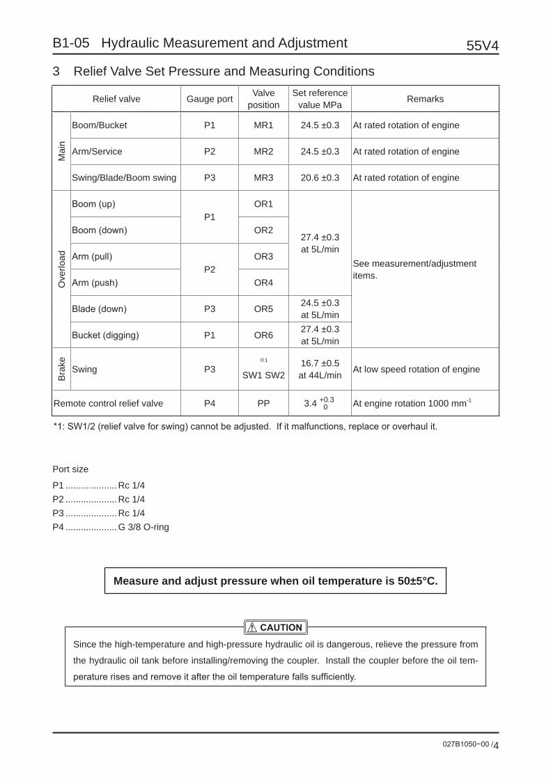
55V4
027B1050−00 /4
B1-05 Hydraulic Measurement and Adjustment
3 Relief Valve Set Pressure and Measuring Conditions
Relief valve Gauge port Valve position
Set reference value MPa Remarks
Mai
n
Boom/Bucket P1 MR1 24.5 ±0.3 At rated rotation of engine
Arm/Service P2 MR2 24.5 ±0.3 At rated rotation of engine
Swing/Blade/Boom swing P3 MR3 20.6 ±0.3 At rated rotation of engine
Ove
rload
Boom (up)P1
OR1
27.4 ±0.3at 5L/min
See measurement/adjustment items.
Boom (down) OR2
Arm (pull)P2
OR3
Arm (push) OR4
Blade (down) P3 OR5 24.5 ±0.3at 5L/min
Bucket (digging) P1 OR6 27.4 ±0.3at 5L/min
Bra
ke Swing P3※1
SW1 SW216.7 ±0.5at 44L/min At low speed rotation of engine
Remote control relief valve P4 PP 3.4 +0.3 0 At engine rotation 1000 mm-1
*1: SW1/2 (relief valve for swing) cannot be adjusted. If it malfunctions, replace or overhaul it.
Port size
P1 ....................Rc 1/4P2 ....................Rc 1/4P3 ....................Rc 1/4P4 ....................G 3/8 O-ring
Measure and adjust pressure when oil temperature is 50±5°C.
Since the high-temperature and high-pressure hydraulic oil is dangerous, relieve the pressure from
the hydraulic oil tank before installing/removing the coupler. Install the coupler before the oil tem-
perature rises and remove it after the oil temperature falls sufficiently.

027B1050−00 /5
55V4B1-05 Hydraulic Measurement and Adjustment
4 Measuring ToolsThe following kit is recommended.
Oil pressure measuring gauge kit Part No. 598014102
Standard kit
Product name Specification Q’tyPressure gauge 40MPa 2Pressure gauge 6MPa 1High-pressure hose 4m 2High-pressure hose 1m 1Pressure gaugeconnector
For connecting pressure gauge and hose 3
Coupling G1/4 3Coupling R1/4 3Coupling R1/8 2Special case Kit storing box 1
Added optionName Part No.
Pressure gauge 40MPa 500 ‒ 42.400Pressure gauge 6MPa 500 ‒ 42.060Coupling (R1/8) 100 ‒ 51.000Coupling (R1/4) 100 ‒ 42.001Coupling (G1/4) 100 ‒ 52.000Hose (1m) 200 ‒ 16.100Hose (4m) 200 ‒ 16.400
Name Part No. SpecificationAdapter 1/4” 407295301 Rc1/4: HoleAdapter 3/8” 407295302Adapter 1/2” 407295303Adapter 3/4” 407295304Adapter 1” 407295305Adapter UNF6/19 D06028600
Coupling High-pressure hose Pressure gauge connector Pressure gauge

55V4
027B1050−00 /6
B1-05 Hydraulic Measurement and Adjustment
5 Measurement/Adjustment of Main Relief Valve Set Pressure Measurement
Remove the cover.
Remove the plug and attach the coupling. Then, connect the measuring gauge.
MR1 measurement ....... P1MR2 measurement ....... P2MR3 measurement ....... P3
Start the engine and increase the rotation to the maximum.Operate the cylinder on each relief valve circuit to the stroke end and relieve the relief valve.
MR1 measurement .. Boom or bucket cylinderMR2 measurement .. Arm cylinderMR3 measurement .. Boom swing cylinder
Read the gauge value.
If the measured value deviates from the set value, perform adjustment.
When a large amount of pressure leaks from the cylinder, a low relief pressure is indicated. If it seems that the leak occurs, disconnect the hose from the cylinder, block with a plug and then measure the pressure.
P3
Coupling (R1/4)
Serial No. :100-42001
P2
P1
Cover

027B1050−00 /7
55V4B1-05 Hydraulic Measurement and Adjustment
Adjustment
Adjust the main relief valve pressure in the state of pressure measurement.
Loosen the lock nut.Turn the adjusting screw with a hexagonal wrench and adjust the pressure based on your intuition.(Approx. 9.8MPa is changed by one turn of adjusting screw.)
Right turn ....... The pressure rises.Left turn .......... The pressure falls.
Decide the adjusting position as tightening the adjusting screw.
Fasten with the lock nut and measure the pressure.
Repeat the procedure mentioned above until the set value is obtained.
If the pressure is not changed though you turn the adjusting screw, maybe the cause is not the fatigued spring but the adjusting valve or pres-sure-adjusting valve which is eccentrically worn or dust or stuffing. Remove the relief valve and then disassemble and overhaul it.
MR1
Lock nut
Adjusting screw
MR2
MR3

55V4
027B1050−00 /8
B1-05 Hydraulic Measurement and Adjustment
6 Measurement/Adjustment of Overload Relief Valve Set Pressure Measurement
Install the measuring gauge.OR1 (boom up) measurement ...............P1OR2 (boom down) measurement ..........P1OR3 (arm pull) measurement ................P2OR4 (arm push) measurement ..............P2OR5 (blade down) measurement ..........P3OR6 (bucket-dig) measurement ............P1
Set the main relief pressure temporarily.OR1 (boom up) measurement ...............MR1OR2 (boom down) measurement ..........MR1OR3 (arm pull) measurement ................MR2OR4 (arm push) measurement ..............MR2OR5 (blade down) measurement ..........MR3OR6 (bucket-dig) measurement ............MR1
Loosen the lock nut, turn the adjusting screw clock-wise by 180 degrees, and tighten the lock nut for fastening.
After measurement is completed, perform read-justment according to the main relief valve pres-sure adjusting method.
Start the engine and set the rotation to “idling”. Operate the cylinder on each relief valve circuit to the stroke end and relieve the relief valve.
The flow amount at the overload relief valve set-ting is 5L/min. If the flow amount is large, the relief pressure is high. Be sure to measure the pressure in the idling status.
Read the gauge value.
If the measured value deviates from the set value, perform adjustment.
Readjust the main relief valve pressure.
MR1
MR2
MR3
P3
P2P1
Lock nut
Adjusting screw

027B1050−00 /9
55V4B1-05 Hydraulic Measurement and Adjustment
Adjustment
Adjust the overload relief valve pressure in the state of pressure measurement.The main relief valve must be temporarily ad-justed.
Loosen the lock nut.Turn the adjusting screw with a hexagonal wrench and adjust the pressure based on your intuition.(Approx. 9.8MPa is changed by one turn of adjusting screw.)
Right turn ....... The pressure rises.Left turn .......... The pressure falls.
Decide the adjusting position as tightening the adjusting screw.
Fasten with the lock nut and measure the pressure.
Repeat the procedure mentioned above until the set value is obtained.
If the pressure is not changed though you turn the adjusting screw, maybe the cause is not the fatigued spring but the adjusting valve or pres-sure-adjusting valve which is eccentrically worn or dust or stuffing. Remove the relief valve and then disassemble and overhaul it.
After measurement is completed, perform read-justment according to the main relief valve pres-sure adjusting method.
OR2 Boom: upOR6 Bucket: digging
OR1 Boom: down
Arm: push OR4
OR3 Arm: pull
Blade: down OR5
Lock nut
Adjusting screw

55V4
027B1050−00 /10
B1-05 Hydraulic Measurement and Adjustment
7 Measurement/Adjustment of Swing Brake Relief Valve Set Pressure Measurement
Before measurement of the swing brake relief valve, measure the main relief valve pressure and make sure that the pressure is normal.
With the position shown at right, let the bucket blade bite the ground surface to fasten it so that the upper machine cannot swing.
As the main relief valve measurement, remove the covers.Install the measuring gauge on the P3 port.
Start the engine and set the rotation to “idling”.Operate the swing operation lever slowly to the stroke end and relieve the relief valve.
SW1 measurement ......... Left swingSW2 measurement ......... Right swing
Read the gauge value
If the measured value deviates from the set value, replace or overhaul the relief valve.
SW2Right swing
SW1Left swing
P3

027B1060−00 /1
55V4B1-06 Consumable Parts and Use Limitation
1 Chassis Parts1-1 Steel crawler
Item Unit Reference dimension
Permissible value Action to be taken
Link height (A)
mm
67 57
Sample one link. If the permissible value is
exceeded again, replace the crawler.
Grouser height (B) 14 10
Bushing
Outsidediameter (C) 35 33
Insidediameter (D) 22.3 25
Link pitch (E) 135 140
Master pin diameter (F) 22 20

55V4
027B1060−00 /2
B1-06 Consumable Parts and Use Limitation
1-2 Lower roller
Item Unit Reference dimension
Permissible value Action to be taken
Boss width (A)
mm
50 45
Replace.Tread outside diameter (B) 110 100
Boss outside diameter (C) 132 122
Roller axial play 0.5 0.9 Replace the ball bearing.

027B1060−00 /3
55V4B1-06 Consumable Parts and Use Limitation
1-3 Upper roller
Item Unit Reference dimension
Permissible value Action to be taken
Tread outside diameter (A)mm
70 66Replace.
Roller axial play (B) 0.3 0.9

55V4
027B1060−00 /4
B1-06 Consumable Parts and Use Limitation
1-4 Sprocket
Item Unit Reference dimension
Permissible value Action to be taken
Root diameter (A)
mm
380.4 370
Replace.Tooth width (B) 44 39
Outside diameter (C) 435.8 425

027B1060−00 /5
55V4B1-06 Consumable Parts and Use Limitation
1-5 Idler
Item Unit Reference dimension
Permissible value Action to be taken
Boss outside diameter (A)
mm
411 -
Replace.Tread outside diameter (B) 363 353
Boss width (C) 52 32
Shaft axial play - -

55V4
027B1060−00 /6
B1-06 Consumable Parts and Use Limitation
1-6 Rubber crawlerWhen the lug height is beyond the permissible value, replace the rubber crawler.
(mm)Reference dimension
Permissible value
A 25 5
The status mentioned below is the use limit and the rubber crawler must be replaced.
1. The rubber is worn or damaged and so the steel cord is exposed.
2. Half or more of the steel cord layer at one side is broken.
3. The core metal of rubber crawler is separated at one place or more.
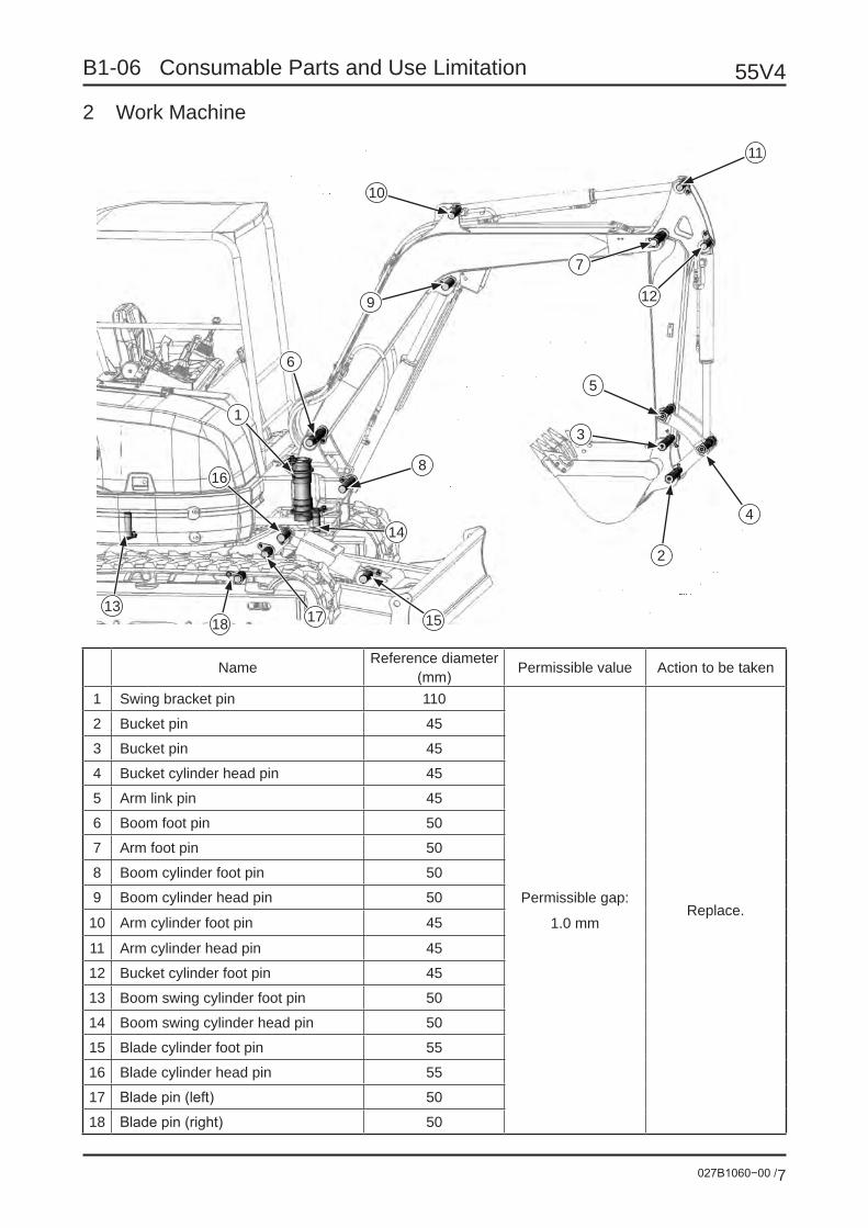
027B1060−00 /7
55V4B1-06 Consumable Parts and Use Limitation
2 Work Machine
Name Reference diameter (mm) Permissible value Action to be taken
1 Swing bracket pin 110
Permissible gap:
1.0 mmReplace.
2 Bucket pin 45
3 Bucket pin 45
4 Bucket cylinder head pin 45
5 Arm link pin 45
6 Boom foot pin 50
7 Arm foot pin 50
8 Boom cylinder foot pin 50
9 Boom cylinder head pin 50
10 Arm cylinder foot pin 45
11 Arm cylinder head pin 45
12 Bucket cylinder foot pin 45
13 Boom swing cylinder foot pin 50
14 Boom swing cylinder head pin 50
15 Blade cylinder foot pin 55
16 Blade cylinder head pin 55
17 Blade pin (left) 50
18 Blade pin (right) 50
11
7
12
5
3
2
4
15
14
8
171813
16
1
6
9
10

55V4
027B1060−00 /8
B1-06 Consumable Parts and Use Limitation
Bushing (except cylinder)
Name Reference diameter (mm) Permissible value Action to be taken
1 Swing bracket bushing (upper) 110
+0.5mm Replace.
2 Swing bracket bushing (lower) 110
3 Boom foot bushing 50
4 Arm foot bushing 50
5 Arm head bushing 45
6 Arm link bushing 45
7 Bucket link bushing (bucket side) 45
8 Bucket link bushing (cylinder side) 45
9 Blade bushing 50
Use limit of bucket tooth
When the tooth is worn and a hole can be made on it, replace it.
4
6
5
8
7
1
2
9
9
3
Tooth
Hole caused by wear

B2 Maintenance Method

027B2010−00 /1
55V4B2-01 Crawler Check/Tension Adjustment
Crawler shoe tension check/adjustment
Since the shoe tension is checked with the body lifted, a very dangerous state may occur if the body is dropped by mistake dur-ing check. Never move the machine during measurement.
Growth of shoe wear or looseness depends on the situation of the work site.If the loosened shoe is used, slip-off of the crawler shoe may be caused.Check/adjust the tension as required.
1. Check
(1) Using the work machine and blade, lift the main body until the shoe leaves the ground.
(2) Measure the clearance between the tread of the second lower roller from the sprocket and the shoe tread.
Clearance: 10 to 20 mm for the rubber shoe 30 to 50 mm for the steel shoe
These reserve standard tensions.
Jack up until the shoe leaves the ground.
Lower roller
ShoeSlack
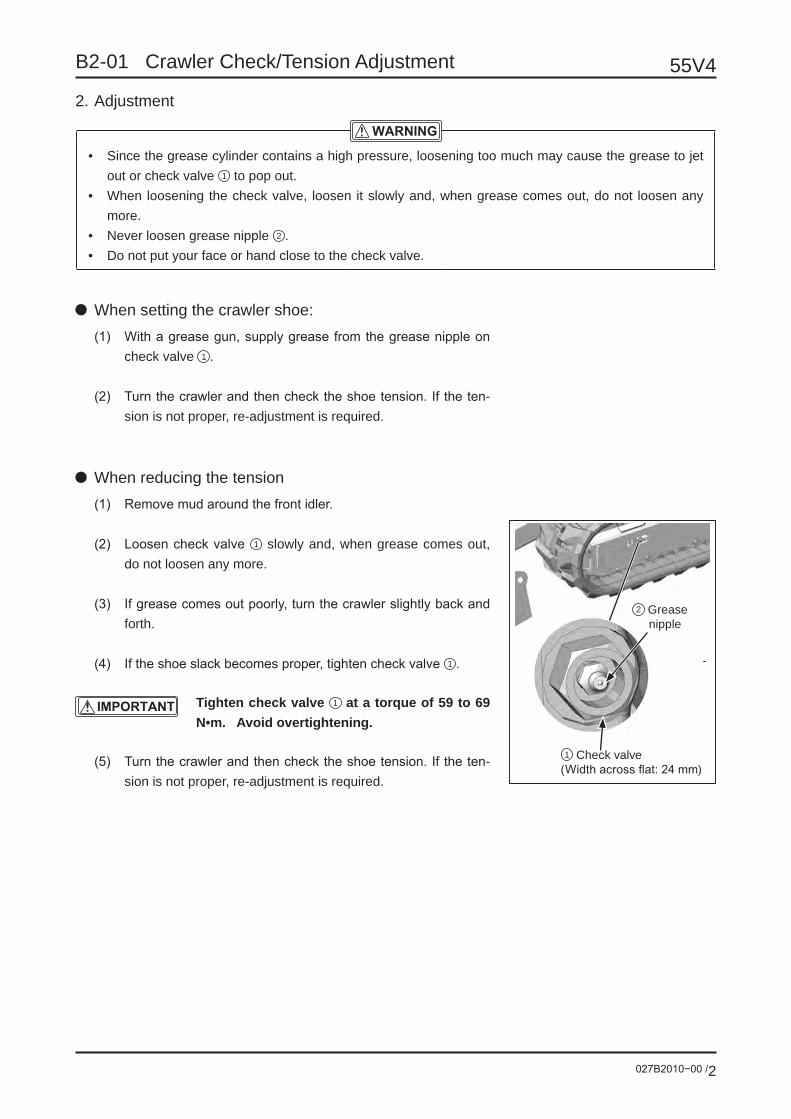
55V4
027B2010−00 /2
B2-01 Crawler Check/Tension Adjustment
2. Adjustment
• Since the grease cylinder contains a high pressure, loosening too much may cause the grease to jet out or check valve 1 to pop out.
• When loosening the check valve, loosen it slowly and, when grease comes out, do not loosen any more.
• Never loosen grease nipple 2 .• Do not put your face or hand close to the check valve.
When setting the crawler shoe:(1) With a grease gun, supply grease from the grease nipple on
check valve 1 .
(2) Turn the crawler and then check the shoe tension. If the ten-sion is not proper, re-adjustment is required.
When reducing the tension(1) Remove mud around the front idler.
(2) Loosen check valve 1 slowly and, when grease comes out, do not loosen any more.
(3) If grease comes out poorly, turn the crawler slightly back and forth.
(4) If the shoe slack becomes proper, tighten check valve 1 .
Tighten check valve 1 at a torque of 59 to 69 N•m. Avoid overtightening.
(5) Turn the crawler and then check the shoe tension. If the ten-sion is not proper, re-adjustment is required.
2 Grease nipple
1 Check valve(Width across flat: 24 mm)

027B2010−00 /3
55V4B2-01 Crawler Check/Tension Adjustment
Rubber crawler check1. Lug height
Replace with a new one when the remaining lug height is 5 mm or smaller.
2. Steel cord exposureIf the steel cord is exposed as a result of the wear or damage of rubber, replace with a new one.
3. Rubber crawler steel cord is brokenIf a half or more of the one-side steel cord layer is broken, immedi-ate replacement is required.
If the rubber crawler is left in this state, the rubber crawler may be suddenly broken during work and a serious accident may occur.
4. Repairing cover rubber flawsIf the flaw length is at least 30 mm and the depth is at least 8 mm, repair is required.If the steel cord is visible, immediate repair is required regardless of the flaw size.
If this state is left unchanged, water may enter, rust will be generated on the steel cord, and the rubber crawler may be broken.
5. Slip-off of rubber crawler core metalIf the rubber crawler core metal slips off at one or more positions, replace the rubber crawler with a new one.
If the cover rubber crack length is 30 mm or larger and the depth is 8 mm or larger, repair is required.
Lug height 5 mm or smaller
Steel cord 1/2 or more broken
Steel cord exposed

027B2020−00 /1
55V4B2-02 Bucket Tooth Check and Replacement
• Before replacing the bucket tooth, put the bucket on a block and stop the engine.
• When knocking the lock pin in, fragments may fly and per-sonal injury may occur. Before the work, put on protectors such as the protection glasses, helmet, gloves, etc.
If tooth 1 is worn out and the hole is likely to grow, replace the tooth.Replace tooth 1 before wear of adapter 2 be-gins.
(1) With the hammer and removing tool, knock off lock pin 3 and remove the tooth.
(2) Remove mud from nose 4 .
(3) Check the removed lock pin 3 and rubber lock pin 5 . If lock pin 3 is too short or rubber is broken and the ball is coming out from rubber lock pin 5 , replace with a new one.
It is recommended to replace the rubber lock pin each time the tooth is replaced.
(4) Attach rubber lock pin 5 on the nose.
(5) Insert tooth 1 into nose 4 .
(6) With a hammer, knock in lock pin 3 to the same level as the surface of tooth 1 . If knocking is insufficient, tooth 1 may slip down.
(7) Make sure that tooth 1 is fastened securely.
Wear hole
1 Tooth
5 Rubber lock pin
1 Tooth
4 Nose
2 Adapter
3 Lock pin
Failure
3 Lock pin
Too short lock pin
Insufficient knocking of the lock pin
3 Lock pinFailure
Failure
5 Rubber lock pin
The ball is stuck.

027B2030−00 /1
55V4B2-03 Bucket Mounting Clearance Adjustment
The standard bucket of this machine is equipped with a bucket clear-ance adjusting mechanism to prevent shakiness.If shakiness becomes extremely large during use, perform adjustment as described below.
(1) Let the back of the bucket lightly touch the ground, swing the bucket slightly to the right, and make the arm end press the inside of the clearance adjusting part.
(2) Stop the engine.
(3) Move O-ring 1 onto the boss and measure the mounting clearance between bucket 2 and arm 3 .
(4) If the clearance is 1 mm or larger, remove shim 4 and make adjustment. Thickness of shim 4 is 0.8 mm. If the clearance is 0.8 mm or smaller, do not remove the shim because the clearance will be lost.
(5) Remove three bolts 5 and remove shim 4 inside flange 6 according to shakiness (wear).
(6) Attach flange 6 and tighten three bolts 5 .
(7) Measure the mounting clearance. The standard clearance is 0.1 to 0.8 mm.
If the mounting clearance is a negative value, abnormal wear of the boss contact surface between the arm and bucket will be caused. Therefore, be sure to reserve the clearance.
Clearance adjusting part
3 Arm
Pin
4 Shim
Standard clearance: 0.1 to 0.8 mm
2 Bucket
1 O-ring1 O-ring
6 Flange
5 Bolt

027B2040−00 /1
55V4B2-04 Greasing
Use Extreme Pressure Grease (EP) No. 2.
Contentes Page
1 Attachment/Dozer Blade Pin P2
1-1 Pin location and name
1-2 Grease nipple location
1-3 Greasing
2 Swing Bearing P5
2-1 Grease nipple location
2-2 Greasing
3 Swing Gear P6
3-1 Check/filler port and drain port
3-2 Check/greasing

55V4
027B2040−00 /2
B2-04 Greasing
1 Attachment/Dozer Blade PinThe units (including the hydraulic cylinder mounting section) are connected with 19 pins.The grease nipple peculiar to each unit is provided. Apply grease with a grease gun periodically.
1-1 Pin location and name
Name Name
1 Swing bracket pin 10 Arm cylinder foot pin
2 Bucket pin 11 Arm cylinder head pin
3 Bucket pin 12 Bucket cylinder foot pin
4 Bucket cylinder head pin 13 Boom swing cylinder foot pin
5 Arm link pin 14 Boom swing cylinder head pin
6 Boom foot pin 15 Blade cylinder foot pin
7 Arm foot pin 16 Blade cylinder head pin
8 Boom cylinder foot pin 17 Blade pin (left)
9 Boom cylinder head pin 18 Blade pin (right)
11
12
4
2
3
5
7
9
10
6
1
13 8
14
16
17
18
15

027B2040−00 /3
55V4B2-04 Greasing
1-2 Greasing location (Grease nipple location. The number is the pin number in the preceding page.)
5
3
2
4
7
13
814
9
10
6
1
14
12
16
18
15
17

55V4
027B2040−00 /4
B2-04 Greasing
1-3 Greasing(1) Lower the work machine to the ground and stop the engine.
(2) With a grease gun, supply grease from the grease nipples until old grease comes out of the clear-ance.
(3) After greasing, wipe off the old grease that has come out.
Interval for greasing: 50 hours
For 5 positions around the bucket, be sure to supply grease before underwater excavation regardless of the maintenance time.
4
5
3
2

027B2040−00 /5
55V4B2-04 Greasing
2 Swing Bearing2-1 Grease nipple location
2-2 Greasing1. Lower the bucket to the ground and stop the engine.2. With a grease gun, supply grease through the grease nipple by 3 - 5 strokes.3. Each time the upper machine is swung in about 90°, supply grease. Repeat greasing until it swings by
one round.
Because the swing bearing diameter is large, grease is not circulated in the whole unit even if greasing is done from one position. Change the position by swinging in 90° , stop swinging and supply grease.
Interval for greasing: 50 hours
If you supply grease while the machine is swing-ing, you may be caught by it. To avoid danger, stop swinging and then supply grease.
Grease nipple

55V4
027B2040−00 /6
B2-04 Greasing
3 Swing Gear3-1 Check/filler port and drain port
3-2 Check/greasing1. Lower the bucket to the ground and stop the en-
gine.
2. Remove the filler port cover on the upper machine side. Check if grease is supplied enough on the swing gear.
If grease is insufficient on the tooth, supply grease with about 0.5kg as standard.
Interval for checking/greasing: 500 hours
Filler port cover
Swing motor
Filler port cover
Drain port cover
Swing gear

027B2040−00 /7
55V4B2-04 Greasing
3. If grease is whitish due to the mixed water or mud, replace the total volume of grease with new one.
Remove the lower machine cover and the drain port cover and drain away the old grease. Attach the drain port cover again and supply new grease from the filler port.
Total grease volume: 11L
4. After swinging a few times, make sure that grease is fully supplied to the swing gear. Then, attach the lower machine cover and the filler port cover on the upper machine.
Drain port cover
Lower machine cover

027B2050−00 /1
55V4B2-05 Hydraulic Oil Check, Refilling, Replacement, and Strainer Washing
1 Hydraulic oil volume check/refilling
1 Do not run the machine if the hydraulic oil is below the “L” level.
2. If the hydraulic oil is refilled exceeding the “H” level, loosen drain plug 3 and discharge the extra oil.
(1) Put the machine on a flat location, ground the blade, fully retract the arm and bucket cylinders, lower the boom and ground the bucket, and stop the engine.
(2) Check oil level gauge 1 . The oil level should be between H and L. Since the oil level varies depending on the oil tempera-ture, the following should be used for refer-ence:
• Near the L level before running (oil tem-perature 10 to 30°C)
• Near the H level during running (oil tem-perature 50 to 80°C)
(3) If the hydraulic oil is below the L level, refill the hydraulic oil from oil supply port 2 .
Before removing the oil supply port 2 , press the air breather button and relieve the pres-sure.
Position for hydraulic oil level check
H
L
1 Oil level gauge
3 Drain plug
2 Oil supply port
Air breather button

55V4
027B2050−00 /2
B2-05 Hydraulic Oil Check, Refilling, Replacement, and Strainer Washing
2 Hydraulic oil replacement and
strainer cleaning
• Oil is hot immediately after movement. Touch-ing may result in a burn. Start the work after oil is cooled down.
• Be sure to perform the work after the pressur-ized air in the hydraulic oil tank is relieved.
(1) Perform turning so that the drain plug on the hydraulic oil tank will be on the middle be-tween the right and left crawlers.
(2) Fully retract the arm and bucket cylinders, lower the boom, and ground the bucket.
(3) Ground the blade and stop the engine.
(4) Press the air breather button and relieve the pressure from the hydraulic oil tank. Then, remove the oil supply plug .
(5) Put an oil receiving container below the drain plug on the bottom of the hydraulic oil tank, remove drain plug 2 , and discharge the oil. After discharging, tighten drain plug 2 .
(6) Remove the hose 3 , loosen the bolt 4 and remove the strainer cover 5 .
(7) Remove dust from strainer 6 , clean the strainer, and assemble it.
(8) Fasten strainer cover 5 with bolt 4 and at-tach hose 3 .
1
Position for hydraulic oil replacement
1 Oil supply port
2 Drain plug
4 Bolt
3 Hose
5 Strainer cover
5 Strainer cover
6 Strainer7 O-ring
Air breather button

027B2050−00 /3
55V4B2-05 Hydraulic Oil Check, Refilling, Replacement, and Strainer Washing
(10) Supply the specified volume of hydraulic oil from the oil supply port. Be sure that the hydraulic oil is between H and L on level gauge.
(11) Exhaust air from the hydraulic pump. Remove the air exhaust plug. Make sure
that air is exhausted from the plug hole and oil comes out.
Unless air is exhausted, sei-zure may occur on the hy-draulic pump. When replacing the hydraulic oil or hydraulic pump, be sure to exhaust air from the hydraulic pump.
(12) Run the engine for a few minutes in low idling. Then, check the oil level in the level check position. If the oil is insufficient, refill.
H
L
Oil level gauge
Air exhaust plug

027B2060−00 /1
55V4B2-06 Return Filter Cartridge Replacement
• Oil is hot immediately after movement. Start the work after the oil is cooled down.
• The hydraulic oil tank is pressurized with air. Removing the filter cartridge immediately will cause the oil to jet out and it is dangerous, so be sure to stop the engine, press the air breather button and relieve the internal pres-sure before removal.
(1) Put the work machine on the ground and stop the engine.
(2) Press the air breather button 1 to relieve the internal air in the tank.
(3) With a filter wrench, turn filter cartridge 2 counterclockwise and remove it.
(4) Thinly coat the hydraulic oil to the O-ring 3 of the new cartridge and tighten it with a filter wrench.
(5) Start the engine and make sure that oil does
not leak
1 Air breather button
Return filter
3 O-ring
4 Head
2 Cartridge

55V4
027B2060−00 /2
B2-06 Return Filter Cartridge Replacement
(6) Put the work machine in the oil level check posture and check the level.
The oil should be between “H” and “L” on the level gauge 5 .
If the oil is not sufficient, replenish the hy-draulic oil.
Posture for checking the hydraulic oil level
H
L
5 Oil level gauge
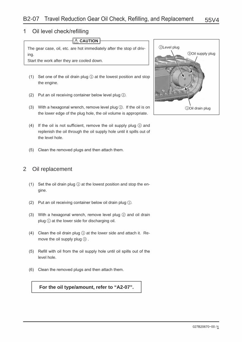
027B20670−00 /1
55V4B2-07 Travel Reduction Gear Oil Check, Refilling, and Replacement
1 Oil level check/refilling
The gear case, oil, etc. are hot immediately after the stop of driv-ing.Start the work after they are cooled down.
(1) Set one of the oil drain plug 1 at the lowest position and stop the engine.
(2) Put an oil receiving container below level plug 2 .
(3) With a hexagonal wrench, remove level plug 2 . If the oil is on the lower edge of the plug hole, the oil volume is appropriate.
(4) If the oil is not sufficient, remove the oil supply plug 3 and replenish the oil through the oil supply hole until it spills out of the level hole.
(5) Clean the removed plugs and then attach them.
2 Oil replacement
(1) Set the oil drain plug 1 at the lowest position and stop the en-gine.
(2) Put an oil receiving container below oil drain plug 1 .
(3) With a hexagonal wrench, remove level plug 2 and oil drain plug 1 at the lower side for discharging oil.
(4) Clean the oil drain plug 1 at the lower side and attach it. Re-move the oil supply plug 3 .
(5) Refill with oil from the oil supply hole until oil spills out of the level hole.
(6) Clean the removed plugs and then attach them.
For the oil type/amount, refer to “A2-07”.
2 Level plug3 Oil supply plug
1 Oil drain plug

027B2080−00 /1
55V4B2-08 Battery Check, Electrolyte Refilling and Replacement
Battery handling
• Combustible hydrogen gas is generated from the battery. Since ignition or explosion may be caused, never put fire close nor generate spark.
• Never put metal materials such as tools and combustible materials on or near the battery. Short-circuiting will result in ignition or explosion.
• The battery liquid (diluted sulfuric acid) may cause blindness or burns. If it adheres on your eye, skin, or clothes, wash and remove it immediately with a large amount of water and accept medi-cal treatment.
• When handling the battery, be sure to put on protection glasses.• While the engine is rotating, never remove the battery cable.
Battery liquid refillingIf you check the indicator and <LIQUID INSUFFICIENT> is indicat-ed, or if you check the liquid level on the side of the battery and the liquid level is about to reach LOWER LEVEL, be sure to remove the cap on each cell and refill with the liquid to UPPER LEVEL. Do not refill exceeding UPPER LEVEL.
Battery terminal cleaning• Be sure to stop the engine before starting
the work.• During work, be careful not to cause short-
circuiting of the and connectors on the battery with tools, etc.
• When removing battery connectors from the terminal, remove the connector first.
When attaching, attach the connector last.
• Tighten securely so that looseness will not occur on the terminal side.
(1) Remove dirt or corrosion from the terminal. (If white powder
is deposited on the terminal as a result of corrosion, dip cloth
into warm water and then use the cloth to wipe the white pow-
der off.)
(2) If excessive corrosion exists on the terminal, remove the ter-
minal and polish it with wire brush and sandpaper.
(3) After cleaning and tightening, thinly coat grease on the termi-
nal.
Shows the charged state and liquid level state for reference.
Indication by the indicator
(White)• Liquid insufficient
• Charging required
• Good
(Red)
(Blue)
Indicator
Cap
Upper level
Lower level

027B2090−00 /1
55V4B2-09 Fuel Circuit Check, Cleaning, and Filter Replacement
Water sedimentor check
• Perform this work after each part of the engine is cooled down.
• Do not put fire close.• Since spilled light oil may result in fire disasters, wipe it off
carefully.
If float 1 of the water sedimentor is floating, water is accumulated below the float. Drain water before the float contacts the bottom of filter 2 .
(1) Stop the engine.
(2) Loosen drain valve 3 until water flows out.
(3) When water is drained and the float reaches the bottom of the cup, close drain valve 3 .
(4) Purge air from the water sedimentor. Turn the starter switch key to “Start” (ON) and leave it for approximately 20 seconds. The automatic air purge unit purges air automati-cally and allows the engine to be started.
Water sedimentor
2 Filter
1 Float
3 Drain valve

55V4
027B2090−00 /2
B2-09 Fuel Circuit Check, Cleaning, and Filter Replacement
Fuel filter cartridge replacement
• Perform this work after each part of the engine is cooled down.
• Do not put fire close.• Since spilled light oil may result in fire disasters, wipe it off
carefully.
Do not tighten filter cartridge 1 too much. Over-tightening may result in element damages.
(1) Put the work machine on the ground and stop the engine.
(2) With a filter wrench, turn filter cartridge 1 counterclock-wise and remove it.
(3) When attaching a filter cartridge, thinly coat the engine oil on the gasket of filter cartridge 1 . After gasket 2 contacts the seal surface, tighten by 3/4 to 1 turn.
(4) After attaching, purge air.
Air purging methodIf the cartridge is replaced or the fuel tank is emptied, air comes in the circuit and the fuel does not flow. Therefore, air purging is re-quired.
(1) Fill the fuel tank with the fuel.
(2) Turn the starter switch key to “Start” (ON) and leave it for approximately 20 seconds.
(3) The automatic air purge unit purges air automatically and allows the engine to be started.
Fuel filter
2 Gasket
Body
1 Cartridge

B2-10 Coolant Check, Refilling, and Replacement
027B2100−00 /1
55V4
Check/refilling
In normal cases, do not open the radiator cap. Check the coolant with the reservoir tank only if the engine is cold.
(1) Open the engine cover and check to see if the level of coolant in the reservoir tank is between FULL and LOW. If the level is lower, refill with coolant to the FULL level from the water supply port of the reservoir tank.
(2) If the reservoir tank is empty, stop the engine and check for water leak and check the water level in the radiator. If the level is lower, refill the radiator and reservoir tank with the coolant.
Replacement
• Immediately after the engine is stopped, the coolant is hot. Draining the coolant immediately may result in a burn.
Drain the coolant after the engine is cooled down.• If the water temperature in the radiator is high, do not re-
move the cap. After the water is cooled down, turn the cap slowly to re-
lieve the pressure from the radiator and then remove the cap.
(1) Put the work machine on the ground and stop the engine.
(2) Remove radiator cap 1 .
Reservoir tank level
Lower limit
Upper limit
Water supply port
1 Radiator cap

B2-10 Coolant Check, Refilling, and Replacement 55V4
027B2100−00 /2
(3) Open drain cock 2 on the bottom of the radiator to drain water.
(4) Close drain cock 2 and drain plug 3 . Put in service water and cleanser (radiator cleaner). Run the engine for ap-proximately 10 minutes at a slightly higher rotation than low idling.
(5) Stop the engine and open drain cock 2 to drain water.
(6) After water is drained, close drain cock 2 to supply service water.
(7) Open drain cock 2 and set the engine to low idling. While adjusting the supplied water volume so that the radiator will always be full of water, perform washing with water for 10 minutes.
(8) Close drain cock 2 and fill with the coolant consisting of the service water and long-life coolant to the lower edge of the radiator water supply port.
(9) Run the engine for 5 minutes in low idling and then stop it. The water level drops because the internal air is purged. Refill with the coolant to near the water supply port and close the cap.
(10) Drain the coolant from reservoir tank 3 . Wash the inside of the tank. Fill with the coolant consisting of the service water and long-life coolant to the FULL mark.
2 Drain cock
3 Reservoir tank

B2-11 Engine Oil Check, Refilling, Replacement, and Filter Replacement
027B2110−00 /1
55V4
Engine oil volume check/refilling(1) Remove the oil level gauge and wipe it with dry cloth.
Then, fully insert it and remove it calmly.(2) If the level is between the upper and lower limits on the
level gauge, the oil volume is appropriate. If the oil does not reach the lower limit, refill with the engine oil from the oil supply port.
(3) If the oil is above the upper limit, remove the extra volume from the drain plug and check the oil level again.
• Before check, set the machine horizon-tal.
• To check after the engine is started, start checking at least 10 minutes after the engine stops.
• Do not start the engine if the oil level is above the upper limit or below the lower limit.
Engine oil and oil filter replacement
Oil is hot and a burn may occur immediately after movement. Start the work after the oil is cooled down.
Engine oil draining(1) Stop the engine.(2) Put a drain oil receiver below drain plug 2 of the engine.(3) Clean around oil supply port cap 1 so that foreign matters
will not come in. Then, remove oil supply port cap 1 .(4) Remove drain plug 2 slowly so that oil will not splash, for
oil draining.(5) Check the drained oil. If the drained oil has much metal
powder or foreign matters, it is necessary to overhaul the engine. (Refer to the engine service manual.)
3 Filter cartridge4 Oil level gauge
1 Oil supply port cap
Upper limit
Oil level gauge
Lower limit
Drain plug

B2-11 Engine Oil Check, Refilling, Replacement, and Filter Replacement 55V4
027B2110−00 /2
Filter cartridge replacement(1) With a filter wrench, turn filter cartridge 3 counterclockwise
and remove it.
(2) Remove dust, etc. from the cartridge mounting surface.
(3) Thinly coat the engine oil on the gasket of the new cartridge.
(4) Screw in the cartridge by hand. After the gasket contacts the seal surface, tighten by approximately 3/4 turn with a filter wrench.
Engine oil refilling(1) Attach drain plug 2 .
(2) From oil supply port 1 , refill with the engine oil to the level be-tween the upper limit and lower limit on level gauge 4 .
(3) Run the engine in idling for several minutes then stop it. Check the engine oil volume 10 to 20 minutes later. If the volume is insufficient, refill with the engine oil to the specified level.

B2-12 Air Cleaner Check, Cleaning, and Element Replacement
027B2120−00 /1
55V4
• Be sure to clean/replace the air cleaner after the engine stops. If this work is done while the en-gine is rotating, dust is absorbed and the engine may be damaged.
• When cleaning the element using the compressed air, put on protection glasses because dust may enter your eyes and it is dangerous.
• If the element is dirty with oily smoke, soot, oil, etc., replace with a new ele-ment regardless of the replacement cycle.
• Do not hit, knock, or drop the element.• If it is found in daily check that dust indicator shows the red signal, clean or re-
place element regardless of the maintenance cycle.
Cleaning: Every 250 hours or when the dust indicator shows the red signal.Replacement: When the air cleaner has been cleaned up to five times or when one year has passed since
the last replacement or when the dust indicator shows the red signal right after cleaning.
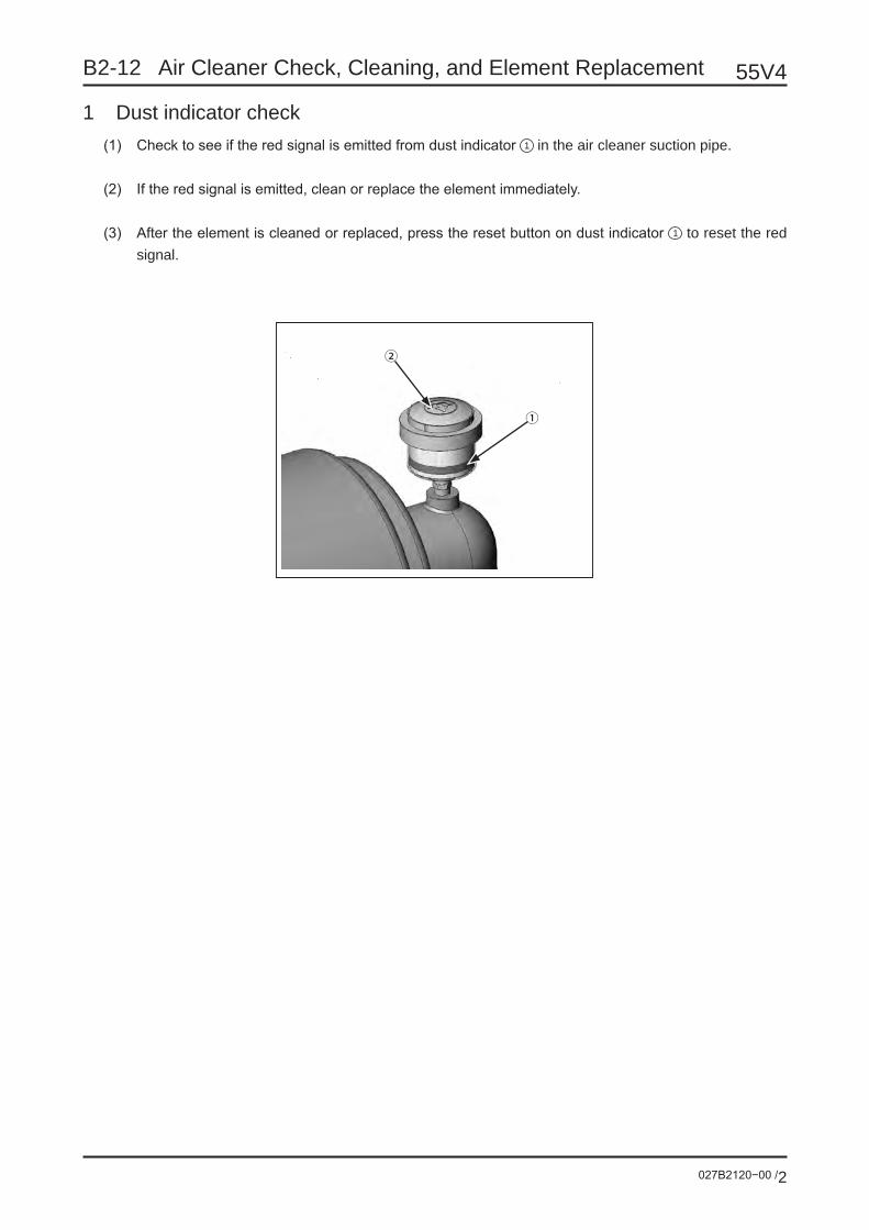
B2-12 Air Cleaner Check, Cleaning, and Element Replacement 55V4
027B2120−00 /2
②
①
1 Dust indicator check(1) Check to see if the red signal is emitted from dust indicator 1 in the air cleaner suction pipe.
(2) If the red signal is emitted, clean or replace the element immediately.
(3) After the element is cleaned or replaced, press the reset button on dust indicator 1 to reset the red signal.
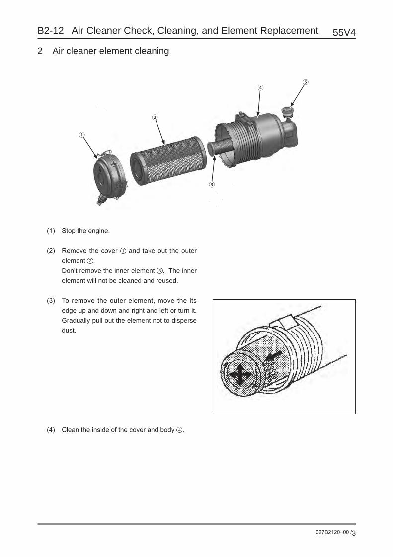
B2-12 Air Cleaner Check, Cleaning, and Element Replacement
027B2120−00 /3
55V4
①
②
④
③
⑤
2 Air cleaner element cleaning
(1) Stop the engine.
(2) Remove the cover 1 and take out the outer element 2 .
Don’t remove the inner element 3 . The inner element will not be cleaned and reused.
(3) To remove the outer element, move the its edge up and down and right and left or turn it. Gradually pull out the element not to disperse dust.
(4) Clean the inside of the cover and body 4 .

B2-12 Air Cleaner Check, Cleaning, and Element Replacement 55V4
027B2120−00 /4
(5) From the inside of the element, blow the dry compressed air (0.29 - 0.49 MPa) in the verti-cal direction along the fold of the filter paper. Then, blow the air from the outside and then blow from the inside again to remove dust from the surface.
(6) With a light spotted from the inside of the ele-ment, check the filter paper. If the filter paper is broken, the paper has pin holes (particularly thin parts), or the packing is broken, replace-ment is required.
(7) After cleaning is completed, attach element. Push not the edge center but the edge outer
circumference of the element securely to at-tach it.
(8) With the arrow (↑) on cover 1 facing up, at-tach the cover and fasten it with the clamp.
(9) Press the button on dust indicator 5 to reset the red signal.

B2-12 Air Cleaner Check, Cleaning, and Element Replacement
027B2120−00 /5
55V4
3 Air cleaner element replacement
(1) Stop the engine.
(2) Remove the cover 1 . Take out the outer element 2 and inner element 3 .
(3) Clean the inside of the cover and body 4 .
(4) Attach the new inner and outer elements in turn. Push not the edge center but the edge outer circumference of the element securely to attach it.
(5) With the arrow (↑) on cover 1 facing up, at-tach the cover and fasten it with the clamp.
(6) Press the button on dust indicator 5 to reset the red signal.
①
②
④
③
⑤

B2-13 Fan Belt Check, Adjustment, and Replacement
027B2130−00 /1
55V4
• Perform this work after each part of the engine is cooled down.
• Stop the engine and remove the starter switch key.
• If the belt is excessively tensed, the bear-ing or belt will be damaged earlier than usual.
• If the elongated belt does not have the ad-justing allowance or if the belt has a cut or crack, replace it.
• After you have replaced the belt, run the engine at high speed for 30 minutes. Then, check and adjust the belt tension.
Check(1) Open the tank cover. Remove the bolts and then remove the
check port cover so that you can see the alternator.
(2) Press the middle position between the fan pulley and alterna-tor with your thumb (approximately 98 N). A deflection of ap-proximately 10 mm is appropriate.
(3) If the belt has flaws or cracks, replace the belt.
Adjustment(1) Loosen bolt 1 and nut 2 .
(2) Move alternator 3 so that the belt tension will result in a de-flection of approximately 10 mm (98 N).
(3) Tighten bolt 1 and nut 2 .
(4) If the belt is elongated and there is no more adjusting allow-ance, replace the belt.
Crank pulley
Alternator pulley
Fan pulley
Alternator
2 Nut
Fan pulley 1 Bolt Adjustingplate
3 Alternator

B2-14 Fuse/Fusible Link
027B2140−00 /1
55V4
• As the cause of melting of the fuse or fusible link, circuit short-circuiting, component damages, etc. are considered. Detect the cause, make repair, and replace the fuse.
• Before replacing the fuse, be sure to set the starter switch to the stop (OFF) position.• Be sure to install the fuse and fusible link with the specified capacities. Never use steel wire, wrapping
foil, etc.
Contents Page
1 Fuse replacement P2
2 Fusible link replacement P5
Fuse box
Fusible link

B2-14 Fuse/Fusible Link 55V4
027B2140−00 /2
1 Fuse Replacement
• Before replacing the fuse, be sure to set the starter switch to the stop (OFF) position.
• Don’t use steel wire, wrapping foil, etc. instead of fuse. The wire may be overheated or burned to cause a fire.
• When the fuse has blown out right after re-placement, it is probable that the harness or component malfunctions (e.g. short-circuiting). Find out the cause and repair the trouble part at once. Fuse box
1-1 Components supported by fuses
Search for the inactive component in the correspondence table on the cover to find out the relevant fuse.
Fuse remover
AUX forreplacement

B2-14 Fuse/Fusible Link
027B2140−00 /3
55V4
Fuse
10A Red
2A Gray 5A Brownish-red
15A Blue
20A Yellow25A Water-clear
30A Green

B2-14 Fuse/Fusible Link 55V4
027B2140−00 /4
1-2 ReplacementMake sure that the starter switch is at the stop (OFF) position.(The key is perpendicular to the forward direction.)
Unlock the latch of the fuse box cover. Pull the cover forward and remove it.
With a fuse remover, take off the fuse of the problem component.
Check the fuse for wire break.
If there is not wire break, it is probable that the har-ness or component malfunctions (e.g. short-circuit-ing). Find out the cause and repair the trouble part at once.
Replace the broken fuse with a new one of the same capacity. (If you use the auxiliary fuse, supply a new auxiliary fuse.)
1
1
2
Starter switch
Fuse remover
Wire break

B2-14 Fuse/Fusible Link
027B2140−00 /5
55V4
2 Fusible link replacement
If you set the starter switch to “Start” (ON) and the power is not turned on, it is probable that the fusible link on the circuit from battery to starter switch is broken by an accident (e.g. short-circuiting of circuit). Remove the fusible link and check it. If the fusible link has blown out, repair the problem part and re-place the fusible link.
2-1 Relevant units
ReplacementPush in the lock of the fusible link ( 1 ) and pull it up ( 2 ). The fusible link can be removed.
Check for wire break from the window on the fusible link end surface.If wire break has occurred, repair the problem part and replace the fusible link with a new one.
65A
2
1
Wire break
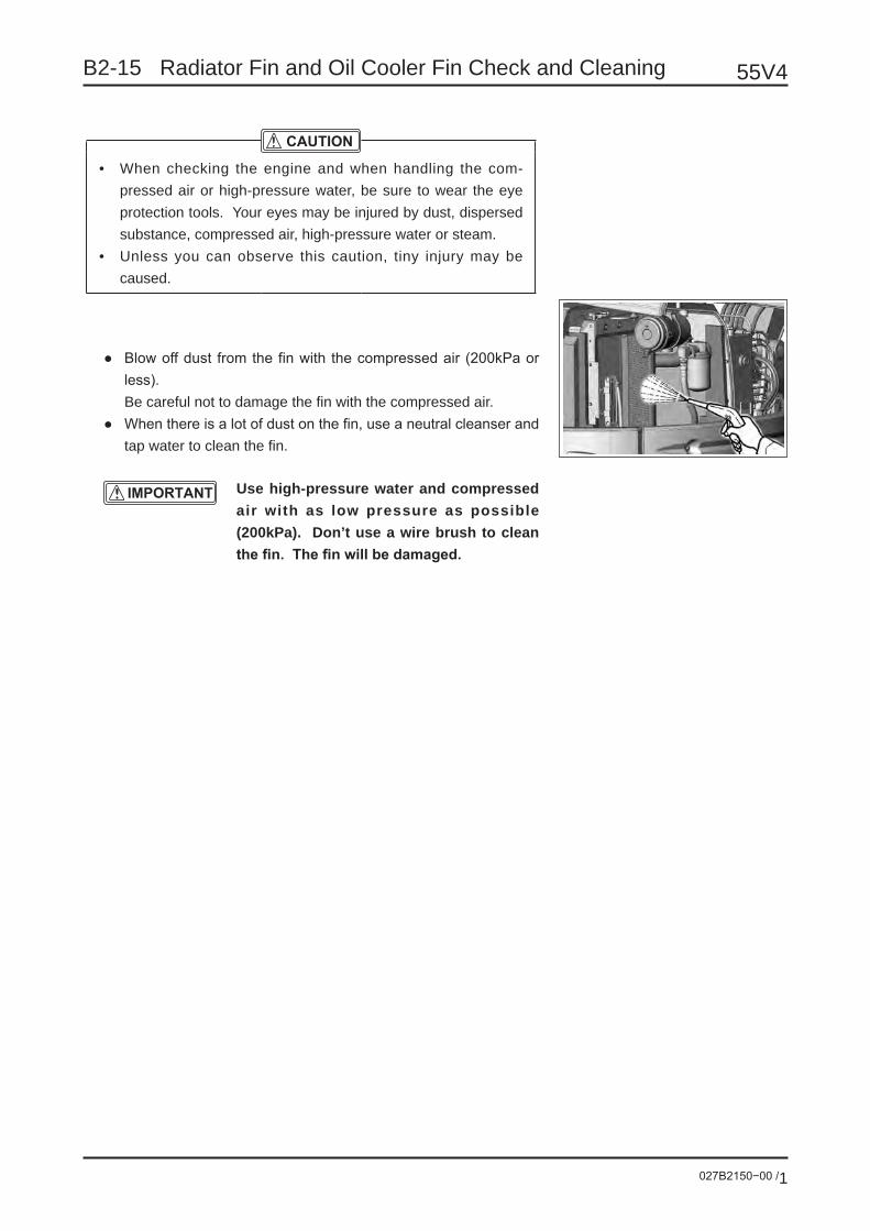
B2-15 Radiator Fin and Oil Cooler Fin Check and Cleaning
027B2150−00 /1
55V4
• When checking the engine and when handling the com-pressed air or high-pressure water, be sure to wear the eye protection tools. Your eyes may be injured by dust, dispersed substance, compressed air, high-pressure water or steam.
• Unless you can observe this caution, tiny injury may be caused.
● Blow off dust from the fin with the compressed air (200kPa or less).
Be careful not to damage the fin with the compressed air.● When there is a lot of dust on the fin, use a neutral cleanser and
tap water to clean the fin.
Use high-pressure water and compressed air with as low pressure as possible (200kPa). Don’t use a wire brush to clean the fin. The fin will be damaged.
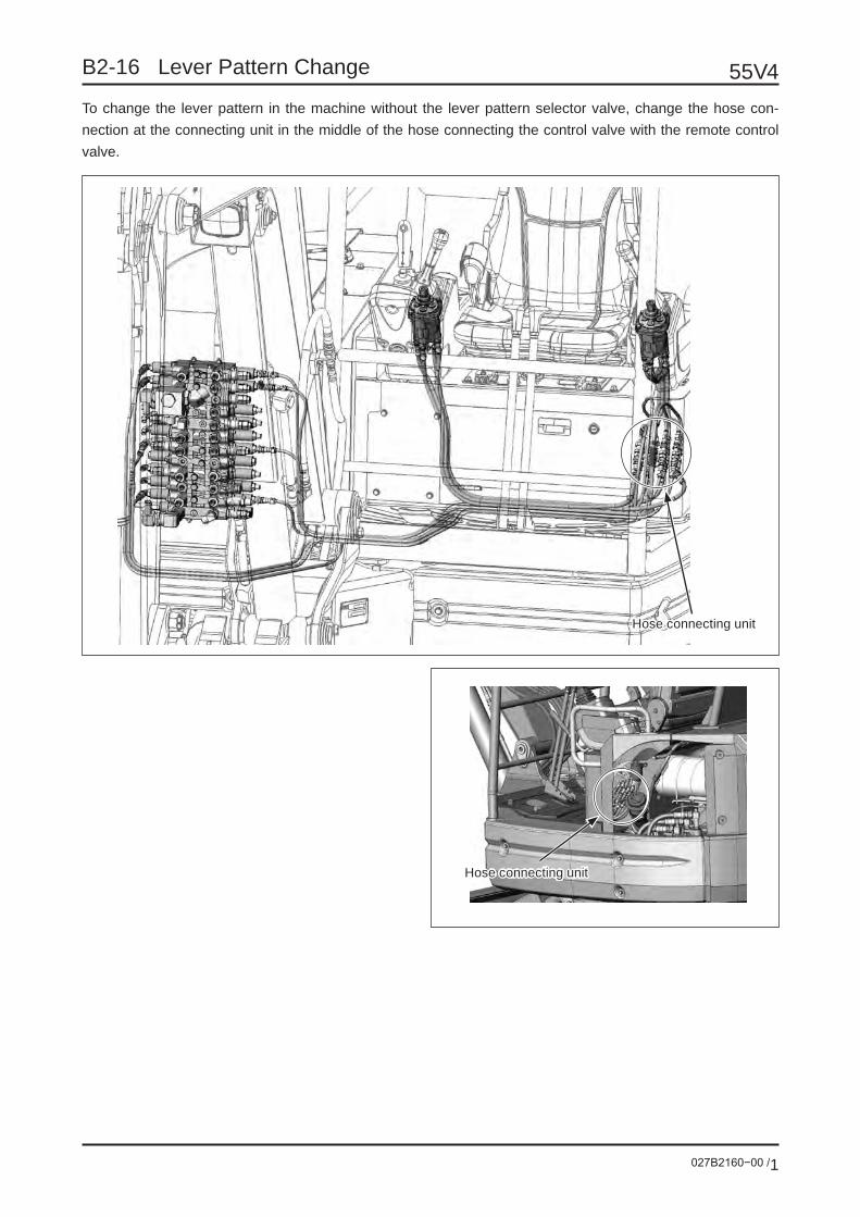
B2-16 Lever Pattern Change
027B2160−00 /1
55V4To change the lever pattern in the machine without the lever pattern selector valve, change the hose con-nection at the connecting unit in the middle of the hose connecting the control valve with the remote control valve.
Hose connecting unit
Hose connecting unit

B2-16 Lever Pattern Change 55V4
027B2160−00 /2
Before changing the hose connection, stop the engine and press the air breather button of the hy-draulic oil tank to relieve the pressure of the tank.
Air breather button
After changing the pattern, change the pattern indication nameplate, which is adhered on the ma-chine body, to the one indicating the new pattern.
Canopy specification Cab specification

B2-16 Lever Pattern Change
027B2160−00 /3
55V4
Pattern and name
Name Pattern Remarks
A L
Arm: Push
Arm: Pull
Left swing Right swing Bucket:Digging
Bucket:ReleaseR
Boom: Down
Boom: Up
IHI standard(JIS method)(ISO method)
B L
Right swing
Left swing
Arm: Push Arm: Pull Bucket:Digging
Bucket:ReleaseR
Boom: Down
Boom: Up
(Old)HitachiKomatsuSumitomo
C L
Boom: Down
Boom: Up
Bucket:Release
Bucket:Digging Left swing Right swingR
Arm: Push
Arm: Pull
(Old)KOBELCO
D L
Boom: Down
Boom: Up
Bucket:Release
Bucket:Digging Left swing Right swingR
Arm: Pull
Arm: Push
(Old)Mitsubishi
F L
Boom: Down
Boom: Up
Left swing Right swing Bucket:Digging
Bucket:ReleaseR
Arm: Push
Arm: Pull
JCBJOHN DEERE
G L
Arm: Push
Arm: Pull
Bucket:Release
Bucket:Digging Left swing Right swingR
Boom: Down
Boom: Up
(Old)NAKAMICHI ANTIWAFUJI

B2-16 Lever Pattern Change 55V4
027B2160−00 /4
For your desired pattern, arrange the hoses as shown below.“L” and “R” hoses are fixed.Change the connection of “A”, “B”, “C” and “S” hoses.
“A” pattern(when a standard machine is shipped)
“C” pattern
“F” pattern
“B” pattern
“D” pattern
“G” pattern

B2-16 Lever Pattern Change
027B2160−00 /5
55V4The hoses are connected to the control valve and remote control valve as shown below (as reference).
Symbol Operation when pressurizingA1 Arm DiggingA2 Arm ExtendB1 Boom LoweringB2 Boom HoistC1 Bucket DumpC2 Bucket DiggingS1 Swing LeftS2 Swing Right
Control valve: Right side Control valve: Left side
Right remote control valve Left remote control valve
C1C2
A1
S2
B1
B2
A2
S1

B3 Disassembly/Assembly

027B3010−00 /1
55V4B3-01 Swing Motor Disassembly/Assembly
1. General cautions for disassembly/assemblyPay attention to the following points when disassembling/assembling.
1 Perform the work in a clean place. Be careful to prevent the swing motor from dust, paint scrap or water. Prepare a clean container which will receive the disassembled parts.
2 Before disassembling, remove dust from the outside of swing motor and, using a wire brush or others, re-move the paint at the joints between the units.
3 Before disassembling, place a mark on each part so that the parts can be set at the original positions when assembling.
4 Handle the disassembled parts carefully not to damage them.5 Fully wash the disassembled parts with wash oil.6 Check the disassembled parts for abnormal wear or seizure. Remove burr with a sandpaper, etc.7 Replace seals and snap rings with new ones.
2. Disassembly/assembly procedureThe disassembly/assembly procedure of swing motor (PCR-3B) will be explained in this chapter.Swing motor consists of two blocks as shown below. The disassembly/assembly of each block will be explained.For disassembling/assembling, refer to the operation manual and parts list.
Hydraulic motor
Reduction gear
Fig. 1: Block diagram
Necessary tools for disassembly/assemblyNo. Tools to be used1 Manual torque wrench: Preset type 45N (JIS B4650)2 90N (JIS B4650)3 Socket head bit for the above wrench Width across flat 54 Width across flat 65 Width across flat 86 Manual torque wrench: Single-function type T=147.1±14.7N•m Width across flat 367 Allen wrench Width across flat 58 Width across flat 69 Width across flat 810 Wrench Width across flat 3611 Slotted screwdriver Width 6 - 1012 Snap ring pliers φ28 for hole13 φ22 for shaft14 Hammer15 Plastic hammer16 Others Grease17 Oil (Specified hydraulic oil)18 Wire brush19 Sandpaper20 Screw lock (Three-Bond #1305)

55V4
027B3010−00 /2
B3-01 Swing Motor Disassembly/Assembly
Exploded view

027B3010−00 /3
55V4B3-01 Swing Motor Disassembly/Assembly
Disassembly1. Hydraulic motor
Step 1Loosen the socket head bolt (124) and remove the hydraulic motor Ass’y from the reduction gear.
ToolAllen wrench: 6mm
• When removing the hydraulic motor Ass’y from the reduction gear, open the drain port.
• If it is difficult to remove the hydraulic mo-tor Ass’y, insert a slotted screwdriver or the like to the mating surface with the reduction gear. If burr or others occur, remove them completely.
Step 2Loosen the socket head bolt (245) and remove the reverse rotation prevention valve from the hydraulic motor Ass’y.
ToolAllen wrench: 5mm
• Do not disassemble the reverse rotation pre-vention valve if not necessary.
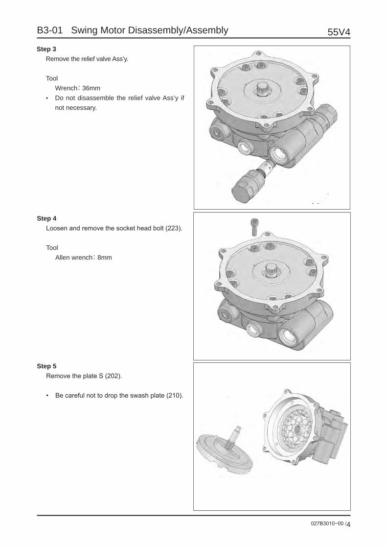
55V4
027B3010−00 /4
B3-01 Swing Motor Disassembly/Assembly
Step 4Loosen and remove the socket head bolt (223).
ToolAllen wrench: 8mm
Step 5Remove the plate S (202).
• Be careful not to drop the swash plate (210).
Step 3Remove the relief valve Ass’y.
ToolWrench: 36mm
• Do not disassemble the relief valve Ass’y if not necessary.

027B3010−00 /5
55V4B3-01 Swing Motor Disassembly/Assembly
Step 7Remove the filter (214) and parallel pin (225) from the plate S (202).• Filter (214): 1 pc.• Parallel pin (225): 3 pcs.
Step 8Remove the spring Ass’y (232) from the body H (201).
Step 6Remove the swash plate (210) and shaft kit from the plate S (202).
• If it is difficult to remove the shaft, lightly tap it from the end surface of the opposite side with a plastic hammer.
• The bearing (216) is press-fitted to the shaft. Don’t remove the bearing except when re-placing the bearing.

55V4
027B3010−00 /6
B3-01 Swing Motor Disassembly/Assembly
Step 10Remove the piston (206)/shoe (207) Ass’y, shoe holder (208), barrel holder (209) and pin (213).
Step 11Remove the snap ring (221), retainer (212) and spring C (215).
Step 9Remove the cylinder barrel kit.
・ Small parts may be scattered. Be careful not to lose them.

027B3010−00 /7
55V4B3-01 Swing Motor Disassembly/Assembly
Step 12Remove the brake piston (231) from the body H (201). Then, remove the O-rings (235 & 236).
Inject air from the PP port gradually, and the brake piston can be removed.
Inject air gradually to prevent the brake pis-ton from jumping out suddenly.
Step 13Remove the disk plate (233).
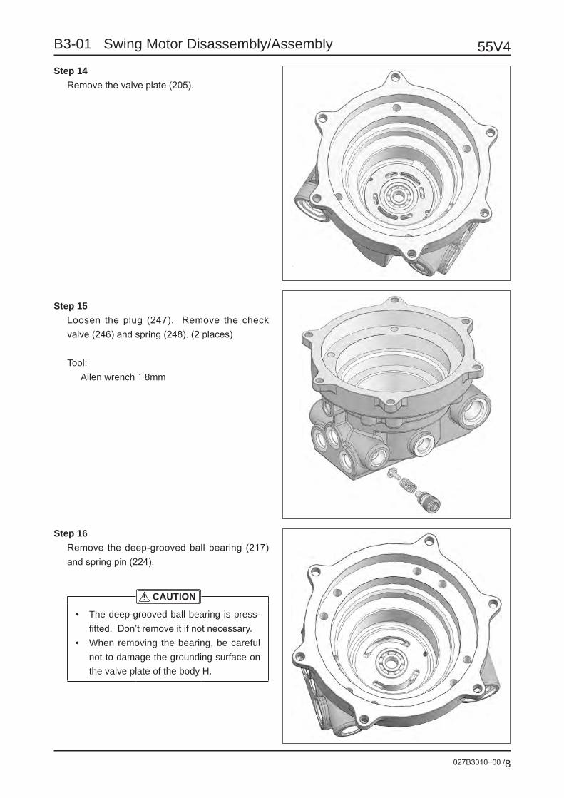
55V4
027B3010−00 /8
B3-01 Swing Motor Disassembly/Assembly
Step 16Remove the deep-grooved ball bearing (217) and spring pin (224).
• The deep-grooved ball bearing is press-fitted. Don’t remove it if not necessary.
• When removing the bearing, be careful not to damage the grounding surface on the valve plate of the body H.
Step 14Remove the valve plate (205).
Step 15Loosen the plug (247). Remove the check valve (246) and spring (248). (2 places)
Tool:Allen wrench : 8mm

027B3010−00 /9
55V4B3-01 Swing Motor Disassembly/Assembly
2. Reduction gear
Step 1Remove the O-ring (114).
Step 2Remove the S2 gear (109).
Step 3Remove the carrier 2 Ass’y.
To remove the carrier 2 Ass’y, be careful not to drop the parts and, as lifting the S1 gear, pull out the carrier 2 Ass’y perpendicularly.

55V4
027B3010−00 /10
B3-01 Swing Motor Disassembly/Assembly
Step 4Remove the carrier 1 Ass’y.
Step 5Remove the ring (128) and precompression col-lar (119).• Put the tip of a slotted screwdriver or the
like in the gap of two precompression col-lars. Tap the screwdriver with a hammer to remove the precompression collars.
• The gap against the bearing has already been adjusted. Don’t remove the ring and precompression collars if not necessary.
Step 6Remove the pinion Ass’y.
• To ensure the removal allowance of pinion shaft, place a pad of about 130mm on the flange unit. Push the end surface of pinion shaft (104) with a press or the like to remove the pinion Ass’y.
• The gap against the bearing has already been adjusted. Don’t remove the pinion Ass’y if not necessary.

027B3010−00 /11
55V4B3-01 Swing Motor Disassembly/Assembly
Step 7Remove the outer rings of bearings (121 & 122) and oil seal (123).
• It is difficult to remove the outer rings of bearings (121 & 122). Don’t remove them if not necessary.
• Don’t reuse the oil seal.• The inner ring of bearing (122) comes off of
itself.
Step 8Remove the thrust plate 2 (116) from the carrier 2 Ass’y.
Step 9Remove the b2 gear (107) and roller 2 (112) from the carrier 2 Ass’y.

55V4
027B3010−00 /12
B3-01 Swing Motor Disassembly/Assembly
Step 10Remove the inner ring 2 (130) and thrust washer 2 (118) from the carrier 2 Ass’y.
Step 11Remove the snap ring (120) and thrust plate 1 (115) from the carrier 1 Ass’y.
Step 12Remove the b1 gear (106) and roller 1 (111) from the carrier 1 Ass’y.

027B3010−00 /13
55V4B3-01 Swing Motor Disassembly/Assembly
Step 13Remove the inner ring 1 (129) and thrust wash-er 1 (117) from the carrier 1 Ass’y.
Step 14Remove the inner ring of bearing (121) and ring seal (113) from the pinion Ass’y.
• The inner ring of bearing (121) is press-fitted. Don’t remove it if not necessary.
• Don’t reuse the ring seal (113).

55V4
027B3010−00 /14
B3-01 Swing Motor Disassembly/Assembly
Assembly1. Hydraulic motor
Step 1Press-fit the deep-grooved ball bearing (217) and spring pin (224) to the body H (201).
Step 2Mount the check valve (246), spring (248) and plug (247) onto the body H (201). (2 places)
Tools:Allen wrench: 8mmManual torque wrench
Thinly coat grease to O-ring (249) and mount the parts as taking care not to catch the seals.
• Plug tightening torque: 58.8±2.9N•m
Step 3Mount the valve plate (205).
• Mount the valve plate (205) with its iron sur-face at the lower side.
O-ring
Lining surface
Iron surface
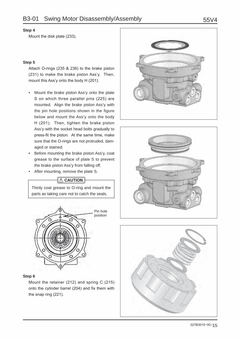
027B3010−00 /15
55V4B3-01 Swing Motor Disassembly/Assembly
Step 4Mount the disk plate (233).
Step 5Attach O-rings (235 & 236) to the brake piston (231) to make the brake piston Ass’y. Then, mount this Ass’y onto the body H (201).
• Mount the brake piston Ass’y onto the plate S on which three parallel pins (225) are mounted. Align the brake piston Ass’y with the pin hole positions shown in the figure below and mount the Ass’y onto the body H (201). Then, tighten the brake piston Ass’y with the socket head bolts gradually to press-fit the piston. At the same time, make sure that the O-rings are not protruded, dam-aged or stained.
• Before mounting the brake piston Ass’y, coat grease to the surface of plate S to prevent the brake piston Ass’y from falling off.
• After mounting, remove the plate S.
Thinly coat grease to O-ring and mount the parts as taking care not to catch the seals.
Step 6Mount the retainer (212) and spring C (215) onto the cylinder barrel (204) and fix them with the snap ring (221).
Pin hole position

55V4
027B3010−00 /16
B3-01 Swing Motor Disassembly/Assembly
Step 7Mount the piston (206)/shoe (207) Ass’y onto the shoe holder (208) to make the shoe holder Ass’y.
Step 8Insert three pins (213) into the cylinder barrel (204). Use the shoe holder Ass’y and barrel holder (209) to make the cylinder barrel Ass’y.
Step 9Insert the cylinder barrel Ass’y into the body H (201) as aligning the Ass’y with the groove on the disk plate.
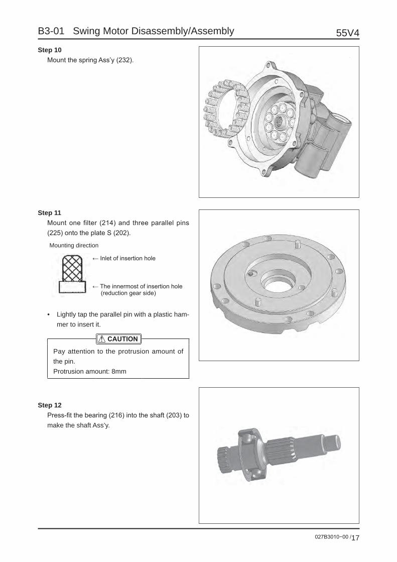
027B3010−00 /17
55V4B3-01 Swing Motor Disassembly/Assembly
Step 10Mount the spring Ass’y (232).
Step 11Mount one filter (214) and three parallel pins (225) onto the plate S (202).
← Inlet of insertion hole
← The innermost of insertion hole (reduction gear side)
Mounting direction
• Lightly tap the parallel pin with a plastic ham-mer to insert it.
Pay attention to the protrusion amount of the pin.Protrusion amount: 8mm
Step 12Press-fit the bearing (216) into the shaft (203) to make the shaft Ass’y.

55V4
027B3010−00 /18
B3-01 Swing Motor Disassembly/Assembly
Step 13Mount the shaft Ass’y onto the plate S (202).
Step 14Mount the swash plate (210) onto the plate S (202).
• Before mounting the swash plate, coat grease to the surface of plate S to prevent the swash plate from falling off.
Step 15Combine the body H (201) with the plate S (202).
• Align the serration on the shaft, which is mounted on the plate S, with the serration on the cylinder barrel Ass’y, which is mounted on the body H. Then, mount the plate S onto the body H.
• Mount the plate S so that the pins on the plate S can be put into the pin holes shown in the figure below.
Pin hole position

027B3010−00 /19
55V4B3-01 Swing Motor Disassembly/Assembly
Step 16Tighten the plate S with the socket head bolts (223).
Tools:Allen wrench: 8mmManual torque wrench
Tightening torque: 58.8 ±2.9N•m
Step 17Mount the relief valve Ass’y.
Tools:Wrench: 36mmManual torque wrench
Tightening torque: 147.1 ±14.7N•m
When disassembling, replace the O-rings and backup rings shown in the figure below with new ones and tighten the cap by the following torque.
O-ring
Backup ringCap tightening torque: 147.1 ±14.7N•m

55V4
027B3010−00 /20
B3-01 Swing Motor Disassembly/Assembly
Step 18Mount the reverse rotation prevention valve.
ToolAllen wrench: 5mmManual torque wrenchTightening torque: 11.8±1N ·m
When disassembling, replace the O-ring shown below with a new one and tighten the plug by the following torque.
O-ring
Plug tightening torque: 132±5N ·m

027B3010−00 /21
55V4B3-01 Swing Motor Disassembly/Assembly
2. Reduction gear
Step 1Press-fit the oil seal (123) to the main unit (101).
Pay attention to the oil seal mounting direc-tion. Place a patch and press-fit the oil seal not to be inclined.
• Outer diameter of patch: ø77.5
Step 2Attach the ring seal (113) to the pinion shaft (104).
Mounting direction of ring sealBearing side
Pinion side
Step 3Press-fit the inner ring of bearing (121) to the pinion shaft (104) to make the pinion Ass’y.
After press-fitting, coat grease to the roller surface of bearing and roll the roller to per-vade the grease on the whole roller.
← Patch
← Reduction gear side
← Pinion side
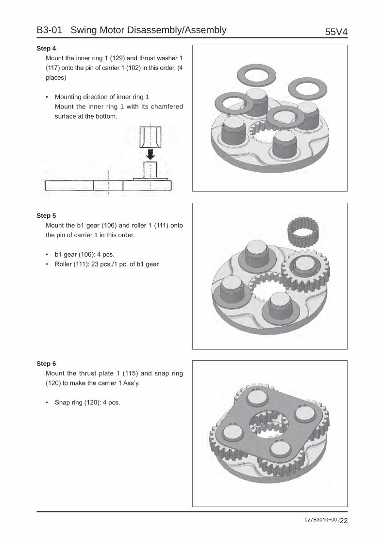
55V4
027B3010−00 /22
B3-01 Swing Motor Disassembly/Assembly
Step 4Mount the inner ring 1 (129) and thrust washer 1 (117) onto the pin of carrier 1 (102) in this order. (4 places)
• Mounting direction of inner ring 1 Mount the inner ring 1 with its chamfered
surface at the bottom.
Step 5Mount the b1 gear (106) and roller 1 (111) onto the pin of carrier 1 in this order.
• b1 gear (106): 4 pcs.• Roller (111): 23 pcs./1 pc. of b1 gear
Step 6Mount the thrust plate 1 (115) and snap ring (120) to make the carrier 1 Ass’y.
• Snap ring (120): 4 pcs.

027B3010−00 /23
55V4B3-01 Swing Motor Disassembly/Assembly
Step 7Mount the thrust washer 2 (118) and inner ring 2 (130) onto the pin of carrier 2 (103) in this order. (3 places))
Step 8Mount the b2 gear (107) and roller 2 (112) onto the pin of carrier 2 (103) in this order.
• b2 gear (107): 3 pcs.• Roller (112): 24 pcs./1 pc. of b2 gear
Step 9Mount the S1 gear (108) and thrust plate 2 (116) onto the carrier 2 (103) to make the carrier 2 Ass’y.

55V4
027B3010−00 /24
B3-01 Swing Motor Disassembly/Assembly
Step 10Press-fit the outer ring of bearing (122) into the main unit (101).
Step 11Press-fit the outer ring of bearing (121) into the main unit (101).
Step 12Apply grease to the portion where the bearing (121) will be mounted on the main unit (101).
Grease amount: Approx. 80% of space

027B3010−00 /25
55V4B3-01 Swing Motor Disassembly/Assembly
Step 13Insert the pinion shaft (104) into the main unit (101).
Be careful not to damage the lip of oil seal.
Step 14Reverse the main unit (101) and press-fit the in-ner ring of bearing (122).
Step 15Mount the two precompression collars (119).
The thickness of precompression collar must be 0 to +0.05mm against the really measured width “L” between the end sur-face of bearing and the groove end surface of pinion shaft.
L: Groove width
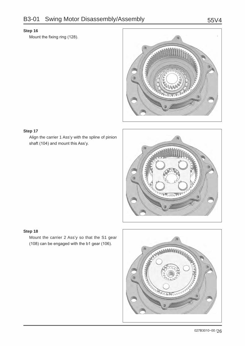
55V4
027B3010−00 /26
B3-01 Swing Motor Disassembly/Assembly
Step 16Mount the fixing ring (128).
Step 17Align the carrier 1 Ass’y with the spline of pinion shaft (104) and mount this Ass’y.
Step 18Mount the carrier 2 Ass’y so that the S1 gear (108) can be engaged with the b1 gear (106).

027B3010−00 /27
55V4B3-01 Swing Motor Disassembly/Assembly
Step 19Mount the S2 gear (109).
Step 20Mount the O-ring (114) onto the main unit (101).
Step 21Pour the hydraulic oil, which should be used in a real machine, into the main unit (101).
Hydraulic oilISO VG46 or SAE-10W-CD or its equivalent
Oil amountUp to 2 - 3mm below the upper end surface of thrust plate 2
If the hydraulic oil adheres to the mating surface, wipe off the oil.

55V4
027B3010−00 /28
B3-01 Swing Motor Disassembly/Assembly
Step 22Mount the hydraulic motor onto the main unit and tighten it with the socket head bolt (124).
Tools:Allen wrench: 6mmManual torque wrench
Tightening torque: 29.4 ±2.9N•m
• Insert the hydraulic motor’s shaft to be en-gaged with the S2 gear.
• Apply the screw lock (Three-Bond #1305) to the socket head bolt.
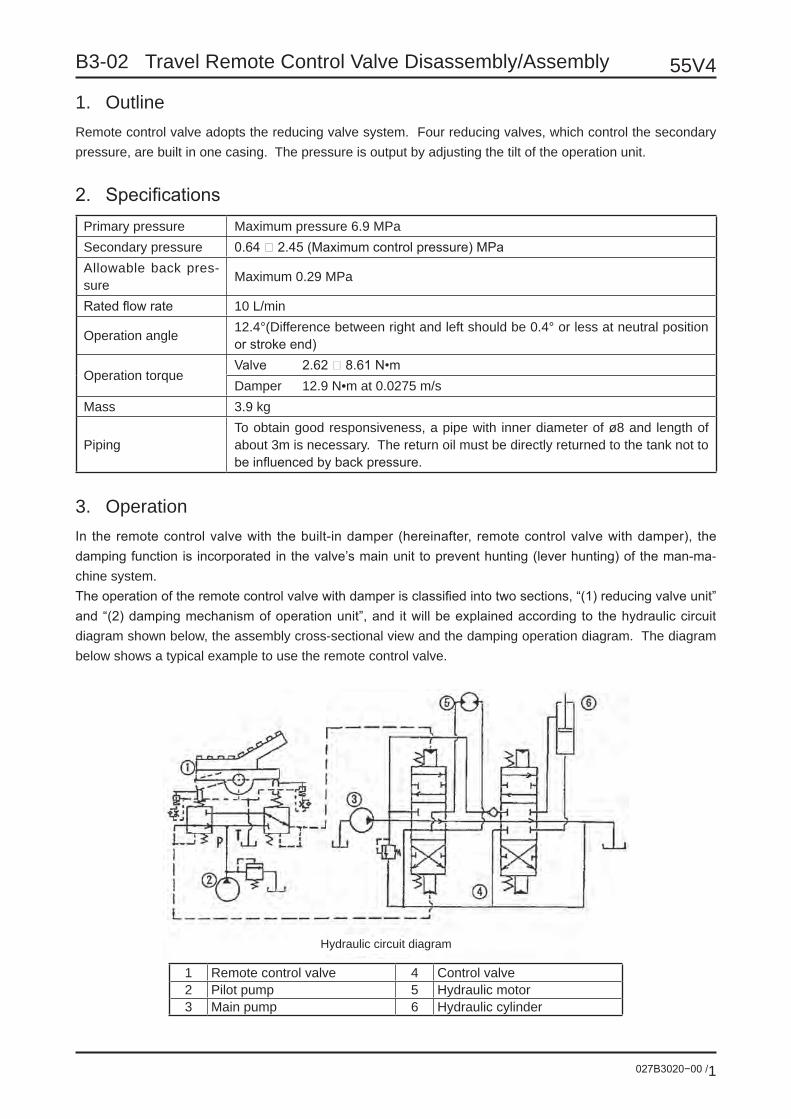
027B3020−00 /1
55V4B3-02 Travel Remote Control Valve Disassembly/Assembly
1. OutlineRemote control valve adopts the reducing valve system. Four reducing valves, which control the secondary pressure, are built in one casing. The pressure is output by adjusting the tilt of the operation unit.
2. SpecificationsPrimary pressure Maximum pressure 6.9 MPaSecondary pressure 0.64 ‒ 2.45 (Maximum control pressure) MPaAllowable back pres-sure Maximum 0.29 MPa
Rated flow rate 10 L/min
Operation angle 12.4°(Difference between right and left should be 0.4° or less at neutral position or stroke end)
Operation torqueValve 2.62 ‒ 8.61 N•mDamper 12.9 N•m at 0.0275 m/s
Mass 3.9 kg
PipingTo obtain good responsiveness, a pipe with inner diameter of ø8 and length of about 3m is necessary. The return oil must be directly returned to the tank not to be influenced by back pressure.
3. OperationIn the remote control valve with the built-in damper (hereinafter, remote control valve with damper), the damping function is incorporated in the valve’s main unit to prevent hunting (lever hunting) of the man-ma-chine system.The operation of the remote control valve with damper is classified into two sections, “(1) reducing valve unit” and “(2) damping mechanism of operation unit”, and it will be explained according to the hydraulic circuit diagram shown below, the assembly cross-sectional view and the damping operation diagram. The diagram below shows a typical example to use the remote control valve.
1 Remote control valve 4 Control valve2 Pilot pump 5 Hydraulic motor3 Main pump 6 Hydraulic cylinder
Hydraulic circuit diagram

55V4
027B3020−00 /2
B3-02 Travel Remote Control Valve Disassembly/Assembly
(1) Reducing valve unit[1] In neutral status
The spool (301) is pushed up by the reset spring (355) via the spring seat (311) to be at the neutral posi-tion shown on the assembly cross-sectional view.Consequently the output port is connected to only Port T due to the spool change function. The pressure of Output Ports 1 & 2 is the same as Port T.
[2] When the remote control valve operation unit is tilted from the neutral status
When the cam (420) is turned clockwise on the assembly sectional-view, the push rod (214) at the Port 1 side is pushed down. The spool at the Port 1 side is moved down via the spring seat, the secondary pres-sure setting spring (324), shim (217) and washer (313). Port P is connected to Port 1 and the oil supplied by the pilot pump flows into Port 1 to generate pressure.When the pressure at Port 1 rises to be equivalent to the secondary pressure setting spring force, which is set by tilting the operation unit, the hydraulic force applied to the spool is balanced with the secondary pressure setting spring force. So, the output pressure of Port 1 is kept at a fixed value. The spool at the Port 2 side is kept at neutral position. The oil from the control valve is discharged via Port T.In some type of remote control valve, when the operation unit is near the maximum angle, the push rod contacts the spool top directly to push in the spool forcedly. So, Port P makes contact with the output port to have the same pressure.
(2) Damping mechanism of operation unit[1] In neutral status
The push rod is pushed up by the damping spring (336) via the piston (224) to be at the position shown on the assembly cross-sectional view.
[2] When the operation unit is tilted from the neutral status (Refer to Fig. 1 of “[4] Damping operation
diagram”.)
When the cam is turned clockwise on the assembly cross-sectional view, the push rod at the Port 1 side is pushed down and the piston is moved down.At the same time, the oil in the damping piston chamber is discharged from the throttle hole of piston and pressure is generated. This pressure generates the damping force.The push rod at the Port 2 side is moved up by the damping spring via the piston.At the same time, the oil of the tank chamber is absorbed into the damping piston chamber through the ball check unit (3 places), which consists of steel balls (225). The oil outside the piston chamber is dis-charged through the passage, which connects the casing’s top edge to Port T.
[3] When reversing the operation unit from the fully tilted status (Refer to Fig. 2 of “[4] Damping op-
eration diagram”.)
When the cam is turned counterclockwise after fully turning it clockwise on the assembly cross-sectional view, the push rod at the Port 2 side is pushed down and the piston is moved down.At the same time, as mentioned above, the oil in the damping piston chamber is discharged through the throttle hole of the piston and pressure is generated. This pressure generates the damping force.The push rod at the Port 1 side is moved up by the reset spring (335) and the damping spring.At the same time, the oil of the tank chamber is absorbed into the damping piston chamber through the ball check unit (3 places), which consists of steel balls. The oil outside the piston chamber is discharged through the passage, which connects the casing’s top edge to Tank Port.The damping force works by tilting the operation unit from the neutral position to the fully tilted position and vice versa.

027B3020−00 /3
55V4B3-02 Travel Remote Control Valve Disassembly/Assembly
[4] Damping operation diagram
1) When moving the lever from the neutral status to the stroke end
Throttle
When moving the lever from the neutral status in the “( / )” direction, the oil in the right <left> piston chamber is discharged through the throttle hole and pressure is generated. This pressure generates the damping force.
Fig. 1
1 Push rod 5 Port P2 Piston 6 Port 1 (3)3 Piston chamber 7 Port 2 (4)4 Port T
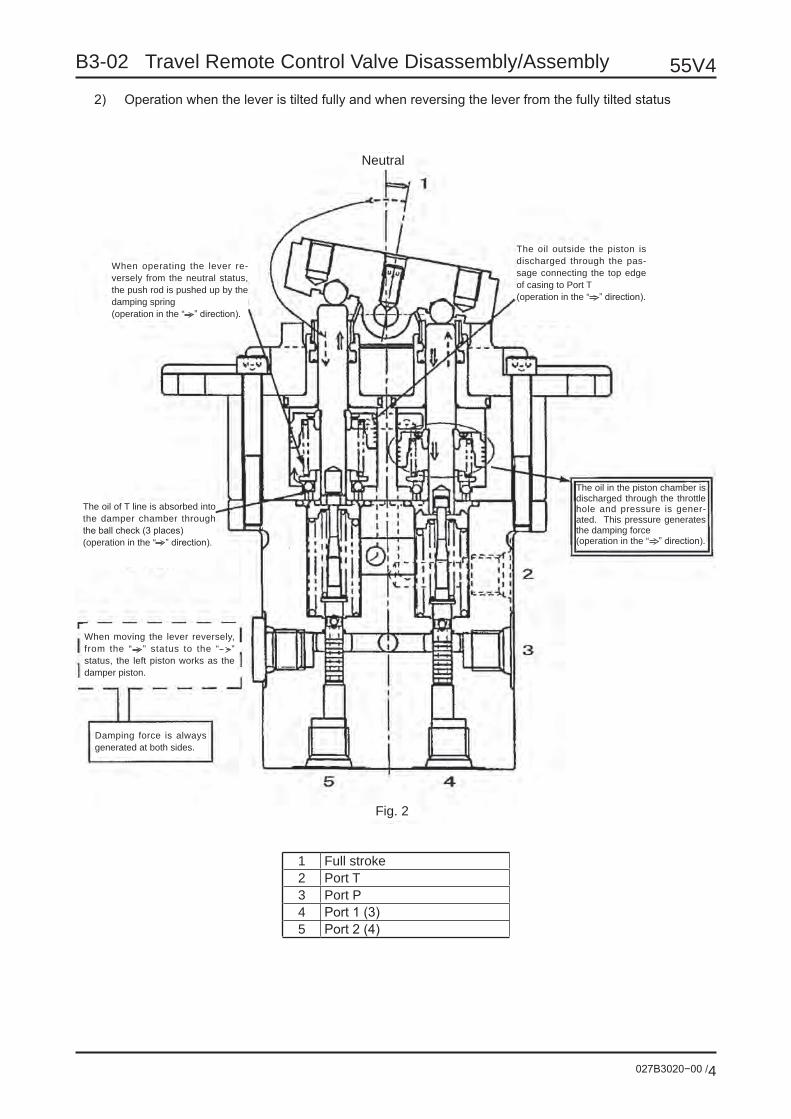
55V4
027B3020−00 /4
B3-02 Travel Remote Control Valve Disassembly/Assembly
2) Operation when the lever is tilted fully and when reversing the lever from the fully tilted status
Neutral
The oil in the piston chamber is discharged through the throttle hole and pressure is gener-ated. This pressure generates the damping force (operation in the “ ” direction).
The oil outside the piston is discharged through the pas-sage connecting the top edge of casing to Port T (operation in the “ ” direction).
When operating the lever re-versely from the neutral status, the push rod is pushed up by the damping spring (operation in the “ ” direction).
The oil of T line is absorbed into the damper chamber through the ball check (3 places) (operation in the “ ” direction).
When moving the lever reversely, from the “ ” status to the “ ” status, the left piston works as the damper piston.
Damping force is always generated at both sides.
Fig. 2
1 Full stroke2 Port T3 Port P4 Port 1 (3)5 Port 2 (4)

027B3020−00 /5
55V4B3-02 Travel Remote Control Valve Disassembly/Assembly
4. Maintenance(1) Special jig for disassembly/assembly[1] Special jig 1 (for removing bush)
Center hole is permitted (ø2 or less)
(2) Disassembly1) Preparation
1. Prepare a work table meeting the following conditions.- It has a space enough to put the parts;- It is solid and stable;- It does not allow the parts to drop or move during the work.
2. Prepare tools and materials.
2) General cautions for work
1. The parts are precisely manufactured. Handle them very carefully not to hit them each other or drop them.
2. If you tap or twist the parts, which cannot be removed easily, forcedly during the work, they are burred or broken. So, the parts cannot be mounted or the oil leak or the lowered performance is caused. Carry out the work patiently with care.
3. If the unit is left in the disassembled status or if disassembling is stopped midway, the parts may be rusted by moisture or dust. If you are com-pelled to stop the work midway, be careful to pre-vent rust and dust.
3) Disassembly
1. Wash the remote control valve with white kero-sene.• Apply a blind plug to each port.
2. Using an impact board, fix the remote control valve on a vise.
Separate the bellows (501) from the cover (201) and remove it upward.
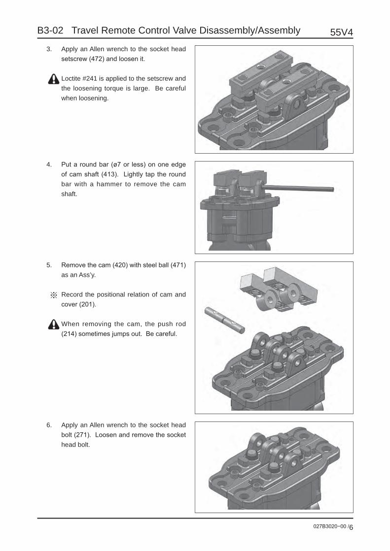
55V4
027B3020−00 /6
B3-02 Travel Remote Control Valve Disassembly/Assembly
3. Apply an Allen wrench to the socket head setscrew (472) and loosen it.
Loctite #241 is applied to the setscrew and the loosening torque is large. Be careful when loosening.
4. Put a round bar (ø7 or less) on one edge of cam shaft (413). Lightly tap the round bar with a hammer to remove the cam shaft.
5. Remove the cam (420) with steel ball (471) as an Ass’y.
Record the positional relation of cam and cover (201).
When removing the cam, the push rod (214) sometimes jumps out. Be careful.
6. Apply an Allen wrench to the socket head bolt (271). Loosen and remove the socket head bolt.

027B3020−00 /7
55V4B3-02 Travel Remote Control Valve Disassembly/Assembly
7. Remove the cover (201).
Record the positional relation of cover and casing (102).
When removing the cover, the push rod (214) and plug (202) sometimes jump out due to damping spring (336). Be careful.(Plug is put in the casing by the slide resis-tance of O-ring (212) only.)
8. Remove the casing upper Ass’y and fix it on the vise.• Record the positional relation of casing
(damper) (102) and casing (101).

55V4
027B3020−00 /8
B3-02 Travel Remote Control Valve Disassembly/Assembly
9. Remove the push rod (214) from the plug (202).
Record the positional relation of plug and push rod.
Be careful not to damage the push rod sur-face.
When removing the push rod, the plug sometimes jumps out. Be careful.
10. Remove the plug with grease cup (203), packing (210) and O-ring (212).
Record the positional relation between plug and casing.
When removing the plug, the piston some-times jumps out due to damping spring. Be careful.
11. Remove the piston (224).
Record the positional relation of piston and casing hole.

027B3020−00 /9
55V4B3-02 Travel Remote Control Valve Disassembly/Assembly
12. Take out the damping spring (336) from the casing.
Record the positional relation of damping spring and casing hole.
13. Take out the spring seat (218) from the casing.
Record the positional relation of spring seat and casing hole.
14. Using a magnet or others, take out the steel ball (255).
Be careful not to lose the steel ball.

55V4
027B3020−00 /10
B3-02 Travel Remote Control Valve Disassembly/Assembly
15. Fix the lower casing Ass’y on the vise. Remove the O-rings (211 & 213) from the casing (101).
16. Remove the reducing valve Ass’y and the reset spring (335) from the casing.
Record the positional relation against the casing hole.
17. Place the cover (201) transversely on a flat table. Put the special tool 1 to the bush (414). Lightly tap the tool with a hammer to remove the bush.

027B3020−00 /11
55V4B3-02 Travel Remote Control Valve Disassembly/Assembly
18. Disassemble the reducing valve Ass’y as mentioned below: Push in the spring seat (311). As bending the secondary pressure setting spring (324), move the spring seat sidewise and remove the reducing valve Ass’y from the spool (301) through the larger hole.
Be careful not to damage the spool sur-face.
Don’t move down the spring seat by 4mm or more.
Regard the above-mentioned parts as an Ass’y until assembling.
19. Separate the spool (301), spring seat (311), secondary pressure setting spring (324), shim (217) and washer (313).
Regard these parts as an Ass’y until assem-bling.
Washer 2 should be used for the preset adjustment of secondary pressure set-ting spring. The thickness of washer 2 is changed for each spool Ass’y. Sometimes washer 2 is not used.
20. Remove the grease cup (203) from the plug (202).
21. Remove the packing (210) from the plug (202).To remove the packing (210), use a small slotted screwdriver or the like.
Be careful not to damage the plug inside.
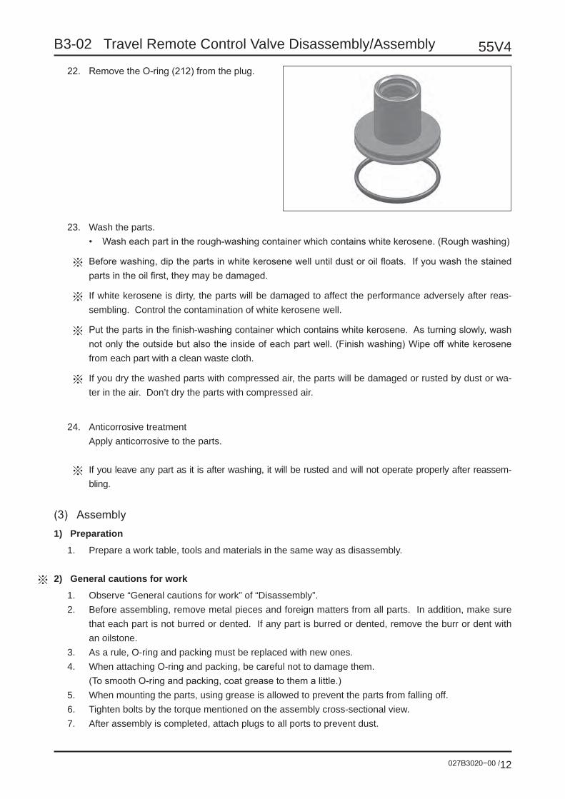
55V4
027B3020−00 /12
B3-02 Travel Remote Control Valve Disassembly/Assembly
22. Remove the O-ring (212) from the plug.
23. Wash the parts.• Wash each part in the rough-washing container which contains white kerosene. (Rough washing)
Before washing, dip the parts in white kerosene well until dust or oil floats. If you wash the stained parts in the oil first, they may be damaged.
If white kerosene is dirty, the parts will be damaged to affect the performance adversely after reas-sembling. Control the contamination of white kerosene well.
Put the parts in the finish-washing container which contains white kerosene. As turning slowly, wash not only the outside but also the inside of each part well. (Finish washing) Wipe off white kerosene from each part with a clean waste cloth.
If you dry the washed parts with compressed air, the parts will be damaged or rusted by dust or wa-ter in the air. Don’t dry the parts with compressed air.
24. Anticorrosive treatmentApply anticorrosive to the parts.
If you leave any part as it is after washing, it will be rusted and will not operate properly after reassem-bling.
(3) Assembly1) Preparation
1. Prepare a work table, tools and materials in the same way as disassembly.
2) General cautions for work
1. Observe “General cautions for work” of “Disassembly”.2. Before assembling, remove metal pieces and foreign matters from all parts. In addition, make sure
that each part is not burred or dented. If any part is burred or dented, remove the burr or dent with an oilstone.
3. As a rule, O-ring and packing must be replaced with new ones.4. When attaching O-ring and packing, be careful not to damage them. (To smooth O-ring and packing, coat grease to them a little.)5. When mounting the parts, using grease is allowed to prevent the parts from falling off.6. Tighten bolts by the torque mentioned on the assembly cross-sectional view.7. After assembly is completed, attach plugs to all ports to prevent dust.

027B3020−00 /13
55V4B3-02 Travel Remote Control Valve Disassembly/Assembly
3) Assembly
1. Attach the washer (313), shim (217), sec-ondary pressure setting spring (324) and spring seat (311) to the spool (301) in this order.
The washer should be used for the preset adjustment of secondary pressure setting spring. The thickness of the washer is changed for each spool Ass’y. Sometimes the washer is not used.
2. Pass the spool (301) through the larger hole of the spring seat (311). Push in the spring seat. As bending the secondary pressure setting spring, move the spring seat sidewise to mount the spring.
Be careful not to damage the spool surface.
Don’t move down the spring seat by 4mm or more.
3. Fix the casing (101) onto a vise. Attach the reset spring (335) to the casing (101).
Attach the spring to the same position as before disassembling.
4. Attach the reducing valve sub Ass’y, which has been completed as the sub Ass’y in Step 1 to 2, to the casing (101).
Attach the sub Ass’y to the same position as before disassembling.
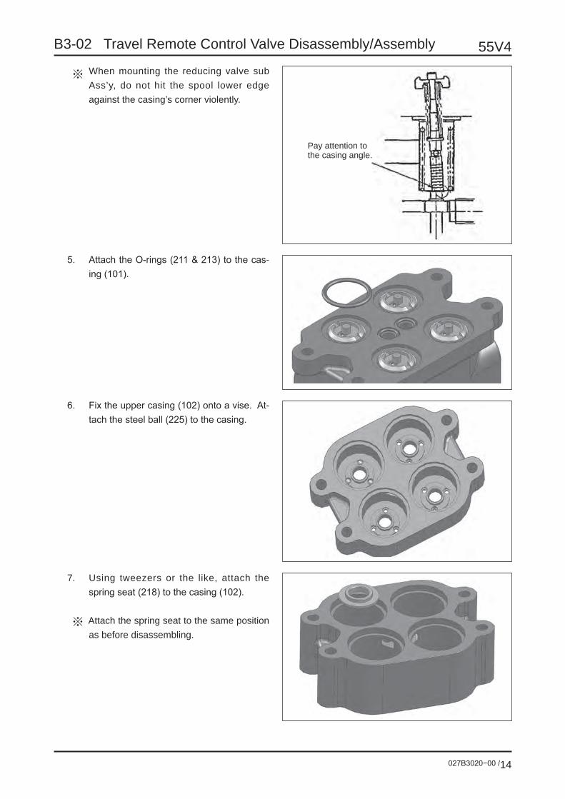
55V4
027B3020−00 /14
B3-02 Travel Remote Control Valve Disassembly/Assembly
When mounting the reducing valve sub Ass’y, do not hit the spool lower edge against the casing’s corner violently.
Pay attention to the casing angle.
5. Attach the O-rings (211 & 213) to the cas-ing (101).
6. Fix the upper casing (102) onto a vise. At-tach the steel ball (225) to the casing.
7. Using tweezers or the like, attach the spring seat (218) to the casing (102).
Attach the spring seat to the same position as before disassembling.

027B3020−00 /15
55V4B3-02 Travel Remote Control Valve Disassembly/Assembly
8. Attach the damping spring (336) to the casing.
Attach the damping spring to the same po-sition as before disassembling.
The damping spring must not run on the spring seat (218).
9. Attach the O-ring (212) to the piston (224).
Attach the O-ring to the same position as before disassembling.
10. Attach the O-ring (212) to the plug (202).

55V4
027B3020−00 /16
B3-02 Travel Remote Control Valve Disassembly/Assembly
11. Attach the packing (210) to the plug.
When attaching the packing, be careful for its direction. (Refer to the figure below.)
Before attaching the packing, thinly coat grease to it.
12. Attach the grease cup (203) to the plug.
13. Attach the push rod (214) to the plug.
Before attaching the push rod, coat the hy-draulic oil to its surface.
Do not insert the push rod strongly, or the lip of the packing may be damaged.

027B3020−00 /17
55V4B3-02 Travel Remote Control Valve Disassembly/Assembly
14. Attach the push rod sub Ass’y, which has been completed as the sub Ass’y in Step 10 to 13, to the casing.
15. Place the cover (201) transversely on a flat table. Using the special jig 1, press the bush (414). Using a hammer, lightly tap the jig to press-fit the bush.
Be careful not to protrude the bush edge from the cover inside.
16. Fix the lower cover Ass’y, which has been completed as the Ass’y in Step 1 to 5, onto a vise. Mount the upper cover Ass’y, which has been completed as the Ass’y in Step 6 to 14, onto the lower cover Ass’y.
Mount the upper cover Ass’y to the same position as before disassembling.
17. Attach the cover to the casing.
Attach the cover to the same position as before disassembling.
The cover moves up due to the damping spring (336). Be careful.
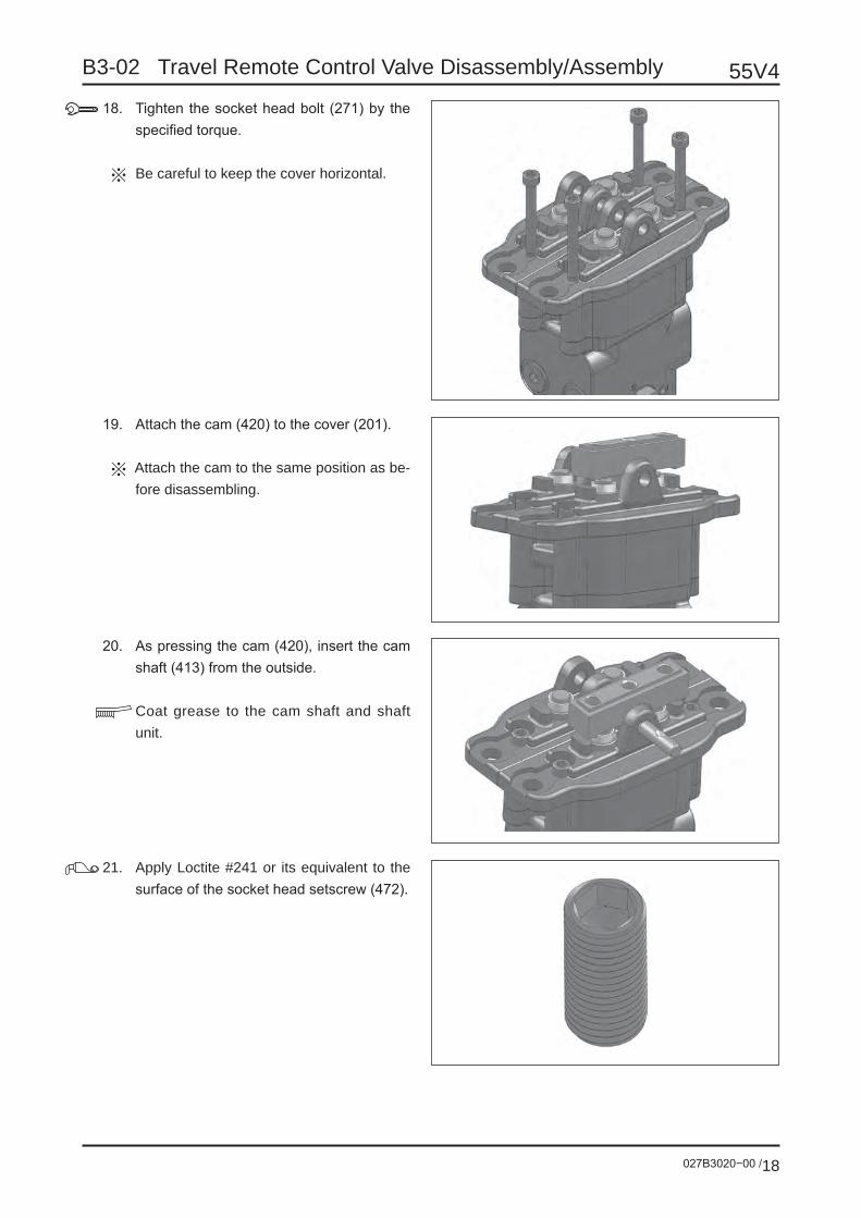
55V4
027B3020−00 /18
B3-02 Travel Remote Control Valve Disassembly/Assembly
18. Tighten the socket head bolt (271) by the specified torque.
Be careful to keep the cover horizontal.
19. Attach the cam (420) to the cover (201).
Attach the cam to the same position as be-fore disassembling.
20. As pressing the cam (420), insert the cam shaft (413) from the outside.
Coat grease to the cam shaft and shaft unit.
21. Apply Loctite #241 or its equivalent to the surface of the socket head setscrew (472).

027B3020−00 /19
55V4B3-02 Travel Remote Control Valve Disassembly/Assembly
22. Tighten the socket head setscrew (472) by the specified torque.
23. Tilt the cam (420) and coat grease to the top of push rod (214). Pour grease into the grease cup (203) of plug (202).
Coat and pour grease with a soft spatular thing not to damage the surface of push rod and plug.
24. Fit the upper edge of bellows (501) to the cam (420). Then, fit the lower edge to the groove of cover (201).
Before fitting the lower edge of bellows to the groove of cover, spray the anticorro-sive oil to the internal parts of bellows.
If bellows is not securely fitted to the groove or if it is mounted under the twisted status, the dustproof and waterproof char-acteristics will be deteriorated. Be careful.

55V4
027B3020−00 /20
B3-02 Travel Remote Control Valve Disassembly/Assembly
5. Trouble shootingIt is not easy to locate the trouble place. The following table describes the probable problems. Repair is dif-ficult. Refer to the probable causes and remedial measures in the table.The following table describes general phenomena, probable causes and remedial measures. But, in many cases, the machine trouble is caused not by only one defective part but by the relation between one part and others. You should bear in mind that other remedial measures except those in the table are sometimes needed.The following table does not show all of probable causes and remedial measures. Under certain circum-stances, the person in charge of repair must not only obey the instructions of the table but also examine the troubles and causes independently.
Phenomenon Cause Remedial measure
Secondary pressure does not rise.
1. Primary pressure is not sufficient.2. The secondary pressure setting
spring (324) is fatigued.3. The gap between spool and casing
is abnormally large.4. The operation unit has play.
1. Ensure the primary pressure.2. Replace the secondary pressure set-
ting spring with a new one.3. Replace the spool Ass’y and casing
Ass’y with new ones.4. Perform disassembling/assembling
and replace the parts of operation unit with new ones.
Secondary pressure is not stable.
1. Sliding parts are scratched.2. Tank line pressure is changed.3. Air is mixed in the pipes.
1. Correct the scratched parts.2. Return the oil to the oil tank directly.3. Exhaust air by several operations.
Secondary pressure is high.
1. Tank line pressure is high.2. Sliding parts are scratched.
1. Return the oil to the oil tank directly.2. Correct the scratched parts.
Damping is not ef-fective.
1. Air is accumulated in the piston cham-ber.
2. Sliding parts are scratched.3. Damping spring (336) is fatigued.
4. The gap between damping spring (224) and casing (102) is abnormally large.
5. Check valve does not operate prop-erly.
6. The throttle hole of damping piston (224) is abnormally large.
1. Exhaust air by several operations.
2. Correct the scratched parts.3. Replace the damping spring with a
new one.4. Replace the damping piston Ass’y
and casing Ass’y with new ones.
5. Disassemble and examine the check valve unit.
6. Replace the damping piston with a new one.
Damping torque is heavy.
1. Sliding parts are scratched.2. The throttle hole of damping piston
(224) is clogged.
1. Correct the scratched parts.2. Correct or replace the damping pis-
ton.

027B3020−00 /21
55V4B3-02 Travel Remote Control Valve Disassembly/Assembly
6. Remote control valve: Assembly cross-sectional view
Hydraulic symbols
Tightening torque tableNo. Screw size Tightening torque271 M6 8.8 ±0.8 N•m251 G 1/4 29.4 ±2.0 N•m252 NPTF 1/16 6.9 ±1.0 N•m
472 M6 6.9 ±1.0 N•mApply Loctite #241.
Coat grease to the bearing
Port 2 (4) Port 1 (3)
Use two push rods having the same length.
Coat grease to the top.
Coat grease to the top.
No. Name Q’ty No. Name Q’ty101 Casing 1 252 Plug 2102 Casing (damper) 1 261 O-ring 3201 Cover 2 271 Socket head bolt 4202 Plug 4 301 Spool 4203 Grease cup 4 311 Spring seat 4210 Packing 4 313 Washer 4211 O-ring 4 324 Spring 4212 O-ring 4 335 Spring 4213 O-ring 2 336 Spring 4214 Push rod 4 413 Cam shaft 2217 Shim 4 414 Bush 4218 Spring seat 4 420 Cam 2224 Piston 2D055 4 471 Steel ball 4225 Steel ball 12 472 Socket head setscrew 2251 R0 Plug 3 501 Bellows 2

C Option

027C1010−00 /1
55V4C1-01 Auxiliary Piping
Contents Page
1 Types of auxiliary piping P2
2 Details of each type P4
3 Hydraulic equipment P24
4 Hydraulic circuit diagram P26
Refer to “A5-02 Electrical Wiring Diagram/Wire Harness” for the electrical circuit of switch, control-ler, solenoid and others.

55V4
027C1010−00 /2
C1-01 Auxiliary Piping
1 Types of auxiliary pipingIn this model, five types of auxiliary piping are set as option by combining three systems.
1-1 Auxiliary piping system No. 1 auxiliary piping
Application: Used to operate the breaker, demolishing fork and others. The special section for control valve is provided as standard equipment.Operating method: Use the pedal or the proportional switch on the right operation lever.Pressure: 24.5MPaMaximum flow rate: 60.0L/min
No. 2 auxiliary piping
Application: Used when the oil pressure source is needed for others except the breaker, de-molishing fork or the like (e.g. when slide arm is used together). This piping sys-tem is not installed as a single unit.
Operating method: To use this piping system, change the swing cylinder circuit with the seesaw switch on the console. Use the swing pedal for operating this system. This pip-ing system is not installed as a single unit.
Pressure: 20.6MPaMaximum flow rate: 44.2L/min
No. 3 auxiliary piping
Application: Used for the line of the quick hitch opening/closing pressure. This piping system is not used for a power source.Operating method: Set ON/OFF with the seesaw switch on the console. The safety lock switch is
provided.Pressure: 3.4MPa

027C1010−00 /3
55V4C1-01 Auxiliary Piping
1-2 Type for installing
No. 1 auxiliary piping system as a single unit (Proportional) (Refer to “2-1”.)
No. 1 and No. 2 auxiliary piping systems as a set (No. 1 proportional) (Refer to “2-2”.)
No. 1 and No. 3 auxiliary piping systems as a set (No. 1 proportional) (Refer to “2-3”.)
No. 1, No. 2 and No. 3 auxiliary piping systems as a set (No. 1 proportional) (Refer to “2-4”.)
No. 3 auxiliary piping system as a single unit (Refer to “2-5”.)
No. 1 auxiliary piping system as a single unit (Pedal operation/with stop valve) (Refer to “2-6”.)
No. 1 and No. 3 auxiliary piping systems as a set (No. 1 pedal operation/with stop valve) (Refer to “2-7”.)
No. 1 auxiliary piping system as a single unit (Proportional/with stop valve) (Refer to “2-1”.)
No. 1 and No. 3 auxiliary piping systems as a set (No. 1 proportional/with stop valve) (Refer to “2-3”.)

55V4
027C1010−00 /4
C1-01 Auxiliary Piping
Console electrical parts
2 Details of each type2-1 No. 1 auxiliary piping system as a single unit (Proportional)
Inside piping
Arm piping
Operation switch
Proportional switch
SwitchFor keeping the A port ON
Fine operation selector switch
Proportional switch controller

027C1010−00 /5
55V4C1-01 Auxiliary Piping
Operating method
Switch name and relevant work
No. NameWork
Breaker Demolishing fork
1 No. 1 auxiliary proportional lever2 No. 1 auxiliary one-touch button3 No. 1 auxiliary flow rate hold switch4 No. 1 auxiliary flow rate limit switch
When you do not use the No. 1 auxiliary flow rate limit switch and No. 1 auxiliary flow rate hold switch, set them to OFF.
When using the breaker1. Connect the supply hose to the pipe at the left side of arm and
the return hose to the pipe at the right side.2. Set the mark (6) on the selector valve vertically.3. Press the No. 1 auxiliary one-touch button (2) to operate the
breaker. The pressure oil of the maximum pump flow rate at the current
engine rotary speed is fed. It is also possible to operate the breaker by sliding the No. 1
auxiliary proportional lever (1) leftward.4. Release the switch, and the breaker stops.5. Use the No. 1 auxiliary flow rate hold switch (3) when discharg-
ing the pressure oil continuously.ON (Lamp is ON) : It is possible to perform continuous op-
eration. By pressing the No. 1 auxiliary one-touch button once, you can supply the pressure oil continuously to the auxil-iary pipe at the left side.
OFF (Lamp is OFF) : The continuous operation is canceled.
Be sure to set the mark on the selector valve as instructed in this manual.If the mark is set wrongly, the machine and breaker will be damaged.

55V4
027C1010−00 /6
C1-01 Auxiliary Piping
When using the demolishing fork1. Connect the hoses to the right and left pipes of arm.
2. Set the mark (5) on the selector valve horizontally.
3. Slide the No. 1 auxiliary proportional lever (1) rightward and left-ward to operate the demolishing fork.• Sliding leftward : Supplies the pressure oil to the left pipe of
arm.• Sliding rightward : Supplies the pressure oil to the right pipe of
arm. The flow rate is changed by the sliding amount.
It is also possible to operate the demolishing fork by pressing the No. 1 auxiliary one-touch button (2).
4. When performing the fine operationPress the “ON” side of No. 1 auxiliary flow rate limit switch (4). Then, operate the No. 1 auxiliary proportional lever. Press the “OFF” side, and the flow rate is set as before.
Be sure to set the mark on the selector valve as instructed in this manual.If the mark is set wrongly, the pressure oil is not supplied to the right pipe of arm.

027C1010−00 /7
55V4C1-01 Auxiliary Piping
Inside piping
Arm piping
Swivel cap G1/2
Swivel cap G3/8
Swivel cap G3/8
Swivel cap G3/8
With stop valve
Check valve
Hydraulicpump
Solenoid valve
Control valve

55V4
027C1010−00 /8
C1-01 Auxiliary Piping
2-2 No. 1 and No. 2 auxiliary piping systems as a set (No. 1 proportional)
Operation switch
Inside piping
Arm piping
Operation switch
Proportional switch
Proportional switchcontroller
Boom swing-No. 2 auxiliary piping selector switch
A port ON status hold switch (No. 1 auxiliary piping)
Fine operation mode switch (No. 1 auxiliary piping)

027C1010−00 /9
55V4C1-01 Auxiliary Piping
Inside piping
Inside piping (No. 2 auxiliary piping section)
Control valve
Solenoid valve (No. 1 auxiliary)
Check valve
Solenoid valve (No. 2 auxiliary)
Solenoid valve (No. 2 auxiliary)
Hydraulicpump

55V4
027C1010−00 /10
C1-01 Auxiliary Piping
Arm piping
Operating method of No. 2 auxiliary piping
1 Set “Boom swing-No. 2 auxiliary piping selector switch” to ON.2 Step on the right side of swing pedal, and high pressure is generated in the right pipe of boom.3 Step on the left side of swing pedal, and high pressure is generated in the left pipe of boom.
Swivel cap G1/4(No. 2 auxiliary)
Swivel cap G1/4(No. 2 auxiliary)
Swivel cap G1/2 (No. 1 auxiliary)
Swivel cap G3/8 (No. 1 auxiliary)
Step on this, and there is high pressure at left side.
Step on this, and there is high pressure at right side.

027C1010−00 /11
55V4C1-01 Auxiliary Piping
2-3 No. 1 and No. 3 auxiliary piping systems as a set (No. 1 proportional)
Operation switch
Inside piping
Arm piping
Operation switch
A port ON status hold switch(No. 1 auxiliary piping)
Fine operation selector switch(No. 1 auxiliary piping)
Proportional switchcontroller
Safety lock switch(No. 3 auxiliary piping)
No. 3 auxiliary piping control switchProportional switch

55V4
027C1010−00 /12
C1-01 Auxiliary Piping
Arm piping
Inside piping
Swivel cap G3/4 (No. 1 auxiliary) Swivel cap G3/4
(No. 1 auxiliary)
Swivel cap G3/4 (No. 1 auxiliary) Swivel cap G3/4
(No. 1 auxiliary)
Control valveCheck valve
Solenoid valve (No. 3 auxiliary)
Solenoid valve (No. 1 auxiliary)
Swivel cap G1/4 (No. 3 auxiliary)
Swivel cap G1/4 (No. 3 auxiliary)
Swivel cap G1/4 (No. 3 auxiliary)
Swivel cap G1/4 (No. 3 auxiliary)
Hydraulicpump
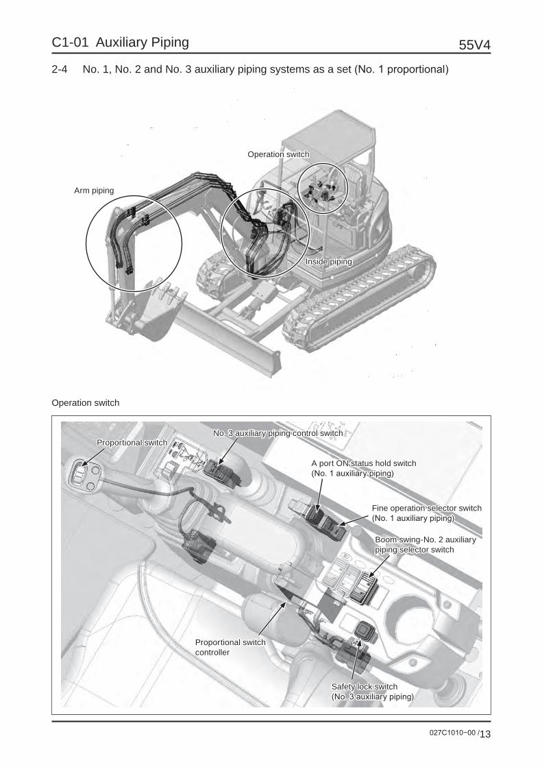
027C1010−00 /13
55V4C1-01 Auxiliary Piping
2-4 No. 1, No. 2 and No. 3 auxiliary piping systems as a set (No. 1 proportional)
Operation switch
Arm piping
Operation switch
Inside piping
Proportional switch
A port ON status hold switch(No. 1 auxiliary piping)
Fine operation selector switch(No. 1 auxiliary piping)
Proportional switch controller
Boom swing-No. 2 auxiliary piping selector switch
Safety lock switch(No. 3 auxiliary piping)
No. 3 auxiliary piping control switch
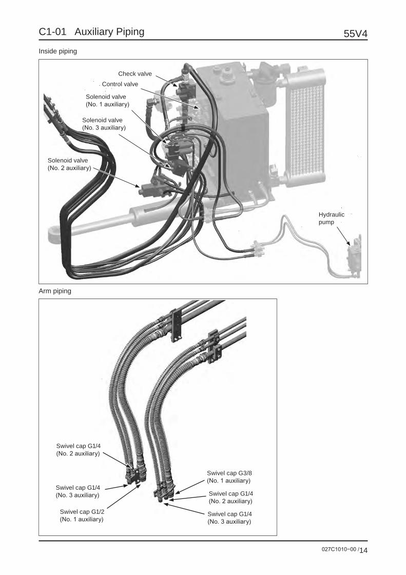
55V4
027C1010−00 /14
C1-01 Auxiliary Piping
Inside piping
Arm piping
Control valve
Solenoid valve (No. 3 auxiliary)
Solenoid valve (No. 2 auxiliary)
Solenoid valve (No. 1 auxiliary)
Check valve
Swivel cap G1/4 (No. 3 auxiliary)
Swivel cap G1/2 (No. 1 auxiliary)
Swivel cap G1/4 (No. 3 auxiliary)
Swivel cap G3/8 (No. 1 auxiliary)
Swivel cap G1/4(No. 2 auxiliary)
Swivel cap G1/4(No. 2 auxiliary)
Hydraulicpump
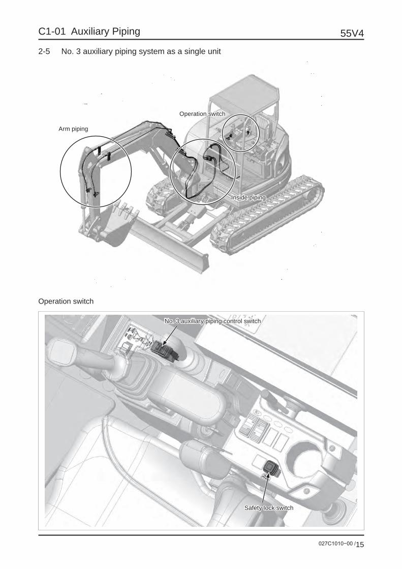
027C1010−00 /15
55V4C1-01 Auxiliary Piping
2-5 No. 3 auxiliary piping system as a single unit
Operation switch
Arm piping
Operation switch
Inside piping
Safety lock switch
No. 3 auxiliary piping control switch

55V4
027C1010−00 /16
C1-01 Auxiliary Piping
Inside piping
Arm piping
Solenoid valve
Swivel cap G1/4
Swivel cap G1/4
Hydraulicpump
027C1010−00 /17
55V4C1-01 Auxiliary Piping
Operating method of No. 3 auxiliary piping (Installing/removing quick hitch) Installing
1 When connecting and fixing the quick hitch, pressure is high at one side and is low at the other side. Connect the high-pressure side to the left piping of arm and the low-pressure side to the right piping.
2 Start the engine. Sit on the seat and set the safety lever to ON.
3 Press the safety lock switch to be ON. At the same time the buzzer keeps sounding.
4 Set “No. 3 auxiliary piping switch” to “FREE”, and the solenoid is charged with electricity. High pres-sure is generated at the right pipe of arm and low pressure is generated at the left pipe. The quick hitch is unlocked.
5 Operate the boom and arm to set the quick hitch on the attachment which is the mate for connection.
6 Set “No. 3 auxiliary piping switch” to “LOCK”. High pressure is generated at the left pipe of arm and low pressure is generated at the right pipe. The quick hitch is locked.
7 Press the safety lock switch again. Make sure that the switch is OFF and the buzzer stops sounding.
Removing
1 Put the attachment stably on a flat ground.
2 Press the safety lock switch to be ON. At the same time the buzzer keeps sounding.
3 Set “No. 3 auxiliary piping switch” to “FREE”, and the solenoid is charged with electricity. High pres-sure is generated at the right pipe of arm and low pressure is generated at the left pipe. The quick hitch is unlocked.
4 Remove the quick hitch from the attachment which is the mate for connection.
5 Press the safety lock switch again. Make sure that the switch is OFF and the buzzer stops sounding.

55V4
027C1010−00 /18
C1-01 Auxiliary Piping
2-6 No. 1 auxiliary piping system as a single unit (Pedal operation/with stop valve)
Arm piping
Inside piping

027C1010−00 /19
55V4C1-01 Auxiliary Piping
Operating method
When using the breaker1. Connect the supply hose to the pipe at the left side of arm and
the return hose to the pipe at the right side.
2. Set the mark (2) on the selector valve vertically.
3. Set the pedal lock lever to the “unlock” position.
4. Step on the front side of auxiliary pedal (1) to operate the breaker.
5. Release the pedal, and the breaker stops.
6. Set the pedal lock lever to the “lock” position under the condition that you are stepping on the front side of auxiliary pedal. The pressure oil is discharged continuously.
Be sure to set the mark on the selector valve as instructed in this manual.If the mark is set wrongly, the machine and breaker will be damaged.
Pedal lock lever
Lock
Unlock

55V4
027C1010−00 /20
C1-01 Auxiliary Piping
When using the demolishing fork
1. Connect the hoses to the right and left pipes of arm.
2. Set the mark (2) on the selector valve horizontally.
3. Step on the front and rear sides of auxiliary pedal (1) to operate the demolishing fork.• Stepping on the front side: Supplies the pressure oil to the left pipe of arm.• Stepping on the rear side: Supplies the pressure oil to the right pipe of arm.
Be sure to set the mark on the selector valve as instructed in this manual.If the mark is set wrongly, the pressure oil is not supplied to the right pipe of arm.
Pedal lock lever
Lock
Unlock

027C1010−00 /21
55V4C1-01 Auxiliary Piping
Inside piping
Arm piping
Control valve
Selector valve
Remote control valve
Swivel cap G3/4
Swivel cap G3/4
Hydraulicpump

55V4
027C1010−00 /22
C1-01 Auxiliary Piping
2-7 No. 1 and No. 3 auxiliary piping systems as a set (No. 1 pedal operation/with stop valve)
Operation switch
Arm piping
Operation switch
Inside piping
No. 3 auxiliary piping control switch
Safety lock switch

027C1010−00 /23
55V4C1-01 Auxiliary Piping
Inside piping
Arm piping
Control valve
Selector valve
Remote control valve (No. 1 auxiliary)
Solenoid valve (No. 3 auxiliary)
Swivel cap G1/4 (No. 3 auxiliary)
Swivel cap G1/4 (No. 3 auxiliary)
Swivel cap G3/4 (No. 1 auxiliary)
Swivel cap G3/4 (No. 1 auxiliary)
Hydraulicpump
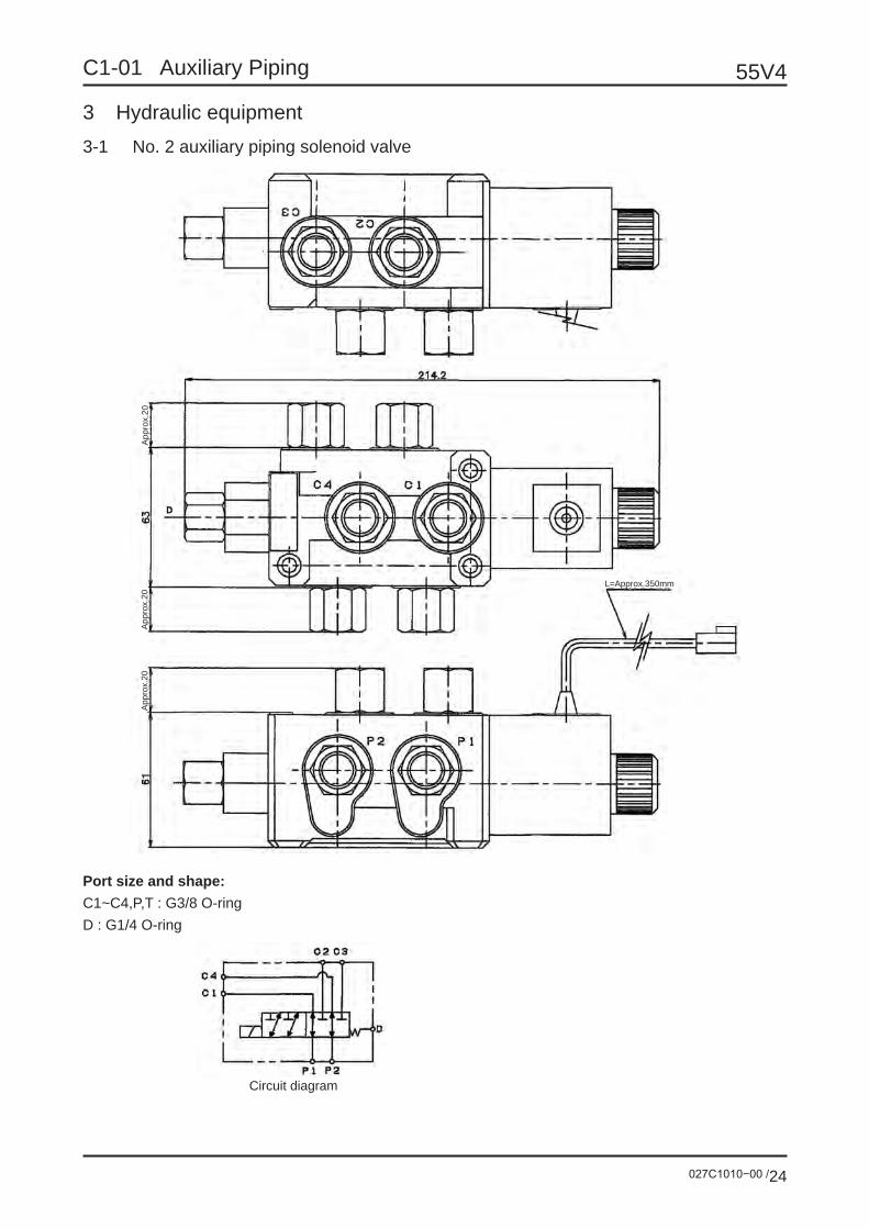
55V4
027C1010−00 /24
C1-01 Auxiliary Piping
3 Hydraulic equipment3-1 No. 2 auxiliary piping solenoid valve
Circuit diagram
Port size and shape:C1~C4,P,T : G3/8 O-ringD : G1/4 O-ring
L=Approx.350mm
App
rox.
20A
ppro
x.20
App
rox.
20
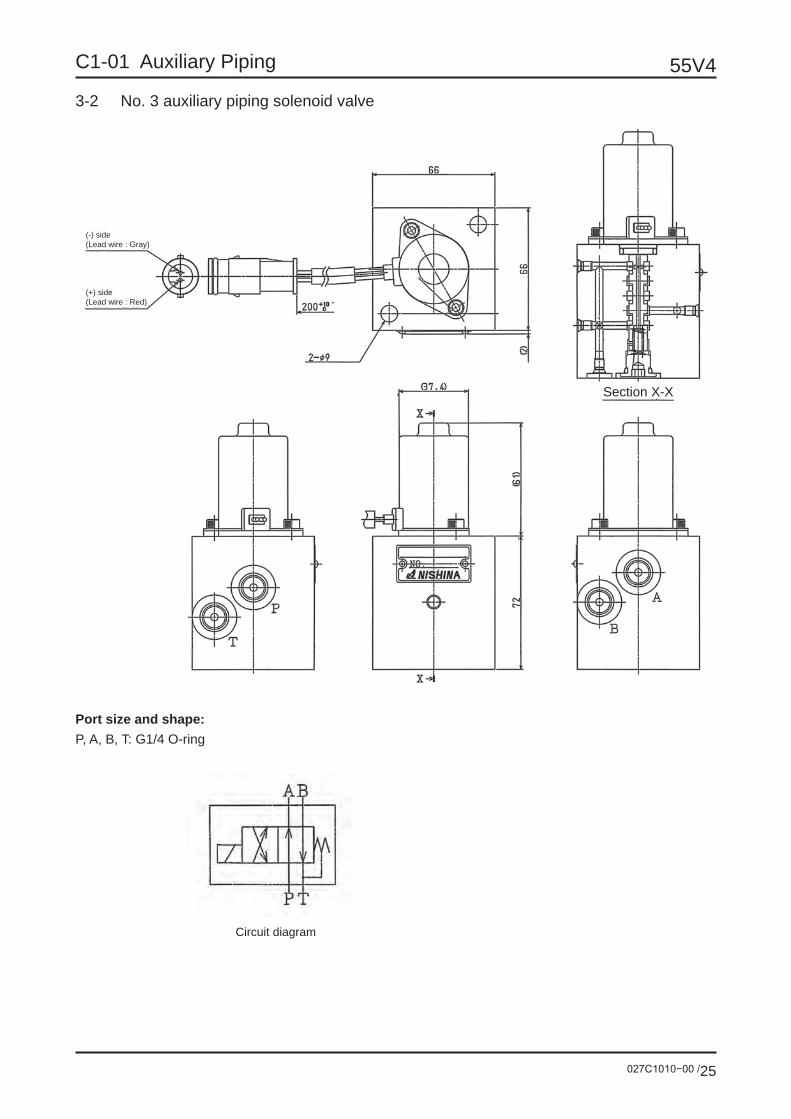
027C1010−00 /25
55V4C1-01 Auxiliary Piping
3-2 No. 3 auxiliary piping solenoid valve
Port size and shape:P, A, B, T: G1/4 O-ring
Circuit diagram
Section X-X
(-) side(Lead wire : Gray)
(+) side(Lead wire : Red)

55V4
027C1010−00 /26
C1-01 Auxiliary Piping
4 Hydraulic circuit diagramN
o. 3
AU
X
Left
Left
Left
Rig
htR
ight
Rig
ht
No.
1 A
UX
No.
2 A
UX
Man
ifold
w
ith c
ock
No.
2 A
UX
so
leno
id v
alve
No.
1 A
UX
so
leno
id
valv
e
Boo
m s
win
g cy
linde
rN
o. 3
AU
X
sole
noid
va
lve
Eng
ine
Suc
tion
stra
iner
Ret
urn
filte
r
150
mes
hes
0.2M
Pa
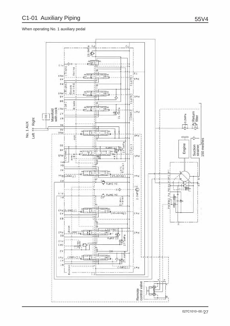
027C1010−00 /27
55V4C1-01 Auxiliary Piping
When operating No. 1 auxiliary pedal
Rem
ote
cont
rol v
alve
Left
Rig
ht
No.
1 A
UX M
anifo
ld
with
coc
k
Eng
ine
Suc
tion
stra
iner
150
mes
hes
Ret
urn
filte
r
0.2M
Pa