Mud Dog® Vacuum Excavator - Super Products
126
-
Upload
khangminh22 -
Category
Documents
-
view
0 -
download
0
Transcript of Mud Dog® Vacuum Excavator - Super Products


As of 12/20/19
LIMITED WARRANTYSubject to the terms and conditions below, Super Products warrants to its original purchaser ("original purchaser") that new equipment sold after theeffective date of this limited warranty is free of defects in material or workmanship at the time it was shipped from Super Products for a period of 12months from the shipment date, provided the equipment is used in a normal and reasonable manner and in accordance with all operating instructions.Super Products agrees, at its sole election, to either repair or replace (inclusive of labor) any parts and components manufactured by Super Products.Super Products must be notified with thirty (30) days of such defect or failure, at which time Super Products will provide instructions on the warrantyprocedures to be followed, This limited warranty is subject to those limitations and exclusions as described in such warranty procedures. Super Productswill not honor claims for warranty that have not been previously authorized via the warranty procedures (including that labor rates and times must bepreapproved in writing).
In addition, Super Products agrees to provide extended warranties for certain components as indicated below: (extended warranty periods begin fromthe shipment date to the original purchaser).
• "10 Years on the debris body and all poly water tanks (from defects in material or workmanship). • "3 Years on Super Products' single-piston water pump (from defects in material or workmanship).
Super Products does not provide any express or implied warranty to (and Super Products shall not be responsible for)
• "Any major components of the equipment that Super Products used in manufacturing or assembling the equipment but that Super Products did not manufacture (including, but not limited to, truck engines or any component of the chassis, vacuum pump, water pump, and hydraulics, driveline, power takeoff, and transfer case). Super Products assigns to the original purchaser any warranty extended by the manufacturer of such components. Disposition of any warranty claim for such components will be at the sole discretion and remedy of the component supplier. Super Products shall have the right of disposal of parts and components that are replaced.
• "Normal wear parts, including but not limited to, valves, gaskets, light bulbs, filters, oils and fluids.• "Consumable items, including but not limited to, vacuum hose, sewer hose, nozzles, and vacuum tubes.• "Normal adjustments and maintenance services.
This limited warranty does not cover any damage to nonfunctioning or malfunctioning of the equipment, or any components or parts comprising theequipment, due to: (a) any alteration, substitution, misuse or abuse by the original purchaser or its agents; (b) their non-compliance with any operator'smanual, maintenance manual or warning published by Super Products or the component manufacturer and issued to the original purchaser; or (c) theirnon-compliance with the general standard of reasonable care.
OTHER THAN AS EXPRESSLY STATED HEREIN, THERE ARE NO OTHER WARRANTIES OF ANY KIND, EXPRESS OR IMPLIED. MORESPECIFICALLY, THERE ARE NO IMPLIED WARRANTIES OF FITNESS FOR A PARTICULAR PURPOSE OR OF MERCHANTABILITY. ORIGINALPURCHASER ACKNOWLEDGES AND AGREES THAT SUPER PRODUCTS MAKES NO REPRESENTATIONS OR PROMISES, AND THATORIGINAL PURCHASER IS NOT RELYING UPON ANY ORAL OR WRITTEN REPRESENTATIONS OR PROMISES , REGARDING ANYPERFORMANCE CHARACTERISTICS OR CAPABILITIES OF THE EQUIPMENT OR THE COMPONENTS THEREOF (INCLUDING , WITHOUTLIMITATION, THE INTEGRATION OF SUCH COMPONENTS OR THE COMBINATION IN WHICH SUCH COMPONENTS MAY BE USED), EXCEPTAS EXPRESSLY STATED IN THE DESCRIPTION OF THE EQUIPMENT CONTAINED IN THE ACKNOWLEDGMENT OR OTHER WRITTENDESCRIPTIONS PROVIDED BY SUPER PRODUCTS.
SUPER PRODUCTS' MAXIMUM LIABILITY SHALL NOT EXCEED AND ORIGINAL PURCHASER'S REMEDY IS LIMITED TO EITHER (a) REPAIROR REPLACEMENT OF THE DEFECTIVE EQUIPMENT, OR AT SELLER'S OPTION (b) RETURN OF THE PRODUCT AND REFUND OF THEPURCHASE PRICE. SUCH REMEDY SHALL BE ORIGINAL PURCHASER'S ENTIRE AND EXCLUSIVE REMEDY. ORIGINAL PURCHASERACKNOWLEDGES THAT UNDER NO CIRCUMSTANCES SHALL SUPER PRODUCTS BE LIABLE FOR ANY SPECIAL, INDIRECT, INCIDENTAL ORCONSEQUENTIAL DAMAGES OF ANY KIND ARISING IN CONNECTION WITH OR OUT OF THE EQUIPMENT AND THAT SUPER PRODUCTS'LIABILITY, WHETHER IN CONTRACT, TORT, UNDER ANY WARRANTY OR OTHERWISE SHALL NOT EXCEED THE RETURN OF THE AMOUNTOF THE PURCHASE PRICE PAID BY BUYER, WHICH AMOUNT MAY BE REDUCED DUE TO DEPRECIATION AND DAMAGE BEYOND NORMALWEAR AND TEAR. ORIGINAL PURCHASER UNDERSTANDS THAT THE LIMITATION OF SUPER PRODUCTS' LIABILITY RELATING TO THEEQUIPMENT IS A MATERIAL TERM OF THE PARTIES' TRANSACTION.
This limited warranty is not transferable without the prior written approval of Super Products.
NO ACTION ARISING OUT OF ANY CLAIMED BREACH OF THIS LIMITED WARRANTY OR TRANSACTIONS UNDER THIS LIMITED WARRANTYMAY BE BROUGHT MORE THAN TWO (2) YEARS AFTER THE CAUSE OF ACTION HAS OCCURRED.
130 W Boxhorn Drive, Mukwonago, WI 53149 • P: 800.837.9711 • www.superproductsllc.com

Table of Contents
Super Products LLC Publication: 0004175 TOC-1
1 SafetyGeneral Safety Instructions and Practices . . . . . . . . . . . . . . . . . . . . . . . . . . . . . . . . . . . . . . . . . . . . 1-1Visual Attention Safety . . . . . . . . . . . . . . . . . . . . . . . . . . . . . . . . . . . . . . . . . . . . . . . . . . . . . . . . . . . . 1-2Personal Protection Equipment (PPE) . . . . . . . . . . . . . . . . . . . . . . . . . . . . . . . . . . . . . . . . . . . . . . . . 1-3When Using Pressurized Air or Water . . . . . . . . . . . . . . . . . . . . . . . . . . . . . . . . . . . . . . . . . . . . . . . . 1-4General Hazards and Prevention Safety . . . . . . . . . . . . . . . . . . . . . . . . . . . . . . . . . . . . . . . . . . . . . . 1-5
Visibility Conditions When Operating . . . . . . . . . . . . . . . . . . . . . . . . . . . . . . . . . . . . . . . . . . . . . 1-6Mounting and Dismounting Truck or Equipment . . . . . . . . . . . . . . . . . . . . . . . . . . . . . . . . . . . . . 1-6Hot Surface . . . . . . . . . . . . . . . . . . . . . . . . . . . . . . . . . . . . . . . . . . . . . . . . . . . . . . . . . . . . . . . . . 1-6Safety Signs . . . . . . . . . . . . . . . . . . . . . . . . . . . . . . . . . . . . . . . . . . . . . . . . . . . . . . . . . . . . . . . . 1-6Equipment Guards . . . . . . . . . . . . . . . . . . . . . . . . . . . . . . . . . . . . . . . . . . . . . . . . . . . . . . . . . . . 1-6
Crushing Hazards and Prevention Safety . . . . . . . . . . . . . . . . . . . . . . . . . . . . . . . . . . . . . . . . . . . . . 1-7Debris Body Prop Support . . . . . . . . . . . . . . . . . . . . . . . . . . . . . . . . . . . . . . . . . . . . . . . . . . . . . . 1-7Tailgate Prop Support . . . . . . . . . . . . . . . . . . . . . . . . . . . . . . . . . . . . . . . . . . . . . . . . . . . . . . . . . 1-7Truck Tip Over . . . . . . . . . . . . . . . . . . . . . . . . . . . . . . . . . . . . . . . . . . . . . . . . . . . . . . . . . . . . . . . 1-7
Trip and Fall Prevention Safety . . . . . . . . . . . . . . . . . . . . . . . . . . . . . . . . . . . . . . . . . . . . . . . . . . . . . 1-8High-Pressure Fluid Leak Hazards . . . . . . . . . . . . . . . . . . . . . . . . . . . . . . . . . . . . . . . . . . . . . . . . . . . 1-9Power Lines/Static Electrical Hazard Warnings . . . . . . . . . . . . . . . . . . . . . . . . . . . . . . . . . . . . . . . 1-10
Overhead Power Line Tips for Construction Workers Before You Begin Construction Work . . 1-10Working with Tools and Equipment . . . . . . . . . . . . . . . . . . . . . . . . . . . . . . . . . . . . . . . . . . . . . . 1-10
Chemical and Biological Hazard Safety . . . . . . . . . . . . . . . . . . . . . . . . . . . . . . . . . . . . . . . . . . . . . . 1-11Chemicals and Diesel Engine Exhaust . . . . . . . . . . . . . . . . . . . . . . . . . . . . . . . . . . . . . . . . . . . 1-11Sewer Gas Hazard . . . . . . . . . . . . . . . . . . . . . . . . . . . . . . . . . . . . . . . . . . . . . . . . . . . . . . . . . . 1-11Chemical Waste Hazard . . . . . . . . . . . . . . . . . . . . . . . . . . . . . . . . . . . . . . . . . . . . . . . . . . . . . . 1-11Biological Hazards . . . . . . . . . . . . . . . . . . . . . . . . . . . . . . . . . . . . . . . . . . . . . . . . . . . . . . . . . . . 1-11Dust Hazard . . . . . . . . . . . . . . . . . . . . . . . . . . . . . . . . . . . . . . . . . . . . . . . . . . . . . . . . . . . . . . . 1-11
Transport Safety and Hazards Warnings . . . . . . . . . . . . . . . . . . . . . . . . . . . . . . . . . . . . . . . . . . . . . 1-12Before Transporting Truck Inspection . . . . . . . . . . . . . . . . . . . . . . . . . . . . . . . . . . . . . . . . . . . . 1-12Never Exceed your Gross Vehicle Weight Rating (GVWR) . . . . . . . . . . . . . . . . . . . . . . . . . . . 1-12Pedestrian Safety . . . . . . . . . . . . . . . . . . . . . . . . . . . . . . . . . . . . . . . . . . . . . . . . . . . . . . . . . . . 1-12Determine Stopping Characteristics of Truck for Transporting Braking Tests . . . . . . . . . . . . . 1-13Determine Maximum Turning Speed Before Operating on Roads or Uneven Ground . . . . . . . 1-13When Transporting Equipment . . . . . . . . . . . . . . . . . . . . . . . . . . . . . . . . . . . . . . . . . . . . . . . . . 1-13
Job Site Safety and Hazard Warnings . . . . . . . . . . . . . . . . . . . . . . . . . . . . . . . . . . . . . . . . . . . . . . . 1-14To Help Avoid Injury . . . . . . . . . . . . . . . . . . . . . . . . . . . . . . . . . . . . . . . . . . . . . . . . . . . . . . . . . 1-14Arrange for Traffic Control . . . . . . . . . . . . . . . . . . . . . . . . . . . . . . . . . . . . . . . . . . . . . . . . . . . . . 1-14Prepare for Working Near Existing Utilities . . . . . . . . . . . . . . . . . . . . . . . . . . . . . . . . . . . . . . . . 1-14Plan for Emergency Services . . . . . . . . . . . . . . . . . . . . . . . . . . . . . . . . . . . . . . . . . . . . . . . . . . 1-14Inspect the Job Site . . . . . . . . . . . . . . . . . . . . . . . . . . . . . . . . . . . . . . . . . . . . . . . . . . . . . . . . . . 1-15Visibility Conditions When Operating . . . . . . . . . . . . . . . . . . . . . . . . . . . . . . . . . . . . . . . . . . . . 1-15Prepare the Job Site . . . . . . . . . . . . . . . . . . . . . . . . . . . . . . . . . . . . . . . . . . . . . . . . . . . . . . . . . 1-15

TOC-2 Super Products LLC Publication: 0004175
Vacuum Equipment Operation Safety and Hazard Warnings . . . . . . . . . . . . . . . . . . . . . . . . . . . . 1-16Emergency Stop Button Function . . . . . . . . . . . . . . . . . . . . . . . . . . . . . . . . . . . . . . . . . . . . . . . 1-16Vacuum Operation Safety . . . . . . . . . . . . . . . . . . . . . . . . . . . . . . . . . . . . . . . . . . . . . . . . . . . . . 1-17Pre-Start Checklist . . . . . . . . . . . . . . . . . . . . . . . . . . . . . . . . . . . . . . . . . . . . . . . . . . . . . . . . . . . 1-18Vacuum Operation . . . . . . . . . . . . . . . . . . . . . . . . . . . . . . . . . . . . . . . . . . . . . . . . . . . . . . . . . . . 1-18
Vacuum Relief Valve Safety . . . . . . . . . . . . . . . . . . . . . . . . . . . . . . . . . . . . . . . . . . . . . . . . . . . . . . . . 1-19Vacuum Relief Valves . . . . . . . . . . . . . . . . . . . . . . . . . . . . . . . . . . . . . . . . . . . . . . . . . . . . . . . . 1-19Operating the T-Type Vacuum Relief Valve . . . . . . . . . . . . . . . . . . . . . . . . . . . . . . . . . . . . . . . 1-19Testing the T-Type Vacuum Relief Valve . . . . . . . . . . . . . . . . . . . . . . . . . . . . . . . . . . . . . . . . . 1-20Operating the Remote-Operated Vacuum Relief Valve . . . . . . . . . . . . . . . . . . . . . . . . . . . . . . . 1-21High Water Pressure . . . . . . . . . . . . . . . . . . . . . . . . . . . . . . . . . . . . . . . . . . . . . . . . . . . . . . . . . 1-25
Dust Hazard and Explosion Prevention Safety . . . . . . . . . . . . . . . . . . . . . . . . . . . . . . . . . . . . . . . . 1-26Hydrocarbon Waste Recovery . . . . . . . . . . . . . . . . . . . . . . . . . . . . . . . . . . . . . . . . . . . . . . . . . . . . . 1-27Controlling Lower Explosive Level (LEL) . . . . . . . . . . . . . . . . . . . . . . . . . . . . . . . . . . . . . . . . . . . . . 1-27High-Temperature Prevention . . . . . . . . . . . . . . . . . . . . . . . . . . . . . . . . . . . . . . . . . . . . . . . . . . . . . . 1-28Static Charge Dissipation . . . . . . . . . . . . . . . . . . . . . . . . . . . . . . . . . . . . . . . . . . . . . . . . . . . . . . . . . 1-29Spark and Fire Prevention Safety . . . . . . . . . . . . . . . . . . . . . . . . . . . . . . . . . . . . . . . . . . . . . . . . . . . 1-30Debris Body Dumping Safety and Hazard Warnings . . . . . . . . . . . . . . . . . . . . . . . . . . . . . . . . . . . 1-31Sewer Gas Safety and Hazard Warnings . . . . . . . . . . . . . . . . . . . . . . . . . . . . . . . . . . . . . . . . . . . . . 1-32Confined Space Hazard . . . . . . . . . . . . . . . . . . . . . . . . . . . . . . . . . . . . . . . . . . . . . . . . . . . . . . . . . . . 1-32Trenching Hazards . . . . . . . . . . . . . . . . . . . . . . . . . . . . . . . . . . . . . . . . . . . . . . . . . . . . . . . . . . . . . . . 1-33De-energize and Lockout Procedures . . . . . . . . . . . . . . . . . . . . . . . . . . . . . . . . . . . . . . . . . . . . . . . 1-34Hazards With Equipment Maintenance . . . . . . . . . . . . . . . . . . . . . . . . . . . . . . . . . . . . . . . . . . . . . . 1-35
Before Performing Service, Repairs, and Maintenance on the Equipment . . . . . . . . . . . . . . . . 1-35Performing Service, Repairs, Lubrication, and Maintenance . . . . . . . . . . . . . . . . . . . . . . . . . . . 1-35Safety Shields, Guards, and Safety Devices Inspection . . . . . . . . . . . . . . . . . . . . . . . . . . . . . . 1-35
Decal Location . . . . . . . . . . . . . . . . . . . . . . . . . . . . . . . . . . . . . . . . . . . . . . . . . . . . . . . . . . . . . . . . . . 1-36Debris Body Tailgate Props . . . . . . . . . . . . . . . . . . . . . . . . . . . . . . . . . . . . . . . . . . . . . . . . . . . . . . . . 1-52
Unlocking the Tailgate Props and Raising the Debris Body Tailgate . . . . . . . . . . . . . . . . . . . . 1-52Lowering the Debris Body Tailgate and Storing the Props . . . . . . . . . . . . . . . . . . . . . . . . . . . . 1-52
Preparation Before Traveling to Worksite . . . . . . . . . . . . . . . . . . . . . . . . . . . . . . . . . . . . . . . . . . . . 1-53
2 Pre-OperationIntroduction . . . . . . . . . . . . . . . . . . . . . . . . . . . . . . . . . . . . . . . . . . . . . . . . . . . . . . . . . . . . . . . . . . . . . . 2-1Principles of Operation . . . . . . . . . . . . . . . . . . . . . . . . . . . . . . . . . . . . . . . . . . . . . . . . . . . . . . . . . . . . 2-1Equipment Specifications . . . . . . . . . . . . . . . . . . . . . . . . . . . . . . . . . . . . . . . . . . . . . . . . . . . . . . . . . . 2-1Vacuum System . . . . . . . . . . . . . . . . . . . . . . . . . . . . . . . . . . . . . . . . . . . . . . . . . . . . . . . . . . . . . . . . . . 2-3
Pure Vacuum . . . . . . . . . . . . . . . . . . . . . . . . . . . . . . . . . . . . . . . . . . . . . . . . . . . . . . . . . . . . . . . . 2-3Air Conveyance . . . . . . . . . . . . . . . . . . . . . . . . . . . . . . . . . . . . . . . . . . . . . . . . . . . . . . . . . . . . . . 2-3Vacuum Pump Operation . . . . . . . . . . . . . . . . . . . . . . . . . . . . . . . . . . . . . . . . . . . . . . . . . . . . . . 2-5Vacuum Relief Valves . . . . . . . . . . . . . . . . . . . . . . . . . . . . . . . . . . . . . . . . . . . . . . . . . . . . . . . . . 2-7
Suction Line Connections . . . . . . . . . . . . . . . . . . . . . . . . . . . . . . . . . . . . . . . . . . . . . . . . . . . . . . . . . . 2-8
Super Products LLC Publication: 0004175 TOC-3
3 Control System OperationControl Panel . . . . . . . . . . . . . . . . . . . . . . . . . . . . . . . . . . . . . . . . . . . . . . . . . . . . . . . . . . . . . . . . . . . . 3-1Emergency Stop (E-Stop) Button on Remotes . . . . . . . . . . . . . . . . . . . . . . . . . . . . . . . . . . . . . . . . . 3-2Control Valves . . . . . . . . . . . . . . . . . . . . . . . . . . . . . . . . . . . . . . . . . . . . . . . . . . . . . . . . . . . . . . . . . . . 3-3
Water Control Valve . . . . . . . . . . . . . . . . . . . . . . . . . . . . . . . . . . . . . . . . . . . . . . . . . . . . . . . . . . 3-3Boom Operation . . . . . . . . . . . . . . . . . . . . . . . . . . . . . . . . . . . . . . . . . . . . . . . . . . . . . . . . . . . . . . . . . . 3-4Water Lance Operation . . . . . . . . . . . . . . . . . . . . . . . . . . . . . . . . . . . . . . . . . . . . . . . . . . . . . . . . . . . . 3-5Water Heater Operation . . . . . . . . . . . . . . . . . . . . . . . . . . . . . . . . . . . . . . . . . . . . . . . . . . . . . . . . . . . . 3-6Winter Recirculation System . . . . . . . . . . . . . . . . . . . . . . . . . . . . . . . . . . . . . . . . . . . . . . . . . . . . . . . 3-6Air purge Anti-freeze back into Anti-freeze tank . . . . . . . . . . . . . . . . . . . . . . . . . . . . . . . . . . . . . . . . 3-8
Separator Air System . . . . . . . . . . . . . . . . . . . . . . . . . . . . . . . . . . . . . . . . . . . . . . . . . . . . . . . . 3-11Front Body Drain Valve . . . . . . . . . . . . . . . . . . . . . . . . . . . . . . . . . . . . . . . . . . . . . . . . . . . . . . . 3-11
Debris Level Sensor (Optional) . . . . . . . . . . . . . . . . . . . . . . . . . . . . . . . . . . . . . . . . . . . . . . . . . . . . 3-11
4 Lubrication and MaintenanceGeneral Information . . . . . . . . . . . . . . . . . . . . . . . . . . . . . . . . . . . . . . . . . . . . . . . . . . . . . . . . . . . . . . . 4-1Preventive Maintenance Instructions . . . . . . . . . . . . . . . . . . . . . . . . . . . . . . . . . . . . . . . . . . . . . . . . 4-1Lubrication Recommendation Chart . . . . . . . . . . . . . . . . . . . . . . . . . . . . . . . . . . . . . . . . . . . . . . . . . 4-1Maintenance Schedule . . . . . . . . . . . . . . . . . . . . . . . . . . . . . . . . . . . . . . . . . . . . . . . . . . . . . . . . . . . . 4-2Maintenance Items . . . . . . . . . . . . . . . . . . . . . . . . . . . . . . . . . . . . . . . . . . . . . . . . . . . . . . . . . . . . . . . . 4-4
Boom . . . . . . . . . . . . . . . . . . . . . . . . . . . . . . . . . . . . . . . . . . . . . . . . . . . . . . . . . . . . . . . . . . . . . . 4-4Debris Body . . . . . . . . . . . . . . . . . . . . . . . . . . . . . . . . . . . . . . . . . . . . . . . . . . . . . . . . . . . . . . . . . 4-4Electrical System . . . . . . . . . . . . . . . . . . . . . . . . . . . . . . . . . . . . . . . . . . . . . . . . . . . . . . . . . . . . . 4-4Hydraulic System . . . . . . . . . . . . . . . . . . . . . . . . . . . . . . . . . . . . . . . . . . . . . . . . . . . . . . . . . . . . 4-4Power Unit: . . . . . . . . . . . . . . . . . . . . . . . . . . . . . . . . . . . . . . . . . . . . . . . . . . . . . . . . . . . . . . . . . 4-4Water System . . . . . . . . . . . . . . . . . . . . . . . . . . . . . . . . . . . . . . . . . . . . . . . . . . . . . . . . . . . . . . . 4-5Air Purge . . . . . . . . . . . . . . . . . . . . . . . . . . . . . . . . . . . . . . . . . . . . . . . . . . . . . . . . . . . . . . . . . . . 4-5Cabinet & Toolbox Doors . . . . . . . . . . . . . . . . . . . . . . . . . . . . . . . . . . . . . . . . . . . . . . . . . . . . . . 4-5
Adjusting Hydraulic Tailgate Latches & Hinges . . . . . . . . . . . . . . . . . . . . . . . . . . . . . . . . . . . . . . . . 4-5Ejector Plate Slide Pad and Wiper Adjustment . . . . . . . . . . . . . . . . . . . . . . . . . . . . . . . . . . . . . . . . . 4-6
Wiper Adjustment . . . . . . . . . . . . . . . . . . . . . . . . . . . . . . . . . . . . . . . . . . . . . . . . . . . . . . . . . . . . 4-7
5 TroubleshootingTroubleshooting Overview . . . . . . . . . . . . . . . . . . . . . . . . . . . . . . . . . . . . . . . . . . . . . . . . . . . . . . . . . 5-1
The Basic Troubleshooting Process . . . . . . . . . . . . . . . . . . . . . . . . . . . . . . . . . . . . . . . . . . . . . . 5-1Electrical Troubleshooting . . . . . . . . . . . . . . . . . . . . . . . . . . . . . . . . . . . . . . . . . . . . . . . . . . . . . . . . . 5-7Eject / Retract Function Troubleshooting . . . . . . . . . . . . . . . . . . . . . . . . . . . . . . . . . . . . . . . . . . . . 5-17Winter Recirculation Troubleshooting . . . . . . . . . . . . . . . . . . . . . . . . . . . . . . . . . . . . . . . . . . . . . . . 5-17
6 Service and Spare Parts
7 Index


Super Products LLC Publication: 0004175 1-1
Chapter 1
1Safety
General Safety Instructions and PracticesA careful operator is the best operator. Safety is of primary importance to the manufacturer and should be to the owner/operator. Most accidents can be avoided by being aware of your equipment, your surroundings, and observing certain precautions. The first section of this manual includes a list of Safety Messages that, if followed, will help protect the operator and bystanders from injury or death. Read and understand these safety messages before assembling, operating, or servicing this equipment. This equipment should only be operated by those persons who have read the manual, who are responsible and trained, and who know how to do so responsibly.
Practice all usual and customary safe working precautions and above all remember safety is up to you. Only you can prevent serious injury or death from unsafe practices.
DANGER
WARNING
CAUTION
NOTICE
NOTEIdentifies points of particular interest for more efficient and convenient operation or repair.
The Safety Alert Symbol combined with a Signal Word, as seen below, is used throughout this manual and on decals which are attached to the equipment. The Safety Alert Symbol means: “ATTENTION! BECOME ALERT! YOUR SAFETY IS INVOLVED!” The Symbol and Signal Word are intended to warn the owner/operator of impending hazards and the degree of possible injury faced when operating this equipment.
Indicates an imminently hazardous situation which, if not avoided, WILL result in death or serious injury.
Indicates a potentially hazardous situation which, if not avoided, COULD result in death or serious injury.
Indicates a potentially hazardous situation which, if not avoided, MAY result in minor or moderate injury and property damage. It may also be used to alert against unsafe practices.
Indicates a potentially hazardous situation which, if not avoided, MAY result in property damage. It may also be used to alert against unsafe practices.
READ, UNDERSTAND, and FOLLOW the following Safety Messages. Serious injury or death may occur unless care is taken to follow the warnings and instructions stated in this manual and in the Safety Messages on the implement. Always follow the instruction in this manual and use common sense to avoid hazards.

1-2 Super Products LLC Publication: 0004175
SAFETY
1
Visual Attention Safety Pictographs are used throughout this manual to help bring your visual attention to safety issues.
Figure 1-1
NOTEIf you want a translation of this safety section in Spanish or French, please contact:
Translation — Safety Section130 W Boxhorn Drive
Mukwonago, WI 53149(800) 837-9711

SAFETY
Super Products LLC Publication: 0004175 1-3
1
Personal Protection Equipment (PPE)
Figure 1-2
Always wear protective clothing and personal safety devices issued to you or required by job conditions.This should always include:
• Hard hat • Safety shoes • Safety glasses, goggles, or face shield • Heavy gloves (chemical resistant) • Hearing protection • Reflective clothing
WARNINGNever wear loose clothing or jewelry that can catch on controls or other parts of the machine. Loose clothing can be drawn into the suction hose. Never wear a wristwatch or finger rings when working on or around equipment.

1-4 Super Products LLC Publication: 0004175
SAFETY
1
When Using Pressurized Air or Water
Figure 1-3
When using pressurized air or water for cleaning or material erosion/movement, you should use the following:
• Face Shield• Wet Weather Protective Suit • Waterproof Gloves • Respirator • Safety Boots with Metatarsal Guard
SAFETY
Super Products LLC Publication: 0004175 1-5
1
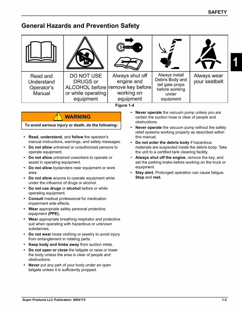
General Hazards and Prevention Safety
Figure 1-4
WARNING
• Read, understand, and follow the operator's manual instructions, warnings, and safety messages.
• Do not allow untrained or unauthorized persons to operate equipment.
• Do not allow untrained coworkers to operate or assist in operating equipment.
• Do not allow bystanders near equipment or work area.
• Do not allow anyone to operate equipment while under the influence of drugs or alcohol.
• Do not use drugs or alcohol before or while operating equipment.
• Consult medical professional for medication impairment side effects.
• Wear appropriate safety personal protective equipment (PPE).
• Wear appropriate breathing respirator and protective suit when operating with hazardous or unknown substances.
• Do not wear loose clothing or jewelry to avoid injury from entanglement in rotating parts.
• Keep body and limbs away from suction inlets.• Do not open or close the tailgate or raise or lower
the body unless the area is clear of people and obstructions.
• Never put any part of your body under an open tailgate unless it is sufficiently propped.
• Never operate the vacuum pump unless you are certain the suction hose is clear of people and obstructions.
• Never operate the vacuum pump without the safety relief systems working properly as described within this manual.
• Do not enter the debris body if hazardous materials are suspected inside the debris body. Take the unit to a certified tank cleaning facility.
• Always shut off the engine, remove the key, and set the parking brake before working on the truck or equipment.
• Stay alert. Prolonged operation can cause fatigue. Stop and rest.
To avoid serious injury or death, do the following:

1-6 Super Products LLC Publication: 0004175
SAFETY
1
General Hazards and Prevention Safety — continued
Figure 1-5
Visibility Conditions When Operating• Operate in daylight or with lights that gives at least
50 yards clear visibility. • Be able to see and identify passersby, steep slopes,
ditches, drop-offs, overhead obstructions, power lines, debris, and foreign objects.
• Use extreme care when backing up. Vision may be limited. Severe damage or injury can occur.
• Do not run engines in enclosed building without adequate exhaust ventilation.
Mounting and Dismounting Truck or Equipment• Only mount or dismount when truck and moving
parts are stopped. • Always use three-point contact when climbing on
or dismounting equipment. • Walkways, steps, and handrails should be checked
before use to ensure a proper non-slip surface. Replace or repair damaged component immediately.
Hot Surface• Stay clear of hot surfaces such as mufflers, hydraulic
pumps, valves, and tanks. • Relieve pressure from tank, reservoirs, valves, and
hoses before servicing or opening.
Safety Signs• Replace missing, damaged, or unreadable safety
signs immediately!
Equipment Guards• Never operate machine if equipment guards are
damaged or missing. • Replace missing or damaged guards immediately!

SAFETY
Super Products LLC Publication: 0004175 1-7
1
Crushing Hazards and Prevention Safety
Figure 1-6
Debris Body Prop Support
WARNING
1. Raise body sufficiently to allow body prop support to be swung into position.
2. Swing body prop support into support position.3. Slowly lower body until body contacts body prop
support. • To remove body prop support, reverse above
procedure.
Tailgate Prop Support
WARNING
1. Raise tailgate sufficiently to allow tailgate prop support to be swung into position.
2. Swing body prop support into support position.3. Slowly lower body tailgate until tailgate contacts
tailgate prop support.
• To remove tailgate body prop support, reverse above procedure.
Truck Tip Over
WARNING
• Truck driver must have valid and appropriate training license before transporting liquids on public roads.
• Slow down on curves to prevent truck from tipping over.
• Always ensure unit is on firm and level ground before operating the dump system. When dumping, raise the body in steps, allowing the material to dump out in a steady flow.
• Do not allow people and/or vehicles beside debris body while dumping.
• Never drive truck with raised debris body. • Keep truck away from drop-offs and soft soil shoulder
where truck could tip over.
Never go under raised debris body until prop is installed. Failure to do so could result in personal injury or death.
Always position tailgate prop in proper position before entering any areas beneath tailgate or entering body. Failure to do so could result in serious injury or death.
Always wear seat belt while seated in truck to prevent injury.
1-8 Super Products LLC Publication: 0004175
SAFETY
1
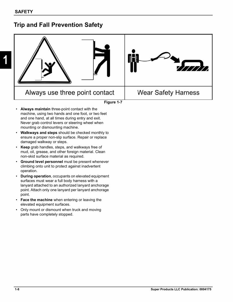
Trip and Fall Prevention Safety
Figure 1-7
• Always maintain three-point contact with the machine, using two hands and one foot, or two feet and one hand, at all times during entry and exit. Never grab control levers or steering wheel when mounting or dismounting machine.
• Walkways and steps should be checked monthly to ensure a proper non-slip surface. Repair or replace damaged walkway or steps.
• Keep grab handles, steps, and walkways free of mud, oil, grease, and other foreign material. Clean non-skid surface material as required.
• Ground level personnel must be present whenever climbing onto unit to protect against inadvertent operation.
• During operation, occupants on elevated equipment surfaces must wear a full body harness with a lanyard attached to an authorized lanyard anchorage point. Attach only one lanyard per lanyard anchorage point.
• Face the machine when entering or leaving the elevated equipment surfaces.
• Only mount or dismount when truck and moving parts have completely stopped.

SAFETY
Super Products LLC Publication: 0004175 1-9
1
High-Pressure Fluid Leak Hazards
Figure 1-8
DANGER
• Do not operate equipment with oil or fuel leaks. • Keep all hydraulic hoses, lines, and connections
tight and in good condition before applying pressure to the system.
• Relieve hydraulic pressure before servicing the hydraulic system.
• Remove and replace or test hydraulic hoses if a leak is suspected. Have a qualified service facility perform the test.
DANGERHI
• Always wear safety glasses and impenetrable gloves.
• Use paper or cardboard to search for leaks. • Do not use hands or body parts to search for leak. • Keep hands and body away from pin holes and
nozzles ejecting hydraulic fluid.
CAUTION
• Tank contents may be under pressure. • Allow oil to cool before removing cap slowly. • Relieve oil pressure before removing cap slowly. • Stay away from hot oil that may spray from tank or
hoses.
DANGER
Figure 1-9
To avoid serious injury or death from high-pressure hydraulic oil leaks penetrating skin, follow these rules:
High-pressure fluid leaks can be invisible. When checking for hydraulic leaks and working around hydraulic systems, follow these rules:
Use caution when removing hydraulic tank cap. Contents may be under pressure.
High-pressure hydraulic oil can puncture skin. If injured, seek immediate medical attention and inform the physician of the cause of the injury. Surgery is required to remove the fluid from the body. Failure to seek proper medical attention will result in serious injury or death.

1-10 Super Products LLC Publication: 0004175
SAFETY
1
Power Lines/Static Electrical Hazard Warnings
Figure 1-10
DANGER
• Never operate the unit in an area where overhead power lines, overhead or underground cables, or other power sources may exist without ensuring that the appropriate power or utility company has de-energized the lines.
• Always check for power lines before raising boom or debris body.
Follow all requirements for using mobile equipment when working around power lines. The Occupational Safety and Health Administration (OSHA) requirements apply to most workers. The following information is from OSHA. Additional information can be obtained from www.osha.gov.
Overhead Power Line Tips for Construction Workers Before You Begin Construction Work• Survey the site for overhead power lines.
NOTENever get within 10 feet of an overhead power line!
• Consider all overhead lines as energized until the electric utility indicates otherwise or an electrician verifies that the line is not energized and has been grounded.
• In construction work, an overhead power line safety component should be part of your employer's overall safety and health program and safety training.
• If overhead lines are present, call the utility company and ask if the utility company can shut off the lines while you are working near them.
• If overhead lines cannot be shut down, ask the utility company if they can install insulation over the lines during the time you will be working near them.
Working with Tools and Equipment• If the lines cannot be shut down and/or insulation
cannot be applied, a minimum safe distance of 10 feet must be established.
• Only use non-conductive ladders when working on or near overhead power lines.
• Employees shall not be permitted to approach or carry any conductive object closer than 10 feet to an energized line.
WARNING
This machine is not insulated and does not provide protection from contact or being near electrical current.
Electrically insulating coating must be used on water nozzles to prevent electrical contact with underground electrical power lines.

SAFETY
Super Products LLC Publication: 0004175 1-11
1
Chemical and Biological Hazard Safety
Figure 1-11
Chemicals and Diesel Engine Exhaust
WARNING
WARNING
Sewer Gas Hazard• Do not smoke or have lighted materials in or around
sewer lines, drains, or catch basins.
Chemical Waste Hazard• Storm drains, catch basins, and sewers may contain
harmful chemicals. To prevent contamination and injury, wear chemical resistant gloves, long sleeves, trousers, and safety glasses or face shields.
• Seek immediate medical attention if exposure or contamination is suspected.
Biological Hazards• Germs and other biological hazards are common in
sewers, drains, and catch basins. Use appropriate personal protective equipment to avoid injury and contamination. Get medical attention for injuries associated with cleaning sewers, drains, and catch basins if biological contamination is suspected.
Dust Hazard• Repeated or substantial breathing of hazardous
dusts, including crystalline silica, could cause fatal or serious respiratory disease including silicosis. Concrete, masonry, many types of rock, and various other materials contain silica sand. California lists repairable crystalline silica as a substance known to cause cancer. Operation of this equipment under certain conditions may generate airborne dust particles that could contain crystalline silica. In those conditions personal protective equipment including an appropriate respirator must be used. If excessive dust is generated, a dust collection or suppression system should also be used during operation.
Operating, servicing and maintaining this equipment can expose you to chemicals including gasoline, diesel fuel, lubricants, petroleum products, engine exhaust, carbon monoxide, and phthalates, which are known to the State of California to cause cancer and birth defects or other reproductive harm. To minimize exposure, avoid breathing exhaust, do not idle the engine except as necessary, service your vehicle in a well-ventilated area and wear gloves or wash your hands frequently when servicing your vehicle. Battery posts, terminals and related accessories contain lead and lead compounds, chemicals known to the state of California to cause cancer, birth defects or other reproductive harm. For more information go to www.P65Warnings.ca.gov. This website, operated by California's Office of Environmental Health Hazard Assessment, provides information about these chemicals and how individuals may be exposed to them.
Always read carefully and comply fully with the manufacturer’s instructions when handling fuels, oils, solvents, cleansers, and any other chemical agent.

1-12 Super Products LLC Publication: 0004175
SAFETY
1
Transport Safety and Hazards Warnings
Figure 1-12
WARNING
Before Transporting Truck Inspection• Ensure unit is road worthy by performing a pre-trip
inspection before driving to and from job site.• Check that tailgate is closed and properly locked.• Ensure all equipment is properly secured and
positioned for maximum visibility and adequate clearances.
• Close all water drain valves and install all plugs and strainers previously removed.
• Check that boom (if equipped) is locked in transport position and properly secured.
• Check that all tools, accessories, and work tubes/hoses are properly secured.
• Check that cabinet doors and access panels are closed.
• Check that all clean-out doors are closed and latched shut.
• Check that the dust chute and tailgate are closed and latched shut.
• Always measure overhead clearance height of truck and equipment.
• Check for low hanging electric or telephone wires and power cables on the ground.
• Look out for and avoid other personnel, machinery and vehicles in the area. Use a spotter if you do not have clear view.
Never Exceed your Gross Vehicle Weight Rating (GVWR)• In operation on public highways, the combined
weight of the chassis, body, and payload must not exceed the gross vehicle weight rating of the chassis as rated by the cab and chassis manufacturer.
NOTEIt is possible to overload the unit capacity.
• Load your water supply at or near the job site.• Regulate your work to maintain minimum water
storage when leaving the work location.
Pedestrian Safety • Conduct a visual check and warning (honk horn)
before starting or moving the truck to ensure the safety of people on the ground and other equipment in the area.
• Be aware of all personnel who are working on the ground.
• Look out for and avoid other personnel, machinery and vehicles in the area. Use a spotter if you do not have clear view.
Follow all steps before moving truck when towing or transporting equipment to avoid serious injury and death:

SAFETY
Super Products LLC Publication: 0004175 1-13
1
Transport Safety and Hazards Warnings — continued
Figure 1-13
Determine Stopping Characteristics of Truck for Transporting Braking Tests• Stopping distance with loaded debris body will be
greater than empty truck. • Reduce travel speed on wet or icy roads; stopping
distances increase.
Determine Maximum Turning Speed Before Operating on Roads or Uneven Ground• Test equipment by slowly increasing speed on turns
to determine if it can be operated at higher speeds.• Use reduced turning speeds on sharp turns to avoid
equipment turning over. • Truck has a high center of gravity when carrying a
loaded debris body. Use extreme caution when transporting at highway speeds. Slow down for sharp corners to avoid tipping or turning over.
When Transporting Equipment• Do not move truck unless debris body is fully
lowered in the horizontal storage position. • Always wear seat belt when operating truck. • Follow all local traffic regulations. • Use low speeds to avoid overturn tipping when
debris body is filled.
• Use low speeds and gradual steering on curves, hills, rough or uneven surfaces, and wet roads.
• Turn on truck flashing warning lights when driving slower than traffic.
• Transport the truck only at safe speeds that allow for proper control of the truck while driving and stopping.

1-14 Super Products LLC Publication: 0004175
SAFETY
1
Job Site Safety and Hazard Warnings
Figure 1-14
WARNING
To Help Avoid InjuryIf job site classification is in question or if the possibility of unmarked electric utilities exists, classify the job site as electric.
Arrange for Traffic Control• If working near a road or other traffic area, contact
local authorities about safety procedures and regulations.
• Always activate beacons and flashers before job setup.
• Always use safety cones.• If working on a roadway, follow required temporary
traffic control measures.• Use job site controls, such as cones and barricade
tape, to prevent bystanders from entering potentially hazardous areas and to keep them away from machinery.
Prepare for Working Near Existing Utilities• Boots must have high tops and meet the electric
hazard protection requirements of ASTM F2413 OR ASTMF117, when tested at 14,000 volts. Tuck legs of pants completely inside boots.
• Gloves must have 17,000 AC maximum use voltage, according to ASTM specification D120. If working around higher voltage, use gloves and boots with appropriately higher ratings.
Plan for Emergency Services• Make sure you have the telephone numbers for local
emergency and medical facilities on hand, and access to a telephone.
Job site hazards could cause death or serious injury. Use correct equipment and work methods. Use and maintain proper safety equipment.

SAFETY
Super Products LLC Publication: 0004175 1-15
1
Job Site Safety and Hazard Warnings — continued
Figure 1-15
Inspect the Job Site• Follow U.S. Department of Labor regulations on
excavating and trenching (Part 1926, Subpart P) and other similar regulations.
• Contact your local One-Call (811 in USA) or the One-Call referral number (888-258-0808 in USA and Canada) to have underground utilities located before digging. Also contact any utilities that do not participate in the One-Call service.
• Inspect job site and perimeter for evidence of underground hazards, such as the following:— “Buried utility” notices— Utility facilities without overhead lines— Gas or water meters— Junction boxes— Drop boxes— Light poles— Manhole covers— Sunken ground— Mark location of all buried utilities and
obstructions• Walk and inspect job site for unsafe conditions and
identify any potential hazards for operators and bystanders. Do not operate equipment if unsafe conditions cannot be controlled.
Visibility Conditions When Operating• Operate in daylight or with lights that provide
adequate visibility to perform job safely.• Make sure passersby, steep slopes, ditches,
drop-offs, overhead obstructions, and power lines are visible and identifiable.
Prepare the Job Site• Open manholes and other access openings create
risk of trips and falls. Be aware of such locations and do not step in or over them. Ensure manhole covers and other covers are in place prior to leaving the job site.
• Be aware of traffic and pedestrians on the job site. Use extreme caution while moving around the vehicle to avoid contact with other moving vehicles. Before stowing the boom or moving the vehicle, make sure pedestrians are clear of the area.
• Clear the area to be excavated. Remove rocks or branches too large for vacuum hose.
• Select a solid area to stand on while excavating.
Fire ExtinguisherIf required, mount a fire extinguisher near the power unit but away from possible points of ignition. The fire extinguisher should always be classified for both oil and electric fires. It should meet legal and regulatory requirements.

1-16 Super Products LLC Publication: 0004175
SAFETY
1
Vacuum Equipment Operation Safety and Hazard Warnings
Figure 1-16
It is the operator's responsibility to be knowledgeable of all potential operating hazards and to take every reasonable precaution to ensure that oneself, others, animals, and property are not injured or damaged by the operation of this equipment. Do not operate the equipment if passersby or untrained persons are within the active job site.
Never operate this equipment if a shield or guard is missing or in poor operational condition.
NOTERead and understand all operating instructions and the entire safety section of this manual and the truck manual before attempting to operate any equipment.
If you do not understand any of the instructions, contact your nearest authorized dealer for a full explanation. Pay close attention to all safety signs and safety messages contained in this manual and those affixed to the unit.
WARNING
WARNING
Before operating the equipment, conduct a walk-around inspection of the equipment for proper operation. Repair any improperly functioning, broken, or damaged equipment before operating.Inspect the job site for unsafe conditions and identify any potential hazards for operators and bystanders. Do not operate equipment if unsafe conditions cannot be controlled.
Emergency Stop Button FunctionThis equipment is equipped with multiple emergency stop buttons that can be activated at any time during operation to disconnect the power and shut down the vacuum, boom, and body operation. Emergency stop buttons are located on the drivers side, passenger side, and each remote pendant.Pressing the emergency stop button while the machine is in operation has the following results:• Brings truck RPM to idle• Opens the vacuum relief valve• Shuts off the water pump• All functions remain inactive
READ, UNDERSTAND, and FOLLOW the following Safety Messages. Serious injury or death may occur unless care is taken to follow the warnings and instructions stated in the Safety Messages. Always use common sense to avoid hazards.
Always set the truck parking brakes and chock the wheels. Unexpected truck movement can cause serious injuries.

SAFETY
Super Products LLC Publication: 0004175 1-17
1
Vacuum Equipment Operation Safety and Hazard Warnings — continued
Figure 1-17
To Restore Power1. The operator must reset the E-Stop button.
• Twist the emergency stop button, and it will pop out
2. Upon resetting the emergency stop switch, the truck does not automatically go back to the state it was in when the button was pushed.
3. The switch panel must have power restored to continue operation. This will activate the boom and body functions at a neutral state.
• The engine RPM must be increased• Water pump is engaged• Vacuum relief is closed
Vacuum Operation Safety
WARNING
WARNING
• Keep vacuum tools and hoses away from face and body. An injury caused by vacuum can be serious. The vacuum must be stopped or the vacuum pressure relieved as quickly as possible at any sign of danger. Seek medical attention immediately.
• Do not attach hose, pipe, or accessories with the vacuum on. The vacuum can trap fingers, hands, and feet with enough force to crush or cut.
• Do not use a bare open hose end for vacuuming. A variety of hose and attachments are available to keep the operator clear of the hose opening.
When operating the vacuum equipment with extended vacuum hoses or tubes lying horizontal on the ground, you must install a vacuum relief T-type valve in the hose line.NEVER operate the vacuum system without the vacuum relief valve being installed. Failure to install and operate the vacuum relief valve properly may result in serious injury and/or death.The in-line vacuum relief valve must be in line within 50 feet from the end of the hose or pipe for proper operation.
Make sure no one is near the end of the vacuum hose and that the vacuum relief door is open before engaging the vacuum pump. Failure to do so could cause personal injury.

1-18 Super Products LLC Publication: 0004175
SAFETY
1
Vacuum Equipment Operation Safety and Hazard Warnings — continued
CAUTION
Pre-Start Checklist• Ensure operator and co-workers have read and
understood the safety instructions in the Operator’s Manual.
• Ensure that all required maintenance has been performed.
• Park truck on level ground and set parking brakes.• Ensure cleanout doors and tailgate are closed and
latched shut.• Attach suction hose and tubing as required, including
relief valve.• The unit must be thoroughly cleaned between jobs to
prevent cross-contamination or chemical reactions.• Cleaning chemicals must be compatible with the
residual debris material to prevent hazardous reactions.
• Cleaning chemicals must be compatible with equipment seals to prevent equipment damage.
Vacuum OperationNOTE
See “Vacuum Relief Valve Safety” on pages 1-19–1-22.
• Never use the vacuum in any type of rescue operation.
• Operating the unit inside a building or confined areas can create additional risks to the unit, operators, and building occupants. Engine exhaust gas can reach deadly levels. Heat buildup from the engine and blower discharge can overheat equipment.
• Never use an air mover machine for vacuuming hydrocarbon or flammable materials unless the flash point of the material is 150°F or higher. Pressurized or pump off loading is not permitted unless the flash point of the material is 150°F or higher, unless nitrogen is present.
DANGER
• The use of this equipment in the removal or handling of any regulated substance or material must be performed in strict accordance with all applicable federal, state, and local laws and regulations. Approved safety and personal protection equipment and clothing must be used and worn at all times.
• Never use a vacuum machine to vacuum dusty materials until the material safety data sheets (MSDS) have been consulted to determine if the dust is combustible. Only air mover units that are part of a verified assured grounding system and that have bags, doors, and any other non-welded debris body components grounded to the debris body can be used if the materials contain combustible dusts.
Figure 1-18
Failure to engage parking brakes and/or position wheel chocks could result in unexpected chassis movement, which could cause bodily injury or property damage.
Never operate engines where there are or can be combustible vapors. Vapors pulled into an engine air intake can cause engine acceleration and over speeding. This can result in death, injury, and property damage.

SAFETY
Super Products LLC Publication: 0004175 1-19
1
Vacuum Relief Valve SafetyVacuum Relief ValvesThe in-line T-type vacuum relief valve is delivered with the unit, and its operation is described in this procedure. The unit will also have a remote-operated vacuum relief valve. It consists of a hinged door that is opened and closed by a pneumatic cylinder. The vacuum relief valve is controlled by the operator at the front control panel or by the wired and wireless pendant remote. Its operation is also described in this section.
• Always use emergency T-type relief valve, except as noted below.
• When safety person is used, make sure he/she is in full view of person(s) at the end of vacuum hose.
• When working close to end of hose, wear tight-fitting clothes. Keep shirts and jackets closed so that shirt tails and jacket tails will not be pulled into end of hose. Remove loose-fitting jewelry such as bracelets and necklaces unless they are under tight-fitting clothing.
• Do not use hand or foot to remove obstructions from end of hose.
• Keep all body extremities and clothing from end of hose.
• The only time the emergency T-type relief valve is not required is when the operator is working vertically off the boom hose. In this case only, the operator should use the remote-operated relief valve. Failure to comply with this requirement could cause bodily injury, for which the manufacturer will not be responsible.
Operating the T-Type Vacuum Relief Valve
WARNING
1. With vacuum pump shut down, assemble T-type vacuum relief valve into vacuum inlet tubing or hose. The T-type vacuum relief valve should be kept as close as possible to the person working at the end of the vacuum hose (maximum of thirty feet away). If there is more than one operator, there must be a separate T-type valve for each operator.
2. Place a safety belt around the waist of the person working at the end of the vacuum inlet hose.
3. Attach the end of the pull cord to the loop on the safety belt. It is important to keep the pull cord as short as possible. Depending on how far the person with the safety belt is from the T-type vacuum relief valve, it might be necessary to shorten the pull cord. To shorten the pull cord (always keep pull cord swivel snap attached to loop on safety belt), loop the pull cord through the loop on the safety belt at the length required and knot the loop. During operation, the pull cord should be checked frequently (minimum of every two hours) to see that it can be operated freely and has not been damaged.
WARNING
4. When needed, the vacuum relief valve can be opened by pulling on the pull cord, which will greatly reduce the amount of vacuum at the end of the inlet hose. To totally eliminate the vacuum at the end of the inlet hose, the vacuum pump should be shut down.
5. With the vacuum pump shut down and the truck’s engine off, reset the vacuum relief valve by placing the circular disk on top of the T-section.
6. When the relief valve is not being used, store it properly to prevent damage.
Test the type T-type vacuum relief valve before using to ensure proper relief operation and to prevent injury or death.
If the person operating at the end of the vacuum hose is in a confined space or cannot easily reach the pull cord on their safety belt, there must be a safety person(s) wearing a safety belt with a pull cord attached who is in a position to view the person(s) working at the end of the vacuum hose.

1-20 Super Products LLC Publication: 0004175
SAFETY
1
Vacuum Relief Valve Safety — continuedTesting the T-Type Vacuum Relief ValveNOTE
The following test should be done every time the vacuum relief valve is assembled into the vacuum inlet line or every two hours of during operation, whichever is more frequent.
1. Visually inspect the vacuum relief valve, pull cord, and safety belt. Repair or replace as needed.
2. With the vacuum pump shut down and the truck’s engine turned off, assemble the vacuum relief valve in the vacuum inlet line as shown in Figure 1-20. Attach the pull cord to the vacuum relief valve.
3. Insert the male plug into the end of the vacuum relief valve or vacuum inlet hose, whichever is at the inlet point.
4. With the vacuum relief valve closed, start up the vacuum pump and pull full vacuum.
5. At full vacuum, pull the cord to open the vacuum relief valve.
6. After the test, shut down the vacuum pump per operating procedure.
7. Open the vent door to make sure all vacuum is relieved before removing the plug from the end of the vacuum inlet hose.
8. Reset the vacuum relief valve. Remove and store the vacuum relief valve if it is not going to be used.
Figure 1-19
WARNING
Figure 1-20
If the vacuum relief valve is not working properly, personnel should not be allowed to work at the end of the vacuum inlet hose due to possible injury or death.
SAFETY
Super Products LLC Publication: 0004175 1-21
1
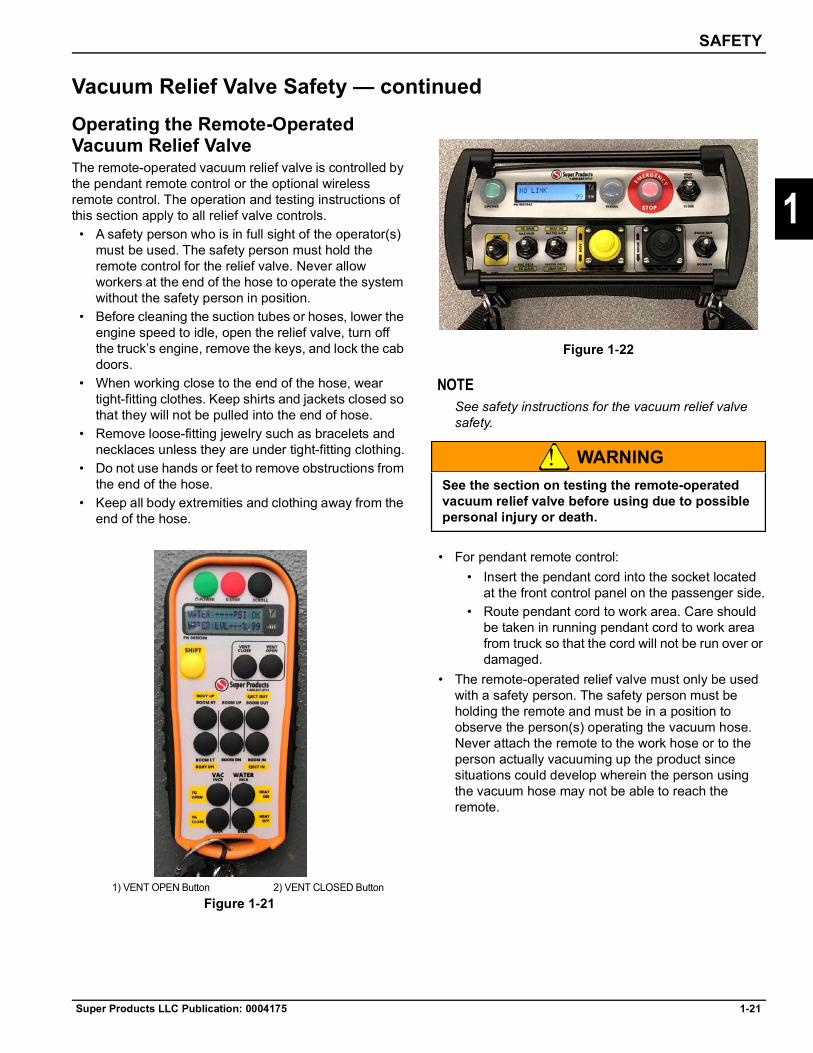
Vacuum Relief Valve Safety — continuedOperating the Remote-Operated Vacuum Relief ValveThe remote-operated vacuum relief valve is controlled by the pendant remote control or the optional wireless remote control. The operation and testing instructions of this section apply to all relief valve controls.
• A safety person who is in full sight of the operator(s) must be used. The safety person must hold the remote control for the relief valve. Never allow workers at the end of the hose to operate the system without the safety person in position.
• Before cleaning the suction tubes or hoses, lower the engine speed to idle, open the relief valve, turn off the truck’s engine, remove the keys, and lock the cab doors.
• When working close to the end of the hose, wear tight-fitting clothes. Keep shirts and jackets closed so that they will not be pulled into the end of hose.
• Remove loose-fitting jewelry such as bracelets and necklaces unless they are under tight-fitting clothing.
• Do not use hands or feet to remove obstructions from the end of the hose.
• Keep all body extremities and clothing away from the end of the hose.
Figure 1-21
Figure 1-22
NOTESee safety instructions for the vacuum relief valve safety.
WARNING
• For pendant remote control:• Insert the pendant cord into the socket located
at the front control panel on the passenger side.• Route pendant cord to work area. Care should
be taken in running pendant cord to work area from truck so that the cord will not be run over or damaged.
• The remote-operated relief valve must only be used with a safety person. The safety person must be holding the remote and must be in a position to observe the person(s) operating the vacuum hose. Never attach the remote to the work hose or to the person actually vacuuming up the product since situations could develop wherein the person using the vacuum hose may not be able to reach the remote.
1) VENT OPEN Button 2) VENT CLOSED Button
See the section on testing the remote-operated vacuum relief valve before using due to possible personal injury or death.

1-22 Super Products LLC Publication: 0004175
SAFETY
1
• If the safety person observes an unsafe or dangerous action of any type, he/she should immediately press the OPEN vent door button on the remote pendant. Only after all potential dangers have been removed should the vent door be closed and normal vacuum operations continue. The safety person should continue to be in a position to observe all vacuum hose operators until those operators have moved a safe distance from the end of all vacuum work hoses.
• After vacuum operation is completed and the vacuum pump is shut down, properly store pendant to prevent damage when truck is being moved.
WARNINGNever move close to the end of any vacuum hose unless the safety person has the remote pendant and is in a position to observe all operators. Failure to comply with this could result in serious personal injury or death.

SAFETY
Super Products LLC Publication: 0004175 1-23
1
Testing the Remote-Operated Vacuum Relief ValveNOTE
The following test should be done every time the pendant is plugged in or every two hours of operation, whichever is more frequent.
1. Visually inspect the pendant cord, electrical plug, and control switch for damage. Repair or replace as needed.
2. If the pendant is not currently plugged in, insert the electrical plug on the end of pendant cord into the socket located at the control panel on the passenger side.
3. With vacuum pump shut down and truck engine off ( see operating procedure “ start up and shut down of vacuum pump” in manual) insert male plug into end of inlet vacuum hose.
4. Start up the vacuum pump per operating procedure in manual.
5. With unit at full vacuum, press the VENT OPEN button on the remote and verify that the vacuum relief door has opened. Press the VENT CLOSE button and verify that the vacuum relief door has closed.Observe that the vacuum door has opened by inspecting the Relief Valve Door to ensure it is in the open position.
WARNING
6. After testing, shut down the vacuum pump per operating procedure.
CAUTION
If vacuum relief valve is not working properly, personnel should not be allowed to work at end of vacuum hose due to possible personal injury or death. Repair or replace valve before operating vacuum pump.
Never work beyond the distance from the truck that the wireless remote control was previously tested at. Failure to comply could result in equipment not properly operating.
1-24 Super Products LLC Publication: 0004175
SAFETY
1
High-Pressure Water Safety and Hazard Warnings
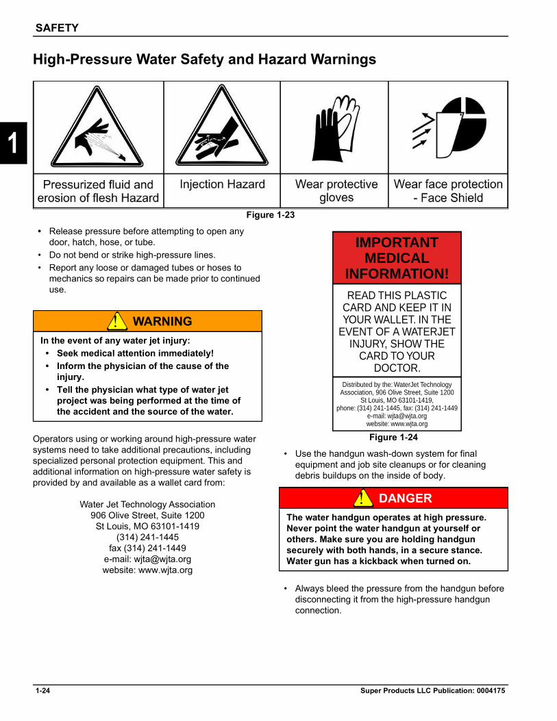
Figure 1-23
• Release pressure before attempting to open any door, hatch, hose, or tube.
• Do not bend or strike high-pressure lines.• Report any loose or damaged tubes or hoses to
mechanics so repairs can be made prior to continued use.
WARNING
Operators using or working around high-pressure water systems need to take additional precautions, including specialized personal protection equipment. This and additional information on high-pressure water safety is provided by and available as a wallet card from:
Water Jet Technology Association906 Olive Street, Suite 1200St Louis, MO 63101-1419
(314) 241-1445fax (314) 241-1449
e-mail: [email protected]: www.wjta.org
Figure 1-24
• Use the handgun wash-down system for final equipment and job site cleanups or for cleaning debris buildups on the inside of body.
DANGER
• Always bleed the pressure from the handgun before disconnecting it from the high-pressure handgun connection.
In the event of any water jet injury:• Seek medical attention immediately!• Inform the physician of the cause of the
injury.• Tell the physician what type of water jet
project was being performed at the time of the accident and the source of the water.
The water handgun operates at high pressure. Never point the water handgun at yourself or others. Make sure you are holding handgun securely with both hands, in a secure stance. Water gun has a kickback when turned on.
IMPORTANTMEDICAL
INFORMATION!READ THIS PLASTIC
CARD AND KEEP IT INYOUR WALLET. IN THE
EVENT OF A WATERJETINJURY, SHOW THE
CARD TO YOURDOCTOR.
Distributed by the: WaterJet TechnologyAssociation, 906 Olive Street, Suite 1200
St Louis, MO 63101-1419,phone: (314) 241-1445, fax: (314) 241-1449
e-mail: [email protected]: www.wjta.org

SAFETY
Super Products LLC Publication: 0004175 1-25
1
High-Pressure Water Safety and Hazard Warnings — continuedWhen setting up for rodding operations, use the appropriate guide fin and hose guard (tiger tail) to prevent the nozzle from turning in the pipe and returning toward the operator. The length of the assembled nozzle and guide fin must be greater than the diameter of the pipe to be cleaned.Inspect the rodder hose often for indications of damage or wear. Check the hose before each use for movement in hose fittings, exposed hose reinforcement, kinking or collapsing, blisters or bubbles, and fittings that are improperly installed or cutting into the hose.
Figure 1-25
WARNING
All hose manufacturers have instituted a color code system for identification of the hose, fittings, and tools. When repairing a hose, the inside color of the hose, the color of the fitting, and the die colors must match. Fittings from one manufacturer will not properly crimp onto hose from another manufacturer. The outside color of the hose indicates the pressure rating of the hose and must match during splicing operations. Be aware of the operating pressures associated with the vehicle and the proper hose specifications for safe operation.
Waste Equipment Technology Association publishes a variety of industrial-related information that owners and operators can obtain. This material includes specifications, repair, and inspection information for high-pressure hoses used in connection with sewer/catch basin cleaning equipment.
Waste Equipment Technology Association4301 Connecticut Avenue, NW
Suite 300Washington, DC 20008-2304
(Phone) (202) 244-4700(Fax) (202) 966-4824
(E-mail) [email protected](Web) http://www.wastec.org
High Water Pressure
WARNING
Figure 1-26
Do not turn on the water pressure until the hose is fully inserted into the sewer pipe, then increase water pressure slowly as you feed the hose into the sewer pipe.Special safety equipment is required when operating the high-pressure handgun. Always wear safety toe shoes or boots (waterproof shoes or boots preferred), coveralls, face shield, safety goggles, and gloves (waterproof gloves preferred).
Using improper fittings or using the sewer hose outside the sewer pipe can cause violent loss of control of the rodder hose.The sewer hose creates tremendous pressure and must not be fitted with a reducer or hand-held nozzle or be operated outside the sewer pipe. The back pressure created by such action will cause loss of control of the hose. Violent movement of the hose and fittings or high pressure can cause severe injury or death.
The handgun operates under high pressure. High-pressure water can cause serious injury or death.

1-26 Super Products LLC Publication: 0004175
SAFETY
1
Dust Hazard and Explosion Prevention Safety
Figure 1-27
In a confined area, certain concentrations of dust in an otherwise normal atmosphere can explode when spark occurs. This phenomenon is known as a dust explosion. It has been known to occur in grain elevators, underground mines, flour mills, crushers, etc. The dust itself need not be an explosive or flammable substance.The safe operation of transferring potentially explosive dust should be addressed by the following:
• Static charge dissipation• Spark prevention
See “Static Charge Dissipation” on page 1-28 and “Spark and Fire Prevention Safety” on page 1-30 for specific information on addressing these two concerns.

SAFETY
Super Products LLC Publication: 0004175 1-27
1
Hydrocarbon Waste Recovery
Figure 1-28
DANGER
Never use a rotary lobe blower to vacuum materials with flash points below 150°F. However, hydrocarbon materials with flash points greater than 150°F may be picked up with a rotary lobe blower if the following four concerns are addressed:
• Controlling the lower explosive level (LEL)• High temperature prevention• Static charge dissipation• Spark prevention
DANGER
A rotary lobe blower may be used to pick up materials with flash points greater than 300°F without addressing the four concerns.Refer to API Standard 2219 for more information on safe operation of vacuum trucks in petroleum service.
Controlling Lower Explosive Level (LEL)Super Products recommends that a monitor for hazardous hydrocarbon concentrations be installed in the exhaust stream of the vacuum pump to continuously monitor for lower explosive level (LEL). The monitor must be properly calibrated based on the product being picked up.For details on how the monitor operates, it is suggested you contact a reputable monitor manufacturer such as Industrial Scientific Corporation in Oakdale, PA at 1-800-338-3287.If the LEL reading approaches 50%, it is recommended that the operator at the end of the work hose lift the hose out of the material being conveyed and allow only air to enter the vacuum hose. As an alternative, a bypass switch could be installed to open the two valves discussed in “High Temperature Prevention” on page 1-27.
Do not vacuum flammable or explosive materials.
It is not recommended that materials with a flash point below 150°F be picked up under any operating conditions. The potential for an explosion is too great.

1-28 Super Products LLC Publication: 0004175
SAFETY
1
High-Temperature Prevention
DANGER
We suggest that in order to pick up materials with flash points below 300°F, primary and backup system sensors and air flow modifications to limit operating temperatures should be made to a standard vacuum system as manufactured by Super Products. They include the addition of two temperature gauges with adjustable switches, and two temperature sensors, which should be installed in the exhaust airstream of the vacuum pump. In addition, two air-operated valves should be installed on the body. The temperature sensors and gauges should be similar to a Murphy temperature “switch gauge” whereby a contact closes, permitting use of an electrical signal at temperatures above an adjustable preset temperature. The valves should have a minimum four inch diameter.
In operation, the operator should set the trip point of the temperature switches at or below the flash point of the material being picked up. If the exhaust temperature reaches the set point of the temperature switch, the valves would open. This would stop the conveyance of material through the vacuum hose, permit cool air to be sucked into the body and vacuum system for cooling the vacuum pump, and quickly vent from the body so as to not cause an explosion. Prior to each load being vacuumed, the operator should test each system to ensure the valves are working.The operator should set the trip point of both Murphy gauges to the lowest possible setting, block off the intake hose, and operate the vacuum pump at a minimum of 1000 RPM until the temperature rises to the trip point. The operator should ensure that once the temperature has reached the trip point, the respective valve opens.
DANGER
Failure to comply with the recommendations for high-temperature prevention could result in equipment failure, personal injury, or death.
Do not use the unit unless both temperature limitation systems are working properly.

SAFETY
Super Products LLC Publication: 0004175 1-29
1
Static Charge Dissipation
DANGER
When picking up potential explosive materials (either hydrocarbons with flash points below 300°F, or explosive dust), it is necessary to safely dissipate static charges by completely grounding the vacuum truck, intake hose, and container from which the material is being removed. Only a static dissipating vacuum hose supplied by Super Products should be used. There should be a grounding strap run from the truck frame to a grounding stake.All grounding cables should be a minimum of 1/0 in size. Grounding lugs should be welded onto the male and female couplings of all hose sections so that grounding straps (min. #10 gauge wire) can be run from the male coupling to the female coupling at all connection points. A grounding reel should be installed on the vacuum loader with the ground cable run to the container from which the material is being removed.When material is being transferred by a pneumatic conveying system, static electricity is generated. If this electricity is not dissipated through an electrical ground, arcing can occur. The resulting spark can cause a dust explosion or a hydrocarbon explosion either within the unit or within a building that the conveying line enters. The following safeguards are recommended to dissipate static charge caused by operation of the unit:
• Truck tires can insulate the unit; therefore, an electrical wire should be connected between the body and a known electrical ground such as a water pipe, plant ground loop system, or metal stake driven into the ground sufficiently deep to ensure an electrical ground. Bolt wire to truck frame — do not weld.
• The electrical resistance from the truck to the electrical ground must be at 10 ohms or less for the duration of the material transfer process. Some companies, such as Newson Gale, provide a ground verification system to enable operators to establish safe grounding of their vehicle.
• Supertube and hose couplers have rubber sealing gaskets. The presence of dirt and corrosion can prevent electrical conduction from tube to tube through the tube clamps. It is recommended to weld a bolt or a threaded stud to each end of each tube or hose coupler, and connect a wire of sufficient length from tube to tube after installation of the clamp. Wing nuts could assist in making these connections quickly.
• Standard Super Products material handling hoses are specially designed to conduct static electricity. Do not substitute hoses of unknown construction, particularly plastic hoses, which may not be static conducting.
• Never operate the unit inside a building that has a dust-laden atmosphere, such as inside of a grain elevator. The unit's electrical system and electrical components will arc in normal operation. Sparks and flame could also be emitted from the engine exhaust. Any of these conditions could cause a dust explosion within the building.
• Before operation, ensure that all ground wire connections are tight and free from corrosion and paint.
Failure to comply with the recommendations for static charge prevention could result in equipment failure, personal injury, or death.

1-30 Super Products LLC Publication: 0004175
SAFETY
1
Spark and Fire Prevention Safety
Figure 1-29
DANGER
When picking up materials with flash points below 300°F, it is necessary to take precautions to prevent generating sparks. Explosion from spark ignition can occur when picking up an explosive product (solid or gaseous). Typically, sparks occur from material striking steel or when metal objects within the material, such as nuts, bolts, or nails, strikes a steel surface. This is especially prevalent where bends in the vacuum piping system occur or inside the collector body when material strikes the floor.The suggested way of protecting from such an explosion is to use abrasive-resistant rubber-lined elbows where a bend occurs. Line the inside of the material deflector with a rubber abrasion-resistant material and partially fill the debris body with an extinguishing liquid, such as water, so the incoming material does not strike another object, causing a spark. The entire unit should be grounded, as described previously, and only static dissipating hoses should be used. It is essential the truck engine exhaust is directed away from the blower exhaust silencer to avoid an explosion caused by the hot gases or a spark from the engine exhaust.The vacuum pump exhaust air should only enter the atmosphere at a minimum of 100 feet away from any other potential ignition source.
If the environment in which the truck sits has an explosive gas in the atmosphere, protective measures such as grounding all engine belts, explosive proof alternators, voltage regulators, special truck exhaust mufflers, engine run-away protection devices etc., must be used. Consult the truck manufacturer for details.
DANGER
Failure to comply with the recommendation for spark prevention could result in equipment failure, personal injury, or death.
All of the above situations are extremely dangerous, and all precautionary steps must be taken or else equipment damage, personal injury, or death could occur. If there is any doubt as to the material to be conveyed, a complete analysis must be done prior to vacuuming.
SAFETY
Super Products LLC Publication: 0004175 1-31
1
Debris Body Dumping Safety and Hazard Warnings
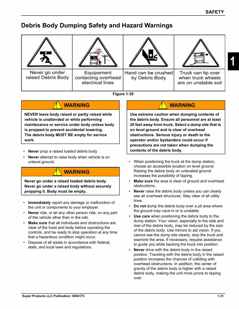
Figure 1-30
WARNING
• Never prop a raised loaded debris body.• Never attempt to raise body when vehicle is on
unlevel ground.
WARNING
• Immediately report any damage or malfunction of the unit or components to your employer.
• Never ride, or let any other person ride, on any part of the vehicle other than in the cab.
• Make sure that all individuals and obstructions are clear of the hoist and body before operating the controls, and be ready to stop operation at any time that a hazardous condition might occur.
• Dispose of all waste in accordance with federal, state, and local laws and regulations.
WARNING
• When positioning the truck at the dump station, choose an accessible location on level ground. Raising the debris body on unleveled ground increases the possibility of tipping.
• Make sure the area is clear of ground and overhead obstructions.
• Never raise the debris body unless you can clearly see all overhead structures. Stay clear of all utility lines.
• Do not dump the debris body over a pit area where the ground may cave in or is unstable.
• Use care when positioning the debris body to the dump station. Your vision, especially to the side and rear of the debris body, may be reduced by the size of the debris body. Use mirrors to aid vision. If you cannot see the dump site clearly, stop the truck and examine the area. If necessary, request assistance to guide you while backing the truck into position.
• Never drive with the debris body in the raised position. Traveling with the debris body in the raised position increases the chances of colliding with overhead obstructions. In addition, the center of gravity of the debris body is higher with a raised debris body, making the unit more prone to tipping over.
NEVER leave body raised or partly raised while vehicle is unattended or while performing maintenance or service under body unless body is propped to prevent accidental lowering. The debris body MUST BE empty for service work.
Never go under a raised loaded debris body.Never go under a raised body without securely propping it. Body must be empty.
Use extreme caution when dumping contents of the debris body. Ensure all personnel are at least 20 feet away from truck. Select a dump site that is on level ground and is clear of overhead obstructions. Serious injury or death to the operator and/or bystanders could occur if precautions are not taken when dumping the contents of the debris body.

1-32 Super Products LLC Publication: 0004175
SAFETY
1
Sewer Gas Safety and Hazard Warnings
Figure 1-31
WARNING
Confined Space HazardFollow all requirements for confined space when servicing. All large water bodies and vessels that can be entered are to be considered permit-required confined space as defined by the Occupational Safety and Health Administration (OSHA). The following information is from OSHA 3138-01R 2004. The full document can be obtained from www.osha.gov.
Many workplaces contain spaces that are considered to be “confined” because their configurations hinder the activities of employees who must enter into, work in, or exit from them. In many instances, employees who work in confined spaces also face increased risk of exposure to serious physical injury from hazards such as entrapment, engulfment, and hazardous atmospheric conditions. Confinement itself may pose entrapment hazards, and working in confined spaces may keep employees closer to hazards such as machinery components than they would be otherwise. For example, confinement, limited access, and restricted airflow can result in hazardous conditions that would not normally arise in an open workplace. The terms “permit-required confined space” and “permit space” refer to spaces that meet OSHA’s definition of a “confined space” and contain health or safety hazards. For this reason, OSHA requires workers to have a permit to enter these spaces. By definition, a confined space: • Is large enough for an employee to enter fully and
perform assigned work.• Is not designed for continuous occupancy by the
employee.• Has a limited or restricted means of entry or exit.
These spaces may include underground vaults, bodies, storage bins, pits and diked areas, vessels, and silos.
• Sewer lines often contain poisonous or explosive gas such as methane. NEVER enter or bend over a sewer without proper ventilation and personal protective equipment. If another person needs help in a sewer, immediately call for emergency assistance. NEVER enter the sewer to help unless you have been trained to do so and have proper personal protective equipment.
• NEVER smoke in or around sewer lines, drains, or catch basins.
• Failure to follow these instructions may result in death or serious injury.
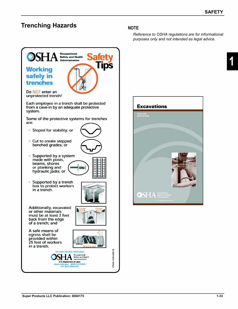
SAFETY
Super Products LLC Publication: 0004175 1-33
1
Trenching Hazards NOTEReference to OSHA regulations are for informational purposes only and not intended as legal advice.
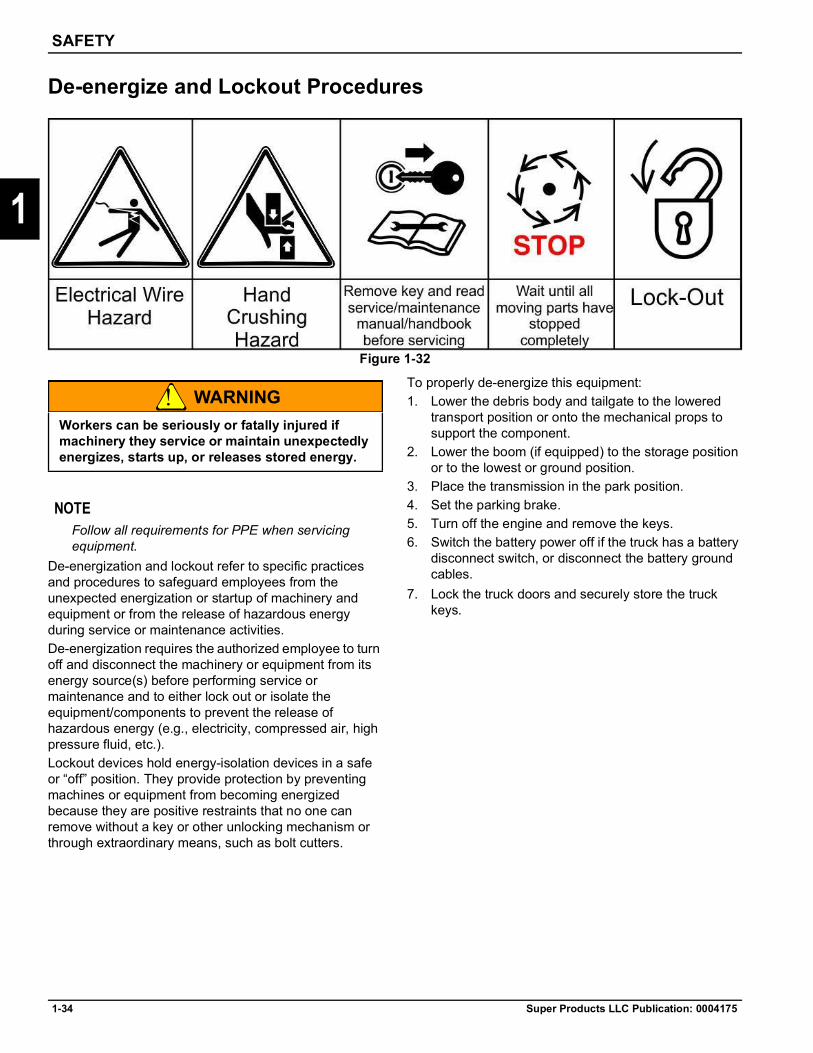
1-34 Super Products LLC Publication: 0004175
SAFETY
1
De-energize and Lockout Procedures
Figure 1-32
WARNING
NOTEFollow all requirements for PPE when servicing equipment.
De-energization and lockout refer to specific practices and procedures to safeguard employees from the unexpected energization or startup of machinery and equipment or from the release of hazardous energy during service or maintenance activities. De-energization requires the authorized employee to turn off and disconnect the machinery or equipment from its energy source(s) before performing service or maintenance and to either lock out or isolate the equipment/components to prevent the release of hazardous energy (e.g., electricity, compressed air, high pressure fluid, etc.).Lockout devices hold energy-isolation devices in a safe or “off” position. They provide protection by preventing machines or equipment from becoming energized because they are positive restraints that no one can remove without a key or other unlocking mechanism or through extraordinary means, such as bolt cutters.
To properly de-energize this equipment: 1. Lower the debris body and tailgate to the lowered
transport position or onto the mechanical props to support the component.
2. Lower the boom (if equipped) to the storage position or to the lowest or ground position.
3. Place the transmission in the park position. 4. Set the parking brake. 5. Turn off the engine and remove the keys. 6. Switch the battery power off if the truck has a battery
disconnect switch, or disconnect the battery ground cables.
7. Lock the truck doors and securely store the truck keys.
Workers can be seriously or fatally injured if machinery they service or maintain unexpectedly energizes, starts up, or releases stored energy.

SAFETY
Super Products LLC Publication: 0004175 1-35
1
Hazards With Equipment Maintenance
WARNING
Before Performing Service, Repairs, and Maintenance on the Equipment• Stop pto and engine, engage parking brake, lower
equipment, allow all moving parts to stop, and remove key before dismounting from truck.
• Place debris body, tailgate, and boom in lowered position or securely block up with support props.
• Wear safety glasses, protective gloves and follow safety procedures when performing service, repairs and maintenance on the equipment.
• Allow components to cool before servicing or performing maintenance.
• Avoid contact with hot hydraulic oil tanks, pumps, motors, valves and hose connection surfaces.
• Securely support or block up raised framework and lifted components before working underneath equipment.
• Follow instructions in maintenance section when replacing hydraulic cylinders to prevent component from falling.
• Stop and shut off truck engine before doing any work procedures.
• Use ladder or raised stands to reach high equipment areas inaccessible from ground.
• Ensure good footing by standing on solid flat surfaces when getting on equipment to perform work.
• Follow manufacturer's instructions in handling oils, solvents, cleansers, and other chemical agents.
• Do not change any factory-set hydraulic calibrations to avoid component or equipment failures.
• Do not modify or alter equipment, functions, or components.
• Ensure the equipment is cleaned appropriately. Sanitizing may be required if biological hazards are present.
Performing Service, Repairs, Lubrication, and Maintenance• Inspect for loose fasteners, worn or broken parts,
leaky or loose fittings, missing or broken cotter keys, washers on pins, and all moving parts for wear.
• Replace any worn or broken parts with authorized service parts.
• Lubricate unit as specified by lubrication schedule.• Never lubricate, adjust, or remove material while it is
running or in motion.• Torque all bolts and nuts as specified.
Safety Shields, Guards, and Safety Devices Inspection• Replace any missing, broken, or worn safety shields,
guards, and safety devices.• Replace any damaged or worn safety warning
decals. Damaged or worn decals need to be replaced with new ones.
Avoid serious injury or death from component failure by keeping implement in good operating condition by performing proper service, repairs, and maintenance.

1-36 Super Products LLC Publication: 0004175
SAFETY
1
Decal LocationIn addition to the decals provided by Super Products there may be decals shown that are part of the cab and chassis or other non Super Products components; these will not be covered.Some decals shown may appear in a different location than pictured due to differences in optional equipment on each machine and differences in cab and chassis configuration.
If any decal provided by Super Products is missing or becomes illegible, a replacement decal can be requested from Super Products at no charge and should be replaced immediately.
Figure 1-33: View of Driver Side
ITEM DESCRIPTION TYPE PART NO. SEE FIG.
1 Serious Injury WARNING 3050-00479 1-392 Rotating shafts can be dangerous DANGER 3050-01179 1-403 Made in the USA INFORMATION 3050-00433 1-414 Emergency Stop Switch INSTRUCTION 0028252 1-425 Dumping and tailgate warning WARNING 0003403 1-436 Super Products Logo Logo 0037229 (Black letters)
0037228 (White letters)–

SAFETY
Super Products LLC Publication: 0004175 1-37
1
Figure 1-34: View of Passenger side
ITEM DESCRIPTION TYPE PART NO. SEE FIG.
1 Regen Alert INSTRUCTION 3050-01174 1-452 Body Prop, Crushing Hazard WARNING 0007448 1-463 Emergency Stop Switch INSTRUCTION 0029444 1-474 Hydraulic Reservoir INSTRUCTION 3050-00051 1-485 Rotating shafts can be dangerous WARNING 3050-01179 1-406 Suction line valve CAUTION 3050-01286 1-497 Manual override INSTRUCTION 3050-01219 1-508 Water Tank Fill INSTRUCTION 3050-00579 1-519 Boom/Body Override INSTRUCTION 3050-01218 1-5210 Boom/Body Valve INSTRUCTION 3050-01196 1-5311 Body Flusher INSTRUCTION 3050-00581 1-5412 Dumping and tailgate warning WARNING 0003403 1-4313 Super Products Logo LOGO 0037229 (Black letters)
0037228 (White letters)–
14 Do Not Power Wash Control CAUTION 0033298 1-81
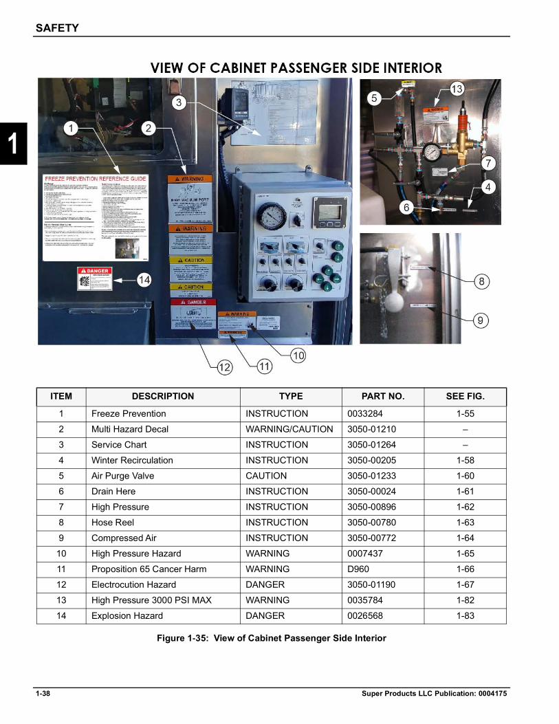
1-38 Super Products LLC Publication: 0004175
SAFETY
1
Figure 1-35: View of Cabinet Passenger Side Interior
ITEM DESCRIPTION TYPE PART NO. SEE FIG.
1 Freeze Prevention INSTRUCTION 0033284 1-552 Multi Hazard Decal WARNING/CAUTION 3050-01210 –3 Service Chart INSTRUCTION 3050-01264 –4 Winter Recirculation INSTRUCTION 3050-00205 1-585 Air Purge Valve CAUTION 3050-01233 1-606 Drain Here INSTRUCTION 3050-00024 1-617 High Pressure INSTRUCTION 3050-00896 1-628 Hose Reel INSTRUCTION 3050-00780 1-639 Compressed Air INSTRUCTION 3050-00772 1-6410 High Pressure Hazard WARNING 0007437 1-6511 Proposition 65 Cancer Harm WARNING D960 1-6612 Electrocution Hazard DANGER 3050-01190 1-6713 High Pressure 3000 PSI MAX WARNING 0035784 1-8214 Explosion Hazard DANGER 0026568 1-83
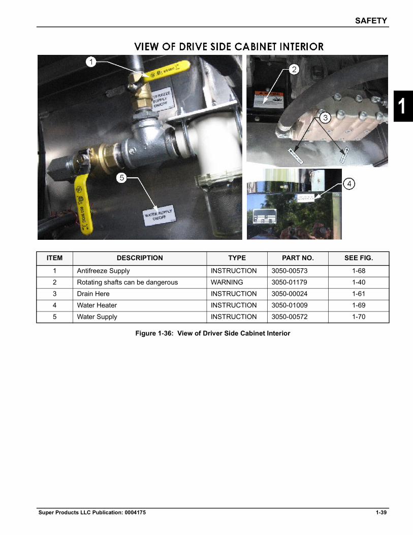
SAFETY
Super Products LLC Publication: 0004175 1-39
1
Figure 1-36: View of Driver Side Cabinet Interior
ITEM DESCRIPTION TYPE PART NO. SEE FIG.
1 Antifreeze Supply INSTRUCTION 3050-00573 1-682 Rotating shafts can be dangerous WARNING 3050-01179 1-403 Drain Here INSTRUCTION 3050-00024 1-614 Water Heater INSTRUCTION 3050-01009 1-695 Water Supply INSTRUCTION 3050-00572 1-70

1-40 Super Products LLC Publication: 0004175
SAFETY
1
Figure 1-37: View of Rear of Truck
ITEM DESCRIPTION TYPE PART NO. SEE FIG.
1 Remote Grease INSTRUCTION 0007541 1-712 Pinch Point Hazards WARNING 3050-01201 1-723 Crushing Hazards WARNING 0003403 1-464 Anchor Point INSTRUCTION 3050-01222 1-735 Remote Grease INSTRUCTION 3050-01200 1-746 Remote Grease INSTRUCTION 3050-01278 1-717 ConspicuityTape REFLECT 0024904 –8 Mud Log Logo LOGO 0037231 (Black letters)
0037230 (White letters)–
9 Water Drain INSTRUCTION 3050-00580 1-44

SAFETY
Super Products LLC Publication: 0004175 1-41
1
Figure 1-38: View of Cab Interior
ITEM DESCRIPTION TYPE PART NO. SEE FIG.
1 Boom Up Alarm WARNING 00282421 –2 Body Up Alarm WARNING 00282423 –3 Software Parameters INSTRUCTIONS 0003392 1-764 Second Highest Gear INSTRUCTIONS 0002445 1-775 Drop Suspension Air INSTRUCTIONS 3050-01230 1-786 Disengage Hydraulic Pump CAUTION 0024915 1-797 Alarm Must Sound WARNING 0024921 1-808 Final Vehicle Certification INSTRUCTION 3050-00196 –9 Vac Pump INSTRUCTION 3050-01272 –10 Rear Axle Disengage (for Auto Trans) INSTRUCTION 3050-01271 –
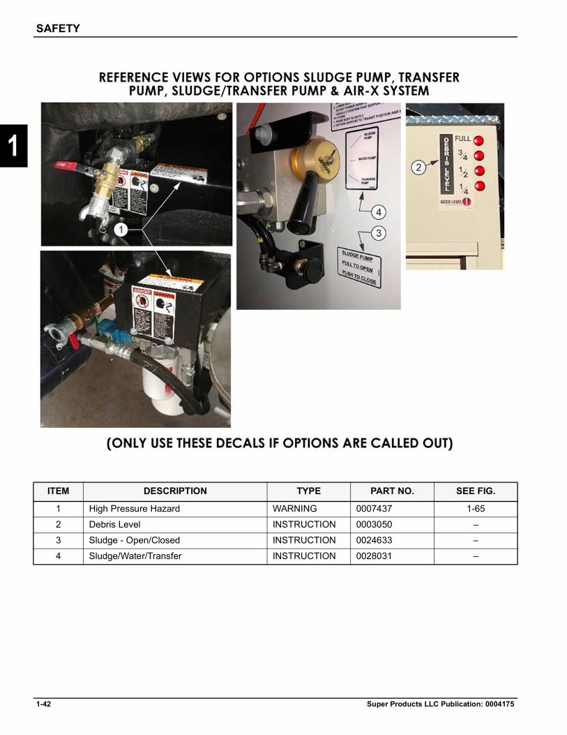
1-42 Super Products LLC Publication: 0004175
SAFETY
1
ITEM DESCRIPTION TYPE PART NO. SEE FIG.
1 High Pressure Hazard WARNING 0007437 1-652 Debris Level INSTRUCTION 0003050 –3 Sludge - Open/Closed INSTRUCTION 0024633 –4 Sludge/Water/Transfer INSTRUCTION 0028031 –

SAFETY
Super Products LLC Publication: 0004175 1-43
1
Decals
Figure 1-39
Figure 1-40
Figure 1-41
Figure 1-42
Figure 1-43
Figure 1-44
Part no. 3050-00479
Part no. 3050-01179
Part no. 3050-00433
Part no. 0028252
Part no. 0003403
Part no. 3050-00580
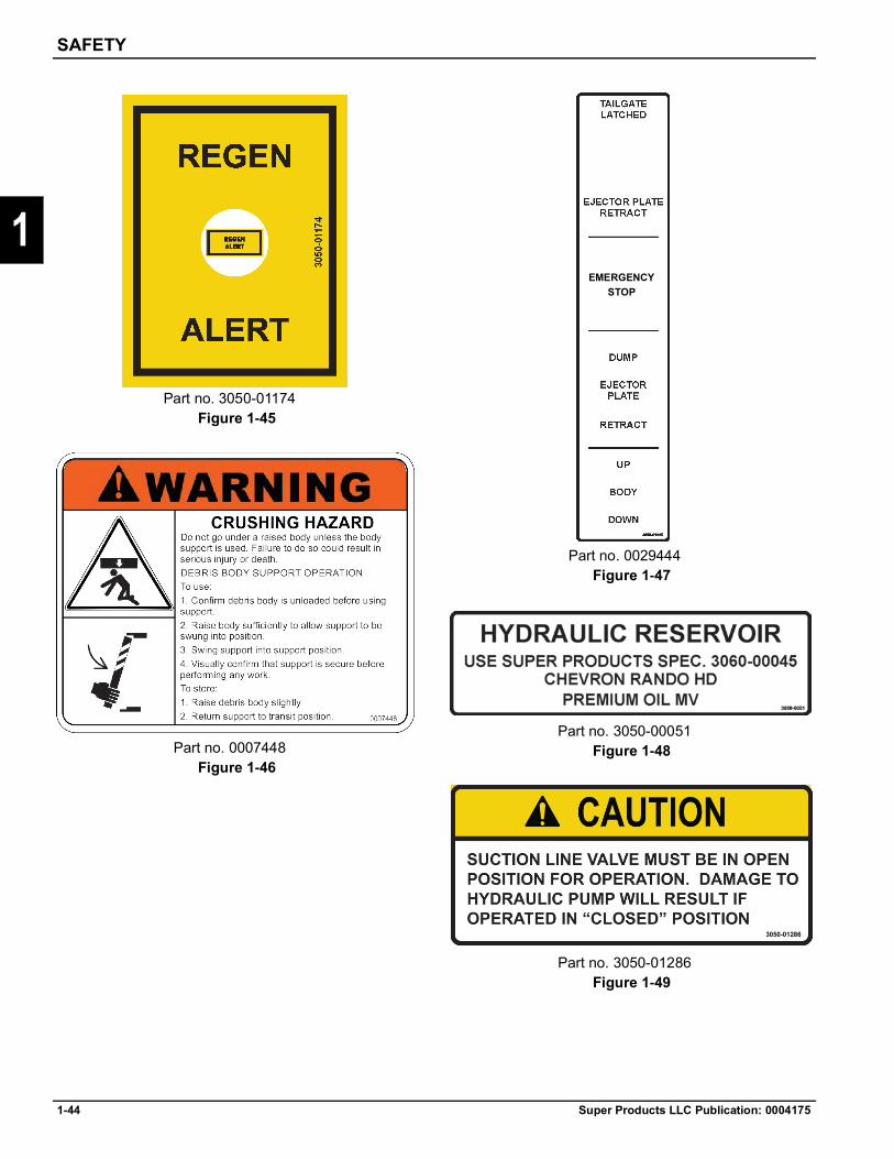
1-44 Super Products LLC Publication: 0004175
SAFETY
1
Figure 1-45
Figure 1-46
Figure 1-47
Figure 1-48
Figure 1-49
Part no. 3050-01174
Part no. 0007448
Part no. 0029444
Part no. 3050-00051
Part no. 3050-01286
EMERGENCYSTOP

SAFETY
Super Products LLC Publication: 0004175 1-45
1Figure 1-50
Figure 1-51
Figure 1-52
Figure 1-53
Figure 1-54
Part no. 3050-01219
Part no. 3050-00579
Part no. 3050-01218
Part no. 3050-01196
Part no. 3050-00581
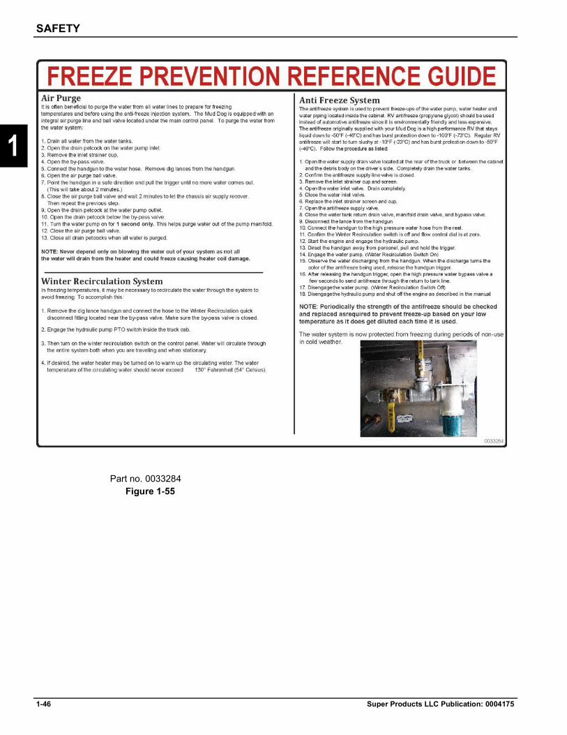
1-46 Super Products LLC Publication: 0004175
SAFETY
1
Figure 1-55Part no. 0033284
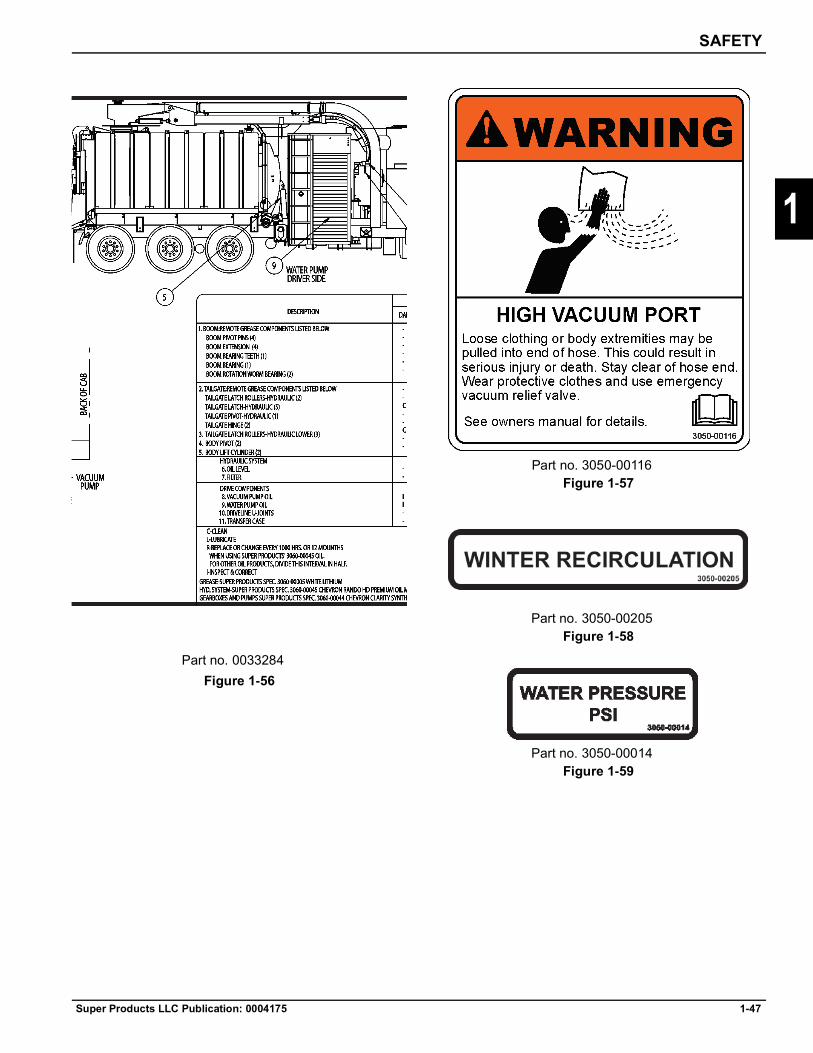
SAFETY
Super Products LLC Publication: 0004175 1-47
1
Figure 1-56
Figure 1-57
Figure 1-58
Figure 1-59
Part no. 0033284
Part no. 3050-00116
Part no. 3050-00205
Part no. 3050-00014
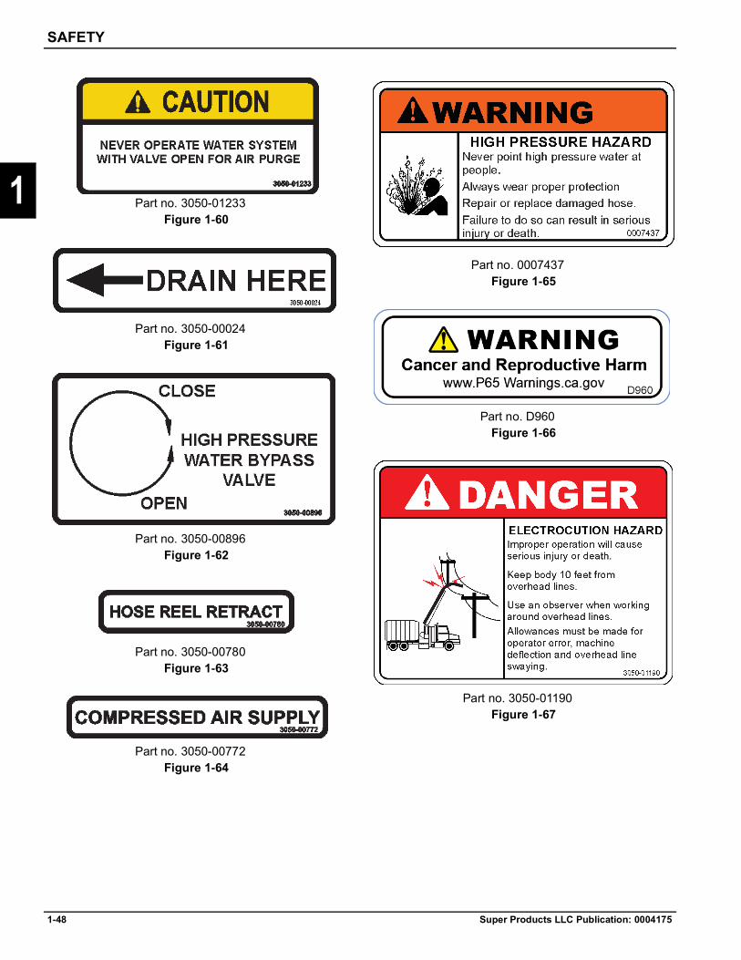
1-48 Super Products LLC Publication: 0004175
SAFETY
1Figure 1-60
Figure 1-61
Figure 1-62
Figure 1-63
Figure 1-64
Figure 1-65
Figure 1-66
Figure 1-67
Part no. 3050-01233
Part no. 3050-00024
Part no. 3050-00896
Part no. 3050-00780
Part no. 3050-00772
Part no. 0007437
Part no. D960
Part no. 3050-01190

SAFETY
Super Products LLC Publication: 0004175 1-49
1
Figure 1-68
Figure 1-69
Figure 1-70
Figure 1-71
Figure 1-72
Figure 1-73
Part no. 3050-00573
Part no. 3050-01009
Part no. 3050-00572
Part no. 0007541
Part no.3000-01201
Part no. 3050-01222
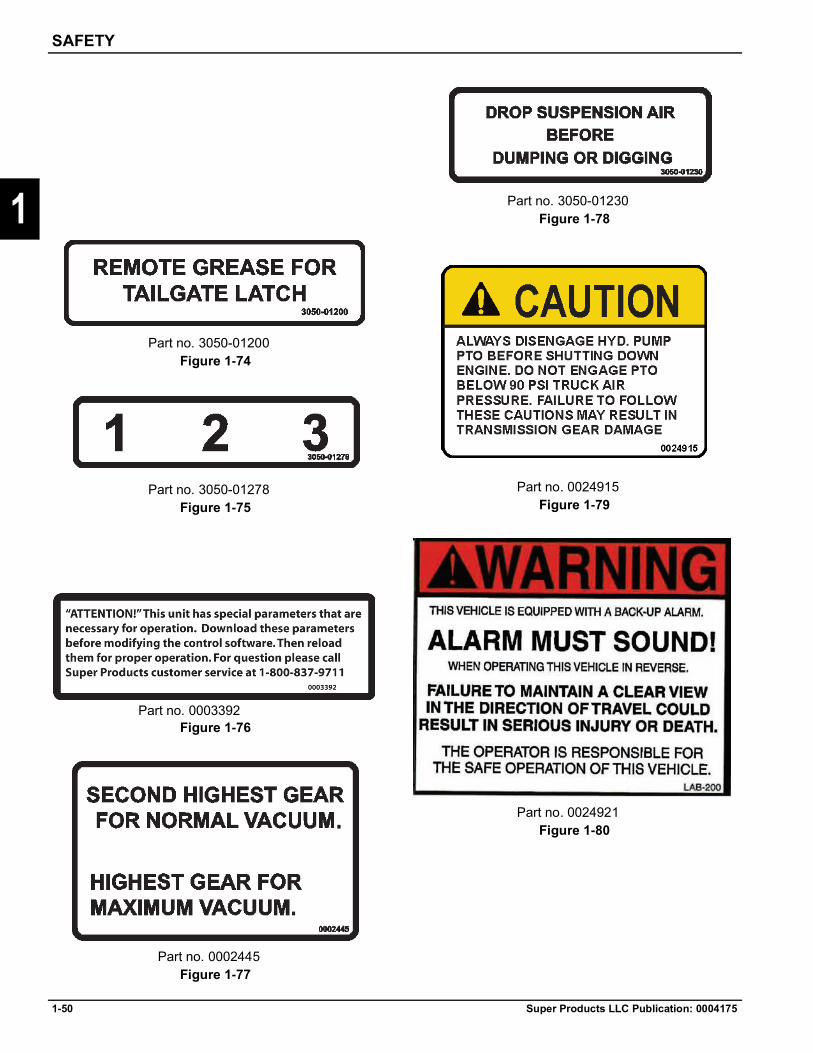
1-50 Super Products LLC Publication: 0004175
SAFETY
1
Figure 1-74
Figure 1-75
Figure 1-76
Figure 1-77
Figure 1-78
Figure 1-79
Figure 1-80
Part no. 3050-01200
Part no. 3050-01278
Part no. 0003392
Part no. 0002445
Part no. 3050-01230
Part no. 0024915
Part no. 0024921

SAFETY
Super Products LLC Publication: 0004175 1-51
1
Part no. 0033298Figure 1-81
Figure 1-82
Figure 1-83
Part no. 0035784
Part no. 0026568

1-52 Super Products LLC Publication: 0004175
SAFETY
1
Debris Body Tailgate Props
DANGER
Unlocking the Tailgate Props and Raising the Debris Body Tailgate1. Ensure the tailgate area is clear of people and
obstructions. 2. Remove the retaining pins (1) from both tailgate
props (2). Allow the tailgate props to rest on the tailgate pins (3).
Figure 1-84
3. Unlock and raise the debris body tailgate. The tailgate props will maintain their aligned position with the tailgate pins.
4. Lower the debris body tailgate enough so that the tailgate pins rest against the tailgate props.
Figure 1-85
5. Shut the truck engine off and remove the keys.
Lowering the Debris Body Tailgate and Storing the Props1. Ensure the area is clear of people and obstructions
before lowering the debris body tailgate.2. Raise the debris body tailgate off the tailgate props.3. Return both tailgate props to their stored position and
install the retaining pins.4. Lower and latch the debris body tailgate.
Always position the tailgate props in the proper position before entering any area beneath the debris body tailgate or entering the debris body. Failure to do so could result in serious injury or death.
13
2

SAFETY
Super Products LLC Publication: 0004175 1-53
1
Preparation Before Traveling to WorksiteIf there are any questions on how to implement the below procedures, contact Super Products prior to starting operation. Super Products will not be responsible for any damage or injuries if all safety procedures are not completely followed.1. Perform required maintenance as specified in the
Maintenance Schedule section of this manual.2. Check the oil and water levels in the engine,
transmission, and fuel. 3. Close all water drain valves and install all plugs and
strainers previously removed. 4. Make sure the boom is in transport position and
properly secured. 5. Make sure the tailgate is closed and properly locked. 6. Make sure all tools, accessories, and work
tubes/hoses are properly secured. 7. Make sure all cabinet doors and access panels are
closed and there are no loose items on the truck exterior.
8. Make sure the final filter is clean and that the access cover is secure.
9. Make sure the fresh water fill pipe strainer is clean. 10. Close the water tank drain valve located above the
rear bumper. 11. Conduct a complete truck walk-around to visually
inspect the truck for damage, leaks, or unsafe conditions.
12. Check all lights for proper operation. 13. Set the brakes and place the transmission in neutral. 14. Check the engine oil, coolant, windshield washer
fluid, and transmission fluid. The truck must be running to check the transmission fluid.
15. Turn the ignition key to off. 16. Check both vacuum pump sight glasses. They
should be half full on level ground. 17. Make sure the Y-strainer is clean and the cap is on
the drain. 18. Make sure the cyclone separator is clean. 19. Make sure the hydraulic fluid reservoir is full,
showing halfway up on the sight glass. 20. Make sure the debris tank is lowered, the debris tank
door is locked, and all clean-out ports and drains are closed.
21. Make sure the body flusher handle is closed. 22. Make sure the ejector plate is retracted and the
HOME switch on the curbside panel is lit green.


Super Products LLC Publication: 0004175 2-1
Chapter 2
2
Pre-Operation
IntroductionThis manual contains important information regarding safe operation, adjustment, and maintenance for the Super Products’ Mud Dog® Vacuum Excavator.DO NOT allow anyone to operate or service this machine until they have read and understood all aspects of this manual.DO NOT use this machine for any purpose or application other than those listed in this manual. Improper use or neglect of safety precautions will cause serious injury or death. Refer to Section 1, Safety.
NOTEThis operator’s manual is to stay with the truck and be used as reference for operator personnel.
Principles of OperationThe Mud Dog is designed for removing soil from around utilities such as gas, water, electric and telephone lines as well as in industrial plants for exposing buried lines of any nature. It can be used for "pot holing" on horizontal directional drilling sites. It also can be used to dig post holes for telephone and electric poles as well as many other applications.The unit uses a water system for breaking up the soil and a vacuum system to remove the soil.The vacuum system utilizes a positive displacement "Roots" type vacuum pump which is driven by the truck engine through a transfer case. Material is picked up at the end of a suction tube and pneumatically conveyed into a collector body. The vacuum hose is supported by a boom which, at the operators discretion, can be raised, lowered, extended, retracted or rotated left or right. As material enters the collector body, the majority of the material falls out into the body because of gravity and the tremendous reduction in air velocity. An air-backed elbow allows the material to make a 90° bend as it enters the body while minimizing elbow wear.
The air exits the body at the top front section where the ball float is located. The ball float will shut off the air system when picking up materials with enough of a liquid content to float the ball and therefore prevent overfilling the unit.Any material or mist still airborne will then enter a centrifugal separator which is located just forward of the large storage compartment on the left side of the unit. Centrifugal force causes the airborne materials to be separated from the air stream with the material falling into a storage compartment located at the bottom of the separator and the clean air exiting out the top of the separator.The air then enters a "final filter" which is a pleated element capable of ten (10) micron filtration which will capture any remaining carryover dust.The clean air then enters the vacuum pump and then exits out of the vacuum pump through a high efficiency exhaust silencer and into the environment.The Mud Dog™ is designed to pick up wet materials as well as slurries. If picking up dry materials that are dusty, you must wet the material down to limit the carryover into the separator and final filter.
Equipment SpecificationsMaximum vacuum pressure rating of vacuum system = 27" Hg (0.90 bar)Maximum pressure rating = Not Applicable. This unít is not designed for pressure unloading.Maximum pressure of water system = 3,000 psi (207 bar)Maximum pressure of air system (optional air-excavation system) = 175 psi (12 bar)Maximum height in transport configuration = 13'-4" (4,064 mm)Maximum height with boom raised and extended = 28'-6" (8,687 mm)Approximate empty weight of stock MD1200 = 43,880 lbs (19,904 kg)Approximate empty weight of stock MD1600 = 48,500 lbs (21,999 kg)

2-2 Super Products LLC Publication: 0004175
PRE-OPERATION
2
Figure 2-1
Figure 2-2

PRE-OPERATION
Super Products LLC Publication: 0004175 2-3
2
Vacuum SystemThe vacuum system utilizes a positive displacement type of vacuum pump that is mechanically driven from the truck’s engine. The vacuum system has the capability of transferring materials using two methods — Pure Vacuum and Air Conveyance.
CAUTION
Pure VacuumAs a general rule, pure vacuum would be used for removing sludge from beneath liquid or for rapid liquid loading. In this mode, the vacuum tube is totally submersed in the liquid and only material (no air) transports through the line. With the standard vacuum pump, the maximum distance from the top of the vacuum hose supported by the boom to the liquid surface cannot exceed three hundred sixty-seven (367) inches (30.5) feet at sea level assuming water as the liquid. For materials of a higher density than water, these figures must be reduced. Consult the factory for additional information. In pure vacuum mode, select the transmission gear that is 1:1 ratio (16th gear for 18-speed transmission, 9th gear for 10-speed) or lower. The vacuum pump should be operated at one thousand two hundred (1200) RPM. Operating the unit too fast will decrease performance. Loading rates up to one thousand (1000) GPM through a six (6) inch hose can be realized.
Air ConveyanceThe second conveying method is "air conveyance" and requires enough air velocity going past the material to be picked up to capture such, and convey through the vacuum tube to the body. This requires the vacuum pump be operating at a fast enough speed to produce the required airflow to capture the material.
NOTEIt should be noted that the most efficient and highest loading rate occurs when the pump is run as slow as permissible and still pick up the material. Vacuum tube lengths up to one thousand (1000) feet can be used and liquid loading rates up to five hundred (500) GPM through a six (6) inch line can be realized. Select the overdrive transmission gear (18th gear) for air conveyance mode.
IMPORTANTThere are also applications where a vacuum fluidizing nozzle should be used. This combines the benefits of pure vacuum and air conveyance. The fluidizing nozzle has the ability to remove sludge from beneath liquids where the distance exceeds the limitation of pure vacuum.
NOTEIt should be noted that for maximum efficiency, all vacuum line connection points must be air tight. This is accomplished by installing the O-ring gasket over the male end of the tube. Refer to the "Operation Instructions" and "Maintenance Schedule" for further details.It should also be noted that the vacuum pump should never be operated above a pump exhaust temperature of 320°F. Deviations from this maximum operating temperature must be approved by Super Products.
The vacuum system is designed for liquids, slurries, and damp materials. Dry or dusty materials must be wet down before vacuuming to limit the carryover of debris into the separator and final filter. This can be accomplished with the handgun attachment or by injecting water into the vacuum line with the liquid ring accessory.

2-4 Super Products LLC Publication: 0004175
PRE-OPERATION
2
AirflowPlease refer to below drawing.1. Material along with air enters body through top air
backed elbow (#1).2. Air speed is greatly reduced inside body allowing
material to separate from air stream. Material settles to the bottom of the body. Air with some fine carryover dust or mist exits body past float ball. (#2).
3. Float ball (#2) acts as vacuum shutoff when body becomes full of liquids.
4. Air exits the body through a hose (#3) and enters the cyclone separator (#4) located on left side of unit.
5. Air is spun centrifugally with majority of carryover dust and mist setting to bottom of separator area.
6. Air continues out the top of the separator (#5) over to the final filter (#6).
7. The air goes from the outside of the filter (#6) to the inside of the filter. Any remaining material, ten microns or larger is captured on the outside of the filter.
8. The air goes through the final filter (#6) and into the inlet of the vacuum pump (#7).
9. The air goes horizontally through the vacuum pump where the air normally gets heated up because of the work being done on the air by the vacuum pump. The amount of heat being generated depends on operating vacuum and pump speed.
10. The air exits the vacuum pump (#7) and goes through a discharge silencer (#8) before entering the atmosphere at the top of the silencer.
11. To keep high vacuum blowers cool, there will be an inlet silencer bolted directly above the vacuum pump (#7). Cooling air comes from the atmosphere into the top of the silencer and on into the vacuum pump. This air cools the vacuum pump allowing for high vacuum.
PRE-OPERATION
Super Products LLC Publication: 0004175 2-5
2
Vacuum Pump Operation1. The vacuum pump is driven through a transfer case.
For vacuum pump operation, the rear drive axle is disengaged and the vacuum pump is engaged. The transmission should be in neutral, parking brakes engaged and wheel chocks properly positioned before beginning the engagement process.
CAUTION
2. Start engine and allow it to idle. Let chassis air build to the maximum 120psi.
3. The truck is equipped with a "throttle enable" switch located on the chassis instrument panel. Move this switch to the "on" position.
4. Transfer Case/Vacuum Pump EngagementMethods of engagement vary with the chassis transmission and transfer case equipment. Select the section below that matches the configuration of the unit being operated. The standard configuration is manual transmission with manual shift transfer case.Manual Transmission with Manual Shift or Air Shift Transfer Case.
a. Fully depress the clutch pedal.b. Shift transmission into high range.c. Put the gear shift in reverse.d. Locate the lever between the driver's and
passenger seat labeled "Rear Axle". Pull up on the lever until it is fully engaged. It may be necessary to feather the clutch in order to get full engagement. A green light will come on indicating the rear axle is disengaged.
e. Locate the PTO control on dash for the hydraulic pump. Move PTO control switch to the engaged position. If the unit is equipped with an optional air shift transfer case, locate the valve or switch (respectively) labeled "Rear Axle" or "Vacuum Pump" between the driver's and passenger seats or on the instrument panel. Move the valve or switch to the "engaged" position.
f. Let out the clutch momentarily two (2) to three (3) seconds.
g. Depress clutch again and select the proper forward gear. The proper gear should be the highest forward gear which will keep the engine speed above 1000 RPM at the desired vacuum pump speed.
h. Slowly release the clutch, the vacuum pump will be turning at this time.
CAUTIONFailure to engage parking brakes and/or position wheel chocks could result in unexpected chassis movement which could cause bodily injury or property damage.
Make sure no one is near the end of the vacuum hose and that the vacuum relief door is open before engaging the vacuum pump. Failure to do so could cause personal injury.
2-6 Super Products LLC Publication: 0004175
PRE-OPERATION
2
• Automatic Transmission with Manual Shift or Air Shift Transfer Case.a. Confirm that the transmission gear selector is in
the neutral position. Never shift the transfer case with the transmission gear selector in the drive "D" or reverse "R" position. Damage to the transfer case can result if the transfer case is shifted while the transmission is in gear.
b. Locate the lever between the driver's and passenger seat labeled "Rear Axle". With the transmission in neutral, pull up on the lever until it is fully engaged. If It does not fully engage, it will be necessary to pull up lightly on the lever during the next step. Pull up lightly on the lever while momentarily placing the transmission gear selector in drive "D" position. Immediately return the transmission gear selector to the neutral "N" position. A red light will come on indicating the rear axle is disengaged.
c. Locate the PTO control on dash for the hydraulic pump. Move PTO control switch to the engaged position.
d. If the unit is equipped with an optional air shift transfer case, locate the valve or switch (respectively) labeled "Rear Axle" between the driver's and passenger seats or on the instrument panel. Move the valve or switch to the "engaged" position
e. Place the transmission gear selector in the forward drive "D" position. The vacuum pump will be turning at this time.
CAUTION
5. At the main control panel, wireless remote, or pendant increase the vacuum pump speed to the desired level as observed on the tachometer in the main control panel. Run the vacuum pump at the slowest speed possible to reduce fuel consumption and wear, limit carryover and have a quieter machine. To maintain proper lubrication, do not run the vacuum pump slower than 900 RPM. Never exceed 2000 RPM with the vacuum pump engaged. When it is time to vacuum material, close the vacuum relief door by operating the switch on the wireless remote or pendant. The vacuum relief door switch on the main control panel must be in the "closed" position for the vacuum relief door to close.
6. When done vacuuming, open the vacuum relief door. Reduce the engine speed to idle.
7. Transfer Case/Vacuum Pump Disengagement • Manual Transmission with Manual Shift or Air Shift
Transfer Case.a. Fully depress the clutch pedal.b. Wait five to ten seconds for the driveline and
vacuum pump to stop turning.c. Locate the lever between the driver's and
passenger seat labeled "Rear Axle". Push down on the lever until it is fully disengaged. It may be necessary to feather the clutch in order to get full axle engagement. The green light will go out, indicating the rear axle is engaged.
d. Locate the PTO control on dash for the hydraulic pump. Move PTO control switch to the disengaged position. If the unit is equipped with an optional air shift transfer case, locate the valve or switch (respectively) labeled "Rear Axle" or "Vacuum Pump" between the driver's and passenger seats or on the instrument panel. Move the valve or switch to the "disengaged" position.
e. Shift to neutral and slowly release the clutchf. The vacuum pump should not be turning at this
time.• Automatic Transmission with Manual Shift or Air Shift
Transfer Case.a. Place the transmission gear selector in the
neutral "N" position. Never shift the transfer case with the transmission gear selector in the drive "D" or reverse "R" position. Damage to the transfer case can result if the transfer case is shifted while the transmission is in gear.
b. Locate the lever between the driver's and passenger seat labeled "Rear Axle". With the transmission in neutral "N", push down on the lever until it is fully engaged. If it does not fully engage, push down lightly on the lever while momentarily placing the transmission gear selector in drive "D" position. Immediately return the transmission gear selector to the neutral "N" position. The green light will go out, indicating the rear axle is engaged.
c. Locate the PTO control on dash for the hydraulic pump. Move PTO control switch to the disengaged position. If the unit is equipped with an optional air shift transfer case, locate the valve or switch (respectively) labeled "Rear Axle" or "Vacuum Pump" between the driver's and passenger seats or on the instrument panel. Move the valve or switch to the "disengaged" position.
8. Move the throttle enable switch to the "off" position.
Make sure no one is near the end of the vacuum hose and that the vacuum relief door is open before engaging the vacuum pump. Failure to do so could cause personal injury.
PRE-OPERATION
Super Products LLC Publication: 0004175 2-7
2
Vacuum Relief ValvesSuper Products offers two (2) types of vacuum relief valves. The in-line "T" type vacuum relief valve is delivered with the unit as optional equipment and its operation is described in this procedure. The remote operated vacuum relief valve is standard. It consists of a hinged door which is opened/closed by a pneumatic cylinder. The cylinder is controlled by the operator at the control panel or the pendant remote or the wireless remote. Its operation is also described in this procedure.
• Always use emergency "T" type relief valve, except as noted in item six (6) below.
• When safety person is used, make sure he/she is in full view of person(s) at end of vacuum hose.
• When working close to end of hose, wear tight fitting clothes. Keep shirts and jackets closed so that shirt tails and jacket tails will not be pulled into end of hose. Remove loose fitting jewelry such as bracelets and necklaces unless they are under tight fitting clothing.
• Do not use hand or foot to remove obstructions from end of hose.
• Keep all body extremities and clothing from end of hose.
• The only time the emergency "T" type relief valve is not required is when the operator is working vertically off the boom hose. In this case only, the operator should use the remote operated relief valve as described elsewhere in this manual section. Otherwise, use only the emergency relief valves approved by Super Products. Failure to comply with this requirement could cause bodily injury, for which Super Products will not be responsible.
Operating Instructions - “T” Type Vacuum Relief
WARNING
CAUTION
WARNING
WARNING
WARNING
WARNING
CAUTIONSee section on "Testing of T" type vacuum relief valve before using due topossible personal injury or death.
If person operating at end of vacuum hose is in a confined space or for any other reason cannot easily reach pull cord on their safety belt, there must be a safety person(s) wearing safety belt with pull cord attached who must be in a position to view person(s) working at end of vacuum hose.
If vacuum relief valve is not working properly, personnel should not be allowed in work at end of vacuum inlet hose due to possible injury or death.
See section on testing of remote operated vacuum relief valve before using due to possible personal injury or death.
Never move close to the end of any vacuum hose unless the safety person has the remote and is in a position to observe all operators. Failure to comply with this could result in serious personal injury or death
If vacuum relief valve is not working properly, personnel should not be allowed to work at end of vacuum hose due to possible personal injury or death.
Never work beyond the distance from the truck that the wireless remote control was previously tested at. Failure to comply could result in equipment not properly operating.

2-8 Super Products LLC Publication: 0004175
PRE-OPERATION
2
Suction Line ConnectionsSuper Products hose-to-hose and hose-to-tube connections provide for fast set up of suction lines. This is achieved by providing loose fitting male and female ends of each length of suction hose or Supertube aluminum suction tube. The loose fit allows for quick and easy assembly. An O-ring gasket is placed over the male coupler before assembly to female coupler to eliminate air leaks. A lockring secures the ends together and snaps overcenter.This coupler system is used on all four (4), six (6) and eight (8) inch diameter suction line systems. In determining the best overall suction line set-up, the following facts should be considered:1. Larger hose diameters provide greater loading rates.2. Loading rates are reduced as conveying distance is
increased.3. Physical effort required relative to hose size:
a. Four (4) inch diameter hose and smaller can be handled by one (1) man with minimal rest periods.
b. Six (6) inch diameter hose can be handled by one man but requires frequent rest periods. Normally two (2) men will alternate or multiple smaller hoses are used at work area.
c. Eight (8) inch diameter hose can not be handled by the average man without great physical exertion. Normally fed with shovels, wheel barrows or multiple smaller hoses.
4. The chart below gives the recommended normal particle size range for each hose diameter. Occasional particles larger than those indicated below can be handled.
Hose Diameter Particle Size8" 3"6" 2"4" 1"2.5" 0.5"5. Bends reduce loading rates significantly. Straight
runs with a minimum number of long radius bends made with smooth bore suction hose are the most efficient.
Suction Line Set Up Guidelines1. Install relief valve as shown in this manual.2. Use largest diameter suction line possible.
Performance is affected by material handled, Mud Dog™ model, and crew size. Use Supertube for straight runs and hose for bends and material pick-up.
3. When using Y connectors, branch from eight (8) or six (6) inch diameter main suction line to multiple four (4) inch hoses whenever possible. An average person will achieve higher loading rates over the period of a full shift using four (4) inch diameter suction hoses.a. Minimize length of all suction lines.b. Minimize number of bends in all suction lines,
use of Supertube reduces excess bends.c. Install permanent access ducting in area to be
cleaned frequently.
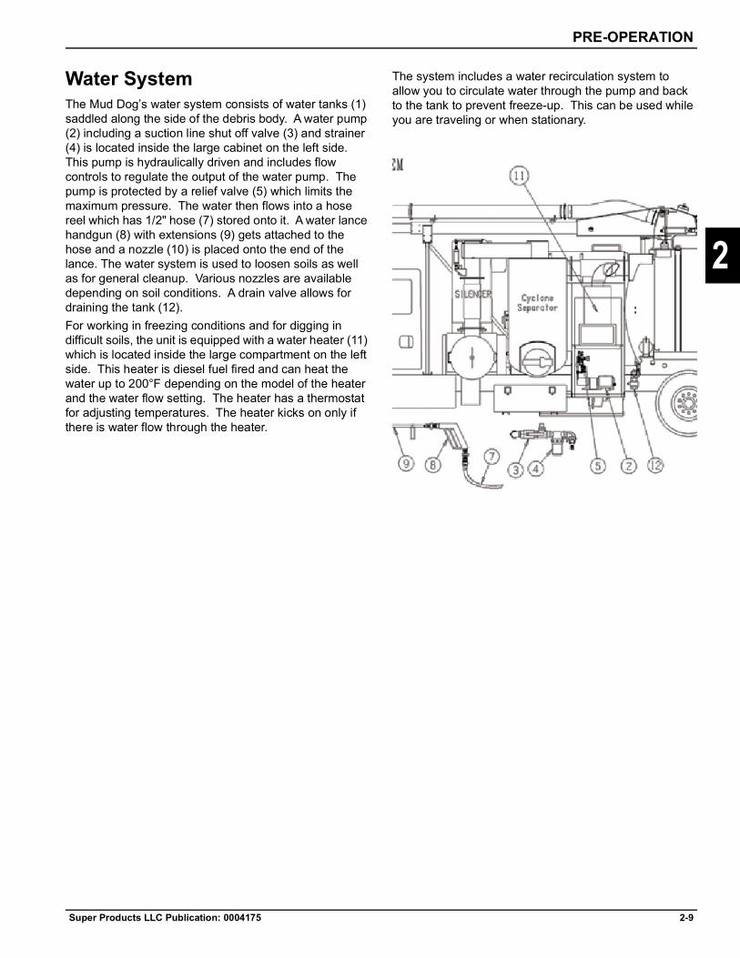
PRE-OPERATION
Super Products LLC Publication: 0004175 2-9
2
Water SystemThe Mud Dog’s water system consists of water tanks (1) saddled along the side of the debris body. A water pump (2) including a suction line shut off valve (3) and strainer (4) is located inside the large cabinet on the left side. This pump is hydraulically driven and includes flow controls to regulate the output of the water pump. The pump is protected by a relief valve (5) which limits the maximum pressure. The water then flows into a hose reel which has 1/2" hose (7) stored onto it. A water lance handgun (8) with extensions (9) gets attached to the hose and a nozzle (10) is placed onto the end of the lance. The water system is used to loosen soils as well as for general cleanup. Various nozzles are available depending on soil conditions. A drain valve allows for draining the tank (12).For working in freezing conditions and for digging in difficult soils, the unit is equipped with a water heater (11) which is located inside the large compartment on the left side. This heater is diesel fuel fired and can heat the water up to 200°F depending on the model of the heater and the water flow setting. The heater has a thermostat for adjusting temperatures. The heater kicks on only if there is water flow through the heater.
The system includes a water recirculation system to allow you to circulate water through the pump and back to the tank to prevent freeze-up. This can be used while you are traveling or when stationary.


Super Products LLC Publication: 0004175 3-1
Chapter 3
3
Control System Operation
Control Panel
The control panel is located inside the main cabinet and contains a number of gauges and controls. Standard gauges include:
• Vacuum Gauge - indicates vacuum at the blower.• Service Hydraulic Filter indicator light - change
in-tank hydraulic filter when lit.• Cabin Heater Switch - turns on dual cabin heater
fans, three speed settings.• LCD Display
• Blower Tachometer • Engine Tachometer• Fuel - percent in fuel tank & instantaneous
gallons per hour• Press Mode button to view blower hour meter
• Winter Recirculation Switch• Dump/Dig Mode switch
• Dump mode enables dumping functions
• Dig mode enables boom functions• Water control is available in both modes
• Vacuum Relief switch• Water Heater switch - must be ON to allow remotes
to turn on the water heater• Boom Lights switch - (optional)• Work Lights switch - turns on lights above tailgate• Cabin Lights switch• Variable Water Flow dial• Variable Vacuum dial• Boom Function buttons
The socket for the pendant remote control plug in is on the bottom side of the control panel. Plugging in the wired pendant remote will disable the wireless radio remote.
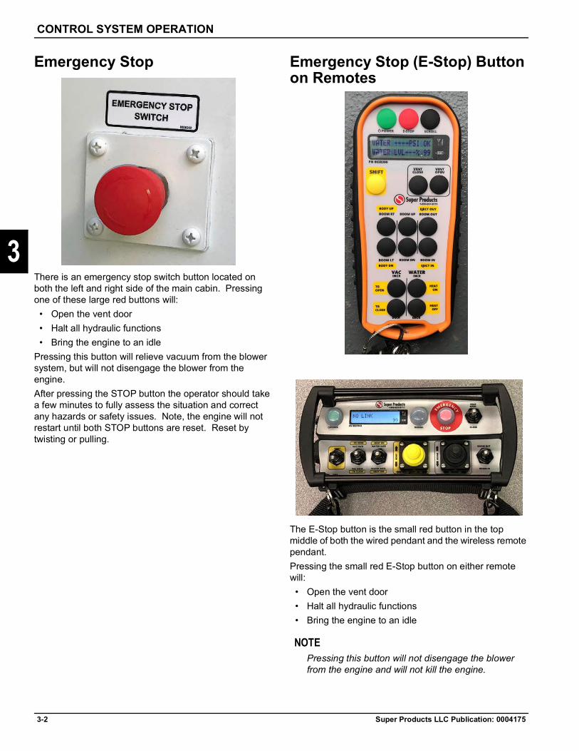
3-2 Super Products LLC Publication: 0004175
CONTROL SYSTEM OPERATION
3
Emergency Stop
There is an emergency stop switch button located on both the left and right side of the main cabin. Pressing one of these large red buttons will:
• Open the vent door• Halt all hydraulic functions• Bring the engine to an idle
Pressing this button will relieve vacuum from the blower system, but will not disengage the blower from the engine. After pressing the STOP button the operator should take a few minutes to fully assess the situation and correct any hazards or safety issues. Note, the engine will not restart until both STOP buttons are reset. Reset by twisting or pulling.
Emergency Stop (E-Stop) Button on Remotes
The E-Stop button is the small red button in the top middle of both the wired pendant and the wireless remote pendant.Pressing the small red E-Stop button on either remote will:• Open the vent door• Halt all hydraulic functions• Bring the engine to an idle
NOTEPressing this button will not disengage the blower from the engine and will not kill the engine.
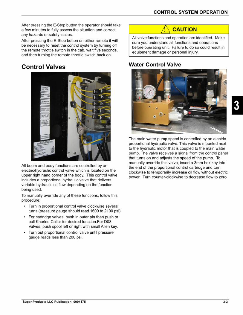
CONTROL SYSTEM OPERATION
Super Products LLC Publication: 0004175 3-3
3
After pressing the E-Stop button the operator should take a few minutes to fully assess the situation and correct any hazards or safety issues.After pressing the E-Stop button on either remote it will be necessary to reset the control system by turning off the remote throttle switch in the cab, wait five seconds, and then turning the remote throttle switch back on.
Control Valves
All boom and body functions are controlled by an electric/hydraulic control valve which is located on the upper right hand corner of the body. This control valve includes a proportional hydraulic valve that delivers variable hydraulic oil flow depending on the function being used. To manually override any of these functions, follow this procedure:
• Turn in proportional control valve clockwise several turns (pressure gauge should read 1600 to 2100 psi).
• For cartridge valves, push in outer pin then push or pull Knurled Collar for desired function.For D03 Valves, push spool left or right with small Allen key.
• Turn out proportional control valve until pressure gauge reads less than 200 psi.
CAUTION
Water Control Valve
The main water pump speed is controlled by an electric proportional hydraulic valve. This valve is mounted next to the hydraulic motor that is coupled to the main water pump. The valve receives a signal from the control panel that turns on and adjusts the speed of the pump. To manually override this valve, insert a 3mm hex key into the end of the proportional control cartridge and turn clockwise to temporarily increase oil flow without electric power. Turn counter-clockwise to decrease flow to zero
All valve functions and operation are identified. Make sure you understand all functions and operations before operating unit. Failure to do so could result in equipment damage or personal injury.

3-4 Super Products LLC Publication: 0004175
CONTROL SYSTEM OPERATION
3
Draft Pump Control (Optional)
When the truck is equipped with the optional draft pump (a.k.a. charge pump, liquid transfer pump, or water fill pump), an additional directional control valve is mounted next to the draft pump. This manual control valve sends hydraulic oil to either the main water pump or the draft pump or back to the hydraulic reservoir. A relief valve and a flow control valve are also provided to protect the draft pump.To operate the draft pump:1. Pour 2 quarts of water into pump to prime pump. It is
not necessary to prime the suction hose.2. Connect outlet to water tank fill with jumper hose.3. Connect inlet to suction hose with strainer at end.
NOTESWater level must be within 25 vertical feet of pump inlet.
4. With truck engine at idle, pull spool valve lever to "draft pump" or "charge pump".
5. When tanks are full, return spool valve lever to main water pump position.
Boom Operation1. Start truck engine and allow to idle. Make sure
parking brake is set and wheel chocks positioned. Place transmission into neutral.
CAUTION
2. Turn the "Remote Control" switch on the instrument panel to "ON". The boom is operated off the main hydraulics so the hydraulic system must be engaged.
3. Inside truck cab, locate the PTO control for the hydraulic pump. With engine at idle, fully depress truck clutch pedal and move PTO control switch to the engaged position.
4. With manual transmission, slowly release clutch.5. Make sure boom hose transport lock, if equipped, is
released first before operating boom. 6. At the control panel, in the main storage cabin, locate
the six boom control buttons. Simply press one of the buttons to make the boom go up, down, left, right, extend or retract. Boom will swing 320° clockwise from transport position. A mechanical stop will automatically limit the maximum swing. The control panel is meant to be a back-up station to either a hand held pendant or a wireless control.
CAUTION
DANGER
7. Connect required intake tubes onto intake hose. Make sure gaskets are positioned on couplings and over center clamp is fully closed. Use shortest possible length of tubing to ensure most direct route.
Failure to do so could result in truck rolling forward or backward resulting in potential personal or property damage.
When swinging boom, make sure you are aware of where all other personnel in the area are and that swing path for the boom will not hit any obstruction. Failure to comply could result in personal injury and/or property damage.For pendant remote control, locate the boom pendant receptacle. Lift the cover and insert the male plug end making sure that the key on the plug matches the notch on the receptacle.By operating the properly marked buttons, you can perform any of the functions outlined above. When done with the pendant, make sure you unplug it and properly store it before moving the truck.
When operating the boom, make sure you watch for overhead electrical wires or anything else which could result in personal injury or property damage.

CONTROL SYSTEM OPERATION
Super Products LLC Publication: 0004175 3-5
3
WARNING
8. When finished using the boom, position the boom to the transport position before moving the truck. Make sure the boom arm is in contact with the boom rest. When applicable, connect the hose hold-down latch to the hose. Extend the boom until the boom hose is slightly taught so it does not bounce around when transporting the unit.
9. Disengage the hydraulic system PTO located inside the cab by pushing the clutch pedal down and disengaging the PTO.
Water Lance OperationYour unit is equipped with a water system to be used for loosening soils to make them easier to vacuum, to wet down dry materials, to limit carryover into the separator or final filter and for general clean-up.WARNING:Never point the discharge flow of water from the lance toward a person as serious injury could result. Always make sure your feet are firmly planted and you are securely holding the lance with both hands before operating the lance.1. Start truck engine and allow to idle. Make sure
parking brake is set and wheel chocks positioned. Place transmission into neutral.
2. Inside truck cab, locate the PTO control for the hydraulic pump. With engine at idle, fully depress truck clutch pedal and move PTO control switch to the engaged position.
3. With manual transmission, slowly release clutch.4. Turn the remote control switch located inside the
chassis to the "on" position.5. Make sure the suction line strainer is installed and
the quarter turn suction line valve is open.6. Pull out the hose from the spring return reel located
in the main cabinet and attach the lance gun and the appropriate extensions and work nozzle.
CAUTION
7. If equipped with the optional draft pump, ensure that the manual control valve lever is in the "main water pump" position.
8. Turn "on" the water pump by either turning the water pump speed dial on the control panel clockwise to desired water pump speed; or press water increase button on the remote control. Press the water increase button several times or hold down the increase button until desired pump speed is reached. The control system obeys the most recent command from either the remote control or the speed dial. For this reason, it is possible for the pump to be running while the speed dial is OFF. Set the water pump speed to correspond to the job being done so you have the proper flow and pressure.
WARNING
9. Firmly grab the lance with both hands and point in the direction of the work to be done. Squeeze the trigger on the lance and water will come out of the end. Releasing the trigger will shut off the flow of water through the lance.
WARNING
10. When done using the lance, shut the water pump off by either turning the water pump speed dial fully counter clockwise or by pressing and holding the water DECREASE button on the remote control.
Return boom to cradle before moving truck. Moving the truck with the boom out of the cradle could cause excessive boom wear or failure resulting in severe personal injury or death.
Only use nozzles with urethane coatings fully intact to protect against damaging exposed lines. Failure to comply could result in personal injury and/or property damage.
Always wear a full face shield with eye protection. Wear safety shoes and gloves. Do not have any exposed skin not covered by "work" clothes. There could be flying material from the lance as the water stream strikes the soil. Failure to comply with the above could result in serious injury or death.
Never block or tie back the trigger on the lance as this is meant to be a safety device so the water stream can instantaneously be shut off if the need arises. Failure to comply could result in personal injury.
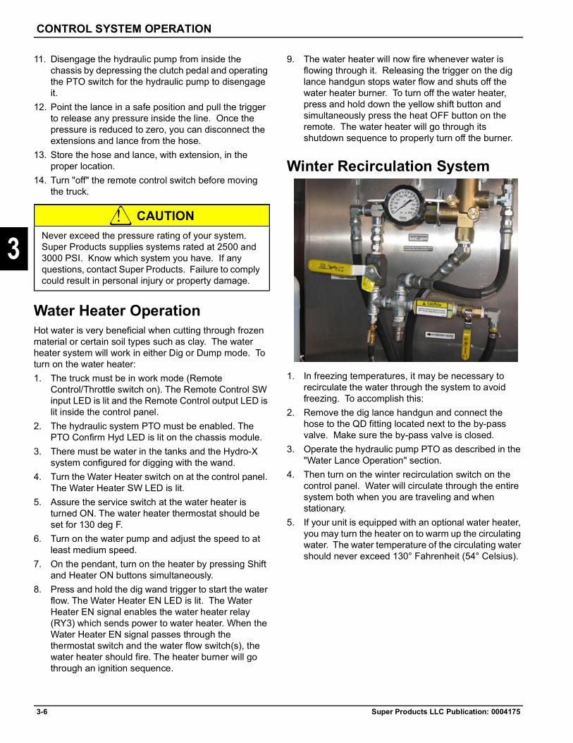
3-6 Super Products LLC Publication: 0004175
CONTROL SYSTEM OPERATION
3
11. Disengage the hydraulic pump from inside the chassis by depressing the clutch pedal and operating the PTO switch for the hydraulic pump to disengage it.
12. Point the lance in a safe position and pull the trigger to release any pressure inside the line. Once the pressure is reduced to zero, you can disconnect the extensions and lance from the hose.
13. Store the hose and lance, with extension, in the proper location.
14. Turn "off" the remote control switch before moving the truck.
CAUTION
Water Heater OperationHot water is very beneficial when cutting through frozen material or certain soil types such as clay. The water heater system will work in either Dig or Dump mode. To turn on the water heater:1. The truck must be in work mode (Remote
Control/Throttle switch on). The Remote Control SW input LED is lit and the Remote Control output LED is lit inside the control panel.
2. The hydraulic system PTO must be enabled. The PTO Confirm Hyd LED is lit on the chassis module.
3. There must be water in the tanks and the Hydro-X system configured for digging with the wand.
4. Turn the Water Heater switch on at the control panel. The Water Heater SW LED is lit.
5. Assure the service switch at the water heater is turned ON. The water heater thermostat should be set for 130 deg F.
6. Turn on the water pump and adjust the speed to at least medium speed.
7. On the pendant, turn on the heater by pressing Shift and Heater ON buttons simultaneously.
8. Press and hold the dig wand trigger to start the water flow. The Water Heater EN LED is lit. The Water Heater EN signal enables the water heater relay (RY3) which sends power to water heater. When the Water Heater EN signal passes through the thermostat switch and the water flow switch(s), the water heater should fire. The heater burner will go through an ignition sequence.
9. The water heater will now fire whenever water is flowing through it. Releasing the trigger on the dig lance handgun stops water flow and shuts off the water heater burner. To turn off the water heater, press and hold down the yellow shift button and simultaneously press the heat OFF button on the remote. The water heater will go through its shutdown sequence to properly turn off the burner.
Winter Recirculation System
1. In freezing temperatures, it may be necessary to recirculate the water through the system to avoid freezing. To accomplish this:
2. Remove the dig lance handgun and connect the hose to the QD fitting located next to the by-pass valve. Make sure the by-pass valve is closed.
3. Operate the hydraulic pump PTO as described in the "Water Lance Operation" section.
4. Then turn on the winter recirculation switch on the control panel. Water will circulate through the entire system both when you are traveling and when stationary.
5. If your unit is equipped with an optional water heater, you may turn the heater on to warm up the circulating water. The water temperature of the circulating water should never exceed 130° Fahrenheit (54° Celsius).
Never exceed the pressure rating of your system. Super Products supplies systems rated at 2500 and 3000 PSI. Know which system you have. If any questions, contact Super Products. Failure to comply could result in personal injury or property damage.

CONTROL SYSTEM OPERATION
Super Products LLC Publication: 0004175 3-7
3
Air PurgeIt is often beneficial to purge the water from all water lines to prepare for freezing temperatures and before using the anti-freeze injection system. The Mud Dog is equipped with an integral air purge line and ball valve located under the main control panel. To purge the water from the water system:1. Drain all water from the water tanks.2. Open the drain petcock at the return line water pump
inlet.3. Remove the inlet strainer cup.4. Open the by-pass valve.5. Connect the handgun to the water hose. (Remove
dig lances from the handgun.)6. Open the air purge ball valve.7. Point the handgun in a safe direction and pull the
trigger until no more water comes out. This will take about 2 minutes (less than 1 minute without the heater).
8. Close the air purge ball valve and wait 2 minutes to let the chassis air supply recover. Then repeat the previous step.
9. Open the drain valve at the water pump outlet.10. Open the manifold drain petcock valve below the
by-pass valve and temporarily push open the quick disconnect and fully drain.
11. Turn the water pump on for 1 second only. This helps purge water out of the pump manifold.
12. Close the air purge ball valve.13. Close all drain petcocks after all water is purged.
NOTESNever depend only on blowing the water out of your system (if you have an optional water heater) as not all the water will drain from the heater and could freeze causing heater coil damage.
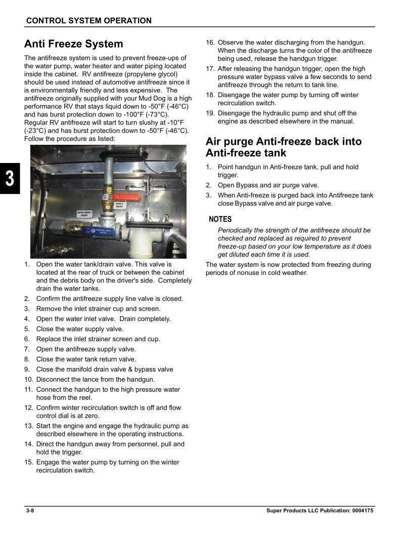
3-8 Super Products LLC Publication: 0004175
CONTROL SYSTEM OPERATION
3
Anti Freeze SystemThe antifreeze system is used to prevent freeze-ups of the water pump, water heater and water piping located inside the cabinet. RV antifreeze (propylene glycol) should be used instead of automotive antifreeze since it is environmentally friendly and less expensive. The antifreeze originally supplied with your Mud Dog is a high performance RV that stays liquid down to -50°F (-46°C) and has burst protection down to -100°F (-73°C). Regular RV antifreeze will start to turn slushy at -10°F (-23°C) and has burst protection down to -50°F (-46°C). Follow the procedure as listed:
1. Open the water tank/drain valve. This valve is located at the rear of truck or between the cabinet and the debris body on the driver's side. Completely drain the water tanks.
2. Confirm the antifreeze supply line valve is closed. 3. Remove the inlet strainer cup and screen.4. Open the water inlet valve. Drain completely.5. Close the water supply valve.6. Replace the inlet strainer screen and cup.7. Open the antifreeze supply valve.8. Close the water tank return valve.9. Close the manifold drain valve & bypass valve10. Disconnect the lance from the handgun.11. Connect the handgun to the high pressure water
hose from the reel.12. Confirm winter recirculation switch is off and flow
control dial is at zero.13. Start the engine and engage the hydraulic pump as
described elsewhere in the operating instructions.14. Direct the handgun away from personnel, pull and
hold the trigger.15. Engage the water pump by turning on the winter
recirculation switch.
16. Observe the water discharging from the handgun. When the discharge turns the color of the antifreeze being used, release the handgun trigger.
17. After releasing the handgun trigger, open the high pressure water bypass valve a few seconds to send antifreeze through the return to tank line.
18. Disengage the water pump by turning off winter recirculation switch.
19. Disengage the hydraulic pump and shut off the engine as described elsewhere in the manual.
Air purge Anti-freeze back into Anti-freeze tank1. Point handgun in Anti-freeze tank, pull and hold
trigger.2. Open Bypass and air purge valve.3. When Anti-freeze is purged back into Antifreeze tank
close Bypass valve and air purge valve.
NOTESPeriodically the strength of the antifreeze should be checked and replaced as required to prevent freeze-up based on your low temperature as it does get diluted each time it is used.
The water system is now protected from freezing during periods of nonuse in cold weather.

CONTROL SYSTEM OPERATION
Super Products LLC Publication: 0004175 3-9
3
Lance/Cleaning Gun PrecautionsThe cleaning gun should be operated only by trained operators. Please read the following instructions before attempting to operate.
Heed these warnings - or serious injury and permanent injury may result
Safety should always be observed
DO NOT: DO:
Aim gun at any person or any parts of the body. Fluids under high pressure can penetrate the human skin and can cause severe injury, possibly resulting in amputation or death. If any part of the body comes in contact with the spray stream, immediately contact a physician.
Develop a habit of shutting off the pressure to the gun and hose before attempting to remove the nozzle, gun or any part of the gun, or when fun is not in use.
Place hand or any other portion of the body in front of the spray nozzle.
Carefully check and tighten threaded connections regularly. Make them secure and leak proof.
Alter equipment in any manner. If repairs are necessary, use only genuine factory repair parts available from Super Products.
Make sure the trigger is properly operating.
Operate gun w/o trigger guard attached. Adopt a secure body stance prior to and during operation onto control the reactionary force of the gun.
Exceed the maximum operating pressure of 3000 psi. Keep gun clean to allow for positive grip and safe operation.
Leave equipment under pressure unattended at any time. Relieve pressure by shutting off the water system; then actuate the gun trigger until all water ceases to flow.
Impress on other people in the area the importance of obeying strict safety precautions for everyone’s safety.
Use damaged or weakened hose. Make sure gun is insulated properly when used in a dangerous environment.
Operate the gun if there are any leaks from the packing, fittings, hoses, etc.
Never exceed maximum operating pressure. Make sure relief valve is properly operating.
Tap or otherwise lock trigger into the ON position.

3-10 Super Products LLC Publication: 0004175
CONTROL SYSTEM OPERATION
3
Dumping Payload
4. Position truck at dump site, engage parking brake and position wheel chocks.
CAUTION
5. Engage water and hydraulic systems as described elsewhere in this manual.
6. From main control panel set "Dig-Dump" mode switch to "DUMP".
7. Ensure that the tailgate area is clear of people and obstructions.
8. Press the YELLOW SHIFT button AND the TG OPEN button on the remote at the same time. This button controls a two step function. First the tailgate latches unlock. Then the tailgate rises. Then the ejector plate extends. Release this button at any time to pause the process. A Dump/Retract switch is also provided on the rear right hand corner of the cabinet.
9. Press the YELLOW SHIFT button and the EJECT out button on the remote at the same time. This will extend the Ejector plate out and push material out of the body. Release this button at any time to pause the process. An Eject switch is also provided on the rear right had corner of the cabinet.
10. Connect water hose to body flusher connection. Turn water pump on. Water will come out of spray bar inside body.
11. Connect the water hose to the handgun and clean tailgate sealing surfaces, tailgate, pusher plate and back of unit as required.
12. Reverse above procedures when completed. Two green lights on the rear right hand corner of the cabinet will come on when the ejector plate is in the forward position and the tailgate latches are locked.
Some Mud Dogs include a body Tilt feature to assist in emptying the debris body. To raise the body, press the YELLEO SHIFT button AND the BODY TILT button on the remote at the same time. Note, the boom should be positioned in its cradle when raising the body. There is also a body tilt switch located on the panel on the rear right side of the main cabin.
Failure to do so could result in truck rolling forward or backwards resulting in potential personal or property damage.

CONTROL SYSTEM OPERATION
Super Products LLC Publication: 0004175 3-11
3
WARNING
When lowering the body, press and hold the lower button for two full seconds after the body contracts the chassis frame rails. This applies the proper retraction force to properly secure the body.
Separator Air SystemYour unit is equipped with a separator. There is little for the operator to do except periodically check for any material accumulation in the bottom of the unit and manually clean out. This separator is located in the air stream between the top of the body and the vacuum pump.
Front Body Drain Valve Your unit has the front body drain valve so you can drain excess liquids from the body through such. Because the pusher plate keeps the larger materials away from this drain, you can drain off virtually all the liquid resulting in a relatively dry payload for the disposal site. Make sure the drain hose is properly secured before moving the unit. If the drain valve should plug, you can suck air backwards through it by blocking off the inlet hose, and engaging the vacuum pump. Allow the vacuum to build up some and then open the drain valve. The drain hose must be disconnected when you do this. Make sure all body parts and clothing are away from the valve opening before opening the valve.
Debris Level Sensor (Optional)Your unit may be equipped with a Debris Level Sensor which will inform the operator of the debris level in the collector body. The system senses liquids, slurries, and solids and operates in the full vacuum environment in the collector body (up to 28" Hg). The components are immune to air flow, noise, vibration, dust, humidity and temperature.
The Debris Level system measures the debris level and includes four red lights representing 25%, 50%, 75%, and 100% full. The lights are located on the main storage cabin above the passenger side door. Additionally the top light (fourth light) will blink when the debris body is about 90% full. This should serve as a warning to the operator that the debris body is almost full. When the body is 100% full the top light will stay lit and the vacuum relief door will open and prevent overfilling.
Ensure the area is clear of hazards before raising or lowering the body.


Super Products LLC Publication: 0004175 4-1
Chapter 4
4
Lubrication and Maintenance
General InformationPeople who maintain this unit should have a basic understanding of the equipment and normal sequence of operation. Refer to other sections of this manual.When any repairs or adjustments are made to this unit, extreme care should be taken and all safety precautions and decals observed.Preventive maintenance routines keep the equipment in proper working condition. Preventive maintenance is not only desirable, but is necessary, since scheduled inspection insures continued trouble free operation of the equipment. It also prevents, or at least detects, at an early stage mechanical, hydraulic, or electrical troubles that might otherwise develop into equipment malfunction.
Preventive Maintenance InstructionsWe urge you to protect your investment by servicing it according to the maintenance schedule listed on the following pages. Regular maintenance will insure maximum unit performance, long unit life, safety, reliability, and full warranty protection.Each maintenance item is numbered and is described on the pages following the schedule.
Lubrication Recommendation Chart
Table 4-1:Component Lubricant
GreaseSuper Products Spec 3060-00023 White Lithium
Hydraulic System
Super Products Spec 3060-00048 Chevron Rando HD Premium Oil MV
Transfer Case
Super Products Spec 3060-00047 Chevron Clarity Synthetic Machine Oil ISO 150
Vacuum Pump
Super Products Spec 3060-00047 Chevron Clarity Synthetic Machine Oil ISO 150
Water Pump
Super Products Spec 3060-00047Chevron Clarity Synthetic Machine Oil ISO 150
Trash Pump
Super Products Spec 3060-00005 Automatic Transmission Fluid Type A Dexron 3
Anti-FreezeSuper Products Spec3060-00036100 Plus RV Anti-Freeze
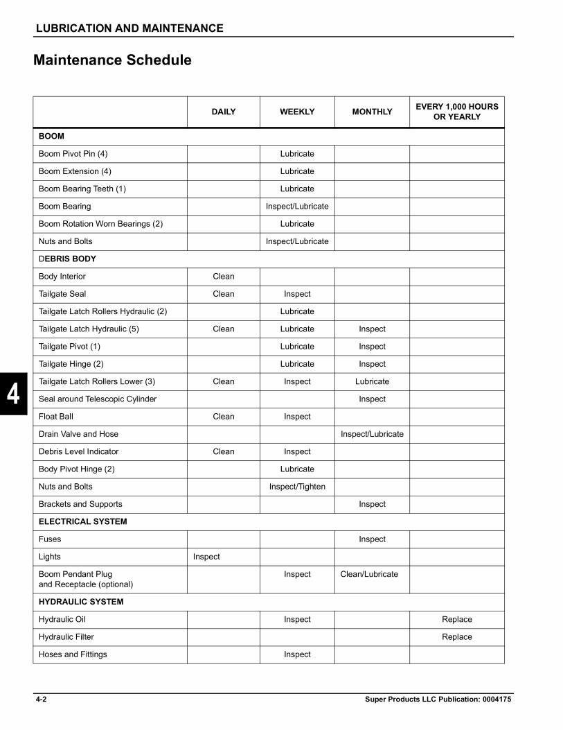
4-2 Super Products LLC Publication: 0004175
LUBRICATION AND MAINTENANCE
4
Maintenance Schedule
DAILY WEEKLY MONTHLY EVERY 1,000 HOURSOR YEARLY
BOOM
Boom Pivot Pin (4) Lubricate
Boom Extension (4) Lubricate
Boom Bearing Teeth (1) Lubricate
Boom Bearing Inspect/Lubricate
Boom Rotation Worn Bearings (2) Lubricate
Nuts and Bolts Inspect/Lubricate
DEBRIS BODY
Body Interior Clean
Tailgate Seal Clean Inspect
Tailgate Latch Rollers Hydraulic (2) Lubricate
Tailgate Latch Hydraulic (5) Clean Lubricate Inspect
Tailgate Pivot (1) Lubricate Inspect
Tailgate Hinge (2) Lubricate Inspect
Tailgate Latch Rollers Lower (3) Clean Inspect Lubricate
Seal around Telescopic Cylinder Inspect
Float Ball Clean Inspect
Drain Valve and Hose Inspect/Lubricate
Debris Level Indicator Clean Inspect
Body Pivot Hinge (2) Lubricate
Nuts and Bolts Inspect/Tighten
Brackets and Supports Inspect
ELECTRICAL SYSTEM
Fuses Inspect
Lights Inspect
Boom Pendant Plug and Receptacle (optional)
Inspect Clean/Lubricate
HYDRAULIC SYSTEM
Hydraulic Oil Inspect Replace
Hydraulic Filter Replace
Hoses and Fittings Inspect
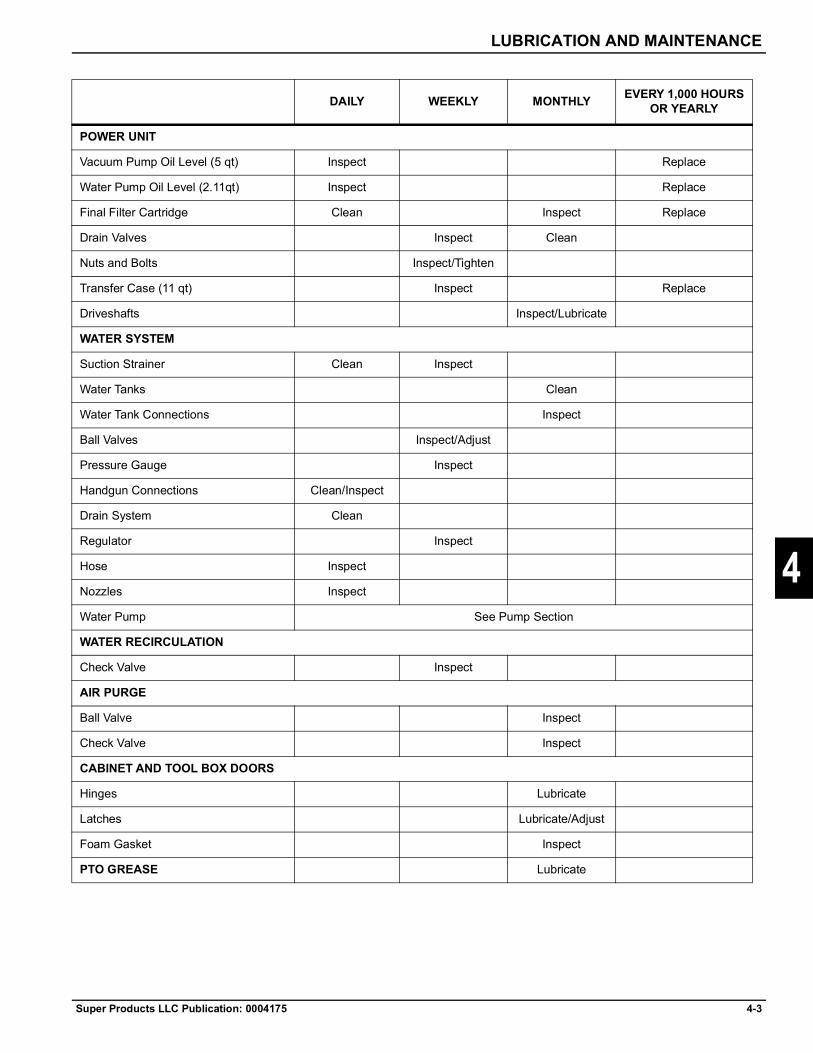
LUBRICATION AND MAINTENANCE
Super Products LLC Publication: 0004175 4-3
4
POWER UNIT
Vacuum Pump Oil Level (5 qt) Inspect Replace
Water Pump Oil Level (2.11qt) Inspect Replace
Final Filter Cartridge Clean Inspect Replace
Drain Valves Inspect Clean
Nuts and Bolts Inspect/Tighten
Transfer Case (11 qt) Inspect Replace
Driveshafts Inspect/Lubricate
WATER SYSTEM
Suction Strainer Clean Inspect
Water Tanks Clean
Water Tank Connections Inspect
Ball Valves Inspect/Adjust
Pressure Gauge Inspect
Handgun Connections Clean/Inspect
Drain System Clean
Regulator Inspect
Hose Inspect
Nozzles Inspect
Water Pump See Pump Section
WATER RECIRCULATION
Check Valve Inspect
AIR PURGE
Ball Valve Inspect
Check Valve Inspect
CABINET AND TOOL BOX DOORS
Hinges Lubricate
Latches Lubricate/Adjust
Foam Gasket Inspect
PTO GREASE Lubricate
DAILY WEEKLY MONTHLY EVERY 1,000 HOURSOR YEARLY
4-4 Super Products LLC Publication: 0004175
LUBRICATION AND MAINTENANCE
4
Maintenance ItemsNote:Any greasing of unit should be done with a general purpose lithium base grease unless otherwise noted.
Boom1. The boom bearing and boom pivot hinges are
greased from ground level. The grease distribution device’s on the passenger side of the truck. Apply grease to the zerk fitting of the grease distribution device weekly.
2. Inspect boom bearing teeth for wear or cracking.3. The boom extension joint is a lifetime polymer slide.
No lubrication is necessary.4. The telescopic boom tube includes a rubber seal
between the inner round boom tube and the outer round boom tube. The lubrication fittings for this seal are on a manifold near the tailgate on the passenger side.Grease this seal weekly.
Debris Body1. Body Interior: Empty material from debris body daily
and clean interior with use of spray bar flushing system (if equipped) or handgun. Clean tailgate sealing surface.
2. Tailgate Seal: Clean tailgate seal after each discharge of debris with the use of the handgun. Inspect seal weekly for rips, tears, and proper alignment with the body. Replace as required.
3. Hydraulic Tailgate Latch Rollers: Clean tailgate latch rollers after each discharge of debris. Lubricate rollers by hand with grease weekly. Inspect condition of rollers and replace if signs of wear appear.
4. Hydraulic Tailgate Latches: Clean any debris off latches daily. Lubricate latch pivots with grease. The upper tailgate latches are lubricated via the grease distribution device on the tailgate at about eye level. The lower tailgate latches are lubricated individually and should be greased more often than the upper latches. Inspect latch rods for bending or bearings for wear.
5. Tailgate Lift Cylinder Pin: Inspect for wear. Lubricate with oil by hand.
6. Seal Around Telescopic Cylinder: Inspect rubber seal around pusher plate telescopic cylinder to make sure it is tight and not damaged.
7. Float Ball: Clean float ball daily or after each load. Inspect ball weekly for dents and proper sealing.
8. Tailgate Hinge: The upper tailgate hinge is lubricated via the grease distribution device on the tailgate at about eye level.
9. Body Drain Valve and Hose: Inspect hose for leaks and wear, and the valve for proper sealing weekly. This applies to both rear and front drain. (If Equipped)
10. Debris Level Indicator: Check that sensor is cleaned daily.
Electrical System1. Fuses: Inspect auxiliary fuse panel located in control
panel for blown fuses. Replace only with a fuse of same rating.
2. Lights: Inspect that all vehicle lights are in good condition and working properly.
3. Boom Pendant Plug and Receptacle: Inspect pendant plug and receptacle for contact and proper alignment. Clean terminals monthly and lubricate with dielectric grease if problems arise.
Hydraulic System1. Hydraulic Oil: Inspect hydraulic oil level in reservoir
weekly. Oil level should be at the center of the sight glass with all cylinders retracted. Add oil if necessary. Change oil after first month of operation. Then change oil every 12 months or 1000 hours whichever comes first. Refer to 'Recommended Lubricants' in this manual.
2. Hydraulic Filter: Initially replace hydraulic filter after first month of operation then replace every six (6) months or sooner if filter indicator light on the control panel comes on.
3. Hoses and Fittings: Inspect all hoses and fittings for leaks. Check hoses for cracks, fraying and rubbing. Replace damaged hoses and tighten fittings.
Power Unit:1. Vacuum Pump Oil Level: Inspect oil level of vacuum
pump daily. Level should be half way up the sight tube on the shaft end of the pump and half way in the sight eye in the tail end. Add oil if necessary. Initially change oil in vacuum pump after 100 hours of use and then every twelve (12) months or 1,000 hours whichever occurs first. Refer to 'Recommended Lubricants' in this manual.
LUBRICATION AND MAINTENANCE
Super Products LLC Publication: 0004175 4-5
4
2. Water Pump Oil Level: Inspect oil level of water pump daily. Level on horizontally mounted pumps should be checked at the sight gauge. On vertically mounted pumps the oil level can be checked by removing a fill plug on the top right hand side of the gear case. Add oil if necessary. Initially change oil in water pump after 100 hours of operation and then every twelve (12) months or 1,000 hours whichever comes first. Refer to 'Recommended Lubricants' in this manual.
3. Drain Valves: Inspect operation of water drain valves monthly. Clean valves, if necessary, every month. See detailed draining procedure located in this manual.
4. Bolts and Nuts: Check that all bolts and nuts are tightened securely.
5. Transfer Case: Inspect oil level of transfer case weekly. Level should be at the center of the sightglass. Add oil if necessary. Initially change oil in splitshaft after 100 hours of use and then every12 months or 1,000 hours whichever comes first. Refer to 'Recommended Lubricants' in this manual.
6. Driveshafts: Lubricate the driveshafts and inspect universal joints for wear monthly.
Water System1. Suction Strainer: Remove water pump suction
strainer daily and clean. Inspect strainer weekly for leaks or damage and replace as necessary
2. Water Tanks: Inspect the interior of water tanks monthly for sand, rust, etc. through top inspection ports. Clean as necessary.
3. Water Tank Connections: Inspect water tank connections for leaks, damage, or wear monthly. Adjust or replace as required.
4. Ball Valves: Inspect ball valves for proper operation and wear. Adjust stem packing if leaks occur. Rebuild or replace valves if necessary.
5. Pressure Gauge: Inspect water pressure gauge and for proper operation or damage. Make sure gauge resets to zero. In freezing weather, store gauge in warm area.
6. Handgun Connections: Inspect and clean handgun connections for proper operation or leaks daily.
7. Drain System: In freezing weather, drain entire water system and hose. See detailed drain system instructions located in this manual.
8. Regulator: Inspect regulator for leaks and any possible spring damage.
9. Hose: Inspect hose for tears or damage.
10. Nozzles: Inspect nozzles for worn or plugged orifices and cracked housing. Repair/replace as necessary. Check that nozzle pressure rating matches unit.
11. Water Pump: See water pump instructions located in this manual.
Air Purge1. Ball Valve: Inspect ball valve for proper operation
and wear. Adjust stem packing if leaks occur. Rebuild or replace valve if necessary.
2. Check Valve: Check for water in air tanks. If present, check that valve is operating properly not allowing water into air tanks.
Cabinet & Toolbox Doors1. Hinges: Lubricate panel hinges with oil monthly.2. Latches: Lubricate panel latches monthly with oil.
Adjust latches to insure proper panel retention.3. Foam Gasket: Inspect foam seal around panel
monthly. Replace if damaged or missing.
Adjusting Hydraulic Tailgate Latches & HingesAdjusting the Tailgate Hinges (See Fig. 1):If the tailgate becomes offset such that the latches won't line up, then check tailgate hinge and hinge supports at the top of the debris body. Call Super Products at 1-800-837-9711 for assistance in diagnosing and correcting. The following procedure may be prescribed, but should only be undertaken by a qualified mechanic.1. If offset, open the tailgate about 8 inches and attach
a come-along to the cylinder bracket. Pull the tailgate about 4 inches past center.
2. Release come-along and re-check alignment. Repeat if necessary, decreasing overstroke each time.
3. When tailgate is aligned properly on center, engage latches.
4. Loosen bolts holding hinge plates. 5. Securely clamp top of tailgate to body flange.6. Adjust actuator cylinder clevis, if necessary, for
proper gap on bottom latchplate.7. Adjust gap of remaining latchplates using the
adjustment rods.8. When adjusting lower rods, start by leaving extra gap
between upper plate and roller. Adjust lower latchplate, then upper, on each side.

4-6 Super Products LLC Publication: 0004175
LUBRICATION AND MAINTENANCE
4
9. Retighten hinge plate bolts. Make sure the bottom edge of hinge support plate is in full contact with support. Weld the front vertical edge of each hinge plate to the mounting plate with a 3/16" fillet.
Adjusting the Tailgate Latches (See Figure 2)1. Close tailgate completely and lock the latches with
the hydraulic control.2. All latches should be in the same contact position
with the cam roller. The latch should contact the cam roller to maintain a 1/8" gap between the roller and the machine edge of the latch pin. See Figure 2.
3. If there is a latch which is not in the same contact position, an adjustment will be required.
4. Adjust by removing the hairpin retainer and pin from the central cam end of rod.
5. Release latches and loosen clevis locknuts on each end and rotate each clevis equally as both are right hand threaded. Replace pin and hairpin and check engagement.
6. Adjust so that the flat on each locking cam is completely under the body bracket roller. Exact sequence can vary but keep all engagements equal throughout this process.
7. When correct engagement is achieved, tighten clevis locknuts securely and make sure that hairpin retainers are in place.
8. If the tailgate gasket is leaking, the latch in the area of the leak must be individually tightened. They are shim-adjusted, with standard 5/8" flat washers. After fully opening latches, remove the wedge roller bolts and add a flat washer. Retighten roller bolts securely and recheck wedge adjustment, as above. Recheck leakage and repeat roller adjustment as necessary.
Figure 4-1: FLAT TAILGATE
Figure 4-2: TAILGATE LATCH
Ejector Plate Slide Pad and Wiper AdjustmentThe ejector plate slide pads should be adjusted or replaced whenever the end of the angle iron guard over the pusher cylinder can be moved up and down 1/2" by hand while the plate is at the narrowest point of its travel.
CAUTION
1. Open tailgate and support it on its props. Clean the debris body, ejector plate and slide pad assemblies with pressurized water. Fully retract ejector plate.
WARNING
WARNING
2. Enter body through tailgate and measure distance between guide rails every 18" to determine narrowest point. Exit from body and move the plate to this point.
3. Remove pad cover and check pad thickness to determine if replacement is necessary. A pad should be replaced when there is less than ¼" of pad behind the pad covers (See FIG. 1.) If so, loosen adjusting bolt lock nut and loosen 1-1/8 hex adjusting bolt, upper and lower pads. FIG. 2.
Failure to maintain proper slide pad adjustment can result in premature ejector plate failure not covered by warranty.
Failure to securely support tailgate whenever working beneath it may cause injury or death.
Shut truck engine off and pocket the keys EACH TIME that the body must be reentered or when working under the raised tailgate. Failure to do this could result in injury or death.

LUBRICATION AND MAINTENANCE
Super Products LLC Publication: 0004175 4-7
4
4. Thread self taping screw with slide hammer (Super Products P/N 3000-03254) into lower pad and tap out. See FIG. 3. Use pry bar to lift Ejector plate. Follow same steps to remove upper pad.
5. Insert backup bars and slide pads, beveled edge toward guide rail. Follow same steps for other side.
6. Reinstall pad covers. See FIG. 4.7. Tighten upper pad adjusting screws so there is ¼" of
white pad showing on each side.8. Position the ejector plate side-to-side with a pry bar
so there is an equal gap on both sides of the body. See Fig. 2.
9. Tighten bottom pads to 40 ft-lbs. each side10. Move the plate backward 2 feet & then back to
narrowest point.11. Tighten to 75 ft-lbs. each side.12. Move the plate backward 2 feet & then back to
narrowest point.13. Loosen bottom pads 2 turns each, & tighten lock
nuts.14. Restart engine and check for binding of the plate
throughout its full stroke. If it binds, evenly back off lower adjusting screws ½ turn each.
Wiper AdjustmentExtend ejector plate to rear edge of body. Note clearances between wiper and around perimeter inside of body. Using a block of wood and a hammer, knock wiper segments outward until they just contact the inside wall of the body.


Super Products LLC Publication: 0004175 5-1
Chapter 5
5
Troubleshooting
Troubleshooting OverviewThis guide is intended as a quick reference to aid operators and technicians in troubleshooting potential issues with the Super Products’ Mud Dog® Vacuum Excavator.This guide describes symptoms and lists several probable causes and their solutions. The primary rule of troubleshooting is to check the simple things first; therefore, the probable causes are generally listed in order of simplest to most complex.Before attempting any repair, read, understand, and follow the operator's manual instructions, warnings, and safety messages.All repairs should be performed by a qualified technician.Before attempting any Troubleshooting you must call our Customer Service Representatives at 262-784-7100
The Basic Troubleshooting Process1. Prepare tools, information, and safety equipment.2. Define the symptom.
• What is the problem?• When does it occur?• When did it work properly?• When did it stop working properly?• What was done in between those times?
3. Reproduce the symptom.4. Narrow it down to the root cause.
• Proceed logically.• Check the simple things first.• Divide and conquer — rule out what is not the
problem. This is especially important to define if the root cause is human error, electrical, hydraulic, or mechanical.
• Believe your evidence — if all else is eliminated, that which remains must be true.
• Never assume anything — check it yourself.
• Check everything — you could have multiple faults.
5. Repair or replace the defective component.6. Educate and train the operator when it is a case of
human error.7. Verify the symptom is gone.

5-2 Super Products LLC Publication: 0004175
TROUBLESHOOTING
5
Mechanical Troubleshooting
Problem Possible Cause RemedyUnit does not draw vacuum: Vacuum Pump not engaged. Engage the vacuum pump.
Transmission not in gear. Shift to high gear.Vacuum relief open. Close Vacuum Relief Door.Body full of material (liquid or solid). Dump load.Intake hose restricted or plugged. Remove obstructions from hose.Filter plugged. Dump load, clean filter.Ducting in body plugged or filled with Material.
Clean ducts.
Inspection doors open. Close doors.Unit does not draw vacuum: Vacuum Leaks:
Holes worn in hose or dig tube. Repair or replace as required.Hose coupler assembly gasket(s) missing or damaged.
Adjust, repair or replace any missing or leaking gaskets.
Gasket from inspection door missing or damaged.
Repair or replace gasket.
Tailgate gasket damaged or not sealing.
Repair or replace seal.
Filter housing door seals damaged or not sealing.
Repair or replace seal.
Hose between body and cyclone separator damaged or not sealing.
Repair or replace hose.
Vacuum Relief will not function: Vacuum relief open due to level sensor sensing full load.
Dump the load.
Lack of air pressure Check chassis air pressure. Run engine until pressure rises.
Electric signal not present. Check electric troubleshooting.Vacuum Pump RPM not displayed: Failed speed sensor on transfer Replace speed sensor.
Dust in vacuum pump discharge: Note: Operating while this condition exits could cause significant damage to vacuumpump and void warranty.
Missing or damaged filter. Replace filter.
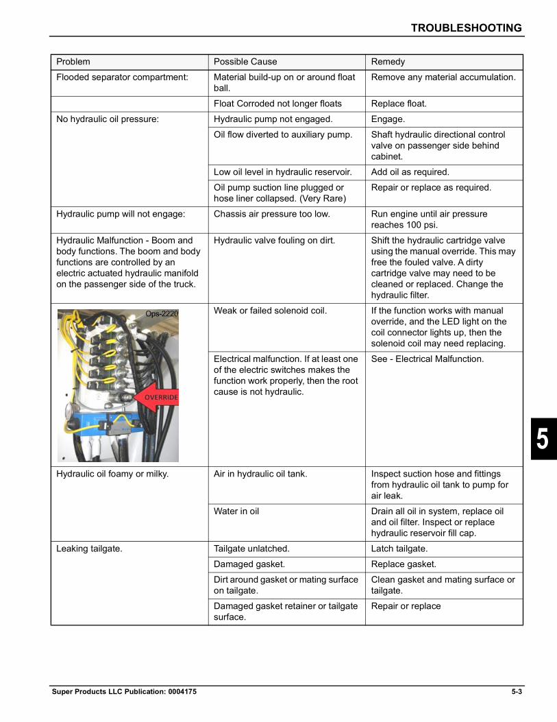
TROUBLESHOOTING
Super Products LLC Publication: 0004175 5-3
5
Flooded separator compartment: Material build-up on or around float ball.
Remove any material accumulation.
Float Corroded not longer floats Replace float.No hydraulic oil pressure: Hydraulic pump not engaged. Engage.
Oil flow diverted to auxiliary pump. Shaft hydraulic directional control valve on passenger side behind cabinet.
Low oil level in hydraulic reservoir. Add oil as required.Oil pump suction line plugged or hose liner collapsed. (Very Rare)
Repair or replace as required.
Hydraulic pump will not engage: Chassis air pressure too low. Run engine until air pressure reaches 100 psi.
Hydraulic Malfunction - Boom and body functions. The boom and body functions are controlled by an electric actuated hydraulic manifold on the passenger side of the truck.
Hydraulic valve fouling on dirt. Shift the hydraulic cartridge valve using the manual override. This may free the fouled valve. A dirty cartridge valve may need to be cleaned or replaced. Change the hydraulic filter.
Weak or failed solenoid coil. If the function works with manual override, and the LED light on the coil connector lights up, then the solenoid coil may need replacing.
Electrical malfunction. If at least one of the electric switches makes the function work properly, then the root cause is not hydraulic.
See - Electrical Malfunction.
Hydraulic oil foamy or milky. Air in hydraulic oil tank. Inspect suction hose and fittings from hydraulic oil tank to pump for air leak.
Water in oil Drain all oil in system, replace oil and oil filter. Inspect or replace hydraulic reservoir fill cap.
Leaking tailgate. Tailgate unlatched. Latch tailgate.Damaged gasket. Replace gasket.Dirt around gasket or mating surface on tailgate.
Clean gasket and mating surface or tailgate.
Damaged gasket retainer or tailgate surface.
Repair or replace
Problem Possible Cause Remedy

5-4 Super Products LLC Publication: 0004175
TROUBLESHOOTING
5
Tailgate will not open or close Not in “Dump” Mode. Set operation mode switch on control to “Dump” mode.
Two hands needed to operate remote pendant.
Press “SHIFT” button on remote pendant while pressing the “EJECT” button.
Ejector plate not fully retracted. Clean debris from in front of ejector plate. Clean ejector plate guides.
Flow control valve at cylinder is plugged or damaged
Securely support tailgate, slowly disconnect hydraulic hoses, replace flow control valve.DANGER: High pressure. Only qualified mechanic should proceed. Change hydraulic filter.
No hydraulic oil pressure. See - No Hydraulic Oil Pressure.Hydraulic line pinched, plugged or broken.
Locate, repair or replace.
Hydraulic cylinders failed. Replace cylinders.Tailgate latch will not close Dirt or material accumulated on
collar, shaft, roller or tailgate surfaceRemove all accumulated dirt and material.
Rollers or shaft binding or frozen. Lubricate rollers and shaft. Free binding parts.
Wireless remote pendant not functioning.
Hydraulic pump not engaged. Engage pump.Remote Control switch in cab is Turn on Remote Control Switch.
OFF.Batteries are dead. Replace batteries.Not in “DIG” Mode. Set operation mode switch on
Control Panel to “DIG” Mode.Electrical malfunction. See Electrical malfunction.
Boom not functioning. Not in “Dig” mode. Set operation mode switch on control
No hydraulic pressure. See - NO hydraulic oil pressure.Pinched, plugged or broken hydraulic line.
Locate, repair or replace.
Hydraulic cylinders failed. Replace cylinders.Electrical malfunction. See - Electrical troubleshooting.
Boom functions are noisy. Dry bearing or pivot points. Lubricate bearing and pivot points.No Water Pressure Water supply valve closed. Open supply valve.
Water tanks empty. Fill water tanks.
Problem Possible Cause Remedy

TROUBLESHOOTING
Super Products LLC Publication: 0004175 5-5
5
(Water pump function should be available in both “DIG” mode and “DUMP” mode.)
Oil flow diverted to auxiliary pump. Shift hydraulic directional control valve on passenger side behind cabinet.
Water by-pass valve open. Close by-pass valve.Drain valve open. Close drain valve.Plugged or dirty water supply strainer.
Clean water supply strainer.
Nozzle too big or worn out. Replace nozzle.Water hose leaking. Replace hoses.Drive Coupling failure. Replace coupling between water
pump and hydraulic motor.No hydraulic pressure. See “No hydraulic pressure”.Electrical malfunction.(Use manual override to verify electrical malfunction. Turn proportional control valve on water control manifold counterclockwise several turns with a 3mm Allen Wrench.)
See Electrical troubleshooting.
Low air pressure. Never reaching one hundred 100) PSI.NOTE: If truck air pressure gauge is less than sixty-five (65) PSI, the problem is in truck system or air safety valve on truck air tank connected to Mud Dog air system.
Solenoid valve or diaphragm valve or filter stuck open.
Clean, repair or replace as required.
Faulty compressor or regulator on truck.
Repair or replace.
Leak in air line, pneumatic valves, cylinders or tanks
Locate, repair or replace as required.
Defective air pressure gauge. Replace gauge.
Problem Possible Cause Remedy

5-6 Super Products LLC Publication: 0004175
TROUBLESHOOTING
5
No Hot Water. Remote throttle on. Turn on Remote Throttle switch on dash.
Water heater switch on control panel not on.
Turn water switch on.
Main hot water switch at heater not on.
Turn switch on.
Shift and heater button on remote not depressed at the same time.
Depress SHIFT and HEATER at the same time.
Plugged or dirty fuel filter at water heater.
Replace fuel filter.
Water flow switch not sensing. See - Electrical Troubleshooting.Electric signal not present. See- Electrical Troubleshooting.
Electrical malfunction LED light on solenoid coil connector should light up when function is pressedElectrical connector lost continuity. Unplug connector, inspect for
damage, add electrical grease and plug it back in.
Broken, loose or misrouted electrical wire.
Locate, repair or replace.
Faulty solenoid on hydraulic power pack.
Replace solenoid.
LED light on proximity sensor should light up when it senses steel.
Hold steel plate up to proximity sensor and check for LED light.
Proximity sensor too far from component to be sensed.
Screw in proximity sensor until it repeatable senses the component.
Truck engine dies. Red E-STOP kill button depressed. Twist & pull out red E-STOP button.
Problem Possible Cause Remedy

TROUBLESHOOTING
Super Products LLC Publication: 0004175 5-7
5
Electrical TroubleshootingFunction Problem Possible
Function Problem Possible Cause RemedyRoad Mode Gas Pedal inoperative Engine still in PTO
mode.Depress clutch pedal to cancel PTO mode.
Remote Throttle Control (Work Mode)
No remote throttle control.
Remote Control (Throttle Enable) switch off.
Turn Remote Control switch off, then on.
Throttle Enable SW signal not present at control module.
Check THROTTLE ENABLE SW input LED is lit on the control module.
Clutch pedal pushed in. Check THROTTLE ENABLE output LED is lit on the control module. Keep foot off clutch pedal, check for pedal interference.
Panic mode enabled via E-STOP enabled, truck shutdown in 5 seconds.
See - Panic ModeReset E-STOP switch, restart work mode.
E-Stop (Remote Button) Vent door opens, engine RPM drops to idle speed, and all functions stop working.
Remote E-Stop button pressed.
Cycle REMOTE CONTROL switch off then back on to reset panic mode and resume control of functions.
Emergency Stop No Throttle response E-Stop Switch Reset the E-Stop switch by twisting down 5
No Function work. depressed at driver’s or passenger’s side of cabinet.
the knob. Turn off ignition, then restart the truck.
E-Stop function initiated due to open circuit in E-Stop circuit.
Check E-Stop OFF input LED is lit on control module.
Vacuum Pump No Rear Axle disengage light when split shaft is engaged.
Proximity switch not sensing that rear axle is fully disengaged.
Check S/S EN PROX SW input is lit on the chassis module. Check REAR AXLE DISEN LT output LED is lit on the control module. Test prox switch with metal to get prox LED to light.
Display not showing. Speed sensor failure. Replace.

5-8 Super Products LLC Publication: 0004175
TROUBLESHOOTING
5
Hydraulic PTO and pump. PTO not engaged. No air pressure confirm signal from pressure switch at PTO.
Check PTO CONFIRM HYD input LED is lit on chassis module. Check for WATER PUMP ON LT output LED lit chassis module
Dash Switch or lever air valve defective.
Verify valve is passing air when on or replace defective part.
Air pressure confirm switch failed.
Check or replace defective part.
Hydraulic pump failure. See - NO hydraulic oil pressure.
Vent Door Vacuum relief will not function.
Remote Throttle not enabled.
See - Remote Throttle Control.
Air solenoid not functioning.
Check VENT DOOR OPEN EN input LED is lit on the control module. Check VENT DOOR OPEN output LED is lit on the control module.
Chassis air and vent door open signal is not present at valve body.
See - Common Electrical Problems.
Rear Axle Disengage prox switch not working.
See - Vacuum Pump
Level Sensor Will not sense debris level in body.
Dig/Dump mode switch set to Dump.
Switch the Dig Mode.
Sensor face and mount clogged with material.
Use pressure washer to clean off sensor mount and face.
System needs reboot Stop vacuuming debris, cycle mode switch to dump then back to dig. Wait one minute for sensor system to re-boot and take a reading.
Sensor signal interfered with.
Check via clean-out port that pusher plate is retracted past the sensor.
Other electrical problem. See- Common Electrical Problems.
Function Problem Possible Cause Remedy

TROUBLESHOOTING
Super Products LLC Publication: 0004175 5-9
5
Tailgate and Pusher Plate Will not unlatch. Dump mode SW signal no present.
Check if DUMP MODE SW input LED is lit on the Control Module. See- Pendant Control
LED on solenoid valve connector not lit when given command.
See - Electrical Problems
Unlatch LED on solenoid connector lit when given command, but no movement.
Perform manual override to verify electrical issue.
Will NOT open. Tailgate latch still enabled.
Check if unlatch cabinet LED is still lit.Check if latched proximity sensor LED is still lit.Perform manual override to verify electrical issue.
Will NOT eject. Tailgate up proximity switch failed.
Check if tailgate up proximity sensor LED is still lit. Perform manual override to verify electrical issue.
Will NOT close. Pusher plate not fully retracted due to interference.
Check via clean-out port that pusher plate is fully retracted. Clean debris away from pusher plate.
Extend, then retract pusher plate again.
Check if retracted cabinet LED is lit.
Pusher plate fully retracted, but cabinet LED is not lit.
Check if PLATE RETRACTED LT output LED is lit on chassis module.Check if retract proximity switch LED is lit.
Metal sensor bracket not actuating prox sensor.
Check bracket adjustment. Test for proximity switch LED lit when metal iron metal touches the sensor face.
Retract proximity switch failed.
Perform manual override to verify electrical issue.
Will NOT latch. Tailgate closed - Proximity switch failed.
Check if tailgate close, proximity sensor LED is still lit. Perform manual override to verify electrical issue.
Function Problem Possible Cause Remedy

5-10 Super Products LLC Publication: 0004175
TROUBLESHOOTING
5
Dig/Dump Model Not switching between dig and dump mode.
Dig/Dump signal not present.
Check if DUMP MODE SW input LED is lit on the control module.
Other electrical problem. See - Common Electrical Problems.
Boom Boom motion will not move.
Remote Throttle not enabled.
See - Remote Throttle Control
Signal not present at each solenoid valve, connector LED not lit.
Verify solenoid signal is present at boom module.
Pendant control not working.
See- Pendant Control
No hydraulic pressure. See - No hydraulic oil pressure.
Solenoid failed. Perform manual override to verify electrical issue.
Boom speed too Low hydraulic system pressure.
See - No Hydraulic Pressure.
Water Pump Will not run, No Water pressure.
Hydraulic PTO not enabled.
See - No Hydraulic Pressure.
Hydraulic supply to water pump not enabled.
Turn bypass valve to water pump.
Remote Throttle not enabled.
See - Remote Throttle Control.
Wireless pendant not working.
See - Pendant Control.
Variable water flow potentiometer failure.
See - Common Electrical Problems.
Proportional valve failed. Perform manual override to verify electrical issue.
Function Problem Possible Cause Remedy

TROUBLESHOOTING
Super Products LLC Publication: 0004175 5-11
5
Water Heater No hot water. Water heater switch not on the control panel.
Verify Water Heater SWLED is lit on the control panel.
Water heater master control switch not on at water heater.
Turn water heater master control switch on.
Flow sensor not sensing water flow.
Verify flow switch is closing when water is flowing.See - Common Electrical Problems
Thermostat switch failure.
Verify thermostat switch is closed.See - Common Electrical Problems
Water heater enable signal not present at water heater relay.
Verify Water Heater EN LED is lit on the control module.
Water heater circuit breaker is blown.
Check circuit breaker status.
Burner control system is in lock-out mode.
Water heater master control switch off, then back on. Observe burner operation sequence.See - Water Heater burner control.
Function Problem Possible Cause Remedy

5-12 Super Products LLC Publication: 0004175
TROUBLESHOOTING
5
Water heater Burner Control
Burner will not ignite or stay lit.
Water heater enable signal now being maintained by control system.
Verify Water Heater SW LED is lit on the control module.
Fuel filter or pump screen plugged.
Clean filter and screen.
Blower motor not running.
Check for motor shaft rotation.
Fuel pump not running. Check for pump shaft rotation.
Fuel temperature too cold, fuel is waxing.
Turn on cabinet heater and close cabinet doors to heat fuel supply. Heat fuel tank by idling engine.
Igniter Failure Check electrode setting using tool. Replace igniter.
Flame sensor failure. Clean soot off of sensor.Burner control system is in lock-out model
Water heater master control switch off, then back on Observe burner operation.See - Beckett oil burner manual. Use Beckett Service Tool fortroubleshooting.
Exhaust output is black shoot or white smoke.
Fuel nozzle partially or fully clogged.
Clean or replace nozzle.
Air-fuel mixture too rich or lean for current altitude.
Adjust airflow setting.
Winter Recirculation Water pump will NOT run.
Winter recirculation switch off.
Turn winter recirculation switch on. Turn on water heater switch if heat is required.
No hydraulic pressure. Enable hydraulic PTO. Remote control not required to be enabled.
No hot water. Water heat burner not running.
See - Water Heater and Burner Control
Lights Lights will not work. Too much current load. See - Common Electrical Problems
Circuit breaker tripped. See - Common Electrical Problems
Function Problem Possible Cause Remedy

TROUBLESHOOTING
Super Products LLC Publication: 0004175 5-13
5
Power distribution Control system not powered up.
Ignition signal no present.
Check circuit breaker at control panel circuit breaker panel.Check for ignition signal at control panel main power relay RY1.
Power not available to control system modules.
Check for +12V IN (IGN) LED at control and chassis module. Check for +12V at boom module. No LEDs available.
Power for components of the control system not present.
Component has tripped the circuit breaker.
Determine the cause of over-current.
Load on an output exceeds the output limit and has shut down.
See Module drawing for maximum current ratings. Determine the cause of over-current.
Other electrical problem. See - Common Electrical Problems.
Remote Control Wireless remote not functioning.
Remote Throttle not enabled.
See - Remote Throttle Control
Weak or no signal received.
Check that the antenna is present and connected properly.
Function may work at control panel, but transmitter might not be working.
Check that desired function first works at the panel switch.
Transmitter not working. Check that transmitter LED is blinking when each button is pushed.
Transmitter LED is blinking, but receiver is not working.
Check that receiver power LED is on. Check that the receiver receive LED is blinking with each button command.
Wired pendant not functioning.
Remote Throttle not enabled.
See - Remote Throttle Control
Connector not completely plugged in.
Check that pendant bridge CAN 2 LED is lit red.
Cord is damaged. See - Common Electrical Problems.
Function Problem Possible Cause Remedy

5-14 Super Products LLC Publication: 0004175
TROUBLESHOOTING
5
Cabinet Heater fan will not run. No power present at speed switch or fan.
Check Cabin Heater circuit breaker F1 at control panel.
Fan resistor pack failure. Replace resistor pack.Fan failure. Replace fan.
No heat Not hot glycol flow in heater hoses.
Check that the heater glycol valves are open, under the hood and at the heater.
Booster pump not working.
Check for spinning shaft.
Air in the glycol lines. Check engine coolant level.Electrical Troubleshooting Loss of power
immediately.Circuit breaker tripped by a short.
Determine cause of short.
Device connected to output is exceeding the maximum current rating.
Determine cause of over-current.
Loss of power after period of time.
Circuit breaker tripped by device drawing too current that is too close to the maximum amperage rating.
Determine cause of over-current.
Control signal not present.
Output not on, due to missing input command.
Check for proper input command and LED.
Output not on. Check for proper output and LED.
Electrical connection failed.
See - Loss of electrical connection.
Special control signal not functioning and not readable with a voltmeter.
Special equipment needed. Contact the service department.
Circuit breaker for module may be tripped.
Check module power LEDs or power input.
Output on but function not working.
Ground return wire failure.
See- Loss of electrical connection.
Device has failed to operate.
See - Device failed.
Loss of electrical connection.
Cut, broken or dislodged wire.
Repair wiring.
Function Problem Possible Cause Remedy

TROUBLESHOOTING
Super Products LLC Publication: 0004175 5-15
5
Cause Remedy
Electrical Troubleshooting (continued)
Connector pin not fully seated inside connector.
Re-seat pin into connector.
Wire pulled out of crimped pin.
Strip wire and crimp on a new pin. Special equipment may be required.
Only a portion of the signal path has failed.
Check wiring against the drawing to determine where the signal is lost. see- schematic at end of troubleshooting section.
Intermittent electrical connection.
Loose wire connection. Connect an incandescent lamp to the circuit and wiggle wires. Using wire jumpers, temporarily connect power and ground to get device to work. CAUTION: Incorrect wiring may damage device.
Function failed. Device failed. Check LEDs on device. Replace device.LED light on proximity sensor should light up when it senses steel.
Wires connected to wrong pin location.
Check wiring against the drawing. see- schematics at end of troubleshooting section
Solenoid shows an open circuit, infinite resistance. lights will not illuminate.
Replace solenoid.
Function will not work using wired or wireless pendants.
Assure that LED light polarity is connected correctly.Use alternate switch to operate function.
Function Problem Possible Cause Remedy

5-16 Super Products LLC Publication: 0004175
TROUBLESHOOTING
5
Remote Throttle TroubleshootingSummary:This document details the steps needed to troubleshootthe Mud Dog Remote Throttle Control operation. Thisdocument describes the mechanical and electricalprocesses that occur when putting the truck into workmode. Perform these steps to determine where there is aproblem.
1. Assure that all dash switches are off, especiallyCruise Control and Remote Control (a.k.a. ThrottleEnable). Start the truck with the transmission is inNeutral or Park. Assure there are no chassis errormessages or that the truck needs to perform aREGEN operation.
Note: Either the Remote Control (a.k.a. Throttle Enable)switch OR the Rear Axle Disengage lever will enable theThrottle Enable function, thereby giving engine throttlecontrol to the Mud Dog control system. The followingsteps are for when each function is done separately.Typically, both are enabled at the same time. Therefore,the remote control switch is always turned on last.
2. To enable the hydraulic system, push in the clutchpedal, wait for 3 to 5 seconds, and then engage theHydraulic PTO by enabling the PTO air shift switch orlever. The PTO air pressure switch will closeconfirming that the PTO is enabled. The PTO HYDEN LED will light on the chassis module and thehydraulic cooling fan will run. Release the clutchpedal.
3. Keeping your foot off the clutch pedal, turn on thedash Remote Control switch. The engine will go intoPTO mode and the engine RPM will increase slightlyas confirmation that the engine is in PTO mode.Engine PTO can be disabled by pressing the clutchpedal.
4. To enable the blower and disengage the rear axle,push in the clutch pedal, wait for 3 to 5 seconds, andthen lift the Blower/Rear Axle Disengage leverupward until the Rear Axle Disengage dash light isilluminated. The vent door will open and the VentDoor Open LED will light on the chassis module. TheRear Axle Diseng LT and the Throttle Enable LEDswill light on the Control Module.
5. Put the transmission into the desired gear and slowlylet out the clutch. The SS EN PROX SW and theThrottle EN LED will light on the chassis module. Thedash may display a parking brake error message andthe speedometer may show road speed until enginePTO mode is established. PTO mode will not enableuntil a vacuum RPM increase or decrease is given.Once in PTO mode, any error message will clear andthe speedometer will drop to zero.
Note: The Vent Door Open EN LED or the Vent DoorOpen LEDs will not be lit intially umtil the Vent Door
switch on the control panel or remote control is cycled.
6. If the PTO mode will not enable, determine if theThrottle Enable LED is lit on the control module. TheThrottle Increase and Decrease LEDs may also be litor flashing.
7. Locate the throttle control relay, typically foundbehind the fuse panel door. On it, there are fourLEDs. The LEDs are labeled 1 thru 4. They are for:
#1 = Throttle Enable#2 = Throttle Increase#3 = Throttle Decrease Throttle Enable LE#4 = Fan Lock-up (no longer used)Assure that Throttle Enable LED is lit.
8. If the Throttle Enable LED is lit, use the vacuumfunction to assure that the increase and decreaseLEDs light when given a command to increase ordecrease vacuum blower RPM.
9. If the above functions do not operate properly, thePTO mode can be enabled manually to test that theengine PTO mode is working so as to eliminate aproblem with the engine or chassis portion of thetruck.
a. Return the truck back to road mode bydisabling the Remote Control switch, HydPTO, and the Vacuum Blower/Rear Axledisengage systems.
b. With the truck idling and your foot off the clutchpedal, turn the cruise control switch on.
c. On the set/resume switch, press the resume(lower) portion of the rocker switch for at leasttwo seconds. The engine RPM will increaseslightly to indicate that the engine is in PTOmode. The accelerator pedal should not beable to change engine speed.
d. Press and hold the set switch. The engineRPM will increase, up to its maximum limit of2000 RPM.
e. Press and hold the resume switch. The engineRPM will decrease, down to its minimum idlespeed of 700 RPM.
f. Increase the RPM again up to 1000 RPM.Turn the Cruise Control switch off. The engineRPM should drop down to idle.
g. Turn the cruise control switch on again.Increase the RPM to 1000 RPM, then depressthe clutch peddle. The engine RPM shoulddrop down to idle.

TROUBLESHOOTING
Super Products LLC Publication: 0004175 5-17
5
Eject / Retract Function TroubleshootingSummary:This document details the steps needed to troubleshootthe Mud Dog Eject/Retract function. This documentdescribes the mechanical and electrical processes thatoccur when ejecting material from a Mud Dog debrisbody. Perform these steps to determine where there is aproblem.
1. The truck must be in work mode.2. Switch the control system to dig mode3. Press and hold the shift and the eject buttons on the
remote control, wired or wireless to start the ejectionsequence.
4. The tailgate locks begin to unlatch. The tailgate proxswitch LED goes out, the green Tailgate Latchedcabinet LED goes out, and the reverse lights andback-up beeper is on.
5. The tailgate hinge prox switch LED is off. After a twosecond delay, the tailgate starts to open. When thetailgate is almost horizontal, the tailgate hinge proxswitch LED turns on.
6. After a two second delay, the pusher plate will ejectthe load until the plate is past the end of the body.The engine RPM will increase
7. The tailgate props are extended for safety.Note: At this point, the operator may take time to cleanthe debris body. In some cases, the tailgate may havevery slowly crept downward from horizontal to the pointwhere the tailgate hinge prox switch LED is off again.8. If the tailgate is not open all the way, press the shift
and eject buttons again to raise the tailgate again.9. To start the retract sequence, press and hold the shift
and retract buttons on the remote control. The pusherplate will start to retract and the engine RPM willincrease.
10. When the pusher plate is fully retracted, the retractprox switch LED should be on. The Plate Retractedgreen LED on the cabinet should go on.
11. After a two second delay, the tailgate will start tolower and the reverse lights and back-up beeper ison.
12. When the tailgate is fully closed, the tailgate closedprox LED will go on.
13. After a two second delay, the tailgate latch will startto lock the tailgate. When fully latched, the tailgatelatched prox switch LED will go on. The TailgateLatched cabinet LED goes on.
14. Release the remote control buttons at any time andall functions, back-up lights, and back-up beeperturns off.
Winter Recirculation TroubleshootingWinter circulation function:
1. Start the truck. The truck can be in road or workmode for Winter Recirculation.
2. The hydraulic system PTO must be enabled. ThePTO Confirm Hyd LED is lit on the chassis module.
3. There must be water in the tanks.4. Without putting the hose through the external
pass-through at the cabinet ladder, connect the lancehose to the water return line quick connect.
5. Turn the high pressure water bypass valve closed.6. Turn the Water Heater switch on at the control panel.
The Water Heater SW LED is lit.7. Turn the Winter Recirculation switch on at the control
panel. The Winter Recirculation SW LED is lit.8. The Water Heater EN signal enables the water
heater relay (RY3) which sends power to waterheater.
When the Water Heater EN signal passes through the thermostat switch and the water flow switch(es), the water heater should fire. Keep the cabinet door closed.

5-18 Super Products LLC Publication: 0004175
TROUBLESHOOTING
5
Hydraulic Schematic

TROUBLESHOOTING
Super Products LLC Publication: 0004175 5-19
5
Electrical Block Diagram

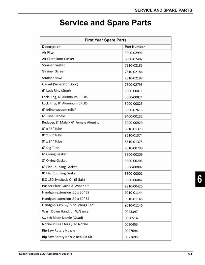
SERVICE AND SPARE PARTS
Super Products LLC Publication: 0004175 6-1
6
Service and Spare Parts
First Year Spare PartsDescription Part NumberAir Filter 3000-02991
Air Filter Door Gasket 6000-02482
Strainer Gasket 7310-02185Strainer Screen 7310-02186
Strainer Bowl 7310-02187
Gasket (Separator Door) 7300-02795
6" Lock Ring (Steel) 3000-00011
Lock Ring, 6" Aluminum CPLRS 3000-00824
Lock Ring, 8" Aluminum CPLRS 3000-00825
6" Inline vacuum relief 3000-02615
6" Tube Handle 9400-00132
Reducer, 8" Male X 6" Female Aluminum 3000-00929
8" x 36" Tube 8510-01373
8" x 60" Tube 8510-01374
8" x 84" Tube 8510-01375
6" Dig Tube 9010-00798
6" O-ring Gasket 3500-00206
8" O-ring Gasket 3500-00205
6" Flat Coupling Gasket 3500-00002
8" Flat Coupling Gasket 3500-00001
ISO 150 Synthetic Oil (5 Gal.) 3060-00047
Pusher Plate Guide & Wiper Kit 9810-00425
Handgun extension .50 x 30" SS 9010-01144
Handgun extension .50 x 60" SS 9010-01145
Handgun Assy, w/SS couplings 1/2” 9010-01146
Wash Down Handgun W/Lance 0023397
Switch Blade Nozzle (Quad) 0030514
Nozzle Pills #3 for Quad Nozzle 0030453
Rip Saw Rotary Nozzle 0027694
Rip Saw Rotary Nozzle Rebuild Kit 0027695

6-2 Super Products LLC Publication: 0004175
SERVICE AND SPARE PARTS
6
Super AccessoriesDescription Part NumberCone, Orange Safety 3000-03006Wrench, Hydrant 3000-01244Hose, (2.5" x 25' Red) Water Filler 3500-00219Hose, 6" Blue Water Discharge 3827-00000Coupler 6" Female Camlock W/Barb 0500-00011Clamp, Hose 5.63" To 6.50" 3000-00325Handgun (Only) 6000-01826Handgun Assy, w/ SS couplings 1/2" 9010-01146'Nozzle, Adjustable 6000-01875Turbo Nozzle, 8GPM@3000PSI 6000-02491Repair Kir, Turbo Nozzle 7310-03015Turbo Nozzle, 6GPM@3000PSI 0003955Nozzle, Rip Saw 5.2GPM@3000PSI #6 0027520Repair Kit, For 0027520 0027521Nozzle, Rip Saw 6.9GPM@3000PSI #8 0027518Repair Kit, For 0027518 0027519Nozzle, Rip Saw 8.7GPM@3000PSI #10 0026363Repair Kit, For 0026363 0026364Nozzle, Rip Saw 10.4GPM@3000PSI #12 0027694Repair Kit, For 0027694 0027695Switch Blade Quad Nozzle w/ #3 Pills 0028196Switch Blade Ace Body Only (1 port) 0030512Switch Blade Deuce Body Only (2 ports) 0030513Switch Blade Quad Body Only (4 ports) 0030514Nozzle Pill #1 0030451Nozzle Pill #2 0030452Nozzle Pill #3 0030453Nozzle Pill #4 0030266Nozzle Pill #5 0030458Nozzle Pill #6 0030459Nozzle Pill #8 0030265Nozzle Pill #10 0030460Nozzle Pill #12 00304621/8" NPT Plug 316 SS 0030463Oil, ISO 150 Synthetic 3060-00047Oil, Hydraulic, Chervon Rando Premium 3060-00048

SERVICE AND SPARE PARTS
Super Products LLC Publication: 0004175 6-3
6
Other Service PartsDescription Part NumberWater SystemWater Pump, General HF25 6000-02528Minor Rebuild Wet End Kit HF-25 7310-03385Major Rebuild Wet End Kit HF-25 7310-03387Suction Valve Kit, Water Pump (Set) 7310-02991Discharge Valve Kit, Water Pump (Set) 7310-02990Packing Kit, Water Pump HE25 (Set) 7310-02611Packing Kit, Water Pump HF25 (Set) 7310-03311Swivel, Hose Reel 7310-02200Brake, Hose Reel 7310-03253Hose Reel, W/O Hose 6000-02448Motor (Air), Hose Reel 7310-03068Hub, Hose Reel 7310-03067Strainer Assembly, Water 6000-01793Hose, (.50" X 100') For Hose Reel 3000-03248Hose (.50" X 50') 3643-60000Unloader 6000-02095Cover, Water Tank 7310-01873Gauge, Water Pressure 6000-01316Ball Valve, Bypass 6000-01150Ball Valve 1.5", Water Supply Shut Off 6000-01030-0007Ball Valve 3", Tank Drain 6000-02493Ball Valve Water Pump Drain 6000-01131Sight Glass, Water Tank Level 3000-01914Bulk Head Fitting, For Sight Glass 3500-00352Snap Ring, External For Pump Coupling 0030878Insert, (New style) Water Pump Coupling 0030922Coupling, 1/2 Q.D Male 6000-00685Coupling, 1/2 Q.D Male Straight Thru 6000-02486Coupling, 1/2 Q.D Female Straight Thru 6000-00684Coupling, 1/2 Female 6000-00975Dampener, Pulsation @1450PSI 0031456Tank, 20 Gallon Anti Freeze 3500-00679Filler Door Assembly, Water Tank 9010-00521
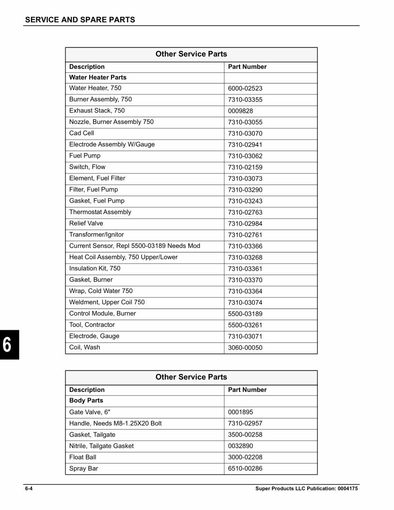
6-4 Super Products LLC Publication: 0004175
SERVICE AND SPARE PARTS
6
Other Service PartsDescription Part NumberWater Heater PartsWater Heater, 750 6000-02523Burner Assembly, 750 7310-03355Exhaust Stack, 750 0009828Nozzle, Burner Assembly 750 7310-03055Cad Cell 7310-03070Electrode Assembly W/Gauge 7310-02941Fuel Pump 7310-03062Switch, Flow 7310-02159Element, Fuel Filter 7310-03073Filter, Fuel Pump 7310-03290Gasket, Fuel Pump 7310-03243Thermostat Assembly 7310-02763Relief Valve 7310-02984Transformer/Ignitor 7310-02761Current Sensor, Repl 5500-03189 Needs Mod 7310-03366Heat Coil Assembly, 750 Upper/Lower 7310-03268Insulation Kit, 750 7310-03361Gasket, Burner 7310-03370Wrap, Cold Water 750 7310-03364Weldment, Upper Coil 750 7310-03074Control Module, Burner 5500-03189Tool, Contractor 5500-03261Electrode, Gauge 7310-03071Coil, Wash 3060-00050
Other Service PartsDescription Part NumberBody Parts
Gate Valve, 6" 0001895
Handle, Needs M8-1.25X20 Bolt 7310-02957
Gasket, Tailgate 3500-00258
Nitrile, Tailgate Gasket 0032890
Float Ball 3000-02208
Spray Bar 6510-00286

SERVICE AND SPARE PARTS
Super Products LLC Publication: 0004175 6-5
6
Cap, For Spray Bar 0024-00011
Nozzle, For Spray Bar 3000-02713
Nozzle, For Spray Bar 3000-02840
Spray Bar Assembly 0027221
Ejector Plate Guide & Wiper Kit, 2010-Present 9810-00425
Guide, Slide Plate 3500-00699
Gasket, 8" Inspection/Clean Out Door 3500-00189
Gasket, 8" Viton, Inspection/Clean Out Door 7310-03259
Mud Flap 3500-00674
Latch Rod, Tailgate 1010-00967
End Yoke, For Latch Rods 3000-01475
Jam Nut, For Latch Rods 0044-00008
Bolt, Latch 4510-00215
Assembly, Tailgate Roller 0002609
Prop, Body 0001143
Prop, Tailgate Safety 2010-00521
Other Service Parts
Other Service PartsDescription Part NumberBoom Parts8" x 128" Boom Hose, Elbow 0034847-051288" x 58" Boom Hose, Cannon 0034847-05058Cannon, Boom 8510-02997Seal, Boom 6000-01251Seal Retainer, Boom 4510-00190Gasket, V-Style 3000-03064Clamp, V-Style 3000-02276Tube, Inner Boom 112.94" 8510-03107Tube, Outer Boom 8510-02975

6-6 Super Products LLC Publication: 0004175
SERVICE AND SPARE PARTS
6
Plug, Port Hose 8" Male 8500-00284Boom Slider Kit 9810-00452Hose, End Port, Alum. 8500-03149Adapter, Hose End (Short) 0009556Adapter, Hose End (Long) 0009555Clamp, 8" Wire 0258-00007Clamp, 8" Double Bolt 3000-00136Bearing, Boom & (0004996) 0004996
Other Service Parts
Other Service PartsDescription Part NumberVacuum PartsFilter, Air 3000-02991Vacuum Gauge 6000-00524Gasket, Air Filter Housing 90" 0005155Blower, Roots 1125DVJ 6000-02217Seal, Drive, Roots 1125DVJ 7300-02622Wing Nut, Filter 8510-02157Gasket, Relief Valve 3500-00014Clamp, 10" Hose 3000-00139Cylinder, Vacuum Relief 6000-01314Air Valve, Vacuum Relief 6000-02286Hose, 8" X 108" Seperator to Debris Body 3906-06108Hose, 8" X 119" Seperator to Debris Body 3906-06119Cable, Transfer Case 7018-15600Transfer Case, OMSI 10810047-03 7000-00198
Other Service PartsDescription Part NumberCabinet PartsFan Assembly 7310-03060Heater Assembly 3000-02804Latch, Cabin Door LS 7310-03274Roller Assembly, 4 Rollers/Reel 3000-00347
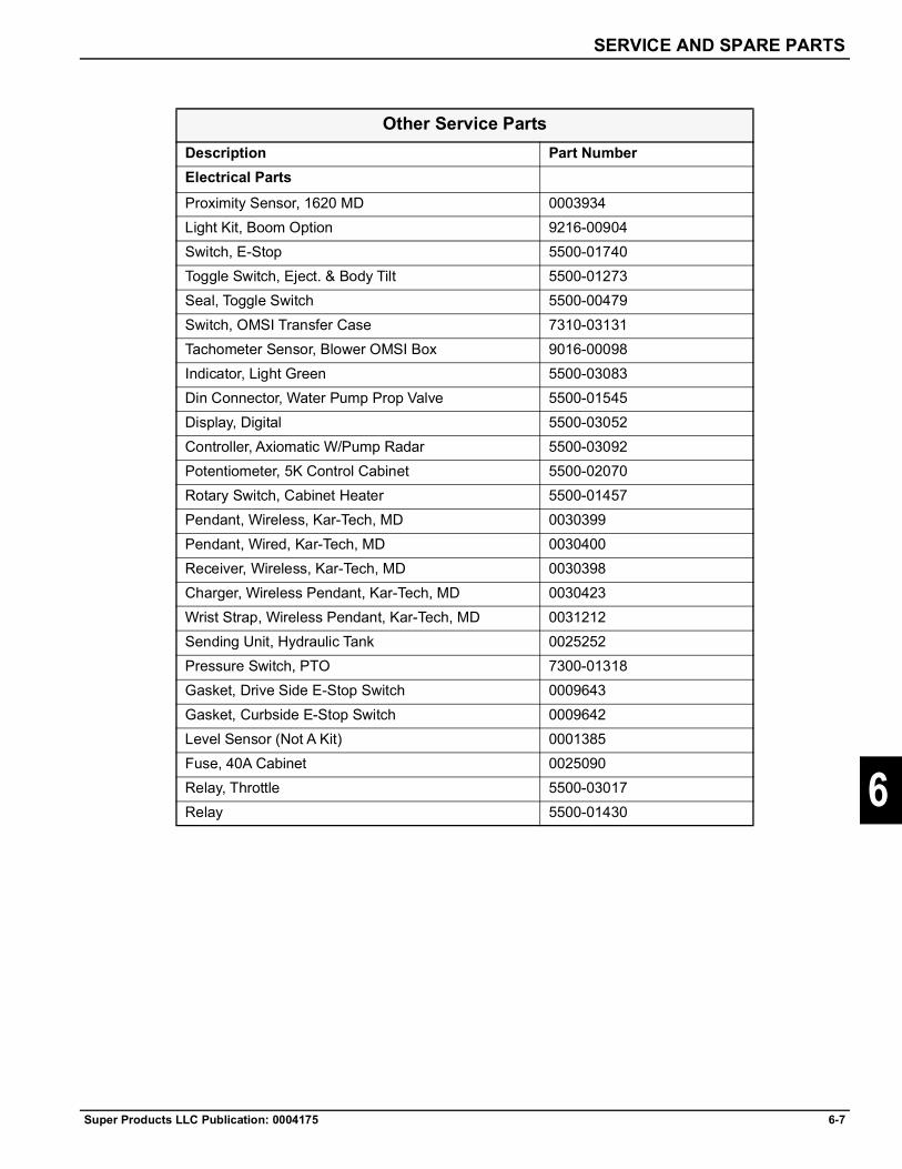
SERVICE AND SPARE PARTS
Super Products LLC Publication: 0004175 6-7
6
Other Service PartsDescription Part NumberElectrical PartsProximity Sensor, 1620 MD 0003934Light Kit, Boom Option 9216-00904Switch, E-Stop 5500-01740Toggle Switch, Eject. & Body Tilt 5500-01273Seal, Toggle Switch 5500-00479Switch, OMSI Transfer Case 7310-03131Tachometer Sensor, Blower OMSI Box 9016-00098Indicator, Light Green 5500-03083Din Connector, Water Pump Prop Valve 5500-01545Display, Digital 5500-03052Controller, Axiomatic W/Pump Radar 5500-03092Potentiometer, 5K Control Cabinet 5500-02070Rotary Switch, Cabinet Heater 5500-01457Pendant, Wireless, Kar-Tech, MD 0030399Pendant, Wired, Kar-Tech, MD 0030400Receiver, Wireless, Kar-Tech, MD 0030398Charger, Wireless Pendant, Kar-Tech, MD 0030423Wrist Strap, Wireless Pendant, Kar-Tech, MD 0031212Sending Unit, Hydraulic Tank 0025252Pressure Switch, PTO 7300-01318Gasket, Drive Side E-Stop Switch 0009643Gasket, Curbside E-Stop Switch 0009642Level Sensor (Not A Kit) 0001385Fuse, 40A Cabinet 0025090Relay, Throttle 5500-03017Relay 5500-01430
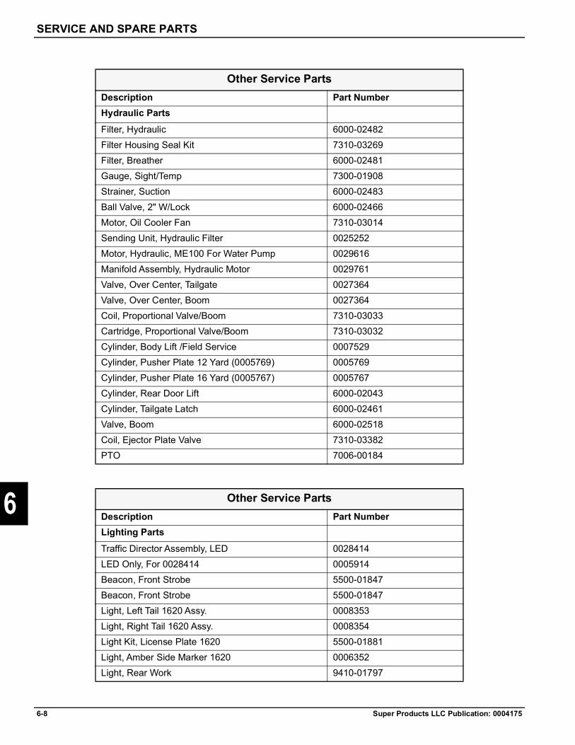
6-8 Super Products LLC Publication: 0004175
SERVICE AND SPARE PARTS
6
Other Service PartsDescription Part NumberHydraulic PartsFilter, Hydraulic 6000-02482Filter Housing Seal Kit 7310-03269Filter, Breather 6000-02481Gauge, Sight/Temp 7300-01908Strainer, Suction 6000-02483Ball Valve, 2" W/Lock 6000-02466Motor, Oil Cooler Fan 7310-03014Sending Unit, Hydraulic Filter 0025252Motor, Hydraulic, ME100 For Water Pump 0029616Manifold Assembly, Hydraulic Motor 0029761Valve, Over Center, Tailgate 0027364Valve, Over Center, Boom 0027364Coil, Proportional Valve/Boom 7310-03033Cartridge, Proportional Valve/Boom 7310-03032Cylinder, Body Lift /Field Service 0007529Cylinder, Pusher Plate 12 Yard (0005769) 0005769Cylinder, Pusher Plate 16 Yard (0005767) 0005767Cylinder, Rear Door Lift 6000-02043Cylinder, Tailgate Latch 6000-02461Valve, Boom 6000-02518Coil, Ejector Plate Valve 7310-03382PTO 7006-00184
Other Service PartsDescription Part NumberLighting PartsTraffic Director Assembly, LED 0028414LED Only, For 0028414 0005914Beacon, Front Strobe 5500-01847Beacon, Front Strobe 5500-01847Light, Left Tail 1620 Assy. 0008353Light, Right Tail 1620 Assy. 0008354Light Kit, License Plate 1620 5500-01881Light, Amber Side Marker 1620 0006352Light, Rear Work 9410-01797
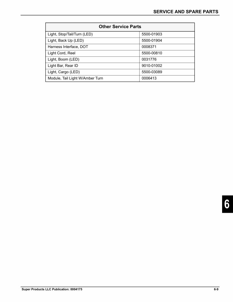
SERVICE AND SPARE PARTS
Super Products LLC Publication: 0004175 6-9
6
Light, Stop/Tail/Turn (LED) 5500-01903Light, Back Up (LED) 5500-01904Harness Interface, DOT 0008371Light Cord, Reel 5500-00810Light, Boom (LED) 0031776Light Bar, Rear ID 9010-01002Light, Cargo (LED) 5500-03089Module, Tail Light W/Amber Turn 0006413
Other Service Parts


Index
Super Products LLC Publication: 0004175 Index-i
7
A
Air Conveyance 2-3
Arrange for Traffic Control 1-14
B
Before Performing Service, Repairs, and Maintenance on the Equipment 1-35
Before Transporting Truck Inspection 1-12
Biological Hazards 1-11
Blower Temperature Sensor (Option) 2-5
C
Chemical and Biological Hazard Safety 1-11
Chemical Waste Hazard 1-11
Chemicals and Diesel Engine Exhaust 1-11
Confined Space Hazard 1-32
Controlling Lower Explosive Level (LEL) 1-27
Crushing Hazards and Prevention Safety 1-7
D
Debris Body Dumping Safety and Hazard Warnings 1-31
Debris Body Prop Support 1-7
Debris Body Tailgate Props 1-52
Decal Location 1-36
De-Energize and Lockout Procedures 1-34
DEF Maintenance 4-2
Determine Maximum Turning Speed Before Operating on Roads or Uneven Ground 1-13
Determine Stopping Characteristics of Truck for Transporting Braking Tests 1-13
Dust Hazard 1-11
Dust Hazard and Explosion Prevention Safety 1-26
E
Emergency Stop Button Function 1-16
Equipment Guards 1-6
F
Fire Extinguisher 1-15
G
General Hazards and Prevention Safety 1-5
General Safety Instructions and Practices 1-1
H
Hazards with Equipment Maintenance 1-35
High Water Pressure 1-25
High-Pressure Fluid Leaks 1-9
High-Pressure Water Safety and Hazard Warnings 1-24
High-Temperature Prevention 1-28
Hot Surface 1-6
Hydrocarbon Waste Recovery 1-27
I
Inspect the Job Site 1-15
Introduction 2-1
Index

Index-ii Super Products LLC Publication: 0004175
Index
7
J
Job Site Safety and Hazard Warnings 1-14
L
Lowering the Debris Body Tailgate and Storing the Props 1-52
Lubrication and Maintenance General Information 4-1
Lubrication Recommendation Chart 4-1
M
Mechanical Troubleshooting 5-2
Mounting and Dismounting Truck or Equipment 1-6
N
Never Exceed your Gross Vehicle Weight Rating (GVWR) 1-12
O
Operating the Remote-Operated Vacuum Relief Valve 1-21
Operating the T-Type Vacuum Relief Valve 1-19
Overhead Power Line Tips for Construction Workers Before You Begin Construction Work 1-10
P
Pedestrian Safety 1-12
Performing Service, Repairs, Lubrication, and Maintenance 1-35
Personal Protection Equipment (PPE) 1-3
Plan for Emergency Services 1-14
Power Distribution Panel 3-1
Power Lines/Static Electrical Hazard Warnings 1-10
Preparation Before Traveling to Worksite 1-53
Prepare for Working Near Existing Utilities 1-14
Prepare the Job Site 1-15
Pre-Start Checklist 1-18
Preventive Maintenance Instructions 4-1
Principles of Operation 2-1
Pure Vacuum 2-3
S
Safety Shields, Guards, and Safety Devices Inspection 1-35
Safety Signs 1-6
Service and Spare Parts 6-1
Sewer Gas Hazard 1-11
Sewer Gas Safety and Hazard Warnings 1-32
Spark and Fire Prevention Safety 1-30
Static Charge Dissipation 1-29
T
Tailgate Prop Support 1-7
Testing of the Remote Operated Vacuum Vent Door 2-7
Testing the Remote-Operated Vacuum Relief Valve 1-23
Testing the T-Type Vacuum Relief Valve 1-20
The Basic Troubleshooting Process 5-1
To Help Avoid Injury 1-14
To Restore Power 1-17
Transport Safety and Hazards Warnings 1-12
Trenching Hazards 1-33
Trip and Fall Prevention Safety 1-8
Troubleshooting Overview 5-1
Truck Tip Over 1-7
U
Unlocking the Tailgate Props and Raising the Debris Body Tailgate 1-52

Index
Super Products LLC Publication: 0004175 Index-iii
7
V
Vacuum Equipment Operation Safety and Hazard Warnings 1-16
Vacuum Operation 1-18
Vacuum Operation Safety 1-17
Vacuum Relief Valve Safety 1-19
Vacuum Relief Valves 1-19
Vacuum System 2-3
Visibility Conditions When Operating 1-6, 1-15
Visual Attention Safety 1-2
W
Water System 2-7
When Transporting Equipment 1-13
When Using Pressurized Air or Water 1-4
Working with Tools and Equipment 1-10


Contact Super Products if you require additional information regarding the operation of your Mud Dog Vacuum Excavator.
Super Products LLC Publication: 0004175 ©2020 Super Products LLC 4/2020
130 W BOXHORN DR. MUKWONAGO, WI 53149 • P: 800.837.9711 • www.superproductsllc.com