Mini Driver MP9
23
CUSTOMER SUPPORT INFORMATION Order toll-free in the U.S. 24 hours, 7 A.M. Monday to midnight Friday: 877-877-BBOX FREE technical support, 24 hours a day, 7 days a week: Call 724-746-5500 or fax 724-746-0746 Mail order: Black Box Corporation, 1000 Park Drive, Lawrence, PA 15055-1018 Web site: www.blackbox.com • E-mail: [email protected] JUNE 1997 ME775A-FSP ME775A-MSP ME776A-FSP ME776A-MSP ME777A-FSP ME777A-MSP Mini Driver MP9 Mini Driver MP
-
Upload
khangminh22 -
Category
Documents
-
view
1 -
download
0
Transcript of Mini Driver MP9

CUSTOMERSUPPORT
INFORMATION
Order toll-free in the U.S. 24 hours, 7 A.M. Monday to midnight Friday: 877-877-BBOXFREE technical support, 24 hours a day, 7 days a week: Call 724-746-5500 or fax 724-746-0746Mail order: Black Box Corporation, 1000 Park Drive, Lawrence, PA 15055-1018Web site: www.blackbox.com • E-mail: [email protected]
JUNE 1997ME775A-FSPME775A-MSPME776A-FSPME776A-MSPME777A-FSPME777A-MSP
Mini Driver MP9
Mini DriverMP

2
MINI DRIVER MP9
FEDERAL COMMUNICATIONS COMMISSIONAND
INDUSTRY CANADARADIO FREQUENCY INTERFERENCE STATEMENTS
This equipment generates, uses, and can radiate radio frequency energy and if not installed and used properly, that is, in strict accordance with themanufacturer’s instructions, may cause interference to radio communication.It has been tested and found to comply with the limits for a Class Acomputing device in accordance with the specifications in Subpart J of Part 15 of FCC rules, which are designed to provide reasonable protectionagainst such interference when the equipment is operated in a commercialenvironment. Operation of this equipment in a residential area is likely tocause interference, in which case the user at his own expense will be requiredto take whatever measures may be necessary to correct the interference..Changes or modifications not expressly approved by the party responsible for compliance could void the user’s authority to operate the equipment.
This digital apparatus does not exceed the Class A limits for radio noise emission fromdigital apparatus set out in the Radio Interference Regulation of Industry Canada.
Le présent appareil numérique n’émet pas de bruits radioélectriques dépassant les limitesapplicables aux appareils numériques de classe A prescrites dans le Règlement sur lebrouillage radioélectrique publié par Industrie Canada.
CE NOTICEThe CE symbol on your Mini Driver MP9 indicates that it is in compliancewiththe Electromagnetic Compatibility (EMC) directive and the Low VoltageDirective (LVD) of the Union European (EU).
TRADEMARKS USED IN THIS MANUALAll applied-for and registered trademarks are the property of their respectiveowners.

3
NOM STATEMENT
NORMAS OFICIALES MEXICANAS (NOM)ELECTRICAL SAFETY STATEMENT
INSTRUCCIONES DE SEGURIDAD
1. Todas las instrucciones de seguridad y operación deberán ser leídas antesde que el aparato eléctrico sea operado.
2. Las instrucciones de seguridad y operación deberán ser guardadas parareferencia futura.
3. Todas las advertencias en el aparato eléctrico y en sus instrucciones deoperación deben ser respetadas.
4. Todas las instrucciones de operación y uso deben ser seguidas.
5. El aparato eléctrico no deberá ser usado cerca del agua—por ejemplo,cerca de la tina de baño, lavabo, sótano mojado o cerca de una alberca,etc..
6. El aparato eléctrico debe ser usado únicamente con carritos o pedestalesque sean recomendados por el fabricante.
7. El aparato eléctrico debe ser montado a la pared o al techo sólo comosea recomendado por el fabricante.
8. Servicio—El usuario no debe intentar dar servicio al equipo eléctrico másallá a lo descrito en las instrucciones de operación. Todo otro serviciodeberá ser referido a personal de servicio calificado.
9. El aparato eléctrico debe ser situado de tal manera que su posición nointerfiera su uso. La colocación del aparato eléctrico sobre una cama,sofá, alfombra o superficie similar puede bloquea la ventilación, no sedebe colocar en libreros o gabinetes que impidan el flujo de aire por losorificios de ventilación.
10. El equipo eléctrico deber ser situado fuera del alcance de fuentes decalor como radiadores, registros de calor, estufas u otros aparatos(incluyendo amplificadores) que producen calor.

4
MINI DRIVER MP9
11. El aparato eléctrico deberá ser connectado a una fuente de poder sólodel tipo descrito en el instructivo de operación, o como se indique en elaparato.
12. Precaución debe ser tomada de tal manera que la tierra fisica y lapolarización del equipo no sea eliminada.
13. Los cables de la fuente de poder deben ser guiados de tal manera que nosean pisados ni pellizcados por objetos colocados sobre o contra ellos,poniendo particular atención a los contactos y receptáculos donde salendel aparato.
14. El equipo eléctrico debe ser limpiado únicamente de acuerdo a lasrecomendaciones del fabricante.
15. En caso de existir, una antena externa deberá ser localizada lejos de laslineas de energia.
16. El cable de corriente deberá ser desconectado del cuando el equipo nosea usado por un largo periodo de tiempo.
17. Cuidado debe ser tomado de tal manera que objectos liquidos no seanderramados sobre la cubierta u orificios de ventilación.
18. Servicio por personal calificado deberá ser provisto cuando:
A: El cable de poder o el contacto ha sido dañado; u
B: Objectos han caído o líquido ha sido derramado dentro delaparato; o
C: El aparato ha sido expuesto a la lluvia; o
D: El aparato parece no operar normalmente o muestra un cambio en sudesempeño; o
E: El aparato ha sido tirado o su cubierta ha sido dañada.
5
CONTENTS
ContentsChapter Page
1. Specifications....................................................................................................6
2. Introduction .....................................................................................................8
3. Configuration ...................................................................................................93.1 Accessing the DIP Switches.......................................................................9
3.1.1 Switch S1 Settings ........................................................................113.1.2 Switch S2 Settings ........................................................................12
3.2 Typical Applications................................................................................13
4. Installation......................................................................................................154.1 Twisted-Pair Connection.........................................................................15
4.1.1 Twisted-Pair Connection Using Terminal Blocks .....................154.1.2 Twisted-Pair Connection Using RJ-11 or RJ-45..........................19
4.2 Wiring for Multipoint Circuits................................................................214.2.1 Star Topology ..............................................................................214.2.2 Daisychain Topology...................................................................21
4.3 Connection to the EIA/TIA-574 Interface ............................................22
5. Operation .......................................................................................................23

6
MINI DRIVER MP9
Protocol — Asynchronous
Range — Up to 15 miles
Data Rates — Up to 115,200 bps
Serial Interface — DB9, male or female; wired as a DCEaccording to EIA/TIA-574 standard
Multipoint — 50 drops
Operation — 2- or 4-wire, half- or full-duplex
RTS/CTS Delay — 8 msec or No Delay
Connectors — All: (1) DB9 male or female; ME775A:(1) 5-screw terminal; ME776A: (1) RJ-11; ME777A: (1) RJ-45
Control Signals — DSR turns “ON” immediately after theterminal raises DTR; DCD turns “ON”after recognizing the receive signal fromthe line; CTS turns “ON” after theterminal raises RTS.
Surge Protection — 600W power dissipation at 1 ms
Carrier — Constantly On or Controlled by RTS
MTBF — 209,384 hours
MTTR — 1 hour
Operating Temperature — 32 to 122°F (0 to 50°C)
Relative Humidity — 5 to 95%, noncondensing
Altitude Tolerance — Up to 10,000 feet (3048 m)
Compliance — CE
1. Specifications
7
CHAPTER 1: Specifications
Power — Draws operating power from EIA/TIA-574 data and control signals; no ACpower or batteries required. If necessary,6 to 12 VDC can be applied to pin 9 ofthe EIA/TIA-574 interface.
Size — 2.5"H x 1.2"W x 0.75"D (6.4 x 3 x 1.9 cm)
Weight — 0.2 lb. (0.1 kg)
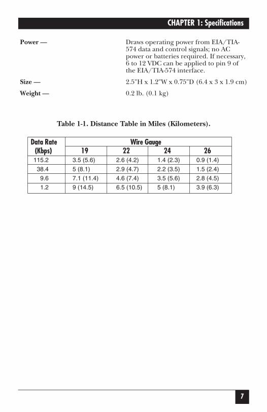
Table 1-1. Distance Table in Miles (Kilometers).
Data Rate Wire Gauge(Kbps) 19 22 24 26115.2 3.5 (5.6) 2.6 (4.2) 1.4 (2.3) 0.9 (1.4)
38.4 5 (8.1) 2.9 (4.7) 2.2 (3.5) 1.5 (2.4)
9.6 7.1 (11.4) 4.6 (7.4) 3.5 (5.6) 2.8 (4.5)
1.2 9 (14.5) 6.5 (10.5) 5 (8.1) 3.9 (6.3)

8
MINI DRIVER MP9
The Mini Driver MP9 is an asynchronous short-range modem that connectsto DB9 RS-232 interfaces. The Driver supports EIA/TIA-574 data rates up to 115.2 Kbps over one or two unconditioned twisted pairs. Distances up to15 miles are attainable at lower data rates (1.2 Kbps, 19 AWG twisted pair).Since the Driver is powered from the interface, it requires no AC power orbatteries for operation.
The Mini Driver MP9 can handle up to 50 terminal drops in a multipointpolling environment. For RS-485 and serial-printer applications requiringhardware handshaking, the Mini Driver passes one control signal in eachdirection. The Mini Driver may be configured for high or low impedance,the carrier may be set to “constantly on” or “controlled by RTS,” and the unitcan operate with or without “echo.” RTS/CTS delay may be set for “no delay”or 8 ms.
Options for twisted-pair connection include terminal blocks with strain relief,RJ-11, and RJ-45 connectors. Silicon Avalanche Diodes provide 600 watts perwire of protection against harmful data-line transient surges.
2. Introduction
9
CHAPTER 3: Configuration
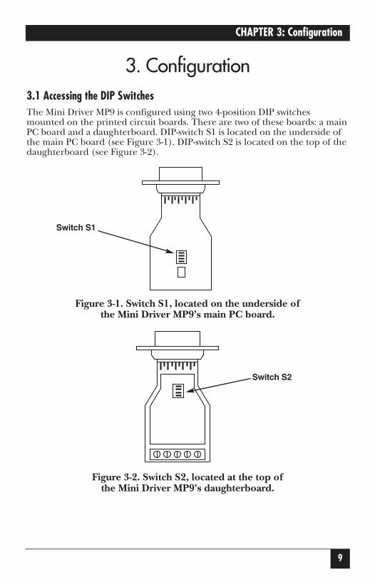
3.1 Accessing the DIP SwitchesThe Mini Driver MP9 is configured using two 4-position DIP switchesmounted on the printed circuit boards. There are two of these boards: a mainPC board and a daughterboard. DIP-switch S1 is located on the underside ofthe main PC board (see Figure 3-1). DIP-switch S2 is located on the top of thedaughterboard (see Figure 3-2).
Figure 3-1. Switch S1, located on the underside ofthe Mini Driver MP9’s main PC board.
Figure 3-2. Switch S2, located at the top of the Mini Driver MP9’s daughterboard.
3. Configuration
Switch S1
Switch S2

10
MINI DRIVER MP9
To access the Mini Driver MP9’s main PC board and daughterboard, inserta small flat-blade screwdriver between the connector and the lip of the case(see Figure 3-3) and gently pry open the case.
Figure 3-3. Opening the Mini Driver MP9’s plastic case with a small screwdriver.
Both DIP-switch S1 and S2 are marked with individual switch numbers 1through 4. Use these numbers, as well as the “ON” designation to set theswitch properly (see Figure 3-4). Use a small screwdriver or similar instrumentto set each individual switch.
Figure 3-4. Closeup of a DIP switch. All four switches are ON.

11
CHAPTER 3: Configuration
3.1.1 SWITCH S1 SETTINGS
DIP-switch S1 is used to configure receive impedance, 2-/4-wire operation and “echo” enable/disable. The table below shows the factory-default settings(printed in bold type) for switch S1. Following the table is a description ofeach individual switch.
Table 3-1. Switch S1 summary. Factory defaults are shown in bold.
Position Function ON Position OFF PositionS1-1 RCV Impedance 120 ohms 16K ohms typical
S1-2* 2-/4-wire 2-wire 4-wire
S1-3* 2-/4-wire 2-wire 4-wire
S1-4 Echo Mode Echo ON Echo OFF
*Note: Switches S1-2 and S1-3 should be switched simultaneously.
S1-1: Receive ImpedanceThe setting for switch S1-1 selects the impedance of the input receiver. Youcan select either a “low” impedance of 120 ohms or a “high” impedance of16K ohms. By selecting the proper impedance for each drop (see Table 3-3),there may be up to 50 receivers in one application.
S1-1 SettingOn Low (120 ohms)Off High (16K ohms typical)
S1-2 and S1-3: 2-/4-Wire ModesSwitches S1-2 and S1-3 are set together to determine whether the Mini DriverMP9 is in 2-wire or 4-wire operating mode. Note: 2-wire mode is half-duplexonly.
S1-2 S1-3 SettingOn On 2-wire modeOff Off 4-wire mode

12
MINI DRIVER MP9
S1-4: Echo ModeThe setting for switch S1-4 determines whether the Mini Driver MP9 echoesdata back to the transmitting device (half-duplex mode only).
S1-4 SettingOn Echo OnOff Echo Off
3.1.2 SWITCH S2 SETTINGS
DIP-switch S2 is used to configure carrier control, RTS/CTS delay, andcommunication protocol. The table below shows the factory-default settings(printed in bold type) for switch S2. Following the table is a description ofeach individual switch.
Table 3-2. Switch S2 summary. Factory defaults are shown in bold.
Position Function ON Position OFF PositionS2-1 Carrier Control RTS Constantly ON
S2-2 RTS/CTS Delay 8 ms No Delay
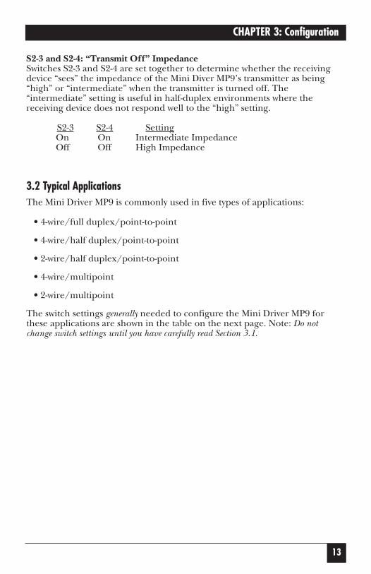
S2-3* “XMT Off” Impedance Intermediate High
S2-4* “XMT Off” Impedance Intermediate High
*Note: Switches S2-3 and S2-4 should be switched simultaneously.
S2-1: Carrier Control MethodThe setting for switch S2-1 determines whether the carrier is “Constantly On”or “Controlled by RTS.” This setting allows for operation in switched-carrier,multipoint, or hardware-handshaking applications.
S2-1 SettingOn Controlled by RTSOff Constantly On
S2-2: RTS/CTS DelayThe switch setting for switch S2-2 determines the amount of delay betweenthe time the Mini Driver MP9 “sees” RTS and when it sends CTS. Note:RTS/CTS Delay setting should be based on transmission timing.
S2-2 SettingOn 8 msecOff No delay
13
CHAPTER 3: Configuration
S2-3 and S2-4: “Transmit Off” ImpedanceSwitches S2-3 and S2-4 are set together to determine whether the receivingdevice “sees” the impedance of the Mini Diver MP9’s transmitter as being“high” or “intermediate” when the transmitter is turned off. The“intermediate” setting is useful in half-duplex environments where thereceiving device does not respond well to the “high” setting.
S2-3 S2-4 SettingOn On Intermediate ImpedanceOff Off High Impedance
3.2 Typical ApplicationsThe Mini Driver MP9 is commonly used in five types of applications:
• 4-wire/full duplex/point-to-point
• 4-wire/half duplex/point-to-point
• 2-wire/half duplex/point-to-point
• 4-wire/multipoint
• 2-wire/multipoint
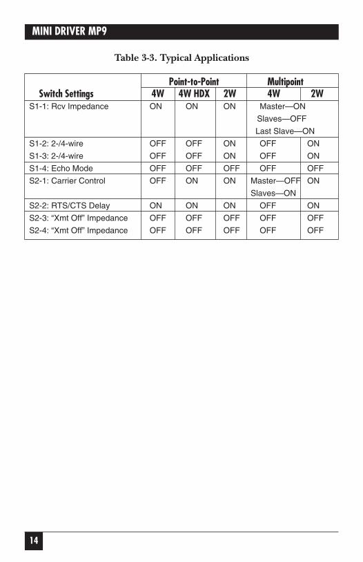
The switch settings generally needed to configure the Mini Driver MP9 forthese applications are shown in the table on the next page. Note: Do notchange switch settings until you have carefully read Section 3.1.
14
MINI DRIVER MP9
Table 3-3. Typical Applications
Point-to-Point MultipointSwitch Settings 4W 4W HDX 2W 4W 2W
S1-1: Rcv Impedance ON ON ON Master—ON
Slaves—OFF
Last Slave—ON
S1-2: 2-/4-wire OFF OFF ON OFF ON
S1-3: 2-/4-wire OFF OFF ON OFF ON
S1-4: Echo Mode OFF OFF OFF OFF OFF
S2-1: Carrier Control OFF ON ON Master—OFF ON
Slaves—ON
S2-2: RTS/CTS Delay ON ON ON OFF ON
S2-3: “Xmt Off” Impedance OFF OFF OFF OFF OFF
S2-4: “Xmt Off” Impedance OFF OFF OFF OFF OFF

15
CHAPTER 4: Installation
Once the Mini Driver MP9 is properly configured, it is ready to connect toyour system.
4.1 Twisted-Pair ConnectionThe Mini Driver MP9 supports 2- or 4-wire communication between two ormore EIA/TIA-574 devices at data rates up to 115.2 Kbps. There are twoessential requirements for installing the Mini Driver MP9.
1) These units work in pairs. Therefore, you must have one Mini Driver MP9at each end of a two twisted-pair interface. In multipoint environments,there must be one Mini Driver MP9 at the EIA/TIA-574 host and one ateach EIA/TIA-574 terminal.
2) To function properly, the Mini Driver MP9 needs two twisted pairs ofmetallic wire. These pairs must be unconditioned dry metallic wire, between19 and 26 AWG (the higher number gauges may limit distance). Standarddial-up telephone circuits, or leased circuits that run through signalequalization equipment, are not acceptable.
For your convenience, the Mini Driver MP9 is available with several differenttwisted-pair interfaces: RJ-11 jack, RJ-45 jack, and terminal blocks with strainrelief.
4.1.1 TWISTED-PAIR CONNECTION USING TERMINAL BLOCKS
If your application requires you to connect one or two pairs of bare wires tothe Mini Driver MP9, you will need to open the case to access the terminalblocks. The instructions on the next page will tell you how to connect thebare wires to the terminal blocks and fasten the strain-relief collar in place so the wires won’t pull loose.
4. Installation

16
MINI DRIVER MP9
1. You should already have the case open for the configuration procedure. If not, refer to Section 3.1.
2. Strip the outer insulation from the twisted pair(s) about one inch fromthe end.
3. Strip the insulation on each of the twisted-pair wires about 0.25".
4. In a two-pair circuit, connect one pair of wires to XMT+ and XMT-(transmit positive and negative) on the terminal block, making carefulnote of which color is positive and which color is negative.
5. Connect the other pair of wires to RCV+ and RCV- (receive positive andnegative) on the terminal block, again making careful note of which coloris positive and which color is negative.
Ultimately, you will want to construct a two-pair crossover cable thatmakes a connection with the two Mini Driver MP9s as shown below.
XMT+XMT- GRCV-RCV+
- - - - - - - - - GRCV- - - - - - - - - - - - - - - - - - - - - -
- - - - - - - - - - - - - - - - - - - - - RCV+
To Shield (Optional)
- - - - - - - - - - - - - - - - - - - - - XMT-- - - - - - - - - - - - - - - - - - - - - XMT+
One Pair
One Pair
G

17
CHAPTER 4: Installation
6. In a single-pair circuit, use only the transmit (XMT) pair as shown below:
XMT+ --------------------------------------------------------------- XMT+XMT- ----------------------------------------------------------------- XMT-
NOTEIf there is a shield around the telephone cable, it may be connected to“G” on the terminal block. To avoid ground loops, we recommendconnecting the shield at the computer end only. A ground wire is notnecessary for proper operation of the Mini Driver MP9.
7. When you finish connecting the wires to the terminal block, the assemblyshould look like this:
8. Place the two halves of the strain-relief assembly on either side of thetelephone wire and press together very lightly. Slide the assembly so thatit is about 2 inches from the terminal posts and press together firmly.
9. Insert the strain-relief assembly with the wire going through it into theslot in the bottom half of the modem case and set it into the recess of the case.

18
MINI DRIVER MP9
10. Bend the top half of the case as necessary to place it over the strain-reliefassembly. Do not snap the case together yet.
11. Insert one captive screw through a saddle washer, and then insert thecaptive screw with the washer on it through the hole in the DB9 end ofthe case. Snap that side of the case closed. Repeat the process for theother side. The cable is installed.

19
CHAPTER 4: Installation
4.1.2 TWISTED-PAIR CONNECTION USING RJ-11 OR RJ-45The RJ-11 and RJ-45 connectors on the Mini Driver MP9’s twisted-pairinterface are pre-wired for a standard telco wiring environment. Thesignal/pin relationships are shown below.
RJ-11 Signal RJ-45 Signal1 ......................GND* 1......................N/C
2 ......................RCV- 2......................GND
3 ......................XMT+ 3......................RCV-
4 ......................XMT- 4......................XMT+
5 ......................RCV+ 5......................XMT-
6 ......................GND 6......................RCV+
7......................GND
8......................N/C
* Connection to ground is optional.
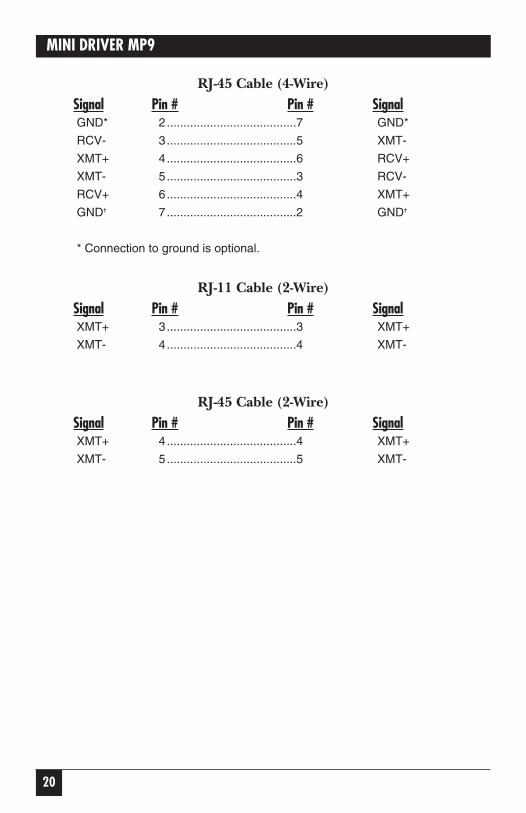
When connecting two Mini Driver MP9s, you must use a crossover cable. The pinouts below show how a crossover cable should be constructed forthe following environments: 4-wire RJ-11, 4-wire RJ-45, 2-wire RJ-11, and 2-wire RJ-45.
RJ-11 Cable (4-Wire)Signal Pin # Pin # SignalGND* 1.......................................6 GND*
RCV- 2.......................................4 XMT-
XMT+ 3.......................................5 RCV+
XMT- 4.......................................2 RCV-
RCV+ 5.......................................3 XMT+
GND✝ 6.......................................1 GND✝
* Connection to ground is optional.
20
MINI DRIVER MP9
RJ-45 Cable (4-Wire)Signal Pin # Pin # SignalGND* 2.......................................7 GND*
RCV- 3.......................................5 XMT-
XMT+ 4.......................................6 RCV+
XMT- 5.......................................3 RCV-
RCV+ 6.......................................4 XMT+
GND✝ 7.......................................2 GND✝
* Connection to ground is optional.
RJ-11 Cable (2-Wire)Signal Pin # Pin # SignalXMT+ 3.......................................3 XMT+
XMT- 4.......................................4 XMT-
RJ-45 Cable (2-Wire)Signal Pin # Pin # SignalXMT+ 4.......................................4 XMT+
XMT- 5.......................................5 XMT-

21
CHAPTER 4: Installation
4.2 Wiring for Multipoint CircuitsThe Mini Driver MP9 supports multipoint applications using either a star ordaisychain topology. Both topologies require special wiring, as well as specificDIP-switch settings for master and slave units.
4.2.1 STAR TOPOLOGY
Using a star topology, you may connect several Mini Driver MP9s together in a master/slave arrangement. Maximum distance between the units will varybased upon the number of drops, data rate, wire gauge, etc. Call Black Boxfor specific distance estimates.
The figure below shows how to wire the two-pair cables properly for a MiniDriver MP9 star topology. Note that the ground connection is not needed.
Host First Slave Second Slave
XMT+ ---------------------------- RCV+
------------------------------------------------------- RCV+
XMT- ----------------------------- RCV-
------------------------------------------------------- RCV-
RCV+ ---------------------------- XMT+
------------------------------------------------------- XMT+
RCV- ----------------------------- XMT-
------------------------------------------------------- XMT-
4.2.2 DAISYCHAIN TOPOLOGY
With a daisychain topology, you can connect several Mini Driver MP9stogether in a master/slave arrangement. Maximum distance between theunits will vary based upon the number of drops, data rate, wire gauge, etc.Call Black Box for specific distance estimates.
The figure on the next page shows how to wire the two-pair cables properlyfor a Mini Driver MP9 daisychain topology. Note that the ground connection

22
MINI DRIVER MP9
is not needed.
Host First Slave Other Slave(s)
XMT+ -------------------------- RCV+ ----------------------------- RCV+
XMT- -------------------------- RCV- ----------------------------- RCV-
RCV+ -------------------------- XMT+ ----------------------------- XMT+
RCV- -------------------------- XMT- ----------------------------- XMT-
4.3 Connection to the EIA/TIA-574 InterfaceThe Mini Driver MP9 is designed to plug directly into the DB9 serial port of an EIA/TIA-574 DTE device (PC, laptop, host). If you must use a cable to connect the Mini Driver MP9 to the DTE device, make sure that it is astraight-through cable of the shortest possible length—we recommend 6 feet (1.8 m) or less. The DB9 connector on the Mini Driver MP9 is wiredaccording to the EIA/TIA-574 standard, as shown below.
EIA/TIA-574 Standard
DB9 Signal
1...............................CD
2...............................RD
3...............................TD
4...............................DTR
5...............................SG/FG
6...............................DSR
7...............................RTS
8...............................CTS
9...............................(Optional 6- to 12-VDC power)
NOTEThe Mini Driver MP9 is configured as a DCE (Data CommunicationsEquipment), and is therefore designed to connect to a DTE (DataTerminal Equipment). If you need to connect the Mini Driver MP9 toanother DCE device, call Black Box for details on constructing the propercrossover cable.

23
CHAPTER 5: Operation
Once the Mini Driver MP9 is properly installed, it should operate trans-parently—as if it were a standard cable connection. Operating power isderived from the RS-232 data and control signals; there is no “ON/OFF”switch. All data signals from the RS-232 and RS-485 interfaces are passedstraight through.
5. Operation