Hydraulic Structures
100
Hydraulic structures University of Diyala , College of Engineering, Civil Engineering Department 1 Hydraulic Structures
-
Upload
khangminh22 -
Category
Documents
-
view
1 -
download
0
Transcript of Hydraulic Structures

Hydraulic structures
University of Diyala , College of Engineering, Civil Engineering Department
1
Hydraulic Structures

Hydraulic structures
University of Diyala , College of Engineering, Civil Engineering Department
2
Theories of Seepage
Causes of failure of weir or barrage on permeable foundation:
I- FAILURE DUE TO SUBSURFACE FLOW
A. Failure by Piping or undermining
The water from the upstream side continuously percolates through the
bottom of the foundation and emerges at the downstream end of the weir
or barrage floor. The force of percolating water removes the soil particles
by scouring at the point of emergence. As the process of removal of soil
particles goes on continuously, a depression is formed which extends
backwards towards the upstream through the bottom of the foundation. A
hollow pipe like formation thus develops under the foundation due to
which the weir or barrage may fail by subsiding. This phenomenon is
known as failure by piping or undermining.
B. Failure by Direct uplift
The percolating water exerts an upward pressure on the foundation of the
weir or barrage. If this uplift pressure is not counterbalanced by the self-
weight of the structure, it may fail by rapture.
II- FAILURE BY SURFACE FLOW
1. By hydraulic jump
When the water flows with a very high velocity over the crest of the weir
or over the gates of the barrage, then hydraulic jump develops. This
hydraulic jump causes a suction pressure or negative pressure on the
downstream side which acts in the direction uplift pressure. If the
thickness of the impervious floor is sufficient, then the structure fails by
rapture.
Hydraulic structures
University of Diyala , College of Engineering, Civil Engineering Department
3
2. By scouring
During floods, the gates of the barrage are kept open and the water flows
with high velocity. The water may also flow with very high velocity over
the crest of the weir. Both the cases can result in scouring effect on the
downstream and on the upstream side of the structure. Due to scouring of
the soil on both sides of the structure, its stability gets endangered by
shearing.
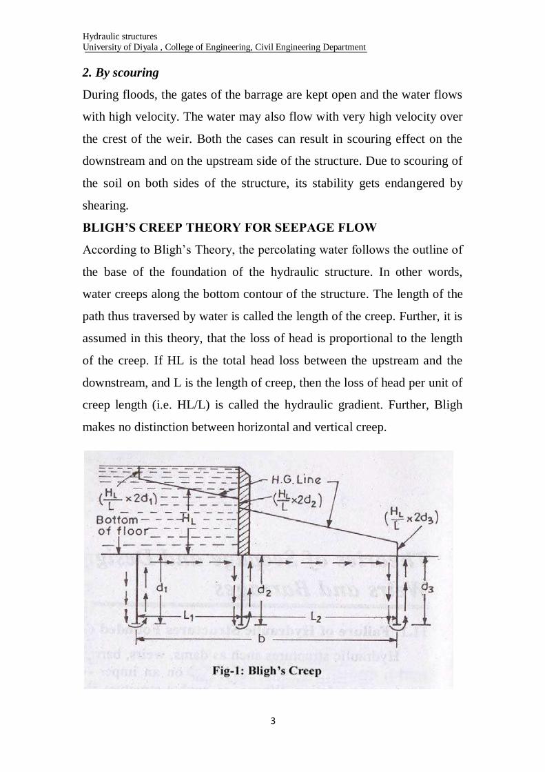
BLIGH’S CREEP THEORY FOR SEEPAGE FLOW
According to Bligh’s Theory, the percolating water follows the outline of
the base of the foundation of the hydraulic structure. In other words,
water creeps along the bottom contour of the structure. The length of the
path thus traversed by water is called the length of the creep. Further, it is
assumed in this theory, that the loss of head is proportional to the length
of the creep. If HL is the total head loss between the upstream and the
downstream, and L is the length of creep, then the loss of head per unit of
creep length (i.e. HL/L) is called the hydraulic gradient. Further, Bligh
makes no distinction between horizontal and vertical creep.

Hydraulic structures
University of Diyala , College of Engineering, Civil Engineering Department
4
Consider a section as shown in Fig above. Let HL be the difference of
water levels between upstream and downstream ends. Water will seep
along the bottom contour as shown by arrows. It starts percolating at A
and emerges at B. The total length of creep is given by
L = d1 + d1 + L1 + d2 + d2 + L2 + d3 + d3
= (L1+ L2) + 2(d1 + d2 + d3)
= b + 2(d1 + d2 + d3)
Head loss per unit length or hydraulic gradient =
Head losses equal to( ),( ), ( ) ; will occur respectively, in the planes of
three vertical cut offs. The hydraulic gradient line (H.G. Line) can then be
drawn as shown in figure above.
SAFETY AGAINST PIPING OR UNDERMINING:
According to Bligh, the safety against piping can be ensured by providing
sufficient creep length, given by L = C.HL, where C is the Bligh’s
Coefficient for the soil. Different values of C for different types of soils
are tabulated in Table 1 below:
Note: The hydraulic gradient i.e. HL/L is then equal to 1/C. Hence, it
may be stated that the hydraulic gradient must be kept under a safe limit
in order to ensure safety against piping.
Hydraulic structures
University of Diyala , College of Engineering, Civil Engineering Department
5
1. SAFETY AGAINST UPLIFT PRESSURE:
The ordinates of the H.G line above the bottom of the floor represent the
residual uplift water head at each point. Say for example, if at any point,
the ordinate of H.G line above the bottom of the floor is 1 m, then 1 m
head of water will act as uplift at that point. If h′ meters is this ordinate,
then water pressure equal to h′ meters will act at this point, and has to be
counterbalanced by the weight of the floor of thickness say t.
Uplift pressure = γw ×h′ [where γw is the unit weight of water]
Downward pressure = (γw ×G).t [Where G is the specific gravity of the
floor material] For equilibrium,
γw ×h′ = γw ×G.
t
Subtracting t on both sides, we get
(h′ – t) = (G ×t – t) = t (G – 1)
Where, h′ – t = h = Ordinate of the H.G line above the top of the floor.
G – 1 = Submerged specific gravity of the floor material.
LANE’S WEIGHTED CREEP THEORY
Bligh, in his theory, had calculated the length of the creep, by simply
adding the horizontal creep length and the vertical creep length, thereby
making no distinction between the two creeps. However, Lane, on the
basis of his analysis carried out on about 200 dams all over the world,
stipulated that the horizontal creep is less effective in reducing uplift (or
in causing loss of head) than the vertical creep. He, therefore, suggested a
weight age factor of 1/3 for the horizontal creep, as against 1.0 for the
vertical creep.
Thus in Fig–1, the total Lane’s creep length (Ll) is given by
Ll = (d1 + d1) + (1/3) L1 + (d2 + d2) + (1/3) L2 + (d3 + d3)
Hydraulic structures
University of Diyala , College of Engineering, Civil Engineering Department
6
= (1/3) (L1 + L2) + 2(d1 + d2 + d3)
= (1/3) b + 2(d1 + d2 + d3)
To ensure safety against piping, according to this theory, the creep length
Ll must no be less than C1HL, where HL is the head causing flow, and
C1 is Lane’s creep coefficient given in table 2.
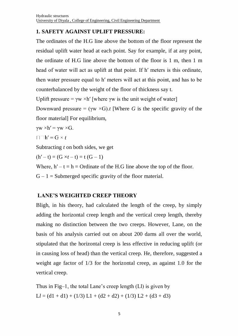
Table 2: Values of Lane’s Safe Hydraulic Gradient for different types
of Soils
KHOSLA’S THEORY AND CONCEPT OF FLOW NETS
Many of the important hydraulic structures, such as weirs and barrage,
were designed on the basis of Bligh’s theory between the periods 1910 to
1925. In 1926 – 27, the upper Chenab canal siphons, designed on Bligh’s
theory, started posing undermining troubles. Investigations started, which
ultimately lead to Khosla’s theory. The main principles of this theory are
summarized below:
(a) The seepage water does not creep along the bottom contour of pucca
flood as started by Bligh, but on the other hand, this water moves
along a set of stream-lines. This steady seepage in a vertical plane for
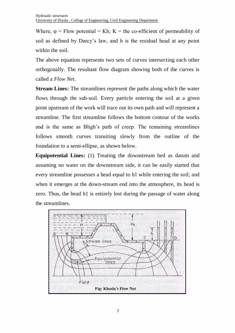
a homogeneous soil can be expressed by Laplacian equation:
Hydraulic structures
University of Diyala , College of Engineering, Civil Engineering Department
7
Where, φ = Flow potential = Kh; K = the co-efficient of permeability of
soil as defined by Darcy’s law, and h is the residual head at any point
within the soil.
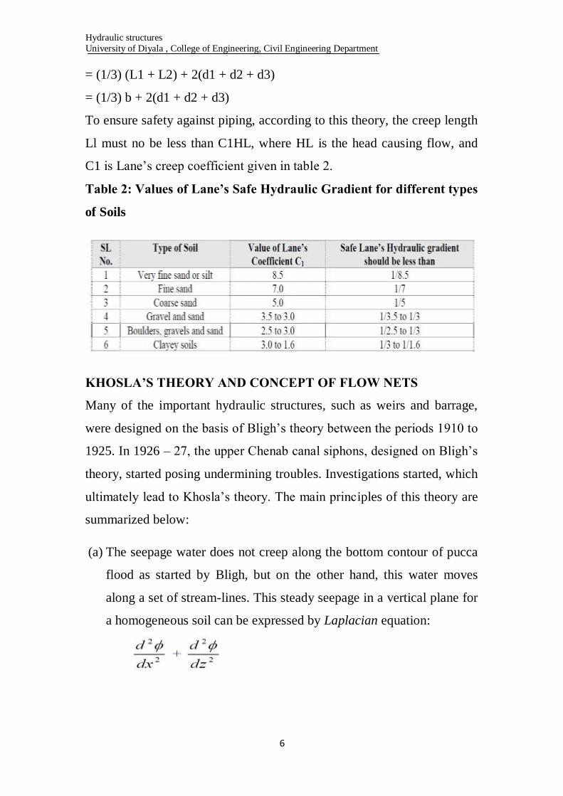
The above equation represents two sets of curves intersecting each other
orthogonally. The resultant flow diagram showing both of the curves is
called a Flow Net.
Stream Lines: The streamlines represent the paths along which the water
flows through the sub-soil. Every particle entering the soil at a given
point upstream of the work will trace out its own path and will represent a
streamline. The first streamline follows the bottom contour of the works
and is the same as Bligh’s path of creep. The remaining streamlines
follows smooth curves transiting slowly from the outline of the
foundation to a semi-ellipse, as shown below.
Equipotential Lines: (1) Treating the downstream bed as datum and
assuming no water on the downstream side, it can be easily started that
every streamline possesses a head equal to h1 while entering the soil; and
when it emerges at the down-stream end into the atmosphere, its head is
zero. Thus, the head h1 is entirely lost during the passage of water along
the streamlines.
Hydraulic structures
University of Diyala , College of Engineering, Civil Engineering Department
8
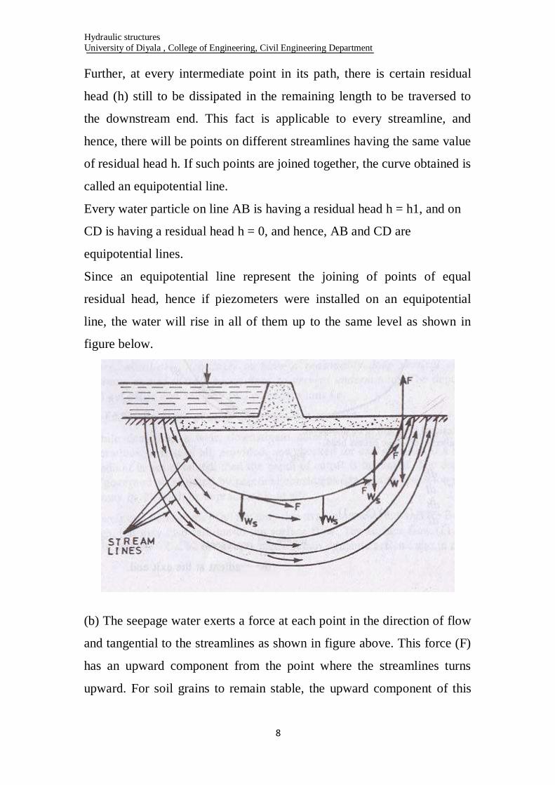
Further, at every intermediate point in its path, there is certain residual
head (h) still to be dissipated in the remaining length to be traversed to
the downstream end. This fact is applicable to every streamline, and
hence, there will be points on different streamlines having the same value
of residual head h. If such points are joined together, the curve obtained is
called an equipotential line.
Every water particle on line AB is having a residual head h = h1, and on
CD is having a residual head h = 0, and hence, AB and CD are
equipotential lines.
Since an equipotential line represent the joining of points of equal
residual head, hence if piezometers were installed on an equipotential
line, the water will rise in all of them up to the same level as shown in
figure below.
(b) The seepage water exerts a force at each point in the direction of flow
and tangential to the streamlines as shown in figure above. This force (F)
has an upward component from the point where the streamlines turns
upward. For soil grains to remain stable, the upward component of this

Hydraulic structures
University of Diyala , College of Engineering, Civil Engineering Department
9
force should be counterbalanced by the submerged weight of the soil
grain. This force has the maximum disturbing tendency at the exit end,
because the direction of this force at the exit point is vertically upward,
and hence full force acts as its upward component. For the soil grain to
remain stable, the submerged weight of soil grain should be more than
this upward disturbing force. The disturbing force at any point is
proportional to the gradient of pressure of water at that point (i.e. dp/dt).
This gradient of pressure of water at the exit end is called the exit
gradient. In order that the soil particles at exit remain stable, the upward
pressure at exit should be safe. In other words, the exit gradient should be
safe.
CRITICAL EXIT GRADIENT
This exit gradient is said to be critical, when the upward disturbing force
on the grain is just equal to the submerged weight of the grain at the exit.
When a factor of safety equal to 4 to 5 is used, the exit gradient can then
be taken as safe. In other words, an exit gradient equal to ¼ to 1/5 of the
critical exit gradient is ensured, so as to keep the structure safe against
piping.
The submerged weight (Ws) of a unit volume of soil is given as:
γw (1 – n) (Ss – 1)
Where, γw = unit weight of water.
Ss = Specific gravity of soil particles
n = Porosity of the soil material
For critical conditions to occur at the exit point
F = Ws
Where F is the upward disturbing force on the grain
Force F = pressure gradient at that point = dp/dl = γw ×dh/dl
Hydraulic structures
University of Diyala , College of Engineering, Civil Engineering Department
11
KHOSLA’S METHOD OF INDEPENDENT VARIABLES FOR
DETERMINATION OF PRESSURES AND EXIT GRADIENT FOR
SEEPAGE BELOW A WEIR OR A BARRAGE
In order to know as to how the seepage below the foundation of a
hydraulic structure is taking place, it is necessary to plot the flownet. In
other words, we must solve the Laplacian equations. This can be
accomplished either by mathematical solution of the Laplacian equations,
or by Electrical analogy method, or by graphical sketching by adjusting
the streamlines and equipotential lines with respect to the boundary
conditions. These are complicated methods and are time consuming.
Therefore, for designing hydraulic structures such as weirs or barrage or
pervious foundations, Khosla has evolved a simple, quick and an accurate
approach, called Method of Independent Variables.
In this method, a complex profile like that of a weir is broken into a
number of simple profiles; each of which can be solved mathematically.
Mathematical solutions of flownets for these simple standard profiles
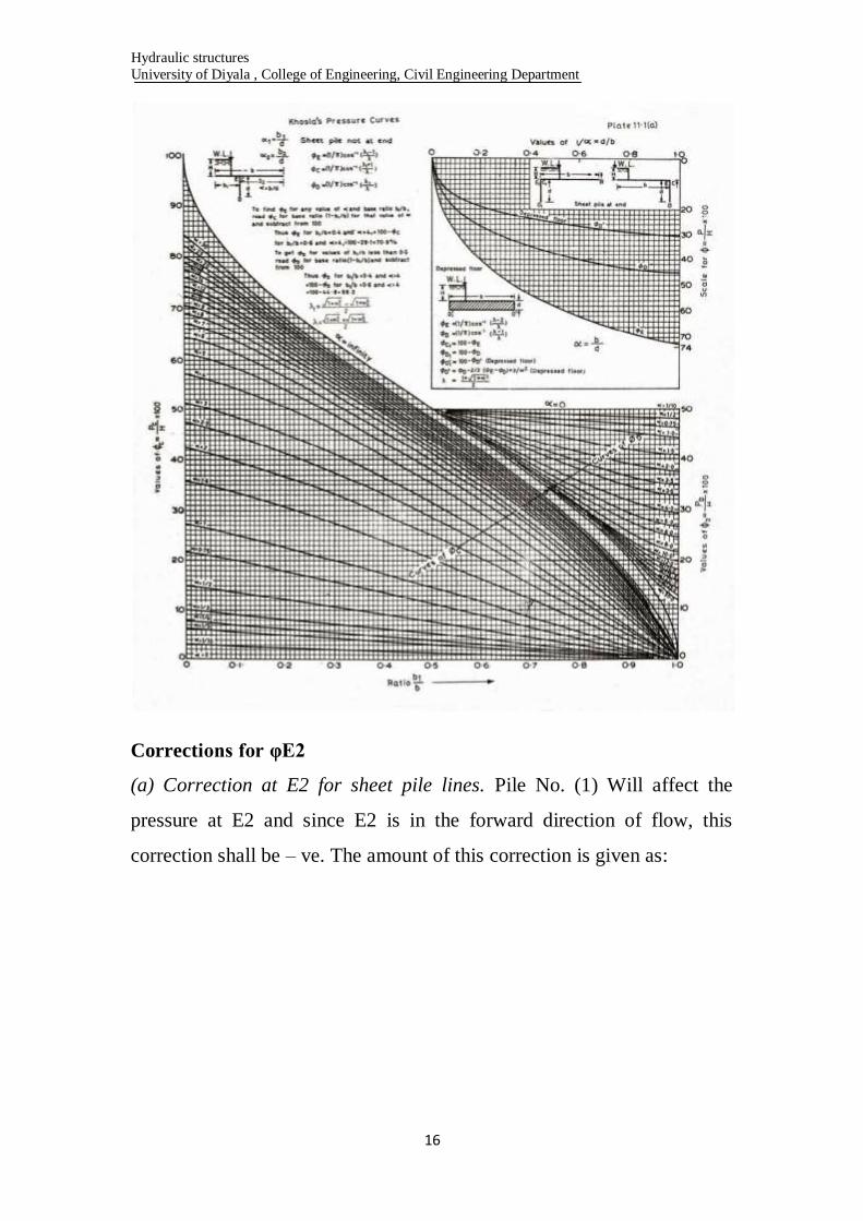
have been presented in the form of equations given in Figure and curves
given in Plate, which can be used for determining the percentage
pressures at the various key points. The simple profiles which hare most
useful are:
(i) A straight horizontal floor of negligible thickness with a sheet pile line
on the u/s end and d/s end.
(ii) A straight horizontal floor depressed below the bed but without any
vertical cut-offs.
(iii) A straight horizontal floor of negligible thickness with a sheet pile
line at some intermediate point.
Hydraulic structures
University of Diyala , College of Engineering, Civil Engineering Department
11
The key points are the junctions of the floor and the pole lines on either
side, and the bottom point of the pile line, and the bottom corners in the
case of a depressed floor. The percentage pressures at these key points for
the simple forms into which the complex profile has been broken is valid
for the complex profile itself, if corrected for
(a) Correction for the Mutual interference of Piles
(b) Correction for the thickness of floor
(c) Correction for the slope of the floor
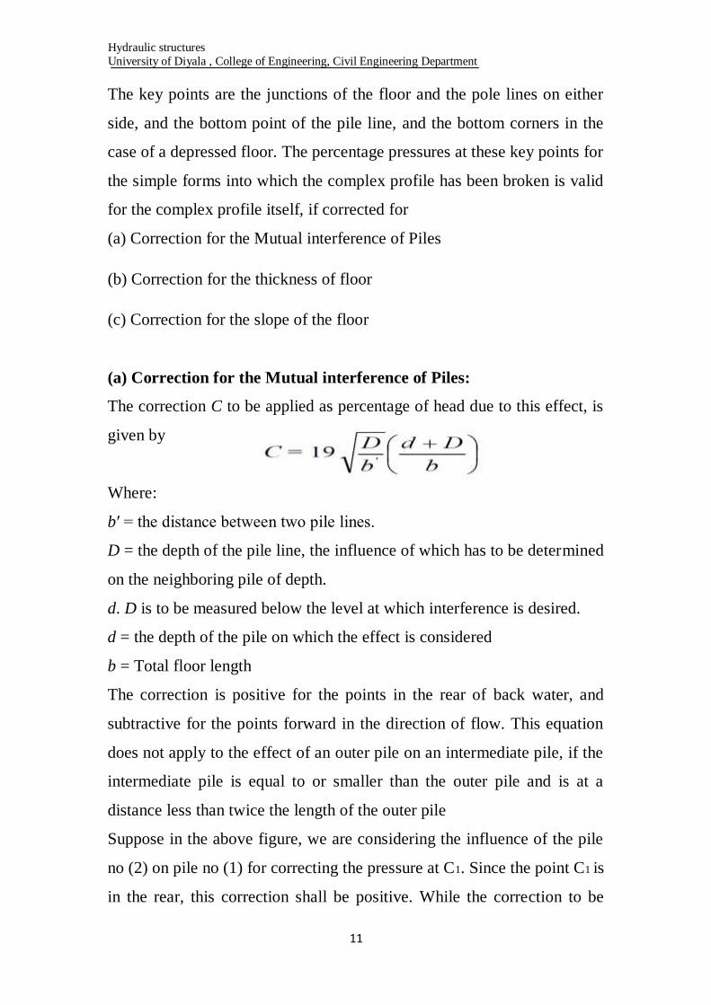
(a) Correction for the Mutual interference of Piles:
The correction C to be applied as percentage of head due to this effect, is
given by
Where:
b′ = the distance between two pile lines.
D = the depth of the pile line, the influence of which has to be determined
on the neighboring pile of depth.
d. D is to be measured below the level at which interference is desired.
d = the depth of the pile on which the effect is considered
b = Total floor length
The correction is positive for the points in the rear of back water, and
subtractive for the points forward in the direction of flow. This equation
does not apply to the effect of an outer pile on an intermediate pile, if the
intermediate pile is equal to or smaller than the outer pile and is at a
distance less than twice the length of the outer pile
Suppose in the above figure, we are considering the influence of the pile
no (2) on pile no (1) for correcting the pressure at C1. Since the point C1 is
in the rear, this correction shall be positive. While the correction to be

Hydraulic structures
University of Diyala , College of Engineering, Civil Engineering Department
12
applied to E2 due to pile no (1) shall be negative, since the point E2 is in
the forward direction of flow. Similarly, the correction at C2 due to pile
no (3) is positive and the correction at E2 due to pile no (2) is negative.
(b) Correction for the thickness of floor:
In the standard form profiles, the floor is assumed to have negligible
thickness. Hence, the percentage pressures calculated by Khosla’s
equations or graphs shall pertain to the top levels of the floor. While the
actual junction points E and C are at the bottom of the floor. Hence, the
pressures at the actual points are calculated by assuming a straight line
pressure variation.
Since the corrected pressure at E1 should be less than the calculated
pressure at E1′, the correction to be applied for the joint E1 shall be
negative. Similarly, the pressure calculated C1′ is less than the corrected
pressure at C1, and hence, the correction to be applied at point C1 is
positive.
(c) Correction for the slope of the floor
A correction is applied for a slopping floor, and is taken as positive for
the downward slopes, and negative for the upward slopes following the
direction of flow. Values of correction of standard slopes such as 1: 1, 2:
1, 3: 1, etc.
Hydraulic structures
University of Diyala , College of Engineering, Civil Engineering Department
13
The correction factor given above is to be multiplied by the horizontal
length of the slope and divided by the distance between the two pile lines
between which the sloping floor is located. This correction is applicable
only to the key points of the pile line fixed at the start or the end of the
slope.
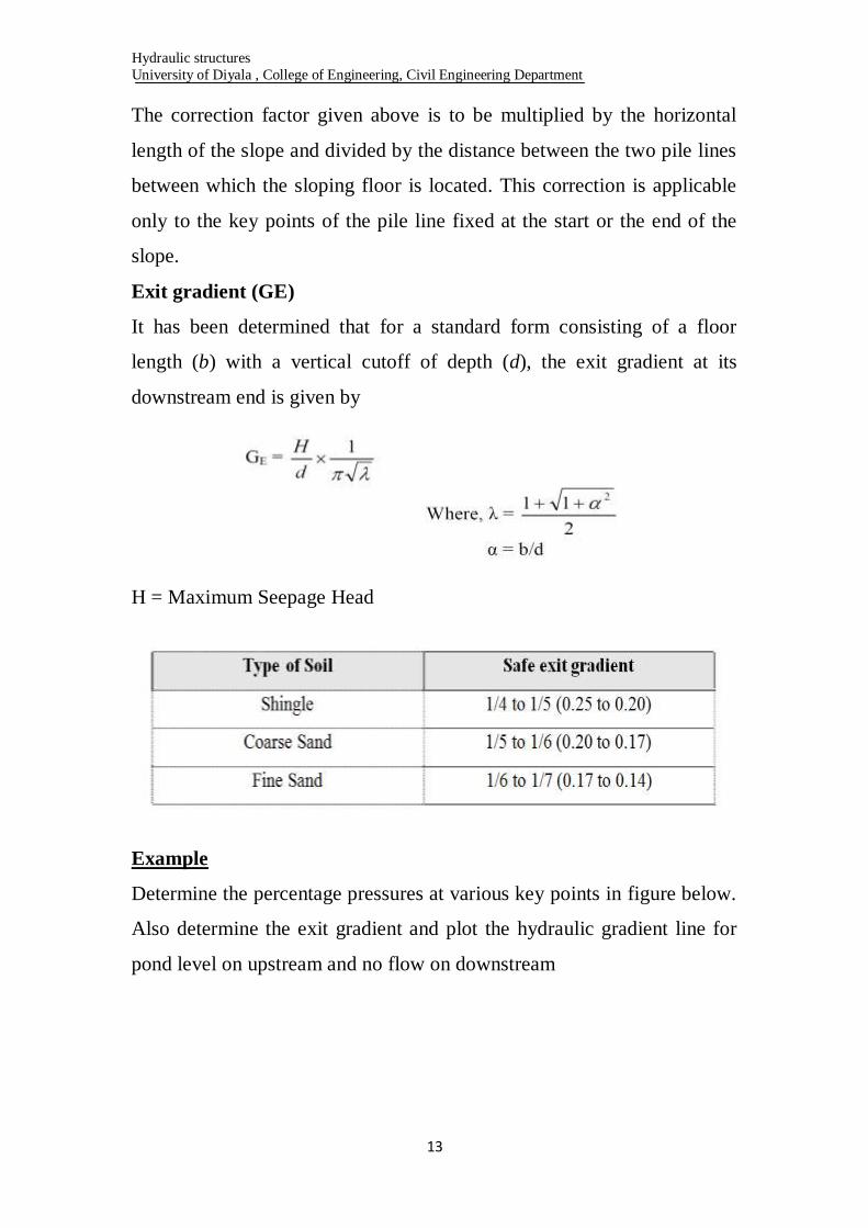
Exit gradient (GE)
It has been determined that for a standard form consisting of a floor
length (b) with a vertical cutoff of depth (d), the exit gradient at its
downstream end is given by
H = Maximum Seepage Head
Example
Determine the percentage pressures at various key points in figure below.
Also determine the exit gradient and plot the hydraulic gradient line for
pond level on upstream and no flow on downstream

Hydraulic structures
University of Diyala , College of Engineering, Civil Engineering Department
14
Solution:
For upstream Pile Line No. 1
Total length of the floor, b = 57.0 m Depth of u/s pile line, d = 154 – 148
= 6 m
α = b/d = 57/6 = 9.5
1/α = 1/9.5 = 0.105
From curve plate 11.1 (a)
φC1 = 100 – 29 = 71 %
φD1 = 100 – 20 = 80 %
These values of φC1 must be corrected for three corrections as below:
Corrections for φC1
(a) Correction at C1 for Mutual Interference of Piles (φC1) is affected by
intermediate pile No.2

Hydraulic structures
University of Diyala , College of Engineering, Civil Engineering Department
15
Since the point C1 is in the rear in the direction of flow, the correction is
(+) ve.
Correction due to pile interference on C1 = 1.88 % (+ ve)
(2) For intermediate Pile Line No. 2
d = 154 – 148 = 6 m
b = 57 m
α = b/d = 57/6 = 9.5
Using curves of plate 11.1 (b), we have b1 in this case b1 = 0.6 + 15.8 =
16.4
b = 57 m
b1/b = 16.4/57 = 0.298 (for φC2) 1 – b1/b = 1 – 0.298 = 0.702
φE2 = 100 – 30 = 70 % (Where 30 % is φC for a base ratio of 0.702 and α
= 9.5)
φC2 = 56 % (For a base ratio 0.298 and α = 9.5)
φD2 = 100 – 37 = 63 % (Where 37 % is φD for a base ratio of 0.702 and
α = 9.5)
Hydraulic structures
University of Diyala , College of Engineering, Civil Engineering Department
16
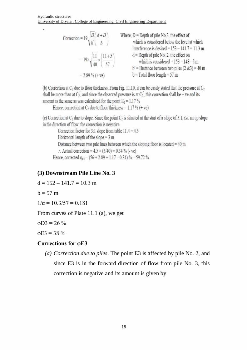
Corrections for φE2
(a) Correction at E2 for sheet pile lines. Pile No. (1) Will affect the
pressure at E2 and since E2 is in the forward direction of flow, this
correction shall be – ve. The amount of this correction is given as:

Hydraulic structures
University of Diyala , College of Engineering, Civil Engineering Department
17
Correction at E2 due to floor thickness = 1.17 % (- ve)
(b) Correction at E2 due to slope is nil, as the point E2 is neither situated
at the start of a slope nor at the end of a shape
Hence, corrected percentage pressure at E2 = Corrected φE2 = (70 – 1.88
– 1.17) % = 66.95 %
Corrections for φC2
(a) Correction at C2 due to pile interference. Pressure at C2 is affected by
pile No.(3) and since the point C2 is in the back water in the direction of
flow, this correction is (+) ve. The amount of this correction is given as:
Hydraulic structures
University of Diyala , College of Engineering, Civil Engineering Department
18
(3) Downstream Pile Line No. 3
d = 152 – 141.7 = 10.3 m
b = 57 m
1/α = 10.3/57 = 0.181
From curves of Plate 11.1 (a), we get
φD3 = 26 %
φE3 = 38 %
Corrections for φE3
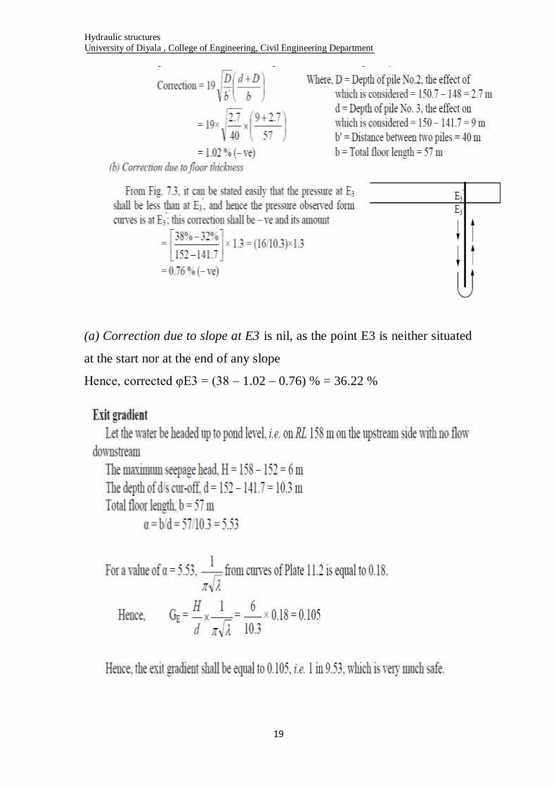
(a) Correction due to piles. The point E3 is affected by pile No. 2, and
since E3 is in the forward direction of flow from pile No. 3, this
correction is negative and its amount is given by
Hydraulic structures
University of Diyala , College of Engineering, Civil Engineering Department
19
(a) Correction due to slope at E3 is nil, as the point E3 is neither situated
at the start nor at the end of any slope
Hence, corrected φE3 = (38 – 1.02 – 0.76) % = 36.22 %

Hydraulic structures
University of Diyala , College of Engineering, Civil Engineering Department
21
Culvert
A culvert is a structure that allows water to flow under a road,
railroad, trail, or similar obstruction from one side to the other side.
Typically embedded so as to be surrounded by soil, a culvert may be
made from a pipe, reinforced concrete or other material. A structure that
carries water above land is known as an aqueduct.
Culverts are commonly used both as cross-drains for ditch relief and to
pass water under a road at natural drainage and stream crossings. A
culvert may be a bridge-like structure designed to allow vehicle or
pedestrian traffic to cross over the waterway while allowing adequate
passage for the water. Culverts come in many sizes and shapes including
round, elliptical, flat-bottomed, pear-shaped, and box-like constructions.
The culvert type and shape selection is based on a number of factors
including: requirements for hydraulic performance, limitation on
upstream water surface elevation, and roadway embankment height.

Hydraulic structures
University of Diyala , College of Engineering, Civil Engineering Department
21
Design of Culvert
• Definition - A structure used to convey surface runoff through
embankments.
• It may be a round pipe, rectangular box, arch, ellipse,
bottomless, or other shapes.
• And it may be made of concrete, steel, corrugated metal,
polyethylene, fiberglass, or other materials.
Design of culvert needs the following studies:
1. Hydrological studies
2. Hydraulic studies
3. Structural studies
Hydraulic structures
University of Diyala , College of Engineering, Civil Engineering Department
22
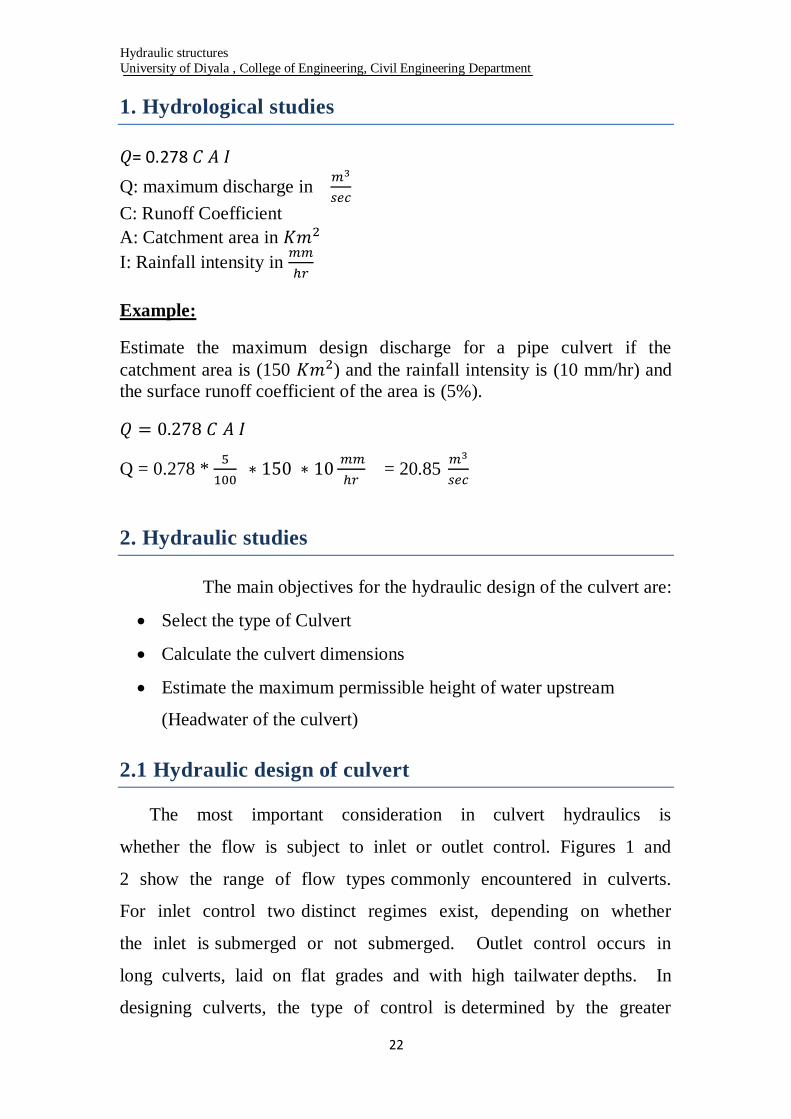
1. Hydrological studies
= 0.278
Q: maximum discharge in
C: Runoff Coefficient
A: Catchment area in
I: Rainfall intensity in
Example:
Estimate the maximum design discharge for a pipe culvert if the
catchment area is (150 ) and the rainfall intensity is (10 mm/hr) and
the surface runoff coefficient of the area is (5%).
Q = 0.278 *
= 20.85
2. Hydraulic studies
The main objectives for the hydraulic design of the culvert are:
Select the type of Culvert
Calculate the culvert dimensions
Estimate the maximum permissible height of water upstream
(Headwater of the culvert)
2.1 Hydraulic design of culvert
The most important consideration in culvert hydraulics is
whether the flow is subject to inlet or outlet control. Figures 1 and
2 show the range of flow types commonly encountered in culverts.
For inlet control two distinct regimes exist, depending on whether
the inlet is submerged or not submerged. Outlet control occurs in
long culverts, laid on flat grades and with high tailwater depths. In
designing culverts, the type of control is determined by the greater

Hydraulic structures
University of Diyala , College of Engineering, Civil Engineering Department
23
of the headwater depths calculated for both inlet control and outlet
control. For the two types of control, different factors and formulae are
used to calculate the hydraulic capacity of a culvert. Under inlet
control, the cross-sectional area of the culvert cell, the inlet geometry and
the amount of headwater or ponding at the entrance are of primary
importance. Outlet control involves the additional consideration of
the elevation of the tailwater in the outlet channel and the slope,
roughness and length of the culvert cell.
Figure (1) Flow Profiles for Culvert under Inlet Control
Hydraulic structures
University of Diyala , College of Engineering, Civil Engineering Department
24
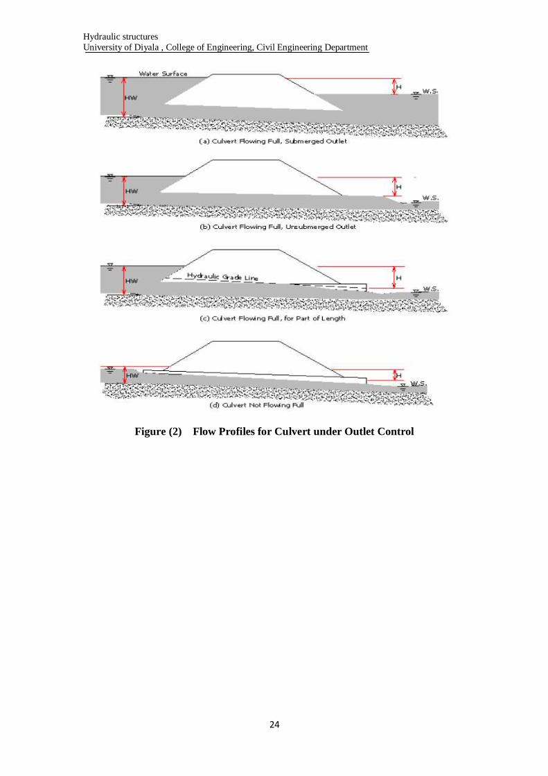
Figure (2) Flow Profiles for Culvert under Outlet Control

Hydraulic structures
University of Diyala , College of Engineering, Civil Engineering Department
25
2.1.1 Culvert operating with outlet control
Figure (3) Outlet Control
In this case as shown in figure 3, the total head loss can be calculated as
follows:
+
Where:
h h
: Entrance Coefficient:
= 0.5 for square edge entrance
= 0.05 for well-rounded entrance
Hydraulic structures
University of Diyala , College of Engineering, Civil Engineering Department
26
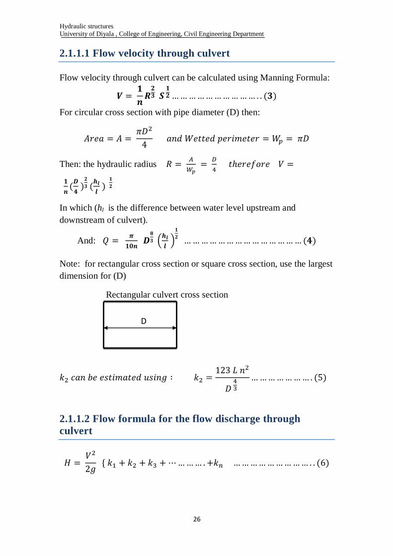
2.1.1.1 Flow velocity through culvert
Flow velocity through culvert can be calculated using Manning Formula:
For circular cross section with pipe diameter (D) then:
Then: the hydraulic radius
In which (hl is the difference between water level upstream and
downstream of culvert).
And:
Note: for rectangular cross section or square cross section, use the largest
dimension for (D)
Rectangular culvert cross section
2.1.1.2 Flow formula for the flow discharge through
culvert
D
Hydraulic structures
University of Diyala , College of Engineering, Civil Engineering Department
27
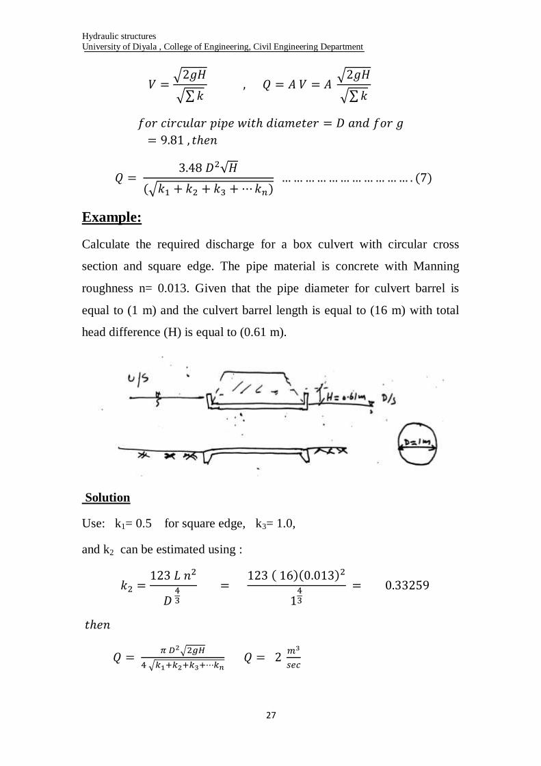
Example:
Calculate the required discharge for a box culvert with circular cross
section and square edge. The pipe material is concrete with Manning
roughness n= 0.013. Given that the pipe diameter for culvert barrel is
equal to (1 m) and the culvert barrel length is equal to (16 m) with total
head difference (H) is equal to (0.61 m).
Solution
Use: k1= 0.5 for square edge, k3= 1.0,
and k2 can be estimated using :
Hydraulic structures
University of Diyala , College of Engineering, Civil Engineering Department
28
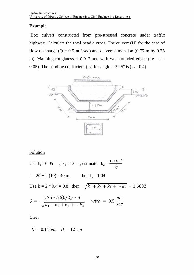
Example
Box culvert constructed from pre-stressed concrete under traffic
highway. Calculate the total head a cross. The culvert (H) for the case of
flow discharge (Q = 0.5 m3/ sec) and culvert dimension (0.75 m by 0.75
m). Manning roughness is 0.012 and with well rounded edges (i.e. k1 =
0.05). The bending coefficient (kn) for angle = 22.5o is (kn= 0.4)
Solution
Use k1= 0.05 , k3= 1.0 , estimate k2 =
L= 20 + 2 (10)= 40 m then k2= 1.04
Use kn= 2 * 0.4 = 0.8 then
Hydraulic structures
University of Diyala , College of Engineering, Civil Engineering Department
29
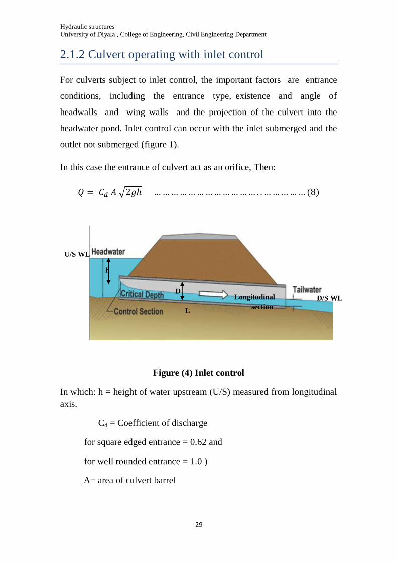
2.1.2 Culvert operating with inlet control
For culverts subject to inlet control, the important factors are entrance
conditions, including the entrance type, existence and angle of
headwalls and wing walls and the projection of the culvert into the
headwater pond. Inlet control can occur with the inlet submerged and the
outlet not submerged (figure 1).
In this case the entrance of culvert act as an orifice, Then:
Figure (4) Inlet control
In which: h = height of water upstream (U/S) measured from longitudinal
axis.
Cd = Coefficient of discharge
for square edged entrance = 0.62 and
for well rounded entrance = 1.0 )
A= area of culvert barrel
D
L
Longitudinal
section
D/S WL
h
U/S WL
Hydraulic structures
University of Diyala , College of Engineering, Civil Engineering Department
31
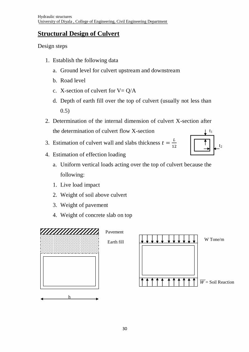
Structural Design of Culvert
Design steps
1. Establish the following data
a. Ground level for culvert upstream and downstream
b. Road level
c. X-section of culvert for V= Q/A
d. Depth of earth fill over the top of culvert (usually not less than
0.5)
2. Determination of the internal dimension of culvert X-section after
the determination of culvert flow X-section
3. Estimation of culvert wall and slabs thickness
4. Estimation of effection loading
a. Uniform vertical loads acting over the top of culvert because the
following:
1. Live load impact
2. Weight of soil above culvert
3. Weight of pavement
4. Weight of concrete slab on top
t1
t2
Pavement
Earth fill
h
W Tone/m
= Soil Reaction

Hydraulic structures
University of Diyala , College of Engineering, Civil Engineering Department
31
I. L.L on Top of culvert
Section (a-a)
Section (b-b)
Impact load = I% x L.L
Note: if the earth fill depth H ˃ 3 m the force (load) of L.L and its impact
(ignored)
H
0.4 W 0.4 W
0.71 H 2 m 0.71 H
2 + 1.42 H
a
a
b b
S
0.71 H 0.71 H
1.42 H
Effection
area for
L.L 2+1.42 H
Hydraulic structures
University of Diyala , College of Engineering, Civil Engineering Department
32
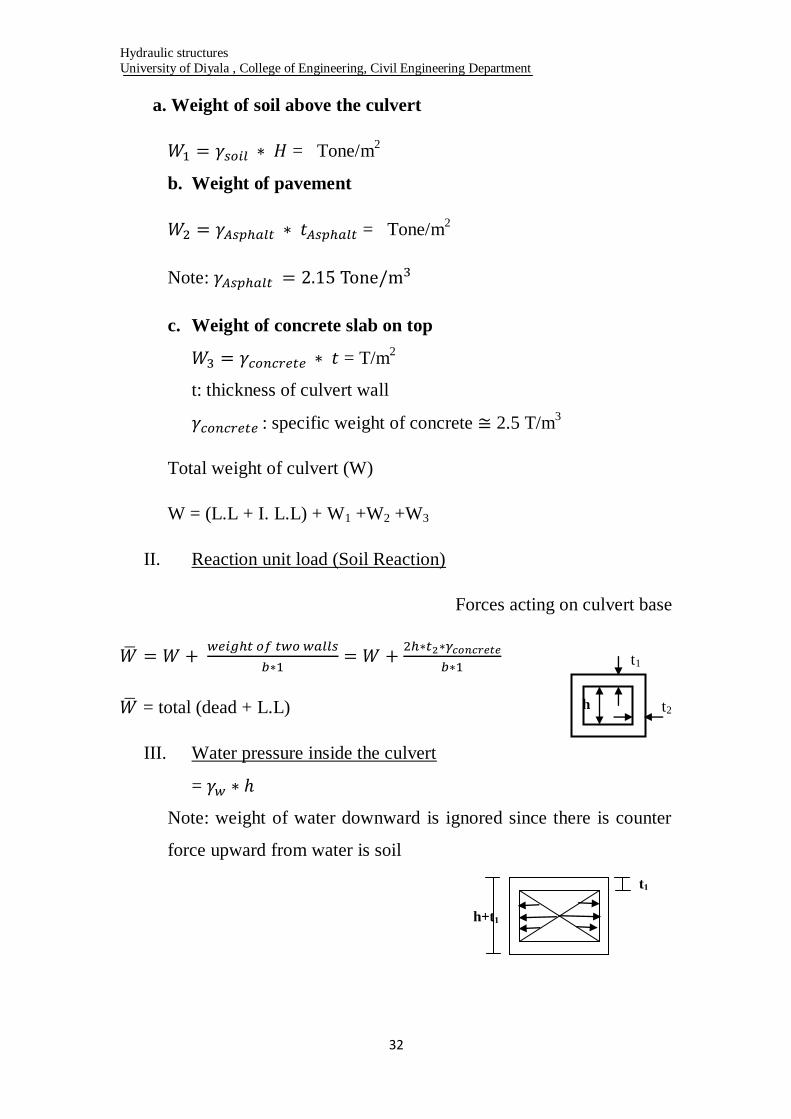
a. Weight of soil above the culvert
= Tone/m2
b. Weight of pavement
= Tone/m2
Note:
c. Weight of concrete slab on top
= T/m2
t: thickness of culvert wall
: specific weight of concrete 2.5 T/m3
Total weight of culvert (W)
W = (L.L + I. L.L) + W1 +W2 +W3
II. Reaction unit load (Soil Reaction)
Forces acting on culvert base
= total (dead + L.L)
III. Water pressure inside the culvert
=
Note: weight of water downward is ignored since there is counter
force upward from water is soil
t1
t2 h
t1
h+t1
Hydraulic structures
University of Diyala , College of Engineering, Civil Engineering Department
33
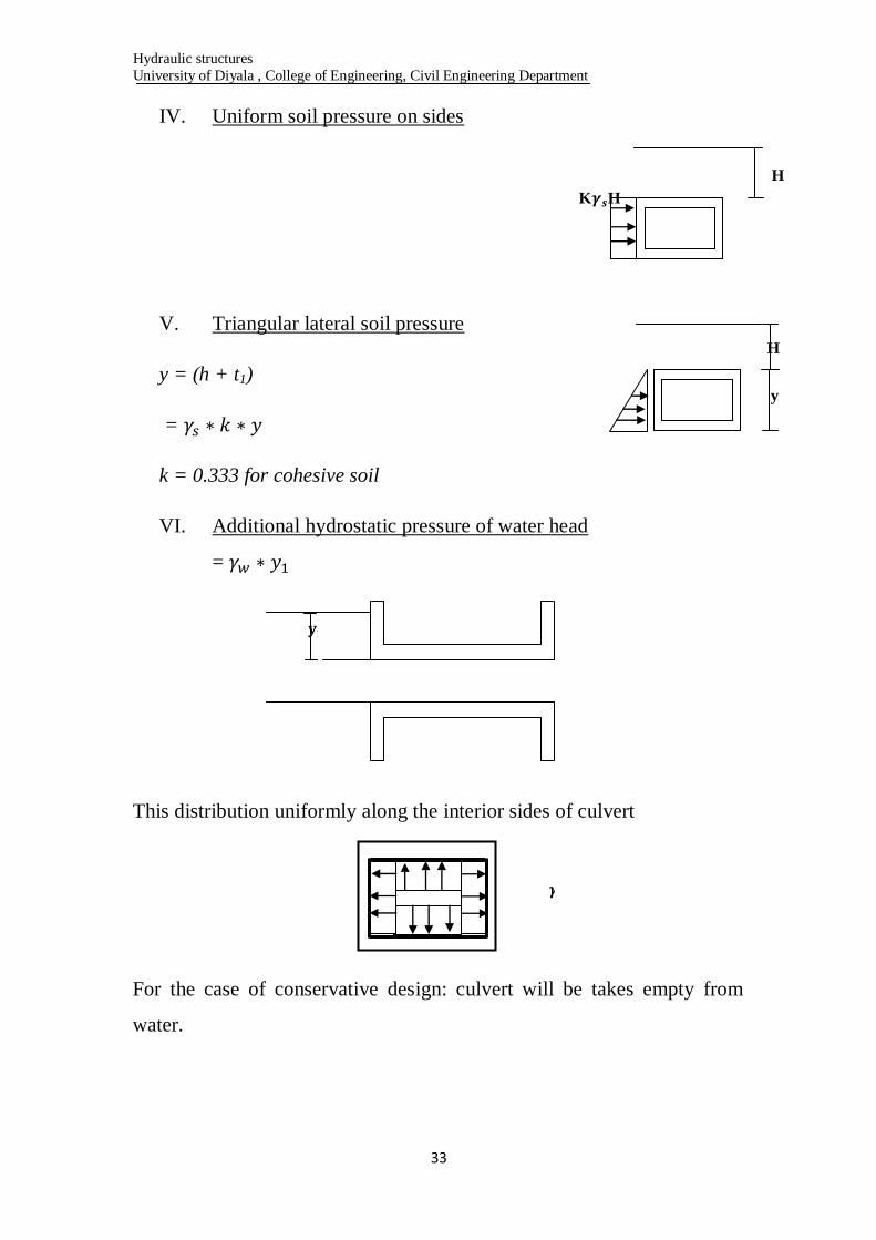
IV. Uniform soil pressure on sides
V. Triangular lateral soil pressure
y = (h + t1)
=
k = 0.333 for cohesive soil
VI. Additional hydrostatic pressure of water head
=
This distribution uniformly along the interior sides of culvert
For the case of conservative design: culvert will be takes empty from
water.
H
K H
H
y

Hydraulic structures
University of Diyala , College of Engineering, Civil Engineering Department
34
Design Example of Culvert
It is required to design a square X-section box culvert, the following data
is established:
- Water X-section area = 4.5 m2 (no water inside culvert)
- Earth fill H = 1.5 m
- Live load type (H-10)
- No water exist up the top level of culvert
- Specific weight of earth fill =
- Coefficient of soil lateral pressure K= 1/3 = 0.333
- Specific weight of concrete
- Net height of culvert S = 2 m
- Thickness of road pavement t = 0.15 m
- Specific weight of asphalt
- Steel tensile stress fs = 12500 Tone/m2
- Concrete compressive stress fc = 800 Tone/m2
Solution
L1 = L2 = say 2 m
Thickness for slab and side walls is taken to be homogenous:
I- Vertical load acting on culvert
1- Live load (L.L)
L.L
Calculation of load impact = I %
H=1.5 m
S=2 h=2

Hydraulic structures
University of Diyala , College of Engineering, Civil Engineering Department
35
Ok
L.L+Impact = 0.909 +0.345 = 1.254 Tone/m2
2- Weight of soil above culvert
3- Weight of road pavement
4- Weight of culvert slab
5- Total weight acting on Top of culvert
W = 1.254 + 2.4 + 0.5 + 0.323 = 4.477 Tone/m2
II- Soil Reaction ( )
H=1.5 m
S=2 h=2
b
W= 4.477 T/m2
Tone/m
= 5.386 T/m2
Hydraulic structures
University of Diyala , College of Engineering, Civil Engineering Department
36
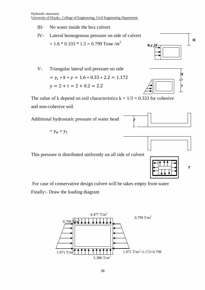
III- No water inside the box culvert
IV- Lateral homogenous pressure on side of culvert
= 1.6 * 0.333 * 1.5 = 0.799 Tone /m2
V- Triangular lateral soil pressure on side
The value of k depend on soil characteristics k = 1/3 = 0.333 for cohesive
and non-cohesive soil.
Additional hydrostatic pressure of water head
=
This pressure is distributed uniformly on all side of culvert
For case of conservative design culvert will be takes empty from water
Finally:- Draw the loading diagram
H
y
0.799 T/m2
4.477 T/m
2
5.386 T/m2
0.799 T/m2
1.971 T/m2=1.172+0.799 1.971 T/m
2
H
K H
Hydraulic structures
University of Diyala , College of Engineering, Civil Engineering Department
37
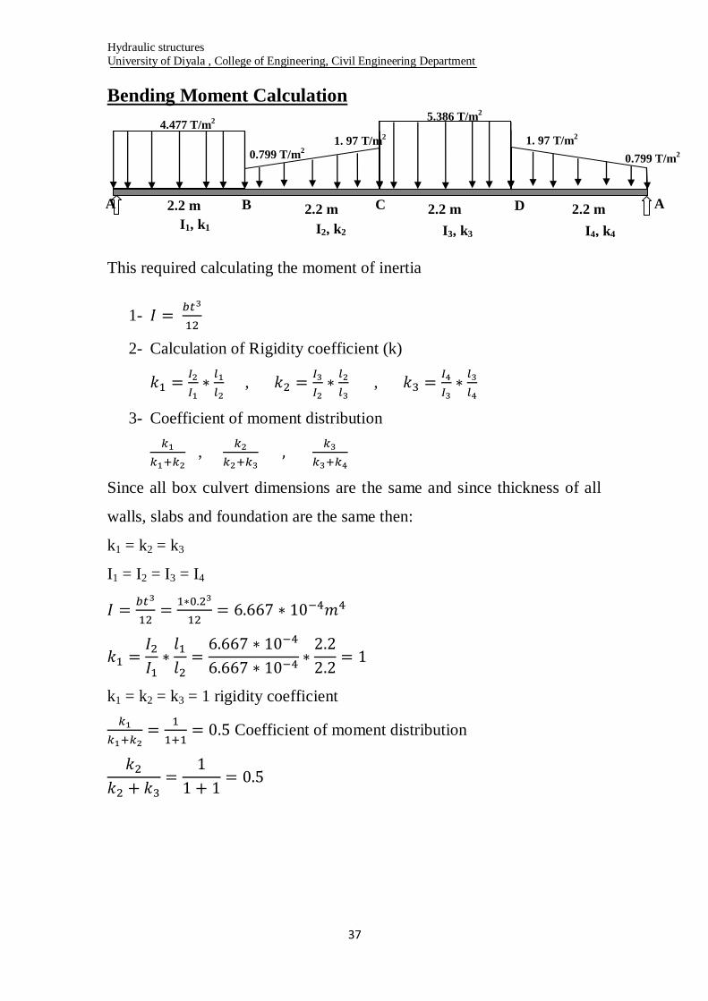
Bending Moment Calculation
This required calculating the moment of inertia
1-
2- Calculation of Rigidity coefficient (k)
,
,
3- Coefficient of moment distribution
,
Since all box culvert dimensions are the same and since thickness of all
walls, slabs and foundation are the same then:
k1 = k2 = k3
I1 = I2 = I3 = I4
k1 = k2 = k3 = 1 rigidity coefficient
Coefficient of moment distribution
4.477 T/m2
A B C D A 2.2 m 2.2 m 2.2 m 2.2 m
0.799 T/m2
1. 97 T/m2
0.799 T/m2
1. 97 T/m2
5.386 T/m2
I4, k4 I3, k3 I2, k2 I1, k1
Hydraulic structures
University of Diyala , College of Engineering, Civil Engineering Department
38
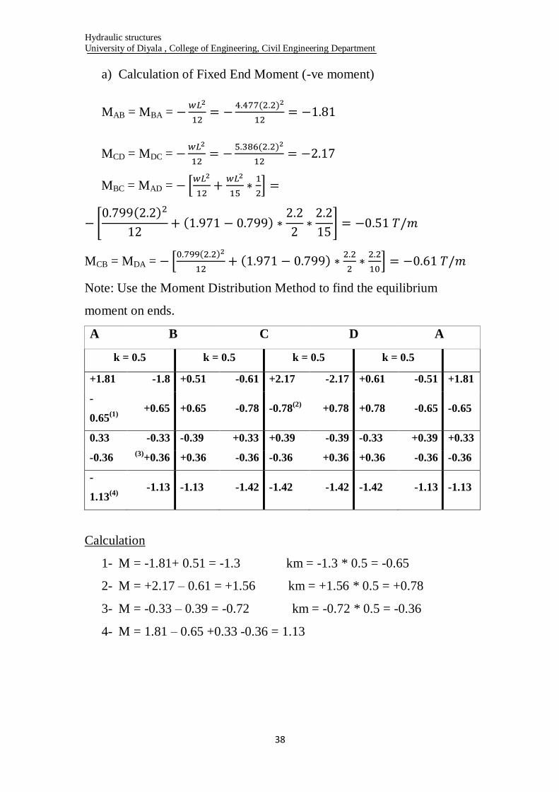
a) Calculation of Fixed End Moment (-ve moment)
MAB = MBA =
MCD = MDC =
MBC = MAD =
MCB = MDA =
Note: Use the Moment Distribution Method to find the equilibrium
moment on ends.
A B C D A
k = 0.5 k = 0.5 k = 0.5 k = 0.5
+1.81 -1.8 +0.51 -0.61 +2.17 -2.17 +0.61 -0.51 +1.81
-
0.65(1)
+0.65 +0.65 -0.78 -0.78
(2) +0.78 +0.78 -0.65 -0.65
0.33 -0.33 -0.39 +0.33 +0.39 -0.39 -0.33 +0.39 +0.33
-0.36 (3)
+0.36 +0.36 -0.36 -0.36 +0.36 +0.36 -0.36 -0.36
-
1.13(4)
-1.13 -1.13 -1.42 -1.42 -1.42 -1.42 -1.13 -1.13
Calculation
1- M = -1.81+ 0.51 = -1.3 km = -1.3 * 0.5 = -0.65
2- M = +2.17 – 0.61 = +1.56 km = +1.56 * 0.5 = +0.78
3- M = -0.33 – 0.39 = -0.72 km = -0.72 * 0.5 = -0.36
4- M = 1.81 – 0.65 +0.33 -0.36 = 1.13

Hydraulic structures
University of Diyala , College of Engineering, Civil Engineering Department
39
Mid Span Moment
a) Top slab Bending Moment
B.M
b) Bottom slab Moment
B.M
c) Side walls Moment
B.M
Reinforcement Calculation
For longitudinal and thermal reinforcement
For check assumed (t) value, find (d) from Max. Moment
- -
0.846 0.846
1.58
1.13
-1.13 -1.13
-1.13
0.429 0.429
1.84
1.42 -1.42
-1.42 -1.42
-1.42
A B
D C
+
+

Hydraulic structures
University of Diyala , College of Engineering, Civil Engineering Department
41
Point B.M (T.m)
1 -1.13
2 +1.58
3 -1.13
4 -0.43
5 -1.42
6 +1.84
7 -1.42
8 -0.43
To calculate reinforcement area, and check for (d) value:
B.M =1.84 Tone.m …………. Max. Moment to calculate (d)
fs = 12500 T/m2 , fc = 800 T/m
2 c1 =0.087, c2 = 0.92
Ok d = 20 – 8
= 12 cm
B.M (T.m) As (cm2/m)
Bar diameter and
Space
-1.13 -8.67
+1.58 +12.12
-1.13 -8.67
-0.43 -3.3
-1.42 -10.89
+1.84 +14.11
-1.42 -10.89
-0.43 -3.3
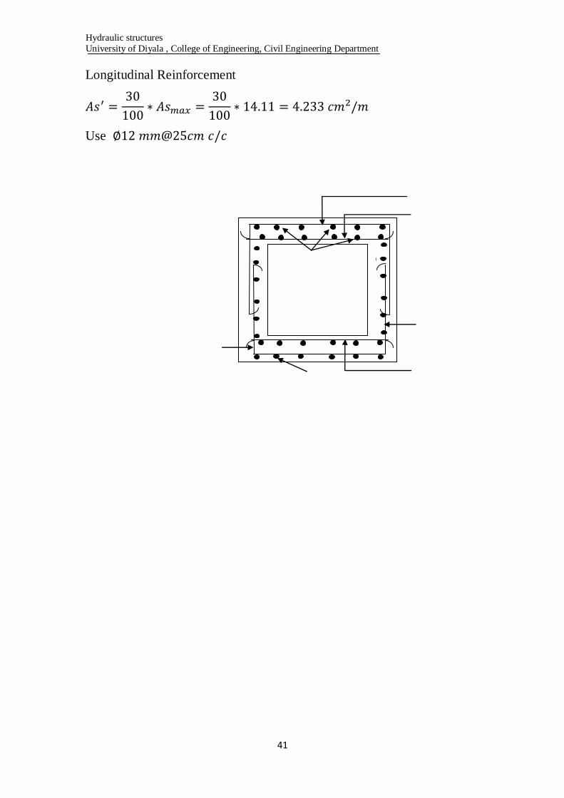
A B
C D
1
8
2 3
4
5 6
7
Hydraulic structures
University of Diyala , College of Engineering, Civil Engineering Department
41
Longitudinal Reinforcement
Use
Hydraulic structures
University of Diyala , College of Engineering, Civil Engineering Department
42
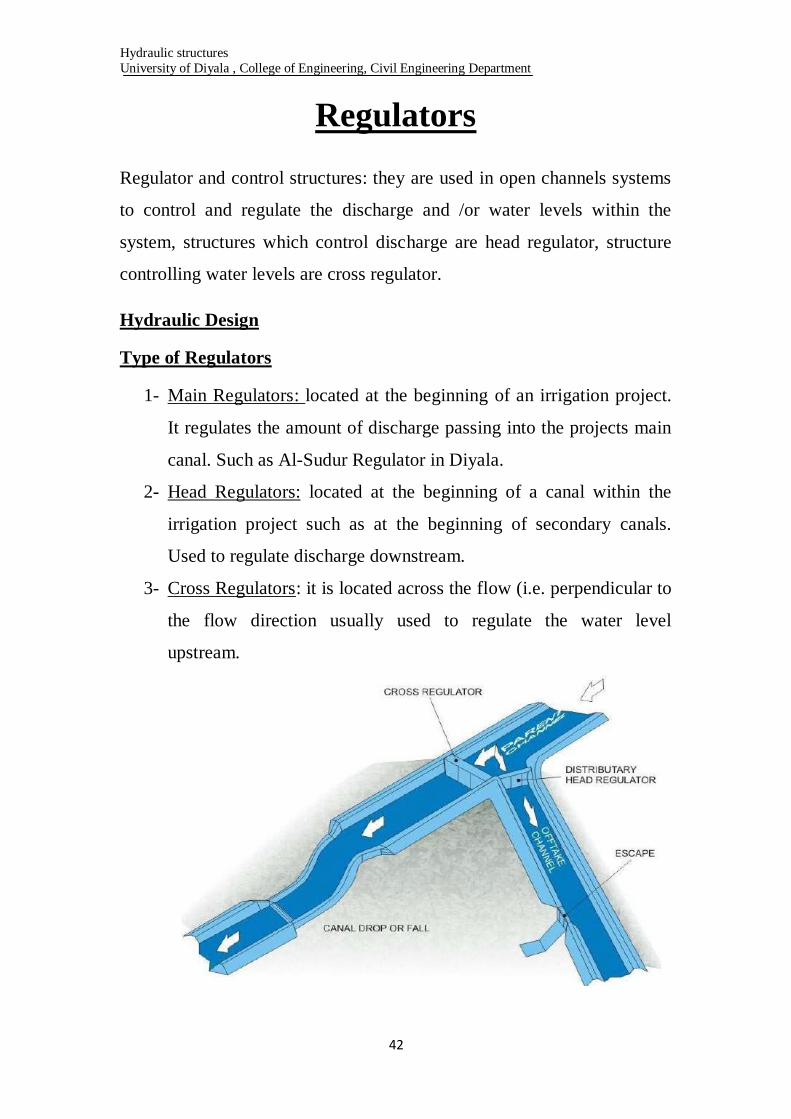
Regulators
Regulator and control structures: they are used in open channels systems
to control and regulate the discharge and /or water levels within the
system, structures which control discharge are head regulator, structure
controlling water levels are cross regulator.
Hydraulic Design
Type of Regulators
1- Main Regulators: located at the beginning of an irrigation project.
It regulates the amount of discharge passing into the projects main
canal. Such as Al-Sudur Regulator in Diyala.
2- Head Regulators: located at the beginning of a canal within the
irrigation project such as at the beginning of secondary canals.
Used to regulate discharge downstream.
3- Cross Regulators: it is located across the flow (i.e. perpendicular to
the flow direction usually used to regulate the water level
upstream.
Hydraulic structures
University of Diyala , College of Engineering, Civil Engineering Department
43
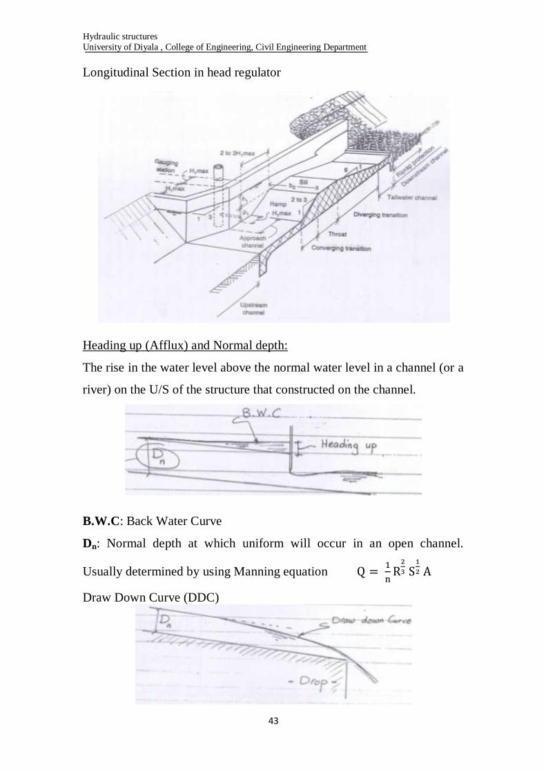
Longitudinal Section in head regulator
Heading up (Afflux) and Normal depth:
The rise in the water level above the normal water level in a channel (or a
river) on the U/S of the structure that constructed on the channel.
B.W.C: Back Water Curve
Dn: Normal depth at which uniform will occur in an open channel.
Usually determined by using Manning equation
Draw Down Curve (DDC)

Hydraulic structures
University of Diyala , College of Engineering, Civil Engineering Department
44
Hydraulic Calculation of Regulators
Velocity and Discharge
For efficient hydraulic design the following should be met:
1- Losses are to be kept at minimum
2- Hydraulic jump must be contained within the structure
3- The flow pattern must be as uniform as possible
Maximum and Minimum discharge flow
Qn : Normal discharge
Qmax.: 1.2 Qn (in order to find Vmax.)
Qmin.: 0.6 Qn (in order to find Vmin.)
For the case of regulator consist of an opening controlled by radial or
vertical lift gates;
The discharge is determined by the orifice equation
A: Area of water way through the regulator (net area = d*S)
S: Regulator net width
d: actual height of gate above sill in partially closed opening
d: D/S W.L – Sill level under gate, for fully open regulator
V: velocity through the regulator opening
Va: Approach velocity
ha: Va2/2g
h: heading up (afflux)
Hydraulic structures
University of Diyala , College of Engineering, Civil Engineering Department
45
Afflux: the rise in U/S due to construction on the structure across river
The design purpose the full discharge Q is given and consequently the
regulator should be fully opened at this discharge. The discharge equation
through fully opened regulator is:
Cases of gate discharge
1- Fully opened gate
Flow is subcritical with free surface
Fr < 1, Q = max.
Water way: the max. design discharge for canal structure is (1.2 Qn),
where Qn = Normal full supply discharge .
The formula to be used for calculates the discharge at full gate opening
(is given by Serge Leliavsky) as:
C: discharge coeff. = 0.82 for square entrance
= 0.9 for round entrance
L: width of gate (m)
d: tail water depth
ha: head due to velocity of approach = Va2/2g
HL: difference in U/S and D/S water levels
The velocity head (ha) of approaching flow is to be considered for in-line
structure (cross regulator) but in case of head regulator where the gate
opening is at an angle to the main stream, the term (ha = Va2/2g) is
ignored.

Hydraulic structures
University of Diyala , College of Engineering, Civil Engineering Department
46
(Fully gate opening, Horizontal floor)
For the case of sill exist under gate
(Fully gate opening, floor with crest)
C: 0.82 or 0.9
d: D/S W.L – (sill level, or crest level, or floor level) under gate
H: U/S W.L - D/S W.L
For partially opening for the gate one can a (ha) ignore.
2- Gate is partially closed
Free floor condition
Discharge is smaller; (ha) is so small (Ignored)
Submerged orifice formula is used
A: Flow area = width of gate (L)* gate opening (d)
H: operating head (U/S water depth)
Cd: coeff. Of discharge = 0.62

Hydraulic structures
University of Diyala , College of Engineering, Civil Engineering Department
47
(Partially Closed gate, Horizontal floor)
(Partially Closed gate, floor with crest)
Example 1
Find the width of distributary canal head regulator, given the following
data:-
Main canal Distributary canal
Normal discharge m3/sec 22.1 3
Normal full supply water level (m) 51.9 51.8
Bed level (m) 49.51 50.6
Bed width (m) 5 2.5
Side Slope 1 1/2 H:1V 1 1/2 H:1V
Depth of flow (m) 2.39 1.2

Hydraulic structures
University of Diyala , College of Engineering, Civil Engineering Department
48
Neglect the effect of approaching velocity
C = 0.82 (square opening)
D = D/S W.L – Sill level = 51.8 – 50.6 = 1.2 m
H = 51.9 -51.8 = 0.1 m

Hydraulic structures
University of Diyala , College of Engineering, Civil Engineering Department
49
Example 2
A cross regulator is to be constructed on a canal of 10 m bed width, 1:1
side slope, U/S W.L of 43.50 m, U/S B.L 39.50 m, D/S W.L 43.20 m, sill
level under gate 40.10 m, full supply discharge Q = 55 cumecs, calculate
the required width of regulator taking velocity of approach into
consideration.
Solution:
To find the approaching velocity:
D = 3.1 m (as shown above)
H=U/S W.L –D/S W.L = 43.5 – 43.2 = 0.3 m
Now
Assuming rounded entrance C = 0.9
S = 7.75 m
Hydraulic structures
University of Diyala , College of Engineering, Civil Engineering Department
51
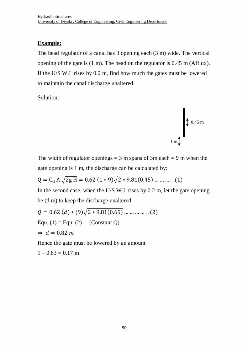
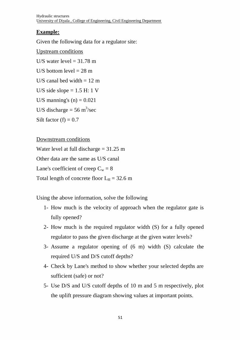
Example:
The head regulator of a canal has 3 opening each (3 m) wide. The vertical
opening of the gate is (1 m). The head on the regulator is 0.45 m (Afflux).
If the U/S W.L rises by 0.2 m, find how much the gates must be lowered
to maintain the canal discharge unaltered.
Solution:
The width of regulator openings = 3 m spans of 3m each = 9 m when the
gate opening is 1 m, the discharge can be calculated by:
In the second case, when the U/S W.L rises by 0.2 m, let the gate opening
be (d m) to keep the discharge unaltered
Equ. (1) = Equ. (2) (Constant Q)
Hence the gate must be lowered by an amount
1 – 0.83 = 0.17 m
0.45 m
1 m
Hydraulic structures
University of Diyala , College of Engineering, Civil Engineering Department
51
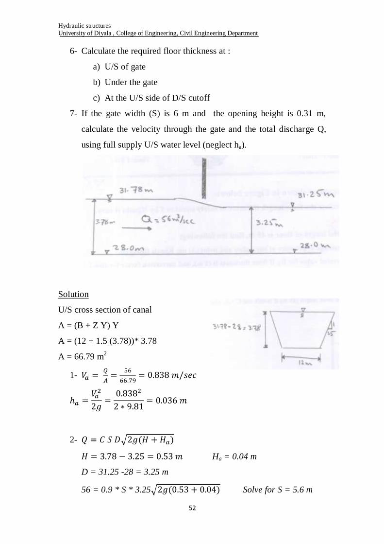
Example:
Given the following data for a regulator site:
Upstream conditions
U/S water level = 31.78 m
U/S bottom level = 28 m
U/S canal bed width = 12 m
U/S side slope = 1.5 H: 1 V
U/S manning's (n) = 0.021
U/S discharge = 56 m3/sec
Silt factor (f) = 0.7
Downstream conditions
Water level at full discharge = 31.25 m
Other data are the same as U/S canal
Lane's coefficient of creep Cw = 8
Total length of concrete floor LH = 32.6 m
Using the above information, solve the following
1- How much is the velocity of approach when the regulator gate is
fully opened?
2- How much is the required regulator width (S) for a fully opened
regulator to pass the given discharge at the given water levels?
3- Assume a regulator opening of (6 m) width (S) calculate the
required U/S and D/S cutoff depths?
4- Check by Lane's method to show whether your selected depths are
sufficient (safe) or not?
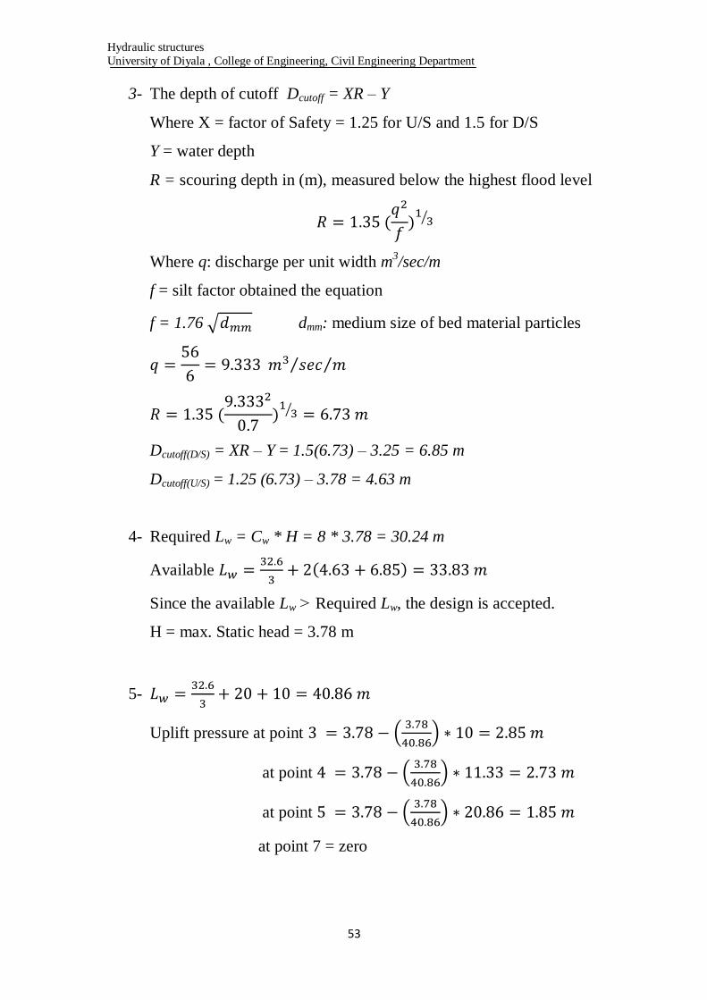
5- Use D/S and U/S cutoff depths of 10 m and 5 m respectively, plot
the uplift pressure diagram showing values at important points.
Hydraulic structures
University of Diyala , College of Engineering, Civil Engineering Department
52
6- Calculate the required floor thickness at :
a) U/S of gate
b) Under the gate
c) At the U/S side of D/S cutoff
7- If the gate width (S) is 6 m and the opening height is 0.31 m,
calculate the velocity through the gate and the total discharge Q,
using full supply U/S water level (neglect ha).
Solution
U/S cross section of canal
A = (B + Z Y) Y
A = (12 + 1.5 (3.78))* 3.78
A = 66.79 m2
1-
2-
Ha = 0.04 m
D = 31.25 -28 = 3.25 m
56 = 0.9 * S * 3.25 Solve for S = 5.6 m
Hydraulic structures
University of Diyala , College of Engineering, Civil Engineering Department
53
3- The depth of cutoff Dcutoff = XR – Y
Where X = factor of Safety = 1.25 for U/S and 1.5 for D/S
Y = water depth
R = scouring depth in (m), measured below the highest flood level
Where q: discharge per unit width m3/sec/m
f = silt factor obtained the equation
f = 1.76 dmm: medium size of bed material particles
Dcutoff(D/S) = XR – Y = 1.5(6.73) – 3.25 = 6.85 m
Dcutoff(U/S) = 1.25 (6.73) – 3.78 = 4.63 m
4- Required Lw = Cw * H = 8 * 3.78 = 30.24 m
Available
Since the available Lw ˃ Required Lw, the design is accepted.
H = max. Static head = 3.78 m
5-
Uplift pressure at point
at point
at point
at point 7 = zero
Hydraulic structures
University of Diyala , College of Engineering, Civil Engineering Department
54
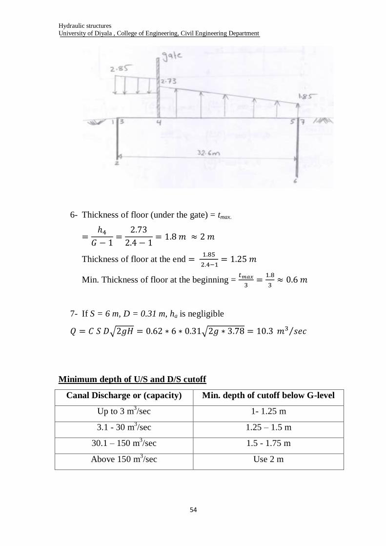
6- Thickness of floor (under the gate) = tmax.
Thickness of floor at the end
Min. Thickness of floor at the beginning =
7- If S = 6 m, D = 0.31 m, ha is negligible
Minimum depth of U/S and D/S cutoff
Canal Discharge or (capacity) Min. depth of cutoff below G-level
Up to 3 m3/sec 1- 1.25 m
3.1 - 30 m3/sec 1.25 – 1.5 m
30.1 – 150 m3/sec 1.5 - 1.75 m
Above 150 m3/sec Use 2 m

Hydraulic structures
University of Diyala , College of Engineering, Civil Engineering Department
55
Structural Design of Regulators
Cases of structural Design:-
1- Regulators with fully opened gates
In this case the water head (H) is small also small uplift pressure.
2- Regulators with fully closed gates
In this case we practice very high water head (H) and very high
uplift pressure.
3- Regulators under dry condition
In this case the downward weight of regulators is high and the soil
reaction equal to downward force per unit area.
Note that: in case of water exist the behavior of structure floor is as
floating body (submerged).
Rs: Soil Reaction
The design should be at critical condition (i.e. no water exists).
In this case the soil Reaction is calculated at dry condition and the floor is
design according to it.
The design should be checked as follows:
1- Check for structure stability
In this case the following should be:
Uplift pressure weight of submerged structure
2- For structural design the structure is taken as dry and
(Per one meter of footing length)
B

Hydraulic structures
University of Diyala , College of Engineering, Civil Engineering Department
56
Moments Calculation
1- Take moment around point (A) at the center of floor this will be
done in two cases
a- Water exist around the structure (Soil surrounding the structure
is saturated)
b- Water does not exist around the structure (dry Soil)
= Ma
2- Take moment around point B at the center of regulator column (B)
as shown in figure below = MB
3- From (1) and (2) choose the max. Positive Bending Moment and
the max. Negative Bending Moment
- From max. (+Ve) B.M we estimate floor thickness
- From max. (+Ve) & (-Ve) B.M we calculate the steel
reinforcement.
t = d + cover
Hydraulic structures
University of Diyala , College of Engineering, Civil Engineering Department
57
Where:
M: Bending Moment T.m
d: effective depth m
b: section width m
fs: steel stress T/m2
fc: concrete compressive strength T/m2
As: Area of steel required cm2
C1 & C2: coefficient (from tables)
- Area of Temp. Steel
AsTemp. = 0.2 % * t* 1
- Cover for steel reinforcement According to USBR (United
States Bureau of Reclamation)
For side facing water not less than 8 cm for other sides (5-6 cm)
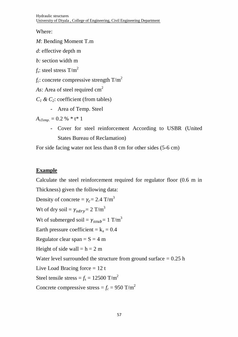
Example
Calculate the steel reinforcement required for regulator floor (0.6 m in
Thickness) given the following data:
Density of concrete = = 2.4 T/m3
Wt of dry soil = = 2 T/m3
Wt of submerged soil = = 1 T/m3
Earth pressure coefficient = ka = 0.4
Regulator clear span = S = 4 m
Height of side wall = h = 2 m
Water level surrounded the structure from ground surface = 0.25 h
Live Load Bracing force = 12 t
Steel tensile stress = fs = 12500 T/m2
Concrete compressive stress = fc = 950 T/m2
Hydraulic structures
University of Diyala , College of Engineering, Civil Engineering Department
58
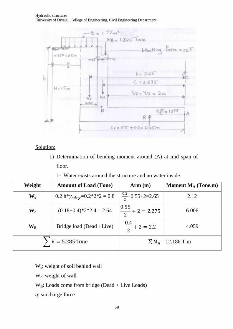
Solution:
1) Determination of bending moment around (A) at mid span of
floor.
1- Water exists around the structure and no water inside.
Weight Amount of Load (Tone) Arm (m) Moment MA (Tone.m)
Ws 0.2 h* =0.2*2*2 = 0.8
+0.55+2=2.65 2.12
Wc (0.18+0.4)*2*2.4 = 2.64
6.006
WB Bridge load (Dead +Live)
4.059
=-12.186 T.m
Ws: weight of soil behind wall
Wc: weight of wall
WB: Loads come from bridge (Dead + Live Loads)
q: surcharge force
Hydraulic structures
University of Diyala , College of Engineering, Civil Engineering Department
59
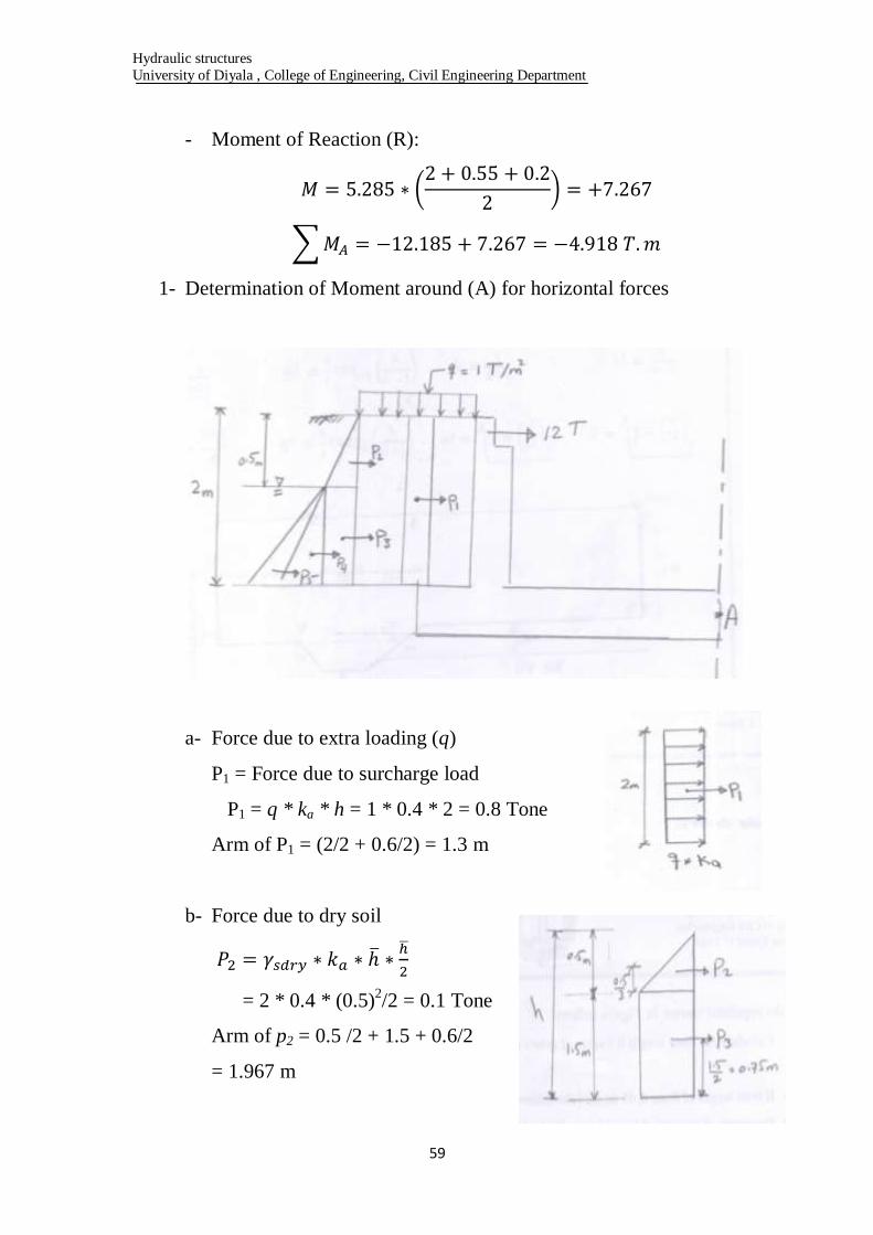
- Moment of Reaction (R):
1- Determination of Moment around (A) for horizontal forces
a- Force due to extra loading (q)
P1 = Force due to surcharge load
P1 = q * ka * h = 1 * 0.4 * 2 = 0.8 Tone
Arm of P1 = (2/2 + 0.6/2) = 1.3 m
b- Force due to dry soil
= 2 * 0.4 * (0.5)2/2 = 0.1 Tone
Arm of p2 = 0.5 /2 + 1.5 + 0.6/2
= 1.967 m

Hydraulic structures
University of Diyala , College of Engineering, Civil Engineering Department
61
c- Force due to dry soil
= 2 * 0.4 *0.5 (2 – 0.5) = 0.6 Tone
Arm of P3 = 0.75 + 0.6 /2 = 1.05 m
d- Force due to submerged soil
Arm of
e- Force due to water pressure
Arm of
Hydraulic structures
University of Diyala , College of Engineering, Civil Engineering Department
61
- Calculation of bending moment around (A):
Force (Horizontal) Tone Arm (m) Moment around A (T.M)
P1 0.8 1.3 1.04
P2 0.1 1.967 0.197
P3 0.6 1.05 0.63
P4 0.45 0.8 0.35
P5 1.125 0.8 0.9
∑ 3.075 3.127
∑MA = +3.127 Tone.m
- Moment due to braking force
∑MA = 3.127 + 4.929 = + 8.056 T.m
Sum of Moment due to both horizontal & vertical forces around
(A) = ∑MA = - 4.018 + 8.056 = 3.138 T.m
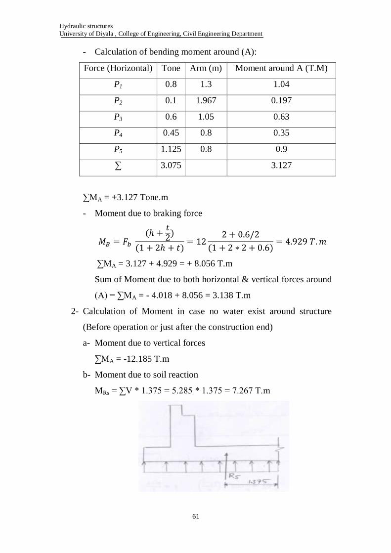
2- Calculation of Moment in case no water exist around structure
(Before operation or just after the construction end)
a- Moment due to vertical forces
∑MA = -12.185 T.m
b- Moment due to soil reaction
MRs = ∑V * 1.375 = 5.285 * 1.375 = 7.267 T.m
Hydraulic structures
University of Diyala , College of Engineering, Civil Engineering Department
62
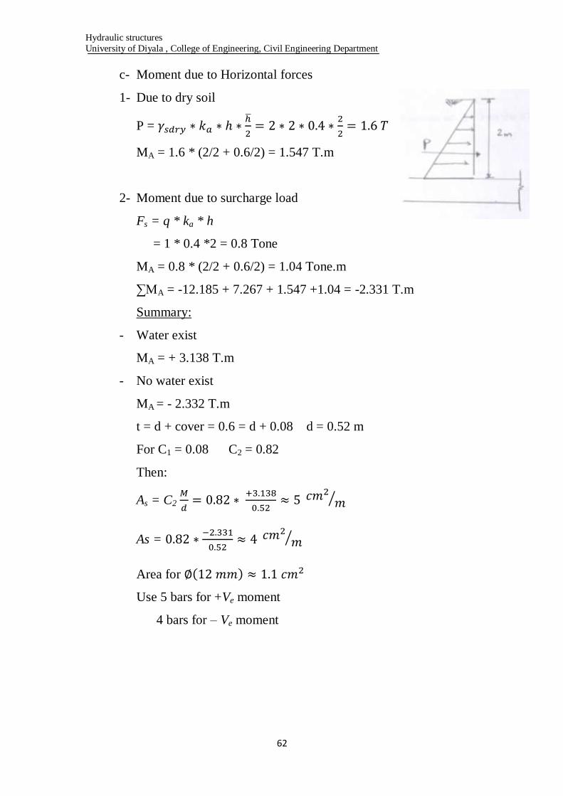
c- Moment due to Horizontal forces
1- Due to dry soil
P =
MA = 1.6 * (2/2 + 0.6/2) = 1.547 T.m
2- Moment due to surcharge load
Fs = q * ka * h
= 1 * 0.4 *2 = 0.8 Tone
MA = 0.8 * (2/2 + 0.6/2) = 1.04 Tone.m
∑MA = -12.185 + 7.267 + 1.547 +1.04 = -2.331 T.m
Summary:
- Water exist
MA = + 3.138 T.m
- No water exist
MA = - 2.332 T.m
t = d + cover = 0.6 = d + 0.08 d = 0.52 m
For C1 = 0.08 C2 = 0.82
Then:
As = C2
As =
Area for
Use 5 bars for +Ve moment
4 bars for – Ve moment
Hydraulic structures
University of Diyala , College of Engineering, Civil Engineering Department
63
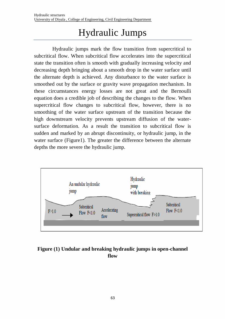
Hydraulic Jumps
Hydraulic jumps mark the flow transition from supercritical to
subcritical flow. When subcritical flow accelerates into the supercritical
state the transition often is smooth with gradually increasing velocity and
decreasing depth bringing about a smooth drop in the water surface until
the alternate depth is achieved. Any disturbance to the water surface is
smoothed out by the surface or gravity wave propagation mechanism. In
these circumstances energy losses are not great and the Bernoulli
equation does a credible job of describing the changes to the flow. When
supercritical flow changes to subcritical flow, however, there is no
smoothing of the water surface upstream of the transition because the
high downstream velocity prevents upstream diffusion of the water-
surface deformation. As a result the transition to subcritical flow is
sudden and marked by an abrupt discontinuity, or hydraulic jump, in the
water surface (Figure1). The greater the difference between the alternate
depths the more severe the hydraulic jump.
Figure (1) Undular and breaking hydraulic jumps in open-channel
flow
Hydraulic structures
University of Diyala , College of Engineering, Civil Engineering Department
64
Hydraulic jumps appear in the surface of rivers as standing waves or
surges. In their most fully developed state they appear as a line of
breaking waves normal to the river bank which remains stationary with
respect to an observer on the bank. Upstream of the jump the flow is
supercritical and downstream it is subcritical. Hydraulic jumps may occur
as a single event in a reach of channel or they may occur in trains as flow
alternates back and forth across the two flow states. They may be steady-
state features or they may be intermittent or even periodic, forming and
collapsing, and reestablishing again, in response to the highly unsteady
non-uniform flow. As we might expect, hydraulic jumps are more likely
to be found disrupting flows in steep mountain streams rather than those
in large low-slope rivers although even the latter may exhibit this flow
phenomenon at high flood discharges. Because the flow at the hydraulic
jump often is surging and highly agitated, there is a great deal of energy
lost here, precisely the circumstance we must avoid if the Bernoulli
equation is the only analytical tool at our disposal.
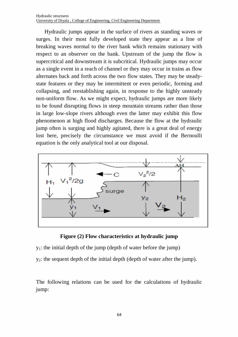
Figure (2) Flow characteristics at hydraulic jump
y1: the initial depth of the jump (depth of water before the jump)
y2: the sequent depth of the initial depth (depth of water after the jump).
The following relations can be used for the calculations of hydraulic
jump:
Hydraulic structures
University of Diyala , College of Engineering, Civil Engineering Department
65
Problem (1): Water flows along a 10-m wide rectangular channel and
through a hydraulic jump. If the flow depth just before the jump is 2.0 m,
and 3.0 m after it, what is the discharge through the channel?
We get
So that and
Thus discharge,
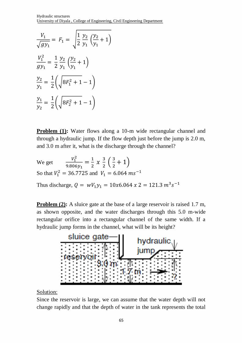
Problem (2): A sluice gate at the base of a large reservoir is raised 1.7 m,
as shown opposite, and the water discharges through this 5.0 m-wide
rectangular orifice into a rectangular channel of the same width. If a
hydraulic jump forms in the channel, what will be its height?
Solution:
Since the reservoir is large, we can assume that the water depth will not
change rapidly and that the depth of water in the tank represents the total
Hydraulic structures
University of Diyala , College of Engineering, Civil Engineering Department
66
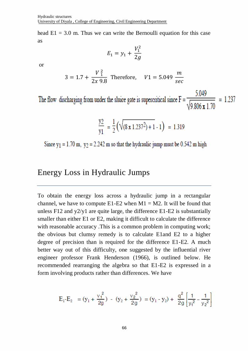
head E1 = 3.0 m. Thus we can write the Bernoulli equation for this case
as
or
Energy Loss in Hydraulic Jumps
To obtain the energy loss across a hydraulic jump in a rectangular
channel, we have to compute E1-E2 when M1 = M2. It will be found that
unless F12 and y2/y1 are quite large, the difference E1-E2 is substantially
smaller than either E1 or E2, making it difficult to calculate the difference
with reasonable accuracy .This is a common problem in computing work;
the obvious but clumsy remedy is to calculate E1and E2 to a higher
degree of precision than is required for the difference E1-E2. A much
better way out of this difficulty, one suggested by the influential river
engineer professor Frank Henderson (1966), is outlined below. He
recommended rearranging the algebra so that E1-E2 is expressed in a
form involving products rather than differences. We have
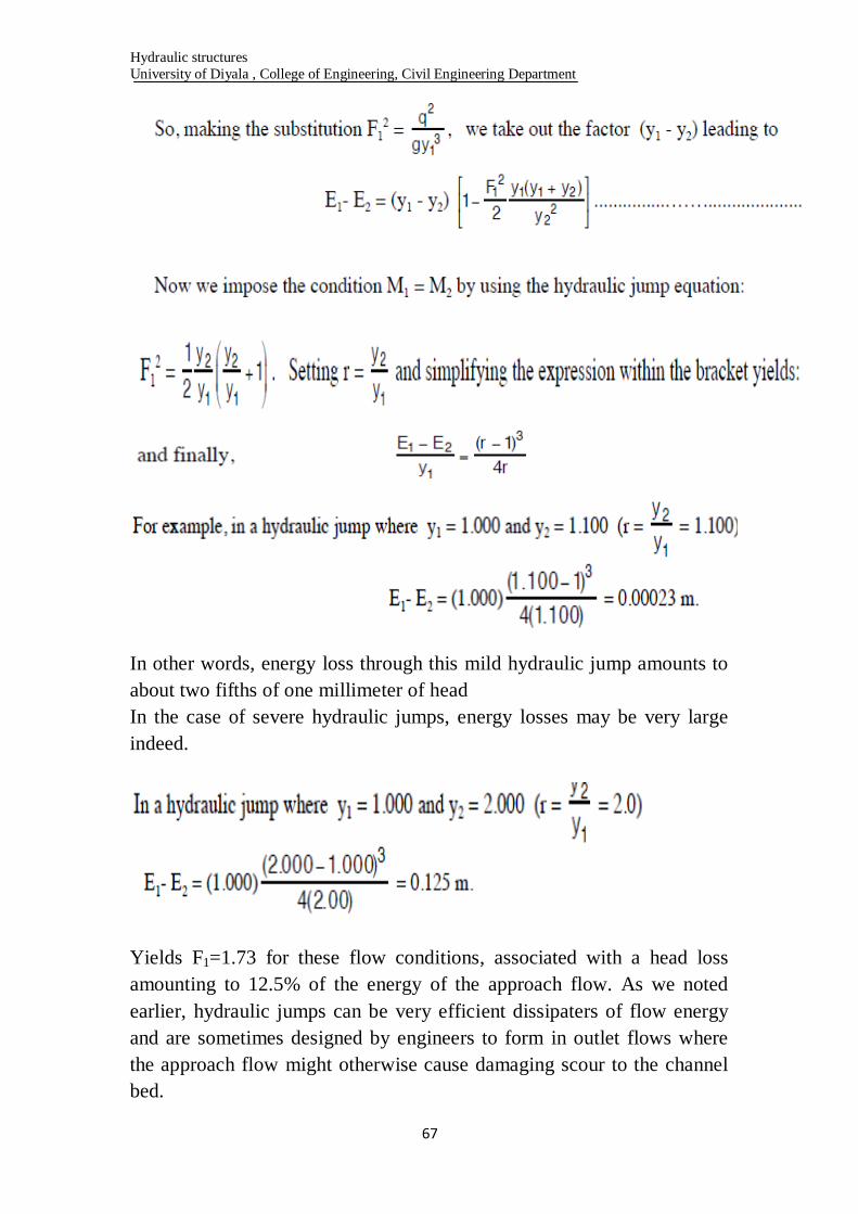
Hydraulic structures
University of Diyala , College of Engineering, Civil Engineering Department
67
In other words, energy loss through this mild hydraulic jump amounts to
about two fifths of one millimeter of head
In the case of severe hydraulic jumps, energy losses may be very large
indeed.
Yields F1=1.73 for these flow conditions, associated with a head loss
amounting to 12.5% of the energy of the approach flow. As we noted
earlier, hydraulic jumps can be very efficient dissipaters of flow energy
and are sometimes designed by engineers to form in outlet flows where
the approach flow might otherwise cause damaging scour to the channel
bed.
Hydraulic structures
University of Diyala , College of Engineering, Civil Engineering Department
68
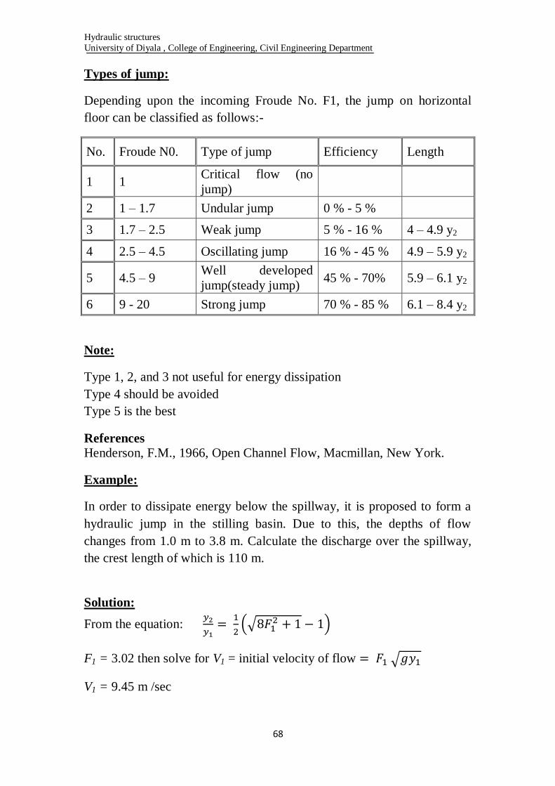
Types of jump:
Depending upon the incoming Froude No. F1, the jump on horizontal
floor can be classified as follows:-
No. Froude N0. Type of jump Efficiency Length
1 1 Critical flow (no
jump)
2 1 – 1.7 Undular jump 0 % - 5 %
3 1.7 – 2.5 Weak jump 5 % - 16 % 4 – 4.9 y2
4 2.5 – 4.5 Oscillating jump 16 % - 45 % 4.9 – 5.9 y2
5 4.5 – 9 Well developed
jump(steady jump) 45 % - 70% 5.9 – 6.1 y2
6 9 - 20 Strong jump 70 % - 85 % 6.1 – 8.4 y2
Note:
Type 1, 2, and 3 not useful for energy dissipation
Type 4 should be avoided
Type 5 is the best
References
Henderson, F.M., 1966, Open Channel Flow, Macmillan, New York.
Example:
In order to dissipate energy below the spillway, it is proposed to form a
hydraulic jump in the stilling basin. Due to this, the depths of flow
changes from 1.0 m to 3.8 m. Calculate the discharge over the spillway,
the crest length of which is 110 m.
Solution:
From the equation:
F1 = 3.02 then solve for V1 = initial velocity of flow
V1 = 9.45 m /sec
Hydraulic structures
University of Diyala , College of Engineering, Civil Engineering Department
69
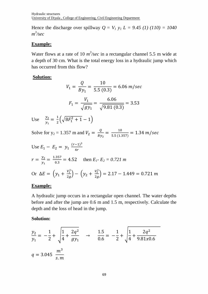
Hence the discharge over spillway Q = V1 y1 L = 9.45 (1) (110) = 1040
m3/sec
Example:
Water flows at a rate of 10 m3/sec in a rectangular channel 5.5 m wide at
a depth of 30 cm. What is the total energy loss in a hydraulic jump which
has occurred from this flow?
Solution:
Use
Solve for y2 = 1.357 m and
Use
then E1- E2 = 0.721 m
Or
Example:
A hydraulic jump occurs in a rectangular open channel. The water depths
before and after the jump are 0.6 m and 1.5 m, respectively. Calculate the
depth and the loss of head in the jump.
Solution:
Hydraulic structures
University of Diyala , College of Engineering, Civil Engineering Department
71
Or
Or
Hydraulic structures
University of Diyala , College of Engineering, Civil Engineering Department
71
Standard Stilling Basins
A stilling basin is a short length of paved channel placed at the end of
any source of super critical flow. The aim of the designer is to make a
hydraulic jump from within the basin; so that the flow is converted to
subcritical flow before it reaches the exposed and unpaved riverbed D/S.
The basin thus designed is usually provided with special appurtenances,
including chute blocks, sills, and baffle blocks.
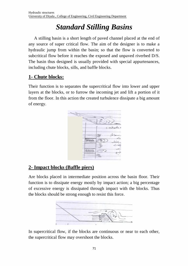
1- Chute blocks:
Their function is to separates the supercritical flow into lower and upper
layers at the blocks, or to furrow the incoming jet and lift a portion of it
from the floor. In this action the created turbulence dissipate a big amount
of energy.
2- Impact blocks (Baffle piers)
Are blocks placed in intermediate position across the basin floor. Their
function is to dissipate energy mostly by impact action; a big percentage
of excessive energy is dissipated through impact with the blocks. Thus
the blocks should be strong enough to resist this force.
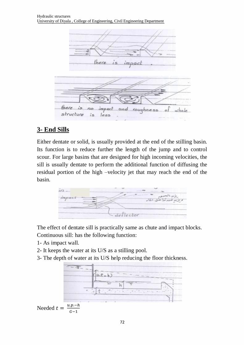
In supercritical flow, if the blocks are continuous or near to each other,
the supercritical flow may overshoot the blocks.
Hydraulic structures
University of Diyala , College of Engineering, Civil Engineering Department
72
3- End Sills
Either dentate or solid, is usually provided at the end of the stilling basin.
Its function is to reduce further the length of the jump and to control
scour. For large basins that are designed for high incoming velocities, the
sill is usually dentate to perform the additional function of diffusing the
residual portion of the high –velocity jet that may reach the end of the
basin.
The effect of dentate sill is practically same as chute and impact blocks.
Continuous sill: has the following function:
1- As impact wall.
2- It keeps the water at its U/S as a stilling pool.
3- The depth of water at its U/S help reducing the floor thickness.
Needed

Hydraulic structures
University of Diyala , College of Engineering, Civil Engineering Department
73
Type Stilling Basins and Energy Dissipaters
Using the U.S.B.R. (U.S. Bureau of Reclamation) 1987 classification,
there are five basic hydraulic jump type basins that are briefly described:-
Basin I
For Froude number less than 1.7, no special stilling basin is required.
This basin do not required baffle or dissipation devices. For (Fr) between
1.7 and 2.5 the type I-basin also applies.
U.S.B.R. Stilling Basin No. II
It is used when the incoming velocities exceed 15 m/sec, and for high
spillways or high head and large structures, Fr1 ˃ 4.5. The basin contains
chute blocks at the U/S end and a dentate sill near the D/S end. No baffle

Hydraulic structures
University of Diyala , College of Engineering, Civil Engineering Department
74
piers are used because the relatively high velocities entering the jump
might cause cavitations on piers.

Hydraulic structures
University of Diyala , College of Engineering, Civil Engineering Department
75
U.S.B.R Stilling Basin No. III
This basin may be used when the incoming velocity do not exceeds 15
m/sec, and for Fr1 > 4.5 but small structures. It is the same as No. II but
with additional impact blocks and continuous end sill.

Hydraulic structures
University of Diyala , College of Engineering, Civil Engineering Department
76
U.S.B.R Stilling Basin No. IV
This is recommended for use with jump of Fr1 = 2.5 to 4.5 (Oscillating
jump) which usually occur on canal structures and diversion dams. This
Hydraulic structures
University of Diyala , College of Engineering, Civil Engineering Department
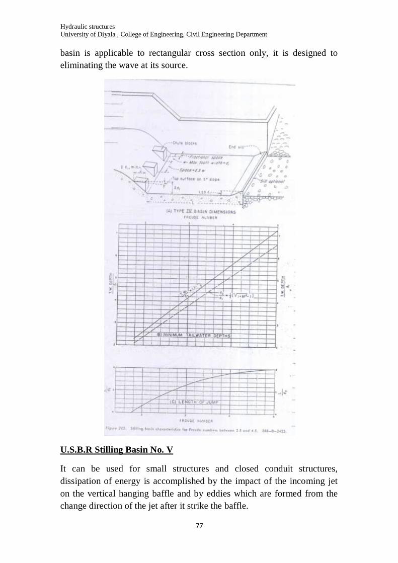
77
basin is applicable to rectangular cross section only, it is designed to
eliminating the wave at its source.
U.S.B.R Stilling Basin No. V
It can be used for small structures and closed conduit structures,
dissipation of energy is accomplished by the impact of the incoming jet
on the vertical hanging baffle and by eddies which are formed from the
change direction of the jet after it strike the baffle.
Hydraulic structures
University of Diyala , College of Engineering, Civil Engineering Department
78
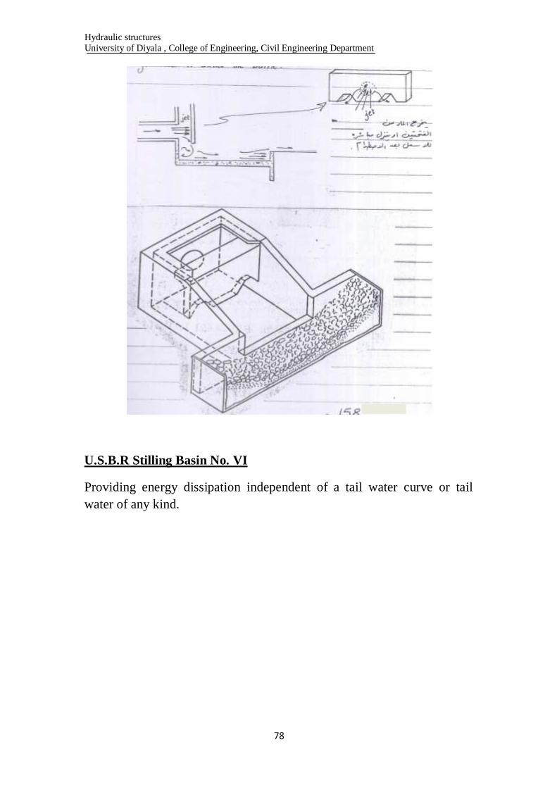
U.S.B.R Stilling Basin No. VI
Providing energy dissipation independent of a tail water curve or tail
water of any kind.

Hydraulic structures
University of Diyala , College of Engineering, Civil Engineering Department
79
Hydraulic structures
University of Diyala , College of Engineering, Civil Engineering Department
81
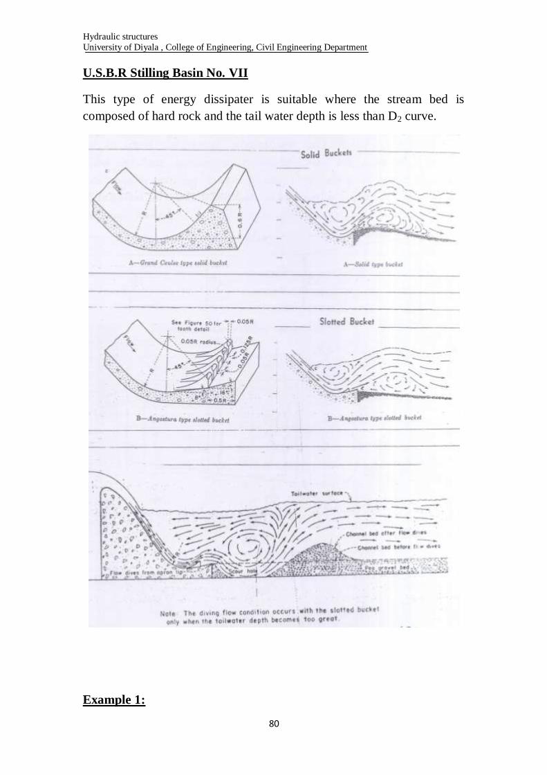
U.S.B.R Stilling Basin No. VII
This type of energy dissipater is suitable where the stream bed is
composed of hard rock and the tail water depth is less than D2 curve.
Example 1:

Hydraulic structures
University of Diyala , College of Engineering, Civil Engineering Department
81
Design U.S.B.R. stilling basin for the following hydraulic structures, Q=
5.15 m3/sec, crest width = 6 m, neglect the effect of approaching velocity.
Solution
The energy equation (Bernoulli)
by trial and error
from the curve on page 14
Therefore use stilling basin No. III
Now for
Hydraulic structures
University of Diyala , College of Engineering, Civil Engineering Department
82
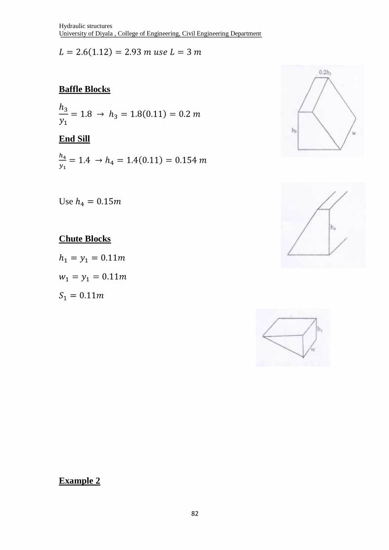
Baffle Blocks
End Sill
Use
Chute Blocks
Example 2

Hydraulic structures
University of Diyala , College of Engineering, Civil Engineering Department
83
Proportion a U.S.B.R. stilling basin type II for the given flow spillway.
Q= 2125.4 m3/sec, assuming a high over flow spillway, the approaching
of velocity is negligible.
Solution: assuming a high over flow spillway, the effect of approach
velocity is negligible or you can calculate it as following:-
The energy equation (Bernoulli)
- The height, width and spacing of the chute blocks as recommended are
y1=0.105m.
- The height of the dentate sill is 0.2 y2 = 0.2(11.81) = 2.36 m.
-The width and spacing of the dentate =0.15 y2 = 0.15(11.81) = 1.8 m.

Hydraulic structures
University of Diyala , College of Engineering, Civil Engineering Department
84
Dams
Introduction
A dam is a hydraulic structure of fairly impervious material built
across a water way to create a reservoir on its upstream side for
impounding water for various purposes. Such as storing water and or
controlling flood. Dams are generally constructed in the mountainous
reach of the river where the valley is narrow and the foundation is good. Dams are probably the most important hydraulic structure. These are very
huge structure and require huge money, manpower and time to construct.
Hydraulic structures
University of Diyala , College of Engineering, Civil Engineering Department
85
Classification
1. Based on Function Served - Storage dams
- Detention dams
- Diversion dams
- Debris dams
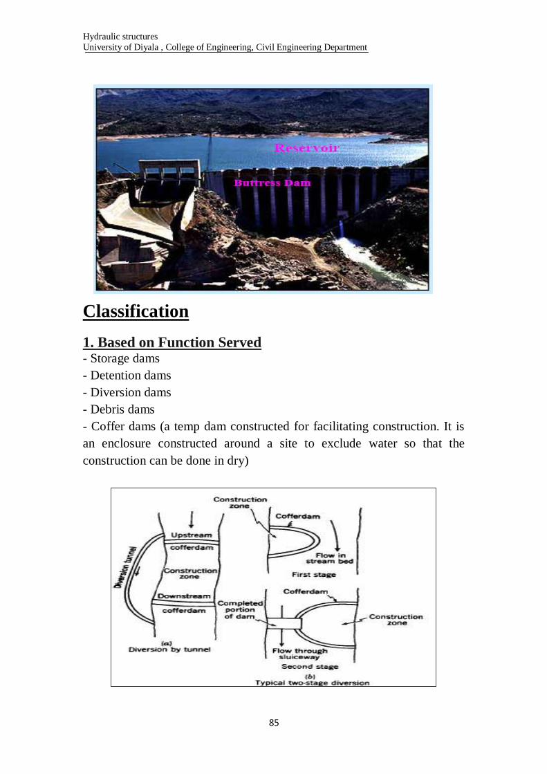
- Coffer dams (a temp dam constructed for facilitating construction. It is
an enclosure constructed around a site to exclude water so that the
construction can be done in dry)
Hydraulic structures
University of Diyala , College of Engineering, Civil Engineering Department
86
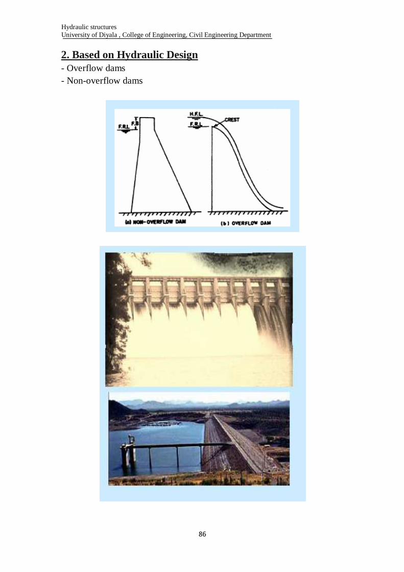
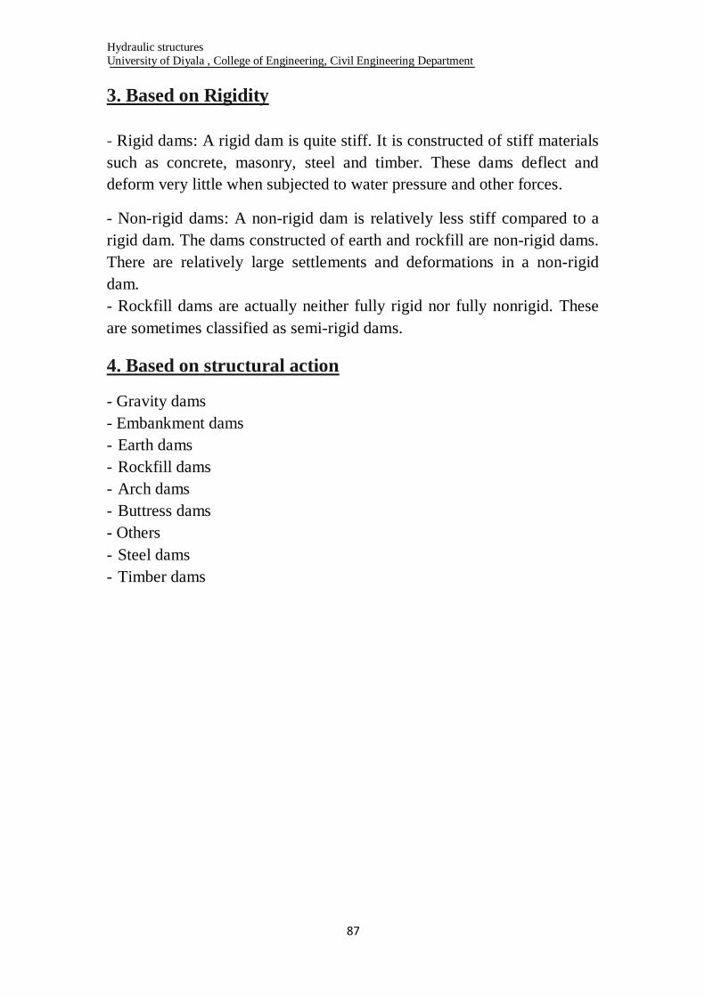
2. Based on Hydraulic Design
- Overflow dams
- Non-overflow dams
Hydraulic structures
University of Diyala , College of Engineering, Civil Engineering Department
87
3. Based on Rigidity
- Rigid dams: A rigid dam is quite stiff. It is constructed of stiff materials
such as concrete, masonry, steel and timber. These dams deflect and
deform very little when subjected to water pressure and other forces.
- Non-rigid dams: A non-rigid dam is relatively less stiff compared to a
rigid dam. The dams constructed of earth and rockfill are non-rigid dams.
There are relatively large settlements and deformations in a non-rigid
dam.
- Rockfill dams are actually neither fully rigid nor fully nonrigid. These
are sometimes classified as semi-rigid dams.
4. Based on structural action
- Gravity dams
- Embankment dams
- Earth dams
- Rockfill dams
- Arch dams
- Buttress dams
- Others
- Steel dams
- Timber dams
Hydraulic structures
University of Diyala , College of Engineering, Civil Engineering Department
88
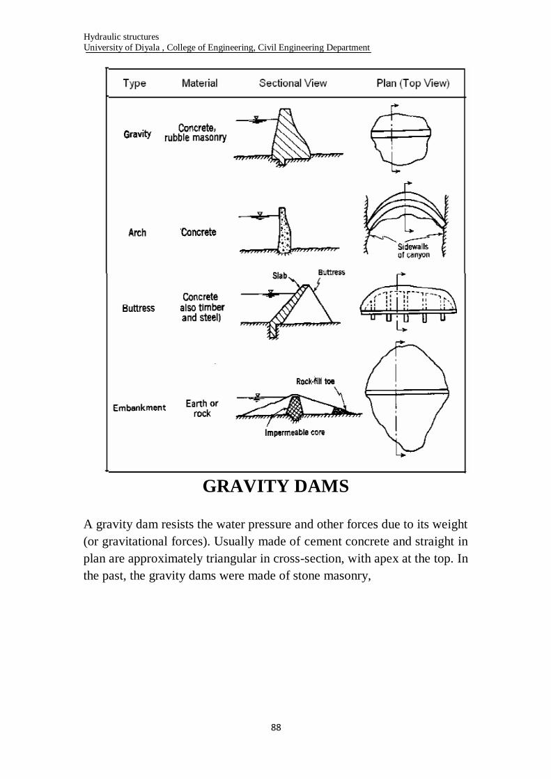
GRAVITY DAMS
A gravity dam resists the water pressure and other forces due to its weight
(or gravitational forces). Usually made of cement concrete and straight in
plan are approximately triangular in cross-section, with apex at the top. In
the past, the gravity dams were made of stone masonry,
Hydraulic structures
University of Diyala , College of Engineering, Civil Engineering Department
89
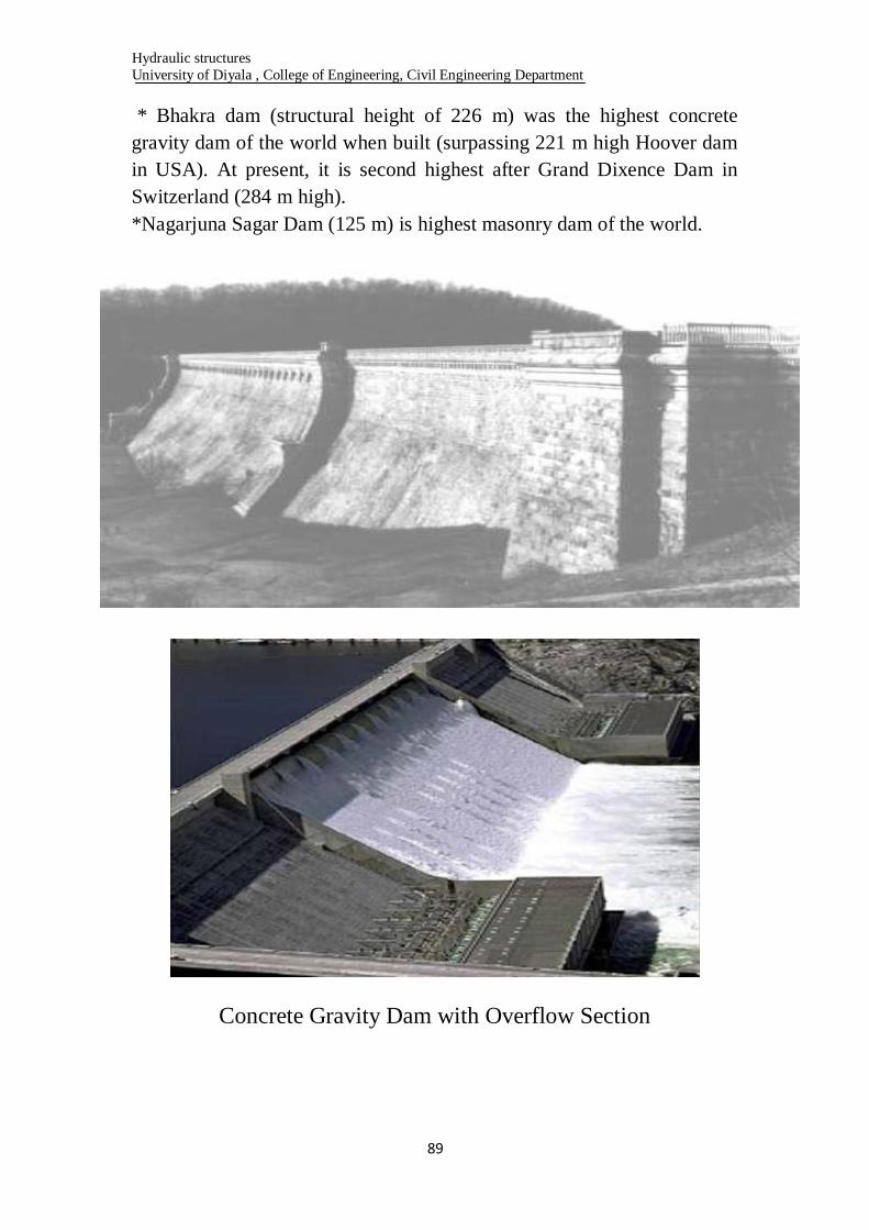
* Bhakra dam (structural height of 226 m) was the highest concrete
gravity dam of the world when built (surpassing 221 m high Hoover dam
in USA). At present, it is second highest after Grand Dixence Dam in
Switzerland (284 m high).
*Nagarjuna Sagar Dam (125 m) is highest masonry dam of the world.
Concrete Gravity Dam with Overflow Section

Hydraulic structures
University of Diyala , College of Engineering, Civil Engineering Department
91
Advantages
1. Gravity dams are quite strong, stable and durable.
2. are quite suitable across moderately wide valleys and gorges having
steep slopes where earth dams, if constructed, might slip.
3. Can be constructed to very great heights, provided good rock
foundations are available.
4. are well adapted for use as an overflow spillway section. Earth dams
cannot be used as an overflow section. Even in earth dams, the overflow
section is usually a gravity dam.
5. are specially suited to such areas where there is very heavy downpour.
The slopes of the earth dams might be washed away in such an area.
Disadvantages
1. Gravity dams of great height can be constructed only on sound rock
foundations. These cannot be constructed on weak or permeable
foundations on which earth dams can be constructed.
2. Initial cost of a gravity dam is usually more than that of an earth dam.
At the sites where good earth is available for construction and funds are
limited, earth dams are better.
3. Usually take a longer time in construction than earth dams, especially
when mechanized plants for batching, mixing and transporting concrete
are not available.
4. Require more skilled labour than that in earth dams.
5. Subsequent raising is not possible in a gravity dam.
EARTH DAMS
- An earth dam is made of earth (or soil) and resists the forces exerted
upon it mainly due to shear strength of the soil.
- are usually built in wide valleys having flat slopes at flanks (abutments).
- can be homogeneous when the height of the dam is not great.
- are of zoned sections, with an impervious zone (called core) in the
middle and relatively pervious zones (called shells or shoulders)
enclosing the impervious zone on both sides.
Nowadays majority of dams constructed are of this type.
Hydraulic structures
University of Diyala , College of Engineering, Civil Engineering Department
91
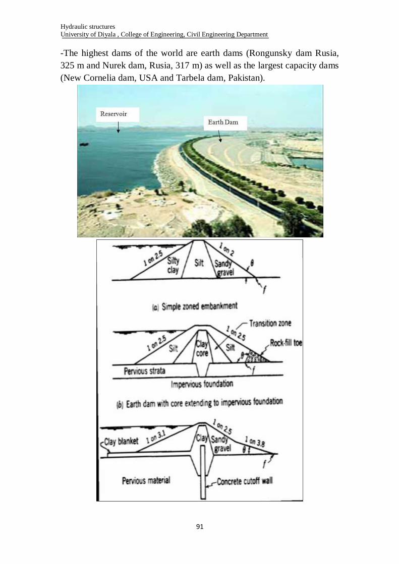
-The highest dams of the world are earth dams (Rongunsky dam Rusia,
325 m and Nurek dam, Rusia, 317 m) as well as the largest capacity dams
(New Cornelia dam, USA and Tarbela dam, Pakistan).

Hydraulic structures
University of Diyala , College of Engineering, Civil Engineering Department
92
Advantages
1. are usually cheaper than gravity dams if suitable earth for construction
is available near the site.
2. can be constructed on almost all types of foundations, provided
suitable measures of foundation treatment and seepage control are taken.
3. can be constructed in a relatively short period.
4. skilled labor is not required in construction of an earth dam.
5. can be raised subsequently.
6. are aesthetically more pleasing than gravity dams.
7. are more earthquake-resistant than gravity dams.
Disadvantages
1. are not suitable for narrow gorge with steep slopes.
2. Cannot be designed as an overflow section. A spillway has to be
located away from the dam.
3. Cannot be constructed in regions with heavy downpour, as the slopes
might be washed away.
4. Maintenance cost of an earth dam is quite high. It requires constant
supervision.
5. Sluices cannot be provided in a high earth dam to remove slit.
6. Fails suddenly without any sign of imminent failure. A sudden failure
causes havoc and untold miseries.
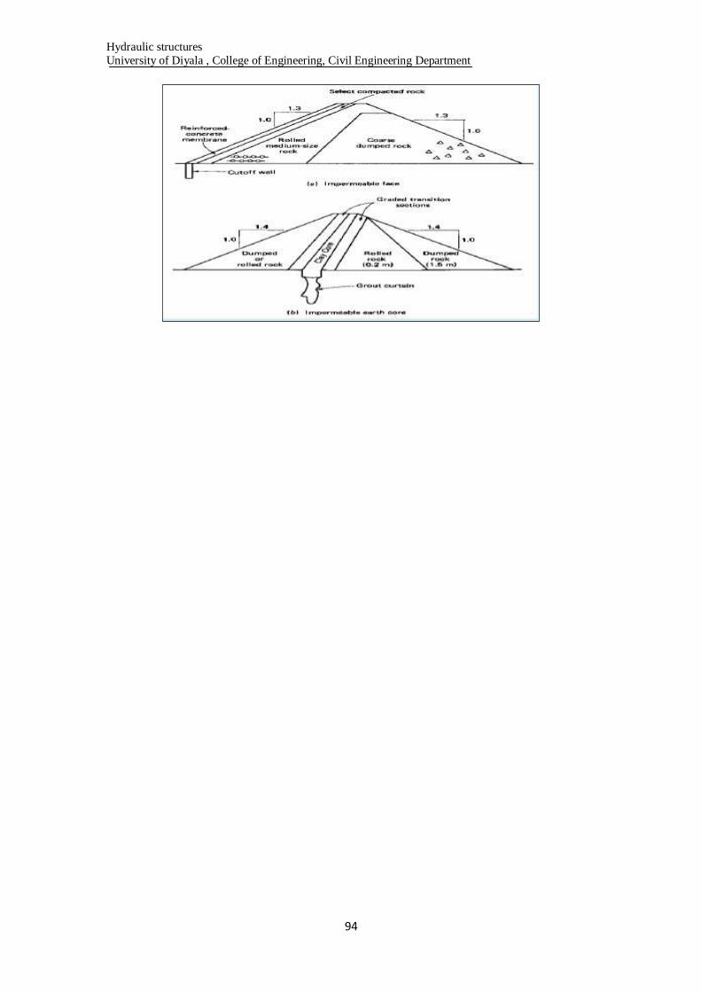
ROCKFILL DAMS -A rockfill dam is built of rock fragments and boulders of large size.
- An impervious membrane (cement concrete or asphaltic concrete or
earth core) is placed on the rockfill on the upstream side to reduce the
seepage through the dam.
- A dry rubble cushion is placed between the rockfill and the membrane
for the distribution of water load and for providing a support to the
membrane.
- Side slopes of rockfill are usually kept equal to the angle of repose of
rock (1.4:1 or 1.3:1).
-Rockfill dams are quite economical when a large quantity of rock is
easily available near the site.
Mica dam (242 m, Canada), and Chicoasen dam (240 m, Maxico) are
highest rockfill dams.

Hydraulic structures
University of Diyala , College of Engineering, Civil Engineering Department
93
Advantages
Rockfill dams have almost the same advantages and disadvantages over
gravity dams as discussed for earth dams.
Particular advantages and disadvantages over earth dams.
1. are quite inexpensive if rock fragments are easily available.
2. can be constructed quite rapidly.
3. can better withstand the shocks due to earthquake than earth dams.
4. can be constructed even in adverse climates
Disadvantages
1. Rockfill dams require more strong foundations than earth dams.
2. Rockfill dams require heavy machines for transporting, dumping and
compacting rocks.
Hydraulic structures
University of Diyala , College of Engineering, Civil Engineering Department
94
Hydraulic structures
University of Diyala , College of Engineering, Civil Engineering Department
95
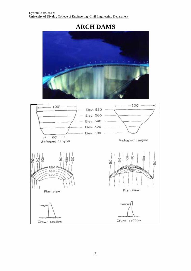
ARCH DAMS
Hydraulic structures
University of Diyala , College of Engineering, Civil Engineering Department
96
Advantages
1. An arch dam requires less concrete as compared to a gravity dam as the
section is thinner.
2. Arch dams are more suited to narrow, V-shaped valley, having very
steep slopes.
3. Uplift pressure is not an important factor in the design of an arch dam
because the arch dam has less width and the reduction in weight due to
uplift does not affect the stability.
4. An arch dam can be constructed on a relatively less strong foundation
because a small part of load is transferred to base, whereas in a gravity
dam full load is transferred to base.
Disadvantages
1. An arch dam requires good rock in the flanks (abutments) to resist the
thrust. If the abutments yield, extra stresses develop which may cause
failure.
2. The arch dam requires sophisticated formwork, more skilled labour and
richer concrete.
3. The arch dam cannot be constructed in very cold climates because
spalling of concrete occurs due to alternate freezing and thawing.
4. The arch dams are more prone to sabotage.
5. The speed of construction is relatively slow.
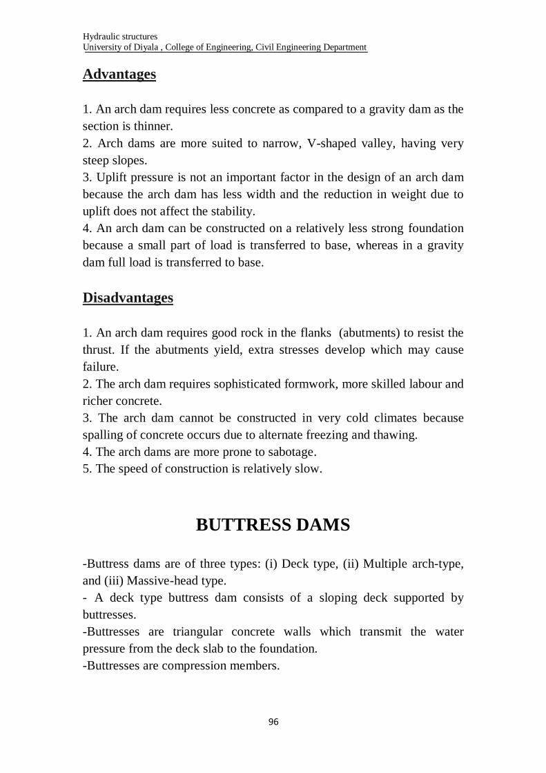
BUTTRESS DAMS
-Buttress dams are of three types: (i) Deck type, (ii) Multiple arch-type,
and (iii) Massive-head type.
- A deck type buttress dam consists of a sloping deck supported by
buttresses.
-Buttresses are triangular concrete walls which transmit the water
pressure from the deck slab to the foundation.
-Buttresses are compression members.

Hydraulic structures
University of Diyala , College of Engineering, Civil Engineering Department
97
-The deck is usually a reinforced concrete slab supported between the
buttresses, which are usually equally spaced.
-In a multiple-arch type buttress dam the deck slab is replaced by
horizontal arches supported by buttresses. The arches are usually of small
span and made of concrete.
-In a massive-head type buttress dam, there is no deck slab.
Instead of the deck, the upstream edges of the buttresses are flared to
form massive heads which span the distance between the buttresses.
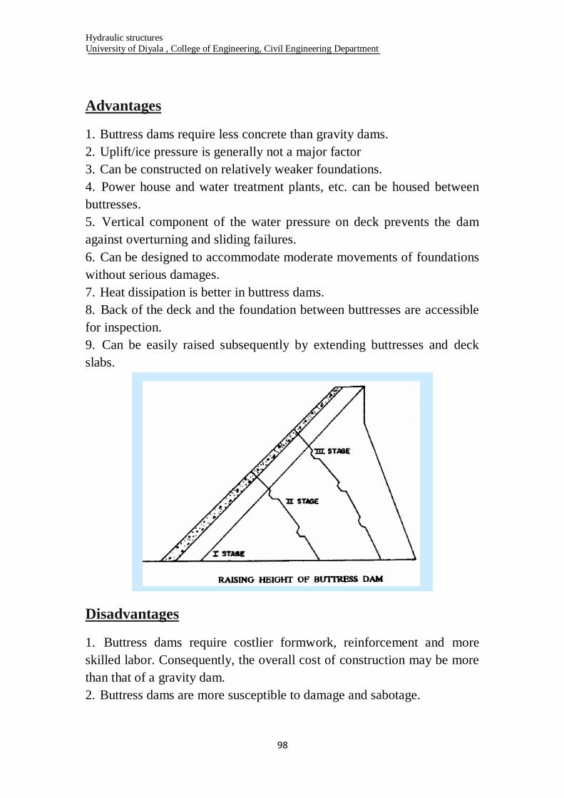
Hydraulic structures
University of Diyala , College of Engineering, Civil Engineering Department
98
Advantages
1. Buttress dams require less concrete than gravity dams.
2. Uplift/ice pressure is generally not a major factor
3. Can be constructed on relatively weaker foundations.
4. Power house and water treatment plants, etc. can be housed between
buttresses.
5. Vertical component of the water pressure on deck prevents the dam
against overturning and sliding failures.
6. Can be designed to accommodate moderate movements of foundations
without serious damages.
7. Heat dissipation is better in buttress dams.
8. Back of the deck and the foundation between buttresses are accessible
for inspection.
9. Can be easily raised subsequently by extending buttresses and deck
slabs.
Disadvantages
1. Buttress dams require costlier formwork, reinforcement and more
skilled labor. Consequently, the overall cost of construction may be more
than that of a gravity dam.
2. Buttress dams are more susceptible to damage and sabotage.
Hydraulic structures
University of Diyala , College of Engineering, Civil Engineering Department
99
3. Buttress dams cannot be constructed in very cold climates because of
spalling of concrete.
4. Because the upstream deck slab is thin, its deterioration may have very
serious effect on the stability.
SITE SELECTION FOR A DAM
- A dam is a huge structure requiring a lot of funds.
-Extreme care shall be taken while selecting the site of a dam.
-A wrong decision may lead to excessive cost and difficulties in
construction and maintenance.
-Various factors should be considered when selecting the site of a dam.
1. Topography
2. Suitable Foundation
3. Good Site for reservoir –
(i) Large storage capacity
(ii) Shape of reservoir basin
(iii) Watertightness of the reservoir
(iv) Good hydrological conditions
(v) Deep reservoir
(vi) Small submerged area
(vii) Low silt inflow
(viii) No objectionable minerals
5. Spillway site
6. Availability of materials
7. Accessibility
8. Healthy surroundings
9. Minimum overall cost
10. Other considerations
SELECTION OF TYPE OF DAM
- Selection of the most suitable type of dam for a particular site requires a
lot of judgment and experience.
- It is only in exceptional cases that the most suitable type is obvious.
- Preliminary designs and estimates are usually required for several types
of dams before making the final selection on economic basis.

Hydraulic structures
University of Diyala , College of Engineering, Civil Engineering Department
111
-The salient features of different types of dams discussed in the preceding
sections should be kept in mind while selecting the type of dam.
- Various factors govern the selection of type of dam
1. Topography and valley shape
2. Geology and foundation conditions
3. Availability of construction materials
4. Overall cost
5. Spillway size and location
6. Earthquake hazards
7. Climatic conditions
8. Diversion problems
9. Environmental considerations
10. Roadway
11. Length and height of dam
12. Life of dam
13. Miscellaneous considerations