Hydraulic Work Support - Hyfore.shop
42
Model LD Model LC Model TNC Model TC Strong support from opposite side when load is exerted Pioneer and leading innovator of hydraulic work support collet technology. Hydraulic Work Support Application Examples To avoid chattering during machining of thin-walled sections. To avoid the radial chatter on lathe machining. To back up the screw fastener machine and a nut-runner. Work piece with different heights. PAT. < No work support > < With work support > Chatter and deformation Workpiece Workpiece Seating Seating Load Load Load Load Support by work support Work support eliminates chattering while machining and prevents deformation by the cutting load. 545
-
Upload
khangminh22 -
Category
Documents
-
view
3 -
download
0
Transcript of Hydraulic Work Support - Hyfore.shop

Hole Clamp
SFASFC
Link Clamp
LKALKCLKWLM/LJTMA-2TMA-1
Work Support
LDLCTNCTC
LLW
Air SensingLift Cylinder
Compact Cylinder
LLLLRLLUDPDRDSDT
Block Cylinder
DBADBC
Control Valve
BZLBZTBZX/JZG
Pallet Clamp
VSVT
Expansion Locating Pin
VLVMVJVK
FPFQ
Pull Stud Clamp
DWA/DWB
CustomizedSpring Cylinder
Swing Clamp
LHALHCLHSLHWLT/LGTLA-2TLB-2TLA-1
Pneumatic Series
Hydraulic Series
Valve / CouplerHydraulic Unit
Cautions / Others
High-PowerSeries
Manual OperationAccessories
Work SupportDigest
Model LDModel LCModel TNCModel TC
Strong support from opposite side when load is exertedPioneer and leading innovator of hydraulic work support col let technology.
Hydraulic Work Support
Application Examples
To avoid chattering duringmachining of thin-walled sections.
To avoid the radial chatteron lathe machining.
To back up the screw fastener machineand a nut-runner.
Work piece with different heights.
PAT.
< No work support > < With work support >
Chatter and deformation
Workpiece Workpiece
Seating Seating
LoadLoadLoadLoad
Support by work support
Options
Accessories
Work support eliminates chattering while machiningand prevents deformation by the cutting load.
写真
Single ActionExternal Thread
LZ-S/SQ DZ-C/R
LZ-MP
BZL、BZX、JZG
→ P.547
Classification
Operating Pressure Range
Standard Hydraulic Advance Model
2.5~7MPa
Options
Standard Hydraulic Advance Model
Accessories
Model LD
→ P.1029
Single ActionTop Flange
→ P.571
2.5~7MPa
Model LC
Low Pressure ModelMAX 7MPa
→ P.1026
→ P.727
Single ActionExternal Thread
TNZ-S/SQ
LZ-MP
→ P.599
Classification
Operating Pressure Range 7~35MPa
Manifold Block
Piping Block
Model TNC
→ P.1034
Single ActionTop Flange
→ P.613
7~25MPa
Model TC
High Pressure ModelTNC:MAX 35MPa / TC:MAX 25MPa
→ P.1026
Hydraulic AdvanceLong Stroke Model
Hydraulic AdvanceLong Stroke Model
Spring Advance ModelSpring Advance Short Model
Spring AdvanceLong Stroke Model
Air Sensing Option
Rodless Hollow Model
Manifold Block
Piping Block
Hydraulic Advance Short Model
Spring Advance Model
Speed Control ValvePlug
Long
Short
Connecting air sensor is available
Long
→ P.557
→ P.557
→ P.559
→ P.561
→ P.563
→ P.565
-
-
-
External Dimensions → P.583
→ P.585
→ P.587
→ P.589
→ P.593
→ P.591
→ P.607
→ P.611
→ P.609
External Dimensions
External Dimensions
External Dimensions
External Dimensions
External Dimensions
→ P.617
→ P.619
ー
External Dimensions
External Dimensions
External Dimensions External Dimensions
External Dimensions External Dimensions
External Dimensions External Dimensions
External Dimensions External Dimensions
External Dimensions
※ Please contact us for detail dimension at ★ part.
Long
ー
★
-
-
545

Hole Clamp
SFASFC
Link Clamp
LKALKCLKWLM/LJTMA-2TMA-1
Work Support
LDLCTNCTC
LLW
Air SensingLift Cylinder
Compact Cylinder
LLLLRLLUDPDRDSDT
Block Cylinder
DBADBC
Control Valve
BZLBZTBZX/JZG
Pallet Clamp
VSVT
Expansion Locating Pin
VLVMVJVK
FPFQ
Pull Stud Clamp
DWA/DWB
CustomizedSpring Cylinder
Swing Clamp
LHALHCLHSLHWLT/LGTLA-2TLB-2TLA-1
Pneumatic Series
Hydraulic Series
Valve / CouplerHydraulic Unit
Cautions / Others
High-PowerSeries
Manual OperationAccessories
Work SupportDigest
Model LDModel LCModel TNCModel TC
Strong support from opposite side when load is exertedPioneer and leading innovator of hydraulic work support col let technology.
Hydraulic Work Support
Application Examples
To avoid chattering duringmachining of thin-walled sections.
To avoid the radial chatteron lathe machining.
To back up the screw fastener machineand a nut-runner.
Work piece with different heights.
PAT.
< No work support > < With work support >
Chatter and deformation
Workpiece Workpiece
Seating Seating
LoadLoadLoadLoad
Support by work support
Options
Accessories
Work support eliminates chattering while machiningand prevents deformation by the cutting load.
写真
Single ActionExternal Thread
LZ-S/SQ DZ-C/R
LZ-MP
BZL、BZX、JZG
→ P.547
Classification
Operating Pressure Range
Standard Hydraulic Advance Model
2.5~7MPa
Options
Standard Hydraulic Advance Model
Accessories
Model LD
→ P.1029
Single ActionTop Flange
→ P.571
2.5~7MPa
Model LC
Low Pressure ModelMAX 7MPa
→ P.1026
→ P.727
Single ActionExternal Thread
TNZ-S/SQ
LZ-MP
→ P.599
Classification
Operating Pressure Range 7~35MPa
Manifold Block
Piping Block
Model TNC
→ P.1034
Single ActionTop Flange
→ P.613
7~25MPa
Model TC
High Pressure ModelTNC:MAX 35MPa / TC:MAX 25MPa
→ P.1026
Hydraulic AdvanceLong Stroke Model
Hydraulic AdvanceLong Stroke Model
Spring Advance ModelSpring Advance Short Model
Spring AdvanceLong Stroke Model
Air Sensing Option
Rodless Hollow Model
Manifold Block
Piping Block
Hydraulic Advance Short Model
Spring Advance Model
Speed Control ValvePlug
Long
Short
Connecting air sensor is available
Long
→ P.557
→ P.557
→ P.559
→ P.561
→ P.563
→ P.565
-
-
-
External Dimensions → P.583
→ P.585
→ P.587
→ P.589
→ P.593
→ P.591
→ P.607
→ P.611
→ P.609
External Dimensions
External Dimensions
External Dimensions
External Dimensions
External Dimensions
→ P.617
→ P.619
ー
External Dimensions
External Dimensions
External Dimensions External Dimensions
External Dimensions External Dimensions
External Dimensions External Dimensions
External Dimensions External Dimensions
External Dimensions
※ Please contact us for detail dimension at ★ part.
Long
ー
★
-
-
546
Hole Clamp
SFASFC
Link Clamp
LKALKCLKWLM/LJTMA-2TMA-1
Work Support
LDLCTNCTC
LLW
Air SensingLift Cylinder
Compact Cylinder
LLLLRLLUDPDRDSDT
Block Cylinder
DBADBC
Control Valve
BZLBZTBZX/JZG
Pallet Clamp
VSVT
Expansion Locating Pin
VLVMVJVK
FPFQ
Pull Stud Clamp
DWA/DWB
CustomizedSpring Cylinder
Swing Clamp
LHALHCLHSLHWLT/LGTLA-2TLB-2TLA-1
Pneumatic Series
Hydraulic Series
Valve / CouplerHydraulic Unit
Cautions / Others
High-PowerSeries
Manual OperationAccessories
Work SupportDigest P.545
Model No. IndicationSpecifications
PerformanceCurve
ActionDescription
IndexCross Section
ExternalDimensions
CautionsP.623Work Support Threaded Body Model model TNC
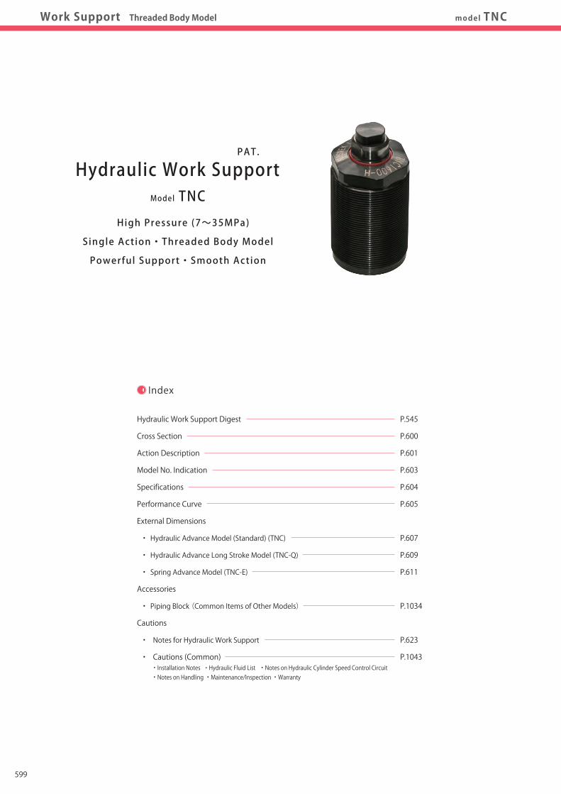
Index
Hydraulic Work Support Digest
Cross Section
Action Description
Model No. Indication
Specifications
Performance Curve
External Dimensions
・ Hydraulic Advance Model (Standard) (TNC)
・ Hydraulic Advance Long Stroke Model (TNC-Q)
・ Spring Advance Model (TNC-E)
Accessories
・ Piping Block (Common Items of Other Models)
Cautions
・ Notes for Hydraulic Work Support
・ Cautions (Common) ・ Installation Notes ・ Hydraulic Fluid List ・ Notes on Hydraulic Cylinder Speed Control Circuit ・ Notes on Handling ・ Maintenance/Inspection ・ Warranty
P.545
P.600
P.601
P.603
P.604
P.605
P.607
P.609
P.611
P.1034
P.623
P.1043
Model TNC
Hydraulic Work Support
High Pressure (7~35MPa)
Single Action・Threaded Body Model
Powerful Support・Smooth Action
PAT.
Cross Section
It adopts the collet structure, the first in the world, ensuring powerful support and smooth action.KOSMEK was the first to develop the collet design in 1996.
Compared with the traditional sleeve design, it ensures powerful gripping force via a wedge effect.
In addition, a larger gap between collet and plunger is designed to prevent sticking and allow smoother action.
Concrete Workpiece TouchAs the collet gripping the plunger is always pressed downwards, it helps prevent tilting when locked
and the clearance with the work piece.
Excellent Coolant ResistanceOur exclusive dust seal is designed to protect against high pressure coolant. It also has high durability against
chlorine-based coolant by using a sealing material with excellent chemical resistance.
Certain Sequence ActionAs it is equipped with a powerful sequencing spring, the action sequences as such;
Plunger goes up→ workpiece touches→ collet locks. This is carried out via one hydraulic circuit system.
Collet
Sequence Spring
Plunger
Excellent Coolant ResistanceElastic Spacer to Press Down the Collet
Large Clearance between the Collet and Plunger
599

Hole Clamp
SFASFC
Link Clamp
LKALKCLKWLM/LJTMA-2TMA-1
Work Support
LDLCTNCTC
LLW
Air SensingLift Cylinder
Compact Cylinder
LLLLRLLUDPDRDSDT
Block Cylinder
DBADBC
Control Valve
BZLBZTBZX/JZG
Pallet Clamp
VSVT
Expansion Locating Pin
VLVMVJVK
FPFQ
Pull Stud Clamp
DWA/DWB
CustomizedSpring Cylinder
Swing Clamp
LHALHCLHSLHWLT/LGTLA-2TLB-2TLA-1
Pneumatic Series
Hydraulic Series
Valve / CouplerHydraulic Unit
Cautions / Others
High-PowerSeries
Manual OperationAccessories
Work SupportDigest P.545
Model No. IndicationSpecifications
PerformanceCurve
ActionDescription
IndexCross Section
ExternalDimensions
CautionsP.623Work Support Threaded Body Model model TNC
Index
Hydraulic Work Support Digest
Cross Section
Action Description
Model No. Indication
Specifications
Performance Curve
External Dimensions
・ Hydraulic Advance Model (Standard) (TNC)
・ Hydraulic Advance Long Stroke Model (TNC-Q)
・ Spring Advance Model (TNC-E)
Accessories
・ Piping Block (Common Items of Other Models)
Cautions
・ Notes for Hydraulic Work Support
・ Cautions (Common) ・ Installation Notes ・ Hydraulic Fluid List ・ Notes on Hydraulic Cylinder Speed Control Circuit ・ Notes on Handling ・ Maintenance/Inspection ・ Warranty
P.545
P.600
P.601
P.603
P.604
P.605
P.607
P.609
P.611
P.1034
P.623
P.1043
Model TNC
Hydraulic Work Support
High Pressure (7~35MPa)
Single Action・Threaded Body Model
Powerful Support・Smooth Action
PAT.
Cross Section
It adopts the collet structure, the first in the world, ensuring powerful support and smooth action.KOSMEK was the first to develop the collet design in 1996.
Compared with the traditional sleeve design, it ensures powerful gripping force via a wedge effect.
In addition, a larger gap between collet and plunger is designed to prevent sticking and allow smoother action.
Concrete Workpiece TouchAs the collet gripping the plunger is always pressed downwards, it helps prevent tilting when locked
and the clearance with the work piece.
Excellent Coolant ResistanceOur exclusive dust seal is designed to protect against high pressure coolant. It also has high durability against
chlorine-based coolant by using a sealing material with excellent chemical resistance.
Certain Sequence ActionAs it is equipped with a powerful sequencing spring, the action sequences as such;
Plunger goes up→ workpiece touches→ collet locks. This is carried out via one hydraulic circuit system.
Collet
Sequence Spring
Plunger
Excellent Coolant ResistanceElastic Spacer to Press Down the Collet
Large Clearance between the Collet and Plunger
600

Hole Clamp
SFASFC
Link Clamp
LKALKCLKWLM/LJTMA-2TMA-1
Work Support
LDLCTNCTC
LLW
Air SensingLift Cylinder
Compact Cylinder
LLLLRLLUDPDRDSDT
Block Cylinder
DBADBC
Control Valve
BZLBZTBZX/JZG
Pallet Clamp
VSVT
Expansion Locating Pin
VLVMVJVK
FPFQ
Pull Stud Clamp
DWA/DWB
CustomizedSpring Cylinder
Swing Clamp
LHALHCLHSLHWLT/LGTLA-2TLB-2TLA-1
Pneumatic Series
Hydraulic Series
Valve / CouplerHydraulic Unit
Cautions / Others
High-PowerSeries
Manual OperationAccessories
Work SupportDigest P.545
Model No. IndicationSpecifications
PerformanceCurve
ActionDescription
IndexCross Section
ExternalDimensions
CautionsP.623Work Support Threaded Body Model model TNC
Action Description
Internal Action Description
Hydraulic Advance model TNC
Hydraulic Advance Model (TNC)
Hydraulic Pressure:OFFThe state of plunger down.
Hydraulic Pressure:ONPlunger rises with oil pressure and stops after touching workpiece.
Hydraulic Pressure:ONOnce it is in the stopped position where it touches the workpiece, the plunger doesn’t go down even if pressed from above.
Plunger
Spring Advance Model (TNC-E)
Hydraulic Pressure:OFFThe state of plunger up.
Hydraulic Pressure:OFFWhen workpiece rests on the work support, plunger goes down due to the weight of workpiece and is balanced.
Hydraulic Pressure:ONOnce it is in the stopped position where it touches the workpiece, the plunger doesn’t go down even if pressed from above.
Work Support Body
Seat
Workpiece
Seat
Plunger
Work Support Body
It doesn't moveeven if pressed from the top !!
Grippingthe plunger !
Grippingthe plunger !
It doesn't moveeven if pressed from the top !!
When releasing (Cross Section) Contact bolt makes contact with workpiece Locked State
① The piston starts to press down via hydraulic pressure.
② The tapering action between the piston and collet affects
the steel ball so that the collect can grip the plunger with even
and strong power to generate the supporting force.
Plunger extends
Plunger piston rises first when hydraulic pressure is supplied.
Plunger rises via spring force to the workpiece with this action.
Plunger piston rises to the upper limit even after
contact bolt makes contact with workpiece.
Plunger lowered by spring force.
Workpiece
Contact Bolt
Steel Ball
Collet
Plunger Piston
Vent PortHydraulic PortHydraulic Pressure ON
Hydraulic Pressure ON Hydraulic Pressure ON
Spring Advance model TNC-E
Workpiece set(Plunger goes down) Locked StateReleased State
Hydraulic Pressure OFFHydraulic Pressure OFF
Hydraulic Pressure ON
When releasing (Cross Section)
Hydraulic Port
Piston
Plunger
②
Plunger
Steel Ball
Collet
Vent Port
Workpiece
★ ★Section of Collet ★-★
Collet
Plunger
②
Section of Collet ★-★
Collet
Plunger
②
①
②
①
Piston
Contact Bolt
★ ★
601

Hole Clamp
SFASFC
Link Clamp
LKALKCLKWLM/LJTMA-2TMA-1
Work Support
LDLCTNCTC
LLW
Air SensingLift Cylinder
Compact Cylinder
LLLLRLLUDPDRDSDT
Block Cylinder
DBADBC
Control Valve
BZLBZTBZX/JZG
Pallet Clamp
VSVT
Expansion Locating Pin
VLVMVJVK
FPFQ
Pull Stud Clamp
DWA/DWB
CustomizedSpring Cylinder
Swing Clamp
LHALHCLHSLHWLT/LGTLA-2TLB-2TLA-1
Pneumatic Series
Hydraulic Series
Valve / CouplerHydraulic Unit
Cautions / Others
High-PowerSeries
Manual OperationAccessories
Work SupportDigest P.545
Model No. IndicationSpecifications
PerformanceCurve
ActionDescription
IndexCross Section
ExternalDimensions
CautionsP.623Work Support Threaded Body Model model TNC
Action Description
Internal Action Description
Hydraulic Advance model TNC
Hydraulic Advance Model (TNC)
Hydraulic Pressure:OFFThe state of plunger down.
Hydraulic Pressure:ONPlunger rises with oil pressure and stops after touching workpiece.
Hydraulic Pressure:ONOnce it is in the stopped position where it touches the workpiece, the plunger doesn’t go down even if pressed from above.
Plunger
Spring Advance Model (TNC-E)
Hydraulic Pressure:OFFThe state of plunger up.
Hydraulic Pressure:OFFWhen workpiece rests on the work support, plunger goes down due to the weight of workpiece and is balanced.
Hydraulic Pressure:ONOnce it is in the stopped position where it touches the workpiece, the plunger doesn’t go down even if pressed from above.
Work Support Body
Seat
Workpiece
Seat
Plunger
Work Support Body
It doesn't moveeven if pressed from the top !!
Grippingthe plunger !
Grippingthe plunger !
It doesn't moveeven if pressed from the top !!
When releasing (Cross Section) Contact bolt makes contact with workpiece Locked State
① The piston starts to press down via hydraulic pressure.
② The tapering action between the piston and collet affects
the steel ball so that the collect can grip the plunger with even
and strong power to generate the supporting force.
Plunger extends
Plunger piston rises first when hydraulic pressure is supplied.
Plunger rises via spring force to the workpiece with this action.
Plunger piston rises to the upper limit even after
contact bolt makes contact with workpiece.
Plunger lowered by spring force.
Workpiece
Contact Bolt
Steel Ball
Collet
Plunger Piston
Vent PortHydraulic PortHydraulic Pressure ON
Hydraulic Pressure ON Hydraulic Pressure ON
Spring Advance model TNC-E
Workpiece set(Plunger goes down) Locked StateReleased State
Hydraulic Pressure OFFHydraulic Pressure OFF
Hydraulic Pressure ON
When releasing (Cross Section)
Hydraulic Port
Piston
Plunger
②
Plunger
Steel Ball
Collet
Vent Port
Workpiece
★ ★Section of Collet ★-★
Collet
Plunger
②
Section of Collet ★-★
Collet
Plunger
②
①
②
①
Piston
Contact Bolt
★ ★
602

Hole Clamp
SFASFC
Link Clamp
LKALKCLKWLM/LJTMA-2TMA-1
Work Support
LDLCTNCTC
LLW
Air SensingLift Cylinder
Compact Cylinder
LLLLRLLUDPDRDSDT
Block Cylinder
DBADBC
Control Valve
BZLBZTBZX/JZG
Pallet Clamp
VSVT
Expansion Locating Pin
VLVMVJVK
FPFQ
Pull Stud Clamp
DWA/DWB
CustomizedSpring Cylinder
Swing Clamp
LHALHCLHSLHWLT/LGTLA-2TLB-2TLA-1
Pneumatic Series
Hydraulic Series
Valve / CouplerHydraulic Unit
Cautions / Others
High-PowerSeries
Manual OperationAccessories
Work SupportDigest P.545
Model No. IndicationSpecifications
PerformanceCurve
ActionDescription
IndexCross Section
ExternalDimensions
CautionsP.623Work Support Threaded Body Model model TNC
Model No. Indication
3
2
Plunger Spring Force
L : Low Spring Force
H : High Spring Force
Blank : Q selected
1
1 2 3
Support Force
040 : Support Force 4.4kN at 35MPa
060 : Support Force 7.1kN at 35MPa
100 : Support Force 11.7kN at 35MPa
160 : Support Force 16.3kN at 35MPa
0 : Revision Number
Design No.
TNC 040 0 - L - 4
4 Options
Blank : Hydraulic Advance Model (Standard)
Q : Hydraulic Advance Long Stroke Model
E : Spring Advance Model
Model No.
Support Force at 35MPa kN
Support Force (Calculation Formula)※1 kN
Plunger Stroke mm
Cylinder Capacity cm3
Plunger Spring Force ※2 N
Max. Operating Pressure MPa
Min. Operating Pressure MPa
Operating Temperature ℃
Mass kg
TNC0400-Q TNC0600-Q TNC1000-Q TNC1600-Q
4.4 7.1 11.7 16.3
0.147×P-0.733 0.237×P-1.183 0.390×P-1.950 0.543×P-2.717
13 16 20 24
0.6 1.0 1.9 3.1
6.1~11.4 6.2~12.9 7.8~20.4 10.1~24.8
35
7
0~70
0.2 0.3 0.4 0.95
Specifications
Notes ※ 1. P in the formula for support force indicates the hydraulic pressure (MPa). ※ 2. The plunger spring force figure indicates the spring design force. It may vary due to moving resistance of the plunger and spring. Please use it as reference for the work piece contacting force. ※ Please contact us for Spring Advance Long Stroke model.
Model No.
Support Force at 35MPa kN
Support Force (Calculation Formula)※1 kN
Plunger Stroke mm
Cylinder Capacity
cm3
Plunger Spring Force※2 L: Low Spring Force
N H:High Spring Force
Max. Operating Pressure MPa
Min. Operating Pressure MPa
Operating Temperature ℃
Mass kg
TNC0400-□ TNC0600-□ TNC1000-□ TNC1600-□
TNC0400-□-E TNC0600-□-E TNC1000-□-E TNC1600-□-E
4.4 7.1 11.7 16.3
0.147×P-0.733 0.237×P-1.183 0.390×P-1.950 0.543×P-2.717
6.5 8 10 12
0.3 0.6 1.1 1.8
0.1 0.1 0.3 0.4
4.0~5.8 4.7~7.8 5.8~9.7 8.3~14.6
5.6~8.0 6.2~11.0 7.8~13.5 10.1~22.0
35
7
0~70
0.15 0.2 0.3 0.75
Blank Selected
E Selected
4
4
Blank / E selected4
Q selected4
4
603

Hole Clamp
SFASFC
Link Clamp
LKALKCLKWLM/LJTMA-2TMA-1
Work Support
LDLCTNCTC
LLW
Air SensingLift Cylinder
Compact Cylinder
LLLLRLLUDPDRDSDT
Block Cylinder
DBADBC
Control Valve
BZLBZTBZX/JZG
Pallet Clamp
VSVT
Expansion Locating Pin
VLVMVJVK
FPFQ
Pull Stud Clamp
DWA/DWB
CustomizedSpring Cylinder
Swing Clamp
LHALHCLHSLHWLT/LGTLA-2TLB-2TLA-1
Pneumatic Series
Hydraulic Series
Valve / CouplerHydraulic Unit
Cautions / Others
High-PowerSeries
Manual OperationAccessories
Work SupportDigest P.545
Model No. IndicationSpecifications
PerformanceCurve
ActionDescription
IndexCross Section
ExternalDimensions
CautionsP.623Work Support Threaded Body Model model TNC
Model No. Indication
3
2
Plunger Spring Force
L : Low Spring Force
H : High Spring Force
Blank : Q selected
1
1 2 3
Support Force
040 : Support Force 4.4kN at 35MPa
060 : Support Force 7.1kN at 35MPa
100 : Support Force 11.7kN at 35MPa
160 : Support Force 16.3kN at 35MPa
0 : Revision Number
Design No.
TNC 040 0 - L - 4
4 Options
Blank : Hydraulic Advance Model (Standard)
Q : Hydraulic Advance Long Stroke Model
E : Spring Advance Model
Model No.
Support Force at 35MPa kN
Support Force (Calculation Formula)※1 kN
Plunger Stroke mm
Cylinder Capacity cm3
Plunger Spring Force ※2 N
Max. Operating Pressure MPa
Min. Operating Pressure MPa
Operating Temperature ℃
Mass kg
TNC0400-Q TNC0600-Q TNC1000-Q TNC1600-Q
4.4 7.1 11.7 16.3
0.147×P-0.733 0.237×P-1.183 0.390×P-1.950 0.543×P-2.717
13 16 20 24
0.6 1.0 1.9 3.1
6.1~11.4 6.2~12.9 7.8~20.4 10.1~24.8
35
7
0~70
0.2 0.3 0.4 0.95
Specifications
Notes ※ 1. P in the formula for support force indicates the hydraulic pressure (MPa). ※ 2. The plunger spring force figure indicates the spring design force. It may vary due to moving resistance of the plunger and spring. Please use it as reference for the work piece contacting force. ※ Please contact us for Spring Advance Long Stroke model.
Model No.
Support Force at 35MPa kN
Support Force (Calculation Formula)※1 kN
Plunger Stroke mm
Cylinder Capacity
cm3
Plunger Spring Force※2 L: Low Spring Force
N H:High Spring Force
Max. Operating Pressure MPa
Min. Operating Pressure MPa
Operating Temperature ℃
Mass kg
TNC0400-□ TNC0600-□ TNC1000-□ TNC1600-□
TNC0400-□-E TNC0600-□-E TNC1000-□-E TNC1600-□-E
4.4 7.1 11.7 16.3
0.147×P-0.733 0.237×P-1.183 0.390×P-1.950 0.543×P-2.717
6.5 8 10 12
0.3 0.6 1.1 1.8
0.1 0.1 0.3 0.4
4.0~5.8 4.7~7.8 5.8~9.7 8.3~14.6
5.6~8.0 6.2~11.0 7.8~13.5 10.1~22.0
35
7
0~70
0.15 0.2 0.3 0.75
Blank Selected
E Selected
4
4
Blank / E selected4
Q selected4
4
604

Hole Clamp
SFASFC
Link Clamp
LKALKCLKWLM/LJTMA-2TMA-1
Work Support
LDLCTNCTC
LLW
Air SensingLift Cylinder
Compact Cylinder
LLLLRLLUDPDRDSDT
Block Cylinder
DBADBC
Control Valve
BZLBZTBZX/JZG
Pallet Clamp
VSVT
Expansion Locating Pin
VLVMVJVK
FPFQ
Pull Stud Clamp
DWA/DWB
CustomizedSpring Cylinder
Swing Clamp
LHALHCLHSLHWLT/LGTLA-2TLB-2TLA-1
Pneumatic Series
Hydraulic Series
Valve / CouplerHydraulic Unit
Cautions / Others
High-PowerSeries
Manual OperationAccessories
Work SupportDigest P.545
Model No. IndicationSpecifications
PerformanceCurve
ActionDescription
IndexCross Section
ExternalDimensions
CautionsP.623Work Support Threaded Body Model model TNC
TNC1600-Q
TNC1000-Q
TNC0600-QTNC0400-Q
Load
When the static load is added
Displacement
When locked (Without load)
2018168 10 12 146420
Load (kN)Load (kN)
0 1 3 420
20
10
5
15
Displacement (μm)
50
30
40
20
10
0
Performance Curve(TNC-Q:Hydraulic Advance Long Stroke Model )
1 Body Size
Applicable Model
TNC 040 0 - Q
4.4 7.1 11.7 16.3 4.0 6.5 10.7 14.9 3.7 5.9 9.8 13.6 3.3 5.3 8.8 12.2 2.9 4.7 7.8 10.9 2.6 4.1 6.8 9.5 2.2 3.6 5.9 8.1 1.8 3.0 4.9 6.8 1.5 2.4 3.9 5.4 1.1 1.8 2.9 4.1 0.7 1.2 2.0 2.7 0.4 0.6 1.0 1.4 0.147×P-0.733 0.237×P-1.183 0.390×P-1.950 0.543×P-2.717
Model No.Operating Hydraulic Pressure (MPa)
3532.53027.52522.52017.51512.5107.5
Support Force Formula kN
Support Force (kN)
TNC0400-Q TNC0600-Q TNC1000-Q TNC1600-Q
※3
Note ※ 3. P : Operating hydraulic pressure (MPa)
TNC1600-Q
TNC1000-Q
TNC0600-Q
TNC0400-Q
TNC1600-Q
TNC1000-Q
TNC0400-Q
TNC0600-Q
0 35302520151050
20
15
10
5
Operating Hydraulic Pressure (MPa)
Support Force (kN)
TNC1600
TNC1000
TNC0600TNC0400
Load
When the static load is added
Displacement
When locked (Without load)
2018168 10 12 146420
Load (kN)Load (kN)
0 1 3 420
20
10
5
15
Displacement (μm)
50
30
40
20
10
0
Performance Curve(TNC-□:Hydraulic Advance Model / TNC-□-E:Spring Advance Model )
1 Body Size
Applicable Model
TNC 040 0 - -
4.4 7.1 11.7 16.3 4.0 6.5 10.7 14.9 3.7 5.9 9.8 13.6 3.3 5.3 8.8 12.2 2.9 4.7 7.8 10.9 2.6 4.1 6.8 9.5 2.2 3.6 5.9 8.1 1.8 3.0 4.9 6.8 1.5 2.4 3.9 5.4 1.1 1.8 2.9 4.1 0.7 1.2 2.0 2.7 0.4 0.6 1.0 1.4 0.147×P-0.733 0.237×P-1.183 0.390×P-1.950 0.543×P-2.717
Model No.Operating Hydraulic Pressure (MPa)
3532.53027.52522.52017.51512.5107.5
Support Force Formula kN
Support Force (kN) TNC0400-□ TNC0600-□ TNC1000-□ TNC1600-□ TNC0400-□-E TNC0600-□-E TNC1000-□-E TNC1600-□-E
※3
Note ※ 3. P : Operating hydraulic pressure (MPa)
TNC1600
TNC1000
TNC0600
TNC0400
TNC1600
TNC1000
TNC0400
TNC0600
0 35302520151050
20
15
10
5
Operating Hydraulic Pressure (MPa)
Support Force (kN)
LH
BlankE
4 Options:Blank、E selected
4 Options:Q selected
Load / Displacement Graph ※ This graph shows the static load displacement at 35 MPa hydraulic pressure.
Support Force Graph ※ This graph shows the support force under static load condition. Support Force Graph ※ This graph shows the support force under static load condition.
Load / Displacement Graph ※ This graph shows the static load displacement at 35 MPa hydraulic pressure.
※ The Displacement of TNC-Q :long stoke model is bigger than TNC:standard model.
605

Hole Clamp
SFASFC
Link Clamp
LKALKCLKWLM/LJTMA-2TMA-1
Work Support
LDLCTNCTC
LLW
Air SensingLift Cylinder
Compact Cylinder
LLLLRLLUDPDRDSDT
Block Cylinder
DBADBC
Control Valve
BZLBZTBZX/JZG
Pallet Clamp
VSVT
Expansion Locating Pin
VLVMVJVK
FPFQ
Pull Stud Clamp
DWA/DWB
CustomizedSpring Cylinder
Swing Clamp
LHALHCLHSLHWLT/LGTLA-2TLB-2TLA-1
Pneumatic Series
Hydraulic Series
Valve / CouplerHydraulic Unit
Cautions / Others
High-PowerSeries
Manual OperationAccessories
Work SupportDigest P.545
Model No. IndicationSpecifications
PerformanceCurve
ActionDescription
IndexCross Section
ExternalDimensions
CautionsP.623Work Support Threaded Body Model model TNC
TNC1600-Q
TNC1000-Q
TNC0600-QTNC0400-Q
Load
When the static load is added
Displacement
When locked (Without load)
2018168 10 12 146420
Load (kN)Load (kN)
0 1 3 420
20
10
5
15
Displacement (μm)
50
30
40
20
10
0
Performance Curve(TNC-Q:Hydraulic Advance Long Stroke Model )
1 Body Size
Applicable Model
TNC 040 0 - Q
4.4 7.1 11.7 16.3 4.0 6.5 10.7 14.9 3.7 5.9 9.8 13.6 3.3 5.3 8.8 12.2 2.9 4.7 7.8 10.9 2.6 4.1 6.8 9.5 2.2 3.6 5.9 8.1 1.8 3.0 4.9 6.8 1.5 2.4 3.9 5.4 1.1 1.8 2.9 4.1 0.7 1.2 2.0 2.7 0.4 0.6 1.0 1.4 0.147×P-0.733 0.237×P-1.183 0.390×P-1.950 0.543×P-2.717
Model No.Operating Hydraulic Pressure (MPa)
3532.53027.52522.52017.51512.5107.5
Support Force Formula kN
Support Force (kN)
TNC0400-Q TNC0600-Q TNC1000-Q TNC1600-Q
※3
Note ※ 3. P : Operating hydraulic pressure (MPa)
TNC1600-Q
TNC1000-Q
TNC0600-Q
TNC0400-Q
TNC1600-Q
TNC1000-Q
TNC0400-Q
TNC0600-Q
0 35302520151050
20
15
10
5
Operating Hydraulic Pressure (MPa)
Support Force (kN)
TNC1600
TNC1000
TNC0600TNC0400
Load
When the static load is added
Displacement
When locked (Without load)
2018168 10 12 146420
Load (kN)Load (kN)
0 1 3 420
20
10
5
15
Displacement (μm)
50
30
40
20
10
0
Performance Curve(TNC-□:Hydraulic Advance Model / TNC-□-E:Spring Advance Model )
1 Body Size
Applicable Model
TNC 040 0 - -
4.4 7.1 11.7 16.3 4.0 6.5 10.7 14.9 3.7 5.9 9.8 13.6 3.3 5.3 8.8 12.2 2.9 4.7 7.8 10.9 2.6 4.1 6.8 9.5 2.2 3.6 5.9 8.1 1.8 3.0 4.9 6.8 1.5 2.4 3.9 5.4 1.1 1.8 2.9 4.1 0.7 1.2 2.0 2.7 0.4 0.6 1.0 1.4 0.147×P-0.733 0.237×P-1.183 0.390×P-1.950 0.543×P-2.717
Model No.Operating Hydraulic Pressure (MPa)
3532.53027.52522.52017.51512.5107.5
Support Force Formula kN
Support Force (kN) TNC0400-□ TNC0600-□ TNC1000-□ TNC1600-□ TNC0400-□-E TNC0600-□-E TNC1000-□-E TNC1600-□-E
※3
Note ※ 3. P : Operating hydraulic pressure (MPa)
TNC1600
TNC1000
TNC0600
TNC0400
TNC1600
TNC1000
TNC0400
TNC0600
0 35302520151050
20
15
10
5
Operating Hydraulic Pressure (MPa)
Support Force (kN)
LH
BlankE
4 Options:Blank、E selected
4 Options:Q selected
Load / Displacement Graph ※ This graph shows the static load displacement at 35 MPa hydraulic pressure.
Support Force Graph ※ This graph shows the support force under static load condition. Support Force Graph ※ This graph shows the support force under static load condition.
Load / Displacement Graph ※ This graph shows the static load displacement at 35 MPa hydraulic pressure.
※ The Displacement of TNC-Q :long stoke model is bigger than TNC:standard model.
606

Hole Clamp
SFASFC
Link Clamp
LKALKCLKWLM/LJTMA-2TMA-1
Work Support
LDLCTNCTC
LLW
Air SensingLift Cylinder
Compact Cylinder
LLLLRLLUDPDRDSDT
Block Cylinder
DBADBC
Control Valve
BZLBZTBZX/JZG
Pallet Clamp
VSVT
Expansion Locating Pin
VLVMVJVK
FPFQ
Pull Stud Clamp
DWA/DWB
CustomizedSpring Cylinder
Swing Clamp
LHALHCLHSLHWLT/LGTLA-2TLB-2TLA-1
Pneumatic Series
Hydraulic Series
Valve / CouplerHydraulic Unit
Cautions / Others
High-PowerSeries
Manual OperationAccessories
Work SupportDigest P.545
Model No. IndicationSpecifications
PerformanceCurve
ActionDescription
IndexCross Section
ExternalDimensions
CautionsP.623Work Support Threaded Body Model:Hydraulic Advance Model (Standard) model TNC
min.EC
φEB
φED
EEEG EF
EX ScrewO-ring
D Screw (Prepared HoleφCB ) CC
C1
CD or more
12.5S
Vent Port ※1φCG
Hydraulic PortφCE
0.4
Hexagon B
BC W
X Screw
External Dimensions Machining Dimensions of Mounting Area
Contact Bolt Design Dimensions※Please use as reference in case contact bolts (attachment) other than the attached contact bolt are designed and manufactured to the customer.
Z0.05
+ 0.17- 0.12
Z
※ This drawing shows the released state of TNC-□ (before the plunger is lifted).
Note ※ 1. The vent port needs to be processed in an open air environment without the presence of coolant, dust, etc. to avoid any internal contamination. (Refer to P.623: Appropriate Position of Vent Port for reference.)
EY
F
A
GH
ETV
φC
φBAφU
D Screw
φJ + 0.1 0
BB
Contact Bolt(Included)
Plunger Stroke
15°
Vent PortHydraulic PortφCGφCE
O-ring (Included)DB
O-ring (Included)DA
p.c.d.CF
Model No. Indication
LH
1 32
4 Options
3 Plunger Spring Force
1 Body Size
2 Design No.
(Format Example:TNC0480-L)
TNC 040 0-
(mm)
(mm) Corresponding Product Model EB EC ED EE EF EG EX (Nominal×Pitch) O-ring
Model No. Plunger Stroke A B C D(Nominal×Pitch) E F G H J T U V W X (Nominal×Pitch×Depth) BA BB BC CB CC CD CE CF CG DA DB EY Tightening Torque for Main Body※2
Contact Bolt Design Dimensions※Please use as reference in case contact bolts (attachment) other than the attached contact bolt are designed and manufactured to the customer.
TNC0400-□ TNC0600-□ TNC1000-□ TNC1600-□ 6.5 8 10 12 60 65 76.5 88 24 27 32 41 26 30 36 45 M26×1.5 M30×1.5 M36×1.5 M45×1.5 48.5 53.5 64.5 71.5 5 5 5 6 27.5 31.5 51.2 55.2 16 17 8.3 10.3 24.2 28.2 34.2 43.2 11.5 11.5 12 16.5 12 15 18 22 6 6 6.5 9 10 13 14 19 M8×1.25×12 M10×1.5×11 M10×1.5×11 M12×1.75×13 11.5 12.5 12.5 16.5 4 4 4 6 10 11 11 14 24.5 28.5 34.5 43.5 13 ~ 32 13 ~ 36 15 ~ 55 18 ~ 60 CC- 4 CC- 4 CC-4 CC-5 max. 8 max. 10 max. 10 max. 12 p.c.d. 19 p.c.d. 22 p.c.d. 26 p.c.d. 30 max. 2.5 max. 3 max. 5 max. 6 AS568-013(90°) AS568-014(90°) AS568-015(90°) AS568-017(90°) AS568-020(90°) AS568-022(90°) AS568-026(90°) AS568-030(90°) SR30 SR50 SR50 SR80 31.5 N・m 50 N・m 63 N・m 80 N・m
TNC0400-□ TNC0600-□ TNC1000-□ TNC1600-□ 5.4 7.4 7.4 9.4 10 12.5 12.5 16.5 5 6 6 7.5 10 10 10 12 7.3 7.3 7.3 8.7 1.7 1.7 1.7 2.3 M8×1.25 M10×1.5 M10×1.5 M12×1.75 AS568-009(70°) AS568-010(70°) AS568-010(70°) AS568-012(70°)
Note ※ 2. Use the recommended mounting torque in the chart above when mounting to the unit. If the recommended torque is exceeded, abnormal action may be incurred due to deformation of the body. However, if the torque is much lower than the recommended one, the O ring may be damaged due to loosening, resulting in oil leakage.
External Dimensions and Machining Dimensions for Mounting
Notes 1. Design and manufacture in consideration of the contact bolt's weight and the plunger's spring force. 2. If contact bolts are designed and manufactured with different specs than the above chart, the plunger spring force will differ from the catalog and could result in damage to the plunger spring and cause it to malfunction.
607

Hole Clamp
SFASFC
Link Clamp
LKALKCLKWLM/LJTMA-2TMA-1
Work Support
LDLCTNCTC
LLW
Air SensingLift Cylinder
Compact Cylinder
LLLLRLLUDPDRDSDT
Block Cylinder
DBADBC
Control Valve
BZLBZTBZX/JZG
Pallet Clamp
VSVT
Expansion Locating Pin
VLVMVJVK
FPFQ
Pull Stud Clamp
DWA/DWB
CustomizedSpring Cylinder
Swing Clamp
LHALHCLHSLHWLT/LGTLA-2TLB-2TLA-1
Pneumatic Series
Hydraulic Series
Valve / CouplerHydraulic Unit
Cautions / Others
High-PowerSeries
Manual OperationAccessories
Work SupportDigest P.545
Model No. IndicationSpecifications
PerformanceCurve
ActionDescription
IndexCross Section
ExternalDimensions
CautionsP.623Work Support Threaded Body Model:Hydraulic Advance Model (Standard) model TNC
min.EC
φEB
φED
EEEG EF
EX ScrewO-ring
D Screw (Prepared HoleφCB ) CC
C1
CD or more
12.5S
Vent Port ※1φCG
Hydraulic PortφCE
0.4
Hexagon B
BC W
X Screw
External Dimensions Machining Dimensions of Mounting Area
Contact Bolt Design Dimensions※Please use as reference in case contact bolts (attachment) other than the attached contact bolt are designed and manufactured to the customer.
Z0.05
+ 0.17- 0.12
Z
※ This drawing shows the released state of TNC-□ (before the plunger is lifted).
Note ※ 1. The vent port needs to be processed in an open air environment without the presence of coolant, dust, etc. to avoid any internal contamination. (Refer to P.623: Appropriate Position of Vent Port for reference.)
EY
F
A
GH
ETV
φC
φBAφU
D Screw
φJ + 0.1 0
BB
Contact Bolt(Included)
Plunger Stroke
15°
Vent PortHydraulic PortφCGφCE
O-ring (Included)DB
O-ring (Included)DA
p.c.d.CF
Model No. Indication
LH
1 32
4 Options
3 Plunger Spring Force
1 Body Size
2 Design No.
(Format Example:TNC0480-L)
TNC 040 0-
(mm)
(mm) Corresponding Product Model EB EC ED EE EF EG EX (Nominal×Pitch) O-ring
Model No. Plunger Stroke A B C D(Nominal×Pitch) E F G H J T U V W X (Nominal×Pitch×Depth) BA BB BC CB CC CD CE CF CG DA DB EY Tightening Torque for Main Body※2
Contact Bolt Design Dimensions※Please use as reference in case contact bolts (attachment) other than the attached contact bolt are designed and manufactured to the customer.
TNC0400-□ TNC0600-□ TNC1000-□ TNC1600-□ 6.5 8 10 12 60 65 76.5 88 24 27 32 41 26 30 36 45 M26×1.5 M30×1.5 M36×1.5 M45×1.5 48.5 53.5 64.5 71.5 5 5 5 6 27.5 31.5 51.2 55.2 16 17 8.3 10.3 24.2 28.2 34.2 43.2 11.5 11.5 12 16.5 12 15 18 22 6 6 6.5 9 10 13 14 19 M8×1.25×12 M10×1.5×11 M10×1.5×11 M12×1.75×13 11.5 12.5 12.5 16.5 4 4 4 6 10 11 11 14 24.5 28.5 34.5 43.5 13 ~ 32 13 ~ 36 15 ~ 55 18 ~ 60 CC- 4 CC-4 CC-4 CC-5 max. 8 max. 10 max. 10 max. 12 p.c.d. 19 p.c.d. 22 p.c.d. 26 p.c.d. 30 max. 2.5 max. 3 max. 5 max. 6 AS568-013(90°) AS568-014(90°) AS568-015(90°) AS568-017(90°) AS568-020(90°) AS568-022(90°) AS568-026(90°) AS568-030(90°) SR30 SR50 SR50 SR80 31.5 N・m 50 N・m 63 N・m 80 N・m
TNC0400-□ TNC0600-□ TNC1000-□ TNC1600-□ 5.4 7.4 7.4 9.4 10 12.5 12.5 16.5 5 6 6 7.5 10 10 10 12 7.3 7.3 7.3 8.7 1.7 1.7 1.7 2.3 M8×1.25 M10×1.5 M10×1.5 M12×1.75 AS568-009(70°) AS568-010(70°) AS568-010(70°) AS568-012(70°)
Note ※ 2. Use the recommended mounting torque in the chart above when mounting to the unit. If the recommended torque is exceeded, abnormal action may be incurred due to deformation of the body. However, if the torque is much lower than the recommended one, the O ring may be damaged due to loosening, resulting in oil leakage.
External Dimensions and Machining Dimensions for Mounting
Notes 1. Design and manufacture in consideration of the contact bolt's weight and the plunger's spring force. 2. If contact bolts are designed and manufactured with different specs than the above chart, the plunger spring force will differ from the catalog and could result in damage to the plunger spring and cause it to malfunction.
608
Hole Clamp
SFASFC
Link Clamp
LKALKCLKWLM/LJTMA-2TMA-1
Work Support
LDLCTNCTC
LLW
Air SensingLift Cylinder
Compact Cylinder
LLLLRLLUDPDRDSDT
Block Cylinder
DBADBC
Control Valve
BZLBZTBZX/JZG
Pallet Clamp
VSVT
Expansion Locating Pin
VLVMVJVK
FPFQ
Pull Stud Clamp
DWA/DWB
CustomizedSpring Cylinder
Swing Clamp
LHALHCLHSLHWLT/LGTLA-2TLB-2TLA-1
Pneumatic Series
Hydraulic Series
Valve / CouplerHydraulic Unit
Cautions / Others
High-PowerSeries
Manual OperationAccessories
Work SupportDigest P.545
Model No. IndicationSpecifications
PerformanceCurve
ActionDescription
IndexCross Section
ExternalDimensions
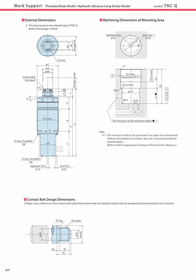
CautionsP.623Work Support Threaded Body Model:Hydraulic Advance Long Stroke Model model TNC-Q
min.EC
φEB
φED
EEEG EF
EX ScrewO-ring
Hexagon B
BC W
X Screw
External Dimensions Machining Dimensions of Mounting Area
Contact Bolt Design Dimensions※Please use as reference in case contact bolts (attachment) other than the attached contact bolt are designed and manufactured to the customer.
※ This drawing shows the released state of TNC-Q (before the plunger is lifted).
EY
F
A
GH
ETV
φC
φBAφU
D Screw
φJ + 0.1 0
BB
Contact Bolt(Included)
Plunger Stroke
15°
Vent PortHydraulic PortφCGφCE
O-ring (Included)DB
O-ring (Included)DA
φK
CD or more
CC
CK
D Screw
C1
R0.4
φCGφCEVent Port ※1Hydraulic Port
CJ ◆
φCH
C0.4 or less
R0.4
The vent port can be machined within ◆.※1
p.c.d.CF
(Prepared HoleφCB )
12.5S
+0.17-0.12
Z
Z0.05
Note ※ 1. The vent port needs to be processed in an open air environment without the presence of coolant, dust, etc. to avoid any internal contamination. (Refer to P.623: Appropriate Position of Vent Port for reference.)
Model No. Indication
Q
1 42
4 Options (Q selected)
3 Plunger Spring Force (Blank)
1 Body Size
2 Design No.
(Format Example:TNC0480-Q)
TNC 040 0-
(mm)
(mm) Corresponding Product Model EB EC ED EE EF EG EX (Nominal×Pitch) O-ring
Model No. Plunger Stroke A B C D(Nominal×Pitch) E F G H J K T U V W X (Nominal×Pitch×Depth) BA BB BC CB CC CD CE CF CG CH CK CJ DA DB EY Tightening Torque for Main Body※2
Contact Bolt Design Dimensions※Please use as reference in case contact bolts (attachment) other than the attached contact bolt are designed and manufactured to the customer.
TNC0400-Q TNC0600-Q TNC1000-Q TNC1600-Q 13 16 20 24 83.5 95 112 137 24 27 32 41 26 30 36 45 M26×1.5 M30×1.5 M36×1.5 M45×1.5 72 83.5 100 120.5 28.5 35 40.5 55 27.5 31.5 51.2 55.2 16 17 8.3 10.3 24.2 28.2 34.2 43.2 18.5 21 23 27 11.5 11.5 12 16.5 12 15 18 22 6 6 6.5 9 10 13 14 19 M8×1.25×12 M10×1.5×11 M10×1.5×11 M12×1.75×13 11.5 12.5 12.5 16.5 4 4 4 6 10 11 11 14 24.5 28.5 34.5 43.5 13 ~ 32 13 ~ 36 15 ~ 55 18 ~ 60 CC- 4 CC- 4 CC-4 CC-5 max. 8 max. 10 max. 10 max. 12 p.c.d. 20 p.c.d. 24 p.c.d. 26 p.c.d. 30 max. 2 max. 3 max. 3 max. 5 20 24 30 39 CC + 23.5 CC + 30 CC + 35.5 CC + 49 23.5 30 35.5 49 AS568-014(90°) AS568-015(90°) AS568-016(90°) AS568-018(90°) AS568-020(90°) AS568-022(90°) AS568-026(90°) AS568-030(90°) SR30 SR50 SR50 SR80 31.5 N・m 50 N・m 63 N・m 80 N・m
TNC0400-Q TNC0600-Q TNC1000-Q TNC1600-Q 5.4 7.4 7.4 9.4 10 12.5 12.5 16.5 5 6 6 7.5 10 10 10 12 7.3 7.3 7.3 8.7 1.7 1.7 1.7 2.3 M8×1.25 M10×1.5 M10×1.5 M12×1.75 AS568-009(70°) AS568-010(70°) AS568-010(70°) AS568-012(70°)
Note ※ 2. Use the recommended mounting torque in the chart above when mounting to the unit. If the recommended torque is exceeded, abnormal action may be incurred due to deformation of the body. However, if the torque is much lower than the recommended one, the O ring may be damaged due to loosening, resulting in oil leakage.
External Dimensions and Machining Dimensions for Mounting
Notes 1. Design and manufacture in consideration of the contact bolt's weight and the plunger's spring force. 2. If contact bolts are designed and manufactured with different specs than the above chart, the plunger spring force will differ from the catalog and could result in damage to the plunger spring and cause it to malfunction.609

Hole Clamp
SFASFC
Link Clamp
LKALKCLKWLM/LJTMA-2TMA-1
Work Support
LDLCTNCTC
LLW
Air SensingLift Cylinder
Compact Cylinder
LLLLRLLUDPDRDSDT
Block Cylinder
DBADBC
Control Valve
BZLBZTBZX/JZG
Pallet Clamp
VSVT
Expansion Locating Pin
VLVMVJVK
FPFQ
Pull Stud Clamp
DWA/DWB
CustomizedSpring Cylinder
Swing Clamp
LHALHCLHSLHWLT/LGTLA-2TLB-2TLA-1
Pneumatic Series
Hydraulic Series
Valve / CouplerHydraulic Unit
Cautions / Others
High-PowerSeries
Manual OperationAccessories
Work SupportDigest P.545
Model No. IndicationSpecifications
PerformanceCurve
ActionDescription
IndexCross Section
ExternalDimensions
CautionsP.623Work Support Threaded Body Model:Hydraulic Advance Long Stroke Model model TNC-Q
min.EC
φEB
φED
EEEG EF
EX ScrewO-ring
Hexagon B
BC W
X Screw
External Dimensions Machining Dimensions of Mounting Area
Contact Bolt Design Dimensions※Please use as reference in case contact bolts (attachment) other than the attached contact bolt are designed and manufactured to the customer.
※ This drawing shows the released state of TNC-Q (before the plunger is lifted).
EY
F
A
GH
ETV
φC
φBAφU
D Screw
φJ + 0.1 0
BB
Contact Bolt(Included)
Plunger Stroke
15°
Vent PortHydraulic PortφCGφCE
O-ring (Included)DB
O-ring (Included)DA
φK
CD or more
CC
CK
D Screw
C1
R0.4
φCGφCEVent Port ※1Hydraulic Port
CJ ◆
φCH
C0.4 or less
R0.4
The vent port can be machined within ◆.※1
p.c.d.CF
(Prepared HoleφCB )
12.5S
+0.17-0.12
Z
Z0.05
Note ※ 1. The vent port needs to be processed in an open air environment without the presence of coolant, dust, etc. to avoid any internal contamination. (Refer to P.623: Appropriate Position of Vent Port for reference.)
Model No. Indication
Q
1 42
4 Options (Q selected)
3 Plunger Spring Force (Blank)
1 Body Size
2 Design No.
(Format Example:TNC0480-Q)
TNC 040 0-
(mm)
(mm) Corresponding Product Model EB EC ED EE EF EG EX (Nominal×Pitch) O-ring
Model No. Plunger Stroke A B C D(Nominal×Pitch) E F G H J K T U V W X (Nominal×Pitch×Depth) BA BB BC CB CC CD CE CF CG CH CK CJ DA DB EY Tightening Torque for Main Body※2
Contact Bolt Design Dimensions※Please use as reference in case contact bolts (attachment) other than the attached contact bolt are designed and manufactured to the customer.
TNC0400-Q TNC0600-Q TNC1000-Q TNC1600-Q 13 16 20 24 83.5 95 112 137 24 27 32 41 26 30 36 45 M26×1.5 M30×1.5 M36×1.5 M45×1.5 72 83.5 100 120.5 28.5 35 40.5 55 27.5 31.5 51.2 55.2 16 17 8.3 10.3 24.2 28.2 34.2 43.2 18.5 21 23 27 11.5 11.5 12 16.5 12 15 18 22 6 6 6.5 9 10 13 14 19 M8×1.25×12 M10×1.5×11 M10×1.5×11 M12×1.75×13 11.5 12.5 12.5 16.5 4 4 4 6 10 11 11 14 24.5 28.5 34.5 43.5 13 ~ 32 13 ~ 36 15 ~ 55 18 ~ 60 CC- 4 CC-4 CC-4 CC-5 max. 8 max. 10 max. 10 max. 12 p.c.d. 20 p.c.d. 24 p.c.d. 26 p.c.d. 30 max. 2 max. 3 max. 3 max. 5 20 24 30 39 CC + 23.5 CC + 30 CC + 35.5 CC + 49 23.5 30 35.5 49 AS568-014(90°) AS568-015(90°) AS568-016(90°) AS568-018(90°) AS568-020(90°) AS568-022(90°) AS568-026(90°) AS568-030(90°) SR30 SR50 SR50 SR80 31.5 N・m 50 N・m 63 N・m 80 N・m
TNC0400-Q TNC0600-Q TNC1000-Q TNC1600-Q 5.4 7.4 7.4 9.4 10 12.5 12.5 16.5 5 6 6 7.5 10 10 10 12 7.3 7.3 7.3 8.7 1.7 1.7 1.7 2.3 M8×1.25 M10×1.5 M10×1.5 M12×1.75 AS568-009(70°) AS568-010(70°) AS568-010(70°) AS568-012(70°)
Note ※ 2. Use the recommended mounting torque in the chart above when mounting to the unit. If the recommended torque is exceeded, abnormal action may be incurred due to deformation of the body. However, if the torque is much lower than the recommended one, the O ring may be damaged due to loosening, resulting in oil leakage.
External Dimensions and Machining Dimensions for Mounting
Notes 1. Design and manufacture in consideration of the contact bolt's weight and the plunger's spring force. 2. If contact bolts are designed and manufactured with different specs than the above chart, the plunger spring force will differ from the catalog and could result in damage to the plunger spring and cause it to malfunction. 610

Hole Clamp
SFASFC
Link Clamp
LKALKCLKWLM/LJTMA-2TMA-1
Work Support
LDLCTNCTC
LLW
Air SensingLift Cylinder
Compact Cylinder
LLLLRLLUDPDRDSDT
Block Cylinder
DBADBC
Control Valve
BZLBZTBZX/JZG
Pallet Clamp
VSVT
Expansion Locating Pin
VLVMVJVK
FPFQ
Pull Stud Clamp
DWA/DWB
CustomizedSpring Cylinder
Swing Clamp
LHALHCLHSLHWLT/LGTLA-2TLB-2TLA-1
Pneumatic Series
Hydraulic Series
Valve / CouplerHydraulic Unit
Cautions / Others
High-PowerSeries
Manual OperationAccessories
Work SupportDigest P.545
Model No. IndicationSpecifications
PerformanceCurve
ActionDescription
IndexCross Section
ExternalDimensions
CautionsP.623Work Support Threaded Body Model:Spring Advance Model model TNC-E
min.EC
φEB
φED
EEEG EF
EX ScrewO-ring
D Screw(Prepared HoleφCB ) CC
C1
CD or more
12.5S
Vent Port ※1φCG
Hydraulic PortφCE
0.4
Hexagon B
BC W
F
A
GH
ET
φC
φBAφU
D Screw
φJ + 0.1 0
X Screw Plunger Stroke
15°
Vent PortHydraulic PortφCGφCE
O-ring (Included)DB
O-ring (Included)DA
External Dimensions Machining Dimensions of Mounting Area
Contact Bolt Design Dimensions※Please use as reference in case contact bolts (attachment) other than the attached contact bolt are designed and manufactured to the customer.
EY
Contact Bolt(Included)
VBB
Z0.05
+ 0.17- 0.12
Z
※ This drawing shows the released state of release of TNC-□-E (before the plunger is lifted).
Note ※ 1. The vent port needs to be processed in an open air environment without the presence of coolant, dust, etc. to avoid any internal contamination. (Refer to P.623: Appropriate Position of Vent Port for reference.)
p.c.d.CF
Model No. Indication
LH
1 32 4
4 Options (E selected)
3 Plunger Spring Force
1 Body Size
2 Design No.
(Format Example:TNC0480-L-E)
TNC 040 0- -
(mm)
(mm) Corresponding Product Model EB EC ED EE EF EG EX (Nominal×Pitch) O-ring
Model No. Plunger Stroke A B C D(Nominal×Pitch) E F G H J T U V W X (Nominal×Pitch×Depth) BA BB BC CB CC CD CE CF CG DA DB EY Tightening Torque for Main Body※2
Contact Bolt Design Dimensions※Please use as reference in case contact bolts (attachment) other than the attached contact bolt are designed and manufactured to the customer.
TNC0400-□-E TNC0600-□-E TNC1000-□-E TNC1600-□-E 6.5 8 10 12 66.5 73 86.5 100 24 27 32 41 26 30 36 45 M26×1.5 M30×1.5 M36×1.5 M45×1.5 48.5 53.5 64.5 71.5 5 5 5 6 27.5 31.5 51.2 55.2 16 17 8.3 10.3 24.2 28.2 34.2 43.2 18 19.5 22 28.5 12 15 18 22 6 6 6.5 9 10 13 14 19 M8×1.25×12 M10×1.5×11 M10×1.5×11 M12×1.75×13 11.5 12.5 12.5 16.5 4 4 4 6 10 11 11 14 24.5 28.5 34.5 43.5 13 ~ 32 13 ~ 36 15 ~ 55 18 ~ 60 CC- 4 CC- 4 CC-4 CC-5 max. 8 max. 10 max. 10 max. 12 p.c.d. 19 p.c.d. 22 p.c.d. 26 p.c.d. 30 max. 2.5 max. 3 max. 5 max. 6 AS568-013(90°) AS568-014(90°) AS568-015(90°) AS568-017(90°) AS568-020(90°) AS568-022(90°) AS568-026(90°) AS568-030(90°) SR30 SR50 SR50 SR80 31.5 N・m 50 N・m 63 N・m 80 N・m
TNC0400-□-E TNC0600-□-E TNC1000-□-E TNC1600-□-E 5.4 7.4 7.4 9.4 10 12.5 12.5 16.5 5 6 6 7.5 10 10 10 12 7.3 7.3 7.3 8.7 1.7 1.7 1.7 2.3 M8×1.25 M10×1.5 M10×1.5 M12×1.75 AS568-009(70°) AS568-010(70°) AS568-010(70°) AS568-012(70°)
Note ※ 2. Use the recommended mounting torque in the chart above when mounting to the unit. If the recommended torque is exceeded, abnormal action may be incurred due to deformation of the body. However, if the torque is much lower than the recommended one, the O ring may be damaged due to loosening, resulting in oil leakage.
External Dimensions and Machining Dimensions for Mounting
Notes 1. Design and manufacture in consideration of the contact bolt's weight and the plunger's spring force. 2. If contact bolts are designed and manufactured with different specs than the above chart, the plunger spring force will differ from the catalog and could result in damage to the plunger spring and cause it to malfunction.
E
611

Hole Clamp
SFASFC
Link Clamp
LKALKCLKWLM/LJTMA-2TMA-1
Work Support
LDLCTNCTC
LLW
Air SensingLift Cylinder
Compact Cylinder
LLLLRLLUDPDRDSDT
Block Cylinder
DBADBC
Control Valve
BZLBZTBZX/JZG
Pallet Clamp
VSVT
Expansion Locating Pin
VLVMVJVK
FPFQ
Pull Stud Clamp
DWA/DWB
CustomizedSpring Cylinder
Swing Clamp
LHALHCLHSLHWLT/LGTLA-2TLB-2TLA-1
Pneumatic Series
Hydraulic Series
Valve / CouplerHydraulic Unit
Cautions / Others
High-PowerSeries
Manual OperationAccessories
Work SupportDigest P.545
Model No. IndicationSpecifications
PerformanceCurve
ActionDescription
IndexCross Section
ExternalDimensions
CautionsP.623Work Support Threaded Body Model:Spring Advance Model model TNC-E
min.EC
φEB
φED
EEEG EF
EX ScrewO-ring
D Screw(Prepared HoleφCB ) CC
C1
CD or more
12.5S
Vent Port ※1φCG
Hydraulic PortφCE
0.4
Hexagon B
BC W
F
A
GH
ET
φC
φBAφU
D Screw
φJ + 0.1 0
X Screw
Plunger Stroke
15°
Vent PortHydraulic PortφCGφCE
O-ring (Included)DB
O-ring (Included)DA
External Dimensions Machining Dimensions of Mounting Area
Contact Bolt Design Dimensions※Please use as reference in case contact bolts (attachment) other than the attached contact bolt are designed and manufactured to the customer.
EY
Contact Bolt(Included)
VBB
Z0.05
+ 0.17- 0.12
Z
※ This drawing shows the released state of release of TNC-□-E (before the plunger is lifted).
Note ※ 1. The vent port needs to be processed in an open air environment without the presence of coolant, dust, etc. to avoid any internal contamination. (Refer to P.623: Appropriate Position of Vent Port for reference.)
p.c.d.CF
Model No. Indication
LH
1 32 4
4 Options (E selected)
3 Plunger Spring Force
1 Body Size
2 Design No.
(Format Example:TNC0480-L-E)
TNC 040 0- -
(mm)
(mm) Corresponding Product Model EB EC ED EE EF EG EX (Nominal×Pitch) O-ring
Model No. Plunger Stroke A B C D(Nominal×Pitch) E F G H J T U V W X (Nominal×Pitch×Depth) BA BB BC CB CC CD CE CF CG DA DB EY Tightening Torque for Main Body※2
Contact Bolt Design Dimensions※Please use as reference in case contact bolts (attachment) other than the attached contact bolt are designed and manufactured to the customer.
TNC0400-□-E TNC0600-□-E TNC1000-□-E TNC1600-□-E 6.5 8 10 12 66.5 73 86.5 100 24 27 32 41 26 30 36 45 M26×1.5 M30×1.5 M36×1.5 M45×1.5 48.5 53.5 64.5 71.5 5 5 5 6 27.5 31.5 51.2 55.2 16 17 8.3 10.3 24.2 28.2 34.2 43.2 18 19.5 22 28.5 12 15 18 22 6 6 6.5 9 10 13 14 19 M8×1.25×12 M10×1.5×11 M10×1.5×11 M12×1.75×13 11.5 12.5 12.5 16.5 4 4 4 6 10 11 11 14 24.5 28.5 34.5 43.5 13 ~ 32 13 ~ 36 15 ~ 55 18 ~ 60 CC- 4 CC-4 CC-4 CC-5 max. 8 max. 10 max. 10 max. 12 p.c.d. 19 p.c.d. 22 p.c.d. 26 p.c.d. 30 max. 2.5 max. 3 max. 5 max. 6 AS568-013(90°) AS568-014(90°) AS568-015(90°) AS568-017(90°) AS568-020(90°) AS568-022(90°) AS568-026(90°) AS568-030(90°) SR30 SR50 SR50 SR80 31.5 N・m 50 N・m 63 N・m 80 N・m
TNC0400-□-E TNC0600-□-E TNC1000-□-E TNC1600-□-E 5.4 7.4 7.4 9.4 10 12.5 12.5 16.5 5 6 6 7.5 10 10 10 12 7.3 7.3 7.3 8.7 1.7 1.7 1.7 2.3 M8×1.25 M10×1.5 M10×1.5 M12×1.75 AS568-009(70°) AS568-010(70°) AS568-010(70°) AS568-012(70°)
Note ※ 2. Use the recommended mounting torque in the chart above when mounting to the unit. If the recommended torque is exceeded, abnormal action may be incurred due to deformation of the body. However, if the torque is much lower than the recommended one, the O ring may be damaged due to loosening, resulting in oil leakage.
External Dimensions and Machining Dimensions for Mounting
Notes 1. Design and manufacture in consideration of the contact bolt's weight and the plunger's spring force. 2. If contact bolts are designed and manufactured with different specs than the above chart, the plunger spring force will differ from the catalog and could result in damage to the plunger spring and cause it to malfunction.
E
612
Hole Clamp
SFASFC
Link Clamp
LKALKCLKWLM/LJTMA-2TMA-1
Work Support
LDLCTNCTC
LLW
Air SensingLift Cylinder
Compact Cylinder
LLLLRLLUDPDRDSDT
Block Cylinder
DBADBC
Control Valve
BZLBZTBZX/JZG
Pallet Clamp
VSVT
Expansion Locating Pin
VLVMVJVK
FPFQ
Pull Stud Clamp
DWA/DWB
CustomizedSpring Cylinder
Swing Clamp
LHALHCLHSLHWLT/LGTLA-2TLB-2TLA-1
Pneumatic Series
Hydraulic Series
Valve / CouplerHydraulic Unit
Cautions / Others
High-PowerSeries
Manual OperationAccessories
Work SupportDigest P.545
Model No. IndicationSpecifications
PerformanceCurve
ActionDescription
ExternalDimensions CautionsPlunger Spring
Design DimensionsIndex
Cross SectionWork Support Flange Model model TC
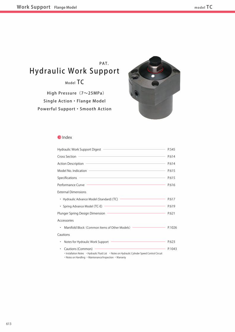
Index
Hydraulic Work Support Digest
Cross Section
Action Description
Model No. Indication
Specifications
Performance Curve
External Dimensions
・ Hydraulic Advance Model (Standard) (TC)
・ Spring Advance Model (TC-E)
Plunger Spring Design Dimension
Accessories
・ Manifold Block (Common Items of Other Models)
Cautions
・ Notes for Hydraulic Work Support
・ Cautions (Common) ・ Installation Notes ・ Hydraulic Fluid List ・ Notes on Hydraulic Cylinder Speed Control Circuit ・ Notes on Handling ・ Maintenance/Inspection ・ Warranty
P.545
P.614
P.614
P.615
P.615
P.616
P.617
P.619
P.621
P.1026
P.623
P.1043
Model TC
Hydraulic Work Support
High Pressure(7~25MPa)
Single Action・Flange Model
Powerful Support・Smooth Action
PAT.
Cross Section
Action Description
Hydraulic Advance Model (TC)
Hydraulic Pressure:OFFThe state of plunger down.
Hydraulic Pressure:ONPlunger rises with oil pressure and stops after touching workpiece.
Hydraulic Pressure:ONOnce it is in the stopped position where it touches the workpiece, the plunger doesn’t go down even if pressed from above.
Plunger
It doesn't moveeven if pressed fromthe top!!
Spring Advance Model (TC-E)
Hydraul ic Pressure:OFFThe state of plunger up.
Hydraul ic Pressure:OFFWhen work piece rests on the work support, plunger goes down due to the weight of workpiece and is balanced.
Hydraul ic Pressure:ONOnce it is in the stopped position where it touches the workpiece, the plunger doesn’t go down even if pressed from above.
Work Support Body
Plunger
Seat
Workpiece
Seat
Work Support Body
Spring Advance Model (TC-E)The drawing shows the released state.
Hydraulic Advance Model (TC)The drawing shows the released state.
Plunger Plunger
ColletCollet
It doesn't moveeven if pressed fromthe top!!
Grippingthe plunger!
Grippingthe plunger!
613

Hole Clamp
SFASFC
Link Clamp
LKALKCLKWLM/LJTMA-2TMA-1
Work Support
LDLCTNCTC
LLW
Air SensingLift Cylinder
Compact Cylinder
LLLLRLLUDPDRDSDT
Block Cylinder
DBADBC
Control Valve
BZLBZTBZX/JZG
Pallet Clamp
VSVT
Expansion Locating Pin
VLVMVJVK
FPFQ
Pull Stud Clamp
DWA/DWB
CustomizedSpring Cylinder
Swing Clamp
LHALHCLHSLHWLT/LGTLA-2TLB-2TLA-1
Pneumatic Series
Hydraulic Series
Valve / CouplerHydraulic Unit
Cautions / Others
High-PowerSeries
Manual OperationAccessories
Work SupportDigest P.545
Model No. IndicationSpecifications
PerformanceCurve
ActionDescription
ExternalDimensions CautionsPlunger Spring
Design DimensionsIndex
Cross SectionWork Support Flange Model model TC
Index
Hydraulic Work Support Digest
Cross Section
Action Description
Model No. Indication
Specifications
Performance Curve
External Dimensions
・ Hydraulic Advance Model (Standard) (TC)
・ Spring Advance Model (TC-E)
Plunger Spring Design Dimension
Accessories
・ Manifold Block (Common Items of Other Models)
Cautions
・ Notes for Hydraulic Work Support
・ Cautions (Common) ・ Installation Notes ・ Hydraulic Fluid List ・ Notes on Hydraulic Cylinder Speed Control Circuit ・ Notes on Handling ・ Maintenance/Inspection ・ Warranty
P.545
P.614
P.614
P.615
P.615
P.616
P.617
P.619
P.621
P.1026
P.623
P.1043
Model TC
Hydraulic Work Support
High Pressure(7~25MPa)
Single Action・Flange Model
Powerful Support・Smooth Action
PAT.
Cross Section
Action Description
Hydraulic Advance Model (TC)
Hydraulic Pressure:OFFThe state of plunger down.
Hydraulic Pressure:ONPlunger rises with oil pressure and stops after touching workpiece.
Hydraulic Pressure:ONOnce it is in the stopped position where it touches the workpiece, the plunger doesn’t go down even if pressed from above.
Plunger
It doesn't moveeven if pressed fromthe top!!
Spring Advance Model (TC-E)
Hydraul ic Pressure:OFFThe state of plunger up.
Hydraul ic Pressure:OFFWhen work piece rests on the work support, plunger goes down due to the weight of workpiece and is balanced.
Hydraul ic Pressure:ONOnce it is in the stopped position where it touches the workpiece, the plunger doesn’t go down even if pressed from above.
Work Support Body
Plunger
Seat
Workpiece
Seat
Work Support Body
Spring Advance Model (TC-E)The drawing shows the released state.
Hydraulic Advance Model (TC)The drawing shows the released state.
Plunger Plunger
ColletCollet
It doesn't moveeven if pressed fromthe top!!
Grippingthe plunger!
Grippingthe plunger!
614

Hole Clamp
SFASFC
Link Clamp
LKALKCLKWLM/LJTMA-2TMA-1
Work Support
LDLCTNCTC
LLW
Air SensingLift Cylinder
Compact Cylinder
LLLLRLLUDPDRDSDT
Block Cylinder
DBADBC
Control Valve
BZLBZTBZX/JZG
Pallet Clamp
VSVT
Expansion Locating Pin
VLVMVJVK
FPFQ
Pull Stud Clamp
DWA/DWB
CustomizedSpring Cylinder
Swing Clamp
LHALHCLHSLHWLT/LGTLA-2TLB-2TLA-1
Pneumatic Series
Hydraulic Series
Valve / CouplerHydraulic Unit
Cautions / Others
High-PowerSeries
Manual OperationAccessories
Work SupportDigest P.545
Model No. IndicationSpecifications
PerformanceCurve
ActionDescription
ExternalDimensions CautionsPlunger Spring
Design DimensionsIndex
Cross SectionWork Support Flange Model model TC
Model No. Indication
Model No.
Support Force at 25MPa kN
Support Force (Calculation Formula)※1 kN
Plunger Stroke mm
Cylinder Capacity cm3
Plunger Spring Force※2 L:Low Spring Force
N H:High Spring Force
Max. Operating Pressure MPa
Min. Operating Pressure MPa
Withstanding Pressure MPa
Operating Temperature ℃
Mass kg
TC0402-□□-□ TC0482-□□-□ TC0552-□□-□ TC0652-□□-□ TC0752-□□-□
10.1 15.5 24.9 40.0 64.9
0.47×P-1.63 0.72×P-2.52 1.16×P-4.07 1.86×P-6.51 3.02×P-10.58
10 12 14 16 20
1.1 1.9 2.5 4.7 6.5
5.8~9.7 8.3~14.6 9.8~14.6 12.4~18.8 14.6~21.0
7.9~13.6 10.1~21.9 15.8~22.0 18.7~31.9 21.4~34.2
25
7
37.5
0~70
0.7 1.1 1.6 2.7 4.3
Specifications
4
2
3
SG
Plunger Spring Force
L : Low Spring Force
H : High Spring Force
Piping Method
G : Gasket Option (With R Thread Plug)
S : Piping Option (Rc Thread Port)
5 Options
Blank : Hydraulic Advance Model (Standard)
E : Spring Advance Model
Piping Option
Rc Thread PortNo Gasket Port
With R Thread Plug
Gasket Option
1
1 2 3 4 5
※ Outer diameter (φD) of the cylinder.
Body Size
040 : φD=40mm
048 : φD=48mm
055 : φD=55mm
065 : φD=65mm
075 : φD=75mm
2 : Revision Number
Design No.
TC 040 2 - G L -
φD
Performance Curve(TC-□□:Hydraulic Advance Model / TC-□□-E:Spring Advance Model )
1 Body Size
BlankE
GS
LH
Applicable Model
5 Options:Blank、E selected
TC 040 2 - -
Support Force Graph ※ This graph shows the support force under static load condition.
Load / Displacement Graph ※ This graph shows the static load displacement at 25 MPa hydraulic pressure.
0 10 20 255 150
60
70
20
40
10
30
50
TC0752
TC0652
TC0552
TC0482
TC0402
Operating Hydraulic Pressure (MPa)
Support Force (kN)
Load (kN)
0 2.5 7.5 1050
35
40
20
5
10
30
25
15 TC0752
TC0652
TC0552
Load (kN)
Displacement (μm)
TC0402
TC0482
706050403020100
100
80
60
40
20
0
TC0402 TC0482
TC0552
TC0652 TC
0752
Displacement
LoadWhen locked(Without load)
When the static load is added
10.1 15.5 24.9 40.0 64.9 8.9 13.7 22.0 35.3 57.4 7.8 11.9 19.1 30.7 49.8 6.6 10.1 16.2 26.0 42.3 5.4 8.3 13.3 21.4 34.7 4.2 6.5 10.4 16.7 27.2 3.1 4.7 7.5 12.1 19.6 1.9 2.9 4.6 7.4 12.1 0.47×P-1.63 0.72×P-2.52 1.16×P-4.07 1.86×P-6.51 3.02×P-10.58
Model No.Operating Hydraulic Pressure (MPa)
2522.52017.51512.5107.5
Support Force Formula kN
Support Force (kN) TC0402-□□ TC0482-□□ TC0552-□□ TC0652-□□ TC0752-□□ TC0402-□□-E TC0482-□□-E TC0552-□□-E TC0652-□□-E TC0752-□□-E
※3
Note ※ 3. P : Operating Hydraulic Pressure (MPa)
Notes ※ 1. P in the formula for support force indicates the hydraulic pressure (MPa). ※ 2. The plunger spring force figure indicates the spring design force. It may vary due to moving resistance of the plunger and spring. Please use it as reference for the work piece contacting force.
615

Hole Clamp
SFASFC
Link Clamp
LKALKCLKWLM/LJTMA-2TMA-1
Work Support
LDLCTNCTC
LLW
Air SensingLift Cylinder
Compact Cylinder
LLLLRLLUDPDRDSDT
Block Cylinder
DBADBC
Control Valve
BZLBZTBZX/JZG
Pallet Clamp
VSVT
Expansion Locating Pin
VLVMVJVK
FPFQ
Pull Stud Clamp
DWA/DWB
CustomizedSpring Cylinder
Swing Clamp
LHALHCLHSLHWLT/LGTLA-2TLB-2TLA-1
Pneumatic Series
Hydraulic Series
Valve / CouplerHydraulic Unit
Cautions / Others
High-PowerSeries
Manual OperationAccessories
Work SupportDigest P.545
Model No. IndicationSpecifications
PerformanceCurve
ActionDescription
ExternalDimensions CautionsPlunger Spring
Design DimensionsIndex
Cross SectionWork Support Flange Model model TC
Model No. Indication
Model No.
Support Force at 25MPa kN
Support Force (Calculation Formula)※1 kN
Plunger Stroke mm
Cylinder Capacity cm3
Plunger Spring Force※2 L:Low Spring Force
N H:High Spring Force
Max. Operating Pressure MPa
Min. Operating Pressure MPa
Withstanding Pressure MPa
Operating Temperature ℃
Mass kg
TC0402-□□-□ TC0482-□□-□ TC0552-□□-□ TC0652-□□-□ TC0752-□□-□
10.1 15.5 24.9 40.0 64.9
0.47×P-1.63 0.72×P-2.52 1.16×P-4.07 1.86×P-6.51 3.02×P-10.58
10 12 14 16 20
1.1 1.9 2.5 4.7 6.5
5.8~9.7 8.3~14.6 9.8~14.6 12.4~18.8 14.6~21.0
7.9~13.6 10.1~21.9 15.8~22.0 18.7~31.9 21.4~34.2
25
7
37.5
0~70
0.7 1.1 1.6 2.7 4.3
Specifications
4
2
3
SG
Plunger Spring Force
L : Low Spring Force
H : High Spring Force
Piping Method
G : Gasket Option (With R Thread Plug)
S : Piping Option (Rc Thread Port)
5 Options
Blank : Hydraulic Advance Model (Standard)
E : Spring Advance Model
Piping Option
Rc Thread PortNo Gasket Port
With R Thread Plug
Gasket Option
1
1 2 3 4 5
※ Outer diameter (φD) of the cylinder.
Body Size
040 : φD=40mm
048 : φD=48mm
055 : φD=55mm
065 : φD=65mm
075 : φD=75mm
2 : Revision Number
Design No.
TC 040 2 - G L -
φD
Performance Curve(TC-□□:Hydraulic Advance Model / TC-□□-E:Spring Advance Model )
1 Body Size
BlankE
GS
LH
Applicable Model
5 Options:Blank、E selected
TC 040 2 - -
Support Force Graph ※ This graph shows the support force under static load condition.
Load / Displacement Graph ※ This graph shows the static load displacement at 25 MPa hydraulic pressure.
0 10 20 255 150
60
70
20
40
10
30
50
TC0752
TC0652
TC0552
TC0482
TC0402
Operating Hydraulic Pressure (MPa)
Support Force (kN)
Load (kN)
0 2.5 7.5 1050
35
40
20
5
10
30
25
15 TC0752
TC0652
TC0552
Load (kN)
Displacement (μm)
TC0402
TC0482
706050403020100
100
80
60
40
20
0
TC0402 TC0482
TC0552
TC0652 TC
0752
Displacement
LoadWhen locked(Without load)
When the static load is added
10.1 15.5 24.9 40.0 64.9 8.9 13.7 22.0 35.3 57.4 7.8 11.9 19.1 30.7 49.8 6.6 10.1 16.2 26.0 42.3 5.4 8.3 13.3 21.4 34.7 4.2 6.5 10.4 16.7 27.2 3.1 4.7 7.5 12.1 19.6 1.9 2.9 4.6 7.4 12.1 0.47×P-1.63 0.72×P-2.52 1.16×P-4.07 1.86×P-6.51 3.02×P-10.58
Model No.Operating Hydraulic Pressure (MPa)
2522.52017.51512.5107.5
Support Force Formula kN
Support Force (kN) TC0402-□□ TC0482-□□ TC0552-□□ TC0652-□□ TC0752-□□ TC0402-□□-E TC0482-□□-E TC0552-□□-E TC0652-□□-E TC0752-□□-E
※3
Note ※ 3. P : Operating Hydraulic Pressure (MPa)
Notes ※ 1. P in the formula for support force indicates the hydraulic pressure (MPa). ※ 2. The plunger spring force figure indicates the spring design force. It may vary due to moving resistance of the plunger and spring. Please use it as reference for the work piece contacting force.
616

Hole Clamp
SFASFC
Link Clamp
LKALKCLKWLM/LJTMA-2TMA-1
Work Support
LDLCTNCTC
LLW
Air SensingLift Cylinder
Compact Cylinder
LLLLRLLUDPDRDSDT
Block Cylinder
DBADBC
Control Valve
BZLBZTBZX/JZG
Pallet Clamp
VSVT
Expansion Locating Pin
VLVMVJVK
FPFQ
Pull Stud Clamp
DWA/DWB
CustomizedSpring Cylinder
Swing Clamp
LHALHCLHSLHWLT/LGTLA-2TLB-2TLA-1
Pneumatic Series
Hydraulic Series
Valve / CouplerHydraulic Unit
Cautions / Others
High-PowerSeries
Manual OperationAccessories
Work SupportDigest P.545
Model No. IndicationSpecifications
PerformanceCurve
ActionDescription
ExternalDimensions CautionsPlunger Spring
Design DimensionsIndex
Cross SectionWork Support Flange Model:Hydraulic Advance Model (Standard) model TC
Yx
□K
Nx
YyNy
φD+ 0.3 0
R0.4
C0.66.3S※5
4-CA Thread ※2
Remove all burrs ※5
15°
Bmax.1.5mm
BC W□KC
φD-0.1-0.2
FG
E
S※1
M
φAB
φBAφU
AC TA
H JYy
Ny
φL
Plunger Stroke
BBV
Nx
Yx
YyNy
Spot FacingφQ
(Only ‒S option is assembled for delivery)
Contact Bolt (Included)
4-φR
Vent PortRc Thread (Rc Thread Plug)
Air Vent Port (Included)
X Thread
(-G option only)R Thread Plug
2-Z
Vent PortRc Thread(with Air Vent)
Hydraulic PortRc Thread
Vent Port ※4φP※5(-G option)
Hydraulic PortφP※5(-G option)
※3
O-ring for Hydraulic Pressure Port (Included)(-G option)
O-ring for Vent Port (Included)(-G option)
Yx
External Dimensions
※The graph shows TC-S□.S : Piping Option (Rc-Thread)
※This drawing shows the released state of TC-G□ (before the plunger is lifted).G:Gasket Option (with R Thread Plug)
Machining Dimensions of Mounting Area
Piping Method
Contact Bolt Design Dimensions
min.φEC
φEB
φED
EEEG EF
X ThreadO-ring
EY
※1. Mounting bolts are not provided. Customer should prepare based on dimension "S".
Notes
※2.
※3.
※4.
※5.
The CA thread depth of the mounting bolt should be decided based on the mounting height with reference to S size.The φD depth of the body mounting hole should be decided from dimension F.The vent port needs to be processed in an open air environment without the presence of coolant, dust, etc. to avoid any internal contamination.(Refer to P.623 : Appropriate Position of Vent Port for reference.)This process indicates -G:gasket option.
Notes
(mm)
(mm) Corresponding Item Model No.
EB
EC
ED
EE
EF
EG
EX (Nominal×Pitch)
O-ring
Model No.
Plunger Stroke
A
B
C
D
E
F
G
H
J
K
L
M
Nx
Ny
P
Q
R
S
T
U
V
W
X (Nominal×Pitch×Depth)
Yx
Yy
Z (Chamfer)
AB
AC
BA
BB
BC
CA (Nominal×Pitch)
EY
Hydraulic Port -S option
R Thread Plug -G option
O-ring (-G option)
Vent Port Rc Thread
TC0402-□□ TC0482-□□ TC0552-□□ TC0652-□□ TC0752-□□
8.2 10 10 13.5 13.5
12.5 16.5 16.5 21.5 21.5
6 7.5 7.5 10.5 10.5
10 12 12 16 16
7 8 8 11 11
2 3 3 4 4
M10×1.5 M12×1.75 M12×1.75 M16×2 M16×2
S8 (Made by NOK) S10 (Made by NOK) S10 (Made by NOK) AS568-014(70°) AS568-014(70°)
TC0402-□□ TC0482-□□ TC0552-□□ TC0652-□□ TC0752-□□
10 12 14 16 20
75 85 101 126 149
54 61 69 81 92
45 51 60 70 80
40 48 55 65 75
64 70 85 107 128
28 34 49 69 82
36 36 36 38 46
31.5 35.5 39 46 52
22.5 25.5 30 35 40
34 40 47 55 63
68 73 80 94 106
11 12 12 12 14
26 30 33.5 39.5 45
5 0 0 0 0
3 3 3 5 5
9.5 9.5 11 11 14
5.5 5.5 6.8 6.8 9
26 25 23 24 29
11 15 16 19 21
16 20 22 25 30
6 8 9 9 10.5
13 17 19 22 24
M10×1.5×11 M12×1.75×13 M12×1.75×13 M16×2×20 M16×2×20
25 28 31 37 42.5
8 11 13 14 15
C1 C3 R40 R47 R53
12 12 12 12 12
5 4.5 4 3 1.5
12.5 16.5 16.5 21.5 21.5
4 6 6 9 9
11 14 14 19 19
M5×0.8 M5×0.8 M6×1 M6×1 M8×1.25
SR50 SR80 SR80 SR125 SR125
Rc1/8 Rc1/8 Rc1/8 Rc1/8 Rc1/4
R1/8 R1/8 R1/8 R1/8 R1/4
1BP5 1BP5 1BP5 1BP7 1BP7
Rc1/8 Rc1/8 Rc1/8 Rc1/8 Rc1/8
External Dimensions and Machining Dimensions for Mounting
Contact Bolt Design Dimensions
Model No. Indication
GS
LH
1 4324 Plunger Spring Force
3 Piping Method
5 Options:Blank
1 Body Size
2 Design No.
(Format Example:TC0402-GL、TC0752-SH)
TC 040 2 -
※Please use as reference in case contact bolts (attachment) other than the attached contact bolt are designed and manufactured to the customer.
617

Hole Clamp
SFASFC
Link Clamp
LKALKCLKWLM/LJTMA-2TMA-1
Work Support
LDLCTNCTC
LLW
Air SensingLift Cylinder
Compact Cylinder
LLLLRLLUDPDRDSDT
Block Cylinder
DBADBC
Control Valve
BZLBZTBZX/JZG
Pallet Clamp
VSVT
Expansion Locating Pin
VLVMVJVK
FPFQ
Pull Stud Clamp
DWA/DWB
CustomizedSpring Cylinder
Swing Clamp
LHALHCLHSLHWLT/LGTLA-2TLB-2TLA-1
Pneumatic Series
Hydraulic Series
Valve / CouplerHydraulic Unit
Cautions / Others
High-PowerSeries
Manual OperationAccessories
Work SupportDigest P.545
Model No. IndicationSpecifications
PerformanceCurve
ActionDescription
ExternalDimensions CautionsPlunger Spring
Design DimensionsIndex
Cross SectionWork Support Flange Model:Hydraulic Advance Model (Standard) model TC
Yx
□K
Nx
YyNy
φD+ 0.3 0
R0.4
C0.66.3S※5
4-CA Thread ※2
Remove all burrs ※5
15°
Bmax.1.5mm
BC W□KC
φD-0.1-0.2
FG
E
S※1
M
φAB
φBAφU
AC TA
H J
YyNy
φL
Plunger Stroke
BBV
Nx
Yx
YyNy
Spot FacingφQ
(Only ‒S option is assembled for delivery)
Contact Bolt (Included)
4-φR
Vent PortRc Thread (Rc Thread Plug)
Air Vent Port (Included)
X Thread
(-G option only)R Thread Plug
2-Z
Vent PortRc Thread(with Air Vent)
Hydraulic PortRc Thread
Vent Port ※4φP※5(-G option)
Hydraulic PortφP※5(-G option)
※3
O-ring for Hydraulic Pressure Port (Included)(-G option)
O-ring for Vent Port (Included)(-G option)
Yx
External Dimensions
※The graph shows TC-S□.S : Piping Option (Rc-Thread)
※This drawing shows the released state of TC-G□ (before the plunger is lifted).G:Gasket Option (with R Thread Plug)
Machining Dimensions of Mounting Area
Piping Method
Contact Bolt Design Dimensions
min.φEC
φEB
φED
EEEG EF
X ThreadO-ring
EY
※1. Mounting bolts are not provided. Customer should prepare based on dimension "S".
Notes
※2.
※3.
※4.
※5.
The CA thread depth of the mounting bolt should be decided based on the mounting height with reference to S size.The φD depth of the body mounting hole should be decided from dimension F.The vent port needs to be processed in an open air environment without the presence of coolant, dust, etc. to avoid any internal contamination.(Refer to P.623 : Appropriate Position of Vent Port for reference.)This process indicates -G:gasket option.
Notes
(mm)
(mm) Corresponding Item Model No.
EB
EC
ED
EE
EF
EG
EX (Nominal×Pitch)
O-ring
Model No.
Plunger Stroke
A
B
C
D
E
F
G
H
J
K
L
M
Nx
Ny
P
Q
R
S
T
U
V
W
X (Nominal×Pitch×Depth)
Yx
Yy
Z (Chamfer)
AB
AC
BA
BB
BC
CA (Nominal×Pitch)
EY
Hydraulic Port -S option
R Thread Plug -G option
O-ring (-G option)
Vent Port Rc Thread
TC0402-□□ TC0482-□□ TC0552-□□ TC0652-□□ TC0752-□□
8.2 10 10 13.5 13.5
12.5 16.5 16.5 21.5 21.5
6 7.5 7.5 10.5 10.5
10 12 12 16 16
7 8 8 11 11
2 3 3 4 4
M10×1.5 M12×1.75 M12×1.75 M16×2 M16×2
S8 (Made by NOK) S10 (Made by NOK) S10 (Made by NOK) AS568-014(70°) AS568-014(70°)
TC0402-□□ TC0482-□□ TC0552-□□ TC0652-□□ TC0752-□□
10 12 14 16 20
75 85 101 126 149
54 61 69 81 92
45 51 60 70 80
40 48 55 65 75
64 70 85 107 128
28 34 49 69 82
36 36 36 38 46
31.5 35.5 39 46 52
22.5 25.5 30 35 40
34 40 47 55 63
68 73 80 94 106
11 12 12 12 14
26 30 33.5 39.5 45
5 0 0 0 0
3 3 3 5 5
9.5 9.5 11 11 14
5.5 5.5 6.8 6.8 9
26 25 23 24 29
11 15 16 19 21
16 20 22 25 30
6 8 9 9 10.5
13 17 19 22 24
M10×1.5×11 M12×1.75×13 M12×1.75×13 M16×2×20 M16×2×20
25 28 31 37 42.5
8 11 13 14 15
C1 C3 R40 R47 R53
12 12 12 12 12
5 4.5 4 3 1.5
12.5 16.5 16.5 21.5 21.5
4 6 6 9 9
11 14 14 19 19
M5×0.8 M5×0.8 M6×1 M6×1 M8×1.25
SR50 SR80 SR80 SR125 SR125
Rc1/8 Rc1/8 Rc1/8 Rc1/8 Rc1/4
R1/8 R1/8 R1/8 R1/8 R1/4
1BP5 1BP5 1BP5 1BP7 1BP7
Rc1/8 Rc1/8 Rc1/8 Rc1/8 Rc1/8
External Dimensions and Machining Dimensions for Mounting
Contact Bolt Design Dimensions
Model No. Indication
GS
LH
1 4324 Plunger Spring Force
3 Piping Method
5 Options:Blank
1 Body Size
2 Design No.
(Format Example:TC0402-GL、TC0752-SH)
TC 040 2 -
※Please use as reference in case contact bolts (attachment) other than the attached contact bolt are designed and manufactured to the customer.
618

Hole Clamp
SFASFC
Link Clamp
LKALKCLKWLM/LJTMA-2TMA-1
Work Support
LDLCTNCTC
LLW
Air SensingLift Cylinder
Compact Cylinder
LLLLRLLUDPDRDSDT
Block Cylinder
DBADBC
Control Valve
BZLBZTBZX/JZG
Pallet Clamp
VSVT
Expansion Locating Pin
VLVMVJVK
FPFQ
Pull Stud Clamp
DWA/DWB
CustomizedSpring Cylinder
Swing Clamp
LHALHCLHSLHWLT/LGTLA-2TLB-2TLA-1
Pneumatic Series
Hydraulic Series
Valve / CouplerHydraulic Unit
Cautions / Others
High-PowerSeries
Manual OperationAccessories
Work SupportDigest P.545
Model No. IndicationSpecifications
PerformanceCurve
ActionDescription
ExternalDimensions CautionsPlunger Spring
Design DimensionsIndex
Cross SectionWork Support Flange Model:Spring Advance Model model TC-E
Yx
□K
Nx
YyNy
φD+ 0.3 0
R0.4
C0.66.3S※5
4-CA Thread ※2
Remove all burrs ※5
15°
Bmax.1.5mm
BC W□KC
φD-0.1-0.2
FG
E
S※1
M
φAB
AC
A
H JYy
Ny
φL
Nx
Yx
YyNy
Spot FacingφQ
(Only ‒S option is assembled for delivery)
4-φR
Vent PortRc Thread (Rc Thread Plug)
Air Vent Port (Included)
X Thread
2-Z
Vent Port ※4φP※5(-G option)
Hydraulic PortφP※5(-G option)
※3
O-ring for Hydraulic Pressure Port (Included)(-G option)
O-ring for Vent Port (Included)(-G option)
Yx
External Dimensions
※The graph shows TC-S□-E.S : Piping Option (Rc-Thread)
※This drawing shows the released state of TC-G□-E (plunger rises).G:Gasket Option (with R Thread Plug)
Machining Dimensions of Mounting Area
Piping Method
Contact Bolt Design Dimensions
min.φEC
φEB
φED
EEEG EF
X ThreadO-ring
φBAφU
T
Plunger Stroke
Port Contact Bolt (Included)
BBV
(-G option only)R Thread Plug
※1. Mounting bolts are not provided. Customer should prepare based on dimension "S".
Notes
※2.
※3.
※4.
※5.
The CA thread depth of the mounting bolt should be decided based on the mounting height with reference to S size.The φD depth of the body mounting hole should be decided from dimension F.The vent port needs to be processed in an open air environment without the presence of coolant, dust, etc. to avoid any internal contamination.(Refer to P.623 : Appropriate Position of Vent Port for reference.)This process indicates -G:gasket option.
Notes
Vent PortRc Thread(with Air Vent)
Hydraulic PortRc Thread
(mm)
(mm) Corresponding Item Model No.
EB
EC
ED
EE
EF
EG
EX (Nominal × Pitch)
O-ring
Model No.
Plunger Stroke
A
B
C
D
E
F
G
H
J
K
L
M
Nx
Ny
P
Q
R
S
T
U
V
W
X (Nominal×Pitch×Depth)
Yx
Yy
Z (Chamfer)
AB
AC
BA
BB
BC
CA (Nominal × Pitch)
EY
Hydraulic Port -S option
R thread Plug -G option
O-ring (-G option)
Vent Port Rc Thread
TC0402-□□-E TC0482-□□-E TC0552-□□-E TC0652-□□-E TC0752-□□-E
8.2 10 10 13.5 13.5
12.5 16.5 16.5 21.5 21.5
6 7.5 7.5 10.5 10.5
10 12 12 16 16
7 8 8 11 11
2 3 3 4 4
M10×1.5 M12×1.75 M12×1.75 M16×2 M16×2
S8 (Made by NOK) S10 (Made by NOK) S10 (Made by NOK) AS568-014(70°) AS568-014(70°)
TC0402-□□-E TC0482-□□-E TC0552-□□-E TC0652-□□-E TC0752-□□-E
10 12 14 16 20
85 97 115 142 169
54 61 69 81 92
45 51 60 70 80
40 48 55 65 75
64 70 85 107 128
28 34 49 69 82
36 36 36 38 46
31.5 35.5 39 46 52
22.5 25.5 30 35 40
34 40 47 55 63
68 73 80 94 106
11 12 12 12 14
26 30 33.5 39.5 45
5 0 0 0 0
3 3 3 5 5
9.5 9.5 11 11 14
5.5 5.5 6.8 6.8 9
26 25 23 24 29
21 27 30 35 41
16 20 22 25 30
6 8 9 9 10.5
13 17 19 22 24
M10×1.5×11 M12×1.75×13 M12×1.75×13 M16×2×20 M16×2×20
25 28 31 37 42.5
8 11 13 14 15
C1 C3 R40 R47 R53
12 12 12 12 12
5 4.5 4 3 1.5
12.5 16.5 16.5 21.5 21.5
4 6 6 9 9
11 14 14 19 19
M5×0.8 M5×0.8 M6×1 M6×1 M8×1.25
SR50 SR80 SR80 SR125 SR125
Rc1/8 Rc1/8 Rc1/8 Rc1/8 Rc1/4
R1/8 R1/8 R1/8 R1/8 R1/4
1BP5 1BP5 1BP5 1BP7 1BP7
Rc1/8 Rc1/8 Rc1/8 Rc1/8 Rc1/8
External Dimensions and Machining Dimensions for Mounting
Contact Bolt Design Dimensions
Model No. Indication
GS
LH
1 432 54 Plunger Spring Force
3 Piping Method
5 Options (E selected)
1 Body Size
2 Design No.
(Format Example:TC0402-GL-E、TC0752-SH-E)
TC 040 2 - - E
※Please use as reference in case contact bolts (attachment) other than the attached contact bolt are designed and manufactured to the customer.
619

Hole Clamp
SFASFC
Link Clamp
LKALKCLKWLM/LJTMA-2TMA-1
Work Support
LDLCTNCTC
LLW
Air SensingLift Cylinder
Compact Cylinder
LLLLRLLUDPDRDSDT
Block Cylinder
DBADBC
Control Valve
BZLBZTBZX/JZG
Pallet Clamp
VSVT
Expansion Locating Pin
VLVMVJVK
FPFQ
Pull Stud Clamp
DWA/DWB
CustomizedSpring Cylinder
Swing Clamp
LHALHCLHSLHWLT/LGTLA-2TLB-2TLA-1
Pneumatic Series
Hydraulic Series
Valve / CouplerHydraulic Unit
Cautions / Others
High-PowerSeries
Manual OperationAccessories
Work SupportDigest P.545
Model No. IndicationSpecifications
PerformanceCurve
ActionDescription
ExternalDimensions CautionsPlunger Spring
Design DimensionsIndex
Cross SectionWork Support Flange Model:Spring Advance Model model TC-E
Yx
□K
Nx
YyNy
φD+ 0.3 0
R0.4
C0.66.3S※5
4-CA Thread ※2
Remove all burrs ※5
15°
Bmax.1.5mm
BC W□KC
φD-0.1-0.2
FG
E
S※1
M
φAB
AC
A
H J
YyNy
φL
Nx
Yx
YyNy
Spot FacingφQ
(Only ‒S option is assembled for delivery)
4-φR
Vent PortRc Thread (Rc Thread Plug)
Air Vent Port (Included)
X Thread
2-Z
Vent Port ※4φP※5(-G option)
Hydraulic PortφP※5(-G option)
※3
O-ring for Hydraulic Pressure Port (Included)(-G option)
O-ring for Vent Port (Included)(-G option)
Yx
External Dimensions
※The graph shows TC-S□-E.S : Piping Option (Rc-Thread)
※This drawing shows the released state of TC-G□-E (plunger rises).G:Gasket Option (with R Thread Plug)
Machining Dimensions of Mounting Area
Piping Method
Contact Bolt Design Dimensions
min.φEC
φEB
φED
EEEG EF
X ThreadO-ring
φBAφU
T
Plunger Stroke
Port Contact Bolt (Included)
BBV
(-G option only)R Thread Plug
※1. Mounting bolts are not provided. Customer should prepare based on dimension "S".
Notes
※2.
※3.
※4.
※5.
The CA thread depth of the mounting bolt should be decided based on the mounting height with reference to S size.The φD depth of the body mounting hole should be decided from dimension F.The vent port needs to be processed in an open air environment without the presence of coolant, dust, etc. to avoid any internal contamination.(Refer to P.623 : Appropriate Position of Vent Port for reference.)This process indicates -G:gasket option.
Notes
Vent PortRc Thread(with Air Vent)
Hydraulic PortRc Thread
(mm)
(mm) Corresponding Item Model No.
EB
EC
ED
EE
EF
EG
EX (Nominal × Pitch)
O-ring
Model No.
Plunger Stroke
A
B
C
D
E
F
G
H
J
K
L
M
Nx
Ny
P
Q
R
S
T
U
V
W
X (Nominal×Pitch×Depth)
Yx
Yy
Z (Chamfer)
AB
AC
BA
BB
BC
CA (Nominal × Pitch)
EY
Hydraulic Port -S option
R thread Plug -G option
O-ring (-G option)
Vent Port Rc Thread
TC0402-□□-E TC0482-□□-E TC0552-□□-E TC0652-□□-E TC0752-□□-E
8.2 10 10 13.5 13.5
12.5 16.5 16.5 21.5 21.5
6 7.5 7.5 10.5 10.5
10 12 12 16 16
7 8 8 11 11
2 3 3 4 4
M10×1.5 M12×1.75 M12×1.75 M16×2 M16×2
S8 (Made by NOK) S10 (Made by NOK) S10 (Made by NOK) AS568-014(70°) AS568-014(70°)
TC0402-□□-E TC0482-□□-E TC0552-□□-E TC0652-□□-E TC0752-□□-E
10 12 14 16 20
85 97 115 142 169
54 61 69 81 92
45 51 60 70 80
40 48 55 65 75
64 70 85 107 128
28 34 49 69 82
36 36 36 38 46
31.5 35.5 39 46 52
22.5 25.5 30 35 40
34 40 47 55 63
68 73 80 94 106
11 12 12 12 14
26 30 33.5 39.5 45
5 0 0 0 0
3 3 3 5 5
9.5 9.5 11 11 14
5.5 5.5 6.8 6.8 9
26 25 23 24 29
21 27 30 35 41
16 20 22 25 30
6 8 9 9 10.5
13 17 19 22 24
M10×1.5×11 M12×1.75×13 M12×1.75×13 M16×2×20 M16×2×20
25 28 31 37 42.5
8 11 13 14 15
C1 C3 R40 R47 R53
12 12 12 12 12
5 4.5 4 3 1.5
12.5 16.5 16.5 21.5 21.5
4 6 6 9 9
11 14 14 19 19
M5×0.8 M5×0.8 M6×1 M6×1 M8×1.25
SR50 SR80 SR80 SR125 SR125
Rc1/8 Rc1/8 Rc1/8 Rc1/8 Rc1/4
R1/8 R1/8 R1/8 R1/8 R1/4
1BP5 1BP5 1BP5 1BP7 1BP7
Rc1/8 Rc1/8 Rc1/8 Rc1/8 Rc1/8
External Dimensions and Machining Dimensions for Mounting
Contact Bolt Design Dimensions
Model No. Indication
GS
LH
1 432 54 Plunger Spring Force
3 Piping Method
5 Options (E selected)
1 Body Size
2 Design No.
(Format Example:TC0402-GL-E、TC0752-SH-E)
TC 040 2 - - E
※Please use as reference in case contact bolts (attachment) other than the attached contact bolt are designed and manufactured to the customer.
620

Hole Clamp
SFASFC
Link Clamp
LKALKCLKWLM/LJTMA-2TMA-1
Work Support
LDLCTNCTC
LLW
Air SensingLift Cylinder
Compact Cylinder
LLLLRLLUDPDRDSDT
Block Cylinder
DBADBC
Control Valve
BZLBZTBZX/JZG
Pallet Clamp
VSVT
Expansion Locating Pin
VLVMVJVK
FPFQ
Pull Stud Clamp
DWA/DWB
CustomizedSpring Cylinder
Swing Clamp
LHALHCLHSLHWLT/LGTLA-2TLB-2TLA-1
Pneumatic Series
Hydraulic Series
Valve / CouplerHydraulic Unit
Cautions / Others
High-PowerSeries
Manual OperationAccessories
Work SupportDigest P.545
Model No. IndicationSpecifications
PerformanceCurve
ActionDescription
ExternalDimensions CautionsPlunger Spring
Design DimensionsIndex
Cross SectionWork Support Plunger Spring Design Dimension model TC
Plunger Spring Design Dimension MEMO
φFA
φFB
FD
FF※2
FE
Plunger Spring
Small Piston
Contact Bolt
Plunger
StrokeFG※2
(mm)
Corresponding Product Model
TC
TC-E
FA
FB
FD
FE
FF※2
FG※2
Stroke
FA
FB
FD
FE
FF※2
FG※2
Stroke
TC0402 TC0482 TC0552 TC0652 TC0752
6 7.5 7.5 10.5 10.5
8.5 10.3 10.3 14 14
8.1 9.1 9.1 12.6 12.6
1 1 1 1 1
19.6 22.6 34.6 34.3 46.3
9.6 10.6 20.6 18.3 26.3
10 12 14 16 20
6 7.5 7.5 10.5 10.5
8.5 10.3 10.3 14 14
2.5 3 3 3.5 3.5
1 1 1 1 1
19.6 22.6 34.6 34.3 46.3
9.6 10.6 20.6 18.3 26.3
10 12 14 16 20
Notes ※ 2. Please perform a spring design so that spring set length is below FF dimension and spring contact length is below FG dimension.
※ Please use as reference in case springs other than an attached plunger spring are designed and manufactured to the customer.※ This drawing shows the released state.
621

Hole Clamp
SFASFC
Link Clamp
LKALKCLKWLM/LJTMA-2TMA-1
Work Support
LDLCTNCTC
LLW
Air SensingLift Cylinder
Compact Cylinder
LLLLRLLUDPDRDSDT
Block Cylinder
DBADBC
Control Valve
BZLBZTBZX/JZG
Pallet Clamp
VSVT
Expansion Locating Pin
VLVMVJVK
FPFQ
Pull Stud Clamp
DWA/DWB
CustomizedSpring Cylinder
Swing Clamp
LHALHCLHSLHWLT/LGTLA-2TLB-2TLA-1
Pneumatic Series
Hydraulic Series
Valve / CouplerHydraulic Unit
Cautions / Others
High-PowerSeries
Manual OperationAccessories
Work SupportDigest P.545
Model No. IndicationSpecifications
PerformanceCurve
ActionDescription
ExternalDimensions CautionsPlunger Spring
Design DimensionsIndex
Cross SectionWork Support Plunger Spring Design Dimension model TC
Plunger Spring Design Dimension MEMO
φFA
φFB
FD
FF※2
FE
Plunger Spring
Small Piston
Contact Bolt
Plunger
StrokeFG※2
(mm)
Corresponding Product Model
TC
TC-E
FA
FB
FD
FE
FF※2
FG※2
Stroke
FA
FB
FD
FE
FF※2
FG※2
Stroke
TC0402 TC0482 TC0552 TC0652 TC0752
6 7.5 7.5 10.5 10.5
8.5 10.3 10.3 14 14
8.1 9.1 9.1 12.6 12.6
1 1 1 1 1
19.6 22.6 34.6 34.3 46.3
9.6 10.6 20.6 18.3 26.3
10 12 14 16 20
6 7.5 7.5 10.5 10.5
8.5 10.3 10.3 14 14
2.5 3 3 3.5 3.5
1 1 1 1 1
19.6 22.6 34.6 34.3 46.3
9.6 10.6 20.6 18.3 26.3
10 12 14 16 20
Notes ※ 2. Please perform a spring design so that spring set length is below FF dimension and spring contact length is below FG dimension.
※ Please use as reference in case springs other than an attached plunger spring are designed and manufactured to the customer.※ This drawing shows the released state.
622
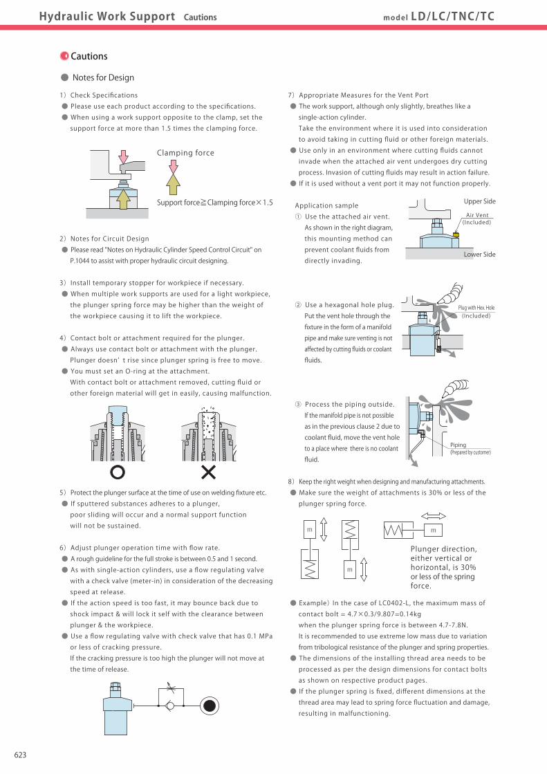
Hole Clamp
SFASFC
Link Clamp
LKALKCLKWLM/LJTMA-2TMA-1
Work Support
LDLCTNCTC
LLW
Air SensingLift Cylinder
Compact Cylinder
LLLLRLLUDPDRDSDT
Block Cylinder
DBADBC
Control Valve
BZLBZTBZX/JZG
Pallet Clamp
VSVT
Expansion Locating Pin
VLVMVJVK
FPFQ
Pull Stud Clamp
DWA/DWB
CustomizedSpring Cylinder
Swing Clamp
LHALHCLHSLHWLT/LGTLA-2TLB-2TLA-1
Pneumatic Series
Hydraulic Series
Valve / CouplerHydraulic Unit
Cautions / Others
High-PowerSeries
Manual OperationAccessories
Work SupportDigest P.545 CautionsHydraulic Work Support Cautions model LD/LC/TNC/TC
Cautions
● Notes for Design ● Installation Notes
1)Check Specifications
● Please use each product according to the specifications.
● When using a work support opposite to the clamp, set the
support force at more than 1.5 times the clamping force.
2)Notes for Circuit Design
● Please read "Notes on Hydraulic Cylinder Speed Control Circuit" on
P.1044 to assist with proper hydraulic circuit designing.
3)Install temporary stopper for workpiece if necessary.
● When multiple work supports are used for a light workpiece,
the plunger spring force may be higher than the weight of
the workpiece causing it to lift the workpiece.
4)Contact bolt or attachment required for the plunger.
● Always use contact bolt or attachment with the plunger.
Plunger doesn’ t rise since plunger spring is free to move.
● You must set an O-ring at the attachment.
With contact bolt or attachment removed, cutting fluid or
other foreign material will get in easily, causing malfunction.
5)Protect the plunger surface at the time of use on welding fixture etc.
● If sputtered substances adheres to a plunger,
poor sliding will occur and a normal support function
will not be sustained.
6)Adjust plunger operation time with flow rate.
● A rough guideline for the full stroke is between 0.5 and 1 second.
● As with single-action cylinders, use a flow regulating valve
with a check valve (meter-in) in consideration of the decreasing
speed at release.
● If the action speed is too fast, it may bounce back due to
shock impact & will lock it self with the clearance between
plunger & the workpiece.
● Use a flow regulating valve with check valve that has 0.1 MPa
or less of cracking pressure.
If the cracking pressure is too high the plunger will not move at
the time of release.
7)Appropriate Measures for the Vent Port
● The work support, although only slightly, breathes like a
single-action cylinder.
Take the environment where it is used into consideration
to avoid taking in cutting fluid or other foreign materials.
● Use only in an environment where cutting fluids cannot
invade when the attached air vent undergoes dry cutting
process. Invasion of cutting fluids may result in action failure.
● If it is used without a vent port it may not function properly.
Application sample
① Use the attached air vent.
As shown in the right diagram,
this mounting method can
prevent coolant fluids from
directly invading.
② Use a hexagonal hole plug.
Put the vent hole through the
fixture in the form of a manifold
pipe and make sure venting is not
affected by cutting fluids or coolant
fluids.
③ Process the piping outside.
If the manifold pipe is not possible
as in the previous clause 2 due to
coolant fluid, move the vent hole
to a place where there is no coolant
fluid.
8)Keep the right weight when designing and manufacturing attachments.
● Make sure the weight of attachments is 30% or less of the
plunger spring force.
● Example) In the case of LC0402-L, the maximum mass of
contact bolt = 4.7×0.3/9.807=0.14kg
when the plunger spring force is between 4.7-7.8N.
It is recommended to use extreme low mass due to variation
from tribological resistance of the plunger and spring properties.
● The dimensions of the installing thread area needs to be
processed as per the design dimensions for contact bolts
as shown on respective product pages.
● If the plunger spring is fixed, different dimensions at the
thread area may lead to spring force fluctuation and damage,
resulting in malfunctioning.
1)Check the Usable Fluid
● Please use the appropriate fluid by referring to the Hydraulic
Fluid List. (Refer to P.1043 for Hydraulic Fluid List)
2)Mounting the Unit
● All the mounting bolt holes should be used for the plunger type with
tightening torque shown in the table below.
● While mounting, make sure there are no scratches or damage to the O-ring
or to the seals. Tighten according to the torque’ s mentioned in the table.
● Apply an adequate amount of grease to the O-ring.
● If it is mounted under dry state, the O-ring may have twisting or be defective.
● If it is tightened with higher torque, it may lead to malfunction.
3)Replacement of Attachment
● Do not lose the plunger spring when the attachment (contact bolt)
is removed.
● When the attachment is removed, stop the plunger with a spanner
at its front end and tighten it with torque as shown in the table below.
・ Installation Notes ・ Hydraulic Fluid List ・ Notes on Hydraulic Cylinder Speed Control Circuit・ Notes on Handling ・ Maintenance/Inspection ・ Warranty
※ Please refer to P.1043 for common cautions.
Plunger direction, either vertical or horizontal, is 30% or less of the spring force.
m
m
m
Upper Side
Lower Side
Air Vent(Included)
Plug with Hex. Hole(Included)
Clamping force
Support force≧Clamping force×1.5
Tightening Torque (N・m)6.36.3101025506.36.3101025
Thread SizeM5×0.8M5×0.8M6×1M6×1M8×1.25M10×1.5M5×0.8M5×0.8M6×1M6×1M8×1.25
LC0402LC0482LC0552LC0652LC0752LC0902TC0402TC0482TC0552TC0652TC0752
LC
TC
Model No.
Piping(Prepared by customer)
Attachment (Contact Bolt)
Tightening Torque (N・m)1631.550638031.5506380
Thread SizeM22×1.5M26×1.5M30×1.5M36×1.5M45×1.5M26×1.5M30×1.5M36×1.5M45×1.5
LD0222LD0262LD0302LD0362LD0452TNC0400TNC0600TNC1000TNC1600
LD
TNC
Model No.
Tightening Torque(N・m)16164040808016404080801.6510161610161640
Front Thread SizeM10×1.5M10×1.5M12×1.75M12×1.75M16×2M16×2M10×1.5M12×1.75M12×1.75M16×2M16×2M4×0.7M6×1M8×1.25M10×1.5M10×1.5M8×1.25M10×1.5M10×1.5M12×1.75
LC0402LC0482LC0552LC0652LC0752LC0902TC0402TC0482TC0552TC0652TC0752LD0222LD0262LD0302LD0362LD0452TNC0400TNC0600TNC1000TNC1600
LC
TC
LD
TNC
Model No.
623

Hole Clamp
SFASFC
Link Clamp
LKALKCLKWLM/LJTMA-2TMA-1
Work Support
LDLCTNCTC
LLW
Air SensingLift Cylinder
Compact Cylinder
LLLLRLLUDPDRDSDT
Block Cylinder
DBADBC
Control Valve
BZLBZTBZX/JZG
Pallet Clamp
VSVT
Expansion Locating Pin
VLVMVJVK
FPFQ
Pull Stud Clamp
DWA/DWB
CustomizedSpring Cylinder
Swing Clamp
LHALHCLHSLHWLT/LGTLA-2TLB-2TLA-1
Pneumatic Series
Hydraulic Series
Valve / CouplerHydraulic Unit
Cautions / Others
High-PowerSeries
Manual OperationAccessories
Work SupportDigest P.545 CautionsHydraulic Work Support Cautions model LD/LC/TNC/TC
Cautions
● Notes for Design ● Installation Notes
1)Check Specifications
● Please use each product according to the specifications.
● When using a work support opposite to the clamp, set the
support force at more than 1.5 times the clamping force.
2)Notes for Circuit Design
● Please read "Notes on Hydraulic Cylinder Speed Control Circuit" on
P.1044 to assist with proper hydraulic circuit designing.
3)Install temporary stopper for workpiece if necessary.
● When multiple work supports are used for a light workpiece,
the plunger spring force may be higher than the weight of
the workpiece causing it to lift the workpiece.
4)Contact bolt or attachment required for the plunger.
● Always use contact bolt or attachment with the plunger.
Plunger doesn’ t rise since plunger spring is free to move.
● You must set an O-ring at the attachment.
With contact bolt or attachment removed, cutting fluid or
other foreign material will get in easily, causing malfunction.
5)Protect the plunger surface at the time of use on welding fixture etc.
● If sputtered substances adheres to a plunger,
poor sliding will occur and a normal support function
will not be sustained.
6)Adjust plunger operation time with flow rate.
● A rough guideline for the full stroke is between 0.5 and 1 second.
● As with single-action cylinders, use a flow regulating valve
with a check valve (meter-in) in consideration of the decreasing
speed at release.
● If the action speed is too fast, it may bounce back due to
shock impact & will lock it self with the clearance between
plunger & the workpiece.
● Use a flow regulating valve with check valve that has 0.1 MPa
or less of cracking pressure.
If the cracking pressure is too high the plunger will not move at
the time of release.
7)Appropriate Measures for the Vent Port
● The work support, although only slightly, breathes like a
single-action cylinder.
Take the environment where it is used into consideration
to avoid taking in cutting fluid or other foreign materials.
● Use only in an environment where cutting fluids cannot
invade when the attached air vent undergoes dry cutting
process. Invasion of cutting fluids may result in action failure.
● If it is used without a vent port it may not function properly.
Application sample
① Use the attached air vent.
As shown in the right diagram,
this mounting method can
prevent coolant fluids from
directly invading.
② Use a hexagonal hole plug.
Put the vent hole through the
fixture in the form of a manifold
pipe and make sure venting is not
affected by cutting fluids or coolant
fluids.
③ Process the piping outside.
If the manifold pipe is not possible
as in the previous clause 2 due to
coolant fluid, move the vent hole
to a place where there is no coolant
fluid.
8)Keep the right weight when designing and manufacturing attachments.
● Make sure the weight of attachments is 30% or less of the
plunger spring force.
● Example) In the case of LC0402-L, the maximum mass of
contact bolt = 4.7×0.3/9.807=0.14kg
when the plunger spring force is between 4.7-7.8N.
It is recommended to use extreme low mass due to variation
from tribological resistance of the plunger and spring properties.
● The dimensions of the installing thread area needs to be
processed as per the design dimensions for contact bolts
as shown on respective product pages.
● If the plunger spring is fixed, different dimensions at the
thread area may lead to spring force fluctuation and damage,
resulting in malfunctioning.
1)Check the Usable Fluid
● Please use the appropriate fluid by referring to the Hydraulic
Fluid List. (Refer to P.1043 for Hydraulic Fluid List)
2)Mounting the Unit
● All the mounting bolt holes should be used for the plunger type with
tightening torque shown in the table below.
● While mounting, make sure there are no scratches or damage to the O-ring
or to the seals. Tighten according to the torque’ s mentioned in the table.
● Apply an adequate amount of grease to the O-ring.
● If it is mounted under dry state, the O-ring may have twisting or be defective.
● If it is tightened with higher torque, it may lead to malfunction.
3)Replacement of Attachment
● Do not lose the plunger spring when the attachment (contact bolt)
is removed.
● When the attachment is removed, stop the plunger with a spanner
at its front end and tighten it with torque as shown in the table below.
・ Installation Notes ・ Hydraulic Fluid List ・ Notes on Hydraulic Cylinder Speed Control Circuit・ Notes on Handling ・ Maintenance/Inspection ・ Warranty
※ Please refer to P.1043 for common cautions.
Plunger direction, either vertical or horizontal, is 30% or less of the spring force.
m
m
m
Upper Side
Lower Side
Air Vent(Included)
Plug with Hex. Hole(Included)
Clamping force
Support force≧Clamping force×1.5
Tightening Torque (N・m)6.36.3101025506.36.3101025
Thread SizeM5×0.8M5×0.8M6×1M6×1M8×1.25M10×1.5M5×0.8M5×0.8M6×1M6×1M8×1.25
LC0402LC0482LC0552LC0652LC0752LC0902TC0402TC0482TC0552TC0652TC0752
LC
TC
Model No.
Piping(Prepared by customer)
Attachment (Contact Bolt)
Tightening Torque (N・m)1631.550638031.5506380
Thread SizeM22×1.5M26×1.5M30×1.5M36×1.5M45×1.5M26×1.5M30×1.5M36×1.5M45×1.5
LD0222LD0262LD0302LD0362LD0452TNC0400TNC0600TNC1000TNC1600
LD
TNC
Model No.
Tightening Torque(N・m)16164040808016404080801.6510161610161640
Front Thread SizeM10×1.5M10×1.5M12×1.75M12×1.75M16×2M16×2M10×1.5M12×1.75M12×1.75M16×2M16×2M4×0.7M6×1M8×1.25M10×1.5M10×1.5M8×1.25M10×1.5M10×1.5M12×1.75
LC0402LC0482LC0552LC0652LC0752LC0902TC0402TC0482TC0552TC0652TC0752LD0222LD0262LD0302LD0362LD0452TNC0400TNC0600TNC1000TNC1600
LC
TC
LD
TNC
Model No.
624

1043
Notes on Hydraulic Cylinder Speed Control Circuit
Cautions
Installation Notes(For Hydraulic Series)
Hydraulic Fluid List
Notes on Handling
Maintenance/ Inspection
Warranty
Index
Search byAlphabetical Order
Company Profile
Sales Offices
Company Profile
Our Products
History
Pneumatic Series
Hydraulic Series
Valve / CouplerHydraulic Unit
Cautions / Others
High-PowerSeries
Manual OperationAccessories
Cautions Installation Notes(For Hydraulic Series)
Notes on Hydraulic CylinderSpeed Control Circuit Maintenance/Inspection WarrantyNotes on HandlingHydraulic Fluid List
Cautions
● Installation Notes (For Hydraulic Series) ● Hydraulic Fluid List
1)Check the Usable Fluid
● Please use the appropriate fluid by referring to the Hydraulic Fluid List.
2)Procedure before Piping
● The pipeline, piping connector and fixture circuits should be cleaned
by thorough flushing.
● The dust and cutting chips in the circuit may lead to fluid leakage
and malfunction.
● There is no filter provided with Kosmek’ s product except for a part
of valves which prevents foreign materials and contaminants from
getting into the circuit.
3)Applying Sealing Tape
● Wrap with tape 1 to 2 times following the screw direction.
● Pieces of the sealing tape can lead to oil leakage and malfunction.
● In order to prevent a foreign substance from going into the product
during the piping work, it should be carefully cleaned before working.
4)Air Bleeding of the Hydraulic Circuit
● If the hydraulic circuit has excessive air, the action time may become
very long. If air enters the circuit after connecting the hydraulic port
or under the condition of no air in the oil tank, please perform
the following steps.
① Reduce hydraulic pressure to less than 2MPa.
② Loosen the cap nut of pipe fitting closest to the clamp by one full turn.
③ Wiggle the pipeline to loosen the outlet of pipe fitting.
Hydraulic fluid mixed with air comes out.
④ Tighten the cap nut after bleeding.
⑤ It is more effective to bleed air at the highest point inside the circuit
or at the end of the circuit.
(Set an air bleeding valve at the highest point inside the circuit.)
5)Checking Looseness and Retightening
● At the beginning of the machine installation, the bolt and nut may
be tightened lightly. Check the looseness and re-tighten as required.
Flow Control at the Release Side
W
Flow Control Valve(Any location is OK)
Sequence Valve
Showa Shell SekiyuIdemitsu KosanJX Nippon Oil & EnergyCosmo OilExxonMobilMatsumura OilCastrol
Maker Anti-Wear Hydraulic OilTellus S2 M 32
Daphne Hydraulic Fluid 32Super Hyrando 32Cosmo Hydro AW32Mobil DTE 24Hydol AW-32Hyspin AWS 32
Multi-Purpose Hydraulic OilMorlina S2 B 32
Daphne Super Multi Oil 32Super Mulpus DX 32Cosmo New Mighty Super 32Mobil DTE 24 Light
Note As it may be difficult to purchase the products as shown in the table from overseas, please contact the respective manufacturer.
ISO Viscosity Grade ISO-VG-32
● Notes on Hydraulic Cylinder Speed Control Unit
Please pay attention to the cautions below. Design the hydraulic circuit for controlling the action speed of hydraulic cylinder.
Improper circuit design may lead to malfunctions and damages. Please review the circuit design in advance.! ● Flow Control Circuit for Single Acting Cylinder For spring return single acting cylinders, restricting flow during release can extremely slow down or disrupt release action. The preferred method is to control the flow during the lock action using a valve that has free-flow in the release direction. It is also preferred to provide a flow control valve at each actuator.
Accelerated clamping speed by excessive hydraulic flow to the cylinder may sustain damage. In this case add flow control to regulate flow. (Please add flow control to release flow if the lever weight is put on at the time of release action when using swing clamps.)
● Flow Control Circuit for Double Acting Cylinder Flow control circuit for double acting cylinder should have meter-out circuits for both the lock and release sides. Meter-in control can have adverse effect by presence of air in the system. However, in the case of controlling LKE, TMA, TLA, both lock side
and release side should be meter-in circuit.
Refer to P.47 for speed adjustment of LKE.
For TMA and TLA, if meter-out circuit is used, abnormal high
pressure is created, which causes oil leakage and damage.
【Meter-out Circuit】 (Except LKE/TMA/TLA)
【Meter-in Circuit】 (LKE/TMA/TLA must be controlled with meter-in.)
In the case of meter-out circuit, the hydraulic circuit should be designed with the following points. ① Single acting components should not be used in the same flow control circuit as the double acting components. The release action of the single acting cylinders may become erratic or very slow.
Refer to the following circuit when both the single acting cylinder and double acting cylinder are used together. ○ Separate the control circuit.
○ Reduce the influence of double acting cylinder control unit. However, due to the back pressure in tank line, single action cylinder is activated after double action cylinder works.
② In the case of meter-out circuit, the inner circuit pressure may increase during the cylinder action because of the fluid supply. The increase of the inner circuit pressure can be prevented by reducing the supplied fluid beforehand via the flow control valve. Especially when using sequence valve or pressure switches for clamping detection. If the back pressure is more than the set pressure then the system will not work as it is designed to.

1044
Notes on Hydraulic Cylinder Speed Control Circuit
Cautions
Installation Notes(For Hydraulic Series)
Hydraulic Fluid List
Notes on Handling
Maintenance/ Inspection
Warranty
Index
Search byAlphabetical Order
Company Profile
Sales Offices
Company Profile
Our Products
History
Pneumatic Series
Hydraulic Series
Valve / CouplerHydraulic Unit
Cautions / Others
High-PowerSeries
Manual OperationAccessories
Cautions Installation Notes(For Hydraulic Series)
Notes on Hydraulic CylinderSpeed Control Circuit Maintenance/Inspection WarrantyNotes on HandlingHydraulic Fluid List
Cautions
● Installation Notes (For Hydraulic Series) ● Hydraulic Fluid List
1)Check the Usable Fluid
● Please use the appropriate fluid by referring to the Hydraulic Fluid List.
2)Procedure before Piping
● The pipeline, piping connector and fixture circuits should be cleaned
by thorough flushing.
● The dust and cutting chips in the circuit may lead to fluid leakage
and malfunction.
● There is no filter provided with Kosmek’ s product except for a part
of valves which prevents foreign materials and contaminants from
getting into the circuit.
3)Applying Sealing Tape
● Wrap with tape 1 to 2 times following the screw direction.
● Pieces of the sealing tape can lead to oil leakage and malfunction.
● In order to prevent a foreign substance from going into the product
during the piping work, it should be carefully cleaned before working.
4)Air Bleeding of the Hydraulic Circuit
● If the hydraulic circuit has excessive air, the action time may become
very long. If air enters the circuit after connecting the hydraulic port
or under the condition of no air in the oil tank, please perform
the following steps.
① Reduce hydraulic pressure to less than 2MPa.
② Loosen the cap nut of pipe fitting closest to the clamp by one full turn.
③ Wiggle the pipeline to loosen the outlet of pipe fitting.
Hydraulic fluid mixed with air comes out.
④ Tighten the cap nut after bleeding.
⑤ It is more effective to bleed air at the highest point inside the circuit
or at the end of the circuit.
(Set an air bleeding valve at the highest point inside the circuit.)
5)Checking Looseness and Retightening
● At the beginning of the machine installation, the bolt and nut may
be tightened lightly. Check the looseness and re-tighten as required.
Flow Control at the Release Side
W
Flow Control Valve(Any location is OK)
Sequence Valve
Showa Shell SekiyuIdemitsu KosanJX Nippon Oil & EnergyCosmo OilExxonMobilMatsumura OilCastrol
Maker Anti-Wear Hydraulic OilTellus S2 M 32
Daphne Hydraulic Fluid 32Super Hyrando 32Cosmo Hydro AW32Mobil DTE 24Hydol AW-32Hyspin AWS 32
Multi-Purpose Hydraulic OilMorlina S2 B 32
Daphne Super Multi Oil 32Super Mulpus DX 32Cosmo New Mighty Super 32Mobil DTE 24 Light
Note As it may be difficult to purchase the products as shown in the table from overseas, please contact the respective manufacturer.
ISO Viscosity Grade ISO-VG-32
● Notes on Hydraulic Cylinder Speed Control Unit
Please pay attention to the cautions below. Design the hydraulic circuit for controlling the action speed of hydraulic cylinder.
Improper circuit design may lead to malfunctions and damages. Please review the circuit design in advance.! ● Flow Control Circuit for Single Acting Cylinder For spring return single acting cylinders, restricting flow during release can extremely slow down or disrupt release action. The preferred method is to control the flow during the lock action using a valve that has free-flow in the release direction. It is also preferred to provide a flow control valve at each actuator.
Accelerated clamping speed by excessive hydraulic flow to the cylinder may sustain damage. In this case add flow control to regulate flow. (Please add flow control to release flow if the lever weight is put on at the time of release action when using swing clamps.)
● Flow Control Circuit for Double Acting Cylinder Flow control circuit for double acting cylinder should have meter-out circuits for both the lock and release sides. Meter-in control can have adverse effect by presence of air in the system. However, in the case of controlling LKE, TMA, TLA, both lock side
and release side should be meter-in circuit.
Refer to P.47 for speed adjustment of LKE.
For TMA and TLA, if meter-out circuit is used, abnormal high
pressure is created, which causes oil leakage and damage.
【Meter-out Circuit】 (Except LKE/TMA/TLA)
【Meter-in Circuit】 (LKE/TMA/TLA must be controlled with meter-in.)
In the case of meter-out circuit, the hydraulic circuit should be designed with the following points. ① Single acting components should not be used in the same flow control circuit as the double acting components. The release action of the single acting cylinders may become erratic or very slow.
Refer to the following circuit when both the single acting cylinder and double acting cylinder are used together. ○ Separate the control circuit.
○ Reduce the influence of double acting cylinder control unit. However, due to the back pressure in tank line, single action cylinder is activated after double action cylinder works.
② In the case of meter-out circuit, the inner circuit pressure may increase during the cylinder action because of the fluid supply. The increase of the inner circuit pressure can be prevented by reducing the supplied fluid beforehand via the flow control valve. Especially when using sequence valve or pressure switches for clamping detection. If the back pressure is more than the set pressure then the system will not work as it is designed to.

Notes on Hydraulic Cylinder Speed Control Circuit
Cautions
Installation Notes(For Hydraulic Series)
Hydraulic Fluid List
Notes on Handling
Maintenance/ Inspection
Warranty
Index
Search byAlphabetical Order
Company Profile
Sales Offices
Company Profile
Our Products
History
Pneumatic Series
Hydraulic Series
Valve / CouplerHydraulic Unit
Cautions / Others
High-PowerSeries
Manual OperationAccessories
Cautions Installation Notes(For Hydraulic Series)
Notes on Hydraulic CylinderSpeed Control Circuit Maintenance/Inspection WarrantyNotes on HandlingHydraulic Fluid List
Cautions
1)Warranty Period
● The product warranty period is 18 months from shipment from
our factory or 12 months from initial use, whichever is earlier.
2)Warranty Scope
● If the product is damaged or malfunctions during the warranty
period due to faulty design, materials or workmanship, we will
replace or repair the defective part at our expense.
Defects or failures caused by the following are not covered.
① If the stipulated maintenance and inspection are not carried out.
② If the product is used while it is not suitable for use based on
the operator’ s judgment, resulting in defect.
③ If it is used or handled in inappropriate way by the operator.
(Including damage caused by the misconduct of the third party.)
④ If the defect is caused by reasons other than our responsibility.
⑤ If repair or modifications are carried out by anyone other than Kosmek,
or without our approval and confirmation, it will void warranty.
⑥ Other caused by natural disasters or calamities not attributable to
our company.
⑦ Parts or replacement expenses due to parts consumption and
deterioration.
(Such as rubber, plastic, seal material and some electric components.)
Damages excluding from direct result of a product defect shall be
excluded from the warranty.
● Warranty
1)It should be handled by qualified personnel.
● The hydraulic machine and air compressor should be handled
and maintained by qualified personnel.
2)Do not handle or remove the machine unless the safety protocols
are ensured.
① The machine and equipment can only be inspected or prepared
when it is confirmed that the preventive devices are in place.
② Before the machine is removed, make sure that the above-mentioned
safety measures are in place. Shut off the air of hydraulic source
and make sure no pressure exists in the hydraulic and air circuit.
③ After stopping the machine, do not remove until the temperature
cools down.
④ Make sure there is no abnormality in the bolts and respective parts
before restarting the machine or equipment.
3)Do not touch clamps (cylinder) while clamps (cylinder) is working.
Otherwise, your hands may be injured due to clinching.
4)Do not disassemble or modify.
● If the equipment is taken apart or modified, the warranty will be
voided even within the warranty period.
1)Removal of the Machine and Shut-off of Pressure Source
● Before the machine is removed, make sure that the
above-mentioned safety measures are in place. Shut off the
air of hydraulic source and make sure no pressure exists in
the hydraulic and air circuit.
● Make sure there is no abnormality in the bolts and respective
parts before restarting.
2)Regularly clean the area around the piston rod and plunger.
● If it is used when the surface is contaminated with dirt, it may
lead to packing seal damage, malfunctioning , fluid leakage
and air leaks.
3) Please clean out the reference surface regularly (taper reference
surface and seating surface) of locating machine .(VS/VT/VL/VM/
VJ/VK/WVS/WM/WK/VX/VXF)
● Location products, except VX/VXF model, can remove
contaminants with cleaning functions.
When installing pallets makes sure there is no thick sludge like
substances on pallets.
● Continuous use with dirt on components will lead to locating
functions not work properly, leaking and malfunction.
4) If disconnecting by couplers on a regular basis, air bleeding
should be carried out daily to avoid air mixed in the circuit.
5)Regularly tighten nuts, bolts, pins, cylinders and pipe line to
ensure proper use.
6)Make sure the hydraulic fluid has not deteriorated.
7)Make sure there is smooth action and no abnormal noise.
● Especially when it is restarted after left unused for a long
period, make sure it can be operated correctly.
8)The products should be stored in the cool and dark place
without direct sunshine or moisture.
9)Please contact us for overhaul and repair.
● Notes on Handling ● Maintenance and Inspection
1045

Notes on Hydraulic Cylinder Speed Control Circuit
Cautions
Installation Notes(For Hydraulic Series)
Hydraulic Fluid List
Notes on Handling
Maintenance/ Inspection
Warranty
Index
Search byAlphabetical Order
Company Profile
Sales Offices
Company Profile
Our Products
History
Pneumatic Series
Hydraulic Series
Valve / CouplerHydraulic Unit
Cautions / Others
High-PowerSeries
Manual OperationAccessories
Cautions Installation Notes(For Hydraulic Series)
Notes on Hydraulic CylinderSpeed Control Circuit Maintenance/Inspection WarrantyNotes on HandlingHydraulic Fluid List
Cautions
1)Warranty Period
● The product warranty period is 18 months from shipment from
our factory or 12 months from initial use, whichever is earlier.
2)Warranty Scope
● If the product is damaged or malfunctions during the warranty
period due to faulty design, materials or workmanship, we will
replace or repair the defective part at our expense.
Defects or failures caused by the following are not covered.
① If the stipulated maintenance and inspection are not carried out.
② If the product is used while it is not suitable for use based on
the operator’ s judgment, resulting in defect.
③ If it is used or handled in inappropriate way by the operator.
(Including damage caused by the misconduct of the third party.)
④ If the defect is caused by reasons other than our responsibility.
⑤ If repair or modifications are carried out by anyone other than Kosmek,
or without our approval and confirmation, it will void warranty.
⑥ Other caused by natural disasters or calamities not attributable to
our company.
⑦ Parts or replacement expenses due to parts consumption and
deterioration.
(Such as rubber, plastic, seal material and some electric components.)
Damages excluding from direct result of a product defect shall be
excluded from the warranty.
● Warranty
1)It should be handled by qualified personnel.
● The hydraulic machine and air compressor should be handled
and maintained by qualified personnel.
2)Do not handle or remove the machine unless the safety protocols
are ensured.
① The machine and equipment can only be inspected or prepared
when it is confirmed that the preventive devices are in place.
② Before the machine is removed, make sure that the above-mentioned
safety measures are in place. Shut off the air of hydraulic source
and make sure no pressure exists in the hydraulic and air circuit.
③ After stopping the machine, do not remove until the temperature
cools down.
④ Make sure there is no abnormality in the bolts and respective parts
before restarting the machine or equipment.
3)Do not touch clamps (cylinder) while clamps (cylinder) is working.
Otherwise, your hands may be injured due to clinching.
4)Do not disassemble or modify.
● If the equipment is taken apart or modified, the warranty will be
voided even within the warranty period.
1)Removal of the Machine and Shut-off of Pressure Source
● Before the machine is removed, make sure that the
above-mentioned safety measures are in place. Shut off the
air of hydraulic source and make sure no pressure exists in
the hydraulic and air circuit.
● Make sure there is no abnormality in the bolts and respective
parts before restarting.
2)Regularly clean the area around the piston rod and plunger.
● If it is used when the surface is contaminated with dirt, it may
lead to packing seal damage, malfunctioning , fluid leakage
and air leaks.
3) Please clean out the reference surface regularly (taper reference
surface and seating surface) of locating machine .(VS/VT/VL/VM/
VJ/VK/WVS/WM/WK/VX/VXF)
● Location products, except VX/VXF model, can remove
contaminants with cleaning functions.
When installing pallets makes sure there is no thick sludge like
substances on pallets.
● Continuous use with dirt on components will lead to locating
functions not work properly, leaking and malfunction.
4) If disconnecting by couplers on a regular basis, air bleeding
should be carried out daily to avoid air mixed in the circuit.
5)Regularly tighten nuts, bolts, pins, cylinders and pipe line to
ensure proper use.
6)Make sure the hydraulic fluid has not deteriorated.
7)Make sure there is smooth action and no abnormal noise.
● Especially when it is restarted after left unused for a long
period, make sure it can be operated correctly.
8)The products should be stored in the cool and dark place
without direct sunshine or moisture.
9)Please contact us for overhaul and repair.
● Notes on Handling ● Maintenance and Inspection
1046

Pressure Gauge
Coupler Switch
PS
G-Thread Fitting
Manifold Block
WHZ-MD
LZY-MD
LZ-MS
LZ-MP
TMZ-1MB
TMZ-2MB
DZ-M
Screw Locator
VXF
Manual ExpansionLocating Pin
VX
Manifold Block /Nut
DZ-R
Pressure Switch
JB
Manifold
JX
DZ-C
DZ-P
DZ-B
LZ-S
LZ-SQ
TNZ-S
TNZ-SQ
JGA/JGB
Pneumatic Series
Hydraulic Series
Valve / CouplerHydraulic Unit
Cautions / Others
High-PowerSeries
Manual OperationAccessories
Manifold BlockModel No. Indication/External Dimensions
Manifold BlockApplicable Model/Application Examples
Applicable Model
Application Examples
Model WHZ-MD
Corresponding Item Model No.Manifold Block Model No.
Model WHZ-MDModel LZY-MDModel LZ-MSModel LZ-MPModel TMZ-1MBModel TMZ-2MBModel DZ-MG□Model DZ-MS□
Manifold BlockModel WHAModel WCAModel WHEModel WCE
Model LZ-MSModel LTModel LMModel LGModel LJ
Model LKEModel LKAModel LKC
Model LZY-MD
Model LZ-MP Model TC
Model LHSModel LL
Model LC
Model TMZ-1MB Model TMA-1
Model TMZ-2MB Model TMA-2
Model DZ-MG□/MS□ Model DP
Model LHCModel LHA Model LHE
Manifold Block
The mounting height of clamp is adjustable with the manifold block.
Manifold BlockWorkpiece
Fixture Base
Clamp
Manifold Block
Work Support (LC) Application Example
Push Cylinder (DP) Application Example
DP-A□ DZ-MG□
Fixture Base
LC
Standard Mounting
Manifold Block (LZ□-MP× one piece)
Manifold Block (LZ□-MP×three pieces)
Fixture Base
This drawing shows ▼surface is machined by customer one out of three pieces
1023

Pressure Gauge
Coupler Switch
PS
G-Thread Fitting
Manifold Block
WHZ-MD
LZY-MD
LZ-MS
LZ-MP
TMZ-1MB
TMZ-2MB
DZ-M
Screw Locator
VXF
Manual ExpansionLocating Pin
VX
Manifold Block /Nut
DZ-R
Pressure Switch
JB
Manifold
JX
DZ-C
DZ-P
DZ-B
LZ-S
LZ-SQ
TNZ-S
TNZ-SQ
JGA/JGB
Pneumatic Series
Hydraulic Series
Valve / CouplerHydraulic Unit
Cautions / Others
High-PowerSeries
Manual OperationAccessories
Manifold BlockModel No. Indication/External Dimensions
Manifold BlockApplicable Model/Application Examples
Applicable Model
Application Examples
Model WHZ-MD
Corresponding Item Model No.Manifold Block Model No.
Model WHZ-MDModel LZY-MDModel LZ-MSModel LZ-MPModel TMZ-1MBModel TMZ-2MBModel DZ-MG□Model DZ-MS□
Manifold BlockModel WHAModel WCAModel WHEModel WCE
Model LZ-MSModel LTModel LMModel LGModel LJ
Model LKEModel LKAModel LKC
Model LZY-MD
Model LZ-MP Model TC
Model LHSModel LL
Model LC
Model TMZ-1MB Model TMA-1
Model TMZ-2MB Model TMA-2
Model DZ-MG□/MS□ Model DP
Model LHCModel LHA Model LHE
Manifold Block
The mounting height of clamp is adjustable with the manifold block.
Manifold BlockWorkpiece
Fixture Base
Clamp
Manifold Block
Work Support (LC) Application Example
Push Cylinder (DP) Application Example
DP-A□ DZ-MG□
Fixture Base
LC
Standard Mounting
Manifold Block (LZ□-MP× one piece)
Manifold Block (LZ□-MP×three pieces)
Fixture Base
This drawing shows ▼surface is machined by customer one out of three pieces
1024

Pressure Gauge
Coupler Switch
PS
G-Thread Fitting
Manifold Block
WHZ-MD
LZY-MD
LZ-MS
LZ-MP
TMZ-1MB
TMZ-2MB
DZ-M
Screw Locator
VXF
Manual ExpansionLocating Pin
VX
Manifold Block /Nut
DZ-R
Pressure Switch
JB
Manifold
JX
DZ-C
DZ-P
DZ-B
LZ-S
LZ-SQ
TNZ-S
TNZ-SQ
JGA/JGB
Pneumatic Series
Hydraulic Series
Valve / CouplerHydraulic Unit
Cautions / Others
High-PowerSeries
Manual OperationAccessories
Manifold Block model WHZ-MD/LZY-MD/LZ-MS/LZ-MPManifold Block
Model No. Indication/External DimensionsManifold Block
Applicable Model/Application Examples
Manifold Block for WCA/WCE/WHA/WHE
Size(Refer tofollowing table)
Model No. Indication
Design No.(Revision Number)
WHZ 048 0 - MD
Manifold Block for LKA/LKC/LKE/LHA/LHC/LHE/LHS/LL
Z Surface
C0.6C0.6
A
6.3S
JB
HNx
KJ
CK
Ny Ny
4-φR±0.1
φD+ 0.3
0
L Surface
C0.6C0.6
±0.1C6.3S
F
A
EG
B
J
H
4-φK
φD+ 0.3
0
LZY0360-MD LZY0400-MD LZY0480-MD LZY0550-MD LZY0650-MD LZY0750-MD LZY0900-MD LZY1050-MD LKA0360 / LKE0360 LKA0400 / LKC0400 LKA0480 / LKC0480 LKA0550 / LKC0550 LKA0650 / LKC0650 LKA0750 LKA0900 LKA1050 LHA0360 / LHC0360 LKE0400 / LHA0400 LKE0480 / LHA0480 LKE0550 / LHA0550 LHA0650 / LHC0650 LHA0750 LHA0900 LHA1050 LHE0360 / LHS0360 LHC0400 / LHE0400 LHC0480 / LHE0480 LHC0550 / LHE0550 LHS0650 LHS0750 LHS0900 LHS1050 LL0360 LHS0400 / LL0400 LHS0480 / LL0480 LHS0550 / LL0550 LL0650 LL0750 LL0900 LL1050 49 54 61 69 81 92 107 122 40 45 51 60 70 80 95 110 20 20 27 30 32 37 45 50 36 40 48 55 65 75 90 105 29 31.5 35.5 39 46 52 59.5 67 20 22.5 25.5 30 35 40 47.5 55 23.5 26 30 33.5 39.5 45 52.5 60 16 18 22 24 30 32 37 45 31.4 34 40 47 55 63 75 88 4.5 5.5 5.5 6.8 6.8 9 11 14 1BP5 1BP5 1BP5 1BP5 1BP7 1BP7 1BP7 1BP7 0.2 0.2 0.3 0.4 0.5 0.8 1.2 1.7
Model No.
ABCDEFGHJK
O-ring Mass kg
(mm)
Notes 1. Material:S45C 2. Mounting bolts are not provided. Prepare mounting bolts according to the mounting height using the C dimensions as a reference. 3. If thickness other than C is required, perform additional machining on surface L. Please refer to the drawing.
WHZ0600-MD WHZ0320-MD WHZ0400-MD WHZ0500-MD WHZ0630-MD WCE0601 WCA0321 WCE1001 WCA0401 WCE1601 WCA0501 WCE2501 WCA0631 WCE4001 WHE0600 WHA0320 WHE1000 WHA0400 WHE1600 WHA0500 WHE2500 WHA0630 WHE4000 23 25 27 31 35 54 60 67 77 88.5 45 50 58 68 81 40 46 54 64 77 31.5 35 38 43 48 22.5 25 29 34 40.5 34 39 45 53 65 26 28 31 36 41 9 10 13 15 20 5.5 5.5 5.5 6.5 6.5 1BP5 1BP7 1BP7 1BP7 1BP7 0.1 0.1 0.1 0.2 0.2
Model No.
ABCDHJKNxNyR
O-ring Mass kg
(mm)
Notes 1. Material:A2017BE-T4 2. Mounting bolts are not provided. Prepare mounting bolts according to the mounting height using the A dimensions as a reference. 3. If thickness other than A is required, perform additional machining on surface Z. Please refer to the drawing.
Manifold Block for LC/TC
LZ0400-MP LZ0480-MP LZ0550-MP LZ0650-MP LZ0750-MP LZ0900-MP LC0402 LC0482 LC0552 LC0652 LC0752 LC0902 TC0402 TC0482 TC0552 TC0652 TC0752 20 27 30 32 37 45 56.5 62 70 82 93 107 45 51 60 70 80 95 40 48 55 65 75 90 34 36.5 40 47 53 59.5 22.5 25.5 30 35 40 47.5 34 40 47 55 63 75 26 30 33.5 39.5 45 52.5 5 0 0 0 0 0 5.5 5.5 6.8 6.8 9 11 25 28 31 37 42.5 50 8 11 13 14 15 15 1BP5 1BP5 1BP5 1BP7 1BP7 1BP7 0.2 0.3 0.4 0.5 0.8 1.2
Model No.
ABCDHJKNxNyRYxYyO-ring
Mass kg
(mm)
Notes 1. Material:S45C 2. Mounting bolts are not provided. Prepare mounting bolts according to the mounting height using the A dimensions as a reference. 3. If thickness other than A is required, perform additional machining on surface P. Please refer to the drawing.
Manifold Block for LM/LJ/LT/LG
LZ0360-MS LZ0400-MS LZ0480-MS LZ0550-MS LZ0650-MS LZ0750-MS LZ0900-MS LZ1050-MS LT0360 LT0400 LT0480 LT0550 LT0650 LT0750 LG0900 LG1050 LM0360 LM0400 LM0480 LM0550 LM0650 LM0750 LJ0902 LJ1052 51.5 56.5 62 70 82 93 107 122 40 45 51 60 70 80 95 110 20 20 27 30 32 37 45 50 36 40 48 55 65 75 90 105 31.5 34 36.5 40 47 53 59.5 67 20 22.5 25.5 30 35 40 47.5 55 31.4 34 40 47 55 63 75 88 4.5 5.5 5.5 6.8 6.8 9 11 14 23.5 26 30 33.5 39.5 45 52.5 60 5 5 0 0 0 0 0 0 1BP5 1BP5 1BP5 1BP5 1BP7 1BP7 1BP7 1BP7 0.2 0.2 0.3 0.4 0.5 0.8 1.2 1.7
Model No.
ABCDEFHJLM
O-ring Mass kg
(mm)
Notes 1. Material:S45C 2. Mounting bolts are not provided. Prepare mounting bolts according to the mounting height using the C dimensions as a reference. 3. If thickness other than C is required, perform additional machining on surface L. Please refer to the drawing.
2-O-ring(Included)
2-O-ring(Included)
Corresponding ItemModel Number
Corresponding ItemModel Number
Size(Refer tofollowing table)
Model No. Indication
Design No.(Revision Number)
LZY 048 0 - MD
Size(Refer tofollowing table)
Model No. Indication
Design No.(Revision Number)
LZ 048 0 - MS
Size(Refer tofollowing table)
B
φD+0.3
0
P Surface
C0.6C0.6
C±0.1
FA
EL
H
H
M
4-φJ
6.3S
φD+0.3
0
JB
HNx
KYx
CK
Yy Ny P Surface
4-φR
2-O-ring(Included)
C0.6C0.6
A±0.1
Model No. Indication
Design No.(Revision Number)
LZ 048 0 - MP
O-ring(Included)
Corresponding ItemModel Number
Corresponding ItemModel Number
1025

Pressure Gauge
Coupler Switch
PS
G-Thread Fitting
Manifold Block
WHZ-MD
LZY-MD
LZ-MS
LZ-MP
TMZ-1MB
TMZ-2MB
DZ-M
Screw Locator
VXF
Manual ExpansionLocating Pin
VX
Manifold Block /Nut
DZ-R
Pressure Switch
JB
Manifold
JX
DZ-C
DZ-P
DZ-B
LZ-S
LZ-SQ
TNZ-S
TNZ-SQ
JGA/JGB
Pneumatic Series
Hydraulic Series
Valve / CouplerHydraulic Unit
Cautions / Others
High-PowerSeries
Manual OperationAccessories
Manifold Block model WHZ-MD/LZY-MD/LZ-MS/LZ-MPManifold Block
Model No. Indication/External DimensionsManifold Block
Applicable Model/Application Examples
Manifold Block for WCA/WCE/WHA/WHE
Size(Refer tofollowing table)
Model No. Indication
Design No.(Revision Number)
WHZ 048 0 - MD
Manifold Block for LKA/LKC/LKE/LHA/LHC/LHE/LHS/LL
Z Surface
C0.6C0.6
A
6.3S
JB
HNx
KJ
CK
Ny Ny
4-φR±0.1
φD+ 0.3
0
L Surface
C0.6C0.6
±0.1C
6.3S
F
A
EG
B
J
H
4-φK
φD+ 0.3
0
LZY0360-MD LZY0400-MD LZY0480-MD LZY0550-MD LZY0650-MD LZY0750-MD LZY0900-MD LZY1050-MD LKA0360 / LKE0360 LKA0400 / LKC0400 LKA0480 / LKC0480 LKA0550 / LKC0550 LKA0650 / LKC0650 LKA0750 LKA0900 LKA1050 LHA0360 / LHC0360 LKE0400 / LHA0400 LKE0480 / LHA0480 LKE0550 / LHA0550 LHA0650 / LHC0650 LHA0750 LHA0900 LHA1050 LHE0360 / LHS0360 LHC0400 / LHE0400 LHC0480 / LHE0480 LHC0550 / LHE0550 LHS0650 LHS0750 LHS0900 LHS1050 LL0360 LHS0400 / LL0400 LHS0480 / LL0480 LHS0550 / LL0550 LL0650 LL0750 LL0900 LL1050 49 54 61 69 81 92 107 122 40 45 51 60 70 80 95 110 20 20 27 30 32 37 45 50 36 40 48 55 65 75 90 105 29 31.5 35.5 39 46 52 59.5 67 20 22.5 25.5 30 35 40 47.5 55 23.5 26 30 33.5 39.5 45 52.5 60 16 18 22 24 30 32 37 45 31.4 34 40 47 55 63 75 88 4.5 5.5 5.5 6.8 6.8 9 11 14 1BP5 1BP5 1BP5 1BP5 1BP7 1BP7 1BP7 1BP7 0.2 0.2 0.3 0.4 0.5 0.8 1.2 1.7
Model No.
ABCDEFGHJK
O-ring Mass kg
(mm)
Notes 1. Material:S45C 2. Mounting bolts are not provided. Prepare mounting bolts according to the mounting height using the C dimensions as a reference. 3. If thickness other than C is required, perform additional machining on surface L. Please refer to the drawing.
WHZ0600-MD WHZ0320-MD WHZ0400-MD WHZ0500-MD WHZ0630-MD WCE0601 WCA0321 WCE1001 WCA0401 WCE1601 WCA0501 WCE2501 WCA0631 WCE4001 WHE0600 WHA0320 WHE1000 WHA0400 WHE1600 WHA0500 WHE2500 WHA0630 WHE4000 23 25 27 31 35 54 60 67 77 88.5 45 50 58 68 81 40 46 54 64 77 31.5 35 38 43 48 22.5 25 29 34 40.5 34 39 45 53 65 26 28 31 36 41 9 10 13 15 20 5.5 5.5 5.5 6.5 6.5 1BP5 1BP7 1BP7 1BP7 1BP7 0.1 0.1 0.1 0.2 0.2
Model No.
ABCDHJKNxNyR
O-ring Mass kg
(mm)
Notes 1. Material:A2017BE-T4 2. Mounting bolts are not provided. Prepare mounting bolts according to the mounting height using the A dimensions as a reference. 3. If thickness other than A is required, perform additional machining on surface Z. Please refer to the drawing.
Manifold Block for LC/TC
LZ0400-MP LZ0480-MP LZ0550-MP LZ0650-MP LZ0750-MP LZ0900-MP LC0402 LC0482 LC0552 LC0652 LC0752 LC0902 TC0402 TC0482 TC0552 TC0652 TC0752 20 27 30 32 37 45 56.5 62 70 82 93 107 45 51 60 70 80 95 40 48 55 65 75 90 34 36.5 40 47 53 59.5 22.5 25.5 30 35 40 47.5 34 40 47 55 63 75 26 30 33.5 39.5 45 52.5 5 0 0 0 0 0 5.5 5.5 6.8 6.8 9 11 25 28 31 37 42.5 50 8 11 13 14 15 15 1BP5 1BP5 1BP5 1BP7 1BP7 1BP7 0.2 0.3 0.4 0.5 0.8 1.2
Model No.
ABCDHJKNxNyRYxYyO-ring
Mass kg
(mm)
Notes 1. Material:S45C 2. Mounting bolts are not provided. Prepare mounting bolts according to the mounting height using the A dimensions as a reference. 3. If thickness other than A is required, perform additional machining on surface P. Please refer to the drawing.
Manifold Block for LM/LJ/LT/LG
LZ0360-MS LZ0400-MS LZ0480-MS LZ0550-MS LZ0650-MS LZ0750-MS LZ0900-MS LZ1050-MS LT0360 LT0400 LT0480 LT0550 LT0650 LT0750 LG0900 LG1050 LM0360 LM0400 LM0480 LM0550 LM0650 LM0750 LJ0902 LJ1052 51.5 56.5 62 70 82 93 107 122 40 45 51 60 70 80 95 110 20 20 27 30 32 37 45 50 36 40 48 55 65 75 90 105 31.5 34 36.5 40 47 53 59.5 67 20 22.5 25.5 30 35 40 47.5 55 31.4 34 40 47 55 63 75 88 4.5 5.5 5.5 6.8 6.8 9 11 14 23.5 26 30 33.5 39.5 45 52.5 60 5 5 0 0 0 0 0 0 1BP5 1BP5 1BP5 1BP5 1BP7 1BP7 1BP7 1BP7 0.2 0.2 0.3 0.4 0.5 0.8 1.2 1.7
Model No.
ABCDEFHJLM
O-ring Mass kg
(mm)
Notes 1. Material:S45C 2. Mounting bolts are not provided. Prepare mounting bolts according to the mounting height using the C dimensions as a reference. 3. If thickness other than C is required, perform additional machining on surface L. Please refer to the drawing.
2-O-ring(Included)
2-O-ring(Included)
Corresponding ItemModel Number
Corresponding ItemModel Number
Size(Refer tofollowing table)
Model No. Indication
Design No.(Revision Number)
LZY 048 0 - MD
Size(Refer tofollowing table)
Model No. Indication
Design No.(Revision Number)
LZ 048 0 - MS
Size(Refer tofollowing table)
B
φD+0.3
0
P Surface
C0.6C0.6
C±0.1
FA
EL
H
H
M
4-φJ
6.3S
φD+0.3
0
JB
HNx
KYx
CK
Yy Ny P Surface
4-φR
2-O-ring(Included)
C0.6C0.6
A±0.1
Model No. Indication
Design No.(Revision Number)
LZ 048 0 - MP
O-ring(Included)
Corresponding ItemModel Number
Corresponding ItemModel Number
1026

VX
Pressure Gauge
Coupler Switch
PS
G-Thread Fitting
Manifold Block
WHZ-MD
LZY-MD
LZ-MS
LZ-MP
TMZ-1MB
TMZ-2MB
DZ-M
Screw Locator
VXF
Manual ExpansionLocating Pin
VX
Manifold Block /Nut
DZ-R
Pressure Switch
JB
Manifold
JX
DZ-C
DZ-P
DZ-B
LZ-S
LZ-SQ
TNZ-S
TNZ-SQ
JGA/JGB
Pneumatic Series
Hydraulic Series
Valve / CouplerHydraulic Unit
Cautions / Others
High-PowerSeries
Manual OperationAccessories
Manifold BlockModel No. Indication/External Dimensions
Manifold BlockApplicable Model/Application Examples
Applicable Model/Application Examples
Model DZ-RModel DZ-CModel DZ-PModel DZ-BModel LZ-SModel LZ-SQModel TNZ-SModel TNZ-SQ
Manifold Block / Nut
Manifold Block for DPCorresponding Item Model No. :DP
DS-S
Fixture Base Fixture Base
DT-S
DZ-B DZ-B
DP-A
DZ-P
DZ-C
DP-A
DR
DP-R
DZ-P DZ-P
DZ-C
DZ-C
DZ-R
LD (Except LD-Q)
LD-Q
Fixture Base
Fixture Base
LZ-S
LZ-SQ
Applicable Model/Application Examples
LD
Fixture Base
DZ-C
Fixture Base
Fixture Base
LD (Except LD-Q)
Fixture Base
DZ-R
Fixture Base
Fixture Base
Bulkhead Nut forDP/DR/DS/DTCorresponding Item Model No. :DP / DR / DS / DT
Manifold Block for LD/WNCCorresponding Item Model No. :LD / WNC
Manifold Block for TNCCorresponding Item Model No. :TNC
Manifold Block forDR/LD/WNCCorresponding Item Model No. :DR / LD / WNC
Flanged Nut forDP/DR/DS/DT/LD/WNCCorresponding Item Model No. :DP / DR / DS / DT / LD / WNC
Manifold Block for LD-QCorresponding Item Model No. :LD-Q
Manifold Block for TNC-QCorresponding Item Model No. :TNC-Q
DZ- P
DZ- B
LZ- S
TNZ- S
DZ- R
DZ- C
LZ- SQ
TNZ- SQ
1029

VX
Pressure Gauge
Coupler Switch
PS
G-Thread Fitting
Manifold Block
WHZ-MD
LZY-MD
LZ-MS
LZ-MP
TMZ-1MB
TMZ-2MB
DZ-M
Screw Locator
VXF
Manual ExpansionLocating Pin
VX
Manifold Block /Nut
DZ-R
Pressure Switch
JB
Manifold
JX
DZ-C
DZ-P
DZ-B
LZ-S
LZ-SQ
TNZ-S
TNZ-SQ
JGA/JGB
Pneumatic Series
Hydraulic Series
Valve / CouplerHydraulic Unit
Cautions / Others
High-PowerSeries
Manual OperationAccessories
Manifold BlockModel No. Indication/External Dimensions
Manifold BlockApplicable Model/Application Examples
Applicable Model/Application Examples
Model DZ-RModel DZ-CModel DZ-PModel DZ-BModel LZ-SModel LZ-SQModel TNZ-SModel TNZ-SQ
Manifold Block / Nut
Manifold Block for DPCorresponding Item Model No. :DP
DS-S
Fixture Base Fixture Base
DT-S
DZ-B DZ-B
DP-A
DZ-P
DZ-C
DP-A
DR
DP-R
DZ-P DZ-P
DZ-C
DZ-C
DZ-R
LD (Except LD-Q)
LD-Q
Fixture Base
Fixture Base
LZ-S
LZ-SQ
Applicable Model/Application Examples
LD
Fixture Base
DZ-C
Fixture Base
Fixture Base
LD (Except LD-Q)
Fixture Base
DZ-R
Fixture Base
Fixture Base
Bulkhead Nut forDP/DR/DS/DTCorresponding Item Model No. :DP / DR / DS / DT
Manifold Block for LD/WNCCorresponding Item Model No. :LD / WNC
Manifold Block for TNCCorresponding Item Model No. :TNC
Manifold Block forDR/LD/WNCCorresponding Item Model No. :DR / LD / WNC
Flanged Nut forDP/DR/DS/DT/LD/WNCCorresponding Item Model No. :DP / DR / DS / DT / LD / WNC
Manifold Block for LD-QCorresponding Item Model No. :LD-Q
Manifold Block for TNC-QCorresponding Item Model No. :TNC-Q
DZ- P
DZ- B
LZ- S
TNZ- S
DZ- R
DZ- C
LZ- SQ
TNZ- SQ
1030
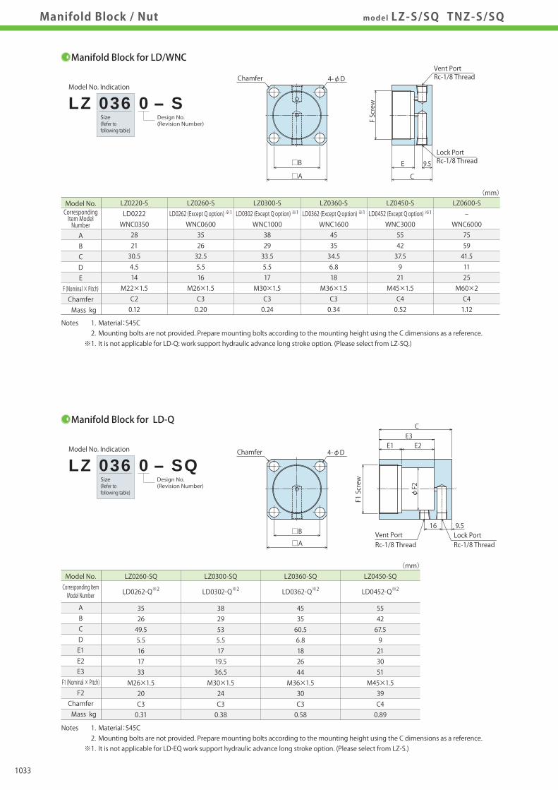
VX
Pressure Gauge
Coupler Switch
PS
G-Thread Fitting
Manifold Block
WHZ-MD
LZY-MD
LZ-MS
LZ-MP
TMZ-1MB
TMZ-2MB
DZ-M
Screw Locator
VXF
Manual ExpansionLocating Pin
VX
Manifold Block /Nut
DZ-R
Pressure Switch
JB
Manifold
JX
DZ-C
DZ-P
DZ-B
LZ-S
LZ-SQ
TNZ-S
TNZ-SQ
JGA/JGB
Pneumatic Series
Hydraulic Series
Valve / CouplerHydraulic Unit
Cautions / Others
High-PowerSeries
Manual OperationAccessories
Manifold Block / Nut model LZ-S/SQ TNZ-S/SQ
Size(Refer tofollowing table)
Size(Refer tofollowing table)
Size(Refer tofollowing table)
CorrespondingItem ModelNumber
Manifold BlockModel No. Indication/External Dimensions
Manifold BlockApplicable Model/Application Examples
Size(Refer tofollowing table)
Model No. Indication
Design No.(Revision Number)
TNZ 060 0 - S
Manifold Block for LD/WNC
Model No. Indication
Design No.(Revision Number)
LZ 036 0 - S
Manifold Block for LD-Q
Model No. Indication
Design No.(Revision Number)
LZ 036 0 - SQ
Manifold Block for TNC
Model No.
ABCDE
F (Nominal × Pitch)Chamfer Mass kg
(mm)
Notes 1. Material:S45C 2. Mounting bolts are not provided. Prepare mounting bolts according to the mounting height using the C dimensions as a reference. ※1. It is not applicable for LD-Q: work support hydraulic advance long stroke option. (Please select from LZ-SQ.)
LZ0220-S LZ0260-S LZ0300-S LZ0360-S LZ0450-S LZ0600-S LD0222 LD0262 (Except Q option) ※1 LD0302 (Except Q option) ※1 LD0362 (Except Q option) ※1 LD0452 (Except Q option) ※1 - WNC0350 WNC0600 WNC1000 WNC1600 WNC3000 WNC6000 28 35 38 45 55 75 21 26 29 35 42 59 30.5 32.5 33.5 34.5 37.5 41.5 4.5 5.5 5.5 6.8 9 11 14 16 17 18 21 25 M22×1.5 M26×1.5 M30×1.5 M36×1.5 M45×1.5 M60×2 C2 C3 C3 C3 C4 C4 0.12 0.20 0.24 0.34 0.52 1.12
Model No.Corresponding ItemModel Number
ABCDE
M (Nominal × Pitch)Chamfer Mass kg
(mm)
Notes 1. Material:S45C 2. Mounting bolts are not provided. Prepare mounting bolts according to the mounting height using the C dimensions as a reference.
TNZ0400-S TNZ0600-S TNZ1000-S TNZ1600-S
TNC0400 TNC0600 TNC1000 TNC1600
35 38 45 55 26 29 35 42 32.5 33.5 34.5 37.5 5.5 5.5 6.8 9 16 17 18 21 M26×1.5 M30×1.5 M36×1.5 M45×1.5 C3 C3 C3 C4 0.20 0.23 0.34 0.52
Model No.Corresponding ItemModel Number
ABCDE1E2E3
F1 (Nominal × Pitch)F2
Chamfer Mass kg
(mm)
Notes 1. Material:S45C 2. Mounting bolts are not provided. Prepare mounting bolts according to the mounting height using the C dimensions as a reference. ※1. It is not applicable for LD-EQ work support hydraulic advance long stroke option. (Please select from LZ-S.)
LZ0260-SQ LZ0300-SQ LZ0360-SQ LZ0450-SQ
LD0262-Q※2 LD0302-Q※2 LD0362-Q※2 LD0452-Q※2
35 38 45 55 26 29 35 42 49.5 53 60.5 67.5 5.5 5.5 6.8 9 16 17 18 21 17 19.5 26 30 33 36.5 44 51 M26×1.5 M30×1.5 M36×1.5 M45×1.5 20 24 30 39 C3 C3 C3 C4 0.31 0.38 0.58 0.89
□B
□A
4-φD
F Screw
C
9.5E
Lock Port
Vent PortChamfer
Rc-1/8 Thread
Rc-1/8 Thread
9.516
E3E1 E2
C
φF2
F1 Screw
Lock PortVent PortRc-1/8 ThreadRc-1/8 Thread
□B
□A
4-φDChamfer
Chamfer 4-φD
□B□A
M Screw
C9.5E
G1/8 ThreadLock Port
Vent PortG1/8 Thread
φ17.5
0.5
0.5
9.5
0.5
19.5
E3E1 E2
C
Chamfer 4-φD
F1 Screw
φF2
φ17.5
□B
□ALock PortVent PortG1/8 ThreadG1/8 Thread
Model No. Indication
Design No.(Revision Number)
TNZ 060 0 - SQ
Manifold Block for TNC-Q
Model No.Corresponding Item Model Number
ABCDE1E2E3
F1 (Nominal × Pitch)F2
Chamfer Mass kg
(mm)
Notes 1. Material:S45C 2. Mounting bolts are not provided. Prepare mounting bolts according to the mounting height using the C dimensions as a reference.
TNZ0400-SQ TNZ0600-SQ TNZ1000-SQ TNZ1600-SQ
TNC0400-Q TNC0600-Q TNC1000-Q TNC1600-Q 35 38 45 55 26 29 35 42 56 63.5 70 86.5 5.5 5.5 6.8 9 16 17 18 21 23.5 30 35.5 49 39.5 47 53.5 70 M26×1.5 M30×1.5 M36×1.5 M45×1.5 20 24 30 39 C3 C3 C3 C4 0.36 0.46 0.68 1.16
1033

VX
Pressure Gauge
Coupler Switch
PS
G-Thread Fitting
Manifold Block
WHZ-MD
LZY-MD
LZ-MS
LZ-MP
TMZ-1MB
TMZ-2MB
DZ-M
Screw Locator
VXF
Manual ExpansionLocating Pin
VX
Manifold Block /Nut
DZ-R
Pressure Switch
JB
Manifold
JX
DZ-C
DZ-P
DZ-B
LZ-S
LZ-SQ
TNZ-S
TNZ-SQ
JGA/JGB
Pneumatic Series
Hydraulic Series
Valve / CouplerHydraulic Unit
Cautions / Others
High-PowerSeries
Manual OperationAccessories
Manifold Block / Nut model LZ-S/SQ TNZ-S/SQ
Size(Refer tofollowing table)
Size(Refer tofollowing table)
Size(Refer tofollowing table)
CorrespondingItem ModelNumber
Manifold BlockModel No. Indication/External Dimensions
Manifold BlockApplicable Model/Application Examples
Size(Refer tofollowing table)
Model No. Indication
Design No.(Revision Number)
TNZ 060 0 - S
Manifold Block for LD/WNC
Model No. Indication
Design No.(Revision Number)
LZ 036 0 - S
Manifold Block for LD-Q
Model No. Indication
Design No.(Revision Number)
LZ 036 0 - SQ
Manifold Block for TNC
Model No.
ABCDE
F (Nominal × Pitch)Chamfer Mass kg
(mm)
Notes 1. Material:S45C 2. Mounting bolts are not provided. Prepare mounting bolts according to the mounting height using the C dimensions as a reference. ※1. It is not applicable for LD-Q: work support hydraulic advance long stroke option. (Please select from LZ-SQ.)
LZ0220-S LZ0260-S LZ0300-S LZ0360-S LZ0450-S LZ0600-S LD0222 LD0262 (Except Q option) ※1 LD0302 (Except Q option) ※1 LD0362 (Except Q option) ※1 LD0452 (Except Q option) ※1 - WNC0350 WNC0600 WNC1000 WNC1600 WNC3000 WNC6000 28 35 38 45 55 75 21 26 29 35 42 59 30.5 32.5 33.5 34.5 37.5 41.5 4.5 5.5 5.5 6.8 9 11 14 16 17 18 21 25 M22×1.5 M26×1.5 M30×1.5 M36×1.5 M45×1.5 M60×2 C2 C3 C3 C3 C4 C4 0.12 0.20 0.24 0.34 0.52 1.12
Model No.Corresponding ItemModel Number
ABCDE
M (Nominal × Pitch)Chamfer Mass kg
(mm)
Notes 1. Material:S45C 2. Mounting bolts are not provided. Prepare mounting bolts according to the mounting height using the C dimensions as a reference.
TNZ0400-S TNZ0600-S TNZ1000-S TNZ1600-S
TNC0400 TNC0600 TNC1000 TNC1600
35 38 45 55 26 29 35 42 32.5 33.5 34.5 37.5 5.5 5.5 6.8 9 16 17 18 21 M26×1.5 M30×1.5 M36×1.5 M45×1.5 C3 C3 C3 C4 0.20 0.23 0.34 0.52
Model No.Corresponding ItemModel Number
ABCDE1E2E3
F1 (Nominal × Pitch)F2
Chamfer Mass kg
(mm)
Notes 1. Material:S45C 2. Mounting bolts are not provided. Prepare mounting bolts according to the mounting height using the C dimensions as a reference. ※1. It is not applicable for LD-EQ work support hydraulic advance long stroke option. (Please select from LZ-S.)
LZ0260-SQ LZ0300-SQ LZ0360-SQ LZ0450-SQ
LD0262-Q※2 LD0302-Q※2 LD0362-Q※2 LD0452-Q※2
35 38 45 55 26 29 35 42 49.5 53 60.5 67.5 5.5 5.5 6.8 9 16 17 18 21 17 19.5 26 30 33 36.5 44 51 M26×1.5 M30×1.5 M36×1.5 M45×1.5 20 24 30 39 C3 C3 C3 C4 0.31 0.38 0.58 0.89
□B
□A
4-φD
F Screw
C
9.5E
Lock Port
Vent PortChamfer
Rc-1/8 Thread
Rc-1/8 Thread
9.516
E3E1 E2
C
φF2
F1 Screw
Lock PortVent PortRc-1/8 ThreadRc-1/8 Thread
□B
□A
4-φDChamfer
Chamfer 4-φD
□B□A
M Screw
C9.5E
G1/8 ThreadLock Port
Vent PortG1/8 Thread
φ17.5
0.5
0.5
9.5
0.5
19.5
E3E1 E2
C
Chamfer 4-φD
F1 Screw
φF2
φ17.5
□B
□ALock PortVent PortG1/8 ThreadG1/8 Thread
Model No. Indication
Design No.(Revision Number)
TNZ 060 0 - SQ
Manifold Block for TNC-Q
Model No.Corresponding Item Model Number
ABCDE1E2E3
F1 (Nominal × Pitch)F2
Chamfer Mass kg
(mm)
Notes 1. Material:S45C 2. Mounting bolts are not provided. Prepare mounting bolts according to the mounting height using the C dimensions as a reference.
TNZ0400-SQ TNZ0600-SQ TNZ1000-SQ TNZ1600-SQ
TNC0400-Q TNC0600-Q TNC1000-Q TNC1600-Q 35 38 45 55 26 29 35 42 56 63.5 70 86.5 5.5 5.5 6.8 9 16 17 18 21 23.5 30 35.5 49 39.5 47 53.5 70 M26×1.5 M30×1.5 M36×1.5 M45×1.5 20 24 30 39 C3 C3 C3 C4 0.36 0.46 0.68 1.16
1034

Company Profile
TEL.078-991-5115 FAX.078-991-8787
Sales Offices in Japan
〒651-2241 兵庫県神戸市西区室谷2丁目1番5号
Tokyo Sales OfficeTEL.048-652-8839 FAX.048-652-8828
〒331-0815 埼玉県さいたま市北区大成町4丁目81番地
Nagoya Sales OfficeTEL.0566-74-8778 FAX.0566-74-8808
〒446-0076 愛知県安城市美園町2丁目10番地1
Fukuoka Sales OfficeTEL.092-433-0424 FAX.092-433-0426
Japan
〒812-0006 福岡県福岡市博多区上牟田1丁目8-10-101
Overseas Sales
TEL. +81-78-991-5162 FAX. +81-78-991-8787
Sales Offices across the World
〒651-2241 兵庫県神戸市西区室谷2丁目1番5号
USA
KOSMEK(USA)LTD.
G.E.T. Inc, Phil.
KOS-MECH GmbH
TEL. +1-630-241-3465 FAX. +1-630-241-38341441 Branding Avenue, Suite 110, Downers Grove, IL 60515 USA
Thailand TEL. +66-2-715-3450 FAX. +66-2-715-3453 67 Soi 58, RAMA 9 Rd., Suanluang, Suanluang, Bangkok 10250, Thailand
Victoria Wave Special Economic Zone Mt. Apo Building, Brgy. 186, North Caloocan City, Metro Manila, Philippines 1427
China
考世美(上海)貿易有限公司
TEL.+86-21-54253000 FAX.+86-21-54253709
中国上海市浦东新区向城路58号东方国际科技大厦21F室 200122
Taiwan
盈生貿易有限公司
Thailand Representative Office
TEL. +886-2-82261860 FAX. +886-2-82261890
台湾新北市中和區建八路2號 16F-4(遠東世紀廣場)
Philippines TEL.+63-2-310-7286 FAX. +63-2-310-7286
Schleppeplatz 2 9020 Klagenfurt Austria
Europe TEL. +43-463-287587-10 FAX. +43-463-287587-20
Sales Offices Global Network
P.T PANDU HYDRO PNEUMATICS Ruko Green Garden Blok Z-Ⅱ No.51 Rt.005 Rw.008 Kedoya Utara-Kebon Jeruk Jakarta Barat 11520 Indonesia
Indonesia TEL. +62-21-5818632 FAX. +62-21-5814857Victoria Wave Special Economic Zone Mt. Apo Building, Brgy. 186, North Caloocan City, Metro Manila, Philippines 1427
Head OfficeOsaka Sales OfficeOverseas Sales
16F-4, No.2, Jian Ba Rd., Zhonghe District, New Taipei City Taiwan 23511
21/F, Orient International Technology Building, No.58, Xiangchen Rd, Pudong Shanghai 200122., P.R.China
KOSMEK LTD. 1-5, 2-chome, Murotani, Nishi-ku, Kobe-city, Hyogo, Japan 651-2241
KOSMEK(CHINA)LTD.
Full Life Trading Co., Ltd.
(Indonesia Exclusive Distributor)
(Europe Exclusive Distributor)
(Philippines Exclusive Distributor)
(Taiwan Exclusive Distributor)
EuropeEuropeU.S.A.U.S.A.
AustraliaAustralia
Asia
BrazilBrazil
Asia
Overseas Affiliates and Sales OfficesDistributors
MexicoMexico
JapanChina
Taiwan
PhilippinesThailand
Japan
Korea
China
Taiwan
PhilippinesThailand
IndiaIndia
Korea
SingaporeSingaporeMalaysiaMalaysia
IndonesiaIndonesia
Asia Detailed Map
● FOR FURTHER INFORMATION ON UNLISTED SPECIFICATIONS AND SIZES, PLEASE CALL US.● SPECIFICATIONS IN THIS CATALOG ARE SUBJECT TO CHANGE WITHOUT NOTICE.
JQA-QMA10823KOSMEK HEAD OFFICE
1061

Company Profile
TEL.078-991-5115 FAX.078-991-8787
Sales Offices in Japan
〒651-2241 兵庫県神戸市西区室谷2丁目1番5号
Tokyo Sales OfficeTEL.048-652-8839 FAX.048-652-8828
〒331-0815 埼玉県さいたま市北区大成町4丁目81番地
Nagoya Sales OfficeTEL.0566-74-8778 FAX.0566-74-8808
〒446-0076 愛知県安城市美園町2丁目10番地1
Fukuoka Sales OfficeTEL.092-433-0424 FAX.092-433-0426
Japan
〒812-0006 福岡県福岡市博多区上牟田1丁目8-10-101
Overseas Sales
TEL. +81-78-991-5162 FAX. +81-78-991-8787
Sales Offices across the World
〒651-2241 兵庫県神戸市西区室谷2丁目1番5号
USA
KOSMEK(USA)LTD.
G.E.T. Inc, Phil.
KOS-MECH GmbH
TEL. +1-630-241-3465 FAX. +1-630-241-38341441 Branding Avenue, Suite 110, Downers Grove, IL 60515 USA
Thailand TEL. +66-2-715-3450 FAX. +66-2-715-3453 67 Soi 58, RAMA 9 Rd., Suanluang, Suanluang, Bangkok 10250, Thailand
Victoria Wave Special Economic Zone Mt. Apo Building, Brgy. 186, North Caloocan City, Metro Manila, Philippines 1427
China
考世美(上海)貿易有限公司
TEL.+86-21-54253000 FAX.+86-21-54253709
中国上海市浦东新区向城路58号东方国际科技大厦21F室 200122
Taiwan
盈生貿易有限公司
Thailand Representative Office
TEL. +886-2-82261860 FAX. +886-2-82261890
台湾新北市中和區建八路2號 16F-4(遠東世紀廣場)
Philippines TEL.+63-2-310-7286 FAX. +63-2-310-7286
Schleppeplatz 2 9020 Klagenfurt Austria
Europe TEL. +43-463-287587-10 FAX. +43-463-287587-20
Sales Offices Global Network
P.T PANDU HYDRO PNEUMATICS Ruko Green Garden Blok Z-Ⅱ No.51 Rt.005 Rw.008 Kedoya Utara-Kebon Jeruk Jakarta Barat 11520 Indonesia
Indonesia TEL. +62-21-5818632 FAX. +62-21-5814857Victoria Wave Special Economic Zone Mt. Apo Building, Brgy. 186, North Caloocan City, Metro Manila, Philippines 1427
Head OfficeOsaka Sales OfficeOverseas Sales
16F-4, No.2, Jian Ba Rd., Zhonghe District, New Taipei City Taiwan 23511
21/F, Orient International Technology Building, No.58, Xiangchen Rd, Pudong Shanghai 200122., P.R.China
KOSMEK LTD. 1-5, 2-chome, Murotani, Nishi-ku, Kobe-city, Hyogo, Japan 651-2241
KOSMEK(CHINA)LTD.
Full Life Trading Co., Ltd.
(Indonesia Exclusive Distributor)
(Europe Exclusive Distributor)
(Philippines Exclusive Distributor)
(Taiwan Exclusive Distributor)
EuropeEuropeU.S.A.U.S.A.
AustraliaAustralia
Asia
BrazilBrazil
Asia
Overseas Affiliates and Sales OfficesDistributors
MexicoMexico
JapanChina
Taiwan
PhilippinesThailand
Japan
Korea
China
Taiwan
PhilippinesThailand
IndiaIndia
Korea
SingaporeSingaporeMalaysiaMalaysia
IndonesiaIndonesia
Asia Detailed Map
● FOR FURTHER INFORMATION ON UNLISTED SPECIFICATIONS AND SIZES, PLEASE CALL US.● SPECIFICATIONS IN THIS CATALOG ARE SUBJECT TO CHANGE WITHOUT NOTICE.
JQA-QMA10823KOSMEK HEAD OFFICE