SERVICE MANUAL - Hydraulic Master
48
Document number S071 Revision C Date 2011-10-17 Document type Manual SERVICE MANUAL Remote Control System RC400 G2B/G3B
-
Upload
khangminh22 -
Category
Documents
-
view
0 -
download
0
Transcript of SERVICE MANUAL - Hydraulic Master

Document numberS071
RevisionC
Date2011-10-17
Document typeManual
SERVICE MANUAL
Remote ControlSystem RC400 G2B/G3B

Contents1 General..........................................................................................................3
1.1 Synopsis 31.2 Distribution 31.3 Terminology 41.4 Applicable products 41.5 Productidentification5
2 Preface..........................................................................................................62.1 General information 6
3 General system description.........................................................................7 3.1 General description 73.2 Schematic overview of Scanreco RC-400 G2B 83.3 Schematic overview of Scanreco RC400 G3B 9
4 Getting started ............................................................................................104.1 PortableControlUnitdefinition 104.2 CentralUnitG2Bdefinition 114.3 CentralUnitG3Bdefinition 124.4 Cable or radio communication 134.5 Cable connection schematics 13
5 Inputs & Outputs........................................................................................145.1 Analogue functions 145.2 Portable Control Unit MAXI digital inputs 165.3 Portable Control Unit MINI digital inputs 175.4 Digital functions 185.5 Terminal schematics for current controlled Central Unit G2B 195.6 Terminal schematics for voltage controlled Central Unit G2B 205.7 Terminal schematics for Central Unit G2B CAN interface 215.8 Connection schematics for Central Unit G3B 22
6 Operational indications.............................................................................236.1 Central Unit status and operational indications 236.2 Central Unit LED-display 24 6.3 Portable Control Unit status indications 25
7 Error code indications...............................................................................267.1 General description 267.2 Central Unit error codes 267.3 Portable Control Unit error codes 29
8 Radio...........................................................................................................308.1 General description 308.2 Determining radio quality 308.3 Radio channel / Frequency 308.4 Range 30
9 Diagnostics mode......................................................................................319.1 General description 319.2 Activating diagnostics mode 319.3 Table / Diagnostics data 32
10 Online Programming mode........................................................................3510.1 General description 3510.2 Activating online programming mode 3610.3 Table / Programming options 37
11 Portable Control Unit self test mode........................................................4011.1 General description 4011.2 Activating PCU Test Mode 40
12 ID-code programming.................................................................................41 12.1 General description 41 12.2 Procedure 41 13 G2B Standard cable kits............................................................................42 13.1 General description 42 13.2 Standard supply cable kits 43 13.3 Standard valve cable kits for Sauer-Danfoss PVG-32 44 13.4 Standard valve cable kits for HAWE 45 13.5 Standard valve cable kits for PWM solenoids 46
Document type Document number PageRevService Manual S071 C 2 of 46

Attribute InformationDocument type ManualTitle Remote Control System RC400 G2B / G3BSubtitle Service ManualDocument number S071Filename S071Revision CRevision date 2011-10-17
Revision Date Name NoteA 2010-10-29 Scanreco AB First releaseB 2011-08-14 Scanreco AB G3B Central Unit added
Major changes in documentC 2011-10-17 Scanreco AB G2B Standard Cable kit chapter added
Minor changes in document
Name Rule
Internal Only within own organization
Document information
Revision history
1 GeneralSynopsisScanreco Remote Control System RC400 G2B/G3B Service Manual
This service manual is intended as a complement to the Remote Control System RC400 G2B Instructionmanualandcoversmorein-depthinformationsurroundingserviceandfaultfind-ings on the systems.
1.1
1.2 Distribution
Document type Document number PageRevService Manual S071 B 3 of 46

Abbreviation Descriptionn/a Not applicablePWM Pulse Width ModulationPCU Portable Control UnitCU Central UnitLED Light Emitting DiodeST Status LEDDV Dump Valve
Item no: Description Program version3010 G2B Central Unit PWM EU 4.103011 G2B Central Unit PWM NAFTA 4.102010 G2B Central Unit Danfoss EU 2.142011 G2B Central Unit Danfoss NAFTA 2.141602 G3B Central Unit Type 1 EU 1.001603 G3B Central Unit Type 1 NAFTA 1.001604 G3B Central Unit Type 2 EU 1.001605 G3B Central Unit Type 2 NAFTA 1.00n/a* G2B Portable Control Unit Maxi Linear 1.07n/a* G2B Portable Control Unit Maxi Joystick 1.07n/a* G2B Portable Control Unit Mini Linear 1.07n/a* G2B Portable Control Unit Mini Joystick 1.07
1.4 Applicable products This document is applicable on the below declared products and program versions.
1.3 Terminology
*DuetothevarietyofconfigurationsavailableforthePortableControlUnits,itemnumbersarenotdeclared;onlytheavailablePortableControlUnitplatformtypesaredeclared,formoredetailedinformation refer to customer part list where available.
Document type Document number PageRevService Manual S071 C 4 of 46

Portable Control Unit MINI
Portable Control Unit MAXI
Central Unit G3B Central Unit G2B
1.5 Product identification AllSCANRECOProductsarelabeledwithproductpartnumberandserialnumberforverification.
Below illustrations shows where these numbers can be located.
Alwayscheckandverifyproductitem-andserialno.beforeanytypeofserviceiscommisioned,refertocustomerpartslistandsystem-/producttechnicalspecificationsinordertodeterminesystem-/productconfiguration.
Document type Document number PageRevService Manual S071 C 5 of 46

2.1 General information
•Remotelycontrolledcranesmayonlybeoperatedbyqualifiedpersonnel.Thedriver must be aware of the contents of chapter 4 “Safety regulations andOperating instructions” available in the Intruction Manual before operation is started. Serious accidents may occur if these instructions are not followed.
•Toprotecttheportablecontrolunitfromdamageandforsafetyreasons,thecontrol unit must be kept in a locked cabin
•Followtheinstructionsgiveninthecranehandbookregardingmovingthecranefromitsparkingposition,thebestarmpositioningwhileloadsarebeinghandled and parking of the crane.
•Duetotheunlimitedvarietyofcranes,machines,objects,vehiclesandequipmentonwhichtheremotecontrolsystemareused,andthenumerousstandardswhicharefrequentlythesubjectofvaryinginterpretation,itisimpossible for the personnel at Scanreco to provide expert advice regardingthesuitabilityofagivenremotecontrolforaspecificapplication.Itistheresponsibility of the purchaser to determine the suitability of any Scanrecoremote control product for an intended application and to insure that it isinstalledandguardedinaccordancewithallcountry,federal,state,local,andprivatesafetyandhealthregulation,codes,standardsandScanrecorecommendation (this manual). If the Scanreco RC 400 G2B/G3B will be used in asafetycriticalapplication,thecustomer/drivermustundertakeappropriatetesting and evaluation to prevent injury to the ultimate user. Scanreco doesnot take responsibility for any damage or injury.
•UnauthorizedtamperingwithaScanrecoremotecontrolsystemautomaticallyinvalidates guarantee.
This manual is intended as a complement to the crane / machine instruction bookand covers the Scanreco RC 400 G2B/G3B Remote Control System.
The Scanreco RC 400 G2B/G3B offers the driver an extremely advanced remote controlsystemwithspeed,precision,controlandmaximumsafety.
In order to ensure your safety and the safety of your crane / machine you shouldstudy and learn these instructions. This will enable you to quickly familiarise yourselfwith your new remote control system and how to utilise it.
2 Preface
Document type Document number PageRevService Manual S071 C 6 of 46

3.1 General description of Scanreco RC-400 G2B/G3B
The Scanreco RC 400 G2B/G3B remote control system has been especially developed forhydraulically driven mobile cranes and machinery. The system is a digital remotecontrol system based on an extremely advanced microprocessor technology. Years ofexhaustive and demanding testing have shown that the remote control system cancope with the roughest of environments.
The system is protected against electromagnetic and radio frequency radiation andcanbeinstalledontomosthydraulicvalvetypes(voltage,currentpulsewidth,orprotocol steered) found on the market.
In its basic form the remote control system is comprised of a portable control unitwithmanoeuvreleversforproportionalcontrolandswitchesforON/OFFfunctions,acentral unit with connection cable for driving proportional electro-hydraulic slidecontrollers.
Digitallycodedcontrolinformation(leverdeflectionandswitchposition)issentfromthe control unit via electric cable or via radio to the central unit. The control unit andcentralunittranslatethemagnitudeanddirectionofthemanoeuvreleverdeflectionsandswitchpositionstocorrespondingvalvefunction,speedanddirectionandthuscrane movement.
3 General system description
Document type Document number PageRevService Manual S071 C 7 of 46

No Description Qty1 Portable Control unit (PCU) 12 Central unit G2B (CU) 13 Battery Charger (10 - 30 VDC) 14 Battery cassette (NiMH 7.2 VDC) 25 Manoeuvre cable (10 meters) 16 Emergency stop box (Optional) 17 Cable kit supply cables + digital outputs 18 Cable kit valves cables (analogue outputs) 1
3.2 Schematic overview of Scanreco RC-400 G2B
1
4
2
3
5
Below illustrations shows a typical system consistory for the G2B system
2A
6
7 Supply Cable KitSee chapter 13 for standard available types
Dump valve output8 Valve Cable Kit
See chapter 13 for standard available types
Document type Document number PageRevService Manual S071 C 8 of 46

No Description Qty1 Portable Control unit (PCU) 12 Central unit G3B (CU) 13 Battery Charger (10 - 30 VDC) 14 Battery cassette (NiMH 7.2 VDC) 25 Manoeuvre cable (10 meters) 1
3.3 Schematic overview of Scanreco RC-400 G3B
1
4
3
5
Below illustrations shows a typical system consistory for the G3B system
2
Document type Document number PageRevService Manual S071 C 9 of 46

Micro-toggle
Micro-LED
Stop-button
Power-LED
On-button
Cable port
4.1 Portable Control Unit definition
4 Getting started
The illustrations below aims to delare all entities mentioned in this document.
Insert battery or connect cable connector!
1. Twist up the Stop-button
2. Press the On-button once - LED-Power will be illuminated RED
Activating the Portable Control Unit
Document type Document number PageRevService Manual S071 C 10 of 46

R/M-SwitchStatus LEDsLED-displayCable / Programming portTerminal connectors
4.2 Central Unit G2B definition The illustrations below aims to declare all
entities mentioned in this document.
Activating the Central Unit The Central Unit can be activated in two modes via the R/M switch; REMOTE or MANUAL mode.
InREMOTEmodetheCentralUnitiscontrolledbythePCU,inMANUALmodethesystemsuppliesonly the DV-output intended for Dump valve supply; the complete system is by-passed allowing manual operation of distributor bench (where available).
REMOTE MODE:
Operation via PCU LED STATUS will be illuminated redatfirstthengreenwhenincontact with PCU.
MANUAL MODE:
System by-pass / Manual operation
LED DV will be illuminated red.
RemoteManual Off
Document type Document number PageRevService Manual S071 C 11 of 46

LED-display
Cable A
Cable C
Cable B
4.3 Central Unit G3B definition The illustrations below aims to declare all entities mentioned in this document.
Activating the Central Unit G3B TheCentralUnitG3BissuppliedthruCableAandrequiresexternalpowerswitching,seechapter
5.8 for further info.
The Central Unit G3B exists in 2 different versions; one with 2 cable outputs and one with 3 cable outputs. Refer to chapter 5.8 for further info.
Document type Document number PageRevService Manual S071 C 12 of 46

Cable A
Cable C
Cable B
4.4 Cable or radio communication
4.5 Cable connection schematics
Cablecommunicationhashigherprioritythanradiocommunication,ifacablelinkispresentbetweenthePCUandCentralUnitthiswillbedetectedbythesystem,disablingradiocommunica-tion.
33
445 5
2 2
1 1
Standard 10m cable connector
Portable Control Unit Pin assignments Central Unit G2B/G3B Pin Assignments
11
1 2 3 4
22
33
44
55
Brown / DataBrown / Data
White / GNDWhite / GND
n/a
n/a
Blue / RS 232 TX
Black / RS 232 RX
Grey / Supply outputGrey / Supply output
+ _
BatteryTerminal
4-pole main printcard connection
5- pole maleM12 connector
5- pole femaleM12 connector
OrangeWhite
Cable connection
Pin no. Wire color
1 Brown
2 White
3 Blue
4 Black
5 Grey
Document type Document number PageRevService Manual S071 C 13 of 46

5 Inputs & Outputs
1A 4A1B 4B
2A7B 8A7A 8B
2B
3A
3B
5A
5B
6B 6A
5.1 Analogue functionsTheanalogueinputsavailableforeachplatform(MAXILinear,MAXIJoystick,MINILinearandMINIJoystick)arebydefaultassignedananalogueoutputontheCentralUnit,belowfigures declares the standard assignments.
PCU MAXI Linear standard assignments
PCU MAXI Joystick standard assignments
1A 2A
2B1B
3A
3B
4A
4B
5A
5B
6A 7A 8A
6B 7B 8B
Document type Document number PageRevService Manual S071 C 14 of 46

PCU MINI Linear standard assignments
PCU MINI Joystick standard assignments
1A
1B 1A
2A
2A 5A 3A
3B5B
6B 4B 4A6A
2B
2B1B
3A
3B
4A
4B
5A
5B
6A
6B
Document type Document number PageRevService Manual S071 C 15 of 46

Note that on the MAXI platform the Terminals 1 and 2 are mirrored and available on both left and right hand side of the stop button
5.2 Portable Control Unit MAXI digital inputs
ThedigitalinputsavailableareNOTallbydefaultassignedandigitaloutputontheCentralUnit, belowfiguresonlydeclaresdigitalinputaccess.
No. Type Colourcode
AMPPin no.
- Common (GND) Black 1
10 Digital input 33 Pink 2
9 Digital input 06 Grey 3
8 Digital input 02 Brown 4
7 Digital input 32 Purple 5
6 Digital input 05 Orange 6
5 Digital input 31 Black 7
4 Digital input 07 White 8
3 Digital input 04 Blue 9
2 Digital input 03 Green 10
1 Digital input 01 Yellow 11
- Supply output Red 12
No. Type Colourcode
AmpPin no.
- Common (GND) Black 1
20 Digital input 36 Pink 2
19 Digital input 35 Grey 3
18 Digital input 34 Brown 4
17 Digital input 37 Purple 5
16 Digital input 08 Orange 6
15 Digital input 09 Black 7
14 Digital input 13 White 8
13 Digital input 12 Blue 9
12 Digital input 11 Green 10
11 Digital input 10 Yellow 11
- Supply output Red 12
1-12 1-12 1-121-12
Terminal 2Terminal 1
Document type Document number PageRevService Manual S071 C 16 of 46

5.3 Portable Control Unit MINI digital inputs
ThedigitalinputsavailableareNOTallbydefaultassignedandigitaloutputontheCentralUnit, belowfiguresonlydeclaresdigitalinputaccess.
No. Type Colourcode
AMPPin no.
- Common (GND) Black 1
10 Digital input 33 Pink 2
9 Digital input 06 Grey 3
8 Digital input 02 Brown 4
7 Digital input 32 Purple 5
6 Digital input 05 Orange 6
5 Digital input 31 Black 7
4 Digital input 07 White 8
3 Digital input 04 Blue 9
2 Digital input 03 Green 10
1 Digital input 01 Yellow 11
- Supply output Red 12
No. Type Colourcode
AmpPin no.
- Common (GND) Black 1
20 Digital input 36 Pink 2
19 Digital input 35 Grey 3
18 Digital input 34 Brown 4
17 Digital input 37 Purple 5
16 Digital input 08 Orange 6
15 Digital input 09 Black 7
14 Digital input 13 White 8
13 Digital input 12 Blue 9
12 Digital input 11 Green 10
11 Digital input 10 Yellow 11
- Supply output Red 12
Terminal 2Terminal 1
1-12 1-12
Document type Document number PageRevService Manual S071 C 17 of 46

5.4 Digital functions
Thedigitalfunctionsutilizedvariesdependingonsystemconfiguration,upto20digitalfunctionscan be implemented thru left- and/or right switch panels with programmable assignments to up to 14 digital outputs.
In excess the On-button may also be assigned a digital output.
Below shows PCU platforms standard digital inputs and default Central Unit output assignment
Position Type Central Unit301 3 way detent
toggleDigital output 1 / Digital output 1 Parallel with ana-logue input movement (AutoRPM engine feature)
302 3 way springback toggle
Digital output 2 / Digital output 3 (Engine start /Engine stop)
303 3 way springback toggle
Digital output 4 / Digital output 5 (Engine RPM+ /Engine RPM-)
304/305 2 way detenttoggle
Digital output 6 (Optional)
On-button Push button Digital output 7
301
301
304
305
302
302
303
303
On-button
On-button
PCU MINI Standard assignment
PCU MAXI Standard assignment
Document type Document number PageRevService Manual S071 C 18 of 46

5.5 Terminal schematics for current controlled Central Unit G2B The drawing below declares access points for each available input and output both from the inside
terminal (above) and the standard cable kits (below). Standard cable wire number/marking is also declared.
Position Type Central Unit301 3 way detent
toggleDigital output 1 / Digital output 1 Parallel with ana-logue input movement (AutoRPM engine feature)
302 3 way springback toggle
Digital output 2 / Digital output 3 (Engine start /Engine stop)
303 3 way springback toggle
Digital output 4 / Digital output 5 (Engine RPM+ /Engine RPM-)
304/305 2 way detenttoggle
Digital output 6 (Optional)
On-button Push button Digital output 7 9= Digital output 14 / Serial out8= Digital output 13 / Digital input 47= Digital output 126= Digital output 115= GND4= Digital output 103= Digital output 92= Digital output 81= Digital output 7
10= GND
EX 2
EX 1
11 Input supply +VDC10= Digital input 39= Digital input 28=Digital input 1
1= Digital output 1
3= Digital output 32= Digital output 2
4= Digital output 45= Digital output 56= Digital output 6
7= GND
11 Input supply +VDC10= Digital input 39= Digital input 28= Digital input 17= GND6= Digital output 65= Digital output 54= Digital output 43= Digital output 32= Digital output 21= Digital output 1
1= Supply
1= DV+
2= GND
2= DV-
+/-
DV
1
1 16
17 32
1 = 1A PWM +
17 = 5A PWM +
2 = 1A PWM -
18 = 5A PWM -
3 = 1B PWM +
19 = 5B PWM +
4 = 1B PWM -
20 = 5B PWM -
5 = 2A PWM +
21 = 6A PWM +
6 = 2A PWM -
22 = 6A PWM -
7 = 2B PWM +
23 = 6B PWM +
8 = 2B PWM -
24 = 6B PWM -
9 = 3A PWM +
25 = 7A PWM +
10 = 3A PWM -
26 = 7A PWM -
11 = 3B PWM +
27 = 7B PWM +
12 = 3B PWM -
28 = 7B PWM -
13 = 4A PWM +
29 = 8A PWM +
14 = 4A PWM -
30 = 8A PWM -
15 = 4B PWM +
31 = 8B PWM +
16 = 4B PWM -
32 = 8B PWM -
1= PWM +
2= PWM -Analogue outputs
1 4
1 A
11
1 B2 A
2 B3 A
......8 B
10= GND
4 = DV-3 = DV+2 = GND1 = + Supply
9= Digital output 14 / Serial out8= Digital output 13 / Digital input 4
7= Digital output 126= Digital output 115= GND4= Digital output 103= Digital output 92= Digital output 8
1= Digital output 7
1 10
Document type Document number PageRevService Manual S071 C 19 of 46

The drawing below declares access points for each available input and output both from the inside terminal (above) and the standard cable kits (below). Standard cable wire number/marking is also declared.
5.6 Terminal schematics for voltage controlled Central Unit G2B
EX 1
11 Input supply +VDC10= Digital input 39= Digital input 28=Digital input 1
1= Digital output 1
3= Digital output 32= Digital output 2
4= Digital output 45= Digital output 56= Digital output 6
7= GND
11 Input supply +VDC10= Digital input 310= GND9= Digital input 28= Digital input 17= GND6= Digital output 65= Digital output 54= Digital output 43= Digital output 32= Digital output 21= Digital output 1
4 = DV-3 = DV+2 = GND1 = + Supply
1= Supply
1= DV+
2= GND
2= DV-
+/-
DV
1
1 16
17 32
1 = 1 Module supply voltage
17 = 5 Module supply voltage
2 = 1 Regulated supply voltage
18 = 5 Regulated supply voltage
3 = 1 GND
19 = 5 GND
4 = 1 Error input (optional)
20 = 5 Error input (optional)
5 = 2 Module supply voltage
21 = 6 Module supply voltage
6 = 2 Regulated supply voltage
22 = 6 Regulated supply voltage
7 = 2 GND
23 = 6 GND
8 = 2 Error input (optional)
24 = 6 Error input (optional)
9 = 3 Module supply voltage
25 = 7 Module supply voltage
10 = 3 Regulated supply voltage
26 = 7 Regulated supply voltage
11 = 3 GND
27 = 7 GND1 = Module supply voltage
12 = 3 Error input (optional)
28 = 7 Error input (optional)2 = Regulated supply voltage
13 = 4 Module supply voltage
29 = 8 Module supply voltage3 = GND
14 = 4 Regulated supply voltage
30 = 8 Regulated supply voltage4 = Error input (optional)
15 = 4 GND
31 = 8 GND
16 = 4 Error input (optional)
32 = 8 Error input (optional)
1 4
11
1
23
45
....8
9= Digital output 14 / Serial out8= Digital output 13 / Digital input 4
7= Digital output 126= Digital output 115= GND4= Digital output 103= Digital output 92= Digital output 8
1= Digital output 7
1 10
9= Digital output 14 / Serial out8= Digital output 13 / Digital input 47= Digital output 126= Digital output 115= GND4= Digital output 103= Digital output 92= Digital output 81= Digital output 7
10= GND
EX 2
Document type Document number PageRevService Manual S071 C 20 of 46

5.7 Terminal schematics for Central Unit G2B CAN interface The Central Unit is equipped with terminal connections for CAN. The drawing below declares the access
points both from the inside terminals (above) and the standard cable kit (below).
NOTE:
*asvariouscablekitsexists,pleaserefertochapter13orsystemtechnicalspecificationforfur-ther information
TheCentralUnitG2Bisnotequippedwithaspecific“STOPloop”connection,ifneededadigitaloutputareinsuchcasesassigned;ifmoreinfoisrequired;refertosystemtechnicalspecification.
If required; a terminator resistor can be installed between points 4 & 5: the resistor value needs to bedefinedbythesysteminstaller.
5= CAN L 4= CAN H 3= GND2= CAN L1= CAN H
1 = CAN H
4 = CAN H
2 = CAN L
5 = CAN L
3 = GND
1 5
EX*
Document type Document number PageRevService Manual S071 C 21 of 46

Itemno:1602,1603
Itemno:1604,1605
A
A
A
BC
B
B
C
Connection
Pin no. Colour / Function
1 Brown / DATA
2 White /GND
3 Blue / RS 232 TX
4 Black / RS 232 RX
5 Grey / Supply output
Connection
Pin no. Colour / Function
1 Brown / DV1
2 White /Power supply
3 Blue / GND
4 Black / CAN_HIGH
5 Grey / CAN_LOW
Cable B (3 meters)
Cable A (3 meters)
Connection
Pin no. Colour / Function
1 Brown / DV2
2 White / LOOP1_OUT
3 Blue / LOOP1_IN
4 Black / LOOP2_OUT
5 Grey / LOOP2_IN
Cable C (3 meters)
5- pole maleM12 connector
5- pole maleM12 connector
5- pole femaleM12 connector
AB
5.8 Connection schematics for Central Unit G3B
The Central Unit G3B is equipped with either 2 or 3 circular M12 5-pole connectors (check item no).The drawing below declares Pin-assignments for both versions of the Central Unit G3B
Document type Document number PageRevService Manual S071 C 22 of 46

LED STATUS MeaningOFF Off,CentralUnitisdeactivatedRED ON – Central Unit is activated in REMOTE mode
No communication with PCUGREEN ON – Central Unit is activated in REMOTE mode
Communication link with Portable Control UnitREDflashing4/1
Error code being displayed on internal LED Display
LED DV MeaningRED Dump Valve output is supplied
External LEDs (on Central Unit G2B only!)
Note that the LED STATUS is used also for error code alarms and operator controlledfunctionsandisthentriggeredbyanevent,thetypeofindicationwillbedeclaredforeach event further in this document.
6.1 Central Unit status and operational indications The Central Unit G2B is equipped with 2 individual positions where status and operational
indicationscanberead,theexternalLEDsSTATUSandDVprovidesbasiclimitedinformationwhilsttheLEDdisplayprovidesmoredetailedinformation,theCentralUnitG3BonlyhavetheLED-display as shown below.
Position 4: Status LEDs
Position 5: LED-display
5
54
6 Operational indications
Document type Document number PageRevService Manual S071 C 23 of 46

LED Display MeaningOff,deactivated
Standbymode,nocommunicationlinkwithPCU
Standbymode,communicationlinkwithPCU
Communicationlinkviacable,ID-codeapproved
Communicationlinkviacable,ID-codenotapproved
Communicationlinkviaradio,frequencyhopping
Communicationlinkviaradio,frequencylockedonchannel1
Communicationlinkviaradio,frequencylockedonchannel2
Communicationlinkviaradio,frequencylockedonchannel3
Communicationlinkviaradio,frequencylockedonchannel4
Communicationlinkviaradio,frequencylockedonchannel5
Communicationlinkviaradio,frequencylockedonchannel6
Communicationlinkviaradio,frequencylockedonchannel7
Communicationlinkviaradio,frequencylockedonchannel9
Communicationlinkviaradio,frequencylockedonchannel10
Communicationlinkviaradio,frequencylockedonchannel11
Communicationlinkviaradio,frequencylockedonchannel12
Communicationlinkviaradio,frequencylockedonchannel13
Radio communication deactivated via program setting (WinSCI)
ID-programming procedure is active (See chapter 12 for further info)
ID-programming procedure rejected (See chapter 12 for further info)
Below table shows the variety of status indications available for both the Central Unit G2B and G3B:
6.2 Central Unit LED-display
Document type Document number PageRevService Manual S071 C 24 of 46

Power-LED MeaningOFF Off,PortableControlUnitisdeactivatedRED Fixed ON – Transmitting dataREDFlashing 1/1sec.
ON – Transmitting dataLowbattery!(Buzzerwillemitanalarmforthefirstthreesequences when low level is detected)
Micro-LED MeaningOFF Normal modeGreenFlashing 1/3thsec.
Micro step 1 active
2 / 3rd sec Micro step 2 active
3 / 3rd sec Micro step 3 active4 / 3rd sec Micro step 4 active5 / 3rd sec Micro step 5 active
Note that these LEDs are used also for error code alarms and operator controlledfunctionsandarethentriggeredbyanevent,thetypeofindicationwillbedeclaredfor each event further in this document.
ThePortableControlUnituses2LEDstoindicateoperationalstatus,thePortableControl Unit is also equipped with an internal buzzer that emits sounds and alarmswhen required.
Typical status indications involving the Micro- and Power-LED are declared below:
6.3 Portable Control Unit status indications
Micro-LED Power-LED
Document type Document number PageRevService Manual S071 C 25 of 46

7.1 General description
7.2 Central Unit Error codes
7 Error code indications
BoththePortableControlUnitandtheCentralUnitareembeddedwithconstantfaultmonitoring,any errors noticed by the system will result in interruption of all operational commands.
AlloftheCentralUnitsoutputsarefaultmonitoredforshortcircuitsand/oroverloads,intheeventof an error being detected the Central Unit will alert that an error has occurred via the external LEDStatusandindicatetheappropriateerrorcodeviatheLED-display,theCentralUnitwillthenreset to operational mode if possible.
Belowexampleflowchartonbehaviour:
Thisfaultsequencewilltakeanapproximately6secondsTheexternalLEDSTATUSwillflashrapidlyinredcolourdeclaringthatanerrorhasbeendetected,formoredetailedinformation;theLED-display must be monitored (or error code log available from diagnostics menu).
Fault detected
*Deactivate all outputs
*Alert via external LEDStatus
*Declare type of error(error code) via
LED-display
Reset system tooperational mode if pos-
sible.
Document type Document number PageRevService Manual S071 C 26 of 46

2nd 3rd Description Cause Action01. 01 EEPROM
failure.IncorrectchecksumonEEPROM,laststored data will be set.
Resetsystem,ifpersistent;Re-load application program.
01. 02 Flash memoryfailure.
Incorrectchecksumonflashmemory.
Resetsystem,ifpersistent;Re-load application program.
01. 03 Stack memoryfailure.
Incorrect sizes of data in CANopenprotocol,incorrectdatafloworstackoverflow.
System will self reset automatically.If persistent;Re-load application program.
01. 04 RAM memoryfailure.
Incorret RAM and/or hardwareidentification.
System will self reset automatically.If persistent;Re-load application program.
02. 01 Illegalvoltage; DVoutput.
DV-output error;DV-output (DV+) externally supplied
System will self reset.Check DV-output connection.Remove terminal connector and resetsystem.
02. 02 Short circuit;DV-output.
DV-output error;DV output (DV+) short circuited oroverloaded.
System will self reset.Check DV-output connection.Remove terminal connector and resetsystem.
02. 03 Safety switcherror
Safetyswitchoutputreadbackerror,incorrect voltage (High instead ofLow)
System will self reset.Remove all terminal connectors andreset system.
02. 04 Safety switcherror
Safetyswitchoutputreadbackerror,incorrect voltage (Low instead ofHigh)
System will self reset.Remove all terminal connectors andreset system.
03. 00 Illegalvoltage;Digital output
Digitaloutput(1-14)illegalvoltage,expected low signal but read as high(Could be any of the available 14
System will self reset.Check digital output connections.Remove terminal connector and reset
7.2.1 Error codes
TheLED-displayErrorcodesaredisplayedinupto3sequences,thisallowstheCentralUnittodeclare exactly which output that is related to the error (where applicable).
First sequence: Letters E:r is presented declaring an error code
Second sequence: Type of error code
Third sequence: Additional information (where applicable)In example:
The example would imply that there is an short circuit on output 1A
(Repeated 3 times)+ +
Document type Document number PageRevService Manual S071 C 27 of 46
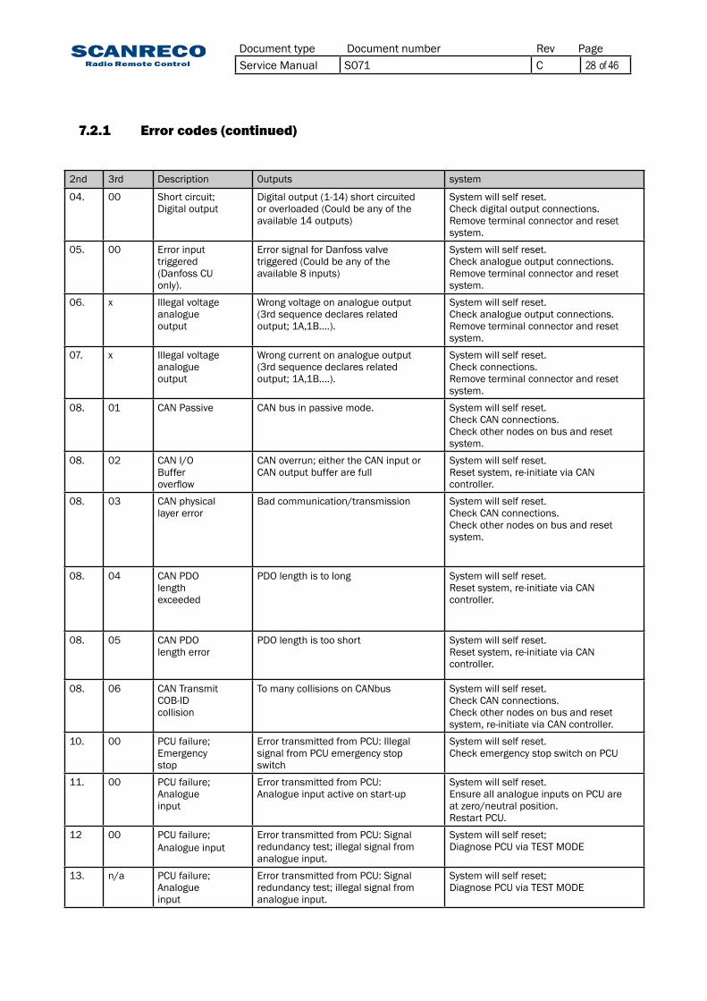
2nd 3rd Description 0utputs system
04. 00 Short circuit;Digital output
Digital output (1-14) short circuitedor overloaded (Could be any of theavailable 14 outputs)
System will self reset.Check digital output connections.Remove terminal connector and resetsystem.
05. 00 Error inputtriggered(Danfoss CUonly).
Error signal for Danfoss valvetriggered (Could be any of theavailable 8 inputs)
System will self reset.Check analogue output connections.Remove terminal connector and resetsystem.
06. x Illegal voltageanalogueoutput
Wrong voltage on analogue output(3rd sequence declares relatedoutput;1A,1B….).
System will self reset.Check analogue output connections.Remove terminal connector and resetsystem.
07. x Illegal voltageanalogueoutput
Wrong current on analogue output(3rd sequence declares relatedoutput;1A,1B….).
System will self reset.Check connections.Remove terminal connector and resetsystem.
08. 01 CAN Passive CAN bus in passive mode. System will self reset.Check CAN connections.Check other nodes on bus and resetsystem.
08. 02 CAN I/OBufferoverflow
CAN overrun; either the CAN input orCAN output buffer are full
System will self reset.Resetsystem,re-initiateviaCANcontroller.
08. 03 CAN physicallayer error
Bad communication/transmission System will self reset.Check CAN connections.Check other nodes on bus and resetsystem.
08. 04 CAN PDOlengthexceeded
PDO length is to long System will self reset.Resetsystem,re-initiateviaCANcontroller.
08. 05 CAN PDOlength error
PDO length is too short System will self reset.Resetsystem,re-initiateviaCANcontroller.
08. 06 CAN TransmitCOB-IDcollision
To many collisions on CANbus System will self reset.Check CAN connections.Check other nodes on bus and resetsystem,re-initiateviaCANcontroller.
10. 00 PCU failure;Emergencystop
Error transmitted from PCU: Illegalsignal from PCU emergency stopswitch
System will self reset.Check emergency stop switch on PCU
11. 00 PCU failure;Analogueinput
Error transmitted from PCU:Analogue input active on start-up
System will self reset.Ensure all analogue inputs on PCU areat zero/neutral position.Restart PCU.
12 00 PCU failure;Analogue input
Error transmitted from PCU: Signalredundancy test; illegal signal fromanalogue input.
System will self reset;Diagnose PCU via TEST MODE
13. n/a PCU failure;Analogueinput
Error transmitted from PCU: Signalredundancy test; illegal signal fromanalogue input.
System will self reset;Diagnose PCU via TEST MODE
7.2.1 Error codes (continued)
Document type Document number PageRevService Manual S071 C 28 of 46

14. 01 ID programmingfailure
ID-code and/or parameter settingsnot accepted.
System will self reset.Verify ID-programming procedure.Reset application program.
14. 02 Programfailure
Programmable logic parameter error System will self reset.Reset application program.
15. x PWM outputfailure
Analogue output short circuited oroverloaded.(3rd sequence declares relatedoutput;1A,1B….).
System will self reset.Check analogue output connections.Remove terminal connector and resetsystem.
16. x PWM outputfailure
Analogue output not connected(Programmable feature).(3rd sequence declares relatedoutput;1A,1B….).
System will self reset.Check analogue output connections.Remove terminal connector and resetsystem.
17. 01 Low supplypower
Lowpowersupply(Below8,5VDC) System will self reset.Check power supply and supplyconnections.
17. 02 High supplypower
Highpowersupply(Above36,0VDC) System will self reset.Check power supply and supplyconnections.
98. n/a UndefinedPCUerror
UndefinederrorinPCU. Diagnose PCU via TEST MODE
99. n/a UndefinedCUerror
UndefinederrorinCU. System will self reset.Remove all terminal connectorsCheck power supply and supplyconnections.Reset system.
7.2.1 Error codes (continued)
Indications Meaning1 Analogue input 1 not at zero position during start-up2 Analogue input 2 not at zero position during start-up3 Analogue input 3 not at zero position during start-up4 Analogue input 4 not at zero position during start-up5 Analogue input 5 not at zero position during start-up6 Analogue input 6 not at zero position during start-up7 Analogue input 7 not at zero position during start-up8 Analogue input 8 not at zero position during start-up
7.3 Portable Control Unit error codes
The Portable Control Unit monitors all analogue and digital inputs for faults and uses the Power-LED and BUZZER to indicate alarms.
Below available error codes:
Document type Document number PageRevService Manual S071 C 29 of 46

8 Radio8.1 General description
8.2 Determining radio quality
8.3 Radio channel / Frequency
8.4 Range
Radio is used as a bus link for data packages between the transmitter (Portable Control Unit) and receiver(CentralUnit),theradiocontinuouslytransmitsthepositionsoftheanalogueanddigitalinputs available on the Portable Control Unit to the Central Unit for further processing.
Thedigitalizeddatatransferprotocolusesahighsecuritylevelforverificationofeachdatapack-age,nolossofindividualfunctionsduetoradiointerferencescanoccur.
The unique ID-code held in the Portable Control Unit ensures that the system can not be operated unintentionally by other Control Unit.
The transmission allows interferences to some extent as long as multiple data packages are not interfered successively.
TheradioqualitycanbedeterminedbytheexternalstatusLEDand/orthefirst7-segmentontheLED-display during radio communication
WhenanoptimalcommunicationisacquiredtheexternalStatusLEDwillbefixedgreenandtheCentral Unit LED-display will indicate “1x” (x being dependent on program setting).
Shortinterruptionsandlossesofdatapackageswillbeindicatedbyirregularflashesoftheseindicators,anincreasingintensityofflashesindicatesadecreasingradioreception.
Notethatirregularflashesisacommonoccurence,unlesstheycauseaninteruptionincommuni-cation they should not be considered a cause for concern.
Refer to separate document for radio channel used in your region
Refer to separate document for radio channel used in your region
Fixed indications
Fixed green
Flashing green(Irregular)
Fixed red
Irregularflashes
Standby
NOTE:Insuchcasesthatalockedfrequencyisusedthesecond7-segmentindicationwillbedifferent,check chapter 6.2 for further information.
Document type Document number PageRevService Manual S071 C 30 of 46

9.1 General description
9.2 Activating diagnostics mode
Adiagnosticsmodehasbeenmadeavailableastodiagnoseandmanagethesystem,theLED-display is required to be monitored during diagnostics and will allow operator to read out recently occurrederrorcodes,outputcharacteristicsandprograminformationinordertodiagnosethesystem.
Note that the LED-display is required to be monitored during diagnostics mode.
Do as follows:
1. Remove the battery pack. Connect the cable between the Portable Control Unit and turn off the Central Unit via the R/M-switch.
2. Activate the Central Unit in REMOTE mode.
3. Press the Portable Control units On-button once.-The Power-LED should be illuminated
4. Produce impulses in very quick succession with the Micro-toggle to the LEFT (MICRO-ON direc-tion) 15 times or until the Central Units LED-display indicates D:i – 0:0.
5. Diagnostics mode is now active!
Thediagnosticsmodeconsistof8differentmenus’thatcanbetoggledusingtheon-button,onceamenuisenteredthecurrentvaluesforthatspecificparameterispresentedintheLED-display.
To exit diagnostics mode press Stop-button on Portable Control Unit.
9 Diagnostics mode
Ifactivationfails,the4thstepmayhavebeendonetooslow,thetogglehastobedonewithamaximum0,5secondinterval.
Attention:Notethatsystemwilloperateoutputsasinnormaloperationalmode,real-timevalues(whereavailable) are shown in the LED-display.
Notethatbyenteringthediagnosticsmode,theMicrofunctionhasbeenactivatedandanalogueoutputsmayoperatereducedspeeds,iffullspeedsaredesired;pressMicro-toggletotherightonce (MICRO-OFF direction).
Stop-button On-buttonPower-LED
Micro-toggle
Document type Document number PageRevService Manual S071 C 31 of 46

9.3 Table / diagnosics data
9.3.1 Position 1 - Analogue output status
Press On-button once from position D:i – 0:0
D:i – 0:1 is displayed
As to determine the current status for all analogue outputs. Lever/joystick assignments and ana-logueoutputstart,stoppandrampvalues.
Whileinthisposition,actuatingaspecificleverwillresultintheLED-displaypresentingwhichoutputthatisassigned,thedirectionandthecurrentrealtimevalue.
In example:
Leverisactuated,displayrespondsbyindicatingrelatedoutputfor1second
In example
1:A,2:A,3:A,4:A,5:A,6:A,7:A,8:A,1:b,2:b,3:b,4:b,5:b,6:b,7:b,8:b
Followed by the current value in correspondance to lever angle.
1-99,h:i*
*h:i indicating that 100% velocity is achieved
Position / LED Indication MeaningD:i - 0:0 Default positionD:i - 0:1 Analogue output statusD:i - 0:2 Digital output statusD:i - 0:3 Digital Input statusD:i - 0:4 Error code LogD:i - 0:5 Program saveD:i - 0:6 Program loadD:i - 0:7 CentralUnitfirmwareversionD:i - 08 PortableControlUnitfirmwareversion- Return to position 00
Document type Document number PageRevService Manual S071 C 32 of 46

9.3 Table / diagnosics data
9.3.3 Position 3 - Digital input status
9.3.4 Position 4 - Error code log
9.3.4.1 Clear error code log
Press On-button three times from position D:i – 0:0
D:i–0:3isdisplayedfor1second,theLED-displaywillthentoggleallCentralUnitdigitalinputsand present current value (High or Low).
i:n – 0:1 - 0:1 or 0:0 (High/Low)
i:n – 0:2 - 0:1 or 0:0 (High/Low)
i:n – 0:3 - 0:1 or 0:0 (High/Low)
i:n – 0:4 - 0:1 or 0:0 (High/Low)
As to determine the current status for all digital inputs.
WhileinthispositiontheLED-displaywillpresenteachdigitalinputfrom1to4,highorlow,con-tinuously
Press On-button four times from position D:i – 0:0
D:i–0:4isdisplayedfor1second,theLED-displaywillthentogglethe5mostrecenterrorcodesthat have been triggered in the Central Unit.
AstodeterminefaultsregisteredbytheCentralUnit,refertochapter7forerrorcodeinformation.
The LED-display will toggle the logged error codes continuously.
Hold Micro-toggle in LEFT position for 5 seconds
E:r – C:L is displayed in the LED-display (Error Clear)
ReleaseandpressMicro-toggleoncemoretoLEFTpositiontoconfirm.
Central Unit error code logg is cleared.
An error code clear is suitable to conduct after service!
9.3.2 Position 2 - Digital output status
Press On-button two times from position D:i – 0:0
D:i–0:2isdisplayedfor1second,theLED-displaywillthentoggleallCentralUnitdigitaloutputsand present current value (High or Low)
O:n – 0:1 - 0:1 or 0:0 (High/Low)
O:n – 0:2 - 0:1 or 0:0 (High/Low)
O:n – 0:3 - 0:1 or 0:0 (High/Low)…O:n – 1:4 = 0:1 or 0:0 (High/Low)
As to determine the current status for all digital outputs.
WhileinthispositiontheLEDdisplaywillpresenteachdigitaloutputfrom1to14,highorlow,continuously
Document type Document number PageRevService Manual S071 C 33 of 46

+
9.3.6 Position 6 - Program load
9.3.7 Position 7 - Central Unit program version
9.3.8 Position 8 - Portable Control Unit program version
Press On-button six times from position D:i – 0:0
D:i – 0:6 is displayed
Press and hold Micro-toggle in LEFT position for 3 seconds
P:o – F:A is displayed
ReleaseandpressMicro-toggleoncemoretoLEFTpositiontoconfirmandloadthesettingsprevi-osly stored
Enables a reset to previously stored application program setting “Program save”
Press On-button seven times from position D:i – 0:0D:i–0:7isdisplayedfollowedbycurrentfirmwareversionV:n – n:nThecurrentversionoftheCentralUnitsprogramispresentedintwosequences,continuouslyrepeatedIn example:
Press On-button eight times from position D:i – 0:0D:i–0:8isdisplayedfollowedbythecurrentfirmwareversionV:n – n:nThecurrentversionofthePortableControlUnitsprogramispresentedintwosequences,con-tinuously repeated
9.3.5 Position 5 - Program save
PressOn-buttonfivetimesfrompositionD:i–0:0
D:i – 0:5 is displayed
Press and hold Micro-toggle in LEFT position for 3 seconds
C:o – F:A is displayed
ReleaseandpressMicro-toggleoncemoretoLEFTpositiontoconfirmandstorethecurrentset-tings
SavesthecurrentsettingsforDIRECTIONandSPEEDS(START,STOPP,MICRO,RAMP)andDV-delaytimeasback-upforeventualfutureprogramload,seebelowchapter“programload”.
Document type Document number PageRevService Manual S071 C 34 of 46

10 Online Programming mode
10.1 General description The Scanreco RC 400 offers considerable possibilities for system constructors of hydraulically
drivenmobilecranesandmachines.Theprograminthecontrolsystemisverycomprehensive,flexibleandhasmanyadaptationpossibilitiesforspecificapplications.Thecontrolsystemofferssimple programming of a number of functions which can easily be turned on or off or altered dur-ing operation.
Toobtainthebestmanoeuvrecharacteristicsinthesimplestway,allprogramming/calibrationofmanoeuvre characteristics is made during operation (so called on-line programming). All program-ming / calibration is made from the Portable Control Unit.
Programming is simple and does not require tools / instruments.
The installer/system designer is responsible for seeing that system is used correctly and is responsible for any re-programming of the system functions and the characteristics changes caused by this!
The system has 4 levels of authorisation:
Authorisation level 1. (Installer)Change direction of analogue movement
Authorisation level 2.(Welltrainedinstaller,welltrainedservicepersonnel)
Change direction of analogue outputs A/BChange start speeds for analogue outputsChange stop speeds for analogue outputsChange micro speed for analogue outputs
Change ramp speeds for analogue outputs
Authorisation level 3.(Welltrainedcraneandvalvemanufacturer,welltrainedsystem constructor)Not declared in this document
Authorisation level 4. (Scanreco AB)Not declared in this document
IMPORTANT SAFETY NOTE:Inonlineprogrammingmode,whenyouselectaprogrammingstep,thesystemautomaticallyactivates the speeds of the corresponding selected lever. Speeds used are independent by SET selected in the system and depend only by programming step in which you are.
EXAMPLE:EvenifthesystemisworkinginSET1(SET1argumentisvalid),whenyouenterintheprogram-mingmodestepno.8(SET2),thesystemwillactivateandworkwiththespeedsofSET2
Document type Document number PageRevService Manual S071 C 35 of 46

10.2 Activating online programming mode The Central Units LED-display or Portable Control Units acoustic step signalling is required to be
monitoredduringprogrammingmode,checkthetable(10.3)fortheindicationsgiven.
Do as follows:
1. Remove the battery pack. Connect the cable between the Portable Control Unit and the Central Unit and test run the system.
2. Press the Stop-button on the Portable Control Unit and deactivate the Central Unit via the R/M-switch.
2. Twist up the Stop-button on the Portable Control Unit and activate the Central Unit in REMOTE mode.
3. Press the Portable Control Units On-button once. -The Power-LED should be illuminated
4. Produce impulses in very quick succession with the Micro-toggle to the RIGHT (MICRO-OFF direc-tion) 10 times or until the Portable Control Unit gives a long beep signal and the Central Units LED-display indicates P:o – 0:0.
5.Onlineprogrammingmodeisnowactive,Theonlineprogrammingmodeconsistof15differentmenu’sthatcanbetoggledusingtheOn-button,onceamenuisenteredtheCentralUnitsLED-dis-playwillindicatethecurrentparametervalueofanyactuatedanalogueoutput,MICRO-ON(left)willdecrease the value and MICRO OFF (right) will increase the value.
To exit online programming mode press the Stop-button on the Portable Control Unit.
Ifactivationfails;the4thstepmayhavebeendonetooslow,thetogglehastobedonewithamaxi-mum0,5secondinterval.
Attention:Note that the system will operate outputs as in normal operational mode!
Onlineprogrammingisdoneinrealtime,anyparameterssetareimmediatelyeffecitve!
Ifnotsatisfiedwiththenewsettingsyoumaybeabletoretriveprevious/defaultparametersettingviathediagnosticsmode,loadprogram.
Stop-button On-buttonPower-LED
Micro-toggle
Document type Document number PageRevService Manual S071 C 36 of 46

10.3 Table / Programming options
Position via CU LED Indication
PCU Acoustic signal(L=Long,S=Short)
Meaning
P:O - 0:0 1L Start / Default positionP:O - 0:1 1S Direction
P:O - 0:2 2S Start value SET1P:O - 0:3 3S Stop value SET1P:O - 0:4 4S Micro value SET1P:O - 0:5 1L,1S Ramp delay up SET1P:O - 0:6 1L,2S Ramp delay down SET1P:O - 0:7 1L,3S Start value SET2P:O - 0:8 1L,4S Stop value SET2P:O - 0:9 2L,1S Micro value SET2P:O - 1:0 2L,2S Ramp delay up SET2P:O - 1:1 2L,3S Ramp delay down SET2P:O - 1:2 2L,4S Start value SET3P:O - 1:3 3L,1S Stop value SET3P:O - 1:4 3L,2S Micro value SET3P:O - 1:5 3L,3S Dump valve delay time- Return to position 00
10.3.1 Position 01 - Direction
10.3.2 Position 02 - Start speed SET1
For individual adjustment of the direction of lever movementAvailable values0 or 1 (Normal or reversed direction)
When actuating a lever/joystick the LED-display will indicate which output that is active and its cor-responding direction.
Example:1:b – 0:1 meaning reversed direction is enabled for output 1
For individual adjustment of start speedAvailable values:Values ranging from 1-100
When activating a lever/joystick the LED-display will indicate which output that is active and its corre-sponding start speed.
Example:2:A – 2:0 meaning that the start speed is set to 20% of the maximum velocity on output 2A
10.3.3 Position 03 - Stop speed SET1
For individual adjustment of stop speedAvailable values:Values ranging from 1-100
When activating a lever/joystick the LED-display will indicate which output that is active and its corresponding start speed.
Example:3:b – h:I meaning stop speed is set to 100% of maximum velocity on output 3B
Document type Document number PageRevService Manual S071 C 37 of 46

10.3.6 Position 06 - Stop ramp SET1
10.3.7 Position 07 - Start speed SET2
10.3.8 Position 08 - Stop speed SET2
For individual adjustment of stop rampAvailable values:Valuesrangingfrom0-100(0=Norampdelay,1-50=x100msdelay/step)
When activating a lever/joystick the LED-display will indicate which output that is active and its corresponding stop ramp speed.
For individual adjustment of start speedAvailable values:Values ranging from 1-100
When activating a lever/joystick the LED-display will indicate which output that is active and its corresponding start speed.
For individual adjustment of stop speedAvailable values:Values ranging from 1-99
When activating a lever/joystick the LED-display will indicate which output that is active and its corresponding stop speed.
10.3.9 Position 09 - Micro speed SET2
For individual adjustment of 1st step micro speedAvailable values:Values ranging from 1-100
When activating a lever/joystick the LED-display will indicate which output that is active and its corresponding 1st step micros speed.
10.3.5 Position 05 - Start ramp SET1 For individual adjustment of start ramp
Available values:Valuesrangingfrom0-100(0=Norampdelay,1-50=x100msdelay/step)
When activating a lever/joystick the LED-display will indicate which output that is active and its corresponding start ramp speed.
10.3.4 Position 04 - Micro speed SET1 For individual adjustment of 1st step micro speed
Available values:Values ranging from 1-100
When activating a lever/joystick the LED-display will indicate which output that is active and its corresponding 1st step micros speed.
Example:4:b – 6:0 meaning micro speed is set to 60% of maximum velocity on output 4B.
Document type Document number PageRevService Manual S071 C 38 of 46

10.3.10 Position 10 - Start ramp SET2
10.3.11 Position 11 - Stop ramp SET2
10.3.12 Position 12 - Start speed SET3
10.3.13 Position 13 - Stop speed SET3
10.3.14 Position 14 - Micro speed SET3
10.3.15 Position 15 - Dump valve delay time
For individual adjustment of start rampAvailable values:Valuesrangingfrom0-100(0=Norampdelay,1-50=x100msdelay/step)
When activating a lever/joystick the LED-display will indicate which output that is active and its corresponding start ramp speed.
For individual adjustment of stop rampAvailable values:Valuesrangingfrom0-100(0=Norampdelay,1-50=x100msdelay/step)
When activating a lever/joystick the LED-display will indicate which output that is active and its corresponding stop ramp speed
For individual adjustment of start speedAvailable values:Values ranging from 1-100
When activating a lever/joystick the LED-display will indicate which output that is active and its corresponding start speed.
For individual adjustment of stop speedAvailable values:Values ranging from 1-00
When activating a lever/joystick the LED-display will indicate which output that is active and its corresponding stop speed.
For individual adjustment of 1st step micro speedAvailable values:Values ranging from 1-100
When activating a lever/joystick the LED-display will indicate which output that is active and its corresponding 1st step micros speed.
For adjustment of the dump valve delay timeA lever/joystick is required to be actuated before value can be changed.
Available values:Valuesrangingfrom0-100(0=Nodelay,1-99=x100msdelay/step,100=Alwaysactive*
*TheDVoutputwillremainactiveafterlever/joystickactuationuntilCUisreset,
Document type Document number PageRevService Manual S071 C 39 of 46

11 Portable Control Unit self test mode
11.1 General description
11.2 Activating Portable Control Unit Self Test Mode
Tosimplifyserviceandfaultfinding,theportablecontrolunitcanbeputintointernalselftestmode. This means that the service man can easily control the Portable Control unit’s switches andmanoeuvrelevers,withouttheneedtoopenthePortableControlUnit.Wheneachswitchormanoeuvre lever is activated / manoeuvred the Portable Control Unit gives a “beep - signal” to confirmthatthefunctionisworking.
1. Press the Stop-button on the Portable Control Unit to disable it.
2. Twist up the Stop-button and press On-button once so that the Power-LED is illuminated red.
3. Wait approx. 1 seconds from step 2 then press the On-button in quick successions until the Power-LED is distinguished (approx 10 times).
4. Portable Control Unit Self Test Mode is now active
Each time a switch is activated / manoeuvred the control unit should beep.
Each time a manoeuvre lever is activated / manoeuvred a beep signal should be heard from the Portable Control Unit which increases in “sound intensity” along with lever displacement. The control unit beeps with a continuous tone when the manoeuvre lever is manoeuvred to maximum. Thisgivesaconfirmationthatthecontrolunit’slevershavebeenmanoeuvredfully/max.(Ifacertainmanoeuvreleverdoesnotbeepthereisafaultinthemanoeuvrelever,pin/socketcon-tact or in the control unit’s electronic card).
WhentestingofthePortableControlUnitiscompleted,pressdowntheStop-buttontoexitselftest mode.
Note:When self test mode is active no data is transmitted to the Central Unit.
Stop-button On-buttonPower-LED
Document type Document number PageRevService Manual S071 C 40 of 46

12 ID-code programming
12.1 General description
12.2 Procedure
The unique ID-code required for radio communication is programmed between thePortable Control Unit and Central Unit
TheCentralUnitmaystoretheID-codeofmaximumone(1)PortableControlUnit,ifanotherPortable Control Unit is required to operate the Central Unit via radio the ID-code procedure is required to be done.
The previous ID-code will be overwritten.
1. Remove the battery pack from the Portable Control Unit. Test run the system/application via cable control.
2. Leave the cable control connected between the Portable Control Unit and the Central Unit.
3. Press the Stop-button on the Portable Control Unit and deactivate the Central Unit via the R/M-switch
4.ActivatetheCentralUnitinREMOTEmode,twistuptheStop-buttononthePortableControlUnit.
5. Press and hold the On-button on the Portable Control Unit until you get a beep indication (ap-prox 5 seconds). Release the On-button and wait; the Portable Control Unit will beep once followed by the indication “Po-Id” in the LED-display (approx 8 seconds) then further followed by 5 beeps and the deactivate.
6.WhenID-programmingiscompleted,removethecablecontrol,insertbatterypackandtestrun the system/application with radio control.
-Iftheinitialshortbeepisfollowedbyonelongbeep,theCentralUnitLED-displayindication“bL”andPortableControlUnitthendeactivatestheID-programminghasbeenrejected,checkbelowfor further info.
Note:Via cable control option you can easily determine via the LED-display if the ID-code is accepted; if the LED-display indicates “2-” the ID-code programming procedure is required prior to radio opera-tion,iftheLED-displayindicates“1-”;theID-codehasalreadybeenprogrammed/accepted.
Typical reasons to ID-programming failure:
The5thstep,pressingandholdningtheon-button,needstobeinitializedfrommax.10secondsfrom activation of the Central Unit.
Thecablecontrolcableisdamaged,ensurethatnobatteryisinsertedinthePortableControlUnitand that the system/application can be operated via cable alone.
ThePortableControlUnitdeactivatesimmediatelyuponstart-up,checkthatthePower-LEDremainslitduringtheprocedure,thePower-LEDshouldremainlituntilthelast5beepscanbeheard; if the Portable Control Unit deactivates beforehand it has an internal malfunction.
Document type Document number PageRevService Manual S071 C 41 of 46
1 2
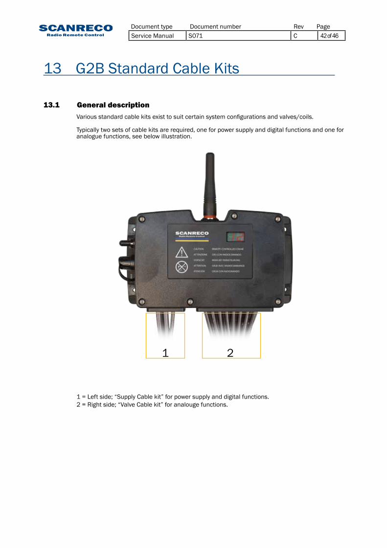
13 G2B Standard Cable Kits
13.1 General description Variousstandardcablekitsexisttosuitcertainsystemconfigurationsandvalves/coils.
Typicallytwosetsofcablekitsarerequired,oneforpowersupplyanddigitalfunctionsandoneforanaloguefunctions,seebelowillustration.
1 = Left side; “Supply Cable kit” for power supply and digital functions.2 = Right side; “Valve Cable kit” for analouge functions.
Document type Document number PageRevService Manual S071 C 42 of 46

Part number information:
Part no: Output Cables47979 Powersupply,DV&EX147752 Powersupply,DV,EX1&EX248810 Powersupply,DV,EX1,EX2,EX3&EX4
+/-
DV
EX1
EX2
EX3
EX4
1 23
EX1 +/- DV
EX2 EX3 EX4
EX1 - Digital functionsSee chapter 5.5 - 5.6 for assignments
EX2 - Digital functionsSee chapter 5.5 - 5.6 for assignments
EX3 - CANBUSSee chapter 5.7 for assignments
EX4 - CANBUSSee chapter 5.7 for assignments
+/- Power supplySee chapter 5.5 - 5.6 for assignments
DV - Dump Valve outputHirchmann GDM3009
1DV+
2DV-
Cablespecification:Cable Lenght Wires x Dim.
+/- 2,5meters 2x2,5mm
DV 2 meters 2x1,0mm
EX1 3 meters 11x0,5mm
EX2 3 meters 10x0,5mm
EX3 3 meters 5x0,5mm
EX4 3 meters 5x0,5mm
Girder/cable alignment:
2
2
2
2
2
2
2
13.2 Standard Supply cable kits
Forconnectionofpowersupplyinput,DV-output,DigitalfunctionsandCANBUS.
Central Unit type:2010201130103011
Document type Document number PageRevService Manual S071 C 43 of 46

Part number information:
Part no: No of outputs Type of connector47753 8 AMP-JTP 4-pol47961 8 Hirchmann GDM3009
1
11 23
1 42 53 6 7 8
CONNECTOR:AMP-JPT 4-pol
CONNECTOR:Hirchmann GDM3009
1 2
3 Cablespecification:Cable Lenght Wires x Dim.
1-8 2 meters 3x0,5mm
43
1 = MODULE SUPPLY
1 = MODULE SUPPLY
1
1
2
2
3
3
2
3 = GND
3 = GND
1
2 = REGULATED SUPPLY
2 = REGULATED SUPPLY
WIRE:
WIRE:
Girder/cable alignment:
13.3 Standard valve cable kits for Sauer-Danfoss PVG-32
For connection of analogue functions for Sauer-Danfoss PVG-32 module
Central Unit type:20102011
Document type Document number PageRevService Manual S071 C 44 of 46

Part number information:
Part no: No of outputs Type of connector48046 8 Hirchmann GDM3009
1
1 23
1 42 53 6 7 8
CONNECTOR:Hirchmann GDM3009
1
2 3
Cablespecification:Cable Lenght Wires x Dim.
1-8 2 meters 3x0,5mm
1 = PWM+ A
3 = PWM+ B
2 = PWM -
WIRE:
Girder/cable alignment:
1
2
3
13.3 Standard valve cable kits for HAWE
For connection of analogue functions for HAWE module
Central Unit type:30103011
Document type Document number PageRevService Manual S071 C 45 of 46

Part number information:
Part no: No of outputs Type of connector47925 8 (1A-4B) Hirchmann GDM300947924 12 (1A-6B) Hirchmann GDM300947903 16 (1A-8B) Hirchmann GDM300948238 12 (1A-6B) AMP-JPT 2-pol48362 16 (1A-8B) AMP-JPT 2-pol
1A
1A1 23
1A1B
4A4B
2A2B
5A5B
3A3B
6A6B
7A7B
8A8B
CONNECTOR:AMP-JPT 2-pol
CONNECTOR:Hirchmann GDM3009
1 2
Cablespecification:Cable Lenght Wires x Dim.
1-8 (A/B) 2 meters 2x0,5mm
2 = PWM-
2 = PWM-
1 = PWM+
1 = PWM+
WIRE:
WIRE:
Girder/cable alignment:
21 1
1
2
2
13.3 Standard valve cable kits for PWM solenoids
For connection of analogue functions for PWM solenoids
Central Unit type:30103011
Document type Document number PageRevService Manual S071 C 46 of 46