
HYDRAULIC SNUBBERS
24
HYDRAULIC SNUBBERS 6 - 4 - 6 Minami-Shinagawa, Shinagawa-Ku, Tokyo 140 - 0004, Japan PHONE: +81 - 3 - 3474 - 0090 FAX: +81 - 3 - 5460 - 9170 URL: http://www.tekki.co.jp/english/ E-mail: [email protected] Cat.No.2020. SNBR-SN R1 (Non-Nuclear)
-
Upload
khangminh22 -
Category
Documents
-
view
0 -
download
0
Transcript of HYDRAULIC SNUBBERS

HYDRAULICSNUBBERS
6-4-6 Minami-Shinagawa, Shinagawa-Ku, Tokyo 140-0004, JapanPHONE: +81-3-3474-0090FAX: +81-3-5460-9170URL: http://www.tekki.co.jp/english/E-mail: [email protected]
Cat.No.2020. SNBR-SN R1 (Non-Nuclear)
Introduction 3
1. OUTLINE OF PIPE HANGERS AND SUPPORTS 5
2. HYDRAULIC SNUBBER 6
3. HYDRAULIC SNUBBER ASSEMBLIES 11
4. BRACKET & PIPE CLAMPS 18
Items Type
BRACKET …………………………………………………………… BSN&BSNA 19
PIPE CLAMP (Carbon Steel) ……………………………………… PCBC-M,PCBCZ-M 20
PIPE CLAMP (Carbon Steel) ……………………………………… PCBC-1,PCBCZ-1 21
PIPE CLAMP (Carbon Steel) ……………………………………… PCBC-3,PCBCZ-3 22
PIPE CLAMP (Carbon Steel) ……………………………………… PCBC-6,PCBCZ-6 23
PIPE CLAMP (Carbon Steel) ……………………………………… PCBC-T,PCBCZ-T 24
PIPE CLAMP (Carbon Steel) ……………………………………… PCBC-S,PCBCZ-S 25
PIPE CLAMP (Carbon Steel) ……………………………………… PCBC-Q,PCBCZ-Q 26
PIPE CLAMP (SB-Carbon Steel) …………………………………… PCBB-M,PCBBZ-M 27
PIPE CLAMP (SB-Carbon Steel) …………………………………… PCBB-1,PCBBZ-1 28
PIPE CLAMP (SB-Carbon Steel) …………………………………… PCBB-3,PCBBZ-3 29
PIPE CLAMP (SB-Carbon Steel) …………………………………… PCBB-6,PCBBZ-6 30
PIPE CLAMP (SB-Carbon Steel) …………………………………… PCBB-T,PCBBZ-T 31
PIPE CLAMP (SB-Carbon Steel) …………………………………… PCBB-S,PCBBZ-S 32
PIPE CLAMP (SB-Carbon Steel) …………………………………… PCBB-Q,PCBBZ-Q 33
PIPE CLAMP (Alloy Steel) ………………………………………… PCBA-M,PCBAZ-M 34
PIPE CLAMP (Alloy Steel) ………………………………………… PCBA-1,PCBAZ-1 35
PIPE CLAMP (Alloy Steel) ………………………………………… PCBA-3,PCBAZ-3 36
PIPE CLAMP (Alloy Steel) ………………………………………… PCBA-6,PCBAZ-6 37
PIPE CLAMP (Alloy Steel) ………………………………………… PCBA-T,PCBAZ-T 38
PIPE CLAMP (Alloy Steel) ………………………………………… PCBA-S,PCBAZ-S 39
PIPE CLAMP (Alloy Steel) ………………………………………… PCBA-Q,PCBAZ-Q 40
Pipe Outer Diameter of JIS,ANSI and API Standards ……………………………… 42
Chemical Composition and Mechanical Properties of JIS (Japanese Industrial Std.) Steel Materials, and Equivalent ASTM ……………… 43
CONTENTS
2

Introduction
We, SANWA TEKKI CORPORATION (STC) was founded in 1907 to meet the increasing demands for modernizing the public railway facilities as Japan's very first manufacturer and specialist of hardwareand equipment for overhead power supply(catenary)systems in the railway electrification program.
Since then, STC has been continuously contributing to Japan's industrial development through its high quality products and its ceaseless research and development of new products for infrastructure inJapan.
In 1953, STC began to manufacture pipe hangers and supports including variable spring hangers andconstant spring hangers for high temperature and high pressure pipings in thermal power plants andlarge ships as the first and only manufacturer in Japan. Through its strict quality control, STC's pipehangers & supports could receive high evaluation from customers, and expanded the market intopetrochemical plants and nuclear power plants in Japan and also in the world.
Furthermore, STC originally developed hydraulic snubbers, mechanical snubbers, and computerprograms for analysis of thermal stress and displacement, supporting load and static & dynamic seismic effects of piping systems. At the present, STC can prepare and supply 3D-CAD design data for efficient and easy checking of the support design by virtually examining the interface of the support assemblies by objects in the vicinity. And then, STC have been the only one manufacturer having a full line services of piping hangers, supports, hydraulic & mechanical snubbers and engineering services in the world.
To prove its high quality and excellent performance in every phase of our business activities -customers relations, engineering and design, manufacturing, output products, after-sales services and quality control, STC is registered as an ISO 9001 company.
Trade Name: SANWA TEKKI CORPORATION
Head officeAddress
6-4-6 Minami-Shinagawa, Shinagawa-Ku,Tokyo 140-0004, Japan
Established: September, 1907
Paid-in Capital: Yen 423,800,000
No. of Employees 388 (As of April 2020)
Plants:Utsunomiya
Kumamoto
Branches:
Tohoku (Sendai)
Chubu (Nagoya)
Kansai (Osaka)
Kyushu (Fukuoka)
Sales Offices:
Sapporo
Niigata
Shizuoka
Hiroshima
Takamatsu
3 4

2. HYDRAULIC SNUBBER
2.1 General
Hydraulic Snubber is a device developed to protect high pressure/temperature piping system in powergenerating plants and various types of industrial plants. They function to restrain undesirabledisplacement of piping system or components when they are about to oscillate due to seismic or other types of dynamic loading, while, to allow their free movement during the thermal displacement mode. Our hydraulic snubber is designed to provide such essential two-way functions by means of asophisticated combination of hydraulic cylinder with a valve mechanism. A built-in flexible reservoir isalso a dominant design feature. As an important step among entire development works, comprehensivedesign verifications and thorough testing were conducted to assure the highest reliability. Since theywere put into service decades ago, they have been proving perfect trouble-free performance and excellent maintainability, and thus assuring maximum safeness for operation of various piping systemswhen they were subjected to occasional dynamic events.
1. OUTLINE OF PIPE HANGERS AND SUPPORTS
Depending on their function and uses, hangers and supports are classified as follows:(A) Items designed to support the weight of piping and equipment; these are collectivelyreferred to as Hangers or Supports.
(B) Items designed to restrain or limit three-dimensional displacements due to thermal expansion; these are known by the generic term of Restraints.
(C) Items designed to prevent piping systemsfrom cyclic loading due to forces other thangravity or thermal expansion, such as impactby vibration, earthquake, and water-hammer;these products are called Braces or Snubbers
Each of the above three categories is subdivided,according to applications and functions, as shown in Table 1-1 and Fig. 1-1.
Table 1-1 Classification of Hangers and Supports
Item
No.
Divisions Subdivisions
Designation Application Classification Application
A Hangers and Supports
To support weight of piping systems, either from above(Hangers) or from below(Supports)
① Rigid Hangers For point without vertical displacement.
② Variable Spring HangersFor point with small vertical displacement.(upto approx. 50mm)
③ Constant Spring HangersFor points with large verticaldisplacement.(over approx. 50mm)
B RestraintsTo restrain or limit movementof piping systems due to thermal expansion.
④ Anchors To completely fix the pipingsystems at certain points.
⑤ StopsTo prevent longitudinalmovement of pipes whileallowing them to rotate.
⑥ Guides To permit displacement only for specified direction.
⑦ Rod Restraints To prevent pipe movementfrom voluntary directions.
C Braces or SnubbersTo limit pipe movement due to forces other than thermal expansion and gravity.
⑧ Vibration Eliminators To prevent or d imin ishvibrations.
⑨ Hydraulic SnubbersMechanical SnubbersShock Absorbers
To suppress movementdue to earthquake, water-hammer, relief valve reactionwithout restraining thermal movement.
Fig. 1-1
5 6

2.4 Construction and Features
Design principle of our hydraulic snubber is a hydraulic system controlled by a valve mechanism. The magnitude of generated resistance force is a function of input velocity. Namely, CVn = F ( C = constant, V = piston velocity, n = valve property, F = force generated)
① Hydraulic cylinder is fully enclosed in the outer casing and they are filled with hydraulic fluid. A piston divides the cylinder into two pressure chambers. They are hydraulically linked each other through a fluid path formed by a pair of poppet valves and outer casing.
② A poppet valve, being loaded by a built-in coil spring, stays open so far as the pressure in a fluid chamber is lower than the pre-determined threshold, and thus allowing reciprocal free movement of the piston during the thermal displacement mode of piping.
③ The cubic volume of lateral piston rod, penetrating one of the chambers, causes a difference in fluid volume in each chamber. An elastic accumulator, inserted between the cylinder wall and outer casing, functions as the self-adjustment means for offsetting the difference. For this design advantage, Model SN/SNS snubber has no projection on the cylindrical body unlike conventional snubbers having outside oil reservoirs.
④ Dynamic input displacement gives a quick driving force to the piston, and then causes a rapid pressure increase inside the compressed chamber. The valve on the compressed chamber side closes and the fluid path is shut off on the spot. Complete stop of fluid flow generates the resistant force inside the cylinder to restrain the displacement.
⑤ The entire process takes place against a reverse loading, and completely suppress the dynamic loading. (For Model SN only)
⑥ Very precise through hole on the valve or peripherals keeps a minimum fluid flow even when it is in shut off position. For this design feature, the snubber unit is capable of allowing thermal displacement of the piping even during a dynamic oscillation of the piping system. This ability is defined by so-called release rate or bleed rate. This function is not equipped for model SNS, as to withstand continuous one-way reaction force from safety valve, etc.
2.5 Parts of Hydraulic Snubber
2. HYDRAULIC SNUBBER
No. Part Name Material
1 Holder SS400/S25C2 Casing SGP3 Cylinder Cover SS4004 Cylinder Tube STKM13C5 Rod Cover SS400/S25C6 Piston SS4007 Piston Rod S45C8 Tie-Rod S45C/SCM4359 Accumulator EPDM10 Casing Cover SS40011 Travel Indicator SUS30412 Canvas Cover CLOTH
2.2 Model, Type and Size of Hydraulic Snubbers
SANWA TEKKI's Hydraulic Snubber models are classified by means of the symbols explained in the Table 2.2.
0306 1001 160
SN 3 E A 250or … or or …
SNS 100 F B 550
SN 16 E A ー 160| | | | |
Model Size Type1 Type2 Stroke
Table 2.2
Item Symbol Description
ModelSN
Model of Hydraulic Snubber having poppet valves at both side.For reciprocating motion such as earthquake, steam hammer, water hammer, etc.
SNS Model of Hydraulic Snubber having single valve at tension side.For one way thrust motion such as safety valve reaction, etc.
Size A numeralfrom 03 to 100
Indicate sizes (size x 10 = Rated Load in kN)03, 06, 1, 3, 6, 10, 16, 25, 40, 60, and 100 is available.* For larger size up to 5000kN is available on request.
AssemblyType1
E With extension attachments, for a longer installation space.F With the shortest attachments, for a limited installation space.
Main UnitType2
A Model Number for size 03 ~ 25.
B, GModel Number for size 40 ~ 100.B is for standard model.G is for special short model. (Details, please see page 15)
Stroke A numeralfrom 100 to 550
Total stroke length (mm)100, 160, 250, 310, 400, 460, and 550 is available.
2.3 Typical Application of Hydraulic Snubbers
2. HYDRAULIC SNUBBER
Size 03 ~ 25
7 8

2.7 Major Design Specifications
1. Applicable Code and Standard
① JIS (Japanese Industrial Standard) Code② MSS (Manufacturers Standardization Society) Standard③ ASTM (American Society of Testing and Materials) Standard④ SSPC (Steel Structure Painting Council) Standard
2. Design Parameters and Conditioins
3. Minimum Spring Rate (kN/mm)
4. Properties of Seals and Hydraulic Fluid
2. HYDRAULIC SNUBBER
Drag Force (Frictional Resistance) Max. 2% of the rated load, or 0.49kN, Whichever is greater.Bleed Rate (Release Rate) 0.2 ~ 2.0 mm/sec.
Lock-up Rate 2.0 ~ 6.0 mm/sec.Applicable Frequency Range 1 Hz ~ 33 Hz
Lost Motion Max. 2.0 mmDesign Safety Margin (*) Withstand 150% of the rated load without loss of proper function.Ultimate Strength (*) Withstand 200% of the rated load without loss of structual integrity.
Loading Capacity (under 100% rated load) 20,000 loading cycles.Applicable Ambient Temperature Max. 70°C
Design Life 40 years.Recommended Maintenance Period Once every 10 years.
Angular Offset Max. ± 7.5°
*This value is applicable to Size SN25 and less, and the stroke shorter than 250mm.
Group Parts / Parameters Material / Characteristics
SealsO-Ring FKMDust Seal NBRAccumulator EPDM
Fluid
Fluid Non-Flammable Silicone OilAppearance Transparent and odorlessViscosity 47.5 - 52.5 (CS-25°C)
Specific Gravity 0.955 - 0.965 (25°C)Flash Point 300°C or overVolatile 5% or lower (150°C-24 Hour)Pour Point -50°C or lower
*For Spring Rate of larger size, longer stroke snubbers, contact the manufacturer.
SizeStroke (mm)
100/160 250
SN-03 2.45 1.47SN-06 2.94 1.96SN- 1 4.90 2.94SN- 3 14.70 9.81SN- 6 29.40 19.61SN-10 49.03 29.42
SizeStroke (mm)
100/160 250
SN-16 68.65 44.13SN-25 98.07 63.74SN-40 117.68 78.45SN-60 137.29 88.26SN-100 230.46 147.10
2.6 Size Selection Guideline
Selection of the proper snubber assembly shall be made based on the following design elements:
① Design dynamic load.② Amount of Piston Displacement (calculated from pipe thermal travel) and its direction.③ Overall installation length allotted for the snubber assembly.④ Details of end conditions (Bracket or Pipe clamp).⑤ Pipe size, material, and operating temparature, insulation thickness, if any.
(1) Rated LoadSelect Snubber unit having a rated load nearest to but greater than the design load (calculated dynamic load).For example, when the calculated design load is 45kN( ≒ 4,500kgf), size SN 6 (rated load = 60kN( ≒6,000kgf) ) is the proper size to be selected.Min. Snubber size is recommended depending on applicable pipe size as per below table.
(2) Stroke The total stroke of the snubber unit selected must be sufficiently greater than the calculated piston displacement so as to provide a safety margin for the extra movement not counted in at the designing stage of the piping system. STC recommends to consider Min. 25mm margin at both side. [25mm margin + design piston displacement + 25mm margin Total Stroke]
Each snubber unit is factory pre-set at designated Cold Position (C.P.) to provide the ready-to-install length of the assembly based on the design amount and direction of the piston displacement. Customer does not need to adjust piston position at site during installation works.
(3) Assembly TypeType EA/EB : With extension attachments, for a longer installation length between the range L1(Max) and L1(Min) as given in the table of Page 12 & 14.
Type FA/FB : With the shortest attachments, for a limited installation length. The overall dimensions are as given by L2 in the table of Page 12 & 14.
2. HYDRAULIC SNUBBER
Size No. Rated Load(N) Rated Load(kgf)
SN 03 3,000 305SN 06 6,000 611SN 1 10,000 1,019SN 3 30,000 3,059SN 6 60,000 6,118SN 10 100,000 10,197
Size No. Rated Load(N) Rated Load(kgf)
SN 16 160,000 16,315SN 25 250,000 25,492SN 40 400,000 40,788SN 60 600,000 61,182SN 100 1,000,000 101,971
Pipe Size Min.Snubber Size
~ 5" 036" ~ 10" 0612" ~ 16" 118" ~ 24" 325" ~ 6
Type FA
Total Stroke 100 160 250 310 400 460 550 630 * 710 *
Recm. Design PistonDisplacement 0 ~ 50 51~ 110 111 ~ 200 201 ~ 260 261 ~ 350 351 ~ 410 411 ~ 500 501 ~ 580 581 ~ 660
Total Stroke and Design Displacement (mm)
* For special stroke 630, 710 is available upon request.
Type EA
9 10

Dimension Table for Type EA/FA (mm)
Size Stroke L1(Min.)
L1(Max.) L2 A1 A2 K ØA M ØD E E1 F1 G ØH R1 R2 U1 U2 B T a
SN-03
100 642 1,340 563 500 501 255
76.3 M16 12 49 28 50 55.5 27.2 18.0 19.0 62 44 47 22 4160 732 1,340 653 590 591 315
250 867 1,340 788 725 726 405
SN-06
100 659 1,567 573 517 511 255
89.1 M20 12 56 35 50 61.5 34.0 20.0 19.0 62 48 47 22 4160 749 1,567 663 607 601 315
250 884 1,567 798 742 736 405
SN - 1
100 683 1,718 580 524 511 250
101.6 M20 15 68 44 55 68.5 42.7 24.0 25.0 69 48 52 26 4160 773 1,718 670 614 601 310
250 908 1,718 805 749 736 400
SN - 3
100 811 1,917 671 611 591 293
139.8 M30
17 94 62
74 87.5
60.5 31.5 32.5
80 58
73.5 31.5 4
160 901 1,917 761 701 681 353
250 1,036 1,917 896 836 816 443
310 1,126 - 986 926 906 503
400 1,321 ー 1,199 1,121 1,114 638
165.2 M36 87 100.5 85 64460 1,411 ー 1,289 1,211 1,204 698
550 1,546 ー 1,424 1,346 1,339 788
SN - 6
100 906 2,152 749 691 664 338
165.2 M3625 114 78
87 100.576.3 41.5 37.5
85 6480 34 6
160 996 2,152 839 781 754 398
250 1,131 2,152 974 916 889 488
310 1,221 ー 1,064 1,006 979 548
400 1,356 ー 1,199 1,141 1,114 638
460 1,446 ー 1,289 1,231 1,204 698
550 1,628 ー 1,492 1,400 1,394 810 190.7 M42 108 113.5 98 70
SN-10
100 1,002 2,405 817 744 719 360
190.7 M42
30 133 91
108 113.5
89.1 54.0 50.0
98 70
97 38 8
160 1,092 2,405 907 834 809 420
250 1,227 2,405 1,042 969 944 510
310 1,317 ー 1,132 1,059 1,034 570
400 1,452 ー 1,267 1,194 1,169 660
460 1,608 ー 1,445 1,331 1,328 753 216.3 M48 130 126.5 117 76
550 1,799 ー 1,666 1,506 1,533 868 267.4 M56 160 152.5 133 84
SN-16
100 1,130 3,024 905 823 788 393
216.3 M48
40 165 116
130 126.5
114.3 63.0 62.5
117 76
116 47 10
160 1,220 3,024 995 913 878 453
250 1,355 3,024 1,130 1,048 1,013 543
310 1,445 ー 1,220 1,138 1,103 603
400 1,636 ー 1,441 1,313 1,308 718
267.4 M56 160 152.5 133 84460 1,726 ー 1,531 1,403 1,398 778
550 1,861 ー 1,666 1,538 1,533 868
SN-25
100 1,256 3,497 991 893 858 418
267.4 M56 50 195 142 160 152.5 139.8 73.0 75.0 133 84 139 68 12
160 1,346 3,497 1,081 983 948 478
250 1,481 3,497 1,216 1,118 1,083 568
310 1,571 ー 1,306 1,208 1,173 628
400 1,706 ー 1,441 1,343 1,308 718
Notes.1. Model Number The model number of the Hydraulic Snubber is shown by the following procedure SN (S) - 6 EA - 100 Valve Type Type
Part Code Size Stroke
2. Ordering Instruction Part Code-Size,Type-Stroke Example : (1)SN-3EA-160 (Poppet Valve)
(2)SNS-3EA-160 (Single Valve)3. If the designed installation length is shorter than L1 (Min.) for EA Type in the table on the right, change the installation length so that it is the L2 dimension for FA Type.If the designed installation length is shorter than L1 (Min.) and longer than L2 in the table on the right, or shorter than L2, please consult with STC.
SIZE : SN03 ~ 25Snubber sizes 03 to 25 are classified as Type EA and FA.Ordering Instruction and major dimensions are as follows.
Type EA (with Extension Pipe)
NOTE 1. Adjustable range of U2 = +/- 25mm
NOTE 2. L1(Min.), L2, A1 and A2 dimensions are those when the indicator position is at the center of the total stroke.
NOTE 3. When the piston design movement direction (from Cold to Hot condition) is the extension direction (plus direction), the snubber is pre-set at the stroke position 25mm from the fully retracted end of stroke.In this case, the L1(Min.), L2, A1 and A2 dimensions are the value obtained by subtracting [ (Total Stroke / 2) - 25mm ] from the values in the above table.
NOTE 4. When the piston design movement direction (from Cold to Hot condition) is the compression direction (minus direction), the snubber is pre-set at the stroke position 25mm from the fully extended end of stroke.In this case, the L1(Min.), L2, A1 and A2 dimensions are the value obtained by adding [ (Total Stroke / 2) - 25mm ] from the values in the above table.
NOTE 5. Check with STC for the Max. Dimensions of L1 when the stroke is 310 mm or more.
Type FA (with Direct Ear)
3. HYDRAULIC SNUBBER ASSEMBLIES3. HYDRAULIC SNUBBER ASSEMBLIES
11 12

3. HYDRAULIC SNUBBER ASSEMBLIES
Notes.1. Model Number The model number of the Hydraulic Snubber is shown by the following procedure SN (S) - 40 EB - 100 Valve Type Type
Part Code Size Stroke
2. Ordering Instruction Part Code-Size,Type-Stroke Example : (1)SN-40EB-100 (Poppet Valve)
(2)SNS-40FB-100 (Single Valve)3. If the designed installation length is shorter than L1 (Min.) for EB Type in the table on the right, change the installation length so that it is the L2 dimension for FB Type.If the designed installation length is shorter than L1 (Min.) and longer than L2 in the table on the right, or shorter than L2, please consult with STC.
SIZE : SN40 ~ 100Snubber sizes 40, 60 and 100 are classified as Type EB and FB.Ordering Instruction and major dimensions are as follows.
3. HYDRAULIC SNUBBER ASSEMBLIES
Type EB (with Extension Pipe)
Type FB (with Direct Ear)
Dimension Table for Type EB/FB (mm)
Type Size Stroke L1(Min.) L1(Max.) L2 A1 A2 K F ØA M ØD E E1 ØH R T G U1 U2 a
EB,FB
40
100 1,297 1,920 1,110 1,052 639 385 299
238 60 60 241 70 139.8 80 56 150 172 73 16160 1,387 2,010 1,260 1,142 729 445 359
250 1,522 2,145 1,485 1,277 864 535 449
60
100 1,472 2,020 1,223 1,187 679 415 348
280 68 70 312 80 165.2 93 65 170 196 79 20160 1,562 2,110 1,373 1,277 769 475 408
250 1,697 2,245 1,598 1,412 904 565 498
100
100 1,651 2,155 1,357 1,306 727 445 399
326 80 80 348 90 216.3 118 75 195 231 89 25160 1,741 2,245 1,507 1,396 817 505 459
250 1,876 2,380 1,732 1,531 952 595 549
NOTE 1. Adjustable range of U2 = +/- 25mm
NOTE 2. L1(Min.), L2, A1 and A2 dimensions are those when the indicator position is at the center of the total stroke.
NOTE 3. When the piston design movement direction (from Cold to Hot condition) is the extension direction (plus direction), the snubber is pre-set at the stroke position 25mm from the fully retracted end of stroke.In this case, the L1(Min.), L2, A1 and A2 dimensions are the value obtained by subtracting [(Total Stroke / 2) - 25mm] from the values in the above table.
NOTE 4. When the piston design movement direction (from Cold to Hot condition) is the compression direction (minus direction), the snubber is pre-set at the stroke position 25mm from the fully extended end of stroke.In this case, the L1(Min.), L2, A1 and A2 dimensions are the value obtained by adding [(Total Stroke / 2) - 25mm] from the values in the above table.
NOTE 5. Collars will be supplied along with Bracket and/or Clamps for type EB/FB Snubbers.
NOTE 6. Clamps for size 40, 60, and 100 are specially designed and supplied in each request.
13 14

Notes.1. Model Number The model number of the Hydraulic Snubber is shown by the following procedure SN (S) - 60 G - 100 Valve Type Type
Part Code Size Stroke
2. Ordering Instruction Part Code-Size,Type-Stroke Example : (1)SN-60G-100 (Poppet Valve)
(2)SNS-60G-100 (Single Valve)
This Type G can be selected when Type EB or FB cannot be adopted due to the designed installation dimensions for Size 40, 60 and 100.Ordering Instruction and major dimensions are as follows.
3. HYDRAULIC SNUBBER ASSEMBLIES
Type G
3. HYDRAULIC SNUBBER ASSEMBLIES
Dimension Table for Type G (mm)
Type Size Stroke L(Min.) L(Max.) A2 K ØA M ØD F ØH R T U2
G
40
100 1,095 1,920 800 310
340 72 60 180 165.2 95 76 100160 1,185 2,010 890 370
250 1,320 2,145 1,025 460
60
100 1,180 2,020 870 335
375 80 70 210 216.3 115 86 110160 1,270 2,110 960 395
250 1,405 2,245 1,095 485
100
100 1,300 2,155 970 375
425 90 80 250 267.4 155 96 120160 1,390 2,245 1,060 435
250 1,525 2,380 1,195 525
NOTE 1. Adjustable range of U2 = +/- 25mm
NOTE 2. L(Min.) and A2 dimensions are those when the indicator position is at the center of the total stroke.
NOTE 3. When the piston design movement direction (from Cold to Hot condition) is the extension direction (plus direction), the snubber is pre-set at the stroke position 25mm from the fully retracted end of stroke.In this case, the L(Min.) and A2 dimensions are the value obtained by subtracting [(Total Stroke / 2) - 25mm] from the values in the above table.
NOTE 4. When the piston design movement direction (from Cold to Hot condition) is the compression direction (minus direction), the snubber is pre-set at the stroke position 25mm from the fully extended end of stroke.In this case, the L(Min.) and A2 dimensions are the value obtained by adding [(Total Stroke / 2) - 25mm] from the values in the above table.
NOTE 5. Clamps for size 40, 60, and 100 are specially designed and supplied in each request.
15 16
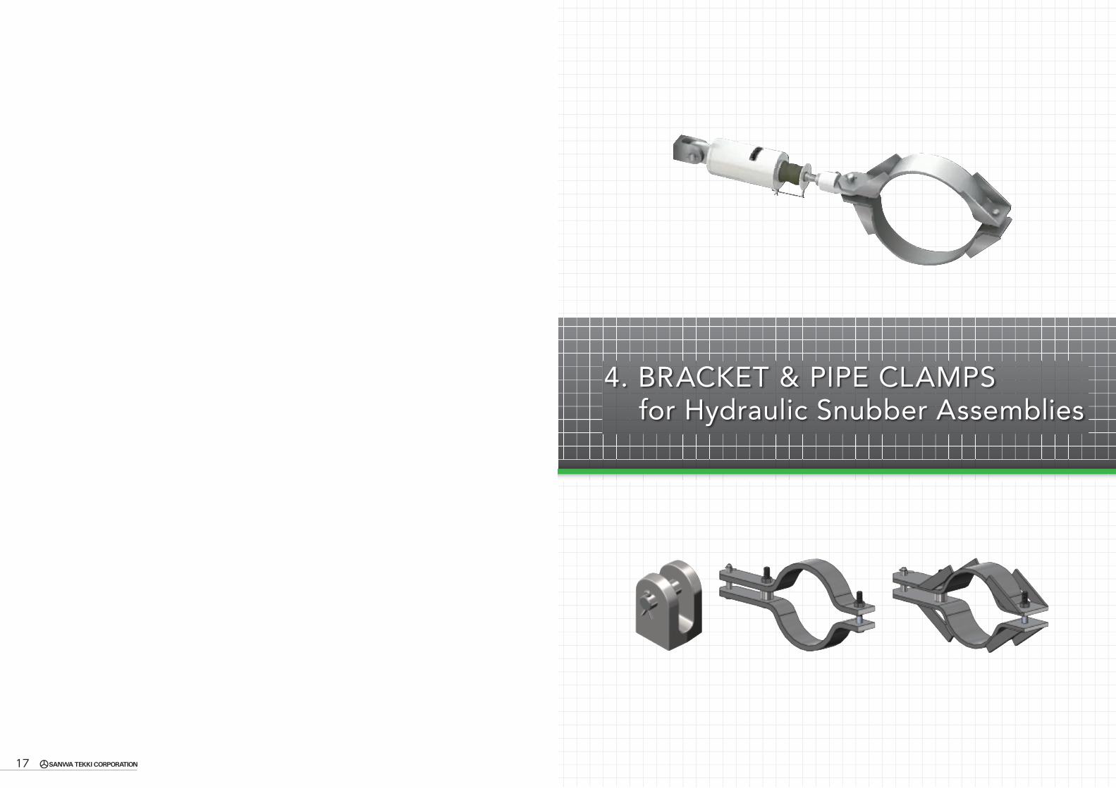
17
4. BRACKET & PIPE CLAMPSfor Hydraulic Snubber Assemblies

(mm)
SIZE NO. MAX.RECOMLOAD(kN) A B C φD E F H K φ d
WELD SIZE : aWeight(N)
θ:0o±7.5o θ:45o±7.5o θ:90o-7.5o
BSN 01,03,06 6 37 23 36 12 44 18 62 36 12 4 4 4 6BSN 1 10 51 27 50 15 56 25 81 42 15 4 4 4 11BSN 3 30 61 33 60 17 66 30 96 50 17 4 7 8 17BSN 6 60 75 35 75 25 83 37.5 120.5 60 25 6 11 12 40BSN 10 100 90 39 90 30 99 45 144 72 30 8 15 16 65BSN 16 160 110 48 110 40 116 55 171 81 40 10 19 20 118BSN 25 250 145 69 145 50 150 72.5 222.5 110 50 12 23 24 226BSNA 40 400 200 80 175 60 185 87.5 272.5 120 60 16 30 31 510BSNA 60 600 220 90 210 70 225 105 330 145 70 21 40 42 805BSNA 100 1000 290 100 255 80 280 127.5 407.5 170 80 27 52 55 1697
SIZE RANGE01 ~ 100
MATERIAL(1)BSN : Carbon steel (JIS G4051 S25C) (ASTM Equivalent A668 CL70)(2)BSNA : Carbon steel (JIS G3101 SS400) (ASTM Equivalent A36)(3)Ream pin : Carbon steel (JIS G4051 S45C) (ASTM Equivalent A576 Gr1045)
FINISH(1) Bracket Body: Applied STC's standard anti-corrosive paint unless otherwise specified.
(2)Ream pin : Electro-plated.(3) Ream Pin and Pin Holes on the Bracket are machined to close tolerances.
SERVICEConnected with each size of Hydraulic or Me-chanical Snubber and Rod Restraint.
ORDERINGEx: Indicate the Size No. like BSN6, BSN25, BSNA60, etc.
BRACKET FOR SNUBBER AND ROD RESTRAINT (TYPE : BSN & BSNA)
(mm)
SIZE NO. &Load Symbol
PIPE DIAANSIA
C D EStandardPlate SizeTxW
F S Weight(N)
PCBC 1-1/2 - M 48.3
24
180 1606x50
12
80 15PCBC 2 - M 60.3 190 170 85 16PCBCZ 2-1/2 - M 73.0 210 190 95 18PCBC 3 - M 88.9 220 200
9x50
110 27PCBC 3-1/2 - M 101.6 225 205 115 28PCBC 4 - M 114.3 235 215 125 30PCBCZ 5 - M 141.3 255 235 135 33PCBCZ 6 - M 168.3 265 245
12x50155 47
PCBCZ 8 - M 219.1 300 280 185 55PCBCZ 10 - M 273.0 330 310 210 63PCBCZ 12 - M 323.8 355 335 16x50 250 94
For other pipe standards (JIS, API, etc.) are available on request.
SIZE RANGE1-1/2 through 12 inch pipe outer diameter
MATERIAL(1)Clamp plate : Carbon steel (JIS G3101 SS400) (ASTM Equivalent A36)(2)Hex bolts, nuts : Carbon steel (JIS G3101 SS400) (ASTM Equivalent A307 Gr.B & A563 Gr.A)(3)Ream pin : Carbon steel (JIS G4051 S45C) (ASTM Equivalent A576 Gr1045)
FINISH(1) Clamp Plate : Applied STC's standard anti-corrosive paint unless otherwise specified.
(2)Hex bolts, nuts and ream pin : Electro-plated.(3) Ream Pin and Ream Pin Holes on the clamp are machined to close tolerances.
SERVICEUsed for occasional loads of insulated pipe with temperature less than 350℃ .Connected with Hydraulic or Mechanical Snubber and Rod Restraint for the Load Capacity 6.00kN or less.
ORDERINGSpecify Part Code, Pipe Size and Load Symbol required. PCBCZ 6 - M
Load SymbolPipe SizePart Code
Ex: PCBC 4-M & PCBCZ 8-M
PIPE CLAMP FOR BRACING USE CARBON STEEL (TYPE : PCBC-M , PCBCZ-M)
Applicable Temperature : ~ 350℃
LOAD CAPACITY : 6kN
19 20

(mm)
SIZE NO. &Load Symbol
PIPE DIAANSIA
C D EStandardPlate SizeTxW
F S Weight(N)
PCBC 1-1/2 - 1 48.3
28
185 160
9x50
15
85 28PCBC 2 - 1 60.3 195 170 95 29PCBCZ 2-1/2 - 1 73.0 215 190 105 32PCBC 3 - 1 88.9 225 200 120 34PCBC 3-1/2 - 1 101.6 230 205 130 37PCBC 4 - 1 114.3 240 215 135 38PCBCZ 5 - 1 141.3 260 235 150 42PCBCZ 6 - 1 168.3 270 245
9x75
165 62PCBCZ 8 - 1 219.1 305 280 195 76PCBCZ 10 - 1 273.0 335 310 230 89PCBCZ 12 - 1 323.8 360 335 250 97PCBC 14 - 1 355.6 390 365 265 104PCBC 16 - 1 406.4 415 390 290 113PCBC 18 - 1 457.2 440 415 315 121PCBC 20 - 1 508.0 465 440 350 138PCBC 22 - 1 558.8 500 475
12x100
390 249PCBC 24 - 1 609.6 525 500 415 265PCBC 26 - 1 660.4 555 530 440 281PCBC 28 - 1 711.2 580 555 470 299PCBC 30 - 1 762.0 605 580 495 315PCBC 32 - 1 812.8 630 605 520 331PCBC 34 - 1 863.6 655 630 545 347PCBC 36 - 1 914.4 680 655 570 362PCBC 40 - 1 1016.0 735 710 625 391PCBC 44 - 1 1117.6 785 760 675 422
For other pipe standards (JIS, API, etc.) are available on request.
PIPE CLAMP
SIZE RANGE1-1/2 through 44 inch pipe outer diameter
MATERIAL(1)Clamp plate : Carbon steel (JIS G3101 SS400) (ASTM Equivalent A36)(2)Hex bolts, nuts : Carbon steel (JIS G3101 SS400) (ASTM Equivalent A307 Gr.B & A563 Gr.A)(3)Ream pin : Carbon steel (JIS G4051 S45C) (ASTM Equivalent A576 Gr1045)
FINISH(1) Clamp Plate : Applied STC's standard anti-corrosive paint unless otherwise specified.
(2)Hex bolts, nuts and ream pin : Electro-plated.(3) Ream Pin and Ream Pin Holes on the clamp are machined to close tolerances.
SERVICEUsed for occasional loads of insulated pipe with temperature less than 350℃ .Connected with Hydraulic or Mechanical Snubber and Rod Restraint for the Load Capacity 6.01 through 10.0kN.
ORDERINGSpecify Part Code, Pipe Size and Load Symbol required. PCBCZ 10 - 1
Load SymbolPipe SizePart Code
Ex: PCBC4-1 & PCBCZ 8-1
FOR BRACING USE CARBON STEEL(TYPE : PCBC-1 , PCBCZ-1)
SIZE RANGE1-1/2 through 44 inch pipe outer diameter
MATERIAL(1)Clamp plate : Carbon steel (JIS G3101 SS400) (ASTM Equivalent A36)(2)Hex bolts, nuts : Carbon steel (JIS G3101 SS400) (ASTM Equivalent A307 Gr.B & A563 Gr.A)(3)Ream pin : Carbon steel (JIS G4051 S45C) (ASTM Equivalent A576 Gr1045)
FINISH(1) Clamp Plate : Applied STC's standard anti-corrosive paint unless otherwise specified.
(2)Hex bolts, nuts and ream pin : Electro-plated.(3) Ream Pin and Ream Pin Holes on the clamp are machined to close tolerances.
SERVICEUsed for occasional loads of insulated pipe with temperature less than 350℃ .Connected with Hydraulic or Mechanical Snubber and Rod Restraint for the Load Capacity 10.01 through 30.0kN.
ORDERINGSpecify Part Code, Pipe Size and Load Symbol required. PCBCZ 12 - 3
Load SymbolPipe SizePart Code
Ex: PCBC4-3 & PCBCZ 8-3
PIPE CLAMP FOR BRACING USE CARBON STEEL(TYPE : PCBC-3 , PCBCZ-3)
(mm)
SIZE NO. &Load Symbol
PIPE DIAANSIA
C D EStandardPlate SizeTxW
F S Weight(N)
PCBC 1-1/2 - 3 48.3
34
210 175
12x75
17
80 49PCBC 2 - 3 60.3 225 190 90 53PCBCZ 2-1/2 - 3 73.0 240 205 105 58PCBC 3 - 3 88.9 245 210 115 61PCBC 3-1/2 - 3 101.6 255 220 125 65PCBC 4 - 3 114.3 265 230 130 68PCBCZ 5 - 3 141.3 280 245 145 75PCBCZ 6 - 3 168.3 295 260
12x100
180 112PCBCZ 8 - 3 219.1 330 295 205 132PCBCZ 10 - 3 273.0 360 325 230 148PCBCZ 12 - 3 323.8 385 350 250 162PCBC 14 - 3 355.6 415 380 290 189PCBC 16 - 3 406.4 440 405 320 207PCBC 18 - 3 457.2 465 430 340 221PCBC 20 - 3 508.0 490 455 365 236PCBC 22 - 3 558.8 535 500
12x125
385 310PCBC 24 - 3 609.6 560 525 410 330PCBC 26 - 3 660.4 585 550 435 349PCBC 28 - 3 711.2 610 575 465 371PCBC 30 - 3 762.0 635 600 490 390PCBC 32 - 3 812.8 660 625 520 411PCBC 34 - 3 863.6 695 660 540 432PCBC 36 - 3 914.4 715 680 565 449PCBC 40 - 3 1016.0 765 730 625 489PCBC 44 - 3 1117.6 820 785 12x150 675 626
For other pipe standards (JIS, API, etc.) are available on request.
Applicable Temperature : ~ 350℃
LOAD CAPACITY : 30kN
Applicable Temperature : ~ 350℃
LOAD CAPACITY : 10kN
21 22

SIZE RANGE3 through 44 inch pipe outer diameter
MATERIAL(1)Clamp plate : Carbon steel (JIS G3101 SS400) (ASTM Equivalent A36)(2)Hex bolts, nuts : Carbon steel (JIS G3101 SS400) (ASTM Equivalent A307 Gr.B & A563 Gr.A)(3)Ream pin : Carbon steel (JIS G4051 S45C) (ASTM Equivalent A576 Gr1045)
FINISH(1) Clamp Plate : Applied STC's standard anti-corrosive paint unless otherwise specified.
(2)Hex bolts, nuts and ream pin : Electro-plated.(3) Ream Pin and Ream Pin Holes on the clamp are machined to close tolerances.
SERVICEUsed for occasional loads of insulated pipe with temperature less than 350℃ .Connected with Hydraulic or Mechanical Snubber and Rod Restraint for the Load Capacity 30.01 through 60.0kN.
ORDERINGSpecify Part Code, Pipe Size and Load Symbol required. PCBC 14 - 6
Load SymbolPipe SizePart Code
Ex: PCBC4-6 & PCBCZ 8-6
(mm)
SIZE NO. &Load Symbol
PIPE DIAANSIA
C D EStandardPlate SizeTxW
F S Weight(N)
PCBC 3 - 6 88.9
36
250 210
12x100
25
130 88PCBC 3-1/2 - 6 101.6 260 220 135 92PCBC 4 - 6 114.3 270 230 145 97PCBCZ 5 - 6 141.3 285 245 160 106PCBCZ 6 - 6 168.3 300 260 180 117PCBCZ 8 - 6 219.1 335 295
12x125
205 164PCBCZ 10 - 6 273.0 365 325 245 194PCBCZ 12 - 6 323.8 390 350 280 219PCBC 14 - 6 355.6 420 380 300 236PCBC 16 - 6 406.4 445 405
12x150
320 299PCBC 18 - 6 457.2 470 430 345 322PCBC 20 - 6 508.0 495 455 370 346PCBC 22 - 6 558.8 540 500 395 373PCBC 24 - 6 609.6 565 525 420 395PCBC 26 - 6 660.4 590 550 445 418PCBC 28 - 6 711.2 615 575 470 443PCBC 30 - 6 762.0 640 600 505 468PCBC 32 - 6 812.8 665 625 530 492PCBC 34 - 6 863.6 690 650 555 515PCBC 36 - 6 914.4 720 680 580 539PCBC 40 - 6 1016.0 770 730 640 598PCBC 44 - 6 1117.6 825 785 690 645
For other pipe standards (JIS, API, etc.) are available on request.
PIPE CLAMP FOR BRACING USE CARBON STEEL(TYPE : PCBC-6 , PCBCZ-6) PIPE CLAMP
SIZE RANGE6 through 44 inch pipe outer diameter
MATERIAL(1)Clamp plate : Carbon steel (JIS G3101 SS400) (ASTM Equivalent A36)(2)Hex bolts, nuts : Carbon steel (JIS G3101 SS400) (ASTM Equivalent A307 Gr.B & A563 Gr.A)(3)Ream pin : Carbon steel (JIS G4051 S45C) (ASTM Equivalent A576 Gr1045)
FINISH(1) Clamp Plate : Applied STC's standard anti-corrosive paint unless otherwise specified.
(2)Hex bolts, nuts and ream pin : Electro-plated.(3) Ream Pin and Ream Pin Holes on the clamp are machined to close tolerances.
SERVICEUsed for occasional loads of insulated pipe with temperature less than 350℃ .Connected with Hydraulic or Mechanical Snubber and Rod Restraint for the Load Capacity 60.01 through 100.0kN.
ORDERINGSpecify Part Code, Pipe Size and Load Symbol required. PCBC 14 - T
Load SymbolPipe SizePart Code
Ex: PCBC14-T & PCBCZ 8-T
FOR BRACING USE CARBON STEEL(TYPE : PCBC-T , PCBCZ-T)
(mm)
SIZE NO. &Load Symbol
PIPE DIAANSIA
C D EStandardPlate SizeTxW
F S Weight(N)
PCBCZ 6 - T 168.3
40
330 280 16x125
30
195 212PCBCZ 8 - T 219.1 365 315
16x150
225 286PCBCZ 10 - T 273.0 395 345 260 327PCBCZ 12 - T 323.8 420 370 285 358PCBC 14 - T 355.6 450 400 310 397PCBC 16 - T 406.4 475 425 335 428PCBC 18 - T 457.2 500 450 365 466PCBC 20 - T 508.0 525 475 390 496PCBC 22 - T 558.8 560 510 415 531PCBC 24 - T 609.6 585 535 440 561PCBC 26 - T 660.4 615 565 470 598PCBC 28 - T 711.2 640 590 495 628PCBC 30 - T 762.0 665 615 520 659PCBC 32 - T 812.8 690 640 545 689PCBC 34 - T 863.6 715 665
16x180
585 863PCBC 36 - T 914.4 740 690 610 899PCBC 40 - T 1016.0 795 745 665 980PCBC 44 - T 1117.6 845 795 715 1052
For other pipe standards (JIS, API, etc.) are available on request.
Applicable Temperature : ~ 350℃
LOAD CAPACITY : 100kN
Applicable Temperature : ~ 350℃
LOAD CAPACITY : 60kN
23 24

SIZE RANGE6 through 44 inch pipe outer diameter
MATERIAL(1)Clamp plate : Carbon steel (JIS G3101 SS400) (ASTM Equivalent A36)(2)Hex bolts, nuts : Carbon steel (JIS G3101 SS400) (ASTM Equivalent A307 Gr.B & A563 Gr.A)(3)Ream pin : Carbon steel (JIS G4051 S45C) (ASTM Equivalent A576 Gr1045)
FINISH(1) Clamp Plate : Applied STC's standard anti-corrosive paint unless otherwise specified.
(2)Hex bolts, nuts and ream pin : Electro-plated.(3) Ream Pin and Ream Pin Holes on the clamp are machined to close tolerances.
SERVICEUsed for occasional loads of insulated pipe with temperature less than 350℃ .Connected with Hydraulic or Mechanical Snubber and Rod Restraint for the Load Capacity 100.01 through 160.0kN.
ORDERINGSpecify Part Code, Pipe Size and Load Symbol required. PCBC 14 - S
Load SymbolPipe SizePart Code
Ex: PCBC14-S & PCBCZ 8-S
PIPE CLAMP FOR BRACING USE CARBON STEEL(TYPE : PCBC-S , PCBCZ-S)
(mm)
SIZE NO. &Load Symbol
PIPE DIAANSIA
C D EStandardPlate SizeTxW
F S Weight(N)
PCBCZ 6 - S 168.3
50
355 290
19x150
40
210 315PCBCZ 8 - S 219.1 390 325 255 374PCBCZ 10 - S 273.0 415 350 285 431PCBCZ 12 - S 323.8 440 375 315 472PCBC 14 - S 355.6 465 400 335 501PCBC 16 - S 406.4 495 430 360 540PCBC 18 - S 457.2 525 460
19x180
400 700PCBC 20 - S 508.0 550 485 415 731PCBC 22 - S 558.8 585 520 450 791PCBC 24 - S 609.6 610 545 475 834PCBC 26 - S 660.4 635 570 500 877PCBC 28 - S 711.2 660 595 525 921PCBC 30 - S 762.0 685 620 550 964PCBC 32 - S 812.8 710 645 580 1028PCBC 34 - S 863.6 735 670 605 1070PCBC 36 - S 914.4 760 695
19x200640 1248
PCBC 40 - S 1016.0 815 750 690 1346PCBC 44 - S 1117.6 865 800 745 1450
For other pipe standards (JIS, API, etc.) are available on request.
SIZE RANGE10 through 44 inch pipe outer diameter
MATERIAL(1)Clamp plate : Carbon steel (JIS G3101 SS400) (ASTM Equivalent A36)(2)Hex bolts, nuts : Carbon steel (JIS G3101 SS400) (ASTM Equivalent A307 Gr.B & A563 Gr.A)(3)Ream pin : Carbon steel (JIS G4051 S45C) (ASTM Equivalent A576 Gr1045)
FINISH(1) Clamp Plate : Applied STC's standard anti-corrosive paint unless otherwise specified.
(2)Hex bolts, nuts and ream pin : Electro-plated.(3) Ream Pin and Ream Pin Holes on the clamp are machined to close tolerances.
SERVICEUsed for occasional loads of insulated pipe with temperature less than 350℃ .Connected with Hydraulic or Mechanical Snubber and Rod Restraint for the Load Capacity 160.01 through 250.0kN.
ORDERINGSpecify Part Code, Pipe Size and Load Symbol required. PCBC 18 - Q
Load SymbolPipe SizePart Code
Ex: PCBC14-Q & PCBCZ 10-Q
PIPE CLAMP FOR BRACING USE CARBON STEEL(TYPE : PCBC-Q , PCBCZ-Q)
(mm)
SIZE NO. & Load Symbol
PIPE DIAANSIA
C D EStandardPlate SizeTxW
F S Weight(N)
PCBCZ 10 - Q 273.0
72
455 375
25x180
50
295 704PCBCZ 12 - Q 323.8 480 400 330 785PCBC 14 - Q 355.6 510 430 350 836PCBC 16 - Q 406.4 535 455 380 901PCBC 18 - Q 457.2 565 485 405 963PCBC 20 - Q 508.0 590 510
25x200
440 1141PCBC 22 - Q 558.8 625 545 465 1211PCBC 24 - Q 609.6 650 570 495 1285PCBC 26 - Q 660.4 675 595 520 1389PCBC 28 - Q 711.2 700 620 545 1454PCBC 30 - Q 762.0 725 645 575 1528PCBC 32 - Q 812.8 750 670 600 1592PCBC 34 - Q 863.6 775 695 625 1657PCBC 36 - Q 914.4 800 720 655 1752PCBC 40 - Q 1016.0 860 780 720 1916PCBC 44 - Q 1117.6 910 830 770 2042
For other pipe standards (JIS, API, etc.) are available on request.
Applicable Temperature : ~ 350℃
LOAD CAPACITY : 250kN
Applicable Temperature : ~ 350℃
LOAD CAPACITY : 160kN
25 26

PIPE CLAMP
SIZE RANGE1-1/2 through 12 inch pipe diameter.
MATERIAL(1)Clamp plate : Carbon steel (JIS G3103 SB410) (ASTM Equivalent A515 Gr60)(2)Stud bolts, nuts and ream pin : Carbon Steel (JIS G4051 S45C) (ASTM Equivalent A576 Gr1045)
FINISH(1) Clamp Plate : Applied STC's standard anti-corrosive paint unless otherwise specified.
(2)Stud bolts, nuts and ream pin : Electro-plated.(3) Ream Pin and Ream Pin Holes on the clamp are machined to close tolerances.
SERVICEUsed for occasional loads of insulated pipe with temperature range 351℃ through 450℃ .Connected with Hydraulic or Mechanical Snubber and Rod Restraint for the Load Capacity 6.00kN or less.
ORDERINGSpecify Part Code, Pipe Size and Load Symbol required. PCBBZ 6 - M
Load SymbolPipe SizePart Code
Ex: PCBB 4-M & PCBBZ 6-M
FOR BRACING USE SB-CARBON STEEL(TYPE : PCBB-M , PCBBZ-M)
(mm)
SIZE NO. &Load Symbol
PIPE DIAANSIA
C D EStandardPlate SizeTxW
F S Weight(N)
PCBB 1-1/2 - M 48.3
24
180 160 6x50
12
80 15PCBB 2 - M 60.3 190 170
9x50
90 23PCBBZ 2-1/2 - M 73.0 210 190 100 26PCBB 3 - M 88.9 220 200 110 27PCBB 3-1/2 - M 101.6 225 205 115 28PCBB 4 - M 114.3 235 215 125 30PCBBZ 5 - M 141.3 255 235
12x50140 43
PCBBZ 6 - M 168.3 265 245 155 47PCBBZ 8 - M 219.1 300 280 185 56PCBBZ 10 - M 273.0 330 310
16x50220 84
PCBBZ 12 - M 323.8 355 335 250 94For other pipe standards (JIS, API, etc.) are available on request.
SIZE RANGE1-1/2 through 44 inch pipe diameter.
MATERIAL(1)Clamp plate : Carbon steel (JIS G3103 SB410) (ASTM Equivalent A515 Gr60)(2)Stud bolts, nuts and ream pin : Carbon Steel (JIS G4051 S45C) (ASTM Equivalent A576 Gr1045)
FINISH(1) Clamp Plate : Applied STC's standard anti-corrosive paint unless otherwise specified.
(2)Stud bolts, nuts and ream pin : Electro-plated.(3) Ream Pin and Ream Pin Holes on the clamp are machined to close tolerances.
SERVICEUsed for occasional loads of insulated pipe with temperature range 351℃ through 450℃ .Connected with Hydraulic or Mechanical Snubber and Rod Restraint for the Load Capacity 6.01 through 10.0kN.
ORDERINGSpecify Part Code, Pipe Size and Load Symbol required. PCBBZ 10 - 1
Load SymbolPipe SizePart Code
Ex: PCBB 4-1 & PCBBZ 6-1
PIPE CLAMP FOR BRACING USE SB-CARBON STEEL(TYPE : PCBB-1 , PCBBZ-1)
(mm)
SIZE NO. &Load Symbol
PIPE DIAANSIA
C D EStandardPlate SizeTxW
F S Weight(N)
PCBB 1-1/2 - 1 48.3
28
185 160
9x50
15
85 28PCBB 2 - 1 60.3 195 170 95 30PCBBZ 2-1/2 - 1 73.0 215 190 105 32PCBB 3 - 1 88.9 225 200 120 35PCBB 3-1/2 - 1 101.6 230 205 130 37PCBB 4 - 1 114.3 240 215 135 38PCBBZ 5 - 1 141.3 260 235 150 42PCBBZ 6 - 1 168.3 270 245
9x75
165 62PCBBZ 8 - 1 219.1 305 280 195 76PCBBZ 10 - 1 273.0 335 310 230 89PCBBZ 12 - 1 323.8 360 335 250 97PCBB 14 - 1 355.6 390 365 265 104PCBB 16 - 1 406.4 415 390 290 113PCBB 18 - 1 457.2 440 415 315 121PCBB 20 - 1 508.0 465 440 350 138PCBB 22 - 1 558.8 500 475
12x100
390 249PCBB 24 - 1 609.6 525 500 415 265PCBB 26 - 1 660.4 555 530 440 282PCBB 28 - 1 711.2 580 555 470 300PCBB 30 - 1 762.0 605 580 495 315PCBB 32 - 1 812.8 630 605 520 332PCBB 34 - 1 863.6 655 630 545 349PCBB 36 - 1 914.4 680 655 570 362PCBB 40 - 1 1016.0 735 710 625 391PCBB 44 - 1 1117.6 785 760 675 422
For other pipe standards (JIS, API, etc.) are available on request.
Applicable Temperature : 351℃~ 450℃
LOAD CAPACITY : 10kN
Applicable Temperature : 351℃~ 450℃
LOAD CAPACITY : 6kN
27 28

SIZE RANGE1-1/2 through 44 inch pipe diameter.
MATERIAL(1)Clamp plate : Carbon steel (JIS G3103 SB410) (ASTM Equivalent A515 Gr60)(2)Stud bolts, nuts and ream pin : Carbon Steel (JIS G4051 S45C) (ASTM Equivalent A576 Gr1045)
FINISH(1) Clamp Plate : Applied STC's standard anti-corrosive paint unless otherwise specified.
(2)Stud bolts, nuts and ream pin : Electro-plated.(3) Ream Pin and Ream Pin Holes on the clamp are machined to close tolerances.
SERVICEUsed for occasional loads of insulated pipe with temperature range 351℃ through 450℃ .Connected with Hydraulic or Mechanical Snubber and Rod Restraint for the Load Capacity 10.01 through 30.0kN.
ORDERINGSpecify Part Code, Pipe Size and Load Symbol required. PCBBZ 12 - 3
Load SymbolPipe SizePart Code
Ex: PCBB 4-3 & PCBBZ 6-3
PIPE CLAMP FOR BRACING USE SB-CARBON STEEL(TYPE : PCBB-3, PCBBZ-3)
(mm)
SIZE NO. &Load Symbol
PIPE DIAANSIA
C D EStandardPlate SizeTxW
F S Weight(N)
PCBB 1-1/2 - 3 48.3
34
210 17512x75
17
80 49PCBB 2 - 3 60.3 225 190 90 53PCBBZ 2-1/2 - 3 73.0 240 205 105 59PCBB 3 - 3 88.9 245 210
12x100
120 80PCBB 3-1/2 - 3 101.6 255 220 130 86PCBB 4 - 3 114.3 265 230 135 89PCBBZ 5 - 3 141.3 280 245 150 98PCBBZ 6 - 3 168.3 295 260
12x125
190 139PCBBZ 8 - 3 219.1 330 295 215 164PCBBZ 10 - 3 273.0 360 325 235 183PCBBZ 12 - 3 323.8 385 350 255 200PCBB 14 - 3 355.6 415 380 300 233PCBB 16 - 3 406.4 440 405 330 254PCBB 18 - 3 457.2 465 430
12x150
355 323PCBB 20 - 3 508.0 490 455 375 344PCBB 22 - 3 558.8 535 500 395 371PCBB 24 - 3 609.6 560 525 420 394PCBB 26 - 3 660.4 585 550 445 417PCBB 28 - 3 711.2 610 575 475 443PCBB 30 - 3 762.0 635 600 500 465PCBB 32 - 3 812.8 660 625 530 490PCBB 34 - 3 863.6 695 660 550 515PCBB 36 - 3 914.4 715 680 575 536PCBB 40 - 3 1016.0 765 730 635 593PCBB 44 - 3 1117.6 820 785 685 640
For other pipe standards (JIS, API, etc.) are available on request.
SIZE RANGE3 through 44 inch pipe diameter.
MATERIAL(1)Clamp plate : Carbon steel (JIS G3103 SB410) (ASTM Equivalent A515 Gr60)(2)Stud bolts, nuts and ream pin : Carbon Steel (JIS G4051 S45C) (ASTM Equivalent A576 Gr1045)
FINISH(1) Clamp Plate : Applied STC's standard anti-corrosive paint unless otherwise specified.
(2)Stud bolts, nuts and ream pin : Electro-plated.(3) Ream Pin and Ream Pin Holes on the clamp are machined to close tolerances.
SERVICEUsed for occasional loads of insulated pipe with temperature range 351℃ through 450℃ .Connected with Hydraulic or Mechanical Snubber and Rod Restraint for the Load Capacity 30.01 through 60.0kN.
ORDERINGSpecify Part Code, Pipe Size and Load Symbol required. PCBB 14 - 6
Load SymbolPipe SizePart Code
Ex: PCBB 4-6 & PCBBZ 6-6
PIPE CLAMP FOR BRACING USE SB-CARBON STEEL(TYPE : PCBB-6 , PCBBZ-6)
(mm)
SIZE NO. &Load Symbol
PIPE DIAANSIA
C D EStandardPlate SizeTxW
F S Weight(N)
PCBB 3 - 6 88.9
36
250 210
12x125
25
130 112PCBB 3-1/2 - 6 101.6 260 220 135 117PCBB 4 - 6 114.3 270 230 145 125PCBBZ 5 - 6 141.3 285 245 160 136PCBBZ 6 - 6 168.3 300 260
12x150
190 179PCBBZ 8 - 6 219.1 335 295 215 206PCBBZ 10 - 6 273.0 365 325 255 256PCBBZ 12 - 6 323.8 390 350 290 288PCBB 14 - 6 355.6 420 380 310 308PCBB 16 - 6 406.4 445 405 330 330PCBB 18 - 6 457.2 470 430 355 354PCBB 20 - 6 508.0 495 455 380 378PCBB 22 - 6 558.8 540 500 405 405PCBB 24 - 6 609.6 565 525 430 429PCBB 26 - 6 660.4 590 550 455 452PCBB 28 - 6 711.2 615 575 480 477PCBB 30 - 6 762.0 640 600
12x180
525 601PCBB 32 - 6 812.8 665 625 550 630PCBB 34 - 6 863.6 690 650 575 658PCBB 36 - 6 914.4 720 680 600 687PCBB 40 - 6 1016.0 770 730 650 767PCBB 44 - 6 1117.6 825 785 700 825
For other pipe standards (JIS, API, etc.) are available on request.
Applicable Temperature : 351℃~ 450℃
LOAD CAPACITY : 60kN
Applicable Temperature : 351℃~ 450℃
LOAD CAPACITY : 30kN
29 30

SIZE RANGE6 through 44 inch pipe diameter.
MATERIAL(1)Clamp plate : Carbon steel (JIS G3103 SB410) (ASTM Equivalent A515 Gr60)(2)Stud bolts, nuts and ream pin : Carbon Steel (JIS G4051 S45C) (ASTM Equivalent A576 Gr1045)
FINISH(1) Clamp Plate : Applied STC's standard anti-corrosive paint unless otherwise specified.
(2)Stud bolts, nuts and ream pin : Electro-plated.(3) Ream Pin and Ream Pin Holes on the clamp are machined to close tolerances.
SERVICEUsed for occasional loads of insulated pipe with temperature range 351℃ through 450℃ .Connected with Hydraulic or Mechanical Snubber and Rod Restraint for the Load Capacity 60.01 through 100.0kN.
ORDERINGSpecify Part Code, Pipe Size and Load Symbol required. PCBB 14 - T
Load SymbolPipe SizePart Code
Ex: PCBB 14-T & PCBBZ 6-T
PIPE CLAMP FOR BRACING USE SB-CARBON STEEL(TYPE : PCBB-T , PCBBZ-T)
(mm)
SIZE NO. &Load Symbol
PIPE DIAANSIA
C D EStandardPlate SizeTxW
F S Weight(N)
PCBBZ 6 - T 168.3
40
330 280
16x150
30
230 285PCBBZ 8 - T 219.1 365 315 275 335PCBBZ 10 - T 273.0 395 345 295 372PCBBZ 12 - T 323.8 420 370 310 397PCBB 14 - T 355.6 450 400 325 422PCBB 16 - T 406.4 475 425 345 446PCBB 18 - T 457.2 500 450 380 487PCBB 20 - T 508.0 525 475 405 522PCBB 22 - T 558.8 560 510 430 561PCBB 24 - T 609.6 585 535 455 592PCBB 26 - T 660.4 615 565 485 630PCBB 28 - T 711.2 640 590 510 690PCBB 30 - T 762.0 665 615 535 723PCBB 32 - T 812.8 690 640 560 755PCBB 34 - T 863.6 715 665
16x180
590 933PCBB 36 - T 914.4 740 690 615 969PCBB 40 - T 1016.0 795 745 670 1056PCBB 44 - T 1117.6 845 795 720 1131
For other pipe standards (JIS, API, etc.) are available on request.
SIZE RANGE6 through 44 inch pipe diameter.
MATERIAL(1)Clamp plate : Carbon steel (JIS G3103 SB410) (ASTM Equivalent A515 Gr60)(2)Stud bolts, nuts and ream pin : Carbon Steel (JIS G4051 S45C) (ASTM Equivalent A576 Gr1045)
FINISH(1) Clamp Plate : Applied STC's standard anti-corrosive paint unless otherwise specified.
(2)Stud bolts, nuts and ream pin : Electro-plated.(3) Ream Pin and Ream Pin Holes on the clamp are machined to close tolerances.
SERVICEUsed for occasional loads of insulated pipe with temperature range 351℃ through 450℃ .Connected with Hydraulic or Mechanical Snubber and Rod Restraint for the Load Capacity 100.01 through 160.0kN.
ORDERINGSpecify Part Code, Pipe Size and Load Symbol required. PCBB 14 - S
Load SymbolPipe SizePart Code
Ex: PCBB 14-S & PCBBZ 6-S
PIPE CLAMP FOR BRACING USE SB-CARBON STEEL(TYPE : PCBB-S , PCBBZ-S)
(mm)
SIZE NO. &Load Symbol
PIPE DIAANSIA
C D EStandardPlate SizeTxW
F S Weight(N)
PCBBZ 6 - S 168.3
50
355 29019x180
40
220 424PCBBZ 8 - S 219.1 390 325 255 479PCBBZ 10 - S 273.0 415 350
19x200
295 631PCBBZ 12 - S 323.8 440 375 325 688PCBB 14 - S 355.6 465 400 345 727PCBB 16 - S 406.4 495 430 370 781PCBB 18 - S 457.2 525 460 410 859PCBB 20 - S 508.0 550 485 425 891PCBB 22 - S 558.8 585 520 460 986PCBB 24 - S 609.6 610 545 485 1036PCBB 26 - S 660.4 635 570 510 1085PCBB 28 - S 711.2 660 595 535 1135PCBB 30 - S 762.0 685 620 560 1185PCBB 32 - S 812.8 710 645 590 1268PCBB 34 - S 863.6 735 670 615 1316PCBB 36 - S 914.4 760 695
19x250655 1691
PCBB 40 - S 1016.0 815 750 705 1815PCBB 44 - S 1117.6 865 800 760 1951
For other pipe standards (JIS, API, etc.) are available on request.
Applicable Temperature : 351℃~ 450℃
LOAD CAPACITY : 160kN
Applicable Temperature : 351℃~ 450℃
LOAD CAPACITY : 100kN
31 32

PIPE CLAMP
SIZE RANGE10 through 44 inch pipe diameter.
MATERIAL(1)Clamp plate : Carbon steel (JIS G3103 SB410) (ASTM Equivalent A515 Gr60)(2)Stud bolts, nuts and ream pin : Carbon Steel (JIS G4051 S45C) (ASTM Equivalent A576 Gr1045)
FINISH(1) Clamp Plate : Applied STC's standard anti-corrosive paint unless otherwise specified.
(2)Stud bolts, nuts and ream pin : Electro-plated.(3) Ream Pin and Ream Pin Holes on the clamp are machined to close tolerances.
SERVICEUsed for occasional loads of insulated pipe with temperature range 351℃ through 450℃ .Connected with Hydraulic or Mechanical Snubber and Rod Restraint for the Load Capacity 160.01 through 250.0kN.
ORDERINGSpecify Part Code, Pipe Size and Load Symbol required. PCBB 18 - Q
Load SymbolPipe SizePart Code
Ex: PCBB 14-Q & PCBBZ 10-Q
FOR BRACING USE SB-CARBON STEEL(TYPE:PCBB-Q , PCBBZ-Q)
(mm)
SIZE NO. &Load Symbol
PIPE DIAANSIA
C D EStandardPlate SizeTxW
F S Weight(N)
PCBBZ 10 - Q 273.0
72
455 375
25x200
50
295 844PCBBZ 12 - Q 323.8 480 400 335 973PCBB 14 - Q 355.6 510 430 355 1033PCBB 16 - Q 406.4 535 455 385 1109PCBB 18 - Q 457.2 565 485 410 1181PCBB 20 - Q 508.0 590 510
25x250
455 1541PCBB 22 - Q 558.8 625 545 480 1629PCBB 24 - Q 609.6 650 570 510 1726PCBB 26 - Q 660.4 675 595 535 1870PCBB 28 - Q 711.2 700 620 560 1952PCBB 30 - Q 762.0 725 645 590 2049PCBB 32 - Q 812.8 750 670 615 2130PCBB 34 - Q 863.6 775 695 640 2213PCBB 36 - Q 914.4 800 720 665 2295PCBB 40 - Q 1016.0 860 780
25x300745 2975
PCBB 44 - Q 1117.6 910 830 795 3164For other pipe standards (JIS, API, etc.) are available on request.
PIPE CLAMP
SIZE RANGE1-1/2 through 12 inch pipe outer diameter.
MATERIAL(1) Clamp plate : Chromium Molybdenum steel (ASTM A387 Gr22)
(2) Stud bolts and nuts : Chromium Molybdenum steel (JIS G4052 SCM435H)
(ASTM Equivalent A322 Gr4137)(3)Ream pin : Carbon steel (JIS G4051 S45C) (ASTM Equivalent A576 Gr1045)
FINISH(1) Clamp Plate : Applied STC's standard anti-corrosive paint unless otherwise specified.
(2)Ream pin : Electro-plated.(3) Ream Pin and Ream Pin Holes on the clamp are machined to close tolerances.
SERVICEUsed for occasional loads of insulated pipe with temperature range 451℃ through 575℃Connected with Hydraulic or Mechanical snubber and Rod restraint for the load capacity of 6.00kN or less.
ORDERINGSpecify Part Code, Pipe Size and Load Symbol required. PCBAZ 6 - M
Load SymbolPipe SizePart Code
Ex: PCBA 4-M & PCBAZ 6-M
FOR BRACING USE ALLOY STEEL(TYPE:PCBA-M , PCBAZ-M)
(mm)
SIZE NO. &Load Symbol
PIPE DIAANSIA
C D EStandardPlate SizeTxW
F S Weight(N)
PCBA 1-1/2 - M 48.3
24
220 2009x50
12
80 24PCBA 2 - M 60.3 230 210 90 26PCBAZ 2-1/2 - M 73.0 250 230
12x50
105 37PCBA 3 - M 88.9 260 240 110 39PCBA 3-1/2 - M 101.6 265 245 120 41PCBA 4 - M 114.3 275 255 130 43PCBAZ 5 - M 141.3 295 275
16x50150 63
PCBAZ 6 - M 168.3 325 305 165 70PCBAZ 8 - M 219.1 360 340 16x65 195 104PCBAZ 10 - M 273.0 390 370 16x75 220 134PCBAZ 12 - M 323.8 415 395 16x90 260 182
For other pipe standards (JIS, API, etc.) are available on request.
Applicable Temperature : 451℃~ 575℃
LOAD CAPACITY : 6kN
Applicable Temperature : 351℃~ 450℃
LOAD CAPACITY : 250kN
33 34

PIPE CLAMP
SIZE RANGE1-1/2 through 44 inch pipe outer diameter.
MATERIAL(1) Clamp plate : Chromium Molybdenum steel (ASTM A387 Gr22)
(2) Stud bolts and nuts : Chromium Molybdenum steel (JIS G4052 SCM435H)
(ASTM Equivalent A322 Gr4137)(3)Ream pin : Carbon steel (JIS G4051 S45C) (ASTM Equivalent A576 Gr1045)
FINISH(1) Clamp Plate: Applied STC's standard anti-corrosive paint unless otherwise specified.
(2)Ream pin : Electro-plated.(3) Ream Pin and Ream Pin Holes on the clamp are machined to close tolerances.
SERVICEUsed for occasional loads of insulated pipe with temperature range 451℃ through 575℃Connected with Hydraulic or Mechanical snubber and Rod restraint for the Load Capacity of 6.01 through 10.0kN
ORDERINGSpecify Part Code, Pipe Size and Load Symbol required. PCBAZ 10 - 1
Load SymbolPipe SizePart Code
Ex: PCBA 4-1 & PCBAZ 6-1
FOR BRACING USE ALLOY STEEL(TYPE:PCBA-1 , PCBAZ-1)
(mm)
SIZE NO. &Load Symbol
PIPE DIAANSIA
C D EStandardPlate SizeTxW
F S Weight(N)
PCBA 1-1/2 - 1 48.3
28
225 200
9x50
15
85 31PCBA 2 - 1 60.3 235 210 95 32PCBAZ 2-1/2 - 1 73.0 255 230 105 35PCBA 3 - 1 88.9 265 240 120 37PCBA 3-1/2 - 1 101.6 270 245 130 40PCBA 4 - 1 114.3 280 255 135 41PCBAZ 5 - 1 141.3 300 275 150 45PCBAZ 6 - 1 168.3 320 295
9x75
165 67PCBAZ 8 - 1 219.1 355 330 195 81PCBAZ 10 - 1 273.0 390 365 230 95PCBAZ 12 - 1 323.8 420 395 250 104PCBA 14 - 1 355.6 440 415 265 109PCBA 16 - 1 406.4 465 440 290 118PCBA 18 - 1 457.2 500 475 9x100 320 165PCBA 20 - 1 508.0 525 500 350 184PCBA 22 - 1 558.8 550 525
12x100
390 259PCBA 24 - 1 609.6 575 550 415 274PCBA 26 - 1 660.4 630 605 440 295PCBA 28 - 1 711.2 635 610 470 310PCBA 30 - 1 762.0 660 635 495 325PCBA 32 - 1 812.8 690 665 520 343PCBA 34 - 1 863.6 715 690 545 358PCBA 36 - 1 914.4 740 715 570 373PCBA 40 - 1 1016.0 795 770 625 402PCBA 44 - 1 1117.6 845 820 675 433
For other pipe standards (JIS, API, etc.) are available on request.
PIPE CLAMP
SIZE RANGE1-1/2 through 44 inch pipe outer diameter.
MATERIAL(1) Clamp plate : Chromium Molybdenum steel (ASTM A387 Gr22)
(2) Stud bolts and nuts : Chromium Molybdenum steel (JIS G4052 SCM435H)
(ASTM Equivalent A322 Gr4137)(3)Ream pin : Carbon steel (JIS G4051 S45C) (ASTM Equivalent A576 Gr1045)
FINISH(1) Clamp Plate : Applied STC's standard anti-corrosive paint unless otherwise specified.
(2)Ream pin : Electro-plated.(3) Ream Pin and Ream Pin Holes on the clamp are machined to close tolerances.
SERVICEUsed for occasional loads of insulated pipe with temperature range 451℃ through 575℃ Connected with Hydraulic or Mechanical snubber and Rod restraint for the Load Capacity of 10.01 through 30.0kN
ORDERINGSpecify Part Code, Pipe Size and Load Symbol required. PCBAZ 12 - 3
Load SymbolPipe SizePart Code
Ex: PCBA 4-3 & PCBAZ 6-3
FOR BRACING USE ALLOY STEEL(TYPE:PCBA-3 , PCBAZ-3)
(mm)
SIZE NO. &Load Symbol
PIPE DIAANSIA
C D EStandardPlate SizeTxW
F S Weight(N)
PCBA 1-1/2 - 3 48.3
34
250 21512x100
17
80 71PCBA 2 - 3 60.3 265 230 100 82PCBAZ 2-1/2 - 3 73.0 280 245 115 89PCBA 3 - 3 88.9 285 250 120 90PCBA 3-1/2 - 3 101.6 295 260
12x125140 123
PCBA 4 - 3 114.3 305 270 150 135PCBAZ 5 - 3 141.3 320 285 165 147PCBAZ 6 - 3 168.3 355 320 190 162PCBAZ 8 - 3 219.1 390 355
12x150
230 232PCBAZ 10 - 3 273.0 420 385 255 257PCBAZ 12 - 3 323.8 445 410 290 289PCBA 14 - 3 355.6 475 440 305 318PCBA 16 - 3 406.4 500 465 335 345PCBA 18 - 3 457.2 525 490 350 364PCBA 20 - 3 508.0 550 515 380 389PCBA 22 - 3 558.8 595 560 405 418PCBA 24 - 3 609.6 620 585 430 441PCBA 26 - 3 660.4 645 610 455 465PCBA 28 - 3 711.2 670 635 480 490PCBA 30 - 3 762.0 695 660 505 514PCBA 32 - 3 812.8 720 685 530 538PCBA 34 - 3 863.6 755 720 560 566PCBA 36 - 3 914.4 775 740
12x180600 702
PCBA 40 - 3 1016.0 825 790 650 778PCBA 44 - 3 1117.6 880 845 700 846
For other pipe standards (JIS, API, etc.) are available on request.
Applicable Temperature : 451℃~ 575℃
LOAD CAPACITY : 30kN
Applicable Temperature : 451℃~ 575℃
LOAD CAPACITY : 10kN
35 36

SIZE RANGE3 through 44 inch pipe outer diameter.
MATERIAL(1) Clamp plate : Chromium Molybdenum steel (ASTM A387 Gr22)
(2) Stud bolts and nuts : Chromium Molybdenum steel (JIS G4052 SCM435H)
(ASTM Equivalent A322 Gr4137)(3)Ream pin : Carbon steel (JIS G4051 S45C) (ASTM Equivalent A576 Gr1045)
FINISH(1) Clamp Plate : Applied STC's standard anti-corrosive paint unless otherwise specified.
(2)Ream pin : Electro-plated.(3) Ream Pin and Ream Pin Holes on the clamp are machined to close tolerances.
SERVICEUsed for occasional loads of insulated pipe with temperature range 451℃ through 575℃ Connected with Hydraulic or Mechanical snubber and Rod restraint for the Load Capacity of 30.01 through 60.0kN
ORDERINGSpecify Part Code, Pipe Size and Load Symbol required. PCBA 14 - 6
Load SymbolPipe SizePart Code
Ex: PCBA 4-6 & PCBAZ 6-6
PIPE CLAMP FOR BRACING USE ALLOY STEEL(TYPE:PCBA-6, PCBAZ-6)
(mm)
SIZE NO. &Load Symbol
PIPE DIAANSIA
C D EStandardPlate SizeTxW
F S Weight(N)
PCBA 3 - 6 88.9
36
290 250
12x150
25
140 158PCBA 3-1/2 - 6 101.6 300 260 145 164PCBA 4 - 6 114.3 310 270 155 171PCBAZ 5 - 6 141.3 325 285 170 185PCBAZ 6 - 6 168.3 360 320 200 227PCBAZ 8 - 6 219.1 395 355 235 259PCBAZ 10 - 6 273.0 425 385
12x180
270 347PCBAZ 12 - 6 323.8 450 410 295 377PCBA 14 - 6 355.6 480 440 325 428PCBA 16 - 6 406.4 505 465 340 447PCBA 18 - 6 457.2 530 490 370 480PCBA 20 - 6 508.0 555 515 395 510PCBA 22 - 6 558.8 600 560 420 544PCBA 24 - 6 609.6 625 585 445 574PCBA 26 - 6 660.4 650 610
12x200
480 688PCBA 28 - 6 711.2 675 635 505 719PCBA 30 - 6 762.0 700 660 535 758PCBA 32 - 6 812.8 725 685 565 806PCBA 34 - 6 863.6 750 710 590 838PCBA 36 - 6 914.4 780 740 615 871PCBA 40 - 6 1016.0 830 790 670 949PCBA 44 - 6 1117.6 885 845 720 1014
For other pipe standards (JIS, API, etc.) are available on request.
PIPE CLAMP
SIZE RANGE6 through 44 inch pipe outer diameter.
MATERIAL(1) Clamp plate : Chromium Molybdenum steel (ASTM A387 Gr22)
(2) Stud bolts and nuts : Chromium Molybdenum steel (JIS G4052 SCM435H)
(ASTM Equivalent A322 Gr4137)(3)Ream pin : Carbon steel (JIS G4051 S45C) (ASTM Equivalent A576 Gr1045)
FINISH(1) Clamp Plate : Applied STC's standard anti-corrosive paint unless otherwise specified.
(2)Ream pin : Electro-plated.(3) Ream Pin and Ream Pin Holes on the clamp are machined to close tolerances.
SERVICEUsed for occasional loads of insulated pipe with temperature range 451℃ through 575℃ Connected with Hydraulic or Mechanical snubber and Rod restraint for the Load Capacity of 60.01 through 100.0kN
ORDERINGSpecify Part Code, Pipe Size and Load Symbol required. PCBA 14 - T
Load SymbolPipe SizePart Code
Ex: PCBA 14-T & PCBAZ 6-T
FOR BRACING USE ALLOY STEEL(TYPE:PCBA-T, PCBAZ-T)
(mm)
SIZE NO. &Load Symbol
PIPE DIAANSIA
C D EStandardPlate SizeTxW
F S Weight(N)
PCBAZ 6 - T 168.3
40
380 330
16x180
30
245 391PCBAZ 8 - T 219.1 415 365 275 438PCBAZ 10 - T 273.0 440 390 305 488PCBAZ 12 - T 323.8 480 430 330 532PCBA 14 - T 355.6 500 450 350 565PCBA 16 - T 406.4 525 475 375 603PCBA 18 - T 457.2 560 510 405 653PCBA 20 - T 508.0 585 535 430 697PCBA 22 - T 558.8 610 560 455 741PCBA 24 - T 609.6 635 585 480 780PCBA 26 - T 660.4 670 620
16x200
515 930PCBA 28 - T 711.2 695 645 540 973PCBA 30 - T 762.0 720 670 565 1024PCBA 32 - T 812.8 750 700 590 1069PCBA 34 - T 863.6 775 725 615 1117PCBA 36 - T 914.4 800 750 640 1158PCBA 40 - T 1016.0 855 805 695 1263PCBA 44 - T 1117.6 905 855 750 1386
For other pipe standards (JIS, API, etc.) are available on request.
Applicable Temperature : 451℃~ 575℃
LOAD CAPACITY : 100kN
Applicable Temperature : 451℃~ 575℃
LOAD CAPACITY : 60kN
37 38

SIZE RANGE6 through 44 inch pipe outer diameter.
MATERIAL(1) Clamp plate : Chromium Molybdenum steel (ASTM A387 Gr22)
(2) Stud bolts and nuts : Chromium Molybdenum steel (JIS G4052 SCM435H)
(ASTM Equivalent A322 Gr4137)(3)Ream pin : Carbon steel (JIS G4051 S45C) (ASTM Equivalent A576 Gr1045)
FINISH(1) Clamp Plate : Applied STC's standard anti-corrosive paint unless otherwise specified.
(2)Ream pin : Electro-plated.(3) Ream Pin and Ream Pin Holes on the clamp are machined to close tolerances.
SERVICEUsed for occasional loads of insulated pipe with temperature range 451℃ through 575℃Connected with Hydraulic or Mechanical snubber and Rod restraint for the Load Capacity of 100.01 through 160.0kN
ORDERINGSpecify Part Code, Pipe Size and Load Symbol required. PCBA 14 - S
Load SymbolPipe SizePart Code
Ex: PCBA 14-S & PCBAZ 6-S
PIPE CLAMP FOR BRACING USE ALLOY STEEL(TYPE:PCBA-S , PCBAZ-S)
(mm)
SIZE NO. &Load Symbol
PIPE DIAANSIA
C D EStandardPlate SizeTxW
F S Weight(N)
PCBAZ 6 - S 168.3
50
415 350
19x200
40
230 562PCBAZ 8 - S 219.1 450 385 275 671PCBAZ 10 - S 273.0 475 410 300 725PCBAZ 12 - S 323.8 500 435 330 785PCBA 14 - S 355.6 525 460 350 842PCBA 16 - S 406.4 555 490
19x250
390 1101PCBA 18 - S 457.2 585 520 420 1178PCBA 20 - S 508.0 610 545 445 1242PCBA 22 - S 558.8 645 580 475 1315PCBA 24 - S 609.6 670 605 500 1394PCBA 26 - S 660.4 695 630 525 1458PCBA 28 - S 711.2 720 655
19x300
575 1838PCBA 30 - S 762.0 745 680 600 1913PCBA 32 - S 812.8 770 705 630 2003PCBA 34 - S 863.6 795 730 655 2095PCBA 36 - S 914.4 820 755 680 2171PCBA 40 - S 1016.0 875 810 730 2322PCBA 44 - S 1117.6 925 860 785 2498
For other pipe standards (JIS, API, etc.) are available on request.
SIZE RANGE10 through 44 inch pipe outer diameter.
MATERIAL(1) Clamp plate : Chromium Molybdenum steel (ASTM A387 Gr22)
(2) Stud bolts and nuts : Chromium Molybdenum steel (JIS G4052 SCM435H)
(ASTM Equivalent A322 Gr4137)(3)Ream pin : Carbon steel (JIS G4051 S45C) (ASTM Equivalent A576 Gr1045)
FINISH(1) Clamp Plate : Applied STC's standard anti-corrosive paint unless otherwise specified.
(2)Ream pin : Electro-plated.(3) Ream Pin and Ream Pin Holes on the clamp are machined to close tolerances.
SERVICEUsed for occasional loads of insulated pipe with temperature range 451℃ through 575℃Connected with Hydraulic or Mechanical snubber and Rod restraint for the Load Capacity of 160.01 through 250.0kN
ORDERINGSpecify Part Code, Pipe Size and Load Symbol required. PCBA 18 - Q
Load SymbolPipe SizePart Code
Ex: PCBA 14-Q & PCBAZ 10-Q
PIPE CLAMP FOR BRACING USE ALLOY STEEL(TYPE:PCBA-Q , PCBAZ-Q)
(mm)
SIZE NO. &Load Symbol
PIPE DIAANSIA
C D EStandardPlate SizeTxW
F S Weight(N)
PCBAZ 10 - Q 273.0
72
515 435 25x250
50
320 1231PCBAZ 12 - Q 323.8 540 460
25x300
375 1636PCBA 14 - Q 355.6 570 490 395 1724PCBA 16 - Q 406.4 595 515 425 1819PCBA 18 - Q 457.2 625 545 450 1926PCBA 20 - Q 508.0 650 570 480 2033PCBA 22 - Q 558.8 685 605 505 2142PCBA 24 - Q 609.6 710 630 550 2361PCBA 26 - Q 660.4 735 655 575 2464PCBA 28 - Q 711.2 760 680 600 2560PCBA 30 - Q 762.0 785 705 630 2706PCBA 32 - Q 812.8 810 730 655 2806PCBA 34 - Q 863.6 835 755 680 2905PCBA 36 - Q 914.4 860 780 705 2998PCBA 40 - Q 1016.0 920 840
25x350775 3810
PCBA 44 - Q 1117.6 970 890 825 4030For other pipe standards (JIS, API, etc.) are available on request.
Applicable Temperature : 451℃~ 575℃
LOAD CAPACITY : 250kN
Applicable Temperature : 451℃~ 575℃
LOAD CAPACITY : 160kN
39 40

PIPE OUTER DIAMETER OF JIS, ANSI API STANDARD
BNominal Pipe Out Dia.
(In)
ANominal Pipe Out Dia
(mm)
Actual Outer Diameter
JIS(mm)
ANSI(mm)
API(mm)
1/8 6 10.5 10.29 10.3
1/4 8 13.8 13.72 13.7
3/8 10 17.3 17.15 17.1
1/2 15 21.7 21.34 21.3
3/4 20 27.2 26.67 26.7
1 25 34.0 33.40 33.4
1-1/4 32 42.7 42.16 42.2
1-1/2 40 48.6 48.26 48.3
2 50 60.5 60.33 60.3
2-1/2 65 76.3 73.03 73.0
3 80 89.1 88.90 88.9
3-1/2 90 101.6 101.60 101.6
4 100 114.3 114.30 114.3
5 125 139.8 141.30 141.3
6 150 165.2 168.28 168.3
8 200 216.3 219.08 219.1
10 250 267.4 273.05 273.0
12 300 318.5 323.85 323.8
14 350 355.6 355.60 355.6
16 400 406.4 406.40 406.4
18 450 457.2 457.20 457.2
20 500 508.0 508.00 508.0
22 550 558.8 558.80 558.8
24 600 609.6 609.60 609.6
26 650 660.4 660.40 660.4
28 700 711.2 711.20 711.2
30 750 762.0 762.00 762.0
32 800 812.8 812.80 812.8
34 850 863.6 863.60 863.6
36 900 914.4 914.40 914.4
40 1000 1016.0 1016.0
44 1100 1117.6 1117.6
48 1200 1219.2 1219.2
54 1350 1371.6
60 1500 1524.0
Note: JIS = Japanese Industrial Standards ANSI = American National Standards Institute API = American Petroleum Institute
41 42

JIS (Japanese Industrial Standards) Steel Materials mainly used for pipe supportsCHEMICAL COMPOSITION AND MECHANICAL PROPERTIES
JIS No. & Symbol Thick (mm)Chemical Composition (%) Chemical
Composition (%)Mechanical Properties
(N/mm2)Nearly EquivalentASTM Material No.
(Example)Remarks
C Si Mn P S Cr Other Yield P. Tensile S.
G3101-SS400 t ≦ 16 - - - ≦ 0.050 ≦ 0.050 - - 245 ≦ 400 ~ 510 A36 For Plate
16 < t ≦ 40 - - - " " - - 235 ≦ " A36 For rod,bar
40 < t - - - " " - - 215 ≦ " A307GrB & A563GrA For bolt and nuts
G3106-SM400B t ≦ 16 ≦ 0.20 ≦ 0.35 0.60 ~ 1.50 ≦ 0.035 ≦ 0.035 - - 245 ≦ 400 ~ 510
A516 Gr60 For plate16 < t ≦ 40 " " " " " - - 235 ≦ "
40 < t ≦ 50 " " " " " - - 215 ≦ "
50 < t ≦ 100 ≦ 0.22 " " " " - - 215 ≦ "
G3103-SB410 t ≦ 25 ≦ 0.24 0.15 ~ 0.40 ≦ 0.90 ≦ 0.020 ≦ 0.020 - - 225 ≦ 410 ~ 550
A515 Gr60 For plate25 < T ≦ 50 ≦ 0.27 " " " " " "
50 < t ≦ 100 ≦ 0.29 " " " " " "
G4304-SUS304 ≦ 0.08 ≦ 1.00 ≦ 2.00 ≦ 0.045 ≦ 0.030 18.00 ~ 20.00 Ni 8.00 ~ 10.50 205 ≦ 520 ≦ A240Tp304 For plate
G4303-SUS304 " " " " " " " " " A276Tp304 For rod
A193GrB8 & A194Gr8 For bolt and nuts
G4051-S25C 0.22 ~ 0.28 0.15 ~ 0.35 0.30 ~ 0.60 ≦ 0.030 ≦ 0.035 - - 265 ≦ 440 ≦ A576Gr1025 For rod, bar
A668ClD For Forgings
A193GrB7 & A194Gr7 For bolt and nuts
G4051-S45C 0.42 ~ 0.48 0.15 ~ 0.35 0.60 ~ 0.90 ≦ 0.030 ≦ 0.035 - - N345 ≦ , H490 ≦ N570 ≦ , H690 ≦ A576Gr1045 For rod, bar
A193GrB7 & A194Gr7 For bolt and nuts
G4052-SCM435H 0.32 ~ 0.39 0.15 ~ 0.35 0.55 ~ 0.95 ≦ 0.030 ≦ 0.030 0.85 ~ 1.25 Mo 0.15 ~ 0.35Ni ≦ 0.25 785 ≦ 930 ≦ A322Gr4137
A540GrB23 & A194Gr2HFor rod, barFor bolt and nuts
G3452-SGP - - - ≦ 0.040 ≦ 0.040 - - - 290 ≦ A53GrA TpF For ordinary piping
G3454-STPG370 ≦ 0.25 ≦ 0.35 0.30 ~ 0.90 ≦ 0.040 ≦ 0.040 - - 215 ≦ 370 ≦ A53GrA TpE For pressure service piping
G3456-STPT370 ≦ 0.25 0.10 ~ 0.35 0.30 ~ 0.90 ≦ 0.035 ≦ 0.035 - - 215 ≦ 370 ≦ A106GrA For high temperatureservice pipingG3456-STPT480 ≦ 0.33 0.10 ~ 0.35 0.30 ~ 1.00 ≦ 0.035 ≦ 0.035 - - 275 ≦ 480 ≦ A106GrC
G3458-STPA24 ≦ 0.15 ≦ 0.50 0.30 ~ 0.60 ≦ 0.030 ≦ 0.030 1.90 ~ 2.60 Mo 0.87 ~ 1.13 205 ≦ 410 ≦ A335GrP22 Alloy steel piping
G3459-SUS-304TP ≦ 0.08 ≦ 1.00 ≦ 2.00 ≦ 0.045 ≦ 0.030 18.00 ~ 20.00 Ni 8.00 ~ 11.00 205 ≦ 520 ≦ A312GrTP304 Stainless steel piping
G3201-SF390A ≦ 0.60 0.15 ~ 0.50 0.30 ~ 1.20 ≦ 0.030 ≦ 0.035 - - 195 ≦ 390 ~ 490 A105Gr1 Carbon steel forging
G4801-SUP9 0.52 ~ 0.60 0.15 ~ 0.35 0.65 ~ 0.95 ≦ 0.030 ≦ 0.030 0.65 ~ 0.95 Cu ≦ 0.30 1080 ≦ 1230 ≦ A322Gr5155
Spring steelG4801-SUP9A 0.56 ~ 0.64 " 0.70 ~ 1.00 " " 0.70 ~ 1.00 " " " A322Gr5160
G4801-SUP11A 0.56 ~ 0.64 0.15 ~ 0.35 0.70 ~ 1.00 " " " B 0.0050 ≦ " " A322Gr51B60
Cu ≦ 0.30
43 44

Copyright © 2020 by SANWA TEKKI CORPORATION, JapanCat. No. 2020 SNBR-SN R1 (Non-Nuclear)Issued in September, 2020
GENERAL NOTESpecifications in this catalog are subject to change without notice.