Surface modifications of cellulose nanocrystals for biobased ...
Upload
khangminh22Category
view
0download
0
Hydraulic modifications

Hydraulic modifications• pore water is forced out of the soil via (by means of)
drains.
• - In coarse grained soils , This is achieved by lowering theground water level through pumping from boreholes ortrenches.
• - In fine-grained soils, The long term application ofexternal loads (preloading) or electrical forces (electrokinetic stabilization) is required.
• Hydraulic Modification can be termed as dewatering.Dewatering means modifying ground by lowering thewater table, redirecting seepage or simply reducing itswater content.

PURPOSES FOR DEWATERING
• To provide suitable working surface of the bottom of
the excavation.
• Lowering the water table can also be utilized to
increase the effective weight of the soil and
consolidate the soil layers.

Vertical drains can be classified in to two types
• 1)sand drains
• 2)prefabricated sand drains(wick drains)

SAND DRAINS
• The sand drain system uses to reinforce good to poor
soils, including soft to stiff clay and silt, loose to
dense sand, organic silt and peat.
• Sand drains are used to reinforce and stiffen
compressible foundation soils and increase the time-
rate of settlement by expulsion of pore water
pressure.
• A circular casing or hollow steel mandrel, of about
25-cm internal diameter and 6-m height, is driven
vertically into the soft soil up to the required depth


Three different techniques for installation of
sand drains
• Mandrel drive
• Hollow stem continuous flight auger
• Jetted hollow or closed end pipe

Mandrel drive
• In this method a closed end pipe (mandrel) is driven to
the bottom of the soil to be consolidated, it is filled
with sand which is placed under approximately 100
Ib/in2 of air pressure and then it is gradually lifted out
of ground. The closed end, being a hinged valve, opens
and the sand under pressure rushes out.
• The pipe continues to be lifted until it reaches the
ground surface.
• The entire process is then repeated for next sand drain.
• The cycle takes 2 to 10 minute, depending upon local
conditions.

Hollow stem continuous flight auger
• Here a continuous flight auger of the diameter as the
intended sand drains is rotated into the soil to the
specified depth. Since the auger is formed around a
hollow pipe, sand under pressure can be introduced
into it.
• Auger is back rotated out of the hole; the sand drain
is left behind and forms the sand drain.
• Cycle time for this installation method is 5 to 20
minutes.

Jetted hollow or closed end pipe
The driving in to the soil of either hollow or either
closed end hinged pipes via water jetting is also used
for sand drain installation.
After pipe placement, the sand is introduced under
pressure as the pipe withdrawn.
Cycle time is 5 to 20 minutes.

Process of construction of sand drains:
• The driven casing is withdrawn after the sand
has been filled. A sand blanket is placed over
the top of the sand drains to connect all the
sand drains.
• To accelerate the drainage, a surcharge load is
placed on the sand blanket. The surcharge is
usually in the form of dumped soil.

Mechanism of consolidation:
• The pore water pressure is increased by the applied
surcharge load in the embankment.
• The drainage occur in the vertical and horizontal
directions. The horizontal drainage occur because of
sand drains.
• The sand drains accelerate the process of dissipation
of excess pore water created by the surcharge.

Spacing of Sand drains :
• The drains are generally laid either in a square pattern
or a triangular pattern.
• The typical design parameter for sand drain may vary
as below :
a) Spacing of sand drains, S = ( 2 ~ 5) m
b) Depth of sand drains = (3 ~ 35) m
c) Radius of sand drains well = (0.2 ~ 0.3) m
d) Thickness of sand blanket = (0.6 ~ 1) m

Application Of Sand Drains:• Airport Runways
• Golf Courses
• Mine Tailings Consolidation
• Tailing Ponds
• Swampland/Wetland Development
• Building Foundations
• Retaining Walls
• Parking Lots
• Landfills

ADVANTAGES
• Provision of sand drains allows drainage of pore water in
radial direction in addition to the drainage in vertical
direction.
• With faster consolidation
• The long-term stability of the structure is also increased
• DISADVANTAGES
• Requires frequent maintenance.
• Time taking process about an years based on soil
type.
• sand drains may have discontinuities if the mandril is
withdrawn too fast

Wick drains
• sand drains people were using in the olden days. Now
we are using pre-fabricated vertical drains.
• It is composed of a polypropylene strip with drainage
channels wrapped in a geotextile filter fabric
• In this drain, you have a drain inside, which has
drainage channels; so, the moment you apply the
load, water comes here, and then goes to the drainage
channels.

• wick drains are prefabricated vertical drains installed
to accelerate the consolidation of compressible soils.
• The drain consists of a geotextile filter-wrapped
plastic strip with extruded channels that allow water
to drain from soft soil as it consolidates under an
applied surcharge load.
• The geotextile filter prevents soil particles from
entering the channels and clogging the drain.
• The time required for the consolidation to occur
depends on the permeability of the soft strata, the
existence of sand layers in the strata, the weight of the
surcharge, and the spacing of the wicks.


Applications
• Wick drains can be applied to any site that requires consolidation, including sites for:
• Roadway embankments
• Bridge approaches and overpasses
• Storage tanks
• Dams
• residential buildings
• Railway embankments
• Mining wastes and tailings

By applying surcharge load

Installation procedure of wick drains
• Before installation can begin, the working surface
must be prepared to ensure a stable working platform.
• Since wick drain sites are typically soft, a sand or
gravel blanket may be needed to provide support for
the equipment.
• The sand and gravel will also act as a drainage
blanket to direct water away from the treatment area.
• Drains can be installed up to 140 feet deep from a
track-mounted excavator

• The installation force is typically provided byvibratory hammers, static force methods, or acombination of these methods depending on the soilconditions.
• Generally PVD is installed by using a MANDRELmounted on a installation machine.
• MANDREL is a metallic hollow tube eitherrectangular or cylindrical contains the PVD.
• A disposable metallic shoe is connected at the end ofthe mandrel so that PVD can be easily inserted withinthe soil.
• After inserting the PVD the mandrel is extracted whilethe PVD remains at its position within the ground.

Wick drain material
• The wick drain material
is a 4-in. wide x 0.25-in.
(100 mm x 0.64 mm)
thick plastic band shaped
conduit.
• It is composed of a
polypropylene strip with
drainage channels
wrapped in a geotextile
filter fabric.

Spacing
• Layout usually consists of triangular or square grid
patterns.
• Typical spacing ranges from 2.5 to 8 feet on center.

PVD Installation Sequence
Position Rig at Drain Location
Place Anchor on Drain End
Penetrate Mandrel to Desired Depth
Withdraw Mandrel
Cut Drain Material Above Drainage Blanket

INSTALLATION METHODS OF
VERTICAL DRAINS
GROUP
DESCRIPTION
PARTICULAR
METHODS
REMARKS
Driving A mandrel with or
Vibration without a disposal
DISPLACEMNT Pull Down(static shoe is used in
METHODS Force) each case
Washing
Combinations Of
Above

GROUP
DESCRIPTION
PARTICULAR
METHODS
REMARKS
DRILLING
METHOD
S
Rotary drill, with or
without a casing
Rotary anger,
including
continuous
standard and
hollow fight augers
Percussive(shell
and auger)
methods, with or
without casing
Hand auger
A mandrel with or
without a disposal
shoe is used in
each case.
Continued…

GROUP
DESCRIPTION
PARTICULAR
METHODS
REMARKS
Rotary wash jet Methods in which
Washed open sand is washed in
WASHING ended case via the jet pipe are
METHODS Weighted wash jet not suitable for
head on flexible prefabricated
hose drains
Continued…

Ground Improvement Scheme
10.00 m to 18.00 m below OGL
Depth of PVD
Spacing of PVD
(Triangular)
1.00 m c/c belowstackerreclaimers
Consolidati on Period
1.50 m c/c in other area
For 1.00 m spacing: 65 days
For 1.50 m spacing: 174 days
300 mmThickness of Sand
Mat
HorizontalDrainageSystem
Geotextile pipes filledby boulders / gravels;PVD laid horizontally
Machinery Used
Hydraulic Stitchers

Advantages
• There is no risk of PVDs breaking installation, while
sand drains may have discontinuities if the mandril is
withdrawn too fast.
• There is no risk of shear failure of PVDs during
settlement, while sand drains are vulnerable to shear
failure during settlement.
• PVDs have discharge capacities, typically 30 X 10-6
to 90 X 10-6 m3/s, while a 0.35 m diameter sand
drain has a discharge capacity of 20 X 10-6 m3/s

• When installed with a properly designed mandril,
smear effects are much less for PVDs than for large
diameter sand drains. The zone of smear is directly
proportional to the diameter of mandril used for
installation.
• PVDs are factory produced materials and are quality
controlled, whereas sand drains are subject to the
quality variance of naturally occuring sands.

Disadvantages
• If the compression layer is overlain by dense fills or
sands, very stiff clay or other obstructions, drain
installation could require predrilling, jetting, and/or
use of a vibratory hammer, or may not even be
feasible under such conditions, general pre-
excavation can be performed if appropriate.
• Cost is more.

Example:
During construction of a highway bridge, the average
permanent load on the clay layer is expected to
increase by about 115 kN/m3. The average effective
overburden pressure at the middle of the clay layer is
210 kN/m3. Here, Hc = 10m,Cc = 0.81, eo = 2.7 and Cv
= 1.08m2/month. The clay is normally consolidated.
Determine
a.The total primary consolidation settlement of the
bridge without precompression.
b.The surcharge, ∆σ’(f), needed to eliminate the entire
primary consolidation settlement in nine months by
precompression.

Solution
Part a
The total primary consolidation settlement may
be calculated from Eq(1):
=
= 0.4152m =
415.2mm

Part b
We have,
Cv = 1.08 m2/month.
H = 6m (two way drainage)
t2 = 9 months.
Hence,
According to Figure 3, for Tv = 0.27, the value of
U is 40%.

we have,
∆σ’(p) = 115 kN/m2
and ∆σ’o = 210kN/m2
so
According to Figure 2, for U=40% and ∆σ̕(p)/σ̕o = 0.548,
∆σ(f)/σ̕(p) =2.5; ∆σ(̕f) = (2.5)(115) =287.5kN/m2
Assuming a bulk density of 20 kN/m3 for fill material and a
height of 5m gives a pre-load of 100 kN/m2. The required
surcharge is higher than pre-load and hence consolidation by sand drains/PVDs is required.

Vaccum consolidation
• Vacuum consolidation was first proposed in the early
1950s by Kjellman (1952), the developer of the
prefabricated vertical “wick” drain. In the 1960s,
isolated studies of vacuum induced or assisted
consolidation continued for the next two decades
(Holtz 1975). However, vacuum consolidation was
not seriously investigated as an alternative to
conventional surcharging until recently due to the
low cost of placing and removing surcharge fills and
the difficulties involved in applying and maintaining
the vacuum.

• The steadily increasing direct and indirect costs of placing
and removing surcharge fill the vacuum- consolidation an
economically viable method as a replacement for or
supplement to surcharge fill.
• Vacuum Consolidation is an effective means for
accelerating the improvement of saturated soft soils.
• The soil site is covered with an airtight membrane and a
vacuum is created underneath it by using a dual Venturi and
vacuum pump.
• The technology can provide an equivalent pre-loading of about
4.5 m high as compared with a conventional surcharging fill.

• Instead of increasing the effective stress in the soil massby increasing the total stress as in conventional mechanicalsurcharging, vacuum-assisted consolidation preloads thesoil by reducing the pore pressure while maintaining aconstant total stress.
• The effectiveness can be increased when applied withcombination of a surcharge fill. Field experience indicates asubstantial cost and time savings by this technologycompared to conventional surcharging.

Vaccum consolidation

The current main application of vacuum assisted consolidation include:
Replacement of standard pre-loading techniques, eliminatingthe risk of pre-loading induced foundation failures.
Combining VCP with water pre-loading in scare fill areas. Themethod has been used to build large development projects onthick compressible soil.
Combining VCP with surcharge pre-loading to increasefoundation stability and thereby optimize pre-loading stagesequence and reduce project time.

DEWATERING

DEWATERING• Dewatering is the term for the control of groundwater
by pumping. On construction sites it may be known
as ‘construction dewatering’. The method is also
used on mine sites – ‘mine dewatering’
• The process of dewatering can be defined as –
pumping from wells or sumps to temporarily lower
groundwater levels, to allow excavations to be made
in dry and stable conditions below natural
groundwater level

Purpose of Dewatering
• dry excavation
• work efficiently
• To decrease seepage and pore water pressure
• Improve characteristics of foundation materials
• Increase stability of slopes
• Prevent frost heaving in pavements

Factors Controlling Selection
• Nature and Permeability of Ground
• Geological conditions of soil
• Extent of area to be Dewatered
• Depth of Water table below ground level
• Amount by which it has to be lowered
• Proposed methods of excavation and ground support
• Proximity of existing structure


Methods of Dewatering
• Open sumps and ditches
• Well point systems
• Deep well drainage
• Vacuum Dewatering Systems
• Electro Osmosis

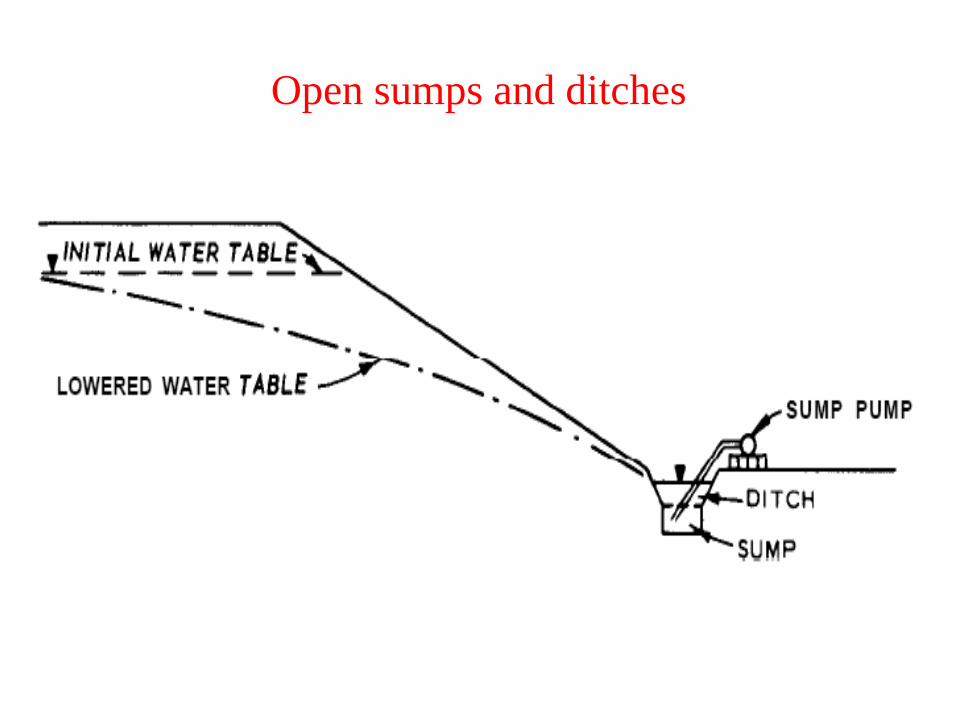
Open sumps and ditches
• The essential feature of this method is a sump below the
ground level of the excavation at one or more Corners or
sides..
• A small ditch is cut around the bottom of the excavation ,
falling towards the sump.
• It is the most widely used and economical of all methods of
ground water lowering. Sumps provide localized, very shallow
dewatering (less than 3 feet) and consist of pumping from
perforated drums or casings in a gravel-filled backhoe pit.
Sumps work best in fine grained soils, or very coarse, boulder
deposits.
• There is also a disadvantage that the groundwater flows
towards the excavation with a high head or a steep slope and
hence there is a risk of collapse of the sides.
Open sumps and ditches

Open sumps and ditches

Well point systems• Wells are systematically drilled around the
construction area and submersible pumps placed into
these wells.
• Wells are large-diameter (greater than 6 inches) holes,
drilled relatively deep (greater than10 feet), and
contain slotted casings and down hole pumps
• This practice appears to work effectively for many
projects, especially those building projects that
require excavations for deep basements.
• For dewatering deeper excavations, the well points
must be installed in two or more stages
1. Single stage unit
2. Double stage unit

Setup and Procedure of working:
• A well-point is 5.0-7.5 cm diameter metal or plastic pipe 60cm – 120 cm long which is perforated and covered with ascreen.
• The lower end of the pipe has a driving head with waterholes for jetting as shown in fig. Well-points are connectedto 5.0-7.5 cm diameter pipes known as riser pipes and areinserted into the ground by driving or jetting.
• The upper ends of the riser pipes lead to a header pipewhich, in turn, connected to a pump. The ground water isdrawn by the pump into the wellpoints through the headerpipe and discharged as shown in fig.
• The well-points are usually installed with 0.75m – 3mspacing

Double stage unit

Well point systems

Well point systems

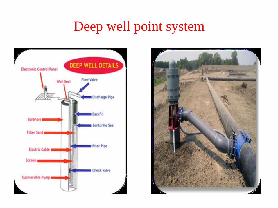
DEEP WELL
• Deep well drainage system consists of deep wells and
submersible or turbine pumps which can be installed
outside the zone of construction operations and the
water table lowered to the desire level.
• Deep wells are usually spaced from 8-80 meters
depending upon the level to which water table must
be lowered, permeability of the sand stratum, source
of seepage and amount of submergence available.
• Deep wells may be combined with the well point
system on certain field conditions for lowering the
ground water tables

SPACING OF DEEP WELL POINT SYSTEM
• Normally, individual wells are spaced at an
approximate distance of 15 m (50 feet) apart.
• However, depending upon soil conditions and the
dewatering plan the spacing may need to be just a few
meters apart.

DEWATERING CAPACITY OF DEEP WELL POINT
SYSTEM
• Individual well capacities are from 2100 to 3000
gallons per minute and with total systems the
capacities can be as high as 60,000 gallons per
minute.
• Deep well pumps can lift water 30 m (100 feet) or
more in a single stage and the variation of the typical
deep well system is a pressure within an aquifer.
• Deep well points require no pump as the water is
forced to the surface by its own pressure. To boost the
water flow a vacuum pump is frequently used.
Deep well point system

Deep well point system

Vacuum dewatering systems
• Gravity methods, such as well points and deep wells
are not much effective in the fine-grained soils. Such
soils can be dewatered satisfactorily by applying a
vacuum to the piping system.
• A vacuum dewatering system requires that the well-
point screens, and rise a pipe be surrounded with
filter sand extending to within a few metres of the
ground surface.
• This method is most suitable in layered or stratified
soils.

Vacuum dewatering systems

Design steps for dewatering systems
• Design of a dewatering system requires the determination ofthe number, size, spacing, and penetration of wells or wellpoints and the rate at which water must be removed from thepervious strata to achieve the required groundwater loweringor pressure relief. The size and capacity of pumps andcollectors also depend on the required discharge anddrawdown.
• The essential steps involved in the designing of the dewateringsystem are given below:
1. Subsoil investigation
2. Source And Water Table Details
3. Distance of well points

4.Effective Wall Radius• The effective wall radius is decided based on the installation of
the wells with or without filter. If a well is installed without
gravel or a sand filter the effective radius can be taken as one
half the outer diameter of the well screen. If a filter is used, the
well radius is taken as one half the outside diameter of the
filter
5.Discharge computations
The discharge Q of the well is then calculated using the formula
given below:
Electro osmosis
• Dewatering Technique is done through the use of
cathodes and anodes with passage of Electrical
current.
• Electro-osmosis is defined as “the movement of water
through a porous media by applying a direct current
(DC) field”.
• It is the only effective method of dewatering in deep
clay soils, silty clays, silts and some peats.

Electro osmosis

Mechanism of Electro-osmosis
• When electrodes are placed across a clay mass and a
direct current is applied, water in the clay pore space
is transported to the cathodically charged electrode by
electro-osmosis.
• Electro-osmotic transport of water through a clay is a
result of diffuse double layer cations in the clay pores
being attracted to a negatively charged electrode or
cathode.
• The macroscopic effect is a reduction of water
content at the anode and an increase in water content
of the clay at the cathode.

Effectiveness of Electro-osmosis
• First, electro-osmosis provides uniform pore water
movement in most types of soil.
• The entire soil mass between the electrodes is
basically treated equally
Disadvantages
• Installation and running costs are usually high.
Copyright © 2022 FDOKUMEN