Änderungsnachweis Identification List Liste de modifications
Upload
khangminh22Category
view
1download
0
HAL Id: tel-03170952https://tel.archives-ouvertes.fr/tel-03170952v2
Submitted on 17 Mar 2021
HAL is a multi-disciplinary open accessarchive for the deposit and dissemination of sci-entific research documents, whether they are pub-lished or not. The documents may come fromteaching and research institutions in France orabroad, or from public or private research centers.
L’archive ouverte pluridisciplinaire HAL, estdestinée au dépôt et à la diffusion de documentsscientifiques de niveau recherche, publiés ou non,émanant des établissements d’enseignement et derecherche français ou étrangers, des laboratoirespublics ou privés.
Surface modifications of cellulose nanocrystals forbiobased food packaging applications
Manon Le Gars
To cite this version:Manon Le Gars. Surface modifications of cellulose nanocrystals for biobased food packaging appli-cations. Polymers. Université Grenoble Alpes [2020-..], 2020. English. �NNT : 2020GRALI021�.�tel-03170952v2�

THÈSE
Pour obtenir le grade de
DOCTEUR DE L’UNIVERSITE GRENOBLE ALPES
Spécialité : Matériaux, Mécanique, Génie Civil, Electrochimie
Arrêté ministériel : 25 mai 2016
Présentée par
Manon LE GARS Thèse dirigée par Julien BRAS, Maître de Conférences, Grenoble INP, et codirigée par Philippe ROGER, Professeur, Université Paris-Sud et Naceur BELGACEM, Professeur, Grenoble INP
préparée au sein du Laboratoire Génie des Procédés Papetiers dans l'École Doctorale I-MEP2 – Ingénierie – Matériaux, Mécanique, Environnement, Energétique, Procédés, Production
Surface modifications of cellulose nanocrystals for biobased food packaging applications
Thèse soutenue publiquement le 05 Mars 2020, devant le jury composé de :
Dr. Bénédicte LEPOITTEVIN Maître de Conférences, ENSICAEN, Rapporteur
Pr. Jose-Maria LAGARON Professeur, Spanish Council for Scientific Research, Rapporteur
Dr. Hélène ANGELLIER-COUSSY Maître de Conférences, Université de Montpellier II, Examinateur
Pr. Evelyne MAURET Professeur, Grenoble INP, Présidente
Dr. Julien BRAS Maître de Conférences, Grenoble INP, Directeur de thèse
Pr. Philippe ROGER Professeur, Université Paris-Sud, Co-Directeur de thèse
Pr. Naceur BELGACEM Professeur, Grenoble INP, Co-Directeur de thèse
Dr. Hanène SALMI-MANI Maître de Conférences, Université Paris-Sud, Co-Encadrante de thèse
Dr. Sandra DOMENEK Maître de Conférences, AgroParisTech, Membre Invité


Remerciements
I would like to address my first thanks to the jury of my PhD defense. Dr. Bénédicte Lepoittevin and Pr.
José-Maria Lagaron, thank you for the time you spent on the evaluation of my manuscript, and for all
your enriching and relevant questions and comments during the defense. Dr Hélène Angellier-Coussy,
thank you for having examinated this work and for your very constructive remarks. Evelyne, thank you
for having chaired this jury and for your kindness over the past few months. Sandra, thank you for
having attended my defense, and for all your availability and your help throughout this project. To all
of you, thank you for being come all the way to Grenoble, and for having made this PhD thesis defense
an enriching and interesting moment.
Je souhaiterais maintenant remercier mes directeurs et encadrants de thèse, sans qui l’aboutissement
d’un tel projet n’aurait jamais pu se faire. Tout d’abord, Julien, merci de m’avoir toujours fait confiance,
et ce, même avant le début de cette thèse. Merci pour ton optimisme, pour tes encouragements (tu as
toujours su me remonter le moral quand j’en avais besoin), pour tes idées toujours plus nombreuses,
ainsi que pour nos nombreux échanges et réunions. Merci également de m’avoir donné l’opportunité de
voyager aux quatre coins du monde pour assister à des conférences (notamment notre séjour à la
Nouvelle-Orléans). Philippe, merci à toi aussi de m’avoir fait confiance dès le début de cette thèse, de
m’avoir intégrée à l’équipe d’Orsay, de m’avoir toujours poussée à aller plus loin dans ma réflexion, et
de m’avoir soutenue jusqu’au bout de cette thèse. Hanène, merci de m’avoir beaucoup appris, que ce
soit dans le laboratoire ou autour d’un café, tu as su me motiver et me donner confiance. Philippe et
Hanène, merci à vous deux pour votre précieuse aide, j’ai énormément appris à vos côtés. Enfin, Naceur,
merci pour ton soutien si bénéfique dans l’acheminement de cette thèse. Merci pour ta disponibilité et
ton aide sans failles, pour tes relectures, tes conseils et avis qui m’ont été très précieux. Merci pour ta
confiance, j’ai énormément apprécié travailler à tes côtés, et tout particulièrement lors des derniers mois
de cette thèse. Julien, Naceur, Philippe et Hanène, vous avez été un quatuor encadrant très
complémentaire, et vous m’avez permis, chacun à votre manière, d’évoluer tant professionnellement
que personnellement au cours de ces trois années. Je vous remercie très sincèrement pour cela.
Cette thèse est non seulement le fruit d’un travail personnel, mais aussi celui d’un projet collaboratif
dans lequel elle s’inscrit. Tout d’abord, merci à l’Agence Nationale de la Recherche d’avoir financé ce
projet, et à Sandra de le coordonner. Merci pour tout ton investissement, et pour l’organisation des
différents Copils aux quatre coins de la France. Je suis très heureuse de continuer à travailler à tes côtés
dans les mois à venir. Je souhaiterais également remercier tous les membres du projet GASP. Eliane
Espuche, Matthieu Gervais, Giana Perre, Antoine Cassel, Fabrice Gouanve, Alain Guinault, Laurent

Lebrun, Stéphane Marais, Cyrille Sollogoub, Matthieu Zinet, Nadège Follain et Vincent Huc, merci
pour les discussions et présentations enrichissantes lors des Copils ou réunions téléphoniques. Bien qu’il
ait parfois été délicat de s’accorder sur les attentes de chacun, je ressors grandie et je retire beaucoup de
positif de tous ces échanges. Hajar, je suis heureuse de t’avoir rencontrée via ce projet et d’avoir pu y
évoluer avec toi. Tu m’as beaucoup aidée, et j’ai énormément apprécié nos discussions, coups de
téléphones et petites sorties dans Paris pour se motiver mutuellement. J’espère pouvoir t’aider sur la fin
de ta thèse comme tu l’as fait pour moi, et te souhaite tout le meilleur. Un énorme merci à Karim et
Benjamin avec qui j’ai également pu collaborer à travers ce projet. Karim, merci pour ta franchise, tes
coups de gueule, ta disponibilité, ton aide et tes conseils. Benjamin, merci pour tout. J’ai rencontré un
collègue génial, mais aussi un ami. Merci à vous deux pour les discussion et les soirées, j’en garde des
souvenirs géniaux.
Je voudrais remercier les membres de mon comité de suivi de thèse, Aurore Denneulin, Isabelle
Desloges et Alain Dufresne, pour leur écoute et leurs conseils. Ces réunions de comité ont à chaque fois
été bénéfiques et motivantes.
Merci également à toutes les personnes qui m’ont apporté leurs connaissances techniques et scientifiques,
et qui m’ont énormément aidée dans mes manipulations : Diana Dragoe (pour la XPS, à l’ICMMO),
Thierry Encinas (pour la XRD, au CMTC), Jean-Luc Puteaux et Christine Lancelon-Pin (pour le TEM,
au Cermav), Cécile Sillard (pour, entre autres, l’AFM, au LGP2), Marie-Christine Brochier-Salon (pour
la RMN, au LGP2), Ludovic Costa (pour la SEC, à l’ICMMO), et Bertine Khelifi (pour le MEB, au
LGP2). Merci à Laurine et Aurore que j’ai encadrées durant leur stage de fin d’étude, qui m’ont aidée
sur ce projet de thèse, et à qui je souhaite tout le meilleur dans leurs parcours respectifs.
Ces travaux de recherche n’auraient pas été possibles sans la présence du personnel des deux laboratoires
dans lesquels j’ai travaillé.
Au LGP2, merci au service technique (Chu, Charlotte, Olivier, Philippe, Momo) pour leur gentillesse,
leur disponibilité et leur aide si précieuses. Merci à la direction du laboratoire, et tout particulièrement
à Didier pour sa disponibilité et son écoute infaillibles. Merci au service administratif (le secrétariat,
Stéphane V. et Laurence (qui m’a beaucoup vue passer…)), et tous les permanents (Stéphane D.,
Maxime T., et tous les autres) toujours prêts à aider. Un énorme merci à Cécile, non seulement pour son
aide scientifique dans cette thèse, mais aussi pour son amitié, son écoute et sa gentillesse. Enfin, merci
à tous les doctorants et post-doctorants que j’ai eu la chance de côtoyer dans les labos et/ou les bureaux,
et qui ont rendu cette thèse bien plus agréable : Johanna, Claire, Gabriel, Loreleï, Estelle, Florian, Amina,
Hugo, Axelle, Sudha, Saad, Enrique, Flavien, Fleur, Etienne G., Eva, Maxime W., Alhem, Malek,
Bastien, Hippolyte, Erwan, Charlène, Lili, Clémentine, Elsa, Hélène, Fanny et tous les autres. Plus
personnellement, merci à mes copines Johanna, Fleur, Fanny et Hélène, pour nos soirées, week-ends,
deliveroo et j’en passe. J’ai rencontré des amies (et amis par la même occasion) formidables. Fleur,

merci pour ton aide, ton soutien, ton amitié, et pour tous nos commérages qui m’ont tellement manqué
sur les derniers mois ! Une mention spéciale à Gabriel et Bastien, qui, malgré mes plaintes et mes doutes,
ont toujours su trouver les mots, et avec qui j’ai vraiment passé de supers moments. Je vous souhaite
tout le meilleur. Loreleï et Florian, vous m’avez supportée sur les derniers mois de ma thèse et avez
toujours été là pour discuter et remonter le moral, merci pour tout. Enfin, merci à Estelle (copine de
bureau, mais pas que) et Hugo pour tous les moments dans le labo et en dehors, merci d’avoir fait le
déplacement pour assister à ma soutenance, ça m’a vraiment touchée.
Même si ils m’ont vue moins souvent, je tenais à remercier tous les membres de l’équipe SM2B à
l’ICMMO, qui m’ont toujours bien accueillie : Philippe, Hanène, Nadine, Caroline, Ludo, Thu (pour
m’avoir secourue à plusieurs reprises dans les labos), Mélanie, Mohamad et Nassim. Merci pour vos
conseils, pour les cafés, et pour tous vos encouragements.
Les trois années de thèse ne sont pas toujours faciles, et j’ai eu la chance de pouvoir toujours compter
sur le soutien et la bienveillance de mes collègues.
J’ai également la chance d’avoir, à l’extérieur, des amis en or, sans qui ces années auraient été bien
différentes. Un énorme merci à mes copains de toujours (Eliot, Mylène, Aude, Romuald, Thibault, Jules,
Adèle, Aymeric, Guillaume, Jolan, Titouan, et tous les +1 évidemment), pour leur amitié et soutien sans
failles, et qui n’ont pas hésité une seule seconde à venir assister à ma soutenance. Vous n’imaginez pas
à quel point votre présence le jour J m’a touchée et aidée. Héloïse, un énorme merci à toi aussi pour tout,
j’ai été tellement déçue que tu ne puisses pas être là…
En plus d’avoir des amis en or, je suis entourée d’une famille exceptionnelle : mes parents et ma sœur
qui m’ont toujours soutenue dans mes choix, ainsi que le reste de ma famille. Papa, Maman, Camille,
merci d’avoir toujours su trouver les mots pour m’encourager, et merci de croire si fort en moi. C’est
grâce à vous si j’en suis arrivée là aujourd’hui. Je vous aime.
Enfin, je souhaitais terminer en remerciant celui qui a rendu ces dernières années si belles. Jean-Marc,
merci pour tout ce que tu fais pour moi au quotidien, pour ta joie de vivre, ton optimisme, tes solutions
à tous problèmes (qui n’en sont donc plus), et pour tout ton amour. J’ai une chance inouïe de t’avoir à
mes côtés, je t’aime.


Manon LE GARS, 2020 7
This PhD project has been funded by Agence Nationale de la Recherche (ANR)
Project ANR-16-CE08-0040

Manon LE GARS, 2020 8

General table of contents
Manon LE GARS, 2020 9
General table of contents
Scientific contributions _____________________________________________________ 11
Abbreviations _____________________________________________________________ 13
General introduction _______________________________________________________ 15
I. Literature Review _______________________________________________________ 25
Introduction to Chapter I _______________________________________________________29
1. Biobased polymer materials for food packaging ___________________________________31
2. Cellulose nanocrystals and functionalization _____________________________________53
3. Use of nanocelluoses in polymeric systems for food packaging applications ____________83
Conclusions of Chapter I _______________________________________________________99
References – Chapter I _______________________________________________________101
II. Chemical modifiactions of cellulose nanocrystals ____________________________ 113
Introduction to Chapter II _____________________________________________________117
1. Surface-initiated transfer radical polymerization from the surface of modified-cellulose
nanocrystals ________________________________________________________________119
2. Grafting of fatty acids on cellulose nanocrystals via a novel procedure __________________145
2.1. Comparison between two different methods for the chemical modification of cellulose
nanocrystals __________________________________________________________145
2.2. Role of solvent exchange in dispersion of cellulose nanocrystals and their esterification
using acids as solvents __________________________________________________157
3. Amidation of TEMPO-oxidized cellulose nanocrystals using aromatic aminated molecules 185
4. Adsorption of rosin nanoparticles from a nano-emulsion on both cellulose nanocrystals and
nanofibrils _________________________________________________________________215
Conclusions of Chapter II _____________________________________________________227
References - Chapter II _______________________________________________________231
III. PLA-based materials including designed nanostructures____________________ 241
Introduction to Chapter III ____________________________________________________245
1. Elaboration of poly(lactic acid)-based nanocomposites including different designed cellulose
nanostructures: comparison of the interfaces ______________________________________247
2. Two distinct methods for the elaboration of multi-layred materials based on poly(lactic acid)
and active cellulosic nanostructures _____________________________________________271
Conclusions of Chapter III ____________________________________________________299
References - Chapter III ______________________________________________________301
General conclusion and perspectives _________________________________________ 309
Extended French Abstract – Résumé en français ______________________________ 317

Manon LE GARS, 2020 10

Scientific contributions
Manon LE GARS, 2020 11
Scientific contributions (2017-2020)
Publications in scientific journals
1. Le Gars M., Bras J., Salmi-Mani H., Ji M., Dragoe D., Faraj H., Domenek S., Belgacem M.
N., Roger P. « Polymerization of glycidyl methacrylate from the surface of cellulose
nanocrystals for the elaboration of PLA-based nanocomposites », Carbohydrate Polymers,
2020
2. Le Gars M., Roger P., Belgacem M. N., Bras J. « Role of solvent exchange in dispersion of
cellulose nanocrystals and their esterification using fatty acids as solvents », Cellulose, 2020
3. Le Gars M., Delvart A., Roger P., Belgacem M. N., Bras J. « Amidation of TEMPO-oxidized
cellulose nanocrystals using aromatic aminated molecules », Colloid and Polymer Science,
2020
4. Le Gars M., Dhuiège B., Delvart A., Belgacem M. N., Missoum K., Bras J. « High barrier
antioxidant PLA/nanocellulose multi-layered materials for packaging”, under revision, ACS
Omega, 2020
Author’s contributions:
1. Manon Le Gars, Naceur Belgacem, Julien Bras, Hanène Salmi-Mani and Philippe Roger were
responsible for the experimental design and planning of the work. Marisol Ji performed
preliminary work on the same topic. Manon Le Gars performed most of the experiments,
analyzed the results and wrote the manuscript as principal author. Diana Dragoe carried out
XPS experiments and helped for the interpretation of the corresponding results. Hajar Faraj
and Sandra Domenek were involved in the nanocomposites part, and Hajar Faraj performed
and provided nanocomposites samples to Manon Le Gars. Hanène Salmi-Mani, Philippe
Roger and Julien Bras supervised the writing of the manuscript.
2. Manon Le Gars, Naceur Belgacem and Julien Bras were responsible for the experimental
design and planning of the work. Manon Le Gars performed most of the experiments,
analyzed the results and wrote the manuscript as principal author under the supervision of
Julien Bras, Philippe Roger and Naceur Belgacem. Marie-Christine Brochier-Salon performed
13C-NMR analyses and helped for the interpretation of the NRM results. Diana Dragoe
performed XPS analyses.
3. Manon Le Gars and Julien Bras were responsible for the experimental design and planning of
the work. Manon Le Gars and Aurore Delvart were in charge of the experimental part. Cécile

Manon LE GARS, 2020 12
Sillard performed the XPS analysis and helped for the corresponding part. Manon Le Gars
wrote the manuscript as first author and all the authors helped for the corrections.
4. Manon Le Gars and Benjamin Dhuiège performed the experimental work related to the rosin
adsorption and preparation of multi-layered films by lamination. Benjamin Dhuiège and
Karim Missoum (from INOFIB startup) prepared the rosin nano-emulsion and performed the
related characterizations. They supervised and designed the experimental work dealing with
CNF. Manon Le Gars performed the work related to CNC. Manon Le Gars and Benjamin
Dhuiège wrote the publication, supervised by Julien Bras, Naceur Belgacem and Karim
Missoum.
Oral presentations in international conferences
Le Gars M., Salmi-Mani H., Ji M., Belgacem M. N., Roger P., Bras J. « Cellulose
nanocrystals grafted with poly(glycidyl methacrylate) for their compatibilization in
nanocomposites » in ACS, American Chemical Society – National Meeting & Exposition.
New Orleans, USA (2018)
Le Gars M., Belgacem M. N., Roger P., Bras J. « Chemical modifications of cellulose
nanocrystals for nanocomposites applications » in NRC-Grenoble INP International
Conference. Cairo, Egypt (2019)
Le Gars M., Delvart A., Roger P., Belgacem M. N., Bras J. « Immobilization of active
molecules on CNC for the preparation of hybrid multi-layered CNC-PLA based packaging
materials » in EPNOE, International Polysaccharide Conference. Aveiro, Portugal (2019)
Poster presentation in scientific conference
Le Gars M., Belgacem M. N., Salmi-Mani H., Roger P., Bras J. « Role of cellulose
nanocrystals dispersion on functionalization with fatty acids as solvent » in Scientific Day of
Chemistry. Grenoble, France (2019)
Other contributions
Le Gars M., Douard L., Belgacem M. N., Bras J. « Cellulose Nanocrystals: From Classical
Hydrolysis to the Use of Deep Eutectic Solvents », Chapter of the book «Nanosystems»
(DOI:10.5772/intechopen.89878), IntechOpen (2019)

Abbreviations
Manon LE GARS, 2020 13
Abbreviations
▪ Chemicals and Materials
1-M-3-PP 1-methyl-3-phenylpropylamine AGU Anhydroglucose unit
BIB α-bromoisobutyryl bromide
CNCs Cellulose nanocrystals CNC-1-M-3-PP CNCs modified with 1-methyl-3-phenylpropylamine
CNC-Br CNCs modified with α-bromoisobutyryl bromide
CNC-Lauric CNCs modified with lauric acid
CNC-PGMA-Br CNCs polymerized with poly(glycidyl methacrylate) CNC-Rosin CNCs modified with rosin mixture
CNC-Stearic CNCs modified with stearic acid
CNFs Cellulose nanofibrils CNF-Rosin CNFs modified with rosin mixture
DCM Dichloromethane
DMF Dimethylformamide DPPH 2,2-diphenyl-1-picrylhydrazyl
EBIB Ethyl α-bromoisobutyrate
EDC N-(3-Dimethylaminopropyl)-N’-ethylcarbodiimide
EtOH Ethanol GMA Glycidyl methacrylate
H2SO4 Sulfuric acid
HCl Hydrochloric acid NaBr Sodium bromide
NaClO Sodium hypochlorite
NaOH Sodium hydroxide
NHS N-Hydroxysuccinimide PGMA Poly(glycidyl methacrylate)
PLA Poly(lactic acid)
TEMPO 2,2,6,6-Tetramethylpiperidine-1-oxyl TEMPO-CNCs TEMPO-oxidized cellulose nanocrystals
▪ Characterization tools
AFM Atomic force microscopy
CI Crystallinity index 13
C-NMR Carbon nuclear magnetic resonance
DLS Dynamic light scattering DMA Dynamic mechanical analysis
DO Degree of oxidation
DS Degree of substitution DSC Differential Scanning Calorimetry
FTIR Fourier transform infrared spectroscopy 1H-NMR Proton nuclear magnetic resonance
OTR Oxygen transmission rate

Manon LE GARS, 2020 14
QCM-d Quartz crystal microbalance with dissipation
monitoring SEC Size-exclusion chromatography
SEM Scanning electron microscopy
SI-ATRP Surface-initiated atom transfer radical polymerization TEM Transmission electron microscopy
TGA Thermogravimetric analysis
WVTR Water vapour transmission rate
XPS X-ray photoelectron spectrometry XRD X-ray diffraction

Manon LE GARS, 2020 15
General Introduction

Manon LE GARS, 2020 16
General Introduction
Manon LE GARS, 2020 17
General Introduction
In the current context, it is common to hear about pollution, sustainable development, recycling, and
many other terms related to environmental issues. In addition, shocking images of beaches covered
with plastic waste, or oceans of plastics, for example, are alarming. This pollution, both on land and in
seas, is the logical result of an accumulation of plastic waste generated over the years. In fact, since the
1950s, the production of plastics has continuously increased, with an average increase by around 9%
per year1. Today, in Europe, the annual production of plastics represents 64.4 million tons (348 million
tons all over the world), and is still on the rise, as presented in Figure 1. However, this evolution is not
surprising, since it has followed the evolution of consumer society for decades, with an ever-
increasing consumption of products, and thus, related packaging materials. Today, packaging is the
sector representing the greatest demand for plastics2.
Figure 1. Total demand and production of plastics in Europe in 2018 (Data extracted from 2)
However, with the society’s awareness of the alarming state of environmental problems, this
production and consumption of fossil-based plastics is now becoming increasingly controversial. In
this environmental context, the interest in biobased polymers, especially for packaging materials, is
particularly important, and these materials are intended to compete with traditional petro-based
plastics. However, such a competition is ambitious, since the traditional plastics (PET, PE, PP, PVC,
PS, etc.) exhibit exceptional characteristics, due to their low cost, lightness, transparency, mechanical
properties and barriers, making them excellent materials to meet packaging ─ and especially food
packaging ─ specifications3–5.

Manon LE GARS, 2020 18
Among biobased polymers, poly(lactic acid), also known as PLA, is a transparent, biobased and
biodegradable (in compost) polymer, and is currently one of the best alternatives to fossil-based
polymers. PLA is polymerized from lactic acid monomer, which is extracted from agricultural
products (mainly corn, sugar cane, and beet)6,7. Although this point may be open to debate, as well as
the lack of its recycling chain, PLA remains today one of the most interesting solutions. Figure 2
illustrates its theoretical life cycle: after being produced from natural corn resources, PLA is processed
for different applications, and the final products can then be recycled ─ although this recycling step is
not always implemented ─, and finally industrially composted, leading ideally to a closed loop. Since
several decades, PLA has attracted academic and industrial research interests, especially because of its
other promising properties, like its high stiffness, transparency, printability, and ease of processing8.
However, certain aspects still limit its entry into the packaging market, in particular its low thermal
and barrier properties which can be very restrictive for food packaging applications7,9. Numerous
research groups focused on the improvement of these thermal and barrier properties, especially
through the introduction of nanometric fillers inside the polymer and so the development of
nanocomposites. Various inorganic or organic nanofillers were thus introduced in PLA10,11, including,
more recently, the incorporation of nanocellulosic materials.
Figure 2. Theoretical life cycle of poly(lactic acid) (PLA) (Adapted from the website https://www.total-corbion.com (consulted in November 2019))

General Introduction
Manon LE GARS, 2020 19
These nanomaterials ─ called nanocelluloses ─ are extracted from numerous cellulosic sources (wood,
cotton, sisal, flax, tunicates, algae, bacteria, etc.) via different routes, leading to different types of
nanocelluloses, namely cellulose nanofibrils (CNFs)12–14, cellulose nanocrystals (CNCs)15–17, and
bacterial cellulose18,19. Figure 3 provides an example of TEM images of CNCs and CNFs materials.
Both CNCs and CNFs exhibit outstanding properties ─ among other, a high crystallinity, a low density,
a high specific surface area, a high surface reactivity, etc. ─ making them excellent candidates for a
wide range of innovative applications, particularly for biobased and biodegradable materials20–22.
Figure 3. TEM images of cellulose nanocrystals (CNCs) and cellulose nanofibrils (CNFs)
Over the past decades, the interest in these cellulosic nanomaterials has significantly increased, in
parallel with the environmental awareness. Moreover, as previously mentioned, the development and
the optimization of PLA-based nanocomposites including cellulosic nanostructures have attracted a lot
of researches23–25. Figure 4 represents the evolution of publications dealing with nanocelluloses and
with PLA since the 1990s, confirming the previously mentioned trend.
Figure 4. Non-cummulative evolution of the number of publications dealing with nanocelluloses and poly(lactic acid) (Source: SciFinder, November 2019 ─ Descriptors for “Nanocellulose”: cellulose nanocrystal, cellulose nanorod, rod-like
cellulose, cellulose nanowire, cellulose crystallite, cellulose nanoparticle, cellulose whiskers, nanocrystalline cellulose, cellulose nanofibrils, cellulose microfibrils, nanofibrillated cellulose, microfibrillated cellulose, and descriptors for “PLA”:
poly(lactic acid), PLA ─ Language: English)
In order to produce high performance PLA-based materials designed for their use as food packaging
applications (i.e. with interesting mechanical and barrier properties), a consortium of industrial and

Manon LE GARS, 2020 20
academic partners was established to include fillers, and especially chemically modified cellulosic
nanostructures. This collaborative research was carried out through the GASP project, supported by
the French National Research Agency (ANR-16-CE08-0040), which started in January 2017, for a
total duration of 48 months. The PhD project presented in this manuscript took place within the
framework of this GASP project, and more particularly between two partners (LGP2 and ICMMO). In
addition, many collaborative stays and constructive exchanges were realized thanks to the wide and
complementary fields of expertise of the different partners.
Figure 5. French National Research Agency (ANR, Agence Nationale de la Recherche) and GASP Project logos
The main objectives of this PhD are as follows:
1. Innovative chemical surface modifications of cellulose nanocrystals via grafting routes
that are as environmentally friendly as possible
2. Study of the influence of the CNCs surface modification on their adhesion with a PLA-
based matrix
3. Development of active biobased materials including both PLA and nanocellulosic
structures for food packaging applications
Therefore, it is naturally that this thesis manuscript has been organized in three chapters, as presented
in the general scheme (Figure 6).
The Chapter I provides a literature review of the general context of this study, with a more detailed
state of the art of the nanocelluloses field ─ particularly that of cellulose nanocrystals (CNCs) and
their functionalization ─, as well as, that of multi-phasic materials including both poly(lactic acid) and
nanocellulose materials, with a specific focus on food packaging applications.
In Chapter II, different surface modifications of CNCs are proposed. The chapter is divided into three
main sections, each dealing with increasing possible grafted CNCs quantities. In fact, the sub-chapter
II.1 proposes a polymerization of a monomer bearing reactive epoxy functions from the surface of the
CNCs. The sub-chapter II.2 is divided in two parts. The short section II.2.1 presents a comparison
between a classical esterification procedure of long aliphatic chains on CNCs, and a novel
esterification method with similar grafted compounds. This innovative esterification route is detailed
in the section II.2.2, with the grafting of two fatty acids on the CNCs. The aim of the sub-chapter II.3
is to introduce aromatic molecules at the surface of the CNCs via a two-step procedure. Finally, the

General Introduction
Manon LE GARS, 2020 21
short sub-chapter II.4 briefly introduces the preparation of a rosin-based nano-emulsion, which is then
adsorbed on both CNCs and CNFs.
All these surface-modified CNCs are then used for the elaboration of PLA-based materials, whose two
different strategies are presented in Chapter III. The sub-chapter III.1 exhibits the preparation and
the characterization of PLA-based nanocomposites including modified CNCs previously studied in the
sub-chapters II.1 and II.2.2, in order to compare their interfaces with the PLA matrix. In the sub-
chapter III.2, modified CNCs and CNFs presented in sections II.3 and II.4 are incorporated in PLA-
based multi-layered materials, and their structural, barrier, and active properties are investigated.
The sub-chapters of this PhD project are based either on submitted scientific publications, or on
additional parts structured as scientific publications. Some comments (in grey italic) are added and
provide some complementary information about the PhD organization and/or guide the reader between
the different sections of the manuscript.

Manon LE GARS, 2020 22
Figure 6. General organization of the PhD manuscript
The complete PhD study brings news understandings on cellulose nanocrystals surface modifications
and their influence on PLA-based nanocomposites. Moreover, a proof a concept for the elaboration of
food packaging materials is provided via the multi-layered materials produced from both PLA and
modified –or not nanocelluloses.

General Introduction
Manon LE GARS, 2020 23
References
1. Gourmelon, G. Global Plastic Production Rises, Recycling Lags. WorldWatch Institute (2015).
2. PlasticsEurope. Plastics - the Facts 2018 - An analysis of European plasticsproduction, demand
and waste data (2018).
3. PlasticsEurope. PlasticsEurope Market Research Group (PEMRG) (2016).
4. Crompton, T. R. Mechanical Properties of Polymers (2012).
5. Siracusa, V., Rocculi, P., Romani, S. & Rosa, M. D. Biodegradable polymers for food packaging:
a review. Trends in Food Science & Technology 19, 634–643 (2008).
6. Jiménez, A., Peltzer, M. & Ruseckaite, R. Poly(lactic acid) science and technology: processing,
properties, additives and applications (Royal Society of Chemistry, 2015).
7. Castro-Aguirre, E., Iñiguez-Franco, F., Samsudin, H., Fang, X. & Auras, R. Poly(lactic acid)—
Mass production, processing, industrial applications, and end of life. Advanced Drug Delivery
Reviews 107, 333–366 (2016).
8. Fiori, S. Industrial Uses of PLA. In: Polymer Chemistry Series (eds. Jiménez, A., Peltzer, M. &
Ruseckaite, R.) (Royal Society of Chemistry, 2014).
9. Colomines, G., Ducruet, V., Courgneau, C., Guinault, A. & Domenek, S. Barrier properties of
poly(lactic acid) and its morphological changes induced by aroma compound sorption. Polymer
International 59, 818–826 (2010).
10. Raquez, J.-M., Habibi, Y., Murariu, M. & Dubois, P. Polylactide (PLA)-based nanocomposites.
Progress in Polymer Science 38, 1504–1542 (2013).
11. Papageorgiou, G. Z., Achilias, D. S., Nanaki, S., Beslikas, T. & Bikiaris, D. PLA nanocomposites:
Effect of filler type on non-isothermal crystallization. Thermochimica Acta 511, 129–139 (2010).
12. Nechyporchuk, O., Belgacem, M. N. & Bras, J. Production of cellulose nanofibrils: A review of
recent advances. Industrial Crops and Product 93, 2–25 (2016).
13. Jonoobi, M. et al. Different preparation methods and properties of nanostructured cellulose from
various natural resources and residues: a review. Cellulose 22, 935–969 (2015).
14. Rol, F., Belgacem, M. N., Gandini, A. & Bras, J. Recent advances in surface-modified cellulose
nanofibrils. Progress in Polymer Science 88, 241–264 (2019).
15. Habibi, Y., Lucia, L. A. & Rojas, O. J. Cellulose Nanocrystals: Chemistry, Self-Assembly, and
Applications. Chemical Reviews 110, 3479–3500 (2010).
16. Natterodt, J. C., Petri-Fink, A., Weder, C. & Zoppe, J. O. Cellulose Nanocrystals: Surface
Modification, Applications and Opportunities at Interfaces. CHIMIA International Journal for
Chemistry 71, 376–383 (2017).
17. Lin, N., Huang, J. & Dufresne, A. Preparation, properties and applications of polysaccharide
nanocrystals in advanced functional nanomaterials: a review. Nanoscale 4, 3274–3294 (2012).
18. Jozala, A. F. et al. Bacterial nanocellulose production and application: a 10-year overview. Appl
Microbiol Biotechnol 100, 2063–2072 (2016).
19. Fu, L., Zhang, J. & Yang, G. Present status and applications of bacterial cellulose-based materials
for skin tissue repair. Carbohydrate Polymers 92, 1432–1442 (2013).
20. Hubbe, M. A. et al. Nanocellulose in Thin Films, Coatings, and Plies for Packaging Applications:
A Review. BioResources 12, 2143–2233 (2017).
21. Ferrer, A., Pal, L. & Hubbe, M. Nanocellulose in packaging: Advances in barrier layer
technologies. Industrial Crops and Products 95, 574–582 (2017).
22. Kontturi, E. et al. Advanced Materials through Assembly of Nanocelluloses. Advanced Materials
30, 1703779 (2018).

Manon LE GARS, 2020 24
23. Bagheriasl, D., Safdari, F., Carreau, P. J., Dubois, C. & Riedl, B. Development of cellulose
nanocrystal-reinforced polylactide: A comparative study on different preparation methods.
Polymer Composites 40, E342–E349 (2019).
24. Muiruri, J. K., Liu, S., Teo, W. S., Kong, J. & He, C. Highly Biodegradable and Tough Polylactic
Acid–Cellulose Nanocrystal Composite. ACS Sustainable Chem. Eng. 5, 3929–3937 (2017).
25. Spinella, S. et al. Polylactide/cellulose nanocrystal nanocomposites: Efficient routes for nanofiber
modification and effects of nanofiber chemistry on PLA reinforcement. Polymer 65, 9–17 (2015).

Manon LE GARS, 2020 25
CHAPTER I
Literature Review

Table of contents – Chapter I
Manon LE GARS, 2020 26

CHAPTER I : Literature Review
Manon LE GARS, 2020 27
Table of contents – Chapter I
Introduction to Chapter I ___________________________________________________ 29
1. Biobased polymer materials for food packaging ______________________________ 31
1.1. Polymers in packaging: generalities ____________________________________________31
1.1.1. Current context of packaging materials 32
1.1.2. Definitions of biopolymers 34
1.2. Requirements for food packaging ______________________________________________36
1.2.1. Barrier properties in food packaging 37
1.2.2. Mechanical properties of food packaging 39
1.2.3. Development of new active packaging 40
1.2.4. Biobased polymers in food packaging and sustainability approaches 41
1.2.5. Poly(lactic acid) : a relevant biopolymer 43
1.3. Packaging processing ________________________________________________________46
1.3.1. Extrusion and composites materials 46
1.3.2. Coating strategy 48
1.3.3. Composites materials 50
2. Cellulose nanocrystals and functionalization _________________________________ 53
2.1. From cellulose to nanocelluloses _______________________________________________53
2.1.1. Structure of cellulose 53
2.1.2. Nanomaterials from cellulose: cellulose nanofibrils and nanocrystals 56
2.2. Cellulose nanocrystals: nanomaterials with interesting properties ___________________59
2.2.1. Isolation of cellulose nanocrystals 59
2.2.2. Properties of cellulose nanocrystals 61
2.2.3. Various applications of cellulose nanocrystals and their industrialization 63
2.3. Functionalization of cellulose nanocrystals ______________________________________65
2.3.1. TEMPO oxidation of cellulose nanocrystals 66
2.3.2. Covalent grafting on cellulose nanocrystals 67
2.3.3. Grafting of polymer chains at the surface of cellulose nanocrystals 73
2.3.4. Physical adsorption of various molecules on cellulose nanocrystals 79
3. Use of nanocelluloses in polymeric systems for food packaging applications _______ 83
3.1. Nanocomposites and legislation________________________________________________83
3.1.1. Interest of the introduction of nano-fillers in polymer matrices 83
3.1.2. Nanocomposites and legislation 84
3.2. Cellulose nanocrystals as fillers in nanocomposites _______________________________85
3.2.1. Effect of cellulose nanocrystals on nanocomposites mechanical and barrier properties 85
3.2.2. PLA-based / CNCs nanocomposites 87
3.3. Multi-layered CNC-based materials ____________________________________________94
3.3.1. Interest of nanocellulose-based multi-layered packaging materials 94
3.3.2. Absorbers and scavenging properties 96
Conclusion _______________________________________________________________ 99
References ______________________________________________________________ 101

Table of contents – Chapter I
Manon LE GARS, 2020 28

CHAPTER I : Literature Review
Manon LE GARS, 2020 29
Introduction to Chapter I
Through the literature review presented in this first chapter, the global context of this PhD project will
be introduced. Indeed, this chapter attempts to give an overview of the context, by providing
definitions and references (more than 200). Moreover, this chapter is intended for both “expert” and
“non-experts” scientists. In this sense, general knowledge, as well as, more specific data will be
presented in different forms (tables, schemes, figures). In order to link each section with the PhD
project, some comments (in grey and italic) are added.
The first part of this chapter describes an overview of biobased polymers for food packaging.
Generalities on current economic and environmental context will be provided. After having been
defined, the place of biobased polymers in food packaging field, as well as, their requirements and
main processing will be introduced. As poly(lactic acid) (PLA) is studied in this project, a part will be
dedicated to this polymer.
In the second part, nanocelluloses, and especially cellulose nanocrystals (CNCs) – the main raw
materials of this project – will be introduced. Their extraction, properties and applications will be
detailed. Moreover, as CNC surface modification is one of the main challenges of this PhD, a part will
provide an overview of the different ways of CNCs grafting described in the literature.
Finally, the third part will present the rising interest in combining CNCs with polymeric matrices, and
especially with PLA. Thus, CNC/PLA nanocomposites will be the focus of this part. Their
processing, properties and challenges will be detailed. A last part will describe multi-layered systems,
which offer another way to produce polymeric systems by combining PLA and CNCs.
Thus, this literature review will highlight the main scientific advances and challenges closely
associated to the objectives of the PhD project for an easier reading of the next chapters.

Introduction to Chapter I
Manon LE GARS, 2020 30

CHAPTER I : Literature Review
Manon LE GARS, 2020 31
1. Biobased polymer materials for food packaging
This section aims to focus on current context of existing packaging materials and biopolymers, and
on the requirements for the development of food packaging materials, as well as, their different
processing routes. Moreover, one section will focus on poly(lactic acid) (PLA), the bio-based plastic
used in this PhD project.
1.1. Polymers in packaging: generalities
Since the beginning of the 21st century, the current ecological situation is a priority in political and
citizen spheres. Global warming, greenhouse gas emissions, ecosystem degradation, and plastic waste
are the open-ended list of environmental challenges regularly referred in our society. All these issues,
added to the global limited resources and the demographic growth, require -according to the European
Commission- “new ways of producing and consuming that respect the ecological boundaries of our
planet” and a “need to fit with sustainability”. It is part of the updated European Bioeconomy Strategy
expressed in 2018, aiming at improving and innovating the way of production and consumption of
food, products, and materials within healthy ecosystems through a sustainable bioeconomy, and
implementing human and financial resources to reach their objectives, showing the large awareness on
the part of the society. Fourteen actions are set out in this strategy, whose first is entitled “Strengthen
and scale-up the bio-based sectors, unlock investments and markets”. Bio-based materials and
products are described in order to substitute their fossil-based counterparts. One of the main sector
concerned by the Bioeconomy strategy is plastic packaging material, which represents about 40 % of
the total plastic demand (49.9 million of tons in 2016) in Europe1. Among this plastic demand, fossil-
based polypropylene (PP), polyethylene (PE), polyvinyl chloride (PVC), polyethylene terephthalate
(PET), and polystyrene (PS) are widely and classically used in packaging industry1. The interest of the
development of new biobased polymers for packaging applications thus makes sense.
Figure I. 1.Packaging mondial market by sector, in 2015 (Adapted from Euromonitor International2)

Biobased polymer materials for food packaging
Manon LE GARS, 2020 32
1.1.1. Current context of packaging materials
By definition, a packaging is all the elements delivered with a product, and which is designed for its
presentation, information, conservation, handling, and transporting. Food, beverages, and tobacco
packaging are the most important sectors of the global packaging market, followed by beauty and
personal care, tissue and hygiene, and home care packaging2, as shown in Figure I. 1. Plastics are
materials of choice in food packaging sector, representing over a quarter of the different materials
used.3 Indeed, according to their outstanding mechanical and barrier properties, they allow a controlled
and optimized distribution of products by preserving their aspect, shape, and, in the case of food
packaging, the safety, taste, and shelf-life of the products. Currently, fossil-based plastics represent
around 99% of the total plastic market4.
The production of such fully synthetic polymers dates back to the end of 19th century, with the 1st
polymerization of PVC in 1938. The mondial plastic production increases over the years and grows
from 50 million tons in 1977 to 335 million in 2016, with 50% of plastics produced in Asia, 19% in
Europe and 18% in North America1. Traditional plastic industry is based on the use of distilled crude
oil, a limited resource extracted from oil reservoirs. Naphta, a mixture of hydrocarbons obtained from
distilled crude oil, is essential for the further production of plastics, consisting in the polymerization of
several monomers.
Today, a wide variety of fossil-based plastics exists with interesting properties, applications, and low
prices. Table I. 1 summarizes the main properties of produced plastics in European packaging field.
At the end of their life, fossil-based synthetic plastics are left mostly as non degradable waste.
Thermo-mechanical recycling is the most widely used treatement in Europe, reprensenting around
99% of total recycling. It consits in two steps: first, the sorting (automatically or manually) of plastics
to ensure the non presence of contaminants, and then, the melting of plastics into new pellets or
granulates, without changing their chemical structure. The resulted recycled plastics can then be mixed
with neat plastics, in order to reduce plastic consumption. Note that more and more companies are
recycling internally their unused and cutting waste. In Europe, the collecting and recycling systems
vary from a country to another, although all the countries seek to improve their system with innovative
collect and society sensibilization. In 2016, in Europe, the total plastic packaging collected waste
represented 16.7 million tons, and 41% were recycled, despite the huge effort in recycling loop
regulations and waste management1. These data clearly show the larger society consideration for
recycling.

CHAPTER I : Literature Review
Manon LE GARS, 2020 33
Converter
demand
(million tons)
Properties Applications
Unit
price
(€/kg)5
Polypropylene
(PP) 9.8
Low moisture vapor transmission /
Inertness towards acids, alkalis
and most solvents / Optical clarity
in oriented films and molded
containers
Containers for yogurts, takeout
meals, butter / Medicine bottles 0.90
Low Density
Polyethylene
(LDPE)
8.8
Resistance to acids, bases and
vegetable oils / Thoughness /
Flexibility / Transparency
Bags for frozen foods and fresh
products / shrink wraps and stretch
films / Coatings fro paper milk
cartons and beverage cups
1.12
High Density
Polyethylene
(HDPE)
6.1 Resistance to solvents / High
tensile strength / Stiffness
Bottles for beverages, cosmetics,
detergents and houshold cleaners /
Bags
1.21
Polyvinyl
Chloride (PVC) 5 1.59
Polyethylene
Teraphthalate
(PET)
3.8
Clear and optically smooth
surfaces / Oxygen, water and CO2
barrier / Resistance to solvents /
Shatter restistance
Plastic bottles / Food jars /
Ovenable films and microwavable
food trays
1.05
Polyurethane
(PUR) 3.8
Versatile chemistry : Strength /
Rigidity / Flexibility / Good
resistance to oil, hydrocarbons,
oxygen
Versatile chemistry :
Automotive industry(backs,
armrests, door panels, bumpers) /
Building / Refrigirators /
Skateboards / Adhesives /
Coatings / Sealants
3
Polystryene
(PS) 1.9
Moisture barrier / optical clarity /
Stiffness / Low density and low
thermal conductivity in foamed
form
Food service items / Takeout
containers / Meat trays / Rigid food
containers
0.57
Table I. 1. Main synthetic polymers converter demand in Europe, in 2016, and their properties and applications (Data from PlasticsEurope Market Research Group1)
In parallel, plastic pollution, especially of the oceans and seas, is increasing, and is a disaster for the
aquatic flora and fauna. Geyer et al.6 conducted a study on the total production and waste of plastics
within a period higher than 60 years over the world. According to this study, the total plastic waste
was around 6300 Mt in 2015, taking into account primary and recycled plastic wastes, and only 9% of
these resisudes have been already recycled. As shown in Figure I. 2, an accumulation of 4900 Mt of
plastics produced between 1950 and 2015 are today accumulated in the nature. The projections
concerning plastics waste are not optimistic. Indeed, considering similar production and use of plastics
for the next decades, and validating the calculations done in the previously described study, 12000 Mt
of plastic will be discarded in the nature6, and recent studies consider there will be more plastic than
fish in the ocean in 2050. This alert was the main driver in the launching of the new bioeconomy and
circular economy European directives.

Biobased polymer materials for food packaging
Manon LE GARS, 2020 34
Figure I. 2. Accumulated amount (in million metric tons) of global production, stocks and waste of plastics between 1950 and 2015 (Extracted and completed from 6)
Packaging is a real need for a lot of applications, and fossil-based plastic polymers are today the
best candidates in term of price and properties for the elaboration of such products. However, the
awareness of the society about the environmental issues encourages research and development to
focus on sustainable and bio-based materials for packaging. This last point is the purpose of the
following section.
1.1.2. Definitions of biopolymers
First of all, it is essential to correctly define biopolymers, bio-based, biodegradable, and
biocompostable (or compostable) terminologies. Indeed, in the current mass media and general
discussions, generalisations are often carried out when it comes to sustainability and environmental
issues. Note that a common confusion consists in the correlation between biodegradability and
recyclability, the last term relating to the reintroduction of the materials in the production cycle at its
end-of-life. Accordingly to the definition provided by IUPAC, a biopolymer is a macromolecule
which is formed by living organisms. In 1999, Petersen et al.7 proposed the definition of biopolymers
as biobased polymers. More recently, a bioplastic is defined as a family of polymeric materials
comprising (i) bio-based, (ii) bio-based and biodegradable and (iii) fossil-based, and biodegradable
plastics5. According to IUPAC (2012), a bio-based polymer is a polymer totally or partially composed
or derived of biological products issued from biomass, such as plants, animals, marine or forestry
materials. Bio-based polymers family is usually split into three groups: chemically synthesized from
biomass monomers, produced by micro-organisms, or naturally occurring.

CHAPTER I : Literature Review
Manon LE GARS, 2020 35
Note that bio-based polymers are not always biodegradable, biocompostable, biocompatible or
environmentally-friendly. In short, bio-based character is opposed to fossil-based one. Both types of
polymers can be biodegradable or biocompostable, and these terms need to be precisely defined.
According to IUPAC definition, biodegradability is the capability of a material of being degraded by
biological activity, by decreasing the polymer molar mass until bioassimilation, i.e. converting into
H2O, CO2 or CH4. This aerobic or anaerobic degradation results in a chemical process due to
microorganisms activity producing biomass, carbon dioxide, water and/or methane from degraded
polymer5, under different conditions of temperature, humidity, light, and environment, according to
several standards. This large number of standards demonstrates how complex the biodegradation
process is, since biodegradation can occur in different environments (industrial or individual compost,
soil, water), and standards provide required parameterized conditions to argue biodegradability8.
Speaking about biodegradability, it is essential to indicate in which environment the biodegradation
takes place.
Table I. 2. Existing (bio-)polymers sorted according their properties (Extracted from 8)
Thus, the term biocompostability relates to biodegradability occurring in compost conditions
(temperature around 70-80 °C, high humidity rate around 70%), with a decomposition of the material
carried out in a specific environment and time without residues. In order to avoid misunderstanding
and common confusion between these terms, the European Standard EN 13432 entitled “Requirements
for packaging recoverable through composting and biodegradation – Test scheme and evaluation
criteria for the final acceptance of packaging” defines the characteristics and properties of a

Biobased polymer materials for food packaging
Manon LE GARS, 2020 36
compostable packaging polymer, which, in addition to being biodegradable, must respond to other
characteristics, like disintegrability (less than 10% of the initial mass of residues larger than 2 mm),
ecotoxicity (low levels of heavy metals, absence of ecotoxicological effects on the plant growth),
composition, and quality of final compost9. Table I. 2 shows the properties of main (bio)-plastics
currently used. Although the term fossil-based plastics (or petrochemical-based) suggests non-
biodegradability, this is not always the case. In fact, as shown in Table I. 2, fossil-based plastics like
PBAT, PBS, PCL, and PVOH are biodegradable in compost, even they are not produced from biomass
resources.
Similarly, the term bio-based plastic leads to think about biodegradability, although these two
properties are not necessarily linked. Moreover, as presented in Table I. 2, polylactide or poly(lactic
acid) (PLA) is a bio-based and biodegradable polymer in industrial compost. Controversial place of
PLA on current packaging market comes from this industrial compostability, needing specific
conditions and infrastructures to be fully performed. This point is a current matter of controversy.
In this project, PLA is studied and used as a polymer matrix, especially in food packaging sector,
and therefore it will be described more precisely afterwards (section 1.2.5).
1.2. Requirements for food packaging
Among all the packaging sectors, that of food and beverages is the most preponderant, regarding the
production and demand (Figure I. 1). Indeed, food is a vital, valuable and perishable resource, whose
more than one billion of tons are thrown away every year, leading to food waste (more than one third
of the global production of food consumption), and induced environmental impact. This food waste is
considered as the second reason of gas emission (especially CO2) in the world, after transports.
Innovation and research in packaging field has become one of the priorities of the European
Commission since the beginning of the 2000s (Directive 2008/98/EC, Landfill Directive 1999/31/EC,
Packaging and Packaging Waste Directive 94/62/EC). In parallel food plastic packaging generates a
large amount of plastic waste. European Commission is releasing several calls aiming at finding new
solutions to reduce the environmental footprint of packaging and ensure a better shelf life of food and
specific indicators, less materials and energy use for packaging process, optimization of supply chain,
better food safety and recyclability of materials. It is in this context that bio-based and biodegradable
packaging, along with functional and active performance, has been at the centre of ongoing research
on development of new food packaging systems.
Following part aims to describe the main barrier and mechanical properties required in food
packaging area, then the current development of new active packaging, and finally the use of
biobased polymers in food packaging.

CHAPTER I : Literature Review
Manon LE GARS, 2020 37
1.2.1. Barrier properties in food packaging
A food packaging is produced and used in order to transport and protect the product against humidity,
temperature, micro-organisms, to ensure its safety, and to inform the consumers. It correlates with the
four basic functions of a packaging successively expressed by Paine10 and Robertson11 in the 1990s,
namely: protection, communication, convenience, and containment. Packaging ensures the
conservation of the product and limit food waste by constantly improving its shelf life. Among these
utilities, protection against external environment is the main challenge in the development of food
packaging. Traditionally, food packaging acts as an inert wall between the product and oxygen or
others gas and moisture from outside environment. Investigation on barrier properties of a packaging
material is crucial and necessary when speaking about food packaging.
More precisely, oxygen and water vapor permeability are always studied. Indeed, these two permeants
can largely influence and reduce the food conservation. Figure I. 3 represents the interactions between
outside and inside gas molecules. The movement of gas molecules can be described in three steps: first,
external gas molecules at high concentration are in motion, and some of them sorb into the packaging
material. Then, they diffuse through the material, and are finally desorbed from the material inside the
packaging, at a lower concentration. Same principle acts from internal gas molecules to outside
environment.
Figure I. 3. Schematic representation of gas permeant molecules through a packaging material
OTR (Oxygen transmission rate) is the most relevant characterization presented in the literature when
investigating barrier properties. It allows the quantification of the oxygen amount permeating the
material per unit of area and time, and is expressed in cc.m-².day-1. Oxygen permeability (OP) is often
expressed as a function of the thickness of the material, as well as, with respect to the oxygen partial
pressure applied between the two sides of the sample material12 (Standard ASTM F1927-14).

Biobased polymer materials for food packaging
Manon LE GARS, 2020 38
Generally speaking, lower the OTR value is, better the conservation of the product is, if oxidation
process is neglected. WVTR (Water vapor transmission rate) is extremely important since the status of
the food product is closely linked to its moisture content. As well as for oxygen, the water vapor
amount is quantified by the water vapor permeability (WVP) indicating the amount of water vapor
permeating the material per unit of area and time, normalized with the thickness of the material and
the pressure difference between the two sides of the sample (Standard ISO 2528). The WVTR is then
expressed in g.m-2.day-1 12. As well as for OTR, it is important for the majority of food products to
have a low WVTR value, especially to avoid dehydration or moisturizing of the products. It is worth
nothing that lot of different units can be found in the literature for OTR and WVTR, which may lead
to some confusion. Moreover, for both oxygen and water vapor permeability, relative humidity (RH)
at which the measure is carried out can affect the permeation of the gas, therefore this RH value is
significant when speaking about barrier properties.
Figure I. 4. Water vapor transmission rate (WVTR) and Oxygen transmission rate (OTR) for polymers traditionally used for
packaging materials and ranges of barrier properties required for specific food products (adapted from 13 and E. Espino Perez
PhD, 2014)
Other gas permeability can be investigated, such as ethylene or carbon dioxide. Indeed, the importance
of carbon dioxide relies in modified atmosphere packaging (MAP). A MAP consists in the change or
replacement of initial gas inside the packaging by another (till the reaching of the equilibrium),
including the use of a specifically chosen packaging material inducing the diffusion of gas through the
material. Several techniques exist, with “passive” or “active” MAP, but they are all based of the
previously described principle14. The gas inside the packaging and/or the material is chosen according
to the product whose shelf life increases15. Carbon dioxide - produced by food products respiration - is
one of the most common gases used in MAP, and equilibrium is established inside the packaging
depending on its oxygen and carbon dioxide permeability16.

CHAPTER I : Literature Review
Manon LE GARS, 2020 39
These barrier properties are crucial in the investigation of food packaging, since they largely influence
the shelf life of the food products. Figure I. 4 correlates barrier properties (WVTR and OTR) of
classical polymers used in packaging with the required area of barrier properties of some food stuffs.
According to Figure I. 4, the choice of a packaging material is highly dependent of its application.
Moreover, as previously mentioned (Figure I. 3), the transportation and the safety of the product are
also essential, and are closely linked to the mechanical properties of the packaging.
1.2.2. Mechanical properties of food packaging
The mechanical properties of polymers used for packaging are relevant, mainly for their processability,
as well as, for the use of an adapted process, as described further in this section. Moreover, the storage
conditions of filled packaging can vary, especially concerning temperature and humidity. Indeed, high
or low temperature comparing to standard room temperature and high humidity can negatively
influence the mechanical properties of the materials, like their tensile strength, Young’s modulus, or
elongation at break. These properties are also investigated under different conditions (temperature,
humidity). Moreover, according to the targeted application (type of packaging, storage life and
conditions, properties of the packaged product), required properties vary a lot. For example, meat or
fish need to be stored between 0 and 5 °C, whereas pastas, spices or water can be stored at room
temperature or even higher. According to the required gas composition and barrier properties, an
adapted polymer has to be found. The following Table I. 3 summarizes the main barrier and
mechanical properties of synthetic polymers classically used in food packaging.
Barrier properties Mechanical properties
Oxygen permeability
(cc.mm.m-2.d-1.atm-1)
23 °C, 50%-0% RH
WVTR
(g.m-2.d-1)
23 °C, 85%
RH
Tensile
strength
(MPa)
Elongation
at break
(%)
Young’s
Modulus
(GPa)
Polypropylene (PP) 50-100 0.2-0.4 26 80 2
Low Density
Polyethylene
(LDPE)
≈60 ≈0.2 10 400 0.25
High Density
Polyethylene
(HDPE)
≈270 ≈0.5 32 150 1.25
Plasticised
Polyvinyl Chloride
(PVC)
2-8 1-2 14-20 280-95 0.007-0.03
Polyethylene
Teraphthalate
(PET)
1-5 0.5-2 55 300 2.3
Polyurethane
(PUR) / / 24 700 0.003
Polystryene (PS) 100-150 1-4 34 1.6 3
Table I. 3. Barrier and mechanical properties of usual fossil-based polymers used in food packaging (data from 17)

Biobased polymer materials for food packaging
Manon LE GARS, 2020 40
These data correlate with the fact that fossil-based polymers are materials of choice for food packaging.
Indeed, their properties largely satisfy the mechanical and barrier properties requirements, in addition
to their large industrialization, and low price. Moreover, current research is focusing of the
development of packaging with innovative properties, also called active packaging. This last point is
the topic of the following part.
1.2.3. Development of new active packaging
In packaging field, the term “intelligent and active packaging” is increasingly used by researchers, as
well as, by producers. Indeed, the development of such new kind of packaging has been naturally
apprehended since the beginning of the 2000s, in order to follow the change in the consumer habits,
and especially his wish for healthier eat with reduced additives, preservatives, and food waste.
Figure I. 5. Properties and examples of active and intelligent packaging : a) Respective functions of active and intelligent packaging (Extracted from 18), Active packaging : b) Oxygen absobers and ethylene scavengers (EU Guidance to the
Commission Regulation (EC) No 450/2009), c) Ethylene absorbers (Blueapple®), d) Antibacterial hand towels (Cascades®), e) Antimicrobial plasters (Hansaplast®), f) CO2Pad for fish conservation (McAirlaid’s®), Intelligent packaging : g) & h)
RFID readers for compagnies logistics and consumers (from StoraEnso www.storaenso.com), i) Time-temperature indicator (Fresh-Check® by Lifelines Technologies Inc. (extracted from 19), j) Freshness sensor (SensorQ®) (extracted from 20), k)
Time-temperature indicator (OnVu®) (extracted from 20)
There is no official definition for active packaging, even if active packaging can be defined as an
extension of protection function of a packaging. More precisely, according to Yam et al.18, active
packaging can be considered as the second generation of packaging, following the primary passive
generation, acting only as an inert protection barrier against oxygen and water vapor among others.

CHAPTER I : Literature Review
Manon LE GARS, 2020 41
Miltz et al.21 have considered this new active protection as a system where the product, the packaging,
and the environment are in interaction, in order to improve the shelf life of the product, or to provide
interesting new properties, better food safety, and quality. Active packaging are often associated to
intelligent or smart ones, which can be defined as an extension of communication and identification
function of packaging, including for example RFID, NFC, QR codes, or time or temperature sensors
technologies. Intelligent packaging does not change or improve the properties of the product, but it
aims to enhance the logistic, stocks management, traceability, safety and marketing related to a
product. Moreover, numerous active packaging exist today, like moisture scavengers, antimicrobial
agents, ethylene absorbers or antimicrobial tissues. Some of intelligent and active packaging
applications are summarized in Figure I. 5, taking into account the European definition for both active
and intelligent packaging, respectively a packaging increasing products shelf life, and giving
information about the product.
Today, the large majority of all active packaging are produced from fossil-based plastics. Indeed, the
active packaging market is growing fast, and it still relies on the use of non-bio-based polymers.
The use of bio-based materials for barrier or active packaging processing appears to be a more
sustainable solution as existing products.
1.2.4. Biobased polymers in food packaging and sustainability approaches
Through their properties, low price and processability, fossil-based plastics are largely used in
traditional and in more innovative packaging sector. But the use of bio-based polymers is relevant and
more and more investigated. Indeed, according to the results of a study carried out by the Institute for
Bioplastics and Composites in 201622, around 830.103 tons of bio-based plastics for flexible packaging
and 2230.103 tons for rigid packaging will be produced in 2022, as presented in Figure I. 6. It’s
almost twice more that the data for the year 2017, highlighting the large impact of bio-based polymers
in packaging field. Moreover, bioplastics will represent around 10% of the global plastics market in
2022, and most of them will be used in packaging industry.
Moreover, as shown in Figure I. 6, biodegradable polymers, and especially PLA, are of high interest
in flexible packaging (bags, films for example), and less present – although relevant – in rigid
packaging (food cups and trays, bottles for example). Although other bio-based plastics are under
development and still commercialized - like among others bio-based PET (e.g. Johnson & Johnson
with the commercialization of sunscreen bottles in Brazil since 2009) or bio-based HDPE (e.g. Procter
and Gamble with the commercialization of shampoo and cosmetics packaging in USA since 2011)23 -
PLA presents interesting properties for food packaging applications. Indeed, despite its low thermal
stability and brittleness which limits its access to a lot of applications, PLA presents interesting

Biobased polymer materials for food packaging
Manon LE GARS, 2020 42
mechanical properties, a controlled and easy processability24, as well as, a low cost comparing to other
bio-based plastics.
Figure I. 6. Bio-based plastics production capacities by market segment, in 2017, and projections for the year 2022 (Adapted from 22)
A lot of researches are currently carried out in order to improve the poor thermal and mechanical
properties (at temperatures higher than its glass transition temperature Tg) of PLA, as well as, its
barrier properties. This point will be described later in this chapter. Moreover, as previously
mentioned, interesting properties of PLA make it a promising and conceivable bio-based and bio-
degradable polymer for food packaging applications. Indeed, commercialized PLA packaging is
currently accessible (bottles, cups, shopping bags etc.), as shown in Figure I. 7.
By definition, sustainable development is the development of products combining and satisfying social,
economic, and environmental concerns. Economic and social issues were previously mentioned, and
regarding the environmental aspect, Life Cycle Assessment (LCA) is the most popular sustainability
assessment tool used to assess the environmental impacts in whole life cycle of selected subject matter.
It can be used to rate and compare a product with another with similar functionality, and is based on
two main standards (EN ISO 14040 and EN ISO 14044). Several researches were interested in the
LCA of different bio-based polymers25–28. Although all these studies are not using the same methods,
criteria, assumptions, and boundaries for the LCA, all their conclusions are converging to the same

CHAPTER I : Literature Review
Manon LE GARS, 2020 43
trend: the use of bio-based polymers has a more efficient sustainable impact than fossil-based ones,
especially for what the non-renewable energy use and the global warming potential concerns28.
Moreover, several categories are investigated in LCA (e.g. climate change, ozone depletion, human
toxicity, water depletion, freshwater ecotoxicity, etc.) and bio-based polymers present not always the
lower impacts in other categories, leading to difficult conclusions. It can be attributed to the lack of
data for these emerging polymers, and even they are not only environmental friendly compared to
fossil-based homologues, they tend to improve this last point. Spierling et al.26 concluded that an
estimated 65.8% substitution of synthetic fossil-based polymers by bio-based counterparts can reduce
the CO2 emissions by almost 25%.
Figure I. 7. Examples of commercialized PLA-based food packaging : a) Sant'Anna water bottles (Italy), b) Carrefour grocery bags (Belgium, Romania), c) Noble Juice bottles (USA), and d) Activia (Danone) yogurt cups (Germany)
Despite not always favorable environmental LCA results, bio-based polymers, and especially PLA27,
seem to be environmentally relevant for what global warming potential and non-renewable energy use
concerns. Nevertheless, industrial compostability and non-recyclability are once again negative points
in the LCA of PLA. Indeed, in their critical review, Yates and Barlow28 compared different LCA
analyses undertaken with different assumptions and criteria. In all cases, industrial composting is not
the best option, especially because of generated oxidized carbon-based gases from compost produced.
Several studies conclude that incineration of PLA or landfills (leading to anaerobic digestion
producing methane) are preferred waste management solutions. Moreover, it is difficult to conclude
about recycling, since several limitations of the analysis (infrastructures availability and adaptability,
competition with incineration and other waste treatments, low amount of studies) are important.
However, this option would be the best from the environmental point of view, although PLA recycling
is currently not totally proved and industrially possible, only at pilot scale. LCA of PLA is still a
matter of debate about PLA industrial use.
1.2.5. Poly(lactic acid) : a relevant biopolymer
Poly(lactic acid) or polylactide, usually called PLA is, as previously mentioned, a bio-based and
biocompostable polymer. It is a thermoplastic bio-polyester, polymerized from 2-hydroxy propionic
acid monomer units of lactic acid. This monomer was isolated for the first time in 1780 from sour milk,
by a Swedish chemist, and its production has been industrialized since the end of 19th century,

Biobased polymer materials for food packaging
Manon LE GARS, 2020 44
especially as additive in food, cosmetics and pharmaceutical products. Lactic acid can be obtained by
chemical synthesis or by carbohydrate bacterial fermentation. The latter is classically used for its
industrial production, with moderate costs and a better control of the synthesis, under mild reaction
conditions (pH around 6, temperature around 40 °C, low oxygen concentration). Indeed, according to
the type of bacterial fermentation, different yields of synthesis, as well as, different ratio of the two
stereo isomers of lactic acid - the L-LA and D-LA (Figure I. 8) – can be reached, leading to different
properties of the final polymer. Different sources of carbohydrates are extracted and used as raw
materials, like corn, potatoes, cane, and beet sugar. The obtained lactic acid is purified in various ways,
according to its application. The polymerization of PLA was first carried out in 1845, by the French
chemist Pelouze, who performed the poly-condensation route, leading to low molecular weight
polymer (800-5000 g.mol-1). The polymerization of lactic acid into PLA has been then improved
during the 20th century by Cargill Dow Company, leading to higher molecular weights via ring
opening polymerization. Figure I. 8 schematizes the different ways of PLA syntheses.
Figure I. 8. Three ways for the synthesis of high molecular weight PLA (extracted from 29)
Another way of PLA synthesis consists in the dehydration-condensation of lactic acid monomer,
leading to high molecular weight polymer, without any addition of chain extenders or additives.
Actually, the main PLA production process is the intermediate formation of lactide, following by its
ring-opening polymerization (ROP), and leading to high molecular weight PLA. At the industrial scale,
PLA was first polymerized in the 1930s and patented twenty years later by DuPont industry.
Currently, a lot of companies all around the world are producing PLA in large volumes, as presented
in the non-exhaustive Table I. 4. The largest producer is NatureWorks, producing the brand Ingeo,
following by the joint-venture between Total and Corbion companies. Note that other numerous
companies are plastic converters, supplying converted PLA materials like bags, food trays, or others.

CHAPTER I : Literature Review
Manon LE GARS, 2020 45
Supplier
Product
name /
Brand
Country Starting year of production
Annual
production
capacity
(x103 tons)
NatureWorks Ingeo USA 2003 150
Total Corbion
(joint venture) Luminy® Netherlands 2018 75
Weforyou / Austria 2014 10
Synbra
Technology bv
BioFoam®
Synterra® Netherlands
2011
2011
/
5
Radici Group CornLeaf Italy / /
Table I. 4. Main PLA producers with their starting year of production and their annual production capacity
If PLA generates all this interest, especially in food packaging field, it is especially because of its
transparency, and some interesting properties. Table I. 5 shows the main properties of PLA, as well as,
those of PET and PP for the comparison. According to this non-exhaustive data table, it’s possible to
confirm about the interesting mechanical properties of PLA. Indeed, its high elastic modulus allows its
use as rigid packaging, reducing the required thickness compared to other less rigid usual polymers
(PET, PS). However, its low elongation at break limits its use as flexible packaging. Note that a high
elastic modulus generally induces a high brittleness, which is the case for PLA in its pure form.
Natural colorless, brightness of amorphous PLA (which is more opaque in its crystalline form due to
the presence of relatively big-size crystals), as well as, its low interactions with passing light make it
relevant for food packaging applications. Due to its high surface energy, the printability of PLA is
suitable and relevant for packaging applications. Nevertheless, PLA is highly permeable to water
vapor allowing applications for textile, fresh vegetables (reduced condensation inside the packaging),
but limiting those for dried and perishable products.
Properties Unit PLA PET PP
Thermal
properties
Tg °C 50-60 75 10
Tm °C 130-180 255-265 160
Mechanical
properties
Elongation at
brek % 3-30 50-300 10-600
Modulus of
elasticity GPa 2-4 2-3 1-2
Tensile strength MPa 40-60 50-60 30-40
Barrier
properties
Oxygen
permeability m3.m.m-2.s-1.Pa-1 1-4 10-18 6-8 10-19 2-4 10-18
Water vapor
permeability kg.m.m-2.s-1.Pa-1 1-2 10-14 2-3 10-15 1-2 10-17
Table I. 5. Main properties of PLA and comparison with PET and PP properties (data from 27,30–35)
In addition, PLA is barrier to fatty substance and aroma and present a low toxicity. All these properties
make the relevance of PLA in food packaging development27,31. Nevertheless, controversies
surrounding industrial use of PLA exist. Indeed, as previously mentioned, the first one deals with its
biodegradability in industrial compost and its non-recyclability, which can negatively influence its use

Biobased polymer materials for food packaging
Manon LE GARS, 2020 46
for packaging for example. In fact, during their industrial composting requiring fossil energies
especially for heating, greenhouse methane is produced. Moreover, the use of natural alimentary
resources needed for its production is controversial in current economic health global context. Those
aspects must be borne in mind when speaking about PLA interests, especially in this project.
1.3. Packaging processing
Polymers must be transformed and shaped into packaging materials, whether or not they are bio-based
or fossil-based. Indeed, according to the type and the use of packaging and its required properties,
different ways of shaping exist. The most common processing are moulding (blow, injection or
compression), film casting, blown film extrusion, thermoforming, and spinning.
Since we are interested in PLA in this project, following part is focused on existing processing of
PLA-based materials: composites and coating strategies are detailed, modifying bulk and surface
properties of PLA, respectively.
1.3.1. Extrusion and composites materials
Extrusion processes are commonly used for PLA-based materials processing. Indeed, conventionally
industrial extruders can be adapted for the PLA processing. The process temperature is generally set
around 210 °C (40-50 °C above the PLA melting temperature), leading to an optimal controlled melt
viscosity and homogeneity. According to the final desired material, different types of melt processing
exist, and are briefly described in this section.
The casting of films and sheets leads to materials thickness from few micrometres to several
millimetres, which can be co-extruded with other polymers or metallic films, in order to improve final
properties.
Film blowing extrusion allows the production of bi-axially oriented films through efficient process,
with large amount of production.
Injection stretch blow moulding is essentially used for bottles production, which is interesting in the
case of PLA which has properties closed to those of PET, although parameters need to be adjusted.
Spinning processes via extrusion of PLA lead to polymer fibers generally used in textile of filter
industry.
Another type of extrusion, called reactive extrusion (REX) is interesting in term of PLA synthesis
and modification. Thus, REX uses existing extruders as continuous chemical reactors, and allows the
production of highly viscous materials by reducing the heat and mass transfer issues generally
involved. Moreover, additives can be easily added, like fillers and plasticizers. Modified produced
PLA, with or without additives, is interested in term of properties for further applications36.

CHAPTER I : Literature Review
Manon LE GARS, 2020 47
All these processing methods (more precisely detailed in a recent review of Castro-Aguirre et al.27)
require the adjustments of conventional parameters. In particular, PLA extrusion is an essential and
required step for any further processing, as those presented just before. Extrusion is an optimized
process which was developed at the end of the 19th and has been widely used in plastic industry,
especially for polymer processing, shaping or compounding, and more recently reactive extrusion as
previously mentioned. Briefly, the solid polymer resin is transported, melted and mixed with control
of the temperature, pressure and rotation of the screw (single or twin screw). Figure I. 9 presents a
general view of a twin-screw extruder. It is visible that the solid polymer is transported through
rotating heated screw.
Figure I. 9. Twin-screw extruder general scheme (extracted from 37)
Numerous parameters have to be set (e.g. temperature, pressure, dimensions of the screws
(length/diameter)) in order to optimize extrusion of the polymer. Moreover, PLA extrusion can be
carried out using same screw profiles, as those used for polyesters or PS, which is interesting for an
industrial point of view, since it avoids wasting the production time. Indeed, although properties of
PLA are closed of those of PET for what processing concerns, it’s essential to modify some of them to
ensure final mechanical and thermal properties of the materials.
The main challenge of PLA extrusion is the degradation of the polymer. By definition, the degradation
of a polymer is an irreversible phenomenon, leading to polymer changes and losses of properties. In
case of PLA, its degradation can be hydrolytic or thermal. In the first case, the presence of water in the
solid PLA resin leads to the hydrolysis of ester bonds from polymer chains, conducting to the decrease
of the molecular weight of the polymer, and thus to the presence of oligomers and monomers in the
mixture. This reaction can be avoided with a previous drying step, in order to reach a water content
lower than 0.01 wt% in the polymer27. Moreover, the PLA thermal degradation can occur during the
extrusion process. Indeed, it can be correlated with the presence of water leading to hydrolysis reaction,
or to other reactions, like random main-chain scissions, intra-and intermolecular transesterifications.
These mechanisms are complex, but they lead to a decrease of the polymer molecular weight, as well

Biobased polymer materials for food packaging
Manon LE GARS, 2020 48
as, to the presence of other degradation products (CO, CO2, oligomers, acetaldehydes, methylketones)
in the mixture. Optimization of extrusion processing parameters (e.g. polymer moisture, temperature,
pressure, residence time in the extruder etc.) can reduce or avoid PLA degradation. Moreover,
improving thermal properties of initial PLA has been a huge concern in literature since several
years36,38.
1.3.2. Coating strategy
Although extrusion is the main process for PLA shaping, coating strategy can be another solution to
surface modify the PLA, and by thus providing additional properties to PLA-based materials. Indeed,
coating process allows the deposition of a controlled thin layer on a substrate (a polymer film, textile,
cardboard or paper for example), as shown in Figure I. 10. Industrially, different coating devices exist
according to the substrate (thickness, porosity, etc.), coating colors (viscosity, composition, etc.), and
application (targeted coating layer thickness, drying, etc.). As presented in Figure I. 10, knife coating,
roll coating, deeping coating, spray coating, hot-melt coating, or powder coating are some coating
methods usually used in industry. General principle always consists in the deposition of a thin material
layer on a specific substrate, whatever the coating process. Moreover, other laboratory devices exist in
order to carry out lab-scale experiment (e.g. bar-coater, pilot-scale roll, spin-coater).
Figure I. 10. Schematized coating principle and main industrial coating processes (processes schemes extracted from 39)
The coating strategy is particularly interesting in active packaging field, since it allows the increasing
of barrier properties, or the deposition of active compounds (antioxidant, antibacterial for example) at
the surface of a material, in order to confer enhanced properties to the final packaging. Although

CHAPTER I : Literature Review
Manon LE GARS, 2020 49
regulations of food packaging are very strict, coating strategy is also often employed in “sandwich
materials”, in which the coated layer is surrounded by another substrate and hot-pressed for example,
so that the coated layer is encapsulated and does not enter directly in contact with the food, but can
keep its activity. For example, Reis et al.40 have recently shown that the coating of a natural wax
emulsion on a tray made with a blend of PLA, and starch can improve the mechanical and barrier
properties of the final product, which can be used as fresh fruits and vegetables packaging. In this case,
coating layer is directly in contact with the food, but no release of any compound could occur. In
another study of Pierleoni et al.41, it has been demonstrated that the incorporation of a graphene layer
(0.25 g.m-2) between two PLA films leads to enhanced gas barrier properties of final multi-layered
materials. In a same way, Goh et al.42 have developed a similar multi-layered material in which a
graphene oxide (GO) or reduced graphene oxide (rGO) layer is encapsulated between two PLA films
by applying a polymer PVP solution as a binder, and by heat-compressing all the layers. Figure I. 11
shows the morphology of these different composite films, as well as, their barrier properties.
Figure I. 11. a) FE-SEM images of cross-sections of reference, PLA-GO and PLA-rGO multi-layered films, b) Water vapor permeability, and c) Oxygen permeability of composites films (extracted from 42)
The main challenge of PLA coating relies on its hydrophobic nature, which makes difficult the
deposition of an aqueous coating without a previous surface treatment of the PLA substrate, aiming at
improving its wettability, and thus its adhesion with the deposited layer. Generally, corona or plasma
treatments are carried out39. In both cases, the surface energy of the substrate is modified once cold
corona or plasma discharge has been applied, and induced partial ionization, leading to excited species
oxidizing surface molecules of the polymer and creating new polar chemical groups. Such equipment
is already widely used in printing and packaging industry43. In a recent study, Rocca-Smith et al.43
have investigated the effect of corona treatment on PLA properties.
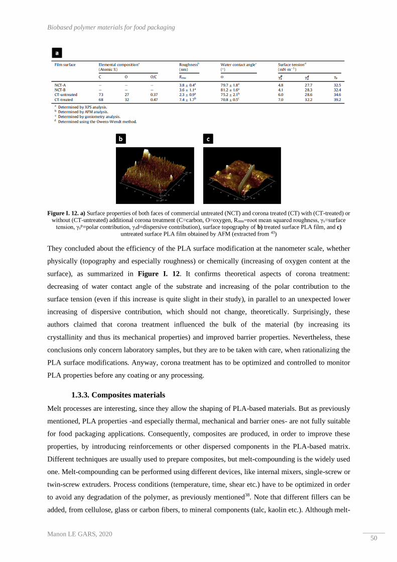
Biobased polymer materials for food packaging
Manon LE GARS, 2020 50
Figure I. 12. a) Surface properties of both faces of commercial untreated (NCT) and corona treated (CT) with (CT-treated) or without (CT-untreated) additional corona treatment (C=carbon, O=oxygen, Rrms=root mean squared roughness, γs=surface
tension, γsp=polar contribution, γsd=dispersive contribution), surface topography of b) treated surface PLA film, and c)
untreated surface PLA film obtained by AFM (extracted from 43)
They concluded about the efficiency of the PLA surface modification at the nanometer scale, whether
physically (topography and especially roughness) or chemically (increasing of oxygen content at the
surface), as summarized in Figure I. 12. It confirms theoretical aspects of corona treatment:
decreasing of water contact angle of the substrate and increasing of the polar contribution to the
surface tension (even if this increase is quite slight in their study), in parallel to an unexpected lower
increasing of dispersive contribution, which should not change, theoretically. Surprisingly, these
authors claimed that corona treatment influenced the bulk of the material (by increasing its
crystallinity and thus its mechanical properties) and improved barrier properties. Nevertheless, these
conclusions only concern laboratory samples, but they are to be taken with care, when rationalizing the
PLA surface modifications. Anyway, corona treatment has to be optimized and controlled to monitor
PLA properties before any coating or any processing.
1.3.3. Composites materials
Melt processes are interesting, since they allow the shaping of PLA-based materials. But as previously
mentioned, PLA properties -and especially thermal, mechanical and barrier ones- are not fully suitable
for food packaging applications. Consequently, composites are produced, in order to improve these
properties, by introducing reinforcements or other dispersed components in the PLA-based matrix.
Different techniques are usually used to prepare composites, but melt-compounding is the widely used
one. Melt-compounding can be performed using different devices, like internal mixers, single-screw or
twin-screw extruders. Process conditions (temperature, time, shear etc.) have to be optimized in order
to avoid any degradation of the polymer, as previously mentioned38. Note that different fillers can be
added, from cellulose, glass or carbon fibers, to mineral components (talc, kaolin etc.). Although melt-

CHAPTER I : Literature Review
Manon LE GARS, 2020 51
compounding is the most used method, solvent-based methods are often used at lab-scale, although it
does not always show the same final materials properties to compare with the previous method.
Nevertheless, it’s useful to simulate in the laboratory the behavior of composites and their properties.
Finally, other methods are employed for the preparation of PLA-based composites, like physical
blending of PLA with fibers, co-extrusion, hot pressing (film-stacking method) and others.
Table I. 6 summarizes the main PLA-based composites recently described in the literature, as well as,
their production methods. It lists, in a non-exhaustive manner, some relevant examples, and shows the
diversity of fillers introduced in PLA-based composites. Indeed, introduction of various natural or
synthetic fibers (cellulose, glass, carbon, etc.), as well as, mineral fillers (clay, talc, hydroxyapatite,
etc.) in PLA matrix allows the override of low properties of PLA for what food packaging applications
concerns, particularly by improving the thermal and mechanical properties of final materials.
Moreover, the barrier properties can be improved with the creation of tortuous pathways inside the
materials to impede the passage of the gas molecules. Finally, it is important to bear in mind that
biodegradation or biocompostability properties can be changed after addition of fillers inside the PLA,
depending on the source and properties of the filler.
Fillers Process Filler wt% Improved properties Reference
Poly(urea-formaldehyde)
(plasticizer)
microcapsules
Solvent casting 5-20 % Mechanical properties (Meesorn et al., 2019)44
Talc and biocarbon
Melt-
compounding
and
compression-
molding
10 % Abrasive resistance, barrier
properties and flammability (Snowdon et al., 2019)45
Talc and kaolinite Twin-screw
extruding 5-30%
Morphology and
thermomechanical properties (Ouchiar et al., 2015)46
Basalt fibers
Dry-blending
and single-
screw
extruding
5-20% Mechanical properties and 3D
printing feasability (Sang et al., 2019)47
Cellulose fibers
Dry-blending,
twin-screw
extruding and
injection
molding
10% Thermal and mechanical
properties (Kyutoku et al., 2019)48
Mixing, twin-
screw
extruding and
injection
molding
5-20% Thermal and mechanical
properties (Aliotta et al., 2019)49
Woven jute fabric
Hot pressing
(film-stacking
between two
PLA films)
/ Mechanical properties (Khan et. al., 2016)50
Table I. 6. Examples of recent PLA-based composites found in literature (Completed and adapted from 38)

Biobased polymer materials for food packaging
Manon LE GARS, 2020 52
In this first part, bio-based materials were detailed. But another range of materials, called
nanocomposites, have entered in the food packaging market. They aim to increase the properties of
the materials by introducing nanometric materials in the packaging. Thus, the use of bio-based
nanomaterials is interesting since it is consistent with the previously presented bioeconomy strategy.
The following part focuses on a specific range of bio-based nanomaterials: the nanocelluloses.

CHAPTER I : Literature Review
Manon LE GARS, 2020 53
2. Cellulose nanocrystals and functionalization
The sections 2.1 and 2.2 are adapted from « Le Gars M., Douard L., Belgacem M. N., Bras J.
Cellulose Nanocrystals: From Classical Hydrolysis to the Use of Deep Eutectic Solvents », Chapter
of the book « Nanosystems », published in IntechOpen (2019)
As renewable and biodegradable nanomaterials, nanocelluloses have raised a huge interest for the last
decades. Indeed, their natural available and abundant sources – the biomass – as well as their
interesting properties, make them materials of choice for new nanomaterials science, in a large panel
of applications. As presented in Figure I. 13, the exponential evolution of the number of publications
and patents dealing with nanocelluloses confirms the large interest generated by these nanomaterials.
Only during this PhD project, about 2800 papers and 400 patents have been published on the topic.
Figure I. 13. Non-cummulative evolution of the number of publications and patents dealing with nanocelluloses (CNC and CNF) (Source : SciFinder, April 2019 – Descriptors : cellulose nanocrystal, cellulose nanorod, rod-like cellulose, cellulose nanowire, cellulose crystallite, cellulose nanoparticle, cellulose whiskers, nanocrystalline cellulose, cellulose nanofibrils,
cellulose microfibrils, nanofibrillated cellulose, microfibrillated cellulose – Language : English)
Two types of nanocelluloses exist: cellulose nanofibrils (CNFs) and cellulose nanocrystals (CNCs),
differing from each other in their properties, as well as, in their isolation process. This part aims to
describe their isolation from cellulose, properties, and applications. A third variety of nanocellulose is
also available in the literature(bacterial cellulose)51.
2.1. From cellulose to nanocelluloses
2.1.1. Structure of cellulose
Cellulose can be extracted from a large variety of sources, like wood (the main source), seed fibers
(cotton), bast fibers (flax, jute, ramie), some animal species (tunicates), fungi and fruits, with different
cellulose contents52. With around 1011-1012 tons of cellulose produced through photosynthesis each
year53,54, whose less than 5% is extracted for applications, cellulose is the most abundant polymer on
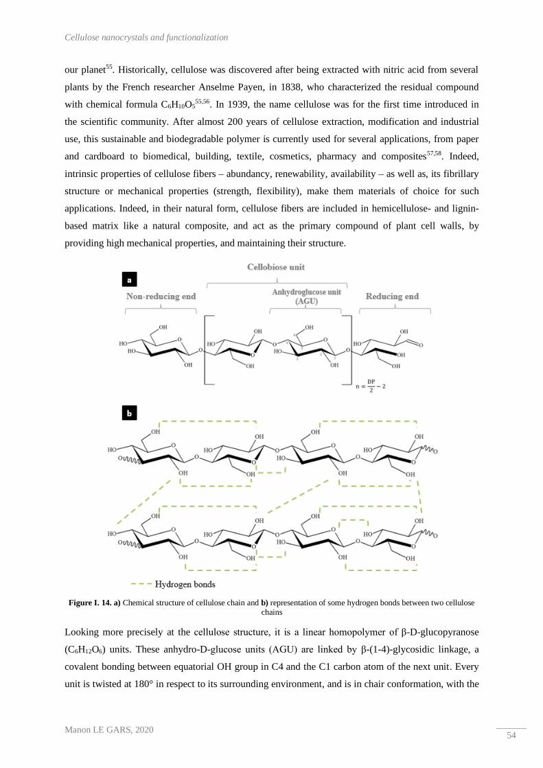
Cellulose nanocrystals and functionalization
Manon LE GARS, 2020 54
our planet55. Historically, cellulose was discovered after being extracted with nitric acid from several
plants by the French researcher Anselme Payen, in 1838, who characterized the residual compound
with chemical formula C6H10O555,56. In 1939, the name cellulose was for the first time introduced in
the scientific community. After almost 200 years of cellulose extraction, modification and industrial
use, this sustainable and biodegradable polymer is currently used for several applications, from paper
and cardboard to biomedical, building, textile, cosmetics, pharmacy and composites57,58. Indeed,
intrinsic properties of cellulose fibers – abundancy, renewability, availability – as well as, its fibrillary
structure or mechanical properties (strength, flexibility), make them materials of choice for such
applications. Indeed, in their natural form, cellulose fibers are included in hemicellulose- and lignin-
based matrix like a natural composite, and act as the primary compound of plant cell walls, by
providing high mechanical properties, and maintaining their structure.
Figure I. 14. a) Chemical structure of cellulose chain and b) representation of some hydrogen bonds between two cellulose chains
Looking more precisely at the cellulose structure, it is a linear homopolymer of β-D-glucopyranose
(C6H12O6) units. These anhydro-D-glucose units (AGU) are linked by β-(1-4)-glycosidic linkage, a
covalent bonding between equatorial OH group in C4 and the C1 carbon atom of the next unit. Every
unit is twisted at 180° in respect to its surrounding environment, and is in chair conformation, with the

CHAPTER I : Literature Review
Manon LE GARS, 2020 55
three hydroxyl groups in equatorial position. Cellobiose (C12H22O11) ─ the combination of two
anhydroglucose units (AGU) ─ is the repeating unit of cellulose53,55. The general formula of cellulose
is represented in Figure I. 14 a).
End-groups of cellulose polymer are chemically different: one non-reducing end, and the other
reducing bearing aldehyde group. Note that cellulose degree of polymerization (DP) is expressed as a
function of the AGU unit number, and depends on the cellulose source and isolation process (DP
between 300-1700 for wood pulp, 800-1000 for cotton for example)55. The numerous hydroxyl groups
─ three per AGU ─ induce the possible functionalization of cellulose, as well as, intra- and
intermolecular hydrogen bonds in and between the cellulose chains. These interactions form strong
stabilized and flexible cellulose filaments: the cellulose microfibrils (Figure I. 15 a)).
Figure I. 15. Schematization of a simplified a) composition of a cellulose fiber (extracted and adapted from 59) and b) arrangements of crystalline and amorphous domains in cellulose chains (extracted from 60)
Moreover, the cellulosic chains are rearranged into different regions: the ordered crystalline, and the
disordered amorphous ones. Indeed, a cellulose chain can be represented as a crystalline wire
connected by amorphous areas (Figure I. 15 b)). It explains the aggregation of cellulose chains, and
thus, their arrangement into microfibrils. These last are assembled in bundles, themselves assembled in
cellulose fibers, with a semi-crystalline structure. Cellulose crystals present four polymorphs:
Cellulose I, II, III and IV. Cellulose I is the most abundant form in nature, and is present under
cellulose Iα and Iβ forms, whose ratio depends on the source. This ratio affects cellulose fibers
properties55,56. Crystallinity of the cellulose varies according to the source, and is in the large range of
40-80%55, leading to highly cohesive fibers. Looking more precisely at the level of the microfibrils,

Cellulose nanocrystals and functionalization
Manon LE GARS, 2020 56
they are composed of elementary fibrils, with a diameter around 5 nm. This general structure provides
visualization of the different scales inside the cellulose fiber. In addition to being environmentally
relevant, cellulose fibers present interesting mechanical properties, an ability for further surface
chemical modification, low toxicity, low cost, and others properties making them outstanding
materials for lot of traditional, as well as, for innovative applications.
2.1.2. Nanomaterials from cellulose: cellulose nanofibrils and nanocrystals
The hierarchical structure of cellulose fibers is at the origin of cellulosic nanomaterials: the
nanocelluloses, having at least one dimension of nanometric scale, as their name suggests. Indeed,
from elementary fibrils, two types of nanocellulose can be obtained, differing by their isolation
procedure, as well as, by their properties and applications. Figure I. 16 shows their different
morphologies.
Figure I. 16. TEM images of a) Microfibrillated cellulose (MFC), b) TEMPO-oxidized nanofibrillated cellulose (CNF) and c) wood cellulose nanocrystals (CNCs) (extracted from 60)
In the 1980s, two research groups, headed by Herrick61 and Turbak62, developed for the first time what
they called microfibrillated cellulose (MFC), after applying repeated high-pressure homogenization to
cellulose fibers. Resulting 2% suspension showed the presence of both fibrils and microfibrils, and
presented a gel-like behavior. Rheological, morphological, and chemical reactivity properties of MFC
(also called cellulose nanofibrils (CNFs) since new standards ISO/TC 6, ISO/TC 229 and TAPPI
(2013) for nanocelluloses terminologies standardization) were extremely promising at the beginning
and at the root of many further researches until today. Indeed, CNFs are interesting nanomaterials
widely characterized and used in a large panel of applications. In accordance with the first results
obtained by Herrick and Turbak, CNFs are obtained by applying a high shear mechanical treatment to
a cellulose suspension. Most common mechanical processes are homogenization63–65, ultrafine
grinding66–68, and microfluidizing69, as broadly found in literature, and new innovative processes are
presented since few years like extrusion70,71, ultrasonication or steam explosion, for example. Due to
the numerous strong hydrogen bonds between cellulose chains, obtaining nanofibrillated cellulose by
these mechanical treatments required a lot of energy. In this context, during the last years, research

CHAPTER I : Literature Review
Manon LE GARS, 2020 57
focused on the decrease of energy used, especially by chemical or biological pre-treatment of cellulose
fibers facilitating the defibrillation. Main steps of CNFs extraction are represented in Figure I. 17.
Figure I. 17. General schematized procedures for the production of both cellulose nanofibrils (CNFs) and cellulose
nanocrystals (CNCs)
Numerous chemical pre-treatments have been reported in the literature, with among others some
enzymatic pre-treatment72–75, cationization76,77 and oxidation using TEMPO78–80 or periodate81,82. A
recent review by Rol et al. 83 describes the recent advances in cellulose nanofibrils pre-treatments. As
their name suggests, CNFs have at least one dimension of nanometric scale (i.e. <100nm). Their
dimension vary, depending on the cellulose source and the extraction process, but their length is
comprised between 500 nm and 10 µm, and their width between 5 and 50 nm60 (see Figure I. 16). Note
that chemical pre-treatments influence the morphology of CNFs by reducing their dimensions. Thus,
CNFs composed of both crystalline and amorphous parts present a high aspect ratio which confers
them, additionally to the hydrogen bonds between nanofibers, highly cohesive network properties. At
low solid content, CNF water suspensions exhibit a gel-like properties75. CNFs can also be assembled
in flexible self-standing dried films (also called nanopapers), with interesting transparency in visible
domain (80-90%) due to the nanometric size of CNFs and their dense arrangement54. Their mechanical
and thermal properties are also pretty high comparing to classical biopolymer. CNFs find application
as rheological modifier, nanocomposites reinforcement, additives in paper, and cardboard industry,
coating, barrier layer in packaging or biomedical applications84–86. Despite the high production energy
costs, and the “nano risk” precautions industrialization of CNFs started in the 2010’s. Today, more
than thirty CNFs producers can be listed all around the world, with production capacities up to 10000
tons per year, as shown in Table I. 7. To overcome their industrialization issues, the development and

Cellulose nanocrystals and functionalization
Manon LE GARS, 2020 58
optimization of pre-treatments, as well as, the search for advanced applications, aim to develop the
CNFs industrial production.
Company Country Annual production
capacity (tons)
FiberLean® Technologies UK 12000
Borregaard Norway 1000
Tuners Falls Paper USA 700
Fibria Brazil 700
Nippon Paper Group Japan 500 (TEMPO)
Norske Skog Norway 350 (Pilot)
University of Maine – Process Development Center USA 350
Daio Paper Corp. Japan 100 (Pilot)
American Process Inc. USA 100
CelluComp UK 50
DKS Co., Ltd Japan 50
RISE Bioeconomy Sweden 35 (Pilot)
Sappi Netherlands 8 (Pilot)
Kruger Biomaterials Inc. Canada 6
InTechFibres (CTP/FCBA) France 4
University of Queensland Australia 2 (Pilot)
University of Alberta / InnoTech Alberta Canada 2 (Pilot)
Betulium Oy Finland Pilot
Forest Products Laboratory (FPL) USA Pilot
Stora Enso Ltd. Sweden Recent investment for ~6000t
Table I. 7. Non-exhaustive list of main CNFs producers and their country, as well as, their annual production capacity (data extracted from 87)
Another class of nanocelluloses is cellulose nanocrystals (CNCs). Their first investigation was
reported by Ranby et al. in 195088,89 : after carrying out a sulfuric acid hydrolysis to wood cellulose
fibers, they observed rod-like particles, with two nanoscale dimensions. Indeed, by hydrolyzing
cellulose fibers, most of the amorphous parts of cellulose are disintegrated, and final nanomaterials are
highly crystalline. Cellulose nanocrystals have a length between 100 and 500 nm, and a width varying
from 2 to 15 nm, depending on the cellulose source and the chemical treatment applied. Indeed, even
if the use of sulfuric acid for hydrolysis is the most common process, other research groups have
investigated the use of other acids, leading to CNCs with different properties. In any case, washing
steps are essential to remove chemicals and to well-disperse the isolated CNCs, as presented in Figure
I. 17.
Regarding their industrialization, around thirteen CNCs producers can be recorded, with annual
production capacity up to 400 tons per year. These productions are significantly lower than those of
CNFs, but requirement of more chemicals and difficult industrial production steps (washing, dialysis,
and sonication) can easily explain this difference. Table I. 8 shows the non-exhaustive list of CNCs
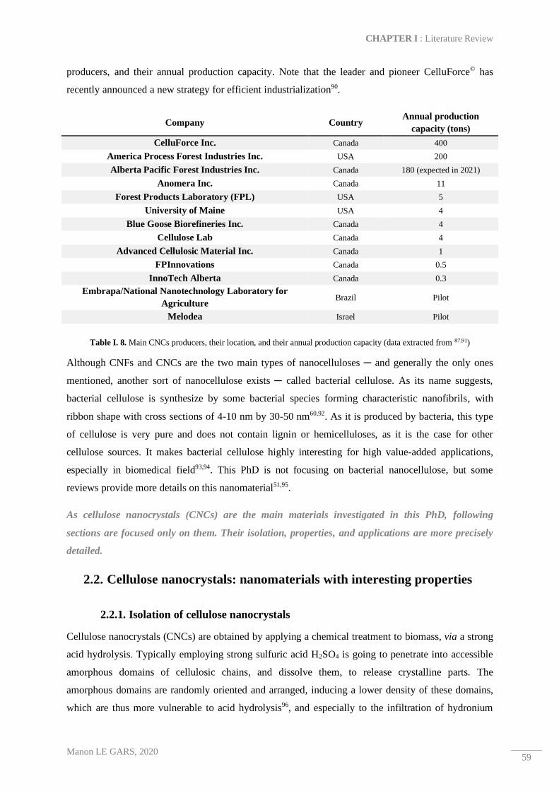
CHAPTER I : Literature Review
Manon LE GARS, 2020 59
producers, and their annual production capacity. Note that the leader and pioneer CelluForce© has
recently announced a new strategy for efficient industrialization90.
Company Country Annual production
capacity (tons)
CelluForce Inc. Canada 400
America Process Forest Industries Inc. USA 200
Alberta Pacific Forest Industries Inc. Canada 180 (expected in 2021)
Anomera Inc. Canada 11
Forest Products Laboratory (FPL) USA 5
University of Maine USA 4
Blue Goose Biorefineries Inc. Canada 4
Cellulose Lab Canada 4
Advanced Cellulosic Material Inc. Canada 1
FPInnovations Canada 0.5
InnoTech Alberta Canada 0.3
Embrapa/National Nanotechnology Laboratory for
Agriculture Brazil Pilot
Melodea Israel Pilot
Table I. 8. Main CNCs producers, their location, and their annual production capacity (data extracted from 87,91)
Although CNFs and CNCs are the two main types of nanocelluloses ─ and generally the only ones
mentioned, another sort of nanocellulose exists ─ called bacterial cellulose. As its name suggests,
bacterial cellulose is synthesize by some bacterial species forming characteristic nanofibrils, with
ribbon shape with cross sections of 4-10 nm by 30-50 nm60,92. As it is produced by bacteria, this type
of cellulose is very pure and does not contain lignin or hemicelluloses, as it is the case for other
cellulose sources. It makes bacterial cellulose highly interesting for high value-added applications,
especially in biomedical field93,94. This PhD is not focusing on bacterial nanocellulose, but some
reviews provide more details on this nanomaterial51,95.
As cellulose nanocrystals (CNCs) are the main materials investigated in this PhD, following
sections are focused only on them. Their isolation, properties, and applications are more precisely
detailed.
2.2. Cellulose nanocrystals: nanomaterials with interesting properties
2.2.1. Isolation of cellulose nanocrystals
Cellulose nanocrystals (CNCs) are obtained by applying a chemical treatment to biomass, via a strong
acid hydrolysis. Typically employing strong sulfuric acid H2SO4 is going to penetrate into accessible
amorphous domains of cellulosic chains, and dissolve them, to release crystalline parts. The
amorphous domains are randomly oriented and arranged, inducing a lower density of these domains,
which are thus more vulnerable to acid hydrolysis96, and especially to the infiltration of hydronium

Cellulose nanocrystals and functionalization
Manon LE GARS, 2020 60
ions H3O+, leading to hydrolytic cleavage of glycosidic bonds. In this sense, Ranby et al.88,89 were the
first to prove the preparation and the presence of CNCs, the smallest cellulosic building blocks.
Figure I. 18 synthesises the different steps of CNCs isolation using sulfuric acid hydrolysis.
Figure I. 18. Schematic representation of sulfuric acid hydrolysis of cellulose fibers (extracted from E. Gicquel PhD, 2017)
As previously mentioned, the cellulose fibrils are exposed to a sulfuric acid hydrolysis, with a defined
concentration, temperature, and reaction time. Once amorphous domains are dissolved, a sonication
step allows the separation between intact crystalline domains, leading to isolated CNCs bearing half-
sulfate ester groups on their surface. These charges come from the reaction between sulfuric acid and
surface hydroxyl groups of cellulose, and induce repulsive forces between negatively charged CNCs,
leading to colloidal stability and dispersion in water97. While sulfuric acid is the most common acid
used for the cellulose fibers hydrolysis, other researches have focused on the use of other organic or
mineral acids, like phosphoric acid, hydrobromic acid, or hydrochloric acid98–101, generally leading to
less stable suspension, due to the lack of charges at the surface of the CNCs. Moreover, the use of
deep eutectic solvents (DES) ─ a new class of green organic solvents ─ has been investigated too, and
yielded cellulosic nanoparticles using less toxic and easier process102,103.
When the cellulosic source is not totally pure, previous steps are required. Indeed, alkali treatment
(generally NaOH) and bleaching steps (generally acetic acid, aqueous chlorite) are essential to remove
impurities, especially lignin and hemicelluloses. Note that numerous studies have investigated the
production of CNCs from less conventional sources like rice, soy, and others, in order to valorise food
and organic waste104,105.
Final yield and morphology of CNCs are highly dependent on the cellulosic botanic source and on the
hydrolysis conditions. Indeed, optimization and control of the acid hydrolysis has been the subject of
several publications. If common parameters are the hydrolysis with 64 wt% sulfuric acid at 40-45 °C
during about 30 min, it has been proved that the variation of one of parameters can largely influence

CHAPTER I : Literature Review
Manon LE GARS, 2020 61
the reaction yield, as well as, the final CNCs properties. For example, by increasing the time of
hydrolysis by 10 min, it has been shown by Flauzino Neto et al.104 that crystalline parts are destructed,
inducing a significant decrease in CNCs length. Beck et al.106 confirmed this point, admitting that too
long times of reaction induce degradation of cellulose. In contrary, too short times induce only large
and non-dispersible fibers and large aggregates. Only specific reaction times yield to a well-dispersed
colloidal suspension of CNCs. Chen et al.99 confirmed that the best yield and CNCs properties are
obtained with previously mentioned standard conditions. Moreover, the importance of acid
concentration relative to cellulose fibers is highlighted too, since a too high concentration could be too
drastic, and a too low concentration insufficient for the hydrolysis efficiency.
At the end of the reaction, mixture media is first diluted with distilled water to quench the reaction,
then submitted to several separation steps with centrifugation cycles and filtrations, and washed by
dialysis against distilled water for several days, in order to remove unreacted compounds and
chemicals. In some cases, NaOH is also used to neutralize pH, which can modify the crystallinity and
the surface ions. After dialysis, a final centrifugation cycle or another filtration process aim to remove
aggregates. CNC suspension is finally sonicated in order to well disperse the nanocrystals, and obtain
a colloidal suspension thanks to dimensions and sulfate half ester groups bearing by CNCs.
In this PhD, a commercial batch of CNCs is used, and was obtained via sulfuric acid hydrolysis
from wood. It was supplied by CelluForce (Canada). More details will be provided in corresponding
results chapters.
2.2.2. Properties of cellulose nanocrystals
In addition to their nanometric size, CNCs are unique biodegradable and renewable nanomaterials.
Moreover, they result from a previously described optimized acid hydrolysis applied on various
sources of cellulose, and exhibit many other interesting properties. Figure I. 19 summarizes the main
CNCs properties, as well as, their potential applications. Regarding the surface properties of CNCs,
they generally exhibit ─ in addition to –OH functions borne by cellulose macromolecules ─ half-
sulfate ester groups (-SO3-) on their surface after being treated with sulfuric acid. Even if the amount
of –SO3- groups is pretty low (about 50-200 µmol.g-1), these negative charges are sufficient to induce
repulsive forces between nanomaterials, and thus ensure colloidal stability in aqueous media.
Moreover, as presented in Figure I. 19, due to the isolation process, other charged groups can be
present on CNC surface, like carboxyl groups (-COO-), aldehyde groups (-CHO) and others107, leading
to different charge amount inducing different CNC properties. Moreover, numerous hydroxyl groups
(3 groups in each AGU) are reactive surface sites for the introduction of new functional groups via
hydroxyl groups’ functionalization. Regarding the physical properties of CNCs, they have a low
density (1.606 g.cm-3) compared to other organic materials, a high aspect ratio length/width (varying
between 10-30 for CNCs extracted from cotton and around 70 for those extracted from tunicate for

Cellulose nanocrystals and functionalization
Manon LE GARS, 2020 62
example97), and a high surface area (between 150 and 800 m².g-1). Note that all their morphological
and surface properties are highly dependent on their source, as well as, on their isolation process and
conditions60,108. Moreover, CNCs exhibit highly interesting mechanical properties. In addition to their
high crystallinity (between 54-88% according to the source109), their high elastic modulus (≈150 ± 50
GPa), and tensile strength (≈7.5 ± 0.5 GPa)110 make them interesting materials as mechanical
reinforcement in polymer matrices, for example. For comparison, their mechanical properties are
similar to Kevlar® fibers111 widely used in high-performance composites materials.
Figure I. 19. Main surface and physical properties of cellulose nanocrystals (CNCs) and inherent main applications
At low solid content (<3 wt%), due to hydrogen bonds between cellulose chains and thus between
each nanocrystals, CNC water suspension is in the form of a translucent gel. Rheological properties of
CNCs are outstanding and concentration dependent. Thus, at low concentration (<3 wt%), CNC
suspension presents shear thinning behavior at high shear rate, and at higher concentration (>3 wt%),
the suspension presents shear thinning behavior explained by the nanocrystals alignment in the flow
direction at a critical shear rate112. Source and isolation of CNCs influence these rheological properties

CHAPTER I : Literature Review
Manon LE GARS, 2020 63
too. Besides all these properties, CNCs self-organize themselves in ordered structure, especially to
form a nematic phase. Revol et al.113 described in the 1990s this self-organization of CNCs in water
suspension into stable chiral nematic phases. The materials exhibit liquid crystalline properties, which
added to intrinsic birefringence of CNCs, induce interesting optical properties. Moreover, when
ordered CNC suspension is solvent evaporated, they yielded a self-standing film, conserving a chiral
nematic structure (helicoidal structures), and an iridescent behavior of films is observed and monitored
by CNC concentration and surface charge, as well as, the quality of suspension dispersion112,113.
Figure I. 20 shows explicit pictures of these rheological and liquid crystalline properties.
Figure I. 20. a) Translucent gel-like CNC suspension at 15 wt% in water (extracted from 114), b) Birefringence with shear-inducing observed for an aqueous CNC suspension at 0.6 wt% in cross-polarized light (extracted from 115), c) Solvent-casted CNC film in diffuse light, normal to the surface (on the left part) and oblique to the surface (on the right part) (extracted from 116), and d) Schematic representation of CNCs orientation in isotropic and anisotropic phases (extracted from R. Bardet PhD,
2014)
All these outstanding surface and physical properties of CNCs confirm their high and increasing
interest in research and industrial field during the last decades. Although their isolation and
characterization are currently well-advanced and optimized, applications field are at the center of
ongoing researches, as described in the following section.
2.2.3. Various applications of cellulose nanocrystals and their industrialization
As exposed in Figure I. 19, CNCs found applications in various fields thanks to their outstanding
morphological, mechanical, and rheological properties, as well as, their colloidal stability and high
surface reactivity. All these properties, added to their biodegradability and renewability, make them
highly interesting and innovative materials with many potential applications. Table I. 9 summarizes
CNCs applications and the corresponding exploited properties, as well as, some literature references.
Nanocomposites field is an emerging research area which finds applications in several domains like
food packaging, medical devices, and building. The renewable aspect of CNCs is particularly
interesting, since it correlates with the development of bio-based and biodegradable polymers, as
mentioned in the first part of this chapter. Moreover, these materials possess interesting properties, and
could be potential candidates in new fields of applications, such as coatings, electronics, filtration,
biomedical, energy, cosmetics, and security.

Cellulose nanocrystals and functionalization
Manon LE GARS, 2020 64
Market Applications Exploited CNC properties References
Composites /
Films
Nanocomposites
Flexible packaging
Optical films
High mechanical properties
Filmogenic properties
Morphology
(Mariano et al., 2014)117
(Hube et al., 2017)84
Coatings / Paints /
Adhesives Coatings for flexible packaging
Morphology
Rheological properties
(Kaboorani et al., 2012)118
(Mascheroni et al., 2016)119
Electronics /
Sensors
Flexible electronics
E-paper
Piezeoelectric sensors
Electrical insulating
Piezeoelectric properties
Surface area
(Hoeng et al., 2016)120
(Csoka et al., 2012)121
(Gaspar et al., 2014)122
Filtration Mesoporous films and membranes
High specific surface area
High mechanical properties
Hydrophilicity
(Karim et al., 2014)123
Biomedical
Biocomposites for bone/tooth
replacement
Drug delivery
Protein immobilisation
Wound dressings
Biosensors
Low toxicity
Colloidal stability
High mechanical properties
Surface reactivity
(Domingues et al., 2014)124
(Lin et al., 2014)125
Energy Supercapacitors
Flexible batteries
Strength
Large surface ara (Yang et al., 2015)126
Cosmetics Hydrogels & foams
Colloidal stablity
Emulsion interfacial
stabilization
(Kalashnikova et al.,
2013)127
(Tasset et al., 2014)128
Security Security papers and inks Iridescent properties
Morphology (Zhang et al., 2012)129
Table I. 9. Main market applications of CNCs with related properties, and some literature references
Note that for applications that may enter in contact with food or human body, and for any
industrialization, toxicity of CNCs is a key challenge to investigate. Indeed, even if cellulose is known
to be a non-toxic polymer, CNCs are nanomaterials ─ whose the “nano” prefix can be frightened for
media and population ─ with specific morphology and surface properties. A recent review of Roman
et al.130 explored the CNCs toxicity. The results of this study correlate with previous results of Lin et
al.125 and Kovacs et al.131, who demonstrated that CNCs are not toxic by ingestion, or if a dermal
contact is established. They were also considered as non-toxic for aquatic organisms. However,
pulmonary diseases and cytotoxicity depend on CNCs properties and shapes (especially if they are in
powder form, since they are more easily air-suspended). In any case, toxicity of CNCs is low,
especially when they are in wet-state or in composites, films or coatings for example, not constraining
the development of new CNC-based products.
The wide range of CNCs applications is subjected to numerous research projects and publications
and is achieved, in most cases, thanks to the surface functionalization of CNCs. The following part
aims to describe the potential surface modifications applied to CNCs.

CHAPTER I : Literature Review
Manon LE GARS, 2020 65
2.3. Functionalization of cellulose nanocrystals
Through numerous hydroxyl groups on their surface and their high specific surface area, CNCs have
been surface-modified through different techniques, in order to improve their properties and further
potential applications. Recent reviews summarize the different ways of CNC surface functionalization,
including those of Natterodt et al.132, Tang et al.107, Wohlhauser et al.133, Kedzior et al.134 and less
recently those of Eyley et al135. and Habibi et al57. Through their high reactivity, CNCs thus can be
modified via different reactions. Figure I. 21 shows the different possible ways for CNCs chemical
modifications: by grafting or adsorbing single molecules or polymer chains at their surface. For each
modification method, some examples are given, although the list is absolutely not exhaustive.
Figure I. 21. Different paths of chemically modifying cellulose nanocrystals with some examples for each method. Synthesis: extraction with [1] sulfuric acid106, [2] hydrochloric acid101 and [3] phosphoric acid98, [4] TEMPO oxidized
CNC136 – Single molecules grafting using: [5] [6] long-chain aliphatic acid chlorides137,138, [7] malonic acid139, [8] acetic anhydride140, [9] benzylacetic acid141, [10] 4-(bromomethyl)benzoic acid142, [11] 1,4-diaminobutane143, [12] octadecyl
amine138, [13] Jeffamine144, [14] propargylamine145, [15] aminated-polyethylene oxide (PEO-NH2)146, [16] aminated-poly(N-isopropylacrylamide) (PNIPAM-NH2) 147, [17] n-dodecyl and n-butyl dimethylchlorosilane148, [18] hexamethyldisilane149,
[19] epichlorohydrin150, [20] glycidyltrimethylamonium chloride (EPTMAC) 151, [21] isocyanatepropyltriethoxysilane152 and [22] n-octadecyl isocyanate153 – Polymer chains : grafting-to : [23] PNIPAM-NH2
147, [24] polycaprolactone (PCL)154, [25] poly(ethylene oxide) (PEO)155, [26] polystyrene (PS) and poly(tert-butyl acetate) 156 and [27] chitosan157 – grafting-from : [28] PCL158, [29] 159,160 PS, [30] poly(methyl methacrylate) (PMMA) 161, [31] poly(n-butyl methacrylate) 162, [32] poly(4-

Cellulose nanocrystals and functionalization
Manon LE GARS, 2020 66
vinylpyridine) 163 and [33] block copolymer of PNIPAM and poly(acrylic acid) 164 – Adsorption : [34] cetyltrimethylammonium bromide (CTAB) 165, [35] didecyldimethylammonium bromide (DMAB) 166, [36] acid phosphate
ester of ethoxylated nonylphenol (Beycostat A B09) 167, [23] PNIPAM-NH2147, [37] poly(diallyldimethylammonium
chloride) (polyDADMAC) 168 and [38] tannic acid169.
In this section, the different types of surface modification exploited in this PhD are described:
TEMPO-oxidation, surface polymerization, covalent (especially esterification and amidation) and
non-covalent bonding. These chemical surface modifications are carried out in order to
compatibilize the CNCs with a polymer matrix, in the case of nanocomposites applications, as
detailed in the next part (3) of this chapter.
2.3.1. TEMPO oxidation of cellulose nanocrystals
Among CNCs chemical modifications, oxidation – and especially TEMPO-mediated oxidation – of
CNCs is one of the most common and optimized one. In fact, besides being well-known as pre-
treatment of cellulose to facilitate the defibrillation in CNFs production170, TEMPO radical oxidation
allows the introduction of carboxylate groups –COO- at the surface of CNC. These charges are highly
reactive for further grafting or adsorption of molecules or polymers, and increase the stability of
TEMPO-oxidized CNCs in water, leading to well dispersed nanosize particles, thus providing
translucent suspension in water. This reaction was carried out on HCl hydrolyzed CNCs for the first
time by Araki et al. in 2001146, and was subsequently optimized by different research groups,
including Habibi et al.136, Montanari et al.171, and Fraschini et al.172, working with different types of
CNC. Figure I. 22 represents the oxidation mechanism generally presented in the literature with the
system TEMPO/NaBr/NaClO, where RCH2OH represents the CNC. Common chemicals used in
TEMPO-assisted oxidation of cellulose are TEMPO radical (2,2,6,6-tetramethylpiperidin-1-yl)oxyl as
oxidizing agent, sodium bromide (NaBr) and sodium hypocholorite (NaClO). The reaction is generally
carried out in water, in basic conditions (pH=10), and follows different steps: a hypobromite ion BrO-
is formed in situ from the reaction between a hypochlorite ion ClO- and NaBr. The BrO- ion reacts
with TEMPO radical ((1) in Figure I. 22) to form the nitrosonium salt (2), which is an active
oxidizing agent in the reaction. Then, this nitrosonium salt is going to react with CNCs, and oxidize
primary alcohol groups into sodium carboxylate. The oxidation occurs in two steps: first, the alcohol
groups are oxidized into aldehyde groups. TEMPO radical being continuously regenerated (by
reaction between (3) and (2)), a second oxidation can take place on aldehyde groups, leading to acid
carboxyl groups. Thus, 2 mol of NaClO are required to oxidize one mole of primary alcohol, and the
introduced initial amount of NaClO is determinative for the oxidation yield172.

CHAPTER I : Literature Review
Manon LE GARS, 2020 67
Figure I. 22. General reaction mechanism of TEMPO-mediated oxidation of CNC : regioselective oxidation of primary hydroxyl groups of cellulose using TEMPO/NaClO/NaBr system (in blue) and TEMPO oxidized CNC bearing carboxylate
groups (in green) (extracted and adapted from 173)
It has been proved that reaction occurs only on CNCs surface171, and on accessible primary alcohol
carried by C6 carbons. Some studies have shown that this selectivity is kept when the oxidation occurs
in neutral conditions with NaClO2174. TEMPO-oxidized CNCs conserve their dimensions and
crystallinity, and exhibit surface charge that may reach around 1600 µmol.g-1 136. If TEMPO-mediated
oxidation is the most optimized and used method to introduce carboxylate charges on the CNCs
surface, other techniques, like the sodium periodate oxidation, have been published in the literature175,
leading to aldehyde groups on the surface.
In any case, introduction of carboxylate charges at the surface of CNCs is interesting in terms of
suspension stability and in surface reactivity, expanding the grafting possibilities from this carboxylate
groups, or the adsorption strategies.
2.3.2. Covalent grafting on cellulose nanocrystals
Thanks to the numerous hydroxyl groups present at the surface of CNC and to their high specific
surface area, the availability of these reactive sites is a key point in the functionalization of CNCs.
Indeed, the chemical modifications allow the introduction of various functional groups, aiming to
confer them new functionalities, like active properties (antimicrobial, antioxidant etc.) or, in most
cases, to enhance their compatibility with different hydrophobic polymeric matrices. These
modifications are covalent, meaning that hydroxyl groups of CNCs are chemically bonded to another
molecule with which they share electron pairs. In the literature, different covalent grafting processes
are presented, with among others oxidation, esterification, amidation, etherification, silylation, and
nucleophilic substitutions, as previously presented in Figure I. 21.

Cellulose nanocrystals and functionalization
Manon LE GARS, 2020 68
In an amidation reaction, reactive carboxyl groups –COOH introduced on TEMPO-oxidized CNCs,
can be activated by reacting with a primary amine via a peptidic linkage, meaning a covalent amide
bond between a primary amine-terminated compound and carboxylate groups borne by CNCs.
Commonly, EDC (1-ethyl-3-(3-dimethylaminopropyl) carbodiimide and NHS (N-hydrosuccinimide)
catalysts are used in amidation strategy as activators of the carboxyl groups. Figure I. 23 schematizes
this activation occurring during the amidation reaction. In a first time, EDC gives an unstable O-acyl
urea compound to the carboxylic function. In a second time, NHS is reacting with this compound by
stabilizing it in a stable N-acyl urea compound. Finally, aminated molecule is going to react with the
activated CNC surface.135
Figure I. 23. General mechanism of an amine-terminated molecule at the surface of TEMPO-oxidized CNCs in presence of EDC/NHS coupling agents ((1):activation of oxidized TEMPO-CNC with EDC, (2): stabilization with NHS, (3) reaction
with aminated compound / reagents in blue – final grafted CNC (CNC-g-amine) in green)
Araki et al.146 were the first who introduced this method, using EDC/NHS as catalyst system, to graft
amine-terminated-poly(ethylene glycol) on TEMPO-oxidized CNCs, in order to sterically stabilized
CNC water suspensions. Around 20-30% of the total amount of previously introduced carboxyl groups
was converted into amide groups, which was sufficient for suspension stabilization and redispersion146.
Knowing that not all –COOH groups (on C6 carbons) are converted into amide groups during the
amidation process and due to the previous low degree of oxidation of TEMPO-oxidized CNCs, the
grafting density of an amidation is relatively low, generally lower than 0.2. The coupling reaction is
pH dependent, and a pH between 7 and 10 has been reported to be efficient, in the case of CNC (R-
NH2 configuration)57. In the literature, several studies used the EDC/NHS reagents to decorate the
CNC surface with an amine. For example, Bendahou et al.138 compared the efficiency of the amidation
of aliphatic amine with that of the esterification of equivalent acid chloride molecules. Predictably, the
esterification with highly reactive allyl chloride was highly efficient, although the amidation of

CHAPTER I : Literature Review
Manon LE GARS, 2020 69
aliphatic amine was also proved, and selective at the level of C6 carbons. Note that the pH, the time of
reaction, and the introduction order of EDC/NHS compounds influence the yield of the reaction.
Studies have been carried out to optimize this amidation reaction143,176.
The amidation reaction is long, compared to classical reactions (several days for CNCs), and leads to
low yields (around 10-30%). Nevertheless, the low amount of grafted aminated compounds is
generally good enough to modify desired properties. For example, in a recent study, Guo et al.176
investigated EDC/NHS monitored amidation reaction of functionalized aminated carbon quantum dots,
in order to confer fluorescence properties to modified CNCs. The surface composition analysis was
established using XPS, and allowed to conclude that about a 36% conversion of carboxyl groups into
amide groups and fluorescence of final modified CNCs was performed, as shown in Figure I. 24 a)
and c). Moreover, although amidation reaction did not influence or damage CNCs morphology,
grafted carbon quantum dots were visible by TEM imaging (Figure I. 24 b)).
Figure I. 24. Evidence of fluorescent behavior of modified CNCs through EDC/NHS coupling amidation: a) Characterization of fluorescence by confocal microscopy : modified CNCs with carbon quantum dots on the top, unmodified TEMPO-CNCs at the bottom, b) TEM image of modified CNCs with carbon quantum dots (visible at the level of red arrows),
and c) Fluorescence spectra of unmodified TEMPO-CNCs (TO-CNCs), aminated carbon quantum dots (NH2-CQDs) and grafted TEMPO-CNCs with carbon quantum dots (CQDs-CNCs) (extracted from 176)
Nevertheless, the advantages of an amidation catalysed by EDC/NHS compounds are its possible
occurring in water, at room temperature, and without highly toxic chemicals, which is interesting in
current ecological context, and in terms of green chemistry.
Esterification is another common CNCs grafting procedure. Different kind of esterification exist, with
for example the sulfation and phosphorylation, occurring during the isolation of CNCs, according to
the involved hydrolysis condition. Sulfate or phosphate half-ester groups are created on the surface of
CNCs from secondary hydroxyl groups. Such in situ sulfation or phosphorylation allow colloidal
stability of isolated CNCs. Several studies have taken advantage of the hydrolysis isolation process of
CNCs by combining it with a Fischer esterification, in a one-step procedure, in order to obtain
modified CNCs. Boujemaoui et al.177 have produced functionalized CNCs by combining hydrochloric
acid hydrolysis with Fischer esterification, using different functional carboxylic acids, as presented in
Figure I. 25 a).

Cellulose nanocrystals and functionalization
Manon LE GARS, 2020 70
Figure I. 25. a) Principle of the one-step procedure combining acid hydrolysis and esterification of cellulose fibers using 2-bromopropionic acid / 3-mercaptopropionic acid / 4-pentenoic acid / 2-propynoic acid, b) Nomenclature of recovered CNCs with different acids, yield and dimensions, and c) obtained by AFM analyses, (A):HCl-CNC (unmodified), (B): 2-PyA-CNC,
(C): 2-BPA-CNC, (D): 3-MPA-CNC and (E): 4-PA-CNC) (extracted from 177)
The modified CNCs were recovered with yield comprised between 48 and 62%, which was consistent
with the values found in the literature for CNC produced from cotton sources178. Functionalized
CNCs with double and triple bonds, as well as with thiols and brominated groups, were also
characterized. No significant differences in term of CNCs morphology were visible, with lengths
between 170-200 nm and width between 13-18 nm, in agreement with the literature. In a same way,
Spinella et al.139 modified CNC in a similar one-step procedure with natural carboxylic acid (citric,
malonic and malic acids). Figure I. 26 a) shows the schematized process for the isolation of modified-
CNC. The grafting efficiency was highlighted by FTIR, among other techniques. First of all, all FTIR
spectra showed the presence of intact cellulose (Figure I. 26 c)). Moreover, peaks related to ester
groups (C=O stretches) and –CH2 carbons evidenced the presence of the introduced ester bonds
between cellulose and acids moieties. The TEM images of unmodified CNCs obtained via common
hydrochloric acid hydrolysis and those associated to modified CNCs obtained via the one-step
hydrolysis/Fischer esterification process showed no significant differences in terms of dimensions.
Degrees of substitution between 0.16 and 0.22 were obtained, which was lower than those obtained
with classical esterification (generally around 1 – 2)135, but they still corroborated the literature values.

CHAPTER I : Literature Review
Manon LE GARS, 2020 71
Figure I. 26. a) General procedure of the one-step isolation/modification process of CNCs with different bio-based carboxylic acids (citric, malic and malonic acids), b) FTIR spectra of unmodified HCl CNCs and modified malonate / citrated
/ malate CNCs, and c) TEM images of resulted unmodified (D) and modified (A, B, C) CNCs (extracted from 139)
In their study, the compatibilization of modified CNCs with polymer was targeted, as it is often the
case. In fact, several studies have investigated the grafting of long aliphatic chains on the surface of
CNCs to increase their hydrophobic character, and thus their compatibility with hydrophobic polymers.
Other post-esterification of CNCs are widely presented in literature, including acetylation140,179,
transesterifications180 or the use of acid halide reagents159,181. The efficiency of these reactions was
already proved in literature, with high degrees of substitution (generally higher than 0.4 and until 2-
3)135. Indeed, the surface high reactivity of the CNCs and the use of organic solvents are favourable
conditions, and traditional method using fatty acid chlorides in organic solvents have been exposed in
the literature135,153. Another way of esterification is to modify directly CNC aerogels with a vapor
phase of the chosen acid chloride. For example, Fumagalli et al.182 exposed that the modification of
CNC aerogels, prepared in a mixture of water and tert-butanol, and then dried, could efficiently
performed with palmitoyl chloride vapors. The redispersion of these modified CNCs in organic
solvents was also a success. The efficiency of the esterification on CNCs was controlled and proved,

Cellulose nanocrystals and functionalization
Manon LE GARS, 2020 72
but the question of green chemistry and limitation of organic solvent remain a key point in current
research. Indeed, in a spirit of green chemistry with limitation of toxic and organic solvent,
esterification of CNCs remains a challenge, since the presence of water shifts the equilibrium in the
undesired direction.
In the literature, more and more “solvent-free” or “green” methods are reported. Although these terms
have to be understood properly, these methods have a common objective: the reduced use of toxic and
organic solvents. Yoo and Youngblood183 proposed a method in which aqueous lactic acid solution
was used as reactive solvent in the esterification process of CNCs with long chains carboxylic acids.
Thus, intermediate CNCs-grafted-PLA possessed a hydroxyl function at their end and acted as reactive
species for the further esterification of carboxylic acids. Low degrees of substitution were calculated,
although they were suitable for such innovative esterification. In a same way, Espino-Perez et al.141,184
presented a novel method for the esterification of CNCs. Figure I. 27 a) schematizes their protocol.
Briefly, a CNC suspension in water was mixed with a water soluble acid, and heated above the acid
melting point. After total evaporation of water, CNCs were in suspension in the melted acid and the
reaction mixture was stirred for several hours, followed by washing steps. In this work, Espino-Perez
et al. indirectly proved the enhanced dispersion of modified CNCs in organic solvents, like chloroform
(Figure I. 27 b)), as well as, their increased hydrophobic character due to the introduction of
hydrophobic groups at their surface, as suggested by the increasing of their water contact angle
(Figure I. 27 c)). Generally speaking, chemical modifications of CNCs tend to turn to green and less
toxic chemistry, although efficiency of such reaction is still lower than traditional reactions using
organic and toxic chemicals.
Figure I. 27. a) Solvent-free process ("SolReact") of the functionalization of CNCs with various carboxylic acids (benzoic acid (BA), phenylacetic acid (PhAA) and benzylacetic acid (BzAA)) and corresponding esterification mechanisms, b)
Pictures of neat and esterified CNCs dispersed in chloroform at 0.5 wt%, and c) Contact angles of neat and modified CNCs (extracted from141)

CHAPTER I : Literature Review
Manon LE GARS, 2020 73
2.3.3. Grafting of polymer chains at the surface of cellulose nanocrystals
For some applications, the modification of the CNC surface is required, in order to make them more
compatible with apolar medium and polymeric matrix, or to confer them new interesting properties.
The covalent grafting of polymer chains on the surface of CNCs can be performed, according to two
different methods, respectively called grafting-onto and grafting-from. Recent reviews well described
the polymer chains grafting on CNCs, with among others those of Natterodt et al.132, Kedzior et al.134,
and Wohlhauser et al.133. They all put in parallel the two strategies.
The grafting-onto method is schematized in Figure I. 28. In this strategy, CNCs are used as such, or
are pre-modified with functional groups. In the case of unmodified CNCs, the numerous reactive
hydroxyl groups on their surface are used as functional groups. In the grafting-onto strategy,
functional groups on the surface of the CNCs react with end-functionalized polymers (commercial
grade or previously synthetized), generally in the presence of a coupling agent. Thus, the polymers are
directly grafted onto the CNCs surface. Due to eventual steric repulsion between the grafted polymer
chains ─ which can hindrance the polymer grafting ─ this method leads to quite low grafting densities.
Nevertheless, it also presents benefits, since the grafted polymers, and especially its molecular weight,
can previously be characterized, and the grafted surface of modified CNCs can thus be better
controlled and modelled.
According to Kedzior et al.134, the most common reactions generally used in the grafting-onto strategy
are the carbodiimide coupling, the opening of epoxy groups and the grafting of isocyanate groups. In
these cases, functional groups on the surface of CNCs are carboxylic acid –COOH (previously
introduced by TEMPO-oxidation), deprotonated hydroxyl groups –O- and hydroxyl groups –OH,
respectively. These reactive groups thus react with amine-terminated polymers, epoxy-terminated
polymers, and various polymers like poly(caprolactone) or poly(urethane), respectively. Although
most of these reactions occur in organic solvent with any trace of water due to the hydrophobic
character of grafted polymers, some of them can take place in aqueous conditions. It’s the purpose, for
example, of the research conducted by Araki et al.155, who grafted aminated-poly(ethylene glycol) in
water onto TEMPO-CNCs surface146. Another example is the grafting of epoxy-terminated-
poly(ethyleoxide) on deprotonated CNCs, leading steric stabilization of grafted CNCs which are not
ionic sensitive. Colloidal stability and compatibilization in apolar polymeric matrices are generally
targeted, as well as, the development of new functional materials, like thermoresponsive behavior of
amine-terminated PNIMPAM (poly(N-Isopropylacrylamide)) grafted on CNCs surface in aqueous
medium, as presented by Gicquel et al.147 As previously mentioned, the main drawback of the
“grafting-onto” strategy lies in the low grafting densities, mainly due to steric hindrance between the
polymer chains.

Cellulose nanocrystals and functionalization
Manon LE GARS, 2020 74
Figure I. 28. Schematized principles of Grafting-onto and Grafting-from strategies
The grafting-from method is a two-steps strategy, in which neat or previously grafted CNCs (with an
initiator of the further reaction) are involved. The hydroxyl groups on the neat CNCs surface, or the
grafted functional groups on the modified CNCs surface act, most of the time, as initiator of the
polymerization. As its name suggests, the grafting-from strategy consists in the polymerization from
the CNCs surface, by the addition of the monomer and potential coupling agents in the reaction
mixture, as presented in Figure I. 28. This method allows higher grafting densities (between 100 and
1000 polymer chains per CNC), since the steric hindrance between the polymer chains are generally
limited, because of their living polymerization, and a better control of the grafting density and
polymeric chains length.
Several grafting-from strategies are known in the literature, where three main types are reported: the
ring-opening polymerizations (ROP) of monomers bearing rings, the free radical polymerizations, and
the controlled radical polymerizations.
ROP is currently a well-known procedure to graft cyclic monomers (ε-Caproplactone, lactide, ethers)
from hydroxyl groups acting as initiator groups at the surface of CNCs, and most of these
polymerizations are highly water sensitive. Habibi et al.158 were the first to perform the ROP of ε-

CHAPTER I : Literature Review
Manon LE GARS, 2020 75
Caproplactone via ring-opening polymerization (ROP) from the surface of CNC, in toluene, and using
Tin(II) ethylhexanoate (Sn(Oct)2) as catalyst. In their review, Kedzior et al134 presented recent
advances and publications dealing with ROP on CNCs. The polymerization of lactic acid from the
CNCs surface by ROP was proposed several times in the literature. Peltzer et al.185 performed the ROP
of L-lactide in toluene, with a catalytic amount of Sn(Oct)2, and with different initial monomer/CNC
weight ratios. More recently, Miao and Hamad186 carried out a similar in situ ROP with Sn(Oct)2 and
zinc oxide as catalyst and initiator, respectively. In both studies, the efficiency of the polymerization
was highlighted.
Free radical polymerizations are generally performed in water and do not require the presence of
attached surface initiators. In fact, these polymerizations involve water soluble radical initiators (for
example, ceric ammonium nitrate (CAN), ammonium persulfate (APS), potassium persulfate (KPS),
etc.) which mainly react with hydroxyl groups from CNC surface, allowing the chain growth of
polymer from water soluble monomers. In 2013, Kan et al.187 were among the first to carry out a free
radical polymerization of poly(4-vinylpyridine) from the CNCs surface, using CAN as initiator. In the
literature, numerous publications deal with the free radical polymerization from CNCs surface, like
Kedzior et al.161 who polymerized poly(methyl methacrylate) from CNCs surface in water with CAN,
or Zubik et al.188 who performed the free radical polymerization of N-isopropylacrylamide monomer
from CNCs surface, in the presence of APS as initiator and 1,2-di-(dimethylamino)ethane, in water.
Each time, the efficiency of the polymerization was highlighted, as well as the benefits of the such free
radical polymerizations (i.e. aqueous media and one-step reaction). In a same way of green chemistry,
Espino-Pérez et al.160 first activated the CNCs surface by ozonolysis, to create -O• radicals at their
surface, and then performed the free radical polymerization of styrene from these radicals in the
presence of APS. During free radical polymerizations, it is generally difficult to well control the
polymer growth, which leads to heterogeneous chains lengths. Moreover, a significant amount of
homopolymer ─ polymerized from the reaction media ─ is generally produced, and it is difficult to
totally remove this free polymer.
Various controlled radical polymerizations exist, like among others, the atom-transfer radical
polymerization (ATRP), the reversible addition-fragmentation chain-transfer polymerization (RAFT),
single electron transfer-living radical polymerization (SET-LRP), or the nitroxide-mediated
polymerization (NMP). These polymerizations are reversible-deactivation radical polymerizations
(RDRP).
The atom transfer radical polymerization, referred to as the ATRP, was developed by Matyjaszewski
et al.189 and Sawamoto et al.91 at the end of the 1990s. ATRP is defined as equilibrium between
propagating radicals and dormant species. Figure I. 29 represents the ATRP principle.

Cellulose nanocrystals and functionalization
Manon LE GARS, 2020 76
Figure I. 29. General representation of the ATRP equilibrium with (Pn-X) the initiating alkyl halides/macromolecular dormant species and (Mtm/L) the transition metal complex, (Pn*) the propagatin radicals and (X-Mtm+1/L) the metal complex
in the higher oxidation state (extracted from 190)
Briefly, the initiating dormant species (Pn-X) react with a transition metal complex in their lower
oxidation state (Mtm/L, generally CuI/L or X-CuII/L, with m the oxidation state and L the ligand) with
a rate constant of activation kact. Thus, the growing radicals Pn* are formed, leading to the addition of
monomers, and thus the growth polymer chains, with kp the rate constant of propagation. In parallel,
the radicals react in a deactivation reaction with oxidized metal complex (X-Mtm+1/L) to recreate
dormant species and transition metal complex in their lower oxidation state, and thus recreating the
activator with the rate constant of deactivation kdeact. The rate constant of termination kt governs the
termination of the polymerization. Several parameters influence the rate and yield of the
polymerization : ligand and monomer/dormant species structure, reaction conditions like solvent,
temperature, reaction time and reactive proportions190,191. In the case of a grafting at the surface of
CNC, surface-initiating ATRP (called SI-ATRP) is carried out. In a two-step procedure, CNC are first
modified with an initiator of the polymerization, commonly the brominated initiator α-
bromoisobutyryl bromide (BIBB), whose grafting occurs generally in DMF in presence of
trimethylamine and 4-(dimethylamino)pyridine. In 2008, Yi et al.192 were the first to report the SI-
ATRP of polystyrene of functionalized CNC and performed acidic cleavage of grafted chains in a way
of characterization. Since that date, numerous publications have presented SI-ATRP on CNC with
different kind of polymers, especially hydrophobic polymers, in a way of CNCs compatibilization
with hydrophobic polymeric matrices. Grafting-from polystyrene on CNCs has been optimized in the
literature, especially by Morandi et al159. In their study, they polymerized polystyrene by ATRP from
brominated initiator sites, and proved that the substitution degree of these initiator sites influenced the
polymerization efficiency. The principle of their grafting-from strategy is presented in Figure I. 30.
The homopolymer produced from sacrificial initiator in solution was recovered after each
polymerizations carried out with different conditions (initial brominated sites content, initial
monomer/sacrificial initiator ratio, polymerization time), and in each case, the control of the
polymerization was proved at short reaction times.

CHAPTER I : Literature Review
Manon LE GARS, 2020 77
Figure I. 30. Principle of the grafting-from of polystyrene on pre-functionalized CNC-Br proposed by Morandi et al. (1 = unmodified CNCs, 2= CNCs modified with BIB and 3=CNCs grafted with polystyrene / Reaction conditions : (a) = 2-
bromoisobutyrylbromide (BIB), Et3N (trimethylamine), DMF, 24h, 70 °C and (b) = [styrene]:[EBiB]:[CuBr]:[PMDETA] = 100:1:0.5:0.5, anisole (50%v/v), 100 °C) (extracted and adapted from 159)
The novel ARGET-ATRP method (Surface-Initiated Activator Re-Generated by Electron Transfer
ATRP) is highly interesting, since it aims to reduce the amount of catalyst in the media, and can be
performed with a better oxygen tolerance (presence of air). It clearly reduces the reaction time and the
number of steps, especially for what the removal of metal salts concerns. Recently, Zhang et al.193
polymerized styrene from the surface of CNCs (previously modified with BIB) by ARGET-ATRP,
with CuBr2 and tris(2-(dimethylamino)ethyl)amine as catalyst system. Briefly, ARGET-ATRP
involves an excess of reducing agent which regenerates the active species (Cu(I)) from the deactivate
species (Cu(II)). These species are thus continuously formed. The authors compared the ARGET-
ATRP with the SI-ATRP procedure, and concluded that ARGET-ATRP allows the grafting of longer
polymeric chains with a lower grafting density, with a reduced amount of catalysts and a reduced time
of polymerization. In a recent publication, Lepoittevin et al.194 performed surface-initiated ARGET-
ATRP of 2-hydroxyethyl methacrylate (HEMA) on previously prepared chitosan-based
polysaccharide films, in order to make them more hydrophobic. After having modified the films with
the BIB as initiator, the reaction was performed at room temperature, using CuBr2 and tris(2-
pyridylmethyl)amine (TMPA) as catalyst system, and ascorbic acid as reducing agent. The authors
confirmed that the presence of air in the reaction media didn’t influence the efficiency of the
polymerization, which is also controlled. The polymerized chitosan films were then fluorinated using
heptafluorobutyryl chloride, in order to enhance their hydrophobic behavior. In addition to the direct
characterization of the simple ARGET-ATRP polymerization limiting the use of metallic salts, the
hydrophobicity of the modified chitosan films was evidenced by the significant increase in the value
of the water contact angle (from 87° to 101° after fluorination). Photo-induced ATRP is another kind
of ATRP using less initiator and thus leading less washing steps195. In the review of Kedzior et al.134, a
complete Table I summarizes all the different polymers grafted on CNCs via SI-ATRP, with the same
pre-functionalization with BIBB in all cases. Among others, hydrophobic polymers like
polystyrene159,192, poly(methacrylate)196, poly(butyl methacrylate)197, N-isopropylacrylamide198 were

Cellulose nanocrystals and functionalization
Manon LE GARS, 2020 78
efficiently grafted on CNCs. Most of the time, targeted properties is hydrophobicity and compatibility
of CNC with hydrophobic systems.
In the literature, in addition to the ATRP, other reversible-deactivation radical polymerizations
(RDRP), like SET (or SARA ATRP) and RAFT are proposed. SET is carried out under the same
conditions as the ATRP. Zoppe et al.181 were the first to use SET living radical polymerization for the
grafting of poly(N-isopropylacrylamide) on CNCs, using Cu(I)Br copper salt as catalyst. Wang et
al.196 also reported a SET polymerization, and grafted poly(methacrylate) on CNC by using Cu(O)
copper wire as catalyst. Both of their studied aimed to simplify the washing procedure of grafted
CNCs. On the other hand, the RAFT technique is more recent, and its use in the grafting-from strategy
is much less reported in the literature. RAFT can be used with numerous monomers and reactions
conditions, and ensure a well-controlled polymerization. The techniques requires first the attachment
of chains transfer agents (mainly xanthates, trithiocarbonates, and dithioesters)134,199 on the surface of
the materials200, leading to fast exchanges with the monomers. The initiation and termination steps are
similar to those of classical radical polymerizations, and termination reactions are limited, due to the
low amount of radicals in the media. In 2014, Zeinali et al.201 were the first to perform RAFT
polymerization of N-isopropylacrylamide and acrylic acid copolymers from the CNCs surface
previously modified with thiocarbonates (2-(dodecylthiocarbonothioylthio)-2-methylpropionic acid,
DDMAT) as chain transfer agents. More recently, Boujemaoui et al.202 immobilized a similar chain
transfer agent (2-(ethoxycarbonothioylthio)-propanoic acid) on CNCs surface to perform the RAFT
polymerization of vinyl acetate, as presented in Figure I. 31.
Figure I. 31. Principle of the grafting-from of poly(vinyl acetate) (PVAc) using the RAFT polymerization from the CNCs surface modified with (2-ethoxycarbonothioylthio)-propanoic acid) as chain transfer agent (extracted from 202)
Few other studies deal with the RAFT polymerization of various monomers from the surface of CNCs.
For example, Liu et al.203 synthetized macro-agents, which were then covalently attached on the CNCs
surface, and from which the RAFT polymerization of acrylamide was performed, in the presence of
CAN and nitric acid.
Another controlled radical polymerization is the NMP, which involves nitroxide compounds as control
agents and thus, reversible termination equilibrium between these nitroxide moieties and the growing

CHAPTER I : Literature Review
Manon LE GARS, 2020 79
propagating radicals. In 2016, Roeder et al.204 were the first to perform NMP from the surface of
CNCs. They polymerized poly(methyl acrylate) and poly(methyl methacrylate) from the CNCs surface
previously modified with N-(2-methylpropyl)-N-(1-diethylphosphono-2,2-imethylpropyl)-O-(2-
carboxylprop-2-yl)hydroxylamine (BlocBuilder®) initiators, and they highlighted the efficiency of the
polymerization. Only few publications deal with this technique in the grafting-from CNCs strategy.
More generally, the main grafting-from method’s difficulty lies in the fact that the determination of the
molecular weight of the grafted polymer is challenging. It is commonly assumed that the
homopolymer growth from sacrificial initiator in the media is very similar to that of the polymer from
initiator sites at the CNCs surface, leading to very close values of molecular weight of grafted and free
homopolymers205. Cleavage of grafted polymeric chains could be a solution, but this process is drastic
and could certainly damage both CNCs and polymer, leading to distorted results. In a recent
publication, Zhang et al.206 proposed different characterizations (DLS, DSC, TGA) to determine
precisely the grafted polymer characteristics. However, they concluded that the commonly done
assumption is coherent: free homopolymer and grafted polymer are very similar in term of molecular
weight. Noteworthy, the main advantage of the “grafting-from” technique relies in the control of the
chains grafting density and length.
2.3.4. Physical adsorption of various molecules on cellulose nanocrystals
The stronger type of non-covalent bond relies on an electrostatic phenomenon. Indeed, negative
surface charges at the surface of CNCs, and positive charge on molecules thus establish ionic bonds.
Other types of interactions can occur, such as hydrogen bonds, or Van der Waals forces, but these
phenomena are even weaker than charge-charge interactions ones. Thus, the surface charges of CNCs
can be exploited in order to simply attach moieties at their surface, without using harsh chemistry.
Although adsorption mechanisms are not easy to model (as studied by Villares et al.207) and not
sufficient for all applications, the adsorption strategy has been widely studied in the literature.
In the case of surfactants acting as stabilizing compounds, their hydrophilic part can be adsorbed at the
surface of hydrophilic CNCs, while their hydrophobic part aim to create a hydrophobic surface around
the CNCs. Generally, the stabilization and dispersion of such decorated CNCs in organic solvents are
targeted. Heux et al.208 were among the first to investigate the use of surfactant (in their case, a
phosphoric ester of polyoxyethylene nonylphenyl ether anionic surfactant) in order to obtain a well-
dispersed suspension of coated CNC in non-polar solvents, such cyclohexane, via a simple procedure.
More generally, CNCs and oxidized TEMPO-CNCs bear surface anionic groups, providing from
residual components from fibers, or naturally oxidized or ionizated hydroxyl groups. The adsorption
of anionic surfactants is thus interesting.209
Abitbol et al.165 used cationic surfactant cetyltrimethylammonium bromide (CTAB) to adsorb via
electrostatic interactions at the surface of CNCs, precisely on negatively charged half-sulfate ester

Cellulose nanocrystals and functionalization
Manon LE GARS, 2020 80
groups. According to their results, between 50% and 100% of surface charges were recovered by the
CTAB, and this efficiency was mainly dependent on ionic strength, and to a lesser degree, on the
surfactant concentration, and surfactants/anionic sulfur charges molar ratio. Indeed, by increasing the
ionic strength of the reaction media, electrostatic interactions were screened, leading to a decrease in
the adsorption efficiency. Figure I. 32 schematizes the different reaction conditions exposed by
Abitbol et al.165 in their work. In case a), the pH was adjusted with NaOH, and electrostatic
interactions between cationic surfactant and negative surface charges of CNC were more hindered than
in case b), were pH was equal to 4. The concentration of CTAB varied between cases a) and b) (higher
or equal to the critical micellar concentration).
Figure I. 32. Scheme of the two adsorption reactions proposed by Abitbol et al. with a) a concentration of surfactant higher than the critical micelle concentration (CMC) and pH=10, and b) a concentration of surfactant equal to the CMC and pH=4
(extracted from 165)
Note that CTAB is commonly used as surfactant for the adsorption on CNCs, since it is not expensive,
widely available and efficient, although other cationic surfactants have also been studied, like
hexadecyltrimethylammonium bromide (HDTMA). More recentrly, Kaboorani and Riedl.210 have
investigated the adsorption of HDTMA in a similar procedure as that previously proposed, varying the
ratio HDTMA/CNC and the reaction time. The stability in water and THF of recovered modified
CNCs at different conditions was studied, as shown in Figure I. 33. The AFM images clearly showed
that by increasing the amount of HDTMA at the surface of CNCs, coated CNCs were more aggregated,
which could be explained by the absence of repulsive negative charges which play a role in the
stability of water suspensions. It was confirmed by the stability of water suspensions, as presented in
Figure I. 33 a): modified CNCs were not stable in water and precipitated, whereas they were stable in
THF (Figure I. 33 b)), depending on the initial surfactant concentration. It highlighted the
hydrophobic behavior of CNCs once they have adsorbed long aliphatic chains surfactants. More
generally, negatively charged groups at the surface of CNCs result from residual fibers components
and/or chemical modifications like TEMPO oxidation or acid hydrolysis, and are interesting sites for
adsorption of cationic surfactants.

CHAPTER I : Literature Review
Manon LE GARS, 2020 81
Figure I. 33. a) AFM images in hight (from left to right) of unmodified CNCs, modified CNC at 0.35mmol/g HDTMA for 2 h and modified CNC at 1.4mmol/g for 4 h, b) Water suspensions, and c) THF suspensions of A) unmodified CNCs, B)
modified CNCs at 0.35mmol/g for 2 h, C) modified CNCs at 0.35mmol/g for 4 h, D) modified CNCs at 1.4mmol/g for 2 h and E) modified CNCs at 1.4mmol/g for 4 h (extracted from 210)
The use of non-ionic surfactants was also described in the literature. For example, Rojas et al.211 used
non-ionic sorbitan monostearate surfactant to adsorb CNCs in order to introduce and disperse such
modified CNC in a polystyrene matrix. Efficiency of the adsorption of anionic surfactant on CNCs
was proved by the reduction of bead during the electrospinning process, because of the charges
decreasing in the CNC/Polystyrene system. Another goal of the adsorption at the CNCs surface is the
stabilization of emulsions. Capron et al.59 highlighted the stabilization effect of CNCs on oil-water
interfaces, in order to create strongly stabilized emulsions. Kedzior et al.212 built their work on the
emulsion stabilization properties of CNCs, by adsorbing different types of surfactants (anionic or
cationic) on the CNCs. The polymerization in emulsion was the aim of their study, and it was
controlled and tailored by the presence of adsorbed CNCs. More generally, CNCs can act as stabilizer
in Pickering emulsions (particle-stabilized emulsions), in which they can adsorbed at the droplets
interfaces. These Pickering emulsions have been widely studied in the literature, in particular with the
use of surfactants to enhance their stabilization127,166,213.
In the case of molecules or polymers adsorption, a similar principle is considered. Indeed, adsorbed
molecule or polymer has to contain both hydrophilic and hydrophobic parts. The aim of
macromolecules or polymer adsorption on CNCs is generally the enhancement of their
compatibilization and dispersion in polymeric systems. In a recent publication of Boujemaoui et al.197
the physisorption of the poly(n-butyl methacrylate) was carried out and compared with a covalent
grafting strategy. Even if the covalent bonding was more efficient than the adsorption route, the final
nanocomposites of modified-CNC in polycaprolactone matrix showed interesting properties. Cheng et
al.214 have performed the adsorption of polyethylene oxide (PEO) with different molar masses on
CNCs in order to improve their re-dispersion after drying. They proved that the presence of adsorbed
PEO allowed the CNCs re-dispersion in water. They also assumed that the presence of adsorbed PEO

Cellulose nanocrystals and functionalization
Manon LE GARS, 2020 82
on CNCs induced steric hindrance, and thus led to the re-dispersion. Pereda et al.215 have mixed PEO
solution with a CNC suspension, and investigated the evolution of the viscosity. They concluded,
according to the trend of the viscosity curve function of the CNC content (decreasing of the viscosity
when CNCs were added), that an optimum of CNCs amount, called “critical concentration”, existed
and corresponded to the amount of CNCs needed for adsorbed all the PEO chains. Once CNCs have
adsorbed PEO, the viscosity of the system increased. Final freeze-dried CNCs coated with PEO were
then extruded with polyethylene and recovered films were more homogeneous than those prepared
with unmodified CNCs, and more thermally stable. Thus, the PEO adsorption allows surface
modification of CNCs via simple routes in water, with a wide range of possibilities. Nevertheless,
since molecules are not covalently linked to CNCs, release or leaching phenomena have to be
considered.
In this second part, nanocelluloses were introduced, and especially cellulose nanocrystals (CNCs).
Their isolation, properties, applications, and some of their chemical surface modifications were
detailed. As presented in the first part, composites ─ and especially those using bio-based polymers
─ are interesting materials in terms of barrier and mechanical properties. With the emergence of
innovative nanomaterials such nanocelluloses, the research is focusing on outstanding
nanocomposites materials. The following part focuses on the introduction of nanocelluloses in
polymeric matrices, for food packaging applications.

CHAPTER I : Literature Review
Manon LE GARS, 2020 83
3. Use of nanocelluloses in polymeric systems for food packaging
applications
Cellulose nanocrystals are of great interest in composites field, and especially for food packaging
applications. The number of publications and patents dealing with cellulose nanocrystals in
nanocomposites field increased over the years, and followed the same trend as the evolution of
cellulose nanocrystals alone. Although CNCs present a wide range of applications and applied
researches, composites field ─ and especially that of nanocomposites ─ is the most important targeted
application area of CNCs. As schematized in Figure I. 34, around 450 papers have been published on
the topic just since the beginning of this project (2017), and innovative aspect of CNC-based
nanocomposites is also highlighted. Recent reviews reported the use of cellulose nanocrystals in
nanocomposites field117,216–218.
Figure I. 34. Schematic representation of number of publications dealing with CNCs and nanocomposite applications especially and number repartition before and after the starting year of this project (Source : SciFinder, April 2019 –
Descriptors : cellulose nanocrystal, cellulose nanorod, rod-like cellulose, cellulose nanowire, cellulose crystallite, cellulose nanoparticle, cellulose whiskers, nanocrystalline cellulose combined with nanocomposites – Language : English)
Although both CNFs and CNCs can be introduced in polymeric matrix and enhance the final
properties of the materials, CNCs are in the center of this PhD project, and their use in composite
field is described in this last section. Several reviews detailed the use of CNFs for composites
applications86,217,219,220
. Nanocomposites for food packaging applications will be first described,
following by the interest of the CNCs introduction, and finally the properties of resulting CNC-
based nanocomposites.
3.1. Nanocomposites and legislation
3.1.1. Interest of the introduction of nano-fillers in polymer matrices
By definition, a nanocomposite is a multiphasic material, in which one of the phases present one or
several nanometric scale, meaning less than 100 nm117. Okada et al.221 were the first to introduce

Use of nanocelluloses in polymeric systems for food packaging applications
Manon LE GARS, 2020 84
nanomaterials in a polymeric matrix. Indeed, by incorporating silicate in polyamide, they exhibited
high mechanical properties and high temperature resistance of the final nanocomposites. Since this
date, numerous studies have been investigated, and the incorporation of nanomaterials (especially
inorganic ones) in polymer matrices for packaging applications has shown interesting results. Indeed,
due to their nanometric size, nanomaterials allow to reach unique properties, when compared to
properties of traditional composites, and this unique effect visible even at low filler content (few
weight percentages)117. Safety, low cost, and enhanced barrier and mechanical properties, as well as
antimicrobial activity, have stimulated the development of such nanocomposites, with among others
the use of metal-based, oxide, carbon-based, or clay-based nanoparticles222. Numerous examples of
industrialized and commercialized nanocomposites in food packaging sector with inorganic fillers can
be provided: nanoclays in nylon or starch for beer bottles (Aegis® OXCE, USA) and thermoformed
trays for chocolate (Plantic®Plastic Tray, Australia), silver nanoparticles in polypropylene or
polyethylene for food containers (FinePolymer, Inc., South Korea or Cixi Mingxin Plastic & Rubber
Factory, China), and other examples. In each case, the properties of the final products are improved,
especially their barrier, mechanical, or antimicrobial (with silver) properties.
As mentioned in the first part of this chapter, in the current economic and environmental context,
development of innovative bio-based, biodegradable, active and intelligent food packaging is in the
centre of researches in this field, especially with the use of renewable materials. Since the 1990s, the
incorporation of bio-based nanomaterials into polymers has been of great interest.
3.1.2. Nanocomposites and legislation
When speaking about nanomaterials and nanocomposites, one spontaneous question is the health risk
related to the presence of “nano”. Indeed, in consumers and media mind, the term “nano” refers to
dangerous materials. Several studies have been carried out in order to get rid of this risk and this poor
perception. European Union ─ the main European organization for nanotechnology and nanomaterials
─ has published in January 2011 a Commission Regulation on plastic materials and articles intended
to come into contact with food223. The regulations and specifications were given, with limit values of
compounds migrations. In this legislation, the European Union aims to limit the amount of additives
used in food packaging and results of migration studies have to be provided before any
industrialization. Bumbudsanpharoke et al.224 published a recent review on the nano-food packaging
market. According to their study, the nanoparticles presented in nanocomposites possibly migrate from
the packaging, but it has been proved that the amount of migrated nanoparticles is lower than the
legislated limitations. Nevertheless, consumers and media perception is still suspicious. As previously
mentioned, low toxicity of CNCs has been demonstrated but question of potential migration of the
nanocelluloses into the food products is still under question for what CNC-based nanocomposites
concerns. However, taking into account the bio-based and renewable character of CNCs, as well as,

CHAPTER I : Literature Review
Manon LE GARS, 2020 85
that of bio-based polymer used as template matrix, the strategy of the elaboration of bio-
nanocomposites is an innovative and promising strategy in food packaging science.
3.2. Cellulose nanocrystals as fillers in nanocomposites
After the first introduction of nanocelluloses in polymer in the beginning of the 1990s, lot of
researches have been carried out to optimize and characterize the preparation of nanocellulose-based
nanocomposites. Through their nanometric size and their high specific surface area, CNC exhibit
outstanding properties when incorporated in a polymeric matrix. Moreover, use of renewable and bio-
based polymeric matrices is currently leading the research.
3.2.1. Effect of cellulose nanocrystals on nanocomposites mechanical and barrier
properties
The presence of nanometric fillers, like CNCs, in a polymer matrix exhibit enhanced properties
comparing to the presence of micrometric fillers, even at low content of nanofiller. Thus, in the case of
CNCs, due to their high specific area, their interphase with the polymer is large, especially for well-
dispersed nanofillers. In fact, the molecular mobility of the polymer matrix is modified, leading to a
relaxation behavior with improved thermal and mechanical properties225. In 1995, Favier et al.226 were
the first to introduce CNCs in a copolymer of polystyrene/poly(butyl acrylate) and poly(acrylic acid).
The study highlighted the improvement in mechanical and thermal properties when 6 wt% of CNCs
are introduced into the matrix.
Figure I. 35. Schematization of nanocomposites with various amounts of nanofillers in the matrix: a) low amount, b) percolation threshold, and c) higher amount than the percolation threshold (extracted from 84)
Since this date, several studies have modelled the behavior of such nanocomposites. Intrinsic tensile
properties of CNCs lead to the continuous network formed by the percolation mechanism. Indeed,
above a critical CNCs concentration, called the percolation threshold, a large increasing of mechanical
properties of nanocomposite is observed. This formalism allows predicting mechanical behavior of
nanocomposites, considering that CNCs are organized into a rigid network inducing their reinforcing

Use of nanocelluloses in polymeric systems for food packaging applications
Manon LE GARS, 2020 86
effect178, and the optimum CNCs concentration in a polymer matrix for improvement of mechanical
and thermal properties has been widely studied in the literature. This concentration does generally not
exceed 10 wt%, in the case of rod-like particle shapes, and depends on the CNCs source and isolation
process, as well as, on the polymer matrix. If CNCs are introduced in a too high concentration,
dispersion and aggregation issues can occur, leading to a loss of mechanical properties. Figure I. 35
schematizes this behavior.
Furthermore, CNCs act as nucleating agent, and can thus enhance the crystallization kinetics of the
polymer, improving the thermal properties of the final nanocomposites. Well-dispersed nanofillers ─
particularly disk-like particle shapes ─ in a polymeric host matrix can also improve the barrier
properties of the final material. Indeed, as presented in Figure I. 36, gas molecules diffuse through the
nanocomposite material with a certain diffusion coefficient. In the case of a simple polymer, the gas
molecules diffuse with a diffusion coefficient D. In the case of a nanocomposite, they diffuse
following a tortuous pathway, with a diffusion coefficient Dm. Theoretically, D and Dm are linked by
the following equation227 :
D=Dm/τ.
Thus, one of the preponderant theories relies on the fact that the diffusion of gas molecules through a
nanocomposite is slowed by the presence of nanofillers. In this sense, the enhancement of barrier
properties of CNC-based nanocomposites is targeted, as a key property for food packaging application,
as previously mentioned.
Figure I. 36. Schematized representation of tortuous pathway of gas molecules inducing by the presence of fillers (CNCs) through a polymeric matrix
However, all these assumptions are highly dependent on the properties of the introduced fillers
(especially CNCs), and on their dispersion state. This dispersion of CNCs in a polymeric matrix is an
important issue, which gives rise to a lot of studies. In fact, due to the inherent hydrophilic character of
the CNCs, their introduction in hydrophobic polymer matrices is challenging, and requires generally

CHAPTER I : Literature Review
Manon LE GARS, 2020 87
the surface modification of CNCs, as detailed in the previous part of this chapter. Due to the numerous
hydroxyl groups at the surface of CNCs, their interfacial adhesion with hydrophobic polymers is too
weak, and makes their dispersion difficult, which is cause for the limitation of their use in
nanocomposites.
Since PLA is the selected biobased polymer in this PhD project, the rest of this section will focus on
PLA-based / CNCs nanocomposites.
3.2.2. PLA-based / CNCs nanocomposites
The production of PLA-based / CNCs nanocomposites is interesting, especially because of the
advantageous properties of both CNCs and PLA, as previously mentioned. Different processing can
lead to the elaboration of such nanocomposites, grouped into three main types: melt-processing,
electrospinning, and casting / evaporation, as presented in Figure I 37.
Figure I 37. Strategies for the elaboration of nanocomposites (Extracted from Espino-Perez E. PhD, 2014)
The melt-processing methods include extrusion and injection molding, and are commonly used to
process and shape thermoplastic polymers. Industrial equipment used for common polymers can also
be used for PLA nanocomposites processing, which is interesting from an industrial point of view.
CNC fillers can be classically introduced in dried form (solid feeding), or in suspension (liquid
feeding). In the liquid feeding strategy, a well-dispersed suspension of CNCs is directly pumped,
improving the final CNCs dispersion in the extruded material. Oksman et al.228 were the first to

Use of nanocelluloses in polymeric systems for food packaging applications
Manon LE GARS, 2020 88
prepare CNC/PLA nanocomposites by compounding extrusion, with 5 wt% of CNCs. A gravimetric
feeding system was used to introduce the CNC suspension, whose solvent phase was removed by
evaporation under vacuum. This method allowed a better dispersion of CNCs in final nanocomposites.
They added poly(ethylene glycol) to improve the CNCs dispersion and, as a consequence, the
mechanical properties were also significantly improved (increase of 800% of elongation at break). One
year later, Bondeson and Oksman167 carried out the extrusion by introducing freeze-dried CNCs
previously modified by adsorption with an anionic surfactant called Beycostat A B09 (Figure I. 38 a)).
The improvement of the nanofillers dispersion was highlighted, as well as, the nanocomposite
mechanical properties. Figure I. 38 a) confirms this improvement of dispersion, as well as, tensile
strength and elongation at break (Figure I. 38 c)) when CNCs are introduced with the surfactant.
Figure I. 38. a) Acid phosphate ester of ethoxylated nonylphenol anionic surfactant (Beycostat A B09) adsorbed on CNCs, b) TEM images of nanocomposites fractured surfaces : 1) unmodified CNCs(5 wt%)/PLA, 2) CNCs (5 wt%) + Surfactant (5
wt%) / PLA, 3) CNCs (5 wt%) + Surfactant (10 wt%) / PLA and 4) CNCs (5 wt%) + Surfactant (20 wt%) / PLA, and c) Some mechanical properties of neat PLA, unmodified CNCs (5 wt%) /PLA (PLA-CNW), PLA with 5 wt% of surfactant
(PLA-S5) and CNCs (5 wt%) + Surfactant (5 wt%) / PLA (PLA-CNW-S5) (extracted from167)
The same research team investigated, the same year, the production of PLA/CNC nanocomposite by
liquid feeding method229. First, they mixed CNCs and PVOH, and introduced the mixture directly
during extrusion process. In order to prevent the challenging removal of water, they used different
venting systems. Although CNCs were essentially located in the PVOH area, the improvement of
CNCs dispersion and mechanical properties were highlighted. Nevertheless, PVOH reinforcement, at
the cost of that of PLA, was proved.
More recently, Yang et al.230 performed reactive extrusion, in order to modify in situ the PLA with
glycidyl methacrylate, following a masterbatch approach to produce CNC/PLA nanocomposites.
Tensile strength and modulus increased by 22% and 19%, respectively, confirming the efficiency of
the method. Dhar et al.231 carried out reactive extrusion, by grafting CNCs onto PLA, using a
crosslinking reagent (dicumyl peroxide, DCP). Briefly, dried PLA pellets were sprayed with DCP and

CHAPTER I : Literature Review
Manon LE GARS, 2020 89
mixed with 3 wt% freeze-dried CNCs, and the mixture was extruded. The compatibilization between
the PLA and the CNCs was enhanced, as well as, the ensuing mechanical properties, with an
increasing in tensile strength and Young’s modulus of 41 and 490%, respectively. Moreover, the
crystallinity was also improved, probably because of the presence of amorphous PLA chains on
crystalline CNCs, which also act as nucleating surface. In order to improve the CNCs dispersion, Arias
et al.232 have developed a two-step strategy, in which they first freeze-dried a poly(ethylene oxide)
(PEO) solution containing CNCs, and then extruded the ensuing encapsulated CNCs into PEO with
PLA. CNCs were well-dispersed in the nanocomposites, and the authors assumed that miscibility
between PEO and PLA, in a certain composition, positively influenced this dispersion.
The electrospinning is usually performed to produce polymer nanofibers. Briefly, by the action of
electrostatic forces, polymer filaments from a polymer solution are formed, principally due to the
evaporation of the solvent. Xiang et al.233 were the first to use electrospinning to produce CNC/PLA
nanocomposites, with amounts of CNCs equal to 1 or 10 wt%. After having proved the presence of
CNCs on the surface of nanofibers, they assumed that the CNCs behaved as nucleation agent, inducing
an increase in the fibers crystallinity. Nevertheless, they noted a poor adhesion between CNCs and
PLA, correlated with the theory. Shi et al.234 investigated the electrospinning of CNC/PLA
nanocomposites from a mixture of DMF and chloroform. Efficient processing was highlighted, as well
as, the improvement of the mechanical properties of electrospun fibers. Figure I. 39 shows SEM
images of the fibers produced with different amount of nanofillers. Although thermal and mechanical
properties of nanofibers were improved, they proved the presence of CNC aggregates too, leading to
heterogeneity of morphology and properties of fibers.
Figure I. 39. SEM images of electrospun nanocomposites fibers : PLA with a) 0 wt%, b) 1 wt%, c) 2 wt%, d) 5 wt%, e) 10 wt%, and f) 5 wt% (higher magnification) of CNCs (extracted from 234)
The casting / evaporation technique is commonly used at the laboratory level. A dispersed CNC
suspension is introduced in a polymer solution, and the mixture is poured into a dish in order to
evaporate the solvent. Thus, the dispersion of CNCs can be better conserved. It is important to have in
mind that the prepared casted nanocomposite films are not fully representative of nanocomposites
prepared at larger scale, by extrusion for example. Nevertheless, this efficient process is widely used

Use of nanocelluloses in polymeric systems for food packaging applications
Manon LE GARS, 2020 90
in the literature, especially to compare compatibilization between different kinds of CNCs. As
schematized in Figure I 37, several systems exist, according to the matrix polymer: emulsion,
hydrosoluble or non-hydrosoluble, and hydrodispersable and non-hydropdispersable systems. In
hydrosoluble systems, the initial CNC aqueous suspension is well-dispersed, and CNCs are compatible
with the host matrix which leads to well dispersed final systems, even if the water evaporation remains
the main issue. In the case of CNC/PLA nanocomposite, the non-hydrosoluble system is a challenge
which has to be overcome. Generally, previous surface modification is needed to enhance the
compatibility and thus the adhesion between CNCs and PLA.
Various CNCs surface chemical modifications can be performed, as previously detailed in section 2.3.
Adsorption and covalent grafting of molecules, macromolecules or polymers on CNCs for CNC/PLA
nanocomposites have already been performed in the literature. The adsorption of surfactant, especially
the Beycostat A B09, as previously described, can improve the CNCs dispersion after extrusion. The
results obtained by Fortunati et al.235 showed that nanocomposites produced with same anionic
surfactant adsorbed on CNCs, and performed by casting method, exhibited enhanced CNCs dispersion.
The polymerization of PLA on CNCs surface by grafting-from method ─ especially by ring-opening
polymerization ─ has been widely investigated. Recently, Miao and Hamad186 have performed a
similar polymerization of PLA on CNCs and produced CNC-g-PLA/PLA nanocomposites by both
casting and extrusion methods. Free PLA used as matrix aimed to avoid the CNC-g-PLA aggregation
and improved the interfacial adhesion between CNC-g-PLA and PLA homopolymer. Figure I. 40 b),
c) and d) confirms the uniform dispersion of CNC in the PLA matrix. Moreover, the significant
decrease of OTR values, presented in Figure I. 40 a), highlights the barrier effect induced by the
presence of dispersed nanofillers in the PLA matrix.
Figure I. 40. a) OTR (normalized with materials thickness) of unmodified PLA (neat PLA_E) and CNC/PLA with 1, 2 and 3 wt% of CNC-g-PLA (CNC-PLA_1%E, CNC-PLA_2%E and CNC-PLA_3%E), b) c), and d) SEM images of co-extruded
CNC-g-PLA/PLA nanocomposites with 3 wt% CNC-g-PLA at different magnifications (extracted from 186)

CHAPTER I : Literature Review
Manon LE GARS, 2020 91
Similarly, the polymerization using same grafting-from procedure via the ROP of polycaprolactone
(PCL) on CNCs was investigated by Lin et al.236 The polymerization was microwave assisted, and
polymerized CNC-g-PCL was casted with a PLA solution. An optimal amount of 8 wt% of loaded
CNCs was found, and the mechanical properties of the final nanocomposites were highly improved.
According to this study, the grafted flexible PCL chains allow transferring a mechanical stress to the
rigid reinforcing CNCs elements. Numerous other grafting of various compounds can be found in
literature, as presented in Table I. 10. Indeed, acetylation, carbamylation, or other esterifications have
been performed via classical methods, to enhance the compatibilization of CNCs with hydrophobic
PLA. Generally, grafted molecules are composed of long aliphatic chains237,238 or other hydrophobic
chemical groups.
Surface
modification
type
Grafted
compound
CNCs wt% in
PLA matrix
Nanocompo
-site
processing
Improved properties Reference
CN
C F
un
ctio
nali
zati
on
Adsorption
Anionic
surfactant
(Beycostat A
B09)
5 Extrusion
CNCs dispersion
Tensile modulus and strength
Elongation at break
(Bondeson and
Oksman, 2007) 167
5 (+1 wt% silver
nanoparticles)
Extrusion +
film formation
process
CNCs dispersion
Thermal and mechanical
properties
(Fortunati et al.,
2012) 239
1 or 5 Casting/evapo
ration
CNCs dispersion
Crystallinity
OTR (decrease of 26% or 48%)
WVTR (decrease of 34% for
1%wt CNC)
(Fortunati et al.,
2012)235
PLA-based
surfactant
(PEO-b-PLLA
or imidazolium-
PLLA)
5- 10 - 20
Extrusion and
injection-
molding
(masterbatch
approach)
CNCs dispersion
Rheological properties
(Mariano et al.,
2017)240
Polymerization
“Grafting-from”
(ROP microwave
assisted)
Polycaprolacton
e (PCL) 8
Casting/evapo
ration
Miscibility PLC chains / PLA
matrix : CNCs dispersion
Tensile strength and elongation
(Lin et al.,
2009)236
Acetylation Anhydride
acetic
6 Casting/evapo
ration
CNCs dispersion
Interfacial adhesion CNC/PLA
Thermal properties
Crystallization
(Lin et al.,
2001)140
3 Casting/evapo
ration
Interface CNC/PLA adhesion
Tensile strength (increase of
20%)
(Xu et al., 2016)241
Urethanization
(carbanylation)
n-octadeceyl
isocyanate 10
Casting
combined
with extrusion
Crystallization (Bitinis et al.,
2013)237
Toluene
diisocyanate 1 - 9
Casting/evapo
ration
CNCs dispersion
Tensile strength
Polymerization
“Grafting-from”
(ROP)
PLA
10
Casting
combined
with extrusion
Crystallization (Bitinis et al.,
2013)237
2.5 / 5 /10
Melt-blending
(mini-
extruder)
Mechanical properties (Habibi et al.,
2013)242
1 Melt-spinning
Interfacial adhesion CNC/PLA
Thermal stability
Mechanical properties
(Mujica-Garcia et
al., 2016)243

Use of nanocelluloses in polymeric systems for food packaging applications
Manon LE GARS, 2020 92
1 / 3 Extrusion Crystallization
Mechanical properties
(Lizundia et al.,
2016)244
1
Casting
evaporation or
extrusion
CNCs dispersion
Barrier properties (WVTR and
OTR improvement of 81% and
87%)
Mechanical properties
(Miao et Hamad.,
2016)186
1
Extrusion
(PLA/PCL
blend)
Blend compatibilization
Mechanical properties
(Sessini et al.,
2018)184
Esterification
Maleic acid 5 Electrospinnin
g
Fibers uniformity
Thermal stability
Mechanical properties
(Zhou et al.,
2013)245
Dodecanoyl
chloride 2 Extrusion
Interaction CNC/PLA
Tensile strength (increase of
25%)
Thermal properties
(Robles et al.,
2015)238
Hydrocinnamic
and
phenylacetic
acid (In situ
solvent
exchange)
2 / 6 Casting/evapo
ration
Compatibility CNC/PLA
Barrier properties
(Espino Perez et
al., 2018) 184
Radical grafting Glycidyl
methacrylate 1 / 6
Masterbatches
/ Extrusion
Thermal resistance
Mechanical properties
(Pracella et al.,
2014)246
Acid
hydrolysis/Fischer
esterification
HCl / Lactic
acid 3 / 5 Extrusion
CNC dispersion
Thermal properties
(Spinella et al.,
2015)247
PL
A f
un
ctio
nali
zati
on
Radical grafting Glycidyl
methacrylate 1 / 6
Masterbatches
/ Extrusion
Thermal resistance
Mechanical properties
(Pracella et al.,
2014)246
Reactive extrusion Glycidyl
methacrylate
1 (+15 wt% grafted
PLA)
Masterbatches
/ Extrusion
Crystallization
Tensile strength and modulus
(improvement of 22% and
19%)
(Yang et al.,
2015)230
Table I. 10. Main surface modifications performed on CNCs to enhance their compatibilization with PLA matrix, inducing improved nanocomposites properties and corresponding literature references
As seen in Table I. 10, studies are generally focused on the improvement of mechanical and thermal
properties of nanocomposites, and a lower amount of publications deal with the barrier properties,
which are still required for numerous packaging applications. Figure I. 41 summarizes the main
advances in CNC/PLA nanocomposites processing, and highlights the huge interest for such materials
in scientific community.

CHAPTER I : Literature Review
Manon LE GARS, 2020 93
Figure I. 41. Some recent advances in CNC/PLA nanocomposites processing : [1] Twin-screw extrusion with gravimetric feeding system228, [2] Compounding / Extrusion167, [3] Extrusion / Liquid feeding229, [4] Electrospinning233, [5] Polymer
grafting on CNC + PLA (Solvent casting)236, [6] Surface modification of CNC + PLA (Solvent casting) 140, [7] Melt extrusion + film formation239, [8] Electrospinning from solvent mixture234, [9] PLA grafted-from CNC + PLA by melt-
blending242, [10] Reactive extrusion / Masterbatches + film processing230, [11] Two-step process : solvent-mixing and melt-mixing232, [12] Single step reactive extrusion231, [13] PLLA-based surfactants-CNC/PLA Twin-screw extrusion and injection molding240, [14] In-situ grafting of CNC + Solvent casting CNC-g/PLA184, [15] PLA-CNC masterbatch + PLA (Twin-screw
extruder)248
The elaboration of PLA/CNC nanocomposites with compatibilized CNCs is one of the main
challenges of this PhD project. Although the casting/evaporation and extrusion methods are
generally carried out, the development of multi-layered materials including CNCs and PLA
structures is also investigated. The following part focuses on the state of the art associated to these
multi-phase materials.
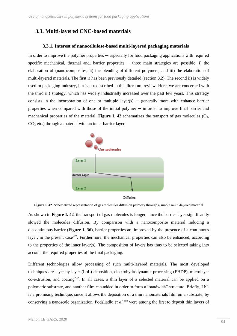
Use of nanocelluloses in polymeric systems for food packaging applications
Manon LE GARS, 2020 94
3.3. Multi-layered CNC-based materials
3.3.1. Interest of nanocellulose-based multi-layered packaging materials
In order to improve the polymer properties ─ especially for food packaging applications with required
specific mechanical, thermal and, barrier properties ─ three main strategies are possible: i) the
elaboration of (nano)composites, ii) the blending of different polymers, and iii) the elaboration of
multi-layered materials. The first i) has been previously detailed (section 3.2). The second ii) is widely
used in packaging industry, but is not described in this literature review. Here, we are concerned with
the third iii) strategy, which has widely industrially increased over the past few years. This strategy
consists in the incorporation of one or multiple layer(s) ─ generally more with enhance barrier
properties when compared with those of the initial polymer ─ in order to improve final barrier and
mechanical properties of the material. Figure I. 42 schematizes the transport of gas molecules (O2,
CO2 etc.) through a material with an inner barrier layer.
Figure I. 42. Schematized representation of gas molecules diffusion pathway through a simple multi-layered material
As shown in Figure I. 42, the transport of gas molecules is longer, since the barrier layer significantly
slowed the molecules diffusion. By comparison with a nanocomposite material inducing a
discontinuous barrier (Figure I. 36), barrier properties are improved by the presence of a continuous
layer, in the present case222. Furthermore, the mechanical properties can also be enhanced, according
to the properties of the inner layer(s). The composition of layers has thus to be selected taking into
account the required properties of the final packaging.
Different technologies allow processing of such multi-layered materials. The most developed
techniques are layer-by-layer (LbL) deposition, electrohydrodynamic processing (EHDP), microlayer
co-extrusion, and coating222. In all cases, a thin layer of a selected material can be applied on a
polymeric substrate, and another film can added in order to form a “sandwich” structure. Briefly, LbL
is a promising technique, since it allows the deposition of a thin nanomaterials film on a substrate, by
conserving a nanoscale organization. Podsliadlo et al.168 were among the first to deposit thin layers of

CHAPTER I : Literature Review
Manon LE GARS, 2020 95
CNCs on poly(diallyldimethylammonium chloride) using the LbL technology. All these processing
strategies have the same challenges, like the compatibility between all the materials, explaining the
addition of adhesive layers in most cases. Moreover, the recycling issue is another challenge, since
layers with different composition generally don’t require the same recyclability processes.
Introduction of nanocelluloses-based layers is highly interesting. Indeed, due to the entrapped
nanostructured network once nanocelluloses are dried, as well as, their outstanding mechanical
properties, final properties of the multi-layered material can be significantly enhanced, and the use of
adhesive is not always needed, since the adhesion of nanomaterials with surrounding layers can act as
an adhesive. Note that for now, only micro-sized structures have been industrially developed (by
extrusion coating or lamination). In this sense, the development of multi-layered materials including
nanostructures is highly challenging. Moreover, the interest of such multi-layered materials including
nanocellulosic materials and poly(lactic acid) makes sense, since the barrier and mechanical properties
of PLA can thus be enhanced, and get close to those of traditional packaging polymers. Nevertheless,
the incompatibility between hydrophobic PLA and hydrophilic CNCs is still a huge issue.
Figure I. 43. SEM images of cross-sectoins of LbL deposition of a) 20 layers and b) 50 layers of NFC/PEI, c) oxygen permeance and d) water vapor permeance of CNF/PEI coated on PLA (extracted from 249)
Regarding the literature, Aulin et al.249 performed layer-by-layer deposition of cellulose nanofibrils
(CNFs) combined with a cationic polymer polyethyleneimine (PEI) on a PLA substrate. After having
proved the efficient deposition of the PEI/CNF mixture onto PLA, they concluded about the
improvement of the barrier properties (towards both oxygen and water vapor) of the final coated
materials, as presented in Figure I. 43. In this case, even if CNFs were used, it is possible to draw a
parallel with a possible behavior of CNCs. This promising study was confirmed by the work of
Meriçer et al.250. Thus, the authors developed multi-layered PLA/MFC (microfibrillated cellulose)
structures by casting evaporation of both layers, and concluded also about the improvement of the
mechanical and barrier properties, as shown in Figure I. 44.

Use of nanocelluloses in polymeric systems for food packaging applications
Manon LE GARS, 2020 96
Figure I. 44. a) Stress-strain curves and b) oxygen permeability (different temperatures, RH=0%) of amorphous or crystalline PLA film (PLA-Am or PLA), MFC self-standing film (MFC G2) and PLA/MFC multi-layered film (PLA/MFC
G2) (extracted from 250)
Thus, only few researches focused on multi-layered materials based on the introduction of
nanocelluloses layers. However, they all concluded about the improvement of barrier and mechanical
properties of the final materials.
The multi-layered strategy is encouraging for the development of new renewable food packaging
materials, by potentially improving the properties of bio-based polymers. Moreover, active
packaging materials can be produced through this strategy, as presented in the following part.
3.3.2. Absorbers and scavenging properties
Active packaging concept was described in previous section 1.2.3. Moisture or specific compound
absorbers, as well as, antimicrobial or antioxidant agents are some examples of active compounds
aiming to improve specificities of a food packaging. A recent and complete review reported by
Yildirim et al.251 summarizes the active compounds according to their properties for active food
packaging. Other macromolecules exist, like calixarenes ─ modified or not ─ which present large
cavities, able to entrap gas molecules like CO2, and thus to slow their diffusion through a packaging.
Such molecules have already been immobilized onto a cellulosic substrate surface, and the entrapment
of nitrogen oxide molecules were proved252.
Figure I. 45. General principle of an active packaging (extracted from 253)

CHAPTER I : Literature Review
Manon LE GARS, 2020 97
Distinctions between absorbers (scavenging systems) and emitter (releasing systems) are clear. Figure
I. 45 schematizes the behavior of an active packaging, with the two different systems, and the presence
of an active layer is visible. Indeed, active compounds are generally introduced in multi-layered
structure, in order to be released inside the packaging or to scavenge specific molecules from food
products. In such a strategy, the presence of both nanocellulose and active compound in the active
layer allow their entrapment or their possible release. In the literature, CNCs have been mixed with
silver nanoparticles239 for antibacterial activity or with carvacrol254 for antioxidant for example. Even
if nanocomposites were the aim of these studies, multi-layered strategies can also be considered.
In this third part, the introduction of cellulose nanocrystals in a polymeric matrix, and especially in
PLA, was detailed. The outstanding final barrier and mechanical properties of the materials are
encouraging and open the door to new composites or multi-layered systems including
nanocelluloses, whose compatibilization with the matrix is still a challenge.

Use of nanocelluloses in polymeric systems for food packaging applications
Manon LE GARS, 2020 98

CHAPTER I : Literature Review
Manon LE GARS, 2020 99
Conclusions of Chapter I
This chapter highlights the outstanding properties of cellulose nanocrystals (CNCs) for a wide range of
applications. In particular, in current environmental context, in which bio-based materials are of high
interest, cellulose nanocrystals can be combined with biobased poly(lactic acid) (PLA), in order to
produce novel multi-component materials, especially for food packaging applications. Indeed,
mechanical and barrier properties of PLA can thus be enhanced, and be competitive with those of
traditional fossil-based polymers.
The main challenge emerging of this first chapter is the poor compatibility between hydrophilic CNCs
and hydrophobic PLA. In this sense, CNCs have to be modified in order to improve their adhesion
with the PLA.
This point is the main objective of this PhD project: the chemical modification of CNCs, in order to
produce original PLA-based materials with improved barrier properties. Moreover, the use of toxic
chemicals will be reduced as far as possible, in order to be consistent with environmental concerns.

Conclusions of Chapter I
Manon LE GARS, 2020 100

CHAPTER I : Literature Review
Manon LE GARS, 2020 101
References – Chapter I
1. PlasticsEurope. PlasticsEurope Market Research Group (PEMRG) (2016).
2. Eurominitor International. Euromonitor International Market Research (2015).
3. REXAM annual report. https://www.companyreporting.com/sites/default/files/accounts/12.12-rexam-
2011.pdf (2011).
4. Alaerts, L., Augustinus, M. & Van Acker, K. Impact of Bio-Based Plastics on Current Recycling of Plastics.
Sustainability 10, 1487 (2018).
5. Karan, H., Funk, C., Grabert, M., Oey, M. & Hankamer, B. Green Bioplastics as Part of a Circular
Bioeconomy. Trends in Plant Science 24, 237–249 (2019).
6. Geyer, R., Jambeck, J. R. & Law, K. L. Production, use, and fate of all plastics ever made. Science
Advances 3, 1700782 (2017).
7. Petersen, K. et al. Potential of biobased materials for food packaging. Trends in Food Science &
Technology 10, 52–68 (1999).
8. Helanto, K., Matikainen, L., Talja, R. & Rojas, O. J. Bio-based Polymers for Sustainable Packaging and
Biobarriers: A Critical Review. BioResources 14, 1-50 (2019).
9. European Standard EN 13432. Requirements for packaging recoverable through composting and
biodegradation – Test scheme and evaluation criteria for the final acceptance of packaging (2000).
10. Paine, F. A. The packaging user’s handbook. (New York: AVI, 1991).
11. Robertson, G. L. Food packaging: principles and practice. (CRC press, 2005).
12. Siracusa, V., Rocculi, P., Romani, S. & Rosa, M. D. Biodegradable polymers for food packaging: a review.
Trends in Food Science & Technology 19, 634–643 (2008).
13. Schmid, M. et al. Properties of Whey-Protein-Coated Films and Laminates as Novel Recyclable Food
Packaging Materials with Excellent Barrier Properties. International Journal of Polymer Science 2012, 1–7
(2012).
14. Oliveira, M. et al. Application of modified atmosphere packaging as a safety approach to fresh-cut fruits
and vegetables – A review. Trends in Food Science & Technology 46, 13–26 (2015).
15. Lee, L., Arul, J., Lencki, R. & Castaigne, F. A review on modified atmosphere packaging and preservation
of fresh fruits and vegetables: Physiological basis and practical aspects—part II. Packaging Technology and
Science 9, 1–17 (1996).
16. Sandhya. Modified atmosphere packaging of fresh produce: Current status and future needs. LWT - Food
Science and Technology 43, 381–392 (2010).
17. Crompton, T. R. Physical testing of plastics (Smithers Rapra, 2012).
18. Yam, K. L., Takhistov, P. T. & Miltz, J. Intelligent Packaging: Concepts and Applications. Journal of Food
Science 70, R1–R10 (2005).
19. Ghaani, M., Cozzolino, C. A., Castelli, G. & Farris, S. An overview of the intelligent packaging
technologies in the food sector. Trends in Food Science & Technology 51, 1–11 (2016).
20. Poyatos-Racionero, E., Ros-Lis, J. V., Vivancos, J.-L. & Martínez-Máñez, R. Recent advances on
intelligent packaging as tools to reduce food waste. Journal of Cleaner Production 172, 3398–3409 (2018).
21. Miltz, J., Passy, N. & Mannheim, C. Trends and applications of active packaging systems. Special
Publication-Royal Society of Chemistry 162, 201–201 (1995).
22. Institute for Bioplastics and Composites. Biopolymers facts and statistics. https://www.ifbb-
hannover.de/files/IfBB/downloads/faltblaetter_broschueren/Biopolymers-Facts-Statistics-2018.pdf (2016).
23. Farmer, N. Trends in packaging of food, beverages and other fast-moving consumer goods (FMCG):
markets, materials and technologies. (Elsevier, 2013).
24. Jiménez, A., Peltzer, M. & Ruseckaite, R. Poly(lactic acid) science and technology processing, properties,
additives and applications. (Royal Society of Chemistry, 2015).
25. Hottle, T. A., Bilec, M. M. & Landis, A. E. Biopolymer production and end of life comparisons using life
cycle assessment. Resources, Conservation and Recycling 122, 295–306 (2017).
26. Spierling, S. et al. Bio-based plastics - A review of environmental, social and economic impact assessments.
Journal of Cleaner Production 185, 476–491 (2018).

References – Chapter I
Manon LE GARS, 2020 102
27. Castro-Aguirre, E., Iñiguez-Franco, F., Samsudin, H., Fang, X. & Auras, R. Poly(lactic acid)—Mass
production, processing, industrial applications, and end of life. Advanced Drug Delivery Reviews 107, 333–
366 (2016).
28. Yates, M. R. & Barlow, C. Y. Life cycle assessments of biodegradable, commercial biopolymers—A
critical review. Resources, Conservation and Recycling 78, 54–66 (2013).
29. Belgacem, M. N. & Gandini, A. Monomers, polymers and composites from renewable resources. (Elsevier,
2008).
30. Garlotta, D. A Literature Review of Poly(Lactic Acid). Journal of Polymers and the Environment 9, 63-842
(2001).
31. Penu, C. & Helou, M. Acide polylactique (PLA). (Techniques de l'Ingénieur, 2017).
32. Colomines, G., Ducruet, V., Courgneau, C., Guinault, A. & Domenek, S. Barrier properties of poly(lactic
acid) and its morphological changes induced by aroma compound sorption. Polymer International 59, 818-
826 (2010).
33. Auras, R. A., Singh, S. P. & Singh, J. J. Evaluation of oriented poly(lactide) polymers vs. existing PET and
oriented PS for fresh food service containers. Packaging Technology and Science 18, 207–216 (2005).
34. Willige, R. W. G. van, Linssen, J. P. H., Meinders, M. B. J., Stege, H. J. van der & Voragen, A. G. J.
Influence of flavour absorption on oxygen permeation through LDPE, PP, PC and PET plastics food
packaging. Food Additives & Contaminants 19, 303–313 (2002).
35. Dumont, M.-J., Reyna‐Valencia, A., Emond, J.-P. & Bousmina, M. Barrier properties of
polypropylene/organoclay nanocomposites. Journal of Applied Polymer Science 103, 618–625 (2007).
36. Raquez, J.-M., Ramy-Ratiarison, R., Murariu, M. & Dubois, P. Reactive Extrusion of PLA-based Materials:
from Synthesis to Reactive Melt-blending. In: Poly(lactic acid) Science and Technlogoy: Processing,
Properties, Additives and Applications (Royal Society of Chemistry, 2014).
37. Vergnes, B. & Chapet, M. Extrusion - Procédés d’extrusion bivis. (Techniques de l'Ingénieur, 2001).
38. Murariu, M. & Dubois, P. PLA composites: From production to properties. Advanced Drug Delivery
Reviews 107, 17–46 (2016).
39. Giessmann, A. Coating Substrates and Textiles - A Practical Guide to Coating and Laminating
Technologies. (Springer Science & Business Media, 2012).
40. Reis, M. O. et al. Biodegradable trays of thermoplastic starch/poly (lactic acid) coated with beeswax.
Industrial Crops and Products 112, 481–487 (2018).
41. Pierleoni, D. et al. Graphene-based coatings on polymer films for gas barrier applications. Carbon 96, 503–
512 (2016).
42. Goh, K. et al. Sandwich-Architectured Poly(lactic acid)–Graphene Composite Food Packaging Films. ACS
Applied Materials & Interfaces 8, 9994–10004 (2016).
43. Rocca-Smith, J. R. et al. Impact of corona treatment on PLA film properties. Polymer Degradation and
Stability 132, 109–116 (2016).
44. Meesorn, W., Calvino, C., Natterodt, J. C., Zoppe, J. O. & Weder, C. Bio-Inspired, Self-Toughening
Polymers Enabled by Plasticizer-Releasing Microcapsules. Advanced Materials 31, 1807212 (2019).
45. R. Snowdon, M., Wu, F., K. Mohanty, A. & Misra, M. Comparative study of the extrinsic properties of
poly(lactic acid)-based biocomposites filled with talc versus sustainable biocarbon. RSC Advances 9, 6752–
6761 (2019).
46. Ouchiar, S. et al. Comparison of the influence of talc and kaolinite as inorganic fillers on morphology,
structure and thermomechanical properties of polylactide based composites. Applied Clay Science 116–117,
231–240 (2015).
47. Sang, L., Han, S., Li, Z., Yang, X. & Hou, W. Development of short basalt fiber reinforced polylactide
composites and their feasible evaluation for 3D printing applications. Composites Part B: Engineering 164,
629–639 (2019).
48. Kyutoku, H., Maeda, N., Sakamoto, H., Nishimura, H. & Yamada, K. Effect of surface treatment of
cellulose fiber (CF) on durability of PLA/CF bio-composites. Carbohydrate Polymers 203, 95–102 (2019).
49. Aliotta, L., Gigante, V., Coltelli, M. B., Cinelli, P. & Lazzeri, A. Evaluation of Mechanical and Interfacial
Properties of Bio-Composites Based on Poly(Lactic Acid) with Natural Cellulose Fibers. International
Journal of Molecular Sciences 20, 960 (2019).

CHAPTER I : Literature Review
Manon LE GARS, 2020 103
50. Khan, G. M. A., Terano, M., Gafur, M. A. & Alam, M. S. Studies on the mechanical properties of woven
jute fabric reinforced poly(l-lactic acid) composites. Journal of King Saud University - Engineering
Sciences 28, 69–74 (2016).
51. Jozala, A. F. et al. Bacterial nanocellulose production and application: a 10-year overview. Appl Microbiol
Biotechnol 100, 2063–2072 (2016).
52. Varshney, V. K. & Naithani, S. Chemical Functionalization of Cellulose Derived from Nonconventional
Sources. In: Cellulose Fibers: Bio- and Nano-Polymer Composites (Springer Berlin Heidelberg, 2011).
53. Suhas et al. Cellulose: A review as natural, modified and activated carbon adsorbent. Bioresource
Technology 216, 1066–1076 (2016).
54. Nechyporchuk, O., Belgacem, M. N. & Bras, J. Production of cellulose nanofibrils: A review of recent
advances. Industrial Crops and Products 93, 2–25 (2016).
55. Klemm, D., Heublein, B., Fink, H.-P. & Bohn, A. Cellulose: Fascinating Biopolymer and Sustainable Raw
Material. Angewandte Chemie International Edition 44, 3358–3393 (2005).
56. O’Sullivan, A. C. Cellulose: the structure slowly unravels. Cellulose 4, 173–207 (1996).
57. Habibi, Y. Key advances in the chemical modification of nanocelluloses. Chem. Soc. Rev. 43, 1519–1542
(2014).
58. Dufresne, A. Nanocellulose: from nature to high performance tailored materials. (Walter de Gruyter GmbH
& Co KG, 2017).
59. Capron, I., Rojas, O. J. & Bordes, R. Behavior of nanocelluloses at interfaces. Current Opinion in Colloid &
Interface Science 29, 83–95 (2017).
60. Moon, R. J., Martini, A., Nairn, J., Simonsen, J. & Youngblood, J. Cellulose nanomaterials review:
structure, properties and nanocomposites. Chemical Society Reviews 40, 3941–3994 (2011).
61. Herrick, F. W., Casebier, R. L., Hamilton, J. K. & Sandberg, K. R. Microfibrillated cellulose: morphology
and accessibility. J. Appl. Polym. Sci.: Appl. Polym. Symp.; (United States) 37, (1983).
62. Turbak, A. F., Snyder, F. W. & Sandberg, K. R. Microfibrillated cellulose, a new cellulose product:
properties, uses, and commercial potential. J. Appl. Polym. Sci.: Appl. Polym. Symp.; (United States) 37,
(1983).
63. Naderi, A., Lindström, T. & Sundström, J. Repeated homogenization, a route for decreasing the energy
consumption in the manufacturing process of carboxymethylated nanofibrillated cellulose? Cellulose 22,
1147–1157 (2015).
64. Jonoobi, M. et al. Different preparation methods and properties of nanostructured cellulose from various
natural resources and residues: a review. Cellulose 22, 935–969 (2015).
65. Osong, S. H., Norgren, S. & Engstrand, P. Processing of wood-based microfibrillated cellulose and
nanofibrillated cellulose, and applications relating to papermaking: a review. Cellulose 23, 93–123 (2016).
66. Iwamoto, S., Nakagaito, A. N. & Yano, H. Nano-fibrillation of pulp fibers for the processing of transparent
nanocomposites. Appl. Phys. A 89, 461–466 (2007).
67. Josset, S. et al. Energy consumption of the nanofibrillation of bleached pulp, wheat straw and recycled
newspaper through a grinding process. Nordic Pulp & Paper Research Journal 29, 167–175 (2014).
68. Abdul Khalil, H. P. S. et al. Production and modification of nanofibrillated cellulose using various
mechanical processes: A review. Carbohydrate Polymers 99, 649–665 (2014).
69. Taipale, T., Österberg, M., Nykänen, A., Ruokolainen, J. & Laine, J. Effect of microfibrillated cellulose and
fines on the drainage of kraft pulp suspension and paper strength. Cellulose 17, 1005–1020 (2010).
70. Baati, R., Magnin, A. & Boufi, S. High Solid Content Production of Nanofibrillar Cellulose via Continuous
Extrusion. ACS Sustainable Chem. Eng. 5, 2350–2359 (2017).
71. Rol, F. et al. Pilot-Scale Twin Screw Extrusion and Chemical Pretreatment as an Energy-Efficient Method
for the Production of Nanofibrillated Cellulose at High Solid Content. ACS Sustainable Chem. Eng. 5,
6524–6531 (2017).
72. Wang, W. et al. Production of cellulose nanofibrils from bleached eucalyptus fibers by hyperthermostable
endoglucanase treatment and subsequent microfluidization. Cellulose 22, 351–361 (2015).
73. Sehaqui, H., Zhou, Q., Ikkala, O. & Berglund, L. A. Strong and Tough Cellulose Nanopaper with High
Specific Surface Area and Porosity. Biomacromolecules 12, 3638–3644 (2011).

References – Chapter I
Manon LE GARS, 2020 104
74. Henriksson, M., Henriksson, G., Berglund, L. A. & Lindström, T. An environmentally friendly method for
enzyme-assisted preparation of microfibrillated cellulose (MFC) nanofibers. European Polymer Journal 43,
3434–3441 (2007).
75. Pääkkö, M. et al. Enzymatic Hydrolysis Combined with Mechanical Shearing and High-Pressure
Homogenization for Nanoscale Cellulose Fibrils and Strong Gels. Biomacromolecules 8, 1934–1941 (2007).
76. Liimatainen, H., Suopajärvi, T., Sirviö, J., Hormi, O. & Niinimäki, J. Fabrication of cationic cellulosic
nanofibrils through aqueous quaternization pretreatment and their use in colloid aggregation. Carbohydrate
Polymers 103, 187–192 (2014).
77. Saini, S., Yücel Falco, Ç., Belgacem, M. N. & Bras, J. Surface cationized cellulose nanofibrils for the
production of contact active antimicrobial surfaces. Carbohydrate Polymers 135, 239–247 (2016).
78. Fukuzumi, H., Saito, T. & Isogai, A. Influence of TEMPO-oxidized cellulose nanofibril length on film
properties. Carbohydrate Polymers 93, 172–177 (2013).
79. Shinoda, R., Saito, T., Okita, Y. & Isogai, A. Relationship between Length and Degree of Polymerization of
TEMPO-Oxidized Cellulose Nanofibrils. Biomacromolecules 13, 842–849 (2012).
80. Fujisawa, S., Okita, Y., Fukuzumi, H., Saito, T. & Isogai, A. Preparation and characterization of TEMPO-
oxidized cellulose nanofibril films with free carboxyl groups. Carbohydrate Polymers 84, 579–583 (2011).
81. Tejado, A., Alam, Md. N., Antal, M., Yang, H. & van de Ven, T. G. M. Energy requirements for the
disintegration of cellulose fibers into cellulose nanofibers. Cellulose 19, 831–842 (2012).
82. Liimatainen, H., Visanko, M., Sirviö, J. A., Hormi, O. E. O. & Niinimaki, J. Enhancement of the
Nanofibrillation of Wood Cellulose through Sequential Periodate–Chlorite Oxidation. Biomacromolecules
13, 1592–1597 (2012).
83. Rol, F., Belgacem, M. N., Gandini, A. & Bras, J. Recent advances in surface-modified cellulose nanofibrils.
Progress in Polymer Science 88, 241–264 (2019).
84. Hubbe, M. A. et al. Nanocellulose in Thin Films, Coatings, and Plies for Packaging Applications: A Review.
BioResources 12, 2143–2233 (2017).
85. Ferrer, A., Pal, L. & Hubbe, M. Nanocellulose in packaging: Advances in barrier layer technologies.
Industrial Crops and Products 95, 574–582 (2017).
86. Siró, I. & Plackett, D. Microfibrillated cellulose and new nanocomposite materials: a review. Cellulose 17,
459–494 (2010).
87. ISO/TC 6/TG 1 - Cellulose Nanomaterials. Summary of International Activities on Cellulose Nanomaterials.
(2017).
88. Ranby, B. G. Fibrous macromolecular systems. Cellulose and muscle. The colloidal properties of cellulose
micelles. Discuss. Faraday Soc. 11, 158–164 (1951).
89. Ranby, B. G. & Ribi, E. Über den feinbau der zellulose. Experientia 6, 12–14 (1950).
90. CelluForce. CelluForce https://www.celluforce.com/en/technology/ (2016).
91. Cranston, E. Overview of Canada. TAPPI Nano Division Conference (Chiba, Japan, 2019).
92. Stevanic, J. S. et al. Bacterial nanocellulose-reinforced arabinoxylan films. Journal of Applied Polymer
Science 122, 1030–1039 (2011).
93. Fu, L., Zhang, J. & Yang, G. Present status and applications of bacterial cellulose-based materials for skin
tissue repair. Carbohydrate Polymers 92, 1432–1442 (2013).
94. Svensson, A. et al. Bacterial cellulose as a potential scaffold for tissue engineering of cartilage.
Biomaterials 26, 419–431 (2005).
95. Gatenholm, P. & Klemm, D. Bacterial Nanocellulose as a Renewable Material for Biomedical Applications.
MRS Bull. 35, 208–213 (2010).
96. Lima, M. M. de S. & Borsali, R. Rodlike Cellulose Microcrystals: Structure, Properties, and Applications.
Macromolecular Rapid Communications 25, 771–787 (2004).
97. Habibi, Y., Lucia, L. A. & Rojas, O. J. Cellulose Nanocrystals: Chemistry, Self-Assembly, and Applications.
Chemical Reviews 110, 3479–3500 (2010).
98. Camarero Espinosa, S., Kuhnt, T., Foster, E. J. & Weder, C. Isolation of Thermally Stable Cellulose
Nanocrystals by Phosphoric Acid Hydrolysis. Biomacromolecules 14, 1223–1230 (2013).
99. Chen, L. et al. Tailoring the yield and characteristics of wood cellulose nanocrystals (CNC) using
concentrated acid hydrolysis. Cellulose 22, 1753–1762 (2015).
CHAPTER I : Literature Review
Manon LE GARS, 2020 105
100. Sadeghifar, H., Filpponen, I., Clarke, S. P., Brougham, D. F. & Argyropoulos, D. S. Production of cellulose
nanocrystals using hydrobromic acid and click reactions on their surface. J Mater Sci 46, 7344–7355 (2011).
101. Yu, H. et al. Facile extraction of thermally stable cellulose nanocrystals with a high yield of 93% through
hydrochloric acid hydrolysis under hydrothermal conditions. Journal of Materials Chemistry A 1, 3938–
3944 (2013).
102. Sirviö, J. A., Visanko, M. & Liimatainen, H. Acidic Deep Eutectic Solvents As Hydrolytic Media for
Cellulose Nanocrystal Production. Biomacromolecules 17, 3025–3032 (2016).
103. Liu, Y. et al. Efficient Cleavage of Strong Hydrogen Bonds in Cotton by Deep Eutectic Solvents and Facile
Fabrication of Cellulose Nanocrystals in High Yields. ACS Sustainable Chem. Eng. 5, 7623–7631 (2017).
104. Flauzino Neto, W. P., Silvério, H. A., Dantas, N. O. & Pasquini, D. Extraction and characterization of
cellulose nanocrystals from agro-industrial residue – Soy hulls. Industrial Crops and Products 42, 480–488
(2013).
105. Johar, N., Ahmad, I. & Dufresne, A. Extraction, preparation and characterization of cellulose fibres and
nanocrystals from rice husk. Industrial Crops and Products 37, 93–99 (2012).
106. Beck-Candanedo, S., Roman, M. & Gray, D. G. Effect of Reaction Conditions on the Properties and
Behavior of Wood Cellulose Nanocrystal Suspensions. Biomacromolecules 6, 1048–1054 (2005).
107. Tang, J., Sisler, J., Grishkewich, N. & Tam, K. C. Functionalization of cellulose nanocrystals for advanced
applications. Journal of Colloid and Interface Science 494, 397–409 (2017).
108. Beck-Candanedo, S., Roman, M. & Gray, D. G. Effect of Reaction Conditions on the Properties and
Behavior of Wood Cellulose Nanocrystal Suspensions. Biomacromolecules 6, 1048–1054 (2005).
109. Lin, N., Huang, J. & Dufresne, A. Preparation, properties and applications of polysaccharide nanocrystals in
advanced functional nanomaterials: a review. Nanoscale 4, 3274–3294 (2012).
110. Klemm, D. et al. Nanocelluloses: A New Family of Nature-Based Materials. Angewandte Chemie
International Edition 50, 5438–5466 (2011).
111. Cheng, M., Chen, W. & Weerasooriya, T. Mechanical Properties of Kevlar® KM2 Single Fiber. Journal of
Engineering Materials and Technology 127, 197–203 (2005).
112. George, J. & Sabapathi, S. Cellulose nanocrystals: synthesis, functional properties, and applications.
Nanotechnol Sci Appl 8, 45–54 (2015).
113. Revol, J.-F., Bradford, H., Giasson, J., Marchessault, R. H. & Gray, D. G. Helicoidal self-ordering of
cellulose microfibrils in aqueous suspension. International Journal of Biological Macromolecules 14, 170–
172 (1992).
114. Foster, E. J. et al. Current characterization methods for cellulose nanomaterials. Chemical Society Reviews
47, 2609–2679 (2018).
115. Viet, D., Beck-Candanedo, S. & Gray, D. G. Dispersion of cellulose nanocrystals in polar organic solvents.
Cellulose 14, 109–113 (2007).
116. Beck, S., Bouchard, J., Chauve, G. & Berry, R. Controlled production of patterns in iridescent solid films of
cellulose nanocrystals. Cellulose 20, 1401–1411 (2013).
117. Mariano, M., Kissi, N. E. & Dufresne, A. Cellulose nanocrystals and related nanocomposites: Review of
some properties and challenges. Journal of Polymer Science Part B: Polymer Physics 52, 791–806 (2014).
118. Kaboorani, A. et al. Nanocrystalline cellulose (NCC): A renewable nano-material for polyvinyl acetate
(PVA) adhesive. European Polymer Journal 48, 1829–1837 (2012).
119. Mascheroni, E. et al. Comparison of cellulose nanocrystals obtained by sulfuric acid hydrolysis and
ammonium persulfate, to be used as coating on flexible food-packaging materials. Cellulose 23, 779–793
(2016).
120. Hoeng, F., Denneulin, A. & Bras, J. Use of nanocellulose in printed electronics: a review. Nanoscale 8,
13131–13154 (2016).
121. Csoka, L. et al. Piezoelectric Effect of Cellulose Nanocrystals Thin Films. ACS Macro Lett. 1, 867–870
(2012).
122. Gaspar, D. et al. Nanocrystalline cellulose applied simultaneously as the gate dielectric and the substrate in
flexible field effect transistors. Nanotechnology 25, 094008 (2014).
123. Karim, Z., Mathew, A. P., Grahn, M., Mouzon, J. & Oksman, K. Nanoporous membranes with cellulose
nanocrystals as functional entity in chitosan: Removal of dyes from water. Carbohydrate Polymers 112,
668–676 (2014).

References – Chapter I
Manon LE GARS, 2020 106
124. Domingues, R. M. A., Gomes, M. E. & Reis, R. L. The Potential of Cellulose Nanocrystals in Tissue
Engineering Strategies. Biomacromolecules 15, 2327–2346 (2014).
125. Lin, N. & Dufresne, A. Nanocellulose in biomedicine: Current status and future prospect. European
Polymer Journal 59, 302–325 (2014).
126. Yang, X., Shi, K., Zhitomirsky, I. & Cranston, E. D. Cellulose Nanocrystal Aerogels as Universal 3D
Lightweight Substrates for Supercapacitor Materials. Advanced Materials 27, 6104–6109 (2015).
127. Kalashnikova, I., Bizot, H., Bertoncini, P., Cathala, B. & Capron, I. Cellulosic nanorods of various aspect
ratios for oil in water Pickering emulsions. Soft Matter 9, 952–959 (2013).
128. Tasset, S., Cathala, B., Bizot, H. & Capron, I. Versatile cellular foams derived from CNC-stabilized
Pickering emulsions. RSC Adv. 4, 893–898 (2014).
129. Zhang, Y. P. Nanocrystalline cellulose for covert optical encryption. Journal of Nanophotonics 6, 063516
(2012).
130. Roman, M. Toxicity of Cellulose ecotoxicological Nanocrystals: A Review. Industrial Biotechnology 11,
25–33 (2015).
131.Kovacs, T. et al. An characterization of nanocrystalline cellulose (NCC). Nanotoxicology 4, 255–270 (2010).
132. Natterodt, J. C., Petri-Fink, A., Weder, C. & Zoppe, J. O. Cellulose Nanocrystals: Surface Modification,
Applications and Opportunities at Interfaces. CHIMIA International Journal for Chemistry 71, 376–383
(2017).
133. Wohlhauser, S. et al. Grafting Polymers from Cellulose Nanocrystals: Synthesis, Properties, and
Applications. Macromolecules 51, 6157–6189 (2018).
134. Kedzior, S. A., Zoppe, J. O., Berry, R. M. & Cranston, E. D. Recent advances and an industrial perspective
of cellulose nanocrystal functionalization through polymer grafting. Current Opinion in Solid State and
Materials Science 23, 74–91 (2018).
135. Eyley, S. & Thielemans, W. Surface modification of cellulose nanocrystals. Nanoscale 6, 7764–7779
(2014).
136. Habibi, Y., Chanzy, H. & Vignon, M. R. TEMPO-mediated surface oxidation of cellulose whiskers.
Cellulose 13, 679–687 (2006).
137. Peng, S. X., Chang, H., Kumar, S., Moon, R. J. & Youngblood, J. P. A comparative guide to controlled
hydrophobization of cellulose nanocrystals via surface esterification. Cellulose 23, 1825–1846 (2016).
138. Bendahou, A., Hajlane, A., Dufresne, A., Boufi, S. & Kaddami, H. Esterification and amidation for grafting
long aliphatic chains on to cellulose nanocrystals: a comparative study. Research on Chemical
Intermediates 41, 4293–4310 (2015).
139. Spinella, S. et al. Concurrent Cellulose Hydrolysis and Esterification to Prepare a Surface-Modified
Cellulose Nanocrystal Decorated with Carboxylic Acid Moieties. ACS Sustainable Chemistry &
Engineering 4, 1538–1550 (2016).
140. Lin, N., Huang, J., Chang, P. R., Feng, J. & Yu, J. Surface acetylation of cellulose nanocrystal and its
reinforcing function in poly(lactic acid). Carbohydrate Polymers 83, 1834–1842 (2011).
141. Espino-Pérez, E., Domenek, S., Belgacem, N., Sillard, C. & Bras, J. Green Process for Chemical
Functionalization of Nanocellulose with Carboxylic Acids. Biomacromolecules 15, 4551–4560 (2014).
142. Jasmani, L., Eyley, S., Wallbridge, R. & Thielemans, W. A facile one-pot route to cationic cellulose
nanocrystals. Nanoscale 5, 10207–10211 (2013).
143. Hemraz, U. D., Boluk, Y. & Sunasee, R. Amine-decorated nanocrystalline cellulose surfaces: synthesis,
characterization, and surface properties. Canadian Journal of Chemistry 91, 974–981 (2013).
144. Azzam, F., Heux, L., Putaux, J.-L. & Jean, B. Preparation By Grafting Onto, Characterization, and
Properties of Thermally Responsive Polymer-Decorated Cellulose Nanocrystals. Biomacromolecules 11,
3652–3659 (2010).
145. Filpponen, I. & Argyropoulos, D. S. Regular Linking of Cellulose Nanocrystals via Click Chemistry:
Synthesis and Formation of Cellulose Nanoplatelet Gels. Biomacromolecules 11, 1060–1066 (2010).
146. Araki, J., Wada, M. & Kuga, S. Steric Stabilization of a Cellulose Microcrystal Suspension by
Poly(ethylene glycol) Grafting. Langmuir 17, 21–27 (2001).
147. Gicquel, E., Martin, C., Heux, L., Jean, B. & Bras, J. Adsorption versus grafting of poly(N-
Isopropylacrylamide) in aqueous conditions on the surface of cellulose nanocrystals. Carbohydrate
Polymers 210, 100–109 (2019).

CHAPTER I : Literature Review
Manon LE GARS, 2020 107
148. Gousse, C., Chanzy, H., Excoffier, G., Soubeyrand, L. & Fleury, E. Stable suspensions of partially silylated
cellulose whiskers dispersed in organic solvents. 43, 2645–2651 (2002).
149. Grunert, M. & Winter, W. T. Nanocomposites of Cellulose Acetate Butyrate Reinforced with Cellulose
Nanocrystals. Journal of Polymers and the Environment 10, 27–30 (2002).
150. Dong, S. & Roman, M. Fluorescently Labeled Cellulose Nanocrystals for Bioimaging Applications. J. Am.
Chem. Soc. 129, 13810–13811 (2007).
151. Zaman, M., Xiao, H., Chibante, F. & Ni, Y. Synthesis and characterization of cationically modified
nanocrystalline cellulose. Carbohydrate Polymers 89, 163–170 (2012).
152. de Oliveira Taipina, M., Ferrarezi, M. M. F., Yoshida, I. V. P. & Gonçalves, M. do C. Surface modification
of cotton nanocrystals with a silane agent. Cellulose 20, 217–226 (2013).
153. Siqueira, G., Bras, J. & Dufresne, A. New Process of Chemical Grafting of Cellulose Nanoparticles with a
Long Chain Isocyanate. Langmuir 26, 402–411 (2010).
154. Habibi, Y. & Dufresne, A. Highly Filled Bionanocomposites from Functionalized Polysaccharide
Nanocrystals. Biomacromolecules 9, 1974–1980 (2008).
155. Kloser, E. & Gray, D. G. Surface Grafting of Cellulose Nanocrystals with Poly(ethylene oxide) in Aqueous
Media. Langmuir 26, 13450–13456 (2010).
156. Harrisson, S., Drisko, G. L., Malmström, E., Hult, A. & Wooley, K. L. Hybrid Rigid/Soft and
Biologic/Synthetic Materials: Polymers Grafted onto Cellulose Microcrystals. Biomacromolecules 12,
1214–1223 (2011).
157. Akhlaghi, S. P., Berry, R. C. & Tam, K. C. Surface modification of cellulose nanocrystal with chitosan
oligosaccharide for drug delivery applications. Cellulose 20, 1747–1764 (2013).
158. Habibi, Y. et al. Bionanocomposites based on poly(ε-caprolactone)-grafted cellulose nanocrystals by ring-
opening polymerization. Journal of Materials Chemistry 18, 5002–5010 (2008).
159. Morandi, G., Heath, L. & Thielemans, W. Cellulose Nanocrystals Grafted with Polystyrene Chains through
Surface-Initiated Atom Transfer Radical Polymerization (SI-ATRP). Langmuir 25, 8280–8286 (2009).
160. Espino-Pérez, E. et al. Nanocomposites with functionalised polysaccharide nanocrystals through aqueous
free radical polymerisation promoted by ozonolysis. Carbohydrate Polymers 135, 256–266 (2016).
161. Kedzior, S. A., Graham, L., Moorlag, C., Dooley, B. M. & Cranston, E. D. Poly(methyl methacrylate)-
grafted cellulose nanocrystals: One-step synthesis, nanocomposite preparation, and characterization. The
Canadian Journal of Chemical Engineering 94, 811–822 (2016).
162. Boujemaoui, A. et al. Polycaprolactone Nanocomposites Reinforced with Cellulose Nanocrystals Surface-
Modified via Covalent Grafting or Physisorption: A Comparative Study. ACS Applied Materials &
Interfaces 9, 35305–35318 (2017).
163. Zhang, Z., Sèbe, G., Wang, X. & Tam, K. C. Gold nanoparticles stabilized by poly(4-vinylpyridine) grafted
cellulose nanocrystals as efficient and recyclable catalysts. Carbohydrate Polymers 182, 61–68 (2018).
164. Zeinali, E., Haddadi‐Asl, V. & Roghani‐Mamaqani, H. Synthesis of dual thermo- and pH-sensitive poly(N-
isopropylacrylamide-co-acrylic acid)-grafted cellulose nanocrystals by reversible addition-fragmentation
chain transfer polymerization. Journal of Biomedical Materials Research Part A 106, 231–243 (2018).
165. Abitbol, T. Surface modification of cellulose nanocrystals with cetyltrimethylammonium bromide. Nordic
Pulp and Paper Research Journal 29, 046–057 (2014).
166. Hu, Z., Ballinger, S., Pelton, R. & Cranston, E. D. Surfactant-enhanced cellulose nanocrystal Pickering
emulsions. Journal of Colloid and Interface Science 439, 139–148 (2015).
167. Bondeson, D. & Oksman, K. Dispersion and characteristics of surfactant modified cellulose whiskers
nanocomposites. Composite Interfaces 14, 617–630 (2007).
168. Podsiadlo, P. et al. Molecularly Engineered Nanocomposites: Layer-by-Layer Assembly of Cellulose
Nanocrystals. Biomacromolecules 6, 2914–2918 (2005).
169. Hu, Z., Berry, R. M., Pelton, R. & Cranston, E. D. One-Pot Water-Based Hydrophobic Surface
Modification of Cellulose Nanocrystals Using Plant Polyphenols. ACS Sustainable Chem. Eng. 5, 5018–
5026 (2017).
170. Isogai, A., Saito, T. & Fukuzumi, H. TEMPO-oxidized cellulose nanofibers. Nanoscale 3, 71–85 (2011).
171. Montanari, S., Roumani, M., Heux, L. & Vignon, M. R. Topochemistry of Carboxylated Cellulose
Nanocrystals Resulting from TEMPO-Mediated Oxidation. Macromolecules 38, 1665–1671 (2005).

References – Chapter I
Manon LE GARS, 2020 108
172. Fraschini, C., Chauve, G. & Bouchard, J. TEMPO-mediated surface oxidation of cellulose nanocrystals
(CNCs). Cellulose 24, 2775–2790 (2017).
173. Saito, T. & Isogai, A. Introduction of aldehyde groups on surfaces of native cellulose fibers by TEMPO-
mediated oxidation. Colloids and Surfaces A: Physicochemical and Engineering Aspects 289, 219–225
(2006).
174. Saito, T. et al. Individualization of Nano-Sized Plant Cellulose Fibrils by Direct Surface Carboxylation
Using TEMPO Catalyst under Neutral Conditions. Biomacromolecules 10, 1992–1996 (2009).
175. Sun, B., Hou, Q., Liu, Z. & Ni, Y. Sodium periodate oxidation of cellulose nanocrystal and its application as
a paper wet strength additive. Cellulose 22, 1135–1146 (2015).
176. Guo, J. et al. Photoluminescent Hybrids of Cellulose Nanocrystals and Carbon Quantum Dots as
Cytocompatible Probes for in Vitro Bioimaging. Biomacromolecules 18, 2045–2055 (2017).
177. Boujemaoui, A., Mongkhontreerat, S., Malmström, E. & Carlmark, A. Preparation and characterization of
functionalized cellulose nanocrystals. Carbohydrate Polymers 115, 457–464 (2015).
178. Dufresne, A. Nanocellulose: from nature to high performance tailored materials. (Walter de Gruyter GmbH
& Co KG, 2017).
179. Çetin, N. S. et al. Acetylation of Cellulose Nanowhiskers with Vinyl Acetate under Moderate Conditions.
Macromolecular Bioscience 9, 997–1003 (2009).
180. Goffin, A.-L. et al. From Interfacial Ring-Opening Polymerization to Melt Processing of Cellulose
Nanowhisker-Filled Polylactide-Based Nanocomposites. Biomacromolecules 12, 2456–2465 (2011).
181. Zoppe, J. O. et al. Poly( iNi -isopropylacrylamide) Brushes Grafted from Cellulose Nanocrystals via
Surface-Initiated Single-Electron Transfer Living Radical Polymerization. Biomacromolecules 11, 2683–
2691 (2010).
182. Fumagalli, M., Sanchez, F., Molina Boisseau, S. & Heux, L. Gas-phase esterification of cellulose
nanocrystal aerogels for colloidal dispersion in apolar solvents. Soft Matter 9, 11309–11317 (2013).
183. Yoo, Y. & Youngblood, J. P. Green One-Pot Synthesis of Surface Hydrophobized Cellulose Nanocrystals in
Aqueous Medium. ACS Sustainable Chemistry & Engineering 4, 3927–3938 (2016).
184. Espino-Pérez, E. et al. Designed cellulose nanocrystal surface properties for improving barrier properties in
polylactide nanocomposites. Carbohydrate Polymers 183, 267–277 (2018).
185. Peltzer, M., Pei, A., Zhou, Q., Berglund, L. & Jiménez, A. Surface modification of cellulose nanocrystals by
grafting with poly(lactic acid). Polymer International 63, 1056–1062 (2014).
186. Miao, C. & Hamad, W. Y. In-situ polymerized cellulose nanocrystals (CNC)-poly(l-lactide) (PLLA)
nanomaterials and applications in nanocomposite processing. Carbohydr Polym 153, 549–558 (2016).
187. Kan, K. H. M., Li, J., Wijesekera, K. & Cranston, E. D. Polymer-Grafted Cellulose Nanocrystals as pH-
Responsive Reversible Flocculants. Biomacromolecules 14, 3130–3139 (2013).
188. Zubik, K., Singhsa, P., Wang, Y., Manuspiya, H. & Narain, R. Thermo-Responsive Poly(N-
Isopropylacrylamide)-Cellulose Nanocrystals Hybrid Hydrogels for Wound Dressing. Polymers 9, 119
(2017).
189. Matyjaszewski, K. & Xia, J. Atom Transfer Radical Polymerization. Chemical Reviews 101, 2921–2990
(2001).
190. Matyjaszewski, K. Advanced Materials by Atom Transfer Radical Polymerization. Advanced Materials 30,
1706441 (2018).
191. Matyjaszewski, K. Atom Transfer Radical Polymerization (ATRP): Current Status and Future Perspectives.
Macromolecules 45, 4015–4039 (2012).
192. Yi, J., Xu, Q., Zhang, X. & Zhang, H. Chiral-nematic self-ordering of rodlike cellulose nanocrystals grafted
with poly(styrene) in both thermotropic and lyotropic states. Polymer 49, 4406–4412 (2008).
193. Zhang, Z., Wang, X., Tam, K. C. & Sèbe, G. A comparative study on grafting polymers from cellulose
nanocrystals via surface-initiated atom transfer radical polymerization (ATRP) and activator re-generated
by electron transfer ATRP. Carbohydrate Polymers 205, 322–329 (2019).
194. Lepoittevin, B. et al. Hydrophobization of chitosan films by surface grafting with fluorinated polymer
brushes. Carbohydrate Polymers 205, 437–446 (2019).
195. Hatton, F. L., Kedzior, S. A., Cranston, E. D. & Carlmark, A. Grafting-from cellulose nanocrystals via
photoinduced Cu-mediated reversible-deactivation radical polymerization. Carbohydrate Polymers 157,
1033–1040 (2017).

CHAPTER I : Literature Review
Manon LE GARS, 2020 109
196. Wang, H.-D., Roeder, R. D., Whitney, R. A., Champagne, P. & Cunningham, M. F. Graft modification of
crystalline nanocellulose by Cu(0)-mediated SET living radical polymerization. Journal of Polymer Science
Part A: Polymer Chemistry 53, 2800–2808 (2015).
197. Boujemaoui, A. et al. Polycaprolactone Nanocomposites Reinforced with Cellulose Nanocrystals Surface-
Modified via Covalent Grafting or Physisorption: A Comparative Study. ACS Appl. Mater. Interfaces 9,
35305–35318 (2017).
198. Hemraz, U. D., Lu, A., Sunasee, R. & Boluk, Y. Structure of poly(N-isopropylacrylamide) brushes and
steric stability of their grafted cellulose nanocrystal dispersions. Journal of Colloid and Interface Science
430, 157–165 (2014).
199. Braunecker, W. A. & Matyjaszewski, K. Controlled/living radical polymerization: Features, developments,
and perspectives. Progress in Polymer Science 32, 93–146 (2007).
200. Chiefari, J. et al. Living Free-Radical Polymerization by Reversible Addition−Fragmentation Chain
Transfer: The RAFT Process. Macromolecules 31, 5559–5562 (1998).
201. Zeinali, E., Haddadi-Asl, V. & Roghani-Mamaqani, H. Nanocrystalline cellulose grafted random
copolymers of N -isopropylacrylamide and acrylic acid synthesized by RAFT polymerization: effect of
different acrylic acid contents on LCST behavior. RSC Advances 4, 31428–31442 (2014).
202. Boujemaoui, A., Mazières, S., Malmström, E., Destarac, M. & Carlmark, A. SI-RAFT/MADIX
polymerization of vinyl acetate on cellulose nanocrystals for nanocomposite applications. Polymer 99, 240–
249 (2016).
203. Liu, T., Xue, F. & Ding, E. Cellulose nanocrystals grafted with polyacrylamide assisted by macromolecular
RAFT agents. Cellulose 23, 3717–3735 (2016).
204. D. Roeder, R., Garcia-Valdez, O., A. Whitney, R., Champagne, P. & F. Cunningham, M. Graft modification
of cellulose nanocrystals via nitroxide-mediated polymerisation. Polymer Chemistry 7, 6383–6390 (2016).
205. Hansson, S., Antoni, P., Bergenudd, H. & Malmström, E. Selective cleavage of polymer grafts from solid
surfaces: assessment of initiator content and polymer characteristics. Polymer Chemistry 2, 556–558 (2011).
206. Zhang, Z., Tam, K. C., Sèbe, G. & Wang, X. Convenient characterization of polymers grafted on cellulose
nanocrystals via SI-ATRP without chain cleavage. Carbohydrate Polymers 199, 603–609 (2018).
207. Villares, A., Moreau, C., Dammak, A., Capron, I. & Cathala, B. Kinetic aspects of the adsorption of
xyloglucan onto cellulose nanocrystals. Soft Matter 11, 6472–6481 (2015).
208. Heux, L., Chauve, G. & Bonini, C. Nonflocculating and Chiral-Nematic Self-ordering of Cellulose
Microcrystals Suspensions in Nonpolar Solvents. Langmuir 16, 8210–8212 (2000).
209.Tardy, B. L. et al. Nanocellulose–surfactant interactions. Current Opinion in Colloid & Interface Science 29,
57–67 (2017).
210. Kaboorani, A. & Riedl, B. Surface modification of cellulose nanocrystals (CNC) by a cationic surfactant.
Industrial Crops and Products 65, 45–55 (2015).
211. Rojas, O. J., Montero, G. A. & Habibi, Y. Electrospun nanocomposites from polystyrene loaded with
cellulose nanowhiskers. Journal of Applied Polymer Science 113, 927–935 (2009).
212. Kedzior, S. A., Marway, H. S. & Cranston, E. D. Tailoring Cellulose Nanocrystal and Surfactant Behavior
in Miniemulsion Polymerization. Macromolecules 50, 2645–2655 (2017).
213. Hu, Z., Marway, H. S., Kasem, H., Pelton, R. & Cranston, E. D. Dried and Redispersible Cellulose
Nanocrystal Pickering Emulsions. ACS Macro Letters 5, 185–189 (2016).
214. Cheng, D. et al. Adsorption of polyethylene glycol (PEG) onto cellulose nano-crystals to improve its
dispersity. Carbohydrate Polymers 123, 157–163 (2015).
215. Pereda, M., Kissi, N. E. & Dufresne, A. Extrusion of Polysaccharide Nanocrystal Reinforced Polymer
Nanocomposites through Compatibilization with Poly(ethylene oxide). ACS Appl. Mater. Interfaces 6,
9365–9375 (2014).
216. Dufresne, A. Cellulose nanomaterials as green nanoreinforcements for polymer nanocomposites.
Philosophical Transactions of the Royal Society A: Mathematical, Physical and Engineering Sciences 376,
20170040 (2018).
217. Oksman, K. et al. Review of the recent developments in cellulose nanocomposite processing. Composites
Part A: Applied Science and Manufacturing 83, 2–18 (2016).
218. Ferreira, F. V. et al. How do cellulose nanocrystals affect the overall properties of biodegradable polymer
nanocomposites: A comprehensive review. European Polymer Journal 108, 274–285 (2018).

References – Chapter I
Manon LE GARS, 2020 110
219. Abdul Khalil, H. P. S., Bhat, A. H. & Ireana Yusra, A. F. Green composites from sustainable cellulose
nanofibrils: A review. Carbohydrate Polymers 87, 963–979 (2012).
220. Eichhorn, S. J. et al. Review: current international research into cellulose nanofibres and nanocomposites. J
Mater Sci 45, 1–33 (2010).
221. Okada, A. et al. Composite material and process for manufacturing same. U.S. Patent No 4,739,007 (1988).
222. Cerqueira, M. A. P. R., Lagaron, J. M., Castro, L. M. P., de Oliveira Soares Vincente A. A. M.
Nanomaterials for food packaging: materials, processing technologies and safety issues. (Elsevier, 2018).
223. European Commission, Commission Regulation (EU) No 10/2011 of 14 January 2011 on plastic materials
and articles intended to come into contact with food. Off J Eur Union 12, 1-89 (2011).
224. Bumbudsanpharoke, N. & Ko, S. Nano-Food Packaging: An Overview of Market, Migration Research, and
Safety Regulations. Journal of Food Science 80, R910–R923 (2015).
225. Siqueira, G., Bras, J. & Dufresne, A. Cellulosic Bionanocomposites: A Review of Preparation, Properties
and Applications. Polymers 2, 728–765 (2010).
226. Favier, V. et al. Nanocomposite materials from latex and cellulose whiskers. Polymers for Advanced
Technologies 6, 351–355 (1995).
227. Nielsen, L. E. Models for the Permeability of Filled Polymer Systems. Journal of Macromolecular Science:
Part A - Chemistry 1, 929–942 (1967).
228. Oksman, K., Mathew, A. P., Bondeson, D. & Kvien, I. Manufacturing process of cellulose
whiskers/polylactic acid nanocomposites. Composites Science and Technology 66, 2776–2784 (2006).
229. Bondeson, D. & Oksman, K. Polylactic acid/cellulose whisker nanocomposites modified by polyvinyl
alcohol. Composites Part A: Applied Science and Manufacturing 38, 2486–2492 (2007).
230. Yang, W., Dominici, F., Fortunati, E., M. Kenny, J. & Puglia, D. Melt free radical grafting of glycidyl
methacrylate (GMA) onto fully biodegradable poly(lactic) acid films: effect of cellulose nanocrystals and a
masterbatch process. RSC Advances 5, 32350–32357 (2015).
231. Dhar, P., Tarafder, D., Kumar, A. & Katiyar, V. Thermally recyclable polylactic acid/cellulose nanocrystal
films through reactive extrusion process. Polymer 87, 268–282 (2016).
232. Arias, A., Heuzey, M.-C., Huneault, M. A., Ausias, G. & Bendahou, A. Enhanced dispersion of cellulose
nanocrystals in melt-processed polylactide-based nanocomposites. Cellulose 22, 483–498 (2015).
233. Xiang, C., Joo, Y. L. & Frey, M. W. Nanocomposite fibers electrospun from poly(lactic acid)/cellulose
nanocrystals. Journal of Biobased Materials and Bioenergy 3, 147–155 (2009).
234. Shi, Q. et al. Mechanical properties and in vitro degradation of electrospun bio-nanocomposite mats from
PLA and cellulose nanocrystals. Carbohydrate Polymers 90, 301–308 (2012).
235. Fortunati, E. et al. Effects of modified cellulose nanocrystals on the barrier and migration properties of PLA
nano-biocomposites. Carbohydrate Polymers 90, 948–956 (2012).
236. Lin, N., Chen, G., Huang, J., Dufresne, A. & Chang, P. R. Effects of polymer-grafted natural nanocrystals
on the structure and mechanical properties of poly(lactic acid): A case of cellulose whisker-graft-
polycaprolactone. Journal of Applied Polymer Science 113, 3417–3425 (2009).
237. Bitinis, N. et al. Poly(lactic acid)/natural rubber/cellulose nanocrystal bionanocomposites. Part II: Properties
evaluation. Carbohydrate Polymers 96, 621–627 (2013).
238. Robles, E., Urruzola, I., Labidi, J. & Serrano, L. Surface-modified nano-cellulose as reinforcement in
poly(lactic acid) to conform new composites. Industrial Crops and Products 71, 44–53 (2015).
239. Fortunati, E. et al. Multifunctional bionanocomposite films of poly(lactic acid), cellulose nanocrystals and
silver nanoparticles. Carbohydrate Polymers 87, 1596–1605 (2012).
240. Mariano, M. et al. Preparation of Cellulose Nanocrystal-Reinforced Poly(lactic acid) Nanocomposites
through Noncovalent Modification with PLLA-Based Surfactants. ACS Omega 2, 2678–2688 (2017).
241. Xu, C. et al. Polylactide/acetylated nanocrystalline cellulose composites prepared by a continuous route: A
phase interface-property relation study. Carbohydrate Polymers 146, 58–66 (2016).
242. Habibi, Y., Aouadi, S., Raquez, J.-M. & Dubois, P. Effects of interfacial stereocomplexation in cellulose
nanocrystal-filled polylactide nanocomposites. Cellulose 20, 2877–2885 (2013).
243. Mujica-Garcia, A. et al. Poly(lactic acid) melt-spun fibers reinforced with functionalized cellulose
nanocrystals. RSC Adv. 6, 9221–9231 (2016).
244. Lizundia, E. et al. PLLA-grafted cellulose nanocrystals: Role of the CNC content and grafting on the PLA
bionanocomposite film properties. Carbohydrate Polymers 142, 105–113 (2016).

CHAPTER I : Literature Review
Manon LE GARS, 2020 111
245. Zhou, C. et al. Electrospun Bio-Nanocomposite Scaffolds for Bone Tissue Engineering by Cellulose
Nanocrystals Reinforcing Maleic Anhydride Grafted PLA. ACS Appl. Mater. Interfaces 5, 3847–3854
(2013).
246. Pracella, M., Haque, Md. M.-U. & Puglia, D. Morphology and properties tuning of PLA/cellulose
nanocrystals bio-nanocomposites by means of reactive functionalization and blending with PVAc. Polymer
55, 3720–3728 (2014).
247. Spinella, S. et al. Polylactide/cellulose nanocrystal nanocomposites: Efficient routes for nanofiber
modification and effects of nanofiber chemistry on PLA reinforcement. Polymer 65, 9–17 (2015).
248. Bagheriasl, D., Safdari, F., Carreau, P. J., Dubois, C. & Riedl, B. Development of cellulose nanocrystal-
reinforced polylactide: A comparative study on different preparation methods. Polymer Composites 40,
E342–E349 (2019).
249. Aulin, C., Karabulut, E., Tran, A., Wågberg, L. & Lindström, T. Transparent Nanocellulosic Multilayer
Thin Films on Polylactic Acid with Tunable Gas Barrier Properties. ACS Appl. Mater. Interfaces 5, 7352–
7359 (2013).
250. Meriçer, Ç. et al. Atmospheric plasma assisted PLA/microfibrillated cellulose (MFC) multilayer
biocomposite for sustainable barrier application. Industrial Crops and Products 93, 235–243 (2016).
251. Yildirim, S. et al. Active Packaging Applications for Food. Comprehensive Reviews in Food Science and
Food Safety 17, 165–199 (2018).
252. Hines, J. H., Wanigasekara, E., Rudkevich, D. M. & Rogers, R. D. Calix[4]arenes immobilized in a
cellulose-based platform for entrapment and detection of NOx gases. Journal of Materials Chemistry 18,
4050–4055 (2008).
253. Yildirim, S. Newsletter Transfer. (Switzerland, 2010).
254. Luzi, F. et al. Cellulose nanocrystals from Actinidia deliciosa pruning residues combined with carvacrol in
PVA_CH films with antioxidant/antimicrobial properties for packaging applications. International Journal
of Biological Macromolecules 104, 43–55 (2017).

Manon LE GARS, 2020 112

Manon LE GARS, 2020 113
CHAPTER II
Chemical modifications
of cellulose nanocrystals

Table of contents – Chapter II
Manon LE GARS, 2020 114

CHAPTER II : Chemical modifications of CNCs
Manon LE GARS, 2020 115
Table of contents – Chapter II
Introduction to Chapter II _________________________________________________ 117
1. Surface-initiated transfer radical polymerization from the surface of modified-
cellulose nanocrystals _____________________________________________________ 119
1. Introduction _______________________________________________________________121
2. Materials and methods ______________________________________________________124
2.1. Materials_______________________________________________________________________124
2.2. Functionalization of CNCs with α-Bromoisobutyryl Bromide ______________________________124
2.3. SI-ATRP of glycidyl methacrylate on functionalized CNC-Br _____________________________124
2.4. Polymerization of homopolymer PGMA ______________________________________________125
2.5. Characterization methods __________________________________________________________125
3. Results and discussions _____________________________________________________129
3.1. Characterization of cellulose nanomaterials ____________________________________________129
3.2. Preparation of initiator modified CNC ________________________________________________129
3.3. Kinetics of SI-ATRP of GMA ______________________________________________________134
3.4. SI-ATRP of functionalized CNC-Br at different polymerization times _______________________138
3.5. Efficiency of SI-ATRP on CNCs ____________________________________________________139
4. Conclusion _______________________________________________________________143
2. Grafting of fatty acids on cellulose nanocrystals via a novel procedure __________ 145
2.1. Comparison between two different methods for the chemical modification of
cellulose nanocrystals _____________________________________________________ 145
1. Introduction _______________________________________________________________147
2. Materials and methods ______________________________________________________149
2.1. Materials_______________________________________________________________________149
2.2. Classical esterification of CNCs using 10-undecenoyl chloride _____________________________149
2.3. Esterification of CNCs with 10-undecenoic acid via a novel method ________________________149
2.4. Characterization methods __________________________________________________________150
3. Results and discussions _____________________________________________________152
3.1. Influence of the chemical modifications on the structure of the CNCs _______________________152
3.2. Efficiency of the two surface modification methods _____________________________________153
4. Conclusion _______________________________________________________________156
2.2. Role of solvent exchange in dispersion of cellulose nanocrystals and their
esterification using acids as solvents _________________________________________ 157
1. Introduction _______________________________________________________________159
2. Materials and methods ______________________________________________________162
2.1. Materials_______________________________________________________________________162
2.2. CNC suspensions preparation ______________________________________________________162
2.3. Esterification of CNCs with fatty acids _______________________________________________163
2.4. Characterization methods __________________________________________________________164
3. Results and discussions _____________________________________________________167
3.1. Different ways for the dispersion of CNC in acetone _____________________________________167
3.2. Influence of solvent exchange on the grafting efficiency __________________________________169
3.3. Influence of chain length on CNC grafting (Suspension 3) ________________________________176
3.4. Surface analyses of long chains onto CNC _____________________________________________179

Table of contents – Chapter II
Manon LE GARS, 2020 116
4. Conclusion _______________________________________________________________183
3. Amidation of TEMPO-oxidized cellulose nanocrystals using aromatic aminated
molecules _______________________________________________________________ 185
1. Introduction _______________________________________________________________187
2. Materials and methods ______________________________________________________190
2.1. Materials_______________________________________________________________________190
2.2. Oxidation of CNCs using TEMPO reagent _____________________________________________190
2.3. Amidation of TEMPO-CNC using 1-M-3-PP with EDC/NHS catalysis ______________________190
2.4. Characterization methods __________________________________________________________192
3. Results and discussions _____________________________________________________199
3.1. Characterization of TEMPO-CNC prepared on a large scale _______________________________199
3.2. Grafting efficiency of 1-M-3-PP on TEMPO-CNC through amidation _______________________205
3.3. Indirect proofs of grafting efficiency _________________________________________________207
3.4. Physico-chemical adsorption of 1-M-3-PP at the surface of TEMPO-CNC ___________________209
4. Conclusion ________________________________________________________________213
4. Adsorption of rosin nanoparticles from a nano-emulsion on both cellulose
nanocrystals and nanofibrils _______________________________________________ 215
1. Introduction _______________________________________________________________217
2. Materials and methods ______________________________________________________219
2.1. Materials_______________________________________________________________________219
2.2. Preparation of rosin nano-emulsion __________________________________________________219
2.3. Adsorption of rosin nano-emulsion on CNF ___________________________________________220
2.4. Adsorption of rosin nano-emulsion on CNC ___________________________________________220
2.5. Elaboration of neat and modified CNF-Rosin films by filtration ____________________________220
2.6. Elaboration of neat and modified CNC-Rosin films by solvent casting_______________________220
2.7. Characterization methods __________________________________________________________221
3. Results and discussions _____________________________________________________222
3.1. Nanometric size of rosin particles ___________________________________________________222
3.2. Efficiency of the rosin adsorption on both CNF and CNC _________________________________223
4. Conclusion ________________________________________________________________225
Conclusions of Chapter II __________________________________________________ 227
References - Chapter II ____________________________________________________ 231

CHAPTER II : Chemical modifications of CNCs
Manon LE GARS, 2020 117
Introduction to Chapter II
As described in the Chapter I, surface chemical modifications of CNCs are made possible thanks to
their high surface area and highly reactive surface. One of the main goals of this PhD project is the
functionalization of the CNCs surface (objective 1), in order to enhance their compatibilization with a
hydrophobic PLA polymeric matrix. The global project ─ in which the PhD is part of ─ involved
different partners, with different needs in terms of quantities of grafted CNCs. It explains the division
of the following Chapter II in four different sections, whose respective chemical modifications can be
performed on increasing amounts of CNCs.
More precisely, the Chapter II proposes four different new routes for the chemical modifications of
CNCs, with related characterizations and discussions. The Figure II. 1 represents the organization of
this chapter.
▪ The section II.1 relates the polymerization of the glycidyl methacrylate (GMA) from the
surface of previously functionalized CNCs, as well as, the characterization of the kinetics of the
polymerization. The chosen route for the polymerization is the SI-ATRP (Surface-Initiated Atom
Transfer Polymerization), in order to control the surface polymerization. Moreover, the choice of
GMA as monomer is explained by the presence of numerous highly reactive epoxy groups all along
the polymer chain, which could be potentially help for the incorporation of polymerized CNC-PGMA-
Br in a PLA matrix. This study was mainly performed in the laboratory ICMMO (Institut de Chimie
Moléculaire et des Matériaux d’Orsay, in Orsay, France)
▪ The section II.2 is divided in two sub-sections, and the first one (II.2.1) is a short additional
part aiming to compare a classical esterification procedure using an acid chloride (10-Undecenoyl
chloride) with that using a novel esterification using a similar carboxylic acid (10-Undecenoic acid). In
the second sub-section (II.2.2), this new esterification procedure is more detailed, and its efficiency is
investigated. Moreover, the preliminary study focusing on the role of the initial CNC dispersion state
is also explained.
▪ The section II.3 is dedicated to the modification of a large batch of previously oxidized
TEMPO-CNC via an amidation reaction using an aromatic amine (1-methyl-3-phenylpropylamine).
The efficiency of the two-step reaction is investigated, as well as, preliminary results of the parallel
adsorption occurring in the reaction media.

Introduction to Chapter II
Manon LE GARS, 2020 118
▪ Finally, the short section II.4 presents the preliminary results related to the preparation of
rosin nano-emulsion, and their adsorption on both cellulose nanocrystals and nanofibrils surface. This
study includes results produced by the start-up INOFIB (Grenoble, France), with whom collaboration
was carried out during this PhD project.
All the modified nanomaterials described and characterized in this Chapter II will then be used for
the preparation of PLA-based materials, whose results are described in the following Chapter III of
this manuscript.
Figure II. 1. General organization of the PhD manuscript

CHAPTER II : Chemical modifications of CNCs
Manon LE GARS, 2020 119
1. Surface-initiated transfer radical
polymerization of glycidyl methacrylate from the
surface of modified-cellulose nanocrystals
This section is adapted from M. Le Gars, J. Bras, H. Salmi-Mani, M. Ji, D. Dragoe, H. Faraj, S.
Domenek, M. N. Belgacem, P. Roger “Polymerization of glycidyl methacrylate from the surface of
cellulose nanocrystals for the elaboration of PLA-based nanocomposites”, Carbohydrate Polymers,
2020.

Surface-initiated transfer radical polymerization of glycidyl methacrylate from the surface of modified-cellulose
nanocrystals
Manon LE GARS, 2020 120
Abstract
Cellulose nanocrystals (CNCs) are used to design nanocomposites because of their high aspect ratio
and their outstanding mechanical and barrier properties. However, the low compatibility of
hydrophilic CNCs with hydrophobic polymers remains a barrier to their use in the nanocomposite field.
To improve this compatibility, poly(glycidyl methacrylate) (PGMA) was grafted from CNCs
containing α-bromoisobutyryl moieties via surface-initiated atom transfer radical polymerization. The
novelty of this research is the use of a reactive epoxy-containing monomer that can serve as a new
platform for further modifications or crosslinking. Polymer-grafted CNC-PGMA-Br prepared at
different polymerization times were characterized by XRD, DLS, FTIR, XPS and elemental analysis.
Approximately 40% of the polymer at the surface of the CNCs was quantified after only 1 h of
polymerization.
Keywords:
Cellulose nanocrystals ─ Chemical grafting ─ Surface-initiated atom transfer radical polymerization ─
Poly(glycidyl methacrylate)

CHAPTER II : Chemical modifications of CNCs
Manon LE GARS, 2020 121
1. Introduction
Because of its abundance and availability from a wide variety of sources, cellulose is currently a
polymer of choice in the field of bio-based materials. Recently, several novel nanomaterials have been
extracted from this natural biopolymer. Indeed, cellulose nanofibrils (CNFs) have been classically
obtained since the 1980s by applying a mechanical treatment to a cellulose suspension1. Conversely,
since the 1960s, CNCs are produced by performing an acid hydrolysis, meaning removing the
amorphous part of cellulose2,3. Such nanomaterials are relevant for a large number of research fields,
like nanocomposites2,4–6, coatings7,8, packaging7,8 and biomedical applications9–11. They exhibit
interesting properties like biodegradability, renewability and mechanical and barrier properties that
endow them with particular advantages. In the past decade, accelerated industrialization and
commercialization of such cellulosic nanomaterials has occurred, in parallel with an ever-increasing
demand from industry.
Among nanocelluloses, CNCs exhibit interesting properties. Acid hydrolysis of native cellulose from
various sources (cotton, wood, natural fibers, etc.) using sulfuric acid H2SO4 leads to CNCs with
different dimensions and aspect ratios. The resulting sulfuric-acid-hydrolyzed CNCs hold sulfate half
ester groups (-OSO3-) on their surface12,13, with a surface charge density generally in the range from 80
to 350 µmol.g-1 12,14. These surface charges combined with their nanometric size — 150-500 nm in
length (up to 1000 nm), 5-20 nm in width according to their source2,12 — induce colloidal stability of
aqueous suspensions12,13. In addition to their high aspect ratio, CNCs exhibit a high surface area12,15,
high crystallinity16 and a large availability of hydroxyl groups on their surface12,15. Moreover, their
rod-like shape, their high mechanical strength (Young’s modulus between 120 and 200 GPa)17,18, and
their sustainability make them attractive materials as fillers in nanocomposites5,19–21.
However, the hydrophilicity of CNCs, resulting from the three OH groups per anhydroglucose unit
(AGU), limits their dispersion in several polymer matrices, especially non-polar matrices. Moreover,
CNCs begin to degrade at approximately 200-300 °C22, depending on their morphology, crystallinity,
and source. These two last points are challenging when such nanomaterials are used for
nanocomposite processing, where high temperatures are reached with expected well-dispersed
nanofillers23,24. These challenges can be overcome through chemical or physico-chemical
modifications of CNCs4,15,25, by grafting single molecules19,20,25–28 or polymers chains21,29–32 at the
surface of CNCs, or by adsorbing various molecules, involving ionic or low-energy bonding
phenomena2,33–36.
Chemical modifications are carried out by modifying multiple hydroxyl groups at the surface of CNCs
to provide the nanomaterials with specific properties. To improve the compatibility of CNCs with a
hydrophobic polymer matrix, grafting single molecules or polymer chains are classically described in
the literature and in reviews. Focusing on the second strategy, two major approaches are commonly

Surface-initiated transfer radical polymerization of glycidyl methacrylate from the surface of modified-cellulose
nanocrystals
Manon LE GARS, 2020 122
used to introduce polymeric chains at the surface of CNCs. In the grafting-onto strategy, CNCs, ether
pre-functionalized or not, are directly grafted with previously polymerized and characterized polymer
chains30,37–39, leading to limited surface grafting density because of the steric hindrance between
polymers. In the grafted-from approach — on which this study focuses — monomers are polymerized
from pre-functionalized CNCs with initiator sites21,29,40,41. This two-step strategy leads to an overall
controlled structure and higher surface grafting density because of the facilitated access to the
activated initiator sites on CNCs, although characterization of grafted polymer chains is more
challenging42. Ring-opening polymerization (ROP)32,40 and atom transfer radical polymerization
(ATRP)29,41,43 are the most common types of polymerization used in the grafting-from strategy.
Controlled surface-initiated ATRP (SI-ATRP) from the surface of CNCs has been described in the
literature29,41,43,44. However, the major issues with SI-ATRP are the difficulty in characterizing grafted
polymers and recovery of the free homopolymer. Control of the polymerization is generally studied
using polymers obtained from a sacrificial initiator, from which the kinetics of the polymerization is
considered similar to polymerization from the surface of CNCs. By recovering and characterizing the
free homopolymer, information about the grafted chains can be acquired45. It should be noted that this
step of cleaning is challenging and crucial for characterizing both grafted CNCs and free polymers.
The aim of this study is to graft polymer brushes of various lengths on the surface of CNCs via
grafting-from SI-ATRP. Numerous studies have focused on the polymerization of various polymers on
CNCs, mostly in order to compatibilize these nanomaterials with various polymer matrices. Recently,
Zoppe et al.46 studied the synthesis of poly(N,N-dimethylacrylamide) chains at the surface of CNCs
and carried out an alkaline hydrolysis to remove and analyze the polymerized chains. Sessini et al.37
reported the polymerization via grafting-from of L-lactide and ε-caprolactone at the surface of CNCs
and studied the morphological, thermal, and mechanical properties of such modified CNCs in various
polymer matrices.
The objective of the present study is to graft the poly(glycidyl methacrylate) (PGMA) obtained from
the polymerization of glycidyl methacrylate (GMA), an epoxy-functional and commercially available
monomer47 on CNCs. The traditional method of polymerizing GMA in a controlled manner is by atom
transfer radical polymerization (ATRP), with the use of an initiator and a catalyst system47. These
methods aim to control the polymerization behavior. PGMA was selected for this study because of its
hydrophobicity48 and the presence of the highly reactive epoxy functions, which can be an active
attachment point for further modifications. To our knowledge, such a strategy is new in the field of
CNC modification and with respect to this reactive polymer at the surface of CNCs. Control of the
polymerization is essential to quantify the polymer and is conducted through SI-ATRP, as mentioned
previously. To the best of our knowledge, PGMA has never been polymerized at the surface of CNCs
via a grafting-from SI-ATRP approach. Martinez-Sanz et al.49 grafted PGMA via a non-controlled
polymerization applied on bacterial cellulose nanowhiskers for PLA nanocomposites applications.

CHAPTER II : Chemical modifications of CNCs
Manon LE GARS, 2020 123
Hansson et al.50 grafted various polymers, including PGMA from a cellulosic filter paper substrate, via
activators regenerated by electron transfer (ARGET) ATRP to limit the use of reducing reagents and
avoid the use of a totally inert atmosphere. Malmström et al.51 presented different ways of
functionalizing cellulose papers by controlling the surface grafting and grafted PGMA via SI-ATRP
but the grafting was done at the surface of cellulose fibers to introduce a large amount of oxirane
groups. More recently, Cheng et al.52 performed a similar SI-ATRP of GMA from a nanoporous
cellulose gel (NCG) followed by a hydrophobic modification of polymerized NCG to produce
functional materials based on NCGs.
In the present paper, an efficient SI-ATRP polymerization of GMA from the surface of CNCs is
described. The experiment method covers various steps. First, CNCs are functionalized with α-
bromoisobutyryl bromide (BIB), a brominated initiator commonly used in ATRP47,53. Then, GMA is
polymerized from these initiator sites, with challenges like control and recovery of the homopolymer.
Polymerized CNCs at different polymerization times are characterized using various techniques, from
bulk characterization (FTIR, elemental analysis, TGA) to surface characterization (XPS).

Surface-initiated transfer radical polymerization of glycidyl methacrylate from the surface of modified-cellulose
nanocrystals
Manon LE GARS, 2020 124
2. Materials and methods
Materials
Cellulose nanocrystals (CNC) were produced from wood pulp and purchased from CelluForce
(Quebec, Canada), in spray-dried form. 4-(dimethylamino)pyridine (DMAP), triethylamine (TEA), α-
bromoisobutyryl bromide (BIB), ethyl α-bromoisobutyrate (EBIB), and N,N,N’,N’’,N’’-
pentamethyldiethylenetriamine (PMDETA) were supplied from Sigma-Aldrich Chimie (Saint-
Quentin-Fallavier, France) and were used as received. Copper (I) bromide (CuBr) was purchased from
Sigma-Aldrich Chimie. CuBr was purified by washing in glacial acetic acid for 24 h at ambient
temperature, filtered, rinsed extensively with ethanol and diethyl ether, dried under vacuum, and
stored in an inert atmosphere before use54. Glycidyl methacrylate (GMA) was purchased from Fisher
Scientific (France) and purified through a basic alumina column to remove stabilizers before use. N,N-
Dimethylformamide (DMF) was purchased from Sigma-Aldrich Chimie, stored, and used in
anhydrous conditions. Dichloromethane (DCM) and ethanol (EtOH) were purchased from Sigma-
Aldrich Chimie and used as received.
Functionalization of CNCs with α-Bromoisobutyryl Bromide
Functionalization of CNC with BIB was performed by esterification reaction according to the protocol
adapted from Morandi et al.41. This protocol is as follows. First, 1.0 g of dry CNCs was dispersed in
100 mL of anhydrous DMF and an ultrasonic treatment was applied. Then, 125 mg of DMAP (1.02
mmol) was solubilized in 2 mL of anhydrous DMF and added to the CNC suspension. Thereafter, 2.1
mL of TEA (14.9 mmol) was added, followed by 1.9 mL of BIB (14.9 mmol). The reaction was
performed at room temperature for 24 h, under argon flow. At the end of the reaction, the
functionalized CNC-Br were washed by successive cycles of centrifugation (9000 rpm, 10’, 5 °C): in
DMF once, in DCM twice, in a mixture of DCM/EtOH (1/1, v/v) once, and in EtOH twice. CNC-Br
were then dried under vacuum.
SI-ATRP of glycidyl methacrylate on functionalized CNC-Br
The method for SI-ATRP of GMA onto CNCs was adapted from classical ATRP of this monomer47.
First, 0.5 g of previously functionalized CNC-Br was redispersed in a Schlenk in 10 mL of anhydrous
DMF and magnetically stirred under argon, before being treated with ultrasound. Then, 0.054 mL of
EBIB, 0.076 mL of PMDETA, and 4.8 mL of purified GMA were successively added to the
suspension ([GMA]0:[EBIB]0:[PMDETA]0:[CuBr]0 = 100:1:1:1). The sacrificial EBIB was added to
react as a sacrificial initiator, assuming that the polymerization of GMA occurred from this initiator, in
the same manner as from the surface of our CNC-Br. Next, 0.054 g of CuBr was introduced quickly
and at the last moment, to avoid oxidation, noticeable by a color change. A flow of argon was set up in
the closed Schlenk under magnetic stirring. A total of 7 freeze-thaw cycles were carried out to

CHAPTER II : Chemical modifications of CNCs
Manon LE GARS, 2020 125
completely remove oxygen from the suspension. The mixture was then magnetically stirred under
argon at room temperature for 24 h. Study of the polymerization kinetics was performed by collecting
aliquots of the reaction media with a purged argon syringe. At the end of the reaction, a small amount
of DCM was added to recover all the mixture and a first centrifugation cycle (9000 rpm, 15’, 5 °C)
was carried out. The supernatant containing PGMA polymerized from the sacrificial initiator was
recovered for characterization. The centrifuged part was further washed in DCM with five cycles of
centrifugation (9000 rpm, 15’, 5 °C) to eliminate all the free homopolymer and to only retrieve CNC-
PGMA-Br. The solubilized PGMA homopolymer recovered in the DCM supernatant was purified on a
basic alumina column, precipitated in cold methanol, filtered, and dried under vacuum.
Polymerization of homopolymer PGMA
The reference homopolymer PGMA was prepared by ATRP according to the previously described
method. Indeed, the same protocol was used without CNC and a sacrificial initiator and with
[GMA]0:[PMDETA]0:[CuBr]0 = 100:1:1. After 7 freeze-thaw cycles, polymerization occurred at room
temperature for 1 h. At the end of the reaction, solubilized PGMA was purified on a basic alumina
column and precipitated in cold methanol. After filtration and drying, PGMA homopolymer was
characterized by 1H-NMR, and a conversion rate of 52% and a theoretical molar mass of 7300 g.mol-1
was calculated. This homopolymer was used as reference PGMA in this study.
Characterization methods
2.5.1. Atomic Force Microscopy (AFM)
AFM images of CNC suspensions were recorded using a Dimension Icon Brucker equipped with a
silicon-coated micro cantilever (O-TESPA) using tapping mode. Droplets of diluted CNC suspension
(10-4 wt%) were deposited on clean mica plates, which were allowed to dry by evaporation overnight.
Approximately ten scans of 10 µm x 10 µm and 3 µm x 3 µm were obtained for each sample to
analyze the morphology of the nanoparticles by measuring the dimensions of at least 50 CNC samples
using ImageJ software.
2.5.2. Transmission Electron Microscopy (TEM)
TEM copper grids with thin amorphous carbon films were submitted to glow discharge in an easiGlow
station (Pelco). A 4-µL diluted CNC suspension droplet was deposited on the carbon film, followed by
a droplet of uranyl acetate (2 wt%). Negative dye in excess was absorbed, and the remaining film was
dried. The CNC suspension was observed through a transmission electron microscope FEI/Philips
CM200 with the microscopy NanoBio-ICMG platform (Grenoble, France), under an acceleration
voltage of 200 kV. Pictures were recorded with a digital camera TVIPS TemCam F216 (2040 x 2040
pixels). Representative images were selected for the analysis.
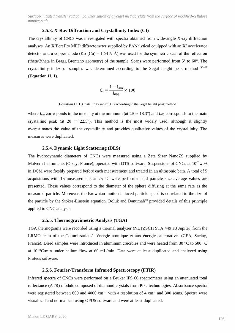
Surface-initiated transfer radical polymerization of glycidyl methacrylate from the surface of modified-cellulose
nanocrystals
Manon LE GARS, 2020 126
2.5.3. X-Ray Diffraction and Crystallinity Index (CI)
The crystallinity of CNCs was investigated with spectra obtained from wide-angle X-ray diffraction
analyses. An X’Pert Pro MPD diffractometer supplied by PANalytical equipped with an X’ accelerator
detector and a copper anode (Kα (Cu) = 1.5419 Å) was used for the symmetric scan of the reflection
(theta/2theta in Bragg Brentano geometry) of the sample. Scans were performed from 5° to 60°. The
crystallinity index of samples was determined according to the Segal height peak method 55–57
(Equation II. 1).
CI =1 − Iam
I002× 100
Equation II. 1. Cristallinity index (CI) according to the Segal height peak method
where Iam corresponds to the intensity at the minimum (at 2θ ≃ 18.3°) and I002 corresponds to the main
crystalline peak (at 2θ ≃ 22.5°). This method is the most widely used, although it slightly
overestimates the value of the crystallinity and provides qualitative values of the crystallinity. The
measures were duplicated.
2.5.4. Dynamic Light Scattering (DLS)
The hydrodynamic diameters of CNCs were measured using a Zeta Sizer NanoZS supplied by
Malvern Instruments (Orsay, France), operated with DTS software. Suspensions of CNCs at 10-2 wt%
in DCM were freshly prepared before each measurement and treated in an ultrasonic bath. A total of 5
acquisitions with 15 measurements at 25 °C were performed and particle size average values are
presented. These values correspond to the diameter of the sphere diffusing at the same rate as the
measured particle. Moreover, the Brownian motion-induced particle speed is correlated to the size of
the particle by the Stokes-Einstein equation. Boluk and Danumah58 provided details of this principle
applied to CNC analysis.
2.5.5. Thermogravimetric Analysis (TGA)
TGA thermograms were recorded using a thermal analyzer (NETZSCH STA 449 F3 Jupiter) from the
LRMO team of the Commissariat à l'énergie atomique et aux énergies alternatives (CEA, Saclay,
France). Dried samples were introduced in aluminum crucibles and were heated from 30 °C to 500 °C
at 10 °C/min under helium flow at 60 mL/min. Data were at least duplicated and analyzed using
Proteus software.
2.5.6. Fourier-Transform Infrared Spectroscopy (FTIR)
Infrared spectra of CNCs were performed on a Bruker IFS 66 spectrometer using an attenuated total
reflectance (ATR) module composed of diamond crystals from Pike technologies. Absorbance spectra
were registered between 600 and 4000 cm-1, with a resolution of 4 cm-1 and 300 scans. Spectra were
visualized and normalized using OPUS software and were at least duplicated.
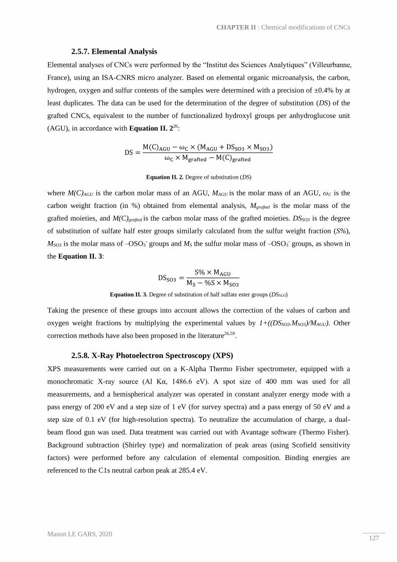
CHAPTER II : Chemical modifications of CNCs
Manon LE GARS, 2020 127
2.5.7. Elemental Analysis
Elemental analyses of CNCs were performed by the “Institut des Sciences Analytiques” (Villeurbanne,
France), using an ISA-CNRS micro analyzer. Based on elemental organic microanalysis, the carbon,
hydrogen, oxygen and sulfur contents of the samples were determined with a precision of ±0.4% by at
least duplicates. The data can be used for the determination of the degree of substitution (DS) of the
grafted CNCs, equivalent to the number of functionalized hydroxyl groups per anhydroglucose unit
(AGU), in accordance with Equation II. 226:
DS =M(C)AGU − ωC × (MAGU + DSSO3 × MSO3)
ωC × Mgrafted − M(C)grafted
Equation II. 2. Degree of substitution (DS)
where M(C)AGU is the carbon molar mass of an AGU, MAGU is the molar mass of an AGU, ωC is the
carbon weight fraction (in %) obtained from elemental analysis, Mgrafted is the molar mass of the
grafted moieties, and M(C)grafted is the carbon molar mass of the grafted moieties. DSSO3 is the degree
of substitution of sulfate half ester groups similarly calculated from the sulfur weight fraction (S%),
MSO3 is the molar mass of –OSO3- groups and MS the sulfur molar mass of –OSO3
- groups, as shown in
the Equation II. 3:
DSSO3 =S% × MAGU
MS − %S × MSO3
Equation II. 3. Degree of substitution of half sulfate ester groups (DSSO3)
Taking the presence of these groups into account allows the correction of the values of carbon and
oxygen weight fractions by multiplying the experimental values by 1+((DSSO3.MSO3)/MAGU). Other
correction methods have also been proposed in the literature26,59.
2.5.8. X-Ray Photoelectron Spectroscopy (XPS)
XPS measurements were carried out on a K-Alpha Thermo Fisher spectrometer, equipped with a
monochromatic X-ray source (Al Kα, 1486.6 eV). A spot size of 400 mm was used for all
measurements, and a hemispherical analyzer was operated in constant analyzer energy mode with a
pass energy of 200 eV and a step size of 1 eV (for survey spectra) and a pass energy of 50 eV and a
step size of 0.1 eV (for high-resolution spectra). To neutralize the accumulation of charge, a dual-
beam flood gun was used. Data treatment was carried out with Avantage software (Thermo Fisher).
Background subtraction (Shirley type) and normalization of peak areas (using Scofield sensitivity
factors) were performed before any calculation of elemental composition. Binding energies are
referenced to the C1s neutral carbon peak at 285.4 eV.

Surface-initiated transfer radical polymerization of glycidyl methacrylate from the surface of modified-cellulose
nanocrystals
Manon LE GARS, 2020 128
2.5.9. 1H-Liquid State Nuclear Magnetic Resonance (1H-NMR)
1H-NMR analyses were performed on a Bruker 360 MHz spectrometer in deuterated chloroform at
room temperature, with a residual signal appearing at 7.24 ppm. Chemical shift values were calculated
with TMS as the first reference. Spectra were analyzed using NMR Notebook software.
2.5.10. Size-Exclusion Chromatography (SEC)
Polymeric samples were dissolved in tetrahydrofuran (THF) at a concentration of 1 mg/mL. SEC
analyses were carried out with a two-column ViscoGel mixed bed from Viscotek (7.8 x 300 mm, type
GMHH r-H). This mixed bed was mounted on a device equipped with a refractive index detector
(Waters 410). The injected volume of sample solution was equal to 50 µL. The calibration range
corresponded to linear polystyrene standards. The process was duplicated.

CHAPTER II : Chemical modifications of CNCs
Manon LE GARS, 2020 129
3. Results and discussions
Characterization of cellulose nanomaterials
Commercial spray-dried cellulose nanocrystal powder was used in this study (Figure II. 2 a)). These
CNCs are produced from wood by sulfuric acid hydrolysis of bleached pulp14 and can easily be
redispersed at low concentration in water and polar organic solvents (such as DMF or DMSO) using
ultrasound treatment with an ultrasonic probe60.
Figure II. 2. a) Spray-dried CNC from CelluForce, b) AFM height image of CNC, and c) TEM image of CNC
Using the AFM and TEM images (Figure II. 2 b) and c)), morphology of the neat nanomaterials can
be confirmed, and the average length is 108 +/- 33 nm and average diameter is 4 +/- 1 nm, confirming
the values found in the literature12,14. The X-Ray diffractograms (Figure II. 3 a)) display three main
peaks, at 16.2° (signal 110), 22.6° (signal 200), and 34.6° (signal 004), characteristic of the cellulose I
crystalline form. Moreover, the CI calculated according to Equation II. 1 has a value equal to 91%,
consistent with the high crystallinity of CNC presented in the literature3.
Preparation of initiator modified CNC
BIB is a common reagent used in the CNC functionalization based on ATRP. As found in the
literature41,44,48, this grafting introduces highly reactive brominated functionality at the surface of
nanomaterials. These functionalized sites can then be used as initiator sites for further controlled
radical polymerization reactions. In the present study, the brominated functionalized site at the surface
of the CNC-Br served as initiators for the SI-ATRP applied to the GMA monomer. The
functionalization of CNCs with BIB, leading to CNC-Br, is illustrated in Scheme II. 1.

Surface-initiated transfer radical polymerization of glycidyl methacrylate from the surface of modified-cellulose
nanocrystals
Manon LE GARS, 2020 130
Scheme II. 1. Procedure for to the preparation of CNC-Br and CNC-PGMA-Br materials
Conservation of the structure of the CNCs after their functionalization is crucial and has been
investigated by XRD analyses. Figure II. 3 a) shows wide-angle diffractogram of modified CNC-Br,
whose spectra correspond to cellulose I beta. The calculated CI is equal to 86%, confirming the
conservation of the crystalline structure of CNC-Br. Modified CNC-Br are well-dispersed in DCM,
with a mean apparent diameter size of 122 nm, which is similar to that of neat CNC dispersed in DCM
(Figure II. 3 b)). Even if the dispersion of CNC in DCM does not lead to conclusions regarding their
dispersion in DMF, the dispersion state in DCM provides some insight about their dispersion in polar

CHAPTER II : Chemical modifications of CNCs
Manon LE GARS, 2020 131
DMF. This dispersion should theoretically be greater. Thus, it is likely that isolated CNC-Br in DMF
would provide a large accessible surface for further polymerization.
Figure II. 3. a) X-ray diffractograms of neat CNCs, pre-functionalized CNC-Br, CNC-PGMA-Br after 1 h and 24 h of polymerization and PGMA homopolymer, b) DLS curves of neat CNC, pre-functionalized CNC-Br and CNC-PGMA-Br
after two different polymerization times in dichloromethane, and c) FTIR spectra of PGMA homopolymer, unmodified CNC, grafted CNC-Br, polymerized CNC-PGMA-Br-1h, and CNC-PGMA-Br_24h
FTIR analyses carried out on neat CNC and modified CNC-Br clearly show the efficiency of the
grafting of BIB. Indeed, in addition to the characteristic peaks of cellulose (i.e., large peak between
3000 cm-1 and 3700 cm-1 corresponding to the stretching vibrations bands of the -OH bonds of

Surface-initiated transfer radical polymerization of glycidyl methacrylate from the surface of modified-cellulose
nanocrystals
Manon LE GARS, 2020 132
hydroxyl groups, as well as peaks at 1110 cm-1, 1060 cm-1 and 1035 cm-1 corresponding to the
vibration of the -C-O bonds of carbons from the repeating unit of cellulose), the peak at 1730 cm-1 is
correlates to the -C=O vibration band resulting from ester functional units introduced at the surface of
CNC (Figure II. 3 c)).
Moreover, no peak near 1760-1800 cm-1 corresponding to the (-C=O)-Br bond from unreacted BIB is
observed. This confirms the efficiency of the washing steps after the reaction. Elemental analyses were
carried out on unmodified CNC and grafted CNC-Br to confirm this grafting (Table II. 1). Corrected
values were obtained by considering the presence of half-sulfate ester groups at the surface of CNCs,
and the DS of the grafts on the CNCs that were equal to 0.17 was calculated according to Equation II.
2. Differences between the corrected values for neat CNC and theoretical values for pure cellulose can
be attributed to the presence of hemicelluloses and impurities in the raw materials. The calculations
performed in this study are based on the values corrected according to the method proposed previously
(Equation II. 2).
Sample Experimental values
DSSO3
Corrected
values Experimental
O/C
Theoretical
O/C DS %PGMA
%C %O %H %S %C %O
Neat CNC 40.7 50.8 6.4 0.8 0.04 41.5 51.8 1.2 1.1 / 0
CNC-Br 42.0 45.3 6.0 0.8 0.04 42.8 46.2 1.1 0.8 0.17 0
CNC-PGMA-
Br_1h 49.6 37.0 6.9 0.6 0.03 50.6 37.7 0.7
0.7
/ 48
CNC-PGMA-
Br_24h 53.2 36.7 6.9 0.2 0.01 54.2 37.4 0.7 / 70
PGMA
(theoretical) / / / / / 59.1 33.8 / 0.6 / 100
Table II. 1. Atomic composition of neat CNCs, CNC-Br, CNC-PGMA-Br_1h and CNC-PGMA-Br_24h obtained by
elemental analysis
To further determine and quantify the grafting at the surface of CNC-Br, XPS measurements were
taken allowing the characterization of the surface of the materials as being approximately 10 nm in
depth41. Figure II. 4 a) shows the XPS sureys of neat CNC and grafted CNC-Br. Both spectra are
composed of two main peaks at approximately 534 and 288 eV corresponding to the oxygen and
carbon components, respectively. A peak at 71 eV correlated with a bromine component is visible in
the CNC-Br survey, and quantification of the Br3d spectrum leads to an atomic percentage of bromine
equal to 1.0% at the surface of CNC-Br. Figure II. 4 b) and c) show the decomposition spectra of the
C1s signal for both neat and grafted CNC-Br.

CHAPTER II : Chemical modifications of CNCs
Manon LE GARS, 2020 133
Figure II. 4. a) XPS survey of neat CNCs and grafted CNC-Br, and decomposition of the C1s peak of b) neat CNCs and c) CNC-Br spectra
The neat CNC spectrum displays three peaks, at 285.4 eV, 287.0 eV (ΔeV= 1.6 eV), and 288.4 eV
(ΔeV= 3 eV), corresponding to C1 (C-C/C-H), C2 (C-O), and C3 (O-C-O/C=O) bonds respectively.
The C1 signal is present in the neat CNC spectrum but is related to the contribution of non-oxidized
alkane-type carbon atoms and impurities, residual lignin, or extractive compounds, justifying its
presence. The C2 signal is related to the presence of ether groups from pure cellulose, as well as the
hydroxyl groups of the unmodified CNCs and of the end of the cellulose chains, explaining its
presence in both samples. The C3 signal corresponds to acetal moieties from AGU units and should
not change significantly after chemical modification, because the corresponding carbon is not affected.
Subsequent to α-bromoisobutyryl bromide grafting, a C4 contribution appears in the CNC-Br
spectrum and is correlated to the introduction of (O-C=O) bonds on the material with a ratio of 5%,
which confirms the success of the bromide derivative grafting, as previously described in the
literature61 (Figure II. 4 b) and Table II. 2)

Surface-initiated transfer radical polymerization of glycidyl methacrylate from the surface of modified-cellulose
nanocrystals
Manon LE GARS, 2020 134
Sample
Experimental values C1s decomposition
%C %O O/C C-C /
C-H C-O
O-C-O /
C-O O-C=O C*-C-O
C-O-C
(epoxy ring)
Neat CNC 56 44 0.79 7 72 21 / / /
CNC-Br 57 41 0.72 8 69 18 5 / /
CNC-PGMA-Br_1h 68 32 0.47 29 13 / 9 15 33
CNC-PGMA-Br_24h 70 30 0.43 21 17 / 16 18 28
PGMA homopolymer 72 28 0.39 30 31 / 13 13 13
Table II. 2. Elemental molar compositions and surface functional group compositions obtained by XPS analysis
In addition, the oxygen to carbon ratio (O/C) associated with the sample before and after modification
changed from 0.79 (close to that of pure cellulose ≈0.83 17) for the neat CNCs to 0.72 for the CNC-Br
as a result of the α-bromoisobutyryl bromide moiety grafted at the surface of CNCs (Table II. 2).
From these results, it is possible to conclude the efficient grafting of CNC-Br. Thus, the presence of
initiator sites for the further polymerization of GMA on CNC-Br is clearly confirmed.
Kinetics of the SI-ATRP of GMA
Prior to any polymerization and characterization, it is essential to determine that no parallel reaction
— especially adsorption — occurs between cellulose and the monomer. This point was investigated by
applying a similar treatment to that of SI-ATRP, but without an initiator, catalyst, or ligand. Only neat
CNCs dispersed in anhydrous DMF in the same proportions and the GMA monomer were
magnetically stirred for 24 h. CNCs were then recovered after five centrifugation cycles in DCM, and
FTIR spectra were obtained after evaporation of the solvent (Figure II. 5 a)). There is no change in
the FTIR spectra of neat CNC after being mixed with the monomer for 24 h; in particular, there is no
peak related to a C=O bond from GMA at approximately 1720 cm-1. At this stage, it can be assumed
that further evidence of the presence of characteristic groups of GMA and PGMA do not come from
possible adsorbed monomer on CNC.
After being grafted, CNC-Br were then polymerized at their brominated initiator sites with GMA, as
illustrated in Scheme II. 1. Glycidyl methacrylate (GMA) is a monomer that has never been used as
part of the polymerization from the surface of wood CNC, to the best of our knowledge. In the
literature, only a few studies describe ATRP of GMA47,62 on cellulose, presented as a well-known and
controlled polymerization. In our case, the difficulty of the polymerization lays in the high reactivity
of the epoxy groups of PGMA which can rapidly open. Nevertheless, opening of these epoxy
functional groups has been avoided by the reaction at room temperature, in anhydrous conditions, and
with the absence of any reagents that can react with these groups. Moreover, it has been shown in the
literature that a similar system for SI-ATRP of GMA on a substrate (CuBr/PMDETA) leads to the
conservation of active epoxy groups on the polymer chains 63. Meanwhile, the presence of these epoxy
groups at the surface of polymerized CNC is one objective of this polymerization and is precisely
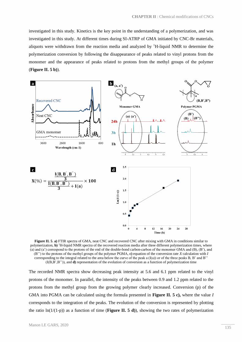
CHAPTER II : Chemical modifications of CNCs
Manon LE GARS, 2020 135
investigated in this study. Kinetics is the key point in the understanding of a polymerization, and was
investigated in this study. At different times during SI-ATRP of GMA initiated by CNC-Br materials,
aliquots were withdrawn from the reaction media and analyzed by 1H-liquid NMR to determine the
polymerization conversion by following the disappearance of peaks related to vinyl protons from the
monomer and the appearance of peaks related to protons from the methyl groups of the polymer
(Figure II. 5 b)).
Figure II. 5. a) FTIR spectra of GMA, neat CNC and recovered CNC after mixing with GMA in conditions similar to polymerization, b) 1H-liquid NMR spectra of the recovered reaction media after three different polymerization times, where (a) and (a’) correspond to the protons of the end of the double-bond carbon-carbon of the monomer GMA and (B), (B’), and
(B’’) to the protons of the methyl groups of the polymer PGMA, c) equation of the conversion rate X calculation with I corresponding to the integral related to the area below the curve of the peak a (I(a)) or of the three peaks B, B’ and B’’
(I(B,B’,B’’)), and d) representation of the evolution of conversion as a function of polymerization time
The recorded NMR spectra show decreasing peak intensity at 5.6 and 6.1 ppm related to the vinyl
protons of the monomer. In parallel, the intensity of the peaks between 0.9 and 1.2 ppm related to the
protons from the methyl group from the growing polymer clearly increased. Conversion (p) of the
GMA into PGMA can be calculated using the formula presented in Figure II. 5 c), where the value I
corresponds to the integration of the peaks. The evolution of the conversion is represented by plotting
the ratio ln(1/(1-p)) as a function of time (Figure II. 5 d)), showing the two rates of polymerization

Surface-initiated transfer radical polymerization of glycidyl methacrylate from the surface of modified-cellulose
nanocrystals
Manon LE GARS, 2020 136
with a higher rate in a shorter time period (between 0 and 4 h) and a slower rate after a longer
polymerization time period. From each collected aliquot the PGMA homopolymer was recovered after
filtration on basic alumina and precipitated in cold methanol. Each homopolymer sample was
subjected to SEC analysis to obtain the value of its molar mass (according to the equivalent
polystyrene). Polydispersity index Ð was calculated as the ratio of weight average molar mass (Mw) to
the number average molar mass (Mn). The results are presented in Figure II. 6 a).
Figure II. 6. a) Molar masses of homopolymer and dispersities obtained by conventional SEC analyses, b) FTIR spectra of recovered CNC-PGMA-Br at different polymerization times, and c) ratios of peak intensities related to epoxy
groups/cellulose and ester groups/cellulose
The evolution of the PGMA molar masses calculated by SEC analyses as a function of the conversion
follows the same trend as previously mentioned with two different rates of polymerization. Indeed, in
the first 3 h of polymerization, the molar masses increased from 8179 g.mol-1 to 9791 g.mol-1,
followed by a slower rate of polymerization reaching molar masses equal to 10343 g.mol-1 after 24 h
of reaction (Figure II. 6 d)). This behavior has been previously described for a similar system
(GMA/CuBr/PMDETA) in the literature64, where it was attributed to the heterogeneous character of
the system inducing side-reactions at high conversion rates. Indeed, radical bromine elements from the

CHAPTER II : Chemical modifications of CNCs
Manon LE GARS, 2020 137
cellulose surface could be lost, inducing termination at the level of the CNCs. Nevertheless,
polymerization would continue in the system solution. Figure II. 6 b) shows the FTIR spectra of
CNC-PGMA-Br at different polymerization times, recovered from the aliquots after centrifugation in
DCM. Qualitative analysis of these spectra confirms the polymerization on CNCs, with an increase in
the peak at 1725 cm-1 related to the C=O stretching of ester groups and the presence of a peak at 910
cm-1 related to the C-O stretching from epoxy groups. It is interesting to note that ATRP
polymerization applied on the GMA monomer, involving the present CuBr/PMEDETA catalytic
system, ensures the preparation of an epoxy functional polymer. In fact, as shown in the the literature65,
decribing the grafting of multiwalled carbon nanotubes with PGMA polymer using the same ATRP
polymerization procedure, a further post modification to introduce molecules of interest is possible by
taking advantage of the epoxy functional groups.
Furthermore, to quantitatively analyze these spectra, the ratios of the absorbance values of both C=O
and C-O peaks and cellulose (1110 cm-1) were plotted as a function of time. The obtained curves
(Figure II. 6 c)) follow the previously mentioned trend: with short polymerization time (1 to 3 h),
there is an increase in the polymer chain length at the surface of cellulose, which becomes slower at
longer times (4 to 24 h). Taking into account these results (summarized in Table II. 3), one hypothesis
might be that the decreasing polymerization rate is due to the deactivation of brominated active sites
grafted at the surface of CNC as well as those from the sacrificial initiator. A transfer reaction
resulting from the hydroxyl -OH groups of CNC could be an explanation for this deactivation. In the
remainder of this study, we will focus on the characterization of CNC-PGMA-Br polymerized at two
different polymerization times (1 h and 24 h): CNC-PGMA-Br_1h and CNC-PGMA-Br_24h,
respectively.
Time
(h)
1H-liquid NMR SEC (Conventional) FTIR absorbance ratio
Conversion
(%)
Mntheoretical
(g.mol-1)
Mn
(g.mol-1)
Dispersity
(Ð)
Epoxy (intensity at 910
cm-1) / Cellulose
(intensity at 1110 cm-1)
Ester (intensity at 1725
cm-1) / Cellulose
(intensity at 1110 cm-1)
0 0 / / / 0.08 0
0.3 35 4944 8200 1.2 0.45 1.13
1 46 6600 8900 1.3 0.37 1.0
2 53 7552 9800 1.3 0.65 1.33
3 58 8209 9800 1.3 0.54 1.60
17 80 11391 10000 1.4 0.59 1.85
24 85 12145 10300 1.4 0.58 1.84
Table II. 3. Summary of kinetics study data obtained from 1H-liquid NMR, SEC (conventional), and FTIR (* Mntheoretical = (p*([GMA]/[EBIB])*MGMA)+MEBIB with p the conversion, [GMA] the initial concentration in monomer, [EBIB] the initial
concentration in initiator, MGMA the molar mass of GMA and MEBIB the molar mass of EBIB (the calculation takes into account the polymer chain extremities))
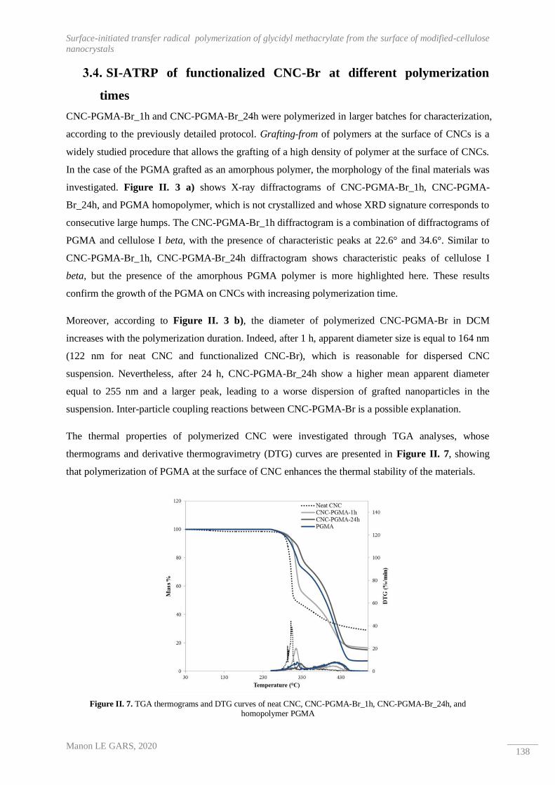
Surface-initiated transfer radical polymerization of glycidyl methacrylate from the surface of modified-cellulose
nanocrystals
Manon LE GARS, 2020 138
SI-ATRP of functionalized CNC-Br at different polymerization
times
CNC-PGMA-Br_1h and CNC-PGMA-Br_24h were polymerized in larger batches for characterization,
according to the previously detailed protocol. Grafting-from of polymers at the surface of CNCs is a
widely studied procedure that allows the grafting of a high density of polymer at the surface of CNCs.
In the case of the PGMA grafted as an amorphous polymer, the morphology of the final materials was
investigated. Figure II. 3 a) shows X-ray diffractograms of CNC-PGMA-Br_1h, CNC-PGMA-
Br_24h, and PGMA homopolymer, which is not crystallized and whose XRD signature corresponds to
consecutive large humps. The CNC-PGMA-Br_1h diffractogram is a combination of diffractograms of
PGMA and cellulose I beta, with the presence of characteristic peaks at 22.6° and 34.6°. Similar to
CNC-PGMA-Br_1h, CNC-PGMA-Br_24h diffractogram shows characteristic peaks of cellulose I
beta, but the presence of the amorphous PGMA polymer is more highlighted here. These results
confirm the growth of the PGMA on CNCs with increasing polymerization time.
Moreover, according to Figure II. 3 b), the diameter of polymerized CNC-PGMA-Br in DCM
increases with the polymerization duration. Indeed, after 1 h, apparent diameter size is equal to 164 nm
(122 nm for neat CNC and functionalized CNC-Br), which is reasonable for dispersed CNC
suspension. Nevertheless, after 24 h, CNC-PGMA-Br_24h show a higher mean apparent diameter
equal to 255 nm and a larger peak, leading to a worse dispersion of grafted nanoparticles in the
suspension. Inter-particle coupling reactions between CNC-PGMA-Br is a possible explanation.
The thermal properties of polymerized CNC were investigated through TGA analyses, whose
thermograms and derivative thermogravimetry (DTG) curves are presented in Figure II. 7, showing
that polymerization of PGMA at the surface of CNC enhances the thermal stability of the materials.
Figure II. 7. TGA thermograms and DTG curves of neat CNC, CNC-PGMA-Br_1h, CNC-PGMA-Br_24h, and homopolymer PGMA

CHAPTER II : Chemical modifications of CNCs
Manon LE GARS, 2020 139
Indeed, the primary onset of the degradation temperature of CNCs before and after 1 and 24 h of
polymerization increases from 305 °C to 314 °C and 326 °C respectively. Moreover, the CNC
thermogram shows one weight loss peak between 250 °C and 350 °C. In a recent study, Zhang et al.42
studied different ways to characterize grafted polymers on CNCs, including the use of TGA analysis.
Their method appears to be not totally applicable in our case because of the presence of a weight loss
peak of PGMA in the same temperature ranges as for cellulose. Moreover, the presence of a second
weight loss peak for PGMA, polymerized CNC-PGMA-Br_1h, and CNC-PGMA-Br_24h between
350 °C and 480 °C allows an approximation of the amount of PGMA polymerized on CNC. Indeed,
taking into account the slight weight loss of cellulose in this second temperature range for calculation,
and considering that samples are only composed of cellulose and polymer, a weight percentage of
PGMA equal to 38% and 83% respectively for CNC-PGMA-Br_1h and CNC-PGMA-Br_24h are
calculated (Table II. 4). The large amount of grafted polymer after 24 h of polymerization is
confirmed. Moreover, even after a short polymerization time, nearly 40% by mass of the sample is
PGMA, corresponding to the previous kinetic study of this polymerization.
Sample % weight loss (350 °C – 480 °C) Thermal degradation onset Tonset (°C) PGMA (wt%)
CNC 14 305 0
CNC-PGMA-Br_1h 30 314 38
CNC-PGMA-Br_24h 49 326 83
PGMA homopolymer 56 319 100
Table II. 4. Thermal degradation onset temperatures and calculated amount of PGMA in both CNC-PGMA-Br_1h and CNC-PGMA-Br_24h
By regarding only the morphology of polymerized CNC-PGMA-Br, 1 h of polymerization ensures the
conservation of the crystallinity, which is critical for further applications, while introducing a
significant amount of PGMA.
Efficiency of SI-ATRP on CNCs
The efficiency of the polymerization of GMA from brominated initiator sites previously grafted on
CNC was first investigated by FTIR analysis, whose spectra are shown in Figure II. 3 c). Results
confirm the conclusion drawn from Figure II. 6 b), proving the efficiency of the polymerization and
the growth of the polymer over time. Indeed, peaks at 910 cm-1, 906 cm-1, 1728 cm-1, and between
2840 cm-1 and 3000 cm-1 are respectively characteristic of the epoxy groups, terminal vinyl groups and
ester bonds from carbonyl groups, and -CH2 and -CH3 carbons from the PGMA backbone polymer.
The clear increase in those peaks for the CNC-PGMA-Br_1h and CNC-PGMA-Br_24h spectra
demonstrates the polymerization of PGMA at the level of CNCs over time. These results are
confirmed by elemental analyses (Table II. 1). Indeed, for both CNC-PGMA-Br_1h and CNC-
PGMA-Br_24h, an increase in the %C values and a decrease in the %O values are notable and
consistent with the introduction of the polymer PGMA (C7H10O3)n on CNCs. This is reaffirmed by the

Surface-initiated transfer radical polymerization of glycidyl methacrylate from the surface of modified-cellulose
nanocrystals
Manon LE GARS, 2020 140
decrease in the O/C ratio for these polymerized CNCs, which is also similar to the corresponding
theoretical calculated ratio and to those of pure PGMA. The slight difference between the O/C ratios
of CNC-PGMA-Br and PGMA confirms the presence of cellulose in the sample. Note that values are
corrected according to the previously described method by considering the presence of half-sulfate
ester groups at the surface of CNCs, without however considering the presence of impurities like
hemicelluloses in the samples, which could influence the values, so they must be interpreted
comparatively. Moreover, considering that CNC-PGMA-Br_1h and CNC-PGMA-Br_24h are
composed of cellulose and PGMA, an estimation of the weight percentage of PGMA may also be
calculated in both cases, as presented in Table II. 1. Values are not totally equal to those previously
calculated through TGA thermograms (Figure II. 7 b)), but the trend is similar, keeping in mind that
TGA and elemental analysis have different sensitivities and involve different approaches. The amount
of PGMA with increasing polymerization time, and approximately 48% and 70% by mass of PGMA is
attached to CNCs after 1 h and 24 h respectively.
One of the primary challenges to SI-ATRP on CNCs involves the characterization and quantification
of the grafted polymer at the surface of the nanomaterials. Hansson et al.45 investigated this point by
proving that the kinetics of the polymerization at the surface of CNCs is similar to those in the media
from a sacrificial initiator. Previous characterizations allow the proof of the polymerization as well as
an estimate of the calculated amount of polymer. The surfaces of polymerized CNC-PGMA-Br_1h
and CNC-PGMA-Br_24h were investigated by XPS analyses; the decompositions spectra of the C1s
signal are presented in Figure II. 8 c) and d). In Figure II. 8 b), the decomposition spectra of the C1s
peak of PGMA homopolymer shows the presence of characteristic peaks of the polymer: at 285.4 eV,
286.1 eV (ΔeV = 0.7 eV), 287.1 eV (ΔeV = 1.7 eV), 287.5 eV (ΔeV = 2.1 eV), and 289.5 eV (ΔeV =
4.1 eV) for respectively the C-C/C-H, C*-C=O- , C-O, C-O-C (epoxy ring), and O-C=O bonds. The
CNC-PGMA-Br_1h and CNC-PGMA-Br_24h (Figure II. 8 c) and d)) decomposition spectra show
the same characteristics, as well as a peak characteristic of cellulose at 288.2 eV (ΔeV = 3.3 eV)
related to the C3 signal (O-C-O or C=O) from the neat CNCs. It is important to note that the intense
C2 signal from cellulose is also present but is superimposed over other C-O and C-O-C peaks. This
result confirms the grafting of a PGMA polymer layer onto CNCs.

CHAPTER II : Chemical modifications of CNCs
Manon LE GARS, 2020 141
Figure II. 8. Decomposition of the C1s peak of a) CNC-PGMA-Br_1h, b) CNC-PGMA-Br_24h, and c) PGMA homopolymer obtained by XPS analyses
Moreover, the determination of the O/C ratio (Table II. 2) leads to a value of 0.47 for CNC-PGMA-
Br_1h materials, whereas a ratio of 0.42 is observed for CNC-PGMA-Br_24h, which is similar to the
theoretical value associated with pure PGMA polymer66. This result could explain the increasing
grafted polymer weight with time, as shown in Figure II. 6 d). According to the XPS results, it is
possible to make a conclusion about the presence of PGMA over the surface of CNC. Moreover, it is
possible to observe in Figure II. 8 that after 1 h of polymerization, the intensity of the peak associated
Surface-initiated transfer radical polymerization of glycidyl methacrylate from the surface of modified-cellulose
nanocrystals
Manon LE GARS, 2020 142
with the epoxy C-O-C bond is less intense than that of the homopolymer reference. After 24 h of
polymerization, this intensity is closer to that of the homopolymer, confirming that the amount of
polymerized PGMA is more important. Quantification of the polymer is not possible considering these
results, but the presence of PGMA at the surface of CNCs is clearly highlighted. Moreover, highly
reactive epoxy rings are conserved during the polymerization and are available at the surface of both
CNC-PGMA-Br_1h and CNC-PGMA-Br_24h.

CHAPTER II : Chemical modifications of CNCs
Manon LE GARS, 2020 143
4. Conclusion
CNCs were initially modified with BIB as an initiator of SI-ATRP of PGMA; the efficiency of the
functionalization was highlighted using bulk and surface characterization. After ensuring that only the
polymerized monomer is present at the level of CNCs after washing, polymerized CNC at two
different polymerization times were recovered and characterized using FTIR, XRD, TGA, XPS and
elemental analysis. After only 1 h of polymerization, PGMA covers almost all the surface of CNCs,
with a weight percentage of approximately 40% relative to CNC. After 24 h of polymerization, the
weight proportion of PGMA represents almost 80% of the total weight, but the obtained polymerized
CNCs are more aggregated in non-polar solvent. In both cases, the presence of characteristic bonds of
the polymer, and especially carbonyl groups and epoxy rings are highlighted, although 1 h of
polymerization seems to optimize the reaction conditions for the preparation of well-dispersed,
polymerized, hydrophobized CNCs for further incorporation in hydrophobic polymer matrices or
further chemical modification. The results presented in this study are encouraging, and further
investigation of poly(lactic acid)-based nanocomposites including CNC-PGMA-Br as nanofillers
would be interesting, in order to highlight the interest of the SI-ATRP of GMA at the surface of CNCs.

Surface-initiated transfer radical polymerization of glycidyl methacrylate from the surface of modified-cellulose
nanocrystals
Manon LE GARS, 2020 144
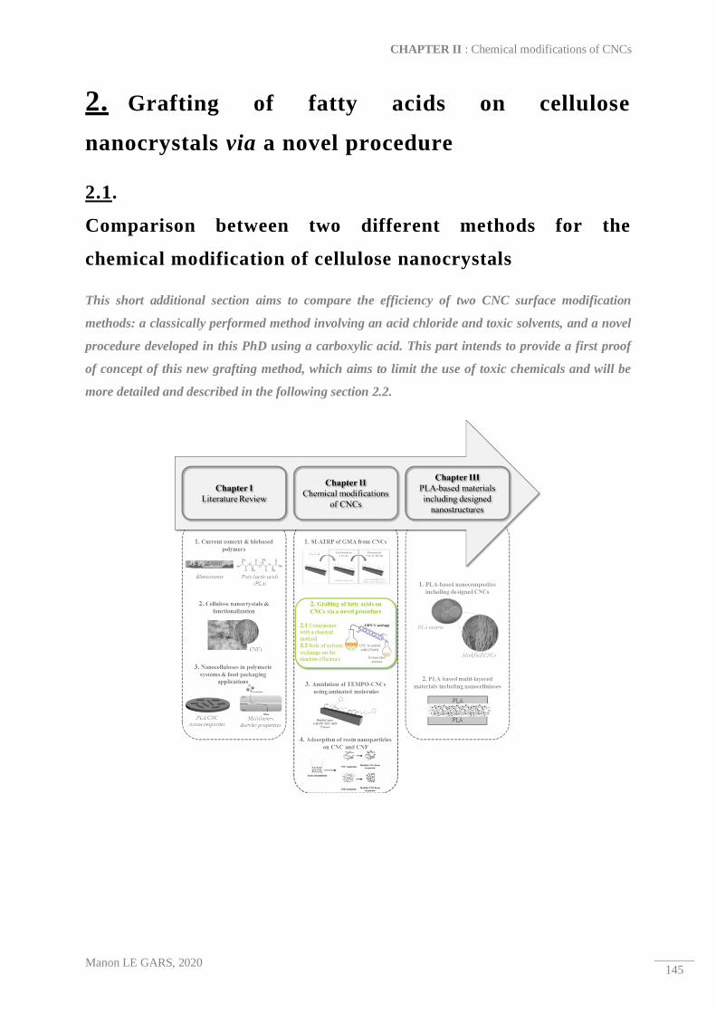
CHAPTER II : Chemical modifications of CNCs
Manon LE GARS, 2020 145
2. Grafting of fatty acids on cellulose
nanocrystals via a novel procedure
2.1.
Comparison between two different methods for the
chemical modification of cellulose nanocrystals
This short additional section aims to compare the efficiency of two CNC surface modification
methods: a classically performed method involving an acid chloride and toxic solvents, and a novel
procedure developed in this PhD using a carboxylic acid. This part intends to provide a first proof
of concept of this new grafting method, which aims to limit the use of toxic chemicals and will be
more detailed and described in the following section 2.2.

Comparison between two different methods for the chemical modification of cellulose nanocrystals
Manon LE GARS, 2020 146
Abstract
In addition to their outstanding intrinsic properties making them excellent candidates for a wide range
of applications, high surface reactivity of cellulose nanocrystals (CNCs) is highly interesting for
potential diverse surface modifications. In fact, the presence of reactive hydroxyl groups at their
surface allows many chemical grafting to be performed. Among these chemical modifications,
esterification procedures have been widely described in the literature, with an incredible number of
various (macro)molecules grafted. Moreover, in a spirit of greener and less toxic chemistry, a novel
procedure for the esterification of CNCs using 10-undecenoic acid as carboxylic acid (CNC-
10UndecenoicAcid) was developed in this work, and its efficiency was compared with that of a
classical successful esterification method involving 10-undecenoyl chloride as acid halide (CNC-
10UndecenoylChloride). Although the crystallinity of modified CNCs slightly decreased in both cases,
the grafting efficiency was highlighted by Fourier-transform infrared (FTIR) spectroscopy and
elemental analyses, with calculated degrees of substitution values equal to 0.1 and 0.4 for CNC-
10UndecenoylChloride and CNC-10UndecenoicAcid, respectively. This study emphasizes the
efficiency of such a novel greener procedure, as well as, its interest in the CNCs surface modification
research field.
Keywords:
Cellulose nanocrystals ─ Esterification ─ Acid chloride ─ Carboxylic acid
CHAPTER II : Chemical modifications of CNCs
Manon LE GARS, 2020 147
1. Introduction
At a time of developing sustainable materials, nano-size cellulosic materials are highly attractive
materials2. In addition to being biobased and biodegradable, their crystallinity, density, high specific
surface area, and high reactivity are outstanding properties which can be used for numerous and
diverse applications2,7,8,22,67. Focusing on cellulose nanocrystals (CNCs), they exhibit a highly reactive
surface due to the presence of numerous hydroxyl groups, which are beneficial for a large panel of
surface modifications. In fact, in the literature, a large amount of publications deal with the chemical
modifications of the CNCs’ surface4,15,18,68, attending to graft molecules, macromolecules, or
polymeric chains at their surface. These surface modifications have different objectives: For example,
the grafting of single molecules can confer new active properties to the CNCs, like antibacterial27,69,70,
antioxidant71, or specific sorption properties72. On the other hand, the grafting of long aliphatic chains
or hydrophobic polymer chains can lead to the CNCs hydrophobization, in order to enhance their
compatibilization with an apolar polymeric matrix, for the purpose of nanocomposites preparation73–75.
Among surface modifications of CNCs, esterification is commonly performed. In fact, numerous
procedures are described in the literature, like the acetylation76,77, transesterification32, or the use of
acid halide reagents41,43, and their efficiency was highlighted, with degrees of substitution generally
comprise between 0.4 and 368. Furthermore, some authors performed a so-called “one-step” reaction,
taking advantage of the hydrolysis isolation process of CNC by combining it with a Fischer
esterification, in order to directly produce modified CNC. In this sense, Boujemaoui et al.44 combined
hydrochloric acid hydrolysis with a Fischer esterification using several carboxylic acids and
determined degrees of substitution comprised between 0.06 and 0.27, depending on the carboxylic
acid used. However, all these previously described esterification procedures are generally carried
out in organic and toxic solvents and require numerous reagents and multi-step procedures.
In current environmental context, renewability and biodegradability of materials is a key point in
the production and use of materials. The idea of green chemistry was born in the 2010s, and its
principles were described by Anastas and Eghbali78, aiming to make greener chemicals, processes and
products, and by applying these principles, ensuring the efficiency of the chemical modifications and
reactions. In the literature, more and more authors propose greener methods for the surface grafting of
CNCs4,79,80. Among these authors, Espino-Pérez et al.26 developed a procedure ─ called SolReact
process ─ in which an aromatic carboxylic acid was added to a water suspension of CNCs. By heating
the system at a temperature higher than the acid melting point, and after water evaporation, CNCs
were suspended in the melted acid, which became the solvent. Highly interesting results were shown
by the authors, and degrees of substitution between 0.3 and 0.5 were calculated, accordingly to the
acid grafted.

Comparison between two different methods for the chemical modification of cellulose nanocrystals
Manon LE GARS, 2020 148
In this study, a novel method, adapted from that proposed by Espino-Pérez et al.26, was carried out on
CNCs, using the 10-undecenoic acid a long carbon chain molecule. In order to compare the efficiency
of this developed method with that of a common esterification of CNCs surface, an esterification using
the 10-undecenoyl chloride as acid chloride was performed, in parallel. Recovered modified CNCs,
called CNC-10UndecanoicAcid and CNC-10UndecenoylChloride, respectively, were characterized by
X-ray diffraction (XRD), Fourier-transform infrared (FTIR) spectroscopy and elemental analysis, in
order to prove and compare their efficiency, and to give a proof of concept of the developed greener
esterification procedure.

CHAPTER II : Chemical modifications of CNCs
Manon LE GARS, 2020 149
2. Materials and methods
Materials
Cellulose nanocrystals (CNCs) were supplied by CelluForce (Canada) in spray-dried from. 10-
undecenoyl Chloride, 4-Dimethylaminopyridine (DMAP), 10-undecenoic Acid, and sulfuric acid
(H2SO4 , 92 %) were supplied by Sigma-Aldrich Chimie (France), and used as received. Toluene was
supplied by Sigma-Aldrich Chimie (France), and was stored and used in anhydrous conditions.
Ethanol (95%) was purchased from Revol (France).
Classical esterification of CNCs using 10-undecenoyl chloride
An aqueous suspension of 10 g of CNCs in water at 1 wt% was prepared by introducing a proper
amount of dried CNC in water, following by 1 h of magnetic stirring, and an ultrasonic treatment
(2500 J/g) using a Sonifier S-250A (Branson, USA). The suspension was then solvent exchanged.
Briefly, the water suspension was first subjected to a centrifugation cycle (10 000 rpm, 5 °C, 15 min),
and the supernatant was removed. The recovered CNCs were re-dispersed in ethanol using an
ultrasonic treatment, and the suspension was then submitted to another centrifugation step (10 000 rpm,
5 °C, 15 min). After recovery of the supernatant, the re-dispersion (this time in acetone) and
centrifugation steps were carried out twice, following the same procedure as before. The two last
centrifugations (10 000 rpm, 5 °C, 15 min) were similarly performed in toluene. The final
concentration of the CNC suspension in toluene was adjusted to 1 wt%, sonicated (2500 J/g), and was
then introduced into a three-neck flask. 2.26 g of DMAP (0.19 mol) were introduced in the flask, and
the reaction mixture was left stirring at room temperature for 30 min. Thereafter, 3.75 g of 10-
undecenoyl chloride (0.19 mol) were added dropwise, using a dropping funnel, and the reaction media
was stirred under reflux at 110 °C for 4 h. At the end of the reaction, the mixture was cooled at room
temperature, and submitted to 5 successive centrifugation cycles (10 000 rpm, 5 °C, 15 min) in ethanol.
Recovered CNC-10UndecenoylChloride were stored in a hermetically sealed vial in the fridge.
Esterification of CNCs with 10-undecenoic acid via a novel method
An aqueous CNC suspension was prepared and solvent exchanged from water to ethanol, and then to
acetone, as previously described in section 2.2. The concentration of the final suspension in acetone
was adjusted to 1 wt%, and the suspension was poured into a round-bottomed flask equipped with a
distillation system, and heated at 110 °C. The 10-undecenoic acid was then introduced into the flask in
a ratio of 100:1 relatively to the dry mass of CNC, and a catalytic amount of sulfuric acid was also
added. After the total acetone evaporation, the CNC suspension was dispersed in the melted 10-
undecenoic acid (melting point ~ 25 °C) and was magnetically stirred for 8 h at 110 °C. At the end of
the reaction, the CNCs were extensively washed by six successive centrifugation and re-dispersion

Comparison between two different methods for the chemical modification of cellulose nanocrystals
Manon LE GARS, 2020 150
cycles (10 000 rpm, 25 °C, 15 min) in acetone. Recovered CNC-10UndecenoicAcid were stored in a
hermetically sealed vial in the fridge.
Characterization methods
2.4.1. X-ray diffraction (XRD)
XRD analyses were performed on dried powder samples of neat CNC (commercially spray-dried), and
modified CNC-10UndecenoylChloride and CNC-10UndecenoicAcid. Diffractogram patterns were
obtained using a PANalytical X’Pert PRO MPD diffractometer, equipped with an X’accelerator
detector. A copper anode (Kα radiation of 1.5419 Å) allows a symmetric scan reflection (θ /2 θ, Bragg
angle), in a range of 2 θ between 5° and 60°. Using the Segal height peak method55,57, the crystallinity
indexes (CI) of each sample were calculated following the Equation II. 4:
CI = (1 − Iam
I002) × 100
Equation II. 4. Crystallinity index (CI) calculation according to the Segal height peak method
where Iam corresponds to the intensity at the minimum (2θ ≃ 18.3°) and I002 is the intensity associated
with the main crystalline region of cellulose (2θ ≃ 22.5°). Measurements were repeated at least twice.
2.4.2. Fourier transform infrared (FTIR) spectroscopy
FTIR spectra of neat CNC, and modified CNC-10UndecenoylChloride and CNC-10UndecenoicAcid
were performed on a Perkin Elmer Spectrum 65 spectrometer via the transmission method. By mixing
and milling KBr and CNC powders (ratio 99:1 wt/wt), pellets were obtained by applying a 10 t/m2
pressure for one min, and were left drying an oven (1 hour, 105 °C) before the analysis. The
absorbance spectra were recorded between 600 and 4000 cm-1, with a resolution of 4 cm-1, and 32
scans. All the spectra were normalized at 1110 cm-1 (characteristic peak of the pure cellulose).
Measurements were at least duplicated for each sample.
CHAPTER II : Chemical modifications of CNCs
Manon LE GARS, 2020 151
2.4.3. Elemental analysis
Elemental analyses were performed by the Institut des Sciences Analytiques (Villeurbane, France).
The carbon, hydrogen, oxygen and sulfur contents were titrated by a micro analyzer (CNRS, France),
and the relative error on the measurements was close to 0.4%. From the data, the degree of substitution
(DS) of modified CNC — corresponding to the number of grafted hydroxyl groups per AGU — was
calculated from the Equation II. 5, which was adapted from the previous work of Espino-Pérez et
al.72:
DS =M(C)AGU − ωC. (MAGU + DSSO3
. MSO3)
ωC. Mgrafted − M(C)grafted
Equation II. 5. Degree of substitution (DS) calculation
where M(C)AGU corresponds to the carbon molar mass in an AGU (72.06 g.mol-1), MAGU is the total
molar mass of an AGU (162.14 g.mol-1), ωC is the relative carbon content obtained from the analysis,
Mgrafted the molar mass of the graft (154.1 g.mol-1) and M(C)grafted the carbon molar mass of the grafted
acid (120.1 g.mol-1). Note that in the case of pure cellulose, weight fractions %C and %O are
theoretically equal to 44.4% and 49.4%, with an O/C ratio equal to 1.11. In this study,
experimental %C and %O values were corrected by taking the theoretical values for the neat CNC
sample, as previously done in the literature26,59. DSSO3 corresponds to the degree of substitution linked
to the presence of sulfate-half ester groups present the surface of CNC, and was calculated from the
sulfur weight fraction %S obtained from the elemental analysis, accordingly to the Equation II. 6,
where where MSO3 is the molar mass of the substituted –SO3- groups (80.1 g.mol-1):
DSSO3 =S%. MAGU
MS − %S. MSO3
Equation II. 6. Degree of substitution of half sulfate ester groups (DSSO3) calculation

Comparison between two different methods for the chemical modification of cellulose nanocrystals
Manon LE GARS, 2020 152
3. Results and discussions
Influence of the chemical modifications on the structure of the CNCs
Chemical modifications carried out on CNCs can affect their crystallinity, mainly because of the
reduction in hydrogen bonding or the change in polymorph to cellulose II68. In the present study, the
evolution of the crystalline structure of the CNCs after the two different surface modifications was
investigated via XRD analyses performed on powder-form samples. The corresponding X-ray
diffractograms are presented in Figure II. 9. As expected, the unmodified CNC sample exhibits a
crystalline organization. At 16.5°, 22.6° and 34.6°, peaks related to the signals (101) / (101̅), (002),
and (040) are characteristic of the cellulose I β structure, and the crystallinity index (Equation II. 4)
was determined to be equal to 86%, confirming the high crystalline behavior of neat CNCs.
Figure II. 9. X-ray diffractograms of neat CNC, CNC-10UndecenoylChloride, and CNC-10UndecenoicAcid
The X-ray diffractograms of CNC-10UndecenoylChloride and CNC-10UndecenoicAcid samples
present similar peaks at 16.5°, 22.6° and 34.6°, confirming the conservation of their cellulose I β
structure. The calculated crystallinity indexes of modified CNC-10UndecenoylChloride and CNC-
10UndecenoicAcid are equal to 81% and 78%, respectively. A slight decrease in crystallinity is thus
observed in both cases, and can be assigned to the reactions conditions (time, temperature, etc.), as
well as, to the manual grinding step. In fact, this step was particularly long, especially for the CNC-
10UndecenoicAcid. Moreover, it is essential to point out that the peak height method should only be
taken as an approximation14, and it is therefore difficult to quantitatively conclude about these results.
Nevertheless, the two methods of functionalization do not heavily affect the crystallinity of the grafted
materials. More generally, the conservation of the materials crystallinity is highly important,
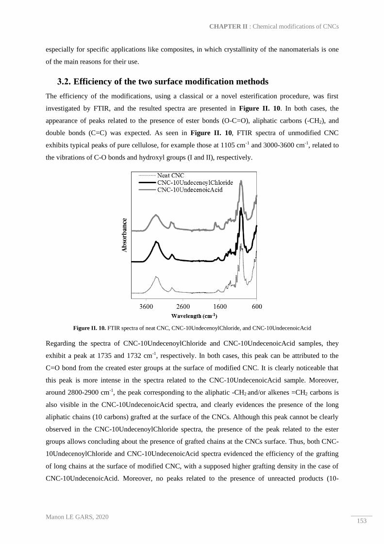
CHAPTER II : Chemical modifications of CNCs
Manon LE GARS, 2020 153
especially for specific applications like composites, in which crystallinity of the nanomaterials is one
of the main reasons for their use.
Efficiency of the two surface modification methods
The efficiency of the modifications, using a classical or a novel esterification procedure, was first
investigated by FTIR, and the resulted spectra are presented in Figure II. 10. In both cases, the
appearance of peaks related to the presence of ester bonds (O-C=O), aliphatic carbons (-CH2), and
double bonds (C=C) was expected. As seen in Figure II. 10, FTIR spectra of unmodified CNC
exhibits typical peaks of pure cellulose, for example those at 1105 cm-1 and 3000-3600 cm-1, related to
the vibrations of C-O bonds and hydroxyl groups (I and II), respectively.
Figure II. 10. FTIR spectra of neat CNC, CNC-10UndecenoylChloride, and CNC-10UndecenoicAcid
Regarding the spectra of CNC-10UndecenoylChloride and CNC-10UndecenoicAcid samples, they
exhibit a peak at 1735 and 1732 cm-1, respectively. In both cases, this peak can be attributed to the
C=O bond from the created ester groups at the surface of modified CNC. It is clearly noticeable that
this peak is more intense in the spectra related to the CNC-10UndecenoicAcid sample. Moreover,
around 2800-2900 cm-1, the peak corresponding to the aliphatic -CH2 and/or alkenes =CH2 carbons is
also visible in the CNC-10UndecenoicAcid spectra, and clearly evidences the presence of the long
aliphatic chains (10 carbons) grafted at the surface of the CNCs. Although this peak cannot be clearly
observed in the CNC-10UndecenoylChloride spectra, the presence of the peak related to the ester
groups allows concluding about the presence of grafted chains at the CNCs surface. Thus, both CNC-
10UndecenoylChloride and CNC-10UndecenoicAcid spectra evidenced the efficiency of the grafting
of long chains at the surface of modified CNC, with a supposed higher grafting density in the case of
CNC-10UndecenoicAcid. Moreover, no peaks related to the presence of unreacted products (10-

Comparison between two different methods for the chemical modification of cellulose nanocrystals
Manon LE GARS, 2020 154
undecenoyl chloride or 10-undecenoic acid) are visible, confirming the efficiency of the washing steps
at the end of each reaction.
In order to quantify the amount of grafted molecules, elemental analyses were performed on the
modified CNC-10UndecenoylChloride and CNC-10UndecenoicAcid samples, as well as, on neat CNC
sample as reference. Results of these analyses are summarized in Table II. 5. As previously
mentioned, the values of %C and %O were corrected accordingly to the theoretical values of pure
cellulose. Note that differences between experimental and theoretical values can be attributed to the
presence of some impurities in the samples. It could also have been interesting to treat the unmodified
CNCs in the same way as CNC-10UndecenoylChloride and CNC-10UndecenoicAcid (same reaction
times, temperature, solvent and, washing steps) without reagents, in order to have a more
representative reference. Moreover, the DSSO3 was calculated for the three samples (Equation II. 6),
and a decrease from 0.04 to 0.02 (50%) is observed for the CNC-10UndecenoicAcid sample, probably
due to the desulphation of CNC occurring during the esterification reaction. One the other hand, the
values of DSSO3 are equal for both neat CNCs and modified CNC-10UndecenoylChloride, indicating
that the acylation reaction conditions do not induce desulphation of the CNCs.
Sample Experimental values
DSSO3
Corrected
values Experimental
O/C
Theoretical
O/C DS
%C %O %H %S %C %O
Neat CNC 40.7 50.8 6.4 0.8 0.04 44.4 49.4 - 1.11 -
CNC_10UndecenoylChloride 42.3 50.0 6.2 0.7 0.04 46.1 48.6 1.05 0.47 0.07
CNC_10UndecenoicAcid 49.0 43.2 7.3 0.4 0.02 53.5 42.0 0.79 0.47 0.36
Table II. 5. Atomic composition of neat CNC, CNC-10UndecenoylChloride and CNC-10UndecenoicAcid obtained by
elemental analyses with corrected values, theoretical and calculated ratio O/C, and calculated degree of substitution (DS)
Regarding the calculated O/C ratios, that of CNC-10UndecenoylChloride only slightly decreased from
1.11 to 1.05, while CNC-10UndecenoicAcid sample exhibits a decrease around 0.79. It clearly
highlights the efficient introduction of numerous carbons coming from the grafted long carbon chains.
Note that in both cases, these experimental ratios were higher than the theoretical ones (equal to 0.47
in both cases), clearly indicating that not all hydroxyl groups have been modified during the two
reactions, as expected. It was confirmed by the calculated degrees of substitution DS (Equation II. 5),
whose values were equal to 0.07 and 0.36, for modified CNC-10UndecenoylChloride and CNC-
10UndecenoicAcid, respectively. The low value obtained for CNC-10UndecenoylChloride was
surprising, since high degree of substitution were reported in the literature for similar graftings using
acid halide reagents68,81. However, some publications74,82 showed that such a grafting using long
aliphatic chains led to lower degrees of substitution, in the range 0.2-0.1. In our study, the low DS
obtained for the grafting of 10-UndecenoylChloride can thus be attributed to the length of the grafted
moieties, the possible presence of water traces, or the kinetics of the reaction which could have lasted
longer. The DS calculated for the CNC-10UndecenoicAcid was equal to 0.36, which is very satisfied,

CHAPTER II : Chemical modifications of CNCs
Manon LE GARS, 2020 155
especially for such a novel esterification procedure involving no toxic reagents and milder conditions.
Regarding the literature, the efficiency of this second esterification method is comparable with that of
other classical efficient esterification methods4,68.

Comparison between two different methods for the chemical modification of cellulose nanocrystals
Manon LE GARS, 2020 156
4. Conclusion
In the present short study, the efficiency of the two methods of esterification procedures was proved,
and the presence of grafted 10-undecenoyl chloride and 10-undecenoic acid compounds on CNCs was
highlighted by FTIR analysis. Moreover, their quantifications were performed via elemental analyses,
and the calculated degree of substitutions values were consistent with those found in the literature,
although the classical reaction involving an acid chloride was expected to be more efficient.
Nevertheless, the satisfying degree of substitution of the 10-undecenoic acid compounds on the CNC
via a novel esterification procedure aiming to reduce the use of toxic chemicals was highlighted. These
results are encouraging as they allow the grafting of carboxylic acids on CNC, while limiting the use
of organic toxic chemicals.
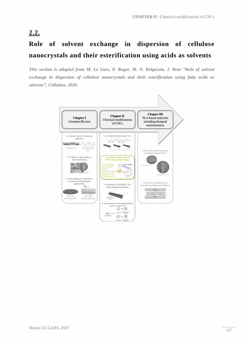
CHAPTER II : Chemical modifications of CNCs
Manon LE GARS, 2020 157
2.2.
Role of solvent exchange in dispersion of cellulose
nanocrystals and their esterification using acids as solvents
This section is adapted from M. Le Gars, P. Roger, M. N. Belgacem, J. Bras “Role of solvent
exchange in dispersion of cellulose nanocrystals and their esterification using fatty acids as
solvents”, Cellulose, 2020.

Role of solvent exchange in dispersion of cellulose nanocrystals and their esterification using acids as solvents
Manon LE GARS, 2020 158
Abstract
The recent emergence of bio-based nanocomposites makes perfect sense from a technical and
environmental point of view. Cellulose nanocrystals (CNC) are novel bio-based nanomaterials with a
wide range of beneficial properties. Their biodegradability, crystallinity, high surface area, and
mechanical strength, as well as their highly reactive surface, make them ideal materials as nanofillers
in polymeric matrices. However, most the bio-based polymers are hydrophobic, and the hydrophilicity
of CNC is therefore a challenge to their incorporation in such matrices. In this study, a new procedure
for surface modification of CNC with long aliphatic chains (lauric acid (12 carbons) and stearic acid
(18 carbons)) was developed that limits the use of petro-chemicals and facilitates their potential
recycling. A study of the dispersion state of CNC in acetone was performed first. Then, grafting
efficiency was highlighted by several techniques and quantification of the amount of grafted fatty
chains was investigated. Degrees of substitution on the bulk and on the surface of the CNC were
calculated between 0.1 and 0.3, which provided enough grafted functions to confer hydrophobic
behavior to modified CNCs, as highlighted by the increasing of contact angle from 65° for neat CNC
to 80° after modification. Finally, conservation of CNC crystalline structure and morphology was
proved by both X-ray diffraction and transmission electron microscopy analyses. Modified CNCs
exhibit a crystallinity index close to 86% and length of approximately 350 nm. Thus, crystalline
hydrophobic cellulosic nanomaterials were prepared using a more environmentally friendly procedure
than those classically found in the literature.
Keywords:
Cellulose nanocrystals ─ Chemical surface modification ─ Esterification ─ Green chemistry

CHAPTER II : Chemical modifications of CNCs
Manon LE GARS, 2020 159
1. Introduction
Recently, novel nanomaterials extracted from cellulose sources have been developed and
exponentially studied17. Two main types of nanocelluloses currently exist: cellulose nanofibrils
(CNFs) and cellulose nanocrystals (CNCs). CNFs can be obtained by applying a mechanical treatment
after biological or chemical pre-treatments on cellulose, resulting in nanofibrils with dimensional
properties varying from 2 to 50 nm in width and 500 nm to 2 µm in length, depending on the isolation
process and the source1. By chemically treating biomass using acid hydrolysis, CNCs are extracted.
Ranby et al.83 were the first to discover that reacting cellulose with sulfuric acid leads to a
disintegration of the amorphous parts of the cellulose polymer chains while keeping crystalline areas
intact. Although several studies have demonstrated this method’s success with several different acids,
sulfuric acid hydrolysis remains the most common, controlled and optimized method for CNC
extraction3,84–87. CNCs classically present widths in the range of 2 to 15 nm and lengths between 100
and 500 nm, leading to high aspect ratios, depending mainly on their source — some CNCs from
tunicate can even achieve lengths of approximately 1500 nm3. As their name and isolation process
suggests, CNCs have high crystallinity (up to 95%) depending on their specific source and isolation
process18. They exhibit other interesting intrinsic properties like low toxicity, low density, high
specific area, and high intrinsic mechanical properties3,12,16. Moreover, their isolation via sulfuric acid
hydrolysis induces the presence of sulfate half ester groups (-OSO3-) on their surfaces. CNCs are
therefore highly stable in aqueous media, leading to stable colloidal suspensions with interesting
rheological properties88. This partly explains the enthusiasm for these novel nanocelluloses for use in
the laboratory as well as on an industrial scale. Indeed, CNCs are studied for a wide range of
applications, like biomedicine, cosmetics, paints, coatings, food additives, filtrations, and composites.
Nonetheless, CNCs also have some drawbacks. Due to the numerous hydroxyl groups of cellulose
chains and the resulting hydrogen bonds, dispersion of CNCs in organic solvents, as well as their re-
dispersion after drying is difficult60,89. This point can be an issue when working in non-aqueous
solvents or in dried form. CNCs are hydrophilic, and their dispersion in hydrophobic compounds —
solvents or polymers — is challenging and is the main obstacle for their use in nanocomposites,
although they are the materials of choice for this kind of application. Indeed, their nano-scale
dimensions, high crystallinity, and stiffness, as well as high specific area are extremely relevant for
their use as nanofillers in a polymeric matrix3,90. Most polymeric systems used are hydrophobic
(including polyethylene (PE), polypropylene (PP), and poly(lactic acid) (PLA), among others), and
incorporation of CNCs as fillers requires a previous compatibilization step with the selected apolar
matrix in order to render them hydrophobic. In literature, numerous publications deal with this
compatibilization of CNC in order to enhance the mechanical and barrier properties of the final
nanocomposites5,6,90,91. The abundance of reactive hydroxyl groups (three per anhydroglucose unit
(AGU)) on the surface of CNCs offers a wide range of possible functionalizations and three main

Role of solvent exchange in dispersion of cellulose nanocrystals and their esterification using acids as solvents
Manon LE GARS, 2020 160
types of surface modifications are presented in literature: physical adsorption, the grafting of polymer
chains, and the grafting of single (macro)molecules. These functionalizations aim to maintain other
intrinsic properties of CNCs, like their morphology and crystallinity.
In this study, covalent grafting of long aliphatic chains via esterification on the surface of CNCs is
investigated by the limited use of chemicals and organic solvents. Grafting fatty acids on
nanocellulose for their hydrophobization has been a scientific challenge for several decades, and
numerous strategies have been described in literature. Indeed, apart from surfactant adsorption92,93 or
polymer adsorption94, covalent grafting of fatty acids has been the subject of many publications.
Acylation of cellulose fibers and cellulose nanocrystals with various fatty acyl chlorides95–97 or surface
modification of cellulose nanofibers using octadecyl isocyanate59 have been efficiently developed over
the past several years. However, these surface modifications require the use of organic and often toxic
solvents. Other modifications carried out in water have been described with the use of hydrophobic
alkyl ketone dimer (AKD) molecule nano-emulsion to modify the surface of cellulose nanofibers98–100.
However, this simple and efficient procedure has never been performed on CNCs because they would
play an undesirable role as a surfactant. Currently, surface hydrophobization of CNCs traditionally
involves multi-step procedures and toxic organic solvents, and these aspects are limiting factors for
any industrialization. However, other hydrophobization procedures have been proposed through the
use of fatty acid chlorides directly onto dried cellulosic substrate via a chromatogeny procedure
involving liquid-vapor equilibrium101, or via a gas procedure on CNC aerogels102. Both methods,
however, require already-formed cellulosic materials and cannot be performed on CNC suspensions.
Though grafting of long aliphatic chains on CNC is a research topic that has already proposed several
times in literature, it has always been performed with the use of organic solvents or on dried formed
materials. In this work, we investigated a novel method of modification of suspended CNCs that
makes limited use of toxic solvents. Recently, Espino-Pérez et al.20,26 described a novel method —
called SolReact — for the surface functionalization of CNCs directly with carboxylic acids, using a
“Green Process” for further incorporation of such modified CNCs in PLA matrices. In this method, a
CNC-water suspension was briefly heated to a temperature greater than the melting point of the
selected carboxylic acid, which was added in large excess. After complete water evaporation, the
CNCs are dispersed in the melted acid, acting as the reaction solvent. Half sulfate ester groups on the
surface of the CNC play the role of catalyst. After several hours of reaction, recovered washed CNCs
were characterized, and the efficiency of the grafting was highlighted. This novel method was the
starting point of our work. This technique is promising (limited solvent used) but cannot be used with
fatty acids, as they are not soluble in water. Indeed, an emulsion is obtained and grafting would not be
homogeneous on CNCs. Therefore we decided to investigate a possible pre-step to favor a good
dispersion of CNC, and to avoid emulsification.

CHAPTER II : Chemical modifications of CNCs
Manon LE GARS, 2020 161
In this paper, a new and adapted method for the surface esterification of CNCs with aliphatic chains is
described. Although the idea is still to use such natural fatty carboxylic acid as a solvent, it opens the
door to the use of acids that are not soluble in water. The initial dispersion of CNCs is studied
extensively, and its influence on grafting yield is analyzed. The efficiency of a novel esterification
procedure in which a reagent acts as solvent and can be recycled is investigated. CNCs were modified
with lauric or stearic acid — long aliphatic chains bearing 12 and 18 carbons respectively — and
different characterization techniques were used to highlight the grafting efficiency in the bulk
(Fourier-transform infrared spectroscopy (FTIR), 13C-solid state nuclear magnetic resonance (NMR),
elemental analysis), as well as on the surface (X-ray photoelectron spectroscopy (XPS)).

Role of solvent exchange in dispersion of cellulose nanocrystals and their esterification using acids as solvents
Manon LE GARS, 2020 162
2. Materials and methods
Materials
Spray-dried cellulose nanocrystals supplied by CelluForce (Canada) were produced from bleached
Kraft pulp by sulfuric acid hydrolysis. Sulfuric acid (H2SO4, 92%) was purchased from Revol (France).
Lauric acid (≥98%) and stearic acid (Reagent grade 95%) were supplied by Sigma-Aldrich Chimie
(France) and used as received. Acetone (95%) and ethanol (95%) were purchased from Revol (France)
and used as received.
CNC suspensions preparation
In order to study the dispersion of CNC suspensions, different suspension preparations with a common
concentration equal to 1 wt% were investigated. In Suspension 1, CNC powder was introduced into
distilled water and magnetically stirred for one hour at room temperature. Next, an ultrasonic
treatment (2500 J/g) was applied to the suspension, maintaining the temperature with the use of an
external ice water bath. Suspension 2 was prepared by following the same method, but water was
replaced with acetone. After ultrasound treatment, the suspension was continuously stirred until
further characterization occurred. Suspension 3 was prepared by solvent-exchange. First, suspension
1 was centrifuged (10 000 rpm, 5 °C, 15 min), and the supernatant was recovered. Recovered CNCs
were re-dispersed in ethanol, and ultrasonic treatment was applied (2500 J/g). This step was repeated
twice, and the suspension was submitted to another centrifugation step (10 000 rpm, 5 °C, 15 min).
After recovery of the supernatant, the re-dispersion (this time in acetone) and centrifugation steps were
carried out twice, following the same procedure as before. Recovered CNCs were then re-dispersed in
acetone with ultrasonic treatment after adjusting the final concentration to 1 wt%. Finally, suspension
4 was prepared by evaporating acetone from suspension 3 at room temperature, re-dispersing the
obtained dried CNCs in acetone following the described suspension 2 protocol, and adjusting
concentration to 1 wt%. All suspensions were stored in perfectly closed vials in a refrigerator before
any reaction or characterization. Figure II. 11 a) schematizes the different procedures for CNC
suspension preparation.

CHAPTER II : Chemical modifications of CNCs
Manon LE GARS, 2020 163
Figure II. 11. a) CNC suspension preparation methods for their dispersion study and b) General procedure of
CNC esterification using fatty acid reagent as solvent : (1) CNC suspension in acetone obtained after solvent
exchange, (2) heating of the reaction media at 110 °C and addition of fatty acid, (3) 8 h of reaction after
complete acetone evaporation, (4) washing steps by centrifugation-redispersion cycles in ethanol or acetone
according to the fatty acid used, (5) recovering of washed grafted CNC in acetone. Green dashed lines represent
recyclability of both acetone and fatty acid after the process
Esterification of CNCs with fatty acids
The CNC esterification procedure was adapted from the protocol described by Espino-Pérez et al.26
However, knowing that both lauric and stearic acid are not soluble in water, unlike the acids used in
their work, this study’s procedure has been modified and optimized. Firstly, a CNC suspension was
prepared according to the protocol previously described for suspensions 2 or 3. The suspension was
introduced into a round-bottomed flask equipped with a distillation system to allow evaporation of the
solvent. An oil bath was heated to 110 °C. A fatty carboxylic acid — lauric or stearic — was
introduced into the flask in a ratio of 100:1 relative to the mass of CNC. A catalytic amount of sulfuric
acid was also added to catalyze the esterification. After total evaporation of acetone, the CNC
suspension was then dispersed in melted lauric acid (melting point 44—46 °C) or stearic acid (melting
point 67—72 °C) and was magnetically stirred for 8 h at 110 °C. At the end of the reaction, CNCs
were extensively washed with a solvent of the fatty acid (ethanol or acetone in the case of lauric or
stearic acid, respectively) by six centrifugation and re-dispersion cycles (10 000 rpm, 25 °C, 15 min).
To ensure effective washing of CNC, the supernatant from the last centrifugation was recovered and
analyzed by FTIR. No trace of unreacted acid was found. After the last washing step, the CNC

Role of solvent exchange in dispersion of cellulose nanocrystals and their esterification using acids as solvents
Manon LE GARS, 2020 164
suspension in acetone or ethanol was subjected to an ultrasonic treatment and stored in a hermetically
sealed vial in the fridge. A scheme of the reaction is presented in Figure II. 11 b).
Characterization methods
2.4.1. Dynamic light scattering (DLS)
DLS analysis was carried out to determine the apparent size of CNCs. A VASCO particle size
analyzer (Cordouan Technologies, France) was used for particle size measurement from nano- to
micro-scales in liquid. A diluted suspension of CNCs around 10-2 — 10-3 wt% in a chosen solvent was
prepared and introduced to the device. Ten measurements at 15 second time steps and a limit noise
ratio of 0.7 were carried out for each sample. To correlate the result with the theoretical model used,
the polydispersity index (PDI) must be less than 0.2. Measurements, that were at least triplicated, were
collected and analyzed using nanoQTM software. The cumulative method allows for the calculation of
the hydrodynamic diameter of particles.
2.4.2. Fourier-transform infrared (FTIR) spectroscopy
FTIR spectra of neat and modified CNCs were performed on a Perkin Elmer Spectrum 65
spectrometer via the transmission method. KBr pellets were prepared by mixing and milling a 99:1
ratio by mass of KBr:CNC, followed by 10 t/m2 pressure for one min. Pellets were dried in an oven (1
hour, 105 °C) before any analysis to limit the presence of water. Absorbance spectra were registered
between 600 and 4000 cm-1, with a resolution of 4 cm-1 and 32 scans. Spectra were normalized
according to the characteristic peak of cellulose at 1110 cm-1, and were at least triplicated. The most
representative spectrum was used for the discussion.
2.4.3. Transmission electron microscopy (TEM)
Diluted suspensions of neat and modified CNCs were prepared in water and acetone, respectively.
Suspension drops were deposited on copper grids covered with a thin amorphous carbon film, which
had been previously plasma cleaned (easiGlow Pelco). After a few minutes, liquid excess was
absorbed with filter paper. If necessary, the preparation was negatively colored by placing a drop of
2% uranyl acetate on the grid. After one min, the excess dye was absorbed with the filter paper.
Samples were observed with a JEOL JEM 2100-Plus transmission electron microscope, operating at
an acceleration voltage of 200 kV. Images were recorded using a Gatan Rio 16 digital camera.
2.4.4. Atomic force microscopy (AFM)
Diluted suspensions at approximately 10-3 — 10-4 wt% were prepared and dispersed using a sonication
probe (2500 J/g). A suspension droplet was deposited on the surface of a cleaved mica plate which
was left to dry overnight at ambient temperature. Images of dried CNC suspensions were analyzed
using AFM and recorded using the tapping mode with a Dimension Icon Bruker equipped with a

CHAPTER II : Chemical modifications of CNCs
Manon LE GARS, 2020 165
silicon cantilever (O-TESPA, Bruker, USA). Scans of 10 µm² and 3 µm² were recorded and analyzed
using Nanoscope Analysis and ImageJ software. Average dimensions with standard deviation were
measured from at least 50 measurements of CNC for each sample, and the height was used to measure
CNC width.
2.4.5. X-Ray diffraction (XRD)
XRD analysis was performed on dried powder samples obtained by drying neat or grafted CNC
suspensions at room temperature, which were then gently ground with a mortar to obtain a very fine
powder. Diffractogram patterns were obtained with a PANalytical X’Pert PRO MPD diffractometer,
equipped with an X’accelerator detector. A copper anode (Kα radiation of 1.5419 Å) allows a
symmetric scan reflection (θ /2 θ, Bragg angle), in a range of 2 θ between 5° and 60°. In accordance
with the Segal height peak method55,57, the crystallinity index (CI) of each sample can be calculated
according to the Equation II. 7:
CI = (1 − Iam
I002) × 100
Equation II. 7. Crystallinity index (CI) calculation according to the Segal height peak method
where Iam is the intensity at the minimum (2θ ≃ 18.3°) and I002 is the intensity associated with the main
crystalline region of cellulose (2θ ≃ 22.5°). Measurements were repeated at least twice.
2.4.6. Elemental analysis
Elemental analyses were carried out by Institut des Sciences Analytiques (Villeurbane, France).
Carbon, hydrogen, oxygen and sulfur contents were titrated with the use of a micro analyzer (CNRS,
France). The relative error of our duplicated measurements was approximately 0.4%. Obtained data
allowed the determination of the degree of substitution (DS) of modified CNC — corresponding to the
number of grafted hydroxyl groups per AGU — according to Equation II. 8 and adapted from a
previous study26.
DS =M(C)AGU − ωC. (MAGU + DSSO3
. MSO3)
ωC. Mgrafted − M(C)grafted
Equation II. 8. Degree of substitution (DS) calculation
where M(C)AGU is the carbon molar mass in an AGU (72.06 g.mol-1), MAGU the total molar mass of an
AGU (162.14 g.mol-1), ωC the relative carbon content obtained from the analysis, Mgrafted the molar
mass of the graft (173 g.mol-1 or 267 g.mol-1 respectively for lauric or stearic acid) and M(C)grafted the
carbon molar mass of the grafted acid (144 g.mol-1 or 216 g.mol-1 respectively for lauric or stearic
acid). DSSO3 — the degree of substitution related to the presence of sulfate half ester groups on the
surface of CNC — was introduced in the equation and calculated from the sulfur weight fraction %S
obtained by the analysis following Equation II. 9:

Role of solvent exchange in dispersion of cellulose nanocrystals and their esterification using acids as solvents
Manon LE GARS, 2020 166
DSSO3 =S%. MAGU
MS − %S. MSO3
Equation II. 9. Degree of substitution of half sulfate ester groups (DSSO3) calculation
where MSO3 corresponds to the molar mass of the substituted –SO3- groups (80.1 g.mol-1). Considering
the presence of these sulfate half ester groups allows for the correction of the values of carbon and
oxygen weight fractions, which has been determined by other methods in literature26,59.
2.4.7. CP-MAS 13C-solid state NMR
13C-NMR analyses were performed at Institut Nanoscience and Cryogénie, which is attached to the
French Alternative Energies and Atomic Energy Commission. 13C-NMR spectra were obtained from a
Bruker AVANCE 500 spectrometer. Dry CNC samples were placed in ZrO2 rotors and cross-
polarization, high power proton decoupling and magic angle spinning (CP/MAS) were applied.
Spectra were provided at 298K, with a spinning speed equal to 12 kHz. For each sample, 40,000 scans
with 300 ppm spectral width were recorded with relaxation and CP times equal to 2.0 seconds and 2.0
milliseconds, respectively. Chemical shift values were calculated with tetramethylsilane as the first
reference, and with glycine as the second. The carboxyl signal was set to 176.03 ppm.
2.4.8. X-ray photoelectron spectroscopy (XPS)
XPS experiments were carried out on a K-Alpha Thermo Fischer spectrometer installed with a
monochromatic source (Al Kα, 1486.6 eV). A spot size of 400 mm was used for all measurements,
and the hemispherical analyzer operated in constant analyzer energy mode (CAE), with pass energy of
200 eV and a step of 1 eV for surveys spectra, and with pass energy of 50 eV and a step of 0.1 eV for
high resolution spectra. To neutralize charge accumulation, a dual beam flood gun was used. Data
treatment was carried out using Avantage software (Thermo Fischer). Background subtraction (Shirley
type) and normalization of peak areas (using Scofield sensitivity factors) were performed before any
calculation of elemental composition. Binding energies were referenced to C1s neutral carbon peak at
284.8 eV. Measurements were performed on at least two zones of 0.12 cm² of the sample.
2.4.9. Contact angle
Contact angle measurements were carried out using a contact angle meter OCA20 equipped with a
CCD camera and SCA20 software. A 5 µL droplet of distilled water was deposited on casted films of
neat CNC or on pellets of modified CNC. Experiments were performed at room temperature and
acquisition of contact angle and droplet volume evolution was recorded during the first 30 seconds,
just after droplet deposition until its stabilization. All measurements were at least repeated five times.

CHAPTER II : Chemical modifications of CNCs
Manon LE GARS, 2020 167
3. Results and discussions
Different ways for the dispersion of CNC in acetone
Although numerous methods have been described to functionalize CNC surfaces to favor their
compatibilization with hydrophobic polymers, only a few of them were performed in non-toxic
solvents. The SolReact method recently described by Espino-Pérez et al.26 was a novel strategy
limiting solvent use. However, our use of lauric or stearic fatty acids did not allow the use of aqueous
conditions due to their insolubility in water. Indeed, the use of water-suspended CNCs would lead to
an emulsion. For this reason, a different solvent was needed for CNC suspensions, acetone was chosen
because of its solubility with both lauric and stearic acids, as well as its low boiling point. The
dispersion of CNC in such an organic solvent, however, is not as efficient as in aqueous media. The
presence of half sulfate ester groups on the surface of CNC induces electrostatic repulsions between
the nanoparticles in a diluted aqueous system, leading to an extremely well-dispersed and stabilized
CNC. However, in non-polar organic solvents, these electrostatic repulsions are not sufficient to
stabilize the CNCs which will aggregate and decant relatively rapidly60,103. Several studies have
investigated the dispersion of CNCs in organic solvent by modifying their surface, particularly by the
adsorption of surfactants104, or after the covalent grafting of low molecular weight polymers93 at the
CNC surface. In our case, we aimed to avoid pre-functionalization or surfactants, and therefore
dispersion of unmodified CNCs in acetone was required as the first step of the CNC esterification
reaction. Thus, a study of the dispersion state of different CNC suspensions in both acetone and water
(for the sake of comparison) was essential before any surface modification of CNCs could be done.
Indeed, CNC dispersion is crucial for any chemical modification, because the larger their surface is,
the more accessible the surface hydroxyl groups will be, and therefore the more efficient their
modification will be. In this study, four different CNC suspensions were prepared, according to
protocols previously described (Figure II. 11 b)).
To determine the state of CNC dispersion in the different suspensions, dynamic light scattering (DLS)
measurements were performed. It is important to bear in mind that dynamic light scattering only
provides qualitative information, because it uses a model based on spherical particles, as opposed to
the rod-like CNC particles. In our case, DLS analyses allow quantitative and comparative studies of
our different samples, as same has already been performed in literature58,60,105,106. As previously
mentioned, CNCs are known to stabilize in an aqueous media, and therefore Suspension 1 is our
positive reference for dispersion. Each suspension was analyzed by DLS, and recovered curves are
presented in Figure II. 12 a).

Role of solvent exchange in dispersion of cellulose nanocrystals and their esterification using acids as solvents
Manon LE GARS, 2020 168
Figure II. 12. a) Dynamic light scattering (DLS) curves of CNC suspensions in water with and without
ultrasonication (dark and grey solid lines), in acetone after solvent exchange (---- line), in acetone after
redispersion of dried CNC from acetone suspension (···· line) and in acetone after direct incorporation of dried
CNC (-·-· line), b-e) Pictures of CNC suspensions at 1 wt% after four hours of rest, b) CNC in water
(Suspension 1), c) CNC in acetone (Suspension 2), d) CNC in acetone after solvent exchange (Suspension 3) and
e) CNC in acetone after re-dispersion of dried CNC from suspension in acetone (Suspension 4)
As seen in Figure II. 12 a), all polydispersity indexes (PDI) were close to 0.2, which allows for
validation of the model used by the acquisition software. Moreover, CNCs dispersed in water and
ultrasonically treated exhibited an apparent mean diameter of 115 nm, which correlates with values
found in the literature12. Note that without ultrasounds, this value increased to 165 nm, confirming the
role of ultrasounds in CNC dispersion in water. By directly incorporating the dry powder of neat
CNCs in acetone (Suspension 2), the apparent particle size reached 3100 nm, suggesting the presence
of micrometric aggregates, and confirming the fact that CNCs are not stabilized by electrostatic
repulsions in such an organic solvent. Suspension 4’s protocol was designed to avoid the solvent

CHAPTER II : Chemical modifications of CNCs
Manon LE GARS, 2020 169
exchange procedure, which is energy- and time-consuming on a larger scale. By firstly mixing CNCs
in acetone, drying them, and finally re-dispersing them in acetone, an improvement of the dispersion
due to a possible surface modification of CNC was expected. Although the apparent particle size was
lower than that in Suspension 2, it was equal to 635 nm, suggesting the presence of large aggregates.
On the other hand, by firstly dispersing CNCs in water and then performing a solvent exchange with
ethanol and then acetone, the particle size observed by DLS was approximately equal to 300 nm. Even
though this value was higher than those obtained for water-suspended CNCs, it was still in the range
of nanometric particles, and we can speak about a dispersed nano-suspension. It could be explained by
the fact that the electrostatic forces occurring in water between each CNC were not totally lost after
the centrifugation cycles, leading to a more stable suspension in acetone than those obtained by direct
mixing of CNC in acetone. Moreover, when CNCs in acetone were dried at ambient temperature and
then re-dispersed in acetone, the mean diameter obtained by DLS was approximately 635 nm. This
value was six times higher than for neat CNCs in water, but still lower than in suspension 2. This
could be because acetone slightly modifies the surface layer of CNC, inducing a better
compatibilization and dispersion with the solvent. These results are illustrated by Figure II. 12 b-e),
showing the different suspensions 1, 2, 3 and 4 at 1 wt% four hours after dispersion. In Figure II. 12
b), it is clearly visible that water-suspended CNC was highly stable and transparent, confirming the
stability of CNC in water. Moreover, in Figure II. 12 c), it is observable that CNC sedimented at the
bottom of the vial. This confirms the fact that CNCs directly introduced in acetone were not stabilized
and dispersed, leading to their complete sedimentation. On the other hand, as observed in Figure II.
12 d), the CNC suspension in acetone obtained after solvent exchange was much more stable. Indeed,
even if a slight sedimentation is visible, a more homogeneous suspension is observed, although no
transparency is reached. Finally, in Figure II. 12 e) corresponding to suspension 4, similar
sedimentation to that of suspension 2 is observed. All these results confirm the fact that CNCs were
well-dispersed in aqueous systems but their dispersion was more difficult in an organic solvent.
Without surface modification, the most effective method to obtain the most dispersed suspension in
acetone is to perform solvent exchange from a well-dispersed suspension in water to ethanol and then
to acetone (suspension 3). In the remainder of this study, the aforementioned method was chosen and
performed.
Influence of solvent exchange on the grafting efficiency
In order to confirm the previous assertion (assuming that suspension 3 would be the most suitable for
our protocol) and to highlight the role of the dispersion state of CNC suspensions before chemical
modification, esterification reactions using both lauric and stearic acid were performed on CNC
directly dispersed in acetone (suspension 2) (on aggregated CNC). Esterification was carried out
according to the previously described protocol. After the washing steps, recovered CNCs respectively

Role of solvent exchange in dispersion of cellulose nanocrystals and their esterification using acids as solvents
Manon LE GARS, 2020 170
named CNC_Lauric and CNC_Stearic were analyzed by FTIR. The obtained spectra are presented in
Figure II. 13 a).
Figure II. 13. FTIR spectra of recovered CNCs after esterification performed with lauric or stearic acid carried
out on a) aggregated CNCs in acetone (suspension 2) and b) dispersed CNCs in acetone (suspension 3)
According to these FTIR spectra (Figure II. 13 a)), no significant difference in peaks is visible.
However, in both Figure II. 13 a) and b), all spectra present peaks of pure cellulose, among others:
the large peak between 3000 and 3600 cm-1 is linked to stretching vibration bonds in hydroxyl groups
(I and II), the peak at 1636 cm-1 is related to the presence of adsorbed water, and peaks at 1105, 1059,
and 1028 cm-1 are linked to the vibrations of C-O bonds. The esterification reaction aims to create
ester bonds with the hydroxyl groups of CNCs, and therefore the appearance of a peak related to the -
C=O bond in an ester bond (at approximately 1720-1730 cm-1) should be observed after reaction. Thus,

CHAPTER II : Chemical modifications of CNCs
Manon LE GARS, 2020 171
no evidence of grafting is seen here, which confirms the fact that grafting on poorly-dispersed CNC is
not effective because of the limited available surface area of the nanoparticles. Furthermore, the peak
at approximately 1700 cm-1 related to the -C=O bond from the acid is not visible on CNC_Lauric and
CNC_Stearic spectra, which highlights the washing step’s efficiency in totally removing unreacted
acid. In the rest of this study, it is therefore accepted that the washing steps were optimized and
allowed us to perfectly remove all the unreacted acid.
Thus, it has been proved that esterification carried out on aggregated CNC was not efficient.
According to the preliminary study of CNC dispersion, a suspension of CNC in acetone obtained by
solvent exchange (suspension 3) was prepared to achieve an esterification reaction. A kinetic follow-
up of the esterification of CNC was investigated. An aliquot of the reaction media was collected at
different reaction times and analyzed by FTIR. This kinetics study was carried out for an esterification
performed with stearic acid. It was considered that the kinetics of esterification using lauric acid would
be quite similar. Obtained FTIR spectra are represented on Figure II. 14 a).
Figure II. 14. Kinetics study of esterification of CNC with stearic acid : a) FTIR spectra of different
CNC_Stearic in the time and b) evolution of the logarithm Ln of the ratio of absorbance values related to the
peak of –C=O bond from ester (1728 cm-1) on the peak characteristic of cellulose (1110 cm-1)

Role of solvent exchange in dispersion of cellulose nanocrystals and their esterification using acids as solvents
Manon LE GARS, 2020 172
The appearance and increase of the peak at 1728 cm-1 related to the –C=O bond from introduced ester
groups is observed. In addition, the appearance of two intense peaks between 2900 and 2950 cm-1
related to the –CH2 and –CH3 carbons correlates with the introduction of long aliphatic chains on the
surface of CNC. Figure II. 14 b) was plotted as function of the time. The resulting curve exhibits a
linear evolution with respect to time and evidences the first order of the esterification reaction with a
velocity constant k equal to 6.4x10⁻⁶ s-1. Because the esterification proposed in this work follows a
first-order kinetic law, it is possible to assume that the reaction takes place as long as there is a
limiting reagent, which is the surface hydroxyl group of CNC. These first-order esterification kinetics
have already been demonstrated in literature in a heterogeneous system consisting of flax fibers107. As
part of our study, an 8-hour reaction time was chosen to be conscious of energy consumption.
Moreover, in the spirit of greener, sustainable chemistry, washed unreacted acid was recovered and
characterized. Figure II. 15 shows the FTIR spectra of both unreacted lauric and stearic acids
recovered after the reaction and compared with their commercial received forms. For each of the acids,
the two FTIR spectra are perfectly identical and in both cases the peak at 1700 cm-1 related to the –
C=O bond from the carboxylic groups remains unchanged. Thus, recycling and reuse of these acids
after reaction is feasible and would be interesting from an economic and environmental point of view
because it would reduce the cost and chemicals waste of this esterification reaction on CNC.
Figure II. 15. FTIR spectra of commercial and recovered unreacted a) stearic acid and b) lauric acid
The structure of modified CNC was investigated by TEM, AFM, and XRD analyses. TEM images
were obtained with and without coloring in order to mitigate against possible artefacts, especially due
to the presence of acetone. Nevertheless, coloring allows for a more accurate observation of the
nanoparticles. Resulting images are presented in Figure II. 16 a), b) and c). It is clearly visible that
both modified CNC_Lauric and CNC_Stearic were slightly aggregated at the end of the reaction.
Indeed, neat CNC size was determined to be equal to 110 +/- 30 nm in length and 4 +/- 1 nm in width,
whereas CNC_Lauric and CNC_Stearic exhibited lengths equal to 347 +/- 106 nm and 350 +/- 60 nm
and widths equal to 29 +/- 8 nm and 30 +/- 10 nm respectively. It can then be assumed that several
modified CNCs have aggregated together.

CHAPTER II : Chemical modifications of CNCs
Manon LE GARS, 2020 173
Figure II. 16. TEM images obtained with negative coloring using uranyl acetate (on the left) and without
coloring (on the right) of a) unmodified CNC, modified b) CNC_Lauric and c) CNC_Stearic, d) XRD analyses
of near CNC, CNC_Lauric and CNC_Stearic
AFM images of modified CNC_Lauric recovered in acetone after modification are presented in Figure
II. 17. Length dimensions were determined equal to 470 +/- 170 nm and are in adequacy with those
measured from TEM.

Role of solvent exchange in dispersion of cellulose nanocrystals and their esterification using acids as solvents
Manon LE GARS, 2020 174
Figure II. 17. AFM height images of modified CNC_Lauric
Moreover, particle size of unmodified CNC in acetone determined by DLS (Figure II. 12 a)) was
close to 300 nm. This suggests that the particle size of CNC after reaction would not change, and that
CNCs would keep their initial dispersion state. This point was confirmed by DLS analyses performed
on CNC_Lauric and CNC_Stearic diluted suspensions in acetone, presented in Figure II. 18.
Measured particle sizes were equal to 373 +/- 18 nm (PDI = 0.2) and 402 +/- 5 nm (PDI = 0.2) for
CNC_Lauric and CNC_Stearic, respectively. No significant differences with value obtained for neat
CNC in acetone after solvent exchange (suspension 2) was observed. It can be assumed that the
dispersion state and size of the CNC nanoparticles after reaction was unchanged. Moreover, the
particle sizes obtained by DLS correlated with data obtained from the TEM analyses. Aggregation of
esterified CNCs was thus evidenced, but aggregated modified particles are still on the nanoscale,
which was satisfying for the study, because modified nanoparticles were obtained at this stage of the
study.
Figure II. 18. Dynamic light scattering (DLS) curves of CNC suspension in acetone after solvent exchange (grey line) and recovered CNC_Lauric (-·-· line) and CNC_Stearic (---- line) in acetone

CHAPTER II : Chemical modifications of CNCs
Manon LE GARS, 2020 175
The change in the crystalline structure of modified CNCs was investigated by XRD (Figure II. 19)
and crystallinity indexes (CI) were determined according to Equation II. 7. Although this method
provides overestimated values of crystallinity compared to other values like peak deconvolution or
amorphous subtraction methods described by Park et al.56, it was chosen in this study to provide a
qualitative comparison of samples crystallinity. For both neat and modified CNCs, the presence of
signals 110 and 200 respectively at 16.5° and 22.6° was characteristic of cellulose I β.
Figure II. 19. XRD analyses of near CNC, CNC_Lauric and CNC_Stearic
Moreover, neat CNCs exhibit a CI equal to 86%, whereas both CNC_Lauric and CNC_Stearic have a
CI equal to 83%. Considering the measurement error, the slight crystallinity decrease is not significant.
Thus, cellulose I crystalline structure of CNC after esterification was conserved, which is critically
important for further applications, especially for those of polymeric material reinforcement.
Other indirect or qualitative methods can also highlight the grafting. After reaction and washing steps,
modified CNCs were stored in an acetone suspension. A small amount of this suspension was added to
distilled water, and the final concentration was adjusted to 1 wt%. Pictures of resulting water
suspensions are presented on the right side of Figure II. 20. In Figure II. 20 a), a well-dispersed
suspension of unmodified hydrophilic CNC in water was observed. In contrast, in Figure II. 20 b)
and c), flotation of modified CNCs on the surface of the aqueous system was clearly observed.

Role of solvent exchange in dispersion of cellulose nanocrystals and their esterification using acids as solvents
Manon LE GARS, 2020 176
Figure II. 20. Water contact angle and pictures of water suspension at 1 wt% of a) neat CNC, modified b)
CNC_Lauric, and c) CNC_Stearic
It qualitatively proves that CNCs recovered after esterification with both lauric and stearic acids are
more hydrophobic than neat CNCs and are not dispersible in water. It was further confirmed by water
contact angle measurements, presented on the left side of Figure II. 20. Indeed, the water contact
angle measured after the deposition of a water droplet on a neat CNC casted film was equal to 54° (+/-
1°), while those measured on both CNC_Lauric and CNC_Stearic pellets were respectively equal to
80° (+/- 2°) and 82° (+/-4°), clearly indicating an hydrophobization of modified CNC.
Influence of chain length on CNC grafting (Suspension 3)
FTIR analyses were carried out on purified grafted CNCs recovered after 8 h of reaction with lauric
and stearic acid, and spectra are presented in Figure II. 13 b). Peaks at 1728 cm-1, and between 2900
and 2950 cm-1 were observed and associated to the presence of –C=O bonds from ester groups and –
CH2 and –CH3 aliphatic carbons respectively. Efficiency of the grafting of both lauric and stearic acid
on initially-well-dispersed CNC in acetone was thus highlighted.
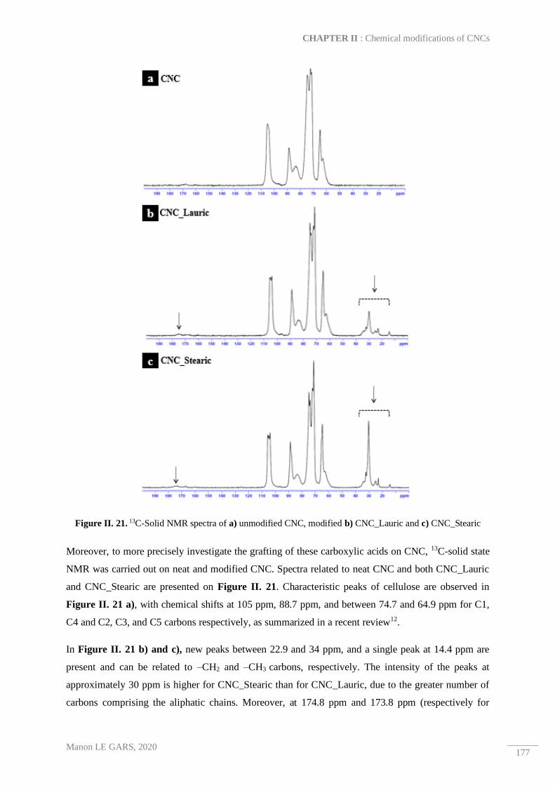
CHAPTER II : Chemical modifications of CNCs
Manon LE GARS, 2020 177
Figure II. 21. 13C-Solid NMR spectra of a) unmodified CNC, modified b) CNC_Lauric and c) CNC_Stearic
Moreover, to more precisely investigate the grafting of these carboxylic acids on CNC, 13C-solid state
NMR was carried out on neat and modified CNC. Spectra related to neat CNC and both CNC_Lauric
and CNC_Stearic are presented on Figure II. 21. Characteristic peaks of cellulose are observed in
Figure II. 21 a), with chemical shifts at 105 ppm, 88.7 ppm, and between 74.7 and 64.9 ppm for C1,
C4 and C2, C3, and C5 carbons respectively, as summarized in a recent review12.
In Figure II. 21 b) and c), new peaks between 22.9 and 34 ppm, and a single peak at 14.4 ppm are
present and can be related to –CH2 and –CH3 carbons, respectively. The intensity of the peaks at
approximately 30 ppm is higher for CNC_Stearic than for CNC_Lauric, due to the greater number of
carbons comprising the aliphatic chains. Moreover, at 174.8 ppm and 173.8 ppm (respectively for

Role of solvent exchange in dispersion of cellulose nanocrystals and their esterification using acids as solvents
Manon LE GARS, 2020 178
CNC_Lauric and CNC_Stearic), low peaks can be observed and correlated to ester bonds. They
clearly evidence the covalent grafting of acids on CNC, even if the intensity of these peaks is low
which could be explained by the low grafting density of acids and by the chain lengths introduced on
the surface, making the detection of these ester bonds difficult. However, it is possible to ensure that
there was a covalent grafting of fatty acids on the CNC surface, although quantification of the amount
of grafted acid was not possible according to FTIR and NMR results.
In order to investigate this point, elemental analyses were carried out on neat CNC and grafted CNC,
and the results are presented in Table II. 6. For both CNC_Lauric and CNC_Stearic samples, the
increase of %C values was significant, leading to a large decrease of experimentally calculated O/C
ratio, and is explained by the introduction of long aliphatic chains. Values of %C and %O were
corrected according to the previously described method taking into account the presence of sulfate half
ester groups on the surface of CNCs and without considering the presence of other impurities which
could influence the values. Note that the sulfur content %S decreased after esterification, which was
probably due to the desulphation of CNC under the reaction conditions. Moreover, by comparing
experimental and theoretical O/C ratios, experimental ratios are higher than theoretical ones,
indicating that not all hydroxyl groups –OH of anhydroglucose units (AGU) are modified by the
esterification, which was predictable.
Sample Experimental values
DSSO3 Corrected values
Experimental O/C Theoretical O/C DS %C %O %H %S %C %O
Neat CNC 40.7 50.8 6.4 0.8 0.04 42.4 52.9 1.2 1.1 -
CNC_Lauric 47.3 40.0 7.2 0.7 0.04 49.3 41.7 0.8 0.4 0.14
CNC_Stearic 55.4 28.8 9.0 0.4 0.02 57.7 30.0 0.5 0.3 0.35
Table II. 6. Atomic composition of neat CNC, CNC_Lauric and CNC_Stearic obtained by elemental analyses
with corrected values, theoretical and calculated ratio O/C, and calculated degree of substitution (DS)
Degrees of substitution (DS) were calculated according to the previously described Equation II. 5 for
both CNC_Lauric and CNC_Stearic samples. These DS were equal to 0.13 and 0.31 for CNC_Lauric
and CNC_Stearic respectively, which was in accordance with values generally found in literature for
covalent grafting on a CNC surface12,20,108. However, it is important to keep in mind that experimental
measurement errors are large, and there was some amount of difficulty in determining slight
differences between carbon element contents before and after modifications due to the large presence
of the cellulosic background signal12. Nevertheless, higher values of DS obtained for CNC_Stearic
suggest better efficiency of the grafting using a longer fatty chain. One explanation for this could be
the difference in viscosity between lauric and stearic acids in the molten state. However, rheological
analyses were performed on both lauric and stearic acids to understand their rheological behavior as
solvents during the esterification reaction. At the reaction temperature (110 °C), both of the acids

CHAPTER II : Chemical modifications of CNCs
Manon LE GARS, 2020 179
exhibited the same behavior of Newtonian fluids, because the evolution of the shear stress function of
shear rate was linear in both cases, as presented Figure II. 22 a). Moreover, their viscosities are close
to zero at a low shear rate as well as at a high shear rate (Figure II. 22 b)). These results confirmed
that their low viscosities at 110 °C made them good solvents for the reaction but did not provide a
better understanding of why grafting density of stearic acid is higher than that of lauric acid on CNC.
Figure II. 22. Shear Rheological analyses of both lauric and stearic acids at 110 °C, a) apparent viscosity function of shear rate, and b) shear stress function of shear rate
Another potential explanation is based on the difference in acidity between both acids. Indeed, the
stronger an acid is, the smaller its pKa is. As found in literature109, pKa in solution of lauric acid (pKa
= 4.80) and stearic acid (pKa = 4.75) are similar. This difference is very slight, and therefore other
more relevant explanations should be found, including the repetition of the experiments in order to
draw a clear conclusion.
Surface analyses of long chains onto CNC
The efficiency of the grafting at the bulk level of both CNC_Lauric and CNC_Stearic has been
previously studied and highlighted. It was interesting to investigate the grafting at the CNC surface
level, because it is this modified interface that will influence further compatibilization of grafted CNC
with a hydrophobic polymer matrix. Thus, to characterize just the surface of the materials with a
penetration depth less than 5 nm, XPS analyses were carried out on the different samples.
Decomposition spectra of the C1s signal are represented in Figure II. 23 a) c) and d). Neat CNC
spectra exhibits four peaks at 285.4 eV, 287.0 eV (ΔeV= 1.6 eV), 288.4 eV (ΔeV= 3 eV) and 289.5 eV
(ΔeV= 4.1 eV) corresponding to C1 (C-C/C-H), C2 (C-O), C3 (O-C-O/C=O) and C4 (O-C=O) bonds
respectively. The C1 signal is related to the contribution of non-oxidized alkane-type carbon atoms
and impurities, residual lignin or extractive compounds. The C2 signal is related to the presence of
ether groups from pure cellulose, as well as the hydroxyl groups of the unmodified CNCs, and of the
end of the cellulose chains. The C3 signal corresponds to acetal moieties from AGU units and should
not change significantly after chemical modification because the corresponding carbon is not affected.

Role of solvent exchange in dispersion of cellulose nanocrystals and their esterification using acids as solvents
Manon LE GARS, 2020 180
The C4 signal is present in low proportions in the neat CNC spectrum, and is attributed to presence of
glucuronic acid from hemicelluloses residuals.
Figure II. 23. Decomposition of the C1s peaks of a) neat CNC, c) CNC_Lauric, and d) CNC_Stearic, and b)
Superposition of the C1s spectra of the three samples
In the case of the grafting of long aliphatic chains inducing the introduction of a large number of
carbons on the surface of CNC, the C1 peak was particularly interesting, because it was correlated to
C-C and C-H bonds. Superposition of the C1s envelopes of neat CNC, CNC_Lauric, and CNC_Stearic
was plotted on Figure II. 23 b), and the main difference between the three curves is clearly visible at
the C1 peaks. In Table II. 7, the percentages of carbon and oxygen (molar compositions) are
expressed, as well as, the different percentages for each peak of the C1s decomposition.
Sample
Experimental values C1s decomposition Ratio
C1/C3 DSS
%C %O O/C C1
C-C / C-H
C2
C-O
C3
O-C-O / C=O
C4
O-C=O
Neat CNC 56 44 0.8 7 72 20 1 0.4 -
CNC_Lauric 59 41 0.7 15 68 15 2 1 0.1
CNC_Stearic 64 36 0.6 30 56 12 2 2.5 0.2
Table II. 7. Elemental molar compositions and surface functional groups compositions obtained by XPS
analysis and C1s decomposition

CHAPTER II : Chemical modifications of CNCs
Manon LE GARS, 2020 181
First, a large increase in %C was observed, correlated with previous bulk characterizations like
elemental analysis. It was interesting to follow the evolution of the calculated ratio C1/C3, because C3
carbons are normally not affected by the chemical grafting of cellulose. Therefore, this ratio reflected
the increase of aliphatic carbons introduced on the surface of CNC. Indeed, the C1/C3 ratio was equal
to 0.4 for neat CNC, and increased to 1 for CNC_Lauric, and finally to 2.5 for CNC_Stearic. The
efficiency of the grafting on the surface of CNC was clearly seen here. Also, an increase in the
percentage of the C4 carbon related to the ester bonds was also evidenced, although this evolution was
less significant, possibly due to the steric hindrance on the surface of CNCs coated with long aliphatic
chains. Nonetheless, the presence of a large number of aliphatic chains on the surface, as well as the
covalent grafting of these compounds, was highlighted with these XPS spectra.
It is important to mention that in this study, commercial neat CNCs were used as a reference. It would
have been preferable to subject them to the same reaction conditions without acid (time, temperature,
centrifugations in acetone) but the rapid, total evaporation of acetone would have led to their
degradation. Thus, the elemental molar compositions expressed in Table II. 7 for neat CNCs probably
would have been different from those of the neat CNCs after treatment, due to the potential removal of
some sample impurities. In this sense, the results should be carefully analyzed. This also applies to the
previous results of the elemental analyses. Despite errors in XPS values, surface degrees of
substitution (DSS) were calculated for both CNC_Lauric and CNC_Stearic. This calculation was based
on the evolution of the C1 ratio, which should increase significantly after the grafting of long aliphatic
chains on CNC surface. However, because of the presence of impurities, the C1 signal is present in
neat CNC sample. Calculation of the DSS has been adapted from the previous work of Espino-Pérez et
al.26. First, it is possible to express %C1 of modified CNC_Lauric or CNC_Stearic by following
Equation II. 10 :
%C1 =Number of C1 carbons
Number of total carbons=
DSS × M(C1)grafted
M(C)AGU + DSS × M(C)grafted
Equation II. 10. General expression of the %C1 obtained from XPS analysis
where M(C1)grafted corresponds to the molar mass of C1 carbons of the grafted acid (respectively 132.1
g.mol-1, 204.2 g.mol-1 for lauric and stearic acid), M(C)grafted corresponds to the molar carbon mass of
the grafted acid (respectively 144.1 g.mol-1 and 216.2 g.mol-1 for lauric and stearic acid), and M(C)AGU
is related to the carbon molar mass of an anhydroglucose unit (AGU) (72.1 g.mol-1). It is then possible
to propose Equation II. 11 for the calculation of the DSS from XPS data:
𝐷𝑆𝑆 =%C1 × M(C)AGU
M(C1)grafted − %C1 × M(C)grafted
Equation II. 11. General equation for the calculation of the degree of surface substitution from XPS data

Role of solvent exchange in dispersion of cellulose nanocrystals and their esterification using acids as solvents
Manon LE GARS, 2020 182
Calculated DSS are expressed in Table II. 7 and are equal to 0.1 and 0.2 for CNC_Lauric and
CNC_Stearic, respectively. To be consistent with the literature, it was expected that the values of DSS
would be higher than those of the DS, because grafting normally takes place mainly on the CNC
surface26,110. In our case, values of DS and DSS were similar for CNC_Lauric and CNC_Stearic,
respectively. This can be explained by the fact that the neat CNC taken as reference should have
endured the same treatment as described for our sample, in order to take into account the reference
value of C1 signals to correct our equation.

CHAPTER II : Chemical modifications of CNCs
Manon LE GARS, 2020 183
4. Conclusion
In this study, dried CNC powder was dispersed in acetone via different methods, and the dispersion
state of each suspension was investigated. After accepting that the solvent exchange method was the
most accurate procedure for the preparation of a well-dispersed CNC suspension in acetone, the aim of
this study was to perform the esterification of neat CNC with natural fatty lauric or stearic acids
following a SolReact procedure. The novelty of this grafting lies in the fact that the consumption of
toxic solvents and chemicals is largely reduced, and that the fatty acids can be simply recycled and
reused after the reaction. Esterification of the CNCs was characterized via FTIR, 13C-NMR, elemental
analyses, and XPS, ensuring that a covalent grafting was performed. Quantification of the amount of
aliphatic chains was completed, leading to a significant and satisfying degree of substitution results:
between 0.1 and 0.3. Finally, structure conservation was assessed by TEM, AFM, and XRD
techniques. These results are chemically and environmentally satisfying and open the way for further
incorporation of modified CNCs in hydrophobic polymer matrices for nanocomposites applications.

Role of solvent exchange in dispersion of cellulose nanocrystals and their esterification using acids as solvents
Manon LE GARS, 2020 184

CHAPTER II : Chemical modifications of CNCs
Manon LE GARS, 2020 185
3. Amidation of TEMPO-oxidized cellulose
nanocrystals using aromatic aminated molecules
This section is adapted from M. Le Gars, A. Delvart, P. Roger, M. N. Belgacem, J. Bras “Amidation
of TEMPO-oxidized cellulose nanocrystals using aromatic aminated molecules”, Colloid and
Polymer Science, 2020.

Amidation of TEMPO-oxidized cellulose nanocrystals using aromatic aminated molecules
Manon LE GARS, 2020 186
Abstract
In this study, the grafting of 1-methyl-3-phenylpropylamine (1-M-3-PP) on cellulose nanocrystals
(CNCs) via a two-step reaction route was investigated and compared with physico-chemical surface
adsorption. The first step involved subjecting CNCs to a 2,2,6,6-Tetramethyl-1-piperidinyloxy
(TEMPO)-mediated oxidation. The carboxylic groups present on recovered oxidized TEMPO-CNC
were quantified by several characterization methods (conductometric titration, elemental analysis, and
X-ray photoelectron spectroscopy) and a degree of oxidation close to 0.2 was found. The second step
was an amidation reaction carried out in an aqueous medium under mild conditions and in the
presence of N-(3-dimethylaminopropyl)-N’-ethylcarbodiimide (EDC)/N-hydroxysuccinimide (NHS)
as catalyst. The recovered modified CNCs after amidation reaction with 1-M-3-PP (CNC-1-M-3-PP)
were extensively washed and then characterized. The amount of grafted molecules was determined by
several techniques like X-ray photoelectron spectroscopy, and the calculated degree of substitution
was found to be close to 0.05 with respect to the bulk CNC. This low amount is sufficient to enhance
the modified CNC dispersion and their colloidal stabilization in organic solvents, allowing the
preparation of nanocomposites. Furthermore, such CNC-1-M-3-PP units with aromatic molecules
attached to it can find applications in barrier materials in which the sorption of aromatic molecules can
be very useful.
Keywords:
Cellulose nanocrystals (CNCs) ─ Amidation ─ Aromatic molecule ─ 1-methyl-3-phenylpropylamine
─ Adsorption

CHAPTER II : Chemical modifications of CNCs
Manon LE GARS, 2020 187
1. Introduction
Cellulose is one of the most abundant natural polymers, with 1011 - 1012 tons of cellulose produced
through photosynthesis per year1. Its large availability (wood, cotton, leaves, bacteria, algae, etc.)
makes it a strong competitor against numerous traditional materials111. Thus, cellulose is an attractive
biodegradable, renewable and biocompatible material. With the emergence and the development of
nanotechnology, interest in nanoscale cellulose has widely increased in the last two decades. These
nanoscale cellulose materials – also called nanocellulose – are produced in different ways. Three main
types can be described, of which two are cellulose nanofibrils (CNFs) and cellulose nanocrystals
(CNCs). They differ in morphology, crystallinity, surface charges and intrinsic properties. The third
variety deals with bacterial cellulose112.
CNC extraction from various cellulose sources was introduced by Rånby et al. in the 1950s113, and is
currently being optimized and even industrialized. Traditionally, it involves sulfuric acid hydrolysis
(under specific conditions of time, temperature, and concentration) of biomass which leads to CNC
formation followed by several sonication and washing steps114. Other preparation procedures are also
described in literature85,86. When prepared via sulfuric acid hydrolysis, the residual half-sulfate ester
groups present on the surface of the recovered CNC allow for colloidal stability of the prepared
nanomaterials in aqueous media103. CNCs exhibit a wide range of other outstanding properties as well,
such as high crystallinity (until 90%18), high aspect ratio (length between 100 nm and several µm and,
width between 2 and 15 nm2,17,114), high specific surface area (150 - 800 m².g-1)17, high viscosity even
at low concentrations (liquid crystalline phase behavior, gelation properties91) and optical properties
(iridescence capacity115,116). Due to these intrinsic properties, CNCs are excellent candidates for a large
range of applications (such as for cosmetics, coatings, papers, paints, food additives, films, biomedical,
composites)8,67,117,118. Furthermore, after having been prepared on a laboratory-scale for several years
and with several studies aimed at the optimization and characterization of their production, CNCs are
currently being produced on a larger scale and being industrialized, especially in North America (for
example, CelluForce, Canada (yearly capacity of 365 tons)).
Surface modification of CNCs has been the aim of numerous studies over the past few years. In fact,
with increasing interest in nanocelluloses and their applications, providing them with new properties
(like sorption, antioxidant, antibacterial, or compatibilization with hydrophobic matrices
improvement)19,20,27,68,72,119 has been made possible by grafting molecules or polymers onto their
surface. Thus, their chemical structure — especially the three reactive hydroxyl groups present on
each anhydroglucose unit (AGU) — allows efficient chemical modifications. There are numerous
publications and reviews dealing with these surface graftings of CNC, which can be classified in two
main groups: grafting-from and grafting-onto strategies120. Grafting-from procedures consist of the
functionalization of CNCs with initiator sites, followed by the polymerization of monomers from these

Amidation of TEMPO-oxidized cellulose nanocrystals using aromatic aminated molecules
Manon LE GARS, 2020 188
reactive sites. On the other hand, grafting-onto strategies aim to directly graft previously characterized
molecules or polymers onto the surface of CNCs. These two approaches differ not only in their
procedure, but also in the final grafting density and graft size, which makes the characterization of the
grafted surfaces more or less easy. Moreover, contrary to the grafting-from procedure — in which
organic and toxic solvents and reagents are generally needed —grafting-onto strategy opens the way
to a more eco-friendly chemistry with limited use of polymerization coupling reagents and toxic
chemicals.
In this work, we decide not to graft polymers, but to directly graft aromatic molecules on the surface
of the CNCs. More precisely, CNCs are first oxidized via a 2,2,6,6-tetramethyl-1-piperidinyloxy
(TEMPO)-mediated oxidation process, which introduces carboxylate groups (–COO-) at their surface.
TEMPO oxidation has been well described in the literature and its optimization leads to TEMPO-
CNCs bearing controlled surface charges121–123. Interest in the carboxylate groups’ introduction is due
to the further potential chemical modifications possible by these groups as well as guaranteeing the
colloidal suspension of the CNC. Thereby, in the second step, an amidation was carried out between
these carboxylate groups (–COO-) and the amine functions (–NH2) borne by a reactive molecule. This
reaction is performed through peptidic linkages using N-(3-dimethylaminopropyl)-N’-
ethylcarbodiimide (EDC)/N-hydroxysuccinimide (NHS) catalyst124, as sketched in Scheme II. 2. In
literature, several studies have proved the efficiency of EDC/NHS catalyzed amidation on oxidized
TEMPO-CNC125,126. Recently, Guo et al.127 performed a similar amidation in for grafting previously
amino-functionalized carbon quantum dots on TEMPO-CNC in order to enhance photoluminescent
hybrid materials. It was followed by Gicquel et al.124, who proved the efficiency of the peptidic
linkage between amine terminated poly-N-isopropylacrylamide (PNIPAM) and oxidized TEMPO-
CNC obtained through grafting compared to those obtained through its adsorption. The limited use of
chemicals and the aqueous conditions are the advantages of employing the amidation via EDC/NHS
coupling.
The purpose of this study was to investigate the grafting of 1-methyl-3-phenylpropylamine (1-M-3PP)
on previously oxidized TEMPO-CNC. 1-M-3-PP is an amine-containing aromatic molecule, and the
interest in it is due to the presence of aromatic rings, as already demonstrated by Espino-Pérez et al.,
who showed that the presence of aromatic functions on the surface of CNCs significantly improved
the aromatic-ring-bearing molecules’ sorption, owing to the π -π interactions between the sorbent and
the sorbate72. In their study, CNCs were modified via different procedures (esterification, silylation,
and grafting using isocyanates), taking advantage of the presence of hydroxyl groups on the surface of
CNCs. In short, amidation coupled with EDC/NHS was chosen to graft 1-M-3-PP on TEMPO-CNC
because of the reaction’s efficiency and low toxicity, combined with the aim to introduce aromatic
rings on the surface of CNCs.

CHAPTER II : Chemical modifications of CNCs
Manon LE GARS, 2020 189
In this study, we aim to develop an efficient and green method for the introduction of aromatic
molecules on the surface of CNCs, in order to enhance their physico-chemical affinity towards
aromatic compounds and apolar polymers, which in turn will enhance their sorption capacity.
Moreover, the hydrophobic character of aromatic compounds could be interesting for the elaboration
of nanocomposites with apolar polymeric systems, which can also exhibit barrier properties. The
degree of oxidation of TEMPO-oxidized CNC is generally between 1000 and 2000 µmol.mg-1,
depending on the oxidation conditions122. It naturally leads to low degree of substitution after
amidation reaction, and thus to low amount of aromatic groups on the surface of CNC, considering
that all –COOH groups will not be converted. However, it has been proved that even a low amount of
hydrophobic grafts at the surface of nanocellulosic materials can induce positive effects on its barrier
or compatibilization properties.
In this work, TEMPO-mediated oxidation of a large batch of CNCs will be first described. After
characterization of these oxidized TEMPO-CNCs, their amidation with aromatic 1-M-3-PP will be
described and characterized (Fourier-transform infrared spectroscopy, conductometric titration,
elemental analysis, X-ray photoelectron spectrometry). The presence of peptidic amide bonds will be
highlighted, as well as, the effects associated with the presence of aromatic rings.

Amidation of TEMPO-oxidized cellulose nanocrystals using aromatic aminated molecules
Manon LE GARS, 2020 190
2. Materials and methods
Materials
CNCs were supplied in spray-dried form by CelluForce© (Canada). Briefly, their extraction was
processed via an acid hydrolysis process performed on wood pulp. 2,2,6,6-Tetramethyl-1-
piperidinyloxy (TEMPO, 98%), sodium bromide (NaBr, BioXra, >99.0%), sodium hydroxide (NaOH,
BioXtra, >98%, pellets), hydrochloric acid (HCl, ACS reagent, 37%), N-(3-dimethylaminopropyl)-N’-
ethylcarbodiimide (EDC, >97%), N-hydroxysuccinimide (NHS, 98%), 1-methyl-3-phenylpropylamine
(98%) and polyethylenimine (PEI, average Mn 10,000 g.mol-1) were supplied by Sigma-Aldrich
Chimie (France) and used as received. Sodium hypochlorite solution (NaClO, 12% Cl) was provided
by Carl Roth (France) and used as received. Ethanol (95%) was purchased from Revol (France) and
used without further purification.
Oxidation of CNCs using TEMPO reagent
In order to oxidize a large amount of CNCs, the oxidation was performed in a 15 L reactor
(Büchiglasuster, Switzerland). Firstly, 150 g of dried CNCs were dispersed in 10 L of distilled water
following the dispersion procedure provided by the supplier, i.e., one hour of magnetic stirring
followed by sonication (2.5 kJ per g of dried CNC). In order to avoid the temperature rise during the
sonication process, the suspension was maintained in an ice bath. Well-dispersed CNC suspension was
then introduced into the reactor under moderate mechanical stirring at ambient temperature. 4.43 g of
TEMPO and 48.6 g of NaBr were dissolved in 150 mL of water, and the solution was then added
dropwise to the CNC suspension. 900 g of NaClO was then slowly introduced into the reaction media.
The pH was set and adjusted to 10-10.5 with freshly prepared 1 M NaOH solution. At this stage of the
reaction, coloration of the reaction switched from whitish to yellowish. After 3 h of oxidation at room
temperature, the reaction was quenched with 550 mL of ethanol. In order to extensively wash the
oxidized CNCs, three centrifugation cycles (10000 rpm, 15 min, 5 °C) were performed after adjusting
the pH of the suspension to 2-3 using 0.5 M HCl which would make the separation of CNCs from the
supernatant easier. Oxidized CNCs were then put into a dialysis membrane (molecular weight cut-off
6-8 kD) against distilled water for one week with the water regularly changed until a neutral pH was
attained. Recovered TEMPO-CNCs were dispersed in distilled water using a sonication probe (2.5 kJ
per g of dried CNC) and were suitable for further characterizations and use. Scheme II. 2 presents the
TEMPO-mediated oxidation.
Amidation of TEMPO-CNC 1-M-3-PP with EDC/NHS catalysis
Concentration of lab-made TEMPO-CNC suspension was adjusted to 1 wt% with distilled water and
dispersed using a sonication probe (2.5 kJ per g of dried CNC). The pH of the suspension was adjusted

CHAPTER II : Chemical modifications of CNCs
Manon LE GARS, 2020 191
to 4.5 with 0.5 M HCl in order to be in acidic form (-COOH). The TEMPO-CNC suspension
underwent a controlled magnetic stirring at room temperature. Solutions of dissolved EDC and NHS
in water were freshly prepared with molar ratios 4NCOOH: NEDC: NNHS, where NCOOH, NEDC and NNHS
represent the molar amounts of carboxylic groups in TEMPO-CNC, EDC, and NHS, respectively.
Firstly, EDC solution was added to the suspension, followed by the addition of NHS solution. After 30
min of stirring, the pH was adjusted to 8-8.5 using 0.5M NaOH solution. Then, 1-M-3-PP was added
to the suspension with the molar ratio 4NCOOH: NNH2, where NNH2 corresponds to the molar amount of
amino groups in 1-M-3-PP. The suspension was left magnetically stirring at room temperature with
the pH controlled at 8-8.5 using 0.5 M NaOH or HCl solutions. After 72 h, the amidation reaction was
quenched by decreasing the pH to 1-2 with 0.5 M HCl, followed by three centrifugation cycles (10000
rpm, 15 min, 5 °C) with distilled water. The suspension of the recovered modified CNC-1-M-3-PP
was then put into dialysis (molecular weight cut-off 6-8 kD) against distilled water for at least one
week to ensure a high quality washing step. Before stopping the dialysis, the water was characterized
to prove there is no more 1-M-3-PP leaching. Scheme II. 2 shows the amidation reaction.
Scheme II. 2. Procedure of the preparation of oxidized 2,2,6,6-tetramethyl-1-piperidinyloxy (TEMPO)-cellulose nanocrystals (CNC) and functionalized CNC-1-methyl-3-phenylpropylamine materials

Amidation of TEMPO-oxidized cellulose nanocrystals using aromatic aminated molecules
Manon LE GARS, 2020 192
Characterization methods
2.4.1. Atomic force microscopy (AFM)
AFM images were obtained from a Dimension Icon Bruker equipped with a silicon cantilever (O-
TESPA, Bruker, USA). Well-dispersed CNC suspension was diluted to 10-3 or 10-4 wt%, and a drop
was deposited on a cleaved mica plate, which was left drying overnight under a fume hood at ambient
temperature until complete water evaporation. AFM analysis was performed in a tapping mode in air
and scans of 10 µm² and 3.3 µm² were recorded. Image treatment and dimensional analyses were
carried out by Nanoscope Analysis and ImageJ software, respectively. At least 40 measurements were
needed to give representative dimensions with standard deviation values.
2.4.2. Transmission electron microscopy (TEM)
Diluted CNC suspension and uranyl acetate were deposited on a carbon film set on a TEM copper grid
and were dried in ambient air. The suspension was observed using a transmission electron microscope
FEI/Philips CM200 (acceleration voltage of 200 kV) of the microscopy platform from the NanoBio-
ICMG platform (Grenoble, France). The most relevant pictures were selected for the discussion.
2.4.3. X-ray diffraction (XRD)
X-ray diffraction analyses were carried out on an X’Pert Pro MPD diffractometer, PANalytical with an
X’accelerator detector. A copper-based anode was used with Kα radiation of 1.5419 Å in order to
obtain ϴ/2ϴ (Bragg angle) symmetric scan reflections between 5° and 60°. Crystallinity of dried
powder samples was calculated using the Segal height peak method55,56, where crystallinity index (CI)
of a sample is evaluated according to Equation II. 12,
CI = (1 −Iam
I002) × 100
Equation II. 12. Crystallinity index calculation according to the height peak method (Segal et al.)
where Iam corresponds to the minimum value of intensity (2ϴ≈18.3°) and I002 to the value of intensity
of the main crystalline area (2ϴ≈22.5°). The analyses were repeated twice for each sample.
2.4.4. Fourier transform infrared (FTIR) spectroscopy
A PerkinElmer spectrum was used to record FTIR spectra. Dried films of neat and modified CNCs
were analyzed using Attenuated Total Reflectance (ATR) method. After performing background scans
in air, absorbance spectra were recorded (600-4000 cm-1, 4 cm-1 resolution, 32 scans) and analyzed
using Spectrum, PerkinElmer software. All spectra were normalized at 1110 cm-1 (characteristic peak
of cellulose), and at least two spectra for each sample were recorded.
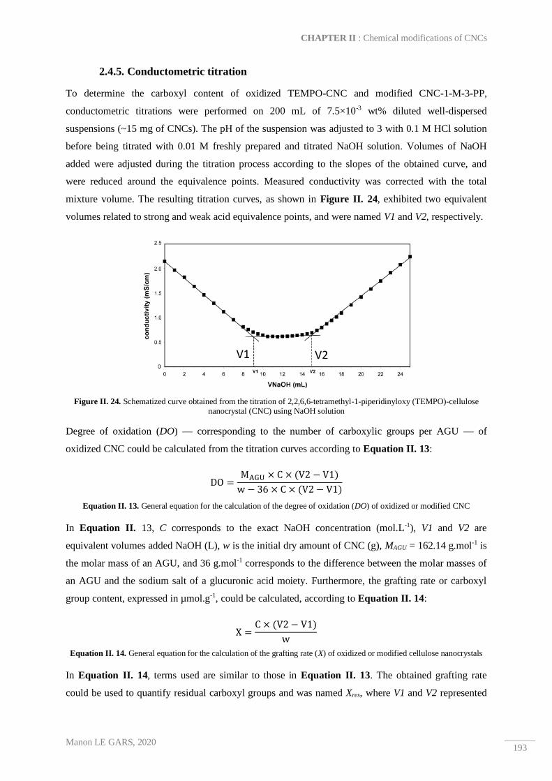
CHAPTER II : Chemical modifications of CNCs
Manon LE GARS, 2020 193
2.4.5. Conductometric titration
To determine the carboxyl content of oxidized TEMPO-CNC and modified CNC-1-M-3-PP,
conductometric titrations were performed on 200 mL of 7.5×10⁻³ wt% diluted well-dispersed
suspensions (~15 mg of CNCs). The pH of the suspension was adjusted to 3 with 0.1 M HCl solution
before being titrated with 0.01 M freshly prepared and titrated NaOH solution. Volumes of NaOH
added were adjusted during the titration process according to the slopes of the obtained curve, and
were reduced around the equivalence points. Measured conductivity was corrected with the total
mixture volume. The resulting titration curves, as shown in Figure II. 24, exhibited two equivalent
volumes related to strong and weak acid equivalence points, and were named V1 and V2, respectively.
Figure II. 24. Schematized curve obtained from the titration of 2,2,6,6-tetramethyl-1-piperidinyloxy (TEMPO)-cellulose nanocrystal (CNC) using NaOH solution
Degree of oxidation (DO) — corresponding to the number of carboxylic groups per AGU — of
oxidized CNC could be calculated from the titration curves according to Equation II. 13:
DO =MAGU × C × (V2 − V1)
w − 36 × C × (V2 − V1)
Equation II. 13. General equation for the calculation of the degree of oxidation (DO) of oxidized or modified CNC
In Equation II. 13, C corresponds to the exact NaOH concentration (mol.L-1), V1 and V2 are
equivalent volumes added NaOH (L), w is the initial dry amount of CNC (g), MAGU = 162.14 g.mol-1 is
the molar mass of an AGU, and 36 g.mol-1 corresponds to the difference between the molar masses of
an AGU and the sodium salt of a glucuronic acid moiety. Furthermore, the grafting rate or carboxyl
group content, expressed in µmol.g-1, could be calculated, according to Equation II. 14:
X =C × (V2 − V1)
w
Equation II. 14. General equation for the calculation of the grafting rate (X) of oxidized or modified cellulose nanocrystals
In Equation II. 14, terms used are similar to those in Equation II. 13. The obtained grafting rate
could be used to quantify residual carboxyl groups and was named Xres, where V1 and V2 represented
V2 V1

Amidation of TEMPO-oxidized cellulose nanocrystals using aromatic aminated molecules
Manon LE GARS, 2020 194
equivalent volumes of the titration performed on grafted CNC-1-M-3-PP. According to Equation II.
15, the difference between the grafting rates before and after amidation can lead to the percentage of
carboxylic groups converted during this reaction (%COOHreact):
%COOHreact = (1 −Xres
X) × 100
Equation II. 15. General equation for the calculation of the number of converted carboxylic groups during the amidation reaction
In order to ensure repeatability of the measure, each titration was performed at least three times.
2.4.6. Elemental analysis (EA)
Carbon, hydrogen, oxygen, nitrogen and sulfur contents of dried CNC samples were sent to “Institut
des Sciences Analytiques” in Villeurbanne (France) and quantified by a micro analyzer with a
precision of 0.4%. The experiments were conducted on each sample. Weight percent of different
atoms can be used to quantify the –COOH charges of oxidized TEMPO-CNC and the grafting degree
of substitution of modified CNC. The degree of oxidation calculated from these data, DOelemental analysis,
can be also determined according to Equation II. 16:
DOelemental analysis =M(C)AGU − %C × MAGU
%C × (MAGU−COONa − MAGU)
Equation II. 16. General equation for the calculation of the degree of oxidation of TEMPO-CNC from elemental analysis results
In Equation II. 16, M(C)AGU, %C, MAGU and MAGU-COONa correspond to the molecular mass of carbon
in an AGU (72.04 g.mol-1), the carbon content in CNC-TEMPO sample obtained by elemental analysis,
the total molar mass of an AGU (162.14 g.mol-1), and the molar mass of an oxidized AGU with
sodium salt as counter ion (35.93 g.mol-1), respectively. Moreover, a degree of substitution (DSelemental
analysis) can be calculated according to Equation II. 17:
DSelemental analysis = %N × (MAGU + DO × (MAGU−COONa − MAGU)
M(N)grafted − %N × Mgrafted
Equation II. 17. General equation for the calculation of the degree of substitution of modified cellulose nanocrystals after
amidation calculated from elemental analysis results
In Equation II. 17, the terms MAGU and MAGU-COONa are similar to those used in Equation II. 16.
Terms %N, M(N)grafted and Mgrafted correspond to the nitrogen content in modified CNC sample
obtained by elemental analysis, the nitrogen molar mass of grafted moieties (14.0 g.mol-1), and the
total molar mass of the grafted moieties (131.23 g.mol-1), respectively. Degree of substitution
corresponds to the number of amine compounds introduced in each AGU.

CHAPTER II : Chemical modifications of CNCs
Manon LE GARS, 2020 195
2.4.7. X-ray photoelectron spectrometry (XPS)
XPS measurements were carried out on a K-Alpha+ surface analysis spectrometer (Thermo Scientific),
equipped with a monochromatic X-ray source (Al Kα, 1487.5 eV). Spots of diameter 400 µm were
used for all the measurements and a hemispherical analyzer was operating in constant analyzer energy
mode under ultra-high vacuum. Data treatments were carried out using Avantage software (Thermo
Fisher). Background subtraction (Smart type) and normalization of peak areas (using Scofield
sensitivity factors) were performed before any elemental composition calculation. Calibration of
binding energies was carried out with the C1s neutral carbon peak at 285 eV. O/C ratios were
calculated according to Equation II. 18,
O
C=
IO
SO×
SC
IC
Equation II. 18. General equation for the calculation of oxygen to carbon ratio from X-ray photoelectron spectrometry data
where IO and IC are intensities of oxygen and carbon peaks, and SO and SC are the atomic Scofield
sensitivity factors of oxygen and carbon equal to 0.00477 and 0.00170, respectively. From O/C ratios,
it is possible to determine the degree of oxidation of TEMPO-CNC. By knowing the O/C ratios for
both neat CNC ((O/C)neat) and oxidized TEMPO-CNC ((O/C) TEMPO), their values can be linked to the
degree of oxidation, DOXPS, as presented in Equation II. 19:
DOXPS = ((O
C)
TEMPO− (
O
C)
Neat ) ×
M(C)AGU
M(O)
Equation II. 19. General equation for the calculation of the degree of oxidation from X-ray photoelectron spectrometry data
Moreover, from C1s spectra decompositions, it is possible to determine a degree of substitution at the
surface (DSXPS) of CNC-1-M-3-PP according to Equation II. 20:
DSXPS =%C − N × M(C)AGU
M(C − N)grafted − %C − N × M(C)grafted
Equation II. 20. General equation for the calculation of the degree of substitution from X-ray photoelectron spectrometry
data
On the other hand, taking into account the geometry of CNC and the crystalline arrangement of their
cellulosic chains, a ratio of the amount of surface chains to the total amount of chains has been
proposed in literature. In fact, Eyley and Thielemans68 — based on the previous work of Habibi et
al.128 — have determined the relation between the number of exposed cellulose chains on the surface
of a CNC and its total number of cellulose chains, and named Rc. This relation takes into account the
crystalline cellulose Iβ structure of a nanocrystal in which (110) and (110̅̅ ̅̅ ̅) planes are perpendicular to
the crystal face, as presented in Scheme II. 3.

Amidation of TEMPO-oxidized cellulose nanocrystals using aromatic aminated molecules
Manon LE GARS, 2020 196
Scheme II. 3. Schematized section of an isolated cellulose nanocrystal, where black squares correspond to cellulose chains’
ends, d(110) and d(𝟏𝟏𝟎̅̅ ̅̅ ̅̅ ) the plane spacings of the crystal planes (Adapted from 68,128)
According to the values found in literature and especially those presented by Lin et Dufresne129, mean
values for d(110) and d(110̅̅ ̅̅ ̅̅ ) for CNC are on average equal to 0.66 and 0.53 nm, respectively.
Moreover, the cross-section of an isolated CNC was supposed to be a square in our study, with l = L =
6 nm. In their study, Eyley and Thielemans68 have proposed Equation 21 for the calculation of the
previously defined ratio, Rc.
Rc =#surface cellulose chains of the CNC
#cellulose chains of the CNC=
2 × (L
d(110)̅̅ ̅̅ ̅̅ ) + 2 × (l
d(110))
L × l
d(110)̅̅ ̅̅ ̅̅ × d(110)
Equation 21. General equation for the calculation of the ratio Rc, wich represents the number of cellulose chains at the
surface to the total number of cellulose chains of a cellulose nanocrystal
In our case, using our assumptions, Rc was equal to 0.39. Additionally, a simple relation links the
degree of substitution with the degree of substitution (DS) at the surface (for example, calculated from
XPS data), as presented by Equation II. 22:
DS = Rc × DSsurface
Equation II. 22. Relation between the degree of substitution, DS, and the degree of the substitution at the surface, DSsurface, of a cellulose nanocrystal
It is important to keep in mind that only 1.5 OH groups are accessible for modification at the surface
of an AGU. All these assumptions and calculations allow the modified groups to be quantified at the
surface or in the bulk of CNCs.

CHAPTER II : Chemical modifications of CNCs
Manon LE GARS, 2020 197
2.4.8. Contact angle
Casted films of unmodified, oxidized and modified CNCs were prepared, and a droplet of 4 µL of
distilled water was deposited for the determination of the angle between the substrate and the droplet
at room temperature. A contact angle meter OCA20 combined with a camera charge-coupled device
(CCD) was used. Acquisition of the angle was performed for one min after the droplet’s deposition,
and the collected data was processed on SCA20 software. All measurements were at least repeated
five times.
2.4.9. Quartz crystal microbalance with dissipation (QCM-d)
Quartz crystals coated with gold (F-QSX-301) supplied by LOT-QuantumDesign (France) were
washed in a piranha bath (H2O2:H2SO4 = 1:3) for 30 min, rinsed with deionized water, and dried with
nitrogen steam. Spin-coating of the sensors with CNCs was performed just after cleaning. Sensors
were introduced in a spin-coater (SPIN150i – POLOSTM) and a washing step (60 seconds off after
drop deposition, acceleration of 360 rpm.s-1, and 3600 rpm for 60 seconds) was carried out with milliQ
water. Sensors were then i) spin-coated with a 2.5 mg.mL-1 PEI solution (300 seconds off after drop
deposition, acceleration of 360 rpm.s-1, and 3600 rpm for 60 seconds), ii) rinsed with milliQ water, iii)
spin-coated with a 2 wt% CNC water suspension, and iv) finally rinsed with milliQ water. Sensors
were then left in an oven for 2 h at 80 °C in order to ensure the stability of the created CNC film. AFM
was used to observe the sensor surface before any analysis in order to ensure the formation of a
homogeneous CNC film. Lastly, the sensors were put in milliQ water for 3 h before QCM-d analysis.
Once the sensors were successfully prepared, they were mounted onto the QCM-d device (Biolin
Scientific, Sweden) and exposed to a milliQ water flow (0.07 µL.min-1) until baseline stabilization.
Measurement temperature was set at 20 °C. A 0.1 wt% 1-M-3-PP solution in milliQ water at pH 8 was
passed through the device with a 100 µL.min-1 flow. After reaching a plateau, milliQ water was introduced
(100 µL.min-1) until another plateau was observed. QCM-d analysis can be used for the investigation
of the mass change of the sensor, and Rodhal et al.130 described the principle of the technique. They
were among the first to relate the change in frequency to the mass added to the crystal and explained
that the sensor vibration fluctuates with the adsorbed mass on its surface. Frequency and dissipation
data were recorded and processed on QTools software (Biolin). Sauerbrey equation (Equation II. 23)
was used for the calculation of the amount of molecules adsorbed on the CNC-coated gold sensor (Δm
in mg per m² of CNC, or mg.m-2CNC). This equation was proposed by Sauerbrey in 1959131 and
required assumptions that have been proposed only more recently in literature. In order to ensure the
validity of the equation, it has been clarified that the film created on the sensor should i) be rigid
(dissipation change inferior to 10 times the frequency change), ii) be uniform, and iii) have a small
mass compared to that of the crystal132,133.

Amidation of TEMPO-oxidized cellulose nanocrystals using aromatic aminated molecules
Manon LE GARS, 2020 198
∆m = −C × ∆f
n
Equation II. 23. Sauerbrey equation for the calculation of the amount of adsorbed molecules from QCM-d analysis
where C is a constant related to the quartz crystal parameters (density and thickness) and equal to 17.7
ng.cm-2.Hz-1 (for a 5 MHz crystal), Δf the change in frequency, and n the overtone number. In this
work, the third overtone number was used and the frequencies were normalized by the QTools
software, so n was equal to 1. From Δm value, the amount (in mol) of molecules adsorbed per g of
CNC was calculated, taking into consideration the theoretical specific surface area of a CNC which
was equal to 500 m2.g-1 (value extracted from literature17).

CHAPTER II : Chemical modifications of CNCs
Manon LE GARS, 2020 199
3. Results and discussions
Characterization of TEMPO-CNC prepared on a large scale
As presented in Scheme II. 2, commercially dried CNCs were oxidized via a TEMPO-mediated
oxidation after being well-dispersed in water. The presence of negatively charged sulfate half ester
groups on their surface (around 250 mmolR-OSO3H/kgCNC)14 induced the colloidal stability of the
supplied unmodified CNCs in water. AFM and TEM images obtained from the unmodified CNC in
water, presented in Figure II. 25 a) and d), confirmed the well-dispersed behavior of the aqueous
suspension. Isolated CNCs exhibited dimensions equal to 108 +/- 33 nm in length and to 4 +/- 1 nm in
width, correlating to values commonly found in literature14,22.
Figure II. 25. Atomic force microscopy (AFM) (height sensor) and transmission electron microscopy (TEM) images of neat cellulose nanocrystal CNC (a and d), TEMPO-CNC (b and e), and modified CNC-1-M-3-PP (c and f)
Figure II. 25 b) and e) represent AFM and TEM observations of oxidized TEMPO-CNC. AFM image
allowed to conclude about the dispersion of TEMPO-CNC in water, even if they were more
aggregated compared to TEM images, probably because of a lack of sonication treatment before
analysis. Moreover, the dimensions of TEMPO-CNCs were close to those of neat CNCs, with 127 +/-
25 nm in length and 5 +/- 1 nm in width, meaning that TEMPO oxidation did not induce any
significant change in terms of CNC dimensions. All the dimensions measured by TEM are
summarized in Table II. 8.

Amidation of TEMPO-oxidized cellulose nanocrystals using aromatic aminated molecules
Manon LE GARS, 2020 200
Neat CNC TEMPO-CNC CNC-1-M-3-PP
Length (nm) Mean 108 127 111
Std. dev. 33 25 19
Width (nm) Mean 4 5 4
Std. dev. 1 1 1
Table II. 8. Summarized lengths and widths of neat CNC, TEMPO-CNC and CNC-1-M-3-PP measured by TEM
In order to further investigate TEMPO oxidation’s influence on CNC’s morphology, XRD analyses
were performed on both unmodified and oxidized CNCs. Figure II. 26 shows diffractograms obtained
from XRD analyses. The three spectra exhibited classical cellulose crystalline structure, with peaks at
2ϴ ~ 15.2° and 2ϴ = 22.6° related to the planes (101) / (101̅), and (002), respectively12. Additionally,
a peak at 2ϴ = 34.6° was present only in the neat CNC sample, and can be related to the (040)
crystalline cellulose contribution due to a textural effect of cellulose, as mentioned several times in the
literature129,134,135. Note that the determination of samples’ crystallinity did not take into account this
contribution. Crystallinity indexes (CI) calculated according to Equation II. 12 demonstrated that
oxidative treatment did not induce any significant change in the crystallinity of CNC since CI
decreases from 91% to 89%. These values corroborate those found in literature4,22, where it has been
proved that an overly intensive oxidation can damage the crystallinity of CNC, contrary to the findings
in another work136. At this stage, it was possible to conclude about the structure conservation of CNC
after their TEMPO oxidation, which was crucial for further chemical modifications and applications.
Figure II. 26. X-Ray diffractograms of neat cellulose nanocrystal (CNC), oxidized TEMPO-CNC, and modified CNC-1-M-3-PP
Further characterizations were performed in order to confirm and quantify oxidation efficiency. FTIR
spectra were recorded for both unmodified and oxidized CNCs, as shown in Figure II. 27. After
normalization at 1110 cm-1 for both spectra, a clear peak at 1730 cm-1 was visible and was correlated to

CHAPTER II : Chemical modifications of CNCs
Manon LE GARS, 2020 201
the presence of carboxylic –COOH groups introduced through the oxidation process. This peak was
related to the C=O stretching vibrations from the acid form of carboxyl groups.
Figure II. 27. Fourier transform infrared normalized spectra of neat cellulose nanocrystal (CNC) and oxidized TEMPO-CNC
Thus, the efficiency of the grafting was proved by FTIR analysis, which in turn proved the presence of
carboxyl groups in the TEMPO-CNC sample. To further modify these groups, their quantification was
needed. In this sense, conductometric titrations were performed on TEMPO-CNC, and one of the
titration curves is presented in Figure II. 28 as example.
Figure II. 28. Conductometric titration curve of TEMPO-CNC with equivalent volumes V1 and V2
The calculated values of degree of oxidation (DO) (Equation II. 13) and grafting rate (X) (Equation
II. 14) are presented in Table II. 9. Oxidized TEMPO-CNC exhibited a calculated degree of oxidation
equal to 0.22 +/- 0.03 and a grafting rate of 1295 +/- 147 µmol of –COOH group per g of dry TEMPO-
CNC, which was in agreement with the literature data128,137. However, although conductometric

Amidation of TEMPO-oxidized cellulose nanocrystals using aromatic aminated molecules
Manon LE GARS, 2020 202
titration is a simple and rapid method, it is highly dependent on the operator, especially during the
titration. Thus, these results must be confirmed by other bulk or surface characterizations.
Sample DO X (µmol.g-1) %COOHreact
TEMPO-CNC 0.22 ± 0.03 1295 ± 147 /
CNC-1-M-3-PP 0.19 ± 0.01 1138 ± 28 12%
Table II. 9. Summarized values of the quantification of carboxylic groups on TEMPO-CNC and modified CNC-1-M-3-PP
Elemental analyses were performed on each sample, and the obtained results are presented in Table II.
10. Experimental values obtained from elemental analyses were corrected since presence of impurities
or other species can largely influence the results. The experimental values were corrected with the
degree of substitution of half-sulfate ester groups (DSSO3) calculated from the percentage of sulfur
element in neat CNC sample. Several other methods to correct these values have been reported, by the
likes of Siqueira et al.59 and Espino-Pérez et al.26, considering that the corrected value of %C for
unmodified CNC sample was equal to the theoretical one (44.4%). In our study, calculated values of
DSSO3 (presented in Table II. 10) were equal to 0.04 for both CNC and TEMPO-CNC samples,
showing that no release of sulfate groups occurred during TEMPO oxidation process, which was
predictable from the mild conditions (temperature, pH, and reaction time) of TEMPO-mediated
oxidation.
Sample Experimental values
DSSO3
Corrected values DO DS %COOHreact
%C %O %H %S %N %C %O
Neat CNC 40.7 50.8 6.4 0.8 <0.1 0.04 42.4 47.1 / / /
TEMPO-CNC 37.0 52.2 5.9 0.8 <0.1 0.04 38.6 48.4 0.68 / /
CNC-1-M-3-PP 40.1 49.5 6.2 0.6 0.5 0.03 41.8 45.9 / 0.07 10
Table II. 10. Atomic composition of neat cellulose nanocrystals (CNCs), oxidized TEMPO-CNC and modified CNC-1-M-3-PP obtained by elemental analyses and calculations of DOelemental analysis, DSelemental analysis and %COOHreact elemental analysis
From elemental analyses’ data, it was possible to determine the degree of oxidation, DOelemental analysis
(Equation II. 16). Calculated DOelemental analysis was equal to 0.68, which was higher than that obtained
from conductometric titrations (Table II. 9) Nevertheless, if corrections to %C and %O were made
according to the previously described method in literature (i.e., considering %Ccorrected in neat CNC is
equal to 44.4), a value of DO = 0.45 would have been obtained. It emphasizes the fact that data
obtained from such analyses (elemental analyses or conductometric titrations) have to be handled with
care, and that calculated values are highly dependent on corrections and formulas used. Therefore,
comparative rather than purely quantitative analyses are preferred. However, when the correction of
the values and the large errors in the values were taken into account, it was possible to conclude that
the degree of oxidation values obtained from both conductometric titrations and elemental analyses
were consistent.

CHAPTER II : Chemical modifications of CNCs
Manon LE GARS, 2020 203
In order to chemically investigate the surface of oxidized TEMPO-CNC, XPS analyses were carried
out on both CNC and TEMPO-CNC. Figure II. 29 shows survey spectra of neat CNC and oxidized
TEMPO-CNC.
Figure II. 29. a) X-ray photoelectron spectroscopy (XPS) survey of neat cellulose nanocrystal (CNC), oxidized TEMPO-CNC and modified CNC-1-M-3-PP and b) Elemental molar compositions, surface functional groups compositions, DOXPS
and DSXPS obtained by XPS analyses
On both spectra, peaks at 532 eV and 285 eV have been related to the O1s and C1s elements,
respectively. In addition, a peak at 400 eV (assigned to nitrogen atoms) appeared on the TEMPO-CNC
spectra and was consistent with the presence of residual TEMPO reagent. No significant change was
observed between the survey spectra of neat and oxidized CNCs, although a slight increase in O1s
peak could be monitored and related to the introduction of –COOH groups.
C1s N1s
%C %O %N O/C
C1
(C-C
/C-H
)
C2
(C-O
)
C3
(O-C
-O /
C=
O)
C4
(O-C
=O
)
C-N
N-H
/N-C
N-C
=O
DO DS
Neat CNC 62.3 36.7 <0.1 0.58 16 66 15 2 / / / / /
TEMPO-CNC 62.4 37.4 0.3 0.60 18 61 17 4 / / / 0.23 /
CNC-1-M-3-PP 62.7 36.3 1 0.58 17 57 17 4 5 73 27 / 0.05
Table II. 11. Elemental molar compositions, surface functional groups compositions, DOXPS and DSXPS obtained by XPS analyses

Amidation of TEMPO-oxidized cellulose nanocrystals using aromatic aminated molecules
Manon LE GARS, 2020 204
Surface DOXPS related to the amount of –COOH groups on the surface of CNC was calculated
according to Equation II. 19 and found to be 0.09. Taking into account the relation expressed in
Equation II. 22, the total degree of oxidation was found to be equal to 0.23, as presented in Table II.
11. This value was consistent with the DO determined by conductometric titration. Here again, XPS
measurement errors have to be taken into consideration, especially in the case of such surface
modifications that introduce a low amount of carbon or oxygen elements.
Figure II. 30 a) and b) present the decomposition spectra of C1s peaks of neat and oxidized CNCs,
respectively. On the neat CNC C1s decomposition spectra, four peaks were displayed at 284.7 eV,
286.3 eV (ΔeV= 1.6 eV), 287.8 eV (ΔeV= 3.1 eV) and 289.1 eV (ΔeV= 4.4 eV), and these correspond
to C1 (C-C/C-H), C2 (C-O), C3 (O-C-O/C=O) and C4 (O-C=O) contributions, respectively.
Figure II. 30. X-ray photoelectron spectroscopy decomposition of the C1s peak of a) unmodified cellulose nanocrystal (CNC), b) oxidized TEMPO-CNC, and c) modified CNC-1-M-3-PP, and d) decomposition of the N1s peak of modified
CNC-1-M-3-PP

CHAPTER II : Chemical modifications of CNCs
Manon LE GARS, 2020 205
The C1 signal from neat CNC decomposition spectra was linked to the presence of non-oxidized
alkane-type carbon atoms and some impurities like lignin residuals or other compounds. Therefore, its
intensity should not increase after oxidation. The C2 signal was related to the ether groups or hydroxyl
groups from pure cellulose as well as to the ends of cellulose chains. The C3 signal corresponded to
the acetal entities present that bridged two AGUs. Its intensity should not increase after chemical
modifications since the corresponding carbon will not be affected by chemical modifications. Finally,
C4 signal was present in low proportions in the neat CNC spectra, and was attributed to the presence
of glucuronic acid from hemicellulose residuals. Comparing Figure II. 30 a) and b), an increase in
this C4 peak was observed and was consistent with the oxidation performed on CNC. This observation
was confirmed by values of C4 contribution (Table II. 11) which increased by a factor of 2.
Thus, the efficiency of TEMPO-mediated oxidation performed in a reactor on a large batch of CNCs
was proved. The amount of –COOH groups on a CNC was quantified and confirmed via direct
characterizations, and it was needed for further modifications for the groups with 1-M-3-PP molecule
obtained through the amidation reaction.
Grafting efficiency of 1-M-3PP on TEMPO-CNC through amidation
Taking advantage of the carboxylic groups previously introduced at the surface of CNC via different
chemical reactions has been already proposed in literature4,68. In this study, efficiency and green
aspects of amidation via EDC/NHS catalysis have been key elements for the choice of such an
amidation procedure. 1-M-3-PP molecule has been widely used in the pharmaceutical industry for
biotechnology, highlighting its potential for further applications, e.g. in barrier packaging with food
contact. Moreover, as mentioned in literature, its possible interaction with aromatic compounds could
be interesting in terms of organic compounds’ sorption.
In a preliminary study, the kinetics of the EDC/NHS catalyzed amidation reaction was investigated.
After the beginning of the reaction, aliquots of the system were collected at different times of reaction,
washed by centrifugation cycles, and then dialyzed against water, as presented in the section 1.3.
Aqueous suspensions of different modified CNC-1-M-3-PP were casted and dried films were analyzed
by FTIR spectroscopy, whose spectra are presented in Figure II. 31. For each spectra of recovered
CNC-1-M-3-PP at acidic pH, the presence of a peak at 1650 cm-1 was related to the presence of –
N(H)-C=O amide bonds introduced during amidation reaction. When the pH was changed from an
acidic pH to a basic pH, this peak shifted to 1745 cm-1. Simultaneously, a peak at 1600 cm-1 appeared
which was related to the presence of residual unreacted carboxylic groups. Moreover, between 2800
and 3000 cm-1, peaks related to –CH2 and –CH3 groups from grafted 1-M-3-PP were observed and
correlated with the same peaks present in the commercial molecule 1-M-3-PP. These peaks can also be
attributed to the presence of =C-H and –C=C elongations from the aromatic rings of 1-M-3-PP

Amidation of TEMPO-oxidized cellulose nanocrystals using aromatic aminated molecules
Manon LE GARS, 2020 206
molecule, confirming the presence of 1-M-3-PP on the surface of CNC. Peaks related to amide bonds
highlight the covalent grafting between TEMPO-CNC and 1-M-3-PP. After the kinetics study of the
amidation performed on TEMPO-CNC, a reaction time of 72 h was selected for the reaction.
Following this study, samples named “CNC-1-M-3-PP” were recovered after 72 h of reaction.
Figure II. 31. Fourier transform infrared (FTIR) spectra of 1-M-3-PP molecule, oxidized TEMPO-CNC, modified CNC-1-M-3-PP after 24h (at acid and basic pH, dashed and solid lines, respectively), 48h and 72h of amidation
Regarding the AFM image of CNC-1-M-3-PP in Figure II. 25 c), a length of 150 +/- 50 nm was
obtained, showing that no significant change in size was induced after the amidation. Furthermore,
their crystallinity index (CI = 90%) was substantially the same. Thus, the morphology of CNCs did not
change after amidation with 1-M-3-PP, which was once again predictable due to the mild conditions
(pH, temperature) of the amidation reaction. This result was interesting since crystallinity and
dimensions of CNCs are required properties for most applications.
In order to quantify the amount of carboxylic groups converted into amide groups, conductometric
titrations were performed on CNC-1-M-3-PP sample. Using both Equation II. 13 and Equation II. 14,
the degree of oxidation and the residual grafting rate of –COOH were determined to be 0.19 +/- 0.01
and 1138 +/- 28, respectively. The percentage of converted –COOH groups were deduced from the
results obtained for TEMPO-CNC using Equation II. 15 and was equal to 12%, as presented in Table
II. 9. The results of the elemental analysis performed on CNC-1-M-3-PP are presented in Table II. 10.
The atomic percentage of nitrogen was found to be 0.5% (whereas, less than 0.1% was present in both
neat and oxidized samples), confirming the presence of nitrogen compound in the CNC-1-M-3-PP
sample. Moreover, a degree of substitution of 0.07 was obtained using Equation II. 17, corresponding
to 10% of COOH groups converted into amide groups. This was in line with the values found through

CHAPTER II : Chemical modifications of CNCs
Manon LE GARS, 2020 207
the conductometric titrations. Finally, XPS analysis was performed on the amidated sample.
Regarding the Figure II. 29, the survey spectra obtained from CNC-1-M-3-PP exhibited an intense
peak at 400 eV, which clearly indicates the presence of nitrogen elements in the sample. From Table
II. 11, it can be seen that the atomic percentage of nitrogen we found to be 1% the analysis, which was
much higher than the percentage found in the TEMPO-CNC sample (0.3 %), correlating with the
survey spectra. C1s decomposition spectrum of CNC-1-M-3-PP is presented in Figure II. 30 c). C1,
C2, C3 and C4 peaks were clearly identified, and a new peak at 285.3 eV (ΔeV= 0.6 eV) which is
related to the C-N bond was also identified. Although the determination of this peak was difficult
because of its overlapping with C1 peak, it was clearly assigned to the C-N bond, as previously shown
in literature33,138. However, at this stage, it was not possible to confirm the presence of any covalent
amide linkage between nitrogen compound and oxidized TEMPO-CNC. In this sense, N1s
decomposition spectrum of CNC-1-M-3-PP was performed as presented in Figure II. 30 d). The two
peaks at 399.6 eV and 401.6 eV (ΔeV= 2 eV) were related to N-H/N-C and N-C=O bonds,
respectively. In literature, it has already been seen that the second peak was decomposed in two
peaks33. However, due to the close electronegativity of hydrogen and carbon elements, only one peak
can be attributed to the two bonds N-H and N-C. According to the amidation reaction and as shown in
Scheme II. 2, theoretical ratio between the peaks N-H/N-C and N-C=O should be equal to 2:1 if only
amidation takes place. However, this ratio was higher in our case (2.7:1), suggesting that other
nitrogen compounds were present in the sample. This opened the door to a possible case of adsorption
of the 1-M-3-PP molecule at the surface of TEMPO-CNC. Nevertheless, a degree of substitution
(DSXPS) was calculated according to Equation II. 20 and was equal to 0.6. This value was related to
the –COOH groups present on the surface of TEMPO-CNC, and by taking into account the previously
determined DOXPS as well as the relation presented in Equation II. 22, a degree of substitution of 0.05
was obtained. It was consistent with the value previously found by conductometric titration and
elemental analysis and in accordance — although lower — with values found in literature for such
amidation procedures124,125. It can be due to the heterogeneous reaction leading to lower grafting
densities than those obtained in homogenous chemistry or the mild reaction conditions (i.e. aqueous
system, ambient temperature) compared to traditionally performed organic chemistry reactions.
Indirect proofs of grafting efficiency
We proved the presence of covalently attached 1-M-3-PP molecules at the surface of CNCs. Although
the degree of substitution was quite low, it has been proved in literature that even if that is the case,
grafting can lead to significant changes in properties like barrier or compatibilization properties20,72,
and some indirect characterization can further confirm their grafting efficiency.
Dispersion of modified CNC-1-M-3-PP in different organic solvents was investigated. Indeed, as
shown in Figure II. 32, suspensions of both oxidized TEMPO-CNC and modified CNC-1-M-3-PP

Amidation of TEMPO-oxidized cellulose nanocrystals using aromatic aminated molecules
Manon LE GARS, 2020 208
were prepared by solvent exchange in acetone or dichloromethane at the same concentration (0.3 wt%)
through successive centrifugation cycles (10000 rpm, 5 °C, 15’). Pictures presented in Figure II. 32
were taken after 4 h following a sonication step (2500 J.gCNC-1). As shown in Figure II. 32 a),
TEMPO-CNC was less stable in acetone than in dichloromethane, and in both cases, sedimentation of
CNC at the bottom of the vial was observed after 4 h of rest.
Figure II. 32. Pictures of a) TEMPO-CNC and b) CNC-1-M-3-PP suspensions (0.3 wt%) in acetone and dichloromethane after 4 h without stirring
In Figure II. 32 b), modified CNC-1-M-3-PP in acetone was also subjected to sedimentation, but it
was significantly less than TEMPO-CNC in acetone. On the other hand, the suspensions of CNC-1-M-
3-PP in dichloromethane were stable after 4 h. Stabilization of CNCs in an organic solvent — acetone
and dichloromethane in this study — after their modification with aromatic compounds highlighted
the presence of the hydrophobic groups at their surface. Moreover, this dispersion in an organic
solvent — especially in dichloromethane which is the solvent of numerous polymers — was
encouraging in terms of application purposes, and especially for the preparation of nanocomposites,
where the preparation of stable and well-dispersed CNC suspension in dichloromethane is generally
the first step in the nanocomposites’ elaboration. Furthermore, in order to confirm the
hydrophobization of CNC-1-M-3-PP, contact angles of neat CNC, TEMPO-CNC, and modified CNC-
1-M-3-PP were determined and the results are summarized in Table II. 12.
Neat CNC TEMPO-CNC CNC-1-M-3-PP
Contact angle (°) Mean value 53 52 43
Std. Dev. 3 2 1
Table II. 12. Contact angles measured with a 4-uL water drop on neat cellulose nanocrystals (CNCs), TEMPO-CNC and CNC-1-M-3-PP casted films
Measured contact angles of both unmodified CNC and oxidized TEMPO-CNC were close (53 +/- 3°
and 52 +/- 2°, respectively). This result was predictable since oxidized hydroxyl groups were replaced
by carboxyl groups after oxidation, which did not affect hydrophilicity of the TEMPO-CNC surface.
After modification with 1-M-3-PP, surface behavior of CNC-1-M-3-PP was expected to change. As
mentioned before, presence of aromatic hydrophobic groups would change polarity, and thus an

CHAPTER II : Chemical modifications of CNCs
Manon LE GARS, 2020 209
increase in the contact angle was expected. According to Table II. 12, contact angle measured for
CNC-1-M-3-PP (43 +/- 1°) did not follow this trend. The reason could be the bad surface quality of
the casted film or the presence of more pores leading to the absorption of water inside the film, which
was confirmed by the significant decrease in water droplet volume during the experiment.
All these characterizations helped determine the efficiency of the grafting of 1-M-3-PP molecules
from carboxylic groups. Nevertheless, as deduced from quantitative analyses of the CNC-1-M-3-PP
sample, parallel adsorption possibly occurred at the CNC surface. Several researchers have previously
investigated the competition between covalent grafting and non-covalent phenomenon. Recently,
Gicquel et al. reported that the adsorption of aminated PNIPAM-NH2 competed with its amidation on
the TEMPO-CNC surface124. In the present study, this adsorption was also investigated, and QCM-d
experiments were performed in a preliminary study, as presented in the remainder of this section.
Physico-chemical adsorption of 1-M-3-PP at the surface of TEMPO-
CNC
The investigation of the adsorption of 1-M-3-PP occurring on oxidized TEMPO-CNC was firstly
monitored by UV absorbance. In the first step, a calibration curve of the absorption of the molecule at
258 nm as a function of the concentration was plotted, as shown in Figure II. 33 a). Beer-Lambert law
is valid for values of absorbance comprised between 0.1 and 1. For a defined ratio NCOOH: NNH2, a
specific amount of 1-M-3-PP was added to an aqueous TEMPO-CNC suspension, and the reaction
mixture was left under magnetic stirring. At different stirring times, an aliquot was recovered and two
centrifugation cycles (10000 rpm, 5 °C, 20’) were performed. Each recovered filtrate was then diluted
in order to correlate with Beer-Lambert law and analyzed using an UV spectrophotometer.
Concentration of 1-M-3-PP — corresponding to the non-adsorbed mass — was determined using its
calibration curve presented in Figure II. 33 a). Finally, adsorbed mass of 1-M-3-PP was plotted as a
function of the reaction time. In order to investigate the behavior of 1-M-3-PP molecules on TEMPO-
CNC, the adsorption was monitored within the time. Taking into account the number of carboxylic
groups –COOH at the surface of TEMPO-CNC, as previously determined, a precise amount of 1-M-3-
PP was added to the TEMPO-CNC suspension with conservation of the molar ratio NCOOH:NNH2 (1:4)
used in the amidation reaction. According to the previously described method, adsorbed mass of 1-M-
3-PP per g of dry TEMPO-CNC was determined and plotted as a function of the time, as presented in
Figure II. 33 b).

Amidation of TEMPO-oxidized cellulose nanocrystals using aromatic aminated molecules
Manon LE GARS, 2020 210
Figure II. 33. a) Calibration curve of 1-M-3-PP absorbance function of its concentration in a water solution and b) Mass of 1-M-3-PP adsorbed per grgam of dry TEMPO-CNC function on the time (with molar ratio 4NCOOH=NNH2)
Figure II. 33 b) shows clearly that the adsorbed mass reached a plateau after 2 h. In this sense, it was
difficult to assume if the previously determined %COOHreact was related only to the amidation
reaction or to the adsorption phenomenon also. This point was relevant: indeed, as soon as a chemical
modification is performed, competing adsorptions or other parallel modifications must be considered.
Since one objective of this study was to introduce aromatic ring at the surface of CNCs for further
barrier properties, this parallel adsorption did not hinder our work.
In order to investigate more precisely the adsorption of 1-M-3-PP on TEMPO-CNC, QCM-d analyses
were performed. Figure II. 34 shows the QCM-d measurements obtained after 1-M-3-PP adsorption
on both unmodified CNC and oxidized TEMPO-CNC at pH 8, in order to be in -OSO3- (neat CNC) or
-COO- (TEMPO-CNC) configuration. In both Figure II. 34 a) and b), a long plateau can be observed
at the beginning of the measurement recording, corresponding to the water flow, and thus the water
swelling of cellulose. Just after 1-M-3-PP solution injection (indicated by arrows), a large increase in
the frequency was observed which was related to the increase of the sensors’ mass and thus the
adsorption of the molecule (Figure II. 34 a)). Note that this increase was much greater for TEMPO-
CNC than for unmodified CNC. In both cases, the rinsing (indicated by droplet symbols) and the
subsequent increase in frequency followed by a stable plateau indicated a partial release of compounds
from the CNC surface.

CHAPTER II : Chemical modifications of CNCs
Manon LE GARS, 2020 211
Figure II. 34. Shifts in a) frequency and b) dissipation plotted function of the time and obtained from the third overtone of QCM-d measurement data and normalized by n=3 (Arrows indicate when 1-M-3-PP solution was injected and droplet
symbols correspond to the beginning of rinsing with milliQ water)
The final frequency changes are presented in Table II. 13 and were equal to -11.6 Hz and -47.8 Hz for
neat and oxidized CNC, respectively. In parallel, an increase in dissipation — much lower than
frequency changes in both cases — was clearly observed and the final dissipation changes equal to
2.8.106 and 9.7.106 for CNC and TEMPO-CNC, respectively, are presented in Table II. 13. Note that
in both cases, dissipation changes were largely lower than 10 times the corresponding frequency
changes, which allowed the use of Sauerbrey equation (Equation II. 23) as previously detailed.
Neat CNC TEMPO-CNC
Δf3/3 (Hz) -11.6 -47.8
ΔD3 (106) 2.8 9.7
Δm (mg1-M-3-PP.m-2CNC) 2.1 8.5
Δn (mol1-M-3-PP.g-1CNC) 7.0x10⁻³ 2.8x10⁻²
Table II. 13. Frequency (Δf/3) and dissipation (ΔD3) changes after 1-M-3-PP adsorption on both CNC and TEMPO-CNC with determined adsorbed amount (Δm and Δn)
Table II. 13 presents the amounts of 1-M-3-PP molecule adsorbed (in mass or in mol, Δm and Δn
respectively) per surface or mass of CNC and calculated using Sauerbrey equation (Equation II. 23).
According to QCM-d experiments, 2.1 and 8.5 mg of 1-M-3-PP were adsorbed per m² of neat CNC
and TEMPO-CNC, respectively, corresponding to 7.0×10⁻³ and 2.8×10⁻² moles of 1-M-3-PP adsorbed

Amidation of TEMPO-oxidized cellulose nanocrystals using aromatic aminated molecules
Manon LE GARS, 2020 212
per g of CNC and TEMPO-CNC. Thus, adsorption occurred in both cases and was four times more
efficient when CNCs were previously oxidized, which was predictable due to the presence of a large
number of negative charges (-COO-) on their surface. Moreover, by comparing the value of DSXPS
(0.05, or 3.10-4 moles of 1-M-3-PP per g of TEMPO-CNC) with the value of Δn, it can be assumed
that adsorption allows the introduction of about 90 times more 1-M-3-PP molecules on the surface of
CNCs, than the amidation procedure. This value is very high and confirms that the washing step
applied during the QCM-d experiment is not adapted, since the value after the grafting is much lower.
It also proves that the value of adsorbed molecules obtained from QCM-d is related to irreversibly
adsorbed molecules. Unfortunately, QCM-d cannot simulate the same extensive washing steps as
those performed in the amidation procedure. In this sense, it is not possible to conclude about the
proportion of grafted and/or adsorbed molecules on the CNCs.
Based on the literature and on the direct characterizations performed on the CNC-1-M-3-PP, it can be
assumed that the washing steps performed in the grafting strategy is sufficient, and it is thus possible
to assume that most of the quantified aminated molecules are covalently attached on the CNCs at the
end of the reaction.

CHAPTER II : Chemical modifications of CNCs
Manon LE GARS, 2020 213
4. Conclusion
In this study, a TEMPO-mediated oxidation was performed on a large batch of CNCs. Although this
oxidation has been widely detailed in the literature, performing it efficiently on such a large volume is
interesting and challenging. Quantification of carboxyl groups introduced on TEMPO-CNC was
carried out by classic conductometric titrations, and confirmed by elemental analyses and XPS
methods. In the second step, TEMPO-CNCs were subjected to an amidation reaction using 1-M-3-PP
which bears aromatic groups. These chemically modified CNCs have been characterized by direct
methods (FTIR spectroscopy, elemental analysis, XPS) as well as, by indirect methods. Dispersion
and stabilization in organic solvents, such as dichloromethane, is an interesting feature since it opens
the door to further applications for nanocomposites. Furthermore, with the investigation of sorption
and barrier properties, it opens the road to nanocomposites’ applications in packaging materials.

Amidation of TEMPO-oxidized cellulose nanocrystals using aromatic aminated molecules
Manon LE GARS, 2020 214

CHAPTER II : Chemical modifications of CNCs
Manon LE GARS, 2020 215
4. Adsorption of rosin nanoparticles from a nano-
emulsion on both cellulose nanocrystals and
nanofibrils
This short section aims to briefly describe the preparation of modified nanocelluloses, whose
application will be further discussed in Chapter III.2 of this manuscript.
Moreover, this part is the result of a close collaborative work with the startup INOFIB (K. Missoum
and B. Dhuiège), and the presented results are the subject of a patent registered by the startup.

Adsorption of rosin nanoparticles from a nano-emulsion on both cellulose nanocrystals and nanofibrils
Manon LE GARS, 2020 216
Abstract
Outstanding properties of nanocelluloses make them materials of choice for their use in
nanocomposites or multi-layered materials. Indeed, besides their sources availability, renewability and,
sustainability, their intrinsic properties (low density, morphology and, chemical reactivity) are of great
interest for the enhancement of the final materials properties. In this short study, both cellulose
nanofibrils (CNF) and cellulose nanocrystals (CNC) were modified by adsorption of rosin
nanoparticles obtained from the preparation of a rosin-based nano-emulsion. The rosin mixture as a
natural compound is of interest because of its low cost, renewability, hydrophobicity, as well as, its
antimicrobial and antioxidant properties. Successfully prepared modified CNF-Rosin and CNC-Rosin
aqueous suspensions can then be used for further applications, especially for the preparation of fully
bio-based food packaging materials with improving active properties.
Keywords:
Cellulose nanofibrils ─ Cellulose nanocrystals ─ Rosins ─ Nano-emulsion ─ Adsorption
CHAPTER II : Chemical modifications of CNCs
Manon LE GARS, 2020 217
1. Introduction
Sustainability, biodegradability, renewability and abundancy are the main exceptional advantages
of the novel category of cellulosic materials: the nanocelluloses. These nanoscale materials, whether
cellulose nanofibrils (CNF) or nanocrystals (CNC), have been the focus of numerous researches in
recent decades. In fact, their outstanding intrinsic properties (i.e., low density compared to other
organic materials, high specific surface area, surface chemical reactivity, high tensile strength, barrier
properties towards oxygen)1,2,15–17 make them materials of choice for many different applications
(hydrogels, composites, conducting materials, piezoelectric materials, biosensors, pharmaceuticals,
biomedical devices, etc.)2,67. Among these applications, their use in the elaboration of multi-phasic
materials (i.e. nanocomposites, multi-layers) is highly interesting and promising, especially for bio-
based food packaging applications. Moreover, conferring them active functionalities, like
antimicrobial or antioxidant properties, could increase their interest in such applications7,8. In the
literature, numerous publications focused on this topic, with the use of various active molecules and
different procedures for their attachment on nanocelluloses27,139,140.
Among exploitable and tunable natural materials, rosins are highly interesting because of their
abundancy, sustainability and low cost. They are the main products from conifers, especially pine
resin derived from pine trees, and more than 1 million metric tons of rosin are produced each year141,142.
Abietic- and primaric-type acids are the main components of a natural rosin mixture, whose structure
is presented in Figure II. 3512. These acids bear hydrophenanthrene ring structures, conferring them
similar rigidity to that of fossil-based plastics, and Liu et al. took advantage of rosin rigidity to
produce rosin-based thermosetting resins with properties comparable to synthetic materials143.
Moreover, rosins find applications in inks, adhesives, cosmetics, varnishes, paints, coatings, medicines,
paper-sizing agents and, emulsions142,144,145. It is worth to note that rosin is often used in growth
polymerization in order to produce low molecular weight polymeric materials including rosin as
natural compounds, and these polymerizations are generally performed via atom-transfer radical
polymerization (ATRP)144. For example, Wang et al.141 performed ATRP to polymerize rosin
monomers on the surface of lignin for surface functionalization. Moreover, antimicrobial activity of
rosin is a major advantage, which has been widely exploited, as found in the literature. Indeed,
Moustafa et al.142 recently focused on the fact that rosin can be used as food products shelf-life
extender in packaging materials, and performed esterification of rosin on organoclay and introduced
these modified organoclays in a blend of poly(lactic acid)/poly(butylene adipate-co-terephtalate). They
concluded about the antibacterial activity of produced nanocomposites and their interest in food
packaging applications. De Castro et al.27 performed an efficient green esterification of rosin on
cellulose nanocrystals and highlighted the hydrophobic and antimicrobial behavior of the resulted
grafted CNC. Note that insolubility of natural rosins in water may limit their use in numerous
applications requiring water conditions, unless they are used in suspended form.

Adsorption of rosin nanoparticles from a nano-emulsion on both cellulose nanocrystals and nanofibrils
Manon LE GARS, 2020 218
One main advantage of the preparation of emulsions is the solubility of compounds in a solvent
with which they are not soluble. In fact, by definition, an emulsion lies in the mixing of two
immiscible liquids by using both mechanical shear and surfactant146. A nano-emulsion is defined as
the dispersion of nano-sized particles (typically between 20 and 200 nm)147 prepared by mechanical
forces. More precisely, nano-emulsions are clear and thermodynamically stable and their main
application is the drug-delivery in various systems, as widely described in the literature147,148.
The combination of both nanocelluloses and natural rosins has only recently been proposed in
literature. Indeed, as previously mentioned, de Castro et al.27 performed a green esterification
procedure, adapted from a previous study published by Espino-Pérez et al.26, to covalently link rosins
on the cellulose nanocrystals surface. More recently, Niu et al. 149 performed a similar protocol on
cellulose nanofibers and introduced modified CNF in a poly(lactic acid)/chitosan polymeric matrix.
Both studies highlighted antimicrobial activity brought by the presence of rosin in the prepared
systems. Although these grafting methods aimed to limit the use of organic and toxic solvents, they
required time-consuming multi-steps procedure. In this sense, adsorption of rosin on nanocellulose can
be considered, thus decreasing the use of chemicals and reaction steps.
In this short part, a nano-emulsion of natural rosin was prepared and its stability and nano-size
character were carefully investigated by Dynamic Light Scattering (DLS). In a second step, both CNF
and CNC were modified by adsorption of rosin nano-particles from the nano-emulsion, leading to
modified CNF-Rosin and CNC-Rosin. Films of the ensuing modified nanocelluloses were performed
by filtration or solvent casting for CNF-Rosin and CNC-Rosin respectively, and the presence of rosins
in each film was investigated by infrared spectroscopy and contact angle measurements.

CHAPTER II : Chemical modifications of CNCs
Manon LE GARS, 2020 219
2. Materials and methods
Materials
Tetradecyltrimethylammonium Bromide (TTAB), Gum rosin (natural resin) and, Chloroform (>99%)
were supplied by Sigma Aldrich and used as received. Spray-dried powder of cellulose nanocrystals
(CNC) was supplied by CelluForce© (Canada). Cellulose nanofibrils suspension (2 wt%) was provided
by INOFIB (Saint-Martin d’Hères, France). Figure II. 35 represents the main components found in
commercial mixture of natural rosin.
Figure II. 35. Main carboxylic acids found in rosin (extracted from 27)
Preparation of rosin nano-emulsion
An aqueous and an oily phase were prepared according to the following protocols. Aqueous phase was
prepared by total dissolving 0.606 g of TTAB in 50 mL of water, which corresponds to around 10
times the TTAB Critical Micellar Concentration. Concerning the oily phase preparation, a solution of
rosins in chloroform was prepared at the concentration of 550 g/L. Thereafter, 14.8 g of the oily phase
were slowly introduced into 49.5 g of the aqueous phase previously put in a beaker, and the mixture
was emulsified by using an ultrasonic probe for 2 min with a 25 W power. The reaction media was
then heated at 65 °C using an oil bath until total evaporation of the chloroform. Final nano-emulsion
was then recovered in a perfectly hermetically closed vial and stored at 4 °C until used.
Preparation of rosin nano-emulsion was performed by the INOFIB startup (Karim Missoum and
Benjamin Dhuiège).

Adsorption of rosin nanoparticles from a nano-emulsion on both cellulose nanocrystals and nanofibrils
Manon LE GARS, 2020 220
Adsorption of rosin nanoparticles on CNF
A correct amount of previously prepared rosin nano-emulsion was added to a 2% (wt/wt) aqueous
suspension of CNF in order to reach a rosin/CNF weight ratio equal to 0.11. The formulated
suspension was then mixed under mechanical stirring for 30 min at room temperature to adsorb the
nano-micelles of rosin onto the CNF surface. Final CNF-Rosin suspension was stored in a
hermetically closed vial at 4 °C before being used.
Adsorption of rosin nanoparticles on CNF was performed by the INOFIB startup (Karim Missoum
and Benjamin Dhuiège).
Adsorption of rosin nano-emulsion on CNC
Rosin nanoparticles were adsorbed on CNC, as previously described for CNF. Briefly, an aqueous
suspension of CNC at 1% (wt/wt) was prepared by adding a correct amount of spray-dried CNC in
water and by applying an ultrasonic treatment to the suspension (2.5 kJ/g of dried CNC). A precise
amount of rosin nano-emulsion was then introduced in the suspension by keeping a rosin/CNC weight
ratio equal to 0.11. After 30 min of magnetic stirring at room temperature, it was considered that rosin
was adsorbed at the CNC surface. Recovered CNC-Rosin suspension was stored in a hermetically
closed vial at 4 °C before use.
Elaboration of neat and modified CNF films by filtration
Appropriate amounts of both neat CNF and formulated CNF-Rosin suspensions were diluted to 0.5
wt%. and mixed for 10 min under magnetic stirring. The diluted suspensions were then filtered
through a 1µm-cut-off Nylon web, dried at 90 °C for 12 min under vacuum to obtain the CNF and
CNF-Rosin films. More precisely, 20 cm diameter sheets were prepared at 30 g/m², using a Rapid-
Köthen hand sheet former.
Preparation of modified CNF-Rosin films was performed by the INOFIB startup (Karim Missoum
and Benjamin Dhuiège).
Elaboration of neat and modified CNC-Rosin films by solvent
casting
Both neat CNC and modified CNC-Rosin suspensions were diluted at 0.5 wt% and sonicated (2.5 kJ/g
of dried CNC). Correct amounts of both suspensions were introduced in petri dishes keeping the basis
weight of targeted films equal to 40 g/m². Casted suspensions were left under fume hood at room
temperature for several days until total water evaporation, in order to prepare the CNC and CNC-
Rosin films.

CHAPTER II : Chemical modifications of CNCs
Manon LE GARS, 2020 221
Characterization methods
2.7.1. Rosin nano-emulsion characterization by Dynamic Light Scattering (DLS)
The particle size of the rosin nanoparticles from the nano-emulsion was determined by DLS using a
VASCO Cordouan nanosizer. More precisely, three droplets of the nano-emulsion were introduced in
the device with the dual thickness controller (DTC) in up position, diluted with distilled water and
roughly homogenized. The laser intensity and the correlator settings were adjusted at 5 µs as time
interval, and 600 as the number of channels. Data were recorded using NanoQ software at 25 °C for 15
acquisitions of 30 s with a noise/signal ratio limit inferior to 0.5% (dual limits settings). Both the
Pade-Laplace and the Cumulants method were used for data processing. At least triplicate
measurements were performed.
2.7.2. CNC and CNF film characterization by Fourier-transform infrared
spectroscopy (FTIR)
Fourier-transform infrared spectroscopy was performed on both unmodified and modified
nanocellulose films using a Perkin-Elmer spectrum 65. Films were analyzed through 16 scans and
with a resolution of 2 cm-1. The baseline of the FTIR spectra was corrected and the data tuned up.
Each spectrum containing CNC or CNF was normalized at 1110 cm-1 (related to pure cellulose). Each
measurement was at least duplicated, and most representative spectra were plotted.
2.7.3. Contact angle measurements
Contact angle measurements were carried out on neat and modified nanocellulose films by depositing
5 µL-water droplets on the film surface at room temperature. An OCA20 DataPhysics (DataPhysics
Instrument) system, equipped with a CCD camera, was used to record the angles between the solvent
and the substrate. The acquisition of contact angle was collected for the first 60 s after deposition. At
least five measurements were performed for each sample.

Adsorption of rosin nanoparticles from a nano-emulsion on both cellulose nanocrystals and nanofibrils
Manon LE GARS, 2020 222
3. Results and discussions
Nanometric size of rosin particles
The preparation of rosin nano-emulsion was based on the alkyl ketene dimer (AKD)-based nano-
emulsion production method patented by Missoum et al.99. By definition, as previously mentioned,
nano-emulsions are nano-sized stable colloidal emulsions150. Rosin nano-emulsion was prepared
following the protocol of mixing two immiscible liquids (water and chloroform) in the presence of a
surfactant (TTAB), which resulted in a dispersed oil-in-water single phase. To avoid the aggregation
and get the proper nanometric size of rosin particles in the prepared emulsion, DLS measurement was
performed on a diluted sample. The size distribution of the intensity of rosin particles obtained with
the cumulant method is presented in Figure II. 36. The size distribution of particles is Gaussian, with
the particle diameter size equal to 186 nm measured by DLS, confirming the nanometric character of
the rosin particles in the emulsion.
Figure II. 36. Size distribution of relative intensity obtained from DLS measurement performed on rosin nano-emulsion
The DLS measurement has been performed six months after the nano-emulsion preparation, which
proves the stability of the nano-emulsions, that were used for further adsorption on both CNF and
CNC.

CHAPTER II : Chemical modifications of CNCs
Manon LE GARS, 2020 223
Efficiency of the rosin adsorption on both CNF and CNC
Adsorption of rosin nano-emulsions on CNF and CNC was performed according to the previously
described procedure. As discussed in the introduction, several acids are present in natural rosin
mixture, the most predominant of which are shown in Figure II. 35. Both CNF and CNC contain
many hydroxyl groups (–OH) at their surface, which can easily create hydrogen bonds with carboxyl
groups in the acid mixture from rosin particles. In order to confirm the presence of rosin molecules on
both CNF and CNC, FTIR analyses were performed on commercial rosin, as well as, neat CNF, CNF-
Rosin, neat CNC, and CNC-Rosins films. The resulting spectra are presented in Figure II. 37.
Figure II. 37. FTIR spectra of commercial rosin (powder), and, neat CNF, CNF-Rosin, neat CNC, and CNC-Rosin films
In the spectrum of the supplied neat rosin, an intense peak at 1695 cm-1 can be related to many
carboxylic groups (–COOH) from the different acids composing the rosin mixture. Moreover, a large
peak between 2900 and 3000 cm-1 can be attributed to the –CH carbons from alkene bonds of different
acids. The spectra related to neat CNF and CNC both exhibit peaks classically observed for cellulosic
samples, with, among others, peaks at 1105, 1059 and 1028 cm-1 linked to the vibrations of C-O bonds,
and a large peak at approximately 3000 ─ 3600 cm-1 linked to stretching vibration of bonds of primary
and secondary hydroxyl groups. In both CNF-Rosin and CNC-Rosin spectra, respectively, the peaks at
1692 cm-1 and 1691 cm-1 are attributed to the carboxylic groups from the rosin mixture present in the
samples. Note that this peak is more intense in the case of CNC, which could be explained by the loss
of the not adsorbed rosin nano-emulsion during the filtration process of CNF-based film preparation.

Adsorption of rosin nanoparticles from a nano-emulsion on both cellulose nanocrystals and nanofibrils
Manon LE GARS, 2020 224
However, from the FTIR spectra, it is possible to qualitatively conclude about the presence of rosin in
both CNF-Rosin and CNC-Rosin samples. Modified CNF-Rosin and CNC-Rosin were thus efficiently
produced, with a weight ratio of rosin to CNC or CNF close to 0.11.
Water contact angle measurements were performed on both unmodified CNF and CNC films, as well
as on modified CNF-Rosin and CNC-Rosin films. Neat CNC and CNF films exhibit water contact
angle equal to 54° ± 1 ° and 36° ± 6°, respectively, and these values are consistent with values found
in the literature151,152. After adsorption of rosin nanoparticles on CNC, CNC-Rosin casted film shows a
visible decrease in the contact angle down to 32° ± 1.5°, probably due to the presence of hydrophilic
properties of rosin molecules. The contact angle of the modified CNF-Rosin film is equal to 42° ± 5°.
Taking into account the standard deviation of this value and the uncertainty of the neat CNF film
contact angle, it is difficult to reach any conclusions about the evolution of the water contact angle,
although a similar trend was observed for the CNC-Rosin sample.

CHAPTER II : Chemical modifications of CNCs
Manon LE GARS, 2020 225
4. Conclusion
A stable nano-emulsion of rosins was successfully prepared by the INOFIB Startup. In order to confer
new active properties (antibacterial, antioxidant, etc.) to nanocelluloses, rosin nanoparticles from the
nano-emulsion were adsorbed on the surface of both CNF and CNC by a simple, fast and, low
chemical consumption route. Finally, prepared aqueous suspensions of modified CNF-Rosin and
CNC-Rosin can then be used for further applications.

Adsorption of rosin nanoparticles from a nano-emulsion on both cellulose nanocrystals and nanofibrils
Manon LE GARS, 2020 226

CHAPTER II : Chemical modifications of CNCs
Manon LE GARS, 2020 227
Conclusions of Chapter II
The aim of the Chapter II was to propose new routes for the CNCs surface chemical modification.
Four different strategies were successfully performed on cellulose nanocrystals.
▪ In the first section II.1, the grafting-from via a surface-initiated radical transfer polymerization
(SI-ATRP) of the glycidyl methacrylate (GMA) was successfully performed, accordingly to an
optimized protocol. The initial surface modifications of CNCs with the BIB ─ a common initiator of
the SI-ATRP method ─ was efficiently performed, in accordance with values found in the literature.
Furthermore, the kinetics study of the SI-ATRP led to an optimization of the reaction time. In fact,
after only one hour of polymerization, around 50% of the total mass of recovered nanomaterials was
related to the PGMA polymer. The presence of reactive epoxy groups at the surface of recovered
polymerized CNCs at the end of the reaction was also highlighted, and this point is highly encouraging,
since it could favor further reactions with a polymeric matrix, or more simply the compatibility
between the polymerized CNCs and a hydrophobic polymeric matrix, like the poly(lactic acid).
▪ The section II.2 was introduced in a first part (II.2.1) evidencing the efficiency of a novel
esterification procedure compared to a well-known esterification involving an acid chloride as reagent.
The degree of substitution of CNCs modified via the new esterification method was five times higher
than that of CNCs obtained through the classical method. In the second following part (II.2.2), the
novel esterification procedure was described and performed on CNCs using both lauric and stearic
acids as reagents. The efficiency of the reaction was highlighted ─ with degrees of substitution equal
to 0.1 and 0.3 for lauric and stearic acids, respectively ─, as well as, the hydrophobicity of the
modified CNCs surface, and these results are encouraging for further use of the modified CNCs.
Moreover, the possible recyclability of the chemicals, less toxic as usual, at the end of the proposed
esterification method is an important matter, particularly in a spirit of more green chemistry.
▪ In the section II.3, the characterization of TEMPO-CNC oxidized on a larger scale than those
reported in the literature (~ 100 g) proved the efficiency of the oxidation (with an oxidation degree
around 0.2), in accordance with values found in the literature. Furthermore, the grafting of the 1-
methyl-3-phenylpropylamine molecule ─ an aminated molecule bearing aromatic group ─ was
performed on the TEMPO-CNCs through an amidation reaction, and the efficiency of the reaction was
quantified, with a degree of substitution close to 0.1. Through multiple characterizations, it was
assumed that another reaction ─ the adsorption ─ could take place at the surface of the TEMPO-CNCs.
This adsorption phenomenon was thus investigated, and it was shown that it allowed the introduction
of ninety times more aromatic molecules on the surface of the CNCs than the amidation reaction. This

Conclusions of Chapter II
Manon LE GARS, 2020 228
result highlighted the potential bonding of numerous molecules on the TEMPO-CNC, in a simple and
more environmentally friendly way.
▪ Finally, the additional section II.4 was intended to briefly introduce the preparation of CNCs
and CNFs adsorbed with rosin nanoparticles. The stable nanometric behavior of the prepared nano-
emulsion containing rosin nanoparticles, and the presence of rosin in final dried films composed of
CNCs or CNFs were proved. This adsorption procedure did not involve toxic chemicals, and is
interesting because of its simplicity and short duration (no washing steps required).
The Table II. 14 summarizes the different grafting methods described in the Chapter II, as
well as, their required reaction time, their efficiency, and the limitation in terms of quantity of
grafted CNCs. This highlights the fact that in order to be able to functionalize the CNCs on a
large scale ─ which is often necessary for many applications, such as the elaboration of
packaging materials ─, it is necessary to move towards grafting or adsorption methods that
consume less reaction steps, and thus less time and toxic chemicals.
Chapter Grafted or adsorbed
polymer/molecule Grafting method
Reaction
time Efficiency
Maximum possible
quantity of grafted
CNCs at lab scale
II.1 Poly(glycidyl
methacrylate) (PGMA)
Surface-initiated transfer
radical polymerization
(SI-ATRP)
1h 50 % (w/w)
of PGMA A few milligrams
II.2(.2) Lauric & stearic acid
Esterification
(novel procedure: the acid
acts as the solvent)
8h
Degree of
substitution
0.1-0.3
A few tens of grams
II.3 1-methyl-3-
phenylpropylamine
Amidation on oxidized
TEMPO-CNC or
adsorption
72h 0.1 A few hundred grams
II.4 Rosin nanoparticles Adsorption 30 min / A few hundred grams
Table II. 14. Summary of the different grafting methods presented in the Chapter II
By way of a detailed comparison between these different grafting methods, the Table II. 15. Main
advantages and drawbacks of the different grafting methods proposed in the Chapter II presents
the main advantages and main drawbacks of the latter, from the point of view of the reaction time, the
cost of raw materials, the possible amount of modified material, and the industrial feasibility.

CHAPTER II : Chemical modifications of CNCs
Manon LE GARS, 2020 229
Procedure Main advantages Main drawbacks
SI-ATRP
(PGMA)
▪ Entire CNCs surface covered with polymer
▪ Quantified and controlled amount of grafted
polymer
▪ Short time of polymerization (1h)
▪ Restricting amount of grafted CNCs (≈ 1g)
▪ Organic & toxic chemicals
▪ Oxygen free media required
▪ 2-step procedure (1st surface-initiation with
active sites)
▪ Difficult industrial feasibility
▪ Considerable cost
Esterification
(fatty acids)
▪ Limiting use of toxic chemicals
▪ Satisfying grafting densities
▪ Possible recyclability of solvent/chemicals
▪ Low cost of chemicals
▪ Conceivable industrial feasibility
▪ Limited amount of grafted CNCs at lab-scale
(≈ 10-20g)
▪ Large amount of solvent (acetone) required
▪ Multi-step procedure
▪ High energy consumption
▪ Time-consuming washing steps
▪ Long reaction times (solvent exchange + 8h)
Amidation
(1-M-3-PP)
▪ Mild and aqueous conditions
▪ Relative low cost and low energy
consumption
▪ Possible reaction on a larger scale (TEMPO
oxidation performed on ≈ 100g)
▪ Low grafting densities
▪ Possible concurrent adsorption
▪ Mutli-step procedure
▪ Long reaction time (72h)
Adsorption
(Rosins)
▪ Simple efficient route, no washing-step
▪ Low energy consumption
▪ Possible large amount of modified CNCs (≈
kg)
▪ Short reaction time (≈ 30 min)
▪ No control of the adsorption (reversible /
irreversible?)
▪ Preliminary step required for the preparation
of the nano-emulsion
Table II. 15. Main advantages and drawbacks of the different grafting methods proposed in the Chapter II
As previously mentioned, all the modified nanocellulosic materials prepared and characterized were
then used for the preparation of final materials based on a polymer matrix, whose results are presented
in the following Chapter III.

Conclusions of Chapter II
Manon LE GARS, 2020 230

CHAPTER II : Chemical modifications of CNCs
Manon LE GARS, 2020 231
References – Chapter II
1. Nechyporchuk, O., Belgacem, M. N. & Bras, J. Production of cellulose nanofibrils: A review of
recent advances. Industrial Crops and Products 93, 2–25 (2016).
2. Kargarzadeh, H. et al. Advances in cellulose nanomaterials. Cellulose 25, 2151–2189 (2018).
3. Habibi, Y., Lucia, L. A. & Rojas, O. J. Cellulose Nanocrystals: Chemistry, Self-Assembly, and
Applications. Chemical Reviews 110, 3479–3500 (2010).
4. Habibi, Y. Key advances in the chemical modification of nanocelluloses. Chem. Soc. Rev. 43,
1519–1542 (2014).
5. Oksman, K. et al. Review of the recent developments in cellulose nanocomposite processing.
Composites Part A: Applied Science and Manufacturing 83, 2–18 (2016).
6. Ferreira, F. V., Pinheiro, I. F., Gouveia, R. F., Thim, G. P. & Lona, L. M. F. Functionalized
cellulose nanocrystals as reinforcement in biodegradable polymer nanocomposites. Polymer
Composites 39, E9–E29 (2017).
7. Ferrer, A., Pal, L. & Hubbe, M. Nanocellulose in packaging: Advances in barrier layer
technologies. Industrial Crops and Products 95, 574–582 (2017).
8. Hubbe, M. A. et al. Nanocellulose in Thin Films, Coatings, and Plies for Packaging
Applications: A Review. BioResources 12, 2143–2233 (2017).
9. Domingues, R. M. A., Gomes, M. E. & Reis, R. L. The Potential of Cellulose Nanocrystals in
Tissue Engineering Strategies. Biomacromolecules 15, 2327–2346 (2014).
10. Lin, N. & Dufresne, A. Nanocellulose in biomedicine: Current status and future prospect.
European Polymer Journal 59, 302–325 (2014).
11. Jorfi, M. & Foster, E. J. Recent advances in nanocellulose for biomedical applications. Journal
of Applied Polymer Science 132, 41719–41738 (2015).
12. Foster, E. J. et al. Current characterization methods for cellulose nanomaterials. Chemical
Society Reviews 47, 2609–2679 (2018).
13. Beck, S., Méthot, M. & Bouchard, J. General procedure for determining cellulose nanocrystal
sulfate half-ester content by conductometric titration. Cellulose 22, 101–116 (2015).
14. Reid, M. S., Villalobos, M. & Cranston, E. D. Benchmarking cellulose nanocrystals: from the
laboratory to industrial production. Langmuir 33, 1583–1598 (2016).
15. Natterodt, J. C., Petri-Fink, A., Weder, C. & Zoppe, J. O. Cellulose Nanocrystals: Surface
Modification, Applications and Opportunities at Interfaces. CHIMIA International Journal for
Chemistry 71, 376–383 (2017).
16. Klemm, D. et al. Nanocelluloses: A New Family of Nature-Based Materials. Angewandte
Chemie International Edition 50, 5438–5466 (2011).
17. Dufresne, A. Nanocellulose: from nature to high performance tailored materials. (Walter de
Gruyter GmbH & Co KG, 2017).
18. Lin, N., Huang, J. & Dufresne, A. Preparation, properties and applications of polysaccharide
nanocrystals in advanced functional nanomaterials: a review. Nanoscale 4, 3274–3294 (2012).
19. Espino-Pérez, E. et al. Nanocomposites with functionalised polysaccharide nanocrystals through
aqueous free radical polymerisation promoted by ozonolysis. Carbohydrate Polymers 135, 256–
266 (2016).
20. Espino-Pérez, E. et al. Designed cellulose nanocrystal surface properties for improving barrier
properties in polylactide nanocomposites. Carbohydrate Polymers 183, 267–277 (2018).
21. Boujemaoui, A. et al. Polycaprolactone Nanocomposites Reinforced with Cellulose Nanocrystals
Surface-Modified via Covalent Grafting or Physisorption: A Comparative Study. ACS Applied
Materials & Interfaces 9, 35305–35318 (2017).

References – Chapter II
Manon LE GARS, 2020 232
22. Moon, R. J., Martini, A., Nairn, J., Simonsen, J. & Youngblood, J. Cellulose nanomaterials
review: structure, properties and nanocomposites. Chemical Society Reviews 40, 3941–3994
(2011).
23. Belgacem, M. N., Gandini, A. Monomers, polymers and composites from renewable resources.
(Elsevier, 2008)
24. Siqueira, G., Bras, J. & Dufresne, A. Cellulosic Bionanocomposites: A Review of Preparation,
Properties and Applications. Polymers 2, 728–765 (2010).
25. Eyley, S. & Thielemans, W. Surface modification of cellulose nanocrystals. Nanoscale 6, 7764–
7779 (2014).
26. Espino-Pérez, E., Domenek, S., Belgacem, N., Sillard, C. & Bras, J. Green Process for Chemical
Functionalization of Nanocellulose with Carboxylic Acids. Biomacromolecules 15, 4551–4560
(2014).
27. de Castro, D. O., Bras, J., Gandini, A. & Belgacem, N. Surface grafting of cellulose nanocrystals
with natural antimicrobial rosin mixture using a green process. Carbohydrate Polymers 137, 1–8
(2016).
28. Fatona, A., Berry, R. M., Brook, M. A. & Moran-Mirabal, J. M. Versatile Surface Modification
of Cellulose Fibers and Cellulose Nanocrystals through Modular Triazinyl Chemistry. Chemistry
of Materials 30, 2424–2435 (2018).
29. Kedzior, S. A., Graham, L., Moorlag, C., Dooley, B. M. & Cranston, E. D. Poly(methyl
methacrylate)-grafted cellulose nanocrystals: One-step synthesis, nanocomposite preparation,
and characterization. The Canadian Journal of Chemical Engineering 94, 811–822 (2016).
30. Azzam, F., Heux, L., Putaux, J.-L. & Jean, B. Preparation By Grafting Onto, Characterization,
and Properties of Thermally Responsive Polymer-Decorated Cellulose Nanocrystals.
Biomacromolecules 11, 3652–3659 (2010).
31. Hatton, F. L., Kedzior, S. A., Cranston, E. D. & Carlmark, A. Grafting-from cellulose
nanocrystals via photoinduced Cu-mediated reversible-deactivation radical polymerization.
Carbohydrate Polymers 157, 1033–1040 (2017).
32. Goffin, A.-L. et al. From Interfacial Ring-Opening Polymerization to Melt Processing of
Cellulose Nanowhisker-Filled Polylactide-Based Nanocomposites. Biomacromolecules 12,
2456–2465 (2011).
33. Hu, Z., Berry, R. M., Pelton, R. & Cranston, E. D. One-Pot Water-Based Hydrophobic Surface
Modification of Cellulose Nanocrystals Using Plant Polyphenols. ACS Sustainable Chem. Eng. 5,
5018–5026 (2017).
34. Abitbol, T. Surface modification of cellulose nanocrystals with cetyltrimethylammonium
bromide. Nordic Pulp and Paper Research Journal 29, 046–057 (2014).
35. Kedzior, S. A., Marway, H. S. & Cranston, E. D. Tailoring Cellulose Nanocrystal and Surfactant
Behavior in Miniemulsion Polymerization. Macromolecules 50, 2645–2655 (2017).
36. Nagalakshmaiah, M., El Kissi, N. & Dufresne, A. Ionic Compatibilization of Cellulose
Nanocrystals with Quaternary Ammonium Salt and Their Melt Extrusion with Polypropylene.
ACS Applied Materials & Interfaces 8, 8755–8764 (2016).
37. Sessini, V. et al. Effect of the addition of polyester-grafted-cellulose nanocrystals on the shape
memory properties of biodegradable PLA/PCL nanocomposites. Polymer Degradation and
Stability 152, 126–138 (2018).
38. Kloser, E. & Gray, D. G. Surface Grafting of Cellulose Nanocrystals with Poly(ethylene oxide)
in Aqueous Media. Langmuir 26, 13450–13456 (2010).
39. Zhou, L. et al. Grafting polycaprolactone diol onto cellulose nanocrystals via click chemistry:
Enhancing thermal stability and hydrophobic property. Carbohydrate Polymers 189, 331–341
(2018).

CHAPTER II : Chemical modifications of CNCs
Manon LE GARS, 2020 233
40. Habibi, Y. et al. Bionanocomposites based on poly(ε-caprolactone)-grafted cellulose
nanocrystals by ring-opening polymerization. Journal of Materials Chemistry 18, 5002–5010
(2008).
41. Morandi, G., Heath, L. & Thielemans, W. Cellulose Nanocrystals Grafted with Polystyrene
Chains through Surface-Initiated Atom Transfer Radical Polymerization (SI-ATRP). Langmuir
25, 8280–8286 (2009).
42. Zhang, Z., Tam, K. C., Sèbe, G. & Wang, X. Convenient characterization of polymers grafted on
cellulose nanocrystals via SI-ATRP without chain cleavage. Carbohydrate Polymers 199, 603–
609 (2018).
43. Zoppe, J. O. et al. Poly(N-isopropylacrylamide) Brushes Grafted from Cellulose Nanocrystals
via Surface-Initiated Single-Electron Transfer Living Radical Polymerization.
Biomacromolecules 11, 2683–2691 (2010).
44. Boujemaoui, A., Mongkhontreerat, S., Malmström, E. & Carlmark, A. Preparation and
characterization of functionalized cellulose nanocrystals. Carbohydrate Polymers 115, 457–464
(2015).
45. Hansson, S., Antoni, P., Bergenudd, H. & Malmström, E. Selective cleavage of polymer grafts
from solid surfaces: assessment of initiator content and polymer characteristics. Polymer
Chemistry 2, 556–558 (2011).
46. Zoppe, J. O. et al. Effect of Surface Charge on Surface-Initiated Atom Transfer Radical
Polymerization from Cellulose Nanocrystals in Aqueous Media. Biomacromolecules 17, 1404–
1413 (2016).
47. Cañamero, P. F., de la Fuente, J. L., Madruga, E. L. & Fernández-García, M. Atom Transfer
Radical Polymerization of Glycidyl Methacrylate: A Functional Monomer. Macromol. Chem.
Phys. 205, 2221–2228 (2004).
48. Nyström, D., Lindqvist, J., Östmark, E., Hult, A. & Malmström, E. Superhydrophobic bio-fibre
surfaces via tailored grafting architecture. Chem. Commun. 3594–3596 (2006)
49. Martínez-Sanz, M. et al. Incorporation of poly(glycidylmethacrylate) grafted bacterial cellulose
nanowhiskers in poly(lactic acid) nanocomposites: Improved barrier and mechanical properties.
European Polymer Journal 49, 2062–2072 (2013).
50. Hansson, S., Östmark, E., Carlmark, A. & Malmström, E. ARGET ATRP for Versatile Grafting
of Cellulose Using Various Monomers. ACS Appl. Mater. Interfaces 1, 2651–2659 (2009).
51. Malmström, E. & Carlmark, A. Controlled grafting of cellulose fibres – an outlook beyond paper
and cardboard. Polymer Chemistry 3, 1702–1713 (2012).
52. Cheng, D., Wei, P., Zhang, L. & Cai, J. Surface-initiated atom transfer radical polymerization
grafting from nanoporous cellulose gels to create hydrophobic nanocomposites. RSC Adv. 8,
27045–27053 (2018).
53. Morandi, G. et al. ATRP and ROMP: Modular chemical tools for advanced macromolecular
engineering. Materials Science and Engineering: C 29, 367–371 (2009).
54. McCaig, H. C., Myers, E., Lewis, N. S. & Roukes, M. L. Vapor Sensing Characteristics of
Nanoelectromechanical Chemical Sensors Functionalized Using Surface-Initiated
Polymerization. Nano Letters 14, 3728–3732 (2014).
55. Segal, L., Creely, J. J., Martin, A. E. & Conrad, C. M. An Empirical Method for Estimating the
Degree of Crystallinity of Native Cellulose Using the X-Ray Diffractometer. Textile Research
Journal 29, 786–794 (1959).
56. Park, S., Baker, J. O., Himmel, M. E., Parilla, P. A. & Johnson, D. K. Cellulose crystallinity
index: measurement techniques and their impact on interpreting cellulase performance.
Biotechnology for Biofuels 3, 1–10 (2010).

References – Chapter II
Manon LE GARS, 2020 234
57. Ahvenainen, P., Kontro, I. & Svedström, K. Comparison of sample crystallinity determination
methods by X-ray diffraction for challenging cellulose I materials. Cellulose 23, 1073–1086
(2016).
58. Boluk, Y. & Danumah, C. Analysis of cellulose nanocrystal rod lengths by dynamic light
scattering and electron microscopy. J Nanopart Res 16, 2174 (2014).
59. Siqueira, G., Bras, J. & Dufresne, A. New Process of Chemical Grafting of Cellulose
Nanoparticles with a Long Chain Isocyanate. Langmuir 26, 402–411 (2010).
60. Viet, D., Beck-Candanedo, S. & Gray, D. G. Dispersion of cellulose nanocrystals in polar
organic solvents. Cellulose 14, 109–113 (2007).
61. Tian, C., Fu, S., Habibi, Y. & Lucia, L. A. Polymerization Topochemistry of Cellulose
Nanocrystals: A Function of Surface Dehydration Control. Langmuir 30, 14670–14679 (2014).
62. Barbey, R., Laporte, V., Alnabulsi, S. & Klok, H.-A. Postpolymerization Modification of
Poly(glycidyl methacrylate) Brushes: An XPS Depth-Profiling Study. Macromolecules 46,
6151–6158 (2013).
63. Wang, X., Jing, S., Liu, Y., Qiu, X. & Tan, Y. Preparation of dithiocarbamate polymer brush
grafted nanocomposites for rapid and enhanced capture of heavy metal ions. RSC Advances 7,
13112–13122 (2017).
64. Xiao, M., Li, S., Chanklin, W., Zheng, A. & Xiao, H. Surface-initiated atom transfer radical
polymerization of butyl acrylate on cellulose microfibrils. Carbohydrate Polymers 83, 512–519
(2011).
65. Sabatini, D. M. Leading Edge Nanotechnology Research Developments. (Nova Publishers, 2007).
66. Beamson, G. & Briggs, D. High Resolution XPS of Organic Polymers: The Scienta ESCA300
Database. J. Chem. Educ. 70, A25 (1993).
67. Kontturi, E. et al. Advanced Materials through Assembly of Nanocelluloses. Advanced
Materials 30, 1703779 (2018).
68. Eyley, S. & Thielemans, W. Surface modification of cellulose nanocrystals. Nanoscale 6, 7764–
7779 (2014).
69. Castro, D. O. et al. Effect of different carboxylic acids in cyclodextrin functionalization of
cellulose nanocrystals for prolonged release of carvacrol. Materials Science and Engineering: C
69, 1018–1025 (2016).
70. de Castro, D. O. et al. Controlled release of carvacrol and curcumin: bio-based food packaging
by synergism action of TEMPO-oxidized cellulose nanocrystals and cyclodextrin. Cellulose 25,
1249–1263 (2018).
71. Tang, J., Sisler, J., Grishkewich, N. & Tam, K. C. Functionalization of cellulose nanocrystals for
advanced applications. Journal of Colloid and Interface Science 494, 397–409 (2017).
72. Espino-Pérez, E. et al. Cellulose nanocrystal surface functionalization for the controlled sorption
of water and organic vapours. Cellulose 23, 2955–2970 (2016).
73. Wei, L. et al. Chemical modification of nanocellulose with canola oil fatty acid methyl ester.
Carbohydrate Polymers 169, 108–116 (2017).
74. Peng, S. X., Chang, H., Kumar, S., Moon, R. J. & Youngblood, J. P. A comparative guide to
controlled hydrophobization of cellulose nanocrystals via surface esterification. Cellulose 23,
1825–1846 (2016).
75. Bendahou, A., Hajlane, A., Dufresne, A., Boufi, S. & Kaddami, H. Esterification and amidation
for grafting long aliphatic chains on to cellulose nanocrystals: a comparative study. Research on
Chemical Intermediates 41, 4293–4310 (2015).
76. Çetin, N. S. et al. Acetylation of Cellulose Nanowhiskers with Vinyl Acetate under Moderate
Conditions. Macromolecular Bioscience 9, 997–1003 (2009).

CHAPTER II : Chemical modifications of CNCs
Manon LE GARS, 2020 235
77. Lin, N., Huang, J., Chang, P. R., Feng, J. & Yu, J. Surface acetylation of cellulose nanocrystal
and its reinforcing function in poly(lactic acid). Carbohydrate Polymers 83, 1834–1842 (2011).
78. Anastas, P. & Eghbali, N. Green Chemistry: Principles and Practice. Chemical Society Reviews
39, 301–312 (2010).
79. Shojaeiarani, J., Bajwa, D. S. & Stark, N. M. Green esterification: A new approach to improve
thermal and mechanical properties of poly(lactic acid) composites reinforced by cellulose
nanocrystals. Journal of Applied Polymer Science 135, 46468 (2018).
80. Yoo, Y. & Youngblood, J. P. Green One-Pot Synthesis of Surface Hydrophobized Cellulose
Nanocrystals in Aqueous Medium. ACS Sustainable Chemistry & Engineering 4, 3927–3938
(2016).
81. Junior de Menezes, A., Siqueira, G., Curvelo, A. A. S. & Dufresne, A. Extrusion and
characterization of functionalized cellulose whiskers reinforced polyethylene nanocomposites.
Polymer 50, 4552–4563 (2009).
82. de Mesquita, J. P., Donnici, C. L., Teixeira, I. F. & Pereira, F. V. Bio-based nanocomposites
obtained through covalent linkage between chitosan and cellulose nanocrystals. Carbohydrate
Polymers 90, 210–217 (2012).
83. Ranby, B. G. & Ribi, E. Über den feinbau der zellulose. Experientia 6, 12–14 (1950).
84. Sadeghifar, H., Filpponen, I., Clarke, S. P., Brougham, D. F. & Argyropoulos, D. S. Production
of cellulose nanocrystals using hydrobromic acid and click reactions on their surface. J Mater
Sci 46, 7344–7355 (2011).
85. Camarero Espinosa, S., Kuhnt, T., Foster, E. J. & Weder, C. Isolation of Thermally Stable
Cellulose Nanocrystals by Phosphoric Acid Hydrolysis. Biomacromolecules 14, 1223–1230
(2013).
86. Yu, H. et al. Facile extraction of thermally stable cellulose nanocrystals with a high yield of 93%
through hydrochloric acid hydrolysis under hydrothermal conditions. Journal of Materials
Chemistry A 1, 3938–3944 (2013).
87. Beck-Candanedo, S., Roman, M. & Gray, D. G. Effect of Reaction Conditions on the Properties
and Behavior of Wood Cellulose Nanocrystal Suspensions. Biomacromolecules 6, 1048–1054
(2005).
88. Roman, M. & T. Winter, W. Effect of Sulfate Groups from Sulfuric Acid Hydrolysis on the
Thermal Degradation Behavior of Bacterial Cellulose. Biomacromolecules 5, 1671–1677 (2004).
89. Liu, Y. et al. Nanoscale Assembly of Cellulose Nanocrystals during Drying and Redispersion.
ACS Macro Lett. 7, 172–177 (2018).
90. Ferreira, F. V. et al. How do cellulose nanocrystals affect the overall properties of biodegradable
polymer nanocomposites: A comprehensive review. European Polymer Journal 108, 274–285
(2018).
91. George, J. & Sabapathi, S. Cellulose nanocrystals: synthesis, functional properties, and
applications. Nanotechnol Sci Appl 8, 45–54 (2015).
92. Abitbol, T. Surface modification of cellulose nanocrystals with cetyltrimethylammonium
bromide. Nordic Pulp and Paper Research Journal 29, 046–057 (2014).
93. Heux, L., Chauve, G. & Bonini, C. Nonflocculating and Chiral-Nematic Self-ordering of
Cellulose Microcrystals Suspensions in Nonpolar Solvents. Langmuir 16, 8210–8212 (2000).
94. Nagalakshmaiah, M., Pignon, F., Kissi, N. E. & Dufresne, A. Surface adsorption of triblock
copolymer (PEO–PPO–PEO) on cellulose nanocrystals and their melt extrusion with
polyethylene. RSC Advances 6, 66224–66232 (2016).
95. Freire, C. S. R., Silvestre, A. J. D., Neto, C. P., Belgacem, M. N. & Gandini, A. Controlled
heterogeneous modification of cellulose fibers with fatty acids: Effect of reaction conditions on

References – Chapter II
Manon LE GARS, 2020 236
the extent of esterification and fiber properties. Journal of Applied Polymer Science 100, 1093–
1102 (2006).
96. Robles, E., Urruzola, I., Labidi, J. & Serrano, L. Surface-modified nano-cellulose as
reinforcement in poly(lactic acid) to conform new composites. Industrial Crops and Products 71,
44–53 (2015).
97. Yuan, H., Nishiyama, Y., Wada, M. & Kuga, S. Surface Acylation of Cellulose Whiskers by
Drying Aqueous Emulsion. Biomacromolecules 7, 696–700 (2006).
98. Boufi, S. et al. Nanofibrillated cellulose as an additive in papermaking process: A review.
Carbohydrate Polymers 154, 151–166 (2016).
99. Missoum, K., Bras, J. & Belgacem, N. Method for forming a hydrophobic layer. U.S. Patent
Application No. 14/907, 326 (2016).
100. Missoum, K., Martoïa, F., Belgacem, M. N. & Bras, J. Effect of chemically modified
nanofibrillated cellulose addition on the properties of fiber-based materials. Industrial Crops and
Products 48, 98–105 (2013).
101. Martinez, P., Guerin, D., Jeong-Yong Ryu & Kwon, J. Y. Upscaling a new technology for the
development of silicone free recyclable release paper. (2016) doi:10.13140/rg.2.1.2656.5526.
102. Fumagalli, M., Sanchez, F., Molina Boisseau, S. & Heux, L. Gas-phase esterification of
cellulose nanocrystal aerogels for colloidal dispersion in apolar solvents. Soft Matter 9, 11309–
11317 (2013).
103. Zhong, L., Fu, S., Peng, X., Zhan, H. & Sun, R. Colloidal stability of negatively charged
cellulose nanocrystalline in aqueous systems. Carbohydrate Polymers 90, 644–649 (2012).
104. Araki, J., Wada, M. & Kuga, S. Steric Stabilization of a Cellulose Microcrystal Suspension by
Poly(ethylene glycol) Grafting. Langmuir 17, 21–27 (2001).
105. Brand, J., Pecastaings, G. & Sèbe, G. A versatile method for the surface tailoring of cellulose
nanocrystal building blocks by acylation with functional vinyl esters. Carbohydrate Polymers
169, 189–197 (2017).
106. Chang, H. et al. Individually Dispersed Wood-Based Cellulose Nanocrystals. ACS Appl. Mater.
Interfaces 8, 5768–5771 (2016).
107. Zini, E., Scandola, M. & Gatenholm, P. Heterogeneous Acylation of Flax Fibers. Reaction
Kinetics and Surface Properties. Biomacromolecules 4, 821–827 (2003).
108. Spinella, S. et al. Concurrent Cellulose Hydrolysis and Esterification to Prepare a Surface-
Modified Cellulose Nanocrystal Decorated with Carboxylic Acid Moieties. ACS Sustainable
Chemistry & Engineering 4, 1538–1550 (2016).
109. Quast, K. Flotation of hematite using C6–C18 saturated fatty acids. Minerals Engineering 19,
582–597 (2006).
110. Missoum, K., Bras, J. & Belgacem, M. N. Organization of aliphatic chains grafted on
nanofibrillated cellulose and influence on final properties. Cellulose 19, 1957–1973 (2012).
111. Ikram, S. & Ahmed, S. Natural Polymers: Derivatives, Blends and Composites. (Nova
Publishers, 2016).
112. Rol, F., Belgacem, M. N., Gandini, A. & Bras, J. Recent advances in surface-modified cellulose
nanofibrils. Progress in Polymer Science 88, 241–264 (2019).
113. Ranby, B. G. Fibrous macromolecular systems. Cellulose and muscle. The colloidal properties of
cellulose micelles. Discuss. Faraday Soc. 11, 158–164 (1951).
114. Beck-Candanedo, S., Roman, M. & Gray, D. G. Effect of Reaction Conditions on the Properties
and Behavior of Wood Cellulose Nanocrystal Suspensions. Biomacromolecules 6, 1048–1054
(2005).
CHAPTER II : Chemical modifications of CNCs
Manon LE GARS, 2020 237
115. Nguyen, T.-D., Y. Hamad, W. & J. MacLachlan, M. Tuning the iridescence of chiral nematic
cellulose nanocrystals and mesoporous silica films by substrate variation. Chemical
Communications 49, 11296–11298 (2013).
116. Frka‐Petesic, B., Radavidson, H., Jean, B. & Heux, L. Dynamically Controlled Iridescence of
Cholesteric Cellulose Nanocrystal Suspensions Using Electric Fields. Advanced Materials 29,
1606208 (2017).
117. Athukoralalage, S. S., Balu, R., Dutta, N. K. & Roy Choudhury, N. 3D Bioprinted
Nanocellulose-Based Hydrogels for Tissue Engineering Applications: A Brief Review. Polymers
11, 898 (2019).
118. Du, H. et al. Cellulose nanocrystals and cellulose nanofibrils based hydrogels for biomedical
applications. Carbohydrate Polymers 209, 130–144 (2019).
119. Mariano, M., Kissi, N. E. & Dufresne, A. Cellulose nanocrystals and related nanocomposites:
Review of some properties and challenges. Journal of Polymer Science Part B: Polymer Physics
52, 791–806 (2014).
120. Kedzior, S. A., Zoppe, J. O., Berry, R. M. & Cranston, E. D. Recent advances and an industrial
perspective of cellulose nanocrystal functionalization through polymer grafting. Current Opinion
in Solid State and Materials Science 23, 79-91 (2018).
121. Hoeng, F., Denneulin, A., Neuman, C. & Bras, J. Charge density modification of carboxylated
cellulose nanocrystals for stable silver nanoparticles suspension preparation. Journal of
Nanoparticle Research 17, 244 (2015).
122. Fraschini, C., Chauve, G. & Bouchard, J. TEMPO-mediated surface oxidation of cellulose
nanocrystals (CNCs). Cellulose 24, 2775–2790 (2017).
123. Saito, T. et al. Individualization of Nano-Sized Plant Cellulose Fibrils by Direct Surface
Carboxylation Using TEMPO Catalyst under Neutral Conditions. Biomacromolecules 10, 1992–
1996 (2009).
124. Gicquel, E., Martin, C., Heux, L., Jean, B. & Bras, J. Adsorption versus grafting of poly(N-
Isopropylacrylamide) in aqueous conditions on the surface of cellulose nanocrystals.
Carbohydrate Polymers 210, 100–109 (2019).
125. Hemraz, U. D., Boluk, Y. & Sunasee, R. Amine-decorated nanocrystalline cellulose surfaces:
synthesis, characterization, and surface properties. Canadian Journal of Chemistry 91, 974–981
(2013).
126. Arcot, L. R., Lundahl, M., Rojas, O. J. & Laine, J. Asymmetric cellulose nanocrystals: thiolation
of reducing end groups via NHS–EDC coupling. Cellulose 21, 4209–4218 (2014).
127. Guo, J. et al. Photoluminescent Hybrids of Cellulose Nanocrystals and Carbon Quantum Dots as
Cytocompatible Probes for in Vitro Bioimaging. Biomacromolecules 18, 2045–2055 (2017).
128. Habibi, Y., Chanzy, H. & Vignon, M. R. TEMPO-mediated surface oxidation of cellulose
whiskers. Cellulose 13, 679–687 (2006).
129. Lin, N. & Dufresne, A. Surface chemistry, morphological analysis and properties of cellulose
nanocrystals with gradiented sulfation degrees. Nanoscale 6, 5384–5393 (2014).
130. Rodahl, M., Höök, F., Krozer, A., Brzezinski, P. & Kasemo, B. Quartz crystal microbalance
setup for frequency and Q ‐factor measurements in gaseous and liquid environments. Review of
Scientific Instruments 66, 3924–3930 (1995).
131. Sauerbrey, G. Z. The use of quartz oscillators for weighing thin layers on a microbalance. J Phys
155, 206–212 (1959).
132. Vogt, B. D., Lin, E. K., Wu, W. & White, C. C. Effect of Film Thickness on the Validity of the
Sauerbrey Equation for Hydrated Polyelectrolyte Films. J. Phys. Chem. B 108, 12685–12690
(2004).

References – Chapter II
Manon LE GARS, 2020 238
133. Slavin, S. et al. Adsorption behaviour of sulfur containing polymers to gold surfaces using
QCM-D. Soft Matter 8, 118–128 (2012).
134. Bardet, R. et al. Substitution of nanoclay in high gas barrier films of cellulose nanofibrils with
cellulose nanocrystals and thermal treatment. Cellulose 22, 1227–1241 (2015).
135. Trinh, B. M. & Mekonnen, T. Hydrophobic esterification of cellulose nanocrystals for epoxy
reinforcement. Polymer 155, 64–74 (2018).
136. Montanari, S., Roumani, M., Heux, L. & Vignon, M. R. Topochemistry of Carboxylated
Cellulose Nanocrystals Resulting from TEMPO-Mediated Oxidation. Macromolecules 38, 1665–
1671 (2005).
137. Xu, Q., Li, W., Cheng, Z., Yang, G. & Qin, M. TEMPO/NaBr/NaClO-Mediated Surface
Oxidation of Nanocrystalline Cellulose and Its Microparticulate Retention System with Cationic
Polyacrylamide. BioResources 9, 994–1006 (2013).
138. Morandi, G. & Thielemans, W. Synthesis of cellulose nanocrystals bearing photocleavable grafts
by ATRP. Polym. Chem. 3, 1402–1407 (2012).
139. Bideau, B., Bras, J., Saini, S., Daneault, C. & Loranger, E. Mechanical and antibacterial
properties of a nanocellulose-polypyrrole multilayer composite. Materials Science and
Engineering: C 69, 977–984 (2016).
140. Missoum, K., Sadocco, P., Causio, J., Belgacem, M. N. & Bras, J. Antibacterial activity and
biodegradability assessment of chemically grafted nanofibrillated cellulose. Materials Science
and Engineering: C 45, 477–483 (2014).
141. Wang, J. et al. Combining renewable gum rosin and lignin: Towards hydrophobic polymer
composites by controlled polymerization. Journal of Polymer Science Part A: Polymer
Chemistry 49, 3728–3738 (2011).
142. Moustafa, H., El Kissi, N., Abou-Kandil, A. I., Abdel-Aziz, M. S. & Dufresne, A. PLA/PBAT
Bionanocomposites with Antimicrobial Natural Rosin for Green Packaging. ACS Appl. Mater.
Interfaces 9, 20132–20141 (2017).
143. Liu, X. Q., Huang, W., Jiang, Y. H., Zhu, J. & Zhang, C. Z. Preparation of a bio-based epoxy
with comparable properties to those of petroleum-based counterparts. Express Polym. Lett. 6,
293–298 (2012).
144. Zheng, Y. et al. Well-Defined Renewable Polymers Derived from Gum Rosin. Macromolecules
43, 5922–5924 (2010).
145. Arrieta, M. P., Samper, M. D., Jiménez-López, M., Aldas, M. & López, J. Combined effect of
linseed oil and gum rosin as natural additives for PVC. Industrial Crops and Products 99, 196–
204 (2017).
146. Kale, S. N. & Deore, S. L. Emulsion Micro Emulsion and Nano Emulsion: A Review. Systematic
Reviews in Pharmacy 8, 39–47 (2016).
147. Fornaguera, C. et al. PLGA nanoparticles prepared by nano-emulsion templating using low-
energy methods as efficient nanocarriers for drug delivery across the blood–brain barrier.
Journal of Controlled Release 211, 134–143 (2015).
148. Anton, N., Benoit, J.-P. & Saulnier, P. Design and production of nanoparticles formulated from
nano-emulsion templates—A review. Journal of Controlled Release 128, 185–199 (2008).
149. Niu, X., Liu, Y., Song, Y., Han, J. & Pan, H. Rosin modified cellulose nanofiber as a reinforcing
and co-antimicrobial agents in polylactic acid /chitosan composite film for food packaging.
Carbohydrate Polymers 183, 102–109 (2018).
150. Jaiswal, M., Dudhe, R. & Sharma, P. K. Nanoemulsion: an advanced mode of drug delivery
system. 3 Biotech 5, 123–127 (2015).

CHAPTER II : Chemical modifications of CNCs
Manon LE GARS, 2020 239
151. Xhanari, K., Syverud, K., Chinga-Carrasco, G., Paso, K. & Stenius, P. Reduction of water
wettability of nanofibrillated cellulose by adsorption of cationic surfactants. Cellulose 18, 257–
270 (2011).
152. Dankovich, T. A. & Gray, D. G. Contact Angle Measurements on Smooth Nanocrystalline
Cellulose (I) Thin Films. Journal of Adhesion Science and Technology 25, 699–708 (2011).

Manon LE GARS, 2020 240

Manon LE GARS, 2020 241
CHAPTER III
PLA-based materials including
designed nanostructures

Manon LE GARS, 2020 242

CHAPTER III: PLA-based materials including designed nanostructures
Manon LE GARS, 2020 243
Table of contents – Chapter III
Introduction to Chapter III ________________________________________________ 245
1. Elaboration of poly(lactic acid)-based nanocomposites including different designed
cellulose nanostructures: comparison of the interfaces___________________________247
1. Introduction _______________________________________________________________249
2. Materials and methods ______________________________________________________252
2.1. Materials ______________________________________________________________________ 252
2.2. SI-ATRP of glycidyl methacrylate on pre-functionalized CNCs ___________________________ 252
2.3. Surface esterification of CNCs with lauric acids _______________________________________ 253
2.4. PLA-CNC nanocomposites preparation ______________________________________________ 253
2.5. Characterization methods _________________________________________________________ 254
3. Results and discussions _____________________________________________________257
3.1. Morphological analyses of PLA-based nanocomposites _________________________________ 257
3.2. Thermomechanical properties of PLA-based nanocomposites ____________________________ 263
3.3. Barrier properties of PLA-based nanocomposites ______________________________________ 265
4. Conclusion _______________________________________________________________270
2. Two distinct methods for the elaboration of multi-layered materials based on
poly(lactic acid) and active cellulosic nanostructures ___________________________ 271
1. Introduction _______________________________________________________________273
2. Materials and methods ______________________________________________________276
2.1. Materials ______________________________________________________________________ 276
2.2. Elaboration of multi-layered materials by the wet way __________________________________ 276
2.3. Elaboration of multi-layered materials by complexing __________________________________ 277
2.4. Characterization methods _________________________________________________________ 277
3. Results and discussions _____________________________________________________281
3.1. Coating of wet CNC suspension for the elaboration of PLA-based multi-layered materials ______ 281
3.2. Multi-layered materials prepared by complexing _______________________________________ 288
4. Conclusion _______________________________________________________________298
Conclusions of Chapter III _________________________________________________ 299
References - Chapter III ___________________________________________________ 301

Table of contents – Chapter III
Manon LE GARS, 2020 244

CHAPTER III: PLA-based materials including designed nanostructures
Manon LE GARS, 2020 245
Introduction to Chapter III
As described in the Chapter I, surface modifications of CNCs are performed for two main reasons, in
this PhD: (objective 2) their compatibilization with a PLA-based matrix for the development of
nanocomposites including CNCs as nanofillers, or (objective 3) the preparation of final biobased
materials (including both PLA and nanocelluloses) for food packaging applications. The global ANR
project of this PhD is a collaborative project, and some of the results presented in the following
Chapter III have been obtained after many collaborative exchanges between different partners
(especially the partner AgroParisTech, INRA, in Massy, France).
The Chapter III is divided in two sections, each presenting the final PLA-based materials of this PhD
project, prepared through different strategies. The Figure III. 1 schematizes the organization of the
Chapter III.
▪ The section III.1 presents the results obtained from the preparation of PLA-based
nanocomposites including the modified CNC-PGMA-Br and CNC-Lauric previously described in the
sections II.1 and II.2.2 (Chapter II), respectively. The nanocomposites are performed by the solvent-
casting method at the laboratory scale. The main goal of this section III.1 is to compare the
morphological behavior of the different nanocomposites, as well as, their barrier properties, in a spirit
of food packaging applications. Moreover, this comparison aims to understand the role of each grafted
moieties on the adhesion between the nanofillers and the matrix. The main difficulty encountered in
this study (III.1) was the limited modified CNCs available for the sample’s preparation, and therefore,
the limited number of nanocomposites samples.
▪ In the section III.2, another strategy is adopted for the preparation of multi-phase materials.
Indeed, in this part, multi-layered materials based on PLA are prepared. More precisely, a thin layer of
modified CNC-1-M-3-PP (presented in Chapter II, section II.3) is coated on a PLA substrate, and
another PLA sheet is heat-pressed on the coated materials, leading to a multi-layered material.
Similarly, another protocol consists in the introduction in a modified CNF-Rosin or CNC-Rosin dried
film (described in Chapter II, section II.4) between two PLA sheets, following by a similar heat-
pressing step. The different “sandwich” PLA-nanocelluloses-PLA materials are compared in terms of
processability, and barrier properties. This section III.2 is therefore a proof of concept of the proposed
multi-layered materials elaboration strategy.

Introduction to Chapter III
Manon LE GARS, 2020 246
Figure III. 1. General organization of the PhD manuscript

CHAPTER III: PLA-based materials including designed nanostructures
Manon LE GARS, 2020 247
1. Elaboration of poly(lactic acid)-based
nanocomposites including different designed
cellulose nanocrystals: comparison of the
interfaces
This section is the result of a collaborative work with H. Faraj and S. Domenek (AgroParisTech,
INRA, Massy, France). The nanocomposites samples were prepared by H. Faraj, and
characterizations were performed by M. Le Gars and H. Faraj. This work will be subject of the
writing of a common publication, after further characterization.

Elaboration of poly(lactic acid)-based nanocomposites including different designed cellulose nanocrystals:
comparison of the interfaces
Manon LE GARS, 2020 248
Abstract
Cellulose nanocrystals (CNC) were previously functionalized by different original methods, and both
surface polymerized CNC with poly(glycidyl methacrylate) (PGMA) and surface esterified CNC with
long fatty lauric acid, respectively named CNC-PGMA-Br and CNC-Lauric, were used in the present
study. These two types of modified CNC were introduced in an amorphous poly(lactic acid) (PLA)
matrix at different concentrations. Their dispersion in the PLA matrix has been observed by several
microscopic methods like scanning electron microscopy (SEM), transmission electron microscopy
(TEM), and optical microscopy under polarized light. After having assumed that both CNC
modifications enhanced the interfacial effects between CNC and PLA, thermomechanical and barrier
properties of nanocomposites have been investigated by dynamic mechanical analysis (DMA),
differential scanning calorimetry (DSC), oxygen and water vapor permeability. After having shown
the reinforcing effect of CNC-PGMA-Br in related PLA-based nanocomposites, the positive influence
of CNCs modifications on oxygen permeability has been highlighted.
Keywords:
Cellulose Nanocrystals ─ Compatibilization ─ Poly(lactic acid) ─ Nanocomposites ─ Barrier
properties
CHAPTER III: PLA-based materials including designed nanostructures
Manon LE GARS, 2020 249
1. Introduction
In polymer composites science, the nanocomposites field has emerged since the late 1980s1. Indeed,
over the last few decades, the development of such promising multi-phase materials has attracted
particular interest, in both academic and industrial research. The introduction of various nanofillers
into polymeric systems – synthetic or not – has thus made it possible to achieve interesting properties,
whether at the barrier, conductive or mechanical level. These nanofillers can then be of an inorganic or
organic nature. In the literature, many complete reviews deal with the development of nanocomposites,
such as those of Thostenson et al.2 and Winey et al.3. Nanometric fillers (spheres, rods or plates) like
among others carbon nanofibers, nanoclay or nano-TiO2 have been widely used in nanocomposites in
order to enhance strength and stiffness mechanical properties of initial polymeric materials, for various
applications (packaging, automotive, paints, adhesives etc.).
However, current environmental context tends to limit the use of fossil-based synthetic plastics, and
particularly for packaging applications. Thus, bio-based and biodegradable polymers have seen their
interest increased significantly in recent years. Among these polymers, poly(lactic acid), known as
PLA, has been at the centre of scientific discussions. Because of its bio-sourced and biodegradable
nature, the PLA has long been chosen as a model for biobased plastic packaging. However, like many
other bio-based polymers, this polymer exhibit poor barrier and thermal properties, although its
mechanical properties are sufficient for most packaging applications. Indeed, PLA exhibit oxygen and
water vapor permeability values respectively five and six times higher than traditionally used synthetic
polyethylene terephthalate (PET)4–6, as well as, a low glass transition temperature (around 60 °C)4.
The development of PLA-based – and more generally of bio-based polymers-based – nanocomposites
then makes sense, and the elaboration of such materials makes it possible to comply with packaging –
and especially food packaging – requirements. In the literature, numerous publications deal with the
introduction of various fillers in PLA. Cabedo et al.7 have studied the introduction of modified
kaolinite in a PLA/PCL (polycaprolactone) blend and concluded about the improvement of oxygen
permeability of resulted nanocomposites. Thellen et al.8 investigated the presence of 5 wt% of
montmorillonite layered silicate in PLA, and showed the increasing of resulted barrier properties.
More recently, it was confirmed by Bouakaz et al.9 who studied the introduction of combined
montmorillonite and graphene in PLA, and concluded about an improvement in both mechanical
properties and water vapor permeability.
Nevertheless, although these nanofillers can enhance the properties of polymers, and especially those
of PLA, their inorganic and non-biodegradable character is not consistent with current ecological trend
and the use of fully biodegradable materials. In this way, the introduction of bio-based and
biodegradable nanofillers in polymeric matrices, and especially nanometric cellulosic materials
(cellulose nanofibrils CNFs and nanocrystals CNCs), has been widely studied in recent years. More

Elaboration of poly(lactic acid)-based nanocomposites including different designed cellulose nanocrystals:
comparison of the interfaces
Manon LE GARS, 2020 250
generally, the properties of nanocomposites rely on the interface between the nanofillers and the
matrix, and thus on their compatibility. The presence of a well-dispersed nanofillers network in a
polymeric matrix induces a tortuosity in gas molecules diffusive pathway, and thus an improvement of
the gas barrier properties. It has been demonstrated that above a specific amount of nanofillers, the
latter percolate and mechanically reinforce the system. Several studies provided theoretical modeling
approaches of this percolation10. More broadly, the interface between the fillers and a matrix is the
main element governing the final nanocomposites properties. This point is the main issue when
working with nanocellulosic fillers, and especially with CNCs. Indeed, although the latter exhibit
outstanding properties, like a high crystallinity and large specific surface area, their hydrophilic
character remains the main issue for their compatibilization with generally hydrophobic polymeric
matrices. According to the book of Dufresne10, it is crucial to promote CNC homogenous dispersion in
the matrix and favorable interactions between the two phases, while ensuring interactions between the
fillers themselves in order to allow the percolation network formation.
In order to ensure the dispersion of the CNC inside a hydrophobic matrix – especially the PLA – and
to favour their interactions, a compatibilization step is generally required. Many research teams have
worked on this point, and several literature reviews synthesize the elaboration of CNC/PLA-based
nanocomposites11–13, in which several routes are proposed for this compatibilization strategy. Most of
the time, surface modification – specifically hydrophobization – of the CNCs is performed, although
the polymeric PLA matrix can also be modified14,15. The modification can be performed through
surfactant adsorption16,17, or by covalent grafting of single molecules18–23 or polymers, as previously
summarized in the Chapter I. Focusing on the covalent grafting of single molecules, Robles et al.21
performed a similar protocol as that proposed by Freire et al.24 to graft dodecanoyl chloride on the
surface of the CNCs. After having prepared PLA-based nanocomposites by twin-screw extrusion, they
highlighted an increase in both mechanical and thermal properties of the nanocomposites. Spinella et
al.23 have esterified CNCs with both lactic acid and acetic acid and produced PLA/CNC
nanocomposites by melt-blending, and they also proved the increase in the mechanical properties.
Focusing on the polymer grafting, the Grafting-from of lactic acid on the CNCs surface through ring-
opening polymerization (ROP), as described by Habibi et al.25 and more recently by Lizundia et al.26
and Miao and Hamad27. This strategy was highly efficient in terms of CNCs dispersion and barrier
properties of produced CNC-PLA nanocomposites. For their part, Lin et al.28 polymerized poly(ε-
caprolactone) (PCL) chains on CNCs via a ROP microwave-assisted, and proved the enhancement in
nanocomposites mechanical properties. Looking more precisely on the molecules grafted on the CNCs,
those containing epoxy groups have been particularly appreciated. Pracella et al.14 have grafted
glycidyl methacrylate (GMA) on cellulose nanofibers, and the enhancement of such modified fibers
dispersion in the PLA has been highlighted.

CHAPTER III: PLA-based materials including designed nanostructures
Manon LE GARS, 2020 251
In this study, on the one hand, the CNCs were surface modified with poly(glycidyl methacrylate)
(PGMA) polymer chains containing such epoxy groups. This modification was performed through a
SI-ATRP method previously described in the Chapter II.1 of this manuscript, and CNC-PGMA-Br
were recovered. On the second hand, the CNCs were surface grafted with long aliphatic lauric acid via
a novel esterification procedure previously described in the Chapter II.2.2, and modified CNC-Lauric
were recovered. Different amount of both CNC-PGMA-Br and CNC-Lauric were then introduced in
PLA matrices by solvent casting method, in order to enhance barrier and/or thermomechanical
properties of resulted nanocomposites. In the literature, it has already been proved that the presence of
epoxy groups at the level of fillers could improve their compatibilization with a PLA matrix. Sun et
al.29 modified nanoparticles of acrylonitrile-butadiene-styrene (ABS) with GMA, and investigated the
properties of PLA/ABS-GMA nanocomposites. According to the improved mechanical properties of
the materials, they concluded about the probable cross-linking reaction between the epoxy groups
from GMA on particles surface and carboxyl or hydroxyl groups at the end of the PLA polymeric
chains. This cross-linking reaction was confirmed by Juntuek et al.30 who used a copolymer composed
of GMA as compatibilizing agent between poly(ethylene oxide) copolymers and PLA.
Therefore, in the present work, the compatibility between a PLA matrix and both epoxy-containing
and long aliphatic chains-bearing CNCs was expected to be enhanced. In order to avoid the
crystallisation of the polymer due to possible nucleating effect of CNCs, an amorphous PLA ─
composed of a high D-Lactic acid content ─ was selected for this study22. PLA_CNC-PGMA-Br and
PLA_CNC-Lauric nanocomposites were then characterized by various microscopic characterization
techniques (SEM, TEM, polarized light microscopy) and thermo-mechanical analyses (DMA and
DSC). Moreover, in order to investigate the effect of the introduction of modified cellulosic nanofillers
in the PLA matrix, oxygen and water vapor permeability was determined. These last characterizations
were performed for food packaging applications purposes, for which these barrier properties aspects
are particularly required.

Elaboration of poly(lactic acid)-based nanocomposites including different designed cellulose nanocrystals:
comparison of the interfaces
Manon LE GARS, 2020 252
2. Materials and methods
Materials
Cellulose nanocrystals (CNCs) were supplied by CelluForce (Quebec, Canada), in spray-dried form.
4-(dimethylamino)pyridine (DMAP), triethylamine (TEA), α-bromoisobutyryl Bromide (BIB), ethyl
α-bromoisobutyrate (EBIB), N,N,N’,N’’,N’’-pentamethyldiethylenetriamine (PMDETA) and
Copper(I) bromide (CuBr) were purchased from Sigma-Aldrich Chimie (Saint-Quentin-Fallavier,
France) and were used as received except CuBr which was purified. Glycidyl Methacrylate (GMA)
was purchased from Fisher Scientific (France) and purified through a basic alumina column to remove
stabilizers before use. N,N-Dimethylformamide (DMF) was purchased from Sigma-Aldrich Chimie
and was stored and used in anhydrous conditions. Dichloromethane (DCM) and Ethanol (EtOH) were
purchased from Sigma-Aldrich Chimie and used as received. Poly(lactic acid) INGEO pellets (4060D
grade) were purchased from NatureWorks (France).
SI-ATRP of Glycidyl methacrylate on pre-functionalized CNCs
CNCs were modified by a surface-initiated radical polymerization (SI-ATRP) of glycidyl methacrylate
(GMA), previously described in the Chapter II.1. Briefly, the CNCs were first modified with α-
bromoisobutyryl bromide reagent (BIB), in order to introduce brominated initiator sites at their surface
for further radical polymerization. Recovered CNC-Br were then subjected to several freeze-thaw
cycles to remove oxygen, following by the SI-ATRP of GMA for one hour involving
GMA/EBIB/PMDETA/CuBr reagents system with 100:1:1:1 composition ratio. At the end of the
reaction, polymerized CNC-PGMA-Br were extensively washed by successive centrifugation cycles
(9000 rpm, 15’, 5 °C) in dichloromethane to remove all unreacted reagents and homopolymer PGMA
polymerized from EBIB as sacrificial initiator. CNC-PGMA-Br were stored in dichloromethane until
further use and characterizations. Scheme III. 1 schematizes the recovered polymerized CNC-PGMA-
Br.
Scheme III. 1. Schematic representation of polymerized CNC-PGMA-Br

CHAPTER III: PLA-based materials including designed nanostructures
Manon LE GARS, 2020 253
Surface esterification of CNC with lauric acid
CNCs were modified according to the esterification procedure previously described in the Chapter
II.2.2. Briefly, a CNC water suspension was solvent exchanged to acetone. This acetone suspension (1
wt%) was then introduced in a flask mounted with a distillation system, and heated at 110 °C. A
catalytic amount of sulfuric acid H2SO4, as well as, a large excess of lauric acid (weight ratio CNC:
acid = 1: 100) were added to the reaction media. After total acetone evaporation, CNCs were dispersed
in melted lauric acid, which thus acted as the reaction solvent, and the system was let under stirring for
8 h. At the end of the reaction, CNCs were extensively washed with ethanol by successive
centrifugation cycles (10000 rpm, 25 °C, 15 min). The recovered modified CNC-Lauric in ethanol
where then stored in a perfectly hermetically closed container until further use and characterizations.
Scheme III. 2 schematizes the recovered modified CNC-Lauric.
Scheme III. 2. Schematic representation of esterified CNC-Lauric
PLA-CNC nanocomposites preparation
First, a 10 wt% PLA solution was prepared by dissolving PLA pellets in dichloromethane under
constant magnetic stirring overnight. Neat CNCs or polymerized CNC-PGMA-Br were solvent
exchanged to dichloromethane, and introduced into the PLA solution. The mixture was then
homogenized using an Ultra-Turrax homogenizer (IKA), following by an ultrasound treatment (10
kJ.gCNC-1), and then poured into a Teflon petri dish. The latter was left to evaporate under a fume hood
for 48 h. The recovered films were then hot pressed between two Teflon sheets with the use of a 150-
µm-thick mould. Hot pressing was performed at 180 °C, first for 3 min without pressure, and then for
1 min under 150 bar pressure. After the compression, the samples were cooled down to room
temperature. The films prepared with 10 wt% of neat CNCs, with 2 wt%, 5 wt% and 10 wt% of
polymerized CNC-PGMA-Br, and with 5 wt% and 10 wt% of modified CNC-Lauric were respectively
referenced as PLA_CNC10, PLA_CNC-PGMA-Br2, PLA_CNC-PGMA-Br5 and PLA_CNC-PGMA-
Br10, and PLA_CNC-Lauric5 and PLA_CNC-Lauric10. Neat PLA reference was prepared following
this protocol without any addition of CNCs.

Elaboration of poly(lactic acid)-based nanocomposites including different designed cellulose nanocrystals:
comparison of the interfaces
Manon LE GARS, 2020 254
Characterization methods
2.5.1. Scanning Electron Microscopy (SEM)
Samples cross-sections of PLA_CNC10, PLA_CNC-PGMA-Br10 and PLA_CNC-Lauric10 were
prepared by cryofracture or at ambient temperature. Briefly, each sample was fractured in liquid
nitrogen and was allowed to return at room temperature. Fractured samples of 3 nm thickness were
then metallized with gold/palladium. On the other hand, 90 nm-thick sample cuts at room temperature
were performed using an ultra-microtome UC6 (LEICA) equipped with a diamond knife, and were
then metallized as previously described. For each sample, both cuts obtained by cryofracture or with
the microtome at ambient temperature were analyzed using a Quanta 250 FEG (Thermofischer) device
at a 2.5 kV voltage in high vacuum mode. Images were processed using ImageJ software.
2.5.2. Transmission Electron Microscopy (TEM)
Sample cuts of PLA_CNC10, PLA_CNC-PGMA-Br10 and PLA_CNC-Lauric10 were prepared at
room temperature, using an ultra-microtome UC6 (LEICA) equipped with a diamond knife, and
exhibit thicknesses of 90 nm. The cuts were then deposited on a copper grid covered with a carbon
film and observed with a JEOL JEM 2100-Plus transmission electron microscope operating at an
acceleration voltage of 200 kV. Images were recorded using a Gatan Rio 16 digital camera and were
then processed using ImageJ software.
2.5.3. Polarized Light Microscopy
The surfaces of both PLA_CNC10 and PLA_CNC-PGMA-Br10 nanocomposites casted films were
analyzed using an Axioplan 2 (ZEISS) microscope, operating under polarized light. Recorded images
were processed using ImageJ software.
2.5.4. Dynamic Mechanical Analysis (DMA)
DMA analyses were performed on neat PLA, PLA_neatCNC10 and PLA_CNC-PGMA-Br
nanocomposites casted films using a TA Instrument RSA 3 device. Samples of 10 mm length and 5
mm width were carefully prepared and analyses were performed from 30 °C to 120 °C at 1 Hz with a
heating rate equal to 2 °C per minute. Data were recorded and processed using a TA Orchestra
software. As far as possible (limited number of samples), each analysis was duplicated or triplicated
and the most representative curve was plotted.
2.5.5. Differential Scanning Calorimetry (DSC)
DSC analyses were carried out with a MT-DSC Q1000 (TA Instruments) device. Samples of neat PLA
and PLA_CNC-PGMA-Br were deposited in hermetically closed aluminum pans. Heating rate was set
at 2 °C per minute and analyses were performed from -20 °C to 260 °C under nitrogen flow (50 mL

CHAPTER III: PLA-based materials including designed nanostructures
Manon LE GARS, 2020 255
per minute). Around 5 mg of each sample was weighted, and each mass was exactly determined at the
beginning of each analysis. TA Universal Analysis software was used to process data. For each sample,
measurement was at least duplicated.
2.5.6. Oxygen Permeability
The oxygen permeability of neat PLA and PLA_CNC-PGMA-Br nanocomposites cased films was
investigated at 23 °C and 0% RH, using a Systech Illinois (USA) M8001 Oxygen Permeation
Analyzer. Data were processed according to the ASTM-F 1927 standard. For each sample, masks with
a specific exchange surface of 1.5 cm² were prepared and placed in the device chamber. Pure oxygen
was used for the measure. The final value of oxygen transmission rate (OTR) was determined at the
level of the reached plateau of the curve. The oxygen permeability coefficient (OP) was obtained
according to the Equation III. 1, where l is the average thickness of the sample, in mm.
OP = OTR × l
Equation III. 1. General relation between oxygen permeability coefficient (OP) and oxygen transmission rate (OTR)
according to ASTM-F 1927 standard
Another sample of neat PLA, as well as PLA_CNC-Lauric samples, were analyzed using a GDP-C
device from Brugger (Germany). Samples were outgassed under vacuum for 15 h, and then an oxygen
pressure gradient was applied at 1 bar, 0% RH and 23 °C. Control samples were used to ensure
measurement accuracy among different devices. All experiments should be at least duplicated as much
as possible (limited number of samples).
2.5.7. Water Vapor Permeability
The water vapor permeability of both neat PLA and PLA_CNC nanocomposites cased films was
determined at 23 °C and 50% RH, according to T 448 om-09 TAPPI standard. For each sample, masks
with a specific exchange surface of 1.5 cm² were prepared, and installed on specific test dishes filled
with dried CaCl2 as desiccant material. Regular weighing of the whole system was performed, and the
water vapor transmission rate (WVTR), in g/m².day, was determined following the Equation III. 2 :
WVTR =24x
Ay
Equation III. 2. General equation for the calculation of the water vapor transmission rate (WVTR) according to T 448 om-
09 TAPPI standard
where x is the gain in grams for the period y in hours, and A the exposed area of the sample (1.5 cm² in
our study). The water vapor permeability coefficient (WVP) was determined according to the
Equation III. 3, where l is the average thickness of the sample, in mm.
WVP = WVTR × l
Equation III. 3. General relation between water vapor permeability coefficient (WVP) and water vapor transmission rate
(WVTR)

Elaboration of poly(lactic acid)-based nanocomposites including different designed cellulose nanocrystals:
comparison of the interfaces
Manon LE GARS, 2020 256
Taking into consideration the heterogeneity of the samples, each experiment should be at least
duplicated as much as possible (limited number of samples).

CHAPTER III: PLA-based materials including designed nanostructures
Manon LE GARS, 2020 257
3. Results and discussions
Morphological analyses of PLA-based nanocomposites
In this study, bio-based PLA has been selected as the host matrix for the elaboration of CNC/PLA-
based nanocomposites. The surface-polymerized CNC-PGMA-Br were previously characterized in the
Chapter II.1, and it was proved that their surface was covered with PGMA polymeric chains
containing reactive epoxy functions. Although several methods exist to process CNC/PLA-based
nanocomposites, as described in the literature review (Chapter I), the solvent casting method was
selected in this study because of its lab-scale size and its adaptability to low amounts of material, as
was the case for prepared CNC-PGMA-Br. Indeed, as presented in the Chapter II.1, only few grams
of CNC-PGMA-Br were produced, limiting the quantity of produced nanocomposites films. Besides,
even if the CNC_Lauric were produced at a larger scale (Chapter II.2), PLA_CNC-Lauric were also
produced by the solvent casting method, in order to be able to compare their final properties. However,
it is important to keep in mind that morphological properties can vary with the processing materials
method, especially on a larger scale. These differences in the properties can result, for example, from
the nanofillers orientation inducing by the process, or by the drying conditions. In their work, Yang et
al.31 showed the differences in terms of mechanical properties of PLA-based nanocomposites prepared
with lignin nanoparticles by both extrusion and solvent casting methods. In fact, they observed poor
nanoparticles dispersion in PLA by solvent casting, whereas extruded nanocomposites samples
exhibited a better fillers dispersion and adhesion, leading to better mechanical properties. Fortunati et
al.32 confirmed these results, and observed better fillers dispersion in the nanocomposites prepared by
extrusion, leading to a positive change in their elongation at break. A review of Oksman et al.33
synthesizes and details the different cellulose/PLA-based nanocomposites processing techniques.
The Figure III. 2 a) shows a photograph of a neat PLA casted film of 155 µm thickness, as presented
in the Table III. 1. The neat PLA film is highly transparent and homogenous, as expected, according
to the literature34. In fact, the transmittance of a PLA film is generally comprised around 95% at 700
nm wavelength35, confirming its huge interest for food packaging applications.

Elaboration of poly(lactic acid)-based nanocomposites including different designed cellulose nanocrystals:
comparison of the interfaces
Manon LE GARS, 2020 258
Figure III. 2. Photographs of a) neat PLA casted film, b) PLA_neatCNC10 nanocomposite, PLA_CNC-PGMA-Br
nanocomposites with c) 2 wt%, d) 5 wt%, and e) 10 wt% of polymerized CNC-PGMA-Br, and PLA_CNC-Lauric
nanocomposites with f) 5 wt% and g) 10 wt% of modified CNC-Lauric
In the Figure III. 2 b), the transparency of 153 µm-thick nanocomposite film prepared with 10 wt% of
unmodified neat CNC decreased, and this opacity can be attributed to the presence of large CNCs
aggregates in the matrix, resulted from the poor compatibility between neat hydrophilic CNCs and
hydrophobic PLA. Such a transparency reduction has been already observed several times in the
literature22,36 and is related to the presence of non-dispersed micrometric materials. In Figure III. 2 c),
d) and e), it is clearly observed that by increasing filler content of CNC-PGMA-Br from 2 wt% to 10
wt%, the films coloration changed from light green to darker green. This color was attributed to the
presence of copper salts residues from the SI-ATRP polymerization of GMA on CNC surface.
However, the homogeneity of PLA_CNC-PGMA-Br nanocomposites films could be clearly confirmed
from these photographs, as well as, their preserved transparency, suggesting a good dispersion of the
cellulosic fillers inside the matrix. Moreover, relatively homogenous thicknesses were comprised
between 120 and 130 µm (Table III. 1) and were ensured thanks to the use of normalized metal
spacers during films heat-pressing. Note that this compression step is essential for the removal of
residual solvent, as well as, for the erasing of the thermal history of each nanocomposite films, which
was critical for further thermo-mechanical analyses of the materials. Nevertheless, the coloration of
PLA_CNC-PGMA-Br films would be a major disadvantage for packaging applications, where perfect
colorless transparency is a key requirement, especially with regard to consumers opinion37,38.
The photographs of both PLA_CNC-Lauric5 and PLA_CNC-Lauric10 are presented in Figure III. 2
f) and g), respectively. Both samples show a good transparency and any coloration, confirming also
the well dispersion of modified CNC-Lauric in the PLA matrix. Table III. 1 summarizes the
thicknesses measured for each sample.

CHAPTER III: PLA-based materials including designed nanostructures
Manon LE GARS, 2020 259
Ref Sample Thickness (µm)
a) Neat PLA 155
b) PLA_neatCNC10 153
c) PLA_CNC-PGMA-Br2 130
d) PLA_CNC-PGMA-Br5 130
e) PLA_CNC-PGMA-Br10 120
f) PLA_CNC-Lauric5 182
g) PLA_CNC-Lauric10 230
Table III. 1. Measured thicknesses for each nanocomposite
In order to investigate the morphological behavior of PLA-based nanocomposites in more details,
SEM analyses were performed on PLA_neatCNC10, PLA_CNC-PGMA-Br10 and PLA_CNC-
Lauric10 samples. Figure III. 3 shows SEM images of PLA_neatCNC10 cross-sections prepared at
ambient temperature (Figure III. 3 a) and b)) or by cryofracture (Figure III. 3 c) and d)). In Figure
III. 3 a) and b), large micrometric aggregates are clearly visible. These aggregates exhibit apparent
size equal to 11 µm +/- 8 µm, clearly confirming their micrometric size, as well as, their
heterogeneous character. Moreover, regarding the repartition of these aggregates inside the PLA
matrix, their sedimentation is observed, and is probably due to the deposition of the large and dense
cellulosic aggregates at the bottom of the dish during solvent casting process. By regarding Figure III.
3 c) and d), the cryofractured CNC_neatPLA10 sample highlights the presence of very distinguishable
large aggregates, as well as, the poor adhesion between cellulosic materials and the PLA matrix.
Indeed, the interface between PLA and the aggregates exhibits any adhesion, and several cavities can
be observed, resulting from remnants of removed aggregates during the cryofracture process. It
demonstrates the lack of adhesion between micrometric fillers and the polymeric matrix. Similar
expected SEM observations of PLA/unmodified CNC have been already shown in literature17,22,39.
Figure III. 3. SEM images of PLA-neatCNC10 cross-sections prepared a), b) at ambient temperature, and c), d) by
cryofracture at different magnifications

Elaboration of poly(lactic acid)-based nanocomposites including different designed cellulose nanocrystals:
comparison of the interfaces
Manon LE GARS, 2020 260
Figure III. 4 a) and b) represent SEM images of PLA-based nanocomposites prepared with 10 wt% of
polymerized CNC-PGMA-Br, whose cross-sections were prepared at ambient temperature. A more
homogenous surface is observed compared to that PLA_neatCNC10 sample, since no micrometric
aggregates are visible. Moreover, the cryofractured sample (Figure III. 4 c) and d)) also exhibits a
homogeneous cross-section, as no micrometric particles or cavities are visible. This result emphasizes
the enhancement of the fillers dispersion inside the matrix, and thus the improvement of the adhesion
between the cellulosic nanofillers CNC-PGMA-Br and the PLA matrix. Such similar behavior
between epoxy groups present on fillers and a PLA matrix has already been described in literature. In
fact, Wang et al.40 introduced an epoxidized natural rubber in a PLA matrix, and concluded about a
possible cross-linking reaction between the epoxy functional groups and the end-chains of PLA, as
well as, about the enhanced adhesion between rubber and PLA. Highly comparable SEM images were
presented in their study.
Similar observations were made from cryofractured cross-sections of the PLA_CNC-Lauric10 sample
presented in Figure III. 4 e) and f). In fact, no micrometric aggregates are distinguished, and a similar
smooth surface as in the case of PLA_CNC-PGMA-Br10 is observed. In Figure III. 4 f), some
spherical particles are observed and, although their interpretation is difficult, they probably result from
residual unreacted lauric acid. However, cryofractured PLA_CNC-Lauric10 confirms the enhanced
compatibilization between the modified CNC-Lauric and the PLA matrix.
Figure III. 4. SEM images of nanocomposites cross-sections of PLA_CNC-PGMA-Br prepared a), b) at ambient
temperature and c), d) by cryofracture; and e), f) of PLA_CNC-Lauric10 prepared by cryofracture at different magnifications
In a recent publication, Rigotti et al.41 modified CNCs with lauryl chloride (same carbon chains as
lauric acid used in our study) via a classical acylation procedure (i.e., anhydrous conditions, organic
toxic solvents) and introduced the recovered modified CNCs in a PLA matrix via a solvent casting

CHAPTER III: PLA-based materials including designed nanostructures
Manon LE GARS, 2020 261
method. They observed micrometric aggregates at fillers concentration higher than 6.5 wt%, resulting
in the observation of large pores on the nanocomposites SEM images. This difference is probably due
to the grafting, which was possibly less homogenous or less dense at the surface of their CNCs.
However, numerous studies have presented results correlated with our SEM images. For example,
Dong et al.42 modified CNC with acetic anhydride and Shojaeiarani et al.43 and Espino-Pérez et al.22
esterified the CNCs with benzoic and hydrocinnamic acid, respectively, and in both cases, similar
PLA-based nanocomposites cross-sections were observed. Both PLA_CNC-PGMA-Br10 and
PLA_CNC-Lauric10 samples exhibit more homogenous cryofractured surfaces than that of
PLA_neatCNC10 sample, clearly confirming that the interfaces between CNC-PGMA-Br or CNC-
Lauric and PLA were therefore improved.
In order to observe the samples cross-sections on a smaller scale, TEM observations were performed
on PLA_neatCNC10 (Figure III. 5 a)), PLA_CNC-PGMA-Br10 (Figure III. 5 b)) and PLA_CNC-
Lauric10 (Figure III. 5 c)). The PLA_neatCNC10 TEM picture presented in Figure III. 5 a) confirms
the previous SEM observations, since large micrometric aggregates (15 µm +/- 4 µm) are clearly
visible. Bagheriasl et al.44 prepared PLA_neatCNC nanocomposites (with 4 wt% of nanofillers) by
solvent casting, and observed similar large micrometric aggregates on TEM images, although their
nanocomposites preparation method seemed to be more efficient since aggregates were in the range of
1-3 µm. These differences can result from the nanocomposites processing method, or from the CNCs
source and preparation. In Figure III. 5 b), CNC-PGMA-Br are more dispersed in the matrix than the
neat CNCs, although some CNC clusters are clearly observed, with heterogeneous nanometric size. It
emphasizes the improved dispersion of CNC-PGMA-Br due to the presence of PGMA polymer at the
CNCs surface, although nanometric aggregates are still present.
Figure III. 5. TEM images of nanocomposites cross-sections prepared at ambient temperature: a) PLA_neatCNC10, b)
PLA_CNC-PGMA-Br10, and c) PLA_CNC-Lauric10
In Figure III. 5 c), CNC-Lauric seem to be more dispersed in the PLA matrix. Even if CNC-Lauric
clusters are observed, they are smaller and more homogenously distributed throughout the matrix than
those of CNC-PGMA-Br. It highlights the enhanced compatibilization of CNC-Lauric with the PLA

Elaboration of poly(lactic acid)-based nanocomposites including different designed cellulose nanocrystals:
comparison of the interfaces
Manon LE GARS, 2020 262
matrix, similarly to CNC-PGMA-Br. Espino-Pérez et al.22 obtained close results after having similarly
made CNC hydrophobic with hydrocinnamic acid and introduced them in a PLA matrix.
Another way to investigate the dispersion state of crystalline anisotropic CNCs inside an amorphous
PLA matrix was the observation of nanocomposites surface by optical microscopy under polarized
light. Briefly, as explained by Xu et al.45, the polarized light can pass through the nanocomposite
sample, and observed birefringent zones thus correspond to the presence of CNC particle or aggregates
perpendicularly to the light path. Although this observation method does not provide precision at the
nano-scale, it makes it possible to conclude whether or not micrometric CNC aggregates are present in
the sample. Only PLA_neatCNC10 and PLA_CNC-PGMA-Br10 nanocomposites were observed
under polarized light in this study, as presented in Figure III. 6.
Figure III. 6. Images of a), b) PLA_neatCNC10 and c), d) PLA_CNC-PGMA-Br10 obtained from optical microscope with
polarized light at different magnifications
In Figure III. 6 a) and b), large micrometric aggregates (12 µm +/- 4 µm) are visible on
PLA_neatCNC10 sample, correlated with previously SEM results. In the literature, it is confirmed by
Xu et al.45 who introduced CNC in an epoxy resin, and observed similar aggregation under polarized
light. Kaboorani et al.46 also performed microscopy analyses under polarized light in order to detect
CNC aggregates in a wood coating system. In Figure III. 6 c) and d), no large particles are visible,
suggesting that CNC-PGMA-Br were more isolated and no clustered at micrometric scale, confirming
the previous results obtained by SEM and TEM observations. Similar observations performed on
PLA_CNC-Lauric10 would be interesting, in order to be able to compare the dispersion state and the
clusters size of CNC-Lauric with that of CNC-PGMA-Br.
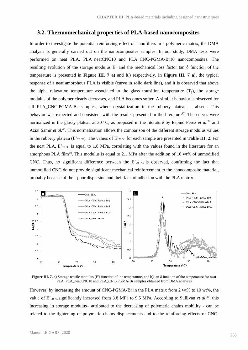
CHAPTER III: PLA-based materials including designed nanostructures
Manon LE GARS, 2020 263
Thermomechanical properties of PLA-based nanocomposites
In order to investigate the potential reinforcing effect of nanofillers in a polymeric matrix, the DMA
analysis is generally carried out on the nanocomposites samples. In our study, DMA tests were
performed on neat PLA, PLA_neatCNC10 and PLA_CNC-PGMA-Br10 nanocomposites. The
resulting evolution of the storage modulus E’ and the mechanical loss factor tan δ function of the
temperature is presented in Figure III. 7 a) and b,) respectively. In Figure III. 7 a), the typical
response of a neat amorphous PLA is visible (curve in solid dark line), and it is observed that above
the alpha relaxation temperature associated to the glass transition temperature (Tg), the storage
modulus of the polymer clearly decreases, and PLA becomes softer. A similar behavior is observed for
all PLA_CNC-PGMA-Br samples, where crystallization in the rubbery plateau is absent. This
behavior was expected and consistent with the results presented in the literature47. The curves were
normalized in the glassy plateau at 30 °C, as proposed in the literature by Espino-Pérez et al.22 and
Azizi Samir et al.48. This normalization allows the comparison of the different storage modulus values
in the rubbery plateau (E’70 °C). The values of E’70 °C for each sample are presented in Table III. 2. For
the neat PLA, E’70 °C is equal to 1.8 MPa, correlating with the values found in the literature for an
amorphous PLA film49. This modulus is equal to 2.1 MPa after the addition of 10 wt% of unmodified
CNC. Thus, no significant difference between the E’70 °C is observed, confirming the fact that
unmodified CNC do not provide significant mechanical reinforcement to the nanocomposite material,
probably because of their poor dispersion and their lack of adhesion with the PLA matrix.
Figure III. 7. a) Storage tensile modulus (E') function of the temperature, and b) tan δ function of the temperature for neat
PLA, PLA_neatCNC10 and PLA_CNC-PGMA-Br samples obtained from DMA analyses
However, by increasing the amount of CNC-PGMA-Br in the PLA matrix from 2 wt% to 10 wt%, the
value of E’70 °C significantly increased from 3.8 MPa to 9.5 MPa. According to Sullivan et al.39, this
increasing in storage modulus– attributed to the decreasing of polymeric chains mobility - can be
related to the tightening of polymeric chains displacements and to the reinforcing effects of CNC-
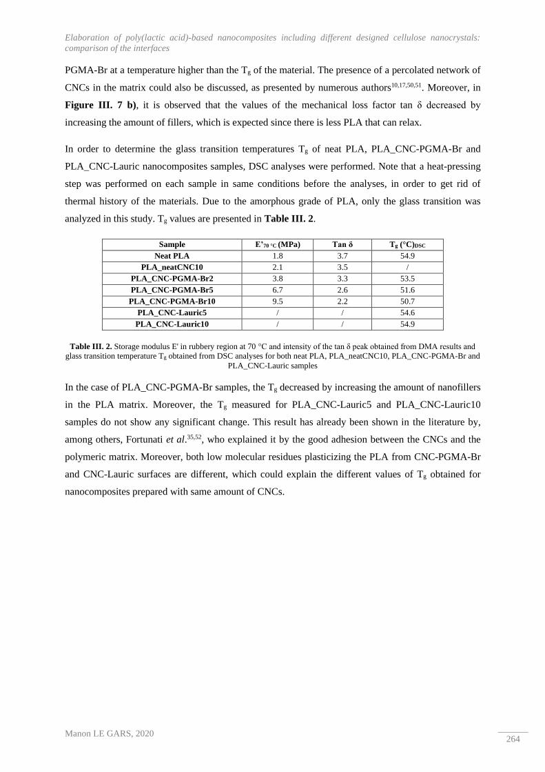
Elaboration of poly(lactic acid)-based nanocomposites including different designed cellulose nanocrystals:
comparison of the interfaces
Manon LE GARS, 2020 264
PGMA-Br at a temperature higher than the Tg of the material. The presence of a percolated network of
CNCs in the matrix could also be discussed, as presented by numerous authors10,17,50,51. Moreover, in
Figure III. 7 b), it is observed that the values of the mechanical loss factor tan δ decreased by
increasing the amount of fillers, which is expected since there is less PLA that can relax.
In order to determine the glass transition temperatures Tg of neat PLA, PLA_CNC-PGMA-Br and
PLA_CNC-Lauric nanocomposites samples, DSC analyses were performed. Note that a heat-pressing
step was performed on each sample in same conditions before the analyses, in order to get rid of
thermal history of the materials. Due to the amorphous grade of PLA, only the glass transition was
analyzed in this study. Tg values are presented in Table III. 2.
Sample E’70 °C (MPa) Tan δ Tg (°C)DSC
Neat PLA 1.8 3.7 54.9
PLA_neatCNC10 2.1 3.5 /
PLA_CNC-PGMA-Br2 3.8 3.3 53.5
PLA_CNC-PGMA-Br5 6.7 2.6 51.6
PLA_CNC-PGMA-Br10 9.5 2.2 50.7
PLA_CNC-Lauric5 / / 54.6
PLA_CNC-Lauric10 / / 54.9
Table III. 2. Storage modulus E' in rubbery region at 70 °C and intensity of the tan δ peak obtained from DMA results and
glass transition temperature Tg obtained from DSC analyses for both neat PLA, PLA_neatCNC10, PLA_CNC-PGMA-Br and
PLA_CNC-Lauric samples
In the case of PLA_CNC-PGMA-Br samples, the Tg decreased by increasing the amount of nanofillers
in the PLA matrix. Moreover, the Tg measured for PLA_CNC-Lauric5 and PLA_CNC-Lauric10
samples do not show any significant change. This result has already been shown in the literature by,
among others, Fortunati et al.35,52, who explained it by the good adhesion between the CNCs and the
polymeric matrix. Moreover, both low molecular residues plasticizing the PLA from CNC-PGMA-Br
and CNC-Lauric surfaces are different, which could explain the different values of Tg obtained for
nanocomposites prepared with same amount of CNCs.

CHAPTER III: PLA-based materials including designed nanostructures
Manon LE GARS, 2020 265
Figure III. 8. Evolution of the storage modulus (E') at 70 °C and the tanδ value function of the weight fraction (wt%) of
CNC-PGMA-Br from DMA analyses
Figure III. 8 graphically represents the values of E’70 °C and tan δ (expressed in the Table III. 2) for
neat PLA and PLA_CNC-PGMA-Br, function of the filler content, in wt%. According to the previous
discussion and Figure III. 8, it is possible to do the assumption that PLA_CNC-PGMA-Br10 sample
is the best candidate in term of thermo-mechanical properties, although its Tg slightly decreased
compared to the neat PLA casted film. Moreover, even if DMA analyses have not been performed on
PLA_CNC-Lauric sample, it would be interesting to compare their thermomechanical response, in
order to be able to conclude about the different CNCs filler content influence, since first
thermomechanical properties are encouraging. Indeed, thermomechanical nanocomposites properties
are essential, especially when thinking about packaging applications, since they allow being aware of
the mechanical behavior of a nanocomposite material in a specific range of temperatures.
Barrier properties of PLA-based nanocomposites
Besides the thermomechanical properties of the nanocomposites, their barrier properties are key points
for their application as food packaging. Indeed, as previously mentioned in the Chapter I, the
permeability towards oxygen and water vapor are main elements responsible for food products
deterioration. In order to investigate this point, oxygen permeability measures were performed on neat
PLA, PLA_neatCNC, PLA_CNC-PGMA-Br and PLA_CNC-Lauric nanocomposites, in order to
understand the effect of the various CNC fillers and content. Table III. 3 summarizes the values of
oxygen permeability (in m3.m/m².s.Pa) and water vapor permeability (in kg.m/m².s.Pa). Oxygen
permeability of neat PLA is consistent with the values found in the literature4,53, and the P/P0 ratio has
been calculated for each sample, in order to clearly understand the effect of each nanofillers on the
nanocomposites.

Elaboration of poly(lactic acid)-based nanocomposites including different designed cellulose nanocrystals:
comparison of the interfaces
Manon LE GARS, 2020 266
Sample
Oxygen permeability
(x1018)
(m3.m/m2.s.Pa)
(23 °C, 0% RH)
P/P0
Water vapor permeability
(x1014)
(kg.m/m².s.Pa)
(23 °C, 50% RH)
Mean value Std. Dev. Mean value Std. Dev.
Neat PLA 5.60 1.0 1 1.8 0.02
PLA_CNC-PGMA-Br2 5.10 1.2 0.91 1.1 0.15
PLA_CNC-PGMA-Br5 5.13 / 0.92 0.9 /
PLA_CNC-PGMA-Br10 3.25 / 0.58 0.4 /
Neat PLA (2) 2.47 / 1 / /
PLA_CNC-Lauric5 2.28 0.09 0.92 / /
PLA_CNC-Lauric10 2.24 0.1 0.91 / /
PLA_neatCNC10 2.81 0.22 1.14 / /
Table III. 3. Summarized oxygen permeability and water vapor permeability values for both neat PLA, PLA_CNC-PGMA-
Br, PLA_CNC-Lauric and PLA_neatCNC nanocomposites
Regarding the results presented in the Table III. 3 for neat PLA and PLA_CNC-PGMA-Br, it can be
observed that the values of oxygen permeability of PLA_CNC-PGMA-Br decreased by increasing the
nanofillers content from 2 wt% to 10 wt%. This decrease is hardly significant for low nanofillers
contents (2 wt% and 5 wt%) but it en tcould be confirmed for the PLA_CNC-PGMA-Br10 sample.
Furthermore, the value obtained for the neat PLA as reference (5.6 ±1 m3.m/m².s.Pa) is very high
compared to the values found in the literature, and interpretations taking this value into account must
therefore be treated with caution. In Figure III. 9 a), the P/P0 ratio was plotted function of the CNC-
PGMA-Br volumetric fraction (%vol). In the literature, several models have been proposed to predict
the gas molecules permeability through a multiphasic polymer system, as recently synthesized in the
review of Zid et al. 54. Among numerous models, that of Nielsen55 was used in this study for
PLA/CNC systems. This model is expressed as follows:
P
P0=
1 − ϕ
1 + (L
2D) × ϕ
Equation III. 4. Calculation P/P0 ratio according to Nielsen model55,56
where ϕ is the volumetric fraction of nanofillers in the polymeric matrix and, L and D are respectively
the average length and diameter of nanofillers. It is important to mention that this model considers the
presence of ribbons nanofillers, which may not be the most suitable model for nanocomposites (for
example, Maxwell's model for spherical particles could have been chosen). This inadequacy in the
model could explain the difficult following interpretations. The Equation III. 4 was used to plot the
predicted oxygen permeability evolution function of the CNC-PGMA-Br (taking L=600 nm and D=50

CHAPTER III: PLA-based materials including designed nanostructures
Manon LE GARS, 2020 267
nm for CNC-PGMA-Br, according to previous results presented in Chapter II.1) and of the neat
CNCs (taking L=110 nm and D=4 nm for neat CNC) volumetric contents. In Figure III. 9 a), it is
observed that P/P0 ratios of PLA_CNC-PGMA-Br samples decreased by increasing the amount of
CNC-PGMA-Br. Moreover, the results are relatively close to the Nielsen model plotted for CNC-
PGMA-Br as fillers (grey solid line), whereas the P/P0 ratio is far from the predicted model for
unmodified CNCs (dashed line). It emphasizes the poor and heterogeneous dispersion of the
unmodified CNCs in the matrix compared to that of CNC-PGMA-Br, inducing a positive effect on the
oxygen barrier. It is thus possible to assume that the CNC-PGMA-Br network induces a tortuous
pathway of oxygen gas molecules through the nanocomposites, and that this effect is reinforced at
high CNC-PGMA-Br content (10 wt%). This notion of tortuosity has been widely used in the
nanocomposites research field51,57,58.
Figure III. 9. Evolution of the oxygen permeability P of PLA-based nanocomposites function of the a) CNC-PGMA-Br and
b) CNC-Lauric volume fraction
By regarding the PLA_CNC-Lauric oxygen permeability results (taking into account “neat PLA (2)”
sample as a new reference), the influence of the CNC-Lauric is not significant, contrary to that of the
CNC-PGMA-Br. In fact, the P/P0 ratio only shows a slight decrease, smaller than experimental
uncertainty. In Figure III. 9 b), the values of P/P0 ratios are far above the predicted Nielsen model
(taking L=350 nm and D=30 nm for CNC-Lauric, according to the previous results presented in the
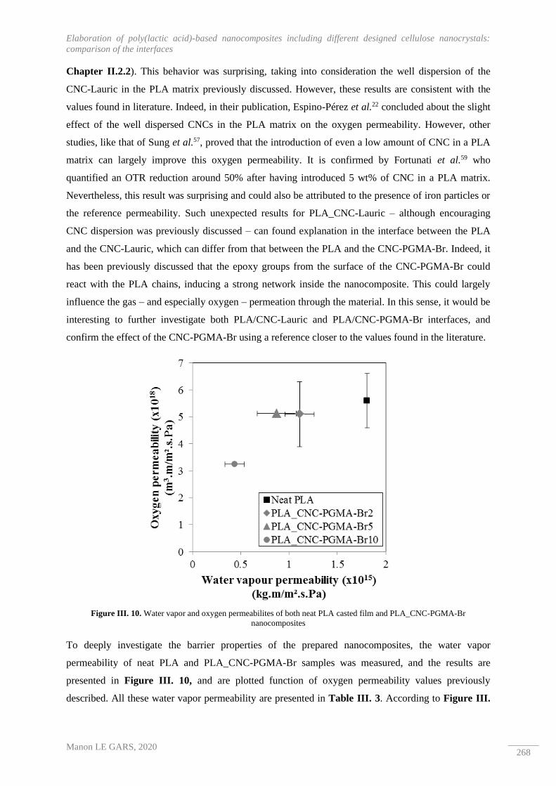
Elaboration of poly(lactic acid)-based nanocomposites including different designed cellulose nanocrystals:
comparison of the interfaces
Manon LE GARS, 2020 268
Chapter II.2.2). This behavior was surprising, taking into consideration the well dispersion of the
CNC-Lauric in the PLA matrix previously discussed. However, these results are consistent with the
values found in literature. Indeed, in their publication, Espino-Pérez et al.22 concluded about the slight
effect of the well dispersed CNCs in the PLA matrix on the oxygen permeability. However, other
studies, like that of Sung et al.57, proved that the introduction of even a low amount of CNC in a PLA
matrix can largely improve this oxygen permeability. It is confirmed by Fortunati et al.59 who
quantified an OTR reduction around 50% after having introduced 5 wt% of CNC in a PLA matrix.
Nevertheless, this result was surprising and could also be attributed to the presence of iron particles or
the reference permeability. Such unexpected results for PLA_CNC-Lauric – although encouraging
CNC dispersion was previously discussed – can found explanation in the interface between the PLA
and the CNC-Lauric, which can differ from that between the PLA and the CNC-PGMA-Br. Indeed, it
has been previously discussed that the epoxy groups from the surface of the CNC-PGMA-Br could
react with the PLA chains, inducing a strong network inside the nanocomposite. This could largely
influence the gas – and especially oxygen – permeation through the material. In this sense, it would be
interesting to further investigate both PLA/CNC-Lauric and PLA/CNC-PGMA-Br interfaces, and
confirm the effect of the CNC-PGMA-Br using a reference closer to the values found in the literature.
Figure III. 10. Water vapor and oxygen permeabilites of both neat PLA casted film and PLA_CNC-PGMA-Br
nanocomposites
To deeply investigate the barrier properties of the prepared nanocomposites, the water vapor
permeability of neat PLA and PLA_CNC-PGMA-Br samples was measured, and the results are
presented in Figure III. 10, and are plotted function of oxygen permeability values previously
described. All these water vapor permeability are presented in Table III. 3. According to Figure III.
CHAPTER III: PLA-based materials including designed nanostructures
Manon LE GARS, 2020 269
10, it is difficult to conclude about the influence of nanofillers on the nanocomposites water vapor
permeability at low content of CNC-PGMA-Br, although these values are consistent with values found
in literature for neat PLA59. Furthermore, when a higher amount of CNC-PGMA-Br was introduced
(i.e., 10 wt%), a significant decrease of 80% of water vapor permeability was measured. However,
several studies showed that water vapor permeability of similar nanocomposites systems decreased by
increasing the amount of nanofillers. In fact, Fortunati et al.59 modified CNCs by adsorbing a
surfactant (Beycostat A B09) on their surface, and proved that by introducing only 1 wt% of these
modified CNCs, the water vapor permeability decreased by 34%, whereas 5% of modified CNCs
induced a decrease of only 15%. Follain et al.58 confirmed this result by showing that the water vapor
barrier was negatively affected by increasing the amount of CNC from 3 wt% to 12 wt% in a poly(ε-
caprolactone) matrix. It was explained by the hydrophilic behavior of CNCs, leading to a better
affinity of nanofillers to water molecules. This increase in water vapor permeability was limited when
the CNCs were surface modified, although no improvement was observed. The affinity between
hydrophilic CNCs and water molecules was also investigated by Espino-Pérez et al.60 who evidenced
the increase in water vapour permeability according to the increasing content of neat CNC (increase of
21.3%, 42.4%, and 195.8% for CNC contents equal to 2.5 wt%, 7.5 wt%, and 15 wt%, respectively).
More recently, Espino-Pérez et al.22 confirmed this result, and proved that the surface
hydrophobization of CNCs led to the improvement of the water vapour permeability of the related
PLA/CNC nanocomposites. In our study, CNC-PGMA-Br were covered at their surface by
hydrophobic PGMA chains, explaining the different trend observed by increasing nanofillers amount
in the PLA matrix. Moreover, it confirms the previously assumption, assuming that the CNC-PGMA-
Br introduced in the PLA matrix created a strong network, inducing a possible tortuosity through the
material.
Elaboration of poly(lactic acid)-based nanocomposites including different designed cellulose nanocrystals:
comparison of the interfaces
Manon LE GARS, 2020 270
4. Conclusion
Two different surface modifications were performed on the surface of CNCs. The first one, consisting
in the surface-initiated radical polymerization of glycidyl methacrylate (GMA), led to polymerized
CNC-PGMA-Br bearing functional epoxy groups on their surface. The second one consisted in the
surface esterification of CNCs using long fatty acid (especially lauric acid), and led to modified CNC-
Lauric exhibiting a hydrophobic behavior. The introduction of both CNC-PGMA-Br and CNC-Lauric
in a hydrophobic amorphous PLA matrix has been successfully carried out by the solvent casting
method. Unmodified CNCs were also introduced in a PLA matrix, as a negative reference. In
accordance with what can be found in the literature, the PLA_neatCNC nanocomposites prepared with
10 wt% of neat CNC exhibited clear micrometric aggregates and a poor adhesion between the
nanofillers and the polymeric matrix. However, both PLA_CNC-PGMA-Br and PLA_CNC-Lauric
nanocomposites showed a clearly enhanced compatibilization. In fact, according to SEM and TEM
observations of these nanocomposites cross-sections, the dispersion of both CNC-PGMA-Br and
CNC-Lauric in PLA seemed to be improved, since no micrometric aggregates were distinguished,
although the CNC-PGMA-Br were more aggregated at nanoscale than the CNC-Lauric. In case of
CNC-PGMA-Br, their enhanced interface with the PLA can be attributed to cross-linking reaction
between the highly reactive epoxy groups at their surface and the hydroxyl groups present at the end of
the polymeric PLA chains. This reaction would occur during the nanocomposites preparation, and
especially during the heat-pressing step. The hydrophobicity of CNC-Lauric was clearly evidenced by
their enhanced dispersion in the PLA matrix. Regarding the barrier properties of the nanocomposites,
and despite some surprising values obtained for the PLA references, the oxygen permeability was
improved in both cases, although the influence of the CNC-PGMA-Br was more clearly distinguished
than that of the CNC-Lauric, which could be explained by the formation of a strong network in
PLA_CNC-PGMA-Br. These results are encouraging, especially in a scientific context, in which the
development of bio-nanocomposites is currently challenging. In fact, although the preparation of
CNC-PGMA-Br is more time-consuming and leads to small amount of materials, that of CNC-Lauric
could be conceivable at a larger scale. It thus paves the way for the development of new bio-based
nanocomposites with interesting properties, particularly for food packaging applications. In this
perspective, it would be interesting to carry out further barrier properties towards other gases and
organic molecules, in order to confirm their interest for specific food packaging applications.

CHAPTER III: PLA-based materials including designed nanostructures
Manon LE GARS, 2020 271
2. Two distinct methods for the elaboration of
multi-layered materials based on poly(lactic acid)
and active cellulosic nanostructures
The second part of this section is adapted from « M. Le Gars, B. Dhuiège, A. Delvart, P. Roger, M.
N. Belgacem, K. Missoum, J. Bras – High barrier antioxidant PLA/nanocellulose multi-layered
materials for packaging », submitted and under revisions in ACS Omega in April 2020.

Two distinct methods for the elaboration of multi-layered materials based on poly(lactic acid) and active
cellulosic nanostructures
Manon LE GARS, 2020 272
Abstract
In order to combine the outstanding properties of nanocellulosic materials (sustainability, crystallinity,
high tensile strength, large specific surface area, low density, O2-barrier properties) with those of
biobased poly(lactic acid) (transparency, stiffness, biodegradability), three-phase multi-layered
materials (TML) were built up via two different methods. Indeed, two kinds of multi-layered materials
were produced (i) by depositing in wet state a thin layer of nanocellulose from an aqueous suspension,
or (ii) by introducing a thicker dry nanocellulosic film, both between two PLA sheets, and using a
heat-pressing process. Furthermore, after having proved the efficiency of the two procedures, barrier
properties of the materials towards both oxygen and water vapor were investigated, and results were
highly encouraging. Indeed, even a very thin layer of cellulose nanocrystals inside the PLA-based
material induced a reduction in oxygen and water vapor permeability of around 90% and 50%,
respectively. Moreover, effect of the surface pre modification of the nanocelluloses with different
active molecules (1-methyl-3-phenylpropylamine and natural rosins) was investigated. It was proved
that the introduction of rosin-based nanoparticles inside the materials was responsible for their
antioxidant activity. In a more general way, the presence of various amounts of nanocellulose as an
inner layer between two PLA films led to an enhancement of the barrier and active properties of the
final multi-layered materials. Owing to the simplicity and efficiency of the two proposed methods, this
study opens the way to the elaboration of hybrid multi-materials which could be highly interesting,
especially for food packaging applications.
Keywords:
Cellulose nanofibrils ─ Cellulose nanocrystals ─ Poly(lactic acid) ─ Multi-layered materials ─ Barrier
properties ─ Antioxidant properties

CHAPTER III: PLA-based materials including designed nanostructures
Manon LE GARS, 2020 273
1. Introduction
Cellulose is a highly abundant biopolymer on earth, extracted most of the time from wood or annual
plants. The cellulose fibers are composed of several fibrils, which were first isolated by Turbak et al.61
in 1983, are currently presented as microfibrillated cellulose (MFC), nanofibrillated cellulose (NFC)
or cellulose nanofibrils (CNFs), and are obtained after mechanical disintegration, generally preceded
by an enzymatic or a chemical pretreatment. Such pretreatments aim to weaken the cellulosic fibers,
and thus, to reduce the energy consumed during the mechanical step of their production62–64. Biobased
CNFs materials are highly studied, and their production, as well as, their applications, were reported in
several books and reviews10,65–67. Since the early 2010’s, CNF development has demonstrated
exponential interest in scientific field, as well as, in industrial one, and there are currently nearly 60
industrial producers all over the world. In 2016, CNFs were identified as the second bio-economy
priority in Europe, thanks to their outstanding properties. Indeed, CNFs display high mechanical
resistance and excellent barrier level, in addition to being biodegradable and biocompatible. All these
properties make this bio-based material a prime candidate for many applications, such as packaging68,
paper and board69, composites33, printed electronics70, biomedical devices71, etc. Another class of
nanomaterials can be extracted from cellulosic biomass, by applying this time a chemical treatment. In
fact, by subjecting biomass to a sulfuric acid hydrolysis, and thus by removing most of the amorphous
parts of cellulose, cellulose nanocrystals (CNC) can be obtained. Their extraction was first reported by
Ranby et al.72,73, and their production has been widely studied and optimized since last decades.
Currently, the CNC annual production capacity is approximately close to 400 tons, and around 13
companies already produce and market CNCs74,75. Like CNFs, CNCs exhibit outstanding mechanical
and barrier properties76,77 and can find applications in similar fields, like among others, biomedical78,79,
electronics70,80,81, coatings82 and composites82,83. Therefore, both CNFs and CNCs, owing to their
exceptional intrinsic properties (morphology, crystallinity, large specific surface area, etc.), are nano-
sized renewable materials that can be used for many applications.
Although nano-scale cellulosic materials present a wide range of applications and applied researches,
composites field – and especially that of nanocomposites – is one of the most important targeted
application in current ecological context. In fact, with consumer awareness of the use of biodegradable
and synthetic plastic-free materials, packaging industry – and especially that of food packaging – has
been constantly evolving for several years. Among biobased and biodegradable materials, poly(lactic
acid) (PLA) is highly interesting because of its production from natural resources, as well as, its
transparency, mechanical properties, and printability, making it a polymer of choice for replacing
fossil-based plastics generally used in food packaging industry4,84. However, thermal and barrier
properties of PLA are generally not sufficient for food packaging applications. In fact, its glass
transition temperature is around 60 °C, and PLA is highly permeable to water vapor and oxygen,
comparing to other food packaging traditional polymers. Inserting cellulosic nanostructures in PLA-

Two distinct methods for the elaboration of multi-layered materials based on poly(lactic acid) and active
cellulosic nanostructures
Manon LE GARS, 2020 274
based packaging makes it possible by combining their respective intrinsic properties, and thus, to
produce packaging that is still biodegradable and more efficient in terms of mechanical and/or barrier
properties. The elaboration of such multi-phasic materials has already been studied in literature, and
the main type of process is based on the elaboration of nanocomposites. However, it is highly
challenging, as the compatibilization between the hydrophilic nanocelluloses and the generally
hydrophobic polymeric matrix needs to be highly improved, and numerous research groups proposed
various procedures in order to enhance this compatibilization22,33,36,85. Another strategy consists in the
incorporation of one or multiple layer(s) to improve final barrier and mechanical properties of the
multi-layered system.
The elaboration of multi-layered materials can be processed via different methods (like among others,
layer by layer deposition, electrodynamic processing, microlayer co-extrusion, coating)38 which all
aim to deposit a layer of a specific material on a polymeric substrate. As suggested, a multi-layered
material is composed of at least two layers, but the thinnest layer is generally covered with another
polymeric layer, different or not from the initial one. The compatibility between the layers is generally
challenging, and that explains the common use of adhesive layers, especially in packaging industry.
Regarding the literature, only few studies deal with the preparation of such PLA-based multi-layers
materials. In 2013, Aulin et al.86 were among the firsts to perform the layer-by-layer deposition of
CNFs combined with cationic polyethyleneimine (PEI) on a PLA substrate. They concluded about the
efficient deposition of the nanocellulose/PEI mixture onto the PLA substrate, and highlighted the
improvement of both oxygen and water vapor barrier properties of the final coated materials by 94%
and 50%, respectively. This promising study was confirmed by the work of Meriçer et al.87 who
produced multi-layered PLA-based materials including MFC by casting evaporation of both layer with
improved mechanical- (increase in Young’s modulus by 60%) and barrier properties (decrease in
oxygen permeability of one order of magnitude). Similarly, Hosseini et al.88 prepared multi-layered
films based on PLA and fish gelatin by successive solvent casting procedures with enhanced oxygen
and water vapor barrier properties compared to pristine PLA, by 87% and 91%, respectively.
Furthermore, specific active compounds can be added to the food packaging to improve specificities of
the packaging, like for example antibacterial, antimicrobial or antioxidant properties. This point was
summarized in a recent review of Yildirim et al.89, describing the various active compounds generally
used in food packaging and emphasizing the clear distinction between absorbers (scavenging systems)
and emitter (releasing systems) compounds. In case of multi-layered materials, such active compounds
are generally inserted inside the multi-layered structure, in order to be released through the packaging
or to scavenge some specific molecules from food products. In a multi-layer strategy, the presence of
both nanocelluloses and active compounds inside the active layer can help for their entrapment and/or
their possible release. In the literature CNC have been mixed with silver nanoparticles52 or with
carvacrol90 to confer them antibacterial or antioxidant properties, respectively.

CHAPTER III: PLA-based materials including designed nanostructures
Manon LE GARS, 2020 275
Throughout this study, multi-layered materials based on PLA and nanocelluloses, including active
molecules or not, were prepared following two different strategies. The first one consists in the wet
deposition of a modified-CNC suspension on a PLA film, following by the heat-pressing with another
PLA sheet above. Note that CNC were previously oxidized and covalently bound to aromatic
molecules (1-methyl-3-phenyl-propylamine, or 1-M-3-PP) by an amidation procedure (previously
detailed in Chapter II.3), leading to a low amount of 1-M-3-PP molecules on their surface. The 1-M-
3-PP molecule was chosen because of its aromatic rings, which are expected to bring sorption
properties to the modified CNCs. The second strategy consists in the complexing of two PLA sheets
with an inner layer consisting in a CNF or CNC casted film including adsorbed rosin nanoparticles
(previously described in Chapter II.4). After processes optimization, all materials were characterized,
and their structural, mechanical, barrier, and antioxidant properties were investigated.

Two distinct methods for the elaboration of multi-layered materials based on poly(lactic acid) and active
cellulosic nanostructures
Manon LE GARS, 2020 276
2. Materials and methods
Materials
Spray-dried cellulose nanocrystals (CNC) extracted from wood pulp were supplied from Canadian
company Celluforce©. Cellulose nanofibrils (CNF) aqueous suspension (2 wt%) was provided by
INOFIB (Saint-Martin d’Hères, France). 2,2,6,6-Tetramethyl-1-piperidinyloxy (TEMPO, 98%),
sodium bromide (NaBr, BioXra, >99.0%), sodium hydroxide (NaOH, BioXtra, >98%, pellets),
hydrochloric acid (HCl, ACS reagent, 37%), N-(3-Dimethylaminopropyl)-N’-ethylcarbodiimide (EDC,
>97%), N-Hydroxysuccinimide (NHS, 98%), 1-methyl-3-phenylpropylamine (98%),
Tetradecyltrimethylammonium Bromide (TTAB), Gum rosin (natural resin), Chloroform (>99%), and
2,2-diphenyl-1-picrylhydrazyl (DPPH) were supplied by Sigma-Aldrich Chimie (France). Sodium
hypochlorite solution (NaClO, 12% Cl) was provided by Carl Roth (France). Ethanol (95%) was
purchased from Revol (France). Two different types of Earthfirst® PLA films (IndegeoTM) were
supplied by Sidaplax (France) company. PLA film used in the section 3.1 exhibits a theoretical
thickness equal to 75 µm, and that used in the section 3.2 exhibits a theoretical thickness equal to 25
µm.
Elaboration of multi-layered materials by the wet way
2.2.1. Modification of CNC via an amidation procedure using 1-M-3-PP
molecules
The grafting of 1-M-3-PP molecules on the surface of CNC was performed via a two-step procedure,
previously described in Chapter II.3. Briefly, CNC were first TEMPO-mediated oxidized, and
carboxylic groups were thus introduced on the surface of TEMPO-CNC. The amidation of 1-M-3-PP
molecules on TEMPO-CNC was catalyzed by EDC/NHS reagents, and recovered CNC-1-M-3-PP
were successfully surface modified, as detailed in Chapter II.3.
2.2.2. Coating of the CNC suspension on a PLA substrate
Before being coated, the PLA film was surface treated by corona effect, using a SG2 Generator
(Société de Transfert Technologique, France), which was equipped with an ozone filter. By applying
an electric discharge on the polymer surface, the corona treatment aims to create new polar carbonyl
and hydroxyl groups, in order to increase the tension surface and the wettability of the film and thus,
to facilitate the coating. Corona treatment was performed on the PLA film in motion at a speed equal
to 2.5 m/min, and an intensity of 245 mA, with different number of passes under the generator.
Once corona treated, the PLA film was coated using a bar coater device (LGP2, France). TEMPO-
CNC or CNC-1-M-3-PP suspension at 5 wt%, with a certain amount of isopropanol (5, 10 or 15

CHAPTER III: PLA-based materials including designed nanostructures
Manon LE GARS, 2020 277
wt/wt) was deposited on the PLA substrate, with a coating speed equal to 3.5 m/min. Coated film was
then dried at 40 °C, for 10 min in an oven. For each sample, two layers of CNC suspension were
successively deposited in order to ensure a total recovering of the PLA film with the coating sauce.
2.2.3. Heat-pressing of the coated PLA
The multilayers materials were prepared by superposing previously coated PLA-TEMPO-CNC or
PLA-CNC-1-M-3-PP films with another neat PLA film. The system was then heat-pressed (heat press
device, Saint-Eloi Mécanique Outillage, France) between two metallic plates and two protective non-
adhesive paper sheets under 0.5 MPa pressure for 30 min at 110 °C.
Elaboration of multi-layered materials by complexing
2.3.1. Preparation of rosin-based nano-emulsion
The rosin-based nano-emulsion was prepared by the INOFIB startup, following a patented protocol91.
This confidential protocol was previously described in Chapter II.4.
2.3.2. Elaboration of neat and modified CNF and CNC films
The neat and rosin-modified CNF and CNC films were prepared according to the procedure previously
described in Chapter II.4. Briefly, a proper amount of the rosin nano-emulsion was added to an
aqueous suspension of CNF (2 wt%) or of CNC (1 wt%) in order to respect a rosin/nanocellulose
weight ratio equal to 0.11. Thirty minutes of magnetic stirring at room temperature was performed to
adsorb rosin nano-emulsion onto the nanocellulose surface. The films were prepared by filtration and
solvent casting in the case of CNF and CNC, respectively, and called CNF-Rosin and CNC-Rosin,
respectively.
2.3.3. Complexing of multi-layered materials by heat-pressing
The multi-layered materials were prepared by incorporating one neat or modified CNC or CNF film
between two PLA sheets. The 3-layer sandwich system was then heat-pressed, according to the same
protocol as previously described in part 2.2.3, under 0.5 MPa pressure, for 10 min at 170 °C.
Characterization methods
2.4.1. Contact angle and surface energy
Contact angle measurements were carried out by depositing 5 µL-water droplets at the surface of the
substrate at room temperature. OCA20 DataPhysics (DataPhysics Instrument) system equipped with a
CCD camera was used to record the angles between the solvent and the substrate. The acquisition of
contact angle and drop volume was collected for the first 60 s after deposition. At least five
measurements were performed for each sample. The substrates surface energy was determined in

Two distinct methods for the elaboration of multi-layered materials based on poly(lactic acid) and active
cellulosic nanostructures
Manon LE GARS, 2020 278
accordance with the Owens-Wendt model, and using four different solvents (water, ethylene glycol,
glycerol and diiodomethane). Briefly, by decomposing the surface energy into a dispersive and polar
parts, γd and γp, respectively, it is possible to express the total surface energy of the substrate s and a
liquid l through γs=γsd + γs
p and γl= γld + γl
p, respectively. These two surface energies are linked by the
Equation III. 5. By plotting γl ×(1+cos θ)
2√γlx
as a function of √γsp
γlp with values obtained with the four
different solvents, the curve slope can directly be linked to the substrate surface energy γs value.
γl × (1 + cos θ) = 2√γsdγl
d + 2√γsp
γlp
Equation III. 5. Owens-Wendt model for the determination of the substrate surface energy
2.4.2. Surface tension
The surface tensions of the different coating suspensions were measured using an Attension Sigma
700 (Biolin Scientific) force tensiometer. Briefly, a platinum ring was tared and immersed in the
suspension to be analyzed. The surface tension values were recorded and processed using
OneAttension software. At least 5 measurements were performed for each sample.
2.4.3. Oxygen permeability
The oxygen permeability of the materials was investigated at 23 °C and 0% RH or 50% RH, using a
Systech Illinois (USA) M8001 Oxygen Permeation Analyzer. Data were processed according to the
ASTM-F 1927 standard. For each sample, masks with a specific exchange surface of 6.2 cm² were
prepared and placed in the device chamber. Pure oxygen was used for the measurement. The final
value of the oxygen transmission rate (OTR) was determined when a plateau was reached. The oxygen
permeability coefficient (OP) was obtained from Equation III. 6, where l is the average thickness of
the sample in mm.
OP = OTR × l
Equation III. 6. General relation between oxygen permeability coefficient (OP) and oxygen transmission rate (OTR)
according to ASTM-F 1927 standard
Because of the large error of measurement, all experiments should be at least duplicated, as much as
possible (limited number of samples).
2.4.4. Water vapor permeability
Water vapor permeability of the materials was determined at 23 °C and 50% RH, according to the
T448 om-09 TAPPI standard. For each sample, masks with a specific exchange surface of 6.2 cm²
were prepared and mounted on specific test dishes filled with dried CaCl2 as desiccant material. A
regular weighing of the whole system was performed, and the water vapor transmission rate (WVTR)
in g/(m².day) was determined from Equation III. 7:

CHAPTER III: PLA-based materials including designed nanostructures
Manon LE GARS, 2020 279
WVTR =24x
Ay
Equation III. 7. General equation for the calculation of the water vapor transmission rate (WVTR) according to T 448 om-09
TAPPI standard
where x is the gain, in grams for the period y, in hours, and A is the exposed area of the sample (6.2
cm² in our study). The water vapor permeability coefficient (WVP) was determined from Equation III.
8:
WVP = WVTR × l
Equation III. 8. General relation between water vapor permeability coefficient (WVP) and water vapor transmission rate
(WVTR)
where l is the average thickness of the sample, in mm. Each experiment has been at least duplicated.
2.4.5. Test on food product
The influence of the multi-layered materials as packaging materials on the evolution of food product’s
shelf-life was investigated. The protocol was inspired by the work of Bideau et al.93. Banana was
selected as a food product reference because of its fast and colored degradation. Briefly, banana slices
(~ 10 g) were freshly cut and placed in a sachet composed of the multi-layered, and hermetically
closed with aluminum tape. The samples were stored for 72 h at 23 °C and 50% RH. Qualitative
observations were performed on each sample.
2.4.6. Scanning electron microscopy (SEM)
SEM images were obtained from PLA films and multi-layered materials sections obtained by
cryofracture, using a Quanta200 device. The working distance during the acquisition was between 9.8
and 10.1 mm, with a voltage of 10 kV and at a magnification of x1000.
2.4.7. Tensile tests
Mechanical properties of the films were determined under specific conditions (23 °C, 50% RH) using
an Instron Universal Testing Machine Model 4507 (Instron Engineering Corporation, Canton, MA)
equipped with pneumatic. After its average thickness was measured, each sample (100 mm x 15 mm)
endured a tensile cross-head speed of 10 mm/min, according to the French standard NF Q 03-004
(July 1986). The samples were preconditioned at 23 °C and 50% RH at least one day before the
experiment. At least five tests were carried out for each sample.
2.4.8. UV-visible spectrophotometric direct transmission analysis
Three samples of each film were prepared with dimensions equal to 15 mm x 50 mm. Direct
transmittance, at a wavelength of 550 nm (T550nm), was measured at least three times for each sample,
using a UV–vis spectrophotometer (UV-1800, Shimadzu).

Two distinct methods for the elaboration of multi-layered materials based on poly(lactic acid) and active
cellulosic nanostructures
Manon LE GARS, 2020 280
2.4.9. Antioxidant activity characterization
The DPPH assay (free radical 2,2-diphenyl-1-picrylhydrazyl DPPH•) was performed to determine the
radical scavenging activity (RSA) of the samples. The method was adapted from the one recently
proposed by Crouvisier-Urion et al.94. Samples of 100 mg of material previously prepared and placed
in a closed vial containing 10 mL of a 50 mg/L solution of DPPH in ethanol, and were left under
magnetic stirring in the dark and at room temperature. Aliquots of the medium solutions were
collected at regular time intervals, and absorbance at 515 nm was measured (Asample), using a UV-vis
spectrophotometer (UV-1800, Shimadzu). Note that in ethanol, DPPH• is purple and turns yellowish
when it is in direct contact with an antioxidant molecule. The collected solutions were returned to the
corresponding vial after each measurement. Absorbance measurement of the DPPH solution (ADPPH) in
ethanol was performed at the same time, in order to correct for the auto-degradation of the DPPH•
radical. From experimental data, the radical scavenging activity (RSA) at time t of each sample can be
calculated from Equation III. 9:
RSA(t) = 100 −ADPPH(t) − Asample(t)
ADPPH(t)× 100
Equation III. 9. General equation for the calculation of the radical scavenging activity (RSA) of a material sample
For each sample, the measurements of the RSA (in %) were duplicated and plotted as a function of the
reaction time until a plateau was visible.
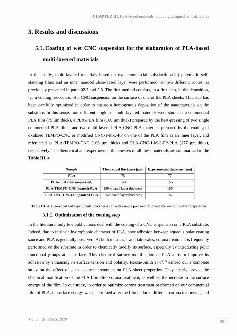
CHAPTER III: PLA-based materials including designed nanostructures
Manon LE GARS, 2020 281
3. Results and discussions
Coating of wet CNC suspension for the elaboration of PLA-based
multi-layered materials
In this study, multi-layered materials based on two commercial poly(lactic acid) polymeric self-
standing films and an inner nanocellulose-based layer were performed via two different routes, as
previously presented in parts 02.2 and 2.3. The first method consists, in a first step, in the deposition,
via a coating procedure, of a CNC suspension on the surface of one of the PLA sheets. This step has
been carefully optimized in order to ensure a homogenous deposition of the nanomaterials on the
substrate. In this sense, four different single- or multi-layered materials were studied : a commercial
PLA film (75 µm thick), a PLA-PLA film (160 µm thick) prepared by the heat-pressing of two single
commercial PLA films, and two multi-layered PLA-CNC-PLA materials prepared by the coating of
oxidized TEMPO-CNC or modified CNC-1-M-3-PP on one of the PLA film as an inner layer, and
referenced as PLA-TEMPO-CNC (166 µm thick) and PLA-CNC-1-M-3-PP-PLA (177 µm thick),
respectively. The theoretical and experimental thicknesses of all these materials are summarized in the
Table III. 4.
Sample Theoretical thickness (µm) Experimental thickness (µm)
PLA 75 77
PLA-PLA (thermopressed) 150 156
PLA-TEMPO-CNC(coated)-PLA 150+coated layer thickness 156
PLA-CNC-1-M-3-PP(coated)-PLA 150+coatd layer thickness 157
Table III. 4. Theoretical and experimental thicknesses of each sample prepared following the wet multi-layer preparation
3.1.1. Optimization of the coating step
In the literature, only few publications deal with the coating of a CNC suspension on a PLA substrate.
Indeed, due to intrinsic hydrophobic character of PLA, poor adhesion between aqueous polar coating
sauce and PLA is generally observed. At both industrial- and lab-scales, corona treatment is frequently
performed on the substrate in order to chemically modify its surface, especially by introducing polar
functional groups at its surface. This chemical surface modification of PLA aims to improve its
adhesion by enhancing its surface tension and polarity. Rocca-Smith et al.95 carried out a complete
study on the effect of such a corona treatment on PLA sheet properties. They clearly proved the
chemical modification of the PLA film after corona treatment, as well as, the increase in the surface
energy of the film. In our study, in order to optimize corona treatment performed on our commercial
film of PLA, its surface energy was determined after the film endured different corona treatments, and

Two distinct methods for the elaboration of multi-layered materials based on poly(lactic acid) and active
cellulosic nanostructures
Manon LE GARS, 2020 282
results are presented in Figure III. 11. Note that the different corona treatments were quantified by the
number of times the PLA film passed under the electrodes constituting the discharge generator.
Figure III. 11. Dispersive and polar contributions of surface energies related to PLA films subjected to different corona
treatments
As expected, the total surface energy of PLA film does not change significantly by increasing the
number of passes under the corona system. Indeed, as shown in Figure III. 11, this surface energy
increased from 40 mN/m to 40.7 mN/m and 43.5 mN/m for 3 and 5 passes, respectively. However, the
polar contribution increased from 2.9 mN/m to 12.9 mN/m and 20.7 mN/m for 3 and 5 passes,
respectively. It clearly confirms the creation of polar groups on the PLA surface induced by the corona
treatment.
In order to investigate the behavior of the deposited coating sauces on the surface of the corona-treated
PLA films, surface tensions of various aqueous CNC suspensions were determined. As described in
part 2.2.2, different amount of isopropanol were added to the water TEMPO-CNC suspension, the
latter being studied as a reference suspension. Indeed, taking into account the low amount of grafted
molecules on the surface of modified CNC-1-M-3-PP (previously proved in Chapter II.3), it was
assumed that the behavior of both TEMPO-CNC and CNC-1-M-3-PP aqueous suspensions was almost
similar. Isopropanol was selected because of its common use in industry - especially in coating and
printing industry - to reduce the surface tension of dampening solutions. Evolution of the TEMPO-
CNC suspension surface tension following the weight amount of isopropanol added to the suspension
is plotted in Figure III. 12.

CHAPTER III: PLA-based materials including designed nanostructures
Manon LE GARS, 2020 283
Figure III. 12. Surface tension of aqueous TEMPO-CNC suspensions prepared with various amount of isopropanol
According to Figure III. 12, a clear decrease in TEMPO-CNC suspensions’ surface tension is
observed by increasing the amount of isopropanol in the suspension, as expected. Indeed, due to its
low surface tension, even a low amount of isopropanol can leads to a large decrease in the total surface
tension of the suspension. As shown in Figure III. 12, by adding 15% (wt/wt) of isopropanol in the
suspension, the surface tension decreases from 66.2 mN/m to 34.5 mN, or a decrease of almost 50%.
These results are summarized in Table III. 5. Moreover, in order to concretely study the behavior of
the suspensions deposited on PLA substrates, the adhesion work WAT was calculated in each case,
according to Equation III. 10:
WAT = γl × (1 + cos θ)
Equation III. 10. General equation for the calculation of the adhesion work between a substrate and a liquid
where 𝛾𝑙 is the surface energy of the liquid and θ the contact angle between the liquid and the
substrate, more precisely between the TEMPO-CNC suspension with a certain amount of isopropanol
and the corona-treated PLA. Measured contact angles and calculated adhesion work values are
presented in Table III. 5. According to these results, the effect of corona treatment on the contact
angle between the suspension and the PLA film is clearly visible. In fact, for a given suspension, the
contact angle decreases by increasing the number of passes under the corona device. Moreover, by
increasing the amount of isopropanol in the suspension, this contact angle decreases for a given
number of passes under the corona device. By regarding calculated adhesion works, their values
decrease by increasing the amount of isopropanol, but for a given suspension, the increasing of passes
under corona led to an increase in adhesion work value.

Two distinct methods for the elaboration of multi-layered materials based on poly(lactic acid) and active
cellulosic nanostructures
Manon LE GARS, 2020 284
Suspension 1
wt%
TEMPO-
CNC
Surface
tension
(mN/m)
Contact angle (°) Adhesion work (J)
PLA PLA+
Corona*3
PLA+
Corona*5 PLA
PLA+
Corona*3
PLA+
Corona*5
+0 wt%
isopropanol 66.2 ± 0.2 77 ± 2 51 ± 3 50 ± 1 81.1 ± 0.03 107.9 ± 0.06 108.8 ± 0.02
+5 wt%
isopropanol 47.3 ± 0.0 65 ± 1 44 ± 2 44 ± 1 67.3 ± 0.02 81.3 ± 0.05 81.3 ± 0.02
+10 wt%
isopropanol 39.6 ± 0.1 57 ± 1 33 ± 3 33 ± 2 61.2 ± 0.02 72.8 ± 0.09 72.8 ± 0.06
+15 wt%
isopropanol 34.5 ± 0.1 44 ± 1 28 ± 2 27 ± 1 59.3 ± 0.03 65.0 ± 0.07 65.2 ± 0.04
Table III. 5. Surface tensions of TEMPO-CNC suspensions prepared with various amount of isopropanol, contact angles of
PLA substrates subjected to different corona treatments, and resulted calculated adhesion works between different previous
substrates and suspensions
All these results allowed the optimization of the coating process of a TEMPO-CNC suspension on a
PLA substrate. In fact, after numerous trials and after having taken into account the visual aspects of
the different coatings performed, it was assumed that the most homogeneous coating was achieved
with a TEMPO-CNC suspension containing 15% (wt/wt) of isopropanol and a PLA substrate
subjected to 5 passes under the corona generator. In a second step, the heat-pressing step was
optimized too, and different parameters, like the temperature, pressure, and time, were tested. It was
assumed that the best multi-layered materials were obtained at 110 °C and 0.5 MPa, with a contact
time equal to 30 min. Materials previously presented in Table III. 4 were prepared following this
optimized protocol.
3.1.2. Barrier properties of multi-layered materials prepared by wet deposition of
a CNC suspension
The optimized protocol was applied to both TEMPO-CNC and CNC-1-M-3-PP aqueous suspension
containing 15% (wt/wt) of isopropanol. Resulting PLA-TEMPO-CNC-PLA and PLA-CNC-1-M-3-
PP-PLA multi-layered materials were then characterized, as well as, a neat PLA film and a heat-
pressed PLA-PLA material without any inner coated layer, as reference. Investigation of the thickness
of the coated layer was performed by different techniques (AFM, MEB) without success. In fact, due
to the very low amount of deposited CNC, this investigation has proved highly difficult. However,
regarding the literature, Li et al.96 performed the coating of CNC on plastic substrates (poly(ethylene
terephthalate, polypropylene, polyamide) using an automatic bar-coater, and the deposited CNC film
thickness was determined equal to 600 nm. In our study, it is thus possible to similarly assume that the
deposited layer thickness was around 500 nm, leading to a very low amount of CNC in the final
material.

CHAPTER III: PLA-based materials including designed nanostructures
Manon LE GARS, 2020 285
The barrier properties – especially towards oxygen and water vapor – of the prepared multi-layered
materials were investigated. The oxygen and water vapor permeability values measured at 23 °C and
50% RH are presented in Figure III. 13. Commercial PLA film exhibits an oxygen and water vapor
permeability equal to 3.9 x 10¹⁸ +/- 0.3 x 10¹⁸ m3.m/m².s.Pa and 2.3 x 10¹⁶ +/- 0.3 x 10¹⁶ kg.m/m².s.Pa,
respectively, which are consistent with values found in the literature4,6, although water vapor
permeability values are much higher in our study. This significant difference can be attributed to the
PLA degradation since its purchase, leading to a decrease of its barrier property. Moreover, by
comparing the values obtained for single PLA with that of the heat-pressed PLA-PLA reference, it can
be observed that oxygen permeability is slightly improved (equal to 2.4 x 10¹⁸ +/- 0.01 x 10¹⁸
m3.m/m².s.Pa), whereas water vapor permeability value increases until 5.9 x 10¹⁶ +/- 0.9 x 10¹⁶
kg.m/m².s.Pa. It can be attributed to the fact that both corona treatment and heat-pressing could
degrade the structure of the PLA and thus create some holes inside the films, leading to a preferential
path for gas molecules.
Figure III. 13. Oxygen and water vapor permeability of neat commercial PLA film, PLA-PLA reference, PLA-TEMPO-
CNC-PLA, and PLA-CNC-1-M-3-PP-PLA multi-layered materials
However, according to Figure III. 13, it can clearly be assumed that the presence of an inner TEMPO-
CNC layer between the two PLA films highly improves the barrier towards oxygen of the
corresponding PLA-TEMPO-CNC-PLA sample, which exhibits an oxygen permeability value equal to
0.45 x 10¹⁸ +/- 0.2 x10¹⁸ m3.m/m².s.Pa, or a decrease of almost 80% in regard to the PLA-PLA
reference. Similar behavior is observed for PLA-CNC-1-M-3-PP-PLA sample, which exhibit an
oxygen permeability equal to 0.15 x10¹⁸ m3.m/m².s.Pa, or a decrease of almost 94%. Note that for the
PLA-TEMPO-CNC-PLA sample, no standard variation was obtained, and it is thus difficult to
conclude about the specific influence of the 1-M-3-PP molecules grafted on CNC on the oxygen

Two distinct methods for the elaboration of multi-layered materials based on poly(lactic acid) and active
cellulosic nanostructures
Manon LE GARS, 2020 286
permeability. Regarding the water vapor permeability, the values are equal to 2.7 x 10¹⁶ kg.m/m².s.Pa
for either PLA-TEMPO-CNC-PLA and PLA-CNC-1-M-3-PP-PLA samples, or a reduction of almost
54% compared to the PLA-PLA reference. This reduction was less significant that the reduction of the
oxygen permeability and it can be related to the hydrophilic character of CNC, which have the ability
to retain water. This phenomenon was observed by Fortunati et al.59 who prepared CNC/PLA
nanocomposites by solvent casting, and observed that an increase in the amount of CNC led to a less
important decrease in water vapor permeability. Similarly, Sanchez-Garcia et al.97 produced PLA-
based nanocomposites including cellulosic microfibers and observed that only 1 wt% of microfibers in
the PLA matrix had an effect on water vapor permeability, higher amounts increasing this
permeability. They assumed that poor dispersion of the fillers were responsible for lower tortuosity of
water vapor molecules through the material. In our case, creation of cracks in the material during the
heat-pressing can also be responsible for this increase in water vapor permeability. However, the
highly significant decrease in oxygen permeability contradicts this assumption.
Figure III. 14. Oxygen and water vapor permeability values required for food packaging materials according to specific
foodstuffs and multi-layered materials (PLA-PLA, PLA-TEMPO-CNC-PLA, and PLA-CNC-1-M-3-PP-PLA) positioning
(adapted from 98)
Figure III. 14 shows the different oxygen and water vapor permeability values required for materials
used for specific food packaging applications, and these values are compared to those determined from
the materials studied and prepared in this work. According to Figure III. 14, it is confirmed that
commercial PLA film is not enough barrier towards oxygen and water vapor for most of food
packaging applications. Similar conclusions can be drawn for the PLA-PLA multi-layered reference
material. However, by deposing even a very low amount of TEMPO-CNC or modified CNC-1-M-3-
PP between the two PLA sheets, corresponding multi-layered materials are clearly usable in food
packaging, especially for meat products packaging applications. Figure III. 14 is highly interesting

CHAPTER III: PLA-based materials including designed nanostructures
Manon LE GARS, 2020 287
since it exhibits the huge potential of such multi-layered materials including a very thin layer
composed of nanocellulosic materials for food packaging applications.
In order to simulate the influence of such a multi-layered material on the evolution of the shelf-life of
a food product, small bags prepared from commercial polyethylene (PE) film, commercial PLA film
and multi-layered material PLA-CNC-1-M-3-PP-PLA, containing banana slices were prepared and
hermetically closed in order to avoid any opening to the external environment. In each case, visual
aspect of the banana slice was qualitatively evaluated, and corresponded pictures are presented in
Figure III. 15.
Figure III. 15. Comparison on a banana slice shelf-life evolution with different materials simulating its packaging:
polyethylene (PE), poly(lactic acid) (PLA), and multi-layered PLA-CNC-1-M-3-PP-PLA, at 23 °C and 50% RH
In this study, banana was chosen as food product because of its rapid and visual degradation. In the
literature, Bideau et al.93 performed similar experiment using TEMPO-CNC combined with
polypyrrole films to investigate banana preservation, related particularly to barrier and antioxidant
properties of the films. In another study, Bideau et al.92 carried out antibacterial meat tests on pork
liver in order to study the activity by contact of similar materials. In our case, even if test on meat
product would have been interesting too, only banana products were tested. In Figure III. 15, the first
line corresponds to the degradation of a banana at 23 °C and 50% RH without any packaging (negative
reference). The second line corresponds to the evolution of a banana packaged in a polyethylene (PE)
material, taken as positive reference, since PE is commonly used in food packaging industry. In the
third line, banana slice was packaged in the commercial PLA material used in this study part, and no
significant difference is observed between the PLA package and the PE one. However, by comparing

Two distinct methods for the elaboration of multi-layered materials based on poly(lactic acid) and active
cellulosic nanostructures
Manon LE GARS, 2020 288
these pictures with the ones related to a packaging composed of PLA-CNC-1-M-3-PP-PLA materials
(fourth line), it is possible to see a slight difference in terms of banana coloration. In fact, after 72 h in
the PLA-CNC-1-M-3-PP-PLA packaging, the food product seems to be less brown colored. This
could highlight the slower degradation of the banana induced by the package. However, at this stage, it
is difficult to conclude about the role of the grafting of the 1-M-3-PP molecules at the surface of CNC,
although the positive influence of CNC inside the package is confirmed once again. It is important to
note that to investigate the role of the grafting of 1-M-3-PP aromatic molecules on the CNCs, sorption
measures could have been performed. Indeed, in their study, Espino-Pérez et al.99 proved that the
presence of even a low amount of similar aromatic molecules on the CNC surface leads to the sorption
of aromatic compounds such as anisole and, to a lesser extent, cyclohexane.
At this stage of the study, it is possible to conclude about the positive influence of a highly thin inner
layer of nanocellulosic materials inside a PLA packaging on the barrier properties of the multi-layered
materials. However, it is still difficult to clearly prove the role of the grafted 1-M-3-PP molecules on
the material properties, and further experiments should be performed in this sense.
Multi-layered materials prepared by complexing
In this second part, multi-layered materials (TML) based on both PLA and nanocellulose were built up
via the complexing of three dry films: two commercial PLA films (different from the commercial PLA
used in the first part) and a single neat or modified CNC or CNF self-standing film in between. As
previously described in part 2.3.2, neat (or modified) CNC (or CNC-Rosin) and CNF (or CNF-Rosin)
self-standing films were prepared by solvent casting or filtration processes, respectively, and were then
heat-pressed between two PLA films (25 µm thick each) (see part 2.3.3), leading to TML-CNC (or
TML-CNC-Rosin) and TML-CNF (or TML-CNF-Rosin) multi-layered materials. After several trials,
the optimal conditions for the protocol of heat-pressing of multi-layered materials were determined.
Indeed, it was observed that at a temperature lower than 150 °C, a delamination between the three
layers occurred, and at 180 °C, a yellowing of the material was observed. It was found that setting the
temperature at 170 °C allowed the preparation of homogenous and uncolored samples. Note that this
process temperature was higher than the temperature used for the elaboration of multi-layered
materials in the previous part (wet coating). It is due to the fact that CNC or CNF films are thicker (~
several tens of µm) than the CNC layer deposited by coating (~ 500 nm), and the temperature needs to
be higher than the melting temperature of the PLA (approximately 150 °C) to permit the creep of the
semi-crystalline polymer throughout the multi-layered system and to ensure good adhesion and sealing
between the three layers. Table III. 6 summarizes all the samples with their respective references, as
well as, their determined basis weight (in g/m²), and their theoretical and experimental thicknesses (in
µm).

CHAPTER III: PLA-based materials including designed nanostructures
Manon LE GARS, 2020 289
Sample Basis weight
(g/m²)
Theoretical
thickness (µm)
Experimental
thickness (µm)
Single films
PLA 30 25 25
CNC 67 40 40
CNC-Rosin 61 40 44
CNF 29 30 35
CNF-Rosin 32 30 38
Heat-pressed
multi-layered
(TML) materials
TML-PLA 90 75 86
TML-CNC 100 90 82
TML-CNC-Rosin 121 94 94
TML-CNF 90 85 78
TML-CNF-Rosin 93 88 75
Table III. 6. Samples references with corresponding basis weights (in g/m²), and theoretical and experimental thicknesses
By comparing theoretical and experimental thicknesses presented in Table III. 6 for multilayers
(TML) prepared with an inner layer composed of CNC or CNF, it is worth noting that the
experimental thicknesses are lower than the theoretical ones (except for TML-CNC-Rosin sample).
This discrepancy can be explained by the potential impregnation of the melted PLA through the CNF
or CNC nanoporous films during the heat-compression process, leading to a decrease in the total
thickness of the material.
3.2.1. Structural and mechanical properties of complexed multi-layered materials
In order to confirm the assumption made about the impregnation of the PLA layers within the
cellulosic layer, the structure of the multi-layered (TML) materials was investigated using SEM
imaging. The cross-sectional images are presented in Figure III. 16.
In Figure III. 16 a) and b), the cross-sections of the commercial PLA film built up in the same heat-
pressing conditions as multi-layered materials and of the TML-PLA multi-layered system are
respectively presented. Some defects can be observed on the PLA cross-section in Figure III. 16 a),
that might have been generated by the heat-pressing process. The corresponding multi-layered TML-
PLA material (Figure III. 16 b)), composed of three heat-pressed PLA films, seems to be
homogenous, and no separation between the three layers can be observed. However, some defects and
cracks also appear, indicating that heat-pressing can affect the structure of the PLA-based materials.
Figure III. 16 c) shows the cross-section of the TML-CNF. The inner CNF layer can be distinctly
observed, although it seems to be impregnated with the top PLA layer. The boundary between the
CNF and the lower PLA layer can be clearly distinguished, showing the poor compatibility between
neat CNF and PLA. A similar boundary can be observed in the cross-section of the TML-CNC
presented in Figure III. 16 d). The top PLA layer seems to be impregnated in the inner CNC layer,
whereas the boundary between the CNC and the lower PLA layer is visible.

Two distinct methods for the elaboration of multi-layered materials based on poly(lactic acid) and active
cellulosic nanostructures
Manon LE GARS, 2020 290
Figure III. 16. SEM images of a) commercial PLA heat-pressed film, b) reference TML-PLA multi-layered material, and
multi-layered prepared with c) a CNF film, and d) a CNC film as the inner layer
Figure III. 16 a) and b) are interesting since they allow the conclusion about the efficiency of the
heat-pressing method to complex several PLA sheets together. The process is not entirely
homogeneous, probably because of a difference in temperature and pressure in the heat-press device,
and it requires further optimization. However, both TML-CNF and TML-CNC materials are self-
standing and uniform, without delamination between the layers. In their study, Sanyang et al.100
prepared starch/PLA bi-layered materials using a casting procedure and observed, by SEM analysis,
the interface between the two layers, probably due to the poor compatibility between the two
components. However, they found the enhancement in mechanical and barrier properties in their bi-
layered materials.
Regarding the transparencies of the different materials studied in this work, their transmittances were
measured at the wavelength of 550 nm, corresponding to the visible light wavelength, and show the
values in Figure III. 17 c). The commercial film of PLA exhibits a transmittance at 550 nm equal to
91%, which is consistent with values found in the literature101. CNC and modified CNC-Rosin films
have transmittances of 61% and 82%, respectively. The value obtained for neat CNC is consistent with
the literature, although this value is highly dependent on the dispersion state and chirality of the CNC
inside the film102,103. The transmittances of CNF and CNF-Rosin films are equal to 15% and 11%,
respectively, and highlight the fact that CNF-based films are less transparent than CNC films. These

CHAPTER III: PLA-based materials including designed nanostructures
Manon LE GARS, 2020 291
values are consistent with values found in the literature104 for similar CNF. In both cases, the presence
of rosin nanoparticles in the film does not significantly influence the optical transparency of the CNC
or CNF film.
Figure III. 17. Photographs of films prepared by a) solvent-casting of a suspension of modified CNC-Rosin, and b) filtration
of a suspension of a modified CNF-Rosin suspension, and c) Transmittance values of single films (PLA, CNC, CNC-Rosin,
CNF, CNF-Rosin) and corresponding multi-layered materials
Figure III. 17 shows photographs of prepared films of modified CNC-Rosin (Figure III. 17 a)) and
modified CNF-Rosin (Figure III. 17 b)) and highlights their self-standing and transparency properties.
The transmittance values of multi-layers indicate that their transparency decreases by incorporating a
PLA, CNC or CNC-Rosin layer between two PLA films. The transmittances of TML-PLA, TML-
CNC and TML-CNC-Rosin are very close and equal to 47%, 47%, and 50%, respectively. Despite the
lower transmittance values of CNC-based films compared to pure PLA film, the incorporation of the
nanocellulosic films does not influence the entire multi-layered material transmittance. However, by
incorporating a CNF or CNF-Rosin layer in the multi-layered system, transmittance slightly increases
up to 21% and 17%, respectively. This result could be explained by the fact that the pores present in
both CNF and CNF-Rosin films are closed and covered by transparent PLA during the heat-pressing
procedure, leading to an increase in the transparency. Meriçer et al.87 combined one layer of PLA with
a top layer of CNF through a casting procedure, and reported a similar trend in the transmittance
values. For food packaging applications, transparency of materials is essential for aesthetic, marketing,
and consumer satisfaction, as often mentioned in the literature related to this topic37,38.

Two distinct methods for the elaboration of multi-layered materials based on poly(lactic acid) and active
cellulosic nanostructures
Manon LE GARS, 2020 292
The mechanical properties of both single- and multi-layered materials were also investigated. The
values of Young’s modulus E are presented in Figure III. 18.
Figure III. 18. Young's modulus values measured on single films (PLA, CNC, CNC-Rosin, CNF, CNF-Rosin) and
corresponding multi-layered materials
According to these values, commercial PLA film exhibits a Young’s modulus equal to 3.0 GPa.
Although this value is highly dependent on the type of PLA and its processing, it is consistent with the
literature values4,5. Young’s modulus of CNC and CNF films is not affected by the presence of
adsorbed rosin nanoparticles at the nanocelluloses surface. In fact, from the values presented in Figure
III. 18, Young’s modulus of CNC and CNC-Rosin is equal to 17 GPa and 13 GPa, respectively, and
CNF and CNF-Rosin have the modulus equal to 8.1 GPa and 8.4 GPa, respectively. These values are
consistent with the values found in the literature for CNF films, although the values obtained for the
CNC films are somewhat higher10,105–107. Note that these values are highly linked to the nature of the
nanocelluloses, as well as to their dispersion and orientation. Nevertheless, Young’s modulus values of
multi-layered materials are lower than those of corresponding single films, probably due to the heat-
pressing process inducing some defects in the material structure and thus a relative fragility, as
suggested by SEM images in Figure III. 16. However, the presence of nanocellulosic film between
the two PLA sheets clearly improves the final mechanical properties. In fact, in each case, Young’s
modulus of the multi-layered material (TML-CNC, TML-CNC-Rosin, TML-CNF or TML-CNF-
Rosin) is at least 2.5 times higher than the modulus of the TML-PLA sample. It can be explained by
the higher Young’s modulus of the inner nanocellulosic layer compared to the pure PLA film, or by
the relatively good adhesion between the three layers.
The evaluation of the mechanical properties is crucial when thinking about packaging applications,
and especially food packaging, since one of the purposes of the food packaging material is to protect
the product during its transportation and handling, while ensuring its mechanical integrity until it
reaches the consumer88,108.

CHAPTER III: PLA-based materials including designed nanostructures
Manon LE GARS, 2020 293
3.2.2. Barrier and antioxidant properties
Still focusing on food packaging applications, barrier properties of the multi-layered materials (TML),
as well as, those of the commercial PLA film, were investigated. Values of oxygen and water vapor
permeability are presented in Figure III. 19. As expected, CNC and CNF films have a high barrier
against oxygen (with values equal to 0.02 and 0.01 x 10¹⁸ m3.m/m².s.Pa, respectively) but low barrier
towards water vapor (with values equal to 8.9 ± 0.3 and 14.3 ± 0.2 x 10¹⁶ kg.m/m².s.Pa, for CNC and
CNF films, respectively). These values are expected for such nanocelluloses. In fact, the dense and
entangled network of nanomaterials created in the dry films causes their high oxygen barrier properties,
whereas their hydrophilic behavior explains their high water vapor transmission rate. Furthermore, a
commercial single PLA film - different from the one used in the preparation strategy for wet multi-
layered materials - exhibits an oxygen and water vapor permeability equal to 1.8 x 10¹⁸ m3.m/m².s.Pa
and 3.7 ± 0.4 x 10¹⁶ kg.m/m².s.Pa, respectively, which is consistent with values found in literature4,6.
The water vapor permeability value is still much higher in this study, which can be linked to the
degradation of the commercial PLA in ambient conditions since its purchase (two years ago).
Figure III. 19. Oxygen and water vapor permeability of neat commercial PLA film, and multi-layered materials with PLA,
CNC, CNC-Rosin, CNF, and CNF-Rosin films as inner layers (TML-PLA, TML-CNC, TML-CNC-Rosin, TML-CNF, and
TML-CNF-Rosin, respectively)
As seen in Figure III. 19, oxygen and water vapor permeability values of multi-layered TML-PLA
material increased to 8.1 x 10¹⁸ m3.m/m².s.Pa and 6.1 x ± 0.6 x 10¹⁶ kg.m/m².s.Pa, respectively. This
increase is attributed to the heat-pressing process, during which some cracks or pores are created in the
materials, inducing a preferential path for both oxygen and water vapor molecules. PLA crystallinity

Two distinct methods for the elaboration of multi-layered materials based on poly(lactic acid) and active
cellulosic nanostructures
Manon LE GARS, 2020 294
might also be influenced by the heat-pressing step. The presence of a nanocellulosic layer between the
two PLA films clearly decreases the oxygen permeability of the multi-layered materials. Indeed, TML-
CNC and TML-CNF exhibit an oxygen permeability equal to 0.1 x 10¹⁸ m3.m/m².s.Pa and 0.3 x 10¹⁸
m3.m/m².s.Pa, respectively. The oxygen permeability is thus reduced by 80 and 27 times, respectively,
which is highly promising. However, the presence of rosin on the nanocellulose surface seems to
increase these values up to 0.9 x 10¹⁸ m3.m/m².s.Pa and 1.2 x 10¹⁸ m3.m/m².s.Pa, for TML-CNC-Rosin
and TML-CNF-Rosin, respectively. This increase in oxygen permeability after the adsorption of rosin
onto nanocellulosic materials could screen the hydrogen interactions, resulting in the spacing of the
nanocrystals or the nanofibrils away from each other, and thus inducing a more porous cellulosic
structure. The values obtained for water vapor permeability are equal to 2.3 ± 0.2, 2.9 ± 0.2, 4.5 ± 0.5,
and 3.2 ± 0.5 x 10¹⁶ kg.m/m².s.Pa, for TML-CNC, TML-CNC-Rosin, TML-CNF, and TML-CNF-
Rosin, respectively. Water vapor permeability is enhanced in both cases with the introduction of
nanocelluloses in the materials, compared to TML-PLA material, although any trend can be drawn for
the presence of rosin in the sample. In addition, as the molecules composing the gum rosin mixture
(previously detailed in Chapter II.4) are hydrophilic, their presence in both TML-CNC-Rosin and
TML-CNF-Rosin should not positively influence the barrier properties against water vapor.
However, it is interesting to position the multi-layered materials prepared in this study in relation to
the polymers classically used in food packaging industry, as shown in Figure III. 20. Note that in
Figure III. 20, neither oxygen and nor water vapor permeability values are normalized with respect to
their thickness, unlike what has been done for values presented in Figure III. 19. These are not
permeability but transmission rate. Moreover, values of oxygen permeability were measured at 0% RH,
whereas all other materials in Figure III. 20 were characterized at 50% RH. However, since only a
general trend is required here, this does not affect the conclusions made from this Figure III. 20. As
expected and observed in the previous part (see Figure III. 14), the commercial PLA film used in this
part is not a strong enough barrier against oxygen and water vapor to compete with the other synthetic
polymers, in terms of the food packaging applications requirements.

CHAPTER III: PLA-based materials including designed nanostructures
Manon LE GARS, 2020 295
Figure III. 20. Oxygen and water vapor permeability values required for food packaging materials according to specific
foodstuffs and TML multi-layered materials (TML-PLA, TML-CNC, TML-CNC-Rosin, TML-CNF, and TML-CNF-Rosin)
positioning (adapted from 98)
Moreover, the multi-layered TML-PLA material ─ prepared with an inner PLA layer ─ exhibits
somewhat interesting properties which are, in fact, close to those required for a packaging of low fat
and dry food. The multi-layered materials prepared with a nanocellulosic inner layer come closer, in
terms of barrier properties, to meat packaging materials. However, only the material containing a neat
CNC casted film (TML-CNC) could be used as such a meat packaging material. Other materials
(TML-CNC-Rosin, TML-CNF, and TML-CNF-Rosin) are not a strong enough barrier towards oxygen
and water vapor, although they could also be used as materials for low fat and dry food packaging. In
addition, it could be highly interesting to investigate the sorption properties of the materials containing
rosins in relation to aromatic compounds. Indeed, the presence of aromatic groups brought by rosin
molecules could interact with aromatic rings of volatile compounds99, and so enhance some specific
sorption properties, interesting for special food packaging applications, as already studied in the
literature109.
In addition to their antimicrobial properties, widely demonstrated in the literature110,111, antioxidant
properties of natural rosins was investigated. Indeed, oxidation is one of the main degradation
processes occurring during food degradation. Several methods exist to characterize this antioxidant
activity, as presented in the review of Gomez-Estaca et al.112. Among these methods, the DPPH assay
is classically used to determine the efficiency of antioxidant-active materials, as previously detailed in
part 2.4.9. Crouvisier-Urion et al.94 performed the DPPH assay on chitosan/lignin composites films.
Lignin is a known antioxidant compound, and the authors investigated the kinetics of the radical
scavenging activity (RSA) of the films. They found that, for any antioxidant compound, RSA kinetics
always decreases and generally reaches a plateau, with the value of this plateau a characteristic of the

Two distinct methods for the elaboration of multi-layered materials based on poly(lactic acid) and active
cellulosic nanostructures
Manon LE GARS, 2020 296
antioxidant. In our study, a similar protocol as that proposed by Crouvisier-Urion et al.94 was
performed on commercial rosins, for the first time. In Figure III. 21, the RSA evolution of the rosins
is plotted as a function of time, reaching a plateau leading to up to 90% decrease in the DPPH radical.
It highlights the high antioxidant capacity of the rosin mixture.
Figure III. 21. Evolution of the radical scavenging activity (RSA) as a function of time for different samples: neat CNC and
CNF films, CNC-Rosin and CNF-Rosins films, TML-CNC-Rosin and TML-CNF-Rosin, and a rosin mixture
Moreover, the DPPH test was then performed on neat CNC, neat CNF, modified CNC-Rosin, and
modified CNF-Rosin films, as well as, on TML-CNC-Rosin and TML-CNF-Rosin multi-layered
materials. The resulted RSA kinetics are plotted as a function of time in Figure III. 21. The
antioxidant capacity of CNC-Rosin and CNF-Rosin films is clearly observed, with the RSA value at
the plateau equal to 21% and 20%, respectively. The CNC and CNF films were studied as a negative
reference, and the observed unstable values can be directly linked to the fact that nanocellulose films
were slightly disintegrated in the ethanol medium. However, it is noteworthy that neither CNC nor
CNF exhibit any antioxidant capacity, as expected. In this sense, it is assumed that rosin nano-
emulsion present in CNC-Rosin and CNF-Rosin films are still active against oxidation. Multi-layered
materials TML-CNC-Rosin and TML-CNF-Rosin were also analyzed through the DPPH test. This
experiment may be controversial and need some further explanations. Indeed, in DPPH assay,
antioxidant compounds need to be in direct contact with radicals. An additional DPPH test was
performed on samples fully sealed (no direct contact between the inner layer and the DPPH solution),
and no significant decrease in RSA was observed. In this experiment, the inner cellulosic layer of the
multi-layered materials is in direct contact with the DPPH solution, leading to the RSA values at the

CHAPTER III: PLA-based materials including designed nanostructures
Manon LE GARS, 2020 297
plateau equal to 29% and 43% for TML-CNC-Rosin and TML-CNF-Rosin samples, respectively.
These results highlight the activity of the rosin nanoparticles inside the multi-layered materials.
However, it is difficult to deduce anything about the possible migration of the rosin nanoparticles
through the films. Future release experiments should be performed on TML-CNC-Rosin and TML-
CNF-Rosin samples, as well as on CNC-Rosin and CNF-Rosin films, to determine whether the
antioxidant properties are due to the surface activity of the films or not. Moreover, according to the
type of application, different antioxidant phenomena can be envisaged. Nevertheless, at this stage of
the study, it can be assumed that TML-CNC-Rosin and TML-CNF-Rosin films are antioxidants by
direct contact with the inner layer, which emphasizes the role of rosin nanoparticles in the films.
Although they do not significantly influence the barrier properties against oxygen and water vapor
molecules, they bring the antioxidant behavior to the prepared films, which is highly sought after for
many food packaging applications. In addition, to go further in the characterization of all the multi-
layered materials presented in this study, it would be interesting to investigate the possible phenomena
of release and migrations of molecules from the materials, which are very critical for the elaboration of
food packaging materials.

Two distinct methods for the elaboration of multi-layered materials based on poly(lactic acid) and active
cellulosic nanostructures
Manon LE GARS, 2020 298
4. Conclusion
This study highlights two different effective methods for the development of PLA-based multi-layered
materials containing different amounts of cellulosic nanostructures. The first method, consisting of the
wet deposition of a modified CNC aqueous suspension on a PLA substrate, and following by the heat-
pressing with another PLA film, allows concluding on the positive influence of even a very thin layer
of CNC inside the material on the final barrier properties towards both oxygen and water vapor. The
second method, consisting of the complexing of a dry CNC or CNF self-standing film modified with
natural rosins by heat-pressing between two PLA sheets, clearly shows a significant improvement in
oxygen barrier properties of the multi-layered materials. Moreover, presence of rosin nanoparticles in
the inner cellulosic layer provides antioxidant properties to the materials. These two procedures make
it possible to incorporate nanocelluloses – modified or not – into a PLA matrix quickly and easily,
which opens the way to the development of hybrid-materials containing nanostructures and active
compounds for, among others, food packaging applications.

CHAPTER III: PLA-based materials including designed nanostructures
Manon LE GARS, 2020 299
Conclusions of Chapter III
The aim of the Chapter III was the elaboration of poly(lactic acid)-based materials including
designed nanocelluloses (previously described in the Chapter II) for final food packaging applications.
Two main different strategies were thus developed, and related materials were characterized.
▪ In the first section III.1, nanocomposites were produced at laboratory scale by introducing, at
different charge contents, the modified CNC-PGMA-Br (described in Chapter II.1) and CNC-Lauric
(described in Chapter II.2.2) in a PLA matrix, by solvent casting method. As detailed in the Chapter I,
the dispersion of CNCs in a hydrophobic polymeric matrix is still a huge challenge. In this sense, the
morphology of the PLA_CNC-PGMA-Br and PLA_CNC-Lauric nanocomposite materials was
investigated by SEM and TEM. In both cases, the dispersion of nanofillers was enhanced, although the
two samples exhibited different morphologies. In the case of PLA_CNC-PGMA-Br, a distinct network
was clearly observed and related to the possible reaction between still reactive epoxy groups on
polymerized CNC-PGMA-Br and hydroxyl groups present at the ends of PLA chains. On the other
hand, hydrophobic behavior of CNC-Lauric seemed to clearly better enhance their dispersion in the
PLA matrix. Furthermore, all the nanocomposites exhibited an improvement in the barrier properties
towards oxygen and water vapor, with , respectively, the best reached decreasing equal to 40% and
80%, respectively, for the PLA_CNC-PGMA-Br (with 10 wt% of charge content). These barrier
properties are encouraging, especially for what the development of biobased food packaging materials
concerns.
▪ In the section III.2, another strategy was proposed for the preparation of materials based on
both nanocelluloses and PLA. In fact, multi-layered materials were produced, with an inner layer
composed of nanocelluloses ─ namely CNC-1-M-3-PP (described in Chapter II.3) and CNC-Rosin or
CNF-Rosin (described in Chapter II.4) ─ previously modified with active molecules. Two routes were
exposed for the introduction of the cellulosic layer: by coating (leading to a thin layer) or by
complexing with a thicker dried film of nanocellulose. In both cases, final materials exhibited a
decrease in oxygen permeability close to 90% (compared to the multi-layered PLA-PLA-PLA as
reference). The decreasing in water vapor permeability of 50% was lower but also significant, and
these barrier properties are highly encouraging. Moreover, the introduction of active molecules was
carried out via their attachment (covalent or not) to the nanocelluloses. In fact, the antioxidant
properties of rosins adsorbed on the CNC-Rosin or CNF-Rosin was found in the final multi-layered
materials. Finally, the proposed multi-layered strategy allows the introduction of a huge panel of
active molecules, and thus opens the way to the production of barrier and active food packaging
materials.

Conclusions of Chapter III
Manon LE GARS, 2020 300
The Table III. 7 summarizes the different materials prepared and presented in the Chapter III, as
well as, their processing method, and the decrease in both oxygen and water vapor permeability
determined for each samples.
Chapter Strategy Method Designed
nanostructures
Barrier properties
Decrease in
oxygen
permeability
(%)
Decrease in
water vapor
permeability
(%)
III.1 PLA-based
nanocomposites
Solvent
Casting
CNC-PGMA-
Br_1h
(Section II.1)
10% or 40%
(charge content:
5 or 10 wt%)
50% or 80%
(charge content:
5 or 10 wt%)
CNC-Lauric
(Section II.2.2)
10%
(charge content:
5 wt% or 10 wt%)
/
III.2
PLA-based
multi-layered
materials
Coating +
Heat-pressing CNC-1-M-3-PP
(Section II.3)
90% 50%
Dried films +
Heat-pressing
CNF-Rosin and
CNC-Rosin
(Section II.4)
90%
(for both CNC-
Rosin and CNF-
Rosin)
50%
(for both CNC-
Rosin and CNF-
Rosin)
Table III. 7. Summary of the different final PLA-based materials presented in the Chapter III, and corresponding oxygen and
water vapor barrier properties improvement

CHAPTER III: PLA-based materials including designed nanostructures
Manon LE GARS, 2020 301
References – Chapter III
1. Kelly, A. Composites in context. Composites Science and Technology 23, 171–199 (1985).
2. Thostenson, E. T., Li, C. & Chou, T.-W. Nanocomposites in context. Composites Science and
Technology 65, 491–516 (2005).
3. Winey, K. I. & Vaia, R. A. Polymer Nanocomposites. MRS Bulletin 32, 314–322 (2007).
4. Castro-Aguirre, E., Iñiguez-Franco, F., Samsudin, H., Fang, X. & Auras, R. Poly(lactic acid)—
Mass production, processing, industrial applications, and end of life. Advanced Drug Delivery
Reviews 107, 333–366 (2016).
5. Garlotta, D. A Literature Review of Poly(Lactic Acid). Journal of Polymers and the
Environment 9, 63–84 (2001).
6. Colomines, G., Ducruet, V., Courgneau, C., Guinault, A. & Domenek, S. Barrier properties of
poly(lactic acid) and its morphological changes induced by aroma compound sorption. Polymer
International 59, 818–826 (2010).
7. Cabedo, L., Feijoo, J. L., Villanueva, M. P., Lagarón, J. M. & Giménez, E. Optimization of
Biodegradable Nanocomposites Based on aPLA/PCL Blends for Food Packaging Applications.
Macromolecular Symposia 233, 191–197 (2006).
8. Thellen, C. et al. Influence of montmorillonite layered silicate on plasticized poly(l-lactide)
blown films. Polymer 46, 11716–11727 (2005).
9. Bouakaz, B. S., Pillin, I., Habi, A. & Grohens, Y. Synergy between fillers in
organomontmorillonite/graphene–PLA nanocomposites. Applied Clay Science 116–117, 69–77
(2015).
10. Dufresne, A. Nanocellulose: from nature to high performance tailored materials. (Walter de
Gruyter GmbH & Co KG, 2017).
11. Scaffaro, R., Botta, L., Lopresti, F., Maio, A. & Sutera, F. Polysaccharide nanocrystals as fillers
for PLA based nanocomposites. Cellulose 24, 447–478 (2017).
12. Kargarzadeh, H. et al. Recent developments on nanocellulose reinforced polymer
nanocomposites: A review. Polymer 132, 368–393 (2017).
13. Kargarzadeh, H. et al. Recent developments in nanocellulose-based biodegradable polymers,
thermoplastic polymers, and porous nanocomposites. Progress in Polymer Science 87, 197–227
(2018).
14. Pracella, M., Haque, Md. M.-U. & Puglia, D. Morphology and properties tuning of
PLA/cellulose nanocrystals bio-nanocomposites by means of reactive functionalization and
blending with PVAc. Polymer 55, 3720–3728 (2014).
15. Yang, W., Dominici, F., Fortunati, E., M. Kenny, J. & Puglia, D. Melt free radical grafting of
glycidyl methacrylate (GMA) onto fully biodegradable poly(lactic) acid films: effect of cellulose
nanocrystals and a masterbatch process. RSC Advances 5, 32350–32357 (2015).
16. Bondeson, D. & Oksman, K. Dispersion and characteristics of surfactant modified cellulose
whiskers nanocomposites. Composite Interfaces 14, 617–630 (2007).
17. Mariano, M. et al. Preparation of Cellulose Nanocrystal-Reinforced Poly(lactic acid)
Nanocomposites through Noncovalent Modification with PLLA-Based Surfactants. ACS Omega
2, 2678–2688 (2017).
18. Xu, C. et al. Polylactide/acetylated nanocrystalline cellulose composites prepared by a
continuous route: A phase interface-property relation study. Carbohydrate Polymers 146, 58–66
(2016).
19. Bitinis, N. et al. Poly(lactic acid)/natural rubber/cellulose nanocrystal bionanocomposites Part I.
Processing and morphology. Carbohydrate Polymers 96, 611–620 (2013).

References – Chapter III
Manon LE GARS, 2020 302
20. Zhou, C. et al. Electrospun Bio-Nanocomposite Scaffolds for Bone Tissue Engineering by
Cellulose Nanocrystals Reinforcing Maleic Anhydride Grafted PLA. ACS Appl. Mater.
Interfaces 5, 3847–3854 (2013).
21. Robles, E., Urruzola, I., Labidi, J. & Serrano, L. Surface-modified nano-cellulose as
reinforcement in poly(lactic acid) to conform new composites. Industrial Crops and Products 71,
44–53 (2015).
22. Espino-Pérez, E. et al. Designed cellulose nanocrystal surface properties for improving barrier
properties in polylactide nanocomposites. Carbohydrate Polymers 183, 267–277 (2018).
23. Spinella, S. et al. Polylactide/cellulose nanocrystal nanocomposites: Efficient routes for
nanofiber modification and effects of nanofiber chemistry on PLA reinforcement. Polymer 65,
9–17 (2015).
24. Freire, C. S. R., Silvestre, A. J. D., Neto, C. P., Belgacem, M. N. & Gandini, A. Controlled
heterogeneous modification of cellulose fibers with fatty acids: Effect of reaction conditions on
the extent of esterification and fiber properties. Journal of Applied Polymer Science 100, 1093–
1102 (2006).
25. Habibi, Y., Aouadi, S., Raquez, J.-M. & Dubois, P. Effects of interfacial stereocomplexation in
cellulose nanocrystal-filled polylactide nanocomposites. Cellulose 20, 2877–2885 (2013).
26. Lizundia, E. et al. PLLA-grafted cellulose nanocrystals: Role of the CNC content and grafting
on the PLA bionanocomposite film properties. Carbohydrate Polymers 142, 105–113 (2016).
27. Miao, C. & Hamad, W. Y. In-situ polymerized cellulose nanocrystals (CNC)-poly(l-lactide)
(PLLA) nanomaterials and applications in nanocomposite processing. Carbohydrate Polymers
153, 549–558 (2016).
28. Lin, N., Chen, G., Huang, J., Dufresne, A. & Chang, P. R. Effects of polymer-grafted natural
nanocrystals on the structure and mechanical properties of poly(lactic acid): A case of cellulose
whisker-graft-polycaprolactone. Journal of Applied Polymer Science 113, 3417–3425 (2009).
29. Sun, S., Zhang, M., Zhang, H. & Zhang, X. Polylactide toughening with epoxy-functionalized
grafted acrylonitrile–butadiene–styrene particles. Journal of Applied Polymer Science 122,
2992–2999 (2011).
30. Juntuek, P., Ruksakulpiwat, C., Chumsamrong, P. & Ruksakulpiwat, Y. Effect of glycidyl
methacrylate-grafted natural rubber on physical properties of polylactic acid and natural rubber
blends. Journal of Applied Polymer Science 125, 745–754 (2012).
31. Yang, W., Fortunati, E., Dominici, F., Kenny, J. M. & Puglia, D. Effect of processing conditions
and lignin content on thermal, mechanical and degradative behavior of lignin
nanoparticles/polylactic (acid) bionanocomposites prepared by melt extrusion and solvent
casting. European Polymer Journal 71, 126–139 (2015).
32. Fortunati, E. et al. Lignocellulosic nanostructures as reinforcement in extruded and solvent
casted polymeric nanocomposites: an overview. European Polymer Journal 80, 295–316 (2016).
33. Oksman, K. et al. Review of the recent developments in cellulose nanocomposite processing.
Composites Part A: Applied Science and Manufacturing 83, 2–18 (2016).
34. Yang, W. et al. Synergic effect of cellulose and lignin nanostructures in PLA based systems for
food antibacterial packaging. European Polymer Journal 79, 1–12 (2016).
35. Fortunati, E. et al. Processing of PLA nanocomposites with cellulose nanocrystals extracted
from Posidonia oceanica waste: Innovative reuse of coastal plant. Industrial Crops and Products
67, 439–447 (2015).
36. Chi, K. & Catchmark, J. M. Enhanced dispersion and interface compatibilization of crystalline
nanocellulose in polylactide by surfactant adsorption. Cellulose 24, 4845–4860 (2017).
37. Arrieta, M. P., Samper, M. D., Aldas, M. & López, J. On the Use of PLA-PHB Blends for
Sustainable Food Packaging Applications. Materials 10, 1008 (2017).

CHAPTER III: PLA-based materials including designed nanostructures
Manon LE GARS, 2020 303
38. Cerqueira, M. A. P. R., Lagaron, J. M., Castro, L. M. P. & de Oliveira Soares, A. A. M.
Nanomaterials for food packaging: materials, processing technologies and safety issues.
(Elsevier, 2018).
39. Sullivan, E. M., Moon, R. J. & Kalaitzidou, K. Processing and Characterization of Cellulose
Nanocrystals/Polylactic Acid Nanocomposite Films. Materials 8, 8106–8116 (2015).
40. Wang, Y., Chen, K., Xu, C. & Chen, Y. Supertoughened Biobased Poly(lactic acid)–Epoxidized
Natural Rubber Thermoplastic Vulcanizates: Fabrication, Co-continuous Phase Structure,
Interfacial in Situ Compatibilization, and Toughening Mechanism. J. Phys. Chem. B 119,
12138–12146 (2015).
41. Rigotti, D. et al. Polylactic acid-lauryl functionalized nanocellulose nanocomposites:
Microstructural, thermo-mechanical and gas transport properties. Express Polym. Lett. 13, 858–
876 (2019).
42. Dong, F., Yan, M., Jin, C. & Li, S. Characterization of Type-II Acetylated Cellulose
Nanocrystals with Various Degree of Substitution and Its Compatibility in PLA Films. Polymers
9, 346 (2017).
43. Shojaeiarani, J., Bajwa, D. S. & Stark, N. M. Green esterification: A new approach to improve
thermal and mechanical properties of poly(lactic acid) composites reinforced by cellulose
nanocrystals. Journal of Applied Polymer Science 135, 46468 (2018).
44. Bagheriasl, D., Carreau, P. J., Riedl, B., Dubois, C. & Hamad, W. Y. Shear rheology of
polylactide (PLA)–cellulose nanocrystal (CNC) nanocomposites. Cellulose 23, 1885–1897
(2016).
45. Xu, S., Girouard, N., Schueneman, G., Shofner, M. L. & Meredith, J. C. Mechanical and thermal
properties of waterborne epoxy composites containing cellulose nanocrystals. Polymer 54, 6589–
6598 (2013).
46. Kaboorani, A., Auclair, N., Riedl, B. & Landry, V. Physical and morphological properties of
UV-cured cellulose nanocrystal (CNC) based nanocomposite coatings for wood furniture.
Progress in Organic Coatings 93, 17–22 (2016).
47. Kamal, M. R. & Khoshkava, V. Effect of cellulose nanocrystals (CNC) on rheological and
mechanical properties and crystallization behavior of PLA/CNC nanocomposites. Carbohydrate
Polymers 123, 105–114 (2015).
48. Azizi Samir, M. A. S., Alloin, F. & Dufresne, A. Review of Recent Research into Cellulosic
Whiskers, Their Properties and Their Application in Nanocomposite Field. Biomacromolecules 6,
612–626 (2005).
49. Jonoobi, M., Harun, J., Mathew, A. P. & Oksman, K. Mechanical properties of cellulose
nanofiber (CNF) reinforced polylactic acid (PLA) prepared by twin screw extrusion. Composites
Science and Technology 70, 1742–1747 (2010).
50. Miao, C. & Hamad, W. Y. Cellulose reinforced polymer composites and nanocomposites: a
critical review. Cellulose 20, 2221–2262 (2013).
51. Ferreira, F. V. et al. How do cellulose nanocrystals affect the overall properties of biodegradable
polymer nanocomposites: A comprehensive review. European Polymer Journal 108, 274–285
(2018).
52. Fortunati, E. et al. Multifunctional bionanocomposite films of poly(lactic acid), cellulose
nanocrystals and silver nanoparticles. Carbohydrate Polymers 87, 1596–1605 (2012).
53. Guinault, A., Sollogoub, C., Domenek, S., Grandmontagne, A. & Ducruet, V. Influence of
crystallinity on gas barrier and mechanical properties of pla food packaging films. Int J Mater
Form 3, 603–606 (2010).

References – Chapter III
Manon LE GARS, 2020 304
54. Zid, S., Zinet, M. & Espuche, E. Modeling diffusion mass transport in multiphase polymer
systems for gas barrier applications: A review. J. Polym. Sci. Part B: Polym. Phys. 56, 621–639
(2018).
55. Nielsen, L. E. Models for the Permeability of Filled Polymer Systems. Journal of
Macromolecular Science: Part A - Chemistry 929–942 (1967).
56. Duan, Z., Thomas, N. L. & Huang, W. Water vapour permeability of poly(lactic acid)
nanocomposites. Journal of Membrane Science 445, 112–118 (2013).
57. Sung, S. H., Chang, Y. & Han, J. Development of polylactic acid nanocomposite films
reinforced with cellulose nanocrystals derived from coffee silverskin. Carbohydrate Polymers
169, 495–503 (2017).
58. Follain, N. et al. Water transport properties of bio-nanocomposites reinforced by Luffa
cylindrica cellulose nanocrystals. Journal of Membrane Science 427, 218–229 (2013).
59. Fortunati, E. et al. Effects of modified cellulose nanocrystals on the barrier and migration
properties of PLA nano-biocomposites. Carbohydrate Polymers 90, 948–956 (2012).
60. Espino-Pérez, E. et al. Influence of chemical surface modification of cellulose nanowhiskers on
thermal, mechanical, and barrier properties of poly(lactide) based bionanocomposites. European
Polymer Journal 49, 3144–3154 (2013).
61. Turbak, A. F., Snyder, F. W. & Sandberg, K. R. Microfibrillated cellulose, a new cellulose
product: properties, uses, and commercial potential. J. Appl. Polym. Sci.: Appl. Polym. Symp.;
(United States) 37, (1983).
62. Pääkkö, M. et al. Enzymatic Hydrolysis Combined with Mechanical Shearing and High-Pressure
Homogenization for Nanoscale Cellulose Fibrils and Strong Gels. Biomacromolecules 8, 1934–
1941 (2007).
63. Josset, S. et al. Energy consumption of the nanofibrillation of bleached pulp, wheat straw and
recycled newspaper through a grinding process. Nordic Pulp & Paper Research Journal 29,
167–175 (2014).
64. Rol, F., Belgacem, M. N., Gandini, A. & Bras, J. Recent advances in surface-modified cellulose
nanofibrils. Progress in Polymer Science 88, 241–264 (2019).
65. Nechyporchuk, O., Belgacem, M. N. & Bras, J. Production of cellulose nanofibrils: A review of
recent advances. Industrial Crops and Products 93, 2–25 (2016).
66. Klemm, D. et al. Nanocelluloses: A New Family of Nature-Based Materials. Angewandte
Chemie International Edition 50, 5438–5466 (2011).
67. Abdul Khalil, H. P. S. et al. Production and modification of nanofibrillated cellulose using
various mechanical processes: A review. Carbohydrate Polymers 99, 649–665 (2014).
68. Lavoine, N., Desloges, I., Dufresne, A. & Bras, J. Microfibrillated cellulose – Its barrier
properties and applications in cellulosic materials: A review. Carbohydrate Polymers 90, 735–
764 (2012).
69. Brodin, F. W., Gregersen, Ø. W. & Syverud, K. Cellulose nanofibrils: Challenges and
possibilities as a paper additive or coating material – A review. Nordic Pulp & Paper Research
Journal 29, 156–166 (2014).
70. Hoeng, F., Denneulin, A. & Bras, J. Use of nanocellulose in printed electronics: a review.
Nanoscale 8, 13131–13154 (2016).
71. Jorfi, M. & Foster, E. J. Recent advances in nanocellulose for biomedical applications. Journal
of Applied Polymer Science 132, 41719–41738 (2015).
72. Ranby, B. G. Fibrous macromolecular systems. Cellulose and muscle. The colloidal properties of
cellulose micelles. Discuss. Faraday Soc. 11, 158–164 (1951).
73. Ranby, B. G. & Ribi, E. Über den feinbau der zellulose. Experientia 6, 12–14 (1950).

CHAPTER III: PLA-based materials including designed nanostructures
Manon LE GARS, 2020 305
74. ISO/TC 6/TG 1 - Cellulose Nanomaterials. Summary of International Activities on Cellulose
Nanomaterials (2017).
75. Cranston, E. Overview of Canada. In TAPPI Nano Division Conference (Chiba, Japan, 2019).
76. Habibi, Y., Lucia, L. A. & Rojas, O. J. Cellulose Nanocrystals: Chemistry, Self-Assembly, and
Applications. Chemical Reviews 110, 3479–3500 (2010).
77. Natterodt, J. C., Petri-Fink, A., Weder, C. & Zoppe, J. O. Cellulose Nanocrystals: Surface
Modification, Applications and Opportunities at Interfaces. CHIMIA International Journal for
Chemistry 71, 376–383 (2017).
78. Domingues, R. M. A., Gomes, M. E. & Reis, R. L. The Potential of Cellulose Nanocrystals in
Tissue Engineering Strategies. Biomacromolecules 15, 2327–2346 (2014).
79. Lin, N. & Dufresne, A. Nanocellulose in biomedicine: Current status and future prospect.
European Polymer Journal 59, 302–325 (2014).
80. Csoka, L. et al. Piezoelectric Effect of Cellulose Nanocrystals Thin Films. ACS Macro Lett. 1,
867–870 (2012).
81. Gaspar, D. et al. Nanocrystalline cellulose applied simultaneously as the gate dielectric and the
substrate in flexible field effect transistors. Nanotechnology 25, 094008 (2014).
82. Hubbe, M. A. et al. Nanocellulose in Thin Films, Coatings, and Plies for Packaging
Applications: A Review. BioResources 12, 2143–2233 (2017).
83. Mariano, M., Kissi, N. E. & Dufresne, A. Cellulose nanocrystals and related nanocomposites:
Review of some properties and challenges. Journal of Polymer Science Part B: Polymer Physics
52, 791–806 (2014).
84. Fiori, S. Industrial Uses of PLA. In: Polymer Chemistry Series (eds. Jiménez, A., Peltzer, M. &
Ruseckaite, R.) (Royal Society of Chemistry, 2014).
85. Lin, N. & Dufresne, A. Physical and/or Chemical Compatibilization of Extruded Cellulose
Nanocrystal Reinforced Polystyrene Nanocomposites. Macromolecules 46, 5570–5583 (2013).
86. Aulin, C., Karabulut, E., Tran, A., Wågberg, L. & Lindström, T. Transparent Nanocellulosic
Multilayer Thin Films on Polylactic Acid with Tunable Gas Barrier Properties. ACS Appl. Mater.
Interfaces 5, 7352–7359 (2013).
87. Meriçer, Ç. et al. Atmospheric plasma assisted PLA/microfibrillated cellulose (MFC) multilayer
biocomposite for sustainable barrier application. Industrial Crops and Products 93, 235–243
(2016).
88. Hosseini, S. F., Javidi, Z. & Rezaei, M. Efficient gas barrier properties of multi-layer films based
on poly(lactic acid) and fish gelatin. International Journal of Biological Macromolecules 92,
1205–1214 (2016).
89. Yildirim, S. et al. Active Packaging Applications for Food. Comprehensive Reviews in Food
Science and Food Safety 17, 165–199 (2018).
90. Luzi, F. et al. Cellulose nanocrystals from Actinidia deliciosa pruning residues combined with
carvacrol in PVA_CH films with antioxidant/antimicrobial properties for packaging applications.
International Journal of Biological Macromolecules 104, 43–55 (2017).
91. Missoum, K., Bras, J. & Belgacem, N. Method for forming a hydrophobic layer. U.S. Patent
Application No. 14/907, 326 (2016).
92. Bideau, B., Bras, J., Saini, S., Daneault, C. & Loranger, E. Mechanical and antibacterial
properties of a nanocellulose-polypyrrole multilayer composite. Materials Science and
Engineering: C 69, 977–984 (2016).
93. Bideau, B., Bras, J., Adoui, N., Loranger, E. & Daneault, C. Polypyrrole/nanocellulose
composite for food preservation: Barrier and antioxidant characterization. Food Packaging and
Shelf Life 12, 1–8 (2017).

References – Chapter III
Manon LE GARS, 2020 306
94. Crouvisier-Urion, K. et al. Biobased Composite Films from Chitosan and Lignin: Antioxidant
Activity Related to Structure and Moisture. ACS Sustainable Chemistry & Engineering 4, 6371–
6381 (2016).
95. Rocca-Smith, J. R. et al. Impact of corona treatment on PLA film properties. Polymer
Degradation and Stability 132, 109–116 (2016).
96. Li, F., Biagioni, P., Bollani, M., Maccagnan, A. & Piergiovanni, L. Multi-functional coating of
cellulose nanocrystals for flexible packaging applications. Cellulose 20, 2491–2504 (2013).
97. Sanchez-Garcia, M. D., Gimenez, E. & Lagaron, J. M. Morphology and barrier properties of
solvent cast composites of thermoplastic biopolymers and purified cellulose fibers.
Carbohydrate Polymers 71, 235–244 (2008).
98. Schmid, M. et al. Properties of Whey-Protein-Coated Films and Laminates as Novel Recyclable
Food Packaging Materials with Excellent Barrier Properties. International Journal of Polymer
Science 2012, 1–7 (2012).
99. Espino-Pérez, E. et al. Cellulose nanocrystal surface functionalization for the controlled sorption
of water and organic vapours. Cellulose 23, 2955–2970 (2016).
100. Sanyang, M. L., Sapuan, S. M., Jawaid, M., Ishak, M. R. & Sahari, J. Development and
characterization of sugar palm starch and poly(lactic acid) bilayer films. Carbohydrate Polymers
146, 36–45 (2016).
101. Pinto, A. M., Cabral, J., Tanaka, D. A. P., Mendes, A. M. & Magalhães, F. D. Effect of
incorporation of graphene oxide and graphene nanoplatelets on mechanical and gas permeability
properties of poly(lactic acid) films: Incorporation of GO and GNP in PLA films. Polym. Int. 62,
33–40 (2013).
102. Beck, S., Bouchard, J., Chauve, G. & Berry, R. Controlled production of patterns in iridescent
solid films of cellulose nanocrystals. Cellulose 20, 1401–1411 (2013).
103. Lizundia, E., Urruchi, A., Vilas, J. L. & León, L. M. Increased functional properties and thermal
stability of flexible cellulose nanocrystal/ZnO films. Carbohydrate Polymers 136, 250–258
(2016).
104. Xiong, R. et al. Flexible, highly transparent and iridescent all-cellulose hybrid nanopaper with
enhanced mechanical strength and writable surface. Carbohydrate Polymers 113, 264–271
(2014).
105. Hänninen, A. et al. Nanocellulose and chitosan based films as low cost, green piezoelectric
materials. Carbohydrate Polymers 202, 418–424 (2018).
106. Reising, A. B., Moon, R. J. & Youngblood, J. P. Effect of particle Alignment on mechanical
properties of neat cellulose nanocrystal films. Journal of Science & Technology for Forest
Products and Processes 2, 32–41 (2012).
107. Bras, J., Viet, D., Bruzzese, C. & Dufresne, A. Correlation between stiffness of sheets prepared
from cellulose whiskers and nanoparticles dimensions. Carbohydrate Polymers 84, 211–215
(2011).
108. Arora, A. & Padua, G. W. Review: Nanocomposites in Food Packaging. Journal of Food
Science 75, R43–R49 (2010).
109. Auras, R., Harte, B. & Selke, S. Sorption of ethyl acetate and d-limonene in poly(lactide)
polymers. Journal of the Science of Food and Agriculture 86, 648–656 (2006).
110. de Castro, D. O., Bras, J., Gandini, A. & Belgacem, N. Surface grafting of cellulose nanocrystals
with natural antimicrobial rosin mixture using a green process. Carbohydrate Polymers 137, 1–8
(2016).
111. Niu, X., Liu, Y., Song, Y., Han, J. & Pan, H. Rosin modified cellulose nanofiber as a reinforcing
and co-antimicrobial agents in polylactic acid /chitosan composite film for food packaging.
Carbohydrate Polymers 183, 102–109 (2018).

CHAPTER III: PLA-based materials including designed nanostructures
Manon LE GARS, 2020 307
112. Gómez-Estaca, J., López-de-Dicastillo, C., Hernández-Muñoz, P., Catalá, R. & Gavara, R.
Advances in antioxidant active food packaging. Trends in Food Science & Technology 35, 42–
51 (2014).

Manon LE GARS, 2020 308

Manon LE GARS, 2020 309
General conclusions and
perspectives

Manon LE GARS, 2020 310

General conclusions and perspectives
Manon LE GARS, 2020 311
General conclusions and perspectives
This PhD project focused on the surface modification of cellulose nanocrystals (CNCs), in order to
enhance their compatibilization with a hydrophobic poly(lactic acid) (PLA) matrix. The main targeted
application was the development of PLA-based materials for food packaging applications. The barrier
and/or active properties of the final materials were thus the intended and targeted properties.
The Chapter I presented, in a complete manner, the general context of this study, namely the desire
for a transition from fossil-based plastic materials to biobased and/or biodegradable ones. Knowing
that food packaging is one of the most demanding sectors in plastic materials, the Chapter I mainly
focused on this field. To date, no ideal solution has been developed to replace packaging petroleum-
based materials, but a biobased material has stood out from the others for several years: the poly(lactic
acid), also known as PLA. Furthermore, the use of nanocelluloses ─ cellulose nanocrystals (CNCs) or
nanofibrils (CNFs) ─ to enhance the PLA properties has been the subject of numerous researches in
the last decades, as presented in the Chapter I. Furthermore, the compatibilization of hydrophilic
nanocelluloses, and especially CNCs, with the hydrophobic PLA remains a huge challenge.
Figure 1. Main evolution in the number of publications and patents dealing with the main topics of the project
(Functionalization of CNCs ─ CNCs and PLA ─ CNCs and PLA for food packaging applications) during the timeline of the
project (Jan. 2017 – Jan. 2020)

Manon LE GARS, 2020 312
The Chapter I synthesized the different chemical modifications of CNCs presented in the literature, as
well as, the different routes for the preparation of PLA-based materials including the modified or not
CNCs. The literature review also confirmed the recent CNCs use for food packaging applications. In
fact, over this PhD project timeline (2017-2020), the number of publications and patents linked to the
main PhD topics has largely increased, proving the innovativeness, as presented in Figure 1.
It is therefore fluidly that this PhD project was divided into two main complementary parts. In the
Chapter II, CNCs were modified via different routes, with the aim of effectively grafting various
molecules or polymers onto their surfaces, and keeping in mind a more environmentally friendly
chemistry. The question of feasibility on an industrial scale was also an important point in the progress
of this project. Then, in a second step (Chapter III), the interest of the different chemical
modifications of the CNCs has been studied, with the development of materials based on both PLA
and modified CNCs, for food packaging purposes.
This multi-disciplinary PhD project has allowed for a variety of experiments to be carried out, from
chemical modifications and characterization of cellulose nanocrystals, to the development of final
materials, including the investigation of their barrier properties. In order to have an overview of the
work presented throughout this PhD manuscript, the main results obtained in the Chapters II and III
are summarized in the Table 1 and Table 2, respectively, as well as, the main related perspectives.
The Chapter II proposed different routes for the surface modification of cellulose nanocrystals, with a
panel of four modification methods, resulting in the efficient production of CNCs decorated with the
poly(glycidyl methacrylate) (PGMA) polymer (II.1), fatty acids (lauric and stearic acids) (II.2.2),
aromatic 1-methyl-3-phenylpropylamine molecule (II.3), or rosin-nanoparticles (in a short additional
part) (II.4). These modifications were efficiently performed after having optimized the reaction
conditions, and led to interesting modified CNCs.
First, the PGMA chains polymerized from the pre-functionalized CNC-Br via a controlled SI-ATRP
procedure induced the presence of highly reactive groups at their surface. Two different times of
polymerization led to different amount of polymer at the surface of the CNCs (50% w/w and 80% w/w,
for 1h and 24h of polymerization, respectively). These results are encouraging since these epoxy
groups could lead to the improvement of their compatibilization with a polymer matrix. Nevertheless,
the SI-ATRP method induced the use of metallic salts during the polymerization, and a perspective
would be the carrying of another novel polymerization (like the ARGET ATRP or another metal-free
ATRP) in order to simplify the washing steps. Moreover, by controlling the grafting densities of the
BIB initiator on the CNCs, it would be interesting to control the density of the PGMA chains on the
CNC. Furthermore, another perspective would be to take advantage of the epoxy groups by reacting
them with PLA chains or other compatibilizing agents, for example, and thus obtain multi-branch

General conclusions and perspectives
Manon LE GARS, 2020 313
structures, with a huge range of possibilities. However, this strategy only allows very small quantities
of CNCs to be grafted, which will remain a barrier to their use in further applications.
The novel procedure for the esterification of CNCs with long aliphatic chains (using both lauric and
stearic acids) is highly encouraging, since by avoiding the use of organic toxic chemicals, satisfying
grafting densities were achieved, and the hydrophobic behavior of modified CNCs was clearly
evidenced. In perspective, this esterification route could be more optimized and performed at larger
scale. To do this, the washing step would no longer have to be carried out by centrifugation (time-
consuming), but by filtration. This would make it possible to produce CNCs on a large scale, and
would considerably expand the possible applications.
Finally, the two-steps procedure, involving a well-known TEMPO-mediated oxidation followed by an
amidation reaction (catalysed by EDC/NHS compounds) was also efficiently performed. The presence
of aromatic grafted molecules on the CNCs surface was clearly highlighted and is encouraging for
what sorption properties concerns, especially towards aromatic compounds. Moreover, the amidation
procedure using the DMTMM (4-(4,6-dimethoxy-1,3,5-triazin-2-yl)-4-methyl-morpholinium
chloride)) reagent through a one-step activation would be highly interesting in a spirit of time and
chemicals reducing. Furthermore, the adsorption of the 1-methyl-3-phenylpropylamine on the CNCs
was evidenced, although the washing step performed during the adsorption experiment (QCM-d) was
not similar to that of the grafting procedure. The investigation of the adsorption of 1-M-3-PP on CNCs
should therefore be further conducted. For this adsorption at higher scale, no toxic chemicals or long
and tedious washing steps would be necessary, which are often two limiting steps in the up-scaling.

Manon LE GARS, 2020 314
Scientific
issue Key results Main perspectives
Ch
ap
ter
II
New
rou
tes
for
the
effi
cien
t ch
emic
al
surf
ace
mod
ific
ati
on
s o
f ce
llu
lose
na
no
cry
stals
Chapter II.1
▪ Efficient SI-ATRP of GMA onto the
CNCs surface
▪ Controlled polymerization
▪ Presence of reactive epoxy groups on
the polymerized CNCs
▪ Polymerization of the PGMA via
novel atom transfer radical
polymerizations like ARGET ATRP
or metal-free ATRP
▪ Different grafting densities of the
grafted BIB initiator on CNC-Br for a
more controlled and optimized amount
of PGMA polymer on CNCs
▪ Functionalization of highly reactive
epoxy groups bearing by CNC-
PGMA-Br with poly(lactic acid)
chains or other compatibilizing agents
(multi-branch structure)
Chapter II.2
▪ Novel process for the efficient
esterification of CNCs with long
aliphatic carboxylic acids (lauric and
stearic acids)
▪ Clear positive influence of the solvent
exchange of CNCs suspension from
water to acetone
▪ No toxic chemicals
▪ Hydrophobicity of modified CNCs
▪ Optimization of the reaction
conditions (i.e., initial CNCs
concentration in acetone, amount of
carboxylic acids)
▪ Pilot-scale tests for the efficient
grafting on a large amount of CNCs
Chapter II.3
▪ Optimized two-steps immobilization
of aromatic 1-methyl-3-phenyl-
propylamine on CNCs (TEMPO-
mediated oxidation and EDC/NHS
catalysed amidation)
▪ Optimization of the reaction
conditions (i.e., amine and EDC/NHS
amounts, reaction time)
▪ Aromatic molecules sorption capacity
of grafted CNCs
▪ Comparison with other amidation
procedure, like that involving
DMTMM (4-(4,6-dimethoxy-1,3,5-
triazin-2-yl)-4-methyl-morpholinium
chloride)) common reagent
▪ Adsorption of the 1-methyl-3-
phenylpropylamine on a large amount
of CNCs (pilot-scale)
Table 1. Main results and perspectives of the chemical modifications of CNCs performed in this PhD project (Chapter II)
In order to investigate the behavior of the various modified CNCs in final materials, two types of
PLA-based materials were prepared, and corresponding results were reported in the Chapter III, and
summarized in the Table 2.

General conclusions and perspectives
Manon LE GARS, 2020 315
The first strategy for the elaboration of final materials was that of nanocomposites, involving PLA as
the polymeric matrix, and the modified CNCs as nanofillers. Polymerized CNCs with PGMA chains
on their surface, as well as, esterified CNC with lauric acid were thus introduced in the PLA by the
solvent casting method, and in both cases, an improvement in their dispersion, compared to that of
unmodified CNCs, was clearly observed. Moreover, a significant improvement of the barrier
properties towards oxygen and water vapor was highlighted, confirming the well-dispersion state of
the nanofillers in the matrix. In perspective, it would be interesting to explore more in detail the
different interfaces between the fillers and the PLA, and also understand the visible network created
by the introduction of polymerized CNC-PGMA-Br in the PLA. Finally, since a well dispersion of the
CNCs was reached thanks to their surface modification, the increasing of their content in the matrix
(higher than 10 wt%) could significantly enhance the final thermomechanical and barrier properties of
the nanocomposites.
The second strategy provided a proof of concept of the elaboration of multi-layered materials
composed of two outer layers of PLA and one inner thin (deposited by coating) or thick (dried CNC or
CNF film) layer of nanocelluloses previously modified by amidation or adsorption. Once the process
was optimized, encouraging barrier properties were evidenced. This multi-layer strategy opened the
way to a wide panel of materials, composed of various active molecules. In a further work, the
structure of the multi-layered materials could be deeply understood, as well as, their active properties.
Moreover, the elaboration of a demonstrator, in which the film would serve as a lid or a seal, could be
an efficient tool to clearly highlight the barrier and/or antioxidant properties of the films.
The question of the biodegradability of and/or recyclability of multi-phase materials remains a key
issue. Indeed, after being modified, the biodegradability of the modified-CNC is not always
maintained, and it is therefore essential to investigate their behavior to ensure the biodegradability or
recyclability of the final materials.

Manon LE GARS, 2020 316
Scientific
issue Key results Main perspectives
Ch
ap
ter
III
Poly
(la
ctic
aci
d)-
ba
sed
ma
teri
als
in
clu
din
g d
esig
ned
nan
ost
ruct
ure
s w
ith
en
han
ced
ba
rrie
r a
nd
/or
act
ive
pro
per
ties
Chapter III.1
▪ Improved dispersion of CNCs
(previously modified in chapters II.1
and II.2) in PLA (solvent casting
method)
▪ Decrease in oxygen and water vapor
transmission rates of final
nanocomposites
▪ Further investigation of the interfaces
between both modified CNC-PGMA-
Br or CNC-Lauric and the PLA matrix
▪ Highlighting the probable reaction
between epoxy groups from CNC-
PGMA-Br and the –OH groups from
the end-chains of the PLA
▪ Introduce higher amount of modified
CNCs in the PLA matrix (>10 wt%)
Chapter III.2
▪ Elaboration of PLA-based multi-
layered materials with an inner
nanocellulosic layer (CNCs or CNFs
previously modified in chapters II.3
and II.4)
▪ Barrier and antioxidant properties of
multi-layered materials
▪ Better understanding of the multi-
layered structures
▪ Investigation of the sorption capacity
towards organic molecules of multi-
layered including modified CNC-1-M-
3-PP (section I.3)
▪ Further food testing (for example,
elaboration of a biobased food tray
with the multi-layered as a sealed lid)
Table 2. Main results and perspectives of the PLA-based materials including modified CNCs performed in this PhD project
(Chapter III)
To conclude, the works provides new results regarding the surface modification of cellulose
nanocrystals via novel routes. Once CNCs are introduced into a PLA matrix or inside a PLA-based
multi-layered structure, their enhanced dispersion, as well as, the interesting barrier properties of the
materials are encouraging for further investigations on this topic. Although PLA was selected for this
PhD project, the study could also be transposed to other biobased polymers, which would open the
way to a huge panel of possible materials.
This study may is certainly useful for future work dealing with the surface modification of cellulose
nanocrystals, and especially for their use in food packaging applications based on PLA or other
biobased polymers.

Manon LE GARS, 2020 317
Extended French Abstract
Résumé en français

Manon LE GARS, 2020 318

Extended French abstract – Résumé en français
Manon LE GARS, 2020 319
Extended French abstract – Résumé en français
Il est aujourd’hui courant d’entendre parler de pollution, de développement durable, de recyclage,
ainsi que de nombreux autres termes étroitement liés à des questions environnementales majeures. Ces
dernières ne sont pourtant que le résultat logique d’une accumulation croissante de déchets – entre
autres, plastiques – au fil des années, parallèlement à leur production qui n’a cessé de croître depuis
des décennies. Toutefois, depuis quelques années maintenant, une prise de conscience
environnementale est apparue, aussi bien dans les sphères citoyennes que politiques, avec notamment
la mise en place, par la Commission Européenne, d’une stratégie de la Bioéconomie circulaire, visant
à développer l’utilisation durable des ressources renouvelables pour relever les défis
environnementaux mondiaux et locaux.
C’est dans ce contexte que les scientifiques et les industriels se tournent aujourd’hui vers des
matériaux biosourcés, biodégradables et plus durables. Parmi eux, l’acide polylactique, ou PLA, a
beaucoup fait parler de lui. En effet, le PLA (Figure 1) est produit à partir de ressources agricoles,
telles que l’amidon de maïs, et présente des propriétés intéressantes (par exemple, sa rigidité,
transparence, imprimabilité, ainsi que sa facilité de mise en forme). Bien que l’utilisation du PLA soit
souvent controversée ─ notamment par le fait qu’il ne soit biocompostable qu’en milieu industriel, et
qu’aujourd’hui, aucune filière ne permette son recyclage ─, il reste à ce jour l’une des meilleures
solutions en termes de plastiques biosourcés. Toutefois, son utilisation dans le secteur de l’emballage
(qui est actuellement l’un des secteurs les plus demandeurs en termes de matières plastiques) reste
limitée, du fait des propriétés thermiques et barrières souvent insuffisantes du PLA.
Figure 1. a) Structure chimique de l'acide polylactique (PLA), b) Billes de PLA utilisées pour la mise en forme de produits finaux c)
Afin d’améliorer les propriétés de ce polymère, l’introduction de charges (organiques ou non) pour
l’élaboration de matériaux composites a été sujet à de nombreuses recherches. Plus récemment,
l’introduction de charges de tailles nanométriques dans une matrice PLA pour la préparation de
nanocomposites a montré des résultats particulièrement intéressants, notamment en termes de
propriétés barrières (à l’oxygène et à la vapeur d’eau). D’autre part, avec l’intérêt croissant des
matériaux biosourcés, des nano-charges issues de la cellulose sont produites et étudiées depuis
plusieurs décennies, et représentent une excellente solution pour l’élaboration de nanocomposites.

Manon LE GARS, 2020 320
Ces nanomatériaux cellulosiques ─ les nanocelluloses ─ peuvent être extraits à partir de différentes
sources de biomasse (comme le bois, le coton, le tunicier, le lin, etc.), et par différents procédés,
comme représenté sur la Figure 2. Selon le procédé subi par les fibres de celluloses, différents types
de nanocelluloses sont obtenus. Les nanofibrilles de cellulose (NFC) sont obtenues par traitement
mécanique, et s’apparentent à de longs filaments flexibles, alors que les nanocristaux de cellulose
(NCC), semblables à des bâtonnets rigides, sont obtenus à partir de l’hydrolyse acide de la biomasse.
Figure 2. Schématisation de l'extraction des nanocelluloses (nanofibrilles (NFC) et nanocristaux (NCC)) à partir de fibres cellulosiques
Outre leur caractère biosourcé et biodégradable, les nanocelluloses présentent des propriétés
exceptionnelles, comme entre autres, une surface très réactive, un aspect de forme élevé, et de très
bonnes propriétés mécaniques. Ces propriétés en font des matériaux uniques et intéressants pour une
large gamme d’applications, comme le papier et l’emballage, la formulation d’encres et de peintures,
la cosmétique, le bâtiment, le biomédical, ou encore, comme précédemment mentionné, les
nanocomposites.
C’est à cette dernière application que s’intéresse ce projet de thèse. En effet, afin de produire
des matériaux à partir d’acide polylactique pour des applications d’emballage alimentaire, il peut être
intéressant d’inclure des nano-charges cellulosiques, hydrophiles, préalablement modifiées afin
d’améliorer leur compatibilité avec la matrice polymère hydrophobe. C’est autour de cette idée que, en

Extended French abstract – Résumé en français
Manon LE GARS, 2020 321
2017, s’est établit un consortium composé de plusieurs partenaires académiques et industriels, et
qu’une collaboration est née au sein du projet GASP, financé par l’Agence Nationale de la Recherche
(ANR-16-CE08-0040), et qui débuta en janvier 2017. Les travaux de thèse présentés dans ce
manuscrit ont été réalisés dans le cadre de ce projet GASP, et se sont attachés à approfondir les points
suivants :
1. La modification de surface des nanocristaux de cellulose par des voies innovantes et se
rapprochant le plus possible des principes de la chimie verte
2. L’étude de l’influence des modifications de surface des nanocristaux de cellulose sur leur
adhésion avec une matrice polymère basée sur le PLA
3. Le développement de matériaux actifs et biosourcés, basés sur le PLA et incluant des
nanocelluloses, pour des applications d’emballages alimentaires
Ce travail de thèse a été mené dans un contexte dynamique, et de nombreux échanges ont eu lieu entre
les différents partenaires du projet, aux champs de compétences variés et complémentaires. La Figure
3 présente l’organisation de la thèse telle qu’elle est présentée dans ce manuscrit.
Figure 3. Schéma récapitulatif de l'organisation du manuscrit

Manon LE GARS, 2020 322
Le Chapitre I s’applique à décrire, de la façon la plus complète possible, le contexte général de cette
étude, avec une attention toute particulière portée sur l’acide polylactique (PLA), sur les nanocristaux
de cellulose et leur modification de surface, ainsi que sur l’élaboration de matériaux biosourcés et
multiphasiques pour l’emballage alimentaire.
Le Chapitre II propose quatre différentes voies pour la modification chimique des nanocristaux de
cellulose. Du fait de la pluridisciplinarité du projet GASP et des différentes attentes propres à chacun
des partenaires, ce chapitre est organisé autour de stratégies conduisant à des quantités croissantes de
NCC modifiés. Dans le Chapitre III, les différents NCC modifiés sont introduits dans des matériaux
PLA au travers de deux méthodes différentes, et les propriétés barrières des matériaux finis sont
présentées.
Ainsi, dans une première stratégie, des NCC ont été fonctionnalisés, puis polymérisés depuis leur
surface avec le poly(glycidyl methacrylate) (PGMA). Ces NCC polymérisés ont alors été introduits, à
différents taux d’inclusion, dans une matrice de PLA par une méthode de moulage/évaporation, et
l’observation des nanocomposites produits a permis de conclure quant à l’efficacité du greffage sur la
dispersion des NCC dans le PLA (Figure 4). D’autre part, des résultats encourageants en termes de
propriétés barrières à l’oxygène et à la vapeur d’eau ont été obtenus.
Figure 4. Stratégie de polymérisation du PGMA sur les nanocristaux de cellulose (NCC) (Chapitre I.1) et leur introduction dans une matrice PLA (Chapitre II.1)
a) Schématisation de la réaction en deux étapes de la polymérisation du PGMA sur les NCC préalablement modifiés avec un amorceur de la polymérisation radicalaire, et observations au microscope électronique à balayage des coupes des
nanocomposites préparés avec des NCC non modifiés (b) et c)) et avec des NCC polymérisés avec le PGMA (d) et e))

Extended French abstract – Résumé en français
Manon LE GARS, 2020 323
Dans une seconde stratégie visant à modifier les NCC à plus grande échelle, une méthode innovante
d’estérification a été mise en place pour le greffage d’acides carboxyliques à longues chaines
aliphatiques ─ l’acide laurique (12 carbones) et stéarique (18 carbones) ─ sur des NCC, tout en
limitant l’utilisation de produits chimiques toxiques et polluants. Cette méthode de greffage efficace a
donc conduit à des NCC modifiés hydrophobes, qui ont également pu être introduits dans une matrice
PLA pour la préparation de matériaux nanocomposites. L’amélioration flagrante de la dispersion des
NCC dans le PLA après leur modification est l’un des résultats clé de cette stratégie (Figure 5),
induisant une amélioration des propriétés barrières à l’oxygène et à la vapeur d’eau des
nanocomposites.
Figure 5. Stratégie de greffage d'acides gras (acide laurique et stéarique) sur les NCC (Chapitre I.2.2) et leur introduction dans une matrice PLA (Chapitre II.1)
a) Schéma d’un NCC modifié à sa surface avec un acide gras, angles de contacts d’une goutte d’eau sur des NCC non
modifiés (b)) et modifiés avec les acides gras (c) et d)) ainsi que leur introduction dans l’eau, et images obtenues par microscopie électronique en transmission des coupes de nanocomposites préparées avec des NCC non modifiés (e)) et
modifiés (f))
Outre son efficacité, l’intérêt de cette méthode de greffage repose sur le possible recyclage des réactifs
à la fin de la réaction, ainsi que sur la possibilité d’envisager ce greffage à une échelle plus large
(échelle pilote).
Une réaction d’amidation en conditions aqueuses, précédée d’une oxydation des NCC (Figure 6), a
également été réalisée, et l’efficacité du greffage d’une molécule aromatique (1-methyl-3-
phenylpropylamine) a été prouvée. D’autre part, l’adsorption de ces molécules sur les NCC oxydés a
également été mise en évidence, laissant envisager une possible adsorption de ces molécules sur une
quantité bien plus large de NCC. L’intérêt d’un tel greffage repose sur l’utilisation limitée de produits
chimiques organiques et toxiques, ainsi que sur la présence de groupements aromatiques à la surface
des NCC greffés. En effet, il a déjà été montré que de tels cycles pouvaient induire une capacité de

Manon LE GARS, 2020 324
sorption des NCC modifiés, notamment pour ce qui concerne l’adsorption des molécules aromatiques
(par exemple l’anisole, le cyclohexane). De plus, cette stratégie ouvre la voie vers d’innombrables
greffages de molécules aminées sur des NCC.
Figure 6. Réaction en deux étapes effectuée lors du greffage du 1-methyl-3-phenylpropylamine sur les NCC (Chapitre I.3)
Ces NCC modifiés ont ensuite pu être introduits dans des structures multicouches PLA, via le
couchage de leur suspension aqueuse sur des films commerciaux de PLA. Après optimisation du
procédé de thermopressage appliqué sur le PLA couché avec un second film de PLA, des matériaux
multicouches aux propriétés barrières considérablement améliorées ont été obtenus et caractérisés.
Cette stratégie a été transposée à l’élaboration de matériaux multiphasiques (TML) incluant, cette fois,
des films secs de NCC ou NFC, préalablement adsorbés avec des nanoparticules de colophanes
naturelles (Figure 7). Ces matériaux, présentant une couche interne de NCC ou NFC plus épaisse que
dans le cas précédent, présentent également des propriétés très intéressantes en termes de barrières à
l’oxygène ou à la vapeur d’eau, de même qu’une activité antioxydante apportée par le collophane. Ces
résultats ouvrent ainsi la voie vers des matériaux multicouches totalement biosourcés pour des
applications d’emballages alimentaires spécifiques. En effet, via ce procédé, de nombreuses molécules,
actives par exemple, peuvent être introduites dans les matériaux après avoir été immobilisées sur les
nanocelluloses.
Figure 7. Stratégie de l'élaboration de matériaux PLA multicouches incluant une couche interne composée de NCC ou NFC
préalablement adsorbés avec des nanoparticules de colophane (Chapitres I.4 et II.2)

Extended French abstract – Résumé en français
Manon LE GARS, 2020 325
L’étude des propriétés barrières à l’oxygène et à la vapeur d’eau des matériaux multicouches (TML)
présentés dans la Figure 7 a été réalisée, et des résultats intéressants et encourageants ont été obtenus.
En effet, la présence d’une couche interne de nanocellulose (NCC ou NFC) entre les deux films de
PLA a conduit à diviser la perméabilité à l’oxygène d’un facteur 80 ou 27 par rapport à une référence
PLA-PLA, et à maintenir celle à la vapeur d’eau. La Figure 8 situe les différentes perméabilités à
l’oxygène et à la vapeur d’eau requises pour l’emballage d’aliments spécifiques. Les valeurs obtenues
pour les matériaux multicouches produits dans cette étude ont été ajoutées, et permettent de conclure
quant à l’intérêt de tels matériaux incluant des nanostructures cellulosiques pour une application
d’emballage alimentaire, et plus particulièrement celui de produits carnés.
Figure 8. Perméabilités à l'oxygène et à la vapeur d'eau requises pour des applications spécifiques d'emballage alimentaire et positionnement des valeurs obtenues pour les matériaux multicouches élaborés au Chapitre III.2 (TML-PLA, TML-CNC,
TML-CNC-Rosin, TML-CNF et TML-CNF-Rosin)
En conclusion, ce projet s’intéresse à la modification chimique de nanocristaux de cellulose pour leur
utilisation dans des matériaux basés sur l’acide polylactique, pour des applications d’emballage
alimentaire. Différentes méthodes de modification chimique, plus ou moins innovantes, des NCC sont
présentées. Elles permettent toutes de venir greffer des molécules spécifiques à la surface des NCC, et
sur différentes quantités. D’autre part, des matériaux ─ nanocomposites et multicouches ─ ont pu être
efficacement mis en œuvre, et des résultats intéressants, notamment en termes de dispersion des
nanocelluloses dans la matrice composée de PLA, ont pu être présentés.
Ces travaux de thèse viennent ainsi étayer les possibilités de modifications chimiques des NCC en vue
de leur application dans des matériaux biosourcés, à des fins d’emballage alimentaire. Ils confirment
l’intérêt de tels nanomatériaux cellulosiques dans le développement de matériaux innovants et actifs.

Manon LE GARS, 2020 326


English abstract – Résumé en anglais
The purpose of this project is to develop new surface chemical modifications of cellulose nanocrystals
(CNCs), in order to enhance their compatibility with biobased poly(lactic acid) (PLA) polymer, and to
combine their respective outstanding intrinsic properties. Biobased PLA-based multi-phase materials,
including the designed nanostructures, are produced. Furthermore, the final materials are expected to
be used in food packaging sector, and the improvement of the barrier properties of the PLA, especially
towards oxygen and water vapour, is a key point in the characterization of the materials. In this project,
different routes are proposed for the grafting of various compounds ─ polymers or single molecules ─
on the surface of the CNCs. Their grafting efficiency has been confirmed and carefully characterized.
The modified CNCs are then introduced in PLA-based materials via two different strategies. Indeed,
they are either used as nanofillers in a PLA matrix with inclusion rates comprised between 2 and 10
wt%, or as an inner layer of PLA-based multi-layered materials. In both cases, final PLA-based
materials including various designed cellulosic nanomaterials exhibit enhanced and highly
encouraging properties in terms of homogeneity, transparency, and barrier towards oxygen and water
vapour, in accordance with required properties for food packaging materials.
Keywords: nanocellulose, cellulose nanocrystals, surface functionalization, nanocomposites, barrier
properties
Résumé en français – French abstract
Ce projet vise à développer de nouvelles modifications chimiques de surface des nanocristaux de
cellulose (NCC), afin d’améliorer leur compatibilité avec le polymère biosourcé qu’est l’acide
polylactique (PLA), afin de combiner leurs propriétés intrinsèques respectives. Ainsi, des matériaux
multiphasiques ont été produits à partir du PLA en y incluant des nanomatériaux cellulosiques.
L’application visée est celle de l’emballage alimentaire, et l'amélioration des propriétés barrières du
PLA, notamment vis-à-vis de l'oxygène et de la vapeur d'eau, est alors un point clé dans la
caractérisation des produits finis. Plus précisément, dans ce projet, différentes voies sont proposées
pour le greffage de divers composés ─ polymères ou molécules ─ à la surface des nanocristaux de
cellulose. Le succès de ces greffages a été confirmé et quantifié via diverses techniques de
caractérisation. Les NCC ainsi modifiés sont ensuite introduits dans un matériau PLA à travers deux
stratégies différentes : soit en tant que nanocharges dans une matrice PLA, avec des taux d'inclusion
compris entre 2 et 10% massique, soit en tant que couche interne dans des matériaux multicouches de
PLA. Dans les deux cas, les matériaux finaux, préparés à partir de PLA et de nanomatériaux
cellulosiques modifiés, présentent des propriétés intéressantes et encourageantes en termes
d’homogénéité, de transparence, et de barrière à l'oxygène et la vapeur d'eau, conformément aux
propriétés requises pour les matériaux de conditionnement alimentaire.
Mots-clés : nanocellulose, nanocristaux de cellulose, fonctionnalisation de surface, nanocomposites, propriétés
barrières
Copyright © 2022 FDOKUMEN