Hydraulic Rescue Tools - Amkus
16
©Copyright AMKUS Rescue Systems, Inc. 2020 LAL-001 May 21, 2020 Rev00 DANGER Understand manual before use. Operating AMKUS Rescue Systems without understanding the manual, receiving proper training, and using appropriate personal protective equipment is a misuse of AMKUS equipment. Obtain safety information at amkus.com This instruction manual is intended to familiarize operators and maintenance personnel with the operation, basic maintenance, and safety procedures associated with this product. This manual should be kept available to all operating and maintenance personnel. This manual does NOT address Level 2 & 3 servicing of AMKUS Rescue Systems. Only competent rescue tool repair technicians are qualified to repair AMKUS equipment. INSTRUCTIONS FOR SAFE OPERATION AND MAINTENANCE C750M S320M CT716M Hydraulic Rescue Tools AMKUS RESCUE SYSTEMS AMKUS.com 4201 Montdale Drive, Valparaiso, IN 46383-4098 USA 800-592-6587 • 219-548-5000 CUTTER Model: C750/C750M SPREADER Model: S320/S320M COMBI TOOL Model: CT716/CT716M RATED INPUT PRESSURE 10,500 psi (724 bar) - designed to be driven only by an AMKUS hydraulic power unit rated for this pressure HYDRAULIC FLUID AMKUS MV1 (Mineral Oil base) Safety Data Sheet (SDS) for AMKUS MV1 Hydraulic Fluid is available at AMKUS.com and CHEMTREC.com (for equipment stored and operated in environments below 32°F (0°C) contact AMKUS Rescue Systems for recommendation)
-
Upload
khangminh22 -
Category
Documents
-
view
1 -
download
0
Transcript of Hydraulic Rescue Tools - Amkus

©Copyright AMKUS Rescue Systems, Inc. 2020 LAL-001 May 21, 2020 Rev00
DANGERUnderstand manual before use. Operating AMKUS Rescue Systems without understanding the manual, receiving proper training, and using appropriate personal protective equipment is a misuse of AMKUS equipment. Obtain safety information at amkus.comThis instruction manual is intended to familiarize operators and maintenance personnel with the operation, basic maintenance, and safety procedures associated with this product. This manual should be kept available to all operating and maintenance personnel.This manual does NOT address Level 2 & 3 servicing of AMKUS Rescue Systems. Only competent rescue tool repair technicians are qualified to repair AMKUS equipment.
INSTRUCTIONS FOR SAFE OPERATION AND MAINTENANCE
C750M S320M CT716M
Hydraulic Rescue Tools
AMKUS RESCUE SYSTEMSAMKUS.com
4201 Montdale Drive, Valparaiso, IN 46383-4098 USA800-592-6587 • 219-548-5000
CUTTER Model: C750/C750M
SPREADER Model: S320/S320M
COMBI TOOL Model: CT716/CT716M
RATED INPUT PRESSURE 10,500 psi (724 bar) - designed to be driven only by an AMKUS hydraulic power unit rated for this pressure
HYDRAULIC FLUID AMKUS MV1 (Mineral Oil base)Safety Data Sheet (SDS) for AMKUS MV1 Hydraulic Fluid is available at AMKUS.com and CHEMTREC.com (for equipment stored and operated in environments below 32°F (0°C) contact AMKUS Rescue Systems for recommendation)
©Copyright AMKUS Rescue Systems, Inc. 2020 LAL-001 May 21, 2020 Rev002
SUPPORTING MATERIALSThis Safety Manual is not intended as a substitute for proper training in the use of rescue systems as taught from credible sources such as the National Fire Protection Association (NFPA), The International Fire Service Training Association (IFSTA), or sources approved by the Authority Having Jurisdiction (AHJ).Examples of recent publications:
The following documents contain supporting safety and operating information pertaining to the equipment described in this manual
©Copyright Amkus Rescue Systems, Inc. 2014-2016 LAA-004 December 8, 2016 Rev04
SAFETY DATA SHEETAccording to OSHA Hazard Communication
Standard, 29 CFR 1910.1200
AMKUS RESCUE SYSTEMSamkus.com
4201 Montdale Drive, Valparaiso, IN 46383-4098 USA800-592-6587 • 219-548-5000 • Fax 219-476-1669
SECTION 1. IDENTIFICATIONDIULF CILUARDYH 1VM SUKMAemaN tcudorP
Manufacturers of suppliers detailsAMKUS RESCUE SYSTEMS, INC.4201 Montdale DriveValparaiso, IN 46383-4098 USA
0005-845-912tseuqeR SDSCustomer ServiceEmergency telephone number
CERTMEHC 0039-424-008noitamrofnI llipSHealth InformationRecommend use of the chemical and restrictions on use
lio ciluardyHesU dednemmoceR
SECTION 2. HAZARDS IDENTIFICATIONGHS Classi� cationNot a hazardous substance or mixtureGHS Label element
deriuqer lobmys drazah oNsmargotcip drazaHdrow langis oNdrow langiS
:SDRAZAH LACISYHPstnemetatS drazaH Not classi� ed as a physical hazard under GHS criteria. HEALTH HAZARDS: Not classi� ed as a health hazard under GHS criteria. ENVIRONMENTAL HAZARDS: Not classi� ed as an environmental hazard under GHS criteria.
Precautionary statementsPrevention: No precautionary phrases.Response: No precautionary phrases.Storage: No precautionary phrases.Disposal: No precautionary phrases.
Other hazards which do not result in classi� cationProlonged or repeated skin contact without proper cleaning can clog the pores of the skin resulting in disorders such as oil acne/folliculitis.Used oil may contain harmful impurities.High-pressure injection under the skin may cause serious damage including local necrosis.Not classi� ed as � ammable but will burn.The classi� cation of this material is based on OSHA HCS 2012 criteria.Under normal conditions of use or in a foreseeable emergency, this product does not meet the de� nition of a hazardous chemical when evaluated according to the OSHA Hazard Communication Standard, 29 CFR 1910.1200.
Safety Data Sheet (SDS)AMKUS MV1 HYDRAULIC FLUID
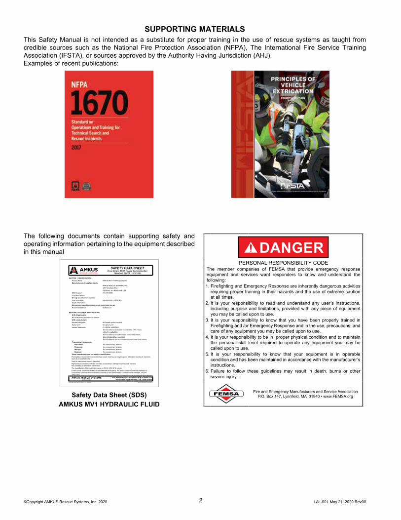
DANGERPERSONAL RESPONSIBILITY CODE
The member companies of FEMSA that provide emergency response equipment and services want responders to know and understand the following:1. Firefighting and Emergency Response are inherently dangerous activities
requiring proper training in their hazards and the use of extreme caution at all times.
2. It is your responsibility to read and understand any user’s instructions, including purpose and limitations, provided with any piece of equipment you may be called upon to use.
3. It is your responsibility to know that you have been properly trained in Firefighting and /or Emergency Response and in the use, precautions, and care of any equipment you may be called upon to use.
4. It is your responsibility to be in proper physical condition and to maintain the personal skill level required to operate any equipment you may be called upon to use.
5. It is your responsibility to know that your equipment is in operable condition and has been maintained in accordance with the manufacturer’s instructions.
6. Failure to follow these guidelines may result in death, burns or other severe injury.
FEMSA Fire and Emergency Manufacturers and Service AssociationP.O. Box 147, Lynnfield, MA 01940 • www.FEMSA.org

©Copyright AMKUS Rescue Systems, Inc. 2020 LAL-001 May 21, 2020 Rev003
Table Of Contents1.0 MEANING OF SAFETY SIGNAL WORDS2.0 SAFETY3.0 GENERAL DESCRIPTION 3.1 VARIOUS MODELS AND TERMS 3.2 SAFETY MARKINGS4.0 SPECIFICATIONS 4.1 GENERAL SPECIFICATIONS 4.2 CUTTER SPECIFICATIONS 4.3 SPREADER SPECIFICATIONS 4.4 COMBI TOOL SPECIFICATIONS5.0 SAFETY CONSIDERATIONS 5.1 PROTECTIVE CLOTHING 5.2 TRAINING 5.3 OPERATING CONSIDERATIONS6.0 SET-UP PROCEDURE 6.1 ROTATING HANDLE 6.1.1 HANDLE LIGHTS7.0 OPERATION 7.1 CONTROL VALVE ACTUATOR 7.2 CUTTING 7.3 SPREADING / SQUEEZING / LIFTING8.0 ACCESSORIES 8.1 EXTENDED REACH SPREADER TIPS (ERT) 8.2 CHAIN USE9.0 SAFETY GUARDS10.0 MAINTENANCE 10.1 ROUTINE MAINTENANCE 10.1.1 CHECK THE BLADES 10.1.2 HYDRAULIC MAINTENANCE 10.1.3 LUBRICATION 10.1.4 HANDLE LIGHT BATTERY REPLACEMENT11.0 TROUBLESHOOTING 11.1 GENERAL 11.2 TROUBLESHOOTING THE HYDRAULICS12.0 PARTS, SERVICE, AND TECHNICAL INFORMATION13.0 DECOMMISSIONING14.0 INSPECTION, CLEANING, DECONTAMINATION, AND STORAGE

©Copyright AMKUS Rescue Systems, Inc. 2020 LAL-001 May 21, 2020 Rev004
1.0 MEANING OF SAFETY SIGNAL WORDSA safety related message is identified by a safety alert symbol and a signal word to indicate the level of risk involved with a particular hazard. Per ANSI standard Z535.6, the definitions of the four signal words are as follows:
DANGERDANGER indicates a hazardous situation which, if not avoided, will result in death or serious injury.
WARNINGWARNING indicates a hazardous situation which, if not avoided, could result in death or serious injury.
CAUTIONCAUTION indicates a potentially hazardous situation which, if not avoided, could result in minor or moderate injury.
NOTICENOTICE is used to address practices not related to physical injury.
2.0 SAFETY
DANGERHydraulic tools can apply many tons of force which can bend, move, or lift large loads storing potential energy. Loads can become unstable and suddenly move without warning causing severe injury or death. Never support a load solely by a rescue tool. Use secondary supports to limit the extent of uncontrolled movements. Never put body parts in a situation where a shifting or falling load can cause a crushing injury. Stay clear of the path of travel.• Metal-on-metal contact is likely to slide sideways when the load is not able to deform around
the area of contact. Use care when lifting structural and hardened objects.• Chains can break when overloaded or improperly loaded.• Spreader tips and rams can kick (move) when direction of force isn’t perpendicular to load• Loads can suddenly shift sideways when forced, lifted, or moved. Stabilize load to reduce risk
of movement from ice, gravel, soft ground, precarious positions, objects which can break, wheels which depressurize or roll, and loading which can change during rescue operations.
WARNINGOperating rescue tools can result in injury or death from laceration, projectile (high speed flying debris), and pinch point injuries. Stay clear of the path of travel. Avoid unnecessary risk. Examples include:• Never lift, or hold a rescue tool by its cutting blades or spreader arms. Never place hands
between moving tool and a load. Pinch points are created from tool movement causing risk of limb amputation (i.e. fingers, hands, arms, feet, legs).
• Sharp metal objects formed during cutting and extrication cause potential for laceration and puncture wounds
• Projectiles can be ejected during cutting, spreading, or lifting operations when objects break suddenly under load. Sudden fractures are common with springs and hardened steels.
• Damaging pressurized objects such as airbag cylinders can create projectiles.• Using a rescue tool beyond its reasonable lifespan increases risk of fatigue failure. Expected
lifetime of the tool is 10 years from the date of manufacture.• Tools can drift (move side-to-side) as load is applied or released resulting in body parts being
trapped and crushed between tool handles and stationary objects. Always be aware of body, hand, and finger position. Stop before harmful contact is made.
WARNINGUsing rescue tools can cause ignition or explosion resulting in injury or death. Ignition or explosion can result from situations such as:• Flammable hazards are created when fuel lines, refrigerant lines (atomized oil), or pressurized
hydraulic fluid lines are breached. Ignition sources can suddenly ignite these fuels.• Flammable vapors can be released by careless refueling or operation of gasoline driven
engines. Refer to engine manufacturer’s manuals for specific details.• Extrication tools can create sparks as metals are cut and deformed. Avoid unnecessary risk
when flammable vapors are present.• Power units with electric motors or internal combustion engines are ignition sources.• Flammable vapors heavier than air can accumulate in low spots. Avoid selecting these
locations when setting up the power units. Use detectors to verify safe site selection.

©Copyright AMKUS Rescue Systems, Inc. 2020 LAL-001 May 21, 2020 Rev005
WARNINGHydraulic fluid (mineral oil) escaping under pressure can puncture the skin, infiltrate eyes, or lungs resulting in serious injury. Seek medical attention immediately. Avoid the urge to contain leaks with hands. Injection injuries require immediate medical attention. Safety Data Sheet (SDS) for AMKUS MV1 and AMKUS MV0 Hydraulic Fluid is available at AMKUS.com and CHEMTREC.com Hydraulic leaks can occur from situations such as:• Leaks at hose crimps and connections can develop from constant use, over-pressurization,
side-loading, or mis-crimping.• Hose damage from being driven over, stepped on, twisted, kinked, crushed, excessive
vibration, abuse, or neglect.• Leaks and breaks in hydraulic components can occur from improper maintenance or exceeding
service life expectations. Establish sound practices.• Connecting hydraulic tools in series can pressurize both sides of double acting cylinders.
Each tool must be separately connected to a power unit.• Release stored pressure before servicing tools by moving off end stops. Refer to power unit
manuals for proper operation.
WARNINGElectric shock can result in injury or death. Rescue tools are made from metal which is a conductor of electricity. Electric current can flow from the hazard through the rescue tool to shock nearby people. Maintain awareness of potential hazards. Examples include:• Never operate electric power units with damaged power cords.• Do not drive over or crush power cords.• Use care to avoid cutting power cords on sharp objects.• Do not strain cords during storage. Hidden cord damage can remain undetected until wet
conditions create an electrocution hazard.• Power sources and electronics are not waterproof. Do not submerge or douse the power units
or controls. Refer to manuals from battery, charger, and motor manufacturers for specific details.
• Cutting into concealed spaces can be hazardous. Power cables and battery packs may be hidden from view in structures and electric vehicles.
• Never operate near damaged electric power lines before power is verified as OFF
WARNINGMisuse of AMKUS Rescue Systems can result in a wide variety of hazards and consequences.Remain aware of and avoid misuse situations. Examples of misuse include:• Using low pressure (5000 psi) tools on high pressure (10,500 psi) hydraulic power units
creates high risk of hydraulic cylinder rupture. Ensure compatibility before use.• Failure to inspect and properly maintain rescue equipment. Inspect all rescue equipment after
each use. Any equipment found damaged or inoperable should be removed from service.• Storage of rescue equipment in adverse conditions. Always store rescue equipment in
clean,dry, and secure conditions.• Operation of rescue equipment with missing or illegible safety markings• Modification of tools and power units inconsistent with manufacturer’s specifications• Repairs attempted by unqualified workers.• Use of rescue tools for non-rescue purposes such as construction, production use, demolition,
or as a jack for vehicle service.• Pressure relief valve set over +5% above the Rated Output Pressure 10,500 psi (724 bar)• Using tools which have been heat damaged. Heating beyond 212°F (100°C) will compromise
the strength.
CAUTIONLifting or moving rescue tools and power units can result in falling or spine injury. Rescue tools and power units are heavy. Risk of injury increases in unfavorable conditions such as poor lighting, inclines, loose, wet, or icy surfaces. Follow accepted safe lifting practices.
NOTICEUse of hydraulic fluids other than AMKUS MV1 or MV0 (see Specifications for fluid for specific tool lines) can result in equipment damage and loss of function. Some examples include:• Phosphate ester hydraulic fluids and blends are incompatible with Buna-N seal and hose
materials used in AMKUS Rescue Systems• Mixing glycol with mineral oils can result in gelling and plugging of pump inlet screens• Using fluids with wrong viscosity or wear properties. Always use AMKUS MV1 or MV0 as
specified for your tools.

©Copyright AMKUS Rescue Systems, Inc. 2020 LAL-001 May 21, 2020 Rev006
3.0 GENERAL DESCRIPTIONAMKUS manufactures a complete line of hydraulic rescue tools. These rescue tools continue the AMKUS tradition of superior craftsmanship and quality. AMKUS backs these tools with a standard warranty published on the AMKUS website.AMKUS tools are designed to be driven only by an AMKUS hydraulic power unit. Hydraulic fluid from the pump passes through a user operated control valve and moves the piston as directed by the user. Moving the piston actuates the arms or blades of the rescue tool.
3.1 VARIOUS MODELS AND TERMSGripControl Valve
ActuatorLightedHandle
Guard
Cutter Blades
Hydraulic Hoses
Mono Coupler(optional)
Figure 3.1AC750M Cutter
Removable Tips
CutterBlades
Figure 3.1BCT716M Combination Tool
©Copyright AMKUS Rescue Systems, Inc. 2020 LAL-001 May 21, 2020 Rev007
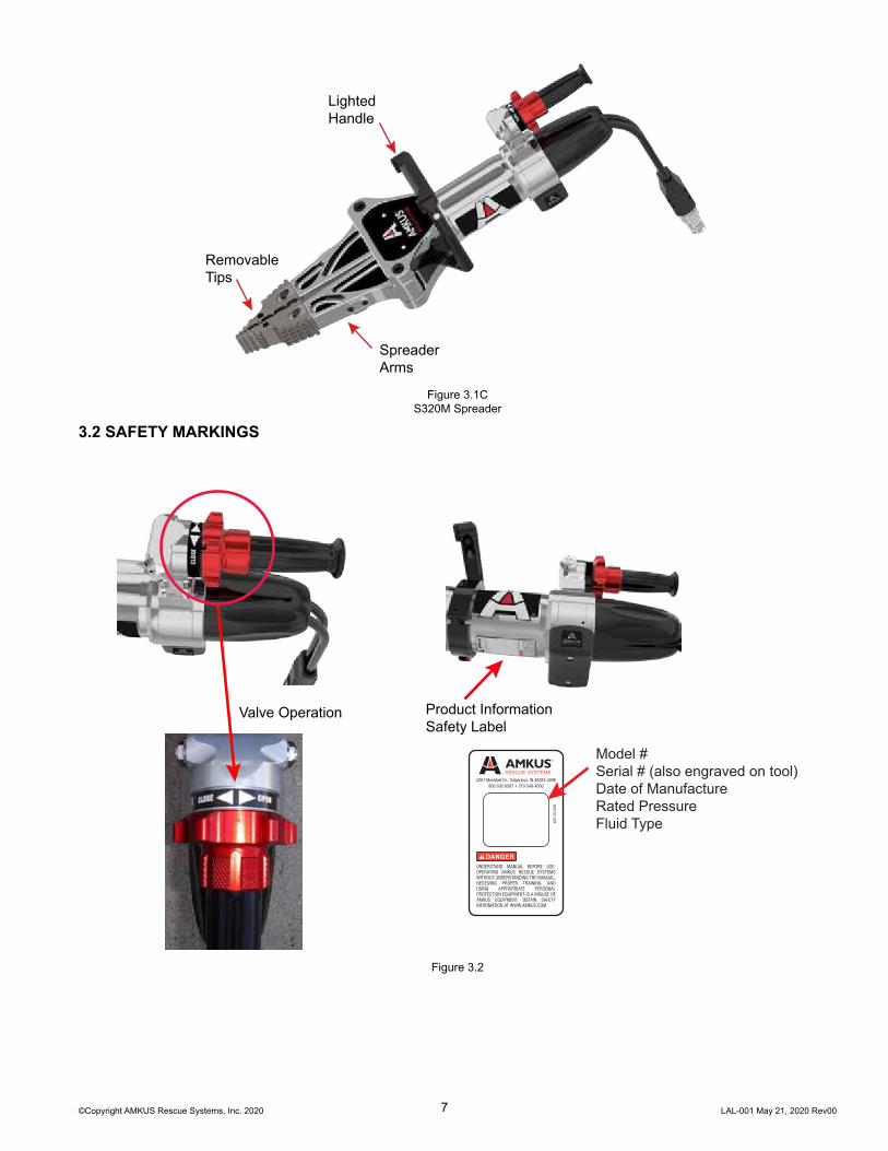
RemovableTips
LightedHandle
SpreaderArms
Figure 3.1CS320M Spreader
3.2 SAFETY MARKINGS
4201 Montdale Dr., Valparaiso, IN 46383-4098800-592-6587 • 219-548-4000
UNDERSTAND MANUAL BEFORE USE. OPERATING AMKUS RESCUE SYSTEMS WITHOUT UNDERSTANDING THE MANUAL, RECEIVING PROPER TRAINING, AND USING APPROPRIATE PERSONAL PROTECTION EQUIPMENT IS A MISUSE OF AMKUS EQUIPMENT. OBTAIN SAFETY INFORMATION AT WWW.AMKUS.COM
DANGER
KEL1
0-00
8
Valve Operation
Model #Serial # (also engraved on tool)Date of ManufactureRated PressureFluid Type
Product InformationSafety Label
Figure 3.2

©Copyright AMKUS Rescue Systems, Inc. 2020 LAL-001 May 21, 2020 Rev008
4.0 SPECIFICATIONS4.1 GENERAL SPECIFICATIONS
OPERATING LIMITSOperating Temperature Range: Degrees F (C) -25 TO 140 (-32 TO 60)HYDRAULIC SPECIFICATIONSFluid Type: AMKUS MV1 Hydraulic Fluid (Part#) KF0001Maximum Operating Pressure PSI ( bar ) 10,500 (724)
Table 4.1
4.2 CUTTER SPECIFICATIONS
Part#: C750MECHANICAL SPECIFICATIONSDimensions: Length X Width X Height inches ( mm ) 32.6 x 8.7 x 10.2 (827 x 222 x 259)Weight (ready to use) lb (kg) 46 lbs (20.9 kg)Cutter Opening Inches (mm) 7.5 (190)Cutter Rating NFPA 1936 A7/B9/C7/D9/E9
Table 4.2
4.3 SPREADER SPECIFICATIONS
Part#: S320MECHANICAL SPECIFICATIONSDimensions: Length X Width X Height inches ( mm ) 36.8 x 11.1 x 10.2 (935 x 282 x 259)Weight (w/out tips) lb (kg) 40.6 (18.4)Weight (ready to use) lb (kg) 45.9 (20.8)Max Spreading Distance Inches (mm) 32.0 (812)Max Spreading Distance (w/optional ERT tips) Inches (mm) 39.1 (993)Highest Spreading Force (HSF) lb (kN) 14,750 (65.6)Lowest Spreading Force (LSF) lb (kN) 10,000 (44.5)Max Spreading Force lb (kN) 39,500 (175.7)Highest Pulling Force (HPF) lb (kN) 11,500 (51.1)Lowest Pulling Force (LPF) lb (kN) 7,500 (33.4)
Table 4.3
4.4 COMBI TOOL SPECIFICATIONS
Part#: CT716MECHANICAL SPECIFICATIONSDimensions (w/out tips): Length x Width x Height Inches (mm) 33.7 x 8.7 x 10.2 (855 x 222 x 259)Dimensions (w/tips): Length x Width x Height Inches (mm) 34.9 x 8.7 x 10.2 (887 x 222 x 259)Weight (ready to use w/out tips) lb (kg) 44.8 (20.3)Weight (ready to use w/tips) lb (kg) 48.9 (22.2)Max Spreading Distance inches (mm) 15.8 (401)Highest Spreading Force (HSF) lb (kN) 8,260 (36.7)Lowest Spreading Force (LSF) lb (kN) 6,620 (29.4)Max Spreading Force lb (kN) 40,900 (218)Cutter Opening Inches (mm) 9.1 (231)
Table 4.4

©Copyright AMKUS Rescue Systems, Inc. 2020 LAL-001 May 21, 2020 Rev009
5.0 SAFETY CONSIDERATIONS5.1 PROTECTIVE CLOTHING
WARNINGTool operators bear responsibility for ensuring use of appropriate protective clothing and equipment. The chosen protective clothing and equipment must provide protection from potential hazards users may encounter while operating AMKUS rescue tools. Requirements for protective clothing and equipment are determined by the Authority Having Jurisdiction (AHJ).
5.2 TRAININGAMKUS tools facilitate the extrication of entrapment victims. Only trained emergency services personnel should attempt victim extrication. All personnel using AMKUS rescue tools are assumed to have completed a training course covering safe extrication of entrapment victims. The training must be acknowledged as educationally sound by the local Authority Having Jurisdiction (AHJ) over such training.
5.3 OPERATING CONSIDERATIONS
NOTICEAMKUS tools are intended for intermittent use. Allow sufficiently long pauses for the rescuetool to cool. If the tool’s exterior becomes too hot to touch, the temperature is likely above 120°F(49°C). An overheated rescue tool operates less effectively. When hydraulic oil temperature reaches 158°F (70°C), the tool’s efficiency drops significantly, and the tool should be stopped to cool down.
To avoid rescue tool overheating:• After use, clean off any accumulated oil, grease, dirt, or corrosive substances with a damp cloth and soapy water.
NOTICEOperating the rescue tool continuously against an end stop may cause overheating resulting in an inoperable tool. Permanent damage to the tool may occur. When an end stop is reached, release the control handle to return the control to the neutral position.
6.0 SET-UP PROCEDURENormally, AMKUS equipment is prepared and serviced by your dealer prior to delivery. If, however, you have decided to place the equipment into service yourself, remove equipment from the packing cartons and carefully inspect for damage. Damage that occurs during shipment should be reported immediately to the carrier.
1. Gather and review all safety and use documentation prior to operating any rescue tool.2. Connect the tool connection hoses to the hose lines from the AMKUS hydraulic power unit.
A. Standard Couplings: Please note that the male and female couplings on the hose lines leading from the power unit should be connected to the corresponding male and female couplings on the tool connection hoses. To connect the couplings, twist the sleeve on the female coupling so that the notch in the sleeve lines up with the pin. Push the sleeve back so the pin fits into the notch. While holding the sleeve back, push the male coupling into the female coupling. Release the sleeve; it will spring forward into place. Twist the sleeve 1/4 turn so that the pin no longer lines up with the notch. Pull on the couplings to check that they are securely connected.
B. Mono Couplings: Please note that the female coupling on the hose lines leading from the power unit should be connected to the corresponding male coupling on the tool connection hoses. To connect the couplings, place the male coupling into the female coupling. Rotate clockwise until you feel the coupling latch. Pull on the couplings to check that they are securely connected.
In most cases, the Mono Couplings can be connected and disconnected while the hose line is under flow. It is usually not necessary to place the directional control of the power unit in the neutral position before connecting and disconnecting. However, certain circumstances such as back pressure in the return line and/or cold temperatures, may make connecting and disconnecting under flow extremely difficult or impossible. If you are unable to connect and disconnect while the line is under flow, place the directional control valve of the power unit in the neutral position and then disconnect or connect.

©Copyright AMKUS Rescue Systems, Inc. 2020 LAL-001 May 21, 2020 Rev0010
6.1 ROTATING HANDLECutter and Combi Tools come equipped with a 360° swiveling handle that has variable tension.
RELEASE
LOCK
TENSION SCREW
To increase rotating handle tension, tighten the tension screw shown above.Flip the red latch handle up on the tool’s cuff to rotate the rescue tool,
and flip it down to lock the handle position.
Figure 6.1
6.1.1 HANDLE LIGHTSAMKUS dual handle lights operate at three levels of intensity. To operate these lights, press the button located behind each light. The lights can be powered OFF by scrolling through each setting to OFF, or by a single button press from a setting that’s been powered ON for over 5 seconds. Continuous use time is about 60 hours on low. Battery saver function will turn the lights off after 15 minutes of continuous use. Button press:
1st light level low2nd light level medium3rd light level high4th power off light
Figure 6.1.1
7.0 OPERATION
WARNINGDo not connect tools in series. Connecting tools in series could cause operational problems, equipment failure, or catastrophic failure of the equipment resulting in serious injury or death.
Start the power unit (refer to power unit and engine manuals). Following the instructions in the power unit manual, operate the selector valve to charge the hose line to which the tool is connected. Pick up the tool, noticing that the design of the cutter makes it natural to grip the handle with one hand and the control valve hand grip with the other.
7.1 CONTROL VALVE ACTUATORThe control valve actuator has three positions, OPEN, OFF, and CLOSE. The control valve actuator includes a deadman safety feature which returns the control valve actuator to the OFF position (neutral) when released. When the control valve is in the OFF position, the tool movement stops, and holds position and load. Verify operation of control valve actuator by checking to see it returns automatically to the neutral position when released.
7.2 CUTTINGRotating the control valve actuator regulates the hydraulic flow rate and power delivered to the tool. Turning the control valve actuator to the end stops provides maximum hydraulic flow rate and power.
Figure 7.2

©Copyright AMKUS Rescue Systems, Inc. 2020 LAL-001 May 21, 2020 Rev0011
7.2 CUTTING (CONTINUED)To perform a cutting operation, first, open the cutter blades. Place the blades around the object being cut. Close the blades to cut the object. Obtain the maximum cutting forces nearest the pivot point. Start the cut with the blades as fully engaged as possible. Make the cut. Open the blades and remove the tool when finished.
WARNINGWhen operating the cutter, take care to be positioned to the side of the cutter. As the cutter blades meet resistance, the rescue tool may rotate or drift. If tool rotation places the user, operator, or others in jeopardy, immediately release the control valve actuator. The deadman safety feature of the control valve actuator should immediately return the control valve actuator to the center (neutral) position stopping blade movement. Reposition the cutter as needed for optimal cutting performance.
WARNINGBlades can break if positioned incorrectly, causing hazardous projectiles and an inoperable tool. If blades start to flex sideways (tool rolls as space between blades increases), stop immediately and reconsider cutting strategies.
CAUTIONThe blades on AMKUS cutters effectively cut steering columns, brake pedals, door mechanisms, and other vehicle items as necessary for extrication. However, using AMKUS cutters as a piercing tool for heavy metal is not recommended. Therefore, when cutting, take care to insure the blade tips move through a clear path of travel. The blade tips can pierce automotive sheet metal body panels. Avoid obstacles like the heavy metal backing plates hidden behind seat belt mounts, door hinges, and latching mechanisms or locks.
NOTICECutting hardened metals can potentially dent or deform the blade’s cutting edge. Blades may break at these weak spots on subsequent cuts, especially if cutting near the tips. Avoid cutting hardened solids of unknown strength such as:
• Padlock shackles• Tie rods• Leaf springs• Spindles• Hardened bolts• Tool steel• Heat treated chain
Blade damage or breakage that results from cutting hardened metals or solids is not covered by the AMKUS Rescue Systems warranty.The blades are intended and designed to cut hardened auto bodies and components without damage.We recommend an Authorized AMKUS Rescue Systems Dealer inspect, evaluate, and replace dented or damaged blades as necessary.
Figure 7.2B
©Copyright AMKUS Rescue Systems, Inc. 2020 LAL-001 May 21, 2020 Rev0012
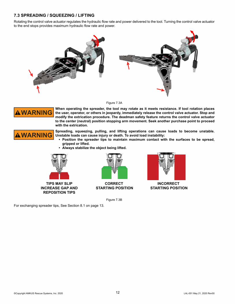
7.3 SPREADING / SQUEEZING / LIFTINGRotating the control valve actuator regulates the hydraulic flow rate and power delivered to the tool. Turning the control valve actuator to the end stops provides maximum hydraulic flow rate and power.
Figure 7.3A
WARNINGWhen operating the spreader, the tool may rotate as it meets resistance. If tool rotation places the user, operator, or others in jeopardy, immediately release the control valve actuator. Stop and modify the extrication procedure. The deadman safety feature returns the control valve actuator to the center (neutral) position stopping arm movement. Seek another purchase point to proceed with the extrication.
WARNINGSpreading, squeezing, pulling, and lifting operations can cause loads to become unstable. Unstable loads can cause injury or death. To avoid load instability:
• Position the spreader tips to maintain maximum contact with the surfaces to be spread, gripped or lifted.
• Always stabilize the object being lifted.
TIPS MAY SLIPINCREASE GAP AND
REPOSITION TIPS
CORRECT STARTING POSITION
INCORRECT STARTING POSITION
Figure 7.3B
For exchanging spreader tips, See Section 8.1 on page 13.
©Copyright AMKUS Rescue Systems, Inc. 2020 LAL-001 May 21, 2020 Rev0013
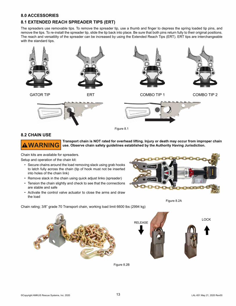
8.0 ACCESSORIES8.1 EXTENDED REACH SPREADER TIPS (ERT)The spreaders use removable tips. To remove the spreader tip, use a thumb and finger to depress the spring loaded tip pins, and remove the tips. To re-install the spreader tip, slide the tip back into place. Be sure that both pins return fully to their original positions. The reach and versatility of the spreader can be increased by using the Extended Reach Tips (ERT). ERT tips are interchangeable with the standard tips.
GATOR TIP ERT COMBO TIP 1 COMBO TIP 2
Figure 8.1
8.2 CHAIN USE
WARNINGTransport chain is NOT rated for overhead lifting. Injury or death may occur from improper chain use. Observe chain safety guidelines established by the Authority Having Jurisdiction.
Chain kits are available for spreaders.Setup and operation of the chain kit:
• Secure chains around the load removing slack using grab hooks to latch fully across the chain (tip of hook must not be inserted into holes of the chain link)
• Remove slack in the chain using quick adjust links (spreader)• Tension the chain slightly and check to see that the connections
are stable and safe• Activate the control valve actuator to close the arms and draw
the loadFigure 8.2A
Chain rating; 3/8” grade 70 Transport chain, working load limit 6600 lbs (2994 kg)
LOCKRELEASE
Figure 8.2B
©Copyright AMKUS Rescue Systems, Inc. 2020 LAL-001 May 21, 2020 Rev0014
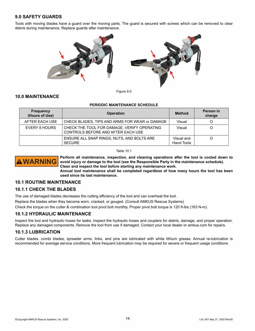
9.0 SAFETY GUARDSTools with moving blades have a guard over the moving parts. The guard is secured with screws which can be removed to clear debris during maintenance. Replace guards after maintenance.
Figure 9.010.0 MAINTENANCE
PERIODIC MAINTENANCE SCHEDULEFrequency
(Hours of Use) Operation Method Person incharge
AFTER EACH USE CHECK BLADES, TIPS AND ARMS FOR WEAR or DAMAGE Visual OEVERY 8 HOURS CHECK THE TOOL FOR DAMAGE, VERIFY OPERATING
CONTROLS BEFORE AND AFTER EACH USEVisual O
ENSURE ALL SNAP RINGS, NUTS, AND BOLTS ARE SECURE
Visual andHand Tools
O
Table 10.1
WARNINGPerform all maintenance, inspection, and cleaning operations after the tool is cooled down to avoid injury or damage to the tool (see the Responsible Party in the maintenance schedule).Clean and inspect the tool before starting any maintenance work.Annual tool maintenance shall be completed regardless of how many hours the tool has been used since its last maintenance.
10.1 ROUTINE MAINTENANCE10.1.1 CHECK THE BLADESThe use of damaged blades decreases the cutting efficiency of the tool and can overheat the tool.Replace the blades when they become worn, cracked, or gouged. (Consult AMKUS Rescue Systems)Check the torque on the cutter & combination tool pivot bolt monthly. Proper pivot bolt torque is 120 ft-lbs (163 N-m).
10.1.2 HYDRAULIC MAINTENANCEInspect the tool and hydraulic hoses for leaks. Inspect the hydraulic hoses and couplers for debris, damage, and proper operation. Replace any damaged components. Remove the tool from use if damaged. Contact your local dealer or amkus.com for repairs.
10.1.3 LUBRICATIONCutter blades, combi blades, spreader arms, links, and pins are lubricated with white lithium grease. Annual re-lubrication is recommended for average service conditions. More frequent lubrication may be required for severe or frequent usage conditions.

©Copyright AMKUS Rescue Systems, Inc. 2020 LAL-001 May 21, 2020 Rev0015
10.1.4 HANDLE LIGHT BATTERY REPLACEMENTTo replace the batteries for either of the independent lights located at opposite ends of the handle:1. Remove the corresponding lid screws with a 3mm hex key.2. Remove and replace the CR123A battery in each of the battery holders.3. Use the hex key to tighten the lid screws back into position.
REMOVESCREWS
Figure 10.1.4
11.0 TROUBLESHOOTING11.1 GENERAL
NOTICEImmediately remove malfunctioning or damaged tools from service. Consult your dealer or AMKUS Rescue Systems.ALL SERVICE MUST BE PERFORMED BY QUALIFIED SERVICE TECNICIANS IN OBSERVANCE OF SAFETY REGULATIONS.
Malfunctions can be divided into two sections:1. Malfunction of the hydraulic system2. Malfunctions related to other rescue tool systems
Remedies marked by the letter M require the intervention of the Maintenance Technician.Remedies marked with the letter O can be performed by the Operator.
11.2 TROUBLESHOOTING THE HYDRAULICS
FAULT POSSIBLE REASON POSSIBLE REMEDY PERFORMED BYSTROKE DOES
NOT BEGINControl valve actuator damaged Replace control valve M
DISCONTINUOUS MOTION
Max. pressure valve fault Consult AMKUS ServiceDepartment
M, O
12.0 PARTS, SERVICE, AND TECHNICAL INFORMATIONParts, service, and technical information may be obtained from your local AMKUS dealer, or at amkus.com.
13.0 DECOMMISSIONINGWhen decommissioning any AMKUS Rescue Systems Tool or power supply, follow local regulations. For proper disposal information, contact your local AMKUS Rescue Systems dealer.

©Copyright AMKUS Rescue Systems, Inc. 2020 LAL-001 May 21, 2020 Rev00
AMKUS RESCUE SYSTEMSAMKUS.com
4201 Montdale Drive, Valparaiso, IN 46383-4098 USA800-592-6587 • 219-548-5000
14.0 INSPECTION, CLEANING, DECONTAMINATION, AND STORAGE1. Always store the tool securely in a clean, cool, dry space.2. Relieve the pressure on the tools after use by backing off the end stop..
BEFORE BEING PLACED BACK IN SERVICE, the rescue tool must be inspected to this list:1. Check to see that all rescue tool markings are legible. Contact your local dealer or AMKUS Rescue Systems for replacement
labels.2. Wipe the tool clean.3. If the rescue tool becomes contaminated, determine the nature of the contamination. Follow the decontamination guidelines
provided by the Authority Having Jurisdiction. Technical advice may be requested from AMKUS Rescue Systems.4. Inspect the tool, controls, and hoses after each use for damage, leakage, and excessive wear.5. If rescue tool damage or excessive wear is noticed, remove the rescue tool from service immediately. Contact your local dealer
or AMKUS Rescue Systems for service.6. Attach the hydraulic power unit and verify tool operation.
WARNINGAny rescue tool failing any part of this checklist is unsafe for use and must have the problem corrected before use or being placed back in service. Operating a rescue tool that has failed the checklist is a misuse of this equipment. Contact your local AMKUS dealer or AMKUS Rescue Systems.