MAZDA RESCUE MANUAL - Amazon S3
71
MAZDA RESCUE MANUAL MAZDA MOTOR CORPORATION
-
Upload
khangminh22 -
Category
Documents
-
view
0 -
download
0
Transcript of MAZDA RESCUE MANUAL - Amazon S3

MAZDA RESCUE MANUAL
MAZDA MOTOR CORPORATION

General informationIntroduction
2/71
IntroductionGeneral informationThis manual describes the precautions necessary for the first responders and second responders to perform rescue operations for Mazda vehicles.The content described in this manual is an overview of the technologies adopted by Mazda Motor Corporation. The type of technology adopted, parts, and arrangement differ depending on the vehicle, always check the rescue sheet of each vehicle and observe the precautions.The representative vehicle models for this manual is the left-hand drive MAZDA3, however, other vehicle models are represented as well. The vehicle specifications differ depending on the country or region. Check each rescue sheet for information of the vehicle model and specifications. Please note that the content in this manual may not match the vehicle due to specification changes.
Indication concerning safetyThe marks and their meanings used in this manual are as follows. Please be sure to read.
WARNING • Possibility of death or serious injury could result if warning is ignored
CAUTION • Possibility of bodily injury or damage to the vehicle could result if caution is ignored
Note • Important and useful information
Means that the contents shown in the illustration are prohibited.
The arrows in the illustrations indicate the following.
• Indicates the 1st operation.
• Indicates the 2nd operation.
• Indicates the location of the part.
• Indicates the transition of the status.

Table of Contents
3/71
Table of ContentsIntroduction 2
General information 2Indication concerning safety 2
Table of Contents 3
1. Identification / recognition 5
1-1. How to identify Mazda vehicles by exterior appearance 51-2. How to identify Mazda vehicles by VIN 7
2. Immobilization / stabilization / lifting 9
2-1. How to apply parking brake 92-1-1. How to apply mechanical parking brake 92-1-2. How to apply electric parking brake (EPB) 92-1-3. How to make sure that parking brake is applied 9
2-2. How to shift to P position (automatic transmission) 102-2-1. How to shift to P position (vehicles without shift-by-wire system) 112-2-2. How to shift to P position (vehicles with shift-by-wire system) 122-2-3. How to make sure that transmission is in P position 12
2-3. Immobilizing manual transmission vehicle 132-3-1. How to immobilize manual transmission vehicle 13
2-4. Vehicle support 142-4-1. Wheel chocks 142-4-2. Vehicle support positions 14
3. Disable direct hazards / safety regulations 15
3-1. Operation for systems that do not operate if power is lost 153-1-1. Operation of locking/unlocking door, trunk lid/liftgate, and fuel lid 153-1-2. Opening trunk lid or liftgate 163-1-3. Opening/closing windows 173-1-4. Sliding operation of power sliding window sunroof 173-1-5. Retractable hardtop open/close operation 183-1-6. Power seat operation 183-1-7. Electric parking brake (EPB) operation 193-1-8. Shift-by-wire system shift operation 19
3-2. Checking that system is disabled 203-3. Disabling systems 24
3-3-1. Disabling systems on vehicles equipped with high voltage devices 243-3-2. Disabling systems on vehicles not equipped with high voltage devices 27
4. Access to the occupants 28
4-1. Operation of parts related to access of occupants 284-1-1. Glass 284-1-2. Doors 294-1-3. Front seat and steering wheel position adjustment 294-1-4. Head restraint removal 314-1-5. Seat belt removal 31
4-2. Recommended cut position 324-2-1. High voltage areas 324-2-2. High pressure gas or areas where high pressure gas is generated (deployment areas of air bags,
knee air bags, side air bags, far side air bags, curtain air bags, seat belt pre-tensioners, active hood) 32

Table of Contents
4/71
4-2-3. High strength steel sheeting 355. Stored energy / liquids / gases / solids 36
5-1. Stored energy (high voltage) 365-1-1. High voltage system 365-1-2. High voltage battery 385-1-3. Electric motor 395-1-4. Inverter 405-1-5. DC-DC converter 415-1-6. Junction box 425-1-7. Battery charge control module 435-1-8. Charge port 445-1-9. Electric compressor 455-1-10. PTC heater 46
5-2. Stored energy (low voltage) 475-2-1. 12 V battery 475-2-2. Mazda M Hybrid battery (Exceeds 12 V) 485-2-3. Capacitor (Exceeds 12 V) 495-2-4. DC-DC converter (Exceeds 12 V) 505-2-5. Seat warmer (Exceeds 12 V) 51
5-3. Liquids 525-3-1. Fuel tank 525-3-2. Oil tank 535-3-3. Engine coolant 54
5-4. Gases 565-4-1. Air conditioning refrigerant 56
6. In case of fire 57
6-1. Vehicles equipped with high voltage battery 576-1-1. Measures in case of fluid leakage 57
7. In case of submersion 58
7-1. Vehicles equipped with high voltage battery 587-1-1. Measures when performing rescue operation 587-1-2. Measures after performing rescue operation 58
8. Towing / transportation / storage 59
8-1. Towing cautions 598-1-1. Engine vehicles 598-1-2. Vehicles equipped with high voltage battery 62
8-2. Towing eyelet position 668-3. Vehicle storage 67
8-3-1. Vehicles equipped with high voltage battery 679. Important additional information 69
10. Explanation of pictograms used 70

Identification / recognitionHow to identify Mazda vehicles by exterior appearance
5/71
1. Identification / recognition1-1. How to identify Mazda vehicles by exterior appearanceVehicles requiring rescue can be identified as a Mazda vehicle, as well as the vehicle model, drive system, and type of powertrain by the exterior emblems.The emblems installed on the vehicle and their installation positions differ depending on the vehicle model.Identify the vehicle requiring rescue using the following figures.
(1) Front center brand emblemMazda vehicles are equipped with the following emblem.
(2) Rear model name emblemThe vehicle is equipped with an emblem to identify the vehicle model. The following is an example of the MAZDA3 emblem. Refer to the rescue sheet for details on each vehicle.
(3) Rear AWD emblemAWD (all-wheel drive) vehicles are equipped with the following emblem. However, there is no emblem on 2WD vehicles to identify it as a 2WD vehicle.
(4) Rear center brand emblemMazda vehicles are equipped with the following emblem.
1 2 3 4 5 6

How to identify Mazda vehicles by exterior appearanceIdentification / recognition
6/71
(5) Rear SKYACTIV emblem
Indicates that the vehicle is equipped with a gasoline engine (SKYACTIV-G or SKYACTIV-X).
Indicates that the vehicle is equipped with a powertrain (e-SKYACTIV G) that combines a gasoline engine and a Mazda M hybrid system.
Indicates that the vehicle is equipped with a diesel engine (SKYACTIV-D).
Indicates that the vehicle is equipped with high voltage devices (e-SKYACTIV).
(6) High voltage device identification stickerThe following sticker is adhered to the rear quarter window on vehicles equipped with high voltage devices.

Identification / recognitionHow to identify Mazda vehicles by VIN
7/71
1-2. How to identify Mazda vehicles by VINThe vehicle's VINs are stamped at either the lower left corner of the windshield or in the footwell on the right side of the front seat as shown in the following figures.
The VIN consists of alphanumeric characters such as the following. The number of digits differ depending on the country or region, and vehicle model.
• Japan
» Stamp example
ABC - DE FG - 123456
6BA - BP 5P - 123456
Serial No.
Serial No.
Exhaust emission regulation identification code
BP: MAZDA3DR: MAZDA MX-30ND: MAZDA MX-5 / ROADSTER
Carline, series
Carline, series

How to identify Mazda vehicles by VINIdentification / recognition
8/71
• Except Japan
» Stamp example
ABC - DE FGHJKL - 123456
ABC - DE FGHJKL - 123456
Serial No.
Serial No.
World manufacture identification
World manufacture identification
Carline, series
Carline, series
BP: MAZDA3DR: MAZDA MX-30ND: MAZDA MX-5 / ROADSTER
The following codes all indicate Mazda vehicles.JMZJM0JM1JM4JM6JM7MM8

Immobilization / stabilization / liftingHow to apply parking brake
9/71
2. Immobilization / stabilization / liftingPerform the following procedure to secure the vehicle. How to apply the parking brake and the support positions of the vehicle differ depending on vehicle model.
2-1. How to apply parking brakeThere are 2 types of parking brakes, a mechanical parking brake and an electric parking brake (EPB). Apply the parking brake according to the type equipped on the vehicle.Check if the parking brake is applied by viewing the indicator/warning lights in the instrument cluster while the power switch is switched ON.
2-1-1. How to apply mechanical parking brake
2-1-2. How to apply electric parking brake (EPB)
2-1-3. How to make sure that parking brake is applied
Pull the parking brake lever up.
Pull the electric parking brake (EPB) switch up.
Note• If the 12 V battery is disconnected or has lost power, the electric
parking brake (EPB) cannot be applied or released.
When the parking brake is applied with the power switch switched ON, any of the indicator/warning lights shown in the figure turn on.

How to shift to P position (automatic transmission)Immobilization / stabilization / lifting
10/71
2-2. How to shift to P position (automatic transmission)
When stopping a vehicle with an automatic transmission, shift the selector lever to the P position so that the vehicle does not move. The condition in which the selector lever is in the P position can be checked by the indication in the instrument cluster while the power switch is switched ON.
There are some Mazda vehicles with an automatic transmission which have adopted a shift-by-wire system. The shift-by-wire system transmits the operation of the selector lever to the transmission by electric signals. The method for shifting to the P position differs depending on whether or not the shift-by-wire system is equipped.
Note
• How to identify transmissions There are 2 types of transmissions for Mazda vehicles, a manual transmission and an automatic
transmission. For vehicles with an automatic transmission, the characteristics differ with those without a shift-
by-wire system and those with a shift-by-wire system. Make sure of which system is equipped on the vehicle and perform the securing procedure
according to the equipped system.
» How to identify manual transmissions Vehicles with a manual transmission are equipped with a clutch pedal.
» How to identify automatic transmissions
Vehicles with an automatic transmission are not equipped with a clutch pedal.
Note
• How to identify shift-by-wire systemFor vehicles with an automatic transmission, vehicles without and vehicles with a shift-by-wire system can be identified by how the selector lever is operated.
How to operate selector leverVehicles without shift-by-wire system Vehicles wit h shift-by-wire system

Immobilization / stabilization / liftingHow to shift to P position (automatic transmission)
11/71
2-2-1. How to shift to P position (vehicles without shift-by-wire system)
1
2
1. Lock-release button2. Selector lever
Indication Various Lockouts
Indicates that you must depress the brake pedal and hold in the lock-release button to shift (The ignition must be switched ON).
Indicates the selector lever can be shifted freely into any position.
Indicates that you must hold in the lock-release button to shift.

How to shift to P position (automatic transmission)Immobilization / stabilization / lifting
12/71
When the transmission is in the P position with the power switch switched ON, the selector lever position indication is [P].
2-2-2. How to shift to P position (vehicles with shift-by-wire system)
2-2-3. How to make sure that transmission is in P position
1. Lock-release button2. Selector lever
Indication Various Lockouts
Indicates that you must depress the brake pedal and hold in the lock-release button to shift (The ignition must be switched ON).
Indicates the selector lever can be shifted freely into any position.
Indicates that you must hold in the lock-release button to shift.
12
Note
• The shift-by-wire system transmits the operation of the selector lever to the transmission by electric signals. As a result, the position where the selector lever is in and the actual position where the transmission is in may differ.
• When the power is lost such as if the 12 V battery is disconnected, the actual position of the transmission does not change even though the selector lever is operated.

Immobilization / stabilization / liftingImmobilizing manual transmission vehicle
13/71
1. Neutral position
Note
• Vehicles with a manual transmission are equipped with a device to prevent mis-operation of the shift lever.
• When shifting to the R position, shift the shift lever towards R while pushing it down.
2-3. Immobilizing manual transmission vehicle
When a vehicle with a manual transmission needs to be secured on a slope, secure it by shifting the shift lever to the 1st gear or the R position.
2-3-1. How to immobilize manual transmission vehicle
1

Vehicle supportImmobilization / stabilization / lifting
14/71
Displays the support positions when viewing from the side of the vehicle.
Displays the support positions when viewing from underneath the vehicle.
WARNING• Do not touch any exposed wiring or parts underneath the vehicle such as high voltage
wiring harnesses and parts when securing the tires with wheel chocks. Touching them could cause electrical shock and result in serious injury or, in the worst case, death.
CAUTION• Supports should be installed avoiding each high voltage, exhaust, and fuel system.• If the interior parts of the high voltage components or high voltage wiring harnesses are
exposed, do not place supports or lift airbag rescue devices underneath them.
2-4. Vehicle support
2-4-1. Wheel chocks
2-4-2. Vehicle support positions
• How to view vehicle support positions
Use the wheel chocks at the positions shown in the rescue sheets for each vehicle model so that the vehicle is secured firmly.
Support the vehicle at 4 points using the vehicle support positions shown in the rescue sheets for each vehicle model.
Note
• The vehicle support positions indicate the positions where the vehicle is supported using an auto lift and safety stands (rigid rack).

Disable direct hazards / safety regulationsOperation for systems that do not operate if power is lost
15/71
3. Disable direct hazards / safety regulations3-1. Operation for systems that do not operate if power is lostIf the power supply is lost, such as when the 12 V battery is disconnected, some electrical components may become inoperable, such as door unlocking. Before disconnecting the negative 12 V battery terminal, perform the following operations if necessary.
3-1-1. Operation of locking/unlocking door, trunk lid/liftgate, and fuel/charge lid(1) Locking/unlocking using touch sensor or request switch while carrying key
(2) Locking/unlocking using key(3) Locking/unlocking using lock switch
1. Sensing area of door unlock touch sensor (Inner side of door handle)
2. Sensing area of door lock touch sensor (Depression on outer side of door handle)
3. Request switch — Locks and unlocks repeatedly each time the switch is
operated.
1 2 3
1. Operation indicator light
2. Lock switch ( )
3. Unlock switch ( )
4. Trunk button (Sedan) ( or )
5. Intrusion sensor cancel button ( )
1
2
3
4
5

Operation for systems that do not operate if power is lostDisable direct hazards / safety regulations
16/71
(4) Locking using lock switch on liftgate
(1) Unlocking using trunk lid opener switch
(2) Unlocking using electric trunk lid opener
1
2
1. Unlocking2. Locking
3-1-2. Opening trunk lid or liftgate

Disable direct hazards / safety regulationsOperation for systems that do not operate if power is lost
17/71
1. Closing2. Opening3. Right front window4. Right rear window5. Left rear window6. Left front window7. Power window lock switch8. Unlock
— Power window can be operated.9. Lock
— Power window cannot be operated.
1. Closing2. Opening
1. Opening2. Closing
(1) Opening/closing using driver's seat power window switch
(2) Opening/closing using front passenger’s or rear seat power window switch
3-1-3. Opening/closing windows
3-1-4. Sliding operation of power sliding window sunroof
2
3
45
6
1
7
8
9
2
1
1
2

Operation for systems that do not operate if power is lostDisable direct hazards / safety regulations
18/71
1. Opening2. Closing
1. Forward/back adjustment (seat slide)2. Seat height adjustment3. Seat front end height adjustment4. Angle adjustment (reclining)5. Lumbar support adjustment
3-1-5. Retractable hardtop open/close operation
3-1-6. Power seat operation
1
2
1
1
2
2
3
3
4
4
5
5

Disable direct hazards / safety regulationsOperation for systems that do not operate if power is lost
19/71
3-1-7. Electric parking brake (EPB) operation
3-1-8. Shift-by-wire system shift operation
Note
• The electric parking brake (EPB) can be applied or released manually using the electric parking brake (EPB) switch. Additionally, it has functions to apply the parking brake automatically when the power switch is switched from ON to ACC or OFF, or to release the parking brake automatically when the driver performs a specific action while the parking brake is applied.
• If the function to apply the parking brake automatically is canceled, such as when towing the vehicle, refer to [8. Towing / transportation / storage].
1. Applying parking brake2. Releasing parking brake
(1) Manual parking brake operation
1
2

Checking that system is disabledDisable direct hazards / safety regulations
20/71
CAUTION
• The system may be operating even though there is no engine sound coming from the electric vehicle. Always make sure that the system is disabled using other methods.
• For vehicles equipped with gasoline or diesel engines, the engine may be stopped by i-stop.
Note
• i-stop is a function which automatically stops and restarts the engine when the vehicle is stopped at a stoplight or in heavy traffic to improve fuel efficiency, and reduce exhaust gas and idling noise.
3-2. Checking that system is disabledMake sure that the system is disabled before performing any work. However, the system could operate regardless of the damage condition of the vehicle. If any of the following behaviors is occurring, the system is operating, therefore, disable the system.
(1) Engine is runningThe system is operating if the tachometer in the instrument cluster is operating, and if noise can be heard from the engine compartment or exhaust system.

Disable direct hazards / safety regulationsChecking that system is disabled
21/71
(2) Instrument cluster is turned on
(3) Navigation system or audio is operatingThe system is operating if the navigation system or audio is displayed on the center display, or if sound is output from the speakers.

Checking that system is disabledDisable direct hazards / safety regulations
22/71
CAUTION
• The climate control system for an electric vehicle can be set by a timer or remotely operated by a Smartphone. For this reason, the system may be operating even though the climate control system seems to not be operating. Always make sure that the system is disabled using other methods.
WARNING
• If the charge connector is connected to the vehicle, perform the rescue work after removing the charge connector. Otherwise, high voltage may be supplied to the vehicle. If this occurs, it could cause electrical shock and result in serious injury or, in the worst case, death.
(4) Climate control system is operatingThe system is operating if air flows through the air vents or the climate control display is turned on.
(5) Charging cable is connected
The charge port has a lock function to prevent the charge connector from being unplugged due to vibration or mischievous behavior during charging.
Disable direct hazards / safety regulationsChecking that system is disabled
23/71
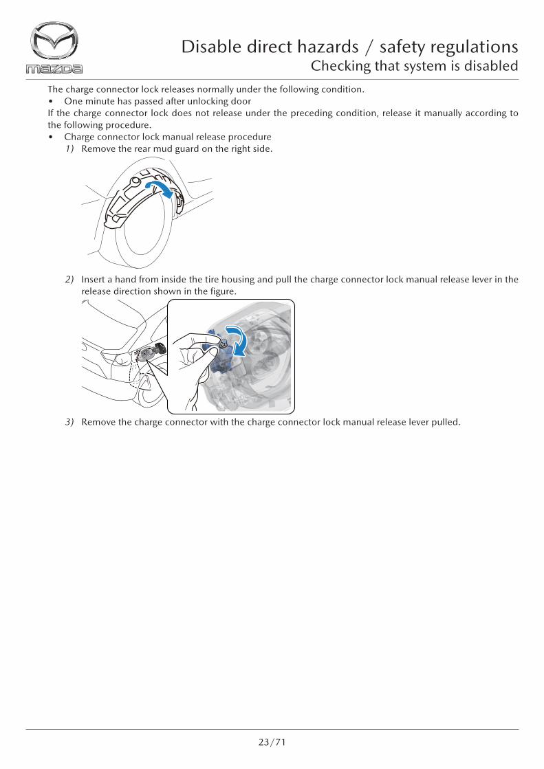
The charge connector lock releases normally under the following condition.• One minute has passed after unlocking doorIf the charge connector lock does not release under the preceding condition, release it manually according to the following procedure.• Charge connector lock manual release procedure
1) Remove the rear mud guard on the right side.
2) Insert a hand from inside the tire housing and pull the charge connector lock manual release lever in the release direction shown in the figure.
3) Remove the charge connector with the charge connector lock manual release lever pulled.

Disabling systemsDisable direct hazards / safety regulations
24/71
3-3. Disabling systems3-3-1. Disabling systems on vehicles equipped with high voltage devices(1) Disabling high voltage system when motor compartment is accessible
1) Disable the system using the power switch. » Repeatedly press the power switch 3 times or press and hold it for 3 seconds or longer. » Make sure that the [READY] indication is not displayed in the instrument cluster and the climate control
system is not operating.
2) Keep the key 5 m {16 ft 5 in} or farther away from the vehicle so that the system does not restart.
3) Open the hood. » Pull the hood release handle at the location shown in the figure. » Insert a hand into the gap under the hood and lift the hood while turning the lever in the direction of
the arrow. » Raise the stay and secure the hood by inserting the stay into the hood stay hole indicated by the arrow.
4) Disconnect the negative 12 V battery terminal.
5) Remove the relays shown in the figure.
5 m{16 ft 5 in}
WARNING• Any removed relays should be carried by the worker to prevent accidental connection by
another person while performing work. Additionally, cover the fuse box on the vehicle side with insulating tape.

Disable direct hazards / safety regulationsDisabling systems
25/71
(2) Disabling high voltage system when motor compartment is not accessible
1) Disable the system using the power switch. » Repeatedly press the power switch 3 times or press and hold it for 3 seconds or longer. » Make sure that the [READY] indication is not displayed in the instrument cluster and the climate control
system is not operating.
2) Keep the key 5 m {16 ft 5 in} or farther away from the vehicle so that the system does not restart.
3) Remove the service plug.
5 m{16 ft 5 in}
WARNING• Do not touch damaged parts or exposed internal parts of high voltage components or
high voltage wiring harnesses with bare hands. Such an action could cause electrical shock and result in serious injury or, in the worst case, death.
WARNING
<<High voltage>>
• Touching the terminal on the vehicle side can result in serious injury or death from electric shock. For this reason, after removing the service plug, cover the vehicle-side terminals with insulating tape so that they cannot be touched.
• Do not touch high voltage parts for 10 min after removing service plug. Electric charges may be stored on the condenser for 10 min after the service plug is removed, and touching high voltage parts during that time can result in serious injury or death from electric shock.
• Service plugs must be removed by workers inspecting/removing/installing high voltage parts. Keep the removed service plug on your person until inspection/removal/installation of the high voltage parts is completed to prevent other workers from accidentally installing the service plug.

Disabling systemsDisable direct hazards / safety regulations
26/71
» Partially peel back the cover.
» Remove the service hole cover.
» Wear insulating gloves and remove the service plug using the following procedure. » Slide the lock in the direction of the arrow shown in the figure. (Do not pull out completely)
» Raise the lever.
» Press the area indicated by arrow shown in the figure, release the tabs, and then raise the lever until it is perpendicular.
CAUTION
<<High voltage>>
• After removing the service plug, cover the vehicle side terminals with insulating tape to prevent foreign matter from adhering to them.
• When you are keeping the service plug on your person, cover the service plug terminals with insulating tape to prevent damage to them.
• Do not switch the power switch ON (READY on) after removing the service plug. If the power switch is switched ON (READY on) after removing the service plug, the vehicle may malfunction.

Disable direct hazards / safety regulationsDisabling systems
27/71
» Hold the lever and pull the service plug straight up.
» After removing the service plug, leave it for 10 min.
3-3-2. Disabling systems on vehicles not equipped with high voltage devices1) Disable the system using the push button start.
» Verify that the instrument cluster is not turned on. » If the instrument cluster is turned on, the system is operating, therefore, repeatedly press the push button
start 3 times or press and hold it for 3 seconds or longer to stop the system.
2) Keep the key 5 m {16 ft 5 in} or farther away from the vehicle so that the system does not restart.
3) Open the hood. » Pull the hood release handle at the location shown in the figure. » Insert a hand into the gap under the hood and lift the hood while turning the lever in the direction of the
arrow. » Raise the stay and secure the hood by inserting the stay into the hood stay hole indicated by the arrow. »
4) Disconnect the negative 12 V battery terminal.
5 m{16 ft 5 in}

Operation of parts related to access of occupantsAccess to the occupants
28/71
Indicates the laminated glass.
Indicates the tempered glass.
4. Access to the occupantsIf the power supply is lost, such as when the 12 V battery is disconnected, some electrical components may become inoperable, such as door unlocking. For the electrical components that cannot be operated, refer to [3. Disable direct hazards / safety regulations].
4-1. Operation of parts related to access of occupants4-1-1. Glass• Glass types
» Two types of glass have been adopted to Mazda vehicles; laminated glass and tempered glass. » The laminated glass is mainly used for the windshield. The tempered glass is used for the rear window glass,
door glass, quarter glass, and sunroof glass.

Access to the occupantsOperation of parts related to access of occupants
29/71
1. Forward/back adjustment (seat slide)2. Seat height adjustment3. Seat front end height adjustment4. Angle adjustment (reclining)5. Lumbar support adjustment
4-1-2. Doors• Types of doors There are some Mazda vehicle models which have adopted free-style doors.
» Free-style door With freestyle doors, the rear door is hinged at its rear and opens in the opposite direction to the front door. » Opening the doors
1) Open the front door.2) Pull the rear door handle and open the rear door.
• Door removal Any door can be removed using the conventional electric or hydraulic rescue tool or hand tool. Prying a door to
remove the hinge will facilitate the work depending on the situation.
4-1-3. Front seat and steering wheel position adjustmentThe front seat and steering wheel are operated as follows:• Power seat
1
1
2
2
3
3
4
4
5
5

Operation of parts related to access of occupantsAccess to the occupants
30/71
• Manual seat
• Steering wheel
1
1
2
2
3
3
44
1. Forward/back adjustment (seat slide)2. Seat height adjustment3. Seat front end height adjustment4. Angle adjustment (reclining)
Note• The steering wheel can be adjusted in the up/down direction shown on the pictogram in
addition to the forward/back direction.

Access to the occupantsOperation of parts related to access of occupants
31/71
4-1-4. Head restraint removalPull up the head restraint while pressing the lock knob.
4-1-5. Seat belt removalPull out the seat belt upward while pressing the button on the buckle.If the seat belt cannot be removed, cut it off using a belt cutter.
1
1. Button

Recommended cut positionAccess to the occupants
32/71
WARNING
• Removing each airbag module and disconnecting each airbag module connector with the main power switched ON or with power stored in the backup power supply of the SAS control module, can accidentally operate (deploy) each air bag and seat belt pre-tensioner, which may cause serious injury. Before removing each air bag module and disconnecting each air bag module connector, switch the main power OFF, disconnect the negative lead-acid battery terminal, and then wait for 1 min or more to allow the backup power supply of the SAS control module to deplete its stored power.
4-2. Recommended cut positionThere are the following 3 points to note when cutting the vehicle.
4-2-1. High voltage areas• High voltage systems are shown in [5. Stored energy / liquids / gases / solids].
4-2-2. High pressure gas or areas where high pressure gas is generated (deployment areas of air bags, knee air bags, side air bags, far side air bags, curtain air bags, seat belt pre-tensioners, and active hood)

Access to the occupantsRecommended cut position
33/71
• Air bagsIf the vehicle receives a strong impact to the front or rear when the power switch is switched ON, the air bags inflate instantaneously.The types of air bags equipped differ depending on the vehicle specifications. There is an [SRS AIRBAG] label at the positions where each air bag is stored.

Recommended cut positionAccess to the occupants
34/71
• Seat belt pre-tensionersThe seat belt pre-tensioners are devices that enhance the effect of the seat belts by retracting them when the vehicle receives a strong impact to the front or side. The pre-tensioner mechanism operates when the vehicle receives a strong impact to the front or side, however, it does not operate on a weak impact.
• Active hoodThe active hood functions to raise the rear side of the hood instantaneously if the vehicle hits a pedestrian and a certain level of impact is applied to the front of the vehicle. By keeping a large space between the hood and the parts inside the engine compartment, the impact when the head of a pedestrian collides with the hood is mitigated.When the power switch is switched ON and the vehicle is traveling within the deployment speed range, the system will deploy and raise the hood when the sensors installed in the back of the front bumper detect a certain amount of impact due to a collision with a pedestrian or other object.If the hood release handle is pulled after the active hood has deployed, the hood will rise even farther. Additionally, a deployed hood cannot be lowered manually.

Access to the occupantsRecommended cut position
35/71
CAUTION• To access the occupants, perform the procedure being careful of the parts shown on the
rescue sheet.
4-2-3. High strength steel sheeting• Ultra-high strength steel sheet
For Mazda vehicles, an ultra-high strength steel sheet has been adopted for the frame and the main frame parts that create the cabin to maintain strength even when thinned and reduce the weight of the vehicle.The [High strength zone] on the rescue sheet indicates the ultra-high strength steel sheets of the door, roof, and cabin side openings having tension strength of 780 MPa {795 kgf/cm2, 11,313 psi} or higher. Refer to the rescue sheet for details on each vehicle.

Stored energy (high voltage)Stored energy / liquids / gases / solids
36/71
5. Stored energy / liquids / gases / solids5-1. Stored energy (high voltage)5-1-1. High voltage system
• The high voltage system mainly consists of the following parts. Because high voltage may be applied to the high voltage parts, be very careful when working with them.
No. Component part Outline
1High voltage battery
• Supplies electrical power to drive the electric motor.• Stores electrical power regenerated by the electric motor.• The vehicle has a built-in service plug for physically cutting off the high voltage
circuit and decreasing the voltage.
2 Electric motor
• Generates drive force using electrical power from the high voltage battery during driving.
• Acts as a regenerative brake during deceleration to recover the vehicle’s kinetic energy as electrical power.
3 Inverter
• Converts the direct current of the high voltage battery to alternating current to drive the electric motor.
• Converts the alternating current generated by the electric motor to direct current to charge the high voltage battery.
4 DC-DC converter• Steps down 355 V DC of the high voltage battery to 14 V DC to supply power
to accessories and to charge the 12 V battery.
5 Junction box• Distributes the electrical power from the high voltage battery to the high
voltage parts in the electric motor.
6Battery charge control module
• During normal charge, converts alternating current supplied from the charge port to direct current for charging the high voltage battery.
7 Charge port
• Conducts the electrical power required to charge the high voltage battery from the charging equipment by being connected to the charge connector.
• An actuator that secures the charge cable, a charge indicator that indicates the charging status of the high voltage battery, and a charge port illumination that improves the visibility of the charge port when charging in dark places, such as at night, are installed.
8 Electric compressor • Compresses and circulates the gaseous refrigerant in the refrigeration cycle.
9 PTC heater• The PTC heater generates heat and warms the air passing through the A/C
unit to improve its heating performance.

Stored energy / liquids / gases / solidsStored energy (high voltage)
37/71
123
4 5 67
8
9
WARNING
• The temperature inside the motor compartment is high directly after driving the vehicle. Be very careful when performing work on the vehicle.
• If the necessary measures are not implemented before working on an electric vehicle, it could cause electrical shock and result in serious injury or, in the worst case, death. Before working on an electric vehicle, check the information regarding the high voltage locations and implement the necessary measures.
• Wear insulating gloves when performing work involving high voltage parts. Touching high voltage parts without wearing insulating gloves could cause electrical shock and result in serious injury or, in the worst case, death.
• Before performing work involving high voltage parts, remove the service plug and wait until 10 min have elapsed. Performing work without removing the service plug or before 10 min have elapsed after removing the service plug could cause electrical shock and result in serious injury or, in the worst case, death.
• Do not spin the tires while performing work involving high voltage parts. If the tires spin, the electric motor generates power even if the service plug is removed. If power generation occurs, it could cause electrical shock and result in serious injury or, in the worst case, death.
• Disconnect the charge connector from the vehicle when performing work involving high voltage parts. If the charge connector is connected to the vehicle, high voltage may be supplied to the vehicle. If this occurs, it could cause electrical shock and result in serious injury or, in the worst case, death.
• When storing the vehicle, place a caution display on the vehicle to alert other people. The high voltage system is shown in [8. Towing / transportation / storage].
CAUTION• Do not switch the power switch ON after removing the service plug. If the power switch
is switched ON after removing the service plug, a malfunction may occur with the vehicle.
Note• The high voltage parts can be identified as follows.
» Parts that are connected using orange wiring harnesses » Parts with high voltage warning label attached

Stored energy (high voltage)Stored energy / liquids / gases / solids
38/71
5-1-2. High voltage battery
• The high voltage battery supplies power to drive the electric motor. Additionally, it stores the power generated by the electric motor using regenerative braking and the power charged externally.
• The high voltage battery utilizes lithium-ion chemical reactions to perform charging and discharging.• The high voltage battery has a structure which protects the battery part in a case so that it cannot be contacted
from the outside. In the event of an impact such as a collision, the case provides protection and prevents the high voltage circuit from being exposed to the outside.
• The high voltage battery is located underneath the vehicle floor outside the cabin.
WARNING
• If there is no occurrence of deformation, leakage, or heat generation in the high voltage battery, there is no hazard.
• The electrolyte in the high voltage battery is highly acidic. If electrolyte leaks and electrolyte steam is inhaled or it gets into an eye or on the skin, perform the following first aid. » Electrolyte steam is inhaled
9 If electrolyte steam is inhaled, it could cause nausea and respiratory difficulty. Move the affected person immediately to a location where there is fresh air and if the affected person does not feel well, seek prompt medical attention.
» Electrolyte gets on skin 9 Wash with soap and large quantities of water. If there is itching or inflammation,
seek prompt medical attention. » Electrolyte gets into an eye
9 Flush the eye with water for a minimum of 15 minutes and seek prompt medical attention.

Stored energy / liquids / gases / solidsStored energy (high voltage)
39/71
5-1-3. Electric motor
• The electric motor generates drive force using electrical power from the high voltage battery during driving. It also generates electrical power for charging the high voltage battery from the kinetic energy during deceleration.
• The electric motor is located in the motor compartment.

Stored energy (high voltage)Stored energy / liquids / gases / solids
40/71
5-1-4. Inverter
• The direct current supplied by the high voltage battery is converted to alternating current for driving the electric motor. In addition, the alternating current generated by the electric motor during regenerative braking is converted to direct current for charging the high voltage battery.
• The inverter is located in the motor compartment.
Stored energy / liquids / gases / solidsStored energy (high voltage)
41/71
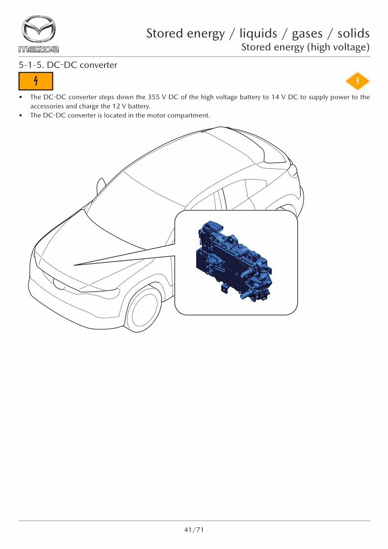
5-1-5. DC-DC converter
• The DC-DC converter steps down the 355 V DC of the high voltage battery to 14 V DC to supply power to the accessories and charge the 12 V battery.
• The DC-DC converter is located in the motor compartment.

Stored energy (high voltage)Stored energy / liquids / gases / solids
42/71
5-1-6. Junction box
• The junction box distributes the electrical power from the high voltage battery to the high voltage parts.• The Junction box is located in the motor compartment.

Stored energy / liquids / gases / solidsStored energy (high voltage)
43/71
5-1-7. Battery charge control module
• During AC normal charging, the alternating current supplied from the power supply equipment is converted to direct current and regulated to the charging voltage according to the state of the high voltage battery.
• The onboard charger is located underneath the cargo sub compartment.

Stored energy (high voltage)Stored energy / liquids / gases / solids
44/71
5-1-8. Charge port
• The charge port conducts the power required to charge the high voltage battery from the charging equipment by being connected to the charge connector.
• The charge port is equipped with a charge indicator that indicates the charging status of the high voltage battery and a charge port illumination that improves the visibility of the charge port when charging in dark places, such as at night. Also, inside the charge port, an actuator that secures the charge cable is installed.
• The charge port is equipped with a quick charge (DC) port and normal charge (AC) port. The installation positions of the quick charge (DC) port and normal charge (AC) port vary depending on the market.

Stored energy / liquids / gases / solidsStored energy (high voltage)
45/71
5-1-9. Electric compressor
• The electric compressor compresses and circulates the gaseous refrigerant in the refrigeration cycle.• The electric compressor compresses the gaseous refrigerant by rotating the movable scroll using the electric
motor built into the electric compressor as the driving source. It also sends the compressed refrigerant to the cabin condenser.
• The electric compressor is located in the motor compartment.

Stored energy (high voltage)Stored energy / liquids / gases / solids
46/71
5-1-10. PTC heater
• The PTC heater generates heat and warms the air passing through the A/C unit to improve its heating performance.
• The PTC heater is located in the cabin.

Stored energy / liquids / gases / solidsStored energy (low voltage)
47/71
5-2. Stored energy (low voltage)5-2-1. 12 V battery
• The 12 V battery stores the electricity generated by the generator/integrated starter generator (ISG), and supplies electricity to the electrical components.
• The 12 V battery for vehicles with i-stop is an exclusive product with enhanced durability and charge recovery performance.
• The 12 V battery is a lead-acid battery.• The 12 V battery is located in the engine compartment.• For the location of the 12 V battery on each vehicle, refer to the rescue sheet for each vehicle.
WARNING
• Keep all flames away from the battery and work in a well-ventilated area. Otherwise, evaporated battery fluid could ignite.
• Dilute sulfuric acid is used for the 12 V battery electrolyte. Dilute sulfuric acid is harmful. If it gets on the body regardless of body parts, wash it thoroughly with running water. Especially, if it gets into an eye, wash it off for 15 min and seek medical treatment.
• Dilute sulfuric acid is used for the 12 V battery electrolyte. The battery fluid is highly corrosive. Be careful not to allow it to adhere to clothes or a vehicle body.
• To avoid vehicle damage, when connecting to the battery charger, make sure that the positive and negative cables are connected correctly.

Stored energy (low voltage)Stored energy / liquids / gases / solids
48/71
5-2-2. Mazda M Hybrid battery (Exceeds 12 V)
• The Mazda M Hybrid battery is a lithium-ion battery.• The Mazda M Hybrid battery has an internally integrated relay circuit. If a malfunction occurs in the vehicle, a
protection control operates and opens the contactor circuit in the Mazda M Hybrid battery, which stops the Mazda M Hybrid operation.
• The Mazda M Hybrid battery is located underneath the vehicle floor outside the cabin. Refer to the rescue sheet for details on each vehicle.
WARNING
• If there is no deformation, leakage, or heat generation in the Mazda M Hybrid battery, there is no hazard.
• The electrolyte in the M Hybrid battery is highly acidic. If leaked electrolyte gets into an eye or on the skin, or electrolyte steam is inhaled, perform the following first aid. » Electrolyte steam is inhaled
9 If electrolyte steam is inhaled, it could cause nausea and respiratory difficulty. Move the affected person immediately to a location where there is fresh air and if the affected person does not feel well, seek prompt medical attention.
» Electrolyte gets on skin 9 Wash with soap and large quantities of water. If there is itching or inflammation,
seek prompt medical attention. » Electrolyte gets into an eye
9 Flush the eye with water for a minimum of 15 minutes and seek prompt medical attention.

Stored energy / liquids / gases / solidsStored energy (low voltage)
49/71
5-2-3. Capacitor (Exceeds 12 V)
• The capacitor is a storage battery (electric double layer capacitor) which stores electrical power generated by regenerative braking. In conjunction with the variable voltage type generator which can generate a maximum of 24.3 V, the capacitor efficiently stores electrical power generated in a short period of time.
• Different from a battery associated with chemical reactions, a capacitor charges/discharges using physical reactions. Therefore, large amounts of electricity can be charged/discharged quickly and the deterioration rate is extremely low even if it is used for a long period of time.
• The capacitor has an internally integrated relay circuit. To assure safety in the event of a vehicle collision, the relay circuit is disconnected so that no electrical power can be supplied from the capacitor to the vehicle. This condition can be canceled by switching the ignition OFF.

Stored energy (low voltage)Stored energy / liquids / gases / solids
50/71
5-2-4. DC-DC converter (Exceeds 12 V)
• To supply the power generated by the generator/integrated starter generator (ISG) to the vehicle’s electrical components, the DC-DC converter performs control according to the engine operation conditions.
• To prevent electrical circuit damage, part over-heating, or ignition due to large amounts of current, if the power supplied from the capacitor exceeds the rated voltage of the vehicle’s electrical components, power cannot be supplied directly to the vehicle’s electrical components. Therefore, the DC-DC converter steps down the 24.3 V maximum voltage to 12 V, and supplies the power to the vehicle’s electrical components.

Stored energy / liquids / gases / solidsStored energy (low voltage)
51/71
5-2-5. Seat warmer (Exceeds 12 V)
• The seat warmer warms the seat cushion and seat back.• The seat warmer is located in the seat.• A maximum of approx. 24 V of power is supplied to the seat warmer.

LiquidsStored energy / liquids / gases / solids
52/71
5-3. Liquids5-3-1. Fuel tank
• The fuel tank stores the fuel.• The fuel tank is made of either hard plastic or iron.• A valve is installed in the fuel tank to prevent fuel from returning to the fuel filler opening.• The fuel tank is located underneath the vehicle floor outside the cabin in the rear part of the vehicle.
WARNING
• Always keep sparks and flames away from fuel. Fuel can easily ignite which could cause serious injury or death, and damage to equipment or facilities.
• Highly pressurized fuel may spray out if fuel line parts are disconnected. » Fuel may cause irritation if it comes in contact with skin or eyes. » If fuel ignites and causes a fire, it may lead to serious injury or death, and damage to
equipment or facilities.• A person charged with static electricity could cause a fire or explosion, resulting in
serious injury or death. Before working on the fuel system, make sure to discharge static electricity by touching a vehicle body.
• Fuel is highly flammable and dangerous. Fuel line spills and leakage can cause serious injury or death, and damage to equipment or facilities. In addition, fuel can cause irritation if it comes in contact with skin or eyes.

Stored energy / liquids / gases / solidsLiquids
53/71
5-3-2. Oil pan
• Engine oil is stored in the oil pan underneath the engine.
WARNING • A hot engine can cause severe burns. Be careful when working around the engine.

LiquidsStored energy / liquids / gases / solids
54/71
5-3-3. Engine coolant
• Coolant can be poured in through the radiator cap. The radiator cap maintains appropriate pressure in the coolant passage. When the temperature of the coolant is high, the pressure in the coolant passage is kept at a higher pressure than the barometric pressure. » Example of vehicles equipped with low voltage devices
» Example of vehicles equipped with high voltage devices

Stored energy / liquids / gases / solidsLiquids
55/71
WARNING
• A hot engine can cause severe burns directly after the engine stops.• If the radiator cap is removed when the engine is hot, steam and boiling water may be
ejected, causing severe burns or injury.• Depending on the vehicle, the cooling fan may operate suddenly even while the ignition
is switched OFF. Keep hands away from the cooling fan even if the cooling fan is not operating, to prevent injury or damage to the cooling fan. Disconnect the negative (-) terminal of the battery when working on or around the cooling fan.

GasesStored energy / liquids / gases / solids
56/71
5-4. Gases5-4-1. Air conditioning refrigerant
• The air conditioning refrigerant is pressurized by the compressor and rapidly depressurized by the expansion valve. The air that passes through the evaporator is cooled and dehumidified using the latent heat of vaporization generated when the depressurized liquid refrigerant vaporizes.
WARNING
• Do not allow the refrigerant to leak near fire or any kind of heat. A poisonous gas may be generated if the refrigerant gas contacts fire or heat such as from cigarettes and heaters. When performing any work in which the refrigerant may leak, extinguish or remove all such heat sources and maintain adequate ventilation.
• If the refrigerant contacts the skin, it could cause frostbite. Always wear gloves and protective eyewear when handling the refrigerant. If the refrigerant gets into the eyes, immediately flush the eyes with clean water.
In case of fireVehicles equipped with high voltage battery
57/71
6. In case of fire
• Extinguish a fire with water when large amounts of water is available such as from a fire hydrant.
• Use an ABC fire extinguisher when using a fire extinguisher to extinguish a fire. An ABC fire extinguisher is effective for normal fire, oil fire (fire caused by gasoline and other petroleum oils) and electrical fire (fire caused by electrical wiring and equipment).
6-1. Vehicles equipped with high voltage battery• A lithium-ion battery has been adopted to the high voltage battery.• The lithium-ion battery electrolyte is clear and has an aromatic odor.• The lithium-ion battery electrolyte enters electrode and separator in the battery. Large amounts of the lithium-ion
battery electrolyte does not flow out if the battery is damaged.
6-1-1. Measures in case of fluid leakage• The lithium-ion battery electrolyte is flammable. If the electrolyte is leaking, immediately keep it away from
any flames. In addition, make sure that the area is sufficiently ventilated, and wear solvent-resistant protective equipment and wipe off the leaked electrolyte using a cloth.
• Dispose of the cloth that was used to wipe off the lithium-ion battery electrolyte in accordance with regulations.• The fluids used for vehicles equipped with a high voltage battery, excluding the lithium-ion battery electrolyte, are
the same as the standard fluids used for engine vehicles. Take the same measures as for engine vehicles.
WARNING• Do not touch the lithium-ion battery electrolyte and its steam. Otherwise, it could irritate
the skin and eyes. If touched, flush with large amounts of water and seek immediate medical attention.

Vehicles equipped with high voltage batteryIn case of submersion
58/71
7. In case of submersion7-1. Vehicles equipped with high voltage battery• Water may penetrate the high voltage battery if the vehicle is submerged or partially submerged in water.
7-1-1. Measures when performing rescue operation• Check if the vehicle is damaged.• If the vehicle is extremely damaged and the high voltage battery is under any of the following conditions, perform
the rescue operation while wearing the appropriate insulating protective equipment so that the high voltage battery is not touched. » High voltage battery is deformed » High voltage battery is damaged » Interior part of high voltage battery is exposed » Cannot determine if high voltage battery is damaged or not
7-1-2. Measures after performing rescue operation• After pulling the vehicle out of the water, drain the interior of the vehicle. After that, wear the appropriate
insulating protective equipment and remove the service plug.
WARNING
• Do not remove the service plug when the vehicle is submerged or partially submerged in water. In addition, do not touch the high voltage areas such as the high voltage battery and high voltage wiring harnesses. Otherwise, it could cause electrical shock and result in serious injury or, in the worst case, death.
Towing / transportation / storageTowing cautions
59/71
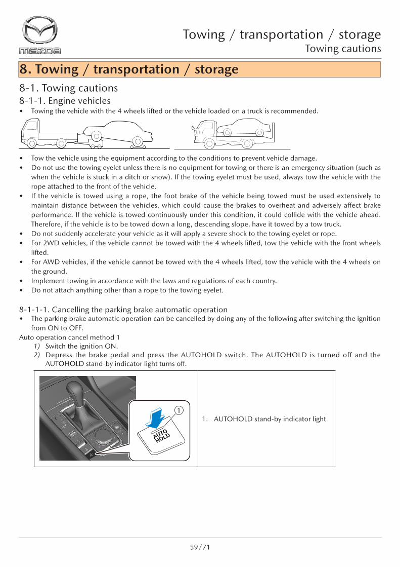
8. Towing / transportation / storage8-1. Towing cautions8-1-1. Engine vehicles• Towing the vehicle with the 4 wheels lifted or the vehicle loaded on a truck is recommended.
• Tow the vehicle using the equipment according to the conditions to prevent vehicle damage.• Do not use the towing eyelet unless there is no equipment for towing or there is an emergency situation (such as
when the vehicle is stuck in a ditch or snow). If the towing eyelet must be used, always tow the vehicle with the rope attached to the front of the vehicle.
• If the vehicle is towed using a rope, the foot brake of the vehicle being towed must be used extensively to maintain distance between the vehicles, which could cause the brakes to overheat and adversely affect brake performance. If the vehicle is towed continuously under this condition, it could collide with the vehicle ahead. Therefore, if the vehicle is to be towed down a long, descending slope, have it towed by a tow truck.
• Do not suddenly accelerate your vehicle as it will apply a severe shock to the towing eyelet or rope.• For 2WD vehicles, if the vehicle cannot be towed with the 4 wheels lifted, tow the vehicle with the front wheels
lifted.• For AWD vehicles, if the vehicle cannot be towed with the 4 wheels lifted, tow the vehicle with the 4 wheels on
the ground.• Implement towing in accordance with the laws and regulations of each country.• Do not attach anything other than a rope to the towing eyelet.
8-1-1-1. Cancelling the parking brake automatic operation• The parking brake automatic operation can be cancelled by doing any of the following after switching the ignition
from ON to OFF.Auto operation cancel method 1
1) Switch the ignition ON.2) Depress the brake pedal and press the AUTOHOLD switch. The AUTOHOLD is turned off and the
AUTOHOLD stand-by indicator light turns off.
1. AUTOHOLD stand-by indicator light
1

Towing cautionsTowing / transportation / storage
60/71
3) Press the EPB switch continuously for 2 seconds or longer (until a sound is activated).
4) Release the EPB switch and switch the ignition OFF within 5 seconds after the sound was activated.»» »»After the auto operation is cancelled, a sound is activated one time, and the EPB switch indicator light
switches from illumination to flashing, and then turns off after 3 seconds.
Auto operation cancel method 21) Switch the ignition ON.2) Depress the brake pedal and press the AUTOHOLD switch. The AUTOHOLD is turned off and the
AUTOHOLD stand-by indicator light turns off.
1. AUTOHOLD stand-by indicator light
3) Switch the ignition OFF with the EPB switch pressed. (1) When the auto operation is cancelled, a sound is activated one time, and the EPB switch indicator light
from normal flashing to faster flashing, and then turns off after 3 seconds.
WARNING • When the ignition is switched ON, the parking brake auto operation is restored.
1

Towing / transportation / storageTowing cautions
61/71
Vehicles without active hood
Vehicles with active hood
Towing vehicle methodOperation required for towing
CommentParking brake
Transmission shift position
Towing vehicle with 4 wheels lifted or vehicle loaded on truck
Operation Any position• Secure vehicle so that it does
not move• 2WD vehicles, AWD vehicles
Towing vehicle by tow truck
Release Neutral • 2WD vehicles
Towing vehicle with front or rear wheels lifted
Release Neutral • 2WD vehicles
Towing vehicle using rope (4 wheels on ground)
Release Neutral• Switch ignition to ACC or ON• 2WD vehicles, AWD vehicles
Towing vehicle methodOperation required for towing
CommentParking brake
Transmission shift position
Towing vehicle with 4 wheels lifted or vehicle loaded on truck
Operation Any position• Secure vehicle so that it does
not move and disconnect negative battery terminal

Towing cautionsTowing / transportation / storage
62/71
8-1-2. Vehicles equipped with high voltage battery
• Tow the vehicle using the equipment according to the conditions to prevent vehicle damage.• Do not use a towing eyelet unless there is no towing equipment or it is an emergency (vehicle has fallen into a
ditch or is stuck in snow). If the towing eyelet must be used, always tow the vehicle with the rope attached to the front of the vehicle.
• Tow the vehicle with the front wheels lifted. If the vehicle cannot be towed with the front wheels lifted, tow the vehicle with the 4 wheels lifted.
• Always handle and tow the vehicle in accordance with road traffic laws. When towing with a rope, drive at a speed of 30 km/h {18 mph} or slower and keep to the edge of the road, or only drive to reach a tow truck to minimize the range.
• Do not attach anything other than a rope to the towing hook.
WARNING
• Even if the vehicle is transported with the [main power switched OFF], if the driving wheels are grounded and towed, the electric motor generator will generate electricity. Touching a high voltage part or the high voltage wiring harness in this state may result in an electric shock and cause a serious accident. Vehicles should be transported with the driving wheels (front wheels) or the 4 wheels raised.
• Make sure that the EV system is stopped (main power is switched OFF) before towing the EV vehicle. Towing with READY ON may result in a serious accident such as an electric shock.
• When setting the vehicle for towing, touching the high voltage components or the exposed inside of the high voltage wiring harness may result in an electric shock and cause a serious accident. Wear insulating gloves if you must touch the high voltage parts or the exposed inside of the high voltage wiring harness.
CAUTION
• If the driving wheels (front wheels) are grounded when transporting the vehicle, the electric motor/generator may generate power and damage the EV system components. Vehicles should be transported with the driving wheels (front wheels) or the 4 wheels raised.
• When transporting by a transportation vehicle, remove the negative 12 V battery terminal and protect it with insulating tape.
• If any of the following apply, transport with a transportation vehicle.(1) High voltage components or high-voltage wiring harnesses are damaged.(2) If the high voltage system cannot be turned on/off by operating the power switch
(when the READY indicator does not turn on/off).(3) If the powertrain, brakes, suspension, or tires are damaged.(4) If oil or engine coolant is leaking.
• In cases (1) and (2) above, verify that the power switch is switched OFF (READY indicator is off) before transporting the vehicle, then wear insulating gloves and remove the service plug.
• In order to avoid secondary problems such as breakage of driving parts, the vehicle should be transported with the driving wheels (front wheels) or the 4 wheels raised.
• If it is necessary to use a tow rope and tow the vehicle with the 4 wheels in contact with the ground, drive at a speed of 30 km/h {18 mph} or slower and keep to the edge of the road, or only drive to reach a tow truck to minimize the range.
CAUTION
• After switching the power switch OFF, the transmission is switched to the P position by the Auto P function, and the drive wheels are fixed.
• After switching the power switch OFF, the parking brake is activated by the electric parking brake's automatic activation function.

Towing / transportation / storageTowing cautions
63/71
8-1-2-1. Cancelling the parking brake automatic operation• The parking brake automatic operation can be cancelled by doing any of the following after switching the power
switch from ON to OFF.
Auto operation cancel method 11) Switch the power switch ON.2) Release the parking brake manually.3) Depress the brake pedal and press the AUTOHOLD switch. The AUTOHOLD is turned off and the
AUTOHOLD stand-by indicator light turns off.
1. AUTOHOLD stand-by indicator light
4) Press the EPB switch continuously for 2 seconds or longer (until a sound is activated).
5) Release the EPB switch and switch the power switch OFF within 5 seconds after the sound was activated. » After the auto operation is cancelled, a sound is activated one time, and the EPB switch indicator light
switches from illumination to flashing, and then turns off after 3 seconds.
1

Towing cautionsTowing / transportation / storage
64/71
Auto operation cancel method 21) Switch the power switch ON.2) Release the parking brake manually.3) Depress the brake pedal and press the AUTOHOLD switch. The AUTOHOLD is turned off and the
AUTOHOLD stand-by indicator light turns off.
1. AUTOHOLD stand-by indicator light
4) Switch the power switch OFF with the EPB switch pressed while the brake pedal is not depressed. » When the auto operation is cancelled, a sound is activated one time, and the EPB switch indicator light
goes from normal flashing to faster flashing, and then turns off after 3 seconds.
WARNING • When the power switch is switched ON, the parking brake auto operation is restored.
1

Towing / transportation / storageTowing cautions
65/71
Towing vehicle method
Operation required for towing
CommentParking brake
Transmission shift position
Towing vehicle with 4 wheels lifted or vehicle loaded on truck
Operation Any position• Secure vehicle so that it does not
move
Towing vehicle by tow truck
Release Neutral —
Towing vehicle with front or rear wheels lifted
Release Neutral —
Towing vehicle using rope (4 wheels on ground)
Release Neutral
• Towing prohibited (When the driving wheels are grounded and towed, the electric motor generator generates electricity. Touching a high voltage part or a high voltage wiring harness in this state may result in an electric shock and cause a serious accident.)
• If it is necessary to tow the vehicle with the 4 wheels in contact with the ground, drive at a speed of 30 km/h {18 mph} or slower and keep to the edge of the road, or only drive to reach a tow truck to minimize the range.

Towing eyelet positionTowing / transportation / storage
66/71
8-2. Towing eyelet position
1) Remove the towing eyelet and lug wrench from the luggage compartment.2) Wrap the end of the towing eyelet in a cloth and remove the cover.
• Front
• Rear
3) Install the towing eyelet securely using the lug wrench.• Front
• Rear
4) Attach a rope to the eyelet.
CAUTION• When using a metal chain or wire cable, wrap a cloth around the attachment area.
Otherwise, a metal chain or wiper cable could contact the bumper directly causing damage.
CAUTION • Remove the cover completely from the bumper and store it so that it does not get lost.
2
1
2
1
1. Towing eyelet2. Lug wrench
1. Towing eyelet2. Lug wrench

Towing / transportation / storageVehicle storage
67/71
8-3. Vehicle storage8-3-1. Vehicles equipped with high voltage battery
• Apply the parking brake and use wheel chocks on the tires.
• Cut off the high voltage circuit by removing the service plug.• To warn the surrounding area that the vehicle is equipped with the high voltage battery, use the following sign
[DANGER! HIGH VOLTAGE DO NOT TOUCH.] and / or following all specific / national rules.
WARNING
• Do not touch the high voltage areas such as the high voltage wiring harnesses. Otherwise, it could cause electrical shock and result in serious injury or, in the worst case, death.
• Keep the vehicle outdoors away from flammables. If the high voltage battery becomes hot it could cause a fire.

Towing / transportation / storage
68/71
PERSON IN CHARGE
DANGER! HIGH VOLTAGEDO NOT TOUCH.
PERSON IN CHARGE
DANGER! HIGH VOLTAGEDO NOT TOUCH.

Important additional information
69/71
9. Important additional informationNo content.
Explanation of pictograms used
70/71
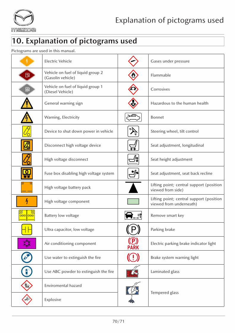
10. Explanation of pictograms usedPictograms are used in this manual.
Electric Vehicle Gases under pressure
Vehicle on fuel of liquid group 2 (Gasolin vehicle)
Flammable
Vehicle on fuel of liquid group 1 (Diesel Vehicle)
Corrosives
General warning sign Hazardous to the human health
Warning, Electricity Bonnet
Device to shut down power in vehicle Steering wheel, tilt control
Disconnect high voltage device Seat adjustment, longitudinal
High voltage disconnect Seat height adjustment
Fuse box disabling high voltage system Seat adjustment, seat back recline
High voltage battery packLifting point; central support (position viewed from side)
High voltage componentLifting point; central support (position viewed from underneath)
Battery low voltage Remove smart key
Ultra capacitor, low voltage Parking brake
Air conditioning component Electric parking brake indicator light
Use water to extinguish the fire Brake system warning light
Use ABC powder to extinguish the fire Laminated glass
Enviromental hazard
Tempered glass
Explosive

MAZDA MOTOR CORPORATION
MAZDA
RETTUNGSHANDBUCHMAZDA MOTOR CORPORATION
RME-C 2021/07