1983 Mazda RX-7 Maintenance Information - RotaryHeads.com
87
This file is available for free download at http://www.iluvmyrx7.com This file is fully text-searchable – select Edit and Find and type in what you’re looking for. This file is intended more for online viewing than printing out so some graphics may not print 100% legibly, you can zoom in on them if you need to. www.iluvmyrx7.com
-
Upload
khangminh22 -
Category
Documents
-
view
8 -
download
0
Transcript of 1983 Mazda RX-7 Maintenance Information - RotaryHeads.com

This file is available for free download at http://www.iluvmyrx7.com
This file is fully text-searchable – select Edit and Find and type in what you’re looking for. This file is intended more for online viewing than printing out so some graphics may not print 100% legibly, you can zoom in on them if you need to.
www.iluvmyrx7.com

1.1L ROTARYArticle Text
1983 Mazda RX7For www.iluvmyrx7.com
Copyright © 1998 Mitchell Repair Information Company, LLCSunday, August 26, 2001 04:57PM
ARTICLE BEGINNING
1983 ENGINES Mazda 1.1L Rotary
RX7
ENGINE CODING
ENGINE IDENTIFICATION
Engine identification number is stamped on front enginehousing behind the distributor.
ENGINE IDENTIFICATION CODES TABLEÄÄÄÄÄÄÄÄÄÄÄÄÄÄÄÄÄÄÄÄÄÄÄÄÄÄÄÄÄÄÄÄÄÄÄÄÄÄÄÄÄÄÄÄÄÄÄÄÄÄÄÄÄÄApplication Engine Code
RX7 1.1L Rotary Engine .............................. 12AÄÄÄÄÄÄÄÄÄÄÄÄÄÄÄÄÄÄÄÄÄÄÄÄÄÄÄÄÄÄÄÄÄÄÄÄÄÄÄÄÄÄÄÄÄÄÄÄÄÄÄÄÄÄ
ENGINE
REMOVAL & INSTALLATION
Removal 1) Remove hood and disconnect battery ground cable. Drainengine oil and coolant. Remove engine under cover. 2) Disconnect following electrical wires: Primary andsecondary ignition wires at coils, pick-up coil wiring connections,condenser lead, oil level sensor lead, temperature sensor and oilthermo sensor (except California vehicles).

1.1L ROTARYArticle Text (p. 2)
1983 Mazda RX7For www.iluvmyrx7.com
Copyright © 1998 Mitchell Repair Information Company, LLCSunday, August 26, 2001 04:57PM
Fig. 1: Exploded View of Rotors & Eccentric Shaft Assembly
3) Remove air cleaner assembly. Disconnect the followingtubes and hoses: Oil hoses at cooler, radiator hoses, automatictransmission cooler lines (if equipped), heater hoses, fuel supply andreturn lines, vacuum and evaporative hoses, and air pipe at rearof intake manifold. 4) Remove cooling fan and drive assembly, radiator, andradiator shroud assembly. Disconnect connector and "B" terminal wirefrom alternator. Disconnect connector from throttle sensor. 5) Without disconnecting refrigerant lines, remove compressorand air conditioning condenser (if equipped) and tie out of the way. 6) Disconnect choke heater connector. Disconnect accelerator,choke and hot start assist cables. Disconnect any remaining wires,tubes or linkages between engine and chassis at top of engine. Removeupper engine-to-transmission bolts. 7) Raise and support vehicle. Remove starter. Remove lowerengine-to-transmission bolts. Remove exhaust pipe front cover. Remove

1.1L ROTARYArticle Text (p. 3)
1983 Mazda RX7For www.iluvmyrx7.com
Copyright © 1998 Mitchell Repair Information Company, LLCSunday, August 26, 2001 04:57PM
nuts and bolts, and disconnect exhaust pipe from exhaust manifold.Support front catalytic converter. 8) Support front of transmission with jack and remove leftand right engine mount nuts. Attach sling to engine and take up slack.Pull engine forward to clear clutch shaft, then lift engine fromvehicle.
Installation To install engine, reverse removal procedure ensuring thatlinkages, tubes and electrical connections are restored inoriginal position. Refill all fluids to specified levels, warm upengine and check for leaks.
DISASSEMBLY
NOTE: To ease engine disassembly, manufacturer recommends use of special engine stand (49 0107 680A) and hanger (49 1114 005).
1) Loosen drive belts and hoses, and remove air pump andalternator. Disconnect metering oil pump connecting rod and hoses atmetering oil pump outlets. Remove exhaust manifold cover. Removeintake manifold and carburetor. Remove gasket and "O" ring. 2) Remove exhaust manifold, engine mount and distributor .Remove, oil filter and cover from front housing. Remove water pump anddrive pulley for air conditioning compressor (if equipped). 3) Turn engine over, and remove oil pan and strainer. Installflywheel brake (49 1881 060) on manual transmission models or stopper(49 1881 055) on automatic transmission models. 4) Remove eccentric shaft pulley. Take off front cover withgasket, and slide distributor gear off shaft. Remove "O" ring from oilpassage. Remove oil pump sprocket nut. See Fig. 2. Slide oil pumpsprocket, eccentric shaft sprocket and drive chain off together.Remove oil pump.
Fig. 2: Oil Pump Drive and Sprocket RemovalPump drive and sprocket must be removed together.
5) Remove balance weight and following parts in order: Thrust

1.1L ROTARYArticle Text (p. 4)
1983 Mazda RX7For www.iluvmyrx7.com
Copyright © 1998 Mitchell Repair Information Company, LLCSunday, August 26, 2001 04:57PM
washer, needle bearing, bearing housing, needle bearing, spacer andthrust plate. 6) On manual transmission models, remove clutch assembly. Usepuller to remove flywheel. On automatic transmission models, removedrive plate. Use puller to remove counterweight. 7) Remove tension bolts on rear housing in sequence. SeeFig. 3. Loosen in 2 or 3 steps. Lift rear housing off shaft. Removeany seals stuck to rotor sliding surface, and place them back inoriginal positions. Remove seals and "O" rings from face of rear rotorhousing.
Fig. 3: Loosening Sequence of Tension BoltsLoosen in 2 or 3 steps.
8) Attach dowel puller (49 0813 215A), and pull tubulardowels off rear rotor housing. See Fig. 4. Hold rotor housing by handto keep it from moving up, and remove rear rotor housing. Use cautionto avoid dropping apex seals and side pieces of rear rotor. Removeseals and "O" ring from front side of rear rotor housing. 9) Remove side pieces, apex seals and springs from rear rotorand store in order for reassembly. Remove all corner seals, cornerseal springs, side seals and side seal springs and store in order forreassembly. Remove rear rotor, and place on clean pad with internalgear side down. 10) Remove seals and springs on remaining side of rotor, andstore in order for reassembly. Place protector on seal inner lip, andremove outer seal with remover (49 0813 225). Remove inner seal.Remove seals and springs and store in order for reassembly. Mark rearrotor for assembly identification. 11) Attach puller, and while holding housing down, pulltubular dowels off intermediate housing. Remove intermediate housing

1.1L ROTARYArticle Text (p. 5)
1983 Mazda RX7For www.iluvmyrx7.com
Copyright © 1998 Mitchell Repair Information Company, LLCSunday, August 26, 2001 04:57PM
by sliding beyond rear rotor journal on eccentric shaft. Carefullylift out eccentric shaft to avoid damage to rotor bearing and mainbearing. Repeat steps 6) through 8) to remove front rotor housing androtor assembly.
Fig. 4: Extracting Tubular Dowels from EngineHold housing down with hand.
INSPECTION & OVERHAUL
Front, Intermediate & Rear Housings 1) Clean housings, using extra fine emery paper to removecarbon deposits from rotor running surface. Use ketone or thinner toremove sealing agent. 2) Place a straightedge across housing surface in positionsshown in Fig. 5. Using a feeler gauge, measure distortion of fronthousing. Replace housing if distortion limit of .0016" (.04 mm) isexceeded.
Fig. 5: Straightedge Positions for Checking Housing DistortionsReplace if warpage exceeds limit.
3) Remove oil pressure control valve and spring from frontcover. Check for damage or corrosion. Replace if defective. Measure

1.1L ROTARYArticle Text (p. 6)
1983 Mazda RX7For www.iluvmyrx7.com
Copyright © 1998 Mitchell Repair Information Company, LLCSunday, August 26, 2001 04:57PM
control valve spring free length. Free length must be 2.74" (69.6 mm).
NOTE: Cap bolt and valve spring for 1983 models are painted yellow. Never use a control valve spring from a 1982 or earlier year in 1983 models.
4) Check for stepped wear on rotor sliding surfaces of the 3housings . Measurements are made using a dial indicator and gaugebody. See Fig. 6.
Fig. 6: Measuring Housing Wear with Dial IndicatorCheck entire circumference of housing.
5) Side seal step wear must be checked on the inside andoutside of oil seal tracing mark. See Fig. 7.
Fig. 7: Checking Side Seal Step WearReplace housing if step wear exceeds limit.
SIDE SEAL STEP WEAR TABLEÄÄÄÄÄÄÄÄÄÄÄÄÄÄÄÄÄÄÄÄÄÄÄÄÄÄÄÄÄÄÄÄÄÄÄÄÄÄÄÄÄÄÄÄÄÄÄÄÄÄÄÄÄÄÄÄÄÄÄÄLocation Limit

1.1L ROTARYArticle Text (p. 7)
1983 Mazda RX7For www.iluvmyrx7.com
Copyright © 1998 Mitchell Repair Information Company, LLCSunday, August 26, 2001 04:57PM
Inside Oil Seal Tracing Mark ............. .0004" (.01 mm)Outside Oil Seal Tracing Mark ............. .004" (.10 mm)ÄÄÄÄÄÄÄÄÄÄÄÄÄÄÄÄÄÄÄÄÄÄÄÄÄÄÄÄÄÄÄÄÄÄÄÄÄÄÄÄÄÄÄÄÄÄÄÄÄÄÄÄÄÄÄÄÄÄÄÄ
6) Check oil seal step wear. Limit is .0008" (.02 mm). SeeFig. 8.
Fig. 8: Oil Seal Step WearStep wear limit is .0008" (.02 mm)
7) Measure inner diameter of main bearing and outer diameterof bearing journal on eccentric shaft. Standard clearance is .0016-.0028" (.04-.07 mm). If clearance exceeds .0039" (.10 mm), replacebearing. 8) To replace front or rear main bearing, remove stationarygear retaining bolts. Using a mandrel (49 0813 235), drive stationarygear with bearing out of housing . 9) Place stationary gear in a press. Use same mandrel andpress main bearing out of stationary gear. 10) Install new bearings while aligning tang bearing with aslot of stationary gear. Press bearing into gear until adapter ofmandrel just contacts stationary gear flange. Install the stationarygear into the housing, aligning the slot of the gear flange with thedowel pin on the housing. See Fig. 9.
NOTE: When installing rear main bearing, check condition of "O" ring and replace if necessary. Apply sealing agent on stationary gear flange prior to installing it on rear housing. Align pin and slot.

1.1L ROTARYArticle Text (p. 8)
1983 Mazda RX7For www.iluvmyrx7.com
Copyright © 1998 Mitchell Repair Information Company, LLCSunday, August 26, 2001 04:57PM
Fig. 9: Stationary Gear Slot & Dowel AlignmentIllustration applies to front and rear housings.
Rotor Housing 1) Inspect rotor housing for signs of water or gas leakage.Check for wear or damage to rotor running surface or stationary gear.Check main bearings for signs of scoring or flaking. 2) To clean housing, wipe off sealing agent or carbon inrotor running surface with a rag and ketone or thinner. Remove rustdeposits in water cooling passages. 3) Inspect for cracks or damage to chromium-plated surface.Check for signs of gas or water leakage. Housing must be replaced ifany of these conditions exist. 4) Place a straightedge across sealing surface of rotorhousing and check for distortion with a feeler gauge. If distortionexceeds .0016" (.04 mm), replace housing. See Fig. 10.
Fig. 10: Measuring Rotor Housing for DistortionReplace if distortion exceeds limit.
5) Check rotor housing thickness at points A, B, C, and D inFig. 11. If micrometer readings vary between point A and minimum valuefor B, C, and D by more than .0024" (.06 mm), replace rotor housing.

1.1L ROTARYArticle Text (p. 9)
1983 Mazda RX7For www.iluvmyrx7.com
Copyright © 1998 Mitchell Repair Information Company, LLCSunday, August 26, 2001 04:57PM
NOTE: This excessive clearance would indicate a possibility of gas or water leakage.
Fig. 11: Rotor Housing Thickness Check PointsCheck thickness at A, B, C & D.
Rotors 1) Inspect rotor for wear or damage, and check internal gearfor chips, cracks or scoring. Measure rotor width at 3 points, andsubtract maximum width from width of rotor housing at point "A" inFig. 11. 2) Clearance between side housing and rotor should be .0047-.0071" (.12-.18 mm). If clearance is excessive or rotor is damaged,replace rotor assembly. 3) If clearance is less than specified, internal gear mayhave come out. Strike internal gear lightly with plastic hammer andremeasure. 4) Measure inner diameter of rotor bearing and outsidediameter of rotor bearing journal on eccentric shaft. Replace rotorbearing if clearance exceeds .0039" (.10 mm) or any damage is shown.See Rotor Bearing Replacement.
Rotor Oil Seal With oil seal installed in rotor, measure contact lip widthof seal. Seal must be replaced if contact width exceeds .020" (0.5mm). Measure seal protrusion, and replace seal spring if protrusion isless than .020" (0.5 mm). See Fig. 12.
Fig. 12: Measuring Point of Oil Seal ProtrusionCheck for free movement of seals in groove.

1.1L ROTARYArticle Text (p. 10)
1983 Mazda RX7For www.iluvmyrx7.com
Copyright © 1998 Mitchell Repair Information Company, LLCSunday, August 26, 2001 04:57PM
Rotor Bearing Replacement 1) Place rotor bearing on support so internal gear is facingdownward. Using rotor bearing replacer (49 0813 240), without adapterring, press bearing out of rotor. 2) Place rotor on support with internal gear facing upward.Place a new rotor bearing so slot in rotor bore is in line withbearing lug. Press new bearing (using tool with adapter) until bearingis flush with rotor boss. See Fig. 13.
Fig. 13: Pressing Rotor Bearing from RotorSlot in rotor bore must be in line with bearing lug.
Apex Seal 1) Clean all carbon from apex seal and spring with a cleaningsolution (not emery paper). Measure height of apex seal with amicrometer. See Fig. 14. Replace seal if height is less than .275" (7.0 mm).
Fig. 14: Measuring Apex Seal HeightClean thoroughly before measuring.
2) Check for warpage by measuring the clearance between thetop surfaces of 2 apex seals with a feeler gauge. Replace all 3 sealsif clearance exceeds .0024" (.06 mm). See Fig. 15.

1.1L ROTARYArticle Text (p. 11)
1983 Mazda RX7For www.iluvmyrx7.com
Copyright © 1998 Mitchell Repair Information Company, LLCSunday, August 26, 2001 04:57PM
Fig. 15: Apex Seal WarpageReplace if the clearance exceeds limits.
3) Using a feeler gauge, check gap between apex seal andgroove in rotor. Feeler gauge should be inserted until tip of feelergauge reaches bottom of groove. 4) Standard clearance is .0020-.0035" (.05-.09 mm). Replaceapex seal if gap exceeds .0059" (.15 mm). Check seal spring height asshown in Fig. 16. Replace spring if free height is less than .2165"(5.5 mm).
Fig. 16: Measuring Free Height of Apex Seal SpringHeight must be more than .2165" (5.5 mm).
Side Seal 1) Remove all carbon from side seal and spring. Check sideseal protrusion from rotor surface, and confirm free movement bypressing with finger. Protrusion should be more than .02" (.5 mm). 2) Check gap between side seal and groove with a feelergauge. Standard gap is .0012-.0031" (.03-.08 mm). If wear limit of .004" (.10 mm) is measured, replace side seal. 3) Check gap between side seal and corner seal with sealsinstalled on rotor. Insert feeler gauge between end of side seal(against rotating direction of rotor) and the corner seal. If gapexceeds .016" (.4 mm), replace side seal. 4) When side seal is replaced, adjust gap between side sealand corner seal by grinding one end of side seal along round shape ofcorner seal, using a fine file. Adjust gap .002-.006" (.05-.15 mm).
Corner Seal 1) Clean carbon from corner seal. Check corner sealprotrusion from rotor surface, and check free movement by pressingwith finger. Protrusion should be more than .02" (.5 mm). 2) Extent of corner seal groove wear is determined by using

1.1L ROTARYArticle Text (p. 12)
1983 Mazda RX7For www.iluvmyrx7.com
Copyright © 1998 Mitchell Repair Information Company, LLCSunday, August 26, 2001 04:57PM
special Bar Limit Gauge (49 0839 165) shown in Fig. 17, and isclassified according to the following.
Fig. 17: Checking Corner Seal Groove MeasurementReplace rotor if both ends of gauge fit in gap.
3) If neither end of gauge goes into groove, it indicatesthat gap conforms to specifications. If "Go" end of gauge goes intogroove, it indicates that gap is more than standard, but less thanwear limit. In this case replace corner seal. See Fig. 18.
Fig. 18: Measuring Clearance of Apex, Side & Corner Seals
4) If both ends of gauge (both the "Go" and "No Go" ends) fitin groove, it indicates that gap exceeds wear limit. Replace rotor.
Eccentric Shaft 1) Thoroughly clean eccentric shaft in a cleaning solutionand blow out oil passages with compressed air. Inspect shaft forscratching or scoring of bearing journals and possible blocked oilpassages. 2) Check rotor bearing clearance by measuring inner diameterof the rotor bearing and outer diameter of the eccentric shaft rotorjournal. Clearance should be .0016-.0031" (.04-.08 mm). 3) Replace the bearing if clearance exceeds .0039" (.10 mm).Replace eccentric shaft if journal diameters are under specifiedlimits. 4) Place eccentric shaft in 2 "V" blocks. Mount a dialindicator and check runout of both ends by rotating shaft slowly. If

1.1L ROTARYArticle Text (p. 13)
1983 Mazda RX7For www.iluvmyrx7.com
Copyright © 1998 Mitchell Repair Information Company, LLCSunday, August 26, 2001 04:57PM
runout exceeds .0024" (.06 mm), replace shaft. 5) Oil passages in eccentric shaft are sealed by a blind plugin rear of shaft. Inspect plug for possible oil leakage. If leakage isdetected, remove plug with an Allen wrench, and install new "O" ring.Tighten plug. 6) Inspect needle bearings in end of shaft for wear ordamage. Check for spring weakness, stuck, or damaged steel ball at theoil jets. Inspect front needle bearing, bearing housing, and thrustplate for wear or damage. Inspect front and rear oil seals for leaks,replace as necessary.
REASSEMBLY
Oil Seals 1) Place the rotor on rubber pad or cloth. Install oil sealsprings in their respective grooves on rotors, with each edge ofspring fitted in stopper hole. 2) Ensure oil seal springs have been painted in cream or bluecolor: Cream colored springs must be placed on front edge faces ofrotors and blue springs on rear faces of rotors. When installing,painted side of spring must face oil seal (upward). See Fig. 19.
Fig. 19: Installing Oil Seal Spring on RotorPainted side of spring must face oil seal.
3) Insert new "O" ring in each oil seal. Install inner oilseal to each side of rotor as follows: Position oil seal to groove sosquare edge of spring fits in stopper notch of oil seal. Press into

1.1L ROTARYArticle Text (p. 14)
1983 Mazda RX7For www.iluvmyrx7.com
Copyright © 1998 Mitchell Repair Information Company, LLCSunday, August 26, 2001 04:57PM
position by using a used inner oil seal so lip of inner oil seal sinksinto position approximately .016" (.4 mm) below surface of rotor. 4) Install outer oil seal so square edge of spring fits instopper notch of oil seal. Slowly push oil seal in position withfingers. Confirm smooth movement of each oil seal by pressing oilseal. 5) Check oil seal protrusion. Install oil seal springs andoil seals on the other side of rotor. Take care not to deform lip ofoil seal.
Apex, Corner & Side Seals 1) Before installing apex seal, cut the assist piece to alength of .08-.011" (2.0-2.8 mm). Peel off paper and install assistpiece of apex seal. See Fig. 20. 2) Position apex seals without springs and side pieces intotheir respective grooves so that each side piece rests on rear side ofeach rotor. Install the soft seal into the corner seal.
Fig. 20: Installing Assist Piece on Apex SealCheck each seal for smooth movement.
3) Place corner seals and springs into their respectivegrooves, then position side seals and springs into proper grooves.Ensure smooth movement of each seal by pressing its head.
Installing Front Rotor Mount front housing on engine stand and place front rotorassembly on housing. Use care not to drop seal into port. Meshinternal and stationary gears so that one rotor apex is set to one of4 positions shown in Fig. 21.

1.1L ROTARYArticle Text (p. 15)
1983 Mazda RX7For www.iluvmyrx7.com
Copyright © 1998 Mitchell Repair Information Company, LLCSunday, August 26, 2001 04:57PM
Fig. 21: Positioning Rotor Apex for ReassemblyUse care not to drop seal into port.
Installing Eccentric Shaft Lubricate front rotor journal and main journal on shaft withengine lubricant. Being careful not to damage rotor and main bearings,insert eccentric shaft.
Installing Front Rotor Housing 1) As front and rear rotor housings are not interchangeable,be sure they are installed in correct sequence. Apply sealing agent tofront side of rotor housing. See Fig. 22.
Fig. 22: Applying Sealing Agent to Rotor Assembly
2) To provide greater durability to sealing rubbers, installa protector behind each inner sealing rubber. See Fig. 23. Install anew "O" ring, sealing rubbers and protector in front side of enginehousing. Apply light coat of petroleum jelly to hold seals in place.

1.1L ROTARYArticle Text (p. 16)
1983 Mazda RX7For www.iluvmyrx7.com
Copyright © 1998 Mitchell Repair Information Company, LLCSunday, August 26, 2001 04:57PM
Fig. 23: Installing Protectors for Inner Sealing RubbersApply light coat of petroleum jelly to hold seals in place.
NOTE: Inner sealing rubber is square type. The wider white line of sealing rubber should face toward combustion chamber and seam of rubber should be placed as shown in Fig. 24. Do not stretch sealing rubbers.
3) Invert front rotor housing using care that seals remain inposition, and install on front housing. Lubricate tubular dowels andinsert through front rotor housing holes.
Fig. 24: Positioning Inner Sealing RubberWider white line of sealing rubber should face toward combustionchamber.

1.1L ROTARYArticle Text (p. 17)
1983 Mazda RX7For www.iluvmyrx7.com
Copyright © 1998 Mitchell Repair Information Company, LLCSunday, August 26, 2001 04:57PM
4) Insert apex seal springs so that both ends of spring maysupport the back side of the apex seal. Install the soft seal intocorner seal. Install corner seal springs and seals into theirrespective grooves. Fit side pieces to original positions andlubricate with engine oil. 5) Confirm that spring is set correctly on side piece. SeeFig. 25. Confirm smooth movement of each seal by pressing on head. 6) Apply sealing agent on the rear side of front housing inareas shown in Fig. 22 and then place new "O" ring, sealing rubbersand protector on rear side of front housing. Apply engine oil tosliding surfaces of front rotor housing.
Fig. 25: Positioning of Apex Seal and SpringCheck side piece for correct installation.
Installing Intermediate Housing 1) Turn front housing and rotor assembly so that top ofhousing is upward. Pull eccentric shaft outward approximately 1.0" (25mm), but not more than 1.5" (38 mm). 2) Rotate eccentric shaft until eccentric portion points to 2o'clock position. Install intermediate housing over eccentric shaftand turn engine so that rear of engine is upward.
Installing Rear Rotor & Housing Use same procedures up to Intermediate Housing wheninstalling rear rotor and rotor housing.
Installing Rear Housing Position engine with rear end upward. Apply sufficientlubricant onto stationary gear and main bearing. Install rear housingonto rear rotor housing, and turn rear rotor slightly to engage rearhousing stationary gear with rear rotor internal gear.
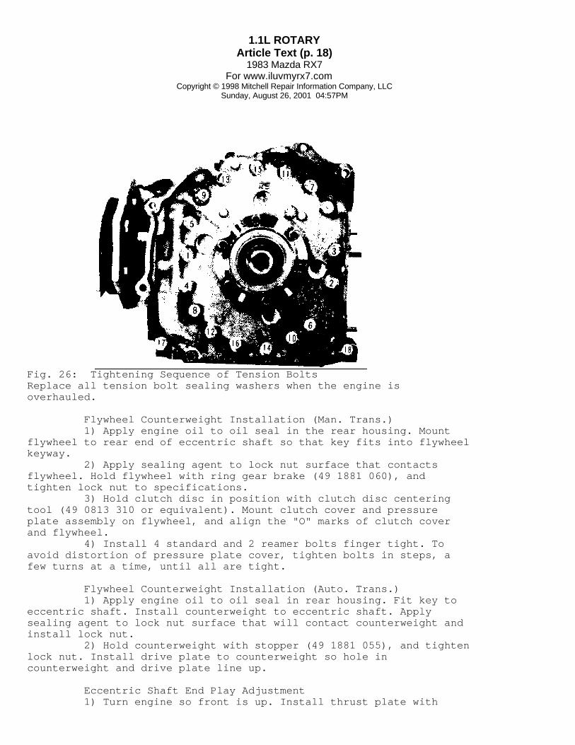
Tightening Tension Bolts Place a new sealing washer on each tension bolt and oilthreads of each bolt. Tighten bolts, in sequence shown in Fig. 26, instages until final torque is reached. After tightening, turn eccentricshaft to make sure rotation is light and smooth.
1.1L ROTARYArticle Text (p. 18)
1983 Mazda RX7For www.iluvmyrx7.com
Copyright © 1998 Mitchell Repair Information Company, LLCSunday, August 26, 2001 04:57PM
Fig. 26: Tightening Sequence of Tension BoltsReplace all tension bolt sealing washers when the engine isoverhauled.
Flywheel Counterweight Installation (Man. Trans.) 1) Apply engine oil to oil seal in the rear housing. Mountflywheel to rear end of eccentric shaft so that key fits into flywheelkeyway. 2) Apply sealing agent to lock nut surface that contactsflywheel. Hold flywheel with ring gear brake (49 1881 060), andtighten lock nut to specifications. 3) Hold clutch disc in position with clutch disc centeringtool (49 0813 310 or equivalent). Mount clutch cover and pressureplate assembly on flywheel, and align the "O" marks of clutch coverand flywheel. 4) Install 4 standard and 2 reamer bolts finger tight. Toavoid distortion of pressure plate cover, tighten bolts in steps, afew turns at a time, until all are tight.
Flywheel Counterweight Installation (Auto. Trans.) 1) Apply engine oil to oil seal in rear housing. Fit key toeccentric shaft. Install counterweight to eccentric shaft. Applysealing agent to lock nut surface that will contact counterweight andinstall lock nut. 2) Hold counterweight with stopper (49 1881 055), and tightenlock nut. Install drive plate to counterweight so hole incounterweight and drive plate line up.
Eccentric Shaft End Play Adjustment 1) Turn engine so front is up. Install thrust plate with

1.1L ROTARYArticle Text (p. 19)
1983 Mazda RX7For www.iluvmyrx7.com
Copyright © 1998 Mitchell Repair Information Company, LLCSunday, August 26, 2001 04:57PM
chamfer downward. Slide spacer and needle bearing on eccentric shaft.Lubricate shaft and bearings, and install bearing housing.
NOTE: If bearing housing has not been removed, use care that center of needle bearing in bearing housing comes to center of eccentric shaft and that spacer is seated to thrust plate.
2) Lubricate and install needle bearing, thrust washer, andbalance weight on shaft. Install keys in oil pump and eccentric shaftkeyways. Place oil pump drive chain on oil pump sprocket and eccentricshaft sprocket. Install sprockets on shafts. 3) Align the keyways of eccentric shaft sprocket and balanceweight. Install key. Install distributor drive gear, with "F" mark ongear facing front of engine. Install eccentric shaft pulley on shaft.Use new washer, and tighten pulley bolt to specification. 4) Turn engine so top is upward. Attach a dial indicator onthe flywheel or counterweight so it contacts rear housing. Moveflywheel or counterweight back and forth. 5) Standard end play is .0016-.0028" (.04-.07 mm). If endplay is more than .0035" (.09 mm) grind spacer on surface plate withemery paper or install thinner spacer. If end play is less than .0016"(.04 mm), install thicker spacer. 6) Oversize spacers are available in 5 sizes from .3181" to .3150" (8.08 mm to 8.00 mm) and are identified by stamped letter "X","K", "Y", "V", and "Z" respectively. When spacer has been installed,recheck end play.
Fig. 27: Measuring Eccentric Shaft End PlayStandard end play is .0016-.0028" (.04-.07mm).

1.1L ROTARYArticle Text (p. 20)
1983 Mazda RX7For www.iluvmyrx7.com
Copyright © 1998 Mitchell Repair Information Company, LLCSunday, August 26, 2001 04:57PM
NOTE: If end play is below specified amount, spacer thickness is too small. If end play is beyond specifications, spacer is too thick.
Installing Front Cover & Eccentric Shaft Pulley 1) Turn engine so front is upward. Remove eccentric shaftpulley. Tighten oil pump sprocket nut and bend tab of lock washer. 2) Check oil pump drive chain slack by pressing fingeragainst chain. See Fig. 29 Chain slack measurement should not exceed .47" (12 mm). If the slack exceeds the limit, replace drive chain. 3) Install new "O" ring on front housing oil passage. Installfront cover and gasket on front housing. Lubricate oil seal in frontcover. Install eccentric shaft pulley on shaft. Use new washer andtighten pulley bolt.
Installing Oil Strainer & Oil Pan 1) Invert engine so that bottom of engine is up. Install oilstrainer gasket and strainer on front housing. Cut off excess gasketalong mounting surface of oil pan. 2) Apply a .16-.24" (4-6 mm) bead of sealer on mountingsurface of oil pan (to the inside of pan bolt holes) and installgasket. Apply a similar bead of sealant to gasket. Install pan andtighten bolts.
Installing Water Pump Turn engine upright, position gasket and water pump on fronthousing and tighten attaching bolts.
NOTE: For further information on cooling system components, see Cooling System in this article.
Installing Distributor 1) Rotate eccentric shaft until yellow mark (leading timingmark) on pulley aligns with indicator pin on front cover. Align notchon distributor housing with punch mark on driven gear. 2) Insert distributor and lock nut. Turn distributor housinguntil a trigger wheel blade aligns with pick-up coil. Tighten locknut.
Installing External Components 1) Install exhaust manifold, engine mount, intake manifoldwith carburetor, and alternator and drive belt. Check clearancebetween alternator support and bracket. Limit is .0059" (.15 mm).Adjust with shim if necessary. 2) Install air pump and drive belt. oil filter assembly andall other external components. Before removing engine from stand,install engine hanger bracket to front cover.
ENGINE OILING
CRANKCASE CAPACITY

1.1L ROTARYArticle Text (p. 21)
1983 Mazda RX7For www.iluvmyrx7.com
Copyright © 1998 Mitchell Repair Information Company, LLCSunday, August 26, 2001 04:57PM
The crankcase capacity is 4.9 quarts (4.6L), includingfilter.
OIL FILTER
A full-flow, disposable cartridge-type filter is mounted onthe rear housing.
NORMAL OIL PRESSURE
Normal oil pressure is 10-26 psi (.7-1.8 kg/cmý) at idlespeed, 64-78 psi (4.5-5.5 kg/cmý) at 3000 RPM.
ENGINE OILING SYSTEM
Engine oiling system is forced circulation using a 2 rotortype oil pump. Oil pump is mounted on front housing and is chaindriven through eccentric shaft. The oil pressure is maintained througha regulator valve and pressure control valve. A full flow oil filterand oil cooler are mounted on the rear housing. Oil is directed from the oil pump to the oil pressure controlvalve in the front cover. The oil then flows to the oil filter/coolerassembly on the rear cover which directs lubricating oil to allinternal parts. The pressure regulator valve in the rear cover acts asa secondary pressure regulation device. The oil pressure control valve is designed to open at 114 psi(8 kg/cmý). The free length of the control valve spring should be 2.74" (69.6 mm). Never use an oil pressure control spring from aprevious year in a 1983 model. The cap bolt and spring are paintedyellow in 1983. The oil pressure regulator valve will relieve pressureat 71.1 psi (4.9 kg/cmý). Its spring free length should be 1.83" (46.4mm). The engine is equipped with a metering oil pump whichregulates the amount of oil pumped to the float chamber of thecarburetor. The oil enters the combustion chamber with the air/fuelmixture to lubricate the seals within the chamber. The amount of oilincreases as engine RPM increases. The metering pump control lever isactuated by a rod connected to the throttle lever.

1.1L ROTARYArticle Text (p. 22)
1983 Mazda RX7For www.iluvmyrx7.com
Copyright © 1998 Mitchell Repair Information Company, LLCSunday, August 26, 2001 04:57PM
Fig. 28: Mazda RX7 Engine Oiling System
OIL PUMP
NOTE: Oil pump is mounted on the front engine housing and must be overhauled with front engine cover removed.
1) Remove front engine cover. Check oil pump drive chainslack by pressing finger against chain and measuring slack. Ifmeasurement exceeds .47" (12 mm), replace drive chain. See Fig. 29.
Fig. 29: Measuring Oil Pump Drive Chain SlackReplace chain if slack exceeds limit.
2) Disassemble oil pump in following order: Remove snap ring,rear outer rotor, rear inner rotor, key, and middle plate. Removefront inner rotor, key shaft, spring pin, and front outer rotor. SeeFig. 30.

1.1L ROTARYArticle Text (p. 23)
1983 Mazda RX7For www.iluvmyrx7.com
Copyright © 1998 Mitchell Repair Information Company, LLCSunday, August 26, 2001 04:57PM
Fig. 30: Exploded View of Oil Pump Assembly
3) Insert a feeler gauge between lobes of inner and outerrotors and check clearance. If beyond .006" (.15 mm), replace bothrotors. 4) Check clearance between outer rotor and pump housing witha feeler gauge. If clearance exceeds .012" (.30 mm), replace rotorsand housing. 5) Place straightedge across pump mounting surface, and checkrotor end play with a feeler gauge. If beyond .006" (.15 mm), replacepump body or rotors. 6) To assembly oil pump, reverse disassembly procedure.Install oil pump and tighten bolts. Install sprockets and chain aspreviously outlined. See Eccentric Shaft End Play Adjustment.
METERING OIL PUMP
1) Check clearance between metering pump lever and washer.See Fig. 31. Clearance must be no more than .04" (1.0 mm).
Fig. 31: Adjusting Metering Pump Control RodAdjust clearance by changing washers.
2) To check oil discharge, detach connecting rod. Disconnectoil lines at carburetor. Start engine and adjust idle to 2000 RPM.Once oil flow from hoses becomes steady, measure volume discharged.Pump should discharge .07-.08 oz. (2.0-2.4 cc) in 6 minutes.
CAUTION: Carburetor will not be receiving oil during test. Add small amount of clean oil to carburetor to provide proper lubrication during testing.

1.1L ROTARYArticle Text (p. 24)
1983 Mazda RX7For www.iluvmyrx7.com
Copyright © 1998 Mitchell Repair Information Company, LLCSunday, August 26, 2001 04:57PM
3) To adjust oil metering pump, turn the adjusting screwclockwise to increase flow or counterclockwise to decrease flow. Onecompleter turn will change oil discharge flow by .007-.011" oz. (.2-.3cc) for 6 minutes of operation. 4) Ensure lock nut on adjustment screw is tight. Recheckmetering oil pump discharge rate.
OIL COOLER
Inspection Check the oil cooler for damage, cracks, or leaks. Replacethe oil cooler if defective.
Removal & Installation 1) Remove water hoses installed on the inlet and outlet sidesof cooler. Remove oil pipe and sealing washer. Remove oil cooler andfilter housing as an assembly. 2) Remove "O" rings. Do not disassemble. Replace as anassembly if necessary. To install, reverse removal procedure. Use newfilter, "O" rings, and sealing washer. Add engine oil and coolant.Start engine and check for leaks.
ENGINE COOLING
THERMOSTAT
Thermostat is a wax pellet type which starts to open at 180øF(82øC) and fully opens at 203øF (95øC).
PRESSURE CAP
The radiator pressure cap is rated at 13 psi (.9 kg/cmý).
WATER PUMP
Removal 1) Drain cooling system. Remove air cleaner, watertemperature switch connector, air conditioner drive belt, and air pumpdrive belt. 2) Remove alternator, cooling fan, and drive belts. Removeair conditioning pulley (if equipped). Disconnect radiator hoses andremove water pump.
Disassembly 1) Press the pulley boss off of the pump shaft. Remove thesnap ring. 2) Supporting the pump body, apply pressure to the rear endof the shaft to press the shaft, spacer, and bearing assembly outthrough the front of the pump body. See Fig. 32. 3) Remove impeller and seal assembly from the pump body.Press bearings and spacer from the shaft.

1.1L ROTARYArticle Text (p. 25)
1983 Mazda RX7For www.iluvmyrx7.com
Copyright © 1998 Mitchell Repair Information Company, LLCSunday, August 26, 2001 04:57PM
Fig. 32: Exploded View of Water Pump
Reassembly 1) Install stop ring and dust seal on the shaft. Drive baffleplate onto the taper of the shaft. 2) Press the rear bearing onto the shaft with sealed siderearward until it contacts the stop ring. Press shaft and bearingassembly into the pump body. 3) Place spacer on the shaft fill with grease. Install frontbearing (sealed side forward) until the snap ring can be installed.Press pulley boss onto pump shaft. 4) Install the seal assembly into the body. Press impelleronto the shaft until it is flush with the end of the shaft.
Installation To install, reverse removal procedure. Adjust drive belttension and refill cooling system.
TORQUE SPECIFICATIONS
TORQUE SPECIFICATIONS TABLEÄÄÄÄÄÄÄÄÄÄÄÄÄÄÄÄÄÄÄÄÄÄÄÄÄÄÄÄÄÄÄÄÄÄÄÄÄÄÄÄÄÄÄÄÄÄÄÄÄÄÄÄÄÄÄÄÄÄÄÄApplication Ft. Lbs. (N.m)
Eccentric Shaft Pulley .................... 72-87 (98-118)Flywheel Lock Nut ...................... 289-362 (393-492)Intake Manifold ............................ 14-19 (19-26)Oil Pump Sprocket .......................... 23-34 (32-47)Pressure Plate ............................. 13-20 (18-27)Water Pump ................................. 13-20 (18-27)ÄÄÄÄÄÄÄÄÄÄÄÄÄÄÄÄÄÄÄÄÄÄÄÄÄÄÄÄÄÄÄÄÄÄÄÄÄÄÄÄÄÄÄÄÄÄÄÄÄÄÄÄÄÄÄÄÄÄÄÄ
ENGINE SPECIFICATIONS
GENERAL SPECIFICATIONS
GENERAL SPECIFICATIONS TABLEÄÄÄÄÄÄÄÄÄÄÄÄÄÄÄÄÄÄÄÄÄÄÄÄÄÄÄÄÄÄÄÄÄÄÄÄÄÄÄÄÄÄÄÄÄÄÄÄÄÄÄÄÄÄÄÄÄÄÄÄDisplacement

1.1L ROTARYArticle Text (p. 26)
1983 Mazda RX7For www.iluvmyrx7.com
Copyright © 1998 Mitchell Repair Information Company, LLCSunday, August 26, 2001 04:57PM
Cu. In. ............................................. 70 Liters ............................................. 1.1Fuel System ....................................... 4 Bbl.HP @ RPM ............................................. ...Torque Ft. @ RPM ..................................... ...Compr. Ratio ....................................... 9.4:1Rotor Housing Width In. (mm) ................................... 2.7559 (70)ÄÄÄÄÄÄÄÄÄÄÄÄÄÄÄÄÄÄÄÄÄÄÄÄÄÄÄÄÄÄÄÄÄÄÄÄÄÄÄÄÄÄÄÄÄÄÄÄÄÄÄÄÄÄÄÄÄÄÄÄ
ROTOR SPECIFICATIONS
ROTOR HOUSING, INTERMEDIATE HOUSING & ROTOR SPECIFICATIONSTABLEÄÄÄÄÄÄÄÄÄÄÄÄÄÄÄÄÄÄÄÄÄÄÄÄÄÄÄÄÄÄÄÄÄÄÄÄÄÄÄÄÄÄÄÄÄÄÄÄÄÄÄÄÄÄÄÄÄÄÄÄFront Rotor Housing Width In. (mm) ............................. 2.7559 (70) Distortion Limit In. (mm) .................. .0016 (.04) Front, Intermediate & Rear Housing Width In. (mm) .............................. 1.576 (40) Distortion Limit In. (mm) .................. .0016 (.40) Rotor Width In (mm) ............................. 2.748 (69.8) Housing-to-Rotor Protrusion ...... .0047-.0074 (.12-.19) Land Protrusion In. (mm) ........................... ...Center Front, Intermediate & Rear Housing Width In. (mm) .............................. 1.969 (50) Distortion Limit In. (mm) .................. .0016 (.40)Rear Rotor Housing Width In. (mm) ............................. 2.7559 (70) Distortion Limit In. (mm) .................. .0016 (.04) Front, Intermediate & Rear Housing Width In. (mm) .............................. 2.362 (60) Distortion Limit In. (mm) .................. .0016 (.40) Rotor Width In (mm) ............................. 2.748 (69.8) Housing-to-Rotor Protrusion ...... .0047-.0074 (.12-.19) Land Protrusion In. (mm) ........................... ...ÄÄÄÄÄÄÄÄÄÄÄÄÄÄÄÄÄÄÄÄÄÄÄÄÄÄÄÄÄÄÄÄÄÄÄÄÄÄÄÄÄÄÄÄÄÄÄÄÄÄÄÄÄÄÄÄÄÄÄÄ
APEX SEAL SPECIFICATIONS
APEX SEAL SPECIFICATIONS TABLEÄÄÄÄÄÄÄÄÄÄÄÄÄÄÄÄÄÄÄÄÄÄÄÄÄÄÄÄÄÄÄÄÄÄÄÄÄÄÄÄÄÄÄÄÄÄÄÄÄÄÄÄÄÄÄÄÄÄÄÄ Length In. (mm) ............................ 2.748 (69.8) Seal Width In. (mm) ......................... .1181 (3.0) Height In. (mm) ............................. .3347 (8.5)Seal-To-Housing Clearance ........................................... ...

1.1L ROTARYArticle Text (p. 27)
1983 Mazda RX7For www.iluvmyrx7.com
Copyright © 1998 Mitchell Repair Information Company, LLCSunday, August 26, 2001 04:57PM
Wear Limit .......................................... ...Seal-To-Rotor Groove Clearance .................. .0020-.0035 (.05-.09) Wear Limit .................................. .0059 (.15)ÄÄÄÄÄÄÄÄÄÄÄÄÄÄÄÄÄÄÄÄÄÄÄÄÄÄÄÄÄÄÄÄÄÄÄÄÄÄÄÄÄÄÄÄÄÄÄÄÄÄÄÄÄÄÄÄÄÄÄÄ
SIDE SEAL SPECIFICATIONS
SIDE SEAL SPECIFICATIONS TABLEÄÄÄÄÄÄÄÄÄÄÄÄÄÄÄÄÄÄÄÄÄÄÄÄÄÄÄÄÄÄÄÄÄÄÄÄÄÄÄÄÄÄÄÄÄÄÄÄÄÄÄÄÄÄÄÄÄÄÄÄ Thickness In. (mm) ......................... .4331 (11.0) Width In. (mm) .............................. .2756 (7.0)Seal-To-Groove Clearance In. (mm) .................................. ... Limit In (mm) ....................................... ...Side Seal-To-Corner Seal Clearance In. (mm) ................ .0020-.0059 (.05-.15) Limit In. (mm) .............................. .0157 (.40)ÄÄÄÄÄÄÄÄÄÄÄÄÄÄÄÄÄÄÄÄÄÄÄÄÄÄÄÄÄÄÄÄÄÄÄÄÄÄÄÄÄÄÄÄÄÄÄÄÄÄÄÄÄÄÄÄÄÄÄÄ
SHAFT & ROTOR BEARING SPECIFICATIONS
ECCENTRIC SHAFT MAIN & ROTOR BEARINGS SPECIFICATIONS TABLEÄÄÄÄÄÄÄÄÄÄÄÄÄÄÄÄÄÄÄÄÄÄÄÄÄÄÄÄÄÄÄÄÄÄÄÄÄÄÄÄÄÄÄÄÄÄÄÄÄÄÄÄÄÄÄÄÄÄÄÄMain Bearings Journal Diameter In. (mm) ................... 1.6929 (43) Clearance In. (mm) ................ .0016-.0031 (.04-.08) Eccentric Shaft End Play In. (mm) . .0016-.0028 (.04-.07)Rotor Bearings Journal Diameter In. (mm) ................... 2.9134 (74) Clearance ......................... .0016-.0031 (.04-.08)ÄÄÄÄÄÄÄÄÄÄÄÄÄÄÄÄÄÄÄÄÄÄÄÄÄÄÄÄÄÄÄÄÄÄÄÄÄÄÄÄÄÄÄÄÄÄÄÄÄÄÄÄÄÄÄÄÄÄÄÄ
CORNER SEAL SPECIFICATIONS
CORNER SEAL SPECIFICATIONS TABLEÄÄÄÄÄÄÄÄÄÄÄÄÄÄÄÄÄÄÄÄÄÄÄÄÄÄÄÄÄÄÄÄÄÄÄÄÄÄÄÄÄÄÄÄÄÄÄÄÄÄÄÄÄÄÄÄÄÄÄÄ Diameter In. (mm) .......................... .4331 (11.0) Height In. (mm) ............................. .2756 (7.0)Seal-To-Groove Clearance In. (mm) .................................. ... Limit In. (mm) ...................................... ...Side Seal-To-Corner Seal Clearance In. (mm) ................ .0020-.0059 (.05-.15) Limit In. (mm) .............................. .0157 (.40)ÄÄÄÄÄÄÄÄÄÄÄÄÄÄÄÄÄÄÄÄÄÄÄÄÄÄÄÄÄÄÄÄÄÄÄÄÄÄÄÄÄÄÄÄÄÄÄÄÄÄÄÄÄÄÄÄÄÄÄÄ
OIL SEAL SPECIFICATIONS
OIL SEAL SPECIFICATIONS TABLEÄÄÄÄÄÄÄÄÄÄÄÄÄÄÄÄÄÄÄÄÄÄÄÄÄÄÄÄÄÄÄÄÄÄÄÄÄÄÄÄÄÄÄÄÄÄÄÄÄÄÄÄÄÄÄÄÄÄÄÄ Height In. (mm) ............................. .2205 (5.6)

1.1L ROTARYArticle Text (p. 28)
1983 Mazda RX7For www.iluvmyrx7.com
Copyright © 1998 Mitchell Repair Information Company, LLCSunday, August 26, 2001 04:57PM
Seal Lip Contact Width Standard In. (mm) .......... Less than .02 (Less than .5) Limit In. (mm) ...................................... ...ÄÄÄÄÄÄÄÄÄÄÄÄÄÄÄÄÄÄÄÄÄÄÄÄÄÄÄÄÄÄÄÄÄÄÄÄÄÄÄÄÄÄÄÄÄÄÄÄÄÄÄÄÄÄÄÄÄÄÄÄ
PORT TIMING SPECIFICATIONS
PORT TIMING SPECIFICATION TABLESÄÄÄÄÄÄÄÄÄÄÄÄÄÄÄÄÄÄÄÄÄÄÄÄÄÄÄÄÄÄÄÄÄÄÄÄÄÄÄÄÄÄÄÄÄÄÄÄÄÄÄÄÄÄÄÄÄÄÄÄIntake Open (ATDC) ......................................... 32ø Close (ABDC) ........................................ 40øExhaust Open (BBDC) ......................................... 75ø Close (ATDC) ........................................ 38øÄÄÄÄÄÄÄÄÄÄÄÄÄÄÄÄÄÄÄÄÄÄÄÄÄÄÄÄÄÄÄÄÄÄÄÄÄÄÄÄÄÄÄÄÄÄÄÄÄÄÄÄÄÄÄÄÄÄÄÄ
END OF ARTICLE

A - ENGINE/VIN IDArticle Text
1983 Mazda RX7For www.iluvmyrx7.com
Copyright © 1998 Mitchell Repair Information Company, LLCSunday, August 26, 2001 05:51PM
ARTICLE BEGINNING
1983-88 ENGINE PERFORMANCE Mazda VIN Code Identification
RX7
MODEL IDENTIFICATION
Fig. 1: VIN Code Identification
VIN CODE ID EXPLANATION
Numbers preceding the explanations in the legend below referto the sequence of characters as listed on VIN identification label inFig. 1. The legend listed below will also be found in Fig. 1.
1 Manufacturing Country J * Japan
2 Make M * Mazda Motors Corp., Japan
3 Type 1 * Passenger Car V * Passenger Car
4-5 Model FB * RX7 1983-85 FB * RX7 1986-88
6-7 Body Style 33 * HB RX7

A - ENGINE/VIN IDArticle Text (p. 2)
1983 Mazda RX7For www.iluvmyrx7.com
Copyright © 1998 Mitchell Repair Information Company, LLCSunday, August 26, 2001 05:51PM
35 * Convertible
8 Modification Code 1 * Not Specified By Manufacturer
9 VIN Check Digit 1 * Constant For All Models
10 Vehicle Model Year D * 1983 E * 1984 F * 1985 G * 1986 H * 1987 J * 1988
11 Assembly Plant 0 * Hiroshima, Japan
12-17 Serial Number * Sequential Production Number
END OF ARTICLE

AIR INJECTION SYSTEMArticle Text
1983 Mazda RX7For www.iluvmyrx7.com
Copyright © 1998 Mitchell Repair Information Company, LLCSunday, August 26, 2001 04:57PM
ARTICLE BEGINNING
1983 Exhaust Emission Systems MAZDA RX7 ENGINE AIR INJECTION SYSTEM
DESCRIPTION
This system controls CO, HC and NOx emissions by injectingsecondary air into the exhaust system to cause further burning ofexhaust gases. System consists of an air pump, 2 check valves, an aircontrol valve, relief solenoid valve, switching solenoid valve, heathazard sensor, monolith converter and pellet converter. Air is drawn from the clean side of the air cleaner by theair pump and directed to the air control valve under pressure. Fromthe air control valve, secondary air is directed (by the switchingsolenoid valve) "downstream" to the pellet converter or "upstream" tothe exhaust port. The secondary air system contains 2 check valves to preventexhaust gas from leaking back into the air pump. The switchingsolenoid valve directs secondary air through the air control valve"downstream" and/or "upstream", based upon engine temperature,manifold vacuum and engine speed. The relief solenoid valve controls the amount of airinjected according to intake manifold vacuum. Under normal operatingconditions, part of the secondary air supplied by the air pump isdirected back to the air cleaner. The heat hazard sensor lights anexhaust temperature warning light on the instrument panel if exhausttemperatures become excessive.
Fig. 1: Mazda RX7 Air Injection System
TESTING
Note: Before replacing air control valve, switching solenoid valve or relief solenoid valve, check auxiliary control unit, No. 2 water temperature switch, choke switch and choke relay as described in "Mazda RX7 Auxiliary Control Device" article in this section. Also, check throttle

AIR INJECTION SYSTEMArticle Text (p. 2)
1983 Mazda RX7For www.iluvmyrx7.com
Copyright © 1998 Mitchell Repair Information Company, LLCSunday, August 26, 2001 04:57PM
sensor as described in "Mazda RX7 Deceleration Control System" article in this section.
AIR PUMP TEST
1) With engine at normal operating temperature, inspect allhose connections for leaks. Check for pump noise and belt tension. 2) Stop engine and disconnect air line at air control valve.Connect hose to a pressure gauge. Connect tachometer to engine. 3) Start engine and run at idle speed. Gauge should registermore than 1.64 psi (.12 kg/cmý) with engine at 800 RPM. If pumppressure is below specification, replace air pump.
CHECK VALVES TEST
1) Check valves are located at the air control valve exhaustport outlet and in the air supply line between the air control valveand pellet converter. 2) To test exhaust port check valve, detach air pump-to-aircontrol valve hose at air control valve. To test converter checkvalve, detach air control valve-to-pellet converter hose at aircontrol valve. Test each valve separately using the followingprocedure: 3) With engine at normal operating temperature, connecttachometer to engine. Detach hose for valve to be tested. Startengine and increase engine speed to 1500 RPM. Watch for exhaust leak.If leak exists, replace check valve being tested.
AIR CONTROL VALVE TEST
1) After ensuring air pump and all hoses are correct, checkcarburetor and air control valve attaching nuts for tightness. Warmengine to normal operating temperature. 2) Stop engine and connect a tachometer. Disconnect aircleaner-to-air control valve hose at air cleaner. Disconnect bothvacuum hoses from relief solenoid valve (Blue color dot). 3) Using rubber hose, by-pass relief solenoid valve byconnecting vacuum lines on each side of relief valve together. SeeFig. 2. This will cause manifold vacuum to be routed directly to aircontrol valve. 4) Start engine and run at idle. Place finger over aircleaner-to-air control valve hose and check that air is not escapingthrough hose. Disconnect rubber hose used to by-pass relief solenoidvalve; air should escape at air cleaner-to-air control valve hose. 5) Reconnect by-pass hose at relief solenoid valve. Usingthrottle, set engine speed at 2500 RPM. Disconnect vacuum sensingtube from switching solenoid valve (Gray color dot). 6) Place finger over air cleaner-to-air control valve hose;air should escape through hose. Reconnect switching solenoid valvevacuum tube. 7) Air should not escape at air cleaner-to-air control valve

AIR INJECTION SYSTEMArticle Text (p. 3)
1983 Mazda RX7For www.iluvmyrx7.com
Copyright © 1998 Mitchell Repair Information Company, LLCSunday, August 26, 2001 04:57PM
hose. If air control valve does not respond as described, replace aircontrol valve.
Fig. 2: Hose Arrangement for CheckingAir Control Valve Operation
RELIEF SOLENOID VALVE TEST
1) Disconnect vacuum sensing tubes from relief solenoidvalve and vacuum pipe. Blow through solenoid valve from vacuumsensing tube "B" in Fig. 3. Air should pass through valve and escapefrom front port. 2) Disconnect electrical connector from relief solenoidvalve and connect battery power to solenoid terminals. Blow throughvacuum hose again. Air should pass through valve and escape throughair filter. If valve does not respond as described, replace valve.

AIR INJECTION SYSTEMArticle Text (p. 4)
1983 Mazda RX7For www.iluvmyrx7.com
Copyright © 1998 Mitchell Repair Information Company, LLCSunday, August 26, 2001 04:57PM
Fig. 3: Testing Relief Solenoid Valve
RELIEF SOLENOID VALVE SIGNAL CHECK TEST
1) Warm engine to normal operating temperature. Connecttachometer to engine. Connect voltmeter to relief solenoid valveconnector terminals. 2) Disconnect connector from throttle sensor and connect ajumper wire between terminals "A" and "C" of connector. See Fig. 4.Start engine and increase engine speed. 3) Voltmeter should read near 0V when engine speed is3600-4400 RPM. Set engine speed at 2000 RPM. Disconnect No. 2 watertemperature switch (located on radiator) electrical connector. 4) Slowly decrease engine speed from 2000 RPM and watchvoltmeter. When engine speed is 1000-1200 RPM, voltmeter should readnear 12V. Decrease engine speed to idle. 5) Remove jumper wire from throttle sensor connector andreconnect throttle sensor connector. Slowly increase engine speedfrom idle (with throttle) and watch voltmeter. The voltmeter shouldread 12V at any engine speed. 6) The voltmeter should read near 0V if engine isaccelerated quickly. Disconnect electrical connector from No. 1 watertemperature switch (located behind alternator) and connect a jumperwire between both terminals of connector.

AIR INJECTION SYSTEMArticle Text (p. 5)
1983 Mazda RX7For www.iluvmyrx7.com
Copyright © 1998 Mitchell Repair Information Company, LLCSunday, August 26, 2001 04:57PM
7) Pull out choke knob and check that NO current flows torelief solenoid valve. Push choke knob back in. Reconnect No. 1 andNo. 2 water temperature switch and disconnect jumper wire. 8) Remove passenger seat and fold back carpeting to exposeheat hazard sensor wiring. Disconnect heat hazard sensor connectorand connect a jumper wire to both terminals in the connector. 9) Voltmeter should read 0V at any engine speed. Reconnectheat hazard sensor. If relief solenoid valve does not operate asoutlined, check heat hazard sensor and retest relief solenoid valve.
Fig. 4: Testing Relief Solenoid Valve Signal
SWITCHING SOLENOID VALVE TEST
1) Disconnect vacuum sensing tubes from switching solenoidvalve and vacuum pipe. Blow through switching valve from vacuumsensing tube "B" in Fig. 5. Air should pass through valve and escapefrom front port. 2) Disconnect electrical connector from switching valve andconnect battery power to terminals on valve. 3) Blow through hose again; air should pass through valveand escape through filter at rear of valve. If switching valve doesnot respond as described, replace switching solenoid valve.
SWITCHING SOLENOID VALVE SIGNAL CHECK TEST
1) Warm engine to normal operating temperature. Connecttachometer to engine. Connect voltmeter to negative terminal (LightGray) of switching solenoid valve connector. 2) Disconnect throttle sensor connector and connect a jumperwire between terminals "A" and "C" of connector. Start engine and runat 2000 RPM. Voltmeter should read near 0V. Slowly decrease engine

AIR INJECTION SYSTEMArticle Text (p. 6)
1983 Mazda RX7For www.iluvmyrx7.com
Copyright © 1998 Mitchell Repair Information Company, LLCSunday, August 26, 2001 04:57PM
speed and watch voltmeter. 3) Voltmeter should read near 12V when engine speed is1000-1200 RPM. Disconnect No. 1 water temperature switch (locatedbehind alternator) and connect a jumper wire between both terminalsin connector. 4) Pull out choke knob and check that voltmeter reads near12V. Push choke knob back in. Remove jumper wire from throttle sensorconnector and reconnect connector. 5) Slowly increase engine speed from idle. Voltmeter shouldread near 12V at any engine speed. Quickly accelerate engine; thereshould be NO current flow to switching valve. If switching valve doesnot respond as outlined, replace switching solenoid valve.
Fig. 5: Testing Switching Solenoid Valve
HEAT HAZARD SENSOR TEST
1) Turn ignition on; "Overheat Exh. System" warning lightshould glow. Start engine and warning light should go out. Removepassenger seat, fold back carpeting and disconnect heat hazard sensorconnector. 2) Warning light should glow when jumper wire is connectedto both terminals of the connector. If warning light does not respondas outlined, remove and test sensor. Wrap sensor and a thermometer inaluminum foil (electrical connector must be exposed for access).

AIR INJECTION SYSTEMArticle Text (p. 7)
1983 Mazda RX7For www.iluvmyrx7.com
Copyright © 1998 Mitchell Repair Information Company, LLCSunday, August 26, 2001 04:57PM
3) Place sensor and thermometer (wrapped in aluminum foil)in container filled with oil. Place a second thermometer in containerof oil. See Fig. 6. 4) Connect a battery and test lamp to sensor connector. Testlamp should glow. Gradually heat oil. Test lamp should go OFF whentemperature inside aluminum foil is 248-284øF (120-140øC). If sensordoes not respond as outlined, replace heat hazard sensor.
NOTE: Do not heat oil above 302øF (150øC).
Fig. 6: Testing Heat Hazard Sensor
END OF ARTICLE

AUXILIARY CONTROL DEVICEArticle Text
1983 Mazda RX7For www.iluvmyrx7.com
Copyright © 1998 Mitchell Repair Information Company, LLCSunday, August 26, 2001 04:58PM
ARTICLE BEGINNING
1983 Exhaust Emission Systems MAZDA RX7 AUXILIARY CONTROL DEVICE
DESCRIPTION
In addition to the regular exhaust emission control systemspreviously described, RX7 models use an auxiliary control device.This unit works in conjunction with emission systems previouslyexplained. The components of the auxiliary control device include thecontrol unit, choke switch, choke magnet, choke relay, and 2 watertemperature switches.
TESTING
CONTROL UNIT
1) Engine must be at normal operating temperature andtransmission in Neutral (Park on A/T models). Check the control unitaccording to Control Unit Testing chart. 2) When more than 1 Checking Condition is listed, allconditions must be checked. Connect the negative probe of voltmeterto terminal "P" and positive probe to other terminals as described. 3) If a problem exists, check circuit to which terminal isconnected. If circuit is normal, replace control unit.
NOTE : Disconnect electrical coupler from throttle sensor on carburetor and connect a known good throttle sensor to coupler.
Fig. 1: Terminal Locations of Control Unit & Throttle SensorUnit is located under left side of dashboard.

AUXILIARY CONTROL DEVICEArticle Text (p. 2)
1983 Mazda RX7For www.iluvmyrx7.com
Copyright © 1998 Mitchell Repair Information Company, LLCSunday, August 26, 2001 04:58PM
CHOKE RELAY
1) Disconnect coupler from relay. With engine off and nopower applied, check continuity of terminals. 2) There should be continuity between No. 1 and No. 2. Thereshould be no continuity between No. 3 and No. 4. 3) Connect a wire from battery positive post to terminal No.6 and battery negative post to terminal No. 5. There should becontinuity between No. 3 and No. 4. There should be no continuitybetween No. 1 and No. 2.
Fig. 2: Choke Relay Terminal Locations
CHOKE SWITCH
1) Unplug connector from choke switch. Check continuitybetween numbered terminals in connector using an ohmmeter. 2) Continuity should exist between terminals No. 3 and No. 7when choke knob is pulled to about 0.4" (10 mm.). Continuity shouldexist between terminals No. 6 and No. 8 when choke knob is at anyposition. See Fig. 3 for terminal locations.
Fig. 3: Choke Switch Terminal Locations
WATER TEMPERATURE SWITCHES

AUXILIARY CONTROL DEVICEArticle Text (p. 3)
1983 Mazda RX7For www.iluvmyrx7.com
Copyright © 1998 Mitchell Repair Information Company, LLCSunday, August 26, 2001 04:58PM
No. 1 Switch 1) Remove switch from water pump housing. Place switch inwater with a thermometer. Connect ohmmeter to switch connector andgradually heat water. 2) Continuity should not exist between terminals whentemperature reaches 146-170øF (63-77øC). If switch does not respondas described, replace No. 1 water temperature switch.
No. 2 Switch 1) Remove switch from lower radiator tank and perform sametest as for No. 1 water temperature switch. 2) Continuity should not exist between terminals untiltemperature reaches 52-66øF (12-18øC). If switch does not respond asdescribed, replace No. 2 water temperature switch.

AUXILIARY CONTROL DEVICEArticle Text (p. 4)
1983 Mazda RX7For www.iluvmyrx7.com
Copyright © 1998 Mitchell Repair Information Company, LLCSunday, August 26, 2001 04:58PM
Fig. 4: Control Unit Testing
END OF ARTICLE

CARBURETOR - NIKKI 4-BBLArticle Text
1983 Mazda RX7For www.iluvmyrx7.com
Copyright © 1998 Mitchell Repair Information Company, LLCSunday, August 26, 2001 05:52PM
ARTICLE BEGINNING
1983 Nikki Carburetors NIKKI 4-BARREL
Mazda RX7
DESCRIPTION
Carburetor is of 4-barrel, 2-stage design. Primary stageincludes idle system, slow speed circuit, accelerator pump system andmain metering system. In addition, Federal models are equipped with asub-zero starting device which admits fluid into the primary stage. Secondary stage contains secondary vacuum diaphragmoperating system, stepping circuit and main metering system. Chokingis accomplished through a semi-automatic choke. Other featuresinclude a deceleration control system, automatic choke return, hotstart assist, idle compensation and dashpot (manual transmission).
ADJUSTMENTS
NOTE: For all on-vehicle adjustments not covered in this article, see the appropriate TUNE-UP SERVICE PROCEDURES article.
FLOAT LEVEL
1) Before assembling air horn to main body, adjust floatlevel. Invert air horn and allow float to hang by its own weight. 2) Measure clearance between float and air horn gasket. SeeFig. 1. Clearance should be .61-.65" (15.5-16.5 mm). If not withinspecifications, bend float seat to adjust.
Fig. 1: Float Level Adjustment
FLOAT DROP
Turn air horn upright and allow float to hang by its ownweight. Measure distance between bottom of float and air horn gasket.See Fig. 2. Distance should be 1.98-2.02" (50.5-51.5 mm). If not,

CARBURETOR - NIKKI 4-BBLArticle Text (p. 2)
1983 Mazda RX7For www.iluvmyrx7.com
Copyright © 1998 Mitchell Repair Information Company, LLCSunday, August 26, 2001 05:52PM
bend float stop to adjust.
Fig. 2: Float Drop Adjustment
CHOKE LINKAGE (FAST IDLE OPENING ANGLE)
Close choke valve fully and measure clearance betweenprimary throttle valve and wall of throttle bore. Set clearance to.040-.047" (1.0-1.2 mm) by bending fast idle rod. See Fig. 3.
Fig. 3: Choke Linkage (Fast Idle Opening Angle)Bend fast idle rod to adjust.
CHOKE VALVE OPENING ANGLE
NOTE: Choke diaphragm No. 1 is the dual diaphragm assembly, choke diaphragm No. 2 is the single diaphragm assembly.
1) Disconnect both vacuum sensing tubes from No. 1 vacuumdiaphragms. Pull choke lever link out fully and hold in place. Applymore than 19.7 in. Hg to inner diaphragm. See Fig. 4. 2) Clearance should be .22-.24" (5.5-6.2 mm). Apply morethan 19.7 in. Hg to both diaphragms and measure clearance again.

CARBURETOR - NIKKI 4-BBLArticle Text (p. 3)
1983 Mazda RX7For www.iluvmyrx7.com
Copyright © 1998 Mitchell Repair Information Company, LLCSunday, August 26, 2001 05:52PM
Clearance should be .45-.51" (11.5-13.0 mm).
Fig. 4: Choke Valve Opening Angle Adjustment
NO. 2 CHOKE DIAPHRAGM
1) Disconnect vacuum sensing tube from No. 2 vacuumdiaphragm. Pull choke lever link out fully and hold in place. Chokevalve should close fully. (Cool bi-metal coil if necessary). 2) Apply more than 19.7 in. Hg to vacuum diaphragm andmeasure clearance between choke valve and wall of air horn. Clearanceshould be .057-.070" (1.46-1.80 mm).
CHOKE DIAPHRAGM OPERATION (NO. 1 & NO. 2 DIAPHRAGMS)
Remove air cleaner. Start engine and run at idle. Disconnectboth vacuum sensing tubes from No. 1 diaphragm and one from the No. 2diaphragm. Each diaphragm shaft should move outward from diaphragm.
CHECKING CHOKE DELAY VALVE OPERATION
NOTE: Automatic transmission must be in Neutral.
1) Warm engine to normal operating temperature. Stop engineand remove air cleaner assembly. Disconnect inner vacuum sensing tubefrom choke diaphragm No. 1. 2) Start the engine and run at idle speed. Diaphragm shaftshould move fully inward within 10-20 seconds after reconnectingvacuum sensing tube to choke diaphragm.

CARBURETOR - NIKKI 4-BBLArticle Text (p. 4)
1983 Mazda RX7For www.iluvmyrx7.com
Copyright © 1998 Mitchell Repair Information Company, LLCSunday, August 26, 2001 05:52PM
Fig. 5: Checking Automatic Choke Release
CHECKING AUTOMATIC CHOKE RELEASE
1) With engine cold and ignition "OFF", pull choke knob outfully and release. Knob should return automatically and freely.Connect tachometer to engine. 2) Start engine and set engine speed at 2000 RPM with chokeknob. As engine temperature reaches range indicated in Fig. 5., chokeknob should return automatically and freely.
CHECKING CARBURETOR HEATER
1) Disconnect electrical connector from No. 1 watertemperature switch and connect jumper wire to both terminals ofconnector. Connect tachometer to engine. 2) Disconnect carburetor heater electrical connector andconnect voltmeter to connector. Start engine and set engine speed at2000 RPM with choke knob. 3) With choke knob pulled out, current should flow tocarburetor heater lead. Current should not flow to heater lead withchoke knob pushed in. 4) Connect ohmmeter between carburetor heater lead andcarburetor body. If ohmmeter shows no movement, carburetor heater isdefective and must be replaced.
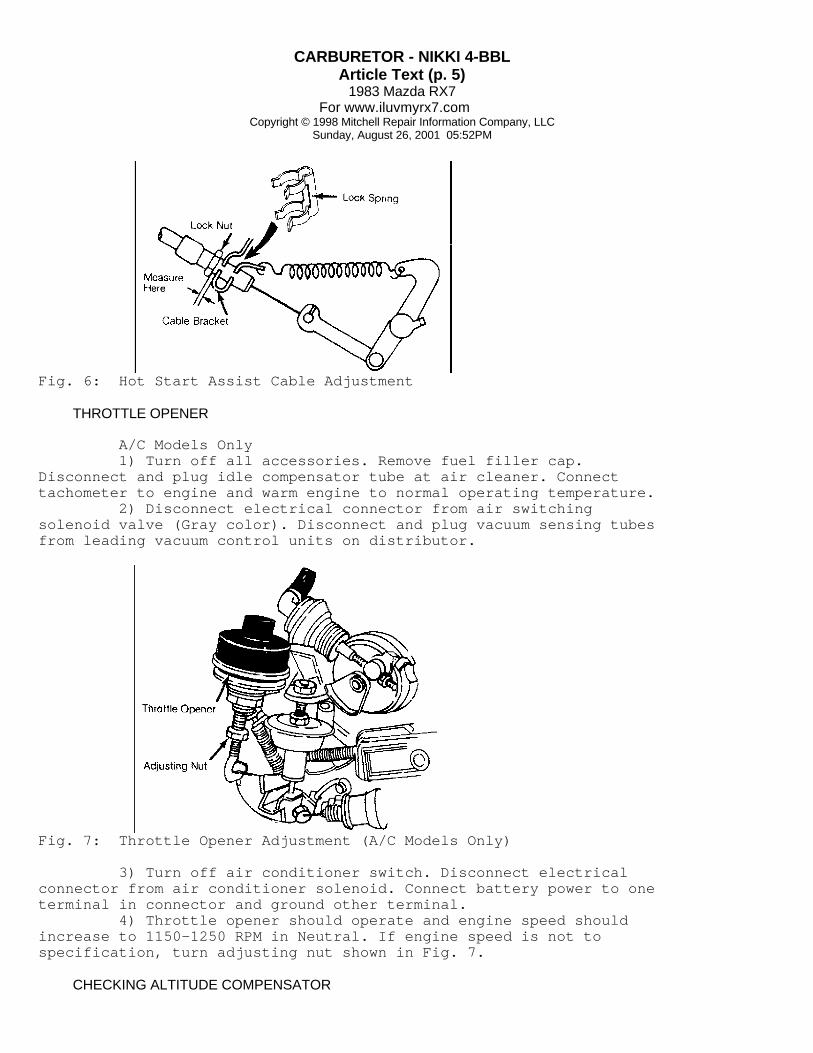
HOT START ASSIST CABLE
1) Remove lock spring of hot start assist cable from cablebracket. Slowly pull outer cable until hot start lever just touchesstop lever. 2) Check clearance between cable bracket and lock nut oncable. See Fig. 6. Clearance should be .02-.08" (0.5-2.0 mm). Adjustby turning lock nut, then install lock spring securely on cable.
CARBURETOR - NIKKI 4-BBLArticle Text (p. 5)
1983 Mazda RX7For www.iluvmyrx7.com
Copyright © 1998 Mitchell Repair Information Company, LLCSunday, August 26, 2001 05:52PM
Fig. 6: Hot Start Assist Cable Adjustment
THROTTLE OPENER
A/C Models Only 1) Turn off all accessories. Remove fuel filler cap.Disconnect and plug idle compensator tube at air cleaner. Connecttachometer to engine and warm engine to normal operating temperature. 2) Disconnect electrical connector from air switchingsolenoid valve (Gray color). Disconnect and plug vacuum sensing tubesfrom leading vacuum control units on distributor.
Fig. 7: Throttle Opener Adjustment (A/C Models Only)
3) Turn off air conditioner switch. Disconnect electricalconnector from air conditioner solenoid. Connect battery power to oneterminal in connector and ground other terminal. 4) Throttle opener should operate and engine speed shouldincrease to 1150-1250 RPM in Neutral. If engine speed is not tospecification, turn adjusting nut shown in Fig. 7.
CHECKING ALTITUDE COMPENSATOR

CARBURETOR - NIKKI 4-BBLArticle Text (p. 6)
1983 Mazda RX7For www.iluvmyrx7.com
Copyright © 1998 Mitchell Repair Information Company, LLCSunday, August 26, 2001 05:52PM
NOTE: Altitude compensator must be checked at altitudes of 1640-4920 feet.
1) Remove air cleaner and start engine. Engine should runsmoothly at specified idle. Place finger over slow port on carburetorair horn; idle speed should drop. 2) If idle speed did not drop, remove compensator valve andblow through both ports. Air should pass through compensator valve.If not replace altitude compensator valve.
Fig. 8: Adjusting Accelerator Cable and Pedal Height
ACCELERATOR CABLE ADJUSTMENT
1) Check accelerator pedal position. Pedal should be1.5-1.9" (37-47 mm) lower than brake pedal. See Fig. 8. If necessary,adjust nut "A" to obtain correct position. 2) Cable free play at carburetor should be .04-.12" (1-3mm). To adjust free play, adjust nut "B". Depress accelerator tofloor and check that throttle valves are wide open. If necessary,adjust stop bolt "C".
OVERHAUL
NOTE: Disassembly and assembly procedures will vary from vehicle to vehicle due to emissions equipment and type of transmission. Some carburetors may not have all parts referred to in the following procedures.
DISASSEMBLY
1) Remove vacuum sensing tubes for altitude compensator

CARBURETOR - NIKKI 4-BBLArticle Text (p. 7)
1983 Mazda RX7For www.iluvmyrx7.com
Copyright © 1998 Mitchell Repair Information Company, LLCSunday, August 26, 2001 05:52PM
valve and choke delay valve. Remove choke heater lead, chokediaphragm No. 2 vacuum sensing tube and altitude compensator valve. 2) Remove throttle opener and bracket assembly, No. 1 chokediaphragm vacuum sensing tube, dashpot diaphragm and bracket assembly(Man. Trans. only) and throttle return spring. 3) Remove sub-return spring, return spring bracket, bi-metalspring housing and bracket assembly. Remove split pin and fast idlerod, hot start assist lever spring and bracket assembly and chokelever. 4) Remove the choke return diaphragm and bracket, No. 2choke diaphragm and air horn assembly from main body. Disconnectfloat pin and remove float, needle valve, spring, valve stem andretainer. 5) From main body, remove accelerator pump rod, secondarythrottle valve rod, throttle sensor and main body attaching bolts.Remove main body from throttle body.
Fig. 9: Removing Jets and Air Bleeds
6) Remove secondary throttle attaching screws, cover, returnspring, pin and clip, diaphragm, housing and gasket. Remove "E" clip,washer and shaft, accelerator pump lever, attaching screws, cover,diaphragm and return spring. 7) From main body, remove accelerator pump injection screw,nozzle, gasket, weight, outlet check valve, check valve seat, weightand inlet check valve. Remove retainer, blind plug and washer,primary main jet and secondary main jet. 8) Remove air bleeds and jets. See Fig. 9. Using a hacksaw,remove idle limiter cap by cutting through limiter cap, 0.4" (10 mm)from cap end. Remove and discard mixture adjusting screw and spring.
CLEANING & INSPECTION

CARBURETOR - NIKKI 4-BBLArticle Text (p. 8)
1983 Mazda RX7For www.iluvmyrx7.com
Copyright © 1998 Mitchell Repair Information Company, LLCSunday, August 26, 2001 05:52PM
1) Wash all parts in clean solvent and clear all passagesusing compressed air. Never use wire for cleaning jets, orifices orpassages. Inspect air horn, main body and throttle body for cracks orbreakage. 2) Inspect choke shaft and throttle shaft for wear, linkageand connecting rods for bends, and return springs for damage. Inspectfloat, needle valve and seat and strainer for damage. 3) To check air vent solenoid for proper operation, applybattery voltage to solenoid valve, valve stem should pull into valvebody. Replace solenoid if it fails to operate properly.
REASSEMBLY
1) To reassemble, reverse the disassembly procedure, usingnew gaskets. Avoid mixing primary and secondary system parts havingsimilar shape. When installing new mixture screw, seat lightly andback out 3 turns for initial adjustment. 2) When installing bi-metal spring housing, fit choke shaftlever to bi-metal spring by closing choke valve and pulling vacuumdiaphragm shaft. Before installing air horn, make necessary floatadjustments.
ADJUSTMENT SPECIFICATION
CARBURETOR ADJUSTMENT SPECIFICATIONSÄÄÄÄÄÄÄÄÄÄÄÄÄÄÄÄÄÄÄÄÄÄÄÄÄÄÄÄÄÄÄÄÄÄÄÄÄÄÄÄÄÄÄÄÄÄÄÄÄÄÄÄÄÄÄÄÄÄÄÄÄÄÄÄÄÄÄÄÄÄApplication Specification
RX7 Float Level In. (mm) .......................... .61-.65 (15.5-16.5) Float Drop In. (mm) ......................... 1.98-2.02 (50.5-51.5) Choke Linkage In. (mm) ........................ .040-.047 (1.0-1.2) Accel. Cable Free Play In. (mm)................... .04-.12 (1.0-1.3) Choke Valve Opening In. (mm)...................... .22-.24 (5.5-6.2)ÄÄÄÄÄÄÄÄÄÄÄÄÄÄÄÄÄÄÄÄÄÄÄÄÄÄÄÄÄÄÄÄÄÄÄÄÄÄÄÄÄÄÄÄÄÄÄÄÄÄÄÄÄÄÄÄÄÄÄÄÄÄÄÄÄÄÄÄÄÄ
END OF ARTICLE

CHOKE - ELECTRIC ASSISTArticle Text
1983 Mazda RX7For www.iluvmyrx7.com
Copyright © 1998 Mitchell Repair Information Company, LLCSunday, August 26, 2001 04:58PM
ARTICLE BEGINNING
1983 Exhaust Emission Systems MAZDA RX7 CHOKE RETURN & HOT START ASSIST SYSTEMS
DESCRIPTION
The Choke Return system prevents the choke knob from beingleft unreturned to prevent overheating of the exhaust system. The HotStart Assist system opens the throttle valve partially duringcranking of warm engine to optimize air/fuel mixture to improvestarting. The choke return system components include No. 1 watertemperature switch, choke relay, choke magnet and choke switch. Thehot start assist system components include No. 1 water temperatureswitch, hot start relay and hot start motor.
OPERATION
CHOKE RETURN SYSTEM
When cold engine is started with assist of choke knob, theknob is held in pulled position by the choke magnet. Full release ofchoke knob is achieved as engine coolant temperature reaches 158øF(70øC). The No. 1 water temperature switch stops the flow ofelectrical current to magnet and the choke knob is released.
HOT START ASSIST SYSTEM
During cranking of a warm engine, the No. 1 watertemperature switch provides power to the hot start relay when starteris engaged. When hot start relay is activated, the hot start motorpulls the hot start cable which opens the throttle valve.

CHOKE - ELECTRIC ASSISTArticle Text (p. 2)
1983 Mazda RX7For www.iluvmyrx7.com
Copyright © 1998 Mitchell Repair Information Company, LLCSunday, August 26, 2001 04:58PM
Fig. 1: Choke Return and Hot Start Assist Systems
TESTING
CHOKE RETURN SYSTEM
1) With engine cold and ignition switch "OFF", pull chokeknob out fully. Choke knob should return automatically. 2) Connect tachometer to engine. Start engine and set enginespeed at 2000 RPM with choke knob. With engine running, choke knobshould automatically return when engine temperature indicator is inposition shown in Fig. 2.
Fig. 2: Engine Temperature Indication forRelease of Choke Knob

CHOKE - ELECTRIC ASSISTArticle Text (p. 3)
1983 Mazda RX7For www.iluvmyrx7.com
Copyright © 1998 Mitchell Repair Information Company, LLCSunday, August 26, 2001 04:58PM
CHOKE MAGNET
Disconnect electrical connector from choke switch. Using anohmmeter, check continuity between terminals. Continuity should existbetween terminals No. 6 and No. 8. See Fig. 3.
Fig. 3: Choke Switch Terminal Numbering
HOT START ASSIST SYSTEM
NOTE: Before replacing hot start motor or relay, check No. 1 water temperature switch as outlined in "Mazda RX7 Auxiliary Control Device" article in this section.
1) Inspect hot start assist cable and linkage for properinstallation, no binding or sticking, and full return. Warm engine tonormal operating temperature and stop engine. 2) Disconnect leading and trailing primary wires fromignition coils. Crank engine. Hot start lever should open throttlevalve. If hot start system does not respond as outlined, check hotstart assist relay.
HOT START ASSIST RELAY
1) Disconnect electrical connector from hot start relay.Using an ohmmeter, check continuity between terminals. Continuityshould exist between terminals No. 1 and No. 5 without power applied.Continuity should not exist between terminals No. 1 and No. 3 withoutpower applied. 2) Connect battery power to relay (positive to terminal No.2, negative to terminal No. 4). With battery power applied,continuity should exist between terminals No. 1 and No. 3. Continuityshould not exist between terminals No. 1 and No. 5 with power applied.
Fig. 4: Hot Start Assist RelayTerminal Numbering

CHOKE - ELECTRIC ASSISTArticle Text (p. 4)
1983 Mazda RX7For www.iluvmyrx7.com
Copyright © 1998 Mitchell Repair Information Company, LLCSunday, August 26, 2001 04:58PM
HOT START ASSIST CABLE ADJUSTMENT
1) Remove hot start assist cable lock spring from cablebracket. Slowly pull outer cable until hot start lever just touchesstopper lever. Check clearance between cable bracket and cable locknut. 2) If clearance is not .02-.08" (0.5-2.0 mm), adjustclearance by turning lock nut. Recheck clearance and install lockspring.
Fig. 5: Adjusting Hot Start Relay Cable
END OF ARTICLE

DECELERATION CONTROL SYSTEMArticle Text
1983 Mazda RX7For www.iluvmyrx7.com
Copyright © 1998 Mitchell Repair Information Company, LLCSunday, August 26, 2001 04:58PM
ARTICLE BEGINNING
1983 Exhaust Emission Systems MAZDA RX7 DECELERATION CONTROL SYSTEM
DESCRIPTION
The Deceleration system is designed to maintain a balancedair/fuel mixture during deceleration. System consists of 2anti-afterburn valves, shutter solenoid valve, coasting/shuttervalve, throttle sensor, dashpot (manual transmission models) andconnecting hoses and wiring.
OPERATION
The No. 2 anti-afterburn valve (located below air cleaner)is actuated by the shutter solenoid valve to supply additional airfrom air cleaner to intake manifold at initial deceleration toprevent afterburning of fuel. The coasting/shutter valve worktogether to supply air (coasting valve) and fuel (shutter valve)during deceleration to prevent backfiring.
TESTING
NO. 1 ANTI-AFTERBURN VALVE
1) Warm engine to normal operating temperature and ensureengine operates smoothly at idle. Stop engine. Disconnect airpump-to-air control hose at air pump. 2) Disconnect electrical connectors from relief solenoidvalve (Blue color dot) and switching solenoid valve (Gray color dot).Start engine and run at idle. Place finger over air pump-to-aircontrol hose. 3) Air should not be drawn in and idle speed should notchange. Disconnect vacuum sensing tube "A". The idle speed shoulddrop and return to normal idle when tube is connected. If valve doesnot respond as outlined, replace No. 1 anti-afterburn valve.
NOTE: Before replacing No. 1 anti-afterburn valve, check auxiliary control unit as outlined in "Mazda RX7 Auxiliary Control Device" article in this section. Also check relief solenoid valve and switching solenoid valve as described in "Mazda RX7 Air Injection System" article in this section.

DECELERATION CONTROL SYSTEMArticle Text (p. 2)
1983 Mazda RX7For www.iluvmyrx7.com
Copyright © 1998 Mitchell Repair Information Company, LLCSunday, August 26, 2001 04:58PM
Fig. 1: Testing No. 1 Anti-Afterburn Valve
NO. 2 ANTI-AFTERBURN VALVE
1) Warm engine to normal operating temperature. DisconnectNo. 2 anti-afterburn valve-to-air cleaner hose at air cleaner. Placefinger over hose and ensure air is not drawn into hose. 2) Disconnect vacuum sensing hose from No. 2 anti-afterburnvalve. Air should not be drawn into hose. Connect vacuum sensing hoseto valve; air should be drawn into anti-afterburn valve-to-aircleaner hose for 3 seconds. 3) If air is drawn for more than 3 seconds or no air isdrawn, replace No. 2 anti-afterburn valve.
THROTTLE SENSOR
1) Warm engine to normal operating temperature. Stop engine.Connect tachometer to engine. Disconnect throttle sensor electricalconnector, located on right side of engine (Black/Yellow andGreen/Black wires). 2) Using 2 voltmeters, connect positive lead of onevoltmeter to Light Green/Yellow wire terminal of throttle sensorcheck connector. 3) Connect positive lead of other voltmeter to Green/Yellowwire terminal of throttle sensor connector. Connect negativeterminals of voltmeters to good ground. See Fig. 2.

DECELERATION CONTROL SYSTEMArticle Text (p. 3)
1983 Mazda RX7For www.iluvmyrx7.com
Copyright © 1998 Mitchell Repair Information Company, LLCSunday, August 26, 2001 04:58PM
Fig. 2: Testing Throttle Sensor
4) Start engine and run at 3000 RPM. Quickly decelerateengine. Current should flow to both terminals simultaneously whenengine speed is 1000-1200 RPM. 5) If current does not flow to both terminals at the sametime, remove cap from throttle sensor adjusting screw and adjustthrottle sensor. 6) Adjust timing of current flow to voltmeter "A" in Fig. 2by turning throttle sensor adjusting screw. 7) Turning screw in causes current to flow to LightGreen/Yellow wire at lower engine speed. After adjustment, installcap on throttle sensor adjusting screw and retest throttle sensor.
SHUTTER SOLENOID VALVE
1) Disconnect vacuum sensing tubes from shutter solenoidvalve (Yellow color dot). Blow through solenoid valve through vacuumhose "B" shown in Fig. 3; air should go through valve and escape atfront port. 2) Disconnect electrical connector and apply battery powerto terminals on solenoid valve. Blow through hose again; air shouldescape through air filter at rear of solenoid valve. Replace valve ifit does not respond as outlined.

DECELERATION CONTROL SYSTEMArticle Text (p. 4)
1983 Mazda RX7For www.iluvmyrx7.com
Copyright © 1998 Mitchell Repair Information Company, LLCSunday, August 26, 2001 04:58PM
Fig. 3: Testing Shutter Solenoid Valve
SHUTTER SOLENOID VALVE SIGNAL CHECK
1) Warm engine to normal operating temperature. Stop engine.Connect tachometer to engine. Connect voltmeter to negative (LightGreen/Yellow) terminal of shutter solenoid valve electrical connectorwithout disconnecting connector. 2) Disconnect throttle sensor electrical connector(Black/Yellow and Green/Black wires). Shift automatic transmissioninto "P" or "N". Start engine and run at idle. 3) Voltmeter should read 0V at shutter solenoid valveterminals. Disconnect electrical connector from throttle sensor.Voltmeter should read near 12V and engine idle is erratic. 4) Shift automatic transmission into "D". Connect throttlesensor connector disconnected in step 1). Voltmeter should read near12V.

DECELERATION CONTROL SYSTEMArticle Text (p. 5)
1983 Mazda RX7For www.iluvmyrx7.com
Copyright © 1998 Mitchell Repair Information Company, LLCSunday, August 26, 2001 04:58PM
Fig. 4: Testing Shutter Solenoid Valve Signal
5) On automatic transmissions, shift into "P" or "N".Current should NOT flow to solenoid valve terminal at any enginespeed. If solenoid valve does not respond as described, replaceshutter solenoid valve.
NOTE: Before replacing shutter solenoid valve, check auxiliary control unit as outlined in "Mazda RX7 Auxiliary Control Device" article in this section. Also check relief solenoid valve and switching solenoid valve as described in "Mazda RX7 Air Injection System" article in this section.
COASTING/SHUTTER VALVE
1) Warm engine to normal operating temperature. Stop engine.Disconnect air cleaner-to-coasting valve hose at air cleaner. Startengine and run at idle. Place finger over disconnected hose; airshould not be drawn into hose. 2) Disconnect electrical connector from shutter solenoidvalve (Yellow dot). Air should be drawn into disconnected hose andidle should fluctuate. 3) At the same time, the coasting valve rod should be pulledinto coasting valve about .4" (10mm), opening shutter valve. Replacecoasting/shutter valve if it does not respond as outlined.
DASHPOT (MAN. TRANS. ONLY)
1) Remove air cleaner. Checking all vacuum sensing tubes forproper condition and connections. Check that dashpot rod does notbind throttle lever movement. 2) Quickly operate throttle lever fully and make suredashpot rod extends quickly. Release throttle lever and make surethat throttle lever returns slowly to idle position after it hastouched dashpot rod. 3) Connect tachometer to engine. Start engine and warm tooperating temperature. Ensure engine idle speed is adjusted tospecification. Operate throttle lever until it is away from dashpotrod. 4) Slowly decrease engine speed and check speed at whichthrottle lever just touches dashpot rod. It should be 3800-4200 RPM.
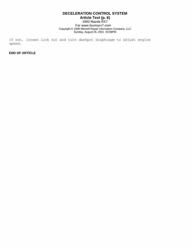
DECELERATION CONTROL SYSTEMArticle Text (p. 6)
1983 Mazda RX7For www.iluvmyrx7.com
Copyright © 1998 Mitchell Repair Information Company, LLCSunday, August 26, 2001 04:58PM
If not, loosen lock nut and turn dashpot diaphragm to adjust enginespeed.
END OF ARTICLE

EMISSION APPLICATIONArticle Text
1983 Mazda RX7For www.iluvmyrx7.com
Copyright © 1998 Mitchell Repair Information Company, LLCSunday, August 26, 2001 04:58PM
ARTICLE BEGINNING
1983 ENGINE EMISSIONS Mazda Emission Control Applications
626, GLC, Pickup, RX7
EMISSION CONTROL DEVICE APPLICATIONS
EMISSION CONTROL DEVICE APPLICATIONS TABLEÄÄÄÄÄÄÄÄÄÄÄÄÄÄÄÄÄÄÄÄÄÄÄÄÄÄÄÄÄÄÄÄÄÄÄÄÄÄÄÄÄÄÄÄÄÄÄÄÄÄÄÄÄÄÄÄÄÄÄÄÄÄÄÄÄB2000 2.0L PCV, AIS, EVAP, OC, EGR, SPK, AI (1), DCS
B2000 2.2L Diesel PCV, EGR
FWD GLC 1.5L PCV, EVAP, EGR, ECC, FCO, HIC
RWD GLC 1.5L PCV, AIS, EVAP, OC, EGR, DCS, HIC
RX7 PCV, AIS, EVAP, TWC, ACD, CRV, DCS, IC, ITCS (2)
626 2.0L TAC, EVAP, OC, EGR, FCO, HIC
(1) - California only.(2) - Exc. California only.ÄÄÄÄÄÄÄÄÄÄÄÄÄÄÄÄÄÄÄÄÄÄÄÄÄÄÄÄÄÄÄÄÄÄÄÄÄÄÄÄÄÄÄÄÄÄÄÄÄÄÄÄÄÄÄÄÄÄÄÄÄÄÄÄÄ
ABBREVIATION DEFINITIONS
ABBREVIATIONS DEFINITIONS TABLEÄÄÄÄÄÄÄÄÄÄÄÄÄÄÄÄÄÄÄÄÄÄÄÄÄÄÄÄÄÄÄÄÄÄÄÄÄÄÄÄÄÄÄÄÄÄÄÄÄÄÄÄÄÄÄÄÄÄÄÄÄÄÄÄÄAbbreviation Description
ACD .................................. Auxiliary Control DeviceAI .............................................. Air InjectionAIS ...................................... Air Injection SystemCEC .............................. Computerized Engine ControlsCRV ..................................... Coasting Richer ValveDCS ............................... Deceleration Control SystemECC .......................... Electronic Controlled CarburetorEVAP ............................. Evaporative Emission ControlEGR ................................. Exhaust Gas RecirculationFCO .............................................. Fuel Cut-OffHIC ...................................... Hot Idle CompensatorIC ......................................... Integrated Control

EMISSION APPLICATIONArticle Text (p. 2)
1983 Mazda RX7For www.iluvmyrx7.com
Copyright © 1998 Mitchell Repair Information Company, LLCSunday, August 26, 2001 04:58PM
ITCS ........................... Ignition Timing Control SystemOC ........................................ Oxyidation CatalystO2 .............................................. Oxygen SensorPCV ............................ Positive Crankcase VentilationSPK ..................................................... SparkTAC .................................. Thermostatic Air CleanerTWC ........................................ Three-Way CatalystÄÄÄÄÄÄÄÄÄÄÄÄÄÄÄÄÄÄÄÄÄÄÄÄÄÄÄÄÄÄÄÄÄÄÄÄÄÄÄÄÄÄÄÄÄÄÄÄÄÄÄÄÄÄÄÄÄÄÄÄÄÄÄÄÄ
END OF ARTICLE

FUEL EVAPORATION SYSTEMArticle Text
1983 Mazda RX7For www.iluvmyrx7.com
Copyright © 1998 Mitchell Repair Information Company, LLCSunday, August 26, 2001 04:58PM
ARTICLE BEGINNING
1983 Fuel Evaporation Systems MAZDA ROTARY ENGINE
RX7
DESCRIPTION
System prevents escape of fuel vapors into atmosphere.Components consist of a non-vented fuel tank with integral vaporseparator, vapor valve, check and cut valve (located at fuel tank),charcoal canister, air vent solenoid valve, purge valve andconnecting hoses.
OPERATION
When engine is not running, fuel vapors formed in fuel tankpass through vapor valve. Those vapors that do not condense to liquidfuel are routed through vent lines to charcoal canister where theyare adsorbed. When engine is running, filtered air is drawn into thesystem through the air cleaner, mixed with gases and vapors that blowby the rotor and are drawn through purge valve and into intake runnerto be burned. The purge valve operates as the PCV and check valve.
AIR VENT SYSTEM
An air vent solenoid on carburetor prevents carburetor bowlevaporated fuel from collecting in the intake manifold after hotengine shut off. With ignition off, the solenoid closes an air ventin the carbon canister, trapping the evaporated fuel.
Fig. 1: Mazda RX7 Check and Cut Valve

FUEL EVAPORATION SYSTEMArticle Text (p. 2)
1983 Mazda RX7For www.iluvmyrx7.com
Copyright © 1998 Mitchell Repair Information Company, LLCSunday, August 26, 2001 04:58PM
Fig. 2: Mazda RX7 Air Vent and Fuel Evaporation System
CHECK & CUT VALVE
This valve has 3 functions: When fuel tank pressure becomestoo high, valve releases pressure to atmosphere. When vacuum becomestoo high, valve allows air into tank to prevent tank from collapsing.If vehicle is overturned, valve prevents fuel leakage by sealing theline with a check ball.
TESTING
EVAPORATIVE LINE CHECK
1) Disconnect evaporative hose from canister. Connectdetached hose to a "U" tube type pressure gauge filled with water. 2) Gradually apply low air pressure into "U" tube so thatdifference of water level reaches 14" (356 mm). 3) Bind inlet of "U" tube and leave bound for 5 minutes. Ifwater level drops no more than 1" (25 mm) after 5 minutes,evaporative line is in good condition.
CHECK & CUT VALVE
1) Remove check and cut valve from lines. Connect a pressuregauge with "T" on nipple leading to fuel tank. Hold finger overopposite nipple. 2) Blow through open end of "T" fitting. When pressure gaugereads .78-1.0 psi (.06-.07 kg/cmý), valve should open. 3) Remove "T" fitting and gauge from fuel tank nipple andconnect to nipple at bottom of valve (atmosphere vent). Valve shouldbe located horizontally. 4) Repeat test. Valve should open when pressure gauge reads.14-.71 psi (.01-.05 kg/cmý). If valve does not operate asdescribed, replace check and cut valve.
FUEL EVAPORATION SYSTEMArticle Text (p. 3)
1983 Mazda RX7For www.iluvmyrx7.com
Copyright © 1998 Mitchell Repair Information Company, LLCSunday, August 26, 2001 04:58PM
AIR VENT SOLENOID VALVE
Check air vent hose for cracks or damage. Disconnect airvent hose from ventilation pipe. Slowly blow through hose. Air shouldpass through solenoid. Turn ignition "ON" and blow through hoseagain. Air should not pass through valve. If valve does not operateas described, replace valve.
MAINTENANCE
Check system function every 15,000 miles. Check and CutValve should be tested every 25,000 miles. Replace parts as necessary.
END OF ARTICLE

FUEL PUMP - ELECTRICArticle Text
1983 Mazda RX7For www.iluvmyrx7.com
Copyright © 1998 Mitchell Repair Information Company, LLCSunday, August 26, 2001 05:54PM
ARTICLE BEGINNING
1983 Electric Fuel Pump MAZDA
RX7, Pickup
DESCRIPTION & OPERATION
Electric fuel pump is mounted near fuel tank on frame member.Power is supplied when ignition switch is in the "RUN" position. Thiscircuit is protected by a 15-amp fuse (20-amp on RX7) at fuse panel.In-line fuel filter must be changed within recommended mileageinterval before performing tests. If in doubt, install new filter.
TESTING
PRESSURE TEST
1) Remove air cleaner assembly and disconnect fuel line atcarburetor. Connect pressure gauge with restrictor and a flexiblehose. See Fig. 1. Turn ignition on and briefly vent the system intocontainer by opening hose restrictor. 2) Pressure should stabilize at 2.8-3.6 psi (.19-.25kg/cmý). If not within specifications, and lines and filter are insatisfactory condition, replace pump.
Fig. 1: Fuel Pump Pressure and Volume Test
VOLUME TEST
With fuel pressure within limits, open restrictor for oneminute and measure fuel expelled. If not within specifications, checkfor restrictions in tank, line or filter. Replace pump if required.
FUEL PUMP VOLUMEÄÄÄÄÄÄÄÄÄÄÄÄÄÄÄÄÄÄÄÄÄÄÄÄÄÄÄÄÄÄÄÄÄÄÄÄÄÄÄÄÄÄÄÄÄÄÄÄÄÄÄÄÄÄÄÄÄÄÄÄÄÄÄÄÄÄÄÄÄÄ VolumeApplication Qt./Min. (cc/Min.)

FUEL PUMP - ELECTRICArticle Text (p. 2)
1983 Mazda RX7For www.iluvmyrx7.com
Copyright © 1998 Mitchell Repair Information Company, LLCSunday, August 26, 2001 05:54PM
RX7 ....................................................... 1.5 (1400)Pickup ....................................................... .8(800)ÄÄÄÄÄÄÄÄÄÄÄÄÄÄÄÄÄÄÄÄÄÄÄÄÄÄÄÄÄÄÄÄÄÄÄÄÄÄÄÄÄÄÄÄÄÄÄÄÄÄÄÄÄÄÄÄÄÄÄÄÄÄÄÄÄÄÄÄÄÄ
FUEL PUMP
Removal & Installation (B2000) Disconnect negative battery cable. Unplug connector at fuelpump. Disconnect inlet and outlet hoses at fuel pump. Remove fuelpump-to-mounting bracket nuts and remove pump. To install, reverseremoval procedure.
Removal & Installation (RX7) Remove rear floor mat and disconnect fuel pump electricallead. Raise and support vehicle. Remove fuel pump cover. Disconnectinlet and outlet hoses from pump. Remove fuel pump. To install,reverse removal procedure.
END OF ARTICLE
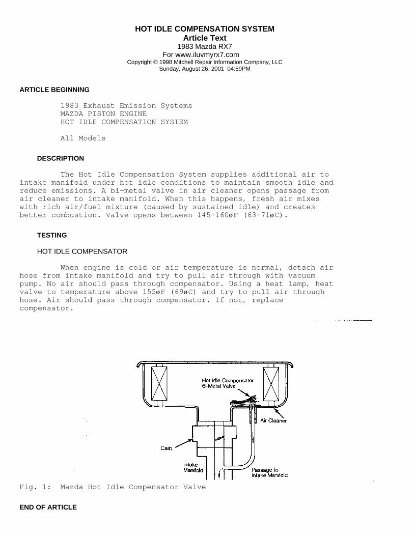
HOT IDLE COMPENSATION SYSTEMArticle Text
1983 Mazda RX7For www.iluvmyrx7.com
Copyright © 1998 Mitchell Repair Information Company, LLCSunday, August 26, 2001 04:59PM
ARTICLE BEGINNING
1983 Exhaust Emission Systems MAZDA PISTON ENGINE HOT IDLE COMPENSATION SYSTEM
All Models
DESCRIPTION
The Hot Idle Compensation System supplies additional air tointake manifold under hot idle conditions to maintain smooth idle andreduce emissions. A bi-metal valve in air cleaner opens passage fromair cleaner to intake manifold. When this happens, fresh air mixeswith rich air/fuel mixture (caused by sustained idle) and createsbetter combustion. Valve opens between 145-160øF (63-71øC).
TESTING
HOT IDLE COMPENSATOR
When engine is cold or air temperature is normal, detach airhose from intake manifold and try to pull air through with vacuumpump. No air should pass through compensator. Using a heat lamp, heatvalve to temperature above 155øF (69øC) and try to pull air throughhose. Air should pass through compensator. If not, replacecompensator.
Fig. 1: Mazda Hot Idle Compensator Valve
END OF ARTICLE

IDLE COMPENSATION SYSTEMArticle Text
1983 Mazda RX7For www.iluvmyrx7.com
Copyright © 1998 Mitchell Repair Information Company, LLCSunday, August 26, 2001 04:59PM
ARTICLE BEGINNING
1983 Exhaust Emission Systems MAZDA RX7 IDLE COMPENSATION SYSTEM
DESCRIPTION
The Idle Compensation system is installed to control theair/fuel mixture under varying engine operating conditions. The systemconsists of idle compensator, altitude compensator and throttle opener(air conditioned models).
IDLE COMPENSATOR OPERATION
The idle compensator is a bimetal valve installed in the aircleaner. The bimetal valve opens at approximately 149øF (65øC) tosupply additional air to intake manifold to lean the air/fuel mixturefor more complete burning.
Fig. 1: Idle Compensator
ALTITUDE COMPENSATOR OPERATION
The altitude compensator is installed on the carburetor tosupply additional air to carburetor during idle mode in high altitudeareas. The altitude compensator stabilizes engine operation.
THROTTLE OPENER OPERATION
AIR CONDITIONED MODELS
The throttle opener consists of air conditioner switch (relayon manual transmission models), air conditioner solenoid valve, servo

IDLE COMPENSATION SYSTEMArticle Text (p. 2)
1983 Mazda RX7For www.iluvmyrx7.com
Copyright © 1998 Mitchell Repair Information Company, LLCSunday, August 26, 2001 04:59PM
diaphragm (throttle opener) and connecting hoses and wires. Thethrottle opener opens the primary throttle valve when air conditioneris operated at engine speeds of 1000-1200 RPM to maintain smoothengine operation.
IDLE COMPENSATOR TEST
Remove air cleaner cover and filter element. When bi-metaltemperature is below 149øF (65øC), valve should be closed and no airleakage should exist when vacuum is applied to tube. Bi-metal valveshould be open when temperature exceeds 159øF (69øC). If valve doesnot function as described, replace valve.
ALTITUDE COMPENSATOR TEST
NOTE: Altitude compensator can only be checked at altitudes of 1640-4920 ft. (500-1500 m).
1) Remove air cleaner and start engine. Engine should idlesmoothly. Place finger over slow port inside carburetor bore (locatedon right side of rear bore). With slow port covered, idle speed shoulddrop. 2) If idle speed does not drop, stop engine and removecompensator valve. With compensator valve removed, blow throughdrilled passages. 3) Air should pass through valve from both passages ataltitudes of 1640-4920 ft. (500-1500 m). If not, replace altitudecompensator valve.
Fig. 2: Altitude Compensator
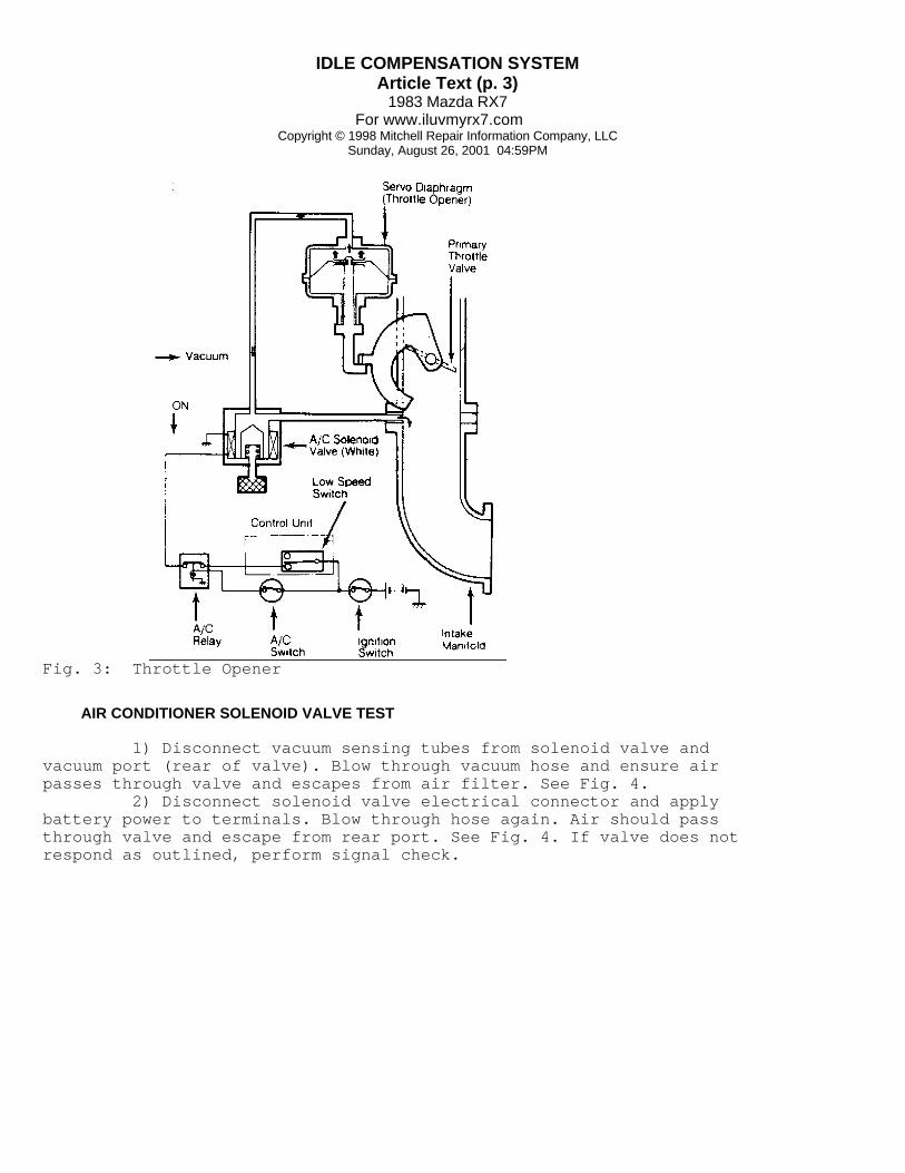
IDLE COMPENSATION SYSTEMArticle Text (p. 3)
1983 Mazda RX7For www.iluvmyrx7.com
Copyright © 1998 Mitchell Repair Information Company, LLCSunday, August 26, 2001 04:59PM
Fig. 3: Throttle Opener
AIR CONDITIONER SOLENOID VALVE TEST
1) Disconnect vacuum sensing tubes from solenoid valve andvacuum port (rear of valve). Blow through vacuum hose and ensure airpasses through valve and escapes from air filter. See Fig. 4. 2) Disconnect solenoid valve electrical connector and applybattery power to terminals. Blow through hose again. Air should passthrough valve and escape from rear port. See Fig. 4. If valve does notrespond as outlined, perform signal check.

IDLE COMPENSATION SYSTEMArticle Text (p. 4)
1983 Mazda RX7For www.iluvmyrx7.com
Copyright © 1998 Mitchell Repair Information Company, LLCSunday, August 26, 2001 04:59PM
Fig. 4: Testing Air Conditioner Solenoid Valve
AIR CONDITIONER SOLENOID VALVE SIGNAL CHECK TEST
1) Warm engine to normal operating temperature. Stop engineand connect tachometer. Connect a voltmeter to the air conditionersolenoid valve (White color dot) negative terminal. Start engine andturn air conditioner on. 2) On automatic transmission models, current should NOT flowto solenoid valve at any engine speed. On manual transmission models,increase engine speed to 2000 RPM with throttle. 3) Slowly decrease engine speed and watch voltmeter.Voltmeter should read near 0V when engine speed is 1000-1200 RPM. Ifvalve does not respond as outlined, replace air conditioner solenoidvalve.
NOTE: Before replacing air conditioner solenoid valve, check auxiliary control unit as outlined in "Mazda RX7 Auxiliary Control Device" article in this section.
AIR CONDITIONER RELAY TEST
Man. Trans. Only 1) Disconnect electrical connector from air conditionerrelay. Using an ohmmeter, check continuity between terminals. 2) With engine off and no power applied, there should be

IDLE COMPENSATION SYSTEMArticle Text (p. 5)
1983 Mazda RX7For www.iluvmyrx7.com
Copyright © 1998 Mitchell Repair Information Company, LLCSunday, August 26, 2001 04:59PM
continuity between No. 1 and No. 5. There should be no continuitybetween No. 1 and No. 3. 3) Connect a wire from battery positive post to terminal No.2 and battery negative post to terminal No. 4. There should becontinuity between No. 1 and No. 3. There should be no continuitybetween No. 1 and No. 5.
Fig. 5: Air Conditioner Relay Terminals (Manual Transmission Only)
THROTTLE OPENER TEST
1) Switch off all accessories. Remove fuel filler cap.Disconnect and plug idle compensator tube at air cleaner. Connecttachometer to engine and warm engine to normal operating temperature. 2) Disconnect electrical connector from switching solenoidvalve (Gray color dot). Disconnect and plug vacuum sensing tubes fromvacuum control units on distributor (except Calif. Man. Trans.). 3) Turn air conditioner off. Disconnect electrical connectorfrom air conditioner solenoid valve and connect battery power tosolenoid terminals. 4) With battery power applied to solenoid terminals, throttleopener should increase engine speed from idle to 1150-1250 RPM (inNeutral). If engine speed is not within specification, turn adjustingnut on throttle opener arm until engine speed is within specification.
END OF ARTICLE

PCV SYSTEMArticle Text
1983 Mazda RX7For www.iluvmyrx7.com
Copyright © 1998 Mitchell Repair Information Company, LLCSunday, August 26, 2001 04:59PM
ARTICLE BEGINNING
1983 Crankcase Ventilation MAZDA
B2000, B2200, GLC, 626, RX7
DESCRIPTION & OPERATION
PISTON ENGINES
The PCV system includes 2 hoses and a PCV valve. Airnormally flows out of the valve cover hose, through the PCV valve andinto combustion chambers. A hose from the air cleaner to the valvecover supplies fresh air to the crankcase. When intake manifold vacuum drops due to heavy loads, theamount of blow-by exceeds the capacity of the PCV valve. Air thenflows directly from the valve cover into the air cleaner andcarburetor. When engine is not running, the PCV valve is closed andvapors are stored in the crankcase.
ROTARY ENGINES
The system used on the rotary engine (RX7) is also a closedsystem and operates basically the same way as the piston enginearrangement. Filtered air is drawn into the system through the aircleaner, mixed with the gases and vapors that blow by the rotorduring engine operation, and is drawn out through a purge valve andinto the intake manifold. The purge valve operates as the PCV valvein this system.
DIESEL ENGINE
The PCV system on diesel engines consists of a hose to theair intake from the cylinder head cover. All blow-by gases areintroduced into the air intake and prevented from entering theatmosphere. There is no testing the PCV system on the diesel engines.Hoses should be kept free of obstructions.

PCV SYSTEMArticle Text (p. 2)
1983 Mazda RX7For www.iluvmyrx7.com
Copyright © 1998 Mitchell Repair Information Company, LLCSunday, August 26, 2001 04:59PM
Fig. 1: B2000 Pickup Crankcase Ventilation System
TESTING
PISTON ENGINES
All Exc. GLC FWD With engine idling at normal operating temperature,disconnect PCV valve hose at valve cover. Close off hose opening withfinger and check that idle speed drops. If idle speed does not drop,replace valve.
GLC FWD Remove PCV valve from valve cover. Blow through valve withmouth pressure from valve cover side of valve. Air should passthrough. Blow through valve from opposite end. Air should not passthrough. If valve does not operate as described, replace valve.
ROTARY ENGINES
1) Disconnect purge valve-to-oil filler tube hose from purgevalve. Start engine and operate at idle speed. Place finger over port"C" and check that air is not being drawn into port. See Fig. 2. 2) Increase engine speed to 2000 RPM and check port "C". Airshould be drawn into port. If valve does not operate as outlined,replace purge valve.
MAINTENANCE
Clean valve and check PCV system operation every 30,000miles.

PCV SYSTEMArticle Text (p. 3)
1983 Mazda RX7For www.iluvmyrx7.com
Copyright © 1998 Mitchell Repair Information Company, LLCSunday, August 26, 2001 04:59PM
Fig. 2: RX7 Rotary Engine Purge ValveAir flow should be checked at port "C".
Fig. 3: GLC & 626 Crankcase Ventilation SystemNote direction of flow.
Fig. 4: B2200 Diesel Pickup Crankcase Ventilation System
END OF ARTICLE

SPARK CONTROL SYSTEMArticle Text
1983 Mazda RX7For www.iluvmyrx7.com
Copyright © 1998 Mitchell Repair Information Company, LLCSunday, August 26, 2001 04:59PM
ARTICLE BEGINNING
1983 Exhaust Emission Systems MAZDA RX7 IGNITION CONTROL SYSTEM
RX7 (Exc. Calif. Man. Trans.)
DESCRIPTION
The Ignition Control system is used to regulate vacuumadvance of leading and trailing distributor systems. In addition,this system helps reduce CO and HC emissions by aiding pelletconverter warm-up during cold engine starts. System consists of leading and trailing components ofdistributor system, vacuum control solenoid valve (except Calif. man.trans.), No. 1 water temperature switch and connecting wiring andtubing.
OPERATION
The Ignition Control system operates when engine is cold andrunning between 1000-1200 RPM and when engine is hot during quickdeceleration from 3000 RPM.
TESTING
NOTE: For additional information and adjustments on distributor spark timing, see appropriate information in "Mazda RX7 Tune-Up Service Procedures," article in this section.
VACUUM CONTROL SOLENOID VALVE
1) Disconnect vacuum sensing tubes from leading vacuumcontrol solenoid valve (Brown dot). Blow through solenoid valve fromvacuum tube "B" shown in Fig. 1. Air should escape at front port.Trailing vacuum control solenoid valve (Green dot) is tested in thesame manner. 2) Disconnect electrical connector from solenoid valveand connect battery power to terminals on valve. Blow through hoseagain. Air should escape through air filter at rear of valve. Replacevalve if it does not perform as outlined.
VACUUM CONTROL SOLENOID VALVE SIGNAL CHECK
1) Warm engine to normal operating temperature. Stop engineand connect tachometer to engine. Connect voltmeter to negativeterminal of leading vacuum control solenoid valve (do not unplugconnector). Place auto. trans. vehicles in "P", man. trans. vehiclesin Neutral. 2) Start engine and run at idle speed. Voltmeter should read

SPARK CONTROL SYSTEMArticle Text (p. 2)
1983 Mazda RX7For www.iluvmyrx7.com
Copyright © 1998 Mitchell Repair Information Company, LLCSunday, August 26, 2001 04:59PM
0V at idle. When transmission is shifted into any forward or reversegears, voltmeter should read near 12V. 3) Increase engine speed to 2000 RPM. Slowly decrease enginespeed from 2000 RPM and watch voltmeter. Current should stop flowingto solenoid terminals when engine speed is 1000-1200 RPM. 4) Stop engine and disconnect No. 1 water temperature switchconnector (located behind alternator). Connect a jumper wire betweenterminals of water temperature connector. Start engine and set enginespeed at 2000 RPM with choke knob. 5) Unplug connector from No. 2 water temperature switch(located on radiator). Check that the voltmeter reads near 12V whenthe connector is unplugged from the switch. Disconnect jumper wireand plug in No. 1 water temperature switch connector. 6) Quickly decelerate engine speed from 3000 RPM. Thevoltmeter should read near 0V during deceleration and at idle speed.Trailing vacuum control solenoid valve (Green dot) is tested in thesame manner.
NOTE: Before replacing vacuum control solenoid valve, check auxiliary control unit, No. 2 water temperature switch, choke switch and choke relay as described in "Mazda RX7 Auxiliary Control Device," article in this section. Also check throttle sensor as described in "Mazda RX7 Deceleration Control System," article in this section.
Fig. 1: Testing Vacuum Control Solenoid ValveVoltmeter and tachometer required for tests.

TUNE-UP - ROTARYArticle Text
1983 Mazda RX7For www.iluvmyrx7.com
Copyright © 1998 Mitchell Repair Information Company, LLCSunday, August 26, 2001 05:54PM
ARTICLE BEGINNING
1983 Mazda Rotary Tune-Up TUNE-UP
RX7
IDENTIFICATION
ENGINE IDENTIFICATION
Engine type code is stamped on rear rotor housing, to therear of oil filter. Engine serial number is stamped on front rotorhousing behind distributor.
TESTING
ENGINE COMPRESSION
The manufacturer recommends using a special compressiontester (49 0820 280K). Compression testers for piston engines willread only the highest pressure of the 3 combustion chambers in therotor housing.
COMPRESSION SPECIFICATIONSÄÄÄÄÄÄÄÄÄÄÄÄÄÄÄÄÄÄÄÄÄÄÄÄÄÄÄÄÄÄÄÄÄÄÄÄÄÄÄÄÄÄÄÄÄÄÄÄÄÄÄÄÄÄÄÄÄÄÄÄÄÄÄÄÄÄÄÄÄÄApplication Specification
Min. Compression Pressure ...................... 86 psi (6.0 kg/cmý)Max. Variation ................................. 21 psi (1.5 kg/cmý)ÄÄÄÄÄÄÄÄÄÄÄÄÄÄÄÄÄÄÄÄÄÄÄÄÄÄÄÄÄÄÄÄÄÄÄÄÄÄÄÄÄÄÄÄÄÄÄÄÄÄÄÄÄÄÄÄÄÄÄÄÄÄÄÄÄÄÄÄÄÄ
SPARK PLUGS
SPARK PLUG TYPEÄÄÄÄÄÄÄÄÄÄÄÄÄÄÄÄÄÄÄÄÄÄÄÄÄÄÄÄÄÄÄÄÄÄÄÄÄÄÄÄÄÄÄÄÄÄÄÄÄÄÄÄÄÄÄÄÄÄÄÄÄÄÄÄÄÄÄÄÄÄApplication Nippondenso No. NGK No.
All Models ................ W25EDR14 ..................... BR8EQ14ÄÄÄÄÄÄÄÄÄÄÄÄÄÄÄÄÄÄÄÄÄÄÄÄÄÄÄÄÄÄÄÄÄÄÄÄÄÄÄÄÄÄÄÄÄÄÄÄÄÄÄÄÄÄÄÄÄÄÄÄÄÄÄÄÄÄÄÄÄÄ
SPARK PLUG SPECIFICATIONSÄÄÄÄÄÄÄÄÄÄÄÄÄÄÄÄÄÄÄÄÄÄÄÄÄÄÄÄÄÄÄÄÄÄÄÄÄÄÄÄÄÄÄÄÄÄÄÄÄÄÄÄÄÄÄÄÄÄÄÄÄÄÄÄÄÄÄÄÄÄGap: In. (mm) Torque: Ft. Lbs. (N.m)
0.055 (1.4) ................................................ 11 (15)ÄÄÄÄÄÄÄÄÄÄÄÄÄÄÄÄÄÄÄÄÄÄÄÄÄÄÄÄÄÄÄÄÄÄÄÄÄÄÄÄÄÄÄÄÄÄÄÄÄÄÄÄÄÄÄÄÄÄÄÄÄÄÄÄÄÄÄÄÄÄ
HIGH TENSION WIRE RESISTANCE
Carefully remove high tension wires from spark plugs and

TUNE-UP - ROTARYArticle Text (p. 2)
1983 Mazda RX7For www.iluvmyrx7.com
Copyright © 1998 Mitchell Repair Information Company, LLCSunday, August 26, 2001 05:54PM
distributor cap. Using an ohmmeter, measure resistance of wires whilegently twisting wires. If resistance is not to specifications, orfluctuates from infinity to any value, replace high tension wire(s).
HIGH TENSION WIRE RESISTANCEÄÄÄÄÄÄÄÄÄÄÄÄÄÄÄÄÄÄÄÄÄÄÄÄÄÄÄÄÄÄÄÄÄÄÄÄÄÄÄÄÄÄÄÄÄÄÄÄÄÄÄÄÄÄÄÄÄÄÄÄÄÄÄÄÄÄÄÄÄÄApplication Ohms
All Models ........................................... 4880 per FootÄÄÄÄÄÄÄÄÄÄÄÄÄÄÄÄÄÄÄÄÄÄÄÄÄÄÄÄÄÄÄÄÄÄÄÄÄÄÄÄÄÄÄÄÄÄÄÄÄÄÄÄÄÄÄÄÄÄÄÄÄÄÄÄÄÄÄÄÄÄ
ADJUSTMENTS
DISTRIBUTOR
All models are equipped with Mitsubishi electronic ignitionwith 2 pick-up coils. Air gap is non-adjustable.
Fig. 1: Firing Order and Distributor Rotation
IGNITION TIMING
NOTE: On vehicles equipped with automatic transmission, place selector lever in "D" position and block the wheels.
1) Warm engine to normal operating temperature. Connect atachometer, then connect timing light to leading (lower) spark plug offront rotor. Start engine and run at idle speed. 2) Check ignition timing and rotate distributor to correct ifnecessary. Tighten distributor lock nut and recheck timing. 3) Connect timing light to trailing (upper) plug of frontrotor. Start engine and check timing. If not correct, loosen vacuumunit attaching screws. Move vacuum unit in or out to adjust trailingtiming. Remove test equipment.

TUNE-UP - ROTARYArticle Text (p. 3)
1983 Mazda RX7For www.iluvmyrx7.com
Copyright © 1998 Mitchell Repair Information Company, LLCSunday, August 26, 2001 05:54PM
Fig. 2: Connecting Timing LightCheck leading plug timing first.
Fig. 3: Ignition Timing Mark Location
IGNITION TIMING (DEGREES ATDC @ RPM)ÄÄÄÄÄÄÄÄÄÄÄÄÄÄÄÄÄÄÄÄÄÄÄÄÄÄÄÄÄÄÄÄÄÄÄÄÄÄÄÄÄÄÄÄÄÄÄÄÄÄÄÄÄÄÄÄÄÄÄÄÄÄÄÄÄÄÄÄÄÄApplication Timing
Leading .................................................... TDC@750Trailing .................................................... 20@750ÄÄÄÄÄÄÄÄÄÄÄÄÄÄÄÄÄÄÄÄÄÄÄÄÄÄÄÄÄÄÄÄÄÄÄÄÄÄÄÄÄÄÄÄÄÄÄÄÄÄÄÄÄÄÄÄÄÄÄÄÄÄÄÄÄÄÄÄÄÄ
IDLE SPEED & MIXTURE
Idle Speed 1) Switch off all accessories. Remove fuel filler cap.Disconnect and plug idle compensator tube at air cleaner. Connecttachometer to engine. Ensure parking brake is engaged and wheels areblocked. 2) On manual transmission models, make sure dashpot rod doesnot keep throttle lever from returning to stop. On air conditionedmodels, make sure throttle opener does not keep throttle lever fromreturning to stop. 3) Warm engine to normal operating temperature. Placeautomatic transmission in "D". Check idle speed. Adjust curb idle

TUNE-UP - ROTARYArticle Text (p. 4)
1983 Mazda RX7For www.iluvmyrx7.com
Copyright © 1998 Mitchell Repair Information Company, LLCSunday, August 26, 2001 05:54PM
speed to specification by turning throttle adjusting screw.
NOTE: Mixture adjustment is not part of normal tune-up procedure and should not be performed unless carburetor is overhauled or vehicle fails emissions testing.
Idle Mixture 1) Idle mixture adjustment requires removal of carburetor toremove limiter cap. Using a hacksaw, cut through limiter cap andmixture screw 0.4" (10 mm) from cap end. Remove mixture screw andinstall new mixture screw. 2) To install new mixture screw, tighten screw lightly andensure it is fully seated. Back screw out 3 turns for preliminaryadjustment. Reinstall carburetor with new gaskets and warm engine tonormal operating temperature. 3) To adjust idle mixture, set idle speed to idle setspecification by turning throttle set screw (automatic transmission in"N"). Set idle speed to highest RPM obtainable by turning mixturescrew. Reset idle speed to idle set specification by turning throttlescrew. See Fig. 4. 4) Turn mixture screw until lean drop specification isobtained (automatic transmission in "N"). On automatic transmission,shift transmission to "D" and set idle speed to curb idlespecification by turning throttle screw.
IDLE SPEED & MIXTURE SPECIFICATIONSÄÄÄÄÄÄÄÄÄÄÄÄÄÄÄÄÄÄÄÄÄÄÄÄÄÄÄÄÄÄÄÄÄÄÄÄÄÄÄÄÄÄÄÄÄÄÄÄÄÄÄÄÄÄÄÄÄÄÄÄÄÄÄÄÄÄÄÄÄÄApplication Curb Idle RPM Idle Set RPM Lean Drop RPM
Man. Trans. ........ 750 ............. 770 ................. 750Auto. Trans. .. (1) 750 ......... (2) 870 ............. (2) 840
(1) - Transmission in "D".(2) - Transmission in "N".ÄÄÄÄÄÄÄÄÄÄÄÄÄÄÄÄÄÄÄÄÄÄÄÄÄÄÄÄÄÄÄÄÄÄÄÄÄÄÄÄÄÄÄÄÄÄÄÄÄÄÄÄÄÄÄÄÄÄÄÄÄÄÄÄÄÄÄÄÄÄ
Fig. 4: Carburetor Adjusting Screw Locations
COLD (FAST) IDLE RPM

TUNE-UP - ROTARYArticle Text (p. 5)
1983 Mazda RX7For www.iluvmyrx7.com
Copyright © 1998 Mitchell Repair Information Company, LLCSunday, August 26, 2001 05:54PM
NOTE: Carburetor must be removed to check and/or adjust fast idle.
Adjust fast idle by setting angle of primary throttle valvewith choke valve fully closed. Clearance between primary throttlevalve and throttle bore should be .040-.047" (1.0-1.2 mm). If not tospecification, bend fast idle rod until correct clearance is obtained.
SERVICING
EMISSION CONTROL
See EMISSIONS section.
SPECIFICATIONS
IGNITION
Distributor All models are equipped with Mitsubishi electronic ignitionwith 2 pick-up coils. Air gap is non-adjustable.
IGNITION COIL RESISTANCE - Ohms @ 68øF (20øC)ÄÄÄÄÄÄÄÄÄÄÄÄÄÄÄÄÄÄÄÄÄÄÄÄÄÄÄÄÄÄÄÄÄÄÄÄÄÄÄÄÄÄÄÄÄÄÄÄÄÄÄÄÄÄÄÄÄÄÄÄÄÄÄÄÄÄÄÄÄÄPrimary Secondary
1.2-1.5 ........................................................ N/AÄÄÄÄÄÄÄÄÄÄÄÄÄÄÄÄÄÄÄÄÄÄÄÄÄÄÄÄÄÄÄÄÄÄÄÄÄÄÄÄÄÄÄÄÄÄÄÄÄÄÄÄÄÄÄÄÄÄÄÄÄÄÄÄÄÄÄÄÄÄ
FUEL SYSTEMS
FUEL PUMP PERFORMANCEÄÄÄÄÄÄÄÄÄÄÄÄÄÄÄÄÄÄÄÄÄÄÄÄÄÄÄÄÄÄÄÄÄÄÄÄÄÄÄÄÄÄÄÄÄÄÄÄÄÄÄÄÄÄÄÄÄÄÄÄÄÄÄÄÄÄÄÄÄÄPressure: psi (kg/cmý) Pints (Liters): Volume in 30 Sec.
2.8-3.6 (.2-.3) ........................................... 1.5 (.7)ÄÄÄÄÄÄÄÄÄÄÄÄÄÄÄÄÄÄÄÄÄÄÄÄÄÄÄÄÄÄÄÄÄÄÄÄÄÄÄÄÄÄÄÄÄÄÄÄÄÄÄÄÄÄÄÄÄÄÄÄÄÄÄÄÄÄÄÄÄÄ
Carburetor All models use a Nikki 4-Bbl. carburetor.
BATTERY
BATTERY SPECIFICATIONSÄÄÄÄÄÄÄÄÄÄÄÄÄÄÄÄÄÄÄÄÄÄÄÄÄÄÄÄÄÄÄÄÄÄÄÄÄÄÄÄÄÄÄÄÄÄÄÄÄÄÄÄÄÄÄÄÄÄÄÄÄÄÄÄÄÄÄÄÄÄApplication Amp Hr. Capacity
Standard ........................................................ 50Optional ........................................................ 55ÄÄÄÄÄÄÄÄÄÄÄÄÄÄÄÄÄÄÄÄÄÄÄÄÄÄÄÄÄÄÄÄÄÄÄÄÄÄÄÄÄÄÄÄÄÄÄÄÄÄÄÄÄÄÄÄÄÄÄÄÄÄÄÄÄÄÄÄÄÄ
STARTER

TUNE-UP - ROTARYArticle Text (p. 6)
1983 Mazda RX7For www.iluvmyrx7.com
Copyright © 1998 Mitchell Repair Information Company, LLCSunday, August 26, 2001 05:54PM
All models are equipped with a Mitsubishi starter using anoverrunning clutch.
STARTER SPECIFICATIONSÄÄÄÄÄÄÄÄÄÄÄÄÄÄÄÄÄÄÄÄÄÄÄÄÄÄÄÄÄÄÄÄÄÄÄÄÄÄÄÄÄÄÄÄÄÄÄÄÄÄÄÄÄÄÄÄÄÄÄÄÄÄÄÄÄÄÄÄÄÄApplication Volts Amps Test RPM
Man. Trans. .......... 11.5 ........... 60 ................ 6500Auto. Trans. ......... 11.5 ........... 100 ............... 3500ÄÄÄÄÄÄÄÄÄÄÄÄÄÄÄÄÄÄÄÄÄÄÄÄÄÄÄÄÄÄÄÄÄÄÄÄÄÄÄÄÄÄÄÄÄÄÄÄÄÄÄÄÄÄÄÄÄÄÄÄÄÄÄÄÄÄÄÄÄÄ
ALTERNATOR
All models are equipped with a Mitsubishi alternator.
ALTERNATOR SPECIFICATIONSÄÄÄÄÄÄÄÄÄÄÄÄÄÄÄÄÄÄÄÄÄÄÄÄÄÄÄÄÄÄÄÄÄÄÄÄÄÄÄÄÄÄÄÄÄÄÄÄÄÄÄÄÄÄÄÄÄÄÄÄÄÄÄÄÄÄÄÄÄÄApplication Rated Amp Output
All Models ...................................................... 50ÄÄÄÄÄÄÄÄÄÄÄÄÄÄÄÄÄÄÄÄÄÄÄÄÄÄÄÄÄÄÄÄÄÄÄÄÄÄÄÄÄÄÄÄÄÄÄÄÄÄÄÄÄÄÄÄÄÄÄÄÄÄÄÄÄÄÄÄÄÄ
ALTERNATOR REGULATOR
All models are equipped with a Mitsubishi voltage regulator.
REGULATOR OPERATING VOLTAGE @ 68øF (20øC)ÄÄÄÄÄÄÄÄÄÄÄÄÄÄÄÄÄÄÄÄÄÄÄÄÄÄÄÄÄÄÄÄÄÄÄÄÄÄÄÄÄÄÄÄÄÄÄÄÄÄÄÄÄÄÄÄÄÄÄÄÄÄÄÄÄÄÄÄÄÄApplication Voltage
All Models .................................................... 13.5ÄÄÄÄÄÄÄÄÄÄÄÄÄÄÄÄÄÄÄÄÄÄÄÄÄÄÄÄÄÄÄÄÄÄÄÄÄÄÄÄÄÄÄÄÄÄÄÄÄÄÄÄÄÄÄÄÄÄÄÄÄÄÄÄÄÄÄÄÄÄ
SERVICE SPECIFICATIONS
BELT ADJUSTMENTÄÄÄÄÄÄÄÄÄÄÄÄÄÄÄÄÄÄÄÄÄÄÄÄÄÄÄÄÄÄÄÄÄÄÄÄÄÄÄÄÄÄÄÄÄÄÄÄÄÄÄÄÄÄÄÄÄÄÄÄÄÄÄÄÄÄÄÄÄÄApplication (1) Deflection In. (mm)
Alternator Belt ...................................... .5-.7 (13-17)Air Pump Belt ...................................... .43-.51 (11-13)A/C Belt ........................................... .39-.47 (10-12)
(1) - Deflection is with 22 lbs. (10 kg) pressure applied midway on longest belt run.ÄÄÄÄÄÄÄÄÄÄÄÄÄÄÄÄÄÄÄÄÄÄÄÄÄÄÄÄÄÄÄÄÄÄÄÄÄÄÄÄÄÄÄÄÄÄÄÄÄÄÄÄÄÄÄÄÄÄÄÄÄÄÄÄÄÄÄÄÄÄ
REPLACEMENT INTERVALSÄÄÄÄÄÄÄÄÄÄÄÄÄÄÄÄÄÄÄÄÄÄÄÄÄÄÄÄÄÄÄÄÄÄÄÄÄÄÄÄÄÄÄÄÄÄÄÄÄÄÄÄÄÄÄÄÄÄÄÄÄÄÄÄÄÄÄÄÄÄComponent Interval (Miles)
Engine Oil .................................................... 7500

TUNE-UP - ROTARYArticle Text (p. 7)
1983 Mazda RX7For www.iluvmyrx7.com
Copyright © 1998 Mitchell Repair Information Company, LLCSunday, August 26, 2001 05:54PM
Oil Filter .................................................. 15,000Air Filter .................................................. 30,000Spark Plugs ................................................. 30,000ÄÄÄÄÄÄÄÄÄÄÄÄÄÄÄÄÄÄÄÄÄÄÄÄÄÄÄÄÄÄÄÄÄÄÄÄÄÄÄÄÄÄÄÄÄÄÄÄÄÄÄÄÄÄÄÄÄÄÄÄÄÄÄÄÄÄÄÄÄÄ
FLUID CAPACITIESÄÄÄÄÄÄÄÄÄÄÄÄÄÄÄÄÄÄÄÄÄÄÄÄÄÄÄÄÄÄÄÄÄÄÄÄÄÄÄÄÄÄÄÄÄÄÄÄÄÄÄÄÄÄÄÄÄÄÄÄÄÄÄÄÄÄÄÄÄÄApplication Quantity
Crankcase (Includes Filter) ........................ 4.9 qts. (4.6L)Cooling System (Includes Heater) .................. 10.0 qts. (9.5L)Man. Trans. (SAE 90) ............................... 2.1 qts. (1.9L)Auto Trans. (ATF Type F) ........................... 6.6 qts. (6.2L)Rear Axle (SAE 90) Standard ......................................... 2.6 pts. (1.2L) Limited Slip ..................................... 3.4 pts. (1.6L)Fuel Tank ......................................... 16.6 gals. (63L)ÄÄÄÄÄÄÄÄÄÄÄÄÄÄÄÄÄÄÄÄÄÄÄÄÄÄÄÄÄÄÄÄÄÄÄÄÄÄÄÄÄÄÄÄÄÄÄÄÄÄÄÄÄÄÄÄÄÄÄÄÄÄÄÄÄÄÄÄÄÄ
END OF ARTICLE

VACUUM DIAGRAMSArticle Text
1983 Mazda RX7For www.iluvmyrx7.com
Copyright © 1998 Mitchell Repair Information Company, LLCSunday, August 26, 2001 05:00PM
ARTICLE BEGINNING
1983 EXHAUST EMISSION SYSTEMS Mazda Vacuum Diagram
RX7
VACUUM DIAGRAM

VACUUM DIAGRAMSArticle Text (p. 2)
1983 Mazda RX7For www.iluvmyrx7.com
Copyright © 1998 Mitchell Repair Information Company, LLCSunday, August 26, 2001 05:00PM
Fig. 1: Mazda RX7 Rotary Engine Vacuum Diagram
END OF ARTICLE