SuperLink Rx 1900 Operation and Installation manual
86
830-0016C SuperLink Rx 1900 Operation and Installation Manual
-
Upload
khangminh22 -
Category
Documents
-
view
0 -
download
0
Transcript of SuperLink Rx 1900 Operation and Installation manual

830-0016C
SuperLink Rx 1900 Operation and Installation Manual

TABLE OF CONTENTS
Chapter 1 Introduction ................................................................................................................... 1 Overview................................................................................................................................... 1 About this Manual..................................................................................................................... 1 General Safety........................................................................................................................... 3
Warnings, Cautions, and Notes............................................................................................3 Electrostatic Discharge ........................................................................................................3
Technical Assistance................................................................................................................. 3
Chapter 2 Using the SuperLink Rx 1900....................................................................................... 5 Equipment Configurations ........................................................................................................ 5 Functional Description.............................................................................................................. 6
RF Signal Flow ....................................................................................................................7 Control .................................................................................................................................8 Cryogenic Cooling ...............................................................................................................8 Power ...................................................................................................................................8 Dual Duplexers ....................................................................................................................9
Indicators, Connectors, and Controls...................................................................................... 11 Front View of the SuperLink Rx 1900 ..............................................................................11 FAULT LED......................................................................................................................11 RS-232 Console Cover Plate .............................................................................................12 RF Connectors and Covers ................................................................................................12 Junction Box ......................................................................................................................12
Model Number Identification ................................................................................................. 15
Chapter 3 Unpacking the SuperLink Rx 1900............................................................................. 17 Reviewing the Contents of the SuperLink Rx 1900 Package ................................................. 17 Unpacking the SuperLink Rx 1900......................................................................................... 17 Instructions for Return Shipment............................................................................................ 18
Chapter 4 Installation Requirements............................................................................................ 19 Overview................................................................................................................................. 19 SuperLink Rx 1900 Requirements.......................................................................................... 19
Site Requirements ..............................................................................................................19 Required Installation Tools and Materials.........................................................................20 Required Functional Checks Test Equipment....................................................................21 Reviewing PC System Requirements ................................................................................21
Chapter 5 Installing the SuperLink Rx 1900 ............................................................................... 23 Overview................................................................................................................................. 23 SL Rx 1900 Installation Procedures ....................................................................................... 23
Installing the Java Runtime Environment..........................................................................23 Installing the System Status Portal ....................................................................................27 Mounting the SuperLink Rx 1900 .....................................................................................30 Connecting Cables and Wires............................................................................................31 Performing Functional Checks ..........................................................................................35 Connecting RF Cables .......................................................................................................42
STI Customer Service Hotline 800.727.3648 SuperLink Rx 1900 Operation and Installation Manual i

Integrating the SuperLink Rx 1900 with the Base Station ................................................43
Chapter 6 Troubleshooting Tips .................................................................................................. 45 Overview................................................................................................................................. 45 Installation Troubleshooting ................................................................................................... 46 Operation Troubleshooting ..................................................................................................... 51
Chapter 7 Periodic Visual Inspection .......................................................................................... 55
Appendix A Using the System Status Portal ............................................................................... 57 Overview................................................................................................................................. 57 System Status Portal Interface ................................................................................................ 58
Main Screen Buttons..........................................................................................................58 Menu Bar ...........................................................................................................................59 Status View ........................................................................................................................61 Fault Records View............................................................................................................68
Appendix B SuperLink Rx 1900 Specifications.......................................................................... 73
Appendix C Receive Path Gain/Loss Calculator ......................................................................... 75
Index ............................................................................................................................................. 77
STI Customer Service Hotline 800.727.3648 SuperLink Rx 1900 Operation and Installation Manual ii
LIST OF FIGURES
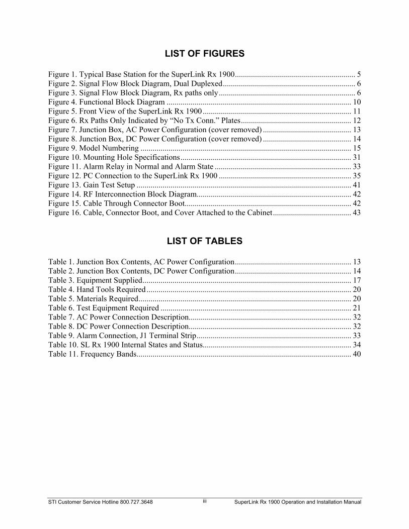
Figure 1. Typical Base Station for the SuperLink Rx 1900............................................................ 5 Figure 2. Signal Flow Block Diagram, Dual Duplexed.................................................................. 6 Figure 3. Signal Flow Block Diagram, Rx paths only.................................................................... 6 Figure 4. Functional Block Diagram ............................................................................................ 10 Figure 5. Front View of the SuperLink Rx 1900 .......................................................................... 11 Figure 6. Rx Paths Only Indicated by “No Tx Conn.” Plates....................................................... 12 Figure 7. Junction Box, AC Power Configuration (cover removed) ............................................ 13 Figure 8. Junction Box, DC Power Configuration (cover removed) ............................................ 14 Figure 9. Model Numbering ......................................................................................................... 15 Figure 10. Mounting Hole Specifications..................................................................................... 31 Figure 11. Alarm Relay in Normal and Alarm State .................................................................... 33 Figure 12. PC Connection to the SuperLink Rx 1900 .................................................................. 35 Figure 13. Gain Test Setup ........................................................................................................... 41 Figure 14. RF Interconnection Block Diagram............................................................................. 42 Figure 15. Cable Through Connector Boot................................................................................... 42 Figure 16. Cable, Connector Boot, and Cover Attached to the Cabinet....................................... 43
LIST OF TABLES
Table 1. Junction Box Contents, AC Power Configuration.......................................................... 13 Table 2. Junction Box Contents, DC Power Configuration.......................................................... 14 Table 3. Equipment Supplied........................................................................................................ 17 Table 4. Hand Tools Required ...................................................................................................... 20 Table 5. Materials Required.......................................................................................................... 20 Table 6. Test Equipment Required ............................................................................................... 21 Table 7. AC Power Connection Description................................................................................. 32 Table 8. DC Power Connection Description................................................................................. 32 Table 9. Alarm Connection, J1 Terminal Strip............................................................................. 33 Table 10. SL Rx 1900 Internal States and Status.......................................................................... 34 Table 11. Frequency Bands........................................................................................................... 40
STI Customer Service Hotline 800.727.3648 SuperLink Rx 1900 Operation and Installation Manual iii

STI Customer Service Hotline 800.727.3648 SuperLink Rx 1900 Operation and Installation Manual iv

Chapter 1 Introduction
Overview The SuperLink Rx 1900 (SL Rx 1900) is a highly selective and sensitive RF filter LNA used in the receive path of wireless base stations. The SL Rx 1900 eliminates the trade-off between selectivity and sensitivity. The superior performance of the SL Rx 1900 enables wireless service providers to enhance customer satisfaction and increase their subscriber base by improving the quality of voice and data transmissions by their networks. Some advantages of incorporating a SL Rx 1900 in a wireless telecommunications network include: Improved receiver noise figure Improved out-of-band signal rejection Stable sensitivity (site performance not impacted by out-of-band interference) Low power consumption Maintenance free operation Convenient outdoor installation Worry-free uplink enhancement
About this Manual
The SuperLink Rx 1900 Operation and Installation manual describes the 2-, 4-, and 6-channel SL Rx 1900. Detailed information such as installation requirements, testing procedures, and troubleshooting tips will assist you with the proper installation and operation of the SL Rx 1900.
STI Customer Service Hotline 800.727.3648 SuperLink Rx 1900 Operation and Installation Manual 1

Review the manual carefully for proper installation and operation of your SL Rx 1900 system. The following summary provides information about the chapters and appendices.
Chapter Title Description 1 Introduction States the purpose of the manual. Provides general information about
the manual that you need to know. 2 Using the SuperLink Rx
1900 Describes the role of the SL Rx 1900 in a typical wireless system. Provides information on SL Rx 1900 equipment configurations and functional descriptions.
3 Unpacking the
SuperLink Rx 1900 Provides detailed information about unpacking the SL Rx 1900.
4 Installation
Requirements Lists the tools, materials, and test equipment requirements for SL Rx 1900 installation.
5 Installing the SuperLink
Rx 1900 Provides the following information for installing the SL Rx 1900: installing the software programs, mounting the system, connecting the power and alarm wires, performing power up/cooldown, performing functional checks, connecting RF cables, and integrating the SL Rx 1900 with the base station.
6 Troubleshooting Tips Provides basic troubleshooting procedures for problems that may occur
during installation and operation. 7 Periodic Visual
Inspection Provides information about inspecting the SL Rx 1900 on a periodic basis.
Appendix A Using the System Status
Portal Explains the STI System Status Portal interface.
Appendix B SuperLink Rx 1900
Specifications Provides detailed information about the SL Rx 1900 specifications.
Appendix C Receive Path Gain/Loss
Calculator Provides a table to record channel gain/loss values as you conduct the Receive Path Gain test. This Appendix is also available as a Microsoft® Excel file in the SuperLink Rx 1900 Operation and Installation Manual folder located on the STI CD.
STI Customer Service Hotline 800.727.3648 SuperLink Rx 1900 Operation and Installation Manual 2

General Safety Warnings, Cautions, and Notes Warnings, cautions, and notes are used throughout the manual. Review the significance of each:
A warning denotes a hazard to personnel. A warning calls attention to a procedure, which if not correctly performed or adhered to, could result in injury to personnel.
A caution denotes a hazard to equipment. A caution calls attention to a procedure, which if not correctly performed or adhered to, could result in damage to the equipment
A note calls attention to a procedure for informational purposes only.
Electrostatic Discharge The SL Rx 1900 contains components that are subject to damage from electrostatic discharge (ESD). Ensure that you adhere to all appropriate ESD precautions when handling components mounted at the front of the system. The following caution appears throughout the manual during procedures in which the SL Rx 1900 may be subject to damage by ESD.
The SL Rx 1900 contains components that are subject to damage from electrostatic discharge (ESD). Take precautionary measures when handling connectors at the front of the SL Rx 1900.
Technical Assistance For technical assistance, call the STI Customer Service Hotline (CS-Hotline): 800.727.3648.
“CS-Hotline” refers to the STI Customer Service Hotline. For your convenience, the CS-Hotline number is located on the bottom of each page throughout the manual.
STI Customer Service Hotline 800.727.3648 SuperLink Rx 1900 Operation and Installation Manual 3

Warranty On a standard basis, Superconductor Technologies Inc. (STI) warrants its SuperLink Rx 1900 to be free from any defect in material and workmanship for a period of one (1) year from the date of shipment. STI’s sole obligation under this warranty is to repair or replace the SuperLink Rx 1900 or any part thereof, which proves to be defective after inspection by STI. The warranty for the repaired or replaced SuperLink Rx 1900 is the un-expired warranty period of the original SuperLink Rx 1900, or ninety (90) days whichever is greater. This warranty does not apply to any SuperLink Rx 1900 that has been disassembled, modified, subjected to unusual electrical or physical stress, misuse, neglect, excessive deterioration or erosion, abuse, accident, unauthorized repair, improper installation, or use in any way that is contrary to the instructions set forth herein. STI is not liable for any indirect, incidental, consequential or special damages, including without limitation, lost profits and cost of procurement of substitute goods. This warranty is the full extent of obligation and liability assumed by STI with respect to its SuperLink Rx 1900. STI neither assumes nor authorizes any other person to assume for it any other obligations or liability in connection with the sale, installation or use of its SuperLink Rx 1900.
STI Customer Service Hotline 800.727.3648 SuperLink Rx 1900 Operation and Installation Manual 4

Chapter 2 Using the SuperLink Rx 1900
Equipment Configurations The SL Rx 1900 is available for use in the United States Personal Communication Service (PCS) frequency bands. SL Rx 1900 systems are available in 2-channel and 6-channel RF receiver configurations: The 2-channel SL Rx 1900 system provides two RF receive paths, and operates in a
cellular system that uses omni-directional antennas, one main, and one diversity. The 6-channel SL Rx 1900 system is designed for a cellular system that uses three
antenna sectors, each consisting of one main and one diversity antenna. The 4-channel SL Rx 1900 is also offered for flexibility. Figure 1 shows a typical wireless telecommunications base station diagram with a SL Rx 1900 system.
SUPERLINK Rx 1900 -Enhances theperformance of theBase Station Receiver.
Note: Single RF path shown for simplicity.
Base StationReceivingEquipment
BASE STATION RECEIVE ANTENNA -Receives RF signals from Wireless NetworkSubscribers.
ANTENNA CABLE -Conducts received RFsignals to the Base StationReceiving Equipment viathe SuperLink Rx 1900.
BASE STATIONRECEIVINGEQUIPMENT -Processes receivedRF signals in normalmanner.
4
4
WIRELESS NETWORKSUBSCRIBERS
SuperLink Rx1900
Downlink Boost(optional)
Dual Duplexer
Figure 1. Typical Base Station for the SuperLink Rx 1900
STI Customer Service Hotline 800.727.3648 SuperLink Rx 1900 Operation and Installation Manual 5

Functional Description The functional areas of the SL Rx 1900 are described in the following paragraphs. See Figure 4 for a functional block diagram of the SL Rx 1900. Dual Duplexed System
The SL Rx 1900 is a Filter-Amplifier that connects in-line (cascade) with the existing receiver equipment. Figure 2 shows a dual duplexed system with a cascade connection with a base station antenna. The block diagram shows the Bypass RF path, which provides pre-SL Rx 1900 performance if the Filter-Amplifier should develop a problem. The in-path dual duplexer allows the duplexed transmit power signal to route around the receive filter LNA (CoRE).
Note: Single RF path shown for simplicity.
LNA
Duplexed Base StationReceiver Front-End
Filter/LNA andTransmit Output
BTS or PASector α1Rx+Tx
AntennaSector α1Rx+Tx
SuperLink Rx 1900
Dual Duplexer
TxTx
RxRx
CombinedRF
CombinedRF
ANT 1A
PowerAmplifier
RFFront-End
DUPLEXER
Tx
Rx
Figure 2. Signal Flow Block Diagram, Dual Duplexed
Simplexed System (Rx paths only) Figure 3 shows a simplexed system (Rx paths only) with a cascade connection to a base station antenna. The block diagram shows the Bypass RF path, which provides pre-SL Rx 1900 performance if the Filter-Amplifier should develop a problem. With the simplexed (Rx paths only) configuration, the Filter-Amplifier connects directly to the antenna cable through lightning protectors, and provides a clear, low noise signal to the receiver.
LNADuplexed Base Station
Receiver Front-EndFilter/LNA and
Transmit Output
BTSSector α
1Rx
AntennaSector α
1Rx
SuperLink Rx 1900
RxRx ANT 1A
Note: Single RF path shown for simplicity.
Figure 3. Signal Flow Block Diagram, Rx paths only
STI Customer Service Hotline 800.727.3648 SuperLink Rx 1900 Operation and Installation Manual 6
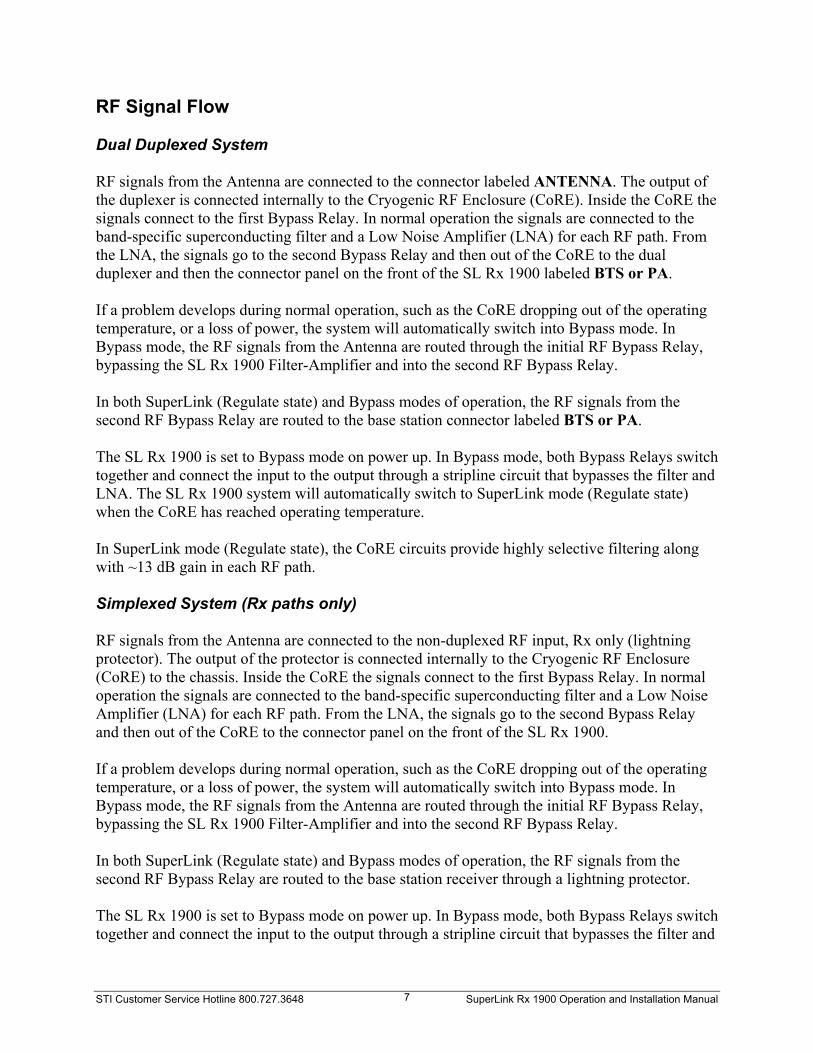
RF Signal Flow Dual Duplexed System RF signals from the Antenna are connected to the connector labeled ANTENNA. The output of the duplexer is connected internally to the Cryogenic RF Enclosure (CoRE). Inside the CoRE the signals connect to the first Bypass Relay. In normal operation the signals are connected to the band-specific superconducting filter and a Low Noise Amplifier (LNA) for each RF path. From the LNA, the signals go to the second Bypass Relay and then out of the CoRE to the dual duplexer and then the connector panel on the front of the SL Rx 1900 labeled BTS or PA. If a problem develops during normal operation, such as the CoRE dropping out of the operating temperature, or a loss of power, the system will automatically switch into Bypass mode. In Bypass mode, the RF signals from the Antenna are routed through the initial RF Bypass Relay, bypassing the SL Rx 1900 Filter-Amplifier and into the second RF Bypass Relay. In both SuperLink (Regulate state) and Bypass modes of operation, the RF signals from the second RF Bypass Relay are routed to the base station connector labeled BTS or PA. The SL Rx 1900 is set to Bypass mode on power up. In Bypass mode, both Bypass Relays switch together and connect the input to the output through a stripline circuit that bypasses the filter and LNA. The SL Rx 1900 system will automatically switch to SuperLink mode (Regulate state) when the CoRE has reached operating temperature. In SuperLink mode (Regulate state), the CoRE circuits provide highly selective filtering along with ~13 dB gain in each RF path. Simplexed System (Rx paths only) RF signals from the Antenna are connected to the non-duplexed RF input, Rx only (lightning protector). The output of the protector is connected internally to the Cryogenic RF Enclosure (CoRE) to the chassis. Inside the CoRE the signals connect to the first Bypass Relay. In normal operation the signals are connected to the band-specific superconducting filter and a Low Noise Amplifier (LNA) for each RF path. From the LNA, the signals go to the second Bypass Relay and then out of the CoRE to the connector panel on the front of the SL Rx 1900. If a problem develops during normal operation, such as the CoRE dropping out of the operating temperature, or a loss of power, the system will automatically switch into Bypass mode. In Bypass mode, the RF signals from the Antenna are routed through the initial RF Bypass Relay, bypassing the SL Rx 1900 Filter-Amplifier and into the second RF Bypass Relay. In both SuperLink (Regulate state) and Bypass modes of operation, the RF signals from the second RF Bypass Relay are routed to the base station receiver through a lightning protector. The SL Rx 1900 is set to Bypass mode on power up. In Bypass mode, both Bypass Relays switch together and connect the input to the output through a stripline circuit that bypasses the filter and
STI Customer Service Hotline 800.727.3648 SuperLink Rx 1900 Operation and Installation Manual 7

LNA. The SL Rx 1900 system will automatically switch to SuperLink mode (Regulate state) when the CoRE has reached operating temperature. In SuperLink mode (Regulate state), the CoRE circuits provide highly selective filtering along with ~13 dB gain in each RF path. Control The Digital Signal Processor (DSP) provides the SL Rx 1900 control and performance monitoring function. The DSP monitors: Input voltage from the Power Supply Driver power for the Cooling Motor Driver CoRE temperature from the Thermal Sensor Interface LNA current
If input voltage drops or rises to an unacceptable level the DSP will cause the SL Rx 1900 to switch into the Fault Bypass mode and, at the same time, activate the alarm relay. Signals from the alarm relay are available for connection to a base station alarm system. The FAULT LED, located on the SL Rx 1900 front panel, will illuminate RED to indicate Bypass mode. The DSP senses variations in driver power. If the motor driver power levels move to an unacceptable level the DSP will cause the SL Rx 1900 to switch into the Shutdown (Bypass) mode and, at the same time, activate the alarm relay as previously mentioned. The DSP controls the temperature of the CoRE. The Thermal Sensor Interface routes multiplexed sensor signals to the DSP. Correction signals are sent to the Cooling Motor Driver. If temperature levels move to an unacceptable level the DSP will cause the SL Rx 1900 to switch into the Fault Bypass mode. Additionally, the DSP monitors the LNA current. Unacceptable levels of LNA current will cause the SL Rx 1900 to switch to Fault Bypass mode. Each time the SL Rx 1900 is switched to Bypass mode, the alarm relay is activated. Cryogenic Cooling The STI Stirling Cycle Cryogenic Cooler is a highly efficient state-of-the-art Cryogenic Cooler. The Cryogenic Cooler maintains the CoRE at an operating temperature of ~79 K (Kelvin). The compressor and cold finger are fully integrated into a single self-contained unit. The Cooling Motor Driver provides drive and control to maintain a constant temperature. Temperature sensors in both the CoRE and the STI Stirling Cycle Cryogenic Cooler provide for constant temperature monitoring of the system by the Thermal Sensor Interface. Power Input power is received at the POWER terminal block connections located in the Junction Box on the side panel of the SL Rx 1900. Three power source options are available: AC (110 VAC or 220 VAC) or DC (27 VDC or -48 VDC).
STI Customer Service Hotline 800.727.3648 SuperLink Rx 1900 Operation and Installation Manual 8

AC The AC routes through the lightning protection, then to the AC/DC converter. DC The DC directly routes to the DSP controller board. The power is routed through a fuse. Dual Duplexers The Dual Duplexers work to route the RF transmit power around the CoRE, but at the same time allowing the receiver frequency signals to and from the CoRE with very low loss. This is accomplished using classical duplexer methods of tuned resonators, but using proprietary STI technology for superior performance in low loss, high power, and high rejection characteristics.
STI Customer Service Hotline 800.727.3648 SuperLink Rx 1900 Operation and Installation Manual 9

DC
Cryogenic RF Enclosure (CoRE)
BypassRelay
BypassRelay
Filter and Amplifier
Col
dFi
nger
Stirling CycleCryogenic Cooler
Printed Circuit Assembly
CoolingMotor Driver
Thermal SensorInterface
Control Electronics(Digital Signal Processor )
Power Supply
Serial Interface
Alarm Relay
LNARF Input
FromAntenna
RF Output
To BaseStation
AmbientTemperature
Sensor
Narrow Range andWide Range Cold Stage
Temperature Sensor
Motor TemperatureSensor
Motor Drive60 Hz,
VariableVoltage
Motor current &voltage sensors
Proportional controldrive
Regulated powerto all functions
Input VoltageSensor
LNA currentsensor
RS-232SerialDigitalData
27 VDC or -48 VDC Power
110 VAC or 220 VAC Power
LightningProtectionTo Alarm Connection
Junction Box
LightningProtection
Junction Box
LightningProtection To Power Supply
To Alarm Connection Alarm Panel
AC
Dual Duplexer
TxTx
RxRx
Dual duplexers areoptional for diversity paths
Figure 4. Functional Block Diagram
STI Customer Service Hotline 800.727.3648 SuperLink Rx 1900 Operation and Installation Manual 10

Indicators, Connectors, and Controls Front View of the SuperLink Rx 1900 Figure 5 shows several features on the front of the system. The FAULT LED is located in the top left corner, next to the RS-232 Console Cover Plate.
FAULT LED
RS-232 Console Cover Plate (not pictured)
Junction Box
RF Connectors
RF Connector Covers
Figure 5. Front View of the SuperLink Rx 1900
FAULT LED The FAULT LED illuminates RED for the following reasons: Power up: When you power up the SL Rx 1900, the FAULT LED remains on (RED)
until the system reaches operating temperature (~79 K). When the system cools down, the FAULT LED turns off (no light).
FAULT condition: During operation of the SL Rx 1900, the FAULT LED only illuminates RED when a fault occurs.
Although the FAULT LED is bright, you may need to shade the LED with your hand in direct sunlight.
Forced Bypass: When the system is set to Forced Bypass, the FAULT LED will flash RED. To set the system to Forced Bypass, using the System Status Portal, go to View > Set Points and find the Relay tab. Check the Forced Bypass box.
STI Customer Service Hotline 800.727.3648 SuperLink Rx 1900 Operation and Installation Manual 11

RS-232 Console Cover Plate The RS-232 console cover plate protects the console when not in use. When the cover plate is removed, the dust protector must also be removed to access the console.
You can order a replacement for the RS-232 console cover plate (part number 018-0174-01 for $5). Contact the CS-Hotline for assistance.
RF Connectors and Covers The system can accommodate up to six RF paths. The RF paths are grouped into three sectors, with main and diversity paths in each sector, as shown in Figure 6. For models with Rx only paths (simplex): RF paths 2, 4, and 6 handle receive signals only, indicated by the “No Tx Conn.” plates on the system as shown in Figure 6.
No Tx.
Make sure that no transmit signals are connected up to the diversity paths (2, 4, and 6) when they are configured for receive only. When transmit signals are fed into receive only paths, they will damage the system.
Figure 6. Rx Paths Only Indicated by “No Tx Conn.” Plates
Junction Box
When you apply power to the system or remove the Junction Box cover, you are exposed to high voltage. Be careful when handling the system under these circumstances. This label is located on the Junction Box cover for your safety.
STI Customer Service Hotline 800.727.3648 SuperLink Rx 1900 Operation and Installation Manual 12

The Junction Box contains the power and alarm connectors. Figure 7 shows the interior of the Junction Box for AC power, with each item explained in Table 1, and Figure 8 shows the interior of the Junction Box for DC power, with each item explained in Table 2. AC Power Configuration Lightning protection is provided for both the AC power and alarm connections in the Junction Box. It contains the AC power protection module and alarm circuit surge protection. You may need to replace the AC power protection module after lightning activity at the base station. The alarm circuit also has a replaceable module for restoring function after an extreme power surge. The fuse is located on the left panel of the AC power surge protector.
1 7
6
2
3
5
4
Figure 7. Junction Box, AC Power Configuration (cover removed)
Table 1. Junction Box Contents, AC Power Configuration
Item No. Item Description 1 AC to DC converter For providing conditioned power to the system. 2 Power connections For attaching external power wiring to the system. 3 Green wire ground terminal block For attaching external power ground wire to the system. 4 Conduit access ports For external wire access (3/4-inch). 5 Alarm connection input terminal
strip For attaching external alarm wiring to the system.
6 Alarm surge protection module For protecting the system against surge. 7 Fuse (Not pictured.) For providing 15-amp input power protection for the system.
The fuse is located to the left of the power surge protector.
You can order replacements for Item number 3 (part number 360-0075-02 for $4), and the entire AC board (part number 302-0029 for $186). Contact the CS-Hotline for assistance.
STI Customer Service Hotline 800.727.3648 SuperLink Rx 1900 Operation and Installation Manual 13
STI Customer Service Hotline 800.727.3648 SuperLink Rx 1900 Op14
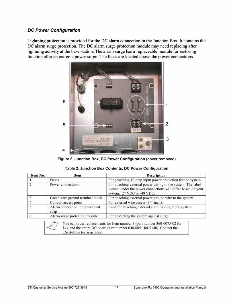
DC Power Configuration Lightning protection is provided for the DC alarm connection in the Junction Box. It contains the DC alarm surge protection. The DC alarm surge protection module may need replacing after lightning activity at the base station. The alarm surge has a replaceable module for restoring function after an extreme power surge. The fuses are located above the power connections.
ightning protection is provided for the DC alarm connection in the Junction Box. It contains the DC alarm surge protection. The DC alarm surge protection module may need replacing after lightning activity at the base station. The alarm surge has a replaceable module for restoring function after an extreme power surge. The fuses are located above the power connections. . .
Figure 8. Junction Box, DC Power Configuration (cover rem
Table 2. Junction Box Contents, DC Power Configurati
Item No. Item Descriptio1 Fuses For providing 10-amp input power p2 Power connections For attaching external power wiring
located under the power connectionssystem: 27 VDC or -48 VDC.
3 Green wire ground terminal block For attaching external power ground4 Conduit access ports For external wire access (3/4-inch). 5 Alarm connection input terminal
strip Used for attaching external alarm w
6 Alarm surge protection module For protecting the system against su
You can order replacements for Item number 3 (part number 360-$4), and the entire DC board (part number 040-0051 for $140). CoCS-Hotline for assistance.
5
6
4
1 2eration and Installation Manual
oved)
on
n rotection for the system.
to the system. The label will differ based on your
wire to the system.
iring to the system.
rge.
0075-02 for ntact the
3

Model Number Identification The SL Rx 1900 model number provides information on filter generation, frequency ranges, number of RF receive paths, and types of options selected. The model (and serial) numbers are located in two locations: Inside the Junction Box Underneath the Junction Box
See Figure 9 for a description of the STI SL Rx 1900 model numbers.
1900 = 1900 MHz (PCS)
Band TypeA = A-Band Frequency 1850-1864.95 MHzB = B-Band Frequency 1870-1884.95 MHzC = C-Band Frequency 1895-1909.95 MHzD = D-Band Frequency 1865-1869.95 MHzE = E-Band Frequency 1885-1889.95 MHzF = F-Band Frequency 1890-1894.95 MHzDE = D plus E-Band Frequency 1865-1869.95 and 1885-1889.95 MHzAD = AD-Band Frequency 1850-1869.95 MHzDB = DB-Band Frequency 1865-1884.95 MHzBE = BE-Band Frequency 1870-1889.95 MHz
1900 B 6 - ERx
Rx = Receiver
D1
Duplexer SetupD1 = 1 Dual Duplexed Diversity PathD2 = 2 Dual Duplexed Diversity PathsD3 = 3 Dual Duplexed Diversity Pathsnone = Dual Duplexers on main path only
(Dual duplexed = Tx+Rx together on diversity paths)
AC
PowerAC = AC powered at +110V to +220V at 60 Hznone = DC powered at +22.5V to +30V48 = DC powered at -32V to -58V
RF Paths6 = 6 RF paths4 = 4 RF paths2 = 2 RF paths
Cabinet TypeE = Outdoor Cabinet
Figure 9. Model Numbering
STI Customer Service Hotline 800.727.3648 SuperLink Rx 1900 Operation and Installation Manual 15

STI Customer Service Hotline 800.727.3648 SuperLink Rx 1900 Operation and Installation Manual 16

STI Customer Service Hotline 800.727.3648 SuperLink Rx 1900 Operation and Installation Manual 17
Chapter 3 Unpacking the SuperLink Rx 1900
Reviewing the Contents of the SuperLink Rx 1900 Package When you unpack the SL Rx 1900 package, review the contents to ensure you received the supplied items as shown in Table 3. If you discover items missing, call the CS-Hotline.
Table 3. Equipment Supplied
Item No. Item Part No. Qty Notes 1 SL Rx 1900, 2-, 4-,
or 6-channel As ordered 1 each 2-, 4-, or 6-channel SL Rx 1900 as
ordered. 2 Connector boots 360-0188 12 each for 6-channel
8 each for 4-channel 4 each for 2-channel
For connector/cable weather protection.
3 STI CD 831-0001 1 each Contains the product manual and the STI System Status Portal software that communicates with the SL Rx 1900.
Unpacking the SuperLink Rx 1900 The following steps ensure that you unpack the SL Rx 1900 properly.
The following tools are required to remove the system from the pallet: 1/2-inch wrench or 1/2-inch socket head and driver.
Depending on the configuration, the un-boxed SuperLink Rx 1900 weighs approximately 180+20 lbs. To prevent injury to personnel and damage to equipment, it is recommended that you use a special hoist to move the system.
1. Inspect the shipping container for signs of damage. Report any damage to the CS-Hotline.
2. Remove the straps securing the cardboard to the pallet.
3. Remove the heavy-duty cardboard box from the SL Rx 1900.
4. Remove the bag containing the connector boots and STI CD.
5. Using either a 1/2-inch wrench or a 1/2-inch socket head and driver, remove the screws holding the system to the pallet.
6. Inspect the SL Rx 1900 for signs of damage. Report any damage to the CS-Hotline.
7. Using a special hoist or crane, carefully move the system from the pallet to the desired location.

STI Customer Service Hotline 800.727.3648 SuperLink Rx 1900 Operation and Installation Manual 18
The bottom of the system contains sensitive components. Only use a forklift when the system is on a pallet. Otherwise, use a special hoist or crane to move the system.
8. Retain the shipping container and all packing materials for reuse. Store the shipping container in a dry place.
Instructions for Return Shipment The SL Rx 1900 may be returned to STI to incorporate an optional feature, upgrade to a newer model, or for repair. STI handles all upgrades and repair activity. To return a system, complete the following:
1. Call the CS-Hotline for a Return Material Authorization (RMA) number. Provide the following information:
Model number (located inside and underneath the Junction Box) Serial number (located inside and underneath the Junction Box) Comprehensive description as to the nature of the return
The representative will inform you about the return shipment process, including a brief explanation about shipping Hazardous Materials. You must be certified to ship Hazardous Materials.
The representative will mail you a packet that contains the information you need to learn more about Hazardous Materials and to properly ship the system back to STI.
2. The day you receive your paperwork, the representative will contact you to discuss Hazardous Materials. The representative will certify you after a brief discussion over the phone, concluding with a quiz. When you successfully complete the quiz, provide the representative with the following information to complete your certification:
Your title Immediate supervisor’s name Immediate supervisor’s e-mail
3. After you are certified, follow the instructions provided in the RMA packet to ship the system back to STI.
Failure to properly package the SL Rx 1900 system could result in significant shipping damage. STI is not responsible for shipping damage due to improper packaging.
Keep the original shipping container for return shipment, or request a new shipping container from STI.

STI Customer Service Hotline 800.727.3648 SuperLink Rx 1900 Operation and Installation Manual 19
Chapter 4 Installation Requirements
Overview Before you install the SL Rx 1900, review the installation requirements: Establish site requirements Assemble tools and materials required for installation Assemble functional checks test equipment Review PC requirements for the Java Runtime Environment/System Status Portal
The tools, materials, and test equipment are not supplied with the SL Rx 1900. The following sections guide you in preparing the items you need to install the SL Rx 1900. If you have questions about the installation requirements, call the CS-Hotline.
SuperLink Rx 1900 Requirements
Site Requirements A NEMA 4X compliant outdoor cabinet encloses the SL Rx 1900. Using a chimney built into the rear of the cabinet, internal heat pipes and natural convection cool the SL Rx 1900. The mounting area you choose must provide space for air circulation around the cabinet for continuous airflow through the bottom and top rear of the cabinet. Review the following site requirements: Determine a mounting location (3-foot x 3-foot) with unobstructed air vent space on top
and on the bottom of the SL Rx 1900. This location must provide enough space to access the Junction Box and the RF cable connections.
Install the cabinet on a level surface with no more than a 2-inch height (level within 5º) difference across the base. It is acceptable to mount the system with the rear against the wall.
Power Source: o AC: 90 to 132 VAC, 180 to 264 VAC Power Source provided through a Power
Distribution Panel Circuit Breaker of 5-amp capability. o 27 VDC: 27 VDC Power Source provided through a Power Distribution Panel
Circuit Breaker of 15-amp capability (15 to 30 amps). o -48 VDC: -48 VDC Power Source provided through a Power Distribution Panel
Circuit Breaker of 10-amp capability. Remote monitoring connection for the SL Rx 1900 alarm relay.

STI Customer Service Hotline 800.727.3648 SuperLink Rx 1900 Operation and Installation Manual 20
Required Installation Tools and Materials You are responsible for providing hand tools and materials to install the SL Rx 1900. Review the following requirements:
Table 4. Hand Tools Required
Item No. Item Notes 1 Drill For drilling holes to fasten the SL Rx 1900 to the mounting
surface. 2 Screwdriver, 1/8-inch flat blade For power and alarm connection, and removing the fuse (AC). 3 Screwdriver, large flat blade For attaching the ground wire to the system. 4 Screwdriver, Phillips #2 For removing the Junction Box cover, RS-232 console cover
plate, and RF connector covers. 5 Scissors For cutting connector boots. 6 Torque wrench For tightening the DIN 7/16 RF connectors with a setting of
228+12 in.-lbs. 7 Wrench For mounting the system. 8 Wire Stripper For power wire installation. 9 Wire Cutter (diagonal cutter) For power wire installation and wire tie removal. 10 Conduit cutter, bending tools For cutting conduits required for the power and alarm access. 11 Allen wrench 7/64 For removing the ground terminal.
Table 5. Materials Required
Item No. Item Qty Notes 1 RF Jumper Cable,
Flexible, Low Loss (1/2-inch)
1 per receive path, length as required
DIN 7/16 connectors, one male and one female. This cable must be long enough to connect between the existing antenna feed coaxial connector and the SL Rx 1900 antenna port. (Rerouting the existing feed jumper cable may be sufficient for this cable.)
2 RF Jumper Cable, Flexible, Low Loss (1/2-inch)
1 per receive path, length as required
DIN 7/16 connectors, male to female. This cable must be long enough to connect the SL Rx 1900 BTS port to the existing antenna input connector of the base station receiver.
3 Wire, Duplex AC: 14-gauge or
16-gauge DC: 10-gauge
Length as required
AC power: White, black, and green wire (14-gauge or 16-gauge AWG wire is recommended). DC power: Red and black wire preferred for color-coding + and - power. Power wire, 12-gauge for lengths up to 20 feet, 10-gauge up to 30 feet.
4 Wire, Duplex 24-gauge
Length as required
If desired, for connecting the SL Rx 1900 alarm relay output to the base system Alarm Control Unit.
5 Wire, 6-gauge Length as required
For connecting the SL Rx 1900 chassis ground to the base station ground.
6 Nylon Wire Ties As required Used to dress connector boots after installation. 7 Circuit Breaker As required
Used to install the system and perform functional checks. Use the following breaker for each power source: 5-amp Breaker (AC); 20-amp Breaker (27 VDC); and 10-amp Breaker (-48 VDC).
8 Conduit and Conduit-to-Junction Box adapters
As required
Per local electrical code, NEMA 4X recommended.
9 Mounting hardware
6 each Used to bolt the system to a flat surface. Use mounting hardware that works best for the mounting surface.

STI Customer Service Hotline 800.727.3648 SuperLink Rx 1900 Operation and Installation Manual 21
Required Functional Checks Test Equipment You are responsible for providing test equipment to perform functional checks on the SL Rx 1900. Review the following test equipment requirements:
Table 6. Test Equipment Required
Item No. Test Equipment Notes 1 Digital Multimeter (DMM) or
equivalent Checks the alarm relay and input power.
2 Personal Computer (PC) with Comm Port
Accesses SL Rx internal states using the serial port. See the “Reviewing PC System Requirements” section on page 21 for more information.
3 Straight-thru cable, DB-9 Female Connector to DB-9 Male Connector (50 feet maximum)
Connects PC to SL Rx 1900.
4 Signal Generator, Radio Frequency Generates a continuous wave (CW) carrier at approximately 1900 MHz depending on the band, with output level adjusted to -50 dBm.
5 Spectrum Analyzer Receives and displays CW carrier at approximately 1900 MHz, across levels -55 to -35 dBm; measure received power level accurately (+1 dB).
Reviewing PC System Requirements To communicate with the SL Rx 1900, STI provides two programs you need to install on your PC: Java Runtime Environment and the System Status Portal. The Java Runtime Environment is required for the System Status Portal to operate properly. If you already have the Java Runtime Environment on your PC, you do not need to install this program. Review the system requirements to ensure your PC has the minimum system requirements to run these programs. Call the CS-Hotline if you have questions about the requirements. Windows 95, 98 (1st or 2nd edition), 2000, NT 4.0 (with Service Pack 6), ME, or XP Pentium 166 MHz or faster processor 70 MB available disk space 32 MB RAM minimum, 48 MB RAM (or higher) ideal CD-ROM drive Comm Port available (supporting 19.2K baud data rates) Internet Explorer 5.5 and higher, Netscape Navigator 6.2 and higher, or Netscape
Communicator 4.79 and higher

STI Customer Service Hotline 800.727.3648 SuperLink Rx 1900 Operation and Installation Manual 22
STI Customer Service Hotline 800.727.3648 SuperLink Rx 1900 Operation and Installation Manual 23
Chapter 5 Installing the SuperLink Rx 1900
Overview
Qualified technicians should install the SuperLink Rx 1900 system. Contact the CS-Hotline for assistance: 800.727.3648.
Proper installation of the SL Rx 1900 consists of the following steps: Installing the Java Runtime Environment/System Status Portal Mounting the SL Rx 1900 Connecting the conduit, chassis ground, and power and alarm wires Performing power up/cooldown Performing functional checks Connecting RF cables Integrating the SL Rx 1900 with the base station
Site-specific installation and checkout information may be available by calling the CS-Hotline. SL Rx 1900 Installation Procedures Installing the Java Runtime Environment The Java Runtime Environment, version 1.4, supports the System Status Portal. This version is available on the STI CD shipped with the SL Rx 1900. If you currently have this version installed on your PC, you do not need to install this program again. To install from the STI CD:
1. Insert the STI CD into your CD-ROM drive.
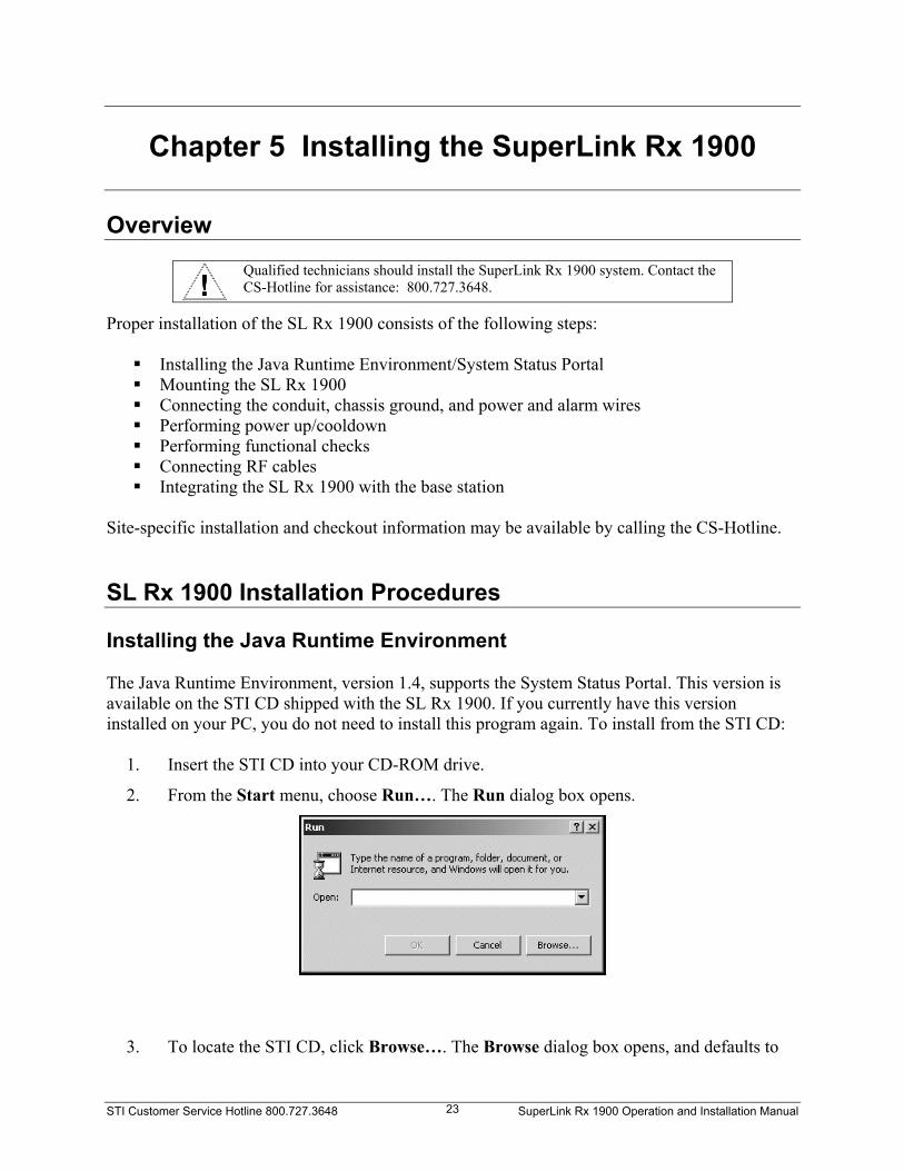
2. From the Start menu, choose Run…. The Run dialog box opens.
3. To locate the STI CD, click Browse…. The Browse dialog box opens, and defaults to

STI Customer Service Hotline 800.727.3648 SuperLink Rx 1900 Operation and Installation Manual 24
the C: drive. Find the CD-ROM drive on your PC, and display the contents of the STI CD.
4. Double-click the JavaRE folder. This folder contains the setup file for the Java Runtime Environment: j2re-1_4_0_01-windows-i586.exe.
5. Double-click the setup file: j2re-1_4_0_01-windows-i586.exe. The file path displays in the Run dialog box. Click OK to begin the installation, and the InstallShield Wizard dialog box opens. Click Next >.

STI Customer Service Hotline 800.727.3648 SuperLink Rx 1900 Operation and Installation Manual 25
6. Review the information on the License Agreement dialog box, and click Yes to continue with the installation.
7. Choose a destination location. By default, the InstallShield Wizard chooses the C: drive to install the Java Runtime Environment. Install the program on the default drive: C:\Program Files\Java\j2re1.4.0_01. Click Next >.

STI Customer Service Hotline 800.727.3648 SuperLink Rx 1900 Operation and Installation Manual 26
7a. If you want to change the destination folder, click Browse…. The Choose Folder dialog box opens. Choose a location to install the Java Runtime Environment, and click OK to continue with the installation.
8. Choose the browser used on your PC: Microsoft Internet Explorer or Netscape 6. Click Next >.
For Netscape users only. Verify that the Java Plugin box is checked to enable proper operation of the System Status Portal. Choose Edit > Preferences. Find Category and click Advanced. In this window, check Enable Java Plugin, and click OK.
The InstallShield Wizard installs the Java Runtime Environment on your PC. When the installation is complete, the Java Runtime Environment InstallShield Wizard closes.

STI Customer Service Hotline 800.727.3648 SuperLink Rx 1900 Operation and Installation Manual 27
Installing the System Status Portal The System Status Portal provides a user-friendly interface to observe the operating parameters of the SL Rx 1900. For more information about using the System Status Portal, see Appendix A, “Using the System Status Portal.”
1. Locate the STI CD using Start > Run…. The Run dialog box opens.
2. To locate the STI CD, click Browse…. The Browse dialog box opens, and defaults to the C: drive. Find the CD-ROM drive on your PC, and display the contents of the STI CD.
3. Double-click the Application folder. The folder contains the setup file for the System Status Portal: setup.exe.

STI Customer Service Hotline 800.727.3648 SuperLink Rx 1900 Operation and Installation Manual 28
4. Double-click the setup file: setup.exe. The file path displays in the Run dialog box.
Click OK to begin the installation, and the InstallShield Wizard dialog box opens. Click Next >.
5. Choose a Destination Folder. By default, the InstallShield Wizard chooses the C: drive to install the System Status Portal. Install the program on the default drive and folder: C:\Program Files\STI\App\. Click Next >.

STI Customer Service Hotline 800.727.3648 SuperLink Rx 1900 Operation and Installation Manual 29
5a. If you want to change the destination folder, click Change…. The Change Current
Destination Folder dialog box opens. Choose a folder to install the System Status Portal, and click OK to continue with the installation.
6. Review the installation settings before you complete the installation. If you need to make any changes, click < Back to review the previous screens. Click Install to continue with the installation.
STI Customer Service Hotline 800.727.3648 SuperLink Rx 1900 Operation and Installation Manual 30
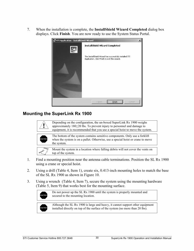
7. When the installation is complete, the InstallShield Wizard Completed dialog box
displays. Click Finish. You are now ready to use the System Status Portal.
Mounting the SuperLink Rx 1900
Depending on the configuration, the un-boxed SuperLink Rx 1900 weighs approximately 180+20 lbs. To prevent injury to personnel and damage to equipment, it is recommended that you use a special hoist to move the system.
The bottom of the system contains sensitive components. Only use a forklift when the system is on a pallet. Otherwise, use a special hoist or crane to move the system.
Mount the system in a location where falling debris will not cover the vents on top of the system.
1. Find a mounting position near the antenna cable terminations. Position the SL Rx 1900 using a crane or special hoist.
2. Using a drill (Table 4, Item 1), create six, 0.413-inch mounting holes to match the base of the SL Rx 1900 as shown in Figure 10.
3. Using a wrench (Table 4, Item 7), secure the system using the mounting hardware (Table 5, Item 9) that works best for the mounting surface.
Do not power up the SL Rx 1900 until the system is properly mounted and secured to the mounting location.
Although the SL Rx 1900 is large and heavy, it cannot support other equipment installed directly on top of the surface of the system (no more than 20 lbs).

STI Customer Service Hotline 800.727.3648 SuperLink Rx 1900 Operation and Installation Manual 31
1.0"
9.0"
9.0"
0.413" Mounting Hole, 6 places
Junc
tion
Box
RF Connector Cover
Top View
Rear of SL Rx 1900
25.5"
22.5"
24.5"
Figure 10. Mounting Hole Specifications
Connecting Cables and Wires Installing the Conduit
You are responsible for adhering to all local electrical codes and permit requirements.
1. Using a Phillips #2 screwdriver (Table 4, Item 4), remove the Junction Box cover.
2. Three conduit access ports, covered with plastic caps, are provided in the bottom of the Junction Box for alarm and power wiring. Remove the plastic caps from the bottom of the Junction Box.
3. Push the conduit (Table 5, Item 8) through the access ports. Use the right access port for the power connection and the left access port for the alarm connection. Use Nema 4X compliant fittings to maintain the integrity of the enclosure.
Connecting the Chassis Ground A lug for connecting a chassis ground is provided at the foot of the system on the left side. Connect the chassis ground to the base station ground using 6-gauge green wire (Table 5, Item 5).
1. Using a large, flat blade screwdriver (Table 4, Item 3), open the setscrew on the ground terminal.
2. Insert 6-gauge wire (Table 5, Item 5) in the ground terminal and tighten the setscrew halo using an Allen wrench 7/64 (Table 4, Item 11).
3. Connect the other end of the ground wire to the base station ground.

STI Customer Service Hotline 800.727.3648 SuperLink Rx 1900 Operation and Installation Manual 32
Co ecnn ting Power Wires: AC Power
The procedure to connect the cables for AC and DC power is different. Follow the correct procedure, and continue with the Power up/cooldown procedure.
Keep the power wire to less than 30 feet in length. A 14-gauge wire is preferr
ed but a 16-gauge wire may be used for wire lengths of less than 20 feet.
Before you proceed, set the power source circuit breaker to the open or
off
position. Failure to comply may result in personnel injury.
1. Prior to pulling the power wires (Table 5, Item 3), remove the alarm surge protector to
2. access port on the right, pull the wires for AC power through the e 7
Table 7. AC Power Connection Description
access the fuse (Figure 7). Using a flat blade screwdriver (1/8-inch) (Table 4, Item 2), remove the fuse.
sing the conduitUconduit and connect as labeled in the Junction Box: power, return, ground. See Tablfor AC power connection.
Wire Description Hot (blac Left termink) al Neutral (white) Center terminal Ground (green) Ground lug on chassis
Connecting Power Wires: DC Power
Keep the power wire to less than 30 feet in length. A 10-gauge wire is preferred but a 12-gauge wire may be used for wire lengths of less than 20 feet.
Before you proceed, set the power source circuit breaker to the open or
off
position. Failure to comply may result in personnel injury.
1. Prior to pulling the power wires (Table 5, Item 3), remove the fuse (Figure 8).
the e
Table 8. DC Power Connection Description
.
sing the conduit access port on the right, pull the wires for DC power through2. Uconduit and connect as labeled in the Junction Box: power, return, ground. See Tabl8 for DC power connection.
Wire Description Negative (-) (black) Left terminal Positive (+) (red) Center terminal Ground (green) Ground lug on chassis
STI Customer Service Hotline 800.727.3648 SuperLink Rx 1900 Operation and Installation Manual 33
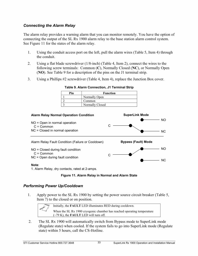
Connecting the Alarm Relay The alarm relay provides a warning alarm that you can monitor remotely. You have the option of connecting the output of the SL Rx 1900 alarm relay to the base station alarm control system. See Figure 11 for the states of the alarm relay.
1. Using the conduit access port on the left, pull the alarm wires (Table 5, Item 4) through the conduit.
2. Using a flat blade screwdriver (1/8-inch) (Table 4, Item 2), connect the wires to the following screw terminals: Common (C), Normally Closed (NC), or Normally Open (NO). See Table 9 for a description of the pins on the J1 terminal strip.
3. Using a Phillips #2 screwdriver (Table 4, Item 4), replace the Junction Box cover.
Table 9. Alarm Connection, J1 Terminal Strip
Pin Function 1 Normally Open 2 Common 3 Normally Closed
Alarm Relay Normal Operation Condition
NO = Open in normal operation C = CommonNC = Closed in normal operation
Alarm Relay Fault Condition (Failure or Cooldown)
NO = Closed during fault condition C = CommonNC = Open during fault condition
Note:1. Alarm Relay, dry contacts, rated at 2-amps.
SuperLink Mode
Bypass (Fault) Mode
C
C
NO
NO
NC
NC
Figure 11. Alarm Relay in Normal and Alarm State
Performing Power Up/Cooldown
1. Apply power to the SL Rx 1900 by setting the power source circuit breaker (Table 5, Item 7) to the closed or on position.
Initially, the FAULT LED illuminates RED during cooldown.
When the SL Rx 1900 cryogenic chamber has reached operating temperature (~79 K), the FAULT LED will turn off.
2. The SL Rx 1900 will automatically switch from Bypass mode to SuperLink mode (Regulate state) when cooled. If the system fails to go into SuperLink mode (Regulate state) within 5 hours, call the CS-Hotline.

STI Customer Service Hotline 800.727.3648 SuperLink Rx 1900 Operation and Installation Manual 34
3. t the SL Rx 1900 input voltage and polarity Using a DMM (Table 6, Item 1), verify thaat the terminal block contact reads the following based on your system:
AC: 90 to 132 VAC, 180 to 264 VAC 27 VDC: 27+3 VDC -48 VDC: -48+4 VDC
4. 7)
5. plant, turn the breaker on to power up the system. The
erLink mode ate
able 10 provides the following states, relay settings, and indicator readings for the SL Rx 1900.
Table 10. SL Rx 1900 Internal States and Status
State
After verifying proper voltage and polarity, turn the circuit breaker (Table 5, Itemoff, and install the fuse.
n the base station powerIFAULT LED illuminates RED and the system will hum or vibrate.
atically switch from Bypass mode to SupThe SL Rx 1900 will autom(Regulate state) when cooled. If the system fails to go into SuperLink mode (Regulstate) within 5 hours, call the CS-Hotline.
T
Bypass Indicator M e Description od Name Relay
State BYPASS
(RED) ypass
minimum power setting. Transitions to the Cooldown state.
Cools cooler motor at the maximum motor drive power, baseon the cooldown profile of the cooler. The LNAs turn onin the Cooldown state when the cold stage narrow range temperature is within operating bounds. Transitions to Normal (Regulate) state when the narrow range temperature is within its operating tolerance for 3seconds (LNA on). Regulates the cold st
Bypass 3. Bypass (Fault)
Bypass On Continues to regulate the cooler temperature. This Fault
state occurs when the Input Voltage is out of bounds. When the Input Voltage fault has cleared, the system transitions back to Normal (Regulate) state (Automaticmode).
(Fault) The cooTransitions back to Initial state in Automatic mode when cold stage narrow range temperature has warmed sufficiently to be out of its valid range and the faulcleared.
Bypass You manthe System Status Portal. The LED always flashes on in Forced Bypass mode.
Bypass 0. Initial B On Initializes the system and powers up the cooler motor to
Bypass 1. Cooldown Bypass On down the CoRE. The Cooldown state runs the d
00
SuperLink 2. Regulate Normal Off age temperature indefinitely.
Bypass 4. Shutdown Bypass On ler motor drive reduces to zero and is turned off.
ts are
Bypass 5. Forced Bypass Flash if On ually force the system into Bypass mode using
egulat state = SuperLink mode. In all other states, the SL Rx 1900 is in Bypass mode. R e

STI Customer Service Hotline 800.727.3648 SuperLink Rx 1900 Operation and Installation Manual 35
Performing Functional Checks Before you can perform any functional checks for the SL Rx 1900, the system must be in SuperLink mode (Regulate state). If the system is not in SuperLink mode (Regulate state) after five hours, review Chapter 6 Troubleshooting Tips. When your system is in SuperLink mode (Regulate state), continue with the functional checks. The functional checks consists of the following procedures:
Console connection and operation Alarm Relay test SL Rx 1900 receive path gain test
Review the test equipment required for these checks in Table 6.
Before continuing with the functional checks, turn on the RF Signal Generator (Table 6, Item 4) and the Spectrum Analyzer (Table 6, Item 5) to warm them up. Consult the equipment operator manuals for proper test equipment warm up time.
Console Connection and Operation Check the operational parameters of the SL Rx 1900.
1. Using a Phillips #2 screwdriver (Table 4, Item 4), remove the RS-232 console cover plate and dust protector plate.
2. Connect the DB-9 cable (Table 6, Item 3) to your PC (Table 6, Item 2) and the SL Rx 1900 as shown in Figure 12.
SuperLink Rx 1900
CONSOLE
3 2 5 DB-9Connector
GroundReceive DataTransmit Data
RF connections in accordance with siterequirements.
Comm Port to PC
5
2
3
PC(Table 6, Item 2)
DB-9ConnectorStraight-thru Cable
(Table 6, Item 3)
Alarm Wire
PowerSource
Power Wire
Terminal Block
To AlarmContacts
+-POWER: 110 VAC
27 VDC -48 VDC
NC
CNO
ALARM
LUGGround
Figure 12. PC Connection to the SuperLink Rx 1900

STI Customer Service Hotline 800.727.3648 SuperLink Rx 1900 Operation and Installation Manual 36
3. From the Start menu, choose Programs > STI > STI System Status Portal.
The System Status Portal opens.
4. Click Communicate with Unit to establish communication with the SL Rx 1900.
5. Select the correct Comm Port to establish communication, and then click OK. Typically, the System Status Portal selects COM1 as the available Comm Port.

STI Customer Service Hotline 800.727.3648 SuperLink Rx 1900 Operation and Installation Manual 37
5a. If a connection cannot be established after five seconds, the Serial Port Connection Error dialog box displays.
5b. Review the message in the dialog box, and try reconnecting again. If the problem persists, call the CS-Hotline.
See Chapter 6, “Troubleshooting Tips,” if you cannot establish communication with your system, or call the CS-Hotline.
Before you check the Wide Range Cold Finger Temperature, the system must be in SuperLink mode (Regulate state), indicated by the FAULT LED turned off (no light), or cools within 5 hours. If the system fails to go into SuperLink mode (Regulate state) within 5 hours, call the CS-Hotline.
6. Read the Wide Range Cold Finger Temperature (View > Status > Measure) and verify that the temperature falls in the range of 79+4 K. If the temperature is out of range, check if the system has been on more than two hours and call the CS-Hotline.
The SuperLink Rx 1900 requires a cryogenic cooler to keep the High Temperature Superconductor material cold. The Cold Stage Wide Range Temperature sensor monitors the temperature.
At this time, keep your PC connected to the SL Rx 1900 to continue with the functional checks.
Alarm Relay Test Check the operation of the alarm relay.
To check the alarm relay parameters of the SL Rx 1900, the system must be in SuperLink mode (Regulate state) before proceeding (FAULT LED off).
Do not use contacts internal to the Junction Box to test alarms. You are exposed to high voltage when you apply power to the system and when you remove the Junction Box cover. Be careful when handling the SL Rx 1900.
Testing the Connection
1. Set the system to Bypass mode. From the System Status Portal, go to View > Set Points. Click the Relay tab and check the Forced Bypass box. The system is now in Bypass mode. Verify that the base station alarm is activated.

STI Customer Service Hotline 800.727.3648 SuperLink Rx 1900 Operation and Installation Manual 38
The SL Rx 1900 FAULT LED flashes RED; the alarm relay is now in alarm condition.
2. Set the system to SuperLink mode (Regulate state). From the System Status Portal, go to View > Set Points. Click the Relay tab and uncheck the Forced Bypass box. The system is now in SuperLink mode (Regulate state). Verify that the base station alarm is no longer activated.
The SL Rx 1900 FAULT LED turns off (no light); the alarm relay is now in normal condition.
Testing the Alarm Relay
3. Set the system to Bypass mode. From the System Status Portal, go to View > Set
Points. Click the Relay tab and check the Forced Bypass box. The system is now in Bypass mode.
The SL Rx 1900 FAULT LED flashes RED; the alarm relay is now in alarm condition.
4. Set the DMM (Table 6, Item 1) to measure resistance.
5. Place the DMM leads between wires external to the Junction Box for ALARM NO and C. The DMM should read less than 25 ohms only between ALARM NO and C.
6. Move the DMM leads between wires for ALARM NC and C. The DMM should read greater than 10,000 ohms.
7. After you record the measurements, set the system to SuperLink mode (Regulate state). From the System Status Portal, go to View > Set Points. Click the Relay tab and uncheck the Forced Bypass box. The system is now in SuperLink mode (Regulate state).
Ensure you have set the system in SuperLink mode (Regulate state). Otherwise, the SL Rx 1900 will remain in the Bypass mode, indicated by the FAULT LED flashing RED.
The SL Rx 1900 FAULT LED will turn off, indicating that the system is in SuperLink mode (Regulate state), with the alarm relay in normal position.
8. Place the DMM leads between the wires for ALARM NO and C. The DMM should read greater than 10,000 ohms.
9. Move the DMM leads between the wires for ALARM NC and C. The DMM should read less than 25 ohms.
10. Disconnect the PC (Table 6, Item 2), replace the dust protector, and the RS-232 console cover plate using a Phillips #2 screwdriver (Table 4, Item 4). Using a torque wrench (Table 4, Item 6) with a setting of 16+1 in.-lbs., tighten the RS-232 console cover plate.

STI Customer Service Hotline 800.727.3648 SuperLink Rx 1900 Operation and Installation Manual 39
SL Rx 1900 Receive Path Gain Test
The SL Rx 1900 must be in SuperLink mode (Regulate state) before you proceed with the Receive Path Gain test.
Calculate the RF path loss (Bypass) and gain (SuperLink) levels for the SL Rx 1900 preamplifier receive paths. Record the measurements in Appendix C, “Receive Path Gain/Loss Calculator,” or use the Microsoft® Excel spreadsheet labeled Appendix C in the SuperLink Rx 1900 Operation and Installation Manual folder on the STI CD.
The SL Rx 1900 contains components that are subject to damage from electrostatic discharge (ESD). Take precautionary measures when handling connectors at the front of the SL Rx 1900.
During these procedures, refer to the SL Rx 1900 test setup diagram in Figure 13.
1. Turn on the RF Signal Generator (Table 6, Item 4) and the Spectrum Analyzer (Table 6, Item 5) and allow them to warm up. Consult the equipment operator manuals for proper test equipment warm up time.
2. Using a Phillips #2 screwdriver (Table 4, Item 4), remove the RF connector covers.
3. Remove the plastic ESD covers from the RF connectors to perform the Receive Path Gain Test. Store the covers in the shipping container.
4. Set the RF Signal Generator to output a CW signal with the level set to -50+1 dBm. Set the frequency using Table 11.
5. To check the RF gain and loss on SL Rx 1900 Receive path number 1, connect the RF Signal Generator to the SL Rx 1900 DIN 7/16 connector labeled ANTENNA Sector α 1 Rx+Tx (bottom row). (The Rx path only configuration connects to ANTENNA Sector α 1 Rx (bottom row).)
6. Connect the Spectrum Analyzer to the SL Rx 1900 DIN 7/16 connector labeled BTS or PA Sector α 1 Rx+Tx (top row). (The Rx path only configuration connects to BTS or PA Sector α 1 Rx (top row).)
7. Measure the output signal coming from the connector labeled BTS or PA Sector α 1 Rx+Tx (top row). (For Rx path only configuration, measure BTS or PA Sector α 1 Rx (top row).)
8. Measure the Normal gain of the RF output level for Receive path 1 and record in Appendix C, “Receive Path Gain/Loss Calculator.”
9. Set the system to Bypass mode. From the System Status Portal, go to View > Set Points. Click the Relay tab and check the Forced Bypass box. The system is in Bypass mode, as indicated by the FAULT LED flashing RED.
10. Measure the Bypass loss of the RF output level for Receive path 1 and record in Appendix C, “Receive Path Gain/Loss Calculator.”

STI Customer Service Hotline 800.727.3648 SuperLink Rx 1900 Operation and Installation Manual 40
11. Calculate the RF path loss (Bypass) and gain (SuperLink) by subtracting the reference level. (See Appendix C, “Receive Path Gain/Loss Calculator.”) Gain: 12.5+2 dB Loss: -1+1 dB
12. Repeat steps 4-11 to check the RF gain and bypass loss on all additional SL Rx 1900 receive paths based on your configuration.
13. Set the system to SuperLink mode (Regulate state). From the System Status Portal, go to View > Set Points. Click the Relay tab and check the Forced Bypass box. When the FAULT LED is turned off, the system is in SuperLink mode (Regulate state).
Make sure that the system is in SuperLink mode (Regulate state), as indicated with the FAULT LED turned off.
14. Disconnect the RF Signal Generator (Table 6, Item 4) and the Spectrum Analyzer (Table 6, Item 5) and secure them. Leave the PC connected to the SL Rx 1900 at this time.
Table 11. Frequency Bands
SL Rx 1900 Band Frequency 1900 Rx A 1858+2MHz 1900 Rx B 1878+2 1900 Rx C 1902+2 1900 Rx D 1867.5+1 1900 Rx E 1887.5+1 1900 Rx F 1892.5+1

STI Customer Service Hotline 800.727.3648 SuperLink Rx 1900 Operation and Installation Manual 41
Straight-thru Cable(Table 6, Item 3)
1. Receive Path 1 RF Connections shown. RF connections for all additional receive paths are the same. 2. Connect alarm wire in accordance with user-specified Alarm Requirements.
(See Note 1)
SuperLink Rx 1900
CONSOLE
3 2 5DB-9Connector
Spectrum Analyzer(Table 6, Item 5)
GroundReceive Data
Transmit Data
Notes:
DIN7/16
DIN7/16
RFSignal
Generator(Table 6,Item 4)
PC(Table 6, Item 2)
Comm Port on PC
5
2
3
DB-9Connector
Alarm Wire(See Note 2)
PowerSource+
-POWER: 110 VAC 27 VDC
-48 VDC
Power Wire
J1 Terminal Block
NC
CNO
ALARMTo AlarmContacts
DMM(Table 6,Item 1)
Connect asrequired
ANTENNA BTS
Neutral
Hot
GroundLUG
Figure 13. Gain Test Setup

STI Customer Service Hotline 800.727.3648 SuperLink Rx 1900 Operation and Installation Manual 42
Connecting RF Cables The following procedure assumes that the antenna cables connected to the base station will be disconnected from the base station and connected to the bottom row of the SL Rx 1900 system.
BTS or PA
Antenna
1 Rx + Tx 2 Rx + Tx 3 Rx + Tx 4 Rx + Tx 5 Rx + Tx 6 Rx + Tx
1 Rx + Tx 2 Rx + Tx 3 Rx + Tx 4 Rx + Tx 5 Rx + Tx 6 Rx + Tx
Sector Sector Sector
Sector Sector Sector
RF 1
RF 2
RF 3
RF 4
RF 5
RF 6
AlphaBeta
Gamma
Sectored Antennas
BaseStation
G1G0
B1B0
A1A0RF 7
RF 8
RF 9
RF 10
RF 11
RF 12
New RF Jumpers required
Reuse existing cables
Figure 14. RF Interconnection Block Diagram
The SL Rx 1900 contains components that are subject to damage from electrostatic discharge (ESD). Take precautionary measures when handling connectors at the front of the SL Rx 1900.
1. Prepare a set of jumper cables (RF 7-RF 12 in Figure 14) that will reach from the top row of the SL Rx 1900 to the base station main and diversity antenna connections. Sweep the cables to verify performance.
2. Using scissors (Table 4, Item 5), cut the last ring from the narrow end of the connector boot (Table 3, Item 2). Pull the cable through the connector boot and the RF connector cover as shown in Figure 15.
Figure 15. Cable Through Connector Boot

STI Customer Service Hotline 800.727.3648 SuperLink Rx 1900 Operation and Installation Manual 43
3. Insert the RF connector through the first hole in the connector cover. Feed the largest ring of the boot into the hole.
4. Connect the RF cable to the SL Rx 1900 on the top row labeled BTS or PA Sector α 1. Using a torque wrench (Table 4, Item 6) with a setting of 228+12 in.-lbs., tighten the RF cable.
5. Repeat these steps for all remaining jumper cables.
6. Using a Phillips #2 screwdriver (Table 4, Item 4), reattach the RF connector cover to the front of the cabinet (Figure 16).
Figure 16. Cable, Connector Boot, and Cover Attached to the Cabinet
Integrating the SuperLink Rx 1900 with the Base Station
From this point forward, call service may be interrupted. It is recommended that this part of the installation be done during the maintenance window.
This portion of the procedure connects the SL Rx 1900 into the RF receive paths of the base station, using one sector as an example. The required cables are listed in Table 5, and the connections are shown in Figure 14.
1. Turn off the transmit power in the α sector.
2. Disconnect the RF jumper cable from the base station connector labeled Main α 0. Save the base station connector boot for reuse.
It is recommended that you turn off your cell phones while making power measurements. If your phone tries to register, it will alter the transmit power level.
3. Connect the power meter to the base station connector labeled α 0. Turn on the transmitter in Sector α for all provisioned carriers, Pilot, Page, Sync (PPS) only. Ensure a stable measurement before proceeding. Measure the reference power level and record the value. Turn off the transmit power.

STI Customer Service Hotline 800.727.3648 SuperLink Rx 1900 Operation and Installation Manual 44
4. Connect the RF jumper cable from the SL Rx 1900 connector labeled BTS or PA Sector α 1 to the base station α 0 connector. Reuse the base station connector boot.
5. Connect the power meter to the SL Rx 1900 connector labeled ANTENNA Sector α 1. Turn on the transmitter in Sector α for all carriers, PPS only. Measure, record, and verify that the measurement is within 1.5 dB of the recorded base station transmit value.
If the difference is greater than 1.5 dB, then troubleshoot the RF path beginning with the cables.
While the power meter is connected to the SL Rx 1900 ANTENNA connectors, the transmit power should be adjusted if desired.
Turn off the transmit power, and disconnect the power meter.
6. Add the connector boot to the antenna jumper cable and thread through the connector cover.
7. Attach the antenna jumper cable to the SL Rx 1900 connector labeled ANTENNA Sector α 1. This completes the connection for the first RF path.
If all remaining connections are duplexed, repeat the same integration steps for each connector one at a time. For Rx only paths, see the next section.
8. Using a Phillips #2 screwdriver (Table 4, Item 4), reattach the RF connector cover to the front of the cabinet. Using nylon wire ties (Table 5, Item 6), secure and weather proof the connector boots.
For Rx only paths
1. Disconnect the RF jumper cable from the base station connector labeled Diversity α 1. Save the base station connector boot (if applicable) for reuse.
2. Reconnect the same RF jumper cable to the SL Rx 1900 connector labeled ANTENNA α 2.
3. Take the loose end of the RF jumper cable attached to the SL Rx 1900 connector labeled BTS or PA α 2 and connect that to the base station connector labeled Diversity α 1. Reuse the base station connector boot.
4. Repeat these steps for all remaining Rx only paths.
5. After all sectors are complete, reinitialize the base station by power cycling.
6. Using a Phillips #2 screwdriver (Table 4, Item 4), reattach the RF connector cover to the front of the cabinet. Using nylon wire ties (Table 5, Item 6), secure and weather proof the connector boots.
STI Customer Service Hotline 800.727.3648 SuperLink Rx 1900 Operation and Installation Manual 45
Chapter 6 Troubleshooting Tips
Overview Problems may occur during installation, or from hardware or software failures that occur during operation. This chapter identifies the most common problems, providing troubleshooting tips to resolve them. If your problem does not appear in this chapter, please call the CS-Hotline for assistance. Problem No. Description Page No.
1 System Status Portal will not install. Page 46
2 System Status Portal does not run. Page 46
3 Cannot establish communication with SL Rx 1900. Page 47
4 No traffic in SuperLink mode (Regulate state). A traffic signal does not appear on the Spectrum Analyzer connected or directly in the receive path after the SL Rx 1900 (or detected at the switch).
Page 47
5 FAULT LED flashes RED. Page 48
6 Fuse blows out or circuit breaker trips. Page 48
7 The SL Rx 1900 does not reach SuperLink mode (Regulate state) after five hours.
Page 49
8 Alarm Relay Test failed. Page 50
9 Receive Path Gain Test failed. Page 50
10 In SuperLink mode (Regulate state), the alarm signals when the RF cable is connected between the SL Rx 1900 BTS port and the BTS antenna input.
Page 51
11 FAULT LED is RED (Alarm is on). Page 51
12 RF Performance is not optimal, detected by the following conditions: degradation in statistical performance, customer complaints, or Base Station Built-in Test (BIT) failure.
Page 52
13 Abnormal SL Rx 1900 noise. Page 52
14 No power is available to the system, but voltage can be detected. Page 53

STI Customer Service Hotline 800.727.3648 SuperLink Rx 1900 Operation and Installation Manual 46
Installation Troubleshooting Problem 1
System Status Portal will not install.
Cause 1.1 Your PC’s operating system (OS) is not compatible with the System Status
Portal.
Solution 1.1 See the “Reviewing PC System Requirements” section on page 21 to see what OS is compatible with the System Status Portal.
Cause 1.2 Other.
Solution 1.2 Call the CS-Hotline. Problem 2
System Status Portal does not run.
Cause 2.1 Java Runtime Environment is not installed correctly.
Solution 2.1a Check if the Java Runtime Environment is installed (Start > Programs > Java 2 Runtime Environment). If the program is not available, install the program from the STI CD, and run the System Status Portal again.
Solution 2.1b Check if you have the correct version (1.4) of the Java Runtime Environment installed. If the correct version is not available, uninstall the version on your PC, and install the version of the program from the STI CD.
Cause 2.2 The System Status Portal installation failed.
Solution 2.2 If the installation of the System Status Portal failed, reinstall the program again. If it fails a second time, call the CS-Hotline to obtain a new STI CD.
Cause 2.3 Other.
Solution 2.3 Call the CS-Hotline.

STI Customer Service Hotline 800.727.3648 SuperLink Rx 1900 Operation and Installation Manual 47
Problem 3
Cannot establish communication with SL Rx 1900.
Cause 3.1 Faulty straight-thru cable.
Solution 3.1 Use a DMM to check the continuity of the cable. Pin-to-pin connections are shown in Figure 12.
Cause 3.2 Straight-thru cable is not seated properly.
Solution 3.2 Reseat the cable and try again. Cause 3.3 Unavailable Comm (serial) Port.
Solution 3.3
If you run the System Status Portal and the cables are connected to the SL Rx 1900, but you cannot establish communication with the system, an error dialog box opens with a serial communications message. Change the Comm Port, and connect to the SL Rx 1900 again. If the problem persists, call the CS-Hotline.
Cause 3.4 Other.
Solution 3.4 Call the CS-Hotline.
Problem 4
No traffic in SuperLink mode (Regulate state). A traffic signal does not appear on the Spectrum Analyzer (detected at the swtich or directly in the receive path after the SL Rx 1900).
Cause 4.1 RF cable connections are not correct.
Solution 4.1 Check the cables for proper connection (see Figure 14). If the cables are connected properly, then set the system to Forced Bypass (from the System Status Portal, go to View > Set Points, and click the Relay tab to check the Forced Bypass box). If you do not see traffic, see Cause 4.2. If you see traffic, the cables may be reversed. Reconnect the cables so the antenna connects to the SL Rx 1900 antenna port and the BTS port connects to the base station.
Cause 4.2 Cables not mated or broken cable.
Solution 4.2 Remove cables one at a time, and do a physical inspection of the conductor and connectors. Use a DMM to check the center conductor. Replace any bad cables found. Recheck the RF cabling and try the RF performance test again.
Cause 4.3 Other.
Solution 4.3 Call the CS-Hotline.
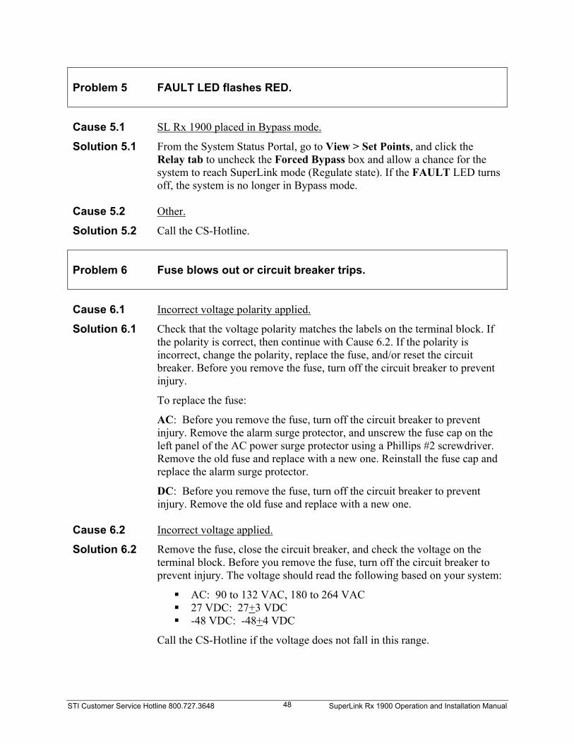
STI Customer Service Hotline 800.727.3648 SuperLink Rx 1900 Operation and Installation Manual 48
Problem 5
FAULT LED flashes RED.
Cause 5.1 SL Rx 1900 placed in Bypass mode.
Solution 5.1 From the System Status Portal, go to View > Set Points, and click the Relay tab to uncheck the Forced Bypass box and allow a chance for the system to reach SuperLink mode (Regulate state). If the FAULT LED turns off, the system is no longer in Bypass mode.
Cause 5.2 Other.
Solution 5.2 Call the CS-Hotline. Problem 6
Fuse blows out or circuit breaker trips.
Cause 6.1 Incorrect voltage polarity applied.
Solution 6.1 Check that the voltage polarity matches the labels on the terminal block. If the polarity is correct, then continue with Cause 6.2. If the polarity is incorrect, change the polarity, replace the fuse, and/or reset the circuit breaker. Before you remove the fuse, turn off the circuit breaker to prevent injury.
To replace the fuse:
AC: Before you remove the fuse, turn off the circuit breaker to prevent injury. Remove the alarm surge protector, and unscrew the fuse cap on the left panel of the AC power surge protector using a Phillips #2 screwdriver. Remove the old fuse and replace with a new one. Reinstall the fuse cap and replace the alarm surge protector.
DC: Before you remove the fuse, turn off the circuit breaker to prevent injury. Remove the old fuse and replace with a new one.
Cause 6.2 Incorrect voltage applied.
Solution 6.2 Remove the fuse, close the circuit breaker, and check the voltage on the terminal block. Before you remove the fuse, turn off the circuit breaker to prevent injury. The voltage should read the following based on your system:
AC: 90 to 132 VAC, 180 to 264 VAC 27 VDC: 27+3 VDC -48 VDC: -48+4 VDC
Call the CS-Hotline if the voltage does not fall in this range.

STI Customer Service Hotline 800.727.3648 SuperLink Rx 1900 Operation and Installation Manual 49
Cause 6.3 Wrong circuit breaker rating.
Solution 6.3 If the circuit breaker trips, check the rating. The circuit breaker rating should read 5-amps for AC or 15 to 30 amps for DC. Replace the circuit breaker if necessary.
Cause 6.4 Other.
Solution 6.4 Call the CS-Hotline. Problem 7
The SL Rx 1900 does not reach SuperLink mode (Regulate state) after five hours.
Cause 7.1
SL Rx 1900 is in Bypass mode.
Solutin 7.1 Check if the FAULT LED is flashing RED. If so, the system is in Bypass mode. Set the system to SuperLink mode (Regulate state). From the System Status Portal, go to View > Set Points and click the Relay tab to uncheck Forced Bypass box. Allow time for the system to reach SuperLink mode (Regulate state). When the FAULT LED turns off, the system is in SuperLink mode (Regulate state). If the problem persists, call the CS-Hotline.
Cause 7.2 Source voltage is low under load.
Solution 7.2 Measure the voltage with a DMM. Replace the power wire and/or breaker if necessary.
Cause 7.3 Other.
Solution 7.3 Establish communication with the system using the System Status Portal (Start > Programs > STI > STI System Status Portal). With the program open, click Communicate with Unit to connect to a Comm Port, and establish communication with the SL Rx 1900. To observe the Cold Stage Wide Range Temperature, from the System Status Portal, choose View > Status > Measure. Review the temperature. If the temperature is not in the range of 79+4 K, call the CS-Hotline.

STI Customer Service Hotline 800.727.3648 SuperLink Rx 1900 Operation and Installation Manual 50
Problem 8
Alarm Relay Test failed.
Cause 8.1 Relay wire is not making a proper connection.
Solution 8.1 Use an ohmmeter to measure connectivity from the SL Rx 1900 to the alarm relay. If either connection is bad, reset the wires or replace them and try connecting again. If both connections are good, see Cause 8.2.
Cause 8.2 Alarm has been mis-wired.
Solution 8.2 Ensure that the one wire is connected to the terminal block connection labeled C and one wire is connected to NC or NO.
Cause 8.3 Alarm cable fault (alarm on, but front panel does not show a RED LED).
Solution 8.3 Inspect alarm cable and connections at both ends. Set and reset the alarm by checking the Forced Bypass box in the System Status Portal (go to View > Set Points and click the Relay tab to check or uncheck the Forced Bypass box), and check the operation at both ends of the alarm cable. See the “Connecting the Alarm Relay” section on page 33 for more information.
Cause 8.4 Other.
Solution 8.4 Call the CS-Hotline. Problem 9
Receive Path Gain Test failed.
Cause 9.1 Attempting to measure backwards or cross receive paths.
Solution 9.1 Recheck the connection to the SL Rx 1900, and try the receive path gain test again.
Cause 9.2 Used wrong test frequency.
Solution 9.2 See Table 11 to verify the frequency band, and try the receive path gain test again.
Cause 9.3 Test setup error. The SL Rx 1900 is not in SuperLink mode (Regulate
state).
Solution 9.3 Ensure that you inject the signal into the DIN 7/16 ANTENNA ports and that they are measured at the BTS or PA ports with the same receive path number.
Cause 9.4 Other.
Solution 9.4 Call the CS-Hotline.
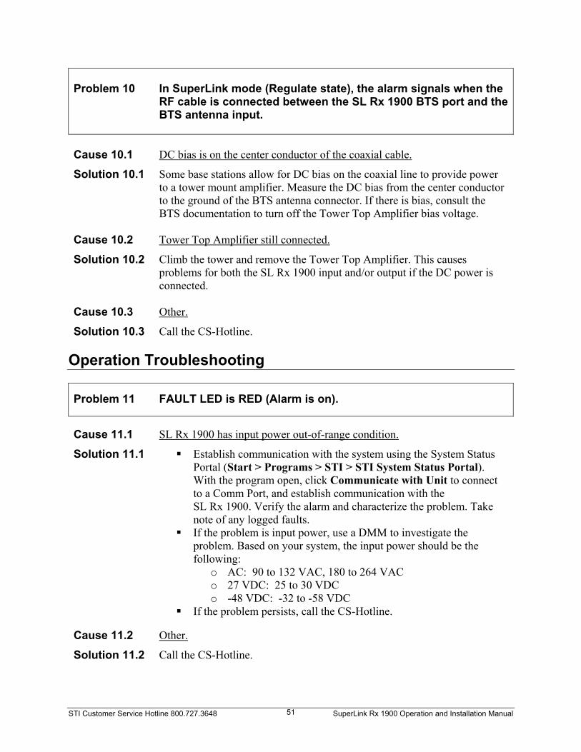
STI Customer Service Hotline 800.727.3648 SuperLink Rx 1900 Operation and Installation Manual 51
Problem 10
In SuperLink mode (Regulate state), the alarm signals when the RF cable is connected between the SL Rx 1900 BTS port and the BTS antenna input.
Cause 10.1 DC bias is on the center conductor of the coaxial cable.
Solution 10.1 Some base stations allow for DC bias on the coaxial line to provide power to a tower mount amplifier. Measure the DC bias from the center conductor to the ground of the BTS antenna connector. If there is bias, consult the BTS documentation to turn off the Tower Top Amplifier bias voltage.
Cause 10.2 Tower Top Amplifier still connected.
Solution 10.2 Climb the tower and remove the Tower Top Amplifier. This causes problems for both the SL Rx 1900 input and/or output if the DC power is connected.
Cause 10.3 Other.
Solution 10.3 Call the CS-Hotline. Operation Troubleshooting
Problem 11
FAULT LED is RED (Alarm is on).
Cause 11.1 SL Rx 1900 has input power out-of-range condition.
Solution 11.1 Establish communication with the system using the System Status Portal (Start > Programs > STI > STI System Status Portal). With the program open, click Communicate with Unit to connect to a Comm Port, and establish communication with the SL Rx 1900. Verify the alarm and characterize the problem. Take note of any logged faults.
If the problem is input power, use a DMM to investigate the problem. Based on your system, the input power should be the following:
o AC: 90 to 132 VAC, 180 to 264 VAC o 27 VDC: 25 to 30 VDC o -48 VDC: -32 to -58 VDC
If the problem persists, call the CS-Hotline. Cause 11.2 Other.
Solution 11.2 Call the CS-Hotline.

STI Customer Service Hotline 800.727.3648 SuperLink Rx 1900 Operation and Installation Manual 52
Problem 12
RF Performance is not optimal, detected by the following conditions: Degradation in statistical performance Customer complaints Base Station Built-in Test (BIT) failure
Cause 12.1 Open/short in SL Rx 1900 receive path.
Solution 12.1 Check the gain of each receive path of the SL Rx 1900, one receive path at a time. Turn off the BTS transmitters. Inject the RF signal to the antenna port of the SL Rx 1900, and sample the signal at any point further up the RF receive ports. Check the measurement in SuperLink mode (Regulate state) and record. Place the system into Forced Bypass mode (with the System Status Portal open, go to View > Set Points and click the Relay tab to check the Forced Bypass box), and then recheck the measurement. The difference between the two readings should be ~13 dB. Check each subsequent receive path in the same manner. If you discover a receive path that is not ~13 dB in SuperLink mode (Regulate state), but in Forced Bypass mode, call the CS-Hotline.
Cause 12.2 Other.
Solution 12.2 Call the CS-Hotline. Problem 13
Abnormal SL Rx 1900 noise.
Cause 13.1 SL Rx 1900 becomes abnormally loud.
Solution 13.1 Check for loose mounting hardware, cover screws, and other hardware.
Check the FAULT LED. If the FAULT LED illuminates RED, the system may be recovering from power drop out. Wait three hours to allow it to recool. When LED turns off, listen to the system again for normal vibration, and sound level.
Cause 13.2 Other.
Solution 13.2 Call the CS-Hotline.

STI Customer Service Hotline 800.727.3648 SuperLink Rx 1900 Operation and Installation Manual 53
Problem 14
No power is available to the system, but voltage is detected.
Cause 14.1 The power surge protector was hit by lightning, or no power is observed at
the system.
Solution 14.1 AC: Check the AC input power. If the power is 90 to 132 VAC, 180 to 264 VAC, then check the AC surge protector output power. If the voltage is out of range, then turn off the circuit breaker and check the fuse. Replace the fuse if necessary. Before you remove the fuse, turn off the circuit breaker to prevent injury.
DC: Turn off the circuit breaker and check the fuse. Replace the fuse if necessary. Before you remove the fuse, turn off the circuit breaker to prevent injury.
Cause 14.2 The alarm surge protector was hit by lightning, or no power is observed at
the system.
Solution 14.2 AC and DC: See page 37 to test the Alarm connections. Test the “unprotected” alarms. If the alarms fail, test the “protected” alarms. If the alarms pass, then the lightning protection needs replacing. Contact the CS-Hotline.
Cause 14.3 Other.
Solution 14.3 Call the CS-Hotline.

STI Customer Service Hotline 800.727.3648 SuperLink Rx 1900 Operation and Installation Manual 54

STI Customer Service Hotline 800.727.3648 SuperLink Rx 1900 Operation and Installation Manual 55
Chapter 7 Periodic Visual Inspection
The SL Rx 1900 is maintenance free. However, the following periodic visual inspection steps are suggested. The frequency of inspections depends on the installation site conditions. Check that ventilation spaces on the top rear and bottom of the SL Rx 1900 are clear of
debris. Check the cabinet for damage. Check that the mounting hardware is tight and the SL Rx 1900 is securely mounted. Check the seals around the RF connector covers and connector boots on the cables. Check the connector boots for wear. Look for damaged RF cables. Check the FAULT LED. When the system is in Bypass mode, the FAULT LED
illuminates RED. If the FAULT LED illuminates RED, see Chapter 6, Troubleshooting Tips” to resolve the problem.

STI Customer Service Hotline 800.727.3648 SuperLink Rx 1900 Operation and Installation Manual 56

STI Customer Service Hotline 800.727.3648 SuperLink Rx 1900 Operation and Installation Manual 57
Appendix A Using the System Status Portal
Overview Included in the SL Rx 1900 package is the STI CD that contains the System Status Portal, and other resources required to run the program. Proper installation of the program will ensure communication between the SL Rx 1900 and the program on your PC. To install the System Status Portal, see Chapter 5, “Installing the SL Rx 1900” or review the ReadMe.html file on the STI CD. The STI CD contains the following items: Application folder: Contains the System Status Portal. JavaRE folder: Contains the Java Runtime Environment required to support the System
Status Portal. Manual folder: Contains the Operation and Installation manuals in Adobe Acrobat PDF,
Appendix C in Microsoft® Excel, and the Adobe Acrobat Reader. ReadMe.html: Provides instructions to install the required programs on your PC.

STI Customer Service Hotline 800.727.3648 SuperLink Rx 1900 Operation and Installation Manual 58
System Status Portal Interface
The System Status Portal provides a user-friendly interface to observe the operating parameters of the SL Rx 1900. Explained in this section are the various buttons, menus, and fields to view the information you need to troubleshoot or verify proper operation of the system. Main Screen Buttons On the main screen of the System Status Portal, you will find two buttons at the bottom of the window. These buttons are shortcuts to menu items that are most commonly used.
Communicate with Unit
Opens a Comm Port (typically COM1) connection to establish communication with the SL Rx 1900. Select the correct Comm Port to connect to the SL Rx 1900. This button is the same as File > New.
View a Unit Record Displays the Open dialog box, allowing you to choose an existing XML data file. This button is the same as File > Open.

STI Customer Service Hotline 800.727.3648 SuperLink Rx 1900 Operation and Installation Manual 59
Menu Bar File Menu
New… Opens a Comm Port connection to establish communication with the SL Rx 1900. The System Status Portal lists the available Comm Ports on your PC. Select a Comm Port, then click OK to connect. You can also click Communicate with Unit on the main screen to open a file.
The following events open an error dialog box:
o When a Comm Port cannot be found. o When the System Status Portal cannot talk to the SL Rx 1900.
If you find an error, review Chapter 6, “Troubleshooting Tips” to troubleshoot the System Status Portal, or call the CS-Hotline.
Open… Displays the Open dialog box, allowing you to choose an existing XML data file. You can also click View a Unit Record on the main screen to open a file.
Close Closes the current session without saving, but does not exit the System Status Portal.
Save Updates all the data records in the System Status Portal before saving them. The File Save dialog box opens if the data has not been previously saved. If you previously saved a file, the most recent data overwrites the previously saved file.
Save As… Opens the File Save As dialog box, allowing you to change the filename and destination if you do not want to overwrite previous results.
Print Prints the screen you are currently viewing.
Exit Closes the current session and exits the System Status Portal without saving.

STI Customer Service Hotline 800.727.3648 SuperLink Rx 1900 Operation and Installation Manual 60
Edit Menu
The Edit menu is available when you have established a connection with the SL Rx 1900 or use File > Open. This menu allows you to copy information to the Windows clipboard, and paste the information to another program such as Microsoft® Word, Notepad, or WordPad.
Copy Copies text from a current tab to the Windows clipboard. You can paste the information to another program such as Microsoft® Word, Notepad, or WordPad.
Password… Opens the Logon Information dialog box to enter a valid password to change or clear values in the Set Points and Fault Records.
The Password feature is for STI Customer Service only.
View Menu
The View menu allows you to review information about the operation, fault records, and values of the SL Rx 1900.
Status Displays the operating status of the SL Rx 1900. See the “Status View” section on page 61 for more information.
Fault Records Displays the status of the faults, showing the first and last occurrence. Only STI can clear the faults in this view. See the “Fault Records View” section on page 68 for more information.
Clearing faults in this view is for STI Customer Service use only.
Set Points Displays the values that configure the operation of the SL Rx 1900 and debugging information.
Changing values in this view is for STI Customer Service use only.

STI Customer Service Hotline 800.727.3648 SuperLink Rx 1900 Operation and Installation Manual 61
Help Menu
The Help menu contains information about the System Status Portal and how to contact STI Customer Service.
Support… Opens the dialog box containing the CS-Hotline information.
About… Opens the dialog box containing the version number and the date the System Status Portal was built.
Status View The Status View displays the operating status of the system. Time Tab The Time tab displays the run and accumulated operating times in hours.
Runtime since Powerup Displays the time the system has been running since power was last applied to the system.
System Accumulated Displays the total accumulated time the system has been powered on.
Cooler Accumulated

STI Customer Service Hotline 800.727.3648 SuperLink Rx 1900 Operation and Installation Manual 62
Displays the total accumulated time the cooler has been powered on. LED Tab The LED tab displays the state of the LED on the system.
Status LED
Status LED turned on (GREEN).
Status LED turned off.
Bypass LED
Bypass LED turned on (RED).
Bypass LED turned off.
For SL Rx 1900: The SL Rx 1900 uses one LED labeled FAULT. When the FAULT LED is turned off, the system is in SuperLink mode (Regulate state). The FAULT LED illuminates RED only when the system cools, a fault occurs, or you set the system into Forced Bypass mode.

STI Customer Service Hotline 800.727.3648 SuperLink Rx 1900 Operation and Installation Manual 63
Relay Tab The Relay tab displays the state of the relays or power to the LNAs.
Bypass Relay
Bypass Relay is on.
Bypass Relay is off.
Forced Bypass
Forced Bypass is on.
Forced Bypass is off.
LNA Power
LNA Power is on.
LNA Power is off.
SL Rx 1900 specific: Check the Forced Bypass box to place the system into Bypass mode. The FAULT LED flashes RED in this situation. When you uncheck the box, the system returns to SuperLink mode (Regulate state).

STI Customer Service Hotline 800.727.3648 SuperLink Rx 1900 Operation and Installation Manual 64
System Tab The System tab shows the operating status of the SL Rx 1900 features, control loops, and operating limits.
LNA Power On
LNA power turned on.
LNA power turned off.
Power/Current Loop Regulating
Power or current loop regulates within tolerance.
Power or current loop is not regulating within tolerance.
Power Loop Active
Power loop is the active loop.
Current loop is the active loop.
Power Duty Limit Exceeded
Power duty cycle has exceeded the maximum limit.
Power duty cycle has not exceeded the maximum limit.
Power drive Limit Foldback
Power maximum drive level is folding back on a limit.
Power maximum drive level is off the cooldown table.

STI Customer Service Hotline 800.727.3648 SuperLink Rx 1900 Operation and Installation Manual 65
Auto Frequency Adjust
SL Rx 1900 automatically adjusts the operating cooler drive frequency to minimize vibration.
SL Rx 1900 operating frequency remains constant.
Temperature Loop Regulating
Temperature loop regulates within tolerance.
Temperature loop is not regulating within tolerance.
Cold Stage narrow range temperature out of bounds
Cold Stage narrow range temperature is out of normal operating bounds.
Cold Stage narrow range temperature is within normal operating bounds.
Cold Stage wide range temperature out of bounds
Cold Stage wide range temperature is out of normal operating bounds.
Cold Stage wide range temperature is within normal operating bounds.
Cooler Rejection temperature out of bounds
Cooler Rejection temperature is out of normal operating bounds.
Cooler Rejection temperature is within normal operating bounds.
Ambient temperature out of bounds
Ambient temperature is out of normal operating bounds.
Ambient temperature is within normal operating bounds.

STI Customer Service Hotline 800.727.3648 SuperLink Rx 1900 Operation and Installation Manual 66
Measure Tab The Measure tab displays either the current or previously saved system temperature, cooler drive, and LNA measurements.
Cold Stage narrow range temperature Displays the Cold Stage narrow range temperature measured in K.
Cold Stage wide range temperature Displays the Cold Stage wide range temperature measured in K.
Cooler Rejection temperature D
isplays the Cooler Rejection temperature measured in °C.
Ambient temperature Displays the Ambient temperature measured in °C.
Input Voltage Displays the Input Voltage measured in VDC.
Cooler Power Displays the Cooler motor drive real Power measured in W.
Cooler Power Error Displays the Cooler motor drive real Power error measured in W.
Cooler Voltage Real Displays the Cooler motor drive real voltage measured in VRMS.
Cooler Current Real Displays the Cooler motor drive real current measured in ARMS.
Cooler Current Phase Displays the Cooler motor drive current phase referenced to voltage, in degrees.

STI Customer Service Hotline 800.727.3648 SuperLink Rx 1900 Operation and Installation Manual 67
Cooler Impedance Displays the Cooler motor drive impedance measured in ohms.
Cooler Current RMS Displays the Cooler motor drive total current measurement in ARMS.
PWM Drive Displays the Cooler motor drive pulse width modulation measured in %.
PWM Feedforward Displays the Cooler motor drive feedforward gain measured in %.
PWM Frequency Displays the Cooler motor drive sine wave frequency measured in Hz.
Internal LNA Current Displays the Internal LNA Current measured in mA.
External Current Displays the External LNA Current measured in mA.
State Tab The State tab indicates the state machine status of the SL Rx 1900.
State Machine Mode Displays the operating mode of the SL Rx 1900. In Automatic mode, the system will automatically sequence through the states. In Manual mode, the operator manually changes states by selecting the state.
State Machine State Displays the operating state of the SL Rx 1900. See Table 10 for more information about the states.

STI Customer Service Hotline 800.727.3648 SuperLink Rx 1900 Operation and Installation Manual 68
Fault Records View The Fault Records view displays the status of the faults, showing the first and last occurrence. If you find any active faults, call the CS-Hotline.
Status Tab The Status tab displays the status of each fault:
Record The fault was recorded for either the first or last occurrence.
Active The fault is currently active.
Clear For STI Customer Service only. Call the CS-Hotline to clear faults that appear in this tab.
If your system experiences a fault, review Chapter 6, “Troubleshooting Tips” to troubleshoot your system or call the CS-Hotline for assistance. PM-Power Loop regulation fault?
A Power or Current Loop out of regulation fault was recorded.
Tcsw-Cold Stage wide range temperature out of operating range fault? A Cold Stage wide range temperature out of bounds fault was recorded.
Trej-Cooler Rejection temperature exceeds operating range fault? A Cooler rejection temperature out of bounds fault was recorded.

STI Customer Service Hotline 800.727.3648 SuperLink Rx 1900 Operation and Installation Manual 69
Tcsn-Temperature Loop regulation fault? A Temperature Loop out of regulation fault was recorded.
Ilna-LNA current exceeds operating range fault? A LNA current out of bounds fault was recorded. The reason for the fault may be due to the internal or external LNA.
Vin-Input Voltage exceeds operating range fault? An Input Voltage out of bounds fault was recorded.
Duty-Duty Cycle exceeds operating range fault? The Duty Cycle exceeded the maximum fault was recorded. This does not affect the active fault indication.
PM First Tab
Since the tabs in the Fault Records View contain the same fields, only the PM First and Last tabs are described. The following tabs will only describe the type of faults that occurred.
The PM First tab shows the fault for the first occurrence of a power loop out of regulation or cooler impedance fault.
Fault Type Two types of faults that trigger this record: a power loop out of regulation fault or cooler motor impedance out of bounds fault.
Operating State Displays the state machine state when this fault occurred. The states are defined in Table 10.
Fault Count Displays the number of times this fault record was written. The first occurrence will always be one if the fault occurred. The last occurrence will be one if the fault occurred twice and the number of times the fault occurred less one subsequently.

STI Customer Service Hotline 800.727.3648 SuperLink Rx 1900 Operation and Installation Manual 70
Run Time Displays the time since the system was last powered up in Hours:Minutes:Seconds when this fault occurred.
System Accumulated Time Displays the number of hours the system had operated when this fault occurred.
Ambient temperature Displays the ambient temperature in ºC when this fault occurred.
Cooler Rejection temperature Displays the cooler rejection temperature in ºC when this fault occurred.
Cold Stage wide range temperature Displays the cold stage wide range temperature in K when this fault occurred.
Cold Stage narrow range temperature Displays the cold stage narrow range temperature in K when this fault occurred.
Input voltage Displays the input voltage in VDC when this fault occurred.
Cooler voltage Displays the cooler motor voltage in real part Vrms when this fault occurred.
Cooler current Displays the cooler motor current in real part Arms when this fault occurred.
LNA current Displays the LNA current in mAdc when this fault occurred. If an LNA fault occurred, it is either an internal or external LNA fault current. Otherwise, the fault is an internal LNA current.
For the Ilna First and Last tabs only. The LNA current displays the LNA current in mAdc when this fault occurred. If an LNA fault occurred, it is either an internal or external LNA fault current, depending on whether the fault was an internal or external LNA fault.

STI Customer Service Hotline 800.727.3648 SuperLink Rx 1900 Operation and Installation Manual 71
PM Last Tab The PM Last tab shows the last occurrence of a power loop out of regulation or cooler impedance fault.
Tcsw First /Tcsw Last Tabs The Tcsw First/Tcsw Last tabs show the first and last occurrence of a cold stage wide range temperature out of bounds fault. Trej First/Trej Last Tabs The Trej First/Trej Last tabs show the first occurrence of a cooler rejection temperature out of bounds fault. Tcsn First/Tcsn Last Tabs The Tcsn First/Tcsn Last tabs show the first occurrence of a temperature loop out of regulation fault. Ilna First/Ilna Last Tabs The Ilna First/Ilna Last tabs show the first occurrence of either an internal or external LNA current out of bounds fault. Vin First/Vin Last Tabs The Vin First/Vin Last tabs show the first occurrence of an input voltage out of bounds fault. Duty First/Duty Last Tabs The Duty First/Duty Last tabs show the first occurrence of a duty cycle exceeded the maximum fault.

STI Customer Service Hotline 800.727.3648 SuperLink Rx 1900 Operation and Installation Manual 72

STI Customer Service Hotline 800.727.3648 SuperLink Rx 1900 Operation and Installation Manual 73
Appendix B SuperLink Rx 1900 Specifications

STI Customer Service Hotline 800.727.3648 SuperLink Rx 1900 Operation and Installation Manual 74

STI Customer Service Hotline 800.727.3648 SuperLink Rx 1900 Operation and Installation Manual 75
Appendix C Receive Path Gain/Loss Calculator
For your convenience, this record is also available in Microsoft® Excel file located in the SuperLink Rx 1900 Operation and Installation Manual folder on the STI CD. Reference Measured: Frequency = _______________ Power Level = _______________
Mode Receive Path No.
Signal Generator Frequency Power Level
(-50 dBm nominal)
Measured Output Level
Gain/Loss Calculation
Limit Pass/Fail
Example Bypass Example -50.5 dBm -51.0 dBm -0.5 dB -1+1 dB Pass SL Rx Example -50.5 dBm -38.3 dBm +12.2 dB 12.5+2 dB Pass Bypass 1 SL Rx 1 Bypass 2 SL Rx 2 Bypass 3 SL Rx 3 Bypass 4 SL Rx 4 Bypass 5 SL Rx 5 Bypass 6 SL Rx 6

STI Customer Service Hotline 800.727.3648 SuperLink Rx 1900 Operation and Installation Manual 76

STI Customer Service Hotline 800.727.3648 SuperLink Rx 1900 Operation and Installation Manual 77
Index
A
about the SL Rx 1900, 1 AC power, 9
connecting power wires, 32 alarm relay
connection, 33 J1 terminal strip, 33 states, 33 test, 37
B Bypass state, 34
C caution symbol, 3 chassis ground installation, 31 conduit installation, 31 connecting RF cables, 42 connectors and controls, 11 console connection and operation, 35 Cooldown state, 34 cryogenic cooling, 8 Customer Service Hotline (CS-Hotline), 3
D
DC power, 9 connecting power wires, 32
Digital Signal Processor (DSP), 8 dual duplexed system, 6 dual duplexers, 9
E Electrostatic Discharge, 3 equipment configurations, 5 equipment supplied, 17 ESD. See electrostatic discharge.
F FAULT LED, 11 Fault Records view, 68
Duty First tab, 71 Duty Last tab, 71 Ilna First tab, 71 Ilna Last tab, 71 PM First tab, 69 PM Last tab, 71 Status tab, 68 Tcsn First tab, 71 Tcsn Last tab, 71 Tcsw First tab, 71 Tcsw Last tab, 71 Trej First tab, 71 Trej Last tab, 71 Vin First tab, 71 Vin Last tab, 71
Forced Bypass setting, 11 Forced Bypass state, 34 functional checks, 35
alarm relay test, 37 console connection and operation, 35 receive path gain test, 39
G gain test setup, 39 general safety
cautions, 3 notes, 3 warnings, 3
H
hand tools required, 20
I Initial state, 34 inspection procedures, 55 installation
chassis ground, 31 conduit, 31 connecting AC power wires, 32

STI Customer Service Hotline 800.727.3648 SuperLink Rx 1900 Operation and Installation Manual 78
connecting DC power wires, 32 connecting RF cables, 42 integrating with the base station, 43 integrating with the base station (Rx
only), 44 internal states and status, 34 Java Runtime Environment, 23 materials required, 20 mounting the SuperLink Rx 1900, 30 performing power up/cooldown, 33 site requirements, 19 System Status Portal, 27 test equipment required, 21 troubleshooting, 45
integrating the SL Rx 1900 with base station, 43
internal states and status, 34
J Java Runtime Environment, 21, 23 junction box, 12
AC power configuration, 13 DC power configuration, 14
M maintenance, 55 materials required, 20 model numbering, 15 mounting the SL Rx 1900, 30
N No Tx Conn. plates, 12 note symbol, 3
O operation troubleshooting, 51
P PC requirements, 21 power terminal block
AC, 8 DC, 8
power wire installation AC, 32 DC, 32
powering up, 33
R receive path gain test, 39
frequency bands, 40 receive path gain/loss calculator, 75 Regulate state, 34 Return Material Authorization (RMA), 18 return shipments, 18 RF connectors and covers, 12 RF signal flow, 7 RS-232 console cover plate, 12 Rx paths only, 6
No Tx Conn. plate, 12
S safety. See general safety. Shutdown state, 34 simplexed system (Rx paths only), 6 site requirements, 19 Status view, 61
LED tab, 62 Measure tab, 66 Relay tab, 63 State tab, 67 System tab, 64 Time tab, 61
SuperLink mode, 34 system specifications, 73 System Status Portal
communicating with the SL Rx 1900, 35 Edit menu, 60 Fault Records view, 68 File menu, 59 Help menu, 61 installation, 27 interface, 58 Java Runtime Environment, 23 main screen buttons, 58 Menu bar, 59 PC requirements, 21 Status view, 61 using the, 57 View menu, 60

STI Customer Service Hotline 800.727.3648 SuperLink Rx 1900 Operation and Installation Manual 79
T
technical assistance, 3 test equipment required, 21 troubleshooting tips, 45
installation, 46 operation, 51
U unpacking the SL Rx 1900, 17
W warning symbol, 3 warranty, 4

SuperLink Rx 1900 is a trademark of Superconductor Technologies Inc. (STI). All other marks are properties of their respective owners. Superconductor Technologies Inc (STI), 2003-2004. All Rights Reserved. Information in this manual is subject to change without notice. Reproduction, adaptation, or translation without prior written permission is prohibited, except as allowed under the copyright laws. STI part number: 830-0016C. Last updated: 3/5/04.

STI Customer Service Hotline 800.727.3648 SuperLink Rx 1900 Operation and Installation Manual 80