RX64M Group Sensor solution which utilizes a camera RX ...
58
APPLICATION NOTE R01AN2462EJ0100 Rev.1.00 Page 1 of 55 Oct 01, 2015 RX64M Group Sensor solution which utilizes a camera RX Driver Package Application Introduction This application note describes how to install the sensor solution sample code on RX64M. The sample code can perform image and video capturing from a connected camera module, pedestrian detection, motion object detection, and distortion correction in the captured video. The sample code also allows user monitoring the detection process via web browser. This application is based on the industrial network solution using RX64M group TCP/IP protocol stack, a part of RX Driver Package Application (r01an2153). In addition to this, the app note also supports image processing and Web- camera solutions. This solution uses the image processing middleware of Hitachi Industrial & Control Solutions Ltd. In order to protect the technology of this middleware, the code is protected by the RX64M Trusted Memory (TM, herein) function. TM function not only blocks reading the code reading from outside of the MCU, but also blocks the MCU to read or copy the protected code. The MCU can only execute the code. The sample code described in this app note is dedicated for the GR-KAEDE board mounting the RX64M chip. GR-KAEDE specification and where to purchase: http://gadget.renesas.com/en/product/kaede.html RX Driver Package Application is a general term of sample application codes which are combined with RX Driver Package. For more details of RX Driver Package and its module group, FIT (Firmware Integration Technology), please refer to the following web site: http://am.renesas.com/products/mpumcu/rx/child/fit.jsp Target Device RX64M Group(GR-KAEDE) R01AN2462EJ0100 Rev.1.00 Oct 01, 2015
-
Upload
khangminh22 -
Category
Documents
-
view
9 -
download
0
Transcript of RX64M Group Sensor solution which utilizes a camera RX ...

APPLICATION NOTE
R01AN2462EJ0100 Rev.1.00 Page 1 of 55 Oct 01, 2015
RX64M Group Sensor solution which utilizes a camera RX Driver Package Application Introduction This application note describes how to install the sensor solution sample code on RX64M. The sample code can perform image and video capturing from a connected camera module, pedestrian detection, motion object detection, and distortion correction in the captured video. The sample code also allows user monitoring the detection process via web browser. This application is based on the industrial network solution using RX64M group TCP/IP protocol stack, a part of RX Driver Package Application (r01an2153). In addition to this, the app note also supports image processing and Web-camera solutions.
This solution uses the image processing middleware of Hitachi Industrial & Control Solutions Ltd. In order to protect the technology of this middleware, the code is protected by the RX64M Trusted Memory (TM, herein) function.
TM function not only blocks reading the code reading from outside of the MCU, but also blocks the MCU to read or copy the protected code. The MCU can only execute the code.
The sample code described in this app note is dedicated for the GR-KAEDE board mounting the RX64M chip.
GR-KAEDE specification and where to purchase:
http://gadget.renesas.com/en/product/kaede.html
RX Driver Package Application is a general term of sample application codes which are combined with RX Driver Package.
For more details of RX Driver Package and its module group, FIT (Firmware Integration Technology), please refer to the following web site:
http://am.renesas.com/products/mpumcu/rx/child/fit.jsp
Target Device RX64M Group(GR-KAEDE)
R01AN2462EJ0100 Rev.1.00
Oct 01, 2015
RX64M Group Sensor solution which utilizes a camera RX Driver Package Application
R01AN2462EJ0100 Rev.1.00 Page 2 of 55 Oct 01, 2015
Contents
1. Overview ......................................................................................................................... 4 1.1 This Application Note ................................................................................................................. 4 1.2 Operating Environment .............................................................................................................. 5 1.3 Module Structure ......................................................................................................................... 6 1.4 Projects ........................................................................................................................................ 8
2. Acquiring a Development Environment ........................................................................ 9 2.1 Acquire and Install e2 studio ...................................................................................................... 9 2.2 Acquire a Compiler Package.................................................................................................... 10 2.3 How to obtain GR-KAEDE board ............................................................................................. 10
3. Building a Project ......................................................................................................... 11 3.1 Create a Workspace .................................................................................................................. 11 3.2 Import a Project ......................................................................................................................... 12
4. Verify Operation ........................................................................................................... 15 4.1 Check Dip Switch Setting ......................................................................................................... 15 4.2 Build the Project ........................................................................................................................ 15 4.3 Prepare for Debugging ............................................................................................................. 17
4.3.1 Configure Hardware ............................................................................................ 17
4.3.2 Set Up Client PC .................................................................................................. 18 4.4 Debug the Project ..................................................................................................................... 21
5. Specification of Image Processing ............................................................................. 30 5.1 Outline of Performance ............................................................................................................ 30 5.2 Outline of Operation ................................................................................................................. 31
5.2.1 Person Detection ................................................................................................. 31
5.2.2 Moving Detection ................................................................................................ 32 5.3 File List ....................................................................................................................................... 33 5.4 Data Structure............................................................................................................................ 34 5.5 Image processing middleware API Reference ....................................................................... 35
5.5.1 Mdl_IP_Init ........................................................................................................... 35
5.5.2 Mdl_IP_PersonDetection .................................................................................... 36
5.5.3 Mdl_IP_PersonDetection_ParamChg ................................................................. 37
5.5.4 Mdl_IP_MovingDetection .................................................................................... 38
5.5.5 Mdl_IP_MovingDetection_ParamChg ................................................................ 39
RX64M Group Sensor solution which utilizes a camera RX Driver Package Application
R01AN2462EJ0100 Rev.1.00 Page 3 of 55 Oct 01, 2015
5.5.6 Mdl_IP_ImgRevise ............................................................................................... 40
5.5.7 Mdl_IP_ImgRevise_ParamChg ........................................................................... 41
6. When CS+ is used ........................................................................................................ 42 6.1 Acquire and Install CS+ ............................................................................................................ 42 6.2 Install the Project ...................................................................................................................... 43 6.3 Change Settings ........................................................................................................................ 45
7. Supplement ................................................................................................................... 52 7.1 Notes on Using the Free Evaluation Version of the RX Family C/C++ Compiler Package 52 7.2 Capture Data Slow Refreshing on Web Browser ................................................................... 52 7.3 Write-Invalid Area in Code Flash ............................................................................................. 53
8. Camera Solution Product Introduction ....................................................................... 54 8.1 Gadget Renesas GR-KAEDE Board ........................................................................................ 54 8.2 Camera and Voice Recording/Playback Demo Using HMI Expansion Board ..................... 54

RX64M Group Sensor solution which utilizes a camera RX Driver Package Application
R01AN2462EJ0100 Rev.1.00 Page 4 of 55 Oct 01, 2015
1. Overview 1.1 This Application Note
This application note describes how to install the Sensor solution sample code on RX64M. The sample code can perform image and video capturing from a connected camera module, human detection, motion detection, and distortion correction in the captured video. The sample code also allows user monitoring the detection process via web browser.
This application is based on the industrial network solution using RX64M group TCP/IP protocol stack, a part of RX Driver Package Application (r01an2153). In addition to this, the app note also supports image processing and Web-camera solutions.
The Web server, an application program which runs on the TCP/IP stack, is accessed by Web browser in general and distributes the contents stored on the Web server to the browser via TCP/IP.
The installed application code captures the video data from the camera module (OmniVision’s OV7740) on the GR-KAEDE board, performs pedestrian detection and motion object detection, and video distortion correction.
The Web camera application code captures the image data from the attached camera and converts to JPEG file and distributes it to a Web browser via its Web server function. Based on this feature, user can monitor the above image processing transition with a Web browser.
This image processing code is protected by RX64M TM function.
The TM function blocks improper reads or additional code writing in flash memory block 8 and 9 on the RX64M MCU. For more detail of this function, please refer to the following RX64M Group user’s manual:
http://www.renesas.com/products/mpumcu/rx/rx600/rx64m/index.jsp
The sample code described in this app node runs on the GR-KAEDE board.
This application note describes how to install this solution sample code.

RX64M Group Sensor solution which utilizes a camera RX Driver Package Application
R01AN2462EJ0100 Rev.1.00 Page 5 of 55 Oct 01, 2015
1.2 Operating Environment This application note operates in the following environment.
Table 1.2.1 Operating Environment Microcontroller RX64M Group Evaluation board GR-KAEDE
In addition to the above board, camera module, AC adapter, and LAN cable are required For the board specification and how to purchase, please refer to the following URL: http://gadget.renesas.com/en/product/kaede.html
Integrated development environment (IDE)
e2 studio, V4.0.1.07 or later Or: CS+ V3.01.00 or later
Cross tools RX Family C/C++ Compiler Package V2.03.00 or later Emulator E1(must be purchased separately) RX Driver Package RX64M用RX Driver Package Ver1.00(R01AN2144EJ0100)* Webブラウザ Internet Explorer8
Internet Explorer11(add [192.168.0.3] with compatibility display setting)
Note: * The FIT module in this sample code is updated based on RX Driver Package Ver1.00. For the applicable version, check with “Section 1.3 Module Composition”.
Figure 1.2.1 Sample Operating Environment

RX64M Group Sensor solution which utilizes a camera RX Driver Package Application
R01AN2462EJ0100 Rev.1.00 Page 6 of 55 Oct 01, 2015
1.3 Module Structure This section shows the structure of the modules used by this application note and a list of those modules.
Figure 1.3.1 Module Structure
RX64M Group Sensor solution which utilizes a camera RX Driver Package Application
R01AN2462EJ0100 Rev.1.00 Page 7 of 55 Oct 01, 2015
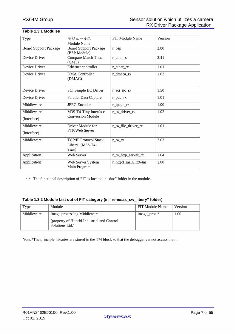
Table 1.3.1 Modules
Type モジュール名 Module Name
FIT Module Name Version
Board Support Package Board Support Package (BSP Module)
r_bsp 2.80
Device Driver Compare Match Timer (CMT)
r_cmt_rx 2.41
Device Driver Ethernet controller r_ether_rx 1.01
Device Driver DMA Controller (DMAC)
r_dmaca_rx 1.02
Device Driver SCI Simple IIC Driver r_sci_iic_rx 1.50
Device Driver Parallel Data Capture r_pdc_rx 1.01
Middleware JPEG Encoder r_jpege_rx 1.00
Middleware
(Interface)
M3S-T4-Tiny Interface Conversion Module
r_t4_driver_rx 1.02
Middleware
(Interface)
Driver Module for FTP/Web Server
r_t4_file_driver_rx 1.01
Middleware TCP/IP Protocol Stack Libery(M3S-T4-Tiny)
r_t4_rx 2.03
Application Web Server r_t4_http_server_rx 1.04
Application Web Server System Main Program
r_httpd_main_rx64m 1.00
※ The functional description of FIT is located in “doc” folder in the module.
Table 1.3.2 Module List out of FIT category (in “renesas_sw_libery” folder)
Type Module FIT Module Name Version
Middleware Image processing Middleware
(property of Hitachi Industrial and Control Solutions Ltd.)
image_proc * 1.00
Note:*The principle libraries are stored in the TM block so that the debugger cannot access them.

RX64M Group Sensor solution which utilizes a camera RX Driver Package Application
R01AN2462EJ0100 Rev.1.00 Page 8 of 55 Oct 01, 2015
1.4 Projects This application note includes an e2 studio and a CS+ project for building and evaluating a web server system. These projects register both a build structure (build mode in CS+) that stores the build settings and a debug structure (debug tool in CS+) that stores debug settings.
The table below lists the build structure and debug structure registered in these projects.
Table 1.4.1 Project Settings
Structure Description
Build structure (referred to as build mode in CS+)
HardwareDebug (Debug on hardware) This setting generates a load module with the debug information.
■Primary Setting
• including the debug information
• Optimization: -optimize=2
Debug structure (referred to as debug tool in CS+)
HardwareDebug (E1)
(This is RX E1 (JTAG) in CS+)
The generated load module with this setting can be hardware-debugged with E1 emulator
When using CS+, please refer to “Section 6 In case of using CS+”.

RX64M Group Sensor solution which utilizes a camera RX Driver Package Application
R01AN2462EJ0100 Rev.1.00 Page 9 of 55 Oct 01, 2015
2. Acquiring a Development Environment 2.1 Acquire and Install e2 studio
The e2 studio can be downloaded from the Renesas web site.
1. Access the following URL to display the e2 studio download page.
http://www.renesas.com/e2studio_download
2. Of the displayed items, click Install the e2 studio 4.0.1.07 installer. (Although there are two versions, one that is broken up into smaller sections, and one that can be downloaded in a single operation, the contents are the same.)
Next, download the e2 studio installer by following the instructions displayed.
3. Run the downloaded e2 studio installer to install e2 studio on your personal computer.
See the e2 studio Integrated Development Environment User's Manual: Getting Started Guide for details on the installation procedure.
http://documentation.renesas.com/doc/products/tool/doc/r20ut2771ej0300_e2_start_s.pdf
Click either of these links.
RX64M Group Sensor solution which utilizes a camera RX Driver Package Application
R01AN2462EJ0100 Rev.1.00 Page 10 of 55 Oct 01, 2015
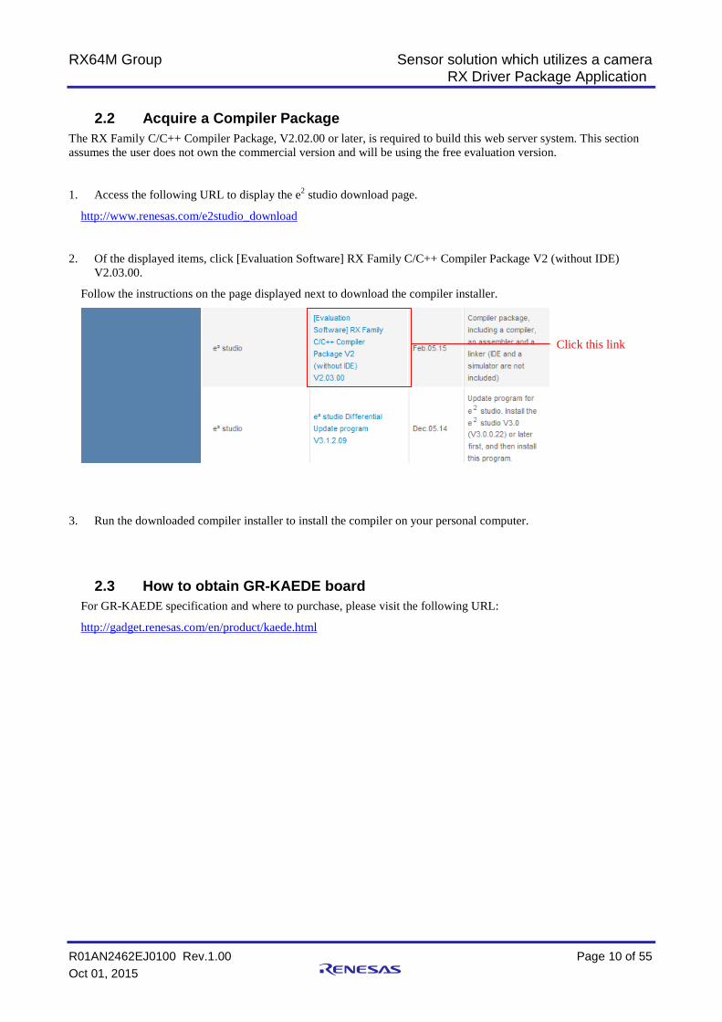
2.2 Acquire a Compiler Package The RX Family C/C++ Compiler Package, V2.02.00 or later, is required to build this web server system. This section assumes the user does not own the commercial version and will be using the free evaluation version.
1. Access the following URL to display the e2 studio download page.
http://www.renesas.com/e2studio_download
2. Of the displayed items, click [Evaluation Software] RX Family C/C++ Compiler Package V2 (without IDE) V2.03.00.
Follow the instructions on the page displayed next to download the compiler installer.
3. Run the downloaded compiler installer to install the compiler on your personal computer.
2.3 How to obtain GR-KAEDE board For GR-KAEDE specification and where to purchase, please visit the following URL:
http://gadget.renesas.com/en/product/kaede.html
Click this link

RX64M Group Sensor solution which utilizes a camera RX Driver Package Application
R01AN2462EJ0100 Rev.1.00 Page 11 of 55 Oct 01, 2015
3. Building a Project 3.1 Create a Workspace
1. First, execute e2 studio.
2. When Workspace Launcher pops up, enter name of your workspace folder. And then click [OK].
3. When the following window is displayed, click Workbench
Enter a workspace folder.
Click OK.
Click Workbench
RX64M Group Sensor solution which utilizes a camera RX Driver Package Application
R01AN2462EJ0100 Rev.1.00 Page 12 of 55 Oct 01, 2015
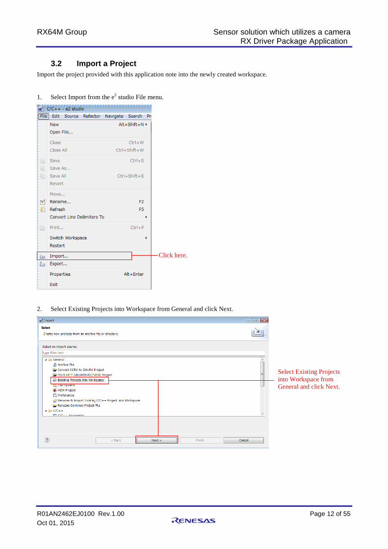
3.2 Import a Project Import the project provided with this application note into the newly created workspace.
1. Select Import from the e2 studio File menu.
2. Select Existing Projects into Workspace from General and click Next.
Click here.
Select Existing Projects into Workspace from General and click Next.
RX64M Group Sensor solution which utilizes a camera RX Driver Package Application
R01AN2462EJ0100 Rev.1.00 Page 13 of 55 Oct 01, 2015
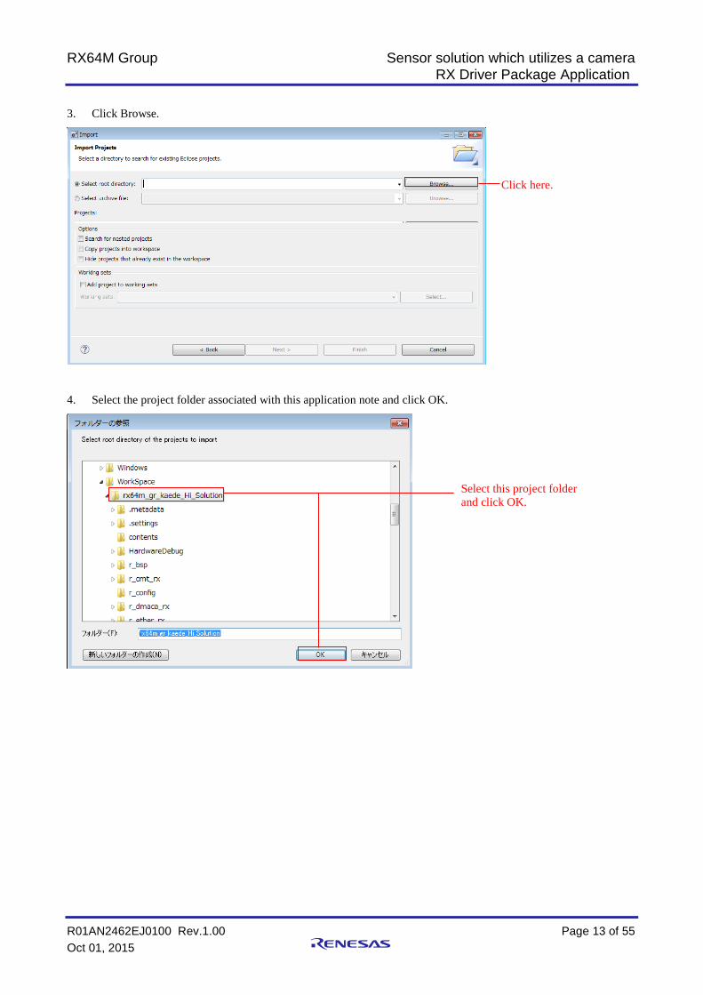
3. Click Browse.
4. Select the project folder associated with this application note and click OK.
Click here.
Select this project folder and click OK.

RX64M Group Sensor solution which utilizes a camera RX Driver Package Application
R01AN2462EJ0100 Rev.1.00 Page 14 of 55 Oct 01, 2015
5. Check Copy projects into workspace and click Finish.
“Copy projects into workspace” is not a essential item. If it is not checked, the root directory will be the build scope.
Check this box and click Finish.

RX64M Group Sensor solution which utilizes a camera RX Driver Package Application
R01AN2462EJ0100 Rev.1.00 Page 15 of 55 Oct 01, 2015
4. Verify Operation 4.1 Check Dip Switch Setting
Check the position of the Dip switch on GR-KAEDE board. The switch positions shown below are the valid settings.
図 4.1.1 Dip Switch 設定
4.2 Build the Project Use the following procedure to build the project and generate a load module.
1. Click the project to build from the Project Explorer.
Click here.

RX64M Group Sensor solution which utilizes a camera RX Driver Package Application
R01AN2462EJ0100 Rev.1.00 Page 16 of 55 Oct 01, 2015
2. Click Build project from the Project menu.
3. When “Build complete” is displayed on the Console panel, the build will have completed.
Click here.

RX64M Group Sensor solution which utilizes a camera RX Driver Package Application
R01AN2462EJ0100 Rev.1.00 Page 17 of 55 Oct 01, 2015
4.3 Prepare for Debugging Configure Hardware 4.3.1
The evaluation board must be configured before starting debugging.
A table of the required equipment and its configuration are shown below.
Table 4.3.1.1 Hardware Configuration
No. Device Supplementary Information 1 Development PC Personal computer used for development. 2 GR-KAEDE 3 Client PC (web browser) The development PC can be used for this function. 4 One of the following must be provided as a network
environment for connecting the client PC to the GR-KAEDE (web server). 1. If a switching hub is used
a. Switching hub b. LAN cable (straight) × 2
2. If cross cables are used a. LAN cable (cross) × 1
Figure 4.3.1.1 Switching Hub Configuration (Two Ethernet Channels Used)
RX64M Group Sensor solution which utilizes a camera RX Driver Package Application
R01AN2462EJ0100 Rev.1.00 Page 18 of 55 Oct 01, 2015
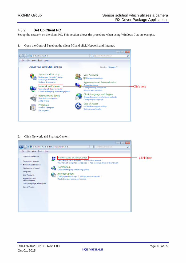
Set Up Client PC 4.3.2Set up the network on the client PC. This section shows the procedure when using Windows 7 as an example.
1. Open the Control Panel on the client PC and click Network and Internet.
2. Click Network and Sharing Center.
Click here
Click here.
RX64M Group Sensor solution which utilizes a camera RX Driver Package Application
R01AN2462EJ0100 Rev.1.00 Page 19 of 55 Oct 01, 2015
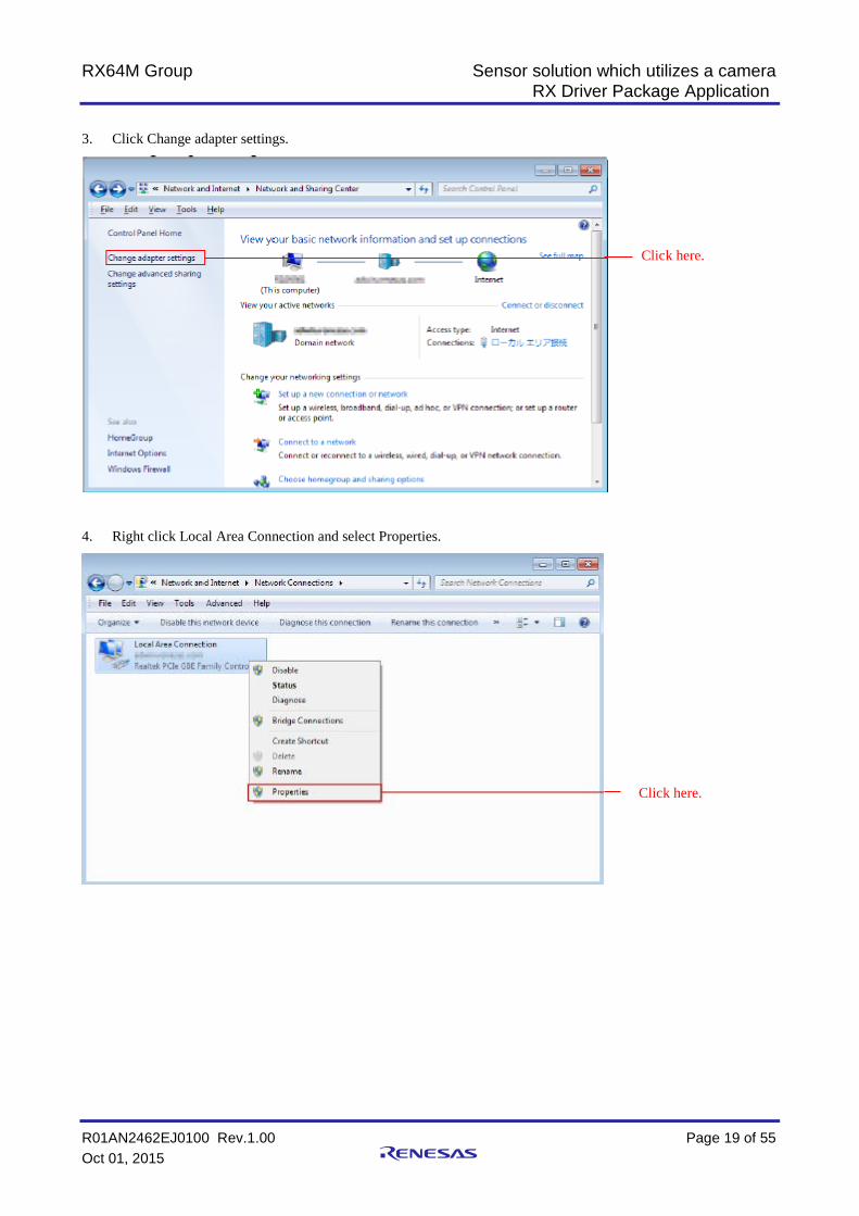
3. Click Change adapter settings.
4. Right click Local Area Connection and select Properties.
Click here.
Click here.

RX64M Group Sensor solution which utilizes a camera RX Driver Package Application
R01AN2462EJ0100 Rev.1.00 Page 20 of 55 Oct 01, 2015
5. Select Internet Protocol Version 4 (TCP/IPv4) and click Properties.
6. The IP address and other settings will be displayed. Set these as shown below and click OK.
Click here.
Click here.

RX64M Group Sensor solution which utilizes a camera RX Driver Package Application
R01AN2462EJ0100 Rev.1.00 Page 21 of 55 Oct 01, 2015
4.4 Debug the Project Use the following procedure to start debugging the project.
1. Connect the development PC to the E1 emulator with a USB cable.
2. Connect the evaluation board (Renesas Starter Kit+ for RX64M) to the adapter and turn on the power.
3. Click Debug Configurations in the e2 studio Run menu.
Click here.

RX64M Group Sensor solution which utilizes a camera RX Driver Package Application
R01AN2462EJ0100 Rev.1.00 Page 22 of 55 Oct 01, 2015
4. Click rx64m_gr_kaede_Hi_Solution HardwareDebug under Renesas GDB Hardware Debugging.
5. Click StartUp.
6. Click outof_TrustedMemory_Data.mot under Filename amd Click Edit.
Click here.
Click here.

RX64M Group Sensor solution which utilizes a camera RX Driver Package Application
R01AN2462EJ0100 Rev.1.00 Page 23 of 55 Oct 01, 2015
7. Change the destination of save file
Pleaseinput:「${workspace_loc:\rx64m_gr_kaede_Hi_Solution}\renesas_sw_library\image_proc\outof_TrustedMemory_Data.mot」
Click OK.
8. Click Debug
When the following message is displayed, click Yes.
Click here.
Click here.
Click here.
Enter
RX64M Group Sensor solution which utilizes a camera RX Driver Package Application
R01AN2462EJ0100 Rev.1.00 Page 24 of 55 Oct 01, 2015
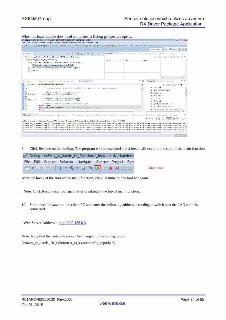
When the load module download completes, a Debug perspective opens.
9. Click Resume on the toolbar. The program will be executed and a break will occur at the start of the main function.
After the break at the start of the main function, click Resume on the tool bar again.
Note: Click Resume symbol again after breaking at the top of main function.
10. Start a web browser on the client PC and enter the following address according to which port the LAN cable is connected.
Web Server Address:http://192.168.0.3
Note: Note that the web address can be changed in the configuration.
(rx64m_gr_kaede_Hi_Solution /r_t4_rx/src/config_tcpudp.c)
Click here.
RX64M Group Sensor solution which utilizes a camera RX Driver Package Application
R01AN2462EJ0100 Rev.1.00 Page 25 of 55 Oct 01, 2015
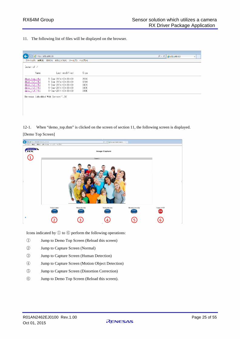
11. The following list of files will be displayed on the browser.
12-1. When “demo_top.thm” is clicked on the screen of section 11, the following screen is displayed.
[Demo Top Screen]
Icons indicated by ① to ⑥ perform the following operations:
① Jump to Demo Top Screen (Reload this screen)
② Jump to Capture Screen (Normal)
③ Jump to Capture Screen (Human Detection)
④ Jump to Capture Screen (Motion Object Detection)
⑤ Jump to Capture Screen (Distortion Correction)
⑥ Jump to Demo Top Screen (Reload this screen).

RX64M Group Sensor solution which utilizes a camera RX Driver Package Application
R01AN2462EJ0100 Rev.1.00 Page 26 of 55 Oct 01, 2015
12-2. When “demo_ru1.thm” is clicked on the screen of section 11, the following screen is displayed.
[Capture Screen (Normal)]
Icons indicated by ① to ⑥ perform the following operations:
① Jump to Demo Top Screen (Reload this screen)
② Jump to Capture Screen (Normal)
③ Jump to Capture Screen (Human Detection)
④ Jump to Capture Screen (Motion Object Detection)
⑤ Jump to Capture Screen (Distortion Correction)
⑥ Stay in the current screen but stop capturing
You can change two parameters in this screen. Please find two blocks indicated by red boxes in the screen.
The upper block indicates the current setting of the parameters:
- JPEG QUALITY: Image quality 1 (Lowest) to 128 (Highest) during JPEG encode
- IMAGE SENSOR Read RT: There are two values, register address and register value of the attached camera module. These two values are results of what you updated in the lower block. By the way, some registers are write-only registers. In this case, the upper block of the screen may not display the valid value of the register.
The lower block is where you can change the register value of the attached camera module. Please find two white boxes where you set values. When you click [SET] button, the screen will refresh and the set value is updated. Every time you click the button, the screen will refresh. This is because this demo is driven by the Web server FIT module specification.
We are very sorry we don’t explain the camera module specification in this app note. We hope you will find the specification by your own way and change the register value.

RX64M Group Sensor solution which utilizes a camera RX Driver Package Application
R01AN2462EJ0100 Rev.1.00 Page 27 of 55 Oct 01, 2015
12-3. When “demo_ru2.thm” is clicked on the screen of section 11, the following screen is displayed.
[Capture Screen (Human Detection)]
Icons indicated by ① to ⑥ perform the following operations:
① Jump to Demo Top Screen (Reload this screen)
② Jump to Capture Screen (Normal)
③ Jump to Capture Screen (Human Detection)
④ Jump to Capture Screen (Motion Object Detection)
⑤ Jump to Capture Screen (Distortion Correction)
⑥ Stay in the current screen but stop capturing(
You can change two parameters in this screen. Please find two blocks indicated by red boxes and a red circle in the screen.
The upper block indicates the current setting of the parameters:
- Human result: This display shows results of capturing object. The function divides the screen into 9 areas, area 1 to 9, and displays number of detected object by area. If an object stays in multiple areas, the object is counted in one of cover areas.
- threshold(1-9): This parameter indicates the threshold value to detect an object
- sensitivity(1-15): when detecting an object, this parameter indicates the judgement value of contrast and brightens.
The lower block is where you can change these parameter values. Please find two white boxes where you set values. When you click [SET] button, the screen will refresh and the set value is updated. Every time you click the button, the screen will refresh. This is because this demo is driven by the Web server FIT module specification.
‘threshold’ value: when the object is not properly detected, set a little smaller value. In contract, if the detection is too much, set larger a value.
‘sensitivity’ value: set a smaller value when you want to perform the detection in the area of which the contrast ansd brightness differentiation is small. And set a greater value for other way around.
RX64M Group Sensor solution which utilizes a camera RX Driver Package Application
R01AN2462EJ0100 Rev.1.00 Page 28 of 55 Oct 01, 2015
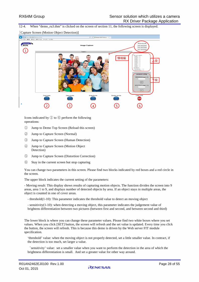
12-4. When “demo_ru3.thm” is clicked on the screen of section 11, the following screen is displayed.
[Capture Screen (Motion Object Detection)]
Icons indicated by ① to ⑥ perform the following operations:
① Jump to Demo Top Screen (Reload this screen)
② Jump to Capture Screen (Normal)
③ Jump to Capture Screen (Human Detection)
④ Jump to Capture Screen (Motion Object Detection)
⑤ Jump to Capture Screen (Distortion Correction)
⑥ Stay in the current screen but stop capturing
You can change two parameters in this screen. Please find two blocks indicated by red boxes and a red circle in the screen.
The upper block indicates the current setting of the parameters:
- Moving result: This display shows results of capturing motion objects. The function divides the screen into 9 areas, area 1 to 9, and displays number of detected objects by area. If an object stays in multiple areas, the object is counted in one of cover areas.
- threshold(1-10): This parameter indicates the threshold value to detect an moving object
- sensitivity(1-10): when detecting a moving object, this parameter indicates the judgement value of brightens differentiation between two pictures (between first and second, and between second and third)
The lower block is where you can change these parameter values. Please find two white boxes where you set values. When you click [SET] button, the screen will refresh and the set value is updated. Every time you click the button, the screen will refresh. This is because this demo is driven by the Web server FIT module specification.
‘threshold’ value: when the moving object is not properly detected, set a little smaller value. In contract, if the detection is too much, set larger a value.
‘sensitivity’ value: set a smaller value when you want to perform the detection in the area of which the brightness differentiation is small. And set a greater value for other way around.

RX64M Group Sensor solution which utilizes a camera RX Driver Package Application
R01AN2462EJ0100 Rev.1.00 Page 29 of 55 Oct 01, 2015
12-5. When “demo_ru4.thm” is clicked on the screen of section 11, the following screen is displayed.
[Capture Screen (Distortion Correction)]
Icons indicated by ① to ⑥ perform the following operations:
① Jump to Demo Top Screen (Reload this screen)
② Jump to Capture Screen (Normal)
③ Jump to Capture Screen (Human Detection)
④ Jump to Capture Screen (Motion Object Detection)
⑤ Jump to Capture Screen (Distortion Correction)
⑥ Stay in the current screen but stop capturing
You can change three parameters in this screen. Please find two blocks indicated by red boxes.
The upper block indicates the current setting of the parameters:
- function: ‘ON’ indicates the distortion correction is active. ‘OFF’ is the correction is inactive.
- H-correction(-127-+127): this parameter indicates the X-direction offset value of the correction start point in the captured picture. (horizontal direction distortion correction)
- V-correction(-127-+127): this parameter indicates the Y-direction offset value of the correction start point in the captured picture. (vertical direction distortion correction)
The lower block is where you can change these parameter values. Please find three white boxes where you set values. When you click [SET] button, the screen will refresh and the set value is updated. Every time you click the button, the screen will refresh. This is because this demo is driven by the Web server FIT module specification.
‘function’ value: set 1 when you enable the function.(0:disable)
‘H-correction’ value: set a positive value if you want to move the correction start point to the right direction. And set a negative value for the left direction.
‘V-correction’ value: set a negative value if you want to move the correction start point to the upward direction. And set a positive value for the downward direction.

RX64M Group Sensor solution which utilizes a camera RX Driver Package Application
R01AN2462EJ0100 Rev.1.00 Page 30 of 55 Oct 01, 2015
5. Specification of Image Processing 5.1 Outline of Performance
The picture processing system shown in this application note is the middleware that is provided from Hitach Industrial Control Solutions. The capture data from external camera modules, and this middleware applies “detect human”, “detect moving”, “adjust distortion“. This application note sample code combines the middleware and web camera system, and realizes displaying the result of these detecting. And using Web server CGI function, it is possible to set the parameter for the middleware.
Table 5.1.1. shows the fixed memory area. Please DO NOT USE this area for other functions.
Table 5.1.1. used area
area name description
used area for internal ROM
<address>
FFC0 0200h~FFC0 C66Bh
FFFE 0000h~FFFE FFFFh(TM area)
When using TM area, all TM area will be disable to write. This address area means all of TM area not but real using size.
used area for internal RAM
about 110Kbyte
<address>
0000 4100h~0001 F942h
on board SDRAM about 4Mbyte
<address>
0800 0000h~0840 0000h
<details>
・capture area (from camera module)
640(vertical)x480(horizontal) YCbCr422 : for 3 area
・input/output for image processing
input 320(vertical)x240(horizontal) gray scale/RGB565 : for 3area
output 320(vertical)x240(horizontal) RGB565: for 3 area
・image format conversion (YCbCr422→RGB565) work area
640(vertical)x480(horizontal) : for 1 area
・work area for image processing middleware
320(vertical)x240(horizontal): for 4 area、160(vertical)x120(horizontal): for 2 area

RX64M Group Sensor solution which utilizes a camera RX Driver Package Application
R01AN2462EJ0100 Rev.1.00 Page 31 of 55 Oct 01, 2015
5.2 Outline of Operation Table 5.2.1. Function list
function function name outline
person detection detection person outline
Detect the “standing person” in the image, and “sitting person” in the image. And outlined red line.
detection person number
Detect the number of person. This function divides the area as 9 area. This function detect the number of person for each 9 area. (max detection number for each 9 area is 5)
moving detection comparison of image Compare the 3 images of which it continuousness capture, detect and extract the differences.
adjust distortion adjust the image Convert coordinate of image using adjust parameter for combination camera with lens.
Person Detection 5.2.1
This function detects the person(standing person, sitting person) from image captured Camera. This function measures the number of person for each 9 area that divided as 9 area from input image. When person (in the picture) is overlay,
Table 5.2.1.1 Function list for person detection
item data
height of camera 2.5[m]
angle of camera 22[°]
viewing angle of camera
130[°]
Depth distance of detection
max sensibility 4[m]
image size 320(vertical) x 240(horizontal) [pixel]
image format gray scale, RAW
This application note can confirm operation this feature in “4.4 Debug the Project” 12-3.
RX64M Group Sensor solution which utilizes a camera RX Driver Package Application
R01AN2462EJ0100 Rev.1.00 Page 32 of 55 Oct 01, 2015
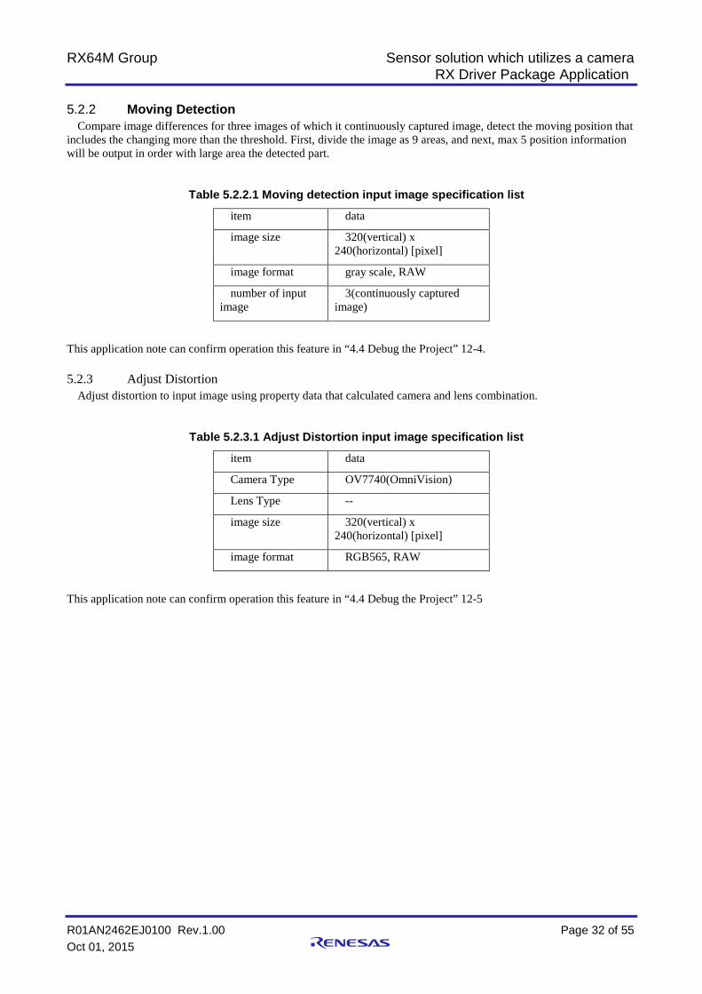
Moving Detection 5.2.2
Compare image differences for three images of which it continuously captured image, detect the moving position that includes the changing more than the threshold. First, divide the image as 9 areas, and next, max 5 position information will be output in order with large area the detected part.
Table 5.2.2.1 Moving detection input image specification list
item data
image size 320(vertical) x 240(horizontal) [pixel]
image format gray scale, RAW
number of input image
3(continuously captured image)
This application note can confirm operation this feature in “4.4 Debug the Project” 12-4.
Adjust Distortion 5.2.3Adjust distortion to input image using property data that calculated camera and lens combination.
Table 5.2.3.1 Adjust Distortion input image specification list
item data
Camera Type OV7740(OmniVision)
Lens Type --
image size 320(vertical) x 240(horizontal) [pixel]
image format RGB565, RAW
This application note can confirm operation this feature in “4.4 Debug the Project” 12-5
RX64M Group Sensor solution which utilizes a camera RX Driver Package Application
R01AN2462EJ0100 Rev.1.00 Page 33 of 55 Oct 01, 2015
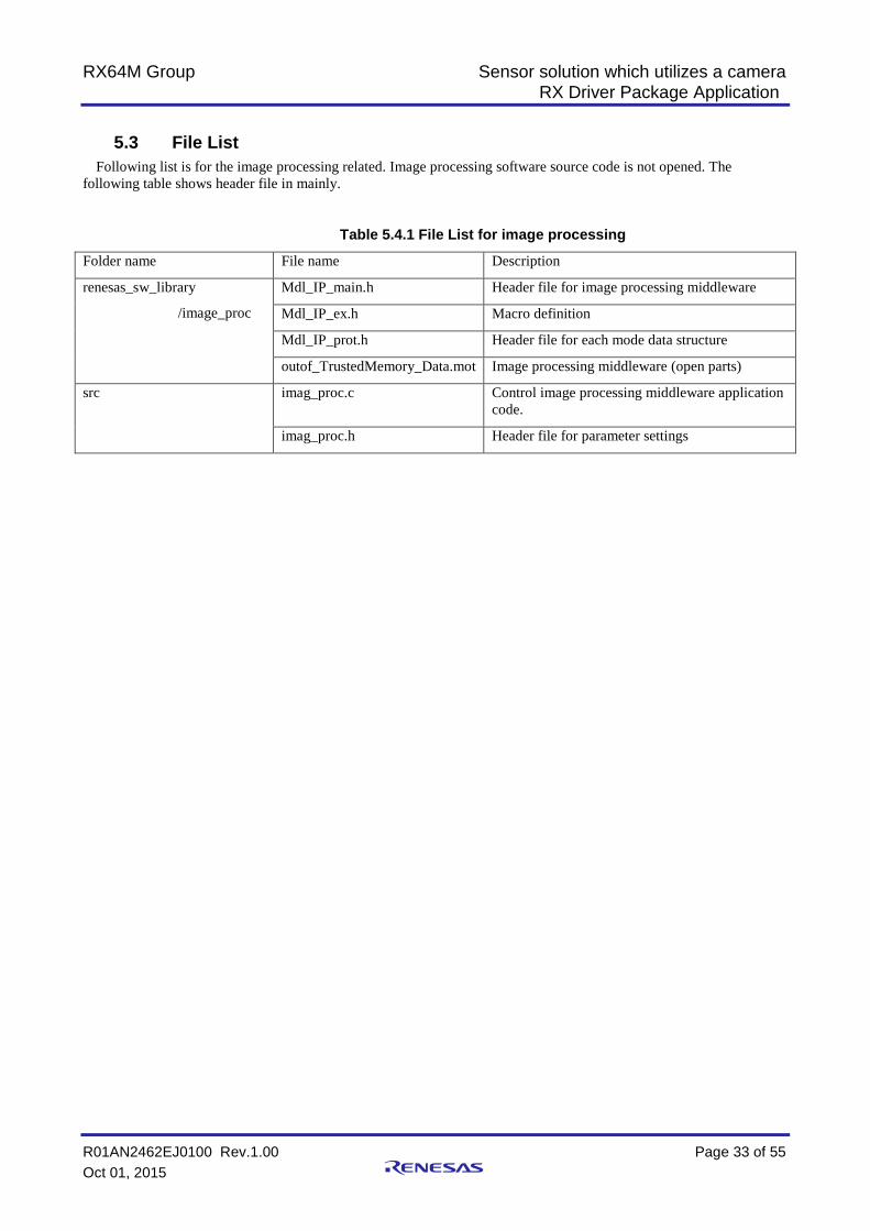
5.3 File List Following list is for the image processing related. Image processing software source code is not opened. The
following table shows header file in mainly.
Table 5.4.1 File List for image processing
Folder name File name Description
renesas_sw_library
/image_proc
Mdl_IP_main.h Header file for image processing middleware
Mdl_IP_ex.h Macro definition
Mdl_IP_prot.h Header file for each mode data structure
outof_TrustedMemory_Data.mot Image processing middleware (open parts)
src imag_proc.c Control image processing middleware application code.
imag_proc.h Header file for parameter settings

RX64M Group Sensor solution which utilizes a camera RX Driver Package Application
R01AN2462EJ0100 Rev.1.00 Page 34 of 55 Oct 01, 2015
5.4 Data Structure
[Person detection structure]
typedef struct _PersonDetection_Info {
int flg; // detect 0:none / 1:exist
float score; // score of comparison
int sx, sy, ex, ey; // start X, start Y, end X, end Y
} PersonDetection_Info;
[Person detection result structure]
typedef struct _PersonDetection_Rslt {
int p_dct_cnt[MAX_AREA]; // number of person at area( [0]:area 1 - [8]:area 9 )
PersonDetection_Info p_dct_inf[MAX_PERSON]; // Person detection information
} PersonDetection_Rslt;
[Moving detection structure]
typedef struct _MovingDetection_Info {
int flg; // detect 0:none / 1:existing
int area; // area No (1-9)
int sx, sy, ex, ey; // start X, start Y, end X, end Y
} MovingDetection_Info;
[Moving detection result structure]
typedef struct _MovingDetection_Rslt {
int p_dct_cnt; // Number of detection
MovingDetection_Info p_dct_inf[MAX_ MOVING]; // information about moving things
} MovingDetection_Rslt;
[Macro definition]
#define MAX_AREA 9
#define MAX_PERSON 5
#define MAX_MOVING 5

RX64M Group Sensor solution which utilizes a camera RX Driver Package Application
R01AN2462EJ0100 Rev.1.00 Page 35 of 55 Oct 01, 2015
5.5 Image processing middleware API Reference Following table shows image processing middleware APIs in table 5.6.1
Table 5.6.1 function list
Function Name Function Outline
Mdl_IP_Init() Initialize process for standard image processing
Mdl_IP_PersonDetection() Process for person detection
Mdl_IP_PersonDetection_ParamChg() Change parameter for person detection
Mdl_IP_MovingDetection() Process for moving detection
Mdl_IP_MovingDetection_ParamChg() Change parameter for moving detection
Mdl_IP_ImgRevise() Process for adjust distortion
Mdl_IP_ImgRevise_ParamChg() Change parameter for adjust distortion
Mdl_IP_Init 5.5.1
Description Application calls this function before other image processing APIs. This function initializes the internal variables that is in the image processing middleware.
Usage #include "Mdl_IP_ex.h"
void Mdl_IP_Init( unsigned char *wk_adr ); Parameters
wk_adr input address for work area Return Value
無し Remark
Argument is the work memory using in the image processing middleware (320x240:4 area、160x120:2area)
RX64M Group Sensor solution which utilizes a camera RX Driver Package Application
R01AN2462EJ0100 Rev.1.00 Page 36 of 55 Oct 01, 2015
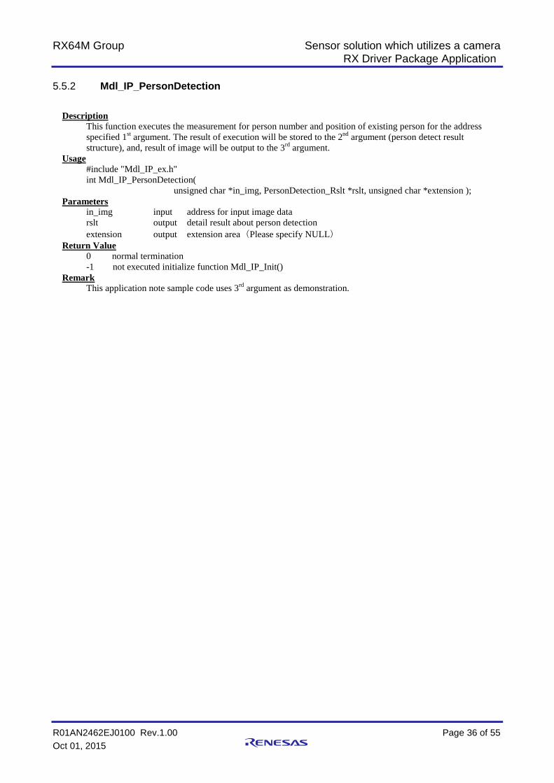
Mdl_IP_PersonDetection 5.5.2
Description This function executes the measurement for person number and position of existing person for the address specified 1st argument. The result of execution will be stored to the 2nd argument (person detect result structure), and, result of image will be output to the 3rd argument.
Usage #include "Mdl_IP_ex.h" int Mdl_IP_PersonDetection(
unsigned char *in_img, PersonDetection_Rslt *rslt, unsigned char *extension ); Parameters
in_img input address for input image data rslt output detail result about person detection extension output extension area(Please specify NULL)
Return Value 0 normal termination -1 not executed initialize function Mdl_IP_Init()
Remark This application note sample code uses 3rd argument as demonstration.

RX64M Group Sensor solution which utilizes a camera RX Driver Package Application
R01AN2462EJ0100 Rev.1.00 Page 37 of 55 Oct 01, 2015
Mdl_IP_PersonDetection_ParamChg 5.5.3
Description This function sets the 2nd argument to the “5.5.3 Mdl_IP_PersonDetection” internal parameter using 1st argument parameter.
Usage #include "Mdl_IP_ex.h" int Mdl_IP_PersonDetection_ParamChg( int kind, int val );
Parameters Kind input type of parameter
val input setting value Return Value
0 normal termination -1 not executed initialize function Mdl_IP_Init() -2 specified parameter is out of range -3 specified setting data is out of range
Remark type of parameter
0: Threshold for person detect(setting range: 1-9) Setting value for threshold to detect “seems to be a person”. When the detection accuracy is not good, please set this value to smaller, when the detection is too excessive, please set this value to bigger. (default value is 7)
1: Sensitivity for person detect(setting range: 1-15) When person detect, specified the threshold value to judge the contrast of the detection candidate part (light and shade) and vividness (number of colors). In case: Enable part(the contrast is smaller, vividness is lesser), please set this value to smaller. In case: Disable part(the contrast is smaller, vividness is lesser), please set this value to bigger.
RX64M Group Sensor solution which utilizes a camera RX Driver Package Application
R01AN2462EJ0100 Rev.1.00 Page 38 of 55 Oct 01, 2015
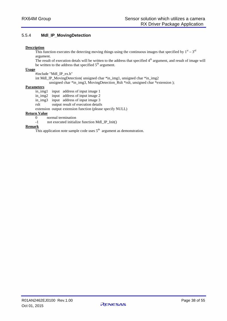
Mdl_IP_MovingDetection 5.5.4
Description This function executes the detecting moving things using the continuous images that specified by 1st – 3rd argument. The result of execution detals will be written to the address that specified 4th argument, and result of image will be written to the address that specified 5th argument.
Usage #include "Mdl_IP_ex.h" int Mdl_IP_MovingDetection( unsigned char *in_img1, unsigned char *in_img2
unsigned char *in_img3, MovingDetection_Rslt *rslt, unsigned char *extension ); Parameters
in_img1 input address of input image 1 in_img2 input address of input image 2 in_img3 input address of input image 3 rslt output result of execution details extension output extension function (please specify NULL)
Return Value 0 normal termination -1 not executed initialize function Mdl_IP_Init()
Remark This application note sample code uses 5th argument as demonstration.
RX64M Group Sensor solution which utilizes a camera RX Driver Package Application
R01AN2462EJ0100 Rev.1.00 Page 39 of 55 Oct 01, 2015
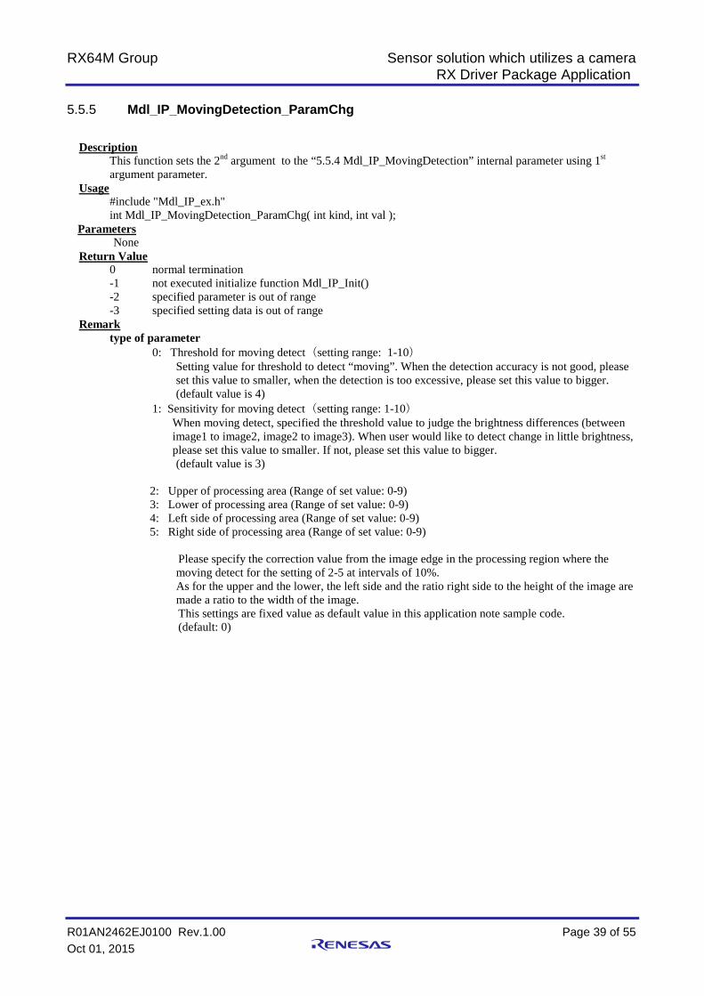
Mdl_IP_MovingDetection_ParamChg 5.5.5
Description This function sets the 2nd argument to the “5.5.4 Mdl_IP_MovingDetection” internal parameter using 1st argument parameter.
Usage #include "Mdl_IP_ex.h" int Mdl_IP_MovingDetection_ParamChg( int kind, int val );
Parameters None Return Value
0 normal termination -1 not executed initialize function Mdl_IP_Init() -2 specified parameter is out of range -3 specified setting data is out of range
Remark type of parameter
0: Threshold for moving detect(setting range: 1-10) Setting value for threshold to detect “moving”. When the detection accuracy is not good, please set this value to smaller, when the detection is too excessive, please set this value to bigger. (default value is 4)
1: Sensitivity for moving detect(setting range: 1-10) When moving detect, specified the threshold value to judge the brightness differences (between image1 to image2, image2 to image3). When user would like to detect change in little brightness, please set this value to smaller. If not, please set this value to bigger. (default value is 3)
2: Upper of processing area (Range of set value: 0-9) 3: Lower of processing area (Range of set value: 0-9) 4: Left side of processing area (Range of set value: 0-9) 5: Right side of processing area (Range of set value: 0-9)
Please specify the correction value from the image edge in the processing region where the moving detect for the setting of 2-5 at intervals of 10%. As for the upper and the lower, the left side and the ratio right side to the height of the image are made a ratio to the width of the image. This settings are fixed value as default value in this application note sample code. (default: 0)

RX64M Group Sensor solution which utilizes a camera RX Driver Package Application
R01AN2462EJ0100 Rev.1.00 Page 40 of 55 Oct 01, 2015
Mdl_IP_ImgRevise 5.5.6
Description This function executes the distortion correction processing for the image stored at the address specified by the 1st argument. This function is written to the address for which the execution result image was specified by the 2nd argument.
Usage #include "Mdl_IP_ex.h" int Mdl_IP_ImgRevise ( unsigned char *in_img, unsigned char *out_img );
Parameters in_img input address for input image out_img output address for result image of distortion process
Return Value 0 normal termination -1 not executed initialize function Mdl_IP_Init()
Remark Destination address for result image of distortion process must be allocated same size as input image.
RX64M Group Sensor solution which utilizes a camera RX Driver Package Application
R01AN2462EJ0100 Rev.1.00 Page 41 of 55 Oct 01, 2015
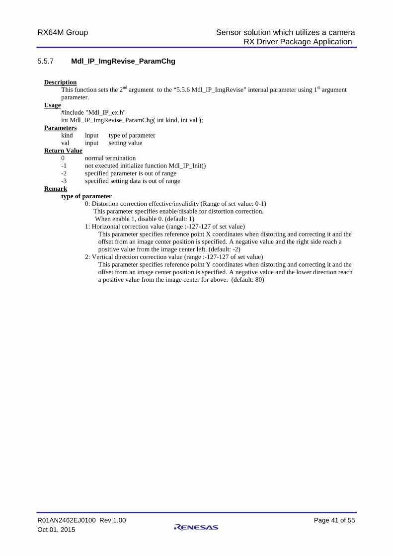
Mdl_IP_ImgRevise_ParamChg 5.5.7
Description This function sets the 2nd argument to the “5.5.6 Mdl_IP_ImgRevise” internal parameter using 1st argument parameter.
Usage #include "Mdl_IP_ex.h" int Mdl_IP_ImgRevise_ParamChg( int kind, int val );
Parameters kind input type of parameter
val input setting value Return Value
0 normal termination -1 not executed initialize function Mdl_IP_Init() -2 specified parameter is out of range -3 specified setting data is out of range
Remark type of parameter
0: Distortion correction effective/invalidity (Range of set value: 0-1) This parameter specifies enable/disable for distortion correction. When enable 1, disable 0. (default: 1) 1: Horizontal correction value (range :-127-127 of set value)
This parameter specifies reference point X coordinates when distorting and correcting it and the offset from an image center position is specified. A negative value and the right side reach a positive value from the image center left. (default: -2)
2: Vertical direction correction value (range :-127-127 of set value) This parameter specifies reference point Y coordinates when distorting and correcting it and the offset from an image center position is specified. A negative value and the lower direction reach a positive value from the image center for above. (default: 80)

RX64M Group Sensor solution which utilizes a camera RX Driver Package Application
R01AN2462EJ0100 Rev.1.00 Page 42 of 55 Oct 01, 2015
6. When CS+ is used This application note can be evaluated using CS+. Note that RX Family C/C++ Compiler Package V2.03.00 or later
is required to build this application note under CS+. This section assumes the user does not own the commercial version and will be using the free evaluation version.
6.1 Acquire and Install CS+ Download CS+ from the Renesas web site.
1. Access the following URL to display the CS+ download page.
http://www.renesas.com/cs+_download
2. Of the displayed items, click [Evaluation Software] CS+ V3.01.00. (Although there are two versions, one that is broken up into smaller sections, and one that can be downloaded in a single operation, the contents are the same.)
Next, download the CS+ installer by following the instructions displayed.
3. Run the downloaded CS+ installer to CS+ on your personal computer. See the CS+ V3.00.00 Integrated Development Environment User’s Manual: Installer.
http://documentation.renesas.com/doc/products/tool/doc/r20ut3094ej0100_csin.pdf
Click this link

RX64M Group Sensor solution which utilizes a camera RX Driver Package Application
R01AN2462EJ0100 Rev.1.00 Page 43 of 55 Oct 01, 2015
6.2 Install the Project Install the Renesas common project files provided with this application note in CubeSuite+.
1. Decompress the ZIP file in which this application note is provided into an arbitrary folder.
2. Start CubeSuite+ and from the start screen, click GO under Open Existing e2 studio/CubeSuite/High-performance Embedded Workshop/PM+ project.
3. Open the folder decompressed in step 1 above and of those entries, open Web server system project (rx64m_gr_kaede_Hi_Solution folder). From there, select Renesas common project files (rx64m_gr_kaede_Hi_Solution.rcpc) and click Open.
Click here.
Click here.
Select this item.

RX64M Group Sensor solution which utilizes a camera RX Driver Package Application
R01AN2462EJ0100 Rev.1.00 Page 44 of 55 Oct 01, 2015
4. Select “rx64m_gr_kaede_Hi_Solution” on the project tree and select required items shown below and then click OK. For the “Target MCU Pin Package” item list, select “R5F564MLCxFB(144pin)”.
5. The project will be converted and the converted project opened. Also, the e2 studio project will be backed up.
Select this item.
Click here

RX64M Group Sensor solution which utilizes a camera RX Driver Package Application
R01AN2462EJ0100 Rev.1.00 Page 45 of 55 Oct 01, 2015
6.3 Change Settings Here we shows how to correct the settings which cannot be inherited in “Renesas Common Project File
(rx64m_gr_kaede_Hi_Solution.rcpc)”
1. Edit un-inheritable parts
[Before Edit] %ProjectFolder%/../%ProjectName%/contents/capture.js}(C:4/DATA,_capture) %ProjectFolder%/../%ProjectName%/contents/com.css}(C:4/DATA,_com) %ProjectFolder%/../%ProjectName%/contents/demo_r_1.htm}(C:4/DATA,_demo_r_1) %ProjectFolder%/../%ProjectName%/contents/demo_r_2.htm}(C:4/DATA,_demo_r_2)
Select binary data file Click here
Edit these files

RX64M Group Sensor solution which utilizes a camera RX Driver Package Application
R01AN2462EJ0100 Rev.1.00 Page 46 of 55 Oct 01, 2015
%ProjectFolder%/../%ProjectName%/contents/demo_r_3.htm}(C:4/DATA,_demo_r_3) %ProjectFolder%/../%ProjectName%/contents/demo_ru1.htm}(C:4/DATA,_demo_ru1) %ProjectFolder%/../%ProjectName%/contents/demo_ru2.htm}(C:4/DATA,_demo_ru2) %ProjectFolder%/../%ProjectName%/contents/demo_ru3.htm}(C:4/DATA,_demo_ru3) %ProjectFolder%/../%ProjectName%/contents/demo_ru4.htm}(C:4/DATA,_demo_ru4) %ProjectFolder%/../%ProjectName%/contents/demo_st1.htm}(C:4/DATA,_demo_st1) %ProjectFolder%/../%ProjectName%/contents/demo_st2.htm}(C:4/DATA,_demo_st2) %ProjectFolder%/../%ProjectName%/contents/demo_st3.htm}(C:4/DATA,_demo_st3) %ProjectFolder%/../%ProjectName%/contents/demo_st4.htm}(C:4/DATA,_demo_st4) %ProjectFolder%/../%ProjectName%/contents/demo_t_1.htm}(C:4/DATA,_demo_t_1) %ProjectFolder%/../%ProjectName%/contents/demo_t_2.htm}(C:4/DATA,_demo_t_2) %ProjectFolder%/../%ProjectName%/contents/demo_top.htm}(C:4/DATA,_demo_top) %ProjectFolder%/../%ProjectName%/contents/ic_title.gif}(C:4/DATA,_ic_title) %ProjectFolder%/../%ProjectName%/contents/rx.jpg}(C:4/DATA,_rx) %ProjectFolder%/../%ProjectName%/contents/start.gif}(C:4/DATA,_start) %ProjectFolder%/../%ProjectName%/contents/stop.gif}(C:4/DATA,_stop) %MainProjectDir%\%ProjectName%/contents/capture.js(C:4/DATA,_capture) %MainProjectDir%\%ProjectName%/contents/com.css(C:4/DATA,_com) %MainProjectDir%\%ProjectName%/contents/demo_r_1.htm(C:4/DATA,_demo_r_1) %MainProjectDir%\%ProjectName%/contents/demo_r_2.htm(C:4/DATA,_demo_r_2) %MainProjectDir%\%ProjectName%/contents/demo_r_3.htm(C:4/DATA,_demo_r_3) %MainProjectDir%\%ProjectName%/contents/demo_ru1.htm(C:4/DATA,_demo_ru1) %MainProjectDir%\%ProjectName%/contents/demo_ru2.htm(C:4/DATA,_demo_ru2) %MainProjectDir%\%ProjectName%/contents/demo_ru3.htm(C:4/DATA,_demo_ru3) %MainProjectDir%\%ProjectName%/contents/demo_ru4.htm(C:4/DATA,_demo_ru4) %MainProjectDir%\%ProjectName%/contents/demo_st1.htm(C:4/DATA,_demo_st1) %MainProjectDir%\%ProjectName%/contents/demo_st2.htm(C:4/DATA,_demo_st2) %MainProjectDir%\%ProjectName%/contents/demo_st3.htm(C:4/DATA,_demo_st3) %MainProjectDir%\%ProjectName%/contents/demo_st4.htm(C:4/DATA,_demo_st4) %MainProjectDir%\%ProjectName%/contents/demo_t_1.htm(C:4/DATA,_demo_t_1) %MainProjectDir%\%ProjectName%/contents/demo_t_2.htm(C:4/DATA,_demo_t_2) %MainProjectDir%\%ProjectName%/contents/demo_top.htm(C:4/DATA,_demo_top) %MainProjectDir%\%ProjectName%/contents/ic_title.gif(C:4/DATA,_ic_title) %MainProjectDir%\%ProjectName%/contents/rx.jpg(C:4/DATA,_rx) %MainProjectDir%\%ProjectName%/contents/start.gif(C:4/DATA,_start) %MainProjectDir%\%ProjectName%/contents/stop.gif(C:4/DATA,_stop)
[After Edit] Delete unnecessary “}” and path (the following list is edited results) %ProjectFolder%/../%ProjectName%/contents/capture.js(C:4/DATA,_capture)
%ProjectFolder%/../%ProjectName%/contents/com.css(C:4/DATA,_com)
%ProjectFolder%/../%ProjectName%/contents/demo_r_1.htm(C:4/DATA,_demo_r_1)
%ProjectFolder%/../%ProjectName%/contents/demo_r_2.htm(C:4/DATA,_demo_r_2)
%ProjectFolder%/../%ProjectName%/contents/demo_r_3.htm(C:4/DATA,_demo_r_3)
%ProjectFolder%/../%ProjectName%/contents/demo_ru1.htm(C:4/DATA,_demo_ru1)
%ProjectFolder%/../%ProjectName%/contents/demo_ru2.htm(C:4/DATA,_demo_ru2)
%ProjectFolder%/../%ProjectName%/contents/demo_ru3.htm(C:4/DATA,_demo_ru3)
%ProjectFolder%/../%ProjectName%/contents/demo_ru4.htm(C:4/DATA,_demo_ru4)
%ProjectFolder%/../%ProjectName%/contents/demo_st1.htm(C:4/DATA,_demo_st1)

RX64M Group Sensor solution which utilizes a camera RX Driver Package Application
R01AN2462EJ0100 Rev.1.00 Page 47 of 55 Oct 01, 2015
%ProjectFolder%/../%ProjectName%/contents/demo_st2.htm(C:4/DATA,_demo_st2)
%ProjectFolder%/../%ProjectName%/contents/demo_st3.htm(C:4/DATA,_demo_st3)
%ProjectFolder%/../%ProjectName%/contents/demo_st4.htm(C:4/DATA,_demo_st4)
%ProjectFolder%/../%ProjectName%/contents/demo_t_1.htm(C:4/DATA,_demo_t_1)
%ProjectFolder%/../%ProjectName%/contents/demo_t_2.htm(C:4/DATA,_demo_t_2)
%ProjectFolder%/../%ProjectName%/contents/demo_top.htm(C:4/DATA,_demo_top)
%ProjectFolder%/../%ProjectName%/contents/ic_title.gif(C:4/DATA,_ic_title)
%ProjectFolder%/../%ProjectName%/contents/rx.jpg(C:4/DATA,_rx)
%ProjectFolder%/../%ProjectName%/contents/start.gif(C:4/DATA,_start)
%ProjectFolder%/../%ProjectName%/contents/stop.gif(C:4/DATA,_stop)

RX64M Group Sensor solution which utilizes a camera RX Driver Package Application
R01AN2462EJ0100 Rev.1.00 Page 48 of 55 Oct 01, 2015
2. Remove multiple folders from the project
Select and right-click these items. And click “Remove From Project”.

RX64M Group Sensor solution which utilizes a camera RX Driver Package Application
R01AN2462EJ0100 Rev.1.00 Page 49 of 55 Oct 01, 2015
3. Change Debug tool to “RX E1(JTAG)(G)”
4. Add download file
Click here
Click here
Click here
RX64M Group Sensor solution which utilizes a camera RX Driver Package Application
R01AN2462EJ0100 Rev.1.00 Page 50 of 55 Oct 01, 2015
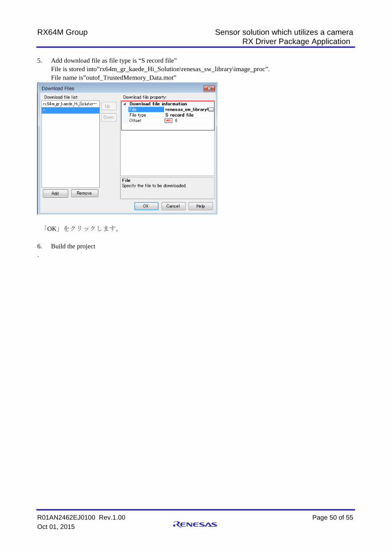
5. Add download file as file type is “S record file”
File is stored into”rx64m_gr_kaede_Hi_Solution\renesas_sw_library\image_proc”. File name is”outof_TrustedMemory_Data.mot”
「OK」をクリックします。
6. Build the project .

RX64M Group Sensor solution which utilizes a camera RX Driver Package Application
R01AN2462EJ0100 Rev.1.00 Page 51 of 55 Oct 01, 2015
[Caution before downloading when using JTAG]
You must configure the clock setting manually.
1. “Main Clock Frequency [MHz]” must be “12”.
2. [Operation Frequency [MHz] must be “120”.
-
Set this value
Set this value
RX64M Group Sensor solution which utilizes a camera RX Driver Package Application
R01AN2462EJ0100 Rev.1.00 Page 52 of 55 Oct 01, 2015
7. Supplement 7.1 Notes on Using the Free Evaluation Version of the RX Family C/C++ Compiler
Package There is a usage period limitation and certain usage limitations on the free evaluation version of the RX Family
C/C++ Compiler Package. If the usage period is exceeded, load modules may not be generated correctly due to the usage limitations.
See the page on evaluation software on the Renesas web site at the link below.
http://www.renesas.com/products/tools/evaluation_software/index.jsp
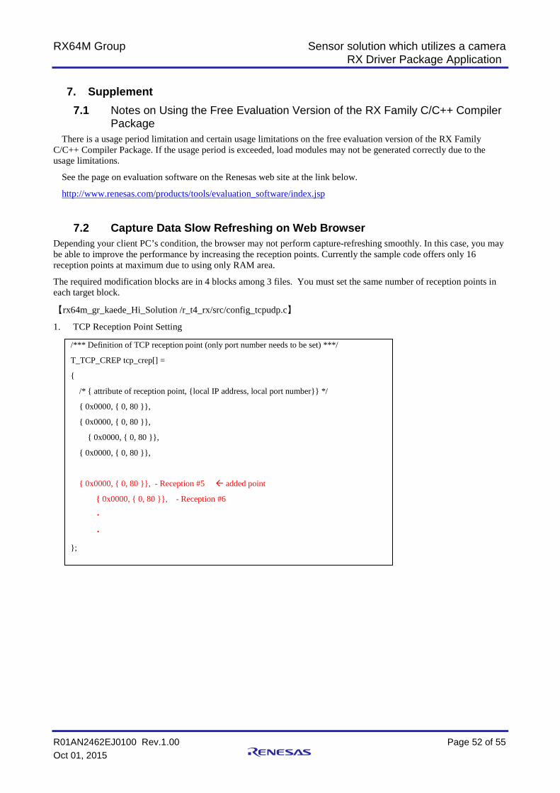
7.2 Capture Data Slow Refreshing on Web Browser Depending your client PC’s condition, the browser may not perform capture-refreshing smoothly. In this case, you may be able to improve the performance by increasing the reception points. Currently the sample code offers only 16 reception points at maximum due to using only RAM area.
The required modification blocks are in 4 blocks among 3 files. You must set the same number of reception points in each target block.
【rx64m_gr_kaede_Hi_Solution /r_t4_rx/src/config_tcpudp.c】
1. TCP Reception Point Setting
変更前の受け口を 4 とする
/*** Definition of TCP reception point (only port number needs to be set) ***/
T_TCP_CREP tcp_crep[] =
{
/* { attribute of reception point, {local IP address, local port number}} */
{ 0x0000, { 0, 80 }},
{ 0x0000, { 0, 80 }},
{ 0x0000, { 0, 80 }},
{ 0x0000, { 0, 80 }},
{ 0x0000, { 0, 80 }}, - Reception #5 added point
{ 0x0000, { 0, 80 }}, - Reception #6
・
・
};
RX64M Group Sensor solution which utilizes a camera RX Driver Package Application
R01AN2462EJ0100 Rev.1.00 Page 53 of 55 Oct 01, 2015
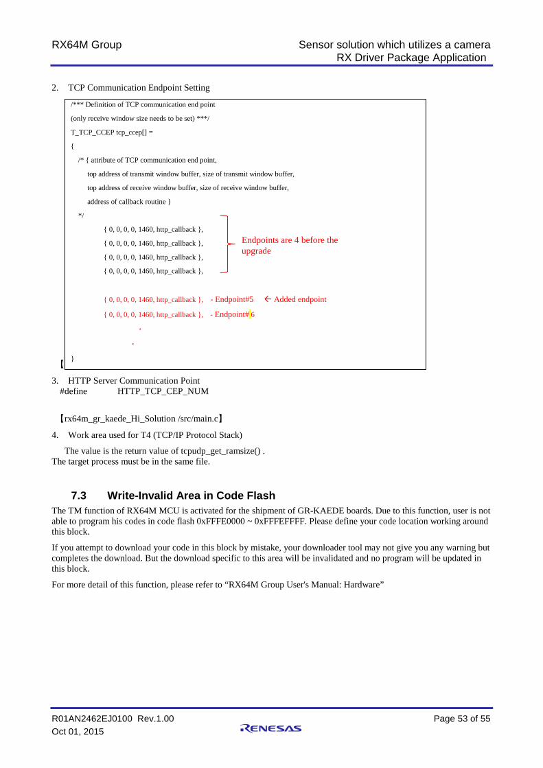
2. TCP Communication Endpoint Setting
【rx64m_gr_kaede_Hi_Solution /r_config/r_t4_http_server_rx_config.h】
3. HTTP Server Communication Point #define HTTP_TCP_CEP_NUM
【rx64m_gr_kaede_Hi_Solution /src/main.c】
4. Work area used for T4 (TCP/IP Protocol Stack)
The value is the return value of tcpudp_get_ramsize() . The target process must be in the same file.
7.3 Write-Invalid Area in Code Flash The TM function of RX64M MCU is activated for the shipment of GR-KAEDE boards. Due to this function, user is not able to program his codes in code flash 0xFFFE0000 ~ 0xFFFEFFFF. Please define your code location working around this block.
If you attempt to download your code in this block by mistake, your downloader tool may not give you any warning but completes the download. But the download specific to this area will be invalidated and no program will be updated in this block.
For more detail of this function, please refer to “RX64M Group User's Manual: Hardware”
/*** Definition of TCP communication end point
(only receive window size needs to be set) ***/
T_TCP_CCEP tcp_ccep[] =
{
/* { attribute of TCP communication end point,
top address of transmit window buffer, size of transmit window buffer,
top address of receive window buffer, size of receive window buffer,
address of callback routine }
*/
{ 0, 0, 0, 0, 1460, http_callback },
{ 0, 0, 0, 0, 1460, http_callback },
{ 0, 0, 0, 0, 1460, http_callback },
{ 0, 0, 0, 0, 1460, http_callback },
{ 0, 0, 0, 0, 1460, http_callback }, - Endpoint#5 Added endpoint
{ 0, 0, 0, 0, 1460, http_callback }, - Endpoint# 6
・
・
}
Endpoints are 4 before the upgrade

RX64M Group Sensor solution which utilizes a camera RX Driver Package Application
R01AN2462EJ0100 Rev.1.00 Page 54 of 55 Oct 01, 2015
8. Camera Solution Product Introduction This application note explains the solution based on CC-RX compiler, GR-KAEDE board, and the camera module connected to GR-KAEDE. But this solution is not limited to only these combinations.
8.1 Gadget Renesas GR-KAEDE Board Gadget Renesas solution will provide the similar sample code which offers the same feature described in this app note. In this solution, the web compiler based on GNU GCC will be used.
In addition to the above, the libraries provided in the web compiler offer the Arduino UNO compatible API and features since GR-KAEDE provides the Arduino UNO compatible I/O pins on the board. The code development with this solution becomes very easy due to free from deep understanding the MCU functions.
http://gadget.renesas.com/en/product/kaede.html
8.2 Camera and Voice Recording/Playback Demo Using HMI Expansion Board
This is a camera solution using “Renesas Starter Kit+ for RX64M (herein RSK)” and “HMI Expansion Board”. This RSK offers more functions of RX64M than GR-KAEDE, such as Ethernet2 port. However, the image processing function does not operate on this solution.
Where to obtain this demo solution: will be announced soon
Information of RSK and HMI Expansion Board:
http://am.renesas.com/products/tools/introductory_evaluation_tools/renesas_starter_kits/rsk_rx64m/index.jsp

RX64M Group Sensor solution which utilizes a camera RX Driver Package Application
R01AN2462EJ0100 Rev.1.00 Page 55 of 55 Oct 01, 2015
Website and Support Renesas Electronics Website
http://www.renesas.com/ Inquiries
http://www.renesas.com/contact/ All trademarks and registered trademarks are the property of their respective owners.

A-1
Revision History
Rev. Date Description Page Summary
1.00 Oct 01, 2015 - First edition issued

General Precautions in the Handling of Microprocessing Unit and Microcontroller Unit Products The following usage notes are applicable to all Microprocessing unit and Microcontroller unit products from Renesas. For detailed usage notes on the products covered by this document, refer to the relevant sections of the document as well as any technical updates that have been issued for the products.
1. Handling of Unused Pins Handle unused pins in accordance with the directions given under Handling of Unused Pins in the manual. The input pins of CMOS products are generally in the high-impedance state. In operation with an
unused pin in the open-circuit state, extra electromagnetic noise is induced in the vicinity of LSI, an associated shoot-through current flows internally, and malfunctions occur due to the false recognition of the pin state as an input signal become possible. Unused pins should be handled as described under Handling of Unused Pins in the manual.
2. Processing at Power-on The state of the product is undefined at the moment when power is supplied. The states of internal circuits in the LSI are indeterminate and the states of register settings and
pins are undefined at the moment when power is supplied. In a finished product where the reset signal is applied to the external reset pin, the states of pins are not guaranteed from the moment when power is supplied until the reset process is completed. In a similar way, the states of pins in a product that is reset by an on-chip power-on reset function are not guaranteed from the moment when power is supplied until the power reaches the level at which resetting has been specified.
3. Prohibition of Access to Reserved Addresses Access to reserved addresses is prohibited. The reserved addresses are provided for the possible future expansion of functions. Do not access
these addresses; the correct operation of LSI is not guaranteed if they are accessed. 4. Clock Signals
After applying a reset, only release the reset line after the operating clock signal has become stable. When switching the clock signal during program execution, wait until the target clock signal has stabilized. When the clock signal is generated with an external resonator (or from an external oscillator)
during a reset, ensure that the reset line is only released after full stabilization of the clock signal. Moreover, when switching to a clock signal produced with an external resonator (or by an external oscillator) while program execution is in progress, wait until the target clock signal is stable.
5. Differences between Products Before changing from one product to another, i.e. to a product with a different part number, confirm that the change will not lead to problems. The characteristics of Microprocessing unit or Microcontroller unit products in the same group but
having a different part number may differ in terms of the internal memory capacity, layout pattern, and other factors, which can affect the ranges of electrical characteristics, such as characteristic values, operating margins, immunity to noise, and amount of radiated noise. When changing to a product with a different part number, implement a system-evaluation test for the given product.
Notice1. Descriptions of circuits, software and other related information in this document are provided only to illustrate the operation of semiconductor products and application examples. You are fully responsible for
the incorporation of these circuits, software, and information in the design of your equipment. Renesas Electronics assumes no responsibility for any losses incurred by you or third parties arising from the
use of these circuits, software, or information.
2. Renesas Electronics has used reasonable care in preparing the information included in this document, but Renesas Electronics does not warrant that such information is error free. Renesas Electronics
assumes no liability whatsoever for any damages incurred by you resulting from errors in or omissions from the information included herein.
3. Renesas Electronics does not assume any liability for infringement of patents, copyrights, or other intellectual property rights of third parties by or arising from the use of Renesas Electronics products or
technical information described in this document. No license, express, implied or otherwise, is granted hereby under any patents, copyrights or other intellectual property rights of Renesas Electronics or
others.
4. You should not alter, modify, copy, or otherwise misappropriate any Renesas Electronics product, whether in whole or in part. Renesas Electronics assumes no responsibility for any losses incurred by you or
third parties arising from such alteration, modification, copy or otherwise misappropriation of Renesas Electronics product.
5. Renesas Electronics products are classified according to the following two quality grades: "Standard" and "High Quality". The recommended applications for each Renesas Electronics product depends on
the product's quality grade, as indicated below.
"Standard": Computers; office equipment; communications equipment; test and measurement equipment; audio and visual equipment; home electronic appliances; machine tools; personal electronic
equipment; and industrial robots etc.
"High Quality": Transportation equipment (automobiles, trains, ships, etc.); traffic control systems; anti-disaster systems; anti-crime systems; and safety equipment etc.
Renesas Electronics products are neither intended nor authorized for use in products or systems that may pose a direct threat to human life or bodily injury (artificial life support devices or systems, surgical
implantations etc.), or may cause serious property damages (nuclear reactor control systems, military equipment etc.). You must check the quality grade of each Renesas Electronics product before using it
in a particular application. You may not use any Renesas Electronics product for any application for which it is not intended. Renesas Electronics shall not be in any way liable for any damages or losses
incurred by you or third parties arising from the use of any Renesas Electronics product for which the product is not intended by Renesas Electronics.
6. You should use the Renesas Electronics products described in this document within the range specified by Renesas Electronics, especially with respect to the maximum rating, operating supply voltage
range, movement power voltage range, heat radiation characteristics, installation and other product characteristics. Renesas Electronics shall have no liability for malfunctions or damages arising out of the
use of Renesas Electronics products beyond such specified ranges.
7. Although Renesas Electronics endeavors to improve the quality and reliability of its products, semiconductor products have specific characteristics such as the occurrence of failure at a certain rate and
malfunctions under certain use conditions. Further, Renesas Electronics products are not subject to radiation resistance design. Please be sure to implement safety measures to guard them against the
possibility of physical injury, and injury or damage caused by fire in the event of the failure of a Renesas Electronics product, such as safety design for hardware and software including but not limited to
redundancy, fire control and malfunction prevention, appropriate treatment for aging degradation or any other appropriate measures. Because the evaluation of microcomputer software alone is very difficult,
please evaluate the safety of the final products or systems manufactured by you.
8. Please contact a Renesas Electronics sales office for details as to environmental matters such as the environmental compatibility of each Renesas Electronics product. Please use Renesas Electronics
products in compliance with all applicable laws and regulations that regulate the inclusion or use of controlled substances, including without limitation, the EU RoHS Directive. Renesas Electronics assumes
no liability for damages or losses occurring as a result of your noncompliance with applicable laws and regulations.
9. Renesas Electronics products and technology may not be used for or incorporated into any products or systems whose manufacture, use, or sale is prohibited under any applicable domestic or foreign laws or
regulations. You should not use Renesas Electronics products or technology described in this document for any purpose relating to military applications or use by the military, including but not limited to the
development of weapons of mass destruction. When exporting the Renesas Electronics products or technology described in this document, you should comply with the applicable export control laws and
regulations and follow the procedures required by such laws and regulations.
10. It is the responsibility of the buyer or distributor of Renesas Electronics products, who distributes, disposes of, or otherwise places the product with a third party, to notify such third party in advance of the
contents and conditions set forth in this document, Renesas Electronics assumes no responsibility for any losses incurred by you or third parties as a result of unauthorized use of Renesas Electronics
products.
11. This document may not be reproduced or duplicated in any form, in whole or in part, without prior written consent of Renesas Electronics.
12. Please contact a Renesas Electronics sales office if you have any questions regarding the information contained in this document or Renesas Electronics products, or if you have any other inquiries.
(Note 1) "Renesas Electronics" as used in this document means Renesas Electronics Corporation and also includes its majority-owned subsidiaries.
(Note 2) "Renesas Electronics product(s)" means any product developed or manufactured by or for Renesas Electronics.
http://www.renesas.comRefer to "http://www.renesas.com/" for the latest and detailed information.
Renesas Electronics America Inc.2801 Scott Boulevard Santa Clara, CA 95050-2549, U.S.A.Tel: +1-408-588-6000, Fax: +1-408-588-6130Renesas Electronics Canada Limited9251 Yonge Street, Suite 8309 Richmond Hill, Ontario Canada L4C 9T3Tel: +1-905-237-2004Renesas Electronics Europe LimitedDukes Meadow, Millboard Road, Bourne End, Buckinghamshire, SL8 5FH, U.KTel: +44-1628-585-100, Fax: +44-1628-585-900Renesas Electronics Europe GmbHArcadiastrasse 10, 40472 Düsseldorf, GermanyTel: +49-211-6503-0, Fax: +49-211-6503-1327Renesas Electronics (China) Co., Ltd.Room 1709, Quantum Plaza, No.27 ZhiChunLu Haidian District, Beijing 100191, P.R.ChinaTel: +86-10-8235-1155, Fax: +86-10-8235-7679Renesas Electronics (Shanghai) Co., Ltd.Unit 301, Tower A, Central Towers, 555 Langao Road, Putuo District, Shanghai, P. R. China 200333Tel: +86-21-2226-0888, Fax: +86-21-2226-0999Renesas Electronics Hong Kong LimitedUnit 1601-1611, 16/F., Tower 2, Grand Century Place, 193 Prince Edward Road West, Mongkok, Kowloon, Hong KongTel: +852-2265-6688, Fax: +852 2886-9022Renesas Electronics Taiwan Co., Ltd.13F, No. 363, Fu Shing North Road, Taipei 10543, TaiwanTel: +886-2-8175-9600, Fax: +886 2-8175-9670Renesas Electronics Singapore Pte. Ltd.80 Bendemeer Road, Unit #06-02 Hyflux Innovation Centre, Singapore 339949Tel: +65-6213-0200, Fax: +65-6213-0300Renesas Electronics Malaysia Sdn.Bhd.Unit 1207, Block B, Menara Amcorp, Amcorp Trade Centre, No. 18, Jln Persiaran Barat, 46050 Petaling Jaya, Selangor Darul Ehsan, MalaysiaTel: +60-3-7955-9390, Fax: +60-3-7955-9510Renesas Electronics India Pvt. Ltd.No.777C, 100 Feet Road, HALII Stage, Indiranagar, Bangalore, IndiaTel: +91-80-67208700, Fax: +91-80-67208777Renesas Electronics Korea Co., Ltd.12F., 234 Teheran-ro, Gangnam-Gu, Seoul, 135-080, KoreaTel: +82-2-558-3737, Fax: +82-2-558-5141
SALES OFFICES
© 2015 Renesas Electronics Corporation. All rights reserved.Colophon 5.0